TNV series - Barmesa Pumps
346
TNV DI Service Manual TNV series SERVICE MANUAL 3TNV82A 3TNV84 • 3TNV84T • 3TNV88 4TNV84 • 4TNV84T • 4TNV88 4TNV94L 4TNV98 • 4TNV98T 4TNV106 • 4TNV106T P/N: 0BTNV0-G0000 INDUSTRIAL ENGINES
-
Upload
khangminh22 -
Category
Documents
-
view
0 -
download
0
Transcript of TNV series - Barmesa Pumps

TNV DI Service Manual
TNV seriesSERVICE MANUAL
3TNV82A3TNV84 • 3TNV84T • 3TNV884TNV84 • 4TNV84T • 4TNV884TNV94L4TNV98 • 4TNV98T4TNV106 • 4TNV106T
P/N: 0BTNV0-G0000
INDUSTRIALENGINES
This Service Manual has been developed for the exclusive use of service and repair professionals such as Yanmer authorized Distributors and Yanmar authorized Dealers. It is written with these professionals in mind and may not contain the necessary detail or safety statements that may be required for a non-professional to perform the service or repair properly and / or safely. Please contact an authorized Yanmar repair or service professional before working on your Yanmar product.
Disclaimers:
All information, illustrations and specifications in this manual are based on the latest information available at the time of publishing. The illustrations used in this manual are intended as representative reference views only. Moreover, because of our continuous product improvement policy, we may modify information, illustrations, and / or specifications to explain and / or exemplify a product, service, or maintenance improvement. We reserve the right to make any change at any time.
Yanmar and are registered trademarks of Yanmar Co., Ltd. in Japan, the United States and / or other countries.
All Rights Reserved:
No part of this publication may be reproduced or used in any form by any means - graphic, electronic, or mechanical, including photocopying, recording, taping, or information storage and retrieval systems - without the written permission of Yanmar Co., Ltd.
© 2005 Yanmar Co. Ltd.
ii TNV DI Service Manual

TABLE OF CONTENTS
Introduction ......................................................................................... 1-1
Yanmar Warranties.............................................................................. 2-1
Safety.................................................................................................... 3-1
General Service Information .............................................................. 4-1
Periodic Maintenance ......................................................................... 5-1
Engine .................................................................................................. 6-1
Fuel System ......................................................................................... 7-1
Cooling System ................................................................................... 8-1
Lubrication System............................................................................. 9-1
Turbocharger ..................................................................................... 10-1
Starter Motor...................................................................................... 11-1
Alternator ........................................................................................... 12-1
Electric Wiring ................................................................................... 13-1
Troubleshooting................................................................................ 14-1
iii

TNV DI Service Manual Section 1
INTRODUCTION
This Service Manual describes the service procedures for the TNV series direct injection engines. These engines are certified by the U.S. EPA, California ARB and/or the 97/68/EC Directive for industrial use.Please use this manual for accurate, quick and safe servicing of the engine. Since the directions in this manual are for a typical engine, some specifications and components may be different from your engine. Refer to the documentation supplied by the optional equipment manufacturer for specific service instructions.
Yanmar products are continuously undergoing improvement. This Service Manual might not address possible field modifications to the equipment. Contact an authorized Yanmar industrial engine dealer or distributor for answers to any questions relating to field modifications.
TNV DI Service Manual 1-1

TNV DI Service Manual Section 2
YANMAR WARRANTIES
Page
Yanmar Limited Warranty................................................................ 2-3What is Covered by this Warranty? .......................................... 2-3How Long is the Warranty Period? ........................................... 2-3What the Engine Owner Must Do: ............................................ 2-3To Locate an Authorized Yanmar Industrial Engine Dealer or Distributor: ................................................................. 2-4What Yanmar Will Do: ............................................................... 2-4What is Not Covered by this Warranty? ................................... 2-4Warranty Limitations: ................................................................ 2-5Warranty Modifications: ............................................................ 2-5Questions: ................................................................................. 2-5Retail Purchaser Registration.................................................... 2-5
Emission System Warranty ............................................................. 2-6
Yanmar Co., Ltd. Limited Emission Control System Warranty - USA Only....................................................................... 2-6
Your Warranty Rights and Obligations: ..................................... 2-6Manufacturer’s Warranty Period:............................................... 2-6Warranty Coverage: .................................................................. 2-7Warranted Parts: ....................................................................... 2-7Exclusions: ................................................................................ 2-8Owner’s Warranty Responsibilities:........................................... 2-8
TNV DI Service Manual 2-1
YANMAR WARRANTIES
YANMAR LIMITED WARRANTY
What is Covered by this Warranty? Yanmar warrants to the original retail purchaser that a new Yanmar TNV Series Industrial Engine will be free from defects in material and / or workmanship for the duration of the warranty period.
Note: Yanmar engines may be equipped with external components including, but not limited to: wiring harnesses, electrical devices, control panels, radiators, air filters, fuel filters, and/or exhaust systems that are supplied and/or installed by manufacturers other than Yanmar. For warranty information on such external components, please contact the machine or component manufacturer directly or see your authorized Yanmar dealer or distributor.
THIS WARRANTY IS PROVIDED IN LIEU OF ALL OTHER WARRANTIES, EXPRESS OR IMPLIED. YANMAR SPECIFICALLY DISCLAIMS ANY IMPLIED WARRANTIES OF MERCHANTABILITY OR FITNESS FOR A PARTICULAR PURPOSE, except where such disclaimer is prohibited by law. IF SUCH DISCLAIMER IS PROHIBITED BY LAW, THEN IMPLIED WARRANTIES SHALL BE LIMITED IN DURATION TO THE LIFE OF THE EXPRESS WARRANTY.
How Long is the Warranty Period? The Yanmar standard limited warranty period runs for a period of twenty-four (24) months or two-thousand (2000) engine operation hours, whichever occurs first. An extended limited warranty of thirty-six (36) months or three thousand (3000) engine operating hours, whichever occurs first, is provided for these specific parts only: the cylinder block, cylinder head, crankshaft forging, connecting rods, flywheel, flywheel housing, camshaft, timing gear, and gear case. The Warranty Period for both the standard limited warranty and the extended limited warranty (by duration or operation hours) begins on the date of delivery to the original retail purchaser and is valid only until the applicable warranted duration has passed or the operation hours are exceeded, whichever comes first.
What the Engine Owner Must Do: If you believe your Yanmar engine has experienced a failure due to a defect in material and / or workmanship, you must contact an authorized Yanmar industrial engine dealer or distributor within thirty (30) days of discovering the failure. You must provide proof of ownership of the engine, proof of the date of the engine purchase and delivery, and documentation of the engine operation hours. Acceptable forms of proof of delivery date include, but are not limited to: the original warranty registration or sales receipts or other documents maintained in the ordinary course of business by Yanmar dealers and / or distributors, indicating the date of delivery of the Yanmar product to the original retail purchaser. This information is necessary to establish whether the Yanmar product is still within the warranty period. Thus, Yanmar strongly recommends you register your engine as soon as possible after purchase in order to facilitate any future warranty matters.
You are responsible for the transportation of the engine to and from the repair location as designated by Yanmar.
TNV DI Service Manual 2-3

YANMAR WARRANTIES
Yanmar Limited Warranty - Continued
To Locate an Authorized Yanmar Industrial Engine Dealer or Distributor:You can locate your nearest authorized Yanmar industrial engine dealer or distributor by visiting the Yanmar Corp., LTD. website at:
http://www.yanmar.co.jp (The Japanese language page will be displayed.) For English language “click” on “English Page.”)
• “Click” on “Network” in the website heading to view the “Yanmar Worldwide Network.”
• Choose and “Click” on the desired product group.
• “Click” on the Icon closest to your region.
• “Click” on the desired country or Associate company to locate your nearest authorized Yanmar industrial engine dealer or distributor.
• You may also contact Yanmar by clicking on “Inquiry” in the website heading and typing in your question or comment.
What Yanmar Will Do:Yanmar warrants to the original retail purchaser of a new Yanmar engine that Yanmar will make such repairs and / or replacements at Yanmar’s option, of any part(s) of the Yanmar product covered by this Warranty found to be defective in material and / or workmanship. Such repairs and / or replacements will be made at a location designated by Yanmar at no cost to the purchaser for parts or labor.
What is Not Covered by this Warranty? This Warranty does not cover parts affected by or damaged by any reason other than defective materials or workmanship including, but not limited to, accident, misuse, abuse, “Acts of God,” neglect, improper installation, improper maintenance, improper storage, the use of unsuitable attachments or parts, the use of contaminated fuels, the use of fuels, oils, lubricants, or fluids other than those recommended in your Yanmar Operation Manual, unauthorized alterations or modifications, ordinary wear and tear, and rust or corrosion. This Warranty does not cover the cost of parts and / or labor required to perform normal / scheduled maintenance on your Yanmar engine. This Warranty does not cover consumable parts such as, but not limited to, filters, belts, hoses, fuel injector nozzles, lubricants and cleaning fluids. This Warranty does not cover the cost of shipping the product to or from the Warranty repair facility.
2-4 TNV DI Service Manual

YANMAR WARRANTIES
Yanmar Limited Warranty - Continued
Warranty Limitations: The foregoing is Yanmar’s only obligation to you and your exclusive remedy for breach of warranty. Failure to follow the requirements for submitting a claim under this Warranty may result in a waiver of all claims for damages and other relief. In no event shall Yanmar or any authorized industrial engine dealer or distributor be liable for incidental, special or consequential damages. Such consequential damages may include, but not be limited to, loss of revenue, loan payments, cost of rental of substitute equipment, insurance coverage, storage, lodging, transportation, fuel, mileage, and telephone costs. The limitations in this Warranty apply regardless of whether your claims are based on breach of contract, tort (including negligence and strict liability) or any other theory. Any action arising hereunder must be brought within one (1) year after the cause of action accrues or it shall be barred. Some states and countries do not allow certain limitations on warranties or for breach of warranties. This Warranty gives you specific legal rights, and you may also have other rights which vary from state to state and country to country. Limitations set forth in this paragraph shall not apply to the extent that they are prohibited by law.
Warranty Modifications: Except as modified in writing and signed by the parties, this Warranty is and shall remain the complete and exclusive agreement between the parties with respect to warranties, superseding all prior agreements, written and oral, and all other communications between the parties relating to warranties. No person or entity is authorized to give any other warranty or to assume any other obligation on behalf of Yanmar, either orally or in writing.
Questions:If you have any questions or concerns regarding this Warranty, please call or write to the nearest authorized Yanmar industrial engine dealer or distributor or other authorized facility.
It is very important for the original retail purchaser to register the Yanmar product. Registration enables Yanmar to provide the best support for your Yanmar product.
At the time of purchase, Yanmar highly recommends registering the retail purchaser’s information through the website http://www.yanmar.co.jp as soon as possible.
If it is not possible to access the website, please contact the nearest authorized Yanmar industrial engine dealer or distributor.
Retail Purchaser Registration
TNV DI Service Manual 2-5
YANMAR WARRANTIES
EMISSION SYSTEM WARRANTY
YANMAR CO., LTD. LIMITED EMISSION CONTROL SYSTEM WARRANTY - USA ONLY
Your Warranty Rights and Obligations:
CaliforniaThe California Air Resources Board (CARB), the Environmental Protection Agency (EPA) and Yanmar Co., Ltd. hereafter referred to as Yanmar, are pleased to explain the emission control system warranty on your industrial compression-ignition engine. In California, model year 2000 or later off-road compression-ignition engines must be designed, built and equipped to meet the State’s stringent anti-smog standards. In all states, 1998 and later non-road compression-ignition engines must be designed, built and equipped to meet the United States EPA emissions standards. Yanmar warrants the emission control system on your engine for the periods of time listed below provided there has been no abuse, neglect or improper maintenance of your engine.
Your emission control system may include parts such as the fuel injection system and the air induction system. Also included may be hoses, belts, connectors and other emission-related assemblies.
Where a warrantable condition exists, Yanmar will repair your non-road compression-ignition engine at no charge to you including diagnosis, parts and labor.
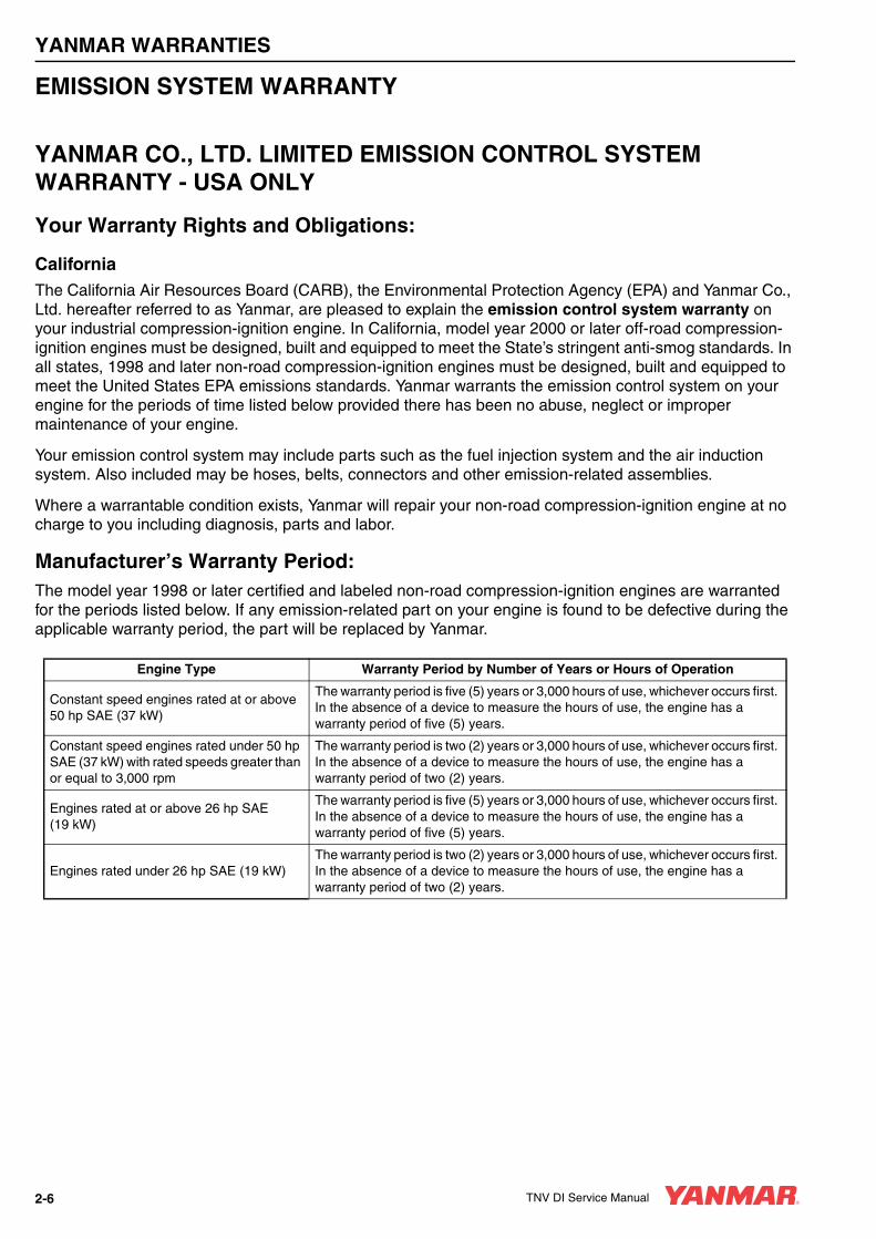
Manufacturer’s Warranty Period:The model year 1998 or later certified and labeled non-road compression-ignition engines are warranted for the periods listed below. If any emission-related part on your engine is found to be defective during the applicable warranty period, the part will be replaced by Yanmar.
Engine Type Warranty Period by Number of Years or Hours of Operation
Constant speed engines rated at or above 50 hp SAE (37 kW)
The warranty period is five (5) years or 3,000 hours of use, whichever occurs first. In the absence of a device to measure the hours of use, the engine has a warranty period of five (5) years.
Constant speed engines rated under 50 hp SAE (37 kW) with rated speeds greater than or equal to 3,000 rpm
The warranty period is two (2) years or 3,000 hours of use, whichever occurs first. In the absence of a device to measure the hours of use, the engine has a warranty period of two (2) years.
Engines rated at or above 26 hp SAE (19 kW)
The warranty period is five (5) years or 3,000 hours of use, whichever occurs first. In the absence of a device to measure the hours of use, the engine has a warranty period of five (5) years.
Engines rated under 26 hp SAE (19 kW)The warranty period is two (2) years or 3,000 hours of use, whichever occurs first. In the absence of a device to measure the hours of use, the engine has a warranty period of two (2) years.
2-6 TNV DI Service Manual

YANMAR WARRANTIES
Limited Emission Control System Warranty - USA Only - Continued
Warranty Coverage:This warranty is transferable to each subsequent purchaser for the duration of the warranty period. Repair or replacement of any warranted part will be performed at an authorized Yanmar industrial engine dealer or distributor.
Warranted parts not scheduled for replacement as required maintenance in the Operation Manual shall be warranted for the warranty period. Warranted parts scheduled for replacement as required maintenance in the operation manual are warranted for the period of time prior to the first scheduled replacement. Any part repaired or replaced under warranty shall be warranted for the remaining warranty period.
During the warranty period, Yanmar is liable for damages to other engine components caused by the failure of any warranted part during the warranty period.
Any replacement part which is functionally identical to the original equipment part in all respects may be used in the maintenance or repair of your engine, and shall not reduce Yanmar’s warranty obligations. Add-on or modified parts that are not exempted may not be used. The use of any non-exempted add-on or modified parts shall be grounds for disallowing a warranty.
Warranted Parts:This warranty covers engine components that are a part of the emission control system of the engine as delivered by Yanmar to the original retail purchaser. Such components may include the following:
• Fuel Injection System
• Cold Start Enrichment System
• Intake Manifold
• Turbocharger Systems
• Exhaust Manifold
• Positive Crankcase Ventilation System
• Hoses, belts, connectors and assemblies associated with emission control systems
Since emissions-related parts may vary slightly between models, certain models may not contain all of these parts and other models may contain the functional equivalents.
TNV DI Service Manual 2-7

YANMAR WARRANTIES
Limited Emission Control System Warranty - USA Only - Continued
Exclusions:Failures other than those arising from defects in material and / or workmanship are not covered by this warranty. The warranty does not extend to the following: malfunctions caused by abuse, misuse, improper adjustment, modification, alteration, tampering, disconnection, improper or inadequate maintenance or use of non-recommended fuels and lubricating oils; accident-caused damage, and replacement of expendable items made in connection with scheduled maintenance. Yanmar disclaims any responsibility for incidental or consequential damages such as loss of time, inconvenience, loss of use of equipment / engine or commercial loss.
Owner’s Warranty Responsibilities:As the engine owner, you are responsible for the performance of the required maintenance listed in your owner’s manual. Yanmar recommends that you retain all documentation, including receipts, covering maintenance on your non-road compression-ignition engine, but Yanmar cannot deny warranty solely for the lack of receipts, or for your failure to ensure the performance of all scheduled maintenance.
Yanmar may deny your warranty coverage of your non-road compression-ignition engine if a part has failed due to abuse, neglect, improper maintenance or unapproved modifications.
Your engine is designed to operate on diesel fuel only. Use of any other fuel may result in your engine no longer operating in compliance with applicable emissions requirements.
You are responsible for initiating the warranty process. You must present your engine to a Yanmar dealer as soon as a problem exists. The warranty repairs should be completed by the dealer as expeditiously as possible. If you have any questions regarding your warranty rights and responsibilities, or would like information on the nearest Yanmar dealer or authorized service center, you should contact Yanmar America Corporation at 1-800-872-2867.
2-8 TNV DI Service Manual

TNV DI Service Manual Section 3
SAFETY
PageSafety Statements ........................................................................... 3-3
Safety Precautions .......................................................................... 3-4
TNV DI Service Manual 3-1

SAFETY
SAFETY STATEMENTSYanmar is concerned for your safety and your machine’s condition. Safety statements are one of the primary ways to call your attention to the potential hazards associated with Yanmar TNV engine operation. Follow the precautions listed throughout the manual before operation, during operation and during periodic maintenance procedures for your safety, the safety of others and to protect the performance of your engine. Keep the labels from becoming dirty or torn and replace them if they are lost or damaged. Also, if you need to replace a part that has a label attached to it, make sure you order the new part and label at the same time.
AThis safety alert symbol appears with most safety statements. It means attention, become alert, your safety is involved! Please read and abide by the message that follows the safety alert symbol.
A DANGERDanger (the word “DANGER” is in white letters with a red rectangle behind it) - indicates an imminently hazardous situation which, if not avoided, will result in death or serious injury. Danger is limited to the most extreme situations.
0000001en
A WARNINGWarning (the word “WARNING” is in black letters with an orange rectangle behind it) – indicates a potentially hazardous situation which, if not avoided, could result in death or serious injury.
0000001en
A CAUTIONCaution (the word “CAUTION” is in black letters with a yellow rectangle behind it) – indicates a potentially hazardous situation which, if not avoided, may result in minor or moderate injury.
0000001en
CAUTIONCaution without the safety alert symbol indicates a potentially hazardous situation that can cause damage to the machine, personal property and / or the environment or cause the machine to operate improperly.
0000001en
TNV DI Service Manual 3-3

SAFETY
SAFETY PRECAUTIONS
A DANGER
SCALD HAZARD!• NEVER remove the radiator cap if the
engine is hot. Steam and hot engine coolant will spurt out and seriously burn you. Allow the engine to cool down before you attempt to remove the radiator cap.
• Tighten the radiator cap securely after you check the radiator. Steam can spurt out during engine operation if the cap is loose.
• ALWAYS check the level of the engine coolant by observing the reserve tank.
• Failure to comply will result in death or serious injury.
0000002en
A DANGER
EXPLOSION HAZARD!• Keep the area around the battery well-
ventilated. While the engine is running or the battery is charging, hydrogen gas is produced which can be easily ignited.
• Keep sparks, open flame and any other form of ignition away while the engine is running or battery is charging.
• Failure to comply will result in death or serious injury.
0000003en
A DANGER
FIRE AND EXPLOSION HAZARD!• Diesel fuel is flammable and explosive
under certain conditions.
• When you remove any fuel system component to perform maintenance (such as changing the fuel filter) place an approved container under the opening to catch the fuel.
• NEVER use a shop rag to catch the fuel. Vapors from the rag are flammable and explosive.
• Wipe up any spills immediately.
• Wear eye protection. The fuel system is under pressure and fuel could spray out when you remove any fuel system component.
• Failure to comply will result in death or serious injury.
0000009en
A DANGER
FIRE AND EXPLOSION HAZARD!• Only use the key switch to start the
engine.
• NEVER jump-start the engine. Sparks caused by shorting the battery to the starter terminals may cause a fire or explosion.
• Failure to comply will result in death or serious injury.
0000004en
3-4 TNV DI Service Manual

SAFETY
A DANGER
FIRE AND EXPLOSION HAZARD!• Diesel fuel is flammable and explosive
under certain conditions.
• If the unit has an electric fuel pump, when you prime the fuel system, turn the key switch to the ON position for 10 to 15 seconds to allow the electric fuel pump to prime the system.
• If the unit has a mechanical fuel pump, when you prime the fuel system, operate the fuel priming lever of the mechanical fuel pump several times until the fuel filter cup is filled with fuel.
• Failure to comply will result in death or serious injury.
0000010en
A DANGER
FIRE AND EXPLOSION HAZARD!• Diesel fuel is flammable and explosive
under certain conditions.
• Only fill the fuel tank with diesel fuel. Filling the fuel tank with gasoline may result in a fire and will damage the engine.
• NEVER refuel with the engine running.
• Wipe up all spills immediately.
• Keep sparks, open flames or any other form of ignition (match, cigarette, static electric source) well away when refueling.
• NEVER overfill the fuel tank.
• Fill the fuel tank. Store any containers containing fuel in a well-ventilated area, away from any combustibles or sources of ignition.
• Failure to comply will result in death or serious injury.
0000005en
TNV DI Service Manual 3-5

SAFETY
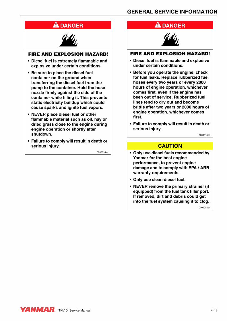
A DANGER
FIRE AND EXPLOSION HAZARD!• Diesel fuel is extremely flammable and
explosive under certain conditions.
• Be sure to place the diesel fuel container on the ground when transferring the diesel fuel from the pump to the container. Hold the hose nozzle firmly against the side of the container while filling it. This prevents static electricity buildup which could cause sparks and ignite fuel vapors.
• NEVER place diesel fuel or other flammable material such as oil, hay or dried grass close to the engine during engine operation or shortly after shutdown.
• Failure to comply will result in death or serious injury.
0000014en
A DANGER
CRUSH HAZARD!• When you need to transport an engine
for repair, have a helper assist you to attach it to a hoist and load it on a truck.
• NEVER stand under a hoisted engine. If the hoist mechanism fails, the engine will fall on you, causing death or serious injury.
• Failure to comply will result in death or serious injury.
0000008en
A DANGER
FIRE AND EXPLOSION HAZARD!• Diesel fuel is flammable and explosive
under certain conditions.
• Before you operate the engine, check for fuel leaks. Replace rubberized fuel hoses every two years or every 2000 hours of engine operation, whichever comes first, even if the engine has been out of service. Rubberized fuel lines tend to dry out and become brittle after two years or 2000 hours of engine operation, whichever comes first.
• Failure to comply will result in death or serious injury.
0000015en
3-6 TNV DI Service Manual

SAFETY
A DANGER
EXPLOSION HAZARD!• NEVER check the remaining battery
charge by shorting out the terminals. This will result in a spark and may cause an explosion or fire. Use a hydrometer to check the remaining battery charge.
• If the electrolyte is frozen, slowly warm the battery before you recharge it.
• Failure to comply will result in death or serious injury.
0000007en
A DANGER
FIRE AND EXPLOSION HAZARD!• Diesel fuel is flammable and explosive
under certain conditions.
• NEVER remove the fuel cap with the engine running.
• Failure to comply will result in death or serious injury.
0000011en
A DANGER
FIRE AND EXPLOSION HAZARD!• Diesel fuel is flammable and explosive
under certain conditions.
• NEVER use diesel fuel as a cleaning agent.
• Failure to comply will result in death or serious injury.
0000012en
TNV DI Service Manual 3-7

SAFETY
A WARNING
SEVER HAZARD!• Keep hands and other body parts
away from moving / rotating parts such as the cooling fan, flywheel or PTO shaft.
• Wear tight-fitting clothing and keep your hair short or tie it back while the engine is running.
• Remove all jewelry before you operate or service the machine.
• NEVER start the engine in gear. Sudden movement of the engine and /or machine could cause death or
serious personal injury.
• NEVER operate the engine without the guards in place.
• Before you start the engine make sure that all bystanders are clear of the area.
• Keep children and pets away while the engine is operating.
• Check before starting the engine that any tools or shop rags used during maintenance have been removed from the area.
• Failure to comply could result in death or serious injury.
0000002en
A WARNING
EXHAUST HAZARD!• NEVER operate the engine in an
enclosed area such as a garage, tunnel, underground room, manhole or ship’s hold without proper ventilation.
• NEVER block windows, vents, or other means of ventilation if the engine is operating in an enclosed area. All internal combustion engines create carbon monoxide gas during operation. Accumulation of this gas within an enclosure could cause illness or even death.
• Make sure that all connections are tightened to specifications after repair is made to the exhaust system.
• Failure to comply could result in death or serious injury.
0000003en
A WARNING
ALCOHOL AND DRUG HAZARD!• NEVER operate the engine while you
are under the influence of alcohol or drugs.
• NEVER operate the engine when you are feeling ill.
• Failure to comply could result in death or serious injury.
0000004en
3-8 TNV DI Service Manual
SAFETY
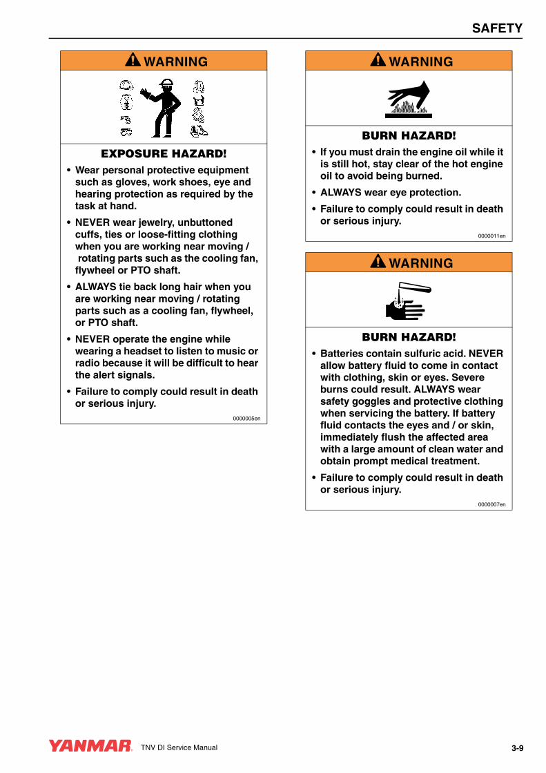
A WARNING
EXPOSURE HAZARD!• Wear personal protective equipment
such as gloves, work shoes, eye and hearing protection as required by the task at hand.
• NEVER wear jewelry, unbuttoned cuffs, ties or loose-fitting clothing when you are working near moving /rotating parts such as the cooling fan,
flywheel or PTO shaft.
• ALWAYS tie back long hair when you are working near moving / rotating parts such as a cooling fan, flywheel, or PTO shaft.
• NEVER operate the engine while wearing a headset to listen to music or radio because it will be difficult to hear the alert signals.
• Failure to comply could result in death or serious injury.
0000005en
A WARNING
BURN HAZARD!• If you must drain the engine oil while it
is still hot, stay clear of the hot engine oil to avoid being burned.
• ALWAYS wear eye protection.
• Failure to comply could result in death or serious injury.
0000011en
A WARNING
BURN HAZARD!• Batteries contain sulfuric acid. NEVER
allow battery fluid to come in contact with clothing, skin or eyes. Severe burns could result. ALWAYS wear safety goggles and protective clothing when servicing the battery. If battery fluid contacts the eyes and / or skin, immediately flush the affected area with a large amount of clean water and obtain prompt medical treatment.
• Failure to comply could result in death or serious injury.
0000007en
TNV DI Service Manual 3-9
SAFETY
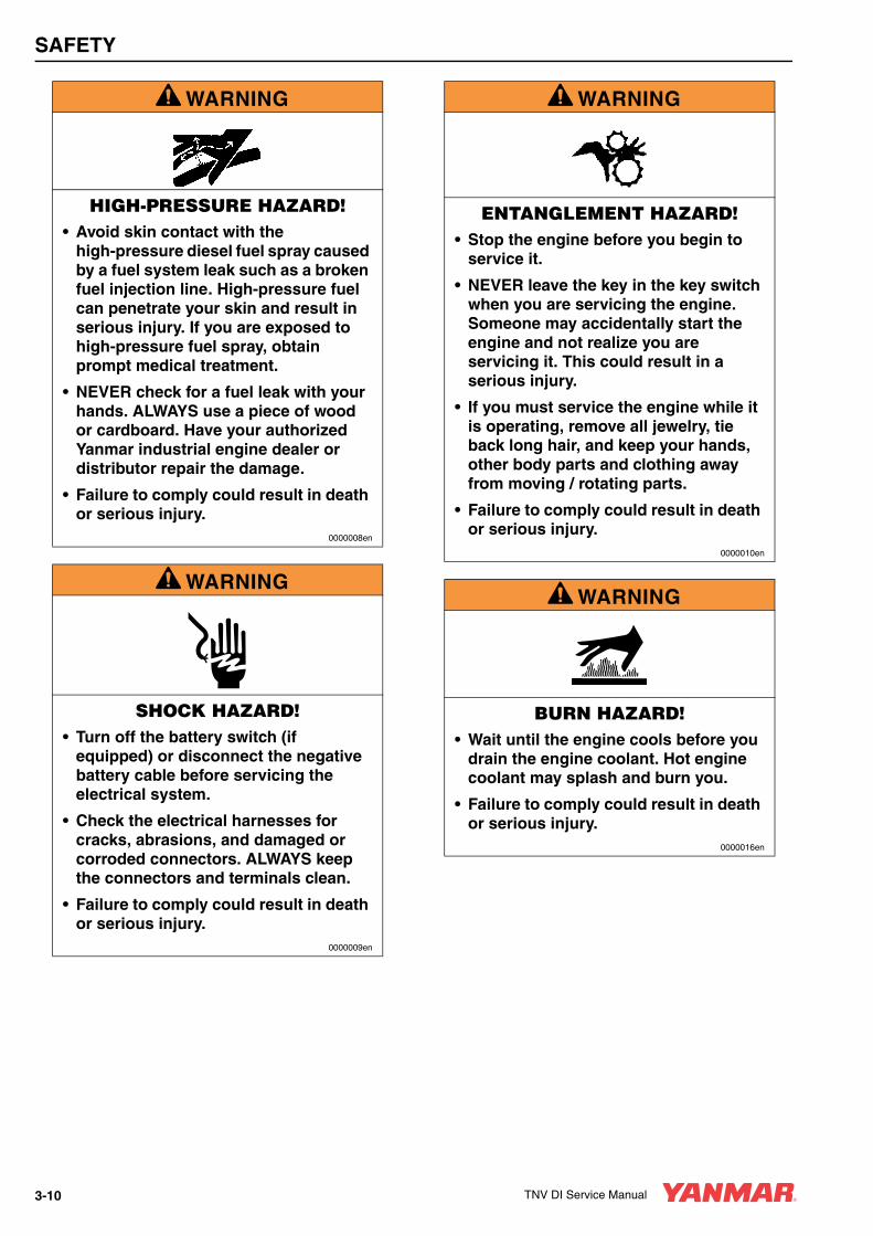
A WARNING
HIGH-PRESSURE HAZARD!• Avoid skin contact with the
high-pressure diesel fuel spray caused by a fuel system leak such as a broken fuel injection line. High-pressure fuel can penetrate your skin and result in serious injury. If you are exposed to high-pressure fuel spray, obtain prompt medical treatment.
• NEVER check for a fuel leak with your hands. ALWAYS use a piece of wood or cardboard. Have your authorized Yanmar industrial engine dealer or distributor repair the damage.
• Failure to comply could result in death or serious injury.
0000008en
A WARNING
SHOCK HAZARD!• Turn off the battery switch (if
equipped) or disconnect the negative battery cable before servicing the electrical system.
• Check the electrical harnesses for cracks, abrasions, and damaged or corroded connectors. ALWAYS keep the connectors and terminals clean.
• Failure to comply could result in death or serious injury.
0000009en
A WARNING
ENTANGLEMENT HAZARD!• Stop the engine before you begin to
service it.
• NEVER leave the key in the key switch when you are servicing the engine. Someone may accidentally start the engine and not realize you are servicing it. This could result in a serious injury.
• If you must service the engine while it is operating, remove all jewelry, tie back long hair, and keep your hands, other body parts and clothing away from moving / rotating parts.
• Failure to comply could result in death or serious injury.
0000010en
A WARNING
BURN HAZARD!• Wait until the engine cools before you
drain the engine coolant. Hot engine coolant may splash and burn you.
• Failure to comply could result in death or serious injury.
0000016en
3-10 TNV DI Service Manual

SAFETY
A WARNINGSUDDEN MOVEMENT HAZARD!
• Engaging the transmission or PTO at an elevated engine speed could result in unexpected movement of the equipment.
• Failure to comply could result in death or serious injury.
0000006en
A WARNING
BURN HAZARD!• Keep your hands and other body parts
away from hot engine surfaces such as the muffler, exhaust pipe, turbocharger (if equipped) and engine block during operation and shortly after you shut the engine down. These surfaces are extremely hot while the engine is operating and could seriously burn you.
• Failure to comply could result in death or serious injury.
0000015en
A WARNING
To prevent possible eye injury, always wear SAFETY GLASSES while servicing the engine.
0000013en
A WARNING
FUME / BURN HAZARD!• Always read and follow safety related
precautions found on containers of hazardous substances like parts cleaners, primers, sealants and sealant removers.
• Failure to comply could result in death or serious injury.
0000014en
A WARNINGNever apply over 40 psi (2.8 kgf/cm) to the waste gate actuator.
0000026en
A WARNING• Never inject fuel toward you. Since the
fuel is injected at high pressure from the nozzle, it may penetrate the skin, resulting in injury.
• Never inject fuel toward a fire source. Atomized fuel is highly flammable and may cause a fire or burn skin.
0000028en
TNV DI Service Manual 3-11

SAFETY
A CAUTION
COOLANT HAZARD!• Wear eye protection and rubber gloves
when you handle long life or extended life engine coolant. If contact with the eyes or skin should occur, flush eyes and wash immediately with clean water.
• Failure to comply may result in minor or moderate injury.
0000005en
A CAUTION
FLYING OBJECT HAZARD!• ALWAYS wear eye protection when
servicing the engine and when using compressed air or high-pressure water. Dust, flying debris, compressed air, pressurized water or steam may injure your eyes.
• Failure to comply may result in minor or moderate injury.
0000003en
A CAUTIONBe sure to secure the engine solidly to prevent injury or damage to parts due to the engine falling during work on the engine.
0000009en
A CAUTION
PINCH HAZARD!Carefully rotate the alternator toward the cylinder block while loosening the V-belt. Failure to comply may result in minor or moderate injury.
0000014en
A CAUTIONIf any oil pump component clearance exceeds its limit, the oil pump must be replaced as an assembly.
0000015en
CAUTION• Only use diesel fuels recommended by
Yanmar for the best engine performance, to prevent engine damage and to comply with EPA / ARB warranty requirements.
• Only use clean diesel fuel.
• NEVER remove the primary strainer (if equipped) from the fuel tank filler port. If removed, dirt and debris could get into the fuel system causing it to clog.
0000004en
CAUTIONNEVER attempt to adjust the low or high idle speed limit screw. This may impair the safety and performance of the machine and shorten its life. If adjustment is ever required, contact your authorized Yanmar industrial engine dealer or distributor.
0000045en
3-12 TNV DI Service Manual

SAFETY
CAUTIONIf any problem is noted during the visual check, the necessary corrective action should be taken before you operate the engine.
0000021en
CAUTIONNEVER hold the key in the START position for longer than 15 seconds or the starter motor will overheat.
0000007en
CAUTIONMake sure the engine is installed on a level surface. If a continuously running engine is installed at an angle greater than 30° (in any direction) or if an engine runs for short periods of time (less than three minutes) at an angle greater than 35° (in any direction) engine oil may enter the combustion chamber causing excessive engine speed and white exhaust smoke. This may cause serious engine damage.
0000010en
CAUTIONObserve the following environmental operating conditions to maintain engine performance and avoid premature engine wear:
• Avoid operating in extremely dusty conditions.
• Avoid operating in the presence of chemical gases or fumes.
• Avoid operating in a corrosive atmosphere such as salt water spray.
• NEVER install the engine in a floodplain unless proper precautions are taken to avoid being subject to a flood.
• NEVER expose the engine to the rain.0000003en
CAUTIONObserve the following environmental operating conditions to maintain engine performance and avoid premature engine wear:
• The standard range of ambient temperatures for the normal operation of Yanmar engines is from +5°F (-15°C) to +113°F (+45°C).
• If the ambient temperature exceeds +113°F (+45°C) the engine may overheat and cause the engine oil to break down.
• If the ambient temperature is below +5°F (-15°C) the engine will be hard to start and the engine oil may not flow easily.
• Contact your authorized Yanmar industrial engine dealer or distributor if the engine will be operated outside of this standard temperature range.
0000065en
TNV DI Service Manual 3-13

SAFETY
CAUTIONThe illustrations and descriptions of optional equipment in this manual, such as the operator’s console, are for a typical engine installation. Refer to the documentation supplied by the optional equipment manufacturer for specific operation and maintenance instructions.
0000018en
CAUTIONIf any indicator illuminates during engine operation, stop the engine immediately. Determine the cause and repair the problem before you continue to operate the engine.
0000029en
CAUTION• Only use the engine oil specified.
Other engine oils may affect warranty coverage, cause internal engine components to seize and / or shorten engine life.
• Prevent dirt and debris from contaminating the engine oil. Carefully clean the oil cap / dipstick and the surrounding area before you remove the cap.
• NEVER mix different types of engine oil. This may adversely affect the lubricating properties of the engine oil.
• NEVER overfill. Overfilling may result in white exhaust smoke, engine overspeed or internal damage.
0000005en
CAUTION• Only use the engine coolant specified.
Other engine coolants may affect warranty coverage, cause an internal buildup of rust and scale and / or shorten engine life.
• Prevent dirt and debris from contaminating the engine coolant. Carefully clean the radiator cap and the surrounding area before you remove the cap.
• NEVER mix different types of engine coolants. This may adversely affect the properties of the engine coolant.
0000006en
CAUTION• NEVER overfill the engine with engine
oil.
• ALWAYS keep the oil level between the upper and lower lines on the oil cap /dipstick.
0000015en
CAUTIONFor maximum engine life, Yanmar recommends that when shutting the engine down, you allow the engine to idle, without load, for five minutes. This will allow the engine components that operate at high temperatures, such as the turbocharger (if equipped) and exhaust system, to cool slightly before the engine itself is shut down.
0000008en
CAUTIONNEVER use an engine starting aid such as ether. Engine damage will result.
0000009en
3-14 TNV DI Service Manual

SAFETY
CAUTION
• ALWAYS be environmentally responsible.
• Follow the guidelines of the EPA or other governmental agencies for the proper disposal of hazardous materials such as engine oil, diesel fuel and engine coolant. Consult the local authorities or reclamation facility.
• NEVER dispose of hazardous materials irresponsibly by dumping them into a sewer, on the ground, or into ground water or waterways.
• Failure to follow these procedures may seriously harm the environment.
0000013en
CAUTIONNEVER engage the starter motor while the engine is running. This may damage the starter motor pinion and / or ring gear.
0000012en
CAUTIONNew Engine Break-in:
• On the initial engine start-up, allow the engine to idle for approximately 15 minutes while you check for proper engine oil pressure, diesel fuel leaks, engine oil leaks, coolant leaks, and for proper operation of the indicators and / or gauges.
• During the first hour of operation, vary the engine speed and the load on the engine. Short periods of maximum engine speed and load are desirable. Avoid prolonged operation at minimum or maximum engine speeds and loads for the next four to five hours.
• During the break-in period, carefully observe the engine oil pressure and engine temperature.
• During the break-in period, check the engine oil and coolant levels frequently.
0000011en
CAUTION• NEVER attempt to modify the engine’s
design or safety features such as defeating the engine speed limit control or the fuel injection quantity control.
• Failure to comply may impair the engine’s safety and performance characteristics and shorten the engine’s life. Any alterations to this engine may affect the warranty coverage of your engine. See Yanmar Limited Warranty in Warranty Section.
0000044enTNVDISM
TNV DI Service Manual 3-15
SAFETY
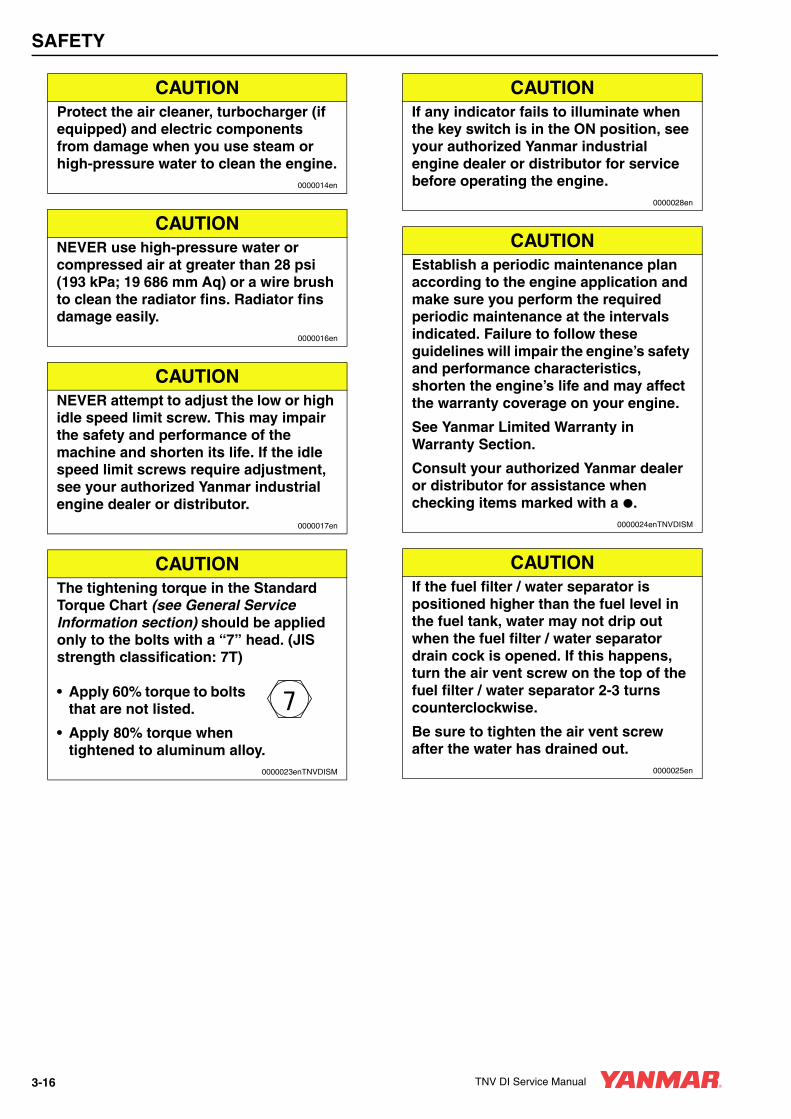
CAUTIONProtect the air cleaner, turbocharger (if equipped) and electric components from damage when you use steam or high-pressure water to clean the engine.
0000014en
CAUTIONNEVER use high-pressure water or compressed air at greater than 28 psi (193 kPa; 19 686 mm Aq) or a wire brush to clean the radiator fins. Radiator fins damage easily.
0000016en
CAUTIONNEVER attempt to adjust the low or high idle speed limit screw. This may impair the safety and performance of the machine and shorten its life. If the idle speed limit screws require adjustment, see your authorized Yanmar industrial engine dealer or distributor.
0000017en
CAUTIONThe tightening torque in the Standard Torque Chart (see General Service Information section) should be applied only to the bolts with a “7” head. (JIS strength classification: 7T)
• Apply 60% torque to bolts that are not listed.
• Apply 80% torque when tightened to aluminum alloy.
0000023enTNVDISM
CAUTIONIf any indicator fails to illuminate when the key switch is in the ON position, see your authorized Yanmar industrial engine dealer or distributor for service before operating the engine.
0000028en
CAUTIONEstablish a periodic maintenance plan according to the engine application and make sure you perform the required periodic maintenance at the intervals indicated. Failure to follow these guidelines will impair the engine’s safety and performance characteristics, shorten the engine’s life and may affect the warranty coverage on your engine.
See Yanmar Limited Warranty in Warranty Section.
Consult your authorized Yanmar dealer or distributor for assistance when checking items marked with a .
0000024enTNVDISM
CAUTIONIf the fuel filter / water separator is positioned higher than the fuel level in the fuel tank, water may not drip out when the fuel filter / water separator drain cock is opened. If this happens, turn the air vent screw on the top of the fuel filter / water separator 2-3 turns counterclockwise.
Be sure to tighten the air vent screw after the water has drained out.
0000025en
3-16 TNV DI Service Manual
SAFETY
CAUTION• When the engine is operated in dusty
conditions, clean the air cleaner element more frequently.
• NEVER operate the engine with the air cleaner element(s) removed. This may allow foreign material to enter the engine and damage it.
0000026en
CAUTIONThe maximum air intake restriction, in terms of differential pressure measurement, must not exceed 0.90 psi (6.23 kPa; 635 mmAq). Clean or replace the air cleaner element if the air intake restriction exceeds the above mentioned value.
0000046en
CAUTIONIt is important to perform daily checks.
Periodic maintenance prevents unexpected downtime, reduces the number of accidents due to poor machine performance and helps extend the life of the engine.
0000060en
CAUTIONIf the oil pump must be replaced, replace it as an assembly only. Do not replace individual components.
0000030en
CAUTIONDo not loosen or remove the four bolts retaining the fuel injection pump drive gear to the fuel injection pump hub. Do not disassemble the fuel injection pump drive gear from the hub. Correct fuel injection timing will be very difficult or impossible to achieve.
0000031en
CAUTIONThe starter motor can be damaged if operated continuously longer than 10 seconds while performing the no-load test.
0000034en
CAUTIONDo not short-circuit the charging system between alternator terminals IG and L. Damage to the alternator will result.
0000035en
CAUTIONDo not connect a load between alternator terminals L and E. Damage to the alternator will result.
0000036en
CAUTIONDo not remove the positive (+) battery cable from alternator terminal B while the engine is operating. Damage to the alternator will result.
0000037en
CAUTIONDo not turn the battery switch OFF while the engine is operating. Damage to the alternator will result.
0000038en
TNV DI Service Manual 3-17

SAFETY
CAUTIONDo not operate the engine if the alternator is producing unusual sounds. Damage to the alternator will result.
0000039en
CAUTIONIf the engine coolant pump must be replaced, replace the engine coolant pump as an assembly only. Do not attempt to repair the engine coolant pump or replace individual components.
0000041en
CAUTIONUse a new special O-ring between the engine coolant pump and the joint. Be sure to use the special O-ring for each engine model. Although the O-ring dimensions are the same as a commercially available O-ring, the material is different.
0000042en
CAUTIONRemove or install the high-pressure fuel injection lines as an assembly whenever possible. Disassembling the high-pressure fuel injection lines from the retainers or bending any of the fuel lines will make it difficult to reinstall the fuel lines.
0000047en
CAUTIONAfter marking the position of the pump drive gear, do not rotate the engine crankshaft. Rotating the crankshaft will cause the fuel injection pump to become misaligned.
0000048en
CAUTIONDo not use a high-pressure wash directly on the alternator. Water will damage the alternator and result in inadequate charging.
0000049en
CAUTIONDo not reverse the positive (+) and negative (-) ends of the battery cable. The alternator diode and stator coil will be damaged.
0000050en
CAUTIONWhen the battery indicator goes out, it should not come on again. The battery indicator only comes on during operation if the alternator fails or if the V-belt breaks. However, if an LED is used in the battery indicator, the LED will shine faintly during normal operation.
0000051en
CAUTIONUsing a non-specified V-belt will cause inadequate charging and shorten the belt life. Use the specified belt.
0000052en
CAUTIONAgricultural or other chemicals, especially those with a high sulfur content, can adhere to the IC regulator. This will corrode the conductor and result in battery over-charging (boiling) and charging malfunctions. Consult Yanmar before using the equipment in such an environment or the warranty is voided.
0000053en
3-18 TNV DI Service Manual

SAFETY
CAUTIONMake sure that the combined total resistance of the battery cable in both directions between the starter motor and the battery is within the value indicated on the wiring diagram. The starter motor will malfunction or break down if the resistance is higher than the specified value.
0000054en
CAUTIONThe starter motor is water-proofed according to JIS D 0203, R2 which protects the motor from rain or general cleaning. Do not use high-pressure wash or submerse the starter motor in water.
0000055en
CAUTIONUse a specialized battery charger to recharge a battery with a voltage of 8 volts or less. Booster starting a battery with a voltage of 8 volts or less will generate an abnormally high voltage and destroy electrical equipment.
0000056en
CAUTIONMake sure that the combined total resistance of the battery cable in both directions between the starter motor and the battery is within the value indicated in the Battery Cable Resistance chart in the Electric Wiring Section of this manual. The starter motor will malfunction and fail if the resistance is higher than the specified value.
0000057en
CAUTIONRemoving the battery cables or the battery while the engine is operating may cause damage to the current limiter depending on the electrical equipment being used. This situation could cause loss of control of output voltage. The continuous high voltage of 23-24 volts (for 5000 rpm dynamo) will damage the current limiter and other electrical equipment.
0000058en
CAUTIONReversing the battery cable connections at the battery or on the engine will destroy the SCR diode in the current limiter. This will cause the charging system to malfunction and may cause damage to the electrical harnesses.
0000059en
CAUTIONAvoid damage to the turbocharger or the engine. Do not spray blower wash fluid or water too quickly.
Use short strokes from a spray bottle to inject blower wash fluid or water into the turbocharger.
Spraying too much wash fluid or water, or spraying too quickly will damage the turbocharger.
0000063en
CAUTIONDo not allow any material to fall into the oil lines or the oil inlet and outlet ports of the turbocharger.
0000064en
TNV DI Service Manual 3-19
SAFETY
CAUTIONIf the waste valve does not meet specifications, replace the turbocharger or have it repaired by a qualified repair facility.
0000078en
CAUTION• NEVER attempt to modify the engine’s
design or safety features such as defeating the engine speed limit control or the diesel fuel injection quantity control.
• Modifications may impair the engine’s safety and performance characteristics and shorten the engine’s life. Any alterations to this engine may void its warranty. Be sure to use Yanmar genuine replacement parts.
0000079en
CAUTIONIdentify all parts and their location using an appropriate method. It is important that all parts are returned to the same position during the reassembly process.
0000080en
CAUTIONEach pressure adjusting shim removed or added changes the pressure threshold by approximately 275 psi (1.9 MPa, 19 kgf/cm2). Adding adjusting shims increases the threshold pressure. Removing adjusting shims reduces the pressure threshold.
0000081en
CAUTIONDo not rotate the crankshaft with the injection pump removed.
0000083en
CAUTIONKeep the piston pin parts, piston assemblies, and connecting rod assemblies together to be returned to the same position during the reassembly process. Label the parts using an appropriate method.
0000088en
CAUTIONDo not allow the honing tool to operate in one position for any length of time. Damage to the cylinder wall will occur. Keep the tool in constant up-and-down motion.
0000090en
CAUTIONAny part which is found defective as a result of inspection or any part whose measured value does not satisfy the standard or limit must be replaced.
0000119en
CAUTIONAny part determined to not meet the service standard or limit before the next service, as determined from the state of current rate of wear, should be replaced even though the part currently meets the service standard limit.
0000120en
3-20 TNV DI Service Manual

SAFETY
CAUTION• NEVER remove or attempt to remove
the tamper-proof devices from the full-load fuel adjusting screw or the high-speed throttle limit screw on the fuel injection pump and governor assembly. These adjustments have been made at the factory to meet all applicable emissions regulations and then sealed.
• NEVER attempt to make any adjustments to these sealed adjustment screws. If adjustments are required, they can be made only by a qualified fuel injection shop that will ensure the injection pump continues to meet all applicable emissions regulations and then replace the tamper-proof seals.
• Tampering with or removing these devices may void the “Yanmar Limited Warranty.”
0000146en
CAUTIONNever use a steel wire brush to clean fuel injectors. Damage to the nozzle and other components is likely to result.
0000172en
CAUTIONAllow the engine to warm-up for at least five minutes and the idle speed of the engine to return to normal before engaging the transmission or any PTOs. Engaging the transmission or PTO at an elevated engine speed could result in an unexpected movement of the equipment.
0000159en
TNV DI Service Manual 3-21
TNV DI Service Manual Section 4
GENERAL SERVICEINFORMATION
Page
Component Identification................................................................. 4-3
Location of Labels ........................................................................... 4-4Engine Nameplate (Typical) ...................................................... 4-4
Emission Control Regulations ......................................................... 4-5EPA / ARB Regulations - USA Only .......................................... 4-5
Emission Control Labels.................................................................. 4-5
The 97/68/EC Directive Certified Engines....................................... 4-6
Engine Family.................................................................................. 4-6
Function of Major Engine Components ........................................... 4-7
Function of Cooling System Components ....................................... 4-8
Diesel Fuel ...................................................................................... 4-9Diesel Fuel Specifications ......................................................... 4-9Filling The Fuel Tank............................................................... 4-10Priming the Fuel System ......................................................... 4-12
Engine Oil...................................................................................... 4-12Engine Oil Specifications ........................................................ 4-12Engine Oil Viscosity................................................................. 4-13Checking Engine Oil ................................................................ 4-13Adding Engine Oil.................................................................... 4-14Engine Oil Capacity (Typical) .................................................. 4-14
Engine Coolant.............................................................................. 4-15Engine Coolant Specifications................................................. 4-16Filling Radiator with Engine Coolant........................................ 4-16Engine Coolant Capacity (Typical) .......................................... 4-17
TNV DI Service Manual 4-1

GENERAL SERVICE INFORMATION
Specifications ................................................................................. 4-18Description of Model Number................................................... 4-18Engine Speed Specifications.................................................... 4-18Engine General Specifications ................................................. 4-19
Principal Engine Specifications ...................................................... 4-203TNV82A.................................................................................. 4-203TNV84 .................................................................................... 4-223TNV84T .................................................................................. 4-243TNV88 .................................................................................... 4-264TNV84 .................................................................................... 4-284TNV84T .................................................................................. 4-304TNV88 .................................................................................... 4-324TNV94L .................................................................................. 4-344TNV98 .................................................................................... 4-364TNV98T .................................................................................. 4-384TNV106 .................................................................................. 4-404TNV106T................................................................................ 4-42
Engine Service Standards.............................................................. 4-44
Tightening Torques for Standard Bolts and Nuts ........................... 4-45
Abbreviations and Symbols............................................................ 4-47Abbreviations............................................................................ 4-47Symbols.................................................................................... 4-47
Unit Conversions............................................................................ 4-48Unit Prefixes ............................................................................. 4-48Units of Length ......................................................................... 4-48Units of Volume ........................................................................ 4-48Units of Mass............................................................................ 4-48Units of Force ........................................................................... 4-48Units of Torque......................................................................... 4-48Units of Pressure...................................................................... 4-48Units of Power .......................................................................... 4-48Units of Temperature................................................................ 4-48
4-2 TNV DI Service Manual

GENERAL SERVICE INFORMATION
COMPONENT IDENTIFICATIONFigure 4-2 shows where the major engine components are located.
1 – Lifting Eye (Flywheel End)2 – Turbocharger*3 – Lifting Eye (Engine Cooling Fan End)4 – Engine Coolant Pump5 – Engine Cooling Fan6 – Crankshaft V-Pulley7 – V-Belt8 – Side Filler Port (Engine Oil) 9 – Drain Plug (Engine Oil)**10 – Fuel Injection Pump11 – Engine Oil Cooler***12 – Engine Oil Filter13 – Dipstick (Engine Oil)
14 – Governor Lever15 – Intake Manifold16 – Fuel Filter17 – Fuel Inlet18 – Fuel Return to Fuel Tank19 – Top Filler Port (Engine Oil)20 – Rocker Arm Cover21 – Air Intake Port (From Air Cleaner)22 – Flywheel23 – Starter Motor24 – Exhaust Manifold25 – Alternator
Figure 4-1
* Only applies to 3TNV84T, 4TNV84T, 4TNV98T, 4TNV106T** The engine oil drain plug location may vary based on oil pan options.*** Not standard on all direct injection models
0000015B
(25)
(24)
(23)
(21)
(22)
(20)(19)
(7)(8)(9)
(6)
(5)
(4)
(3)(2)(1)
(18)
(17)
(16)
(15)
(10)(11)(12)
(13)
(14)
TNV DI Service Manual 4-3

GENERAL SERVICE INFORMATION
LOCATION OF LABELSFigure 4-2 shows the location of regulatory and safety labels on Yanmar TNV series engines.
Figure 4-2
The typical location of the emission control information label is shown for 4TNV84, 4TNV84T and 4TNV88 engines (Figure 4-2, (1)).
The typical location of the emission control information label is affixed to the exhaust side of the rocker arm cover for 3TNV82A, 3TNV84, 3TNV84T and 3TNV88 engines (Figure 4-2, (2)).
The typical location of the emission control information label is affixed to the exhaust side of the rocker arm cover for 4TNV94L, 4TNV98, 4TNV98T, 4TNV106 and 4TNV106T engines (Figure 4-2, (3)).
The typical location of the engine nameplate is shown for various Yanmar TNV engines (Figure 4-2, (4)).
Engine Nameplate (Typical)
0000019A
(3)(4)(4) (2)(1)
0002132
3TNV82A - DSA
1.333000
06532
kW
l
4-4 TNV DI Service Manual
GENERAL SERVICE INFORMATION
EMISSION CONTROL REGULATIONS
EPA / ARB Regulations - USA OnlyYanmar TNV engines meet Environmental Protection Agency (EPA) (U. S. Federal) emission control standards as well as the California Air Resources Board (ARB, California) regulations. Only engines that conform to ARB regulations can be sold in the State of California.
Refer to the specific EPA / ARB installation (page 5-16) and maintenance (page 5-16) in the Periodic Maintenance Schedule section of this manual. Also refer to the Emission System Warranty on page 2-6.
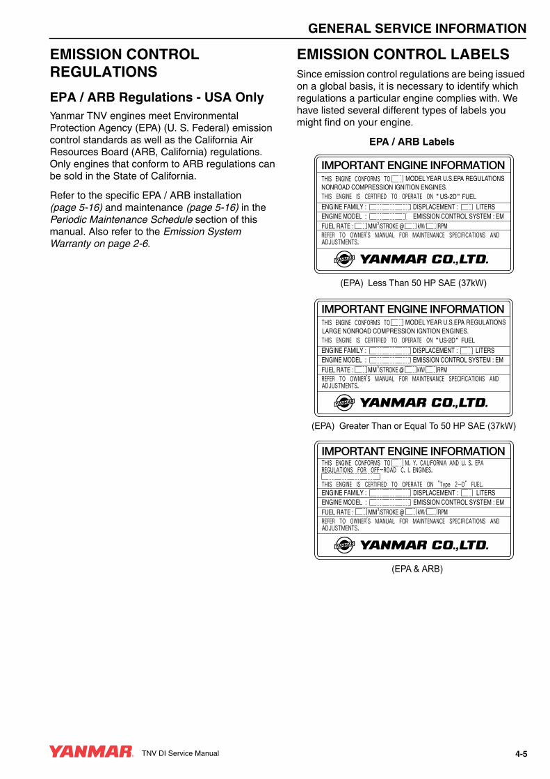
EMISSION CONTROL LABELSSince emission control regulations are being issued on a global basis, it is necessary to identify which regulations a particular engine complies with. We have listed several different types of labels you might find on your engine.
EPA / ARB Labels
(EPA) Greater Than or Equal To 50 HP SAE (37kW)
" US-2D " FUEL
(EPA & ARB)
" "
(EPA) Less Than 50 HP SAE (37kW)
TNV DI Service Manual 4-5

GENERAL SERVICE INFORMATION
THE 97/68/EC DIRECTIVE CERTIFIED ENGINESThe engines described in this manual have been certified by the 97/68/EC Directive.
To identify the engines that meet this certification, the 97/68/EC emission control label is affixed on the engines.
ENGINE FAMILYThe EPA / ARB labels and the 97/68/EC label all have an Engine Family field. The following is an explanation of the Engine Family designation:
(97/68/EC)
97/68/EC DIRECTIVE
5 YDX L 1.33 M 3 N
Method of air aspiration
Number of cylinders
Engine speed specifications
Displacement (liter)
Non-road / Off-road engine
Yanmar Diesel
*2005 Model Year
5*: 2005
6: 2006
7: 2007
4-6 TNV DI Service Manual

GENERAL SERVICE INFORMATION
FUNCTION OF MAJOR ENGINE COMPONENTS
Components Functions
Air Cleaner
The air cleaner prevents airborne contaminants from entering the engine. Since the air cleaner is application specific, it must be carefully selected by an application engineer. It is not part of the basic engine package as shipped from the Yanmar factory. Periodic replacement of the air cleaner filter element is necessary. See the Periodic Maintenance Schedule on page 5-17 for the replacement frequency.
AlternatorThe alternator is driven by a V-belt which is powered by the crankshaft V-pulley. The alternator supplies electricity to the engine systems and charges the battery while the engine is running.
Dipstick (Engine Oil)The engine oil dipstick is used to determine the amount of engine oil in the crankcase.
Electric Fuel Pump
The electric fuel pump makes sure there is a constant supply of diesel fuel to the fuel injection pump. The electric fuel pump is electro-magnetic and runs on 12 VDC. It must be installed on every application. This is standard equipment with every engine.
Engine Oil FilterThe engine oil filter removes contaminants and sediments from the engine oil. Periodic replacement of the engine oil filter is necessary. See the Periodic Maintenance Schedule on page 5-17 for the replacement frequency.
Engine Oil Cooler(If Equipped)
The engine oil cooler helps to keep the engine oil cool. Engine coolant from the cooling system is circulated through an adapter at the base of the engine oil filter assembly and then returned to the cylinder block.
Fuel Filter
The fuel filter removes contaminants and sediments from the diesel fuel. Periodic replacement of the fuel filter is necessary. See the Periodic Maintenance Schedule on page 5-17 for the replacement frequency. Please note that the word “diesel” is implied throughout this manual when the word “fuel” is used.
Fuel Filter / Water Separator
The fuel filter / water separator removes contaminants, sediments and water from the diesel fuel going to the fuel filter. This is a required component of the fuel system. This is standard equipment with every engine. The separator is installed between the fuel tank and the electric fuel pump. Periodically drain the water from the fuel filter / water separator.
Fuel Tank
The fuel tank is a reservoir that holds diesel fuel. When the fuel leaves the fuel tank it goes to the fuel filter / water separator. Next the fuel is pumped to the fuel filter by the electric fuel pump. Then the fuel goes to the fuel injection pump. Since the fuel is used to keep the fuel injection pump cool and lubricated, more fuel than necessary enters the injection pump. When the injection pump pressure reaches a preset value, a relief valve allows the excess fuel to be returned back to the fuel tank. The fuel tank is a required engine component.
Side and Top Filler Port (Engine Oil)You can fill the crankcase with engine oil from either the side or the top filler port depending upon which one is most convenient.
Starter MotorThe starter motor is powered by the battery. When you turn the key switch in the operator’s console to the START position, the starter motor engages with the ring gear installed on the flywheel and starts the flywheel in motion.
Turbocharger(Only applies to 3TNV84T, 4TNV84T, 4TNV98T, 4TNV106T)
The turbocharger pressurizes the air coming into the engine. It is driven by a turbine that is energized by exhaust gases.
TNV DI Service Manual 4-7
GENERAL SERVICE INFORMATION
FUNCTION OF COOLING SYSTEM COMPONENTS
Components Functions
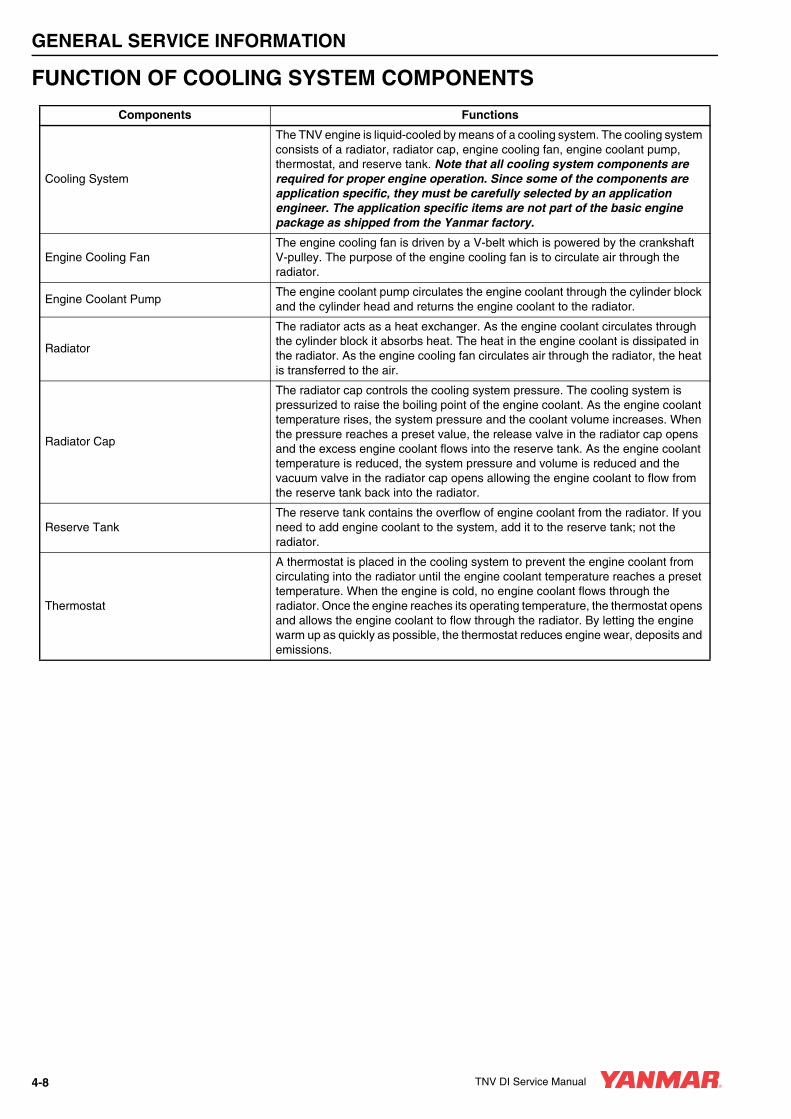
Cooling System
The TNV engine is liquid-cooled by means of a cooling system. The cooling system consists of a radiator, radiator cap, engine cooling fan, engine coolant pump, thermostat, and reserve tank. Note that all cooling system components are required for proper engine operation. Since some of the components are application specific, they must be carefully selected by an application engineer. The application specific items are not part of the basic engine package as shipped from the Yanmar factory.
Engine Cooling FanThe engine cooling fan is driven by a V-belt which is powered by the crankshaft V-pulley. The purpose of the engine cooling fan is to circulate air through the radiator.
Engine Coolant PumpThe engine coolant pump circulates the engine coolant through the cylinder block and the cylinder head and returns the engine coolant to the radiator.
Radiator
The radiator acts as a heat exchanger. As the engine coolant circulates through the cylinder block it absorbs heat. The heat in the engine coolant is dissipated in the radiator. As the engine cooling fan circulates air through the radiator, the heat is transferred to the air.
Radiator Cap
The radiator cap controls the cooling system pressure. The cooling system is pressurized to raise the boiling point of the engine coolant. As the engine coolant temperature rises, the system pressure and the coolant volume increases. When the pressure reaches a preset value, the release valve in the radiator cap opens and the excess engine coolant flows into the reserve tank. As the engine coolant temperature is reduced, the system pressure and volume is reduced and the vacuum valve in the radiator cap opens allowing the engine coolant to flow from the reserve tank back into the radiator.
Reserve TankThe reserve tank contains the overflow of engine coolant from the radiator. If you need to add engine coolant to the system, add it to the reserve tank; not the radiator.
Thermostat
A thermostat is placed in the cooling system to prevent the engine coolant from circulating into the radiator until the engine coolant temperature reaches a preset temperature. When the engine is cold, no engine coolant flows through the radiator. Once the engine reaches its operating temperature, the thermostat opens and allows the engine coolant to flow through the radiator. By letting the engine warm up as quickly as possible, the thermostat reduces engine wear, deposits and emissions.
4-8 TNV DI Service Manual

GENERAL SERVICE INFORMATION
DIESEL FUEL
Diesel Fuel SpecificationsDiesel fuel should comply with the following specifications. The table lists several worldwide specifications for diesel fuels.
Additional Technical Fuel Requirements• The fuel cetane number should be equal to 45 or
higher.
• The sulfur content must not exceed 0.5% by volume. Less than 0.05% is preferred.
• Bio-Diesel fuels. See Bio-Diesel Fuels on page 4-9.
• NEVER mix kerosene, used engine oil, or residual fuels with the diesel fuel.
• The water and sediment in the fuel should not exceed 0.05% by volume.
• Keep the fuel tank and fuel-handling equipment clean at all times.
• Poor quality fuel can reduce engine performance and / or cause engine damage.
• Fuel additives are not recommended. Some fuel additives may cause poor engine performance. Consult your Yanmar representative for more information.
• The ash content must not exceed 0.01% by volume.
• The carbon residue content must not exceed 0.35% by volume. Less than 0.1% is preferred.
• The total aromatics content should not exceed 35% by volume. Less than 30% is preferred.
• The PAH (polycyclic aromatic hydrocarbons) content should be below 10% by volume.
• The metal content of Na, Mg, Si, and Al should be equal to or lower than 1 mass ppm. (Test analysis method JPI-5S-44-95)
• Lubricity: The wear mark of WS1.4 should be Max. 0.018 in (460 µm) at HFRR test.
Bio-Diesel FuelsIn Europe and in the United States, as well as some other countries, non-mineral oil based fuel resources such as RME (Rapeseed Methyl Ester) and SOME (Soybean Methyl Ester), collectively known as FAME (Fatty Acid Methyl Esters), are being used as extenders for mineral oil derived diesel fuels.
Yanmar approves the use of bio-diesel fuels that do not exceed a blend of 5% (by volume) of FAME with 95% (by volume) of approved mineral oil derived diesel fuel. Such bio-diesel fuels are known in the marketplace as B5 diesel fuels.
These B5 diesel fuels must meet certain requirements.1. The bio-fuels must meet the minimum
specifications for the country in which they are used.
• In Europe, bio-diesel fuels must comply with the European Standard EN14214.
• In the United States, bio-diesel fuels must comply with the American Standard ASTM D-6751.
2. Bio-fuels should be purchased only from recognized and authorized diesel fuel suppliers.
Diesel Fuel Specification Location
No. 2-D, No. 1-D, ASTM D975-94
USA
EN590:96 European Union
ISO 8217 DMX International
BS 2869-A1 or A2United Kingdom
JIS K2204 Grade No. 2 Japan
KSM-2610 Korea
GB252 China
TNV DI Service Manual 4-9

GENERAL SERVICE INFORMATION
Precautions and concerns regarding the use of bio-fuels:1. Free methanol in FAME may result in corrosion
of aluminum and zinc FIE components.
2. Free water in FAME may result in plugging of fuel filters and increased bacterial growth.
3. High viscosity at low temperatures may result in fuel delivery problems, injection pump seizures, and poor injection nozzle spray atomization.
4. FAME may have adverse effects on some elastomers (seal materials) and may result in fuel leakage and dilution of the engine lubricating oil.
5. Even bio-diesel fuels that comply with a suitable standard as delivered, will require additional care and attention to maintain the quality of the fuel in the equipment or other fuel tanks. It is important to maintain a supply of clean, fresh fuel. Regular flushing of the fuel system, and /or fuel storage containers, may be necessary.
6. The use of bio-diesel fuels that do not comply with the standards as agreed to by the diesel engine manufacturers and the diesel fuel injection equipment manufacturers, or bio-diesel fuels that have degraded as per the precautions and concerns above, may affect the warranty coverage of your engine. See Yanmar Limited Warranty on page 2-3.
Filling The Fuel Tank
A DANGER
FIRE AND EXPLOSION HAZARD!• Diesel fuel is flammable and explosive
under certain conditions.
• Only fill the fuel tank with diesel fuel. Filling the fuel tank with gasoline may result in a fire and will damage the engine.
• NEVER refuel with the engine running.
• Wipe up all spills immediately.
• Keep sparks, open flames or any other form of ignition (match, cigarette, static electric source) well away when refueling.
• NEVER overfill the fuel tank.
• Fill the fuel tank. Store any containers containing fuel in a well-ventilated area, away from any combustibles or sources of ignition.
• Failure to comply will result in death or serious injury.
0000005en
4-10 TNV DI Service Manual
GENERAL SERVICE INFORMATION
A DANGER
FIRE AND EXPLOSION HAZARD!• Diesel fuel is extremely flammable and
explosive under certain conditions.
• Be sure to place the diesel fuel container on the ground when transferring the diesel fuel from the pump to the container. Hold the hose nozzle firmly against the side of the container while filling it. This prevents static electricity buildup which could cause sparks and ignite fuel vapors.
• NEVER place diesel fuel or other flammable material such as oil, hay or dried grass close to the engine during engine operation or shortly after shutdown.
• Failure to comply will result in death or serious injury.
0000014en
A DANGER
FIRE AND EXPLOSION HAZARD!• Diesel fuel is flammable and explosive
under certain conditions.
• Before you operate the engine, check for fuel leaks. Replace rubberized fuel hoses every two years or every 2000 hours of engine operation, whichever comes first, even if the engine has been out of service. Rubberized fuel lines tend to dry out and become brittle after two years or 2000 hours of engine operation, whichever comes first.
• Failure to comply will result in death or serious injury.
0000015en
CAUTION• Only use diesel fuels recommended by
Yanmar for the best engine performance, to prevent engine damage and to comply with EPA / ARB warranty requirements.
• Only use clean diesel fuel.
• NEVER remove the primary strainer (if equipped) from the fuel tank filler port. If removed, dirt and debris could get into the fuel system causing it to clog.
0000004en
TNV DI Service Manual 4-11

GENERAL SERVICE INFORMATION
Note that a typical fuel tank is shown. The fuel tank on your equipment may be different.
1. Clean the area around the fuel cap (Figure 4-3, (1)).
2. Remove the fuel cap (Figure 4-3, (1)) from the fuel tank (Figure 4-3, (2)).
3. Observe the fuel level sight gauge (Figure 4-3, (3)) and stop fueling when the gauge shows the fuel tank is full. NEVER overfill the fuel tank.
4. Replace the fuel cap (Figure 4-3, (1)) and hand tighten. Over-tightening the fuel cap will damage it.
Figure 4-3
Priming the Fuel SystemThe fuel system needs to be primed under certain conditions:
• Before starting the engine for the first time.
• After running out of fuel and fuel has been added to the fuel tank.
• After fuel system maintenance such as changing the fuel filter and draining the fuel filter / water separator, or replacing a fuel system component.
To prime the fuel system:
1. Turn the key to the ON position for 10 - 15 seconds. This will allow the electric fuel pump to prime the fuel system.
2. NEVER use the starter motor to crank the engine in order to prime the fuel system. This may cause the starter motor to overheat and damage the coils, pinion and / or ring gear.
ENGINE OIL
Engine Oil Specifications Use an engine oil that meets or exceeds the following guidelines and classifications:
Service Categories• API Service Categories CD or higher
• ACEA Service Categories E-3, E-4, and E-5
• JASO Service Category DH-1
Definitions• API Classification (American Petroleum Institute)
• ACEA Classification (Association des Constructeurs Européens d'Automobilies)
• JASO (Japanese Automobile Standards Organization)
0000002A
(1)
(2)
(3)
CAUTION• Only use the engine oil specified.
Other engine oils may affect warranty coverage, cause internal engine components to seize and / or shorten engine life.
• Prevent dirt and debris from contaminating the engine oil. Carefully clean the oil cap / dipstick and the surrounding area before you remove the cap.
• NEVER mix different types of engine oil. This may adversely affect the lubricating properties of the engine oil.
• NEVER overfill. Overfilling may result in white exhaust smoke, engine overspeed or internal damage.
0000005en
4-12 TNV DI Service Manual

GENERAL SERVICE INFORMATION
Notes:
• Be sure the engine oil, engine oil storage containers, and engine oil filling equipment are free of sediment and water.
• Change the engine oil after the first 50 hours of operation and then every 250 hours thereafter.
• Select the oil viscosity based on the ambient temperature where the engine is being operated. See the SAE Service Grade Viscosity Chart (Figure 4-4).
• Yanmar does not recommend the use of engine oil “additives.”
Additional Technical Engine Oil Requirements:The engine oil must be changed when the Total Base Number (TBN) has been reduced to 2.0. TBN (mgKOH/g) test method; JIS K-201-5.2-2 (HCI), ASTM D4739 (HCI).
Engine Oil ViscositySelect the appropriate engine oil viscosity based on the ambient temperature and use the SAE Service Grade Viscosity Chart in Figure 4-4.
Figure 4-4
Checking Engine Oil1. Make sure the engine is level.
2. Remove the dipstick (Figure 4-5, (1)) and wipe it with clean cloth.
3. Fully reinsert the dipstick.
4. Remove the dipstick. The oil level should be between the upper (Figure 4-5, (2)) and lower (Figure 4-5, (3)) lines on the dipstick.
5. Fully reinsert the dipstick.
Figure 4-5
-4°F 14°F 32°F 50°F 68°F 86°F 104°F(-20°C) (-10°C) (0°C) (10°C) (20°C) (30°C) (40°C)
SAE 10W
SAE 20W
SAE 10W-30
SAE 15W-40
SAE 20SAE 30
SAE 40
0000005A
SAE 20W - 50
122°F(50°C)
(3)
(1)(2)
(4)
(4)
(5)
0000007C
TNV DI Service Manual 4-13

GENERAL SERVICE INFORMATION
Adding Engine Oil1. Make sure the engine is level.
2. Remove the oil cap (Figure 4-5, (4)).
3. Add the indicated amount of engine oil at the top or the side engine oil filler port (Figure 4-5, (5)).
4. Wait three minutes and check the oil level.
5. Add more oil if necessary.
6. Reinstall the oil cap (Figure 4-5, (4)) and hand-tighten. Over-tightening may damage the cap.
Engine Oil Capacity (Typical)Note: These are the engine oil capacities
associated with a “deep standard” oil pan. The oil capacity will vary dependant upon which optional oil pan is used. Refer to the operation manual provided by the driven machine manufacturer for the actual engine oil capacity of your machine.
The following are the engine oil capacities for various Yanmar TNV engines.
Engine ModelDipstick Upper Limit /
Lower Limit
3TNV82A5.8 / 3.8 qt (5.5 / 3.6 L)
3TNV84, 3TNV84T7.1 / 4.1 qt (6.7 / 3.9 L)
3TNV887.1 / 4.1 qt (6.7 / 3.9 L)
4TNV84, 4TNV84T7.8 / 4.2 qt (7.4 / 4.0 L)
4TNV887.8 / 4.2 qt (7.4 / 4.0 L)
4TNV94L11.1 / 6.3 qt (10.5 / 6.0 L)
4TNV98, 4TNV98T11.1 / 6.3 qt (10.5 / 6.0 L)
4TNV106(CL), 4TNV106T(CL)
14.8 / 5.3 qt (14.0 / 5.0 L)
4TNV106(VM), 4TNV106T(VM)
14.8 / 6.9 qt (14.0 / 6.5 L)
4-14 TNV DI Service Manual

GENERAL SERVICE INFORMATION
ENGINE COOLANT
A DANGER
SCALD HAZARD!• NEVER remove the radiator cap if the
engine is hot. Steam and hot engine coolant will spurt out and seriously burn you. Allow the engine to cool down before you attempt to remove the radiator cap.
• Tighten the radiator cap securely after you check the radiator. Steam can spurt out during engine operation if the cap is loose.
• ALWAYS check the level of the engine coolant by observing the reserve tank.
• Failure to comply will result in death or serious injury.
0000002en
A WARNING
BURN HAZARD!• Wait until the engine cools before you
drain the engine coolant. Hot engine coolant may splash and burn you.
• Failure to comply could result in death or serious injury.
0000016en
A CAUTION
COOLANT HAZARD!• Wear eye protection and rubber gloves
when you handle long life or extended life engine coolant. If contact with the eyes or skin should occur, flush eyes and wash immediately with clean water.
• Failure to comply may result in minor or moderate injury.
0000005en
CAUTION• Only use the engine coolant specified.
Other engine coolants may affect warranty coverage, cause an internal buildup of rust and scale and / or shorten engine life.
• Prevent dirt and debris from contaminating the engine coolant. Carefully clean the radiator cap and the surrounding area before you remove the cap.
• NEVER mix different types of engine coolants. This may adversely affect the properties of the engine coolant.
0000006en
TNV DI Service Manual 4-15

GENERAL SERVICE INFORMATION
Engine Coolant SpecificationsUse a Long Life Coolant (LLC) or an Extended Life Coolant (ELC) that meets or exceeds the following guidelines and specifications:
Additional Technical Coolant Specifications:• ASTM D6210, D4985 (US)
• JIS K-2234 (Japan)
• SAE J814C, J1941, J1034 or J2036 (International)
Alternative Engine CoolantIf an Extended or Long Life Coolant is not available, alternatively, you may use an ethylene glycol or propylene glycol based conventional coolant (green).
Notes:
• ALWAYS use a mix of coolant and water. NEVER use water only.
• Mix the coolant and water per the mixing instructions on the coolant container.
• Water quality is important to coolant performance. Yanmar recommends that soft, distilled, or demineralized water be used to mix with coolants.
• NEVER mix extended or long life coolants and conventional (green) coolants.
• NEVER mix different types and / or colors of extended life coolants.
• Replace the coolant every 1000 engine hours or once a year.
Filling Radiator with Engine CoolantFill the radiator and reserve tank as follows. This procedure is for filling the radiator for the first time or refilling it after it is flushed. Note that a typical radiator is illustrated (Figure 4-6).
Figure 4-6
1. Check to be sure the radiator drain plug is installed and tightened or the drain cock (Figure 4-6, (1)) is closed. Also make sure the coolant drain plug (Figure 4-7, (1)) in the cylinder block is closed or the oil coolant hoses (Figure 4-8, (1)) are installed at the oil cooler.
Figure 4-7
FULL
LOW
0000029A
(5)
(3)
(6)
(4)
(2)
(1)
(1)
0000027B
4-16 TNV DI Service Manual

GENERAL SERVICE INFORMATION
Figure 4-8
2. Remove the radiator cap (Figure 4-6, (2)) by turning it counter-clockwise about 1/3 of a turn.
3. Pour the engine coolant slowly into the radiator until it is even with the lip of the engine coolant filler port. Make sure that air bubbles do not develop as you fill the radiator.
4. Reinstall the radiator cap (Figure 4-6, (2)). Align the tabs on the back side of the radiator cap with the notches on the engine coolant filler port. Press down and turn the cap clockwise about 1/3 of a turn.
5. Remove the cap on the reserve tank (Figure 4-6, (3)), and fill it to the LOW (COLD) mark (Figure 4-6, (4)) with engine coolant. Reinstall the cap.
6. Check the hose (Figure 4-6, (5)) that connects the reserve tank (Figure 4-6, (3)) to the radiator. Be sure it is securely connected and there are no cracks or damage. If the hose is damaged, the engine coolant will leak out instead of going into the reserve tank.
7. Run the engine until it is at operating temperature. Check the level of engine coolant in the reserve tank. When the engine is running and the engine coolant is at normal temperature, the coolant level in the tank should be at the FULL (HOT) mark (Figure 4-6, (6)). If the engine coolant is not at the FULL (HOT) mark (Figure 4-6, (6)), add additional engine coolant to the reserve tank to bring the level to the FULL (HOT) mark.
Engine Coolant Capacity (Typical)Note: The capacities listed are for the engine
only without a radiator. Refer to the operation manual provided by the driven machine manufacturer for the actual engine coolant capacity on your machine.
The following are the engine coolant capacities for various Yanmar TNV engines.
(1) 0001579BEngine Model
Engine Coolant Capacity
3TNV82A 1.9 qt (1.8 L)
3TNV84, 3TNV84T 2.1 qt (2.0 L)
3TNV88 2.1 qt (2.0 L)
4TNV84, 4TNV84T 2.9 qt (2.7 L)
4TNV88 2.9 qt (2.7 L)
4TNV94L 4.4 qt (4.2 L)
4TNV98, 4TNV98T 4.4 qt (4.2 L)
4TNV106, 4TNV106T 6.3 qt (6.0 L)
TNV DI Service Manual 4-17
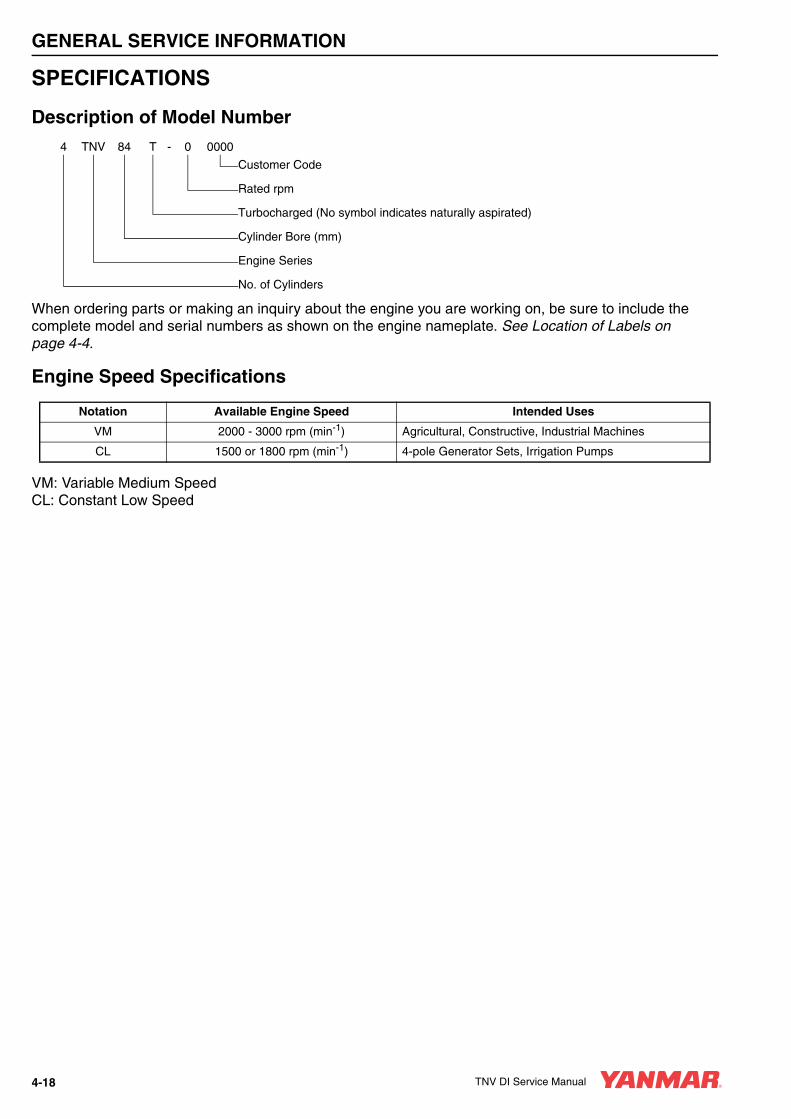
GENERAL SERVICE INFORMATION
SPECIFICATIONS
Description of Model Number
When ordering parts or making an inquiry about the engine you are working on, be sure to include the complete model and serial numbers as shown on the engine nameplate. See Location of Labels on page 4-4.
Engine Speed Specifications
VM: Variable Medium SpeedCL: Constant Low Speed
4 TNV 84 T - 0 0000
Customer Code
Rated rpm
Turbocharged (No symbol indicates naturally aspirated)
Cylinder Bore (mm)
Engine Series
No. of Cylinders
Notation Available Engine Speed Intended Uses
VM 2000 - 3000 rpm (min-1) Agricultural, Constructive, Industrial Machines
CL 1500 or 1800 rpm (min-1) 4-pole Generator Sets, Irrigation Pumps
4-18 TNV DI Service Manual
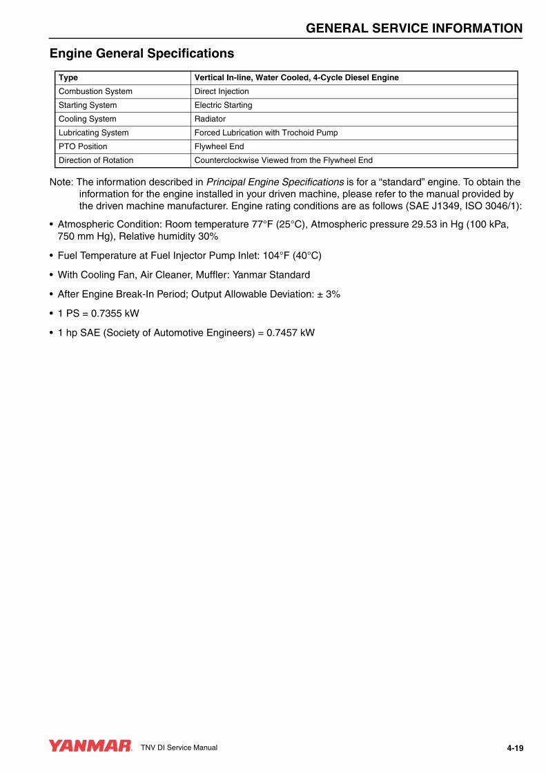
GENERAL SERVICE INFORMATION
Engine General Specifications
Note: The information described in Principal Engine Specifications is for a “standard” engine. To obtain the information for the engine installed in your driven machine, please refer to the manual provided by the driven machine manufacturer. Engine rating conditions are as follows (SAE J1349, ISO 3046/1):
• Atmospheric Condition: Room temperature 77°F (25°C), Atmospheric pressure 29.53 in Hg (100 kPa, 750 mm Hg), Relative humidity 30%
• Fuel Temperature at Fuel Injector Pump Inlet: 104°F (40°C)
• With Cooling Fan, Air Cleaner, Muffler: Yanmar Standard
• After Engine Break-In Period; Output Allowable Deviation: ± 3%
• 1 PS = 0.7355 kW
• 1 hp SAE (Society of Automotive Engineers) = 0.7457 kW
Type Vertical In-line, Water Cooled, 4-Cycle Diesel Engine
Combustion System Direct Injection
Starting System Electric Starting
Cooling System Radiator
Lubricating System Forced Lubrication with Trochoid Pump
PTO Position Flywheel End
Direction of Rotation Counterclockwise Viewed from the Flywheel End
TNV DI Service Manual 4-19
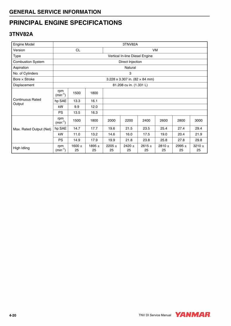
GENERAL SERVICE INFORMATION
PRINCIPAL ENGINE SPECIFICATIONS
3TNV82A
Engine Model 3TNV82A
Version CL VM
Type Vertical In-line Diesel Engine
Combustion System Direct Injection
Aspiration Natural
No. of Cylinders 3
Bore × Stroke 3.228 x 3.307 in. (82 × 84 mm)
Displacement 81.208 cu in. (1.331 L)
Continuous Rated Output
rpm(min-1)
1500 1800
hp SAE 13.3 16.1
kW 9.9 12.0
PS 13.5 16.3
Max. Rated Output (Net)
rpm(min-1)
1500 1800 2000 2200 2400 2600 2800 3000
hp SAE 14.7 17.7 19.6 21.5 23.5 25.4 27.4 29.4
kW 11.0 13.2 14.6 16.0 17.5 19.0 20.4 21.9
PS 14.9 17.9 19.9 21.8 23.8 25.8 27.8 29.8
High Idlingrpm
(min-1)1600 ±
251895 ±
252205 ±
252420 ±
252615 ±
252810 ±
252995 ±
253210 ±
25
4-20 TNV DI Service Manual

GENERAL SERVICE INFORMATION
Engine Model 3TNV82A
Version CL VM
Engine Weight (Dry)with Flywheel Housing* 304.3 lb (138 kg) 282.2 lb (128 kg)
Firing Order 1-3-2-1 (No. 1 Cylinder on the Flywheel End)
Fuel Injection Timing See Checking and Adjusting Fuel Injection Timing on page 7-26.
PTO Position Flywheel End
Direction of Rotation Counterclockwise Viewed From the Flywheel End
Cooling System Liquid-Cooled with Radiator
Lubricating System Forced Lubrication with Trochoid Pump
Normal Oil Pressure at the Rated Engine Speed
42 - 57 psi (0.29 - 0.39 MPa; 2.96 - 3.98 kgf/cm2)
Normal Oil Pressure at the Low Idle Speed
8.8 psi (0.06 MPa; 0.6 kgf/cm2) or greater
Starting System
Electric Starting - Starter Motor: DC12V, 1.6 hp (1.2 kW)
Alternator: DC12V, 40A**
Recommended Battery Capacity: 12V, 52 Amp-Hour (5h rating)
Dimensions (L × W × H)*21.77 x 19.25 x 22.24 in.(553 × 489 × 565 mm)
20.79 x 9.25 x 22.24 in.(528 x 489 x 565 mm)
Engine Oil Pan Capacity***
5.8 / 3.8 qt (5.5 / 3.6 L)(Dipstick Upper Limit / Lower Limit)
Engine Coolant Capacity 0.5 gal (1.8 L) Engine Only
Standard Cooling Fan 13.19 in. (335 mm) O.D., 6 Blades Pusher Type
* Engine specifications without radiator** May vary depending on the application.*** Engine oil capacity for a “deep standard” oil pan. Refer to the operation manual provided by the driven machine
manufacturer for the actual engine oil capacity of your machine.
TNV DI Service Manual 4-21

GENERAL SERVICE INFORMATION
3TNV84
Engine Model 3TNV84
Version CL VM
Type Vertical In-line Diesel Engine
Combustion System Direct Injection
Aspiration Natural
No. of Cylinders 3
Bore × Stroke 3.307 x 3.543 in. (84 x 90 mm)
Displacement 91.275 cu in. (1.496 L)
Continuous Rated Output
rpm(min-1)
1500 1800
hp SAE 15.1 18.0
kW 11.3 13.5
PS 15.3 18.3
Max. Rated Output (Net)
rpm(min-1)
1500 1800 2000 2200 2400 2600 2800 3000
hp SAE 16.6 19.8 22.0 24.3 26.4 28.6 30.9 33.0
kW 12.4 14.8 16.4 18.1 19.7 21.3 23.0 24.6
PS 16.8 20.1 22.3 24.6 26.8 29.0 31.3 33.5
High Idlingrpm
(min-1)1600 ±
251895 ±
252205 ±
252420 ±
252615 ±
252810 ±
252995 ±
253210 ±
25
4-22 TNV DI Service Manual

GENERAL SERVICE INFORMATION
Engine Model 3TNV84
Version CL VM
Engine Weight (Dry)with Flywheel Housing* 355.0 lb (161 kg) 341.8 lb (155 kg)
Firing Order 1-3-2-1 (No. 1 Cylinder on the Flywheel End)
Fuel Injection Timing See Checking and Adjusting Fuel Injection Timing on page 7-26
PTO Position Flywheel End
Direction of Rotation Counterclockwise Viewed From the Flywheel End
Cooling System Liquid-Cooled with Radiator
Lubricating System Forced Lubrication with Trochoid Pump
Normal Oil Pressure at the Rated Engine Speed
42 - 57 psi (0.29 - 0.39 MPa; 2.96 - 3.98 kgf/cm2)
Normal Oil Pressure at the Low Idle Speed
8.8 psi (0.06 MPa; 0.6 kgf/cm2) or greater
Starting System
Electric Starting - Starter Motor: DC12V, 1.6 hp (1.2 kW)
Alternator: DC12V, 40A**
Recommended Battery Capacity: 12V, 60 Amp-Hour (5h rating)
Dimensions (L × W × H)*23.19 x 19.13 x 24.49 in(589 x 486 x 622 mm)
22.20 x 19.13 x 24.49 in(564 x 486 x 622 mm)
Engine Oil Pan Capacity*** 7.1 / 4.1 qt (6.7 / 3.9 L) (Dipstick Upper Limit / Lower Limit)
Engine Coolant Capacity 0.5 gal (2.0 L) Engine Only
* Engine specifications without radiator** May vary depending on the application.*** Engine oil capacity for a “deep standard” oil pan. Refer to the operation manual provided by the driven machine
manufacturer for the actual engine oil capacity of your machine.
TNV DI Service Manual 4-23
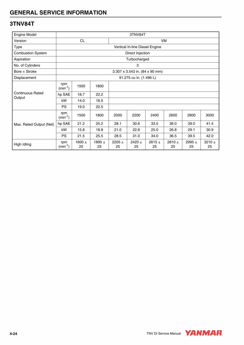
GENERAL SERVICE INFORMATION
3TNV84T
Engine Model 3TNV84T
Version CL VM
Type Vertical In-line Diesel Engine
Combustion System Direct Injection
Aspiration Turbocharged
No. of Cylinders 3
Bore × Stroke 3.307 x 3.543 in. (84 x 90 mm)
Displacement 91.275 cu in. (1.496 L)
Continuous Rated Output
rpm(min-1)
1500 1800
hp SAE 18.7 22.2
kW 14.0 16.5
PS 19.0 22.5
Max. Rated Output (Net)
rpm(min-1)
1500 1800 2000 2200 2400 2600 2800 3000
hp SAE 21.2 25.2 28.1 30.6 33.5 36.0 39.0 41.4
kW 15.8 18.8 21.0 22.8 25.0 26.8 29.1 30.9
PS 21.5 25.5 28.5 31.0 34.0 36.5 39.5 42.0
High Idlingrpm
(min-1)1600 ±
251895 ±
252205 ±
252420 ±
252615 ±
252810 ±
252995 ±
253210 ±
25
4-24 TNV DI Service Manual

GENERAL SERVICE INFORMATION
Engine Model 3TNV84T
Version CL VM
Engine Weight (Dry)with Flywheel Housing* 355.0 lb (161 kg) 341.8 lb (155 kg)
Firing Order 1-3-2-1 (No. 1 Cylinder on the Flywheel End)
Fuel Injection Timing See Checking and Adjusting Fuel Injection Timing on page 7-26
PTO Position Flywheel End
Direction of Rotation Counterclockwise Viewed From the Flywheel End
Cooling System Liquid-Cooled with Radiator
Lubricating System Forced Lubrication with Trochoid Pump
Normal Oil Pressure at the Rated Engine Speed
42 - 57 psi (0.29 - 0.39 MPa; 2.96 - 3.98 kgf/cm2)
Normal Oil Pressure at the Low Idle Speed
8.8 psi (0.06 MPa; 0.6 kgf/cm2) or greater
Starting System
Electric Starting - Starter Motor: DC12 V, 1.6 hp (1.2 kW)
Alternator: DC12V, 40A**
Recommended Battery Capacity: 12V, 60 Amp-Hour (5h rating)
Dimensions (L × W × H)*23.19 x 19.13 x 24.49 in.
(589 x 486 x 622 mm)22.20 x 19.13 x 24.49 in.
(564 x 486 x 622 mm)
Engine Oil Pan Capacity*** 7.1 / 4.1 qt (6.7 / 3.9 L) (Dipstick Upper Limit / Lower Limit)
Engine Coolant Capacity 0.5 gal (2.0 L) Engine Only
Standard Cooling Fan 13.78 in. (350 mm) O.D., 6 Blades Pusher Type
* Engine specifications without radiator** May vary depending on the application.*** Engine oil capacity for a “deep standard” oil pan. Refer to the operation manual provided by the driven machine
manufacturer for the actual engine oil capacity of your machine.
TNV DI Service Manual 4-25

GENERAL SERVICE INFORMATION
3TNV88
Engine Model 3TNV88
Version CL VM
Type Vertical In-line Diesel Engine
Combustion System Direct Injection
Aspiration Natural
No. of Cylinders 3
Bore × Stroke 3.465 x 3.543 in. (88 x 90 mm)
Displacement 100.183 cu in. (1.642 L)
Continuous Rated Output
rpm(min-1)
1500 1800
hp SAE 16.5 19.8
kW 12.3 14.8
PS 16.7 20.1
Max. Rated Output (Net)
rpm(min-1)
1500 1800 2000 2200 2400 2600 2800 3000
hp SAE 18.1 21.8 24.2 26.6 29.0 31.5 33.7 36.3
kW 13.5 16.3 18.0 19.9 21.6 23.5 25.2 27.1
PS 18.4 22.1 24.5 27.0 29.4 31.9 34.2 36.8
High Idlingrpm
(min-1)1600 ±
251895 ±
252205 ±
252420 ±
252615 ±
252810 ±
252995 ±
253210 ±
25
4-26 TNV DI Service Manual

GENERAL SERVICE INFORMATION
Engine Model 3TNV88
Version CL VM
Engine Weight (Dry)with Flywheel Housing* 355.0 lb (161 kg) 341.8 lb (155 kg)
Firing Order 1-3-2-1 (No. 1 Cylinder on the Flywheel End)
Fuel Injection Timing See Checking and Adjusting Fuel Injection Timing on page 7-26
PTO Position Flywheel End
Direction of Rotation Counterclockwise Viewed From the Flywheel End
Cooling System Liquid-Cooled with Radiator
Lubricating System Forced Lubrication with Trochoid Pump
Normal Oil Pressure at the Rated Engine Speed
42 - 57 psi (0.29 - 0.39 MPa; 2.96 - 3.98 kgf/cm2)
Normal Oil Pressure at the Low Idle Speed
8.8 psi (0.06 MPa; 0.6 kgf/cm2) or greater
Starting System
Electric Starting - Starter Motor: DC12V, 1.6 hp (1.2 kW)
Alternator: DC12V, 40A**
Recommended Battery Capacity: 12V, 60 Amp-Hour (5h rating)
Dimensions (L × W × H)*23.19 x 19.13 x 24.49 in.
(589 x 486 x 622 mm)22.20 x 19.13 x 24.49 in.
(564 x 486 x 622 mm)
Engine Oil Pan Capacity*** 7.1 / 4.1 qt (6.7 / 3.9 L) (Dipstick Upper Limit / Lower Limit)
Engine Coolant Capacity 0.5 gal (2.0 L) Engine Only
Standard Cooling Fan 13.19 in. (335 mm) O.D., 6 Blades Pusher Type
* Engine specifications without radiator.** May vary depending on the application.*** Engine oil capacity for a “deep standard” oil pan. Refer to the operation manual provided by the driven machine
manufacturer for the actual engine oil capacity of your machine.
TNV DI Service Manual 4-27

GENERAL SERVICE INFORMATION
4TNV84
Engine Model 4TNV84
Version CL VM
Type Vertical In-line Diesel Engine
Combustion System Direct Injection
Aspiration Natural
No. of Cylinders 4
Bore × Stroke 3.307 x 3.543 in. (84 x 90 mm)
Displacement 121.721 cu in. (1.995 L)
Continuous Rated Output
rpm(min-1)
1500 1800
hp SAE 20.0 23.8
kW 14.9 17.7
PS 20.3 24.1
Max. Rated Output (Net)
rpm(min-1)
1500 1800 2000 2200 2400 2600 2800 3000
hp SAE 22.0 26.1 29.4 32.4 35.3 38.2 41.1 44.1
kW 16.4 19.5 21.9 24.1 26.3 28.5 30.7 32.9
PS 22.3 26.5 29.8 32.8 35.8 38.7 41.7 44.7
High Idlingrpm
(min-1)1600 ±
251895 ±
252205 ±
252420 ±
252615 ±
252810 ±
252995 ±
253210 ±
25
4-28 TNV DI Service Manual

GENERAL SERVICE INFORMATION
Engine Model 4TNV84
Version CL VM
Engine Weight (Dry)with Flywheel Housing* 403.5 lb (183 kg) 374.9 lb (170 kg)
Firing Order 1-3-4-2-1 (No. 1 Cylinder on the Flywheel End)
Fuel Injection Timing See Checking and Adjusting Fuel Injection Timing on page 7-26
PTO Position Flywheel End
Direction of Rotation Counterclockwise Viewed From the Flywheel End
Cooling System Liquid-Cooled with Radiator
Lubricating System Forced Lubrication with Trochoid Pump
Normal Oil Pressure at the Rated Engine Speed
42 - 57 psi (0.29 - 0.39 MPa; 2.96 - 3.98 kgf/cm2)
Normal Oil Pressure at the Low Idle Speed
8.8 psi (0.06 MPa; 0.6 kgf/cm2) or greater
Starting System
Electric Starting - Starter Motor: DC12V, 1.9 hp (1.4 kW)
Alternator: DC12V, 40A**
Recommended Battery Capacity: 12V, 60 Amp-Hour (5h rating)
Dimensions (L × W × H)*26.89 x 19.63 x 24.29 in.(683 x 498.5 x 617 mm)
25.91 x 19.63 x 24.29 in.(658 x 498.5 x 617 mm)
Engine Oil Pan Capacity*** 7.8 / 4.2 qt (7.4 / 4.0 L) (Dipstick Upper Limit / Lower Limit)
Engine Coolant Capacity 0.7 gal (2.7 L) Engine Only
Standard Cooling Fan 14.57 in (370 mm) O.D., 6 Blades Pusher Type
* Engine specifications without radiator** May vary depending on the application.*** Engine oil capacity for a “deep standard” oil pan. Refer to the operation manual provided by the driven machine
manufacturer for the actual engine oil capacity of your machine.
TNV DI Service Manual 4-29

GENERAL SERVICE INFORMATION
4TNV84T
Engine Model 4TNV84T
Version CL VM
Type Vertical In-line Diesel Engine
Combustion System Direct Injection
Aspiration Turbocharged
No. of Cylinders 4
Bore × Stroke 3.307 x 3.543 in. (84 x 90 mm)
Displacement 121.721 cu in. (1.995 L)
Continuous Rated Output
rpm(min-1)
1500 1800
hp SAE 25.6 32.5
kW 19.1 24.3
PS 26.0 33.0
Max. Rated Output (Net)
rpm(min-1)
1500 1800 2000 2200 2400 2600 2800 3000
hp SAE 28.6 36.0 37.5 41.0 44.9 47.8 51.8 55.2
kW 21.3 26.9 27.9 30.5 33.5 35.7 38.6 41.2
PS 29.0 36.5 38.0 41.5 45.5 48.5 52.5 56.0
High Idlingrpm
(min-1)1600 ±
251895 ±
252205 ±
252420 ±
252615 ±
252810 ±
252995 ±
253210 ±
25
4-30 TNV DI Service Manual

GENERAL SERVICE INFORMATION
Engine Model 4TNV84T
Version CL VM
Engine Weight (Dry)with Flywheel Housing* 403.5 lb (183 kg) 374.9 lb (170 kg)
Firing Order 1-3-4-2-1 (No. 1 Cylinder on the Flywheel End)
Fuel Injection Timing See Checking and Adjusting Fuel Injection Timing on page 7-26
PTO Position Flywheel End
Direction of Rotation Counterclockwise Viewed From the Flywheel End
Cooling System Liquid-Cooled with Radiator
Lubricating System Forced Lubrication with Trochoid Pump
Normal Oil Pressure at the Rated Engine Speed
42 - 57 psi (0.29 - 0.39 MPa; 2.96 - 3.98 kgf/cm2)
Normal Oil Pressure at the Low Idle Speed
8.8 psi (0.06 MPa; 0.6 kgf/cm2) or greater
Starting System
Electric Starting - Starter Motor: DC12V, 1.9 hp (1.4 kW)
Alternator: DC12V, 40A**
Recommended Battery Capacity: 12V, 60 Amp-Hour (5h rating)
Dimensions (L × W × H)*26.89 x 19.63 x 28.07 in.(683 x 498.5 x 713 mm)
25.55 x 19.63 x 28.07 in.(649 x 498.5 x 713 mm)
Engine Oil Pan Capacity*** 7.8 / 4.2 qt (7.4 / 4.0 L) (Dipstick Upper Limit / Lower Limit)
Engine Coolant Capacity 0.7 gal (2.7 L) Engine Only
Standard Cooling Fan 14.57 in. (370 mm) O.D., 6 Blades Pusher Type
* Engine specifications without radiator.** May vary depending on the application.*** Engine oil capacity for a “deep standard” oil pan. Refer to the operation manual provided by the driven machine
manufacturer for the actual engine oil capacity of your machine.
TNV DI Service Manual 4-31

GENERAL SERVICE INFORMATION
4TNV88
Engine Model 4TNV88
Version CL VM
Type Vertical In-line Diesel Engine
Combustion System Direct Injection
Aspiration Natural
No. of Cylinders 4
Bore × Stroke 3.465 x 3.543 in. (88 x 90 mm)
Displacement 133.618 cu in. (2.190 L)
Continuous Rated Output
rpm(min-1)
1500 1800
hp SAE 22.0 26.3
kW 16.4 19.6
PS 22.3 26.7
Max. Rated Output (Net)
rpm(min-1)
1500 1800 2000 2200 2400 2600 2800 3000
hp SAE 24.2 29.0 32.3 35.5 38.7 41.9 45.2 47.4
kW 18.0 21.6 24.1 26.5 28.8 31.3 33.7 35.4
PS 24.5 29.4 32.7 36.0 39.2 42.5 45.8 48.1
High Idlingrpm
(min-1)1600 ±
251895 ±
252205 ±
252420 ±
252615 ±
252810 ±
252995 ±
253210 ±
25
4-32 TNV DI Service Manual

GENERAL SERVICE INFORMATION
Engine Model 4TNV88
Version CL VM
Engine Weight (Dry)with Flywheel Housing* 403.5 lb (183 kg) 374.9 lb (170 kg)
Firing Order 1-3-4-2-1 (No. 1 Cylinder on the Flywheel End)
Fuel Injection Timing See Checking and Adjusting Fuel Injection Timing on page 7-26
PTO Position Flywheel End
Direction of Rotation Counterclockwise Viewed From the Flywheel End
Cooling System Liquid-Cooled with Radiator
Lubricating System Forced Lubrication with Trochoid Pump
Normal Oil Pressure at the Rated Engine Speed
42 - 57 psi (0.29 - 0.39 MPa; 2.96 - 3.98 kgf/cm2)
Normal Oil Pressure at the Low Idle Speed
8.8 psi (0.06 MPa; 0.6 kgf/cm2) or greater
Starting System
Electric Starting - Starter Motor: DC12V, 1.9 hp (1.4 kW)
Alternator: DC12V, 40**
Recommended Battery Capacity: 12V, 60 Amp-Hour (5h rating)
Dimensions (L × W × H)*26.89 x 19.63 x 24.33 in.(683 x 498.5 x 618 mm)
25.91 x 19.63 x 24.33 in.(658 x 498.5 x 618 mm)
Engine Oil Pan Capacity***
7.8 / 4.2 qt (7.4 / 4.0 L)(Dipstick Upper Limit / Lower Limit)
Engine Coolant Capacity 0.7 gal (2.7 L) Engine Only
Standard Cooling Fan 14.57 in. (370 mm) O.D., 6 Blades Pusher Type
* Engine specifications without radiator.** May vary depending on the application.*** Engine oil capacity for a “deep standard” oil pan. Refer to the operation manual provided by the driven machine
manufacturer for the actual engine oil capacity of your machine.
TNV DI Service Manual 4-33

GENERAL SERVICE INFORMATION
4TNV94L
Engine Model 4TNV94L
Version CL VM
Type Vertical In-line Diesel Engine
Combustion System Direct Injection
Aspiration Natural
No. of Cylinders 4
Bore × Stroke 3.701 x 4.331 in (94 x 110 mm)
Displacement 186.333 cu in (3.054 L)
Continuous Rated Output
rpm(min-1)
1500 1800
hp SAE 35.0 41.9
kW 26.1 31.3
PS 35.5 42.5
Max. Rated Output (Net)
rpm(min-1)
1500 1800 2000 2200 2400 2500
hp SAE 39.0 46.4 47.3 51.3 55.7 57.7
kW 29.1 34.6 35.3 38.2 41.6 43.0
PS 39.5 47.0 48.0 52.0 56.5 58.5
High Idlingrpm
(min-1)1600 ± 25 1895 ± 25 2205 ± 25 2420 ± 25 2615 ± 25 2725 ± 25
4-34 TNV DI Service Manual

GENERAL SERVICE INFORMATION
Engine Model 4TNV94L
Version CL VM
Engine Weight (Dry)with Flywheel Housing* 540.2 lb (245 kg) 518.2 lb (235 kg)
PTO Position Flywheel End
Firing Order 1-3-4-2-1 (No. 1 Cylinder on the Flywheel End)
Fuel Injection Timing See Checking and Adjusting Fuel Injection Timing on page 7-26
Direction of Rotation Counterclockwise Viewed From the Flywheel End
Cooling System Liquid-Cooled with Radiator
Lubricating System Forced Lubrication with Trochoid Pump
Normal Oil Pressure at the Rated Engine Speed
42 - 57 psi (0.29 - 0.39 MPa; 2.96 - 3.98 kgf/cm2)
Normal Oil Pressure at the Low Idle Speed
8.8 psi (0.06 MPa; 0.6 kgf/cm2) or greater
Starting System
Electric Starting - Starter Motor: DC12V, 3.1 hp (2.3 kW)
Alternator: DC12V, 40A**
Recommended Battery Capacity: 12V, 64 Amp-Hour (5h rating)
Dimensions (L × W × H)*28.31 x 19.61 x 29.21 in.
(719 x 498 x 742 mm)
Engine Oil Pan Capacity***
11.1 / 6.3 qt (10.5 / 6.0 L)(Dipstick Upper Limit / Lower Limit)
Engine Coolant Capacity 1.1 gal (4.2 L) Engine Only
Standard Cooling Fan 16.14 in. (410 mm) O.D., 6 Blades Pusher Type
* Engine specifications without radiator.** May vary depending on the application.*** Engine oil capacity for a “deep standard” oil pan. Refer to the operation manual provided by the driven machine
manufacturer for the actual engine oil capacity of your machine.
TNV DI Service Manual 4-35

GENERAL SERVICE INFORMATION
4TNV98
Engine Model 4TNV98
Version CL VM
Type Vertical In-line Diesel Engine
Combustion System Direct Injection
Aspiration Natural
No. of Cylinders 4
Bore × Stroke 3.858 x 4.331 in. (98 x 110 mm)
Displacement 202.502 cu in. (3.319 L)
Continuous Rated Output
rpm(min-1)
1500 1800
hp SAE 41.4 49.3
kW 30.9 36.8
PS 42.0 50.0
Max. Rated Output (Net)
rpm(min-1)
1500 1800 2000 2200 2400 2500
hp SAE 46.4 55.2 56.2 61.2 66.1 68.5
kW 34.6 41.2 41.9 45.6 49.3 51.1
PS 47.0 56.0 57.0 62.0 67.0 69.5
High Idlingrpm
(min-1)1600 ± 25 1895 ±25 2205 ± 25 2420 ± 25 2615 ± 25 2725 ± 25
4-36 TNV DI Service Manual

GENERAL SERVICE INFORMATION
Engine Model 4TNV98
Version CL VM
Engine Weight (Dry)with Flywheel Housing* 546.8 lb (248 kg) 518.2 lb (235 kg)
PTO Position Flywheel End
Firing Order 1-3-4-2-1 (No. 1 Cylinder on the Flywheel End)
Fuel Injection Timing See Checking and Adjusting Fuel Injection Timing on page 7-26
Direction of Rotation Counterclockwise Viewed From the Flywheel End
Cooling System Liquid-Cooled with Radiator
Lubricating System Forced Lubrication with Trochoid Pump
Normal Oil Pressure at the Rated Engine Speed
42 - 57 psi (0.29 - 0.39 MPa; 2.96 - 3.98 kgf/cm2)
Normal Oil Pressure at the Low Idle Speed
8.8 psi (0.06 MPa; 0.6 kgf/cm2) or greater
Starting System
Electric Starting - Starter Motor: DC12V, 3.1 hp (2.3 kW)
Alternator: DC12V, 40A**
Recommended Battery Capacity: 12V, 64 Amp-Hour (5h rating)
Dimensions (L × W × H)*28.31 x 19.61 x 29.21 in.
(719 x 498 x 742 mm)
Engine Oil Pan Capacity***
11.1 / 6.3 qt (10.5 / 6.0 L)(Dipstick Upper Limit / Lower Limit)
Engine Coolant Capacity 1.1 gal (4.2 L) Engine Only
Standard Cooling Fan 16.14 in. (410 mm) O.D., 6 Blades Pusher Type
* Engine specifications without radiator.** May vary depending on the application.*** Engine oil capacity for a “deep standard” oil pan. Refer to the operation manual provided by the driven machine
manufacturer for the actual engine oil capacity of your machine.
TNV DI Service Manual 4-37

GENERAL SERVICE INFORMATION
4TNV98T
Engine Model 4TNV98T
Version CL VM
Type Vertical In-line Diesel Engine
Combustion System Direct Injection
Aspiration Turbocharged
No. of Cylinders 4
Bore × Stroke 3.858 x 4.331 in. (98 x 110 mm)
Displacement 202.502 cu in. (3.319 L)
Continuous Rated Output
rpm(min-1)
1500 1800
hp SAE 50.8 61.2
kW 37.9 45.6
PS 51.5 62.0
Max. Rated Output (Net)
rpm(min-1)
1500 1800 2000 2200 2400 2500
hp SAE 56.2 67.6 68.1 74.5 80.9 83.8
kW 41.9 50.4 50.7 55.5 60.3 62.5
PS 57.0 68.5 69.0 75.5 82.0 85.0
High Idlingrpm
(min-1)1600 ± 25 1895 ± 25 2205 ± 25 2420 ± 25 2615 ± 25 2725 ± 25
4-38 TNV DI Service Manual

GENERAL SERVICE INFORMATION
Engine Model 4TNV98T
Version CL VM
Engine Weight (Dry)with Flywheel Housing* 568.9 lb (258 kg) 540.2 lb (245 kg)
PTO Position Flywheel End
Firing Order 1-3-4-2-1 (No. 1 Cylinder on the Flywheel End)
Fuel Injection Timing See Checking and Adjusting Fuel Injection Timing on page 7-26
Direction of Rotation Counterclockwise Viewed From the Flywheel End
Cooling System Liquid-Cooled with Radiator
Lubricating System Forced Lubrication with Trochoid Pump
Normal Oil Pressure at the Rated Engine Speed
57 - 71 psi (0.39 - 0.49 MPa; 3.98 - 5.00 kgf/cm2)
Normal Oil Pressure at the Low Idle Speed
8.8 psi (0.06 MPa; 0.6 kgf/cm2) or greater
Starting System
Electric Starting - Starter Motor: DC12V, 3.1 hp (2.3 kW)
Alternator: DC12V, 40A**
Recommended Battery Capacity: 12V, 64 Amp-Hour (5h rating)
Dimensions (L × W × H)*28.31 x 22.64 x 31.65 in.
(719 x 575 x 804 mm)
Engine Oil Pan Capacity***
11.1 / 6.3 qt (10.5 / 6.0 L)(Dipstick Upper Limit / Lower limit)
Engine Coolant Capacity 1.1 gal (4.2 L) Engine Only
Standard Cooling Fan 16.93 in. (430 mm) O.D., 8 Blades Suction Type
* Engine specifications without radiator.** May vary depending on the application.*** Engine oil capacity for a “deep standard” oil pan. Refer to the operation manual provided by the driven machine
manufacturer for the actual engine oil capacity of your machine.
TNV DI Service Manual 4-39
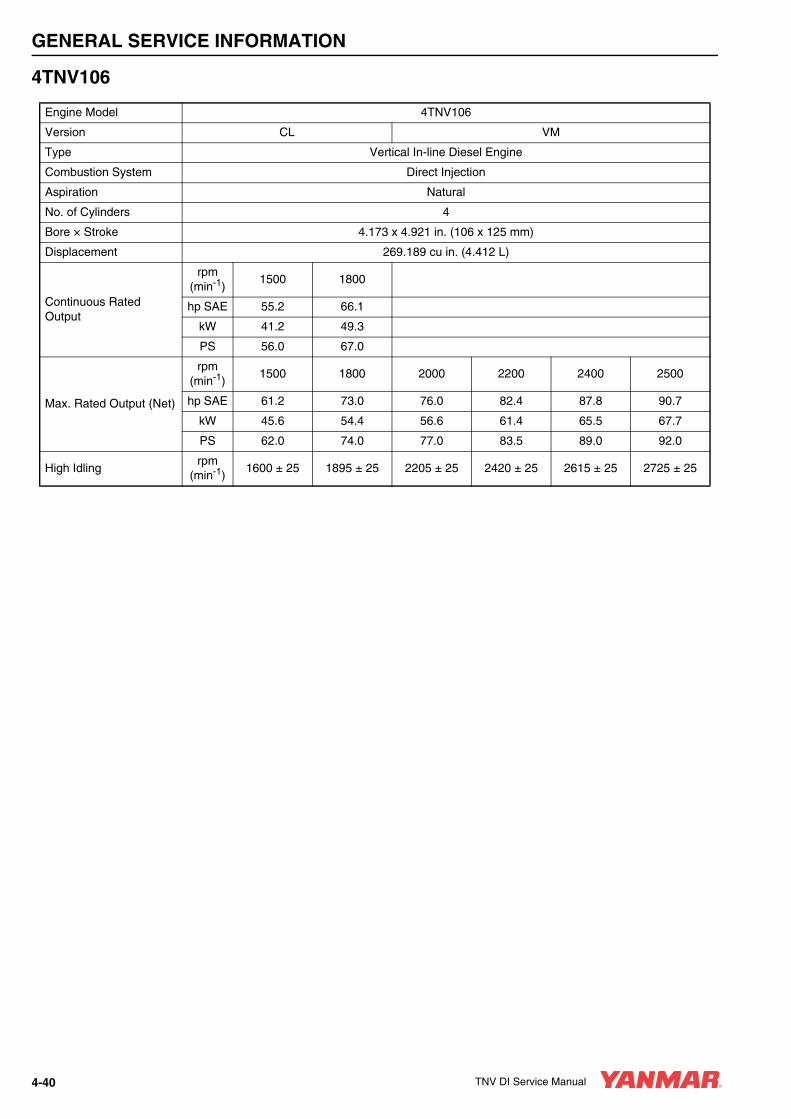
GENERAL SERVICE INFORMATION
4TNV106
Engine Model 4TNV106
Version CL VM
Type Vertical In-line Diesel Engine
Combustion System Direct Injection
Aspiration Natural
No. of Cylinders 4
Bore × Stroke 4.173 x 4.921 in. (106 x 125 mm)
Displacement 269.189 cu in. (4.412 L)
Continuous Rated Output
rpm(min-1)
1500 1800
hp SAE 55.2 66.1
kW 41.2 49.3
PS 56.0 67.0
Max. Rated Output (Net)
rpm(min-1)
1500 1800 2000 2200 2400 2500
hp SAE 61.2 73.0 76.0 82.4 87.8 90.7
kW 45.6 54.4 56.6 61.4 65.5 67.7
PS 62.0 74.0 77.0 83.5 89.0 92.0
High Idlingrpm
(min-1)1600 ± 25 1895 ± 25 2205 ± 25 2420 ± 25 2615 ± 25 2725 ± 25
4-40 TNV DI Service Manual
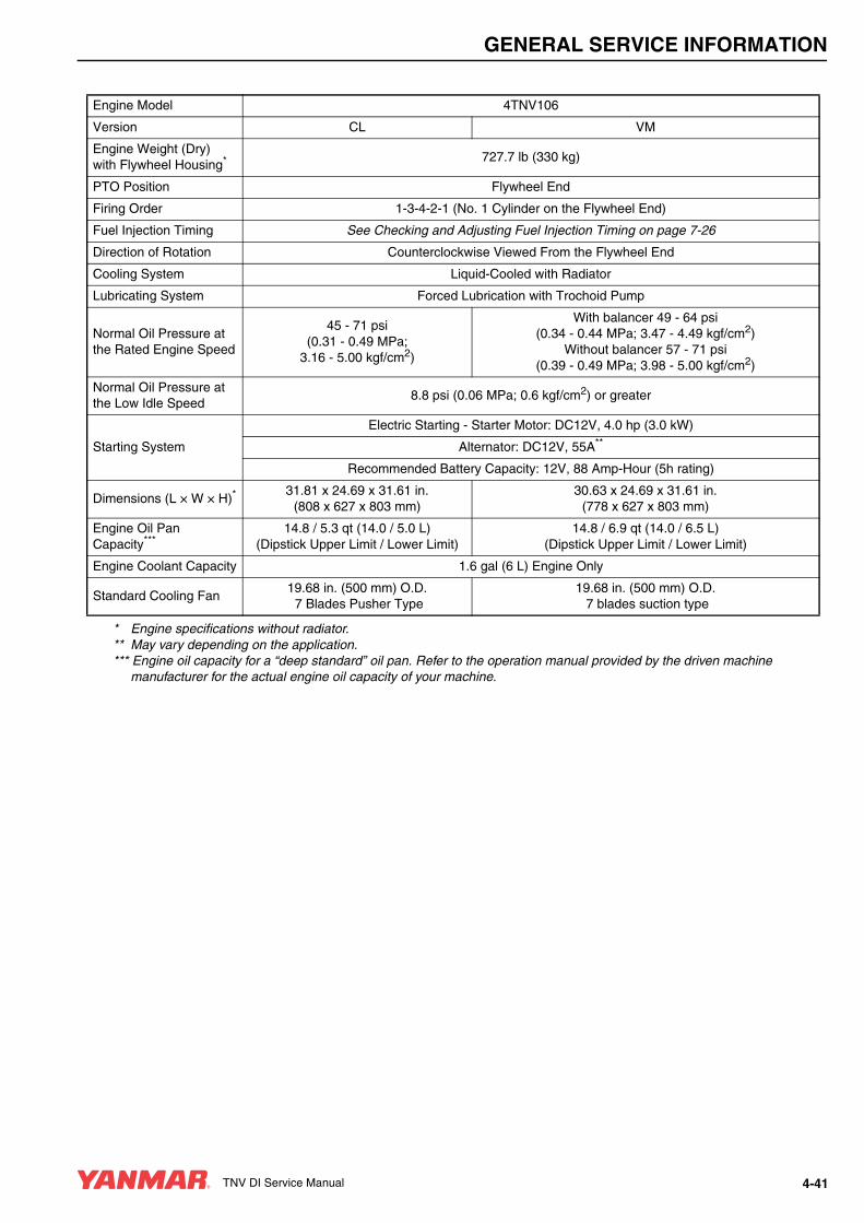
GENERAL SERVICE INFORMATION
Engine Model 4TNV106
Version CL VM
Engine Weight (Dry)with Flywheel Housing* 727.7 lb (330 kg)
PTO Position Flywheel End
Firing Order 1-3-4-2-1 (No. 1 Cylinder on the Flywheel End)
Fuel Injection Timing See Checking and Adjusting Fuel Injection Timing on page 7-26
Direction of Rotation Counterclockwise Viewed From the Flywheel End
Cooling System Liquid-Cooled with Radiator
Lubricating System Forced Lubrication with Trochoid Pump
Normal Oil Pressure at the Rated Engine Speed
45 - 71 psi (0.31 - 0.49 MPa;
3.16 - 5.00 kgf/cm2)
With balancer 49 - 64 psi (0.34 - 0.44 MPa; 3.47 - 4.49 kgf/cm2)
Without balancer 57 - 71 psi (0.39 - 0.49 MPa; 3.98 - 5.00 kgf/cm2)
Normal Oil Pressure at the Low Idle Speed
8.8 psi (0.06 MPa; 0.6 kgf/cm2) or greater
Starting System
Electric Starting - Starter Motor: DC12V, 4.0 hp (3.0 kW)
Alternator: DC12V, 55A**
Recommended Battery Capacity: 12V, 88 Amp-Hour (5h rating)
Dimensions (L × W × H)*31.81 x 24.69 x 31.61 in.
(808 x 627 x 803 mm)30.63 x 24.69 x 31.61 in.
(778 x 627 x 803 mm)
Engine Oil Pan Capacity***
14.8 / 5.3 qt (14.0 / 5.0 L)(Dipstick Upper Limit / Lower Limit)
14.8 / 6.9 qt (14.0 / 6.5 L)(Dipstick Upper Limit / Lower Limit)
Engine Coolant Capacity 1.6 gal (6 L) Engine Only
Standard Cooling Fan19.68 in. (500 mm) O.D. 7 Blades Pusher Type
19.68 in. (500 mm) O.D. 7 blades suction type
* Engine specifications without radiator.** May vary depending on the application.*** Engine oil capacity for a “deep standard” oil pan. Refer to the operation manual provided by the driven machine
manufacturer for the actual engine oil capacity of your machine.
TNV DI Service Manual 4-41

GENERAL SERVICE INFORMATION
4TNV106T
Engine Model 4TNV106T
Version CL VM
Type Vertical In-line Diesel Engine
Combustion System Direct Injection
Aspiration Turbocharged
No. of Cylinders 4
Bore × Stroke 4.173 x 4.921 in. (106 x 125 mm)
Displacement 269.189 cu in. (4.412 L)
Continuous Rated Output
rpm(min-1)
1500 1800
hp SAE 69.0 82.8
kW 51.5 61.8
PS 70.0 84.0
Max. Rated Output (Net)
rpm(min-1)
1500 1800 2000 2200
hp SAE 76.1 91.2 93.7 96.6
kW 56.8 68.0 69.9 72.0
PS 77.2 92.5 95.0 97.9
High Idlingrpm
(min-1)1600 ± 25 1875 ± 25 2205 ± 25 2420 ± 25
4-42 TNV DI Service Manual

GENERAL SERVICE INFORMATION
Engine Model 4TNV106T
Version CL VM
Engine Weight (dry)with Flywheel Housing* 749.7 lb (340 kg)
PTO Position Flywheel End
Firing Order 1-3-4-2-1 (No. 1 Cylinder on the Flywheel End)
Fuel Injection Timing See Checking and Adjusting Fuel Injection Timing on page 7-26
Direction of Rotation Counter-clockwise Viewed From the Flywheel End
Cooling System Liquid-Cooled with Radiator
Lubricating System Forced Lubrication with Trochoid Pump
Normal Oil Pressure at the Rated Engine Speed
45 - 71 psi (0.31 - 0.49 MPa;
3.16 - 5.00 kgf/cm2)
With balancer 49 - 64 psi (0.34 - 0.44 MPa; 3.47 - 4.49 kgf/cm2)
Without balancer 57 - 71 psi (0.39 - 0.49 MPa; 3.98 - 5.00 kgf/cm2)
Normal Oil Pressure at the Low Idle Speed
8.8 psi (0.06 MPa; 0.6 kgf/cm2) or greater
Starting System
Electric Starting - Starter Motor: DC12V, 4.0 hp (3.0 kW)
Alternator: DC12V, 55A**
Recommended Battery Capacity: 12V, 88 Amp-Hour (5h rating)
Dimensions (L × W × H)*31.81 x 24.76 x 34.09 in.
(808 x 629 x 866 mm)30.63 x 24.76 x 34.09 in.
(778 x 629 x 866 mm)
Engine Oil Pan Capacity***
14.8 / 5.3 qt (14.0 / 5.0 L)(Dipstick Upper Limit / Lower Limit)
14.8 / 6.9 qt (14.0 / 6.5 L)(Dipstick Upper Limit / Lower Limit)
Engine Coolant Capacity 1.6 gal (6 L) Engine Only
Standard Cooling Fan19.68 in (500 mm) O.D.7 Blades Pusher Type
19.68 in (500 mm) O.D.7 Blades Suction Type
* Engine specifications without radiator.** May vary depending on the application.*** Engine oil capacity for a “deep standard” oil pan. Refer to the operation manual provided by the driven machine
manufacturer for the actual engine oil capacity of your machine.
TNV DI Service Manual 4-43

GENERAL SERVICE INFORMATION
ENGINE SERVICE STANDARDS
Inspection Item Standard LimitReference
page
Intake / Exhaust Valve Clearance
All models except 4TNV106 and 4TNV106T
0.006 - 0.010 in.(0.15 - 0.25 mm)
- See Measuring and Adjusting
Valve Clearance on page 6-624TNV106 and
4TNV106T0.010 - 0.014 in.(0.25 - 0.35 mm)
-
Fuel Injection Timing
See Checking and Adjusting Fuel Injection Timing on page 7-26.
Fuel Injection Pressure
See Test and Adjustment Specifications on page 7-8.
Compression Pressure at250 rpm (250 min¯¹)
3TNV82A443 - 473 psi
(3.06 - 3.26 MPa;30 - 32 kgf / cm²)
340 - 370 psi(2.35 - 3.55 MPa;24 - 26 kgf / cm²)
See Troubleshooting By Measuring Compression Pressure on page 14-4
3TNV84, 4TNV84455 - 485 psi
(3.14 - 3.34 MPa;32 - 34 kgf / cm²)
355 - 385 psi(2.45 - 2.65 MPa;25 - 27 kgf / cm²)
3TNV84T, 4TNV84T411 - 441 psi
(2.84 - 3.04 MPa;29 - 31 kgf / cm)
340 - 370 psi(2.35 - 2.55 MPa;24 - 26 kgf / cm²)
3TNV88, 4TNV88, 4TNV94L, 4TNV98, 4TNV98T, 4TNV106, 4TNV106T
483 - 513 psi (3.33 - 3.53 MPa;34 - 36 kgf / cm²)
384 - 414 psi(2.65 - 2.85 MPa;27 - 29 kgf / cm²)
Deviation Between Cylinders All Models29 - 43 psi
(0.2 - 0.3 MPa;2 - 3 kgf/cm²)
- -
Oil Pressure Switch Operating Pressure5.8 - 8.8 psi
(0.04 - 0.06 MPa;0.4 - 0.6 kgf / cm²)
- -
Thermostat
Valve Opening Temperature
Full Opening LiftTemperature
See Thermostat on page 8-10
All Models157°F - 163°F(70°C - 73°C)
0.32 in (8 mm) or above
185°F (85°C)
All ModelsOption
176°F - 183°F(80°C - 84°C)
0.39 in (10 mm) or above
203°F (95°C)
Coolant Temperature Switch225°F - 235°F
(107°C - 113°C)-
See Temperature
Switch on page 8-10
4-44 TNV DI Service Manual
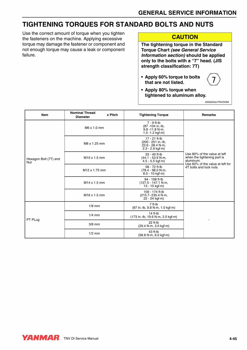
GENERAL SERVICE INFORMATION
TIGHTENING TORQUES FOR STANDARD BOLTS AND NUTSUse the correct amount of torque when you tighten the fasteners on the machine. Applying excessive torque may damage the fastener or component and not enough torque may cause a leak or component failure.
CAUTIONThe tightening torque in the Standard Torque Chart (see General Service Information section) should be applied only to the bolts with a “7” head. (JIS strength classification: 7T)
• Apply 60% torque to bolts that are not listed.
• Apply 80% torque when tightened to aluminum alloy.
0000023enTNVDISM
ItemNominal Thread
Diameterx Pitch Tightening Torque Remarks
Hexagon Bolt (7T) and Nut
M6 x 1.0 mm
7 - 9 ft-lb(87 -104 in.-lb,9.8 -11.8 N·m,1.0 -1.2 kgf·m)
Use 80% of the value at left when the tightening part is aluminum.Use 60% of the value at left for 4T bolts and lock nuts.
M8 x 1.25 mm
17 - 21 ft-lb(200 - 251 in.-lb,22.6 - 28.4 N·m,2.3 - 2.9 kgf·m)
M10 x 1.5 mm33 - 40 ft-lb
(44.1 - 53.9 N·m,4.5 - 5.5 kgf·m)
M12 x 1.75 mm58 - 72 ft-lb
(78.4 - 98.0 N·m,8.0 - 10 kgf·m)
M14 x 1.5 mm94 - 108 ft-lb
(127.5 - 147.1 N·m,13 - 15 kgf·m)
M16 x 1.5 mm159 - 174 ft-lb
(215.7- 235.4 N·m,22 - 24 kgf·m)
PT PLug
1/8 mm 7 ft-lb(87 in.-lb, 9.8 N·m, 1.0 kgf·m)
-1/4 mm 14 ft-lb
(173 in.-lb, 19.6 N·m, 2.0 kgf·m)
3/8 mm 22 ft-lb(29.4 N·m, 3.0 kgf·m)
1/2 mm 43 ft-lb(58.8 N·m, 6.0 kgf·m)
TNV DI Service Manual 4-45

GENERAL SERVICE INFORMATION
Note: Torque values shown in this manual are for clean, non-lubricated fasteners unless otherwise specified.
Pipe Joint Bolt
M8
9 - 12 ft-lb(112 - 148 in.-lb,12.7 - 16.7 N·m,1.3 - 1.7 kgf·m)
-
M10
14 - 19 ft-lb(173 - 225 in.-lb,
19.6 - 18.734 N·m, 2.0 - 3.5 kgf·m)
M1218 - 25 ft-lb
(24.5 - 34.3 N·m,2.5 - 3.5 kgf·m)
M1429 - 36 ft-lb
(39.2 - 49.0 N·m,4.0 - 5.0 kgf·m)
M1636 - 43 ft-lb
(49.0 - 58.8 N·m,5.0 - 6.0 kgf·m)
ItemNominal Thread
Diameterx Pitch Tightening Torque Remarks
4-46 TNV DI Service Manual
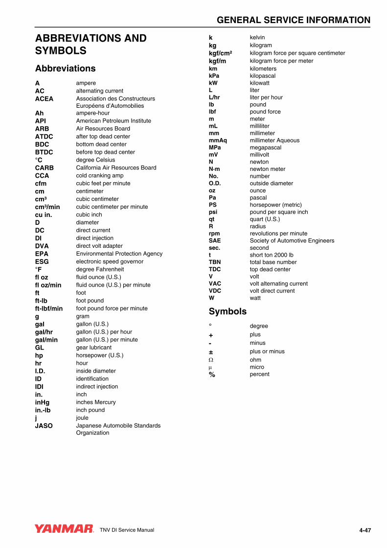
GENERAL SERVICE INFORMATION
ABBREVIATIONS AND SYMBOLS
Abbreviations
Symbols
A ampereAC alternating currentACEA Association des Constructeurs
Européens d’AutomobiliesAh ampere-hourAPI American Petroleum InstituteARB Air Resources BoardATDC after top dead centerBDC bottom dead centerBTDC before top dead center°C degree CelsiusCARB California Air Resources BoardCCA cold cranking ampcfm cubic feet per minutecm centimetercm³ cubic centimetercm³/min cubic centimeter per minutecu in. cubic inchD diameterDC direct currentDI direct injectionDVA direct volt adapterEPA Environmental Protection AgencyESG electronic speed governor°F degree Fahrenheitfl oz fluid ounce (U.S.)fl oz/min fluid ounce (U.S.) per minuteft footft-lb foot poundft-lbf/min foot pound force per minuteg gramgal gallon (U.S.)gal/hr gallon (U.S.) per hourgal/min gallon (U.S.) per minuteGL gear lubricanthp horsepower (U.S.)hr hourI.D. inside diameterID identificationIDI indirect injectionin. inchinHg inches Mercuryin.-lb inch poundj jouleJASO Japanese Automobile Standards
Organization
k kelvinkg kilogramkgf/cm² kilogram force per square centimeterkgf/m kilogram force per meterkm kilometerskPa kilopascalkW kilowattL literL/hr liter per hourlb poundlbf pound forcem metermL millilitermm millimetermmAq millimeter AqueousMPa megapascalmV millivoltN newtonN·m newton meterNo. numberO.D. outside diameteroz ouncePa pascalPS horsepower (metric)psi pound per square inchqt quart (U.S.)R radiusrpm revolutions per minuteSAE Society of Automotive Engineerssec. secondt short ton 2000 lbTBN total base numberTDC top dead centerV voltVAC volt alternating currentVDC volt direct currentW watt
° degree
+ plus
- minus
± plus or minusΩ ohmµ micro% percent
TNV DI Service Manual 4-47

GENERAL SERVICE INFORMATION
UNIT CONVERSIONS
Unit Prefixes
Units of Length
Units of Volume
Units of Mass
Units of Force
Units of Torque
Units of Pressure
Units of Power
Units of Temperature
Prefix Symbol Powermega M x 1,000,000kilo k x 1,000centi c x 0.01milli m x 0.001micro µ x 0.000001
mile x 1.6090 = kmft x 0.3050 = min. x 2.5400 = cmin. x 25.4000 = mmkm x 0.6210 = milem x 3.2810 = ftcm x 0.3940 = in.mm x 0.0394 = in.
gal (U.S.) x 3.78540 = Lqt (U.S.) x 0.94635 = Lcu in. x 0.01639 = Lcu in. x 16.38700 = mLfl oz (U.S.) x 0.02957 = Lfl oz (U.S.) x 29.57000 = mLcm³ x 1.00000 = mLcm³ x 0.03382 = fl oz (U.S.)
lb x 0.45360 = kgoz x 28.35000 = gkg x 2.20500 = lbg x 0.03527 = oz
lbf x 4.4480 = Nlbf x 0.4536 = kgfN x 0.2248 = lbfN x 0.1020 = kgfkgf x 2.2050 = lbfkgf x 9.8070 = N
ft-lb x 1.3558 = N·mft-lb x 0.1383 = kgf/min.-lb x 0.1130 = N·min.-lb x 0.0115 = kgf/mkgf/m x 7.2330 = ft-lbkgf/m x 86.8000 = in.-lbkgf/m x 9.8070 = N·mN·m x 0.7376 = ft-lbN·m x 8.8510 = in.-lbN·m x 0.1020 = kgf/m
psi x 0.0689 = barpsi x 6.8950 = kPapsi x 0.0703 = kg/cm²bar x 14.5030 = psibar x 100.0000 = kPabar x 29.5300 = inHg (60°F)kPa x 0.1450 = psikPa x 0.0100 = barkPa x 0.0102 = kg/cm²kg/cm² x 98.0700 = psikg/cm² x 0.9807 = barkg/cm² x 14.2200 = kPainHg (60°) x 0.0333 = barinHg (60°) x 3.3770 = kPainHg (60°) x 0.0344 = kg/cm²
hp (metric or PS)
x 0.9863201 = hp SAE
hp (metric or PS)
x 0.7354988 = kW
hp SAE x 1.0138697 = hp (metric or PS)hp SAE x 0.7456999 = kWkW x 1.3596216 = hp (metric or PS)kW x 1.3410221 = hp SAE
°F = (1.8 x °C) + 32°C = 0.556 x (°F - 32)
4-48 TNV DI Service Manual

TNV DI Service Manual Section 5
PERIODICMAINTENANCE
Page
Before You Begin Servicing ............................................................ 5-3
Introduction.................................................................................... 5-16The Importance of Periodic Maintenance................................ 5-16Performing Periodic Maintenance ........................................... 5-16Yanmar Replacement Parts .................................................... 5-16Required EPA / ARB Maintenance -USA Only........................ 5-16EPA / ARB Installation Requirements - USA Only .................. 5-16
Periodic Maintenance Schedule.................................................... 5-17
Periodic Maintenance Procedures ................................................ 5-19After Initial 50 Hours of Operation ........................................... 5-19Every 50 Hours of Operation ................................................... 5-23Every 250 Hours of Operation ................................................. 5-26Every 500 Hours of Operation ................................................. 5-31Every 1000 Hours of Operation............................................... 5-35Every 1500 Hours of Operation............................................... 5-37Every 2000 Hours of Operation............................................... 5-39
TNV DI Service Manual 5-1

PERIODIC MAINTENANCE
BEFORE YOU BEGIN SERVICING
A DANGER
EXPLOSION HAZARD!• NEVER check the remaining battery
charge by shorting out the terminals. This will result in a spark and may cause an explosion or fire. Use a hydrometer to check the remaining battery charge.
• If the electrolyte is frozen, slowly warm the battery before you recharge it.
• Failure to comply will result in death or serious injury.
0000007en
A DANGER
FIRE AND EXPLOSION HAZARD!• Only use the key switch to start the
engine.
• NEVER jump-start the engine. Sparks caused by shorting the battery to the starter terminals may cause a fire or explosion.
• Failure to comply will result in death or serious injury.
0000004en
A DANGER
SCALD HAZARD!• NEVER remove the radiator cap if the
engine is hot. Steam and hot engine coolant will spurt out and seriously burn you. Allow the engine to cool down before you attempt to remove the radiator cap.
• Tighten the radiator cap securely after you check the radiator. Steam can spurt out during engine operation if the cap is loose.
• ALWAYS check the level of the engine coolant by observing the reserve tank.
• Failure to comply will result in death or serious injury.
0000002en
TNV DI Service Manual 5-3

PERIODIC MAINTENANCE
A DANGER
FIRE AND EXPLOSION HAZARD!• Diesel fuel is flammable and explosive
under certain conditions.
• Only fill the fuel tank with diesel fuel. Filling the fuel tank with gasoline may result in a fire and will damage the engine.
• NEVER refuel with the engine running.
• Wipe up all spills immediately.
• Keep sparks, open flames or any other form of ignition (match, cigarette, static electric source) well away when refueling.
• NEVER overfill the fuel tank.
• Fill the fuel tank. Store any containers containing fuel in a well-ventilated area, away from any combustibles or sources of ignition.
• Failure to comply will result in death or serious injury.
0000005en
A DANGER
FIRE AND EXPLOSION HAZARD!• Diesel fuel is flammable and explosive
under certain conditions.
• Before you operate the engine, check for fuel leaks. Replace rubberized fuel hoses every two years or every 2000 hours of engine operation, whichever comes first, even if the engine has been out of service. Rubberized fuel lines tend to dry out and become brittle after two years or 2000 hours of engine operation, whichever comes first.
• Failure to comply will result in death or serious injury.
0000015en
A DANGER
FIRE AND EXPLOSION HAZARD!• Diesel fuel is flammable and explosive
under certain conditions.
• NEVER remove the fuel cap with the engine running.
• Failure to comply will result in death or serious injury.
0000011en
5-4 TNV DI Service Manual

PERIODIC MAINTENANCE
A DANGER
FIRE AND EXPLOSION HAZARD!• Diesel fuel is extremely flammable and
explosive under certain conditions.
• Be sure to place the diesel fuel container on the ground when transferring the diesel fuel from the pump to the container. Hold the hose nozzle firmly against the side of the container while filling it. This prevents static electricity buildup which could cause sparks and ignite fuel vapors.
• NEVER place diesel fuel or other flammable material such as oil, hay or dried grass close to the engine during engine operation or shortly after shutdown.
• Failure to comply will result in death or serious injury.
0000014en
A DANGER
FIRE AND EXPLOSION HAZARD!• Diesel fuel is flammable and explosive
under certain conditions.
• NEVER use diesel fuel as a cleaning agent.
• Failure to comply will result in death or serious injury.
0000012en
A DANGER
CRUSH HAZARD!• When you need to transport an engine
for repair, have a helper assist you to attach it to a hoist and load it on a truck.
• NEVER stand under a hoisted engine. If the hoist mechanism fails, the engine will fall on you, causing death or serious injury.
• Failure to comply will result in death or serious injury.
0000008en
TNV DI Service Manual 5-5

PERIODIC MAINTENANCE
A DANGER
FIRE AND EXPLOSION HAZARD!• Diesel fuel is flammable and explosive
under certain conditions.
• When you remove any fuel system component to perform maintenance (such as changing the fuel filter) place an approved container under the opening to catch the fuel.
• NEVER use a shop rag to catch the fuel. Vapors from the rag are flammable and explosive.
• Wipe up any spills immediately.
• Wear eye protection. The fuel system is under pressure and fuel could spray out when you remove any fuel system component.
• Failure to comply will result in death or serious injury.
0000009en
A DANGER
FIRE AND EXPLOSION HAZARD!• Diesel fuel is extremely flammable and
explosive under certain conditions.
• Place an approved container under the air bleed port when you prime the fuel system. Never use a shop rag to catch the fuel. Wipe up any spills immediately. ALWAYS close the air bleed port after you complete priming the system.
• Wear eye protection. The fuel system is under pressure and fuel could spray out when you open the air bleed port.
• If the unit has an electric fuel pump, turn the key switch to the ON position for 10 to 15 seconds, or until the fuel coming out of the air bleed port is free of bubbles, to allow the electric fuel pump to prime the system.
• If the unit has a mechanical fuel pump, operate the fuel priming pump several times until the fuel coming out of the air bleed port is free of bubbles.
• Failure to comply will result in death or serious injury.
0000006en
5-6 TNV DI Service Manual

PERIODIC MAINTENANCE
A WARNING
EXHAUST HAZARD!• NEVER operate the engine in an
enclosed area such as a garage, tunnel, underground room, manhole or ship’s hold without proper ventilation.
• NEVER block windows, vents, or other means of ventilation if the engine is operating in an enclosed area. All internal combustion engines create carbon monoxide gas during operation. Accumulation of this gas within an enclosure could cause illness or even death.
• Make sure that all connections are tightened to specifications after repair is made to the exhaust system.
• Failure to comply could result in death or serious injury.
0000003en
A WARNING
SEVER HAZARD!• Keep hands and other body parts
away from moving / rotating parts such as the cooling fan, flywheel or PTO shaft.
• Wear tight-fitting clothing and keep your hair short or tie it back while the engine is running.
• Remove all jewelry before you operate or service the machine.
• NEVER start the engine in gear. Sudden movement of the engine and /or machine could cause death or
serious personal injury.
• NEVER operate the engine without the guards in place.
• Before you start the engine make sure that all bystanders are clear of the area.
• Keep children and pets away while the engine is operating.
• Check before starting the engine that any tools or shop rags used during maintenance have been removed from the area.
• Failure to comply could result in death or serious injury.
0000002en
TNV DI Service Manual 5-7

PERIODIC MAINTENANCE
A WARNINGSUDDEN MOVEMENT HAZARD!
• Engaging the transmission or PTO at an elevated engine speed could result in unexpected movement of the equipment.
• Failure to comply could result in death or serious injury.
0000006en
A WARNING
BURN HAZARD!• Keep your hands and other body parts
away from hot engine surfaces such as the muffler, exhaust pipe, turbocharger (if equipped) and engine block during operation and shortly after you shut the engine down. These surfaces are extremely hot while the engine is operating and could seriously burn you.
• Failure to comply could result in death or serious injury.
0000015en
A WARNING
ALCOHOL AND DRUG HAZARD!• NEVER operate the engine while you
are under the influence of alcohol or drugs.
• NEVER operate the engine when you are feeling ill.
• Failure to comply could result in death or serious injury.
0000004en
5-8 TNV DI Service Manual

PERIODIC MAINTENANCE
A WARNING
EXPOSURE HAZARD!• Wear personal protective equipment
such as gloves, work shoes, eye and hearing protection as required by the task at hand.
• NEVER wear jewelry, unbuttoned cuffs, ties or loose-fitting clothing when you are working near moving /rotating parts such as the cooling fan,
flywheel or PTO shaft.
• ALWAYS tie back long hair when you are working near moving / rotating parts such as a cooling fan, flywheel, or PTO shaft.
• NEVER operate the engine while wearing a headset to listen to music or radio because it will be difficult to hear the alert signals.
• Failure to comply could result in death or serious injury.
0000005en
A WARNING
BURN HAZARD!• Batteries contain sulfuric acid. NEVER
allow battery fluid to come in contact with clothing, skin or eyes. Severe burns could result. ALWAYS wear safety goggles and protective clothing when servicing the battery. If battery fluid contacts the eyes and / or skin, immediately flush the affected area with a large amount of clean water and obtain prompt medical treatment.
• Failure to comply could result in death or serious injury.
0000007en
A WARNING
HIGH-PRESSURE HAZARD!• Avoid skin contact with the
high-pressure diesel fuel spray caused by a fuel system leak such as a broken fuel injection line. High-pressure fuel can penetrate your skin and result in serious injury. If you are exposed to high-pressure fuel spray, obtain prompt medical treatment.
• NEVER check for a fuel leak with your hands. ALWAYS use a piece of wood or cardboard. Have your authorized Yanmar industrial engine dealer or distributor repair the damage.
• Failure to comply could result in death or serious injury.
0000008en
TNV DI Service Manual 5-9

PERIODIC MAINTENANCE
A WARNING
SHOCK HAZARD!• Turn off the battery switch (if
equipped) or disconnect the negative battery cable before servicing the electrical system.
• Check the electrical harnesses for cracks, abrasions, and damaged or corroded connectors. ALWAYS keep the connectors and terminals clean.
• Failure to comply could result in death or serious injury.
0000009en
A WARNING
ENTANGLEMENT HAZARD!• Stop the engine before you begin to
service it.
• NEVER leave the key in the key switch when you are servicing the engine. Someone may accidentally start the engine and not realize you are servicing it. This could result in a serious injury.
• If you must service the engine while it is operating, remove all jewelry, tie back long hair, and keep your hands, other body parts and clothing away from moving / rotating parts.
• Failure to comply could result in death or serious injury.
0000010en
A WARNING
BURN HAZARD!• If you must drain the engine oil while it
is still hot, stay clear of the hot engine oil to avoid being burned.
• ALWAYS wear eye protection.
• Failure to comply could result in death or serious injury.
0000011en
A WARNING
BURN HAZARD!• Wait until the engine cools before you
drain the engine coolant. Hot engine coolant may splash and burn you.
• Failure to comply could result in death or serious injury.
0000016en
5-10 TNV DI Service Manual

PERIODIC MAINTENANCE
A CAUTION
COOLANT HAZARD!• Wear eye protection and rubber gloves
when you handle long life or extended life engine coolant. If contact with the eyes or skin should occur, flush eyes and wash immediately with clean water.
• Failure to comply may result in minor or moderate injury.
0000005en
A CAUTION
FLYING OBJECT HAZARD!• ALWAYS wear eye protection when
servicing the engine and when using compressed air or high-pressure water. Dust, flying debris, compressed air, pressurized water or steam may injure your eyes.
• Failure to comply may result in minor or moderate injury.
0000003en
CAUTION• Only use diesel fuels recommended by
Yanmar for the best engine performance, to prevent engine damage and to comply with EPA / ARB warranty requirements.
• Only use clean diesel fuel.
• NEVER remove the primary strainer (if equipped) from the fuel tank filler port. If removed, dirt and debris could get into the fuel system causing it to clog.
0000004en
CAUTION• Only use the engine oil specified.
Other engine oils may affect warranty coverage, cause internal engine components to seize and / or shorten engine life.
• Prevent dirt and debris from contaminating the engine oil. Carefully clean the oil cap / dipstick and the surrounding area before you remove the cap.
• NEVER mix different types of engine oil. This may adversely affect the lubricating properties of the engine oil.
• NEVER overfill. Overfilling may result in white exhaust smoke, engine overspeed or internal damage.
0000005en
TNV DI Service Manual 5-11

PERIODIC MAINTENANCE
CAUTION• Only use the engine coolant specified.
Other engine coolants may affect warranty coverage, cause an internal buildup of rust and scale and / or shorten engine life.
• Prevent dirt and debris from contaminating the engine coolant. Carefully clean the radiator cap and the surrounding area before you remove the cap.
• NEVER mix different types of engine coolants. This may adversely affect the properties of the engine coolant.
0000006en
CAUTION• NEVER attempt to modify the engine’s
design or safety features such as defeating the engine speed limit control or the diesel fuel injection quantity control.
• Modifications may impair the engine’s safety and performance characteristics and shorten the engine’s life. Any alterations to this engine may void its warranty. Be sure to use Yanmar genuine replacement parts.
0000079en
CAUTIONObserve the following environmental operating conditions to maintain engine performance and avoid premature engine wear:
• Avoid operating in extremely dusty conditions.
• Avoid operating in the presence of chemical gases or fumes.
• Avoid operating in a corrosive atmosphere such as salt water spray.
• NEVER install the engine in a floodplain unless proper precautions are taken to avoid being subject to a flood.
• NEVER expose the engine to the rain.0000003en
CAUTIONObserve the following environmental operating conditions to maintain engine performance and avoid premature engine wear:
• The standard range of ambient temperatures for the normal operation of Yanmar engines is from +5°F (-15°C) to +113°F (+45°C).
• If the ambient temperature exceeds +113°F (+45°C) the engine may overheat and cause the engine oil to break down.
• If the ambient temperature is below +5°F (-15°C) the engine will be hard to start and the engine oil may not flow easily.
• Contact your authorized Yanmar industrial engine dealer or distributor if the engine will be operated outside of this standard temperature range.
0000065en
5-12 TNV DI Service Manual
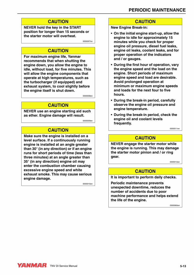
PERIODIC MAINTENANCE
CAUTIONNEVER hold the key in the START position for longer than 15 seconds or the starter motor will overheat.
0000007en
CAUTIONFor maximum engine life, Yanmar recommends that when shutting the engine down, you allow the engine to idle, without load, for five minutes. This will allow the engine components that operate at high temperatures, such as the turbocharger (if equipped) and exhaust system, to cool slightly before the engine itself is shut down.
0000008en
CAUTIONNEVER use an engine starting aid such as ether. Engine damage will result.
0000009en
CAUTIONMake sure the engine is installed on a level surface. If a continuously running engine is installed at an angle greater than 30° (in any direction) or if an engine runs for short periods of time (less than three minutes) at an angle greater than 35° (in any direction) engine oil may enter the combustion chamber causing excessive engine speed and white exhaust smoke. This may cause serious engine damage.
0000010en
CAUTIONNew Engine Break-in:
• On the initial engine start-up, allow the engine to idle for approximately 15 minutes while you check for proper engine oil pressure, diesel fuel leaks, engine oil leaks, coolant leaks, and for proper operation of the indicators and / or gauges.
• During the first hour of operation, vary the engine speed and the load on the engine. Short periods of maximum engine speed and load are desirable. Avoid prolonged operation at minimum or maximum engine speeds and loads for the next four to five hours.
• During the break-in period, carefully observe the engine oil pressure and engine temperature.
• During the break-in period, check the engine oil and coolant levels frequently.
0000011en
CAUTIONNEVER engage the starter motor while the engine is running. This may damage the starter motor pinion and / or ring gear.
0000012en
CAUTIONIt is important to perform daily checks.
Periodic maintenance prevents unexpected downtime, reduces the number of accidents due to poor machine performance and helps extend the life of the engine.
0000060en
TNV DI Service Manual 5-13
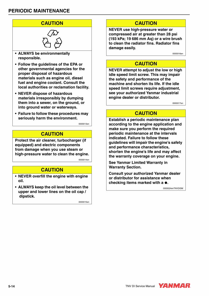
PERIODIC MAINTENANCE
CAUTION
• ALWAYS be environmentally responsible.
• Follow the guidelines of the EPA or other governmental agencies for the proper disposal of hazardous materials such as engine oil, diesel fuel and engine coolant. Consult the local authorities or reclamation facility.
• NEVER dispose of hazardous materials irresponsibly by dumping them into a sewer, on the ground, or into ground water or waterways.
• Failure to follow these procedures may seriously harm the environment.
0000013en
CAUTIONProtect the air cleaner, turbocharger (if equipped) and electric components from damage when you use steam or high-pressure water to clean the engine.
0000014en
CAUTION• NEVER overfill the engine with engine
oil.
• ALWAYS keep the oil level between the upper and lower lines on the oil cap /dipstick.
0000015en
CAUTIONNEVER use high-pressure water or compressed air at greater than 28 psi (193 kPa; 19 686 mm Aq) or a wire brush to clean the radiator fins. Radiator fins damage easily.
0000016en
CAUTIONNEVER attempt to adjust the low or high idle speed limit screw. This may impair the safety and performance of the machine and shorten its life. If the idle speed limit screws require adjustment, see your authorized Yanmar industrial engine dealer or distributor.
0000017en
CAUTIONEstablish a periodic maintenance plan according to the engine application and make sure you perform the required periodic maintenance at the intervals indicated. Failure to follow these guidelines will impair the engine’s safety and performance characteristics, shorten the engine’s life and may affect the warranty coverage on your engine.
See Yanmar Limited Warranty in Warranty Section.
Consult your authorized Yanmar dealer or distributor for assistance when checking items marked with a .
0000024enTNVDISM
5-14 TNV DI Service Manual

PERIODIC MAINTENANCE
CAUTIONIf the fuel filter / water separator is positioned higher than the fuel level in the fuel tank, water may not drip out when the fuel filter / water separator drain cock is opened. If this happens, turn the air vent screw on the top of the fuel filter / water separator 2-3 turns counterclockwise.
Be sure to tighten the air vent screw after the water has drained out.
0000025en
CAUTION• When the engine is operated in dusty
conditions, clean the air cleaner element more frequently.
• NEVER operate the engine with the air cleaner element(s) removed. This may allow foreign material to enter the engine and damage it.
0000026en
CAUTIONThe maximum air intake restriction, in terms of differential pressure measurement, must not exceed 0.90 psi (6.23 kPa; 635 mmAq). Clean or replace the air cleaner element if the air intake restriction exceeds the above mentioned value.
0000046en
TNV DI Service Manual 5-15

PERIODIC MAINTENANCE
INTRODUCTIONThis section of the Service Manual describes the procedures for proper care and maintenance of the engine.
The Importance of Periodic MaintenanceEngine deterioration and wear occurs in proportion to length of time the engine has been in service and the conditions the engine is subject to during operation. Periodic maintenance prevents unexpected downtime, reduces the number of accidents due to poor machine performance and helps extend the life of the engine.
Performing Periodic Maintenance
Perform periodic maintenance procedures in an open, level area free from traffic. If possible, perform the procedures indoors to prevent environmental conditions, such as rain, wind, or snow, from damaging the machine.
Yanmar Replacement PartsYanmar recommends that you use genuine Yanmar parts when replacement parts are needed. Genuine replacement parts help ensure long engine life.
Required EPA / ARB Maintenance -USA OnlyTo maintain optimum engine performance and compliance with the Environmental Protection Agency (EPA) Regulations Non-road Engines and the California Air Resources Board (ARB, California), it is essential that you follow the Periodic Maintenance Schedule on page 5-17 and Periodic Maintenance Procedures on page 5-19.
EPA / ARB Installation Requirements - USA OnlyThe following are the installation requirements for the EPA / ARB. Unless these requirements are met, the exhaust gas emissions will not be within the limits specified by the EPA and ARB.
Maximum Exhaust Gas Restriction shall be:
• 3TNV84T: 1.42 psi (9.81 kPa; 1000 mm Aq) or less
• 4TNV84T and 4TNV98T: 1.71 psi (11.77 kPa; 1200 mm Aq) or Iess
• 3TNV82A, 3TNV84, 3TNV88, 4TNV94, 4TNV88, 4TNV94L, and 4TNV98: 2.22 psi (15.3 kPa; 1560 mm Aq) or Iess
Maximum air intake restriction shall be 0.90 psi (6.23 kPa; 635 mm Aq) or less. Clean or replace the air cleaner element if the air intake restriction exceeds the above mentioned value.
A WARNING
EXHAUST HAZARD!• NEVER operate the engine in an
enclosed area such as a garage, tunnel, underground room, manhole or ship’s hold without proper ventilation.
• NEVER block windows, vents, or other means of ventilation if the engine is operating in an enclosed area. All internal combustion engines create carbon monoxide gas during operation. Accumulation of this gas within an enclosure could cause illness or even death.
• Make sure that all connections are tightened to specifications after repair is made to the exhaust system.
• Failure to comply could result in death or serious injury.
0000003en
5-16 TNV DI Service Manual

PERIODIC MAINTENANCE
PERIODIC MAINTENANCE SCHEDULEDaily and periodic maintenance is important to keep the engine in good operating condition. The following is a summary of maintenance items by periodic maintenance intervals. Periodic maintenance intervals vary depending on engine application, loads, diesel fuel and engine oil used and are hard to establish definitively. The following should be treated only as a general guideline.
CAUTIONEstablish a periodic maintenance plan according to the engine application and make sure you perform the required periodic maintenance at the intervals indicated. Failure to follow these guidelines will impair the engine’s safety and performance characteristics, shorten the engine’s life and may affect the warranty coverage on your engine.
See Yanmar Limited Warranty in Warranty Section.
Consult your authorized Yanmar dealer or distributor for assistance when checking items marked with a .
0000024enTNVDISM
TNV DI Service Manual 5-17
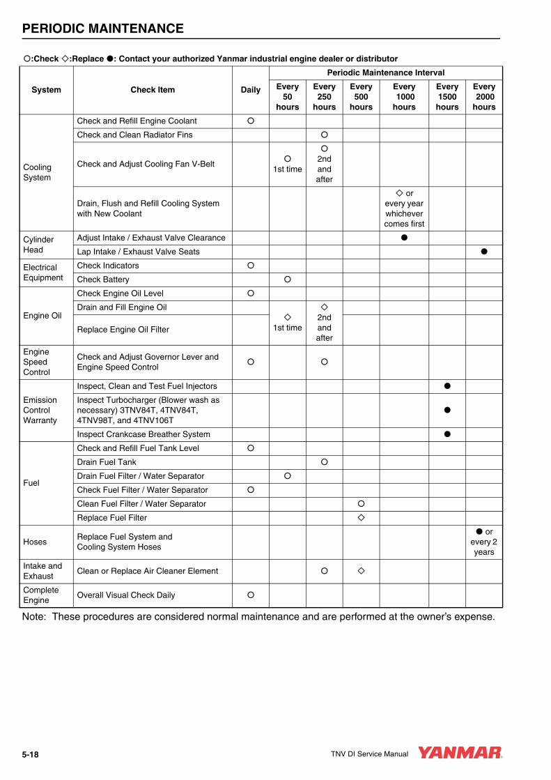
PERIODIC MAINTENANCE
Note: These procedures are considered normal maintenance and are performed at the owner’s expense.
:Check :Replace : Contact your authorized Yanmar industrial engine dealer or distributor
System Check Item Daily
Periodic Maintenance Interval
Every50
hours
Every250
hours
Every500
hours
Every 1000hours
Every 1500
hours
Every 2000hours
CoolingSystem
Check and Refill Engine Coolant
Check and Clean Radiator Fins
Check and Adjust Cooling Fan V-Belt 1st time
2nd and after
Drain, Flush and Refill Cooling System with New Coolant
orevery year whichever comes first
CylinderHead
Adjust Intake / Exhaust Valve Clearance
Lap Intake / Exhaust Valve Seats
ElectricalEquipment
Check Indicators
Check Battery
Engine Oil
Check Engine Oil Level
Drain and Fill Engine Oil
1st time2nd and after
Replace Engine Oil Filter
Engine Speed Control
Check and Adjust Governor Lever and Engine Speed Control
Emission Control Warranty
Inspect, Clean and Test Fuel Injectors
Inspect Turbocharger (Blower wash as necessary) 3TNV84T, 4TNV84T, 4TNV98T, and 4TNV106T
Inspect Crankcase Breather System
Fuel
Check and Refill Fuel Tank Level
Drain Fuel Tank
Drain Fuel Filter / Water Separator
Check Fuel Filter / Water Separator
Clean Fuel Filter / Water Separator
Replace Fuel Filter
HosesReplace Fuel System and Cooling System Hoses
or every 2 years
Intake and Exhaust
Clean or Replace Air Cleaner Element
Complete Engine
Overall Visual Check Daily
5-18 TNV DI Service Manual
PERIODIC MAINTENANCE
PERIODIC MAINTENANCE PROCEDURES
Perform the following maintenance after the initial 50 hours of operation.
• Replace Engine Oil and Engine Oil Filter
• Check and Adjust Cooling Fan V-Belt
Replace Engine Oil and Engine Oil Filter
After Initial 50 Hours of Operation
A WARNING
BURN HAZARD!• If you must drain the engine oil while it
is still hot, stay clear of the hot engine oil to avoid being burned.
• ALWAYS wear eye protection.
• Failure to comply could result in death or serious injury.
0000011en
A WARNINGSUDDEN MOVEMENT HAZARD!
• Engaging the transmission or PTO at an elevated engine speed could result in unexpected movement of the equipment.
• Failure to comply could result in death or serious injury.
0000006en
CAUTION• Only use the engine oil specified.
Other engine oils may affect warranty coverage, cause internal engine components to seize and / or shorten engine life.
• Prevent dirt and debris from contaminating the engine oil. Carefully clean the oil cap / dipstick and the surrounding area before you remove the cap.
• NEVER mix different types of engine oil. This may adversely affect the lubricating properties of the engine oil.
• NEVER overfill. Overfilling may result in white exhaust smoke, engine overspeed or internal damage.
0000005en
CAUTION
• ALWAYS be environmentally responsible.
• Follow the guidelines of the EPA or other governmental agencies for the proper disposal of hazardous materials such as engine oil, diesel fuel and engine coolant. Consult the local authorities or reclamation facility.
• NEVER dispose of hazardous materials irresponsibly by dumping them into a sewer, on the ground, or into ground water or waterways.
• Failure to follow these procedures may seriously harm the environment.
0000013en
TNV DI Service Manual 5-19

PERIODIC MAINTENANCE
The engine oil in a new engine becomes contaminated from the initial break-in of internal parts. It is very important that the initial oil and filter change is performed as scheduled.
Note: The oil drain plug may be in another location if an optional oil pan is used.
Drain the engine oil as follows:
1. Make sure the engine is level.
2. Start the engine and bring it up to operating temperature.
3. Stop the engine.
4. Remove one of the oil filler caps (Figure 5-1, (1)) to vent the engine crankcase and allow the engine oil to drain more easily.
5. Position a container under the engine to collect waste oil.
Figure 5-1
6. Remove the oil drain plug (Figure 5-2, (1)) from the engine oil pan. Allow oil to drain.
7. After all oil has been drained from the engine, reinstall the oil drain plug (Figure 5-2, (1)) and tighten to 14 - 17 ft·lb (19.6 - 23.5 N·m; 2.0 - 2.4 kgf·m).
8. Dispose of used oil properly.
Remove the engine oil filter as follows:1. Turn the engine oil filter (Figure 5-2, (2))
counterclockwise (Figure 5-2, (3)) using a filter wrench.
Figure 5-2
2. Clean the engine oil filter mounting face.
3. Lightly coat the gasket on the new oil filter with engine oil. Install the new engine oil filter manually by turning it clockwise (Figure 5-2, (4)) until it contacts the mounting surface. Tighten an additional 3/4 of a turn using the filter wrench.
0000084
(1)
(1)
0000084B
Applicable Engine Oil Filter Part No.
3TNV82A, 3TNV84, 3TNV84T, 3TNV88, 4TNV84, 4TNV84T, 4TNV88, 4TNV94L4TNV98, 4TNV98T
129150-35152
4TNV106, 4TNV106T 119005-35100
0000062B
(3)
(4)
(2)
(1)
5-20 TNV DI Service Manual

PERIODIC MAINTENANCE
4. Add new engine oil to the engine as specified in Adding Engine Oil on page 4-14.
5. Warm up the engine by running it for five minutes and check for any engine oil leaks.
6. After engine is warm, shut it off and let it sit for 10 minutes.
7. Recheck the engine oil level.
8. Add engine oil (Figure 5-3, (5)) as needed until the level is between the upper (Figure 5-3, (2)) and lower lines (Figure 5-3, (3)) shown on the dipstick (Figure 5-3, (1)).
Figure 5-3
9. Reinstall the oil filler cap (Figure 5-3, (4)). If any engine oil is spilled, wipe it away with a clean cloth.
Check and Adjust Cooling Fan V-BeltThe V-belt will slip if it does not have the proper tension. This will prevent the alternator from generating sufficient power. Also, the engine will overheat due to the engine coolant pump pulley slipping.
Check and adjust the V-belt tension (deflection) as follows:
1. Press the V-belt down with your thumb with a force of approximately 22 ft·lb (98 N·m; 10 kgf) to check the deflection.
There are three positions to check for V-belt tension (Figure 5-4, (A), (B) and (C)). You can check the tension at whichever position is the most accessible. The proper deflection of a used V-belt at each position is:
Note: A “Used V-Belt” refers to a V-belt which has been used on a running engine for five minutes or more.
Figure 5-4
CAUTION• NEVER overfill the engine with engine
oil.
• ALWAYS keep the oil level between the upper and lower lines on the oil cap /dipstick.
0000015en
(3)
(1)(2)
(4)
(4)
(5)
0000007C
Used V-Belt Tension
A B C
3/8 - 1/2 in.(10 - 14 mm)
1/4 - 3/8 in.(7 - 10 mm)
5/16 - 1/2 in.(9 - 13 mm)
(A)
0000063B
(B)
(C)
TNV DI Service Manual 5-21

PERIODIC MAINTENANCE
2. If necessary, adjust the V-belt tension. Loosen the adjusting bolt (Figure 5-5, (1)) and move the alternator (Figure 5-5, (2)) with a pry bar (Figure 5-5, (3)) to tighten the V-belt to the desired tension. Then tighten the adjusting bolt.
Figure 5-5
3. Tighten the V-belt to the proper tension. There must be clearance (Figure 5-6, (1)) between the V-belt and the bottom of the pulley groove. If there is no clearance (Figure 5-6, (2)) between the V-belt and the bottom of the pulley groove, replace the V-belt.
Figure 5-6
4. Check the V-belt for cracks, oil or wear. If any of these conditions exist, replace the V-belt.
5. Install the new V-belt. Refer to the table for proper tension.
6. After adjusting, run the engine for 5 minutes or more. Check the tension again using the specifications for a used V-belt.
0000064B(2)
(1)
(3)
0000584
(2)
(1)
New V-Belt Tension
A B C
5/16 - 7/16 in.(8 - 12 mm)
3/16 - 5/16 in.(5 - 8 mm)
1/4 - 7/16 in.(7 - 11 mm)
Used V-Belt Tension
A B C
3/8 - 1/2 in.(10 - 14 mm)
1/4 - 3/8 in.(7 - 10 mm)
5/16 - 1/2 in.(9 - 13 mm)
5-22 TNV DI Service Manual

PERIODIC MAINTENANCE
After you complete the initial 50 hour maintenance procedures, perform the following procedures every 50 hours thereafter.
• Drain Fuel Filter / Water Separator
• Check Battery
Drain Fuel Filter / Water Separator
Drain the fuel filter / water separator whenever there are contaminants, such as water, collected in the bottom of the cup. NEVER wait until the scheduled periodic maintenance if contaminants are discovered.
Every 50 Hours of Operation
A DANGER
FIRE AND EXPLOSION HAZARD!• Diesel fuel is flammable and explosive
under certain conditions.
• When you remove any fuel system component to perform maintenance (such as changing the fuel filter) place an approved container under the opening to catch the fuel.
• NEVER use a shop rag to catch the fuel. Vapors from the rag are flammable and explosive.
• Wipe up any spills immediately.
• Wear eye protection. The fuel system is under pressure and fuel could spray out when you remove any fuel system component.
• Failure to comply will result in death or serious injury.
0000009en
CAUTIONIf the fuel filter / water separator is positioned higher than the fuel level in the fuel tank, water may not drip out when the fuel filter / water separator drain cock is opened. If this happens, turn the air vent screw on the top of the fuel filter / water separator 2-3 turns counterclockwise.
Be sure to tighten the air vent screw after the water has drained out.
0000025en
CAUTION
• ALWAYS be environmentally responsible.
• Follow the guidelines of the EPA or other governmental agencies for the proper disposal of hazardous materials such as engine oil, diesel fuel and engine coolant. Consult the local authorities or reclamation facility.
• NEVER dispose of hazardous materials irresponsibly by dumping them into a sewer, on the ground, or into ground water or waterways.
• Failure to follow these procedures may seriously harm the environment.
0000013en
TNV DI Service Manual 5-23
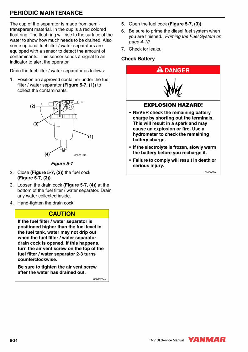
PERIODIC MAINTENANCE
The cup of the separator is made from semi-transparent material. In the cup is a red colored float ring. The float ring will rise to the surface of the water to show how much needs to be drained. Also, some optional fuel filter / water separators are equipped with a sensor to detect the amount of contaminants. This sensor sends a signal to an indicator to alert the operator.
Drain the fuel filter / water separator as follows:
1. Position an approved container under the fuel filter / water separator (Figure 5-7, (1)) to collect the contaminants.
Figure 5-7
2. Close (Figure 5-7, (2)) the fuel cock (Figure 5-7, (3)).
3. Loosen the drain cock (Figure 5-7, (4)) at the bottom of the fuel filter / water separator. Drain any water collected inside.
4. Hand-tighten the drain cock.
5. Open the fuel cock (Figure 5-7, (3)).
6. Be sure to prime the diesel fuel system when you are finished. Priming the Fuel System on page 4-12.
7. Check for leaks.
Check Battery
CAUTIONIf the fuel filter / water separator is positioned higher than the fuel level in the fuel tank, water may not drip out when the fuel filter / water separator drain cock is opened. If this happens, turn the air vent screw on the top of the fuel filter / water separator 2-3 turns counterclockwise.
Be sure to tighten the air vent screw after the water has drained out.
0000025en
0000012C
(1)
(4)
(3)
(2)
A DANGER
EXPLOSION HAZARD!• NEVER check the remaining battery
charge by shorting out the terminals. This will result in a spark and may cause an explosion or fire. Use a hydrometer to check the remaining battery charge.
• If the electrolyte is frozen, slowly warm the battery before you recharge it.
• Failure to comply will result in death or serious injury.
0000007en
5-24 TNV DI Service Manual

PERIODIC MAINTENANCE
• When the amount of fluid nears the lower limit (Figure 5-8, (1)), fill with distilled water (Figure 5-8, (2)) so it is at the upper limit (Figure 5-8, (3)). If operation continues with insufficient battery fluid, the battery life is shortened, and the battery may overheat and explode. During the summer, check the fluid level more often than specified.
Figure 5-8
• If the engine cranking speed is so slow that the engine does not start, recharge the battery.
• If the engine still will not start after charging, have your authorized Yanmar industrial engine dealer or distributor check the battery and the engine’s starting system.
• If operating the machine where the ambient temperature could drop to 5°F (-15°C) or less, remove the battery from the machine at the end of the day. Store the battery in a warm place until the next use. This will help start the engine easily at low ambient temperatures.
A WARNING
BURN HAZARD!• Batteries contain sulfuric acid. NEVER
allow battery fluid to come in contact with clothing, skin or eyes. Severe burns could result. ALWAYS wear safety goggles and protective clothing when servicing the battery. If battery fluid contacts the eyes and / or skin, immediately flush the affected area with a large amount of clean water and obtain prompt medical treatment.
• Failure to comply could result in death or serious injury.
0000007en
CAUTION
• ALWAYS be environmentally responsible.
• Follow the guidelines of the EPA or other governmental agencies for the proper disposal of hazardous materials such as engine oil, diesel fuel and engine coolant. Consult the local authorities or reclamation facility.
• NEVER dispose of hazardous materials irresponsibly by dumping them into a sewer, on the ground, or into ground water or waterways.
• Failure to follow these procedures may seriously harm the environment.
0000013en
0000067A
(3)
(1)
(2)
TNV DI Service Manual 5-25
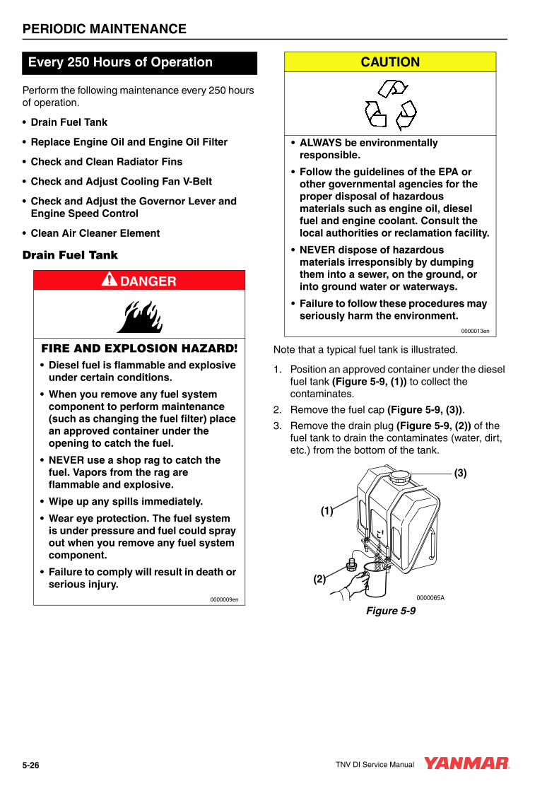
PERIODIC MAINTENANCE
Perform the following maintenance every 250 hours of operation.
• Drain Fuel Tank
• Replace Engine Oil and Engine Oil Filter
• Check and Clean Radiator Fins
• Check and Adjust Cooling Fan V-Belt
• Check and Adjust the Governor Lever and Engine Speed Control
• Clean Air Cleaner Element
Drain Fuel Tank
Note that a typical fuel tank is illustrated.
1. Position an approved container under the diesel fuel tank (Figure 5-9, (1)) to collect the contaminates.
2. Remove the fuel cap (Figure 5-9, (3)).
3. Remove the drain plug (Figure 5-9, (2)) of the fuel tank to drain the contaminates (water, dirt, etc.) from the bottom of the tank.
Figure 5-9
Every 250 Hours of Operation
A DANGER
FIRE AND EXPLOSION HAZARD!• Diesel fuel is flammable and explosive
under certain conditions.
• When you remove any fuel system component to perform maintenance (such as changing the fuel filter) place an approved container under the opening to catch the fuel.
• NEVER use a shop rag to catch the fuel. Vapors from the rag are flammable and explosive.
• Wipe up any spills immediately.
• Wear eye protection. The fuel system is under pressure and fuel could spray out when you remove any fuel system component.
• Failure to comply will result in death or serious injury.
0000009en
CAUTION
• ALWAYS be environmentally responsible.
• Follow the guidelines of the EPA or other governmental agencies for the proper disposal of hazardous materials such as engine oil, diesel fuel and engine coolant. Consult the local authorities or reclamation facility.
• NEVER dispose of hazardous materials irresponsibly by dumping them into a sewer, on the ground, or into ground water or waterways.
• Failure to follow these procedures may seriously harm the environment.
0000013en
0000065A
(1)
(2)
(3)
5-26 TNV DI Service Manual

PERIODIC MAINTENANCE
4. Drain the tank until clean diesel fuel with no water and dirt flows out. Reinstall and tighten the drain plug firmly.
5. Reinstall the fuel cap.
6. Check for leaks.
Replace Engine Oil and Engine Oil Filter
Change the engine oil every 250 hours of operation after the initial change at 50 hours. Replace the engine oil filter at the same time. See Replace Engine Oil and Engine Oil Filter on page 5-19.
CAUTION• Only use the engine oil specified.
Other engine oils may affect warranty coverage, cause internal engine components to seize and / or shorten engine life.
• Prevent dirt and debris from contaminating the engine oil. Carefully clean the oil cap / dipstick and the surrounding area before you remove the cap.
• NEVER mix different types of engine oil. This may adversely affect the lubricating properties of the engine oil.
• NEVER overfill. Overfilling may result in white exhaust smoke, engine overspeed or internal damage.
0000005en
CAUTION
• ALWAYS be environmentally responsible.
• Follow the guidelines of the EPA or other governmental agencies for the proper disposal of hazardous materials such as engine oil, diesel fuel and engine coolant. Consult the local authorities or reclamation facility.
• NEVER dispose of hazardous materials irresponsibly by dumping them into a sewer, on the ground, or into ground water or waterways.
• Failure to follow these procedures may seriously harm the environment.
0000013en
TNV DI Service Manual 5-27
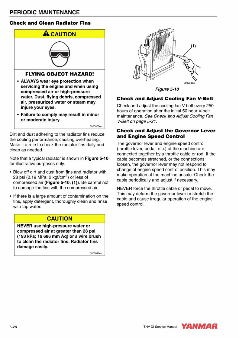
PERIODIC MAINTENANCE
Check and Clean Radiator Fins
Dirt and dust adhering to the radiator fins reduce the cooling performance, causing overheating. Make it a rule to check the radiator fins daily and clean as needed.
Note that a typical radiator is shown in Figure 5-10 for illustrative purposes only.
• Blow off dirt and dust from fins and radiator with 28 psi (0.19 MPa; 2 kgf/cm2) or less of compressed air (Figure 5-10, (1)). Be careful not to damage the fins with the compressed air.
• If there is a large amount of contamination on the fins, apply detergent, thoroughly clean and rinse with tap water.
Figure 5-10
Check and Adjust Cooling Fan V-BeltCheck and adjust the cooling fan V-belt every 250 hours of operation after the initial 50 hour V-belt maintenance. See Check and Adjust Cooling Fan V-Belt on page 5-21.
Check and Adjust the Governor Lever and Engine Speed ControlThe governor lever and engine speed control (throttle lever, pedal, etc.) of the machine are connected together by a throttle cable or rod. If the cable becomes stretched, or the connections loosen, the governor lever may not respond to change of engine speed control position. This may make operation of the machine unsafe. Check the cable periodically and adjust if necessary.
NEVER force the throttle cable or pedal to move. This may deform the governor lever or stretch the cable and cause irregular operation of the engine speed control.
A CAUTION
FLYING OBJECT HAZARD!• ALWAYS wear eye protection when
servicing the engine and when using compressed air or high-pressure water. Dust, flying debris, compressed air, pressurized water or steam may injure your eyes.
• Failure to comply may result in minor or moderate injury.
0000003en
CAUTIONNEVER use high-pressure water or compressed air at greater than 28 psi (193 kPa; 19 686 mm Aq) or a wire brush to clean the radiator fins. Radiator fins damage easily.
0000016en
FULL
LOW
0000085A
(1)
5-28 TNV DI Service Manual

PERIODIC MAINTENANCE
Checking and adjusting the governor lever:
1. Check that the governor lever (Figure 5-11, (1)) makes uniform contact with the high idle (Figure 5-11, (2)) and low idle (Figure 5-11, (3)) speed limit screws when the engine speed control is in the high idle speed or low idle speed position.
Figure 5-11
2. If the governor lever does not make contact with the high idle or low idle speed limit screw, adjust the throttle cable.
3. In some engine speed control applications, loosen the throttle cable lock nut (Figure 5-11, (4)) and adjust the cable so the governor lever makes proper contact with the high / low idle speed limit screw.
Clean Air Cleaner ElementNote that a typical air cleaner is shown in Figure 5-12 and Figure 5-13 for illustrative purposes only.
The engine performance is adversely affected when the air cleaner element is clogged with dust. Be sure to clean the air filter element periodically.
1. Unlatch and remove the air cleaner cover (Figure 5-12, (1)).
Figure 5-12
2. Remove the element (Figure 5-12, (2)) (outer element if equipped with two elements).
CAUTIONNEVER attempt to adjust the low or high idle speed limit screw. This may impair the safety and performance of the machine and shorten its life. If the idle speed limit screws require adjustment, see your authorized Yanmar industrial engine dealer or distributor.
0000017en
0000069A
(4)
(3)
(1)
(2)
A CAUTION
FLYING OBJECT HAZARD!• ALWAYS wear eye protection when
servicing the engine and when using compressed air or high-pressure water. Dust, flying debris, compressed air, pressurized water or steam may injure your eyes.
• Failure to comply may result in minor or moderate injury.
0000003en
0000070A
(3)
(6) (4) (2)(5)
(1)
TNV DI Service Manual 5-29
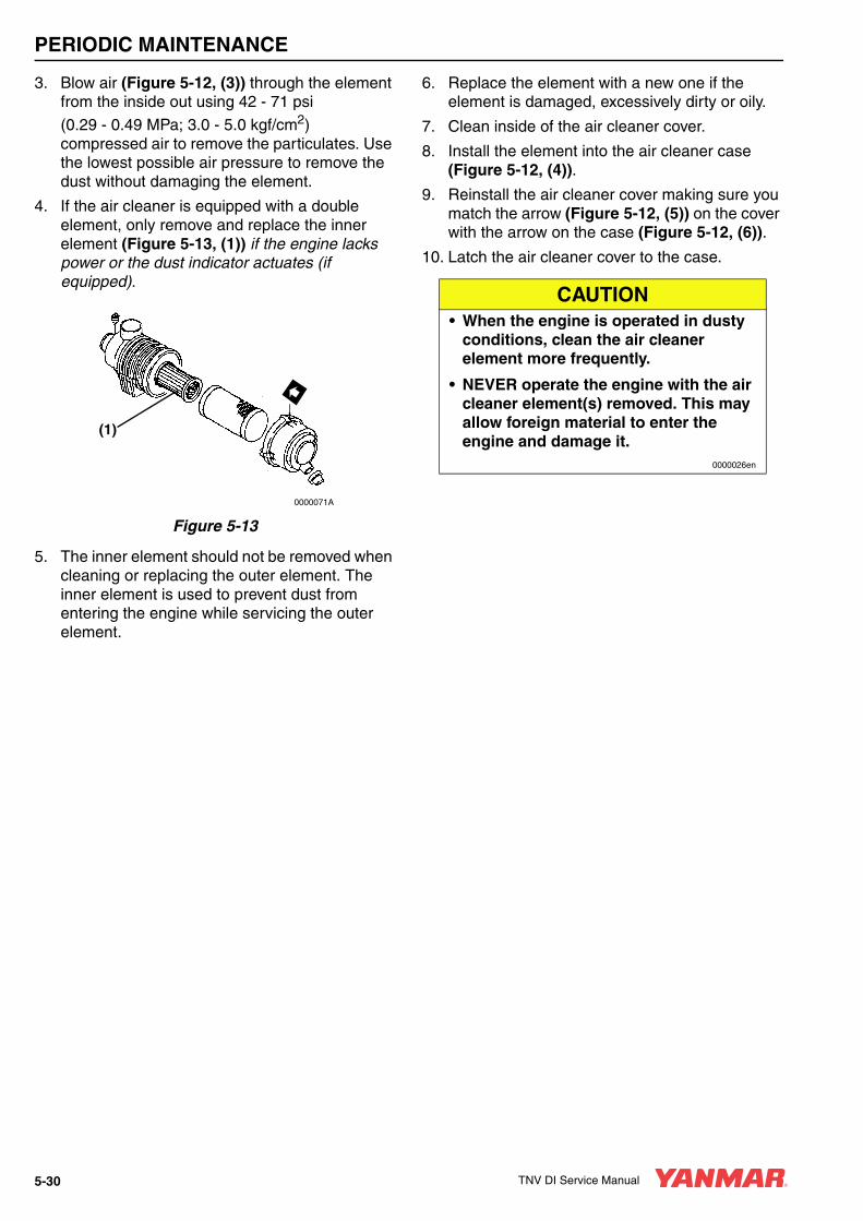
PERIODIC MAINTENANCE
3. Blow air (Figure 5-12, (3)) through the element from the inside out using 42 - 71 psi
(0.29 - 0.49 MPa; 3.0 - 5.0 kgf/cm2) compressed air to remove the particulates. Use the lowest possible air pressure to remove the dust without damaging the element.
4. If the air cleaner is equipped with a double element, only remove and replace the inner element (Figure 5-13, (1)) if the engine lacks power or the dust indicator actuates (if equipped).
Figure 5-13
5. The inner element should not be removed when cleaning or replacing the outer element. The inner element is used to prevent dust from entering the engine while servicing the outer element.
6. Replace the element with a new one if the element is damaged, excessively dirty or oily.
7. Clean inside of the air cleaner cover.
8. Install the element into the air cleaner case (Figure 5-12, (4)).
9. Reinstall the air cleaner cover making sure you match the arrow (Figure 5-12, (5)) on the cover with the arrow on the case (Figure 5-12, (6)).
10. Latch the air cleaner cover to the case.
0000071A
(1)
CAUTION• When the engine is operated in dusty
conditions, clean the air cleaner element more frequently.
• NEVER operate the engine with the air cleaner element(s) removed. This may allow foreign material to enter the engine and damage it.
0000026en
5-30 TNV DI Service Manual

PERIODIC MAINTENANCE
Perform the following maintenance every 500 hours of operation.
• Replace Air Cleaner Element
• Replace Fuel Filter
• Clean Fuel Filter / Water Separator
Replace Air Cleaner Element
Replace the air cleaner element (Figure 5-12, (2)) every 500 hours even if it is not damaged or dirty.
When replacing the element, clean the inside of the air cleaner case (Figure 5-12, (4)).
If the air cleaner is equipped with a double element, only remove and replace the inner element (Figure 5-13, (1)) if the engine lacks power or the dust indicator actuates (if equipped). This is in addition to replacing the outer element.
Replace Fuel FilterEvery 500 Hours of Operation
CAUTIONThe maximum air intake restriction, in terms of differential pressure measurement, must not exceed 0.90 psi (6.23 kPa; 635 mmAq). Clean or replace the air cleaner element if the air intake restriction exceeds the above mentioned value.
0000046en
A DANGER
FIRE AND EXPLOSION HAZARD!• Diesel fuel is flammable and explosive
under certain conditions.
• When you remove any fuel system component to perform maintenance (such as changing the fuel filter) place an approved container under the opening to catch the fuel.
• NEVER use a shop rag to catch the fuel. Vapors from the rag are flammable and explosive.
• Wipe up any spills immediately.
• Wear eye protection. The fuel system is under pressure and fuel could spray out when you remove any fuel system component.
• Failure to comply will result in death or serious injury.
0000009en
CAUTIONFor maximum engine life, Yanmar recommends that when shutting the engine down, you allow the engine to idle, without load, for five minutes. This will allow the engine components that operate at high temperatures, such as the turbocharger (if equipped) and exhaust system, to cool slightly before the engine itself is shut down.
0000008en
TNV DI Service Manual 5-31

PERIODIC MAINTENANCE
Replace the fuel filter at specified intervals to prevent contaminants from adversely affecting the diesel fuel flow.
1. Stop the engine and allow it to cool.
2. Close the fuel cock of the fuel filter / water separator.
3. Remove the fuel filter with a filter wrench, turning it to the left (Figure 5-14, (1)). When removing the fuel filter, carefully hold it to prevent the fuel from spilling. Wipe up all spilled fuel.
Figure 5-14
4. Clean the filter mounting surface and apply a small amount of diesel fuel to the gasket of the new fuel filter.
5. Install the new fuel filter. Turn to the right (Figure 5-14, (2)) and hand-tighten it only until it comes in contact with the mounting surface. Use a filter wrench to tighten it one additional turn.
6. Open the fuel cock of the fuel filter / water separator.
7. Prime the fuel system. See Priming the Fuel System on page 4-12.
8. Check for leaks.
CAUTION
• ALWAYS be environmentally responsible.
• Follow the guidelines of the EPA or other governmental agencies for the proper disposal of hazardous materials such as engine oil, diesel fuel and engine coolant. Consult the local authorities or reclamation facility.
• NEVER dispose of hazardous materials irresponsibly by dumping them into a sewer, on the ground, or into ground water or waterways.
• Failure to follow these procedures may seriously harm the environment.
0000013en
Applicable Fuel Filter Part No.
All models except4TNV98T, 4TNV106, 4TNV106T
119802-55800
4TNV98T, 4TNV106, 4TNV106T
123907-55800
0000072A
(2)(1)
5-32 TNV DI Service Manual
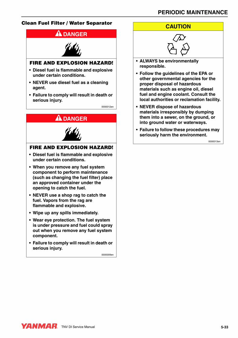
PERIODIC MAINTENANCE
Clean Fuel Filter / Water Separator
A DANGER
FIRE AND EXPLOSION HAZARD!• Diesel fuel is flammable and explosive
under certain conditions.
• NEVER use diesel fuel as a cleaning agent.
• Failure to comply will result in death or serious injury.
0000012en
A DANGER
FIRE AND EXPLOSION HAZARD!• Diesel fuel is flammable and explosive
under certain conditions.
• When you remove any fuel system component to perform maintenance (such as changing the fuel filter) place an approved container under the opening to catch the fuel.
• NEVER use a shop rag to catch the fuel. Vapors from the rag are flammable and explosive.
• Wipe up any spills immediately.
• Wear eye protection. The fuel system is under pressure and fuel could spray out when you remove any fuel system component.
• Failure to comply will result in death or serious injury.
0000009en
CAUTION
• ALWAYS be environmentally responsible.
• Follow the guidelines of the EPA or other governmental agencies for the proper disposal of hazardous materials such as engine oil, diesel fuel and engine coolant. Consult the local authorities or reclamation facility.
• NEVER dispose of hazardous materials irresponsibly by dumping them into a sewer, on the ground, or into ground water or waterways.
• Failure to follow these procedures may seriously harm the environment.
0000013en
TNV DI Service Manual 5-33
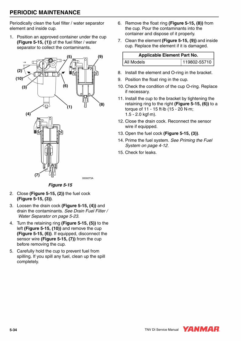
PERIODIC MAINTENANCE
Periodically clean the fuel filter / water separator element and inside cup.
1. Position an approved container under the cup (Figure 5-15, (1)) of the fuel filter / water separator to collect the contaminants.
Figure 5-15
2. Close (Figure 5-15, (2)) the fuel cock (Figure 5-15, (3)).
3. Loosen the drain cock (Figure 5-15, (4)) and drain the contaminants. See Drain Fuel Filter /Water Separator on page 5-23.
4. Turn the retaining ring (Figure 5-15, (5)) to the left (Figure 5-15, (10)) and remove the cup (Figure 5-15, (6)). If equipped, disconnect the sensor wire (Figure 5-15, (7)) from the cup before removing the cup.
5. Carefully hold the cup to prevent fuel from spilling. If you spill any fuel, clean up the spill completely.
6. Remove the float ring (Figure 5-15, (8)) from the cup. Pour the contaminants into the container and dispose of it properly.
7. Clean the element (Figure 5-15, (9)) and inside cup. Replace the element if it is damaged.
8. Install the element and O-ring in the bracket.
9. Position the float ring in the cup.
10. Check the condition of the cup O-ring. Replace if necessary.
11. Install the cup to the bracket by tightening the retaining ring to the right (Figure 5-15, (6)) to a torque of 11 - 15 ft·lb (15 - 20 N·m; 1.5 - 2.0 kgf·m).
12. Close the drain cock. Reconnect the sensor wire if equipped.
13. Open the fuel cock (Figure 5-15, (3)).
14. Prime the fuel system. See Priming the Fuel System on page 4-12.
15. Check for leaks.
0000073A
(2)
(10)
(1)
(3)
(4)
(6)
(5) (9)
(8)
(7)
Applicable Element Part No.
All Models 119802-55710
5-34 TNV DI Service Manual

PERIODIC MAINTENANCE
Perform the following maintenance every 1000 hours of operation.
• Drain, Flush and Refill Cooling System With New Coolant
• Adjust Intake / Exhaust Valve Clearance
Drain, Flush and Refill Cooling System With New Coolant
Every 1000 Hours of Operation
A DANGER
SCALD HAZARD!• NEVER remove the radiator cap if the
engine is hot. Steam and hot engine coolant will spurt out and seriously burn you. Allow the engine to cool down before you attempt to remove the radiator cap.
• Tighten the radiator cap securely after you check the radiator. Steam can spurt out during engine operation if the cap is loose.
• ALWAYS check the level of the engine coolant by observing the reserve tank.
• Failure to comply will result in death or serious injury.
0000002en
A WARNING
BURN HAZARD!• Wait until the engine cools before you
drain the engine coolant. Hot engine coolant may splash and burn you.
• Failure to comply could result in death or serious injury.
0000016en
A CAUTION
COOLANT HAZARD!• Wear eye protection and rubber gloves
when you handle long life or extended life engine coolant. If contact with the eyes or skin should occur, flush eyes and wash immediately with clean water.
• Failure to comply may result in minor or moderate injury.
0000005en
TNV DI Service Manual 5-35
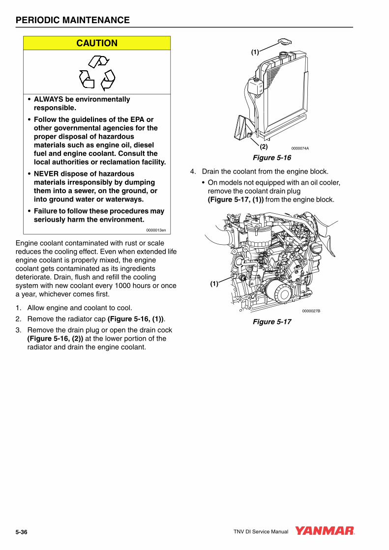
PERIODIC MAINTENANCE
Engine coolant contaminated with rust or scale reduces the cooling effect. Even when extended life engine coolant is properly mixed, the engine coolant gets contaminated as its ingredients deteriorate. Drain, flush and refill the cooling system with new coolant every 1000 hours or once a year, whichever comes first.
1. Allow engine and coolant to cool.
2. Remove the radiator cap (Figure 5-16, (1)).
3. Remove the drain plug or open the drain cock (Figure 5-16, (2)) at the lower portion of the radiator and drain the engine coolant.
Figure 5-16
4. Drain the coolant from the engine block.
• On models not equipped with an oil cooler, remove the coolant drain plug (Figure 5-17, (1)) from the engine block.
Figure 5-17
CAUTION
• ALWAYS be environmentally responsible.
• Follow the guidelines of the EPA or other governmental agencies for the proper disposal of hazardous materials such as engine oil, diesel fuel and engine coolant. Consult the local authorities or reclamation facility.
• NEVER dispose of hazardous materials irresponsibly by dumping them into a sewer, on the ground, or into ground water or waterways.
• Failure to follow these procedures may seriously harm the environment.
0000013en
FULL
LOW
0000074A(2)
(1)
(1)
0000027B
5-36 TNV DI Service Manual

PERIODIC MAINTENANCE
• On models equipped with an oil cooler, remove the coolant hose (Figure 5-18, (1)) at the oil cooler.
Figure 5-18
5. After draining the engine coolant, flush the radiator and engine block to remove any rust, scale and contaminants. Then reinstall and tighten the drain plug or close the drain cock in the radiator. Reinstall and tighten the cylinder block drain plug or reconnect the coolant hose at the oil cooler.
6. Fill radiator and engine with engine coolant. See Filling Radiator with Engine Coolant on page 4-16.
Adjust Intake / Exhaust Valve ClearanceProper adjustment is necessary to maintain the correct timing for opening and closing the valves. Improper adjustment will cause the engine to run noisily, resulting in poor engine performance and engine damage. See Intake / Exhaust Valve and Guide on page 6-7.
Perform the following maintenance every 1500 hours of operation.
• Inspect, Clean and Test Fuel Injectors
• Inspect Turbocharger (Blower Wash as Necessary) - 3TNV84T, 4TNV84T, 4TNV98T and 4TNV106T
• Inspect Crankcase Breather System
Inspect, Clean and Test Fuel Injectors
Proper operation of the fuel injectors is required to obtain the optimum injection pattern for full engine performance. The EPA / ARB requires that the fuel injectors are inspected, cleaned and tested every 1500 hours. See Testing of Fuel Injectors on page 7-33.
(1) 0001579B
Every 1500 Hours of Operation
A WARNING
HIGH-PRESSURE HAZARD!• Avoid skin contact with the
high-pressure diesel fuel spray caused by a fuel system leak such as a broken fuel injection line. High-pressure fuel can penetrate your skin and result in serious injury. If you are exposed to high-pressure fuel spray, obtain prompt medical treatment.
• NEVER check for a fuel leak with your hands. ALWAYS use a piece of wood or cardboard. Have your authorized Yanmar industrial engine dealer or distributor repair the damage.
• Failure to comply could result in death or serious injury.
0000008en
TNV DI Service Manual 5-37
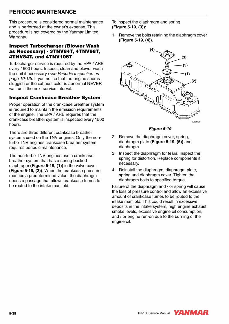
PERIODIC MAINTENANCE
This procedure is considered normal maintenance and is performed at the owner’s expense. This procedure is not covered by the Yanmar Limited Warranty.
Inspect Turbocharger (Blower Wash as Necessary) - 3TNV84T, 4TNV98T, 4TNV84T, and 4TNV106TTurbocharger service is required by the EPA / ARB every 1500 hours. Inspect, clean and blower wash the unit if necessary (see Periodic Inspection on page 10-13). If you notice that the engine seems sluggish or the exhaust color is abnormal NEVER wait until the next service interval.
Inspect Crankcase Breather SystemProper operation of the crankcase breather system is required to maintain the emission requirements of the engine. The EPA / ARB requires that the crankcase breather system is inspected every 1500 hours.
There are three different crankcase breather systems used on the TNV engines. Only the non-turbo TNV engines crankcase breather system requires periodic maintenance.
The non-turbo TNV engines use a crankcase breather system that has a spring-backed diaphragm (Figure 5-19, (1)) in the valve cover (Figure 5-19, (2)). When the crankcase pressure reaches a predetermined value, the diaphragm opens a passage that allows crankcase fumes to be routed to the intake manifold.
To inspect the diaphragm and spring (Figure 5-19, (3)):
1. Remove the bolts retaining the diaphragm cover (Figure 5-19, (4)).
Figure 5-19
2. Remove the diaphragm cover, spring, diaphragm plate (Figure 5-19, (5)) and diaphragm.
3. Inspect the diaphragm for tears. Inspect the spring for distortion. Replace components if necessary.
4. Reinstall the diaphragm, diaphragm plate, spring and diaphragm cover. Tighten the diaphragm bolts to specified torque.
Failure of the diaphragm and / or spring will cause the loss of pressure control and allow an excessive amount of crankcase fumes to be routed to the intake manifold. This could result in excessive deposits in the intake system, high engine exhaust smoke levels, excessive engine oil consumption, and / or engine run-on due to the burning of the engine oil.
(3)
(2)
(4)
(5)
(1)
0002135
5-38 TNV DI Service Manual

PERIODIC MAINTENANCE
Perform the following maintenance every 2000 hours of operation.
• Check and Replace Fuel Hoses and Engine Coolant Hoses
• Lap the Intake and Exhaust Valves
Check and Replace Fuel Hoses and Engine Coolant Hoses
Regularly check the fuel system and engine coolant system hoses. If they are cracked or degraded, replace them. Replace the hoses at least every two years.
Lap the Intake and Exhaust ValvesAdjustment is necessary to maintain proper contact of the valves and seats. See Inspection of Intake and Exhaust Valves on page 6-39.
Every 2000 Hours of Operation
CAUTION
• ALWAYS be environmentally responsible.
• Follow the guidelines of the EPA or other governmental agencies for the proper disposal of hazardous materials such as engine oil, diesel fuel and engine coolant. Consult the local authorities or reclamation facility.
• NEVER dispose of hazardous materials irresponsibly by dumping them into a sewer, on the ground, or into ground water or waterways.
• Failure to follow these procedures may seriously harm the environment.
0000013en
TNV DI Service Manual 5-39

TNV DI Service Manual Section 6
ENGINE
PageBefore You Begin Servicing ............................................................ 6-3
Introduction...................................................................................... 6-6
Cylinder Head Specifications .......................................................... 6-6Adjustment Specifications ......................................................... 6-6Cylinder Head............................................................................ 6-6Intake / Exhaust Valve and Guide ............................................. 6-7Push Rod................................................................................... 6-8Valve Spring .............................................................................. 6-9Rocker Arm and Shaft ............................................................... 6-9
Camshaft and Timing Gear Train Specifications........................... 6-10Camshaft ................................................................................. 6-10Idler Gear Shaft and Bushing .................................................. 6-12Timing Gear Backlash ............................................................. 6-12
Crankshaft and Piston Specifications............................................ 6-13Crankshaft ............................................................................... 6-13Thrust Bearing......................................................................... 6-14Piston....................................................................................... 6-15Piston Ring .............................................................................. 6-17Connecting Rod....................................................................... 6-21Tappet ..................................................................................... 6-22
Cylinder Block Specifications ........................................................ 6-22Cylinder Block.......................................................................... 6-22
Special Torque Chart .................................................................... 6-23Torque for Bolts and Nuts........................................................ 6-23
Special Service Tools.................................................................... 6-26
Measuring Instruments.................................................................. 6-30
TNV DI Service Manual 6-1

ENGINE
2-Valve Cylinder Head ................................................................... 6-322-Valve Cylinder Head Components ........................................ 6-32Disassembly of 2-Valve Cylinder Head .................................... 6-33Cleaning of Cylinder Head Components .................................. 6-37Inspection of Cylinder Head Components................................ 6-37Reassembly of Cylinder Head.................................................. 6-42
4-Valve Cylinder Head ................................................................... 6-464-Valve Cylinder Head Components ........................................ 6-46Disassembly of 4-Valve Cylinder Head .................................... 6-47Cleaning of Cylinder Head Components .................................. 6-52Inspection of Cylinder Head Components................................ 6-52Reassembly of Cylinder Head.................................................. 6-57
Measuring and Adjusting Valve Clearance .................................... 6-622-Valve Cylinder Heads............................................................ 6-634-Valve Cylinder Heads............................................................ 6-64
Crankshaft and Camshaft Components ......................................... 6-68Disassembly of Engine............................................................. 6-69Disassembly of Camshaft and Timing Components ................ 6-70Disassembly of Crankshaft and Piston Components ............... 6-75Inspection of Crankshaft and Camshaft Components.............. 6-79Honing and Boring.................................................................... 6-85Reassembly of Crankshaft and Piston Components................ 6-86Reassembly of Camshaft and Timing Components ................. 6-91Final Reassembly of Engine..................................................... 6-94
6-2 TNV DI Service Manual
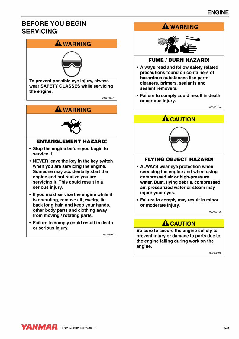
ENGINE
BEFORE YOU BEGIN SERVICING
A WARNING
To prevent possible eye injury, always wear SAFETY GLASSES while servicing the engine.
0000013en
A WARNING
ENTANGLEMENT HAZARD!• Stop the engine before you begin to
service it.
• NEVER leave the key in the key switch when you are servicing the engine. Someone may accidentally start the engine and not realize you are servicing it. This could result in a serious injury.
• If you must service the engine while it is operating, remove all jewelry, tie back long hair, and keep your hands, other body parts and clothing away from moving / rotating parts.
• Failure to comply could result in death or serious injury.
0000010en
A WARNING
FUME / BURN HAZARD!• Always read and follow safety related
precautions found on containers of hazardous substances like parts cleaners, primers, sealants and sealant removers.
• Failure to comply could result in death or serious injury.
0000014en
A CAUTION
FLYING OBJECT HAZARD!• ALWAYS wear eye protection when
servicing the engine and when using compressed air or high-pressure water. Dust, flying debris, compressed air, pressurized water or steam may injure your eyes.
• Failure to comply may result in minor or moderate injury.
0000003en
A CAUTIONBe sure to secure the engine solidly to prevent injury or damage to parts due to the engine falling during work on the engine.
0000009en
TNV DI Service Manual 6-3

ENGINE
CAUTION• Only use the engine oil specified.
Other engine oils may affect warranty coverage, cause internal engine components to seize and / or shorten engine life.
• Prevent dirt and debris from contaminating the engine oil. Carefully clean the oil cap / dipstick and the surrounding area before you remove the cap.
• NEVER mix different types of engine oil. This may adversely affect the lubricating properties of the engine oil.
• NEVER overfill. Overfilling may result in white exhaust smoke, engine overspeed or internal damage.
0000005en
CAUTION• Only use the engine coolant specified.
Other engine coolants may affect warranty coverage, cause an internal buildup of rust and scale and / or shorten engine life.
• Prevent dirt and debris from contaminating the engine coolant. Carefully clean the radiator cap and the surrounding area before you remove the cap.
• NEVER mix different types of engine coolants. This may adversely affect the properties of the engine coolant.
0000006en
CAUTIONIdentify all parts and their location using an appropriate method. It is important that all parts are returned to the same position during the reassembly process.
0000080en
CAUTIONAny part which is found defective as a result of inspection or any part whose measured value does not satisfy the standard or limit must be replaced.
0000119en
CAUTIONAny part determined to not meet the service standard or limit before the next service, as determined from the state of current rate of wear, should be replaced even though the part currently meets the service standard limit.
0000120en
CAUTIONRemove or install the high-pressure fuel injection lines as an assembly whenever possible. Disassembling the high-pressure fuel injection lines from the retainers or bending any of the fuel lines will make it difficult to reinstall the fuel lines.
0000047en
CAUTIONDo not loosen or remove the four bolts retaining the fuel injection pump drive gear to the fuel injection pump hub. Do not disassemble the fuel injection pump drive gear from the hub. Correct fuel injection timing will be very difficult or impossible to achieve.
0000031en
6-4 TNV DI Service Manual
ENGINE
CAUTIONKeep the piston pin parts, piston assemblies, and connecting rod assemblies together to be returned to the same position during the reassembly process. Label the parts using an appropriate method.
0000088en
CAUTIONDo not allow the honing tool to operate in one position for any length of time. Damage to the cylinder wall will occur. Keep the tool in constant up-and-down motion.
0000090en
TNV DI Service Manual 6-5
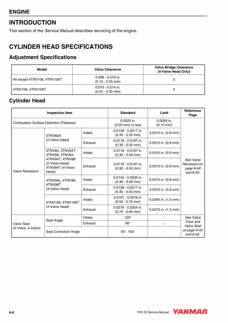
ENGINE
INTRODUCTIONThis section of the Service Manual describes servicing of the engine.
CYLINDER HEAD SPECIFICATIONS
Adjustment Specifications
Cylinder Head
Model Valve ClearanceValve Bridge Clearance
(4-Valve Head Only)
All except 4TNV106, 4TNV106T0.006 - 0.010 in.(0.15 - 0.25 mm)
0
4TNV106, 4TNV106T0.010 - 0.014 in.(0.25 - 0.35 mm)
0
Inspection Item Standard LimitReference
Page
Combustion Surface Distortion (Flatness)0.0020 in.
(0.05 mm) or less0.0059 in. (0.15 mm)
See Valve Recession on
page 6-40 and 6-55.Valve Recession
3TNV82A(2-Valve Head)
Intake0.0138 - 0.0217 in.(0.35 - 0.55 mm)
0.0315 in. (0.8 mm)
Exhaust0.0118 - 0.0197 in.(0.30 - 0.50 mm)
0.0315 in. (0.8 mm)
3TNV84, 3TNV84T, 3TNV88, 4TNV84, 4TNV84T, 4TNV88(2-Valve Head)4TNV84T (4-Valve Head)
Intake0.0118 - 0.0197 in.(0.30 - 0.50 mm)
0.0315 in. (0.8 mm)
Exhaust0.0118 - 0.0197 in.(0.30 - 0.50 mm)
0.0315 in. (0.8 mm)
4TNV94L, 4TNV98, 4TNV98T(4-Valve Head)
Intake0.0142 - 0.0220 in.(0.36 - 0.56 mm)
0.0315 in. (0.8 mm)
Exhaust0.0138 - 0.0217 in.(0.35 - 0.55 mm)
0.0315 in. (0.8 mm)
4TNV106, 4TNV106T(4-Valve Head)
Intake0.0197 - 0.0276 in.(0.50 - 0.70 mm)
0.0394 in. (1.0 mm)
Exhaust0.0276 - 0.0354 in.(0.70 - 0.90 mm)
0.0472 in. (1.2 mm)
Valve Seat(2-Valve, 4-Valve)
Seat AngleIntake 120° - See Valve
Face and Valve Seat
on page 6-40 and 6-55.
Exhaust 90° -
Seat Correction Angle 40°, 150° -
6-6 TNV DI Service Manual

ENGINE
Intake / Exhaust Valve and Guide
Inspection Item Standard LimitReference
Page
3TNV82A(2-Valve Head)
Intake
Guide Inside Diameter0.2756 - 0.2762 in.(7.000 - 7.015 mm)
0.2787 in.(7.08 mm)
See Inspection of Valve Guides
on page 6-39.
Valve Stem Outside Diameter
0.2734 - 0.2740 in.(6.945 - 9.960 mm)
0.2717 in.(6.90 mm)
Valve Stem Bend0.0016 - 0.0028 in.(0.040 - 0.070 mm)
0.0071 in.(0.18 mm)
Exhaust
Guide Inside Diameter0.2756 - 0.2762 in.(7.000 - 7.015 mm)
0.2787 in.(7.08 mm)
Valve Stem Outside Diameter
0.2732 - 0.2754 in.(6.940 - 6.955 mm)
0.2717 in.(6.90 mm)
Valve Stem Bend0.0018 - 0.0030 in.(0.045 - 0.075 mm)
0.0071 in.(0.18 mm)
4TNV84,3TNV84, 3TNV84T,4TNV88, 4TNV88(2-Valve Head)
Intake
Guide Inside Diameter0.3154 - 0.3159 in.(8.010 - 8.025 mm)
0.3189 in.(8.10 mm)
See Inspection of Valve Guides
on page 6-39.
Valve Stem Outside Diameter
0.3132 - 0.3140 in.(7.955 - 7.975 mm)
0.3110 in.(7.90 mm)
Valve Stem Bend0.0014 - 0.0028 in.(0.035 - 0.070 mm)
0.0071 in.(0.18 mm)
Exhaust
Guide Inside Diameter0.3156 - 0.3161 in.(8.015 - 8.030 mm)
0.3189 in.(8.10 mm)
Valve Stem Outside Diameter
0.3132 -.3134 in.(7.955 - 7.960 mm)
0.3110 in.(7.90 mm)
Valve Stem Bend0.0018 - 0.0030 in.(0.045 - 0.075 mm)
0.0071 in.(0.18 mm)
4TNV84T(4-Valve Head)
Intake
Guide Inside Diameter0.2362 - 0.2368 in.(6.000 - 6.015 mm)
0.2394 in.(6.08 mm)
See Inspection of Valve Guides
on page 6-39.
Valve Stem Outside Diameter
0.2346 - 0.2352 in.(5.960 - 5.975 mm)
0.2323 in.(5.90 mm)
Valve Stem Bend0.0010 - 0.0022 in.(0.025 - 0.055 mm)
0.0059 in.(0.15 mm)
Exhaust
Guide Inside Diameter0.2362 - 0.2368 in.(6.000 - 6.015 mm)
0.2394 in.(6.08 mm)
Valve Stem Outside Diameter
0.2341 - 0.2346 in.(5.945 - 5.960 mm)
0.2323 in.(5.90 mm)
Valve Stem Bend0.0016 - 0.0028 in.(0.040 - 0.070 mm)
0.0067 in.(0.17 mm)
TNV DI Service Manual 6-7
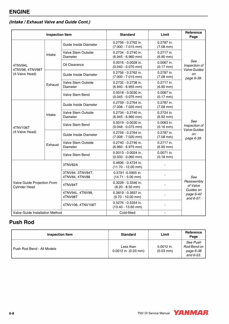
ENGINE
(Intake / Exhaust Valve and Guide Cont.)
Push Rod
Inspection Item Standard LimitReference
Page
4TNV94L4TNV98, 4TNV98T(4-Valve Head)
Intake
Guide Inside Diameter0.2756 - 0.2762 in.(7.000 - 7.015 mm)
0.2787 in.(7.08 mm)
See Inspection of Valve Guides
on page 6-39.
Valve Stem Outside Diameter
0.2734 - 0.2740 in.(6.945 - 6.960 mm)
0.2717 in.(6.90 mm)
Oil Clearance0.0016 - 0.0028 in.(0.040 - 0.070 mm)
0.0067 in.(0.17 mm)
Exhaust
Guide Inside Diameter0.2756 - 0.2762 in.(7.000 - 7.015 mm)
0.2787 in.(7.08 mm)
Valve Stem Outside Diameter
0.2732 - 0.2738 in.(6.940 - 6.955 mm)
0.2717 in.(6.90 mm)
Valve Stem Bend0.0018 - 0.0030 in.(0.045 - 0.075 mm)
0.0067 in.(0.17 mm)
4TNV106T(4-Valve Head)
Intake
Guide Inside Diameter0.2759 - 0.2764 in.(7.008 - 7.020 mm)
0.2787 in.(7.08 mm)
See Inspection of Valve Guides
on page 6-39.
Valve Stem Outside Diameter
0.2734 - 0.2740 in.(6.945 - 6.960 mm)
0.2724 in.(6.92 mm)
Valve Stem Bend0.0019 - 0.0030 in.(0.048 - 0.075 mm)
0.0063 in.(0.16 mm)
Exhaust
Guide Inside Diameter0.2759 - 0.2764 in.(7.008 - 7.020 mm)
0.2787 in.(7.08 mm)
Valve Stem Outside Diameter
0.2740 - 0.2746 in.(6.960 - 6.975 mm)
0.2717 in.(6.90 mm)
Valve Stem Bend0.0013 - 0.0024 in.(0.033 - 0.060 mm)
0.0071 in.(0.18 mm)
Valve Guide Projection From Cylinder Head
3TNV82A0.4606 - 0.4724 in.(11.70 - 12.00 mm)
-
See Reassembly
of Valve Guides on page 6-42 and 6-57.
3TNV84, 3TNV84T, 4TNV84, 4TNV88
0.5791 -0.5905 in.(14.71 - 5.00 mm)
-
4TNV84T0.3228 - 0.3346 in.(8.20 - 8.50 mm)
-
4TNV94L, 4TNV98, 4TNV98T
0.3819 - 0.3937 in.(9.70 - 10.00 mm)
-
4TNV106, 4TNV106T0.5276 - 0.5354 in.(13.40 - 13.60 mm)
-
Valve Guide Installation Method Cold-fitted -
Inspection Item Standard LimitReference
Page
Push Rod Bend - All ModelsLess than
0.0012 in. (0.03 mm)0.0012 in.(0.03 mm)
See Push Rod Bend on
page 6-38 and 6-53.
6-8 TNV DI Service Manual

ENGINE
Valve Spring
Rocker Arm and Shaft
Inspection Item Model Standard LimitReference
Page
Free Length
3TNV82A (2-Valve Head)1.7480 in.(44.4 mm)
1.7283 in.(43.9 mm)
See Inspection of
Valve Springs on page 6-41 and 6-56.
4TNV84, 3TNV84, 3TNV84T, 4TNV88 (2-Valve Head)
1.6535 in.(42.0 mm)
1.6339 in.(41.5 mm)
4TNV84T (4-Valve Head)1.4724 in.(37.4 mm)
1.4528 in.(36.9 mm)
4TNV94L, 4TNV98, 4TNV98T (4-Valve Head)
1.5630 in.(39.7 mm)
1.5433 in.(39.2 mm)
4TNV106, 4TNV106T (4-Valve Head)1.9921 in.(50.6 mm)
1.9724 in.(50.1 mm)
Squareness
3TNV82A (2-Valve Head) -0.0551 in.(1.4 mm)
4TNV84, 3TNV84, 3TNV84T, 4TNV88 (2-Valve Head)
-0.0551 in.(1.4 mm)
4TNV84T (4-Valve Head) -0.0551 in.(1.3 mm)
4TNV94L, 4TNV98, 4TNV98T (4-Valve Head)
-0.0551 in.(1.4 mm)
4TNV106, 4TNV106T (4-Valve Head) -0.0551 in.(1.5 mm)
Model Inspection Item Standard LimitReference
Page
3TNV82A, 3TNV84, 3TNV84T, 3TNV88, 4TNV84, 4TNV84T, 4TNV88
Arm Shaft Hole Diameter0.6299 - 0.6307 in.
(16.000 - 16.020 mm)0.6327 in.
(16.07 mm)
See Inspection of Rocker Arm Assembly on
page 6-38 and 6-53.
Shaft Outside Diameter0.6286 - 0.6293 in.
(15.966 - 15.984 mm)0.6276 in.
(15.94 mm)
Oil Clearance0.0006 - 0.0021 in.(0.016 - 0.054 mm)
0.0051 in.(0.13 mm)
4TNV94L, 4TNV98, 4TNV98T, 4TNV106, 4TNV106T
Arm Shaft Hole Diameter0.7283 - 0.7291 in.
(18.500 - 18.520 mm)0.7311 in.
(18.57 mm)
Shaft Outside Diameter0.7272 - 0.7280 in.
(18.470 - 18.490 mm)0.7260 in.
(18.44 mm)
Oil Clearance0.0004 - 0.0020 in.(0.010 - 0.050 mm)
0.0051 in.(0.13 mm)
TNV DI Service Manual 6-9
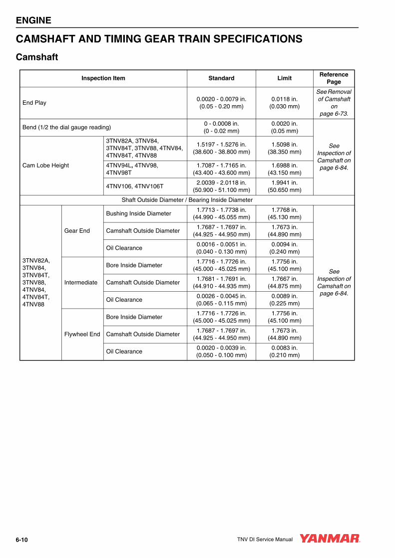
ENGINE
CAMSHAFT AND TIMING GEAR TRAIN SPECIFICATIONS
Camshaft
Inspection Item Standard LimitReference
Page
End Play0.0020 - 0.0079 in.(0.05 - 0.20 mm)
0.0118 in.(0.030 mm)
See Removal of Camshaft
on page 6-73.
Bend (1/2 the dial gauge reading)0 - 0.0008 in.(0 - 0.02 mm)
0.0020 in.(0.05 mm)
See Inspection of Camshaft on page 6-84.Cam Lobe Height
3TNV82A, 3TNV84, 3TNV84T, 3TNV88, 4TNV84, 4TNV84T, 4TNV88
1.5197 - 1.5276 in.(38.600 - 38.800 mm)
1.5098 in.(38.350 mm)
4TNV94L, 4TNV98, 4TNV98T
1.7087 - 1.7165 in.(43.400 - 43.600 mm)
1.6988 in.(43.150 mm)
4TNV106, 4TNV106T2.0039 - 2.0118 in.
(50.900 - 51.100 mm)1.9941 in.
(50.650 mm)
Shaft Outside Diameter / Bearing Inside Diameter
3TNV82A, 3TNV84, 3TNV84T, 3TNV88, 4TNV84, 4TNV84T, 4TNV88
Gear End
Bushing Inside Diameter1.7713 - 1.7738 in.
(44.990 - 45.055 mm)1.7768 in.
(45.130 mm)
See Inspection of Camshaft on page 6-84.
Camshaft Outside Diameter1.7687 - 1.7697 in.
(44.925 - 44.950 mm)1.7673 in.
(44.890 mm)
Oil Clearance0.0016 - 0.0051 in.(0.040 - 0.130 mm)
0.0094 in.(0.240 mm)
Intermediate
Bore Inside Diameter1.7716 - 1.7726 in.
(45.000 - 45.025 mm)1.7756 in.
(45.100 mm)
Camshaft Outside Diameter1.7681 - 1.7691 in.
(44.910 - 44.935 mm)1.7667 in.
(44.875 mm)
Oil Clearance0.0026 - 0.0045 in.(0.065 - 0.115 mm)
0.0089 in.(0.225 mm)
Flywheel End
Bore Inside Diameter1.7716 - 1.7726 in.
(45.000 - 45.025 mm)1.7756 in.
(45.100 mm)
Camshaft Outside Diameter1.7687 - 1.7697 in.
(44.925 - 44.950 mm)1.7673 in.
(44.890 mm)
Oil Clearance0.0020 - 0.0039 in.(0.050 - 0.100 mm)
0.0083 in.(0.210 mm)
6-10 TNV DI Service Manual

ENGINE
(Camshaft Cont.)
Inspection Item Standard LimitReference
Page
4TNV94L, 4TNV98, 4TNV98T
Gear End
Bushing Inside Diameter1.9681 - 1.9707 in.
(49.990 - 50.055 mm)1.9736 in.
(50.130 mm)
See Inspection of Camshaft on page 6-84.
Camshaft Outside Diameter1.9655 - 1.9665 in.
(49.925 - 49.950 mm)1.7673 in.
(49.890 mm)
Oil Clearance0.0016 - 0.0051 in.(0.040 - 0.130 mm)
0.0094 in.(0.240 mm)
Intermediate
Bushing Inside Diameter1.9685 - 1.9695 in.
(50.000 - 50.025 mm)1.9724 in.
(50.100 mm)
Camshaft Outside Diameter1.9650 - 1.9659 in.
(49.910 - 49.935 mm)1.9636 in.
(49.875 mm)
Oil Clearance0.0026 - 0.0045 in.(0.065 - 0.115 mm)
0.0089 in;(0.225 mm)
Flywheel End
Bushing Inside Diameter1.9685 - 1.9695 in.
(50.000 - 50.025 mm)1.9724 in.
(50.100 mm)
Camshaft Outside Diameter1.9655 - 1.9665 in.
(49.925 - 49.950 mm)1.7673 in.
(49.890 mm)
Oil Clearance0.0020 - 0.0039 in.(0.050 - 0.100 mm)
0.0083 in.(0.210 mm)
4TNV106, 4TNV106T
Gear End
Bushing Inside Diameter2.2827 - 2.2854 in.
(57.980 - 58.050 mm)2.2876 in.
(58.105 mm)
Camshaft Outside Diameter2.2799 - 2.2811 in.
(57.910 - 57.940 mm)2.2785 in.
(57.875 mm)
Oil Clearance0.0016 - 0.0055 in.(0.040 - 0.140 mm)
0.0098 in.(0.250 mm)
Intermediate
Bushing Inside Diameter2.2835 - 2.2846 in.
(58.000 - 58.030 mm)2.2876 in.
(58.105 mm)
Camshaft Outside Diameter2.2793 - 2.2805 in.
(57.895 - 57.925 mm)2.2779 in.
(57.860 mm)
Oil Clearance0.0030 - 0.0053 in.(0.075 - 0.135 mm)
0.0096 in.(0.245 mm)
Flywheel End
Bushing Inside Diameter2.2835 - 2.2846 in.
(58.000 - 58.030 mm)2.2876 in.
(58.105 mm)
Camshaft Outside Diameter2.2799 - 2.2811 in.
(57.910 - 57.940 mm)2.2785 in.
(57.875 mm)
Oil Clearance0.0020 - 0.0047 in.(0.050 - 0.120 mm)
0.0091 in.(0.230 mm)
TNV DI Service Manual 6-11
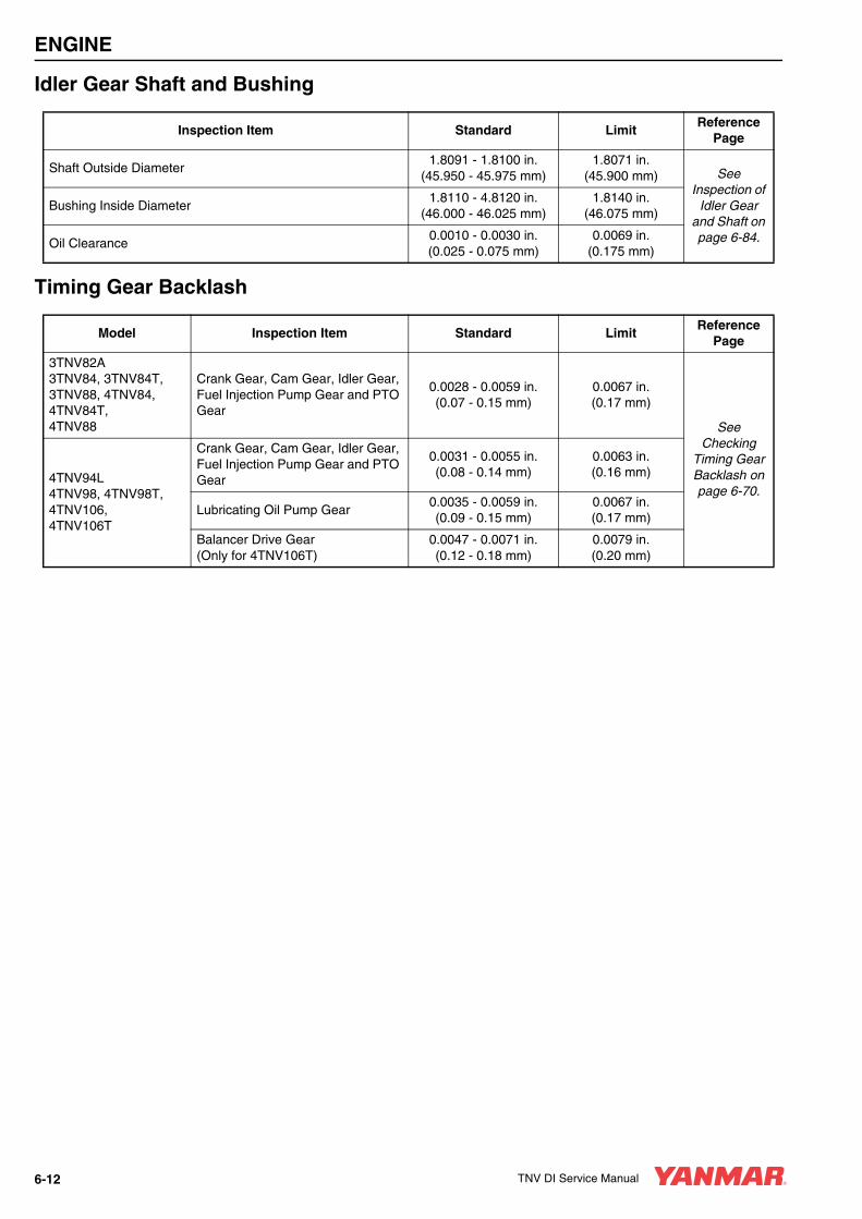
ENGINE
Idler Gear Shaft and Bushing
Timing Gear Backlash
Inspection Item Standard LimitReference
Page
Shaft Outside Diameter1.8091 - 1.8100 in.
(45.950 - 45.975 mm)1.8071 in.
(45.900 mm) See Inspection of
Idler Gear and Shaft on page 6-84.
Bushing Inside Diameter1.8110 - 4.8120 in.
(46.000 - 46.025 mm)1.8140 in.
(46.075 mm)
Oil Clearance0.0010 - 0.0030 in.(0.025 - 0.075 mm)
0.0069 in.(0.175 mm)
Model Inspection Item Standard LimitReference
Page
3TNV82A3TNV84, 3TNV84T,3TNV88, 4TNV84, 4TNV84T, 4TNV88
Crank Gear, Cam Gear, Idler Gear, Fuel Injection Pump Gear and PTO Gear
0.0028 - 0.0059 in.(0.07 - 0.15 mm)
0.0067 in.(0.17 mm)
See Checking
Timing Gear Backlash on page 6-70.
4TNV94L4TNV98, 4TNV98T, 4TNV106, 4TNV106T
Crank Gear, Cam Gear, Idler Gear, Fuel Injection Pump Gear and PTO Gear
0.0031 - 0.0055 in.(0.08 - 0.14 mm)
0.0063 in.(0.16 mm)
Lubricating Oil Pump Gear0.0035 - 0.0059 in.(0.09 - 0.15 mm)
0.0067 in.(0.17 mm)
Balancer Drive Gear(Only for 4TNV106T)
0.0047 - 0.0071 in.(0.12 - 0.18 mm)
0.0079 in.(0.20 mm)
6-12 TNV DI Service Manual

ENGINE
CRANKSHAFT AND PISTON SPECIFICATIONS
CrankshaftNote: Check appropriate parts catalog for various sizes of replacement main bearing inserts.
Inspection Item Standard LimitReference
Page
Bend (1/2 the dial gauge reading) -0.0008 in.(0.02 mm)
See Inspection of Crankshaft
on page 6-83.
Connecting Rod Journals
3TNV82A
Journal Outside Diameter
1.6910 - 1.6914 in.(42.952 - 42.962 mm)
1.6891 in.(42.902 mm)
Bearing Inside Diameter
1.6929 - 1.6946 in.(43.000 - 43.042 mm)
-
Bearing Insert Thickness
0.0585 -.0591 in.(1.487 - 1.500 mm)
-
Oil Clearance0.0015 - 0.0035 in.(0.038 - 0.090 mm)
0.0059 in.(0.150 mm)
3TNV84, 3TNV84T, 3TNV88, 4TNV84, 4TNV84T4TNV88
Journal Outside Diameter
1.8879 - 1.8883 in.(47.952 - 47.962 mm)
1.8859 in.(47.902 mm)
Bearing Inside Diameter
1.8898 - 1.8909 in.(48.000 - 48.026 mm)
-
Bearing Insert Thickness
0.0587 - 0.0591 in.(1.492 - 1.500 mm)
-
Oil Clearance0.0015 - 0.0029 in.(0.038 - 0.074 mm)
0.0059 in.(0.150 mm)
4TNV94L, 4TNV98, 4TNV98T
Journal Outside Diameter
2.2816 - 2.2820 in.(57.952 - 57.962 mm)
2.2796 in.(57.902 mm)
Bearing Inside Diameter
2.2835 - 2.2845 in.(58.000 - 58.026 mm)
-
Bearing Insert Thickness
0.0587 - 0.0591 in.(1.492 - 1.500 mm)
-
Oil Clearance0.0015 - 0.0029 in.(0.038 - 0.074 mm)
0.0059 in.(0.150 mm)
4TNV106, 4TNV106T
Journal Outside Diameter
2.5178 - 2.5182 in.(63.952 - 63.962 mm)
2.5158 in.(63.902 mm)
Bearing Inside Diameter
2.5203 - 2.5213 in.(64.016 - 64.042 mm)
-
Bearing Insert Thickness
0.0781 - 0.0784 in.(1.984 - 1.992 mm)
-
Oil Clearance0.0021 - 0.0035 in.(0.054 - 0.090 mm)
0.0059 in.(0.150 mm)
TNV DI Service Manual 6-13
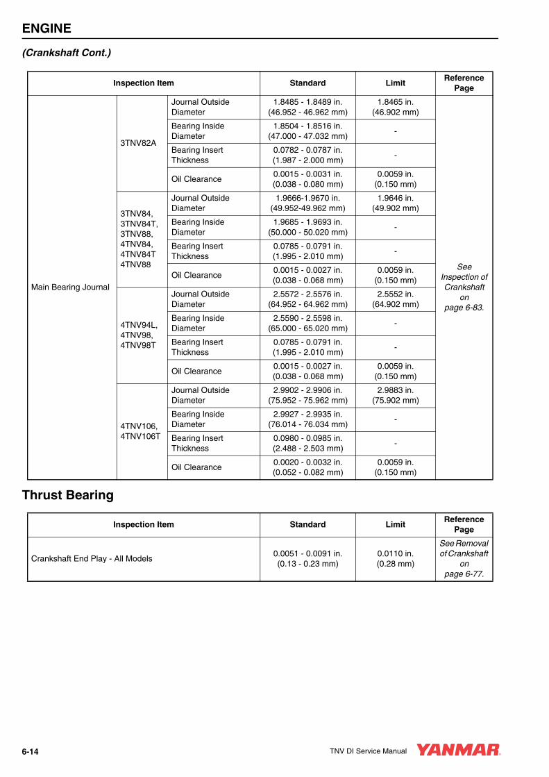
ENGINE
(Crankshaft Cont.)
Thrust Bearing
Inspection Item Standard LimitReference
Page
Main Bearing Journal
3TNV82A
Journal Outside Diameter
1.8485 - 1.8489 in.(46.952 - 46.962 mm)
1.8465 in.(46.902 mm)
See Inspection of Crankshaft
on page 6-83.
Bearing Inside Diameter
1.8504 - 1.8516 in.(47.000 - 47.032 mm)
-
Bearing Insert Thickness
0.0782 - 0.0787 in.(1.987 - 2.000 mm)
-
Oil Clearance0.0015 - 0.0031 in.(0.038 - 0.080 mm)
0.0059 in.(0.150 mm)
3TNV84, 3TNV84T, 3TNV88, 4TNV84, 4TNV84T4TNV88
Journal Outside Diameter
1.9666-1.9670 in.(49.952-49.962 mm)
1.9646 in.(49.902 mm)
Bearing Inside Diameter
1.9685 - 1.9693 in.(50.000 - 50.020 mm)
-
Bearing Insert Thickness
0.0785 - 0.0791 in.(1.995 - 2.010 mm)
-
Oil Clearance0.0015 - 0.0027 in.(0.038 - 0.068 mm)
0.0059 in.(0.150 mm)
4TNV94L, 4TNV98, 4TNV98T
Journal Outside Diameter
2.5572 - 2.5576 in.(64.952 - 64.962 mm)
2.5552 in.(64.902 mm)
Bearing Inside Diameter
2.5590 - 2.5598 in.(65.000 - 65.020 mm)
-
Bearing Insert Thickness
0.0785 - 0.0791 in.(1.995 - 2.010 mm)
-
Oil Clearance0.0015 - 0.0027 in.(0.038 - 0.068 mm)
0.0059 in.(0.150 mm)
4TNV106, 4TNV106T
Journal Outside Diameter
2.9902 - 2.9906 in.(75.952 - 75.962 mm)
2.9883 in.(75.902 mm)
Bearing Inside Diameter
2.9927 - 2.9935 in.(76.014 - 76.034 mm)
-
Bearing Insert Thickness
0.0980 - 0.0985 in.(2.488 - 2.503 mm)
-
Oil Clearance0.0020 - 0.0032 in.(0.052 - 0.082 mm)
0.0059 in.(0.150 mm)
Inspection Item Standard LimitReference
Page
Crankshaft End Play - All Models0.0051 - 0.0091 in.(0.13 - 0.23 mm)
0.0110 in.(0.28 mm)
See Removal of Crankshaft
on page 6-77.
6-14 TNV DI Service Manual

ENGINE
Piston
Inspection Item Standard LimitReference
Page
Piston Outside Diameter(Measure at 90° to the Piston Pin.)
3TNV82A3.2264 - 3.2275 in.
(81.950 - 81.980 mm)3.2246 in.
(81.905 mm)
See Inspection of
Pistons, Piston Rings and Wrist Pin
on page 6-80.
3TNV84, 3TNV84T, 4TNV84, 4TNV84T
3.3047 - 3.3059 in.(83.940 - 83.970 mm)
3.3029 in.(83.895 mm)
3TNV88,4TNV883.4622 - 3.4634 in.
(87.940 - 87.970 mm)3.4604 in.
(87.895 mm)
4TNV94L3.6982 - 3.6994 in.
(93.935 - 93.965 mm)3.6968 in.
(93.900 mm)
4TNV98, 4TNV98T3.8555 - 3.8567 in.
(97.930 - 97.960 mm)3.8541 in.
(97.895 mm)
4TNV106, 4TNV106T4.1705 - 4.1716 in.
(105.930 - 105.960 mm)4.1685 in.
(105.880 mm)
Piston Diameter Measure Location(Upward From the Bottom of the Piston.)
3TNV82A0.6299 in.(16 mm)
-
3TNV84, 3TNV84T, 4TNV84, 4TNV84T
0.9449 in.(24 mm)
-
3TNV88,4TNV880.9449 in.(24 mm)
-
4TNV94L0.8661 in.(22 mm)
-
4TNV98, 4TNV98T0.8661 in.(22 mm)
-
4TNV106, 4TNV106T1.1811 in.(30 mm)
-
TNV DI Service Manual 6-15

ENGINE
(Piston Cont.)
Inspection Item Standard LimitReference
Page
Piston Pin
3TNV82A
Hole Inside Diameter0.9055 - 0.9059 in.
(23.000 - 23.009 mm)0.9070 in.
(23.039 mm)
See Inspection of
Pistons, Piston Rings and Wrist Pin
on page 6-80.
Pin Outside Diameter0.9053 - 0.9055 in.
(22.995 - 23.000 mm)0.9041 in.
(22.965 mm)
Oil Clearance0.0000 - 0.0006 in.(0.000 - 0.014 mm)
0.0029 in.(0.074 mm)
3TNV84, 3TNV84T,3TNV88, 4TNV84, 4TNV84T4TNV88
Hole Inside Diameter1.0236 - 1.0240 in.
(26.000 - 26.009 mm)1.0252 in.
(26.039 mm)
Pin Outside Diameter1.0234 - 1.0236 in.
(25.995 - 26.000 mm)1.0222 in.
(25.965 mm)
Oil Clearance0.0000 - 0.0006 in.(0.000 - 0.014 mm)
0.0029 in.(0.074 mm)
4TNV94L, 4TNV98, 4TNV98T
Hole Inside Diameter1.1811 - 1.1815 in.
(30.000 - 30.009 mm)1.1826 in.
(30.039 mm)
Pin Outside Diameter1.1807 - 1.1811 in.
(29.989 - 30.000 mm)1.1795 in.
(29.959 mm)
Oil Clearance0.0000 - 0.0008 in.(0.000 - 0.020 mm)
0.0031 in.(0.080 mm)
4TNV106, 4TNV106T
Hole Inside Diameter1.4567 - 1.4571 in.
(37.000 - 37.011 mm)1.4582 in.
(37.039 mm)
Pin Outside Diameter1.4563 - 1.4567 in.
(36.989 - 37.000 mm)1.4551 in.
(36.959 mm)
Oil Clearance0.0000 - 0.0009 in.(0.000 - 0.022 mm)
0.0031 in.(0.080 mm)
6-16 TNV DI Service Manual

ENGINE
Piston Ring
Model Inspection Item Standard LimitReference
Page
3TNV82A, 3TNV84, 3TNV84T, 4TNV84, 4TNV84T
Top Ring
Ring Groove Width0.0813 - 0.0819 in.(2.065 - 2.080 mm)
-
See Inspection of
Pistons, Piston Rings
and Wrist Pin on
page 6-80.
Ring Width0.0776 - 0.0783 in.(1.970 - 1.990 mm)
0.0768 in.(1.950 mm)
Side Clearance0.0030 - 0.0043 in.(0.075 - 0.110 mm)
-
End Gap0.0079 - 0.0157 in.(0.200 - 0.400 mm)
0.0193 in.(0.490 mm)
Second Ring
Ring Groove Width0.0801 - 0.0807 in.(2.035 - 2.050 mm)
0.0846 in.(2.150 mm)
Ring Width0.0776 - 0.0783 in.(1.970 - 1.990 mm)
0.0768 in.(2.150 mm)
Side Gap0.0018 - 0.0031 in.(0.045 - 0.080 mm)
0.0079 in.(0.200 mm)
End Gap0.0079 - 0.0157 in.(0.200 - 0.400 mm)
0.0193 in.(0.490 mm)
Oil Ring
Ring Groove Width0.1581 - 0.1587 in.(4.015 - 4.030 mm)
0.1626 in.(4.130 mm)
Ring Width0.1563 - 0.1571 in.(3.970 - 3.990 mm)
0.01555 in.(3.950 mm)
Side Clearance0.0010 - 0.0024 in.(0.025 - 0.060 mm)
0.0071 in.(0.180 mm)
End Gap0.0079 - 0.0157 in.(0.200 - 0.400 mm)
0.0193 in.(0.490 mm)
TNV DI Service Manual 6-17
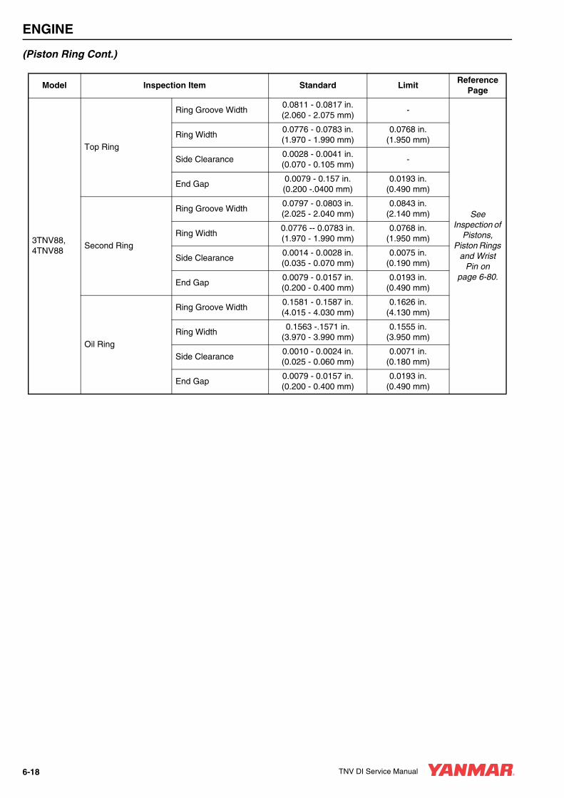
ENGINE
(Piston Ring Cont.)
Model Inspection Item Standard LimitReference
Page
3TNV88, 4TNV88
Top Ring
Ring Groove Width0.0811 - 0.0817 in.(2.060 - 2.075 mm)
-
See Inspection of
Pistons, Piston Rings
and Wrist Pin on
page 6-80.
Ring Width0.0776 - 0.0783 in.(1.970 - 1.990 mm)
0.0768 in.(1.950 mm)
Side Clearance0.0028 - 0.0041 in.(0.070 - 0.105 mm)
-
End Gap0.0079 - 0.157 in.(0.200 -.0400 mm)
0.0193 in.(0.490 mm)
Second Ring
Ring Groove Width0.0797 - 0.0803 in.(2.025 - 2.040 mm)
0.0843 in.(2.140 mm)
Ring Width0.0776 -- 0.0783 in.(1.970 - 1.990 mm)
0.0768 in.(1.950 mm)
Side Clearance0.0014 - 0.0028 in.(0.035 - 0.070 mm)
0.0075 in.(0.190 mm)
End Gap0.0079 - 0.0157 in.(0.200 - 0.400 mm)
0.0193 in.(0.490 mm)
Oil Ring
Ring Groove Width0.1581 - 0.1587 in.(4.015 - 4.030 mm)
0.1626 in.(4.130 mm)
Ring Width0.1563 -.1571 in.
(3.970 - 3.990 mm)0.1555 in.
(3.950 mm)
Side Clearance0.0010 - 0.0024 in.(0.025 - 0.060 mm)
0.0071 in.(0.180 mm)
End Gap0.0079 - 0.0157 in.(0.200 - 0.400 mm)
0.0193 in.(0.490 mm)
6-18 TNV DI Service Manual

ENGINE
(Piston Ring Cont.)
Model Inspection Item Standard LimitReference
Page
4TNV94L, 4TNV98, 4TNV98T
Top Ring
Ring Groove Width0.0803 - 0.0811 in.(2.040 - 2.060 mm)
-
See Inspection of
Pistons, Piston Rings
and Wrist Pin on
page 6-80.
Ring Width0.0764 - 0.0772 in.(1.940 - 1.960 mm)
0.0756 in.(1.920 mm)
Side Clearance0.0031 - 0.0047 in.(0.080 - 0.120 mm)
-
End Gap0.0098 - 0.0177 in.(0.250 - 0.450 mm)
0.0213 in.(0.540 mm)
Second Ring
Ring Groove Width0.0819 - 0.0825 in.(2.080 - 2.095 mm)
0.0864 in.(2.195 mm)
Ring Width0.0776 - 0.0783 in.(1.970 - 1.990 mm)
0.0768 in.(1.950 mm)
Side Clearance0.0035 - 0.0049 in.(0.090 - 0.125 mm)
0.0096 in.(0.245 mm)
End Gap0.0177 - 0.0256 in.(0.450 - 0.650 mm)
0.0287 in.(0.730 mm)
Oil Ring
Ring Groove Width0.1187 - 0.1193 in.(3.015 - 3.030 mm)
0.1232 in.(3.130 mm)
Ring Width0.1169 - 0.1177 in.(2.970 - 2.990 mm)
0.1161 in.(2.950 mm)
Side Clearance0.0010 - 0.0024 in.(0.025 - 0.060 mm)
0.0071 in.(0.180 mm)
End Gap0.0098 - 0.0177 in.(0.250 - 0.450 mm)
0.0217 in.(0.550 mm)
TNV DI Service Manual 6-19

ENGINE
(Piston Ring Cont.)
Model Inspection Item Standard LimitReference
Page
4TNV106, 4TNV106T
Top Ring
Ring Groove Width0.0992 - 0.1000 in.(2.520 - 2.540 mm)
-
See Inspection of
Pistons, Piston Rings
and Wrist Pin on
page 6-80.
Ring Width0.0961 - 0.0969 in.(2.440 - 2.460 mm)
0.0953 in.(2.420 mm)
Side Clearance0.0024 - 0.0039 in.(0.060 - 0.100 mm)
-
End Gap0.0118 - 0.0177 in.(0.300 - 0.450 mm)
0.0213 in.(0.540 mm)
Second Ring
Ring Groove Width0.0815 - 0.0821 in.(2.070 - 2.085 mm)
0.0860 in.(2.185 mm)
Ring Width0.0776 - 0.0783 in.(1.970 - 1.990 mm)
0.0768 in.(1.950 mm)
Side Clearance0.0031 - 0.0045 in.(0.080 - 0.115 mm)
0.0093 in.(0.235 mm)
End Gap0.0177 - 0.0236 in.(0.450 - 0.600 mm)
0.0268 in.(0.680 mm)
Oil Ring
Ring Groove Width0.1187 - 0.1193 in.(3.015 - 3.030 mm)
0.1232 in.(3.130 mm)
Ring Width0.1169 - 0.1177 in.(2.970 - 2.990 mm)
0.1161 in.(2.950 mm)
Side Clearance0.0010 - 0.0024 in.(0.025 - 0.060 mm)
0.0071 in.(0.180 mm)
End Gap0.0118 - 0.0197 in.(0.300 - 0.500 mm)
0.0236 in.(0.600 mm)
6-20 TNV DI Service Manual
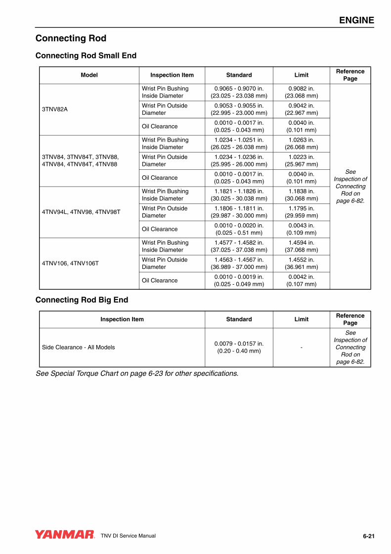
ENGINE
Connecting Rod
Connecting Rod Small End
Connecting Rod Big End
See Special Torque Chart on page 6-23 for other specifications.
Model Inspection Item Standard LimitReference
Page
3TNV82A
Wrist Pin Bushing Inside Diameter
0.9065 - 0.9070 in.(23.025 - 23.038 mm)
0.9082 in.(23.068 mm)
See Inspection of Connecting
Rod on page 6-82.
Wrist Pin Outside Diameter
0.9053 - 0.9055 in.(22.995 - 23.000 mm)
0.9042 in.(22.967 mm)
Oil Clearance0.0010 - 0.0017 in.(0.025 - 0.043 mm)
0.0040 in.(0.101 mm)
3TNV84, 3TNV84T, 3TNV88, 4TNV84, 4TNV84T, 4TNV88
Wrist Pin Bushing Inside Diameter
1.0234 - 1.0251 in.(26.025 - 26.038 mm)
1.0263 in.(26.068 mm)
Wrist Pin Outside Diameter
1.0234 - 1.0236 in.(25.995 - 26.000 mm)
1.0223 in.(25.967 mm)
Oil Clearance0.0010 - 0.0017 in.(0.025 - 0.043 mm)
0.0040 in.(0.101 mm)
4TNV94L, 4TNV98, 4TNV98T
Wrist Pin Bushing Inside Diameter
1.1821 - 1.1826 in.(30.025 - 30.038 mm)
1.1838 in.(30.068 mm)
Wrist Pin Outside Diameter
1.1806 - 1.1811 in.(29.987 - 30.000 mm)
1.1795 in.(29.959 mm)
Oil Clearance0.0010 - 0.0020 in.(0.025 - 0.51 mm)
0.0043 in.(0.109 mm)
4TNV106, 4TNV106T
Wrist Pin Bushing Inside Diameter
1.4577 - 1.4582 in.(37.025 - 37.038 mm)
1.4594 in.(37.068 mm)
Wrist Pin Outside Diameter
1.4563 - 1.4567 in.(36.989 - 37.000 mm)
1.4552 in.(36.961 mm)
Oil Clearance0.0010 - 0.0019 in.(0.025 - 0.049 mm)
0.0042 in.(0.107 mm)
Inspection Item Standard LimitReference
Page
Side Clearance - All Models0.0079 - 0.0157 in.(0.20 - 0.40 mm)
-
See Inspection of Connecting
Rod on page 6-82.
TNV DI Service Manual 6-21
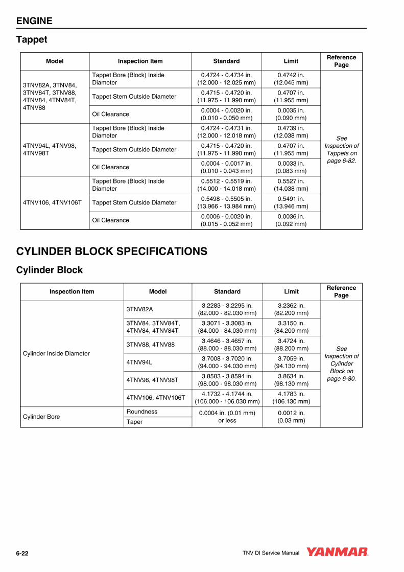
ENGINE
Tappet
CYLINDER BLOCK SPECIFICATIONS
Cylinder Block
Model Inspection Item Standard LimitReference
Page
3TNV82A, 3TNV84, 3TNV84T, 3TNV88, 4TNV84, 4TNV84T, 4TNV88
Tappet Bore (Block) Inside Diameter
0.4724 - 0.4734 in.(12.000 - 12.025 mm)
0.4742 in.(12.045 mm)
See Inspection of Tappets on page 6-82.
Tappet Stem Outside Diameter0.4715 - 0.4720 in.
(11.975 - 11.990 mm)0.4707 in.
(11.955 mm)
Oil Clearance0.0004 - 0.0020 in.(0.010 - 0.050 mm)
0.0035 in.(0.090 mm)
4TNV94L, 4TNV98, 4TNV98T
Tappet Bore (Block) Inside Diameter
0.4724 - 0.4731 in.(12.000 - 12.018 mm)
0.4739 in.(12.038 mm)
Tappet Stem Outside Diameter0.4715 - 0.4720 in.
(11.975 - 11.990 mm)0.4707 in.
(11.955 mm)
Oil Clearance0.0004 - 0.0017 in.(0.010 - 0.043 mm)
0.0033 in.(0.083 mm)
4TNV106, 4TNV106T
Tappet Bore (Block) Inside Diameter
0.5512 - 0.5519 in.(14.000 - 14.018 mm)
0.5527 in.(14.038 mm)
Tappet Stem Outside Diameter0.5498 - 0.5505 in.
(13.966 - 13.984 mm)0.5491 in.
(13.946 mm)
Oil Clearance0.0006 - 0.0020 in.(0.015 - 0.052 mm)
0.0036 in.(0.092 mm)
Inspection Item Model Standard LimitReference
Page
Cylinder Inside Diameter
3TNV82A3.2283 - 3.2295 in.
(82.000 - 82.030 mm)3.2362 in.
(82.200 mm)
See Inspection of
Cylinder Block on
page 6-80.
3TNV84, 3TNV84T, 4TNV84, 4TNV84T
3.3071 - 3.3083 in.(84.000 - 84.030 mm)
3.3150 in.(84.200 mm)
3TNV88, 4TNV883.4646 - 3.4657 in.
(88.000 - 88.030 mm)3.4724 in.
(88.200 mm)
4TNV94L3.7008 - 3.7020 in.
(94.000 - 94.030 mm)3.7059 in.
(94.130 mm)
4TNV98, 4TNV98T3.8583 - 3.8594 in.
(98.000 - 98.030 mm)3.8634 in.
(98.130 mm)
4TNV106, 4TNV106T4.1732 - 4.1744 in.
(106.000 - 106.030 mm)4.1783 in.
(106.130 mm)
Cylinder BoreRoundness 0.0004 in. (0.01 mm)
or less0.0012 in. (0.03 mm)Taper
6-22 TNV DI Service Manual

ENGINE
SPECIAL TORQUE CHART
Torque for Bolts and Nuts
Component ModelThread Diameter
and PitchTorque
Lubricating Oil Application
(Thread Portion and Seat Surface)
Cylinder Head Bolt
3TNV82A M9 x 1.25 mm46 - 49 ft-lb
(61.7 - 65.7 N·m;6.3 - 6.7 kgf/m)
Applied
3TNV82A, 3TNV84, 3TNV84T, 3TNV88, 4TNV84, 4TNV84T, 4TNV88
M10 x 1.25 mm63 - 67 ft-lb
(85.3 - 91.1 N·m;8.7 - 9.3 kgf/m)
4TNV94L, 4TNV98, 4TNV98T
M11 x 1.25 mm76 - 83 ft-lb
(103.1 - 112.9 N·m;10.5 - 11.5 kgf/m)
4TNV106, 4TNV106T M13 x 1.5 mm139 - 146 ft-lb
(188.0 - 112.9 N·m;19.0 - 20.0 kgf/m)
Connecting Rod Bolt
3TNV82A M8 x 1.0 mm27 - 30 ft-lb
(37.2 - 41.2 N·m;3.8 - 4.2 kgf/m)
Applied
3TNV82A, 3TNV84, 3TNV84T, 3TNV88, 4TNV84, 4TNV84T, 4TNV88
M9 x 1.0 mm33 - 36 ft-lb
(44.1 - 49.0 N·m;4.5 - 5.0 kgf/m)
4TNV94L, 4TNV98, 4TNV98T
M10 x 1.0 mm40 - 43 ft-lb
(53.9 - 58.8 N·m;5.5 - 6.0 kgf/m)
4TNV106, 4TNV106T M11 x 1.0 mm58 - 62 ft-lb
(78.5 - 83.4 N·m;8.0 - 8.5 kgf/m)
Flywheel Bolt
3TNV82A, 3TNV84, 3TNV84T, 3TNV88, 4TNV84, 4TNV84T, 4TNV88
M10 x 1.25 mm61 - 65 ft-lb
(83.3 - 88.2 N·m;8.5 - 9.0 kgf/m)
Applied
4TNV94L, 4TNV98, 4TNV98T, 4TNV106, 4TNV106T
M14 x 1.5 mm137 - 152 ft-lb
(186.2 - 205.8 N·m;19 - 21 kgf/m)
EPA Flange Bolt
4TNV106, 4TNV106T M8 x 1.5 mm83 - 91 ft-lb
(113 - 123 N·m;11.5 - 12.5 kgf/m)
Not Applied
TNV DI Service Manual 6-23

ENGINE
(Torque for Bolts and Nuts Cont.)
Component ModelThread Diameter
and PitchTorque
Lubricating Oil Application
(Thread Portion and Seat Surface)
Main Bearing Cap Bolt
3TNV82A M10 x 1.25 mm56 - 60 ft-lb
(76.4 - 80.4 N·m;7.8 - 8.2 kgf/m)
Applied
3TNV84, 3TNV84T, 3TNV88, 4TNV84, 4TNV84T, 4TNV88
M12 x 1.5 mm69 - 72 ft-lb
(93.2 - 98.1 N·m;9.5 - 10.5 kgf/m)
4TNV94L, 4TNV98, 4TNV98T
M11 x 1.25 mm80 - 87 ft-lb
(108.1 - 117.9 N·m;11.0 - 12.0 kgf/m)
4TNV106, 4TNV106T M14 x 1.5 mm137 - 152 ft-lb
(186.2 - 205.8 N·m;19 - 21 kgf/m)
Crankshaft Pulley Bolt
3TNV82A, 3TNV84, 3TNV84T, 3TNV88, 4TNV84, 4TNV84T, 4TNV88
M14 x 1.5 mm83 - 91 ft-lb
(112.7 - 122.7 N·m;11.5 - 12.5 kgf/m)
Applied
4TNV94L, 4TNV98, 4TNV98T, 4TNV106, 4TNV106T
M14 x 1.5 mm80 - 94 ft-lb
(107.9 - 127.5 N·m;11.0 - 13.0 kgf/m)
Fuel Injector Bolt
3TNV82A, 3TNV84, 3TNV84T, 3TNV88, 4TNV84, 4TNV84T, 4TNV88
M8 x 1.25 mm18 - 21 ft-lb
(24.4 - 28.4 N·m;2.5 - 2.9 kgf/m)
Not Applied
4TNV94L, 4TNV98, 4TNV98T, 4TNV106, 4TNV106T
M8 x 1.25 mm17 - 21 ft-lb
(22.6 - 28.4 N·m;2.3 - 2.9 kgf/m)
Fuel Pump Drive Gear Nut
3TNV82A, 3TNV84, 3TNV84T, 3TNV88, 4TNV84, 4TNV84T, 4TNV88
M14 x 1.5 mm58 - 65 ft-lb
(78 - 88 N·m;8 - 9 kgf/m)
Not Applied4TNV94L, 4TNV98, 4TNV98T, 4TNV106, 4TNV106T
M18 x 1.5 mm83 - 90 ft-lb
(113 - 123 N·m;11.5 - 12.5 kgf/m)
High-Pressure Fuel Lines Bolt
3TNV82A, 3TNV84, 3TNV84T, 3TNV88, 4TNV84, 4TNV84T, 4TNV88
M12 x 1.5 mm22 - 25 ft-lb
(29.4 - 34.3 N·m;3.0 - 3.5 kgf/m)
Not Applied
4TNV94L, 4TNV98, 4TNV98T, 4TNV106, 4TNV106T
M12 x 1.5 mm174 - 217 in.-lbin.-lb
(19.6 - 24.5 N·m;2.0 - 2.5 kgf/m)
6-24 TNV DI Service Manual
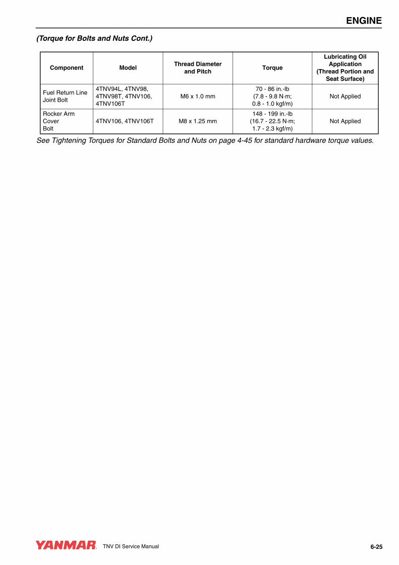
ENGINE
(Torque for Bolts and Nuts Cont.)
See Tightening Torques for Standard Bolts and Nuts on page 4-45 for standard hardware torque values.
Component ModelThread Diameter
and PitchTorque
Lubricating Oil Application
(Thread Portion and Seat Surface)
Fuel Return Line Joint Bolt
4TNV94L, 4TNV98, 4TNV98T, 4TNV106, 4TNV106T
M6 x 1.0 mm70 - 86 in.-lb
(7.8 - 9.8 N·m;0.8 - 1.0 kgf/m)
Not Applied
Rocker Arm Cover Bolt
4TNV106, 4TNV106T M8 x 1.25 mm148 - 199 in.-lb
(16.7 - 22.5 N·m;1.7 - 2.3 kgf/m)
Not Applied
TNV DI Service Manual 6-25
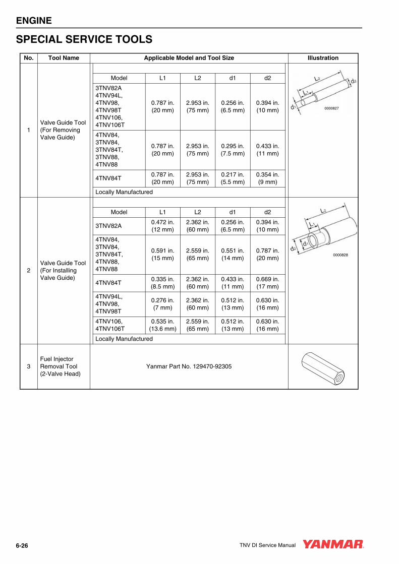
ENGINE
SPECIAL SERVICE TOOLS
No. Tool Name Applicable Model and Tool Size Illustration
1Valve Guide Tool (For Removing Valve Guide)
Model L1 L2 d1 d2
3TNV82A4TNV94L, 4TNV98, 4TNV98T4TNV106, 4TNV106T
0.787 in.(20 mm)
2.953 in.(75 mm)
0.256 in.(6.5 mm)
0.394 in.(10 mm)
4TNV84, 3TNV84, 3TNV84T, 3TNV88, 4TNV88
0.787 in.(20 mm)
2.953 in.(75 mm)
0.295 in.(7.5 mm)
0.433 in.(11 mm)
4TNV84T0.787 in.(20 mm)
2.953 in.(75 mm)
0.217 in.(5.5 mm)
0.354 in.(9 mm)
Locally Manufactured
2Valve Guide Tool (For Installing Valve Guide)
Model L1 L2 d1 d2
3TNV82A0.472 in.(12 mm)
2.362 in.(60 mm)
0.256 in.(6.5 mm)
0.394 in.(10 mm)
4TNV84, 3TNV84, 3TNV84T, 4TNV88, 4TNV88
0.591 in.(15 mm)
2.559 in.(65 mm)
0.551 in.(14 mm)
0.787 in.(20 mm)
4TNV84T0.335 in.(8.5 mm)
2.362 in.(60 mm)
0.433 in.(11 mm)
0.669 in.(17 mm)
4TNV94L, 4TNV98, 4TNV98T
0.276 in.(7 mm)
2.362 in.(60 mm)
0.512 in.(13 mm)
0.630 in.(16 mm)
4TNV106, 4TNV106T
0.535 in.(13.6 mm)
2.559 in.(65 mm)
0.512 in.(13 mm)
0.630 in.(16 mm)
Locally Manufactured
3Fuel Injector Removal Tool (2-Valve Head)
Yanmar Part No. 129470-92305
0000827
0000828
6-26 TNV DI Service Manual
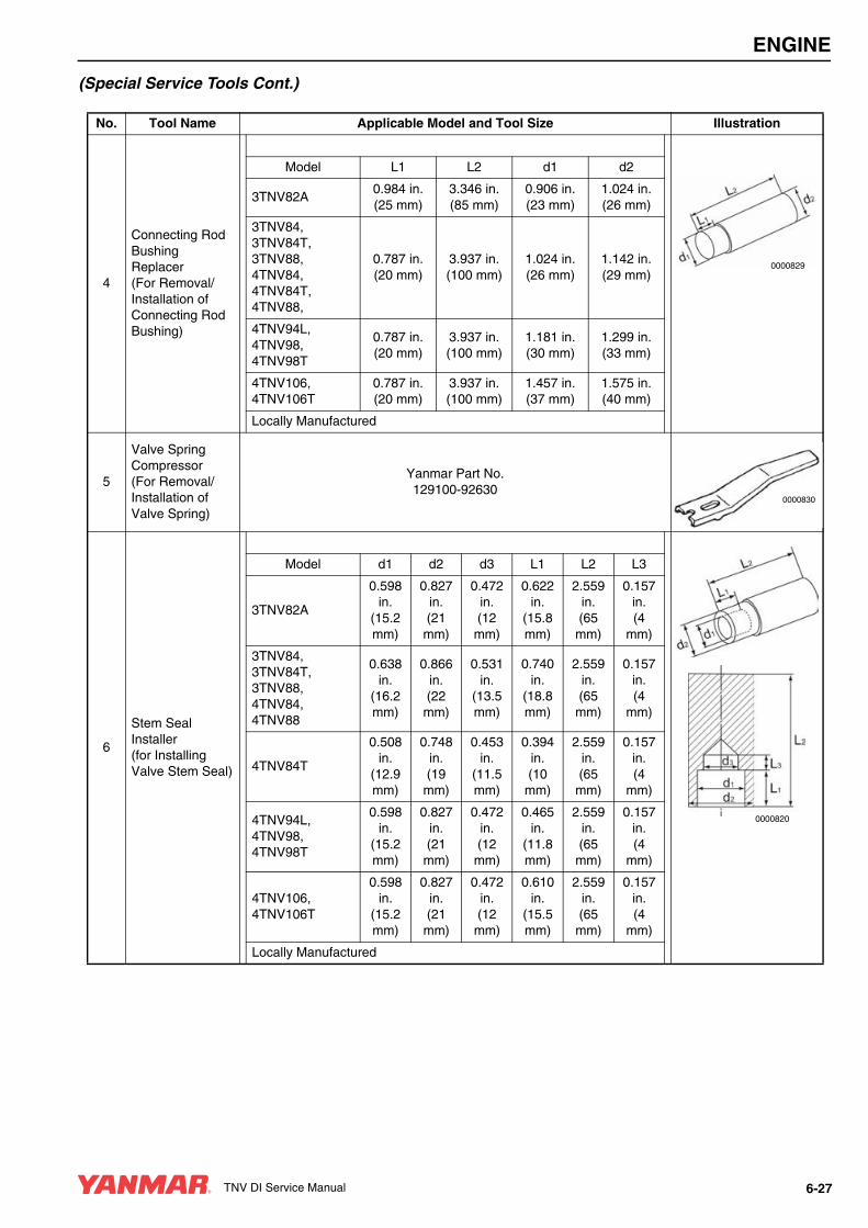
ENGINE
(Special Service Tools Cont.)
No. Tool Name Applicable Model and Tool Size Illustration
4
Connecting Rod Bushing Replacer(For Removal/ Installation of Connecting Rod Bushing)
Model L1 L2 d1 d2
3TNV82A0.984 in.(25 mm)
3.346 in.(85 mm)
0.906 in.(23 mm)
1.024 in.(26 mm)
3TNV84, 3TNV84T, 3TNV88, 4TNV84, 4TNV84T, 4TNV88,
0.787 in.(20 mm)
3.937 in.(100 mm)
1.024 in.(26 mm)
1.142 in.(29 mm)
4TNV94L, 4TNV98, 4TNV98T
0.787 in.(20 mm)
3.937 in.(100 mm)
1.181 in.(30 mm)
1.299 in.(33 mm)
4TNV106, 4TNV106T
0.787 in.(20 mm)
3.937 in.(100 mm)
1.457 in.(37 mm)
1.575 in.(40 mm)
Locally Manufactured
5
Valve Spring Compressor(For Removal/ Installation of Valve Spring)
Yanmar Part No.129100-92630
6
Stem Seal Installer(for Installing Valve Stem Seal)
Model d1 d2 d3 L1 L2 L3
3TNV82A
0.598 in.
(15.2 mm)
0.827 in.(21 mm)
0.472 in.(12 mm)
0.622 in.
(15.8 mm)
2.559 in.(65 mm)
0.157 in.(4
mm)
3TNV84, 3TNV84T, 3TNV88, 4TNV84, 4TNV88
0.638 in.
(16.2 mm)
0.866 in.(22 mm)
0.531 in.
(13.5 mm)
0.740 in.
(18.8 mm)
2.559 in.(65 mm)
0.157 in.(4
mm)
4TNV84T
0.508 in.
(12.9 mm)
0.748 in.(19 mm)
0.453 in.
(11.5 mm)
0.394 in.(10
mm)
2.559 in.(65 mm)
0.157 in.(4
mm)
4TNV94L, 4TNV98, 4TNV98T
0.598 in.
(15.2 mm)
0.827 in.(21 mm)
0.472 in.(12 mm)
0.465 in.
(11.8 mm)
2.559 in.(65 mm)
0.157 in.(4
mm)
4TNV106, 4TNV106T
0.598 in.
(15.2 mm)
0.827 in.(21 mm)
0.472 in.(12 mm)
0.610 in.
(15.5 mm)
2.559 in.(65 mm)
0.157 in.(4
mm)
Locally Manufactured
0000829
0000830
0000820
TNV DI Service Manual 6-27

ENGINE
(Special Service Tools Cont.)
No. Tool Name Applicable Model and Tool Size Illustration
7
Filter Wrench(For Removal / Installation of Engine Oil Filter)
Available Locally
8
Camshaft Bushing Tool(For Extracting Camshaft Bushing)
Model L1 L2 d1 d2
3TNV82A, 3TNV84, 3TNV84T, 3TNV88, 4TNV84, 4TNV84T, 4TNV88
0.709 in.(18 mm)
2.756 in.(70 mm)
1.772 in.(45 mm)
1.890 in.(48 mm)
4TNV94L, 4TNV98, 4TNV98T
0.709 in.(18 mm)
2.756 in.(70 mm)
1.968 in.(50 mm)
2.087 in.(553 mm)
4TNV106, 4TNV106T
0.709 in.(18 mm)
2.756 in.(70 mm)
2.283 in.(58 mm)
2.402 in.(61 mm)
Allowance: d1 d2
Locally Manufactured
9Flex-Hone(For Preparation of Cylinder Walls)
Model Yanmar Part No. Cylinder Bore
3TNV82A 129400-924203.071 - 3.307 in.
(78 - 84 mm)
3TNV88, 4TNV88, 4TNV94L
129400-924303.268 - 3.740 in.
(83 - 95 mm)
4TNV98 129400-924403.504 - 3.976 in.(89 - 101 mm)
4TNV106, 4TNV106T
129400-924503.740 - 4.252 in.(95 - 108 mm)
10
Piston Ring Compressor(For Installing Piston)
Yanmar Part No. 95550-002476The Piston Insertion Tool is Applicable for
2.362 - 4.921 in. (60 - 125 mm) Diameter Pistons
11
Piston Ring Expander(For Removal / Installation of Piston Ring)
Available Locally
0000821
0000822
0000823
0000824
0000825
6-28 TNV DI Service Manual
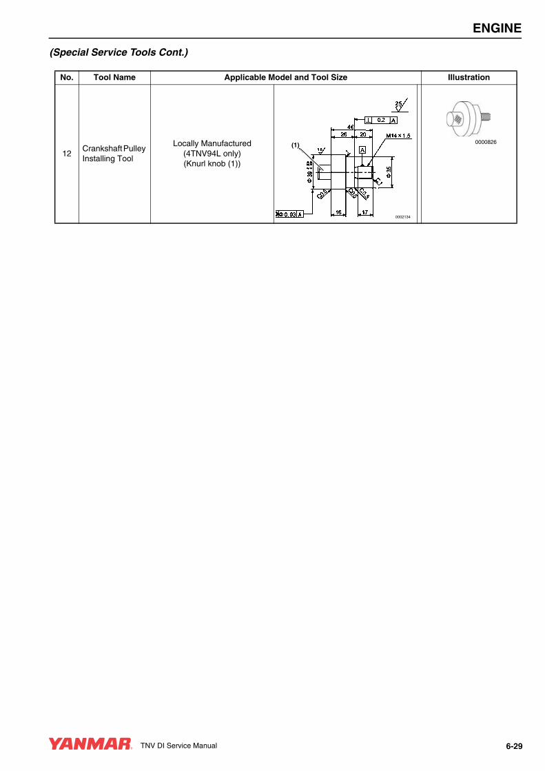
ENGINE
(Special Service Tools Cont.)
No. Tool Name Applicable Model and Tool Size Illustration
12Crankshaft Pulley Installing Tool
Locally Manufactured(4TNV94L only)(Knurl knob (1))
(1)
0002134
0000826
TNV DI Service Manual 6-29
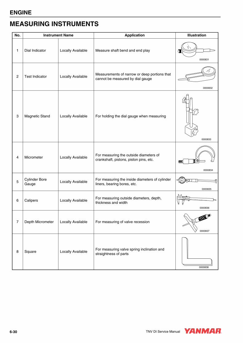
ENGINE
MEASURING INSTRUMENTS
No. Instrument Name Application Illustration
1 Dial Indicator Locally Available Measure shaft bend and end play
2 Test Indicator Locally AvailableMeasurements of narrow or deep portions that cannot be measured by dial gauge
3 Magnetic Stand Locally Available For holding the dial gauge when measuring
4 Micrometer Locally AvailableFor measuring the outside diameters of crankshaft, pistons, piston pins, etc.
5Cylinder Bore Gauge
Locally AvailableFor measuring the inside diameters of cylinder liners, bearing bores, etc.
6 Calipers Locally AvailableFor measuring outside diameters, depth, thickness and width
7 Depth Micrometer Locally Available For measuring of valve recession
8 Square Locally AvailableFor measuring valve spring inclination and straightness of parts
0000831
0000832
0000833
0000834
0000835
0000836
0000837
0000838
6-30 TNV DI Service Manual

ENGINE
9 V-Block Locally Available For measuring shaft bend
10 Torque Wrench Locally AvailableFor tightening nuts and bolts to the specified torque
11 Feeler Gauge Locally AvailableFor measuring piston ring gaps, piston ring clearance, and valve adjustment clearance
No. Instrument Name Application Illustration
0000839
0000840
0000841
TNV DI Service Manual 6-31

ENGINE
2-VALVE CYLINDER HEAD
2-Valve Cylinder Head Components
Figure 6-1
0001919
(27)
(28)
(22)
(21)
(29)
(30)
(31)
(32)
(26)
(23)
(24)(25)
(20)
(19)
(18)
(17)
(12)
(14)
(15)
(16)
(13)
(8)
(7)
(2)(1)
(5)(6)
(4)
(3)
(11)(10)
(33)
(9)
(34)
6-32 TNV DI Service Manual

ENGINE
1 – Valve Cover Nut2 – Valve Cover Nut O-Ring3 – Crankcase Breather Cover4 – Diaphragm Spring5 – Diaphragm Plate6 – Crankcase Breather Diaphragm
(non-turbocharged engines only)7 – Oil FIll Cap8 – Valve Cover Gasket9 – Rocker Arm Shaft Spring10 – Valve Adjusting Screw Lock Nut11 – Valve Adjusting Screw12 – Rocker Arm13 – Rocker Arm Shaft14 – Rocker Arm Shaft Aligning Stud15 – Support Bolt16 – Rocker Arm Shaft Support17 – Valve Cap18 – Valve Keepers19 – Spring Retainer20 – Valve Spring21 – Valve Stem Seal22 – Valve Guide23 – Cylinder Head24 – Intake Valve25 – Exhaust Valve26 – Cylinder Head Gasket27 – Fuel Injector Retainer28 – Washer29 – Fuel Injector Retainer Bolt30 – Fuel Injector Nozzle Protector31 – Fuel Injector Nozzle Seat32 – Push Rod33 – Crankcase Breather Components34 – Valve Cover
Disassembly of 2-Valve Cylinder HeadPrepare a clean, flat working surface on a workbench large enough to accommodate the cylinder head assembly. Discard all gaskets, O-rings and seals. Use new gaskets, O-rings and seals on reassembly of the cylinder head.
1. Drain the coolant from the engine into a suitable container. See Drain, Flush and Refill Cooling System With New Coolant on page 5-35.
2. Disconnect the electrical wire from the intake air heater (Figure 6-2, (1)).
Figure 6-2
CAUTIONIdentify all parts and their location using an appropriate method. It is important that all parts are returned to the same position during the reassembly process.
0000080en
(1)
TNV DI Service Manual 6-33

ENGINE
3. Disconnect the coolant hoses from the cold start device (Figure 6-3, (1)) on the fuel injection pump.
Figure 6-3
4. Remove the intake manifold bolts (Figure 6-4, (1)). Remove the intake manifold (Figure 6-4, (2)). Discard the intake manifold gasket (Figure 6-4, (3)).
Figure 6-4
5. Remove the exhaust manifold bolts (Figure 6-4, (4)) and nuts (Figure 6-4, (5)). Remove the exhaust manifold (Figure 6-4, (6)) and the exhaust manifold gasket (Figure 6-4, (7)).
6. Remove the coolant pump. See Disassembly of Engine Coolant Pump on page 8-10.
7. Remove the high-pressure lines and fuel injectors from the cylinder head. See Removal of Fuel Injectors on page 7-31.
Removal of Valve Cover1. Remove the valve cover nuts (Figure 6-5, (1)).
2. Remove the O-ring (Figure 6-5, (2)) on each valve cover nut.
Figure 6-5
3. Remove the valve cover (Figure 6-5, (3)) and the valve cover gasket (Figure 6-5, (4)).
0002087A
(1)
(5)
(4)
(5)
(2)
(6)(7)
(3)
(1) 0001682
0001920
(4)
(3)
(1)(2)
6-34 TNV DI Service Manual
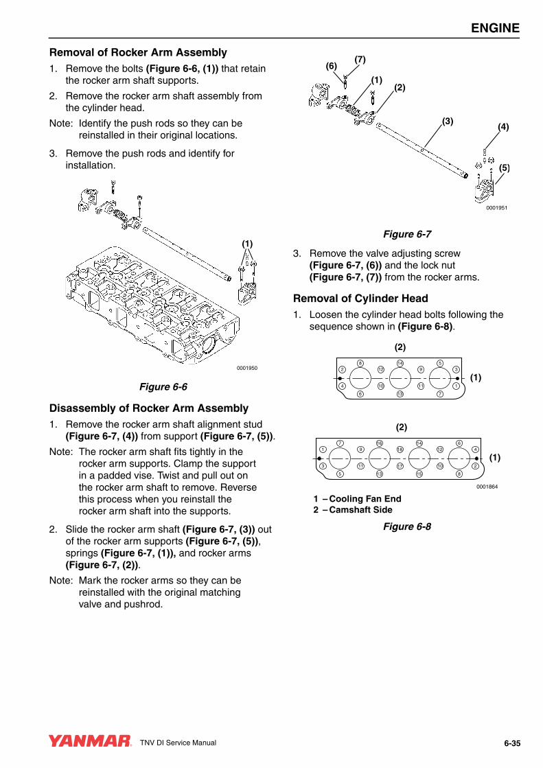
ENGINE
Removal of Rocker Arm Assembly1. Remove the bolts (Figure 6-6, (1)) that retain
the rocker arm shaft supports.
2. Remove the rocker arm shaft assembly from the cylinder head.
Note: Identify the push rods so they can be reinstalled in their original locations.
3. Remove the push rods and identify for installation.
Figure 6-6
Disassembly of Rocker Arm Assembly1. Remove the rocker arm shaft alignment stud
(Figure 6-7, (4)) from support (Figure 6-7, (5)).
Note: The rocker arm shaft fits tightly in the rocker arm supports. Clamp the support in a padded vise. Twist and pull out on the rocker arm shaft to remove. Reverse this process when you reinstall the rocker arm shaft into the supports.
2. Slide the rocker arm shaft (Figure 6-7, (3)) out of the rocker arm supports (Figure 6-7, (5)), springs (Figure 6-7, (1)), and rocker arms (Figure 6-7, (2)).
Note: Mark the rocker arms so they can be reinstalled with the original matching valve and pushrod.
Figure 6-7
3. Remove the valve adjusting screw (Figure 6-7, (6)) and the lock nut (Figure 6-7, (7)) from the rocker arms.
Removal of Cylinder Head1. Loosen the cylinder head bolts following the
sequence shown in (Figure 6-8).
1 – Cooling Fan End2 – Camshaft Side
Figure 6-8
0001950
(1)
0001951
(1)
(5)
(4)(3)
(2)
(6)(7)
(1)
(2)
0001864
16
13
11
97
5
3
114
15
17
186
8
10
12
2
4
(1)
(2)
8
6
4
214
13
10
125
7
11
9
1
3
TNV DI Service Manual 6-35

ENGINE
2. Remove the cylinder head bolts (Figure 6-9, (1)).
3. Lift the cylinder head away from the cylinder block. Discard the cylinder head gasket (Figure 6-9, (2)). Position the cylinder head on the work bench to prevent damage to the combustion surface.
Figure 6-9
Removal of Intake / Exhaust Valves1. Place the cylinder head on the work bench with
the combustion side down.
2. Remove the valve cap (Figure 6-11, (1)) and keep with the valve it was installed on.
3. Using the valve spring compressor tool, compress one of the valve springs (Figure 6-10).
Figure 6-10
4. Remove the valve keepers (Figure 6-11, (2)).
5. Slowly release the tension on the valve spring.
6. Remove the spring retainer (Figure 6-11, (3)) and valve spring (Figure 6-11, (4)).
Figure 6-11
7. Repeat the procedure with all remaining valves.
Note: If the valves are to be reused, identify them so they can be installed in their original location.
8. Turn the cylinder head so the exhaust port side faces down. Remove the intake and exhaust valves (Figure 6-11, (6)) from the cylinder head.
9. Remove the valve stem seals (Figure 6-11, (5)).
(1)
(2)
0001690
0000191
(6)
(5)
(4)
(3)(2)
(1)
0001684
6-36 TNV DI Service Manual

ENGINE
Removal of Valve GuidesNote: Removal of the valve guides should be
postponed until inspection and measurement procedures have been performed. See Inspection of Valve Guides on page 6-39.
1. If the valve guides were not within specifications, use a drift pin and hammer to drive the valve guides (Figure 6-12, (1)) out of the cylinder head.
Figure 6-12
Cleaning of Cylinder Head Components
Thoroughly clean all components using a non-metallic brush and an appropriate solvent. Each part must be free of carbon, metal filings and other debris.
Inspection of Cylinder Head ComponentsVisually inspect the parts. Replace any parts that are obviously discolored, heavily pitted or otherwise damaged. Discard any parts that do not meet its specified limit.
(1)
001689
A WARNING
FUME / BURN HAZARD!• Always read and follow safety related
precautions found on containers of hazardous substances like parts cleaners, primers, sealants and sealant removers.
• Failure to comply could result in death or serious injury.
0000014en
CAUTIONAny part which is found defective as a result of inspection or any part whose measured value does not satisfy the standard or limit must be replaced.
0000119en
TNV DI Service Manual 6-37

ENGINE
Inspection of Push Rods
Push Rod BendDetermine if the bend of the push rods are within the specified limit.
1. Place the push rods on a flat inspection block or layout bed.
2. Roll the push rods until a gap can be observed between a portion of the push rod and the surface of the block or layout bed.
3. Use a feeler gauge to measure the gap (Figure 6-13). See Push Rod on page 6-8 for the service limit.
Figure 6-13
Inspection of Rocker Arm Assembly
Rocker Arm Shaft Hole DiameterUse a test indicator and micrometer to determine if the inside diameter of all the rocker arm support brackets and the rocker arms (Figure 6-14) are within the specified limits. See Rocker Arm and Shaft on page 6-9 for the service limit.
Inspect the contact areas (Figure 6-14, (1)) for excessive wear or damage.
Figure 6-14
CAUTIONAny part determined to not meet the service standard or limit before the next service, as determined from the state of current rate of wear, should be replaced even though the part currently meets the service standard limit.
0000120en
0000204
0001916
(1)(1)
6-38 TNV DI Service Manual
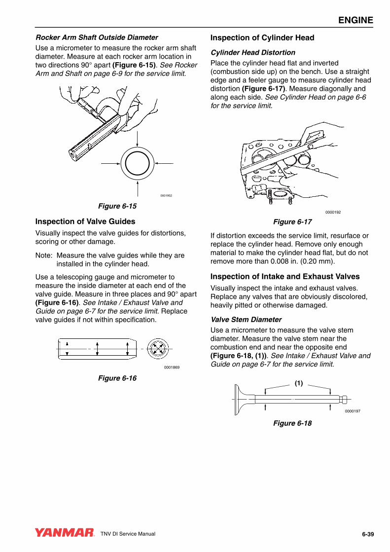
ENGINE
Rocker Arm Shaft Outside DiameterUse a micrometer to measure the rocker arm shaft diameter. Measure at each rocker arm location in two directions 90° apart (Figure 6-15). See Rocker Arm and Shaft on page 6-9 for the service limit.
Figure 6-15
Inspection of Valve GuidesVisually inspect the valve guides for distortions, scoring or other damage.
Note: Measure the valve guides while they are installed in the cylinder head.
Use a telescoping gauge and micrometer to measure the inside diameter at each end of the valve guide. Measure in three places and 90° apart (Figure 6-16). See Intake / Exhaust Valve and Guide on page 6-7 for the service limit. Replace valve guides if not within specification.
Figure 6-16
Inspection of Cylinder Head
Cylinder Head DistortionPlace the cylinder head flat and inverted (combustion side up) on the bench. Use a straight edge and a feeler gauge to measure cylinder head distortion (Figure 6-17). Measure diagonally and along each side. See Cylinder Head on page 6-6 for the service limit.
Figure 6-17
If distortion exceeds the service limit, resurface or replace the cylinder head. Remove only enough material to make the cylinder head flat, but do not remove more than 0.008 in. (0.20 mm).
Inspection of Intake and Exhaust ValvesVisually inspect the intake and exhaust valves. Replace any valves that are obviously discolored, heavily pitted or otherwise damaged.
Valve Stem DiameterUse a micrometer to measure the valve stem diameter. Measure the valve stem near the combustion end and near the opposite end (Figure 6-18, (1)). See Intake / Exhaust Valve and Guide on page 6-7 for the service limit.
Figure 6-18
0001952
0001869
0000192
0000197
(1)
TNV DI Service Manual 6-39

ENGINE
Valve Stem BendPlace the valve stem on a flat inspection block or layout bed. Roll the valve until a gap can be observed between a portion of the valve stem and the surface of the block or bed. Use a feeler gauge to measure the gap (Figure 6-19). See Intake /Exhaust Valve and Guide on page 6-7 for the
service limit.
Figure 6-19
Valve RecessionNote: The valve guides must be installed to
perform this check.
Insert the valves into their original locations and press them down until they are fully seated. Use a depth micrometer (Figure 6-20) to measure the difference between the cylinder head gasket surface and the combustion surface of each exhaust and intake valve (Figure 6-21). See Cylinder Head on page 6-6 for the service limit.
Figure 6-20
Figure 6-21
Valve Face and Valve SeatAlways check the clearance between the valve and valve guide before grinding or lapping the valve seats. See Intake / Exhaust Valve and Guide on page 6-7 for the service limit. If the clearance exceeds the limit, replace the valve and / or valve guide to bring the clearance within the limit.
Roughness or burrs will cause poor seating of a valve. Visually inspect the seating surfaces of each valve and valve seat to determine if lapping or grinding is needed.
Visually inspect all valve faces and valve seats for pitting, distortion, cracking, or evidence of overheating. Usually the valves and the valve seats can be lapped or ground to return them to serviceable condition. Severely worn or damaged components will require replacement.
Coat the valve seat with a thin coat of bluing compound. Install the valve and rotate it to distribute bluing onto the valve face. The contact pattern should be approximately centered on the valve face (Figure 6-22, (1)) and even in width.
0000199
0000193
0001755
6-40 TNV DI Service Manual

ENGINE
Figure 6-22
Also visually inspect the valve seat for even contact.
Light cutting can be performed by the use of a hand-operated cutter (Figure 6-23, (3)).
Figure 6-23
The valve seat diameter can be adjusted by top-grinding with a 150° stone to make the seat diameter smaller, and bottom-grinding using a 40° stone to make the seat diameter larger. Once the seat location has been corrected, grind and lap the seat angle (Figure 6-23, (1)) to specification. See Cylinder Head on page 6-6 for specifications.
Grind the valve face and / or valve seat only enough to return them to serviceable condition. Grinding is needed if the valve and the valve seat do not contact correctly. Check the recession after grinding.
If the valve or seat require grinding, lap the valve after grinding. Lap the valve face to the valve seat using a mixture of valve lapping compound and engine oil.
Be sure to thoroughly wash all parts to remove all grinding powder or compound.
Inspection of Valve SpringsInspect the valve springs. If damage or corrosion is seen, or if measurements exceed the specified limits, replace the springs.
FracturesCheck for fractures on the inside and outside portions of the springs. If the valve spring is fractured, replace the valve spring.
CorrosionCheck for corrosion of the spring material caused by oxidation.
SquarenessUse a flat surface and a square to check each spring for squareness (Figure 6-24). See Valve Spring on page 6-9 for the service limit.
Figure 6-24
Free LengthUse a caliper to measure the length of the spring (Figure 6-25). See Valve Spring on page 6-9 for the service limit.
0001691B
(1)
0001862
(1)40°150°
(2)(3)
0000201
TNV DI Service Manual 6-41

ENGINE
Figure 6-25
Reassembly of Cylinder HeadUse new gaskets, O-rings and seals for the reassembly of the cylinder head.
IMPORTANTLiberally oil all components during reassembly to prevent premature wear or damage.
Reassembly of Valve Guides1. The valve guides are installed into the cylinder
head with an extremely tight press fit. Before installing the valve guides, place the valve guides in a freezer for at least twenty minutes This will cause the valve guides to contract, making it easier to install the valve guides into place.
2. Immediately after removing the valve guides from the freezer, insert the valve guides (Figure 6-26, (1)) in their proper positions.
Figure 6-26
3. Finish installing the valve guides (Figure 6-27, (1)) into the cylinder head to the proper height (Figure 6-27, (3)) using the valve guide installation tool (Figure 6-27, (2)). See Intake / Exhaust Valve and Guide on page 6-7.
Figure 6-27
01
2 34
56
7
98
0000200
(1)
001689
0001756A
(3)
(2)
(1)
6-42 TNV DI Service Manual

ENGINE
Reassembly of Intake and Exhaust Valves
IMPORTANTAlways install new valve stem seals. The exhaust seals can be identified by having yellow paint. Ensure they are installed in the correct locations.
1. Oil the lip of the valve stem seal (Figure 6-28, (2)). Using the valve stem seal installation tool (Figure 6-28, (1)), install a new valve stem seal on each of the valve guides (Figure 6-28, (3)).
Figure 6-28
2. Measure the distance (Figure 6-29, (1)) from the cylinder head to valve stem seal to ensure proper clearance (Figure 6-29, (2)) between the guide and the seal. See Intake / Exhaust Valve and Guide on page 6-7.
Figure 6-29
3. Place the cylinder head assembly on its exhaust port side.
4. Place all the valves (Figure 6-30, (6)) in their proper location in the cylinder head.
Figure 6-30
5. Place the cylinder head on the workbench with the combustion side down to install the valve springs. Install the valve spring (Figure 6-30, (4)) and the spring retainer (Figure 6-30, (5)).
6. Using the valve spring compressor tool, compress the valve spring.
7. Insert the valve keepers (Figure 6-30, (2)) and slowly release the tension on the valve spring. Install the valve cap (Figure 6-30, (1)). Repeat the steps on all the remaining valves.
0001873
(3)
(2)
(1)
(1)(2)
0001874
(6)
(5)
(4)
(3)(2)
(1)
0001684
TNV DI Service Manual 6-43

ENGINE
Reassembly of Cylinder Head1. Carefully clean both the combustion surface of
the cylinder head and the top surface of the cylinder block. Then place a new cylinder head gasket (Figure 6-31, (2)) on the cylinder block.
2. Position the cylinder head on the cylinder head gasket.
Figure 6-31
3. Lightly oil the threads of the cylinder head bolts (Figure 6-31, (1)). Tighten the bolts to the specified torque in two steps as shown in the chart below. Tighten in the sequence shown in (Figure 6-32). See Special Torque Chart on page 6-23 for specification.
4. Insert the push rods in their respective positions.
1 – Fan End2 – Camshaft Side
Figure 6-32
Reassembly of Rocker Arm ReassemblyNote: Ensure the lubrication holes
(Figure 6-33, (1)) in the rocker arm shaft are oriented correctly with respect to the rocker arms (Figure 6-33, (2)).
Figure 6-33
(1)
(2)
0001690
First Step 1/2 of final torque
Second Step Final torque
(1)
(2)
0001875
3
6
8
1012
14
16
185
4
2
113
11
9
7
17
15
(1)
(2)
7
9
11
131
2
5
310
8
4
6
14
12
(2)
(1)
(1)
0001914
6-44 TNV DI Service Manual
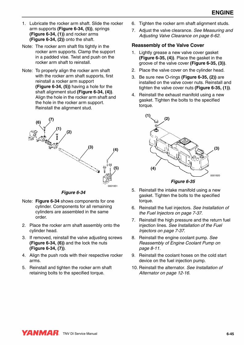
ENGINE
1. Lubricate the rocker arm shaft. Slide the rocker arm supports (Figure 6-34, (5)), springs (Figure 6-34, (1)) and rocker arms (Figure 6-34, (2)) onto the shaft.
Note: The rocker arm shaft fits tightly in the rocker arm supports. Clamp the support in a padded vise. Twist and push on the rocker arm shaft to reinstall.
Note: To properly align the rocker arm shaft with the rocker arm shaft supports, first reinstall a rocker arm support (Figure 6-34, (5)) having a hole for the shaft alignment stud (Figure 6-34, (4)). Align the hole in the rocker arm shaft and the hole in the rocker arm support. Reinstall the alignment stud.
Figure 6-34
Note: Figure 6-34 shows components for one cylinder. Components for all remaining cylinders are assembled in the same order.
2. Place the rocker arm shaft assembly onto the cylinder head.
3. If removed, reinstall the valve adjusting screws (Figure 6-34, (6)) and the lock the nuts (Figure 6-34, (7)).
4. Align the push rods with their respective rocker arms.
5. Reinstall and tighten the rocker arm shaft retaining bolts to the specified torque.
6. Tighten the rocker arm shaft alignment studs.
7. Adjust the valve clearance. See Measuring and Adjusting Valve Clearance on page 6-62.
Reassembly of the Valve Cover1. Lightly grease a new valve cover gasket
(Figure 6-35, (4)). Place the gasket in the groove of the valve cover (Figure 6-35, (3)).
2. Place the valve cover on the cylinder head.
3. Be sure new O-rings (Figure 6-35, (2)) are installed on the valve cover nuts. Reinstall and tighten the valve cover nuts (Figure 6-35, (1)).
4. Reinstall the exhaust manifold using a new gasket. Tighten the bolts to the specified torque.
Figure 6-35
5. Reinstall the intake manifold using a new gasket. Tighten the bolts to the specified torque.
6. Reinstall the fuel injectors. See Installation of the Fuel Injectors on page 7-37.
7. Reinstall the high pressure and the return fuel injection lines. See Installation of the Fuel Injectors on page 7-37.
8. Reinstall the engine coolant pump. See Reassembly of Engine Coolant Pump on page 8-11.
9. Reinstall the coolant hoses on the cold start device on the fuel injection pump.
10. Reinstall the alternator. See Installation of Alternator on page 12-16.
0001951
(1)
(5)
(4)(3)
(2)
(6)(7)
0001920
(4)
(3)
(1)(2)
TNV DI Service Manual 6-45
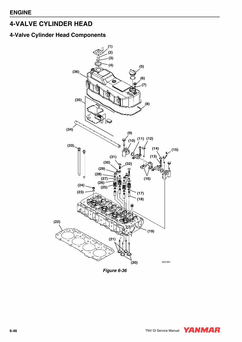
ENGINE
4-VALVE CYLINDER HEAD
4-Valve Cylinder Head Components
Figure 6-36
0001861
(5)
(6)
(8)(35)
(7)
(1)
(2)
(3)
(4)
(36)
(33)
(24)
(22)
(21)
(23)(25)
(26)
(28)
(29)
(30)
(31)
(32)
(13)
(14)
(16)
(17)
(18)
(19)
(15)
(9)
(10)(12)(11)
(27)
(34)
(20)
6-46 TNV DI Service Manual

ENGINE
1 – Crankcase Breather Cover2 – Diaphragm Spring3 – Diaphragm Cup4 – Crankcase Breather Diaphragm5 – Oil Fill Cap6 – Valve Cover Nut7 – Valve Cover Nut O-Ring8 – Valve Cover Gasket9 – Support Bolt10 – Rocker Arm Shaft Support11 – Wave Washer12 – Fuel Injector Retainer Bolt13 – Valve Adjusting Screw (Primary)14 – Valve Adjusting Screw Lock Nut (Primary)15 – Rocker Arm Shaft Aligning Stud16 – Fuel Injector Retainer17 – Valve Stem Seal18 – Valve Guide19 – Cylinder Head20 – Intake Valve21 – Exhaust Valve22 – Cylinder Head Gasket23 – Fuel Injector Nozzle Protector24 – Fuel Injector Nozzle Seat25 – Valve Spring26 – Valve Bridge Guide27 – Spring Retainer28 – Valve Keepers29 – Valve Bridge30 – Valve Bridge Seat31 – Valve Adjusting Screw Lock Nut
(Secondary)32 – Valve Adjusting Screw (Secondary)33 – Push Rod34 – Rocker Arm Shaft35 – Crankcase Breather Components36 – Valve Cover
Disassembly of 4-Valve Cylinder HeadPrepare a clean, flat working surface on a workbench large enough to accommodate the cylinder head assembly. Discard all gaskets, O-rings and seals. Use new gaskets, O-rings and seals on reassembly of the cylinder head.
1. Drain the coolant from the engine into a suitable container. See Drain, Flush and Refill Cooling System With New Coolant on page 5-35.
2. Remove the high pressure fuel injection lines (Figure 6-37, (1)). See Removal of Fuel Injectors on page 7-31.
Figure 6-37
3. Disconnect the fuel return hose (Figure 6-37, (2)) from the cylinder head.
4. Disconnect the hoses (Figure 6-37, (3)) from the cold start device on the fuel injection pump.
CAUTIONIdentify all parts and their location using an appropriate method. It is important that all parts are returned to the same position during the reassembly process.
0000080en
CAUTIONRemove or install the high-pressure fuel injection lines as an assembly whenever possible. Disassembling the high-pressure fuel injection lines from the retainers or bending any of the fuel lines will make it difficult to reinstall the fuel lines.
0000047en
0001876
(1)
(2)
(3)
TNV DI Service Manual 6-47
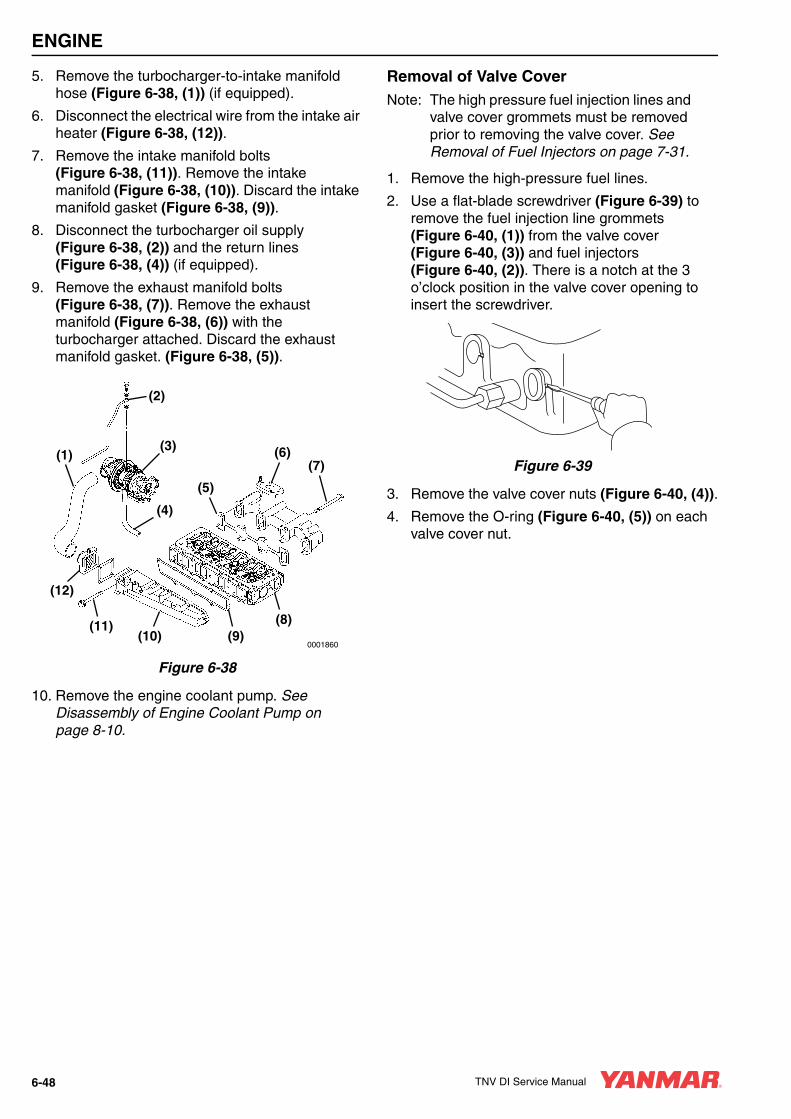
ENGINE
5. Remove the turbocharger-to-intake manifold hose (Figure 6-38, (1)) (if equipped).
6. Disconnect the electrical wire from the intake air heater (Figure 6-38, (12)).
7. Remove the intake manifold bolts (Figure 6-38, (11)). Remove the intake manifold (Figure 6-38, (10)). Discard the intake manifold gasket (Figure 6-38, (9)).
8. Disconnect the turbocharger oil supply (Figure 6-38, (2)) and the return lines (Figure 6-38, (4)) (if equipped).
9. Remove the exhaust manifold bolts (Figure 6-38, (7)). Remove the exhaust manifold (Figure 6-38, (6)) with the turbocharger attached. Discard the exhaust manifold gasket. (Figure 6-38, (5)).
Figure 6-38
10. Remove the engine coolant pump. See Disassembly of Engine Coolant Pump on page 8-10.
Removal of Valve CoverNote: The high pressure fuel injection lines and
valve cover grommets must be removed prior to removing the valve cover. See Removal of Fuel Injectors on page 7-31.
1. Remove the high-pressure fuel lines.
2. Use a flat-blade screwdriver (Figure 6-39) to remove the fuel injection line grommets (Figure 6-40, (1)) from the valve cover (Figure 6-40, (3)) and fuel injectors (Figure 6-40, (2)). There is a notch at the 3 o’clock position in the valve cover opening to insert the screwdriver.
Figure 6-39
3. Remove the valve cover nuts (Figure 6-40, (4)).
4. Remove the O-ring (Figure 6-40, (5)) on each valve cover nut.
0001860
(1)
(2)
(3)
(4)
(5)
(6)(7)
(8)(9)(10)
(11)
(12)
6-48 TNV DI Service Manual

ENGINE
Figure 6-40
5. Remove the valve cover (Figure 6-40, (3)). Discard the valve cover gasket (Figure 6-40, (6)).
6. Inspect and clean the crankcase breather assembly. See Inspect Crankcase Breather System on page 5-38.
Removal of Rocker Arm Assembly1. Remove the fuel injectors from the cylinder
head. See Removal of Fuel Injectors on page 7-31.
2. Remove the bolts (Figure 6-41, (1)) that retain the rocker arm shaft supports to the cylinder head.
3. Remove the rocker arm and shaft assembly from the cylinder head.
Note: Identify the push rods and valve bridges so they can be installed in their original locations.
4. Remove the push rods (Figure 6-41, (2)).
5. Remove the valve bridge assemblies (Figure 6-41, (3)). Remove the seat (Figure 6-41, (4)) from each valve bridge.
6. Identify all parts so that they will be reinstalled in their original locations.
Figure 6-41
0001877
(2)
(3)
(4)
(1)
(5)
(6)
(2)
(4)(3)
(1)
000187
TNV DI Service Manual 6-49

ENGINE
Disassembly of Rocker Arm AssemblyNote: Identify the rocker arms so they can be
reinstalled with the original matching valve and pushrod.
1. Remove the rocker arm shaft alignment studs (Figure 6-42, (5)) from the rocker arm shaft supports (Figure 6-42, (6)).
2. Slide the supports, wave washers (Figure 6-42, (7)), rocker arms (Figure 6-42, (8)), and fuel injector retainers (Figure 6-42, (4)) off the rocker shaft (Figure 6-42, (1)), leaving these parts in order on the bench surface.
Figure 6-42
Note: Figure 6-42 shows components for one cylinder. Components for all remaining cylinders are assembled in the same order.
3. Remove the valve adjusting screw (Figure 6-42, (2)) and the lock nut (Figure 6-42, (3)) from the rocker arms.
Removal of Cylinder Head1. Loosen the cylinder head bolts following the
sequence shown in (Figure 6-43).
1 – Cooling Fan End2 – Camshaft Side
Figure 6-43
2. Remove the cylinder head bolts (Figure 6-44, (1)).
3. Lift the cylinder head away from the cylinder block. Discard the cylinder head gasket (Figure 6-44, (2)). Place the cylinder head on the work bench to prevent damage to the combustion surface.0001866
(7)(6)
(8)
(5)
(1)
(4)(2)
(3)
(1)
(2)
0001864
16
13
11
97
5
3
114
15
17
186
8
10
12
2
4
(1)
(2)
8
6
4
214
13
10
125
7
11
9
1
3
6-50 TNV DI Service Manual

ENGINE
Figure 6-44
Removal of Intake and Exhaust Valves1. Place the cylinder head on the work bench with
the combustion side down.
2. Using the valve spring compressor tool, compress one of the valve springs (Figure 6-45).
Figure 6-45
3. Remove the valve keepers (Figure 6-46, (1)).
4. Slowly release the tension on the valve spring.
5. Remove the spring retainer (Figure 6-46, (2)), valve spring (Figure 6-46, (3)).
Figure 6-46
6. Repeat the procedure with all the remaining valves.
Note: If the valves are to be reused, identify them so they can be installed in their original location.
7. Remove the injector nozzle protectors (Figure 6-46, (6)) and the seats (Figure 6-46, (7)).
8. Turn the cylinder head so the exhaust port side faces down. Remove the intake and exhaust valves (Figure 6-46, (5)) from the cylinder head.
9. Remove the valve stem seals (Figure 6-46, (4)).
(2)
(1)
0001872
0000191
0001867
(1)
(5)
(3)
(4)
(7)
(6)(2)
TNV DI Service Manual 6-51

ENGINE
Removal of Valve GuidesNote: Removal of the valve guides should be
postponed until inspection and measurement procedures have been performed. See Inspection of Valve Guides on page 6-54.
1. Using a drift pin and hammer, drive the valve guides (Figure 6-47, (1)) out of the cylinder head.
Figure 6-47
Cleaning of Cylinder Head Components
Thoroughly clean all components using a non-metallic brush and an appropriate solvent. Each part must be free of carbon, metal filings and other debris.
Inspection of Cylinder Head ComponentsVisually inspect the parts. Replace any parts that are obviously discolored, heavily pitted or otherwise damaged. Discard any parts that do not meet its specified limit.
A WARNING
FUME / BURN HAZARD!• Always read and follow safety related
precautions found on containers of hazardous substances like parts cleaners, primers, sealants and sealant removers.
• Failure to comply could result in death or serious injury.
0000014en
0001868
(1)
CAUTIONAny part which is found defective as a result of inspection or any part whose measured value does not satisfy the standard or limit must be replaced.
0000119en
CAUTIONAny part determined to not meet the service standard or limit before the next service, as determined from the state of current rate of wear, should be replaced even though the part currently meets the service standard limit.
0000120en
6-52 TNV DI Service Manual

ENGINE
Inspection of Push Rods
Push Rod Bend1. Place the push rods on a flat inspection block or
layout bed.
2. Roll the push rods until a gap can be observed between a portion of the push rod and the surface of the block or layout bed.
3. Use a feeler gauge to measure the gap (Figure 6-48). See Push Rod on page 6-8 for the service limit.
Figure 6-48
Inspection of Rocker Arm Assembly
Rocker Arm Shaft Hole Diameter1. Use a telescoping gauge and micrometer to
determine if the inside diameter of all the rocker arm support brackets and the rocker arms (Figure 6-49) are within the specified limits. See Rocker Arm and Shaft on page 6-9 for the service limit.
2. Inspect the contact areas (Figure 6-49, (1)) for excessive wear or damage.
Figure 6-49
Rocker Arm Shaft Outside DiameterUse a micrometer to measure the rocker arm shaft diameter (Figure 6-50). Measure at each rocker arm location in two directions 90° apart (Figure 6-50). See Rocker Arm and Shaft on page 6-9 for the service limit.
Figure 6-50
0000204
0001916
(1)(1)
0001952
TNV DI Service Manual 6-53

ENGINE
Inspection of Valve Guides
Valve Guide Inside DiameterVisually inspect the valve guides for distortions, scoring or other damage.
Note: Measure the valve guides while they are installed in cylinder head.
Use a telescoping gauge and micrometer to measure the inside diameter at each end of the valve guide. Measure in three places and 90° apart (Figure 6-51). See Intake / Exhaust Valve and Guide on page 6-7 for the service limit. Replace the valve guides if not within specification.
Figure 6-51
Inspection of Cylinder Head
Cylinder Head DistortionPlace the cylinder head flat and inverted (combustion side up) on the bench. Use a straight edge and feeler gauge to measure cylinder head distortion (Figure 6-52). Measure diagonally and along each side. See Cylinder Head on page 6-6 for the service limit.
Figure 6-52
If distortion exceeds the service limit, resurface or replace the cylinder head. Remove only enough material to make the cylinder head flat, but do not remove more than 0.008 in (0.20 mm).
Inspection of Intake and Exhaust ValvesVisually inspect the intake and exhaust valves. Replace any valves that are obviously discolored, heavily pitted or otherwise damaged.
Valve Stem DiameterUse a micrometer to measure the valve stem diameter. Measure the valve stem near the combustion end and near the opposite end (Figure 6-53, (1)). See Intake / Exhaust Valve and Guide on page 6-7 for the service limit.
Figure 6-53
0001869
0000192
0000197
(1)
6-54 TNV DI Service Manual

ENGINE
Valve Stem BendPlace the valve stem on a flat inspection block or layout bed. Roll the valve until a gap can be observed between a portion of the valve stem and the surface of the block or bed. Use a feeler gauge to measure the gap (Figure 6-54). See Intake /Exhaust Valve and Guide on page 6-7 for the service limit.
Figure 6-54
Valve RecessionNote: The valve guides must be installed to
perform this check.
Insert the valves into their original locations and press them down until they are fully seated. Use a depth micrometer (Figure 6-55) to measure the difference between the cylinder head gasket surface and the combustion surface of each exhaust and intake valve (Figure 6-56). See Cylinder Head on page 6-6 for the service limit.
Figure 6-55
Note: 2-Valve cylinder head is shown. 4-Valve cylinder head is similar.
Figure 6-56
Valve Face and Valve SeatAlways check the clearance between the valve and valve guide before grinding or lapping the valve seats. See Intake / Exhaust Valve and Guide on page 6-7 for the service limit. If the clearance exceeds the limit, replace the valve and/or valve guide to bring the clearance within the limit.
Roughness or burrs will cause poor seating of a valve. Visually inspect the seating surfaces of each valve and valve seat to determine if lapping or grinding is needed.
Visually inspect all valves faces and valve seats for pitting, distortion, cracking, or evidence of overheating. Usually the valves and valve seats can be lapped or ground to return them to serviceable condition. Severely worn or damaged components will require replacement.
0000199
0000193
0001755
TNV DI Service Manual 6-55

ENGINE
Coat the valve seat with a thin coat of bluing compound. Install the valve and rotate to distribute bluing onto the valve face. The contact pattern should be approximately centered on the valve face (Figure 6-57, (1)) and even in width.
Figure 6-57
Also visually inspect the valve seat for even contact.
Light cutting can be performed by the use of a hand-operated cutter (Figure 6-58).
Figure 6-58
Valve seat diameter can be adjusted by top-grinding with a 150° stone to make the seat diameter smaller, and bottom-grinding using a 40° stone to make the seat diameter larger. Once the seat location has been corrected, grind and lap the seat angle (Figure 6-58, (1)) to specification. See Cylinder Head on page 6-6 for specifications.
Grind the valve face and/or valve seat as necessary to return them to serviceable condition. Grinding is needed if the valve and valve seat do not contact correctly. Check the valve margin and valve recession after grinding.
If the valve or seat require grinding, lap the valve after grinding. Lap the valve face to the valve seat using a mixture of valve lapping compound and engine oil.
Be sure to thoroughly wash all parts to remove all grinding powder or compound.
Inspection of Valve SpringsInspect the valve springs. If damage or corrosion is seen, or if measurements exceed the specified limits, replace the springs.
FracturesCheck for fractures on the inside and outside portions of the springs. If the valve spring is fractured, replace the valve spring.
CorrosionCheck for corrosion of spring material caused by oxidation.
SquarenessUse a flat surface and a square to check each spring for squareness (Figure 6-59). See Valve Spring on page 6-9 for the service limit.
Figure 6-59
0001691B
(1)
0001862
(1)40°150°
(2)(3)
0000201
6-56 TNV DI Service Manual

ENGINE
Free LengthUse a caliper to measure the length of the spring (Figure 6-60). See Valve Spring on page 6-9 for the service limit.
Figure 6-60
Inspection of Valve BridgesVisually inspect the contact surface at both ends of the valve bridge (Figure 6-61, (2)) for excessive wear or mushrooming.
Remove and inspect the seat (Figure 6-61, (1)).
Measure the diameter of the valve bridge guide pin bore in the valve bridge and guide pin (Figure 6-61, (3)). See Rocker Arm and Shaft on page 6-9 for the service limit.
Figure 6-61
Reassembly of Cylinder HeadUse new gaskets, O-rings, and seals on reassembly of the cylinder head.
IMPORTANTLiberally oil all components during reassembly to prevent premature wear or damage.
Reassembly of Valve Guides1. The valve guides are installed into the cylinder
head with an extremely tight press fit. Before installing the valve guides, place the valve guides in a freezer for at least twenty minutes This will cause the valve guides to contract, making it easier to install the valve guides into place.
2. Immediately after removing the valve guides from the freezer, insert the valve guides (Figure 6-62, (1)) in their proper positions.
Figure 6-62
01
2 34
56
7
98
0000200
(2)
(3)
(1)0001868
(1)
TNV DI Service Manual 6-57

ENGINE
3. Finish installing the valve guides (Figure 6-63, (1)) into the cylinder head to the proper height (Figure 6-63, (3)) using the valve guide installation tool (Figure 6-63, (2)). See Intake / Exhaust Valve and Guide on page 6-7.
Figure 6-63
Reassembly of Intake and Exhaust Valves
IMPORTANTAlways install new valve stem seals. The exhaust valve seals can be identified by having yellow paint. Ensure they are installed in the correct locations.
1. Oil the lip of the valve stem seal (Figure 6-64, (2)). Using the valve stem seal installation tool (Figure 6-64, (1)), install a new valve stem seal on each of the valve guides (Figure 6-64, (3)).
Figure 6-64
2. Measure the distance (Figure 6-65, (1)) from the cylinder head to the valve stem seal to ensure proper clearance (Figure 6-65, (2)) between the guide and seal. See Intake /Exhaust Valve and Guide on page 6-7.
Figure 6-65
3. Place the cylinder head assembly on its exhaust port side.
4. Place all the valves (Figure 6-66, (5)) in their proper location in the cylinder head.
Figure 6-66
5. Place the cylinder head on the workbench with the combustion side down. Install the valve spring (Figure 6-66, (3)) and spring retainer (Figure 6-66, (2)).
6. Using the valve spring compressor tool, compress the valve spring.
0001756A
(3)
(2)
(1)
0001873
(3)
(2)
(1)
(1)(2)
0001874
0001867
(1)
(5)
(3)
(4)
(7)
(6)(2)
6-58 TNV DI Service Manual

ENGINE
7. Insert the valve keepers (Figure 6-66, (1)) and slowly release the tension in the valve spring. Repeat the steps on all the remaining valves.
Reassembly of Cylinder Head1. Carefully clean both the combustion surface of
the cylinder head and the top surface of the cylinder block. Then place a new cylinder head gasket (Figure 6-67, (2)) on the cylinder block.
2. Position the cylinder head on the on the cylinder head gasket.
Figure 6-67
3. Lightly oil the threads of the cylinder head bolts (Figure 6-67, (1)). Tighten the bolts to the specified torque in two steps as shown in the chart below. Tighten in the sequence shown in (Figure 6-68). See Special Torque Chart on page 6-23 for specification.
1 – Fan End2 – Camshaft Side
Figure 6-68
Reassembly of Rocker Arm Assembly1. Reinstall the valve bridges (Figure 6-69, (3)) in
their original locations and ensure each seat (Figure 6-69, (4)) is in place.
2. Insert the push rods (Figure 6-69, (2)) in their original locations.
Figure 6-69First Step 1/2 of final torque
Second Step Final torque
(2)
(1)
0001872
(1)
(2)
0001875
3
6
8
1012
14
16
185
4
2
113
11
9
7
17
15
(1)
(2)
7
9
11
131
2
5
310
8
4
6
14
12
(2)
(4)(3)
(1)
0001871
TNV DI Service Manual 6-59
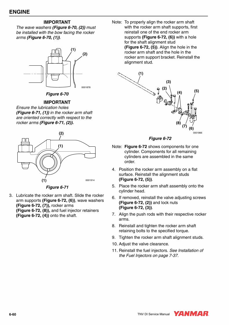
ENGINE
IMPORTANTThe wave washers (Figure 6-70, (2)) must be installed with the bow facing the rocker arms (Figure 6-70, (1)).
Figure 6-70
IMPORTANTEnsure the lubrication holes (Figure 6-71, (1)) in the rocker arm shaft are oriented correctly with respect to the rocker arms (Figure 6-71, (2)).
Figure 6-71
3. Lubricate the rocker arm shaft. Slide the rocker arm supports (Figure 6-72, (6)), wave washers (Figure 6-72, (7)), rocker arms (Figure 6-72, (8)), and fuel injector retainers (Figure 6-72, (4)) onto the shaft.
Note: To properly align the rocker arm shaft with the rocker arm shaft supports, first reinstall one of the end rocker arm supports (Figure 6-72, (6)) with a hole for the shaft alignment stud (Figure 6-72, (5)). Align the hole in the rocker arm shaft and the hole in the rocker arm support bracket. Reinstall the alignment stud.
Figure 6-72
Note: Figure 6-72 shows components for one cylinder. Components for all remaining cylinders are assembled in the same order.
4. Position the rocker arm assembly on a flat surface. Reinstall the alignment studs (Figure 6-72, (5)).
5. Place the rocker arm shaft assembly onto the cylinder head.
6. If removed, reinstall the valve adjusting screws (Figure 6-72, (2)) and lock nuts (Figure 6-72, (3)).
7. Align the push rods with their respective rocker arms.
8. Reinstall and tighten the rocker arm shaft retaining bolts to the specified torque.
9. Tighten the rocker arm shaft alignment studs.
10. Adjust the valve clearance.
11. Reinstall the fuel injectors. See Installation of the Fuel Injectors on page 7-37.
0001878
(1)(2)
(2)
(1)
(1)
0001914
0001866
(7)(6)
(8)
(5)
(1)
(4)(2)
(3)
6-60 TNV DI Service Manual

ENGINE
Reassembly of the Valve Cover1. Lightly grease a new valve cover gasket
(Figure 6-73, (6)). Place the gasket in the groove of the valve cover (Figure 6-73, (3)).
2. Place the valve cover on the cylinder head.
3. Be sure new O-rings (Figure 6-73, (5)) are installed on the valve cover nuts. Reinstall and tighten the valve cover nuts (Figure 6-73, (4)).
Figure 6-73
4. Reinstall the fuel injector grommets (Figure 6-73, (1)).
5. Reinstall the exhaust manifold using a new gasket. Tighten the bolts to specification.
6. Reinstall the intake manifold using a new gasket. Tighten the bolts to specification.
7. Reconnect the fuel injector return hose and fuel injection pump coolant hoses.
8. Reinstall the high-pressure fuel line grommets into the valve cover.
9. Reinstall the high pressure and fuel return lines. See Installation of the Fuel Injectors on page 7-37.
10. Reinstall the coolant pump. Reassembly of Engine Coolant Pump.
11. Reinstall the alternator. See Installation of Alternator on page 12-16.
12. Reconnect the turbocharger oil supply and drain lines.
13. Reconnect the air intake hose.
0001877
(2)
(3)
(4)
(1)
(5)
(6)
TNV DI Service Manual 6-61

ENGINE
MEASURING AND ADJUSTING VALVE CLEARANCEMeasure and adjust while the engine is cold.
Notes:
• The No. 1 piston position is on the flywheel end of the engine, opposite the radiator. The firing order is 1-3-2 for 3-cylinder engines and 1-3-4-2 for 4-cylinder engines.
• 3-cylinder engines fire every 240° of crankshaft rotation.
• 4-cylinder engines fire every 180° of crankshaft rotation.
• Valve clearance of both the intake and exhaust valves can be checked with the piston for that cylinder at top dead center (TDC) of the compression stroke. When a piston is at TDC of the compression stroke, both rocker arms will be loose and the cylinder TDC mark on the flywheel will be visible in the timing port of the flywheel housing.
• If there is no valve clearance, and the cylinder is at TDC of the compression stroke, extreme wear, or damage to the cylinder head or valves may be possible.
• If adjusting each cylinder individually, the cylinder to be adjusted first does not have to be the No. 1 cylinder. Select and adjust the cylinder where the piston is nearest to the top dead center after turning. Make adjustment for the remaining cylinders in the order of firing by turning the crankshaft each time.
• To decrease the number of rotations required to check all cylinders, other cylinders can also be checked as indicated in the chart below.
Example: On a 3-cylinder engine, with the No. 1 piston at TDC on the compression stroke (both valves closed), the valves indicated on the top line of the chart can be adjusted without rotating the crankshaft. To adjust the remaining two valves, rotate the crankshaft until the No. 1 piston is at TDC on the exhaust stroke (exhaust valve only open).
3-Cylinder Engines
4-Cylinder Engines
Cylinder No. 1 2 3
Valve Intake Exhaust Intake Exhaust Intake Exhaust
No. 1 Cylinder at TDC Compression
• • • •
No. 1 Cylinder at TDC Exhaust • •
Cylinder No. 1 2 3 4
Valve Intake Exhaust Intake Exhaust Intake Exhaust Intake Exhaust
No. 1 Cylinder at TDC Compression
• • • •
No. 4 Cylinder at TDC Compression
• • • •
6-62 TNV DI Service Manual
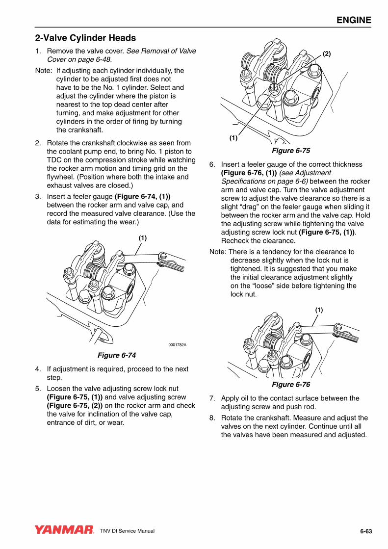
ENGINE
2-Valve Cylinder Heads1. Remove the valve cover. See Removal of Valve
Cover on page 6-48.
Note: If adjusting each cylinder individually, the cylinder to be adjusted first does not have to be the No. 1 cylinder. Select and adjust the cylinder where the piston is nearest to the top dead center after turning, and make adjustment for other cylinders in the order of firing by turning the crankshaft.
2. Rotate the crankshaft clockwise as seen from the coolant pump end, to bring No. 1 piston to TDC on the compression stroke while watching the rocker arm motion and timing grid on the flywheel. (Position where both the intake and exhaust valves are closed.)
3. Insert a feeler gauge (Figure 6-74, (1)) between the rocker arm and valve cap, and record the measured valve clearance. (Use the data for estimating the wear.)
Figure 6-74
4. If adjustment is required, proceed to the next step.
5. Loosen the valve adjusting screw lock nut (Figure 6-75, (1)) and valve adjusting screw (Figure 6-75, (2)) on the rocker arm and check the valve for inclination of the valve cap, entrance of dirt, or wear.
Figure 6-75
6. Insert a feeler gauge of the correct thickness (Figure 6-76, (1)) (see Adjustment Specifications on page 6-6) between the rocker arm and valve cap. Turn the valve adjustment screw to adjust the valve clearance so there is a slight “drag” on the feeler gauge when sliding it between the rocker arm and the valve cap. Hold the adjusting screw while tightening the valve adjusting screw lock nut (Figure 6-75, (1)). Recheck the clearance.
Note: There is a tendency for the clearance to decrease slightly when the lock nut is tightened. It is suggested that you make the initial clearance adjustment slightly on the “loose” side before tightening the lock nut.
Figure 6-76
7. Apply oil to the contact surface between the adjusting screw and push rod.
8. Rotate the crankshaft. Measure and adjust the valves on the next cylinder. Continue until all the valves have been measured and adjusted.
(1)
0001782A
(1)
(2)
(1)
TNV DI Service Manual 6-63

ENGINE
4-Valve Cylinder HeadsThe 4-valve cylinder head operates two valves with a single rocker arm by employing a valve bridge (Figure 6-77, (1)) between the two valves (Figure 6-77, (2)). Clearance (Figure 6-77, (4)) between the valve bridge and valves must be set before adjusting the clearance (Figure 6-77, (5)) between the rocker arm (Figure 6-77, (3)) and valve bridge.
Figure 6-77
1. Remove the valve cover. See Removal of Valve Cover on page 6-48.
Note: If adjusting each cylinder individually, the cylinder to be adjusted first does not have to be the No. 1 cylinder. Select and adjust the cylinder where the piston is nearest to the top dead center after turning, and make adjustment for other cylinders in the order of firing by turning the crankshaft 180° each time.
2. Rotate the crankshaft clockwise as seen from the coolant pump end, to bring No. 1 piston to TDC on the compression stroke while watching the rocker arm motion and the timing grid on the flywheel. (Position where both the intake and exhaust valves are closed.)
3. Make sure there is clearance (Figure 6-77, (5)) between the valve bridge (Figure 6-77, (1)) and the rocker arm (Figure 6-77, (3)).
IMPORTANTDo not loosen or tighten the valve adjusting screw lock nut without holding the valve bridge. Always hold the valve bridge using a wrench to prevent bending of the valve stems.
4. Loosen the valve bridge adjusting screw lock nut (Figure 6-78, (1)) while holding the bridge (Figure 6-78, (3)) with a wrench (Figure 6-78, (2)).
Figure 6-78
5. To assure the valve bridge contacts the rear valve, apply light, downward (Figure 6-79, (4)) finger pressure on the valve bridge (Figure 6-79, (3), and loosen the valve bridge adjusting screw (Figure 6-79, (1)), until there is visible clearance (Figure 6-81, (2)) between the adjusting screw and the front valve.
6. To assure the valve bridge has equal contact with the front and rear valves, apply light downward (Figure 6-79, (4)) pressure on the valve bridge (Figure 6-79, (3), adjust the valve bridge adjusting screw ((Figure 6-79, (1)), (Figure 6-81, (1))) so there is zero “0” clearance (Figure 6-81, (2)) between the adjusting screw and the front valve.
Figure 6-79
0001918B
(1)
(2) (2)
(3)(5)
(4)
0001917A
(3)
(1)
(2)
0001917C
(3)
(1)
(2)
(4)
6-64 TNV DI Service Manual

ENGINE
7. Tighten the lock nut (Figure 6-80, (1)), while holding the valve bridge (Figure 6-80, (3)) with a wrench (Figure 6-80, (2)). Verify that the valve clearance (Figure 6-81, (2) is zero “0”.
Figure 6-80
Figure 6-81
Note: There is a tendency for the clearance to decrease slightly when the lock nut is tightened. It is suggested that you make the initial clearance adjustment is made slightly on the “loose” side before tightening the lock nut.
8. To adjust the actual valve clearance between the rocker arm and the valve bridge, insert a feeler gauge (Figure 6-82, (1)) of the correct thickness (See Adjustment Specifications on page 6-6) between the rocker arm (Figure 6-82, (2)) and valve bridge (Figure 6-82, (3)). Record the results and use this value as an indication of wear.
Figure 6-82
9. If adjustment is required, proceed to the next step.
10. Loosen the valve adjusting screw lock nut (Figure 6-83, (5)) and valve adjusting screw (Figure 6-83, (4)) on the rocker arm (Figure 6-83, (3)) and check the clearance gap (Figure 6-83, (2)) for evidence of dirt or wear.
Note: There is a tendency for the clearance to decrease slightly when the lock nut is tightened. It is suggested that you make the clearance adjustment is made slightly on the “loose” side before tightening the lock nut.
11. Adjust the valve clearance (Figure 6-83, (2)) by turning the adjusting screw (Figure 6-83, (4)) until there is a slight “drag” on the feeler gauge when sliding it between the rocker arm and the valve bridge.
0001917A
(3)
(1)
(2)
0001918D
(1)
(2)
.006006
.152152mmmm
0003566
(1)
(2)
(3)
TNV DI Service Manual 6-65

ENGINE
Figure 6-83
12. Hold the adjusting screw (Figure 6-83, (4)) while tightening the valve adjusting screw lock nut (Figure 6-83, (5)). Recheck the clearance.
13. Apply oil to the contact surface between the adjusting screw and push rod.
14. Rotate the crankshaft to measure and adjust the set of valves. Continue until all valves are measured and adjusted.
0001918
(1) (2)
(3)(4)
(5)
6-66 TNV DI Service Manual
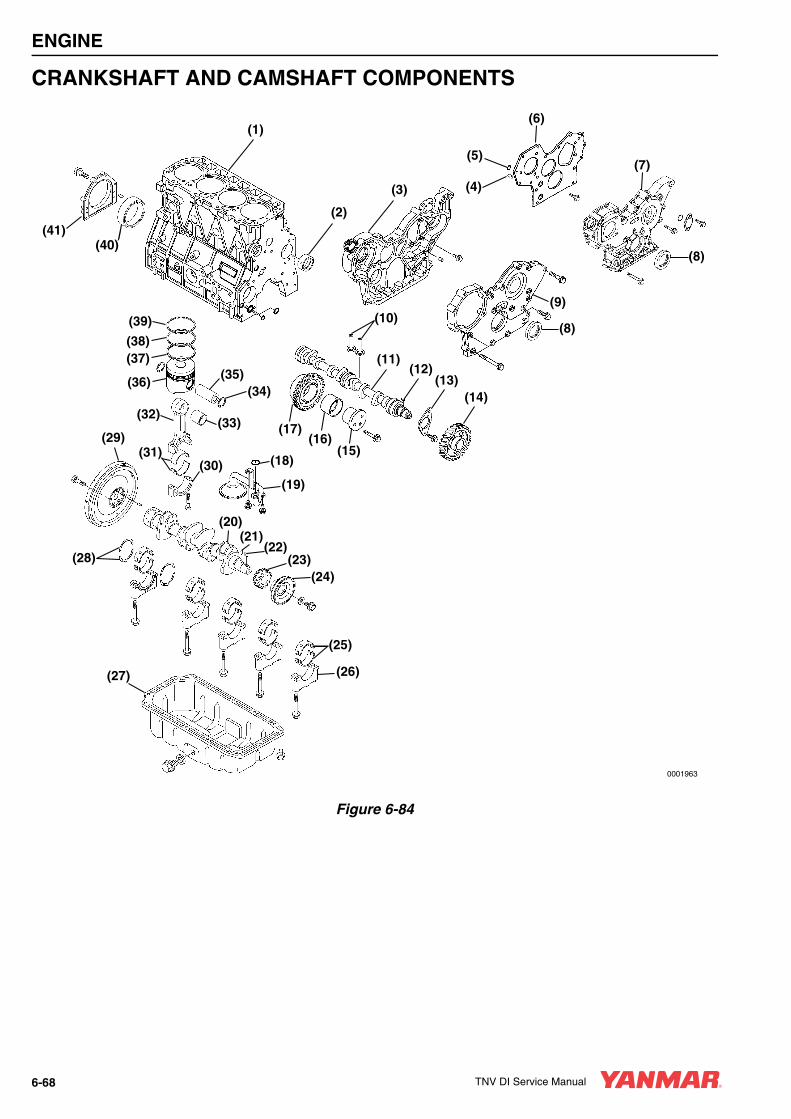
ENGINE
CRANKSHAFT AND CAMSHAFT COMPONENTS
Figure 6-84
0001963
(1)(6)
(4)
(5)
(3)
(2)
(7)
(8)
(9)(10)
(11)(12)
(13)(14)
(15)(16)
(17)
(18)
(19)
(20)(21)
(22)(23)
(24)
(25)
(26)(27)
(28)
(29)
(30)(31)
(32)(33)
(35)(34)
(36)
(37)(38)
(39)
(40)(41)
(8)
6-68 TNV DI Service Manual
ENGINE
1 – Cylinder Block2 – Camshaft Bushing3 – Gear Case (3TNV94 - 4TNV106)4 – Dowel (2 used)5 – O-Ring6 – Front Plate (3TNV82 - 4TNV88)7 – Gear Case Cover (3TNV82 - 4TNV88)8 – Front Crankshaft Seal9 – Gear Case Cover (3TNV94 - 4TNV106)10 – Tappets11 – Camshaft12 – Camshaft Gear Key13 – Camshaft End Plate14 – Camshaft Gear15 – Idler Gear Shaft16 – Idler Gear Bushing17 – Idler Gear18 – Oil Pickup O-Ring19 – Oil Pickup20 – Crankshaft21 – Parallel Pin22 – Crankshaft Gear Key23 – Crankshaft Gear24 – Crankshaft Pulley25 – Main Bearing Inserts26 – Main Bearing Cap27 – Oil Pan28 – Thrust Bearings29 – Flywheel30 – Connecting Rod Cap31 – Connecting Rod Bearing Inserts32 – Connecting Rod33 – Wrist Pin Bushing34 – Circlip35 – Wrist Pin36 – Piston37 – Oil Ring38 – Second Compression Ring39 – Top Compression Ring40 – Crankshaft Rear Seal41 – Crankshaft Rear Seal Housing
Disassembly of EnginePrepare a clean, flat working surface on a workbench large enough to accommodate the engine components. Discard all used gaskets, O-rings and seals. Use new gaskets, O-rings and seals on reassembly of engine.
If the engine will be completely disassembled, the following preliminary steps should be performed:
1. Disconnect the battery cables at the battery. Always disconnect the negative (-) cable first.
2. Remove the throttle cable, electrical connections, intake and exhaust system connections, and fuel supply lines from the engine.
3. Remove the alternator. See Removal of Alternator on page 12-12.
4. Drain the engine coolant from the radiator and cylinder block. See Drain, Flush and Refill Cooling System With New Coolant on page 5-35. Remove the cooling system components from the engine.
5. Remove the engine from the machine. Mount the engine to a suitable engine repair stand having adequate weight capacity.
6. Clean the engine by washing with solvent, air or steam cleaning. Carefully operate so as to prevent any foreign matter or fluids from entering the engine or any fuel system or electrical components remaining on the engine.
7. Drain the engine oil into a suitable container. Remove the oil filter.
8. Remove the cylinder head. See 2-Valve Cylinder Head on page 6-32 or 4-Valve Cylinder Head on page 6-46.
CAUTIONIdentify all parts and their location using an appropriate method. It is important that all parts are returned to the same position during the reassembly process.
0000080en
A CAUTIONBe sure to secure the engine solidly to prevent injury or damage to parts due to the engine falling during work on the engine.
0000009en
TNV DI Service Manual 6-69

ENGINE
9. Remove the fuel injection pump from the gear case / front plate only if it must be sent out for repair, or will interfere with other procedures such as “hot tank” cleaning. If the fuel injection pump does not need to be repaired, leaving it mounted to the timing gear case or plate will eliminate the need to re-time it during reassembly. See Fuel Injection Pump on page 7-16.
10. Remove the starter motor. See Removal of Starter Motor on page 11-10.
Disassembly of Camshaft and Timing ComponentsDiscard all gaskets, O-rings and seals. Use new gaskets, O-rings and seals on reassembly of the camshaft and timing components.
Removal of Timing Gear Case Cover1. Remove the bolt and washer retaining the
crankshaft pulley.
IMPORTANTUse care not to damage the threads in the end of the crankshaft when removing the crankshaft pulley.
2. Remove the crankshaft pulley using a gear puller.
3. Remove the bolts that retain the gear case cover to the cylinder block and oil pan.
4. Remove the gear case cover (Figure 6-85, (1)).
Figure 6-85
Checking Timing Gear BacklashPrior to removing the timing gears, measure the gear backlash and determine the gear wear.
Check the backlash between each pair of mating gears (Figure 6-86). If not within specification, replace both mating gears. See Timing Gear Backlash on page 6-12 for service limits.
Note: Do not allow the gear being checked to move axially as excess end play could cause a false reading.
1 – Fuel Injection Pump Drive Gear2 – Camshaft Drive Gear3 – Auxiliary Drive Gear (Optional)4 – Crankshaft Drive Gear5 – Direction of Rotation6 – Oil Pump Drive Gear (4TNV94L - 4TNV106)7 – Idler Gear
Figure 6-86
0001641A
(1)
0001709A
B B
A
A
C C
(1)(2)
(3)
(4)(5)
(6)
(7)
6-70 TNV DI Service Manual
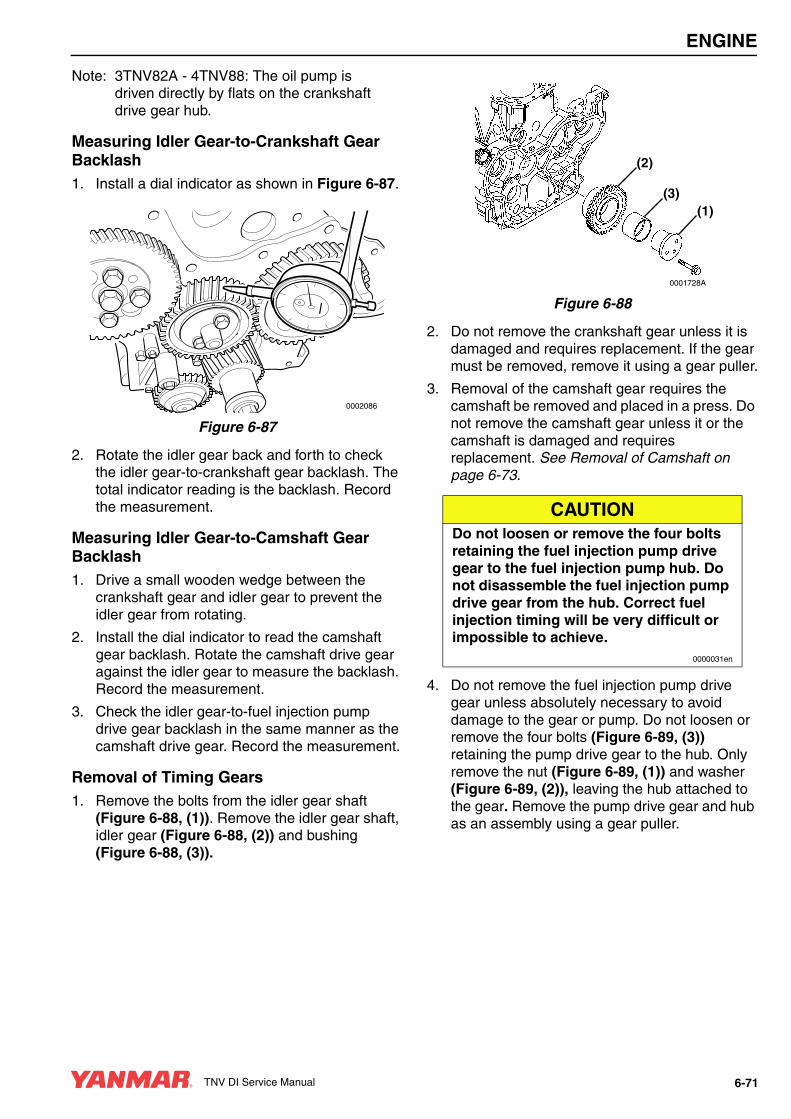
ENGINE
Note: 3TNV82A - 4TNV88: The oil pump is driven directly by flats on the crankshaft drive gear hub.
Measuring Idler Gear-to-Crankshaft Gear Backlash1. Install a dial indicator as shown in Figure 6-87.
Figure 6-87
2. Rotate the idler gear back and forth to check the idler gear-to-crankshaft gear backlash. The total indicator reading is the backlash. Record the measurement.
Measuring Idler Gear-to-Camshaft Gear Backlash1. Drive a small wooden wedge between the
crankshaft gear and idler gear to prevent the idler gear from rotating.
2. Install the dial indicator to read the camshaft gear backlash. Rotate the camshaft drive gear against the idler gear to measure the backlash. Record the measurement.
3. Check the idler gear-to-fuel injection pump drive gear backlash in the same manner as the camshaft drive gear. Record the measurement.
Removal of Timing Gears1. Remove the bolts from the idler gear shaft
(Figure 6-88, (1)). Remove the idler gear shaft, idler gear (Figure 6-88, (2)) and bushing (Figure 6-88, (3)).
Figure 6-88
2. Do not remove the crankshaft gear unless it is damaged and requires replacement. If the gear must be removed, remove it using a gear puller.
3. Removal of the camshaft gear requires the camshaft be removed and placed in a press. Do not remove the camshaft gear unless it or the camshaft is damaged and requires replacement. See Removal of Camshaft on page 6-73.
4. Do not remove the fuel injection pump drive gear unless absolutely necessary to avoid damage to the gear or pump. Do not loosen or remove the four bolts (Figure 6-89, (3)) retaining the pump drive gear to the hub. Only remove the nut (Figure 6-89, (1)) and washer (Figure 6-89, (2)), leaving the hub attached to the gear. Remove the pump drive gear and hub as an assembly using a gear puller.
0002086
CAUTIONDo not loosen or remove the four bolts retaining the fuel injection pump drive gear to the fuel injection pump hub. Do not disassemble the fuel injection pump drive gear from the hub. Correct fuel injection timing will be very difficult or impossible to achieve.
0000031en
0001728A
(1)(3)
(2)
TNV DI Service Manual 6-71

ENGINE
Figure 6-89
Removal of Oil Pan1. Invert the engine (oil pan up) on the engine
stand.
2. Remove the oil pan (Figure 6-90, (1)).
Figure 6-90
(1)
(2)
(3)
0000162A
0001695A
(1)
6-72 TNV DI Service Manual
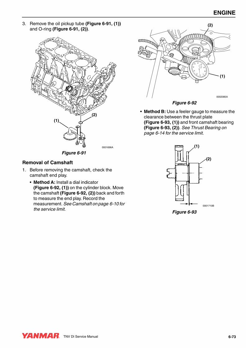
ENGINE
3. Remove the oil pickup tube (Figure 6-91, (1)) and O-ring (Figure 6-91, (2)).
Figure 6-91
Removal of Camshaft1. Before removing the camshaft, check the
camshaft end play.
• Method A: Install a dial indicator (Figure 6-92, (1)) on the cylinder block. Move the camshaft (Figure 6-92, (2)) back and forth to measure the end play. Record the measurement. See Camshaft on page 6-10 for the service limit.
Figure 6-92
• Method B: Use a feeler gauge to measure the clearance between the thrust plate (Figure 6-93, (1)) and front camshaft bearing (Figure 6-93, (2)). See Thrust Bearing on page 6-14 for the service limit.
Figure 6-93
0001696A
(1)(2)
01020
30
40
5060 70
80
90
0002085A
(1)
(2)
(1)
(2)
0001710B
TNV DI Service Manual 6-73

ENGINE
2. Remove the two bolts (Figure 6-94, (3)) retaining the camshaft thrust plate (Figure 6-94, (1)).
Figure 6-94
3. Rotate the engine in the engine stand so that gravity causes the tappets (Figure 6-94, (5)) to drop away from the camshaft lobes.
Note: Rotate the camshaft at least two turns to “bump” any sticking tappets away from the camshaft.
4. Slowly pull the camshaft (Figure 6-94, (2)) assembly out of the engine being careful not to damage the front camshaft bushing.
Note: If the engine is not installed on an engine repair fixture, stand the engine upright on the flywheel end mounting flange. Rotate the camshaft at least two turns to bump the tappets out of the way to prevent the tappets from interfering with the removal of the camshaft.
Note: The tappets are “mushroom” shaped and must be removed from inside the engine crankcase.
5. Remove the tappets. Mark the tappets so they can be reinstalled in the same location.
6. Remove the camshaft drive gear (Figure 6-94, (4)) only if the gear or camshaft require replacement. Use a knife-edge puller and a press to remove the gear. The gear is a shrink-fit and will need to be heated to 356° - 392°F (180° - 200°C) to remove.
Removal of Gear Case or Front PlateNote: The camshaft must be removed before
the gear case / front plate can be removed. See Inspection of Camshaft on page 6-84.
1. TNV94 - TNV106: Remove the oil pump.
Note: It is not necessary to remove the fuel injection pump from the gear case / front plate to remove the gear case / front plate. If the fuel injection pump does not need to be repaired, leaving it mounted to the timing gear case / front plate will eliminate the need to re-time it during assembly. See Fuel Injection Pump on page 7-16.
2. Remove the bolts (Figure 6-95, (4)).
3. Remove the gear case (Figure 6-95, (1)) or front plate from the cylinder block. Thoroughly clean all old sealant from the mating surfaces.
4. Inspect and measure the camshaft bushing. See Camshaft on page 6-10 for the service limit. If damaged or worn beyond service limits, remove the camshaft bushing (Figure 6-95, (3)).
5. TNV94 - TNV106: Remove two O-rings (Figure 6-95, (2)).
Figure 6-95
0001966
(4)
(1)
(3)
(2) (5)
(3) (1)
(2)
(4)
0001737B
6-74 TNV DI Service Manual
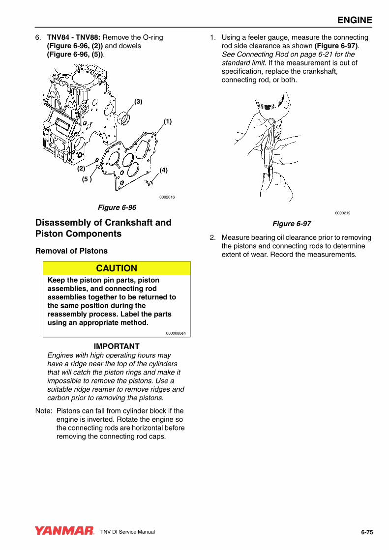
ENGINE
6. TNV84 - TNV88: Remove the O-ring (Figure 6-96, (2)) and dowels (Figure 6-96, (5)).
Figure 6-96
Disassembly of Crankshaft and Piston Components
Removal of Pistons
IMPORTANTEngines with high operating hours may have a ridge near the top of the cylinders that will catch the piston rings and make it impossible to remove the pistons. Use a suitable ridge reamer to remove ridges and carbon prior to removing the pistons.
Note: Pistons can fall from cylinder block if the engine is inverted. Rotate the engine so the connecting rods are horizontal before removing the connecting rod caps.
1. Using a feeler gauge, measure the connecting rod side clearance as shown (Figure 6-97). See Connecting Rod on page 6-21 for the standard limit. If the measurement is out of specification, replace the crankshaft, connecting rod, or both.
Figure 6-97
2. Measure bearing oil clearance prior to removing the pistons and connecting rods to determine extent of wear. Record the measurements.
CAUTIONKeep the piston pin parts, piston assemblies, and connecting rod assemblies together to be returned to the same position during the reassembly process. Label the parts using an appropriate method.
0000088en
0002016
(1)
(3)
(4)(2)
(5 )
0000219
TNV DI Service Manual 6-75

ENGINE
IMPORTANTMark the connecting rod caps and connecting rods so the caps and connecting rods stay together.
(a) Remove the bearing cap. Do not remove the bearing inserts at this time.
(b) Wipe oil from the bearing insert and crankshaft journal surfaces.
(c) Place a piece of PLASTIGAGE® (Figure 6-98, (1)) along the full width of the bearing insert.
Figure 6-98
IMPORTANTDo not rotate the crankshaft when using PLASTIGAGE. A false reading may result.
(d) Reinstall bearing cap and tighten to specification. See Special Torque Chart on page 6-23.
(e) Remove bearing cap.
(f) Compare the width of the flattened PLASTIGAGE to the graduation marks on the package (Figure 6-99, (1)). The mark that most closely matches the width of the flattened PLASTIGAGE will indicate the bearing oil clearance.
Figure 6-99
(g) Repeat with remaining connecting rods.
IMPORTANTDo not allow the connecting rod to contact the crankshaft journal during piston removal. Damage to the bearing journal may result.
3. Use a wooden dowel against the connecting rod and tap the piston / connecting rod assembly out of the cylinder.
4. Mark the cylinder number on the piston and connecting rod.
5. Remove the bearing inserts (Figure 6-100, (2)).
6. Remove the compression rings (Figure 6-100, (3)) from the piston using a piston ring expander.
7. Remove the oil ring (Figure 6-100, (4)) from the piston using a piston ring expander.
Figure 6-100
8. Remove the circlips (Figure 6-100, (5)) from the wrist pin.
9. Remove the wrist pin (Figure 6-100, (6)) and connecting rod (Figure 6-100, (8)) from the piston (Figure 6-100, (9)).
10. Repeat the steps until all pistons are removed and dissembled.
0001898
(1)
0001899
(1)
(3)
(4)(5)
(9) (6)
(8)(7)
(5)
(2)
(1)
0001960
6-76 TNV DI Service Manual
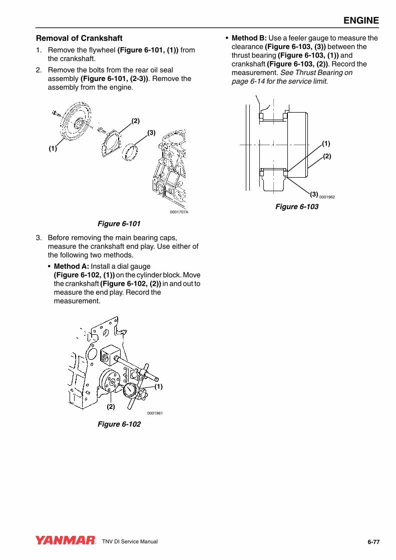
ENGINE
Removal of Crankshaft1. Remove the flywheel (Figure 6-101, (1)) from
the crankshaft.
2. Remove the bolts from the rear oil seal assembly (Figure 6-101, (2-3)). Remove the assembly from the engine.
Figure 6-101
3. Before removing the main bearing caps, measure the crankshaft end play. Use either of the following two methods.
• Method A: Install a dial gauge (Figure 6-102, (1)) on the cylinder block. Move the crankshaft (Figure 6-102, (2)) in and out to measure the end play. Record the measurement.
Figure 6-102
• Method B: Use a feeler gauge to measure the clearance (Figure 6-103, (3)) between the thrust bearing (Figure 6-103, (1)) and crankshaft (Figure 6-103, (2)). Record the measurement. See Thrust Bearing on page 6-14 for the service limit.
Figure 6-103
(2)
0001707A
(1)
(3)
(1)
(2)0001961
(1)
(2)
(3) 0001962
TNV DI Service Manual 6-77

ENGINE
4. Remove the main bearing caps (Figure 6-104, (3)). Be sure to note the markings on the main bearing caps, or mark them yourself, so they can be reinstalled in the same order as they were removed. Do not remove the bearing inserts at this time.
Note: The “arrows” on the main bearing caps point to the flywheel end of the engine.
Figure 6-104
5. Measure bearing oil clearance prior to removing the crankshaft to determine extent of wear. Record the measurements.
(a) Wipe oil from the bearing insert and crankshaft journal surfaces.
(b) Place a piece of PLASTIGAGE (Figure 6-105, (1)) along the full width of each bearing insert.
Figure 6-105
IMPORTANTDo not rotate the crankshaft when using PLASTIGAGE. A false reading may result.
(c) Reinstall bearing caps and tighten to specification. See Special Torque Chart on page 6-23.
(d) Remove bearing caps.
(e) Compare the width of the flattened PLASTIGAGE to the graduation marks on the package (Figure 6-106, (1)). The mark that most closely matches the width of the flattened PLASTIGAGE will indicate the bearing oil clearance.
Figure 6-106
6. Remove the crankshaft from the engine.
7. Remove the bearing inserts (Figure 6-104, (1)) and thrust bearings (Figure 6-104, (2)).
Note: Do not remove the crankshaft gear unless the gear or crankshaft are damaged and require replacement.
(2)
0001752A
(1)
(3)
0001898
(1)
0001899
(1)
6-78 TNV DI Service Manual
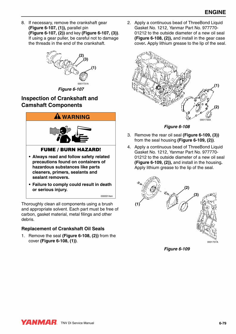
ENGINE
8. If necessary, remove the crankshaft gear (Figure 6-107, (1)), parallel pin (Figure 6-107, (2)) and key (Figure 6-107, (3)). If using a gear puller, be careful not to damage the threads in the end of the crankshaft.
Figure 6-107
Inspection of Crankshaft and Camshaft Components
Thoroughly clean all components using a brush and appropriate solvent. Each part must be free of carbon, gasket material, metal filings and other debris.
Replacement of Crankshaft Oil Seals1. Remove the seal (Figure 6-108, (2)) from the
cover (Figure 6-108, (1)).
2. Apply a continuous bead of ThreeBond Liquid Gasket No. 1212, Yanmar Part No. 977770-01212 to the outside diameter of a new oil seal (Figure 6-108, (2)), and install in the gear case cover. Apply lithium grease to the lip of the seal.
Figure 6-108
3. Remove the rear oil seal (Figure 6-109, (3)) from the seal housing (Figure 6-109, (2)).
4. Apply a continuous bead of ThreeBond Liquid Gasket No. 1212, Yanmar Part No. 977770-01212 to the outside diameter of a new oil seal (Figure 6-109, (2)), and install in the housing. Apply lithium grease to the lip of the seal.
Figure 6-109
A WARNING
FUME / BURN HAZARD!• Always read and follow safety related
precautions found on containers of hazardous substances like parts cleaners, primers, sealants and sealant removers.
• Failure to comply could result in death or serious injury.
0000014en
0001731A
(1)
(2)(3)
(1)
0001735A
(2)
(2)
0001707A
(1)
(3)
TNV DI Service Manual 6-79
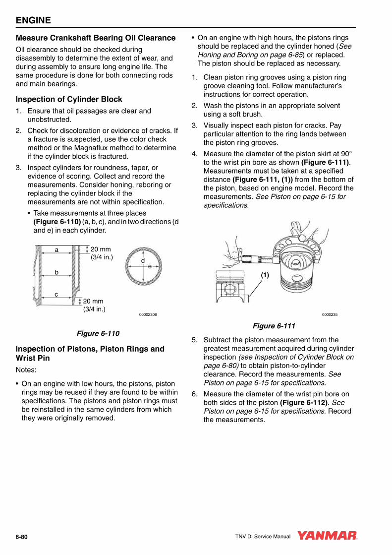
ENGINE
Measure Crankshaft Bearing Oil ClearanceOil clearance should be checked during disassembly to determine the extent of wear, and during assembly to ensure long engine life. The same procedure is done for both connecting rods and main bearings.
Inspection of Cylinder Block1. Ensure that oil passages are clear and
unobstructed.
2. Check for discoloration or evidence of cracks. If a fracture is suspected, use the color check method or the Magnaflux method to determine if the cylinder block is fractured.
3. Inspect cylinders for roundness, taper, or evidence of scoring. Collect and record the measurements. Consider honing, reboring or replacing the cylinder block if the measurements are not within specification.
• Take measurements at three places (Figure 6-110) (a, b, c), and in two directions (d and e) in each cylinder.
Figure 6-110
Inspection of Pistons, Piston Rings and Wrist PinNotes:
• On an engine with low hours, the pistons, piston rings may be reused if they are found to be within specifications. The pistons and piston rings must be reinstalled in the same cylinders from which they were originally removed.
• On an engine with high hours, the pistons rings should be replaced and the cylinder honed (See Honing and Boring on page 6-85) or replaced. The piston should be replaced as necessary.
1. Clean piston ring grooves using a piston ring groove cleaning tool. Follow manufacturer’s instructions for correct operation.
2. Wash the pistons in an appropriate solvent using a soft brush.
3. Visually inspect each piston for cracks. Pay particular attention to the ring lands between the piston ring grooves.
4. Measure the diameter of the piston skirt at 90° to the wrist pin bore as shown (Figure 6-111). Measurements must be taken at a specified distance (Figure 6-111, (1)) from the bottom of the piston, based on engine model. Record the measurements. See Piston on page 6-15 for specifications.
Figure 6-111
5. Subtract the piston measurement from the greatest measurement acquired during cylinder inspection (see Inspection of Cylinder Block on page 6-80) to obtain piston-to-cylinder clearance. Record the measurements. See Piston on page 6-15 for specifications.
6. Measure the diameter of the wrist pin bore on both sides of the piston (Figure 6-112). See Piston on page 6-15 for specifications. Record the measurements.
0000230B
a
b
c
de
20 mm(3/4 in.)
20 mm(3/4 in.)
0000235
(1)
6-80 TNV DI Service Manual

ENGINE
Figure 6-112
7. Measure the outside diameter of the wrist pin in three places and at 90° (Figure 6-113). See Piston on page 6-15 for specifications. Record the measurements.
Figure 6-113
8. Using a micrometer, measure the thickness of each piston ring. See Piston Ring on page 6-17 for specifications. Record the measurements.
Notes:
• On an engine with low hours, the pistons, piston rings and cylinders may be reused if they are found to be within specifications.
• On an engine with high hours, the pistons rings should be replaced and the cylinder honed (see Honing and Boring on page 6-85) or replaced. The piston should be replaced as necessary.
9. Place each compression piston ring in the groove as shown (Figure 6-114). Use a feeler gauge to measure the clearance between the piston ring and the piston ring land. Record the measurements. See Piston Ring on page 6-17 for specifications. Replace the piston if not within specification.
Figure 6-114
0000237
0001889
0001892
TNV DI Service Manual 6-81

ENGINE
10. To measure piston ring end gap, insert each compression piston ring (Figure 6-115, (1)), one at a time, into the cylinder. Use a piston with the piston rings removed to slide the ring into the cylinder bore until it is approximately 1.18 in. (30 mm) (Figure 6-115, (2)) from the bottom of the bore. Remove the piston. Measure the end gap (Figure 6-115, (3)) of each piston ring. Record the measurements. See Piston Ring on page 6-17 for specifications.
Figure 6-115
Note: Always check the piston ring end gap when installing new piston rings. See Piston Ring on page 6-17 for specifications. Use a piston ring end gap filing tool to adjust the piston ring end gap on new piston rings.
11. Repeat the above steps for each cylinder and piston assembly.
Inspection of Connecting Rod1. Measure the wrist pin bushing bore using a
bore gauge (Figure 6-116, (1)). Replace the bushing if not within specifications. If the bushing has been removed, measure the inside diameter of the connecting rod small end (Figure 6-116, (2)). See Connecting Rod on page 6-21 for specifications.
Figure 6-116
2. Place the connecting rod bearing inserts into the connecting rod and connecting rod cap. Install the rod cap and tighten the bolts to the specified torque.
3. Measure the inside diameter. See Crankshaft on page 6-13 for specifications.
Inspection of Tappets1. Inspect the tappet contact surfaces for
abnormal wear (Figure 6-117, (1)). Normal wear will be even as shown in (Figure 6-117, (2)). Slight surface defects can be corrected using an oilstone.
Figure 6-117
0001964
(2)
(1)
(3)
0001724A
(1)
(2)
0001725(1) (2)
6-82 TNV DI Service Manual

ENGINE
2. Measure the outside diameter of the tappet stem (Figure 6-118, (1)). See Tappet on page 6-22 for the service limit.
Figure 6-118
3. Measure the tappet bores in the cylinder block. See Tappet on page 6-22 for the service limit.
Inspection of Crankshaft1. Place the crankshaft end journals
(Figure 6-119, (4)) on V-blocks.
2. Place a dial indicator (Figure 6-119, (3)) on a center main bearing surface.
Figure 6-119
3. Rotate the crankshaft and observe runout. See Crankshaft on page 6-13 for specifications.
4. Use the color check method or Magnaflux® to inspect the crankshaft for cracks. Replace the crankshaft if evidence of fractures are found.
5. Measure the outside diameter of each crankpin (Figure 6-120, (2)) and main bearing journal (Figure 6-120, (1)). See Crankshaft on page 6-13 for specifications. Take measurements at several places around each bearing surface. If not within specification, grind the journals and install undersize bearings, or replace the crankshaft.
Figure 6-120
(1)0001726A
0000232A
(2)
(3)
(4)(4)
(1)
0001733A
(1)
R
R
(2)
TNV DI Service Manual 6-83

ENGINE
Inspection of Camshaft1. Use V-blocks and a dial indicator to check
camshaft bend (Figure 6-121). Place the indicator on the center bearing journal.
Figure 6-121
2. Rotate the camshaft and observe the runout. See Camshaft on page 6-10 for specifications.
3. Measure the height of each lobe (Figure 6-122, (1)). See Camshaft on page 6-10 for specifications.
Figure 6-122
4. Measure the diameter of the gear end (Figure 6-123, (1)), intermediate (Figure 6-123, (2)), and flywheel end (Figure 6-123, (3)) bearing journals. See Camshaft on page 6-10 for specifications.
Figure 6-123
Inspection of Camshaft Bushing and Bores1. Measure the I.D. of the front bushing and the
remaining bores in the cylinder block. See Camshaft on page 6-10 for specifications.
2. If the camshaft bushing is not within specification, replace it using the appropriate service tool. If the remaining bores are not within specification, the cylinder block will require replacement as there are no bearing inserts used.
Inspection of Idler Gear and Shaft1. Measure the outside diameter
(Figure 6-124, (1)) of the idler gear shaft (Figure 6-124, (2)). See Idler Gear Shaft and Bushing on page 6-12 for specifications.
2. Measure the inside diameter (Figure 6-124, (3)) of the idler gear bushing (Figure 6-124, (4)). See Idler Gear Shaft and Bushing on page 6-12 for specifications.
Figure 6-124
0001711
(1)
0001712A
0001713A
(3)
(2)
(1)
(1) (3)
(4)
(2)
0001714A
6-84 TNV DI Service Manual

ENGINE
Honing and BoringPistons must move freely in the cylinders while maintaining adequate compression and oil sealing. If the cylinder walls are scuffed, scored, out-of-round, or tapered beyond specifications, rebore and hone to restore cylinders to usable condition. Slight imperfections can be corrected by honing alone.
1. Boring - Significant cylinder damage may be corrected by boring the cylinder to an oversize dimension. Refer to the appropriate parts catalog for available oversize pistons and piston rings.
• Boring a cylinder should always be done in a properly equipped machine shop.
• A bored cylinder should always be finished with a hone to properly prepare the cylinder surface so the new piston rings will seat properly.
• After the cylinder has been bored and honed, install the appropriate oversize pistons and piston rings.
2. Honing - Minor cylinder imperfections may be corrected by using a rigid cylinder hone (Figure 6-126, (1)). Be sure not to exceed the maximum cylinder bore specification.
Deglazing - A used cylinder that did not require boring or honing, should always be deglazed with a ball hone (Figure 6-126, (2)) before installing new piston rings. This will properly prepare the cylinder surface to allow new piston rings to seat properly.
Note: When honing a cylinder, with either a ridged hone or a ball hone (Figure 6-125, (1)), move the rotating hone up and down in the cylinder bore to accomplish a 30° to 40° crosshatch pattern (Figure 6-125). This will provide the ideal surface for the proper seating of new piston rings.
Figure 6-125
• Use a 50:50 mixture of diesel fuel and engine oil as a honing fluid.
• Use a 300-grit hone at 300 - 1200 rpm (Figure 6-126).
Figure 6-126
IMPORTANTSolvents will not adequately remove honing residue, resulting in premature piston and ring wear. Always wash cylinders using hot, soapy water.
CAUTIONDo not allow the honing tool to operate in one position for any length of time. Damage to the cylinder wall will occur. Keep the tool in constant up-and-down motion.
0000090en
(1)
0000248A
(1)
0000249B
(2)
TNV DI Service Manual 6-85

ENGINE
• When honing is completed, wash the cylinder block with hot water and soap. The cylinder wall is adequately cleaned when a white rag wiped in cylinder comes out clean. Use brushes to clean all passages and crevices. Rinse with hot water and dry with compressed air. Apply clean engine oil to all steel surfaces to prevent rusting.
Reassembly of Crankshaft and Piston ComponentsNotes:
• Proceed slowly. Make no forced assemblies unless a pressing operation is called for. All parts must be perfectly clean and lightly lubricated when assembled.
• Use new gaskets, seals and O-rings during assembly.
• Liberally apply clean engine oil to all internal parts during assembly.
• All fasteners should be tightened to a given torque. If a special torque is not provided in the Special Torque Chart on page 6-23, tighten to standard torque specifications. See Tightening Torques for Standard Bolts and Nuts on page 4-45.
Reassembly of Pistons1. Select the parts needed to reassemble the
piston and connecting rod for one cylinder.
2. If removed, install a new wrist pin bushing (Figure 6-127, (7)) using a press and the appropriate service tool. Be sure to align the oil holes.
Figure 6-127
3. Reinstall one circlip (Figure 6-127, (5)) into the piston. Ensure the circlip is securely seated in the groove.
IMPORTANTThe piston and connecting rod must be assembled with the correct orientation. When correctly assembled, the identification mark (Figure 6-128, (1)) stamped into the top of the piston will be on the same side of the connecting rod as the match marks (Figure 6-128, (3)) stamped into the connecting rod and connecting rod cap. When installed in the cylinder, the embossed mark (Figure 6-128, (2)) cast into the beam of connecting rod will face the flywheel end of the engine.
Note: The actual appearance of the match marks will vary but they will always be in the same locations.
(3)
(4)(5)
(9) (6)
(8)(7)
(5)
(2)
(1)
0001960
6-86 TNV DI Service Manual

ENGINE
Figure 6-128
4. Place the connecting rod into the piston. The match marks (Figure 6-129, (4)) on the connecting rod and cap must be on the same side as the identification mark (Figure 6-129, (2)) on the top of the piston.
1 – Fuel Injection Pump Side of Engine2 – Piston Identification Mark3 – Embossed Mark on Connecting Rod4 – Rod and Cap Match Marks5 – Flywheel End of Engine6 – Camshaft Side of Engine
Figure 6-129
5. Lubricate and reinstall the wrist pin (Figure 6-130, (3)) through the piston and connecting rod.
6. Reinstall the second circlip (Figure 6-130, (4)) and ensure it is securely seated in the groove.
Figure 6-130
ML↓
844V
(1)
0002090
E106 R
(2)
80 80
0002089
(3)
0001967
(1)(6)
(5)
(3)
(2)
(4)
(3)
(4)(5)
(9) (6)
(8)(7)
(5)
(2)
(1)
0001960
TNV DI Service Manual 6-87

ENGINE
Note: If installing new piston rings the end gap must be checked and adjusted as necessary. See Inspection of Pistons, Piston Rings and Wrist Pin on page 6-80 for specifications. Use a piston ring end gap filing tool to adjust the piston ring end gap on new piston rings.
Note: Reinstall the top and second piston rings with the stamped “makers mark” (Figure 6-131, (1)) facing the top of the piston. The “makers mark” may vary in appearance but will always be located on the top surface of the piston ring adjacent to the piston ring gap. The oil ring and oil ring expander can be installed either side up.
Figure 6-131
IMPORTANTAlways use a piston ring installation tool (expander) when installing piston rings. Never attempt to install piston rings by hand.
7. Reinstall the oil ring expander (Figure 6-132, (4)). Reinstall the oil ring (Figure 6-132, (3)) with the end gap at 180° from the expander end gap.
8. Reinstall the second compression ring (Figure 6-132, (2)). This ring is identified by its dark color and tapered face profile.
9. Reinstall the top compression ring (Figure 6-132, (1)). This ring is identified by its silver color and barrel-shaped face profile.
IMPORTANTThe oil ring expander (Figure 6-132, (4)) end gap must be located 180° from the oil ring (Figure 6-132, (3)) end gap.
Figure 6-132
10. Stagger the piston ring end gaps at 120° intervals (Figure 6-133, (1, 2, 3)). Do not position the top piston ring end gap in line with the wrist pin.
1 – Top Compression Ring End Gap2 – Second Compression Ring End Gap3 – Oil Ring End Gap
Figure 6-133
(1)
0000225A
(1)
(2)
(3)
(4)
0001722B
(3)
(1)
(2)
0001968
6-88 TNV DI Service Manual

ENGINE
Installation of Crankshaft1. If removed, reinstall the keys and timing gear on
the crankshaft.
2. Reinstall new bearing inserts (Figure 6-134, (1)) and thrust bearing (Figure 6-134, (2)) in the cylinder block and main bearing caps. Apply a liberal coat of clean engine oil to the bearings and crankshaft journals.
3. Place the crankshaft into the engine.
IMPORTANTThe main bearing caps are numbered and have arrows for proper positioning. The No. 1 cap is at the flywheel end. The arrows point toward the flywheel end of the engine.
4. Reinstall the main bearing caps (Figure 6-134, (3)).
5. Apply a light coat of clean engine oil to the bearing cap bolts and tighten the bolts to the specified torque in two stages (1/2 then full torque). See Special Torque Chart on page 6-23 for specifications.
Figure 6-134
6. Rotate the crankshaft to assure it turns freely.
7. Apply ThreeBond Liquid Gasket No. 1212, Yanmar Part No. 977770-01212 to the mounting flange of the seal housing (Figure 6-135, (2)).
8. Align the seal housing with the two dowel pins.
9. Reinstall seal housing and seal assembly.
10. Reinstall the flywheel (Figure 6-135, (1)) and tighten the bolts to the specified torque. See Special Torque Chart on page 6-23 for specifications.
Figure 6-135
Installation of Pistons
IMPORTANTDo not allow the connecting rod to contact the crankshaft journal during piston installation. Damage to the crankshaft bearing journal may result.
1. Lubricate the piston, piston rings, and cylinder with clean engine oil or assembly lubricant.
(2)
0001752A
(1)
(3)
(2)
0001707A
(1)
(3)
TNV DI Service Manual 6-89

ENGINE
2. Rotate the crankshaft so the crankpin for the piston being installed is near bottom dead center.
IMPORTANTEnsure the piston ring gaps are located correctly (Figure 6-136).
1 – Top Compression Ring End Gap2 – Second Compression Ring End Gap3 – Oil Ring End Gap
Figure 6-136
3. Using a piston ring compressor, compress the piston rings.
IMPORTANTThe piston and connecting rod must be installed with the correct orientation. When installed correctly, the identification mark (Figure 6-137, (2)) stamped into the top of the piston will be on the same side of the engine as the fuel injection pump (Figure 6-137, (1)) and the embossed mark (Figure 6-137, (3)) cast into the connecting rod beam will face the flywheel end of the engine (Figure 6-137, (5)).
4. Carefully reinstall the piston and rod assembly. Be sure the match marks (Figure 6-137, (4)) stamped into the connecting rod and cap, and the identification mark (Figure 6-137, (2)) stamped into the piston top are facing the fuel injection pump side (Figure 6-137, (1)). The embossed mark cast into the connecting rod beam (Figure 6-137, (3)) will be facing the flywheel end of the engine (Figure 6-137, (5)).
1 – Fuel Injection Pump Side of Engine2 – Piston Identification Mark3 – Embossed Mark on Connecting Rod4 – Rod and Cap Match Marks5 – Flywheel End of Engine6 – Camshaft Side of Engine
Figure 6-137
(3)
(1)
(2)
0001968
0001967
(1)(6)
(5)
(3)
(2)
(4)
6-90 TNV DI Service Manual
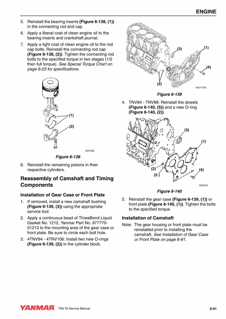
ENGINE
5. Reinstall the bearing inserts (Figure 6-138, (1)) in the connecting rod and cap.
6. Apply a liberal coat of clean engine oil to the bearing inserts and crankshaft journal.
7. Apply a light coat of clean engine oil to the rod cap bolts. Reinstall the connecting rod cap (Figure 6-138, (2)). Tighten the connecting rod bolts to the specified torque in two stages (1/2 then full torque). See Special Torque Chart on page 6-23 for specifications.
Figure 6-138
8. Reinstall the remaining pistons in their respective cylinders.
Reassembly of Camshaft and Timing Components
Installation of Gear Case or Front Plate1. If removed, install a new camshaft bushing
(Figure 6-139, (3)) using the appropriate service tool.
2. Apply a continuous bead of ThreeBond Liquid Gasket No. 1212, Yanmar Part No. 977770-01212 to the mounting area of the gear case or front plate. Be sure to circle each bolt hole.
3. 4TNV94 - 4TNV106: Install two new O-rings (Figure 6-139, (2)) in the cylinder block.
Figure 6-139
4. TNV84 - TNV88: Reinstall the dowels (Figure 6-140, (5)) and a new O-ring (Figure 6-140, (2)).
Figure 6-140
5. Reinstall the gear case (Figure 6-139, (1)) or front plate (Figure 6-140, (1)). Tighten the bolts to the specified torque.
Installation of CamshaftNote: The gear housing or front plate must be
reinstalled prior to installing the camshaft. See Installation of Gear Case or Front Plate on page 6-91.
0001965
(1)
(2)
(3) (1)
(2)
(4)
0001737B
0002016
(1)
(3)
(4)(2)
(5 )
TNV DI Service Manual 6-91
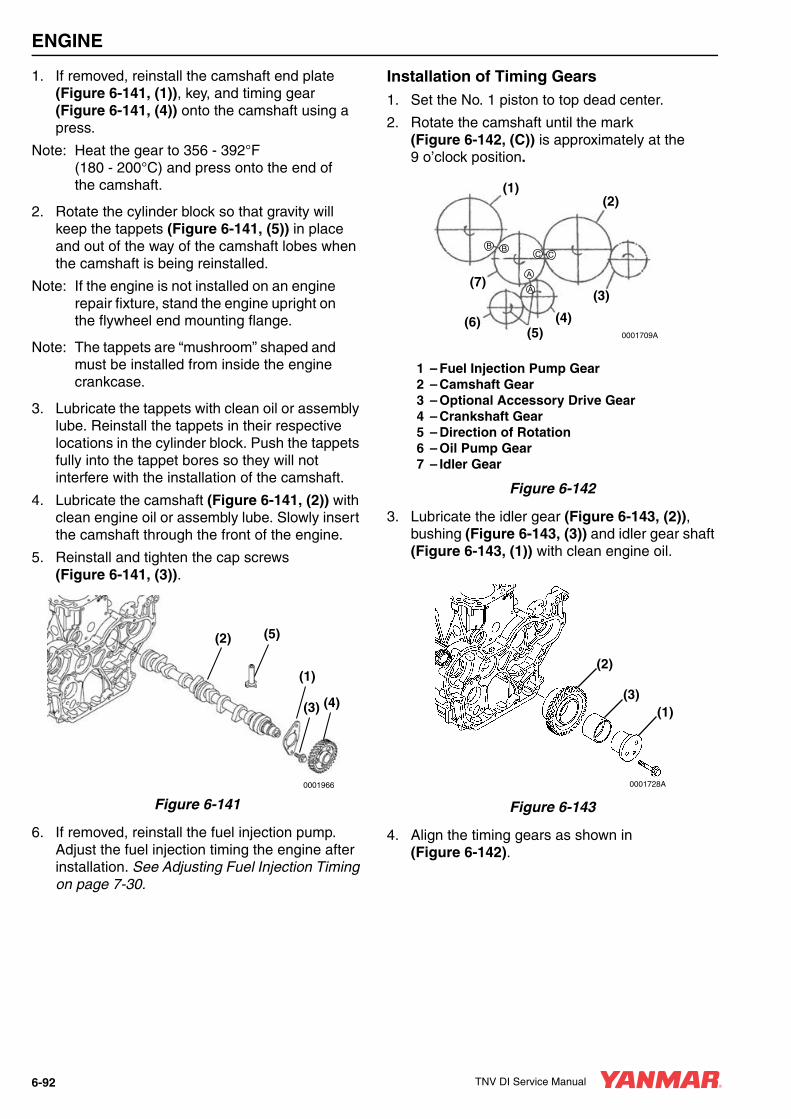
ENGINE
1. If removed, reinstall the camshaft end plate (Figure 6-141, (1)), key, and timing gear (Figure 6-141, (4)) onto the camshaft using a press.
Note: Heat the gear to 356 - 392°F (180 - 200°C) and press onto the end of the camshaft.
2. Rotate the cylinder block so that gravity will keep the tappets (Figure 6-141, (5)) in place and out of the way of the camshaft lobes when the camshaft is being reinstalled.
Note: If the engine is not installed on an engine repair fixture, stand the engine upright on the flywheel end mounting flange.
Note: The tappets are “mushroom” shaped and must be installed from inside the engine crankcase.
3. Lubricate the tappets with clean oil or assembly lube. Reinstall the tappets in their respective locations in the cylinder block. Push the tappets fully into the tappet bores so they will not interfere with the installation of the camshaft.
4. Lubricate the camshaft (Figure 6-141, (2)) with clean engine oil or assembly lube. Slowly insert the camshaft through the front of the engine.
5. Reinstall and tighten the cap screws (Figure 6-141, (3)).
Figure 6-141
6. If removed, reinstall the fuel injection pump. Adjust the fuel injection timing the engine after installation. See Adjusting Fuel Injection Timing on page 7-30.
Installation of Timing Gears1. Set the No. 1 piston to top dead center.
2. Rotate the camshaft until the mark (Figure 6-142, (C)) is approximately at the 9 o’clock position.
1 – Fuel Injection Pump Gear2 – Camshaft Gear3 – Optional Accessory Drive Gear4 – Crankshaft Gear5 – Direction of Rotation6 – Oil Pump Gear7 – Idler Gear
Figure 6-142
3. Lubricate the idler gear (Figure 6-143, (2)), bushing (Figure 6-143, (3)) and idler gear shaft (Figure 6-143, (1)) with clean engine oil.
Figure 6-143
4. Align the timing gears as shown in (Figure 6-142).
0001966
(4)
(1)
(3)
(2) (5)
0001709A
B B
A
A
C C
(1)(2)
(3)
(4)(5)
(6)
(7)
0001728A
(1)(3)
(2)
6-92 TNV DI Service Manual

ENGINE
5. Reinstall the idler gear and idler gear shaft. Be sure the oil hole in the bushing is facing toward the top of the engine.
6. Ensure all three timing marks (Figure 6-142, (A, B, C)) are aligned.
7. When all gears are properly aligned, tighten the idler gear retaining bolts to specified torque. See Special Torque Chart on page 6-23 for specifications.
Installation of Gear Case Cover1. Apply a continuous bead of ThreeBond Liquid
Gasket No. 1212, Yanmar Part No. 977770-01212 to the mounting area of the gear case cover (Figure 6-144, (1)). Be sure to circle the bolt holes.
IMPORTANT3TNV84 - 4TNV88 engines: Be sure to align the flats on the oil pump with the flats on the crankshaft gear when installing the gear case cover.
2. Reinstall and tighten the gear case cover bolts.
Figure 6-144
3. Reinstall the crankshaft pulley.
IMPORTANT4TNV94L: Use the crankshaft pulley installation tool (Figure 6-145, (3)) when reinstalling the pulley (Figure 6-145, (1)). The tool will guide the pulley hub and protect the front seal (Figure 6-145, (2)) from damage.
Figure 6-145
4. Reinstall the washer and bolt. Tighten the bolt to the specified torque. See Special Torque Chart on page 6-23 for specifications.
0001641A
(1)
0002133
(1)(2)
(3)
TNV DI Service Manual 6-93

ENGINE
Installation of Oil Pan1. Reinstall the oil pickup tube (Figure 6-146, (1))
using a new O-ring (Figure 6-146, (2)).
Figure 6-146
2. Apply a continuous bead of ThreeBond Liquid Gasket No. 1212, Yanmar Part No. 977770-01212 to the mounting surface of the oil pan (Figure 6-147, (1)). Be sure to circle each bolt hole.
3. Reinstall the oil pan and tighten the bolts securely.
Figure 6-147
Final Reassembly of Engine1. Reinstall the starter motor.
2. Reinstall the cylinder head. See Reassembly of Cylinder Head on page 6-44 for the 2-valve cylinder head or 6-59 for the 4-valve cylinder head.
3. Reinstall the engine in the machine.
4. Reconnect the fuel and coolant lines.
5. Reinstall the alternator.
6. Reconnect and adjust the throttle cable.
7. Reconnect all electrical connections.
8. Fill the engine with oil and coolant.
9. Reconnect the battery cables, negative (-) cable last.
0001696A
(1)(2)
0001695A
(1)
6-94 TNV DI Service Manual

TNV DI Service Manual Section 7
FUEL SYSTEM
Page
Before You Begin Servicing ............................................................ 7-3
Introduction...................................................................................... 7-5Fuel Injection Pump................................................................... 7-5Stop Solenoid ............................................................................ 7-6Cold Start Device....................................................................... 7-7Trochoid Fuel Pump .................................................................. 7-7
Fuel System Specifications ............................................................. 7-8Special Torque Chart................................................................. 7-8Test and Adjustment Specifications .......................................... 7-8
Special Service Tools...................................................................... 7-9
Measuring Instruments.................................................................... 7-9
Fuel System Diagram.................................................................... 7-10
Fuel System Components ............................................................. 7-122-Valve Cylinder Head............................................................. 7-124-Valve Cylinder Head............................................................. 7-14
Fuel Injection Pump....................................................................... 7-16Removal of Fuel Injection Pump.............................................. 7-16Installation of Fuel Injection Pump........................................... 7-21
Checking and Adjusting Fuel Injection Timing .............................. 7-26Determining the Fuel Injection Timing Specification................ 7-26Checking Fuel Injection Timing ............................................... 7-27Adjusting Fuel Injection Timing................................................ 7-30
TNV DI Service Manual 7-1

FUEL SYSTEM
Fuel Injectors.................................................................................. 7-31Removal of Fuel Injectors......................................................... 7-31Testing of Fuel Injectors ........................................................... 7-33Disassembly and Inspection of Fuel Injectors .......................... 7-35Adjusting Fuel Injector Pressure .............................................. 7-36Reassembly of Fuel Injectors ................................................... 7-37Installation of the Fuel Injectors................................................ 7-37
7-2 TNV DI Service Manual

FUEL SYSTEM
BEFORE YOU BEGIN SERVICING
A WARNING
ENTANGLEMENT HAZARD!• Stop the engine before you begin to
service it.
• NEVER leave the key in the key switch when you are servicing the engine. Someone may accidentally start the engine and not realize you are servicing it. This could result in a serious injury.
• If you must service the engine while it is operating, remove all jewelry, tie back long hair, and keep your hands, other body parts and clothing away from moving / rotating parts.
• Failure to comply could result in death or serious injury.
0000010en
A WARNINGSUDDEN MOVEMENT HAZARD!
• Engaging the transmission or PTO at an elevated engine speed could result in unexpected movement of the equipment.
• Failure to comply could result in death or serious injury.
0000006en
A WARNING• Never inject fuel toward you. Since the
fuel is injected at high pressure from the nozzle, it may penetrate the skin, resulting in injury.
• Never inject fuel toward a fire source. Atomized fuel is highly flammable and may cause a fire or burn skin.
0000028en
A WARNING
FUME / BURN HAZARD!• Always read and follow safety related
precautions found on containers of hazardous substances like parts cleaners, primers, sealants and sealant removers.
• Failure to comply could result in death or serious injury.
0000014en
TNV DI Service Manual 7-3

FUEL SYSTEM
A CAUTION
FLYING OBJECT HAZARD!• ALWAYS wear eye protection when
servicing the engine and when using compressed air or high-pressure water. Dust, flying debris, compressed air, pressurized water or steam may injure your eyes.
• Failure to comply may result in minor or moderate injury.
0000003en
A CAUTION
PINCH HAZARD!Carefully rotate the alternator toward the cylinder block while loosening the V-belt. Failure to comply may result in minor or moderate injury.
0000014en
CAUTION• NEVER remove or attempt to remove
the tamper-proof devices from the full-load fuel adjusting screw or the high-speed throttle limit screw on the fuel injection pump and governor assembly. These adjustments have been made at the factory to meet all applicable emissions regulations and then sealed.
• NEVER attempt to make any adjustments to these sealed adjustment screws. If adjustments are required, they can be made only by a qualified fuel injection shop that will ensure the injection pump continues to meet all applicable emissions regulations and then replace the tamper-proof seals.
• Tampering with or removing these devices may void the “Yanmar Limited Warranty.”
0000146en
CAUTIONNever use a steel wire brush to clean fuel injectors. Damage to the nozzle and other components is likely to result.
0000172en
CAUTIONAllow the engine to warm-up for at least five minutes and the idle speed of the engine to return to normal before engaging the transmission or any PTOs. Engaging the transmission or PTO at an elevated engine speed could result in an unexpected movement of the equipment.
0000159en
7-4 TNV DI Service Manual

FUEL SYSTEM
INTRODUCTIONThis section of the Service Manual describes the procedures necessary to remove, install, and time the MP fuel injection pump and its associated system components. This fuel injection pump is representative of the fuel injection pumps used on other TNV DI model engines.
Fuel Injection PumpNote: If the MP fuel injection pump itself
requires servicing, it must be taken to an authorized Yanmar FIE (Fuel Injection Equipment) repair facility.
CAUTIONRemove or install the high-pressure fuel injection lines as an assembly whenever possible. Disassembling the high-pressure fuel injection lines from the retainers or bending any of the fuel lines will make it difficult to reinstall the fuel lines.
0000047en
CAUTIONAfter marking the position of the pump drive gear, do not rotate the engine crankshaft. Rotating the crankshaft will cause the fuel injection pump to become misaligned.
0000048en
CAUTIONDo not loosen or remove the four bolts retaining the fuel injection pump drive gear to the fuel injection pump hub. Do not disassemble the fuel injection pump drive gear from the hub. Correct fuel injection timing will be very difficult or impossible to achieve.
0000031en
CAUTIONDo not rotate the crankshaft with the injection pump removed.
0000083en
CAUTIONEach pressure adjusting shim removed or added changes the pressure threshold by approximately 275 psi (1.9 MPa, 19 kgf/cm2). Adding adjusting shims increases the threshold pressure. Removing adjusting shims reduces the pressure threshold.
0000081en
CAUTION• NEVER remove or attempt to remove
the tamper-proof devices from the full-load fuel adjusting screw or the high-speed throttle limit screw on the fuel injection pump and governor assembly. These adjustments have been made at the factory to meet all applicable emissions regulations and then sealed.
• NEVER attempt to make any adjustments to these sealed adjustment screws. If adjustments are required, they can be made only by a qualified fuel injection shop that will ensure the injection pump continues to meet all applicable emissions regulations and then replace the tamper-proof seals.
• Tampering with or removing these devices may void the “Yanmar Limited Warranty.”
0000146en
TNV DI Service Manual 7-5

FUEL SYSTEM
Figure 7-1
The following describes the features of the MP fuel injection pump, manufactured by Yanmar.
The fuel injection pump is a very important component of the engine. It is capable of making very precise fuel delivery adjustments according to the varied loads applied to the engine.
All of the fuel injection pump components are very precisely machined. It is extremely important to follow good service practices and maintain cleanliness when servicing the fuel injection pump.
The Yanmar MP “Mono-Plunger” Fuel Injection Pump is a distributor type pump which consists of a single fuel supply plunger, a distributor shaft, a hydraulic head and a pump housing. The hydraulic head has a delivery valve for each cylinder. The fuel injection pump housing contains a governor and an internal camshaft.
The fuel is pressurized by the up and down motion of the camshaft-driven single plunger. It is then distributed to the proper fuel injector by the rotating distributor shaft.
There are two versions and sizes of the MP Fuel Injection Pump. The smaller of the two pumps, the MP2 pump, is used on the 3TNV82A - 4TNV88 model engines. The larger pump, the MP4 pump, which has a larger single plunger and a more aggressive cam profile, is used on the 4TNV94L - 4TNV106T model engines.
Stop SolenoidThe MP fuel injection pumps are equipped with a stop solenoid that controls the fuel flow inside the fuel injection pump.
With the starter switch in the OFF position, no current flows to the stop solenoid and the solenoid plunger is extended holding the fuel injection pump fuel rack in the “closed” position and not allowing fuel to flow through the injection pump and to the engine.
When the starter switch is turned to the start position, the “pull coil” (36.5 Amp draw / white wire) inside the solenoid is activated and pulls the solenoid plunger into the solenoid. This releases the fuel injection pump fuel rack, allowing fuel to flow through the injection pump and allowing the engine to start and run.
When the starter switch is returned to the ON or RUN position, the “pull coil” no longer receives current and the “hold coil” (0.5 Amp draw / red wire) inside the solenoid is activated. The “hold coil” holds the solenoid plunger in the RUN position, allowing fuel to continue flowing and he engine to continue running.
To stop the engine, the key switch is turned to the OFF position. Current no longer flows to the stop solenoid “hold coil”, and the solenoid plunger extends and moves the injection pump fuel rack to the “closed” position, shutting off the fuel flow and stopping the engine.
Failure of the stop solenoid could result in the engine not starting, the engine stopping suddenly, the engine not continuing to run with the key switch returned to the ON or RUN position, or the engine failing to stop when the key switch is turned to the OFF position. Use a multimeter or continuity light to check for 12V at the stop solenoid connector in the correct sequence.
0000038
7-6 TNV DI Service Manual

FUEL SYSTEM
Cold Start DeviceThe Yanmar TNV model engines are equipped with a cold start device (CSD).
The cold start device is located in the upper section of the fuel injection pump and is connected to the engine’s cooling system.
• The cold start device improves engine starting at lower temperatures. At engine cooling system temperatures below 41°F (5°C), the cold start device advances the fuel injection timing and slightly increases the fuel injection volume.
• For approximately the first 5 minutes of operation, the idle speed of the engine will be slightly elevated.
• When the cold start device is activated, you may notice a slight increase in the exhaust smoke of the engine during engine warm-up.
Trochoid Fuel PumpNote: The trochoid fuel pump located on the
side of the MP fuel injection pump is not a “fuel supply” pump. The function of this pump is to raise the pressure of the fuel supplied by the electric fuel supply pump to the internal fuel pressure required by the MP fuel injection pump.
The use of an electric fuel supply pump is required on all TNV model engines with the MP fuel injection pump.
CAUTIONAllow the engine to warm-up for at least five minutes and the idle speed of the engine to return to normal before engaging the transmission or any PTOs. Engaging the transmission or PTO at an elevated engine speed could result in an unexpected movement of the equipment.
0000159en
TNV DI Service Manual 7-7

FUEL SYSTEM
FUEL SYSTEM SPECIFICATIONS
Special Torque Chart
Test and Adjustment Specifications
Note: Fuel injector pressures given are for used parts. New injectors (5 hours operation or less) will read approximately 725 psi (5 MPa; 51 kgf/cm2) higher.
* All DI injectors have 3 letters with the first letter starting with a V or W.
Component Tightening TorqueLubricating Oil Application
(Thread Portion and Seat Surface)
Fuel Injector Retainer Bolt29 ft·lb
(39.2 N·m;4 kgf·m)
Not Applied
Fuel Pump DriveGear Nut
3TNV82Ato4TNV88
58 - 65 ft·lb(78 - 88 N·m; 8 - 9 kgf·m)
Not Applied
4TNV94 to 4TNV106T
83 - 91 ft·lb(113 - 123 N·m;
11.5 - 12.5 kgf·m)Not Applied
High-Pressure Fuel Injection Line Nuts22 - 25 ft·lb
(29 - 34 N·m;3.0 - 3.5 kgf·m)
Not Applied
Fuel Return Line Bolts69 - 87 in·lb
(7.8 - 9.8 N·m;0.8 - 1.0 kgf·m)
Not Applied
Fuel Injection Pump Mounting Nuts17 - 21 ft·lb
(23 - 28 N·m;2.3 - 2.9 kgf·m)
Not Applied
Fuel Injector Nozzle Case Nut30 - 33 ft·lb
(39.2 - 44.1 N·m;4 - 4.5 kgf·m)
Not Applied
Fuel Injection Pump Plunger Plug
3TNV82A to 4TNV88
22 - 26 ft·lb(30 - 35 N·m;
3.1 - 3.6 kgf·m)Not Applied
4TNV94 to 4TNV106T
30 - 33 ft·lb(40 - 45 N·m;
4.1 - 4.6 kgf·m)Not Applied
ModelEngine Class
Injector ID mark*
Fuel Injector Pressure Fuel Injection Timing
3TNV82A - 4TNV88 CL V3133 - 3278 psi
(21.6 - 22.6 MPa;220 - 230 kgf/cm2
See Checking and Adjusting Fuel Injection Timing on page 7-263TNV82A - 4TNV88 VM
W2843 - 2988 psi
(19.6 - 20.6 MPa;200 - 210 kgf/cm24TNV106, 4TNV106T ALL
7-8 TNV DI Service Manual
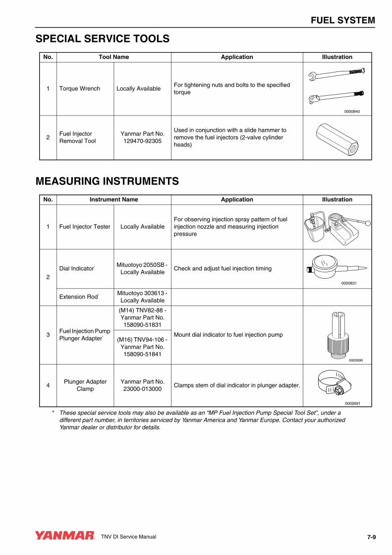
FUEL SYSTEM
SPECIAL SERVICE TOOLS
MEASURING INSTRUMENTS
No. Tool Name Application Illustration
1 Torque Wrench Locally AvailableFor tightening nuts and bolts to the specified torque
2Fuel Injector Removal Tool
Yanmar Part No. 129470-92305
Used in conjunction with a slide hammer to remove the fuel injectors (2-valve cylinder heads)
0000840
No. Instrument Name Application Illustration
1 Fuel Injector Tester Locally AvailableFor observing injection spray pattern of fuel injection nozzle and measuring injection pressure
2
Dial Indicator* Mituotoyo 2050SB - Locally Available
Check and adjust fuel injection timing
Extension Rod* Mituotoyo 303613 - Locally Available
3Fuel Injection Pump Plunger Adapter*
(M14) TNV82-88 - Yanmar Part No. 158090-51831
Mount dial indicator to fuel injection pump(M16) TNV94-106 -
Yanmar Part No. 158090-51841
4Plunger Adapter
ClampYanmar Part No. 23000-013000
Clamps stem of dial indicator in plunger adapter.
* These special service tools may also be available as an “MP Fuel Injection Pump Special Tool Set”, under a different part number, in territories serviced by Yanmar America and Yanmar Europe. Contact your authorized Yanmar dealer or distributor for details.
-GAGE-
P-
ONOFF
OFF
0000831
0002690
0002691
TNV DI Service Manual 7-9

FUEL SYSTEM
FUEL SYSTEM DIAGRAM
1 – Diesel Fuel Tank2 – Fuel Filter / Water Separator3 – Electric Fuel Pump4 – Fuel Filter5 – Air Bleed Orifice6 – Fuel Supply Line7 – Low Pressure Gallery8 – Pressure Control Valve9 – Trochoid Pump
10 – Oil Seal11 – Fuel Injection Pump Cam
12 – Engine Crankcase13 – Tappet14 – High Pressure Gallery15 – Overflow Orifice16 – Accumulator17 – Timer Piston18 – Mono-Plunger19 – Distributor Shaft20 – Fuel Return Line21 – High-Pressure Fuel Injection Lines22 – Fuel Injector
Figure 7-2
0000034B
(3)
(4)
(2)
(1)
(22)
(12)
(5)
(21)
(11)
(18)(17)
(16)
(15)
(14)(13)(17)
(10)
(9)
(8)(7)
(6)
(19)
(20)
7-10 TNV DI Service Manual

FUEL SYSTEM
FUEL SYSTEM COMPONENTS
2-Valve Cylinder Head
Figure 7-3
0002128
(1)
(2)
(3)
(4)
(5)
(6)(7)
(8)
(9)
(10)
(19)
(11)
(17)
(18)
(12)
(13)
(14 )
(15 )
(16 )
7-12 TNV DI Service Manual

FUEL SYSTEM
1 – High-Pressure Fuel Injection Lines2 – Fuel Return Line3 – Fuel Injector4 – Front Plate or Timing Gear Case5 – Gear Case Cover6 – Fuel Injection Pump Drive Gear Nut7 – Lock Washer8 – Fuel Injection Pump Drive Gear Assembly
(DO NOT remove or loosen the four bolts that fasten the injection pump drive gear to the injection pump drive gear hub!)
9 – Coolant Lines for Cold Start Device10 – Fuel Injection Pump Insulator11 – Fuel Injection Pump12 – Rear Fuel Injection Pump Support13 – Fuel Filter / Water Separator14 – Electric Fuel Supply Pump15 – Fuel Filter16 – Fuel Filter Housing17 – Stop Solenoid18 – Cold Start Device (CSD)19 – Trochoid Fuel Pump
TNV DI Service Manual 7-13
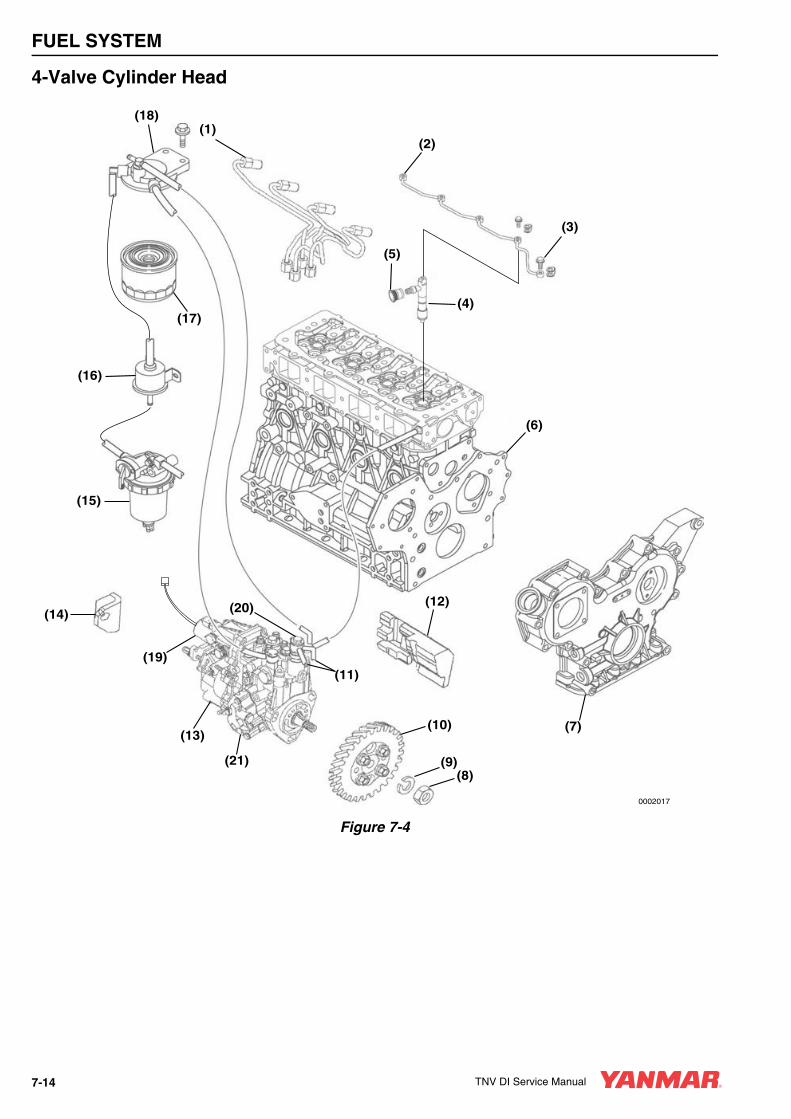
FUEL SYSTEM
4-Valve Cylinder Head
Figure 7-4
0002017
(1)(18)
(6)
(7)
(8)(9)
(10)
(11)
(12)
(21)
(16)
(14)
(15)
(13)
(19)
(20)
(17)
(2)
(3)
(5)
(4)
7-14 TNV DI Service Manual
FUEL SYSTEM
1 – High-Pressure Fuel Injection Lines2 – Fuel Return Line3 – Return Line-to-Cylinder Head Bolt4 – Fuel Injector5 – Injection Line Grommet6 – Front Plate or Timing Gear Case7 – Gear Case Cover8 – Fuel Injection Pump Drive Gear Nut9 – Lock Washer10 – Fuel Injection Pump Drive Gear Assembly
(DO NOT remove or loosen the four bolts that fasten the injection pump drive gear to the injection pump drive gear hub!)
11 – Coolant Lines for Cold Start Device12 – Fuel Injection Pump Insulator13 – Diesel Fuel Injection Pump14 – Rear Fuel Injection Pump Support15 – Fuel Filter / Water Separator16 – Electric Fuel Supply Pump17 – Fuel Filter18 – Fuel Filter Housing19 – Stop Solenoid20 – Cold Start Device (CSD)21 – Trochoid Fuel Pump
TNV DI Service Manual 7-15
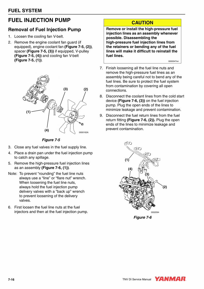
FUEL SYSTEM
FUEL INJECTION PUMP
Removal of Fuel Injection Pump1. Loosen the cooling fan V-belt.
2. Remove the engine coolant fan guard (if equipped), engine coolant fan (Figure 7-5, (2)), spacer (Figure 7-5, (3)) if equipped, V-pulley (Figure 7-5, (4)) and cooling fan V-belt (Figure 7-5, (1)).
Figure 7-5
3. Close any fuel valves in the fuel supply line.
4. Place a drain pan under the fuel injection pump to catch any spillage.
5. Remove the high-pressure fuel injection lines as an assembly (Figure 7-6, (1)).
Note: To prevent “rounding” the fuel line nuts always use a “line” or “flare nut” wrench. When loosening the fuel line nuts, always hold the fuel injection pump delivery valves with a “back up” wrench to prevent loosening of the delivery valves.
6. First loosen the fuel line nuts at the fuel injectors and then at the fuel injection pump.
7. Finish loosening all the fuel line nuts and remove the high-pressure fuel lines as an assembly being careful not to bend any of the fuel lines. Be sure to protect the fuel system from contamination by covering all open connections.
8. Disconnect the coolant lines from the cold start device (Figure 7-6, (3)) on the fuel injection pump. Plug the open ends of the lines to minimize leakage and prevent contamination.
9. Disconnect the fuel return lines from the fuel return fitting (Figure 7-6, (2)). Plug the open ends of the lines to minimize leakage and prevent contamination.
Figure 7-6
(1)
(4)
(3) (2)
0000163A
CAUTIONRemove or install the high-pressure fuel injection lines as an assembly whenever possible. Disassembling the high-pressure fuel injection lines from the retainers or bending any of the fuel lines will make it difficult to reinstall the fuel lines.
0000047en
0002094
(4)
(2)
(3)
(1)
7-16 TNV DI Service Manual
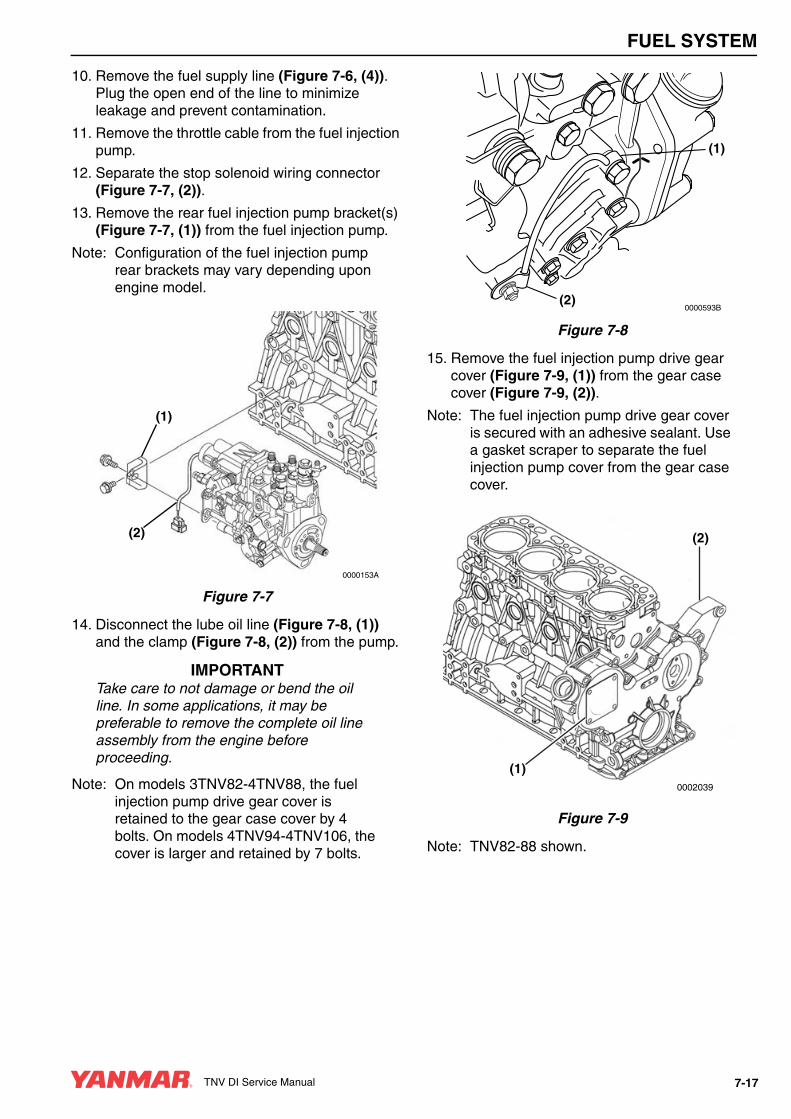
FUEL SYSTEM
10. Remove the fuel supply line (Figure 7-6, (4)). Plug the open end of the line to minimize leakage and prevent contamination.
11. Remove the throttle cable from the fuel injection pump.
12. Separate the stop solenoid wiring connector (Figure 7-7, (2)).
13. Remove the rear fuel injection pump bracket(s) (Figure 7-7, (1)) from the fuel injection pump.
Note: Configuration of the fuel injection pump rear brackets may vary depending upon engine model.
Figure 7-7
14. Disconnect the lube oil line (Figure 7-8, (1)) and the clamp (Figure 7-8, (2)) from the pump.
IMPORTANTTake care to not damage or bend the oil line. In some applications, it may be preferable to remove the complete oil line assembly from the engine before proceeding.
Note: On models 3TNV82-4TNV88, the fuel injection pump drive gear cover is retained to the gear case cover by 4 bolts. On models 4TNV94-4TNV106, the cover is larger and retained by 7 bolts.
Figure 7-8
15. Remove the fuel injection pump drive gear cover (Figure 7-9, (1)) from the gear case cover (Figure 7-9, (2)).
Note: The fuel injection pump drive gear cover is secured with an adhesive sealant. Use a gasket scraper to separate the fuel injection pump cover from the gear case cover.
Figure 7-9
Note: TNV82-88 shown.
(1)
(2)
0000153A
0000593B
(1)
(2)
0002039
(1)
(2)
TNV DI Service Manual 7-17
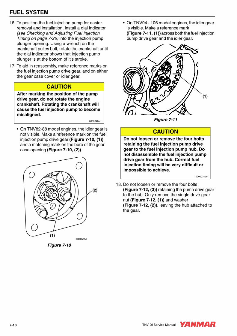
FUEL SYSTEM
16. To position the fuel injection pump for easier removal and installation, install a dial indicator (see Checking and Adjusting Fuel Injection Timing on page 7-26) into the injection pump plunger opening. Using a wrench on the crankshaft pulley bolt, rotate the crankshaft until the dial indicator shows that injection pump plunger is at the bottom of it's stroke.
17. To aid in reassembly, make reference marks on the fuel injection pump drive gear, and on either the gear case cover or idler gear.
• On TNV82-88 model engines, the idler gear is not visible. Make a reference mark on the fuel injection pump drive gear (Figure 7-10, (1)) and a matching mark on the bore of the gear case opening (Figure 7-10, (2)).
Figure 7-10
• On TNV94 - 106 model engines, the idler gear is visible. Make a reference mark (Figure 7-11, (1)) across both the fuel injection pump drive gear and the idler gear.
Figure 7-11
18. Do not loosen or remove the four bolts (Figure 7-12, (3)) retaining the pump drive gear to the hub. Only remove the single drive gear nut (Figure 7-12, (1)) and washer (Figure 7-12, (2)), leaving the hub attached to the gear.
CAUTIONAfter marking the position of the pump drive gear, do not rotate the engine crankshaft. Rotating the crankshaft will cause the fuel injection pump to become misaligned.
0000048en
(2)
(1)0000575A0000575
CAUTIONDo not loosen or remove the four bolts retaining the fuel injection pump drive gear to the fuel injection pump hub. Do not disassemble the fuel injection pump drive gear from the hub. Correct fuel injection timing will be very difficult or impossible to achieve.
0000031en
(1)
7-18 TNV DI Service Manual

FUEL SYSTEM
Figure 7-12
19. Hold the gear train using a large socket wrench on the crankshaft pulley nut. Loosen the fuel injection pump drive gear retaining nut (Figure 7-12, (1)) and turn it out to the end of the fuel injection pump shaft.
20. Remove the pump drive gear and hub as an assembly using an appropriate two-bolt gear puller (Figure 7-13).
Figure 7-13
Note: On TNV82 - 88 models the injection pump drive gear will remain “captured” in the gear case. On TNV94 - 106 models, the injection pump drive gear can be removed through the gear case cover opening.
21. Once the fuel injection pump drive gear and hub assembly has “popped” loose from the tapered fuel injection pump drive shaft, carefully remove the drive gear nut (Figure 7-14, (1)) and lock washer (Figure 7-14, (2)).
Figure 7-14
22. Locate the mark stamped into the upper outside mounting boss of the fuel injection pump. Highlight this mark and make a corresponding mark on the gear case or front plate (Figure 7-15, (1)).
Figure 7-15
(1)
(2)
(3)
0000162A
0000574
(1)
(2)
0000162B
(1)
0000593A0000593
TNV DI Service Manual 7-19

FUEL SYSTEM
Note: Some model engines may require the intake manifold and fuel injection pump insulator (Figure 7-16, (2)) be removed to access the inner fuel injection pump (Figure 7-16, (1)) retaining nuts.
Figure 7-16
23. If required, remove the intake manifold and fuel pump insulator to access the fuel injection pump mounting nuts.
Note: The MP2 fuel injection pumps (TNV82 - 88 model engines) are fastened to the gear case with three (3) studs and nuts. The MP4 fuel injection pumps (TNV94 - 106 model engines) are fastened to the gear case with four (4) studs and nuts.
24. Remove the fuel injection pump (Figure 7-16, (1)). For purposes of future injection timing purposes, record the fuel injection pump timing index number located on the boss on the engine side (back) of the of the fuel injection pump (Figure 7-17, (1)).
Figure 7-17
25. If the fuel injection pump requires servicing, it must be sent to an authorized Yanmar FIE repair facility for repair and calibration, or replaced with a new fuel injection pump.
(1)
(2)
0000263A
CAUTIONDo not rotate the crankshaft with the injection pump removed.
0000083en
0002047
(1)
7-20 TNV DI Service Manual
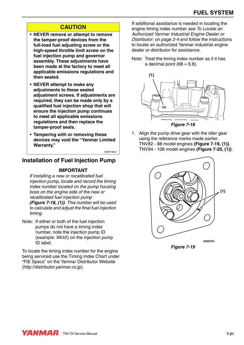
FUEL SYSTEM
Installation of Fuel Injection Pump
IMPORTANTIf installing a new or recalibrated fuel injection pump, locate and record the timing index number located on the pump housing boss on the engine side of the new or recalibrated fuel injection pump (Figure 7-18, (1)). This number will be used to calculate and adjust the final fuel injection timing.
Note: If either or both of the fuel injection pumps do not have a timing index number, note the injection pump ID (example: XK42) on the injection pump ID label.
To locate the timing index number for the engine being serviced use the Timing Index Chart under “FIE Specs” on the Yanmar Distributor Website (http://distributor.yanmar.co.jp).
If additional assistance is needed in locating the engine timing index number see To Locate an Authorized Yanmar Industrial Engine Dealer or Distributor: on page 2-4 and follow the instructions to locate an authorized Yanmar industrial engine dealer or distributor for assistance.
Note: Treat the timing index number as if it has a decimal point (68 = 6.8).
Figure 7-18
1. Align the pump drive gear with the idler gear using the reference marks made earlier. TNV82 - 88 model engines (Figure 7-19, (1)). TNV94 - 106 model engines (Figure 7-20, (1)).
Figure 7-19
CAUTION• NEVER remove or attempt to remove
the tamper-proof devices from the full-load fuel adjusting screw or the high-speed throttle limit screw on the fuel injection pump and governor assembly. These adjustments have been made at the factory to meet all applicable emissions regulations and then sealed.
• NEVER attempt to make any adjustments to these sealed adjustment screws. If adjustments are required, they can be made only by a qualified fuel injection shop that will ensure the injection pump continues to meet all applicable emissions regulations and then replace the tamper-proof seals.
• Tampering with or removing these devices may void the “Yanmar Limited Warranty.”
0000146en
(1)
(1)
0000575B0000575
TNV DI Service Manual 7-21

FUEL SYSTEM
Figure 7-20
2. If installing the fuel injection pump on an engine with the front gear case cover removed, the fuel injection pump drive gear can be aligned with the idler gear by aligning the stamped marks (A, B, C) on the fuel injection pump drive gear, idler gear, and crankshaft drive gear. Ensure all three timing marks (Figure 7-21, (A, B, C)) are aligned.
1 – Fuel Injection Pump Drive Gear2 – Camshaft Drive Gear3 – Auxiliary Drive Gear (Optional)4 – Crankshaft Drive Gear5 – Direction of Rotation6 – Oil Pump Drive Gear (4TNV94L - 4TNV106)7 – Idler Gear
Figure 7-21
3. Install a new O-ring on the pump mounting flange. Apply grease to the O-ring to hold it in place during installation of the injection pump.
Note: Ensure the tapered surface of the fuel injection pump shaft is clean and dry.
4. Align the key on the fuel injection pump shaft with the keyway in the fuel injection pump drive gear hub. Reinstall the fuel injection pump into the fuel injection pump drive gear and gear housing. Reinstall the pump retaining nuts finger tight.
5. Reinstall the fuel injection pump drive gear lock washer (Figure 7-22, (2)) and nut (Figure 7-22, (1)). Do not lubricate the threads of the nut or shaft. Hold the crankshaft pulley bolt with a socket wrench and tighten the drive gear nut to the specified torque. See Special Torque Chart on page 7-8.
Figure 7-22
If reinstalling the original fuel injection pump:
• Align the reference marks (Figure 7-23, (1)) previously made on both the fuel injection pump mounting flange and gear case or front plate.
(1)
0002096
0001709A
B B
A
A
C C
(1)(2)
(3)
(4)(5)
(6)
(7)
(1)
(2)
0000162B
7-22 TNV DI Service Manual
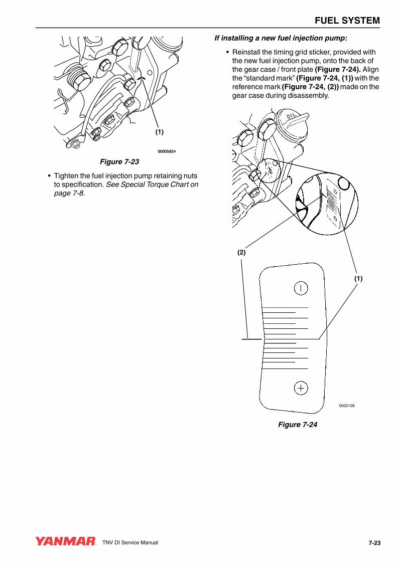
FUEL SYSTEM
Figure 7-23
• Tighten the fuel injection pump retaining nuts to specification. See Special Torque Chart on page 7-8.
If installing a new fuel injection pump:
• Reinstall the timing grid sticker, provided with the new fuel injection pump, onto the back of the gear case / front plate (Figure 7-24). Align the “standard mark” (Figure 7-24, (1)) with the reference mark (Figure 7-24, (2)) made on the gear case during disassembly.
Figure 7-24
(1)
0000593A0000593
(1)
(2)
0002139
TNV DI Service Manual 7-23

FUEL SYSTEM
• Calculate the difference between the timing index numbers (Figure 7-25, (1)) of the fuel injection pump that you removed and the replacement fuel injection pump. See Calculation Example below.
Figure 7-25
Adjusting the fuel injection timing to compensate for the difference in pump timing index numbers:
Calculation Example
• If the difference between the timing index numbers is a positive number, the fuel injection pump mounting position must be advanced (Figure 7-26, (2)) (rotated away from the engine) as compared to the “standard mark” (Figure 7-26, (1)) by the calculated positive amount, adjust the fuel injection pump to the calculated value.
• If the difference between the timing index numbers is a negative number, the replacement injection pump must be retarded (Figure 7-26, (3)) (rotated toward the engine) by the calculated negative amount.
• Each mark on the timing sticker represents 0.5° timing change.
The above calculated difference indicates that the replacement fuel injection pump is to be installed at +0.5° (advanced) from the “Standard Mark” (Figure 7-26, (1)) on the timing sticker.
Figure 7-26
In this case, rotate the top of the fuel injection pump away from the cylinder block until the mark on the outside upper mounting boss (Figure 7-27, (1)) of the fuel injection pump aligns with the +0.5° mark on the timing sticker.
Figure 7-27
Timing Index Number
Original injection pump= 6.8
Replacement injection pump= 7.3
Difference= +0.5
0002047
(1)
0002124A
(1)
(2)
(3)
+0.5°
+1.0°
(1) 0002125A
7-24 TNV DI Service Manual

FUEL SYSTEM
Tighten the fuel injection pump mounting nuts to specification. See Special Torque Chart on page 7-8.
6. Reinstall the rear bracket(s) (Figure 7-28, (1)) to the fuel injection pump. Tighten the rear support bolts.
Note: Configuration of the fuel injection pump rear brackets may vary depending on the model.
Figure 7-28
7. Reconnect the throttle linkage and the stop solenoid connector (Figure 7-29, (2)).
8. Reconnect the lube oil line (Figure 7-29, (1)) and clamp (Figure 7-29, (2)).
Figure 7-29
9. Apply ThreeBond Liquid Gasket No. 1212, Yanmar Part No. 977770-01212, or equivalent sealant to the sealing surface of the pump cover. Install the pump cover and tighten the cover bolts.
10. Reconnect the fuel return lines, fuel supply line and coolant lines to the fuel injection pump.
11. Reinstall the fuel injection high-pressure lines. Tighten the nuts to specification. See Special Torque Chart on page 7-8.
IMPORTANTWhen reinstalling a new or repaired fuel injection pump, it is important to add engine oil to the fuel injection pump to provide lubrication for initial start-up. Add 5-7 oz (150-200 cc) of clean engine oil to the fuel injection pump at the fill plug located in the upper outside section of the governor housing.
(1)
(2)
0000153A
0000593B
(1)
(2)
TNV DI Service Manual 7-25

FUEL SYSTEM
12. If equipped, verify the fuel injection pump insulator (Figure 7-30, (2)) is not damaged. Reinstall the insulator and intake manifold if previously removed.
Figure 7-30
13. Reinstall the coolant pump V-pulley (Figure 7-31, (4)), spacer (Figure 7-31, (3)) (if equipped) and engine coolant fan (Figure 7-31, (2)).
Figure 7-31
14. Reinstall the cooling fan V-belt (Figure 7-31, (1)). Adjust it as described in Check and Adjust Cooling Fan V-Belt on page 5-21.
15. Reinstall the cooling fan guard (if equipped).
16. Prime the fuel system. See Priming the Fuel System on page 4-12.
17. Operate the engine and check for fuel and coolant leaks.
CHECKING AND ADJUSTING FUEL INJECTION TIMING
Determining the Fuel Injection Timing Specification1. Locate and record the fuel injection pump
timing index number (Figure 7-33, (1)) stamped into the boss on the engine side of the fuel injection pump housing (Figure 7-32, (1)). Treat this number as though there is a decimal point between the two digits. i.e. 68 = 6.8
Figure 7-32
Figure 7-33
(1)
(2)
0000263A
(1)
(4)
(3) (2)
0000163A
0000040B
(1)
0002047
(1)
7-26 TNV DI Service Manual

FUEL SYSTEM
2. Using the FIR number for the engine being serviced use the Fuel Injection Reference (FIR) Chart under “FIE Specs” on the Yanmar Distributor Website (http://distributor.yanmar.co.jp).
The FIR number is determined by the complete engine model number. The engine model number is located on the engine nameplate (Figure 7-34).
Figure 7-34
EXAMPLE: The following example is for an engine model 3TNV82A-DSA.
• Find the engine model number in the FIR chart. Locate and record the FIR number (The FIR number for this engine is 4).
• Insert the numbers you have recorded into the following equation:
(Fuel Injection Pump Timing Index Number X 2) + FIR Number = FIT° (Fuel injection Timing in Degrees)
(6.8 X 2) = 13.6 + 4 = 17.6° Fuel injection Timing• Record the calculated fuel injection timing
specification.
Checking Fuel Injection TimingNote: Some fuel may drain from the fuel
injection pump during this process. Make provisions to contain any such spillage.
1. Turn off the fuel valve in the fuel supply hose and the fuel return hose.
2. Clamp shut the fuel injection pump fuel return hose leading to fuel filter (Figure 7-35, (1)).
Figure 7-35
IMPORTANTClean the top of the fuel injection pump to prevent any contamination when the fuel injection pump plunger plug is removed.
3. Remove the forward fuel injection pump plunger plug (Figure 7-35, (2)) on the top of the fuel injection pump.
4. Install a dial indicator adapter and clamp into the pump plunger opening.
0002132
3TNV82A - DSA
1.333000
06532
kW
l
0002087
(1)
(2)
TNV DI Service Manual 7-27
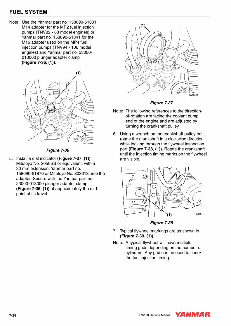
FUEL SYSTEM
Note: Use the Yanmar part no. 158090-51831 M14 adapter for the MP2 fuel injection pumps (TNV82 - 88 model engines) or Yanmar part no. 158090-51841 for the M16 adapter used on the MP4 fuel injection pumps (TNV94 - 106 model engines) and Yanmar part no. 23000-013000 plunger adapter clamp (Figure 7-36, (1)).
Figure 7-36
5. Install a dial indicator (Figure 7-37, (1)), Mitutoyo No. 2050SB or equivalent, with a 30 mm extension, Yanmar part no. 158090-51870 or Mitutoyo No. 303613, into the adapter. Secure with the Yanmar part no. 23000-013000 plunger adapter clamp (Figure 7-36, (1)) at approximately the mid-point of its travel.
Figure 7-37
Note: The following references to the direction-of-rotation are facing the coolant pump end of the engine and are adjusted by turning the crankshaft pulley.
6. Using a wrench on the crankshaft pulley bolt, rotate the crankshaft in a clockwise direction while looking through the flywheel inspection port (Figure 7-38, (1)). Rotate the crankshaft until the injection timing marks on the flywheel are visible.
Figure 7-38
7. Typical flywheel markings are as shown in (Figure 7-39, (1)).
Note: A typical flywheel will have multiple timing grids depending on the number of cylinders. Any grid can be used to check the fuel injection timing.
0002068A
(1)
0002069
(1)
00020(1)
7-28 TNV DI Service Manual
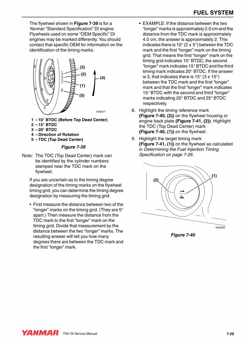
FUEL SYSTEM
The flywheel shown in Figure 7-39 is for a Yanmar “Standard Specification” DI engine. Flywheels used on some “OEM Specific” DI engines may be marked differently. You should contact that specific OEM for information on the identification of the timing marks.
1 – 10° BTDC (Before Top Dead Center)2 – 15° BTDC3 – 20° BTDC4 – Direction of Rotation5 – TDC (Top Dead Center)
Figure 7-39
Note: The TDC (Top Dead Center) mark can be identified by the cylinder numbers stamped near the TDC mark on the flywheel.
If you are uncertain as to the timing degree designation of the timing marks on the flywheel timing grid, you can determine the timing degree designation by measuring the timing grid.
• First measure the distance between two of the “longer” marks on the timing grid. (They are 5° apart.) Then measure the distance from the TDC mark to the first “longer” mark on the timing grid. Divide that measurement by the distance between the two “longer” marks. The resulting answer will tell you how many degrees there are between the TDC mark and the first “longer” mark.
• EXAMPLE: If the distance between the two “longer” marks is approximately 2.0 cm and the distance from the TDC mark is approximately 4.0 cm, the answer is approximately 2. This indicates there is 10° (2 x 5°) between the TDC mark and the first “longer” mark on the timing grid. That means the first “longer” mark on the timing grid indicates 10° BTDC, the second “longer” mark indicates 15° BTDC and the third timing mark indicates 20° BTDC. If the answer is 3, that indicates there is 15° (3 x 15°) between the TDC mark and the first “longer” mark and that the first “longer” mark indicates 15° BTDC with the second and third “longer” marks indicating 20° BTDC and 25° BTDC respectively.
8. Highlight the timing reference mark (Figure 7-40, (2)) on the flywheel housing or engine back plate (Figure 7-41, (2)). Highlight the TDC (Top Dead Center) mark (Figure 7-40, (1)) on the flywheel.
9. Highlight the target timing mark (Figure 7-41, (1)) on the flywheel as calculated in Determining the Fuel Injection Timing Specification on page 7-26.
Figure 7-40
(3)
(2)
(1)
(5)
(4)
0002071
1 4
14
0002065
(2)(1)
TNV DI Service Manual 7-29

FUEL SYSTEM
Figure 7-41
10. Rotate the crankshaft counter-clockwise until the dial indicator shows that the injection pump plunger is at the bottom of its stroke. Rock the crankshaft back and forth slightly to confirm a point where the dial indicator shows no movement. Zero the dial indicator.
11. Slowly rotate the crankshaft clockwise until the dial indicator shows a pump plunger lift of 2.5 mm (0.098 in.).
12. Check the position of the flywheel target timing mark (previously determined) (Figure 7-41, (1)) in relation to the timing reference mark (Figure 7-41, (2)) on the flywheel housing or engine back plate. If the two marks are aligned, the fuel injection timing is correct. If the marks do not align, the fuel injection timing must be adjusted. See Adjusting Fuel Injection Timing on page 7-30.
13. If the injection timing is correct, remove the dial indicator and adapter. Replace the pump plunger plug and its copper gasket and tighten to specifications. Replace the flywheel inspection port cover. Open the fuel supply valve and remove the clamp from the fuel supply hose and the fuel return hose.
14. Prime the fuel system. Operate the engine and check for leaks.
Adjusting Fuel Injection TimingIf the timing marks did not align when performing the Checking Fuel Injection Timing on page 7-27, the following steps must be performed to properly time the engine.
1. Leave the dial indicator installed in the fuel injection pump. Do not disturb the reading on the dial indicator.
2. Rotate the flywheel until the target timing mark (Figure 7-42, (1)) and the timing reference mark (Figure 7-42, (2)) on the flywheel housing or back plate are aligned.
IMPORTANTDo not rotate the crankshaft during the remainder of this procedure.
Figure 7-42
0002066
(2)(1)
0002142
(2)
(1)
0002066
(2)(1)
7-30 TNV DI Service Manual

FUEL SYSTEM
3. Note the reading on the dial indicator (Figure 7-43, (1)). If the reading is less than 2.5 mm (0.098 in.), the fuel injection timing is “retarded.” If the dial indicator reading is greater than 2.5 mm (0.098 in.), the fuel injection timing is “advanced.”
Figure 7-43
Note: Some model engines require the intake manifold and fuel injection pump insulator be removed to access the inner fuel injection pump retaining nuts.
4. Loosen the nuts fastening the fuel injection pump to the gear case or front plate. Loosen the rear bracket(s) on the fuel injection pump.
Note: Loosening the high-pressure injection line nuts on the fuel injection pump may make rotating the pump easier.
5. Rotate the fuel injection pump until the dial indicator reads 2.5 mm (0.098 in.).
6. To “advance” the injection timing, rotate the top of the fuel injection pump away from the engine.
7. To “retard” the injection timing, rotate the top of the fuel injection pump toward the engine.
8. When the dial indicator reads 2.5 mm (0.098 in.) of pump plunger lift and the target timing mark on the flywheel aligns with the reference mark on the flywheel housing or engine back plate, the injection timing is correct.
9. Tighten the fuel injection pump mounting nuts and rear bracket(s).
10. Remove the dial indicator and adapter. Replace the plug in the pump plunger opening and tighten it to specification. If removed, install the intake manifold and pump insulator. Tighten the high-pressure injection line nuts to specification. Open the fuel supply valve, remove the clamp from the fuel return line and prime the fuel system. Operate the engine and check it for leaks.
FUEL INJECTORS
Removal of Fuel Injectors
2-Valve Cylinder Head1. Close any fuel valves in the fuel supply line.
2. Remove the high-pressure fuel injection lines as an assembly (Figure 7-44, (1)).
Figure 7-44
0002069
(1)
(1)
0000154A
TNV DI Service Manual 7-31

FUEL SYSTEM
Note: To prevent “rounding” the fuel line nuts always use a “line” or “flare nut” wrench. When loosening the fuel line nuts, always hold the fuel injection pump delivery valves with a “back up” wrench to prevent loosening.
• Loosen the fuel line nuts at the fuel injectors and then at the fuel injection pump.
• Finish loosening all the fuel line nuts and remove the high-pressure fuel lines as an assembly being careful not to bend any of the fuel lines. Be sure to protect the fuel system from contamination by covering all open connections.
3. Remove the return fuel hoses (Figure 7-45, (1)) from one side of each fuel injector.
4. Remove the bolts and washers that secure the fuel injector retainers (Figure 7-45, (2)) to the cylinder head.
5. Remove the fuel injector retainer.
Figure 7-45
6. Remove the fuel injector.
Note: The fuel injectors can usually be removed by manually pulling them out of the fuel injector wells. If the fuel injectors cannot be manually removed, use the fuel injector removal tool, Yanmar Part No. 129470-92305, and a slide-hammer puller (Figure 7-46).
• Attach a slide-hammer puller to the fuel injector removal tool using a 3/8-16 puller rod.
CAUTIONRemove or install the high-pressure fuel injection lines as an assembly whenever possible. Disassembling the high-pressure fuel injection lines from the retainers or bending any of the fuel lines will make it difficult to reinstall the fuel lines.
0000047en0002092A
(1)
(2)
(3)
(4)
7-32 TNV DI Service Manual
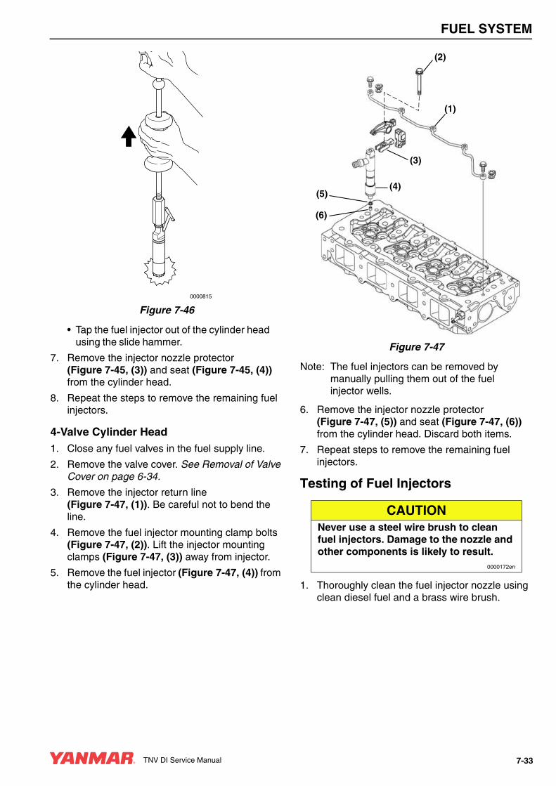
FUEL SYSTEM
Figure 7-46
• Tap the fuel injector out of the cylinder head using the slide hammer.
7. Remove the injector nozzle protector (Figure 7-45, (3)) and seat (Figure 7-45, (4)) from the cylinder head.
8. Repeat the steps to remove the remaining fuel injectors.
4-Valve Cylinder Head1. Close any fuel valves in the fuel supply line.
2. Remove the valve cover. See Removal of Valve Cover on page 6-34.
3. Remove the injector return line (Figure 7-47, (1)). Be careful not to bend the line.
4. Remove the fuel injector mounting clamp bolts (Figure 7-47, (2)). Lift the injector mounting clamps (Figure 7-47, (3)) away from injector.
5. Remove the fuel injector (Figure 7-47, (4)) from the cylinder head.
Figure 7-47
Note: The fuel injectors can be removed by manually pulling them out of the fuel injector wells.
6. Remove the injector nozzle protector (Figure 7-47, (5)) and seat (Figure 7-47, (6)) from the cylinder head. Discard both items.
7. Repeat steps to remove the remaining fuel injectors.
Testing of Fuel Injectors
1. Thoroughly clean the fuel injector nozzle using clean diesel fuel and a brass wire brush.
0000815
CAUTIONNever use a steel wire brush to clean fuel injectors. Damage to the nozzle and other components is likely to result.
0000172en
(1)
(2)
(3)
(4)(5)
(6)
TNV DI Service Manual 7-33

FUEL SYSTEM
2. Visually inspect the fuel injectors and nozzle protectors for deposits or damage. Clean, repair or replace as necessary.
Note: Test the fuel injector using an injection nozzle tester. Operate the tester following the information provided by the tester manufacturer. Use clean, filtered fuel or FIE calibration fluid for the test.
3. Using the correct adapter, connect a fuel injector to a nozzle tester. Aim the fuel injector into a suitable container to catch the fuel spray.
Figure 7-48
4. Pump the operating lever of the tester slowly, observing the pressure reading at the point where the fuel injector begins spraying fuel (Figure 7-48).
See Figure 7-51 for injector ID location.
See Test and Adjustment Specifications on page 7-8 for correct pressure readings.
Note: The opening pressure of a new fuel injector will be approximately 725 psi (5 MPa; 51 kgf/cm2) higher than one that has been operated for five hours or longer.
5. Pump the operating lever slowly to hold the pressure steady at a point just below the opening pressure and hold it for 5 seconds. Observe the injector to see that it is sealing properly and is not “dripping”. If fuel leaks from the return line fitting, check that the nozzle case nut is tight. Service or replace the injector if fuel continues to leak from either the return line fitting or nozzle.
A WARNING• Never inject fuel toward you. Since the
fuel is injected at high pressure from the nozzle, it may penetrate the skin, resulting in injury.
• Never inject fuel toward a fire source. Atomized fuel is highly flammable and may cause a fire or burn skin.
0000028en
A CAUTION
FLYING OBJECT HAZARD!• ALWAYS wear eye protection when
servicing the engine and when using compressed air or high-pressure water. Dust, flying debris, compressed air, pressurized water or steam may injure your eyes.
• Failure to comply may result in minor or moderate injury.
0000003en
-GAGE-
P-
ONOFF
OFF
7-34 TNV DI Service Manual
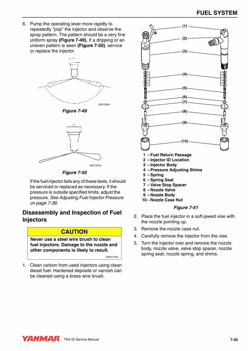
FUEL SYSTEM
6. Pump the operating lever more rapidly to repeatedly “pop” the injector and observe the spray pattern. The pattern should be a very fine uniform spray (Figure 7-49). If a dripping or an uneven pattern is seen (Figure 7-50), service or replace the injector.
Figure 7-49
Figure 7-50
If the fuel injector fails any of these tests, it should be serviced or replaced as necessary. If the pressure is outside specified limits, adjust the pressure. See Adjusting Fuel Injector Pressure on page 7-36.
Disassembly and Inspection of Fuel Injectors
1. Clean carbon from used injectors using clean diesel fuel. Hardened deposits or varnish can be cleaned using a brass wire brush.
1 – Fuel Return Passage2 – Injector ID Location3 – Injector Body4 – Pressure Adjusting Shims5 – Spring6 – Spring Seat7 – Valve Stop Spacer8 – Nozzle Valve9 – Nozzle Body10 – Nozzle Case Nut
Figure 7-51
2. Place the fuel injector in a soft-jawed vise with the nozzle pointing up.
3. Remove the nozzle case nut.
4. Carefully remove the injector from the vise.
5. Turn the injector over and remove the nozzle body, nozzle valve, valve stop spacer, nozzle spring seat, nozzle spring, and shims.
CAUTIONNever use a steel wire brush to clean fuel injectors. Damage to the nozzle and other components is likely to result.
0000172en
0001336A
0001337A
(10)
(9)
(8)
(7)(6)
(5)
(4)
(3)
(1)
(2)
TNV DI Service Manual 7-35
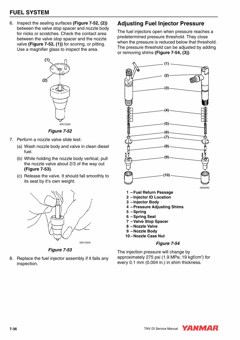
FUEL SYSTEM
6. Inspect the sealing surfaces (Figure 7-52, (2)) between the valve stop spacer and nozzle body for nicks or scratches. Check the contact area between the valve stop spacer and the nozzle valve (Figure 7-52, (1)) for scoring, or pitting. Use a magnifier glass to inspect the area.
Figure 7-52
7. Perform a nozzle valve slide test:
(a) Wash nozzle body and valve in clean diesel fuel.
(b) While holding the nozzle body vertical, pull the nozzle valve about 2/3 of the way out (Figure 7-53).
(c) Release the valve. It should fall smoothly to its seat by it’s own weight.
Figure 7-53
8. Replace the fuel injector assembly if it fails any inspection.
Adjusting Fuel Injector PressureThe fuel injectors open when pressure reaches a predetermined pressure threshold. They close when the pressure is reduced below that threshold. The pressure threshold can be adjusted by adding or removing shims (Figure 7-54, (3)).
1 – Fuel Return Passage2 – Injector ID Location3 – Injector Body4 – Pressure Adjusting Shims5 – Spring6 – Spring Seat7 – Valve Stop Spacer8 – Nozzle Valve9 – Nozzle Body
10 – Nozzle Case Nut
Figure 7-54
The injection pressure will change by approximately 275 psi (1.9 MPa; 19 kgf/cm2) for every 0.1 mm (0.004 in.) in shim thickness.
(1)
(2)
0001333A
0001332A
0002093
(10)
(9)
(8)
(7)(6)
(5)
(4)
(3)
(1)
0002093
(2)
7-36 TNV DI Service Manual

FUEL SYSTEM
See the parts catalog for available shims.
1. Disassemble the fuel injector assembly. See Disassembly and Inspection of Fuel Injectors on page 7-35.
2. Remove or add adjusting shims as needed.
3. Reassemble the fuel injector assembly. See Reassembly of Fuel Injectors on page 7-37.
4. Retest the fuel injector. See Testing of Fuel Injectors on page 7-33. If the injector cannot be adjusted to the appropriate pressure, discard the fuel injector.
Reassembly of Fuel Injectors1. Secure the injector in a soft-jawed vise with the
nozzle end up.
2. Reinstall the shims, nozzle spring, nozzle spring seat, valve stop spacer, nozzle valve, and nozzle body.
3. Reinstall the nozzle case nut. Tighten it to specification. See Special Torque Chart on page 7-8.
Installation of the Fuel Injectors
2-Valve Cylinder Head1. Reinsert a new nozzle seat (Figure 7-55, (4))
and nozzle protector (Figure 7-55, (3)) in the cylinder head for each injector.
2. Reinstall a O-ring on to each injector body.
3. Reinsert each fuel injector into the cylinder head.
4. Reinstall the fuel injector retainers (Figure 7-55, (2)) and torque the retaining bolts to specification.
5. Reinstall the fuel return hoses (Figure 7-55, (1)), one on each side of each injector.
6. Reinstall the fuel high-pressure fuel line assembly and tighten the nuts using a “line” or “flare nut” wrench.
Figure 7-55
7. Prime the fuel system. See Priming the Fuel System on page 4-12.
8. Operate the engine and check for fuel and coolant leaks.
CAUTIONEach pressure adjusting shim removed or added changes the pressure threshold by approximately 275 psi (1.9 MPa, 19 kgf/cm2). Adding adjusting shims increases the threshold pressure. Removing adjusting shims reduces the pressure threshold.
0000081en
0002092A
(1)
(2)
(3)
(4)
TNV DI Service Manual 7-37

FUEL SYSTEM
4-Valve Cylinder Head1. Reinsert a new nozzle seat (Figure 7-56, (6))
and nozzle protector (Figure 7-56, (5)) in the cylinder head for each injector.
2. Reinstall a O-ring on to each injector body.
3. Reinsert each fuel injector (Figure 7-56, (4)) into the cylinder head.
4. Reinstall the fuel injector retainers (Figure 7-56, (3)) and torque the retaining bolts (Figure 7-56, (2)) to specification.
5. Reinstall the fuel injector return line assembly using new gaskets on each side of the injector line screws.
6. Reinstall the fuel high-pressure fuel lines to each injector and tighten the nuts using a “line” or “flare nut” wrench.
Figure 7-56
7. Prime the fuel system. See Priming the Fuel System on page 4-12.
8. Operate the engine and check for fuel and coolant leaks.
0002088
(1)
(2)
(3)
(4)(5)
(6)
7-38 TNV DI Service Manual

TNV DI Service Manual Section 8
COOLING SYSTEM
PageBefore You Begin Servicing ............................................................ 8-3
Introduction...................................................................................... 8-6
Cooling System Diagram................................................................. 8-6
Engine Coolant Pump Components ................................................ 8-7
Engine Coolant System Check........................................................ 8-8
Engine Coolant Pump ..................................................................... 8-8Removal of Engine Coolant Pump ............................................ 8-8Disassembly of Engine Coolant Pump .................................... 8-10Cleaning and Inspection .......................................................... 8-10Reassembly of Engine Coolant Pump..................................... 8-11Installation of Engine Coolant Pump ....................................... 8-11
TNV DI Service Manual 8-1

COOLING SYSTEM
BEFORE YOU BEGIN SERVICING
A DANGER
SCALD HAZARD!• NEVER remove the radiator cap if the
engine is hot. Steam and hot engine coolant will spurt out and seriously burn you. Allow the engine to cool down before you attempt to remove the radiator cap.
• Tighten the radiator cap securely after you check the radiator. Steam can spurt out during engine operation if the cap is loose.
• ALWAYS check the level of the engine coolant by observing the reserve tank.
• Failure to comply will result in death or serious injury.
0000002en
A WARNING
BURN HAZARD!• Wait until the engine cools before you
drain the engine coolant. Hot engine coolant may splash and burn you.
• Failure to comply could result in death or serious injury.
0000016en
A WARNING
ENTANGLEMENT HAZARD!• Stop the engine before you begin to
service it.
• NEVER leave the key in the key switch when you are servicing the engine. Someone may accidentally start the engine and not realize you are servicing it. This could result in a serious injury.
• If you must service the engine while it is operating, remove all jewelry, tie back long hair, and keep your hands, other body parts and clothing away from moving / rotating parts.
• Failure to comply could result in death or serious injury.
0000010en
A WARNING
FUME / BURN HAZARD!• Always read and follow safety related
precautions found on containers of hazardous substances like parts cleaners, primers, sealants and sealant removers.
• Failure to comply could result in death or serious injury.
0000014en
TNV DI Service Manual 8-3

COOLING SYSTEM
A WARNING
BURN HAZARD!• If you must drain the engine oil while it
is still hot, stay clear of the hot engine oil to avoid being burned.
• ALWAYS wear eye protection.
• Failure to comply could result in death or serious injury.
0000011en
A CAUTION
FLYING OBJECT HAZARD!• ALWAYS wear eye protection when
servicing the engine and when using compressed air or high-pressure water. Dust, flying debris, compressed air, pressurized water or steam may injure your eyes.
• Failure to comply may result in minor or moderate injury.
0000003en
A CAUTION
PINCH HAZARD!Carefully rotate the alternator toward the cylinder block while loosening the V-belt. Failure to comply may result in minor or moderate injury.
0000014en
CAUTION• Only use the engine coolant specified.
Other engine coolants may affect warranty coverage, cause an internal buildup of rust and scale and / or shorten engine life.
• Prevent dirt and debris from contaminating the engine coolant. Carefully clean the radiator cap and the surrounding area before you remove the cap.
• NEVER mix different types of engine coolants. This may adversely affect the properties of the engine coolant.
0000006en
CAUTIONIf the engine coolant pump must be replaced, replace the engine coolant pump as an assembly only. Do not attempt to repair the engine coolant pump or replace individual components.
0000041en
8-4 TNV DI Service Manual

COOLING SYSTEM
CAUTIONUse a new special O-ring between the engine coolant pump and the joint. Be sure to use the special O-ring for each engine model. Although the O-ring dimensions are the same as a commercially available O-ring, the material is different.
0000042en
TNV DI Service Manual 8-5
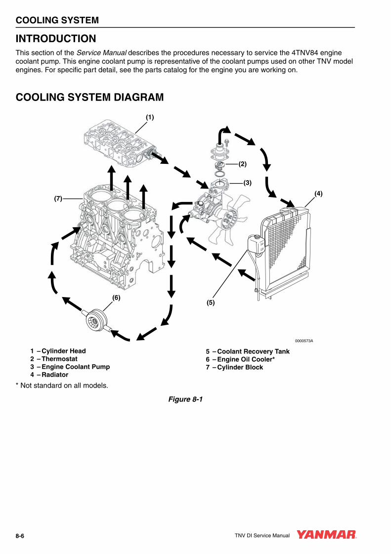
COOLING SYSTEM
INTRODUCTIONThis section of the Service Manual describes the procedures necessary to service the 4TNV84 engine coolant pump. This engine coolant pump is representative of the coolant pumps used on other TNV model engines. For specific part detail, see the parts catalog for the engine you are working on.
COOLING SYSTEM DIAGRAM
1 – Cylinder Head2 – Thermostat3 – Engine Coolant Pump4 – Radiator
5 – Coolant Recovery Tank6 – Engine Oil Cooler*7 – Cylinder Block
* Not standard on all models.
Figure 8-1
FULL
LOW
0000573A
(1)
(4)
(3)
(2)
(7)
(6)(5)
8-6 TNV DI Service Manual

COOLING SYSTEM
ENGINE COOLANT PUMP COMPONENTS
1 – Thermostat Cover2 – Thermostat Cover Gasket3 – Thermostat4 – Thermostat O-Ring5 – Special O-Ring6 – Engine Coolant Pump7 – Temperature Switch
8 – Gasket9 – Engine Coolant Pump Gasket10 – V-Belt11 – Engine Coolant Pump V-Pulley12 – Spacer13 – Engine Coolant Fan
Figure 8-2
(1)
(2)
(3)
(4)
(6)
(9)
(10)
(11)
(12)
(13)
(5)
(7)(8)
0000031A
TNV DI Service Manual 8-7

COOLING SYSTEM
ENGINE COOLANT SYSTEM CHECKCheck the engine coolant system for leakage.
1. With the radiator properly filled, install a cooling system tester (Figure 8-3, (1)).
Figure 8-3
2. Apply 10.8 - 14.8 psi (75 - 105 kPa; 0.75 - 1.05 kgf/cm²) to the cooling system. If the pressure reading drops, the engine coolant system is leaking. Identify the source of the leak and repair it.
ENGINE COOLANT PUMP
Removal of Engine Coolant PumpVerify the condition of the engine coolant pump before disassembling it from the engine. Check the engine coolant pump shaft bearing for abnormal noise, sticking, excessive play and water leakage. Replace the coolant pump if any of these conditions are present.
IMPORTANTMake sure the engine and engine coolant are not hot.
1. Before removing the engine coolant pump or thermostat, it will be necessary to drain the engine coolant. Drain the coolant into a clean container if the coolant is to be reused. Otherwise, properly dispose of the coolant.
2. Remove the radiator cap (Figure 8-4, (1)).
3. Remove the drain plug or open the drain cock (Figure 8-4, (1)) at the lower portion of the radiator and drain the coolant.
Figure 8-4
4. Drain the coolant from the engine block.
• On models equipped with an oil cooler, remove the coolant hose (Figure 8-5, (1)) at the oil cooler.
Figure 8-5
CAUTIONIf the engine coolant pump must be replaced, replace the engine coolant pump as an assembly only. Do not attempt to repair the engine coolant pump or replace individual components.
0000041en
(1)0000577A
FULL
LOW
0000074A(2)
(1)
(1) 0001579B
8-8 TNV DI Service Manual

COOLING SYSTEM
• On models not equipped with an oil cooler, remove the coolant drain plug (Figure 8-6, (1)) from the engine block.
Figure 8-6
5. Loosen the alternator mounting bolts. Loosen and remove the V-belt and rotate the alternator away from the engine and out of the way.
6. Remove the engine coolant fan guard (if equipped), engine coolant fan (Figure 8-7, (1)), spacer (Figure 8-7, (2)) and engine coolant pump V-pulley (Figure 8-7, (3)).
Figure 8-7
7. Disconnect the coolant hoses and the temperature switch lead wire from the engine coolant pump.
8. Remove the engine coolant pump (Figure 8-7, (4)). Discard the gasket.A CAUTION
PINCH HAZARD!Carefully rotate the alternator toward the cylinder block while loosening the V-belt. Failure to comply may result in minor or moderate injury.
0000014en
(1)
0000027B
(4)
(3)
(2) (1)
0000163B
TNV DI Service Manual 8-9

COOLING SYSTEM
Disassembly of Engine Coolant Pump1. Remove the thermostat cover (Figure 8-8, (1)).
Discard the gasket.
Figure 8-8
2. Remove the thermostat (Figure 8-8, (2)). Discard the O-ring. Remove the temperature switch (Figure 8-8, (3)) and gasket (Figure 8-8, (4)). Discard the gasket.
Cleaning and Inspection
Temperature Switch1. Check for proper operation of the temperature
switch. Connect a continuity light or ohmmeter to the temperature switch. Connect one lead to the terminal of the switch (Figure 8-9, (1)) and the other lead to the metal portion of the switch (Figure 8-9, (2)).
Figure 8-9
2. Place the temperature switch and an accurate thermometer (Figure 8-9, (3)) in engine coolant.
3. Slowly increase temperature of the fluid using an external heat source.
4. The temperature switch is operating properly if the continuity light or ohmmeter indicates continuity when the fluid temperature reaches 225°F - 235°F (107°C - 113°C).
Thermostat1. Check for proper operation of the thermostat.
Place the thermostat (Figure 8-10, (1)) and an accurate thermometer (Figure 8-10, (2)) in warm water.
Figure 8-10
2. Slowly increase the temperature of the water using an external heat source.
(1)
(2)(3)
(4)
0000267A
0000577A
(2)
(1)(3)
(2)
(1)
0000577A
8-10 TNV DI Service Manual

COOLING SYSTEM
3. The thermostat is operating properly if it starts to open at the temperature value stamped on the flange of the thermostat, and fully opens as the temperature of the water is increased.
Radiator Cap1. Check for proper operation of the radiator cap.
Install the radiator cap (Figure 8-11, (1)) on a cooling system tester.
Figure 8-11
2. Apply 10.8 - 14.8 psi (75 - 105 kPa; 0.75 - 1.05 kgf/cm²) to the radiator cap. The radiator cap relief valve must open within the specified range.
Reassembly of Engine Coolant Pump1. Reinstall the thermostat (Figure 8-12, (1)) and
a new O-ring.
Figure 8-12
2. Reinstall the thermostat cover (Figure 8-12, (2)) and a new gasket. Tighten the thermostat cover bolts.
3. Reinstall the temperature switch (Figure 8-12, (3)) and a new gasket (Figure 8-12, (4)).
Installation of Engine Coolant Pump1. Position the engine coolant pump on the engine
and install a new gasket. Install a new special O-ring (Figure 8-12, (5)) on assembly between the engine coolant pump and the joint.
0000577A
(1)
CAUTIONUse a new special O-ring between the engine coolant pump and the joint. Be sure to use the special O-ring for each engine model. Although the O-ring dimensions are the same as a commercially available O-ring, the material is different.
0000042en
(2)
(1)
0001623A
(3)(4)
(5)
TNV DI Service Manual 8-11

COOLING SYSTEM
2. Reinstall the engine coolant pump bolts. Tighten the bolts.
3. Inspect and reinstall the coolant hoses and the temperature switch lead wire.
4. Reinstall the engine coolant pump V-pulley (Figure 8-13, (1)), spacer (Figure 8-13, (2)) engine coolant fan (Figure 8-13, (3)) and engine coolant fan guard (if equipped).
Figure 8-13
5. Inspect the condition of the V-belt. There must be clearance (Figure 8-14, (1)) between the V-belt and the bottom of the pulley groove. If there is no clearance (Figure 8-14, (2)) between the V-belt and the bottom of the pulley groove, replace the V-belt.
Figure 8-14
6. Reinstall the V-belt. Tighten the V-belt to the proper tension. See Check and Adjust Cooling Fan V-Belt on page 5-21.
7. Reinstall and tighten the drain plug or close the drain cock in the radiator. Reinstall and tighten the engine block drain plug or reconnect the coolant hose at the oil cooler.
8. Fill the radiator and engine with engine coolant. See Drain, Flush and Refill Cooling System With New Coolant on page 5-35.
(1)
(2) (3)
0000163C
0000584
(2)
(1)
CAUTION• Only use the engine coolant specified.
Other engine coolants may affect warranty coverage, cause an internal buildup of rust and scale and / or shorten engine life.
• Prevent dirt and debris from contaminating the engine coolant. Carefully clean the radiator cap and the surrounding area before you remove the cap.
• NEVER mix different types of engine coolants. This may adversely affect the properties of the engine coolant.
0000006en
8-12 TNV DI Service Manual
TNV DI Service Manual Section 9
LUBRICATION SYSTEM
Page
Before You Begin Servicing ............................................................ 9-3
Introduction...................................................................................... 9-5
Oil Pump Service Information.......................................................... 9-5
Lubrication System Diagram ........................................................... 9-8
Checking Engine Oil Pressure ........................................................ 9-9
Trochoid Oil Pump........................................................................... 9-93TNV82A to 4TNV88 Oil Pump Components............................ 9-9Disassembly of Oil Pump ........................................................ 9-10Cleaning and Inspection .......................................................... 9-11Reassembly of Oil Pump......................................................... 9-12
Trochoid Oil Pump......................................................................... 9-134TNV94L/98/106 Oil Pump Components ................................ 9-13Disassembly of Oil Pump ........................................................ 9-14Cleaning and Inspection .......................................................... 9-14Reassembly of Oil Pump......................................................... 9-15
TNV DI Service Manual 9-1

LUBRICATION SYSTEM
BEFORE YOU BEGIN SERVICING
A WARNING
ENTANGLEMENT HAZARD!• Stop the engine before you begin to
service it.
• NEVER leave the key in the key switch when you are servicing the engine. Someone may accidentally start the engine and not realize you are servicing it. This could result in a serious injury.
• If you must service the engine while it is operating, remove all jewelry, tie back long hair, and keep your hands, other body parts and clothing away from moving / rotating parts.
• Failure to comply could result in death or serious injury.
0000010en
A WARNING
BURN HAZARD!• Keep your hands and other body parts
away from hot engine surfaces such as the muffler, exhaust pipe, turbocharger (if equipped) and engine block during operation and shortly after you shut the engine down. These surfaces are extremely hot while the engine is operating and could seriously burn you.
• Failure to comply could result in death or serious injury.
0000015en
A WARNING
FUME / BURN HAZARD!• Always read and follow safety related
precautions found on containers of hazardous substances like parts cleaners, primers, sealants and sealant removers.
• Failure to comply could result in death or serious injury.
0000014en
TNV DI Service Manual 9-3

LUBRICATION SYSTEM
A CAUTION
FLYING OBJECT HAZARD!• ALWAYS wear eye protection when
servicing the engine and when using compressed air or high-pressure water. Dust, flying debris, compressed air, pressurized water or steam may injure your eyes.
• Failure to comply may result in minor or moderate injury.
0000003en
A CAUTIONIf any oil pump component clearance exceeds its limit, the oil pump must be replaced as an assembly.
0000015en
CAUTION• Only use the engine oil specified.
Other engine oils may affect warranty coverage, cause internal engine components to seize and / or shorten engine life.
• Prevent dirt and debris from contaminating the engine oil. Carefully clean the oil cap / dipstick and the surrounding area before you remove the cap.
• NEVER mix different types of engine oil. This may adversely affect the lubricating properties of the engine oil.
• NEVER overfill. Overfilling may result in white exhaust smoke, engine overspeed or internal damage.
0000005en
CAUTIONIf the oil pump must be replaced, replace it as an assembly only. Do not replace individual components.
0000030en
9-4 TNV DI Service Manual
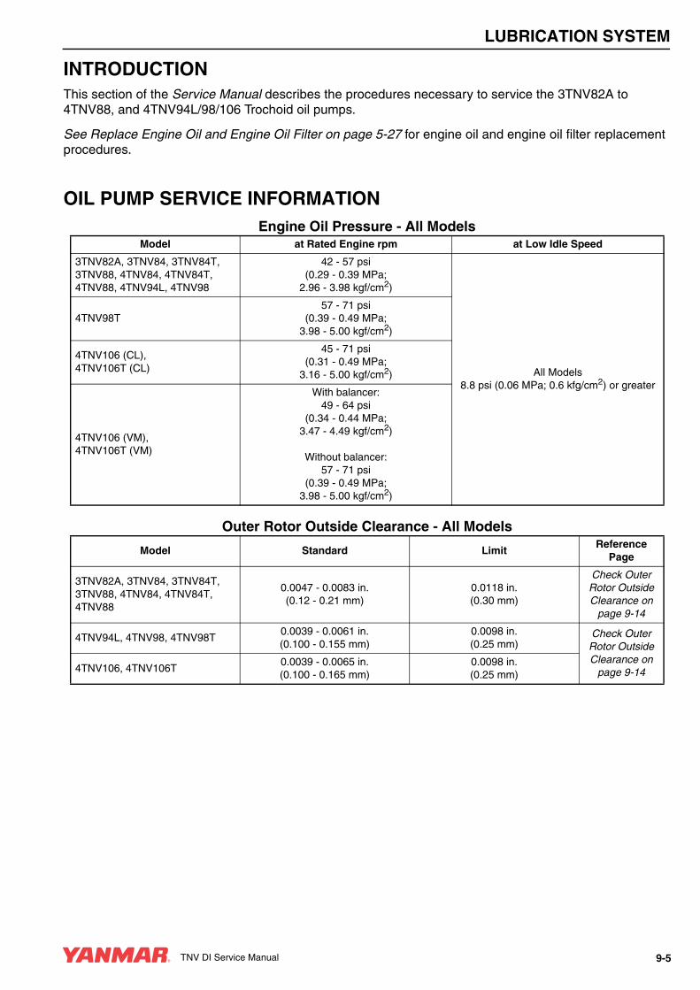
LUBRICATION SYSTEM
INTRODUCTIONThis section of the Service Manual describes the procedures necessary to service the 3TNV82A to 4TNV88, and 4TNV94L/98/106 Trochoid oil pumps.
See Replace Engine Oil and Engine Oil Filter on page 5-27 for engine oil and engine oil filter replacement procedures.
OIL PUMP SERVICE INFORMATIONEngine Oil Pressure - All Models
Outer Rotor Outside Clearance - All Models
Model at Rated Engine rpm at Low Idle Speed
3TNV82A, 3TNV84, 3TNV84T, 3TNV88, 4TNV84, 4TNV84T, 4TNV88, 4TNV94L, 4TNV98
42 - 57 psi (0.29 - 0.39 MPa;
2.96 - 3.98 kgf/cm2)
All Models 8.8 psi (0.06 MPa; 0.6 kfg/cm2) or greater
4TNV98T57 - 71 psi
(0.39 - 0.49 MPa;3.98 - 5.00 kgf/cm2)
4TNV106 (CL),4TNV106T (CL)
45 - 71 psi(0.31 - 0.49 MPa;
3.16 - 5.00 kgf/cm2)
4TNV106 (VM),4TNV106T (VM)
With balancer: 49 - 64 psi
(0.34 - 0.44 MPa;3.47 - 4.49 kgf/cm2)
Without balancer: 57 - 71 psi
(0.39 - 0.49 MPa;3.98 - 5.00 kgf/cm2)
Model Standard LimitReference
Page
3TNV82A, 3TNV84, 3TNV84T, 3TNV88, 4TNV84, 4TNV84T, 4TNV88
0.0047 - 0.0083 in.(0.12 - 0.21 mm)
0.0118 in.(0.30 mm)
Check Outer Rotor Outside Clearance on
page 9-14
4TNV94L, 4TNV98, 4TNV98T0.0039 - 0.0061 in.(0.100 - 0.155 mm)
0.0098 in.(0.25 mm)
Check Outer Rotor Outside Clearance on
page 9-144TNV106, 4TNV106T0.0039 - 0.0065 in.(0.100 - 0.165 mm)
0.0098 in.(0.25 mm)
TNV DI Service Manual 9-5

LUBRICATION SYSTEM
Outer Rotor Side Clearance - All Models
Outer Rotor to Inner Rotor Tip Clearance - All Models
Inner Rotor and Gear Boss Clearance - 3TNV82A to 88
Model Standard LimitReference
Page
3TNV82A, 3TNV84, 3TNV84T, 3TNV88, 4TNV84, 4TNV84T, 4TNV88
0.0008 - 0.0028 in.(0.02 - 0.07 mm)
0.0047 in.(0.12 mm)
Check Outer Rotor Side
Clearance on page 9-12
4TNV94L, 4TNV98, 4TNV98T0.0020 - 0.0039 in.(0.05 - 0.10 mm)
0.0059 in.(0.15 mm)
Check Outer Rotor Side
Clearance on page 9-124TNV106, 4TNV106T
0.0012 - 0.0047 in.(0.03 - 0.12 mm)
0.0067 in.(0.17 mm)
Model Standard LimitReference
Page
3TNV82A, 3TNV84, 3TNV84T, 3TNV88, 4TNV84, 4TNV84T, 4TNV88
–0.0063 in.(0.16 mm)
Outer Rotor to Inner Rotor Tip Clearance on
page 9-11
4TNV94L, 4TNV98, 4TNV98T –0.0063 in.(0.16 mm)
Outer Rotor to Inner Rotor Tip Clearance on
page 9-114TNV106, 4TNV106T –0.0063 in.(0.16 mm)
Item PartsStandard
DimensionStandardClearance
StandardClearance
Limit
Reference Page
Inside Clearance of Inner Rotor
Gear Boss Diameter2.0886 - 2.0925 in.(53.05 - 53.15 mm) 0.012 - 0.020 in.
(0.3 - 0.5 mm)0.024 in.(0.6 mm) Check Inner
Rotor and Gear Boss
Clearance on page 9-12
Rotor Diameter2.1043 - 2.1083 in.(53.45 - 53.55 mm)
Inner Rotor WidthAcross FlatClearance
Width Across Flat of Gear Boss
1.9468 - 1.9587 in.(49.45 - 49.75 mm) 0.008 - 0.024 in.
(0.2 - 0.6 mm)0.028 in.(0.7 mm)Width Across Flat of
Rotor1.9665 - 1.9705 in.(49.95 - 50.05 mm)
9-6 TNV DI Service Manual

LUBRICATION SYSTEM
Rotor Shaft Clearance - 4TNV94L to 4TNV106T
Model Inspection Item Standard LimitReference
Page
4TNV94L, 4TNV98, 4TNV98T
Gear Case Bearing I.D.0.5110 - 0.5126 in.
(12.980 - 13.020 mm)0.5138 in.
(13.05 mm)
Check Rotor Shaft
Clearance on page 9-15
Rotor Shaft O.D.0.5100 - 0.5108 in.
(12.955 - 12.975 mm)0.5096 in.
(12.945 mm)
Rotor Clearance0.0014 - 0.0026 in.(0.035 - 0.065 mm)
0.0041 in.(0.105 mm)
4TNV106, 4TNV106T
Gear Case Bearing I.D.0.5118 - 0.5126 in.(13.00 - 13.02 mm)
0.5138 in.(13.05 mm)
Rotor Shaft O.D.0.5100 - 0.5104 in.
(12.955 - 12.965 mm)0.5096 in.
(12.945 mm)
Rotor Clearance0.0014 - 0.0026 in.(0.035 - 0.065 mm)
0.0041 in.(0.105 mm)
TNV DI Service Manual 9-7

LUBRICATION SYSTEM
LUBRICATION SYSTEM DIAGRAM
Figure 9-1
Note: Items marked * are not standard equipment on all models.
Piston CoolingNozzles*
Idle Gear Shaft
Pressure Regulator Valve
Oil Pump
Oil Suction PipeStrainer
Cylinder Body - Main Gallery
CamshaftBearing
Rocker ArmBearing
Rocker Arm
Tappet Cam Face
Oil PressureSwitch
Oil Cooler*
Bypass Valve
Oil Filter
Crank Pin
CrankJournal
Fuel Injection Pump
Turbocharger*
Oil Pan
0000042
9-8 TNV DI Service Manual

LUBRICATION SYSTEM
CHECKING ENGINE OIL PRESSUREPerform an engine oil pressure check if there is any indication of low oil pressure such as the oil pressure indicator is on or the oil pressure gauge indicates low oil pressure. SeeEngine Oil Pressure - All Models on page 9-5.
1. Disconnect the wire lead from the oil pressure switch or sending unit (Figure 9-2, (1)).
Figure 9-2
2. Remove the oil pressure switch.
3. Install a mechanical oil pressure gauge in the oil pressure switch port.
4. Start the engine:
• If the mechanical oil pressure test gauge indicates good oil pressure, replace the faulty oil pressure switch or sending unit, or faulty machine oil pressure gauge in instrument panel.
• If the mechanical oil pressure test gauge indicates low oil pressure, troubleshoot the lubrication system to locate the cause of the low oil pressure. See Troubleshooting Charts on page 14-7. Repair as necessary.
TROCHOID OIL PUMP
3TNV82A TO 4TNV88 Oil Pump ComponentsOn these model engines, the oil pump is located inside the front gear case cover and is driven by a boss on the front crankshaft gear. You must remove the front gear case cover to gain access to the oil pump.
1 – Crankshaft2 – Oil Pump Cover3 – Oil Pressure Regulator4 – Gear Case Cover5 – Outer Rotor6 – Inner Rotor
Figure 9-3
(1)
0000028B
(1)
0000075A
(2) (5) (6)
(4)
(3)
TNV DI Service Manual 9-9

LUBRICATION SYSTEM
Disassembly of Oil Pump
1. Remove the engine cooling fan guard (if equipped), engine cooling fan (Figure 9-4, (3)), spacer (Figure 9-4, (2)), engine coolant pump V-pulley (Figure 9-4, (1)) and V-belt.
Figure 9-4
2. Remove the crankshaft pulley and gear case cover. See Removal of Timing Gear Case Cover on page 6-70.
3. Remove the seven oil pump cover (Figure 9-5, (1)) screws (Figure 9-5, (2)).
Note: The oil pump cover screws are installed using a liquid thread lock. It may be necessary to use a “localized heat” (small propane torch) and an impact-type screwdriver or air tool to remove these screws.
Figure 9-5
4. Remove the oil pump cover (Figure 9-5, (1)) from the gear case cover.
5. Remove the outer rotor (Figure 9-6, (2)) and inner rotor (Figure 9-6, (1)) from the gear case cover.
Figure 9-6
CAUTIONIf the oil pump must be replaced, replace it as an assembly only. Do not replace individual components.
0000030en
(1)
(2) (3)
0000163C
0001625
(1) (2)
0001626
(1) (2)
9-10 TNV DI Service Manual

LUBRICATION SYSTEM
6. Remove the oil pressure regulator valve (Figure 9-7, (1)) from the oil pump cover (Figure 9-7, (2)).
Figure 9-7
Cleaning and InspectionWash the oil pump cover, the oil pressure regulator valve, the oil pump cavity and the inner and outer rotors. Inspect the parts for wear or damage. Replace as necessary.
Note: If the oil pump cavity is damaged, the gear case cover must be replaced.
Check Outer Rotor Outside Clearance1. Reinstall the outer and inner rotors. The dots on
the rotor faces must face “up.” Make sure that the pilot on the back of the inner rotor fits into the bore of the oil pump cavity and the top surface of the inner rotor is flush with the top surface of the outer rotor.
2. Determine the outside clearance of the outer rotor. Insert a feeler gauge between the outer rotor (Figure 9-8, (1)) and the gear case oil pump cavity (Figure 9-8, (2)).
Record the measurement(s) and seeOuter Rotor Outside Clearance - All Models on page 9-5 for the service limits.
Figure 9-8
Outer Rotor to Inner Rotor Tip ClearanceDetermine the outer rotor to inner rotor tip clearance. Insert a feeler gauge between the top of an inner rotor tooth (Figure 9-9, (1)) and the top of an outer rotor tooth (Figure 9-9, (2)) and measure the clearance.
Figure 9-9
Record the measurement(s) and seeOuter Rotor to Inner Rotor Tip Clearance - All Models on page 9-6 for the service limits.
A CAUTIONIf any oil pump component clearance exceeds its limit, the oil pump must be replaced as an assembly.
0000015en
0001642
(2)
(1)
(1)
(2)
0001151A
0001150A(2)
(1)
TNV DI Service Manual 9-11

LUBRICATION SYSTEM
Check Outer Rotor Side ClearanceDetermine the side clearance of the outer rotor across the pump cavity. While pressing down on the outer rotor, measure the depression using a depth micrometer (Figure 9-10).
Figure 9-10
Record the measurement(s) and see Outer Rotor Side Clearance - All Models on page 9-6 for the service limits.
Check Inner Rotor and Gear Boss ClearanceUsing appropriate measuring instruments, measure the outside dimensions of the crankshaft gear boss and the inside dimensions of the inner rotor (Figure 9-11).
1 – Crank Gear2 – Inner Rotor3 – Inside Width Across Flats of Inner Rotor4 – Overall Inside Diameter of Inner Rotor5 – Outside Width Across Flats of Gear Boss6 – Overall Outside Diameter of Gear Boss
Figure 9-11
Record the measurement(s) and see Inner Rotor and Gear Boss Clearance - 3TNV82A to 88 on page 9-6 for the service limits.
Reassembly of Oil Pump1. Lubricate the outer rotor (Figure 9-12, (1)),
inner rotor (Figure 9-12, (2)) and pump bore in the gear case cover with clean engine oil.
Figure 9-12
2. Reinstall the outer rotor in the gear case. The dot mark on the face of the outer rotor must face up toward the oil pump cover.
3. Reinstall the inner rotor into the gear case cover with the dot mark also facing up. Make sure that the pilot on the back side of the inner rotor fits into the bore in the gear case cover and the top surface of the inner rotor is flush with the top surface of the outer rotor.
4. Reinstall the oil pressure regulator valve into the oil pump cover. Apply LOCTITE® 242 (red) to the valve plug. (Follow LOCTITE package instructions.)
5. Reinstall the oil pump cover (Figure 9-12, (3)). Apply LOCTITE 290 (green) or LOCTITE 262 (red) to the oil pump cover screws. (Follow LOCTITE package instructions.) Tighten the pump cover screws to 61 ± 13 in·lb (6.9 ± 1.5 N·m, 0.7 ± 0.15 kgf·m).
10
15
20
25
0001152
0000076A
(1)
(3)
(4)(2)
(6)
(5)
0000044A
(3)(1)
(2)
(4)
(5)
9-12 TNV DI Service Manual

LUBRICATION SYSTEM
6. Reinstall the gear case cover and crankshaft pulley. See Installation of Gear Case Cover on page 6-93.
7. Reinstall the engine coolant pump V-pulley (Figure 9-13, (1)), spacer (Figure 9-13, (2)), engine cooling fan (Figure 9-13, (3)) and engine cooling fan guard (if equipped).
Figure 9-13
8. Reinstall the V-belt. Tighten the V-belt to the proper tension as described in Check and Adjust Cooling Fan V-Belt on page 5-28.
TROCHOID OIL PUMP
4TNV94L/98/106 Oil Pump ComponentsThe oil pump on these model engines is located in the front gear case and is driven by the same gear train that drives the camshaft and fuel injection pump. You must remove the front gear case cover to gain access to the oil pump.
1 – Gear Case Housing2 – Outer Rotor3 – Inner Rotor4 – Cover Plate5 – Drive Gear
Figure 9-14
(1)
(2) (3)
0000163C
0000043A
(5)
(2)
(1)
(3)
(4)
TNV DI Service Manual 9-13
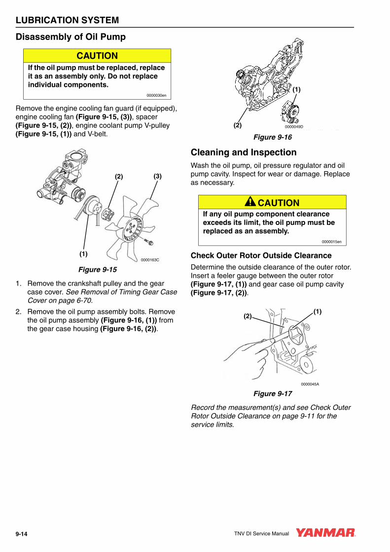
LUBRICATION SYSTEM
Disassembly of Oil Pump
Remove the engine cooling fan guard (if equipped), engine cooling fan (Figure 9-15, (3)), spacer (Figure 9-15, (2)), engine coolant pump V-pulley (Figure 9-15, (1)) and V-belt.
Figure 9-15
1. Remove the crankshaft pulley and the gear case cover. See Removal of Timing Gear Case Cover on page 6-70.
2. Remove the oil pump assembly bolts. Remove the oil pump assembly (Figure 9-16, (1)) from the gear case housing (Figure 9-16, (2)).
Figure 9-16
Cleaning and InspectionWash the oil pump, oil pressure regulator and oil pump cavity. Inspect for wear or damage. Replace as necessary.
Check Outer Rotor Outside ClearanceDetermine the outside clearance of the outer rotor. Insert a feeler gauge between the outer rotor (Figure 9-17, (1)) and gear case oil pump cavity (Figure 9-17, (2)).
Figure 9-17
Record the measurement(s) and see Check Outer Rotor Outside Clearance on page 9-11 for the service limits.
CAUTIONIf the oil pump must be replaced, replace it as an assembly only. Do not replace individual components.
0000030en
(1)
(2) (3)
0000163C
A CAUTIONIf any oil pump component clearance exceeds its limit, the oil pump must be replaced as an assembly.
0000015en
(1)
(2) 0000049D
(1)(2)
0000045A
9-14 TNV DI Service Manual

LUBRICATION SYSTEM
Outer Rotor to Inner Rotor Tip ClearanceDetermine the outer rotor to inner rotor tip clearance. Insert a feeler gauge between the top of an inner rotor tooth (Figure 9-18, (1)) and the top of an outer rotor tooth (Figure 9-18, (2)) and measure the clearance.
Figure 9-18
Record the measurement(s) and seeOuter Rotor to Inner Rotor Tip Clearance on page 9-11 for the service limits.
Check Outer Rotor Side ClearanceDetermine the side clearance of the outer rotor across the pump cavity. Measure the depression using a depth micrometer (Figure 9-19, (1)).
Figure 9-19
Record the measurement(s) and seeCheck Outer Rotor Side Clearance on page 9-12 for the service limits.
Check Rotor Shaft ClearanceDetermine the rotor shaft clearance. Measure the outside diameter of the rotor shaft (Figure 9-20, (1)) and the bore diameter in the gear case housing (Figure 9-20, (2)).
Calculate the difference between the two measurements to determine the clearance.
Figure 9-20
Record the measurement(s) and seeRotor Shaft Clearance - 4TNV94L to 4TNV106T on page 9-7 for the service limits.
Reassembly of Oil Pump1. Lubricate the outer rotor and pump bore in the
gear case with clean engine oil.
2. Reinstall the outer rotor in the gear case housing. The punch mark (Figure 9-21, (1)) on the end of the outer rotor must face away from the gear case housing (Figure 9-21, (2)).
Figure 9-21
0001153A
(2)(1)
0001615A
(1)
(1)
(2)0000047A
1
2
0000048A
TNV DI Service Manual 9-15
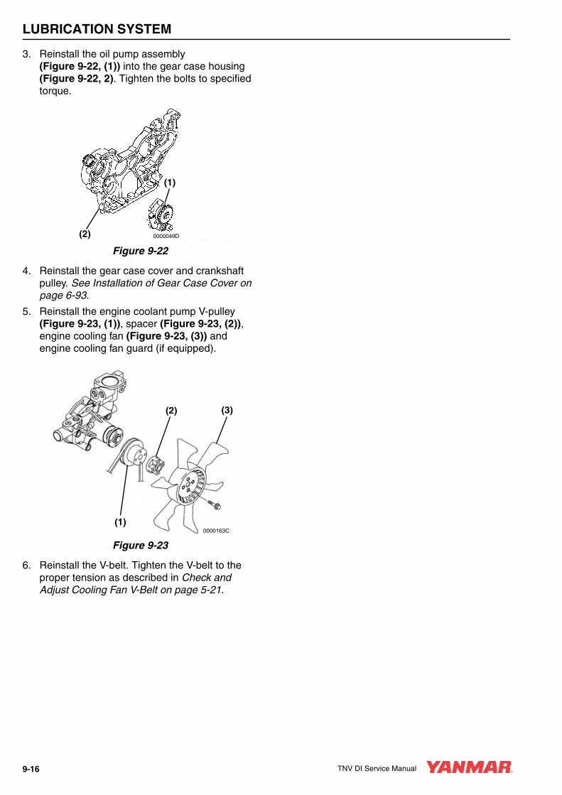
LUBRICATION SYSTEM
3. Reinstall the oil pump assembly (Figure 9-22, (1)) into the gear case housing (Figure 9-22, 2). Tighten the bolts to specified torque.
Figure 9-22
4. Reinstall the gear case cover and crankshaft pulley. See Installation of Gear Case Cover on page 6-93.
5. Reinstall the engine coolant pump V-pulley (Figure 9-23, (1)), spacer (Figure 9-23, (2)), engine cooling fan (Figure 9-23, (3)) and engine cooling fan guard (if equipped).
Figure 9-23
6. Reinstall the V-belt. Tighten the V-belt to the proper tension as described in Check and Adjust Cooling Fan V-Belt on page 5-21.
(1)
(2) 0000049D
(1)
(2) (3)
0000163C
9-16 TNV DI Service Manual

TNV DI Service Manual Section 10
TURBOCHARGER
Page
Before You Begin Servicing .......................................................... 10-3
Introduction.................................................................................... 10-5
Specifications ................................................................................ 10-5Turbocharger Service Information ........................................... 10-5
Troubleshooting............................................................................. 10-6Excessive Exhaust Smoke ...................................................... 10-6Generates White Smoke ......................................................... 10-7Sudden Oil Decrease .............................................................. 10-7Decrease in Output.................................................................. 10-7Poor (Slow) Response (Starting) of Turbocharger .................. 10-7Abnormal Sound or Vibration .................................................. 10-7
Turbocharger Components ........................................................... 10-8
Turbocharger Component Functions........................................... 10-10Theory of Operation............................................................... 10-11Compressor Side Sealing Mechanism .................................. 10-11Waste Gate Modulation ......................................................... 10-11
Washing Procedure..................................................................... 10-12
Periodic Inspection ...................................................................... 10-13Visual Inspection ................................................................... 10-13Inspection of Rotor Rotation .................................................. 10-13Inspection of Rotor Play ........................................................ 10-13Removal of Turbocharger...................................................... 10-13Checking Rotor Play.............................................................. 10-14Waste Gate Valve Test.......................................................... 10-14Waste Gate Actuator Leak Test ............................................ 10-15Installation of Turbocharger................................................... 10-15
TNV DI Service Manual 10-1

TURBOCHARGER
BEFORE YOU BEGIN SERVICING
A WARNING
ENTANGLEMENT HAZARD!• Stop the engine before you begin to
service it.
• NEVER leave the key in the key switch when you are servicing the engine. Someone may accidentally start the engine and not realize you are servicing it. This could result in a serious injury.
• If you must service the engine while it is operating, remove all jewelry, tie back long hair, and keep your hands, other body parts and clothing away from moving / rotating parts.
• Failure to comply could result in death or serious injury.
0000010en
A WARNING
FUME / BURN HAZARD!• Always read and follow safety related
precautions found on containers of hazardous substances like parts cleaners, primers, sealants and sealant removers.
• Failure to comply could result in death or serious injury.
0000014en
A WARNINGNever apply over 40 psi (2.8 kgf/cm) to the waste gate actuator.
0000026en
A CAUTION
FLYING OBJECT HAZARD!• ALWAYS wear eye protection when
servicing the engine and when using compressed air or high-pressure water. Dust, flying debris, compressed air, pressurized water or steam may injure your eyes.
• Failure to comply may result in minor or moderate injury.
0000003en
CAUTIONFor maximum engine life, Yanmar recommends that when shutting the engine down, you allow the engine to idle, without load, for five minutes. This will allow the engine components that operate at high temperatures, such as the turbocharger (if equipped) and exhaust system, to cool slightly before the engine itself is shut down.
0000008en
TNV DI Service Manual 10-3

TURBOCHARGER
CAUTIONAvoid damage to the turbocharger or the engine. Do not spray blower wash fluid or water too quickly.
Use short strokes from a spray bottle to inject blower wash fluid or water into the turbocharger.
Spraying too much wash fluid or water, or spraying too quickly will damage the turbocharger.
0000063en
CAUTIONDo not allow any material to fall into the oil lines or the oil inlet and outlet ports of the turbocharger.
0000064en
CAUTIONIf the waste valve does not meet specifications, replace the turbocharger or have it repaired by a qualified repair facility.
0000078en
10-4 TNV DI Service Manual

TURBOCHARGER
INTRODUCTIONThis section of the Service Manual describes the servicing of the RHF5, RHB31 and RHB51 model turbochargers.
SPECIFICATIONS
Turbocharger Service Information
Note: VM application is provided with the waste gate.
Applicable Engine Model (application)3TNV84T (CL,
VM)4TNV84T (CL)
3TNV84T (VM) 4TNV98T4TNV106T(CL, VM)
Turbocharger Model RHB31 RHB51 RHF5 RHF5
Turbocharger Specification Standard (w/waste gate)
Turbine Type Radial flow
Blower (Compressor) Type Centrifugal
Lubrication External lubrication
Maximum Continuous Allowable Speed 250,000 180,000
Maximum Continuous Allowable Gas Inlet Temperature
750°F (399°C)
Weight (Dry)5.4 lb
(24 N; 2.4 kgf)9.2 lb
(41 N; 4.2 kgf)10.3 lb
(46 N; 4.7 kgf)10.3 lb
(46 N; 4.7 kgf)
TNV DI Service Manual 10-5

TURBOCHARGER
TROUBLESHOOTINGThe following troubleshooting procedures apply to problems identified as turbocharger related. Consider all other troubleshooting possibilities before cleaning or removing the turbocharger.
Excessive Exhaust Smoke
Cause Corrective action
Clogged air cleaner elementBlocked air intake portLeak from a joint in intake line
Clean or replace the air cleaner elementCorrect the conditionCorrect the condition
Cause Corrective action
1. Compressor impeller dirty
2. Deposit of impurities in oil sticking on the turbine side seal portion to make turbine revolution heavy
3. Sticking bearing:
3a. Insufficient lubrication or clogged lubrication piping
3b. Excessively high oil temperature
3c. Unbalanced rotating part
3d. Insufficient warming up or sudden stop from loadedoperation (no-load operation)
1. Wash the impeller blades.
2. Repair the turbocharger. Send to a qualified repair facility.
3a. Repair turbocharger. Send to qualified repair facility.
3b. Inspect the lubricating oil line for problem. Correct the condition and replace lubricating oil.
3c. Repair the turbocharger. Send to a qualified repair facility.
3d. Improper operation of the machine. Refer to the Operation Manual.
4. Contact or breakdown of turbine wheel or blower vane:4a. Excessive revolution4b. Excessive exhaust temperature rise4c. Foreign matter within turbocharger
4d. Worn bearing
4e. Incorrect assembly of turbocharger
4a. Inspection and repair of each engine part4b. Inspection and repair of each engine part4c. Clean the air cleaner and engine compartment. Repair
the turbocharger. Send to a qualified repair facility.4d. Repair the turbocharger. Send to a qualified repair
facility.4e. Repair the turbocharger. Send to a qualified repair
facility.
Cause Corrective action
Exhaust system gas leak prior to the turbocharger. Condition will decrease turbocharger revolutions.
Inspect the exhaust system for leaks. Correct the condition.
Deformed or clogged exhaust pipe. Condition will decrease turbocharger revolutions.
Correct the condition.
10-6 TNV DI Service Manual

TURBOCHARGER
Generates White Smoke
Sudden Oil Decrease
Decrease in Output
Poor (Slow) Response (Starting) of Turbocharger
Abnormal Sound or Vibration
Cause Corrective action
Clogged or deformed oil return pipe causing oil flow to the blower on the turbine sideExcessive bearing wear causing abnormal wear or damage of the seal ring
Correct the condition
Repair the turbocharger. Send to a qualified repair facility.
Cause Corrective action
Excessive bearing wear causing abnormal wear or damage of the seal ring
Repair turbocharger. Send to qualified repair facility.
Cause Corrective action
Gas leak from any part in exhaust piping Correct the condition
Air leak from discharge side of blower Correct the condition
Clogged air cleaner element Clean or replace the air cleaner element
Damaged turbocharger Repair the turbocharger. Send to a qualified repair facility
Cause Corrective action
Hard carbon deposit on the turbine side (wheel sealing portion) causing abnormal revolution of the turbine shaft
Repair the turbocharger. Send to a qualified repair facility
Incomplete combustion Correct the condition
Cause Corrective action
Excessively narrowed gas path due to clogged nozzle in the turbine wheel chamber or reverse flow of blower discharge in acceleration (generally called surging)
Repair the turbocharger. Send to a qualified repair facility
Contact rotating part Repair the turbocharger. Send to a qualified repair facility
Cause Corrective action
Loosened intake, exhaust or oil pipe connection with the turbocharger
Correct the condition
Damaged bearing, contact between rotating part and adjacent part, or chipping of the turbine wheel or blower vane due to foreign matter within the turbocharger
Repair the turbocharger. Send to a qualified repair facility
Unbalanced rotating part Repair the turbocharger. Send to a qualified repair facility
TNV DI Service Manual 10-7
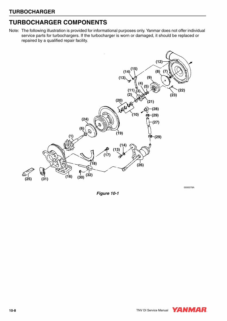
TURBOCHARGER
TURBOCHARGER COMPONENTSNote: The following illustration is provided for informational purposes only. Yanmar does not offer individual
service parts for turbochargers. If the turbocharger is worn or damaged, it should be replaced or repaired by a qualified repair facility.
Figure 10-1
(12)
(9)
(8) (7)
(22)(23)
(15)(14)
(13)
(5)(4)
(3)(2)(11)
(21)
(32)
(18) (26)
(1)
(6)
(17)(13)
(14)
(24)
(19)
(20)
(10)
(29)
(27)
(29)
(28)
(30)(16)(31)(25)
0000078A
10-8 TNV DI Service Manual

TURBOCHARGER
1 – Turbine Shaft2 – Thrust Bearing3 – Oil Thrower4 – Seal Ring5 – Seal Ring6 – Seal Ring (Turbine Side)7 – Lock Nut8 – Impeller9 – Seal Plate10 – Journal Bearing11 – Thrust Bearing12 – Compressor Housing13 – Flanged Bolt14 – Spring Washer15 – Clamp16 – Turbine Housing
17 – Bolt18 – Lock Plate19 – Bearing Housing20 – Retaining Ring21 – Bolt22 – Bolt23 – Lock Washer24 – Heat Protector25 – Liquid Gasket26 – Waste Gate Actuator27 – Hose28 – Adapter29 – Clip30 – Retaining Ring31 – Waste Gate Valve32 – Link Plate
TNV DI Service Manual 10-9

TURBOCHARGER
TURBOCHARGER COMPONENT FUNCTIONS
1 – Turbine Shaft2 – Oil Thrower3 – Turbine Side Seal Ring4 – Seal Plate5 – Journal Bearing6 – Thrust Bearing7 – Compressor Housing8 – M5 Hex Bolt9 – M5 Spring Washer
10 – Compressor Side Clamp
11 – Turbine Housing12 – M6 Hex Bolt13 – Turbine Side Clamp14 – Lock Washer15 – Bearing Housing16 – Retaining Ring17 – M3 Countersunk Flat-Head Bolt18 – Compressor Wheel19 – Shaft End Nut20 – Heat Protector
A. Exhaust Gas InletB. Exhaust Gas OutletC. Air Inlet
D. Air OutletE. Oil InletF. Oil Outlet
Figure 10-2
0000077A
(19)
(18)
(2)(7)(4)(6)(5)(3)(20)(1)(11)
(13) (14) (12) (15) (8) (9) (10) (17)
(16)
B
A
F
C
D
E
10-10 TNV DI Service Manual

TURBOCHARGER
Theory of OperationNormally aspirated engines produce horsepower that is limited by the atmospheric pressure of the induction air. The turbocharger is an exhaust gas pressure driven device that adds to the atmospheric pressure, resulting in a boost in pressure at the combustion chambers. This substantially increases the amount of fuel that can be injected into the combustion chambers, while maintaining the proper fuel-to-air ratio. A slight parasitic loss is imposed on the engine because of added back pressure in the exhaust system. That loss is offset by horsepower gains. The net result is substantially increased overall horsepower over normally aspirated engines.
The turbocharger consists of two main components:
• Turbine
• Compressor
TurbineThe turbine is driven by exhaust gas pressure from the engine and is coupled to a shaft on the compressor side of the turbocharger.
Exhaust gas velocity is accelerated at the nozzle portion in the turbine housing where the cross-sectional area is reduced. As exhaust passes over the turbine impeller at high linear velocity, the turbine shaft is rotated at proportionally high rpm.
CompressorThe compressor is driven by a shaft on the turbine side of the turbocharger and increases the induction air pressure at the intake manifold.
The compressor impeller draws induction air into the turbocharger, compresses it and directs it into the engine at high pressure.
A seal ring and heat insulating plate thermally isolate heat energy, at the turbine side, from the bearings and the induction air, at the compressor side.
Bearings
Thrust BearingA thrust force is continuously imposed on the turbine shaft during engine operation. A thrust bearing prevents the shaft from moving laterally under this thrust force.
Radial BearingA floating radial bearing moves with the turbine shaft as oil films form on the inside and outside bearing surfaces. The bearing slipping speed is slower than the turbine shaft speed, resulting in higher dynamic stability and reduced mechanical noise.
LubricationThe oil pump delivers oil from the engine to the turbocharger for cooling and lubrication of the bearings. As oil leaves the turbocharger, it is returned to the engine.
Compressor Side Sealing MechanismA seal ring and a seal plate form a double wall structure at the rear of the compressor impeller. The seal ring and seal plate prevent Intake air and oil leakage.
Waste Gate ModulationExcessive boost pressure that cannot be accommodated by the engine can damage the turbocharger. The waste gate is a component that monitors intake boost pressure on the compressor side and diverts exhaust gases around the turbocharger turbine. The amount of exhaust gas diverted is varied to limit turbine rpm and maintain the intake pressure equal to, or less than the specified maximum level. This improves the response to load variation in the low to medium rpm range and minimizes black smoke.
Waste Gate ControlA mechanical pressure sensor in the outlet of the compressor side of the turbocharger opens and closes the waste gate to maintain the specified intake pressure at the intake manifold.
TNV DI Service Manual 10-11
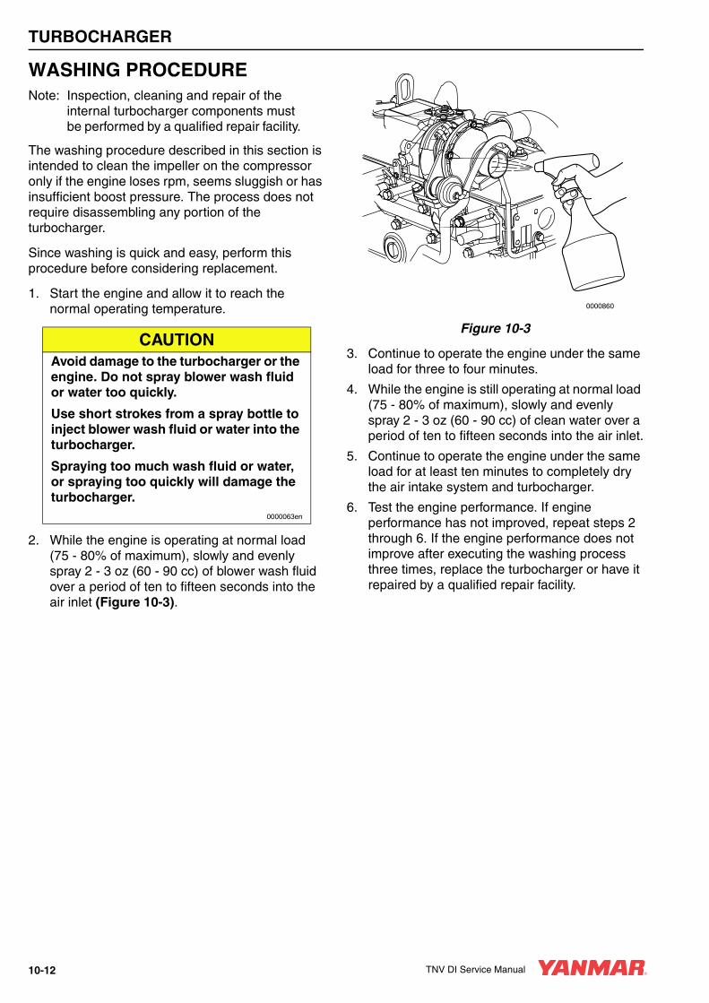
TURBOCHARGER
WASHING PROCEDURENote: Inspection, cleaning and repair of the
internal turbocharger components must be performed by a qualified repair facility.
The washing procedure described in this section is intended to clean the impeller on the compressor only if the engine loses rpm, seems sluggish or has insufficient boost pressure. The process does not require disassembling any portion of the turbocharger.
Since washing is quick and easy, perform this procedure before considering replacement.
1. Start the engine and allow it to reach the normal operating temperature.
2. While the engine is operating at normal load (75 - 80% of maximum), slowly and evenly spray 2 - 3 oz (60 - 90 cc) of blower wash fluid over a period of ten to fifteen seconds into the air inlet (Figure 10-3).
Figure 10-3
3. Continue to operate the engine under the same load for three to four minutes.
4. While the engine is still operating at normal load (75 - 80% of maximum), slowly and evenly spray 2 - 3 oz (60 - 90 cc) of clean water over a period of ten to fifteen seconds into the air inlet.
5. Continue to operate the engine under the same load for at least ten minutes to completely dry the air intake system and turbocharger.
6. Test the engine performance. If engine performance has not improved, repeat steps 2 through 6. If the engine performance does not improve after executing the washing process three times, replace the turbocharger or have it repaired by a qualified repair facility.
CAUTIONAvoid damage to the turbocharger or the engine. Do not spray blower wash fluid or water too quickly.
Use short strokes from a spray bottle to inject blower wash fluid or water into the turbocharger.
Spraying too much wash fluid or water, or spraying too quickly will damage the turbocharger.
0000063en
0000860
10-12 TNV DI Service Manual

TURBOCHARGER
PERIODIC INSPECTIONInspect the turbocharger at regularly scheduled intervals.
Visual Inspection1. Check for indications of oil leaks at the oil inlet
and outlet lines. Repair or replace the oil lines as needed.
2. Inspect the air inlet connection to the turbocharger’s turbine side for cracks or broken hardware. Repair or replace the connection as needed.
3. Inspect the exhaust outlet connection to the turbocharger’s compressor side for cracks or broken hardware. Repair or replace the connection as needed.
Inspection of Rotor Rotation1. With the engine cool and not operating,
manually rotate the rotor. Smooth rotation is normal. Any catching or resistance to rotation is an indication of abnormal operation. Replace the turbocharger or have it repaired by a qualified repair facility.
2. Start the engine.
3. After the engine reaches normal operating temperature, place a stethoscope firmly against the turbocharger case.
4. Increase the rpm gradually. A high-pitched sound, occurring at intervals of two or three seconds, is an indication of abnormal operation. Replace the turbocharger or have it repaired by a qualified repair facility.
Inspection of Rotor PlayTo inspect the rotor, the turbocharger must be removed. Inspect for maximum rotor end play and run-out limits before reinstalling.
Removal of Turbocharger1. Shut down the engine and allow the
turbocharger to cool. Remove the exhaust outlet connection from the turbocharger housing.
2. Remove the air inlet connection from the turbocharger housing.
3. Remove the inlet and outlet oil lines from the turbocharger. Plug the lines and ports with tape to prevent contamination. Discard the sealing washers and O-rings. Inspect the oil lines and replace if damaged.
4. Remove the turbocharger mounting nuts from the mounting studs. Lift the turbocharger from the engine and place it on a clean, level working surface.
5. Discard the turbocharger exhaust manifold gasket.
ApplicationInspection interval
200 hours 400 hours 500 hours 800 hours 1000 hours 2000 hours
Construction EquipmentFirst 6 months
or 500 hrs
First 12 months
or 1000 hrs
Every 24 months
or 2000 hrs
Farm EquipmentFirst 6 months
or 200 hrs
First 12 months
or 400 hrs
Every 24 months
or 800 hrs
Engine Oil and Filter Replacement Based on engine operation manual
CAUTIONDo not allow any material to fall into the oil lines or the oil inlet and outlet ports of the turbocharger.
0000064en
TNV DI Service Manual 10-13

TURBOCHARGER
Checking Rotor PlayNote: If rotor play measurements are not within specification, replace the turbocharger assembly or have it
repaired by a qualified facility.
To Check Rotor End Play:1. Set up a dial indicator as shown (Figure 10-4).
2. Manually move the rotor end-to-end while observing indicated readings. Replace the turbocharger if end play measurements are outside specified limits. See table above.
Figure 10-4
To Check Rotor Run-out:1. Set up a dial indicator as shown (Figure 10-5).
2. Manually rotate the rotor while observing indicated limits. Replace the turbocharger if run-out measurements are outside specified limits. See table above.
Figure 10-5
Waste Gate Valve TestBefore reinstalling the turbocharger, verify the operation of the waste gate valve. Poor waste gate operation will adversely affect the engine performance.
Rotor PlayStandard Dimension Wear Limit
RHF5 RHB31 RHB51 RHF5 RHB31 RHB51
End Play0.0011 - 0.0024 in.(0.03 - 0.06 mm)
0.0009 - 0.0021 in.(0.022 - 0.053 mm)
0.0012 - 0.0024 in.(0.03 - 0.06 mm)
0.0044 in.(0.09 mm)
0.0028 in.(0.07 mm)
0.0035 in.(0.09 mm)
Run-out0.0031 - 0.0051 in.(0.08 - 0.13 mm)
0.0024 - 0.0037 in.(0.061 - 0.093 mm)
0.0031 - 0.0051 in.(0.08 - 0.13 mm)
0.007 in.(0.17 mm)
0.0047 in.(0.12 mm)
0.0067 in.(0.17 mm)
0000080A
(1)
(3)
(2)
CAUTIONIf the waste valve does not meet specifications, replace the turbocharger or have it repaired by a qualified repair facility.
0000078en
(2)(1)
(3)
(4)
0000081A
10-14 TNV DI Service Manual

TURBOCHARGER
1. Connect a hand-operated air pump to the waste gate actuator pipe (Figure 10-6, (1)). The pump should be equipped with a 30 psi (0.21 MPa;
2.21 kgf/cm2) pressure gauge (Figure 10-6, (2)), and a pressure release valve to release any pressure pumped into the system. (Similar pumps are used to check for leaks in marine gear cases.)
Figure 10-6
2. Apply 17 psi (0.12 MPa; 1.2 kgf/cm2) to the waste gate actuator (Figure 10-6, (3)) circuit. Observe if the waste gate valve is open fully. If the waste valve does not open fully, replace the turbocharger or have it repaired by a qualified repair facility.
Waste Gate Actuator Leak TestAllow the pressure, 17 psi (0.12 MPa; 1.2 kgf/cm2) to remain in the circuit for one minute. After one minute, observe the pressure reading.
• If the pressure reading is equal to or greater than 15.9 psi (0.11 MPa; 1.1 kgf/cm2), the waste gate actuator is not leaking and is operating properly.
• If the pressure reading is less than 15.9 psi (0.11 MPa; 1.1 kgf/cm2), the waste gate actuator is leaking. Replace the turbocharger or have it repaired by a qualified repair facility.
Installation of Turbocharger1. Pour 2 oz (60 cc) of clean engine oil in the oil
inlet port at the top of the turbocharger. Rotate the compressor wheel to ensure the shaft bearings are lubricated.
2. Flush the oil lines to ensure that they are free of containments.
3. Put a new turbocharger exhaust manifold gasket in place and reinstall turbocharger on the exhaust manifold.
4. Apply anti-seize compound to the turbocharger mounting studs.
5. Reinstall the mounting nuts. Torque the nuts to the specified torque.
6. Install new sealing washers and O-rings and reinstall the inlet and outlet oil lines to the turbocharger.
7. Reinstall the air inlet connection to the turbocharger turbine housing.
8. Reinstall the exhaust connection to the turbocharger compressor housing.
A WARNINGNever apply over 40 psi (2.8 kgf/cm) to the waste gate actuator.
0000026en
00001617
(1
(2)
(3) CAUTIONDo not allow any material to fall into the oil lines or the oil inlet and outlet ports of the turbocharger.
0000064en
TNV DI Service Manual 10-15

TNV DI Service Manual Section 11
STARTER MOTOR
PageBefore You Begin Servicing .......................................................... 11-3
Introduction.................................................................................... 11-5
Starter Motor Information .............................................................. 11-53TNV82A to 4TNV88 - Standard and Optional........................ 11-5
Starter Motor Specifications .......................................................... 11-7
Starter Motor Troubleshooting....................................................... 11-8
Starter Motor Components ............................................................ 11-9
Starter Motor ............................................................................... 11-10Removal of Starter Motor ...................................................... 11-10Disassembly of Starter Motor ................................................ 11-10Cleaning and Inspection ........................................................ 11-12Reassembly of Starter Motor................................................. 11-17Check Pinion Projection Length ............................................ 11-18No-Load Test......................................................................... 11-19Installation of Starter Motor ................................................... 11-20
TNV DI Service Manual 11-1

STARTER MOTOR
BEFORE YOU BEGIN SERVICING
A WARNING
ENTANGLEMENT HAZARD!• Stop the engine before you begin to
service it.
• NEVER leave the key in the key switch when you are servicing the engine. Someone may accidentally start the engine and not realize you are servicing it. This could result in a serious injury.
• If you must service the engine while it is operating, remove all jewelry, tie back long hair, and keep your hands, other body parts and clothing away from moving / rotating parts.
• Failure to comply could result in death or serious injury.
0000010en
A WARNING
SHOCK HAZARD!• Turn off the battery switch (if
equipped) or disconnect the negative battery cable before servicing the electrical system.
• Check the electrical harnesses for cracks, abrasions, and damaged or corroded connectors. ALWAYS keep the connectors and terminals clean.
• Failure to comply could result in death or serious injury.
0000009en
A WARNING
FUME / BURN HAZARD!• Always read and follow safety related
precautions found on containers of hazardous substances like parts cleaners, primers, sealants and sealant removers.
• Failure to comply could result in death or serious injury.
0000014en
TNV DI Service Manual 11-3

STARTER MOTOR
A CAUTION
FLYING OBJECT HAZARD!• ALWAYS wear eye protection when
servicing the engine and when using compressed air or high-pressure water. Dust, flying debris, compressed air, pressurized water or steam may injure your eyes.
• Failure to comply may result in minor or moderate injury.
0000003en
CAUTIONThe starter motor can be damaged if operated continuously longer than 10 seconds while performing the no-load test.
0000034en
CAUTIONMake sure that the combined total resistance of the battery cable in both directions between the starter motor and the battery is within the value indicated on the wiring diagram. The starter motor will malfunction or break down if the resistance is higher than the specified value.
0000054en
CAUTIONThe starter motor is water-proofed according to JIS D 0203, R2 which protects the motor from rain or general cleaning. Do not use high-pressure wash or submerse the starter motor in water.
0000055en
CAUTIONUse a specialized battery charger to recharge a battery with a voltage of 8 volts or less. Booster starting a battery with a voltage of 8 volts or less will generate an abnormally high voltage and destroy electrical equipment.
0000056en
11-4 TNV DI Service Manual

STARTER MOTOR
INTRODUCTIONThis section of the Service Manual covers the servicing of the starter motor. Yanmar Part No. 129900-77010 is standard equipment on 4TNV94-98 model engines and is used in this section to show the service procedures for a representative starter motor. For specific part detail, see the Yanmar Parts Catalog for the engine you are working on.
STARTER MOTOR INFORMATION
3TNV82A to 4TNV88 - Standard and Optional
YANMAR Part
NumberMfg.
Mfg. Part
NumberSpecification
No Load Loaded
Terminal Voltage
Amperage Draw
rpmTerminal Voltage
Amperage Draw
Torque rpm
129129-77010
Denso228000-
0251DC12V-1.6 hp
(1.2 kW)11.5 90A MAX 3000 8 280 Max
87 in.-lb(9.81N·m;1.0 kgf/m)
900
129407-77010
Denso228000-
3732DC12V-1.9 hp
(1.4 kW)11.5 90A MAX 3000 8.5 350 Max
117 in.-lb(13.2 N·m;1.4 kgf/m)
1000
129608-77010
HitachiS114-817A
DC12V-1.9 hp(1.4 kW)
11 90A MAX 2700 8.4 250 Max74 in.-lb
(8.3 N·m;0.9 kgf/m)
1000
129242-77010
HitachiS114-883
DC12V-2.3 hp(1.7 kW)
11 90A MAX 2300 8 370 Max134 in.-lb
(15.1 N·m;1.5 kgf/m)
880
129136-77011
Hitachi S13-332DC12V-3.1 hp
(2.3 kW)11
140A MAX
4100 7.7 400 Max97 in.-lb
(11.0 N·m;1.1 kgf/m)
1400
129612-77011
HitachiS25-166A
DC24V-5.3 hp (4.0kW)
24100A MAX
3500 18 400 Max269 in.-lb
(30.4 N·m;3.1 kgf/m)
1000
TNV DI Service Manual 11-5

STARTER MOTOR
4TNV94L to 4TNV106T - Standard and Optional
YANMAR Part
NumberMfg.
Mfg. Part
NumberSpecification
No Load Loaded
Terminal Voltage
Amperage Draw
rpmTerminal Voltage
Amperage Draw
Torque rpm
129900-77010
Hitachi S13-204DC12V-3.1 hp
(2.3 kW)11
140A MAX
4100 7.7 400 Max97 in.-lb
(11.0 N·m;1.1 kgf/m)
1400
129940-77010
Hitachi S14-102DC12V-4.0 hp
(3.0 kW)12
160A MAX
3600 10.85 300 Max60 in.-lb(6.9 N·m;0.7 kgf/m)
2000
119131-77010
Hitachi S24-13DC24V-4.8 hp
(3.5 kW)23 90A MAX 3100 20.2 250 Max
130 in.-lb(14.7 N·m;1.5 kgf/m)
1300
129900-77030
Hitachi S24-14DC24V-4.8 hp (3.5 kW) Wet
23 90A MAX 3100 20.2 250 Max130 in.-lb
(14.7 N·m;1.5 kgf/m))
1300
129910-77022
HitachiS13-2050
DC12V-3.1 hp(2.3 kW) Wet
11140A MAX
4100 7.7 400 Max97 in.-lb
(11.0 N·m;1.1 kgf/m)
1400
11-6 TNV DI Service Manual

STARTER MOTOR
STARTER MOTOR SPECIFICATIONS
Yanmar Part Number 129900-77010
Nominal Output 3.0 hp (2.3 kW)
Weight12.1 lb(5.5 kg)
Revolution Direction (As Viewed From Pinion) Clockwise
Engagement System Magnetic Shift
No-loadTerminal Voltage / Current 11 V / 140 A max
Revolution 4100 rpm (min-1)
Loaded
Terminal Voltage / Current 2.5 V / 1050 A max
Torque18 ft-lb
(24.5 N·m; 2.5 kgf/m) minimum
Clutch System Overrunning
Pinion Projection Voltage at 212°F (100 °C) 8.6 V max
Pinion DP or Module / Number of Teeth M3/9
Difference (O-ring, Oil Seal) Dry (none)
Application Standard
Brush
Spring Force 7.868 lbf (35 N; 3.6 kgf)
HeightStandard 0.591 in. (15 mm)
Limit 0.354 in. (9 mm)
Magnetic Switch
Series Coil Resistance 0.27 W at 68°F (20°C)
Shunt Coil Resistance 0.60 W at 68°F (20°C)
Commutator
Outside DiameterStandard 1.437 in. (36.5 mm)
Limit 1.398 in. (35 mm)
Run-OutStandard 0.001 in. (0.03 mm)
Limit 0.008 in. (0.2 mm)
Insulation DepthStandard 0.020 - 0.031 in. (0.5 - 0.8 mm)
Limit 0.008 in. (0.2 mm)
Armature Run-OutStandard 0.001 in. (0.03 mm)
Limit 0.008 in. (0.02 mm)
Bearing Type
Armature Front
Nominal Number
6903DDU
Armature Rear 608DDU
Pinion Front 60004DDU
Pinion Rear 6904DDU
Pinion Projection Length (Length L) 0.012 - 0.059 in. (0.3 - 1.5 mm)
TNV DI Service Manual 11-7
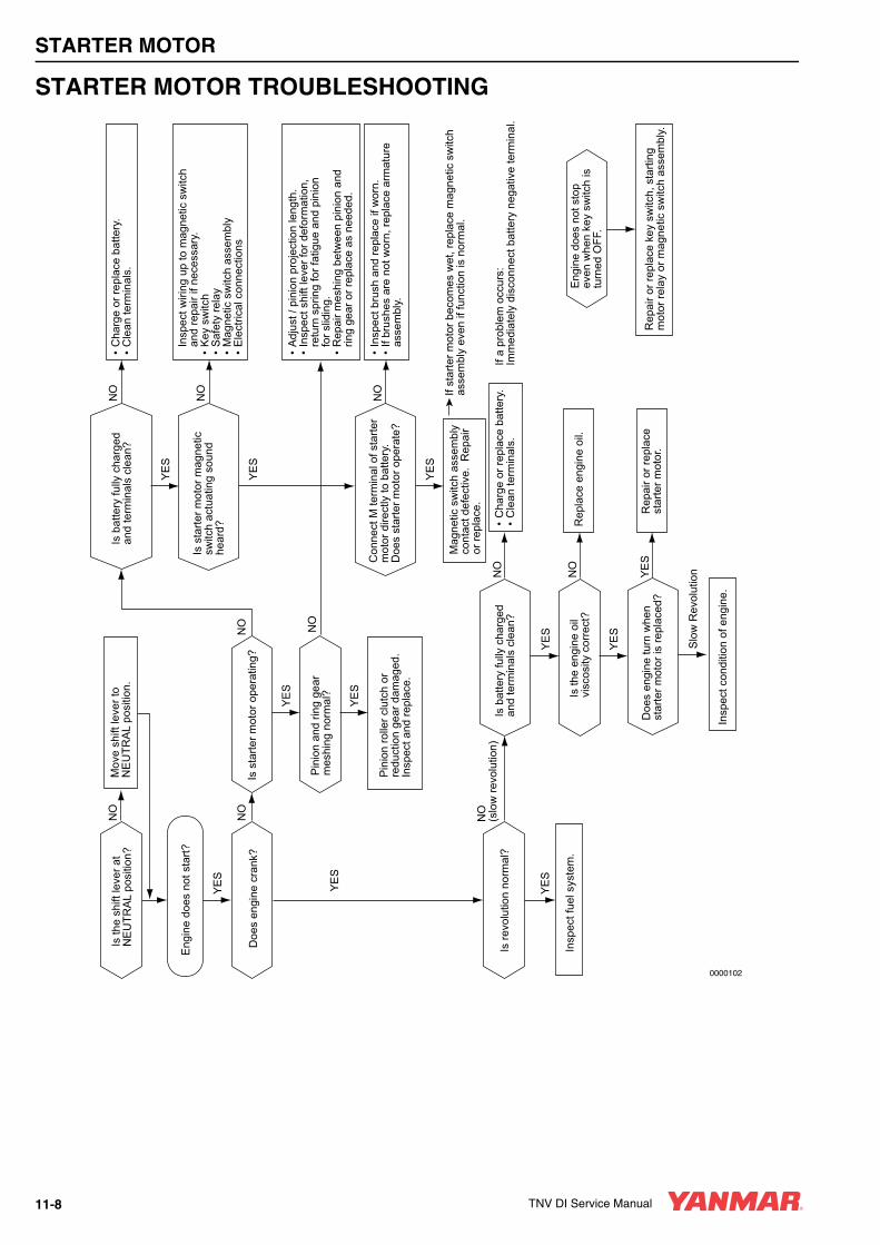
STARTER MOTOR
STARTER MOTOR TROUBLESHOOTINGIs
the
shift
leve
r at
NE
UTR
AL
posi
tion?
Doe
s en
gine
cra
nk?
Eng
ine
does
not
sto
pev
en w
hen
key
switc
h is
turn
ed O
FF.
Is b
atte
ry fu
lly c
harg
edan
d te
rmin
als
clea
n?
Is re
volu
tion
norm
al?
Eng
ine
does
not
sta
rt?
YE
S
NO
NO
YE
S
NO
(slo
w re
volu
tion)
NO
YE
S
Insp
ect f
uel s
yste
m.
Insp
ect c
ondi
tion
of e
ngin
e.
Mov
e sh
ift le
ver t
o N
EU
TRA
L po
sitio
n.
Pin
ion
rolle
r clu
tch
orre
duct
ion
gear
dam
aged
.In
spec
t and
repl
ace.
• C
harg
e or
repl
ace
batte
ry.
• C
lean
term
inal
s.
• In
spec
t bru
sh a
nd re
plac
e if
wor
n.•
If br
ushe
s ar
e no
t wor
n, re
plac
e ar
mat
ure
as
sem
bly.
In
spec
t wiri
ng u
p to
mag
netic
sw
itch
an
d re
pair
if ne
cess
ary.
• K
ey s
witc
h•
Saf
ety
rela
y•
Mag
netic
sw
itch
asse
mbl
y•
Ele
ctric
al c
onne
ctio
ns
• A
djus
t / p
inio
n pr
ojec
tion
leng
th.
• In
spec
t shi
ft le
ver f
or d
efor
mat
ion,
re
turn
spr
ing
for f
atig
ue a
nd p
inio
n
for s
lidin
g.•
Rep
air m
eshi
ng b
etw
een
pini
on a
nd
ring
gear
or r
epla
ce a
s ne
eded
.
Rep
lace
eng
ine
oil.
Rep
air o
r rep
lace
st
arte
r mot
or.
Mag
netic
sw
itch
asse
mbl
yco
ntac
t def
ectiv
e. R
epai
r or
repl
ace.
Rep
air o
r rep
lace
key
sw
itch,
sta
rting
mot
or re
lay
or m
agne
tic s
witc
h as
sem
bly.
If a
prob
lem
occ
urs:
Im
med
iate
ly d
isco
nnec
t bat
tery
neg
ativ
e te
rmin
al.
If
star
ter m
otor
bec
omes
wet
, rep
lace
mag
netic
sw
itch
asse
mbl
y ev
en if
func
tion
is n
orm
al.
YE
S
YE
S
Is s
tarte
r mot
or o
pera
ting?
YE
S
Pin
ion
and
ring
gear
mes
hing
nor
mal
?
YE
S
NO
NO
YE
S
Is b
atte
ry fu
lly c
harg
edan
d te
rmin
als
clea
n?
Slo
w R
evol
utio
n
Doe
s en
gine
turn
whe
n st
arte
r mot
or is
repl
aced
?
YE
S
Is th
e en
gine
oil
visc
osity
cor
rect
?
NO
Is s
tarte
r mot
or m
agne
tic
switc
h ac
tuat
ing
soun
d he
ard?
NO
YE
S
Con
nect
M te
rmin
al o
f sta
rter
mot
or d
irect
ly to
bat
tery
.D
oes
star
ter m
otor
ope
rate
?N
O
YE
S
NO
0000102
• C
harg
e or
repl
ace
batte
ry.
• C
lean
term
inal
s.
11-8 TNV DI Service Manual
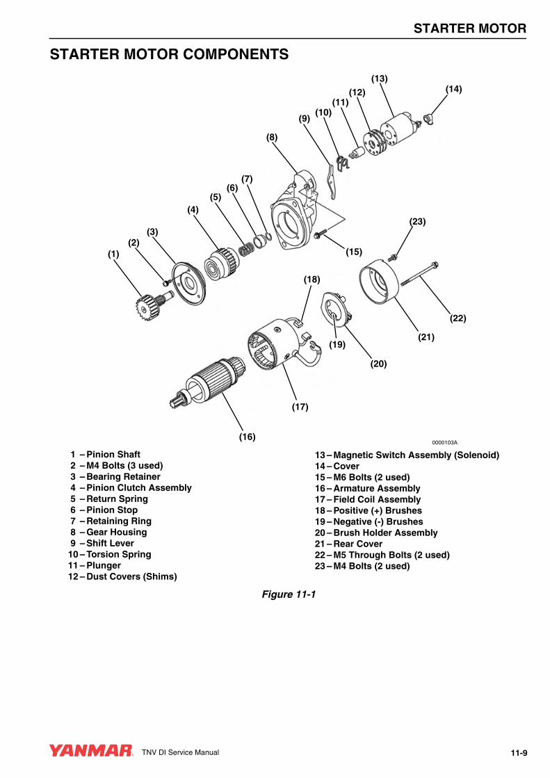
STARTER MOTOR
STARTER MOTOR COMPONENTS
1 – Pinion Shaft2 – M4 Bolts (3 used)3 – Bearing Retainer4 – Pinion Clutch Assembly5 – Return Spring6 – Pinion Stop7 – Retaining Ring8 – Gear Housing9 – Shift Lever10 – Torsion Spring11 – Plunger12 – Dust Covers (Shims)
13 – Magnetic Switch Assembly (Solenoid)14 – Cover15 – M6 Bolts (2 used)16 – Armature Assembly17 – Field Coil Assembly18 – Positive (+) Brushes19 – Negative (-) Brushes20 – Brush Holder Assembly21 – Rear Cover22 – M5 Through Bolts (2 used)23 – M4 Bolts (2 used)
Figure 11-1
(1)
(3)(2)
(4)(5)
(6)(7)
(8)
(9)(10)
(11)(12)
(13)(14)
(15)
(23)
(18)
(22)
(21)
(20)
(19)
(17)
(16)0000103A
TNV DI Service Manual 11-9
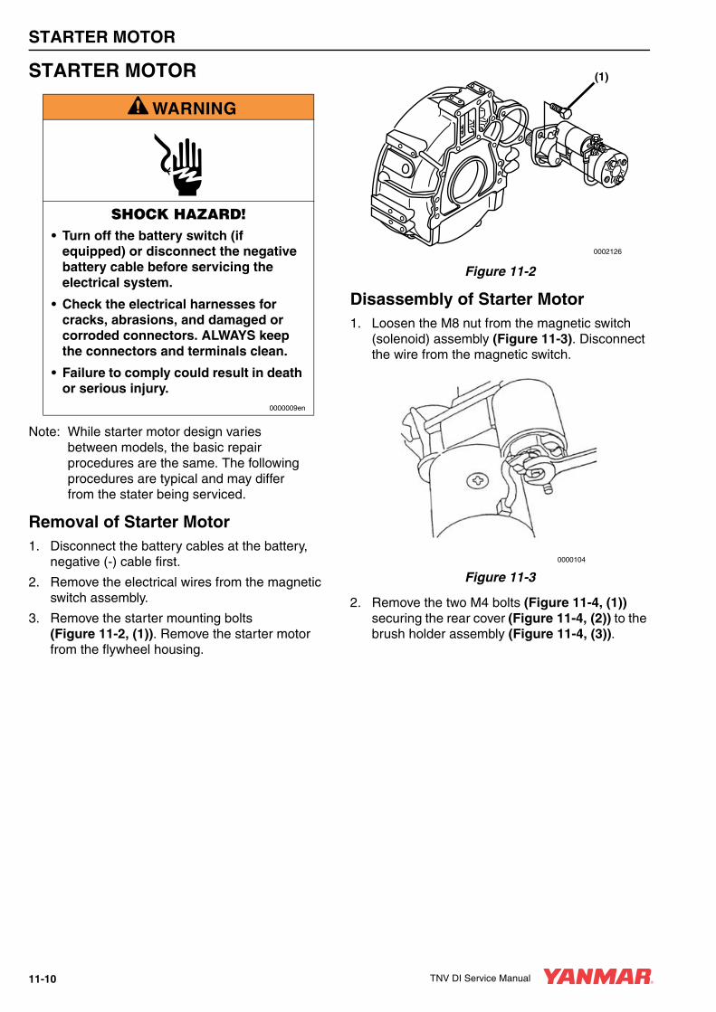
STARTER MOTOR
STARTER MOTOR
Note: While starter motor design varies between models, the basic repair procedures are the same. The following procedures are typical and may differ from the stater being serviced.
Removal of Starter Motor1. Disconnect the battery cables at the battery,
negative (-) cable first.
2. Remove the electrical wires from the magnetic switch assembly.
3. Remove the starter mounting bolts (Figure 11-2, (1)). Remove the starter motor from the flywheel housing.
Figure 11-2
Disassembly of Starter Motor1. Loosen the M8 nut from the magnetic switch
(solenoid) assembly (Figure 11-3). Disconnect the wire from the magnetic switch.
Figure 11-3
2. Remove the two M4 bolts (Figure 11-4, (1)) securing the rear cover (Figure 11-4, (2)) to the brush holder assembly (Figure 11-4, (3)).
A WARNING
SHOCK HAZARD!• Turn off the battery switch (if
equipped) or disconnect the negative battery cable before servicing the electrical system.
• Check the electrical harnesses for cracks, abrasions, and damaged or corroded connectors. ALWAYS keep the connectors and terminals clean.
• Failure to comply could result in death or serious injury.
0000009en
(1)
0002126
0000104
11-10 TNV DI Service Manual
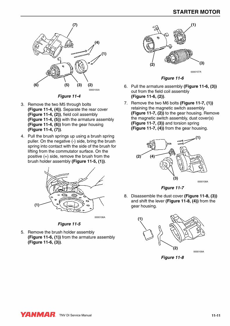
STARTER MOTOR
Figure 11-4
3. Remove the two M5 through bolts (Figure 11-4, (4)). Separate the rear cover (Figure 11-4, (2)), field coil assembly (Figure 11-4, (5)) with the armature assembly (Figure 11-4, (6)) from the gear housing (Figure 11-4, (7)).
4. Pull the brush springs up using a brush spring puller. On the negative (-) side, bring the brush spring into contact with the side of the brush for lifting from the commutator surface. On the positive (+) side, remove the brush from the brush holder assembly (Figure 11-5, (1)).
Figure 11-5
5. Remove the brush holder assembly (Figure 11-6, (1)) from the armature assembly (Figure 11-6, (3)).
Figure 11-6
6. Pull the armature assembly (Figure 11-6, (3)) out from the field coil assembly (Figure 11-6, (2)).
7. Remove the two M6 bolts (Figure 11-7, (1)) retaining the magnetic switch assembly (Figure 11-7, (2)) to the gear housing. Remove the magnetic switch assembly, dust cover(s) (Figure 11-7, (3)) and torsion spring (Figure 11-7, (4)) from the gear housing.
Figure 11-7
8. Disassemble the dust cover (Figure 11-8, (3)) and shift the lever (Figure 11-8, (4)) from the gear housing.
Figure 11-8
(1)
(4)
(7)
(6) (5) (2)(3)0000105A
(1)
0000106A
(2)
(1)
(3)
0000107A
(1)
(2)
(3)
(4)
0000108A
(2)
(1)
0000109A
TNV DI Service Manual 11-11
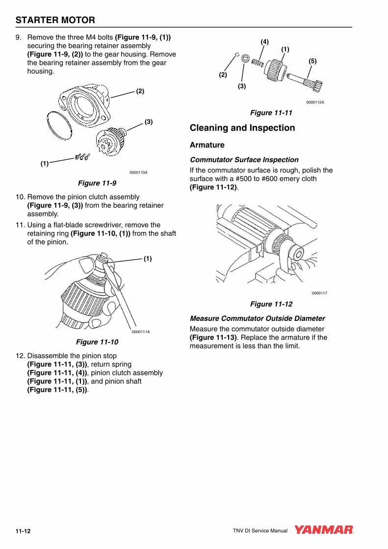
STARTER MOTOR
9. Remove the three M4 bolts (Figure 11-9, (1)) securing the bearing retainer assembly (Figure 11-9, (2)) to the gear housing. Remove the bearing retainer assembly from the gear housing.
Figure 11-9
10. Remove the pinion clutch assembly (Figure 11-9, (3)) from the bearing retainer assembly.
11. Using a flat-blade screwdriver, remove the retaining ring (Figure 11-10, (1)) from the shaft of the pinion.
Figure 11-10
12. Disassemble the pinion stop (Figure 11-11, (3)), return spring (Figure 11-11, (4)), pinion clutch assembly (Figure 11-11, (1)), and pinion shaft (Figure 11-11, (5)).
Figure 11-11
Cleaning and Inspection
Armature
Commutator Surface InspectionIf the commutator surface is rough, polish the surface with a #500 to #600 emery cloth (Figure 11-12).
Figure 11-12
Measure Commutator Outside DiameterMeasure the commutator outside diameter (Figure 11-13). Replace the armature if the measurement is less than the limit.
(2)
(3)
(1)0000110A
(1)
0000111A
(1)
(5)
(4)
(2)
(3)
0000112A
0000117
11-12 TNV DI Service Manual

STARTER MOTOR
Figure 11-13
See Starter Motor Specifications on page 11-7 for the service limit.
Measure Commutator Insulation DepthMeasure the depth of the insulating material (Figure 11-14, (1)) between commutator segments (Figure 11-14, (2)). If the depth measures less than the limit, use a hacksaw blade (Figure 11-14, (3)) to remove the insulating material until the depth is within the limit.
A normal commutator condition is indicated in (Figure 11-14, (4)). An abnormal commutator condition is indicated in (Figure 11-14, (5)).
Figure 11-14
See Starter Motor Specifications on page 11-7 for the service limit.
Armature Coil Continuity TestCheck for continuity between the commutator segments using a multimeter (Figure 11-15). The multimeter should indicate continuity.
Figure 11-15
If the multimeter does not indicate continuity, replace the armature.
Armature Coil Insulation TestCheck for continuity between a commutator segment and the shaft or armature using a multimeter (Figure 11-16). The multimeter should not indicate continuity.
Figure 11-16
If the multimeter indicates continuity, replace the armature.
0000113
(3)
(5) (4)
(2)(1)
0000118
0000114
0000115
TNV DI Service Manual 11-13

STARTER MOTOR
Measure Armature and Commutator Run-OutsMeasure the armature core run-out and the commutator run-out using a dial indicator (Figure 11-17). Replace the armature if either of the measurements is less than the limit.
Figure 11-17
See Starter Motor Specifications on page 11-7 for the service limit.
Field Coil
Field Coil Continuity TestCheck for continuity between the field coil terminals using a multimeter (Figure 11-18). The multimeter should indicate continuity.
If the multimeter does not indicate continuity, replace the field coil assembly.
Figure 11-18
Field Coil Insulation TestCheck for continuity between the field coil terminal and the yoke using a multimeter (Figure 11-19). The multimeter should not indicate continuity.
If the multimeter indicates continuity, replace the field coil assembly.
Figure 11-19
Measure Brush LengthMeasure the length of the brush (Figure 11-20). Replace the brush if the length is less than the limit.
Figure 11-20
See Starter Motor Specifications on page 11-7 for the service limit.
0000116
0000119
0000120
0000121
11-14 TNV DI Service Manual

STARTER MOTOR
Magnetic SwitchIf the starter motor becomes wet, replace the magnetic switch even if the magnetic switch assembly function is normal.
Shunt Coil Continuity TestCheck for continuity between the “S” terminal and the switch body using a multimeter (Figure 11-21). The multimeter should indicate continuity.
If the multimeter does not indicate continuity, replace the magnetic switch.
Figure 11-21
Series Coil Continuity TestCheck for continuity between the “S” and “M” terminals using a multimeter (Figure 11-22). The multimeter should indicate continuity.
If the multimeter does not indicate continuity, replace the magnetic switch.
Figure 11-22
Coil Resistance TestSee Starter Motor Specifications on page 11-7 for the service limit.0000124
0000125
TNV DI Service Manual 11-15

STARTER MOTOR
Contact Continuity TestDepress the plunger at the bottom of the magnetic switch. Check for continuity between the “B” and “M” terminals using a multimeter (Figure 11-23). The multimeter should indicate continuity.
If the multimeter does not indicate continuity, replace the magnetic switch.
Figure 11-23
Pinion Clutch Assembly
Pinion Clutch Assembly InspectionManually rotate the pinion clutch assembly in the drive direction (Figure 11-24). It should rotate freely in the drive direction and is locked by turning it in the opposite direction. Replace the pinion clutch assembly if the results are different.
Figure 11-24
Slide the pinion clutch assembly on the shaft. It should slide smoothly on the shaft (Figure 11-25). Rust, too much grease or damage could prevent the pinion clutch from sliding smoothly. If the pinion clutch assembly does not slide smoothly, clean the shaft and pinion clutch assembly or replace the damaged component.
Figure 11-25
Ball Bearing InspectionRotate each ball bearing while holding the pinion clutch assembly (Figure 11-26). Replace the ball bearing if it does not rotate smoothly or has excessive play.
Figure 11-26
0000126
0000127
0000128
0000129
11-16 TNV DI Service Manual

STARTER MOTOR
Reassembly of Starter Motor1. Apply appropriate starter bendix grease (obtain
locally) to the pinion shaft. Reassemble the pinion shaft (Figure 11-27, (5)), pinion clutch assembly (Figure 11-27, (1)), return spring (Figure 11-27, (4)) and pinion stop (Figure 11-27, (3)). Reinstall the retaining ring (Figure 11-27, (2)) in the groove in the pinion shaft. Slide the piston stop over the retaining ring.
Figure 11-27
2. Reinstall the pinion clutch assembly into the bearing retainer assembly.
3. Reinstall the bearing retainer assembly and pinion assembly to the gear housing. Reinstall and tighten the three M4 bolts.
4. Apply a small amount of high temperature lithium grease (obtain locally) to the sliding portions of the shift lever (Figure 11-28, (1)). Reassemble the torsion spring (Figure 11-28, (2)), shift lever and dust cover(s) (Figure 11-28, (3)), plunger (Figure 11-28, 4) and magnetic switch assembly (Figure 11-28, (5)).
Figure 11-28
5. Reassemble the magnetic switch assembly to the gear housing. Pry the pinion away from the gear housing to allow installation of the magnetic switch assembly (Figure 11-29).
Figure 11-29
6. Secure the magnetic switch assembly to the gear housing using the two M6 bolts.
(1)
(5)
(4)
(2)
(3)
0000112A
0000268
(1)(2)
(3)
(5)
(4)
0000131
TNV DI Service Manual 11-17

STARTER MOTOR
7. Carefully install the armature assembly (Figure 11-30, (1)) into the field coil assembly (Figure 11-30, (2)).
Figure 11-30
8. Position the brush springs in brush holders (Figure 11-31). Reinstall the brushes in the brush holders. Reversing the brushes will cause the starter motor to turn backwards.
Figure 11-31
9. Carefully install the brush holder assembly to the armature assembly.
10. Reinstall the field coil assembly with the armature assembly to the gear housing.
11. Reinstall the rear cover to the brush holder assembly. Securely tighten the two bolts.
12. Reinstall the two M4 through bolts (Figure 11-32). Securely tighten the through bolts. Reconnect the wire to the magnetic switch assembly. Tighten the M8 nut. Reinstall the cover over the connection.
Figure 11-32
Check Pinion Projection Length1. Connect the positive (+) lead from a battery to
the “S” terminal.
2. Connect the negative (-) lead to the “M” terminal.
3. Lightly pull the pinion away from the gear housing.
4. Turn the switch ON and measure the pinion moving distance L in the thrust direction (Figure 11-33). Perform this test within 10 seconds. See Starter Motor Specifications on page 11-7 for the service limit.
Figure 11-33
0000269
(1)
(2)
0000106
0000104
0000132
11-18 TNV DI Service Manual
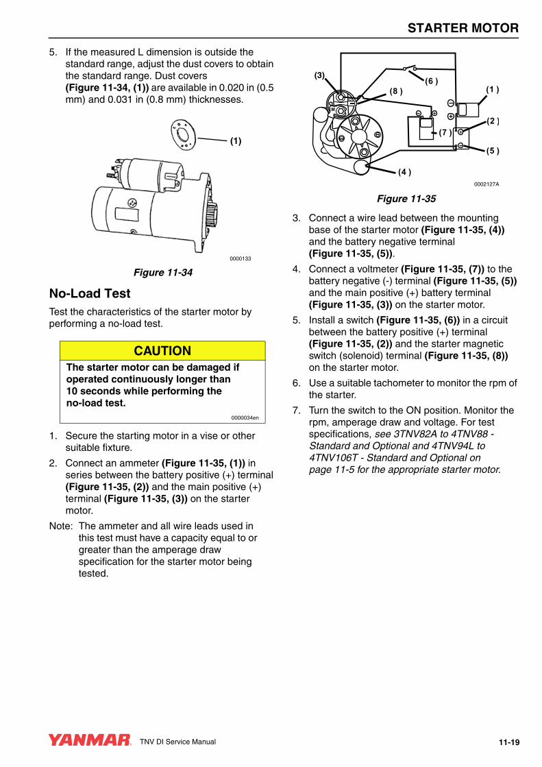
STARTER MOTOR
5. If the measured L dimension is outside the standard range, adjust the dust covers to obtain the standard range. Dust covers (Figure 11-34, (1)) are available in 0.020 in (0.5 mm) and 0.031 in (0.8 mm) thicknesses.
Figure 11-34
No-Load TestTest the characteristics of the starter motor by performing a no-load test.
1. Secure the starting motor in a vise or other suitable fixture.
2. Connect an ammeter (Figure 11-35, (1)) in series between the battery positive (+) terminal (Figure 11-35, (2)) and the main positive (+) terminal (Figure 11-35, (3)) on the starter motor.
Note: The ammeter and all wire leads used in this test must have a capacity equal to or greater than the amperage draw specification for the starter motor being tested.
Figure 11-35
3. Connect a wire lead between the mounting base of the starter motor (Figure 11-35, (4)) and the battery negative terminal (Figure 11-35, (5)).
4. Connect a voltmeter (Figure 11-35, (7)) to the battery negative (-) terminal (Figure 11-35, (5)) and the main positive (+) battery terminal (Figure 11-35, (3)) on the starter motor.
5. Install a switch (Figure 11-35, (6)) in a circuit between the battery positive (+) terminal (Figure 11-35, (2)) and the starter magnetic switch (solenoid) terminal (Figure 11-35, (8)) on the starter motor.
6. Use a suitable tachometer to monitor the rpm of the starter.
7. Turn the switch to the ON position. Monitor the rpm, amperage draw and voltage. For test specifications, see 3TNV82A to 4TNV88 - Standard and Optional and 4TNV94L to 4TNV106T - Standard and Optional on page 11-5 for the appropriate starter motor.
CAUTIONThe starter motor can be damaged if operated continuously longer than 10 seconds while performing the no-load test.
0000034en
0000133
(1)
(4 )
(3)
(8 )(6 )
(1 )
(2 )
(5 )
(7 )
M
0002127A
TNV DI Service Manual 11-19
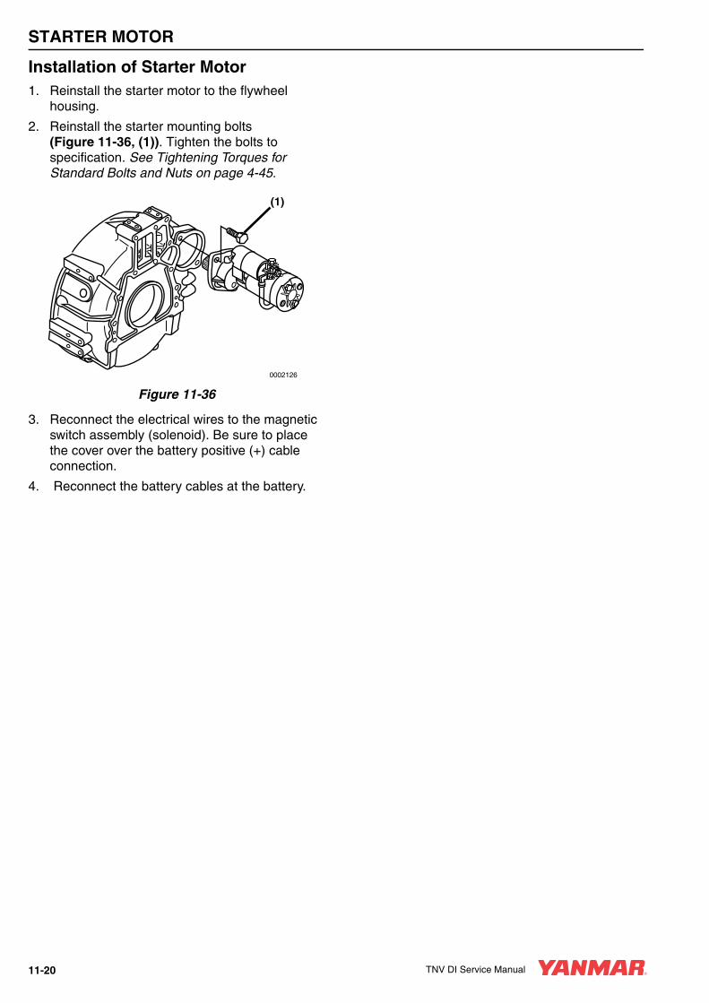
STARTER MOTOR
Installation of Starter Motor1. Reinstall the starter motor to the flywheel
housing.
2. Reinstall the starter mounting bolts (Figure 11-36, (1)). Tighten the bolts to specification. See Tightening Torques for Standard Bolts and Nuts on page 4-45.
Figure 11-36
3. Reconnect the electrical wires to the magnetic switch assembly (solenoid). Be sure to place the cover over the battery positive (+) cable connection.
4. Reconnect the battery cables at the battery.
(1)
0002126
11-20 TNV DI Service Manual

TNV DI Service Manual Section 12
ALTERNATOR
PageBefore You Begin Servicing .......................................................... 12-3
Introduction.................................................................................... 12-6
Dynamo and Alternator Information .............................................. 12-63TNV82A to 4TNV106T - Standard and Optional Dynamos ................................................................................. 12-63TNV82A to 4TNV106T - Standard and Optional Alternators ............................................................................... 12-6
Alternator Specifications................................................................ 12-7
Dynamo Specifications.................................................................. 12-7
Alternator Troubleshooting ............................................................ 12-8
Alternator Components ................................................................. 12-9
Alternator Wiring Diagram ........................................................... 12-10
Alternator Standard Output ........................................................ 12-11
Alternator .................................................................................... 12-12Removal of Alternator............................................................ 12-12Disassembly of Alternator...................................................... 12-12Reassembly of Alternator ...................................................... 12-14Installation of Alternator......................................................... 12-16
Dynamo Component Location..................................................... 12-17
Dynamo Wiring Diagram ............................................................. 12-18
Operation of Dynamo .................................................................. 12-18
Dynamo Standard Output ........................................................... 12-19
Testing of Dynamo ...................................................................... 12-20Testing Stator Coil Continuity ................................................ 12-20Testing Stator Coil Short-to-Ground...................................... 12-20Testing Dynamo Regulated Output ....................................... 12-20
TNV DI Service Manual 12-1

ALTERNATOR
Dynamo........................................................................................ 12-20Removal of Dynamo............................................................... 12-20Disassembly of Dynamo......................................................... 12-21Reassembly of Dynamo ......................................................... 12-21Installation of Dynamo............................................................ 12-22
12-2 TNV DI Service Manual

ALTERNATOR
BEFORE YOU BEGIN SERVICING
A WARNING
ENTANGLEMENT HAZARD!• Stop the engine before you begin to
service it.
• NEVER leave the key in the key switch when you are servicing the engine. Someone may accidentally start the engine and not realize you are servicing it. This could result in a serious injury.
• If you must service the engine while it is operating, remove all jewelry, tie back long hair, and keep your hands, other body parts and clothing away from moving / rotating parts.
• Failure to comply could result in death or serious injury.
0000010en
A WARNING
SHOCK HAZARD!• Turn off the battery switch (if
equipped) or disconnect the negative battery cable before servicing the electrical system.
• Check the electrical harnesses for cracks, abrasions, and damaged or corroded connectors. ALWAYS keep the connectors and terminals clean.
• Failure to comply could result in death or serious injury.
0000009en
A WARNING
BURN HAZARD!• Keep your hands and other body parts
away from hot engine surfaces such as the muffler, exhaust pipe, turbocharger (if equipped) and engine block during operation and shortly after you shut the engine down. These surfaces are extremely hot while the engine is operating and could seriously burn you.
• Failure to comply could result in death or serious injury.
0000015en
TNV DI Service Manual 12-3
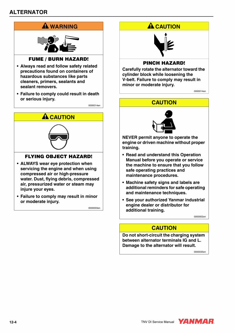
ALTERNATOR
A WARNING
FUME / BURN HAZARD!• Always read and follow safety related
precautions found on containers of hazardous substances like parts cleaners, primers, sealants and sealant removers.
• Failure to comply could result in death or serious injury.
0000014en
A CAUTION
FLYING OBJECT HAZARD!• ALWAYS wear eye protection when
servicing the engine and when using compressed air or high-pressure water. Dust, flying debris, compressed air, pressurized water or steam may injure your eyes.
• Failure to comply may result in minor or moderate injury.
0000003en
A CAUTION
PINCH HAZARD!Carefully rotate the alternator toward the cylinder block while loosening the V-belt. Failure to comply may result in minor or moderate injury.
0000014en
CAUTION
NEVER permit anyone to operate the engine or driven machine without proper training.
• Read and understand this Operation Manual before you operate or service the machine to ensure that you follow safe operating practices and maintenance procedures.
• Machine safety signs and labels are additional reminders for safe operating and maintenance techniques.
• See your authorized Yanmar industrial engine dealer or distributor for additional training.
0000002en
CAUTIONDo not short-circuit the charging system between alternator terminals IG and L. Damage to the alternator will result.
0000035en
12-4 TNV DI Service Manual

ALTERNATOR
CAUTIONDo not connect a load between alternator terminals L and E. Damage to the alternator will result.
0000036en
CAUTIONDo not remove the positive (+) battery cable from alternator terminal B while the engine is operating. Damage to the alternator will result.
0000037en
CAUTIONDo not turn the battery switch OFF while the engine is operating. Damage to the alternator will result.
0000038en
CAUTIONDo not operate the engine if the alternator is producing unusual sounds. Damage to the alternator will result.
0000039en
CAUTIONDo not reverse the positive (+) and negative (-) ends of the battery cable. The alternator diode and stator coil will be damaged.
0000050en
CAUTIONWhen the battery indicator goes out, it should not come on again. The battery indicator only comes on during operation if the alternator fails or if the V-belt breaks. However, if an LED is used in the battery indicator, the LED will shine faintly during normal operation.
0000051en
CAUTIONUsing a non-specified V-belt will cause inadequate charging and shorten the belt life. Use the specified belt.
0000052en
CAUTIONAgricultural or other chemicals, especially those with a high sulfur content, can adhere to the IC regulator. This will corrode the conductor and result in battery over-charging (boiling) and charging malfunctions. Consult Yanmar before using the equipment in such an environment or the warranty is voided.
0000053en
CAUTIONDo not use a high-pressure wash directly on the alternator. Water will damage the alternator and result in inadequate charging.
0000049en
TNV DI Service Manual 12-5

ALTERNATOR
INTRODUCTIONThis section of the Service Manual describes the servicing of the dynamos and alternators. Yanmar Part No. 129423-77200 alternator is used in this section to show the service procedures for the representative alternator. Yanmar Part No. 171301-77201 dynamo is used in this section to show the service procedures for the representative dynamo. For specific part detail, see the Parts Catalog for the engine you are working on.
DYNAMO AND ALTERNATOR INFORMATION
3TNV82A to 4TNV106T - Standard and Optional Dynamos
3TNV82A to 4TNV106T - Standard and Optional Alternators
YANMAR Part Number Mfg. Mfg. Part Number Specification
171301-77201 Kokusan GP8138 DC12V-15A
119910-77200 Kokusan GP9191 DC12V-20A
YANMAR Part Number Mfg. Mfg. Part Number Specification
119620-77201 Denso 100211-4531 DC12V-40A
129423-77200 Denso 101211-1170 DC12V-40A with Pulse
129961-77200 Denso 101211-2591 DC12V-55A
119626-77210 Denso 101211-2951 DC12V-55A with Pulse
129612-77290 Hitachi LR180-772 DC12V-80A with Pulse
129900-77240 Hitachi LR235-705 DC24V-35A with Pulse
12-6 TNV DI Service Manual

ALTERNATOR
ALTERNATOR SPECIFICATIONS
DYNAMO SPECIFICATIONS
Yanmar Part Number 129423-77200
Nominal Output (13.5 Volts Heat) 40 Amps
Weight 6.17 lb (2.8 kg)
Revolution Direction (As Viewed From Pulley) Clockwise
Rating Continuous
Battery Voltage 12 Volts
Rated Revolution 5000 rpm (min-1)
Operating Range 1350 - 18000 rpm (min-1)
Grounding Characteristics Negative (-) Side of Circuit
Integrated Regulator IC Regulator
Outside Diameter of Pulley 2.724 in. (69.2 mm)
Belt Shape Type A
Yanmar Part Number 119910-77200
Nominal Output 20 Amps
Weight 3.97 lb (1.8 kg)
Revolution Direction (As Viewed From Pulley) Clockwise
Rating Continuous
Battery Voltage 12 Volts
Rated Revolution 3500 rpm
Operating Range 1400 - 6600 rpm
Grounding Characteristics Negative (-) Side of Circuit
Integrated Regulator IC Regulator
Outside Diameter of PulleyA-Belt 2.56 in. (65 mm)
Special M-Belt 2.28 in. (58 mm)
Belt Shape Type A or Type Special M
TNV DI Service Manual 12-7

ALTERNATOR
ALTERNATOR TROUBLESHOOTING
Turn
key s
witch O
N.
Does b
attery
indic
ato
r tu
rn O
N?
At id
le, does b
attery
indic
ato
r tu
rn O
FF
?
Does b
attery
indic
ato
rcom
e O
N?
Gro
und d
rive m
achin
e s
ide
L term
inal. D
oes b
attery
in
dic
ato
r tu
rn o
n?
Does b
attery
indic
ato
rcom
e O
N?
Sta
rt E
ngin
e.
ON
OF
F
OF
FO
FF
OF
F
ON
ON
OF
F
Battery
indic
ato
r O
N.
Dis
connect harn
ess L
term
inal
and IG
term
inal at altern
ato
r
Incre
ase e
ngin
e s
peed to
1500 r
pm
. T
urn
lig
ht sw
itch O
N.
With e
ngin
e r
unnin
g a
t 1500
rpm
, m
easure
voltage a
t battery
.
Note
s:
1)
Use a
fully
charg
ed b
attery
2)
DC
voltm
ete
r: 0
to 3
0 V
, 0.5
cla
ss
3)
The c
heck m
eth
od is a
lso a
pplic
able
to the b
ench test
With e
ngin
e idlin
g,
measure
voltage a
t L
term
inal and a
t battery
.
With e
ngin
e idlin
g,
turn
lig
ht sw
itch O
N.
Repla
ce the b
attery
indic
ato
r.B
attery
indic
ato
r is
availa
ble
fro
m
driven m
achin
e m
anufa
ctu
rer.
Battery
indic
ato
r flashes.
Battery
voltage
is b
etw
een 1
3
and 1
5 v
olts.
Battery
voltage g
reate
r th
an 1
5.5
volts.
Battery
voltage m
inus
L term
inal voltage is
gre
ate
r th
an 0
.5 v
olt.
Battery
voltage m
inus
L term
inal voltage is
less than 0
.5 v
olt.
Battery
indic
ato
ris
dim
.
Battery
indic
ato
ris
dim
.
Inspect ro
tor
assem
bly
and
bru
shes.
Excessiv
e v
oltage d
rop b
etw
een
BA
T a
nd b
att (
+ sid
e)
term
inal.
Check c
onditio
n o
f L term
inal.
Inspect dio
de n
egative (
-) s
ide.
Repla
ce r
egula
tor.
Inspect auxili
ary
dio
de.
Not abnorm
al.
Inspect or
repla
ce V
-belt.
Inspect altern
ato
r.
Inspect dio
de p
ositiv
e (
+)
sid
e.
12-8 TNV DI Service Manual

ALTERNATOR
ALTERNATOR COMPONENTSYanmar Part No. 129423-77200 alternator is used in this section to show the service procedures for the representative alternator. For specific part detail, see the Parts Catalog for the engine you are working on.
1 – Nut2 – Pulley3 – Collar4 – Front Frame Housing5 – Stator Assembly6 – Stud (2 used)7 – Front Frame Housing Bearing8 – Bearing Cover9 – Bearing Cover Bolt (4 used)10 – Rotor Assembly11 – Rear Frame Housing Bearing12 – Bearing Cover13 – Thrust Washer14 – Thrust Washer15 – Nut (2 used)16 – Nut
17 – Insulation Bushing18 – Spring (2 used)19 – Brush Holder20 – Rear Frame Housing21 – Bolt (2 used)22 – Holder23 – IC Regulator Assembly24 – Bolt (2 used)25 – Bolt26 – Brush (2 used)27 – Bolt28 – Rear Cover29 – Bolt (3 used)
Figure 12-1
0000255
1
2827
72
3
4
5
13
6
121110
98
14
26
2423
2221
20
19
18
251716
29
15
TNV DI Service Manual 12-9

ALTERNATOR
ALTERNATOR WIRING DIAGRAM
1 – Key Switch2 – Charge Lamp (3.4 Watts Max.)3 – Load
4 – Battery5 – Alternator Assembly6 – IC Regulator Assembly
Figure 12-2
L
IG
B
P
L
IG
IC
B
F
E0
.5µF
E
PI P
1
5 6
2
4
33
BAT
CAUTIONDo not short-circuit the charging system between alternator terminals IG and L. Damage to the alternator will result.
0000035en
CAUTIONDo not connect a load between alternator terminals L and E. Damage to the alternator will result.
0000036en
CAUTIONDo not remove the positive (+) battery cable from alternator terminal B while the engine is operating. Damage to the alternator will result.
0000037en
12-10 TNV DI Service Manual
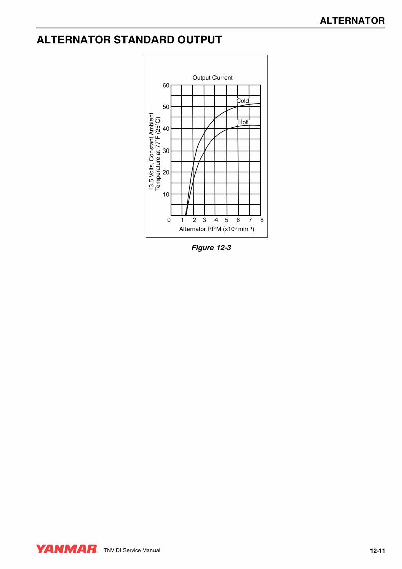
ALTERNATOR
ALTERNATOR STANDARD OUTPUT
Figure 12-3
Alternator RPM (x10³ min¯¹)
13.5
Vol
ts, C
onst
ant A
mbi
ent
Tem
pera
ture
at 7
7˚F
(25
˚C)
Output Current
Cold
Hot
60
50
40
30
20
10
0 1 2 3 4 5 6 7 8
TNV DI Service Manual 12-11
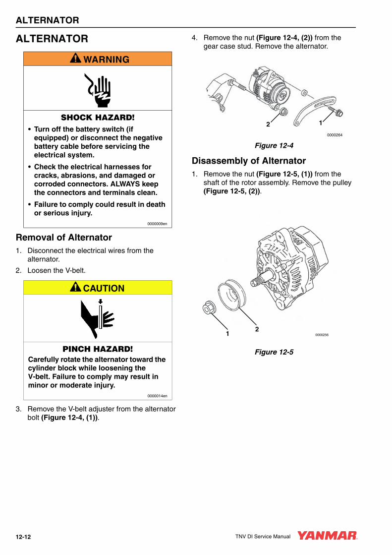
ALTERNATOR
ALTERNATOR
Removal of Alternator1. Disconnect the electrical wires from the
alternator.
2. Loosen the V-belt.
3. Remove the V-belt adjuster from the alternator bolt (Figure 12-4, (1)).
4. Remove the nut (Figure 12-4, (2)) from the gear case stud. Remove the alternator.
Figure 12-4
Disassembly of Alternator1. Remove the nut (Figure 12-5, (1)) from the
shaft of the rotor assembly. Remove the pulley (Figure 12-5, (2)).
Figure 12-5
A WARNING
SHOCK HAZARD!• Turn off the battery switch (if
equipped) or disconnect the negative battery cable before servicing the electrical system.
• Check the electrical harnesses for cracks, abrasions, and damaged or corroded connectors. ALWAYS keep the connectors and terminals clean.
• Failure to comply could result in death or serious injury.
0000009en
A CAUTION
PINCH HAZARD!Carefully rotate the alternator toward the cylinder block while loosening the V-belt. Failure to comply may result in minor or moderate injury.
0000014en
120000264
000025612
12-12 TNV DI Service Manual

ALTERNATOR
2. Remove the three bolts (Figure 12-6, (1)) retaining the rear cover (Figure 12-6, (2)) to the rear frame assembly.
Figure 12-6
3. Remove the brush holder (Figure 12-6, (3)). Remove the brush springs (Figure 12-6, (4)) and brushes (Figure 12-6, (5)).
4. Remove the bolt retaining the regulator assembly (Figure 12-7, (1)) to the holder (Figure 12-7, (2)).
Figure 12-7
5. Remove the bolts retaining the holder (Figure 12-7, (2)) to the rear frame housing. Remove the holder.
6. Remove the nut (Figure 12-7, (3)) retaining the insulation bushing (Figure 12-7, (4)). Remove the insulation bushing.
7. Remove the two bolts (Figure 12-8, (1)) and two nuts (Figure 12-8, (2)) securing the rear frame housing to the front frame housing.
Figure 12-8
8. Using a press, remove the rotor assembly (Figure 12-9, (1)) from the front frame housing (Figure 12-9, (2)) and rear frame housing (Figure 12-9, (1)).
Figure 12-9
3
45
1
2
0000257A
3
41
2
0000258A
0000265A
1
2
100266A
2
1
3
TNV DI Service Manual 12-13
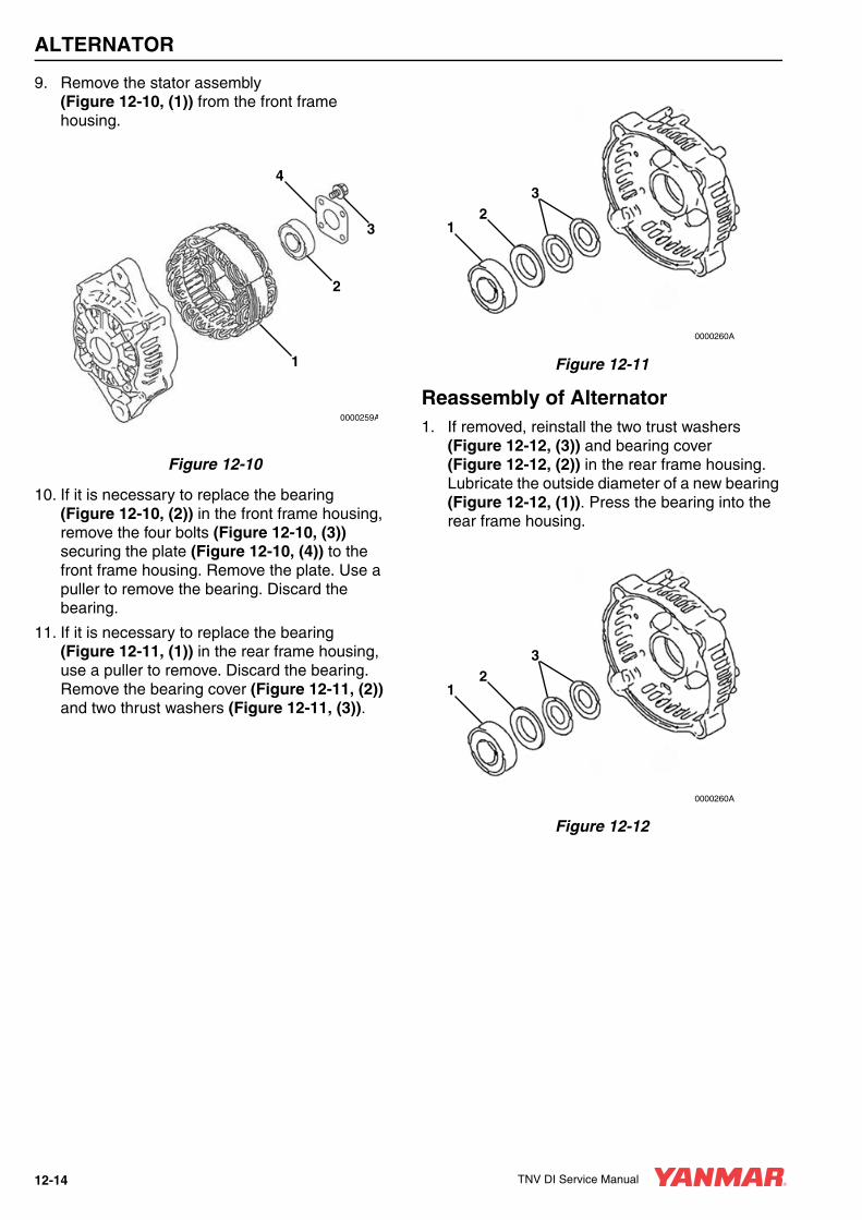
ALTERNATOR
9. Remove the stator assembly (Figure 12-10, (1)) from the front frame housing.
Figure 12-10
10. If it is necessary to replace the bearing (Figure 12-10, (2)) in the front frame housing, remove the four bolts (Figure 12-10, (3)) securing the plate (Figure 12-10, (4)) to the front frame housing. Remove the plate. Use a puller to remove the bearing. Discard the bearing.
11. If it is necessary to replace the bearing (Figure 12-11, (1)) in the rear frame housing, use a puller to remove. Discard the bearing. Remove the bearing cover (Figure 12-11, (2)) and two thrust washers (Figure 12-11, (3)).
Figure 12-11
Reassembly of Alternator1. If removed, reinstall the two trust washers
(Figure 12-12, (3)) and bearing cover (Figure 12-12, (2)) in the rear frame housing. Lubricate the outside diameter of a new bearing (Figure 12-12, (1)). Press the bearing into the rear frame housing.
Figure 12-12
1
2
4
3
0000259A
12
3
0000260A
12
3
0000260A
12-14 TNV DI Service Manual

ALTERNATOR
2. If removed, lubricate the outside diameter of a new front frame housing bearing. Press the bearing (Figure 12-13, (2)) into the front frame housing. Reinstall the plate (Figure 12-13, (4)) to the front housing. Tighten the four bolts (Figure 12-13, (3)).
Figure 12-13
3. Position the stator assembly (Figure 12-13, (1)) on the front frame housing studs.
4. Lubricate the shaft of the rotor assembly (Figure 12-14, (1)). Press the rotor assembly into the front frame housing (Figure 12-14, (2)) and rear frame housing (Figure 12-14, (3)).
Figure 12-14
5. Align the front frame housing with the rear frame housing. Reinstall the two bolts (Figure 12-15, (1)) and two nuts (Figure 12-15, (2)).
Figure 12-15
6. Reinstall the insulation bushing (Figure 12-16, (4)) and nut (Figure 12-16, (3)).
Figure 12-16
7. Reassemble the regulator assembly (Figure 12-16, (1)) to the holder (Figure 12-16, (2)).
1
2
4
3
0000259A
100266A
2
1
3
0000265A
1
2
3
41
2
0000258A
TNV DI Service Manual 12-15

ALTERNATOR
8. Reinstall the brush holder (Figure 12-17, (3)), springs (Figure 12-17, (4)) and brushes (Figure 12-17, (5)).
9. Reattach the regulator assembly and holder to the rear frame housing.
Figure 12-17
10. Reinstall the rear cover (Figure 12-17, (2)) to the rear frame housing with three bolts (Figure 12-17, (1)).
11. Reassemble the pulley (Figure 12-18, (2)) and nut (Figure 12-18, (1)) to the shaft of the rotor assembly. Tighten the nut.
Figure 12-18
Installation of Alternator1. Position the alternator on the gear case.
Loosely reinstall the nut (Figure 12-19, (2)) on the gear case stud and the V-belt adjuster bolt (Figure 12-19, (1)).
Figure 12-19
2. Reconnect the electrical wires to the alternator. Tighten the nuts to 15 - 20 in.-lb (1.7 - 2.3 N·m; 17-23 kgf·m).
3. Reinstall the V-belt. Tighten the V-belt to the proper tension as described in Check and Adjust Cooling Fan V-Belt on page 5-28.
4. Start the engine. Listen for any unusual sounds from the alternator.
5. Verify that the charge indicator is ON while the engine is operating. If the charge indicator is not ON, repair the problem before operating the engine.
3
45
1
2
0000257A
000025612
CAUTIONDo not operate the engine if the alternator is producing unusual sounds. Damage to the alternator will result.
0000039en
120000264
12-16 TNV DI Service Manual

ALTERNATOR
DYNAMO COMPONENT LOCATIONYanmar Part No. 171301-77201 dynamo is used in this section to show the service procedures for the representative dynamo. For specific part detail, see the Parts Catalog for the engine you are working on.
1 – Rear Cover2 – Nut3 – Lock Washer4 – Flat Washer5 – Rear Bearing6 – Output Wire and Connector7 – Plate
8 – Spacer9 – Stator Assembly10 – Front Bearing (2 used)11 – Flat Washer12 – Flywheel Assembly13 – Pulley Half14 – Through Bolt
Figure 12-20
0002140
(1)
(2)(3)
(6)
(4)
(5)
(7)
(8) (9)
(10)
(11) (12)
(13)
(14)
TNV DI Service Manual 12-17

ALTERNATOR
DYNAMO WIRING DIAGRAM
1 – Dynamo2 – IC Regulator Assembly3 – Key Switch4 – Charge Lamp (3.4 Watts Max.)5 – Battery6 – Load
Figure 12-21
OPERATION OF DYNAMOThe dynamo consists of a series of permanent magnets that rotate around a stationary stator coil. The magnets are attached to the flywheel which is rotated via the engine cooling fan drive belt. The resultant output is an AC (alternating current) signal. The AC is converted to DC (direct current) in the IC Regulator. The IC Regulator outputs charging DC current to the battery.
0002137
(1)
(2)
(3)
(4)
(5) (6)
12-18 TNV DI Service Manual
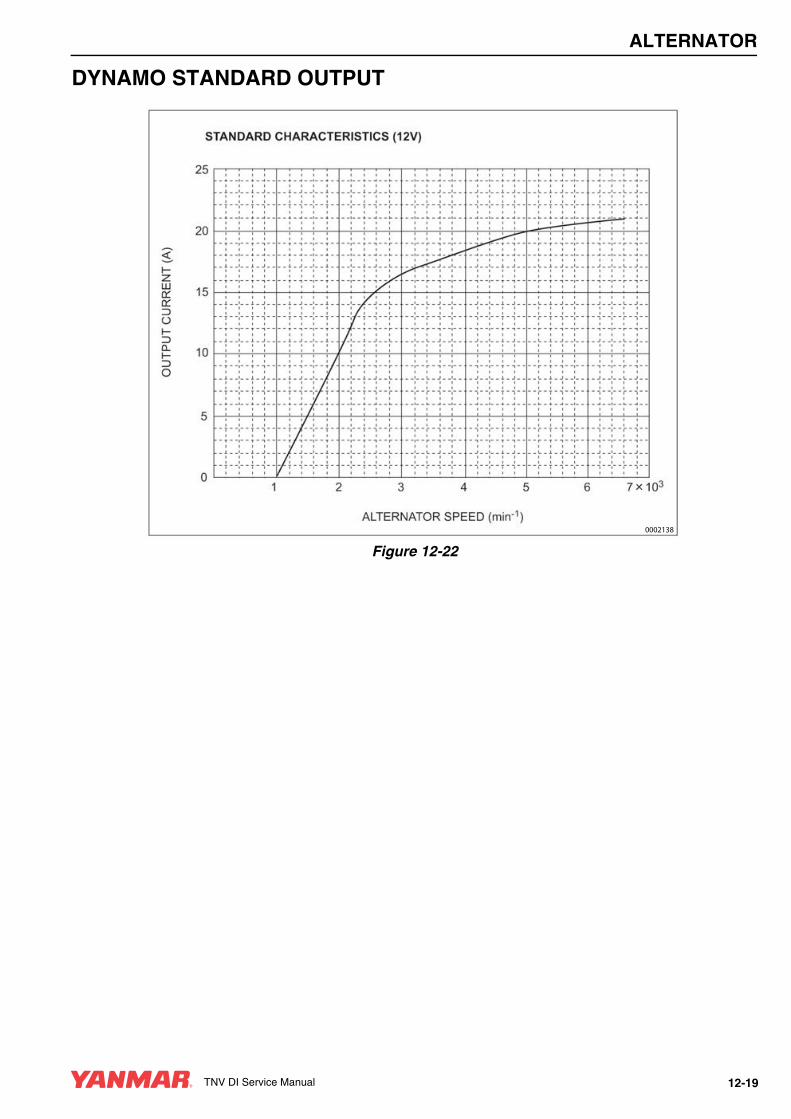
ALTERNATOR
DYNAMO STANDARD OUTPUT
Figure 12-22
0002138
TNV DI Service Manual 12-19

ALTERNATOR
TESTING OF DYNAMOUse a circuit tester or multimeter to perform the following tests.
Testing Stator Coil Continuity1. Disconnect the dynamo output wire connector.
2. Connect one meter lead to each of the stator wire terminals and read the meter.
Results: The meter reading should indicate continuity. If continuity is not indicated, the windings are open and the stator must be replaced.
Testing Stator Coil Short-to-Ground1. Disconnect the dynamo output wire connector.
2. Test continuity between each stator wire terminal and engine ground.
Results: The meter reading should infinity. If the meter reading indicates continuity, the windings are shorted to ground and the stator must be replaced.
Testing Dynamo Regulated Output1. Test and record the battery voltage with the
engine not running.
2. Start the engine and operate it at normal operating rpm.
3. Again, check the battery voltage with the engine running.
Results: The meter reading with the engine running must be higher than with the engine not running.
• If results are not correct, test the stator for continuity and shorts to the ground.
• Check the charging system wiring.
• If no problems are found in previous checks, replace the IC regulator.
DYNAMO
Removal of Dynamo1. Disconnect the output wire connector from the
dynamo.
2. Loosen the V-belt.
3. Remove the V-belt adjuster from the dynamo bolt (Figure 12-23, (1)).
4. Remove the nut (Figure 12-23, (2)) from the gear case stud. Remove the dynamo.
Figure 12-23
A CAUTION
PINCH HAZARD!Carefully rotate the alternator toward the cylinder block while loosening the V-belt. Failure to comply may result in minor or moderate injury.
0000014en
0002141(1)(2)
12-20 TNV DI Service Manual
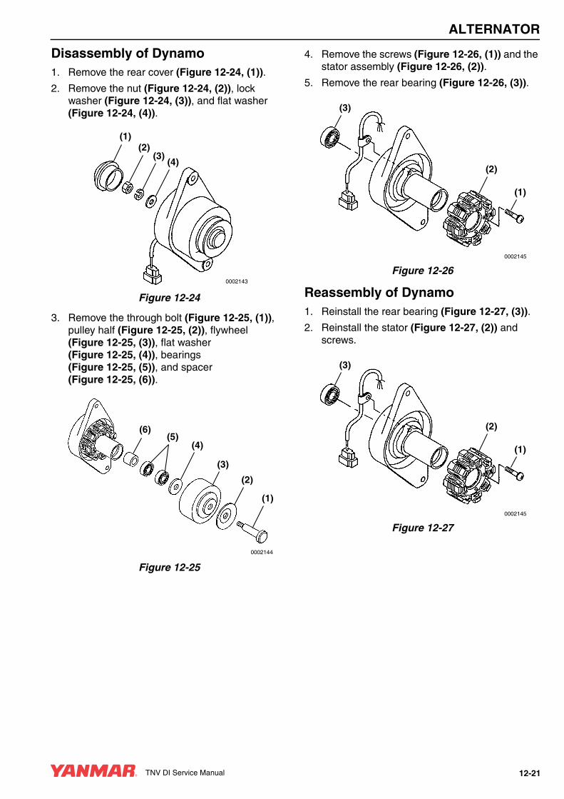
ALTERNATOR
Disassembly of Dynamo1. Remove the rear cover (Figure 12-24, (1)).
2. Remove the nut (Figure 12-24, (2)), lock washer (Figure 12-24, (3)), and flat washer (Figure 12-24, (4)).
Figure 12-24
3. Remove the through bolt (Figure 12-25, (1)), pulley half (Figure 12-25, (2)), flywheel (Figure 12-25, (3)), flat washer (Figure 12-25, (4)), bearings (Figure 12-25, (5)), and spacer (Figure 12-25, (6)).
Figure 12-25
4. Remove the screws (Figure 12-26, (1)) and the stator assembly (Figure 12-26, (2)).
5. Remove the rear bearing (Figure 12-26, (3)).
Figure 12-26
Reassembly of Dynamo1. Reinstall the rear bearing (Figure 12-27, (3)).
2. Reinstall the stator (Figure 12-27, (2)) and screws.
Figure 12-27
(1)(2)
(3)(4)
0002143
(6)(5)
(4)
(3)
(2)
(1)
0002144
(3)
(2)
(1)
0002145
(3)
(2)
(1)
0002145
TNV DI Service Manual 12-21

ALTERNATOR
3. Reinstall the front bearings (Figure 12-28, (5)) and spacer (Figure 12-28, (6)).
4. Reinstall the flat washer (Figure 12-28, (4)), flywheel (Figure 12-28, (3)), pulley half (Figure 12-28, (2), and through bolt (Figure 12-28, (1)).
Figure 12-28
5. Reinstall the flat washer (Figure 12-29, (4)), lock washer (Figure 12-29, (3)), and nut (Figure 12-29, (2)). Tighten the nut to the specified torque.
6. Reinstall the rear cap (Figure 12-29, (1)).
Figure 12-29
Installation of Dynamo1. Position the dynamo on the gear case. Loosely
reinstall the nut (Figure 12-30, (2)) on the gear case stud and the V-belt adjuster bolt (Figure 12-30, (1)).
Figure 12-30
2. Reconnect the dynamo output wire connector.
3. Reinstall the V-belt. Tighten the V-belt to the proper tension as described in Check and Adjust Cooling Fan V-Belt on page 5-28.
4. Start the engine. Listen for any unusual sounds from the alternator.
5. Verify that the charge indicator is ON while the engine is operating. If the charge indicator is not ON, repair the problem before operating the engine.
(6)(5)
(4)
(3)
(2)
(1)
0002144
(1)(2)
(3)(4)
0002143
CAUTIONDo not operate the engine if the alternator is producing unusual sounds. Damage to the alternator will result.
0000039en
0002141(1)(2)
12-22 TNV DI Service Manual
TNV DI Service Manual Section 13
ELECTRIC WIRING
PageElectric Wiring Precautions .......................................................... 13-3
Electrical Wire Resistance ............................................................ 13-4
Battery Cable Resistance.............................................................. 13-5
Electrical Wire Sizes - Voltage Drop ............................................. 13-6
Conversion of AWG to European Standards................................. 13-7
TNV DI Service Manual 13-1

ELECTRIC WIRING
ELECTRIC WIRING PRECAUTIONS Failure to follow these precautions may result in the failure of an electrical component and the loss of warranty coverage on that item as well as related items. Make sure that all users read and understand these precautions.
CAUTIONDo not reverse the positive (+) and negative (-) ends of the battery cable. The alternator diode and stator coil will be damaged.
0000050en
CAUTIONWhen the battery indicator goes out, it should not come on again. The battery indicator only comes on during operation if the alternator fails or if the V-belt breaks. However, if an LED is used in the battery indicator, the LED will shine faintly during normal operation.
0000051en
CAUTIONMake sure that the combined total resistance of the battery cable in both directions between the starter motor and the battery is within the value indicated in the Battery Cable Resistance chart in the Electric Wiring Section of this manual. The starter motor will malfunction and fail if the resistance is higher than the specified value.
0000057en
CAUTIONRemoving the battery cables or the battery while the engine is operating may cause damage to the current limiter depending on the electrical equipment being used. This situation could cause loss of control of output voltage. The continuous high voltage of 23-24 volts (for 5000 rpm dynamo) will damage the current limiter and other electrical equipment.
0000058en
CAUTIONReversing the battery cable connections at the battery or on the engine will destroy the SCR diode in the current limiter. This will cause the charging system to malfunction and may cause damage to the electrical harnesses.
0000059en
TNV DI Service Manual 13-3

ELECTRIC WIRING
ELECTRICAL WIRE RESISTANCE
Wiring voltage drop should not exceed 5% [0.05] x 12 Volts = 0.6 Volts.
Voltage Drop = Current [Amps] x Length of Wire [Feet] x Resistance per Foot Ω
Example:
Current draw of 100 Amps x 3 feet of 4 AWG wire
100 Amps x 3 Feet x 0.000270 = 0.08 Volts [Voltage Drop]
AWGMetric
Nominal mm²Ohms / FootResistance
20 0.5 0.009967
18 0.8 0.006340
16 1.25 0.004359
14 2 0.002685
12 3 0.001704
10 5 0.001073
8 8 0.000707
6 15 0.000421
4 20 0.000270
2 30 0.000158
1 40 0.000130
0 (1/0) 50 0.000103
00 (2/0) 60 0.000087
000 (3/0) 85 0.000066
0000 (4/0) 100 0.000051
13-4 TNV DI Service Manual
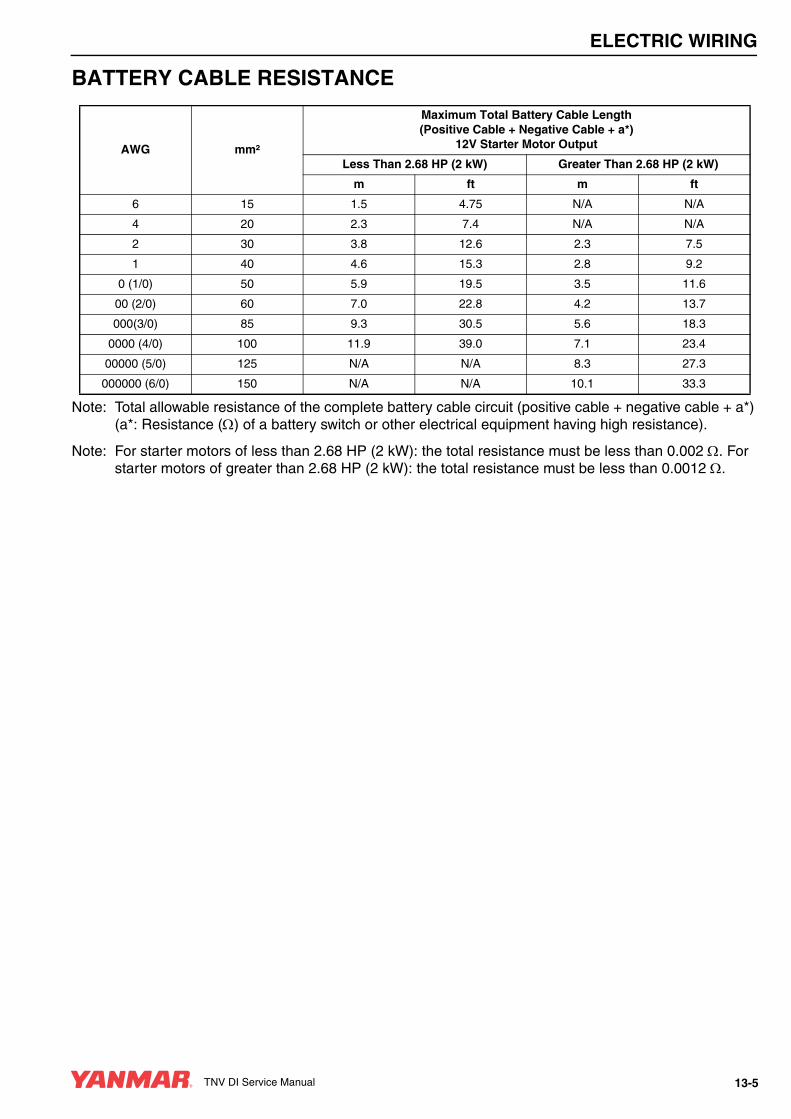
ELECTRIC WIRING
BATTERY CABLE RESISTANCE
Note: Total allowable resistance of the complete battery cable circuit (positive cable + negative cable + a*) (a*: Resistance (Ω) of a battery switch or other electrical equipment having high resistance).
Note: For starter motors of less than 2.68 HP (2 kW): the total resistance must be less than 0.002 Ω. For starter motors of greater than 2.68 HP (2 kW): the total resistance must be less than 0.0012 Ω.
AWG mm²
Maximum Total Battery Cable Length (Positive Cable + Negative Cable + a*)
12V Starter Motor Output
Less Than 2.68 HP (2 kW) Greater Than 2.68 HP (2 kW)
m ft m ft
6 15 1.5 4.75 N/A N/A
4 20 2.3 7.4 N/A N/A
2 30 3.8 12.6 2.3 7.5
1 40 4.6 15.3 2.8 9.2
0 (1/0) 50 5.9 19.5 3.5 11.6
00 (2/0) 60 7.0 22.8 4.2 13.7
000(3/0) 85 9.3 30.5 5.6 18.3
0000 (4/0) 100 11.9 39.0 7.1 23.4
00000 (5/0) 125 N/A N/A 8.3 27.3
000000 (6/0) 150 N/A N/A 10.1 33.3
TNV DI Service Manual 13-5

ELECTRIC WIRING
ELECTRICAL WIRE SIZES - VOLTAGE DROP
Total current on circuit in
amps
Length of conductor from source of current to device and back to source (in feet)
10 15 20 25 30 40 50 60 70 80 90 100 110 120 130 140 150 160 170
12 Volts Wire Size (AWG)
5 18 16 14 12 12 10 10 10 8 8 8 6 6 6 6 6 6 6 6
10 14 12 10 10 10 8 6 6 6 6 4 4 4 4 2 2 2 2 2
15 12 10 10 8 8 6 6 6 4 4 2 2 2 2 2 1 1 1 1
20 10 10 8 6 6 6 4 4 2 2 2 2 1 1 1 0 0 0 2/0
25 10 8 6 6 6 4 4 2 2 2 1 1 0 0 0 2/0 2/0 2/0 3/0
30 10 8 6 6 4 4 2 2 1 1 0 0 0 2/0 2/0 3/0 3/0 3/0 3/0
40 8 6 6 4 4 2 2 1 0 0 2/0 2/0 3/0 3/0 3/0 4/0 4/0 4/0 4/0
50 6 6 4 4 2 2 1 0 2/0 2/0 3/0 3/0 4/0 4/0 4/0
60 6 4 4 2 2 1 0 2/0 3/0 3/0 4/0 4/0 4/0
70 6 4 2 2 1 0 2/0 3/0 3/0 4/0 4/0
80 6 4 2 2 1 0 3/0 3/0 4/0 4/0
90 4 2 2 1 0 2/0 3/0 4/0 4/0
100 4 2 2 1 0 2/0 3/0 4/0
24 Volts
5 18 18 18 16 16 14 12 12 12 10 10 10 10 10 8 8 8 8 8
10 18 16 14 12 12 10 10 10 8 8 8 6 6 6 6 6 6 6 6
15 16 14 12 12 10 10 8 8 6 6 6 6 6 4 4 4 4 4 2
20 14 12 10 10 10 8 6 6 6 6 4 4 4 4 2 2 2 2 2
25 12 12 10 10 8 6 6 6 4 4 4 4 2 2 2 2 2 2 1
30 12 10 10 8 8 6 6 4 4 4 2 2 2 2 2 1 1 1 1
40 10 10 8 6 6 6 4 4 2 2 2 2 1 1 1 0 0 0 2/0
50 10 8 6 6 6 4 4 2 2 2 1 1 0 0 0 2/0 2/0 2/0 3/0
60 10 8 6 6 4 4 2 2 1 1 0 0 0 2/0 2/0 3/0 3/0 3/0 3/0
70 8 6 6 4 4 2 2 1 1 0 0 2/0 2/0 3/0 3/0 3/0 3/0 4/0 4/0
80 8 6 6 4 4 2 2 1 0 0 2/0 2/0 3/0 3/0 3/0 4/0 4/0 4/0 4/0
90 8 6 4 4 2 2 1 0 0 2/0 2/0 3/0 3/0 4/0 4/0 4/0 4/0 4/0
100 6 6 4 4 2 2 1 0 2/0 2/0 3/0 3/0 4/0 4/0 4/0
13-6 TNV DI Service Manual

ELECTRIC WIRING
CONVERSION OF AWG TO EUROPEAN STANDARDS
Conductor Size (AWG)
Conductor Diameter (mm)
Conductor Cross-sectional Area (mm2)
25 0.455 0.163
24 0.511 0.205
23 0.573 0.259
22 0.644 0.325
21 0.723 0.412
20 0.812 0.519
19 0.992 0.653
18 1.024 0.823
17 1.15 1.04
16 1.29 1.31
15 1.45 1.65
14 1.63 2.08
13 1.83 2.63
12 2.05 3.31
11 2.30 4.15
10 2.59 5.27
9 2.91 6.62
8 3.26 8.35
7 3.67 10.6
6 4.11 13.3
5 4.62 16.8
4 5.19 21.2
3 5.83 26.7
2 6.54 33.6
1 7.35 42.4
0 (1/0) 8.25 53.4
00 (2/0) 9.27 67.5
000(3/0) 10.40 85.0
0000 (4/0) 11.68 107.2
00000 (5/0) 13.12 135.1
000000 (6/0) 14.73 170.3
1.1 circular mil (CM) @ 0.0005067 mm2
TNV DI Service Manual 13-7

TNV DI Service Manual Section 14
TROUBLESHOOTING
PageSpecial Service Tools.................................................................... 14-3
Troubleshooting By Measuring Compression Pressure ................ 14-4Compression Pressure Measurement Method........................ 14-4
Quick Reference Table For Troubleshooting ................................ 14-6
Troubleshooting Charts .................................................................. 14-7
Wiring Diagram............................................................................ 14-19
TNV DI Service Manual 14-1
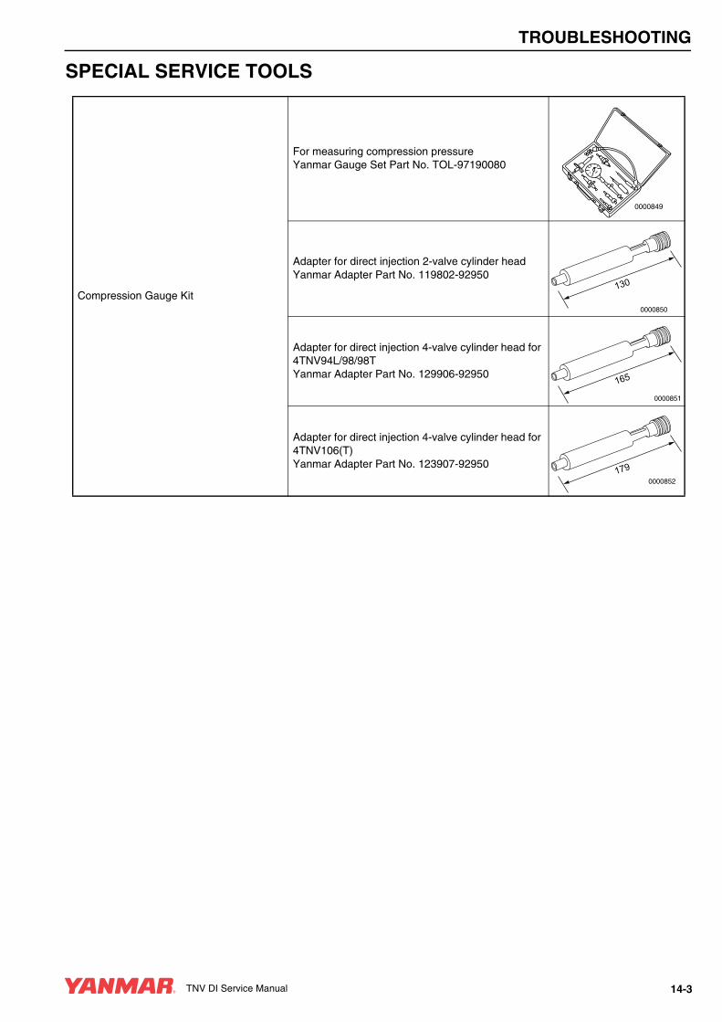
TROUBLESHOOTING
SPECIAL SERVICE TOOLS
Compression Gauge Kit
For measuring compression pressureYanmar Gauge Set Part No. TOL-97190080
Adapter for direct injection 2-valve cylinder headYanmar Adapter Part No. 119802-92950
Adapter for direct injection 4-valve cylinder head for 4TNV94L/98/98TYanmar Adapter Part No. 129906-92950
Adapter for direct injection 4-valve cylinder head for 4TNV106(T)Yanmar Adapter Part No. 123907-92950
0000849
031
0000850
561
0000851
9710000852
TNV DI Service Manual 14-3

TROUBLESHOOTING
TROUBLESHOOTING BY MEASURING COMPRESSION PRESSURECompression pressure drop is one of the major causes of increasing blow-by gas (engine oil contamination or increased engine oil consumption as a resultant phenomenon) or starting failure. The compression pressure is affected by the following factors:
1. Degree of clearance between the piston and cylinder
2. Degree of clearance at the intake / exhaust valve seat
3. Gas leak from the nozzle gasket or cylinder head gasket
The pressure will drop due to increased parts wear. Pressure drop reduces the durability of the engine.
A pressure drop may also be caused by a scratched cylinder or piston, dust entrance from the dirty air cleaner element or a worn or broken piston ring. Measure the compression pressure to determine the condition of the engine.
Compression Pressure Measurement Method1. Warm up the engine.
2. Stop the engine. Remove the high-pressure fuel injection lines as an assembly from the engine. Remove the fuel injector from the cylinder to be measured. See Removal of Fuel Injectors on page 7-31.
3. Turn off the fuel supply valve in the fuel supply line. Disconnect the fuel injection pump stop solenoid at the connector. This prevents the fuel injection pump from injecting fuel during compression testing.
4. Before installing the compression gauge (Figure 14-1, (1)) adapter, crank the engine with the stop solenoid disconnected for a few seconds to clear the cylinder of any residual fuel.
5. Install a nozzle seat at the tip end of the compression gauge adapter. Install the compression gauge and the compression gauge adapter at the cylinder to be measured.
6. Crank the engine until the compression gauge reading is stabilized.
Figure 14-1
7. After performing the compression check remove the compression gauge and compression gauge adapter from the cylinder. Reinstall the fuel injector, high-pressure fuel injection lines, and reconnect the stop solenoid. See Reassembly of Fuel Injectors on page 7-37.
8. Turn on the fuel supply valve and reconnect the injection pump stop solenoid.
9. Prime the fuel system. Check for leaks. Test the engine.
CAUTIONRemove or install the high-pressure fuel injection lines as an assembly whenever possible. Disassembling the high-pressure fuel injection lines from the retainers or bending any of the fuel lines will make it difficult to reinstall the fuel lines.
0000047en
1
14-4 TNV DI Service Manual

TROUBLESHOOTING
Standard Compression Pressure (Reference Value)
Engine Speed and Compression Pressure (Use for Reference)
Figure 14-2
Engine Model
Compression Pressureat 250 rpm (250 min-1) Deviation Between Cylinders
Standard Limit
3TNV82A443 - 473 psi
(3.06 - 3.26 MPa; 30 - 32 kgf/cm²)340 - 370 psi
(2.35 - 2.55 MPa; 24 - 26 kgf/cm²)
29 - 43 psi(0.2 - 0.3 MPa; 2 - 3 kgf/cm²)
3TNV844TNV84
455 - 485 psi(3.14 - 3.34 MPa; 32 - 34 kgf/cm²)
355 - 385 psi(2.45 - 2.65 MPa; 25 - 27 kgf/cm²)
3TNV84T4TNV84T
411 - 441 psi(2.84 3.04 MPa; 29 - 31 kgf/cm²)
340 - 370 psi(2.35 - 2.55 MPa; 24 - 26 kgf/cm²)
3TNV884TNV884TNV94L4TNV984TNV98T4TNV1064TNV106T
483 - 513 psi(3.33 - 3.53 MPa; 34 - 36 kgf/cm²)
384 - 414 psi(2.65 - 2.85 MPa; 27 - 29 kgf/cm²)
200 250 300 350 400
Engine speed (min-1)
3TNV844TNV84
3TNV82A
3TNV84T4TNV84T
569 psi(40 KgF/cm2)
(4 MPa)
(3 MPa)
(2 MPa)
498 psi(35 KgF/cm2)
427 psi(30 KgF/cm2)
284 psi(20 KgF/cm2)
356 psi(25 KgF/cm2)
3TNV884TNV884TNV94L4TNV984TNV98T4TNV1064TNV106T
TNV DI Service Manual 14-5

TROUBLESHOOTING
Measured Value and TroubleshootingWhen the measured compression pressure is below the limit value, inspect each part by referring to the table below.
QUICK REFERENCE TABLE FOR TROUBLESHOOTINGThe following table summarizes the general trouble symptoms and their causes. If any trouble symptom occurs, take corrective action before it becomes a serious problem so as not to shorten the engine service life.
No. Item Cause Corrective Action
1 Air Cleaner Element
Clogged element Clean the element.
Broken elementReplace the element.
Defect at element seal portion
2 Valve Clearance Excessive or no clearance Adjust the valve clearance.
3 Valve Timing Incorrect valve clearance Adjust the valve clearance.
4 Cylinder Head Gasket Gas leak from gasket
Replace the gasket.
Retighten the cylinder head bolts to the specified torque.
5
Intake / Exhaust Valve Sticking valve Replace the intake / exhaust valve.
Valve SeatGas leak due to worn valve seat or foreign matter trapped in valve
Lap the valve seat.
6
PistonGas leak due to scratching or wear
Perform honing and use an oversized part.Piston Ring
Cylinder
14-6 TNV DI Service Manual
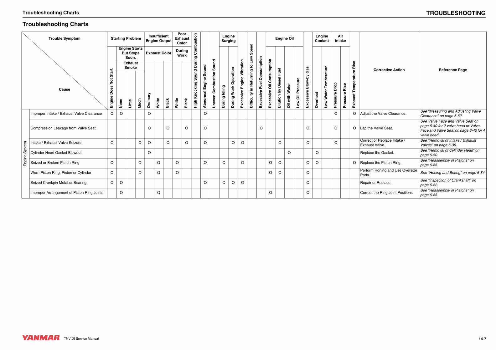
TNV DI Service Manual
Troubleshooting Charts
TNV DI Service Manual TROUBLESHOOTINGTroubleshooting Charts
Trouble Symptom Starting ProblemInsufficient
Engine Output
Poor Exhaust
Color
Hig
h K
no
ckin
g S
ou
nd
Du
rin
g C
om
bu
stio
n
Ab
no
rmal
En
gin
e S
ou
nd
Un
even
Co
mb
ust
ion
So
un
d
Engine Surging
Exc
essi
ve E
ng
ine
Vib
rati
on
Dif
ficu
lty
in R
etu
rnin
g t
o L
ow
Sp
eed
Exc
essi
ve F
uel
Co
nsu
mp
tio
n
Engine Oil
Exc
essi
ve B
low
-by
Gas
Engine Coolant
Air Intake
Exh
aust
Tem
per
atu
re R
ise
Corrective Action Reference Page
En
gin
e D
oes
No
t S
tart
.
Engine Starts But Stops
Soon.Exhaust Color
During Work
Du
rin
g Id
ling
Du
rin
g W
ork
Op
erat
ion
Exc
essi
ve O
il C
on
sum
pti
on
Dilu
tio
n b
y D
iese
l Fu
el
Oil
wit
h W
ater
Lo
w O
il P
ress
ure
Ove
rhea
t
Lo
w W
ater
Tem
per
atu
re
Pre
ssu
re D
rop
Pre
ssu
re R
ise
Exhaust Smoke
Ord
inar
y
Wh
ite
Bla
ck
Wh
ite
Bla
ck
Cause
No
ne
Lit
tle
Mu
ch
Eng
ine
Sys
tem
Improper Intake / Exhaust Valve Clearance O O O O O O Adjust the Valve Clearance.See “Measuring and Adjusting Valve Clearance” on page 6-62.
Compression Leakage from Valve Seat O O O O O O O O Lap the Valve Seat.
See Valve Face and Valve Seat on page 6-40 for 2 valve head or Valve Face and Valve Seat on page 6-40 for 4 valve head.
Intake / Exhaust Valve Seizure O O O O O O O O O O OCorrect or Replace Intake / Exhaust Valve.
See “Removal of Intake / Exhaust Valves” on page 6-36.
Cylinder Head Gasket Blowout O O O Replace the Gasket.See “Removal of Cylinder Head” on page 6-50.
Seized or Broken Piston Ring O O O O O O O O O O O O Replace the Piston Ring.See “Reassembly of Pistons” on page 6-85.
Worn Piston Ring, Piston or Cylinder O O O O O O OPerform Honing and Use Oversize Parts.
See “Honing and Boring” on page 6-84.
Seized Crankpin Metal or Bearing O O O O O O O Repair or Replace.See “Inspection of Crankshaft” on page 6-82.
Improper Arrangement of Piston Ring Joints O O O O Correct the Ring Joint Positions.See “Reassembly of Pistons” on page 6-85.
14-7

TROUBLESHOOTINGTroubleshooting Charts
Trouble Symptom Starting ProblemInsufficient
Engine Output
Poor Exhaust
Color
Hig
h K
no
ckin
g S
ou
nd
Du
rin
g C
om
bu
stio
n
Ab
no
rmal
En
gin
e S
ou
nd
Un
even
Co
mb
ust
ion
So
un
d
Engine Surging
Exc
essi
ve E
ng
ine
Vib
rati
on
Dif
ficu
lty
in R
etu
rnin
g t
o L
ow
Sp
eed
Exc
essi
ve F
uel
Co
nsu
mp
tio
n
Engine Oil
Exc
essi
ve B
low
-by
Gas
Engine Coolant
Air Intake
Exh
aust
Tem
per
atu
re R
ise
Corrective Action Reference Page
En
gin
e D
oes
No
t S
tart
.
Engine Starts But Stops
Soon.Exhaust Color
During Work
Du
rin
g Id
ling
Du
rin
g W
ork
Op
erat
ion
Exc
essi
ve O
il C
on
sum
pti
on
Dilu
tio
n b
y D
iese
l Fu
el
Oil
wit
h W
ater
Lo
w O
il P
ress
ure
Ove
rhea
t
Lo
w W
ater
Tem
per
atu
re
Pre
ssu
re D
rop
Pre
ssu
re R
ise
Exhaust Smoke
Ord
inar
y
Wh
ite
Bla
ck
Wh
ite
Bla
ck
Cause
No
ne
Lit
tle
Mu
ch
Eng
ine
Sys
tem
- C
ontin
ued
Reverse Assembly of Piston Rings O O O O Reassemble Correctly.See “Reassembly of Pistons” on page 6-85.
Worn Crankpin and Journal Bearing O O O O O O Measure and Replace.See “Inspection of Crankshaft” on page 6-82.
Loose Connecting Rod Bolt O O O Tighten to the Specified Torque.See “Torque for Bolts and Nuts” on page 6-23.
Foreign Matter Trapped in Combustion Chamber
O O O O Disassemble and Repair.See “Disassembly of Engine” on page 6-68.
Excessive Gear Backlash O Adjust Gear Meshing.See “Checking Timing Gear Backlash” on page 6-69.
Worn Intake / Exhaust Valve Guide O O O Measure and Replace.See “Inspection of Valve Guides” on page 6-39.
Governor Adjusted Incorrectly O O O O O Make Adjustment.See “Check and Adjust the Governor Lever and Engine Speed Control” on page 5-28.
Improper Open / Close Timing of Intake / Exhaust Valves
O O O O O O Adjust the Valve Clearance.See “Measuring and Adjusting Valve Clearance” on page 6-62.
TNV DI Service Manual 14-9

TROUBLESHOOTINGTroubleshooting Charts
Trouble Symptom Starting ProblemInsufficient
Engine Output
Poor Exhaust
Color
Hig
h K
no
ckin
g S
ou
nd
Du
rin
g C
om
bu
stio
n
Ab
no
rmal
En
gin
e S
ou
nd
Un
even
Co
mb
ust
ion
So
un
d
Engine Surging
Exc
essi
ve E
ng
ine
Vib
rati
on
Dif
ficu
lty
in R
etu
rnin
g t
o L
ow
Sp
eed
Exc
essi
ve F
uel
Co
nsu
mp
tio
n
Engine Oil
Exc
essi
ve B
low
-by
Gas
Engine Coolant
Air Intake
Exh
aust
Tem
per
atu
re R
ise
Corrective Action Reference Page
En
gin
e D
oes
No
t S
tart
.
Engine Starts But Stops
Soon.Exhaust Color
During Work
Du
rin
g Id
ling
Du
rin
g W
ork
Op
erat
ion
Exc
essi
ve O
il C
on
sum
pti
on
Dilu
tio
n b
y D
iese
l Fu
el
Oil
wit
h W
ater
Lo
w O
il P
ress
ure
Ove
rhea
t
Lo
w W
ater
Tem
per
atu
re
Pre
ssu
re D
rop
Pre
ssu
re R
ise
Exhaust Smoke
Ord
inar
y
Wh
ite
Bla
ck
Wh
ite
Bla
ck
Cause
No
ne
Lit
tle
Mu
ch
Tur
boch
arge
r Fouled Blower O O Wash the Blower.See “Washing Procedure” on page 10-12.
Waste Gate Malfunction O O Disassemble and Inspect.See “Waste Gate Valve Test” on page 10-14.
Worn Radial Bearing O O Disassemble and Inspect. See “Radial Bearing” on page 10-11.
Eng
ine
Coo
lant
Sys
tem
Excessive Radiator Cooling O O O Replace Thermostat.See “Disassembly of Engine Coolant Pump” on page 8-10.
Insufficient Radiator Cooling O O OReplace Thermostat or Check for Loose Fan Belt.
See “Disassembly of Engine Coolant Pump” on page 8-10 or Check and Adjust Cooling Fan V-Belt on page 5-21.
Insufficient Engine Coolant Level O O OCheck Water Leakage from Engine Coolant System.
See “Engine Coolant System Check” on page 8-8.
Cracked Water Jacket O O O Repair or Replace.See “Disassembly of Engine Coolant Pump” on page 8-10.
Stretched Fan Belt O O O Adjust the Belt Tension.See “Check and Adjust Cooling Fan V-Belt” on page 5-21.
Defective Thermostat O O O O Check or Replace.See “Disassembly of Engine Coolant Pump” on page 8-10.
TNV DI Service Manual 14-11

TROUBLESHOOTINGTroubleshooting Charts
Trouble Symptom Starting ProblemInsufficient
Engine Output
Poor Exhaust
Color
Hig
h K
no
ckin
g S
ou
nd
Du
rin
g C
om
bu
stio
n
Ab
no
rmal
En
gin
e S
ou
nd
Un
even
Co
mb
ust
ion
So
un
d
Engine Surging
Exc
essi
ve E
ng
ine
Vib
rati
on
Dif
ficu
lty
in R
etu
rnin
g t
o L
ow
Sp
eed
Exc
essi
ve F
uel
Co
nsu
mp
tio
n
Engine Oil
Exc
essi
ve B
low
-by
Gas
Engine Coolant
Air Intake
Exh
aust
Tem
per
atu
re R
ise
Corrective Action Reference Page
En
gin
e D
oes
No
t S
tart
.
Engine Starts But Stops
Soon.Exhaust Color
During Work
Du
rin
g Id
ling
Du
rin
g W
ork
Op
erat
ion
Exc
essi
ve O
il C
on
sum
pti
on
Dilu
tio
n b
y D
iese
l Fu
el
Oil
wit
h W
ater
Lo
w O
il P
ress
ure
Ove
rhea
t
Lo
w W
ater
Tem
per
atu
re
Pre
ssu
re D
rop
Pre
ssu
re R
ise
Exhaust Smoke
Ord
inar
y
Wh
ite
Bla
ck
Wh
ite
Bla
ck
Cause
No
ne
Lit
tle
Mu
ch
Eng
ine
Oil
Sys
tem
Incorrect Engine Oil O O O O O O Use Correct Engine Oil.See “Engine Oil Specifications” on page 4-13.
Engine Oil System Leakage O O Repair.See “Disassembly of Oil Pump” on page 9-10.
Insufficient Delivery Capacity of Trochoid Pump
O Check and Repair.See “Disassembly of Oil Pump” on page 9-10.
Clogged Engine Oil Filter O O Clean or Replace.See “Replace Engine Oil and Engine Oil Filter” on page 5-19.
Defective Pressure Regulating Valve O Clean, Adjust or Replace.See “Disassembly of Oil Pump” on page 9-10.
Insufficient Engine Oil Level O O Add Correct Engine Oil. See “Adding Engine Oil” on page 4-15.
Overfilled Engine Crankcase O Check Engine OilSee “Checking Engine Oil” on page 4-14.
TNV DI Service Manual 14-13

TROUBLESHOOTINGTroubleshooting Charts
Trouble Symptom Starting ProblemInsufficient
Engine Output
Poor Exhaust
Color
Hig
h K
no
ckin
g S
ou
nd
Du
rin
g C
om
bu
stio
n
Ab
no
rmal
En
gin
e S
ou
nd
Un
even
Co
mb
ust
ion
So
un
d
Engine Surging
Exc
essi
ve E
ng
ine
Vib
rati
on
Dif
ficu
lty
in R
etu
rnin
g t
o L
ow
Sp
eed
Exc
essi
ve F
uel
Co
nsu
mp
tio
n
Engine Oil
Exc
essi
ve B
low
-by
Gas
Engine Coolant
Air Intake
Exh
aust
Tem
per
atu
re R
ise
Corrective Action Reference Page
En
gin
e D
oes
No
t S
tart
.
Engine Starts But Stops
Soon.Exhaust Color
During Work
Du
rin
g Id
ling
Du
rin
g W
ork
Op
erat
ion
Exc
essi
ve O
il C
on
sum
pti
on
Dilu
tio
n b
y D
iese
l Fu
el
Oil
wit
h W
ater
Lo
w O
il P
ress
ure
Ove
rhea
t
Lo
w W
ater
Tem
per
atu
re
Pre
ssu
re D
rop
Pre
ssu
re R
ise
Exhaust Smoke
Ord
inar
y
Wh
ite
Bla
ck
Wh
ite
Bla
ck
Cause
No
ne
Lit
tle
Mu
ch
Fue
l Sys
tem
Stop Solenoid Failure O O Check and Replace See “Stop Solenoid” on page 7-6.
Too Early Timing of Fuel Injection Pump O O O O Check and Adjust.See “Checking and Adjusting Fuel Injection Timing” on page 7-26.
Too Late Timing of Fuel Injection Pump O O O O O O Check and Adjust.See “Checking and Adjusting Fuel Injection Timing” on page 7-26.
Incorrect Diesel Fuel O O O O O O Use Correct Fuel Oil.See “Diesel Fuel Specifications” on page 4-10.
Water in Fuel System O O O O O O O Draining the Fuel Filter.See “Drain Fuel Filter / Water Separator” on page 5-23.
Clogged Fuel Filter O O O Clean or Replace.See “Clean Fuel Filter / Water Separator” on page 5-33.
Air in Fuel System O O O Bleed the Air.See “Priming the Fuel System” on page 4-13.
Clogged or Cracked Fuel Line O O O Clean or Replace.
Insufficient Fuel Supply to Fuel Injection Pump O O OCheck the Fuel Tank Cock, Fuel Filter, Fuel Line, and Fuel Feed Pump.
Uneven Injection Volume from Fuel Injection Pump
O O O O O O O O O Check and Adjust.See “Testing of Fuel Injectors” on page 7-33.
Excessive Fuel Injection Volume O O O O O O O Check and Adjust.See “Testing of Fuel Injectors” on page 7-33.
Poor Spray Pattern from Fuel Injection Nozzle O O O O O O O O O Check and Adjust.See “Testing of Fuel Injectors” on page 7-33.
Priming Failure OForeign Matter Trapped in the Valve Inside the Priming Pump (Disassemble and Clean).
See “Fuel System Components” on page 7-12.
Clogged Strainer at Feed Pump Inlet O Clean the Strainer.
TNV DI Service Manual 14-15

TROUBLESHOOTINGTroubleshooting Charts
Trouble Symptom Starting ProblemInsufficient
Engine Output
Poor Exhaust
Color
Hig
h K
no
ckin
g S
ou
nd
Du
rin
g C
om
bu
stio
n
Ab
no
rmal
En
gin
e S
ou
nd
Un
even
Co
mb
ust
ion
So
un
d
Engine Surging
Exc
essi
ve E
ng
ine
Vib
rati
on
Dif
ficu
lty
in R
etu
rnin
g t
o L
ow
Sp
eed
Exc
essi
ve F
uel
Co
nsu
mp
tio
n
Engine Oil
Exc
essi
ve B
low
-by
Gas
Engine Coolant
Air Intake
Exh
aust
Tem
per
atu
re R
ise
Corrective Action Reference Page
En
gin
e D
oes
No
t S
tart
.
Engine Starts But Stops
Soon.Exhaust Color
During Work
Du
rin
g Id
ling
Du
rin
g W
ork
Op
erat
ion
Exc
essi
ve O
il C
on
sum
pti
on
Dilu
tio
n b
y D
iese
l Fu
el
Oil
wit
h W
ater
Lo
w O
il P
ress
ure
Ove
rhea
t
Lo
w W
ater
Tem
per
atu
re
Pre
ssu
re D
rop
Pre
ssu
re R
ise
Exhaust Smoke
Ord
inar
y
Wh
ite
Bla
ck
Wh
ite
Bla
ck
Cause
No
ne
Lit
tle
Mu
ch
Air
/ Exh
aust
Gas
Sys
tem Clogged Air Filter O O O O O Clean Air Filter.
See “Clean Air Cleaner Element” on page 5-29.
Engine Used at High Temperatures or at High Altitude
O O O O OStudy Output Drop and Load Matching.
Clogged Exhaust Pipe O O O O Clean Exhaust Pipe.
Ele
ctric
al S
yste
m
Starting Motor Defect O Repair or Replace Stater Motor. See “Starter Motor” on page 11-10.
Alternator Defect O Repair or Replace Alternator.See “Removal of Alternator” on page 12-12.
Open-Circuit in Wiring O Repair Open Circuit.
Battery Voltage Drop O Inspect and Change the Battery. See “Check Battery” on page 5-24.
TNV DI Service Manual 14-17
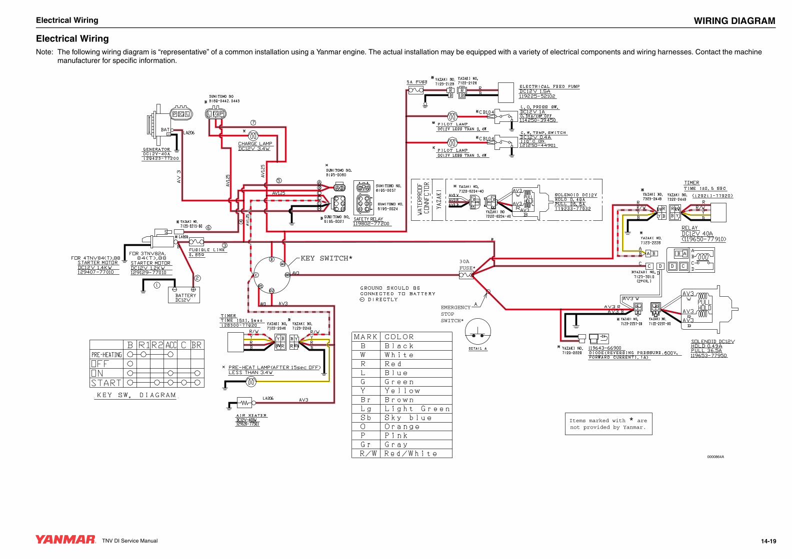
TNV DI Service Manual
Electrical Wiring
TNV DI Service Manual WIRING DIAGRAMElectrical WiringNote: The following wiring diagram is “representative” of a common installation using a Yanmar engine. The actual installation may be equipped with a variety of electrical components and wiring harnesses. Contact the machine
manufacturer for specific information.
0000864A
KEY SWITCH* 30A FUSE*
EMERGENCY STOP SWITCH*
Items marked with * arenot provided by Yanmar.
14-19