
B-SERIES TECHNICAL MANUALS - REED Concrete Pumps
279
Rev* REED LLC 2017 B-SERIES TECHNICAL MANUALS Operations, Maintenance, Schematics, Parts, Safety OPERATIONS/ MAINTENANCE SCHEMATICS/ PARTS LISTS SAFTEY MANUAL AMERICAN CONCRETE PUMPING ASSOCIATION Introduction Warranty Safety Operation Main Controls Priming Pumping Clean-up Maintenance Check-List Pumping Train Group Power Train Group Main Hydraulic Pump Tanks Hydraulic Manifolds Accumulator Electrical Group PLC Controls Frame Installation Available Options Introduction General Safety Rules Appendix
-
Upload
khangminh22 -
Category
Documents
-
view
1 -
download
0
Transcript of B-SERIES TECHNICAL MANUALS - REED Concrete Pumps

Rev* REED LLC 2017
B-SERIES TECHNICAL MANUALS Operations, Maintenance, Schematics, Parts, Safety
OPERATIONS/ MAINTENANCE
SCHEMATICS/ PARTS LISTS
SAFTEY MANUAL AMERICAN CONCRETE PUMPING ASSOCIATION
Introduction Warranty Safety Operation Main Controls Priming Pumping Clean-up Maintenance Check-List
Pumping Train Group Power Train Group Main Hydraulic Pump Tanks Hydraulic Manifolds Accumulator Electrical Group PLC Controls Frame Installation Available Options
Introduction General Safety Rules Appendix

OPERATION and MAINTENANCE
Rev * 1 of 108
13822 Oaks Avenue Chino, CA 91710 reedpumps.com (909) 287 - 2100
INTRODUCTION ........................................................................................................................ 3
WARRANTY ............................................................................................................................... 4
WARRANTY CLAIM FORM..................................................................................................... 5
SAFETY ..................................................................................................................................... 6
SAFETY ALERT SYMBOLS AND SIGNAL WORDS ............................................................... 6 LOCKOUT / TAGOUT ............................................................................................................. 7 GENERAL SAFETY GUIDELINES .......................................................................................... 7 SAFETY DECALS ................................................................................................................... 8
OPERATION ............................................................................................................................ 18
OPERATOR QUALIFICATIONS ........................................................................................... 18 PRODUCT DESCRIPTION ................................................................................................... 19 HYDRAULIC SYSTEM DESCRIPTION ................................................................................. 20 SERIAL PLATE IDENIFICATION .......................................................................................... 27 MAIN PANEL SERIAL IDENIFICATION ................................................................................ 27 CONTROLS .......................................................................................................................... 28
A-SERIES MAIN CONTROLS ........................................................................................ 29 PLC MAIN CONTROLS B,C-SERIES ............................................................................. 30 PLC SCREEN OPERATIONS/SET-UP .......................................................................... 34 REMOTE CONTROL FAMILIARIZION ........................................................................... 37 PLC MAIN CONTROL PANEL WIRING ......................................................................... 39
GROUND BUSSES ..................................................................................................... 39 GROUND BUSSES ..................................................................................................... 39 BUSS #1 ...................................................................................................................... 41 BUSS #2 ...................................................................................................................... 42 BUSS #3 ...................................................................................................................... 43 BUSS #4 ...................................................................................................................... 44
CAN POWER/GROUND ........................................................................................... 44 BUSS #5 ...................................................................................................................... 45
CAN HI/LOW ............................................................................................................ 45 BUSS #6 ..................................................................................................................... 46 BUSS #7 ...................................................................................................................... 47 BUSS #8 .................................................................................................................... 47 BUSS #9 ...................................................................................................................... 49 BUSS #14-15 ............................................................................................................... 49
PROX A/B ................................................................................................................. 50 BUSS #16 .................................................................................................................... 50 BUSS #17 .................................................................................................................... 51
OPTION VOLUME (B-SERIES ONLY) ..................................................................... 52 TIER 3 ......................................................................................................................... 53 CAN/SWITCH (SW1) ................................................................................................... 54 CAN SWITCH (SW2) ................................................................................................... 55 CAN SWITCH (TEE) .................................................................................................... 56

OPERATION and MAINTENANCE
Rev * 2 of 108
13822 Oaks Avenue Chino, CA 91710 reedpumps.com (909) 287 - 2100
MD3 ............................................................................................................................. 57 XC10 ............................................................................................................................ 58 MVEC #1 ..................................................................................................................... 59 MVEC #2 ..................................................................................................................... 61 MVEC #3 ..................................................................................................................... 62 MVEC OUTPUT#1 ....................................................................................................... 63
FUSE/RELAY OUTPUT ............................................................................................ 63 MVEC OUTPUT#2 ....................................................................................................... 64
FUSE/RELAY OUTPUT ............................................................................................ 64 KEY SWITCH / E-STOP CIRCUIT ............................................................................... 65 DEUTSCH 128 PLUG .................................................................................................. 66 DEUTSCH 128 PLUG TIER 3 PIN OUT ...................................................................... 66 BUSS BAR SET-UP .................................................................................................... 68 OMINEX RADIO REMOTE .......................................................................................... 68
PRIMING ............................................................................................................................... 73 PUMPING ............................................................................................................................. 74 CLEANING ............................................................................................................................ 76
MAINTENANCE ....................................................................................................................... 77
RECOMMENDED MAINTENANCE PRACTICES ................................................................. 77 GENERAL MAINTENANCE AREAS ..................................................................................... 78 LUBRICATION ...................................................................................................................... 80 ADDING HYDRAULIC FLUID................................................................................................ 86 COMPONENT REPLACEMENT ........................................................................................... 89
S-TUBE, WEAR RING, AND WEAR PLATE ...................................................................... 89 S-TUBE ADJUSTMENT .................................................................................................. 94
PISTON CUP AND GUIDE BAND REMOVAL/REPLACEMENT ....................................... 96 ACCUMULATOR ............................................................................................................... 99
PUMP MAINTENANCE SCHEDULE AND CHECKLISTS ................................................... 100
REV DATE DESCRIPTION NAME * 3/28/2017 INITIAL J.SLACK

OPERATION and MAINTENANCE
Rev * 3 of 108
13822 Oaks Avenue Chino, CA 91710 reedpumps.com (909) 287 - 2100
INTRODUCTION
This manual introduces the warranty policy, safe operation, safe maintenance, parts, and other aspects of the concrete pump. Reading and understanding this operation manual will help maximize performance and reliability, and help minimize dangers, improper operation, and repair costs. Contact REED Customer Service for additional replacement manuals. All safety guidelines, product descriptions, illustrations, and specifications found throughout this manual were in effect at the time the manual was released for printing. It should be noted; REED RESERVES THE RIGHT TO MAKE CHANGES IN DESIGN OR TO MAKE ADDITIONS TO OR IMPROVEMENTS IN THE PRODUCT WITHOUT IMPOSING ANY OBLIGATIONS UPON ITSELF TO INSTALL THEM ON PRODUCTS PREVIOUSLY MANUFACTURED. Everyone involved with the operation, maintenance, inspection, and repair of the concrete pump MUST READ and UNDERSTANDS this manual and the accompanying Safety Manual.

OPERATION and MAINTENANCE
Rev * 4 of 108
13822 Oaks Avenue Chino, CA 91710 reedpumps.com (909) 287 - 2100
WARRANTY
REED warrants each new A, B, and C Series Concrete Pump to be free of defects in material and workmanship under normal use and service for a period as follows: A Series Pumps
• 1 year or 1200 pumping hours whichever occurs first B and C Series Pumps
• “Hitch to Hopper” for 1 year or 1200 pumping hours, whichever occurs first • All Structural Parts for 3 years
The warranty is issued ONLY to the INITIAL USER. The warranty period begins when the product is delivered to the initial user or when first put into service, whichever occurs first. Said warranty is void if the machine is subject to misuse, neglect, accident, and/or abuse. REED’s obligation under this warranty is limited to correcting without charge, at its factory, any parts or parts thereof which shall be returned to its factory, transportation prepaid and upon REED’s examination proves to have been originally defective. Correction of such defects by repair or replacement shall constitute fulfillment of all obligations to the initial user. This warranty does not include labor or transportation charges unless specifically identified and authorized in writing by REED. Nor does the warranty apply to any unit upon which repairs or unauthorized alterations have been made. This warranty does not apply to normal maintenance service or to normal replacement of certain machine parts which are subject to normal wear (such as concrete cylinders and wear components, valve mechanisms, delivery systems, hopper grate, etc.) REED makes no warranty in respect to trade accessories or outside vendor components, such being subject to the warranties of their respective manufacturers. THIS IS A LIMITED WARRANTY AND IS IN LIEU OF ANY OTHER WARRANTIES, EXPRESSED OR IMPLIED, INCLUDING ANY WARRANTY OF MERCHANTABILITY OF FITNESS FOR A PARTICULAR PURPOSE. In no event shall REED be made liable for incidental, general or consequential damage, loss or any expense directly or indirectly related and resulting from use or lack of use caused by delay in delivery, parts failure, or any other causes associated with the product use. No person, firm or corporation is authorized to assume for REED any other liability in connection with the sale of REED products.
Effective April 2010

OPERATION and MAINTENANCE
Rev * 5 of 108
13822 Oaks Avenue Chino, CA 91710 reedpumps.com (909) 287 - 2100
WARRANTY CLAIM FORM Claim Number: Date: Distributor Account Number: End User Account Number: Distributor: End User: Address: Address: City: State: Zip: City: State: Zip: Phone ( ) Phone ( )
Pump Model: Pump Serial Number:
In Service Date: Hours of Operation: Failure Date: Repair Date:
Do not send part(s) until requested by REED or until claim is approved. All parts requested to be returned must have a Return Authorization Number provided by REED and shipping freight prepaid. Parts must ship within 30 days from REED request. Return Authorization Number: Ship Date:
Part Number Description Qnty Unit Price
Total Price
Replacement Part Invoice
No. Failure Description and Cause:
REED Comments:
Claim Value Approved:$ Claim Value Denied:$ REED Print Name, Sign, and Date:
Dealer Print Name, Sign, and Date:
OPERATION and MAINTENANCE
Rev * 6 of 108
13822 Oaks Avenue Chino, CA 91710 reedpumps.com (909) 287 - 2100
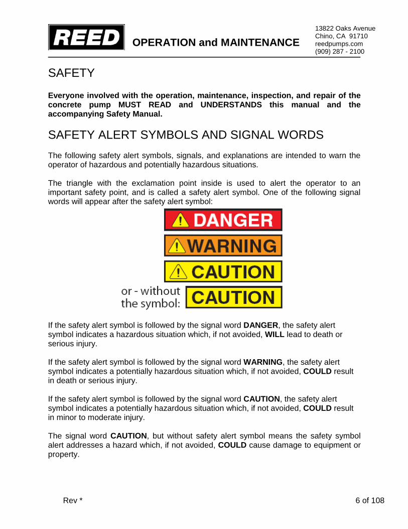
SAFETY Everyone involved with the operation, maintenance, inspection, and repair of the concrete pump MUST READ and UNDERSTANDS this manual and the accompanying Safety Manual. SAFETY ALERT SYMBOLS AND SIGNAL WORDS The following safety alert symbols, signals, and explanations are intended to warn the operator of hazardous and potentially hazardous situations. The triangle with the exclamation point inside is used to alert the operator to an important safety point, and is called a safety alert symbol. One of the following signal words will appear after the safety alert symbol:
If the safety alert symbol is followed by the signal word DANGER, the safety alert symbol indicates a hazardous situation which, if not avoided, WILL lead to death or serious injury. If the safety alert symbol is followed by the signal word WARNING, the safety alert symbol indicates a potentially hazardous situation which, if not avoided, COULD result in death or serious injury. If the safety alert symbol is followed by the signal word CAUTION, the safety alert symbol indicates a potentially hazardous situation which, if not avoided, COULD result in minor to moderate injury. The signal word CAUTION, but without safety alert symbol means the safety symbol alert addresses a hazard which, if not avoided, COULD cause damage to equipment or property.

OPERATION and MAINTENANCE
Rev * 7 of 108
13822 Oaks Avenue Chino, CA 91710 reedpumps.com (909) 287 - 2100
LOCKOUT / TAGOUT The Lockout/Tagout procedure applies to all REED concrete placing equipment. Before performing any maintenance and/or repair on equipment;
1. Unit must be OFF and the ignition key must be removed from the control panel or dash.
2. Key must be securely stored in toolbox or with operator performing maintenance.
3. Signage must be posted to indicate machine is currently under Lockout/Tagout.
The following symbol is a reminder to Lock Out and Tag Out equipment before working on equipment.
GENERAL SAFETY GUIDELINES
Use Only Qualified, Experienced, and Trained Personnel
Wearing Protective Equipment At All Times
For Safe Use, Maintenance, Inspection, and Repair,
Only Operate, Maintain, Inspect, and Repair In Accordance With This Operation Manual and the Safety Manual
Performance and Safety Features Must Never Be Altered, Disconnected, or Removed
Contact REED Technical Support and Service When Assistance Is Required

OPERATION and MAINTENANCE
Rev * 8 of 108
13822 Oaks Avenue Chino, CA 91710 reedpumps.com (909) 287 - 2100
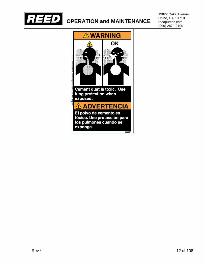
SAFETY DECALS Decals and placement of decals are standardized by the Concrete Pump Manufacturers Association (CPMA) for your protection. They are placed at appropriate areas on the concrete pump to be constant warnings of dangers. Know and adhere to the information they provide. Contact REED Customer Service for complimentary replacements of safety decals, shipping charges may apply. DECALS PLACED NEAR CONTROL BOX AREA

OPERATION and MAINTENANCE
Rev * 9 of 108
13822 Oaks Avenue Chino, CA 91710 reedpumps.com (909) 287 - 2100

OPERATION and MAINTENANCE
Rev * 10 of 108
13822 Oaks Avenue Chino, CA 91710 reedpumps.com (909) 287 - 2100

OPERATION and MAINTENANCE
Rev * 11 of 108
13822 Oaks Avenue Chino, CA 91710 reedpumps.com (909) 287 - 2100
DECALS PLACED NEAR HOPPER GRATE AREA
OPERATION and MAINTENANCE
Rev * 12 of 108
13822 Oaks Avenue Chino, CA 91710 reedpumps.com (909) 287 - 2100

OPERATION and MAINTENANCE
Rev * 13 of 108
13822 Oaks Avenue Chino, CA 91710 reedpumps.com (909) 287 - 2100
DECALS PLACED NEAR WATERBOX AREA
DECALS PLACED NEAR OUTRIGGER CONTROL AREA

OPERATION and MAINTENANCE
Rev * 14 of 108
13822 Oaks Avenue Chino, CA 91710 reedpumps.com (909) 287 - 2100
DECALS PLACED NEAR HOPPER OUTLET AREA

OPERATION and MAINTENANCE
Rev * 15 of 108
13822 Oaks Avenue Chino, CA 91710 reedpumps.com (909) 287 - 2100
DECALS PLACED ON SIDE PANEL AREA

OPERATION and MAINTENANCE
Rev * 16 of 108
13822 Oaks Avenue Chino, CA 91710 reedpumps.com (909) 287 - 2100

OPERATION and MAINTENANCE
Rev * 17 of 108
13822 Oaks Avenue Chino, CA 91710 reedpumps.com (909) 287 - 2100

OPERATION and MAINTENANCE
Rev * 18 of 108
13822 Oaks Avenue Chino, CA 91710 reedpumps.com (909) 287 - 2100
OPERATION OPERATOR QUALIFICATIONS Everyone involved with the operation, maintenance, inspection, and repair of the concrete pump MUST READ and UNDERSTANDS this operation manual and the accompanying Safety Manual. The following are a few general warnings for operator qualifications outlined in the Safety Manual.
• Individuals who cannot read and understand this operation manual, Safety Manual, signs, warnings, notices, and operating instructions, in the language in which they are printed, must not be allowed to operate the concrete pump.
• Only qualified, experienced, and trained personnel may be allowed to operate the
concrete pump. • Operation, maintenance, inspections, and repair must only be made by qualified,
experienced, and trained personnel. • Obey all applicable local and government statutes and regulations applying to safe
operation and towing of concrete pumps.

OPERATION and MAINTENANCE
Rev * 19 of 108
13822 Oaks Avenue Chino, CA 91710 reedpumps.com (909) 287 - 2100
PRODUCT DESCRIPTION The operation of the concrete pump encompasses the use of hydraulic and electrical systems. The concrete pump is designed to safely pump wet concrete through a delivery system of pipes and hoses within its published ratings and specifications. Stability of the concrete pump during operation is provided by the outriggers and front jack. Controls for the outriggers are located on the sides of the concrete pump. The pumping system employs an S-Tube design valve system. This system incorporates material cylinders linked to hydraulic cylinders that cycle alternately. With concrete material in the hopper and the pump operating, a material cylinder retracts, drawing material into the cylinder. At full retraction of the cylinder, a signal is sent to both the S-tube swing cylinder and the drive cylinder directional valves causing the s-tube to shift position to the fully loaded material cylinder and the drive cylinders to change direction. The concrete piston of the loaded cylinder then pushes the material through the s-tube and into the delivery lines. The shifting from one cylinder to the other cylinder takes place providing a continuous flow of material through the delivery piping system. The pump can be operated at the control panel or can be operated from the remote control.
The hydraulic oil flow created by the hydraulic pump pushes the drive cylinder pistons inside the drive cylinders (1) alternately back and forth. Because the drive cylinders and concrete pistons (2) inside the concrete cylinders (3) are linked together, the pistons move synchronously. When a drive cylinder retracts along with the concrete piston, concrete will be sucked from the hopper into the concrete cylinder. Simultaneously, the other drive cylinder and concrete piston are extended toward the hopper. The concrete piston will push concrete from the concrete cylinders through the S-Tube (4) and out to delivery system (5). Next, the pump switches at the end of the stroke, causing the s-tube valve to shift to the other concrete cylinder which has sucked and filled the cylinder with concrete, starting the next cycle. Reverse pumping links the concrete piston in the suction stroke and S-Tube valve to suck concrete from the s-tube instead of the hopper. As a result, the concrete piston pumps concrete into the hopper.

OPERATION and MAINTENANCE
Rev * 20 of 108
13822 Oaks Avenue Chino, CA 91710 reedpumps.com (909) 287 - 2100
The power for operation of the concrete pump is provided by the engine, which drives the hydraulic pumps. All functions for operation of the concrete pump can be accomplished from the local controls mounted on the side of the unit. Optional hand-held cable or radio remotes enable the pump to be operated away from a remote distance. HYDRAULIC SYSTEM DESCRIPTION The hydraulic system of the concrete pump consists of three separate circuits and although integrated, each is designed to perform a particular function within the operation of the concrete pump. The three circuits utilized are: • Main Pump Circuit Controls operation of the hydraulic drive cylinders. • S-Tube Shift Circuit Controls operation of shifting the s-tube from one material cylinder to the other. • Auxiliary Circuit Controls the operation of the agitator and other auxiliary equipment. For the purpose of making the operation of each circuit easier to understand, they are being described separately. MAIN PUMP CIRCUIT The main hydraulic pump is a variable displacement axial piston pump of swashplate design. The pistons run along the swashplate which is capable of being tilted. This tilting changes the angle of the swashplate and thus the stroke length of the pistons, which in turn varies the displacement of fluid. The larger the angle of the swashplate, the greater the flow. The angle of the swashplate is varied by the volume control that works in conjunction with the load sense feature of this pump.
The main hydraulic pump is driven directly by the engine or electric motor. When the engine is running, PUMP switch in the OFF position and the VOLUME control minimized, there is no demand placed on the pump. This is referred to as the pump being de-stroked, meaning, it is only producing a minimal amount of flow to enable the lubrication of the pump. This lubrication exists regardless of whether the engine is at idle or maximum RPM.
The main pump circuit is equipped with a manifold that is drilled and ported to accommodate the relief valve, check valve, flow control and the pilot operated

OPERATION and MAINTENANCE
Rev * 21 of 108
13822 Oaks Avenue Chino, CA 91710 reedpumps.com (909) 287 - 2100
directional valve. The cycle valve is a directional spool valve with electro hydraulic solenoid operation. Its purpose is to direct the flow of oil from the main hydraulic pump to one or the other hydraulic drive cylinders.
To energize the pump circuit, use the adjustable throttle control to set the engine speed at maximum RPM. Open the VOLUME control to any range from 0 to FULL. In so doing, the load sense is alerted to the demand and places the pump on stroke. The pump will now produce the flow in proportion to the amount by which the volume control has been opened. Since the PUMP switch is OFF, the flow from the hydraulic pump is fed to the main directional valve, thru the valve, and then returns to the hydraulic tank.
To energize the cycling circuit, the PUMP switch must be ON. When this is done, an electrical signal is generated which in turn energizes the coils of the main directional pilot valve and also activates the S-Tube directional valve.
The material pumping action is the result of the two material cylinders cycling on an alternate basis. This alternating cycling is controlled by an electrical signal that is generated by the proximity sensors located in the flush box at the end of each material cylinder’s suction or retraction stroke.
As the piston coupler passes under the proximity sensor, it generates an electrical input signal that is sent to the logic controller, designed to control the alternating action of the material cylinders and to synchronize the movement of the s-tube. The output signal from the logic controller is used to energize the coils of the main directional pilot valve as well as that of the s-tube directional valve. As protection to the main pump circuit against excessive pressure, a relief valve has been installed and set. Thus when the system pressure reaches the maximum factory settings, the relief valve opens directing the oil back to the tank.

OPERATION and MAINTENANCE
Rev * 22 of 108
13822 Oaks Avenue Chino, CA 91710 reedpumps.com (909) 287 - 2100
MAIN PUMP CIRCUIT OPERATIONAL SEQUENCE It can be noted in the schematic and the diagram below that the main pressure and flow is only directed to one side of the hydraulic drive cylinder. In this instance, it is directed to the head side or piston side of the double acting drive cylinder.
The hydraulic drive cylinders are identical. Because only one cylinder is pressurized at a time, a means is required to assist in the retraction of the opposite cylinder. This is accomplished by connecting the rod sides of the cylinders together, forming a slave loop. In so doing, the hydraulic fluid that exists in the rod side of the extending cylinder (CYL “A”) is transferred to the rod side of the other cylinder (CYL “B”) causing it to retract simultaneously. The oil in the head side of CYL “B” is then forced out as it retracts and free flows through the directional valve back to the hydraulic tank or system. With this arrangement of connecting the two cylinders together, it is possible for various reasons, such as leakage around the piston seals, that more oil exists on the rod side of the cylinder than is required. When this condition exists, some hydraulic oil remains at the rod end of the cylinder being extended while the other cylinder is fully retracted. As a result, the cylinder will not completely extend and thus short strokes, which will also happen to the other cylinder on the next cycle.
This condition can be corrected by actuating and holding the STROKE CHANGE switch on the electrical control box until extending cylinder is fully extended. Hydraulically, this is accomplished by use of the check valves installed on both cylinders. By holding the

OPERATION and MAINTENANCE
Rev * 23 of 108
13822 Oaks Avenue Chino, CA 91710 reedpumps.com (909) 287 - 2100
STROKE CHANGE switch, you have interrupted the cycle and are forcing more oil into the head side of the extending cylinder. Since that cavity is full, pressure is built up in the rod side of the fully retracted cylinder, which unseats the head-side check valve and forces the excess oil out of the slave loop and back to the tank. Once the extending cylinder has reached its full stroke, regular operation can continue. Short stroking can also occur from incorrect proximity sensor location or leaking check valves. S-TUBE CIRCUIT Since there is only one outlet for the pumping material, a means is required to transfer the material from the material cylinder to the outlet and into the delivery line. To accomplish this, an s-tube is installed in the hopper. Since there are two material cylinders and one s-tube, the s-tube must be shifted from one material cylinder to the other, whichever one is loaded with the pumping material. The s-tube shift hydraulic circuit is of the open center type, meaning that when the control valves are in the neutral position, the internal passages of the valves are open, allowing the hydraulic fluid to return to the tank. With the engine running the hydraulic pump is operating, producing a flow of oil which, with no control energized, will pass through the shift circuit on its way back to tank.
To meet the flow and pressure requirements of the shift circuit, one section of a tandem pump is used. Note: a single pump may be used if unit is not required for auxiliary equipment. The tandem hydraulic pump is of the gear pump design with a fixed displacement, meaning it is designed to constantly produce the same displacement at a pre-set maximum, depending on engine rpm. The tandem gear pump is directly connected to and driven through the main hydraulic pump. In addition to the hydraulic pump, the s-tube shift circuit consists of a manifold, an accumulator, solenoid valve cartridges, a solenoid directional valve, and 1 or 2 hydraulic shift cylinders. The following is offered to describe the function of each in the system.
S-TUBE CIRCUIT MANIFOLD Like the main hydraulic circuit, the shift circuit is also equipped with a manifold block. It contains an unloader cartridge, relief cartridge and solenoid valve cartridges. A solenoid operated directional valve is mounted on top of the block and an s-tube selector control valve is located on front of the block. Each of these components is designed to perform a particular function in the swing circuit as explained in the following descriptions:
• RELIEF CARTRIDGE This cartridge is used to divert the pump flow from going to the accumulator once its capacity has been reached, directing it back to tank. It becomes operational when the unloader cartridge setting has been reached, acting as a dump valve.

OPERATION and MAINTENANCE
Rev * 24 of 108
13822 Oaks Avenue Chino, CA 91710 reedpumps.com (909) 287 - 2100
• UNLOADER CARTRIDGE This pressure sensitive cartridge is used to protect the system from excessive pressure and to limit the amount of pressure being applied to the accumulator by hydraulically signaling the relief cartridge to open once the unloader setting has been reached. The unloader will also redirect the oil back to the accumulator when it senses a drop in system pressure, when the hydraulic cylinder shifts for example.
• SOLENOID VALVE CARTRIDGE There are two (2) of these cartridges used in the circuit. Both, which may be referred to as a dump valve, are designed into the circuit as SAFETY VALVES. Their purpose is to automatically relieve pressure from the shift circuit as commanded by the emergency stop circuit. At start up, the normally open cartridges are open to tank so the shift circuit can not build any pressure. When the emergency stop circuit is reset, an electrical signal is generated which energizes the solenoids, closing the cartridges and allowing the shift circuit to pressurize. When the emergency stop function is activated or the key switch turned off, the power is taken away from solenoids, causing the cartridges to open and dump shift circuit pressure back to tank.
• SOLENOID DIRECTIONAL VALVE This valve is a directional control valve that is shifted by electronically activated solenoids. Its purpose is to direct the flow of oil stored in the accumulator to one or the other end of the shift cylinder based on the signal received by the logic controller that was generated by the proximity sensor.
• SHIFT BALL VALVE This is a manual ball valve and is used to control the speed of the s-tube shift. With valve fully opened, the flow is unrestricted, causing a fast hard shift of the s-tube. When the valve is closed, the shift is slower as the flow must now pass through an orifice. • ACCUMULATOR
The accumulator is incorporated into the shift circuit to provide instant pressure and volume for the shifting of the s-tube, which cannot be obtained under normal circumstances. An accumulator is a hydraulic reservoir that retains the hydraulic fluid under high pressure. The accumulator contains a rubber bladder on the inside of the reservoir. The bladder is pre-charged with dry nitrogen. In the application of the shift circuit, the hydraulic fluid is pumped into the accumulator at a higher pressure than that inside the bladder. This compresses the bladder building up high pressure within the accumulator that is retained until released.

OPERATION and MAINTENANCE
Rev * 25 of 108
13822 Oaks Avenue Chino, CA 91710 reedpumps.com (909) 287 - 2100
S-TUBE CIRCUIT OPERATIONAL SEQUENCE In the operational sequence of the shift circuit with the engine at full RPM, the tandem pump is producing its rated displacement. The flow is going through the system and is being dumped or directed back to the tank thru the solenoid cartridges of the s-tube circuit manifold.
When the HORN/RESET switch is placed to RESET, an electrical signal closes the solenoid cartridges. When this occurs the hydraulic fluid is now directed to the accumulator where it starts compressing the bladder and building up pressure. When the pressure in the shift circuit reaches a setting of the unloader valve, the unloader valve activates causing the relief cartridge to open. The open relief valve now directs the oil flow from the pump back to the tank instead of continuing to pressurize the accumulator. A check valve retains the pressure in the swing circuit and prevents the fluid from going back into the pump line.
In the main pump circuit description it was described how an electrical signal was generated by the proximity sensor which was sent to the logic controller and used to control the alternating action of the hydraulic drive cylinders. This same signal is also used to shift the s-tube so that its movement is synchronized with that of the hydraulic drive cylinder, shifting the s-tube to the material cylinder which is ready to extend (normal forward operation).
The electrical signal activates the solenoid coil of the directional valve, shifting the spool to the appropriate side. The accumulator then releases, exhausting the fluid which flows through the directional valve and is directed to the appropriate side of the shift cylinder. As soon as the shift is made the accumulator is refilled immediately and the sequence starts all over again.
AUXILIARY CIRCUIT The auxiliary circuit has been designed and installed for the purpose of operating the hydraulic function of the auxiliary equipment on the unit, primarily the agitator. This function is that of the agitator rotation for mixing the material in the hopper and feeding of the concrete cylinders.
The flow and pressure requirements for the auxiliary circuit are met by employing the second stage or section of the same tandem pump used on the s-tube shift circuit. With the engine running and throttle set to maximum RPM, the flow from the tandem pump is directed to a single spool directional control valve. This circuit also utilizes a solenoid valve cartridge or dump valve, designed as a safety valve with the purpose of preventing flow to the auxiliary circuit as commanded by the emergency stop circuit. At start up, the normally open cartridge directs the oil flow from the tandem pump to tank,

OPERATION and MAINTENANCE
Rev * 26 of 108
13822 Oaks Avenue Chino, CA 91710 reedpumps.com (909) 287 - 2100
prohibiting function of the auxiliary circuit. When the emergency stop circuit is reset, an electrical signal is generated to energize the solenoid, closing the cartridge and blocking flow directly back to tank, instead allowing the flow to the single spool directional control valve for operation. The directional control valve has relief cartridge to protect the system against excessive pressure
When the valve lever is activated the agitator will rotate in forward direction as hydraulic fluid is
directed to that side of the motor. Rotation can be reversed by moving lever in other direction.

OPERATION and MAINTENANCE
Rev * 27 of 108
13822 Oaks Avenue Chino, CA 91710 reedpumps.com (909) 287 - 2100
SERIAL PLATE IDENIFICATION
A-SERIES
B-SERIES
C-SERIES
OPERATION and MAINTENANCE
Rev * 28 of 108
13822 Oaks Avenue Chino, CA 91710 reedpumps.com (909) 287 - 2100
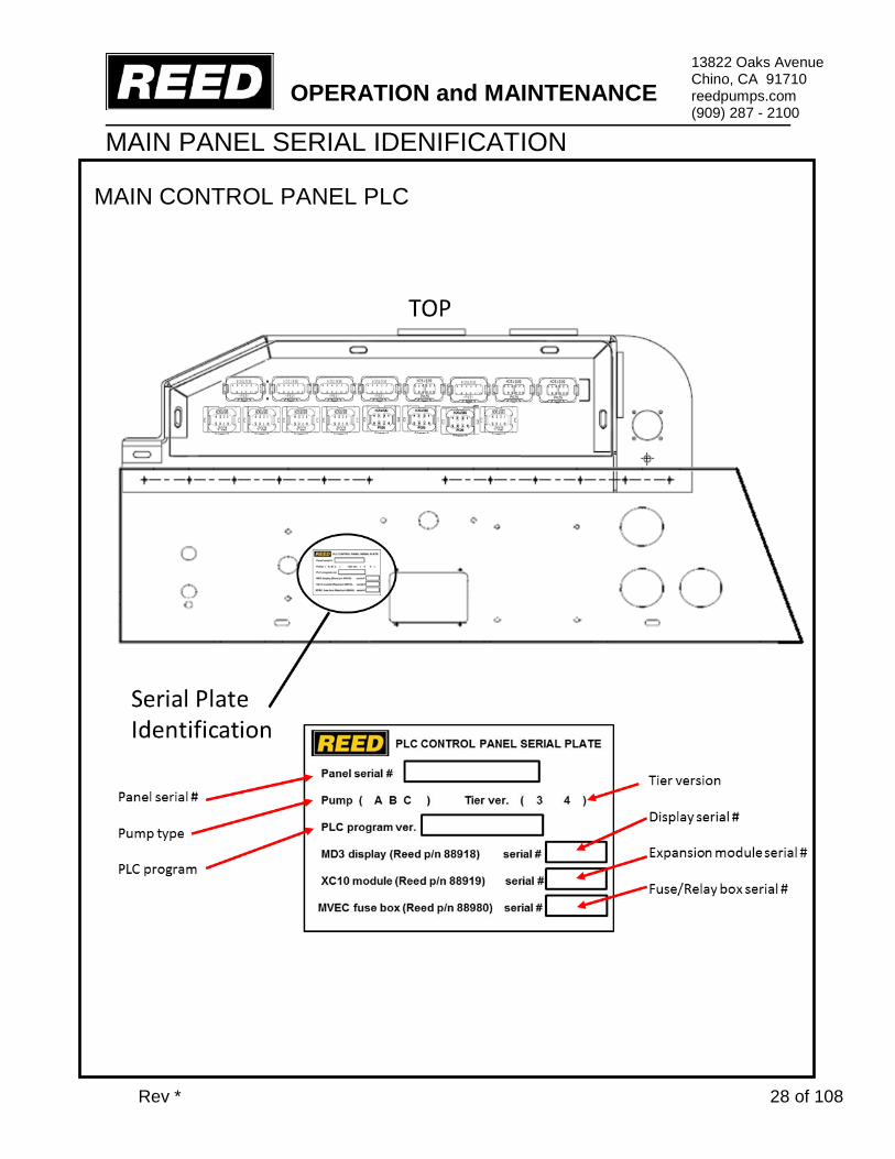
MAIN PANEL SERIAL IDENIFICATION
MAIN CONTROL PANEL PLC

OPERATION and MAINTENANCE
Rev * 29 of 108
13822 Oaks Avenue Chino, CA 91710 reedpumps.com (909) 287 - 2100
CONTROLS A-SERIES MAIN CONTROLS
1. SYSTEM POWER energizes the system enabling Engine Start Button. 2. ENGINE START starts the engine when the System Power Switch is ON. 3. CHECK ENGINE LIGHT (if equipped) is on when engine experiencing possible problems. 4. STOP ENGINE LIGHT (if equipped) indicates operator to stop engine immediately. 5. CONTROL ON LIGHT indicates control circuit energized. 6. DIGITAL DISPLAY (if equipped) displays engine RPM, oil pressure, volts, temperature, coolant level, strokes per minute, and status of systems. 7. HOUR METER records the number of hours the electrical system has been activated when the ignition key is ON. 8. HOPPER GRATE SAFETY SWITCH engages EMERGERGENCY STOP when grate is lifted 9. LOCAL or REMOTE controls intended operation of machine. 10. EMERGENCY STOP stops all hydraulic functions of the concrete pump when pushed in. Pull the Emergency Stop Button out to enable system to reset; Horn/Reset must be pressed to reset pump operation. 11. HORN/RESET activates system for operation 12. RPM +/- controls increase and decrease of engine RPM. 13. PUMP ON controls concrete pump ON/OFF function. 14. PUMP FORWARD REVERSE controls pump direction. 15. PUMP ON and PUMP REVERSE lights indicate pump status. 16. STROKE CHANGE changes stroke direction and eliminates proximity sensor signal while activated. 17. FAST CHANGE (if equipped) controls fast change feature for smoother operation under certain conditions. (Used only on closed loop models.) 18. VIBRATOR (if equipped-HOPPER OPTION) controls vibrator activation 19. VOLUME CONTROL (if equipped) controls volume output of the concrete pump. DIAGNOSTIC INTERFACE (if equipped is accessible by REED and authorized REED dealers only) is a computer port for system settings and diagnostic testing
8
1
2
5 7
10
9
12 11
16
13
14

OPERATION and MAINTENANCE
Rev * 30 of 108
13822 Oaks Avenue Chino, CA 91710 reedpumps.com (909) 287 - 2100
CONTROLS PLC MAIN CONTROLS B,C-SERIES
4
FUSE BLOCK
8 7
5
1
2
3
6

OPERATION and MAINTENANCE
Rev * 31 of 108
13822 Oaks Avenue Chino, CA 91710 reedpumps.com (909) 287 - 2100
CABLE REMOTE (RADIO REMOTE OPTIONAL, CONTACT REED FOR INFORMATION)
1. PUMP ON/OFF SWITCH this is to turn the pump on and off. Press button PUMP ON to turn pump on, and press button PUMP OFF to turn pump off. It will be backlit when each function is engaged.
2. PUMP DIRECTION SWITCHES this is used to select and controls of the cycle direction of the concrete pump. Press button FORWARD to control pump forward, and press button REVERSE to control pump reverse functions. It will be backlit when each function is engaged.
3. CONTROL SWITCH (LOCAL/REMOTE) this is used to select the pump control location. Press
button to LOCAL to enable operation of concrete pump for main stationary panel. Press button to REMOTE for operation using the remote control. It will be backlit when each function is engaged
4. HORN/RESET Press button down to activate horn/reset, it is used to reactivate the control and
PUMP CIRCUIT after machine has been shut down using the EMERGENCY STOP switch or when you start the pump. Once the emergency stop has been depressed it will be necessary to press downs the HORN button to RESET. It will be backlit when engaged.
5. STROKE-SWITCH Press button to test stroke change. It is used for the purpose of pressure
testing the main drive cylinders. Both main and swing cylinders reverse direction when button is depressed. When the main cylinders reach the end of the stroke they will “dead head” until the button is released.
6. MAIN POWER SWITCH this is a three (3) position key switch. Turn key to the ON position to
power control box. Shut down power by turning key to OFF position.
7. EMERGENCY STOP This push/pull emergency switch is used to shut down the pump in an emergency situation by disabling the hydraulic systems. It does not shut the engine or motor off. Depress PUSH knob in to STOP operation. PULL knob out to REACTIVATE system. NOTE: the HORN/RESET must be switched one time to restart pump operation.
8. MAIN DIGITAL DISPLAY this is where all the pumping statues are displayed.
9. INDICATOR LIGHTS, The buttons will be backlit to indicate what function you are using NOTE: Hopper grate safety switch engages EMERGERGENCY STOP when grate is lifted
OPERATION and MAINTENANCE
Rev * 32 of 108
13822 Oaks Avenue Chino, CA 91710 reedpumps.com (909) 287 - 2100
PLC MAIN CONTROLS B,C-SERIES
10
11 12 13
14
OPERATION and MAINTENANCE
Rev * 33 of 108
13822 Oaks Avenue Chino, CA 91710 reedpumps.com (909) 287 - 2100
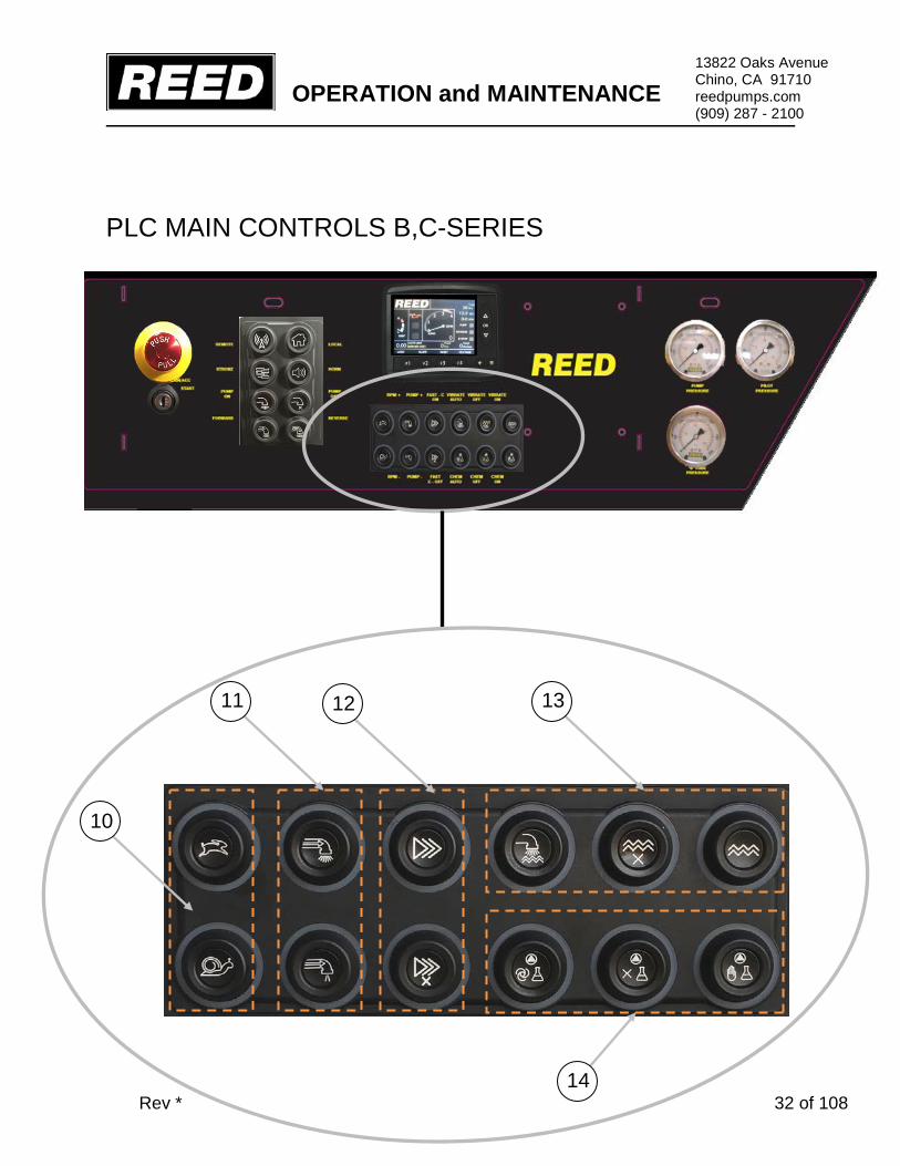
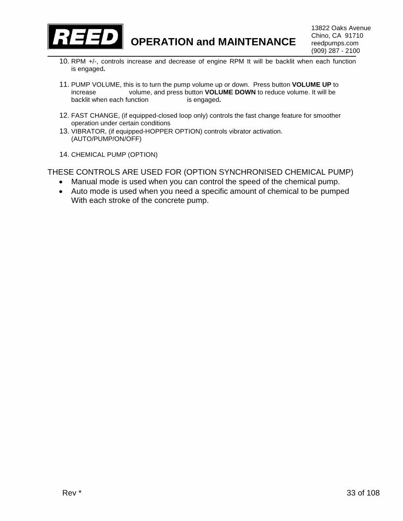
10. RPM +/-, controls increase and decrease of engine RPM It will be backlit when each function is engaged.
11. PUMP VOLUME, this is to turn the pump volume up or down. Press button VOLUME UP to increase volume, and press button VOLUME DOWN to reduce volume. It will be backlit when each function is engaged.
12. FAST CHANGE, (if equipped-closed loop only) controls the fast change feature for smoother operation under certain conditions
13. VIBRATOR, (if equipped-HOPPER OPTION) controls vibrator activation. (AUTO/PUMP/ON/OFF)
14. CHEMICAL PUMP (OPTION) THESE CONTROLS ARE USED FOR (OPTION SYNCHRONISED CHEMICAL PUMP)
• Manual mode is used when you can control the speed of the chemical pump. • Auto mode is used when you need a specific amount of chemical to be pumped
With each stroke of the concrete pump.

OPERATION and MAINTENANCE
Rev * 34 of 108
13822 Oaks Avenue Chino, CA 91710 reedpumps.com (909) 287 - 2100
PLC SCREEN OPERATIONS/SET-UP
1). Turnkey switch on/system on, you will see REED logo on
2). Press “F4” to access main screen, pumping mode.

OPERATION and MAINTENANCE
Rev * 35 of 108
13822 Oaks Avenue Chino, CA 91710 reedpumps.com (909) 287 - 2100
4).Press “F4” to return to main screen.
NOTE: To check Def fluid levels.
3).Press “F1” to return to REED logo screen, press “F1” one more time to check Def fluid levels.

OPERATION and MAINTENANCE
Rev * 36 of 108
13822 Oaks Avenue Chino, CA 91710 reedpumps.com (909) 287 - 2100
NOTE: to access slump values.
5). Press “F2” to see slump values.
NOTE: to access slump values.
6). press “F1” to show the values, to change the values press the arrows UP or DOWN when slump values have been selected press the OK button.

OPERATION and MAINTENANCE
Rev * 37 of 108
13822 Oaks Avenue Chino, CA 91710 reedpumps.com (909) 287 - 2100
NOTE: to reset strokes per minute, Cu/Yd used, and hours pump back to “0”.
8). Press and hold “F3” for a few seconds to reset all.
7). Press the “F4” to return to main screen.

OPERATION and MAINTENANCE
Rev * 38 of 108
13822 Oaks Avenue Chino, CA 91710 reedpumps.com (909) 287 - 2100
REMOTE CONTROL FAMILIARIZION A remote control pistol grip console is provided and is used to enable the operation of the concrete pump away from the immediate vicinity of the unit. The remote is equipped with an umbilical cord that plugs into the side of the main control box. The console consists of the following functions:
1. EMERGENCY STOP SWITCH POWER ON/EMERGENCY STOP switch stops all functions of the concrete pump in OFF position. Move the Emergency Stop switch to ON to enable system reset; Horn/Reset must be pressed to reset pump operation.
. 2. HORN/RESET . Activates system for operation 3. RPM +/- Controls increase and decrease of engine RPM. 4. PUMP ON/OFF Controls concrete pump ON/OFF function. 5. PUMP FORWARD/REVERSE Controls pump direction. 6. VOLUME CONTROL Electrically controls volume output of the concrete pump 7. STROKE CHANGE Changes stroke direction and eliminates proximity sensor signal while activated. 8. FAST CHANGE (if equipped-closed loop only) controls the fast change feature for smoother operation under certain conditions 9. CONTROL Indicates control circuit energized.
1
2
9
4
6 3
8 7
5

OPERATION and MAINTENANCE
Rev * 39 of 108
13822 Oaks Avenue Chino, CA 91710 reedpumps.com (909) 287 - 2100
BW10147
89105 89106
89104
88958
128 PLUG
87807
128 PLUG
PLC MAIN CONTROL PANEL WIRING GROUND BUSSES

OPERATION and MAINTENANCE
Rev * 40 of 108
13822 Oaks Avenue Chino, CA 91710 reedpumps.com (909) 287 - 2100
BW10147
89105 89106
89104
88958
128 PLUG
87807
128 PLUG
GROUND BUSSES

OPERATION and MAINTENANCE
Rev * 41 of 108
13822 Oaks Avenue Chino, CA 91710 reedpumps.com (909) 287 - 2100
89179
BW10147
88542-1 89181
BUSS #1
88960 89110-6
MVEC#1-2
BW10147
BUSS
88958
128 PLUG

OPERATION and MAINTENANCE
Rev * 42 of 108
13822 Oaks Avenue Chino, CA 91710 reedpumps.com (909) 287 - 2100
BW10147
89180
89179
88542-1
BW10147
BUSS
88959
MD3-C1
89112-2 89112-3
MVEC#3
BUSS #2

OPERATION and MAINTENANCE
Rev * 43 of 108
13822 Oaks Avenue Chino, CA 91710 reedpumps.com (909) 287 - 2100
89104
BW10147
89105 89106
88945-S
XC10
BW10147
BUSS MVEC
88960 89110-6 GRN
BUSS #3

OPERATION and MAINTENANCE
Rev * 44 of 108
13822 Oaks Avenue Chino, CA 91710 reedpumps.com (909) 287 - 2100
BW10147
BUSS
88958
REMOTE
BUSS #4 CAN POWER/GROUND
BW10147
89105 89103
89104

OPERATION and MAINTENANCE
Rev * 45 of 108
13822 Oaks Avenue Chino, CA 91710 reedpumps.com (909) 287 - 2100
BUSS #5 CAN HI/LOW
BW10147
BUSS
88958
REMOTE
BW10147
89105 89103
89104
OPERATION and MAINTENANCE
Rev * 46 of 108
13822 Oaks Avenue Chino, CA 91710 reedpumps.com (909) 287 - 2100
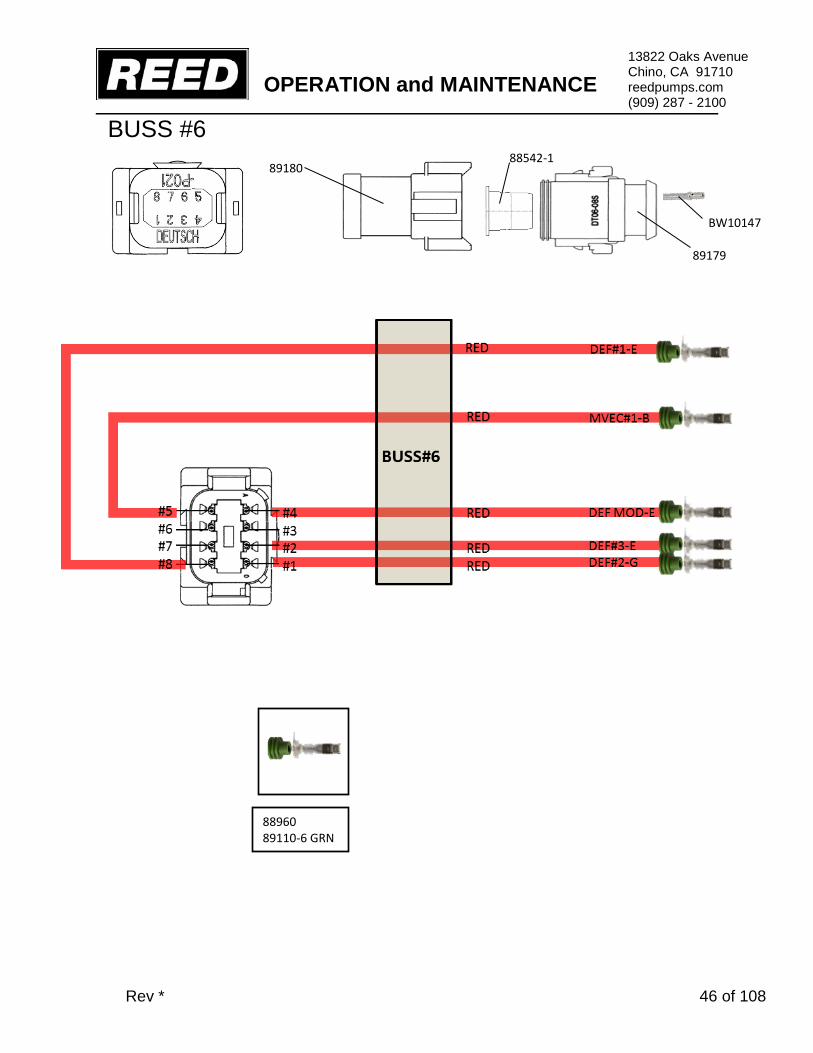
BW10147
88542-1 89180
89179
88960 89110-6 GRN
BUSS #6

OPERATION and MAINTENANCE
Rev * 47 of 108
13822 Oaks Avenue Chino, CA 91710 reedpumps.com (909) 287 - 2100
89104
BW10147
89105 89106
88960 89110-6 GRN
128 PLUG
88958
BUSS #7

OPERATION and MAINTENANCE
Rev * 48 of 108
13822 Oaks Avenue Chino, CA 91710 reedpumps.com (909) 287 - 2100
89104
BW10147
89105 89103
BW10147
BUSS 128 PLUG
88958
BUSS #8

OPERATION and MAINTENANCE
Rev * 49 of 108
13822 Oaks Avenue Chino, CA 91710 reedpumps.com (909) 287 - 2100
BW10147
88542-1 89181
89179
128 PLUG
88958 88960 89110-6
MVEC#1-2 DEF RELAYS
BUSS #9

OPERATION and MAINTENANCE
Rev * 50 of 108
13822 Oaks Avenue Chino, CA 91710 reedpumps.com (909) 287 - 2100
BW10147
88542-1 89181
89179
BW10147
BUSS
BUSS #14-15 PROX A/B
88945-S
XC10 128 PLUG
88958

OPERATION and MAINTENANCE
Rev * 51 of 108
13822 Oaks Avenue Chino, CA 91710 reedpumps.com (909) 287 - 2100
BW10147
88542-1 89180
89179
88958
128 PLUG
BUSS #16

OPERATION and MAINTENANCE
Rev * 52 of 108
13822 Oaks Avenue Chino, CA 91710 reedpumps.com (909) 287 - 2100
89104
BW10147
89105 89104-C
88945-S
XC10
BW10147
BUSS 128 PLUG
88958
BUSS #17 OPTION VOLUME (B-SERIES ONLY)

OPERATION and MAINTENANCE
Rev * 53 of 108
13822 Oaks Avenue Chino, CA 91710 reedpumps.com (909) 287 - 2100
89104
BW10147
89105 89104-C
BW10147
BUSS 128 PLUG
88958
TIER 3
88945-S
XC10

OPERATION and MAINTENANCE
Rev * 54 of 108
13822 Oaks Avenue Chino, CA 91710 reedpumps.com (909) 287 - 2100
CAN/SWITCH (SW1)

OPERATION and MAINTENANCE
Rev * 55 of 108
13822 Oaks Avenue Chino, CA 91710 reedpumps.com (909) 287 - 2100
CAN SWITCH (SW2)

OPERATION and MAINTENANCE
Rev * 56 of 108
13822 Oaks Avenue Chino, CA 91710 reedpumps.com (909) 287 - 2100
CAN SWITCH (TEE)
88932

OPERATION and MAINTENANCE
Rev * 57 of 108
13822 Oaks Avenue Chino, CA 91710 reedpumps.com (909) 287 - 2100
MD3

OPERATION and MAINTENANCE
Rev * 58 of 108
13822 Oaks Avenue Chino, CA 91710 reedpumps.com (909) 287 - 2100
XC10

OPERATION and MAINTENANCE
Rev * 59 of 108
13822 Oaks Avenue Chino, CA 91710 reedpumps.com (909) 287 - 2100
XC10

OPERATION and MAINTENANCE
Rev * 60 of 108
13822 Oaks Avenue Chino, CA 91710 reedpumps.com (909) 287 - 2100
88958
128 PLUG
BW10147 87807
128 PLUG
MVEC #1

OPERATION and MAINTENANCE
Rev * 61 of 108
13822 Oaks Avenue Chino, CA 91710 reedpumps.com (909) 287 - 2100
88960 89110-6
89111 BW10147 87807
128 PLUG
88958
128 PLUG
MVEC #2

OPERATION and MAINTENANCE
Rev * 62 of 108
13822 Oaks Avenue Chino, CA 91710 reedpumps.com (909) 287 - 2100
MVEC #3
89112 89112-2
89112-3 89112-5
89112-4
89112-1
BW10147

OPERATION and MAINTENANCE
Rev * 63 of 108
13822 Oaks Avenue Chino, CA 91710 reedpumps.com (909) 287 - 2100
MVEC OUTPUT#1 FUSE/RELAY OUTPUT
1A BUSS 1A 1B BUSS 1B 1C BUSS 3B 1D BUSS 3A 1E 128-11 HORN 1F 128-12 HORN 1G 128-7 VIB 1H 128-8VIB

OPERATION and MAINTENANCE
Rev * 64 of 108
13822 Oaks Avenue Chino, CA 91710 reedpumps.com (909) 287 - 2100
MVEC OUTPUT#2 FUSE/RELAY OUTPUT

OPERATION and MAINTENANCE
Rev * 65 of 108
13822 Oaks Avenue Chino, CA 91710 reedpumps.com (909) 287 - 2100
KEY SWITCH / E-STOP CIRCUIT

OPERATION and MAINTENANCE
Rev * 66 of 108
13822 Oaks Avenue Chino, CA 91710 reedpumps.com (909) 287 - 2100
DEUTSCH 128 PLUG
89159 89158
89109
88958
87807
CONTROL HARNESS SIDE
ENGINE HARNESS SIDE
89109-B 87457 89157
89158 89116
BW10147

OPERATION and MAINTENANCE
Rev * 67 of 108
13822 Oaks Avenue Chino, CA 91710 reedpumps.com (909) 287 - 2100
DEUTSCH 128 PLUG TIER 3 PIN OUT

OPERATION and MAINTENANCE
Rev * 68 of 108
13822 Oaks Avenue Chino, CA 91710 reedpumps.com (909) 287 - 2100
BUSS BAR SET-UP

OPERATION and MAINTENANCE
Rev * 69 of 108
13822 Oaks Avenue Chino, CA 91710 reedpumps.com (909) 287 - 2100
OMINEX RADIO REMOTE

OPERATION and MAINTENANCE
Rev * 70 of 108
13822 Oaks Avenue Chino, CA 91710 reedpumps.com (909) 287 - 2100
AGITATOR CONTROL controls agitator ON/OFF and FORWARD REVERSE functions.
AGITATOR CONTROL
OPERATION and MAINTENANCE
Rev * 71 of 108
13822 Oaks Avenue Chino, CA 91710 reedpumps.com (909) 287 - 2100
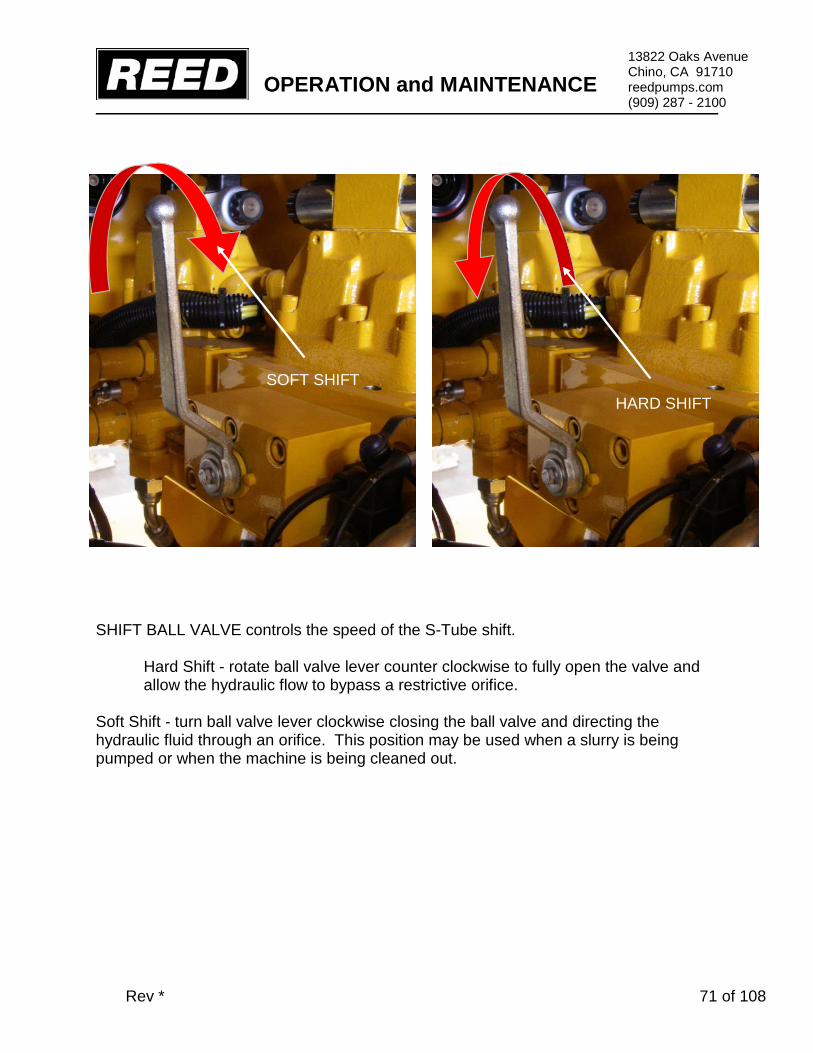
SHIFT BALL VALVE controls the speed of the S-Tube shift.
Hard Shift - rotate ball valve lever counter clockwise to fully open the valve and allow the hydraulic flow to bypass a restrictive orifice.
Soft Shift - turn ball valve lever clockwise closing the ball valve and directing the hydraulic fluid through an orifice. This position may be used when a slurry is being pumped or when the machine is being cleaned out.
SOFT SHIFT HARD SHIFT

OPERATION and MAINTENANCE
Rev * 72 of 108
13822 Oaks Avenue Chino, CA 91710 reedpumps.com (909) 287 - 2100
GAUGES PUMP or DRIVE CYLINDER GAUGE indicates the hydraulic pressure requirement of the pumping cylinders to push material. Gauge reading varies depending upon many circumstances such as: material slump, material line type, size and length, vertical, uphill, downhill or horizontal placement, pumping speed, etc. S-TUBE GAUGE indicates amount of oil pressure stored in accumulator circuit. Pressure will build and stabilize at a set pressure once E-STOP is reset. Pressure will fluctuate as swing cylinder(s) shift but will always recharge to the same set pressure. PILOT GAUGE (CLOSED LOOP ONLY) indicates volume adjustment of main hydraulic pump, Works between a range of 90 PSI(6bar) min and 275 PSI (19 Bar max.

OPERATION and MAINTENANCE
Rev * 73 of 108
13822 Oaks Avenue Chino, CA 91710 reedpumps.com (909) 287 - 2100
SET-UP Refer to the Safety Manual for set-up safety precautions not limited to the following guidelines:
Ensure Machine Can Be Safely Operated In Set-Up Location
Away From Hazards and Dangers Away From Slopes and Excavations
Position Machine On As Solid and Level Ground As Possible
PRIMING Priming consists of pumping a lubricant to coat the s-tube and delivery lines to assist the initial concrete material in getting through the delivery lines and avoid blockages. Once the delivery lines are full of concrete, that material will supply the lubrication necessary for the material to flow through the delivery lines. However, it is imperative that a primer be used ahead of the initial concrete material to pre-lubricate the lines in order to avoid blockages. A suggested grout to use for priming and lubrication may consist of 2 parts sand and 1 part cement and mixed to a consistency of a thick cream. The amount of grout required depends on the length of the delivery line as well as the material being pumped. Operator experience will eventually indicate the amount to be required. In addition to grout, there is a wide variety of priming products available on the market.

OPERATION and MAINTENANCE
Rev * 74 of 108
13822 Oaks Avenue Chino, CA 91710 reedpumps.com (909) 287 - 2100
PUMPING Everyone involved with the operation, maintenance, inspection, and repair of the concrete pump MUST READ and UNDERSTANDS this manual and the Safety Manual. Refer to the Safety Manual for pumping and blockages safety precautions not limited to the following guidelines:
Perform Required Inspection, Lubrication, and Maintenance
Before, During, and After Pumping Operations
Do Not Remove Hopper Grate Or Other Safety Components
Do Not Insert Body Parts into Hopper, S-Tube, or Waterbox
Or Other Moving Components
Turn Pump ON Only When Hopper Is Full Of Concrete
Ensure the following conditions are met before activating pump:
o PUMP Switch Is OFF o VOLUME CONTROL Is Set To MINIMUM o AGITATOR Control Is In OFF Position o EMERGENCY STOPS Are Not Activated o Controls On LOCAL Position

OPERATION and MAINTENANCE
Rev * 75 of 108
13822 Oaks Avenue Chino, CA 91710 reedpumps.com (909) 287 - 2100
PUMPING Continued 1. Turn KEY operated SYSTEM POWER Switch to ON 2. Turn Key switch to start engine 3. Activate the HORN/RESET to prepare the concrete pump for operation 4. After engine warms up, increase RPM to desired engine RPM by adjusting
THROTTLE CONTROL 5. Adjust VOLUME CONTROL to low output when starting pumping operations 6. Switch PUMP Switch to ON to pump concrete when hopper is full, maintain full
level 7. Closely monitor the PUMP pressure gauge while pumping 8. Turn PUMP Switch to REVERSE to reverse the pumping action if necessary.
REVERSE function is typically used to relieve pressure in the delivery line in the event of a blockage. A blockage will generally result in the main hydraulic system reaching maximum pressure as indicated on the PUMP PRESSURE GAUGE
9. Turn PUMP Switch OFF to stop cycling and stop pumping concrete 10. In the event of an emergency, push the EMERGENCY STOP Button IN to stop
all functions of the concrete pump. Pull the EMERGENCY STOP Button OUT to enable system to reset; Horn/Reset function must be activated to reset pump operation.
OPERATION and MAINTENANCE
Rev * 76 of 108
13822 Oaks Avenue Chino, CA 91710 reedpumps.com (909) 287 - 2100
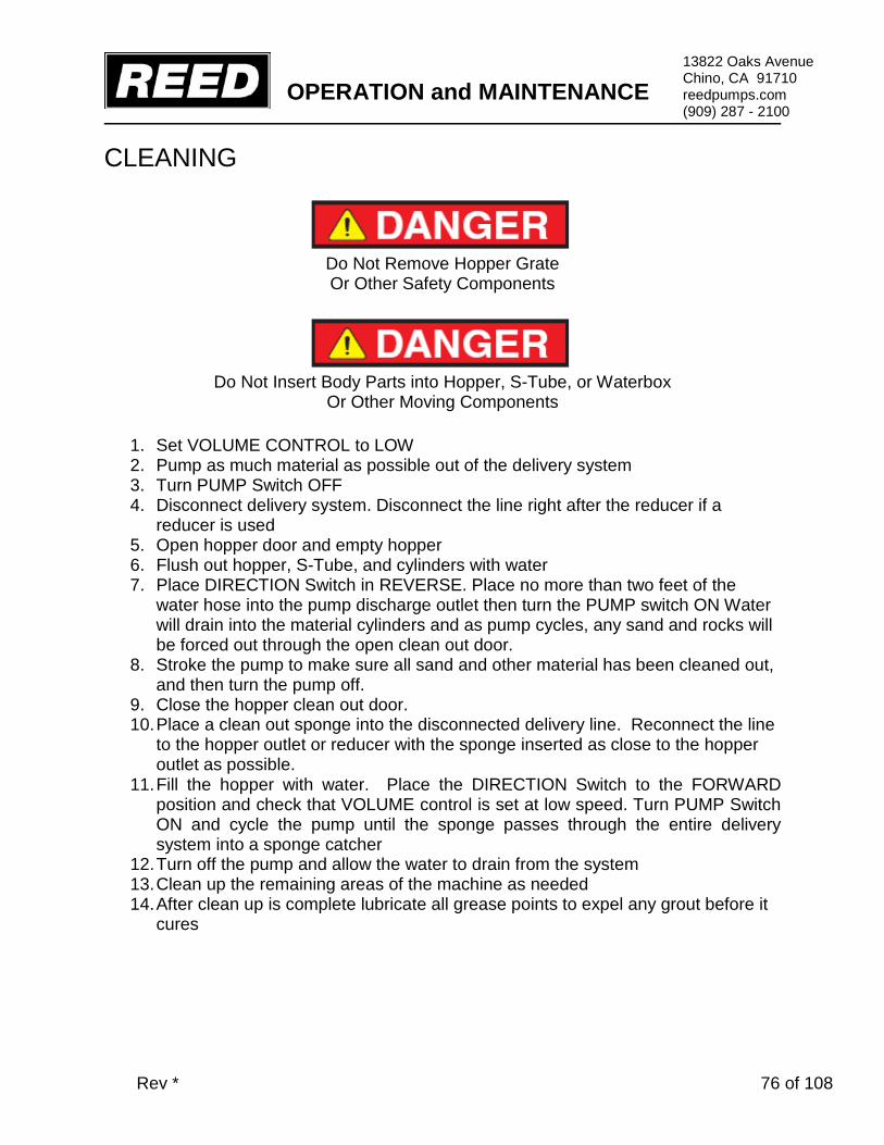
CLEANING
Do Not Remove Hopper Grate Or Other Safety Components
Do Not Insert Body Parts into Hopper, S-Tube, or Waterbox
Or Other Moving Components
1. Set VOLUME CONTROL to LOW 2. Pump as much material as possible out of the delivery system 3. Turn PUMP Switch OFF 4. Disconnect delivery system. Disconnect the line right after the reducer if a
reducer is used 5. Open hopper door and empty hopper 6. Flush out hopper, S-Tube, and cylinders with water 7. Place DIRECTION Switch in REVERSE. Place no more than two feet of the
water hose into the pump discharge outlet then turn the PUMP switch ON Water will drain into the material cylinders and as pump cycles, any sand and rocks will be forced out through the open clean out door.
8. Stroke the pump to make sure all sand and other material has been cleaned out, and then turn the pump off.
9. Close the hopper clean out door. 10. Place a clean out sponge into the disconnected delivery line. Reconnect the line
to the hopper outlet or reducer with the sponge inserted as close to the hopper outlet as possible.
11. Fill the hopper with water. Place the DIRECTION Switch to the FORWARD position and check that VOLUME control is set at low speed. Turn PUMP Switch ON and cycle the pump until the sponge passes through the entire delivery system into a sponge catcher
12. Turn off the pump and allow the water to drain from the system 13. Clean up the remaining areas of the machine as needed 14. After clean up is complete lubricate all grease points to expel any grout before it
cures

OPERATION and MAINTENANCE
Rev * 77 of 108
13822 Oaks Avenue Chino, CA 91710 reedpumps.com (909) 287 - 2100
MAINTENANCE RECOMMENDED MAINTENANCE PRACTICES MAINTENANCE MANAGEMENT Schedule lubrication and maintenance inspections to anticipate maintenance issues. Maintenance management requires the assignment of responsibilities to individual personnel, training of personnel, keeping of records, and the exercise of judgment. INSPECTION AND LUBRICATION CHECKLISTS AND OPERATOR REPORTS Utilize checklists for scheduled inspection and lubrication and maintain a written record regarding observations and actions performed. Maintain all scheduled maintenance reports by the operator listing any malfunctions and observations. PUMP HISTORY FILE NOTING PUMP SERIAL NUMBER File the operator reports, inspection and lubrication checklists, shop repair, work orders and tickets, parts replacement and pump usage records. This file should also include the parts book for the specific serial number and engine. ANNUAL REVIEW Review the history records of each unit once every year to find evidence of repetitive failures, adjustments, problems, or excessive wear so that action can be taken to minimize breakdowns and reduce excessive maintenance costs. A review of the machine history will help in the stocking of spare parts and assemblies in advance of a possible need.
Engine Manufacturer Maintenance Schedule Must Be Followed
Read Engine Manufacturer Manual
REED has provided only general guidelines regarding engine maintenance, and will not cover engine warranty claims.
Accumulator Pressure Must Be ZERO
Before And During Any Maintenance Procedures
Engine Must Be Turned OFF and Lockout / Tagout Procedures Must Be Followed
Before And During Any Maintenance Procedures

OPERATION and MAINTENANCE
Rev * 78 of 108
13822 Oaks Avenue Chino, CA 91710 reedpumps.com (909) 287 - 2100
GENERAL MAINTENANCE AREAS
Perform scheduled inspections to identify and detect any potential problems. The list presented should be inspected and checked on a regular basis and is a recommended minimum. TRAILER
• Frame integrity, visually check welds, cracks • Torsion axle secure • Wheels and tires, lug nuts tight, tire pressure • Electric brakes, breakaway switch connected • Front jack stand handle turns easily, smoothly • Manual jacks slide freely, lock pins in place • Lighting good condition, operational
ENGINE (refer to engine manufacturer manual)
• Inspect mounts, bolts, brackets and belts • Oil and coolant fluids at proper level, check for leaks • Fuel system, tank mounting, filter condition, leaks, damaged lines • Battery hold down, condition, tightness of cables • Key switch, indicator lights • Throttle control functional • Air cleaner and muffler securely mounted
PUMP CELL
• Visually check for structural damage, cracked welds • Hydraulic drive cylinders in good condition, secure, check for leaks • Material cylinders secure, tie rods tight • Water box structurally sound, clean, cover in place • S-Tube shift mechanism structurally sound, all pins and retainers in place • Hydraulic shift cylinder(s) in good condition • Bearing housing, seals etc. in good condition • Hydraulic hoses secure no leaks
HOPPER ASSEMBLY
• Visually check for structural damage, cracked welds • S-Tube secure, in good condition • Check condition of wear plate, wear ring, seals • Check connection of s-tube to outlet, seals, bearing • Hopper drain is functional • Cleaning hopper • Zerk fittings accept grease

OPERATION and MAINTENANCE
Rev * 79 of 108
13822 Oaks Avenue Chino, CA 91710 reedpumps.com (909) 287 - 2100
MAIN CONTROLS • Control box in good condition, sealed, not damaged • All toggles in good condition, stay in position or momentarily return to center • Control identification in good condition, legible • Gauges in good condition
REMOTE CONTROLS
• Control console in good condition, not damaged • Switch in good condition • Cord in good condition, no cuts, securely mounted to box
HYDRAULIC SYSTEM
• Hydraulic tank securely mounted, covers tight • Breather, filler cap and strainer in place, level sight gauge in proper condition • Check filter condition indicators • Hydraulic oil cooler securely mounted, connections tight • Check accumulator condition, mounting brackets & clamps • Hydraulic fluid to proper level and clean • All hoses and tubing secure, check for leaks

OPERATION and MAINTENANCE
Rev * 80 of 108
13822 Oaks Avenue Chino, CA 91710 reedpumps.com (909) 287 - 2100
LUBRICATION The REED concrete pump is equipped with several components that require frequent lubrication. These areas involve the s-tube shifting mechanism, swing components, the shift and outlet bearings and agitator. to insure the economical service and the long life of these components, grease fittings are installed at each point.
Rapid wear and possible shutdown will result if the unit is operated with inadequate lubrication. Follow the recommendations stated herein, and if needed increase the application of lubricants above these recommendations when the equipment is subject to heavy usage.
MINIMUM LUBRICATING INTERVALS Recommended lubrication intervals are based on normal use under normal conditions. The lubrication interval must be increased to meet more challenging uses and uses which subject the equipment to high and/or unusual concentration of forces. The lubrication interval must be increased if the pump has been exposed to environmental conditions such as low humidity, high humidity, excessive dust, high temperatures, low temperatures, heavy rainfall, long term storage, ocean air, etc… 1) every hour of operation 2) after completion of every job All lubrication points must be greased on each and every interval as recommended. TYPE OF LUBRICANT
• Use EP grease, extreme pressure grease available for wheel bearings, general purpose grease, Shell Alvania EP (LFH2), or equivalent if this lubricant is unavailable in your area
• Do NOT use Moly grease, grease with Moly additives
LUBRICATION POINTS The following graphics are for REFERENCE ONLY.

OPERATION and MAINTENANCE
Rev * 81 of 108
13822 Oaks Avenue Chino, CA 91710 reedpumps.com (909) 287 - 2100
S-TUBE SHIFT LUBRICATION
IF EQUIPPED WITH DUAL (2) HYDRAULIC SHIFT CYLINDERS,
RELIEVE SHIFT CIRCUIT HYDRAULIC PRESSURE TO PROPERLY GREASE HYDRAULIC SHIFT CYLINDERS AND BELL CRANK
S-TUBE
BEARING GREASE POINTS BELL CRANK AND SHIFT CYLINDER GREASE POINTS NOTE: RELIEVE S-TUBE CIRCUIT PRESSURE BEFORE APPLYING GREASE IF EQUIPPED WITH DUAL (2) SHIFT CYLINDERS

OPERATION and MAINTENANCE
Rev * 82 of 108
13822 Oaks Avenue Chino, CA 91710 reedpumps.com (909) 287 - 2100
S-TUBE OUTLET LUBRICATION
S-TUBE OUTLET GREASE POINTS
OPERATION and MAINTENANCE
Rev * 83 of 108
13822 Oaks Avenue Chino, CA 91710 reedpumps.com (909) 287 - 2100
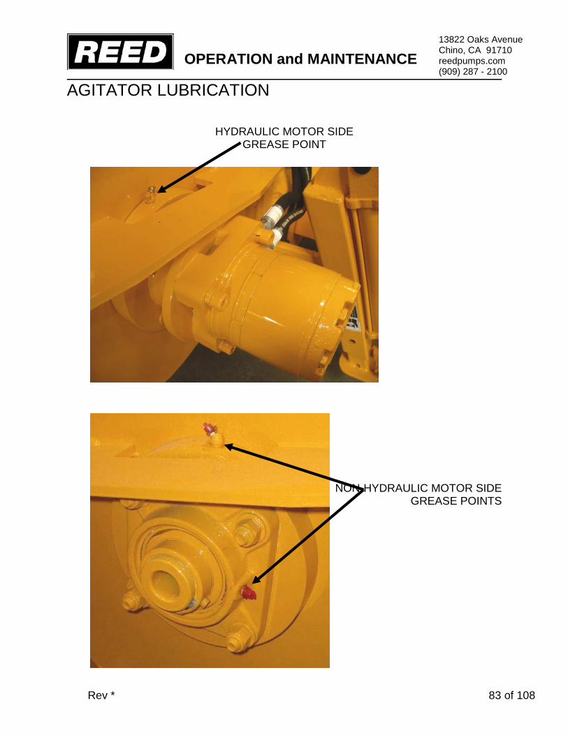
AGITATOR LUBRICATION
HYDRAULIC MOTOR SIDE GREASE POINT
NON-HYDRAULIC MOTOR SIDE GREASE POINTS

OPERATION and MAINTENANCE
Rev * 84 of 108
13822 Oaks Avenue Chino, CA 91710 reedpumps.com (909) 287 - 2100
HYDRAULIC SYSTEM Hydraulic pumps are used to supply the flow of oil necessary to operate actuators of the concrete pump.
Contamination of the Oil Is the Leading Contributor to System Malfunctions
Extreme care must be exercised to prevent contaminants from entering the system. Always cap or plug open ports and hydraulic lines. HYDRAULIC TANK The hydraulic tank is equipped with an access cover with breather and magnetic suction strainers inside the tank. A sight and temperature gauge is installed on the tank to determine the fluid level and temperature inside the tank. The tank is also equipped with drain valve. In addition to the magnetic suction strainers, filtration is accomplished by use of a hydraulic return filter located on top of the hydraulic tank. The return filter is equipped with an indicator gauge to monitor filter restriction. An oil cooler is adjacent to the engine cooling unit.

OPERATION and MAINTENANCE
Rev * 85 of 108
13822 Oaks Avenue Chino, CA 91710 reedpumps.com (909) 287 - 2100
HYDRAULIC SYSTEM MAINTENANCE ITEM DESCRIPTIONS FLUID Check fluid level and oil clarity daily with sight gauge provided. Maintain level at full mark. Add hydraulic oil through the return filter fill port when necessary. TANK BREATHER Clean every 50 hours of operation. Remove from tank, clean with solvent and air blow dry. FILTER Change after first 50 hours of operation. Thereafter change every 250 hours of operation or when condition gauge indicates change is necessary. HYDRAULIC TANK Change oil in tank every 500 hours of operation or yearly, whichever comes first. HYDRAULIC FLUID The hydraulic system is filled with Shell Oil Company TELLUS #46. It is to be used in ambient temperatures of 39-90° F (4-32° C). The normal fluid temperature will range from 100-167° F (38-75° C). For ambient temperatures of 90° F (32° C) and above, use fluid designated with an ISO rating of 68. Use ISO 32 for ambient temperatures of 32° F (4° C) and below.
Use Only Shell Tellus 46 or Equivalent Never Mix With Other Types of Fluids
Always Use Clean and New Fluid
Using impure or other type of fluids not specified will contaminate the hydraulic system and lead to eventual system malfunction and/or damage.

OPERATION and MAINTENANCE
Rev * 86 of 108
13822 Oaks Avenue Chino, CA 91710 reedpumps.com (909) 287 - 2100
ADDING HYDRAULIC FLUID There are a few common methods for filling the hydraulic tank as described below. Exercise extreme care when adding fluid to the hydraulic tank to avoid contamination. • To prevent any dirt or water from entering the hydraulic tank, thoroughly clean area around the return filter fill port plug, the vented fill cap or the inspection cover. • Remove return filter fill port plug, vented cap or inspection cover. • Fill system to MAX LEVEL mark on sight gauge with new clean hydraulic fluid. If a pump is used to transfer the fluid, ensure the pump filter is clean. If pouring fluid from a container, pour it through a fine wire mesh screen, 200 mesh or finer. • Replace filter fill port plug, vented cap or inspection cover immediately after filling tank to proper level.
Do Not Use Cloth for Straining Fluid
Lint Is a Contaminant Harmful To the Hydraulic System FILTER SERVICING
Hydraulic filters provide a means of continuous hydraulic fluid filtration in an effort to prevent recirculation of contamination which will cause rapid wear and component
FILTER ELEMENT
GAUGE
GASKET
FILL PORT

OPERATION and MAINTENANCE
Rev * 87 of 108
13822 Oaks Avenue Chino, CA 91710 reedpumps.com (909) 287 - 2100
breakdown. The filter is equipped with a condition indicator gauge which should be checked daily and the element changed when indicated. To change the filter elements:
1. Shut off machine. 2. VERIFY PRESSURES IN ALL CIRCUITS READ ZERO! 3. Wipe clean any dirt and grime from area surrounding filter housing 4. Loosen the filter cover plate bolts 5. Carefully remove cover so as not to damage the gasket or O-ring 6. Remove and element bypass valve (if equipped) 7. Discard only element and discard responsibly 8. Install bypass valve (if equipped) and new element and replace cover 9. Wipe clean any contaminants around high pressure filter 10. Remove filter housing then remove and discard filter element 11. Check and replace o-ring or gasket if necessary 12. Replace filter element and install filter housing 13. Start up machine and observe for leakage
Do Not Wash Out and Reuse Disposable Filter Elements
CLEANING THE HYDRAULIC TANK The hydraulic tank should be drained and cleaned after 500 hours of operation or yearly, whichever occurs first, to assist in keeping the systems clean and in proper condition.
1. Shut off machine 2. VERIFY PRESSURES IN ALL CIRCUITS READ ZERO! 3. Place a suitable size container under the hydraulic tank drain fitting and then
remove drain plug. Dispose of used oil responsibly 4. After draining, remove the access cover on the hydraulic tank being careful not
to damage the gasket 5. Remove, disassemble and clean magnetic suction strainers before reassembly
(if equipped) 6. Flush the inside of hydraulic tank with clean solvent and wipe clean with lint free
cloths

OPERATION and MAINTENANCE
Rev * 88 of 108
13822 Oaks Avenue Chino, CA 91710 reedpumps.com (909) 287 - 2100
7. Install suction strainers (if equipped) 8. Replace sight gauge 9. Install the tank drain plug and access cover with gasket. 10. Change the hydraulic system filter element(s) and breather cap 11. Refill the hydraulic tank with new clean hydraulic fluid to MAX LEVEL mark 12. Start machine and check for leaks

OPERATION and MAINTENANCE
Rev * 89 of 108
13822 Oaks Avenue Chino, CA 91710 reedpumps.com (909) 287 - 2100
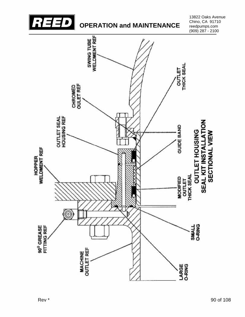
COMPONENT REPLACEMENT When parts are worn, do not delay in replacement. Continued usage with worn parts may lead to damage of other components. This section is provided as a general guideline to assist in replacing major components that will wear. Please contact the REED Service Department or your local dealer for technical support. S-TUBE, WEAR RING, AND WEAR PLATE
The sealing characteristics of the s-tube depend on the positive contact of the wear ring, located inside the s-tube, to the wear plate mounted inside of the hopper. The abrasiveness and friction of the concrete will cause wear and a breakdown of the sealing action. As this breakdown occurs, periodic adjustments to the s-tube can be made. This will help to improve the sealing quality; however, eventually the components will need to be replaced. Adjustment or parts are required if: • s-tube concrete build up • deep grooves have developed on the face of the wear plate and/or on the wear ring • When the output volume at the end of the delivery line noticeably begins to
decrease or eventually stops • When the material being pumped is being forced back into the hopper under
pressure
Accumulator Pressure Must Be ZERO
BEFORE AND DURING Any Maintenance Procedures
Engine Must Be Turned OFF and Lockout / Tagout Procedures Must Be Followed
BEFORE AND DURING Any Maintenance Procedures NOTE: The following graphics are for REFERENCE ONLY.
OPERATION and MAINTENANCE
Rev * 90 of 108
13822 Oaks Avenue Chino, CA 91710 reedpumps.com (909) 287 - 2100

OPERATION and MAINTENANCE
Rev * 91 of 108
13822 Oaks Avenue Chino, CA 91710 reedpumps.com (909) 287 - 2100

OPERATION and MAINTENANCE
Rev * 92 of 108
13822 Oaks Avenue Chino, CA 91710 reedpumps.com (909) 287 - 2100

OPERATION and MAINTENANCE
Rev * 93 of 108
13822 Oaks Avenue Chino, CA 91710 reedpumps.com (909) 287 - 2100
Accumulator Pressure Must Be ZERO
BEFORE AND DURING Any Maintenance Procedures
Engine Must Be Turned OFF and Lockout / Tagout Procedures Must Be Followed
BEFORE AND DURING Any Maintenance Procedures
1. Shut off machine 2. VERIFY PRESSURES IN ALL CIRCUITS READ ZERO! 3. Loosen bell crank pinch bolt (s), remove cotter pin, loosen s-tube nut 1 turn 4. Remove outlet bolts, remove outlet 5. Remove outlet seal housing followed by s-tube nut, spacer, bell crank, washer,
swing ram(s) 6. Place a sling from an overhead hoist around the discharge end of s-tube to help
support the tube. 7. Pry s-tube toward outlet, remove wear ring & thrust seal. The s-tube may be
swung upside down to provide access to clean. Thrust seal groove or cavity must be properly cleaned
Note: for better access, the s-tube may be removed from hopper by removing flange bearing, seal and chromed outlet and hoisting it out of hopper 8. If wear plate is to be changed, remove wear plate mounting bolts. Pry wear
plate from hopper using provided jack bolt. 9. Pry anti-chip rings out of hopper bore. Use caution not to damage chrome
concrete cylinder. Clean anti-chip ring bore and wear plate area. Replace o-rings (if applicable). Test-fit new bolts in new wear plate-they should be below the surface of the wear plate and not protruding (grind if necessary).
10. Apply small bead of silicone to outer diameter of anti-chip rings, install into hopper bore with split at bottom
11. Apply small amount of silicone to hopper-side of wear plate and bolt-heads. Install wear plate, hand tighten bolts. A short pair of bolts with nuts may be
OPERATION and MAINTENANCE
Rev * 94 of 108
13822 Oaks Avenue Chino, CA 91710 reedpumps.com (909) 287 - 2100
placed underneath new wear plate to adjust and align to concrete cylinders. Torque wear plate mounting bolts to 250 ft lbs, remove adjusting bolts.
12. Install new thrust seal & wear ring in s-tube. 13. Install shaft seal and flange bearing (if removed), torque bolts to 100 ft lbs 14. Slide s-tube forward against wear plate, install washer, align/ mount bell crank,
install spacer and castle nut. Do not tighten yet. 15. Replace outlet seals in proper orientation, apply grease and install outlet seal
housing. Install outlet, torque outlet bolts to 100 ft lbs. Grease all zerk fittings for s-tube until grease comes out of seals.
16. Remove sling, tighten s-tube nut/bolt. It may be helpful to start machine and cycle s-tube to help new parts seat. Do final tightening to s-tube nut/bolt, install cotter pin/retainer, tighten bell crank pinch bolt (s). The nut should be as tight as possible without hampering the shift of s-tube
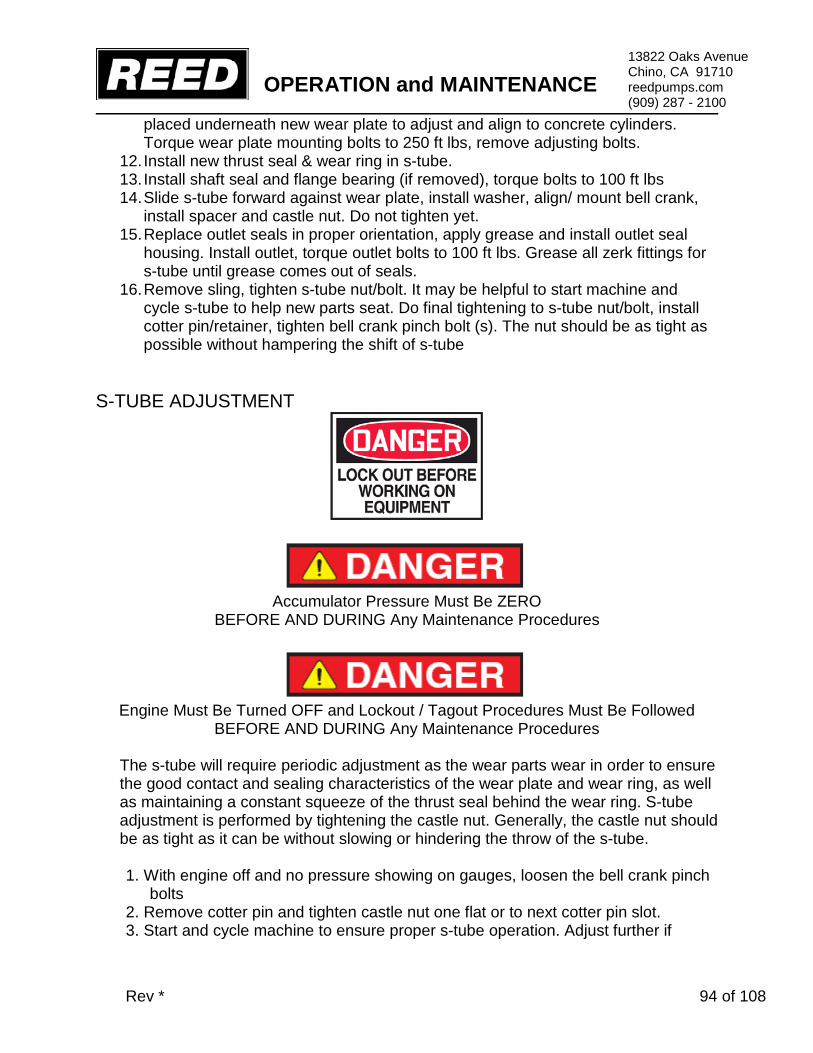
S-TUBE ADJUSTMENT
Accumulator Pressure Must Be ZERO
BEFORE AND DURING Any Maintenance Procedures
Engine Must Be Turned OFF and Lockout / Tagout Procedures Must Be Followed
BEFORE AND DURING Any Maintenance Procedures
The s-tube will require periodic adjustment as the wear parts wear in order to ensure the good contact and sealing characteristics of the wear plate and wear ring, as well as maintaining a constant squeeze of the thrust seal behind the wear ring. S-tube adjustment is performed by tightening the castle nut. Generally, the castle nut should be as tight as it can be without slowing or hindering the throw of the s-tube. 1. With engine off and no pressure showing on gauges, loosen the bell crank pinch
bolts 2. Remove cotter pin and tighten castle nut one flat or to next cotter pin slot. 3. Start and cycle machine to ensure proper s-tube operation. Adjust further if

OPERATION and MAINTENANCE
Rev * 95 of 108
13822 Oaks Avenue Chino, CA 91710 reedpumps.com (909) 287 - 2100
necessary, following lock out tag out rule for each adjustment. 4. When adjustment has been satisfied, install cotter pin and tighten bell crank
pinch bolts.

OPERATION and MAINTENANCE
Rev * 96 of 108
13822 Oaks Avenue Chino, CA 91710 reedpumps.com (909) 287 - 2100
PISTON CUP AND GUIDE BAND REMOVAL/REPLACEMENT Because of the abrasiveness of the material being pumped, it will be necessary to periodically replace the piston cups.
Signs and identifying systems of worn parts might be:
• Slurry of the material being pumped starts to appear in the flush box • The water or lubricating oil in water box begins to rapidly lower level without any
sign of leakage • Operation is rough and erratic
Accumulator Pressure Must Be ZERO
BEFORE AND DURING Any Maintenance Procedures
Engine Must Be Turned OFF and Lockout / Tagout Procedures Must Be Followed
BEFORE AND DURING Any Maintenance Procedures
1. Drain all oil or water from the flush box. 2. Cycle machine using appropriate controls until one of the cylinders is completely
retracted. Turn off engine and allow hydraulic systems to completely depressurize.
3. As a precaution, mark location of proximity sensor adjusting bracket. Remove proximity sensor cross bracket.
4. Mark the end of the piston coupler so that it can be placed in the same relation during reassembly.
5. Unbolt and remove top and bottom halves of coupler. Pry the piston assembly into flush box.
6. Disassemble and clean piston adapter and plate. Check flatness of plate, replace if necessary.
7. Install and grease new guide band. Push adapter/guide band squarely into cleaned and greased concrete cylinder.
8. Install coupler using medium strength Loctite on bolts and torque to 90 ft lbs.
OPERATION and MAINTENANCE
Rev * 97 of 108
13822 Oaks Avenue Chino, CA 91710 reedpumps.com (909) 287 - 2100
9. Start and completely extend the adapter and guide band to hopper side. Jog s-tube if necessary to expose fully extended piston adapter.
10. Turn off engine and allow hydraulic systems to completely depressurize 11. Install one alignment bolt (3/8”x24x5” with head cut off) into the piston adapter to
assist in locating the cup in the correct position to line up the holes. 12. Slide new piston cup, small end first, over alignment bolt until it meets wear plate.
Use a rubber hammer to drive piston cup into concrete cylinder until it seats against piston adapter
13. Slide piston plate into place. 14. Apply medium strength Loctite to bolts. After three bolts with lock washers are
started, remove alignment bolt and thread in the last bolt. Tighten bolts equally and firmly using hand tools.
15. One concrete piston is complete. Follow steps 2-14 again for the other side. 16. Install proximity sensor cross bracket. 17. Install flush box plug, fill to top of rods with oil or water, and install flush box
cover.

OPERATION and MAINTENANCE
Rev * 98 of 108
13822 Oaks Avenue Chino, CA 91710 reedpumps.com (909) 287 - 2100

OPERATION and MAINTENANCE
Rev * 99 of 108
13822 Oaks Avenue Chino, CA 91710 reedpumps.com (909) 287 - 2100
ACCUMULATOR
The hydraulic accumulator is a pressurized vessel and only QUALIFIED TECHNICIANS should perform the necessary repairs. Always drain the fluid COMPLETELY from the accumulator before performing any work on the component. A qualified technician can check the pre-charge pressure of the accumulator using an accumulator charge kit if low pressure is suspected. Check the pre-charge pressure of the accumulator if the needle of the hydraulic s-tube gauge does not suddenly drop off at the specified pressure when the hydraulic s-tube circuit is depressurizing.

OPERATION and MAINTENANCE
Rev * 100 of 108
13822 Oaks Avenue Chino, CA 91710 reedpumps.com (909) 287 - 2100
PUMP MAINTENANCE SCHEDULE AND CHECKLISTS Providing a maintenance schedule defined specifically by run hours or yardage pumped serves only as a general guideline given the large amount of variables a unit might be subject to, such as weather and ambient temperature conditions, jobsite conditions, material differences of concrete mix design, the load burden the unit is typically subject to, i.e. light, medium or heavy duty operation, etc. The list that follows is to be used as a reference guide. However, the end user is encouraged to develop a preventative maintenance program that specifically suites their needs depending on the usage of the equipment. DAILY PUMP MAINTENANCE CHECKLIST Actual Hours Date / / # Maintenance Description Initials
1 Check engine fluid levels (see engine manufacturer maintenance schedule for additional requirements)
2 Check hydraulic tank fluid levels 3 Check flush box fluid levels 4 Check condition of hydraulic oil for water or other contamination Additional Notes:
5 Drain water from tank 6 Check hydraulic filter indicator condition 7 Lubricate lubrication points, during and after pumping 8 Inspect unit for fluid leaks, loose hoses, loose nuts, bolts, fasteners etc. Additional Notes:
9 Trailer Towing Safety Inspection a) brakes functional
b) air pressure in tires is adequate and tire condition c) all “lug nuts” are secure and in place d) tow hitch is secure and in good condition
10 Additional Notes:

OPERATION and MAINTENANCE
Rev * 101 of 108
13822 Oaks Avenue Chino, CA 91710 reedpumps.com (909) 287 - 2100
INITIAL 50 HOUR MAINTENANCE CHECKLIST Actual Hours Date / / # Maintenance Description Initials 1 Change engine oil and filters (see engine manufacturer maintenance schedule
for additional requirements)
Additional Notes:
2 Change hydraulic oil filters
3 Inspect hydraulic hoses and fittings for any signs of external wear or damage
Additional Notes:

OPERATION and MAINTENANCE
Rev * 102 of 108
13822 Oaks Avenue Chino, CA 91710 reedpumps.com (909) 287 - 2100
EVERY 100 HOUR MAINTENANCE CHECKLIST Actual Hours Date / / # Maintenance Description Initials
1 Clean hydraulic tank breather 2 Inspect all structural components (check frame, hopper, axle, hood, towing
hook, and other structural members for any damage)
Additional Notes:
3 Adjust “S-Tube Nut” or “Castle Nut” (refer to “S-Tube Adjustment” in Maintenance Section)
Additional Notes:
4 Change flush box oil and examine for excessive amounts of contamination (excessive contamination might indicate need to change the Piston Cups)
Additional Notes:
5 Check coolers and radiators for dirt or debris. Clean as necessary
6 Check condition of engine drive belts. Change if necessary (see engine manufacturer maintenance schedule for additional requirements)
Additional Notes:

OPERATION and MAINTENANCE
Rev * 103 of 108
13822 Oaks Avenue Chino, CA 91710 reedpumps.com (909) 287 - 2100
EVERY 250 HOUR MAINTENANCE CHECKLIST Actual Hours Date / / # Maintenance Description Initials
1 Change hydraulic filters (or change more frequently as indicated by indicator gauge on filter)
2 Check that S-Tube, wear parts and seals in hopper are secure and adjusted well, rotate wear ring and replace seal if necessary
Additional Notes:
3 Check swing cylinder components: cylinders, bell crank, pins, bushings, bearings and grease fittings are secure, tight, and not worn excessively
Additional Notes:
4 Check piston cup wear (as indicated by analysis of contaminants found in flush box oil)
Additional Notes:
5 Check that all electrical wires, cables, terminals, plugs are in good condition
Additional Notes:
6 Change engine oil and filters (see engine manufacturer guide for all engine requirements)
Additional Notes:
7 Check condition of fuel hoses, fittings, and clamps Additional Notes:
8 Inspect all safety decals to ensure that they are completely visible and legible

OPERATION and MAINTENANCE
Rev * 104 of 108
13822 Oaks Avenue Chino, CA 91710 reedpumps.com (909) 287 - 2100
EVERY 250 HOUR MAINTENANCE CHECKLIST Actual Hours Date / / # Maintenance Description Initials 9 Perform complete inspection of the controls 10 All toggles in good condition, stay in position or momentarily return to center 11 Control identification in good condition, legible 12 Gauges in good condition Additional Notes:
13 Remote controls, control console in good condition
14 Switch in good condition
15 Cord in good condition, no cuts, securely mounted to box Additional Notes:
16 Trailer frame integrity, visually check welds, cracks 17 Torsion axle secure 18 Wheels and tires, lug nuts tight, tire inflation 19 Electric brakes, breakaway switch connected 20 Front jack stand handle turns easily, smoothly
21 Manual jacks slide freely, lock pins in place 22 Lighting good condition operational Additional Notes:

OPERATION and MAINTENANCE
Rev * 105 of 108
13822 Oaks Avenue Chino, CA 91710 reedpumps.com (909) 287 - 2100
EVERY 500 HOUR MAINTENANCE CHECKLIST Actual Hours Date / / # Maintenance Description Initials 1 Inspect hydraulic hoses and fittings for any signs of external wear or damage Additional Notes:
2 Inspect all wear parts and change as necessary (excessive wear may cause inefficient performance and/or shutdown of operation)
Additional Notes:
3 Change hydraulic fluid, clean the reservoir and the suction strainers within reservoir, and replace all hydraulic oil filters
Additional Notes:
4 Complete inspection of the engine (refer to engine manufacturer maintenance schedule for details)
5 Inspect mountings, bolts, brackets
6 Oil level proper, coolant level proper, check for leaks
7 Fuel system, tank mounting, filter condition, check for leaks, damaged lines 8 Battery hold down, condition, tightness of cables
9 Key switch, indicator lights operable 10 Throttle control functional
11 Air cleaner and muffler securely mounted
Additional Notes:

OPERATION and MAINTENANCE
Rev * 106 of 108
13822 Oaks Avenue Chino, CA 91710 reedpumps.com (909) 287 - 2100
EVERY 500 HOUR MAINTENANCE CHECKLIST Actual Hours Date / / # Maintenance Description Initials
12 Pump cell check for structural damage, cracked welds 13 Hydraulic drive cylinders in good condition, secure, check for leaks 14 Material cylinders secure, tie rods tight
15 Water box structurally sound, clean, cover in place 16 S-Tube shift mechanism structurally sound, all pins and retainers in place
17 Hydraulic shift cylinders in good condition
18 Bearing housing, seals etc. in good condition
19 Hydraulic hoses secure no leaks Additional Notes:
20 Hopper check for structural damage, cracked welds 21 S-Tube secure, in good condition
22 Check condition of wear plate, wear ring, seals 23 Check connection of S-Tube to outlet, seals, bearing
24 Hopper drain is functional
Additional Notes:

OPERATION and MAINTENANCE
Rev * 107 of 108
13822 Oaks Avenue Chino, CA 91710 reedpumps.com (909) 287 - 2100
EVERY 500 HOUR MAINTENANCE CHECKLIST Actual Hours Date / / ADDITIONAL GENERAL NOTES:

OPERATION and MAINTENANCE
Rev * 108 of 108
13822 Oaks Avenue Chino, CA 91710 reedpumps.com (909) 287 - 2100
NOTES

HYDRAULIC / ELECTRICAL SCHEMATICS


B20HPC PLC PARTS
B20HPC-V15 ECN#1412 1 of 69
13822 Oaks Avenue Chino, CA 91710 reedpumps.com (909) 287 - 2100
PARTS........................................................................................................................................ 3 PUMPING TRAIN GROUP ......................................................................................................... 3
S-TUBE ........................................................................................................................... 5 4” OUTLET ASSEMBLY ........................................................................................ 5 4” OUTLET SEAL KIT INSTALLATION ................................................................. 5 WEAR PLATE ASSEMBLY ................................................................................... 7
4” PISTON CUP ASSEMBLY ........................................................................................... 8 .............................................................................................................................. 8
DRIVE CYLINDER ASSEMBLY ....................................................................................... 9 DUAL SHIFT BELL CRANK ASSEMBLY ............................................................ 10 DUAL SHIFT CYLINDER ASSEMBLY ................................................................ 11
DUAL SHIFT ASSEMBLY ......................................................................... 11 HOPPER ....................................................................................................................... 13
AGITATOR ASSEMBLY (OPTION 1) .................................................................. 13 AGITATOR ASSEMBLY (OPTION 2) ................................................................. 13 SAFETY GRATE ................................................................................................. 15 GRATE ASSEMBLY ............................................................................................ 17 CLEAN OUT DOOR ASSEMBLY ........................................................................ 18
POWER TRAIN GROUP .......................................................................................................... 19 ENGINE, PUMPS, AND FILTERS ....................................................................... 19
MAIN HYDRAULIC PUMP ....................................................................................................... 20 GEAR PUMP/PUMP DRIVE ............................................................................... 20
FITTINGS ................................................................................................. 22 EXHAUST ........................................................................................................... 23
TANKS ..................................................................................................................................... 24 FUEL TANK ASSEMBLY ..................................................................................... 24 HYDRAULIC TANK ASSEMBLY ......................................................................... 25
MANIFOLDS ............................................................................................................................ 27 DRIVE CYLINDER CIRCUIT MANIFOLD ASSEMBLY ....................................... 27 S-TUBE CIRCUIT MANIFOLD ASSEMBLY ........................................................ 29
ACCUMULATOR ASSEMBLY .................................................................................................. 31 PROXIMITY SWITCHES .................................................................................... 32 STARTER AND ALTERNATOR ........................................................................... 33 TRAILER HARNESS AND BREAKAWAY ........................................................... 34 TAIL LIGHTS ....................................................................................................... 35 WIRING HARNESS ............................................................................................ 36
PLC CONTROLS ..................................................................................................................... 38 B-SERIES CONTROL PANEL ............................................................................ 38
KEY PAD SWITCHES INSERT KIT ......................................................... 39 MVEC/FUSE/RELAY ................................................................................ 41
B20HPC PLC PARTS
B20HPC-V15 ECN#1412 2 of 69
13822 Oaks Avenue Chino, CA 91710 reedpumps.com (909) 287 - 2100
ESTOP, KEY ASSEMBLY, PLUGS ........................................................... 45 BUSSES, CONNECTORS, PINS ............................................................. 46
SERIAL PLATE IDENTICATION ......................................................................... 47 BUSS BAR SET-UP ............................................................................................ 48 CAN PUSH BUTTON SWITCH PLUG ................................................................ 49
SWITCH A ................................................................................................ 49 CAN PUSH BUTTON SWITCH PLUG ................................................................ 50
SWITCH B ............................................................................................... 50 CAN PLUGS, CONNECTORS ............................................................................ 51 DEUTSCH 128 PLUG ASSEMBLY ..................................................................... 52
FRAME INSTALLATION ........................................................................................................... 54 FRAME, TIRES, JACK, AND TOW EYE ............................................................. 54 7000LB AXLE MOUNTING ASSEMBLY ............................................................. 55 HOOD AND COVERS ......................................................................................... 56 FENDERS AND OUTRIGGERS ......................................................................... 57
OPTIONS ................................................................................................................................. 58 HYDRAULIC OUTRIGGER GROUP .................................................................. 58
3 SPOOL CONTROL VALVE ................................................................... 59 HYDRAULIC OUTRIGGER GROUP ........................................................ 60 ELECTRIC HYDRAULIC OUTRIGGER CONTROLS .............................. 62
AGITATOR GROUP ............................................................................................ 63 1 SPOOL AGITATOR VALVE ................................................................... 64
AVAILABLE OPTIONS ........................................................................................ 66
REV DATE DESCRIPTION NAME B20HPC-V15 3/28/2017 INITIAL J.SLACK

B20HPC PLC PARTS
B20HPC-V15 ECN#1412 3 of 69
13822 Oaks Avenue Chino, CA 91710 reedpumps.com (909) 287 - 2100
PARTS PUMPING TRAIN GROUP ASSEMBLY
ID # PART # PART DESCRIPTION QUANTITY 87894-8 DUAL SHIFT PUMPING TRAIN ASSEMBLY 1 EA
1 87893 HOPPER WELD MOD-B20 STD DUAL 1 EA 2 71349 S TUBE WLD, 4X4 1 EA 3 88172 FLUSH BOX WELDMENT, B20/B20HP 1 EA 4 88180 BKT-PROX SENSOR, FLUSH BOX 2 EA 5 88179 BRACKET PROXIMITY SWITCH MOUNT 2 EA 6 10282 PLUGS-PIPE GALV 1” 1 EA 7 86665 STUD, 3/8-16 X3” LONG 1 EA 8 3/8-16 JAM NUT 1 EA 9 73433 COVER REMIX (OUTSIDE) 1 EA 10 73434 COVER PLATE (INSIDE) 1 EA 11 86623 SEAL, AGITATOR (INSIDE) 1 EA 12 86224HT DRIVE CYLINDER -3.25 X 2.00 X 35.75 2 EA
1
2
WITH OUT AGITATOR
ONLY 9 10 11
6 12
3
4
7 8
WATERBOX TOP VIEW
5
DETAIL B
DETAIL C
DETAIL A

B20HPC PLC PARTS
B20HPC-V15 ECN#1412 4 of 69
13822 Oaks Avenue Chino, CA 91710 reedpumps.com (909) 287 - 2100
PUMPING TRAIN ASSEMBLY CONTINUED
ID # PART # PART DESCRIPTION QUANTITY 1 70315 TIE ROD, 1¼” -12 X 48½” 4 EA 2 71232 CONCRETE CYLINDER, 4” X 36” 2 EA 3 ELBOW, MB – MJ-16-16 2 EA 4 85688 TUBE, HYD, LOOP LINE 1 EA 5 71401 END PLATE – HYD.CYL,M20 PAINTED 1 EA 6 HHCS, ½” – 13X1 ¼” GR 4 EA 7 LOCK WASHER, 1/2 4 EA 8 FLATWASHER, 1/2 4 EA 9 HEX NUT 1 ¼”- 12 4 EA 10 LOCK WASHER, 1 ¼” 4 EA
DETAIL F
DETAIL G
1
2 3
4
5
6 7 8
DETAIL D
9 10
150 FT-LB
DETAIL E (OPTION)

B20HPC PLC PARTS
B20HPC-V15 ECN#1412 5 of 69
13822 Oaks Avenue Chino, CA 91710 reedpumps.com (909) 287 - 2100
S-TUBE 4” OUTLET ASSEMBLY
ID # PART # PART DESCRIPTION QUANTITY 1 HHCS, 9/16-12 X 2 1/2 GR/8 6 EA 2 LOCK NUT, 9/16 -12 6 EA 3 GREASE FITTING, 1/8” NPT 90° 2 EA 4 86335 OUTLET SEAL HOUSING- 4” 1 EA 5 71343 CHROMED OUTLET 1 EA 6 HHCS, 3/8 – 16X1 ½” GR 8 6 EA 7 HEX NUT, 3/8” - 16 6 EA 8 LOCK WASHER, 3/8” 6 EA 9 86336 OUTLET, 4" (1-PIECE) 1 EA
VIEW A
9
1 2
3
4
5 6 7 8
DETAIL A

B20HPC PLC PARTS
B20HPC-V15 ECN#1412 6 of 69
13822 Oaks Avenue Chino, CA 91710 reedpumps.com (909) 287 - 2100
4” OUTLET SEAL KIT INSTALLATION
ID # PART # PART DESCRIPTION QUANTITY 1 86621 SEAL KIT 1 EA 2 86369 O-RING-#158 BUNA 90 1 EA 3 86370 O-RING-#163 BUNA 90 1 EA 4 86614 SEAL-MODIFIED- 4 IN OUTLET 1 EA 5 86371 GUIDE BAND - 4.75 OD X 1.00W 1 EA 6 86372 LIP SEAL -4.50 ID X 4.88 OD X.38 1 EA
VIEW A
2 3 4 5 6
1

B20HPC PLC PARTS
B20HPC-V15 ECN#1412 7 of 69
13822 Oaks Avenue Chino, CA 91710 reedpumps.com (909) 287 - 2100
WEAR PLATE ASSEMBLY
ID # PART # PART DESCRIPTION QUANTITY 1 71249 O-RING, #347 BUENA 70 2 EA 2 HHCS, ¾ - 10X 2½” GR 8 5 EA 3 LOCK WASHER, ¾” 5 EA 4 72384 WEAR RING, 4” DOUBLE LIP, 26% CHROME 1 EA 5 71251 WEAR PLATE-CAST 4” M20 1 EA 6 71254 ANTI CHIP RING, 4” 2 EA 7 71247 O-RING FOR CHIP RING 2 EA 8 72285 SEAL, DOUBLE LIP 4” 1 EA 9 71257 CONC, CYL. ADAPTER 2 EA
DETAIL B
1
2 3
4
8
5
6
7
9
S TUBE
CONCRETE CYLINDER

B20HPC PLC PARTS
B20HPC-V15 ECN#1412 8 of 69
13822 Oaks Avenue Chino, CA 91710 reedpumps.com (909) 287 - 2100
4
4” PISTON CUP ASSEMBLY
ID # PART # PART DESCRIPTION QUANTITY 1 70077 PISTON COUPLING, 1 EA 2 87940 PISTON ADAPTER 4" WITH GUIDE BAND 1 EA 3 87994 WEAR RING(GUIDE BAND) 4" 1 EA 4 76500 PISTON CUP, 4 IN 1 EA 5 88011 PISTON PLATE 4” SINGLE BOLT 1 EA 6 87982 HHCS ¾-16 1.5” LONG GR8 PLATED 1 EA 7 80010 LOCKWASHER-3/4 STL ZINC PLATED 1 EA 8 SHCS ½ - 13 X 2 ¼” 2 EA
DETAIL C
3
2 1
3
5
8
6, 7
8

B20HPC PLC PARTS
B20HPC-V15 ECN#1412 9 of 69
13822 Oaks Avenue Chino, CA 91710 reedpumps.com (909) 287 - 2100
1 3 3 1 2
4
2
4A
DRIVE CYLINDER ASSEMBLY
ID # PART # PART DESCRIPTION QUANTITY 86304-2 HYD CYLINDER GROUP REF
1 78961 CHECK VALVE-5K PSI O-RING 2 EA 2 86748 FITTING-MB-MJ90-6-6 3 EA 3 ELBOW, MB-MB90-6-6 2 EA 4 86223HT HYDRAULIC CYLINDER 3.50 X 2.00 X 35.75 1 EA
4A 86222A-SK SEAL KIT 1 EA

B20HPC PLC PARTS
B20HPC-V15 ECN#1412 10 of 69
13822 Oaks Avenue Chino, CA 91710 reedpumps.com (909) 287 - 2100
DUAL SHIFT BELL CRANK ASSEMBLY
ID # PART # PART DESCRIPTION QUANTITY 1 85604 BELL CRANK, B10R, 2 CYLINDER 1 EA 2 86502 LOCATOR RING- FLANGE BEARING 1 EA 3 70124 FLANGED BEARING 1 EA 4 70125 SPACER, S-TUBE NUT 1 EA 5 HHCS, 5/8”-18X5 ½”” GR 8 1 EA 6 LOCK WASHER, 5/8” 1 EA 7 JAM NUT, 5/8 1 EA 8 70825 NUT 1 ½” - 12 CASTLE 1 EA 9 COTTER PIN, ¼ X4” 1 EA 10 73564 SEAL, FLANGE BEARING 2.5 SHAFT 1 EA 11 DOWEL PIN, ½” DIA X 2” 2 EA 12 GREASE FITTING, 1/8” NPT 2 EA 13 HHCS, 9/16 – 12X3” GR 8 4 EA 14 LOCK WASHER, 9/16” 4 EA 15 70141 THRUST WASHER, S –TUBE 1 EA
DETAIL E
13 14
11 10
15
12
3
8
4
1
2
4
5 6 7
8
9
12
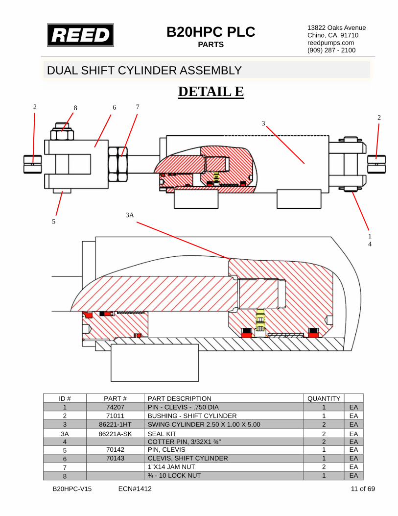
B20HPC PLC PARTS
B20HPC-V15 ECN#1412 11 of 69
13822 Oaks Avenue Chino, CA 91710 reedpumps.com (909) 287 - 2100
DUAL SHIFT CYLINDER ASSEMBLY
ID # PART # PART DESCRIPTION QUANTITY 1 74207 PIN - CLEVIS - .750 DIA 1 EA 2 71011 BUSHING - SHIFT CYLINDER 1 EA 3 86221-1HT SWING CYLINDER 2.50 X 1.00 X 5.00 2 EA
3A 86221A-SK SEAL KIT 2 EA 4 COTTER PIN, 3/32X1 ¾” 2 EA 5 70142 PIN, CLEVIS 1 EA 6 70143 CLEVIS, SHIFT CYLINDER 1 EA 7 1”X14 JAM NUT 2 EA 8 ¾ - 10 LOCK NUT 1 EA
3A
DETAIL E
3 2
1 4
7 8 6
5
2

B20HPC PLC PARTS
B20HPC-V15 ECN#1412 12 of 69
13822 Oaks Avenue Chino, CA 91710 reedpumps.com (909) 287 - 2100
3
4 or 5
6 7 8
1
10
11 13
12 13
2
4 or 5 14
DUAL SHIFT ASSEMBLY
ID # PART # PART DESCRIPTION QUANTITY 1 86220HT SWING RAM – 2.5 X 5.75 STROKE REF 2 86441 RETAINER, SWING RAM 2 EA 3 76798-1 BALL SOCKET, NYLON 4 EA 4 75501 SPACER 1/8” A/R EA 5 75502 SPACER 1/16” A/R EA 6 HHCS, 3/8-24X1 ¼” GR8 4 EA 7 WASHER, 3/8” 4 EA 8 LOCK WASHER, 3/8” 4 EA 10 86283 SETSCREW – 5/8 -11X2.00 CUP 2 EA 11 85941 HOUSING,RH SWING RAM 1 EA 12 85942 HOUSING, LH SWING RAM 1 EA 13 86052 DOWEL PIN, ½” DIA X 2” 4 EA 14 GREASE FITTING, 1/8” NPT 2 EA
DETAIL E SPACE AS REQUIRED FOR PROPER S-TUBE ALIGNMENT
SPACE AS REQUIRED FOR PROPER S-TUBE ALIGNMENT

B20HPC PLC PARTS
B20HPC-V15 ECN#1412 13 of 69
13822 Oaks Avenue Chino, CA 91710 reedpumps.com (909) 287 - 2100
13
7 8
6
5
12
11
14
15
16
1 2
23 4
2
HOPPER AGITATOR ASSEMBLY (OPTION 1)
ID# PART # PART DESCRIPTION QUANTITY 88041-A1 AGITATOR ASSEMBLY
1 HHCS, ½ -13X2 ¼” GR 8 1 EA 2 LOCK NUT, ½” -13 1 EA 3 ¼-28X3/4” 6 EA 4 LOCK WASHER, ¼” 6 EA 5 GREASE FITTING, 1/8” NPT 90° 1 EA 6 85923 SHAFT,AGITATOR 1 EA 7 HHCS, ½ -20X1 ½” GR 8 2 EA 8 LOCK WASHER, ½” 2 EA 9 85717 AGITATOR, PADDLE-B20 1 EA 10 85811 HYD MOTOR, 45.6 CID, 1” SHAFT 1 EA
10A 85809SK SEAL KIT 1 EA 11 85976 WEAR RING, AGITATIOR 1 EA 12 SPRING PIN, ¼” DIA X 1 ¾” 1 EA 13 70211 FLANGE SEAL S/W 1 EA 14 70212 SEAL REMIXER 1 EA 15 85978 BEARING, BALL, PLAIN 1 EA 16 85979 BEARING, BALL 1 SEAL 1 EA
9
DETAIL F
10 10A
VIEW F
KEY

B20HPC PLC PARTS
B20HPC-V15 ECN#1412 14 of 69
13822 Oaks Avenue Chino, CA 91710 reedpumps.com (909) 287 - 2100
AGITATOR ASSEMBLY (OPTION 2)
85761 AGITATOR ASSEMBLY 1 HHCS, ½ -13X2 ¼” GR 8 1 EA 2 LOCK NUT, ½” -13 1 EA 3 ¼-28X3/4” 6 EA 4 LOCK WASHER, ¼” 6 EA 5 GREASE FITTING, 1/8” NPT 90° 1 EA 6 85923 SHAFT,AGITATOR 1 EA 7 HHCS, ½ -20X1 ½” GR 8 2 EA 8 LOCK WASHER, ½” 2 EA 9 87356 AGITATOR, PADDLE-B20 1 EA 10 85811 HYD MOTOR, 45.6 CID, 1” SHAFT 1 EA
10A 85809SK SEAL KIT 1 EA 11 85976 WEAR RING, AGITATIOR 1 EA 12 SPRING PIN, ¼” DIA X 1 ¾” 1 EA 13 70211 FLANGE SEAL S/W 1 EA 14 70212 SEAL REMIXER 1 EA 15 85978 BEARING, BALL, PLAIN 1 EA 16 85979 BEARING, BALL 1 SEAL 1 EA
10 10A DETAIL F
9
7 8
1 2
6
3 4
5
12
11
13
14 15
16
KEY
DETAIL F

B20HPC PLC PARTS
B20HPC-V15 ECN#1412 15 of 69
13822 Oaks Avenue Chino, CA 91710 reedpumps.com (909) 287 - 2100
1
2
3
5
4
6
7
NOTE* Install Grove as shown
ID # PART # PART DESCRIPTION QUANTITY 1 GREASE FITTING, 1/8” NPT STRAIT 1 EA 2 70219 REMIX SHAFT BUSHING 1 EA 3 77877 SPACER, REMIX 1 EA 4 86824 FLAT WASHER, ¾” SAE 1 EA 5 70214 IDLER SHAFT, AGITATOR 1 EA 6 70210 IDLER BREARING HOUSING 1 EA 7 80030 HEX NUT-M20X2.5 PLATED 1 EA
DETAIL G
DETAIL G

B20HPC PLC PARTS
B20HPC-V15 ECN#1412 16 of 69
13822 Oaks Avenue Chino, CA 91710 reedpumps.com (909) 287 - 2100
SAFETY GRATE
ID # PART # PART DESCRIPTION QUANTITY 1 87369 PROXIMITY SENSOR PNP HOPPER GRATE 1 EA 2 801902-006 CLAMP,18MM TUBE CLAMP SET 1 EA 3 87997 COVER WELD PROX SWITCH HOPPER 1 EA
3
2
1

B20HPC PLC PARTS
B20HPC-V15 ECN#1412 17 of 69
13822 Oaks Avenue Chino, CA 91710 reedpumps.com (909) 287 - 2100
1
2 3
4
5
5
6 5
GRATE ASSEMBLY
ID # PART # PART DESCRIPTION QUANTITY 1 87892 GRATE WELDMENT, STD HOPPER 1 EA 2 87857 PIN WELDMENT LONG 1 EA 3 87858 PIN WELDMENT SHORT 1 EA 4 86083 BUMPER, HOPPER GRATE 2 EA 5 W-102490 RUBBER BUFFER 65X22.5X26 2 EA 6 87769 COLLAR SHAFT, 7/8” DIA 1 EA
6
3/8-16-X 1 1/4” HEX BOLT 4EA. 3/8 FLAT WASHER 8EA. 3/8-16 LOCK NUT 4EA.
3/8-16-X 1 1/4” HEX BOLT 4EA. 3/8 FLAT WASHER 8EA. 3/8-16 LOCK NUT 4EA.

B20HPC PLC PARTS
B20HPC-V15 ECN#1412 18 of 69
13822 Oaks Avenue Chino, CA 91710 reedpumps.com (909) 287 - 2100
1
2 3
4
5
6
CLEAN OUT DOOR ASSEMBLY
ID # PART # PART DESCRIPTION QUANTITY 1 86988 DOOR WELDMENT, CLEAN OUT 1 EA 2 86559 BLOCK, CLEAN OUT DOOR, LH 1 EA 3 86560 BLOCK, CLEAN OUT DOOR, RH 1 EA 4 86922 SHOULDER SCREW 1" DIA-1 1/4" 1 EA 5 W102908A O-RING CORD, HOPPER DOOR 2.21 FT 6 SHCS ½”-13 X 1 ¼” 4 EA

B20HPC PLC PARTS
B20HPC-V15 ECN#1412 19 of 69
13822 Oaks Avenue Chino, CA 91710 reedpumps.com (909) 287 - 2100
POWER TRAIN GROUP ENGINE, PUMPS, AND FILTERS
ID # PART # PART DESCRIPTION QUANTITY 87864 POWER TRAIN B20 GROUP REF 87863 POWER TRAIN ASSY B20HP 110 KAW/CUM REF
1 87724-1 ENGINE QSB4.5 110 HP CUMMINS 1 EA 2 87725-002 FUEL FILTER 1 EA 3 87725-001 OIL FILTER 1 EA 4 87725-010 AIR FILTER ELEMENT 1 EA 5 87725-014 AIR FILTER HOUSING ASSEMBLY 1 EA 6 87725-015 AIR FILTER HOUSING COVER, DUST EJECTION 1 EA
1 5 6
7
8
9
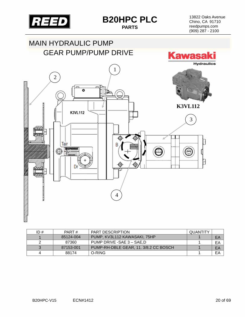
B20HPC PLC PARTS
B20HPC-V15 ECN#1412 20 of 69
13822 Oaks Avenue Chino, CA 91710 reedpumps.com (909) 287 - 2100
MAIN HYDRAULIC PUMP GEAR PUMP/PUMP DRIVE
ID # PART # PART DESCRIPTION QUANTITY 1 85124-004 PUMP, KV3L112 KAWASAKI, 75HP 1 EA 2 87360 PUMP DRIVE -SAE 3 – SAE,D 1 EA 3 87153-001 PUMP-RH-DBLE GEAR, 11. 3/8.2 CC BOSCH 1 EA 4 88174 O-RING 1 EA
K3VL112
2 1
4
3

B20HPC PLC PARTS
B20HPC-V15 ECN#1412 21 of 69
13822 Oaks Avenue Chino, CA 91710 reedpumps.com (909) 287 - 2100
ENGINE, PUMPS, AND FILTERS CONTINUE
ID #
PART # PART DESCRIPTION QUANTITY
1 88036 FITTING FUEL LINE, QUICK DISCONECT 1 EA 2 88037 WASHER SEALING FOR 88036 FITTING 1 EA 3 87793 MOUNT FUEL FILTER, B SER CUMMINS 1 EA 4 87567 FITTING 90DEG METRIC TO JIC 2 EA 5 87566 FITTING BARBED JIC-STEM, 3/8-3/8 2 EA 6 87725-003 FUEL/WATER SEPARATOR REPLACEMENT 1 EA 7 87725-005 FAN BELT 1 EA
1 2
4
5
7 3
6

B20HPC PLC PARTS
B20HPC-V15 ECN#1412 22 of 69
13822 Oaks Avenue Chino, CA 91710 reedpumps.com (909) 287 - 2100
FITTINGS
ID # PART # PART DESCRIPTION QUANTITY 1 86264-007 SPLIT FLANGE-CODE 61- 40 SAE 2 EA 2 86911-009 STEM, 2 ½” 90 DEG, 40GL-40FL90 1 EA 3 79803 CLAMP - T-BOLT - 3.00 DIA 4 EA 4 86265-003 SPLIT FLANGE-CODE 62- 20 SAE 2 EA 5 86912-006 FLANGE, FLH6K-MJ90-20-16 1 EA 6 ADAPTOR, MB-MJ-90-12-10 1 EA 7 86728-023 ADAPTOR, MB-MJ-20-16 1 EA 8 87754-020 ELBOW, MB-MJ45-20-16 1 EA 9 MB-MJ-45-10 1 EA 10 86900-017 MB-MJ0-10-10 1 EA
1
3
3 15 2
6
5
8
9
10 1
4
2

B20HPC PLC PARTS
B20HPC-V15 ECN#1412 23 of 69
13822 Oaks Avenue Chino, CA 91710 reedpumps.com (909) 287 - 2100
EXHAUST
ID # PART # PART DESCRIPTION QUANTITY 1 87199 MOUNTING BAND, 8.5" DIA 2 EA 2 87198 CLAMP, TORCTITE, 3" 1 EA 3 73475 RAIN CAP 3" 1 EA 4 86648 EXHAUST ELBOW 3" 1 EA 5 87579 EXHAUST FLEX TUBE, 3" 12" LONG 1 EA 6 87792 MUFFLER B SER CUMMINS 1 EA 7 87578 EXHAUST CLAMP, BENT BOLT 3" 3 EA 8 87465 TUBE EXHAUST, B SERIES, LONG 1 EA 9 87878 TUBE EXHAUST, B SERIES, SHORT 1 EA 10 88013 CLAMP EXHAUST 3" TORCTITE 1 EA 11 88016 BRACKET 4 CYL CUMMINS EXHAUST 1 EA 12 74679 PLUG 1/4" NPT SOCKET HEAD 1 EA
1
2
3 4
5
6 7 8
9
10
11
12
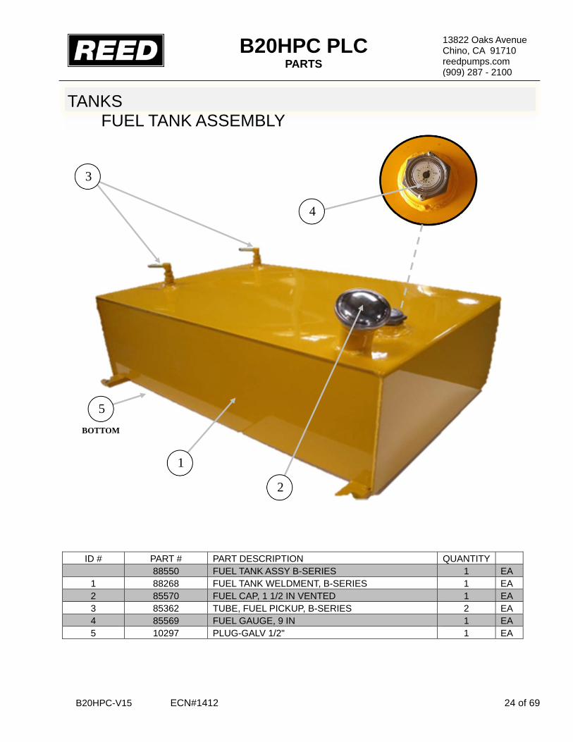
B20HPC PLC PARTS
B20HPC-V15 ECN#1412 24 of 69
13822 Oaks Avenue Chino, CA 91710 reedpumps.com (909) 287 - 2100
TANKS FUEL TANK ASSEMBLY
ID # PART # PART DESCRIPTION QUANTITY 88550 FUEL TANK ASSY B-SERIES 1 EA
1 88268 FUEL TANK WELDMENT, B-SERIES 1 EA 2 85570 FUEL CAP, 1 1/2 IN VENTED 1 EA 3 85362 TUBE, FUEL PICKUP, B-SERIES 2 EA 4 85569 FUEL GAUGE, 9 IN 1 EA 5 10297 PLUG-GALV 1/2" 1 EA
1
2
3
5 BOTTOM
4

B20HPC PLC PARTS
B20HPC-V15 ECN#1412 25 of 69
13822 Oaks Avenue Chino, CA 91710 reedpumps.com (909) 287 - 2100
HYDRAULIC TANK ASSEMBLY
ID # PART # PART DESCRIPTION QUANTITY
87938 HYDRAULIC GROUP B20HP REF 85361 HYD TANK ASSY B-SERIES REF
1 85102 HYDRAULIC TANK WELDMENT, B-SERIES 1 EA 2 85529 ENDCOVER KIT, 12 IN W/DRAIN 1 EA 3 85867 GASKET- END COVER 12” 1 EA 4 85282 FILTER, RETURN, TANK MOUNTED 1 EA
4A BW10241 SEAL KIT FOR 85282 FILTER RETURN 1 EA 4B 85282-G GASKET-CORK 1 EA 5 85283 FILTER ELEMENT, PN 85282 FILTER 1 EA 6 85575 GAUGE, PN 85282 RETURN FILTER 1 EA 7 79247 MAGNETIC SEPERATOR 1 ¼ “ NPT 1 EA 8 800230 MAGNETIC SEPARATOR,3"NPT 1 EA 9 85537 FILLER BREATHER, 3/4 NPT 1 EA 10 10265 NIPPLE-CLOSE 1 ¼ NPT SCH 40 GALV 1 EA
1
2
4
6
9
7
8
MAGNETIC SEPARATOR INSIDE TANK
5
4A
3
4B
10

B20HPC PLC PARTS
B20HPC-V15 ECN#1412 26 of 69
13822 Oaks Avenue Chino, CA 91710 reedpumps.com (909) 287 - 2100
HYDRAULIC TANK ASSEMBLY CONTINUED
ID # PART # PART DESCRIPTION QUANTITY 1 74509 GAUGE-SIGHT/TEMPERATURE 1 EA 2 801025 DRAIN COCK, 1/4 NPT 1 EA 3 BG-12 ¾” SAE PLUG 1 EA 4 70366 PRESSURE GAUGE, 3000 PSI/BAR 1 EA 5 74562 PRESSURE GAUGE, 6000 PSI/BAR 1 EA 6 78594 MINICHECK GAUGE ADAPTOR, 1/4 NPT 2 EA 7 HOFFMAN PLUG 1 A/R 8 87154 SOLENOID VALVE ASSY (REMIX-DUMP) 1 EA 9 87155 COIL 1 A/R 10 87155-C CARTRIDGE 1 A/R
5 4
6 6
1
3 2
8 9 10
7

B20HPC PLC PARTS
B20HPC-V15 ECN#1412 27 of 69
13822 Oaks Avenue Chino, CA 91710 reedpumps.com (909) 287 - 2100
MANIFOLDS DRIVE CYLINDER CIRCUIT MANIFOLD ASSEMBLY
ID # PART # PART DESCRIPTION QUANTITY 85248 MANIFOLD, CYLINDER CIRCUIT ASSEMBLY 1 EA
1 86820 MANIFOLD, MACHINED CYLINDER CIRCUIT 1 EA 2 85689 SOLENOID VALVE, DRIVE CYLINDER 1 EA 3 85696 RELIEF VALVE CARTRIDGE 1 EA
3A 85696-SK SEAL KIT 4 85697 FLOW CONTROL CARTRIDGE 1 EA
4A 85697-SK SEAL KIT 5 86947 KNOB KIT, ALUMINUM 1 EA 6 85698 CHECK VALVE CARTRIDGE 1 EA
6A 85698-SK SEAL KIT 7 78593 MINICHECK ADAPTOR, SAE 4 1 EA 8 86900-002 ADAPTOR, MB-MJ-4-6 1 EA 9 86728-023 ELBOW, MB-MJ45-16-16 1 EA 10 86904-012 ELBOW, MB-MJ90LL-16-16 2 EA 11 86945-001 TEE, MJ-MB-MJT-16 1 EA 12 86905-016 ELBOW, MJ-FJX90-16-16 1 EA 13 86946 O-RING #230 BUNA 90DUR 1 EA 14 86948-001 REDUCER, JIC MJ-FJ-10-16 1 EA
TORQUE 80 FT-LBS 6 PLACES
TORQUE 75 FT-LBS 4 PLACES
2
13
1
11
12
TORQUE 35-40 FT-LBS 3
10 9 8
6A TORQUE
35-40 FT-LBS
TORQUE 350-375 FT-LBS 4
4A
O-RING
½ -13 X 2 ½” SHCS
½ -13 X 4” SHCS
14
3A
6
5
7
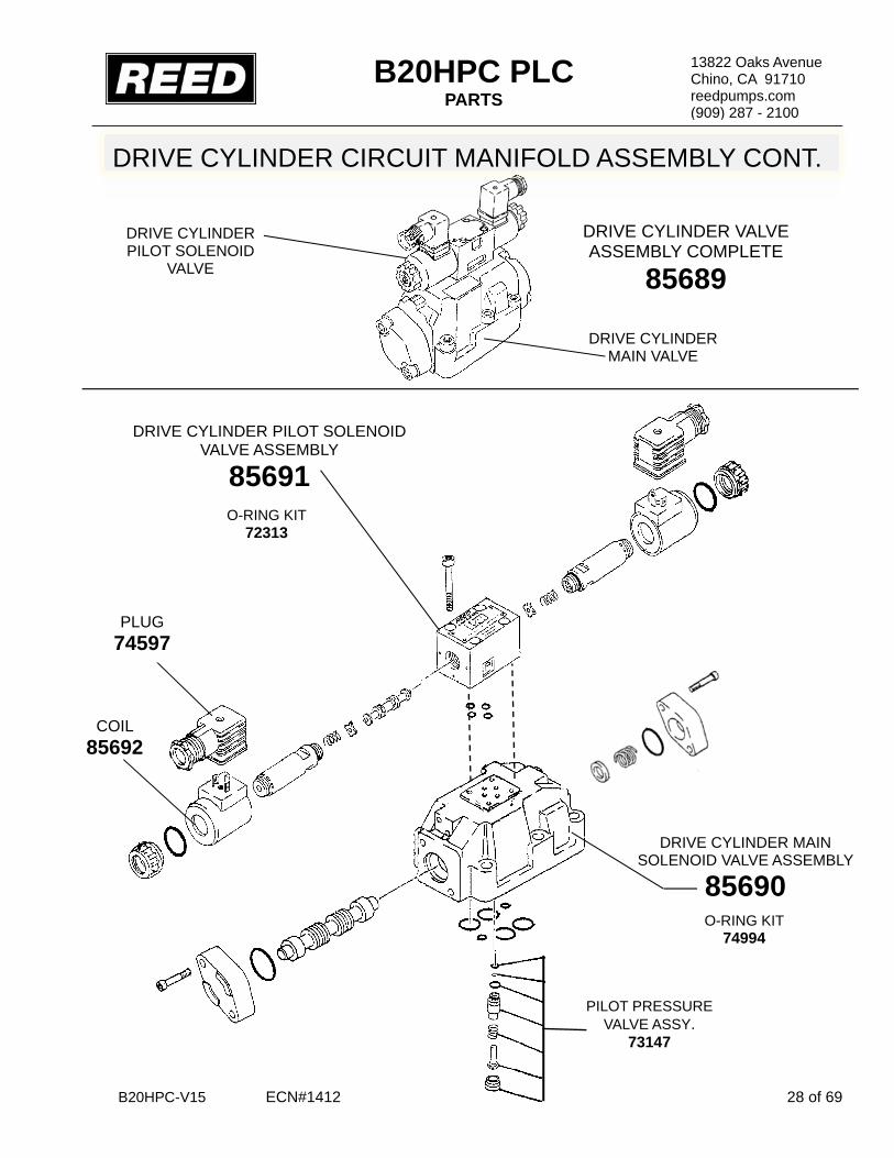
B20HPC PLC PARTS
B20HPC-V15 ECN#1412 28 of 69
13822 Oaks Avenue Chino, CA 91710 reedpumps.com (909) 287 - 2100
PILOT PRESSURE VALVE ASSY.
73147
DRIVE CYLINDER CIRCUIT MANIFOLD ASSEMBLY CONT.
DRIVE CYLINDER PILOT SOLENOID
VALVE
DRIVE CYLINDER MAIN VALVE
DRIVE CYLINDER MAIN SOLENOID VALVE ASSEMBLY
85690 O-RING KIT
74994
DRIVE CYLINDER VALVE ASSEMBLY COMPLETE
85689
COIL 85692
PLUG 74597
DRIVE CYLINDER PILOT SOLENOID VALVE ASSEMBLY
85691 O-RING KIT
72313

B20HPC PLC PARTS
B20HPC-V15 ECN#1412 29 of 69
13822 Oaks Avenue Chino, CA 91710 reedpumps.com (909) 287 - 2100
S-TUBE CIRCUIT MANIFOLD ASSEMBLY
ID # PART # PART DESCRIPTION QUANTITY 85249 MANIFOLD, S-TUBE CIRCUIT ASSEMBLY 1 86821 MANIFOLD, MACHINED S-TUBE CIRCUIT 1 EA 2 85693 SOLENOID VALVE, S-TUBE SHIFT 1 EA 3 85704 UNLOADER VALVE CARTRIDGE, (QCDB) 1 EA
3A 85704-SK SEAL KIT 4 85703 RELIEF VALVE CARTRIDGE, (RVEA) 1 EA
4A 85703-SK SEAL KIT 5 87246 SOLENOID VALVE CARTRIDGE, (12CHS) 1 EA 6 87247 COIL, 12VDC, 1 EA 7 85705 BALL VALVE, 1 EA 8 87248 SOLENOID VALVE CARTRIDGE, (14CHS) 1 EA 9 87249 COIL, 12V DC FOR PN-87248 1 EA 10 78593 MINICHECK ADAPTOR, SAE 2 EA 11 86728-014 ELBOW, MB-MJ90-10-10 2 EA 12 86900-027 ADAPTOR, MB-MJ-16-12 1 EA 13 86946 O-RING #230 BUNA 90DUR 1 EA
2 3 4 TORQUE 45-50
FT-LBS
TORQUE 30-35 FT-LBS
7
TORQUE 35 FT-LBS
10
12 11 10 11
TORQUE 75 FT-LBS 4 PLACES
SHCS ½ -13 X 4”
13 3A 4A
1 O-RING
TORQUE 70 FT-LBS 6 PLACES
SHCS ½”-13 X 2 ½”
TORQUE 20-25 FT-LBS
8
9
5
6
TORQUE 15-20 FT-LBS

B20HPC PLC PARTS
B20HPC-V15 ECN#1412 30 of 69
13822 Oaks Avenue Chino, CA 91710 reedpumps.com (909) 287 - 2100
S-TUBE CIRCUIT MANIFOLD ASSEMBLY CONT.
S-TUBE MAIN SOLENOID ASSEMBLY
85694
S-TUBE PILOT SOLENOID VALVE ASSEMBLY
85695
O-RING KIT 74994
O-RING KIT 72313
S-TUBE MAIN VALVE
S-TUBE PILOT SOLENOID
VALVE
COIL 85692
PLUG 74597
SWING TUBE VALVE ASSEMBLY COMPLETE
85693

B20HPC PLC PARTS
B20HPC-V15 ECN#1412 31 of 69
13822 Oaks Avenue Chino, CA 91710 reedpumps.com (909) 287 - 2100
ACCUMULATOR ASSEMBLY
ID # PART # PART DESCRIPTION QUANTITY 1 71360 ACCUMULATOR-3/4 GAL 1 EA 2 73171 ACCUMULATOR BKT.W/CLOSING HARDWARE 1 EA 3 801028 GROMMET, ACCUMULATOR 1 EA 4 86904-009 ELBOW, MB-MJ90LL-12-12 1 EA
FRAME RAIL
2
1
3
4

B20HPC PLC PARTS
B20HPC-V15 ECN#1412 32 of 69
13822 Oaks Avenue Chino, CA 91710 reedpumps.com (909) 287 - 2100
ELECTRICAL GROUP PROXIMITY SWITCHES
ID # PART # PART DESCRIPTION QUANTITY 89342 ELECTRICAL GROUP B-SERIES, PLC TIER-3 CUMM REF 1 77998 PROXIMITY SENSOR NPN FLUSH BOX MOUT 2 EA 2 10522 STRAIN RELIEF 1 EA 3 30240 GASKET LIQUID TITE ½” -ELECT 1 EA 4 10528 NUT-1/2" BONDING TYPE LOCK 1 EA 5 77990 CABLE, PROXIMITY SWITCH, 5M 2 EA 6 77075 BATTERY-12V 1000 CCA31 1 EA 7 87732 CABLE-43” BATTERY-RED 2/0 1 EA 8 87733 CABLE-37” BATTERY-BLACK 2/0 1 EA
2
3
A
B
1
4

B20HPC PLC PARTS
B20HPC-V15 ECN#1412 33 of 69
13822 Oaks Avenue Chino, CA 91710 reedpumps.com (909) 287 - 2100
STARTER AND ALTERNATOR
ID # PART # PART DESCRIPTION QUANTITY 1 87541 RELAY STARTER 12VDC-SELL W/87544 1 EA 2 73269 GROUND STRAP 1 EA 3 87669 PIGTAIL HARNESS, FOR CUMMINS ALTERN 1 EA 4 87725-006 STARTER MOTOR 1 EA 5 87725-007 ALTERNATOR 1 EA
1
STARTER
+ 12V
3
2
ALTERNATOR
4
5
- GND

B20HPC PLC PARTS
B20HPC-V15 ECN#1412 34 of 69
13822 Oaks Avenue Chino, CA 91710 reedpumps.com (909) 287 - 2100
TRAILER HARNESS AND BREAKAWAY
ID # PART # PART DESCRIPTION QUANTITY 1 77705 BREAK-AWAY KIT 1 EA 2 86533 TRAILER HARNESS- B-SERIES 1 EA 3 86579 TRAILER PLUG 7C FLAT PI 1 EA 4 72949 GROMMET REF 5 72813 GROMMET REF
3
1
2

B20HPC PLC PARTS
B20HPC-V15 ECN#1412 35 of 69
13822 Oaks Avenue Chino, CA 91710 reedpumps.com (909) 287 - 2100
TAIL LIGHTS
ID # PART # PART DESCRIPTION QUANTITY 1 72948 TAIL LIGHT 2 EA 2 87665 LOOM CLAMP 7/8" 2 EA 3 72949 GROMMET 2 EA
UNDERSIDE 3
1
2

B20HPC PLC PARTS
B20HPC-V15 ECN#1412 36 of 69
13822 Oaks Avenue Chino, CA 91710 reedpumps.com (909) 287 - 2100
WIRING HARNESS
1 3
4 2
20
15 18
16
12
13
14 17
11
9
10
19
1 3
4 2
8 7 5
128 PLUG 6
3
17

B20HPC PLC PARTS
B20HPC-V15 ECN#1412 37 of 69
13822 Oaks Avenue Chino, CA 91710 reedpumps.com (909) 287 - 2100
ID # PART # PART DESCRIPTION QUANTITY 89163 WIRING HARNESS B SER PLC, CUMMINGS TIER -3 EA 1 88935 3WAY PLUG DT SER. 2 EA 2 88937 WEDGELOCK 1939V FOR 3 PIN PLUG 2 EA 3 BW10147 CONTACT SOCKET SIZE 16 35 EA 4 88935-B BOOT FOR 3 WAY DT SERIES PLUG 2 EA 5 89116 DEUTSCH WEDGE FOR 89109 2 EA 6 87457 PIN FOR 87456 PLUG 15 EA 7 89109-B BOOT FOR 89109,89157 1 EA 8 89157 DEUTSCH RECEPTACLE 128 CONTACT 1 EA 9 87540 CABLE SOLENOID 3 EA 10 88243 CABLE WITH 2 DIN PLUGS 5M 2 FT 11 77990 CABLE,PROXIMITY SWITCH 3 FT 12 10522 STRAIN RELIEF 1 EA 13 10528 NUT 1/2” BONDING TYPE LOCK 1 FT 14 30240 GASKET-LIQUID ½” 1 EA 15 85615 CABLE, 14AWG-2C, PVC-GRY 6.5 FT 16 85617 CABLE, 14AWG-4C, PVC-GRY 8.1 FT 17 85619 CABLE,16AWG-4C, PVC-GRY 9 FT 18 20169 CABLE, 18AWG-3C PVC BLACK 10 FT 19 87669 PIGTAIL HARNESS, CUMMINS ALT. 1 EA 20 77640 DIODE, IN4003 1 EA

B20HPC PLC PARTS
B20HPC-V15 ECN#1412 38 of 69
13822 Oaks Avenue Chino, CA 91710 reedpumps.com (909) 287 - 2100
PLC CONTROLS B-SERIES CONTROL PANEL
ID # PART # PART DESCRIPTION QUANTITY 89333-T3 B-SERIES CONTROL PANEL ASSY. 1 89090 EMERGENCY STOP PUSH BUTTON HEAVY DUTY 1 EA 2 89090-L ILLUMINATED E-STOP RING 1 EA 3 88979 KEYPAD 2X4 SWITCH, PROGRAMMABLE 1 EA 4 88198 MD3, PARKER DISPLAY MODULE 1 EA 5 89092-D DECAL CONTROL PANEL C-SER PLC 1 EA 6 89004 KEY SWITCH SEALED 1 EA 7 890952-P PANEL FORMED FRONT, PLC C SERIES 1 EA 8 89092-PB PANEL FORMED BACK, PLC B&C SERIES 1 EA 9 89124 HINGE PIANO 1”X12” LONG 2 EA 10 89092-C PLC PROTECTIVE FRONT COVER 1 EA 11 88978 KEYPAD 2X6 SWITCH, PROGRAMMABLE 1 EA 12 89327 DISPLAY PROTECTIVE FILM 1 EA
5 1 2 4 3
6 8 9 11
10 12
7

B20HPC PLC PARTS
B20HPC-V15 ECN#1412 39 of 69
13822 Oaks Avenue Chino, CA 91710 reedpumps.com (909) 287 - 2100
KEY PAD SWITCHES INSERT KIT
ID # PART # PART DESCRIPTION QUANTITY 89412-BC INSERT KIT FOR PLC SWITCH FUNCTIONS REF 1 89412-2L INSERT,REMOTE ICON (CLEAR) 1 EA 2 89412-4L INSERT,PRESSURE A/B ICON (CLEAR) 1 EA 3 89412-5L INSERT, PUMP ON ICON (CLEAR) 1 EA 4 89412-7L INSERT,PUMP FORWARD ICON (CLEAR) 1 EA 5 89412-1L INSERT,PUMP LOCAL ICON (CLEAR) 1 EA 6 89412-3L INSERT, HORN ICON (CLEAR) 1 EA 7 89412-6L INSERT, PUMP OFF ICON (CLEAR) 1 EA 8 89412-8L INSERT, PUMP REVERSE ICON (CLEAR) 1 EA
1 5
6
7
8
2
3
4

B20HPC PLC PARTS
B20HPC-V15 ECN#1412 40 of 69
13822 Oaks Avenue Chino, CA 91710 reedpumps.com (909) 287 - 2100
KEY PAD SWITCHES INSERT KIT CONT.
ID # PART # PART DESCRIPTION QUANTITY 1 89412-9S INSERT, THROTTLE GAIN ICON (CLEAR) 1 EA 2 89412-10S INSERT, TROTTLE DROP ICON (CLEAR) 1 EA 3 89412-12S INSERT, PUMP VOLUME (-) (CLEAR) 1 EA 4 89412-11S INSERT, PUMP VOLUME (+) (CLEAR) 1 EA 5 89412-13S INSERT, FASCHANGE ON ICON (CLEAR) 1 EA 6 89412-14S INSERT, FASCHANGE OFF ICON (CLEAR) 1 EA 7 89412-15S INSERT, VIBRATOR AUTO ICON (CLEAR) 1 EA 8 89412-16S INSERT, CEM AUTO ICON (CLEAR) 1 EA 9 89412-17S INSERT, VIBRATOR OFF ICON (CLEAR) 1 EA 10 89412-18S INSERT, CEM OFF ICON (CLEAR) 1 EA 11 89412-19S INSERT, VIBRATOR ON ICOM (CLEAR) 1 EA 12 89412-20S INSERT, CEM ON ICOM (CLEAR) 1 EA
1
4 5 7 9
2 3 6 8 10
11
12
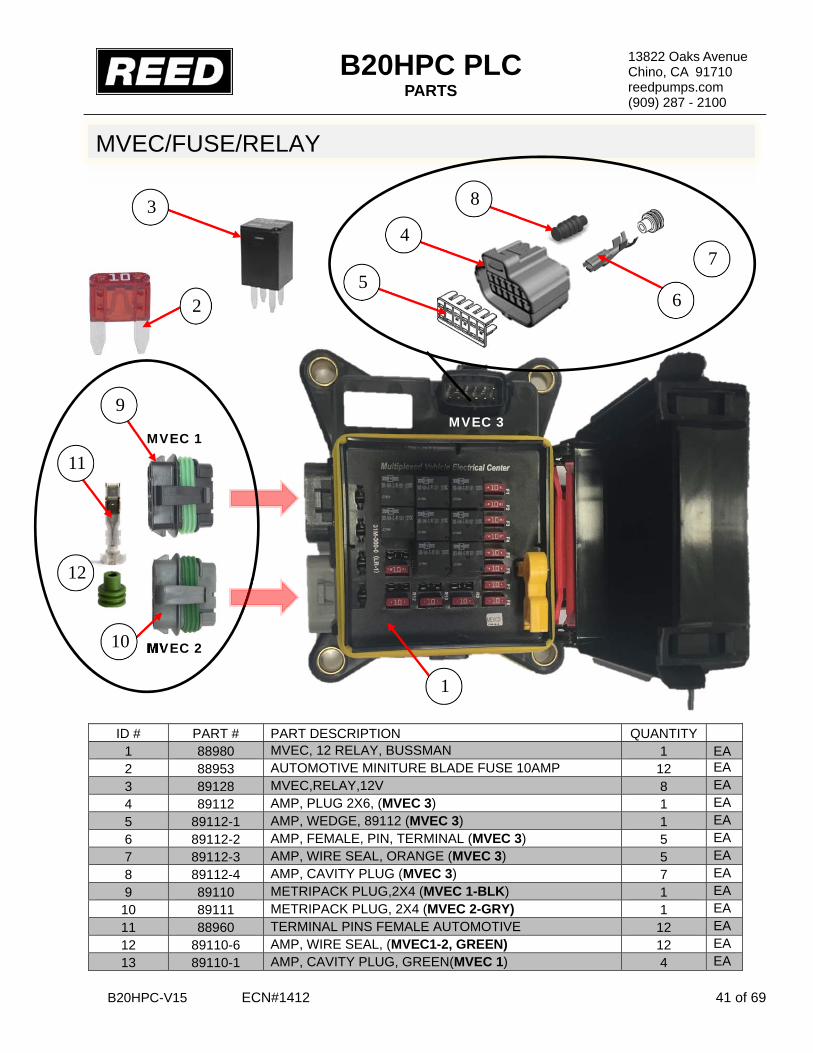
B20HPC PLC PARTS
B20HPC-V15 ECN#1412 41 of 69
13822 Oaks Avenue Chino, CA 91710 reedpumps.com (909) 287 - 2100
MVEC/FUSE/RELAY
ID # PART # PART DESCRIPTION QUANTITY 1 88980 MVEC, 12 RELAY, BUSSMAN 1 EA 2 88953 AUTOMOTIVE MINITURE BLADE FUSE 10AMP 12 EA 3 89128 MVEC,RELAY,12V 8 EA 4 89112 AMP, PLUG 2X6, (MVEC 3) 1 EA 5 89112-1 AMP, WEDGE, 89112 (MVEC 3) 1 EA 6 89112-2 AMP, FEMALE, PIN, TERMINAL (MVEC 3) 5 EA 7 89112-3 AMP, WIRE SEAL, ORANGE (MVEC 3) 5 EA 8 89112-4 AMP, CAVITY PLUG (MVEC 3) 7 EA 9 89110 METRIPACK PLUG,2X4 (MVEC 1-BLK) 1 EA 10 89111 METRIPACK PLUG, 2X4 (MVEC 2-GRY) 1 EA 11 88960 TERMINAL PINS FEMALE AUTOMOTIVE 12 EA 12 89110-6 AMP, WIRE SEAL, (MVEC1-2, GREEN) 12 EA 13 89110-1 AMP, CAVITY PLUG, GREEN(MVEC 1) 4 EA
MVEC 3
1
MVEC 2
MVEC 1
10
9
12
11
3
2
4
8
6
7 5

B20HPC PLC PARTS
B20HPC-V15 ECN#1412 42 of 69
13822 Oaks Avenue Chino, CA 91710 reedpumps.com (909) 287 - 2100
HORN (R3)
VIB (R6)
HORN (R7)
VIB (R8)
BUSS#3 (R1,R4)
10 AMP
89128
BUSS#1 (R2,R5)
MVEC/FUSE/RELAY

B20HPC PLC PARTS
B20HPC-V15 ECN#1412 43 of 69
13822 Oaks Avenue Chino, CA 91710 reedpumps.com (909) 287 - 2100
EXPANSION MODULE PARKER IQAN-XC10
ID # PART # PART DESCRIPTION QUANTITY 1 88919 XC10, PARKER EXPANTION MODULE 1 EA 2 88945 AMP, 35 POS SEAL PLUG, BLACK (C1) 1 EA 3 88946 AMP, 35 POS SEAL PLUG, WHITE (C2) 1 EA 4 88945-S AMP, CONTACT PIN (C1,C2) 38 EA 5 89090-C DC/DC CONVERTER 12VDC TO 24VDC 1 EA
1
C2 C1
C2 C1
4
2 3
5

B20HPC PLC PARTS
B20HPC-V15 ECN#1412 44 of 69
13822 Oaks Avenue Chino, CA 91710 reedpumps.com (909) 287 - 2100
MD3 DISPLAY MODULE
ID # PART # PART DESCRIPTION QUANTITY 1 88918 MD3,PARKER DISPLAY 1 EA 2 88653 PLUG DTM 12 WAY A KEY, GREY (C1) 1 EA 3 88653-2 WEDGELOCK DTM 12 WAY PLUG (C1) 1 EA 4 88959 CONTACT SOCKET SIZE 20 (7.5 AMP) (C1) 9 EA
5 89136 ADDRESS 3 IDTAG WITH DEUTSCH TERMINALS (1K
OHM) 1 EA 6 89327 SCREEN PROTECTOR, MD3 1 EA
1
FRONT
BACK
4
2
3
5

B20HPC PLC PARTS
B20HPC-V15 ECN#1412 45 of 69
13822 Oaks Avenue Chino, CA 91710 reedpumps.com (909) 287 - 2100
ESTOP, KEY ASSEMBLY, PLUGS
ID # PART # PART DESCRIPTION QUANTITY 1 89090 EMERGENCY STOP BUTTON HEAVY DUTY 1 REF 2 89090-L ILLUMINATED E-STOP RING 1 REF 3 89004 KEY SWITCH SEALED 1 REF 4 89107 DEUSCH DT06, 1X6 1 QTY 5 89108 DEUTSCH WEDGE LOCK FOR 89107 1 QTY 6 BW10147 DEUTSCH CONTACT SOCKET, 16AWG 6 QTY
2
ESTOP ASSEMBLY
1
KEY ASSEMBLY
3 5 4 6

B20HPC PLC PARTS
B20HPC-V15 ECN#1412 46 of 69
13822 Oaks Avenue Chino, CA 91710 reedpumps.com (909) 287 - 2100
BUSSES, CONNECTORS, PINS
ID # PART # PART DESCRIPTION QUANTITY 1 89180 DEUTSCH DT04 BUS, 1X8 (SOLID) 3 EA 2 89181 DEUTSCH DT04 BUS, 2X4 (SPLIT) 3 EA 3 89106 DEUTSCH DT04 BUS, 1X12 (SOLID) 5 EA 4 89103 DEUTSCH DT04 BUS, 2X6 (SPLIT) 3 EA 5 89179 DEUTSCH DT06 PLUG, 2X4 5 EA 6 88542-1 WEDGE LOCK FOR 88542 5 EA 7 BW10147 CONTACT SOCKET PIN, SIZE16, 13 AMP EA 8 89104 DEUTSCH DT06 PLUG, 2X6 3 EA 9 89105 WEDGE LOCK FOR 89104 8 EA 10 BW10147 CONTACT SOCKET PIN, SIZE16, 13 AMP EA
3
4
BUSS‐10 BUSS‐11 BUSS‐12 BUSS‐13 BUSS‐3
BUSS‐4 BUSS‐5 BUSS‐8
9 8
10
2
1 BUSS‐2 BUSS‐7 BUSS‐16
BUSS‐1 BUSS‐14 BUSS‐15
6 5
7

B20HPC PLC PARTS
B20HPC-V15 ECN#1412 47 of 69
13822 Oaks Avenue Chino, CA 91710 reedpumps.com (909) 287 - 2100
SERIAL PLATE IDENTICATION
Serial Plate Identification
Panel serial #
Pump type
PLC program
Tier version
Display serial #
Expansion module serial #
Fuse/Relay box serial #
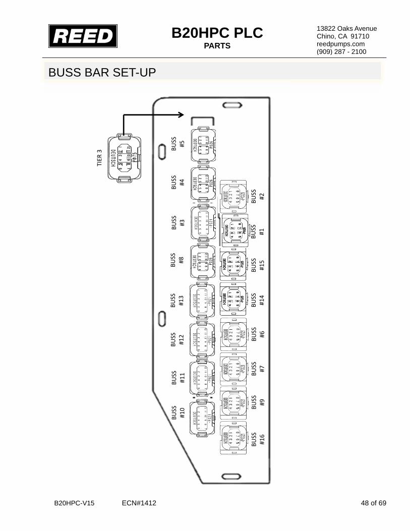
B20HPC PLC PARTS
B20HPC-V15 ECN#1412 48 of 69
13822 Oaks Avenue Chino, CA 91710 reedpumps.com (909) 287 - 2100
BUSS BAR SET-UP
BUSS
#10
BUSS
#11
BUSS
#12
BUSS
#13
BUSS
#8
BUSS
#3
BUSS
#4
BUSS
#5
TIER
3
BUSS
#16
BUSS
#9
BUSS
#7
BUSS
#6
BUSS
#14
BUSS
#15
BUSS
#1
BUSS
#2

B20HPC PLC PARTS
B20HPC-V15 ECN#1412 49 of 69
13822 Oaks Avenue Chino, CA 91710 reedpumps.com (909) 287 - 2100
CAN PUSH BUTTON SWITCH PLUG SWITCH A
ID # PART # PART DESCRIPTION QUANTITY 1 89102 DEUTSCH DT04 PLUG, 2X2 1 EA 2 89132 DEUTSCH WEDGE LOCK FOR 89102 1 EA 3 BW10147 CONTACT PIN 16 AWG (FEMALE) 4 EA 4 89146 DEUTSCH DT04 PLUG, 2X4 1 EA 5 89209 DEUTSCH WEDGE LOCK FOR 89146 1 EA 6 88958 CONTACT PIN 16 AWG (MALE) 4 EA
CAN SWITCH A
X
3 1
5
4
6

B20HPC PLC PARTS
B20HPC-V15 ECN#1412 50 of 69
13822 Oaks Avenue Chino, CA 91710 reedpumps.com (909) 287 - 2100
CAN PUSH BUTTON SWITCH PLUG SWITCH B
ID # PART # PART DESCRIPTION QUANTITY 1 89102 DEUTSCH DT04 PLUG, 2X2 1 EA
2 89132 DEUTSCH WEDGE LOCK FOR 89102 1 EA
3 BW10147 CONTACT PIN 16 AWG (FEMALE) 4 EA
4 89146 DEUTSCH DT04 PLUG, 2X4 1 EA
5 89209 DEUTSCH WEDGE LOCK FOR 89146 1
6 88958 CONTACT PIN 16 AWG (MALE) 4 EA
1
2
5
4
3
6
CAN SWITCH B

B20HPC PLC PARTS
B20HPC-V15 ECN#1412 51 of 69
13822 Oaks Avenue Chino, CA 91710 reedpumps.com (909) 287 - 2100
CAN PLUGS, CONNECTORS
ID # PART # PART DESCRIPTION QUANTITY 1 88934 3 WAY T RECEPTICAL, DT SER. 1 EA 2 88935 3 WAY PLUG DT SER. 3 EA 3 88936 WEDGE LOCK FOR 3 WAY PLUG (GREEN) 2 EA 4 88937 WEDGE LOCK FOR 3 WAY PLUG (BLUE) 1 EA 5 BW10147 CONTACT SOCKETS, 16 AWG (FEMALE) 9 EA 6 88932 3 WAY RECEPTACLES, FLANGE MOUNT-LE08 MOD. 1 EA 7 88938 KEYED WEDGE LOCK FOR 3 WAY RECPT. DT SERIES 1 EA 8 88958 CONTACT PIN, 16 AWG (MALE) 3 EA
6 7 8
ENGINE CAN J1939 BLUE
BLUE
2 GREEN
4
3
1
4
5 2
5
5
NOTE* GREEN-CIRCLE BLUE-TRIANGLE
BLUE

B20HPC PLC PARTS
B20HPC-V15 ECN#1412 52 of 69
13822 Oaks Avenue Chino, CA 91710 reedpumps.com (909) 287 - 2100
ENGINE HARNESS SIDE
6
8
REF 5 9
10 7
DEUTSCH 128 PLUG ASSEMBLY
5
2 1 CONTROL HARNESS SIDE
4
3

B20HPC PLC PARTS
B20HPC-V15 ECN#1412 53 of 69
13822 Oaks Avenue Chino, CA 91710 reedpumps.com (909) 287 - 2100
DEUTSCH 128 PLUG ASSEMBLY CONT.
ID # PART # PART DESCRIPTION QUANTITY 1 89109 DEUTSCH RECEPTACLE 128 CONTACT, PIN 1 EA 2 89159 DEUTSCH WEDGE LOCK FOR 89157 2 EA 3 88958 CONTACT PIN SIZE 16 AWG, (MALE) 72 EA 4 87807 CONTACT PIN SIZE 12 AWG, (MALE) 16 EA 5 89158 DEUTSCH RECEPTACLE, FLANGE 1 EA 6 89109-B DEUTSCH, BOOT COVER 1 EA 7 89157 DEUTSCH RECEPTACLE 128 CONTACT, SOCKET 1 EA 8 89116 DEUTSCH WEDGE LOCK FOR 89157 2 EA 9 87457 CONTACT SOCKET, SIZE 12 AWG, (FEMALE) 1 EA 10 BW10147 CONTACT SOCKET, SIZE 16 AWG, (FEMALE) 1 EA
PLUG ASSEMBLY
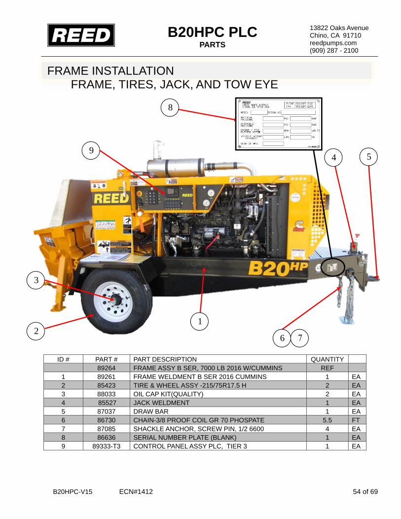
B20HPC PLC PARTS
B20HPC-V15 ECN#1412 54 of 69
13822 Oaks Avenue Chino, CA 91710 reedpumps.com (909) 287 - 2100
FRAME INSTALLATION FRAME, TIRES, JACK, AND TOW EYE
ID # PART # PART DESCRIPTION QUANTITY 89264 FRAME ASSY B SER, 7000 LB 2016 W/CUMMINS REF 1 89261 FRAME WELDMENT B SER 2016 CUMMINS 1 EA 2 85423 TIRE & WHEEL ASSY -215/75R17.5 H 2 EA 3 88033 OIL CAP KIT(QUALITY) 2 EA 4 85527 JACK WELDMENT 1 EA 5 87037 DRAW BAR 1 EA 6 86730 CHAIN-3/8 PROOF COIL GR 70 PHOSPATE 5.5 FT 7 87085 SHACKLE ANCHOR, SCREW PIN, 1/2 6600 4 EA 8 86636 SERIAL NUMBER PLATE (BLANK) 1 EA 9 89333-T3 CONTROL PANEL ASSY PLC, TIER 3 1 EA
1 2
5
7 6
3
4 9
8

B20HPC PLC PARTS
B20HPC-V15 ECN#1412 55 of 69
13822 Oaks Avenue Chino, CA 91710 reedpumps.com (909) 287 - 2100
7000LB AXLE MOUNTING ASSEMBLY
ID # PART # PART DESCRIPTION QUANTITY 89030-H AXLE MOUNTING HARDWARE KIT B20 1 EA 1 ½” -20 X 2.5 HHCS GR8 4 EA 2 ½” SAE WASHER 8 EA 3 ½” USE WASHER 4 EA 4 ½” SAE WASHER 4 EA 5 ½” – 20 LOCK NUT 4 EA 6 ½” BEVELED WASHER 4 EA 7 89030 AXLE, TORSION, 7000 LB 8 on 6.50 HUB FACE 1 EA 8 89011 FLATBAR SPACER 1”X2” 2 EA
6 1
2
3
4
11
5
8
7

B20HPC PLC PARTS
B20HPC-V15 ECN#1412 56 of 69
13822 Oaks Avenue Chino, CA 91710 reedpumps.com (909) 287 - 2100
HOOD AND COVERS
ID # PART # PART DESCRIPTION QUANTITY 1 87737 COVER TOP, B SER CUMMINS PAINTED 1 EA 2 87681 COVER FRONT WELD, B SER CUM PAINTED 1 EA 3 87647 GUSSET ENGINE COVER PAINTED 2 EA 4 85390 SPLASH GUARD, B & C SERIES 1 EA 5 86106 COVER ASSY, FLUSH BOX 1 EA 6 86010 COVER WELDMENT, FLUSH BOX 1 EA 7 86105 KNOB 1 EA 8 79056 HANDLE 1 EA 9 800418 LANYARD, Q/R PIN 1 EA 10 87755 GASKET, FOR FLUSH BOX LID 1 EA
3
TOP COVER BOTTOM COVER
9
FLUSH BOX ASSEMBLY
1
2
4
6 7
8
10
5
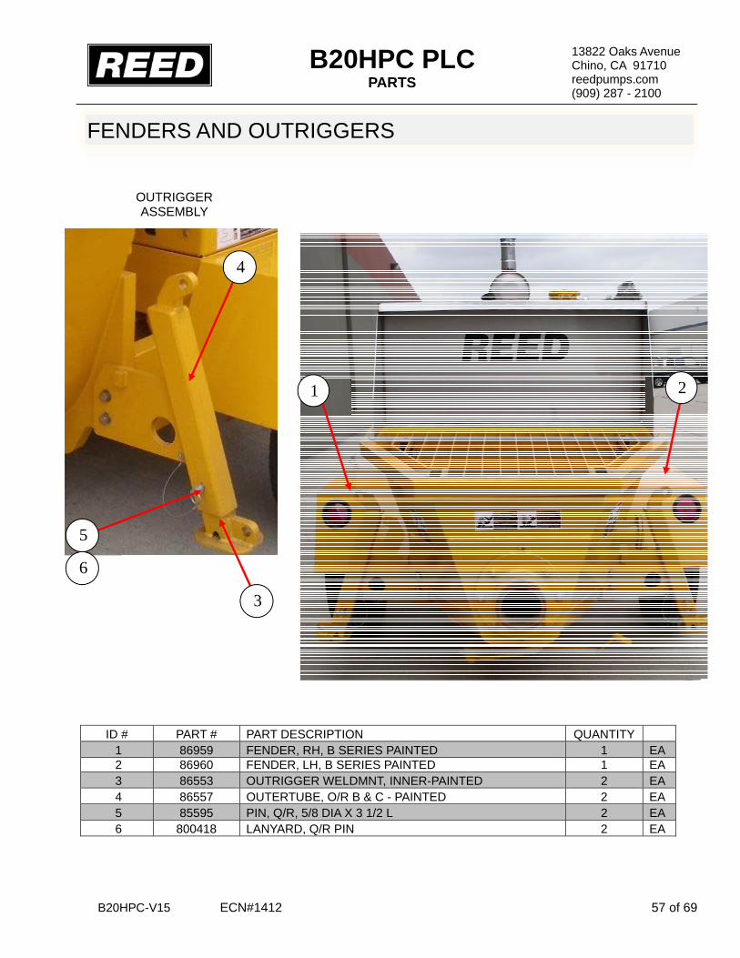
B20HPC PLC PARTS
B20HPC-V15 ECN#1412 57 of 69
13822 Oaks Avenue Chino, CA 91710 reedpumps.com (909) 287 - 2100
FENDERS AND OUTRIGGERS
ID # PART # PART DESCRIPTION QUANTITY 1 86959 FENDER, RH, B SERIES PAINTED 1 EA 2 86960 FENDER, LH, B SERIES PAINTED 1 EA 3 86553 OUTRIGGER WELDMNT, INNER-PAINTED 2 EA 4 86557 OUTERTUBE, O/R B & C - PAINTED 2 EA 5 85595 PIN, Q/R, 5/8 DIA X 3 1/2 L 2 EA 6 800418 LANYARD, Q/R PIN 2 EA
OUTRIGGER ASSEMBLY
6
5
3
4
2 1

B20HPC PLC PARTS
B20HPC-V15 ECN#1412 58 of 69
13822 Oaks Avenue Chino, CA 91710 reedpumps.com (909) 287 - 2100
X 3
X 3
HYDRAULIC OUTRIGGER GROUP
ID # PART # PART DESCRIPTION QUANTITY 88041AO HYD OUTRIGGER GROUP (AGIT=OUTRIGGER) REF 1 85685 TUBE, HYD, OUTRIGGER - PAINTED 1 EA 2 85686 TUBE, HYD, OUTRIGGER - PAINTED 1 EA 3 85659-010 HOSE, 4M2T-6FJX-6FJX-33.00 4 EA 4 801902-020 TUBE CLAMP – 3/8 IN – HALF 4 EA 5 MJ-MJ90-6-6 2 EA 6 74471 VALVE, MAUNAL-3 SPOOL 1 EA 7 800083 FITTING, MINI CHECK (PORT) 1 EA 8 86750 ADAPTER, MB-FB-8-6 1 EA 9 86749 FITTING, MJ-FJX45-10-10 1 EA 10 86746 FITTING, 90° MB-MJ-90-8-10 2 EA 11 86748 FITTING, 90° MB-MJ90-6-6 3 EA 12 86747 FITTING, 90° MB-MJ90LL-6-6 3 EA 13 74471-B BOOT, COVER 3 EA
1 2
3
3
4
5
12
11
6 10 9
7
8
10
13
11
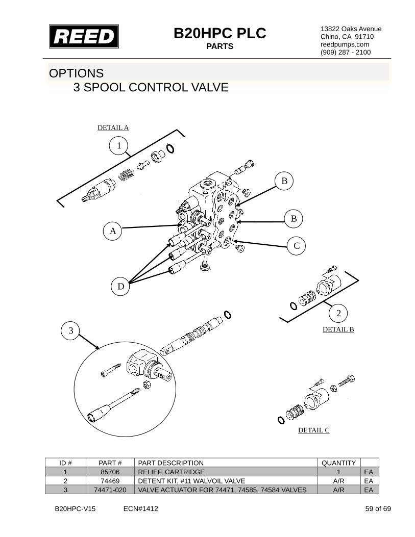
B20HPC PLC PARTS
B20HPC-V15 ECN#1412 59 of 69
13822 Oaks Avenue Chino, CA 91710 reedpumps.com (909) 287 - 2100
OPTIONS 3 SPOOL CONTROL VALVE
ID # PART # PART DESCRIPTION QUANTITY 1 85706 RELIEF, CARTRIDGE 1 EA 2 74469 DETENT KIT, #11 WALVOIL VALVE A/R EA 3 74471-020 VALVE ACTUATOR FOR 74471, 74585, 74584 VALVES A/R EA
DETAIL A
DETAIL D
DETAIL B
DETAIL C
A B
B
2
1
C
3
D

B20HPC PLC PARTS
B20HPC-V15 ECN#1412 60 of 69
13822 Oaks Avenue Chino, CA 91710 reedpumps.com (909) 287 - 2100
OPTIONS HYDRAULIC OUTRIGGER GROUP
ID # PART # PART DESCRIPTION QUANTITY 1 86574 HYD CYL – 2.00 BORE X 12.00 STR – PAINTED 2 EA 2 85659-010 HOSE, 4M2T-6FJX-6FJX-33.00 REF EA 3 86728-008 FITTING, 90° MB-MJ90-8-6 4 EA
REF
1
2
3

B20HPC PLC PARTS
B20HPC-V15 ECN#1412 61 of 69
13822 Oaks Avenue Chino, CA 91710 reedpumps.com (909) 287 - 2100
OPTIONS ELECTRIC HYDRAULIC OUTRIGGER
ID # PART # PART DESCRIPTION QUANTITY 88041-O HYD OUTRIGGER ASSEMBLY, REMOTE REF EA 1 85659-010 HOSE, 4M2T-6FX-6JX-33.00 2 EA 2 87540 CABLE SOLENIOD VALVE, WITH DIN PLUG 4 EA 3 88026 VALVE, 3SPOOL, 2EA. VDC SPOOL 1 EA 4 800083 FITTING, MINI CHECK (PORT) 1 EA 5 86750 ADAPTER, MB-FB-8-6 1 EA 6 86749 FITTING, MJ-FJX45-10-10 1 EA 7 86748 FITTING, 90° MB-MJ90-6-6 3 EA 8 86747 FITTING.90° MB-MJ90LL-6-6 3 EA 9 74471-B BOOT, COVER 3 EA
3
2
4
5
6
1
7
8
9

B20HPC PLC PARTS
B20HPC-V15 ECN#1412 62 of 69
13822 Oaks Avenue Chino, CA 91710 reedpumps.com (909) 287 - 2100
OPTIONS ELECTRIC HYDRAULIC OUTRIGGER CONTROLS
ID # PART # PART DESCRIPTION QUANTITY 1 801206 ENCLOSURE 6X3X3, FIBERGLASS 2 EA 2 88163 DECAL OUTRIGGER UP/DOWN 2 EA 3 BW10205 SWITCH, 3 POSITION MOM/SPDT 2 EA 4 BW10361 SW, SEALING BOOT 2 EA 5 88164-A BRACKET OUTRIGGER CONTROL MOUNT 2 EA 6 73531 90° STRAIN RELIEF 4 EA 7 10528 NUT ½”, BONDING TYPE LOCK 4 EA
1
3
4 2
3/8-16X1” BOLT 3/8 FLAT WASHER 3/8 LOCKNUT
5
7
6

B20HPC PLC PARTS
B20HPC-V15 ECN#1412 63 of 69
13822 Oaks Avenue Chino, CA 91710 reedpumps.com (909) 287 - 2100
1 SPOOL CONTROL VALVE
OPTIONS AGITATOR GROUP
ID # PART # PART DESCRIPTION QUANTITY 1 74584 VALVE, MAUNAL-1 SPOOL 1 EA 2 86746 FITTING, 90° MB-MJ-90-8-10 2 EA 3 86748 FITTING, 90° MB-MJ90-6-6 1 EA 4 86747 FITTING, 90° MB-MJ90LL-6-6 3 EA 5 74471-B BOOT, COVER 1 EA 6 74471-020 VALVE ACTUATOR FOR 74471, 74585, 74584 VALVES A/R EA
1
2
4
3
2
5
6

B20HPC PLC PARTS
B20HPC-V15 ECN#1412 64 of 69
13822 Oaks Avenue Chino, CA 91710 reedpumps.com (909) 287 - 2100
OPTIONS 1 SPOOL AGITATOR VALVE
ID # PART # PART DESCRIPTION QUANTITY 1 85706 RELIEF, CARTRIDGE 1 EA 2 74469 DETENT KIT, #11 WALVOIL VALVE A/R EA 3 74471-020 VALVE ACTUATOR FOR 74471, 74585, 74584 VALVES A/R EA
A
DETAIL A
1
2
DETAIL B
DETAIL C
C
B
3

B20HPC PLC PARTS
B20HPC-V15 ECN#1412 65 of 69
13822 Oaks Avenue Chino, CA 91710 reedpumps.com (909) 287 - 2100
OPTIONS AGITATOR GROUP CONTINUED
ID # PART # PART DESCRIPTION QUANTITY 1 74584 VALVE, MANUAL-1 SPOOL REF EA 2 85657-016 HOSE, 8M2T-10FJX-10FJX45-20.00 2 EA 3 85658-011 HOSE, 6M2T-6FJX-6FJX-21.00 1 EA 4 85658-010 HOSE, 6M2T-6FJX-6FJX-20.00 1 EA 5 FITTING,MB-MJ-10-6 2 EA 6 85845 DECAL, OUTRIGGERS 1 EA 7 800919 DECAL, WARNING, STAND CLEAR 2 EA
4
2
3
1
5
6 7

B20HPC PLC PARTS
B20HPC-V15 ECN#1412 66 of 69
13822 Oaks Avenue Chino, CA 91710 reedpumps.com (909) 287 - 2100
AVAILABLE OPTIONS OUTRIGGER GROUP
HYD OUTRIGGER OUTRIGGER/AGITATOR ELECTRIC OUTRIGGER AGITATOR GROUP
STD/PADDLE OPTION/PADDLE HYD/AGITATOR/SINGLE HYD/AGITATOR/TRIPLE RADIO REMOTE LIFTING KIT
50’ CABLE REMOTE W/STROKE COUNTER
WIRLESS REMOTE 900 MHZ PNUT SYSTEM

B20HPC PLC PARTS
B20HPC-V15 ECN#1412 67 of 69
13822 Oaks Avenue Chino, CA 91710 reedpumps.com (909) 287 - 2100
CARBIDE WEAR PARTS WEAR RING/CARBIDE
WEAR PLATE/CARBIDE REMOTE CONTROL, CABLE
KARTECH PLC 50FT WATER PUMP WASH PUMP INSTALL WASH PUMP ASSY VIBRATOR KIT
COUGAR VIBCO

B20HPC PLC PARTS
B20HPC-V15 ECN#1412 68 of 69
13822 Oaks Avenue Chino, CA 91710 reedpumps.com (909) 287 - 2100
DUAL AXLE TIRE & WHEEL ALUMINUM 9000 LB AUTO LUBE
STEEL TUBING 12 PORT PLASTIC TUBING 12 PORT MANUAL LUBE BLOCK

B20HPC PLC PARTS
B20HPC-V15 ECN#1412 69 of 69
13822 Oaks Avenue Chino, CA 91710 reedpumps.com (909) 287 - 2100
SURGE BRAKE ASSY 9000LB 2"BALL
3”PINTLE
HITCH BALL
2" 2 5/16"


CALIFORNIA
Proposition 65 Warning
Diesel engine exhaust and some of its constituents are knownto the State of California to cause cancer, birth defects, andother reproductive harm.


iv
500ApndxLOP.fm
SAFETY MANUAL
Table of Contents
Introduction
. . . . . . . . . . . . . . . . . . . . . . . . . . . . . . iii
General Rules . . . . . . . . . . . . . . . . . . . . . . . . . . . . . 1
Table of Contents
. . . . . . . . . . . . . . . . . . . . . . . . . . . . . . . . . . . . . . . . . . . .
1
I.
Before You Leave The Yard . . . . . . . . . . . . . . . . . . . . . . . 2
1.
Safety Alert Symbol And Signal Word Explanation . . . . . . . . . . . . . . 22. What To Do Before You Arrive At Work . . . . . . . . . . . . . . . . . . 23. What To Check Before You Leave The Yard . . . . . . . . . . . . . . . . . 44. Safety Rules For Driving Truck Mounted Concrete Pumps . . . . . . . . . . . 85. Safety Rules For Towing Trailer Mounted Concrete Pumps . . . . . . . . . . 10
II.
On The Job site . . . . . . . . . . . . . . . . . . . . . . . . . . . 12
6.
Safety Rules For Job Setup . . . . . . . . . . . . . . . . . . . . . . . 127. Setting Up A Trailer Mounted Pump and/or A Separate Pipeline . . . . . . . . 27
III.
Concrete Pump Operation. . . . . . . . . . . . . . . . . . . . . . . 32
8.
Safety Rules For Pump Operators . . . . . . . . . . . . . . . . . . . . 32
IV.
Cleaning The Pump And System . . . . . . . . . . . . . . . . . . . . 44
9.
Safety Rules For Cleaning The Boom . . . . . . . . . . . . . . . . . . . 4410. Safety Rules For Cleaning The Concrete Valve & Hopper. . . . . . . . . . . 4411. Safety Rules For Cleaning The Water Box . . . . . . . . . . . . . . . . . 4512. Safety Rules For Cleaning A Separately Laid Pipeline . . . . . . . . . . . . 46
V.
Maintenance Of The Machinery . . . . . . . . . . . . . . . . . . . . 51
13.
Safety Rules Regarding Inspection . . . . . . . . . . . . . . . . . . . . 5114. Safety Rules Regarding Scheduled Maintenance . . . . . . . . . . . . . . 5215. Safety Rules When Servicing The Machinery. . . . . . . . . . . . . . . . 53
VI.
Co-worker Safety . . . . . . . . . . . . . . . . . . . . . . . . . . 57
16.
Safety Rules For Workers Assigned To The Pump. . . . . . . . . . . . . . 5717. Safety Rules For The Placing Crew. . . . . . . . . . . . . . . . . . . . 64
Appendix
. . . . . . . . . . . . . . . . . . . . . . . . . . . . . . . 71
VII.
Weld On Ends / Coupling Comparison . . . . . . . . . . . . . . . . . 72
VIII. Minimum Pipe Wall Thickness Chart . . . . . . . . . . . . . . . . . . 73
IX. Glossary Of Terms . . . . . . . . . . . . . . . . . . . . . . . . . 74
X. Recommended Hand Signals . . . . . . . . . . . . . . . . . . . . . 80
XI. Bibliography . . . . . . . . . . . . . . . . . . . . . . . . . . . . 80
Alphabetical Index
. . . . . . . . . . . . . . . . . . . . . . . . . . . . 81
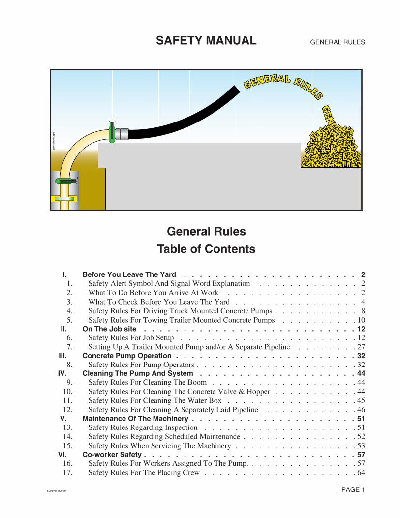
genr
ulec
ov.e
ps
GENERAL RULES
500smgrTOC.fm
PAGE
1
SAFETY MANUAL
I.
Before You Leave The Yard . . . . . . . . . . . . . . . . . . . . . . 2
1.
Safety Alert Symbol And Signal Word Explanation . . . . . . . . . . . . . 22. What To Do Before You Arrive At Work . . . . . . . . . . . . . . . . . 23. What To Check Before You Leave The Yard . . . . . . . . . . . . . . . . 44. Safety Rules For Driving Truck Mounted Concrete Pumps . . . . . . . . . . . 85. Safety Rules For Towing Trailer Mounted Concrete Pumps . . . . . . . . . . 10
II.
On The Job site . . . . . . . . . . . . . . . . . . . . . . . . . . . 12
6.
Safety Rules For Job Setup . . . . . . . . . . . . . . . . . . . . . . . 127. Setting Up A Trailer Mounted Pump and/or A Separate Pipeline . . . . . . . . 27
III.
Concrete Pump Operation . . . . . . . . . . . . . . . . . . . . . . . 32
8.
Safety Rules For Pump Operators . . . . . . . . . . . . . . . . . . . . . 32
IV.
Cleaning The Pump And System . . . . . . . . . . . . . . . . . . . . 44
9.
Safety Rules For Cleaning The Boom . . . . . . . . . . . . . . . . . . . 4410. Safety Rules For Cleaning The Concrete Valve & Hopper . . . . . . . . . . . 4411. Safety Rules For Cleaning The Water Box . . . . . . . . . . . . . . . . . 4512. Safety Rules For Cleaning A Separately Laid Pipeline . . . . . . . . . . . . 46
V.
Maintenance Of The Machinery . . . . . . . . . . . . . . . . . . . . . 51
13.
Safety Rules Regarding Inspection . . . . . . . . . . . . . . . . . . . . 5114. Safety Rules Regarding Scheduled Maintenance . . . . . . . . . . . . . . . 5215. Safety Rules When Servicing The Machinery . . . . . . . . . . . . . . . . 53
VI.
Co-worker Safety . . . . . . . . . . . . . . . . . . . . . . . . . . . 57
16.
Safety Rules For Workers Assigned To The Pump. . . . . . . . . . . . . . . 5717. Safety Rules For The Placing Crew . . . . . . . . . . . . . . . . . . . . 64
General Rules
T
able of Contents

GENERAL RULES
SAFETY MANUAL
I. Before You Leave The Yard
1. Safety Alert Symbol And Signal Word Explanation
1.1 The triangle with the exclamation point inside is used to alert you to an important safety point, and is called a Safety Alert Symbol. One of the following color-coded signal words will appear after the safety alert symbol:
• If the safety alert symbol is followed by the signal word DANGER with white letters in a red box ( ), it indicates a hazardous situation which, if not avoided, WILL lead to death or serious injury.
• If the safety alert symbol is followed by the signal word WARNING with black letters in an orange box ( ), it indicates a potentially hazard-ous situation which, if not avoided, COULD result in death or serious injury.
• If the safety alert symbol is followed by the signal word CAUTION with black letters in a yellow box ( ), it indicates a potentially hazard-ous situation which, if not avoided, COULD result in minor to moderate injury.
• The signal word CAUTION, used in a yellow box, but without the safety alert symbol ( ), means the point addresses a hazard which, if not avoided, COULD cause damage to equipment or property.
2. What To Do Before You Arrive At Work
2.1 Get enough sleep to be ready for the day’s work. Accidents can happen when the body is on the job, but the mind is not.
Dress in appropriate apparel and Personal Protective Equipment (P.P.E.) (see Fig-ure 1). You should always wear these items when pumping concrete:
• hard hat
• safety glasses or goggles
• snug fitting clothes
• gloves
• steel toed shoes
In addition, you should wear:
• hearing protection if you stand near the pump
• breathing mask when mixing slurry or whenever there is cement dust in the air
DANGERWARNINGCAUTIONCAUTIONor - without
the symbol:
DANGER
WARNING
CAUTION
CAUTION
PAGE 2†† Illustration © British Concrete Pumping Association. Used by permission.

GENERAL RULES
SAFETY MANUAL
• rubber gloves during cleanout
• rubber boots anytime you have to stand in concrete
Jewelry, athletic shoes, sandals, and shorts are examples of clothing that should NOT be worn when pumping.
2.2 Be sure that any clothing you wear does not have strings, fringes, or other external tightening means that could be caught in moving parts (Figure 2).
Hard Hat
Safety Glasses
HearingProtection
BreathingMask*
Safety Vest
Work Glovesor Rubber Gloves
Snug-fittingClothes
Steel Toed Shoes orFinisher’s Boots
Saf
eGea
r_w
Ves
tNom
ask.
eps
Figure 1Personal Protective Equipment (P.P.E.)
* Breathing mask needed when cement dust (or other toxic dust) is present in the air.
WARNING
Safewntr.eps
Knot and cut offexcess string
This is ahazard!
Figure 2No strings attached
500smgr.fm PAGE 3

GENERAL RULES SAFETY MANUAL
2.3 Arrive to work on time. Accidents can be caused by hurrying through procedures.
2.4 Never go to work on a construction site or work on, around or near a piece of machinery when under the influence of drugs or alcohol. Beware of “over the counter” drugs, many of which have specific warnings about operat-ing machinery after taking the medication (Figure 3).
2.5 Don’t bring your personal problems to work with you. In an office setting this may be annoying to co-workers, but on a construction site it can be deadly. The workers around you depend on you for their safety.
3. What To Check Before You Leave The Yard
3.1 Do not operate the machine until you read and understand the unit’s operation manual. Lack of understanding of proper operating procedures could result in unsafe operation. Operation manuals are issued with each new unit. If you haven’t seen it, ask your supervisor. Replacements are available from the manufacturer.
3.2 Inspect delivery pipes, concrete delivery hoses, and end hoses for wear. Never use a worn hose or worn or dented pipe. Know the maximum pressure that your machine can exert on the concrete, and be sure that the pipes, hoses and clamps are capable of handling the pressure. Maximum pres-sure on concrete is stated in operation manuals, service manuals, and on the serial number plate of the machine. A chart showing the minimum wall thickness of pipeline versus maximum pressure is found on page 73 in the appendix section of this Safety Manual.
3.3 If you will need to use compressed air to clean out the boom or system pipeline, BE SURE that you have the proper training, equipment, and attachments to do this procedure safely! Proper attachments include:
WARNING
RO
T GUT
NO!
nodrugs.eps
Figure 3Your co-workers depend upon you for their safety
WARNING
WARNING
WARNING
WARNING
PAGE 4 500smgr.fm

GENERAL RULESSAFETY MANUAL
• A blow out head with properly sized air discharge regulator valve and separate water/air inlet. The two openings should be spaced apart far enough that a blowout ball could not cover both openings at once.
• A go devil, or a hard sponge ball. Regardless of which is used, it must fit into the pipeline tight enough that air cannot escape ahead of it.
• A ball or go devil catcher that will catch the go devil or ball when the line has been purged of all concrete. There are two types of catchers (see paragraph 7.23 on page 31).
• A hose that is rated for the pressure of the air compressor you will use and that is able to connect with both the air compressor and the blow out head. The hose must be in good working condition and must be free of cracks, frays, tears or other damage. Do NOT improvise on this. Make sure that you have the right part (Figure 4).
3.4 Be sure that the unit is equipped with all the pipes, clamps, gas-kets and hoses, blow out adapters, ball catchers, and other accessories that you will need for the day’s work. “Making do” with inappropriate equipment could cause accidents.
3.5 On trailer mounted units, check the oil and cooling system (air or water cooled systems) of the pump drive engine. Accidents could occur when lack of mainte-nance is causing a distraction while operating the equipment.
3.6 Be sure the battery has enough charge to start the pump drive engine. You will be rushed on the job if you have to do repair work before you can begin operation.
ball catcher
Water/air inlet
Air dischargeregulator valve
Air inletregulator valve
blow out head
Figure 4Compressed air accessories
WARNING
500smgr.fm PAGE 5
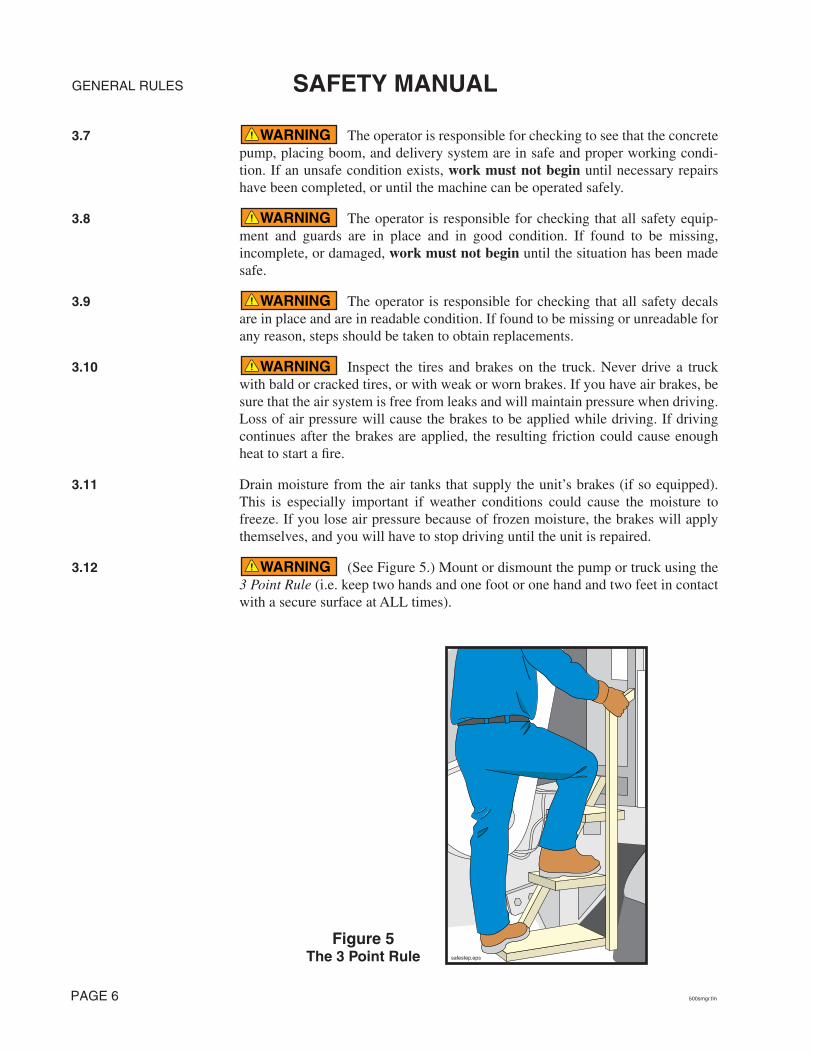
GENERAL RULES SAFETY MANUAL
3.7 The operator is responsible for checking to see that the concrete pump, placing boom, and delivery system are in safe and proper working condi-tion. If an unsafe condition exists, work must not begin until necessary repairs have been completed, or until the machine can be operated safely.
3.8 The operator is responsible for checking that all safety equip-ment and guards are in place and in good condition. If found to be missing, incomplete, or damaged, work must not begin until the situation has been made safe.
3.9 The operator is responsible for checking that all safety decals are in place and are in readable condition. If found to be missing or unreadable for any reason, steps should be taken to obtain replacements.
3.10 Inspect the tires and brakes on the truck. Never drive a truck with bald or cracked tires, or with weak or worn brakes. If you have air brakes, be sure that the air system is free from leaks and will maintain pressure when driving. Loss of air pressure will cause the brakes to be applied while driving. If driving continues after the brakes are applied, the resulting friction could cause enough heat to start a fire.
3.11 Drain moisture from the air tanks that supply the unit’s brakes (if so equipped). This is especially important if weather conditions could cause the moisture to freeze. If you lose air pressure because of frozen moisture, the brakes will apply themselves, and you will have to stop driving until the unit is repaired.
3.12 (See Figure 5.) Mount or dismount the pump or truck using the 3 Point Rule (i.e. keep two hands and one foot or one hand and two feet in contact with a secure surface at ALL times).
WARNING
WARNING
WARNING
WARNING
WARNING
safestep.eps
Figure 5The 3 Point Rule
PAGE 6 500smgr.fm

GENERAL RULESSAFETY MANUAL
3.13 Never mount or dismount the truck or pump while carrying objects that prevent you from using the “3 Point Rule.” Move the objects sepa-rately, if needed.
3.14 Be sure that outriggers are pinned and locked before traveling. If the locking device is damaged or worn, it should be repaired immediately and the unit must not be driven until the outriggers can be positively lockedagainst accidental opening (see Figure 6).
3.15 Be sure there is nothing in the cab of the truck (such as empty soda cans, loose tools, etc.) that could interfere with the operation of the vehicle.
3.16 Be sure that all road-related safety devices (warning signs, flares, fire extin-guisher, etc.) are present and secured for travel.
3.17 Be sure all personal protective equipment (hard hat, safety goggles, rubber gloves, etc.) are secured for travel.
3.18 Be sure the windshield and mirrors are clean and free of frost or ice, and that the mirrors are properly adjusted.
3.19 Verify that head lights, tail lights, turn signals, brake lights, backup warning horn, and backup lights are operational.
3.20 In some cases you may be asked to operate a machine other than the one with which you are familiar. In these cases, be sure to:
• Know the weight, height, and width of the machine.
• Have a copy of the operation manual with you.
• Ask the machine’s normal operator, the dispatcher, or your supervisor ques-tions regarding any unusual or unique operational characteristics of the machine.
• Familiarize yourself with the machine by setting it up in the yard and running the functions, and by familiarizing yourself with the operation manual. This is especially important if the new machine is significantly different than the one you normally operate. Your co-workers depend on you to know the machine.
WARNING
WARNING
outr
gopn
.eps
Figure 6Before driving, be sure outriggers cannot open
WARNING
WARNING
WARNING
500smgr.fm PAGE 7

GENERAL RULES SAFETY MANUAL
3.21 Before driving the unit, be sure the boom is securely in its cra-dle, resting on approved boom rests that are in good condition, and secured by the tie-down strap (if so equipped). On some makes and models, the boom can be damaged by the bouncing motion that occurs while driving, but this damage is easily avoided by using the strap (Figure 7).
3.22 Be certain that all loose items on the unit are secured for travel before driving.
4. Safety Rules For Driving Truck Mounted Concrete Pumps
4.1 Electrocution hazard! (See figure 8.) If you’re going to drive under low-hanging overhead power lines and it is not possible to maintain ade-quate safety distance between the pump and the wires, you should look for another route! If none is available, contact the power company responsible for the lines and have them de-energized.
4.2 Carefully select your route of travel. Avoid steep hills, residential areas, construc-tion, low overpass clearances and narrow bridges whenever possible. The driver is responsible for knowing the weight and height of the machine.
WARNING
boomstrp.eps
Figure 7If your unit has a boom strap, use it
WARNING
WARNING
Figure 8Watch for low-hanging power lines
drvwire.eps
PAGE 8 500smgr.fm

GENERAL RULESSAFETY MANUAL
4.3 Collision/falling hazard! Before driving on bridge or elevated roadways, be sure that they can support the weight of the vehicle (Figure 9).
4.4 Collision hazard! Before driving under ANY structure, BE SURE that the machine will clear (Figure 9).
4.5 Explosion hazard! Never refuel the unit near hot surfaces, sparks, or open flames (Figure 10).
4.6 Tipping hazard! The vehicle must not be driven with an unfolded placing boom.
4.7 Possible boom movement. Before driving the unit be sure that the distribution gearcase (PTO) has disconnected the hydraulic pumps. Driving with the hydraulic pumps engaged creates a hazard and is destructive to the pumps.
4.8 Never drive the unit with concrete in the hopper. Concrete could splash out and damage other cars or property.
4.9 Runaway truck hazard! When going down a hill, use one gear lower going down than it would take to go up.
WARNING
ht&wt.eps
Figure 9Know your height and weight
brdgout.eps
WARNING
WARNING
Figure 10Be careful when refueling
explosionSM.eps
WARNING
WARNING
CAUTION
WARNING
500smgr.fm PAGE 9

GENERAL RULES SAFETY MANUAL
4.10 Truck mounted concrete pumps are generally top-heavy. Use caution when making sharp turns with the vehicle (Figure 11).
4.11 Slow down at intersections, near playgrounds, residential areas, and near schools. Children have no knowledge of the increased stopping distances required by heavy vehicles.
4.12 Be familiar with your emergency equipment. Know how to light a flare, etc.
4.13 Drive defensively. You are at a distinct disadvantage when it comes to maneuverability and stopping distance.
4.14 CAUTION! If you must tow the unit, know the correct places to hook the towing cable(s). Improper towing can damage the vehicle or pump.
4.15 Never back up without a guide.
4.16 Know the rules and laws that apply to your state and locality. They have been enacted for your protection and the protection of those around you.
5. Safety Rules For Towing Trailer Mounted Concrete Pumps
5.1 Be sure the towing vehicle is heavy enough and has enough horsepower and braking ability to tow the trailer. This is critical to maintaining control at highway speeds and to braking ability. If the trailer is heavier than the towing vehicle, braking distances will be greatly increased (Figure 12).
WARNING
tipping.eps
Figure 11Maintain control on the curves
WARNING
CAUTION
WARNING
WARNING
CAUTION
WARNING
trlrbg.eps
NO!
Figure 12Do not under size the towing vehicle
PAGE 10 500smgr.fm

GENERAL RULESSAFETY MANUAL
5.2 Check the tires, tire pressure, and brakes on the trailer before towing. Never tow a vehicle with cracked or bald tires. A trailer tire blowout can cause loss of control in the towing vehicle.
5.3 Be especially careful on ice or slippery roads when towing a trailer. A skid that would normally be easily correctable can be multiplied by the trailer, causing loss of control.
5.4 Be sure that the electrical connections between the towing vehi-cle and the trailer are sturdy and reliable, and that the lights on the towing vehicle and trailer are working.
5.5 Always use safety chains and break-away protection when tow-ing a trailer.
5.6 Be aware of local or state regulations regarding mirrors and lights when towing a trailer.
5.7 When towing a trailer, your stopping distance and turning radius are greatly increased. Be aware of this at all times.
5.8 When towing a trailer long distances, it is important to check the hitch, wiring, and safety chains frequently.
5.9 Be aware of your length when towing a trailer. A common cause of trailer accidents is turning too close to curbs or objects.
5.10 Never back up a trailer without a guide.
WARNING
WARNING
WARNING
WARNING
CAUTION
WARNING
WARNING
WARNING
WARNING
500smgr.fm PAGE 11

GENERAL RULES SAFETY MANUAL
II. On The Job site
6. Safety Rules For Job Setup
SETTING UP A TRUCK MOUNTED BOOM PUMP
6.1 The job setup phase can set the stage for accidents. Taking a few extra moments to correctly set up the job will improve your chances of having a safe, trouble-free day.
6.2 The operator is responsible for the safe operation of the machine. Notify your employer, the job superintendent, and/or O.S.H.A. if you are being asked to set up in an unsafe manner. You are never required to take a chance with safety. You are the only person who can determine that the job circumstances under your con-trol are safe.
6.3 Canadian law requires that the boom remains a minimum of 7 meters from elec-tric wires. To conform to the Canadian law, any text in this manual that refers to a 17 foot or 5 meter safety distance from electric wires should be read as 7 meters for use in Canada.
6.4 When overhead wires are in the area that the boom will be moving to complete a pour, a spotter must be employed whose only job is to warn the operator if the boom comes within 17 feet of the wires. The spotter must understand the responsibilities assigned, and must be able to judge a 17 foot distance.
6.5 You MUST avoid hazardous proximity or contact with electric lines at all times! Position the machine so a minimum safety distance of 17 feet (5 meters) is maintained in all boom positions needed to do the job (Fig-ure 13). Never decrease the safety distance to reach an unsafe area with the boom.
DANGER
DANGER
MINIMUM 17 feet!(5 meters)
17ft3.eps
Figure 13Always maintain the safety distance
PAGE 12 500smgr.fm
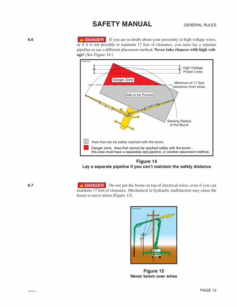
GENERAL RULESSAFETY MANUAL
6.6 If you are in doubt about your proximity to high voltage wires, or if it is not possible to maintain 17 feet of clearance, you must lay a separate pipeline or use a different placement method. Never take chances with high volt-age! (See Figure 14.)
6.7 Do not put the boom on top of electrical wires, even if you can maintain 17 feet of clearance. Mechanical or hydraulic malfunction may cause the boom to move down (Figure 15).
DANGER
Slewing Radiusof the Boom
Slab to be Poured
High VoltagePower Lines
Minimum of 17 feetclearance from wires.
Area that can be safely reached with the boom.
Danger zone. Area that cannot be reached safely with the boom - this area must have a separately laid pipeline, or another placement method.
slbptbad.eps
Danger Zone
Figure 14Lay a separate pipeline if you can’t maintain the safety distance
DANGER
bmovrtop.eps
Figure 15Never boom over wires
500smgr.fm PAGE 13

GENERAL RULES SAFETY MANUAL
6.8 It is crucial to take electric wires into consideration during setup, even if they are away from the area to be pumped! Accidents may occur during cleanout and moving that can be avoided by proper initial setup. In the illustrations below, the pour is outside of the minimum safety distance, but the danger still exists. You must be aware of the wires at all times! (See Figure 16.)
6.9 Depth perception varies from person to person and is affected by the distance from the objects being observed. Minimum distances from electri-cal wires and other obstructions should always be judged by placing yourself in a viewing position that does not require depth perception judgements. If this is not possible, a spotter must be used! See the glossary for the definition of spotter (Figure 17).
DANGER
shckbhnd.eps
Slewing Radiusof the Boom
Slab to bePoured
High VoltagePower Lines
Minimum of 17feet clearance
from wires.
Extremely hazardous area that iswithin the slewing radius of the boom.
Columns to bePoured
tvdgrbhd.eps
Slewing Radiusof the Boom
Slab you poured
High VoltagePower Lines
Minimum of 17 feetclearance from wires.
clnotdgr.eps
Extremely hazardous area that iswithin the slewing radius of the boom.
Figure 16The hazard exists even if the wires
are not in the area of the pour
DANGER
PAGE 14 500smgr.fm

GENERAL RULESSAFETY MANUAL
From the vantage point of this operator, it would be extremely difficult to tell if the end of the boom will contact the electric wires.
dpthprcp.eps
The operator should stand in this position. If this is impossible, a spotter MUST be used. DO NOT RELY ON DEPTH PERCEPTION WITH HIGH VOLTAGE WIRES!
dpthprct.eps
Will it hit the wires?You can’t tell from here.
sptpostn.eps
Get the best possiblevantage point
Figure 17Never rely on depth perception with electric wires
500smgr.fm PAGE 15

GENERAL RULES SAFETY MANUAL
6.10 Always assume that a power line is live. Never take the word of someone on the job site that it has been de-energized. Only a qualified repre-sentative of the responsible power company can verify that a line has been de-energized (see Figure 18).
6.11 Maintain a safe distance from obstructions, such as cranes, scaffolding, and buildings (Figure 19).
6.12 Place wheel chocks under the tires on sloping terrain. Release the brakes and allow the machine to settle against the chocks, then reapply the brakes.
6.13 Remove any snow, ice, oil, or dirt from steps and platforms.
DANGER
alwyslv.eps
Figure 18Assume the wires are energized
WARNING
awyobjct.eps
Figure 19Maintain a safe distance from obstructions
WARNING
CAUTION
PAGE 16 500smgr.fm

GENERAL RULESSAFETY MANUAL
6.14 Possible boom damage! Never add extensions to the end of the placing boom! If continuation pipes are connected to the end hose, they must NOT impose any load on the boom (Figure 20).
6.15 The length of a 125mm boom end hose may not exceed 13 feet (4 meters). Certain machines may require a shorter length or smaller diameter end hose. Check with the boom manufacturer.
WARNING
1hose.eps
Never hang more than one pipe or hose from the boom
mt1hose.eps
Extra pipe or hose must NOT impose an additional load on the boom
Figure 20Know and do not exceed the maximum weight
allowed to hang from the boom
WARNING
500smgr.fm PAGE 17

GENERAL RULES SAFETY MANUAL
6.16 Possible structural damage. If you remove the supplied tip hose and replace it with a combination of reducers and hoses, the total weight of all hanging pieces (including the weight of the concrete) must not exceed the weight of the supplied tip hose (including concrete). The supplied tip hose is typically 12 feet long and 125mm (or 5 inch) diameter. When filled with normal, hard rock concrete it weighs 376 pounds. Certain units may have a lower allowable weight and, thus, a different tip hose. The operation manual included with the unit will inform you of the specification if the unit requires a smaller than standard tip hose. It is the operator’s duty to know the specification of the unit in operation (Figure 21). Find out if your unit has special requirements!
6.17 A concrete delivery hose is a flexible concrete hose that has two end couplings. An end hose is a flexible concrete hose that has one end coupling. In normal usage, it is preferable to have an end hose as the last piece of delivery system. If you will be swinging the full boom over workers or property you must be able to plug the delivery system. See the instructions for plugging the delivery hose on page 43.
WARNING
Adapter pipe from metric 148 mm to Heavy Duty raised ends. Weight of pipe = 5 pounds
Weight of concrete in the pipe = 5 pounds
Heavy Duty 5" clamp.Weight of clamp = 14 pounds
5" to 4" reducer, 36" long. HD ends. Weight of reducer = 43 pounds
Weight of concrete in the reducer = 50 pounds
12 foot long, 4" concrete delivery hose, coupled one end.
4 ply steel reinforced. Heavy Duty raised ends. Weight of hose = 92 pounds
Weight of concrete in the hose = 156 pounds
Heavy Duty 4" clamp.Weight of clamp = 11 pounds
Total of all weights = 376 pounds
Red
wei
ght.e
ps
Figure 21A typical reducer/hose combination
WARNING
PAGE 18 500smgr.fm

GENERAL RULESSAFETY MANUAL
6.18 All hanging system components must be fastened with safety cables or straps, and each component must be capable of handling the maxi-mum concrete pressure of the machine (see Figure 22).
6.19 Placing booms possess a very wide effective operating range. Due to this high degree of mobility, some placing booms can reach a position unsuitable for practical operation. Under certain circumstances overloading, tip-ping, or damage to the boom is possible. These unsuitable areas are documented on safety decals and in operation manuals (see Figure 23). Be aware of these areas if they apply to your unit and set up the pump taking these areas into consideration.
WARNING
Pin all Clamps.
Hanging systemcomponents
redhosnw.eps
Each and every piece of delivery system used must be capable of withstanding the maximum pressure of the pump.
Use a safety cable or strap on each
hanging piece.
Figure 22Assure the safety of hanging system components
WARNING
Figure 23An example of a
hazard area decal
500smgr.fm PAGE 19

GENERAL RULES SAFETY MANUAL
6.20 Collision hazard! Secure the immediate area of the machine from public traffic in accordance with all applicable regulations (warning lights, safety cones, barricades with flashers, etc.).
6.21 Consider the safe approach and departure of the ready-mix trucks and adjust your setup accordingly. Adjusting your setup position by a few degrees one way or another could mean the difference between a safe approach and an unsafe approach. Some examples of unsafe approaches are: too near an excavation or sticking out into traffic.
6.22 If you set up the unit with one or more outriggers not fully extended on the side away from the pour (shortrigging), you will tip the machine if you forget and rotate the boom over the side with the unextended outriggers. That being said, it is known that under certain circumstances, shortrigging is unavoidable (see Figure 24). If no alternatives are practical and you must shortrig for a particular job, keep these points in mind.
• You may only operate the boom when it is placed between outriggers that are completely extended; you may tip if the boom is placed anywhere else.
WARNING
WARNING
WARNING
Job to bePumped
shor
trig
vert
.eps
The green shaded area represents the only area of safe boom movement in this example. Use of the boom in any other area could cause the machine to tip.
Figure 24Shortrigging
PAGE 20 500smgr.fm

GENERAL RULESSAFETY MANUAL
• You should still jack the outriggers that are not fully extended. This will assist in stabilizing and preventing the unit from rocking. The margin of safety this gives you is very small; and won’t prevent you from tipping.
• Don’t get lazy! If it is possible to extend all of the outriggers, do it!
• Don’t forget that you didn’t fully extend all the outriggers. Explain to other workers on the job what will happen if you forget and slew the boom over unextended outriggers. That way, if they see you are moving the boom into a tipping area, they may be able to warn you.
• Outriggers that cannot be fully extended should NOT be partially extended unless specifically allowed by the manufacturer. The inner and outer outrigger box reinforcements will not align in intermediate positions. (Figure 25.)
Figure 25Partial extension is
not allowed
Fulcrum
2. Outrigger fully extended.Lever action present, but
force absorbed by reinforcements.
Force
Force
Fulcrum
OKFulcrum
1. Outrigger fully retracted.No lever action.
Force absorbed by reinforcements.Force must be low, or unit will tip.
Force
OK
3. Outrigger partially extended.Lever action present, but force transmitted to areas
with no reinforcements. Could cause damage.
Fulcrum
NO!Force
Force
Fulcrum
force&leverOUTRIG.eps
OutriggerOuter Box
Reinforcements
OutriggerInner Box
Reinforcements
NO!
nopartialextens ion.eps
500smgr.fm PAGE 21

GENERAL RULES SAFETY MANUAL
When setting the outriggers, jack the unit to within 3° of level, or according to the operation manual of your unit. If the unit is not set up within the specification for level, the boom brakes could fail, causing the boom to rotate downhill by the force of gravity.
6.23 Tipping hazard! Do not unfold the boom until the outriggers have been correctly positioned and secured! The outriggers must be completely extended and opened as described in the operation manual. Do not partially extend the outriggers because intermediate positions are not safe! See the infor-mation regarding shortrigging (paragraph 6.22).
6.24 Tipping hazard! Check soil conditions before jacking the out-riggers. If necessary, use cribbing or suitable pads under the outrigger legs to increase the area of soil contact. See the chart in Figure 26 for examples of load bearing capacities of various soil types and for an example of how to calculate how much cribbing is needed. If in doubt, the site management may be able to supply the load bearing capacity of the soil.
6.25 Tipping hazard! Regardless of whether you know the load bear-ing capacity of the soil or not, you must test your setup by slowly moving the empty boom over each outrigger (Figure 27). If the outrigger begins to sink, retract the boom or move it back in the direction from which it came, until the weight of the boom is removed from the outrigger. Add more cribbing under the outrigger pads and retest until the outriggers are stable. When you put concrete in the boom, again check the outriggers for sinking. Continue to add more cribbing until the soil can support the load. After the pour begins, continue to check the outriggers for sinking throughout the course of the day. The stability of the unit must be ensured.
WARNING
WARNING
WARNING
Virgin groundAsphalt, min. 8" thickCompressed crushed stoneClay/silt soil, firmMixed granular soilFirm compacted gravelmore compactedmore compacted (e.g. class 5)Brittle weathered rock
22 PSI29 PSI36 PSI43 PSI51 PSI58 PSI72 PSI
109 PSI145 PSI
APPROXIMATE PRESSURE SUPPORTINGCAPABILITY OF VARIOUS TYPES OF SOIL
EXAMPLE: Load bearing capacity of the soil (8 inches of asphalt) = 29 PSIForce on the soil by the outrigger leg = 40,000 Pounds (from decal)Pad on outrigger = 12" x 12" (144 square inches)40,000 ÷ 144 = 278 PSI.In this example you could expect the outrigger to sink into the asphalt and possibly cause a tip-over. To prevent this, you install additional cribbing:Additional cribbing = 40" x 40" (1600 square inches)40,000 ÷ 1600 = 25 PSINow the asphalt should support the outrigger. soilpres.eps
Figure 26Calculating load bearing capacity
To calculate soil pressure: Divide theforce on the outrigger leg (from thedecal) by the number of squareinches of soil contact. PSI = LOAD÷AREA PSI = pressure on the soil Load = force in pounds Area = square inches of soil contact.
WARNING
PAGE 22 500smgr.fm

GENERAL RULESSAFETY MANUAL
6.26 TIPPING HAZARD! Maintain a safe distance between the unit and the edge of a cliff or any excavation. The rule of thumb is: for every foot of drop, stay back from the base edge at least 1 foot (the one to one rule). (See Figure 28.) Note that the forces on the outriggers are transferred to the soil at a 45° angle. Watch out for the condition shown in Figure 29.
boomoutwatchpads.eps
Figure 27Verify that the outrigger pads are not sinking
before and after concrete is in the boom.
WARNING
DISTANCEB
DISTANCEA
THE ONE TO ONE RULE:For every 1 foot of vertical drop, stay back from the base edge 1 foot. (Distance "B" must be equal to or greater than distance "A")
Figure 28The one to one rule
X
1to145.eps
Even though the bottom is at a 1 to 1 ratio with the top, this cliff could collapse. Outrigger force is transmitted at a 45 degree angle, and there is no material to support the force at point X.
WARNING!
Figure 29Watch out for this situation!
500smgr.fm PAGE 23

GENERAL RULES SAFETY MANUAL
6.27 Tipping hazard! Take care when setting the outriggers (Figure 30). Never set up on uneven or hilly soil or try to bridge a hole with cribbing. In these cases, you could dig a flat spot in the soil (A, B, & C). Be sure that the out-rigger pad contacts all pieces of cribbing. Run cribbing in the opposite direction, if needed (D).
6.28 When you have the outriggers positioned correctly, close all outrigger hydraulic shutoff valves (if your machine is so equipped).
WARNING
outrgart.eps
A
B
C
D
Figure 30Beware of these outrigger hazards
WARNING
PAGE 24 500smgr.fm
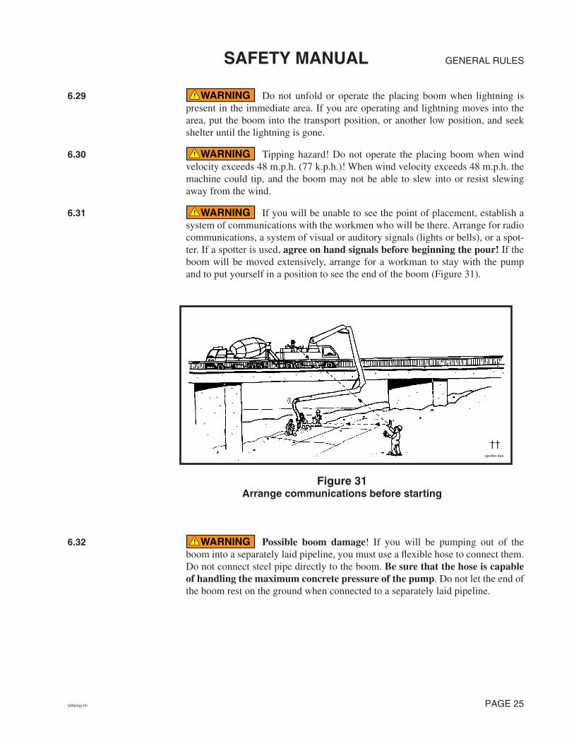
GENERAL RULESSAFETY MANUAL
6.29 Do not unfold or operate the placing boom when lightning is present in the immediate area. If you are operating and lightning moves into the area, put the boom into the transport position, or another low position, and seek shelter until the lightning is gone.
6.30 Tipping hazard! Do not operate the placing boom when wind velocity exceeds 48 m.p.h. (77 k.p.h.)! When wind velocity exceeds 48 m.p.h. the machine could tip, and the boom may not be able to slew into or resist slewing away from the wind.
6.31 If you will be unable to see the point of placement, establish a system of communications with the workmen who will be there. Arrange for radio communications, a system of visual or auditory signals (lights or bells), or a spot-ter. If a spotter is used, agree on hand signals before beginning the pour! If the boom will be moved extensively, arrange for a workman to stay with the pump and to put yourself in a position to see the end of the boom (Figure 31).
6.32 Possible boom damage! If you will be pumping out of the boom into a separately laid pipeline, you must use a flexible hose to connect them. Do not connect steel pipe directly to the boom. Be sure that the hose is capable of handling the maximum concrete pressure of the pump. Do not let the end of the boom rest on the ground when connected to a separately laid pipeline.
WARNING
WARNING
WARNING
spotter.eps
††
Figure 31Arrange communications before starting
WARNING
500smgr.fm PAGE 25

GENERAL RULES SAFETY MANUAL
6.33 It is extremely important to verify that the material deliv-ery system of the boom is capable of handling the pressure of the concrete pump. In some cases, you may not be able to use the boom if you are pumping on piston side. It is up to the machine owner and operator to determine if the boom can be used when pumping on piston side. Keep in mind that pipeline wears out with each stroke of the pump. Verify pipe wall thickness and compare it to pres-sure handling capabilities of that pipe style. The chart for this comparison is found in the appendix of this manual.
6.34 Use only material delivery system components in good con-dition. The useful life of delivery system components is affected by pumping pressure, concrete composition, pipeline material, velocity of moving concrete, and other factors. The use of ultrasonic equipment for determining pipe wall thickness is highly recommended (Figure 32). Read and understand the minimum wall thickness chart in the appendix section of this manual. If you don’t under-stand the chart, contact the service department of the manufacturer of your machine; they will assist you.
6.35 When the machine is ready to work, secure it against unau-thorized use! Either stay with the unit or make sure no one can start it without you. This could be accomplished, for example, by activating the emergency stop switch of the remote control box (cable or radio, whichever is active), then locking it in the cab of the truck. Another way would be to take the transmission out of gear, lock the cab of the truck, and take the key with you.
6.36 Watch for children! When the machine outriggers are jacked up, it is very easy for children to access the space underneath the machine. The rotating driveline(s) and hot components pose serious hazards. Do not let anyone remain under the machine while it is running.
WARNING
WARNING
ultradwg.eps
Figure 32Check for wear on the delivery system components
††
WARNING
WARNING
PAGE 26 500smgr.fm

GENERAL RULESSAFETY MANUAL
6.37 If spectators will be near the pour, cordon off an area where they will be safe. Never operate the machine if it is not safe to do so, even if the spectators just want to see a certain operation or function.
7. Setting Up A Trailer Mounted Pump and/or A Separate Pipeline
7.1 The job setup phase sets the stage for most accidents. Taking a few extra moments to correctly set up the job will improve your chances of having a safe, trouble free day.
7.2 The operator is responsible for the safe operation of the machine. Notify your employer, the job superintendent, and/or O.S.H.A. if you are being asked to set up in an unsafe manner. You are never required to take a chance with safety. You are the only person who can determine that the job circumstances under your con-trol are safe.
7.3 The power connections for electrically driven concrete pumps or separate placing booms must be made by a licensed electrician. The supply power and appropriate disconnect boxes are the responsibility of the con-tractor.
7.4 Electrical power on the job site may be taken only from a fused, grounded disconnect box with a disconnect switch that can be locked against activation. If you will be making repairs to the concrete pump or separate placing boom, first lock out the power at the disconnect box.
7.5 On units equipped with electric motors, check the power cables every day. If they are frayed or have open spots in the insulation, replace the wire. If the connectors are worn or loose, have repairs made by a licensed elec-trician.
7.6 Consider the safe approach and departure of the ready-mix trucks and adjust your setup accordingly. Adjusting your setup position by a few degrees one way or another could mean the difference between a safe approach and an unsafe approach. Some examples of unsafe approaches are: too near an excavation or sticking out into traffic.
7.7 Avoid collisions! Secure the immediate area of the machine from public traffic in accordance with all applicable regulations (warning lights, safety cones, barricades with flashers, etc.).
7.8 Pipelines, end hoses, couplings, and all other material delivery components must be able to withstand the maximum concrete pressure of the pump. Be sure of it! Read and understand the minimum wall thickness chart found in the appendix of this manual.
7.9 Do not use a piece of pipeline, end hose, coupling, or any other material delivery component that is not in good condition. Replace, do not repair damaged pipes and hoses. Concrete pipeline system is subject to wear, and the rate of wear is affected by pumping pressure, concrete composition, pipeline
WARNING
WARNING
WARNING
WARNING
WARNING
WARNING
WARNING
WARNING
500smgr.fm PAGE 27

GENERAL RULES SAFETY MANUAL
material, and other factors. Read and understand the minimum wall thickness chart in the appendix of this manual. Bursting pipes and concrete escaping under pressure is a serious safety hazard! (See Figure 33.)
7.10 When laying out a pipeline, it is preferable to use an elbow instead of a hose to make direction changes. Elbows have less resistance to flow than hoses, and will therefore reduce the overall pressure required to push the concrete.
7.11 Always use the largest diameter pipeline that is practical, and use steel pipe instead of rubber hose. This will keep the pressure required to push the concrete to a minimum.
7.12 Support the delivery pipeline. Either an “S” transition pipe should be used to bring the pipe to ground level, or each section of the pipeline should be supported at the pump outlet level.
7.13 The sections of pipe nearest the pump are subjected to the high-est pressure and the greatest wear. Because of this increase of pressure near the pump, you should install only thick walled pipe, in “like new” condition there. Read and understand the minimum wall thickness chart in the appendix of this manual.
7.14 The maximum concrete pressure of the pump must be the only factor used to determine what thickness of pipe and what type of ends are needed. In the case of a rock jam or any other type of blockage, the maxi-mum pressure of the pump will be exerted.
7.15 Grooved (Victaulic) ends are not recommended for concrete pumping. Read and understand the comparison between heavy duty raised, metric, and grooved ends in the appendix of this manual.
7.16 If the pipeline remains on the job (as is the case when pumping a high rise building), the operator is responsible for checking the pipeline for dents, cracks, wear, and continuity each day before the pour begins.
thinwall.eps
Figure 33Delivery system components must be able
to withstand maximum pump pressure
WARNING
WARNING
WARNING
PAGE 28 500smgr.fm

GENERAL RULESSAFETY MANUAL
7.17 In vertical runs, the weight of the vertical sections of pipe must be supported by a thrust block (often called a deadman, Figure 34) or other load-bearing device. Each section of pipeline in a vertical run must be secured from lateral and horizontal movement.
7.18 If you will be unable to see the point of placement, establish a system of communications with the workmen who will be there. Arrange for radio communications, a system of visual or auditory signals (lights or bells), or a spot-ter (Figure 35). If a spotter is used, agree on hand signals before beginning the pour!
7.19 Never leave the machine unattended when it is running or ready to run. Stop the engine and remove the key if you must leave the area. Make sure no one can start the machine without you. If you’re unsure that the engine would restart, you must leave someone to monitor the unit. This is especially critical if there are children in the vicinity.
WARNING
dead
man
2.ep
s
Thrust block(deadman)
Lateral & horizontalmovement restraint
Figure 34A thrust block (deadman)
WARNING
Figure 35Arrange communications before starting
trlrsptr.eps
WARNING
500smgr.fm PAGE 29

GENERAL RULES SAFETY MANUAL
7.20 Watch for children! It is easy for children to access the space underneath the machine, but it is not safe for them to do so.
7.21 If spectators will be near the job, cordon off an area where they will be safe.
7.22 If you will be cleaning the pipeline with compressed air at the completion of the job, be sure that you have all the necessary accessories to do the job safely. If you don’t have all of them, make arrangements to get them before you begin to pump. Do not improvise on this. Make sure that you have the right parts. The minimum accessories include:
• A blow out head with properly sized air discharge regulator valve, and sepa-rate water/air inlet. The two openings should be spaced apart far enough that a blowout ball could not cover both openings at once.
• A go devil, or a hard sponge ball. Regardless of which is used, it must fit into the pipeline tight enough that air cannot escape ahead of it.
• A ball or “go devil” catcher that will catch the go devil or ball, or some other method of controlling the discharge while the line is being purged of material. There are two types of catchers (see paragraph 7.23).
• A hose that is rated for the pressure of the air compressor you will use and that is able to connect with both the air compressor and the blow out head. The hose must be in good working condition and must be free of cracks, frays, tears or other damage.
• If you will be cleaning the pipeline with compressed air at the completion of the job, be sure an adequate air compressor is available before starting the job.
• If you will be cleaning a vertical pipeline with compressed air at the comple-tion of the job, you must have a shutoff valve or switching valve installed at the bottom of the vertical run!
WARNING
WARNING
WARNING
ball catcher
Water/air inlet
Air dischargeregulator valve
Air inletregulator valve
blow out head
Figure 36Ball catcher and blow out head
PAGE 30 500smgr.fm

GENERAL RULESSAFETY MANUAL
7.23 There are two types of ball catchers. Know which type of catcher you are using. You may need to adjust your clean out procedure according to which type you have. The two types are as follows.
1. Catchers that stop the ball or go devil before air can escape, and
2. Catchers that allow the air out of the pipeline after the ball or go devil has reached the end.
Each type has advantages and disadvantages (Figure 37).
With catcher type 1, the go devil stops, but air is still trapped behind it. The advan-tage is prevention of the sometimes violent expulsion of air at the end of the pipe. The disadvantage is that the air must be drained from the blow out head before the pipe line is safe to open. The pipeline must be controlled; allow no one to open it until all compressed air is relieved.
Catcher type 2 is long enough that the compressed air escapes behind the go devil. Note! This would happen with either catcher when used with a ball instead of a go devil. The advantage of this is that once you hear the turbulent expulsion, there is no pressurized air remaining in the line, and the line may be opened immediately. The disadvantage is the expulsion itself. In this case, the end of the line must be controlled because flying concrete and aggregate pose a hazard.
Both catchers can be safely used if care is given to the hazards involved.
WARNING
AIRPRESSURE
1
AIR
2
ctchrexplnsm.eps
Advantage: There is no turbulent expulsion of air.Disadvantage: Air remains in the line, because it cannot pass thego devil. The line must not be opened until all air is drained at theblow out head.
Advantage: All compressed air is relieved with the expulsion;the pipe may be opened immediately.Disadvantage: There will be a turbulent expulsion as the air escapes.
Figure 37Types of catchers
500smgr.fm PAGE 31

GENERAL RULES SAFETY MANUAL
III. Concrete Pump Operation
8. Safety Rules For Pump Operators
8.1 Only qualified operators are allowed to operate the pump. A “Qualified Operator” is defined as someone who:
• has reached the age of 18 years (21 for interstate travel),
• is physically and mentally capable,
• has been trained in the operation and maintenance of the pump and the plac-ing boom (if applicable),
• has demonstrated his/her capabilities to the employer in respect to the opera-tion and maintenance of the pump and placing boom, and
• can be expected to perform these duties, as assigned, in a reliable manner.
8.2 Because the operator is responsible for the safe operation of the machine, it is crucial that he/she understands the proper operation of the machine and the safety rules that apply to the job at hand, so the course of action taken in unforeseen circumstances will be a safe one. Only thorough training and super-vised job experience can supply the necessary understanding.
8.3 When operating the machine, wear Personal Protective Equipment. (See Figure 38.)
8.4 All guards, covers, and service flaps must be closed and locked during operation.
WARNING
WARNING
WARNING
SafegearWvest.eps
SAFETYGOGGLES
BREATHINGMASK *
SAFETYVEST
SNUGFITTING
CLOTHES
GLOVES
STEEL TOEDSHOES
HARD HAT
HEARINGPROTECTION
Figure 38Wear Personal
Protective Equipment (P.P.E.)
* Needed when exposed to airborne cement particles (or any other toxic dust).
WARNING
PAGE 32 500smgr.fm
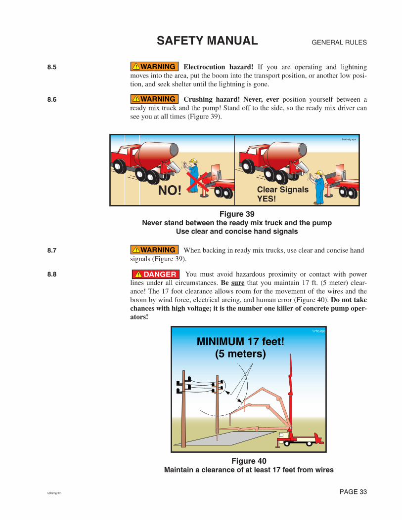
GENERAL RULESSAFETY MANUAL
8.5 Electrocution hazard! If you are operating and lightning moves into the area, put the boom into the transport position, or another low posi-tion, and seek shelter until the lightning is gone.
8.6 Crushing hazard! Never, ever position yourself between a ready mix truck and the pump! Stand off to the side, so the ready mix driver can see you at all times (Figure 39).
8.7 When backing in ready mix trucks, use clear and concise hand signals (Figure 39).
8.8 You must avoid hazardous proximity or contact with power lines under all circumstances. Be sure that you maintain 17 ft. (5 meter) clear-ance! The 17 foot clearance allows room for the movement of the wires and the boom by wind force, electrical arcing, and human error (Figure 40). Do not take chances with high voltage; it is the number one killer of concrete pump oper-ators!
WARNING
WARNING
NO!
backsig.eps
Clear SignalsYES!
Figure 39Never stand between the ready mix truck and the pump
Use clear and concise hand signals
WARNING
DANGER
MINIMUM 17 feet!(5 meters)
17ft3.eps
Figure 40Maintain a clearance of at least 17 feet from wires
500smgr.fm PAGE 33

GENERAL RULES SAFETY MANUAL
8.9 When overhead wires are in the area that the boom will be moving to complete a pour, a spotter must be employed whose only job is to warn the operator if the boom comes within 17 feet of the wires. The spotter must understand the responsibilities assigned, and must be able to judge a 17 foot distance.
8.10 Direct contact with a live power line is always dangerous to everyone and anyone electrically connected to the machine (Figure 41). Use extreme caution near high voltage wires.
8.11 Do not rely on depth perception when working near high volt-age lines. Put yourself at the best possible vantage point to see the distance between the boom and the wires. If that is not possible, then you must use a spot-ter! (See Figure 42.) See the definition of “spotter” in the glossary found in the appendix of this manual.
DANGER
DANGER
everybodyelec.eps
Figure 41If the pump is energized,
everything that touches the pump is also energized
DANGER
From the vantage point of this operator, it would be extremely difficult to tell if the end of the boom will contact the electric wires.
dpthprcp.eps
The operator should stand in this position. If this is impossible, a spotter MUST be used. DO NOT RELY ON DEPTH PERCEPTION WITH HIGH VOLTAGE WIRES!
Figure 42Never rely on depth perception
with high voltage wires
PAGE 34 500smgr.fm

GENERAL RULESSAFETY MANUAL
8.12 Watch for wires that are not directly in the area of the pour. Accidents can happen when moving between points of placement, or when mov-ing the boom after the pour is completed (Figure 43). Never let down your guard when the boom is in the air!
8.13 High voltage makes conductors out of materials that would normally not conduct! Many nonconductors will conduct enough current to kill you if you contact the 8000 volts to ground that is normally found on power poles in the United States (Figure 44). Voltage in the wires may be higher than 8000, especially in industrial areas.
DANGER
shckbhnd.eps
Slewing Radiusof the Boom
Slab you poured
High VoltagePower Lines
Minimum of 17 feetclearance from wires.
clnotdgr.eps
Extremely hazardous area that iswithin the slewing radius of the boom.
Figure 43Never let down your guard
when moving the boom
DANGER
Figure 44Even poor conductors will conduct high voltage
nonc
ondu
ctor
s.ep
s
500smgr.fm PAGE 35

GENERAL RULES SAFETY MANUAL
8.14 Loss of hearing! While standing near a working concrete pump, sound pressure levels may exceed O.S.H.A. standards for constant expo-sure (Figure 45).
8.15 Do not allow unauthorized persons in the operational area of the pump and boom. Warn unauthorized persons present in the area to leave and stop work if they do not comply.
8.16 Do not use the boom as a hoist or crane! (Figure 46.)
8.17 Explosion hazard. Never remove the fuel cap or refuel the unit near hot surfaces, sparks, or open flames. Never smoke while refueling.
CAUTION
WEAR HEARING PROTECTION!
PERMISSIBLE NOISE EXPOSURES* *Under part 1910.95 “Occupational Noise Exposure,” (Dept. of Labor) of the Code ofFederal Regulations, Chap. XVII of Title 29 (39 F.R. 7006).
DURATION per DAYin HOURS
86432
1 1/21
1/21/4 or LESS
Sound level in dB (A)Slow response
90929597100102105110115
††
Figure 45Noise level and exposure time limits
WARNING
WARNING
nolifting4.eps
Figure 46No lifting with the boom
WARNING
PAGE 36 500smgr.fm
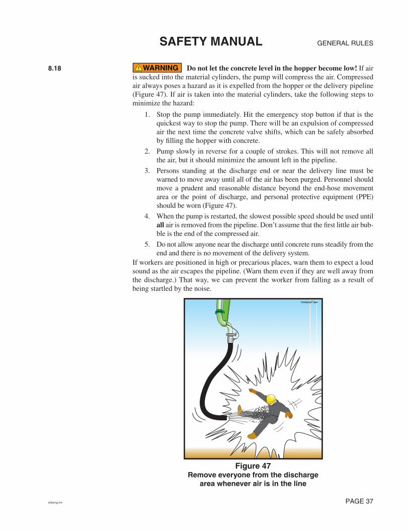
GENERAL RULESSAFETY MANUAL
8.18 Do not let the concrete level in the hopper become low! If air is sucked into the material cylinders, the pump will compress the air. Compressed air always poses a hazard as it is expelled from the hopper or the delivery pipeline (Figure 47). If air is taken into the material cylinders, take the following steps to minimize the hazard:
1. Stop the pump immediately. Hit the emergency stop button if that is the quickest way to stop the pump. There will be an expulsion of compressed air the next time the concrete valve shifts, which can be safely absorbed by filling the hopper with concrete.
2. Pump slowly in reverse for a couple of strokes. This will not remove all the air, but it should minimize the amount left in the pipeline.
3. Persons standing at the discharge end or near the delivery line must be warned to move away until all of the air has been purged. Personnel should move a prudent and reasonable distance beyond the end-hose movement area or the point of discharge, and personal protective equipment (PPE) should be worn (Figure 47).
4. When the pump is restarted, the slowest possible speed should be used until all air is removed from the pipeline. Don’t assume that the first little air bub-ble is the end of the compressed air.
5. Do not allow anyone near the discharge until concrete runs steadily from the end and there is no movement of the delivery system.
If workers are positioned in high or precarious places, warn them to expect a loud sound as the air escapes the pipeline. (Warn them even if they are well away from the discharge.) That way, we can prevent the worker from falling as a result of being startled by the noise.
WARNING
hosepop7.eps
Figure 47Remove everyone from the discharge
area whenever air is in the line
500smgr.fm PAGE 37

GENERAL RULES SAFETY MANUAL
8.19 When initially priming the delivery system, when restarting after moving, when restarting after adding or removing hoses, when attempting to remove a blockage by “rocking” the concrete, or whenever air has been intro-duced into the line, warn everyone to stay away from the discharge until material runs steadily. Personnel should move a prudent and reasonable distance beyond the end-hose movement area or the point of discharge, and personal protective equip-ment (PPE) should be worn (Figure 47).
8.20 A bulk density of approximately 150 pounds per cubic foot is assumed for the material to be pumped with a placing boom (normal concrete). If you intend to pump material with a higher bulk density (e.g., steel fiber entrained concrete), you must contact the manufacturer for advice. Failure to do so may result in damage to the boom and/or instability in certain operating positions.
8.21 Blockages in the pump or delivery pipeline can create an unsafe condition. Blockages are caused by many different factors, as outlined below.
CAUSES OF BLOCKAGES
• Faulty concrete mix design. The concrete that is being supplied may not be a pumpable mix, for example there may be too much sand or too little cement. There may be bleeding or segregation. Some admixtures adversely affect pump-ability (e.g., too much air entrainment). If the mix is not pumpable, no amount of operator expertise will make it so.
• The line size may be inadequate. The line size should always be at least 4 times larger than the largest aggregate being pumped, or blockages could occur.
• Worn concrete valve parts. Worn parts allow the finest material and water to escape back into the hopper when pressure is applied.
• Pipeline and joint deficiencies. This would include dirty pipes (pipes that have not been cleaned properly), worn and leaking pipe joints that allow loss of con-crete fines and water, pipes that haven’t been properly primed before starting, and too many sections of rubber hose, which increases friction. These are all causes of blockages that can be controlled by the operator.
• Pump inadequate for the application. The pump selected for the job may not have enough pressure or horsepower available for the required duty.
• Concrete setting up in the pipeline. This may be caused by delays on site (e.g., repairing a broken form), or by attempting to pump “old” concrete (concrete that was batched hours before pumping and is being kept alive only by adding water and constant agitation). Weather conditions can also affect how quickly the con-crete becomes hard. Companies should establish procedures for these situations. A good rule of thumb is: If in doubt...wash out.
• Foreign matter in the concrete. Pieces of old concrete that break away from mixer fins, unmixed clumps of cement, mixer fins, hammers, and furry mam-mals are examples of foreign matter that have caused blockages.
• An inexperienced operator can cause blockages by setting up the job improperly. For example, if the placing crew is forced to add hose or pipe to reach a far point after the pour is already in progress, there is a great chance of creating a blockage due to the dry conditions inside the pipe or hose. It is for this reason that the job should be set up so pipe or hose need only be removed (never
WARNING
WARNING
WARNING
PAGE 38 500smgr.fm

GENERAL RULESSAFETY MANUAL
added) as the day progresses. If dry pipe or hose must be added, it must be lubri-cated just like the rest of the pipe was lubricated when you first started.
• An inexperienced placing crew can cause blockages by kinking the end hose. This type of blockage can lead to serious accidents because the hose may un-kink by the force of the pump.
• The concrete becomes segregated in the hopper. When it’s raining hard, the cement and fine material get washed from the stone and course sand. This mix will not pump. Cover the hopper as you wait out the passing storm. It is also for this reason that you should never allow a truck mixer to wash out in your hopper!
8.22 Never try to remove a pipeline blockage by applying high pres-sure to it, because that will cause the blockage to become a plug. If you have a blockage, immediately stop the pump. Stroke the pump a couple of times in reverse. Slowly stroke the pump in forward, and try to dislodge the blockage. If you are moving the blockage, continue to do so slowly and gently. While attempt-ing to clear the blockage, remove all personnel from the discharge area, as air may be introduced into the placing line during this process.
8.23 If the pump or associated equipment develops a problem that creates an unsafe condition, you must stop pumping immediately! Do not restart until the unsafe condition has been remedied.
8.24 The following points must be observed when locating a block-age.
• Pump in reverse for at least two strokes, then stop the pump. Do not allow anyone to open the pipeline until this is done (Figure 48).
• Wear personal protective equipment when opening a blocked pipeline.
• Clear the area of nonessential personnel before opening the line.
• Plugs will be found in (in the order of likelihood) reducers, hoses, elbows, and pipe.
• If you are tapping the pipe to find the plug, the sound will be a dull thud (tik-tik) rather than a ringing sound (tong-tong) at the spot of the plug, because the jammed material will keep the pipeline from vibrating. (This method won’t find a plug in a hose.)
WARNING
WARNING
WARNING
Figure 48Never open a pressurized pipeline
smexplode.eps
NO!
500smgr.fm PAGE 39

GENERAL RULES SAFETY MANUAL
8.25 It is possible that some pressure will remain in the pipeline after reversing the pump. Use a shovel or pry bar to open the clamps on a blocked pipeline. Wear face protection, and turn away from the pipeline when opening the clamp.
8.26 It would be better to let the pipe be ruined by setting concrete than to risk injury by ignoring safe procedures. Always use safe practices when cleaning pipe. Remember, pipeline is replaceable, you are not.
8.27 Do not kink hoses. Kinking will cause the pump to create max-imum concrete pressure. The pump may unkink the hose with force! (See Fig-ure 49.)
8.28 Never use compressed air to clear a blockage! It is unsafe and unnecessary. The pump can develop much more pressure than an air compressor. If the pump pressure can’t move it, air pressure won’t either.
8.29 Never stand on, sit on, or straddle a pipeline while it’s in use, or whenever it is pressurized. Pipeline wears out with each stroke of the pump. If the pipe bursts, you want to be to the side of it, not on top of it (Figure 50).
WARNING
WARNING
WARNING
Figure 49Kinking the hose creates a hazard
WARNING
WARNING
NO!
pipelineguyColor.eps
Figure 50Never straddle or sit on a pressurized pipeline
PAGE 40 500smgr.fm
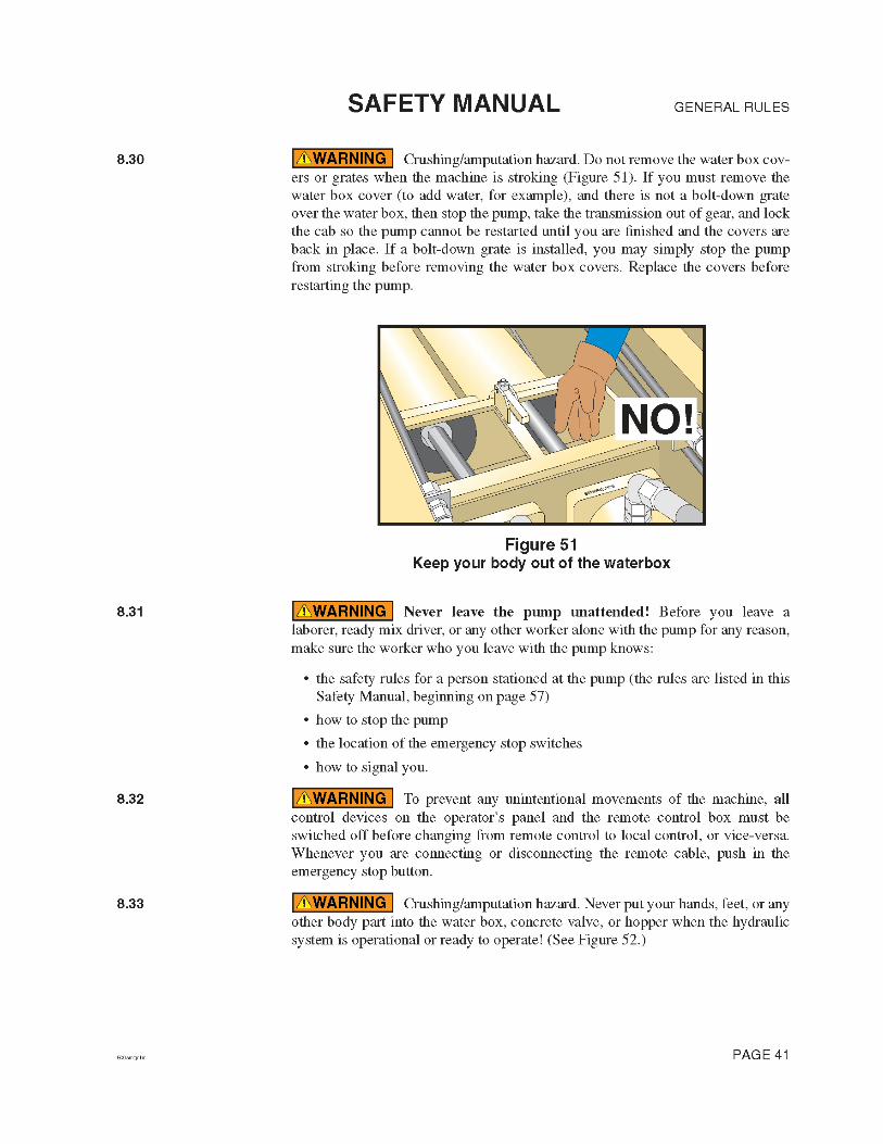

GENERAL RULES SAFETY MANUAL
8.34 Do not work on the hopper, water box, concrete valve, or the hydraulic system unless the drive engine is turned off and the accumulator pres-sure (if so equipped) has been released! On units with internal combustion engines, the key must be removed. If there is more than one key, you should tag the ignition. On units driven by electric motors, the main disconnect must be locked out according to applicable standards.
8.35 Never operate the boom “blind.” If you can’t see the point of placement, you must establish a system of communications with the workmen who can see the point of placement. Arrange for radio communications, a system of visual or auditory signals (lights or bells), or a spotter. If a spotter is used, agree on hand signals before beginning the pour! (Use of the ACPA standardized hand signals is highly recommended.) If the boom will be moved extensively, arrange for a workman to stay with the pump and put yourself in a position to see the end of the boom (Figure 53).
NO!
NO!safehopcolor.eps
Figure 52Don’t put your body
in the machine
WARNING
WARNING
Figure 53Never pump blind spotter2.eps
PAGE 42 500smgr.fm

GENERAL RULESSAFETY MANUAL
8.36 Always block the discharge end when you must swing a full boom over workers or property. You must stop concrete from falling out of the boom. This can be done with a shut-off valve, or by removing the hose and putting a blanking plug on the last elbow (Figure 54), or by kinking the end hose and securing it in the kinked position. Please note— hoses that can be easily kinked may not be strong enough to withstand the pressure of the pump. Verify the work-ing pressure of the hose against the maximum pressure of the pump before using this type of hose.
WARNING
Plu
gone
lbow
.eps
Figure 54A blanking plug in place on a tip
elbow with safety sling
500smgr.fm PAGE 43

GENERAL RULES SAFETY MANUAL
IV. Cleaning The Pump And System
9. Safety Rules For Cleaning The Boom
9.1 Do not let down your guard when the pour is completed. Acci-dents also happen during cleanout and the drive back to the yard. It is important not to become relaxed about job safety until you are no longer on the job.
9.2 Watch for electric wires when moving the boom for cleanout or folding the boom for transport!
9.3 Using compressed air to clean the boom delivery system should only be done when no other method is practical or as recommended by the manu-facturer.
9.4 If you have to use compressed air for cleaning the boom you must have all of the necessary accessories. Read and understand the complete safety rules regarding cleaning out with compressed air (point 12.4 on page 47 of this Safety Manual). Cleaning with compressed air should only be done by a qual-ified person.
9.5 Never use compressed air to blow through rubber hoses or short sections of pipe. In the case of rubber hoses, their flexibility will allow them to “whip” wildly with the force of the air and moving concrete. Short sections of pipe will not have sufficient mass to allow the concrete to move slowly, so there will be rapid expulsion of the material.
9.6 If the ball or go devil doesn’t come out of the delivery system after applying compressed air, you must relieve the pipe of air pressure before opening it. If the bleed off valve plugs when you are draining the air, the only safe way to proceed is to drill small holes into the pipeline, which will then allow the air to escape. Wear a full face shield when drilling the holes. Pipe you have drilled into is ruined and must be replaced. Drill the holes to relieve the air pressure even if the concrete has set up in the pipe. The pipe is hazardous until the pressure is relieved.
9.7 Exercise care when “tapping” on the pipeline to find the loca-tion of the cleanout ball. Applying too much force will dent a standard pipe (mak-ing it weak and unsafe) and could break the carbide insert of double wall pipe.
9.8 It is better to let the pipe be ruined by setting concrete than to risk injury by ignoring safe procedures. Remember, pipeline is replaceable, you are not.
10. Safety Rules For Cleaning The Concrete Valve & Hopper
10.1 Tipping hazard! Before moving the unit for cleaning, fold the boom and secure the outriggers into the travel position.
10.2 Wear protective clothing and equipment when cleaning the con-crete pump. Protect against concrete burns and concrete poisoning by wearing rubber boots and gloves during cleanout or any other time that you will be in con-tact with the concrete.
WARNING
WARNING
WARNING
WARNING
WARNING
WARNING
WARNING
WARNING
WARNING
WARNING
PAGE 44 500smgr.fm

GENERAL RULESSAFETY MANUAL
10.3 Crushing and amputation hazard! Never put your hands or any other body part into the concrete valve. Instead, use water jets and the sup-plied rake (Figure 55).
10.4 Never put your hands or any other body part into the machine when the hydraulic system is operational. If you must remove the grate to chip at hardened concrete, you must first disable the system by taking the transmission out of gear and locking the cab door, or stopping the engine, reliev-ing pressure in the accumulator circuit (if so equipped) and securing the controls against unintended operation. Reinstall the grate before restarting the engine (Fig-ure 55).
11. Safety Rules For Cleaning The Water Box
11.1 Crushing and amputation hazard! Stop the concrete pump before removing the water box covers. If your unit has bolt down guards, do not remove them for cleaning. If there is not a bolt-down guard over the water box, then stop the pump, take the transmission out of gear, and lock the cab so the pump cannot be restarted until you are finished cleaning and the covers are back in place. If a bolt-down grate is installed, you may simply stop the pump from strok-ing before removing the water box covers. Replace the covers before restarting the pump.
11.2 If possible, position the folded boom in a slightly raised posi-tion when cleaning the water box (watch for wires when raising the boom). The outriggers must be extended and jacked. If the boom is raised, it will be unneces-sary to bend over the water box for cleaning.
WARNING
WARNING
NO!
NO!safehopcolor.eps
Figure 55Keep your body parts
out of the machine
WARNING
WARNING
500smgr.fm PAGE 45
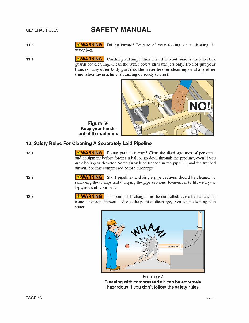

GENERAL RULESSAFETY MANUAL
12.4 Blowing out with compressed air creates potential hazards!Serious injury or death could result if you do not adhere to these safety points.
• Blowing out must be performed under the supervision of a qualified per-son. (See the glossary for the definition of qualified person.)
• Blowing out requires two people! One trained person must be at the inlet end to operate the air insertion, and the other trained person must be near (but safely back from) the discharge point to monitor the discharge and to make sure that no one enters the hazard area.
• No pipe bends or flexible delivery hoses may be connected to the end of the pipeline during the blowing out process, unless there is a pre-planned cleanout station erected to route the discharge into the ready mix truck.
• The point of discharge must be controlled. Clear the discharge area of personnel and equipment before beginning the blowing out process. Do not allow anyone to enter the area during the blow out process. If a ball catcher is used, be aware of which type you have, and adjust your procedure accord-ingly. Ball catcher types are described in paragraph 7.23 on page 31.
• The concrete outlet must be positioned high enough to permit easy dis-charge of the material.
• If you are going to divert the discharge into a discharge pipe system, you must lubricate the discharge line with slurry, or a plug could occur.
• The pipe cleaning blow out head must be equipped with a properly sized air discharge regulator valve and a separate water/air inlet. The two open-ings should be spaced apart far enough that a blowout ball could not cover both openings at once (Figure 58).
• The plug or go devil must be thick enough to prevent compressed air flow around the plug into the concrete.
WARNING
ball catcher
Water/air inlet
Air dischargeregulator valve
Air inletregulator valve
blow out head
Figure 58Ball catcher and blow out head
500smgr.fm PAGE 47

GENERAL RULES SAFETY MANUAL
• The pipeline must not be disassembled until it has been completely relieved of air. Be sure of this! (See Figure 59.)
• Do not use compressed air to blow out concrete delivery hose, single pipe sections and short pipelines up to a length of 40 feet. Hoses will jump and move unpredictably; short pipelines don’t have enough concrete to resist the force of the air, causing it to discharge too quickly, like a cannon (Figure 60).
• When air pressure begins to drop rapidly, shut off the air supply from the compressor, and immediately begin bleeding air out of the pipeline. (The drop in pressure signifies that the pipeline is almost empty of concrete.)
12.5 When blowing out a vertical line, a shutoff valve is required to prevent the following scenario.
1. (See diagram A in Figure 61.) Without a shutoff valve installed, the pipeline is disconnected from the pump. Immediately, the concrete drains out of the ver-tical sections of pipe, leaving concrete in both horizontal sections, and air trapped in between.
explode2col.eps
smexplode.eps
NO!
Figure 59Never open a pressurized pipeline
Figure 60Never use air to blow out hoses or short pipelines
WARNING
PAGE 48 500smgr.fm

GENERAL RULESSAFETY MANUAL
2. (See diagram B in Figure 61.) The ball is inserted, and pushed with com-pressed air. This also compresses the air that is trapped in the vertical sections of pipe. The trapped air will be violently expelled when it reaches the end of the pipe, but the pipe will not yet be empty.
A shutoff valve installed at the bottom of the vertical run will prevent this hazard-ous situation. The shutoff valve must be capable of handling the maximum con-crete pressure of the pump and, of course, must be installed before the pour begins. Several different styles are available, ranging from a manually operated flat gate that is put into place with a hammer to fully hydraulic types that will also divert the concrete to a different pipeline. With a shutoff valve installed, you can proceed as indicated below.
12.6 Blowing out vertical sections of pipe (for example on a high rise building) requires additional safety precautions.
1. Know where the discharge area for blowing out will be before the pour begins. Ready the area and accessories before the pour begins so you will not waste time when pumping is completed.
2. Blowing out with compressed air requires two qualified persons.
Figure 61Blowout of a vertical line
WARNING
500smgr.fm PAGE 49

GENERAL RULES SAFETY MANUAL
3. The persons at both ends of the pipeline must be able to communicate without delays, which means you must establish communications (for exam-ple, with a radio).
4. When pumping is complete, close the shutoff valve before disconnecting the pipeline from the pump (item 1, Figure 61). Failure to do this will cause the concrete to fall out of the vertical sections of pipe, leaving concrete in the horizontal sections of pipe and an air pocket in the vertical sections. This does not apply if you are using a switching (diversion) valve.
5. Install the ball(s) in the pipeline, secure the blow out head and hook up the air compressor. Do not apply the air yet! (Item 2, Figure 61.)
6. If you will be diverting the discharge to a cleanout area, lubricate the dis-charge line with slurry, or a plug could occur.
7. Position the ready mix truck at the cleanout standpipe, or install the ball catcher or other containment device at the end of the discharge line. (Item 3, Figure 61.)
8. Clear the discharge area of personnel. You must allow no one to enter the discharge area until the pipeline is depressurized.
9. Divert the vertical pipe line to the clean out area, or open the shutoff valve in the delivery pipe line now. Allow gravity to start the concrete mov-ing through the discharge line. As the concrete falls from the vertical sections, it will take the ball with it, making it impossible to trap air in the line. (Item 4, Figure 61.)
10. Apply the compressed air to the pipeline. Close communications must be maintained at this time. Add only enough air to keep the concrete moving. Do not allow the concrete to accelerate. (Item 5, Figure 61.)
11. When concrete starts to accelerate, shut-off the air supply from the com-pressor, and open the air regulator to bleed air from the line. Rapidly accelerating concrete indicates that the pipeline is almost empty. After the ball has been expelled from the pipeline, leave the air regulator open to be sure that all air is removed from the system.
12. All the rules for blowing out found in point 12.4 on page 47 also apply to blowing out a vertical pipe line. These rules are in addition to the general “cleaning a pipeline with compressed air” rules.
12.7 Never use compressed air to attempt to clear a blockage! It is unsafe and unnecessary. If the pump pressure can’t move it, air pressure won’t either.
WARNING
PAGE 50 500smgr.fm

GENERAL RULESSAFETY MANUAL
V. Maintenance Of The Machinery
13. Safety Rules Regarding Inspection
13.1 It is imperative that your boom, outriggers, and other structural members be inspected by a certified boom inspector on a regular basis. The results should be documented carefully and a record kept. Consult the manufacturers rec-ommendations for the proper interval for your machine.
13.2 Visually inspect your unit each day before it is put into opera-tion. If any problem is found that will affect the safe operation of the pump, don’t use the pump until it is repaired!
13.3 Any structural problem found on the placing boom, outriggers, or tower section of the unit should be reported to the manufacturer so that proper repair procedures can be designed and implemented. You do not need to report any structural problem that has been previously reported and for which a repair proce-dure has already been designed and implemented.
13.4 If safety decals are faded, missing, damaged, or otherwise unreadable, they must be replaced immediately. Contact the manufacturer of your unit to obtain replacements.
13.5 If safety devices or guards are removed for inspection purposes, they must be replaced before someone uses the machine.
13.6 Pay attention to the Operation Manual and manufacturer’s ser-vice bulletins regarding maintenance and inspection procedures and intervals.
13.7 If inspection reveals something that looks wrong, or even suspi-cious, report it to the manufacturer for consideration. Don’t just assume that it’s OK.
13.8 Inspect the tip hose safety cable and mounting hardware on a regular basis. Replace it if it becomes old, frayed, or rusted.
13.9 Inspect the boom tie down and boom rest assemblies regularly (if your unit is so equipped). The boom must not be allowed to bounce during travel.
13.10 Visual inspection of the concrete pump circuits and safety devices should be done daily. Hands on inspection and documentation of results should be done weekly, or at least when preventive maintenance is scheduled.
WARNING
WARNING
WARNING
WARNING
WARNING
WARNING
WARNING
WARNING
WARNING
WARNING
500smgr.fm PAGE 51

GENERAL RULES SAFETY MANUAL
13.11 Do not neglect the delivery pipeline, clamps, or hoses. Check them often for wear, dents, and frays. Never send a unit to a job with a worn or damaged delivery system. Ultrasonic thickness testers are more accurate than the tap method.
14. Safety Rules Regarding Scheduled Maintenance
14.1 Proper and timely maintenance is important to the safe opera-tion of a concrete pump and placing boom. The proper procedures are outlined in the operation manual supplied with the pump. Do not put it off. Do not treat it lightly. Do not “fudge” results. The lives of the operator, oiler, and workers on the job are depending on it.
14.2 Keep the machine clean! Oil spills, grease, loose tools, and dis-placed accessories are hazards.
14.3 Pins should be used on all delivery system clamps. Clamps that will hang over workers, and clamps used on system that will be dragged shall be pinned (Figure 63).
WARNING
ultradwg.eps
Figure 62Check delivery system wall thickness with an
ultrasonic thickness tester
††
WARNING
WARNING
WARNING
pinclmp.eps
Figure 63Pin the clamps
PAGE 52 500smgr.fm

GENERAL RULESSAFETY MANUAL
14.4 Be sure that you are installing the correct clamps for the types of pipe ends used. Never try to mate dissimilar pipe ends unless using a clamp specifically made for this purpose. See the comparison regarding weld-on ends on page 72 in the appendix of this manual.
14.5 When installing new pipe and/or hose on the machine be sure that it is capable of handling the maximum concrete pressure of the pump.
14.6 Remember that boom pipe cannot weigh more than 10.14 pounds per foot, when empty. Certain models and brands may have different requirements. Check the operation manual for your machine.
14.7 If safety devices or guards are removed for servicing, they must be replaced before the machine is put back in service.
14.8 Do not change the maximum relief valve setting on any hydrau-lic circuit without permission from the manufacturer. Never change an accumula-tor circuit pressure setting without specific instructions from the manufacturer.
14.9 Never make unauthorized modifications to structural members or pressure circuits.
14.10 You must replace, not repair damaged hydraulic or concrete hoses or pipes.
14.11 Never try to repair a machine using worn, damaged, or defec-tive components.
14.12 Welding on the boom, outriggers, tower, or any other structural member may be done only by a welder certified to A.W.S. D1.1 (Sections 3, 5 and paragraph 9.25 of Section 9). All structural welding must be done to the manufac-turer’s specifications.
14.13 Never allow welding current to travel through bearings or hydraulic cylinders. Keep the ground cable on the component that is being welded.
14.14 Electronic components can be destroyed by welding current. Before welding on the unit, you must disconnect the battery cables, and unplug all radio remote control power wires. If you have a proportional boom system, the proportional amplifiers must be removed from the mother board before welding. If in doubt, contact the service department of the manufacturer for instructions before proceeding.
15. Safety Rules When Servicing The Machinery
15.1 Repairs should be carried out by qualified workshop per-sonnel (See the glossary for the definition of qualified personnel.)
WARNING
WARNING
WARNING
WARNING
WARNING
WARNING
WARNING
WARNING
WARNING
CAUTION
CAUTION
WARNING
500smgr.fm PAGE 53

GENERAL RULES SAFETY MANUAL
15.2 Read and understand the maintenance procedures in the Operation Manual of the machine before attempting any repairs. If in doubt, call the manufacturer. Incorrectly done repairs affect the safe use of the machine.
15.3 Burn hazard! Never work on a hot hydraulic system.
15.4 If it is necessary to unfold the placing boom to do mainte-nance work, the outriggers must be extended and jacked, just as if the machine were on a job site. If you are not an operator, have the operator set up the machine for you. The need to repair the machine does not qualify you to oper-ate the machine.
15.5 Electrocution hazard! If it is necessary to unfold the placing boom to do maintenance work, you must watch for overhead power lines. You must maintain a minimum of 17 ft. (5 meters) clearance between the power line and any part of the unit.
15.6 Falling hazard! If you cannot work at ground level, you must find and use a suitable work platform, a tie-off harness system, or otherwise secure yourself from falling.
15.7 If maintenance work requires that you use a crane, hoist, fork truck, or similar machine, read and understand the safety regulations for that equipment. Remember, the boom may not be used as a hoist or crane!
15.8 Crushing hazard! Secure the placing boom and relieve all pressure before working on the boom hydraulic system.
15.9 Only operators should operate the unit. If work on the machine requires that it be operated and you are not qualified as an operator, you must get someone who is qualified to assist you.
WARNING
WARNING
WARNING
WARNING
MINIMUM 17 feet!(5 meters)
17ft3.eps
Figure 64Watch for power lines if you must unfold the boom
WARNING
WARNING
WARNING
WARNING
PAGE 54 500smgr.fm

GENERAL RULESSAFETY MANUAL
15.10 Electrocution hazard! Repair work on high voltage electrical systems must be done by qualified electricians. For this rule, high voltage means anything over 24 volts.
15.11 Explosion hazard! Be sure that you understand the potential danger of spring loaded or compressed gas components before you service them. (Examples: nitrogen accumulators, gas springs for toolbox doors, tires, brake chambers.) If you don’t know the dangers, call the manufacturer before beginning work!
15.12 If you will be working in a hidden area inside the machine, lock it out as follows.
• With a gas or diesel engine, remove the ignition key and place a Do Not Oper-ate sign on the controls. Carry the key with you.
• With an electrically driven pump, lock out the main breaker and tag the con-trols.
The above rules are one simple “Lock Out-Tag Out” procedure. There may be state or local regulations that require a more advanced or stringent Lock Out-Tag Out program. Be aware of the regulations in your area.
15.13 Never activate the system hydraulics without checking if another workman is in a hidden position. Always yell “clear” before starting the engine or electric motor, and allow time for response.
15.14 Never work on a pressurized hydraulic system. Stop the engine or electric motor and relieve the accumulator circuit (if so equipped) before you open the hydraulic system.
15.15 Never use gasoline or diesel fuel as a cleaning solvent. This is critical to remember when cleaning hydraulic oil reservoirs, because gas and die-sel fuels are highly explosive and traces left in the oil may ignite when com-pressed!
Figure 65No lifting with the boom
nolifting4.eps
WARNING
WARNING
WARNING
WARNING
WARNING
WARNING
500smgr.fm PAGE 55

GENERAL RULES SAFETY MANUAL
15.16 Remember to mount and dismount the unit using the “3 Point Rule.” One hand and two feet or two hands and one foot are to be in contact with a secure surface at all times (Figure 66).
15.17 Inspect the repairs. After modifications to structural members (boom, outriggers, tower, etc.) the repair must be inspected by qualified personnel before use.
15.18 Always use the correct tools for the job. Tools should be kept clean and in good condition.
15.19 If you see a co-worker engaging in an unsafe practice, warn him about the dangers. Safety is always in the hands of those on the job!
15.20 After any repair is completed, test the function of the repaired part to be sure that repairs were done correctly.
WARNING
safestep.eps
Figure 66The 3 Point Rule
WARNING
WARNING
WARNING
WARNING
PAGE 56 500smgr.fm

GENERAL RULESSAFETY MANUAL
VI. Co-worker Safety
16.Safety Rules For Workers Assigned To The Pump.
16.1 You must know how to stop the pump and boom. Have the operator show you the locations of the emergency stop switches (Figure 67).
16.2 You should wear the same personal protective equipment as the operator. Goggles, hard hat, ear protection, and rubber gloves are especially important when working near the hopper (Figure 68).
WARNING
Stop agitator before putting any solid object in hopper.
WARNING
DANGERStay clear.Contact will result in death or serious injury if the unit becomes electrically charged.
WARNING
Keep hands out of hopper and valve assembly. See operation manual if access is required.
This machine is remote controlled and may start at any time. Stop engine before servicing unit.
WARNING
E-Stop Switch
estop.eps
Figure 67Know how to stop the unit in an emergency
WARNING
SafegearWvest.eps
SAFETYGOGGLES
BREATHINGMASK *
SAFETYVEST
SNUGFITTING
CLOTHES
GLOVES
STEEL TOEDSHOES
HARD HAT
HEARINGPROTECTION
Figure 68Wear the same personal protective equipment as
the operator
* Breathing mask needed when cement dust (or other toxic dust) is present in the air.
500smgr.fm PAGE 57

GENERAL RULES SAFETY MANUAL
16.3 Electrocution hazard! If the pump or boom becomes energized with high voltage and you are in contact with any part of it, you are at risk of elec-trocution! You should monitor the movement of the boom and alert the operator if the boom comes within 17 feet of an electrical wire. (See Figure 69.)
16.4 Keep an eye on the movements of the boom, even when there are no electrical wires nearby. Alert the operator if the boom is nearing any obstruction or hazard. Where job site safety is concerned, two sets of eyes and ears are better than one.
16.5 Crushing hazard. Never, ever position yourself between the ready mix truck and the pump! Stand to the side, where the driver can see you (Figure 70).
16.6 When backing in ready mix trucks, use clear and concise hand signals (Figure 71).
WARNING
Figure 69If the pump becomes energized, everything
that touches the pump is also energized
everybodyelec.eps
WARNING
WARNING
bkupguy.eps
NO!
Figure 70Never stand between the ready mix truck and the pump
WARNING
PAGE 58 500smgr.fm

GENERAL RULESSAFETY MANUAL
16.7 Do not allow the ready mix driver to put concrete in the pump hopper until the pump operator gives him the OK. Filling the hopper early can cause the pump to plug.
16.8 If you see foreign material that could create a blockage coming from the ready mix truck, alert the operator to stop the pump. Do not attempt to remove the material from the hopper or grate while the hydraulic system is ready to work. (See point 16.17 on page 62.) If necessary, depress the E-stop button to stop the pump and alert the operator.
16.9 Never allow the ready mix driver to clean out in the hopper, because it can create a blockage. (Water will wash the cement and fine sand from the course aggregate causing segregation.)
16.10 Do not operate the pump or boom unless you are also a trained operator and the regular operator has released the controls to you. There must not be more than one operator at a time. This does not apply to stopping the pump or boom if there is a need to do so.
16.11 Do not let the concrete level in the hopper become low! If air is sucked into the material cylinders, the pump will compress the air. Compressed air always poses a hazard as it is expelled from the hopper or the delivery pipeline (Figure 72). If air is taken into the material cylinders, take the following steps to minimize the hazard:
1. Stop the pump immediately. Hit the emergency stop button if that is the quickest way to stop the pump. There will be an expulsion of compressed air the next time the concrete valve shifts. If possible, fill the hopper with concrete to help contain the expulsion.
2. Alert the operator of the problem. It is his job to know the procedures for safe removal of air from the pump and delivery system. These procedures include pumping in reverse for a couple of strokes.
3. Persons standing at the discharge end or near the delivery line must be warned to move away until all of the air has been purged. Warn them to stay
clearsig.eps
Figure 71Use clear, concise hand signals
WARNING
WARNING
WARNING
WARNING
WARNING
500smgr.fm PAGE 59

GENERAL RULES SAFETY MANUAL
a reasonable and prudent distance beyond the reach of the end hose or point of discharge (Figure 72).
4. When the pump is restarted, the slowest possible speed should be used until all air is removed from the pipeline. Don’t assume that the first little air bub-ble is the end of the compressed air.
5. Do not allow anyone near the discharge until concrete runs steadily from the end and there is no movement of the delivery system.
• If workers are positioned in high or precarious places, warn them to expect a loud sound as the air escapes the pipeline. (Warn them even if they are well away from the discharge.) That way, we can prevent the worker from falling as a result of being startled by the noise.
16.12 When initially priming the delivery system, when restarting after moving, when restarting after adding or removing hoses, or whenever air has been introduced into the line, warn everyone to stay away from the discharge until concrete runs steadily and there is no movement of the delivery system. Personnel should stay back a reasonable and prudent distance beyond the reach of the end hose or point of discharge (Figure 72). Air will be in the line when first starting, when restarting after moving, when a blockage has been successfully removed by “rocking” the concrete, and after the line has been taken apart or opened for any reason.
hosepop7.eps
Figure 72Remove everyone from the discharge area whenever
the pump is first starting, restarting after moving, or if air has been introduced into the line
WARNING
PAGE 60 500smgr.fm

GENERAL RULESSAFETY MANUAL
16.13 Never use compressed air to clear a blockage! The operator is responsible for knowing the safe blockage removal procedures. It is unsafe and unnecessary to use compressed air. If the pump pressure can’t move it, air pres-sure won’t either.
16.14 Never stand on, sit on, or straddle a pipeline while it’s in use, or whenever it is pressurized. Pipeline wears out with each stroke of the pump. If the pipe bursts, you want to be to the side of it, not on top of it (Figure 73).
16.15 Expulsion hazard! (See Figure 74.) Never open a pipeline that is under pressure. The pump must be run in reverse for at least two strokes and then stopped before opening a pipeline. If you don’t know how to reverse the pump, have the operator do it. If the pipeline is pressurized with air, do not open it. The operator is responsible for knowing how to safely release the air pressure.
16.16 Be careful when handling pipeline or any other heavy object. Learn how to lift without using your back. Get assistance if needed.
WARNING
WARNING
NO!
pipelineguyColor.eps
Figure 73Never straddle or sit on a pressurized pipeline
WARNING
explode2col.eps
smexplode.eps
NO!
Figure 74Never open a pressurized pipeline
CAUTION
500smgr.fm PAGE 61

GENERAL RULES SAFETY MANUAL
16.17 Crushing/amputation hazard! Never put your hands, feet, or any other body part into the water box, concrete valve, or hopper when the hydraulic system is operational or ready to operate! Never stand on the hopper grate! (See Figure 75.)
16.18 Never lift or remove the hopper grate for any reason (Figure 76).
16.19 Do not remove the water box covers or grates when the machine is stroking (Figure 77). If you must remove the water box cover (to add water, for example), and there is not a bolt-down grate over the water box, then stop the pump and engine, and put the key in your pocket so it cannot be restarted
WARNING
Figure 75Never put your body in the machine!
NO!
NO!safehopcolor.eps
WARNING
agitguy.eps
Figure 76Lifting hopper grate exposes the agitator and the concrete valve
WARNING
PAGE 62 500smgr.fm

GENERAL RULESSAFETY MANUAL
until you are finished and the covers are back in place. If a bolt-down grate is installed, you may simply stop the pump from stroking before removing the water box covers. Replace the covers before restarting the pump.
16.20 Mount or dismount the pump or truck using the 3 Point Rule.One hand and two feet or two hands and one foot are to be in contact with a secure surface at all times (Figure 78).
16.21 Keep unauthorized personnel off of the pump.
donotrem.eps
NO!Figure 77Do not remove the water
box covers when the machine is stroking
WARNING
safestep.eps
Figure 78The 3 Point Rule
WARNING
500smgr.fm PAGE 63
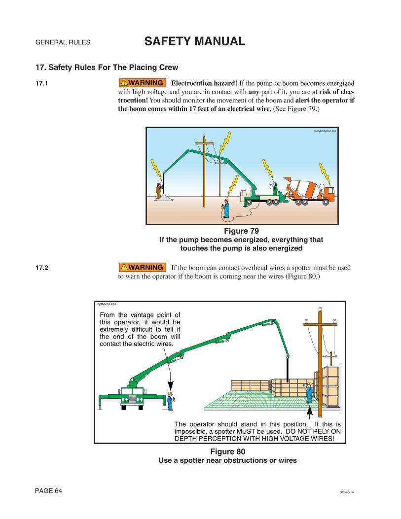
GENERAL RULES SAFETY MANUAL
17. Safety Rules For The Placing Crew
17.1 Electrocution hazard! If the pump or boom becomes energized with high voltage and you are in contact with any part of it, you are at risk of elec-trocution! You should monitor the movement of the boom and alert the operator if the boom comes within 17 feet of an electrical wire. (See Figure 79.)
17.2 If the boom can contact overhead wires a spotter must be used to warn the operator if the boom is coming near the wires (Figure 80.)
WARNING
everybodyelec.eps
Figure 79If the pump becomes energized, everything that
touches the pump is also energized
WARNING
From the vantage point of this operator, it would be extremely difficult to tell if the end of the boom will contact the electric wires.
dpthprcp.eps
The operator should stand in this position. If this is impossible, a spotter MUST be used. DO NOT RELY ON DEPTH PERCEPTION WITH HIGH VOLTAGE WIRES!
Figure 80Use a spotter near obstructions or wires
PAGE 64 500smgr.fm

GENERAL RULESSAFETY MANUAL
17.3 Keep an eye on the movements of the boom, even when there are no electrical wires nearby. Alert the operator if he is nearing any obstruction or hazard. Where job site safety is concerned, two sets of eyes and ears are better than one.
17.4 Wear Personal Protective Equipment (P.P.E.) when working around a concrete pump (Figure 81). The gloves should resist concrete lime burns. If you will be working in the concrete, protect your feet and hands with rubber boots and gloves.
17.5 When the operator is initially priming the delivery system, restarting after moving, restarting after adding or removing pipes or hoses, or any time that air has been introduced into the delivery system, stand a reasonable and prudent distance away from the tip hose or point of discharge. Do not get near the discharge until material runs steadily and there is no movement of the delivery system. (Figure 82). Compressed air in the line can cause rubber hose to move violently. If the operator tells you that air is coming in the delivery system, pro-ceed as follows:
• Get to ground level (if in a high place) and remain well away from the dis-charge or at least take cover.
• Stay away from the discharge. Be sure that all the air is gone before getting near the point of discharge again. It is the operator’s job to know when it’s safe to go back to normal pumping.
WARNING
WARNING
Hard Hat
Safety Glasses
HearingProtection
Safety Vest
Work Glovesor Rubber Gloves
Snug-fittingClothes
Steel Toed Shoes orFinisher’s Boots
Saf
eGea
r4P
laci
ngC
rew
.eps
Figure 81Wear Personal Protective
Equipment (P.P.E.)
WARNING
500smgr.fm PAGE 65
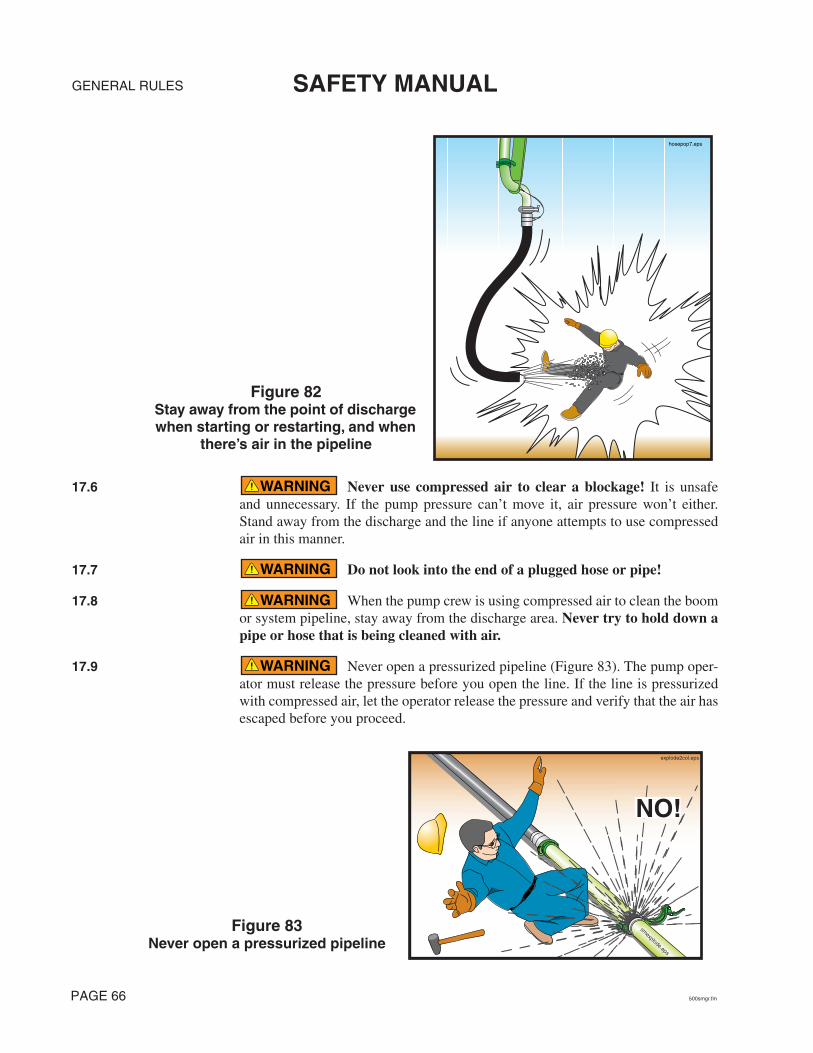
GENERAL RULES SAFETY MANUAL
17.6 Never use compressed air to clear a blockage! It is unsafe and unnecessary. If the pump pressure can’t move it, air pressure won’t either. Stand away from the discharge and the line if anyone attempts to use compressed air in this manner.
17.7 Do not look into the end of a plugged hose or pipe!
17.8 When the pump crew is using compressed air to clean the boom or system pipeline, stay away from the discharge area. Never try to hold down a pipe or hose that is being cleaned with air.
17.9 Never open a pressurized pipeline (Figure 83). The pump oper-ator must release the pressure before you open the line. If the line is pressurized with compressed air, let the operator release the pressure and verify that the air has escaped before you proceed.
hosepop7.eps
Figure 82Stay away from the point of discharge when starting or restarting, and when
there’s air in the pipeline
WARNING
WARNING
WARNING
WARNING
explode2col.eps
smexplode.eps
NO!
Figure 83Never open a pressurized pipeline
PAGE 66 500smgr.fm

GENERAL RULESSAFETY MANUAL
17.10 After removing pipe sections you must reassemble using gas-kets and clamps. Pipelines assembled without gaskets will leak cement and water, which can cause a blockage.
17.11 Concrete is being moved through the delivery system by pres-sure. Failure of a pipe, clamp, hose, or elbow is possible. For this reason, spend as little time as possible standing under the boom, and wear protective clothing.
17.12 The hose man should not hug the hose, but hold it with both hands, to allow the hose to move freely (Figure 84).
17.13 The hose man should not walk backwards (Figure 85). Walking forward will allow him to see obstacles and avoid tripping.
17.14 The hose man should never position himself between the boom or boom hose and any fixed object like a wall or column (Figure 85).
WARNING
WARNING
WARNING
OKNO!
donthug.eps
Figure 84Do not hug the boom hose
WARNING
NO!OK
walkingbacksm
.eps
Figure 85Do not walk backwards, stay out of the path of the boom
WARNING
500smgr.fm PAGE 67

GENERAL RULES SAFETY MANUAL
17.15 Do not kink the end hose. Kinking will cause the pump to cre-ate maximum concrete pressure. The pump may unkink the hose by force! (See Figure 86.)
17.16 Never try to support the tip hose with your back or shoulders. Let the hose hang from the boom (Figure 86).
17.17 Be careful when handling pipeline or any other heavy object. Learn how to lift without using your back. Get assistance if needed.
WARNING
NO!Do not allowthe hose to kink!
hosekinkcolor.eps
This man could be injured if the pump unkinks the
hose by force!
shou
lder
kink
2.ep
s
Figure 86Never kink the hose;Never hold the hose with your shoulder
WARNING
CAUTION
PAGE 68 500smgr.fm

GENERAL RULESSAFETY MANUAL
17.18 Crushing hazard! Never position your hands or any body part between the end of the delivery system and a fixed object (e.g., between the tip hose and the concrete form) (Figure 87). Watch for clamps lowering with the line, because they have a larger diameter than the pipes/hoses they connect.
17.19 Do not allow the boom hose to get lower than two feet above the deck to prevent the boom hose from hitting the feet of the hose man, and to prevent the hose opening from being blocked by the deck, which could cause the hose to whip.
17.20 Falling hazard! When pouring columns, slabs, or walls above ground, secure yourself from falling.
17.21 Never stand on, sit on, or straddle a pipeline while it’s in use, or whenever it is pressurized (Figure 88). Pipeline wears out with each stroke of the pump. If the pipe bursts, you want to be to the side of it, not on top of it.
WARNING
Figure 87Watch out for the pinch points
pinchpoint.eps
WARNING
WARNING
WARNING
NO!
pipelineguyColor.eps
Figure 88Never straddle or sit on a
pressurized pipeline
500smgr.fm PAGE 69

GENERAL RULES SAFETY MANUAL
17.22 To avoid confusion and conflicting signals, only one person should signal the pump operator.
17.23 Before the pour begins, the hose man, the operator and the spotter should agree on the hand signals (Figure 89).
WARNING
WARNING
(2 taps)
acpahandsignew.eps
9.BOOM DOWN
10.BOOM LEFT
11.BOOM RIGHT
12.OPEN OR
EXTEND BOOM
13.CLOSE OR
RETRACT BOOM
8.BOOM UP
6.ADD WATER4-GALLONS
7.ALL DONECLEAN UP
5.RELIEVE
PRESSURE
4.LITTLE BIT
3.STOP PUMP
2.SLOW PUMP
DOWN
1.START PUMP
SPEED UP
14.STOP BOOM
Figure 89ACPA recommended hand signals
PAGE 70 500smgr.fm

apnd
xcov
.eps
APPENDIX
500ApndxTOC.fm
PAGE 71
SAFETY MANUAL
VII. Weld On Ends / Coupling Comparison . . . . . . . . . . . . . . 72
VIII. Minimum Pipe Wall Thickness Chart . . . . . . . . . . . . . . . 73
IX. Glossary Of Terms . . . . . . . . . . . . . . . . . . . . . . 74
X. Recommended Hand Signals . . . . . . . . . . . . . . . . . . 80
XI. Bibliography . . . . . . . . . . . . . . . . . . . . . . . . . 80
Appendix
Table of Contents
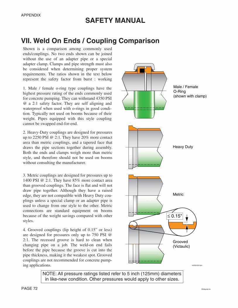
APPENDIX
SAFETY MANUAL
PAGE 72 500Apndx.fm
VII. Weld On Ends / Coupling Comparison
Heavy Duty
Metric
Grooved(Victaulic)
Male / FemaleO-Ring(shown with clamp)
weldends4.eps
≤ 0.15"
NOTE: All pressure ratings listed refer to 5 inch (125mm) diameters in like-new condition. Other pressures would apply to other sizes.
3. Metric couplings are designed for pressures up to1400 PSI @ 2:1. They have 85% more contact areathan grooved couplings. The face is flat and will notdraw pipe together. Although they have a raisededge, they are not compatible with Heavy Duty cou-plings unless a special clamp or an adapter pipe isused to change from one style to the other. Metricconnections are standard equipment on boomsbecause of the weight savings compared with otherstyles.
2. Heavy-Duty couplings are designed for pressuresup to 2250 PSI @ 2:1. They have 20% more contactarea than metric couplings, and a tapered face thatdraws the pipe sections together during assembly.Both the ends and clamps weigh more than metricstyle, and therefore should not be used on boomswithout consulting the manufacturer.
1. Male / female o-ring type couplings have thehighest pressure rating of the ends commonly usedfor concrete pumping. They can withstand 4350 PSI@ a 2:1 safety factor. They are self aligning andwaterproof when used with o-rings in good condi-tion. Typically not used on booms because of theirweight. Pipes equipped with this style couplingcannot be swapped end-for-end.
4. Grooved couplings (lip height of 0.15” or less)are designed for pressures only up to 750 PSI @2:1. The recessed groove is hard to clean whenchanging pipe on a job. The weld-on end failsbefore the pipe because the groove is cut into thepipe thickness, making it the weakest spot. Groovedcouplings are not recommended for concrete pump-ing applications.
Shown is a comparison among commonly usedends/couplings. No two ends shown can be joinedwithout the use of an adapter pipe or a specialadapter clamp. Clamps and pipe strength must alsobe considered when determining proper systemrequirements. The ratios shown in the text belowrepresent the safety factor from burst : working

APPENDIX
SAFETY MANUAL
500Apndx.fm PAGE 73
VIII. Minimum Pipe Wall Thickness Chart
PIPE WALL THICKNESS
0.025"
.050".075"
.100".125"
.150".175"
.200".225"
.250".275"
.300".325"
.350".375"
0
200
400
600
800
1000
1200
1400
1600
1800
2000
2200
2400
2600
2800
3000
3200
3400
3600
3800
4000
4200
0
10
20
30
40
50
60
70
80
90
100
110
120
130
140
150
160
170
180
190
200
210
220
230
240
250
260
270
280
290
300
SCHEDULE 40(1/4 wall)
9 gauge 3/16”11 gauge 7 gauge
MAT
ER
IAL
PR
ES
SU
RE
BARPSI
1. This chart assumes a safety factor of 2:1. Higher safety factors may be required in some circumstances.2. Wear reduces wall thickness. Thickness must be checked on a regular basis.3. Pressures may be limited even more by clamp style or pipe end used.4. The chart is based on 62,000 PSI tensile strength. Heat-treated calculations are based on 120,000 PSI tensile strength.5. The chart is for pressure calculations ONLY. There is no allowance for mechanical forces other than pressure, and thicker
walls may be needed for mechanical strength because of support or restraint considerations.6. The chart does not take into account metal fatigue caused by pressure cycles.
Note! This chart is intended as a guide for concrete pumping applications and is subject to the notes, assumptions, and conditions listed above. Any other use of this chart is not recommended.
This chart does not apply to double-wall pipe. Double wall pipe can be checked by inspecting the inside of the pipe. If the insert is intact, the pipe is okay. If the insert is worn through, the pipe must be replaced. Contact your pipe supplier for the pressure capacity of your double-wall pipe.
pipe
wal
lvsP
ress
2.ep
s
.heat treated .standard
4“ H
EAT
TREA
TED
5“ H
EAT
TREA
TED
6“ H
EAT
TREA
TED
4.8”
& 4
.9“ H
EAT
TREA
TED
4.4”
HEA
T TR
EATE
D
4.9“ (7, 9
, 11 gauge) s
ystem
(125 m
m)
6“ syste
m
5“ syste
m4.0“ s
yste
m 4.4“ sys
tem
4.8“ syste
m
0.12
0”
0.15
0”
0.17
7”
0.18
8”
0.25
0”

APPENDIX
SAFETY MANUAL
PAGE 74 500Apndx.fm
IX. Glossary Of Terms
AccumulatorA hydraulic device that stores fluid power energy in much the same way that a battery storeselectrical energy. Because an accumulator will store energy, it MUST be drained and depressur-ized before work begins on an accumulator equipped actuator or hydraulic system.
AgitatorA device that sits in the concrete hopper to keep concrete moving, preventing it from setting. It istypically a rotating shaft to which several paddles have been mounted. See Also: Hopper Grate
AWS D1.1The code for structural welding with steel as defined by the American Welding Society. Sections3, 5, and paragraph 9.25 of section 9 apply. See Also: Certified Welder and EN 287-1
Blanking PlateAlso known as a blanking plug or end cap. It’s purpose is to prevent material from falling out of the delivery system (typically the end hose) when moving a boom with a full pipeline over personnel or property.
BlockageSimply put, if the pump is pushing and concrete fails to come out at the point of discharge, it iscalled a blockage. Blockages can be removed with pump pressure, by rocking the pump betweenforward and reverse, or some other remedial measure. If the blockage can not be removed in sucha manner, it’s called a plug. See Also: Plug, Rock Jam. The causes of blockages are detailed insection 8.21 of this manual. In all cases, blockages create a hazard by causing high concrete pres-sure, combined with the sometimes uncoordinated efforts of untrained workmen to remedy theproblem.
Bulk DensityThe mass of a substance per volume. For example, one cubic foot of air weighs much less thanone cubic foot of water. One cubic foot of lightweight concrete weighs less than one cubic footof steel entrained concrete. We could say that steel entrained concrete has a higher bulk densitythan lightweight concrete. All calculations for the operation manuals and specifications of con-crete pumps are based upon 150 pounds per cubic foot, which is the approximate mass of hardrock (normal) concrete.
Certified OperatorAn operator that has been issued a certification card by the American Concrete Pumping Associ-ation. There are several classes of certification, each relating to a different category of pump. Foran operator to become certified, he (she) must pass the written tests regarding operation, setup,and clean out for each category of pump, pass the safety rules test which is common to all certifi-cation categories, meet the experience requirements set forth for each category, and maintain asafe and clean driving record. The certification card only certifies that the operator has passed awritten test administered by an A.C.P.A. certification tester and does not attest to their ability tooperate a concrete pump. See Also: Qualified Person, Qualified Operator.
Certified WelderAs it relates to concrete pumping and this Safety Manual, a Certified Welder is a person that hasapplied for, taken and passed the American Welding Society (AWS) or the European Norm (EN)test for structural steel welding. Anyone welding on a concrete pump placing boom, outriggers,towers, etc. must be certified to AWS D1.1 sections 3, 5, and paragraph 9.25 of section 9 and/orEN287-1/PREN288-3.

APPENDIX
SAFETY MANUAL
500Apndx.fm PAGE 75
Concrete Delivery HoseA flexible concrete hose that has two end couplings.
Concrete PressureThe force per square area that is exerted on the concrete. The concrete pressure will always be aratio in direct proportion to the hydraulic oil pressure on the concrete pump circuit. See Also:Maximum Pressure
ConductorsMaterials that will conduct electricity. Copper, silver, aluminum, gold, steel, and water are con-sidered GOOD conductors of electricity. Air, fiberglass, rubber, ceramics and glass are consid-ered POOR conductors. All of these conductors have a resistance to the flow of electricity thatcan be measured in terms of ohms per linear foot. As voltage gets higher, more current flowsthrough the same resistance. In the case of high voltage electric wires (8000 volts, for example)even the poor conductors will carry enough current through your body to ground that you couldbe killed. (As little as 35 milliamps can cause fibrillation of the heart.) Some conductors, like air,resist electricity very well, but if the voltage gets high enough, current will flow (lightning is agood example of this). See Also: Electrocution
DecibelsOne tenth of a bel. Abbreviated dB. It is a measurement of sound volume. As it applies to con-crete pumps, it is a measurement of the sound pressure level one meter away from a noise source.O.S.H.A. has developed guidelines for time limits on exposure to sound at different volume lev-els. The chart can be found on page 36 of this manual.
Drive EngineThe primary source of power for a hydraulic system. Typically, the word “engine” denotes andinternal combustion device, whereas the word “motor” denotes an electrical device.
ElectrocutionMade from the words “Electric” + “Execution.” It means death by electricity. See Also: Conduc-tors
EN 287-1 / PREN 288-3The code for structural welding with steel as defined by the European Norm. See Also: CertifiedWelder, AWS D1.1.
End HoseA flexible concrete hose that has one end coupling.
Foreign MaterialMaterial that was never intended to be pumped, which ends up in the concrete hopper. Examplesof foreign material include small animals, hammers, ready mix truck fins, unmixed clumps ofcement, hardened concrete that breaks away from ready mix truck fins, and soda pop cans. Theseitems could create a blockage if pumped.
Go DevilA plug made from a rubber composite, usually with several fins that expand to seal when pres-sure is applied. They are intended to be inserted in a steel delivery pipeline and pushed withwater or compressed air for the purpose of cleaning the pipe. See Also: Sponge Ball
GuideAn assistant brought in to help in backing up a truck or trailer, or to help in other circumstanceswhere the driver cannot see enough to assure safety. See Also: Spotter

APPENDIX
SAFETY MANUAL
PAGE 76 500Apndx.fm
High VoltageFor the purposes of this manual, anything over 24 volts is to be considered high voltage. In theU.S., electrically driven concrete pumps normally operate the motors at 480 volts AC (high volt-age) and the controls at 24 volt DC (low voltage). When dealing with electric wires in residentialor industrial areas the voltage will be approx. 8000 volts to ground, or 13,800 volts from phase tophase (distribution voltage). When dealing with electric wires that are mounted on steel towershigh above the ground, the voltage will range from 100,000 to 1,000,000 volts (transmissionvoltage).
Hopper GrateA meshwork placed over the concrete hopper, typically made from steel bars. It serves the func-tions of keeping human body parts away from the agitator (when left in it’s proper position) andkeeping large foreign objects from falling into the hopper, which could cause blockages if theywere pumped.
Jacking the OutriggersAdjustment of the outriggers in the vertical direction. With boom mounted concrete pumps youshould strive to make the adjustments so that the unit sits within 3° of level.
Licensed ElectricianA qualified electrician licensed by the state, county or municipality where the connections are tobe made. In some locations electricians are not required to be licensed, and in these cases thework should still be carried out by competent professionals. Under no circumstances should highvoltage connections be made by a concrete pump operator or related personnel.
MaintenanceAll procedures for service, inspection, and repair of concrete pumps and related equipment anddevices. Maintenance and inspection are methods of maintaining the desired state of the equip-ment. Repair is the method of restoring the desired state of the equipment.
Maximum PressureWhen talking about a hydraulic system, maximum pressure refers to the highest pressure that canbe achieved with the settings of the circuit relief valves. When discussing concrete output, maxi-mum pressure refers to the pressure that will be developed if the hydraulic system pressurereaches the relief valve setting. Concrete pressure is the force at which the differential cylindersare moving, divided by the cross sectional area of the concrete cylinder. Maximum concrete pres-sure, then, is developed when the differential cylinders are moving with maximum force, whichis determined by the hydraulic system relief valve setting. See Also: Concrete Pressure.
Minimum Safety DistanceIn this manual, the term “minimum safety distance” refers to the closest distance that you areallowed to approach an object, electrical wires, etc. and still leave room for errors in humanjudgement or machine malfunction. With electrical wires in the U.S., this distance is 17 feet, asrecommended by the American Concrete Pumping Association. This distance may have othervalues in different countries (Canada specifies 7 meters). It is up to the operator to know thevalue for the place of operation.
Operational AreaThe area around a working piece of equipment or point of discharge where hazards can beencountered due to the nature of the machinery or process in use.
O.S.H.A.Occupational Safety and Health Administration. A branch of the United States federal govern-ment that deals with job safety. They establish and enforce safety regulations for industry and

APPENDIX
SAFETY MANUAL
500Apndx.fm PAGE 77
business. Among the areas over which they have authority are construction job sites and workshops.
Personal Protective Equipment (P.P.E.)Things you can wear to protect yourself from potential dangers in a concrete placing environ-ment. Examples are:
• Snug fitting work clothes• Steel toed work boots• Lime resistant gloves• Safety glasses• Ear muffs or ear plugs• Rubber boots when you have to stand in concrete• Hard hat• Breathing mask when working with cement dust
PlugA plug is a blockage that cannot be removed with the pump pressure, or by other remedial mea-sures. A plug must be removed manually. See Also: Blockage.
Point of DischargeAlso known as the point of placement. The location of concrete expulsion from a delivery sys-tem. This can be the point of placement (the actual form that is being filled with concrete) or theclean out area after completion of the job.
PourUsed by the concrete pumping industry and in this manual as a noun. It is the specific job for thepump during any given time period. (e.g. “We’ll grab lunch right after the pour.”)
Qualified PersonAs used in this Safety Manual, a qualified person is defined as: a person who, by possession of arecognized degree of certificate of professional standing, or who by extensive knowledge, train-ing, and experience, has successfully demonstrated the ability to solve or resolve problems relat-ing to the subject matter and work. Other qualified persons may include master mechanics andafter-sales service technicians of the manufacturer. See Also: Certified Operator
Qualified OperatorOperators shall be considered qualified when they have completed a program of training andsupervised operation of concrete pumps and have passed a practical operating examination oftheir ability to operate a specific model and type of equipment as well as their understanding ofthe controls and operating procedures. Furthermore, the operator must meet the knowledge andphysical requirement sections of the concrete pumping safety standard.
Qualified PersonnelA generic term used to describe a person who is qualified in the area of application. For example,having your boom repairs inspected by “qualified personnel” before use would refer to inspec-tion by a certified welder or certified welding inspector. Having repairs to your hydraulic systemdone by “qualified personnel” would refer to repairs made by qualified workshop personnel.
Qualified Workshop PersonnelAn individual who:
• has reached the age of 18 years, • is physically and mentally capable, • has been trained in proper repair, maintenance, and inspection procedures plus the perti-
nent safety rules for concrete pumps and related equipment, • has demonstrated their capabilities to their company in regards to the above mentioned

APPENDIX
SAFETY MANUAL
PAGE 78 500Apndx.fm
procedures and rules, and• can be expected to perform these duties, as assigned, in a reliable manner.
Rock JamA specific type of blockage caused when the cement and fines of the concrete are not present insufficient quantity to fully coat the larger aggregates and the walls of the delivery system. Inthese cases, the rock (larger aggregates of the mix) will form a wedge inside of the pipe. Resis-tance to movement then becomes overpowering and the concrete stops. See Also: Blockage.
Separate PipelineA pipeline that is laid between the concrete pump and the point of discharge, other than the plac-ing boom pipeline.
Shutoff ValveIn hydraulics: a valve with the ability to stop the flow or pressure of hydraulic oil. It must be ableto withstand the maximum pressure of the hydraulic circuit that it controls. In concrete: A manu-ally or hydraulically operated valve that will prevent the flow of concrete in either direction. Theshutoff valve must be able to withstand the maximum pressure on the concrete of which thepump is capable of exerting.
Soil PressureThe force per square area that is exerted on the ground by the outrigger legs. The amount of pres-sure that the soil will support varies with the composition and compaction of the soil. To make adetermination on the stability of the soil, see the chart on page 22 of this manual.
Sponge BallA medium to hard sponge formed into a sphere and used to clean the inside of delivery pipelines.See Also: Go Devil
SpotterA spotter is a person who stands at a vantage point where he (she) can see both the point of dis-charge and the operator of the pump. The spotter would then direct the operator to operate theunit as required by the job circumstances with two-way radios or hand signals. A spotter can beanyone who is familiar with the safety rules for the pump and workers and is equipped with aradio or knows the appropriate hand signals. A spotter is needed whenever the operator cannotsafely see the point of placement or the distance between the unit and an unsafe area. See Also:Guide
Sucking BackThe act of putting the concrete pump into the reverse mode for any of several reasons.
Thrust BlockAlso known as a “dead man”. This is a large block of poured concrete, usually with one or moresweep elbows cast inside, placed at the bottom of a vertical run for the purpose of supporting theweight of the vertical run and for lateral stabilization of the pipeline. It stabilizes and supports thevertical run by virtue of its enormous mass (normally one cubic yard or larger).
Towing VehicleIn this manual, Towing Vehicle applies only to vehicles that tow trailer mounted concrete pumps.It is the vehicle that you will use to tow the trailer on the road, on the job site, or in the yard. Seethe safety rules regarding this subject on page 10 of this Safety Manual.
Transport PositionThis relates to the position of the boom when you will be driving the unit. The travel position ofthe boom is the position of the boom when it is completely folded and lowered into the rests.

APPENDIX
SAFETY MANUAL
500Apndx.fm PAGE 79
UnauthorizedWithout authority, without permission. Examples: Unauthorized operation of the boom could beoperation by a passer-by, unauthorized repairs to the boom could be repairs designed without themanufacturer’s knowledge.
Unintentional MovementMovement of the pump, boom or related equipment without a specific intentional command bythe operator. An example of an unintentional movement would be if an operator fell while walk-ing with the remote control box and accidentally hit a joystick, causing a boom movement.
Vertical RunSections of concrete delivery pipeline that are running in an up (or down) direction. Vertical runshave very specific procedures and rules for installation, support, cleaning, and inspection. Con-crete pumping personnel should, therefore, have specific training in these procedures and rulesbefore attempting to use them in a job setting.
Water JetThe actual stream of water that comes out of the end of a water hose or pressure washer. This isthe only part of the water system that needs to go into the hopper, concrete valve, or water boxfor cleaning.
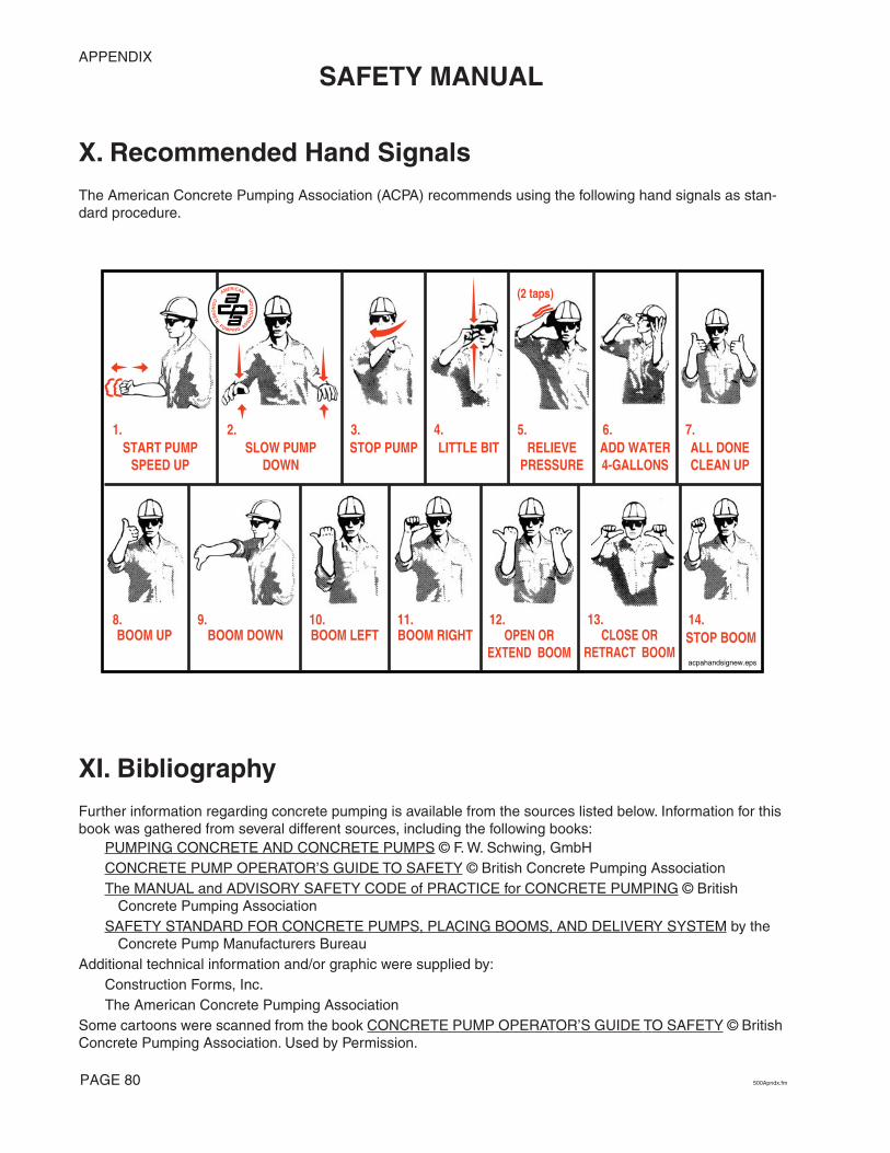
APPENDIX
SAFETY MANUAL
PAGE 80 500Apndx.fm
X. Recommended Hand Signals The American Concrete Pumping Association (ACPA) recommends using the following hand signals as stan-dard procedure.
XI. BibliographyFurther information regarding concrete pumping is available from the sources listed below. Information for this book was gathered from several different sources, including the following books:
PUMPING CONCRETE AND CONCRETE PUMPS © F. W. Schwing, GmbHCONCRETE PUMP OPERATOR’S GUIDE TO SAFETY © British Concrete Pumping AssociationThe MANUAL and ADVISORY SAFETY CODE of PRACTICE for CONCRETE PUMPING © British
Concrete Pumping AssociationSAFETY STANDARD FOR CONCRETE PUMPS, PLACING BOOMS, AND DELIVERY SYSTEM by the
Concrete Pump Manufacturers BureauAdditional technical information and/or graphic were supplied by:
Construction Forms, Inc.The American Concrete Pumping Association
Some cartoons were scanned from the book CONCRETE PUMP OPERATOR’S GUIDE TO SAFETY © British Concrete Pumping Association. Used by Permission.
(2 taps)
acpahandsignew.eps
9.BOOM DOWN
10.BOOM LEFT
11.BOOM RIGHT
12.OPEN OR
EXTEND BOOM
13.CLOSE OR
RETRACT BOOM
8.BOOM UP
6.ADD WATER4-GALLONS
7.ALL DONECLEAN UP
5.RELIEVE
PRESSURE
4.LITTLE BIT
3.STOP PUMP
2.SLOW PUMP
DOWN
1.START PUMP
SPEED UP
14.STOP BOOM

402indexcov.eps
ALPHABETICAL INDEX
500indxcov.fm PAGE 81
SAFETY MANUAL
Alphabetical Index

ALPHABETICAL INDEX SAFETY MANUAL
Numerics1 to 1 rule . . . . . . . . . . . . . . . . . . . . . . . . . . . .233 point rule . . . . . . . . . . . . . . . . . . . . . . . . .7, 56
Aaccidents
causes of . . . . . . . . . . . . . . . . . .5, 12, 27, 44accumulator
changing max. pressure settings . . . . . . . .53defined . . . . . . . . . . . . . . . . . . . . . . . . . . . .74maintenance . . . . . . . . . . . . . . . . . . . . . . .55
ACPA recommended hand signals . . . . . .70, 80agitator, defined . . . . . . . . . . . . . . . . . . . . . . .74air in delivery system . . . . . . . . . . . . .38, 60, 65air, compressed
See cleaning out, with compressed airalcohol, use of when operating . . . . . . . . . . . . .4apparel
appropriate . . . . . . . . . . . . . . . . . . . . . .2, 32inappropriate . . . . . . . . . . . . . . . . . . . . . . . .2
AWS D1.1, defined . . . . . . . . . . . . . . . . . . . . .74
Bball catcher types . . . . . . . . . . . . . . . . . . . . . . .31blanking plate, defined . . . . . . . . . . . . . . . . . .74blockage
before opening pipeline . . . . . . . . . . . .39, 40clearing with compressed air . . . .40, 50, 66concrete segregation . . . . . . . . . . . . . . . . .39defined . . . . . . . . . . . . . . . . . . . . . . . . . . . .74foreign matter . . . . . . . . . . . . . . . . . . .38, 59inadequate pump . . . . . . . . . . . . . . . . . . . .38inexperienced placing crew . . . . . . . . . . . .39kinked hose . . . . . . . . . . . . . . . . . . . . . . . .40operator error . . . . . . . . . . . . . . . . . . . . . .38pipe deficiencies . . . . . . . . . . . . . . . . . . . .38procedure to remove . . . . . . . . . . . . . . . . .39safe removal of . . . . . . . . . . . .39, 40, 61, 66setting of concrete . . . . . . . . . . . . . . . . . . .38unpumpable mix . . . . . . . . . . . . . . . . . . . .38
blow out headSee clean out accessories, blow out head
blowing outSee cleaning out, with compressed air
boomSee placing boom
boom, watching . . . . . . . . . . . . . . . . . . . . . . . 65bulk density, defined . . . . . . . . . . . . . . . . . . . 74
Ccatcher, types of . . . . . . . . . . . . . . . . . . . . . . . 31caution, defined . . . . . . . . . . . . . . . . . . . . . . . . 2certified operator, defined . . . . . . . . . . . . . . . 74certified welder,defined . . . . . . . . . . . . . . . . . 74checks
pre-dispatch . . . . . . . . . . . . . . . . . . . . . . 5, 6children, dangers to . . . . . . . . . . . . . . . . . 26, 30clamps
for dissimilar ends . . . . . . . . . . . . . . . . . . 53pre-dispatch . . . . . . . . . . . . . . . . . . . . . . . . 5re-assembly when removing pipes . . . . . 67
clean out accessoriesblow out head . . . . . . . . . . . . . . . . 5, 30, 47
pre-dispatch . . . . . . . . . . . . . . . . . . . . . 5use . . . . . . . . . . . . . . . . . . . . . 30, 47, 50
catcher . . . . . . . . . . . . . . . . . . . . . . . . 46, 47pre-dispatch . . . . . . . . . . . . . . . . . . . . . 5size . . . . . . . . . . . . . . . . . . . . . . . . . 5, 30types . . . . . . . . . . . . . . . . . . . . . . . . . . 31use . . . . . . . . . . . . . . . . . . . . . . . . 30, 47
compressed airattachments . . . . . . . . . . . . 4, 30, 44, 47hose . . . . . . . . . . . . . . . . . . . . . . . . 5, 30
go devildefined . . . . . . . . . . . . . . . . . . . . . . . . 75size . . . . . . . . . . . . . . . . . . . . . . . . . . . 47use . . . . . . . . . . . . . . . . . . . . . . . . 47, 50
sponge ball . . . . . . . . . . . . . . . . . . . 5, 30, 47defined . . . . . . . . . . . . . . . . . . . . . . . . 78size . . . . . . . . . . . . . . . . . . . . . . 5, 30, 47use . . . . . . . . . . . . . . . . . . . . . . . . 47, 50
cleaning outhopper . . . . . . . . . . . . . . . . . . . . . . . . . . . 45personal protective equipment . . . . . . . . . 44the water box . . . . . . . . . . . . . . . . . . . 45, 46
position of the boom . . . . . . . . . . . . . 45water box . . . . . . . . . . . . . . . . . . . . . . . . . 46with compressed air . . . . . . . . . . . 30, 44, 47
blockage . . . . . . . . . . . . . . . . . . . . . . . 66clean out attachments . . . . . . . . . . . . 30communications . . . . . . . . . . . . . . . . . 50discharge area . . . . . . . . . . . . . . . . . . 49
PAGE 82 500ApndxIOM.fm

ALPHABETICAL INDEXSAFETY MANUAL
experts . . . . . . . . . . . . . . . . . . . . . . . . 47near personnel . . . . . . . . . . . . . . . 47, 50need for 2 people . . . . . . . . . . . . . . . . 47outlet positioning . . . . . . . . . . . . . . . . 47relieving air pressure . . . . . . . . . . . . . 44shutoff valve . . . . . . . . . . . . . . . . . . . . 48through hose . . . . . . . . . . . . . . 44, 47, 48through short pipe . . . . . . . . . 44, 47, 48trapped air . . . . . . . . . . . . . . . . . . . . . 49vertical pipelines . . . . . . . . . . 30, 49, 50when to stop . . . . . . . . . . . . . . . . . . . . 48
with water . . . . . . . . . . . . . . . . . . . . . . . . . 46clothes, appropriate . . . . . . . . . . . . . . . . . . . . . 2compressed air
See cleaning out, with compressed airconcrete
bulk density maximum . . . . . . . . . . . . . . . 38unpumpable mix . . . . . . . . . . . . . . . . . . . . 38
concrete delivery hose, defined . . . . . . . . 18, 75concrete pressure, defined . . . . . . . . . . . . . . . 75concrete valve
danger . . . . . . . . . . . . . . . . . . . . . . 41, 42, 62conductors, defined . . . . . . . . . . . . . . . . . . . . 75couplings . . . . . . . . . . . . . . . . . . . . . . . . . . . . 53
comparison . . . . . . . . . . . . . . . . . . . . . . . . 72grooved type . . . . . . . . . . . . . . . . . . . . . . . 72Heavy-Duty type . . . . . . . . . . . . . . . . . . . 72male/female o-ring type . . . . . . . . . . . . . . 72metric type . . . . . . . . . . . . . . . . . . . . . . . . 72Victaulic type . . . . . . . . . . . . . . . . . . . . . . 72
Ddanger, defined . . . . . . . . . . . . . . . . . . . . . . . . . 2dead man,
See thrust blockdecals
safety . . . . . . . . . . . . . . . . . . . . . . . . . . . . 51decibel, defined . . . . . . . . . . . . . . . . . . . . . . . 75definition
accumulator . . . . . . . . . . . . . . . . . . . . . . . 74agitator . . . . . . . . . . . . . . . . . . . . . . . . . . . 74AWS D1.1 . . . . . . . . . . . . . . . . . . . . . . . . 74blanking plate . . . . . . . . . . . . . . . . . . . . . . 74blockage . . . . . . . . . . . . . . . . . . . . . . . . . . 74bulk density . . . . . . . . . . . . . . . . . . . . . . . 74caution . . . . . . . . . . . . . . . . . . . . . . . . . . . . 2
certified operator . . . . . . . . . . . . . . . . . . . 74certified welder . . . . . . . . . . . . . . . . . . . . . 74concrete delivery hose . . . . . . . . . . . . 18, 75concrete pressure . . . . . . . . . . . . . . . . . . . 75conductors . . . . . . . . . . . . . . . . . . . . . . . . 75danger . . . . . . . . . . . . . . . . . . . . . . . . . . . . . 2decibel . . . . . . . . . . . . . . . . . . . . . . . . . . . 75drive engine . . . . . . . . . . . . . . . . . . . . . . . 75electrocution . . . . . . . . . . . . . . . . . . . . . . . 75EN 287-1 / PREN 288-3 . . . . . . . . . . . . . . 75end hose . . . . . . . . . . . . . . . . . . . . . . . 18, 75expert . . . . . . . . . . . . . . . . . . . . . . . . . . . . 77foreign material . . . . . . . . . . . . . . . . . . . . 75go devil . . . . . . . . . . . . . . . . . . . . . . . . . . . 75guide . . . . . . . . . . . . . . . . . . . . . . . . . . . . . 75high voltage . . . . . . . . . . . . . . . . . . . . . . . 76hopper grate . . . . . . . . . . . . . . . . . . . . . . . 76jacking the outriggers . . . . . . . . . . . . . . . . 76licensed electrician . . . . . . . . . . . . . . . . . . 76maintenance . . . . . . . . . . . . . . . . . . . . . . . 76maximum pressure . . . . . . . . . . . . . . . . . . 76minimum safety distance . . . . . . . . . . . . . 76O.S.H.A. . . . . . . . . . . . . . . . . . . . . . . . . . . 76operational area . . . . . . . . . . . . . . . . . . . . 76personal protective equipment . . . . . . . . . 77point of discharge . . . . . . . . . . . . . . . . . . . 77pour . . . . . . . . . . . . . . . . . . . . . . . . . . . . . . 77qualified operator . . . . . . . . . . . . . . . . . . . 32qualified personnel . . . . . . . . . . . . . . . . . . 77qualified workshop personnel . . . . . . . . . 77rock jam . . . . . . . . . . . . . . . . . . . . . . . . . . 78safety alert symbol . . . . . . . . . . . . . . . . . . . 2separate pipeline . . . . . . . . . . . . . . . . . . . . 78shutoff valve . . . . . . . . . . . . . . . . . . . . . . . 78signal word . . . . . . . . . . . . . . . . . . . . . . . . . 2soil pressure . . . . . . . . . . . . . . . . . . . . . . . 78sponge ball . . . . . . . . . . . . . . . . . . . . . . . . 78spotter . . . . . . . . . . . . . . . . . . . . . . . . . . . . 78sucking back . . . . . . . . . . . . . . . . . . . . . . . 78thrust block . . . . . . . . . . . . . . . . . . . . . . . . 78towing vehicle . . . . . . . . . . . . . . . . . . . . . 78transport position . . . . . . . . . . . . . . . . . . . 78unauthorized . . . . . . . . . . . . . . . . . . . . . . . 79unintentional movement . . . . . . . . . . . . . . 79vertical run . . . . . . . . . . . . . . . . . . . . . . . . 79
500ApndxIOM.fm PAGE 83

ALPHABETICAL INDEX SAFETY MANUAL
warning . . . . . . . . . . . . . . . . . . . . . . . . . . . .2water jet . . . . . . . . . . . . . . . . . . . . . . . . . . .79
delivery systemair in line . . . . . . . . . . . . . . . . . . . .38, 60, 65attaching to boom . . . . . . . . . . . . . . . . . . .25cleaning with compressed air . . . .30, 44, 47cleaning with water . . . . . . . . . . . . . . . . . .46damaged . . . . . . . . . . . . . . . . . . . . . . . . . .28gaskets
pre-dispatch . . . . . . . . . . . . . . . . . . . . . .5reassembly when removing pipe . . . . .67
handling . . . . . . . . . . . . . . . . . . . . . . . .61, 68hose
inspection . . . . . . . . . . . . . . . . . . . . . . .4kinked . . . . . . . . . . . . . . . . . . . . . . . . .40pre-dispatch . . . . . . . . . . . . . . . . . . . . . .5
inspection on the job . . . . . . . . . . . . . . . . .28maximum pressure . . . . . . . . . . . . .4, 27, 53minimum wall thickness . . .4, 26, 27, 28, 52pipe
end comparison . . . . . . . . . . . . . . . . . .72ends . . . . . . . . . . . . . . . . . . . . . . . . . . .53inspection . . . . . . . . . . . . . . . . . . . . . . .4pre-dispatch . . . . . . . . . . . . . . . . . . . . . .5wall thickness chart . . . . . . . . . . . . . . .73
repair of bad hose and pipe . . . . . . . . . . . .53sizing diameter . . . . . . . . . . . . . . . . . . . . .28suspended sections . . . . . . . . . . . . . . . . . .28tapping for ball location . . . . . . . . . . . . . .44tip hose
maximum length . . . . . . . . . . . . . . . . .17usable condition . . . . . . . . . . . . . . . . .26, 27vertical runs . . . . . . . . . . . . . . . . . . . . . . . .28
blowing out . . . . . . . . . . . . . . . . . . . . .50shutoff valve . . . . . . . . . . . . . . . . .30, 50thrust block . . . . . . . . . . . . . . . . . . . . .29
dirtremoval . . . . . . . . . . . . . . . . . . . . . . . . . . .16support capacity See soil, support capacity
drive engine, defined . . . . . . . . . . . . . . . . . . . .75driving
cautions . . . . . . . . . . . . . . . . . . . . . . . . . . .10safety devices . . . . . . . . . . . . . . . . .7, 10, 11selecting route . . . . . . . . . . . . . . . . . . . . . . .8stopping distance . . . . . . . . . . . . . . . . . . . .10
windshield and mirrors . . . . . . . . . . . . . . . 7with concrete in the hopper . . . . . . . . . . . . 9with PTO engaged . . . . . . . . . . . . . . . . . . . 9
drugs . . . . . . . . . . . . . . . . . . . . . . . . . . . . . . . . 4
Eelectrical components
cautions . . . . . . . . . . . . . . . . . . . . . . . . . . 53electrical wires
booming over . . . . . . . . . . . . . . . . . . . . . . 13contact with an energized unit . . . . . . 58, 64depth perception of . . . . . . . . . . . . . . 14, 34driving dangers near . . . . . . . . . . . . . . . . . 8minimum distance from . . . . . . . . 13, 33, 54setup dangers . . . . . . . . . . . . . . . . . . . 14, 16
electrically driven unitsdisconnect box . . . . . . . . . . . . . . . . . . . . . 27maintenance . . . . . . . . . . . . . . . . . . . . . . . 55power supply responsibility . . . . . . . . . . . 27
electrocution,defined . . . . . . . . . . . . . . . . . . . 75emergency stop . . . . . . . . . . . . . . . . . . . . 41, 57EN 287-1 / PREN 288-3
defined . . . . . . . . . . . . . . . . . . . . . . . . . . . 75end hose, defined . . . . . . . . . . . . . . . . . . . 18, 75expert, defined . . . . . . . . . . . . . . . . . . . . . . . . 77
Ffalling, prevention . . . . . . . . . . 9, 37, 54, 60, 69foreign material, defined . . . . . . . . . . . . . . . . 75fuel, dangers of . . . . . . . . . . . . . . . . . . . . . . . 36
Ggasoline and diesel fuel
as cleaning solvents . . . . . . . . . . . . . . . . . 55glossary of terms . . . . . . . . . . . . . . . . . . . . . . 74go devil . . . . . . . . . . . . . . . . . . . . . . . . . . . . . . 5
catcher . . . . . . . . . . . . . . . . . . . . . . . . . 5, 31defined . . . . . . . . . . . . . . . . . . . . . . . . . . . 75size . . . . . . . . . . . . . . . . . . . . . . . . . . . . . . 47use . . . . . . . . . . . . . . . . . . . . . . . . . . . . . . 50
gratewater box . . . . . . . . . . . . . . . . . . . . . . . . . 41
guards, removal offor inspection . . . . . . . . . . . . . . . . . . . . . . 51for servicing . . . . . . . . . . . . . . . . . . . . . . . 53
guidedefined . . . . . . . . . . . . . . . . . . . . . . . . . . . 75
PAGE 84 500ApndxIOM.fm

ALPHABETICAL INDEXSAFETY MANUAL
Hhand signals . . . . . . . . . . . . . . . . . . . . 25, 29, 42
ACPA recommended . . . . . . . . . . . . . 70, 80who should give . . . . . . . . . . . . . . . . . . . . 70
heightknowledge of . . . . . . . . . . . . . . . . . . . . . . . 8
high voltagedefined . . . . . . . . . . . . . . . . . . . . . . . . . . . 76
high-voltage wires, See electrical wireshopper
danger around . . . . . . . . . . 41, 42, 45, 59, 62hopper grate, defined . . . . . . . . . . . . . . . . . . . 76hose
holding correctly . . . . . . . . . . . . . . . . . . . 67hugging . . . . . . . . . . . . . . . . . . . . . . . . . . 67inspection . . . . . . . . . . . . . . . . . . . . . . . . . . 4kinked . . . . . . . . . . . . . . . . . . . . . . . . . . . . 40maximum pressure . . . . . . . . . . . . . . . . . . . 4pre-dispatch . . . . . . . . . . . . . . . . . . . . . . . . 5
hoseman . . . . . . . . . . . . . . . . . . . . . . . . . . . . . 67walking . . . . . . . . . . . . . . . . . . . . . . . . . . . 67
Iice
removal . . . . . . . . . . . . . . . . . . . . . . . . . . 16inspection
after structural repair . . . . . . . . . . . . . . . . 56boom tiedown devices . . . . . . . . . . . . . . . 51concrete pump circuits . . . . . . . . . . . . . . . 51delivery system . . . . . . . . . . . . . . . . . . . . 52placing boom . . . . . . . . . . . . . . . . . . . . . . 51
daily . . . . . . . . . . . . . . . . . . . . . . . . . . 51keeping records . . . . . . . . . . . . . . . . . 51
reporting problems . . . . . . . . . . . . . . . . . . 51safety devices . . . . . . . . . . . . . . . . . . . . . . 51service bulletins . . . . . . . . . . . . . . . . . . . . 51
Jjacking the outriggers, defined . . . . . . . . . . . . 76
Kkinked hose, See blockages
Llaborers
alone at the pump . . . . . . . . . . . . . . . . 41, 57assigned to the pump . . . . . . . . . . . . . 41, 57
e-stop location knowledge . . . . . . . . . 41, 57handling delivery system . . . . . . . . . . 61, 68notifying operator . . . . . . . . . . . . . . . . . . . 59personal protective equipment . . . . . . . . . 57
licensed electrician, defined . . . . . . . . . . . . . . 76lights . . . . . . . . . . . . . . . . . . . . . . . . . . . . . . . . . 7lockout, tagout . . . . . . . . . . . . . . . . . . . . . 42, 55loose items
securing for travel . . . . . . . . . . . . . . . . . . 7, 8
Mmaintenance
changing maximum pressure settings . . . . 53components, damaged . . . . . . . . . . . . . . . 53cranes and hoists, use of . . . . . . . . . . . . . . 54defined . . . . . . . . . . . . . . . . . . . . . . . . . . . 76extending placing boom . . . . . . . . . . . . . . 54for safety . . . . . . . . . . . . . . . . . . . . . . . . . . 52gas or diesel as cleaning solvent . . . . . . . . 55hidden areas . . . . . . . . . . . . . . . . . . . . . . . 55inspection following structural repair . . . . 56of electrically driven units . . . . . . . . . . . . 55of spring- or gas-loaded devices . . . . . . . . 55oil, hot . . . . . . . . . . . . . . . . . . . . . . . . . . . . 54operation of boom . . . . . . . . . . . . . . . . . . 54removal of safety devices . . . . . . . . . . . . . 53repairs
by qualified personnel . . . . . . . . . . . . 53of hydraulic hose and pipe . . . . . . . . . 53of pressurized hydraulics . . . . . . . . . . 55
repairs, incorrect . . . . . . . . . . . . . . . . . . . . 54safety of workers . . . . . . . . . . . . . . . . 55, 56structural modifications, unauthorized . . . 53tools, correct . . . . . . . . . . . . . . . . . . . . . . . 56welding . . . . . . . . . . . . . . . . . . . . . . . . . . . 53
maximum pressure, defined . . . . . . . . . . . . . . 76medications, cautions . . . . . . . . . . . . . . . . . . . . 4minimum safety distance, defined . . . . . . . . . 76
Nnoise exposure chart . . . . . . . . . . . . . . . . . . . . 36
OO.S.H.A. . . . . . . . . . . . . . . . . . . . . . . . . . . 12, 27
defined . . . . . . . . . . . . . . . . . . . . . . . . . . . 76noise exposure chart . . . . . . . . . . . . . . . . . 36
500ApndxIOM.fm PAGE 85
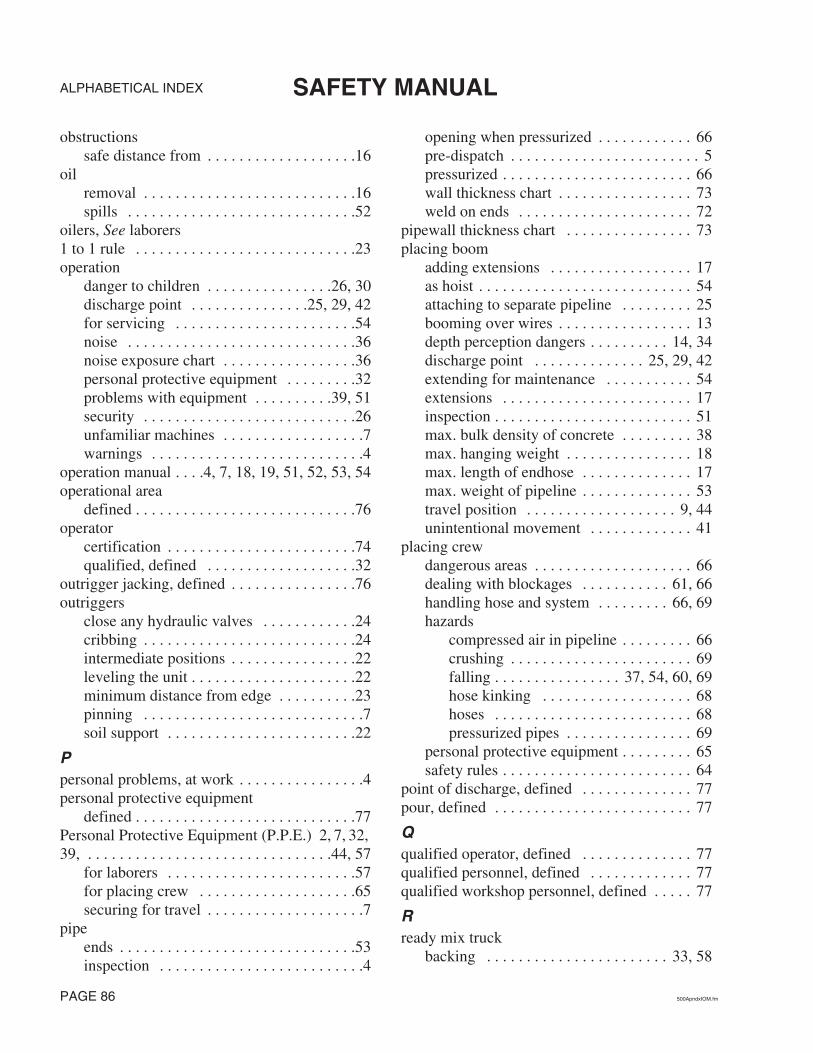
ALPHABETICAL INDEX SAFETY MANUAL
obstructionssafe distance from . . . . . . . . . . . . . . . . . . .16
oilremoval . . . . . . . . . . . . . . . . . . . . . . . . . . .16spills . . . . . . . . . . . . . . . . . . . . . . . . . . . . .52
oilers, See laborers1 to 1 rule . . . . . . . . . . . . . . . . . . . . . . . . . . . .23operation
danger to children . . . . . . . . . . . . . . . .26, 30discharge point . . . . . . . . . . . . . . .25, 29, 42for servicing . . . . . . . . . . . . . . . . . . . . . . .54noise . . . . . . . . . . . . . . . . . . . . . . . . . . . . .36noise exposure chart . . . . . . . . . . . . . . . . .36personal protective equipment . . . . . . . . .32problems with equipment . . . . . . . . . .39, 51security . . . . . . . . . . . . . . . . . . . . . . . . . . .26unfamiliar machines . . . . . . . . . . . . . . . . . .7warnings . . . . . . . . . . . . . . . . . . . . . . . . . . .4
operation manual . . . .4, 7, 18, 19, 51, 52, 53, 54operational area
defined . . . . . . . . . . . . . . . . . . . . . . . . . . . .76operator
certification . . . . . . . . . . . . . . . . . . . . . . . .74qualified, defined . . . . . . . . . . . . . . . . . . .32
outrigger jacking, defined . . . . . . . . . . . . . . . .76outriggers
close any hydraulic valves . . . . . . . . . . . .24cribbing . . . . . . . . . . . . . . . . . . . . . . . . . . .24intermediate positions . . . . . . . . . . . . . . . .22leveling the unit . . . . . . . . . . . . . . . . . . . . .22minimum distance from edge . . . . . . . . . .23pinning . . . . . . . . . . . . . . . . . . . . . . . . . . . .7soil support . . . . . . . . . . . . . . . . . . . . . . . .22
Ppersonal problems, at work . . . . . . . . . . . . . . . .4personal protective equipment
defined . . . . . . . . . . . . . . . . . . . . . . . . . . . .77Personal Protective Equipment (P.P.E.) 2, 7, 32, 39, . . . . . . . . . . . . . . . . . . . . . . . . . . . . . . .44, 57
for laborers . . . . . . . . . . . . . . . . . . . . . . . .57for placing crew . . . . . . . . . . . . . . . . . . . .65securing for travel . . . . . . . . . . . . . . . . . . . .7
pipeends . . . . . . . . . . . . . . . . . . . . . . . . . . . . . .53inspection . . . . . . . . . . . . . . . . . . . . . . . . . .4
opening when pressurized . . . . . . . . . . . . 66pre-dispatch . . . . . . . . . . . . . . . . . . . . . . . . 5pressurized . . . . . . . . . . . . . . . . . . . . . . . . 66wall thickness chart . . . . . . . . . . . . . . . . . 73weld on ends . . . . . . . . . . . . . . . . . . . . . . 72
pipewall thickness chart . . . . . . . . . . . . . . . . 73placing boom
adding extensions . . . . . . . . . . . . . . . . . . 17as hoist . . . . . . . . . . . . . . . . . . . . . . . . . . . 54attaching to separate pipeline . . . . . . . . . 25booming over wires . . . . . . . . . . . . . . . . . 13depth perception dangers . . . . . . . . . . 14, 34discharge point . . . . . . . . . . . . . . 25, 29, 42extending for maintenance . . . . . . . . . . . 54extensions . . . . . . . . . . . . . . . . . . . . . . . . 17inspection . . . . . . . . . . . . . . . . . . . . . . . . . 51max. bulk density of concrete . . . . . . . . . 38max. hanging weight . . . . . . . . . . . . . . . . 18max. length of endhose . . . . . . . . . . . . . . 17max. weight of pipeline . . . . . . . . . . . . . . 53travel position . . . . . . . . . . . . . . . . . . . 9, 44unintentional movement . . . . . . . . . . . . . 41
placing crewdangerous areas . . . . . . . . . . . . . . . . . . . . 66dealing with blockages . . . . . . . . . . . 61, 66handling hose and system . . . . . . . . . 66, 69hazards
compressed air in pipeline . . . . . . . . . 66crushing . . . . . . . . . . . . . . . . . . . . . . . 69falling . . . . . . . . . . . . . . . . 37, 54, 60, 69hose kinking . . . . . . . . . . . . . . . . . . . 68hoses . . . . . . . . . . . . . . . . . . . . . . . . . 68pressurized pipes . . . . . . . . . . . . . . . . 69
personal protective equipment . . . . . . . . . 65safety rules . . . . . . . . . . . . . . . . . . . . . . . . 64
point of discharge, defined . . . . . . . . . . . . . . 77pour, defined . . . . . . . . . . . . . . . . . . . . . . . . . 77
Qqualified operator, defined . . . . . . . . . . . . . . 77qualified personnel, defined . . . . . . . . . . . . . 77qualified workshop personnel, defined . . . . . 77
Rready mix truck
backing . . . . . . . . . . . . . . . . . . . . . . . 33, 58
PAGE 86 500ApndxIOM.fm
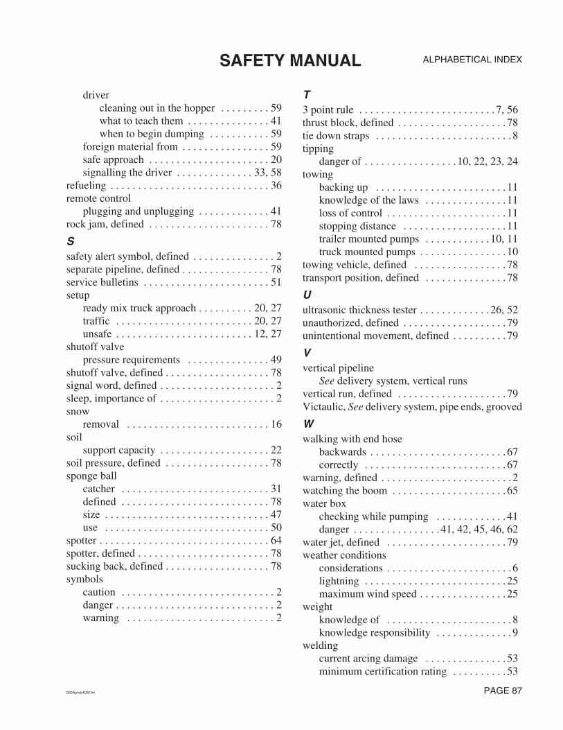
ALPHABETICAL INDEXSAFETY MANUAL
drivercleaning out in the hopper . . . . . . . . . 59what to teach them . . . . . . . . . . . . . . . 41when to begin dumping . . . . . . . . . . . 59
foreign material from . . . . . . . . . . . . . . . . 59safe approach . . . . . . . . . . . . . . . . . . . . . . 20signalling the driver . . . . . . . . . . . . . . 33, 58
refueling . . . . . . . . . . . . . . . . . . . . . . . . . . . . . 36remote control
plugging and unplugging . . . . . . . . . . . . . 41rock jam, defined . . . . . . . . . . . . . . . . . . . . . . 78
Ssafety alert symbol, defined . . . . . . . . . . . . . . . 2separate pipeline, defined . . . . . . . . . . . . . . . . 78service bulletins . . . . . . . . . . . . . . . . . . . . . . . 51setup
ready mix truck approach . . . . . . . . . . 20, 27traffic . . . . . . . . . . . . . . . . . . . . . . . . . 20, 27unsafe . . . . . . . . . . . . . . . . . . . . . . . . . 12, 27
shutoff valvepressure requirements . . . . . . . . . . . . . . . 49
shutoff valve, defined . . . . . . . . . . . . . . . . . . . 78signal word, defined . . . . . . . . . . . . . . . . . . . . . 2sleep, importance of . . . . . . . . . . . . . . . . . . . . . 2snow
removal . . . . . . . . . . . . . . . . . . . . . . . . . . 16soil
support capacity . . . . . . . . . . . . . . . . . . . . 22soil pressure, defined . . . . . . . . . . . . . . . . . . . 78sponge ball
catcher . . . . . . . . . . . . . . . . . . . . . . . . . . . 31defined . . . . . . . . . . . . . . . . . . . . . . . . . . . 78size . . . . . . . . . . . . . . . . . . . . . . . . . . . . . . 47use . . . . . . . . . . . . . . . . . . . . . . . . . . . . . . 50
spotter . . . . . . . . . . . . . . . . . . . . . . . . . . . . . . . 64spotter, defined . . . . . . . . . . . . . . . . . . . . . . . . 78sucking back, defined . . . . . . . . . . . . . . . . . . . 78symbols
caution . . . . . . . . . . . . . . . . . . . . . . . . . . . . 2danger . . . . . . . . . . . . . . . . . . . . . . . . . . . . . 2warning . . . . . . . . . . . . . . . . . . . . . . . . . . . 2
T3 point rule . . . . . . . . . . . . . . . . . . . . . . . . . 7, 56thrust block, defined . . . . . . . . . . . . . . . . . . . . 78tie down straps . . . . . . . . . . . . . . . . . . . . . . . . . 8tipping
danger of . . . . . . . . . . . . . . . . . 10, 22, 23, 24towing
backing up . . . . . . . . . . . . . . . . . . . . . . . . 11knowledge of the laws . . . . . . . . . . . . . . . 11loss of control . . . . . . . . . . . . . . . . . . . . . . 11stopping distance . . . . . . . . . . . . . . . . . . . 11trailer mounted pumps . . . . . . . . . . . . 10, 11truck mounted pumps . . . . . . . . . . . . . . . . 10
towing vehicle, defined . . . . . . . . . . . . . . . . . 78transport position, defined . . . . . . . . . . . . . . . 78
Uultrasonic thickness tester . . . . . . . . . . . . . 26, 52unauthorized, defined . . . . . . . . . . . . . . . . . . . 79unintentional movement, defined . . . . . . . . . . 79
Vvertical pipeline
See delivery system, vertical runsvertical run, defined . . . . . . . . . . . . . . . . . . . . 79Victaulic, See delivery system, pipe ends, grooved
Wwalking with end hose
backwards . . . . . . . . . . . . . . . . . . . . . . . . . 67correctly . . . . . . . . . . . . . . . . . . . . . . . . . . 67
warning, defined . . . . . . . . . . . . . . . . . . . . . . . . 2watching the boom . . . . . . . . . . . . . . . . . . . . . 65water box
checking while pumping . . . . . . . . . . . . . 41danger . . . . . . . . . . . . . . . . 41, 42, 45, 46, 62
water jet, defined . . . . . . . . . . . . . . . . . . . . . . 79weather conditions
considerations . . . . . . . . . . . . . . . . . . . . . . . 6lightning . . . . . . . . . . . . . . . . . . . . . . . . . . 25maximum wind speed . . . . . . . . . . . . . . . . 25
weightknowledge of . . . . . . . . . . . . . . . . . . . . . . . 8knowledge responsibility . . . . . . . . . . . . . . 9
weldingcurrent arcing damage . . . . . . . . . . . . . . . 53minimum certification rating . . . . . . . . . . 53
500ApndxIOM.fm PAGE 87

ALPHABETICAL INDEX SAFETY MANUAL
on electrical components . . . . . . . . . . . . . .53specification . . . . . . . . . . . . . . . . . . . .74, 75
wheel chocks . . . . . . . . . . . . . . . . . . . . . . . . . .16wires, using a spotter . . . . . . . . . . . . . . . . . . . .64workers
alone at the pump . . . . . . . . . . . . . . . .41, 57assigned to the pump . . . . . . . . . . . . . .41, 57e-stop location knowledge . . . . . . . . .41, 57
PAGE 88 500ApndxIOM.fm

cpma, 2006