VORTEX 777 - Product Manuals
98
. . . . . . . . . . . . . . . . . . . . . . . . . . . . . . . . . . . . . . . . . . . . VORTEX 777 Mobile Cleaning Unit Operation and Service Manual
-
Upload
khangminh22 -
Category
Documents
-
view
9 -
download
0
Transcript of VORTEX 777 - Product Manuals

.
.
.
.
.
.
.
.
.
.
.
.
.
.
.
.
.
.
.
.
.
.
.
.
.
.
.
.
.
.
.
.
.
.
.
.
.
.
.
.
.
.
.
.
VORTEX 777
Mobile Cleaning Unit
Operation and Service Manual

.
.
.
.
.
.
.
.
.
.
.
.
.
.
.
.
.
.
.
.
.
.
.
.
.
.
.
.
.
.
.
.
.
.
.
.
.
.
.
.
.
.
.
.
VORTEX 777 Mobile Cleaning Unit
Operation and Service
Manual
Call Vortex Cleaning S'ystems
For Service: 1-801-52:~-9111

.
.
.
.
.
.
.
.
.
.
.
.
.
.
.
.
.
.
.
.
.
.
.
.
.
.
.
.
.
.
.
.
.
.
.
.
.
.
.
.
.
.
.
.
TABLE OF CONTENTS
Section 1: General Information. 1.1. Safety
1
1.2. System Specification 4
1.3. Water Requirements 5
Section 2: Systems
2.1 Water Pumping System 6
2.2 Heat Transfer System 6
2.3 VacuumSystem 7
2.4 Systems
System flow diagram 8
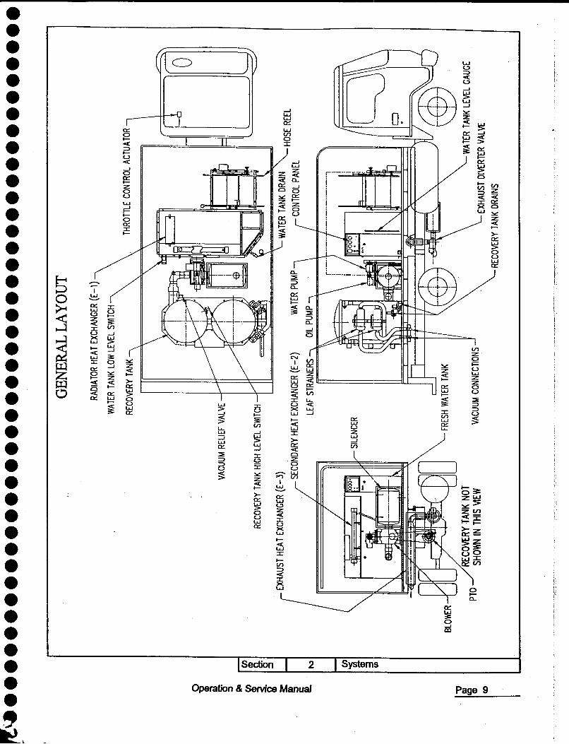
General layout 9
Control panel 10 \.
I>
r
SECTION 3: OPERATION 3.1 Check for adequate fuel 11
3.2 Check oil level in water pump 11
3.3 Check heat transfer fluid level in E-2 exchanger _ II
3.4 Check strainer in recovery tank 11
3.5 Check radiator antifreeze level 11
3.6 Fill fresh water tank 11
3.7 3.8 At the job location 12
3.9 Cleaning I Extraction 13
3.10 Cleaning 13
3.11 Upholstery cleaning 13
3.12 Flood restoration 13
3.13 Shutdown and daily maintenance 13
3.14 Freezing protection 14
,
\:
MAINTENANCE CHART 15 ~-
SECTION 4: MAINTENANCE 4.1 Truck engine and transmission 17
4.2 Vacuum blower 18
4.3 Water pump 18
4.4 Vacuum inlet strainers 19
4.5 Drive shaft; belts, sheaves, & bushings 19
4.6 Inlet strainer to water pump 20
4.7 Recovery tank inlet leaf strainer 20
4.8 Pressure regulator 20
4.9 Vacuum hoses 20 4.10 Engine exhaust heat exchanger B-3 20
4.11 3-wayexhaust diverter valve 21
Operation &: Service Manual _m__

.
.
.
.
.
.
.
.
.
.
.
.
.
.
.
.
.
.
.
.
.
.
.
.
.
.
.
.
.
.
.
.
.
.
.
.
.
.
.
. - . . .
4.12 Heat transfer fluid/water heat exchanger E-2
4.13 High pressure hoses
4.14 Radiator hoses
SECTION 5: GENERAL SERVICE ADJUSTMENTS
5.1 Vacuum blower drive belts
5.2 Water pump drive belt
5.3 Vacuum relief valve
5.4 Pressure regulator
5.5 Adding/draining engine coolant
5.6 Secondary water heating system.
SECTION 6 TROUBLESHOOTING 6.1 PTO will not engage
6.2 pro will not run at speed
6.3 Loss of water pump pressure
6.4 Loss of water volume at cleaning tool
6.5 Loss of vacuum
6.6 Pump does not engage
6.7 Excessive water outlet temperature
6.8 Loss of water temperature
SECTION 7 DESIGN DOCUMENTATION . Truck Main Assembly
. Electrical logic diagram . PTO/Blower Assembly . Water/oil pump assembly
. Exhaust heat system
. Water Piping
. Transfer oil piping system
. Radiator fluid system
. Vacuum recovery system
. Control panel
. Hose reel
. Water Tank Assembly
. Recovery Tank Assembly
. Throttle Control Assembly
. Exhaust diverter valve . Thermostat Assembly
21 21
21
22 22 22 22 23 23
24 25 25 26 26 27 27 28
29
35
31
32 33
. 34 35
36
37
38
39
40 41
42 43
44
Operation &: Service Manual IV
.
.
.
.
.
.
.
.
.
.
.
.
.
.
.
.
.
.
.
.
.
.
.
.
.
.
.
.
.
.
.
.
.
.
.
.
.
.
.
.
.
.
.
.
SECTION 8 PART MANUALS . Blower M-D Pneumatics . PTO series 270 . Water pump CAT . Oil Pump . Water pressure regulator
. Pump inlet strainer
SECTION 9 TECH BULLETIN · Tech bulletin 001 Truck secondary heating system · Tech bulletin 002 Truck drive shaft.
59
69
79
91
94
97
_v_ Operation & Service Manual

.
.
.
.
.
.
.
.
.
.
.
.
.
.
.
.
.
.
.
.
.
.
.
.
.
.
.
.
.
.
.
.
.
.
.
.
.
.
.
.
.
.
.
.
1.1 SAFETY SECTION 1- GENERAL INFORMA1~ION
, . WARNING: For Your Safety!
The following WARNING LABELS are found on your truck. These labels point out important Warnings and Cautions which should be followed at all times. Failure to follow warnings and cautions could result in a fatality, personal injury to yourself and/or others, or property damage. Follow these instructions carefully! DO NOT remove these labels.
ROTATING SHAFTS ARE DANGEROUS
YOUCAllSIIAGCl.OTHfS.~....lIAIII,IWIlS.ElC ~I/= THIS CAll CAUSE GÐIlOUS......, OR 0fA1ll '\) -tllPllSEIlI\01J.T1IIQSlWlSMUSTBE6llNllIED.' ~. . DONØlWllRKONOR_N1EX1'O$EDSlWTWItElI L"~ I_IS RUNIiIllII.
ROO P.T.O. OWNERS NAllUAI. - ~~r~ø:iRE WIIfIlWlGOIPOWERTAKE lIIf fOR MORE SAfETY INfORMATION
~1Ill3
c/ Hot Surfaces. Do not touch.
! This symbol mleans WARNING or CAUTION. Failurl~ to follow warnings and cautions could result in fatality, personal injury to yourself and/or others, or personal damage. Follow instructions carefully.
-.
Section Operation & Service Manual
1 General Information
_1__

.
.
.
.
.
.
.
.
.
.
.
.
.
.
.
.
.
.
.
.
.
.
.
.
.
.
.
.
.
.
.
.
.
.
.
.
.
.
.
.
.
.
.
.
, . WARNING!
1.1.1 Read the operator's manual beCore starting this unit. Failure to adhere to instructions can result in severe personal injury or could be Catal.
1.1.2 Operate this unit only in a well-ventilated area. Exhaust fumes contain carbon monoxide which is an odorless and deadly poison that can cause severe injury or fatality. DO NOT run this unit in an enclosed area. DO NOT operate this unit where the exhaust may enter any building doorway, window, vent or opening of any type.
1.1.3 DO NOT place hands, feet, hair, and clothing near rotating or moving parts. Avoid any contact with moving parts! Rotating machinery can cause injury or fatality.
1.1.4 Never operate this unit without belt guards. The high speed moving parts, such as belts and pulleys, should be avoided while this unit is running. St:vere injury, damage,
or fatality may result.
1.1.5 DO NOT service this unit while it is running. The high-speed mechanical parts as well as high temperature components may result in severe injury.
1.1.6 Never touch electrical wires or components while the engine is running. They can be sources of electrical shock.
1.1.7 Engine components can get extremely hot from operation. To prevent severe burns, DO NOT touch these areas while the engine is running - or immediately after the engine is turned off.
1.1.8 DO NOT touch the exhaust diverter valve, heat transfer pump, or heat exhangers. Severe burns may result.
1.1.9 Before servicing this unit, allow it to "cool down". This will prevent burns from occumng.
1.1.10 Water under high pressure at high temperature can uuse burns, severe personal injury, or Catality. Shut down machine, allow to cool down, and relieC system pressure beCore removing valves, caps, plugs fittings., filters, and misc. equipmen~.
1.1.11 Do not exceed truck weight limit. GVW allowable 14250 lb.
1.1.12 Keep your truck work area clean. Wands, stair tools, and other accessories must be securely Castened beCore. driving the truck. This will prevent damage to yourselves or your equipment in event oC a sudden stop.
1.1.13 All high pressure hoses must be rated Cor 3000psi at 300oF. Do not use hoses with lower rating. Severe burns and injury may result if the hOSI~S do not meet these requirements.
Section 1
Operation & Service Manual 2 G.meral InCormation

.
.
.
.
.
.
.
.
.
.
.
.
.
.
.
.
.
.
.
.
.
.
.
.
.
.
.
.
.
.
.
.
.
.
.
.
.
.
.
.
.
.
.
.
1.1.14 Make certain that you receive complete training before using this truck.
1.1.15 This Truck uses high pressure and temperature. Improper or irresponsible
use may result in serious injury.
1.1.16 Do not modify this unit in any manner. Improper modification can cause severe personal injury or fatality and void any warranty.
Section 1 Gellleral Information Operation & Service Manual 3

.
.
.
.
.
.
.
.
.
.
.
.
.
.
.
.
.
.
.
.
.
.
.
.
.
.
.
.
.
.
.
.
.
.
.
.
.
.
.
.
.-
.
.
.
Radiator Remote Thermostat 1950F
1.2 SYSTEM SPECIFICJ~ TION.
Truck Nissaln UD1400
Truck Idle Speed 600-700 RPM
Truck in Cleaning Mode
Engine RPM 1100 to 1500 RPM
Water Tank
Max. Operating Capacity 260 UlS gal
Waste Tank Capacity
Max. Operating Capacity 260 US gal
Max. Outlet Water Pressure 1500 psi
Max. Outlet Water Temp. 2800F
Blower Flow 700 IGFM @ 2650 RPM
Max. System Design Vacuum 15" Hlg. Limited by Blower
Water Pump Max Flow 4.5 GPM
Max. Truck Operating Weight Weight include all truck equipment, 300gal of water 1/2 full fuel tank and one driver.
124401bs **
Blower RPMIICFM 2300 570 1420 2880 700 1700
** Allowable Truck Gross weight 14250lbs
Section 1 Gene~rallnformation Operation & Service Manual 4

.
.
.
.
.
.
.
.
.
.
.
.
.
.
.
.
.
.
.
.
.
.
.
.
.
.
.
.
.
.
.
.
.
.
.
.
.
.
.
.
.
.
.
.
1.3 WATER REQUIREMENTS
Hard water deposits will adversely affect the plumbing and heat exchange system on the truck
The map below will give you an idea of where areas of high water hardness may occur. Though any water supply obtained from a well is almost always hard water and a water softener will be needed to protect truck equipment.
r'
, . NOTE: Equipment malfunction or component failure caused by hard water scaling is not covered under warranty.
If you are operating this truck in an area where the unit will be using water in which the hardness exceeds 3-1/2 grains, we highly recommend a suitable water softener be installed.
Using a water softener will reduce maintenance and decrease down time caused by hard water scaling. It will also allow cleaning chemical to be more effective in lower concentrations.
HARD WATER MAP D æ;s1HAN35 k~13.sro7 _ MORE1HAN7
Section 1 General llllÍormation Operation & Service Manual 5
.
.
.
.
.
.
.
.
.
.
.
.
.
.
.
.
.
.
.
.
.
.
.
.
.
.
.
.
.
.
.
.
.
.
.
.
.
.
.
. - . . .
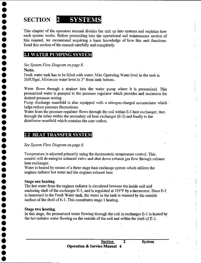
SECTION 2 SYSTEMS
This chapter of the operators manual divides the unit up into systems and explains how each system works. Before proceeding into the operational and maintenance section of this manual, we recommend acquiring a basic knowledge of how this unit functions. Read this section of the manual carefully and completely.
2.1 WATER PUlVIPING SYSTEM
See System Flow Diagram on page 8.
Note. Fresh water tank has to be filled with water. Max Operating Water l,evel in the tank is
260USgal, Minimum water level is 3" from tank bottom.
Water flows through a strainer into the water pump where it is pressurized. This pressurized water is pumped to the pressure regulator which provides and maintains the desired pressure setting.
Pump discharge manifold is also equipped with a nitrogen-charg(~d accumulator which .
helps reduce pressure fluctuations. Water from the pressure regulator flows through the coil within E-l heat exchanger, then through the tubes within the secondary oil heat exchanger (E-2) and finally to the distributor manifold which contains the user outlets.
2.2 MEAT TRANSFER SYSTElVI
See System Flow Diagram on page 8.
Temperature is adjusted primarily using the thermostatic temperatme contro~. This control will de-energize solenoid valve and shut down exhaust gas flow through exhaust heat exchanger.
Water is heated by means of a three stage heat exchange system which utilizes the engines radiator hot water and the engines exhaust heat.
Stage one beating. The hot w~ter from the engines radiator is circulated between the inside coil and enclosing shell of the exchanger E-l, and is regulated at 1950F by a thermostat. Since E-l is immersed in the Fresh Water tank, the water in the tank is warmed by the outside surface of the shell of E-l. This constitutes stage 1 heating.
Stage two heating. In this stage, the pressurized water flowing through the coil in exchanger E-l is heated by
the hot radiator water flowing on the outside of the coil and within 1he shell of E-I.
Section 2
Operation & Service Manual 6
System

.
.
.
.
.
.
.
.
.
.
.
.
.
.
.
.
.
.
.
.
.
.
.
.
.
.
.
.
.
.
.
.
.
.
.
.
.
.
.
.
.
.
.
.
Stage three heating. Here the exhaust heat from the engine is utilized to raise the temperature of the pressurized water leading to the wand. This is done by circulating oil in a secondary loop between exhaust heat exchanger E-3 and secondary exchanger E-2. Oil heated in E-3 is
circulated in a closed loop by the oil pump to E-2 (the secondary heat exchanger) where the hot oil transfers its heat to the pressurized water, thus further raising the water temperature from E-I. At this point the water temperature is limited to 2800F by action of the diverter valve.
Exhaust diverter by-pass valve. Diverter valve located just beyond the engine muffler, the diverter valve is a 3-way by- pass valve that either diverts hot exhaust gases through heat exchanger E-3 or by-passes
E-3 to direct the exhaust gas to the atmosphere. For the diverter valve to direct the exhaust gas through exchanger E-3 the water pump must be operating and the oil temperature must be below the set point on the temperature controller.
2.3 V ACUUlVI SYSTEM
Vacuum flow begins at the cleaning tool, with air and some chemicals being drawn into the vacuum inlets at the Recovery Tame The mixture then flows through leaf strainers prior to the Recovery Tallie Two 100 mesh stainless steel strainers, located inside one Recovery Tank and a reliefvalve have been provided for vacuum blower protection.
The air then flows into the vacuum blower which is driven by the truck engine through a
truck transmission mounted PTO.
The air discharged from vacuum blower exits through the silencer directly into the
atmosphere. A level sensor switch located near the top of the Recovery Tank will shut down the water pump and drop engine RPM to the idle position before the Recovery Tank reaches its full capacity. This protects the vacuum blower from water damage.
Section 2
Operation & Service Manual 7 System

.
.
.
.
.
.
.
.
.
.
.
.
.
.
.
.
.
.
.
.
.
.
.
.
.
.
.
.
.
.
.
.
.
.
.
.
.
.
.
.
.
.
.
.
r I I I I -, I I
I 11_________________________ r----------------J T. '
rr-~~-~-~=======1=' l--------~ I I I
L
~ ::5 o
~ CI.) ~ CI.)
1
.-.--.r I UJ i
.
z r' i~<>=g! i~~U') !
i~~ 1
1::>0 i 0..
1
1
1
L_._.j
a:: (]Jl.&.J ---
-~..... ..- ~
. o l.&.J. --' --' .
CD tñ :
. en 0- f ~~
::J:::>
è;50 0.. :::lE
::> 0.. --' o
V) ~
:z <
t- >- a:: ~ o u l.&.J
a::
en a:: w
;;z < ~ en :::IE
::> ::> CJ ~
l.&.J
:z ë3 :z l.&.J
~ ~
e9 0..0 z
~ tn
-------------, I ~ : -' I
tñ~ I
~gc ~o ....15
-' o
tn
0- ~ is 0- VI ::> <
~ UJ :2 ::> a ~
a:: l.&.J
c> ~ ::I: U X l.&.J
t-~ <l.&.J l.&.J
::I:
t- V) ::> <
~ l.&.J
9 -...........-........ ~
:2 ::>
-..............................0 ~
Systems
Operation & Service Manual
;:: o
--' L...
t- ~ ~ l.&.JW
<;::<wCD~ --'o:cv)~-l OO-lxo>--l u L... W :c a:: ð w:::lE:::lE:::lE<ö:: z ::> ::> ::> --' t- - ::> ::> ::> ::::! u
c>uuuo..w tj~~~ðd I
I I I I I I
;:: o
-l L...
;:: ;:: g g ;:: L... L...
0;:: a:: ~ t- ~g!:;~~ a::
L... -... <( wa:: ;:: ::::! :c t-Wt-Ox <t-oc>w ;::~:czw Cl >-ï=~ 6b8J;5~ U:c>:cw
Cl :z w
c> l.&.J
-l
~..
Page 8
.
.
.
. c::::> w <..:>
=> . < <..:>
-1 . ~ W
-1 . -1 :!o<: W
:z w
~ 0::: ~ . W 0::: -1 Vl I..LJ ~ a
l- . I ~ 0:::
I..LJ
l- . -J 0::: w
1-:1 ~ -1 Z a < ë5 . 0::: a... l- I- Z -J Vl 0 0 => . 0 0::: <
l- I I..LJ Z X ~ 0
I..LJ . l- e..> ! a i . 0::: I
l- . .
a...
. b :::i:
=> a...
. I
0::: 0 ~ W
I- ~ 0::: I <
. I..LJ 0 ~
:s <..:> I- ~ ;: . I en
0 -1
i x ~
. I..LJ
I- I..LJ
en < ....J
--- :z I..LJ ~ ('.j a
. I a :!o<: I ~ 0::: -1 :z ~ 0 ~ I..LJ a :!o<:
0::: :z: . I- :z: >- w
:z: < ~ 0::: c..:> a
0 ë5 ~ :z: 0
. < 0::: < :::i: 0::: I..LJ a I
I- 0 I..LJ :r: L> => <
I..LJ > 0 x => . ~ 0::: ....J I-
W 0 ~ 3: I- 0::: ~
< I..LJ U) 0 . ........ W I..LJ -1 I :z: :J ~ I..LJ
>- ....J
. I..LJ W 0::: in a:: ....J < :::i: :r:
0
=> <..:> :z: . ::> :ë 0
0 L> ~ :!o<: -;;:)
W
V> . :z: I <
I- W
........
. >- 0::: 0::: I..LJ ~ <..:>
. a ~ 0 I w
0::: 0
. x W
l- . < W I
. I- en ::> <
. I X W
.
.
.
.
. Systems
. Operation & Service Manual Page 9
.
~
~l

.
. \~
. ....J \..,
o C'c
. J?= '"
rJ 8 -
. I- --:::E
rJ a::: og, I . 0
0- \ W
. lLJ o~ 0 5 "'C)--c..:>
z
. a::: w w lLJ c..:> U')
. :::> c:( c..:>
. ::E :::> :::>
. w 0 g
c..:> ~ I- :::> . :::c c:( e..:>
e..:> ::J'" :::ï -
. -' w
a::: ~ :::>
. lLJ U') lLJ
-
U') r-- -
-' w Vl . :::c a::: => c ('(
e..:> 0- LL.. () ~
:::c .
a::: ~ - . lLJ :::..::::
I- :::c "') ::z: ~ 0 c:( ....J . l- I- 0 ~ >- ;: a::: (") ~ U') l- . a::: ::z: ~ I- r0 a:::
0 0 c:(
0 () . 0 I- W
.
P-4 lLJ Vl a::: \T' a::: 0 i=! . ~ I- ~
0- c:( :::c
. 0 a::: 0 :::c w I- 0
~ a. ;: I- :::E Vl ;: . W
I- a. Vl 0 W
. 0 l- e..:>
Vl c:( U 0 e..:> :::c
. I- Z 0
0- W I- a. ;: . :::E "U')
lLJ => LL.. e..:> a. LL..
. => 0
c:( ............
e..:> ::z:
. 0 w
:::E a:::
. ~ l=! c:( ~ a::: . lLJ U') 0-
. :::E ~
. a::: w
l- . c:( ~
. a::: 0:: ww 1-1- . W lLJ :::E :::E
00:: . :x: :::>
00 . ~ :x:
wO zz . G c:( z
. w
. System~;
.
. Operation & Service Manual Page 10
.
.
. -

.
.
.
.
.
.
.
.
.
.
.
.
.
.
.
.
.
.
.
.
.
.
.
.
.
.
.
.
.
.
.
.
.
.
.
.
.
.
.
.
.
.
.
.
SECTION 3 OPERATION This chapter of the operators manual explains how to prepare, startup, shut down, and daily maintain the Carpet cleaning unit. Operation of the unit is simple. However, read the following instruction carefully and fully understand the interaction of the various components.
CAUTION: Operate this unit only in a well-ventilated area. Exhaust fumes contain carbon monoxide which is an odorless and deadly poison that can cause severe injury or fatality. DO NOT operate this unit where the exhaust may enter any building
doorwa , window, vent, or 0 en in of an e.
3.1. CHECK FOR ADEQUATE FUEL.
Check the fuel tank to be certain there is adequate fuel to complete the job. This unit use approximately 2 gallons per hour, depending on speed setting.
3.2. CHECK OIL LEVEL IN WATER PUMP DRIVEN BY VACUUM BLOWER
Check water pump oil daily before starting system. Oil level should be in the center of level gauge. If the oil level below level gauge center line add oiL Avoid overfilling or damage may occur to pump. Use only oil specified by water pump manufacturer.
3.3 CHECK HEAT TRANSFER FLUID LEVEL IN E-2 HEAT EXCHANGER.
. Check level in E-2 heat exchanger. Oil level to be checked with system off and heat exchanger temperature between 60 and 80oP. Normal oil level should be in center of level auge.
Avoid overfillin heat transfer fluid otherwise dama e to the s stem may occur.
3.4 CHECK STRAINERS IN RECOVERY TANK. Check vacuum strainers daily. Clean and replace as required.
3.5. CHECK RADIATOR ANTIFREEZE LEVEL.
Check antifreeze level in the beginning of the shift. Add if necessary.
3.6 FILL FRESH WATER TANK WITH CLEAN WATER. Start the truck and proceed to the first job location. Running truck for 20 minutes will preheat Fresh water Tank to appmximately 80 to 1 OooF. Do not turn truck off at the job location.
Section 3
Operation & Service Manual 11 Operation

.
.
.
.
.
.
.
.
.
.
.
.
.
.
.
.
.
.
.
.
.
.
.
.
.
.
.
.
.
.
.
.
.
.
.
.
.
.
.
.
.
.
.
.
3.8 AT THE JOB LOCATION.
3.8.1 Remove tools from vehicle.
3.8.2 Connect the water pressure hose(s) to the outlet connection(s) at the Fresh Water tank Connect the cleaning tool to the pressure hose(s).
3.8.3 Connect the vacuum hose(s) to the vacuum inlet connection(s) at the vacuum ports. Connect the other end of the vacuum hose(s) to the cleaning tool(s).
3.8.4 Turn PTO switch to "Engage" position this will energize PTO solenoid and engage PTO. Engine will run at idle speed approximately 700 RPM. Blower pulley will start turning. Allow 30 second for the system get to the idle speed.
3.8.5 Set the temperature control on the control panel to the desired cleaning
temperature. The thermostatic temperature control will éùlow an increase or decrease in the solution temperature automatically. Simply turn the control knob to the desired temperature setting.
3.8.6 Pull Pump Switch. This action will energize water pump clutch and both water
pump and oil (heat transfer fluid) pump will be on. Allow 30 second for both
pumps get to the idle speed.
Water pump will recirculate water through water bypass valve back to the Fresh Water tank. Oil pump will circulate oil from E-3 exhaust heat exchanger to
E-2 water/oil heat exchanger.
Note: If your unit fails to build water pressure after 15 second, check for adequate
water supply. If necessary, see Loss of Water Pump pressure in Water Pump section troubleshooting of this manual.
Do not engage pumps at high engine RPM damage may occur to pump clutch. Complete system is now ready for high speed operation.
3.8.7 Turn PTO switch to desired speed selection. 3.8.8 Allow adequate time for the engine to get to desired speed.
Allow adequate time for the truck engine to worm up before engaging PTO.
CAUTION WATER UNDER HIGH PRESSURE AND illGH TEMPERATURE CAN CAUSE BURNS, SEVERE PERSONAL INJURY, OR COULD BE FATAL. SHUT DOWN EQUIPMENT, ALLOW TO COOL DOWN, AND RELEASE SYSTEM OF ALL PRESSURE BEFORE ANY WORK.
! CAUTION DO NOt MODIFY UNIT WITHOUT WRITTEN PERMISSION FROM MANUFACTURER
! WARNING! NEVER dispose of waste in storm drains, water ways, or on ground areas. Always dispose of waste in accordance with Local, State, or Federal laws.
Section
Operation & Service Manual 12 3 Operation

.
.
.
.
.
.
.
.
.
.
.
.
.
.
.
.
.
.
.
.
.
.
.
.
.
.
.
.
.
.
.
.
.
.
.
.
.
.
.
.
.
.
.
.
3.9 CLEANING/EXTRACTION.
Once you have completed item 3.8 (starting the unit) proceed with the cleaning operation. PTO should be in speed 1 or speed 2 position (on electrical panel) when cleaning or extracting. A water high level switch located inside the Recovery Tank will automatically shut down PTO when it reaches its full capacity. When this occurs, empty the Recovery Tank before continuing.
3.10 CLEANING
Observe the following guidelines, while cleaning.
3.10.1 Before proceeding make sure the wand spray nozzles are functioning properly. a. To check, hold the wand one foot above the surface to be c:1eaned and open the
wand valve. A full spray should be observed from the spray nozzles. b. If any nozzle is not showing a full spray pattern, adjust for proper pattern, clean,
or replace nozzle, if required.
3.10.2 When cleaning, keep the working opening (mouth) flat on the surface being cleaned. Keep the wand moving when the valve is open.
3.10.3 Truck will automatically return to the idle speed and shutdown water pump when the Recovery Tank is full. This will prevent water being drawing into the vacuum blower. If this occurs, empty the Recovery Tank before proceeding.
WARNING! DO NOT dispose of waste in any manner which, in so doing, would violate any Local, State, or Federal laws.
3.11 UPHOLSTERY CLEANING. Since the upholstery tool has a lower flow rate and smaller spray nozzle orifice, operate the unit with reduced temperature and reduced pressure. Turn temperature control thermostat CCW to reduce temperature setting. This will prevent excessive heat build up in the water system.
3.12 FLOOD RESTORATION. During flood restoration, do not engage pump switch. The water pumping system and exhaust heat transfer system is now OFF. 3-way valve is in the off position with exhaust gases going directly from the mufller to the atmosphere.
3.13 SHUTDOWN AND DAILY MAINTENANCE. 3.13.1Remove as much moisture from the vacuum hoses as is n~asonable. This will
prevent spillage of solution in your vehicle when replacing hoses. Turn sped control nub CCW to reduce engine RPM to idle, Disconnect vacuum hose from the system.
Section Operation & Service Manual
3
13 Operation

.
.
.
.
.
.
.
.
.
.
.
.
.
.
.
.
.
.
.
.
.
.
.
.
.
.
.
.
.
.
.
.
.
.
.
.
.
.
.
.
.
.
.
.
3.13.2 Shutdown water pump and continue running engine in idle position for one minute in order to remove all moisture from the blower.
NOTE: If finished for the day: Run vacuum blower at full speed, plug the vacuum inlets and spray WD-40 (or equivalent) into the vacuum service port (located at front panel). This will lubricate the blower and revent internal rustin .
! WARNING! Do not turn system off at high engine RPM. Lower engine Rl>M and only then shut down blower.
3.13.4 Push PTO "STOP" Push Button switch this action will shut down blower. 3.13.5 Relieve pressure from the cleaning tools and pressure hoses by activating the
valve on the tooL Disconnect the tools and pressure hoses from the unit and store all equipment.
3.13.6 Drain the Recovery Tank and dispose of waste in proper manner.
! WARNING! NEVER dispose of waste in storm drains, water ways, or on ground areas. Always dispose of waste in accordance with Local, State, or Federal law.
3.13.7 Clean the leaf strainers and reinstalL Inspect the vacuum inlet strainer inside the Recovery Tank. If any lint or debris exists, remove and clean strainer.
NOTE: When removing the vacuum inlet strainer, grip the plastic hexagonal section of filter. Grasping strainer by screen may collapse or ruin the straine:r. Re-install the strainer hand-tight. Never operate this unit with this strainer removed, damage or improperly installed. NOTE: When replacing this strainer, use only the recommended stainless steel element. This will prevent rust and corrosion from entering the vacuum system. 3.13.8 At the end of the day, rinse out the waste tank with fresh water. Add special
Deodorizer to the waste tank to inhibit the growth of bacteria.
3.13.9 Clean the unit, tools, hoses, truck interior, etc., as needed. Inspect All equipment for any damage, wear, leaks, etc.
3.14 FREEZING PROTECTION ! WARNING: If the unit is exposed to freezing weather, the water in the unit may freeze causing SERIOUS DAMAGE to the unit. To avoid this, the following is recommended during the cold weather season:
When the unit is not in use, always park it in a heated building or drain completely.
While in operation, avoid long shutdowns as unit provides heat while running. Shut it down just prior to leaving for the next job.
Section Operation & Service Manual 15
3 Operation

.
.
.
.
.
.
.
.
.
.
.
.
.
.
.
.
.
.
.
.
.
.
.
.
.
.
.
.
.
.
.
.
.
.
.
.
.
.
.
.
.
.
.
.
MAINTENANCE CHART DAILY CHECKS
Water Pump
Heating System
Vacuum Blower
Vacuum inlet strainer
Vacuum hoses
**
heck engine oil level. Fill to proper level.
heck engine coolant level
heck transmission level.
heck power Steerin!llevel
heck Brakes and Washer fluid level.
heck speed Actuator Linkage.
heck oil level.
heck oil level. E-2 exchanger
pray WD-40 into lubrication port at front panel
lean strainers. inspect. replace if damaged.
ash out with clean water.
Truck Engine
Note: Start at driver door and walk around the truck checking tires, LU~1 nuts and damage to the truck. Also check under truck for any fluid leakage on the ground. Check truck lighting: headlights. turn signals. brake lights, etc.
! WARNING! * Do not oveñill heating system (Normal liquid level must be
in the middle of glass at temperature 700F.
See Tech Bulletin-001 for instruction.
With Truck Running 1. Engage PTO and pumps and check for water pressure. If system does not develop water
pressure in 15 sec. Shutdown water pump and verify if pump is properly primed.
! WARNING! Iways check for water pressure before going to Cleaning
peed. Running Water Pump dry will Damage Pumpl
2.Check that unit will come up to desired speed. Also check that 1000 psi water pressure Can be obtained.
3. Check system vacuum at the speed.
Section 4 Maintenance
Operation & Service Manual 15

.
.
.
.
.
.
.
.
.
.
.
.
.
.
.
.
.
.
.
.
.
.
.
.
.
.
.
.
.
.
.
.
.
.
.
.
.
.
.
.
.
.
.
.
MAINTENANCE CHART - WEEKLY CHECKS
Vacuum Blower
Water pump inlet Strainer
3-way exhaust diverter valve
Secondary Exchanger
~heck oil level. Fill to proper level.
heck for debris and clean Lubricate weekly
ent E-2 heat exchanger (note 1).
MAINTENANCE CHART
Blower Drive belt
Water Pump Oil
Blower oil * Or as often as required. ** See Truck manual for more information. *** Perform drive belt, sheave, and bushing maintenance after first 25 hours of operation, and then again at 100 hours.
High Pressure Water Hoses Vacuum Blower
Pressure Regulator Engine Oil and Oil Filter
Radiator & E-1 Hoses
Exhaust Heat exchanger Tubes Drive shaft
Lower pulley shaft bearing
Pump belt Heating fluid replacement
Transmission Oil
Note 1. See Tech Bulletin - 001
2. Or every 6 month.
3. See Tech Bulletin -002
Inspect for damage or impending failure
Lubricate bearing
Lubricate a-rings hange engine oil and oil filter monthly.
heck Radiator hoses for leaks and clamp ightness.
lean tubes or every 6 month
Lubricate universal Joints (note 3)
Lubricate bearing (note 3) Inspect, clean, check belt tension and sheave
00 HR*** lignment
00 HR Replace Heat Transfer Fluid (note1 and 2).
00 HR** hange transmission oil. (note 2) Inspect, clean, check belt tension and sheave
00 HR*** Iignment
500 HR hange oil
500 HR hange oil
Section 4 Maintenance
Operation & Service Manual 16

.
.
.
.
.
.
.
.
.
.
.
.
.
.
.
.
.
.
.
.
.
.
.
.
.
.
.
.
.
.
.
.
.
.
.
.
.
.
.
.
.
.
.
.
SECTION 4 MAINTENANCE
This chapter of the operator's manual contains the maintenance information for this unit.
Initiation of the planned PREVENTATIVE MAINTENANCE PROGRAM will assure that your Truck unit has optimal performance, a long operating life, and a minimal amount of "down" time.
ROTATING SHAFTS ARE DANGEROUS
'IOUCAH_cuml'S.~.~R._rn: ~LJ= lltS CAH CAUSE sauoos .....n OR IlfAlll '\) - EXl'llStDROWlIllSlWl3UUSlBEGILWlED.' ~
f.O.r_ . DOlIOT_OIORIlfARAIlÐPOSBJSlW'rWHEII L"'~ VV'" _'s IUIIIIlI1.
READ P.lD. OWlIERS IIAIlUA1. . ~~~WORIIIll 01 POWEll TAKE Off FOR IlORE SAFETY
INFOlUIATIOlI
...... .....
Hot Surfaces. Do not touch.
! WARNING: DO NOT service this unit while it is running. The high speed mechanical parts as well as high temperature of the components may result in severe injury, severed limbs, or fatality.
4.1 TRUCK ENGINE, TRANSMISSION and PTO. Refer to Truck Owner's manual for specific instructions. 4.1.1 Check the engine and transmission oil levels daily, when in use. MAKE
CERTAIN THAT PROPER OIL LEVEL IS MAINTAINED. NEVER overfill. 4.1.2 Check transmission/PTO hoses for leaks daily.
4.1.3 Change the break-in engine oil after the first 100 hours of operation. Thereafter, change engine oil every 200 hours of operation.
Section Operation & Service Manual 17
41 Maintenance

.
.
.
.
.
.
.
.
.
.
.
.
.
.
.
.
.
.
.
.
.
.
.
.
.
.
.
.
.
.
.
.
.
.
.
.
.
.
.
.
.
.
.
.
4.1.4 The Power Take-Off, being an integral part of the transmission, should be serviced at the same intervals as the transmission. The Power Take-Off is also part of a system. The PTO includes a drive shaft. PTO requires periodic check and service. Every time the <:hassis is lubricated or a
mechanic is under the vehicle the PTO system should be checked and serviced. Within the first week of use, recheck the installation of the PTO. Check for leaks and loose mounting hardware (studs, huts, cap screws).
4.2 VACUUM BLOWER:
Refer to Vacuum Blower section in the manual for specific instrm:tions. Lubrication: Recommended mineral based lubricants 320F to 900F Shell AMOCO TEXACO MOBIL Ambient Tellusl00 American ind.l00 Random) 100 DTEHeavy temperature (SAE 30) (SAE 30) (SAE30) SAE30
Or Use CPI 4601-68 (SAE-30) Synthetic Based lubricant oil in the gear end of the vacuum blower.
4.2.1 Check oil level weekly to assure the proper level. PROPER LEVEL cannot be overemphasized. Too little oil will ruin bearings and ge:ars. Too much oil will cause overheating.
4.2.2 To prevent rust from building up inside the vacuum blower (if moisture exist) each truck is supplied with a lubrication port on the front of the panel. First, run the unit at least 1 minute to remove any moisture from th,e vacuum blower. Next, fill the lubrication port with WD-40 or a similar lubricant while the unit is running and the vacuum iIÙet at the Recovery Tank is sealed. Do this at the end of each working day.
4.2.3 Drain, flush and replace oil every lDOO hours or yearly, whichever comes first. Change oil more frequently if inspection so indicates.
4.2.4 The bearings on pulley end of the vacuum blower require grease lubrication every 2 to 3 weeks or every 80 hours. Using a pressure gun, force new grease into each bearing until trace of clean grease comes out of the relief fitting. Use NLGI #2 premium grade, þetroleum base grease with high temperature resistance and good mechanical stability.
CAUTION: Do not inject grease too fast to avoid damaging the drive shaft seal.
4.3 . WATERPUMP:
Refer to the Water Pump Operation and Service Manual for specific instructions. 4.3.1 Check the crankcase oil level daily to assure the proper level. If the level has
dropped, check for the source of leakage and repair.
Section Operation & Service Manual 18
4 Maintenance

.
.
.
.
.
.
.
.
.
.
.
.
.
.
.
.
.
.
.
.
.
.
.
.
.
.
.
.
.
.
.
.
.
.
.
.
.
.
.
.
.
.
.
.
SIGHT GLASS ON CAT WATER PUMP
CRANKCASE COVER
OIL LEVEL WITH UNIT STOPPED & 0
LEVEL GROUND
RED DOT
4.3.2 Refill the oil to the proper level, if required, with Cat Pump Crankcase Oil, SPECIAL FORMULA PREMnJM 1 OW30 GRADE NON-DETERGENT HYDRAULIC Oil. Other Cat approved oil equivalents are:
Mobil DTE 16, Amoco Rycow 68, Shell Tellus T68. 4.3.2 Change the crankcase oil with Cat Pump Crankcase Oil after the first SO hours of
operation. Drain and refill the crankcase oil with Cat Pump Crankcase Oil every 500 hours thereafter.
4.4 VACUUM INLET STRAINERS. Inspect the vacuum inlet strainers inside Recovery Tank. If there is any lint or debries,
remove and clean strainer. Re-install the strainer hand-tight.
The vacuum strainers in Recovery Tank should be removed and cleaned daily. If this is
done, the strainer will last for long time.
! CAUTION: When removing the vacuum inlet filter, grip the plastic hexagonal section of filter. Grasping filter by screen may collapse or ruin the filter.
Replace this strainer if damaged or as needed. Replace strainer with new all stainless steel element 100mesh screen.
4.5 DRIVE SHAFT, BELTS, SHEAVES, & BUSIDNGS.
4.5.1 Check pulley bushing cap screws after the first 25 hours and then again at 100 hours.. Re-torque these screws with a wrench as required.
4.5.2 Grease drive shaft joint every 200 hours. Use Penzoil ULTRA EPI tacky lithium or Penzoil SPL2 grease.
4.5.3 Check for sheave groove wear, clean the belts and sheave grooves, check for worn belts, proper belt tension, and sheave alignment after the first 25 hours and then again at 100 hours.
Check for belt ride in the groove. In multiple groove driV(~S, belt ride should be
uniform, not more than 1116" above or below top of sheave groove. Check groove wear area for wear. Side wall of groove should be straight, not dished
out. Bottom of groove should show no signs of belt contact. <\.
Section Operation & Service Manual 19
4 Maintenance

.
.
.
.
.
.
.
.
.
.
.
.
.
.
.
.
.
.
.
.
.
.
.
.
.
.
.
.
.
.
.
.
.
.
.
.
.
.
.
.
.
.
.
.
Inspect belts for contaminates, such as oil or grease. Wipe belts clean with detergent and water. Inspect sheaves for buildup of such material and remove, if necessary.
Check wear surface of belt for excessive wear. If it has a slick, glazed look, belts are slipping. Check belt tension. Never replace one belt in a used set. Replace entire set if replacement is necessary. Place a straight-edge across the top of belt. There should be no more than ~" deflection in the Center of the belt with I Olbs push, halfway between the sheaves. If there is to much slack, tighten belt, making sure that it stays properly aligned. Check alignment with straight-edge or string across faces of the pulleys, Correct alignment to as near perfect as possible.
4.6 INLET STRAINER TO WATER PUMP.
The strainer is located of the outside fresh water tank. Flush screen regularly and reinstall into body. Check gasket for cuts or wear and replace if necessary to assure proper seal. Thread body and cap hand tight for proper seal.
4.7 RECOVERY TANK INLET LEAF STRAINER.
The leaf strainers are located outside of the Recovery Tank. Strainer bag should be removed and cleaned whenever it is full of debris. This should be done on at least a daily basis.
4.8 PRESSURE REGULATOR. Lubricate the o-rings every 100 hours. Use O-ring lubricant.
For procedure, see "General Service Adjustment Section" in this manual for details.
4.9 VACUUM HOSES. To assure maximum hose life, ATMI recommends that the hose be washed out with clean water at the end of each working day.
4.10 ENGINE EXHAUST HEAT EXCHANGER E-3. If the truck engine is not properly maintained, the exhaust gases will deposit carbon on the inside tubes of the heat exchanger and continuous running willl effect the cleaning solution temperature and may cause damage to the catalytic conve:rter. If this condition exist exchanger tubes can be cleaned by a wire brush. Proper maintenance of the truck engine, such as regular tune-ups and proper fuel will help prevent carbon build-up on the heat exchanger tubes and increase the life of the unit.
Section 4 Maintenance Operation & Service Manual 20

.
.
.
.
.
.
.
.
.
.
.
.
.
.
.
.
.
.
.
.
.
.
.
.
.
.
. . . . . . . . . . . . . . . . . .
4.11 3-WAY EXHAUST DIVERTERVALVE. If the truck engine is not properly maintained, the exhaust gases will deposit carbon on inside walls of the 3-way diverter valve. Lubrication: Use LUBICON series 11M lubricant provided in an aerosol can. Spray into brass tube located on top of the 3-way valve. LUBICON is formulated especially for 3-way valve high temperature servIce. LUBICON will dissolve carbon build up and will lubricate valve shaft surface. Lubricate 3-way valve weekly with the exhaust system at 1200F 0Jr less. Do not use any other type of lubricant.
4.12 HEAT TRANSFER FLUIDIW ATER HEAT EXCHANGER E-2. Vent E-2 heat exchanger weekly or every 40 hours of operation. Replace heat transfer fluid every 6 months of operation. See Tech Bulletin 001 for detailed instructions.
4.13 HIGH PRESSURE HOSES. Inspect high pressure water and oil hoses for wear after the first 100 hours of use. Inspect every 25 hours thereafter. If hoses show any signs of damage or impending rupture, replace the hose. ! CAUTION: DO NOT attempt to repair high pressure hoses! Repairing high pressure hoses may result in severe burns and serious injury! All high pressure hoses must be rated for 3000psi at 250oF. Thermoplastic hoses do not meet these specifications and should not be used. Severe burns and injury may result if the hoses do not meet these requirements.
4.14 RADIATOR HOSES. Inspect all radiator hoses for leaks after the first 25 hours of use. Inspect every 100 hours thereafter. If hoses show any signs of damage or impeding rupture, replace the hose.
Section
Operation & Service Manual 21 4 Maintenance

.
.
.
.
.
.
.
.
.
.
.
.
.
.
.
.
.
.
.
.
.
.
.
.
.
.
.
.
.
.
.
.
.
.
.
.
.
.
.
.
.
.
.
.
SECTION 5. GENERAL SERVICE ADJ STMENTS.
! WARNING: DO NOT service this unit while it is running. The high-speed mechanical parts as well as high temperature components may result in severe injury, severed limbs, or fatality.
WARNING: DO NOT set the engine speed above 1900 RPM. Under no circumstance should vacuum blower operate over 2900 RPM. Permanent damage may occur. DO NOT attempt to adjust RPM without a tachometer. 5.1 VACUUM BLOWER DRIVE BELTS. To tighten the vacuum blower belts:
5.1.1 Remove belt cover from lower pulley assembly. 5.1.2 Loosen the 2 nuts which hold each pillow block. 5.1.3 Turn each adjustment bolt an equal amount until the proper belt tension is
achieved (112" deflection in the center of the belt) halfway between the sheaves with about 100b load on a belt
CAUTION: When adjusting belt tension, make certain that the lower shaft and vacuum blower shaft remain parallel, and the belt tension is equal on all thee belts. 5.1.4 After adjusting, re-tighten the 4 nuts which hold the pillow blocks in position.
Check pulley alignment with a straight edge.
5.2 WATER PUMP DRIVE BELT. To tighten the water pump belt: 5.2.1 Remove belt guard. 5.2.2 Loosen the 2 nuts from front and rear of pump base. 5.2.3 Adjust the belt tension adjusting bolt until the proper belt tension is achieved.
(112" deflection in the center of the belt halfway between the sheaves). 5.2.4 Tighten the pump mount hold-down nuts. 5.2.5 Reinstall belt guard.
5.3 VACUUM RELIEF VALVE. While unit is running at full RPM, Block the air flow at the vacuum inlet connections and read the vacuum gauge. If adjustment is required, shut the unit down and adjust the locking nut tension. Start your unit and read the vacuum gauge. Repeat this process until the relief valve opens at 15"Hg.
5.4 PRESSURE REGULATOR. The pressure regulator serves to maintain water pressure at a preset point and to bypass this water back to the water tank. Adjust as follows:
Section Operation & Service Manual
5 GeneJral Service Adjustment 22

.
.
.
.
.
.
.
.
.
.
.
.
.
.
.
.
.
.
.
.
.
.
.
.
.
.
.
.
.
e, . . . . . . . . . . . . . .
5.4.1 With system running, close the cleaning tool water valve. Check the pressure gauge. Open the water valve. Set pressure regulator so that the pressure gauge reads 1000 PSI with water valve open. When the water valve is open, there is an approximate drop of 100 PSI in pressure. If there is a pressure drop greater than 100 PSI it may be necessary to lubricate the o-:rings in the pressure regulator.
5.4.2 If the pressure regulator requires adjustment, turn the adjustment knob (while observing the pressure gauge on the control panel) until the desired pressure is obtained.
5.5 ADDINGIDRAINING ENGINE COOLANT. Use 50/50 ethylene glycol-water ratio in the truck cooling system. Change the coolant
every 1000 hours or every year. 5.5.1 To drain the coolant, remove the radiator cap and vent plug from E-l heat
exchanger (exchanger located inside fresh water tank) and open the lower engine radiator drain cock.
5.5.2 To add coolant, first close drain cock, add coolant to E-l heat exchanger (it will take appr. 2gal) and add liquid to the radiator untill it is full. Close radiator cap and add more coolant to E-l heat exchanger. Reinstall E-l exchanger vent plug. Then add to overflow container (fill only halfway between the add and full marks). After running truck add more coolant, if necessary, into overflow container only. Check complete coolant system for air pockets.
5.6 SECONDARY WATER HEATING SYSTEM VENTING AND FILLING PROCEDURE.
See Tech Bulletin No. 001 for detail instructions.
Section 5 General Service Adjustment Operation & Service Manual 23

.
.
.
.
.
.
.
.
.
.
.
.
.
.
.
.
.
.
.
.
.
.
.
.
.
.
.
.
.
.
.
.
.
.
.
.
.
.
.
.
.
.
.
.
SECTION 6. TROUBLESHO wmJ WARNING:
DO NOT service this system while it is running. The high-speed mechanical parts as well as high temperature components may result in severe injury, severed limbs, or fatality.
This chapter of the operation manual explains how to look for and fix malfunctions which may occur.
Intelligent, accurate troubleshooting is based on a complete and thorough understanding
of the WATER, V ACUUM, HEAT TRANSFER, SAFETY and WIIUNG systems of the
truck.
If there is a malfunction occurring in a system which you do not fully understand, turn to
the "OPERATION" section 3 of this manual and REVIEW "SYSTEMS".
r-'
In addition, prior to proceeding, time can be saved by checking that:
1. The truck engine is running at the normal speed (1400 to 1500 RPM per RPM meter ), with the diverter valve in heat exchanger position. (check by observing if exhaust is coming out ofE-3 exchanger).
SPECIFIC PROBLEMS
6.1 PTO WILL NOT ENGAGE. Truck engine running at idle speed.
PROBABLE CAUSE CORRECTIVE ACTION Main fuse on control panel has been burned After inspecting the system determine the out. cause of the failed fuse. Replace fuse and
start system. Loose or corroded battery terminals. Clean, tighten, or replace the battery
terminals. Defective 2 position panel switch. Test switch for power going into switch. If
there is power going in but NO power going out, replace switch.
Defective PTO solenoid. Check if there is a power going to the solenoid coil. Check solenoid ground wire. Inspect solenoid for proper operation, replace if necessary.
Defective PTO relay. Check PTO relay for proper operation,
replace if necessary. Engine not at idle position. Check System RPM cable and limit switch
Recovery Tank full with water. Drain Recovery Tank
Section 6
Operation & Service Manual 24 Troubleshooting

.
.
.
.
.
.
.
.
.
.
.
.
.
.
.
.
.
.
.
.
.
.
.
.
.
.
.
.
.
.
.
.
.
.
.
.
.
.
.
.
.
.
.
.
6.2 PTO WILL NOT RUN AT SPEED
PROBABLE CAUSE Defective Throttle Actuator.
CORRECTIVE~ ACTION Check throttle Actuator for proper function
and replace if necessary.
6.3 LOSS OF WATER PUMP PRESSURE.
PROBABLE CAUSE CORRECTIVE: ACTION Improper pump speed. Using a tachometer, check the engine
speed. Engine should run at 1200 to 1500
Pressure regulator O-rings are dry. Lubricate O-rings with special lubricant. Pressure regulator has worn O-rings Check O-rings. If necessary, replace.
Pressure regulator is dirty, stuck open, or Clean or repair pressure reglilator. Adjust improperly adjusted. to working pressure. Lubricate O-rings.
Low pump volume. (Measure the amount Examine the check valves, plunger cups, of water being produced by the pump. With and cylinder head on the water pump. discharge hose disconnected from pressure Repair as required. (Refer to the water regulator. It should fill a gallon container pump section).
every 17 seconds with pump running @ 1300 RPM. Defective water pressure sensor or pressure Replace pressure gauge sensor or pressure gauge. gauge. Orifice (spray nozzle) in the cleaning tool Replace nozzle. is worn, defective, or the wrong size. Debris or calcium bùilt up clogging water Clean or replace as needed. lines.
Section 6
Operation & Service Manual Troubleshooting
25

.
.
.
.
.
.
.
.
.
.
.
.
.
.
.
.
.
.
.
.
.
.
.
.
.
.
.
.
.
.
.
.
.
.
.
.
.
.
.
.
.
.
.
.
6.4 LOSS OF WATER VOLUME AT CLEANING TOOL ORIFICE. Water pressure gauge reads normal.
PROBABLE CAUSE CORRECTIVE ACTION Plugged orifice in the cleaning tool. Unplug or replace spray nozzle. Defective quick-connect on one of the high Replace defective quick-connect(s) on high pressure hoses pressure hose(s). Cleaning tool valve is malfunctioning. Repair or replace valve. Hose inner lining is constricted. Remove restriction or replace hose. Heat exchanger is scaled. De-scale coil, and install a water softener,
if necessary, to protect the equipment. If water contains 5 grains or more of water hardness, a water softener is needed.
6.5 LOSS OF VACUUM. While cleaning, the vacuum is not up to specification. Engine RPM is normal.
PROBABLE CAUSE CORRECTIVE ACTION Vacuum hose is damaged, causing a Inspect the vacuum hose(s). Repair any suction leak. damage or replace.
Recovery Tank gasket not sealing properly, Inspect the gasket. Rt:pair seal or replace. not positioned properly. Reposition lid. Debris and lint is trapped in vacuum line Locate obstruction and remove. between cleaning tool and waste tank. Plugged vacuum line leading to vacuum Unplug or replace the vacuum line. gauge.
Recovery Tank filter or leaf strainer is Clean or replace strainer. plugged.
Loose vacuum blower drive belts. Tighten the drive belts
Recovery Tank drain valve is damaged or Drain the waste tank. Close drain valve, if left open, causing a vacuum leak. open. Remove the drain valve and after
inspecting, replace thl~ defective components.
Vacuum relief requires adjustment. Re-adjust the vacuum relief valve. If the
vacuum does not increase, remove and inspect the relief valve. If damaged, replace.
Vacuum blower is worn out. Replace the vacuum blower.
Section 6
Operation & Service Manual 26 Troubleshooting
.
.
.
.
.
.
.
.
.
.
.
.
.
.
.
.
.
.
.
.
.
.
.
.
.
.
.
.
.
.
.
.
.
.
.
.
.
.
.
.
.
.
.
.
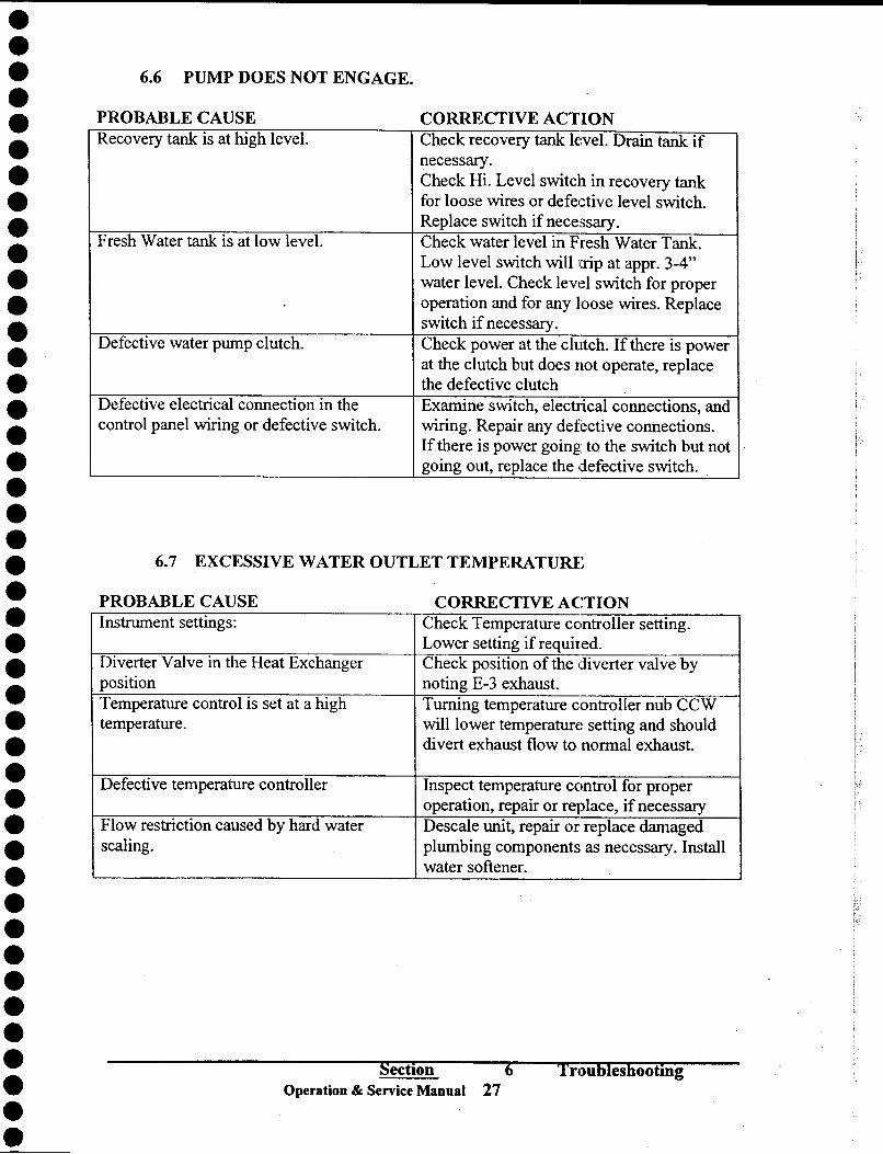
6.6 PUMP DOES NOT ENGAGE.
PROBABLE CAUSE CORRECTIVE ACTION Recovery tank is at high level. Check recovery tank level. Drain tank if
necessary. Check Hi. Level switch in recovery tank for loose wires or defective level switch. Replace switch if necessary.
Fresh Water tank is at low level. Check water level in Fresh Water Tank. Low level switch wi1l1trip at appro 3-4" water level. Check level switch for proper operation and for any loose wires. Replace
switch if necessary.
Defective water pump clutch. Check power at the clutch. If there is power at the clutch but does not operate, replace
the defective clutch Defective electrical connection in the Examine switch, electIical connections, and control panel wiring or defective switch. wiring. Repair any defective connections.
If there is power going to the switch but not going out, replace the defective switch.
6.7 EXCESSIVE WATER OUTLET TEMPERATURE
PROBABLE CAUSE CORRECTIVE ACTION Instrument settings: Check Temperature controller setting.
Lower setting if required.
Diverter Valve in the Heat Exchanger Check position of the diverter valve by position noting E- 3 exhaust.
Temperature control is set at a high Turning temperature controller nub CCW temperature. will lower temperature setting and should
divert exhaust flow to normal exhaust.
Defective temperature controller Inspect temperature control for proper operation, repair or replace, if necessary
Flow restriction caused by hard water Descale unit, repair or replace damaged scaling. plumbing components as necessary. Install
water softener.
Section 6
Operation & Service Manual 27 Troubleshooting

.
.
.
.
.
.
.
.
.
.
.
.
.
.
.
.
.
.
.
.
.
.
.
. . . . . . . . . . . . . . . . . . . .
-'
6.8 LOSS OF WATER TEMPERATURE. The heat output of the unit is LESS than normal. PROBABLE CAUSE CORRECTIVE ACTION Diverter valve is in the Normal Exhaust Check the diverter valve for proper position. operation.
Temperature control is set at a low Set temperature control to a higher setting temperature.
Vacuum relief valve is set too low. Reset vacuum relief valve to 15"Hg. Low Heat Transfer fluid leveL Normal level of Heat Transfer fluid should
be in the middle of the level eye ofE-2 at ambient temperatme or below upper tube if looking from the fill opening. Check heat transfer system for leaks. Add oil if so required. (See Tech Bulletin 001)
Defective Heat Transfer oil pump. Inspect pump for proper operation and replace, if necessary.
Defective temperature controller. Test. If necessary, replace. Engine RPM is low. Check engine RPM. See system
specification of this manuaL Defective temperature sensor. Inspect sensor for proper operation and
replace, if necessary. Defective temperature gauge. Test gauge. If necessary, replace. E-3 heat exchanger is coated on inside of Clean exhaust heat exchanger tubes. the tubes.
E-2 heat exchanger is coated with hard Soak complete heat exchanger at radiator water deposits shop. Rinse exchanger with clean water
I. and completely dry before reinstalling.
Section
Operation & Service Manual
6 Troubleshooting 28

.
.
.
.
.
.
.
.
.
.
.
.
.
.
.
.
.
.
.
.
.
.
.
. . . . . . . . . . . . . . . . . . .
I
~ ~
~ ~ CZ) CZ)
-<
~ ~ u :::>
~
.8 Zl=l ('t'l8õS~~~~ 3
.........................-..4....... InVl".,lnVllnVl
~ ~~~~;;;;;; ø..
4) bO ÐÐ ~
oS SlbO > o~ S j.. 'S bO S .....J ~ u~:=oej i rn~~8~~ø.. ø..l~~~~~j
iiJ~~~!!~ <J:d~~~..J~
~
r-c;... i i ! i ! i ! i ! L._.._.___

-'=
ï -
. a
-.:: -
.
.. CD
... ~
00 00
OJ
:5 li:i
~ae ~ U') 1=:
~Q.lo OJ
0 u
.... OJ
'j ~~ ~ E ro
- U') ....
.0 .... !!:!
.... ~ ....
...... ,- E
~j2:!
ð ..... u
OJ C C o Ü
IE .c e u
.... .....
U') 'j ð U')
Q.l Ü ro ro Q.l 0
E c;::: Q.l
C Q.l
u.. 0
.c u
.....
U') OJ o a. OJ E
,~ ð. ~
Q.l .c -o.cB Q.l ..... 'i 0:: B U')
a. E :::l
a. .... Q.l ..... ro .c ~ u
..... o :::l
I- u
~ i ro U') ro ~ ~.cï= .- +-' ......
~j U')
.c Q.l Q.l
..... :::l~ S:õj

.
.
: . . . . . . . .
'I . . . . . . . . . .
.. . . . . . . . . . . . . . . . . .
,
ELECTRICAL LOGIC DIAGRAM
SYSTEM ON OFF PTO
20 AMP fUSE " STOP
~.J.. C>-<) ·
LFllOM SYSTEM 12:
,-
PUMP START
~ PB-2
r PTO START
THROTllE POSITION
...... ~oH!}-o .
lSH
.
TSH
~
l~ 0 .1 Oil. ~~ì1}
WATER PUMP WATERTANK CLUTCH
LOW LEVEL SWITCH
PRESSURE SENSOR
PRESSURE GAUGE
ENGINE RPM SENSOR
PROBE TACHOMETER
TE-2
TEMP. INDICA TOR
FROM VACUUM SORCE
VACUUM GAUGE
Design Documentation
Operation & Service Manual
, /
R / ,
.
EXHAUST SV .
~
v
30

'. . . . . .
E . . . . . .
! . . . . . . . . . . . . . . . . . . . . . . . . . .
~ ~
~ en en < ~
~ o ~
ð E:
] -~~~~ ~ ~~ ~~g~~ g~~O~N O~~~ 55~~ ~ g~- ~~~~ ~ ~~~ij~~~~~~ ~ij~~~eS~~$qijij~ij~~~~~~~~~ij~~S~q~~~8~~ij z ~~~~~gg~m~ .~~~g~~~~~~>~~~~~~B~g~~~.~~~~~gw~~~~gg rf ~~~~~~~~$~ $~~~$=~~~~~$$~~~~~d~~g~~f~~$~~~~~$~~~
.;! ..e v ~~ <<) -==
t:.t
00 Ð _ Þ ~ 0 P .w Gð ~~ Þb 8: l3 ~ ø:l ü
,::..... J;l bO bObO;:; ~ 'z'" ~ f1] ~ bO ~ Oz CO ë .:3 = =z ~
;::l tl/) = bO ø:l .~
... ø:l ... b ips ~ ...
b;3;3 ~ .N ~ .& go ] ~3
... ... .N ;3 ] .s ! j!] b j t~II!~~Ji. ~~~!~~II ~I i~ .li~~~ll!~~~~l~I'~
- ~ fð ~~ æ !~ ] ø:l ~ 0 bO~ =
æ ~ ~ = b b ~ Ð bO CO~ ~ ~8 =
~ ~ ~ ~ ~ =
h h 0
~ CO!~ ~ ~ b ~ ~
~ ~ >. ~ ~ g~IÐ lo~ =~~~~~>tt~~ N~ ~o~~~5>~1 ~Þ~--~tï::
<Ill p P . ..!S
0 > '" >. ...;Þ ;Þ ;Þ <Ill !;l = A ~ - li'.....;> " '.0 6 '" . . 0 ;Þ o.b o.b \0 ~~~~SSS~~~d
0
~d~~~SS~æ~~~~~~~~~~~d~~~~~~~~~~~æ~~~~ < ~ U Q ~ ~ ó = ~ ~ . ~ z ~ ó~ ~ ~ ~ > ~ ~ ~ N ~ ~ ~ ~ ~ ~ ~ ~ ~~ ~ ~ ~ ~ ~ ~~ ~ ~ ~ ~ ~ ~ ~
CO 7 Design Documentation
.. '" ~ ~ Operation & ServiQ~ Manual 31
o ,
\a

WATER/OIL PUMP ASSEMBLY
. Parts Listing Part Number
A. Pump Mounting Plate 045112 . B. Hinge Assembly 045148 K E C. Adjustment Bracket 045146 . D. Belt Guard 045125
. E. Coupling Guard 045117 F. 5/16-18 x 3/4" Long Bolts HWBL-0069 . G. 5/16-18 Locking Nut HWNT ..()2.05
. H. 1/2-13 x 1-1/4" Long Bolt HWBL-OI08 1. 1(1-13 Locking Nut HWNT ..()2.16
r: K. Oil Pump Cover 045115
--- L. 3/8-16 x 2" Long Bolt HWBL-0098
M. 3/8-16 Hex Nut HWNT-0054 N. 1/4-20 x 3/4" Long Screw HWSC-0547 . P. 5/16-18 X I" Long Bolt HWBL-0094
. Q. 5/16-18 Hex Nut HWNT-0069 R 5/16 Lock Washer HWWA-Ol62
. S. Oil Pump Bracket 045147
T. Drive Helt HWBT-0026 . U. Water Pump Clutch PLPC-OOOI
V. 1(1 Fl21t Washer HWWA-0060 . W. Water Pump PLPP-0039
. X. Oil Pump PLPP-0034 Y. Shaft Coupling HWCP-0018
. Z. 5/16-18 x 1/2" Long Bolt HWBL-Ol00 AA. KeySlock BSKS-0005 . AB. #10-32 x 1/2" Long Screw HWSC-0375 AC. 5/16 Flat Washer HWWA-OI10 . AD. 1/4 Lock Washer HWWA-0014
. AE. 1/4 Fl2lt Washer HWWA-0086
.
.
. .,.--...... . ,. ,
I \ I \
. . \ I , /
'--- /
.
.
.
.
. COVERS AND GUARDS NOT
. SHOWN IN THIS VIEW
.
.
.
. Design Documentation
. Operation & S<<~rvice Manua' 32
e.

.
.
.
.
.
.
.
.
.
.
.
.
.
.
.
.
.
.
.
.
.
.
.
.
.
.
.
.
.
.
.
.
.
.
.
.
.
.
.
.
.
.
.
.
EXHAUST HEAT SYSTEM
Parts Listing Part Number
A. Exhaust Diverter Valve 045110 B. Solenoid Valve Filter PLFL-0024 C.
3" Exhaust Oamp CLMP..()()21
G. E- 3 Exchanger 045103
H. Outlet Hood 045141 1. Exchanger Mounting Bracket 045107
K. Vibration isolator 045142 L. 3/8-16 x 2" L>Dg Bolts HWBL-0110
M. 3/8-16 Hex Nut/Washer HWNT-0208 N. 3/8-16 x 3/4" Long Bolts HWBL-Ol11 P. la" Hex Head Plug PLPL-0032 S. 3/8 Hex Head Plug PFPL-0015 T. Exhaust Solenoid ELS0-0056 U. #10-32 x la" Long Bolts
V. 1/4" Vacuum Hose HWHS-0050 W. 3/8 x 1/4 HOSI~ Tee HWHB-0047 X. Hose Barb Fitting HWHB.:oo50 Y. HoseOamps
Z. #10-32 Self Tapping Screw HWSC-0565
AA. Tail Pipe Connector 045138
AB. TailPipe 045135 AC. 5/16-18 x 314" Long Bolts HWBL-0112 AD. Tab Washer 045196
AE. 5/16-18 x 1" Long Bolts HWBL-0094 AF. 318-16 xl" Lmg Bolts HWBL-0223
MUFFLER AG. 3/8 Flat Washer HWWA-OI46 AH. 3/8-16 Hex Locking Nut HWNT-0210 Al Truck Frame Support Bracket 045190
AK. Exhaust ValV(~ Support Bracket 045191
AL. Exhaust V alV(~ Gasket 045134
AM. #10 Split Lock Washer HWWA-0013 AN. #10 Flat Washer HWWA-OOI2
VIEW FROM ABOVE TRUCK BED
BOX FRAME
Design Documentation
Operation & Service Manual 33

.
.
.
.
.
.
.
.
.
.
.
.
.
.
.
.
.
.
.
.
.
.
.
.
.
.
.
.
.
.
.
.
.
.
.
.
.
.
.
.
.
.
.
.
.8
~ ~ p.,
~il~IIII!I!~illlll;ll~i!IIIII~~ .1111
bO .Ê ;3
~ p.,
0)
~ ~ bObObO bO 0 ~ ~
Oe .e .e .e bO CO'-' 0) e
::c O)'f! 'f! 'f! 'f! .e .e 8:: !:3 U bO e!l .... .... .... .... f! :e 0.... rI) rI) .e
6........ Cd ~~~ ~l:' J;' ...z CO
CO .t! "fi~U .... -5 bO~.8.8.8 .8..... ....08 d d
~~ ~ ã ~~ 8. t5 ~ Cd~~~.!5 ~~.8 5.8=:ø:;'-::;-å .3 ~ -::; 3..d .~ ~88~ ~ co~~~ ~~~~~~~~ ~~æ~~~~~~ ~S~~~ fi B C) 0
co d.S;l <3 bOø:: 'ca'ca"ca "'0 :>'ca 0 SO>......::cO
C) ~ C""l .fä' bO COCJ ì><::r: ,soW rI) p., ~ ~ El 3 0..0 æ > El e b .!:i .!:i ~?' .!:i..o CO e ..0 ~ M ~O ~
"'0 = = ..00 ~ ~~~~~~~ ~]~ à~~~~S~~~ à~ ~~~f ~~~~fj~~~~ ~~~~~~~~:>~~ ~~~~~~~~~ ~~:>~~~ Q~~~~~--~- ~~~~~ ~ ~~ ~~ ~ ~
~~~~~~~~~~~~~~~~~~~~~~~ *
< ~ U Q ~ ~ d ~ ~ ~ ~ z ~ ó~ ~ ~ ~ > ~ ~ ~ N ~ ~ ~ ~ ~ ~ ~ ~ ~ ~ ~ ~~ >-
~ ~
!
Design Documentation
Operation & SemC8 Manual 34

.
.
.
.
.
.
.
.
.
.
.
.
.
.
.
.
.
.
.
.
.
.
.
.
.
.
.
.
.
.
.
.
.
.
.
.
.
.
.
.
.
.
.
.
a ~~N~M N~ ~ij~
~
~-o~ ~ ~g~~g~gga~ ~~~~Na~~ ~ . ó I c;;~~
. ~qC;; I ~~ó~3'"r~ .
! ~~~~~~~~~~~~~~~~~~~
bII bII Ð
Ð~ ~~ i ~ i bl) "ap.. ::I:~ ~ ~ ~ .13 .8<.8 d.8 .~
~ la :s ~~ ~-å .~~ ~~~ll ~-B ~
c::>.... c; .8<.... =' .. 0 E-< =' .~ tI) .::!l
E-< Ð :3 P:: ib> Z Ð
tI) ib CD U ~ ø:l ø: ;.... ~ ~ bII > ~ = ,il:::l U ,;j c::>..'tii] !5 !5 0 bII t.o ~ c::>.. bII 0 ] c;
ø.. ~ b .
øj ,ß< fi ê b ~ ~ '.%:1 ;g ,5 .E~ N ê..E! ~ .;3 >
~ tI) ø:l ~ tI) ~ tI) E-< ~ ~ ~ g ~M ~ ~ ~ E-< ~
~~~~~~~~11~~ gég~~~~ M-MMMOM-~~-~U*OMMM~ ~ 0 ~ ~ d ~ ~ ~ ~ ~ ó~ ~ ~ ~ ~ ~ ~ ~
:E ~ tI) ~ tI)
~ d o
~
~
Design Documentation
Operation & Service Manual 35

.
.
.
.
.
.
.
.
.
.
.
.
.
.
.
.
.
.
.
.
.
.
.
.
.
.
.
.
.
.
.
.
.
.
.
.
.
.
.
.
.
.
.
.
~ lZ) ~ lZ)
~ ~ ~ ~
=- =
,..- -< ë5 -< =- =
Þ-
.... Q)
1 z
~ ø..
~8~~~~~~~ ~~$ ~~~ ~-88-~q~q~q~_O~~q ~~~~i~I~~~I~~~~5~ '
~ .13 ""
;.:J
i ø..
till t>(l U tlIl@ @ -
.~. . 8:
.:e ........ 1; u .... ii::~
~ l:Q õ. Z
.,g M p.,
Q) Q) .S< &.
-ä ~~ :i!!ä~ (g ~ ø. ~ ~ ~~~~OQ).D~ ~ ~~~~ ~
~ t>(l 0 .;1 .:::1.;1 ~ Q) 0 .8 - ~ '"" ø. I ~~~m~~~:i!~~m~~ ~ S~~~~
~~~~~.~~~~ (g~~~~~.2~ e~ ~~~~~~~MM~~~~~_~ÕÖ~ ~ ~ 0d ~ ~ 6 ~ ~ ~ ~ ~ ~ ~ ð~ ~ ~ ~
Desiign Documentation
Operation & SElrvice Manual 36

.
.
.
.
.
.
.
.
.
.
.
.
.
.
.
.
.
. . . . . . . . . . . . . . . . . . . . . . . . . .
e.
VACUUM RECOVERY SYSTEM
Parts Listing
A. 2" PVC Elbow B. 2" Hose Adapter C. 2" Galvanized Pipe Nipple
D. 2" Ball Valve
.. E. Inlet Tubing
H. 1/4-20 x 3/4" Long Bolts 1. Fùter Support
K. 1/~~20 Hex Locking Nut L. 2" PVC Pipe NIpple
.
M. 2" Gate Valve
N. 2" PVC Elbow
TRUCK BED
//////////, DElsign Documentation
Operation & Service Manual
Part Number
PLEL-OI05 PLNP-0174 PLNP-0181
PLBV-0041 045162'
HWBL-0113 045155
HWNf;.Q213 PLNP-OI72 PLVA-0071 PI...EL-ûl00
37

.
.
.
.
.
.
.
.
.
.
.
. - . .
.,
.
.
.
.
.
.
.
.
.
.
.
.
.
.
.
.
.
.
.
.
.
.
.
.
.
.
.
.
ELECfRICAL SYSTEM
Parts Listing Part Number
Tachometer HWGA-003S Temperature Gauge HWGA-0039
(' Pressure Gauge HWGA-0036 .... BACK PANEL D. Vacuum Gauge HWGA-0037 E. System On Off Switch ELSW-0017 F. Pump Start Switch ELSW-OS7S
G. 20 Amp Fuse ELFS-0294 H. Temperatue Controller ELTC-0017 1. Push Pull Control HVia.-ol25
lie. Terminal Strip EL1L-022S L. Ground Bar ELGL-002O
M. Relay ELRL-0352 N. Fuse Holder ELFH-0003 P. Engine RPM Sensor ELSN-OOOl Q. PTO Stop Push Button ELSW-0021 R. 1-112" WJI'C Grommet HWGR-0024 S. 1"
WJI'C Grommet HWGR-0023 U T. #8-32x 3/8" Saew HWSC-OlS6
U. MPf Hose BaIb HWHB-05OO Y. FPf Hose Barb HWHB-0049
W. Vacuum Hose HWHS-0042. X. 3/4" WJI'C Wrap TRPL-OOI0
Y. 114" Wire Wrap TRPL-0011 Z. Beldin Cable ELWR-0200
AN. Engine RPM Sensor Gasket ijWGS-Ol46 AP. #8-32 x 3/4" Long Screw AQ. JumpcrBar EUB-OOS7 AR. Lubrication Port HWOC-OOOl AU. #8 Lock Washer HWWA-0004 Alle. PTO Start Push Button ELSW-0019
CONTROL PANEL
Design Documentaion
Operation & Service Manual 38

.
.
.
.
.
.
.
.
.
.
.
. ~ . . . . . . . . . . . . . . . . . . . . . . . . . . . . . . .
~ ~ ~~ ~ ~~~~O~~ ~~-~-~M~~~g~~~2~~~~@ ~~~ ~ ~88~~~ ~~8~~8~S~~~ij~~~g8~g~99~q~ij~q~~Ñ~~~ ~ ~~~~~~ · ~~~~5;;~~~~i~i~~~i~~ii~~i~ii~i~~ii
,..
,..~ Q
~.ol' Cl)..... ~ ~ Et: Q o~ .....
~ Et: - ..... - -
I '""'l -MCI) 'S p .:: ~ ~ õ ~ ~ ~ ..().... 05 0
..c:ll%l l:'l bO N\~~ bOrn ~~ rJ ~ ~ ~ bO .13 ~ ~
..... bO bO ~ gf ~ .3 is.s...
~ ......3... .3... .s b
~ 8~ ~l 8 ~ ~I ~ j~ ~~ b ~~~J~~t1~~tl~tIJ = 11
~ .f~.Q~ [ ~ g~Æ 8 8"ó.~Æ~-g1~s~~S:!:~ ~-=~~~:!:~ ~:!:~ ~~]S~~ ~ Cl) l:'ll%l ~rn ~ ~ ~
- ~ ~ I%l b'~ ~ ~ ~ ~ ~ ~ ~ ~ - ~
~ ~ Q ~ ~ ~ ~ ~ ~ ~ - (:)
~
oS ~ l:'l 4) ~l:'l'" ~ ~...... O'S.Q.Q'~ uo....= "'M UMOO~O~~~-\O Q\OM QM~ ~~ 0:< - ~ 0- B. . B B 5 U..d..c:l ::> ::I~~~ ='M OM M M
Io'-oM.,b\O\O-b->-l....->-l.... 10'-0' -1 """ II) æ II) 0 0 0...-.4 8 U) roO ---0 "'0 ~ 0 .~,...... ~ ~ ~ ~ I'
.
f""'.J
I 0 0 0
~~. ~~ðð~~ 0 ~ ~u02r\ Q~~~~~~~~~~~~~~~~~~~~ð--- """.... """~ ~~rn ~~ """~>-lM~***~~--~~~~MMM~~_.... *** < ~UÓ~ ~ò~ ~ ~ ~ ~ z ~ ó~ ~~þ > ~ ~ ~ Ñ ~~ ~ ~~~~~ ~ ~ ~~~~ ~~ ~ E-<
~ Sl
~ ~~ Cf.) ::E ~ o 01- ::z:: e: ~
a
is :z ~ o
tn
~ o
@
~ ffi
~ o
I =r o~ lL.I ëë t:) I- 0=: lL.I
~o :z: .......
lL.I .......
tn
:?: Desigln Documentation
Operation & Service Manual 39

.
.
.
.
.
.
.
.
.
.
.
. 4Þ
.
. - . . . . . . . . .
.0 .
.
.
.
.
.
.
.
.
.
.
.
.
.
.
.
. ~
~ ~ tZl tZl -<
~ ~
~ ~
a
o
00 0,0 00
....
i z
æ
>n>nr-....O~~N 9~~~~~gg~ ....~ O\~
· ·
98è(è?9 9è( ~:;;~~~~5~3f1)g~ ~~ ~ ~~ ø.. ø.. ø.. ø..
~ ~ ~
bO .13 '" :.:J
~ ø..
tj ~ Ii: ~ ~
... fI) > U o
>~... u~8Q~ v~... ]~Þ<~.[ -a ~~ ~ U 0 '::!. < _9< ~:a
~ii1.../Xl....vv za ~ o Õ ~1i Þ< rs ~ ~ &~ ~
1;; /Xl ~ lä -.Ej ~ = :> /Xl it fI) .3 tL:
~::S-5 ~ô= t;i: t;ioo ~ ~ &1 m;; ~æ ~ ~~;; < >QcJ ci~~ cj =....; ~....i~
&
I-~ \ I
'---- o
o
Design Documentation
Operation & Servic:e Manual 40

.
.
. .... ~ 000 . i ~q~~~~
. z ~~i~~~ ii
. ø..
---. . !>! 0 Q)
. <
0
:z . < 0
~ bO ~
. m
.13 0:>- m '" .:= '+-t
0: ~ ~~ w
. Q) ~ >. ~ :::30 ::l! "'d > <~ ~ o 0 9 z ø..
. -' i~~.I] ~ < ö::
E-< E-< "l cS
:>- - w
Vl ~
<~UQlIi~ . u => ß
.
. ::ï
. ~
. CI)
. CI) <
. ~ . :r:
. ~ u ...... ~ Vl
. ....J !>!
. 0
O-J t) . ~ . . . . . . . .
Vl . :z: <
a: .
0
.
. ...... w
. .... -' Lo.I 2: ....J ~
.
. Design Documentation
. ~.~.~ Operation & Service Manual 41
.
.
.

.
.
.
.
.
.
.
.
.
.
.
.
.
.
.
.
.
.
.
.
.
.
.
.
.
.
.
.
.
.
.
.
.
.
.
.
.
.
.
.
.
.
.
..
Parts Listing
A. Valve Body
B. Actuator C. Flapper PLate
D. Shaft
E. 8mm Hex Nut
F. 8mmLockWasher
Ii 5/16LockWasher
1. Dowelpin
K. Valve Bracket
L. Valve Cover M. Pivot Plate
N. 5/16-18 x 3/8" Long Bolts
P. 5/16-18 Hex Nut Q. SetScrew R #10-32 x 3/8" Long Screw S. Acuator Connection
T. Clevis
U. Clevis Pin
V. Cotter Pin W. 1/4" Tube Elbow X 1/4-28 Acorn Nut
3 WAYEXHAUSTDIVERTER VALVE
PartNwnber
045110-2 PLVA-0068
045110-3 045110-4
HWNT-0173 HWWA-0163 HWWA-0006 HWPN-0033
045110-7 045110-8 045110-9
HWBL-0228 HWNT-0209 HWSC-0568 HWSC-0542 HWHB-0048 HWCV-OOll HWPN-OOll HWPN-0042 PLEL-0111
HWNT-0229
B (ff
Operation & Service Manua' 42

.
.
.
.
.
.
.
.
.
.
.
.
.
.
.
.
.
.
.
.
.
.
.
.
.
.
.
.
.
.
.
.
.
.
.
.
.
.
.
.
.
.
.
.
::ï
~ u:l en en < E-c < E-c en o
I
.8
~ ~
8~~-~~ ..... Ñ --- ...... ~~~~~ ~ ~~~~~~~
b() .ß
;î ~ j:l..,
b.ll.l!9
t3.6õ >~~....... 8~~.Mz SS:Z~~S '" ... Þ< t:Il... ~~~æ~~ü ~ ~ ;!.~;!.~ ~ <lIitJQ~~d
Design Documentation
Operation & Service Manual .43

.
.
.
.
.
.
.
.
.
.
.
.
.
.
.
.
.
.
.
.
.
.
.
.
.
.
.
.
.
.
.
.
.
.
.
.
.
.
.
.
.
.
.
.
Part Manuals

.
.
.
.
.
.
.
.
.
.'
.
.
.
eo . .
.'
.
.
.
.
.
.
.
.
.
.
.' .~ - .
.'
.',
-, . . .
.: .. _. . . . .
M-D Pneumatics
COMPETITOR +
positive displacement rotary air blower
Model 5009 & 6008
INSTALLATION
OPERATION - MAINTENANCE REPAIR
M'ANUAL
.! f1ì
íÎ ill-l.~ .
H :W -dJ\O\~ J~
WARNING
DO NOT OPERATE BEFORE READING MANUAL.
Section 8 Part Manuals Blower Operation & Service Manual 59

PREVENTATIVE MAINTENANCE
.
.
.
.
.
. . . . . . . . . . . . . . . . . . . . . . . . . .
c. . . . ~ . . . . . . .
..
Safety Precaution
For equipment covered specifically or indirectly in this instruction manual, it is
important that personnel observe safety precautions to minimize the chances of
injury. Among many considerations, the following should particularly be noted:
. Blower casing, oil pump, water pump and all associated piping and tubing or accessories will become hot enough to cause major skin bums on contact.
. Internal and external rotating parts of the equipment can produce serious
physical injuries.
. All truck equipment have to be shout down before doing any work, and avoid
bypassing or rendering inoperative any safety or protective devices.
. Avoid extended exposure in close proximity to machinery with high intensity
noise level.
. Use proper care and good procedures in handling, lifting, installing, operating
and maintaining the equipment.
. Hearing protection are required to operate this equipment.
A good maintenance program will add years of service to the blower.
Blower should be checked frequently during operation, especially lubrication. Check Ç>il
level in the gear housing and add oil as needed. Complete oil changes are recommended
every 500 operating hours.
Daily Maintenance Check and maintain oil level
and add oil as necessary.
Check for unusual noise or vibration.
Clean filters. A clogged air
filter can seriously affect the
efficiency of the blower and
cause overheating and oil
usage.
Weekly Maintenance Cheçk relief valve to
make sure it is operating
properly. Check drive belt tension
and tighten if necessary
Monthly Maintenance Inspect condition of oil
and change if necessary.
60 Section 8 Part Manuals Blower
Operation & Service Manual T

.
.
.
.
.
.
.
.
.
.
.
.
.
.
.
.
.
.
.
.
.
.
.
.
.
.
.
.
.
.
.
.
.
.
.
.
.
.
.
.. .
.
.
.
LUBRICATION
The bearings at the drive shaft end of the blower are
grease lubricated. The timing gears and bearings at the
other end are lubricated by the lower timing gear (when
in the horizontal flow configuration) acting as a oil slinger,
carrying oil to the upper timing gear and providing splash
lubrication for the bearings. Both timing gears act as slingers when the blower is in the vertical flow configura-
tion.
Use a good grade industrial type anti-rust, oxidation and
foam inhibited, non-detergent oil.
FILLING PROCEDURE To fill the gear housing, remove the oil breather* (A) and oil level plug (B) on the gear end. Fill the gear housing
until oil drips out of the oil level hole. Replace plugs in
their respective holes.
.Some units may not have an oil breather, in this case remove plug to fill.
LUBRICATION INSTRUCTIONS FOR OIL LUBRICATED GEARS AND BEARINGS
Add fresh oil as required to maintain proper level. Drain and refill after the first 100 hours of operation and thereafter every 1 ,000 hours of operation under normal service, more frequently depending on the type of oil and oil operating temperature. Use a good quality oil.
AMBIENT TEMPERATURE
OIL GRADE
OIL VISCOSITY, RANGE
SSU AT 1000 F.
Above 900 F SAE 50 1000-1200
320 F to 900 F SAE 40 700-1000
00Ft0320F SAE 30 500-700
Below 00 F SAE 20 300-S00
A=8reather A B=Oil Level
.~ C=Drain Plug
~-,..- r ...... ""
B B
C
HORIZONTAL FLOW
C
VERTICAL FlOW
Section
-~ . - . "
.
WARNI~G. .:...... ..<"_':':~~:;,/':'.c .,....... '~-:':'~':i..:.::i;~'
Dó :nofStart: thå'- b1ówêFúiitil.ÿõïiaresiireOiI6àS beén'pÙf
é.~~~gt<~~~~~~.. ~'.
"~;J;ßi:};i.~.~;t~~~/~;~~~::~it~:t.
GREASE LUBRIC,~TED BEARINGS
Service drive end bearings at regular intervals. (See
"Suggested Lubrication Intervals For Grease Lubricated Beañngs".) Use NLGI #2 premium grade, petroleum base
grease with high temperature resistance and good
mechanical stability. Using a pressure gun, force new grease into each bearing until traces of clean grease
come out of the relief fitting.
CAUTION: Do not inject greasf3 too fast to avoid blowing out the drive
shaft seal.
SUGGESTED LUBRICATION INTERVALS
FOR GREASE LUBRICATED BEARINGS
SPEED OPERATING HOURS PER DAY
IN 8 16 24 . RPM GREASING INTERVALS IN WKS
750-1000 7 4 2
1000-1500 5 2 1
1500-2000 4 2 1
2000-2500 3 1 1
2500-3000 2 1 1
3000 And Up 1 1 1
GREASE FlTTIfG
REUEF GREASE RTTlNG RTTlNG
\
BOTTOM DRIVE lOP DRIVE
REUEF FITTING
RELIEF GREASE -
FrTT"G LEFT DRIVE RIGHT DRIVE
8 Part :Manuals Blower Operation & Service Manual 61

TROUBLESHOOTING
Although blower are well designed and manufactured, problems may occur d1).e to the
normal wear and the need for readjustment. The chart below lists symptoms that may
occur along with probable cause and remedies.
SYNWTOMS PROBABLE CAUSE .
Loss of oil Gear housing not tightened properly. Lip seal failure. Insufficient sealant
Excessive Bearing
or Gear Wear
Lack of Volume
Knocking
Excessive Blower
Temperature
Rotor End or Tip
Drag
Vibration
Improper lubrication.
Excessive belt tension.
Slipping Belts.
Worn lobe clearances. Speed to low. Obstruction in piping.
Unit out-of-time. Womgears. Too much or too little oil in gear
reservOlr.
Too low operating speed. Clogged fller or silencer.
Excessive pressure differential.
Elevated inlet temperature.
Worn lobe clearances. Insufficient assembly clearances.
Excessive operating pressure. Excessive operating temperature
Belt misalignment. Lobes rubbing.
Worn bearings! gears. Unbalanced or rubbing lobes.
Blower loose.
Section 62
REMEDIES Tighten gear housing bolts
Disassembly and replace lip seal.
Remove gear housing and replace
sealant.
Correct oil level. Replace dirty oil. Check belt for tension and adjust
.
accordingly. Check belt for tension and adjustment. Check for proper clearances.
Increase blower speed within limits. Check system to assure an open flow path
Retime. Replace timing gears. Check oil level.
Increase blower speed within limits.
Remove cause of obstruction.
Check relief valve.
Reduce inlet temperature.
Check for proper clearances.
Correct clearances.
Adjust relief valve.
Reduce pressure differential or reduce
inlet temp. Check carefully, realign if necessary.
Check cylinder for hot spots.
Check conditions of gears and bearings.
Check mounting and tighten if necessary.
8 Part Manuals Blower
Operation & Service Manual
.
.
.
.
.
.
.
.
.
.
.
.
.
.
.
.
.
.
. ~ . . . . . . . . . . . . . . . . . . . .
.. . . .

.
.
.
.
.
.
.
.
.
.
.
.
.
.
.
.
.
.
.
.
.
.
.
.
.
.
.
.
.
.
.
.
.
.
.
.
.
.
.
.
.
.
.
.
DISASSEMBLY & INSPECTION With prcper mair:tenance a;-:d h..:bricaliol1. normai life eÄpectancy lor gears. bear:~gs. and seals can be achieved. Howevf;:.
over a periCd of time these parts must be repaired or replaced to malnÍ2:r. the efficier:c'1 01 yeur biower. ïhis sectío~ is writ.
ten in a way that will aHow YOt.: io completely disassemble your blowË;~. The insp~t:on of certain repairabl" or replaceable
paris is referred to at the point of disassembly where these parts are exposed. If at a'(':1 point of inspection. reoair cr replacement is åeemednecessary. appropriate instruction will be given to achi<;ve these repair or replacement is deemed
necessary. appropriate instruction '.'IiI! be given to achieve these repairs or reptacer.:ents.
Remove the oil årain plug (18) in the bottom of the gear cover (5: ar.cdrain the oil. ïake out eight capscrev/S (1ô)
and remove the gearccver. It may be necessary to tap the sides with a maìle! or wooden block to break the seal joint.
Gears are not exposed fer visual inspecton
Referenced item numbers on page
Inspect the gea:-s i<,r the feilo.wing:
- 8rcke~ TE~:h - Chippec Teeth - UneVEl'1 Wear - ExcessiVE! Wear . p..ny Ot'"'lerAbnorma!îties
BLOWER DISASSEMBLY
Pcsiter blQ'>"Jsr wi:h the ér:'/~ gear on the left when fac- inG !r-e gears. Remçve 50<:-<<:< heëd scre~':s ar.d washers. (ltems 29 & 25}
Align t!:;,i~g ma~~s ant C:::t.:~t rCt.:f í4) tee!h down and place re~erence marks on ,he ges..-s. (Refer to figure 1)
CC'2;'{;):: "'" -"'r" 'T" / I
'~ ÿ ,- ; 0 0 I ~
/;:...v~~:_ ~_~~\ o
.::-~~._-,>.-;;::-:.. .c _ ~.: r~":"8"-"" .:;.
'... :-. t,.::'-J ~~ ~~ oj i-: 0. ~~--..../.-
"-,;:. _~- r>; '"
"'l.-"TJ"l"'" ..,.,.
~ "
~t:-~ ~ ., !~ ~tt'Z4 :ll:~-:t... =-:4-:''' :a:~:öt.At
'F ~GJR:: 38 rl,.:....: .....'!; ~ X"4 2 ~a:",fI.
.c:-c=t;w-a -.....:~ -.:QlC:
:: ~G:':;;: 3A 4:"''' :. '.:-r: <i4C .:~~:< ~ -...~
FIGURE 1 .
Align reference marks and use puller 10 pull the driven
gear. (Gear on right side). (Refer to Figure 2)
AGURE2
Section
Use pul!er to remove drì're ~ear. A bar püi!er (F:ç;t.:re 3) or
jack screws Ga:1 bi: used.
FIGURE 3
Remove shim and spacer. (Items 28&30)
Turn blower around and remove grease cover (Item 10)
Removeeighl (8) cap screws. (Item 15)
Use jack screws to remove end plate. (Refer to Rgure 4)
AGUREA
8 Pa:rtManuaIs Blower Operation & Service ManU31 63

FIGURE A3
Ins,aH b<:arinç retainers (Items 22 &25) to both bearings.
Check clearances between the end of the rotors and the
face of the ,=r.d piate. (check internal clearances chart on
page 12 tor proper clearances for your model blower.
(Refer to Figure A4)
AGUREA4
Clearances okay. put a spacer (Item 28) and a shim (Item
30) on each shaft. Timing shims that were removed
should be put back on the shaft they were removed from.
Section
.64
Lubrica1e shafts and bores on gears. Begin by pressinç
00 the DRIVE gear. This will be pressed on the drive rotor which is to the left.
Start the driver gear on the shaft and align the reference timing marks and press gear 00. Lock gears in place with cap screw {Item 29} and washer (Item 26). Turn assembly over and rest the unit or. the cap screws and washers on the gear end. Set dowel pins (Item 9) in housing and. position housing
over the rotors and fasten with cap screws (Item' 5).
Check housing to rotor clesrance. (Refer to Figure AS) Depth rnic can be used. Set on dñve end plate (Item 3) and fasten with cap screws (Item 15). (ATTENTION: There are four cap screws (Item 17) which are used to fasten the feet on.)
Lubricate shafts and bearings. Install the ball bearing
(Item 12) on the dñvenrotor and the roller bearing {Item
1 1) on the input shaft Install grease cover (Item 10) and drive shaft sea!. (Iter:"!
23)
Install any removed plugs (Item 18) and replace breather if required. (Item 27)
Re:erenced item ni;moers on page 11.
ADJUSTING ROTOR INTER LOBE CLEARANCE Using feele~ gauges take interloce readings and record
on each side oj ~ocsing as indicated in Figure 5. By re!":1o'Jir.g or adding shim behind the he::cal gear. !1
rotates as it is moved in or out and the driven rotor turns with it thus c."anging the clearance between rotor lobes.
LONG FE=LEFl G~GE
/' RE~P;'." /
r REAOtNG HE;:lE
.
RECORDs.a REA;);f\lG HERE
~//1 ~~.. ;;./. ~,/.... r.' 1_ rJ~'3~O ...l
\~ V J ~;}
~.; ~::;; ,..
. ,
Figuré' 5.
Changing the shim thickness .006~ will change the roter
lobe clearance .003" or one half the amount.
EXAMPLE: Referñng to Figure 5 check the clearance at
AA (right hand reading) and 88 {left hand reaåíng).1f AA
reading is .000R and 88 reading .003" by removing .006~
shims. the readings will change one half me amount
removed or .003". AA should then read .OOÔ" and BB
should read .00õ. The fmal reading should be within
.002" of each other.
To determine the amount of shim to add or remove. sub.
tract the small figure from. the larger. If the right side is
higher than the left side, remove shim. If the right side is
reading io'.,-:er. add shim.
8 Part Manuals Blower Operation & Sen.-ice Manual
.
.
.
.
.
.
.
.
.
.
.
.
.
.
. - . . . . . . . . . . . . . . . - . . . . . . .
= . . .

.
.
.
.
.
.
.
.
.
.
.
.
.
.
.
.
.
.
.
.
.
.
.
.
.
.
.
.
. ~ . . . . - . . - . - . . . .
BLOWER ASSEMBLY After thorough cleaning of the seal and bearing bores of both end plates apply a thin coat of sealant on the out- side diameter of the new seals and press them into the end plate using a tool that will bear on the outer edge of the seal. Spring side of the seal should be facing you. Apply a thin coat of grease to the seal lip.
Using the drive end plate as a fixture. support it high enough so the input shaft of the drive rotor clears the assembly surface. (Refer to Figure A 1 )Place rotors in fix- ture with the drive rotor to the left. (See figure A 1 and A2)
FIGURE A1
Place end plate (Item 4) on rotors.
Apply a thin coat of lubricant on the rotor shafts and the inner race of the bearings. Tap the bearings (13) into place using a tub,a with a flanged end that will contact both the inner ancl outer bearing races. (Refer to Figure A3)
DRIVE DRIVEN
FIGURE A2
Rotor alignment will be opposite that of Figure A2 on all 6" units (keyway cn drive rotor will be up and driven to the right).
": .
--. -'
-
,-
. ':'-:-~.". -.;..: ~ ';;"':-::"- ~. .
-
.
"',
WARNING Keep hafi&:an(j 10000~dóthi09''f:'::''(fi&ri:.'.~
lobes and gears. . .~~~~~~&:J~~~' .:~~~~
Section 8 Part Manuals Operation & Service Manual
Blower 65

Press rotors OUe of end plat~ :n press ii a'Jaiiable. If press
IS not available support end plate and rotors in the hous-
ing. Block up housing and use a soft mallet to drive the
rotors out. (Refer to Figure 5)
FIGURE 5
A la'N tY;::6 pulle~ can also be L:sed. (Re:éf te figl)re 6)
Using a tube or round bar of a slightly smaller diameter than the shaft clearance holes in the end plates. tap the
bearings out of the end plates. (Bearing retainers (Item 22) must be removed before knocking out the bearings.)
(Refer to Figure 7)
FIGURE 7
Remove seals from both end plates with a punch or dull
chisel. The seals wilt be damaged during removal and
must be replaced.
Inspect all parts for wear and or damage.
Clean and inspect all parts fer bu~rs and polish seal jour-
nals with at least a 320 grit.
Referenced item numbers on page
FIGURE 6
Section 66
8 Part Manuals Blower Operation & Service Manual
.
.
.
.
.
.
.
.
.
.
.
.
.
.. . . . . . . . . . . . . .
.. . . .
.. . . . . . . . . . . . .

.
.
.
.
.
.
.
.
.
.
.
. - . . . . . . . . . . . . . . . .
4t . . . . - . . . . . . . . .
COMPETITOR™ PART'S LIST
@: \
,
(~) C!~ ~'z "
--- ---...-@
@ :~-::.::"~ / ! @
'-- /",/
@,-
(})--- @ -.!. o o
~'
f~.
@ \ ---- í.V
ITEM DESCRIPTION QTY ITEM DESCRIPTION QTY 1 Housing 1 15 Screw, Hex Hd. 16
2 Mounting Feet 2- 16 Screw, Hex Hd. 8u 3 End Plate I Dñve End 1 17 Screw, Hex Hd. 4
4 End Plate I Gear End 1 18 Plug, Oil 3
5 Gear Cover 1 19 Relief Fitting 2
6 Drive Rotor 1 20 Grease Fitting 2
7 Driven Rotor 1 22 Bearing Retainer 4
8 Timing Gear 2 23 Up SElal, Drive Shaft 1
9 Dowel Pin 4 24 Up SElal 4
10 Bearing Cover Plate 1 - 25 Screw, Hex Hd. 4
11 Roller Bearing, Drive Shaft 1 26 Washer 2
12 Bearing 1 27 Breather 1
13 Bearing 2
-Item 2 larger models require 2 left and 2 right feet -Quantity (6) for 5" Gear
When ordering parts use the item number shown plus your model and serial number
Section Blower 67
8 Part Manuals Operation & Service Manual

Section 8 Part Manuals Blower Operation & Service Manual
.
.
.
.
-. . . .
.. .. . .
:. .
.. :. . . . . . . . . . . . . .
..
.
.
.
.
.
.
.
. - . - . . .
M-D BLOWER MAINTENANCE & SERVICE SPECIFICATIONS
Assembly Clearance
Model Lobes - End Plares Lobe - Casing Between Lobes
Total Drive End Gear End Min. Max. Min.
Min Min
5009 .007/.012 0.004 0.003 0.005 0.009 0.012
6008 .011/.015 0.008 0.003 0.006 0.01 0.01
Oil Resen"oir Capacity
Model Fluid Ounces
Horiz. Flow 5009 16.0 6008 28.0
Maximum Operating limits
Model R.P.M. Pressure Inlet Temp. Rise PSI Vacuum Deg. F
5009 2850 7 14 115
6008 2350 12 16 240
Lubrication, Final Assembly and Mounting
Pack the bearing cavities with suitable grease. Install bearing cover plate (10). Replace
front lip seal (23) taking care not to damage the lip as it passes over the keyway. Lip must
point inward toward the bearing. Apply a good quality RTV silicon sealant to the inner
surface of the gear cover (5). Install the gear cover with cap screws (16) and tighten
evenly. Fill gear cover with oil and grease front e~d bearings. Refer to the Lubrication
Section for oil and grease specification and filling procedures.
To insure blower has not been distorted during mounting in the installation, turn the lobes
by hand to make sure they are not making contact prior to start.
Model Total End Clearance Gear end Rotor tip to Interlobe
drive end (minimum) housing
(minimum) Min Max Min Max
5009 10-14 4 4 5 9 12 21
6008 15-19 8 5 6 10 10 14
68

.
.
.
.
.
.
.
.
.
.
.
.
.
.
.
.
.
.
.
.
.
.
.
.
.
.
.
.
.
.
.
.
.
.
.
.
.
.
.
.
.
.
.
.
BLOWER ASSEMBLY After thorough cleaning of the seal and bearing bores of both end plates apply a thin coat of. sealant on the out- side diameter ofthe new seals and press.<them into the end plate using a tool that will bear on the outer edge of the seaL Spring side of the seal should be facing you. Apply a thin coat of grease to the seal lip.
Place end plate (Item 4) on rotors.
Apply a thin coat of lubricant on the rotor shafts and the inner race of the be;arings. Tap the Þearings (13) into place using a tube with a flanged end that will contact both the inner and outer bearing racell. (Refer to Figure A3)
Using the drive end ,plate as a fixture. support it high enough so the input shaft of the drive rotor Clears. the
assembly surface. (Refer to Figure A1 )Place rotors in fix- ture with the drive rotor to the left. (See figure A 1 and A2.)
DRIVE DRIVEN
~
.
FIGUREA2
Rotor alignment will be opposite that I)f Figure A2 on all S".units (keyway on drive rotor will be up and driven to the
AGURE A1 right).
Section ,
8 Part l\1[anuals Blower Operation & Service Manual 65

.
.
.
.
.
.
.
.
.
.
.
.
.
.
.
.
.
.
.
.
.
.
.
.
.
.
.
.
.
.
.
.
.
.
.
.
.
.
.
.
.
.
.
.
Press rotors out of end plat.: in press if available. II press
15 not available support end plate and rotors in the hous-
ing. Block up housing and use a soft mallet to drive the
rotors out. (Refer to Figure 5)
FIGURE 5
A jaw ty;:;e puller can also be used. (Re:er to figL:re 6)
Using a tube or round bar of a slightly smaller diameter
than toe shaft clearancl~ holes in the end plates. tap the
bearings out of the en(1 plates. (Bearing retainers (Item
22) must be removed before knocking OL:t the bearings.}
(Refer to Figure 7)
'.
.. í
.r
FIGURE 7.
Remove seals from both eM plates wth a punch or dull
chisel. The seals wilt be damageodiJrlng remçval and
must be replaçed.
Inspect all parts for wear and or damage.
Clean and inspect all parts for burrs and polish seal jour.
nals with at least a 320 grit.
Referenced item numbers on page
FIGURE 6
Section 66
8 Part :M.anuals Blower
Operation & Service Manual

.
.
.
.
.
.
.
.
.
.
.
.
.
.
.
.
.
.
.
.
. - . . . . . . . . . . . . . . 9 . . ~ .
.,
.
.
[ COMPETITOR™ PARTS LIST ~
."
@; \ \
Q"{ ',.
@-
@
-.-@ (6:
.
,~:
@
\ i $
ITEM DESCRIPTION QTY ITEM DEiSCRIPTJON QTY
1 Housino , 15 Screw, Hex Hd. 16
2 Mounting Feet 2- 16 Screw, Hex Hd. 8--
3 End Plate I Drive End 1 17 Screw,. Hex Hd. 4
4 End Plate I Gear End 1 18 Plug,Oil 3
Relief Fitting .
2 5 Gear Cover
1 19
6 Drive Rotor 1 20 Grease Fitting 2
7 Driven Rotor 1 22 Bearing, Retainer 4
8 TlITIing Gear. 2 23 Up SeaJ, Drive Shaft 1
9 Dowel Pin 4 24 UpSesl1 4
10 Bearing Cover PJate 1 . 25 Screw, Hex Hd. 4
11 RoUer Bearing, Drive Shaft 1 26 Washer 2
12 Bearing 1 .27 BreathE!r 1
13 Bearing 2
-Item 2 larger models require 2 left and 2 right feet
"'Quantity (6) for 5" Gear
When ordering parts use the item number shown plus your model and serial numlJer
Section 8 Part Manuals Blower
Operation & Service Manual 67

.
.
.
.
.
.
.
.
.
.
.
.
.
.
.
.
.
.
.
.
.
.
.
.
.
.
.
.
.
.
.
.
.
.
.
.
.
.
.
.
.
.
.
.
M-D BLOWER MAINTENANCE & SERVICE SPECIFICATIONS
Assembly Clearance
Model Lobes - End Plares Lobe - Casing Between Loben
Total Drive End Gear End Min. Max. Min.
Min Min
5009 .007/.012 0.004 0.003 0.005 0.009 0.012
6008 .011/.015 0.008 0.003 0.006 0.01 0.01
Oil Reservoir Capacity
Model Fluid Ounces
Rom Flow
5009 16.0
6008 28.0
Maximum Operating limits
Model R.P.M. Pressure Inlet Temp. Rise
PSI Vacuum Deg. F
5009 2850 7 14 115
6008 2350 12 16 240
Lubrication, Final Assembly and Mounting
Packthe bearing cavities with suitable grease. Install bearing cover plate (10). Replace
front lip seal (23) talång care not to damage the lip as it passes over the keyway. Lip must
point inward toward the bearing. Apply a good quality RTV silicon sealant to the inner .
surface of the gear cover (5). Install the gear cover with cap screws (16) and tighten
evenly. Fill gear cover with oil and grease front end bearings. Refer to the Lubrication
Section for oil and grease specification and filling procedures.
To insure blower has not been distorted during mounting in the installation, turn the lobes .
by hand to make sure they are not making contact prior to start. .
Model Total. End Clearance Gear end RotCllr tip to Interlobe
drive end (minimum) housing
(minimum) Min Max Min Max
5009 10-14 4 4 5 9 12 21
6008 15-19 8 5 6 10 10 14
,.
'" ..
- ~'.
~~
~~~,
Section 8 Part Manuals Blower
Operation & Service ManlJ:al 68

.
.
.
.
.
.
.
.
.
.
.
.
.
.
.
.
.
.
.
.
.
.
.
.
.
.
.
.
.
.
.
.
.
.
.
.
.
.
.
.
.
.
.
.
Series Power Take-10ft
270 Side Mounted, S.A.E. Six Hole, Hydraulic Shift, Two ~3ear
Section 8 Part Ma.nuals PTO Operation & Service Manual 69

COLD WEATHER OPERATION OF POWER SHIFT P.T.O.'s
ÅWARNING: During extreme cold weather operation [320F (QoC) and lower], a
disengaged Power Shift Power Take-Off can momentarily transmit high torque that will
cause unexpected output shaft rotation. This is caused by the high viscosity of the
transmission oil when it is extremely cold. As slippage occurs between the Power Take-Off
clutch plates, the oil will rapidly heat up and the viscous drag will quickly decrease.
The power take-off output shaft rotation could cause unexpected movement of the driven
equipment resulting in serious personal injury, death, or equipment damage.
To avoid personal injury or equipment damage:
. The driven equipment must be left in the disengaged position when not in operation.
. 00 not operate the driven equipment until the vehicle is allowed to warm up.
Section 8 Part Manuals PTO Operation & Service Manual 70
.
.
.
.
.
.
.
.
.
.
.
.
.
.
.
.
.
.
.
.
.
.
.
.
.
.
.
.
.
.
.
.
. ~ . . . . . . . . . .


MOUNTING -P.T.O. TO TRANSMISSION
5. For the 230, 800, and 852 series, place one thick gasket .020. (.50 mm) and one thin gasket .010.(.25 mm) over the studs. For the 270 series with the AJ gear pitch designation (i.e.: 270XBAJP-B3XD), use the special 35-P-41 gasket that
comes with the P.T.G. When the 35-P-41 gasket is installed with the 270 series, the need for backlash adjustment is greatly reduced. (See Fig. 5.) Fig. 5
. When mounting a P.T.G. use gaskets between all mounting surfaces.
. Do not stack more than 3 gaskets together.
. Usually, one thick gasket .020"
(.50 mm) will be required.
. Remember the lubricant in the transmission also lubricates the
p.T.a. Therefore, a gasket must
always be used.
6. Fasten the P.T.G. to the transmission and
tighten the 6 or 8 bolts. (See Fig. 6.)
7. Torque the 6 or 8 bolts to 32 - 37 Ibs. ft.
(4.43 - 5.12 kg. meters). (See Fig. 7.)
8. Bend the tabs to lock the nuts.
Section 72
.1
.
.
.
.
.
.
.1
.1
.
.
.
.
.
.
.
.
.
.
.
.
.
.
.
.
.
.
.
.
.
.
.
.
.
. - . . .
-- . . . .
- .Fig.6
Fig. 7
8 Part Manuals PTO Operation & Service Manual

.
.
.
.
.
.
.
.
.
.
.
.
. ~ . . . . . . . . . . . . . . ~ . . . . - . . . . . . - . . .
MOUNTING P. T.O. TO TRANSMISSIOt~
The second plug, which is positioned over the input gear, must be removed and replaced with a transducer if you are
using. the Chelsea Electronic Over Speed Control. If you are not using an Fig. 9 Electronic Over Speed Control, the plug will remain in the housing. (See Fig. 9.) After checking backlash, continue with
the plumbing and wiring of the controls.
9. There are two (2) large drilled and tapped holes on the 230, 270, 800, and 852 series P.T.O. housing. (See Fig 8.) These two holes come with plugs installed.
10. One of the plugs will be used for the dump line from the solenoid to the
housing of the 270, 800, and 852 series. The 230 series is air shifted and does not
require the dump line.
Section 8 Part Manuals PTO Operation & Servic~ Manual 73

.
.
.
.
.
.
.
.
.
.
.
.
.
.
. 4Þ
.
.
.
.
.
.
.
.
.
.
.
.
.
.
.
.
.
.
.
.
.
.
. ~ . . . .
.' ". . ...
POWER SHIFTS P. T.O. HOSE CONNECTION ILLUSTRATIONS
A.. High Pressure'Line From Valve.
B. Dump Line to PJ.O. From 3 Way Valve. A
C. Lubrication Line From Transmission.
Attach to Either End of IDLER Shaft.
C
SHIFTERCOMPONENT INSTALLATION SKETCH
.125-27 N.P.TJ. Bracket (1)/ ? ~----------~ .-______________
_
Valve Port "Cyl.' l
: 1G-32UNF.2-BThd 1 .25o-18N.P.TJ.:
I 2 Holes I ~
I I I
Press. Lube I
Hose (2) i 4~, ).-
,.4.... ~ r--------~ I
\.-, 12370' B I
1 @ . 13... I
~~;:9! L________ -- 5~~3~;~;~ Adapter Washer (2)
500457-6 Screw (2)
Valve Port -In"
.250-18 N.P.T.F.
Ground
. I . I ·
Main Pressure :
From Transmission ,
Actuation Pressure
to P.T.D.
Press. Lube
Hose (1)
74
~Valve Port "Ext"
.250
"TO co 1\J-r/<.oL
?A ÞOlE l.
Solenoid Valve
379686--112-Volt
Section 8 Part Manuals PTO Operation & Service Manual

.
.
.
.
.
.
.
.
.
.
.
.
.
.
.
.
.
.
.
.
.
.
.
.
.
-, . . . . .
tt' . . . . . . . - - - . .
P.T.O. SHIFTING PROCEDURE & PRECAUTIONS
CAUTION: This vehicle is equipped with a Power Take-Off. Shut the engine off before working on the Power Take-Off or getting below the vehicle.
POWER TAKE-OFF OPERATION-VEHICLE STATIONARY.
1. Automatic Transmission with Power Shift P. T. O.'s
Enqaqe P.T.O. with the enqine at idle speed.
NOTE Power Shift P. T.O. 's: The engine must be at idle or below 1,000 (pm when the P. T.D.
is initially engaged. See the transmission manufacturer's instructions for special proce- dures.
IMPORTANT: Failure to follow proper shifting or opera-ling sequences will result in premature P.T.O. failure with possible dama~le to other equipment.
ROTATING AUXILIARY DRIVESHAFTS
ÅWARNING: ~ . Rotating auxiliary driveshafts are dangerous. You can snag clothes, skin, hair, hands,
etc. This can cause serious injury or death.
. Do not go under the vehicle when the engine is running.
. Do not work on or near an exposed shaft when the engine is running.
. Shut off the engine before working on the power take-off or driven equipment.
. Exposed rotating driveshafts must be guarded.
Section 8 Pa:rt Manuals PTO Operation & Service Manual 75

270 SERIES
PARTS UST & SPECIFICATIONS
33
.
.
.
.
.
.
.
.
.
.
..
. . . . - . . . . . . . . . . .
:. . . . tþ . . . . ~ . - . - . ~ .
Section 8 Part Manuals PTO Operation & Service Manual 76

.
.
.
.
.
.
.
.
.
.
.
.
.
.
.
.
.
.
.
.
.
.
.
.
.
.
.
.
.
.
.
.
.
.
.
.
.
.
.
.
.
.
.
.
270 SERIES
PARTS LIST & SPECIFICATIONS
Item Part Number Description Quantity 1 1-P-437 HOUSING, Standard Mount 1
1-P-460 HOUSING, Special Mount for Jatco 1
2 68-P-2 NAMEPLATE 1
3 378422 DRIVE SCREW 2 4 See Chart Pg. 5 GEAR,Input 1
.~ 5 9-P-54 SHAFT, Input Idler (Pressure Lube) 1
9-P-55 SHAFT, Input Idler (No Pressure Lube) 1
6 31-P-61 THRUST RACE (1132" Thick) 2 7 560920 BEARING, Needle Thrust - 2 8 31-P-62 THRUST RACE (1/8" Thick) 2
9 550886 BEARING, Needle Assembly 2
10 14-P-54 SPACER, Idler Shaft 1
11 379231 I PIPE PLUG (1/8"-27 N.P.T.F.) 1
12 378452-7 SETSCREW (1/4"-20 x 5/16") 1
13 See Chart Pg. 5 GEAR, Output 1
14 3-P-679 I
SHAFT, Standard Output 1-1/4" Rd. (Assemblies 3 & 5) 1
3-P-677 SHAFT, Standard Output 1-1/4" Rd. (Assemblies 4 & 6) 1
15 378608 SNAP RING 1
16 14-P-49 SPACER 1
17 560918 I ROLLER BEARING 2
18 31-P-57 THRUST WASHER 1
19 550010 I BALL BEARING 2
20 2-P-458 INNER CLUTCH GEAR 1
21 37-P-39 I CLUTCH SPRING 1
22 I 379485 FRICTION DISC 8
23 378684 CLUTCH PLATE 7
328676X CLUTCH PISTON & BALL ASSEMBLY 1
24 379133 PISTON 1
25 378856 WIGGLER WIRE (.012" Diameter) 1
26 28-P-244 O-RING 2 27 28-P-121 BLOCK VEE RING 1
28 378760 CLUTCH BACK-UP CYLINDER 1
29 378576 SNAP RING 1
30 21-P-451 BEARING COVER, Open End (Assemblies 3 & 5) 1
21-P-297 BEARING COVER, Open End (Assemblies 4 & 6) 1
31 28-P-225 OIL SEAL 1
32 22-P-53 GASKET, Bearing Cover 2
328806X BEARING COVER ASSEMBLY, Closed End (Assemblies 3 & 5) 1
328988X BEARING COVER ASSEMBLY, Closed End (Assemblies 4 & 6) 1
(Indudes items 33 thru 36) 33 21-P-295 BEARING COVER, Closed End (Assemblies 3 & S) 1
21-P-449 BEARING COVER, Closed End (Assemblies 4 & E.) 1
34 28-P-119 OIL SEAL 1
35 378811 BACK-UP PLATE 1
36 378849 SNAP RING 1
37 378430-10 CAPSCREW, Hex Head (5/16"-18 x 1j Assemblies 4 & 6, Open End 4
37~12 CAPSCREW, Hex Head (5/16"-.:J8.xJJ/4j Assemblies 3 & 5, Open End 4
Section 8 Part l\1[anuals
Operation & Service Manual
PTO 77

270 SERIES
PARTS UST & SPECIFICATIONS
Item Part Number Description Quantity
38 378430-10 CAPSCREW, Hex Head (5/16"-18 x 1j Assemblies 3 & 5, Closed End 4
378430-12 CAPSCREW, Hex Head (5/16"-18 x 11/4j Assemblies 4 & 6, Closed End 4
39 28-P-171 O-RING, Speed Sensor 1
40 379243 SPEED SENSOR (Transducer) Included wlElectronic Overspeed Control 1
-- 41 379242 ADAPTER PLUG, with EO.C.
1
ADAPTER PLUG, without EO.C. 2
42 379231 PIPE PLUG (1/8".27 N.P.T.F.), with EO.C. 1
PIPE PLUG (1/8"-27 N.P.T.F.), without EO.C. 2
43 328951-6X MOUNTING GASKET & INSTALLATION INSTRUCTIONS 1
Use To Mount Gear Pitch Models 270XAAJ, 270XBAJ, 270XDAJ
35-P~l GASKET, Mounting 1
N.S. 328948-12J:( MOUNTING GASKET & INSTALLATION INSTRUCTIONS, JATCO 1
35-P-79-1 GASKET, Mounting .010" 1
35-P-79-2 GASKET, Mounting .020" 1
LOOSE PARTS 32817Q-101X MOUNTING PARTS KIT (Items 44 thru 47)
1
44 379457:-13 SHOULDER STUD (3/8".16 & 3/8"-24 -1 3/4") 1
N.S. 379423-14 STUD (3/8"-16 & 3/8".24 -13/4") 2
45 379423-16 STUD (3/8"-16 & 3/8".24 -1 7/8") 2
N.S. 379224 T AB-LOCKWASHER 1
N.S. 378774 TAB-LOCKWASHER 5
46 501146-3 HEX NUT (3f8".24) 5
47 378935 CAPSCREW (3/8"-16 x 3 1/4") 1
7170-87X MOUNTING PARTS KIT, Jatco 270J - . 1
48 500007-29 WOODRUFF KEY 1
49 328075X PRESSURE LUBE HOSE, Allison 1
329087X PRESSURE LUBE HOSE, Jatco 270J 1
50 378840 STREET TEE, Allison AT Series 1
378970 STREET TEE, Allison MT Series 1975 & After 1
378880 STREET TEE, Allison MT Series 1974 & Before 1
378897 STREET TEE, Allison CLT, CLBT & HT Series 1
N.S. 329049X FITTING KIT, Jatco 1
For Item SO, see application pages for correct fittings
SERVICE KITS
N.S. 328356-21 X GASKET & SEAL KIT 1
N.S. 328970X SERVICE KIT, Clutch Pack 1
N.S. 328971 X SERVICE KIT, Clutch Pack & Back-Up Piston 1
N.S. 328992X HOSE KIT, For Solenoid Valve Plumbina 1
N.S. -"- Not Shown
Section 8 Part Manuals PTO Operation & Service Manual 78 ,
.
.
.
-. . . . . . . . . . . .
.~ . . . . . . . . . . .
.. . . . . . . . . . . . .
-- . . .

.
.
.
.
.
.
.
.
.
.
.
.
.
.
.
.
.
.
.
.
.
.
.
.
.
.
.
.
.
. - . . . . . . . . . . . . .
5CP Plu~rJger Pump Models
5C~P3120
SPECIFICATIONS
Volume ........................... 4.5 GPM Discharge Pressure ........
100-3500 PSI RPM
................................ 1645 RPM
Bore. ............................... 0.630"
Stroke... ............. ...... ..... ... 0.709"
\^/eight............................. 20.02Ibs.
(17 UM) (7-245 BAR) (1645 RPM)
(16 mm) (18 mm) (9.1 kg)
Section 8 Part j\fanuals Water Pump Operation & Service Manual 79

8 PartM anuals W
Operation & S .
ater Pump ervlce Manual
.
.
. ~ . . . . . . . . . . - - . . . . . . . . . . . . . . . . . . . . . . . . . . . .
/31 ~/32 ~/" o
,) A'
185
~~~~ ~ ....... "- 163
~ '- 164
~ '-.......~ "-168 167166
~............ 173172
174~

.
.
.
.
.
.
.
.
.
.
.
.
.
.
.
.
.
.
.
.
.
.
.
.
.
.
.
.
.
.
.
.
.
. - . . . . . . . . .
ITEM
2 5 8
10 11
15 20 25
30 31 32 33 37 38
40 48 49 50 51
53 64 65 70 75 88 90 98
99 100 106
120 121
125
127
128 139
163
164 166 167 162 172
173 174
185
188 196 250 255
PARTS LIST
PART NUMBER
5CP3120 MATL 30057 STL 96031 STZP 46910 Al 14028 NBR 43222 NBR 14480 STL 46743 zz. 46928 FCM
48233 FCM 48224 AL
82871Q 46798 14179 NBR 43987 44428 NBR 92519 STZP 25625 BBCP 23170 NBR 46940 AL 14044 NBR 46912 AL 46746 S 46747 46838 NBR
439Q9__S__ 45697 S
46884 CC 46730 S
48394 FPM 46729 5
46749 PVDF 43316 NBR
106660 FPM 46888 BB 13978 NBR 14329 FPM
43319 PTFE 46287 HT
46618 NY 22179 BBCP
17547 NBR 11685 FPM 46658 S
46429 S
43750 S
46583 PVDF 17549 NBR 26996 FPM 48365 0
45900 BBCP
46886 FBB
87872 STZP 22187 BBCP
118672 STCP 30243 STZP
:-~-?~~:~-:-J,:~Ytf~
DESCRIPTION QTY
Key (M6) 1
Screw, Sems HHC (M8x16) 8 Cover, Bearing 2/1 O-Ring, Bearing Cover 2 Seal, Oil, Crankshaft 2 Bearing 2 Rod, Connecting Assy 3 Crankshaft, Dual End - 2120W, 3120,5120,6120 1 Crankshaft, Single End - 2140W 1
Crankshaft, Dual End - 2150W 1
Crankshaft, Single End - 3120G1, 5120G1 1
Cover, Bearing Blind 1 Protector, Oil Cap 1
Cap, Oil Filler, Domed 1
O-Ring, Oil Filler Cap 1
Gauge, Oil, Bubble 1
Gasket, Flat, Oil Gauge 1
Screw, Sems HHC (M6x16) 4 Plug, Drain 1
O-Ring, Drain Plug 1
Cover, Crankcase 1
O-Ring, Crankcase Cover 1 Crankcase 1 Pin, Rist 3 Rod, Plunger 3 Seal, Oil, Crankcase 3
_
SIÍD9-er,. Barrier . ___
3 Washer, Keyhole (M18) 3 Plunger (M50) 3 Washer, Seal 3
Washer, Seal 3 Retainer, Plunger w/Stud (M7) 3
Retainer, Seal 3 Seal, LPS w/S-Spg 3 Seal, LPS wlS-Spg 3
Case, Seal, Press-in-style 3
C-Ring, Seal Case 3 O-Ring, Seal Case 3 Seal, HPS wlS 3 Seal, HPS w/S 3
Seal, HPS w/S 3 V-Packing 6 V-Packing 6 V-Packing 6 Adapter, Male 3 Plug, Inlet (1/2") 1
Back-up-Ring, Seat 6 O-Ring, Seat 6 O-Ring, Seat 6 Seat 6 Valve 6 Spring 6 Retainer, Spring 6 O-Ring, Valve Plug 6 O-Ring, Valve Plug 6 Back-up-Ring, Valve Plug 6 Plug, Valve 6 Plug, Valve 6 Manifold, Head 1 Manifold, Head - W770 1
Bolt, HSH (M8x70), Manifold Head 8 Plug, Discharge (318") 1 Protector, Shaft 1
Mount, Direct 1
Section 8 Part l.\.fanuals Water Pump Operation & Service Manual 81

265
275
283 .299
300
310
3ÆL- 400
30611 STZP
30637 STZP 30659
30944 STL
34334 814843 FBB
33629 HBR
33060 HBR
_.3.069ß.__ _ STZP
7655 BB 7659 BS
Assembly, Angle Rail - B
(28499, 30900, 30910, 30920) (Belt Drive Only)
Mount, Angle Assy-Retro fit 1
Kit, Complete Mounting 1
(Inclds: 30611,30944,30633, 118672) (Belt Drive Orr/Y)
Hub & Key Assy (M20 w/M6 Keyway) 1
[See txJmplete Accessol)' Drive Packages, Tech Bulletin O3J
Kit, Oil Drain 1
Hæ~~m~eæ 1. Kit, Seal (Inclds: 98, 106, 121,125) 1
Kit, Seal (Inclds: 98,106,121,125) 1
Kit, Seal (Inelds: 98,106,121,127) 1
Kit, Valve (Inelds: 162,163,164,166,167,168,172) 2
Kit, Valve (Inclds: 163,164,166,167,168,172) 2
Kit, Valve (IncJds: 162,163,164,166,167,168,172) 2
.Too/~Valve Seat Removal 1
Modular Unloader (See Individual Data Sheet) 1
Modular Unloader (With Quick Start, Thermo Valve) 1
. Industrial discount Bold print part numbers are unique to a particular pump model. Italics are optional items.
See Tech Bulletins 03. 24.36,43.53,60,61,64,74.77 and 78 for additional infonnation. ~ Effective with 897 production. Add.3OOO for the Hi-Temp model.
&fA TER/AL CODES (Not Part of Part Number): AL=Aluminum B8=Brass Ce--ceramÎC CP=Chromep/sted CPST =Chromeplsted Steel
D=De1ryrr" EPDM=Ethylene Propylene Diene Monomer FB8=Forged Brass FPM=RuorocartxJn (Vitorl") HT=Hi-Temp (EPDM Altemative)
NBR=Medium Nitrile (Buna-N) NY=Nylon PTFE=Polytetrafluoroethylene (Teffo"') PVDF=FIuoroplsstic (High Strength) S=304SS STL=Steel W77O=W-770 ZP=Zlnc Pisted ZPST =Zinc Plated Steel ZZ=Zsmsck
82
Section 8 Part Manuals Water Pump Operation & Service Manual
.
.
.
.
.
.
.
.
.
.
.
.
.
.
.
.
.
.
.
.
.
.
.
.
.
.
.
.
.
.
.
.
.
.
.
.
.
.
.
.
.
.
.
.

.
.
.
.
.
.
.
.
.
.
.
.
.
.
.
.
.
.
.
.
.
.
.
.
.
.
.
.
.
.
.
.
.
.
.
.
.
.
.
.
.
.
.
.
CP PLUNGER PUMP SERVICE MANUAL '~:'-~ ~',"":'~._~:.,
'".~ ':'-:"_ ,~...'_'. .._". .
~__",(_:\:::-",.:.....:....:~~.~.:~~~.~:.._-::':i~~:-;; ~ -'_:.~-:~ .~_~>... .~ ~.. _~'..
~"'~~:~' _.~:::_~~~;~:<;2.::;Z~:~..,,;::-;',~~~' ~.'~~~..._:,?;::~~~~\~ ~~';::~~
: .:.> ...... ... .' : . '.~- :.~'
,'....-':.~:....'....,.~..
......:: ":" I'
STORING: For extended storing or between use in cold climates, drain all pumped fluids from pump and flush with antifreeze solutil)n to prevent freezing and damage to the pump. DO NOT RUN PUMP WITH FROZEN FLUID.
LUBRICATION: Fill crankcase with special CAT PUMP oil per pump specifications [ 5CP-17 oz.]. DO NOT RUN PUMP WITHOUT OIL IN CRANKCASE. Change initial fill after 50 hours running period. Thereafter, change oil every 3 months or 500 hour intervals.
Section 8 Part Manuals Water Pump Operation & Ser"vice Manual 83

84
.
.
.
.
.
.
.
.
.
.
.
.
.
.
.
.
.
.
.
.
.
.
.
.
.
.
.
.
.
.
.
.
.
.
.
.
.
.
.
.
.
.
.
.
Models SCP3120 and SCP5120
- SERVICING THE VALVES
1. Remove the hex Valve Plugs (top discharge, bottom
inlet). (Fig. A, C)
2. Unthread the Valve Plug and examine the O-Ring under
the plug for cuts or distortion. Replace if worn. Lubricate
new a-Rings before installing.
NOTE: The SCP3120 and SCPS120 have both an
O-Ring and Back-up Ring on the Valve Plug.
3. Grasp Valve Retainer QY the tab at the top with a pliers
and remove from the valve chamber (Fig. 0, E). Usually
the valve assembly will remain together while being re-
moved. To separate the valve assembly, insert a screw-
driver into the side of the Retainer and press on the back
side of the Valve to begin separation, then between the
Retainer and Valve Seat to separate completely. If the
valve assembly separates during removal, remove the
Spring and Valve with a needle nose pliers. With a re-
verse pliers, remove the Valve Seat from the manifold
chamber. Then, with a small screwdriver, carefully remove
the O-Ring at the bottom of the valve chamber. (Rg. F)
4. Examine all valve parts for pitting, gouges or wear and
replace with preassembled Valve Assembly in service kit
containing Retainer, Spring, Valve, Valve Seat and
O-Ring. (Fig. G, ,
NOTE: Inlet and discharge valve parts are interchange-
able. Two Valve Kits are needed for complete valve
change.
5. Grasp new Valve Assembly by the tab at the top with a pli-
ers, immerse in oil and push into valve chamber. (Rg. D)
Be certain valve assembly is completely seated in valve
èhamber.
NOTE: For certain applications apply liquid gasket to the o-ring crevices and seal surfaces. See Tech
Bulletin 53 for model identification.
6. Apply Loctite 242 to the threads of the Valve Plug, thread
into manifold port and torque per chart.
Section 8 Part Manuals Water Pump Operation & Service Manual

.
.
.
.
.
.
.
.
.
.
.
.
.
.
.
.
.
.
.
.
.
.
.
.
.
.
.
.
.
.
.
.
.
.
..
.
.
.
~. - . . . .
SERVICING THE PUMPING SECTION
Disassembly 1. Using an M6 allen wrench, remove the eight (8) Socket
Head Bolts. (Fig. I)
2. Rotate Crankshaft by hand to start separation of Manifold Head from Crankcase.
3. Insert two flat head screwdrivers on opposite sides to further separate Manifold Head from Crankcase or sup- port the underside of the Manifold Head and tap lightly with a rT1allet on the backside of the Manifold Head. CAUTION: KEEP MANIFOLD PROPERLY ALIGNED WITH CERAMIC PLUNGERS WHEN REMOVING TO AVOID DAMAGE TO EITHER PLUNGERS OR SEALS.
4. Remove the Seal Retainer and examine for wear. 5. Examine Ceramic Plunger for cracks or scoring and refer
to Servicing Plungers if replacement is needed.
Reassembly 1. Generally Plungers do not need to be replaced. Clean
plungers and remove any foreign material with a non- abrasive cleaner.
2. Slip the Seal Retainer over the Ceramic Plungers with the holes to the top and bottom and forward. (Fig. L)
3. Turn Crankshaft by hand to line up Plungers so end Plungers are parallel.
4. Ughtly lubricate the Plungers and carefully slide the Manifold Head onto the Plungers supporting from the underside to avoid damaging the Plungers. On the high pressure V-Packing models or larger manifolds, it may be necessary to gently tap with a soft mallet until the Manifold Head is flush with the Crankcase.
5. Replace eight (8) Socket Head Bolts and torque per chart.
Section 8 Part Manuals Water Pump Operation .& Service Manual 85

SERVICING THE PLUNGERS
Disassembly
1. Remove the Manifold Head as described in the Servicing
the Pumping Section.
2. To service the Plungers, remove the Seal Retainers.
3. Using a hex tool, and unthread the Plunger Retainer with .
sealing washer.
5. Remove the Ceramic Plunger, Keyhole Washer and Barrier Slinger from Plunger Rod. (Fig. L)
Reassembly 1. Visually inspect Crankcase Seal for deterioration or leaks
and contact factory for assistance with replacement. Replace Barrier Slinger if damaged and slide onto Plunger Rod with concave side away from Crankcase.
2. Examine Ceramic Plunger for scoring or cracks and re- place if wom.
3. Examine Sealing Washer on the Plunger Retainer and replace if cut or worn. Lubricate new Sealing Washer for
ease of installation and to avoid damage. (Fig. L)
4. Apply Lcctite 242 to the threads of Plunger Retainer and
insert into Ceramic Plunger. Thread hand tight, then torque per chart.
5. Install the Seal Retainer with holes to top and bottom and forward. (Fig. L)
6. Proceed with servicing the seals or remounting of
Manifold Head as described.
SERVICING THE SEAL AND V-PAC KINGS
Disassembly
1. Remove the Manifold Head as described in Servicing the
Pumping Section.
2. Using a reverse pliers, remove the Lo-Pressure Seal
from the Seal Case. (Fig. J)
3. Place the Crankcase side of manifold facing up and
with a reverse pliers, remove the press-in style Seal
Case from the Manifold Head.
4. Remove the O-Ring from 0.0. of Seal Case.
5. Hi-Pressure Seal Models: The Hi-Pressure Seç.1 is gen-
erally easily removed from the manifold without any tools.
If extremely worn a reverse pliers may be used. (Rg. J)
6. V-Packing Models: The V-Packings and Male Adapter
are easily removed from the manifold without any tools.
If extremely worn a reverse pliers may be used. (Rg. K)
Section 8 Part Manuals Water Pump
Operation & Service Manual 86
.
.
.
.
.
.
.
.
.
.
.
.
.
.
.
.
.
.
.
.
.
.
.
.
.
.
.
.
.
.
.
.
. - . . . . . - . . . .

.
.
.
.
.
.
.
.
.
.
.
.
.
.
.
.
.
.
.
.
.
.
.
.
.
.
.
.
.
.
.
.
.
.
.
.
.
.
.
.
.
.
.
.
Reassembly V-Packing Models: 1. lubricate seal chamber in the manifold.
NOTE: For certain applications apply liquid gasket to the o-ring crevices and seal surfaces. See Tech Bulletin 53 for model identification.
2. Insert Male Adapter with notches down and "v" side up and press completely into chamber by hand.
3. lubricate V-Packings and install one at a time with grooved side down.
4. Examine Seal Case O-Ring and replace if worn. lubricate new O-Rings before installing.
5. Press Seal Case into manifold until completely seated.
Hi-Pressure Seal Models: 1. lubricate seal chamber in manifold.
NOTE: For certain applications apply liquid gasket to the o-ring crevices and seal surfaces. See Tech Bulletin 53 for model identification.
2. Carefully square Hi-Pressure Seal into position by hand with the grooved side down (metal back facing out).
3. Examine Seal Case O-Ring and replace if worn. lubricate new O-Ring before installing.
4. Next press the Seal Case into manifold until completely seated.
Lo-Pressure Seal-All Models: 1. Examine La-Pressure Seal for wear or broken spring and
replace if necessary. 2. Install la-Pressure Seal into Seal Case with garter
spring down. 3. All Models: Install Seal Retainer over Plungers with hole
down. 4. Replace Manifold Head onto pump as described under
Servicing the Pumping Section and torque per chart.
SERVICING THE CRANKCASE SECTION 1. While Manifold Head, Plungers and Seal Retainers are
removed, examine Crankcase Seals for wear. 2. Check oil level and for evidence of water in oil. 3. Rotate Crankshaft by hand to feel for smooth bearing
movement. 4. Examine Crankshaft Oil Seal externally for drying,
cracking or leaking.
5. Consult factory or your local distributor if crankcase service is evidenced.
Section 8 Part Mal1uals Water Pump Operation & Service Manual 87

Section 8 Part Manuals Water Pump Operation & Service Manual
.
.
.
.
.
.
.
.
.
.
.
.
.
.
.
.
.
.
.
.
.
.
.
.
.
.
.
.
.
.
.
.
.
.
.
.
.
.
. - . . . .
PREVENTATIVE MAINTENANCE CHECK-LIST Check Daily Weekly 50 hrs. 500 hrs.* 1500 hrs.**
Clean Filters x
Oil LeveVQuaJity x
Oil Leaks x
Water Leaks x
Belts. Pulley ~, x
Plumbing x
Initial Oil Change x
Oil Change ..
x
Seal Change x
Valve Change x
Accessories I x
.If other than CAT PUMPS special multi-viscosity 15068 oil is used, change cycle should be every 300 hours.
"Each system's maintenance cycle will be exclusive. If system performance decreases, check immediately. If no wear at 1500 hours, check àgain at 2000 hours and each 500 hours until wear is observed. ..Remember to service the regulator/unloader at each seal servicing and check all system accessories and connectioñs before resuming operation.
TORQUE CHART Pump Item Thread Tool Size Torque
(Part No.] in.lbs. ft.lbs. Nm
Plunger Retainer M6 M10 Hex 55 4.4 6.2 (25082]
Manifold Bolt M8 M6Allen 115 9.4 13 (30941]
Valve Plugs M22 M24 Hex 870 72.3 100 (44046]
Bearing Cover Screws
3CP M6 M 1 0 Hex./Phil. 50 4.0 6
.(25082]
5CP M8 M13 Hex 115 9.4 13 M5 Hex (253241
Crankcase Cover M6 M 10 Hex./Phil. 50 4.0 6
(250821
Bubble Oil Gauge M28 Oil Gauge Tool 45 3.6 5
[44050]
Mounting Bo!ts M8 M13Hex 115 9.4 13 (25324] .
88

.
.
.
.
.
.
.
.
.
.
.
.
.
.
.
.
.
.
.
.
.
.
.
.
.
.
.
.
.
.
.
.
.
.
.
.
.
.
.
.
.
.
.
.
PROBABLE CAUSE
DIAGNOSIS AND MAINTENANCE
SOLUTION PROBLEM
. Low Pressure . Womnozzle . Belt slippage . Air leak in inlet plumbing . Pressure gauge inoperative or not
registering accurately . Retief valve stuck partially plugged or improperly
adjusted . Wom seat or valves . Inlet suction strainer clogged or improperly sized
. Wom seals. Abrasives in pumped fluid, severe cavitation; inadequate water supply, stressful inlet
conditions . Fouled or dirty inlet or discharge valves . Wom inlet or discharge valves . Leaky discharge hose
. Replace noz:de of proper size.
. Tighten or replace: use correct belt. . Use PTFE tiquid or tape. . Check pressure with new gauge and replace as needed.
. Clean and reset retief valve to system pressure and correct by-p<ISS. Check supply tank for contamination.
. Clean or replace with valve kit.
. Use adequate size for inlet pump connection and fluid being pumped. Clean frequently.
. Install and maintain proper filter, check line size and flow available to pump. Install a CAT.
. Clean inlet and discharge valve assemblies.
. Replace Wittl valve kit. . Replace hose. Check connections.
. Pulsation, pump runs extremely rough, pressure low
. Faulty Pulsation Dampener
. Restñcted inlet or air entering inlet plumbing
. Stuck inlet or discharge valve
. Check precharge (should be 3O-SO%) of system pressure or replace a!; needed.
. Check filters and clean as needed. Check fittings and use PTFE tiquid or tape for airtight connection.
. Clean or replace valve. Check supply tank for contaminatic,n.
. Water leakage from under the manifold 'Slight leakage
. Wom Lo-Pressure, Hi-Pressure seals or V-packings . Replace with seal kit. . Check inlet pressure and system temperature. . Use Thermc Valve in by-pass line. . Use inlet preossure regulator in inlet line.
. Oil leak between crankcase and pumping
section
. Wom crankcase seals . Replace crankcase seals.
. Oil leaking in the area of crankshaft
. Replace damaged seals.
. Replace bearing.
. Wom crankshaft seal
. Badbeañng
. Excessive play in the end of the crankshaft
. Replace bearing. . Wombeañng
. Water in crankcase . Humid air condensing into water inside of the crankcase
. Leaking of crankcase seals or seals installed backward
. Change oill~very 3 months or SOO hour intervals using
special CAT PUMP Premium Grade Oil, PN 06100 (Caseì 6107 (Bottle), (other approved oil every month or 300 hours).
. Replace seals. Follow proper installation procedure. Contact Cat Pumps supplier for crankcase servicing.
. Oil leaking at the rear portion of the crankcase
. Damaged or improperly installed oil gauge, crankcase cover or drain plug O-ring
. Replace oil gauge, crankcase cover or drain plug
O-ring. Thread in oil gauge and drain plug hand tight to avoid extruding o-ring.
. Loud knocking noise in pump
. Pulley loose on crankshaft
. Wom bearing, connecting rod or crankshaft
. Stressful inlet conämons
. Check key .and tighten set screw.
. Consult Cat Pumps supplier for crankcase servicing. . Install CAT.
. Frequent or premature failure of the packing
. Scored plungers . Over pressure to inlet manifold . Abrasive material in the fluid being pumped . Excessive pressure and/or temperature of fluid
being pumped . Running pump dry
. Replace plungers. . Reduce inll!t pressure per instructions. . Install proper filtration on pump inlet plumbing. . Check pressure and inlet fluid temperature. Be sure they
are within ~;pecifled (311ge. . DO NOT RUN PUMP WITHOUT WATER.
. Strong surging at the inlel and low pressure
. Foreign particles in the inlet or discharge valve or worn inlet and/or discharge valves
. Check for smooth surfaces on inlet and ólSCharge valve seats. Replace with kit if pitted or worn.
. Check supply tank for contamination. Install and regularty clean filter. Do not pump abrasive fluids.
Section 8 Part Manuals Water Pump Operation & Service Manual 89

.
.
.
.
.
.
.
.
.
.
.
.
. ~ . . . . . . . . . . . . . . .~ - . . . - - . . . . . - . . .
OIL PUMP
Section 8 Part IVlanuals Oil Pump Operation &: Service Manual 91

Mounting
1. Surfaces pump mounts against must be clean and flat.
2. Use only SAE Grade 5 capscrews for mounting pump.
3. The 4 mounting capscrews for SG-04 and SG-05 pumps
must have a minimum of V2 inch thread engagement and
must be torqued evenly to 12-15 ft. Ibs.
4. Standard SG Series pumps are designed to be used with
jaw type couplings that do not induce axial thrust on the pump shaft. If an improper type of coupling is used, internal
damage m~y result.
S. Do not strike or press pump drive coupling to install.lntemal
pump damage will result. If coupling does not slide on shaft,
inspect coupling, shaft and key for nicks or burrs and
remove.
6. Once pump has been mounted and coupling installed,
pump must be primed. Squirt oil in suction port and turn
pump by hand to make sure it turns freely.
Section
92
Alignment
Check alignment after mounting
1. If the pump is driven by a flexible coupling, remove any
coupling guards or covers and check alignment of coupling
halves. A straight-edge (piece of key stock works good)
across coupling must rest evenly on both rims at top, bottom,
and sides. Refer to FlQure 3.
USE STRAIGHT EDGE. THESE SURFACES MUST BE PARALLEL ""
V CHECK WIDTH BElWEEN THESE SURFACES WITH INSIDE CALI-
PERS OR FEELER GAUGE TO BE CERTAIN THE FACES ARE
EQUAL DISTANCE APART AND PARALLEL.
AGURE3
2. Make linal check on alignment after piping is hooked up.
8 Part Manuals Oil Pump Operation & Service Manual
.
.
.
.
.
.
.
.
.
.
.
.
.
.
.
.
.
.
.
.
.
.
.
.
.
.
.
:-. . . . . . . . . . . . . . . . .

.
.
.
.
.
.
.
.
.
.
.
.
.
.
.
.
.
.
.
.
.
.
.
.
.
.
.
.
.
.
.
.
.
.
.
.
.
.
.
.
.
.
.
.
DANGER Before starting pump, be sure all drive equipment guards are in place. Failure to properly mount guards may result in serious injury or death.
DANGER Before opening any pump liquid chamber (pumping chamber,
reservoir, relief valve adjusting cap fitting, etc). be sure: 1. That any pressure in chamber has been complE~tely vented
through suction or discharge lines or other appropriate openings
or connections.
2. That the PTO has been "locked out" or made non operational so
that it cannot be started while work is been done on pump. Failure to follow above listed precautionary measures may result in serious injury or death.
~@l @)~
~~.
~~~ -~C)~~~ ~ ~O~~. ~
0- -
6) ~O~,~ L7 ~ TYPICAL SG-04lS~5
EXPLODED VIEW
ITEM DESCRIPTION 1 Bracket, lipseal & bearing section 2 Match ground casing & (2) gears, driver
& driven shafts 3 Separation plate & bearing assy. 4 Head and alignment sleeve assy.
ITEM DESCRIPTION
5 ReliE!f valve kit 6 UpSl~al
7 O-ring 8 ÁSSE!mbly capscrews
Section 8 Part Man1llals Oil Pump Operation & Service Manual 93

PRESSURE REGULATOR
MODE 7570
.
.
.
.
.
.
.
.
.
.
.
.
.
.
.
.
.
.
.
.
.
.
.
.
.
.
.
.
.
.
.
.
. - . . . . . . . . . .
94 Section 8 Part Manuals Water Pressure Regulator
Operation & Service Manual

.
.
.
.
.
.
.
.
.
.
.
.
.
.
.
.
.
.
.
.
.
.
.
.
.
.
.
.
.
.
.
.
.
4t . . . . . . . . . .
EXPLODED VIEW
412 430
397 -399
416
456-~
""'~/429 :d1e~440 452 ~
By-pa~
436~ ~~~~A 434~Æ 442 - Alternate 455 Inlet
398
,460
f~D;~~
ITEM DESCRIPTION OTY 7570 MATL
397 Washer. Rat 33633 STZP 1 398 Nut. Jam (M8) 32116 STZP 2 399 Assembly. Complete Handle (Inclds: 397,398.401.404) 32087 NY 1 401 Handle. Black 33782 NY 1 403 Nut. Adjusting (M8) 1 404 Nut. Adjusting wlNylon Insert 32811 STZP 1 408 Spring. White 1450 PSI 32090 sn. 1
Spring. Blue 3450 PSI 1 410 Washer, Retaining BB 1 412 Stem. Piston (Prior to 6/88) 32119 S 1
Stem-2. Piston 33219 S 1 413 Pin. Locking, Piston 32818 S 1 414 Back-up-Ring. Stem 32873 PTFE 2 415 a-Ring. Stem 33533 NBI'l 1
O-Ring, Stem 33572 FPM 1 416 O-Ring, Fitting 32113 NBI'l 1
O-Ring, Fitting 335ô7 FPM 1 425 Retainer. Piston 33318 BB 1 429 O-Ring, Piston 32919 NBI'l 1
O-Ring, Piston 33575 FPM 1 430 Back-up-Ring. Piston 33303 PTFE 2 432 Ball 32289 S 1
434 .. Spring 33781 Sr,~P 1 436 Seat 33640 S 1
437 O-Ring. Seat 32008 FPM 1 O-Ring, Seat 33562 FPM 1
440 Body BB 1
442 O-Ring. Fitting 32113 NBR 1
450 Plug. HeX. Inlet (3/8" NPT) BB 1 452 Plug. Hex, By-Pass (3/8" NPT) BB 1
455 .. Fitting. Inlet (3/8" NPT) 32111 BB 1
.460 Fitting. Discharge (3/8" NPT) 32112 BB 1 458 Kit. O-Ring (Indds: 414.415.415.429.430.437.441.442.445) (Prior to 6188) 33146 NSR 1
Kit-2. O-Ring (IOOds: 414.415.415.429.430.437,441.442.445) (After6l88) 33246 NSR 1
Kit-2. O-Ring (/OOds: 414.415.415.429.430,437.441.442.445) (After6l88) 32878 FPM 1
Kit. Valve (Inclds: 432.434,436.437.442) 33147 5 1
Italics are optional items. MATERIAL CODES (Not Part of Part Number): BB=Brass FPM=Auorocarbon (ilitoo-> NBR=Medium Nitrile (Buna-N) NY =Nylon PTFE=PoIytetraßuoroethylene (Teflon-> S=304SS STL=Steel STZP=S:eeVZinc Plated
Section 8 Part Manuals 'Vater Pressure Regulator 7 Operation & Service Manual 95

TROUBLESHOOTING
.
.
.
.
.
.
.
.
.
. - . . . . . . . . . . . . . . . . .
..
.
.
.
.
.
. - . . . . - . . .
PRESSURE ADJUSTMENT: Setting and adjusting the regulator pressure must be done with the system "on". Start
the system with the regulator backed off to the lowest pressure setting. Squeeze the trigger and read the pressure on the gauge at the pump. If more pressure is desired, release the trigger, turn adjustment knob/bolt one quarter turn, squeeze the trigger and read the pressure. Repeat this process until desired pressure is attained. Pressure fluctuation
from this established system pressure is minimal with the opening of each additional gun.
Monitor the by-pass flow at each adjustment. If the by-pass
flow, with all guns or valves open, drops below 10% of rated regulator flow, STOP ADJUSTMENT. The nozzle(s) selection is
improperly sized to achieve the desired system pressure.
Proceed by accepting the attained pressure OR selecting a
smaller or fewer nozzles OR increasing the pump Rp'M providing you stay within specifications O"R selecting a larger pump or dual pumps.
Once the desired system pressure is reached, stop adjusting
and set the top locking knob to hold the system pressure. Do
not read the pressure at the gun or nozzle for setting
system pressure. Check the nozzle(s) as part of regular
maintenance and replace if worn. Do not adjust .regulator pressure setting to compensate for worn nozzle(s).
Cycling
System will not
build up to pressure
Pressure drop
Pressure spikes
while in by-pass
Leakage from
regulator vent hole
Section 96
. Too little flow for valve specifications.
. Air in system, poor connections.
. Inlet seals in pump wom.
. O-ring in gun wom.
. Nozzle worn.
. Improper nozzle size for system specs.
. Foreign material trapped in seat
. Nozzles worn.
. Piston and seat in regulator worn.
. Air in system, poor connections.
. Insufficient flow to pump.
. Riter clogged. Check and clean regularly.
. Minimum by-pass of 10% not present.
. Excessive pressure adjustment
made for wom nozzle. REPLACE NOZZLE. Reset system pressure.
. O-ring around piston wom. Replace.
. Piston Retainer scored. Replace as needed.
8 Part Manuals Water Pressure Regulator Operation & Service Manual

.
.
.
.
.
.
.
.
.
.
.
.
.
.
.
.
.
.
.
.
.
.
.
.
.
.
.
.
.
.
.
.
.
.
.
.
.
.
.
.
.
.
.
.
ITEM . 1
2
2
.2 2
.3 3
3
3
4
-4 4
4
1
2
3
4
PART NO. MATL
33071 NBR 33073 .NBR 33082 FPM 33083 FPM 33072 SS 33074 SS 33075 SS 33076 SS 33077 NY 33078 NY 33079 NY 33080 NY
EXPLODED VIEW
~
~
PARTS LIST DESCRIPTION
.
Cap Gasket, 1/210,3/410
Gasket, 110, 1-1/410, 1-1/210
Gasket, 1/210, 3/410
Gasket, 110, 1-11410,1-1/210
Screen, 1/2",3/410 80 mesh Screen,
110 80 mesh Screen, 1-11410 80 mesh Screen, 1-1/2" 80 mesh Bowl, clear, 1/2",3/4" Bowl, white, 1/210, 3/410
Bowl, clear, 1", 1-114", 1-1/2'
Bowl, white, 1", 1-1/4", 1-1/2
MATERIAL CODES (Not Part of Part Number): FPM=Flourocalt>on (II N8R=Medium Nitrile (8una-N) NY=Nylon SS=316SS
MAINTENANCE: Flush screen regularly and reinstall
into body. Check gasket for cuts or wear and replace if necessary to assure proper seal. Thread body and
cap hand tight for proper seal.
Section 8 Part Manuals Water Pump Inlet Strainer Operation & Service Manual 97

.
.
.
.
.
.
.
.
.
.
.
.
.
.
.
.
.
.
.
.
.
.
.
.
.
.
.
.
.
.
.
.
.
.
.
.
.
.
.
. - . . .
TECH BULLETIN 001
Service and Maintenance February 16, 2000 Page 1 of 4
Carpet Cleaning Truck secondary heating system
! WARNING: DO NOT service heating system while truck is running. The high-speed mechanical
parts as well as high temperature components may result in severe injury or fatality.
DO NOT smoke or use open flame while servicing secondary water heating system.
1. Carpet -Cleaning Truck is equipped with a
secondary water heating system consisting of the following parts (see attached schematic diagram):
a. 3-way diverter valve.
b. Exhaust heat exchanger E-3
c. Secondary oiVwater heat exchanger E-2. d. Oil Pump. (Heat transfer Pump).
2. SECONDARY HEAT TRANSFER OPERATING CONDITIONS.
a. Engine Exhaust temperature 500 to 5300F (max. operating exhaust temperature should not exceed 550oF).
b. Oil (heat transfer fluid) normal operating temperature 280 to 350oF.
c. System charged with Dynalene SF heat transfer fluid. Total charge 14lbs (The equivalent 1.9 gal or 243 oz @70oF).
3. HEAT TRANSFER SYSTEM MAINTENANCE.
Every 1 week or 40 hours of operation the heat transfer system must be vented to
remove any gases from the oil and to normalize the pressure in E:-2
SYSTEM VENT PROCEDURE a. With all system Of and truck at ambient temperature. Slowly remove E-2 relief
valve. (Relief valve located on top of the E-2 heat exchap.ger c:~xpansion tank). Allow air and gas to escape.
b. Start truck and engage PTO.
c. Run truck for 3 min and engage water/oil pumps.
d. Switch PTO to the 1st speed.

TECH BULLETIN 001
Service and Maintenance February 16,2000 Page 2 of 4
.
.
.
.
.
.
.
.
.
.
.
. e . . - . . . . . . . . . . . . . . . . . . . . . . . . - . . .
e. Preheat water to approximately 1800F on water temperature gauge. (do not
overheat).
f. Switch PTO to the idle position.
g. Shut down water/oil pumps and blower.
! WARNING: DO NOT service heating system while truck is running. The high-speed mechanical -parts as well as high temperature components may result in severe injury or fatality.
DO NOT smoke or use open flame while servicing secondary water heating system.
SYSTEM OIL CHECK PROCEDURE.
a. Cool system to ambient temperature. (900F max)
b. Check heat transfer fluid level in level eye of E-2. Normal level should be at the
middle of the level eye at ambient temperature or slightly below upper tube in
E-2 heat exchanger.
c. Add heat transfer fluid if so required. DO NOT Overfill System. Overfilling system will create high
pressure in the heating system.
d. Reinstall system relief valve.
Every 300 hours heat transfer fluid must be replaced.
HEAT TRANSFER FLUID REPLACEMENT PROCEDURE.
DO NOT drain heat transfer fluid if system is hot. (Greater than 1200F).
a. Slowly remove System relief valve. (Relief valve located on top of the E-2 heat
exchanger expansion chamber). Allow air and gas to escape.
b. Remove drain plug from E-3 exchanger. (E-3 exchanger located below truck floor).
c. Drain all liquid in to a suitable container. (approximately. 1.9 gal charge) It will
take approximately. 1 hr to drain all of the oil.
d. Remove vent plug from E-3 heat exchanger.

.
.
.
.
.
.
.
.
.
.
.
.
.
.
.
.
.
.
.
.
.
.
.
.
.
.
.
.
.
.
.
.
.
.
.
.
.
.
.
.
.
.
.
.
TECH BULLETIN 002 Service and Maintenance May 3, 2000 Page: 1 of2
Carpet Cleaning Truck drive shaft.
.J
! WARNING: DO NOT service truck mechanical components while truck engine is running. The high-speed mechanical parts as well as high temperature components may result in severe injury or fatality.
Carpet Cleaning Truck is equipped with a. transmission PTO, universal joint shaft and main pulley ,shaft. All shafts assemblies located below truck frame on the driver side. (see ~lttached schematic diagram).
Both universal joint shaft and main pulley shaft covered with shaft cov~~rs for safety protection.
Universal joint shaft equipped with three lubrication fittings accessible from the bottom of the shaft cover.
.
All universal joint shaft and main pulley shaft bearings must be lubricated every week.

TECHNICAL BULLETIN vv, UAY J. 2000
D o
PTO
DRIVE SHAFT COVER
uæcAliON RTlING. ACCESS HOlES SHAfT ACCESS COVER
(Fæ ROTATING SHAFT BY HAND)
.. CARPET CLEANING mÛCK
PTO DRIVE SHAFT LUBR1CA 11 ON SYSTEM
.
.
.
.
.
.
.
.
.. .
;. ... .". .
.. :- .. .. ~. . .
.. . - . . . . . . - . . . . . . . . . - . . .

.
.
.
.
.
.
.
.
.
.
.
.
.
.
.
.
.
.
.
.
.
.
.
.
. . . . . . . . . . . . . . . . e . . .
TECD BULLETIN 001
Service and Maintenance February 16,2000 Page 3 of 4
! WARNING: When disposing of used heat transfer fluid, observe 10~lllaws and
regulation. Do not drain on to the ground or into storm drainage
systems.
e. Re-install drain plug. Use Hi. Temperature Teflon threaded sealant tape. f. Fill system through relief valve threaded port. Heat Trallsfer liquid is very
viscous at ambient temperature. Allow some time for liquid tl:' go through.
g. It will take approximately 1.2 gal to fill E-3 heat exchanger. Re-instaJÌ vent plug.
Use Hi. Temperature Teflon threaded sealant tape. .
h. Continue with charging (approximately charge will be 1.5 gal. Assuming that some old liquid is left inside heat excbangers).
i. Run water/oil pump for approximately. 3min. DO Not HEAT THE SYSTEM. Running oil pump will transfer oil from E-2 upper exchanger to E-31ower heat exchanger and eliminate any air pockets in the system.
j. Re-install the relief valve. Use Hi. Temperature Teflon threaded sealant tape. k. Check oil leveL
DO NOT OverfiU System. Overfilling system will cr~~ate high
pressure in the.heating system.

TECHNICAL BUL.LET',N
EXPANSION TANK
WATER OUllET WA lER INtET EXCHANGER E-2
STRAINER
VAlVE.
Ol HEAT
TRANSFER PUMP
VENT PLUG>
C9 EXHAUST EXCHANGER E-3 C9
DRAIN PlUG
NQRl,AAL EXHAUST
EXHAUST OMRTER VALVE
CARPET CLEANING TRUCK
SECONDARY HEA llNG SYSTEM SCHEMATIC
:1 e, . . . . - . . . . . . . . . . . . . . . . . . . . . . . . . . .
.. . . . . - . .
-----.
FEBRUARY 16. 2000
MUFR.ER