ASTRO® - Manuals (Repeater Builder)
124
ASTRO ® XTS TM 2500 XTS TM 2500I XTS TM 2250 XTS TM 1500 MT 1500 PR 1500 Portable Radios Basic Service Manual
-
Upload
khangminh22 -
Category
Documents
-
view
2 -
download
0
Transcript of ASTRO® - Manuals (Repeater Builder)

ASTRO®
XTSTM 2500XTSTM 2500IXTSTM 2250XTSTM 1500MT 1500PR 1500Portable RadiosBasic Service Manual
COLOR CHORDS 7
Foreword
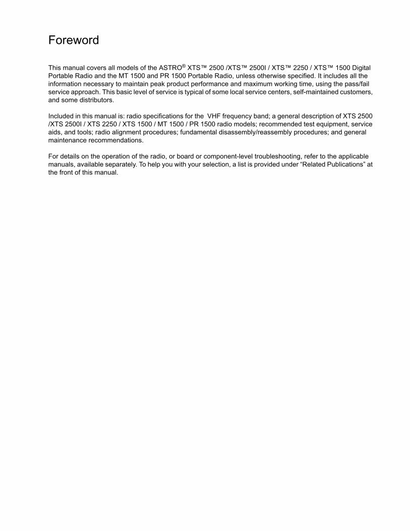
This manual covers all models of the ASTRO® XTS™ 2500 /XTS™ 2500I / XTS™ 2250 / XTS™ 1500 Digital Portable Radio and the MT 1500 and PR 1500 Portable Radio, unless otherwise specified. It includes all the information necessary to maintain peak product performance and maximum working time, using the pass/fail service approach. This basic level of service is typical of some local service centers, self-maintained customers, and some distributors.
Included in this manual is: radio specifications for the VHF frequency band; a general description of XTS 2500 /XTS 2500I / XTS 2250 / XTS 1500 / MT 1500 / PR 1500 radio models; recommended test equipment, service aids, and tools; radio alignment procedures; fundamental disassembly/reassembly procedures; and general maintenance recommendations.
For details on the operation of the radio, or board or component-level troubleshooting, refer to the applicable manuals, available separately. To help you with your selection, a list is provided under “Related Publications” at the front of this manual.

Safety
Before operating an XTS 2500 /XTS 2500I / XTS 2250 / XTS 1500 / MT 1500 / PR 1500 radio, please read the RF energy awareness information and operating instructions in the Product Safety and RF Exposure booklet enclosed with your radio (Motorola Publication part number 6881095C98) to ensure compliance with RF energy exposure limits.
Manual Revisions
Changes which occur after this manual is printed are described in “PMRs.” These PMRs provide complete information on changes, including pertinent parts list data.

Computer Software Copyrights
The Motorola products described in this manual may include copyrighted Motorola computer programs stored in semiconductor memories or other media. Laws in the United States and other countries preserve for Motorola certain exclusive rights for copyrighted computer programs, including, but not limited to, the exclusive right to copy or reproduce in any form the copyrighted computer program. Accordingly, any copyrighted Motorola computer programs contained in the Motorola products described in this manual may not be copied, reproduced, modified, reverse-engineered, or distributed in any manner without the express written permission of Motorola. Furthermore, the purchase of Motorola products shall not be deemed to grant either directly or by implication, estoppel, or otherwise, any license under the copyrights, patents or patent applications of Motorola, except for the normal non-exclusive license to use that arises by operation of law in the sale of a product.

i
Document HistoryThe following major changes have been implemented in this manual since the previous edition:
Edition Description Date
6816984H01-A Initial Release. Feb. 2006
6816984H01-B Added PMR089, PMR090 and 900 MHz stuffers to the manual.
Aug. 2007
6816984H01-C Added PMR140, PMR142 and PMR145 stuffer information. Updated model charts section.
Mar. 2009

Document History
ii
Notes

iii
Table of Contents Document History . . . . . . . . . . . . . . . . . . . . . . . . . . . . . . . . . . . . . . . . . . . . . . . . . . . . . . . . . . . . . . . . . . . .i
Table of Contents . . . . . . . . . . . . . . . . . . . . . . . . . . . . . . . . . . . . . . . . . . . . . . . . . . . . . . . . . . . . . . . . . . . iii
- List of Figures. . . . . . . . . . . . . . . . . . . . . . . . . . . . . . . . . . . . . . . . . . . . . . . . . . . . . . . . . . . . . . . . . . . . vii
- List of Tables . . . . . . . . . . . . . . . . . . . . . . . . . . . . . . . . . . . . . . . . . . . . . . . . . . . . . . . . . . . . . . . . . . . . . ix
- Related Manuals . . . . . . . . . . . . . . . . . . . . . . . . . . . . . . . . . . . . . . . . . . . . . . . . . . . . . . . . . . . . . . . . . . . x
Commercial Warranty . . . . . . . . . . . . . . . . . . . . . . . . . . . . . . . . . . . . . . . . . . . . . . . . . . . . . . . . . . . . . . . .xiLimited Warranty . . . . . . . . . . . . . . . . . . . . . . . . . . . . . . . . . . . . . . . . . . . . . . . . . . . . . . . . . . . . . . . . . . xi
MOTOROLA COMMUNICATION PRODUCTS . . . . . . . . . . . . . . . . . . . . . . . . . . . . . . . . . . . . . . . . xiI. WHAT THIS WARRANTY COVERS AND FOR HOW LONG . . . . . . . . . . . . . . . . . . . . . . . . xiII. GENERAL PROVISIONS . . . . . . . . . . . . . . . . . . . . . . . . . . . . . . . . . . . . . . . . . . . . . . . . . . . . xiIII. STATE LAW RIGHTS . . . . . . . . . . . . . . . . . . . . . . . . . . . . . . . . . . . . . . . . . . . . . . . . . . . . . xiiIV. HOW TO GET WARRANTY SERVICE. . . . . . . . . . . . . . . . . . . . . . . . . . . . . . . . . . . . . . . . xiiV. WHAT THIS WARRANTY DOES NOT COVER . . . . . . . . . . . . . . . . . . . . . . . . . . . . . . . . . xiiVI. PATENT AND SOFTWARE PROVISIONS . . . . . . . . . . . . . . . . . . . . . . . . . . . . . . . . . . . . . xiiiVII. GOVERNING LAW . . . . . . . . . . . . . . . . . . . . . . . . . . . . . . . . . . . . . . . . . . . . . . . . . . . . . . xiii
Specifications . . . . . . . . . . . . . . . . . . . . . . . . . . . . . . . . . . . . . . . . . . . . . . . . . . . . . . . . . . . . . . . . . . . . . xvPortable Radio Model Numbering System . . . . . . . . . . . . . . . . . . . . . . . . . . . . . . . . . . . . . . . . . . . . . . xvSpecifications for VHF Radios . . . . . . . . . . . . . . . . . . . . . . . . . . . . . . . . . . . . . . . . . . . . . . . . . . . . . . . xviASTRO XTS 2500/XTS 2500I/XTS 2250 Model Chart . . . . . . . . . . . . . . . . . . . . . . . . . . . . . . . . . . . .xviiASTRO XTS 2500/XTS 2500I/2250 Model Chart (continued) . . . . . . . . . . . . . . . . . . . . . . . . . . . . . . xviiiASTRO XTS 1500/MT 1500 Model Chart . . . . . . . . . . . . . . . . . . . . . . . . . . . . . . . . . . . . . . . . . . . . . . xixPR 1500 Model Chart. . . . . . . . . . . . . . . . . . . . . . . . . . . . . . . . . . . . . . . . . . . . . . . . . . . . . . . . . . . . . . xxSpecifications for UHF Range 1 Radios. . . . . . . . . . . . . . . . . . . . . . . . . . . . . . . . . . . . . . . . . . . . . . . . xxiASTRO XTS 2500/XTS 2500I/XTS 2250 Model Chart . . . . . . . . . . . . . . . . . . . . . . . . . . . . . . . . . . . .xxii ASTRO XTS 2500/XTS 2500I/XTS 2250 Model Chart (continued) . . . . . . . . . . . . . . . . . . . . . . . . . xxiiiASTRO XTS 2500/XTS 2500I/XTS 2250 Model Chart . . . . . . . . . . . . . . . . . . . . . . . . . . . . . . . . . . . xxivASTRO XTS 1500/MT 1500 Model Chart . . . . . . . . . . . . . . . . . . . . . . . . . . . . . . . . . . . . . . . . . . . . . xxvPR 1500 Model Chart. . . . . . . . . . . . . . . . . . . . . . . . . . . . . . . . . . . . . . . . . . . . . . . . . . . . . . . . . . . . . xxviSpecifications for UHF Range 2 Radios. . . . . . . . . . . . . . . . . . . . . . . . . . . . . . . . . . . . . . . . . . . . . . .xxvii ASTRO XTS 2500/XTS 2500I/XTS 2250 Model Chart . . . . . . . . . . . . . . . . . . . . . . . . . . . . . . . . . . xxviiiASTRO XTS 2500/XTS 2500I/XTS 2250 Model Chart (continued) . . . . . . . . . . . . . . . . . . . . . . . . . . xxixASTRO XTS 1500/MT 1500 Model Chart . . . . . . . . . . . . . . . . . . . . . . . . . . . . . . . . . . . . . . . . . . . . . xxxPR 1500 Model Chart. . . . . . . . . . . . . . . . . . . . . . . . . . . . . . . . . . . . . . . . . . . . . . . . . . . . . . . . . . . . . xxxiSpecifications for 700 MHz/800 MHz Radios . . . . . . . . . . . . . . . . . . . . . . . . . . . . . . . . . . . . . . . . . . .xxxiiASTRO XTS 2500/XTS 2500I/XTS 2250 Model Chart . . . . . . . . . . . . . . . . . . . . . . . . . . . . . . . . . . xxxiiiASTRO XTS 2500/XTS 2500I/XTS 2250 Model Chart (continued) . . . . . . . . . . . . . . . . . . . . . . . . xxxivASTRO XTS 2500/XTS 2500I/XTS 2250 Model Chart (continued) . . . . . . . . . . . . . . . . . . . . . . . . . .xxxvASTRO XTS 1500/MT 1500 Model Chart . . . . . . . . . . . . . . . . . . . . . . . . . . . . . . . . . . . . . . . . . . . . xxxviSpecifications for 900 MHz Radios . . . . . . . . . . . . . . . . . . . . . . . . . . . . . . . . . . . . . . . . . . . . . . . . . xxxviiASTRO XTS 2500/XTS 2500I/XTS 2250 Model Chart . . . . . . . . . . . . . . . . . . . . . . . . . . . . . . . . . xxxviiiASTRO XTS 1500/MT 1500 Model Chart . . . . . . . . . . . . . . . . . . . . . . . . . . . . . . . . . . . . . . . . . . . . xxxix

Table of Contents
iv
1 - Introduction. . . . . . . . . . . . . . . . . . . . . . . . . . . . . . . . . . . . . . . . . . . . . . . . . . . . . . . . . . . . . . . . . . . . . . 1General . . . . . . . . . . . . . . . . . . . . . . . . . . . . . . . . . . . . . . . . . . . . . . . . . . . . . . . . . . . . . . . . . . . . . . . . . . 1Notations Used in This Manual . . . . . . . . . . . . . . . . . . . . . . . . . . . . . . . . . . . . . . . . . . . . . . . . . . . . . . . . 1Radio Description . . . . . . . . . . . . . . . . . . . . . . . . . . . . . . . . . . . . . . . . . . . . . . . . . . . . . . . . . . . . . . . . . . 2FLASHport . . . . . . . . . . . . . . . . . . . . . . . . . . . . . . . . . . . . . . . . . . . . . . . . . . . . . . . . . . . . . . . . . . . . . . . 2
2 - Basic Maintenance . . . . . . . . . . . . . . . . . . . . . . . . . . . . . . . . . . . . . . . . . . . . . . . . . . . . . . . . . . . . . . . . 3Introduction to This Section . . . . . . . . . . . . . . . . . . . . . . . . . . . . . . . . . . . . . . . . . . . . . . . . . . . . . . . . . . 3Preventive Maintenance . . . . . . . . . . . . . . . . . . . . . . . . . . . . . . . . . . . . . . . . . . . . . . . . . . . . . . . . . . . . . 3
Inspection . . . . . . . . . . . . . . . . . . . . . . . . . . . . . . . . . . . . . . . . . . . . . . . . . . . . . . . . . . . . . . . . . . . . . 3Cleaning. . . . . . . . . . . . . . . . . . . . . . . . . . . . . . . . . . . . . . . . . . . . . . . . . . . . . . . . . . . . . . . . . . . . . . . 3
Cleaning External Plastic Surfaces . . . . . . . . . . . . . . . . . . . . . . . . . . . . . . . . . . . . . . . . . . . . . . . 3Handling Precautions . . . . . . . . . . . . . . . . . . . . . . . . . . . . . . . . . . . . . . . . . . . . . . . . . . . . . . . . . . . . . . . 4
3 - Basic Theory of Operation. . . . . . . . . . . . . . . . . . . . . . . . . . . . . . . . . . . . . . . . . . . . . . . . . . . . . . . . . . 5General Overview . . . . . . . . . . . . . . . . . . . . . . . . . . . . . . . . . . . . . . . . . . . . . . . . . . . . . . . . . . . . . . . . . . 5Analog Mode of Operation . . . . . . . . . . . . . . . . . . . . . . . . . . . . . . . . . . . . . . . . . . . . . . . . . . . . . . . . . . . 6
Receiving . . . . . . . . . . . . . . . . . . . . . . . . . . . . . . . . . . . . . . . . . . . . . . . . . . . . . . . . . . . . . . . . . . . . . . 6Transmitting. . . . . . . . . . . . . . . . . . . . . . . . . . . . . . . . . . . . . . . . . . . . . . . . . . . . . . . . . . . . . . . . . . . . 7
ASTRO Mode of Operation. . . . . . . . . . . . . . . . . . . . . . . . . . . . . . . . . . . . . . . . . . . . . . . . . . . . . . . . . . . 8RF Basic Theory of Operation . . . . . . . . . . . . . . . . . . . . . . . . . . . . . . . . . . . . . . . . . . . . . . . . . . . . . . . . 8VOCON Basic Theory of Operation . . . . . . . . . . . . . . . . . . . . . . . . . . . . . . . . . . . . . . . . . . . . . . . . . . . 10
4 - Recommended Test Equipment and Service Aids . . . . . . . . . . . . . . . . . . . . . . . . . . . . . . . . . . . . . 11Recommended Test Equipment . . . . . . . . . . . . . . . . . . . . . . . . . . . . . . . . . . . . . . . . . . . . . . . . . . . . . . 11Service Aids . . . . . . . . . . . . . . . . . . . . . . . . . . . . . . . . . . . . . . . . . . . . . . . . . . . . . . . . . . . . . . . . . . . . . 11Field Programming Equipment . . . . . . . . . . . . . . . . . . . . . . . . . . . . . . . . . . . . . . . . . . . . . . . . . . . . . . . 12
5 - Performance Checks . . . . . . . . . . . . . . . . . . . . . . . . . . . . . . . . . . . . . . . . . . . . . . . . . . . . . . . . . . . . . 13Introduction to This Section . . . . . . . . . . . . . . . . . . . . . . . . . . . . . . . . . . . . . . . . . . . . . . . . . . . . . . . . . 13Setup . . . . . . . . . . . . . . . . . . . . . . . . . . . . . . . . . . . . . . . . . . . . . . . . . . . . . . . . . . . . . . . . . . . . . . . . . . 13Display Radio Test Mode . . . . . . . . . . . . . . . . . . . . . . . . . . . . . . . . . . . . . . . . . . . . . . . . . . . . . . . . . . . 14
Entering Display Radio Test Mode . . . . . . . . . . . . . . . . . . . . . . . . . . . . . . . . . . . . . . . . . . . . . . . . . 14RF Test Mode (Display Radio) . . . . . . . . . . . . . . . . . . . . . . . . . . . . . . . . . . . . . . . . . . . . . . . . . . . . 15Control Top and Keypad Test Mode (Display Radio) . . . . . . . . . . . . . . . . . . . . . . . . . . . . . . . . . . . 16
Non-Display Radio Test Mode . . . . . . . . . . . . . . . . . . . . . . . . . . . . . . . . . . . . . . . . . . . . . . . . . . . . . . . 17Entering Non-Display Radio Test Mode . . . . . . . . . . . . . . . . . . . . . . . . . . . . . . . . . . . . . . . . . . . . . 17RF Test Mode (Non-Display Radio). . . . . . . . . . . . . . . . . . . . . . . . . . . . . . . . . . . . . . . . . . . . . . . . . 18Control Top and Keypad Test Mode (Non-Display Radio) . . . . . . . . . . . . . . . . . . . . . . . . . . . . . . . 18
6 - Radio Alignment Procedures . . . . . . . . . . . . . . . . . . . . . . . . . . . . . . . . . . . . . . . . . . . . . . . . . . . . . . 21Introduction to This Section . . . . . . . . . . . . . . . . . . . . . . . . . . . . . . . . . . . . . . . . . . . . . . . . . . . . . . . . . 21General . . . . . . . . . . . . . . . . . . . . . . . . . . . . . . . . . . . . . . . . . . . . . . . . . . . . . . . . . . . . . . . . . . . . . . . . . 21Radio Information . . . . . . . . . . . . . . . . . . . . . . . . . . . . . . . . . . . . . . . . . . . . . . . . . . . . . . . . . . . . . . . . . 24Reference Oscillator Alignment . . . . . . . . . . . . . . . . . . . . . . . . . . . . . . . . . . . . . . . . . . . . . . . . . . . . . . 24Transmit Power Alignment . . . . . . . . . . . . . . . . . . . . . . . . . . . . . . . . . . . . . . . . . . . . . . . . . . . . . . . . . . 26Transmit Deviation Balance Alignment . . . . . . . . . . . . . . . . . . . . . . . . . . . . . . . . . . . . . . . . . . . . . . . . . 27Transmit Deviation Limit Alignment . . . . . . . . . . . . . . . . . . . . . . . . . . . . . . . . . . . . . . . . . . . . . . . . . . . 30Front End Filter Alignment . . . . . . . . . . . . . . . . . . . . . . . . . . . . . . . . . . . . . . . . . . . . . . . . . . . . . . . . . . 31
Definition . . . . . . . . . . . . . . . . . . . . . . . . . . . . . . . . . . . . . . . . . . . . . . . . . . . . . . . . . . . . . . . . . . . . . 31Procedure for VHF. . . . . . . . . . . . . . . . . . . . . . . . . . . . . . . . . . . . . . . . . . . . . . . . . . . . . . . . . . . . . . 31
Bit Error Rate . . . . . . . . . . . . . . . . . . . . . . . . . . . . . . . . . . . . . . . . . . . . . . . . . . . . . . . . . . . . . . . . . . . . 32Definition . . . . . . . . . . . . . . . . . . . . . . . . . . . . . . . . . . . . . . . . . . . . . . . . . . . . . . . . . . . . . . . . . . . . . 32Bit Error Rate Fields . . . . . . . . . . . . . . . . . . . . . . . . . . . . . . . . . . . . . . . . . . . . . . . . . . . . . . . . . . . . 32
Transmitter Test Pattern . . . . . . . . . . . . . . . . . . . . . . . . . . . . . . . . . . . . . . . . . . . . . . . . . . . . . . . . . . . . 34Definition . . . . . . . . . . . . . . . . . . . . . . . . . . . . . . . . . . . . . . . . . . . . . . . . . . . . . . . . . . . . . . . . . . . . . 34Transmitter Test Fields . . . . . . . . . . . . . . . . . . . . . . . . . . . . . . . . . . . . . . . . . . . . . . . . . . . . . . . . . . 34
XTS 2500/XTS 2250/XTS 1500/MT 1500/PR 1500 Model I Exploded View . . . . . . . . . . . . . . . . . . . . 37

Table of Contents
v
7 - XTS 2500/XTS 2250/XTS 1500/MT 1500/PR 1500 Exploded Views and Parts Lists . . . . . . . . . . . 37XTS 2500 Model II Exploded View. . . . . . . . . . . . . . . . . . . . . . . . . . . . . . . . . . . . . . . . . . . . . . . . . . . . 38XTS 2500 Model III / XTS 2250 Advanced Model Exploded View . . . . . . . . . . . . . . . . . . . . . . . . . . . . 39XTS 2500 / XTS 2250 Model 1.5 Exploded View. . . . . . . . . . . . . . . . . . . . . . . . . . . . . . . . . . . . . . . . . 40
8 - Disassembly/Assembly . . . . . . . . . . . . . . . . . . . . . . . . . . . . . . . . . . . . . . . . . . . . . . . . . . . . . . . . . . . 41Introduction to This Section . . . . . . . . . . . . . . . . . . . . . . . . . . . . . . . . . . . . . . . . . . . . . . . . . . . . . . . . . 41Antenna . . . . . . . . . . . . . . . . . . . . . . . . . . . . . . . . . . . . . . . . . . . . . . . . . . . . . . . . . . . . . . . . . . . . . . . . 41
Attach the Antenna . . . . . . . . . . . . . . . . . . . . . . . . . . . . . . . . . . . . . . . . . . . . . . . . . . . . . . . . . . . . . 41Remove the Antenna . . . . . . . . . . . . . . . . . . . . . . . . . . . . . . . . . . . . . . . . . . . . . . . . . . . . . . . . . . . 42
Battery . . . . . . . . . . . . . . . . . . . . . . . . . . . . . . . . . . . . . . . . . . . . . . . . . . . . . . . . . . . . . . . . . . . . . . . . . 42Attach the Battery . . . . . . . . . . . . . . . . . . . . . . . . . . . . . . . . . . . . . . . . . . . . . . . . . . . . . . . . . . . . . . 42Remove the Battery . . . . . . . . . . . . . . . . . . . . . . . . . . . . . . . . . . . . . . . . . . . . . . . . . . . . . . . . . . . . 43
Belt Clip . . . . . . . . . . . . . . . . . . . . . . . . . . . . . . . . . . . . . . . . . . . . . . . . . . . . . . . . . . . . . . . . . . . . . . . . 43Attach the Belt Clip . . . . . . . . . . . . . . . . . . . . . . . . . . . . . . . . . . . . . . . . . . . . . . . . . . . . . . . . . . . . . 43Remove the Belt Clip . . . . . . . . . . . . . . . . . . . . . . . . . . . . . . . . . . . . . . . . . . . . . . . . . . . . . . . . . . . 44
Universal Connector Cover . . . . . . . . . . . . . . . . . . . . . . . . . . . . . . . . . . . . . . . . . . . . . . . . . . . . . . . . . 44Remove the Universal Connector Cover. . . . . . . . . . . . . . . . . . . . . . . . . . . . . . . . . . . . . . . . . . . . . 44Attach the Universal Connector Cover . . . . . . . . . . . . . . . . . . . . . . . . . . . . . . . . . . . . . . . . . . . . . . 45
Remote Speaker Microphone Adapter . . . . . . . . . . . . . . . . . . . . . . . . . . . . . . . . . . . . . . . . . . . . . . . . . 45Remove the Adapter . . . . . . . . . . . . . . . . . . . . . . . . . . . . . . . . . . . . . . . . . . . . . . . . . . . . . . . . . . . . 45Attach the Adapter . . . . . . . . . . . . . . . . . . . . . . . . . . . . . . . . . . . . . . . . . . . . . . . . . . . . . . . . . . . . . 46
Radio Disassembly—Detailed . . . . . . . . . . . . . . . . . . . . . . . . . . . . . . . . . . . . . . . . . . . . . . . . . . . . . . . 46Required Tools . . . . . . . . . . . . . . . . . . . . . . . . . . . . . . . . . . . . . . . . . . . . . . . . . . . . . . . . . . . . . . . . 46Front Cover from Chassis Disassembly . . . . . . . . . . . . . . . . . . . . . . . . . . . . . . . . . . . . . . . . . . . . . 47Chassis Disassembly . . . . . . . . . . . . . . . . . . . . . . . . . . . . . . . . . . . . . . . . . . . . . . . . . . . . . . . . . . . 49Backup Battery Disassembly . . . . . . . . . . . . . . . . . . . . . . . . . . . . . . . . . . . . . . . . . . . . . . . . . . . . . 50Keypad and Keypad/Option Board Disassembly . . . . . . . . . . . . . . . . . . . . . . . . . . . . . . . . . . . . . . 51Display Disassembly . . . . . . . . . . . . . . . . . . . . . . . . . . . . . . . . . . . . . . . . . . . . . . . . . . . . . . . . . . . . 53Speaker, Microphone, and Universal Connector Flex Disassembly . . . . . . . . . . . . . . . . . . . . . . . . 54
Radio Reassembly—Detailed . . . . . . . . . . . . . . . . . . . . . . . . . . . . . . . . . . . . . . . . . . . . . . . . . . . . . . . 55Keypad and Keypad Option Board Reassembly. . . . . . . . . . . . . . . . . . . . . . . . . . . . . . . . . . . . . . . 56Display Reassembly . . . . . . . . . . . . . . . . . . . . . . . . . . . . . . . . . . . . . . . . . . . . . . . . . . . . . . . . . . . . 56Speaker, Microphone, and Universal Connector Flex Reassembly . . . . . . . . . . . . . . . . . . . . . . . . 56Chassis Assembly Reassembly . . . . . . . . . . . . . . . . . . . . . . . . . . . . . . . . . . . . . . . . . . . . . . . . . . . 57Backup Battery Reassembly . . . . . . . . . . . . . . . . . . . . . . . . . . . . . . . . . . . . . . . . . . . . . . . . . . . . . . 57Chassis and Front Cover Reassembly . . . . . . . . . . . . . . . . . . . . . . . . . . . . . . . . . . . . . . . . . . . . . . 57
Ensuring Radio Immersibility . . . . . . . . . . . . . . . . . . . . . . . . . . . . . . . . . . . . . . . . . . . . . . . . . . . . . . . . 58Standards . . . . . . . . . . . . . . . . . . . . . . . . . . . . . . . . . . . . . . . . . . . . . . . . . . . . . . . . . . . . . . . . . . . . 58Servicing . . . . . . . . . . . . . . . . . . . . . . . . . . . . . . . . . . . . . . . . . . . . . . . . . . . . . . . . . . . . . . . . . . . . . 59Accidental Immersion . . . . . . . . . . . . . . . . . . . . . . . . . . . . . . . . . . . . . . . . . . . . . . . . . . . . . . . . . . . 59Specialized Test Equipment . . . . . . . . . . . . . . . . . . . . . . . . . . . . . . . . . . . . . . . . . . . . . . . . . . . . . . 59
Vacuum Pump Kit NLN9839 . . . . . . . . . . . . . . . . . . . . . . . . . . . . . . . . . . . . . . . . . . . . . . . . . . . 59Pressure Pump Kit NTN4265. . . . . . . . . . . . . . . . . . . . . . . . . . . . . . . . . . . . . . . . . . . . . . . . . . . 59Miscellaneous Hardware . . . . . . . . . . . . . . . . . . . . . . . . . . . . . . . . . . . . . . . . . . . . . . . . . . . . . . 59
Disassembly . . . . . . . . . . . . . . . . . . . . . . . . . . . . . . . . . . . . . . . . . . . . . . . . . . . . . . . . . . . . . . . . . . 59Reassembly . . . . . . . . . . . . . . . . . . . . . . . . . . . . . . . . . . . . . . . . . . . . . . . . . . . . . . . . . . . . . . . . . . 60Vacuum Test . . . . . . . . . . . . . . . . . . . . . . . . . . . . . . . . . . . . . . . . . . . . . . . . . . . . . . . . . . . . . . . . . . 60Pressure Test . . . . . . . . . . . . . . . . . . . . . . . . . . . . . . . . . . . . . . . . . . . . . . . . . . . . . . . . . . . . . . . . . 61Troubleshooting Leak Areas . . . . . . . . . . . . . . . . . . . . . . . . . . . . . . . . . . . . . . . . . . . . . . . . . . . . . . 62
Front Housing . . . . . . . . . . . . . . . . . . . . . . . . . . . . . . . . . . . . . . . . . . . . . . . . . . . . . . . . . . . . . . 62Chassis (Seal Port and Label Seal) . . . . . . . . . . . . . . . . . . . . . . . . . . . . . . . . . . . . . . . . . . . . . . 63Frequency Switch and Antenna Nut . . . . . . . . . . . . . . . . . . . . . . . . . . . . . . . . . . . . . . . . . . . . . 63Main Seal O-ring . . . . . . . . . . . . . . . . . . . . . . . . . . . . . . . . . . . . . . . . . . . . . . . . . . . . . . . . . . . . 63Battery Seal . . . . . . . . . . . . . . . . . . . . . . . . . . . . . . . . . . . . . . . . . . . . . . . . . . . . . . . . . . . . . . . . 64

Table of Contents
vi
9 - Radio-Level Troubleshooting . . . . . . . . . . . . . . . . . . . . . . . . . . . . . . . . . . . . . . . . . . . . . . . . . . . . . . 65Introduction to This Section . . . . . . . . . . . . . . . . . . . . . . . . . . . . . . . . . . . . . . . . . . . . . . . . . . . . . . . . . 65Power-Up Error Codes . . . . . . . . . . . . . . . . . . . . . . . . . . . . . . . . . . . . . . . . . . . . . . . . . . . . . . . . . . . . . 65Operational Error Codes. . . . . . . . . . . . . . . . . . . . . . . . . . . . . . . . . . . . . . . . . . . . . . . . . . . . . . . . . . . . 66
10 - Accessories. . . . . . . . . . . . . . . . . . . . . . . . . . . . . . . . . . . . . . . . . . . . . . . . . . . . . . . . . . . . . . . . . . . . 69General . . . . . . . . . . . . . . . . . . . . . . . . . . . . . . . . . . . . . . . . . . . . . . . . . . . . . . . . . . . . . . . . . . . . . . . . . 69Antennas. . . . . . . . . . . . . . . . . . . . . . . . . . . . . . . . . . . . . . . . . . . . . . . . . . . . . . . . . . . . . . . . . . . . . . . . 69Batteries . . . . . . . . . . . . . . . . . . . . . . . . . . . . . . . . . . . . . . . . . . . . . . . . . . . . . . . . . . . . . . . . . . . . . . . . 69Carry Accessories. . . . . . . . . . . . . . . . . . . . . . . . . . . . . . . . . . . . . . . . . . . . . . . . . . . . . . . . . . . . . . . . . 69
Belt Clips . . . . . . . . . . . . . . . . . . . . . . . . . . . . . . . . . . . . . . . . . . . . . . . . . . . . . . . . . . . . . . . . . . . . . 69Body-Worn. . . . . . . . . . . . . . . . . . . . . . . . . . . . . . . . . . . . . . . . . . . . . . . . . . . . . . . . . . . . . . . . . . . . 69
Chargers . . . . . . . . . . . . . . . . . . . . . . . . . . . . . . . . . . . . . . . . . . . . . . . . . . . . . . . . . . . . . . . . . . . . . . . . 70Enhanced and Multi-Unit Line Cords . . . . . . . . . . . . . . . . . . . . . . . . . . . . . . . . . . . . . . . . . . . . . . . . 70
Microphones, Remote Speaker . . . . . . . . . . . . . . . . . . . . . . . . . . . . . . . . . . . . . . . . . . . . . . . . . . . . . . 70Surveillance Accessories . . . . . . . . . . . . . . . . . . . . . . . . . . . . . . . . . . . . . . . . . . . . . . . . . . . . . . . . . . . 70
CommPort® Integrated Microphone/Receivers . . . . . . . . . . . . . . . . . . . . . . . . . . . . . . . . . . . . . . . . 70Earpieces. . . . . . . . . . . . . . . . . . . . . . . . . . . . . . . . . . . . . . . . . . . . . . . . . . . . . . . . . . . . . . . . . . . . . 71Headsets and Headset Accessories . . . . . . . . . . . . . . . . . . . . . . . . . . . . . . . . . . . . . . . . . . . . . . . . 71Radio Interface Modules for Ear Microphones . . . . . . . . . . . . . . . . . . . . . . . . . . . . . . . . . . . . . . . . 72
Switches . . . . . . . . . . . . . . . . . . . . . . . . . . . . . . . . . . . . . . . . . . . . . . . . . . . . . . . . . . . . . . . . . . . . . . . . 72
A - Appendix: Replacement Parts Ordering . . . . . . . . . . . . . . . . . . . . . . . . . . . . . . . . . . . . . . . . . . . . . 73Basic Ordering Information . . . . . . . . . . . . . . . . . . . . . . . . . . . . . . . . . . . . . . . . . . . . . . . . . . . . . . . . . . 73Radio Board Ordering Information . . . . . . . . . . . . . . . . . . . . . . . . . . . . . . . . . . . . . . . . . . . . . . . . . . . . 73Motorola Online . . . . . . . . . . . . . . . . . . . . . . . . . . . . . . . . . . . . . . . . . . . . . . . . . . . . . . . . . . . . . . . . . . 73Mail Orders . . . . . . . . . . . . . . . . . . . . . . . . . . . . . . . . . . . . . . . . . . . . . . . . . . . . . . . . . . . . . . . . . . . . . . 73Telephone Orders . . . . . . . . . . . . . . . . . . . . . . . . . . . . . . . . . . . . . . . . . . . . . . . . . . . . . . . . . . . . . . . . . 73Fax Orders . . . . . . . . . . . . . . . . . . . . . . . . . . . . . . . . . . . . . . . . . . . . . . . . . . . . . . . . . . . . . . . . . . . . . . 74Parts Identification . . . . . . . . . . . . . . . . . . . . . . . . . . . . . . . . . . . . . . . . . . . . . . . . . . . . . . . . . . . . . . . . 74Product Customer Service . . . . . . . . . . . . . . . . . . . . . . . . . . . . . . . . . . . . . . . . . . . . . . . . . . . . . . . . . . 74
Glossary . . . . . . . . . . . . . . . . . . . . . . . . . . . . . . . . . . . . . . . . . . . . . . . . . . . . . . . . . . . . . . . . . . . . . . . . . . 75
Index . . . . . . . . . . . . . . . . . . . . . . . . . . . . . . . . . . . . . . . . . . . . . . . . . . . . . . . . . . . . . . . . . . . . . . . . . . . . . 77

vii
List of Figures
Figure 1. XTS 2500 Overall Block Diagram. . . . . . . . . . . . . . . . . . . . . . . . . . . . . . . . . . . . . . . . . . . . . . . . . . . . 6
Figure 2. Receiver Block Diagram. . . . . . . . . . . . . . . . . . . . . . . . . . . . . . . . . . . . . . . . . . . . . . . . . . . . . . . . . . . 7
Figure 3. RF Block Diagram for VHF (Power and Control Omitted) . . . . . . . . . . . . . . . . . . . . . . . . . . . . . . . . . 8
Figure 4. Radio Alignment Test Setup. . . . . . . . . . . . . . . . . . . . . . . . . . . . . . . . . . . . . . . . . . . . . . . . . . . . . . . 13
Figure 5. Tuner Menu Layout . . . . . . . . . . . . . . . . . . . . . . . . . . . . . . . . . . . . . . . . . . . . . . . . . . . . . . . . . . . . . 22
Figure 6. Typical Softpot Screen . . . . . . . . . . . . . . . . . . . . . . . . . . . . . . . . . . . . . . . . . . . . . . . . . . . . . . . . . . . 23
Figure 7. Radio Information Screen. . . . . . . . . . . . . . . . . . . . . . . . . . . . . . . . . . . . . . . . . . . . . . . . . . . . . . . . . 24
Figure 8. Reference Oscillator Alignment Screen . . . . . . . . . . . . . . . . . . . . . . . . . . . . . . . . . . . . . . . . . . . . . . 25
Figure 9. Transmit Power Alignment Screen (Typical) . . . . . . . . . . . . . . . . . . . . . . . . . . . . . . . . . . . . . . . . . . 27
Figure 10. Transmit Deviation Balance Alignment Screen . . . . . . . . . . . . . . . . . . . . . . . . . . . . . . . . . . . . . . . 29
Figure 11. Transmit Deviation Limit Alignment Screen . . . . . . . . . . . . . . . . . . . . . . . . . . . . . . . . . . . . . . . . . . 30
Figure 12. Front End Filter Alignment Screen . . . . . . . . . . . . . . . . . . . . . . . . . . . . . . . . . . . . . . . . . . . . . . . . . 32
Figure 13. Bit Error Rate Screen . . . . . . . . . . . . . . . . . . . . . . . . . . . . . . . . . . . . . . . . . . . . . . . . . . . . . . . . . . . 34
Figure 14. Transmitter Test Pattern Screen . . . . . . . . . . . . . . . . . . . . . . . . . . . . . . . . . . . . . . . . . . . . . . . . . . 35
Figure 15. Attaching the Antenna . . . . . . . . . . . . . . . . . . . . . . . . . . . . . . . . . . . . . . . . . . . . . . . . . . . . . . . . . . 41
Figure 16. Removing the Antenna. . . . . . . . . . . . . . . . . . . . . . . . . . . . . . . . . . . . . . . . . . . . . . . . . . . . . . . . . . 42
Figure 17. Attaching the Battery . . . . . . . . . . . . . . . . . . . . . . . . . . . . . . . . . . . . . . . . . . . . . . . . . . . . . . . . . . . 42
Figure 18. Attaching the Battery . . . . . . . . . . . . . . . . . . . . . . . . . . . . . . . . . . . . . . . . . . . . . . . . . . . . . . . . . . . 42
Figure 19. Removing the Battery. . . . . . . . . . . . . . . . . . . . . . . . . . . . . . . . . . . . . . . . . . . . . . . . . . . . . . . . . . . 43
Figure 20. Removing the Battery. . . . . . . . . . . . . . . . . . . . . . . . . . . . . . . . . . . . . . . . . . . . . . . . . . . . . . . . . . . 43
Figure 21. Attaching the Belt Clip . . . . . . . . . . . . . . . . . . . . . . . . . . . . . . . . . . . . . . . . . . . . . . . . . . . . . . . . . . 43
Figure 22. Removing the Belt Clip. . . . . . . . . . . . . . . . . . . . . . . . . . . . . . . . . . . . . . . . . . . . . . . . . . . . . . . . . . 44
Figure 23. Removing the Universal Connector Cover . . . . . . . . . . . . . . . . . . . . . . . . . . . . . . . . . . . . . . . . . . . 44
Figure 24. Attaching the Universal Connector Cover . . . . . . . . . . . . . . . . . . . . . . . . . . . . . . . . . . . . . . . . . . . 45
Figure 25. Removing the RSM Adapter. . . . . . . . . . . . . . . . . . . . . . . . . . . . . . . . . . . . . . . . . . . . . . . . . . . . . . 45
Figure 26. Attaching the RSM Adapter . . . . . . . . . . . . . . . . . . . . . . . . . . . . . . . . . . . . . . . . . . . . . . . . . . . . . . 46
List of Figures
viii
Figure 27. Attaching the RSM Adapter . . . . . . . . . . . . . . . . . . . . . . . . . . . . . . . . . . . . . . . . . . . . . . . . . . . . . . 46
Figure 28. Knob Removal . . . . . . . . . . . . . . . . . . . . . . . . . . . . . . . . . . . . . . . . . . . . . . . . . . . . . . . . . . . . . . . . 47
Figure 29. Chassis Removal . . . . . . . . . . . . . . . . . . . . . . . . . . . . . . . . . . . . . . . . . . . . . . . . . . . . . . . . . . . . . . 48
Figure 30. Chassis Separation. . . . . . . . . . . . . . . . . . . . . . . . . . . . . . . . . . . . . . . . . . . . . . . . . . . . . . . . . . . . . 48
Figure 31. Unlatching the Flex Connectors. . . . . . . . . . . . . . . . . . . . . . . . . . . . . . . . . . . . . . . . . . . . . . . . . . . 49
Figure 32. Removing the Main Board from the Chassis . . . . . . . . . . . . . . . . . . . . . . . . . . . . . . . . . . . . . . . . . 50
Figure 33. Remove the Backup Battery . . . . . . . . . . . . . . . . . . . . . . . . . . . . . . . . . . . . . . . . . . . . . . . . . . . . . . 51
Figure 34. Retainer Removal . . . . . . . . . . . . . . . . . . . . . . . . . . . . . . . . . . . . . . . . . . . . . . . . . . . . . . . . . . . . . . 52
Figure 35. Keypad Retainer and Boards Removal . . . . . . . . . . . . . . . . . . . . . . . . . . . . . . . . . . . . . . . . . . . . . 52
Figure 36. Display Disassembly. . . . . . . . . . . . . . . . . . . . . . . . . . . . . . . . . . . . . . . . . . . . . . . . . . . . . . . . . . . . 53
Figure 37. Speaker-Microphone Removal . . . . . . . . . . . . . . . . . . . . . . . . . . . . . . . . . . . . . . . . . . . . . . . . . . . . 55
Figure 38. Lock Retainer Catches to Radio Body . . . . . . . . . . . . . . . . . . . . . . . . . . . . . . . . . . . . . . . . . . . . . . 56
Figure 39. Reassemble the Backup Battery . . . . . . . . . . . . . . . . . . . . . . . . . . . . . . . . . . . . . . . . . . . . . . . . . . 57
Figure 40. Fastening the Chassis . . . . . . . . . . . . . . . . . . . . . . . . . . . . . . . . . . . . . . . . . . . . . . . . . . . . . . . . . . 58

ix
List of Tables
Table 1.ASTRO XTS 2500/2250/1500 Basic Features . . . . . . . . . . . . . . . . . . . . . . . . . . . . . . . . . . . . . . . . . . . 2
Table 2.Local Oscillator and First IF Frequencies . . . . . . . . . . . . . . . . . . . . . . . . . . . . . . . . . . . . . . . . . . . . . . . 8
Table 3.Recommended Test Equipment . . . . . . . . . . . . . . . . . . . . . . . . . . . . . . . . . . . . . . . . . . . . . . . . . . . . . 11
Table 4.Service Aids . . . . . . . . . . . . . . . . . . . . . . . . . . . . . . . . . . . . . . . . . . . . . . . . . . . . . . . . . . . . . . . . . . . . 12
Table 5.Initial Equipment Control Settings . . . . . . . . . . . . . . . . . . . . . . . . . . . . . . . . . . . . . . . . . . . . . . . . . . . 14
Table 6.Front-Panel Access Test-Mode Displays . . . . . . . . . . . . . . . . . . . . . . . . . . . . . . . . . . . . . . . . . . . . . . 14
Table 7.Test Frequencies . . . . . . . . . . . . . . . . . . . . . . . . . . . . . . . . . . . . . . . . . . . . . . . . . . . . . . . . . . . . . . . . 16
Table 8.Test Environments . . . . . . . . . . . . . . . . . . . . . . . . . . . . . . . . . . . . . . . . . . . . . . . . . . . . . . . . . . . . . . . 16
Table 9.Receiver Performance Checks. . . . . . . . . . . . . . . . . . . . . . . . . . . . . . . . . . . . . . . . . . . . . . . . . . . . . . 19
Table 10.Transmitter Performance Checks. . . . . . . . . . . . . . . . . . . . . . . . . . . . . . . . . . . . . . . . . . . . . . . . . . . 20
Table 11.Reference Oscillator Alignment . . . . . . . . . . . . . . . . . . . . . . . . . . . . . . . . . . . . . . . . . . . . . . . . . . . . 25
Table 12.Transmit Power Settings . . . . . . . . . . . . . . . . . . . . . . . . . . . . . . . . . . . . . . . . . . . . . . . . . . . . . . . . . 26
Table 13.XTS 2500 Model I / XTS 2250 Basic Model / XTS 1500 / MT 1500 / PR1500 Exploded View Parts List 37
Table 14.XTS 2500 Model II Exploded View Parts List . . . . . . . . . . . . . . . . . . . . . . . . . . . . . . . . . . . . . . . . . . 38
Table 15.XTS 2500 Model III / XTS 2250 Advanced Model Exploded View Parts List . . . . . . . . . . . . . . . . . . 39
Table 16.XTS 2500 / XTS 2250 Model 1.5 Exploded View Parts List . . . . . . . . . . . . . . . . . . . . . . . . . . . . . . . 40
Table 17.Front Cover from Chassis Disassembly . . . . . . . . . . . . . . . . . . . . . . . . . . . . . . . . . . . . . . . . . . . . . . 47
Table 18.Chassis Disassembly . . . . . . . . . . . . . . . . . . . . . . . . . . . . . . . . . . . . . . . . . . . . . . . . . . . . . . . . . . . . 49
Table 19.Backup Battery Disassembly . . . . . . . . . . . . . . . . . . . . . . . . . . . . . . . . . . . . . . . . . . . . . . . . . . . . . . 50
Table 20.Keypad and Keypad/Option Board . . . . . . . . . . . . . . . . . . . . . . . . . . . . . . . . . . . . . . . . . . . . . . . . . . 51
Table 21.Display Disassembly . . . . . . . . . . . . . . . . . . . . . . . . . . . . . . . . . . . . . . . . . . . . . . . . . . . . . . . . . . . . 53
Table 22.Speaker, Microphone, and Universal connector Flex Disassembly . . . . . . . . . . . . . . . . . . . . . . . . . 54
Table 23.Power-Up Error Code Displays . . . . . . . . . . . . . . . . . . . . . . . . . . . . . . . . . . . . . . . . . . . . . . . . . . . . 65
Table 24.Operational Error Code Displays . . . . . . . . . . . . . . . . . . . . . . . . . . . . . . . . . . . . . . . . . . . . . . . . . . . 66
Table 25.Receiver Troubleshooting Chart. . . . . . . . . . . . . . . . . . . . . . . . . . . . . . . . . . . . . . . . . . . . . . . . . . . . 67
Table 26.Transmitter Troubleshooting Chart. . . . . . . . . . . . . . . . . . . . . . . . . . . . . . . . . . . . . . . . . . . . . . . . . . 67

x
Related Manuals
ASTRO XTS 2500/XTS 2500I Digital Portable Radio User Guide (CD) (all models) .................PMLN4940_ASTRO XTS 2500 Digital Portable Radio Detailed Service Manual ......................................... 6816985H01ASTRO XTS 2250 Digital Portable Radio Basic Model User Guide (CD) ..................................PMLN4942_ASTRO XTS 2250 Digital Portable Radio Model 1.5 User Guide (CD)......................................PMLN4942_ASTRO XTS 2250 Digital Portable Radio Advanced Model User Guide (CD)...........................PMLN4942_ASTRO XTS 1500 Digital Portable Radio User Guide (CD).......................................................PMLN4940_MT 1500 Analog Portable Radio User Guide (CD) ....................................................................PMLN4940_PR 1500 Analog Portable Radio User Guide (CD).....................................................................PMLN4943_Factory Mutual Approval: MT 1500/XTS 1500/PR 1500/XTS 2500/XTS 2250 Product Listing 6881094C77

xi
Commercial Warranty
Limited Warranty
MOTOROLA COMMUNICATION PRODUCTS
I. What This Warranty Covers And For How Long
MOTOROLA INC. (“MOTOROLA”) warrants the MOTOROLA manufactured Communication Products listed below (“Product”) against defects in material and workmanship under normal use and service for a period of time from the date of purchase as scheduled below:
Motorola, at its option, will at no charge either repair the Product (with new or reconditioned parts), replace it (with a new or reconditioned Product), or refund the purchase price of the Product during the warranty period provided it is returned in accordance with the terms of this warranty. Replaced parts or boards are warranted for the balance of the original applicable warranty period. All replaced parts of Product shall become the property of MOTOROLA.
This express limited warranty is extended by MOTOROLA to the original end user purchaser only and is not assignable or transferable to any other party. This is the complete warranty for the Product manufactured by MOTOROLA. MOTOROLA assumes no obligations or liability for additions or modifications to this warranty unless made in writing and signed by an officer of MOTOROLA. Unless made in a separate agreement between MOTOROLA and the original end user purchaser, MOTOROLA does not warrant the installation, maintenance or service of the Product.
MOTOROLA cannot be responsible in any way for any ancillary equipment not furnished by MOTOROLA which is attached to or used in connection with the Product, or for operation of the Product with any ancillary equipment, and all such equipment is expressly excluded from this warranty. Because each system which may use the Product is unique, MOTOROLA disclaims liability for range, coverage, or operation of the system as a whole under this warranty.
II. General Provisions This warranty sets forth the full extent of MOTOROLA'S responsibilities regarding the Product. Repair, replacement or refund of the purchase price, at MOTOROLA's option, is the exclusive remedy. THIS WARRANTY IS GIVEN IN LIEU OF ALL OTHER EXPRESS WARRANTIES. IMPLIED WARRANTIES, INCLUDING WITHOUT LIMITATION, IMPLIED WARRANTIES OF MERCHANTABILITY AND FITNESS FOR A PARTICULAR PURPOSE, ARE LIMITED TO THE DURATION OF THIS LIMITED WARRANTY. IN NO EVENT SHALL MOTOROLA BE LIABLE
ASTRO Digital XTS 2500 Portable Units One (1) Year
Product Accessories One (1) Year

Commercial Warranty
xii
FOR DAMAGES IN EXCESS OF THE PURCHASE PRICE OF THE PRODUCT, FOR ANY LOSS OF USE, LOSS OF TIME, INCONVENIENCE, COMMERCIAL LOSS, LOST PROFITS OR SAVINGS OR OTHER INCIDENTAL, SPECIAL OR CONSEQUENTIAL DAMAGES ARISING OUT OF THE USE OR INABILITY TO USE SUCH PRODUCT, TO THE FULL EXTENT SUCH MAY BE DISCLAIMED BY LAW.
III. State Law Rights SOME STATES DO NOT ALLOW THE EXCLUSION OR LIMITATION OF INCIDENTAL OR CONSEQUENTIAL DAMAGES OR LIMITATION ON HOW LONG AN IMPLIED WARRANTY LASTS, SO THE ABOVE LIMITATION OR EXCLUSIONS MAY NOT APPLY.
This warranty gives specific legal rights, and there may be other rights which may vary from state to state.
IV. How To Get Warranty Service
You must provide proof of purchase (bearing the date of purchase and Product item serial number) in order to receive warranty service and, also, deliver or send the Product item, transportation and insurance prepaid, to an authorized warranty service location. Warranty service will be provided by Motorola through one of its authorized warranty service locations. If you first contact the company which sold you the Product, it can facilitate your obtaining warranty service. You can also call Motorola at 1-888-567-7347 US/Canada.
V. What This Warranty Does Not Cover
A) Defects or damage resulting from use of the Product in other than its normal and customary manner.
B) Defects or damage from misuse, accident, water, or neglect.
C) Defects or damage from improper testing, operation, maintenance, installation, alteration, modification, or adjustment.
D) Breakage or damage to antennas unless caused directly by defects in material workmanship.
E) A Product subjected to unauthorized Product modifications, disassemblies or repairs (including, without limitation, the addition to the Product of non-Motorola supplied equipment) which adversely affect performance of the Product or interfere with Motorola's normal warranty inspection and testing of the Product to verify any warranty claim.
F) Product which has had the serial number removed or made illegible.
G) Rechargeable batteries if:
•any of the seals on the battery enclosure of cells are broken or show evidence of tampering.
•the damage or defect is caused by charging or using the battery in equipment or service other than the Product for which it is specified.
H) Freight costs to the repair depot.

Commercial Warranty
xiii
I) A Product which, due to illegal or unauthorized alteration of the software/firmware in the Product, does not function in accordance with MOTOROLA's published specifications or the FCC type acceptance labeling in effect for the Product at the time the Product was initially distributed from MOTOROLA.
J) Scratches or other cosmetic damage to Product surfaces that does not affect the operation of the Product.
K) Normal and customary wear and tear.
VI. Patent And Software Provisions
MOTOROLA will defend, at its own expense, any suit brought against the end user purchaser to the extent that it is based on a claim that the Product or parts infringe a United States patent, and MOTOROLA will pay those costs and damages finally awarded against the end user purchaser in any such suit which are attributable to any such claim, but such defense and payments are conditioned on the following:
A) that MOTOROLA will be notified promptly in writing by such purchaser of any notice of such claim;
B) that MOTOROLA will have sole control of the defense of such suit and all negotiations for its settlement or compromise; and
C) should the Product or parts become, or in MOTOROLA's opinion be likely to become, the subject of a claim of infringement of a United States patent, that such purchaser will permit MOTOROLA, at its option and expense, either to procure for such purchaser the right to continue using the Product or parts or to replace or modify the same so that it becomes noninfringing or to grant such purchaser a credit for the Product or parts as depreciated and accept its return. The depreciation will be an equal amount per year over the lifetime of the Product or parts as established by MOTOROLA.
MOTOROLA will have no liability with respect to any claim of patent infringement which is based upon the combination of the Product or parts furnished hereunder with software, apparatus or devices not furnished by MOTOROLA, nor will MOTOROLA have any liability for the use of ancillary equipment or software not furnished by MOTOROLA which is attached to or used in connection with the Product. The foregoing states the entire liability of MOTOROLA with respect to infringement of patents by the Product or any parts thereof.
Laws in the United States and other countries preserve for MOTOROLA certain exclusive rights for copyrighted MOTOROLA software such as the exclusive rights to reproduce in copies and distribute copies of such Motorola software. MOTOROLA software may be used in only the Product in which the software was originally embodied and such software in such Product may not be replaced, copied, distributed, modified in any way, or used to produce any derivative thereof. No other use including, without limitation, alteration, modification, reproduction, distribution, or reverse engineering of such MOTOROLA software or exercise of rights in such MOTOROLA software is permitted. No license is granted by implication, estoppel or otherwise under MOTOROLA patent rights or copyrights.
VII. Governing Law This Warranty is governed by the laws of the State of Illinois, USA.

Commercial Warranty
xiv
Notes

xv
Specifications
Portable Radio Model Numbering System
Position 1 - Type of UnitH = Hand-Held PortablePositions 2 & 3 - Model Series
Position 4 - Frequency BandLess than 29.7MHz29.7 to 35.99MHz36 to 41.99MHz42 to 50MHz66 to 80MHz74 to 90MHzProduct Specific136 to 162MHz146 to 178MHz174 to 210MHz190 to 235MHz
336 to 410MHz403 to 437MHz438 to 482MHz470 to 520MHzProduct Specific764 to 870MHz825 to 870MHz896 to 941MHz1.0 to 1.6GHz1.5 to 2.0GHz
Values given represent range only; they arenot absolute.
Position 5 - Power Level0 to 0.7 Watts0.7 to 0.9 Watts1.0 to 3.9 Watts4.0 to 5.0 Watts5.1 to 6.0 Watts6.1 to 10 Watts
Position 6 - Physical PackagesRF Modem OperationReceiver OnlyStandard Control; No DisplayStandard Control; With DisplayLimited Keypad; No DisplayLimited Keypad; With DisplayFull Keypad; No DisplayFull Keypad; With DisplayLimited Controls; No DisplayLimited Controls; Basic DisplayLimited Controls; Limited DisplayRotary Controls; Standard DisplayEnhanced Controls; Enhanced DisplayLow Profile; No DisplayLow Profile; Basic DisplayLow Profile; Basic Display, Full Keypad
Position 7 - Channel Spacing1 = 5kHz2 = 6.25kHz3 = 10kHz4 = 12.5kHz
5 = 15kHz6 = 20/25kHz7 = 30kHz9 = Variable/Programmable
Sample Model Number:Position:
Position 8 - Primary OperationConventional/SimplexConventional/DuplexTrunked Twin TypeDual Mode TrunkedDual Mode Trunked/DuplexTrunked Type ITrunked Type IIFDMA* Digital Dual ModeTDMA** Digital Dual ModeSingle SidebandGlobal Positioning Satellite CapableAmplitude Companded Sideband (ACSB)Programmable* FDMA = Frequency Division Multiple Access
** TDMA = Time Division Multiple Access
Position 9 - Primary System TypeConventionalPrivacy PlusClear SMARTNETAdvanced Conventional Stat-AlertEnhanced Privacy PlusNauganet 888 SeriesJapan Specialized Mobile Radio (JSMR)Multi-Channel Access (MCA)CoveragePLUSMPT1327* - PublicMPT1327* - PrivateRadiocomTone SignallingBinary SignallingPhonenetProgrammableSecure ConventionalSecure SMARTNET
* MPT = Ministry of Posts and Telecommunications
Position 10 - Feature Level1 = Basic2 = Limited Package3 = Limited Plus4 = Intermediate5 = Standard Package
6 = Standard Plus7 = Expanded Package8 = Expanded Plus9 = Full Feature/ Programmable
Position 11 - VersionVersion Letter (Alpha) - Major Change
Position 12 - Unique Model Variations
C = CenelecN = Standard Package
Positions 13 - 16SP Model Suffix
1 2 3 4 5 6 7 8 9 10 11 12 13 14 15 16H 4 6 Q D H 9 P W 7 A N S P 0 1
46 = XTS 2500 / XTS 2500I / XTS 225066 = XTS 150067 = MT 150079 = PR 1500
ABCDFGHJKLM
===========
PQRSTUVWYZ
==========
A BCDEF
======
A BCDEFGHJKLMNPQR
================
A BCDEFGHJKLMP
=============
A BCDEFGHJKLMNPQWXY
==================
MAEPF-27327-A

Specifications
xvi
Specifications for VHF RadiosAll specifications are per Telecommunications Industries Association TIA-603, unless otherwise noted.
GENERAL RECEIVER TRANSMITTERFCC ID:
136–174 MHz: AZ489FT3807
Temperature Range:Operating: -30°C to +60°CStorage: -40°C to +85°C
Power Supply: Nickel-Cadmium Battery (NiCd)or Nickel-Metal-Hydride Battery (NiMH)
Battery Voltage:Nominal: 7.5 VoltsRange: 6 to 9 Volts
Transmit Current Drain (typical): 1900mAReceive Current Drain (Rated Audio): 220mAStandby Current Drain: 70mA
Dimensions: Height x Width x DepthRadio Less Battery: 6.0" x 2.3" x 1.5"With NiCd Ultra-High Cap.: 6.0" x 2.3" x 2.0"With NiMH Ultra-High Cap.: 6.0" x 2.3" x 2.0"
WeightRadio Less Battery: 11.0 oz.
With NiCd Ultra-High Capacity: 20.0 oz.With NiMH Ultra-High Capacity: 20.5 oz.
Frequency Range: 136–174 MHz
Quieting Sensitivity (typical) (20dBQ): 0.23µV
Usable Sensitivity (typical):(12dB SINAD): 0.25µV
Intermodulation (typical): -78dB
Selectivity (typical):(25kHz Channel): -70dB(12.5kHz Channel): -63dB
Spurious Rejection (typical): -80dB
Frequency Stability:(–30+60°C; 25°C reference): 2.5ppm
Rated Audio: 500mW
FM Hum and Noise (typical):(25kHz channel): -52dB(12.5kHz channel): -40dB
Distortion (at Rated Audio; typical): 1%
Channel Spacing: 12.5/25 kHz
Frequency Range: 136–174 MHz
RF Power:136–174 MHz: 5 Watts
Frequency Stability (typical):(–30 to +60°C; 25°C ref.): 2.5ppm
Emission (typical conducted): -73 dBc<1GHz
FM Hum and Noise (typical):(25 kHz channel): -46dB(12.5 kHz channel): -42dB
Distortion (typical): 1%
Modulation Limiting: 25 kHz chnls ±5.0kHz12.5 kHz chnls ±2.5kHz
Emissions Designators: 16K0F3E,11K0F3E,8K10F1D, and 8K10F1E
(Encryption): 20K0F1E

Specifications
xvii
ASTRO XTS 2500/XTS 2500I/XTS 2250 Model Chart
NOTE: X = Item included. (Model chart continues on next page)
MODEL NUMBER DESCRIPTIONH46KDC9PW5BN 136–174 MHz, 1–5 Watts, ASTRO Digital XTS 2500/XTS 2500I Model I
H46KDD9PW5BN 136–174 MHz, 1–5 Watts, ASTRO Digital XTS 2500/XTS 2500I Model 1.5H46KDF9PW6BN 136–174 MHz, 1–5 Watts, ASTRO Digital XTS 2500/XTS 2500I Model II
H46KDH9PW7BN 136–174 MHz, 1–5 Watts, ASTRO Digital XTS 2500/XTS 2500I Model IIIH46KDC9PW5BNI 136–174 MHz, 1–5 Watts, ASTRO Digital XTS 2250 Model I
H46KDD9PW5BNI 136–174 MHz, 1–5 Watts, ASTRO Digital XTS 2250 Model 1.5H46KDH9PW7BNI 136–174 MHz, 1–5 Watts, ASTRO Digital XTS 2250 Model III
ITEM NUMBER DESCRIPTIONX X X X X X X – Antenna (See “Accessories”)X X X X X X X – Battery (See “Accessories”)X X X X X X X – Carry Accessories (See “Accessories”)X X X X X X X – Hardware (See “Exploded Views and Parts Lists”)X X X X X X X NNTN6263_ JedRay NiMH impres FM Immersible BatteryX X X X X X X 4385665D01 Adapter, Remote Speaker MicrophoneX X X X X X X 1505579Z01 Cover, Dust, Accessory ConnectorX X X X X X X 7285726C04 Display Module, VHF/UHF R1/UHF R2/700/800/900X PMLN4801_ Front Cover Kit, XTS 2500 Model I Non-Immersible, Non-Secure
X PMLN4783_ Front Cover Kit, XTS 2500 Model 1.5 Non-Immersible, Non-SecureX PMLN4851_ Front Cover Kit, XTS 2500 Model II Non-Immersible, Non-Secure
X PMLN4773_ Front Cover Kit, XTS 2500 Model III Non-Immersible, Non-SecureX PMLN4897_ Front Cover Kit, XTS 2500 Model 1.5 Non-Immersible, Secure
X PMLN4898_ Front Cover Kit, XTS 2500 Model II Non-Immersible, SecureX PMLN4899_ Front Cover Kit, XTS 2500 Model III Non-Immersible, Secure
X PMLN4772_ Front Cover Kit, XTS 2500 Model I Immersible, Non-SecureX PMLN4791_ Front Cover Kit, XTS 2500 Model 1.5 Immersible, Non-Secure
X PMLN4792_ Front Cover Kit, XTS 2500 Model II Immersible, Non-Secure X PMLN4794_ Front Cover Kit, XTS 2500 Model III Immersible, Non-Secure
X PMLN4798_ Front Cover Kit, XTS 2500 Model 1.5 Immersible, Secure X PMLN4799_ Front Cover Kit, XTS 2500 Model II Immersible, Secure
X PMLN4800_ Front Cover Kit, XTS 2500 Model III Immersible, Secure X PMLN4784_ Front Cover Kit, XTS 2250 Model I Non-Immersible, Non-Secure
X PMLN4855_ Front Cover Kit, XTS 2250 Model 1.5 Non-Immersible, Non-SecureX PMLN4856_ Front Cover Kit, XTS 2250 Model III Non-Immersible, Non-Secure
X PMLN4779_ Front Cover Kit, XTS 2250 Model 1.5 Non-Immersible, SecureX PMLN4780_ Front Cover Kit, XTS 2250 Model III Non-Immersible, Secure
X X X X X X X PMLD4264_ RF Board Kit, VHF, Commercial & Trade AgreementX X X X NLD8921_ RF Board Kit, VHF, Buy-US
X PMLN4924_ Secure Board, XTS 2500 Model 1.5 AESX PMLN4925_ Secure Board, XTS 2500 Model 1.5 DES, DES-XL, DES-OFBX PMLN4926_ Secure Board, XTS 2500 Model 1.5 ADP
X PMLN4927_ Secure Board, XTS 2500 Model II AESX PMLN4928_ Secure Board, XTS 2500 Model II DES, DES-XL, DES-OFBX PMLN4929_ Secure Board, XTS 2500 Model II ADP
X PMLN4930_ Secure Board, XTS 2500 Model III AESX PMLN4931_ Secure Board, XTS 2500 Model III DES, DES-XL, DES-OFBX PMLN4932_ Secure Board, XTS 2500 Model III ADP
X PMUD2197_ Tanapa, XTS 2500 Mod I Non-Immersible, Non-Secure VHF Commercial/Trade AgreementX PMUD2454_ Tanapa, XTS 2500 Mod I Non-Immersible, Non-Secure VHF Commercial/Trade Agreement
X PMUD2198_ Tanapa, XTS 2500 Mod 1.5 Non-Immersible, Non-Secure VHF Commercial/Trade AgreementX PMUD2457_ Tanapa, XTS 2500 Mod 1.5 Non-Immersible, Non-Secure VHF Commercial/Trade Agreement
X PMUD2199_ Tanapa, XTS 2500 Mod II Non-Immersible, Non-Secure VHF Commercial/Trade AgreementPMUD2462_ Tanapa, XTS 2500 Mod II Non-Immersible, Non-Secure VHF Commercial/Trade Agreement
X PMUD2200_ Tanapa, XTS 2500 Mod III Non-Immersible, Non-Secure VHF Commercial/Trade AgreementX PMUD2467_ Tanapa, XTS 2500 Mod III Non-Immersible, Non-Secure VHF Commercial/Trade Agreement
X PMUD2182_ Tanapa, XTS 2500 Mod 1.5 Non-Immersible, Secure VHF Commercial/Trade AgreementX PMUD2459_ Tanapa, XTS 2500 Mod 1.5 Non-Immersible, Secure VHF Commercial/Trade Agreement
X PMUD2183_ Tanapa, XTS 2500 Mod II Non-Immersible, Secure VHF Commercial/Trade AgreementX PMUD2465_ Tanapa, XTS 2500 Mod II Non-Immersible, Secure VHF Commercial/Trade Agreement
X PMUD2184_ Tanapa, XTS 2500 Mod III Non-Immersible, Secure VHF Commercial/Trade AgreementX PMUD2469_ Tanapa, XTS 2500 Mod III Non-Immersible, Secure VHF Commercial/Trade Agreement

Specifications
xviii
ASTRO XTS 2500/XTS 2500I/2250 Model Chart (continued)
NOTE: X = Item included. (Model chart continues on next page.)
MODEL NUMBER DESCRIPTIONH46KDC9PW5BN 136-174 MHz, 1-5 Watts, ASTRO Digital XTS 2500/XTS 2500I Model I
H46KDD9PW5BN 136-174 MHz, 1-5 Watts, ASTRO Digital XTS 2500/XTS 2500I Model 1.5H46KDF9PW6BN 136-174 MHz, 1-5 Watts, ASTRO Digital XTS 2500/XTS 2500I Model II
H46KDH9PW7BN 136-174 MHz, 1-5 Watts, ASTRO Digital XTS 2500/XTS 2500I Model IIIH46KDC9PW5BNI 136-174 MHz, 1-5 Watts, ASTRO Digital XTS 2250 Model I
H46KDD9PW5BNI 136-174 MHz, 1-5 Watts, ASTRO Digital XTS 2250 Model 1.5H46KDH9PW7BNI 136-174 MHz, 1-5 Watts, ASTRO Digital XTS 2250 Model III
ITEM NUMBER DESCRIPTIONX PMUD2145_ Tanapa, XTS 2500 Model I Immersible, Non-Secure VHF Commercial/Trade AgreementX PMUD2455_ Tanapa, XTS 2500 Model I Immersible, Non-Secure VHF Commercial/Trade Agreement
X PMUD2146_ Tanapa, XTS 2500 Model 1.5 Immersible, Non-Secure VHF Commercial/Trade AgreementX PMUD2458_ Tanapa, XTS 2500 Model 1.5 Immersible, Non-Secure VHF Commercial/Trade Agreement
X PMUD2149_ Tanapa, XTS 2500 Model II Immersible, Non-Secure VHF Commercial/Trade AgreementX PMUD2463_ Tanapa, XTS 2500 Model II Immersible, Non-Secure VHF Commercial/Trade Agreement
X PMUD2152_ Tanapa, XTS 2500 Model III Immersible, Non-Secure VHF Commercial/Trade AgreementX PMUD2468_ Tanapa, XTS 2500 Model III Immersible, Non-Secure VHF Commercial/Trade Agreement
X PMUD2148_ Tanapa, XTS 2500 Model 1.5 Immersible, Secure VHF Commercial/Trade AgreementX PMUD2452_ Tanapa, XTS 2500 Model 1.5 Immersible, Secure VHF Commercial/Trade Agreement
X PMUD2151_ Tanapa, XTS 2500 Model II Immersible, Secure VHF Commercial/Trade AgreementX PMUD2466_ Tanapa, XTS 2500 Model II Immersible, Secure VHF Commercial/Trade Agreement
X PMUD2154_ Tanapa, XTS 2500 Model III Immersible, Secure VHF Commercial/Trade AgreementX PMUD2470_ Tanapa, XTS 2500 Model III Immersible, Secure VHF Commercial/Trade Agreement
X NUD2889_ Tanapa, XTS 2500 Model I Non-Immersible, Non-Secure VHF Buy-USX NUD2890_ Tanapa, XTS 2500 Model 1.5 Non-Immersible, Non-Secure VHF Buy-US
X NUD2892_ Tanapa, XTS 2500 Model II Non-Immersible, Non-Secure VHF Buy-USX NUD2894_ Tanapa, XTS 2500 Model III Non-Immersible, Non-Secure VHF Buy-US
X NUD2891_ Tanapa, XTS 2500 Model 1.5 Non-Immersible, Secure VHF Buy-USX NUD2893_ Tanapa, XTS 2500 Model II Non-Immersible, Secure VHF Buy-US
X NUD2895_ Tanapa, XTS 2500 Model III Non-Immersible, Secure VHF Buy-USX NUD2880_ Tanapa, XTS 2500 Model I Immersible, Non-Secure VHF Buy-US
X NUD2881_ Tanapa, XTS 2500 Model 1.5 Immersible, Non-Secure VHF Buy-USX NUD2883_ Tanapa, XTS 2500 Model II Immersible, Non-Secure VHF Buy-US
X NUD2885_ Tanapa, XTS 2500 Model III Immersible, Non-Secure VHF Buy-USX NUD2888_ Tanapa, XTS 2500 Model 1.5 Immersible, Secure VHF Buy-US
X NUD2884_ Tanapa, XTS 2500 Model II Immersible, Secure VHF Buy-USX NUD2887_ Tanapa, XTS 2500 Model III Immersible, Secure VHF Buy-US
X PMUD2201_ Tanapa, XTS 2250 Model I Non-Immersible, Non-Secure VHFX PMUD2456_ Tanapa, XTS 2250 Model I Non-Immersible, Non-Secure VHF
X PMUD2202_ Tanapa, XTS 2250 Model 1.5 Non-Immersible, Non-Secure VHFX PMUD2460_ Tanapa, XTS 2250 Model 1.5 Non-Immersible, Non-Secure VHF
X PMUD2203_ Tanapa, XTS 2250 Model III Non-Immersible, Non-Secure VHFX PMUD2451_ Tanapa, XTS 2250 Model III Non-Immersible, Non-Secure VHF
X PMUD2155_ Tanapa, XTS 2250 Model 1.5 Non-Immersible, Secure VHFX PMUD2461_ Tanapa, XTS 2250 Model 1.5 Non-Immersible, Secure VHF
X PMUD2156_ Tanapa, XTS 2250 Model III Non-Immersible, Secure VHFX PMUD2453_ Tanapa, XTS 2250 Model III Non-Immersible, Secure VHF
X X X X 3316369H01 Nameplate, XTS 2500, Model 1, 1.5, II, IIIX X X X 3316369H06 Nameplate, XTS 2500I, Model I, 1.5, II, III
X X 3316369H02 Nameplate, XTS 2250, Model 1.5, IIIX 6816978H01 User’s Guide, XTS 2500/XTS 2500I Model I
X 6816979H01 User’s Guide, XTS 2500/XTS 2500I Model 1.5X 6816980H01 User’s Guide, XTS 2500/XTS 2500I Model II
X 6816981H01 User’s Guide, XTS 2500/XTS 2500I Model IIIX 6871190L01 User’s Guide, XTS 2250 Model I
X 6871201L01 User’s Guide, XTS 2250 Model 1.5X 6871202L01 User’s Guide, XTS 2250 Model III
X X X X PMLN4940_ User’s Guide CD, XTS 2500/XTS 2500I Model I, 1.5, II, IIIX X PMLN4942_ User’s Guide CD, XTS 2250 Model I, 1.5, III

Specifications
xix
ASTRO XTS 1500/MT 1500 Model Chart
NOTE: X = Item included.
MODEL NUMBER DESCRIPTIONH66KDC9PW5BN 136-174 MHz, 1-5 Watts, ASTRO Digital XTS 1500 Model I
H66KDD9PW5BN 136-174 MHz, 1-5 Watts, ASTRO Digital XTS 1500 Model 1.5H67KDC9PW5BN 136-174 MHz, 1-5 Watts, ASTRO Digital MT 1500 Model I
H67KDD9PW5BN 136-174 MHz, 1-5 Watts, ASTRO Digital MT 1500 Model 1.5ITEM NUMBER DESCRIPTION
X X X X – Antenna (See “Accessories”)X X X X – Battery (See “Accessories”)X X X X – Carry Accessories (See “Accessories”)X X X X – Hardware (See “Exploded Views and Parts Lists”)X X X X 4385665D01 Adapter, Remote Speaker MicrophoneX X X X 1585746D04 Cover, Dust, Accessory Connector
X X 7285726C04 Display Module, VHF/UHF R1/UHF R2/700/800/900X PMLN4915_ Front Cover Kit, XTS 1500 Model I Non-Immersible, Non-Secure
X PMLN4900_ Front Cover Kit, XTS 1500 Model 1.5 Non-Immersible, Non-SecureX PMLN4916_ Front Cover Kit, MT 1500 Model I Non-Immersible, Non-Secure
X PMLN4901_ Front Cover Kit, MT 1500 Model 1.5 Non-Immersible, Non-SecureX X X X PMLD4264_ RF Board Kit, VHFX PMUD1966_ Tanapa, XTS 1500 Model I Non-Immersible, Non-Secure, VHF, 9600 Digital,
Trunked X PMUD1967_ Tanapa, XTS 1500 Model I Non-Immersible, Non-Secure, VHF, 3600 Analog/
Digital, Trunked X PMUD1968_ Tanapa, XTS 1500 Model I Non-Immersible, Non-Secure, VHF, P25 Conventional
X PMUD2169_ Tanapa, XTS 1500 Model 1.5 Non-Immersible, Non-Secure, VHF, 9600 Digital, Trunked
X PMUD2172_ Tanapa, XTS 1500 Model 1.5 Non-Immersible, Non-Secure, VHF, 3600 Analog/Digital, Trunked
X PMUD2173_ Tanapa, XTS 1500 Model 1.5 Non-Immersible, Non-Secure, VHF, P25 Conventional
X PMUD1969_ Tanapa, MT 1500 Model I Non-Immersible, Non-Secure, VHF, Analog, Conventional
X PMUD1970_ Tanapa, MT 1500 Model I Non-Immersible, Non-Secure, VHF, 3600 AnalogX PMUD2160_ Tanapa,MT 1500 Model 1.5 Non-Immersible, Non-Secure, VHF, Analog,
ConventionalX PMUD2161_ Tanapa, MT 1500 Model 1.5 Non-Immersible, Non-Secure, VHF, 3600 Analog
X X X X 3316369H03 Nameplate, XTS 1500, Model I/1.5X X X X 3316369H04 Nameplate, MT 1500, Model I/1.5X 6816982H01 User’s Guide, XTS 1500 Model I
X 6871198L01 User’s Guide, XTS 1500 Model 1.5X 6816983H01 User’s Guide, MT 1500 Model I
X 6871199L01 User’s Guide, MT 1500 Model 1.5X X X X PMLN4940_ User’s Guide CD, XTS 1500 and MT 1500 Model I, 1.5

Specifications
xx
PR 1500 Model Chart
NOTE: X = Item included
MODEL NUMBER DESCRIPTIONAAH79KDC9PW5BN 136-174 MHz, 1-5 Watts, PR1500 Model I
ITEM NUMBER DESCRIPTIONX – Antenna (See “Accessories”)X – Battery (See “Accessories”)X – Carry Accessories (See “Accessories”)X – Hardware (See “Exploded Views and Parts Lists”)X 4385665D01 Adapter, Remote Speaker MicrophoneX 1585746D04 Cover, Dust, Accessory ConnectorX PMLN4902_ Front Cover Kit, PR 1500 Model I Non-Immersible, Non-Secure X PMLD4264_ RF Board Kit, VHFX PMUD2071_ Tanapa, PR 1500 Model I Non-Immersible, Non-Secure, VHF, Analog,
ConventionalX 3316369H05 Nameplate, PR 1500, Model IX 6871200L01 User’s Guide, PR 1500 Model IX PMLN4943_ User’s Guide CD, PR 1500 Model I

Specifications
xxi
Specifications for UHF Range 1 RadiosAll specifications are per Telecommunications Industries Association TIA-603, unless otherwise noted.
GENERAL RECEIVER TRANSMITTERFCC ID:
380-470 MHz: AZ489FT4865
Temperature Range:Operating: -30°C to +60°CStorage: -40°C to +85°C
Power Supply: Nickel-Cadmium Battery (NiCd)or Nickel-Metal-Hydride Battery (NiMH)
Battery Voltage:Nominal: 7.5 VoltsRange: 6 to 9 Volts
Transmit Current Drain (typical): 2100mAReceive Current Drain (Rated Audio): 220mAStandby Current Drain: 80mA
Recommended Battery:High-Capacity NiCd: NTN9815or Ultra-High-Capacity NiMH: NTN9858or High-Capacity NiCd FM: NTN9816*or Ultra–High-Capacity NiMH FM: NTN9857*or Ultra–High-Cap. NiMH Imrsble: NNTN6263*Optional FM (Factory Mutual) Battery:* FM Intrinsically Safe: Class I, II, III
Dimensions: Height x Width x DepthRadio Less Battery: 6.0" x 2.3" x 1.5"With NiCd Ultra-High Cap.: 6.0" x 2.3" x 2.0"With NiMH Ultra-High Cap.: 6.0" x 2.3" x 2.0"
WeightRadio Less Battery: 11.0 oz.
With NiCd Ultra-High Capacity: 20.0 oz.With NiMH Ultra-High Capacity: 20.5 oz.
Frequency Range: 380-470 MHz
Quieting Sensitivity (typical) (20dBQ): 0.23µV
Usable Sensitivity (typical):(12dB SINAD): 0.25µV
Intermodulati on (typical): -73dB
Selectivity (typical):(25kHz Channel): -73dB(12.5kHz Channel): -63dB
Spurious Rejection (typical): -80dB
Frequency Stability:(–30+60°C; 25°C reference): 2.0ppm
Rated Audio: 500mW
FM Hum and Noise (typical):(25kHz channel): -52dB(12.5kHz channel): -40dB
Distortion (at Rated Audio; typical): 2%
Channel Spacing: 12.5/25 kHz
Frequency Range: 380-470 MHz
RF Power:380-470 MHz: 5 Watts
Frequency Stability (typical):(–30 to +60°C; 25°C ref.): 2.0ppm
Emission (typical conducted): -70dBc<1GHz
FM Hum and Noise (typical):(25 kHz channel): -45dB(12.5 kHz channel): -42dB
Distortion (typical): 1%
Modulation Limiting: 25 kHz chnls ±5.0kHz12.5 kHz chnls ±2.5kHz
Emissions Designators: 16K0F3E,11K0F3E,8K10F1D, and 8K10F1E

Specifications
xxii
ASTRO XTS 2500/XTS 2500I/XTS 2250 Model Chart
NOTE: X = Item included. (Model chart continues on next page.)
MODEL NUMBER DESCRIPTIONH46QDC9PW5BN 380-470 MHz, 1-5 Watt, ASTRO Digital XTS 2500 Model I
H46QDD9PW5BN 380-470 MHz, 1-5 Watt, ASTRO Digital XTS 2500 Model 1.5H46QDF9PW6BN 380-470 MHz, 1-5 Watt, ASTRO Digital XTS 2500 Model II
H46QDH9PW7BN 380-470 MHz, 1-5 Watt, ASTRO Digital XTS 2500 Model IIIH46QDC9PW5BNI 380-470 MHz, 1-5 Watt, ASTRO Digital XTS 2250 Model I
H46QDD9PW5BNI 380-470 MHz, 1-5 Watt, ASTRO Digital XTS 2250 Model I.5H46QDH9PW7BNI 380-470 MHz, 1-5 Watt, ASTRO Digital XTS 2250 Model III
ITEM NUMBER DESCRIPTIONX X X X X X X – Antenna (See “Accessories”)X X X X X X X – Battery (See “Accessories”)X X X X X X X – Carry Accessories (See “Accessories”)X X X X X X X – Hardware (See “Exploded Views and Parts Lists”)X X X X NNTN6263_ NiMH impres FM Immersible BatteryX X X X X X X 4385665D01 Adapter, Remote Speaker MicrophoneX X X X X X X 1505579Z01 Cover, Dust, Accessory ConnectorX X X X X X X 7285726C04 Display Module, VHF/UHF R1/UHF R2/700/800/900X PMLN4801_ Front Cover Kit, XTS 2500 Model I Non-Immersible, Non-Secure
X PMLN4783_ Front Cover Kit, XTS 2500 Model 1.5 Non-Immersible, Non-SecureX PMLN4851_ Front Cover Kit, XTS 2500 Model II Non-Immersible, Non-Secure
X PMLN4773_ Front Cover Kit, XTS 2500 Model III Non-Immersible, Non-SecureX PMLN4772_ Front Cover Kit, XTS 2500 Model I Immersible, Non-Secure
X PMLN4791_ Front Cover Kit, XTS 2500 Model 1.5 Immersible, Non-Secure X PMLN4792_ Front Cover Kit, XTS 2500 Model II Immersible, Non-Secure
X PMLN4794_ Front Cover Kit, XTS 2500 Model III Immersible, Non-Secure X PMLN4784_ Front Cover Kit, XTS 2250 Model I Non-Immersible, Non-Secure
X PMLN4855_ Front Cover Kit, XTS 2250 Model 1.5 Non-Immersible, Non-SecureX PMLN4856_ Front Cover Kit, XTS 2250 Model III Non-Immersible, Non-Secure
X X PMLN4924_ Secure Board, XTS Model 1.5 AESX X PMLN4925_ Secure Board, XTS Model 1.5 DES, DES-XL, DES-OFBX X PMLN4926_ Secure Board, XTS Model 1.5 ADP
X PMLN4927_ Secure Board, XTS Model II AESX PMLN4928_ Secure Board, XTS Model II DES, DES-XL, DES-OFBX PMLN4929_ Secure Board, XTS Model II ADP
X X PMLN4930_ Secure Board, XTS Model III AESX X PMLN4931_ Secure Board, XTS Model III DES, DES-XL, DES-OFBX X PMLN4932_ Secure Board, XTS Model III ADP
X X X X X X X PMLE4425_ RF Board Kit, UHF Range 1, Commercial&Trade AgreementX X X X NLE4281_ RF Board Kit, UHF Range 1, Buy-US

Specifications
xxiii
ASTRO XTS 2500/XTS 2500I/XTS 2250 Model Chart (continued)
NOTE: X = Item included. (Model chart continues on next page.)
MODEL NUMBER DESCRIPTIONH46QDC9PW5BN 380-470 MHz, 1-5 Watt, ASTRO Digital XTS 2500 Model I
H46QDD9PW5BN 380-470 MHz, 1-5 Watt, ASTRO Digital XTS 2500 Model 1.5H46QDF9PW6BN 380-470 MHz, 1-5 Watt, ASTRO Digital XTS 2500 Model II
H46QDH9PW7BN 380-470 MHz, 1-5 Watt, ASTRO Digital XTS 2500 Model IIIH46QDC9PW5BNI 380-470 MHz, 1-5 Watt, ASTRO Digital XTS 2250 Model I
H46QDD9PW5BNI 380-470 MHz, 1-5 Watt, ASTRO Digital XTS 2250 Model I.5H46QDH9PW7BNI 380-470 MHz, 1-5 Watt, ASTRO Digital XTS 2250 Model III
ITEM NUMBER DESCRIPTIONX PMUE4437_ Tanapa, XTS 2500 Model I Non-Immersible, Non-Secure, UHF R1 Comm./Trade
AgreementX PMUE3334_ Tanapa, XTS 2500 Model I Non-Immersible, Non-Secure, UHF R1 Comm./Trade
AgreementX PMUE4438_ Tanapa, XTS 2500 Model 1.5 Non-Immersible, Non-Secure, UHF R1 Comm./Trade
AgreementX PMUE3337_ Tanapa, XTS 2500 Model 1.5 Non-Immersible, Non-Secure, UHF R1 Comm./Trade
AgreementX PMUE4439_ Tanapa, XTS 2500 Model II Non-Immersible, Non-Secure, UHF R1 Comm./Trade
AgreementX PMUE3342_ Tanapa, XTS 2500 Model II Non-Immersible, Non-Secure, UHF R1 Comm./Trade
AgreementX PMUE4440_ Tanapa, XTS 2500 Model III Non-Immersible, Non-Secure, UHF R1 Comm./Trade
AgreementX PMUE3345_ Tanapa, XTS 2500 Model III Non-Immersible, Non-Secure, UHF R1 Comm./Trade
AgreementX PMUE2573_ Tanapa, XTS 2500 Model 1.5 Non-Immersible, Secure, UHF R1 Comm./Trade
AgreementX PMUE3339_ Tanapa, XTS 2500 Model 1.5 Non-Immersible, Secure, UHF R1 Comm./Trade
AgreementX PMUE2574_ Tanapa, XTS 2500 Model II Non-Immersible, Secure, UHF R1 Comm./Trade AgreementX PMUE3344_ Tanapa, XTS 2500 Model II Non-Immersible, Secure, UHF R1 Comm./Trade Agreement
X PMUE2575_ Tanapa, XTS 2500 Model III Non-Immersible, Secure, UHF R1 Comm./Trade AgreementX PMUE3347_ Tanapa, XTS 2500 Model III Non-Immersible, Secure, UHF R1 Comm./Trade Agreement
X PMUE2486_ Tanapa, XTS 2500 Model I Immersible, Non-Secure, UHF R1 Comm./Trade AgreementX PMUE3335_ Tanapa, XTS 2500 Model I Immersible, Non-Secure, UHF R1 Comm./Trade Agreement
X PMUE2487_ Tanapa, XTS 2500 Model 1.5 Immersible, Non-Secure, UHF R1 Comm./Trade Agreement
X PMUE3338_ Tanapa, XTS 2500 Model 1.5 Immersible, Non-Secure, UHF R1 Comm./Trade Agreement
X PMUE2490_ Tanapa, XTS 2500 Model II Immersible, Non-Secure, UHF R1 Comm./Trade AgreementX PMUE3343_ Tanapa, XTS 2500 Model II Immersible, Non-Secure, UHF R1 Comm./Trade Agreement
X PMUE2493_ Tanapa, XTS 2500 Model III Immersible, Non-Secure, UHF R1 Comm./Trade AgreementX PMUE3346_ Tanapa, XTS 2500 Model III Immersible, Non-Secure, UHF R1 Comm./Trade Agreement
X PMUE2489_ Tanapa, XTS 2500 Model 1.5 Immersible, Secure, UHF R1 Comm./Trade AgreementX PMUE4000_ Tanapa, XTS 2500 Model 1.5 Immersible, Secure, UHF1 Comm./Trade Agreement
X PMUE2492_ Tanapa, XTS 2500 Model II Immersible, Secure, UHF R1 Comm./Trade AgreementX PMUE4001_ Tanapa, XTS 2500 Model II Immersible, Secure, UHF1 Comm./Trade Agreement
X PMUE2495_ Tanapa, XTS 2500 Model III Immersible, Secure, UHF R1 Comm./Trade AgreementX PMUE4002_ Tanapa, XTS 2500 Model III Immersible, Secure, UHF1 Comm./Trade Agreement

Specifications
xxiv
ASTRO XTS 2500/XTS 2500I/XTS 2250 Model Chart
NOTE: X = Item included.
MODEL NUMBER DESCRIPTIONH46UCC9PW5BN 380-470 MHz, 1-5 Watt, ASTRO Digital XTS 2500 Model I
H46UCD9PW5BN 380-470 MHz, 1-5 Watt, ASTRO Digital XTS 2500 Model 1.5H46UCF9PW6BN 380-470 MHz, 1-5 Watt, ASTRO Digital XTS 2500 Model II
H46UCH9PW7BN 380-470 MHz, 1-5 Watt, ASTRO Digital XTS 2500 Model IIIH46UCC9PW5BNI 380-470 MHz, 1-5 Watt, ASTRO Digital XTS 2250 Model I
H46UCD9PW5BNI 380-470 MHz, 1-5 Watt, ASTRO Digital XTS 2250 Model I.5H46UCH9PW7BNI 380-470 MHz, 1-5 Watt, ASTRO Digital XTS 2250 Model III
ITEM NUMBER DESCRIPTIONX NUE3594_ Tanapa, XTS 2500 Model I Non-Immersible, Non-Secure, UHF R1 Buy-US
X NUE3595_ Tanapa, XTS 2500 Model 1.5 Non-Immersible, Non-Secure, UHF R1 Buy-USX NUE3597_ Tanapa, XTS 2500 Model II Non-Immersible, Non-Secure, UHF R1 Buy_US
X NUE3599_ Tanapa, XTS 2500 Model III Non-Immersible, Non-Secure, UHF R1 Buy-USX NUE3596_ Tanapa, XTS 2500 Model 1.5 Non-Immersible, Secure, UHF R1 Buy-US
X NUE3598_ Tanapa, XTS 2500 Model II Non-Immersible, Secure, UHF R1 Buy-USX NUE3600_ Tanapa, XTS 2500 Model III Non-Immersible, Secure, UHF R1 Buy-US
X NUE3580_ Tanapa, XTS 2500 Model I Immersible, Non-Secure, UHF R1 Buy-USX NUE3576_ Tanapa, XTS 2500 Model 1.5 Immersible, Non-Secure, UHF R1 Buy-US
X NUE3584_ Tanapa, XTS 2500 Model II Immersible, Non-Secure, UHF R1 Buy-USX NUE3581_ Tanapa, XTS 2500 Model III Immersible, Non-Secure, UHF R1 Buy-US
X NUE3578_ Tanapa, XTS 2500 Model 1.5 Immersible, Secure, UHF R1 Buy-USX NUE3574_ Tanapa, XTS 2500 Model II Immersible, Secure, UHF R1 Buy-US
X NUE3586_ Tanapa, XTS 2500 Model III Immersible, Secure, UHF R1 Buy-USX PMUE4441_ Tanapa, XTS 2250 Model I Non-Immersible, Non-Secure, UHF R1X PMUE3336_ Tanapa, XTS 2250 Model I Non-Immersible, Non-Secure, UHF R1
X PMUE4442_ Tanapa, XTS 2250 Model 1.5 Non-Immersible, Non-Secure, UHF R1X PMUE3340_ Tanapa, XTS 2250 Model 1.5 Non-Immersible, Non-Secure, UHF R1
X PMUE4443_ Tanapa, XTS 2250 Model III Non-Immersible, Non-Secure, UHF R1X PMUE3348_ Tanapa, XTS 2250 Model III Non-Immersible, Non-Secure, UHF R1
X PMUE2496_ Tanapa, XTS 2250 Model 1.5 Non-Immersible, Secure, UHF R1X PMUE3341_ Tanapa, XTS 2250 Model 1.5 Non-Immersible, Secure, UHF R1
X PMUE2497_ Tanapa, XTS 2250 Model III Non-Immersible, Secure, UHF R1X PMUE3349_ Tanapa, XTS 2250 Model III Non-Immersible, Secure, UHF R1
X X X X 3316369H01 Nameplate, XTS 2500, Model I/1.5/II/III, Non-ImmersibleX X X X 3316369H06 Nameplate, XTS 2500I, Model I/1.5/II/III, Immersible
X X X 3316369H02 Nameplate, XTS 2250, Model I/1.5/III, Non-ImmersibleX PMLN4940_ User’s Guide, XTS 2500 Model I
X PMLN4940_ User’s Guide, XTS 2500 Model 1.5X PMLN4940_ User’s Guide, XTS 2500 Model II
X PMLN4940_ User’s Guide, XTS 2500 Model IIIX PMLN4942_ User’s Guide, XTS 2250 Model 1.5
X PMLN4942_ User’s Guide, XTS 2250 Model IIIX PMLN4940_ User’s Guide, XTS 2500I Model I
X PMLN4940_ User’s Guide, XTS 2500I Model 1.5X PMLN4940_ User’s Guide, XTS 2500I Model II
X PMLN4940_ User’s Guide, XTS 2500I Model IIIX X X X PMLN4940_ User’s Guide CD, XTS 2500/2500I Model I,1.5,II,III
X X PMLN4940_ User’s Guide CD, XTS 2250 Model I,1.5,III

Specifications
xxv
ASTRO XTS 1500/MT 1500 Model Chart
NOTE: X = Item included.
MODEL NUMBER DESCRIPTIONH66QDC9PW5BN 380-470 MHz, 1-5 Watt, ASTRO Digital XTS 1500 Model I
H66QDD9PW5BN 380-470 MHz, 1-5 Watt, ASTRO Digital XTS 1500 Model 1.5H67QDC9PW5BN 380-470 MHz, 1-5 Watt, ASTRO Analog MT 1500 Model I
H67QDD9PW5BN 380-470 MHz, 1-5 Watt, ASTRO Analog MT 1500 Model 1.5ITEM NUMBER DESCRIPTION
X X X X – Antenna (See “Accessories”)X X X X – Battery (See “Accessories”)X X X X – Carry Accessories (See “Accessories”)X X X X – Hardware (See “Exploded Views and Parts Lists”)X X X X 4385665D01 Adapter, Remote Speaker MicrophoneX X X X 1585746D04 Cover, Dust, Accessory Connector
X X 7285726C04 Display Module, VHF/UHF R1/UHF R2/700/800/900X PMLN4915_ Front Cover Kit, XTS 1500 Model I Non-Immersible, Non-Secure
X PMLN4900_ Front Cover Kit, XTS 1500 Model 1.5 Non-Immersible, Non-SecureX PMLN4916_ Front Cover Kit, MT 1500 Model I Non-Immersible, Non-Secure
X PMLN4901_ Front Cover Kit, MT 1500 Model 1.5 Non-Immersible, Non-SecureX X X X PMLE4425_ RF Board Kit, UHF Range 1X PMUE4444_ Tanapa, XTS 1500 Model I Non-Immersible, Non-Secure, UHF R1, 9600 Digital,
TrunkedX PMUE4445_ Tanapa, XTS 1500 Model I Non-Immersible, Non-Secure, UHF R1, 3600 Analog/
Digital, TrunkedX PMUE4446_ Tanapa, XTS 1500 Model I Non-Immersible, Non-Secure, UHF R1, P25 Conventional
X PMUE2563_ Tanapa, XTS 1500 Model 1.5 Non-Immersible, Non-Secure, UHF R1, 9600 Digital, Trunked
X PMUE2564_ Tanapa, XTS 1500 Model 1.5 Non-Immersible, Non-Secure, UHF R1, 3600 Analog/Digital, Trunked
X PMUE2565_ Tanapa, XTS 1500 Model 1.5 Non-Immersible, Non-Secure, UHF R1, P25 Conventional
X PMUE4447_ Tanapa, MT 1500 Model I Non-Immersible, Non-Secure, UHF R1, Analog, Conventional
X PMUE4448_ Tanapa, MT 1500 Model I Non-Immersible, Non-Secure, UHF R1, 3600 AnalogX PMUE2567_ Tanapa, MT 1500 Model 1.5 Non-Immersible, Non-Secure, UHF R1, 3600 Analog
X X 3316369H03 Nameplate, XTS 1500, Model I/1.5, Non-ImmersibleX X 3316369H04 Nameplate, MT 1500, Model I/1.5 Non-Immersible
X PMLN4940_ User’s Guide, XTS 1500 Model IX PMLN4940_ User’s Guide, XTS 1500 Model 1.5
X PMLN4940_ User’s Guide, MT 1500 Model IX PMLN4940_ User’s Guide, MT 1500 Model 1.5
X X X X PMLN4940_ User’s Guide CD, XTS 1500 and MT 1500 Model I, 1.5

Specifications
xxvi
PR 1500 Model Chart
NOTE: X = Item included
MODEL NUMBER DESCRIPTIONAAH79QDC9PW5BN 380-470 MHz, 1-5 Watt, PR 1500 Model I
ITEM NUMBER DESCRIPTIONX – Antenna (See “Accessories”)X – Battery (See “Accessories”)X – Carry Accessories (See “Accessories”)X – Hardware (See “Exploded Views and Parts Lists”)X 4385665D01 Adapter, Remote Speaker MicrophoneX 1585746D04 Cover, Dust, Accessory ConnectorX PMLN4902_ Front Cover Kit, PR 1500 Model I Non-Immersible, Non-Secure X PMLE4425_ RF Board Kit, UHF Range 1X PMUE4449_ Tanapa, PR 1500 Model I Non-Immersible, Non-Secure, UHF R1, Analog, ConventionalX 3316369H05 Nameplate, PR 1500, Model IX PMLN4943_ User’s Guide, PR 1500 Model IX PMLN4943_ User’s Guide CD, PR 1500 Model I

Specifications
xxvii
Specifications for UHF Range 2 Radios
All specifications are per Telecommunications Industries Association TIA-603, unless otherwise noted.
GENERAL RECEIVER TRANSMITTERFCC ID:
450-520 MHz: AZ489FT4866
Temperature Range:Operating: -30°C to +60°CStorage: -40°C to +85°C
Power Supply: Nickel-Cadmium Battery (NiCd)or Nickel-Metal-Hydride Battery (NiMH)
Battery Voltage:Nominal: 7.5 VoltsRange: 6 to 9 Volts
Transmit Current Drain (typical): 2100mAReceive Current Drain (Rated Audio): 220mAStandby Current Drain: 80mA
Recommended Battery:High-Capacity NiCd: NTN9815or Ultra-High-Capacity NiMH: NTN9858or High-Capacity NiCd FM: NTN9816*or Ultra–High-Capacity NiMH FM: NTN9857*or Ultra–High-Cap. NiMH Imrsble: NNTN6263*Optional FM (Factory Mutual) Battery:* FM Intrinsically Safe: Class I, II, III
Dimensions: Height x Width x DepthRadio Less Battery: 6.0" x 2.3" x 1.5"With NiCd Ultra-High Cap.: 6.0" x 2.3" x 2.0"With NiMH Ultra-High Cap.: 6.0" x 2.3" x 2.0"
WeightRadio Less Battery: 11.0 oz.
With NiCd Ultra-High Capacity: 20.0 oz.With NiMH Ultra-High Capacity: 20.5 oz.
Frequency Range: 450-520 MHz
Quieting Sensitivity (typical) (20dBQ): 0.23µV
Usable Sensitivity (typical):(12dB SINAD): 0.25µV
Intermodulation (typical): -73dB
Selectivity (typical):(25kHz Channel): -73dB(12.5kHz Channel): -63dB
Spurious Rejection (typical): -80dB
Frequency Stability:(–30+60°C; 25°C reference): 2.0ppm
Rated Audio: 500mW
FM Hum and Noise (typical):(25kHz channel): -52dB(12.5kHz channel): -40dB
Distortion (at Rated Audio; typical): 2%
Channel Spacing: 12.5/25 kHz
Frequency Range: 450-520 MHz
RF Power:380-470 MHz: 5 Watts
Frequency Stability (typical):(–30 to +60°C; 25°C ref.): 2.0ppm
Emission (typical conducted): -70dBc<1GHz
FM Hum and Noise (typical):(25 kHz channel): -45dB(12.5 kHz channel): -41dB
Distortion (typical): 1%
Modulation Limiting: 25 kHz chnls ±5.0kHz12.5 kHz chnls ±2.5kHz
Emissions Designators: 16K0F3E,11K0F3E,8K10F1D,8K10F1E
and 20K0F1E
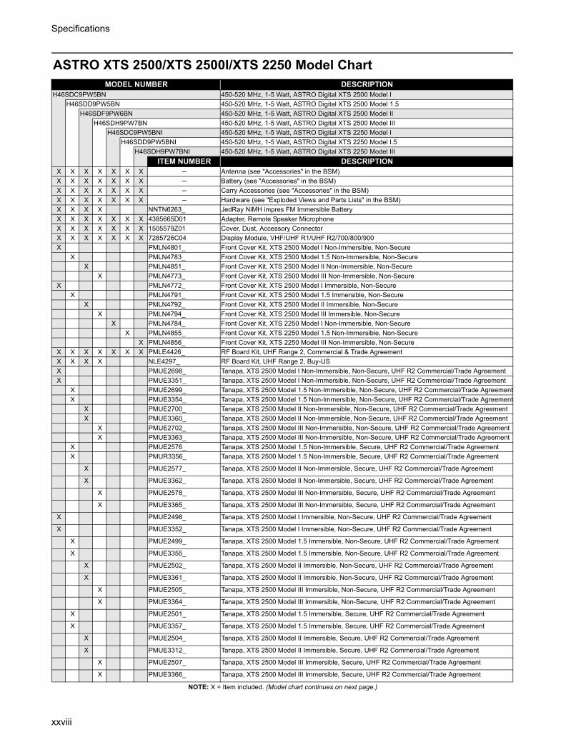
Specifications
xxviii
ASTRO XTS 2500/XTS 2500I/XTS 2250 Model Chart
NOTE: X = Item included. (Model chart continues on next page.)
MODEL NUMBER DESCRIPTIONH46SDC9PW5BN 450-520 MHz, 1-5 Watt, ASTRO Digital XTS 2500 Model I
H46SDD9PW5BN 450-520 MHz, 1-5 Watt, ASTRO Digital XTS 2500 Model 1.5H46SDF9PW6BN 450-520 MHz, 1-5 Watt, ASTRO Digital XTS 2500 Model II
H46SDH9PW7BN 450-520 MHz, 1-5 Watt, ASTRO Digital XTS 2500 Model IIIH46SDC9PW5BNI 450-520 MHz, 1-5 Watt, ASTRO Digital XTS 2250 Model I
H46SDD9PW5BNI 450-520 MHz, 1-5 Watt, ASTRO Digital XTS 2250 Model I.5H46SDH9PW7BNI 450-520 MHz, 1-5 Watt, ASTRO Digital XTS 2250 Model III
ITEM NUMBER DESCRIPTIONX X X X X X X – Antenna (see "Accessories" in the BSM)X X X X X X X – Battery (see "Accessories" in the BSM)X X X X X X X – Carry Accessories (see "Accessories" in the BSM)X X X X X X X – Hardware (see "Exploded Views and Parts Lists" in the BSM)X X X X NNTN6263_ JedRay NiMH impres FM Immersible BatteryX X X X X X X 4385665D01 Adapter, Remote Speaker MicrophoneX X X X X X X 1505579Z01 Cover, Dust, Accessory Connector X X X X X X X 7285726C04 Display Module, VHF/UHF R1/UHF R2/700/800/900X PMLN4801_ Front Cover Kit, XTS 2500 Model I Non-Immersible, Non-Secure
X PMLN4783_ Front Cover Kit, XTS 2500 Model 1.5 Non-Immersible, Non-SecureX PMLN4851_ Front Cover Kit, XTS 2500 Model II Non-Immersible, Non-Secure
X PMLN4773_ Front Cover Kit, XTS 2500 Model III Non-Immersible, Non-SecureX PMLN4772_ Front Cover Kit, XTS 2500 Model I Immersible, Non-Secure
X PMLN4791_ Front Cover Kit, XTS 2500 Model 1.5 Immersible, Non-SecureX PMLN4792_ Front Cover Kit, XTS 2500 Model II Immersible, Non-Secure
X PMLN4794_ Front Cover Kit, XTS 2500 Model III Immersible, Non-SecureX PMLN4784_ Front Cover Kit, XTS 2250 Model I Non-Immersible, Non-Secure
X PMLN4855_ Front Cover Kit, XTS 2250 Model 1.5 Non-Immersible, Non-SecureX PMLN4856_ Front Cover Kit, XTS 2250 Model III Non-Immersible, Non-Secure
X X X X X X X PMLE4426_ RF Board Kit, UHF Range 2, Commercial & Trade AgreementX X X X NLE4297_ RF Board Kit, UHF Range 2, Buy-USX PMUE2698_ Tanapa, XTS 2500 Model I Non-Immersible, Non-Secure, UHF R2 Commercial/Trade AgreementX PMUE3351_ Tanapa, XTS 2500 Model I Non-Immersible, Non-Secure, UHF R2 Commercial/Trade Agreement
X PMUE2699_ Tanapa, XTS 2500 Model 1.5 Non-Immersible, Non-Secure, UHF R2 Commercial/Trade AgreementX PMUE3354_ Tanapa, XTS 2500 Model 1.5 Non-Immersible, Non-Secure, UHF R2 Commercial/Trade Agreement
X PMUE2700_ Tanapa, XTS 2500 Model II Non-Immersible, Non-Secure, UHF R2 Commercial/Trade AgreementX PMUE3360_ Tanapa, XTS 2500 Model II Non-Immersible, Non-Secure, UHF R2 Commercial/Trade Agreement
X PMUE2702_ Tanapa, XTS 2500 Model III Non-Immersible, Non-Secure, UHF R2 Commercial/Trade AgreementX PMUE3363_ Tanapa, XTS 2500 Model III Non-Immersible, Non-Secure, UHF R2 Commercial/Trade Agreement
X PMUE2576_ Tanapa, XTS 2500 Model 1.5 Non-Immersible, Secure, UHF R2 Commercial/Trade AgreementX PMUR3356_ Tanapa, XTS 2500 Model 1.5 Non-Immersible, Secure, UHF R2 Commercial/Trade Agreement
X PMUE2577_ Tanapa, XTS 2500 Model II Non-Immersible, Secure, UHF R2 Commercial/Trade Agreement
X PMUE3362_ Tanapa, XTS 2500 Model II Non-Immersible, Secure, UHF R2 Commercial/Trade Agreement
X PMUE2578_ Tanapa, XTS 2500 Model III Non-Immersible, Secure, UHF R2 Commercial/Trade Agreement
X PMUE3365_ Tanapa, XTS 2500 Model III Non-Immersible, Secure, UHF R2 Commercial/Trade Agreement
X PMUE2498_ Tanapa, XTS 2500 Model I Immersible, Non-Secure, UHF R2 Commercial/Trade Agreement
X PMUE3352_ Tanapa, XTS 2500 Model I Immersible, Non-Secure, UHF R2 Commercial/Trade Agreement
X PMUE2499_ Tanapa, XTS 2500 Model 1.5 Immersible, Non-Secure, UHF R2 Commercial/Trade Agreement
X PMUE3355_ Tanapa, XTS 2500 Model 1.5 Immersible, Non-Secure, UHF R2 Commercial/Trade Agreement
X PMUE2502_ Tanapa, XTS 2500 Model II Immersible, Non-Secure, UHF R2 Commercial/Trade Agreement
X PMUE3361_ Tanapa, XTS 2500 Model II Immersible, Non-Secure, UHF R2 Commercial/Trade Agreement
X PMUE2505_ Tanapa, XTS 2500 Model III Immersible, Non-Secure, UHF R2 Commercial/Trade Agreement
X PMUE3364_ Tanapa, XTS 2500 Model III Immersible, Non-Secure, UHF R2 Commercial/Trade Agreement
X PMUE2501_ Tanapa, XTS 2500 Model 1.5 Immersible, Secure, UHF R2 Commercial/Trade Agreement
X PMUE3357_ Tanapa, XTS 2500 Model 1.5 Immersible, Secure, UHF R2 Commercial/Trade Agreement
X PMUE2504_ Tanapa, XTS 2500 Model II Immersible, Secure, UHF R2 Commercial/Trade Agreement
X PMUE3312_ Tanapa, XTS 2500 Model II Immersible, Secure, UHF R2 Commercial/Trade Agreement
X PMUE2507_ Tanapa, XTS 2500 Model III Immersible, Secure, UHF R2 Commercial/Trade Agreement
X PMUE3366_ Tanapa, XTS 2500 Model III Immersible, Secure, UHF R2 Commercial/Trade Agreement

Specifications
xxix
ASTRO XTS 2500/XTS 2500I/XTS 2250 Model Chart (continued)
NOTE: X = Item included.
MODEL NUMBER DESCRIPTIONH46SDC9PW5BN 450-520 MHz, 1-5 Watt, ASTRO Digital XTS 2500 Model I
H46SDD9PW5BN 450-520 MHz, 1-5 Watt, ASTRO Digital XTS 2500 Model 1.5H46SDF9PW6BN 450-520 MHz, 1-5 Watt, ASTRO Digital XTS 2500 Model II
H46SDH9PW7BN 450-520 MHz, 1-5 Watt, ASTRO Digital XTS 2500 Model IIIH46SDC9PW5BNI 450-520 MHz, 1-5 Watt, ASTRO Digital XTS 2250 Model I
H46SDD9PW5BNI 450-520 MHz, 1-5 Watt, ASTRO Digital XTS 2250 Model I.5H46SDH9PW7BNI 450-520 MHz, 1-5 Watt, ASTRO Digital XTS 2250 Model III
ITEM NUMBER DESCRIPTIONX NUE3607_ Tanapa, XTS 2500 Model I Non-Immersible, Non-Secure, UHF R2 Buy-US
X NUE3602_ Tanapa, XTS 2500 Model 1.5 Non-Immersible, Non-Secure, UHF R2 Buy-USX NUE3603_ Tanapa, XTS 2500 Model II Non-Immersible, Non-Secure, UHF R2 Buy-US
X NUE3605_ Tanapa, XTS 2500 Model III Non-Immersible, Non-Secure, UHF R2 Buy-USX NUE3601_ Tanapa, XTS 2500 Model 1.5 Non-Immersible, Secure, UHF R2 Buy-US
X NUE3604_ Tanapa, XTS 2500 Model II Non-Immersible, Secure, UHF R2 Buy-USX NUE3606_ Tanapa, XTS 2500 Model III Non-Immersible, Secure, UHF R2 Buy-US
X NUE3592_ Tanapa, XTS 2500 Model I Immersible, Non-Secure, UHF R2 Buy-USX NUE3591_ Tanapa, XTS 2500 Model 1.5 Immersible, Non-Secure, UHF R2 Buy-US
X NUE3588_ Tanapa, XTS 2500 Model II Immersible, Non-Secure, UHF R2 Buy-USX NUE3585_ Tanapa, XTS 2500 Model III Immersible, Non-Secure, UHF R2 Buy-US
X NUE3589_ Tanapa, XTS 2500 Model 1.5 Immersible, Secure, UHF R2 Buy-USX NUE3583_ Tanapa, XTS 2500 Model II Immersible, Secure, UHF R2 Buy-US
X NUE3575_ Tanapa, XTS 2500 Model III Immersible, Secure, UHF R2 Buy-USX PMUE2701_ Tanapa, XTS 2250 Model I Non-Immersible, Non-Secure, UHF R2X PMUE3353_ Tanapa, XTS 2250 Model I Non-Immersible, Non-Secure, UHF R2
X PMUE2703_ Tanapa, XTS 2250 Model 1.5 Non-Immersible, Non-Secure, UHF R2X PMUE3358_ Tanapa, XTS 2250 Model 1.5 Non-Immersible, Non-Secure, UHF R2
X PMUE2704_ Tanapa, XTS 2250 Model III Non-Immersible, Non-Secure, UHF R2X PMUE3311_ Tanapa, XTS 2250 Model III Non-Immersible, Non-Secure, UHF R2
X PMUE2508_ Tanapa, XTS 2250 Model 1.5 Non-Immersible, Secure, UHF R2X PMUE3359_ Tanapa, XTS 2250 Model 1.5 Non-Immersible, Secure, UHF R2
X PMUE2509_ Tanapa, XTS 2250 Model III Non-Immersible, Secure, UHF R2X PMUE3313_ Tanapa, XTS 2250 Model III Non-Immersible, Secure, UHF R2
X X X X 3316369H01 Nameplate, XTS 2500, Model I/1.5/II/III, Non-ImmersibleX X X X 3316369H06 Nameplate, XTS 2500I, Model I/1.5/II/III, Immersible
X X X 3316369H02 Nameplate, XTS 2250, Model I/1.5/III, Non-ImmersibleX X PMLN4924_ ASSY,PCB,MN,SECURE BRD M1.5 AESX X PMLN4925_ ASSY,PCB,MN,SECURE BRD M1.5 DES,DES-XL,DES-OFBX X PMLN4926_ ASSY,PCB,MN,SECURE BRD M1.5 ADP
X PMLN4927_ ASSY,PCB,MN,SECURE BRD M2 AESX PMLN4928_ ASSY,PCB,MN,SECURE BRD M2 DES,DES-XL,DES-OFBX PMLN4929_ ASSY,PCB,MN,SECURE BRD M2 ADP
X X PMLN4930_ ASSY,PCB,MN,SECURE BRD M3 AESX X PMLN4931_ ASSY,PCB,MN,SECURE BRD M3 DES,DES-XL,DES-OFBX X PMLN4932_ ASSY,PCB,MN,SECURE BRD M3 ADP
X 6871190L01 User's Guide, XTS 2250 Model I X 6871201L01 User's Guide, XTS 2250 Model 1.5
X 6871202L01 User's Guide, XTS 2250 Model IIIX X X X PMLN4940_ User's Guide CD, XTS 2500 Model I, 1.5, II, IIIX X X X PMLN4940_ User's Guide CD, XTS 2500I Model I, 1.5, II, III
X X X PMLN4940_ User's Guide CD, XTS 2250 Model I, 1.5, III

Specifications
xxx
ASTRO XTS 1500/MT 1500 Model Chart
NOTE: X = Item included.
MODEL NUMBER DESCRIPTIONH66SDC9PW5BN 450-520 MHz, 1-5 Watt, ASTRO Digital XTS 1500 Model I
H66SDD9PW5BN 450-520 MHz, 1-5 Watt, ASTRO Digital XTS 1500 Model 1.5H67SDC9PW5BN 450-520 MHz, 1-5 Watt, ASTRO Analog MT 1500 Model I
H67SDD9PW5BN 450-520 MHz, 1-5 Watt, ASTRO Analog MT 1500 Model 1.5ITEM NUMBER DESCRIPTION
X X X X – Antenna (see "Accessories" in the BSM)X X X X – Battery (see "Accessories" in the BSM)X X X X – Carry Accessories (see "Accessories" in the BSM)X X X X – Hardware (see "Exploded Views and Parts Lists" in the BSM)X X X X 4385665D01 Adapter, Remote Speaker MicrophoneX X X X 1585746D04 Cover, Dust, Accessory Connector
X X 7285726C04 Display Module, VHF/UHF R1/UHF R2/700/800/900X PMLN4915_ Front Cover Kit, XTS 1500 Model I Non-Immersible, Non-Secure
X PMLN4900_ Front Cover Kit, XTS 1500 Model 1.5 Non-Immersible, Non-SecureX PMLN4916_ Front Cover Kit, MT 1500 Model I Non-Immersible, Non-Secure
X PMLN4901_ Front Cover Kit, MT 1500 Model 1.5 Non-Immersible, Non-SecureX X X X PMLE4426_ RF Board Kit, UHF Range 2X PMUE2705_ Tanapa, XTS 1500 Model I Non-Immersible, Non-Secure, UHF R2, 9600 Digital,
TrunkedX PMUE2700_ Tanapa, XTS 1500 Model I Non-Immersible, Non-Secure, UHF R2, 3600 Analog/
Digital, TrunkedX PMUE2707_ Tanapa, XTS 1500 Model I Non-Immersible, Non-Secure, UHF R2, P25 Conventional
X PMUE2568_ Tanapa, XTS 1500 Model 1.5 Non-Immersible, Non-Secure, UHF R2, 9600 Digital, Trunked
X PMUE2569_ Tanapa, XTS 1500 Model 1.5 Non-Immersible, Non-Secure, UHF R2, 3600 Analog/Digital, Trunked
X PMUE2570_ Tanapa, XTS 1500 Model 1.5 Non-Immersible, Non-Secure, UHF R2, P25 Conventional
X PMUE2708_ Tanapa, MT 1500 Model I Non-Immersible, Non-Secure, UHF R2, Analog, Conventional
X PMUE2709_ Tanapa, MT 1500 Model I Non-Immersible, Non-Secure, UHF R2, 3600 AnalogX PMUE2571_ Tanapa, MT 1500 Model 1.5 Non-Immersible, Non-Secure, UHF R2, Analog,
ConventionalX PMUE2572_ Tanapa, MT 1500 Model 1.5 Non-Immersible, Non-Secure, UHF R2, 3600 Analog
X X 3316369H03 Nameplate, XTS 1500, Model I/1.5, Non-ImmersibleX X 3316369H04 Nameplate, MT 1500, Model I/1.5, Non-Immersible
X X X X PMLN4940_ User's Guide CD, XTS 1500 and MT 1500 Model I, 1.5

Specifications
xxxi
PR 1500 Model Chart
NOTE: X = Item included.
MODEL NUMBER DESCRIPTIONAAH79KDC9PW5BN 136-174 MHz, 1-5 Watt, PR 1500 Model I
AAH79QDC9PW5BN 380-470 MHz, 1-5 Watt, PR 1500 Model IAAH79SDC9PW5BN 450-520 MHz, 1-5 Watt, PR 1500 Model I
ITEM NUMBER DESCRIPTIONX X X – Antenna (see "Accessories" in the BSM)X X X – Battery (see "Accessories" in the BSM)X X X – Carry Accessories (see "Accessories" in the BSM)X X X – Hardware (see "Exploded Views and Parts Lists" in the BSM)X X X 4385665D01 Adapter, Remote Speaker MicrophoneX X X 1585746D04 Cover, Dust, Accessory Connector X X X PMLN4902_ Front Cover Kit, PR 1500 Model I Non-Immersible, Non-SecureX PMLD4303_ RF Board Kit, VHF
X PMLE4425_ RF Board Kit, UHF Range 1X PMLE4426_ RF Board Kit, UHF Range 2
X PMUD2211_ Tanapa, PR 1500 Model I Non-Immersible, Non-Secure, VHF, Analog, ConventionalX PMUE4449_ Tanapa, PR 1500 Model I Non-Immersible, Non-Secure, UHF R1, Analog,
ConventionalX PMUE2710_ Tanapa, PR 1500 Model I Non-Immersible, Non-Secure, UHF R2, Analog,
ConventionalX X X 3316369H05 Nameplate, PR 1500, Model I, Non-ImmersibleX X X PMLN4943_ User's Guide CD, PR 1500 Model I

Specifications
xxxii
Specifications for 700 MHz/800 MHz RadiosAll specifications are per Telecommunications Industries Association TIA-603 unless otherwise noted
GENERAL RECEIVER TRANSMITTER
FCC ID:700/800 MHz: AZ489FT5804
Temperature Range:Operating: -30°C to +60°CStorage: -40°C to +85°C
Power Supply: Nickel-Cadmium Battery (NiCd)or Nickel-Metal-Hydride Battery (NiMH)
Battery VoltageNominal: 7.5 VoltsRange: 6 to 9 Volts
Transmit Current Drain (Typical): 1250mAReceive Current Drain (Rated Audio): 220mAStandby Current Drain: 70mA
Recommended Battery:High-Capacity NiCd: NTN9815or Ultra-High-Capacity NiMH: NTN9858or High-Capacity NiCd FM: NTN9816*or Ultra–High-Capacity NiMH FM: NTN9857*or Ultra–High-Cap. NiMH Imrsble: NNTN6263*Optional FM (Factory Mutual) Battery:* FM Intrinsically Safe: Class I, II, III
Dimensions Height x Width x DepthRadio Less Battery: 6.0" x 2.3" x 1.5"With NiCd Ultra-High Cap.: 6.0" x 2.3" x 2.0"With NiMH Ultra-High Cap.: 6.0" x 2.3" x 2.0"
WeightRadio Less Battery: 11.0 oz.With NiCd Ultra-High Capacity: 20.0 oz.With NiMH Ultra-High Capacity: 20.5 oz.
Frequency Range:700 MHz: 764 to 767; 773 to 776 MHz800 MHz: 851 to 870 MHz
Quieting Sensitivity (typical) (20dBQ): 0.23µV
Usable Sensitivity (typical)(12dB SINAD): 0.25µV
Intermodulation (typical): -74dB
Selectivity (typical)(25kHz Channel): -72dB (12.5kHz Channel): -63dB
Spurious Rejection (typical): -75dB
Frequency Stability(–30+60°C; 25°C reference): 1.5ppm
Rated Audio: 500mW
FM Hum and Noise (typical)(25kHz channel): -47dB(12.5kHz channel): -40dB
Distortion (At Rated Audio; typical): 2.5%
Channel Spacing: 12.5/20/25 kHz
RF Power 806 - 870 MHz: 3 Watts764 - 806 MHz: 2.5 Watts
Frequency Range:700 MHz: 764 to 767; 773 to 776; 794 to 797;
803 to 806 MHz800 MHz: 806 to 824; 851 to 870 MHz
Frequency Stability (typical)(–30 to +60°C; 25°C ref.): 1.5ppm
Emission (typical conducted): -75dBc<1GHz
FM Hum and Noise (typical)(25 kHz channel): -43dB(12.5 kHz channel): -40dB
Distortion (typical): 2%
Modulation Limiting: 25 kHz chnls ±5.0kHz20 kHz chnls ±4.0kHz 12.5 kHz chnls ±2.5kHz
Emissions Designators: 16K0F3E,11K0F3E, 8K10F1D, and 8K10F1E
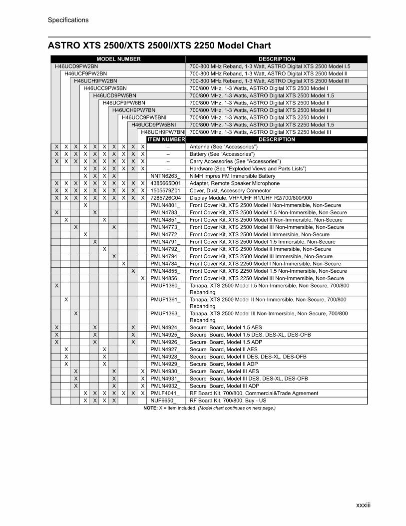
Specifications
xxxiii
ASTRO XTS 2500/XTS 2500I/XTS 2250 Model Chart
NOTE: X = Item included. (Model chart continues on next page.)
MODEL NUMBER DESCRIPTIONH46UCD9PW2BN 700-800 MHz Reband, 1-3 Watt, ASTRO Digital XTS 2500 Model I.5
H46UCF9PW2BN 700-800 MHz Reband, 1-3 Watt, ASTRO Digital XTS 2500 Model IIH46UCH9PW2BN 700-800 MHz Reband, 1-3 Watt, ASTRO Digital XTS 2500 Model III
H46UCC9PW5BN 700/800 MHz, 1-3 Watts, ASTRO Digital XTS 2500 Model IH46UCD9PW5BN 700/800 MHz, 1-3 Watts, ASTRO Digital XTS 2500 Model 1.5
H46UCF9PW6BN 700/800 MHz, 1-3 Watts, ASTRO Digital XTS 2500 Model IIH46UCH9PW7BN 700/800 MHz, 1-3 Watts, ASTRO Digital XTS 2500 Model III
H46UCC9PW5BNI 700/800 MHz, 1-3 Watts, ASTRO Digital XTS 2250 Model IH46UCD9PW5BNI 700/800 MHz, 1-3 Watts, ASTRO Digital XTS 2250 Model 1.5
H46UCH9PW7BNI 700/800 MHz, 1-3 Watts, ASTRO Digital XTS 2250 Model IIIITEM NUMBER DESCRIPTION
X X X X X X X X X X – Antenna (See “Accessories”)X X X X X X X X X X – Battery (See “Accessories”)X X X X X X X X X X – Carry Accessories (See “Accessories”)
X X X X X X X – Hardware (See “Exploded Views and Parts Lists”)X X X X NNTN6263_ NiMH impres FM Immersible Battery
X X X X X X X X X X 4385665D01 Adapter, Remote Speaker MicrophoneX X X X X X X X X X 1505579Z01 Cover, Dust, Accessory ConnectorX X X X X X X X X X 7285726C04 Display Module, VHF/UHF R1/UHF R2/700/800/900
X PMLN4801_ Front Cover Kit, XTS 2500 Model I Non-Immersible, Non-SecureX X PMLN4783_ Front Cover Kit, XTS 2500 Model 1.5 Non-Immersible, Non-Secure
X X PMLN4851_ Front Cover Kit, XTS 2500 Model II Non-Immersible, Non-SecureX X PMLN4773_ Front Cover Kit, XTS 2500 Model III Non-Immersible, Non-Secure
X PMLN4772_ Front Cover Kit, XTS 2500 Model I Immersible, Non-SecureX PMLN4791_ Front Cover Kit, XTS 2500 Model 1.5 Immersible, Non-Secure
X PMLN4792_ Front Cover Kit, XTS 2500 Model II Immersible, Non-Secure X PMLN4794_ Front Cover Kit, XTS 2500 Model III Immersible, Non-Secure
X PMLN4784_ Front Cover Kit, XTS 2250 Model I Non-Immersible, Non-SecureX PMLN4855_ Front Cover Kit, XTS 2250 Model 1.5 Non-Immersible, Non-Secure
X PMLN4856_ Front Cover Kit, XTS 2250 Model III Non-Immersible, Non-SecureX PMUF1360_ Tanapa, XTS 2500 Model I.5 Non-Immersible, Non-Secure, 700/800
RebandingX PMUF1361_ Tanapa, XTS 2500 Model II Non-Immersible, Non-Secure, 700/800
RebandingX PMUF1363_ Tanapa, XTS 2500 Model III Non-Immersible, Non-Secure, 700/800
RebandingX X X PMLN4924_ Secure Board, Model 1.5 AESX X X PMLN4925_ Secure Board, Model 1.5 DES, DES-XL, DES-OFBX X X PMLN4926_ Secure Board, Model 1.5 ADP
X X PMLN4927_ Secure Board, Model II AESX X PMLN4928_ Secure Board, Model II DES, DES-XL, DES-OFBX X PMLN4929_ Secure Board, Model II ADP
X X X PMLN4930_ Secure Board, Model III AESX X X PMLN4931_ Secure Board, Model III DES, DES-XL, DES-OFBX X X PMLN4932_ Secure Board, Model III ADP
X X X X X X X PMLF4041_ RF Board Kit, 700/800, Commercial&Trade AgreementX X X X NUF6650_ RF Board Kit, 700/800, Buy - US
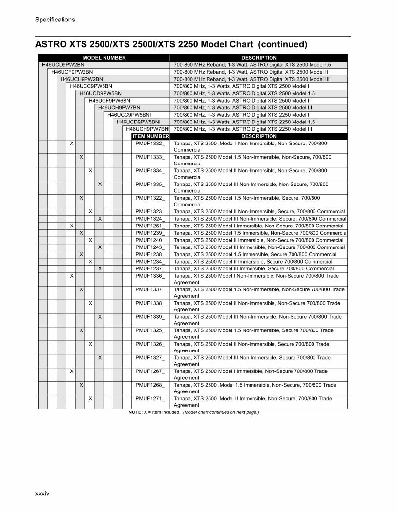
Specifications
xxxiv
ASTRO XTS 2500/XTS 2500I/XTS 2250 Model Chart (continued)
NOTE: X = Item included. (Model chart continues on next page.)
MODEL NUMBER DESCRIPTIONH46UCD9PW2BN 700-800 MHz Reband, 1-3 Watt, ASTRO Digital XTS 2500 Model I.5
H46UCF9PW2BN 700-800 MHz Reband, 1-3 Watt, ASTRO Digital XTS 2500 Model IIH46UCH9PW2BN 700-800 MHz Reband, 1-3 Watt, ASTRO Digital XTS 2500 Model III
H46UCC9PW5BN 700/800 MHz, 1-3 Watts, ASTRO Digital XTS 2500 Model IH46UCD9PW5BN 700/800 MHz, 1-3 Watts, ASTRO Digital XTS 2500 Model 1.5
H46UCF9PW6BN 700/800 MHz, 1-3 Watts, ASTRO Digital XTS 2500 Model IIH46UCH9PW7BN 700/800 MHz, 1-3 Watts, ASTRO Digital XTS 2500 Model III
H46UCC9PW5BNI 700/800 MHz, 1-3 Watts, ASTRO Digital XTS 2250 Model IH46UCD9PW5BNI 700/800 MHz, 1-3 Watts, ASTRO Digital XTS 2250 Model 1.5
H46UCH9PW7BNI 700/800 MHz, 1-3 Watts, ASTRO Digital XTS 2250 Model IIIITEM NUMBER DESCRIPTION
X PMUF1332_ Tanapa, XTS 2500 ,Model I Non-Immersible, Non-Secure, 700/800 Commercial
X PMUF1333_ Tanapa, XTS 2500 Model 1.5 Non-Immersible, Non-Secure, 700/800 Commercial
X PMUF1334_ Tanapa, XTS 2500 Model II Non-Immersible, Non-Secure, 700/800 Commercial
X PMUF1335_ Tanapa, XTS 2500 Model III Non-Immersible, Non-Secure, 700/800 Commercial
X PMUF1322_ Tanapa, XTS 2500 Model 1.5 Non-Immersible, Secure, 700/800 Commercial
X PMUF1323_ Tanapa, XTS 2500 Model II Non-Immersible, Secure, 700/800 CommercialX PMUF1324_ Tanapa, XTS 2500 Model III Non-Immersible, Secure, 700/800 Commercial
X PMUF1251_ Tanapa, XTS 2500 Model I Immersible, Non-Secure, 700/800 CommercialX PMUF1239_ Tanapa, XTS 2500 Model 1.5 Immersible, Non-Secure 700/800 Commercial
X PMUF1240_ Tanapa, XTS 2500 Model II Immersible, Non-Secure 700/800 CommercialX PMUF1243_ Tanapa, XTS 2500 Model III Immersible, Non-Secure 700/800 Commercial
X PMUF1238_ Tanapa, XTS 2500 Model 1.5 Immersible, Secure 700/800 CommercialX PMUF1234_ Tanapa, XTS 2500 Model II Immersible, Secure 700/800 Commercial
X PMUF1237_ Tanapa, XTS 2500 Model III Immersible, Secure 700/800 CommercialX PMUF1336_ Tanapa, XTS 2500 Model I Non-Immersible, Non-Secure 700/800 Trade
AgreementX PMUF1337_ Tanapa, XTS 2500 Model 1.5 Non-Immersible, Non-Secure 700/800 Trade
AgreementX PMUF1338_ Tanapa, XTS 2500 Model II Non-Immersible, Non-Secure 700/800 Trade
AgreementX PMUF1339_ Tanapa, XTS 2500 Model III Non-Immersible, Non-Secure 700/800 Trade
AgreementX PMUF1325_ Tanapa, XTS 2500 Model 1.5 Non-Immersible, Secure 700/800 Trade
AgreementX PMUF1326_ Tanapa, XTS 2500 Model II Non-Immersible, Secure 700/800 Trade
AgreementX PMUF1327_ Tanapa, XTS 2500 Model III Non-Immersible, Secure 700/800 Trade
AgreementX PMUF1267_ Tanapa, XTS 2500 Model I Immersible, Non-Secure 700/800 Trade
AgreementX PMUF1268_ Tanapa, XTS 2500 ,Model 1.5 Immersible, Non-Secure, 700/800 Trade
AgreementX PMUF1271_ Tanapa, XTS 2500 ,Model II Immersible, Non-Secure, 700/800 Trade
Agreement

Specifications
xxxv
ASTRO XTS 2500/XTS 2500I/XTS 2250 Model Chart (continued)
NOTE: X = Item included.
MODEL NUMBER DESCRIPTIONH46UCD9PW2BN 700-800 MHz Reband, 1-3 Watt, ASTRO Digital XTS 2500 Model I.5
H46UCF9PW2BN 700-800 MHz Reband, 1-3 Watt, ASTRO Digital XTS 2500 Model IIH46UCH9PW2BN 700-800 MHz Reband, 1-3 Watt, ASTRO Digital XTS 2500 Model III
H46UCC9PW5BN 700/800 MHz, 1-3 Watts, ASTRO Digital XTS 2500 Model IH46UCD9PW5BN 700/800 MHz, 1-3 Watts, ASTRO Digital XTS 2500 Model 1.5
H46UCF9PW6BN 700/800 MHz, 1-3 Watts, ASTRO Digital XTS 2500 Model IIH46UCH9PW7BN 700/800 MHz, 1-3 Watts, ASTRO Digital XTS 2500 Model III
H46UCC9PW5BNI 700/800 MHz, 1-3 Watts, ASTRO Digital XTS 2250 Model IH46UCD9PW5BNI 700/800 MHz, 1-3 Watts, ASTRO Digital XTS 2250 Model 1.5
H46UCH9PW7BNI 700/800 MHz, 1-3 Watts, ASTRO Digital XTS 2250 Model IIIITEM NUMBER DESCRIPTION
X PMUF1274_ Tanapa, XTS 2500 ,Model III Immersible, Non-Secure, 700/800 Trade Agreement
X PMUF1270_ Tanapa, XTS 2500 ,Model 1.5 Immersible, Secure, 700/800 Trade Agreement
X PMUF1273_ Tanapa, XTS 2500 ,Model II Immersible, Secure, 700/800 Trade AgreementX PMUF1276_ Tanapa, XTS 2500 ,Model III Immersible, Secure, 700/800 Trade
AgreementX NWF1213_ Tanapa, XTS 2500 ,Model I Non-Immersible, Non-Secure, 700/800 Buy-US
X NWF1124_ Tanapa, XTS 2500 ,Model 1.5 Non-Immersible, Non-Secure, 700/800 Buy-US
X NWF1214_ Tanapa, XTS 2500 ,Model II Non-Immersible, Non-Secure, 700/800 Buy-USX NWF1216_ Tanapa, XTS 2500 ,Model III Non-Immersible, Non-Secure, 700/800 Buy-
USX NFW1125_ Tanapa, XTS 2500 ,Model 1.5 Non-Immersible, Secure, 700/800 Buy-US
X NFW1215_ Tanapa, XTS 2500 ,Model II Non-Immersible, Secure, 700/800 Buy-USX NFW1129_ Tanapa, XTS 2500 ,Model III Non-Immersible, Secure, 700/800 Buy-US
X NFW1136_ Tanapa, XTS 2500 ,Model I Immersible, Non-Secure, 700/800 Buy-USX NFW1144_ Tanapa, XTS 2500 ,Model 1.5 Immersible, Non-Secure, 700/800 Buy-US
X NFW1138_ Tanapa, XTS 2500 ,Model II Immersible, Non-Secure, 700/800 Buy-USX NFW1140_ Tanapa, XTS 2500 ,Model III Immersible, Non-Secure, 700/800 Buy-US
X NFW1142_ Tanapa, XTS 2500 ,Model 1.5 Immersible, Secure, 700/800 Buy-USX NFW1139_ Tanapa, XTS 2500 ,Model II Immersible, Secure, 700/800 Buy-US
X NFW1141_ Tanapa, XTS 2500 ,Model III Immersible, Secure, 700/800 Buy-USX PMUF1340_ Tanapa, XTS 2250 ,Model I Non-Immersible, Non-Secure, 700/800
X PMUF1341_ Tanapa, XTS 2250 ,Model 1.5 Non-Immersible, Non-Secure, 700/800X PMUF1342_ Tanapa, XTS 2250 ,Model III Non-Immersible, Non-Secure, 700/800
X PMUF1277_ Tanapa, XTS 2250 ,Model 1.5 Non-Immersible, Secure, 700/800X PMUF1278_ Tanapa, XTS 2250 ,Model I Non-Immersible, Secure, 700/800
X X X X X X X 3316369H01 Nameplate, XTS 2500, Model I/1.5/II/III, Non-ImmersibleX X X X X X X 3316369H06 Nameplate, XTS 2500I, Model I/1.5/II/III, Immersible
X X X 3316369H02 Nameplate, XTS 2250, Model I/1.5/III, Non-ImmersibleX PMLN4940_ User’s Guide, XTS 2500 Model I
X X PMLN4940_ User’s Guide, XTS 2500 Model 1.5X X PMLN4940_ User’s Guide, XTS 2500 Model II
X X PMLN4940_ User’s Guide, XTS 2500 Model IIIX PMLN4942_ User’s Guide, XTS 2250 Model 1.5
X PMLN4942_ User’s Guide, XTS 2250 Model IIIX PMLN4940_ User’s Guide, XTS 2500I Model I
X PMLN4940_ User’s Guide, XTS 2500I Model 1.5X PMLN4940_ User’s Guide, XTS 2500I Model II
X PMLN4940_ User’s Guide, XTS 2500I Model IIIX X X X PMLN4940_ User’s Guide CD, XTS 2500/2500I Model I,1.5,II,III
X X X X X PMLN4942_ User’s Guide CD, XTS 2250 Model I,1.5,III

Specifications
xxxvi
ASTRO XTS 1500/MT 1500 Model Chart
NOTE: X = Item included
MODEL NUMBER DESCRIPTIONH66UCC9PW2BN 700/800 MHz Reband, 1-3 Watt, ASTRO Digital XTS 1500 Model I
H66UCC9PW5BN 700/800 MHz, 1-3 Watts, ASTRO Digital XTS 1500 Model IH66UCD9PW5BN 700/800 MHz, 1-3 Watts, ASTRO Digital XTS 1500 Model 1.5
H67UCC9PW5BN 700/800 MHz, 1-3 Watts, ASTRO Analog MT 1500 Model IH67UCD9PW5BN 700/800 MHz, 1-3 Watts, ASTRO Analog MT 1500 Model 1.5
ITEM NUMBER DESCRIPTIONX X X X X – Antenna (See “Accessories”)X X X X X – Battery (See “Accessories”)X X X X X – Carry Accessories (See “Accessories”)X X X X X – Hardware (See “Exploded Views and Parts Lists”)X X X X X 4385665D01 Adapter, Remote Speaker MicrophoneX X X X X 1585746D04 Cover, Dust, Accessory Connector
X X 7285726C04 Display Module, VHF/UHF R1/UHF R2/700/800/900X X PMLN4915_ Front Cover Kit, XTS 1500 Model I Non-Immersible, Non-Secure
X PMLN4900_ Front Cover Kit, XTS 1500 Model 1.5 Non-Immersible, Non-SecureX PMLN4916_ Front Cover Kit, MT 1500 Model I Non-Immersible, Non-Secure
X PMLN4901_ Front Cover Kit, MT 1500 Model 1.5 Non-Immersible, Non-SecureX PMUF1365_ Tanapa, XTS 1500 Model I Non-Immersible, Non-Secure, 700/800, Digital RBX PMUF1366_ Tanapa, XTS 1500 Model I Non-Immersible, Non-Secure, 700/800, Analog RB
X PMUF1343_ Tanapa, XTS 1500 Model I Non-Immersible, Non-Secure, 700/800 Digital, Trunked X PMUF1344_ Tanapa, XTS 1500 Model I Non-Immersible, Non-Secure, 700/800, 3600 Analog/Digital, Trunked X PMUF1345_ Tanapa, XTS 1500 Model I Non-Immersible, Non-Secure, 700/800, P25 Conventional
X PMUF1317_ Tanapa, XTS 1500 Model 1.5 Non-Immersible, Non-Secure, 700/800, 9600 Digital, Trunked X PMUF1318_ Tanapa, XTS 1500 Model 1.5 Non-Immersible, Non-Secure, 700/800, 3600 Analog/Digital,
Trunked X PMUF1319_ Tanapa, XTS 1500 Model 1.5 Non-Immersible, Non-Secure, 700/800, P25 Conventional
X PMUF1346_ Tanapa, MT 1500 Model I Non-Immersible, Non-Secure, 700/800, Analog, ConventionalX PMUF1347_ Tanapa, MT 1500 Model I Non-Immersible, Non-Secure, 700/800, 3600 Analog
X PMUF1320_ Tanapa,MT 1500 Model 1.5 Non-Immersible, Non-Secure, 700/800, Analog, ConventionalX PMUF1321_ Tanapa, MT 1500 Model 1.5 Non-Immersible, Non-Secure, 700/800, 3600 Analog
X X X 3316369H03 Nameplate, XTS 1500, Model I/1.5, Non-ImmersibleX X 3316369H04 Nameplate, MT 1500, Model I/1.5 Non-Immersible
X X PMLN4940_ User’s Guide, XTS 1500 Model IX PMLN4940_ User’s Guide, XTS 1500 Model 1.5
X PMLN4940_ User’s Guide, MT 1500 Model IX PMLN4940_ User’s Guide, MT 1500 Model 1.5
X X X X PMLN4940_ User’s Guide CD, XTS 1500 and MT 1500 Model I, 1.5X PMLN4940_ User's Guide CD, XTS 2500 and MT 1500 Model I, 1.5

Specifications
xxxvii
Specifications for 900 MHz RadiosAll specifications are per Telecommunications Industries Association TIA-603 unless otherwise noted
GENERAL RECEIVER TRANSMITTER
FCC ID:900 MHz: AZ489FT5849
Temperature Range:Operating: -30°C to +60°CStorage: -40°C to +85°C
Power Supply: Nickel-Cadmium Battery (NiCd)or Nickel-Metal-Hydride Battery (NiMH)
Battery VoltageNominal: 7.5 VoltsRange: 6 to 9 Volts
Transmit Current Drain (Typical): 1350mAReceive Current Drain (Rated Audio): 220mAStandby Current Drain: 80mA
Recommended Battery:High-Capacity NiCd: NTN9815or Ultra-High-Capacity NiMH: NTN9858or High-Capacity NiCd FM: NTN9816*or Ultra–High-Capacity NiMH FM: NTN9857*Optional FM (Factory Mutual) Battery:* FM Intrinsically Safe: Class I, II, III
Dimensions Height x Width x DepthRadio Less Battery: 6.0" x 2.3" x 1.5"With NiCd Ultra-High Cap.: 6.0" x 2.3" x 2.0"With NiMH Ultra-High Cap.: 6.0" x 2.3" x 2.0"
WeightRadio Less Battery: 11.0 oz.With NiCd Ultra-High Capacity: 20.0 oz.With NiMH Ultra-High Capacity: 20.5 oz.
Frequency Range:900 MHz: 935 to 941 MHz
Quieting Sensitivity (typical) (20dBQ): 0.23µV
Usable Sensitivity (typical)(12dB SINAD): 0.25µV
Intermodulation (typical): -74dB
Selectivity (typical)(12.5kHz Channel): -63dB
Spurious Rejection (typical):–75dB
Frequency Stability(–30+60°C; 25°C reference): 1.5ppm
Rated Audio: 500mW
FM Hum and Noise (typical)(12.5kHz channel): -40dB
Distortion (At Rated Audio; typical): 2.5%
Channel Spacing: 12.5 kHz
RF Power 896 - 902 MHz: 2.5 Watts935 - 941 MHz: 2.5 Watts
Frequency Range:900 MHz: 896 to 902; 935 to 941 MHz
Frequency Stability (typical)(–30 to +60°C; 25°C ref.): 1.5ppm
Emission (typical conducted): -75dBc<1GHz
FM Hum and Noise (typical)(12.5 kHz channel): -40dB
Distortion (typical): 2%
Modulation Limiting: 12.5 kHz chnls ±2.5kHz
Emissions Designators: 16K0F3E,11K0F3E, 8K10F1D, and 8K10F1E
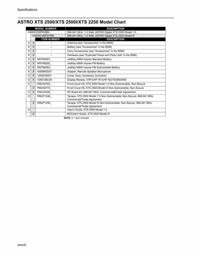
Specifications
xxxviii
ASTRO XTS 2500/XTS 2500I/XTS 2250 Model Chart
NOTE: X = Item included
MODEL NUMBER DESCRIPTIONH46WCD9PW5BN 896-941 MHz, 1-3 Watt, ASTRO Digital XTS 2500 Model 1.5
H46WCH9PW7BN 896-941 MHz, 1-3 Watt, ASTRO Digital XTS 2500 Model lllITEM NUMBER DESCRIPTION
X X – Antenna (see "Accessories" in the BSM)X X – Battery (see "Accessories" in the BSM)X X – Carry Accessories (see "Accessories" in the BSM)X X – Hardware (see "Exploded Views and Parts Lists" in the BSM)X X NNTN6261_ JedRay NiMH impres Standard BatteryX X NNTN6262_ JedRay NiMH impres FM Battery X X NNTN6263_ JedRay NiMH impres FM Submersible BatteryX X 4385665D01 Adapter, Remote Speaker MicrophoneX X 1505579Z01 Cover, Dust, Accessory ConnectorX X 7285726C04 Display Module, VHF/UHF R1/UHF R2/700/800/900X PMLN4783_ Front Cover Kit, XTS 2500 Model 1.5 Non-Submersible, Non-Secure
X PMLN4773_ Front Cover Kit, XTS 2500 Model III Non-Submersible, Non-SecureX X PMLF4036_ RF Board Kit, 896-941 MHz, Commercial&Trade AgreementX PMUF1246_ Tanapa, XTS 2500 Model 1.5 Non-Submersible, Non-Secure, 896-941 MHz
Commercial/Trade AgreementX PMUF1250_ Tanapa, XTS 2500 Model III Non-Submersible, Non-Secure, 896-941 MHz
Commercial/Trade AgreementX User's Guide, XTS 2500 Model 1.5
X MOUser's Guide, XTS 2500 Model III

Specifications
xxxix
ASTRO XTS 1500/MT 1500 Model Chart
NOTE: X = Item included
MODEL NUMBER DESCRIPTIONH66WCD9PW5BN 896-941 MHz, 1-5 Watt, ASTRO Digital XTS 1500 Model 1.5
ITEM NUMBER DESCRIPTIONX – Antenna (see "Accessories" in the BSM)X – Battery (see "Accessories" in the BSM)X – Carry Accessories (see "Accessories" in the BSM)X – Hardware (see "Exploded Views and Parts Lists" in the BSM)X NNTN6261_ JedRay NiMH impres Standard BatteryX NNTN6262_ JedRay NiMH impres FM Battery X 4385665D01 Adapter, Remote Speaker Microphone
1585746D04 Cover, Dust, Accessory Connector7285726C04 Display Module, VHF/UHF R1/UHF R2/700/800/900PMLN4900_ Front Cover Kit, XTS1500 Model 1.5 Non-Submersible, Non-Secure
X PMLF4036_ RF Board Kit, 896-941 MHzPMUF1382_ Tanapa, XTS 1500 Model 1.5 Non-Submersible, Non-Secure, 896-941 MHz

Specifications
xl
Notes
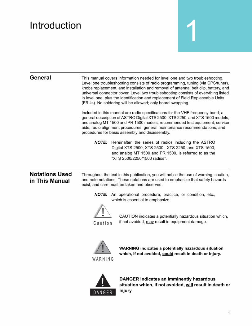
1
Introduction 1General This manual covers information needed for level one and two troubleshooting.
Level one troubleshooting consists of radio programming, tuning (via CPS/tuner), knobs replacement, and installation and removal of antenna, belt clip, battery, and universal connector cover. Level two troubleshooting consists of everything listed in level one, plus the identification and replacement of Field Replaceable Units (FRUs). No soldering will be allowed; only board swapping.
Included in this manual are radio specifications for the VHF frequency band; a general description of ASTRO Digital XTS 2500, XTS 2250, and XTS 1500 models, and analog MT 1500 and PR 1500 models; recommended test equipment; service aids; radio alignment procedures; general maintenance recommendations; and procedures for basic assembly and disassembly.
NOTE: Hereinafter, the series of radios including the ASTRODigital XTS 2500, XTS 2500I, XTS 2250, and XTS 1500,and analog MT 1500 and PR 1500, is referred to as the“XTS 2500/2250/1500 radios”.
Notations Used in This Manual
Throughout the text in this publication, you will notice the use of warning, caution, and note notations. These notations are used to emphasize that safety hazards exist, and care must be taken and observed.
NOTE: An operational procedure, practice, or condition, etc.,which is essential to emphasize.
CAUTION indicates a potentially hazardous situation which, if not avoided, may result in equipment damage. C a u t i o n
WARNING indicates a potentially hazardous situation which, if not avoided, could result in death or injury.
W A R N I N G
DANGER indicates an imminently hazardous situation which, if not avoided, will result in death orinjury.D A N G E R

Introduction
2
Radio Description
The XTS 2500/2250/1500 radios are among the most sophisticated two-way radios available.
These radios provide improved voice quality across more coverage area. The digital process, called “embedded signalling,” intermixes system signalling information with digital voice, resulting in improved system reliability, and the capability of supporting a multitude of advanced features. Such features add up to better, more cost-effective two-way radio communications.
The XTS 2500/2250/1500 radios are available in four basic models. Table 1 describes their basic features.
FLASHport The XTS 2500/2250/1500 radios utilize Motorola’s revolutionary FLASHport™ technology. FLASHport makes it possible to add software that drives the radio’s capabilities both at the time of purchase and later on. Previously, changing a radio’s features and capabilities meant significant modifications, or buying a new radio. But now, just as a computer can be loaded with different software, the radio’s features and capabilities can be upgraded with FLASHport software.
Table 1. ASTRO XTS 2500/2250/1500 Basic Features
Feature Model I* Model 1.5(XTS 2500/2250) Model II Model III
(XTS 2500/2250)
Display None LCD6 lines/
12 characters per line
LCD6 lines/
12 characters per line
LCD6 lines/
12 characters per line
Keypad None None 3 x 2 button with 4-Position Navigation but-
ton
3 x 6 button with 4-Position Navigation but-
ton
Channel Capability 48 48 255 255
Dialing from Prestored List
No No Yes Yes
Programmable Softkeys No No Yes Yes
* “Model I” refers to XTS 2500 Model I, XTS 2250 Basic Model, XTS 1500, MT 1500, and PR 1500
3
Basic Maintenance 2Introduction to This Section
This section of the manual describes preventive maintenance and handling precautions. Each of these topics provides information vital to the successful operation and maintenance of your radio.
Preventive Maintenance
The XTS 2500/2250/1500 radios do not require a scheduled preventive maintenance program; however, periodic visual inspection and cleaning is recommended.
Inspection Check that the external surfaces of the radio are clean, and that all external controls and switches are functional. A detailed inspection of the interior electronic circuitry is not needed.
Cleaning The following procedures describe the recommended cleaning agents and the methods to be used when cleaning the external surfaces of the radio. External surfaces include the housing assembly and battery case. These surfaces should be cleaned whenever a periodic visual inspection reveals the presence of smudges, grease, and/or grime.
The only recommended agent for cleaning the external radio surfaces is a 0.5% solution of a mild dishwashing detergent, such as JOY®, in water.
Cleaning External Plastic Surfaces
The detergent-water solution should be applied sparingly with a stiff, non-metallic, short-bristled brush to work all loose dirt away from the radio. A soft, absorbent, lintless cloth or tissue should be used to remove the solution and dry the radio. Make sure that no water remains entrapped near the connectors, cracks, or crevices.
The effects of certain chemicals and their vapors can have harmful results on certain plastics. Aerosol sprays, tuner cleaners, and other chemicals should be avoided.C a u t i o n

Basic Maintenance
4
Handling Precautions
Complementary metal-oxide semiconductor (CMOS) devices, and other high-technology devices, are used in this family of radios. While these devices have many attributes, their characteristics make them susceptible to damage by electrostatic discharge (ESD) or high-voltage charges. Damage can be latent, resulting in failures occurring weeks or months later. Therefore, special precautions must be taken to prevent device damage during disassembly, troubleshooting, and repair. Handling precautions are mandatory for this radio, and are especially important in low-humidity conditions.
Never heat the RF PA above 210°C while performing repair or rework procedures to maintain its integrity. Utilizing a Chipmaster (R1319 or R1321) top-side set point of 215°C and a Dragon (R1427) bottom-side pre-heat set point of 180°C has proven to satisfy this condition during the rework of the RF PA (note: the RF PA temperature does not reach the Chipmaster’s internal set point temperature). All other parts on the transceiver board can be reworked with Chipmaster top-side heat alone.

5
Basic Theory of Operation 3General Overview
The ASTRO Digital XTS 2500 / XTS 2250 / XTS 1500 radio and the MT 1500 / PR 1500 radio are wideband, synthesized, fixed-tuned radios available in the VHF band. The XTS 2500 / XTS 2250 / XTS 1500 radios are capable of both analog operation (12.5 kHz or 25 kHz bandwidths) and digital ASTRO mode operation (12.5 kHz only). The MT 1500 and PR 1500 radios operate in analog only.
For the secure models only, the encryption module is designed to digitally encrypt voice for ASTRO and Non-ASTRO radios. The secure models are available in XTS 2500 models 1.5, II and III and XTS 2250 models 1.5 and III.
NOTE: The encryption modules are NOT serviceable.
The XTS 2500/2250/1500 radios include the following major assemblies (see Figure 1):
• Main Board: contains the microcontrol unit (MCU) and its associated memory and memory management integrated circuit (IC), the audio power amplifier, and a switching regulator. The board also contains the digital signal processor (DSP) and its support IC and associated memories. It further contains all transmit, receive, and frequency generation circuitry, including the digital receiver back-end IC and the reference oscillator.
• Universal Flex: contains the universal connector, speaker, and microphone.
• Display (XTS 2500 Models 1.5, II and III and XTS 2250 1.5 and Advanced Model only): a six-line, 12-character, liquid-crystal display (LCD).
• Keypad (XTS 2500 Models II and III and XTS 2250 Advanced Model only):
- XTS 2500 Model II: a 3 x 2 keypad
- XTS 2500 Model III and XTS 2250 Advanced Model: a 3 x 6 keypad.
• Keypad with secure option (XTS 2500 Models 1.5, II and III and XTS 2250 Models 1.5 and III Secure Models only):
- XTS 2500 and XTS 2250 Model 1.5: no keypad with secure option
- XTS 2500 model II: 3 x 2 keypad with secure option
- XTS 2500 and XTS 2250 model III: 3 x 6 keypad with secure option

Basic Theory of Operation
6
Analog Mode of Operation
Receiving When the radio is receiving (see Figure 2), the signal comes from the antenna connector to the radio board, passes through the RX/TX antenna switch and into the receiver front end. A 15dB step attenuator is included in the front end to provide additional protection against strong signals. The attenuator is controlled by a DSP based algorithm that continuously monitors signal strength. When the ON threshold is exceeded (approximately -95dBm), the attenuator is activated via a DAC in the PCIC by the host. The attenuator remains activated until the signal drops below the OFF threshold (approximately -115dBm including the 15dB attenuation). Hysterisis and timer functions are included in the algorithm to enhance performance. The algorithm controlling the attenuator is enabled via the CPS for each personality. When the algorithm is disabled, the attenuator is essentially a short circuit from input to output.The signal is then filtered, amplified,
Figure 1. XTS 2500 Overall Block Diagram
����������
� ��� ������������������ �����
������������������
�����
��������� �
!����
����"����
#$%&"�����'
(�'���
)������
�����'
*
�
+%
��
�
,*
-. ,
-.% -, ,
"%
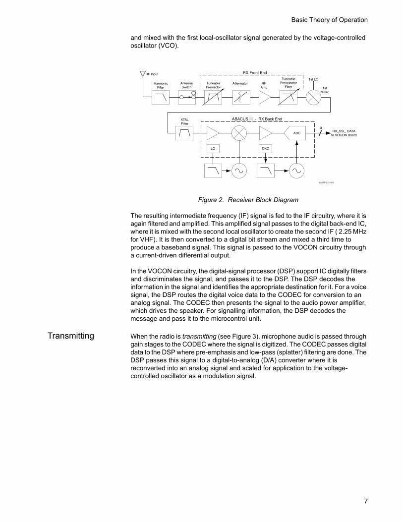
Basic Theory of Operation
7
and mixed with the first local-oscillator signal generated by the voltage-controlled oscillator (VCO).
The resulting intermediate frequency (IF) signal is fed to the IF circuitry, where it is again filtered and amplified. This amplified signal passes to the digital back-end IC, where it is mixed with the second local oscillator to create the second IF ( 2.25 MHz for VHF). It is then converted to a digital bit stream and mixed a third time to produce a baseband signal. This signal is passed to the VOCON circuitry through a current-driven differential output.
In the VOCON circuitry, the digital-signal processor (DSP) support IC digitally filters and discriminates the signal, and passes it to the DSP. The DSP decodes the information in the signal and identifies the appropriate destination for it. For a voice signal, the DSP routes the digital voice data to the CODEC for conversion to an analog signal. The CODEC then presents the signal to the audio power amplifier, which drives the speaker. For signalling information, the DSP decodes the message and pass it to the microcontrol unit.
Transmitting When the radio is transmitting (see Figure 3), microphone audio is passed through gain stages to the CODEC where the signal is digitized. The CODEC passes digital data to the DSP where pre-emphasis and low-pass (splatter) filtering are done. The DSP passes this signal to a digital-to-analog (D/A) converter where it is reconverted into an analog signal and scaled for application to the voltage-controlled oscillator as a modulation signal.
Figure 2. Receiver Block Diagram
�� ����� � ���� ��
�������
�����
���
�� ���
������ ����
�� ����� ��
���
�����
� ��!� ��� " � ��# ��
�������
�$���%
�����&��
'�(�������
���
���������
�����&��
'�(������
����� )(�
*�+�
)(� ��
,
*��'�"-.-./"�

Basic Theory of Operation
8
Transmitted signalling information is accepted by the DSP from the microcontrol unit, coded appropriately, and passed to the D/A converter, which handles it the same as a voice signal. Modulation information is passed to the synthesizer along the modulation line. A modulated carrier is provided to the RF PA, which transmits the signal under dynamic power control.
ASTRO Mode of Operation
In the ASTRO mode (digital mode) of operation, the transmitted or received signal is limited to a discrete set of deviation levels, instead of continuously varying. The receiver handles an ASTRO-mode signal identically to an analog-mode signal up to the point where the DSP decodes the received data. In the ASTRO receive mode, the DSP uses a specifically defined algorithm to recover information.
In the ASTRO transmit mode, microphone audio is processed identically to an analog mode with the exception of the algorithm the DSP uses to encode the information. This algorithm will result in deviation levels that are limited to discrete levels.
RF Basic Theory of Operation
The receiver front end consists of a preselector, an RF amplifier, a second preselector, and a mixer. Both preselectors are varactor-tuned, two-pole filters, controlled by the microcontroller unit through the D/A IC. The RF amplifier is a dual-gate, gallium-arsenide-based IC. The mixer is a double-balanced, active mixer, coupled by transformers. Injection is provided by the VCO through an injection filter. See Table 2 for local oscillator (LO) and first IF information.
For the VHF band, the frequency generation function is performed by two ICs and associated circuitry. The reference oscillator provides a frequency standard to the
Figure 3. RF Block Diagram for VHF (Power and Control Omitted)
ReferenceOscillator
FracNU201
MODIN
LoopFilter
LPFFL200
EPICY200
DACU203
VCO
VCO
CrystalFilterFL51
MixerU1
2NDLO
SampleClk
To RX_SSI
From TX_SSI
PreselectorFilter
Attenuator
PCICU102
PowerModuleQ101
TXBuffer
TX DriverAmplifierU101
RF PowerDetectorD103
DirectionalCouplerU106
AntennaSwitch
PreselectorFilter
RX LNAQ29
ToAntenna
HarmonicFilter
ABACUS III U401
MAEPF-27322-O
3
3
RXBuffer
Table 2. Local Oscillator and First IF Frequencies
VHF
LO Frequency Range --
First IF Frequency 44.85 MHz
Basic Theory of Operation
9
synthesizer/prescaler IC, which controls the VCO buffer for VHF. The VCO buffer, actually generates the first LO and transmit-injection signals and buffers them to the required power level. The synthesizer/prescaler circuit module incorporates frequency-division and comparison circuitry to keep the VCO signals stable. The synthesizer/prescaler IC is controlled by the microcontrol unit through a serial bus.
For the VHF band, the receiver back end consists of a three-pole crystal filter and the digital back-end IC. The crystal filters are wide enough to accommodate 4 kHz modulation. Final IF filtering is done digitally in the DSP.
The digital back-end IC consists of an amplifier, the second mixer, an IF analog-to-digital converter, a baseband down-converter, and a 2.4 MHz synthesis circuit to provide a clock to the DSP-support IC on the VOCON circuitry. The second LO is generated by discrete components external to the IC. The output of the digital back-end IC is a digital bit stream that is current driven on a differential pair for a reduction in noise generation.
The transmitter consists of an RF driver IC that gets an injection signal from the VCO and a final-stage power amplifier. Transmit power is controlled by a power-control IC that monitors the output of a directional coupler and adjusts PA control voltages correspondingly. The signal passes through a RX/TX switch that uses PIN diodes to automatically provide an appropriate interface to transmit or receive signals. Antenna selection is done mechanically in the control top.

Basic Theory of Operation
10
VOCON Basic Theory of Operation
The vocoder and controller (VOCON) circuitry contains the radio’s microcontrol unit with its memory and support circuits, the DSP, its memory devices, and the DSP-support IC, voltage regulators, audio, and power control circuits. Connected to the VOCON circuitry are the display board, RF circuitry, keypad board, and controls/universal flex.
The microcontrol unit controls receive/transmit frequencies, power levels, display, and other radio functions, using either direct logic control or serial communications paths to the devices.The microcontrol unit executes a stored program located in the FLASH ROM. Data is transferred to and from memory by the microcontrol unit data bus. The memory location from which data is read, or to which data is written, is selected by the address lines.
The DSP-support IC is supplied with a 16.8 MHz clock from the RF circuitry. Both the DSP and the microprocessor have their clocks generated by the DSP-support IC. They can both be adjusted so that the harmonics do not cause interference with the radio’s receive channel.
The regulator and power-control circuits include 3.3-volt analog, 3.3-volt digital, and 5-volt regulators. The audio PA is sourced from 7.5V. The regulator’s power-down mode is controlled by the microcontrol unit, which senses the position of the on/off switch. The 5-volt regulator has an error pin for low-voltage resets.
The DSP performs signalling and voice encoding and decoding, as well as audio filtering and volume control. This IC performs Private-Line®/Digital Private Line™ (PL/DPL) encode and alert-tone generation. The IC transmits pre-emphasis on analog signals and applies a low-pass (splatter) filter to all transmitted signals. It requires a clock on the EXTAL pin. An 8 kHz interrupt signal generated by the DSP-support IC is also required for functionality. It is programmed using parallel programming from the microcontrol unit.
The audio CODEC performs analog-to-digital (A/D), and digital-to-analog conversions on audio signals. The DSP controls squelch, deviation, and executes receiver and transmitter filtering. The DSP-support IC receives a 2.4 MHz clock, and also receives data, which it formats for the DSP.

11
Recommended Test Equipment and Service Aids 4RecommendedTest Equipment
The list of equipment contained in Table 3 includes all of the standard test equipment required for servicing two-way portable radios, as well as several unique items designed specifically for servicing this family of radios. The “Characteristics” column is included so that equivalent equipment may be substituted; however, when no information is provided in this column, the specific Motorola model listed is either a unique item or no substitution is recommended.
Service Aids Refer to Table 4., “Service Aids,” for a listing and description of the service aids designed specifically for servicing this family of radios. These kits and/or parts are available from the Motorola Parts Division offices listed in the “Replacement Parts Ordering” section located on the inside back cover of this manual. While all of these items are available from Motorola, most are standard shop equipment items, and
Table 3. Recommended Test Equipment
MotorolaModel Number Description Characteristics Application
R2600 Series Communications System Analyzer
This monitor will substitute for items with an asterisk (*).
Frequency/deviation meter and signal generator for wide-range troubleshooting and alignment.
Fluke 8012 Digital Multimeter Recommended for ac/dc voltage and current measurements
R1150_* Code Synthesizer Injection of audio and digital signalling codes
R1377_* AC Voltmeter 1mV to 300V, 10-Megohm input impedance
Audio voltage measurements
R1094_ Dual-Trace Oscilloscope
20 MHz bandwidth 5mV to 5V/division
Waveform measurements
S1350_*ST1213_ (VHF)*ST1223_ (UHF)*
WattmeterPlug-In ElementRF Dummy Load
50-ohm, ±5% accuracy10 watts, maximum0-1000 MHz, 300W
Transmitter power output measurements
R1065_ Load Resistor 10-watt Broadband For use with wattmeter
S1339_ RF Millivolt Meter 100µV to 3V RF RF-level measurements
R1013_* SINAD Meter Receiver sensitivity measurements
S1347_ or S1348_ (programmable)
DC Power Supply 0-20Vdc, 0-5 Amps current limited
Bench supply for 7.5Vdc
*The R2600 Series monitor will substitute for these items.

Recommended Test Equipment and Service Aids
12
any equivalent item capable of the same performance may be substituted for the item listed.
NOTE: The Radio Interface Box (RIB), Smart RadioInterface Box (SRIB), and any cable that connectswith those boxes are incompatible with the XTS2500 radio and should NOT be used.
Field Programming Equipment
This family of radios can be aligned and programmed in the field. This requires specific equipment and special instructions. Refer to the applicable “CPS On-line Help” for complete field programming information.
Table 4. Service Aids
Motorola Part Number Description Application
– Standard Hex Shank Screw Bit (7/64)
To remove/screw hex nut (0286165A03) for non-Immersible model.
6685666D01 Chassis Opener Tool Used to remove radio knobs and to separate chassis from Front Cover.
NLN9839_ Vacuum Pump Kit Immersible radios only. Vacuum pump with gauge and vacuum hose. Requires NTN9279 Adapter Kit.
NTN4265_ Pressure Pump Kit Immersible radios only. Pressure pump with gauge and pressure hose. Requires NTN9279 Adapter Kit.
NTN9279_ Vacuum Adapter with Gasket Kit
Immersible radios only. Connects the vacuum/pressure hose to the radio’s casting.
RKN-4106_ RS232/Radio/Test Set Cable Connects radio to RLN4460 Test Box and to RS232 computer connector (DB9).
0180305G54 Battery Eliminator Interconnects radio to power supply.
RLN-4460_ Portable Test Set Enables connection to the universal connector.Allows switching for radio testing.
RVN-4181_ Customer Programming Software
Customer Programming Software (CPS)/Tuner on one CD-ROM.
58-80348B33 SMA to BNC Adaptor Adapts radio’s antenna port to BNC cabling of test equipment.
RKN4105_ USB/Radio/Test Set Cable Connects radio to RLN4460 test box and to USB computer connector.
8180384M37 Test Fixture Provides for troubleshooting the radio board when the back casting is removed.

13
Performance Checks 5Introduction to This Section
This section covers performance checks used to verify that the radio meets published specifications. The recommended test equipment listed in the previous section approaches the accuracy of the manufacturing equipment, with a few exceptions. Accuracy of the equipment must be maintained in compliance with the manufacturer’s recommended calibration schedule. Checks should be performed if radio performance degradation is suspected.
Setup Supply voltage can be connected from the battery eliminator. The equipment required for alignment procedures is connected as shown in the “Radio Alignment Test Setup” diagram (Figure 4).
Figure 4. Radio Alignment Test Setup
���
������
�� �� ������
���� ��
�� �����
�
��
�� �� ��
�� �� ��
�� ������
���� �������
�� �����
����
����
��������
�� ���!�!"
������
����
�� ��
�������#� ����
�$�"��%
�� �� ��
� � ������& "!�'� ��� (
����� �'� ��� (
�������
! � ��" ���
� �
����""%�

Performance Checks
14
Initial equipment control settings should be as indicated in the Table 5, and should hold for all alignment procedures except as noted.
Display Radio Test Mode
Entering Display Radio Test Mode
1. Turn the radio on.
2. Within 10 seconds after “Self Test” is complete, press Side button 3 five times in succession.
3. The radio will show a series of displays that will give information regarding various version numbers and subscriber specific information. The displays are described in Table 6.
NOTE: All displays are temporary and will disappearwithout any user intervention. If information islonger than the physical length of the radio’sdisplay, the information will wrap around to the nextdisplay. After the last display, “RF TEST” will bedisplayed. For non-display radios, refer to the CPSRadio Information Screen.
Table 5. Initial Equipment Control Settings
System Analyzer Test Set Power Supply
Monitor Mode: Pwr Mon Spkr Set: A Voltage: 7.5Vdc
RF Attn: –70dB Spkr/Load: Speaker DC On/Standby: Standby
AM, CW, FM: FM PTT: OFF (center) Volt Range: 10Vdc
O'scope Source: ModO'scope Horiz: 10mSec/DivO'scope Vert: 2.5 kHz/DivO'scope Trig: AutoMonitor Image: HiMonitor BW: NarMonitor Squelch: Mid CWMonitor Vol: 1/4 CW
Current: 2.5Amps
Table 6. Front-Panel Access Test-Mode Displays
Name of Display Description Appears
“SERVICE” The literal string indicates the radio has entered test mode.
Always.
Host Software Version The version of host firmware. Always.
DSP Software Version The version of DSP firmware. Always.
Model Number The radio’s model number as programmed in the codeplug.
Always.
Serial Number The radio’s serial number as programmed in the codeplug.
Always.
ROM Size The memory capacity of the host FLASH part. Always.
FLASHcode The FLASH codes as programmed in the codeplug. Always.
Performance Checks
15
4. Press Side Button 1 to stop the displays and put the radio into the Control Top and Keypad test mode (display radio). The test mode menu “CH TEST” will be displayed. Go to the “Control Top and Keypad Test Mode (Display Radio)” section on page 16.
NOTE: Each press of Side Button 1 will toggle between“CH TEST” and “RF TEST.”
OR
4a. Press the Top Programmable Button to stop the displays and put the radio into the RF test mode (display radio). The test mode menu “1 CSQ.” will be displayed, indicating test frequency 1, Carrier SQuelch mode. Go to “RF Test Mode (Display Radio)” in the next section.
RF Test Mode (Display Radio)
When the ASTRO Digital XTS 2500 radio is operating in its normal environment, the radio's microcomputer controls the RF channel selection, transmitter key-up, and receiver muting, according to the customer codeplug configuration. However, when the unit is on the bench for testing, alignment, or repair, it must be removed from its normal environment via a special routine, called TEST MODE or “air test.”
1. Each additional press of Side Button 3 will advance to the next test channel. (Refer to Table 7.)
2. Pressing Side Button 2 will scroll through and access test environments as shown in Table 8.
NOTE: Transmit into a load when keying a radio under test.

Performance Checks
16
Control Top and Keypad Test Mode (Display Radio)
This test mode is used to verify proper operation of all radio buttons and switches if a failure is suspected.
1. Press and hold the Top Programmable Button; all segments on the display will light, and the LED on the control top will illuminate a red color.
2. Release the Top Programmable Button; “3/0” appears, indicating that the Top Programmable Button is in the open condition.
3. Press the Top Programmable Button again; “3/1” appears, indicating that the Top Programmable Button is in the closed condition.
4. Rotate the Mode/Zone Selector Switch; “4/0” through “4/15” appears, indicating that the selector switch is in mode/zone position 1 through 16.
5. Rotate the Three-Position Concentric Switch; “65/0” through “65/2” appear.
6. Cycle through the 16-Position Programmable Switch; “67/0,” “67/1,” and “67/2” appear.
7. Rotate the Volume Control; “2/0” through “2/220” appear.
8. Press Side Button 1; “96/1” appears; release, “96/0” appears.
9. Press Side Button 2; “97/1”appears; release, “97/0” appears.
Table 7. Test Frequencies
FrequencyVHF
RX TX
F1 136.075 136.025
F2 142.075 142.125
F3 154.275 154.225
F4 160.175 160.125
F5 168.125 168.075
F6 173.925 173.975
F7 – –
F8 – –
F9 – –
Table 8. Test Environments
No. of Beeps Display Description Function
1 CSQ Carrier Squelch RX: unsquelch if carrier detectedTX: mic audio
3 TPL Tone Private-Line
RX: unsquelch if carrier and tone (192.8 Hz) detectedTX: mic audio + tone (192.8 Hz)
11 AST ASTRO RX: noneTX: 1200Hz tone **
12 USQ CarrierUnsquelch
RX: unsquelch alwaysTX: mic audio
** All deviation values are based on deviation tuning of this mode.

Performance Checks
17
10. Press Side Button 3; “98/1”appears; release, “98/0” appears.
11. Press the PTT Switch; “1/1” appears; release, “1/0” appears.
12. Keypad Checks:
Model III Only—- Press 0, “48/1” appears; release, “48/0” appears.
- Press 1, “49/1” appears; release, “49/0” appears.
- Press 2, “50/1” appears; release, “50/0” appears.
- Press 3, “51/1” appears; release, “51/0” appears.
- Press 4, “52/1” appears; release, “52/0” appears.
- Press 5, “53/1” appears; release, “53/0” appears.
- Press 6, “54/1” appears; release, “54/0” appears.
- Press 7, “55/1” appears; release, “55/0” appears.
- Press 8, “56/1” appears; release, “56/0” appears.
- Press 9, “57/1” appears; release, “57/0” appears.
- Press *, “58/1” appears; release, “58/0” appears.
- Press #, “59/1” appears; release, “59/0” appears.
All Display Models—- Press V, “128/1” appears; release, “128/0” appears.
- Press h, “129/1” appears; release, “129/0” appears.
- Press U, “130/1” appears; release, “130/0” appears.
- Press the left-hand D key on the top row of keys, “131/1” appears; release, “131/0” appears.
- Press the center E key, “132/1” appears; release, “132/0” appears.
- Press the right-hand F key, “133/1” appears; release, “133/0” appears.
- Press @ button, “134/1” appears; release, “134/0” appears.
- Press X (up arrow), “135/1 appears; release, “135/0” appears.
- Press Y (down arrow), “136/1” appears; release, “136/0” appears.
Non-Display Radio Test Mode
Entering Non-Display Radio Test Mode
1. Turn the radio on.
2. Within 10 seconds after the top green LED turns off, press Side button 3 five times in succession.
3. Press Side Button 1 to put the radio into the Control Top and Keypad test mode (non-display radio). Go to the “Control Top and Keypad Test Mode (Non-Display Radio)” section on page 18.
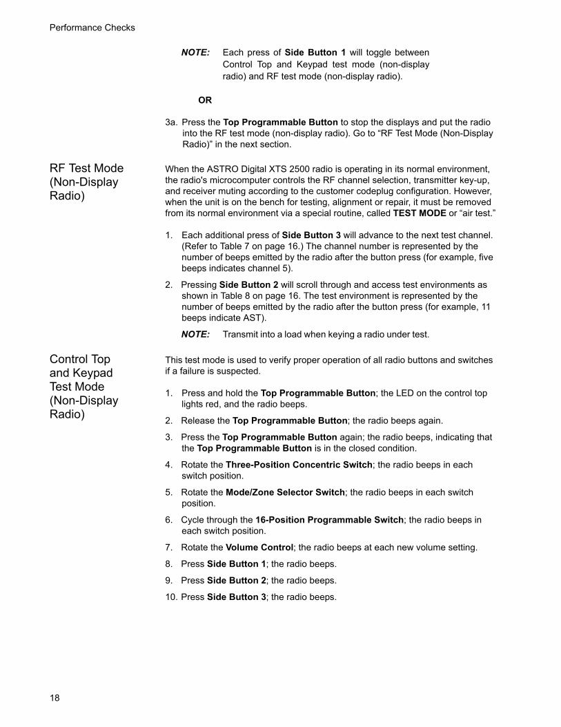
Performance Checks
18
NOTE: Each press of Side Button 1 will toggle betweenControl Top and Keypad test mode (non-displayradio) and RF test mode (non-display radio).
OR
3a. Press the Top Programmable Button to stop the displays and put the radio into the RF test mode (non-display radio). Go to “RF Test Mode (Non-Display Radio)” in the next section.
RF Test Mode (Non-Display Radio)
When the ASTRO Digital XTS 2500 radio is operating in its normal environment, the radio's microcomputer controls the RF channel selection, transmitter key-up, and receiver muting according to the customer codeplug configuration. However, when the unit is on the bench for testing, alignment or repair, it must be removed from its normal environment via a special routine, called TEST MODE or “air test.”
1. Each additional press of Side Button 3 will advance to the next test channel. (Refer to Table 7 on page 16.) The channel number is represented by the number of beeps emitted by the radio after the button press (for example, five beeps indicates channel 5).
2. Pressing Side Button 2 will scroll through and access test environments as shown in Table 8 on page 16. The test environment is represented by the number of beeps emitted by the radio after the button press (for example, 11 beeps indicate AST).
NOTE: Transmit into a load when keying a radio under test.
Control Top and Keypad Test Mode (Non-Display Radio)
This test mode is used to verify proper operation of all radio buttons and switches if a failure is suspected.
1. Press and hold the Top Programmable Button; the LED on the control top lights red, and the radio beeps.
2. Release the Top Programmable Button; the radio beeps again.
3. Press the Top Programmable Button again; the radio beeps, indicating that the Top Programmable Button is in the closed condition.
4. Rotate the Three-Position Concentric Switch; the radio beeps in each switch position.
5. Rotate the Mode/Zone Selector Switch; the radio beeps in each switch position.
6. Cycle through the 16-Position Programmable Switch; the radio beeps in each switch position.
7. Rotate the Volume Control; the radio beeps at each new volume setting.
8. Press Side Button 1; the radio beeps.
9. Press Side Button 2; the radio beeps.
10. Press Side Button 3; the radio beeps.

Performance Checks
19
Table 9. Receiver Performance Checks
Test Name System Analyzer Radio Test Set Comments
Reference Frequency
Mode: PWR MON 4th channel test frequency*Monitor: Frequency error. Input at RF In/Out
TEST MODE, 4 CSQ output at antenna
PTT to continuous (during the performance check)
Frequency error to be ≤ ±1.3 kHz
Rated Audio Mode: GEN Output level: 1.0mV RF 4th channel test frequency*Mod: 1 kHz tone at 3 kHz deviationMonitor: DVM: ac Volts
TEST MODE, 4 CSQ
PTT to OFF (center); meter selector to Audio PA
Set volume control to 3.74Vrms
Distortion As above, except to distortion As above As above Distortion < 3.0%
Sensitivity (SINAD)
As above, except SINAD; lower the RF level for 12dB SINAD
As above PTT to OFF (center) RF input to be < 0.35µV
Noise Squelch Threshold (only radios with conventional system need to be tested)
RF level set to 1mV RF As above PTT to OFF (center); meter selection to Audio PA; spkr/load to speaker
Set volume control to 3.74Vrms
As above, except change frequency to a conventional system. Raise RF level from zero until radio unsquelches.
Out of TEST MODE; select a conventional system
As above Unsquelch to occur at < 0.25µV. Preferred SINAD = 5-8dB
*See Table 7 on page 16.

Performance Checks
20
Table 10. Transmitter Performance Checks
Test Name System Analyzer Radio Test Set Comments
Reference Frequency
Mode: PWR MON 4th channel test frequency*Monitor: Frequency error. Input at RF In/Out
TEST MODE, 4 CSQ
PTT to continuous (during the performance check).
Frequency error to be ≤ ±1.3 kHz.
Power RF As above As above, 4 CSQ
As above Refer to Maintenance Specifications page in front of manual.
Voice Modulation
Mode: PWR MON 4th channel test frequency* atten to –70, input to RF In/Out. Monitor: DVM, ac Volts. Set 1 kHz Mod Out level for 0.025Vrms at test set, 80mVrms at ac/dc test set jack
As above, 4 CSQ
As above, meter selector to mic
Deviation: ≥ 4.1 kHz but ≤ 5.0 kHz
Voice Modulation (internal)
Mode: PWR MON 4th channel test frequency* atten to –70, input to RF In/Out
TEST MODE, 4 CSQ, output at antenna
Remove modulation input
Press PTT switch on radio. Say “four” loudly into the radio mic. Measure deviation: ≥ 4.1 kHz but ≤ 5.0 kHz
PL Modu-lation (radios with conven-tional, clear mode, coded squelch oper-ation only)
Change frequency to a conventional transmit frequency
Conventionalcoded squelch personality (clear mode operation) 4 TPL
As above Deviation: ≥ 500Hz but ≤ 1000Hz
Talkaround Modulation (radios with conventional, clear mode, talk-around operation only)
Change frequency to conventional talk-around frequency. Mode: PWR MON deviation, attenuation to –70, input to RF In/Out. Monitor: DVM, ac volts Set 1 kHz Mod Out level for 25mVrms at test set.
Conventional talkaround personality (clear mode operation) 1 CSQ
As above Deviation: ≥ 4.1 kHz but ≤ 5.0 kHz
*See Table 7 on page 16

21
Radio AlignmentProcedures 6Introduction to This Section
This section describes both receiver and transmitter radio alignment procedures.
General A personal computer (PC) and tuner software are required to align the radio. Refer to the applicable manual for installation and setup procedures for the software. To perform the alignment procedures, the radio must be connected to the PC and to a universal test set as shown in Figure 4. Radio Alignment Test Setup on page 13.
These procedures should only be attempted by qualified service personnel. Failure to perform alignment procedures properly may result in seriously degraded radio or system performance.C a u t i o n

Radio Alignment Procedures
22
Select Tuner from the START menu. To read the radio, use the File → Read Device menu or click on . Figure 5 illustrates how the alignment screens are organized. To access a screen, double-click on the desired screen name in the Tuner menu.
The alignment screens introduce the concept of the “softpot,” an analog SOFTware-controlled POTentiometer used for adjusting all transceiver alignment controls.
Figure 5. Tuner Menu Layout
Do NOT switch radios in the middle of any Alignment procedure. Always left-click the Close button on the screen to return to the MAIN menu screen before disconnecting the radio. Improper exits from the Alignment screens may leave the radio in an improperly configured state and result in seriously degraded radio or system performance.
123ABC1234
Radio Information
Transmitter Alignments
Reference Oscillator (page 24)
Tx Power High (page 26)
Tx Power Mid (page 26)
Tx Power Low (page 26)
Tx Deviation Balance (page 27)
Tx Deviation Limit (page 30)
Receiver Alignments
Front End Filter (page 31)
Performance Testing
Bit Error Rate (page 32)
Transmitter Test Pattern (page 34)
C a u t i o n

Radio Alignment Procedures
23
Each alignment screen provides the ability to increase or decrease the softpot value by using a slider or the screen’s UP/DOWN arrow keys ( ), or by
entering the new value from the keyboard. A graphical scale on the display indicates the minimum, maximum, and proposed value of the softpot; see Figure 6.
Adjusting the softpot value sends information to the radio to increase (or decrease) a voltage in the corresponding circuit. For example, left-clicking the UP arrow on the Reference Oscillator screen instructs the radio’s microcomputer to increase the voltage across a varactor in the reference oscillator, which increases the frequency.
In ALL cases, the softpot value is just a relative number corresponding to a digital-to-analog (D/A) generated voltage in the radio.
Perform the following procedures in the sequence indicated.
NOTE: Some of the following screens may vary depending upon the radio under test and the version of tuner software you are using. Refer to the software’s on-line help.
Figure 6. Typical Softpot Screen

Radio Alignment Procedures
24
Radio Information
Figure 7 shows a typical Radio Information screen.
Reference Oscillator Alignment
Adjustment of the reference oscillator is critical for proper radio operation. Improper adjustment will result not only in poor operation, but also in a misaligned radio that will interfere with other users operating on adjacent channels. For this reason, the reference oscillator should be checked every time the radio is serviced, or once a year, whichever comes first. The frequency counter used for this procedure must have a stability of 0.1 ppm (or better).
NOTE: Reference oscillator alignment is required after replacing (or servicing) the transceiver board.
This test can be done with either the R-2670 Communication Analyzer or the 8901_Modulation Analyzer.
• Initial setup using the R-2670 Communication Analyzer:
- RF Control: MONITOR
- B/W: WB
- Freq: CPS frequency under test
- Attenuation: 20dB
- Mon RF in: RF I/O
- Meter: RF Display
- Mode: STD
- Input Level: uV or W
- Display: Bar Graphs
- Squelch: Mid-range or adjust as necessary
• Initial setup using the 8901_ Series Modulation Analyzer:
Figure 7. Radio Information Screen

Radio Alignment Procedures
25
- Press the green Automatic Operation button on the analyzer.
- Press the FREQ key.
- Type 7.1 followed by SPCL button to set the 8901B_ modulation analyzer for maximum accuracy.
To align the reference oscillator:
1. Select the Reference Oscillator alignment screen. See Figure 8.
2. Left-click the PTT Toggle button on the screen to make the radio transmit. The screen indicates whether the radio is transmitting.
3. Measure the transmit RF frequency with your service monitor.
4. Adjust the reference oscillator’s softpot value until the measured value is as close as possible to the frequency shown on the screen. See Table 11.
5. Left-click the Program All button on the screen to dekey the radio and save the tuned values.
6. Left-click the Close button on the screen to return to the Transmitter Alignments menu.
Figure 8. Reference Oscillator Alignment Screen
Table 11. Reference Oscillator Alignment
Band Target
VHF ±100 Hz

Radio Alignment Procedures
26
Transmit Power Alignment
This alignment procedure adjusts the transmit power of the radio and must be performed for three different power levels (Low, Mid, High), at multiple frequencies for each power level, to allow for proper alignment across the entire RF band. The RF band is divided into frequency zones with a calibration point (value) in each zone.
• The same softpot attenuation value will result in DIFFERENT radio output power levels at different frequencies.
• All power measurements are to be made at the antenna port.
• Transmit Power alignment is required after replacing (or servicing) the transceiver board.
1. Select the TX Power alignment screen. The screen will indicate the transmit frequencies to be used. See Figure 9.
2. Left-click the desired frequency field (starting with the highest frequency shown).
3. Left-click the PTT Toggle button on the screen to make the radio transmit. The screen indicates whether the radio is transmitting.
4. Measure the transmit power of the radio with a service monitor.
5. Adjust the softpot value until the required power, as shown in Table 12, is indicated on the service monitor.
6. Repeat the above process for all frequencies and all power levels.
7. Left-click the Program All button on the screen to dekey the radio and save the tuned values.
Table 12. Transmit Power Settings
Power Level
Test Frequencies
VHF (both ranges)
Low (1 Watt) 2.2–2.4W
Mid (2 Watts) –
High (3 Watts) 5.2–5.4W

Radio Alignment Procedures
27
Left-click the Close button on the screen to return to the Transmitter Alignments menu.
Transmit Deviation Balance Alignment
This alignment procedure balances the modulation contributions of the low- and high-frequency portions of a baseband signal. Proper alignment is critical to the operation of signalling schemes that have very low frequency components (for example, DPL) and could result in distorted waveforms if improperly adjusted.
This procedure needs to be performed at multiple frequencies to allow for proper alignment across the entire RF band. The RF band is divided into frequency zones with a calibration point (value) in each zone.
NOTE: This alignment is required after replacing (or servicing) the VOCON board or the transceiver board.
Proper alignment requires a modulation analyzer or meter with a frequency response to less than 10 Hz modulating frequency. The modulation analyzer settings during this test should be set for average deviation, a 15 kHz low-pass filter, no de-emphasis, and no high-pass filter, if these settings are supported.
This test can be done with either the R-2670 Communication Analyzer or the 8901_ Series Modulation Analyzer. The method of choice is the R-2670 analyzer.
Figure 9. Transmit Power Alignment Screen (Typical)

Radio Alignment Procedures
28
1. Initial setup using the R-2670 Communication Analyzer:
- Connect a BNC cable between the “DEMOD OUT” port and the “VERT/SINAD DIST/DMM COUNTER IN” port on the R-2670.
- Press the SPF key on the R-2670 to display the “SPECIAL FUNCTIONS MENU.” Move the cursor to “High Pass,” and select 5 Hz on the soft key menu. Select 20 kHz for the “Low Pass” setting.
- In the “RF Control” section of the R-2670, enter the frequency displayed on the RSS screen. Move the cursor to the “B/W” setting and select “WIDE +/- 100 kHz” on the soft key menu.
- Place the R-2670 cursor in the “Display” zone. Select “AC VOLTS” on the soft key menu. Move the cursor to the “Range” setting and select “AUTO.”
2. Initial setup using the 8901_ Series Modulation Analyzer:
- Press the FM MEASUREMENT button. (The “Error 03-input level too low” indication is normal until an input signal is applied.)
- Simultaneously press the Peak – and Peak + buttons. Both LEDs on the buttons should light.
- Press the 15 kHz LP filter key.
3. Select the TX Deviation Balance alignment screen. The screen indicates the transmit frequencies to be used. See Figure 10.
4. Left-click the desired frequency field (starting with the highest frequency shown).
5. Left-click the PTT Toggle button on the screen to make the radio transmit. The screen indicates whether the radio is transmitting.

Radio Alignment Procedures
29
6. Left-click the PTT Tone: Low button.
7. Left-click the PTT Toggle button on the screen to enable transmission. The screen indicates whether the radio is transmitting. Wait approximately 5 seconds until the voltage shown on R-2670, or the deviation shown on the 8901_ analyzer, stabilizes.
8. Measure and record the ac voltage value from the R-2670 analyzer or the deviation value from the 8901_ series analyzer.
9. Left-click the PTT Tone: High button.
10. Adjust the softpot value until the measured deviation/voltage, when using the high tone, is within +/- 1.5% of the value observed when using the low tone.
11. Repeat the above process for all frequencies.
12. Left-click the Program All button on the screen to dekey the radio and save the tuned values.
13. Left-click the Close button on the screen to return to the Transmitter Alignments menu.
Figure 10. Transmit Deviation Balance Alignment Screen

Radio Alignment Procedures
30
Transmit Deviation Limit Alignment
This alignment procedure limits the modulation of a baseband signal. It is used for primary modulation limiting.
This procedure needs to be performed at multiple frequencies to allow for proper alignment across the entire RF band. The RF band is divided into frequency zones with a calibration point (value) in each zone.
NOTE: This alignment is required after replacing (or servicing) the VOCON board or the transceiver board.
1. Select the TX Deviation Limit alignment screen. The screen will indicate the transmit frequencies to be used. See Figure 11.
2. Left-click the desired frequency field (starting with the highest frequency shown).
3. Left-click the PTT Toggle button on the screen to make the radio transmit. The screen indicates whether the radio is transmitting.
4. Measure the transmitted signal deviation of the radio with a service monitor.
5. Adjust softpot value until the measured deviation is as close as possible to 2.83 kHz.
Figure 11. Transmit Deviation Limit Alignment Screen

Radio Alignment Procedures
31
6. Repeat the above process for all frequencies.
7. Left-click the Program All button on the screen to dekey the radio and save the tuned values.
8. Left-click the Close button on the screen to return to the Transmitter Alignments menu.
Front End Filter Alignment
Definition This alignment procedure adjusts the front end receiver bandpass filters for best receiver sensitivity and selectivity. It should be performed for all test frequencies to allow for proper software interpolation for frequencies in between the test frequencies in the band (see Figure 12).
NOTE: Rx Front End Filter Alignment is required after replacing (or servicing) the transceiver board.
Procedure for VHF 1. Left-click the desired frequency field.
2. Apply an RF signal with no modulation at -90 dBm on the current operating frequency.
3. Adjust the softpot value until the maximum RSSI value is found.
Refer to your Radio Service Manual for alignment procedure details. This procedure should only be attempted by qualified service personnel.C a u t i o n
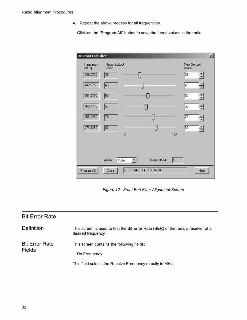
Radio Alignment Procedures
32
4. Repeat the above process for all frequencies.
Click on the “Program All” button to save the tuned values in the radio.
Bit Error Rate
Definition This screen is used to test the Bit Error Rate (BER) of the radio’s receiver at a desired frequency.
Bit Error Rate Fields
This screen contains the following fields:
Rx Frequency:
This field selects the Receive Frequency directly in MHz.
Figure 12. Front End Filter Alignment Screen

Radio Alignment Procedures
33
Test Pattern:
This field selects the Digital test pattern — TIA. Choices are: Standard Tone Test Pattern (framed 1011) and Standard Interface Test Pattern (CCITT V.52).
Modulation Type:
This field represents the digital modulation type of the incoming signal on which BER is to be calculated.
Continuous Operation:
This field allows the user to make the BER test repeat indefinitely. A selection of Yes will cause the radio to calculate BER on a continuous basis and update the results on this screen after each integration time. A selection of No will cause the BER test to execute for only one sample of the integration time and then update the display.
Audio:
This field allows the user to select the audio output during a test. Selecting Internal will cause the radio's built-in speaker to unmute to any signals at the desired frequency which are present during the test. Selecting External will route the same signal to the radio's accessory connector audio output. Selecting Mute will disable the audio output.
Integration Time:
This field represents the amount of time over which the Bit Error Rate is to be calculated. The range is from 0.360 to 91.8 seconds in increments of 0.360 seconds.
NOTE: When Continuous Operation = Yes, all fields will be grayed out while test is in progress. They will be enabled when the STOP button is pressed.

Radio Alignment Procedures
34
NOTE: When Continuous Operation = No, a wait cursor will be displayed while the test is in progress and return to normal when the test is done.
Transmitter Test Pattern
Definition This screen is used to transmit specific test patterns at a desired frequency so that the user can perform tests on the radio’s transmitter.
Transmitter Test Fields
This screen contains the following fields:
Tx Frequency:
This field selects the Transmit Frequency directly in MHz.
Channel Spacing:
This field allows the user to select the desired transmit deviation.
Test Pattern Type:
This field represents the type of test pattern which will be transmitted by the radio when “PTT TOGGLE” button is pressed.
Figure 13. Bit Error Rate Screen

Radio Alignment Procedures
35
NOTE: Channel Spacing and Test Pattern Type fields will be grayed out while radio is transmitting.
Figure 14. Transmitter Test Pattern Screen

Radio Alignment Procedures
36
Notes

37
XTS 2500/XTS 2250/XTS 1500/MT 1500/PR 1500 Exploded Views and Parts Lists 7
XTS 2500/XTS 2250/XTS 1500/MT 1500/PR 1500 Model I Exploded View
16
17
1820
2122
23 2425
2627
42
28
41
40
39
38
3635
3433
32
3130
29
12
34
56
7
8
910
1112
131415
37
19
Table 13. XTS 2500 Model I / XTS 2250 Basic Model / XTS 1500 / MT 1500 / PR1500 Exploded View Parts List
Item Number
Motorola Part Number Description Item
NumberMotorola Part
Number Description
1 1578458A01 Cover, Assy, Front Model 1 27 1485218D01 Boot, Mic
2 7515058H01 Spcr, SQ61.7MML, 8MMThk 28 3585339D01 Speaker Mesh
3 8416317H01 PCB, Dummy Keypad 29 3216389H01 Membrane, Microphone
4 4216345H01 Retainer 30 3516396H01 Mesh Microphone, Front
5 0385563D01 Screw 31 3316396H01 Nameplate, Front
6 2616192H02 Shield, Main 32 3216348H01 Sel, Top Control
7 Typical Main Board 33 6116359H01 Light Pipe
8 3216366H01 Seal, Main 34 1116352H01 Adhesive, Top Control
9 PMLN5005_ Chassis Assembly (Immersible) 35 1385783C01 Escutcheon, Top
PMLN5006_ Chassis (Standard) 36 1385855C01 Label, ABC
10 3216463H01 Seal Base Plate 37 0485667D01 Washer Teflon
11 0286165A03 Nut, Spanner 38 3680529Z01 Knob, Volume
0216965H01 Nut, Spanner (Non-Submersible) 39 4585782C01 Lever Secure
12 3216155H02 Seal, Port 40 3685779C01 Knob Frequency (w / d-clip)
13 3316152H01 Label, Seal 41 Typical Antenna
14 Typical Battery 42 1505579Z01 Cover, Dust, Universal Connector
NNT6263_ NiMH ultra-high-capacity, FactoryMutual Intrinsically Safe,Immersible
15 Typical Belt Clip
16 4385665D01 Adaptor, Remote Speaker Mic
17 3280534Z03 Seal, Cust, Slcn Rub
18 3285027E01 O-Ring Freq Switch
19 6003710K08 Battery, Backup
20 4285633D01 Retaining Clip
21 7516825H01 Shield, Poron
22 7585737D01 Pad Shock
23 4385717D01 Spacer Plastic
24 4285446D01 Retainer Speaker
25 7516153H01 Pad, Speaker Retainer
26 8416579H01 Board, Circuit, Flex Speaker Mic

XTS 2500/XTS 2250/XTS 1500/ MT 1500/PR 1500 Exploded Views and Parts Lists
38
XTS 2500 Model II Exploded View
21
22
23
2425
2627
28 2930
3132
33
48
34
47
46
45
44
4342
41
4039
38
3736
35
12
34
567
8910
11
12
13
141516
171819
20
Table 14. XTS 2500 Model II Exploded View Parts List
Item Number
Motorola Part Number Description Item
NumberMotorola Part
Number Description
1 1578458A03 Cover, Assy, Front Model II 27 7585915C01 Pad Shock LCD
2 7516330H02 Keypad, Limited 28 7585737D01 Pad Shock
3 0104021J67 Assembly Board Model II Limited 29 4385717D01 Spacer, Plastic
4 4216345H01 Retainer 30 4285446D01 Retainer Speaker
5 2671104L01 Gasket, EMI/FRI, Plas-Polyu 31 7516153H01 Pad, Speaker Retainer
6 2616342H02 EMI Shield, Elec Cond. Gasket 32 8416579H01 Board, Circuit, Flex Speaker Mic
7 8416620H01 Board Flex Jumper 33 1485218D01 Boot, Mic
8 7285726C04 Disp, Flat Panel, LCD MDL 34 3585339D01 Speaker Mesh
9 7585011E01 Pad, LCD IC 35 3216389H01 Membrane, Microphone
10 0385563D01 Screw 36 3516396H01 Mesh Microphone, Front
11 2616192H02 Shield Main 37 3316396H01 Nameplate, Front
12 Typical Main Board 38 3216348H01 Sel, Top Control
13 3216366H01 Seal, Main 39 6116359H01 Light Pipe
14 PMLN5005_ Chassis Assembly (Immersible) 40 1116352H01 Adhesive, Top Control
PMLN5006_ Chassis (Standard) 41 1385783C01 Escutcheon, Top
15 3216463H01 Seal Base Plate 42 1385855C01 Label, ABC
16 0286165A03 Nut, Spanner 43 0485667D01 Washer Teflon
0216965H01 Nut, Spanner (Non-Submersible) 44 3680529Z01 Knob, Volume
17 3216155H02 Seal, Port 45 4585782C01 Lever Secure
18 3316152H01 Label, Seal 46 3685779C01 Knob Frequency (w / d-clip)
19 Typical Battery 47 Typical Antenna
NNT6263_ NiMH ultra-high-capacity, FactoryMutual Intrinsically Safe,Immersible
48 1505579Z01 Cover, Dust, Universal Connector
20 Typical Belt Clip
21 4385665D01 Adaptor, Remote Speaker Mic
22 3280534Z03 Seal, Cust, Slcn Rub
23 3285027E01 O-Ring Freq Switch
24 6003710K08 Battery, Backup
25 4285633D01 Retaining Clip
26 7516825H01 Shield, Poron
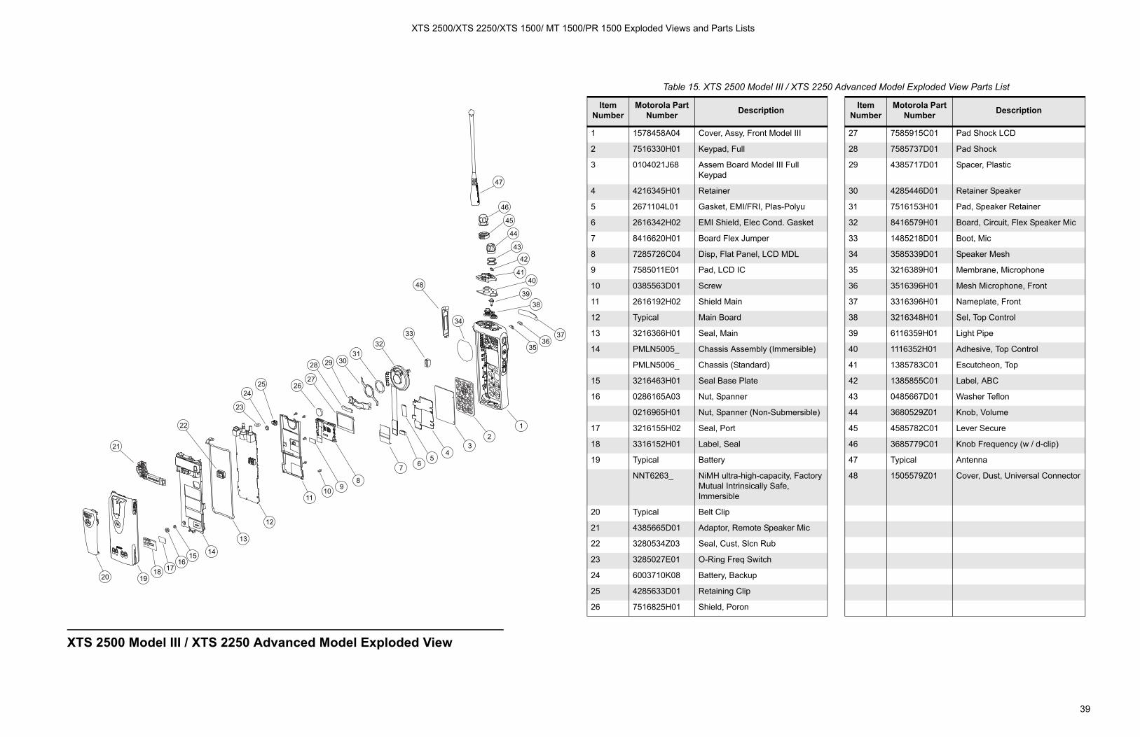
XTS 2500/XTS 2250/XTS 1500/ MT 1500/PR 1500 Exploded Views and Parts Lists
39
XTS 2500 Model III / XTS 2250 Advanced Model Exploded View
21
22
23
2425 26
27
28 29 3031
3233
48
47
46
45
44
43
42
4140
3938
3736
35
12
34
567
8910
11
12
13
141516
17181920
34
Table 15. XTS 2500 Model III / XTS 2250 Advanced Model Exploded View Parts List
Item Number
Motorola Part Number Description Item
NumberMotorola Part
Number Description
1 1578458A04 Cover, Assy, Front Model III 27 7585915C01 Pad Shock LCD
2 7516330H01 Keypad, Full 28 7585737D01 Pad Shock
3 0104021J68 Assem Board Model III Full Keypad
29 4385717D01 Spacer, Plastic
4 4216345H01 Retainer 30 4285446D01 Retainer Speaker
5 2671104L01 Gasket, EMI/FRI, Plas-Polyu 31 7516153H01 Pad, Speaker Retainer
6 2616342H02 EMI Shield, Elec Cond. Gasket 32 8416579H01 Board, Circuit, Flex Speaker Mic
7 8416620H01 Board Flex Jumper 33 1485218D01 Boot, Mic
8 7285726C04 Disp, Flat Panel, LCD MDL 34 3585339D01 Speaker Mesh
9 7585011E01 Pad, LCD IC 35 3216389H01 Membrane, Microphone
10 0385563D01 Screw 36 3516396H01 Mesh Microphone, Front
11 2616192H02 Shield Main 37 3316396H01 Nameplate, Front
12 Typical Main Board 38 3216348H01 Sel, Top Control
13 3216366H01 Seal, Main 39 6116359H01 Light Pipe
14 PMLN5005_ Chassis Assembly (Immersible) 40 1116352H01 Adhesive, Top Control
PMLN5006_ Chassis (Standard) 41 1385783C01 Escutcheon, Top
15 3216463H01 Seal Base Plate 42 1385855C01 Label, ABC
16 0286165A03 Nut, Spanner 43 0485667D01 Washer Teflon
0216965H01 Nut, Spanner (Non-Submersible) 44 3680529Z01 Knob, Volume
17 3216155H02 Seal, Port 45 4585782C01 Lever Secure
18 3316152H01 Label, Seal 46 3685779C01 Knob Frequency (w / d-clip)
19 Typical Battery 47 Typical Antenna
NNT6263_ NiMH ultra-high-capacity, FactoryMutual Intrinsically Safe,Immersible
48 1505579Z01 Cover, Dust, Universal Connector
20 Typical Belt Clip
21 4385665D01 Adaptor, Remote Speaker Mic
22 3280534Z03 Seal, Cust, Slcn Rub
23 3285027E01 O-Ring Freq Switch
24 6003710K08 Battery, Backup
25 4285633D01 Retaining Clip
26 7516825H01 Shield, Poron
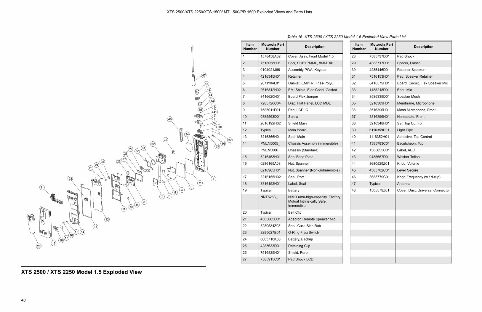
XTS 2500/XTS 2250/XTS 1500/ MT 1500/PR 1500 Exploded Views and Parts Lists
40
XTS 2500 / XTS 2250 Model 1.5 Exploded View
21
22
2324
25 2627
2829
3031
3233
48
47
46
45
44
43
42
41
40
3938
3736
35
12
34
567
89
1011
12
13
141516
1718
1920
34
Table 16. XTS 2500 / XTS 2250 Model 1.5 Exploded View Parts List
Item Number
Motorola Part Number Description Item
NumberMotorola Part
Number Description
1 1578458A02 Cover, Assy, Front Model 1.5 28 7585737D01 Pad Shock
2 7515058H01 Spcr, SQ61.7MML, 8MMThk 29 4385717D01 Spacer, Plastic
3 0104021J66 Assembly PWA, Keypad 30 4285446D01 Retainer Speaker
4 4216345H01 Retainer 31 7516153H01 Pad, Speaker Retainer
5 2671104L01 Gasket, EMI/FRI, Plas-Polyu 32 8416579H01 Board, Circuit, Flex Speaker Mic
6 2616342H02 EMI Shield, Elec Cond. Gasket 33 1485218D01 Boot, Mic
7 8416620H01 Board Flex Jumper 34 3585339D01 Speaker Mesh
8 7285726C04 Disp, Flat Panel, LCD MDL 35 3216389H01 Membrane, Microphone
9 7585011E01 Pad, LCD IC 36 3516396H01 Mesh Microphone, Front
10 0385563D01 Screw 37 3316396H01 Nameplate, Front
11 2616192H02 Shield Main 38 3216348H01 Sel, Top Control
12 Typical Main Board 39 6116359H01 Light Pipe
13 3216366H01 Seal, Main 40 1116352H01 Adhesive, Top Control
14 PMLN5005_ Chassis Assembly (Immersible) 41 1385783C01 Escutcheon, Top
PMLN5006_ Chassis (Standard) 42 1385855C01 Label, ABC
15 3216463H01 Seal Base Plate 43 0485667D01 Washer Teflon
16 0286165A03 Nut, Spanner 44 3680529Z01 Knob, Volume
0216965H01 Nut, Spanner (Non-Submersible) 45 4585782C01 Lever Secure
17 3216155H02 Seal, Port 46 3685779C01 Knob Frequency (w / d-clip)
18 3316152H01 Label, Seal 47 Typical Antenna
19 Typical Battery 48 1505579Z01 Cover, Dust, Universal Connector
NNT6263_ NiMH ultra-high-capacity, FactoryMutual Intrinsically Safe,Immersible
20 Typical Belt Clip
21 4385665D01 Adaptor, Remote Speaker Mic
22 3280534Z03 Seal, Cust, Slcn Rub
23 3285027E01 O-Ring Freq Switch
24 6003710K08 Battery, Backup
25 4285633D01 Retaining Clip
26 7516825H01 Shield, Poron
27 7585915C01 Pad Shock LCD

41
Disassembly/Assembly 8Introduction to This Section
This section contains basic procedures for removing and installing the following components of the XTS 2500 radio:
• Antenna
• Battery
• Belt Clip
• Universal Connector Cover
• Remote Speaker Microphone Adapter
• Radio Disassembly—Detailed
• Radio Reassembly—Detailed
Antenna
Attach the Antenna
With the radio off, turn the antenna clockwise to attach it.
Figure 15. Attaching the Antenna

Disassembly/Assembly
42
Remove the Antenna
With the radio off, turn the antenna counter-clockwise to remove it.
Battery
Attach the Battery 1. With the radio off, fit the three extensions at the bottom of the battery into the bottom slots on the radio.
2. Press the top of the battery against the radio until both latches click into place.
Figure 16. Removing the Antenna
Figure 17. Attaching the Battery
Figure 18. Attaching the Battery
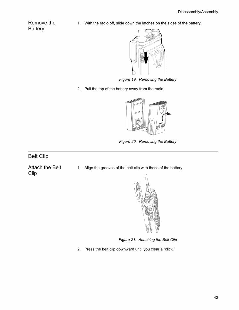
Disassembly/Assembly
43
Remove the Battery
1. With the radio off, slide down the latches on the sides of the battery.
2. Pull the top of the battery away from the radio.
Belt Clip
Attach the Belt Clip
1. Align the grooves of the belt clip with those of the battery.
2. Press the belt clip downward until you clear a “click.”
Figure 19. Removing the Battery
Figure 20. Removing the Battery
Figure 21. Attaching the Belt Clip

Disassembly/Assembly
44
Remove the Belt Clip
1. Use a flat-bladed object to press the belt clip tab away from the battery.
2. Slide the belt clip upward to remove it.
Universal Connector Cover
The universal connector cover is located on the antenna side of the radio. It is used to cover the connector when not in use.
NOTE: To prevent damage to the connector, shield it with the connector cover when not in use.
Remove the Universal Connector Cover
1. Insert a flat-blade screwdriver into the area between the bottom of the cover and the slot below the connector.
2. Hold the top of the cover with your thumb while you pry the bottom of the cover away from the radio with the screwdriver.
Figure 22. Removing the Belt Clip
Figure 23. Removing the Universal Connector Cover

Disassembly/Assembly
45
Attach the Universal Connector Cover
1. Insert the, hooked end of the cover into the top of the connector.
2. Press downward on the top of the cover to seat it into the slot.
3. Press the lower tab of the cover below the connector until it snaps in place.
Remote Speaker Microphone Adapter
The Remote Speaker Microphone (RSM) adapter is located on the back of the radio, just above the battery. It must be used to connect the RSM to the radio. If the RSM is not used, the adapter must be removed.
Remove the Adapter
Lift the larger side (below the antenna port) of the adapter away from the radio using your finger.
If you cannot easily remove the adapter with your finger, use a small, flat bladed screwdriver to pry the larger end side of the adapter away from the radio.
Figure 24. Attaching the Universal Connector Cover
TopSlot
Bottom
Tab
Slot
Hooked End
Figure 25. Removing the RSM Adapter

Disassembly/Assembly
46
Attach the Adapter 1. With the Motorola side of the adapter facing out, snap the smaller end of the adapter into place in the shroud indent, below the On/Off Volume Control Knob.
2. Snap the larger end of the adapter into place in the shroud indent, below the antenna port.
Radio Disassembly—Detailed
When disassembling and reassembling the radio, pay particular attention to the snaps and tabs and how parts align with each other.
The following steps describe how to disassemble the radio. This includes the following major components:
• Front Cover
• Chassis
• Backup Battery
• Keypad
• Keypad/option board
• Display
• Speaker, microphone, universal flex connector
Required Tools • Small, flat-bladed screwdriver
• TORX™ T7-IP screwdriver
• Chassis Opener/Knob removal tool (Motorola part number 6685666D01)
Figure 26. Attaching the RSM Adapter
Figure 27. Attaching the RSM Adapter
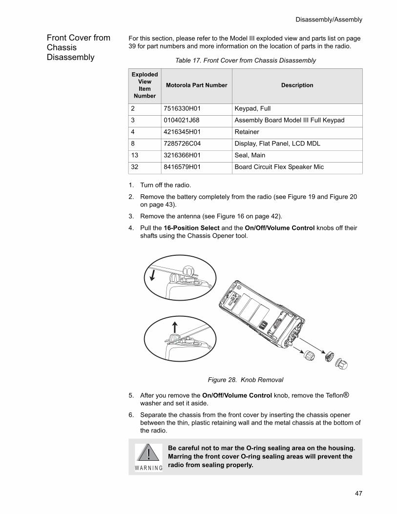
Disassembly/Assembly
47
Front Cover from Chassis Disassembly
For this section, please refer to the Model III exploded view and parts list on page 39 for part numbers and more information on the location of parts in the radio.
1. Turn off the radio.
2. Remove the battery completely from the radio (see Figure 19 and Figure 20 on page 43).
3. Remove the antenna (see Figure 16 on page 42).
4. Pull the 16-Position Select and the On/Off/Volume Control knobs off their shafts using the Chassis Opener tool.
5. After you remove the On/Off/Volume Control knob, remove the Teflon® washer and set it aside.
6. Separate the chassis from the front cover by inserting the chassis opener between the thin, plastic retaining wall and the metal chassis at the bottom of the radio.
Table 17. Front Cover from Chassis Disassembly
Exploded ViewItem
Number
Motorola Part Number Description
2 7516330H01 Keypad, Full
3 0104021J68 Assembly Board Model III Full Keypad
4 4216345H01 Retainer
8 7285726C04 Display, Flat Panel, LCD MDL
13 3216366H01 Seal, Main
32 8416579H01 Board Circuit Flex Speaker Mic
Figure 28. Knob Removal
Be careful not to mar the O-ring sealing area on the housing. Marring the front cover O-ring sealing areas will prevent the radio from sealing properly.W A R N I N G

Disassembly/Assembly
48
7. Slowly pry the bottom of the chassis away from the front cover by pushing the chassis opener tool down. Rotate the handle of the tool over and behind the base of the radio. This prying action forces the thin inner plastic wall toward the base of the radio, releasing the two chassis tabs.
8. Remove the chassis assembly by holding the chassis in one hand while slowly, with a firm side-to-side motion, removing the chassis.
Figure 29. Chassis Removal
The chassis assembly has switches that can be damaged if the chassis is removed too quickly. Be careful not to damage the switches at the top of the board.
Figure 30. Chassis Separation
KNOBS OPENER
CHASSIS OPENER
C a u t i o n

Disassembly/Assembly
49
9. Lay the chassis down. Rotate the front cover backward and slightly away from the chassis.
10. Carefully lift the latches on the main circuit board to release the flexible circuits from their connectors.
NOTE: For proper reassembly, note how the flex circuits are folded.
11. Remove the concentric lever from the front cover assembly.
Chassis Disassembly
For this section, please refer to the Model III exploded view and parts list on page 39 for part numbers and more information on the location of parts in the radio.
1. If disassembly of the chassis or the main board is required, then use a TORX™ screwdriver with a T7-IP head to remove the five screws holding the main board and shield to the chassis.
Flexible ribbon circuits (flexes) connecting the front cover assembly and the chassis prevent you from completely separating the two units. Display radios and radios with option boards have two flexes.
Figure 31. Unlatching the Flex Connectors
C a u t i o n
Table 18. Chassis Disassembly
Exploded ViewItem
Number
Motorola Part Number Description
1 1578458A04 Cover Assy, Front Model III
2 7516330H01 Keypad, Full
4 4216345H01 Retainer
8 7285726C04 Display, Flat Panel, LCD Module

Disassembly/Assembly
50
2. Remove the O-ring from around the bushing at the antenna connector
3. Lift the main board from the chassis as shown in Figure 32.
4. Most repairs to the main board can be performed without further disassembly of the chassis. If it is necessary to replace the O-ring, remove the small O-ring retainers from their slots in the chassis. Note the alignment of the retainers for reassembly.
5. Remove the O-ring.
Backup Battery Disassembly
For this section, please refer to the Model III exploded view and parts list on page 39 for part numbers and more information on the location of parts in the radio.
Refer to the Handling Precautions on page 4 before removing the main board. Be sure to use ESD protection when handing circuit boards.
Figure 32. Removing the Main Board from the Chassis
C a u t i o n
Table 19. Backup Battery Disassembly
Exploded ViewItem
Number
Motorola Part Number Description
1 1578458A04 Cover Assy, Front Model III
29 4385717D01 Spacer Plastic
30 4271058L01 Retainer Speaker
32 8416579H01 Board Circuit Flex Speaker Mic
33 1485218D01 Boot Mic

Disassembly/Assembly
51
1. The backup battery can be removed without disassembling the board or the chassis.
2. Remove the backup battery retaining clip by sliding it away from the main circuit board, as shown in Figure 33.
3. Insert a small, flat head screwdriver between the battery and the battery holder. Gently pry the battery out of the battery holder.
Keypad and Keypad/Option Board Disassembly
For this section, please refer to the Model III exploded view and parts list on page 39 for part numbers and more information on the location of parts in the radio. (For the Model II keypad, please refer to the exploded view and parts list on page 38.)
1. The keypad and keypad board can be disassembled without the disassembly of the display or speaker/microphone flex assembly.
2. If the disassembly of the keypad or the keypad printed circuit board is required, lift the microphone flex circuit up to move it out of the way.
3. Disconnect the display connector, and move the tail of flex circuit out of the way.
Figure 33. Remove the Backup Battery
Table 20. Keypad and Keypad/Option Board
Exploded View Item Number
Motorola Part Number Description
2 7516330H01 Keypad, Full
3 0104021J68 Assem Board Model III Full Keypad
4 4216345H01 Retainer
8 7285726C04 Disp, Flat Panel, LCD Module
13 3216366H01 Seal, Main
32 8416579H01 Board, Circuit, Flex Speaker Mic

Disassembly/Assembly
52
4. To remove the keypad retainer shield, insert the tip of a “penknife size,” flat-bladed screwdriver in the opening at the end of the keypad retainer arm tab. Pry the tab away from the side of the front cover until it moves past the ledges on the side wall. Repeat this procedure for the four remaining retainer arm tabs.
5. Lift the keypad retainer out of the front cover.
6. The keypad/option board and the keypad can be removed without the use of tools.
Be careful not to mar the O-ring sealing area on the housing. Marring the front cover O-ring sealing areas will prevent the radio from sealing properly.
Figure 34. Retainer Removal
Figure 35. Keypad Retainer and Boards Removal
W A R N I N G
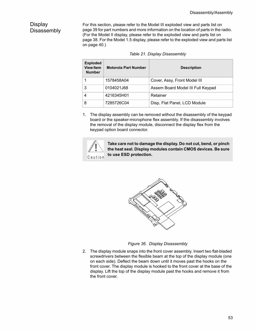
Disassembly/Assembly
53
Display Disassembly
For this section, please refer to the Model III exploded view and parts list on page 39 for part numbers and more information on the location of parts in the radio. (For the Model II display, please refer to the exploded view and parts list on page 38. For the Model 1.5 display, please refer to the exploded view and parts list on page 40.)
1. The display assembly can be removed without the disassembly of the keypad board or the speaker-microphone flex assembly. If the disassembly involves the removal of the display module, disconnect the display flex from the keypad option board connector.
2. The display module snaps into the front cover assembly. Insert two flat-bladed screwdrivers between the flexible beam at the top of the display module (one on each side). Deflect the beam down until it moves past the hooks on the front cover. The display module is hooked to the front cover at the base of the display. Lift the top of the display module past the hooks and remove it from the front cover.
Table 21. Display Disassembly
Exploded View Item Number
Motorola Part Number Description
1 1578458A04 Cover, Assy, Front Model III
3 0104021J68 Assem Board Model III Full Keypad
4 4216345H01 Retainer
8 7285726C04 Disp, Flat Panel, LCD Module
Take care not to damage the display. Do not cut, bend, or pinch the heat seal. Display modules contain CMOS devices. Be sure to use ESD protection.
Figure 36. Display Disassembly
C a u t i o n

Disassembly/Assembly
54
Speaker, Microphone, and Universal Connector Flex Disassembly
For this section, please refer to the Model III exploded view and parts list on page 39 for part numbers and more information on the location of parts in the radio.
1. The speaker-microphone assembly can be removed without the disassembly of the display or the keypad assemblies. If disassembly of the speaker-microphone assembly is necessary, removal of the universal connector dust cover is optional (see Figure 23 on page 44).
2. Remove the plastic spacer at the bottom of the speaker. The spacer can be removed by pulling upward with a slight, side-to-side motion until it clears the retaining ribs in the front cover. Take special care to prevent damage to the tail of the speaker flex circuit while the flex is still in place.
3. Using a screwdriver, push down on the portion of the speaker retainer bracket that is pointing toward the bottom of the radio. Then, remove the retainer by slightly pushing it toward the top of the radio until you slide it past the front cover slot.
4. Remove the microphone boot retainer by inserting a penknife-sized screwdriver in the notch between the retainer and the housing. Pry the retainer away from the housing and remove the clip.
5. Remove the microphone rubber boot by sliding it out of the pocket in the front cover. Take care not to pull on the flex cable while pulling on the microphone boot. Unless you are replacing the microphone, leave it in the boot. At this point, the speaker and microphone are disconnected, but the assembly is still attached to the universal connector by 13 pins in the printed circuit backer board.
6. To remove the speaker-microphone flex circuit from the universal connector, carefully grasp the flex circuit at a point directly across from the universal connector pins. Applying firm pressure, gradually pull the flex away from the pins.
NOTE: There are notches on the ends of the 13-pin printed circuit backer board. If necessary, you can insert a small screwdriver in one of the notches to pry the backer board away from the front cover.
After the universal connector portion of the speaker-microphone flex circuit is detached, the assembly can be completely removed. If it is necessary to replace
Table 22. Speaker, Microphone, and Universal connector Flex Disassembly
Exploded View Item Number
Motorola Part Number Description
1 1578458A04 Cover, Assy, Front Model III
29 4385717D01 Spacer, Plastic
30 4271058L01 Retainer, Speaker
32 8416579H01 Board, Circuit, Flex Speaker Mic
33 1485218D01 Boot, Microphone
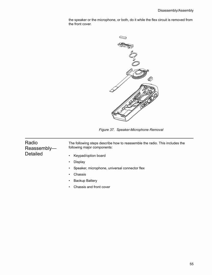
Disassembly/Assembly
55
the speaker or the microphone, or both, do it while the flex circuit is removed from the front cover.
Radio Reassembly—Detailed
The following steps describe how to reassemble the radio. This includes the following major components:
• Keypad/option board
• Display
• Speaker, microphone, universal connector flex
• Chassis
• Backup Battery
• Chassis and front cover
Figure 37. Speaker-Microphone Removal
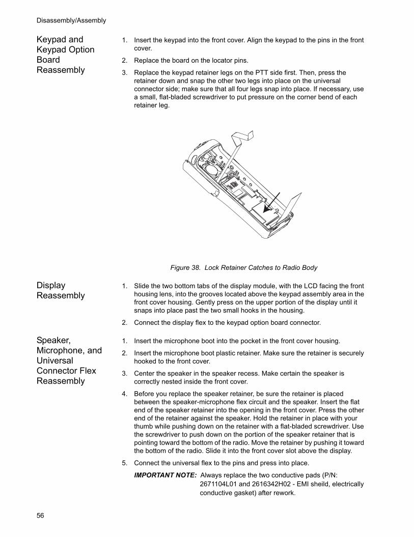
Disassembly/Assembly
56
Keypad and Keypad Option Board Reassembly
1. Insert the keypad into the front cover. Align the keypad to the pins in the front cover.
2. Replace the board on the locator pins.
3. Replace the keypad retainer legs on the PTT side first. Then, press the retainer down and snap the other two legs into place on the universal connector side; make sure that all four legs snap into place. If necessary, use a small, flat-bladed screwdriver to put pressure on the corner bend of each retainer leg.
Display Reassembly
1. Slide the two bottom tabs of the display module, with the LCD facing the front housing lens, into the grooves located above the keypad assembly area in the front cover housing. Gently press on the upper portion of the display until it snaps into place past the two small hooks in the housing.
2. Connect the display flex to the keypad option board connector.
Speaker, Microphone, and Universal Connector Flex Reassembly
1. Insert the microphone boot into the pocket in the front cover housing.
2. Insert the microphone boot plastic retainer. Make sure the retainer is securely hooked to the front cover.
3. Center the speaker in the speaker recess. Make certain the speaker is correctly nested inside the front cover.
4. Before you replace the speaker retainer, be sure the retainer is placed between the speaker-microphone flex circuit and the speaker. Insert the flat end of the speaker retainer into the opening in the front cover. Press the other end of the retainer against the speaker. Hold the retainer in place with your thumb while pushing down on the retainer with a flat-bladed screwdriver. Use the screwdriver to push down on the portion of the speaker retainer that is pointing toward the bottom of the radio. Move the retainer by pushing it toward the bottom of the radio. Slide it into the front cover slot above the display.
5. Connect the universal flex to the pins and press into place.
IMPORTANT NOTE: Always replace the two conductive pads (P/N: 2671104L01 and 2616342H02 - EMI sheild, electrically conductive gasket) after rework.
Figure 38. Lock Retainer Catches to Radio Body

Disassembly/Assembly
57
Chassis Assembly Reassembly
Before you assemble the main board to the chassis, make sure that the following steps are done to the chassis.
1. Replace the O-ring. The tabs on the O-ring should reach into the chassis and point down.
2. Stretch the O-ring to place it into the retaining pocket at the bottom end of the chassis.
NOTE: When properly assembled, the retainers on the O-ring should align with the slots on the chassis. If this is not the case, remove and replace the O-ring until it is aligned with the chassis and completely seated in place around the perimeter.
3. Replace the battery contact seal (if necessary) surrounding the battery contact.
NOTE: Be sure the battery contact seal protrudes through the chassis and is not pinched under the chassis.
4. Make sure the thermal pad is placed on top of the RF Power Amplifier on the main board.
5. Use the notch in the bottom of the main board and the protrusion at the bottom of the casting to align the board to the casting. Place the board against the casting. Make sure that the five screw holes are aligned.
6. Place the main shield assembly on the main board. Again, make sure that the five screw holes are aligned.
7. Use the TORX T7-IP screwdriver to fasten the screws holding the main board and shield to the chassis. Do not over torque. Torque limit is 4 inch-lbs.
8. Place the O-ring at the antenna connector over the antenna connector bushing.
Backup Battery Reassembly
1. Insert the backup battery (positive side up) into the battery holder, as shown in Figure 39.
2. Replace the retaining clip by sliding it into its recess on the board.
Chassis and Front Cover Reassembly
1. Align the chassis assembly end-to-end with the front cover assembly.
2. Insert the tails of the flex circuits into their respective connectors at the bottom of the chassis assembly.
Figure 39. Reassemble the Backup Battery

Disassembly/Assembly
58
3. Push down the latches on the connectors to hold the flex circuits to the main board.
NOTE: Be sure the concentric lever is not in place on the frequency knob shaft when reassembling the chassis with the front cover assembly.
4. Align the volume knob shaft and the frequency switch shaft with their respective holes in the front cover. Slowly reassemble the chassis and front cover assemblies. Slowly slide the volume knob and frequency switch shafts into their respective holes in the front cover.
NOTE: Make sure the flex circuits are correctly folded in place. Take special care to prevent pinching or excess binding of these flexes.
5. Push the chassis assembly completely into the top of the front cover until it settles in place.
NOTE: Be sure the O-ring is properly seated.
6. Press down at the bottom of the chassis until the chassis snaps into place in the front cover.
7. Reassemble the concentric lever to the frequency knob shaft by aligning the protrusions in the lever with the openings in the shaft. The triangular-shaped side of the lever should point toward the back of the radio.
8. Reassemble the Teflon washer to the volume knob shaft. Reassemble the knobs, dust cover, antenna, and battery.
Ensuring Radio Immersibility
This section discusses radio immersibility concerns, tests, and disassembly and reassembly of ASTRO XTS 2500I radios.
Standards ASTRO XTS2500I radio models meet the stringent requirements of U.S. MIL-STD-810C, Method 512.1, Procedure I, MIL-STD-810D, Method 512.2, Procedure I, MIL-STD-512.3, Procedure I, and MIL-STD-512.4, Procedure I, which require the radio to maintain watertight integrity when immersed in three feet of water for two hours.
Figure 40. Fastening the Chassis
Disassembly/Assembly
59
Servicing XTS 2500I radios shipped from the Motorola factory have passed vacuum testing and should be capable of restoring the watertight integrity of the radio.
Accidental Immersion
If the radio is accidentally dropped in water, shake the radio to remove the excess water from the speaker grille and microphone port area before operating; otherwise, the sound may be distorted until the water has evaporated, or is dislodged from these areas.
Specialized Test Equipment
This section summarizes the specialized test equipment necessary for testing the integrity of ASTRO XTS 2500I radios.
To ensure that the radio is truly a watertight unit, special testing, test procedures, and specialized test equipment are required. The special testing involves a vacuum check of the radio and pressure testing (troubleshooting) for water leaks if the vacuum check fails. The specialized test equipment is needed to perform the vacuum check and pressure testing, if required.
Vacuum Pump Kit NLN9839
The vacuum pump kit includes a vacuum pump with gauge, and a vacuum hose. An adapter with gasket (NTN9279_), which must be ordered separately, connects the vacuum hose to the radio’s casting. The vacuum pump kit is also used on Motorola ASTRO XTS 5000 R radio models. The adapter with gasket is the same as that for the ASTRO XTS 5000 R radio models.
Pressure Pump Kit NTN4265
The pressure pump kit includes a pressure pump with gauge, and a pressure hose; the pressure pump kit is also used on Motorola ASTRO XTS 5000 R radio models. As with the vacuum pump kit above, the NTN9279_ adaptor connects the pressure hose to the radio’s casting.
Miscellaneous Hardware
Other items needed for testing the immersibility radio include:
• Large water container
• Deionized (DI) water
• A supply of replacement seals Main seal O-rings, Battery Seal, and Base Plate Seal (refer to the ASTRO XTS 2500I exploded view parts list).
Disassembly Disassemble the radio according to Section “Radio Disassembly—Detailed” on page 46.
It is strongly recommended that the maintenance of the radio be deferred to qualified service personnel and service shops. This is of paramount importance as irreparable damage to the radio can result from service by unauthorized persons. If disassembly is necessary, unauthorized attempts to repair the radio may void any existing warranties or extended performance agreements with Motorola. It is also recommended that immersibility be checked annually by qualified service personnel.
C a u t i o n

Disassembly/Assembly
60
Reassembly
To reassemble the radio:
1. Remove the main seal O-ring from the casting.
2. Inspect the seal area around the casting for foreign material that might prevent the main seal O-ring from sealing properly.
3. Install a new main seal O-ring, discard the old O-ring.
4. Remove the Battery Seal from the Battery Connector on Main Board.
5. Inspect the Battery Connector on Main Board and surrounding areas for foreign material that might prevent the Battery Seal from sealing properly.
6. Install a new Battery Seal; discard the old Seal.
7. Reassemble the housing.
Continue reassembling the radio according to Section “Radio Reassembly—Detailed” on page 55. Tighten all hardware that was loosened or removed.
Vacuum Test The vacuum test uses a vacuum pump and gauge. The pump creates a vacuum condition inside the radio, and the gauge monitors the radio for a stable vacuum reading; that is, checking for a properly sealed, watertight unit. Before starting the vacuum test:
• Remove the battery
• Remove the universal connector cover to expose the universal connector.
To conduct the vacuum test:
1. Attach the vacuum hose to the vacuum pump. Check the pump and hose for leaks by blocking off the open end of the hose and operating the pump a few times. The actual reading of the gauge at this point is not important; it is important that the gauge pointer remained steady, indicating no vacuum leaks in the pump.
2. Unscrew the nut on the chassis for leak test. Remove the Base Plate Seal using needle-nose tweezer; discard the old Base Plate Seal.
3. Ensure that a rubber gasket is attached to the hose-to-casting adapter. Screw the adapter into the tapped hole in the casting.
4. Attach the open end of the hose to the adapter.
Do not reassemble the radio without first performing the following preliminary inspection procedure.
The main seal O-ring should not be visible when looking at the back side of the radio. If the seal is visible, it is improperly installed.
C a u t i o n
C a u t i o n

Disassembly/Assembly
61
5. Place the radio on a flat surface with the casting facing upward. Place two or three drops of water on each slot of the Label Seal that protects the Seal Port on the casting. This will ensure that no air goes through the seal.
6. Operating the pump a few times until the gauge indicates 5 in. Hg; do not pull more that 7 in. Hg of vacuum on the radio.
7. Operate the pump again until the gauge indicates 6 in. Hg.
8. Observe the gauge for approximately 1 minute.
- If the needle falls 1 in. Hg or less (for example, from 6 in. Hg to 5 in. Hg), then the radio has passed the vacuum test and is approved for immersibility. No additional testing will be required.
- If the needle falls more than 1 in. Hg (for example, from 6 in. Hg to leas than 5 in. Hg), then the radio has failed the vacuum test and the radio might leak if immersed. Additional troubleshooting of the radio will be required; complete this procedure, then go to the “Pressure Test” section of this manual.
9. Dry the water from the slots on the Label Seal that protests the Seal Port to allow the radio to equalize. The pressure should drop slowly to “0”.
10. Remove the vacuum hose and adapter from the radio.
11. Install a new Base Plate Seal by using a pair of needle-nosed tweezer, and then screw the Hex Nut. Ensuring that the Hex Nut sits flat all around the edges and it is flushed with (or below) the casting.
Pressure Test Pressure testing the radio is necessary only if the radio has failed the vacuum test. Do not perform the pressure test until the vacuum test has been completed. Pressure testing involves creating a positive pressure condition inside the radio, immersing the radio in water, and observing the radio for a stream of bubbles (leak). Since all areas of the radio are being checked, observe the entire unit carefully for the possibility of multiple leaks before completing this test.
To conduct the pressure test:
1. Unscrew the nut on the chassis for leak test. Remove the Base Plate Seal using needle-nose tweezer; discard the old Base Plate Seal.
2. Screw the adapter (with gasket) into the tapped hole in the casting.
3. Attach one end of the pressure hose to the adapter and the other end to pressure pump.
4. Operate the pump until the gauge reads approximately 1 psig.
5. Maintain the pressure at 1 psig and immerse the radio into a water-filled container.
6. Watch for any continuous series of bubbles. A stream of bubbles indicates a sign of leakage.
NOTE: • Some air entrapment may cause the accumulation of bubbles, especially in the grille area, but the bubbles should not be continuous.
Pressure any greater than 1 psig might push air around the main seal.
C a u t i o n

Disassembly/Assembly
62
NOTE: • Bubbles from the Seal Port are normal, but the bubbles from the edge of the Label Seal, are considered leakage.
7. Note all of the seal areas that show signs of leakage. Pinpoint the problem(s) to one (or more) of the following areas:
- Front Housing
- Chassis (Seal Port and Label Seal)
- Frequency switch and Antenna nut
- Main Seal O-ring
- Battery Seal
8. Remove the radio from the water container, and dry the radio thoroughly. Be especially careful to dry the area around the main seal to prevent contamination of the internal electronics while the unit is open.
9. Remove the adapter from the chassis.
10. Radio after performing Pressure Test must undergo baking process in a temperature chamber for constant temperature soaking at 60°C for 1 hour. This is to ensure no moisture is trapped inside the radio and prevent contamination of the internal electronics after reassembling the radio.
11. Install a new Base Plate Seal by using a pair of needle-nosed tweezer, and then screw the Hex Nut. Ensure that the Hex Nut sits flat all around the edges and it is flushed with (or below) the casting.
12. Inspect the Seal Port to ensure that the seal behind the Label Seal’s three slots has not been punctured. If it has been punctured, the seal and the label must be replaced.
Troubleshooting Leak Areas
Before repairing any leak, first read all of the steps within the applicable section. This will help to eliminate unnecessary disassembly and reassembly of a radio with multiple leaks. Troubleshoot only the faulty seal areas listed in Section “ Pressure Test”, and when multiple leaks exist, in the order listed.
NOTE: Before reassembling the radio, always install a new main seal O-ring, Battery Seal in the defective area.
Front Housing Do one or both of the following:
1. If a leak occurs at the Lens, Universal Connector, Casting/Housing interface, PTT button area of the housing, replace the housing. Refer to Section “Radio Disassembly—Detailed” on page 46.
a. Remove the housing assembly from the radio.
b. Discard the housing assembly and main seal O-ring.
c. Install a new main seal O-ring around the casting assembly.
d. Install a new housing assembly to the radio.
Keep the area around the Seal Port dry by ensuring that there is no water around the casting’s vacuum port.
C a u t i o n

Disassembly/Assembly
63
e. Inspect the main seal for proper seating.
f. Observe carefully to ensure that the main seal O-ring is not pinched between the housing and the casting interface.
2. If the leak occurs at the control top area, remove the knobs and antenna in order to determine the leak location:
a. Conduct the Pressure Test.
b. Identify the leak location.
Chassis (Seal Port and Label Seal)
To replace the Seal Port and Label Seal:
1. Remove the Label Seal that covers the Seal Port from the chassis.
2. Remove the Seal Port.
3. Ensure that the casting’s surface (at the Label Seal & Seal Port recessed) is clean, no/minimum scratches and free from any adhesive or other foreign materials.
4. Install a new Seal Port, covering the three vent port holes, in the small recessed area in the casting. Ensure that no oily substance come in contact with the seal.
5. Install a new Label Seal over the Seal Port in the larger recessed area in the casting. Press down evenly over the label’s surface to ensure good adhesion.
Frequency Switch and Antenna Nut
To replace the frequency switch and antenna nut:
1. Refer to Section “Front Cover from Chassis Disassembly” on page 47, remove the chassis assembly from the radio.
2. Refer to Section “Chassis Disassembly” on page 49, remove the Main Board from chassis.
3. Unsolder the defect Frequency switch and/or Antenna nut, and solder with new Frequency switch and/or Antenna nut.
4. Inspect if the replacement part(s) sits properly on the Main Board, and no tilt is allowed. This is to prevent leakage due to improper placement of Frequency switch and Antenna nut.
5. Install a new main seal O-ring and Battery Seal (22) on the casting assembly.
6. Reassemble the chassis assembly to the radio.
7. Inspect the main seal O-ring for proper seating. Observe carefully to ensure that the main seal O-ring is not pinched between the housing and the casting.
Main Seal O-ring To replace the main seal O-ring
1. Refer to Section “Front Cover from Chassis Disassembly” on page 47, remove the chassis assembly from the radio.
2. Refer to Section “Chassis Disassembly” on page 49, remove the Main Board from chassis.
3. Remove the main seal O-ring.
4. Inspect the seal area around the casting for foreign material that might prevent the main seal O-ring from sealing properly.
5. Assemble a new O-ring; discard the old O-ring.

Disassembly/Assembly
64
6. The O-ring is installed from the bottom of chassis, and ensure the O-ring sits inside the chassis groove.
7. Reassemble the chassis assembly followed by installing into Front Cover (Refer to Section “Radio Reassembly—Detailed” on page 55.)
8. Inspect the main seal O-ring for proper seating. Observe carefully to ensure that the main seal O-ring is not pinched between the housing and the casting.
NOTE: When installing the assembled chassis to the Front Cover, ensure the O-ring at the top two corners are not dislodged from the chassis groove.
Battery Seal To replace the Battery Seal
1. Refer to Section “Front Cover from Chassis Disassembly” on page 47, remove the chassis assembly from the radio.
2. Refer to Section “Chassis Disassembly” on page 49, remove the Main Board from chassis.
3. Remove the Battery Seal from the Battery Connector on Main Board.
4. Inspect the Battery Connector on Main Board and surrounding areas for foreign material that might prevent the Battery Seal from sealing properly.
5. Install a new Battery Seal; discard the old Seal.
6. Replace a new main seal O-ring; discard the old O-ring.
7. Reassemble the chassis assembly followed by installing into Front Cover (Refer to Section “Radio Reassembly—Detailed” on page 55.)
8. Inspect the main seal O-ring for proper seating. Observe carefully to ensure that the main seal O-ring is not pinched between the housing and the casting.

65
Radio-Level Troubleshooting 9Introduction to This Section
This section of the manual contains troubleshooting charts and error codes that will help you to isolate problems. Level one troubleshooting will support only radio alignment, programming, battery replacement, and knob replacement. If the radio needs further troubleshooting, it must be sent to the depot.
Board-level, component-level, and service information can be found in the ASTRO Digital XTS 2500 Portable Radios Detailed Service Manual, Motorola publication number 68P81094C10.
Power-Up Error Codes
When the radio is turned on (power-up), the radio performs cursory tests to determine if its basic electronics and software are in working order. Problems detected during these tests are presented as error codes on the radio’s display. For non-display radios, the problem is indicated at power-up by a single, low-frequency tone. If cycling power and code plug reprogramming do not fix the error, the radio should be sent to the depot for repair. The presence of an error should prompt the user that a problem exists and that a service technician should be contacted.
Self-test errors are classified as either fatal or non-fatal. Fatal errors will inhibit user operation; non-fatal errors will not. Table 23. lists their descriptions and suggested corrective action.
Table 23. Power-Up Error Code Displays
Error Code Description Corrective Action
01/02 FLASH ROM Codeplug Checksum Non-Fatal Error Reprogram the codeplug.
01/12 Security partition Checksum Non-Fatal Error Send Radio to Depot.
01/22 Tuning Codeplug Checksum Non-Fatal Error Send Radio to Depot.
01/81 Host ROM Checksum Fatal Error Send Radio to Depot.
01/82 FLASH ROM Codeplug Checksum Fatal Error Reprogram the codeplug.
01/88 External RAM FATAL Error -- Note: not a checksum failure Send radio to depot.
01/90 General Hardware Failure Fatal Error Turn the radio off, then on.
01/92 Security Partition Checksum Fatal Error Send radio to depot.
01/93 Flashport AUTHENTIFICATION CODE failure Send radio to depot.
01/98 Internal RAM Fail Fatal Error Send radio to depot.
01/A0 ABACUS Tune failure Fatal Error Turn the radio off, then on.
01/A2 Tuning Codeplug Checksum Fatal Error Send radio to depot.
02/10 DSP Support IC Checksum Non-Fatal Error Turn the radio off, then on.
02/81 DSP ROM Checksum Fatal Error Send radio to depot.

Radio-Level Troubleshooting
66
Operational Error Codes
During radio operation, the radio performs dynamic tests to determine if the radio is working properly. Problems detected during these tests are presented as error codes on the radio’s display. An error code indicates that a problem exists and that a service technician should be contacted. Operational error codes are listed in Table 24.
02/88 DSP RAM Fatal Error -- Note: not a checksum failure Turn the radio off, then on.
02/90 General DSP Hardware Failure (DSP startup message not received correctly)
Turn the radio off, then on.
NOTE: If the corrective action does not fix the failure, send the radio to the depot.
Table 23. Power-Up Error Code Displays
Error Code Description Corrective Action
Table 24. Operational Error Code Displays
Error Code Description Corrective Action
FAIL 001 Synthesizer Out-of-Lock a. Reprogram external codeplugb. Send radio to depot
FAIL 002 Selected Mode/Zone Codeplug Checksum Error Reprogram external codeplug

Radio-Level Troubleshooting
67
Table 25. Receiver Troubleshooting Chart
Symptom Possible Cause Correction or Test (Measurements Taken at Room Temperature)
Radio dead; Display does not light up
1. Dead Battery Replace with charged battery.
2. Blown Fuse Send radio to depot.
3. On/Off Switch
4. Regulators
Radio dead; display lights up
1. VOCON Send radio to depot.
2. RF
No receiver audio or receiver does not unmeet
Programming a. Does the transmitted signal match the receiver configuration (PL, DPL, etc.)?b. With the monitor function enabled, can the radio be unmuted?
Audio distorted or not loud enough
Synthesizer Not On Frequency
Check synthesizer frequency by measuring the transmitter frequency; if off by more than ±1000Hz, realign.
RF sensitivity poor 1. Synthesizer Not On Frequency
Check synthesizer frequency by measuring the transmitter frequency; if off by more than ≤ ±1000Hz, realign.
2. Antenna Switch Send radio to depot.
3. Receiver Front- End Tuning
Check RF front-end tuning for optimum sensitivity using the CPS.
Radio will not turn off VOCON Send radio to depot.
Table 26. Transmitter Troubleshooting Chart
Symptom Possible Cause Correction or Test (Measurements Taken at Room Temperature)
No RF power out 1. TX Power Level or Frequency Check TX power level and frequency programming (from CPS).
2. No PTT From Control Top Send radio to depot.
3. No Injection To Power Amplifier
No modulation; Distorted modulation
1. Programming Check deviation and compensation settings using the CPS.
2. VOCON Send radio to depot.
Bad microphone sensitivity 1. Check Deviation and Compensation Realign if necessary.
2. Microphone Send radio to depot.
No/Low signalling (PL, DPL, MDC)
1. Programming Check programming.
2. VOCON Send radio to depot.
Cannot set deviation balance RF Send radio to depot.

Radio-Level Troubleshooting
68
Notes

69
Accessories 10General Motorola provides the following approved accessories to improve the productivity
of your XTS 2500, XTS 2500I, XTS 2250, XTS 1500, MT 1500 and PR 1500 portable two-way radios.
For a list of Motorola-approved antennas, batteries, and other accessories, visit the following web site which lists approved accessories: http://www.motorola.com/cgiss/index.shtml
Antennas
Batteries
Carry Accessories
Belt Clips
Body-Worn
NAD6563_ VHF whip (136–174 MHz)
NAD6566_ VHF (136–150.8 MHz)
NAD6567_ VHF (150.8–162 MHz)
NAD6568_ VHF (162–174 MHz)
NAF5039_ 800 MHz dipole (806–870 MHz)
NTN9815_ NiCd high-capacity
NTN9816_ NiCd high-capacity, Factory Mutual Intrinsically Safe
NTN9857_ NiMH Impres, Factory Mutual Battery
NTN9858_ NiMH Impres, Standard Battery
NNTN6263_ NiMH Immersible Impres, Factory Mutual
HLN6853_ Belt clip, 2 1/4 inch
HLN9844_ Belt
NNTN4115_ Carrying case, leather with 3-in. swivel belt loop and T-strap
NNTN4116_ Carrying case, leather with 2.5-in. swivel belt loop and T-strap
NNTN4117_ Carrying case, leather with 3-in. belt loop and T-strap
NLN6349_ Shoulder strap for carrying radio
NTN5243_ Shoulder strap for carrying radio

Accessories
70
Chargers
Enhanced and Multi-Unit Line Cords
Microphones, Remote Speaker
Surveillance Accessories
CommPort® Integrated Microphone/Receivers
TDN9675_ Wrist strap for carrying radio
NLN7967_ Wall-mount kit for multi-unit charger
NLN7968_ Rack-mount kit for multi-unit charger
NTN1168_ Single-unit dual rate, rapid charger 120V
NTN1169_ Single-unit dual rate, rapid charger 220V (2-prong Euro plug)
NTN1170_ Single-unit dual rate, rapid charger 240V (3-prong UK plug)
NTN1177_ Multi-unit, dual rate, rapid charger 110V
NTN1178_ Multi-unit, dual rate, rapid charger 240V (3-prong UK plug)
NTN1179_ Multi-unit, rapid charger 240V (UK 13 MAP Plug)
NTN1667_ Tri-chemistry, 110V
NTN1669_ Tri-chemistry, 230V
WPLN4114_R Impres Single-unit charger
NTN7209_ Single-unit dual rate, rapid charger w/o cord
NTN7373_ 110V interchangeable line
NTN7374_ 220V interchangeable line (2-prong Euro plug)
NTN7375_ 240V interchangeable line (3-prong UK plug)
NMN6191_ Remote speaker mic, noise-canceling (includes 6.0-ft coiled cord assembly, 3.5-mm earjack, swivel clip, quick disconnect)
NMN6193_ Remote speaker mic
NNTN4285_ Remote speaker mic adapter
ZMN6031_ Speaker mic, 3-piece
ZMN6032_ Speaker mic, 2-piece
ZMN6038_ Speaker mic, 2-piece, extra loud
ZMN6039_ Speaker mic, 3-piece, extra loud
NTN1624_ CommPort with palm PTT
NTN1625_ CommPort ear mic with PTT for noise levels up to 100 dB (requires BDN6676 adapter)
NTN1663_ CommPort ear mic with ring PTT for noise levels up to 100 dB (requires BDN6676 adapter)

Accessories
71
Earpieces
Headsets and Headset Accessories
NTN1736_ CommPort ear mic with snap-on side PTT for noise levels up to 100 dB (requires BDN6676 adapter)
NTN8819_ CommPort II (Intergrated Microphone/Receiver System)
NNTN4186_ CommPort (Intergrated Microphone/Receiver with Body PTT)
BDN6641_ Ear mic, high noise level up to 105 dB, grey (must order BDN6671 interface module)
BDN6664_ Earpiece with standard earphone, beige
BDN6665_ Earpiece with extra-loud earphone (exceeds OSHA limits), beige
BDN6666_ Earpiece with volume control, beige
BDN6667_ Earpiece, mic and PTT combined, beige
BDN6668_ Earpiece, mic and PTT separate, beige
BDN6669_ Earpiece, mic and PTT combined, with extra-loud earphone (exceeds OSHA limits), beige
BDN6670_ Earpiece, mic and PTT separate with extra-loud earphone (exceeds OSHA limits), beige
BDN6677_ Ear mic, standard, noise up to 95 dB (must order BDN6671 interface module), black
BDN6678_ Ear mic, standard, noise up to 95 dB (must order BDN6671 interface module), beige
BDN6719_ Earpad, with 3.5mm threaded plug
BDN6726_ Earpiece with standard earphone, black
BDN6727_ Earpiece with extra-loud earphone (exceeds OSHA limits), black
BDN6728_ Earpiece with volume control, black
BDN6729_ Earpiece, mic and PTT combined, black
BDN6730_ Earpiece, mic and PTT separate, black
BDN6731_ Earpiece, mic and PTT combined, with extra-loud earphone (exceeds OSHA limits), black
BDN6732_ Earpiece, mic and PTT separate, with extra-loud earphone (exceeds OSHA limits), black
BDN6780_ Earbud, single with mic and PTT combined, beige
BDN6781_ Earbud, single, receive only, black
BDN6635_ Heavy-duty VOX headset with noise-canceling boom mic (requires BDN6673 adapter)
BDN6636_ Heavy-duty VOX headset with throat mic (requires BDN6673)
BDN6645_ Noise-canceling boom mic headset with PTT on earcup
BDN6673_ Headset adapter cable (for use with BDN6635 and BDN6645)

Accessories
72
Radio Interface Modules for Ear Microphones
Switches
BDN6676_ Jedi adapter
NTN8613_ Surveillance Adapter (has the 6-pin Hirose Connector)
NMN1020_ Safety helmet headset (requires BDN6676 adapter)
NMN6245_ Light-weight headset
NMN6246_ Ultralite headset with boom mic
NMN6258_ Over-the-head headset with in-line PTT
NMN6259_ Medium-weight, dual headset with NC mic
RMN4049_ Jedi “TEMCO” temple transducer
BDN6671_ Push-to-talk (PTT) and voice-activated (VOX) interface module (for use with BDN6641, BDN6677 and BDN6678)
BDN6708_ PTT interface module (for use with BDN6641, BDN6677 and BDN6678)
0180300E83 Remote PTT body switch
NTN7660_ Tilt / man down switch

73
Appendix:Replacement Parts Ordering ABasic Ordering Information
When ordering replacement parts or equipment information, the complete identification number should be included. This applies to all components, kits, and chassis. If the component part number is not known, the order should include the number of the chassis or kit of which it is a part, and sufficient description of the desired component to identify it.
Crystal orders should specify the crystal type number, crystal and carrier frequency, and the model number in which the part is used.
Radio Board Ordering Information
When ordering a replacement Radio Board, refer to the applicable Model Chart in the front of this manual, read the note at the bottom of the Model Chart, and include the proper information with your order.
Motorola Online Motorola Online users can access our online catalog at
https://www.motorola.com/businessonline
To register for online access:
• Domestic customers: please call 800-814-0601 (U.S. and Canada).
• International customers: please go to https://www.motorola.com/businessonline and click on “Sign Up Now.”
Mail Orders Send written orders to the following addresses:
Telephone Orders
Radio Products and Services Division*(United States and Canada)7:00 AM to 7:00 PM (Central Standard Time)
United States and Canada Orders(except for U.S. Federal Government orders):
Motorola Inc.Radio Products and Services Division*Attention: Order Processing2200 Galvin DriveElgin, IL 60123U.S.A.
U.S. Federal Government Orders:
Motorola Inc.U.S. Federal Government Markets DivisionAttention: Order Processing7230 Parkway DriveLandover, MD 21076U.S.A.
International Orders:
Motorola Inc.Radio Products and Services Division*Attention: International Order Processing2200 Galvin DriveElgin, IL 60123U.S.A.

Appendix: Replacement Parts Ordering
74
Monday through Friday (Chicago, U.S.A.)1-800-422-42101-847-538-8023 (International Orders)
U.S. Federal Government Markets Division (USFGMD)1-800-826-1913 Federal Government Parts - Credit Cards Only8:30 AM to 5:00 PM (Eastern Standard Time)
Fax Orders Radio Products and Services Division*(United States and Canada)1-800-622-62101-847-576-3023 (International)
USFGMD(Federal Government Orders)1-800-526-8641 (For Parts and Equipment Purchase Orders)
Parts Identification
Radio Products and Services Division*(United States and Canada)1-800-422-4210, menu 3
Product Customer Service
Customer Response Center(Non-technical Issues)1-800-247-2346FAX:1-800-247-2347
*The Radio Products and Services Division (RPSD) was formerly known as the Customer Care and Services Division (CCSD) and/or the Accessories and Aftermarket Division (AAD).
75
Glossary
A/D Analog-to-Digital converter; converts an instantaneous dc voltage level to a corresponding digital value.
ABACUS IC Custom integrated circuit providing a digital receiver IF backend.
CPS Customer Programming Software
CODEC Coder/Decoder IC for analog-to-digital and digital-to-analog conversion.
D/A Digital-to-Analog converter; converts a digital value to a corresponding dc voltage value.
DTMF Dual-Tone Multi-Frequency
DPL Digital Private-Line™
DSP Digital Signal Processor; microcontroller specifically tailored for signal processing computations. In this case refers specifically to Motorola DSP56603.
Firmware Software or a software/hardware combination of computer programs and data, with a fixed logic configuration stored in a read-only memory; information can not be altered or reprogrammed.
FGU Frequency Generation Unit
FLASHport™ A Motorola term that describes the ability of a radio to change memory. Every FLASHport radio contains a FLASHport EEPROM memory chip that can be software written and rewritten to, again and again.
Host Motorola HC12A4 microcontrol unit U204 (see MCU).
Host Port Parallel memory mapped interface consisting of eight registers in the DSP56603.
IC Integrated Circuit
IMBE Improved Multi-Band Excitation: a sub-band, voice encoding algorithm used in ASTRO digital voice.
MCU MicroControl Unit
MDC Motorola Digital Communications
MISO Master In Slave Out; used by the slave device to send data to the master device
MOSI Master Out Slave In; used by the master device to send data to the slave device.
Open Architecture A controller configuration that utilizes a microprocessor with extended ROM and RAM.
PC Board Printed Circuit board
PCIC Power Control IC
PL Private-Line® tone squelch; a continuous sub-audible tone that is transmitted along with the carrier.
PLL Phase-Locked Loop; a circuit in which an oscillator is kept in phase with a reference, usually after passing through a frequency divider.

Glossary
76
PTT Push-To-Talk; the switch located on the left side of the radio which, when pressed, causes the radio to transmit.
Registers Short-term data-storage circuits within the microcontrol unit or programmable logic IC.
Repeater Remote transmit/receive facility that re-transmits received signals in order to improve communications coverage.
RESET Reset line; an input to the microcontroller that restarts execution.
RF PA Radio Frequency Power Amplifier
RPT/TA RePeaTer/Talk-Around
RX DATA Recovered digital data line.
Signal Qualifier Mode An operating mode whereby the radio is muted but still continues to analyze receive data to determine RX signal type.
SCI IN Serial Communication Interface INput line
Softpot Software potentiometer; a computer-adjustable electronic attenuator.
Software Computer programs, procedures, rules, documentation, and data pertaining to the operation of a system.
SPI Serial Peripheral Interface; how the microcontroller communicates to modules and ICs through the CLOCK and DATA lines.
Squelch Muting of audio circuits when received signal levels fall below a pre-determined value.
SRAM Static-RAM chip used for volatile, program/data memory.
Standby Mode An operating mode whereby the radio is muted but still continues to monitor data.
System Select The act of selecting the desired operating system with the system-select switch (also, the name given to this switch).
TOT Time-Out Timer; a timer that limits the length of a transmission.
TSOP Thin Small-Outline Package
UART Universal Asynchronous Receiver Transmitter.
µC Microcontrol unit (see MCU).
VCO Voltage-Controlled Oscillator; an oscillator whereby the frequency of oscillation can be varied by changing a control voltage.
Vocoder VOice enCODER; the DSP-based system for digitally processing the analog signals, includes the capabilities of performing voice compression algorithms or voice encoding.
VSWR Voltage Standing Wave Ratio

77
Aaccessories
antennas .................................................................... 69batteries ..................................................................... 69belt clips ..................................................................... 69body-worn ................................................................. 69carry accessories ..................................................... 69chargers ..................................................................... 70Commport integrated microphone/receivers ....... 70earpieces ................................................................... 71headsets .................................................................... 71microphones, remote speaker ............................... 70radio interface modules ........................................... 72switches ..................................................................... 72
analog mode of operation ............................................ 6antenna
attach the antenna ................................................... 41remove the antenna ................................................. 42
antennas ....................................................................... 69ASTRO mode of operation ........................................... 8
Bbasic ordering information .......................................... 73batteries ........................................................................ 69battery
attach the battery ..................................................... 42remove the battery ................................................... 43
belt clipattach the belt clip .................................................... 43remove the belt clip ................................................. 44
bit error rate .................................................................. 32
Ccarry accessories
belt clips ..................................................................... 69body-worn ................................................................. 69
chargers ........................................................................ 70enhanced and multi-unit line cords ....................... 70
chassis disassembly ................................................... 49cleaning external plastic surfaces ............................... 3control top and keypad test mode (display radio) .. 16control top and keypad test mode (non-display radio)
....................................................................................... 18
Ddisplay radio test mode ............................................... 14
Eexploded view, Model 1.5 ........................................... 40
exploded view, Model I ...............................................37exploded view, Model II ........................................38, 40exploded view, Model III .............................................39
Ffield programming equipment ....................................12FLASHport ......................................................................2front end filter alignment .............................................31
Gglossary .........................................................................75
Hhandling precautions .....................................................4
Mmicrophones, remote speaker ...................................70model
chart, radio ...xvii, xviii, xix, xx, xxii, xxiii, xxiv, xxv, xxvi, xxviii, ................. xxix, xxx, xxxi, xxxiii, xxxiv, xxxv, xxxvi
Model numbering system ........................................... xv
Nnon-display radio test mode .......................................17notations used in this manual ......................................1
Ooperational error codes ...............................................66
Ppower-up codes ...........................................................65preventive maintenance ...............................................3
Rradio
model chart ..xvii, xviii, xix, xx, xxii, xxiii, xxiv, xxv, xxvi, xxviii, ................. xxix, xxx, xxxi, xxxiii, xxxiv, xxxv, xxxvi
specifications ............................................ xvi, xxi, xxviiradio alignment
front end filter ............................................................31general .......................................................................21reference oscillator ..................................................24transmit deviation balance (compensation) .........27transmit deviation limit .............................................30transmit power ..........................................................25
radio alignment test setup ..........................................13radio board ordering information ...............................73radio description ............................................................2radio disassembly
backup battery ..........................................................50
Index

Index
78
chassis disassembly ................................................49display disassembly .................................................53front cover from chassis ..........................................47kepad and keypad option board ............................51PTT disassembly ......................................................55required tools ............................................................46speaker, microphone, and universal connector flex 54
radio information screen .............................................24radio reassembly
backup battery ..........................................................57chassis and front cover ...........................................57chassis assembly .....................................................57keypad and keypad option board ....................56, 57speaker, microphone, and universal connector flex 56
recommended test equipment ...................................11reference oscillator alignment ....................................24remote speaker microphone adapter
attach the adapter ....................................................46remove the adpater ..................................................45
required tools ................................................................46RF basic theory of operation ........................................8RF test mode (display model) ....................................15RF test mode (non-display radio) ..............................18
Sservice aids ...................................................................11Specifications for 700/800 MHz radios ..................xxxiispecifications, 700/800 MHz radios .......... xvi, xxi, xxviisurveillance accessories .............................................70
Commport integrated microphone/receivers .......70earpieces ...................................................................71headsets and headset accessories .......................71radio interface modules for ear microphones ......72
switches .........................................................................72
Ttransmit deviation balance alignment .......................27transmit deviation limit alignment ..............................30transmit power alignment ...........................................25transmitter test pattern ................................................34
Uuniversal connector cover
attach the connector cover .....................................45remove the connector cover ...................................44
VVOCON basic theory of operation ............................10
Wwarranty .......................................................................... xiwarranty service ........................................................... xii


Motorola, Inc.1301, E. Algonquin Rd.Schaumburg, IL 60196-1078, U.S.A
MOTOROLA, the Stylized M Logo, ASTRO,and SmartZone are registered in the U.S.Patent & Trademark Office.All other product or service names are theproperty of their respective owners.© Motorola, Inc. 2007, 2009.All rights reserved. Printed in U.S.A.
*6816984H01*6816984H01-C