Control of Surgical Gesture under Lingual Electro-Tactile Stimulation
Upload
khangminh22Category
view
3download
0
PROFESSIONAL DIGITAL TWO-WAY RADIO SYSTEM
MOTOTRBO™REPEATERINSTALLATIONGUIDE
DR 3000 REPEATER


Foreword i
ForewordThis manual is intended for use by experienced technicians familiar with similar types of equipment. Specifically, it contains installation information required for the MOTOTRBO Repeater.
Product Safety and RF Exposure ComplianceSee Installation Requirements for Compliance with Radio Frequency (RF) Energy Exposure Safety Standards on page ii.
Computer Software CopyrightsThe Motorola products described in this manual may include copyrighted Motorola computer programs stored in semiconductor memories or other media. Laws in the United States and other countries preserve for Motorola certain exclusive rights for copyrighted computer programs, including, but not limited to, the exclusive right to copy or reproduce in any form the copyrighted computer program. Accordingly, any copyrighted Motorola computer programs contained in the Motorola products described in this manual may not be copied, reproduced, modified, reverse-engineered, or distributed in any manner without the express written permission of Motorola. Furthermore, the purchase of Motorola products shall not be deemed to grant either directly or by implication, estoppel, or otherwise, any license under the copyrights, patents or patent applications of Motorola, except for the normal non-exclusive license to use that arises by operation of law in the sale of a product.
Document CopyrightsNo duplication or distribution of this document or any portion thereof shall take place without the express written permission of Motorola. No part of this manual may be reproduced, distributed, or transmitted in any form or by any means, electronic or mechanical, for any purpose without the express written permission of Motorola.
DisclaimerThe information in this document is carefully examined, and is believed to be entirely reliable. However, no responsibility is assumed for inaccuracies. Furthermore, Motorola reserves the right to make changes to any products herein to improve readability, function, or design. Motorola does not assume any liability arising out of the applications or use of any product or circuit described herein; nor does it cover any license under its patent rights nor the rights of others.
TrademarksMOTOROLA, the Stylized M logo are registered in the US Patent & Trademark Office. All other product or service names are the property of their respective owners.
© 2007 – 2010 by Motorola, Inc.

ii RF Safety Installation Requirenments
Installation Requirements for Compliance withRadio Frequency (RF) Energy Exposure Safety
Standards
ATTENTION!
This radio is intended for use in occupational/controlled conditions, where users have full knowledge of their exposure and can exercise control over their exposure to meet FCC/ICNIRP limits. This radio device is NOT authorized for general population, consumer, or any other use.
To ensure compliance to RF Energy Safety Standards:
• Install only Motorola approved antennas and accessories• Be sure that Product Safety and RF Safety Booklet enclosed with this radio is available to the end user
upon completion of the installation of this radio
Before using this product, the operator must be familiar with the RF energy awareness information and operating instructions in the Product Safety and RF Exposure booklet enclosed with each radio (Motorola Publication part number 6866537D37) to ensure compliance with Radio Frequency (RF) energy exposure limits.
For a list of Motorola-approved antennas and other accessories, visit the following web site which lists approved accessories for your radio model:
http://www.motorola.com/governmentandenterprise

Table of Contents iii
Table of Contents
Foreword ......................................................................................................... iProduct Safety and RF Exposure Compliance ............................................................................................ iComputer Software Copyrights ................................................................................................................... iDocument Copyrights .................................................................................................................................. iDisclaimer.................................................................................................................................................... iTrademarks ................................................................................................................................................. i
Installation Requirements for Compliance withRadio Frequency (RF) Energy Exposure Safety Standards ...................... ii
List of Figures................................................................................................ v
Repeater Model Numbering Scheme .......................................................... vi
Chapter 1 Pre-Installation Considerations ......................................... 1-11.1 Installation Overview...................................................................................................................... 1-11.2 Environmental Conditions at Intended Installation Site ................................................................. 1-1
1.2.1 Operating Temperature Range......................................................................................... 1-21.2.2 Humidity ............................................................................................................................ 1-21.2.3 Air Quality ......................................................................................................................... 1-2
1.3 Equipment Ventilation.................................................................................................................... 1-21.4 AC Input Power Requirements ...................................................................................................... 1-2
1.4.1 Circuit Overloading ........................................................................................................... 1-31.5 Equipment Mounting Methods ....................................................................................................... 1-31.6 Site Grounding and Lightning Protection ....................................................................................... 1-3
1.6.1 Electrical Ground .............................................................................................................. 1-31.6.2 RF Ground ........................................................................................................................ 1-31.6.3 Lightning Ground .............................................................................................................. 1-31.6.4 Equipment Grounding....................................................................................................... 1-3
Chapter 2 Mechanical Installation ....................................................... 2-12.1 Unpacking Equipment.................................................................................................................... 2-12.2 Transferring Equipment from Shipping Container to Rack or Cabinet........................................... 2-1
Chapter 3 Indicators and Connectors................................................. 3-13.1 Front Panel ................................................................................................................................... 3-1
3.1.1 LED Indicator Descriptions ............................................................................................... 3-13.2 Rear Panel .................................................................................................................................... 3-2
3.2.1 Rear Panel Part ................................................................................................................ 3-23.2.2 Rear Accessory Connector ............................................................................................... 3-33.2.3 Ethernet Connector........................................................................................................... 3-3

iv Table of Contents
Chapter 4 Electrical Connections........................................................ 4-14.1 Power Supply Connections............................................................................................................ 4-1
4.1.1 AC Input Power Connection.............................................................................................. 4-14.1.2 Ground Connection........................................................................................................... 4-24.1.3 Battery Backup Connection .............................................................................................. 4-2
4.2 RF Antenna Connections............................................................................................................... 4-34.2.1 Duplexer Selection............................................................................................................ 4-34.2.2 Antenna Selection............................................................................................................. 4-3
Chapter 5 Post-Installation Checklist.................................................. 5-15.1 Applying Power.............................................................................................................................. 5-15.2 Verifying Proper Operation ............................................................................................................ 5-1
5.2.1 Front Panel LEDs.............................................................................................................. 5-15.3 Archiving ........................................................................................................................................ 5-1
5.3.1 Copying the Repeater Codeplug Data to a Computer ...................................................... 5-1
Appendix A EMEA Regional Warranty, Service and Technical Support .............................................................. A-1
A.1 Warranty and Service Support.......................................................................................................A-1A.1.1 Warranty Period and Return Instructions..........................................................................A-1A.1.2 After Warranty Period .......................................................................................................A-1
A.2 European Radio Support Centre (ERSC) ......................................................................................A-2A.3 Piece Parts ....................................................................................................................................A-2A.4 Technical Support ..........................................................................................................................A-3A.5 Further Assistance From Motorola ................................................................................................A-3
Related PublicationsDR 3000 Basic Service Manual.......................................................................................................6866576D03

List of Figures v
List of Figures
Figure 4-1 Locations of Connectors on the Rear Panel of the Repeater ............................................... 4-1Figure 4-2 Making Connections to a Backup Battery ............................................................................. 4-2

vi Repeater Model Numbering Scheme
Repeater Model Numbering Scheme
Model No.Example : AA M 2 7 Q P R 9 J A 7 A N
Position : 1 2 3 4 5 6 7 8 9 10 11 12
Version Letter
Feature Level1: Mini-U2: BNC7: Rack Mount
Primary System TypeA: Conventional
Primary OperationJ: w/o GPSL: w/ GPS
Channel Spacing9: Variable/Programmable
Power LevelN: 1-25WR: 1-40WP: 25-40WQ: 25-45W
MOTOTRBO RepeaterModel Series
BandJ : 136-174 MHzQ: 403-470 MHzT: 450-527 MHz
Physical PackagesR: Repeater
Repeater
AZ: AsiaLA: Latin AmericaAA: North America (except Mexico)MD: Europe/Middle East/ Africa/Australasia
Unique Model VariationsN: Standard Package
J: 136 – 174 MHzQ: 403 – 470 MHzT: 450 – 512 MHz
N: 1– 25 WR: 1– 40 WP: 25 – 40 WQ: 25 – 45 W

Chapter 1 Pre-Installation Considerations
Proper installation ensures the best possible performance and reliability of the MOTOTRBO Repeater. Pre-installation planning is required. This includes considering the mounting location of the repeater in relation to input power and antennas. Also consider the site environmental conditions, the particular mounting method (several available), and required tools and equipment.
If this is the first time this type of equipment is being installed, it is highly recommended that the user read:
• this entire installation section before beginning the actual installation, and• the Motorola Quality Standard Fixed Network Equipment Installation manual, R56
(6881089E50), specifically refer to the information on ground connection for lightning protection.
1.1 Installation OverviewThe following information is an overview for installing the MOTOTRBO Repeater and ancillary equipment. Step-by-step procedures for each of the major installation tasks are then provided beginning in Section 2, Mechanical Installation.
• Plan the installation, paying particular attention to environmental conditions at the site, ventilation requirements, and grounding and lightning protection.
• Unpack and inspect the equipment.• Mechanical install the equipment at the site.• Make necessary electrical and cabling connections, including the following:
- AC input cabling- Coaxial cables to transmit and receive antennas
• Perform a post-installation function checkout test of the equipment to verify proper installation.• Proceed to customize the repeater parameters per customer specifications (e.g. operating
frequency, PL, codes, color code, etc.).
1.2 Environmental Conditions at Intended Installation SiteThe repeater may be installed in any location suitable for electronic communications equipment, provided that the environmental conditions do not exceed the equipment specifications for temperature, humidity, and air quality.
NOTE: The DR 3000 VHF and UHF Repeaters have been manufactured with a power-saving main fan, since July, 2008. The fan powers ON temporarily as a self-check after the user initially turns the repeater power ON. If the repeater’s internal ambient temperature remains below 30 °C (86 °F), the fan does not operate. It powers ON and remains operational only after the repeater’s internal ambient temperature rises above 30 °C (86 °F), and its speed increases as the temperatures rises. At 50 °C (122 °F), the fan runs at full speed.
Please note that the DR 3000 32 MB repeaters manufactured after October 2010 will have a default setting of full speed for the main fan. However, the dealer will have an option to change the setting to variable speed through an on-board switch on the connector board assembly. The variable speed behavior is as follows: The fan will idle low and be held constant from 10 °C to 30 °C. Between 30 °C and 45 °C, the fan will increase in speed and reach full speed at 46 °C.
1-2 Pre-Installation Considerations Equipment Ventilation
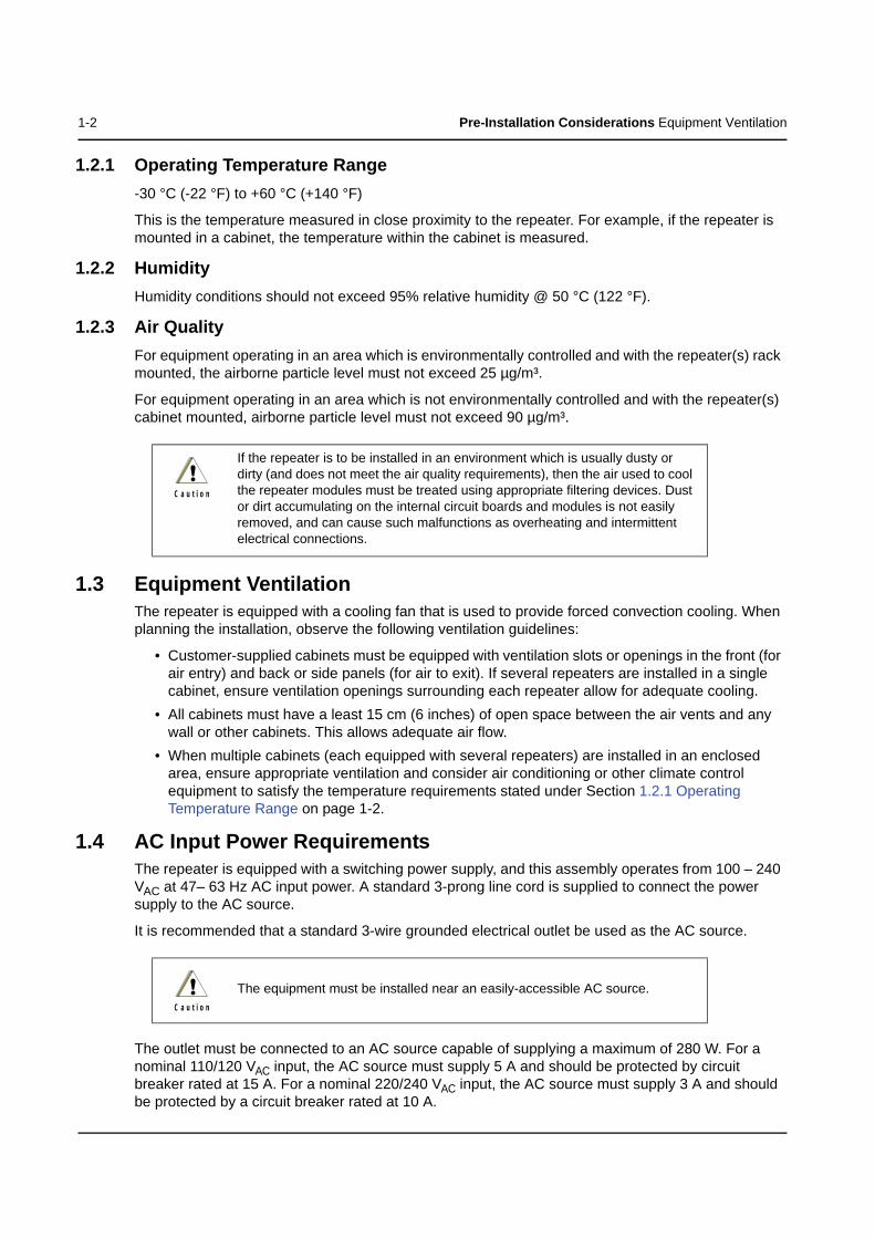
1.2.1 Operating Temperature Range-30 °C (-22 °F) to +60 °C (+140 °F)
This is the temperature measured in close proximity to the repeater. For example, if the repeater is mounted in a cabinet, the temperature within the cabinet is measured.
1.2.2 HumidityHumidity conditions should not exceed 95% relative humidity @ 50 °C (122 °F).
1.2.3 Air Quality For equipment operating in an area which is environmentally controlled and with the repeater(s) rack mounted, the airborne particle level must not exceed 25 µg/m³.
For equipment operating in an area which is not environmentally controlled and with the repeater(s) cabinet mounted, airborne particle level must not exceed 90 µg/m³.
1.3 Equipment VentilationThe repeater is equipped with a cooling fan that is used to provide forced convection cooling. When planning the installation, observe the following ventilation guidelines:
• Customer-supplied cabinets must be equipped with ventilation slots or openings in the front (for air entry) and back or side panels (for air to exit). If several repeaters are installed in a single cabinet, ensure ventilation openings surrounding each repeater allow for adequate cooling.
• All cabinets must have a least 15 cm (6 inches) of open space between the air vents and any wall or other cabinets. This allows adequate air flow.
• When multiple cabinets (each equipped with several repeaters) are installed in an enclosed area, ensure appropriate ventilation and consider air conditioning or other climate control equipment to satisfy the temperature requirements stated under Section 1.2.1 Operating Temperature Range on page 1-2.
1.4 AC Input Power RequirementsThe repeater is equipped with a switching power supply, and this assembly operates from 100 – 240 VAC at 47– 63 Hz AC input power. A standard 3-prong line cord is supplied to connect the power supply to the AC source.
It is recommended that a standard 3-wire grounded electrical outlet be used as the AC source.
The outlet must be connected to an AC source capable of supplying a maximum of 280 W. For a nominal 110/120 VAC input, the AC source must supply 5 A and should be protected by circuit breaker rated at 15 A. For a nominal 220/240 VAC input, the AC source must supply 3 A and should be protected by a circuit breaker rated at 10 A.
If the repeater is to be installed in an environment which is usually dusty or dirty (and does not meet the air quality requirements), then the air used to cool the repeater modules must be treated using appropriate filtering devices. Dust or dirt accumulating on the internal circuit boards and modules is not easily removed, and can cause such malfunctions as overheating and intermittent electrical connections.
The equipment must be installed near an easily-accessible AC source.
!C a u t i o n
!C a u t i o n

Pre-Installation Considerations Equipment Mounting Methods 1-3
1.4.1 Circuit OverloadingConsideration should be given to the effects of overloading on overcurrent protection devices and supply wiring. Appropriate consideration of equipment ratings should be used when addressing this concern.
1.5 Equipment Mounting MethodsThe MOTOTRBO Repeater may be mounted in a rack, bracket or cabinet (available as accessories).
1.6 Site Grounding and Lightning Protection
One of the most important considerations when designing a communications site is the ground and lightning protection system. While proper grounding techniques and lightning protection are closely related, the general category of site grounding may be divided into the following section.
1.6.1 Electrical GroundGround wires carrying electrical current from circuitry or equipment at the site is included in the category of electrical ground. Examples include the AC or DC electrical power used to source equipment located at the site, and wires or cables connected to alarms or sensors located at the site.
1.6.2 RF GroundThis type of ground is related to the bypassing of unwanted radio frequency energy to earth ground. An example of RF grounding is the use of shielding to prevent or at least minimize the leakage of unwanted RF energy from communications equipment and cables.
1.6.3 Lightning Ground Providing adequate lightning protection is critical to a safe reliable communications site. RF transmission cables, and AC and DC power lines must all be protected to prevent lightning energy from entering the site.
Comprehensive coverage of site grounding techniques and lightning protection is not within the scope of this instruction manual, but there are several excellent industry sources for rules and guidelines on grounding and lightning protection at communications sites.
NOTE: Motorola recommends the following reference source: Motorola Quality Standards Fixed Network Equipment Installation Manual R56 (part number 6881089E50)
1.6.4 Equipment GroundingThe repeater is equipped with a ground screw located on the rear of the repeater power supply module. This screw is used to connect the repeater to the site grounding. All antenna cables, and AC and DC power cabling, should be properly grounded and lightning protected by following the rules and guidelines provided in the above reference. Failure to provide proper lightning protection may result in permanent damage to the radio equipment.
Proper site grounding and lightning protection are vitally important considerations. Failure to provide proper lightning protection may result in permanent damage to the radio equipment.
!W A R N I N G
!

1-4 Pre-Installation Considerations
Notes

Chapter 2 Mechanical Installation
This section describes the procedures to unpack and mechanically install the MOTOTRBO Repeater. A variety of mounting methods are possible depending on which type of cabinet or rack (if any) has been selected to house the repeater(s).
2.1 Unpacking EquipmentThe following items are packed together in the box:
• MOTOTRBO Repeater• AC Line Cord• R & TTE Leaflet• Product Safety and RF Exposure Booklet• Battery Backup Cable (option)
2.2 Transferring Equipment from Shipping Container to Rack or CabinetThe repeater is shipped in a box. Upon delivery, the equipment must be removed from the container and transferred to a rack or cabinet.
NOTE: Customer-supplied cabinets and racks must have mounting rail and hole spacing compatible with EIA Universal 48.3 cm (19 inches) specifications. Cabinets must provide adequate ventilation (see “Environmental Conditions at Intended Installation Site” on page 1-1) and must meet the following minimum criteria:
- 41.3 cm (16.25 inches) deep- 48.3 cm (19 inches) wide- 13.4 cm (5.25 inches) high- Two mounting rails 5 cm (2 inches) from the front of the cabinet with front mounting holes
5.7 cm (2.25 inches) apart (center to center).
Contact Motorola Technical Support for specific question(s) regarding mounting equipment in customer-supplied cabinets.
Be sure to observe proper electrostatic discharge precautions if modules must be removed from the repeater.
Inspect the equipment for damage immediately after unpacking, and make a report of the extent of any damage to the transportation company and to Motorola.
!C a u t i o n
!W A R N I N G
!

2-2 Mechanical Installation
Notes
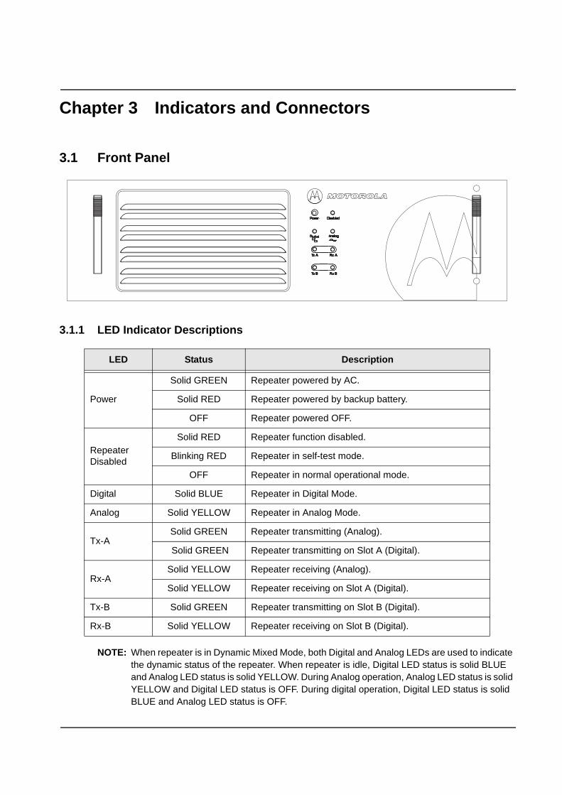
Chapter 3 Indicators and Connectors
3.1 Front Panel
3.1.1 LED Indicator Descriptions
NOTE: When repeater is in Dynamic Mixed Mode, both Digital and Analog LEDs are used to indicate the dynamic status of the repeater. When repeater is idle, Digital LED status is solid BLUE and Analog LED status is solid YELLOW. During Analog operation, Analog LED status is solid YELLOW and Digital LED status is OFF. During digital operation, Digital LED status is solid BLUE and Analog LED status is OFF.
LED Status Description
Power
Solid GREEN Repeater powered by AC.
Solid RED Repeater powered by backup battery.
OFF Repeater powered OFF.
Repeater Disabled
Solid RED Repeater function disabled.
Blinking RED Repeater in self-test mode.
OFF Repeater in normal operational mode.
Digital Solid BLUE Repeater in Digital Mode.
Analog Solid YELLOW Repeater in Analog Mode.
Tx-ASolid GREEN Repeater transmitting (Analog).
Solid GREEN Repeater transmitting on Slot A (Digital).
Rx-ASolid YELLOW Repeater receiving (Analog).
Solid YELLOW Repeater receiving on Slot A (Digital).
Tx-B Solid GREEN Repeater transmitting on Slot B (Digital).
Rx-B Solid YELLOW Repeater receiving on Slot B (Digital).

3-2 Indicators and Connectors
3.2 Rear Panel
3.2.1 Rear Panel Part
No Item Description
Rx Connector BNC (Female).
Power Supply On/Off Switch Turns on or off the power to the repeater from AC input.
Battery Backup Connector (DC Input)
Backup battery supplies backup power to the repeater. The battery is an optional accessory. The repeater will trickle charge battery, but an external charger is recommended to equalize battery after a prolonged use. Auto switching from AC to battery with loss of AC power is a function of the standard repeater power supply. Supply will automatically switch back to AC operation upon the return of AC power. The front panel power LED switches from green to red when on battery power.
Power Supply Fan Runs continuously to cool the repeater.
Main Power Supply Connector (AC Input) 100 – 240 V.
Rear Accessory Connector Programming cable plugs in here.
Ethernet Connector 10-Base-T/100-Base-Tx (RJ45).
Main Fan Variable speed. Idles at room temperature. Speeds up with extended use of the repeater.
Tx Connector Type-N (Female).
Ground Screw Must be connected to System Ground.
1
3
2 4
5
6
78
9
10
1
2
3
4
5
6
7
8
9
10

Indicators and Connectors Rear Panel 3-3
3.2.2 Rear Accessory ConnectorThe rear accessory connector is located above the ethernet connector. Most of the Motorola-approved accessories are supplied with female terminals crimped to a 20-gauge wire specifically designed to fit the housing of the rear accessory connector.
Insert the female terminal into the accessory connector housing in the appropriate locations. The accessory connector housing is provided together with the accessory. Connect the accessory connector housing to the rear accessory connector on the back of the repeater. Do not use other generic terminals in the housing. Generic terminals can cause electrical intermittences and may cause damage to the housing.
3.2.3 Ethernet ConnectorThe Ethernet connector supports both 10-Base T and 100-Base-Tx connections. There are two integrated LEDs (only supported on 32 MB repeaters) in the connector:
Status Description
Green LED Indicates 100 Mbits speed when lit, and 10 Mbits speed when OFF.
Yellow LED Indicates a valid link when lit solid, and transmit/receive activity when blinking.

3-4 Indicators and Connectors Rear Panel
1 Pulling this line to ground activates the PTT function, thus activating the AUX_MIC input.2 Fixed level (independent of volume level) received audio signal, including alert tones. Flat or de-emphasis are
programmed by CPS. Output voltage is approximately 330 mVrms for 1kHz of deviation.3 This input is used to detect when a rear microphone accessory is taken off-hook.4 This microphone signal is independent of the microphone signal on the front microphone connector. The nominal
input level is 80mVrms for 60% deviation. The DC impedance is 660 ohms and the AC impedance is 560 ohms.
Table 3-1 Rear Accessory Connector Pin Functions
Pin No. Pin Name Pin Function Pin
No. Pin Name Pin Function
1 D+ USB + (Data) 14 Rx Audio Receive Live Audio2
2 D- USB - (Data) 15 AUX Audio 2 PUBLIC Address 2
3 VBUS USB Power (5V from USB accessory/cable) 16 GND Ground
4 USB/MAP_ID GND USB/MAP_ID Ground 17 GP5-1 (PTT) 5V Level GPIO, PTT Input1
5 MAP_ID_2 Accessory Identifier 18 GND Ground6 MAP_ID_1 Accessory Identifier 19 GP5-2 (Monitor) 5V Level GPIO, Monitor Input3
7 SW B+ Switched Battery Voltage 20 GP5-6 5V Level GPIO
8 PWRGND Ground 21 GP5-3 5V Level GPIO, Channel Activity Function
9 SPKR- Speaker - (3.2 ohm minimum impedance) 22 GP5-7 5V Level GPIO
10 SPKR+ Speaker + (3.2 ohm minimum impedance) 23 EMERGENCY Emergency Switch Input
11 Tx Audio Rear External Microphone Input4 24 GP5-7 No connection
12 Audio GND Audio Ground 25 IGN SENSE No connection
13 AUX Audio 1 PUBLIC Address 1 26 VIP-1 12V Tolerant, 5V GPIO, External alarm
1
2
3
4
5
6
7
8
9
10
11
12
13
14
15
16
17
18
19
20
21
22
23
24
25
26
D+
Vbu
s
SW
B+
Spk
r-
Tx A
udio
Aux
Aud
io O
ut 1
/ R
xD
Aux
Aud
io O
ut 2
/ Tx
D
GP
5_1
(PTT
)
GP
5_2
(Mon
itor)
GP
5_3
(Cha
n A
ct)
Em
erg
Sw
Ign
Sen
se
D-
US
B /
MA
P_I
D G
roun
d
MA
P_I
D_1
Pow
er G
roun
d
Spk
r+
Aud
io G
roun
d
Rx
Aud
io
Gro
und
Gro
und
GP
5_6
GP
5_7
GP
5_8
VIP
_1 (E
xt A
larm
)
MA
P_I
D_2

Chapter 4 Electrical Connections
After the MOTOTRBO Repeater has been mechanically installed, electrical connections must be made. This involves making the following connections:
• AC power cord, and• antenna coaxial cables
Figure 4-1 shows the position of the various connectors and connections on the rear panel of the repeater.
Figure 4-1 Locations of Connectors on the Rear Panel of the Repeater
4.1 Power Supply Connections 4.1.1 AC Input Power Connection
NOTE: The AC source must be installed near the equipment and must be easily accessible.
Each repeater ships with a 2.438 m (8 feet) 3-conductor line cord that connects the repeater to a 110/120/220/240 VAC source. Figure 4-1 shows the location where the AC line cord connects to the repeater. Insert the 3-prong plug into a 110/120/220/240 VAC grounded outlet.
If an alternate line cord is required, obtain a suitable line cord, with fittings approved by the safety testing agency in the end-use country, from a certified electrical parts supplier.
Do NOT apply AC power to the repeater at this time. Make sure that the circuit breaker associated with the AC outlet is turned to OFF.
Tx Rx
GND
POWER SUPPLY FAN BATTERY
BACKUP CONNECTOR AC LINE CORD CONNECTOR
ETHERNET CONNECTOR
GROUND SCREW
TX CONNECTOR RX CONNECTOR
POWER SUPPLY ON/OFF SWITCH REAR
ACCESSORYCONNECTOR
MAIN FAN
!C a u t i o n

4-2 Electrical Connections Power Supply Connections
4.1.2 Ground ConnectionThe repeater is equipped with a ground screw located on the rear of the repeater. Connect the site ground cable to the ground screw.
4.1.3 Battery Backup ConnectionThe MOTOTRBO Repeater offers the capability of connecting to battery backup power in the event of an AC power failure.
The battery backup system is connected to the repeater through the DC connector mounted at the rear of the repeater (see Figure 4-2).
The repeater power supply will trickle charge the backup battery. If the battery is significantly discharged, it is recommended that an external charger be used to charge the battery.
Figure 4-2 Making Connections to a Backup Battery
Refer to Motorola Quality Standards Fixed Network Equipment Installation Manual R56 (6881089E50), for complete information regarding lightning protection.
The repeater should only be connected to a battery supply that is in accordance with the applicable electrical codes for the end use country; for example, the National Electrical Code ANSI/NFPA No. 70 in the U.S.
The repeater is to be connected to a battery charger that is in accordance with the applicable electrical codes for the end use country; for example, the National Electrical Code ANSI/NFPA No.70 in the U.S.
Unplug the battery from the repeater when charging the battery with an external charger.
!C a u t i o n
!C a u t i o n
!C a u t i o n
!C a u t i o n
+
-
FUSE

Electrical Connections RF Antenna Connections 4-3
4.2 RF Antenna ConnectionsThe transmit and receive antenna RF connection are made using two separate connectors. Coaxial cables from the receive and transmit antenna must be connected to the Type-N (Tx) and BNC (Rx) connectors. The position of these connectors is shown in Figure 4-1. For repeater use, the antennas need adequate isolation between them, or if one antenna is used, the duplexer needs to have adequate isolation between the Tx and Rx ports. The isolation requirements are unique to each band and are shown in the table below:
If the duplexer isolation is not adequate, a preselector may also be used.
4.2.1 Duplexer SelectionThe selection of a duplexer is critical to system performance. The use of a notch (band reject) duplexer is possible in some systems that are not located at high RF density sites.
The duplexer must be able to handle at least 50 W continuously. For the best system performance, the insertion loss should be less than 2 dB. If the repeater is used in higher RF density sites, the use of a pass-notch duplexer is recommended.
4.2.2 Antenna SelectionThe selection of the antenna is critical to system performance. The selected antenna must be 50 Ohm impedance and capable of at least 50 Watts. Gain antennas may be used to increase system coverage. Please take note of licensing restrictions when selecting gain antennas. Some services or regions may have antenna gain or system ERP limitations.
The antenna must be connected to the duplexer with a high grade 50 Ohm transmission line (hardline). The line must have connectors to match the connectors on the duplexer and antenna. For proper antenna installation, please also consult the Motorola Quality Standards Fixed Network Equipment Installation Manual R56 (6881089E50).
Frequency Band Bandwidth Isolation
UHF 1 403 – 470 MHz 75 dB
UHF 2 450 – 512 MHz 85 dB
VHF 136 – 174 MHz 85 dB
The repeater can key up at any time due to input from a subscriber unit or a CW ID. Please ensure that all power is switched off before disconnecting the transmit antenna.
It is important that all antenna cables are grounded at the point they enter the building.
The antenna design is the customer's responsibility. All aspects of the antenna design must comply with the relevant local regulations.
!C a u t i o n
!C a u t i o n
!C a u t i o n

4-4 Electrical Connections
Notes
Chapter 5 Post-Installation Checklist
After the MOTOTRBO Repeater has been mechanically installed and all electrical connections have been made, power may now be applied and the repeater checked for proper operation.
5.1 Applying PowerBefore applying power to the repeater, make sure all boards are securely seated in the appropriate connectors on the backplane and that all RF cables are securely connected.
Turn ON the circuit breaker controlling the AC outlet that is supplying power to the repeater Power Supply Module.
5.2 Verifying Proper OperationOperation of the repeater can be verified by:
• observing the state of the 8 LEDs located on the front panel, and• exercising radio operation.
5.2.1 Front Panel LEDsAfter turning ON the repeater power (or after a repeater reset), the 8 LEDs on the repeater front panel:
• Light for about one second to indicate that they are functional, then• Go off for one second, then• Indicate the operational status of the repeater.
5.3 Archiving5.3.1 Copying the Repeater Codeplug Data to a Computer
Backup the repeater's codeplug data by using the Customer Programming Software (CPS) on a computer.
Some repeater components can become extremely hot during operation. Turn off all power to the repeater and wait until sufficiently cool before touching the repeater.
!C a u t i o n

5-2 Post-Installation Checklist
Notes

Appendix A EMEA Regional Warranty, Service and Technical Support
A.1 Warranty and Service SupportMotorola offers long term support for its products. This support includes full exchange and/or repair of the product during the warranty period, and service/ repair or spare parts support out of warranty. Any "return for exchange" or "return for repair" by an authorized Motorola Dealer must be accompanied by a Warranty Claim Form. Warranty Claim Forms are obtained by contacting an Authorized Motorola Dealer.
A.1.1 Warranty Period and Return Instructions
The terms and conditions of warranty are defined fully in the Motorola Dealer or Distributor or Reseller contract. These conditions may change from time to time and the following notes are for guidance purposes only.
In instances where the product is covered under a "return for replacement" or "return for repair" warranty, a check of the product should be performed prior to shipping the unit back to Motorola. This is to ensure that the product has been correctly programmed or has not been subjected to damage outside the terms of the warranty.
Prior to shipping any radio back to the appropriate Motorola warranty depot, please contact Customer Resources (Please see page A-3). All returns must be accompanied by a Warranty Claim Form, available from your Customer Services representative. Products should be shipped back in the original packaging, or correctly packaged to ensure no damage occurs in transit.
A.1.2 After Warranty Period
After the Warranty period, Motorola continues to support its products in two ways.
1. Motorola's Managed Technical Services (MTS) offers a repair service to both end users and dealers at competitive prices.
2. MTS supplies individual parts and modules that can be purchased by dealers who are technically capable of performing fault analysis and repair.

A-2 EMEA Regional Warranty, Service and Technical Support European Radio Support Centre (ERSC)
A.2 European Radio Support Centre (ERSC)The ERSC Customer Information Desk is available through the following service numbers:
Austria: 08 00 29 75 41 Italy: 80 08 77 387
Belgium: 08 00 72 471 Luxemburg: 08 00 23 27
Denmark: 80 88 05 72 Netherlands: 08 00 22 45 13
Finland: 08 00 11 49 910 Norway: 80 01 11 15
France: 08 00 90 30 90 Portugal: 08 00 84 95 70
Germany: 08 00 18 75 240 Spain: 90 09 84 902
Greece: 00 80 04 91 29 020 Sweden: 02 07 94 307
UK: 08 00 96 90 95 Switzerland: 08 00 55 30 82
Ireland: 18 00 55 50 21 Iceland: 80 08 147
Or dial the European Repair and Service Centre: Tel: +49 30 6686 1555
Please use these numbers for repair enquiries only.
A.3 Piece PartsSome replacement parts, spare parts, and/or product information can be ordered directly. If a complete Motorola part number is assigned to the part, it is available from Motorola Radio Products and Solutions Organization (RPSO). If no part number is assigned, the part is not normally available from Motorola. If the part number is appended with an asterisk, the part is serviceable by Motorola Depot only. If a parts list is not included, this generally means that no user-serviceable parts are available for that kit or assembly.
Orders for replacement parts, kits and assemblies should be placed directly on Motorola's local distribution/dealer organisation or via Motorola Online at: https://emeaonline.motorola.com/Login.aspx
* The Radio Products and Solutions Organization (RPSO) was formerly known as the Radio Products Services Division (RPSD) and/or the Accessories and Aftermarket Division (AAD).

EMEA Regional Warranty, Service and Technical Support Technical Support A-3
A.4 Technical SupportMotorola Product Services is available to assist the dealer/distributors in resolving any malfunctions which may be encountered.
North Europe - Stephen Woodrow Central and East Europe - Siggy PunzenbergerTelephone: +44 (0) 1256 488 082 Telephone: +49 (0) 6128 70 2342Fax: +44 01256 488 080 Fax: +49 (0) 6128 95 1096Mail: [email protected] Mail: [email protected]
Russia and Belarus - Andrey Nagornykh Germany - Customer Connect TeamTelephone: +7 495 787 8910 Telephone: +49 (0) 30 6686 1539Fax: +7 495 785 0185 Fax: +49 (0) 30 6686 1916Email: [email protected] Email: [email protected]
Middle East and Africa - Wayne Holmes Italy - Ugo GentileTelephone: +27 11 800 7922 Telephone: +39 02 5220 7825Fax: +27 11 800 7923 Fax: +39 02 5220 7810Email: [email protected] Email: [email protected]
France - Armand Roy France - Laurent IrrmannTelephone: +33 1 6935 7868 Telephone: +33 1 6935 7866Fax: +33 1 6935 7808 Fax: +33 1 6935 7808Email: [email protected] Email: [email protected]
A.5 Further Assistance From MotorolaYou can also contact the Customer Help Desk through the following web address.http://www.motorola.com/Business/XU-EN/Government

A-4 EMEA Regional Warranty, Service and Technical Support Further Assistance From Motorola
Notes


6866576D02-F*6866576D02*
MOTOROLA, MOTO, MOTOROLA SOLUTIONS and the Stylized M logo are trademarks or registered trademarks of Motorola Trademark Holdings, LLC and are used under license. All other trademarks are the property of their respective owners. © 2007 – 2011 Motorola Solutions, Inc. All rights reserved.March 2011.
www.motorola.com/mototrbo
Copyright © 2022 FDOKUMEN