
PROFIBUS Fiberoptic Repeater OZD 485 G12 PRO ...
12
General Safety Instructions This device is electrically operated. Adhere strictly to the safety requirements relating to voltages applied to the device as described in the operating instructions! Make sure that the electrical installation meets local or nationally applicable safety regulations. z Warning! Failure to observe the information given in the warnings could result in serious injury and/or major damage. Only personnel that have received appropriate training should operate this device or work in its immediate vicinity. The personnel must be fully familiar with all of the warnings and maintenance measures in these operating instructions. Correct transport, storage, and assembly as well as careful operation and maintenance are essential in ensuring safe and reliable operation of this device. Never start operation with damaged components! z Warning! Any work that may have to be performed on the electrical installation should be performed by fully qualified technicians only. z Warning! CLASS 1 LASER PRODUCT in accordance with IEC 60825-1 (2014). Certified Usage Please observe the following: z Warning! The device may only be employed for the purposes described in the catalog and technical description, and only in conjunction with external devices and components recommended or approved by Hirschmann. The product can only be operated correctly and safely if it is transported, stored, installed and assembled properly and correctly. Furthermore, it must be operated and serviced carefully. Safety Guidelines Power Supply Switch the basic devices on only when the housing is closed. z Warning! The devices may only be connected to the supply voltage shown on the type plate. The devices are designed for operation with a safety extra-low voltage.Thus, they may only be connected to the supply voltage connections and to the signal contact with PELV circuits or alternatively SELV circuits with the voltage restrictions in accordance with IEC950/ EN60950/ VDE0805. Relevant for North America: The subject unit is to be suppplied by a Class 2 power source complying with the requirements of the National Electrical Code, table 11(b). If power is redundant supplied (two individual power sources) the power sources together should comply with the requirements of the National Electrical Code, table 11(b). Use 90 or 90°C copper (Cu) wire only. Startup Information OZD 485 G12 PRO FIRMWARE INVENSYS TRICONEX
-
Upload
khangminh22 -
Category
Documents
-
view
0 -
download
0
Transcript of PROFIBUS Fiberoptic Repeater OZD 485 G12 PRO ...

General Safety Instructions� This device is electrically operated. Adhere strictly to the safety requirements relating to voltages applied to the device
as described in the operating instructions!
� Make sure that the electrical installation meets local or nationally applicable safety regulations.
zWarning!Failure to observe the information given in the warnings could result in serious injury and/or major damage. Only personnel that have received appropriate training should operate this device or work in its immediate vicinity.The personnel must be fully familiar with all of the warnings and maintenance measures in these operating instructions.Correct transport, storage, and assembly as well as careful operation and maintenance are essential in ensuringsafe and reliable operation of this device.Never start operation with damaged components!
zWarning!Any work that may have to be per formed on the electrical installation should be performed by fully qualified technicians only.
zWarning!CLASS 1 LASER PRODUCT in accordance with IEC 60825-1 (2014).
Certified UsagePlease observe the following:
zWarning!The device may only be employed for the purposes described in the catalog and technical description, and only inconjunction with external devices and components recommended or approved by Hirschmann. The product canonly be operated correctly and safely if it is transported, stored, installed and assembled properly and correctly. Furthermore, it must be operated and serviced carefully.
Safety Guidelines Power Supply� Switch the basic devices on only when the housing is closed.
zWarning!The devices may only be connected to the supply voltage shown on the type plate. The devices are designed for operation with a safety extra-low voltage.Thus, they may only be connected to the supply voltage connec tions andto the signal contact with PELV circuits or alternatively SELV circuits with the voltage restrictions in accordancewith IEC950/ EN60950/ VDE0805.
Relevant for North America:� The subject unit is to be suppplied by a Class 2 power source complying with the requirements of the National Electrical
Code, table 11(b). If power is redundant supplied (two individual power sources) the power sources together shouldcomply with the requirements of the National Electrical Code, table 11(b).
� Use 90 or 90°C copper (Cu) wire only.
Startup Information
OZD 485 G12 PRO FIRMWARE INVENSYS TRICONEX

2
Safety Guidelines Environment
zWarning!The device may only be operated in the listed ambient temperature range at the listed relative air humidity (non-condensing).
� The installation location is to be selected so as to ensure compliance with the climatic limits listed in the TechnicalData (see page 7).
� To be used in a Pollution Degree 2 environment only (IEC 60664-1).
Note on CE Identification
7The devices comply with the regulations of the following European directive:
89/336/EECCouncil Directive on the harmonization of the legal regulations of member states on electromagnetic compatibility (amended by Directives 91/263/EEC, 92/31/EEC and 93/68/EEC).
The EU declaration of conformity is kept available for the responsible authorities in accordance with the above-mentionedEU directives at:
Hirschmann Automation and Control GmbH Stuttgarter Strasse 45 – 5172654 NeckartenzlingenGermanyTelephone +49 (0) 1805 14-1538Email [email protected]
FCC RULESThis device complies with part 15 of the FCC Rules. Operation is subject to the following two conditions:
(1) This device may not cause harmful interference, and (2) this device must accept any interference received, including interference that may cause undesired operation.
Note: This equipment has been tested and found to comply with the limits for a Class A digital device, pursuant to part15 of the FCC Rules. These limits are designed to provide reasonable protection against harmful interference when theequipment is operated in a commercial environment. This equipment generates, uses, and can radiate radio frequencyenergy and, if not installed and used in accordance with the instruction manual, may cause harmful interference to radiocommunications. Operation of this equipment in a residential area is likely to cause harmful interference in which case theuser will be required to correct the interference at his own expense.
C-TickAustralia/New Zealand
This product meets the requirements of the AS/NZS 3548 standard.
N1337

3
ApprovalscUL508 Please note the important information in: ”Relevant information for North America“, below.
ISA12.12.01Hazardous Locations Class1 Div 2 Groups A, B, C und D Please note the important information in: ”Relevant information for North America“, below.
ATEX RL 94/9EG Zone 2 3GPlease note the important information in: ”Relevant information for use in Ex zone 2 according to ATEX 94/9/EC“ – seepage 4.
Note: Only the certifications indicated on the label attached to each device are applicable.
Relevant information for North America:
� Only for connection with a Class 2 power supply.
� For use in Class 2 Circuits.
� Use 90 or 90°C copper(CU) wire only.
Additional Information for Use in Hazardous Locations:
This product may be operated in hazardous locations only if the product label is marked accordingly. The following information applies when operating this equipment in hazardous locations:
Products marked ”Class I, DIV 2, Group A, B, C and D“ are suitable for use in Class I Division 2 Groups A, B, C, D, Hazardous Locations and nonhazardous locations only. Each product is supplied with markings on the rating nameplateindicating the hazardous location temperature code. When combining products within a system, the most adverse temperature code (lowest ”T“ number) may be used to help determine the overall temperature code of the system. -Wiring must be in accordance with Class I Div. 2 wiring methods and in accordance with the authority having jurisdiction.
� The peripheral equipment must be suitable for the location in which it is used.
� These devices must be installed as non-incendive according to the Control Drawing No. 000100622DNR / Class 1 Div 2 in this document.
� These devices are open-type devices that are to be installed in an enclosure according to ANSI/UL50, suitable for the environment in which it is used.

4
Relevant information for use in Ex zone 2 according to ATEX 94/9/EG:
This product may be operated in EX zone 2 only if the product label is marked accordingly. The following information applies when operating this equipment in EX zone 2:
II 3GEx nA ic IIC T4 Gc
DEMKO 07 ATEX 142156X
Temperature Code T4 Ta: –25 … +70 °C
List of Standards EN 60079-15: 2010, EN 60079-0: 2012EN 60079-11:2012
Optical power emission 5 mW max. (820 nm)
DO NOT OPEN WHEN ENERGIZED7 POLE CONNECTOR: DO NOT SEPERATE WHEN ENERGIZED
Installation instructions:
The OZD 485 G12 PRO modules shall be used in an area with a classification of no more than pollution degree 2 and con-forming to IEC 60664-1.The OZD 485 G12 PRO modules shall be installed in an enclosure with a tool-removable cover that complies with therelevant requirements of EN 60079-15, rated at least IP54.The Fault contacts shall be installed as non-incendive in accordance with the Control Drawing No. 000100622DNR forATEX Zone 2 – see the next pages in this document.The modules shall be connected to supply circuits where the rated voltage cannot exceed the threshold of 119 V due totransient disturbances.
The pictures show two alternatives by external installation.
Max. line length, depending on cross section area: 200 mm at 0.5 mm2
400 mm at 1.0 mm2
800 mm at 2.0 mm2
T2 T2T1 T1
K
A
K
A
K
A
K
A
T1: Transient voltage protection, not exceeding 119 V, shall be provided at the power supply terminal of the apparatus.Example: for 24 V power supply you can use P4KE30A or P6KE30A.
T2: Prevent between 0 V pin or fault pins of 7 pole connector and earth/frame transient voltages greater than 119 V peak, e.g. by overvoltage limiters (T2) or short circuits (see pictures).

5
Notes for OZD 485 G12 PRO FIRMWARE INVENSYS TRICONEX: RT+ and Ua3 are not available, RT- is replaced by GND.
Notes:
DIL-Switches are classified as nA ic.
Energy-limited Parameters:
Entity Parameters
7 pole, Fault contacts 30V 90mA 200nF 5mH
Monitor out: Ua2, Ua3, GND Equipment
K1+, K1-
RT-
K2+, K2-
RT+
RT+Equipment
0V
+24V (P1)
+24V (P2)
Power supply
Equipment with Energy-limitedparameters nA ic
Fault
–– – –
The Energy-limited circuit concept allows interconnection of Energy-limited apparatus and associated
Energy-limited apparatus using any of the wiring methods permitted for unclassified locations when certain
parametric conditions are met.
WARNING – EXPLOSION HAZARD – SUBSTITUTION OF ANY COMPONENTS MAY IMPAIR
SUITABILITY FOR HAZARDOUS LOCATIONS OR EXPLOSIVE ATMOSPHERES.
WARNING – EXPLOSION HAZARD – DO NOT DISCONNECT EQUIPMENT UNLESS POWER HAS BEEN
SWITCHED OFF OR THE AREA IS KNOWN TO BE NON-HAZARDOUS.
DO NOT OPEN WHEN ENERGIZED.
Title:
Size A4 Document No.: 000100622DNR Rev. 3
Date: 2014-04-02 Page 1/1
Control Drawing for OZD 485 G12 Pro

Notes for OZD 485 G12 PRO FIRMWARE INVENSYS TRICONEX: RT+ and Ua3 are not available, RT- is replaced by GND.
Power Supply: (Redundant: P1 P2)
24VDC
NON HAZARDOUS LOCATION
Relay Contacts:
Equipment with nonincendive field wiring
parameters.
Polarity is not relevant.
THE RELAY TERMINALS ARE DEPENDENTUPON THE FOLLOWING ENTITYPARAMETERS.
30V 90mA 200nF 5mH
Vmax
Imax
Ci
Li
HAZARDOUS LOCATION
Rev.: 3 Document No.: 000100622DNR Date: 2013-12-03
CONTROL DRAWING for OZD 485 G12 ProAccording to ANSI / ISA 12.12.01-2011
WARNING – EXPLOSION HAZARD – SUBSTITUTION OF ANY COMPONENTS MAY IMPAIRSUITABILITY FOR HAZARDOUS LOCATIONS OR EXPLOSIVE ATMOSPHERES. WARNING – EXPLOSION HAZARD – DO NOT DISCONNECT EQUIPMENT UNLESS POWER HAS BEENSWITCHED OFF OR THE AREA IS KNOWN TO BE NON-HAZARDOUS. DO NOT OPEN WHEN ENERGIZED.
Notes:
The nonincendive field wiring circuit concept allows interconnection of nonincendive field wiring apparatus
and associated nonincendive field wiring apparatus using any of the wiring methods permitted for unclassified
locations when certain parametric conditions are met.
Capacity: Ca Ci + CCableInductivity: La Li + LCable
The maximum cable length has to be determind as follows:
(a) max. Cable Length < ( La-Li) / CableL and (b) max. Cable Length < ( Ca-Ci) / CableCThe lower value of (a) and (b) is to apply.
CableL: inductance per unit length of used cable.
CableC: capacitance per unit length of used cable.
Other C-parameters and L-parameters are according to ANSI / ISA 12.12.01 2011 section 7.
Nonincendive field wiring circuits must be wired in accordance with the National Electrical Code (NEC),
NFPA 70, article 501.
CONTROL DRAWING: Hazardous Locations Class I Division 2 Groups A, B, C, D
6
7
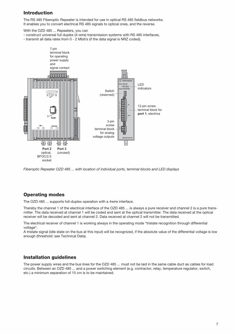
IntroductionThe RS 485 Fiberoptic Repeater is intended for use in optical RS 485 fieldbus networks.It enables you to convert electrical RS 485 signals to optical ones, and the reverse.
With the OZD 485 ... Repeaters, you can - construct universal full duplex (4-wire) transmission systems with RS 485 interfaces,- transmit all data rates from 0 - 2 Mbit/s (if the data signal is NRZ coded).
Fiberoptic Repeater OZD 485 ... with location of individual ports, terminal blocks and LED displays
12-pin screw terminal block for port 1, electrica
7-pin terminal block for operating power supply and signal contact
LEDindicators
Switch(reserved)
Port 3(unused)
Port 2optical,
BFOC/2.5socket
System
OZD 485 G12 TRI
DA/STAT 1P2
2P1
K1+
K1+
K1-
K1-
GND
GND
K2-
K2-
K2+
K2+
Ua2
GND
3-pinscrew
terminal blockfor analog
voltage outputs
IN
OUT
Operating modesThe OZD 485 ... supports full-duplex operation with a 4wire interface.
Thereby the channel 1 of the electrical interface of the OZD 485 ... is always a pure receiver and channel 2 is a pure trans-mitter. The data received at channel 1 will be coded and sent at the optical transmitter. The data received at the opticalreceiver will be decoded and sent at channel 2. Data received at channel 2 will not be transmitted.
The electrical receiver of channel 1 is working always in the operating mode “tristate recognition through differential voltage“. A tristate signal (idle state on the bus at this input) will be recognized, if the absolute value of the differential voltage is lowenough (threshold: see Technical Data).
Installation guidelinesThe power supply wires and the bus lines for the OZD 485 ... must not be laid in the same cable duct as cables for loadcircuits. Between an OZD 485 ... and a power switching element (e.g. contractor, relay, temperature regulator, switch,etc.) a minimum separation of 15 cm is to be maintained.

8
K1+
K1+
K1-
K1-
GND
GND
K2-
K2-
K2+
K2+
Channel 1 / INBus line +Bus line –
Equipotential bonding
Bus line –Bus line +
Channel 2 / OUTtyp. 120 ΩR W
typ. 120 ΩR W
Point-to-point connection
FiberG 50/125 or G 62.5/125
max. 1.2 km
OZD 485 ...Monomaster
Local bus, max. 1 m Remote bus, max. 6 m
Local slaves Remote slaves
Master bus
Response bus
OZD 485 ... Remote slave
Ch2
Ch1Ch1
Ch2
Master bus
Response bus
Permissible network topologyThe OZD 485 ... supports only point-to-point connections. Thereby the optical transmitter of the repeater’s port 2 is connected with glass fibers (G 50/125 or G 62.5/125) to the optical receiver of the other repeater’s port 2, and vice versa.The length of the glass fiber may be from 0 to 1.2 km.
Termination and equipotential bondingThe electrical bus cables must be terminated at the start and end of the line – even for short electrical bus cables – withthe characteristic impedance (typically 120 ohm)If there is an OZD 485 ...I at the start or end of a data line, then the terminating resistors can be mounted directly on therepeater.At one of the two GND connections an equipotential bonding to the electrically connected participants must be set up. If a shielded data cable is used, the shield has to be connected to the ground potential of the switch cabinet.
Connection of the terminating resistors at the 12-pin screw terminal block

9
+ 24 V (P2)
+ 24 V (P1)
0 V 0 V
FAULT
Connection of the operating voltage and the function ground at the 7-pin screw terminal block
+ 24 V (P2)
+ 24 V (P1)
0 V 0 V
FAULT
Connection of the signal contact at the 7-pin screw terminal block
Operating voltage and function ground� The repeater should only be supplied with a regulated safety extra-low voltage in accordance with IEC/EN 60950-1/
VDE 0805 with a maximum of +24 VDC (for non-hazardous locations only: 32 VDC max.). It can be fed in using the 7-pin screw-type terminal block on the upper side of the repeater.
� Connect the function ground of the 7-pin terminal block to the ground of the switch cabinet.
Signaling ContactsAt the 7-pin screw-type terminal block on the upper side of the repeater, floating contacts of a relay are provided as a signaling contact. If the OZD 485 ... is functioning correctly the contact is closed.If a fault or power failure occurs, the contact is opened.
� Always ensure that the correct assignment is provided for the 7-pole terminal block. Make sure that the connectingleads of the signaling contacts are adequately insulated. Incorrect assignment can result in destruction of the repeater.
Limit values of relay contact– Max. switching voltage 32 V– Max. switching current: 90 mA (for non-hazardous locations only: 1 A, max switching capacity 30 W)
� The voltage connected to the relay must correspond to a safety extra-low voltage to IEC/EN 60950-1.
DIL switchesThe DIL switches of the OZD 485 ... are reserved, they must be in the “0“ position.
0 1
S 2S1
S 4S 3
reservedreserved
reservedreserved

10
LED displays
LED Indication Possible causes Signal contact
System Green - Repeater in fault-free operation No signalRed - Signal contact signals malfunction SignalNot lit - No voltage supply Signal
- Internal device fault
P 1 Green - Supply voltage 1 ok No signalNot lit - Supply voltage 1 low Signal
P 2 Green - Supply voltage 2 ok No signalNot lit - Supply voltage 2 low Signal
DA/STAT 1 Yellow - Data receiving at port 1 (channel 1) No signalNot lit - No input signal at port 1 No signal
DA/STAT 2 Green - Input power at port 2 ok No signalYellow - Optical data receiving at port 2 No signalNot lit - No input signal at port 2 Signal
Analog voltage outputsThe device has one analog voltage output Ua2. This supplies a short-circuit-proof output voltage for diagnosis purposese.g. for predictive maintenance in the range from 0 - 5 V (with reference to “GND” of the 3-pin terminal block) dependenton the optical power input at port 2.
� These voltage outputs are connected using a 3-pin screw terminal on the front side of the repeater.
� The screw terminal is suitable for cable leads that have a cross section between 0.2 - 2.5 mm2.
Ua2
GND
Analog voltage outputs – connections for 3-pin terminal block
Relationship between the output voltage at the terminals Ua2 and the optical input power at port 2
1000800600400200
Signal quality
Bad
Critical
Good
Output voltage [mV]
300100 900700500 5000

11
Voltage/power supply
Operating voltage NEC Class 2 power source 18 ... 24 VDC safety extra-low voltage(SELV/PELV); (for non-hazardous locations only: 18 ... 32 VDC), redundant inputs decoupled, buffer time min. 10 ms at 24 VDC
Current consumption at +18 VDC 180 mAat +32 VDC 110 mAInrush peak value 200 mA
Power consumption 3.5 W
Signal contactMaximum switching voltage 32 V (safety extra-low voltage), electrically isolated from the hou-
sing and all electrical connectionsMaximum switching current 90 mA (for non-hazardous locations only: 1 A, max switching
capacity 30 W, resistive load)
Electrical port
Transmitting level channel 2 (differential voltage) min. 1.5 V; max. 5 V
Transmitting offset voltage channel 2 1) min –1 V; max. +3 V
Input level channel 1 2)
Low < -0.7 VTristate –0.1 V to +0.1 VHigh > + 0.7 V
Input voltage range channel 1 3) min. –7 V; max. +12 V
Line lengthlocal bus max. 1 mremote bus max. 6 m
Optical interface
Wavelength typ. 860 nm
Launchable optical power- in fiber G 50/125 –20 dBm- in fiber G 62.5/125 –16 dBm
Receiver sensitivity –30 dBm
Transmission distance with 3 dB 4)
system reserve / line attenuation- with fiber G 50/125 (3.0 dB/km) 0 - 1.2 km/10 dB- with fiber G 62,5/125 (3.5 dB/km) 0 - 1.2 km/14 dB
Overload limit 5) –5 dBm
Optical connector BFOC/2.5 (ST ®)
Timing parameters
Data rate (NRZ) 2 Mbit/s
Signal processing time for a system with two max. 2 µsrepeaters from the electrical receiver of the one repeater to the electrical transmitter of the other repeater with 1m of fiber
Jitter for a system with two repeaters from the 30 nselectrical receiver of the one repeater to the electrical transmitter of the other repeater
Statical bit duration distortion at the electrical 10 nsoutput
Security
Protection class Class III Equipment; the repeater may only be supplied with SELV/PELV according IEC/EN 60950, EN 61131-2
Protection against laser radiation Class 1 Laser protection, according to IEC/EN 60825-1
Technical Data

12
Electromagnetic compatibility (EMC)
Interference immunity for industry in accordance with EN 61000-6-2:2001
Electrostatic discharging (ESD) conforms to EN 61000-4-2; 4 kV contact discharge, 8 kV air discharge
Electromagnetic field conforms to N 61000-4-3; 10 V/m (80 MHz - 2700 MHz), Fast transients (burst) conforms to EN 61000-4-4; 2 kV power line, 1 kV data lineVoltage surge conforms to EN 61000-4-5; 1 kV data line,
1 kV power line symmetrical,1 kV power line asymmetrical
Line-conducted interference voltages conforms to EN 61000-4-6; 10 V (150 kHz - 80 MHz);
Emitted interference conforms to EN 55022; Class Aconforms to FCC CFR47 Part 15; Class A
Ambient conditions during operation
Ambient temperature –25 °C to +70 °C (IEC 60068-2-1, IEC 60068-2-2)
Relative humidity <95 %, non-condensing (IEC 60068-2-30)
Pollution degree 2
Air pressure up to 2000 m (795 hPa)
Vibrations 3 to 9 Hz, 3,5 mm amplitude (IEC 61131-2);9 to 150 Hz, 1 g acceleration (IEC 61131-2)Frequency change range: 1 octave/min10 sweeps per axis in all 3 axesPursuant to IEC 60068-2-6, test Fc
Shock 15 g half sine for 11ms; 3 shocks in pos. and neg. direction in all 3 axesPursuant to IEC 60068-2-27, Test Ea
Ambient conditions during transport and storage
Storage temperature –25 °C to +80 °C (IEC 60068-2-1, IEC 60068-2-2)Relative humidity <95 %, non-condensing (IEC 60068-2-30)
Air pressure up to 3000 m (700 hPa)
HousingProtection class IP 20
Weight 194 g
Dimensions (W x H x D, with connections) 35 x 156 x 119 mm
1) Voltage between the function ground and the average on the signal lines2) Differential voltage K1+ - K1–3) Offset voltage for each individual signal line relating to the function ground4) Because of processing time limitations the lines may not be longer - irrespective of the optical budget5) maximal optical power without bit errors
039 560-501-06-1214
Hirschmann Automation and Control GmbH Stuttgarter Straße 45 – 5172654 NeckartenzlingenGermany
Tel.: +49 (0) 1805 14-1538Fax: +49 (0) 7127 14-1551Email: [email protected]: http://www.hirschmann.com