Release Notes for Cisco UCS Rack Server Software, Release ...
Upload
khangminh22Category
view
0download
0
SOFTWARE KR C2 Seminar workbook of ………………… Field Bus Technology - Profibus Release 4.x, 5.x Issued: April 2004

© Copyright KUKA Roboter GmbH This documentation or excerpts therefrom may not be reproduced or disclosed to third parties without the express permission of the publishers. Other functions not described in this documentation may be operable in the controller. The user has no claim to these functions, however, in the case of a replacement or service work. We have checked the content of this documentation for conformity with the hardware and software described. Nevertheless, discrepancies cannot be precluded, for which reason we are not able to guarantee total conformity. The information in this documentation is checked on a regular basis, however, and necessary corrections will be incorporated in subsequent editions. Subject to technical alterations without an effect on the function.
Page 2 of 163 Workbook FBT PRB KR C2 04.04.01

Workbook FBT PRB KR C2 04.04.01 Page 3 of 163
Contents
1. Introduction field bus technology.......................................................5
1.1. Why bus systems?.....................................................................5
1.2. Bus topologies, bus access methods.........................................9
2. Profibus basics................................................................................21
2.1. Functional principle..................................................................21
2.2. Profibus topology .....................................................................27
2.3. Transmission media.................................................................35
2.4. Bus terminator .........................................................................41
2.5. Key data for Profibus ...............................................................47
2.6. Interface to the KRC ................................................................51
3. Profibus configuration software.......................................................57
3.1. SIMATIC-NCM-PC-MANAGER ...............................................57
3.2. Installation SIMATIC-NCM-PC-MANAGER .............................61
3.3. Operating SIMATIC-NCM-PC-MANAGER...............................65
3.4. Installing a new GSD file..........................................................83
3.5. Consistency .............................................................................85
3.6. COMPROFIBUS V3.x for KSS V4.x ........................................89
4. Configuration KRC ..........................................................................93
4.1. Configuration ...........................................................................93
4.2. PFBMS.INI...............................................................................97
4.3. IOSYS.INI ..............................................................................109
4.4. Offset table ............................................................................127

Page 4 of 163 Workbook FBT PRB KR C2 04.04.01
5. Transfer program ..........................................................................129
6. Coupling segments .......................................................................137
7. Diagnosis ......................................................................................145
8. Exercises ......................................................................................157

Workbook FBT PRB KR C2 04.04.01 Page 5 of 163
1. Introduction field bus technology
1.1. Why bus systems?

Page 6 of 163 Workbook FBT PRB KR C2 04.04.01
I 03.09.2003 I College IPRh I 1KUKA Roboter GmbH, Hery-Park 3000, D-86368 Gersthofen, Tel.: +49 (0) 8 21/45 33-1906, Fax: +49 (0) 8 21/45 33-2340, http://www.kuka-roboter.de© Copyright by KUKA Roboter GmbH College
Communications pyramid
Data volumeCycle time
Mbytemin
kBytes
Byte0.1s
Bitms
Cell level
Field level
Managementlevel Office bus
Factory bus
Process /cell bus
S/A bus
Field bus
Corporatelevel
Productionmanagement level
Process coordination /control (system) level
(Basic)control level
"Decentralized periphery"
Sensor/Actuator level
Communications pyramid Field buses are characterized by the very fast transmission of small quantities of data. Transmission times are in the millisecond range. The data transmission time is constant. This is in contrast to the office bus (office network), where several Mbytes of data may be involved. Compared to the field bus, the transmission time is slow and variable.

Workbook FBT PRB KR C2 04.04.01 Page 7 of 163
I 03.09.2003 I College IPRh I 2KUKA Roboter GmbH, Hery-Park 3000, D-86368 Gersthofen, Tel.: +49 (0) 8 21/45 33-1906, Fax: +49 (0) 8 21/45 33-2340, http://www.kuka-roboter.de© Copyright by KUKA Roboter GmbH College
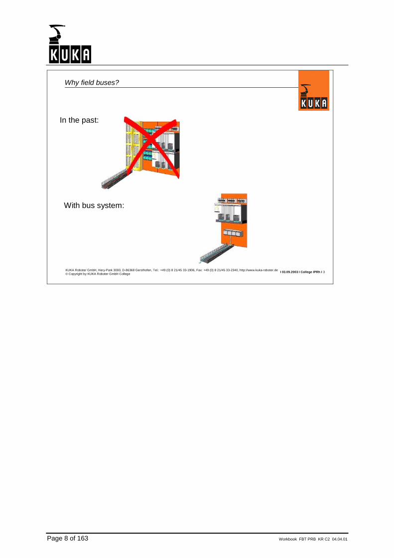
In the past:
With bus system:
PLC KRC
PLC KRC
Bus voltage
Why field buses?
Why bus systems?
• Bus systems require less wiring. As a result, wiring costs are 70% less compared to conventional wiring.
• Bus systems make it easier to expand or convert existing systems. • Bus systems make quick diagnosis possible.
Page 8 of 163 Workbook FBT PRB KR C2 04.04.01
I 03.09.2003 I College IPRh I 3KUKA Roboter GmbH, Hery-Park 3000, D-86368 Gersthofen, Tel.: +49 (0) 8 21/45 33-1906, Fax: +49 (0) 8 21/45 33-2340, http://www.kuka-roboter.de© Copyright by KUKA Roboter GmbH College
In the past:
With bus system:
Why field buses?

Workbook FBT PRB KR C2 04.04.01 Page 9 of 163
1.2. Bus topologies, bus access methods

Page 10 of 163 Workbook FBT PRB KR C2 04.04.01
I 03.09.2003 I College I PRhI 1KUKA Roboter GmbH, Hery-Park 3000, D-86368 Gersthofen, Tel.: +49 (0) 8 21/45 33-1906, Fax: +49 (0) 8 21/45 33-2340, http://www.kuka-roboter.de© Copyright by KUKA Roboter GmbH College
Bus topologies
Line Tree
Ring (active) Ring (physical)

Workbook FBT PRB KR C2 04.04.01 Page 11 of 163
I 03.09.2003 I College I PRhI 2KUKA Roboter GmbH, Hery-Park 3000, D-86368 Gersthofen, Tel.: +49 (0) 8 21/45 33-1906, Fax: +49 (0) 8 21/45 33-2340, http://www.kuka-roboter.de© Copyright by KUKA Roboter GmbH College
Line structure (Profibus or DeviceNet)
Device Device
Device Device Device
Line structure In the line structure, all devices are connected in parallel. Line structure is used in Profibus and DeviceNet.

Page 12 of 163 Workbook FBT PRB KR C2 04.04.01
I 03.09.2003 I College I PRhI 3KUKA Roboter GmbH, Hery-Park 3000, D-86368 Gersthofen, Tel.: +49 (0) 8 21/45 33-1906, Fax: +49 (0) 8 21/45 33-2340, http://www.kuka-roboter.de© Copyright by KUKA Roboter GmbH College
Tree structure
Device Device
Device CouplerCoupler Device
DeviceDevice
Tree structure With the tree structure, the bus can be expanded at any point. The expansion can be cascaded. This structure is used by the ASI bus.

Workbook FBT PRB KR C2 04.04.01 Page 13 of 163
I 03.09.2003 I College I PRhI 4KUKA Roboter GmbH, Hery-Park 3000, D-86368 Gersthofen, Tel.: +49 (0) 8 21/45 33-1906, Fax: +49 (0) 8 21/45 33-2340, http://www.kuka-roboter.de© Copyright by KUKA Roboter GmbH College
Ring structure, active
Device
Device Device
Device
Ring structure, active In the ring structure, the last device must be connected to the first device. This ring structure is used by the ESC circuit on the robot.

Page 14 of 163 Workbook FBT PRB KR C2 04.04.01
I 03.09.2003 I College I PRhI 5KUKA Roboter GmbH, Hery-Park 3000, D-86368 Gersthofen, Tel.: +49 (0) 8 21/45 33-1906, Fax: +49 (0) 8 21/45 33-2340, http://www.kuka-roboter.de© Copyright by KUKA Roboter GmbH College
Ring structure, physical (Interbus)
Device
DeviceDevice Device
DeviceDevice Device
Ring structure, physical In a physical ring, the outgoing and incoming lines are in a single cable. Interbus is an example of this structure.

Workbook FBT PRB KR C2 04.04.01 Page 15 of 163
I 03.09.2003 I College I PRhI 6KUKA Roboter GmbH, Hery-Park 3000, D-86368 Gersthofen, Tel.: +49 (0) 8 21/45 33-1906, Fax: +49 (0) 8 21/45 33-2340, http://www.kuka-roboter.de© Copyright by KUKA Roboter GmbH College
Bus access procedures
Master/slave (Profibus)Token passing & master/slave(Profibus)
Priority (DeviceNet) Summation frame (Interbus)
Slave Slave Slave SlaveSlave Slave Slave Slave
MasterMaster Master Master
Master Slave Slave Slave
Master Master Slave
Slave Slave Slave Slave
Master
Token
Bus access procedures There are various procedures for transferring data via a bus system.

Page 16 of 163 Workbook FBT PRB KR C2 04.04.01
I 03.09.2003 I College I PRhI 7KUKA Roboter GmbH, Hery-Park 3000, D-86368 Gersthofen, Tel.: +49 (0) 8 21/45 33-1906, Fax: +49 (0) 8 21/45 33-2340, http://www.kuka-roboter.de© Copyright by KUKA Roboter GmbH College
Master/slave (Profibus or DeviceNet)
Master
Slave Slave Slave Slave
Master/slave In the master/slave bus access procedure, the bus traffic is controlled by the master. The slaves answer only in response to a prompting telegram from the master. Otherwise the slaves remain passive.

Workbook FBT PRB KR C2 04.04.01 Page 17 of 163
I 03.09.2003 I College I PRhI 8KUKA Roboter GmbH, Hery-Park 3000, D-86368 Gersthofen, Tel.: +49 (0) 8 21/45 33-1906, Fax: +49 (0) 8 21/45 33-2340, http://www.kuka-roboter.de© Copyright by KUKA Roboter GmbH College
Multimaster token passing (Profibus)
Master Master Master
Slave Slave Slave Slave
Token
Token passing In token passing, a token is passed from one master module to the next master module. The master module holding the token has complete bus access to all of the slaves. The token is passed on after a defined time interval. No communication takes place between the individual master modules. The master modules access the slaves in accordance with the master/slave principle.

Page 18 of 163 Workbook FBT PRB KR C2 04.04.01
I 03.09.2003 I College I PRhI 9KUKA Roboter GmbH, Hery-Park 3000, D-86368 Gersthofen, Tel.: +49 (0) 8 21/45 33-1906, Fax: +49 (0) 8 21/45 33-2340, http://www.kuka-roboter.de© Copyright by KUKA Roboter GmbH College
Summation frame (Interbus)
Slave Slave Slave Slave
Master
Summation frame All of the slaves together form a shift register. Writing and reading of data take place in a shift cycle (telegram). No addresses have to be set for the devices.

Workbook FBT PRB KR C2 04.04.01 Page 19 of 163
I 03.09.2003 I College I PRhI 10KUKA Roboter GmbH, Hery-Park 3000, D-86368 Gersthofen, Tel.: +49 (0) 8 21/45 33-1906, Fax: +49 (0) 8 21/45 33-2340, http://www.kuka-roboter.de© Copyright by KUKA Roboter GmbH College
Bus interfaces in the KR C1/2
MFC card20 outputs16 inputs(With KR C1 on MFCcard,with KR C2 external card)
Serial interface(BOSCH_IO,PERCEPTRON)
EthernetDeviceNet
=> Assignment configured in the IOSYS.INI
Option:FIP_IO card
Option: VISION SBIP card
Option: SENSOR LIBO card
Option: DeviceNetLPDN Scanner card
Option:Interbus card
Option:Profibus card


Workbook FBT PRB KR C2 04.04.01 Page 21 of 163
2. Profibus basics
2.1. Functional principle

Page 22 of 163 Workbook FBT PRB KR C2 04.04.01
I 03.09.2003 I College I PRhI 1KUKA Roboter GmbH, Hery-Park 3000, D-86368 Gersthofen, Tel.: +49 (0) 8 21/45 33-1906, Fax: +49 (0) 8 21/45 33-2340, http://www.kuka-roboter.de© Copyright by KUKA Roboter GmbH College
Profibus
I 03.09.2003 I College I PRhI 2KUKA Roboter GmbH, Hery-Park 3000, D-86368 Gersthofen, Tel.: +49 (0) 8 21/45 33-1906, Fax: +49 (0) 8 21/45 33-2340, http://www.kuka-roboter.de© Copyright by KUKA Roboter GmbH College
Profibus variants (1)
Profibus
Profibus FMSFMS - Fieldbus
MessageSpecification
Generalautomation
Profibus PAPA - ProcessAutomation
Process automation
Profibus DPDP -
Decentralized Periphery
Production automation

Workbook FBT PRB KR C2 04.04.01 Page 23 of 163
I 03.09.2003 I College I PRhI 3KUKA Roboter GmbH, Hery-Park 3000, D-86368 Gersthofen, Tel.: +49 (0) 8 21/45 33-1906, Fax: +49 (0) 8 21/45 33-2340, http://www.kuka-roboter.de© Copyright by KUKA Roboter GmbH College
Profibus variants (2)
System coupler
Physical layer (1)DIN19245Part 1
Data link layer (2)
Layers 3 to 6 are notdistinguished
DP profilesDP basic functions
DIN19245Part 3
Physical layer (1)DIN19245Part 1
Data link layer (2)
Layers 3 to 6 are notdistinguished
Application layer (7)with FMS
DIN19245Part 2
Physical layer (1)DIN19245Part 1
Data link layer (2)
Layers 3 to 6 are notdistinguished
PA profilesPA basic functions
DIN19245Part 4
Profibus DP Profibus FMS Profibus PA
I 03.09.2003 I College I PRhI 5KUKA Roboter GmbH, Hery-Park 3000, D-86368 Gersthofen, Tel.: +49 (0) 8 21/45 33-1906, Fax: +49 (0) 8 21/45 33-2340, http://www.kuka-roboter.de© Copyright by KUKA Roboter GmbH College
Master-slave principle (workbook)
SlaveADR3
SlaveADR4
SlaveADR5
SlaveADR6
MasterADR1
RequestInputs send+ outputs
Inputs

Page 24 of 163 Workbook FBT PRB KR C2 04.04.01
I 03.09.2003 I College I PRhI 7KUKA Roboter GmbH, Hery-Park 3000, D-86368 Gersthofen, Tel.: +49 (0) 8 21/45 33-1906, Fax: +49 (0) 8 21/45 33-2340, http://www.kuka-roboter.de© Copyright by KUKA Roboter GmbH College
Token passing principle (workbook)
SlaveADR3
SlaveADR4
SlaveADR5
SlaveADR6
MasterADR2
MasterADR1
Token
Token
I 03.09.2003 I College I PRhI 8KUKA Roboter GmbH, Hery-Park 3000, D-86368 Gersthofen, Tel.: +49 (0) 8 21/45 33-1906, Fax: +49 (0) 8 21/45 33-2340, http://www.kuka-roboter.de© Copyright by KUKA Roboter GmbH College
Communications structure
Start Length Length Start DA SA FC DATA FCS End
0 -1968 bitsEach character 11 bits
Telegram structure:
Note:
Telegram for data exchange (no SAPs)

Workbook FBT PRB KR C2 04.04.01 Page 25 of 163
I 03.09.2003 I College I PRhI 9KUKA Roboter GmbH, Hery-Park 3000, D-86368 Gersthofen, Tel.: +49 (0) 8 21/45 33-1906, Fax: +49 (0) 8 21/45 33-2340, http://www.kuka-roboter.de© Copyright by KUKA Roboter GmbH College
Modular slaves, configurable slaves
•Profibus modules are available in a number of different variants.
•Profibus modules are often of modular design.
•Slave modules are not as "intelligent" and therefore cost less than a master module.
•A slave module can generally not be configured as a master module.(Exception: PLCs)
I 03.09.2003 I College I PRhI 10KUKA Roboter GmbH, Hery-Park 3000, D-86368 Gersthofen, Tel.: +49 (0) 8 21/45 33-1906, Fax: +49 (0) 8 21/45 33-2340, http://www.kuka-roboter.de© Copyright by KUKA Roboter GmbH College
Modular slaves, configurable slaves
•The slave modules have only RAM.
•The configuration files are stored in the master module.
•The slave modules receive their configuration data from the Profibus mastervia a configuration telegram.

Page 26 of 163 Workbook FBT PRB KR C2 04.04.01
I 03.09.2003 I College I PRhI 11KUKA Roboter GmbH, Hery-Park 3000, D-86368 Gersthofen, Tel.: +49 (0) 8 21/45 33-1906, Fax: +49 (0) 8 21/45 33-2340, http://www.kuka-roboter.de© Copyright by KUKA Roboter GmbH College
Configuration by the master (1)
MasterMaster sends configuration telegrams
MasterSlaves answer when they are configured
I 03.09.2003 I College I PRhI 12KUKA Roboter GmbH, Hery-Park 3000, D-86368 Gersthofen, Tel.: +49 (0) 8 21/45 33-1906, Fax: +49 (0) 8 21/45 33-2340, http://www.kuka-roboter.de© Copyright by KUKA Roboter GmbH College
Configuration by the master (2)
Master
Data exchange between master and slave modules

Workbook FBT PRB KR C2 04.04.01 Page 27 of 163
2.2. Profibus topology

Page 28 of 163 Workbook FBT PRB KR C2 04.04.01
I 03.09.2003 I College I PRhI 1KUKA Roboter GmbH, Hery-Park 3000, D-86368 Gersthofen, Tel.: +49 (0) 8 21/45 33-1906, Fax: +49 (0) 8 21/45 33-2340, http://www.kuka-roboter.de© Copyright by KUKA Roboter GmbH College
Line topology
SlaveADR3
SlaveADR4
SlaveADR5
SlaveADR6
MasterADR1
Line topology is used with Profibus
I 03.09.2003 I College I PRhI 2KUKA Roboter GmbH, Hery-Park 3000, D-86368 Gersthofen, Tel.: +49 (0) 8 21/45 33-1906, Fax: +49 (0) 8 21/45 33-2340, http://www.kuka-roboter.de© Copyright by KUKA Roboter GmbH College
Profibus segment
SlaveADR3
SlaveADR4
SlaveADR5
SlaveADR6
MasterADR1
Maximum of 32 devices per segment
The master module is also a device

Workbook FBT PRB KR C2 04.04.01 Page 29 of 163
I 03.09.2003 I College I PRhI 3KUKA Roboter GmbH, Hery-Park 3000, D-86368 Gersthofen, Tel.: +49 (0) 8 21/45 33-1906, Fax: +49 (0) 8 21/45 33-2340, http://www.kuka-roboter.de© Copyright by KUKA Roboter GmbH College
Profibus segment bus terminator
•There must be a bus terminator fitted at the start and end of each segment.•The terminator is often located in the Profibus connector.
SlaveADR3
SlaveADR4
SlaveADR5
SlaveADR6
MasterADR1
I 03.09.2003 I College I PRhI 4KUKA Roboter GmbH, Hery-Park 3000, D-86368 Gersthofen, Tel.: +49 (0) 8 21/45 33-1906, Fax: +49 (0) 8 21/45 33-2340, http://www.kuka-roboter.de© Copyright by KUKA Roboter GmbH College
Repeater (1)
•Additional 31 devices can be connected if a repeater is used. (Repeater is also a device)•The maximum number of slaves is 125 (with 4 repeaters).
Slave Slave Slave Slave
Master
Slave Slave Slave Slave
Repeater
Segment 1 Segment 2
Page 30 of 163 Workbook FBT PRB KR C2 04.04.01
I 03.09.2003 I College I PRhI 5KUKA Roboter GmbH, Hery-Park 3000, D-86368 Gersthofen, Tel.: +49 (0) 8 21/45 33-1906, Fax: +49 (0) 8 21/45 33-2340, http://www.kuka-roboter.de© Copyright by KUKA Roboter GmbH College
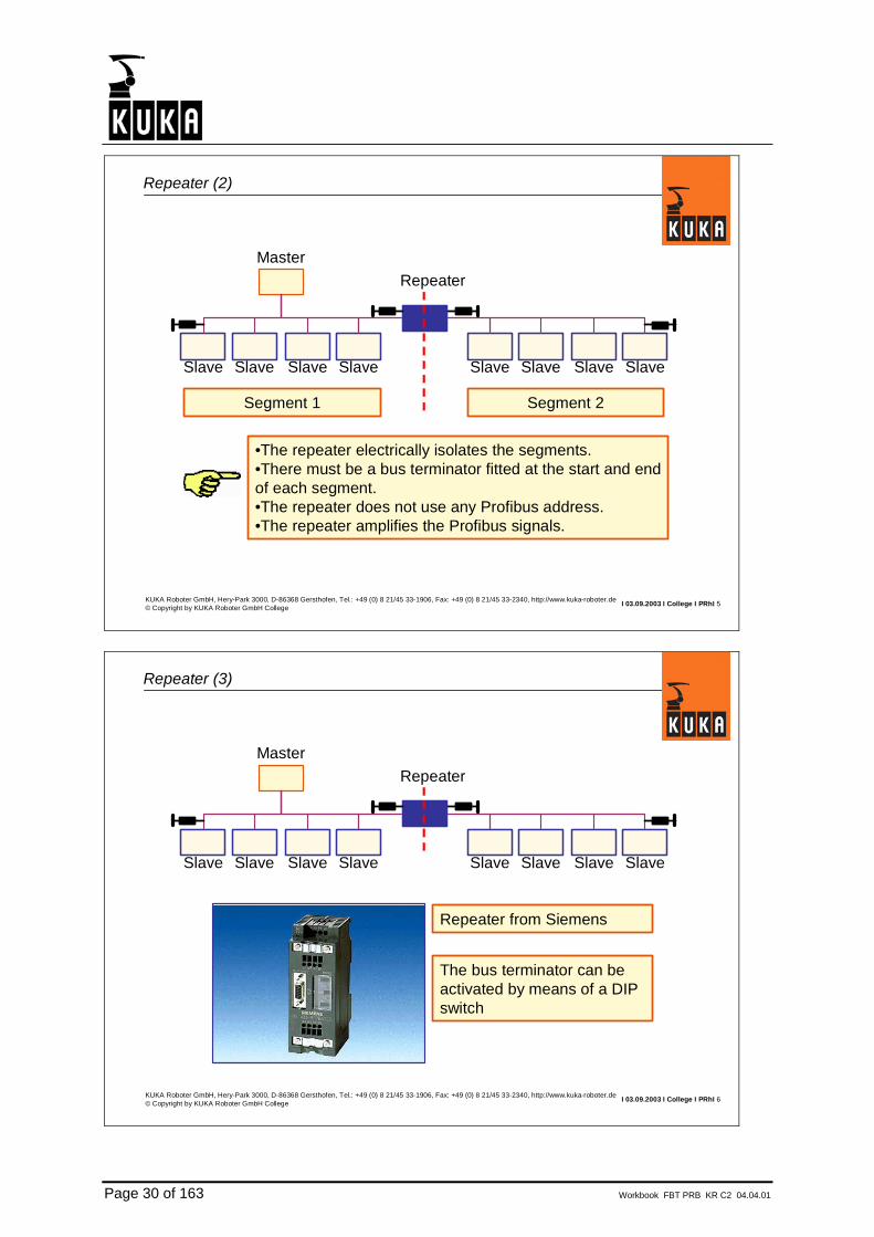
Repeater (2)
•The repeater electrically isolates the segments.•There must be a bus terminator fitted at the start and endof each segment.•The repeater does not use any Profibus address.•The repeater amplifies the Profibus signals.
Slave Slave Slave Slave
Master
Slave Slave Slave Slave
Repeater
Segment 1 Segment 2
I 03.09.2003 I College I PRhI 6KUKA Roboter GmbH, Hery-Park 3000, D-86368 Gersthofen, Tel.: +49 (0) 8 21/45 33-1906, Fax: +49 (0) 8 21/45 33-2340, http://www.kuka-roboter.de© Copyright by KUKA Roboter GmbH College
Repeater (3)
Slave Slave Slave Slave
Master
Slave Slave Slave Slave
Repeater
Repeater from Siemens
The bus terminator can be activated by means of a DIPswitch

Workbook FBT PRB KR C2 04.04.01 Page 31 of 163
I 03.09.2003 I College I PRhI 7KUKA Roboter GmbH, Hery-Park 3000, D-86368 Gersthofen, Tel.: +49 (0) 8 21/45 33-1906, Fax: +49 (0) 8 21/45 33-2340, http://www.kuka-roboter.de© Copyright by KUKA Roboter GmbH College
Repeater (4)
Slave Slave Slave Slave
Master
Slave Slave Slave Slave
Repeater
Slave Slave Slave Slave
Segment 1 Segment 2
I 03.09.2003 I College I PRhI 8KUKA Roboter GmbH, Hery-Park 3000, D-86368 Gersthofen, Tel.: +49 (0) 8 21/45 33-1906, Fax: +49 (0) 8 21/45 33-2340, http://www.kuka-roboter.de© Copyright by KUKA Roboter GmbH College
Two-wire cable (1)
Master

Page 32 of 163 Workbook FBT PRB KR C2 04.04.01
I 03.09.2003 I College I PRhI 9KUKA Roboter GmbH, Hery-Park 3000, D-86368 Gersthofen, Tel.: +49 (0) 8 21/45 33-1906, Fax: +49 (0) 8 21/45 33-2340, http://www.kuka-roboter.de© Copyright by KUKA Roboter GmbH College
Two-wire cable (2)
Master
All Profibus devices are connected to the bus in parallel
Profibus requires two strands (wires).•Green = Signal A•Red = Signal B
I 03.09.2003 I College I PRhI 10KUKA Roboter GmbH, Hery-Park 3000, D-86368 Gersthofen, Tel.: +49 (0) 8 21/45 33-1906, Fax: +49 (0) 8 21/45 33-2340, http://www.kuka-roboter.de© Copyright by KUKA Roboter GmbH College
Cable routing (1)
•The Profibus cable is routed from one device to the next.•Each of the many slave modules has only a single Profibus connection. Theseemploy connectors which can be connected to the Profibus cable.
Profibus cable
Master
Profibus connector

Workbook FBT PRB KR C2 04.04.01 Page 33 of 163
I 03.09.2003 I College I PRhI 11KUKA Roboter GmbH, Hery-Park 3000, D-86368 Gersthofen, Tel.: +49 (0) 8 21/45 33-1906, Fax: +49 (0) 8 21/45 33-2340, http://www.kuka-roboter.de© Copyright by KUKA Roboter GmbH College
Cable routing (2), stubs
•A stub may not be more than 6m long!•A device on a stub does not require a bus terminator.•Recommendation: do not use stubs.
Profibus cable Profibusconnector
Branch
Stub6m max.
Master


Workbook FBT PRB KR C2 04.04.01 Page 35 of 163
2.3. Transmission media

Page 36 of 163 Workbook FBT PRB KR C2 04.04.01
I 03.09.2003 I College I PRhI 1KUKA Roboter GmbH, Hery-Park 3000, D-86368 Gersthofen, Tel.: +49 (0) 8 21/45 33-1906, Fax: +49 (0) 8 21/45 33-2340, http://www.kuka-roboter.de© Copyright by KUKA Roboter GmbH College
Standard
•The cables most often used are two-strand, twisted, shielded cables.•Special configuration tools are available for these cables.•The Profibus cable is connected to theProfibus device by means of a 9-poleSub-D connector.
I 03.09.2003 I College I PRhI 2KUKA Roboter GmbH, Hery-Park 3000, D-86368 Gersthofen, Tel.: +49 (0) 8 21/45 33-1906, Fax: +49 (0) 8 21/45 33-2340, http://www.kuka-roboter.de© Copyright by KUKA Roboter GmbH College
Fiber-optic
•Fiber-optic cables are still rarely seenin conjunction with Profibus

Workbook FBT PRB KR C2 04.04.01 Page 37 of 163
I 03.09.2003 I College I PRhI 3KUKA Roboter GmbH, Hery-Park 3000, D-86368 Gersthofen, Tel.: +49 (0) 8 21/45 33-1906, Fax: +49 (0) 8 21/45 33-2340, http://www.kuka-roboter.de© Copyright by KUKA Roboter GmbH College
Hybrid cable with optical fibers
•Hybrid cable: data lines and power supply in the same cable.•Two optical fibers are used for data transfer.
I 03.09.2003 I College I PRhI 4KUKA Roboter GmbH, Hery-Park 3000, D-86368 Gersthofen, Tel.: +49 (0) 8 21/45 33-1906, Fax: +49 (0) 8 21/45 33-2340, http://www.kuka-roboter.de© Copyright by KUKA Roboter GmbH College
Hybrid cable, Multibus cable
•Multibus cable: a cable which is suitable for more than one bus system.Developed by/for KUKA Roboter. Is often used in the automotive industry.•Multibus cable: data lines and power supply in the same cable. Max. 50 m spur length. Two voltage potentials:
Potential 1: max. permissible load 4APotential 2: max. permissible load 7.5A
•There are slave modules which can be connected directly to the Multibus:Siemens ET200R and Turck FLDPxxx
Master

Page 38 of 163 Workbook FBT PRB KR C2 04.04.01
I 03.09.2003 I College I PRhI 5KUKA Roboter GmbH, Hery-Park 3000, D-86368 Gersthofen, Tel.: +49 (0) 8 21/45 33-1906, Fax: +49 (0) 8 21/45 33-2340, http://www.kuka-roboter.de© Copyright by KUKA Roboter GmbH College
Hybrid cable, Multibus cable connector assignments
Profibus
Voltage potential 2
Voltage potential 1
Female connector
Maleconnector
I 03.09.2003 I College I PRhI 6KUKA Roboter GmbH, Hery-Park 3000, D-86368 Gersthofen, Tel.: +49 (0) 8 21/45 33-1906, Fax: +49 (0) 8 21/45 33-2340, http://www.kuka-roboter.de© Copyright by KUKA Roboter GmbH College
Hybrid cable, Multibus cable Interconnectron connectors

Workbook FBT PRB KR C2 04.04.01 Page 39 of 163
I 03.09.2003 I College I PRhI 7KUKA Roboter GmbH, Hery-Park 3000, D-86368 Gersthofen, Tel.: +49 (0) 8 21/45 33-1906, Fax: +49 (0) 8 21/45 33-2340, http://www.kuka-roboter.de© Copyright by KUKA Roboter GmbH College
Hybrid cable, Multibus cable slave modules
Turck FLDP xxx Siemens ET200R
These modules can be connected directly to the Multibus cable.

Workbook FBT PRB KR C2 04.04.01 Page 41 of 163
2.4. Bus terminator

Page 42 of 163 Workbook FBT PRB KR C2 04.04.01
I 03.09.2003 I College I PRhI 1Hery-Park 3000, D-86368 Gersthofen +49 (0) 8 21/45 33-1906, Fax: +49 (0) 8 21/45 33-2340, http://www.kuka-roboter.de© Copyright by KUKA Roboter GmbH College
Profibus segment bus terminator
•There must be a bus terminator fitted at the start and end of each segment.•The terminator is often located in the Profibus connector.
SlaveADR3
SlaveADR4
SlaveADR5
SlaveADR6
MasterADR1
I 03.09.2003 I College I PRhI 2Hery-Park 3000, D-86368 Gersthofen +49 (0) 8 21/45 33-1906, Fax: +49 (0) 8 21/45 33-2340, http://www.kuka-roboter.de© Copyright by KUKA Roboter GmbH College
Terminators on the connector
Bus terminator
Workbook FBT PRB KR C2 04.04.01 Page 43 of 163
I 03.09.2003 I College I PRhI 3Hery-Park 3000, D-86368 Gersthofen +49 (0) 8 21/45 33-1906, Fax: +49 (0) 8 21/45 33-2340, http://www.kuka-roboter.de© Copyright by KUKA Roboter GmbH College
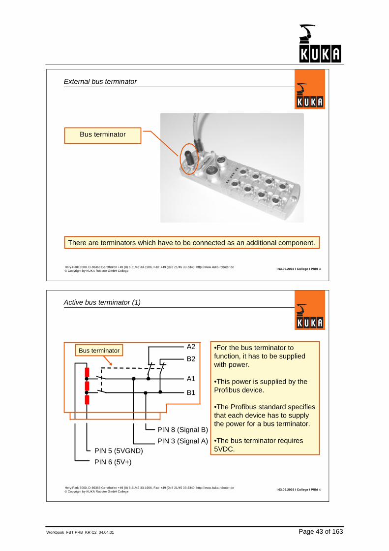
External bus terminator
There are terminators which have to be connected as an additional component.
Bus terminator
I 03.09.2003 I College I PRhI 4Hery-Park 3000, D-86368 Gersthofen +49 (0) 8 21/45 33-1906, Fax: +49 (0) 8 21/45 33-2340, http://www.kuka-roboter.de© Copyright by KUKA Roboter GmbH College
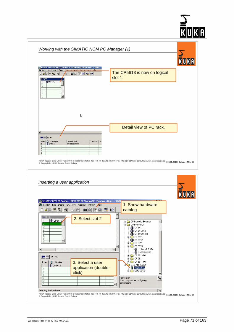
Active bus terminator (1)
•For the bus terminator tofunction, it has to be supplied with power.
•This power is supplied by theProfibus device.
•The Profibus standard specifies that each device has to supply the power for a bus terminator.
•The bus terminator requires5VDC.
PIN 6 (5V+)PIN 5 (5VGND)
PIN 3 (Signal A)PIN 8 (Signal B)
A1
B1
A2
B2Bus terminator

Page 44 of 163 Workbook FBT PRB KR C2 04.04.01
I 03.09.2003 I College I PRhI 5Hery-Park 3000, D-86368 Gersthofen +49 (0) 8 21/45 33-1906, Fax: +49 (0) 8 21/45 33-2340, http://www.kuka-roboter.de© Copyright by KUKA Roboter GmbH College
Terminators on the connector
Bus terminator
+5VDC
GND
Data B
Data AR=390ohm
R=220ohm
R=390ohm
I 03.09.2003 I College I PRhI 6Hery-Park 3000, D-86368 Gersthofen +49 (0) 8 21/45 33-1906, Fax: +49 (0) 8 21/45 33-2340, http://www.kuka-roboter.de© Copyright by KUKA Roboter GmbH College
1
Profibus pin assignment
Repeater control signal9
Received Data/Transmitted Data Minus8
24V potential7
Supply voltage of the terminators(5VDC)
6
Supply voltage of the ground terminators (GND)
5
Repeater control signal4
Received Data/Transmitted Data Plus3
Ground of the 24V potential2
Shield/functional ground1
MeaningPinno.
CNTR-N
RxD/TxD
P24
VP
DGND
CNTR-P
RxD/TxD
M24
Shield
Signal

Workbook FBT PRB KR C2 04.04.01 Page 45 of 163
I 03.09.2003 I College I PRhI 7Hery-Park 3000, D-86368 Gersthofen +49 (0) 8 21/45 33-1906, Fax: +49 (0) 8 21/45 33-2340, http://www.kuka-roboter.de© Copyright by KUKA Roboter GmbH College
Active bus terminator (2)
If the last device in the Profibus segment is deenergized:•Then the bus terminator is no longer functional.•Communication is no longer possible.
Power supply off(e.g. Emergency Stop)
Note: Connect bus devices to two voltage potentials.•Potential1: bus coupler•Potential2: power, e.g. outputs and proximity switch supply.The second potential can be switched off via the E-Stop function.
Master
I 03.09.2003 I College I PRhI 8Hery-Park 3000, D-86368 Gersthofen +49 (0) 8 21/45 33-1906, Fax: +49 (0) 8 21/45 33-2340, http://www.kuka-roboter.de© Copyright by KUKA Roboter GmbH College
Active bus terminator (3)
If the last device in a Profibus segment is switched off (deenergized), then the entire Profibus segment is faulty.Communication is no longer possible.
Master
Main switch off(service work)
PLC is master Robots are slaves
Note: use an I/O module as the last device, or a bus terminator module.

Page 46 of 163 Workbook FBT PRB KR C2 04.04.01
I 03.09.2003 I College I PRhI 9Hery-Park 3000, D-86368 Gersthofen +49 (0) 8 21/45 33-1906, Fax: +49 (0) 8 21/45 33-2340, http://www.kuka-roboter.de© Copyright by KUKA Roboter GmbH College
Bus terminator module
•A bus terminator module can be used to terminate the bus.•The bus terminator module requires 24VDC, and supplies the necessary voltage for terminating the bus.
I 03.09.2003 I College I PRhI 10Hery-Park 3000, D-86368 Gersthofen +49 (0) 8 21/45 33-1906, Fax: +49 (0) 8 21/45 33-2340, http://www.kuka-roboter.de© Copyright by KUKA Roboter GmbH College
Bus connector for transmission rates >1.5Mbit/s
•For transfer rates greater than 1.5Mbit/s, connectors with built-in interference suppression coils must be used.•If a connector is suitable for more than 1.5Mbit/s, then "12MBd" will be printed on the connector.•For all other connectors, the maximum transfer rate is 1.5Mbit/s
A1
B1
A2
B2Bus terminator
Coils with 110nH each

Workbook FBT PRB KR C2 04.04.01 Page 47 of 163
2.5. Key data for Profibus

Page 48 of 163 Workbook FBT PRB KR C2 04.04.01
I 03.09.2003 I College I PRhI 1KUKA Roboter GmbH, Hery-Park 3000, D-86368 Gersthofen, Tel.: +49 (0) 8 21/45 33-1906, Fax: +49 (0) 8 21/45 33-2340, http://www.kuka-roboter.de© Copyright by KUKA Roboter GmbH College
Key data for Profibus
•A maximum of 125 slaves can be connected to a single Profibus master.
•32 devices per segment.
•Transfer rate selectable in steps between 9.6 Kbit/s and 12Mbits/s.
•Maximum data of a Profibus slave module:244 bytes of inputs and244 bytes of outputs
•The devices may be arranged as desired.
I 03.09.2003 I College I PRhI 2KUKA Roboter GmbH, Hery-Park 3000, D-86368 Gersthofen, Tel.: +49 (0) 8 21/45 33-1906, Fax: +49 (0) 8 21/45 33-2340, http://www.kuka-roboter.de© Copyright by KUKA Roboter GmbH College
Transfer rate and segment length
•The segment length is dependent on the transfer rate.Low transfer rate – long segmentHigh transfer rate – short segment
•Standard value is 1.5 Mbit/s
0.0096
1200
0.0192
1200
0.0937
1200
0.1875
1000
0.5
400
1.5
200
3.0
100
6.0
100
12
100
Mbit/sm
•When using the Multibus cable, the transfer rate must notexceed 1.5Mbit/s!
•The cable length of a Profibus network can be increased if arepeater is used.

Workbook FBT PRB KR C2 04.04.01 Page 49 of 163
I 03.09.2003 I College I PRhI 3KUKA Roboter GmbH, Hery-Park 3000, D-86368 Gersthofen, Tel.: +49 (0) 8 21/45 33-1906, Fax: +49 (0) 8 21/45 33-2340, http://www.kuka-roboter.de© Copyright by KUKA Roboter GmbH College
Bus cycle time
•The robot reads the inputs every 12 ms.•The robot writes the outputs immediately.
2
4
6
8
10 (160 I/Os) 20 (320 I/Os) 30 (480 I/Os)Number of slaves
Bus cycle time/ms
Each slave has 2 bytes of input data and 2 bytes of output data
10
12
14
12 Mbit/s
1.5 Mbit/s
500 kbit/s


Workbook FBT PRB KR C2 04.04.01 Page 51 of 163
2.6. Interface to the KRC

Page 52 of 163 Workbook FBT PRB KR C2 04.04.01
I 03.09.2003 I College I PRhI 1KUKA Roboter GmbH, Hery-Park 3000, D-86368 Gersthofen, Tel.: +49 (0) 8 21/45 33-1906, Fax: +49 (0) 8 21/45 33-2340, http://www.kuka-roboter.de© Copyright by KUKA Roboter GmbH College
Master
Interface options on the robot, robot is master
Robot is Profibus master
I 03.09.2003 I College I PRhI 2KUKA Roboter GmbH, Hery-Park 3000, D-86368 Gersthofen, Tel.: +49 (0) 8 21/45 33-1906, Fax: +49 (0) 8 21/45 33-2340, http://www.kuka-roboter.de© Copyright by KUKA Roboter GmbH College
Interface options on the robot, robot is slave
Master
Robot is Profibus slave

Workbook FBT PRB KR C2 04.04.01 Page 53 of 163
I 03.09.2003 I College I PRhI 3KUKA Roboter GmbH, Hery-Park 3000, D-86368 Gersthofen, Tel.: +49 (0) 8 21/45 33-1906, Fax: +49 (0) 8 21/45 33-2340, http://www.kuka-roboter.de© Copyright by KUKA Roboter GmbH College
Interface options on the robot, robot is master and slave
Master
Robot is:•Profibus master and•Profibus slaveat the same time
Robot is slave
Robot is master
I 03.09.2003 I College I PRhI 4KUKA Roboter GmbH, Hery-Park 3000, D-86368 Gersthofen, Tel.: +49 (0) 8 21/45 33-1906, Fax: +49 (0) 8 21/45 33-2340, http://www.kuka-roboter.de© Copyright by KUKA Roboter GmbH College
Profibus interface module CP5613/14 (1)
Profibus master connection
Profibus slave connection
The Profibus master part is electrically isolated from the Profibus slave part
CP5613 = masterCP5614 = slaveCP5613/14 = master and slave on a single card

Page 54 of 163 Workbook FBT PRB KR C2 04.04.01
I 03.09.2003 I College I PRhI 5KUKA Roboter GmbH, Hery-Park 3000, D-86368 Gersthofen, Tel.: +49 (0) 8 21/45 33-1906, Fax: +49 (0) 8 21/45 33-2340, http://www.kuka-roboter.de© Copyright by KUKA Roboter GmbH College
Green LED:flickers: DP master:
•Token passing.off: DP master:
•Incorrect bus parameters•Defective bus•CP not in operation
flashes once per second: DP master:•Database contains errors
Yellow LED:flickers: DP slave:
•Polling by higher-level master (normal operation).off: DP slave:
•Connection is not being addressed
Green and yellow LEDs blink alternately:•Module is being addressed by diagnostic module
Profibus interface module CP5613/14 (2)
I 03.09.2003 I College I PRhI 6KUKA Roboter GmbH, Hery-Park 3000, D-86368 Gersthofen, Tel.: +49 (0) 8 21/45 33-1906, Fax: +49 (0) 8 21/45 33-2340, http://www.kuka-roboter.de© Copyright by KUKA Roboter GmbH College
Profibus interface module CP5613/14 in the KRC (1)
CP5613/14
KUKA robot with optional PSA interface
X12A Profibus slave INX12B Profibus slave OUTX14 Profibus master

Workbook FBT PRB KR C2 04.04.01 Page 55 of 163
I 03.09.2003 I College I PRhI 7KUKA Roboter GmbH, Hery-Park 3000, D-86368 Gersthofen, Tel.: +49 (0) 8 21/45 33-1906, Fax: +49 (0) 8 21/45 33-2340, http://www.kuka-roboter.de© Copyright by KUKA Roboter GmbH College
Profibus interface module CP5613/14 in the KRC (2)
KUKA robot with optionalInterbus Cu and Profibus M/S(e.g. DaimlerChrysler)
X12A Profibus slave INX12B Profibus slave OUTX15 Profibus master
I 03.09.2003 I College I PRhI 8KUKA Roboter GmbH, Hery-Park 3000, D-86368 Gersthofen, Tel.: +49 (0) 8 21/45 33-1906, Fax: +49 (0) 8 21/45 33-2340, http://www.kuka-roboter.de© Copyright by KUKA Roboter GmbH College
Profibus interface module CP5613/14 in the KR C2 (3)
CP5613/14 can be installed inslot 5 or 6.
Profibus master connection X850
Profibus slave connection X851
KR C2


Workbook FBT PRB KR C2 04.04.01 Page 57 of 163
3. Profibus configuration software
3.1. SIMATIC-NCM-PC-MANAGER

Page 58 of 163 Workbook FBT PRB KR C2 04.04.01
I 03.09.2003 I College I PRhI 1KUKA Roboter GmbH, Hery-Park 3000, D-86368 Gersthofen, Tel.: +49 (0) 8 21/45 33-1906, Fax: +49 (0) 8 21/45 33-2340, http://www.kuka-roboter.de© Copyright by KUKA Roboter GmbH College
Configuration by the master (1)
Master sends configuration telegrams
•In order for the Profibus master to configure the slaves, the master needs a database.•The database must be created using the SIMATIC NCM PC Manager.
Database (NAME.LDB)
Master
I 03.09.2003 I College I PRhI 2KUKA Roboter GmbH, Hery-Park 3000, D-86368 Gersthofen, Tel.: +49 (0) 8 21/45 33-1906, Fax: +49 (0) 8 21/45 33-2340, http://www.kuka-roboter.de© Copyright by KUKA Roboter GmbH College
Functional principle of the SIMATIC NCM PC Manager (1)
MasterMaster configures the slaves
Database (NAME.LDB)
*.GSD*.GSE*.GSG
SIMATIC NCM PC Manager

Workbook FBT PRB KR C2 04.04.01 Page 59 of 163
I 03.09.2003 I College I PRhI 3KUKA Roboter GmbH, Hery-Park 3000, D-86368 Gersthofen, Tel.: +49 (0) 8 21/45 33-1906, Fax: +49 (0) 8 21/45 33-2340, http://www.kuka-roboter.de© Copyright by KUKA Roboter GmbH College
Functional principle of the SIMATIC NCM PC Manager (2)
•For each Profibus slave type there is a device master data file (GSD).•GSD files have the following file name extensions:
•GSD (international)•GSE (English)•GSG (German)
•The GSD file contains information about how the Profibus slave can be configured.•If the required GSD file is not contained in the SIMATIC NCM PC Manager, or if the existing GSD file is too old, it can be updated.•The GSD files for most Siemens devices are already present in the SIMATIC NCM PC Manager. For all other devices, the GSD files have to be loaded as anupdate.
I 03.09.2003 I College I PRhI 4KUKA Roboter GmbH, Hery-Park 3000, D-86368 Gersthofen, Tel.: +49 (0) 8 21/45 33-1906, Fax: +49 (0) 8 21/45 33-2340, http://www.kuka-roboter.de© Copyright by KUKA Roboter GmbH College
Examples of GSD files
GSD file for CP5614 S0100008.GSD (KUKArobot as slave)
;===============================================; GSD-File for CP5614 Sample SIEMENS AG; MLFB : 6GK1 561-4AA00; Auto_Baud_supp, 12MBaud;; Date : 15.03.99 mm; File : SIE_0008.GSD;===============================================#Profibus_DP; Unit-Definition-List:GSD_Revision=1Vendor_Name="KUKA Roboter GmbH"Model_Name="KUKA CP5614 Slave"Revision="V1.0"Ident_Number=0x0008
;==============================================; GSD-File for ET 200S Siemens AG ; MLFB : 6ES7 151-1AA02-0AB0; 6ES7 151-1AA01-0AB0; 6ES7 151-1AA00-0AB0;; Date : 23.10.00 V1.7 GW ;; File : SIEM806A.GSG==============================================#Profibus_DP
; <Prm-Text-Def-List>
PrmText = 1Text(0) = "disable"Text(1) = "enable"
GSD file for ET200SSIEM806A.GSG

Page 60 of 163 Workbook FBT PRB KR C2 04.04.01
I 03.09.2003 I College I PRhI 5KUKA Roboter GmbH, Hery-Park 3000, D-86368 Gersthofen, Tel.: +49 (0) 8 21/45 33-1906, Fax: +49 (0) 8 21/45 33-2340, http://www.kuka-roboter.de© Copyright by KUKA Roboter GmbH College
Functional principle of the SIMATIC NCM PC Manager (3)
•Configuring a Profibus network by means of the SIMATIC NCM PC Manager produces the following files:
•Project data directory. The files in this directory can be used to edit or supplement an existing project.
•Database. The database is a file with the extension .ldb. The name of the file can be selected freely (max. of 8 characters).
•In order to function, the CP5613/14 in the robot only requires the database (*.ldb)LDB=Local Data Base
•The database must be saved in the directory C:\KRC\Roboter\INIT.

Workbook FBT PRB KR C2 04.04.01 Page 61 of 163
3.2. Installation SIMATIC-NCM-PC-MANAGER

Page 62 of 163 Workbook FBT PRB KR C2 04.04.01
I 03.09.2003 I College I PRhI 1KUKA Roboter GmbH, Hery-Park 3000, D-86368 Gersthofen, Tel.: +49 (0) 8 21/45 33-1906, Fax: +49 (0) 8 21/45 33-2340, http://www.kuka-roboter.de© Copyright by KUKA Roboter GmbH College
Installing the SIMATIC NCM PC Manager (1)
•The SIMATIC NCM PC Manager can be installed on a Windows PC (notebook), or on the KRC.
I 03.09.2003 I College I PRhI 2KUKA Roboter GmbH, Hery-Park 3000, D-86368 Gersthofen, Tel.: +49 (0) 8 21/45 33-1906, Fax: +49 (0) 8 21/45 33-2340, http://www.kuka-roboter.de© Copyright by KUKA Roboter GmbH College
Installing the SIMATIC NCM PC Manager (2)
•If the Step7 software from Siemens is on the notebook, then the SIMATIC NCM PC Manager cannot be installed.
•The SIMATIC NCM PC Manager is a part of the Step7 software.
•If Step7 is installed, then the SIMATIC NCM PC Manager is not needed.
•Configuration with Step7 is exactly the same as with the SIMATIC NCM PC Manager.

Workbook FBT PRB KR C2 04.04.01 Page 63 of 163
I 03.09.2003 I College I PRhI 3KUKA Roboter GmbH, Hery-Park 3000, D-86368 Gersthofen, Tel.: +49 (0) 8 21/45 33-1906, Fax: +49 (0) 8 21/45 33-2340, http://www.kuka-roboter.de© Copyright by KUKA Roboter GmbH College
Installing the SIMATIC NCM PC Manager (3)
•The SIMATIC NCM PC Manager can be installed on a Windows PC (notebook), or on the KRC.•Software requirements:WinNT, Win2k, WinXP•Hardware requirements:RAM >=64MbyteFree hard disk space >=120Mbyte
Installation on the KRC:•Run up computer without HMI (hold down the CTRL key while booting).•Deactivate virus scanner.
I 03.09.2003 I College I PRhI 4KUKA Roboter GmbH, Hery-Park 3000, D-86368 Gersthofen, Tel.: +49 (0) 8 21/45 33-1906, Fax: +49 (0) 8 21/45 33-2340, http://www.kuka-roboter.de© Copyright by KUKA Roboter GmbH College
Installing the SIMATIC NCM PC Manager (4)
The setup files are located on the KUKA CD starting with V 5.2.3.Path:D:\INTERNAT\BUS\PROFIBUS\NCM_PC_MANAGER\DISK1\SETUP.EXE


Workbook FBT PRB KR C2 04.04.01 Page 65 of 163
3.3. Operating SIMATIC-NCM-PC-MANAGER

Page 66 of 163 Workbook FBT PRB KR C2 04.04.01
I 03.09.2003 I College I PRhI 1KUKA Roboter GmbH, Hery-Park 3000, D-86368 Gersthofen, Tel.: +49 (0) 8 21/45 33-1906, Fax: +49 (0) 8 21/45 33-2340, http://www.kuka-roboter.de© Copyright by KUKA Roboter GmbH College
Working with the SIMATIC NCM PC Manager
There are several ways of working with the SIMATIC NCM PC Manager. One of those ways is described here.
If you are an inexperienced user and problems arise, it is advisable tocreate a new project and repeat all of the steps from the beginning.
In order to work effectively with the SIMATIC NCM PC Manager, you should use a mouse.
I 03.09.2003 I College I PRhI 2KUKA Roboter GmbH, Hery-Park 3000, D-86368 Gersthofen, Tel.: +49 (0) 8 21/45 33-1906, Fax: +49 (0) 8 21/45 33-2340, http://www.kuka-roboter.de© Copyright by KUKA Roboter GmbH College
Working with the SIMATIC NCM PC Manager

Workbook FBT PRB KR C2 04.04.01 Page 67 of 163
I 03.09.2003 I College I PRhI 3KUKA Roboter GmbH, Hery-Park 3000, D-86368 Gersthofen, Tel.: +49 (0) 8 21/45 33-1906, Fax: +49 (0) 8 21/45 33-2340, http://www.kuka-roboter.de© Copyright by KUKA Roboter GmbH College
Creating a new project
Project name
Project path
I 03.09.2003 I College I PRhI 4KUKA Roboter GmbH, Hery-Park 3000, D-86368 Gersthofen, Tel.: +49 (0) 8 21/45 33-1906, Fax: +49 (0) 8 21/45 33-2340, http://www.kuka-roboter.de© Copyright by KUKA Roboter GmbH College
Inserting a Simatic PC Station
Popup menu Insert New Object /Simatic PC StationSimatic PC Station
Right-click withthe mouse (popup menu)MPI can be
deleted

Page 68 of 163 Workbook FBT PRB KR C2 04.04.01
I 03.09.2003 I College I PRhI 5KUKA Roboter GmbH, Hery-Park 3000, D-86368 Gersthofen, Tel.: +49 (0) 8 21/45 33-1906, Fax: +49 (0) 8 21/45 33-2340, http://www.kuka-roboter.de© Copyright by KUKA Roboter GmbH College
Opening hardware configuration
Double-click on SIMATIC PC Station
Double-click on Configuration(hardware configuration is started)
I 03.09.2003 I College I PRhI 6KUKA Roboter GmbH, Hery-Park 3000, D-86368 Gersthofen, Tel.: +49 (0) 8 21/45 33-1906, Fax: +49 (0) 8 21/45 33-2340, http://www.kuka-roboter.de© Copyright by KUKA Roboter GmbH College
Hardware configuration
Virtual PC rack. The slots do nothave to correspond to reality.
Hardware configuration is an extra program which is started from the SIMATIC NCM PC Manager.

Workbook FBT PRB KR C2 04.04.01 Page 69 of 163
I 03.09.2003 I College I PRhI 7KUKA Roboter GmbH, Hery-Park 3000, D-86368 Gersthofen, Tel.: +49 (0) 8 21/45 33-1906, Fax: +49 (0) 8 21/45 33-2340, http://www.kuka-roboter.de© Copyright by KUKA Roboter GmbH College
Inserting CP5613
1. Hide/show hardware catalog
2. Select slot 1
3. Select CP5613, SW V6.0 SP4 (double-click)
I 03.09.2003 I College I PRhI 8KUKA Roboter GmbH, Hery-Park 3000, D-86368 Gersthofen, Tel.: +49 (0) 8 21/45 33-1906, Fax: +49 (0) 8 21/45 33-2340, http://www.kuka-roboter.de© Copyright by KUKA Roboter GmbH College
Properties of CP5613
Master addressRecommendation:Address 2 or 1
•Connect CP5613 with Profibus.
•This requires creation of anew Profibus network.
•To do this, select New.
•The properties window ofthe new Profibus network then opens.

Page 70 of 163 Workbook FBT PRB KR C2 04.04.01
I 03.09.2003 I College I PRhI 9KUKA Roboter GmbH, Hery-Park 3000, D-86368 Gersthofen, Tel.: +49 (0) 8 21/45 33-1906, Fax: +49 (0) 8 21/45 33-2340, http://www.kuka-roboter.de© Copyright by KUKA Roboter GmbH College
Properties of Profibus, general
No settings are requiredon the General tab.
The Network Settings tab is used to set the parameters for theProfibus network.
I 03.09.2003 I College I PRhI 10KUKA Roboter GmbH, Hery-Park 3000, D-86368 Gersthofen, Tel.: +49 (0) 8 21/45 33-1906, Fax: +49 (0) 8 21/45 33-2340, http://www.kuka-roboter.de© Copyright by KUKA Roboter GmbH College
Properties of Profibus, network settings
The transfer rate can be set here.Recommendation: 1.5Mbit/s(default)
Select bus profile DP (default)
Confirm the entry by pressing OK.
Also confirm entries forCP5613 properties by pressing OK.
Workbook FBT PRB KR C2 04.04.01 Page 71 of 163
I 03.09.2003 I College I PRhI 11KUKA Roboter GmbH, Hery-Park 3000, D-86368 Gersthofen, Tel.: +49 (0) 8 21/45 33-1906, Fax: +49 (0) 8 21/45 33-2340, http://www.kuka-roboter.de© Copyright by KUKA Roboter GmbH College
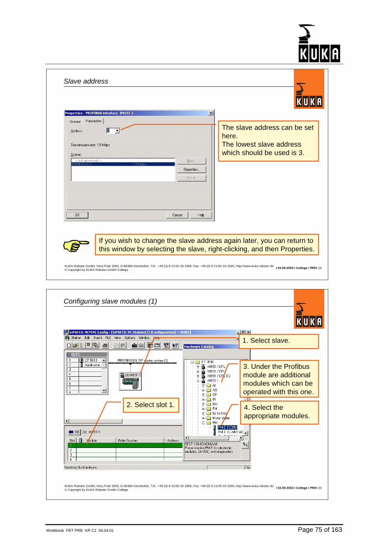
Working with the SIMATIC NCM PC Manager (1)
The CP5613 is now on logical slot 1.
Detail view of PC rack.
I 03.09.2003 I College I PRhI 12KUKA Roboter GmbH, Hery-Park 3000, D-86368 Gersthofen, Tel.: +49 (0) 8 21/45 33-1906, Fax: +49 (0) 8 21/45 33-2340, http://www.kuka-roboter.de© Copyright by KUKA Roboter GmbH College
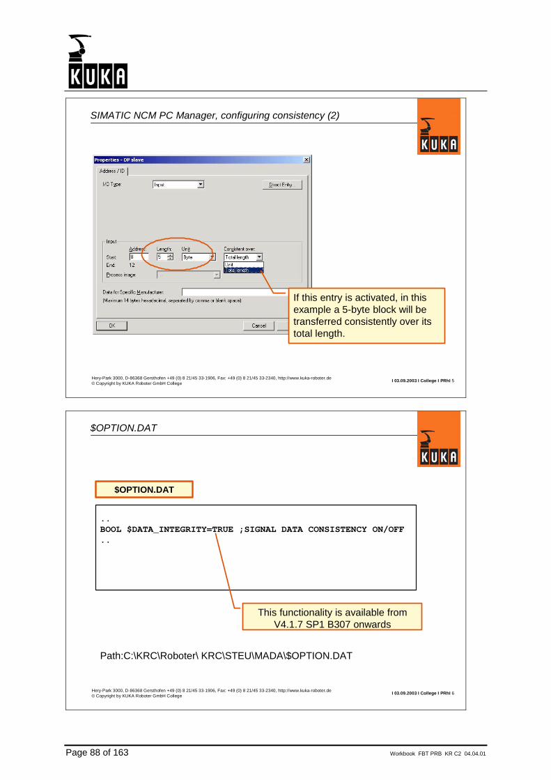
Inserting a user application
1. Show hardware catalog
2. Select slot 2
3. Select a user application (double-click)

Page 72 of 163 Workbook FBT PRB KR C2 04.04.01
I 03.09.2003 I College I PRhI 13KUKA Roboter GmbH, Hery-Park 3000, D-86368 Gersthofen, Tel.: +49 (0) 8 21/45 33-1906, Fax: +49 (0) 8 21/45 33-2340, http://www.kuka-roboter.de© Copyright by KUKA Roboter GmbH College
Selecting CP5613 object properties
Select CP5613 object properties
Popup menu: CP5613/Object Properties
I 03.09.2003 I College I PRhI 14KUKA Roboter GmbH, Hery-Park 3000, D-86368 Gersthofen, Tel.: +49 (0) 8 21/45 33-1906, Fax: +49 (0) 8 21/45 33-2340, http://www.kuka-roboter.de© Copyright by KUKA Roboter GmbH College
CP5613 object properties, General tab
No changes are required here

Workbook FBT PRB KR C2 04.04.01 Page 73 of 163
I 03.09.2003 I College I PRhI 15KUKA Roboter GmbH, Hery-Park 3000, D-86368 Gersthofen, Tel.: +49 (0) 8 21/45 33-1906, Fax: +49 (0) 8 21/45 33-2340, http://www.kuka-roboter.de© Copyright by KUKA Roboter GmbH College
CP5613 object properties, Mode tab (1)
Select DP master
Select Generate LDBfile
Specify path and nameof the LDB file
If the NCM Manager is located on the KRC, then the directoryC:\Roboter\KRC\INIT can simply be selected here.
I 03.09.2003 I College I PRhI 16KUKA Roboter GmbH, Hery-Park 3000, D-86368 Gersthofen, Tel.: +49 (0) 8 21/45 33-1906, Fax: +49 (0) 8 21/45 33-2340, http://www.kuka-roboter.de© Copyright by KUKA Roboter GmbH College
CP5613 object properties, Mode tab (2)
If Autoclear is activ and one module has an error, all outputs of all I/O-Moduls are set to a safe state (mostly state False)
Autoclear is used e.g. for arc-welding.

Page 74 of 163 Workbook FBT PRB KR C2 04.04.01
I 03.09.2003 I College I PRhI 17KUKA Roboter GmbH, Hery-Park 3000, D-86368 Gersthofen, Tel.: +49 (0) 8 21/45 33-1906, Fax: +49 (0) 8 21/45 33-2340, http://www.kuka-roboter.de© Copyright by KUKA Roboter GmbH College
Profibus master system (1)
Select Profibus.
The Profibus symbol is dark.
I 03.09.2003 I College I PRhI 18KUKA Roboter GmbH, Hery-Park 3000, D-86368 Gersthofen, Tel.: +49 (0) 8 21/45 33-1906, Fax: +49 (0) 8 21/45 33-2340, http://www.kuka-roboter.de© Copyright by KUKA Roboter GmbH College
Working with the SIMATIC NCM PC Manager (1)
Select the desired module from theProfibus DP hardware catalog.(double-click)
Some modules are listed more than once. If in doubt, check the ordernumber.
Workbook FBT PRB KR C2 04.04.01 Page 75 of 163
I 03.09.2003 I College I PRhI 19KUKA Roboter GmbH, Hery-Park 3000, D-86368 Gersthofen, Tel.: +49 (0) 8 21/45 33-1906, Fax: +49 (0) 8 21/45 33-2340, http://www.kuka-roboter.de© Copyright by KUKA Roboter GmbH College
Slave address
The slave address can be set here.The lowest slave address which should be used is 3.
If you wish to change the slave address again later, you can return tothis window by selecting the slave, right-clicking, and then Properties.
I 03.09.2003 I College I PRhI 20KUKA Roboter GmbH, Hery-Park 3000, D-86368 Gersthofen, Tel.: +49 (0) 8 21/45 33-1906, Fax: +49 (0) 8 21/45 33-2340, http://www.kuka-roboter.de© Copyright by KUKA Roboter GmbH College
Configuring slave modules (1)
1. Select slave.
2. Select slot 1.
3. Under the Profibusmodule are additionalmodules which can be operated with this one.
4. Select the appropriate modules.

Page 76 of 163 Workbook FBT PRB KR C2 04.04.01
I 03.09.2003 I College I PRhI 21KUKA Roboter GmbH, Hery-Park 3000, D-86368 Gersthofen, Tel.: +49 (0) 8 21/45 33-1906, Fax: +49 (0) 8 21/45 33-2340, http://www.kuka-roboter.de© Copyright by KUKA Roboter GmbH College
Configuring slave modules (2)
The selected module is now on slot 1.
I 03.09.2003 I College I PRhI 22KUKA Roboter GmbH, Hery-Park 3000, D-86368 Gersthofen, Tel.: +49 (0) 8 21/45 33-1906, Fax: +49 (0) 8 21/45 33-2340, http://www.kuka-roboter.de© Copyright by KUKA Roboter GmbH College
Configuring slave modules (3)
Select the appropriate modules.

Workbook FBT PRB KR C2 04.04.01 Page 77 of 163
I 03.09.2003 I College I PRhI 23KUKA Roboter GmbH, Hery-Park 3000, D-86368 Gersthofen, Tel.: +49 (0) 8 21/45 33-1906, Fax: +49 (0) 8 21/45 33-2340, http://www.kuka-roboter.de© Copyright by KUKA Roboter GmbH College
Configuring slave modules (4), packing the ET200S
The address values have no meaning for the KRC.The distribution to the bytes can be seen here. Each 2 DI module occupies one byte.
I 03.09.2003 I College I PRhI 24KUKA Roboter GmbH, Hery-Park 3000, D-86368 Gersthofen, Tel.: +49 (0) 8 21/45 33-1906, Fax: +49 (0) 8 21/45 33-2340, http://www.kuka-roboter.de© Copyright by KUKA Roboter GmbH College
Configuring slave modules (5), packing the ET200S
1. Select module.
The inputs can be grouped together. This applies only to theET200S. It is similar for the other modules. Please follow the instructions in the module documentation.
2. Pack addresses.

Page 78 of 163 Workbook FBT PRB KR C2 04.04.01
I 03.09.2003 I College I PRhI 25KUKA Roboter GmbH, Hery-Park 3000, D-86368 Gersthofen, Tel.: +49 (0) 8 21/45 33-1906, Fax: +49 (0) 8 21/45 33-2340, http://www.kuka-roboter.de© Copyright by KUKA Roboter GmbH College
Configuring slave modules (6), parameterization
Select Object Properties.
Some modules can be parameterized, e.g. analog inputs, analogoutputs, fast counters, encoders, etc.
I 03.09.2003 I College I PRhI 26KUKA Roboter GmbH, Hery-Park 3000, D-86368 Gersthofen, Tel.: +49 (0) 8 21/45 33-1906, Fax: +49 (0) 8 21/45 33-2340, http://www.kuka-roboter.de© Copyright by KUKA Roboter GmbH College
Configuring slave modules (7), parameterization
Under Parameters are the parameters for the corresponding module.

Workbook FBT PRB KR C2 04.04.01 Page 79 of 163
I 03.09.2003 I College I PRhI 27KUKA Roboter GmbH, Hery-Park 3000, D-86368 Gersthofen, Tel.: +49 (0) 8 21/45 33-1906, Fax: +49 (0) 8 21/45 33-2340, http://www.kuka-roboter.de© Copyright by KUKA Roboter GmbH College
Configuring slave modules (8), parameterization
Module-specific parameters are located here.
I 03.09.2003 I College I PRhI 28KUKA Roboter GmbH, Hery-Park 3000, D-86368 Gersthofen, Tel.: +49 (0) 8 21/45 33-1906, Fax: +49 (0) 8 21/45 33-2340, http://www.kuka-roboter.de© Copyright by KUKA Roboter GmbH College
Configuring slave modules (9), parameterization
Selection window for module parameters, e.g. voltage range.The appropriate settings can be made here.

Page 80 of 163 Workbook FBT PRB KR C2 04.04.01
I 03.09.2003 I College I PRhI 29KUKA Roboter GmbH, Hery-Park 3000, D-86368 Gersthofen, Tel.: +49 (0) 8 21/45 33-1906, Fax: +49 (0) 8 21/45 33-2340, http://www.kuka-roboter.de© Copyright by KUKA Roboter GmbH College
General parameters, slave module (1)
Right-click on a slave module – Object Properties.
I 03.09.2003 I College I PRhI 30KUKA Roboter GmbH, Hery-Park 3000, D-86368 Gersthofen, Tel.: +49 (0) 8 21/45 33-1906, Fax: +49 (0) 8 21/45 33-2340, http://www.kuka-roboter.de© Copyright by KUKA Roboter GmbH College
General parameters, slave module (2)
Module-specific parameters are located here.

Workbook FBT PRB KR C2 04.04.01 Page 81 of 163
I 03.09.2003 I College I PRhI 31KUKA Roboter GmbH, Hery-Park 3000, D-86368 Gersthofen, Tel.: +49 (0) 8 21/45 33-1906, Fax: +49 (0) 8 21/45 33-2340, http://www.kuka-roboter.de© Copyright by KUKA Roboter GmbH College
General parameters, slave module (3)
Selection window for module parameters.
I 03.09.2003 I College I PRhI 32KUKA Roboter GmbH, Hery-Park 3000, D-86368 Gersthofen, Tel.: +49 (0) 8 21/45 33-1906, Fax: +49 (0) 8 21/45 33-2340, http://www.kuka-roboter.de© Copyright by KUKA Roboter GmbH College
Save configuration, generate *.ldb
Save project and compile
•When saving, the configuration is saved and an *.LDB file is generated.•The *.LDB can then be copied from the selected directory (the directory is specified under Properties of CP5613) and inserted in the directory C:\Roboter\KRC\INIT.


Workbook FBT PRB KR C2 04.04.01 Page 83 of 163
3.4. Installing a new GSD file

Page 84 of 163 Workbook FBT PRB KR C2 04.04.01
I 03.09.2003 I College I PRhI 1KUKA Roboter GmbH, Hery-Park 3000, D-86368 Gersthofen, Tel.: +49 (0) 8 21/45 33-1906, Fax: +49 (0) 8 21/45 33-2340, http://www.kuka-roboter.de© Copyright by KUKA Roboter GmbH College
Functional principle of the SIMATIC NCM PC Manager (2)
•For each Profibus slave type there is a device master data file (GSD).•GSD files have the following file name extensions:
•GSD (international)•GSE (English)•GSG (German)
•The GSD file contains information about how the Profibus slave can be configured.•If the required GSD file is not contained in the SIMATIC NCM PC Manager, or if the existing GSD file is too old, it can be updated.•The GSD files for most Siemens devices are already present in the SIMATIC NCM PC Manager. For all other devices, the GSD files have to be loaded as an update.
I 03.09.2003 I College I PRhI 2KUKA Roboter GmbH, Hery-Park 3000, D-86368 Gersthofen, Tel.: +49 (0) 8 21/45 33-1906, Fax: +49 (0) 8 21/45 33-2340, http://www.kuka-roboter.de© Copyright by KUKA Roboter GmbH College
Installing a new GSD file
Install new GSD file.
Specify source path andname of the GSD file.
If the required GSD file is not contained in the SIMATIC NCM PC Manager,or if the existing GSD file is too old, it can be updated.

Workbook FBT PRB KR C2 04.04.01 Page 85 of 163
3.5. Consistency

Page 86 of 163 Workbook FBT PRB KR C2 04.04.01
I 03.09.2003 I College I PRhI 1Hery-Park 3000, D-86368 Gersthofen +49 (0) 8 21/45 33-1906, Fax: +49 (0) 8 21/45 33-2340, http://www.kuka-roboter.de© Copyright by KUKA Roboter GmbH College
Consistency
•Profibus operates in a byte-oriented manner.
•Large quantities of data are sometimes transferred using more than one telegram.
•Consistent data transfer can be used for safe transfer of values>=2bytes.
I 03.09.2003 I College I PRhI 2Hery-Park 3000, D-86368 Gersthofen +49 (0) 8 21/45 33-1906, Fax: +49 (0) 8 21/45 33-2340, http://www.kuka-roboter.de© Copyright by KUKA Roboter GmbH College
Consistency (2)
Bit no.Byte 1 Byte 0
256
7 6 5 4 3 2 1 0 7 6 5 4 3 2 1 0
Value 0 0 0 0 0 0 0 1 0 0 0 0 0 0 0 0The integer value now changes to 255.
Bit no.Byte 1 Byte 0
255
7 6 5 4 3 2 1 0 7 6 5 4 3 2 1 0
Value 0 0 0 0 0 0 0 0 1 1 1 1 1 1 1 1 Byte 0 is transferred first.
Bit no.Byte 1 Byte 0
511
7 6 5 4 3 2 1 0 7 6 5 4 3 2 1 0
Value 0 0 0 0 0 0 0 1 1 1 1 1 1 1 1 1
Bit no.Byte 1 Byte 0
255
7 6 5 4 3 2 1 0 7 6 5 4 3 2 1 0
Value 0 0 0 0 0 0 0 0 1 1 1 1 1 1 1 1
The integer value is 256.
If the controller reads the integervalue now, the value will be incorrect!
Byte 1 is transferred now. The value is now correct again.

Workbook FBT PRB KR C2 04.04.01 Page 87 of 163
I 03.09.2003 I College I PRhI 3Hery-Park 3000, D-86368 Gersthofen +49 (0) 8 21/45 33-1906, Fax: +49 (0) 8 21/45 33-2340, http://www.kuka-roboter.de© Copyright by KUKA Roboter GmbH College
Consistency (3)
Remedy:Transferring data consistently.
•Profibus can transfer a number of blocks consistently.
•A consistent data block can contain up to 16 words.
•"Consistent transfer" can be set in the configuration tool (SIMATIC NCM PC Manager).
•If consistent data transfer is required, $OPTION.DAT must be edited appropriately.
I 03.09.2003 I College I PRhI 4Hery-Park 3000, D-86368 Gersthofen +49 (0) 8 21/45 33-1906, Fax: +49 (0) 8 21/45 33-2340, http://www.kuka-roboter.de© Copyright by KUKA Roboter GmbH College
SIMATIC NCM PC Manager, configuring consistency (1)
Object properties
Page 88 of 163 Workbook FBT PRB KR C2 04.04.01
I 03.09.2003 I College I PRhI 5Hery-Park 3000, D-86368 Gersthofen +49 (0) 8 21/45 33-1906, Fax: +49 (0) 8 21/45 33-2340, http://www.kuka-roboter.de© Copyright by KUKA Roboter GmbH College
SIMATIC NCM PC Manager, configuring consistency (2)
If this entry is activated, in this example a 5-byte block will be transferred consistently over its total length.
I 03.09.2003 I College I PRhI 6Hery-Park 3000, D-86368 Gersthofen +49 (0) 8 21/45 33-1906, Fax: +49 (0) 8 21/45 33-2340, http://www.kuka-roboter.de© Copyright by KUKA Roboter GmbH College
$OPTION.DAT
..BOOL $DATA_INTEGRITY=TRUE ;SIGNAL DATA CONSISTENCY ON/OFF..
$OPTION.DAT
This functionality is available fromV4.1.7 SP1 B307 onwards
Path:C:\KRC\Roboter\ KRC\STEU\MADA\$OPTION.DAT

Workbook FBT PRB KR C2 04.04.01 Page 89 of 163
3.6. COMPROFIBUS V3.x for KSS V4.x

Page 90 of 163 Workbook FBT PRB KR C2 04.04.01
I 03.09.2003 I College I PRhI 1KUKA Roboter GmbH, Hery-Park 3000, D-86368 Gersthofen, Tel.: +49 (0) 8 21/45 33-1906, Fax: +49 (0) 8 21/45 33-2340, http://www.kuka-roboter.de© Copyright by KUKA Roboter GmbH College
Installing COMPROFIBUS
•Run the COMPROFIBUS setup program. Path: KUKA CD:\INTERNAT\PROFIBUS\COMPROFIBUS\GER3.3\INSTALL\SETUP.EXE
•For the Profibus master the corresponding type file SI8075AX.2MH must be copied from the KUKA CD to the subdirectory C:\COMPB33\MASTERS. The type file is located here: Path: KUKA CD:\INTERNAT\PROFIBUS\COMPROFIBUS
•For slave modules which are not integrated into COMPROFIBUS, the associated GSD file must be copied into the subdirectory C:\COMPB33\GSD.
I 03.09.2003 I College I PRhI 2KUKA Roboter GmbH, Hery-Park 3000, D-86368 Gersthofen, Tel.: +49 (0) 8 21/45 33-1906, Fax: +49 (0) 8 21/45 33-2340, http://www.kuka-roboter.de© Copyright by KUKA Roboter GmbH College
"File - New" takes you to the dialog box "New Master System". Here select the master type "CP 5613/CP 5614".
New master system
Workbook FBT PRB KR C2 04.04.01 Page 91 of 163
I 03.09.2003 I College I PRhI 3KUKA Roboter GmbH, Hery-Park 3000, D-86368 Gersthofen, Tel.: +49 (0) 8 21/45 33-1906, Fax: +49 (0) 8 21/45 33-2340, http://www.kuka-roboter.de© Copyright by KUKA Roboter GmbH College
Here you can use Drag and Drop to assign the desired slaves to the master stored in the system.
In the event of ambiguities, the order number must be taken into account.
Configuring slaves
I 03.09.2003 I College I PRhI 4KUKA Roboter GmbH, Hery-Park 3000, D-86368 Gersthofen, Tel.: +49 (0) 8 21/45 33-1906, Fax: +49 (0) 8 21/45 33-2340, http://www.kuka-roboter.de© Copyright by KUKA Roboter GmbH College
An *.LDB file can be generated under File - Export - NCM File. This file must then be copied into the ...\INIT directory on the robot.
Generating an *.LDB file


Workbook FBT PRB KR C2 04.04.01 Page 93 of 163
4. Configuration KRC
4.1. Configuration

Page 94 of 163 Workbook FBT PRB KR C2 04.04.01
I 03.09.2003 I College I PRhI 1KUKA Roboter GmbH, Hery-Park 3000, D-86368 Gersthofen, Tel.: +49 (0) 8 21/45 33-1906, Fax: +49 (0) 8 21/45 33-2340, http://www.kuka-roboter.de© Copyright by KUKA Roboter GmbH College
General information on operator control
• User privileges: Expert Modee.g. in order to edit files other than robot programs
• Selection of files and editing
• Alternatively: switch to Windows by means of a keyboard shortcut
I 03.09.2003 I College I PRhI 2KUKA Roboter GmbH, Hery-Park 3000, D-86368 Gersthofen, Tel.: +49 (0) 8 21/45 33-1906, Fax: +49 (0) 8 21/45 33-2340, http://www.kuka-roboter.de© Copyright by KUKA Roboter GmbH College
Directories of the C:\ partition
Home directory of the robot controller:C:\Program Files\KRC\
or C:\KRC\Roboter\
• Directory of the configuration files:C:\...\INIT
• Directory for log files:C:\...\LOG
• Directory of the driver programs:C:\...\DRIVERS
The names of the directories should be viewed only as examples, since there are different variants of the KRC withdifferent directory structures.

Workbook FBT PRB KR C2 04.04.01 Page 95 of 163
I 03.09.2003 I College I PRhI 3KUKA Roboter GmbH, Hery-Park 3000, D-86368 Gersthofen, Tel.: +49 (0) 8 21/45 33-1906, Fax: +49 (0) 8 21/45 33-2340, http://www.kuka-roboter.de© Copyright by KUKA Roboter GmbH College
Configuration and driver files
CP5613/14
• C:\...\INIT\IOSYS.INI: Configuration file of the I/O system
• C:\...\INIT\PFBMS.INI: Parameterization file of the Profibusdriver
• C:\...\DRIVERS\PFBMSDRV.O: Driver program for Profibus CP5613/14
• C:\...\DRIVERS\FW_5613.BIN: Firmware file for Profibus CP5613/14


Workbook FBT PRB KR C2 04.04.01 Page 97 of 163
4.2. PFBMS.INI

Page 98 of 163 Workbook FBT PRB KR C2 04.04.01
I 03.09.2003 I College I PRhI 1KUKA Roboter GmbH, Hery-Park 3000, D-86368 Gersthofen, Tel.: +49 (0) 8 21/45 33-1906, Fax: +49 (0) 8 21/45 33-2340, http://www.kuka-roboter.de© Copyright by KUKA Roboter GmbH College
Sections of PFBMS.INI for the CP5613/14
PFBMS.INI [CP_5613/14] ; General settings[MASTER]; Master parameters
[SLAVE]; Slave parameters
[SWAP]; Exchange high byte with low byte

Workbook FBT PRB KR C2 04.04.01 Page 99 of 163
I 03.09.2003 I College I PRhI 2KUKA Roboter GmbH, Hery-Park 3000, D-86368 Gersthofen, Tel.: +49 (0) 8 21/45 33-1906, Fax: +49 (0) 8 21/45 33-2340, http://www.kuka-roboter.de© Copyright by KUKA Roboter GmbH College
PFBMS.INI: General settings
[CP_5613/14]DEBUG=1LOGFILE_PATH=log/pfms.logERROR_TEXT=GermanFORCE_RESET=0OLD_ERROR_DB=0
PFBMS.INI
This entry is optional
[CP_5613/14] General settings. DEBUG Default setting: DEBUG=1 This parameter can be used to switch Telnet outputs on and off. LOGFILE_PATH Default setting: LOGFILE_PATH=log/pfbms.log Specify path and file name (within the directory C:\KRC\Roboter). Messages from the boot sequence and relevant messages from ongoing operation are logged in the log file. If this entry is missing, no log file is created. ERROR_TEXT Default value: ERROR_TEXT=German The language version of the log file can be selected here. The languages German and English are available. FORCE_RESET Default value: FORCE_RESET=0 If this value is 0 or the entry is missing, the CP5613/14 master or slave module is only restarted in the event of a reset command from the HMI if a bus error is genuinely present.

Page 100 of 163 Workbook FBT PRB KR C2 04.04.01
If this value is 1, the master and the slave module are always restarted in the event of a reset command from the GUI. OLD_ERROR_DB This entry is normally not present. If a Profibus driver of version 4.1.7 or higher is used in a system with version 4.1.6 or lower, then this entry must be OLD_ERROR_DB=1. In all other cases, this entry is not necessary.

Workbook FBT PRB KR C2 04.04.01 Page 101 of 163
I 03.09.2003 I College I PRhI 3KUKA Roboter GmbH, Hery-Park 3000, D-86368 Gersthofen, Tel.: +49 (0) 8 21/45 33-1906, Fax: +49 (0) 8 21/45 33-2340, http://www.kuka-roboter.de© Copyright by KUKA Roboter GmbH College
PFBMS.INI: Master settings
[MASTER]MASTER_USED=1DATABASE_PATH=init/FIRMWARE_PATH=drivers/FW_5613.binWATCHDOG_TIME=3MAPPING_USED=0MAPPING_PATH=init/;DEACTIVATED_SLAVES=
PFBMS.INI
[MASTER] Settings for the master. MASTER_USED=1 Default setting: MASTER_USED=1 The master can be activated (1) and deactivated (0) here. DATABASE_PATH Default setting: DATABASE_PATH=init/name.ldb This entry must correspond to the directory (within the C:\KRC\Roboter directory) and the name of the database. If the driver does not find a database at the specified location, the bus cannot be put into operation. Special case: If the entry MASTER_USED has the value 0 and no database is specified, then the file SLAVE.LDB from the INIT directory is loaded by default. FIRMWARE_PATH Default value: FIRMWARE_PATH=drivers/FW_5613.bin This entry must correspond to the directory (within the C:\KRC\Roboter directory) and the name of the firmware. WATCHDOG_TIME Default value: WATCHDOG_TIME=3 This entry is used to set the watchdog which monitors the robot controller. The setting is made in increments of 10 ms. If the watchdog is not retriggered in the time

Page 102 of 163 Workbook FBT PRB KR C2 04.04.01
set, the master goes to the operational state Clear and the slaves are set to a defined state. If this entry is 0, the watchdog is deactivated. MAPPING_USED Default value: MAPPING_USED=0 If this value is 0, the mapping function is deactivated and the entry MAPPING_PATH is ignored. If this entry is 1, the mapping table specified in the following entry is read and the mapping function is executed according to this table. This entry must correspond to the directory (within the C:\KRC\Roboter directory) and the name of the mapping table. If the driver does not find a mapping table at the specified location, the bus cannot be put into operation. MAPPING_PATH Default value: MAPPING_PATH=init/ If the entry is MAPPING_USED=0, the entry MAPPING_PATH is ignored. If MAPPING_USED=1, this entry must correspond to the directory (within the C:\KRC\Roboter directory) and the name of the mapping table. If the driver does not find a mapping table at the specified location, the bus cannot be put into operation. DEACTIVATED_SLAVES Default value: ;DEACTIVATED_SLAVES= Slaves which are not connected to the bus when the driver is booted, but which have been configured.

Workbook FBT PRB KR C2 04.04.01 Page 103 of 163
I 03.09.2003 I College I PRhI 4KUKA Roboter GmbH, Hery-Park 3000, D-86368 Gersthofen, Tel.: +49 (0) 8 21/45 33-1906, Fax: +49 (0) 8 21/45 33-2340, http://www.kuka-roboter.de© Copyright by KUKA Roboter GmbH College
PFBMS.INI: Slave settings
[SLAVE]MODUL_USED=0MODUL_ADDRESS=;START_TIME=20ERROR_ACTION=1STANDBY=0SLAVE_TIMEOUT=0CHECK_CONFIGURATION_DATA=0ACCEPTABLE_INPUT_LENGTH=244ACCEPTABLE_OUTPUT_LENGTH=244IO_DATA_BASE=0CONSISTENCE=0
PFBMS.INI
[SLAVE] Settings for the slave. MODUL_USED Default setting: MASTER_USED=0 If this value is 0, the slave module is not started and is thus not available to a higher-level DP network. If this value is 1, the slave module is started. After booting, the module waits for the parameterization and configuration data of the corresponding master. Once these are received, the module goes into data exchange mode. MODUL_ADDRESS Default setting: MODUL_ADDRESS= The address, selected during configuration, of the slave module in the higher-level Profibus system must be entered here. START_TIME Default setting: ;START_TIME=20 In order to be able to compare, during the loading process, the configuration of the slave module with the data range in the file IOSYS.INI, the module must be in DATA_EXCHANGE mode. This is assured by means of this time factor (min. 20 as default value). ERROR_ACTION Default value: ERROR_ACTION=1

Page 104 of 163 Workbook FBT PRB KR C2 04.04.01
If this value is 0 and the master of the slave module goes to the state CLEAR (e.g. STOP in the Siemens S7), the KRC is not stopped and no error message is generated. If this value is 1 and the master of the slave module goes to the state CLEAR, the KRC is stopped and a corresponding error message is generated. STANDBY Default setting: STANDBY=0 This function is only supported from Profibus driver version 1.18 onwards. If the value is 0, then in order to start, the slave module must be subordinated to a master, otherwise the driver is deactivated. An I/O reconfiguration must be carried out before it can be started again. If the value is 1, then error messages of the slave module are ignored. As long as the slave module is not initialized by a master, read and write errors will appear. If the slave is initialized by a master, the read and write errors are automatically cleared and the exchange of data can begin. Checking of data lengths is carried out cyclically with each read and write access, and not during initialization as is the case with Standby=0. Errors in the configuration of the slave module (IOSYS.INI) thus appear only after successful initialization by a master. SLAVE_TIMEOUT Default value: SLAVE_TIMEOUT=0 This function is only supported from driver version 1.24 onwards. If this value is 0, the cyclical change in status of the slave is not monitored. If the value is >0, then a max. counter value is set and a timer-controlled counter is activated. The counter evaluates the status WAIT_FOR_CONFIGURATION of the slave module. If this status is left and then reached again within 5 seconds, an internal counter is incremented. If the value SLAVE_TIMEOUT is exceeded by the counter, the driver is unloaded, since a reset cannot correct the error. The following error message is transmitted to the HMI: "Configuration error I/O driver CP561DRV : Slave configuration" If no status change takes place, the counter is reset after 15 seconds. CHECK_CONFIGURATION_DATA Default setting: CHECK_CONFIGURATION_DATA=0 If this value is 0, the configuration data that the slave module receives from the master in the higher-level Profibus system are accepted without being checked. If this value is 1, the configuration data received by the slave module are checked. The criteria for this check are defined in the following entries. ACCEPTABLE_INPUT_LENGTH ACCEPTABLE_INPUT_LENGTH=244 If CHECK_CONFIGURATION_DATA=1, the maximum configured input data length may not exceed this specified value. If the slave module receives a configuration

Workbook FBT PRB KR C2 04.04.01 Page 105 of 163
telegram exceeding this value, it is rejected and the slave module does not go into data exchange mode. If the slave module is divided into several individual modules, the value refers to each of the modules in the slave module. Thus the value which is entered must correspond to the module with the largest data width. ACCEPTABLE_OUTPUT_LENGTH ACCEPTABLE_OUTPUT_LENGTH=244 If CHECK_CONFIGURATION_DATA=1, the maximum configured output data length may not exceed this specified value. If the slave module receives a configuration telegram exceeding this value, it is rejected and the slave module does not go into data exchange mode. If the slave module is divided into several individual modules, the value refers to each of the modules in the slave module. Thus the value which is entered must correspond to the module with the largest data width. IO_DATA_BASE IO_DATA_BASE=0 0 means byte as database, 1 means word. If CHECK_CONFIGURATION_DATA=1, the database which was used to configure the slave module must correspond with this entry. If the slave module receives a configuration telegram which does not agree with this value, it is rejected and the slave module does not go into data exchange mode. CONSISTENCE CONSISTENCE=0 0 signifies no guarantee of consistency over the whole slave module. If this entry is 1, data consistency is guaranteed over the entire length of the module. If CHECK_CONFIGURATION_DATA=1, the consistency condition which was used to configure the slave module must correspond with this entry. If the slave module receives a configuration telegram which does not agree with this value, it is rejected and the slave module does not go into data exchange mode.

Page 106 of 163 Workbook FBT PRB KR C2 04.04.01
I 03.09.2003 I College I PRhI 5KUKA Roboter GmbH, Hery-Park 3000, D-86368 Gersthofen, Tel.: +49 (0) 8 21/45 33-1906, Fax: +49 (0) 8 21/45 33-2340, http://www.kuka-roboter.de© Copyright by KUKA Roboter GmbH College
PFBMS.INI: Swap settings
[SWAP]INWORD_SLAVE_3=2,4OUTWORD_SLAVE_3=2
INWORD_SLAVE_4=0,2OUTWORD_SLAVE_4=0,2
PFBMS.INI
[SWAP] Settings for swapping (exchanging bytes) Syntax: INWORD_SLAVE_X=Y "INWORD_SLAVE" means: data are read by the KRC. X stands for the DP address of the slave, within which a word is to be swapped. Y stands for the offset of the word in the slave. If several words have to be swapped within a slave, this can be specified in the following way: INWORD_SLAVE_X=Y,A,B where "Y, A, B" stand for the different offsets of the words in the slave. NOTE: A "SWAP entry" is only effective if the corresponding data object has a data width of 2 bytes (or 1 word). This is the case for all analog inputs and outputs or if the object has been created accordingly in IOSYS.INI (e.g. INB10=4,0,x2 or INW12=6,2,x1). Syntax: OUTWORD_SLAVE_X=Y "OUTWORD_SLAVE" means: data are written by the KRC. X stands for the DP address of the slave, within which a word is to be swapped. Y stands for the offset of the word in the slave. If several words have to be swapped within a slave, this can be specified in the following way: OUTWORD_SLAVE_X=Y,A,B where "Y, A, B" stand for the different offsets of the words in the slave.

Workbook FBT PRB KR C2 04.04.01 Page 107 of 163
NOTE: A "SWAP entry" is only effective if the corresponding data object has a data width of 2 bytes (or 1 word). This is the case for all analog inputs and outputs or if the object has been created accordingly in IOSYS.INI (e.g. OUTB10=4,0,x2 or OUTW12=6,2,x1).


Workbook FBT PRB KR C2 04.04.01 Page 109 of 163
4.3. IOSYS.INI

Page 110 of 163 Workbook FBT PRB KR C2 04.04.01
I 03.09.2003 I College I PRhI 1KUKA Roboter GmbH, Hery-Park 3000, D-86368 Gersthofen, Tel.: +49 (0) 8 21/45 33-1906, Fax: +49 (0) 8 21/45 33-2340, http://www.kuka-roboter.de© Copyright by KUKA Roboter GmbH College
I/O system
CALL-P
MFC DeviceNetProfibus
Periphery management
Soft PLCRobot system
Interbus
I 03.09.2003 I College I PRhI 2KUKA Roboter GmbH, Hery-Park 3000, D-86368 Gersthofen, Tel.: +49 (0) 8 21/45 33-1906, Fax: +49 (0) 8 21/45 33-2340, http://www.kuka-roboter.de© Copyright by KUKA Roboter GmbH College
Structure of IOSYS.INI
[CONFIG]VERSION=2.00
[DRIVERS];MFC=0,mfcEntry,mfcdrv.o;INTERBUS=1,ibusInit,ibusdrv.o;DEVNET=2,dnInit,dndrv.o......PBMASL=11,pbmsInit,pfbmsdrv.o
[MFC]INW0=0 ;$IN[1-16]OUTW0=0 ;$OUT[1-16]OUTW2=2 ;$OUT[17-32]
IOSYS.INI
Profibusmaster/slave, CP5613/14
Caution!Observe
upper/lower-case!

Workbook FBT PRB KR C2 04.04.01 Page 111 of 163
I 03.09.2003 I College I PRhI 3KUKA Roboter GmbH, Hery-Park 3000, D-86368 Gersthofen, Tel.: +49 (0) 8 21/45 33-1906, Fax: +49 (0) 8 21/45 33-2340, http://www.kuka-roboter.de© Copyright by KUKA Roboter GmbH College
Activating the Profibus driver
Profibusmaster/slave,CP5613/14
Activation
IOSYS.INI [CONFIG]VERSION=2.00
[DRIVERS]MFC=0,mfcEntry,mfcdrv.oINTERBUS=1,ibusInit,ibusdrv.oDEVNET=2,dnInit,dndrv.o......PBMASL=11,pbmsInit,pfbmsdrv.o
[PBMASL];PROFIBUS I/O assignments
I 03.09.2003 I College I PRhI 4KUKA Roboter GmbH, Hery-Park 3000, D-86368 Gersthofen, Tel.: +49 (0) 8 21/45 33-1906, Fax: +49 (0) 8 21/45 33-2340, http://www.kuka-roboter.de© Copyright by KUKA Roboter GmbH College
+24V=TRUE, 0V=FALSE
OUTPUTS$OUT[1]$OUT[2]$OUT[3]$OUT[4]$OUT[5]...$OUT[1024]
INPUTS$IN[1]$IN[2]$IN[3]$IN[4]$IN[5]...$IN[1024]$IN[1025]=TRUE$IN[1026]=FALSE
From the periphery
To the periphery
Inputs and outputs of the KRC controller (1)

Page 112 of 163 Workbook FBT PRB KR C2 04.04.01
I 03.09.2003 I College I PRhI 5KUKA Roboter GmbH, Hery-Park 3000, D-86368 Gersthofen, Tel.: +49 (0) 8 21/45 33-1906, Fax: +49 (0) 8 21/45 33-2340, http://www.kuka-roboter.de© Copyright by KUKA Roboter GmbH College
Inputs and outputs of the KRC controller (2)
The KRC controller is shipped as standard with 1024 inputs and outputs available.
The inputs and outputs can be increased to 4096 by modifying the$OPTION.DAT file.
The KRC controller is shipped as standard with 1024 inputs and outputs available. The inputs and outputs can be increased to 4096 by modifying the $OPTION.DAT file.
Workbook FBT PRB KR C2 04.04.01 Page 113 of 163
I 03.09.2003 I College I PRhI 6KUKA Roboter GmbH, Hery-Park 3000, D-86368 Gersthofen, Tel.: +49 (0) 8 21/45 33-1906, Fax: +49 (0) 8 21/45 33-2340, http://www.kuka-roboter.de© Copyright by KUKA Roboter GmbH College
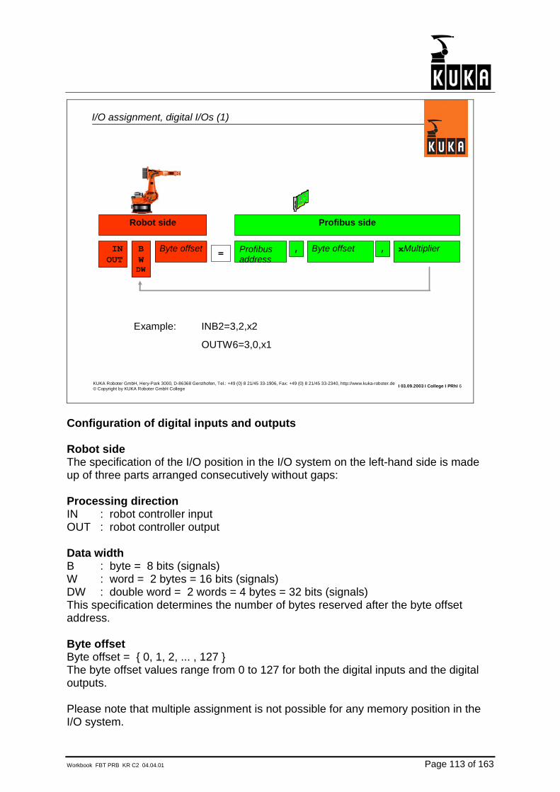
I/O assignment, digital I/Os (1)
Example: INB2=3,2,x2
OUTW6=3,0,x1
Profibus address
, Byte offset=
Profibus side
INOUT
BWDW
Byte offset
Robot side
, xMultiplier
Configuration of digital inputs and outputs Robot side The specification of the I/O position in the I/O system on the left-hand side is made up of three parts arranged consecutively without gaps: Processing direction IN : robot controller input OUT : robot controller output Data width B : byte = 8 bits (signals) W : word = 2 bytes = 16 bits (signals) DW : double word = 2 words = 4 bytes = 32 bits (signals) This specification determines the number of bytes reserved after the byte offset address. Byte offset Byte offset = { 0, 1, 2, ... , 127 } The byte offset values range from 0 to 127 for both the digital inputs and the digital outputs. Please note that multiple assignment is not possible for any memory position in the I/O system.
Page 114 of 163 Workbook FBT PRB KR C2 04.04.01
Profibus side The specifications on the right-hand side refer to the position of the process data in the I/O map of the Profibus card. The specifications are separated from one another by commas: Profibus DP address Profibus DP address = { 0,1,2, ... , 127 } The Profibus DP address is set on each Profibus module. If data are needed from the slave part of the card, the DP address 127 is used. Byte offset Byte offset = { 0,1,2, ... , 243 } The byte offset on the Profibus side designates the position of the I/Os in the memory of the Profibus device. The byte offsets, again counted separately for all the inputs and all the outputs. Multiplier Multiplier = { 1, 2, 3, ... } Using the multiplier, you can assign multiple I/Os (according to the value of the multiplier) to groups; the data width of these groups depends on the data width specified on the robot side.
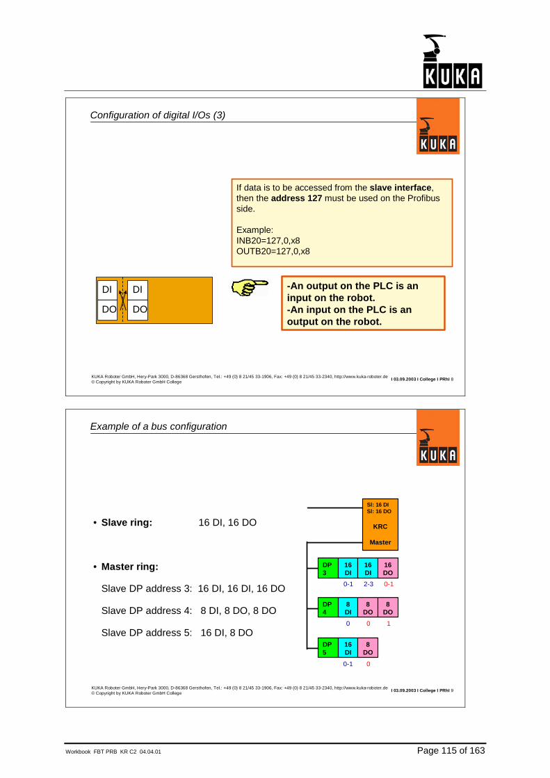
Workbook FBT PRB KR C2 04.04.01 Page 115 of 163
I 03.09.2003 I College I PRhI 8KUKA Roboter GmbH, Hery-Park 3000, D-86368 Gersthofen, Tel.: +49 (0) 8 21/45 33-1906, Fax: +49 (0) 8 21/45 33-2340, http://www.kuka-roboter.de© Copyright by KUKA Roboter GmbH College
DI
DO
DI
DO
Configuration of digital I/Os (3)
If data is to be accessed from the slave interface,then the address 127 must be used on the Profibusside.
Example:INB20=127,0,x8 OUTB20=127,0,x8
-An output on the PLC is aninput on the robot.-An input on the PLC is anoutput on the robot.
I 03.09.2003 I College I PRhI 9KUKA Roboter GmbH, Hery-Park 3000, D-86368 Gersthofen, Tel.: +49 (0) 8 21/45 33-1906, Fax: +49 (0) 8 21/45 33-2340, http://www.kuka-roboter.de© Copyright by KUKA Roboter GmbH College
Sl: 16 DISl: 16 DO
KRC
Master
DP 3
16DI
16DI
16DO
DP 4
8DI
8DO
8DO
DP5
16DI
8DO
0-1 0
0-1 2-3 0-1
0 0 1
Example of a bus configuration
• Slave ring: 16 DI, 16 DO
• Master ring:
Slave DP address 3: 16 DI, 16 DI, 16 DO
Slave DP address 4: 8 DI, 8 DO, 8 DO
Slave DP address 5: 16 DI, 8 DO

Page 116 of 163 Workbook FBT PRB KR C2 04.04.01
I 03.09.2003 I College I PRhI 10KUKA Roboter GmbH, Hery-Park 3000, D-86368 Gersthofen, Tel.: +49 (0) 8 21/45 33-1906, Fax: +49 (0) 8 21/45 33-2340, http://www.kuka-roboter.de© Copyright by KUKA Roboter GmbH College
Configuration of the inputs and outputs (1)
[PBMASL]; Profibus DP slave 3INW0=3,0,x1 ; $IN[1-16]INB2=3,2,x2 ; $IN[17-32]OUTW0=3,0,x1 ; $OUT[1-16]; Profibus DP slave 4INB4=4,0,x1 ; $IN[33-40]OUTB2=4,0,x1 ; $OUT[17-24]OUTB3=4,1,x1 ; $OUT[25-32]; Profibus DP slave 5INB5=5,0,x1 ; $IN[41-48]INB6=5,1,x1 ; $IN[49-56]OUTB4=5,0,x1 ; $OUT[33-40]
IOSYS.INI
Sl: 16 DISl: 16 DO
KRC
Master
DP3
16DI
16DI
16DO
DP4
8DI
8DO
8DO
DP5
16DI
8DO
0-1 0
0-1 2-3 0-1
0 0 1
I 03.09.2003 I College I PRhI 11KUKA Roboter GmbH, Hery-Park 3000, D-86368 Gersthofen, Tel.: +49 (0) 8 21/45 33-1906, Fax: +49 (0) 8 21/45 33-2340, http://www.kuka-roboter.de© Copyright by KUKA Roboter GmbH College
[PBMASL]; Profibus DP slave 3INW0=3,0,x1 ; $IN[1-16]INB2=3,2,x2 ; $IN[17-32]OUTW0=3,0,x1 ; $OUT[1-16]; Profibus DP slave 4INB4=4,0,x1 ; $IN[33-40]OUTB2=4,0,x1 ; $OUT[17-24]OUTB3=4,1,x1 ; $OUT[25-32]; Profibus DP slave 5INB5=5,0,x1 ; $IN[41-48]INB6=5,1,x1 ; $IN[49-56]OUTB4=5,0,x1 ; $OUT[33-40]; Data from and to the slave part (PLC)INB20=127,0,x2 ; $IN[161-176]OUTB20=127,0,x2 ; $OUT[161-176]
Configuration of the inputs and outputs (2)
IOSYS.INI
Sl: 16 DISl: 16 DO
KRC
Master
DP3
16DI
16DI
16DO
DP4
8DI
8DO
8DO
DP5
16DI
8DO
0-1 0
0-1 2-3 0-1
0 0 1

Workbook FBT PRB KR C2 04.04.01 Page 117 of 163
I 03.09.2003 I College I PRhI 13KUKA Roboter GmbH, Hery-Park 3000, D-86368 Gersthofen, Tel.: +49 (0) 8 21/45 33-1906, Fax: +49 (0) 8 21/45 33-2340, http://www.kuka-roboter.de© Copyright by KUKA Roboter GmbH College
ANALOG OUTPUTS$ANOUT[1]...$ANOUT[32]
ANALOG INPUTS$ANIN[1]...$ANIN[32]
From the periphery
To the periphery
Analog inputs and outputs of the KRC controller

Page 118 of 163 Workbook FBT PRB KR C2 04.04.01
I 03.09.2003 I College I PRhI 14KUKA Roboter GmbH, Hery-Park 3000, D-86368 Gersthofen, Tel.: +49 (0) 8 21/45 33-1906, Fax: +49 (0) 8 21/45 33-2340, http://www.kuka-roboter.de© Copyright by KUKA Roboter GmbH College
Configuration of analog I/Os (1)
Profibusaddress
Exponent2
Type
Profibus side
=ANINANOUT
Index
Robot side
Cal factor
CAL factor: limitation of the value range
This entry is optional.For the analog module, the specified value in digits corresponds to the nominal value (e.g. 10V).
Type: justification, sign
2 : left, without sign3 : left, with sign
0 : right, without sign1 : right, with sign
Byte offset
, , , ,
Analog inputs and outputs Robot side Processing direction ANIN : analog controller input ANOUT : analog controller output Index: Index = { 1, ..., 32 } for inputs Index = { 1, ..., 32 } for outputs With analog I/Os, each index can only be used once. The index is positioned immediately after ANIN or ANOUT without a space. Profibus side Profibus DP address Profibus DP address = { 0,1,2, ... , 127 } The Profibus DP address is set on each Profibus module. If data are needed from the slave part of the card, the DP address 127 is used. Byte offset

Workbook FBT PRB KR C2 04.04.01 Page 119 of 163
Byte offset = { 0,1,2, ... , 243 } The byte offset on the Profibus side designates the position of the I/Os in the memory of the Profibus device. The byte offsets, again counted separately for all the inputs and all the outputs. Exponent 2 Exponent2 = { 8, ..., 16 } The parameter Exponent 2 specifies the number of bits used to represent the numeric value of an analog value. Type Type = { 0, 1, 2, 3 } The parameter Type specifies how the Exponent 2 bits are arranged in the word and whether or not the leading bit of the Exponent 2 should be interpreted as a plus/minus sign before the numeric value. The possible parameter values have the following meanings: 0 : right-justified without sign 1 : right-justified with sign 2 : left-justified without sign 3 : left-justified with sign Cal factor The Cal factor specifies the value in digits at which an analog output outputs its nominal value (e.g. 10V). For an analog input, the value of the Cal factor corresponds to the nominal input value.

Page 120 of 163 Workbook FBT PRB KR C2 04.04.01
I 03.09.2003 I College I PRhI 16KUKA Roboter GmbH, Hery-Park 3000, D-86368 Gersthofen, Tel.: +49 (0) 8 21/45 33-1906, Fax: +49 (0) 8 21/45 33-2340, http://www.kuka-roboter.de© Copyright by KUKA Roboter GmbH College
Configuration of analog I/Os (3)
ANIN1=3,4,16,3,CAL30000
Example: Phönix IB IL AI 2/SF:
IOSYS.INI:
From the manual:
I 03.09.2003 I College I PRhI 17KUKA Roboter GmbH, Hery-Park 3000, D-86368 Gersthofen, Tel.: +49 (0) 8 21/45 33-1906, Fax: +49 (0) 8 21/45 33-2340, http://www.kuka-roboter.de© Copyright by KUKA Roboter GmbH College
Configuration of analog I/Os (4)
ANOUT1=3,4,16,2 or
ANOUT1=3,4,16,2,CAL65535
Example: Phönix IB IL AO 1/SF: IOSYS.INI:
From the manual:
FFFFHex = 65535Dec

Workbook FBT PRB KR C2 04.04.01 Page 121 of 163
I 03.09.2003 I College I PRhI 18KUKA Roboter GmbH, Hery-Park 3000, D-86368 Gersthofen, Tel.: +49 (0) 8 21/45 33-1906, Fax: +49 (0) 8 21/45 33-2340, http://www.kuka-roboter.de© Copyright by KUKA Roboter GmbH College
Configuration of analog I/Os (5)
ANIN1=3,4,13,3 or
ANIN1=3,4,13,3,CAL4095
Example: Phönix ST modules:
IOSYS.INI:
From the manual:
Note: 7FF8Hex = 1111 1111 1111 1000Bin 111 1111 1111 1Bin = 8191Dec (13bits)
With positive and negative range – 4096 to + 4095
I 03.09.2003 I College I PRhI 19KUKA Roboter GmbH, Hery-Park 3000, D-86368 Gersthofen, Tel.: +49 (0) 8 21/45 33-1906, Fax: +49 (0) 8 21/45 33-2340, http://www.kuka-roboter.de© Copyright by KUKA Roboter GmbH College
Configuration of analog I/Os (6)
ANIN1=3,4,16,3,CAL27648
Example: Siemens analogmodules (ET200S, ET200M):
IOSYS.INI:
From the manual:

Page 122 of 163 Workbook FBT PRB KR C2 04.04.01
I 03.09.2003 I College I PRhI 20KUKA Roboter GmbH, Hery-Park 3000, D-86368 Gersthofen, Tel.: +49 (0) 8 21/45 33-1906, Fax: +49 (0) 8 21/45 33-2340, http://www.kuka-roboter.de© Copyright by KUKA Roboter GmbH College
Particular characteristics (1), Intel/Motorola format (1)
Intel format
Byte 1 Byte 0
1 word
Bit 8 value 256 (2exp8)
In the Motorola format, the bytes within a word are interchanged.
Bit 0 value 1 (2exp0)
Motorola format
Byte 0 Byte 1
1 word
Bit 0 value 256 (2exp8)
Bit 8 value 1 (2exp0)
I 03.09.2003 I College I PRhI 21KUKA Roboter GmbH, Hery-Park 3000, D-86368 Gersthofen, Tel.: +49 (0) 8 21/45 33-1906, Fax: +49 (0) 8 21/45 33-2340, http://www.kuka-roboter.de© Copyright by KUKA Roboter GmbH College
Particular characteristics (1), Intel/Motorola format (2)
PC-based controllers use the Intel format. (KUKA KRC)
Depending on the module, it may be necessary to swap the bytes within a word!
Phoenix and Siemens use the Motorola format.
Example:
INB0=3,1,x1 ;Word 0
INB1=3,0,x1 ;Word 0
INB2=3,3,x1 ;Word 2
INB3=3,2,x1 ;Word 2
IOSYS.INI:
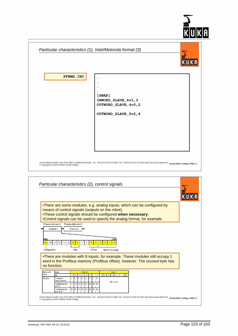
Workbook FBT PRB KR C2 04.04.01 Page 123 of 163
I 03.09.2003 I College I PRhI 22KUKA Roboter GmbH, Hery-Park 3000, D-86368 Gersthofen, Tel.: +49 (0) 8 21/45 33-1906, Fax: +49 (0) 8 21/45 33-2340, http://www.kuka-roboter.de© Copyright by KUKA Roboter GmbH College
Particular characteristics (1), Intel/Motorola format (3)
.
.
.
.[SWAP]INWORD_SLAVE_4=1,3OUTWORD_SLAVE_4=0,2
OUTWORD_SLAVE_5=2,4
PFBMS.INI
I 03.09.2003 I College I PRhI 23KUKA Roboter GmbH, Hery-Park 3000, D-86368 Gersthofen, Tel.: +49 (0) 8 21/45 33-1906, Fax: +49 (0) 8 21/45 33-2340, http://www.kuka-roboter.de© Copyright by KUKA Roboter GmbH College
Particular characteristics (2), control signals
•There are some modules, e.g. analog inputs, which can be configured by means of control signals (outputs on the robot).•These control signals should be configured when necessary.•Control signals can be used to specify the analog format, for example.
•There are modules with 8 inputs, for example. These modules still occupy 1word in the Profibus memory (Profibus offset), however. The unused byte has no function.

Page 124 of 163 Workbook FBT PRB KR C2 04.04.01
I 03.09.2003 I College I PRhI 24KUKA Roboter GmbH, Hery-Park 3000, D-86368 Gersthofen, Tel.: +49 (0) 8 21/45 33-1906, Fax: +49 (0) 8 21/45 33-2340, http://www.kuka-roboter.de© Copyright by KUKA Roboter GmbH College
KRC
master
DP 3
16DI
16DI
16DO
DP 4
8DI
2AI
2AO
DP5
16DO
2AO
0-1 2-3 0-1
0-1 2-3,4-5
0 1-2,3-4
0-1,2-3
Example of a bus configuration
Master ring:
Slave DP address 3: 16 DI, 16 DI, 16 DO
Slave DP address 4: 8 DI, 2 AI, 2 AO
Slave DP address 5: 16 DO, 2 AO
All modules are from Siemens.
I 03.09.2003 I College I PRhI 25KUKA Roboter GmbH, Hery-Park 3000, D-86368 Gersthofen, Tel.: +49 (0) 8 21/45 33-1906, Fax: +49 (0) 8 21/45 33-2340, http://www.kuka-roboter.de© Copyright by KUKA Roboter GmbH College
KRC
master
DP 3
16DI
16DI
16DO
DP 4
8DO
2AO
2AO
DP5
16DO
2AO
0-1 2-3,4-5
0-1 2-3 0-1
0 1-2,3-4
0-1,2-3
Configuration of the inputs and outputs (1)
[PBMASL]; Profibus DP slave 3INW0=3,0,x1 ; $IN[1-16]INB2=3,2,x2 ; $IN[17-32]OUTW0=3,0,x1 ; $OUT[1-16]; Profibus DP slave 4INB4=4,0,x1 ; $IN[33-40]ANIN1=4,1,16,3,CAL27648 ;ANIN[1]ANIN2=4,3,16,3,CAL27648 ;ANIN[2]ANOUT1=4,0,16,3,CAL27648 ;ANOUT[1]ANOUT2=4,2,16,3,CAL27648 ;ANOUT[2]; Profibus DP slave 5OUTB2=5,0,x1 ; $OUT[17-24]OUTB2=5,1,x1 ; $OUT[25-32]ANOUT3=5,2,16,3,CAL27648 ;ANOUT[3]ANOUT4=5,4,16,3,CAL27648 ;ANOUT[4]
IOSYS.INI

Workbook FBT PRB KR C2 04.04.01 Page 125 of 163
I 03.09.2003 I College I PRhI 26KUKA Roboter GmbH, Hery-Park 3000, D-86368 Gersthofen, Tel.: +49 (0) 8 21/45 33-1906, Fax: +49 (0) 8 21/45 33-2340, http://www.kuka-roboter.de© Copyright by KUKA Roboter GmbH College
KRC
master
DP 3
16DI
16DI
16DO
DP 4
8DI
2AI
2AO
DP5
16DO
2AO
0-1 2-3 0-1
0-1 2-3,4-5
0 1-2,3-4
0-1,2-3
Configuration of the inputs and outputs (2)
.
.
.
.[SWAP]INWORD_SLAVE_4=1,3OUTWORD_SLAVE_4=0,2
OUTWORD_SLAVE_5=2,4
PFBMS.INI


Workbook FBT PRB KR C2 04.04.01 Page 127 of 163
4.4. Offset table

Page 128 of 163 Workbook FBT PRB KR C2 04.04.01
I 03.09.2003 I College I PRhI 1KUKA Roboter GmbH, Hery-Park 3000, D-86368 Gersthofen, Tel.: +49 (0) 8 21/45 33-1906, Fax: +49 (0) 8 21/45 33-2340, http://www.kuka-roboter.de© Copyright by KUKA Roboter GmbH College
Table: offset byte and input/output (1)
Offset byte Start End0 1 .. 81 9 .. 162 17 .. 243 25 .. 324 33 .. 405 41 .. 486 49 .. 567 57 .. 648 65 .. 729 73 .. 80
10 81 .. 8811 89 .. 9612 97 .. 10413 105 .. 11214 113 .. 12015 121 .. 12816 129 .. 13617 137 .. 14418 145 .. 15219 153 .. 16020 161 .. 16821 169 .. 17622 177 .. 18423 185 .. 19224 193 .. 200
Offset byte Start End25 201 .. 20826 209 .. 21627 217 .. 22428 225 .. 23229 233 .. 24030 241 .. 24831 249 .. 25632 257 .. 26433 265 .. 27234 273 .. 28035 281 .. 28836 289 .. 29637 297 .. 30438 305 .. 31239 313 .. 32040 321 .. 32841 329 .. 33642 337 .. 34443 345 .. 35244 353 .. 36045 361 .. 36846 369 .. 37647 377 .. 38448 385 .. 39249 393 .. 400
Offset byte Start End50 401 .. 40851 409 .. 41652 417 .. 42453 425 .. 43254 433 .. 44055 441 .. 44856 449 .. 45657 457 .. 46458 465 .. 47259 473 .. 48060 481 .. 48861 489 .. 49662 497 .. 50463 505 .. 51264 513 .. 52065 521 .. 52866 529 .. 53667 537 .. 54468 545 .. 55269 553 .. 56070 561 .. 56871 569 .. 57672 577 .. 58473 585 .. 59274 593 .. 600
Formula for start address: Offset x 8 +1
I 03.09.2003 I College I PRhI 2KUKA Roboter GmbH, Hery-Park 3000, D-86368 Gersthofen, Tel.: +49 (0) 8 21/45 33-1906, Fax: +49 (0) 8 21/45 33-2340, http://www.kuka-roboter.de© Copyright by KUKA Roboter GmbH College
Table: offset byte and input/output (2)
Offset byte Start End75 601 .. 60876 609 .. 61677 617 .. 62478 625 .. 63279 633 .. 64080 641 .. 64881 649 .. 65682 657 .. 66483 665 .. 67284 673 .. 68085 681 .. 68886 689 .. 69687 697 .. 70488 705 .. 71289 713 .. 72090 721 .. 72891 729 .. 73692 737 .. 74493 745 .. 75294 753 .. 76095 761 .. 76896 769 .. 77697 777 .. 78498 785 .. 79299 793 .. 800
Offset byte Start End100 801 .. 808101 809 .. 816102 817 .. 824103 825 .. 832104 833 .. 840105 841 .. 848106 849 .. 856107 857 .. 864108 865 .. 872109 873 .. 880110 881 .. 888111 889 .. 896112 897 .. 904113 905 .. 912114 913 .. 920115 921 .. 928116 929 .. 936117 937 .. 944118 945 .. 952119 953 .. 960120 961 .. 968121 969 .. 976122 977 .. 984123 985 .. 992124 993 .. 1000
Offset byte Start End125 1001 .. 1008126 1009 .. 1016127 1017 .. 1024

Workbook FBT PRB KR C2 04.04.01 Page 129 of 163
5. Transfer program

Page 130 of 163 Workbook FBT PRB KR C2 04.04.01
I 03.09.2003 I College I PRhI 1KUKA Roboter GmbH, Hery-Park 3000, D-86368 Gersthofen, Tel.: +49 (0) 8 21/45 33-1906, Fax: +49 (0) 8 21/45 33-2340, http://www.kuka-roboter.de© Copyright by KUKA Roboter GmbH College
Transfer configuration program
Master Robot is slave
Robot is master
TR Config
•Data can be transferred from the master component to the slave part of theProfibus card and vice versa.•The transfer takes place in real time.•The transfer function is executed directlyon the Profibus card, independently ofthe KRC.
I 03.09.2003 I College I PRhI 2KUKA Roboter GmbH, Hery-Park 3000, D-86368 Gersthofen, Tel.: +49 (0) 8 21/45 33-1906, Fax: +49 (0) 8 21/45 33-2340, http://www.kuka-roboter.de© Copyright by KUKA Roboter GmbH College
Installing the transfer configuration program
•The transfer configuration program is located on theKUKA CDPath:Drive:\Internat\Bus\Profibus\PCI_Card\German\TR_Config.exe
•This program can be started directly, or copied to the harddisk and started there.

Workbook FBT PRB KR C2 04.04.01 Page 131 of 163
I 03.09.2003 I College I PRhI 3KUKA Roboter GmbH, Hery-Park 3000, D-86368 Gersthofen, Tel.: +49 (0) 8 21/45 33-1906, Fax: +49 (0) 8 21/45 33-2340, http://www.kuka-roboter.de© Copyright by KUKA Roboter GmbH College
Working with the transfer configuration program (1)
I 03.09.2003 I College I PRhI 4KUKA Roboter GmbH, Hery-Park 3000, D-86368 Gersthofen, Tel.: +49 (0) 8 21/45 33-1906, Fax: +49 (0) 8 21/45 33-2340, http://www.kuka-roboter.de© Copyright by KUKA Roboter GmbH College
Working with the transfer configuration program (2)
Address=byte offset
Remote master = Slave part of the CP5613/14
The higher-level master sees the robot as an I/O module.The "connections" of this module come from the robot masterpart.
Address=byte offset

Page 132 of 163 Workbook FBT PRB KR C2 04.04.01
I 03.09.2003 I College I PRhI 5KUKA Roboter GmbH, Hery-Park 3000, D-86368 Gersthofen, Tel.: +49 (0) 8 21/45 33-1906, Fax: +49 (0) 8 21/45 33-2340, http://www.kuka-roboter.de© Copyright by KUKA Roboter GmbH College
Working with the transfer configuration program (3)
In this example, the inputs from slave 3 of the robot master ring are transferredto the higher-level master. The first byte (offset 0) of the inputs is transferred.The higher-level master sees these data as inputs at its location.
I 03.09.2003 I College I PRhI 6KUKA Roboter GmbH, Hery-Park 3000, D-86368 Gersthofen, Tel.: +49 (0) 8 21/45 33-1906, Fax: +49 (0) 8 21/45 33-2340, http://www.kuka-roboter.de© Copyright by KUKA Roboter GmbH College
Working with the transfer configuration program (4)
Important:In order for the data to be transferred to the higher-level master, the data must be output on the slave part of the card as outputs. The first output byte of the slave part contains these data. This byte may no longer be used for any other data, i.e.:IOSYS.INI:OUTB20=127,0,x1; This entry has no function. The output byte 0
is occupied by the transfer configuration program
Profibus
CP5613/14Master part Slave partAddress 2 Address 10Input OutputSlave 3, byte 0 Byte 0
Byte 1TR Config Byte 2
Byte 3
Higher-level master (PLC)
Data from slave 10InputByte 0 Data from robot slave 3Byte 1 Other dataByte 2 Other dataByte 3 Other data

Workbook FBT PRB KR C2 04.04.01 Page 133 of 163
I 03.09.2003 I College I PRhI 7KUKA Roboter GmbH, Hery-Park 3000, D-86368 Gersthofen, Tel.: +49 (0) 8 21/45 33-1906, Fax: +49 (0) 8 21/45 33-2340, http://www.kuka-roboter.de© Copyright by KUKA Roboter GmbH College
Working with the transfer configuration program (5)
IOSYS.INI:INB0=3,0,x1; The inputs of slave 3, byte 0 can be used by the KRC
Profibus
CP5613/14Master part Slave partAddress 2 Address 10Input OutputSlave 3, byte 0 Byte 0
Byte 1TR Config Byte 2
Byte 3
Higher-level master (PLC)
Data from slave 10InputByte 0 Data from robot slave 3Byte 1 Other dataByte 2 Other dataByte 3 Other data
I 03.09.2003 I College I PRhI 8KUKA Roboter GmbH, Hery-Park 3000, D-86368 Gersthofen, Tel.: +49 (0) 8 21/45 33-1906, Fax: +49 (0) 8 21/45 33-2340, http://www.kuka-roboter.de© Copyright by KUKA Roboter GmbH College
Working with the transfer configuration program (6)
Transfer list.
The transfer entry must be insertedinto the transfer list.

Page 134 of 163 Workbook FBT PRB KR C2 04.04.01
I 03.09.2003 I College I PRhI 9KUKA Roboter GmbH, Hery-Park 3000, D-86368 Gersthofen, Tel.: +49 (0) 8 21/45 33-1906, Fax: +49 (0) 8 21/45 33-2340, http://www.kuka-roboter.de© Copyright by KUKA Roboter GmbH College
Working with the transfer configuration program (7)
In this example, the outputs from slave 3 of the robot master ring are controlled by the higher-level master. The first byte (offset 0) of the outputs is controlled.The higher-level master sees these data as outputs at its location.
I 03.09.2003 I College I PRhI 10KUKA Roboter GmbH, Hery-Park 3000, D-86368 Gersthofen, Tel.: +49 (0) 8 21/45 33-1906, Fax: +49 (0) 8 21/45 33-2340, http://www.kuka-roboter.de© Copyright by KUKA Roboter GmbH College
Working with the transfer configuration program (8)
In order for the output data to be transferred to the higher-level master, the data must be read in on the slave part of the CP5613/14 card as input data. The first input byte of the slave part contains these data. These data can also be made accessible to the KRC, i.e.:IOSYS.INI:INB20=127,0,x1; Here you can read in the status of the outputs on slave 3,
byte 0.
Profibus
CP5613/14Master part Slave partAddress 2 Address 10Output InputSlave 3, byte 0 Byte 0
Byte 1TR Config Byte 2
Byte 3
Higher-level master (PLC)
Data from slave 10OutputByte 0 Data to robot slave 3Byte 1 Other dataByte 2 Other dataByte 3 Other data

Workbook FBT PRB KR C2 04.04.01 Page 135 of 163
I 03.09.2003 I College I PRhI 11KUKA Roboter GmbH, Hery-Park 3000, D-86368 Gersthofen, Tel.: +49 (0) 8 21/45 33-1906, Fax: +49 (0) 8 21/45 33-2340, http://www.kuka-roboter.de© Copyright by KUKA Roboter GmbH College
Working with the transfer configuration program (9)
Caution:Outputs can only be controlled from a single location. The following entry in theIOSYS.INI has no effect.IOSYS.INI:OUTB0=3,0,x1; This entry has no function. These outputs are controlled
by the higher-level master.
Such entries are invalid and must be avoided!
Profibus
CP5613/14Master part Slave partAddress 2 Address 10Output InputSlave 3, byte 0 Byte 0
Byte 1TR Config Byte 2
Byte 3
Higher-level master (PLC)
Data from slave 10OutputByte 0 Data to robot slave 3Byte 1 Other dataByte 2 Other dataByte 3 Other data
I 03.09.2003 I College I PRhI 12KUKA Roboter GmbH, Hery-Park 3000, D-86368 Gersthofen, Tel.: +49 (0) 8 21/45 33-1906, Fax: +49 (0) 8 21/45 33-2340, http://www.kuka-roboter.de© Copyright by KUKA Roboter GmbH College
Working with the transfer configuration program (10)
Transfer list.
The transfer entry must be insertedinto the transfer list.

Page 136 of 163 Workbook FBT PRB KR C2 04.04.01
I 03.09.2003 I College I PRhI 13KUKA Roboter GmbH, Hery-Park 3000, D-86368 Gersthofen, Tel.: +49 (0) 8 21/45 33-1906, Fax: +49 (0) 8 21/45 33-2340, http://www.kuka-roboter.de© Copyright by KUKA Roboter GmbH College
Working with the transfer configuration program (11)
The transfer list must now be given a name. The file extension is *.tra. Save the transfer list in the directory C:\KRC\Roboter\Init.
I 03.09.2003 I College I PRhI 14KUKA Roboter GmbH, Hery-Park 3000, D-86368 Gersthofen, Tel.: +49 (0) 8 21/45 33-1906, Fax: +49 (0) 8 21/45 33-2340, http://www.kuka-roboter.de© Copyright by KUKA Roboter GmbH College
PFBMS.INI
[MASTER]MASTER_USED=1DATABASE_PATH=init/Rob1.ldbFIRMWARE_PATH=drivers/FW_5613.binWATCHDOG_TIME=3MAPPING_USED=1MAPPING_PATH=init/Rob1.tra;DEACTIVATED_SLAVES=
PFBMS.INI
Activate mapping with the transfer configuration program (1).
Enter the name of the transfer list.

Workbook FBT PRB KR C2 04.04.01 Page 137 of 163
6. Coupling segments
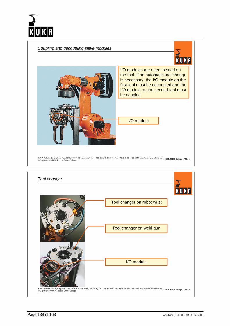
Page 138 of 163 Workbook FBT PRB KR C2 04.04.01
I 03.09.2003 I College I PRhI 1KUKA Roboter GmbH, Hery-Park 3000, D-86368 Gersthofen, Tel.: +49 (0) 8 21/45 33-1906, Fax: +49 (0) 8 21/45 33-2340, http://www.kuka-roboter.de© Copyright by KUKA Roboter GmbH College
Coupling and decoupling slave modules
I/O modules are often located onthe tool. If an automatic tool change is necessary, the I/O module on the first tool must be decoupled and theI/O module on the second tool must be coupled.
I/O module
I 03.09.2003 I College I PRhI 2KUKA Roboter GmbH, Hery-Park 3000, D-86368 Gersthofen, Tel.: +49 (0) 8 21/45 33-1906, Fax: +49 (0) 8 21/45 33-2340, http://www.kuka-roboter.de© Copyright by KUKA Roboter GmbH College
Tool changer
I/O module
Tool changer on weld gun
Tool changer on robot wrist

Workbook FBT PRB KR C2 04.04.01 Page 139 of 163
I 03.09.2003 I College I PRhI 3KUKA Roboter GmbH, Hery-Park 3000, D-86368 Gersthofen, Tel.: +49 (0) 8 21/45 33-1906, Fax: +49 (0) 8 21/45 33-2340, http://www.kuka-roboter.de© Copyright by KUKA Roboter GmbH College
Hardware requirements (1)
If the last device is decoupled, then the bus terminator is no longer present.The entire bus system enters the fault state.
Remedy:Install a repeater upstream of the device that is to be decoupled.The repeater creates electrical isolation between the two bus segments.
Repeater
I 03.09.2003 I College I PRhI 4KUKA Roboter GmbH, Hery-Park 3000, D-86368 Gersthofen, Tel.: +49 (0) 8 21/45 33-1906, Fax: +49 (0) 8 21/45 33-2340, http://www.kuka-roboter.de© Copyright by KUKA Roboter GmbH College
Hardware requirements (2)
If the last device is decoupled, then the bus terminator is no longer present.The entire bus system enters the fault state.
Remedy:•Install modules with an intelligent bus terminator(Turk FLDP).•Install modules with an integrated repeater(Siemens ET200R).

Page 140 of 163 Workbook FBT PRB KR C2 04.04.01
I 03.09.2003 I College I PRhI 5KUKA Roboter GmbH, Hery-Park 3000, D-86368 Gersthofen, Tel.: +49 (0) 8 21/45 33-1906, Fax: +49 (0) 8 21/45 33-2340, http://www.kuka-roboter.de© Copyright by KUKA Roboter GmbH College
Software requirements (1) SIMATIC NCM PC Manager
SIMATIC NCM PC Manager:Configure the bus structure as if all slave modules are connected at the sametime.
Tool 4
Tool 3Tool 2
Tool 1
Each tool is given its own Profibus DP address.
I 03.09.2003 I College I PRhI 6KUKA Roboter GmbH, Hery-Park 3000, D-86368 Gersthofen, Tel.: +49 (0) 8 21/45 33-1906, Fax: +49 (0) 8 21/45 33-2340, http://www.kuka-roboter.de© Copyright by KUKA Roboter GmbH College
Software requirements (2) IOSYS.INI
IOSYS.INI:Configure the bus structure as if all slave modules are connected at the sametime.
[PBMASL];Tool 1 large weld gun slave 3INB0=3,0,x1 ; $IN[1-8]INB1=3,1,x1 ; $IN[9-16]OUTB0=3,0,x1 ; $OUT[1-8]OUTB1=3,1,x1 ; $OUT[9-16];Tool 2 medium weld gun slave 4INB2=4,0,x1 ; $IN[17-24]INB3=4,1,x1 ; $IN[25-32]OUTB2=4,0,x1 ; $OUT[17-24];Tool 3 small weld gun slave 5INB4=5,0,x1 ; $IN[32-40]OUTB3=5,0,x1 ; $OUT[24-32]..
IOSYS.INI

Workbook FBT PRB KR C2 04.04.01 Page 141 of 163
I 03.09.2003 I College I PRhI 7KUKA Roboter GmbH, Hery-Park 3000, D-86368 Gersthofen, Tel.: +49 (0) 8 21/45 33-1906, Fax: +49 (0) 8 21/45 33-2340, http://www.kuka-roboter.de© Copyright by KUKA Roboter GmbH College
Software requirements (3) PFBMS.INI
PFBMS.INI:So that the Profibus driver knows which modules are connected to the bus, allmodules which are not connected have to be deactivated.
.
.
.[MASTER]MASTER_USED=1DATABASE_PATH=init/Rob1.ldbFIRMWARE_PATH=drivers/FW_5613.binWATCHDOG_TIME=3MAPPING_USED=0MAPPING_PATH=init/DEACTIVATED_SLAVES=3,4,5,6...
PFBMS.INI
I 03.09.2003 I College I PRhI 8KUKA Roboter GmbH, Hery-Park 3000, D-86368 Gersthofen, Tel.: +49 (0) 8 21/45 33-1906, Fax: +49 (0) 8 21/45 33-2340, http://www.kuka-roboter.de© Copyright by KUKA Roboter GmbH College
Software requirements (3) PFBMS.INI
After I/O reconfiguration or after switch-on, the modules which have been deactivated in PFBMS.INI are no longer addressed by the Profibus driver.
.
.
.[MASTER]MASTER_USED=1DATABASE_PATH=init/Rob1.ldbFIRMWARE_PATH=drivers/FW_5613.binWATCHDOG_TIME=3MAPPING_USED=0MAPPING_PATH=init/DEACTIVATED_SLAVES=3,4,5,6...
PFBMS.INI

Page 142 of 163 Workbook FBT PRB KR C2 04.04.01
I 03.09.2003 I College I PRhI 9KUKA Roboter GmbH, Hery-Park 3000, D-86368 Gersthofen, Tel.: +49 (0) 8 21/45 33-1906, Fax: +49 (0) 8 21/45 33-2340, http://www.kuka-roboter.de© Copyright by KUKA Roboter GmbH College
Activating/deactivating modules by means of KRL
•If a deactivated module is to be activated, this information must be given to theProfibus master. Otherwise, no data can be exchanged with the module.
•If an activated module is to be deactivated, this information must likewise be given to the Profibus master. If this is not done, a program stop will occur andan error message will appear.
•Deactivation and activation can be carried out via the KRL program.The IOCTL system function is available for this purpose.
I 03.09.2003 I College I PRhI 10KUKA Roboter GmbH, Hery-Park 3000, D-86368 Gersthofen, Tel.: +49 (0) 8 21/45 33-1906, Fax: +49 (0) 8 21/45 33-2340, http://www.kuka-roboter.de© Copyright by KUKA Roboter GmbH College
Activating/deactivating modules by means of KRL
Syntax: Result = IOCTL ( 11 , 1002 , 3 )
KRL command
Driver identification number for Profibus (master/slave)
Code number for "Deactivate slave" command(1001 = activate,1002 = deactivate)
Slave no. 3
Integer variable(0 = command executed)

Workbook FBT PRB KR C2 04.04.01 Page 143 of 163
I 03.09.2003 I College I PRhI 11KUKA Roboter GmbH, Hery-Park 3000, D-86368 Gersthofen, Tel.: +49 (0) 8 21/45 33-1906, Fax: +49 (0) 8 21/45 33-2340, http://www.kuka-roboter.de© Copyright by KUKA Roboter GmbH College
Activating/deactivating modules by means of KRL
Deactivate
Activate
Example:
I 03.09.2003 I College I PRhI 12KUKA Roboter GmbH, Hery-Park 3000, D-86368 Gersthofen, Tel.: +49 (0) 8 21/45 33-1906, Fax: +49 (0) 8 21/45 33-2340, http://www.kuka-roboter.de© Copyright by KUKA Roboter GmbH College
Activating/deactivating modules by means of the KCP
For test purposes, modules can alsobe activated and deactivated by meansof "manual input" on the KCP.At Version <5.x the “=“-Sign is not necessary.


Workbook FBT PRB KR C2 04.04.01 Page 145 of 163
7. Diagnosis

Page 146 of 163 Workbook FBT PRB KR C2 04.04.01
I 03.09.2003 I College I PRhI 1KUKA Roboter GmbH, Hery-Park 3000, D-86368 Gersthofen, Tel.: +49 (0) 8 21/45 33-1906, Fax: +49 (0) 8 21/45 33-2340, http://www.kuka-roboter.de© Copyright by KUKA Roboter GmbH College
Diagnostic options (1) Hardware tester
•For checking the bus cable and wiring.•Wiring errors are displayed.•Tests accessibility of the slaves.
Siemens BT200
I 03.09.2003 I College I PRhI 2KUKA Roboter GmbH, Hery-Park 3000, D-86368 Gersthofen, Tel.: +49 (0) 8 21/45 33-1906, Fax: +49 (0) 8 21/45 33-2340, http://www.kuka-roboter.de© Copyright by KUKA Roboter GmbH College
Diagnostic options (2) HMI message window (GUI)
In the event of a bus fault, error messages appear on the HMI
Messages on theHMI

Workbook FBT PRB KR C2 04.04.01 Page 147 of 163
I 03.09.2003 I College I PRhI 3KUKA Roboter GmbH, Hery-Park 3000, D-86368 Gersthofen, Tel.: +49 (0) 8 21/45 33-1906, Fax: +49 (0) 8 21/45 33-2340, http://www.kuka-roboter.de© Copyright by KUKA Roboter GmbH College
Diagnostic options (3) Log file
Log file is written when the driver is started.Progress of the startup procedure is logged.
PFBMS.LOGFILE_PTR_POS=001559
04/03/04 08:35:58 : Logfile for Profibus CP5613/14 (V1.25.7.0)
04/03/04 08:35:58 : Downloading Firmware and Database.........
04/03/04 08:36:00 : CP5613/14 started!
04/03/04 08:36:00 : Master Application registered at the CP!
04/03/04 08:36:00 : Accessed pointer to DPR from CP!
04/03/04 08:36:00 : Hardware version: 3.08
04/03/04 08:36:00 : Firmware version: 2.01
04/03/04 08:36:00 : Master baudrate : 1,5 MB
04/03/04 08:36:01 : next CP state: DP_STOP
04/03/04 08:36:01 : DP_Master has changed mode to: DP_STOP
04/03/04 08:36:01 : next CP state: DP_CLEAR
04/03/04 08:36:01 : DP_Master has changed mode to: DP_CLEAR
04/03/04 08:36:01 : next CP state: DP_OPERATE
04/03/04 08:36:01 : DP_Master has changed mode to: DP_OPERATE
04/03/04 08:36:01 : Slave Application registered at the CP!
04/03/04 08:36:01 : Slave started!
04/03/04 08:36:01 : Slave baudrate : 1,5 MB
04/03/04 08:36:01 : SLAVE_MODUL: State = WAIT_FOR_CONFIGURATION
04/03/04 08:36:01 : SLAVE_MODUL: State = DATA_EXCHANGE
===== LAST_ENTRY =====
I 03.09.2003 I College I PRhI 4KUKA Roboter GmbH, Hery-Park 3000, D-86368 Gersthofen, Tel.: +49 (0) 8 21/45 33-1906, Fax: +49 (0) 8 21/45 33-2340, http://www.kuka-roboter.de© Copyright by KUKA Roboter GmbH College
Case example: Everything is OK, only the master part is active
PFBMS.LOGFILE_PTR_POS=001154
16/03/04 12:27:38 : Logfile for Profibus CP5613/14 (V1.25.7.0)
16/03/04 12:27:38 : Downloading Firmware and Database.........
16/03/04 12:27:39 : CP5613/14 started!
16/03/04 12:27:39 : Master Application registered at the CP!
16/03/04 12:27:39 : Accessed pointer to DPR from CP!
16/03/04 12:27:39 : Hardware version: 3.08
16/03/04 12:27:39 : Firmware version: 2.01
16/03/04 12:27:39 : Master baudrate : 1,5 MB
16/03/04 12:27:40 : next CP state: DP_STOP
16/03/04 12:27:40 : DP_Master has changed mode to: DP_STOP
16/03/04 12:27:40 : next CP state: DP_CLEAR
16/03/04 12:27:40 : DP_Master has changed mode to: DP_CLEAR
16/03/04 12:27:40 : next CP state: DP_OPERATE
16/03/04 12:27:40 : DP_Master has changed mode to: DP_OPERATE
===== LAST_ENTRY =====
Master is active

Page 148 of 163 Workbook FBT PRB KR C2 04.04.01
I 03.09.2003 I College I PRhI 5KUKA Roboter GmbH, Hery-Park 3000, D-86368 Gersthofen, Tel.: +49 (0) 8 21/45 33-1906, Fax: +49 (0) 8 21/45 33-2340, http://www.kuka-roboter.de© Copyright by KUKA Roboter GmbH College
Case example: Everything is OK, master and slave parts are active
PFBMS.LOGFILE_PTR_POS=001559
16/03/04 12:53:51 : Logfile for Profibus CP5613/14 (V1.25.7.0)
16/03/04 12:53:51 : Downloading Firmware and Database.........
16/03/04 12:53:53 : CP5613/14 started!
16/03/04 12:53:53 : Master Application registered at the CP!
16/03/04 12:53:53 : Accessed pointer to DPR from CP!
16/03/04 12:53:53 : Hardware version: 3.08
16/03/04 12:53:53 : Firmware version: 2.01
16/03/04 12:53:53 : Master baudrate : 1,5 MB
16/03/04 12:53:54 : next CP state: DP_STOP
16/03/04 12:53:54 : DP_Master has changed mode to: DP_STOP
16/03/04 12:53:54 : next CP state: DP_CLEAR
16/03/04 12:53:54 : DP_Master has changed mode to: DP_CLEAR
16/03/04 12:53:54 : next CP state: DP_OPERATE
16/03/04 12:53:54 : DP_Master has changed mode to: DP_OPERATE
16/03/04 12:53:54 : Slave Application registered at the CP!
16/03/04 12:53:54 : Slave started!
16/03/04 12:53:54 : Slave baudrate : 1,5 MB
16/03/04 12:53:54 : SLAVE_MODUL: State = WAIT_FOR_CONFIGURATION
16/03/04 12:53:54 : SLAVE_MODUL: State = DATA_EXCHANGE
===== LAST_ENTRY =====
Master is active
Slave is active

Workbook FBT PRB KR C2 04.04.01 Page 149 of 163
I 03.09.2003 I College I PRhI 7KUKA Roboter GmbH, Hery-Park 3000, D-86368 Gersthofen, Tel.: +49 (0) 8 21/45 33-1906, Fax: +49 (0) 8 21/45 33-2340, http://www.kuka-roboter.de© Copyright by KUKA Roboter GmbH College
HMI: Slave 3 is not present, only the master part is active
HMI
•Communication error•Error in the master ring•Driver error
I 03.09.2003 I College I PRhI 8KUKA Roboter GmbH, Hery-Park 3000, D-86368 Gersthofen, Tel.: +49 (0) 8 21/45 33-1906, Fax: +49 (0) 8 21/45 33-2340, http://www.kuka-roboter.de© Copyright by KUKA Roboter GmbH College
Log file: Slave 3 is not present, only the master part is active
PFBMS.LOGFILE_PTR_POS=001154
16/03/04 12:27:38 : Logfile for Profibus CP5613/14 (V1.25.7.0)
16/03/04 12:27:38 : Downloading Firmware and Database.........
16/03/04 12:27:39 : CP5613/14 started!
16/03/04 12:27:39 : Master Application registered at the CP!
16/03/04 12:27:39 : Accessed pointer to DPR from CP!
16/03/04 12:27:39 : Hardware version: 3.08
16/03/04 12:27:39 : Firmware version: 2.01
16/03/04 12:27:39 : Master baudrate : 1,5 MB
16/03/04 12:27:40 : next CP state: DP_STOP
16/03/04 12:27:40 : DP_Master has changed mode to: DP_STOP
16/03/04 12:27:40 : next CP state: DP_CLEAR
16/03/04 12:27:40 : DP_Master has changed mode to: DP_CLEAR
16/03/04 12:27:40 : next CP state: DP_OPERATE
16/03/04 12:27:40 : DP_Master has changed mode to: DP_OPERATE
===== LAST_ENTRY =====
Master is active
It cannot be determined from the log file whether the connected slaves are active.The log file shows the state of the master.

Page 150 of 163 Workbook FBT PRB KR C2 04.04.01
I 03.09.2003 I College I PRhI 9KUKA Roboter GmbH, Hery-Park 3000, D-86368 Gersthofen, Tel.: +49 (0) 8 21/45 33-1906, Fax: +49 (0) 8 21/45 33-2340, http://www.kuka-roboter.de© Copyright by KUKA Roboter GmbH College
HMI: Connection to the higher-level master is not available
HMI
•Error in slave ring
I 03.09.2003 I College I PRhI 10KUKA Roboter GmbH, Hery-Park 3000, D-86368 Gersthofen, Tel.: +49 (0) 8 21/45 33-1906, Fax: +49 (0) 8 21/45 33-2340, http://www.kuka-roboter.de© Copyright by KUKA Roboter GmbH College
Log file: Connection to the higher-level master is not available
PFBMS.LOG.
.
.
16/03/04 13:29:13 : Accessed pointer to DPR from CP!
16/03/04 13:29:13 : Hardware version: 3.08
16/03/04 13:29:13 : Firmware version: 2.01
16/03/04 13:29:13 : Master baudrate : 1,5 MB
16/03/04 13:29:14 : next CP state: DP_STOP
16/03/04 13:29:14 : DP_Master has changed mode to: DP_STOP
16/03/04 13:29:14 : next CP state: DP_CLEAR
16/03/04 13:29:14 : DP_Master has changed mode to: DP_CLEAR
16/03/04 13:29:14 : next CP state: DP_OPERATE
16/03/04 13:29:14 : DP_Master has changed mode to: DP_OPERATE
16/03/04 13:29:14 : Slave Application registered at the CP!
16/03/04 13:29:14 : Slave started!
16/03/04 13:29:14 : Slave baudrate : 1,5 MB
16/03/04 13:29:14 : SLAVE_MODUL: State = WAIT_FOR_CONFIGURATION
16/03/04 13:29:14 : SLAVE_MODUL: State = DATA_EXCHANGE
16/03/04 13:29:27 : SLAVE_MODUL: State = WAIT_FOR_PARAMETER
===== LAST_ENTRY =====
The slave part waits for aconfiguration telegram from the higher-level master.

Workbook FBT PRB KR C2 04.04.01 Page 151 of 163
I 03.09.2003 I College I PRhI 11KUKA Roboter GmbH, Hery-Park 3000, D-86368 Gersthofen, Tel.: +49 (0) 8 21/45 33-1906, Fax: +49 (0) 8 21/45 33-2340, http://www.kuka-roboter.de© Copyright by KUKA Roboter GmbH College
Log file: Connection to the higher-level master is OK again
PFBMS.LOG.
.
16/03/04 13:29:13 : Accessed pointer to DPR from CP!
16/03/04 13:29:13 : Hardware version: 3.08
16/03/04 13:29:13 : Firmware version: 2.01
16/03/04 13:29:13 : Master baudrate : 1,5 MB
16/03/04 13:29:14 : next CP state: DP_STOP
16/03/04 13:29:14 : DP_Master has changed mode to: DP_STOP
16/03/04 13:29:14 : next CP state: DP_CLEAR
16/03/04 13:29:14 : DP_Master has changed mode to: DP_CLEAR
16/03/04 13:29:14 : next CP state: DP_OPERATE
16/03/04 13:29:14 : DP_Master has changed mode to: DP_OPERATE
16/03/04 13:29:14 : Slave Application registered at the CP!
16/03/04 13:29:14 : Slave started!
16/03/04 13:29:14 : Slave baudrate : 1,5 MB
16/03/04 13:29:14 : SLAVE_MODUL: State = WAIT_FOR_CONFIGURATION
16/03/04 13:29:14 : SLAVE_MODUL: State = DATA_EXCHANGE
16/03/04 13:29:27 : SLAVE_MODUL: State = WAIT_FOR_PARAMETER
16/03/04 13:35:00 : SLAVE_MODUL: State = DATA_EXCHANGE
===== LAST_ENTRY =====
Slave part is active again.

Page 152 of 163 Workbook FBT PRB KR C2 04.04.01
I 03.09.2003 I College I PRhI 13KUKA Roboter GmbH, Hery-Park 3000, D-86368 Gersthofen, Tel.: +49 (0) 8 21/45 33-1906, Fax: +49 (0) 8 21/45 33-2340, http://www.kuka-roboter.de© Copyright by KUKA Roboter GmbH College
HMI: Connection to the higher-level master is not available
HMI
Driver configuration error
PFBMS.INI contains the entry STANDBY=0. After I/O reconfiguration a driver configuration error appears.
I 03.09.2003 I College I PRhI 14KUKA Roboter GmbH, Hery-Park 3000, D-86368 Gersthofen, Tel.: +49 (0) 8 21/45 33-1906, Fax: +49 (0) 8 21/45 33-2340, http://www.kuka-roboter.de© Copyright by KUKA Roboter GmbH College
Log file: Connection to the higher-level master is not available
PFBMS.LOG.
16/03/04 14:59:29 : Master Application registered at the CP!
.
16/03/04 14:59:30 : DP_Master has changed mode to: DP_OPERATE
16/03/04 14:59:30 : Slave Application registered at the CP!
16/03/04 14:59:30 : Slave started!
16/03/04 14:59:30 : SLAVE_MODUL: State = WAIT_FOR_PARAMETER
16/03/04 14:59:32 : Slavemodul is not in mode data_exchange within 2000millisec
>onds! 4 14:59:32 : Slavemodul is not in mode data_exchange within 2000millisec
16/03/04 14:59:32 : Slave is stopped!
16/03/04 14:59:33 : Slave Application cancelled at the CP!
16/03/04 14:59:33 : next CP state: DP_CLEAR
.
16/03/04 14:59:33 : DP_Master has changed mode to: DP_OFFLINE
16/03/04 14:59:33 : DP_Pointer released!
16/03/04 14:59:33 : Master Application cancelled at the CP!
16/03/04 14:59:33 : CP is resetted!
===== LAST_ENTRY =====
The slave part does not receive any configuration telegram from the higher-level master. The entire driver is therefore deleted.
PFBMS.INI contains the entrySTANDBY=0. After I/Oreconfiguration a driver configuration error appears.

Workbook FBT PRB KR C2 04.04.01 Page 153 of 163
I 03.09.2003 I College I PRhI 15KUKA Roboter GmbH, Hery-Park 3000, D-86368 Gersthofen, Tel.: +49 (0) 8 21/45 33-1906, Fax: +49 (0) 8 21/45 33-2340, http://www.kuka-roboter.de© Copyright by KUKA Roboter GmbH College
HMI: Connection to the higher-level master has no bus terminator
HMI
Fault in the slave line
A faulty bus terminator causes reflections in the bus. After a very short time, avery large number of messages are active. Then the only output on the HMI is"Overflow Message Interface".
I 03.09.2003 I College I PRhI 16KUKA Roboter GmbH, Hery-Park 3000, D-86368 Gersthofen, Tel.: +49 (0) 8 21/45 33-1906, Fax: +49 (0) 8 21/45 33-2340, http://www.kuka-roboter.de© Copyright by KUKA Roboter GmbH College
Log file: Connection to the higher-level master has no bus terminator
PFBMS.LOGFILE_PTR_POS=128972
17/03/04 12:16:19 : DP-Error: 8034 0.
17/03/04 12:16:19 : DP-Error: 8034 0
17/03/04 12:16:19 : DP-Error: 8034 0
17/03/04 12:16:19 : DP-Error: 8034 0
17/03/04 12:16:19 : DP-Error: 8034 0
17/03/04 12:16:19 : DP-Error: 8034 0
17/03/04 12:16:19 : DP-Error: 8034 0
17/03/04 12:16:19 : DP-Error: 8034 0
17/03/04 12:16:19 : DP-Error: 8034 0
17/03/04 12:16:19 : DP-Error: 8034 0
17/03/04 12:16:19 : DP-Error: 8034 0
17/03/04 12:16:19 : DP-Error: 8034 0
17/03/04 12:16:19 : DP-Error: 8034 0
17/03/04 12:16:19 : DP-Error: 8034 0
17/03/04 12:16:19 : DP-Error: 8034 0
17/03/04 12:16:19 : DP-Error: 8034 0
17/03/04 12:16:19 : DP-Error: 8034 0
.
The slave part receives aconfiguration telegram from the higher-level master.Shortly after that, the slave once again waits for aconfiguration telegram from the master.
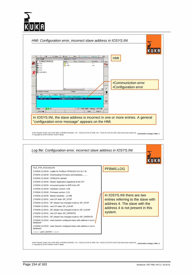
Page 154 of 163 Workbook FBT PRB KR C2 04.04.01
I 03.09.2003 I College I PRhI 17KUKA Roboter GmbH, Hery-Park 3000, D-86368 Gersthofen, Tel.: +49 (0) 8 21/45 33-1906, Fax: +49 (0) 8 21/45 33-2340, http://www.kuka-roboter.de© Copyright by KUKA Roboter GmbH College
HMI: Configuration error, incorrect slave address in IOSYS.INI
HMI
In IOSYS.INI, the slave address is incorrect in one or more entries. A general"configuration error message" appears on the HMI.
•Communiction error•Configuration error
I 03.09.2003 I College I PRhI 18KUKA Roboter GmbH, Hery-Park 3000, D-86368 Gersthofen, Tel.: +49 (0) 8 21/45 33-1906, Fax: +49 (0) 8 21/45 33-2340, http://www.kuka-roboter.de© Copyright by KUKA Roboter GmbH College
Log file: Configuration error, incorrect slave address in IOSYS.INI
PFBMS.LOGFILE_PTR_POS=001478
17/03/04 12:28:59 : Logfile for Profibus CP5613/14 (V1.25.7.0)
17/03/04 12:28:59 : Downloading Firmware and Database.........
17/03/04 12:29:00 : CP5613/14 started!
17/03/04 12:29:00 : Master Application registered at the CP!
17/03/04 12:29:00 : Accessed pointer to DPR from CP!
17/03/04 12:29:00 : Hardware version: 3.08
17/03/04 12:29:00 : Firmware version: 2.01
17/03/04 12:29:00 : Master baudrate : 1,5 MB
17/03/04 12:29:01 : next CP state: DP_STOP
17/03/04 12:29:01 : DP_Master has changed mode to: DP_STOP
17/03/04 12:29:01 : next CP state: DP_CLEAR
17/03/04 12:29:01 : DP_Master has changed mode to: DP_CLEAR
17/03/04 12:29:01 : next CP state: DP_OPERATE
17/03/04 12:29:01 : DP_Master has changed mode to: DP_OPERATE
17/03/04 12:29:02 : read channel: configured slave with address 4 not in database!
17/03/04 12:29:02 : read channel: configured slave with address 4 not in database!
===== LAST_ENTRY =====
In IOSYS.INI there are two entries referring to the slave withaddress 4. The slave with the address 4 is not present in thissystem.
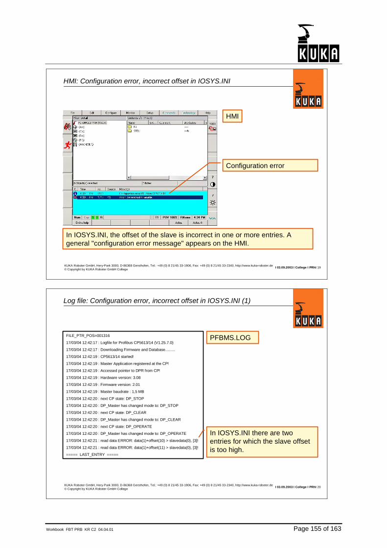
Workbook FBT PRB KR C2 04.04.01 Page 155 of 163
I 03.09.2003 I College I PRhI 19KUKA Roboter GmbH, Hery-Park 3000, D-86368 Gersthofen, Tel.: +49 (0) 8 21/45 33-1906, Fax: +49 (0) 8 21/45 33-2340, http://www.kuka-roboter.de© Copyright by KUKA Roboter GmbH College
HMI: Configuration error, incorrect offset in IOSYS.INI
HMI
In IOSYS.INI, the offset of the slave is incorrect in one or more entries. Ageneral "configuration error message" appears on the HMI.
Configuration error
I 03.09.2003 I College I PRhI 20KUKA Roboter GmbH, Hery-Park 3000, D-86368 Gersthofen, Tel.: +49 (0) 8 21/45 33-1906, Fax: +49 (0) 8 21/45 33-2340, http://www.kuka-roboter.de© Copyright by KUKA Roboter GmbH College
Log file: Configuration error, incorrect offset in IOSYS.INI (1)
PFBMS.LOGFILE_PTR_POS=001316
17/03/04 12:42:17 : Logfile for Profibus CP5613/14 (V1.25.7.0)
17/03/04 12:42:17 : Downloading Firmware and Database.........
17/03/04 12:42:19 : CP5613/14 started!
17/03/04 12:42:19 : Master Application registered at the CP!
17/03/04 12:42:19 : Accessed pointer to DPR from CP!
17/03/04 12:42:19 : Hardware version: 3.08
17/03/04 12:42:19 : Firmware version: 2.01
17/03/04 12:42:19 : Master baudrate : 1,5 MB
17/03/04 12:42:20 : next CP state: DP_STOP
17/03/04 12:42:20 : DP_Master has changed mode to: DP_STOP
17/03/04 12:42:20 : next CP state: DP_CLEAR
17/03/04 12:42:20 : DP_Master has changed mode to: DP_CLEAR
17/03/04 12:42:20 : next CP state: DP_OPERATE
17/03/04 12:42:20 : DP_Master has changed mode to: DP_OPERATE
17/03/04 12:42:21 : read data ERROR: data(1)+offset(10) > slavedata(0), [3]!
17/03/04 12:42:21 : read data ERROR: data(1)+offset(11) > slavedata(0), [3]!
===== LAST_ENTRY =====
In IOSYS.INI there are two entries for which the slave offset is too high.

Page 156 of 163 Workbook FBT PRB KR C2 04.04.01
I 03.09.2003 I College I PRhI 21KUKA Roboter GmbH, Hery-Park 3000, D-86368 Gersthofen, Tel.: +49 (0) 8 21/45 33-1906, Fax: +49 (0) 8 21/45 33-2340, http://www.kuka-roboter.de© Copyright by KUKA Roboter GmbH College
Log file: Configuration error, incorrect offset in IOSYS.INI (2)
PFBMS.LOG.
.
17/03/04 12:42:21 : read data ERROR: data(1)+offset(10) > slavedata(0), [3]!
17/03/04 12:42:21 : read data ERROR: data(1)+offset(11) > slavedata(0), [3]!
===== LAST_ENTRY =====
data(1) = data object with a size of 1 byte.
offset(10) = slave module offset10.
slavedata(0) = the data object size is0 (not present).
[3] = slave address.For this slave, the offset byte 10 and 11is not present.

Workbook FBT PRB KR C2 04.04.01 Page 157 of 163
8. Exercises

Page 158 of 163 Workbook FBT PRB KR C2 04.04.01
I 03.09.2003 I College I PRhI 1KUKA Roboter GmbH, Hery-Park 3000, D-86368 Gersthofen, Tel.: +49 (0) 8 21/45 33-1906, Fax: +49 (0) 8 21/45 33-2340, http://www.kuka-roboter.de© Copyright by KUKA Roboter GmbH College
Overview: Profibus exercises
1. Exercise: Installing the SIMATIC NCM PC Manager2. Exercise: Creating an LDB file with the SIMATIC NCM PC Manager3. Exercise: Robot is Profibus master (digital I/Os)4. Exercise: Robot is Profibus master (analog I/Os)5. Exercise: Robot is Profibus slave6. Exercise: Robot is Profibus master and Profibus slave7. Exercise: Mapping with TR Config8. Exercise: Coupling/decoupling slave modules9. Exercise: Diagnosis10. V4.x exercise: Installing ComProfibusV3.311. V4.x exercise: Creating an LDB file with COMPROFIBUS V3.3
I 03.09.2003 I College I PRhI 2KUKA Roboter GmbH, Hery-Park 3000, D-86368 Gersthofen, Tel.: +49 (0) 8 21/45 33-1906, Fax: +49 (0) 8 21/45 33-2340, http://www.kuka-roboter.de© Copyright by KUKA Roboter GmbH College
1st exercise: Installing the SIMATIC NCM PC Manager
•Switch the robot controller on and hold the CTRL key down; this ensures that only Windows is started, and not the HMI.
•Deactivate the virus scanner.•Install the SIMATIC NCM PC Manager from the KUKA CD. Path:D:\KRC1_CD\Internat\Bus\Profibus\Disk1\SETUP.EXE
•Confirm or modify the information in the setup dialog.•When you have finished the setup procedure, reboot the PC.

Workbook FBT PRB KR C2 04.04.01 Page 159 of 163
I 03.09.2003 I College I PRhI 3KUKA Roboter GmbH, Hery-Park 3000, D-86368 Gersthofen, Tel.: +49 (0) 8 21/45 33-1906, Fax: +49 (0) 8 21/45 33-2340, http://www.kuka-roboter.de© Copyright by KUKA Roboter GmbH College
2nd exercise: Creating an LDB file with the SIMATIC NCM PC Manager
•Start the SIMATIC NCM PC Manager. Create a new project.•Create a project as described in the chapter on operator control of theSIMATIC NCM PC Manager.
•Check that the LDB file is located in the INIT directory of the robot.
I 03.09.2003 I College I PRhI 4KUKA Roboter GmbH, Hery-Park 3000, D-86368 Gersthofen, Tel.: +49 (0) 8 21/45 33-1906, Fax: +49 (0) 8 21/45 33-2340, http://www.kuka-roboter.de© Copyright by KUKA Roboter GmbH College
3rd exercise: Robot is Profibus master (digital I/Os)
•Edit the PFBMS.INI file. Activate the master and specify the name ofthe *.LDB file.
•Edit the IOSYS.INI file. Activate the Profibus master/slave driver,deactivate all other drivers.
•Carry out an I/O reconfiguration.•Check that all of the Profibus modules on the bus are active (greenLED).
•Configure the robot inputs and outputs in IOSYS.INI. Configure only one module. Configure only the digital inputs and outputs.
•Carry out an I/O reconfiguration.•Check the inputs and outputs.•Configure the other modules in the same manner.

Page 160 of 163 Workbook FBT PRB KR C2 04.04.01
I 03.09.2003 I College I PRhI 5KUKA Roboter GmbH, Hery-Park 3000, D-86368 Gersthofen, Tel.: +49 (0) 8 21/45 33-1906, Fax: +49 (0) 8 21/45 33-2340, http://www.kuka-roboter.de© Copyright by KUKA Roboter GmbH College
4th exercise: Robot is Profibus master (analog I/Os)
•Add the entries for the analog inputs and outputs to the IOSYS.INI file.•Carry out an I/O reconfiguration.•Check the analog inputs and outputs.Note: the analog inputs cannot be tested everywhere. A measuring instrument is available for the analog outputs.
I 03.09.2003 I College I PRhI 6KUKA Roboter GmbH, Hery-Park 3000, D-86368 Gersthofen, Tel.: +49 (0) 8 21/45 33-1906, Fax: +49 (0) 8 21/45 33-2340, http://www.kuka-roboter.de© Copyright by KUKA Roboter GmbH College
5th exercise: Robot is Profibus master and Profibus slave
•Edit the PFBMS.INI file on the lower-level robot. Activate the slave partand specify the slave number (robot 1 = address 3, robot 2 = address4, etc.). Set the parameter STANDBY to 1.
•Edit the IOSYS.INI file on the lower-level robot. Here the data from the higher-level master should be present from input 161 onwards andfrom output 161 onwards.
•Carry out an I/O reconfiguration on the higher-level master. Then dothe same on the lower-level robot.
•Create a Profibus configuration on the higher-level master. Each robotshould have 4 input bytes and 4 output bytes.
•Edit the files PFBMS.INI and IOSYS.INI on the higher-level master.•Check the inputs and outputs.

Workbook FBT PRB KR C2 04.04.01 Page 161 of 163
I 03.09.2003 I College I PRhI 7KUKA Roboter GmbH, Hery-Park 3000, D-86368 Gersthofen, Tel.: +49 (0) 8 21/45 33-1906, Fax: +49 (0) 8 21/45 33-2340, http://www.kuka-roboter.de© Copyright by KUKA Roboter GmbH College
6th exercise: Robot is Profibus slave
•Edit the PFBMS.INI file on the lower-level robot. Deactivate the masterpart. Specify Slave.ldb as the database. Activate the slave part andspecify the slave number.
•Edit the IOSYS.INI file on the lower-level robot. Deactivate the entries for the master ring. The data from the higher-level master should be present on the robot from input 161 onwards and from output 161onwards.
•Create a Profibus configuration on the higher-level master. Each robotshould have 4 input bytes and 4 output bytes.
•Edit the files PFBMS.INI and IOSYS.INI on the higher-level master.•Carry out an I/O reconfiguration on the higher-level master. Then dothe same on the lower-level robot.
•Check the inputs and outputs.
I 03.09.2003 I College I PRhI 8KUKA Roboter GmbH, Hery-Park 3000, D-86368 Gersthofen, Tel.: +49 (0) 8 21/45 33-1906, Fax: +49 (0) 8 21/45 33-2340, http://www.kuka-roboter.de© Copyright by KUKA Roboter GmbH College
7th exercise: Mapping with TR Config
•Re-establish the configuration "robot is master and slave". Configure 3bytes of the higher-level master in the IOSYS.INI file of the lower-levelrobot (OUTB20=127,0,x1, OUTB21=127,1,x1, OUTB22=127,2,x1,).
•Copy the program TR_CONFIG from the KUKA CD into the directoryC:\. Start the program.
•Select as the source Slave no. 3, Input, Byte, Address 0, Quantity 1.•Select as the destination Remote Master, Input, Byte, Address 3.•In the Edit menu, select Insert Entry.•Save the file in the ...\INIT directory. The file has the extension .TRA•Edit the PFBMS.INI file. Activate MAPPING and underMAPPING_PATH specify the name of the file created by means of TR_CONFIG.
•Carry out an I/O reconfiguration on the higher-level master. Then dothe same on the lower-level robot.
•Check the inputs and outputs. The inputs are now visible on the higher-level master.

Page 162 of 163 Workbook FBT PRB KR C2 04.04.01
I 03.09.2003 I College I PRhI 9KUKA Roboter GmbH, Hery-Park 3000, D-86368 Gersthofen, Tel.: +49 (0) 8 21/45 33-1906, Fax: +49 (0) 8 21/45 33-2340, http://www.kuka-roboter.de© Copyright by KUKA Roboter GmbH College
8th exercise: Decoupling and coupling a Profibus slave
•Re-establish the configuration "robot is master".•Once the controller has run up, slave no. 4 has to be deactivated(decoupled). To do this, make the following entry in the PFBMS.INI file:DEACTIVATED_Slaves=4
•I/O reconfiguration. Slave no. 4 should now be deactivated. Unplug theProfibus connector on slave no. 4. No error message should appear onthe HMI. Plug the Profibus connector back in again.
•Couple slave no. 4. To do this, go to the menu Monitor - Variable -Single. Enter the following there: "IOCTL(11,1001,4)". Check slave no. 4.
•Decouple slave no. 4. To do this, go to the menu Monitor - Variable -Single. Enter the following there: "IOCTL(11,1002,4)".
•Couple slave no. 4 again.•Optional: write the corresponding KRL program and test it. Note: it is not necessary to program any motion.
I 03.09.2003 I College I PRhI 10KUKA Roboter GmbH, Hery-Park 3000, D-86368 Gersthofen, Tel.: +49 (0) 8 21/45 33-1906, Fax: +49 (0) 8 21/45 33-2340, http://www.kuka-roboter.de© Copyright by KUKA Roboter GmbH College
9th exercise: Diagnosis
•Re-establish the configuration "robot is master".•Unplug the connector on slave no. 4. Observe the response on theGUI.
•Plug the connector back in again. Observe the response on the GUI.Acknowledge all messages.
•Unplug the connector on slave no. 4 once again.•Carry out an I/O reconfiguration. Look at the Profibus.log file.•Re-establish the configuration "robot is master".•Change the configuration in IOSYS.INI; instead of slave no. 4,configure slave no. 44. Carry out an I/O reconfiguration. Observe the response on the GUI. Look at the Profibus.log file.
•Re-establish the configuration "robot is master".•Change the configuration in the IOSYS.INI file; instead of INB0=3,0,x1,configure INB0=3,0,x10. Carry out an I/O reconfiguration. Observe the response on the GUI. Look at the Profibus.log file.
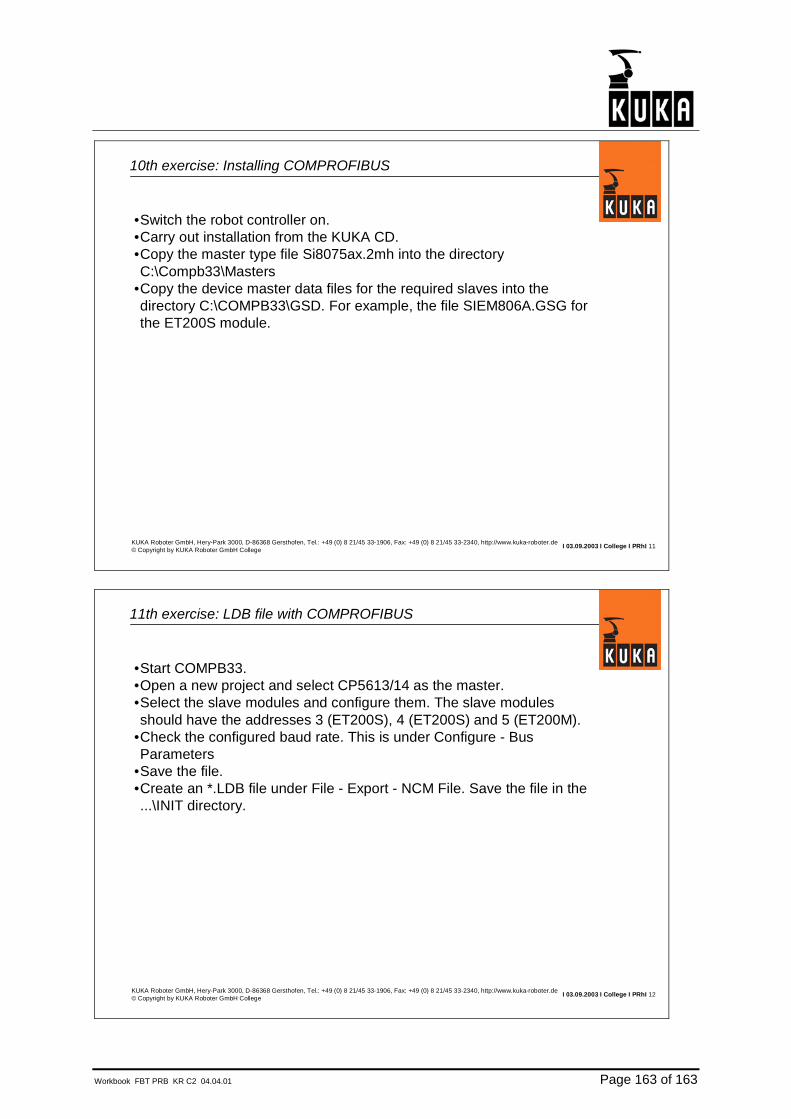
Workbook FBT PRB KR C2 04.04.01 Page 163 of 163
I 03.09.2003 I College I PRhI 11KUKA Roboter GmbH, Hery-Park 3000, D-86368 Gersthofen, Tel.: +49 (0) 8 21/45 33-1906, Fax: +49 (0) 8 21/45 33-2340, http://www.kuka-roboter.de© Copyright by KUKA Roboter GmbH College
10th exercise: Installing COMPROFIBUS
•Switch the robot controller on.•Carry out installation from the KUKA CD.•Copy the master type file Si8075ax.2mh into the directoryC:\Compb33\Masters
•Copy the device master data files for the required slaves into the directory C:\COMPB33\GSD. For example, the file SIEM806A.GSG for the ET200S module.
I 03.09.2003 I College I PRhI 12KUKA Roboter GmbH, Hery-Park 3000, D-86368 Gersthofen, Tel.: +49 (0) 8 21/45 33-1906, Fax: +49 (0) 8 21/45 33-2340, http://www.kuka-roboter.de© Copyright by KUKA Roboter GmbH College
11th exercise: LDB file with COMPROFIBUS
•Start COMPB33.•Open a new project and select CP5613/14 as the master.•Select the slave modules and configure them. The slave modules should have the addresses 3 (ET200S), 4 (ET200S) and 5 (ET200M).
•Check the configured baud rate. This is under Configure - Bus Parameters
•Save the file.•Create an *.LDB file under File - Export - NCM File. Save the file in the...\INIT directory.
Copyright © 2022 FDOKUMEN


![Release Team [oR] 2001 [x] java](https://static.fdokumen.com/doc/165x107/6317b748c72bc2f2dd05959d/release-team-or-2001-x-java.jpg)