Proline Prosonic Flow 93C PROFIBUS DP/PA
130
BA00089D/06/EN/13.10 71121240 Valid as of version PROFIBUS DP V 3.06.XX (Device software) PROFIBUS PA V 3.06.XX (Device software) Operating Instructions Proline Prosonic Flow 93C PROFIBUS DP/PA Ultrasonic flow measuring system 8
-
Upload
khangminh22 -
Category
Documents
-
view
4 -
download
0
Transcript of Proline Prosonic Flow 93C PROFIBUS DP/PA

BA00089D/06/EN/13.10
71121240
Valid as of version
PROFIBUS DP
V 3.06.XX (Device software)
PROFIBUS PA
V 3.06.XX (Device software)
Operating Instructions
Proline Prosonic Flow 93CPROFIBUS DP/PAUltrasonic flow measuring system
8

Proline Prosonic Flow 93C PROFIBUS DP/PA Table of contents
Endress+Hauser 3
Table of contents
1 Safety instructions . . . . . . . . . . . . . . . . 5
1.1 Designated use . . . . . . . . . . . . . . . . . . . . . . . . . . . . 5
1.2 Installation, commissioning and operation . . . . . . . . 5
1.3 Operational safety . . . . . . . . . . . . . . . . . . . . . . . . . . 5
1.4 Return . . . . . . . . . . . . . . . . . . . . . . . . . . . . . . . . . . . 6
1.5 Notes on safety conventions and icons . . . . . . . . . . . 6
2 Identification . . . . . . . . . . . . . . . . . . . . 7
2.1 Device designation . . . . . . . . . . . . . . . . . . . . . . . . . 7
2.1.1 Nameplate of the
Prosonic Flow 93 transmitter . . . . . . . . . . . . 7
2.1.2 Nameplate of the
Prosonic Flow C Inline measuring tube . . . . 8
2.1.3 Nameplate of the
Prosonic Flow W sensors . . . . . . . . . . . . . . . 9
2.1.4 Adhesive label for sensor channel
identification on the measuring tube . . . . . . 9
2.1.5 Nameplate for the connections . . . . . . . . . 10
2.2 Certificates and approvals . . . . . . . . . . . . . . . . . . . 11
2.3 Registered trademarks . . . . . . . . . . . . . . . . . . . . . . 11
3 Installation . . . . . . . . . . . . . . . . . . . . . 12
3.1 Incoming acceptance, transport and storage . . . . . . 12
3.1.1 Incoming acceptance . . . . . . . . . . . . . . . . . 12
3.1.2 Transport . . . . . . . . . . . . . . . . . . . . . . . . . 12
3.1.3 Storage . . . . . . . . . . . . . . . . . . . . . . . . . . . 12
3.2 Installation conditions . . . . . . . . . . . . . . . . . . . . . . 13
3.2.1 Dimensions . . . . . . . . . . . . . . . . . . . . . . . . 13
3.2.2 Mounting location . . . . . . . . . . . . . . . . . . . 13
3.2.3 Down pipes . . . . . . . . . . . . . . . . . . . . . . . . 14
3.2.4 Orientation . . . . . . . . . . . . . . . . . . . . . . . . 14
3.2.5 Inlet and outlet run . . . . . . . . . . . . . . . . . . 15
3.2.6 Vibrations . . . . . . . . . . . . . . . . . . . . . . . . . 15
3.2.7 Foundations, supports . . . . . . . . . . . . . . . . 16
3.2.8 Adapters . . . . . . . . . . . . . . . . . . . . . . . . . . 16
3.2.9 Nominal diameter and flow rate . . . . . . . . 17
3.2.10 Length of connecting cable . . . . . . . . . . . . 18
3.3 Installation . . . . . . . . . . . . . . . . . . . . . . . . . . . . . . 19
3.3.1 Installing the Prosonic Flow C
measuring tube . . . . . . . . . . . . . . . . . . . . 19
3.3.2 Installing the wall-mount housing . . . . . . . 22
3.4 Post-installation check . . . . . . . . . . . . . . . . . . . . . . 24
4 Wiring . . . . . . . . . . . . . . . . . . . . . . . . . 25
4.1 PROFIBUS cable specifications . . . . . . . . . . . . . . . . 25
4.1.1 PROFIBUS DP cable specifications . . . . . . . 25
4.1.2 PROFIBUS PA cable specifications . . . . . . . 27
4.1.3 Shielding and grounding . . . . . . . . . . . . . . 29
4.2 Sensor/transmitter connecting cable . . . . . . . . . . . 30
4.2.1 Connecting the Prosonic Flow W . . . . . . . . 30
4.2.2 Cable specification for connecting cable . . . 31
4.3 Connecting the measuring unit . . . . . . . . . . . . . . . 32
4.3.1 Terminal assignment . . . . . . . . . . . . . . . . . 32
4.3.2 Connecting the transmitter . . . . . . . . . . . . 33
4.3.3 PROFIBUS DP connection diagram . . . . . . 34
4.3.4 PROFIBUS PA connection diagram . . . . . . . 36
4.4 Degree of protection . . . . . . . . . . . . . . . . . . . . . . . 39
4.4.1 Transmitter (wall-mount housing) . . . . . . . 39
4.4.2 Flowrate measuring sensors
Prosonic Flow W . . . . . . . . . . . . . . . . . . . . 40
4.5 Post-connection check . . . . . . . . . . . . . . . . . . . . . . 41
5 Operation . . . . . . . . . . . . . . . . . . . . . . 42
5.1 Quick operation guide . . . . . . . . . . . . . . . . . . . . . . 42
5.2 Local display . . . . . . . . . . . . . . . . . . . . . . . . . . . . . 43
5.2.1 Display and operating elements . . . . . . . . . 43
5.2.2 Display (operating mode) . . . . . . . . . . . . . . 44
5.2.3 Additional display functions . . . . . . . . . . . . 44
5.2.4 Icons . . . . . . . . . . . . . . . . . . . . . . . . . . . . . 45
5.3 Brief guide to the function matrix . . . . . . . . . . . . . . 46
5.3.1 General notes . . . . . . . . . . . . . . . . . . . . . . 47
5.3.2 Enabling the programming mode . . . . . . . . 47
5.3.3 Disabling the programming mode . . . . . . . . 47
5.4 Error messages . . . . . . . . . . . . . . . . . . . . . . . . . . . . 48
5.4.1 Type of error . . . . . . . . . . . . . . . . . . . . . . . 48
5.4.2 Error message types . . . . . . . . . . . . . . . . . . 48
5.5 Operating options . . . . . . . . . . . . . . . . . . . . . . . . . 49
5.5.1 Operating program "FieldCare" . . . . . . . . . . 49
5.5.2 Operating program "SIMATIC PDM" . . . . . 49
5.5.3 Device description files for
operating programs . . . . . . . . . . . . . . . . . . 49
5.6 PROFIBUS DP hardware settings . . . . . . . . . . . . . . 51
5.6.1 Configuring the write protection . . . . . . . . 51
5.6.2 Configuring the device address . . . . . . . . . . 52
5.6.3 Configuring the terminating resistors . . . . . 53
5.6.4 Current output configuration . . . . . . . . . . . 54
5.6.5 Relay output configuration . . . . . . . . . . . . . 55
5.7 PROFIBUS PA hardware settings . . . . . . . . . . . . . . 56
5.7.1 Configuring the write protection . . . . . . . . 56
5.7.2 Configuring the device address . . . . . . . . . . 57
Proline Prosonic Flow 93C PROFIBUS DP/PA Table of contents
4 Endress+Hauser
6 Commissioning . . . . . . . . . . . . . . . . . . 58
6.1 Function check . . . . . . . . . . . . . . . . . . . . . . . . . . . 58
6.2 Switching on the measuring device . . . . . . . . . . . . 58
6.3 Quick Setup . . . . . . . . . . . . . . . . . . . . . . . . . . . . . 59
6.3.1 Quick Setup "Commissioning" . . . . . . . . . . 59
6.3.2 Quick Setup "Communication" . . . . . . . . . 60
6.3.3 Data backup/transmission . . . . . . . . . . . . . 62
6.4 Commissioning the PROFIBUS interface . . . . . . . . 63
6.4.1 PROFIBUS DP commissioning . . . . . . . . . . 63
6.4.2 PROFIBUS PA commissioning . . . . . . . . . . 66
6.5 PROFIBUS DP/PA system integration . . . . . . . . . . 69
6.5.1 Device master file (GSD file) . . . . . . . . . . . 69
6.5.2 Selecting the GSD file in the
measuring device . . . . . . . . . . . . . . . . . . . . 71
6.5.3 Maximum number of writes . . . . . . . . . . . 71
6.6 Cyclic data transmission PROFIBUS DP . . . . . . . . . 72
6.6.1 Block model . . . . . . . . . . . . . . . . . . . . . . . 72
6.6.2 Modules for cyclic data transmission . . . . . 72
6.6.3 Description of the modules . . . . . . . . . . . . 74
6.6.4 Configuration examples with
Simatic S7 HW-Konfig . . . . . . . . . . . . . . . . 80
6.7 Cyclic data transmission PROFIBUS PA . . . . . . . . . 83
6.7.1 Block model . . . . . . . . . . . . . . . . . . . . . . . 83
6.7.2 Modules for cyclic data transmission . . . . . 83
6.7.3 Description of the modules . . . . . . . . . . . . 85
6.7.4 Configuration examples with
Simatic S7 HW-Konfig . . . . . . . . . . . . . . . . 91
6.8 Acyclic data transmission PROFIBUS DP/PA . . . . . 94
6.8.1 Master class 2 acyclic (MS2AC) . . . . . . . . . 94
6.8.2 Master class 1 acyclic (MS1AC) . . . . . . . . . 94
6.9 Adjustment . . . . . . . . . . . . . . . . . . . . . . . . . . . . . . 95
6.10 Memory (HistoROM) . . . . . . . . . . . . . . . . . . . . . . . 96
6.10.1 HistoROM/T-DAT (transmitter-DAT) . . . . 96
7 Maintenance . . . . . . . . . . . . . . . . . . . . 97
7.1 Exterior cleaning . . . . . . . . . . . . . . . . . . . . . . . . . . 97
8 Accessories . . . . . . . . . . . . . . . . . . . . . 98
9 Troubleshooting . . . . . . . . . . . . . . . . 100
9.1 Troubleshooting instructions . . . . . . . . . . . . . . . . 100
9.2 System error messages . . . . . . . . . . . . . . . . . . . . . 102
9.2.1 Displaying the device status on
PROFIBUS DP/PA . . . . . . . . . . . . . . . . . . 102
9.2.2 List of system error messages . . . . . . . . . . 103
9.3 Process error messages . . . . . . . . . . . . . . . . . . . . . 108
9.3.1 Displaying the device status on
PROFIBUS DP/PA . . . . . . . . . . . . . . . . . . 108
9.3.2 List of process error messages . . . . . . . . . . 108
9.4 Process errors without messages . . . . . . . . . . . . . 108
9.5 Response of outputs to errors . . . . . . . . . . . . . . . . 109
9.6 Spare parts . . . . . . . . . . . . . . . . . . . . . . . . . . . . . 110
9.6.1 PROFIBUS DP . . . . . . . . . . . . . . . . . . . . 110
9.6.2 PROFIBUS PA . . . . . . . . . . . . . . . . . . . . . 111
9.6.3 Installing and removing
electronics boards . . . . . . . . . . . . . . . . . . 112
9.6.4 Installing and removing
the W sensors . . . . . . . . . . . . . . . . . . . . . 114
9.6.5 Replacing the device fuse . . . . . . . . . . . . 115
9.7 Return . . . . . . . . . . . . . . . . . . . . . . . . . . . . . . . . 115
9.8 Disposal . . . . . . . . . . . . . . . . . . . . . . . . . . . . . . . 115
9.9 Software history . . . . . . . . . . . . . . . . . . . . . . . . . 116
10 Technical data . . . . . . . . . . . . . . . . . . 117
10.1 Quick technical data guide . . . . . . . . . . . . . . . . . 117
10.1.1 Applications . . . . . . . . . . . . . . . . . . . . . . 117
10.1.2 Function and system design . . . . . . . . . . 117
10.1.3 Input . . . . . . . . . . . . . . . . . . . . . . . . . . . 117
10.1.4 Output . . . . . . . . . . . . . . . . . . . . . . . . . . 117
10.1.5 Power supply . . . . . . . . . . . . . . . . . . . . . 119
10.1.6 Performance characteristics . . . . . . . . . . . 119
10.1.7 Operating conditions: installation . . . . . . 120
10.1.8 Operating conditions: environment . . . . . 120
10.1.9 Operating conditions: process . . . . . . . . . 121
10.1.10 Mechanical construction . . . . . . . . . . . . 121
10.1.11 Human interface . . . . . . . . . . . . . . . . . . 124
10.1.12 Certificates and approvals . . . . . . . . . . . . 124
10.1.13 Ordering information . . . . . . . . . . . . . . . 125
10.1.14 Accessories . . . . . . . . . . . . . . . . . . . . . . 125
10.1.15 Documentation . . . . . . . . . . . . . . . . . . . 125
Index . . . . . . . . . . . . . . . . . . . . . . . . . . . . . 126

Proline Prosonic Flow 93C PROFIBUS DP/PA Safety instructions
Endress+Hauser 5
1 Safety instructions
1.1 Designated use
The measuring device described in these Operating Instructions is to be used only for measuring the
flow rate of liquids in closed pipes.
Examples:
• Acids, alkalis, paints, oils
• Liquid gas
• Ultrapure water with low conductivity, water, wastewater
As well as measuring the volume flow, the sound velocity of the fluid is also always measured.
Different fluids can be distinguished or the fluid quality can be monitored.
Resulting from incorrect use or from use other than that designated the operational safety of the
measuring devices can be suspended. The manufacturer accepts no liability for damages being
produced from this.
1.2 Installation, commissioning and operation
Note the following points:
• Installation, connection to the electricity supply, commissioning and maintenance of the device
must be carried out by trained, qualified specialists authorized to perform such work by the
facility's owner-operator.
The specialist must have read and understood these Operating Instructions and must follow the
instructions they contain.
• The device must be operated by persons authorized and trained by the facility's owner-operator.
Strict compliance with the instructions in these Operating Instructions is mandatory.
• Endress+Hauser is willing to assist in clarifying the chemical resistance properties of parts wetted
by special fluids, including fluids used for cleaning.
However, small changes in temperature, concentration or the degree of contamination in the
process can result in changes to the corrosion resistance properties. Therefore, Endress+Hauser
cannot guarantee or accept liability for the corrosion resistance properties of wetted materials in
a specific application.
The user is responsible for choosing suitable wetted materials in the process.
• If carrying out welding work on the piping, the welding unit may not be grounded by means of
the measuring device.
• The installer must ensure that the measuring system is correctly wired in accordance with the
wiring diagrams. The transmitter must be grounded, except in cases where special protective
measures have been taken (e.g. galvanically isolated power supply SELV or PELV).
• Invariably, local regulations governing the opening and repair of electrical devices apply.
1.3 Operational safety
Note the following points:
• Measuring systems for use in hazardous environments are accompanied by separate
"Ex documentation", which is an integral part of these Operating Instructions. Strict compliance
with the installation instructions and ratings as stated in this supplementary documentation is
mandatory. The symbol on the front of this supplementary Ex documentation indicates the
approval and inspection authority (e.g. 0 Europe, 2 USA, 1 Canada).
• The measuring system complies with the general safety requirements in accordance with
EN 61010-1, the EMC requirements of IEC/EN 61326, and NAMUR Recommendation NE 21
and NE 43.
• The manufacturer reserves the right to modify technical data without prior notice. Your
Endress+Hauser distributor will supply you with current information and updates to this
Operating Instructions.
Safety instructions Proline Prosonic Flow 93C PROFIBUS DP/PA
6 Endress+Hauser
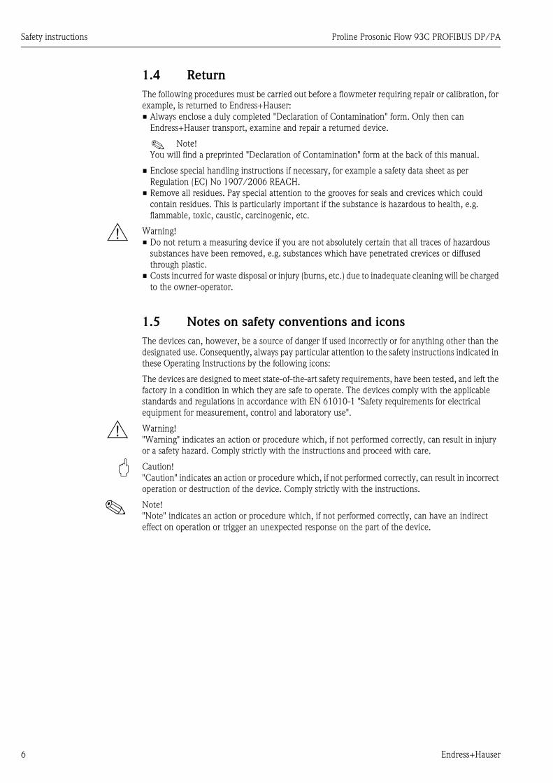
1.4 Return
The following procedures must be carried out before a flowmeter requiring repair or calibration, for
example, is returned to Endress+Hauser:
• Always enclose a duly completed "Declaration of Contamination" form. Only then can
Endress+Hauser transport, examine and repair a returned device.
! Note!
You will find a preprinted "Declaration of Contamination" form at the back of this manual.
• Enclose special handling instructions if necessary, for example a safety data sheet as per
Regulation (EC) No 1907/2006 REACH.
• Remove all residues. Pay special attention to the grooves for seals and crevices which could
contain residues. This is particularly important if the substance is hazardous to health, e.g.
flammable, toxic, caustic, carcinogenic, etc.
# Warning!
• Do not return a measuring device if you are not absolutely certain that all traces of hazardous
substances have been removed, e.g. substances which have penetrated crevices or diffused
through plastic.
• Costs incurred for waste disposal or injury (burns, etc.) due to inadequate cleaning will be charged
to the owner-operator.
1.5 Notes on safety conventions and icons
The devices can, however, be a source of danger if used incorrectly or for anything other than the
designated use. Consequently, always pay particular attention to the safety instructions indicated in
these Operating Instructions by the following icons:
The devices are designed to meet state-of-the-art safety requirements, have been tested, and left the
factory in a condition in which they are safe to operate. The devices comply with the applicable
standards and regulations in accordance with EN 61010-1 "Safety requirements for electrical
equipment for measurement, control and laboratory use".
# Warning!
"Warning" indicates an action or procedure which, if not performed correctly, can result in injury
or a safety hazard. Comply strictly with the instructions and proceed with care.
" Caution!
"Caution" indicates an action or procedure which, if not performed correctly, can result in incorrect
operation or destruction of the device. Comply strictly with the instructions.
! Note!
"Note" indicates an action or procedure which, if not performed correctly, can have an indirect
effect on operation or trigger an unexpected response on the part of the device.
Proline Prosonic Flow 93C PROFIBUS DP/PA Identification
Endress+Hauser 7
2 Identification
2.1 Device designation
The "Prosonic Flow 93C Inline" flowmeter system consists of the following components:
• Prosonic Flow 93 transmitter
• Prosonic Flow C Inline measuring tube
• Prosonic Flow W sensors
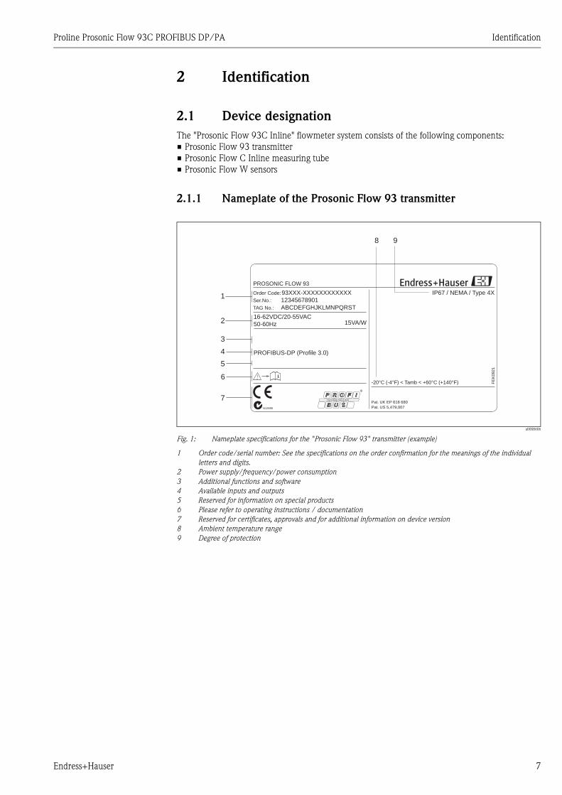
2.1.1 Nameplate of the Prosonic Flow 93 transmitter
a0008606
Fig. 1: Nameplate specifications for the "Prosonic Flow 93" transmitter (example)
1 Order code/serial number: See the specifications on the order confirmation for the meanings of the individual
letters and digits.
2 Power supply/frequency/power consumption
3 Additional functions and software
4 Available inputs and outputs
5 Reserved for information on special products
6 Please refer to operating instructions / documentation
7 Reserved for certificates, approvals and for additional information on device version
8 Ambient temperature range
9 Degree of protection
Order Code:
Ser.No.:
TAG No.:
93XXX-XXXXXXXXXXXX
12345678901
ABCDEFGHJKLMNPQRST
16-62VDC/20-55VAC
50-60Hz
PROFIBUS-DP (Profile 3.0)
15VA/W
IP67 / NEMA / Type 4X
-20°C (-4°F) < Tamb < +60°C (+140°F) FE
K0921
i
Pat. US 5,479,007
Pat. UK EP 618 680
1
2
8 9
4
5
R
6
7
3
PROSONIC FLOW 93
N12895
Identification Proline Prosonic Flow 93C PROFIBUS DP/PA
8 Endress+Hauser
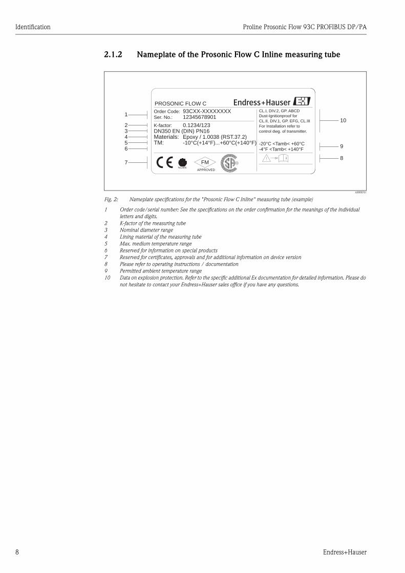
2.1.2 Nameplate of the Prosonic Flow C Inline measuring tube
A0008761
Fig. 2: Nameplate specifications for the "Prosonic Flow C Inline" measuring tube (example)
1 Order code/serial number: See the specifications on the order confirmation for the meanings of the individual
letters and digits.
2 K-factor of the measuring tube
3 Nominal diameter range
4 Lining material of the measuring tube
5 Max. medium temperature range
6 Reserved for information on special products
7 Reserved for certificates, approvals and for additional information on device version
8 Please refer to operating instructions / documentation
9 Permitted ambient temperature range
10 Data on explosion protection. Refer to the specific additional Ex documentation for detailed information. Please do
not hesitate to contact your Endress+Hauser sales office if you have any questions.
CL.I, DIV.2, GP. ABCD
CL.II, DIV.1, GP. EFG, CL.III
For Installation refer to
i
Materials:DN350 EN (DIN) PN16K-factor:
Epoxy / 1.0038 (RST.37.2)
0.1234/123
Ser. No.:
Order Code:
1234567890193CXX-XXXXXXXX
TM: -10°C(+14°F)...+60°C(+140°F)
Dust-Ignitionproof for
control dwg. of transmitter.
-20°C <Tamb< +60°C-4°F <Tamb< +140°F
APPROVED
FM
1
9
1023456
78
R
N12895
PROSONIC FLOW C
Proline Prosonic Flow 93C PROFIBUS DP/PA Identification
Endress+Hauser 9
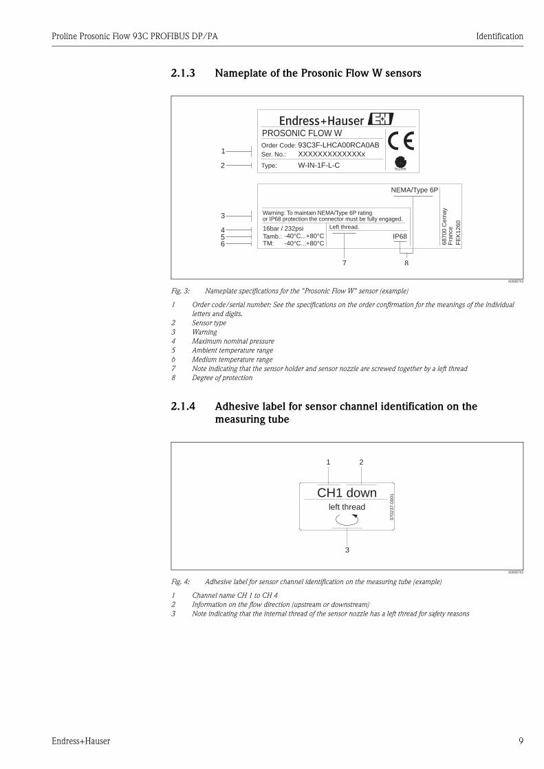
2.1.3 Nameplate of the Prosonic Flow W sensors
A0008763
Fig. 3: Nameplate specifications for the "Prosonic Flow W" sensor (example)
1 Order code/serial number: See the specifications on the order confirmation for the meanings of the individual
letters and digits.
2 Sensor type
3 Warning
4 Maximum nominal pressure
5 Ambient temperature range
6 Medium temperature range
7 Note indicating that the sensor holder and sensor nozzle are screwed together by a left thread
8 Degree of protection
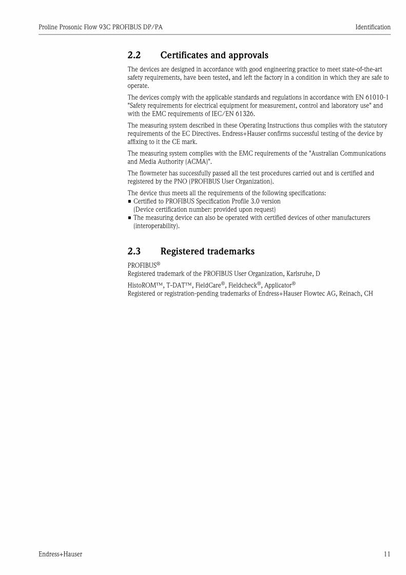
2.1.4 Adhesive label for sensor channel identification on the
measuring tube
A0008765
Fig. 4: Adhesive label for sensor channel identification on the measuring tube (example)
1 Channel name CH 1 to CH 4
2 Information on the flow direction (upstream or downstream)
3 Note indicating that the internal thread of the sensor nozzle has a left thread for safety reasons
W-IN-1F-L-C
XXXXXXXXXXXXXx
93C3F-LHCA00RCA0AB
PROSONIC FLOW W
Type:
Ser. No.:
Order Code:1
3
2
456
7
NEMA/Type 6P
TM:Tamb.: IP68
-40°C...+80°C-40°C...+80°C
or IP68 protection the connector must be fully engaged.Warning: To maintain NEMA/Type 6P rating
Left thread.
68700
Cern
ay
Fra
nce
FE
K1260
16bar / 232psi
N12895
8
left thread
CH1 down
37
02
37
-00
01
1 2
3
Identification Proline Prosonic Flow 93C PROFIBUS DP/PA
10 Endress+Hauser
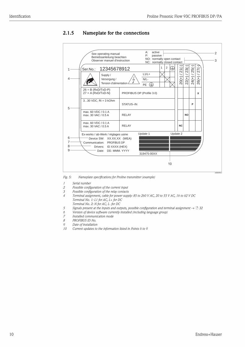
2.1.5 Nameplate for the connections
A0000963
Fig. 5: Nameplate specifications for Proline transmitter (example)
1 Serial number
2 Possible configuration of the current input
3 Possible configuration of the relay contacts
4 Terminal assignment, cable for power supply: 85 to 260 V AC, 20 to 55 V AC, 16 to 62 V DC
Terminal No. 1: L1 for AC, L+ for DC
Terminal No. 2: N for AC, L- for DC
5 Signals present at the inputs and outputs, possible configuration and terminal assignment → ä 32
6 Version of device software currently installed (including language group)
7 Installed communication mode
8 PROFIBUS ID No.
9 Date of installation
10 Current updates to the information listed in Points 6 to 9
26
(+)
/2
7(-
)
NC:
Versorgung /
Tension d'alimentation
Observer manuel d'instruction
See operating manualBetriebsanleitung beachten
Communication:
Drivers:
Device SW:
ID XXXX (HEX)
XX.XX.XX
PROFIBUS DP
PROFIBUS DP Profile 3.0( )
12345678912Ser.No.:
Supply /
24
(+)
/2
5(-
)
22
(+)
/2
3(-
)
20
(+)
/2
1(-
)
N/L-
PE
A:
NO:P:
L1/L+
1 2
319475-00XX
X
activepassivenormally open contactnormally closed contact
Date: DD. MMM. YYYY
Update 1Ex-works / ab-Werk / réglages usine Update 2
(WEA)
1
4
5
6
7
8
9
2
3
P
NO
NCmax. 30 VAC / 0.5 A
max. 60 VDC / 0.1 Amax. 30 VAC / 0.5 A
3...30 VDC, Ri = 3 kOhm
max. 60 VDC / 0.1 A
STATUS–IN
RELAY
RELAY
27 = A (RxD/TxD-N)26 = B (RxD/TxD-P)
Proline Prosonic Flow 93C PROFIBUS DP/PA Identification
Endress+Hauser 11
2.2 Certificates and approvals
The devices are designed in accordance with good engineering practice to meet state-of-the-art
safety requirements, have been tested, and left the factory in a condition in which they are safe to
operate.
The devices comply with the applicable standards and regulations in accordance with EN 61010-1
"Safety requirements for electrical equipment for measurement, control and laboratory use" and
with the EMC requirements of IEC/EN 61326.
The measuring system described in these Operating Instructions thus complies with the statutory
requirements of the EC Directives. Endress+Hauser confirms successful testing of the device by
affixing to it the CE mark.
The measuring system complies with the EMC requirements of the "Australian Communications
and Media Authority (ACMA)".
The flowmeter has successfully passed all the test procedures carried out and is certified and
registered by the PNO (PROFIBUS User Organization).
The device thus meets all the requirements of the following specifications:
• Certified to PROFIBUS Specification Profile 3.0 version
(Device certification number: provided upon request)
• The measuring device can also be operated with certified devices of other manufacturers
(interoperability).
2.3 Registered trademarks
PROFIBUS®
Registered trademark of the PROFIBUS User Organization, Karlsruhe, D
HistoROM™, T-DAT™, FieldCare®, Fieldcheck®, Applicator®
Registered or registration-pending trademarks of Endress+Hauser Flowtec AG, Reinach, CH

Installation Proline Prosonic Flow 93C PROFIBUS DP/PA
12 Endress+Hauser
3 Installation
3.1 Incoming acceptance, transport and storage
3.1.1 Incoming acceptance
On receipt of the goods, check the following points:
• Check the packaging and the contents for damage.
• Check the shipment, make sure nothing is missing and that the scope of supply matches your
order.
3.1.2 Transport
The devices must be transported in the container supplied when transporting them to the measuring
point.
" Caution!
Flanged devices should never be lifted at the sensor nozzle for transportation purposes. To transport,
lift or insert the sensor into the pipe, only use the metal holders fitted on the flange.
3.1.3 Storage
Note the following points:
• Pack the measuring device in such a way as to protect it reliably against impact for storage (and
transportation). The original packaging provides optimum protection.
• The storage temperature corresponds to the ambient temperature range (Page 120) of the
transmitter, the sensors and the corresponding sensor cables.
• The measuring device must be protected against direct sunlight during storage in order to avoid
unacceptably high surface temperatures.
Proline Prosonic Flow 93C PROFIBUS DP/PA Installation
Endress+Hauser 13
3.2 Installation conditions
3.2.1 Dimensions
All the dimensions and lengths of the sensor and transmitter are provided in the separate “Technical
Information” document.
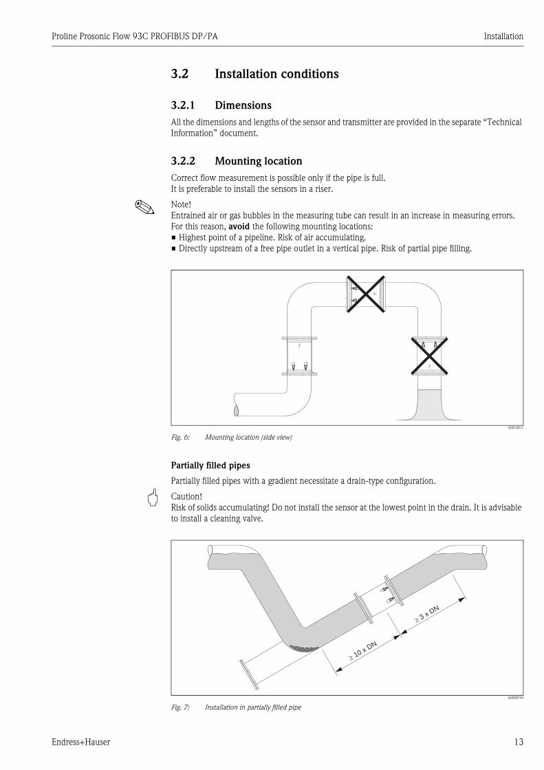
3.2.2 Mounting location
Correct flow measurement is possible only if the pipe is full.
It is preferable to install the sensors in a riser.
! Note!
Entrained air or gas bubbles in the measuring tube can result in an increase in measuring errors.
For this reason, avoid the following mounting locations:
• Highest point of a pipeline. Risk of air accumulating.
• Directly upstream of a free pipe outlet in a vertical pipe. Risk of partial pipe filling.
A0014011
Fig. 6: Mounting location (side view)
Partially filled pipes
Partially filled pipes with a gradient necessitate a drain-type configuration.
" Caution!
Risk of solids accumulating! Do not install the sensor at the lowest point in the drain. It is advisable
to install a cleaning valve.
A0008745
Fig. 7: Installation in partially filled pipe
�3 x DN
�10 x DN
Installation Proline Prosonic Flow 93C PROFIBUS DP/PA
14 Endress+Hauser
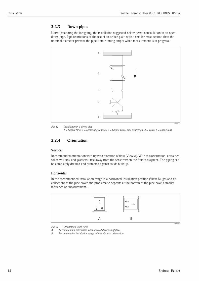
3.2.3 Down pipes
Notwithstanding the foregoing, the installation suggested below permits installation in an open
down pipe. Pipe restrictions or the use of an orifice plate with a smaller cross-section than the
nominal diameter prevent the pipe from running empty while measurement is in progress.
A0008747
Fig. 8: Installation in a down pipe
1 = Supply tank, 2 = Measuring sensors, 3 = Orifice plate, pipe restriction, 4 = Valve, 5 = Filling tank
3.2.4 Orientation
Vertical
Recommended orientation with upward direction of flow (View A). With this orientation, entrained
solids will sink and gases will rise away from the sensor when the fluid is stagnant. The piping can
be completely drained and protected against solids buildup.
Horizontal
In the recommended installation range in a horizontal installation position (View B), gas and air
collections at the pipe cover and problematic deposits at the bottom of the pipe have a smaller
influence on measurement.
A0014015
Fig. 9: Orientation (side view)
A Recommended orientation with upward direction of flow
B Recommended installation range with horizontal orientation
1
2
3
4
5
A B
Proline Prosonic Flow 93C PROFIBUS DP/PA Installation
Endress+Hauser 15
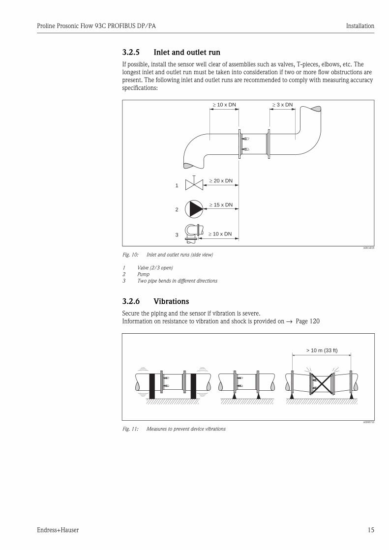
3.2.5 Inlet and outlet run
If possible, install the sensor well clear of assemblies such as valves, T-pieces, elbows, etc. The
longest inlet and outlet run must be taken into consideration if two or more flow obstructions are
present. The following inlet and outlet runs are recommended to comply with measuring accuracy
specifications:
A0014016
Fig. 10: Inlet and outlet runs (side view)
1 Valve (2/3 open)
2 Pump
3 Two pipe bends in different directions
3.2.6 Vibrations
Secure the piping and the sensor if vibration is severe.
Information on resistance to vibration and shock is provided on → Page 120
A0008750
Fig. 11: Measures to prevent device vibrations
� 10 x DN
� 20 x DN
� 15 x DN
� 10 x DN
� 3 x DN
1
2
3
> 10 m (33 ft)
Installation Proline Prosonic Flow 93C PROFIBUS DP/PA
16 Endress+Hauser
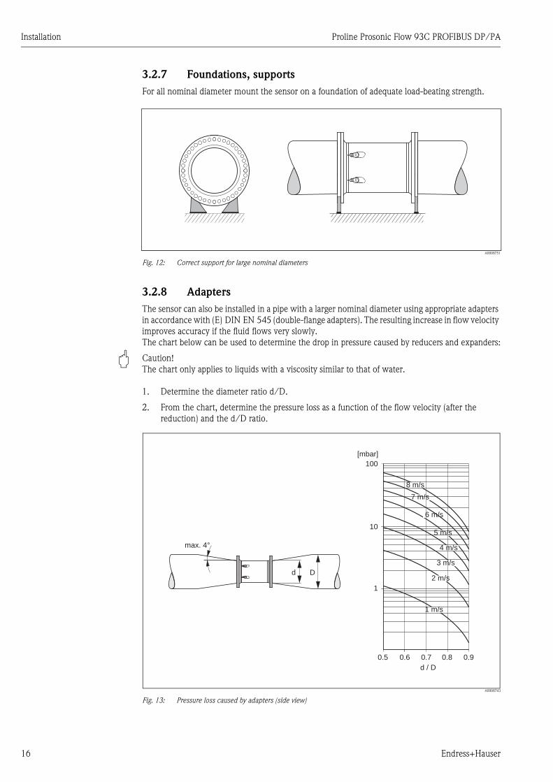
3.2.7 Foundations, supports
For all nominal diameter mount the sensor on a foundation of adequate load-beating strength.
A0008751
Fig. 12: Correct support for large nominal diameters
3.2.8 Adapters
The sensor can also be installed in a pipe with a larger nominal diameter using appropriate adapters
in accordance with (E) DIN EN 545 (double-flange adapters). The resulting increase in flow velocity
improves accuracy if the fluid flows very slowly.
The chart below can be used to determine the drop in pressure caused by reducers and expanders:
" Caution!
The chart only applies to liquids with a viscosity similar to that of water.
1. Determine the diameter ratio d/D.
2. From the chart, determine the pressure loss as a function of the flow velocity (after the
reduction) and the d/D ratio.
A0008743
Fig. 13: Pressure loss caused by adapters (side view)
Dd
max. 4°
100
10
0.5
d / D
[mbar]
0.6 0.7 0.8 0.9
1 m/s
2 m/s
3 m/s
4 m/s
5 m/s
6 m/s
7 m/s
8 m/s
1
Proline Prosonic Flow 93C PROFIBUS DP/PA Installation
Endress+Hauser 17
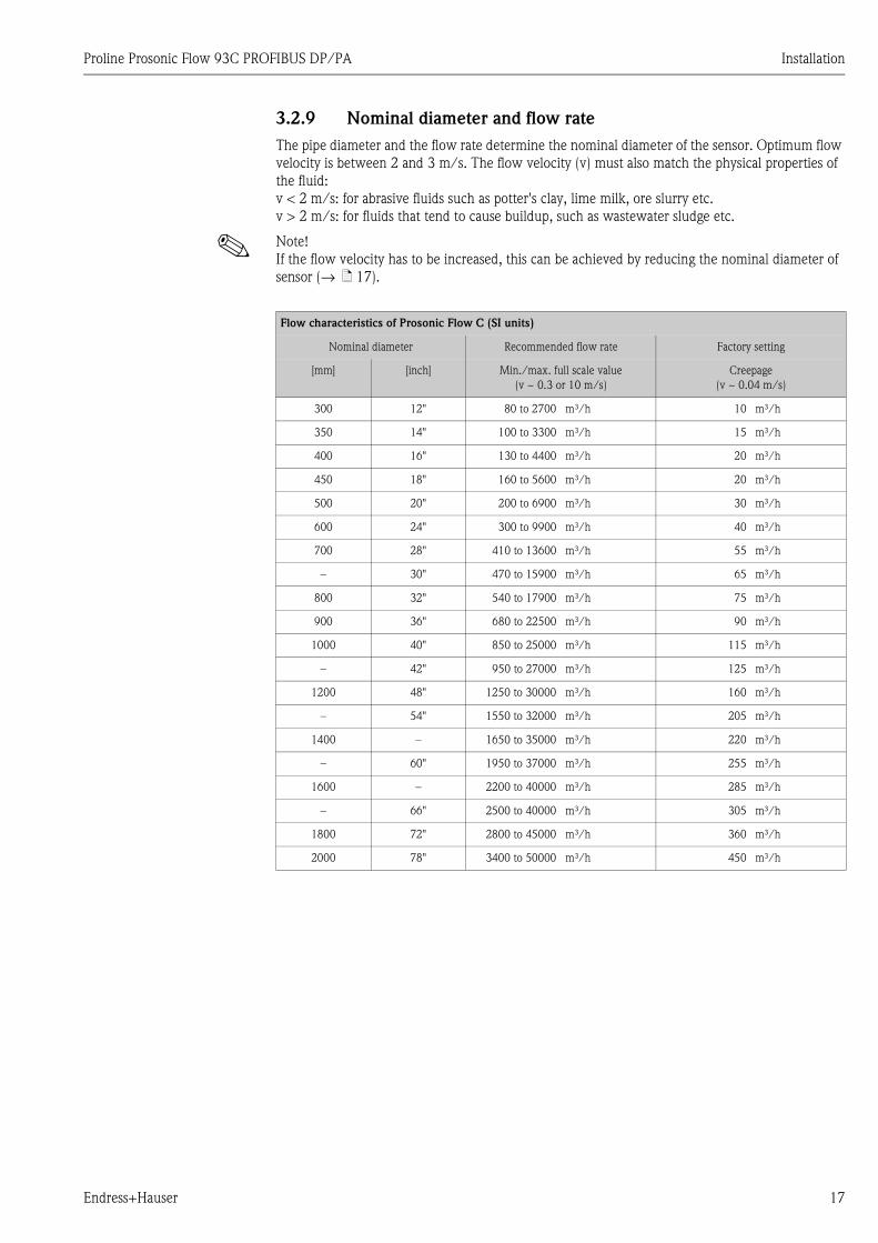
3.2.9 Nominal diameter and flow rate
The pipe diameter and the flow rate determine the nominal diameter of the sensor. Optimum flow
velocity is between 2 and 3 m/s. The flow velocity (v) must also match the physical properties of
the fluid:
v < 2 m/s: for abrasive fluids such as potter's clay, lime milk, ore slurry etc.
v > 2 m/s: for fluids that tend to cause buildup, such as wastewater sludge etc.
! Note!
If the flow velocity has to be increased, this can be achieved by reducing the nominal diameter of
sensor (→ ä 17).
Flow characteristics of Prosonic Flow C (SI units)
Nominal diameter Recommended flow rate Factory setting
[mm] [inch] Min./max. full scale value
(v ~ 0.3 or 10 m/s)
Creepage
(v ~ 0.04 m/s)
300 12" 80 to 2700 m³/h 10 m³/h
350 14" 100 to 3300 m³/h 15 m³/h
400 16" 130 to 4400 m³/h 20 m³/h
450 18" 160 to 5600 m³/h 20 m³/h
500 20" 200 to 6900 m³/h 30 m³/h
600 24" 300 to 9900 m³/h 40 m³/h
700 28" 410 to 13600 m³/h 55 m³/h
– 30" 470 to 15900 m³/h 65 m³/h
800 32" 540 to 17900 m³/h 75 m³/h
900 36" 680 to 22500 m³/h 90 m³/h
1000 40" 850 to 25000 m³/h 115 m³/h
– 42" 950 to 27000 m³/h 125 m³/h
1200 48" 1250 to 30000 m³/h 160 m³/h
– 54" 1550 to 32000 m³/h 205 m³/h
1400 – 1650 to 35000 m³/h 220 m³/h
– 60" 1950 to 37000 m³/h 255 m³/h
1600 – 2200 to 40000 m³/h 285 m³/h
– 66" 2500 to 40000 m³/h 305 m³/h
1800 72" 2800 to 45000 m³/h 360 m³/h
2000 78" 3400 to 50000 m³/h 450 m³/h
Installation Proline Prosonic Flow 93C PROFIBUS DP/PA
18 Endress+Hauser
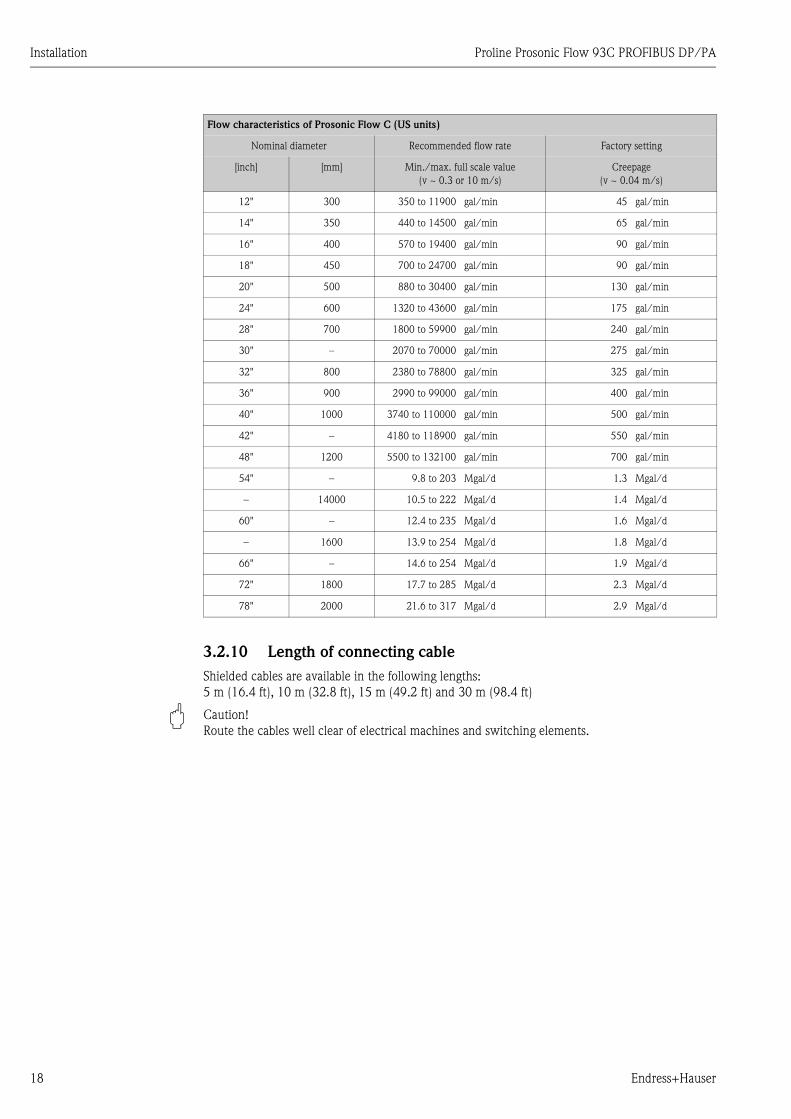
3.2.10 Length of connecting cable
Shielded cables are available in the following lengths:
5 m (16.4 ft), 10 m (32.8 ft), 15 m (49.2 ft) and 30 m (98.4 ft)
" Caution!
Route the cables well clear of electrical machines and switching elements.
Flow characteristics of Prosonic Flow C (US units)
Nominal diameter Recommended flow rate Factory setting
[inch] [mm] Min./max. full scale value
(v ~ 0.3 or 10 m/s)
Creepage
(v ~ 0.04 m/s)
12" 300 350 to 11900 gal/min 45 gal/min
14" 350 440 to 14500 gal/min 65 gal/min
16" 400 570 to 19400 gal/min 90 gal/min
18" 450 700 to 24700 gal/min 90 gal/min
20" 500 880 to 30400 gal/min 130 gal/min
24" 600 1320 to 43600 gal/min 175 gal/min
28" 700 1800 to 59900 gal/min 240 gal/min
30" – 2070 to 70000 gal/min 275 gal/min
32" 800 2380 to 78800 gal/min 325 gal/min
36" 900 2990 to 99000 gal/min 400 gal/min
40" 1000 3740 to 110000 gal/min 500 gal/min
42" – 4180 to 118900 gal/min 550 gal/min
48" 1200 5500 to 132100 gal/min 700 gal/min
54" – 9.8 to 203 Mgal/d 1.3 Mgal/d
– 14000 10.5 to 222 Mgal/d 1.4 Mgal/d
60" – 12.4 to 235 Mgal/d 1.6 Mgal/d
– 1600 13.9 to 254 Mgal/d 1.8 Mgal/d
66" – 14.6 to 254 Mgal/d 1.9 Mgal/d
72" 1800 17.7 to 285 Mgal/d 2.3 Mgal/d
78" 2000 21.6 to 317 Mgal/d 2.9 Mgal/d
Proline Prosonic Flow 93C PROFIBUS DP/PA Installation
Endress+Hauser 19
3.3 Installation
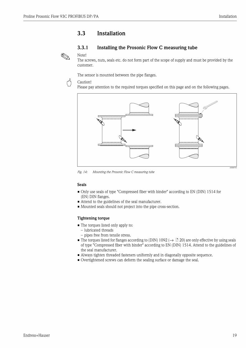
3.3.1 Installing the Prosonic Flow C measuring tube
! Note!
The screws, nuts, seals etc. do not form part of the scope of supply and must be provided by the
customer.
The sensor is mounted between the pipe flanges.
" Caution!
Please pay attention to the required torques specified on this page and on the following pages.
A0008752
Fig. 14: Mounting the Prosonic Flow C measuring tube
Seals
• Only use seals of type "Compressed fiber with binder" according to EN (DIN) 1514 for
(EN) DIN flanges.
• Attend to the guidelines of the seal manufacturer.
• Mounted seals should not project into the pipe cross-section.
Tightening torque
• The torques listed only apply to:
– lubricated threads
– pipes free from tensile stress.
• The torques listed for flanges according to (DIN) 1092 (→ ä 20) are only effective by using seals
of type "Compressed fiber with binder" according to EN (DIN) 1514. Attend to the guidelines of
the seal manufacturer.
• Always tighten threaded fasteners uniformly and in diagonally opposite sequence.
• Overtightened screws can deform the sealing surface or damage the seal.
Installation Proline Prosonic Flow 93C PROFIBUS DP/PA
20 Endress+Hauser
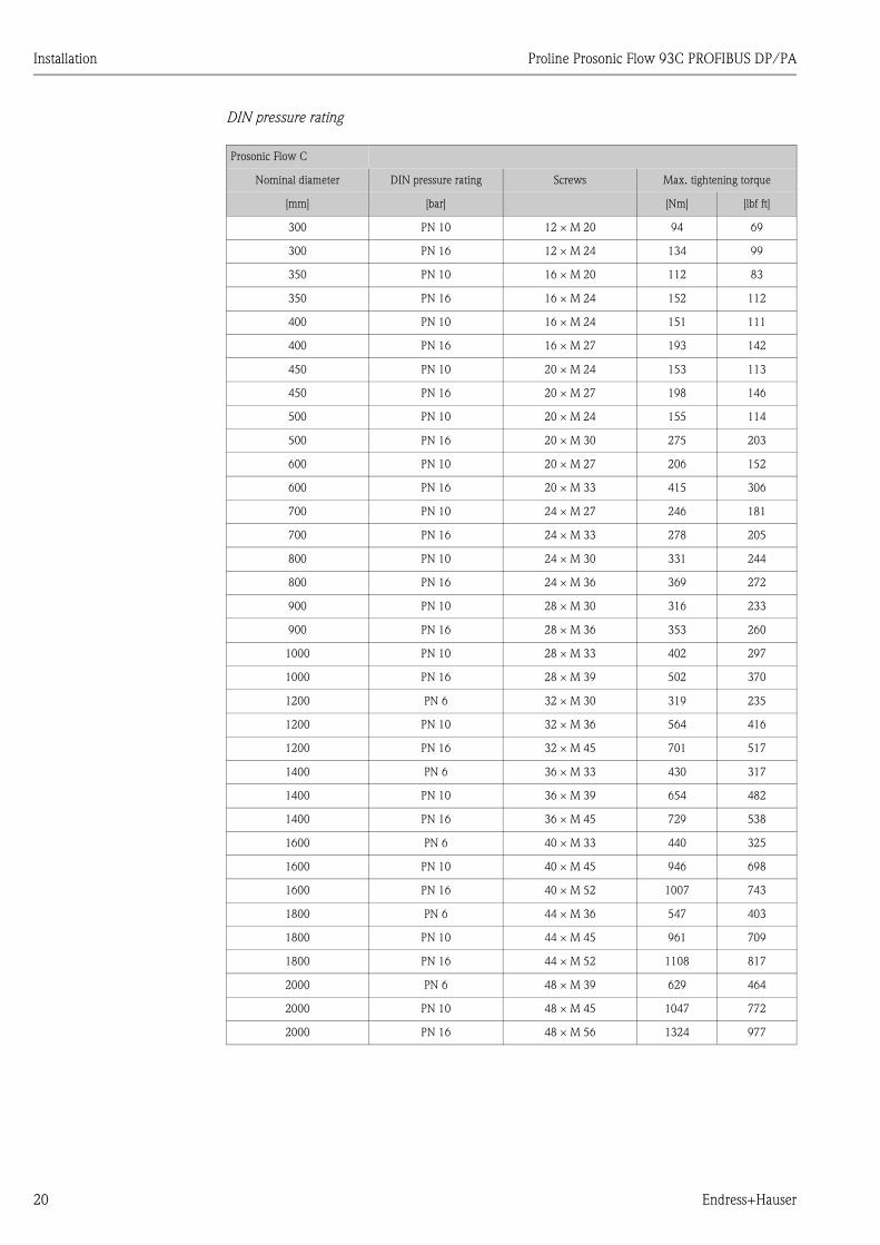
DIN pressure rating
Prosonic Flow C
Nominal diameter DIN pressure rating Screws Max. tightening torque
[mm] [bar] [Nm] [lbf ft]
300 PN 10 12 × M 20 94 69
300 PN 16 12 × M 24 134 99
350 PN 10 16 × M 20 112 83
350 PN 16 16 × M 24 152 112
400 PN 10 16 × M 24 151 111
400 PN 16 16 × M 27 193 142
450 PN 10 20 × M 24 153 113
450 PN 16 20 × M 27 198 146
500 PN 10 20 × M 24 155 114
500 PN 16 20 × M 30 275 203
600 PN 10 20 × M 27 206 152
600 PN 16 20 × M 33 415 306
700 PN 10 24 × M 27 246 181
700 PN 16 24 × M 33 278 205
800 PN 10 24 × M 30 331 244
800 PN 16 24 × M 36 369 272
900 PN 10 28 × M 30 316 233
900 PN 16 28 × M 36 353 260
1000 PN 10 28 × M 33 402 297
1000 PN 16 28 × M 39 502 370
1200 PN 6 32 × M 30 319 235
1200 PN 10 32 × M 36 564 416
1200 PN 16 32 × M 45 701 517
1400 PN 6 36 × M 33 430 317
1400 PN 10 36 × M 39 654 482
1400 PN 16 36 × M 45 729 538
1600 PN 6 40 × M 33 440 325
1600 PN 10 40 × M 45 946 698
1600 PN 16 40 × M 52 1007 743
1800 PN 6 44 × M 36 547 403
1800 PN 10 44 × M 45 961 709
1800 PN 16 44 × M 52 1108 817
2000 PN 6 48 × M 39 629 464
2000 PN 10 48 × M 45 1047 772
2000 PN 16 48 × M 56 1324 977
Proline Prosonic Flow 93C PROFIBUS DP/PA Installation
Endress+Hauser 21
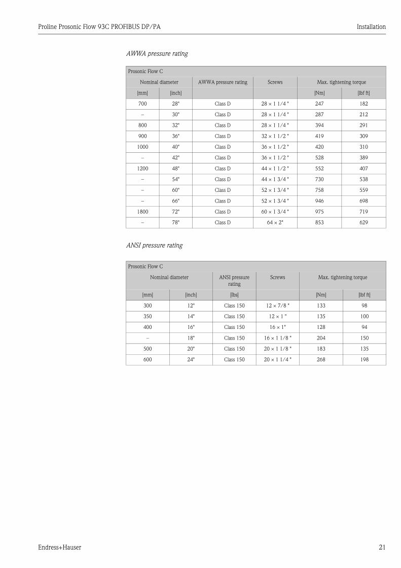
AWWA pressure rating
ANSI pressure rating
Prosonic Flow C
Nominal diameter AWWA pressure rating Screws Max. tightening torque
[mm] [inch] [Nm] [lbf ft]
700 28" Class D 28 × 1 1/4 " 247 182
– 30" Class D 28 × 1 1/4 " 287 212
800 32" Class D 28 × 1 1/4 " 394 291
900 36" Class D 32 × 1 1/2 " 419 309
1000 40" Class D 36 × 1 1/2 " 420 310
– 42" Class D 36 × 1 1/2 " 528 389
1200 48" Class D 44 × 1 1/2 " 552 407
– 54" Class D 44 × 1 3/4 " 730 538
– 60" Class D 52 × 1 3/4 " 758 559
– 66" Class D 52 × 1 3/4 " 946 698
1800 72" Class D 60 × 1 3/4 " 975 719
– 78" Class D 64 × 2" 853 629
Prosonic Flow C
Nominal diameter ANSI pressure
rating
Screws Max. tightening torque
[mm] [inch] [Ibs] [Nm] [lbf ft]
300 12" Class 150 12 × 7/8 " 133 98
350 14" Class 150 12 × 1 " 135 100
400 16" Class 150 16 × 1" 128 94
– 18" Class 150 16 × 1 1/8 " 204 150
500 20" Class 150 20 × 1 1/8 " 183 135
600 24" Class 150 20 × 1 1/4 " 268 198

Installation Proline Prosonic Flow 93C PROFIBUS DP/PA
22 Endress+Hauser
3.3.2 Installing the wall-mount housing
There are various ways of installing the wall-mount housing:
• Direct wall mounting
• Panel mounting (with separate mounting kit, accessories) → ä 23
• Pipe mounting (with separate mounting kit, accessories ) → ä 23
" Caution!
• Make sure that the permitted operating temperature range
(–20 to +60 °C (–4 to + °140 F), optionally –40 to +60 °C (–40 to +140 °F) is not exceeded at
the mounting location. Install the device in a shady location. Avoid direct sunlight.
• Always install the wall-mount housing in such a way that the cable entries are pointing down.
Direct wall mounting
1. Drill the holes as shown in the diagram.
2. Remove the cover of the connection compartment (a).
3. Push the two securing screws (b) through the appropriate bores (c) in the housing.
– Securing screws (M6): max. Ø 6.5 mm (0.26 in)
– Screw head: max. Ø 10.5 mm (0.41" in)
4. Secure the transmitter housing to the wall as indicated.
5. Screw the cover of the connection compartment (a) firmly onto the housing.
a0001130–ae
Fig. 15: Direct wall mounting
a
bc c
90 (3.54)
35 (1.38)
192 (7.56)
81.5
(3.2
)
mm (inch)
Proline Prosonic Flow 93C PROFIBUS DP/PA Installation
Endress+Hauser 23
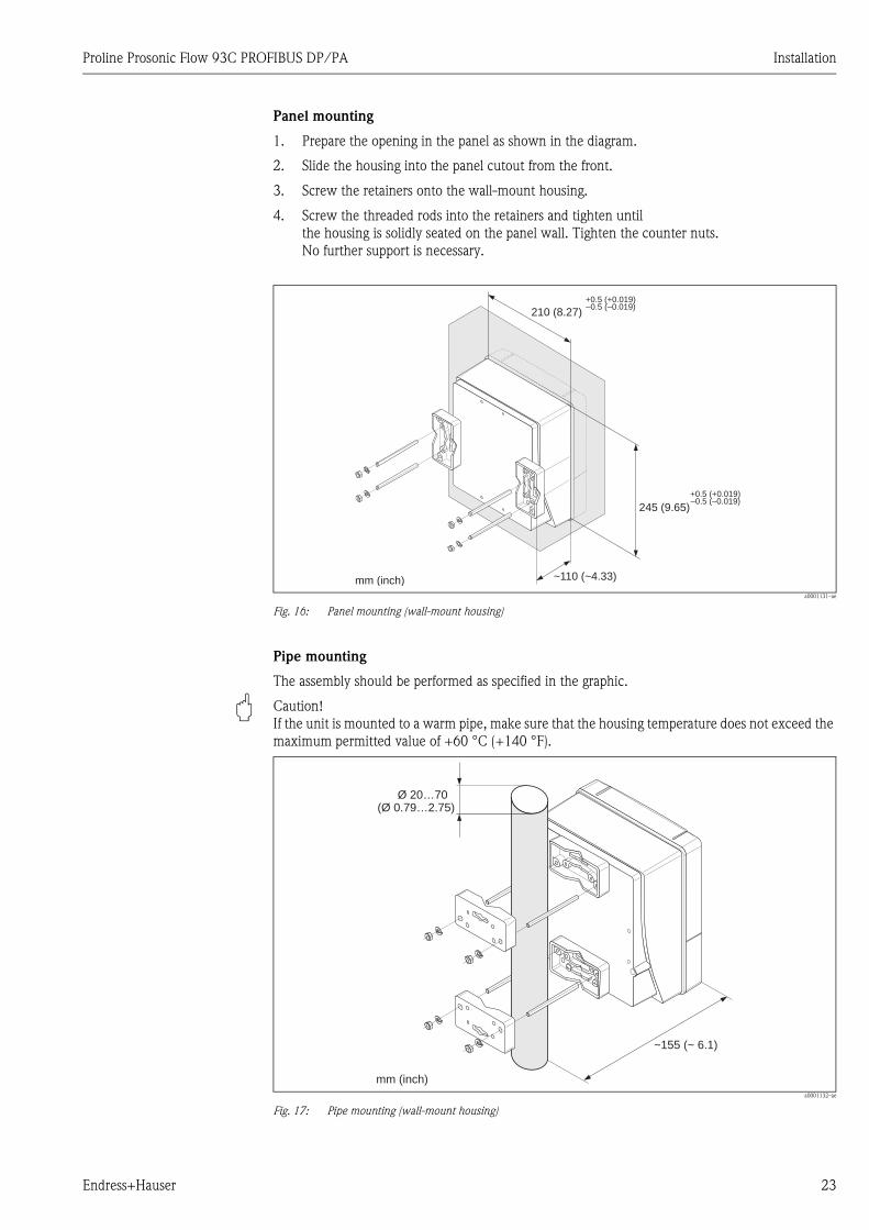
Panel mounting
1. Prepare the opening in the panel as shown in the diagram.
2. Slide the housing into the panel cutout from the front.
3. Screw the retainers onto the wall-mount housing.
4. Screw the threaded rods into the retainers and tighten until
the housing is solidly seated on the panel wall. Tighten the counter nuts.
No further support is necessary.
a0001131–ae
Fig. 16: Panel mounting (wall-mount housing)
Pipe mounting
The assembly should be performed as specified in the graphic.
" Caution!
If the unit is mounted to a warm pipe, make sure that the housing temperature does not exceed the
maximum permitted value of +60 °C (+140 °F).
a0001132–ae
Fig. 17: Pipe mounting (wall-mount housing)
245 (9.65)
~110 (~4.33)
210 (8.27)
+0.5 (+0.019)–0.5 (–0.019)
+0.5 (+0.019)–0.5 (–0.019)
mm (inch)
Ø 20…70(Ø 0.79…2.75)
~ ~ 6.1)155 (
mm (inch)
Installation Proline Prosonic Flow 93C PROFIBUS DP/PA
24 Endress+Hauser
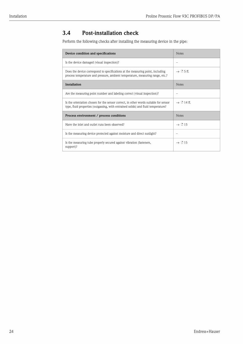
3.4 Post-installation check
Perform the following checks after installing the measuring device in the pipe:
Device condition and specifications Notes
Is the device damaged (visual inspection)? –
Does the device correspond to specifications at the measuring point, including
process temperature and pressure, ambient temperature, measuring range, etc.?
→ ä 5 ff.
Installation Notes
Are the measuring point number and labeling correct (visual inspection)? –
Is the orientation chosen for the sensor correct, in other words suitable for sensor
type, fluid properties (outgassing, with entrained solids) and fluid temperature?
→ ä 14 ff.
Process environment / process conditions Notes
Have the inlet and outlet runs been observed? → ä 15
Is the measuring device protected against moisture and direct sunlight? –
Is the measuring tube properly secured against vibration (fasteners,
support)?
→ ä 15
Proline Prosonic Flow 93C PROFIBUS DP/PA Wiring
Endress+Hauser 25
4 Wiring
# Warning!
When connecting Ex-certified devices, please refer to the notes and diagrams in the Ex-specific
supplement to these Operating Instructions. Please do not hesitate to contact your Endress+Hauser
sales office if you have any questions.
! Note!
The device does not have an internal power switch. For this reason, assign the device a switch or
power-circuit breaker which can be used to disconnect the power supply line from the power grid.
4.1 PROFIBUS cable specifications
4.1.1 PROFIBUS DP cable specifications
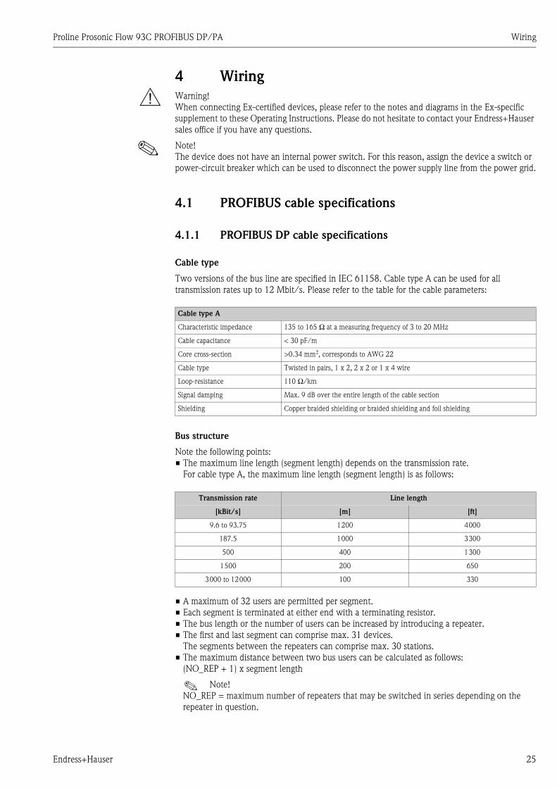
Cable type
Two versions of the bus line are specified in IEC 61158. Cable type A can be used for all
transmission rates up to 12 Mbit/s. Please refer to the table for the cable parameters:
Bus structure
Note the following points:
• The maximum line length (segment length) depends on the transmission rate.
For cable type A, the maximum line length (segment length) is as follows:
• A maximum of 32 users are permitted per segment.
• Each segment is terminated at either end with a terminating resistor.
• The bus length or the number of users can be increased by introducing a repeater.
• The first and last segment can comprise max. 31 devices.
The segments between the repeaters can comprise max. 30 stations.
• The maximum distance between two bus users can be calculated as follows:
(NO_REP + 1) x segment length
! Note!
NO_REP = maximum number of repeaters that may be switched in series depending on the
repeater in question.
Cable type A
Characteristic impedance 135 to 165 Ω at a measuring frequency of 3 to 20 MHz
Cable capacitance < 30 pF/m
Core cross-section >0.34 mm2, corresponds to AWG 22
Cable type Twisted in pairs, 1 x 2, 2 x 2 or 1 x 4 wire
Loop-resistance 110 Ω/km
Signal damping Max. 9 dB over the entire length of the cable section
Shielding Copper braided shielding or braided shielding and foil shielding
Transmission rate Line length
[kBit/s] [m] [ft]
9.6 to 93.75 1200 4000
187.5 1000 3300
500 400 1300
1500 200 650
3000 to 12000 100 330
Wiring Proline Prosonic Flow 93C PROFIBUS DP/PA
26 Endress+Hauser
Example
In accordance with manufacturer specifications, 9 repeaters can be switched in series when using
a standard line. The maximum distance between two bus users at a transmission rate of
1.5 MBit/s can be calculated as follows:
(9 + 1) x 200 m (660 ft) = 2000 m (6600 ft).
Spurs
Note the following points:
• Length of spurs < 6.6 m (21.7 ft) (at max.1.5 MBit/s)
• No spurs should be used for transmission rates >1.5 MBit/s.
The line between the connector and the bus driver is described as a spur. Experience has shown
that you should proceed with caution when configuring spurs. For this reason, you cannot
presume that the sum of all spurs at 1.5 MBit/s may be 6.6 m (21.7 ft).
This is affected greatly by the arrangement of the field devices. Therefore, we recommend you do
not use any spurs, if possible, at transmission rates >1.5 MBit/s.
• If you cannot avoid using spurs, then they may not include any bus terminators.
Bus termination
It is important to terminate the RS485 line correctly at the start and end of the bus segment since
impedance mismatch results in reflections on the line which can cause faulty communication
transmission → ä 53.
Further information
General information and further notes regarding the wiring are contained in BA034S/04:
"Guidelines for planning and commissioning, PROFIBUS DP/PA, field communication."
Proline Prosonic Flow 93C PROFIBUS DP/PA Wiring
Endress+Hauser 27
4.1.2 PROFIBUS PA cable specifications
Cable type
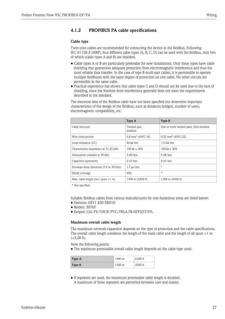
Twin-core cables are recommended for connecting the device to the fieldbus. Following
IEC 61158-2 (MBP), four different cable types (A, B, C, D) can be used with the fieldbus, only two
of which (cable types A and B) are shielded.
• Cable types A or B are particularly preferable for new installations. Only these types have cable
shielding that guarantees adequate protection from electromagnetic interference and thus the
most reliable data transfer. In the case of type B multi-pair cables, it is permissible to operate
multiple fieldbuses with the same degree of protection on one cable. No other circuits are
permissible in the same cable.
• Practical experience has shown that cable types C and D should not be used due to the lack of
shielding, since the freedom from interference generally does not meet the requirements
described in the standard.
The electrical data of the fieldbus cable have not been specified but determine important
characteristics of the design of the fieldbus, such as distances bridged, number of users,
electromagnetic compatibility, etc.
Suitable fieldbus cables from various manufacturers for non-hazardous areas are listed below:
• Siemens: 6XV1 830-5BH10
• Belden: 3076F
• Kerpen: CeL-PE/OSCR/PVC/FRLA FB-02YS(ST)YFL
Maximum overall cable length
The maximum network expansion depends on the type of protection and the cable specifications.
The overall cable length combines the length of the main cable and the length of all spurs >1 m
(>3.28 ft).
Note the following points:
• The maximum permissible overall cable length depends on the cable type used:
• If repeaters are used, the maximum permissible cable length is doubled.
A maximum of three repeaters are permitted between user and master.
Type A Type B
Cable structure Twisted pair,
shielded
One or more twisted pairs, fully shielded
Wire cross-section 0.8 mm2 (AWG 18) 0.32 mm2 (AWG 22)
Loop-resistance (DC) 44 Ω/km 112 Ω/km
Characteristic impedance at 31.25 kHz 100 Ω ± 20% 100 Ω ± 30%
Attenuation constant at 39 kHz 3 dB/km 5 dB/km
Capacitive asymmetry 2 nF/km 2 nF/km
Envelope delay distortion (7.9 to 39 kHz) 1.7 μs/km *
Shield coverage 90% *
Max. cable length (incl. spurs >1 m) 1900 m (6200 ft) 1200 m (4000 ft)
* Not specified
Type A 1900 m 6200 ft
Type B 1200 m 4000 ft
Wiring Proline Prosonic Flow 93C PROFIBUS DP/PA
28 Endress+Hauser
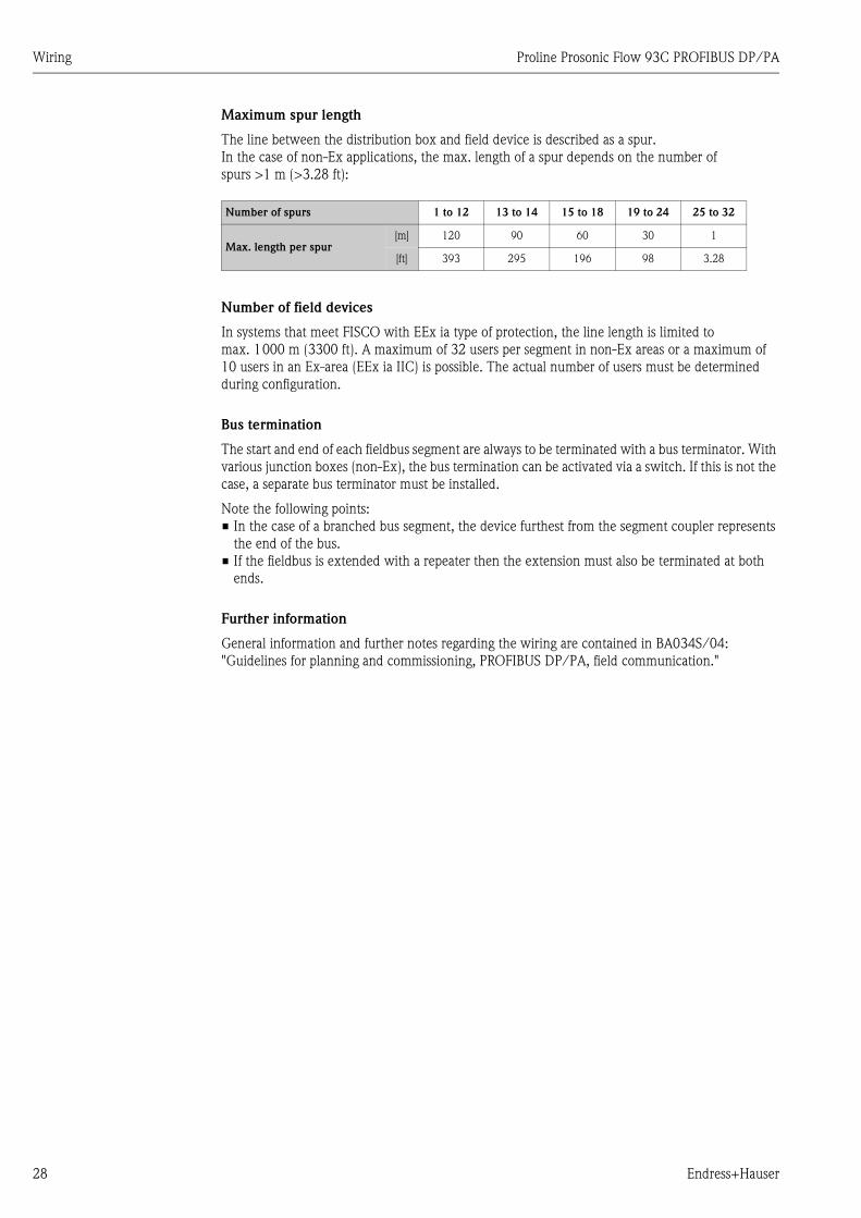
Maximum spur length
The line between the distribution box and field device is described as a spur.
In the case of non-Ex applications, the max. length of a spur depends on the number of
spurs >1 m (>3.28 ft):
Number of field devices
In systems that meet FISCO with EEx ia type of protection, the line length is limited to
max. 1000 m (3300 ft). A maximum of 32 users per segment in non-Ex areas or a maximum of
10 users in an Ex-area (EEx ia IIC) is possible. The actual number of users must be determined
during configuration.
Bus termination
The start and end of each fieldbus segment are always to be terminated with a bus terminator. With
various junction boxes (non-Ex), the bus termination can be activated via a switch. If this is not the
case, a separate bus terminator must be installed.
Note the following points:
• In the case of a branched bus segment, the device furthest from the segment coupler represents
the end of the bus.
• If the fieldbus is extended with a repeater then the extension must also be terminated at both
ends.
Further information
General information and further notes regarding the wiring are contained in BA034S/04:
"Guidelines for planning and commissioning, PROFIBUS DP/PA, field communication."
Number of spurs 1 to 12 13 to 14 15 to 18 19 to 24 25 to 32
Max. length per spur[m] 120 90 60 30 1
[ft] 393 295 196 98 3.28
Proline Prosonic Flow 93C PROFIBUS DP/PA Wiring
Endress+Hauser 29
4.1.3 Shielding and grounding
When planning the shielding and grounding for a fieldbus system, there are three important points
to consider:
• Electromagnetic compatibility (EMC)
• Explosion protection
• Safety of the personnel
To ensure the optimum electromagnetic compatibility of systems, it is important that the system
components and above all the cables, which connect the components, are shielded and that no
portion of the system is unshielded. Ideally, the cable shields are connected to the normally metal
housings of the connected field devices. Since these are generally connected to the protective earth,
the shield of the bus cable is grounded many times. Keep the stripped and twisted lengths of cable
shield to the terminals as short as possible.
This approach, which provides the best electromagnetic compatibility and personal safety, can be
used without restriction in systems with good potential matching.
In the case of systems without potential matching, a power supply frequency (50 Hz) equalizing
current can flow between two grounding points which, in unfavorable cases, e.g. when it exceeds
the permissible shield current, may destroy the cable.
To suppress the low frequency equalizing currents on systems without potential equalization, it is
therefore recommended to connect the cable shield directly to the building ground (or protective
earth) at one end only and to use capacitive coupling to connect all other grounding points.
" Caution!
The legal EMC requirements are fulfilled only when the cable shield is grounded on both sides!
Wiring Proline Prosonic Flow 93C PROFIBUS DP/PA
30 Endress+Hauser
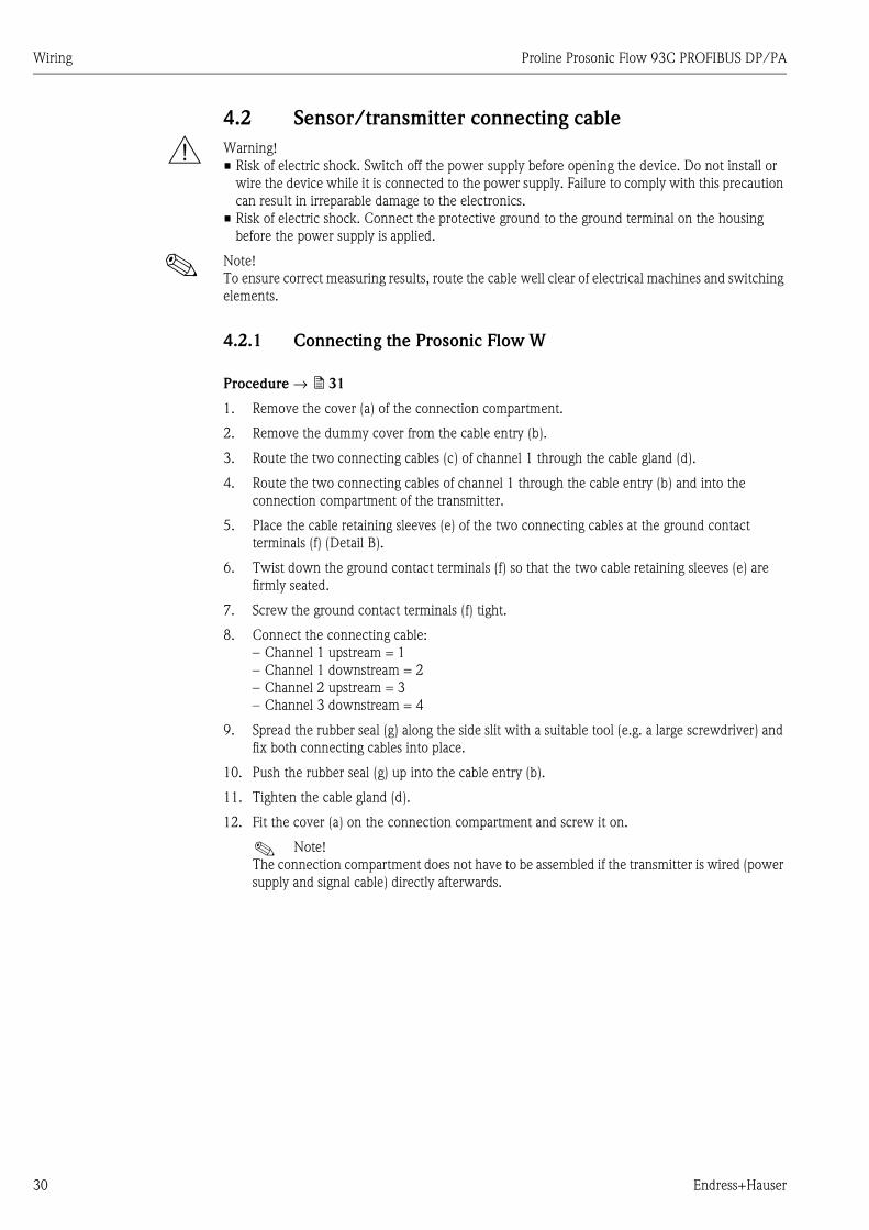
4.2 Sensor/transmitter connecting cable
# Warning!
• Risk of electric shock. Switch off the power supply before opening the device. Do not install or
wire the device while it is connected to the power supply. Failure to comply with this precaution
can result in irreparable damage to the electronics.
• Risk of electric shock. Connect the protective ground to the ground terminal on the housing
before the power supply is applied.
! Note!
To ensure correct measuring results, route the cable well clear of electrical machines and switching
elements.
4.2.1 Connecting the Prosonic Flow W
Procedure → ä 31
1. Remove the cover (a) of the connection compartment.
2. Remove the dummy cover from the cable entry (b).
3. Route the two connecting cables (c) of channel 1 through the cable gland (d).
4. Route the two connecting cables of channel 1 through the cable entry (b) and into the
connection compartment of the transmitter.
5. Place the cable retaining sleeves (e) of the two connecting cables at the ground contact
terminals (f) (Detail B).
6. Twist down the ground contact terminals (f) so that the two cable retaining sleeves (e) are
firmly seated.
7. Screw the ground contact terminals (f) tight.
8. Connect the connecting cable:
– Channel 1 upstream = 1
– Channel 1 downstream = 2
– Channel 2 upstream = 3
– Channel 3 downstream = 4
9. Spread the rubber seal (g) along the side slit with a suitable tool (e.g. a large screwdriver) and
fix both connecting cables into place.
10. Push the rubber seal (g) up into the cable entry (b).
11. Tighten the cable gland (d).
12. Fit the cover (a) on the connection compartment and screw it on.
! Note!
The connection compartment does not have to be assembled if the transmitter is wired (power
supply and signal cable) directly afterwards.
Proline Prosonic Flow 93C PROFIBUS DP/PA Wiring
Endress+Hauser 31
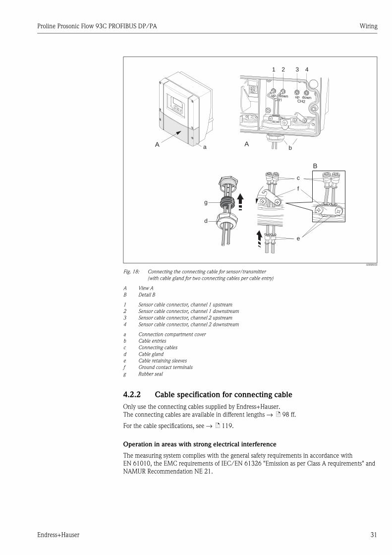
A0008654
Fig. 18: Connecting the connecting cable for sensor/transmitter
(with cable gland for two connecting cables per cable entry)
A View A
B Detail B
1 Sensor cable connector, channel 1 upstream
2 Sensor cable connector, channel 1 downstream
3 Sensor cable connector, channel 2 upstream
4 Sensor cable connector, channel 2 downstream
a Connection compartment cover
b Cable entries
c Connecting cables
d Cable gland
e Cable retaining sleeves
f Ground contact terminals
g Rubber seal
4.2.2 Cable specification for connecting cable
Only use the connecting cables supplied by Endress+Hauser.
The connecting cables are available in different lengths → ä 98 ff.
For the cable specifications, see → ä 119.
Operation in areas with strong electrical interference
The measuring system complies with the general safety requirements in accordance with
EN 61010, the EMC requirements of IEC/EN 61326 "Emission as per Class A requirements" and
NAMUR Recommendation NE 21.
A
1
A
32 4
d
g
e
c
f
B
ba

Wiring Proline Prosonic Flow 93C PROFIBUS DP/PA
32 Endress+Hauser
4.3 Connecting the measuring unit
4.3.1 Terminal assignment
Electrical values for:
• Inputs → ä 117
• Outputs → ä 117
PROFIBUS DP
" Caution!
Only certain combinations of submodules (see Table) on the I/O board are permissible. The
individual slots are marked and assigned to the following terminals in the connection compartment
of the transmitter:
• "INPUT / OUTPUT 3" slot = terminals 22/23
• "INPUT / OUTPUT 4" slot = terminals 20/21
PROFIBUS PA
PROFIBUS PA
Order version
Terminal No. (inputs/outputs)
20 (+) / 21 (–)
Submodule on
slot No. 4
22 (+) / 23 (–)
Submodule on
slot No. 3
24 (+) / 25 (–)
Fixed on I/O board
26 = B (RxD/TxD-P)
27 = A (RxD/TxD-N)
Fixed on I/O board
93***-***********J - -+5V (power supply for
ext. bus terminator)
PROFIBUS DP
93***-***********V Relay output 2 Relay output 1 Status input PROFIBUS DP
93***-***********P Current output Frequency output Status input PROFIBUS DP
Terminal No. (inputs/outputs)
Order version 20 (+) / 21 (–) 22 (+) / 23 (–) 24 (+) / 25 (–) 26 = PA + 1)
27 = PA – 1)
93***-***********H - - - PROFIBUS PA
1) With integrated reverse polarity protection
Proline Prosonic Flow 93C PROFIBUS DP/PA Wiring
Endress+Hauser 33
4.3.2 Connecting the transmitter
# Warning!
• Risk of electric shock. Switch off the power supply before opening the device. Do not install or
wire the device while it is connected to the power supply. Failure to comply with this precaution
can result in irreparable damage to the electronics.
• Risk of electric shock. Connect the protective ground to the ground terminal on the housing
before the power supply is applied (not required for galvanically isolated power supply).
• Compare the specifications on the nameplate with the local supply voltage and frequency. The
national regulations governing the installation of electrical equipment also apply.
Procedure:
• PROFIBUS DP → å 19 (→ ä 34)
• PROFIBUS PA → å 20 (→ ä 35)
1. Unscrew the connection compartment cover (a) from the transmitter housing.
2. Feed the power supply cable (b), the fieldbus cable (d) and the power supply cable for external
bus terminator (optional) or signal cable (g) through the appropriate cable entries.
3. Perform wiring in accordance with the respective terminal assignment and the associated
wiring diagram.
" Caution!
– Risk of damaging the fieldbus cable!
Observe the information about shielding and grounding the fieldbus cable → ä 29.
– We recommend that the fieldbus cable not be looped using conventional cable glands. If you
later replace even just one measuring device, the bus communication will have to be
interrupted.
! Note!
– The terminals for connecting PROFIBUS PA (26/27) have integrated reverse polarity
protection. This ensures correct signal transmission via the fieldbus even if the cables are
connected the wrong way round.
– Cable cross-section: max. 2.5 mm² (0.0039 in², AWG 14)
– Pay attention to the grounding concept of the plant.
4. Screw the cover of the connection compartment (a) back onto the transmitter housing.
Wiring Proline Prosonic Flow 93C PROFIBUS DP/PA
34 Endress+Hauser
4.3.3 PROFIBUS DP connection diagram
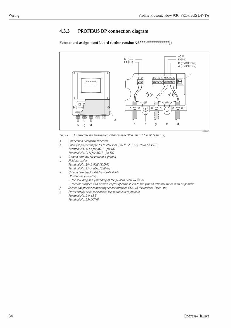
Permanent assignment board (order version 93***-***********J)
A0014363
Fig. 19: Connecting the transmitter, cable cross-section: max. 2.5 mm2 (AWG 14)
a Connection compartment cover
b Cable for power supply: 85 to 260 V AC, 20 to 55 V AC, 16 to 62 V DC
Terminal No. 1: L1 for AC, L+ for DC
Terminal No. 2: N for AC, L− for DC
c Ground terminal for protective ground
d Fieldbus cable:
Terminal No. 26: B (RxD/TxD-P)
Terminal No. 27: A (RxD/TxD-N)
e Ground terminal for fieldbus cable shield
Observe the following:
– the shielding and grounding of the fieldbus cable → ä 29
– that the stripped and twisted lengths of cable shield to the ground terminal are as short as possible
f Service adapter for connecting service interface FXA193 (Fieldcheck, FieldCare)
g Power supply cable for external bus terminator (optional):
Terminal No. 24: +5 V
Terminal No. 25: DGND
A (RxD/TxD-N)B (RxD/TxD-P)
1 2
c e
f
bb ddg
222320 21 2425 26 27
a
DGND+5 V
g
L1 (L+)N (L–)

Proline Prosonic Flow 93C PROFIBUS DP/PA Wiring
Endress+Hauser 35
Flexible assignment boards
(order version 93***-***********V and 93***-***********P)
A0014364
Fig. 20: Connecting the transmitter, cable cross-section: max. 2.5 mm2 (AWG 14)
a Connection compartment cover
b Cable for power supply: 85 to 260 V AC, 20 to 55 V AC, 16 to 62 V DC
Terminal No. 1: L1 for AC, L+ for DC
Terminal No. 2: N for AC, L− for DC
c Ground terminal for protective ground
d Fieldbus cable:
Terminal No. 26: B (RxD/TxD-P)
Terminal No. 27: A (RxD/TxD-N)
e Ground terminal for signal cable shield
Observe the following:
– the shielding and grounding of the fieldbus cable → ä 29
– that the stripped and twisted lengths of cable shield to the ground terminal are as short as possible
f Service adapter for connecting service interface FXA193 (Fieldcheck, FieldCare)
g Signal cable: see terminal assignment → ä 32
1 2f
222320 21 2425 26 27
a
L1 (L+)N (L–)
c ebb ddg g
A (RxD/TxD-N)B (RxD/TxD-P)
Wiring Proline Prosonic Flow 93C PROFIBUS DP/PA
36 Endress+Hauser
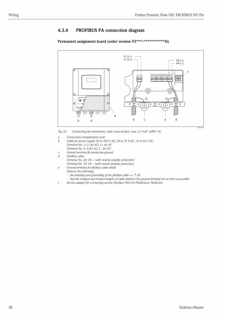
4.3.4 PROFIBUS PA connection diagram
Permanent assignment board (order version 93***-***********H)
A0014365
Fig. 21: Connecting the transmitter, cable cross-section: max. 2.5 mm2 (AWG 14)
a Connection compartment cover
b Cable for power supply: 85 to 260 V AC, 20 to 55 V AC, 16 to 62 V DC
Terminal No. 1: L1 for AC, L+ for DC
Terminal No. 2: N for AC, L− for DC
c Ground terminal for protective ground
d Fieldbus cable:
Terminal No. 26: PA + (with reverse polarity protection)
Terminal No. 27: PA – (with reverse polarity protection)
e Ground terminal for fieldbus cable shield
Observe the following:
– the shielding and grounding of the fieldbus cable → ä 29
– that the stripped and twisted lengths of cable shield to the ground terminal are as short as possible
f Service adapter for connecting service interface FXA193 (Fieldcheck, FieldCare)
PA (–)PA (+)
1 2f
222320 21 2425 26 27
a
L1 (L+)N (L–)
c ebb dd
Proline Prosonic Flow 93C PROFIBUS DP/PA Wiring
Endress+Hauser 37
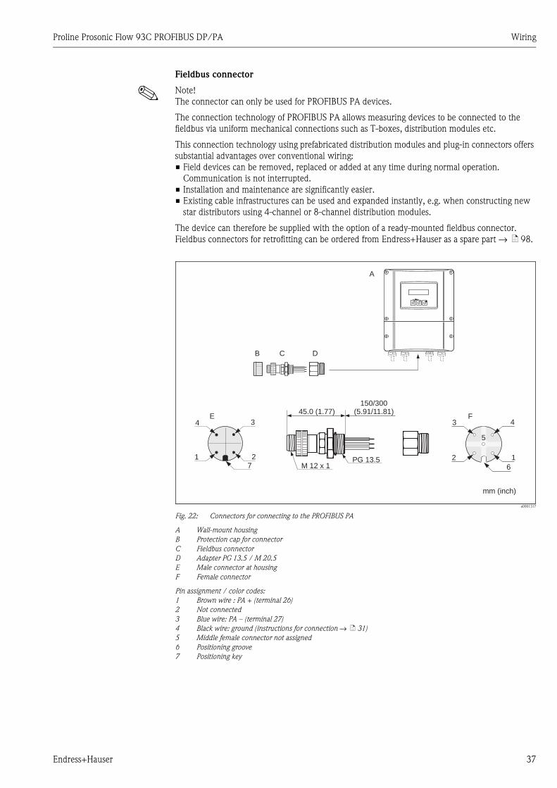
Fieldbus connector
! Note!
The connector can only be used for PROFIBUS PA devices.
The connection technology of PROFIBUS PA allows measuring devices to be connected to the
fieldbus via uniform mechanical connections such as T-boxes, distribution modules etc.
This connection technology using prefabricated distribution modules and plug-in connectors offers
substantial advantages over conventional wiring:
• Field devices can be removed, replaced or added at any time during normal operation.
Communication is not interrupted.
• Installation and maintenance are significantly easier.
• Existing cable infrastructures can be used and expanded instantly, e.g. when constructing new
star distributors using 4-channel or 8-channel distribution modules.
The device can therefore be supplied with the option of a ready-mounted fieldbus connector.
Fieldbus connectors for retrofitting can be ordered from Endress+Hauser as a spare part → ä 98.
a0001317
Fig. 22: Connectors for connecting to the PROFIBUS PA
A Wall-mount housing
B Protection cap for connector
C Fieldbus connector
D Adapter PG 13.5 / M 20.5
E Male connector at housing
F Female connector
Pin assignment / color codes:
1 Brown wire : PA + (terminal 26)
2 Not connected
3 Blue wire: PA – (terminal 27)
4 Black wire: ground (instructions for connection → ä 31)
5 Middle female connector not assigned
6 Positioning groove
7 Positioning key
PG 13.5M 12 x 1
150/300(5.91/11.81)45.0 (1.77)
mm (inch)
3 4
2 1
F
5
6
4
1 2
E3
7
B C D
A
Esc
E- +
Wiring Proline Prosonic Flow 93C PROFIBUS DP/PA
38 Endress+Hauser
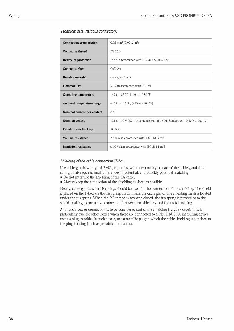
Technical data (fieldbus connector):
Shielding of the cable connection/T-box
Use cable glands with good EMC properties, with surrounding contact of the cable gland (iris
spring). This requires small differences in potential, and possibly potential matching.
• Do not interrupt the shielding of the PA cable.
• Always keep the connection of the shielding as short as possible.
Ideally, cable glands with iris springs should be used for the connection of the shielding. The shield
is placed on the T-box via the iris spring that is inside the cable gland. The shielding mesh is located
under the iris spring. When the PG thread is screwed closed, the iris spring is pressed onto the
shield, making a conductive connection between the shielding and the metal housing.
A junction box or connection is to be considered part of the shielding (Faraday cage). This is
particularly true for offset boxes when these are connected to a PROFIBUS PA measuring device
using a plug-in cable. In such a case, use a metallic plug in which the cable shielding is attached to
the plug housing (such as prefabricated cables).
Connection cross section 0.75 mm2 (0.0012 in²)
Connector thread PG 13.5
Degree of protection IP 67 in accordance with DIN 40 050 IEC 529
Contact surface CuZnAu
Housing material Cu Zn, surface Ni
Flammability V - 2 in accordance with UL - 94
Operating temperature –40 to +85 °C, (–40 to +185 °F)
Ambient temperature range –40 to +150 °C, (–40 to +302 °F)
Nominal current per contact 3 A
Nominal voltage 125 to 150 V DC in accordance with the VDE Standard 01 10/ISO Group 10
Resistance to tracking KC 600
Volume resistance ≤ 8 mΩ in accordance with IEC 512 Part 2
Insulation resistance ≤ 1012 Ω in accordance with IEC 512 Part 2

Proline Prosonic Flow 93C PROFIBUS DP/PA Wiring
Endress+Hauser 39
4.4 Degree of protection
4.4.1 Transmitter (wall-mount housing)
The transmitter fulfills all the requirements for IP 67.
" Achtung!
Do not loosen the screws of the sensor housing, as otherwise the degree of protection guaranteed
by Endress+Hauser no longer applies.
Compliance with the following points is mandatory following installation in the field or servicing,
in order to ensure that IP 67 protection is maintained:
• The housing seals must be clean and undamaged when inserted into their grooves. The seals must
be dried, cleaned or replaced if necessary.
• All the threaded fasteners and screw covers must be firmly tightened.
• The cables used for connection must be of the specified outside diameter → ä 31.
• Securely tighten the cable entries → ä 39.
• Remove all unused cable entries and insert plugs instead.
• Do not remove the grommet from the cable entry.
A0001138
Fig. 23: Installation instructions for cable entries on the transmitter housing
Wiring Proline Prosonic Flow 93C PROFIBUS DP/PA
40 Endress+Hauser
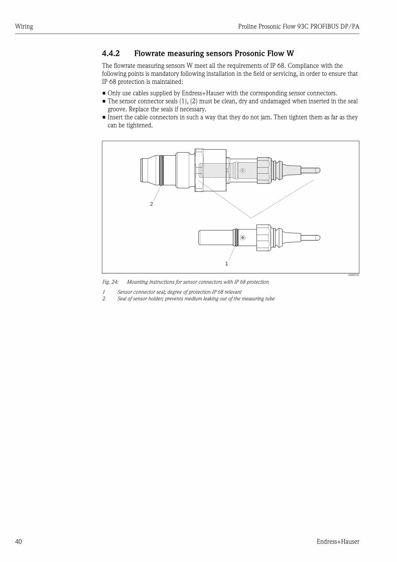
4.4.2 Flowrate measuring sensors Prosonic Flow W
The flowrate measuring sensors W meet all the requirements of IP 68. Compliance with the
following points is mandatory following installation in the field or servicing, in order to ensure that
IP 68 protection is maintained:
• Only use cables supplied by Endress+Hauser with the corresponding sensor connectors.
• The sensor connector seals (1), (2) must be clean, dry and undamaged when inserted in the seal
groove. Replace the seals if necessary.
• Insert the cable connectors in such a way that they do not jam. Then tighten them as far as they
can be tightened.
A0008741
Fig. 24: Mounting instructions for sensor connectors with IP 68 protection
1 Sensor connector seal; degree of protection IP 68 relevant
2 Seal of sensor holder; prevents medium leaking out of the measuring tube
2
1
Proline Prosonic Flow 93C PROFIBUS DP/PA Wiring
Endress+Hauser 41
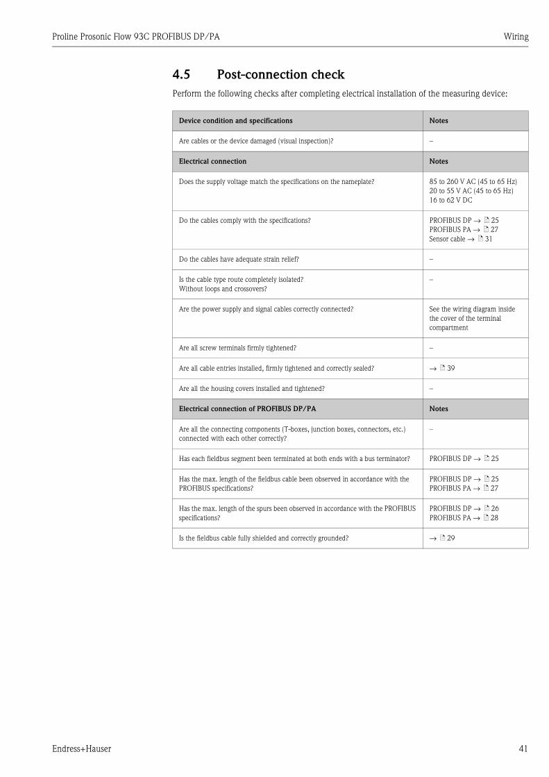
4.5 Post-connection check
Perform the following checks after completing electrical installation of the measuring device:
Device condition and specifications Notes
Are cables or the device damaged (visual inspection)? –
Electrical connection Notes
Does the supply voltage match the specifications on the nameplate? 85 to 260 V AC (45 to 65 Hz)
20 to 55 V AC (45 to 65 Hz)
16 to 62 V DC
Do the cables comply with the specifications? PROFIBUS DP → ä 25
PROFIBUS PA → ä 27
Sensor cable → ä 31
Do the cables have adequate strain relief? –
Is the cable type route completely isolated?
Without loops and crossovers?
–
Are the power supply and signal cables correctly connected? See the wiring diagram inside
the cover of the terminal
compartment
Are all screw terminals firmly tightened? –
Are all cable entries installed, firmly tightened and correctly sealed? → ä 39
Are all the housing covers installed and tightened? –
Electrical connection of PROFIBUS DP/PA Notes
Are all the connecting components (T-boxes, junction boxes, connectors, etc.)
connected with each other correctly?
–
Has each fieldbus segment been terminated at both ends with a bus terminator? PROFIBUS DP → ä 25
Has the max. length of the fieldbus cable been observed in accordance with the
PROFIBUS specifications?
PROFIBUS DP → ä 25
PROFIBUS PA → ä 27
Has the max. length of the spurs been observed in accordance with the PROFIBUS
specifications?
PROFIBUS DP → ä 26
PROFIBUS PA → ä 28
Is the fieldbus cable fully shielded and correctly grounded? → ä 29
Operation Proline Prosonic Flow 93C PROFIBUS DP/PA
42 Endress+Hauser
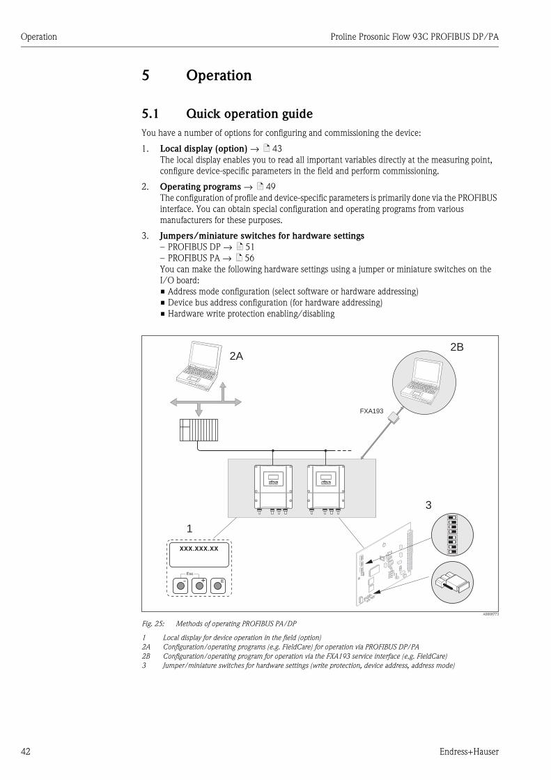
5 Operation
5.1 Quick operation guide
You have a number of options for configuring and commissioning the device:
1. Local display (option) → ä 43
The local display enables you to read all important variables directly at the measuring point,
configure device-specific parameters in the field and perform commissioning.
2. Operating programs → ä 49
The configuration of profile and device-specific parameters is primarily done via the PROFIBUS
interface. You can obtain special configuration and operating programs from various
manufacturers for these purposes.
3. Jumpers/miniature switches for hardware settings
– PROFIBUS DP → ä 51
– PROFIBUS PA → ä 56
You can make the following hardware settings using a jumper or miniature switches on the
I/O board:
• Address mode configuration (select software or hardware addressing)
• Device bus address configuration (for hardware addressing)
• Hardware write protection enabling/disabling
A0008773
Fig. 25: Methods of operating PROFIBUS PA/DP
1 Local display for device operation in the field (option)
2A Configuration/operating programs (e.g. FieldCare) for operation via PROFIBUS DP/PA
2B Configuration/operating program for operation via the FXA193 service interface (e.g. FieldCare)
3 Jumper/miniature switches for hardware settings (write protection, device address, address mode)
2A
3
1
Esc
E- +
Esc
E+-
XXX.XXX.XX
FXA193
2B
Esc
E- +
Proline Prosonic Flow 93C PROFIBUS DP/PA Operation
Endress+Hauser 43
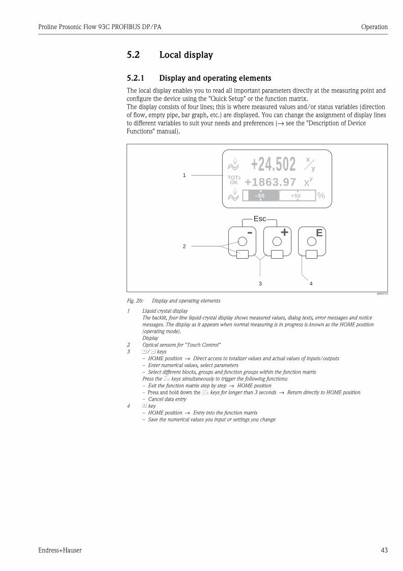
5.2 Local display
5.2.1 Display and operating elements
The local display enables you to read all important parameters directly at the measuring point and
configure the device using the "Quick Setup" or the function matrix.
The display consists of four lines; this is where measured values and/or status variables (direction
of flow, empty pipe, bar graph, etc.) are displayed. You can change the assignment of display lines
to different variables to suit your needs and preferences (→ see the "Description of Device
Functions" manual).
a0004754
Fig. 26: Display and operating elements
1 Liquid crystal display
The backlit, four-line liquid-crystal display shows measured values, dialog texts, error messages and notice
messages. The display as it appears when normal measuring is in progress is known as the HOME position
(operating mode).
Display
2 Optical sensors for "Touch Control"
3 O/ S keys
– HOME position → Direct access to totalizer values and actual values of inputs/outputs
– Enter numerical values, select parameters
– Select different blocks, groups and function groups within the function matrix
Press the X keys simultaneously to trigger the following functions:
– Exit the function matrix step by step → HOME position
– Press and hold down the X keys for longer than 3 seconds → Return directly to HOME position
– Cancel data entry
4 F key
– HOME position → Entry into the function matrix
– Save the numerical values you input or settings you change
+24.502+1863.97
x
y
–50 +50 %
v
v
Esc
E+-
1
2
3 4
xyTOT
OK3
+24.502+1863.97
x
y
–50 +50 %
v
v
xyTOT
OK3
Operation Proline Prosonic Flow 93C PROFIBUS DP/PA
44 Endress+Hauser
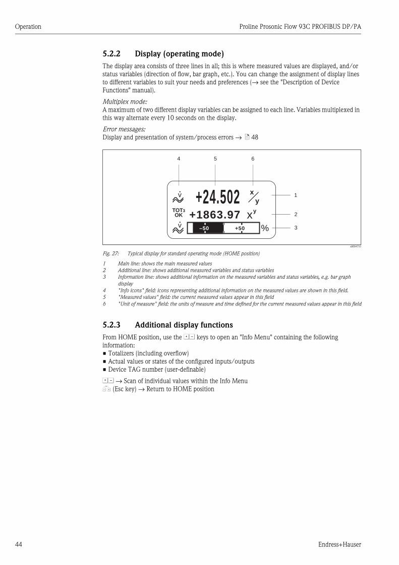
5.2.2 Display (operating mode)
The display area consists of three lines in all; this is where measured values are displayed, and/or
status variables (direction of flow, bar graph, etc.). You can change the assignment of display lines
to different variables to suit your needs and preferences (→ see the "Description of Device
Functions" manual).
Multiplex mode:
A maximum of two different display variables can be assigned to each line. Variables multiplexed in
this way alternate every 10 seconds on the display.
Error messages:
Display and presentation of system/process errors → ä 48
a0004755
Fig. 27: Typical display for standard operating mode (HOME position)
1 Main line: shows the main measured values
2 Additional line: shows additional measured variables and status variables
3 Information line: shows additional information on the measured variables and status variables, e.g. bar graph
display
4 "Info icons" field: icons representing additional information on the measured values are shown in this field.
5 "Measured values" field: the current measured values appear in this field
6 "Unit of measure" field: the units of measure and time defined for the current measured values appear in this field
5.2.3 Additional display functions
From HOME position, use the OS keys to open an "Info Menu" containing the following
information:
• Totalizers (including overflow)
• Actual values or states of the configured inputs/outputs
• Device TAG number (user-definable)
OS → Scan of individual values within the Info Menu
X (Esc key) → Return to HOME position
1
4 5 6
2
3
+24.502+1863.97
x
xy
y
–50 +50 %
v
v
TOTOK
3
Proline Prosonic Flow 93C PROFIBUS DP/PA Operation
Endress+Hauser 45
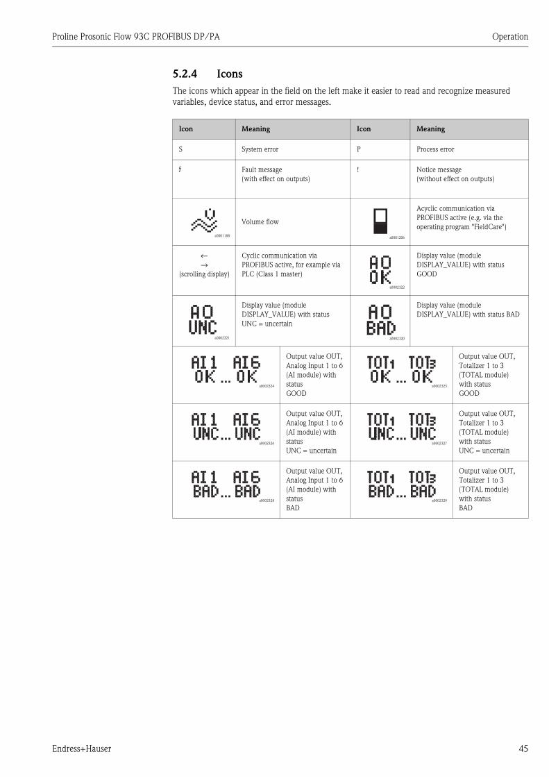
5.2.4 Icons
The icons which appear in the field on the left make it easier to read and recognize measured
variables, device status, and error messages.
Icon Meaning Icon Meaning
S System error P Process error
$ Fault message
(with effect on outputs)
! Notice message
(without effect on outputs)
a0001188
Volume flow
a0001206
Acyclic communication via
PROFIBUS active (e.g. via the
operating program "FieldCare")
←→
(scrolling display)
Cyclic communication via
PROFIBUS active, for example via
PLC (Class 1 master)
a0002322
Display value (module
DISPLAY_VALUE) with status
GOOD
a0002321
Display value (module
DISPLAY_VALUE) with status
UNC = uncertain
a0002320
Display value (module
DISPLAY_VALUE) with status BAD
a0002324
Output value OUT,
Analog Input 1 to 6
(AI module) with
status
GOOD
a0002325
Output value OUT,
Totalizer 1 to 3
(TOTAL module)
with status
GOOD
a0002326
Output value OUT,
Analog Input 1 to 6
(AI module) with
status
UNC = uncertain
a0002327
Output value OUT,
Totalizer 1 to 3
(TOTAL module)
with status
UNC = uncertain
a0002328
Output value OUT,
Analog Input 1 to 6
(AI module) with
status
BAD
a0002329
Output value OUT,
Totalizer 1 to 3
(TOTAL module)
with status
BAD

Operation Proline Prosonic Flow 93C PROFIBUS DP/PA
46 Endress+Hauser
5.3 Brief guide to the function matrix
! Note!
• See the general notes → ä 47
• Function descriptions → see the "Description of Device Functions" manual"
1. HOME position → F → Entry into the function matrix
2. O / S → Select a block (e.g. USER INTERFACE) → F)
3. O / S → Select a group (e.g. CONTROL) → F
4. O / S → Select a function group (e.g. BASIC CONFIG.) → F
5. Select a function (e.g. LANGUAGE)
Change parameter / enter numerical values:
O / S → Select or enter enable code, parameters, numerical values
F → Save your entries
6. Exit the function matrix:
– Press and hold down Esc key X (Esc) for longer than 3 seconds → HOME position
– Repeatedly press Esc key X (Esc) → Return step-by-step to HOME position
a0001210
Fig. 28: Selecting functions and configuring parameters (function matrix)
- + E
Esc
>3s
E
E
E
E
E E E E E E E
–
+
–
+ –
E
+
Esc
–
+– +– +–
+
Esc
–
m
o p q
r
n
+
Proline Prosonic Flow 93C PROFIBUS DP/PA Operation
Endress+Hauser 47
5.3.1 General notes
The Quick Setup menu contains the default settings that are adequate for commissioning. Complex
measuring operations on the other hand necessitate additional functions that you can configure as
necessary and customize to suit your process parameters. The function matrix, therefore, comprises
a multiplicity of additional functions which, for the sake of clarity, are arranged on a number of
menu levels (blocks, groups, and function groups).
Comply with the following instructions when configuring functions:
• You select functions as described → ä 46.
Each cell in the function matrix is identified by a numerical or letter code on the display.
• You can switch off certain functions (OFF). If you do so, related functions in other function groups
will no longer be displayed.
• Certain functions prompt you to confirm your data entries. Press OS to select "SURE [ YES ]" and
press F to confirm. This saves your setting or starts a function, as applicable.
• Return to the HOME position is automatic if no key is pressed for 5 minutes.
• Programming mode is disabled automatically if you do not press a key within 60 seconds
following automatic return to the HOME position.
" Caution!
All functions are described in detail, as is the function matrix itself, in the "Description of Device
Functions" manual which is a separate part of these Operating Instructions.
! Note!
• The transmitter continues to measure while data entry is in progress, i.e. the current measured
values are output via the signal outputs or the fieldbus communication in the normal way.
• If the supply voltage fails all preset and parameterized values remain safely stored in the EEPROM.
5.3.2 Enabling the programming mode
The function matrix can be disabled. Disabling the function matrix rules out the possibility of
inadvertent changes to device functions, numerical values or factory settings. A numerical code
(factory setting = 93) has to be entered before settings can be changed.
If you use a code number of your choice, you exclude the possibility of unauthorized persons
accessing data (→ see the "Description of Device Functions" manual).
Comply with the following instructions when entering codes:
• If programming is disabled and the OS operating elements are pressed in any function, a prompt
for the code automatically appears on the display.
• If "0" is entered as the private code, programming is always enabled.
• The Endress+Hauser service organization can be of assistance if you mislay your personal code.
" Caution!
Changing certain parameters such as all sensor characteristics, for example, influences numerous
functions of the entire measuring system, particularly measuring accuracy.
There is no need to change these parameters under normal circumstances and consequently, they
are protected by a special code known only to the Endress+Hauser service organization. Please
contact Endress+Hauser if you have any questions.
5.3.3 Disabling the programming mode
Programming mode is disabled if you do not press an operating element within 60 seconds following
automatic return to the HOME position.
You can also disable programming in the "ACCESS CODE" function by entering any number (other
than the customer's code).
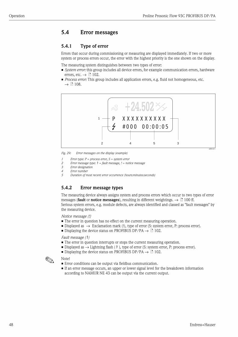
Operation Proline Prosonic Flow 93C PROFIBUS DP/PA
48 Endress+Hauser
5.4 Error messages
5.4.1 Type of error
Errors that occur during commissioning or measuring are displayed immediately. If two or more
system or process errors occur, the error with the highest priority is the one shown on the display.
The measuring system distinguishes between two types of error:
• System error: this group includes all device errors, for example communication errors, hardware
errors, etc. → ä 102.
• Process error: This group includes all application errors, e.g. fluid not homogeneous, etc.
→ ä 108.
a0001211
Fig. 29: Error messages on the display (example)
1 Error type: P = process error, S = system error
2 Error message type: $ = fault message, ! = notice message
3 Error designation
4 Error number
5 Duration of most recent error occurrence (hours:minutes:seconds)
5.4.2 Error message types
The measuring device always assigns system and process errors which occur to two types of error
messages (fault or notice messages), resulting in different weightings. → ä 100 ff.
Serious system errors, e.g. module defects, are always identified and classed as "fault messages" by
the measuring device.
Notice message (!)
• The error in question has no effect on the current measuring operation.
• Displayed as → Exclamation mark (!), type of error (S: system error, P: process error).
• Displaying the device status on PROFIBUS DP/PA → ä 102.
Fault message ( $)• The error in question interrupts or stops the current measuring operation.
• Displayed as → Lightning flash ( $ ), type of error (S: system error, P: process error).
• Displaying the device status on PROFIBUS DP/PA → ä 102.
! Note!
• Error conditions can be output via fieldbus communication.
• If an error message occurs, an upper or lower signal level for the breakdown information
according to NAMUR NE 43 can be output via the current output.
1
2 4 5 3
+24.502XXXXXXXXXX#000 00:00:05
P
+24.502
Proline Prosonic Flow 93C PROFIBUS DP/PA Operation
Endress+Hauser 49
5.5 Operating options
5.5.1 Operating program "FieldCare"
FieldCare is Endress+Hauser’s FDT-based plant asset management tool and allows the configuration
and diagnosis of intelligent field devices. By using status information, you also have a simple but
effective tool for monitoring devices. The Proline flowmeters are accessed via a service interface or
via the service interface FXA193.
5.5.2 Operating program "SIMATIC PDM"
SIMATIC PDM is a standardized, manufacturer-independent tool for the operation, configuration,
maintenance and diagnosis of intelligent field devices.
5.5.3 Device description files for operating programs
The following table illustrates the suitable device description file for the operating program in
question and then indicates where these can be obtained.
PROFIBUS DP
! Note!
The Fieldcheck tester/simulator is used for testing flowmeters in the field. When used in
conjunction with the "FieldCare" software package, test results can be imported into a database,
printed and used for official certification. Contact your Endress+Hauser representative for more
information.
Valid for device software: 3.06.XX → DEVICE SOFTWARE function (8100)
Device data PROFIBUS DP:
Profile Version:
Prosonic Flow 93 ID No.:
Profile ID No.:
3.0
1531 (Hex)
9741 (Hex)
→ PROFILE VERSION function (6160)
→ DEVICE ID function (6162)
GSD file information:
Prosonic Flow 93 GSD file:
Extended Format
(recommended):
Standard Format:
eh3x1531.gsd
eh3_1531.gsd
! Note!
Before configuring the PROFIBUS network, read and follow the
information for using the GSD file → ä 69 ff.
Bitmaps: EH_1531_d.bmp/.dib
EH_1531_n.bmp/.dib
EH_1531_s.bmp/.dib
Profile GSD file: PA039741.gsd
Software release: 06.2010
Operating program/device description: Sources for obtaining device descriptions/program updates:
Prosonic Flow 93 GSD file • www.endress.com → Download
• www.profibus.com
• CD–ROM (Endress+Hauser order number: 56003894)
FieldCare/DTM • www.endress.com → Download
• CD–ROM (Endress+Hauser order number: 56004088)
• DVD (Endress+Hauser order number: 70100690)
SIMATIC PDM • www.endress.com → Download
Tester/simulator: How to acquire:
Fieldcheck • Update via FieldCare with Flow Communication FXA193/291
DTM in Fieldflash module
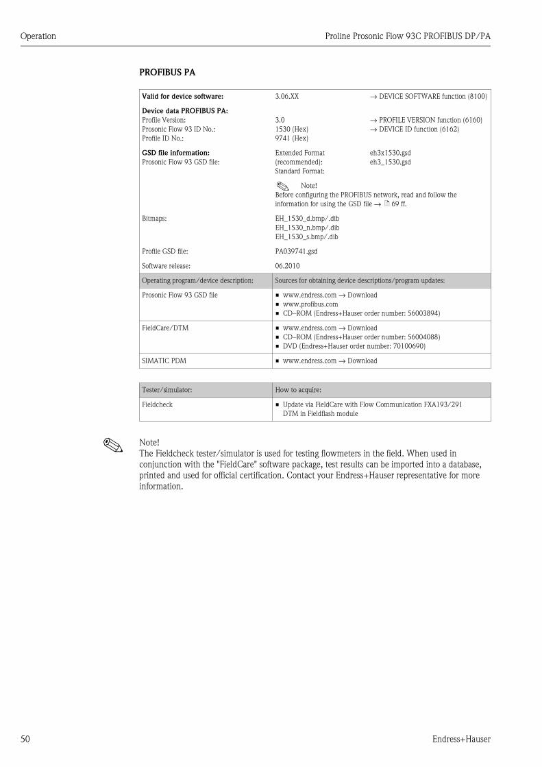
Operation Proline Prosonic Flow 93C PROFIBUS DP/PA
50 Endress+Hauser
PROFIBUS PA
! Note!
The Fieldcheck tester/simulator is used for testing flowmeters in the field. When used in
conjunction with the "FieldCare" software package, test results can be imported into a database,
printed and used for official certification. Contact your Endress+Hauser representative for more
information.
Valid for device software: 3.06.XX → DEVICE SOFTWARE function (8100)
Device data PROFIBUS PA:
Profile Version:
Prosonic Flow 93 ID No.:
Profile ID No.:
3.0
1530 (Hex)
9741 (Hex)
→ PROFILE VERSION function (6160)
→ DEVICE ID function (6162)
GSD file information:
Prosonic Flow 93 GSD file:
Extended Format
(recommended):
Standard Format:
eh3x1530.gsd
eh3_1530.gsd
! Note!
Before configuring the PROFIBUS network, read and follow the
information for using the GSD file → ä 69 ff.
Bitmaps: EH_1530_d.bmp/.dib
EH_1530_n.bmp/.dib
EH_1530_s.bmp/.dib
Profile GSD file: PA039741.gsd
Software release: 06.2010
Operating program/device description: Sources for obtaining device descriptions/program updates:
Prosonic Flow 93 GSD file • www.endress.com → Download
• www.profibus.com
• CD–ROM (Endress+Hauser order number: 56003894)
FieldCare/DTM • www.endress.com → Download
• CD–ROM (Endress+Hauser order number: 56004088)
• DVD (Endress+Hauser order number: 70100690)
SIMATIC PDM • www.endress.com → Download
Tester/simulator: How to acquire:
Fieldcheck • Update via FieldCare with Flow Communication FXA193/291
DTM in Fieldflash module
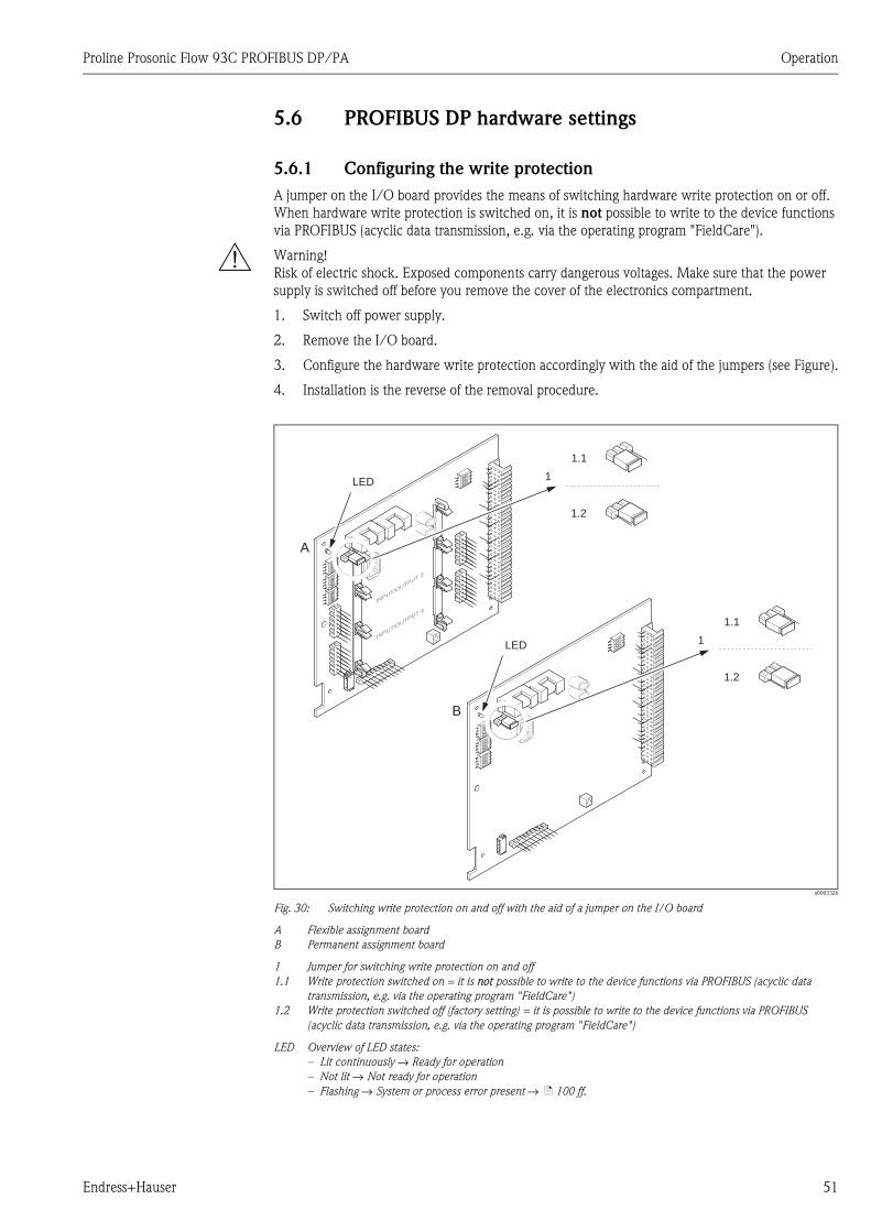
Proline Prosonic Flow 93C PROFIBUS DP/PA Operation
Endress+Hauser 51
5.6 PROFIBUS DP hardware settings
5.6.1 Configuring the write protection
A jumper on the I/O board provides the means of switching hardware write protection on or off.
When hardware write protection is switched on, it is not possible to write to the device functions
via PROFIBUS (acyclic data transmission, e.g. via the operating program "FieldCare").
# Warning!
Risk of electric shock. Exposed components carry dangerous voltages. Make sure that the power
supply is switched off before you remove the cover of the electronics compartment.
1. Switch off power supply.
2. Remove the I/O board.
3. Configure the hardware write protection accordingly with the aid of the jumpers (see Figure).
4. Installation is the reverse of the removal procedure.
a0003326
Fig. 30: Switching write protection on and off with the aid of a jumper on the I/O board
A Flexible assignment board
B Permanent assignment board
1 Jumper for switching write protection on and off
1.1 Write protection switched on = it is not possible to write to the device functions via PROFIBUS (acyclic data
transmission, e.g. via the operating program "FieldCare")
1.2 Write protection switched off (factory setting) = it is possible to write to the device functions via PROFIBUS
(acyclic data transmission, e.g. via the operating program "FieldCare")
LED Overview of LED states:
– Lit continuously → Ready for operation
– Not lit → Not ready for operation
– Flashing → System or process error present → ä 100 ff.
1234
WENO
1234
WENO
1234
WENO
1234
WENO
INPUT/O
UTPUT4
INPUT/O
UTPUT3
1234
WENO
1234
WENO
1234
WENO
1234
WENO
1.1
1.2
1LED
A
1.1
1.2
1
B
LED
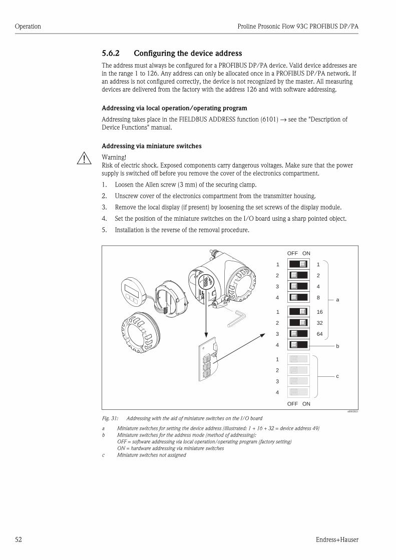
Operation Proline Prosonic Flow 93C PROFIBUS DP/PA
52 Endress+Hauser
5.6.2 Configuring the device address
The address must always be configured for a PROFIBUS DP/PA device. Valid device addresses are
in the range 1 to 126. Any address can only be allocated once in a PROFIBUS DP/PA network. If
an address is not configured correctly, the device is not recognized by the master. All measuring
devices are delivered from the factory with the address 126 and with software addressing.
Addressing via local operation/operating program
Addressing takes place in the FIELDBUS ADDRESS function (6101) → see the "Description of
Device Functions" manual.
Addressing via miniature switches
# Warning!
Risk of electric shock. Exposed components carry dangerous voltages. Make sure that the power
supply is switched off before you remove the cover of the electronics compartment.
1. Loosen the Allen screw (3 mm) of the securing clamp.
2. Unscrew cover of the electronics compartment from the transmitter housing.
3. Remove the local display (if present) by loosening the set screws of the display module.
4. Set the position of the miniature switches on the I/O board using a sharp pointed object.
5. Installation is the reverse of the removal procedure.
a0002821
Fig. 31: Addressing with the aid of miniature switches on the I/O board
a Miniature switches for setting the device address (illustrated: 1 + 16 + 32 = device address 49)
b Miniature switches for the address mode (method of addressing):
OFF = software addressing via local operation/operating program (factory setting)
ON = hardware addressing via miniature switches
c Miniature switches not assigned
1234
WENO
1234
WENO
1234
WENO
1234
WENO
1234
WENO
1234
WENO
161
3
322
4
643
4
1
2
b
OFF ON
11
22
43
84 a
OFF ON
c
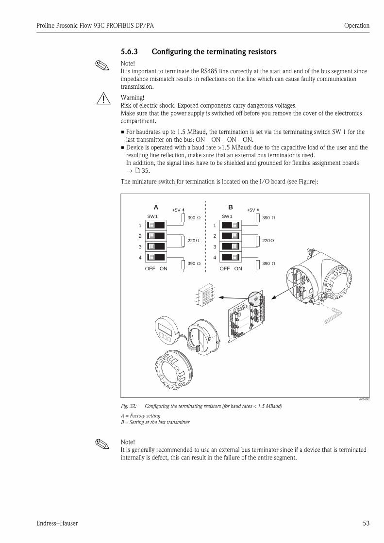
Proline Prosonic Flow 93C PROFIBUS DP/PA Operation
Endress+Hauser 53
5.6.3 Configuring the terminating resistors
! Note!
It is important to terminate the RS485 line correctly at the start and end of the bus segment since
impedance mismatch results in reflections on the line which can cause faulty communication
transmission.
# Warning!
Risk of electric shock. Exposed components carry dangerous voltages.
Make sure that the power supply is switched off before you remove the cover of the electronics
compartment.
• For baudrates up to 1.5 MBaud, the termination is set via the terminating switch SW 1 for the
last transmitter on the bus: ON – ON – ON – ON.
• Device is operated with a baud rate >1.5 MBaud: due to the capacitive load of the user and the
resulting line reflection, make sure that an external bus terminator is used.
In addition, the signal lines have to be shielded and grounded for flexible assignment boards
→ ä 35.
The miniature switch for termination is located on the I/O board (see Figure):
a0004392
Fig. 32: Configuring the terminating resistors (for baud rates < 1.5 MBaud)
A = Factory setting
B = Setting at the last transmitter
! Note!
It is generally recommended to use an external bus terminator since if a device that is terminated
internally is defect, this can result in the failure of the entire segment.
1234
WENO
1234
WENO
1234
WENO
INPUT/O
UTPUT4
INPUT/O
UTPUT3
1234
WENO
1234
WENO
1234
WENO
1234
WENO
1234
WENO
390 W
+5VA
3
4
1
2
OFF ON
220 W
390 W
SW1 390 W
+5VB
3
4
1
2
OFF ON
220 W
390 W
SW1
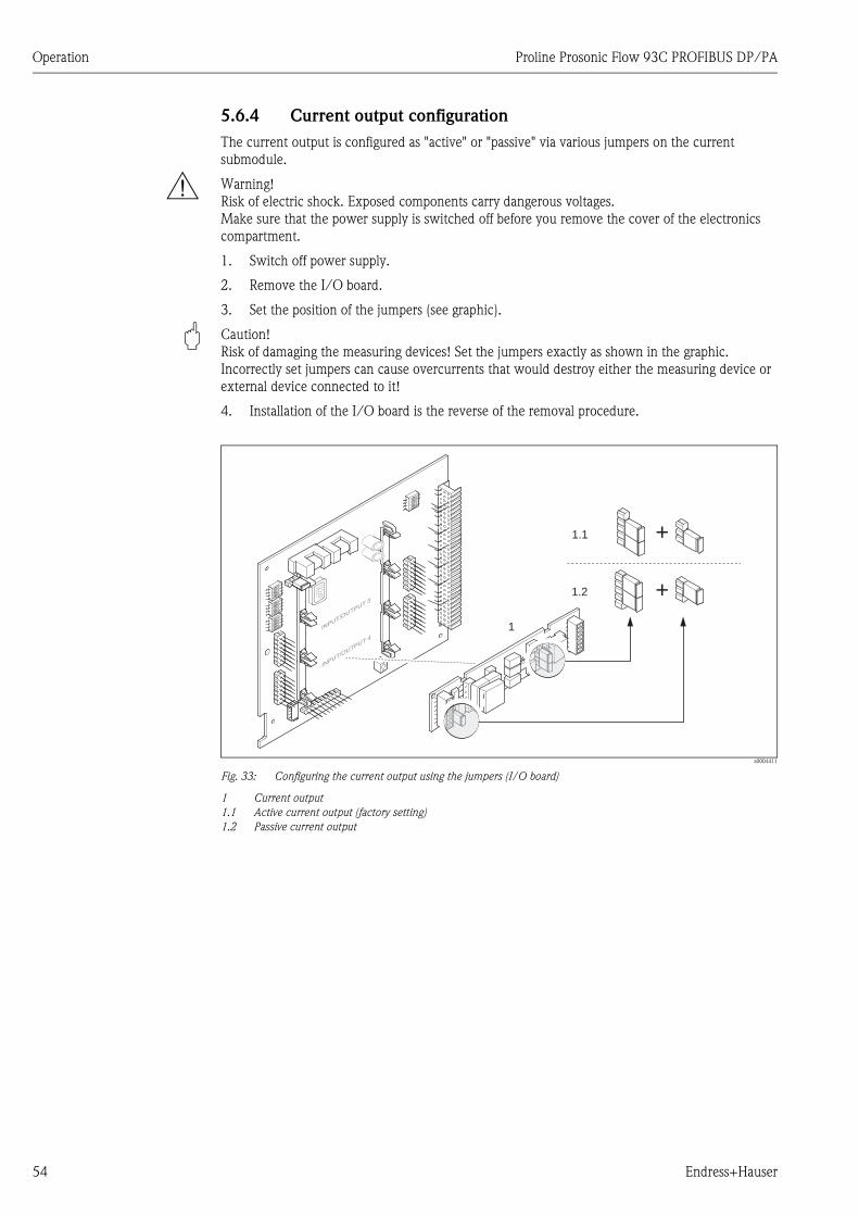
Operation Proline Prosonic Flow 93C PROFIBUS DP/PA
54 Endress+Hauser
5.6.4 Current output configuration
The current output is configured as "active" or "passive" via various jumpers on the current
submodule.
# Warning!
Risk of electric shock. Exposed components carry dangerous voltages.
Make sure that the power supply is switched off before you remove the cover of the electronics
compartment.
1. Switch off power supply.
2. Remove the I/O board.
3. Set the position of the jumpers (see graphic).
" Caution!
Risk of damaging the measuring devices! Set the jumpers exactly as shown in the graphic.
Incorrectly set jumpers can cause overcurrents that would destroy either the measuring device or
external device connected to it!
4. Installation of the I/O board is the reverse of the removal procedure.
a0004411
Fig. 33: Configuring the current output using the jumpers (I/O board)
1 Current output
1.1 Active current output (factory setting)
1.2 Passive current output
1.1
1.2 +
+
INPUT/O
UTPUT4
INPUT/O
UTPUT3
1234
WENO
1234
WENO
1234
WENO
1234
WENO
1
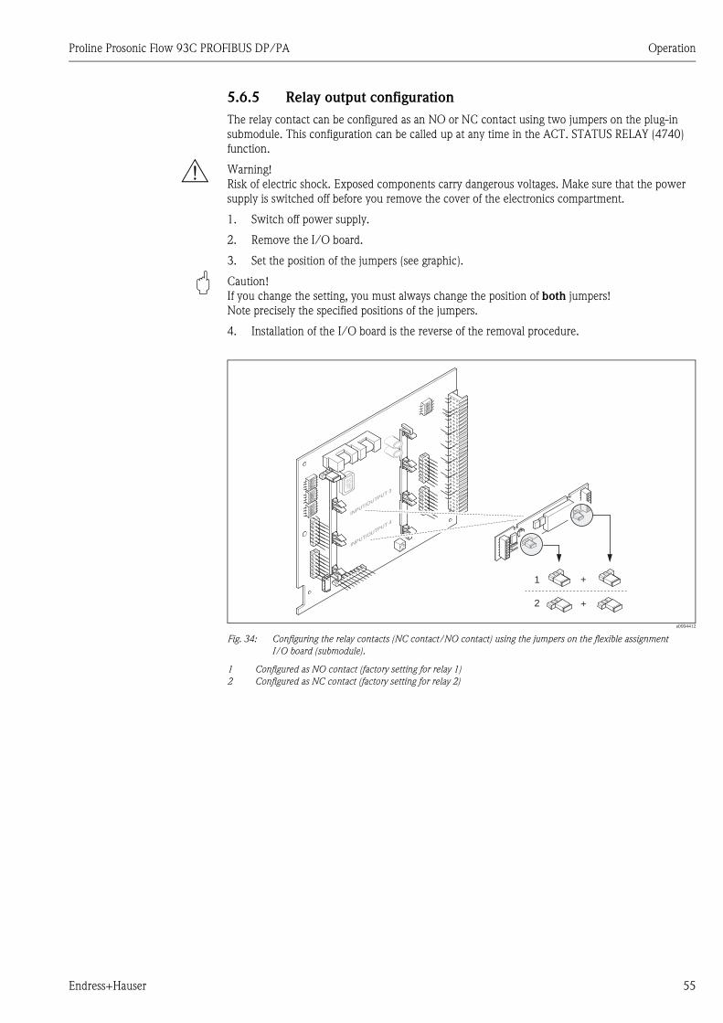
Proline Prosonic Flow 93C PROFIBUS DP/PA Operation
Endress+Hauser 55
5.6.5 Relay output configuration
The relay contact can be configured as an NO or NC contact using two jumpers on the plug-in
submodule. This configuration can be called up at any time in the ACT. STATUS RELAY (4740)
function.
# Warning!
Risk of electric shock. Exposed components carry dangerous voltages. Make sure that the power
supply is switched off before you remove the cover of the electronics compartment.
1. Switch off power supply.
2. Remove the I/O board.
3. Set the position of the jumpers (see graphic).
" Caution!
If you change the setting, you must always change the position of both jumpers!
Note precisely the specified positions of the jumpers.
4. Installation of the I/O board is the reverse of the removal procedure.
a0004412
Fig. 34: Configuring the relay contacts (NC contact/NO contact) using the jumpers on the flexible assignment
I/O board (submodule).
1 Configured as NO contact (factory setting for relay 1)
2 Configured as NC contact (factory setting for relay 2)
INPUT/O
UTPUT4
INPUT/O
UTPUT3
1234
WENO
1234
WENO
1234
WENO
1234
WENO
1
+
+
2

Operation Proline Prosonic Flow 93C PROFIBUS DP/PA
56 Endress+Hauser
5.7 PROFIBUS PA hardware settings
5.7.1 Configuring the write protection
A jumper on the I/O board provides the means of switching hardware write protection on or off.
When hardware write protection is switched on, it is not possible to write to the device functions
via PROFIBUS (acyclic data transmission, e.g. via the operating program "FieldCare").
# Warning!
Risk of electric shock. Exposed components carry dangerous voltages. Make sure that the power
supply is switched off before you remove the cover of the electronics compartment.
1. Switch off power supply.
2. Remove the I/O board.
3. Configure the hardware write protection accordingly with the aid of the jumpers (see Figure).
4. Installation is the reverse of the removal procedure.
a0001359
Fig. 35: Switching write protection on and off with the aid of a jumper on the I/O board
1 Jumper for switching write protection on and off
1.1 Write protection switched on = it is not possible to write to the device parameters via PROFIBUS (acyclic data
transmission, e.g. via FieldCare)
1.2 Write protection switched off (factory setting) = it is possible to write to the device parameters via PROFIBUS
(acyclic data transmission, e.g. via FieldCare)
2 Jumper without function
LED Overview of LED states:
– Lit continuously → Ready for operation
– Not lit → Not ready for operation
– Flashing → System or process error present → ä 100
1
1.21.1
2
LED

Proline Prosonic Flow 93C PROFIBUS DP/PA Operation
Endress+Hauser 57
5.7.2 Configuring the device address
The address must always be configured for a PROFIBUS PA device. Valid device addresses are in
the range 1 to 126. Any address can only be allocated once in a PROFIBUS network. If an address
is not configured correctly, the device is not recognized by the master. All measuring devices are
delivered from the factory with the address 126 and with software addressing.
Addressing via local operation/operating program
Addressing takes place in the FIELDBUS ADDRESS function (6101) → see the "Description of
Device Functions" manual.
Addressing via miniature switches
# Warning!
Risk of electric shock. Exposed components carry dangerous voltages. Make sure that the power
supply is switched off before you remove the cover of the electronics compartment.
1. Loosen the screws and open the housing cover (a).
2. Loosen the screws securing the electronics module (b). Then push up electronics module and
pull it as far as possible out of the wall-mount housing.
3. Remove the ribbon cable connector (c) of the display module.
4. Remove the cover (d) from the electronics compartment by loosening the screws.
5. Remove the I/O board (e):
Insert a thin pin into the hole provided for the purpose and pull the board clear of its holder.
6. Set the position of the miniature switches on the I/O board using a sharp pointed object.
7. Installation is the reverse of the removal procedure.
a0001360
Fig. 36: Addressing with the aid of miniature switches on the I/O board
a Miniature switches for setting the device address (illustrated: 1 + 16 + 32 = device address 49)
b Miniature switches for the address mode (method of addressing)
– OFF = software addressing via local operation/operating program (factory setting)
– ON = hardware addressing via miniature switches
c Miniature switches not assigned
a
b
e
c d
1234
WENO
1234
WENO
1234
WENO
161
3
322
4
643
4
1
2
B
OFF ON
11
22
43
84 A
OFF ON
C

Commissioning Proline Prosonic Flow 93C PROFIBUS DP/PA
58 Endress+Hauser
6 Commissioning
6.1 Function check
Make sure that the following function checks have been performed successfully before switching on
the supply voltage for the measuring device:
• Checklist for "Post-installation check" → ä 24
• Checklist for "Post-connection check" → ä 41
! Note!
When using PROFIBUS PA, please note the following:
• The PROFIBUS interface's technical data must be maintained in accordance with IEC 61158-2
(MBP).
• A normal multimeter can be used to check the bus voltage of 9 to 32 V and the current
consumption of 11 mA at the device.
6.2 Switching on the measuring device
Once the function check has been performed successfully, the device is operational and can be
switched on via the supply voltage. The device then performs internal test functions and the
following messages are shown on the local display:
Normal measuring mode commences as soon as startup completes.
Various measured value and/or status variables appear on the display (HOME position).
! Note!
If startup fails, an appropriate error message is displayed, depending on the cause.
Messages: PROFIBUS DP Messages: PROFIBUS PA
PROSONIC FLOW 93C
START-UP
RUNNING
Startup message
PROSONIC FLOW 93C
START-UP
RUNNING
Æ Æ
PROSONIC FLOW 93C
DEVICE SOFTWARE
V XX.XX.XX
Current software version
Software
PROSONIC FLOW 93C
DEVICE SOFTWARE
V XX.XX.XX
Æ Æ
PROFIBUS DP
RELAY OUTPUT 1
RELAY OUTPUT 2
STATUS INPUT 1
Existing input/output modules
Input/output modules
PROFIBUS PA
Æ Æ
SYSTEM OK
→ OPERATION
Beginning of normal
measuring mode
SYSTEM OK
→ OPERATION

Proline Prosonic Flow 93C PROFIBUS DP/PA Commissioning
Endress+Hauser 59
6.3 Quick Setup
In the case of measuring devices without a local display, the individual parameters and functions
must be configured via the operating program, e.g. FieldCare.
If the measuring device is equipped with a local display, all the important device parameters for
standard operation, as well as additional functions, can be configured quickly and easily by means
of the following Quick Setup menus.
6.3.1 Quick Setup "Commissioning"
a0008715-en
Fig. 37: Quick Setup "Commissioning"
++ +E E
0424 042504230402 0422
1002B
2000
Esc
E+-
XXX.XXX.XX
HOME-POSITION
n
o
m
p
q
UnitVolume Flow
UnitTemperature
UnitViscosity
UnitLength
UnitVelocity
QSCommission.
Language
Presetting
Quick Setup
System Units
Volume Viscosity Length Velocity Quit
Configure another unit? NOYES
Selection system units
Autom. configuration display?
Another quick setup?
NO
NO
Automatical parameterizationof the display
YES
Temperature
Deliver Settingsy
Selection pre-settings
Actual Settings
! Note!
• The display returns to the cell SETUP COMMISSIONING (1002) if you press the X key combination during
parameter interrogation. The stored parameters remain valid.
• The "Commissioning" Quick Setup must be carried out before one of the Quick Setups explained below is run.
m The "DELIVERY SETTINGS" option sets every selected unit to the factory setting.
The "ACTUAL SETTINGS" accepts the units you configured beforehand.
n Only units not yet configured in the current Quick Setup are offered for selection in each cycle. The volume unit is
derived from the volume flow unit.
o The "YES" option remains visible until all the units have been configured.
"NO" is the only option displayed when no further units are available.
p The "automatic parameterization of the display" option contains the following basic settings/factory settings
YES Main line = mass flow
Additional line = totalizer 1
Information line = operating/system condition
NO The existing (selected) settings remain.
q The execution of other Quick Setups is described in the following sections.
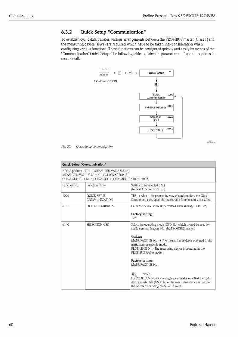
Commissioning Proline Prosonic Flow 93C PROFIBUS DP/PA
60 Endress+Hauser
6.3.2 Quick Setup "Communication"
To establish cyclic data transfer, various arrangements between the PROFIBUS master (Class 1) and
the measuring device (slave) are required which have to be taken into consideration when
configuring various functions. These functions can be configured quickly and easily by means of the
"Communication" Quick Setup. The following table explains the parameter configuration options in
more detail.
a0002600-en
Fig. 38: Quick Setup communication
++E
+E
BQuick SetupQuick Setup
6101
6140
6141
1006
Esc
E+-
XXX.XXX.XX
HOME-POSITION
Fieldbus Address
SelectionGSD
Unit To Bus
SetupCommunication
Quick Setup "Communication"
HOME position → F → MEASURED VARIABLE (A)
MEASURED VARIABLE → O → QUICK SETUP (B)
QUICK SETUP → N→ QUICK SETUP COMMUNICATION (1006)
Function No. Function name Setting to be selected ( P )
(to next function with F )
1006 QUICK SETUP
COMMUNICATION
YES → After F is pressed by way of confirmation, the Quick
Setup menu calls up all the subsequent functions in succession.
6101 FIELDBUS ADDRESS Enter the device address (permitted address range: 1 to 126)
Factory setting:
126
6140 SELECTION GSD Select the operating mode (GSD file) which should be used for
cyclic communication with the PROFIBUS master.
Options:
MANUFACT. SPEC. → The measuring device is operated in the
manufacturer-specific mode.
PROFILE-GSD → The measuring device is operated in the
PROFIBUS Profile mode.
Factory setting:
MANUFACT. SPEC.
! Note!
For PROFIBUS network configuration, make sure that the right
device master file (GSD file) of the measuring device is used for
the selected operating mode → ä 69 ff.
Proline Prosonic Flow 93C PROFIBUS DP/PA Commissioning
Endress+Hauser 61
6141 UNIT TO BUS If this function is executed, the measured variables are transmitted
cyclically to the PROFIBUS master (Class 1) with the system units
set in the measuring device.
Options:
OFF
SET UNITS (Transmission is started by pressing the F key)
" Caution!
Activating this function can cause a sudden change of the
measured variables transmitted to the PROFIBUS master (Class 1);
this, in turn, can affect subsequent control routines.
Æ
Back to the HOME position:
→ Press and hold down the Esc keys X for longer than three seconds or
→Repeatedly press and release the Esc keys X → Exit the function matrix step by step
Quick Setup "Communication"
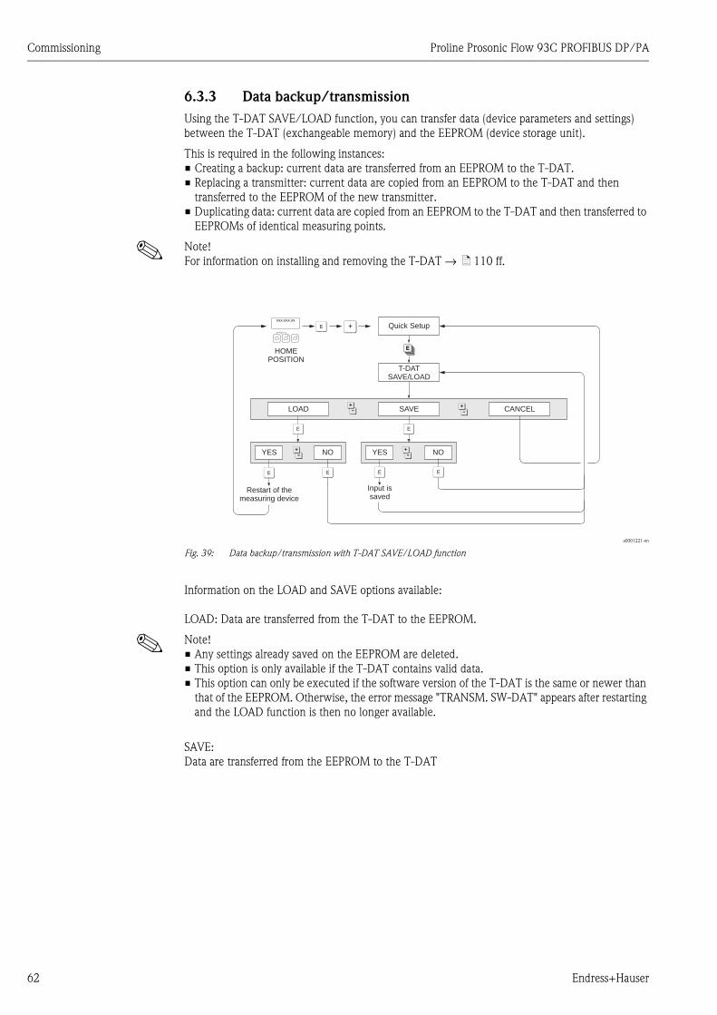
Commissioning Proline Prosonic Flow 93C PROFIBUS DP/PA
62 Endress+Hauser
6.3.3 Data backup/transmission
Using the T-DAT SAVE/LOAD function, you can transfer data (device parameters and settings)
between the T-DAT (exchangeable memory) and the EEPROM (device storage unit).
This is required in the following instances:
• Creating a backup: current data are transferred from an EEPROM to the T-DAT.
• Replacing a transmitter: current data are copied from an EEPROM to the T-DAT and then
transferred to the EEPROM of the new transmitter.
• Duplicating data: current data are copied from an EEPROM to the T-DAT and then transferred to
EEPROMs of identical measuring points.
! Note!
For information on installing and removing the T-DAT → ä 110 ff.
a0001221-en
Fig. 39: Data backup/transmission with T-DAT SAVE/LOAD function
Information on the LOAD and SAVE options available:
LOAD: Data are transferred from the T-DAT to the EEPROM.
! Note!
• Any settings already saved on the EEPROM are deleted.
• This option is only available if the T-DAT contains valid data.
• This option can only be executed if the software version of the T-DAT is the same or newer than
that of the EEPROM. Otherwise, the error message "TRANSM. SW-DAT" appears after restarting
and the LOAD function is then no longer available.
SAVE:
Data are transferred from the EEPROM to the T-DAT
FEsc
E+-
XXX.XXX.XX
F F
FF FF
P P
PP
N
O
T-DATSAVE/LOAD
Quick Setup
HOMEPOSITION
LOAD
YES NO
CANCELSAVE
YES NO
Restart of themeasuring device
Input issaved
Proline Prosonic Flow 93C PROFIBUS DP/PA Commissioning
Endress+Hauser 63
6.4 Commissioning the PROFIBUS interface
! Note!
• All functions required for commissioning are described in detail in the "Description of Device
Functions" manual which is a separate part of these Operating Instructions.
• A code (factory setting: 93) must be entered to change device functions, numerical values or
factory settings → ä 47.
6.4.1 PROFIBUS DP commissioning
The following steps must be carried out in the sequence specified:
1. Check the hardware write protection:
The WRITE PROTECT (6102) parameter indicates whether it is possible to write to the device
functions via PROFIBUS (acyclic data transmission, e.g. via the operating program "FieldCare").
! Note!
This check is not needed if operating via the local display.
BASIC FUNCTION (G) → PROFIBUS DP (GBA) → CONFIGURATION (610) →
WRITE PROTECT (6102) → Display of one of the following options:
– OFF (factory setting) = write access via PROFIBUS possible
– ON = write access via PROFIBUS not possible
Deactivate the write protection if necessary → ä 56.
2. Enter the tag name (optional):
BASIC FUNCTION (G) → PROFIBUS DP (GBA) → CONFIGURATION(610) →
TAG NAME (6100)
3. Configure the bus address:
Software addressing using the local display or an operating program:
BASIC FUNCTION (G) → PROFIBUS DP (GBA)→ CONFIGURATION (610) →
FIELDBUS ADDRESS (6101)
Hardware addressing via miniature switches → ä 57.
4. Select the system unit:
a. Determine the units by means of the system units group:
MEASURED VARIABLES (A) → SYSTEM UNITS (ACA) → CONFIGURATION (040) →
UNIT MASS FLOW (0400) / UNIT MASS (0401) / UNIT VOLUME FLOW (0402) / …
b. In the function UNIT TO BUS (6141), select the option SET UNITS, so that the measured
variables transmitted cyclically to the PROFIBUS master (Class 1) are transmitted with the
system units set in the measuring device:
BASIC FUNCTION (G) → PROFIBUS DP (GBA) → OPERATION (614) →
UNIT TO BUS (6141)
! Note!
• The configuration of the system units for the totalizer is described separately → see step 7
• If the system unit of a measured variable is changed by means of the local operation or an
operating program, this initially does not have any effect on the unit that is used to transmit
the measured variable to the PROFIBUS master (Class 1). Changed system units of the
measured variables are not transmitted to the PROFIBUS master (Class 1) until the
SET UNITS option is activated in the function BASIC FUNCTION (G) → PROFIBUS DP
(GBA) → OPERATION (614) → UNIT TO BUS (6141).
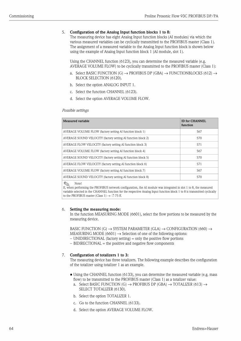
Commissioning Proline Prosonic Flow 93C PROFIBUS DP/PA
64 Endress+Hauser
5. Configuration of the Analog Input function blocks 1 to 8:
The measuring device has eight Analog Input function blocks (AI modules) via which the
various measured variables can be cyclically transmitted to the PROFIBUS master (Class 1).
The assignment of a measured variable to the Analog Input function block is shown below
using the example of Analog Input function block 1 (AI module, slot 1).
Using the CHANNEL function (6123), you can determine the measured variable (e.g.
AVERAGE VOLUME FLOW) to be cyclically transmitted to the PROFIBUS master (Class 1):
a. Select BASIC FUNCTION (G) → PROFIBUS DP (GBA) → FUNCTIONBLOCKS (612) →
BLOCK SELECTION (6120).
b. Select the option ANALOG INPUT 1.
c. Select the function CHANNEL (6123).
d. Select the option AVERAGE VOLUME FLOW.
Possible settings
6. Setting the measuring mode:
In the function MEASURING MODE (6601), select the flow portions to be measured by the
measuring device.
BASIC FUNCTION (G) → SYSTEM PARAMETER (GLA) → CONFIGURATION (660) →
MEASURING MODE (6601) → Selection of one of the following options:
– UNIDIRECTIONAL (factory setting) = only the positive flow portions
– BIDIRECTIONAL = the positive and negative flow components
7. Configuration of totalizers 1 to 3:
The measuring device has three totalizers. The following example describes the configuration
of the totalizer using totalizer 1 as an example.
• Using the CHANNEL function (6133), you can determine the measured variable (e.g. mass
flow) to be transmitted to the PROFIBUS master (Class 1) as a totalizer value:
a. Select BASIC FUNCTION (G) → PROFIBUS DP (GBA) → TOTALIZER (613) →
SELECT TOTALIZER (6130).
b. Select the option TOTALIZER 1.
c. Go to the function CHANNEL (6133).
d. Select the option AVERAGE VOLUME FLOW.
Measured variable ID for CHANNEL
function
AVERAGE VOLUME FLOW (factory setting AI function block 1) 567
AVERAGE SOUND VELOCITY (factory setting AI function block 2) 570
AVERAGE FLOW VELOCITY (factory setting AI function block 3) 571
AVERAGE VOLUME FLOW (factory setting AI function block 4) 567
AVERAGE SOUND VELOCITY (factory setting AI function block 5) 570
AVERAGE FLOW VELOCITY (factory setting AI function block 6) 571
AVERAGE VOLUME FLOW (factory setting AI function block 7) 567
AVERAGE SOUND VELOCITY (factory setting AI function block 8) 570
! Note!
If, when performing the PROFIBUS network configuration, the AI module was integrated in slot 1 to 8, the measured
variable selected in the CHANNEL function for the respective Analog Input function block 1 to 8 is transmitted cyclically
to the PROFIBUS master (Class 1) → ä 75 ff.
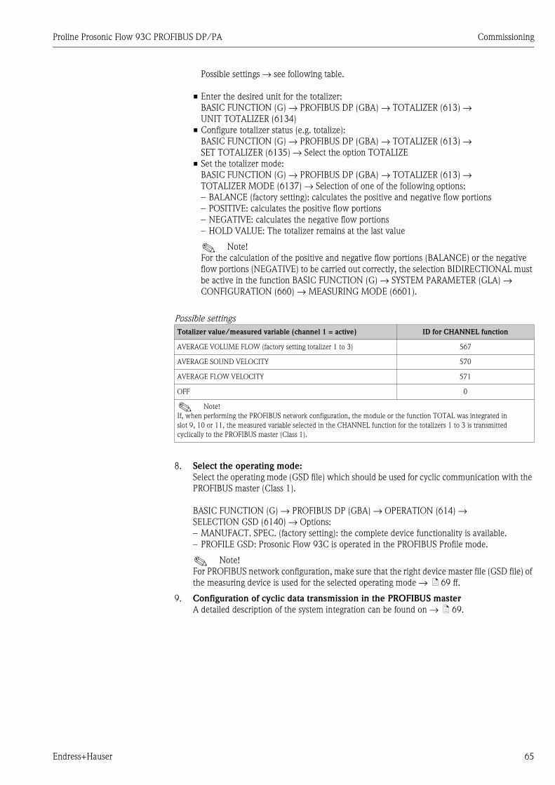
Proline Prosonic Flow 93C PROFIBUS DP/PA Commissioning
Endress+Hauser 65
Possible settings → see following table.
• Enter the desired unit for the totalizer:
BASIC FUNCTION (G) → PROFIBUS DP (GBA) → TOTALIZER (613) →
UNIT TOTALIZER (6134)
• Configure totalizer status (e.g. totalize):
BASIC FUNCTION (G) → PROFIBUS DP (GBA) → TOTALIZER (613) →
SET TOTALIZER (6135) → Select the option TOTALIZE
• Set the totalizer mode:
BASIC FUNCTION (G) → PROFIBUS DP (GBA) → TOTALIZER (613) →
TOTALIZER MODE (6137) → Selection of one of the following options:
– BALANCE (factory setting): calculates the positive and negative flow portions
– POSITIVE: calculates the positive flow portions
– NEGATIVE: calculates the negative flow portions
– HOLD VALUE: The totalizer remains at the last value
! Note!
For the calculation of the positive and negative flow portions (BALANCE) or the negative
flow portions (NEGATIVE) to be carried out correctly, the selection BIDIRECTIONAL must
be active in the function BASIC FUNCTION (G) → SYSTEM PARAMETER (GLA) →
CONFIGURATION (660) → MEASURING MODE (6601).
Possible settings
8. Select the operating mode:
Select the operating mode (GSD file) which should be used for cyclic communication with the
PROFIBUS master (Class 1).
BASIC FUNCTION (G) → PROFIBUS DP (GBA) → OPERATION (614) →
SELECTION GSD (6140) → Options:
– MANUFACT. SPEC. (factory setting): the complete device functionality is available.
– PROFILE GSD: Prosonic Flow 93C is operated in the PROFIBUS Profile mode.
! Note!
For PROFIBUS network configuration, make sure that the right device master file (GSD file) of
the measuring device is used for the selected operating mode → ä 69 ff.
9. Configuration of cyclic data transmission in the PROFIBUS master
A detailed description of the system integration can be found on → ä 69.
Totalizer value/measured variable (channel 1 = active) ID for CHANNEL function
AVERAGE VOLUME FLOW (factory setting totalizer 1 to 3) 567
AVERAGE SOUND VELOCITY 570
AVERAGE FLOW VELOCITY 571
OFF 0
! Note!
If, when performing the PROFIBUS network configuration, the module or the function TOTAL was integrated in
slot 9, 10 or 11, the measured variable selected in the CHANNEL function for the totalizers 1 to 3 is transmitted
cyclically to the PROFIBUS master (Class 1).
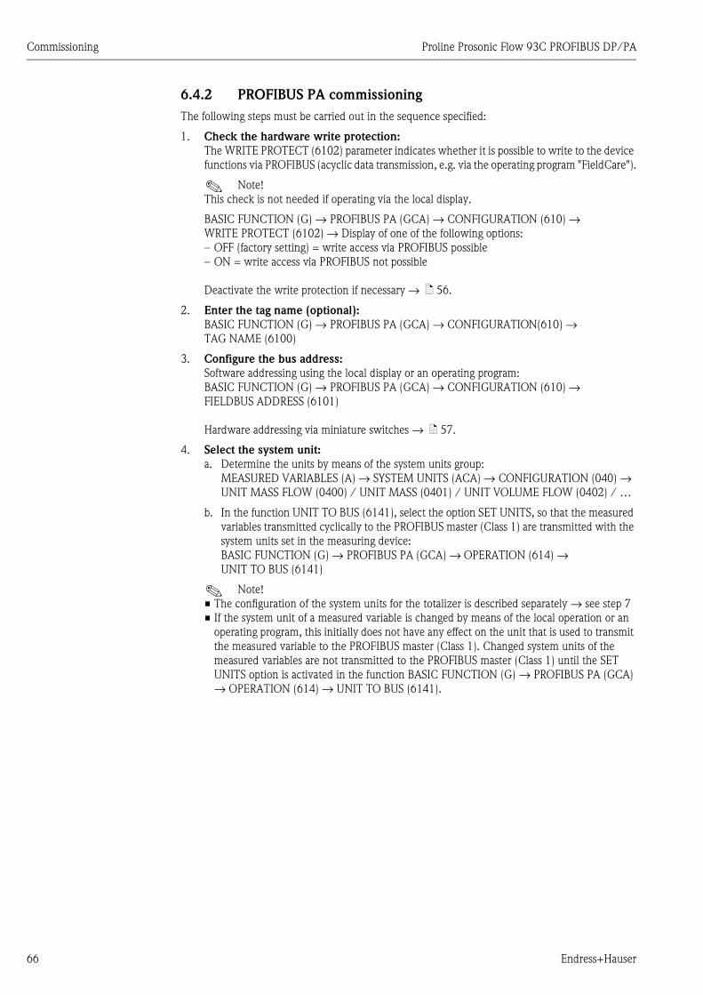
Commissioning Proline Prosonic Flow 93C PROFIBUS DP/PA
66 Endress+Hauser
6.4.2 PROFIBUS PA commissioning
The following steps must be carried out in the sequence specified:
1. Check the hardware write protection:
The WRITE PROTECT (6102) parameter indicates whether it is possible to write to the device
functions via PROFIBUS (acyclic data transmission, e.g. via the operating program "FieldCare").
! Note!
This check is not needed if operating via the local display.
BASIC FUNCTION (G) → PROFIBUS PA (GCA) → CONFIGURATION (610) →
WRITE PROTECT (6102) → Display of one of the following options:
– OFF (factory setting) = write access via PROFIBUS possible
– ON = write access via PROFIBUS not possible
Deactivate the write protection if necessary → ä 56.
2. Enter the tag name (optional):
BASIC FUNCTION (G) → PROFIBUS PA (GCA) → CONFIGURATION(610) →
TAG NAME (6100)
3. Configure the bus address:
Software addressing using the local display or an operating program:
BASIC FUNCTION (G) → PROFIBUS PA (GCA) → CONFIGURATION (610) →
FIELDBUS ADDRESS (6101)
Hardware addressing via miniature switches → ä 57.
4. Select the system unit:
a. Determine the units by means of the system units group:
MEASURED VARIABLES (A) → SYSTEM UNITS (ACA) → CONFIGURATION (040) →
UNIT MASS FLOW (0400) / UNIT MASS (0401) / UNIT VOLUME FLOW (0402) / …
b. In the function UNIT TO BUS (6141), select the option SET UNITS, so that the measured
variables transmitted cyclically to the PROFIBUS master (Class 1) are transmitted with the
system units set in the measuring device:
BASIC FUNCTION (G) → PROFIBUS PA (GCA) → OPERATION (614) →
UNIT TO BUS (6141)
! Note!
• The configuration of the system units for the totalizer is described separately → see step 7
• If the system unit of a measured variable is changed by means of the local operation or an
operating program, this initially does not have any effect on the unit that is used to transmit
the measured variable to the PROFIBUS master (Class 1). Changed system units of the
measured variables are not transmitted to the PROFIBUS master (Class 1) until the SET
UNITS option is activated in the function BASIC FUNCTION (G) → PROFIBUS PA (GCA)
→ OPERATION (614) → UNIT TO BUS (6141).

Proline Prosonic Flow 93C PROFIBUS DP/PA Commissioning
Endress+Hauser 67
5. Configuration of the Analog Input function blocks 1 to 8:
The measuring device has eight Analog Input function blocks (AI modules) via which the
various measured variables can be cyclically transmitted to the PROFIBUS master (Class 1).
The assignment of a measured variable to the Analog Input function block is shown below
using the example of Analog Input function block 1 (AI module, slot 1).
Using the CHANNEL function (6123), you can determine the measured variable (e.g.
AVERAGE VOLUME FLOW) to be cyclically transmitted to the PROFIBUS master (Class 1):
a. Select BASIC FUNCTION (G) → PROFIBUS PA (GCA) → FUNCTIONBLOCKS (612) →
BLOCK SELECTION (6120).
b. Select the option ANALOG INPUT 1.
c. Select the function CHANNEL (6123).
d. Select the option AVERAGE VOLUME FLOW.
Possible settings
6. Setting the measuring mode:
In the function MEASURING MODE (6601), select the flow portions to be measured by the
measuring device.
BASIC FUNCTION (G) → SYSTEM PARAMETER (GLA) → CONFIGURATION (660) →
MEASURING MODE (6601) → Selection of one of the following options:
– UNIDIRECTIONAL (factory setting) = only the positive flow portions
– BIDIRECTIONAL = the positive and negative flow components
7. Configuration of totalizers 1 to 3:
The measuring device has three totalizers. The following example describes the configuration
of the totalizer using totalizer 1 as an example.
• Using the CHANNEL function (6133), you can determine the measured variable (e.g. mass
flow) to be transmitted to the PROFIBUS master (Class 1) as a totalizer value:
a. Select BASIC FUNCTION (G) → PROFIBUS PA (GCA) → TOTALIZER (613) →
SELECT TOTALIZER (6130).
b. Select the option TOTALIZER 1.
c. Go to the function CHANNEL (6133).
d. Select the option AVERAGE VOLUME FLOW.
Measured variable ID for CHANNEL
function
AVERAGE VOLUME FLOW (factory setting AI function block 1) 567
AVERAGE SOUND VELOCITY (factory setting AI function block 2) 570
AVERAGE FLOW VELOCITY (factory setting AI function block 3) 571
AVERAGE VOLUME FLOW (factory setting AI function block 4) 567
AVERAGE SOUND VELOCITY (factory setting AI function block 5) 570
AVERAGE FLOW VELOCITY (factory setting AI function block 6) 571
AVERAGE VOLUME FLOW (factory setting AI function block 7) 567
AVERAGE SOUND VELOCITY (factory setting AI function block 8) 570
! Note!
If, when performing the PROFIBUS network configuration, the AI module was integrated in slot 1 to 8, the measured
variable selected in the CHANNEL function for the respective Analog Input function block 1 to 8 is transmitted cyclically
to the PROFIBUS master (Class 1) → ä 75 ff.

Commissioning Proline Prosonic Flow 93C PROFIBUS DP/PA
68 Endress+Hauser
Possible settings → see following table.
• Enter the desired unit for the totalizer:
BASIC FUNCTION (G) → PROFIBUS PA (GCA) → TOTALIZER (613) →
UNIT TOTALIZER (6134)
• Configure totalizer status (e.g. totalize):
BASIC FUNCTION (G) → PROFIBUS PA (GCA) → TOTALIZER (613) →
SET TOTALIZER (6135) → Select the option TOTALIZE
• Set the totalizer mode:
BASIC FUNCTION (G) → PROFIBUS PA (GCA) → TOTALIZER (613) →
TOTALIZER MODE (6137) → Selection of one of the following options:
– BALANCE (factory setting): calculates the positive and negative flow portions
– POSITIVE: calculates the positive flow portions
– NEGATIVE: calculates the negative flow portions
– HOLD VALUE: The totalizer remains at the last value
! Note!
For the calculation of the positive and negative flow portions (BALANCE) or the negative
flow portions (NEGATIVE) to be carried out correctly, the selection BIDIRECTIONAL must
be active in the function BASIC FUNCTION (G) → SYSTEM PARAMETER (GLA) →
CONFIGURATION (660) → MEASURING MODE (6601).
Possible settings
8. Select the operating mode:
Select the operating mode (GSD file) which should be used for cyclic communication with the
PROFIBUS master (Class 1).
BASIC FUNCTION (G) → PROFIBUS PA (GCA) → OPERATION (614) →
SELECTION GSD (6140) → Options:
– MANUFACT. SPEC. (factory setting): the complete device functionality is available.
– PROFILE GSD: Prosonic Flow 93C is operated in the PROFIBUS Profile mode.
! Note!
For PROFIBUS network configuration, make sure that the right device master file (GSD file) of
the measuring device is used for the selected operating mode → ä 69 ff.
9. Configuration of cyclic data transmission in the PROFIBUS master
A detailed description of the system integration can be found on → ä 69.
Totalizer value/measured variable (channel 1 = active) ID for CHANNEL function
AVERAGE VOLUME FLOW (factory setting totalizer 1 to 3) 567
AVERAGE SOUND VELOCITY 570
AVERAGE FLOW VELOCITY 571
OFF 0
! Note!
If, when performing the PROFIBUS network configuration, the module or the function TOTAL was integrated in
slot 9, 10 or 11, the measured variable selected in the CHANNEL function for the totalizers 1 to 3 is transmitted
cyclically to the PROFIBUS master (Class 1).
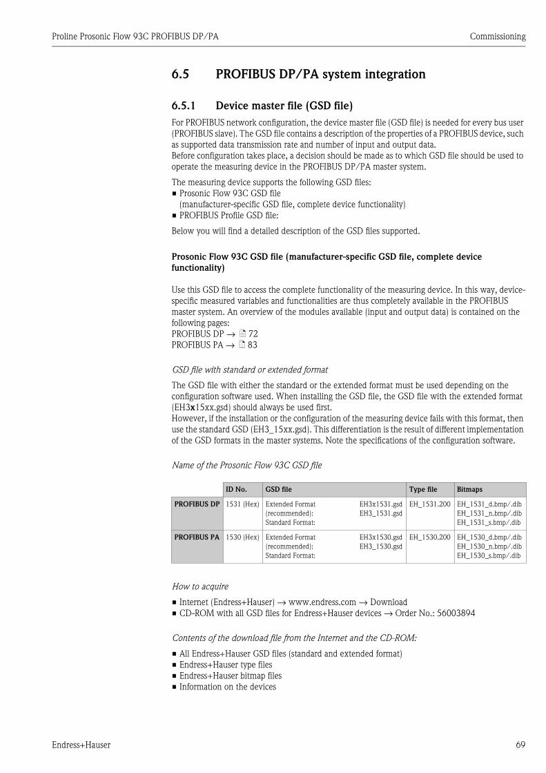
Proline Prosonic Flow 93C PROFIBUS DP/PA Commissioning
Endress+Hauser 69
6.5 PROFIBUS DP/PA system integration
6.5.1 Device master file (GSD file)
For PROFIBUS network configuration, the device master file (GSD file) is needed for every bus user
(PROFIBUS slave). The GSD file contains a description of the properties of a PROFIBUS device, such
as supported data transmission rate and number of input and output data.
Before configuration takes place, a decision should be made as to which GSD file should be used to
operate the measuring device in the PROFIBUS DP/PA master system.
The measuring device supports the following GSD files:
• Prosonic Flow 93C GSD file
(manufacturer-specific GSD file, complete device functionality)
• PROFIBUS Profile GSD file:
Below you will find a detailed description of the GSD files supported.
Prosonic Flow 93C GSD file (manufacturer-specific GSD file, complete device
functionality)
Use this GSD file to access the complete functionality of the measuring device. In this way, device-
specific measured variables and functionalities are thus completely available in the PROFIBUS
master system. An overview of the modules available (input and output data) is contained on the
following pages:
PROFIBUS DP → ä 72
PROFIBUS PA → ä 83
GSD file with standard or extended format
The GSD file with either the standard or the extended format must be used depending on the
configuration software used. When installing the GSD file, the GSD file with the extended format
(EH3x15xx.gsd) should always be used first.
However, if the installation or the configuration of the measuring device fails with this format, then
use the standard GSD (EH3_15xx.gsd). This differentiation is the result of different implementation
of the GSD formats in the master systems. Note the specifications of the configuration software.
Name of the Prosonic Flow 93C GSD file
How to acquire
• Internet (Endress+Hauser) → www.endress.com → Download
• CD-ROM with all GSD files for Endress+Hauser devices → Order No.: 56003894
Contents of the download file from the Internet and the CD-ROM:
• All Endress+Hauser GSD files (standard and extended format)
• Endress+Hauser type files
• Endress+Hauser bitmap files
• Information on the devices
ID No. GSD file Type file Bitmaps
PROFIBUS DP 1531 (Hex) Extended Format
(recommended):
Standard Format:
EH3x1531.gsd
EH3_1531.gsd
EH_1531.200 EH_1531_d.bmp/.dib
EH_1531_n.bmp/.dib
EH_1531_s.bmp/.dib
PROFIBUS PA 1530 (Hex) Extended Format
(recommended):
Standard Format:
EH3x1530.gsd
EH3_1530.gsd
EH_1530.200 EH_1530_d.bmp/.dib
EH_1530_n.bmp/.dib
EH_1530_s.bmp/.dib
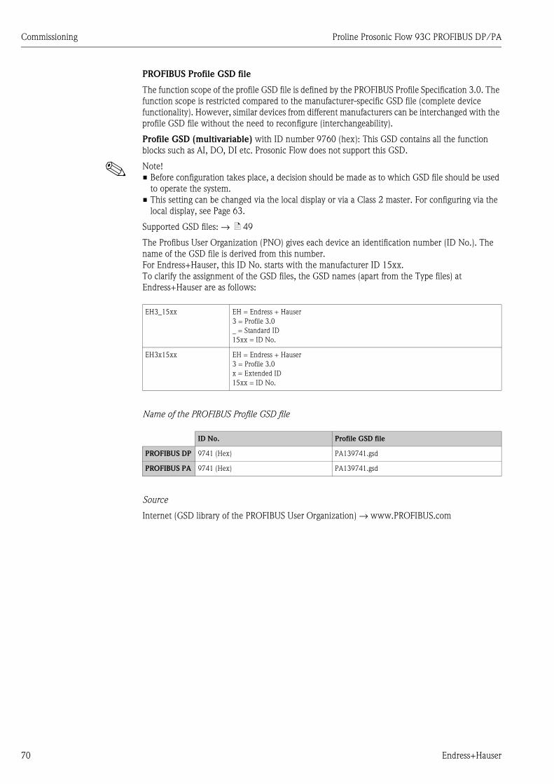
Commissioning Proline Prosonic Flow 93C PROFIBUS DP/PA
70 Endress+Hauser
PROFIBUS Profile GSD file
The function scope of the profile GSD file is defined by the PROFIBUS Profile Specification 3.0. The
function scope is restricted compared to the manufacturer-specific GSD file (complete device
functionality). However, similar devices from different manufacturers can be interchanged with the
profile GSD file without the need to reconfigure (interchangeability).
Profile GSD (multivariable) with ID number 9760 (hex): This GSD contains all the function
blocks such as AI, DO, DI etc. Prosonic Flow does not support this GSD.
! Note!
• Before configuration takes place, a decision should be made as to which GSD file should be used
to operate the system.
• This setting can be changed via the local display or via a Class 2 master. For configuring via the
local display, see Page 63.
Supported GSD files: → ä 49
The Profibus User Organization (PNO) gives each device an identification number (ID No.). The
name of the GSD file is derived from this number.
For Endress+Hauser, this ID No. starts with the manufacturer ID 15xx.
To clarify the assignment of the GSD files, the GSD names (apart from the Type files) at
Endress+Hauser are as follows:
Name of the PROFIBUS Profile GSD file
Source
Internet (GSD library of the PROFIBUS User Organization) → www.PROFIBUS.com
EH3_15xx EH = Endress + Hauser
3 = Profile 3.0
_ = Standard ID
15xx = ID No.
EH3x15xx EH = Endress + Hauser
3 = Profile 3.0
x = Extended ID
15xx = ID No.
ID No. Profile GSD file
PROFIBUS DP 9741 (Hex) PA139741.gsd
PROFIBUS PA 9741 (Hex) PA139741.gsd
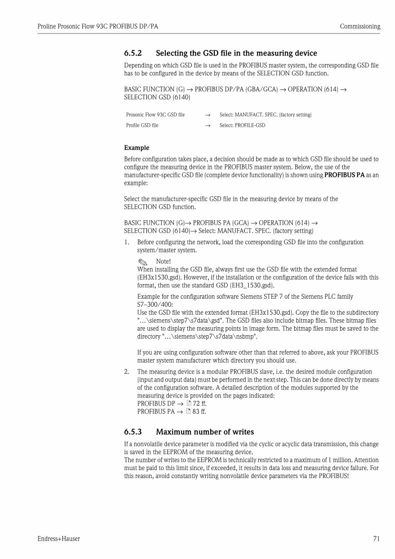
Proline Prosonic Flow 93C PROFIBUS DP/PA Commissioning
Endress+Hauser 71
6.5.2 Selecting the GSD file in the measuring device
Depending on which GSD file is used in the PROFIBUS master system, the corresponding GSD file
has to be configured in the device by means of the SELECTION GSD function.
BASIC FUNCTION (G) → PROFIBUS DP/PA (GBA/GCA) → OPERATION (614) →
SELECTION GSD (6140)
Example
Before configuration takes place, a decision should be made as to which GSD file should be used to
configure the measuring device in the PROFIBUS master system. Below, the use of the
manufacturer-specific GSD file (complete device functionality) is shown using PROFIBUS PA as an
example:
Select the manufacturer-specific GSD file in the measuring device by means of the
SELECTION GSD function.
BASIC FUNCTION (G)→ PROFIBUS PA (GCA) → OPERATION (614) →
SELECTION GSD (6140)→ Select: MANUFACT. SPEC. (factory setting)
1. Before configuring the network, load the corresponding GSD file into the configuration
system/master system.
! Note!
When installing the GSD file, always first use the GSD file with the extended format
(EH3x1530.gsd). However, if the installation or the configuration of the device fails with this
format, then use the standard GSD (EH3_1530.gsd).
Example for the configuration software Siemens STEP 7 of the Siemens PLC family
S7–300/400:
Use the GSD file with the extended format (EH3x1530.gsd). Copy the file to the subdirectory
"…\siemens\step7\s7data\gsd". The GSD files also include bitmap files. These bitmap files
are used to display the measuring points in image form. The bitmap files must be saved to the
directory "…\siemens\step7\s7data\nsbmp".
If you are using configuration software other than that referred to above, ask your PROFIBUS
master system manufacturer which directory you should use.
2. The measuring device is a modular PROFIBUS slave, i.e. the desired module configuration
(input and output data) must be performed in the next step. This can be done directly by means
of the configuration software. A detailed description of the modules supported by the
measuring device is provided on the pages indicated:
PROFIBUS DP → ä 72 ff.
PROFIBUS PA → ä 83 ff.
6.5.3 Maximum number of writes
If a nonvolatile device parameter is modified via the cyclic or acyclic data transmission, this change
is saved in the EEPROM of the measuring device.
The number of writes to the EEPROM is technically restricted to a maximum of 1 million. Attention
must be paid to this limit since, if exceeded, it results in data loss and measuring device failure. For
this reason, avoid constantly writing nonvolatile device parameters via the PROFIBUS!
Prosonic Flow 93C GSD file → Select: MANUFACT. SPEC. (factory setting)
Profile GSD file → Select: PROFILE-GSD
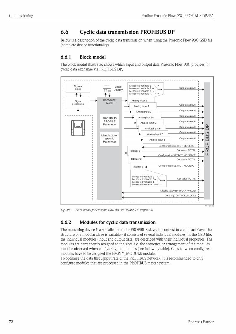
Commissioning Proline Prosonic Flow 93C PROFIBUS DP/PA
72 Endress+Hauser
6.6 Cyclic data transmission PROFIBUS DP
Below is a description of the cyclic data transmission when using the Prosonic Flow 93C GSD file
(complete device functionality).
6.6.1 Block model
The block model illustrated shows which input and output data Prosonic Flow 93C provides for
cyclic data exchange via PROFIBUS DP.
A0014366-en
Fig. 40: Block model for Prosonic Flow 93C PROFIBUS DP Profile 3.0
6.6.2 Modules for cyclic data transmission
The measuring device is a so-called modular PROFIBUS slave. In contrast to a compact slave, the
structure of a modular slave is variable - it consists of several individual modules. In the GSD file,
the individual modules (input and output data) are described with their individual properties. The
modules are permanently assigned to the slots, i.e. the sequence or arrangement of the modules
must be observed when configuring the modules (see following table). Gaps between configured
modules have to be assigned the EMPTY_MODULE module.
To optimize the data throughput rate of the PROFIBUS network, it is recommended to only
configure modules that are processed in the PROFIBUS master system.
Esc
E+-
XXX.XXX.XX
PR
OF
IBU
SD
PEsc
E- +
Output value AI
Analog Input 1
Output value AI
Output value AI
Output value AI
Output value AI
Out value TOTAL
Analog Input 2
Analog Input 3
Analog Input 4
Totalizer 1
Measured variable 1Measured variable 2Measured variable 3Measured variable …
Signalprocessing
PROFIBUSPROFILEParameter
Manufacturerspecific
Parameter
Control (CONTROL_BLOCK)
Display value (DISPLAY_VALUE)
Transducerblock
Configuration SETTOT, MODETOT
Totalizer 3 Configuration SETTOT, MODETOT
Measured variable 1Measured variable 2Measured variable 3Measured variable …
Out value TOTAL
LocalDisplay
Out value TOTAL
Configuration SETTOT, MODETOT
Totalizer 2
Output value AIAnalog Input 5
Output value AIAnalog Input 6
PhysicalBlock
Analog Input 7
Analog Input 8
Output value AI
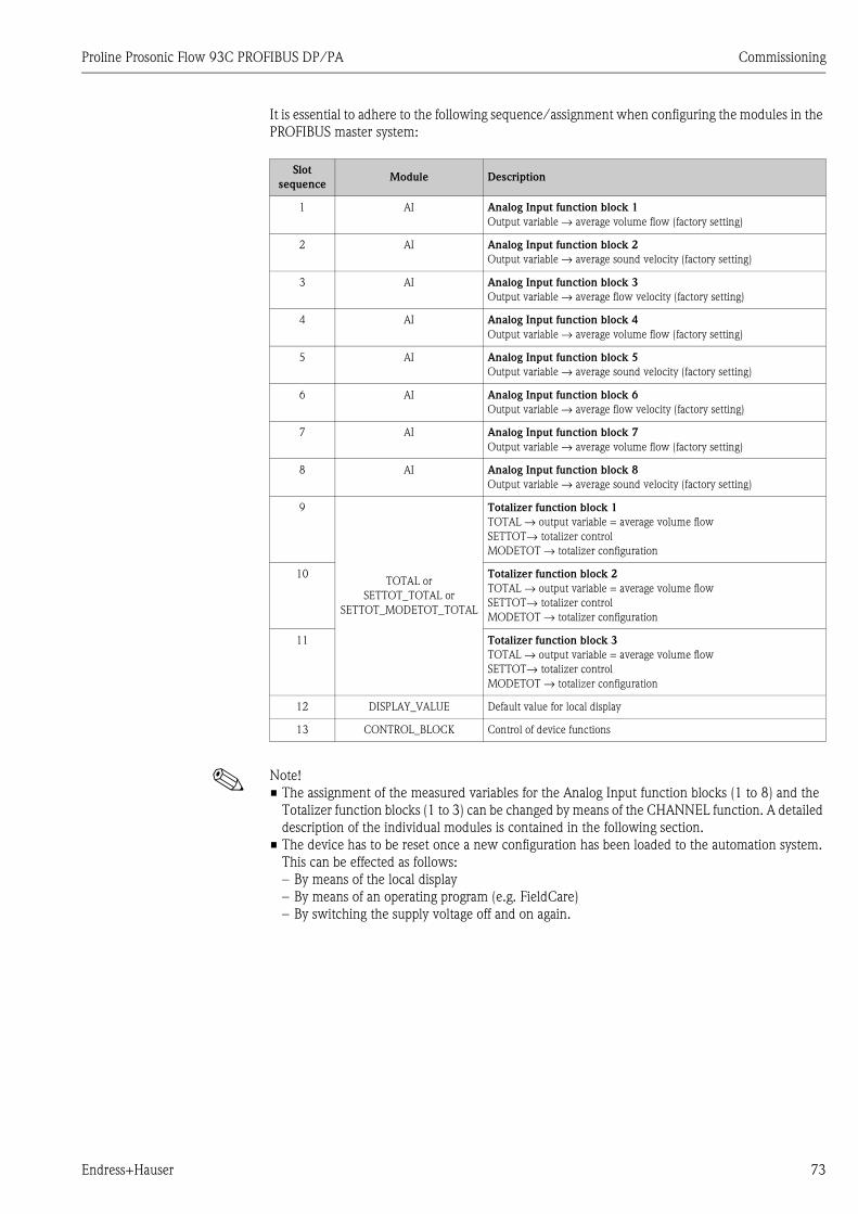
Proline Prosonic Flow 93C PROFIBUS DP/PA Commissioning
Endress+Hauser 73
It is essential to adhere to the following sequence/assignment when configuring the modules in the
PROFIBUS master system:
! Note!
• The assignment of the measured variables for the Analog Input function blocks (1 to 8) and the
Totalizer function blocks (1 to 3) can be changed by means of the CHANNEL function. A detailed
description of the individual modules is contained in the following section.
• The device has to be reset once a new configuration has been loaded to the automation system.
This can be effected as follows:
– By means of the local display
– By means of an operating program (e.g. FieldCare)
– By switching the supply voltage off and on again.
Slot
sequenceModule Description
1 AI Analog Input function block 1
Output variable → average volume flow (factory setting)
2 AI Analog Input function block 2
Output variable → average sound velocity (factory setting)
3 AI Analog Input function block 3
Output variable → average flow velocity (factory setting)
4 AI Analog Input function block 4
Output variable → average volume flow (factory setting)
5 AI Analog Input function block 5
Output variable → average sound velocity (factory setting)
6 AI Analog Input function block 6
Output variable → average flow velocity (factory setting)
7 AI Analog Input function block 7
Output variable → average volume flow (factory setting)
8 AI Analog Input function block 8
Output variable → average sound velocity (factory setting)
9
TOTAL or
SETTOT_TOTAL or
SETTOT_MODETOT_TOTAL
Totalizer function block 1
TOTAL → output variable = average volume flow
SETTOT→ totalizer control
MODETOT → totalizer configuration
10 Totalizer function block 2
TOTAL → output variable = average volume flow
SETTOT→ totalizer control
MODETOT → totalizer configuration
11 Totalizer function block 3
TOTAL → output variable = average volume flow
SETTOT→ totalizer control
MODETOT → totalizer configuration
12 DISPLAY_VALUE Default value for local display
13 CONTROL_BLOCK Control of device functions
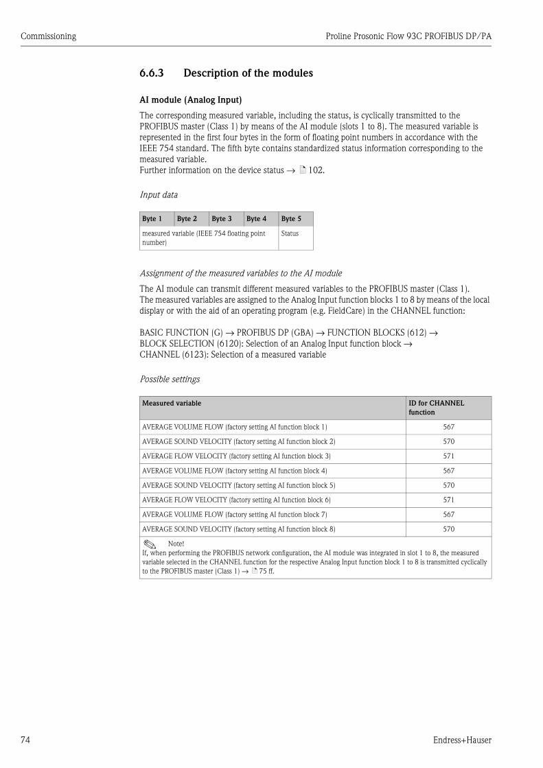
Commissioning Proline Prosonic Flow 93C PROFIBUS DP/PA
74 Endress+Hauser
6.6.3 Description of the modules
AI module (Analog Input)
The corresponding measured variable, including the status, is cyclically transmitted to the
PROFIBUS master (Class 1) by means of the AI module (slots 1 to 8). The measured variable is
represented in the first four bytes in the form of floating point numbers in accordance with the
IEEE 754 standard. The fifth byte contains standardized status information corresponding to the
measured variable.
Further information on the device status → ä 102.
Input data
Assignment of the measured variables to the AI module
The AI module can transmit different measured variables to the PROFIBUS master (Class 1).
The measured variables are assigned to the Analog Input function blocks 1 to 8 by means of the local
display or with the aid of an operating program (e.g. FieldCare) in the CHANNEL function:
BASIC FUNCTION (G) → PROFIBUS DP (GBA) → FUNCTION BLOCKS (612) →
BLOCK SELECTION (6120): Selection of an Analog Input function block →
CHANNEL (6123): Selection of a measured variable
Possible settings
Byte 1 Byte 2 Byte 3 Byte 4 Byte 5
measured variable (IEEE 754 floating point
number)
Status
Measured variable ID for CHANNEL
function
AVERAGE VOLUME FLOW (factory setting AI function block 1) 567
AVERAGE SOUND VELOCITY (factory setting AI function block 2) 570
AVERAGE FLOW VELOCITY (factory setting AI function block 3) 571
AVERAGE VOLUME FLOW (factory setting AI function block 4) 567
AVERAGE SOUND VELOCITY (factory setting AI function block 5) 570
AVERAGE FLOW VELOCITY (factory setting AI function block 6) 571
AVERAGE VOLUME FLOW (factory setting AI function block 7) 567
AVERAGE SOUND VELOCITY (factory setting AI function block 8) 570
! Note!
If, when performing the PROFIBUS network configuration, the AI module was integrated in slot 1 to 8, the measured
variable selected in the CHANNEL function for the respective Analog Input function block 1 to 8 is transmitted cyclically
to the PROFIBUS master (Class 1) → ä 75 ff.
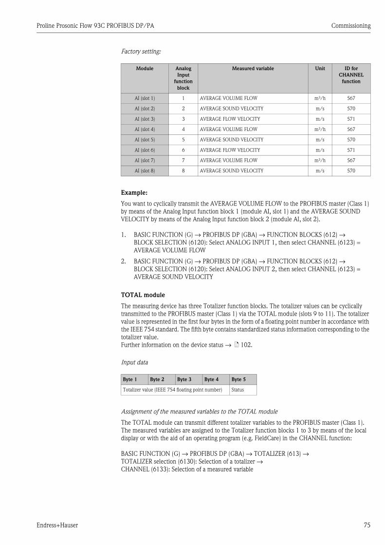
Proline Prosonic Flow 93C PROFIBUS DP/PA Commissioning
Endress+Hauser 75
Factory setting:
Example:
You want to cyclically transmit the AVERAGE VOLUME FLOW to the PROFIBUS master (Class 1)
by means of the Analog Input function block 1 (module AI, slot 1) and the AVERAGE SOUND
VELOCITY by means of the Analog Input function block 2 (module AI, slot 2).
1. BASIC FUNCTION (G) → PROFIBUS DP (GBA) → FUNCTION BLOCKS (612) →
BLOCK SELECTION (6120): Select ANALOG INPUT 1, then select CHANNEL (6123) =
AVERAGE VOLUME FLOW
2. BASIC FUNCTION (G) → PROFIBUS DP (GBA) → FUNCTION BLOCKS (612) →
BLOCK SELECTION (6120): Select ANALOG INPUT 2, then select CHANNEL (6123) =
AVERAGE SOUND VELOCITY
TOTAL module
The measuring device has three Totalizer function blocks. The totalizer values can be cyclically
transmitted to the PROFIBUS master (Class 1) via the TOTAL module (slots 9 to 11). The totalizer
value is represented in the first four bytes in the form of a floating point number in accordance with
the IEEE 754 standard. The fifth byte contains standardized status information corresponding to the
totalizer value.
Further information on the device status → ä 102.
Input data
Assignment of the measured variables to the TOTAL module
The TOTAL module can transmit different totalizer variables to the PROFIBUS master (Class 1).
The measured variables are assigned to the Totalizer function blocks 1 to 3 by means of the local
display or with the aid of an operating program (e.g. FieldCare) in the CHANNEL function:
BASIC FUNCTION (G) → PROFIBUS DP (GBA) → TOTALIZER (613) →
TOTALIZER selection (6130): Selection of a totalizer →
CHANNEL (6133): Selection of a measured variable
Module Analog
Input
function
block
Measured variable Unit ID for
CHANNEL
function
AI (slot 1) 1 AVERAGE VOLUME FLOW m³/h 567
AI (slot 2) 2 AVERAGE SOUND VELOCITY m/s 570
AI (slot 3) 3 AVERAGE FLOW VELOCITY m/s 571
AI (slot 4) 4 AVERAGE VOLUME FLOW m³/h 567
AI (slot 5) 5 AVERAGE SOUND VELOCITY m/s 570
AI (slot 6) 6 AVERAGE FLOW VELOCITY m/s 571
AI (slot 7) 7 AVERAGE VOLUME FLOW m³/h 567
AI (slot 8) 8 AVERAGE SOUND VELOCITY m/s 570
Byte 1 Byte 2 Byte 3 Byte 4 Byte 5
Totalizer value (IEEE 754 floating point number) Status
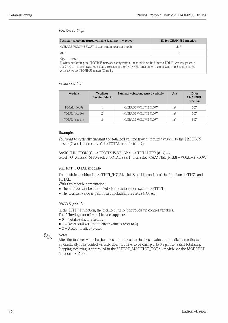
Commissioning Proline Prosonic Flow 93C PROFIBUS DP/PA
76 Endress+Hauser
Possible settings
Possible settings
Factory setting
Example:
You want to cyclically transmit the totalized volume flow as totalizer value 1 to the PROFIBUS
master (Class 1) by means of the TOTAL module (slot 7):
BASIC FUNCTION (G) → PROFIBUS DP (GBA) → TOTALIZER (613) →
select TOTALIZER (6130): Select TOTALIZER 1, then select CHANNEL (6133) = VOLUME FLOW
SETTOT_TOTAL module
The module combination SETTOT_TOTAL (slots 9 to 11) consists of the functions SETTOT and
TOTAL.
With this module combination:
• The totalizer can be controlled via the automation system (SETTOT).
• The totalizer value is transmitted including the status (TOTAL)
SETTOT function
In the SETTOT function, the totalizer can be controlled via control variables.
The following control variables are supported:
• 0 = Totalize (factory setting)
• 1 = Reset totalizer (the totalizer value is reset to 0)
• 2 = Accept totalizer preset
! Note!
After the totalizer value has been reset to 0 or set to the preset value, the totalizing continues
automatically. The control variable does not have to be changed to 0 again to restart totalizing.
Stopping totalizing is controlled in the SETTOT_MODETOT_TOTAL module via the MODETOT
function → ä 77.
Totalizer value/measured variable (channel 1 = active) ID for CHANNEL function
AVERAGE VOLUME FLOW (factory setting totalizer 1 to 3) 567
OFF 0
! Note!
If, when performing the PROFIBUS network configuration, the module or the function TOTAL was integrated in
slot 9, 10 or 11, the measured variable selected in the CHANNEL function for the totalizers 1 to 3 is transmitted
cyclically to the PROFIBUS master (Class 1).
Module Totalizer
function block
Totalizer value/measured variable Unit ID for
CHANNEL
function
TOTAL (slot 9) 1 AVERAGE VOLUME FLOW m³ 567
TOTAL (slot 10) 2 AVERAGE VOLUME FLOW m³ 567
TOTAL (slot 11) 3 AVERAGE VOLUME FLOW m³ 567
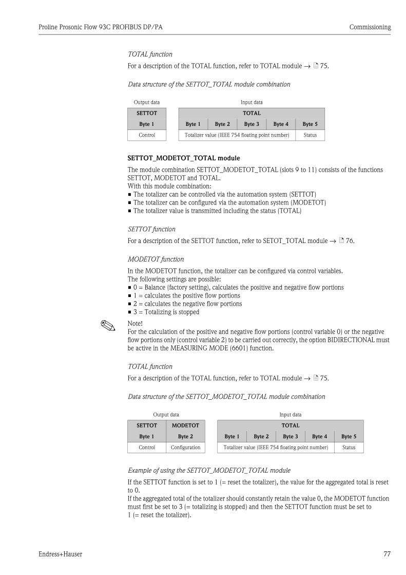
Proline Prosonic Flow 93C PROFIBUS DP/PA Commissioning
Endress+Hauser 77
TOTAL function
For a description of the TOTAL function, refer to TOTAL module → ä 75.
Data structure of the SETTOT_TOTAL module combination
SETTOT_MODETOT_TOTAL module
The module combination SETTOT_MODETOT_TOTAL (slots 9 to 11) consists of the functions
SETTOT, MODETOT and TOTAL.
With this module combination:
• The totalizer can be controlled via the automation system (SETTOT)
• The totalizer can be configured via the automation system (MODETOT)
• The totalizer value is transmitted including the status (TOTAL)
SETTOT function
For a description of the SETTOT function, refer to SETOT_TOTAL module → ä 76.
MODETOT function
In the MODETOT function, the totalizer can be configured via control variables.
The following settings are possible:
• 0 = Balance (factory setting), calculates the positive and negative flow portions
• 1 = calculates the positive flow portions
• 2 = calculates the negative flow portions
• 3 = Totalizing is stopped
! Note!
For the calculation of the positive and negative flow portions (control variable 0) or the negative
flow portions only (control variable 2) to be carried out correctly, the option BIDIRECTIONAL must
be active in the MEASURING MODE (6601) function.
TOTAL function
For a description of the TOTAL function, refer to TOTAL module → ä 75.
Data structure of the SETTOT_MODETOT_TOTAL module combination
Example of using the SETTOT_MODETOT_TOTAL module
If the SETTOT function is set to 1 (= reset the totalizer), the value for the aggregated total is reset
to 0.
If the aggregated total of the totalizer should constantly retain the value 0, the MODETOT function
must first be set to 3 (= totalizing is stopped) and then the SETTOT function must be set to
1 (= reset the totalizer).
Output data Input data
SETTOT TOTAL
Byte 1 Byte 1 Byte 2 Byte 3 Byte 4 Byte 5
Control Totalizer value (IEEE 754 floating point number) Status
Output data Input data
SETTOT MODETOT TOTAL
Byte 1 Byte 2 Byte 1 Byte 2 Byte 3 Byte 4 Byte 5
Control Configuration Totalizer value (IEEE 754 floating point number) Status
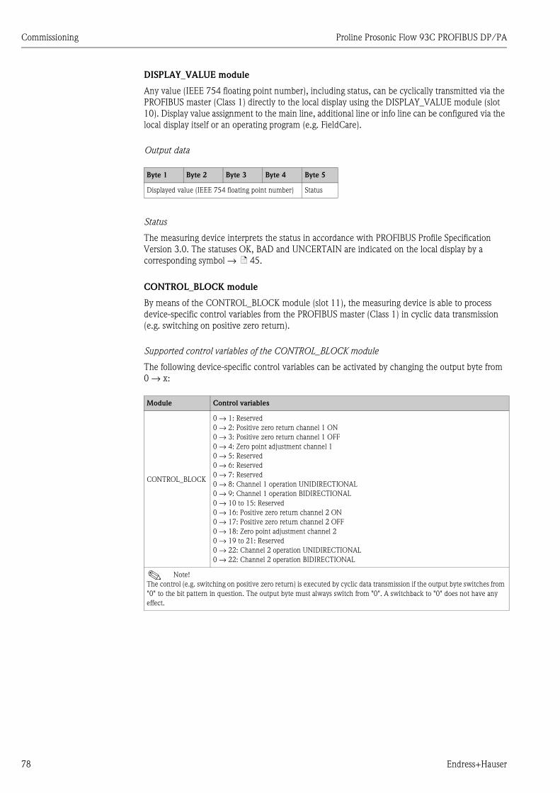
Commissioning Proline Prosonic Flow 93C PROFIBUS DP/PA
78 Endress+Hauser
DISPLAY_VALUE module
Any value (IEEE 754 floating point number), including status, can be cyclically transmitted via the
PROFIBUS master (Class 1) directly to the local display using the DISPLAY_VALUE module (slot
10). Display value assignment to the main line, additional line or info line can be configured via the
local display itself or an operating program (e.g. FieldCare).
Output data
Status
The measuring device interprets the status in accordance with PROFIBUS Profile Specification
Version 3.0. The statuses OK, BAD and UNCERTAIN are indicated on the local display by a
corresponding symbol → ä 45.
CONTROL_BLOCK module
By means of the CONTROL_BLOCK module (slot 11), the measuring device is able to process
device-specific control variables from the PROFIBUS master (Class 1) in cyclic data transmission
(e.g. switching on positive zero return).
Supported control variables of the CONTROL_BLOCK module
The following device-specific control variables can be activated by changing the output byte from
0 → x:
Byte 1 Byte 2 Byte 3 Byte 4 Byte 5
Displayed value (IEEE 754 floating point number) Status
Module Control variables
CONTROL_BLOCK
0 → 1: Reserved
0 → 2: Positive zero return channel 1 ON
0 → 3: Positive zero return channel 1 OFF
0 → 4: Zero point adjustment channel 1
0 → 5: Reserved
0 → 6: Reserved
0 → 7: Reserved
0 → 8: Channel 1 operation UNIDIRECTIONAL
0 → 9: Channel 1 operation BIDIRECTIONAL
0 → 10 to 15: Reserved
0 → 16: Positive zero return channel 2 ON
0 → 17: Positive zero return channel 2 OFF
0 → 18: Zero point adjustment channel 2
0 → 19 to 21: Reserved
0 → 22: Channel 2 operation UNIDIRECTIONAL
0 → 22: Channel 2 operation BIDIRECTIONAL
! Note!
The control (e.g. switching on positive zero return) is executed by cyclic data transmission if the output byte switches from
"0" to the bit pattern in question. The output byte must always switch from "0". A switchback to "0" does not have any
effect.

Proline Prosonic Flow 93C PROFIBUS DP/PA Commissioning
Endress+Hauser 79
Example (change the output byte)
Output data
EMPTY_MODULE module
The measuring device is a so-called modular PROFIBUS slave. In contrast to a compact slave, the
structure of a modular slave is variable - it consists of several individual modules. In the GSD file,
the individual modules are described with their individual properties. The modules are permanently
assigned to the slots, i.e. the sequence or arrangement of the modules must be observed when
configuring the modules. Gaps between configured modules have to be assigned the
EMPTY_MODULE module.
For a more detailed description, see → ä 73.
From To Result
0 → 2 Positive zero return for channel 1 is switched on.
2 → 0 No effect
0 → 3 Positive zero return for channel 1 is switched off.
3 → 2 No effect
Byte 1
Control
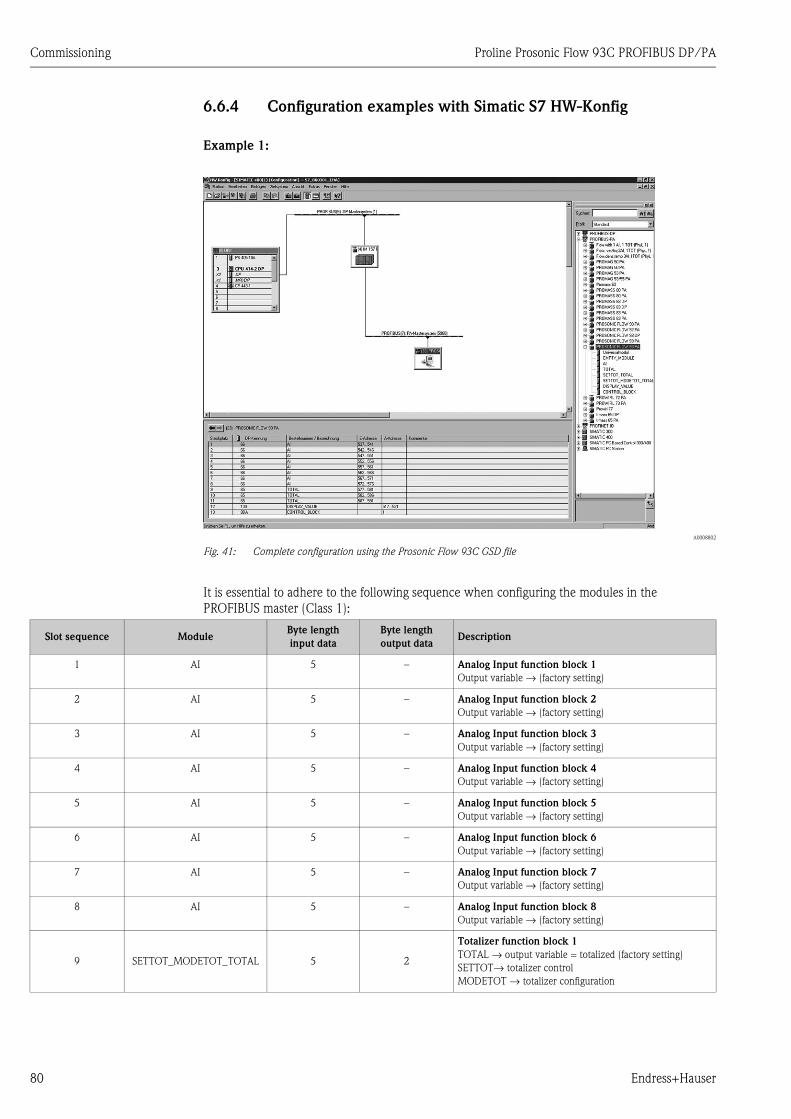
Commissioning Proline Prosonic Flow 93C PROFIBUS DP/PA
80 Endress+Hauser
6.6.4 Configuration examples with Simatic S7 HW-Konfig
Example 1:
A0008802
Fig. 41: Complete configuration using the Prosonic Flow 93C GSD file
It is essential to adhere to the following sequence when configuring the modules in the
PROFIBUS master (Class 1):
Slot sequence ModuleByte length
input data
Byte length
output dataDescription
1 AI 5 – Analog Input function block 1
Output variable → (factory setting)
2 AI 5 – Analog Input function block 2
Output variable → (factory setting)
3 AI 5 – Analog Input function block 3
Output variable → (factory setting)
4 AI 5 – Analog Input function block 4
Output variable → (factory setting)
5 AI 5 – Analog Input function block 5
Output variable → (factory setting)
6 AI 5 – Analog Input function block 6
Output variable → (factory setting)
7 AI 5 – Analog Input function block 7
Output variable → (factory setting)
8 AI 5 – Analog Input function block 8
Output variable → (factory setting)
9 SETTOT_MODETOT_TOTAL 5 2
Totalizer function block 1
TOTAL → output variable = totalized (factory setting)
SETTOT→ totalizer control
MODETOT → totalizer configuration

Proline Prosonic Flow 93C PROFIBUS DP/PA Commissioning
Endress+Hauser 81
10 SETTOT_MODETOT_TOTAL 5 2
Totalizer function block 2
TOTAL → output variable = totalized (factory setting)
SETTOT→ totalizer control
MODETOT → totalizer configuration
11 SETTOT_MODETOT_TOTAL 5 2
Totalizer function block 3
TOTAL → output variable = totalized (factory setting)
SETTOT→ totalizer control
MODETOT → totalizer configuration
12 DISPLAY_VALUE – 5 Default value for local display
13 CONTROL_BLOCK – 1 Control of device functions
Slot sequence ModuleByte length
input data
Byte length
output dataDescription
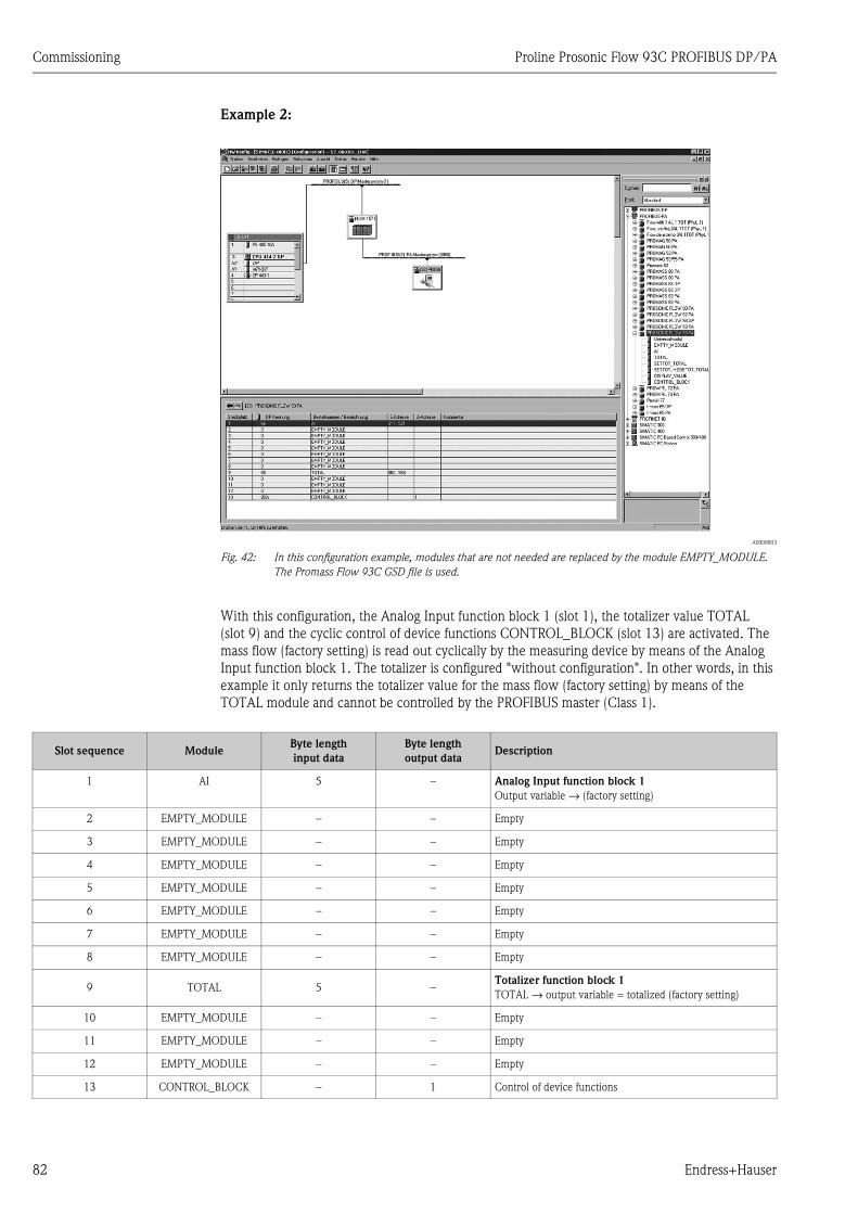
Commissioning Proline Prosonic Flow 93C PROFIBUS DP/PA
82 Endress+Hauser
Example 2:
A0008803
Fig. 42: In this configuration example, modules that are not needed are replaced by the module EMPTY_MODULE.
The Promass Flow 93C GSD file is used.
With this configuration, the Analog Input function block 1 (slot 1), the totalizer value TOTAL
(slot 9) and the cyclic control of device functions CONTROL_BLOCK (slot 13) are activated. The
mass flow (factory setting) is read out cyclically by the measuring device by means of the Analog
Input function block 1. The totalizer is configured "without configuration". In other words, in this
example it only returns the totalizer value for the mass flow (factory setting) by means of the
TOTAL module and cannot be controlled by the PROFIBUS master (Class 1).
Slot sequence ModuleByte length
input data
Byte length
output dataDescription
1 AI 5 – Analog Input function block 1
Output variable → (factory setting)
2 EMPTY_MODULE – – Empty
3 EMPTY_MODULE – – Empty
4 EMPTY_MODULE – – Empty
5 EMPTY_MODULE – – Empty
6 EMPTY_MODULE – – Empty
7 EMPTY_MODULE – – Empty
8 EMPTY_MODULE – – Empty
9 TOTAL 5 –Totalizer function block 1
TOTAL → output variable = totalized (factory setting)
10 EMPTY_MODULE – – Empty
11 EMPTY_MODULE – – Empty
12 EMPTY_MODULE – – Empty
13 CONTROL_BLOCK – 1 Control of device functions
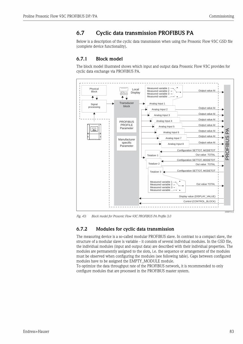
Proline Prosonic Flow 93C PROFIBUS DP/PA Commissioning
Endress+Hauser 83
6.7 Cyclic data transmission PROFIBUS PA
Below is a description of the cyclic data transmission when using the Prosonic Flow 93C GSD file
(complete device functionality).
6.7.1 Block model
The block model illustrated shows which input and output data Prosonic Flow 93C provides for
cyclic data exchange via PROFIBUS PA.
A0008716-en
Fig. 43: Block model for Prosonic Flow 93C PROFIBUS PA Profile 3.0
6.7.2 Modules for cyclic data transmission
The measuring device is a so-called modular PROFIBUS slave. In contrast to a compact slave, the
structure of a modular slave is variable - it consists of several individual modules. In the GSD file,
the individual modules (input and output data) are described with their individual properties. The
modules are permanently assigned to the slots, i.e. the sequence or arrangement of the modules
must be observed when configuring the modules (see following table). Gaps between configured
modules have to be assigned the EMPTY_MODULE module.
To optimize the data throughput rate of the PROFIBUS network, it is recommended to only
configure modules that are processed in the PROFIBUS master system.
Esc
E+-
XXX.XXX.XX
PR
OF
IBU
SP
AEsc
E- +
Output value AI
Analog Input 1
Output value AI
Output value AI
Output value AI
Output value AI
Out value TOTAL
Analog Input 2
Analog Input 3
Analog Input 4
Totalizer 1
Measured variable 1Measured variable 2Measured variable 3Measured variable …
Signalprocessing
PROFIBUSPROFILEParameter
Manufacturerspecific
Parameter
Control (CONTROL_BLOCK)
Display value (DISPLAY_VALUE)
Transducerblock
Configuration SETTOT, MODETOT
Totalizer 3 Configuration SETTOT, MODETOT
Measured variable 1Measured variable 2Measured variable 3Measured variable …
Out value TOTAL
LocalDisplay
Out value TOTAL
Configuration SETTOT, MODETOT
Totalizer 2
Output value AIAnalog Input 5
Output value AIAnalog Input 6
PhysicalBlock
Analog Input 7
Analog Input 8
Output value AI
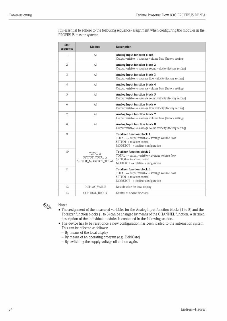
Commissioning Proline Prosonic Flow 93C PROFIBUS DP/PA
84 Endress+Hauser
It is essential to adhere to the following sequence/assignment when configuring the modules in the
PROFIBUS master system:
! Note!
• The assignment of the measured variables for the Analog Input function blocks (1 to 8) and the
Totalizer function blocks (1 to 3) can be changed by means of the CHANNEL function. A detailed
description of the individual modules is contained in the following section.
• The device has to be reset once a new configuration has been loaded to the automation system.
This can be effected as follows:
– By means of the local display
– By means of an operating program (e.g. FieldCare)
– By switching the supply voltage off and on again.
Slot
sequenceModule Description
1 AI Analog Input function block 1
Output variable → average volume flow (factory setting)
2 AI Analog Input function block 2
Output variable → average sound velocity (factory setting)
3 AI Analog Input function block 3
Output variable → average flow velocity (factory setting)
4 AI Analog Input function block 4
Output variable → average volume flow (factory setting)
5 AI Analog Input function block 5
Output variable → average sound velocity (factory setting)
6 AI Analog Input function block 6
Output variable → average flow velocity (factory setting)
7 AI Analog Input function block 7
Output variable → average volume flow (factory setting)
8 AI Analog Input function block 8
Output variable → average sound velocity (factory setting)
9
TOTAL or
SETTOT_TOTAL or
SETTOT_MODETOT_TOTAL
Totalizer function block 1
TOTAL → output variable = average volume flow
SETTOT→ totalizer control
MODETOT → totalizer configuration
10 Totalizer function block 2
TOTAL → output variable = average volume flow
SETTOT→ totalizer control
MODETOT → totalizer configuration
11 Totalizer function block 3
TOTAL → output variable = average volume flow
SETTOT→ totalizer control
MODETOT → totalizer configuration
12 DISPLAY_VALUE Default value for local display
13 CONTROL_BLOCK Control of device functions

Proline Prosonic Flow 93C PROFIBUS DP/PA Commissioning
Endress+Hauser 85
6.7.3 Description of the modules
AI module (Analog Input)
The corresponding measured variable, including the status, is cyclically transmitted to the
PROFIBUS master (Class 1) by means of the AI module (slots 1 to 8). The measured variable is
represented in the first four bytes in the form of floating point numbers in accordance with the
IEEE 754 standard. The fifth byte contains standardized status information corresponding to the
measured variable.
Further information on the device status → ä 102.
Input data
Assignment of the measured variables to the AI module
The AI module can transmit different measured variables to the PROFIBUS master (Class 1).
The measured variables are assigned to the Analog Input function blocks 1 to 8 by means of the local
display or with the aid of an operating program (e.g. FieldCare) in the CHANNEL function:
BASIC FUNCTION (G) → PROFIBUS PA (GCA) → FUNCTION BLOCKS (612) →
BLOCK SELECTION (6120): Selection of an Analog Input function block →
CHANNEL (6123): Selection of a measured variable
Possible settings
Byte 1 Byte 2 Byte 3 Byte 4 Byte 5
measured variable (IEEE 754 floating point
number)
Status
Measured variable ID for CHANNEL
function
AVERAGE VOLUME FLOW (factory setting AI function block 1) 567
AVERAGE SOUND VELOCITY (factory setting AI function block 2) 570
AVERAGE FLOW VELOCITY (factory setting AI function block 3) 571
AVERAGE VOLUME FLOW (factory setting AI function block 4) 567
AVERAGE SOUND VELOCITY (factory setting AI function block 5) 570
AVERAGE FLOW VELOCITY (factory setting AI function block 6) 571
AVERAGE VOLUME FLOW (factory setting AI function block 7) 567
AVERAGE SOUND VELOCITY (factory setting AI function block 8) 570
! Note!
If, when performing the PROFIBUS network configuration, the AI module was integrated in slot 1 to 8, the measured
variable selected in the CHANNEL function for the respective Analog Input function block 1 to 8 is transmitted cyclically
to the PROFIBUS master (Class 1). → ä 75 ff.
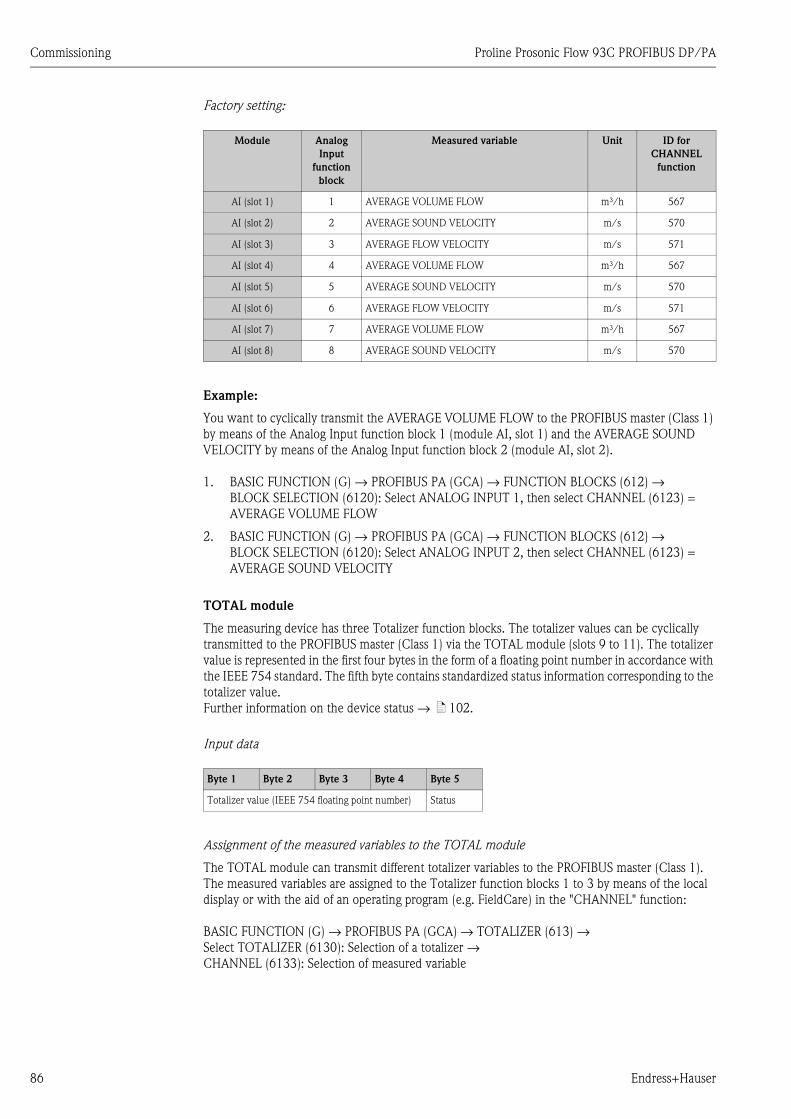
Commissioning Proline Prosonic Flow 93C PROFIBUS DP/PA
86 Endress+Hauser
Factory setting:
Example:
You want to cyclically transmit the AVERAGE VOLUME FLOW to the PROFIBUS master (Class 1)
by means of the Analog Input function block 1 (module AI, slot 1) and the AVERAGE SOUND
VELOCITY by means of the Analog Input function block 2 (module AI, slot 2).
1. BASIC FUNCTION (G) → PROFIBUS PA (GCA) → FUNCTION BLOCKS (612) →
BLOCK SELECTION (6120): Select ANALOG INPUT 1, then select CHANNEL (6123) =
AVERAGE VOLUME FLOW
2. BASIC FUNCTION (G) → PROFIBUS PA (GCA) → FUNCTION BLOCKS (612) →
BLOCK SELECTION (6120): Select ANALOG INPUT 2, then select CHANNEL (6123) =
AVERAGE SOUND VELOCITY
TOTAL module
The measuring device has three Totalizer function blocks. The totalizer values can be cyclically
transmitted to the PROFIBUS master (Class 1) via the TOTAL module (slots 9 to 11). The totalizer
value is represented in the first four bytes in the form of a floating point number in accordance with
the IEEE 754 standard. The fifth byte contains standardized status information corresponding to the
totalizer value.
Further information on the device status → ä 102.
Input data
Assignment of the measured variables to the TOTAL module
The TOTAL module can transmit different totalizer variables to the PROFIBUS master (Class 1).
The measured variables are assigned to the Totalizer function blocks 1 to 3 by means of the local
display or with the aid of an operating program (e.g. FieldCare) in the "CHANNEL" function:
BASIC FUNCTION (G) → PROFIBUS PA (GCA) → TOTALIZER (613) →
Select TOTALIZER (6130): Selection of a totalizer →
CHANNEL (6133): Selection of measured variable
Module Analog
Input
function
block
Measured variable Unit ID for
CHANNEL
function
AI (slot 1) 1 AVERAGE VOLUME FLOW m³/h 567
AI (slot 2) 2 AVERAGE SOUND VELOCITY m/s 570
AI (slot 3) 3 AVERAGE FLOW VELOCITY m/s 571
AI (slot 4) 4 AVERAGE VOLUME FLOW m³/h 567
AI (slot 5) 5 AVERAGE SOUND VELOCITY m/s 570
AI (slot 6) 6 AVERAGE FLOW VELOCITY m/s 571
AI (slot 7) 7 AVERAGE VOLUME FLOW m³/h 567
AI (slot 8) 8 AVERAGE SOUND VELOCITY m/s 570
Byte 1 Byte 2 Byte 3 Byte 4 Byte 5
Totalizer value (IEEE 754 floating point number) Status
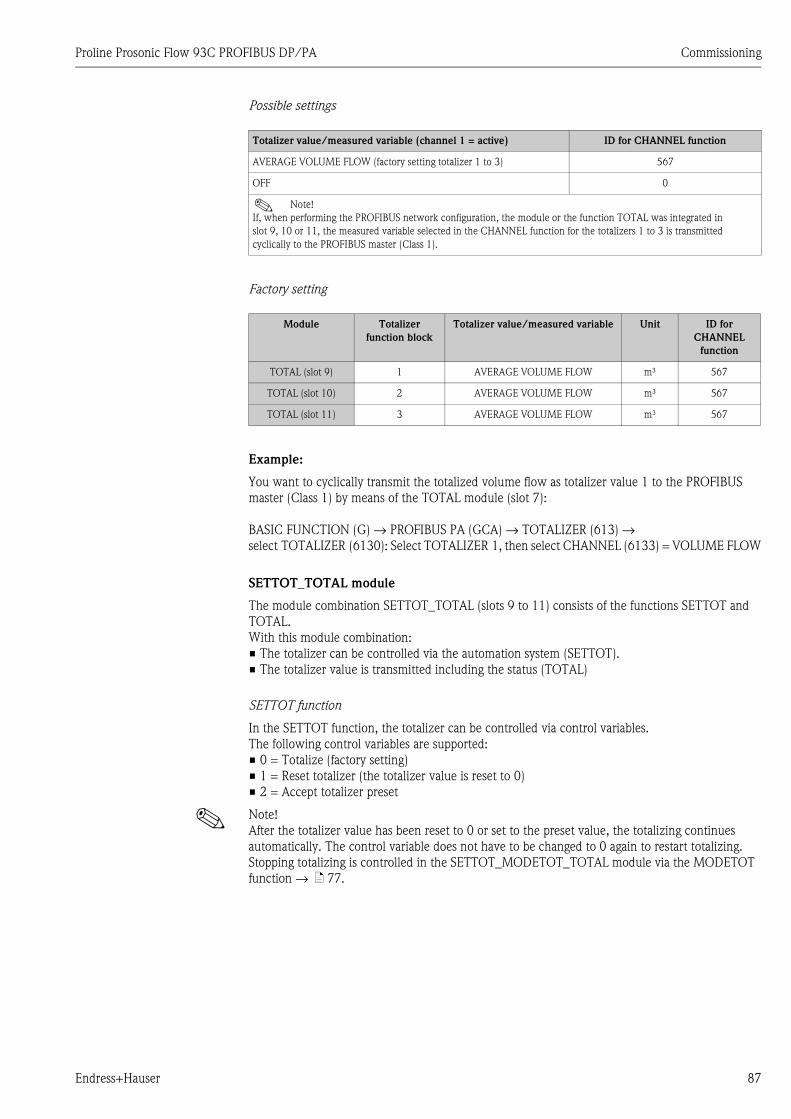
Proline Prosonic Flow 93C PROFIBUS DP/PA Commissioning
Endress+Hauser 87
Possible settings
Possible settings
Factory setting
Example:
You want to cyclically transmit the totalized volume flow as totalizer value 1 to the PROFIBUS
master (Class 1) by means of the TOTAL module (slot 7):
BASIC FUNCTION (G) → PROFIBUS PA (GCA) → TOTALIZER (613) →
select TOTALIZER (6130): Select TOTALIZER 1, then select CHANNEL (6133) = VOLUME FLOW
SETTOT_TOTAL module
The module combination SETTOT_TOTAL (slots 9 to 11) consists of the functions SETTOT and
TOTAL.
With this module combination:
• The totalizer can be controlled via the automation system (SETTOT).
• The totalizer value is transmitted including the status (TOTAL)
SETTOT function
In the SETTOT function, the totalizer can be controlled via control variables.
The following control variables are supported:
• 0 = Totalize (factory setting)
• 1 = Reset totalizer (the totalizer value is reset to 0)
• 2 = Accept totalizer preset
! Note!
After the totalizer value has been reset to 0 or set to the preset value, the totalizing continues
automatically. The control variable does not have to be changed to 0 again to restart totalizing.
Stopping totalizing is controlled in the SETTOT_MODETOT_TOTAL module via the MODETOT
function → ä 77.
Totalizer value/measured variable (channel 1 = active) ID for CHANNEL function
AVERAGE VOLUME FLOW (factory setting totalizer 1 to 3) 567
OFF 0
! Note!
If, when performing the PROFIBUS network configuration, the module or the function TOTAL was integrated in
slot 9, 10 or 11, the measured variable selected in the CHANNEL function for the totalizers 1 to 3 is transmitted
cyclically to the PROFIBUS master (Class 1).
Module Totalizer
function block
Totalizer value/measured variable Unit ID for
CHANNEL
function
TOTAL (slot 9) 1 AVERAGE VOLUME FLOW m³ 567
TOTAL (slot 10) 2 AVERAGE VOLUME FLOW m³ 567
TOTAL (slot 11) 3 AVERAGE VOLUME FLOW m³ 567
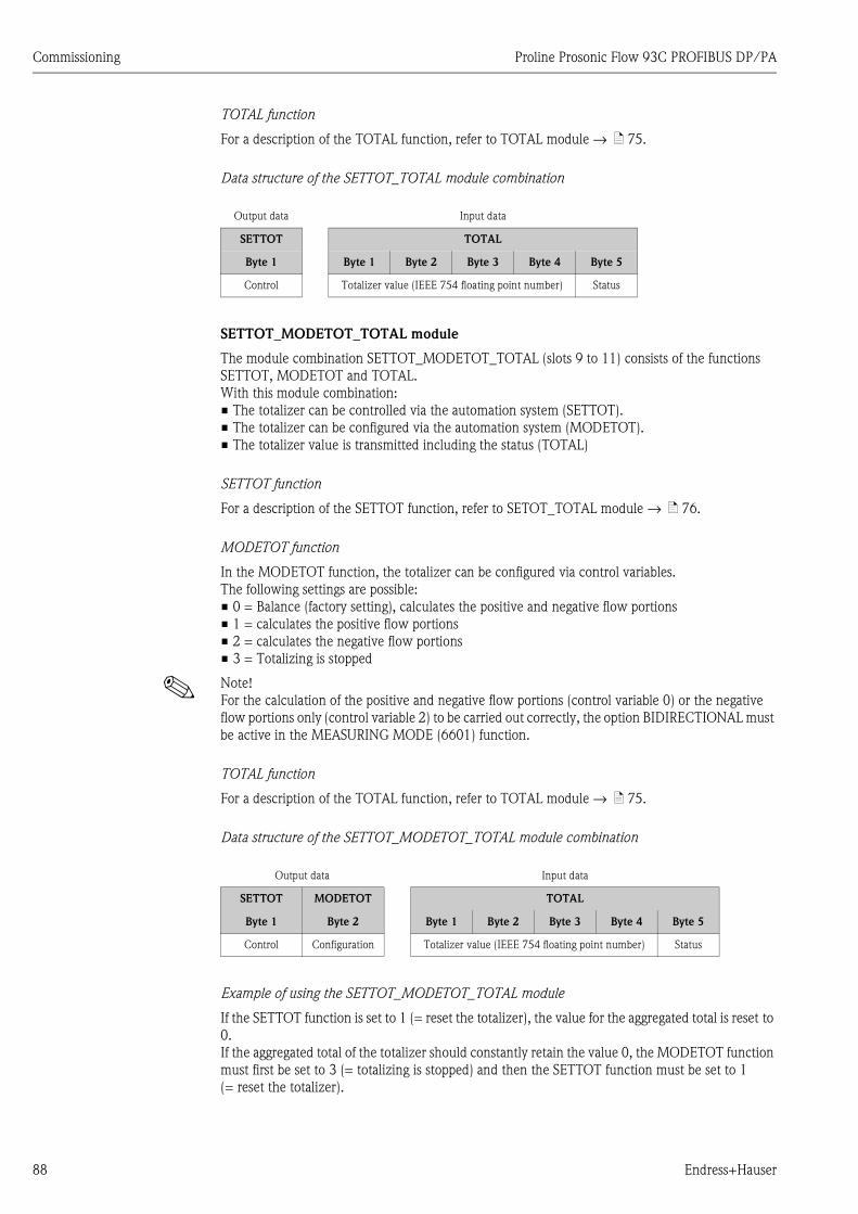
Commissioning Proline Prosonic Flow 93C PROFIBUS DP/PA
88 Endress+Hauser
TOTAL function
For a description of the TOTAL function, refer to TOTAL module → ä 75.
Data structure of the SETTOT_TOTAL module combination
SETTOT_MODETOT_TOTAL module
The module combination SETTOT_MODETOT_TOTAL (slots 9 to 11) consists of the functions
SETTOT, MODETOT and TOTAL.
With this module combination:
• The totalizer can be controlled via the automation system (SETTOT).
• The totalizer can be configured via the automation system (MODETOT).
• The totalizer value is transmitted including the status (TOTAL)
SETTOT function
For a description of the SETTOT function, refer to SETOT_TOTAL module → ä 76.
MODETOT function
In the MODETOT function, the totalizer can be configured via control variables.
The following settings are possible:
• 0 = Balance (factory setting), calculates the positive and negative flow portions
• 1 = calculates the positive flow portions
• 2 = calculates the negative flow portions
• 3 = Totalizing is stopped
! Note!
For the calculation of the positive and negative flow portions (control variable 0) or the negative
flow portions only (control variable 2) to be carried out correctly, the option BIDIRECTIONAL must
be active in the MEASURING MODE (6601) function.
TOTAL function
For a description of the TOTAL function, refer to TOTAL module → ä 75.
Data structure of the SETTOT_MODETOT_TOTAL module combination
Example of using the SETTOT_MODETOT_TOTAL module
If the SETTOT function is set to 1 (= reset the totalizer), the value for the aggregated total is reset to
0.
If the aggregated total of the totalizer should constantly retain the value 0, the MODETOT function
must first be set to 3 (= totalizing is stopped) and then the SETTOT function must be set to 1
(= reset the totalizer).
Output data Input data
SETTOT TOTAL
Byte 1 Byte 1 Byte 2 Byte 3 Byte 4 Byte 5
Control Totalizer value (IEEE 754 floating point number) Status
Output data Input data
SETTOT MODETOT TOTAL
Byte 1 Byte 2 Byte 1 Byte 2 Byte 3 Byte 4 Byte 5
Control Configuration Totalizer value (IEEE 754 floating point number) Status
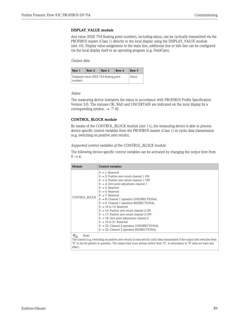
Proline Prosonic Flow 93C PROFIBUS DP/PA Commissioning
Endress+Hauser 89
DISPLAY_VALUE module
Any value (IEEE 754 floating point number), including status, can be cyclically transmitted via the
PROFIBUS master (Class 1) directly to the local display using the DISPLAY_VALUE module
(slot 10). Display value assignment to the main line, additional line or info line can be configured
via the local display itself or an operating program (e.g. FieldCare).
Output data
Status
The measuring device interprets the status in accordance with PROFIBUS Profile Specification
Version 3.0. The statuses OK, BAD and UNCERTAIN are indicated on the local display by a
corresponding symbol. → ä 45
CONTROL_BLOCK module
By means of the CONTROL_BLOCK module (slot 11), the measuring device is able to process
device-specific control variables from the PROFIBUS master (Class 1) in cyclic data transmission
(e.g. switching on positive zero return).
Supported control variables of the CONTROL_BLOCK module
The following device-specific control variables can be activated by changing the output byte from
0 → x:
Byte 1 Byte 2 Byte 3 Byte 4 Byte 5
Displayed value (IEEE 754 floating point
number)
Status
Module Control variables
CONTROL_BLOCK
0 → 1: Reserved
0 → 2: Positive zero return channel 1 ON
0 → 3: Positive zero return channel 1 OFF
0 → 4: Zero point adjustment channel 1
0 → 5: Reserved
0 → 6: Reserved
0 → 7: Reserved
0 → 8: Channel 1 operation UNIDIRECTIONAL
0 → 9: Channel 1 operation BIDIRECTIONAL
0 → 10 to 15: Reserved
0 → 16: Positive zero return channel 2 ON
0 → 17: Positive zero return channel 2 OFF
0 → 18: Zero point adjustment channel 2
0 → 19 to 21: Reserved
0 → 22: Channel 2 operation UNIDIRECTIONAL
0 → 22: Channel 2 operation BIDIRECTIONAL
! Note!
The control (e.g. switching on positive zero return) is executed by cyclic data transmission if the output byte switches from
"0" to the bit pattern in question. The output byte must always switch from "0". A switchback to "0" does not have any
effect.
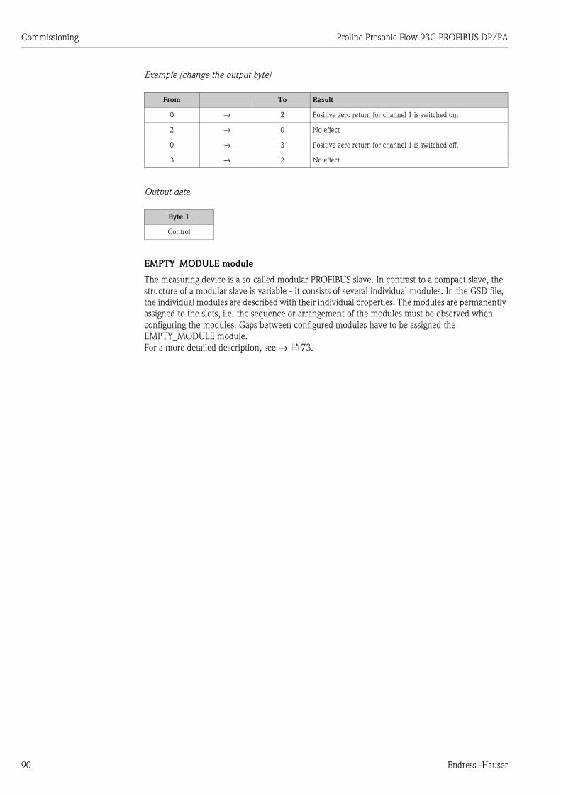
Commissioning Proline Prosonic Flow 93C PROFIBUS DP/PA
90 Endress+Hauser
Example (change the output byte)
Output data
EMPTY_MODULE module
The measuring device is a so-called modular PROFIBUS slave. In contrast to a compact slave, the
structure of a modular slave is variable - it consists of several individual modules. In the GSD file,
the individual modules are described with their individual properties. The modules are permanently
assigned to the slots, i.e. the sequence or arrangement of the modules must be observed when
configuring the modules. Gaps between configured modules have to be assigned the
EMPTY_MODULE module.
For a more detailed description, see → ä 73.
From To Result
0 → 2 Positive zero return for channel 1 is switched on.
2 → 0 No effect
0 → 3 Positive zero return for channel 1 is switched off.
3 → 2 No effect
Byte 1
Control
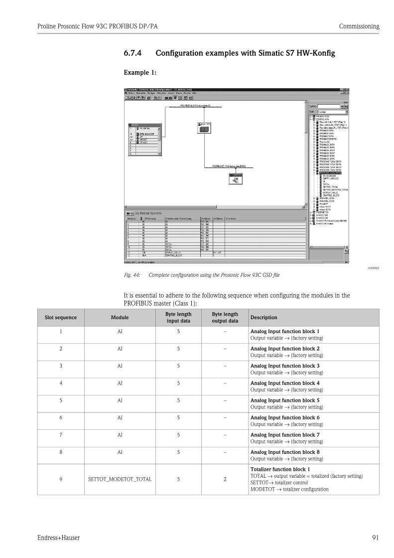
Proline Prosonic Flow 93C PROFIBUS DP/PA Commissioning
Endress+Hauser 91
6.7.4 Configuration examples with Simatic S7 HW-Konfig
Example 1:
A0008802
Fig. 44: Complete configuration using the Prosonic Flow 93C GSD file
It is essential to adhere to the following sequence when configuring the modules in the
PROFIBUS master (Class 1):
Slot sequence ModuleByte length
input data
Byte length
output dataDescription
1 AI 5 – Analog Input function block 1
Output variable → (factory setting)
2 AI 5 – Analog Input function block 2
Output variable → (factory setting)
3 AI 5 – Analog Input function block 3
Output variable → (factory setting)
4 AI 5 – Analog Input function block 4
Output variable → (factory setting)
5 AI 5 – Analog Input function block 5
Output variable → (factory setting)
6 AI 5 – Analog Input function block 6
Output variable → (factory setting)
7 AI 5 – Analog Input function block 7
Output variable → (factory setting)
8 AI 5 – Analog Input function block 8
Output variable → (factory setting)
9 SETTOT_MODETOT_TOTAL 5 2
Totalizer function block 1
TOTAL → output variable = totalized (factory setting)
SETTOT→ totalizer control
MODETOT → totalizer configuration

Commissioning Proline Prosonic Flow 93C PROFIBUS DP/PA
92 Endress+Hauser
10 SETTOT_MODETOT_TOTAL 5 2
Totalizer function block 2
TOTAL → output variable = totalized (factory setting)
SETTOT→ totalizer control
MODETOT → totalizer configuration
11 SETTOT_MODETOT_TOTAL 5 2
Totalizer function block 3
TOTAL → output variable = totalized (factory setting)
SETTOT→ totalizer control
MODETOT → totalizer configuration
12 DISPLAY_VALUE – 5 Default value for local display
13 CONTROL_BLOCK – 1 Control of device functions
Slot sequence ModuleByte length
input data
Byte length
output dataDescription
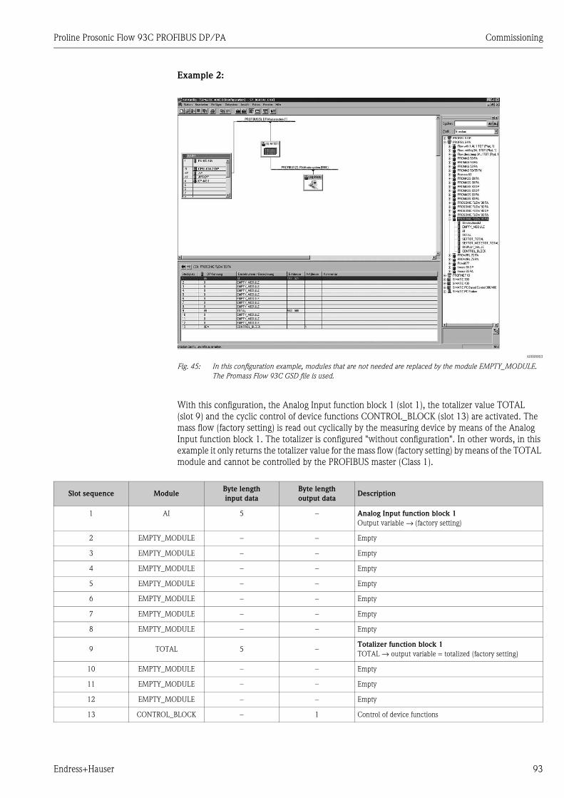
Proline Prosonic Flow 93C PROFIBUS DP/PA Commissioning
Endress+Hauser 93
Example 2:
A0008803
Fig. 45: In this configuration example, modules that are not needed are replaced by the module EMPTY_MODULE.
The Promass Flow 93C GSD file is used.
With this configuration, the Analog Input function block 1 (slot 1), the totalizer value TOTAL
(slot 9) and the cyclic control of device functions CONTROL_BLOCK (slot 13) are activated. The
mass flow (factory setting) is read out cyclically by the measuring device by means of the Analog
Input function block 1. The totalizer is configured "without configuration". In other words, in this
example it only returns the totalizer value for the mass flow (factory setting) by means of the TOTAL
module and cannot be controlled by the PROFIBUS master (Class 1).
Slot sequence ModuleByte length
input data
Byte length
output dataDescription
1 AI 5 – Analog Input function block 1
Output variable → (factory setting)
2 EMPTY_MODULE – – Empty
3 EMPTY_MODULE – – Empty
4 EMPTY_MODULE – – Empty
5 EMPTY_MODULE – – Empty
6 EMPTY_MODULE – – Empty
7 EMPTY_MODULE – – Empty
8 EMPTY_MODULE – – Empty
9 TOTAL 5 –Totalizer function block 1
TOTAL → output variable = totalized (factory setting)
10 EMPTY_MODULE – – Empty
11 EMPTY_MODULE – – Empty
12 EMPTY_MODULE – – Empty
13 CONTROL_BLOCK – 1 Control of device functions
Commissioning Proline Prosonic Flow 93C PROFIBUS DP/PA
94 Endress+Hauser
6.8 Acyclic data transmission PROFIBUS DP/PA
Acyclic data transmission is used to transmit parameters during commissioning or maintenance, or
to display additional measured variables that are not included in cyclic data traffic. Thus parameters
for identification, control or adjustment in the various blocks (Physical Block, Transducer Block,
function block) can be changed while the device is in the process of cyclic data transmission with a
PLC.
The measuring device supports the two basic types of acyclic data transmission:
• MS2AC communication with 2 available SAPs
• MS1AC communication
6.8.1 Master class 2 acyclic (MS2AC)
MS2AC is acyclic data transmission between a field device and a Class 2 master (e.g. FieldCare,
Siemens PDM etc. → ä 49). During this process, the master opens a communication channel via
an SAP (Service Access Point) to access the device.
All parameters to be exchanged with a device via PROFIBUS must be made known to a Class 2
master. This assignment to each individual parameter takes place either in a device description
(DD), a DTM (Device Type Manager), or inside a software component in the master via slot and
index addressing.
When using MS2AC communication, note the following:
• As described above, a Class 2 master accesses a device via special SAPs.
Therefore, the number of Class 2 masters that can communicate with a device simultaneously is
limited to the number of SAPs available for this data transmission.
• The use of a Class 2 master increases the cycle time of the bus system. This must be taken into
account when programming the control system used.
6.8.2 Master class 1 acyclic (MS1AC)
In MS1AC, a cyclic master, that is already reading the cyclic data from the device or writing to the
device opens the communication channel via the SAP 0x33 (special Service Access Point for
MS1AC) and can then read or write a parameter acyclically like a Class 2 master via the slot and
the index (if supported).
When using MS1AC communication, note the following:
• Currently, few PROFIBUS masters on the market support this data transmission.
• MS1AC is not supported by all PROFIBUS devices.
• In the user program, note that constant writing of parameters (for example, at every cycle of the
program) can drastically reduce the service life of a device. Acyclically written parameters are
written to voltage-resistant memory modules (EEPROM, Flash etc.). These memory modules are
designed for a limited number of write operations. In normal operation without MS1AC (during
parameter configuration), the number of write operations does not even come close to this
number. If programming is incorrect, this maximum number can be reached quickly, drastically
reducing a device's service life.
! Note!
The memory module of the measuring device is designed for one million writes.
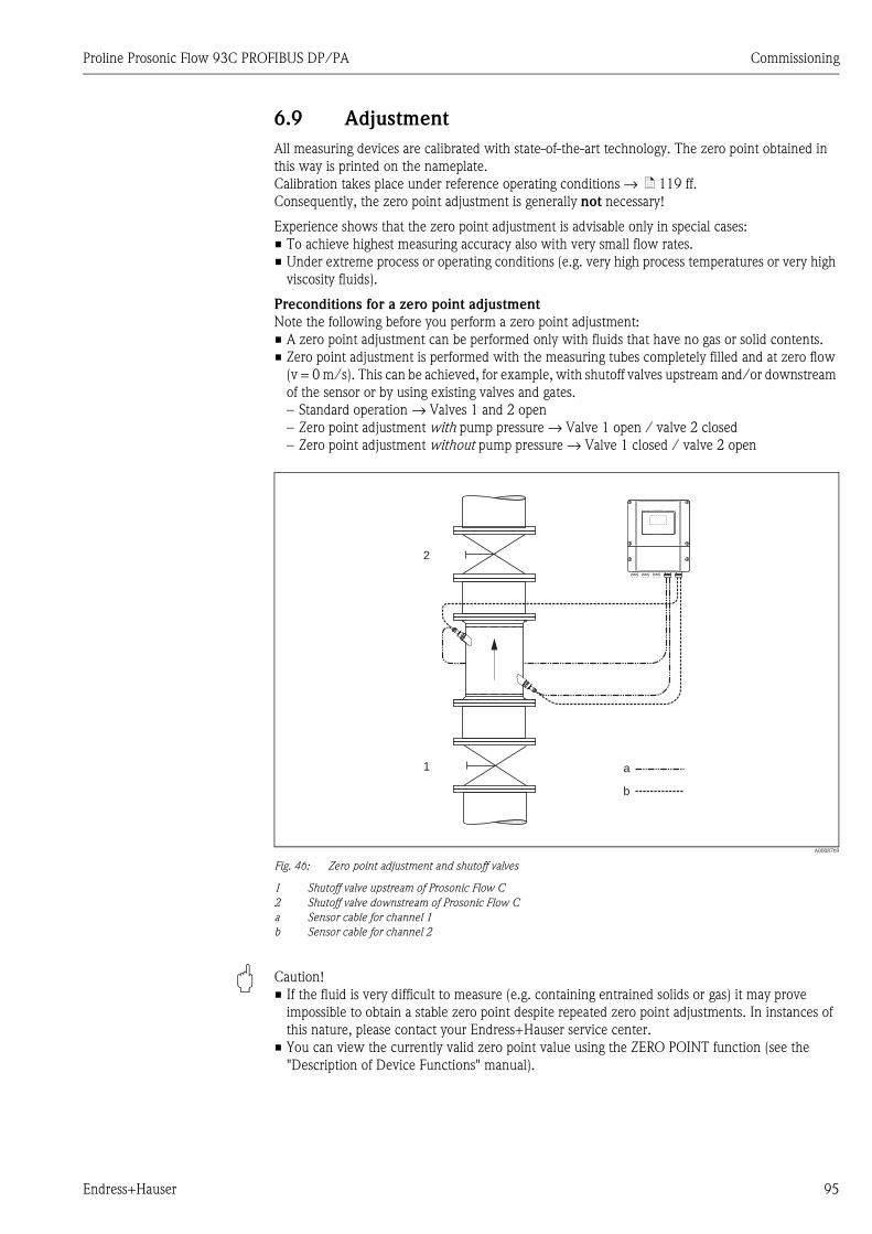
Proline Prosonic Flow 93C PROFIBUS DP/PA Commissioning
Endress+Hauser 95
6.9 Adjustment
All measuring devices are calibrated with state-of-the-art technology. The zero point obtained in
this way is printed on the nameplate.
Calibration takes place under reference operating conditions → ä 119 ff.
Consequently, the zero point adjustment is generally not necessary!
Experience shows that the zero point adjustment is advisable only in special cases:
• To achieve highest measuring accuracy also with very small flow rates.
• Under extreme process or operating conditions (e.g. very high process temperatures or very high
viscosity fluids).
Preconditions for a zero point adjustment
Note the following before you perform a zero point adjustment:
• A zero point adjustment can be performed only with fluids that have no gas or solid contents.
• Zero point adjustment is performed with the measuring tubes completely filled and at zero flow
(v = 0 m/s). This can be achieved, for example, with shutoff valves upstream and/or downstream
of the sensor or by using existing valves and gates.
– Standard operation → Valves 1 and 2 open
– Zero point adjustment with pump pressure → Valve 1 open / valve 2 closed
– Zero point adjustment without pump pressure → Valve 1 closed / valve 2 open
A0008769
Fig. 46: Zero point adjustment and shutoff valves
1 Shutoff valve upstream of Prosonic Flow C
2 Shutoff valve downstream of Prosonic Flow C
a Sensor cable for channel 1
b Sensor cable for channel 2
" Caution!
• If the fluid is very difficult to measure (e.g. containing entrained solids or gas) it may prove
impossible to obtain a stable zero point despite repeated zero point adjustments. In instances of
this nature, please contact your Endress+Hauser service center.
• You can view the currently valid zero point value using the ZERO POINT function (see the
"Description of Device Functions" manual).
1
2
a
b
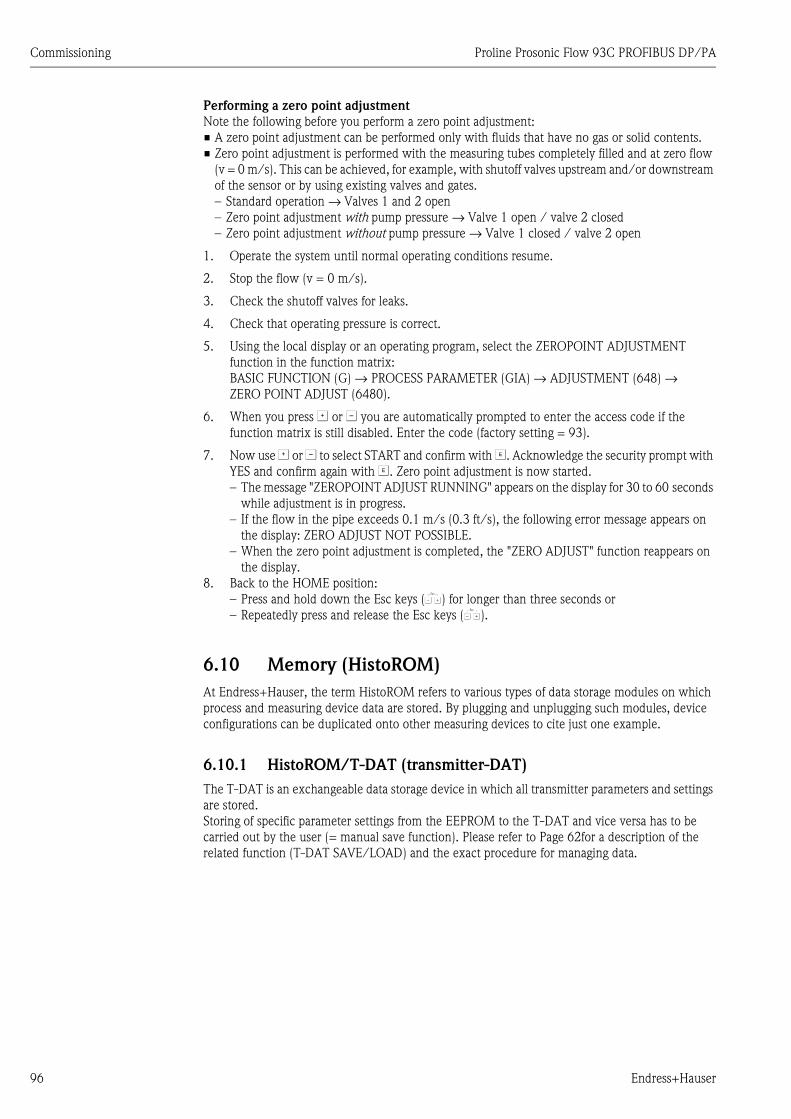
Commissioning Proline Prosonic Flow 93C PROFIBUS DP/PA
96 Endress+Hauser
Performing a zero point adjustment
Note the following before you perform a zero point adjustment:
• A zero point adjustment can be performed only with fluids that have no gas or solid contents.
• Zero point adjustment is performed with the measuring tubes completely filled and at zero flow
(v = 0 m/s). This can be achieved, for example, with shutoff valves upstream and/or downstream
of the sensor or by using existing valves and gates.
– Standard operation → Valves 1 and 2 open
– Zero point adjustment with pump pressure → Valve 1 open / valve 2 closed
– Zero point adjustment without pump pressure → Valve 1 closed / valve 2 open
1. Operate the system until normal operating conditions resume.
2. Stop the flow (v = 0 m/s).
3. Check the shutoff valves for leaks.
4. Check that operating pressure is correct.
5. Using the local display or an operating program, select the ZEROPOINT ADJUSTMENT
function in the function matrix:
BASIC FUNCTION (G) → PROCESS PARAMETER (GIA) → ADJUSTMENT (648) →
ZERO POINT ADJUST (6480).
6. When you press O or S you are automatically prompted to enter the access code if the
function matrix is still disabled. Enter the code (factory setting = 93).
7. Now use O or S to select START and confirm with F. Acknowledge the security prompt with
YES and confirm again with F. Zero point adjustment is now started.
– The message "ZEROPOINT ADJUST RUNNING" appears on the display for 30 to 60 seconds
while adjustment is in progress.
– If the flow in the pipe exceeds 0.1 m/s (0.3 ft/s), the following error message appears on
the display: ZERO ADJUST NOT POSSIBLE.
– When the zero point adjustment is completed, the "ZERO ADJUST" function reappears on
the display.
8. Back to the HOME position:
– Press and hold down the Esc keys (X) for longer than three seconds or
– Repeatedly press and release the Esc keys (X).
6.10 Memory (HistoROM)
At Endress+Hauser, the term HistoROM refers to various types of data storage modules on which
process and measuring device data are stored. By plugging and unplugging such modules, device
configurations can be duplicated onto other measuring devices to cite just one example.
6.10.1 HistoROM/T-DAT (transmitter-DAT)
The T-DAT is an exchangeable data storage device in which all transmitter parameters and settings
are stored.
Storing of specific parameter settings from the EEPROM to the T-DAT and vice versa has to be
carried out by the user (= manual save function). Please refer to Page 62for a description of the
related function (T-DAT SAVE/LOAD) and the exact procedure for managing data.

Proline Prosonic Flow 93C PROFIBUS DP/PA Maintenance
Endress+Hauser 97
7 Maintenance
No special maintenance work is required.
7.1 Exterior cleaning
When cleaning the exterior of measuring devices, always use cleaning agents that do not attack the
surface of the housing and the seals.
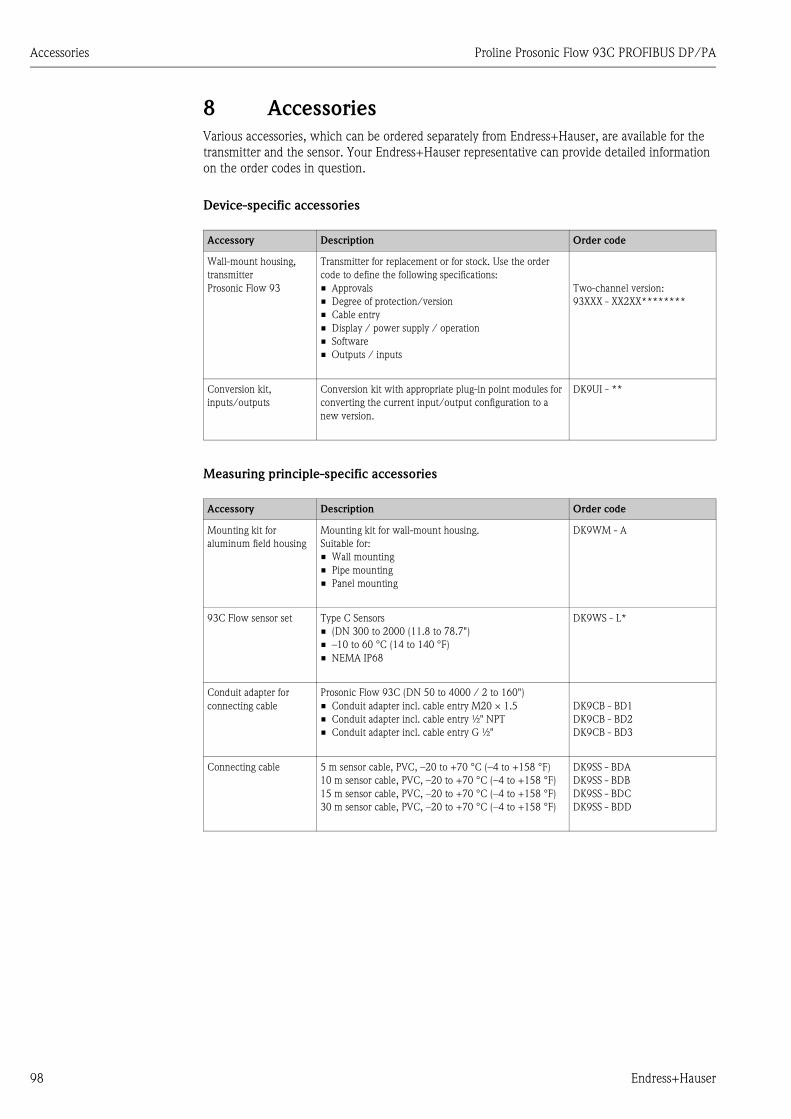
Accessories Proline Prosonic Flow 93C PROFIBUS DP/PA
98 Endress+Hauser
8 Accessories
Various accessories, which can be ordered separately from Endress+Hauser, are available for the
transmitter and the sensor. Your Endress+Hauser representative can provide detailed information
on the order codes in question.
Device-specific accessories
Measuring principle-specific accessories
Accessory Description Order code
Wall-mount housing,
transmitter
Prosonic Flow 93
Transmitter for replacement or for stock. Use the order
code to define the following specifications:
• Approvals
• Degree of protection/version
• Cable entry
• Display / power supply / operation
• Software
• Outputs / inputs
Two-channel version:
93XXX - XX2XX********
Conversion kit,
inputs/outputs
Conversion kit with appropriate plug-in point modules for
converting the current input/output configuration to a
new version.
DK9UI - **
Accessory Description Order code
Mounting kit for
aluminum field housing
Mounting kit for wall-mount housing.
Suitable for:
• Wall mounting
• Pipe mounting
• Panel mounting
DK9WM - A
93C Flow sensor set Type C Sensors
• (DN 300 to 2000 (11.8 to 78.7")
• –10 to 60 °C (14 to 140 °F)
• NEMA IP68
DK9WS - L*
Conduit adapter for
connecting cable
Prosonic Flow 93C (DN 50 to 4000 / 2 to 160")
• Conduit adapter incl. cable entry M20 × 1.5
• Conduit adapter incl. cable entry ½" NPT
• Conduit adapter incl. cable entry G ½"
DK9CB - BD1
DK9CB - BD2
DK9CB - BD3
Connecting cable 5 m sensor cable, PVC, –20 to +70 °C (–4 to +158 °F)
10 m sensor cable, PVC, –20 to +70 °C (–4 to +158 °F)
15 m sensor cable, PVC, –20 to +70 °C (–4 to +158 °F)
30 m sensor cable, PVC, –20 to +70 °C (–4 to +158 °F)
DK9SS - BDA
DK9SS - BDB
DK9SS - BDC
DK9SS - BDD
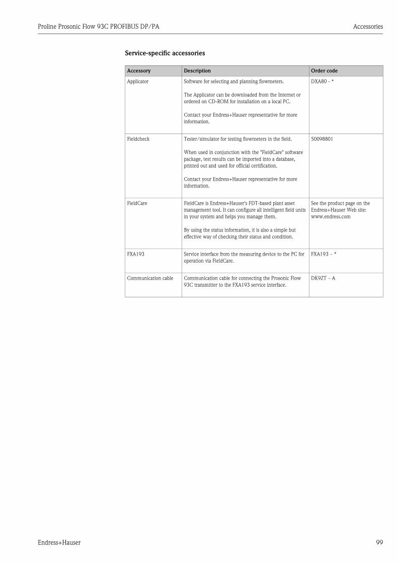
Proline Prosonic Flow 93C PROFIBUS DP/PA Accessories
Endress+Hauser 99
Service-specific accessories
Accessory Description Order code
Applicator Software for selecting and planning flowmeters.
The Applicator can be downloaded from the Internet or
ordered on CD-ROM for installation on a local PC.
Contact your Endress+Hauser representative for more
information.
DXA80 - *
Fieldcheck Tester/simulator for testing flowmeters in the field.
When used in conjunction with the "FieldCare" software
package, test results can be imported into a database,
printed out and used for official certification.
Contact your Endress+Hauser representative for more
information.
50098801
FieldCare FieldCare is Endress+Hauser's FDT-based plant asset
management tool. It can configure all intelligent field units
in your system and helps you manage them.
By using the status information, it is also a simple but
effective way of checking their status and condition.
See the product page on the
Endress+Hauser Web site:
www.endress.com
FXA193 Service interface from the measuring device to the PC for
operation via FieldCare.
FXA193 – *
Communication cable Communication cable for connecting the Prosonic Flow
93C transmitter to the FXA193 service interface.
DK9ZT – A
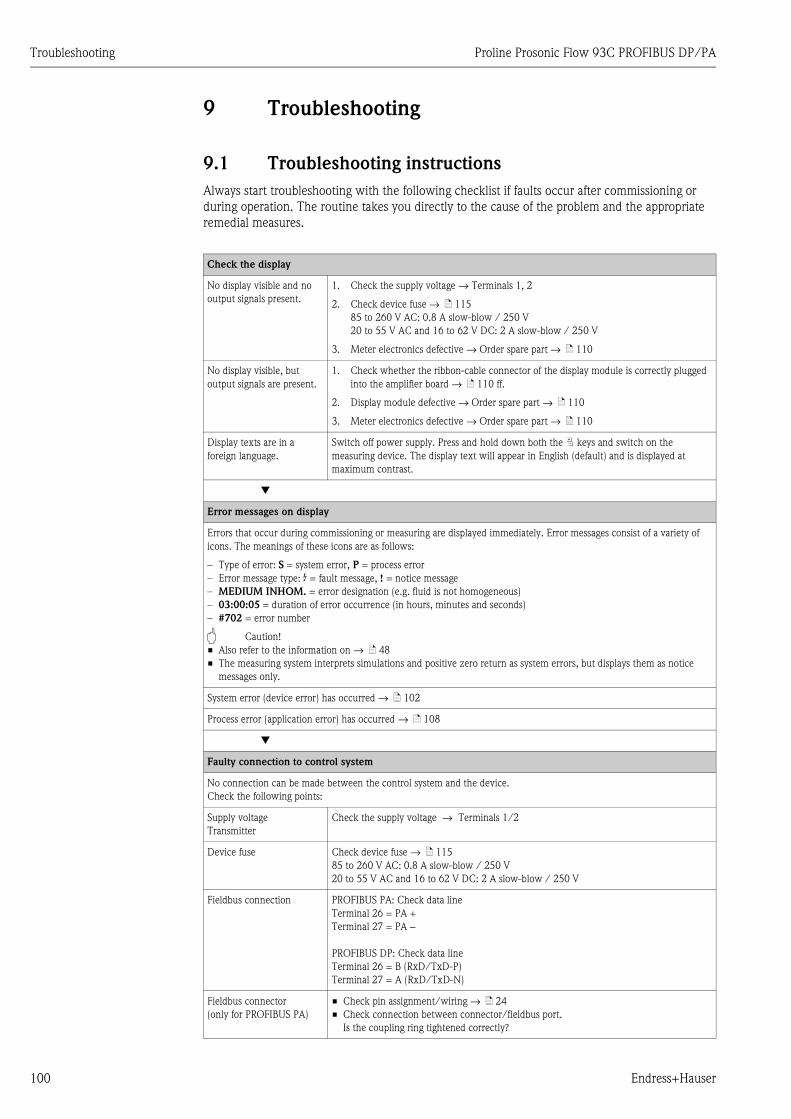
Troubleshooting Proline Prosonic Flow 93C PROFIBUS DP/PA
100 Endress+Hauser
9 Troubleshooting
9.1 Troubleshooting instructions
Always start troubleshooting with the following checklist if faults occur after commissioning or
during operation. The routine takes you directly to the cause of the problem and the appropriate
remedial measures.
Check the display
No display visible and no
output signals present.
1. Check the supply voltage → Terminals 1, 2
2. Check device fuse → ä 115
85 to 260 V AC: 0.8 A slow-blow / 250 V
20 to 55 V AC and 16 to 62 V DC: 2 A slow-blow / 250 V
3. Meter electronics defective → Order spare part → ä 110
No display visible, but
output signals are present.
1. Check whether the ribbon-cable connector of the display module is correctly plugged
into the amplifier board → ä 110 ff.
2. Display module defective → Order spare part → ä 110
3. Meter electronics defective → Order spare part → ä 110
Display texts are in a
foreign language.
Switch off power supply. Press and hold down both the P keys and switch on the
measuring device. The display text will appear in English (default) and is displayed at
maximum contrast.
Æ
Error messages on display
Errors that occur during commissioning or measuring are displayed immediately. Error messages consist of a variety of
icons. The meanings of these icons are as follows:
– Type of error: S = system error, P = process error
– Error message type: $ = fault message, ! = notice message
– MEDIUM INHOM. = error designation (e.g. fluid is not homogeneous)
– 03:00:05 = duration of error occurrence (in hours, minutes and seconds)
– #702 = error number
" Caution!
• Also refer to the information on → ä 48
• The measuring system interprets simulations and positive zero return as system errors, but displays them as notice
messages only.
System error (device error) has occurred → ä 102
Process error (application error) has occurred → ä 108
Æ
Faulty connection to control system
No connection can be made between the control system and the device.
Check the following points:
Supply voltage
Transmitter
Check the supply voltage → Terminals 1/2
Device fuse Check device fuse → ä 115
85 to 260 V AC: 0.8 A slow-blow / 250 V
20 to 55 V AC and 16 to 62 V DC: 2 A slow-blow / 250 V
Fieldbus connection PROFIBUS PA: Check data line
Terminal 26 = PA +
Terminal 27 = PA −
PROFIBUS DP: Check data line
Terminal 26 = B (RxD/TxD-P)
Terminal 27 = A (RxD/TxD-N)
Fieldbus connector
(only for PROFIBUS PA)
• Check pin assignment/wiring → ä 24
• Check connection between connector/fieldbus port.
Is the coupling ring tightened correctly?
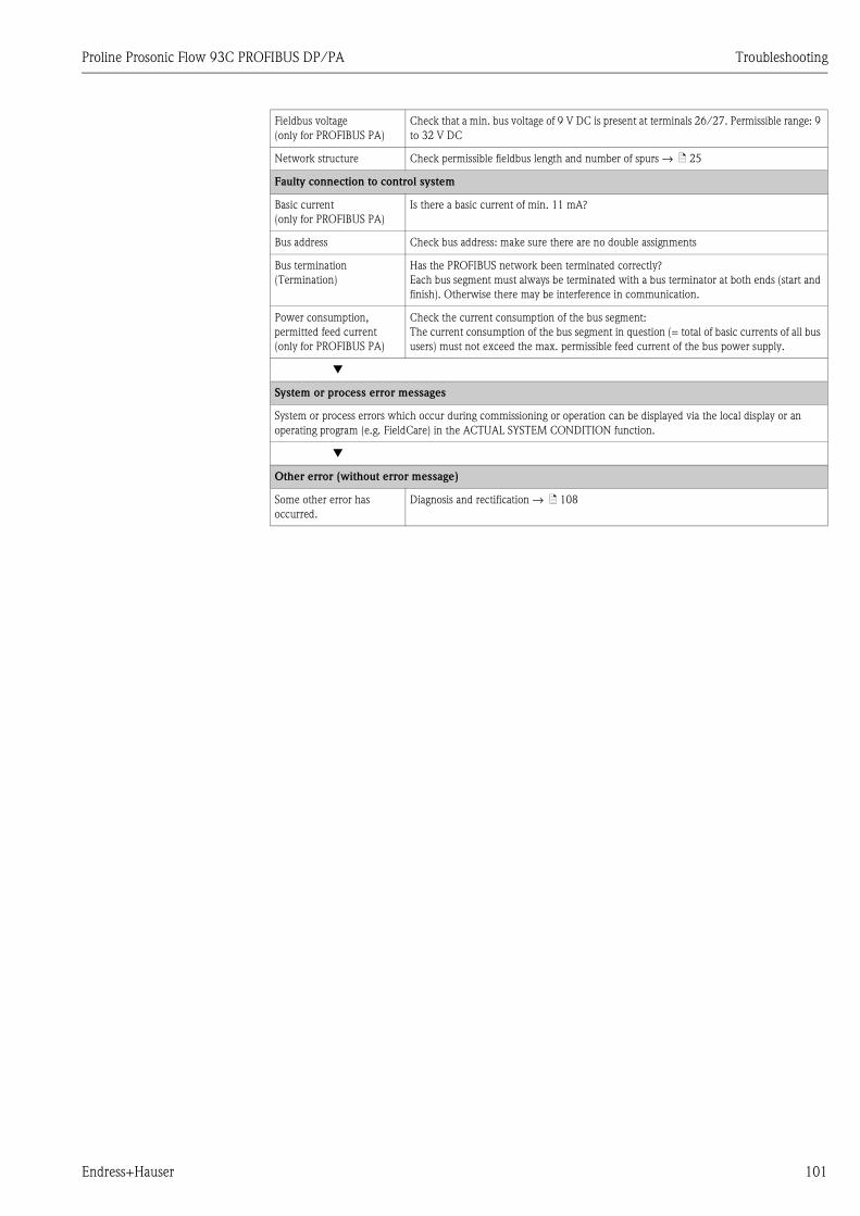
Proline Prosonic Flow 93C PROFIBUS DP/PA Troubleshooting
Endress+Hauser 101
Fieldbus voltage
(only for PROFIBUS PA)
Check that a min. bus voltage of 9 V DC is present at terminals 26/27. Permissible range: 9
to 32 V DC
Network structure Check permissible fieldbus length and number of spurs → ä 25
Faulty connection to control system
Basic current
(only for PROFIBUS PA)
Is there a basic current of min. 11 mA?
Bus address Check bus address: make sure there are no double assignments
Bus termination
(Termination)
Has the PROFIBUS network been terminated correctly?
Each bus segment must always be terminated with a bus terminator at both ends (start and
finish). Otherwise there may be interference in communication.
Power consumption,
permitted feed current
(only for PROFIBUS PA)
Check the current consumption of the bus segment:
The current consumption of the bus segment in question (= total of basic currents of all bus
users) must not exceed the max. permissible feed current of the bus power supply.
Æ
System or process error messages
System or process errors which occur during commissioning or operation can be displayed via the local display or an
operating program (e.g. FieldCare) in the ACTUAL SYSTEM CONDITION function.
Æ
Other error (without error message)
Some other error has
occurred.
Diagnosis and rectification → ä 108
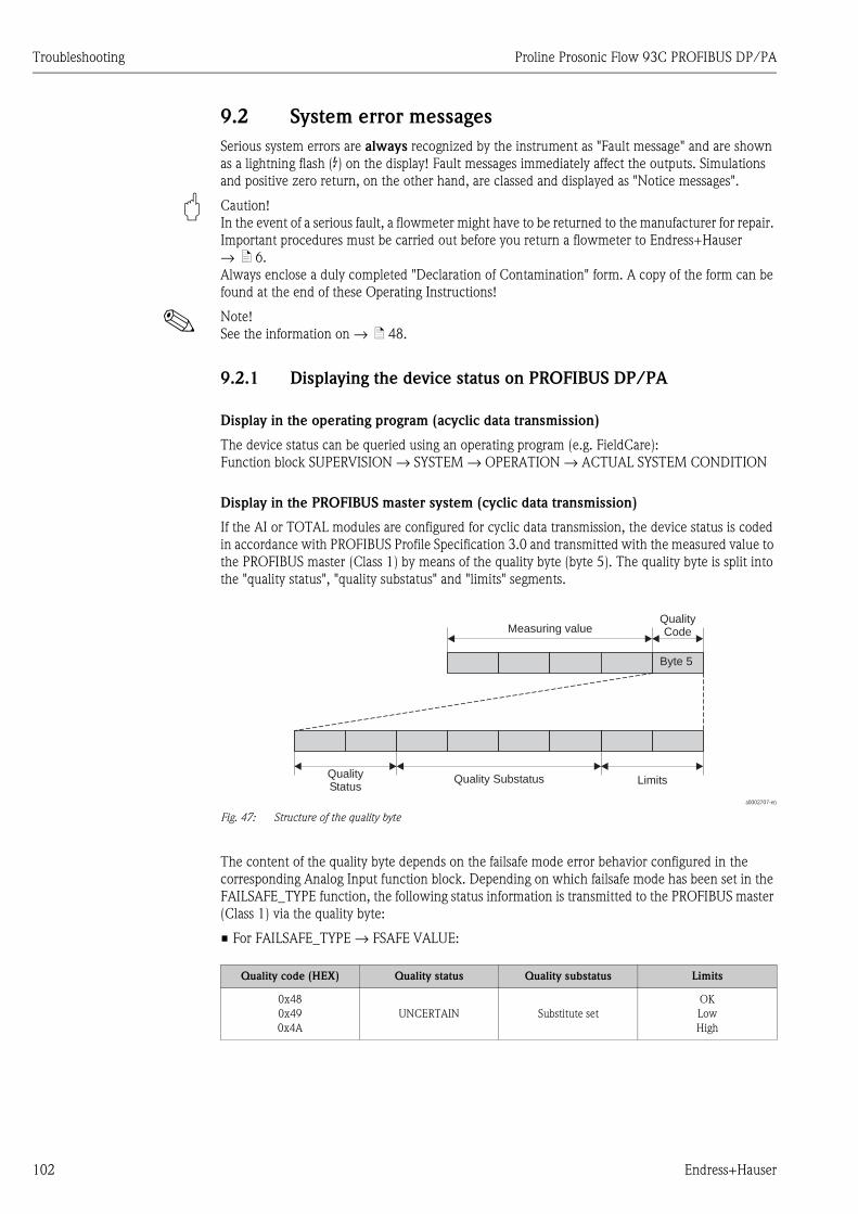
Troubleshooting Proline Prosonic Flow 93C PROFIBUS DP/PA
102 Endress+Hauser
9.2 System error messages
Serious system errors are always recognized by the instrument as "Fault message" and are shown
as a lightning flash ($) on the display! Fault messages immediately affect the outputs. Simulations
and positive zero return, on the other hand, are classed and displayed as "Notice messages".
" Caution!
In the event of a serious fault, a flowmeter might have to be returned to the manufacturer for repair.
Important procedures must be carried out before you return a flowmeter to Endress+Hauser
→ ä 6.
Always enclose a duly completed "Declaration of Contamination" form. A copy of the form can be
found at the end of these Operating Instructions!
! Note!
See the information on → ä 48.
9.2.1 Displaying the device status on PROFIBUS DP/PA
Display in the operating program (acyclic data transmission)
The device status can be queried using an operating program (e.g. FieldCare):
Function block SUPERVISION → SYSTEM → OPERATION → ACTUAL SYSTEM CONDITION
Display in the PROFIBUS master system (cyclic data transmission)
If the AI or TOTAL modules are configured for cyclic data transmission, the device status is coded
in accordance with PROFIBUS Profile Specification 3.0 and transmitted with the measured value to
the PROFIBUS master (Class 1) by means of the quality byte (byte 5). The quality byte is split into
the "quality status", "quality substatus" and "limits" segments.
a0002707-en
Fig. 47: Structure of the quality byte
The content of the quality byte depends on the failsafe mode error behavior configured in the
corresponding Analog Input function block. Depending on which failsafe mode has been set in the
FAILSAFE_TYPE function, the following status information is transmitted to the PROFIBUS master
(Class 1) via the quality byte:
• For FAILSAFE_TYPE → FSAFE VALUE:
QualityCodeMeasuring value
LimitsQuality SubstatusQualityStatus
Byte 5
Quality code (HEX) Quality status Quality substatus Limits
0x48
0x49
0x4A
UNCERTAIN Substitute set
OK
Low
High
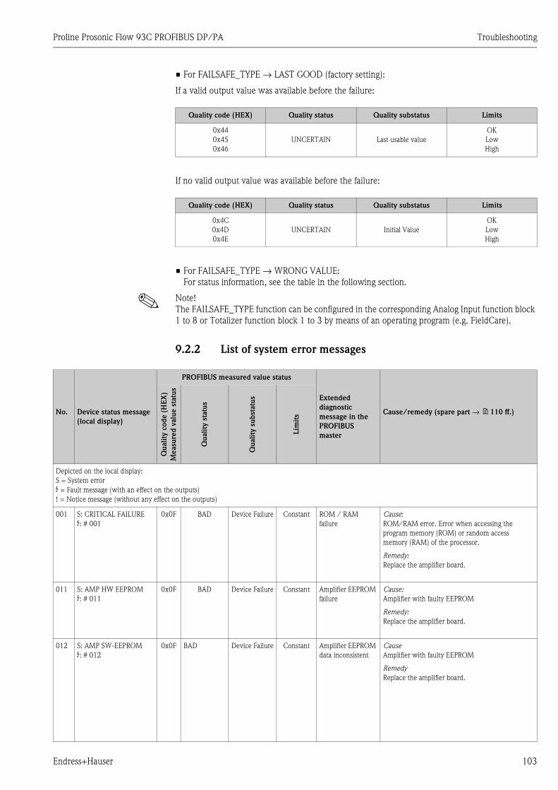
Proline Prosonic Flow 93C PROFIBUS DP/PA Troubleshooting
Endress+Hauser 103
• For FAILSAFE_TYPE → LAST GOOD (factory setting):
If a valid output value was available before the failure:
If no valid output value was available before the failure:
• For FAILSAFE_TYPE → WRONG VALUE:
For status information, see the table in the following section.
! Note!
The FAILSAFE_TYPE function can be configured in the corresponding Analog Input function block
1 to 8 or Totalizer function block 1 to 3 by means of an operating program (e.g. FieldCare).
9.2.2 List of system error messages
Quality code (HEX) Quality status Quality substatus Limits
0x44
0x45
0x46
UNCERTAIN Last usable value
OK
Low
High
Quality code (HEX) Quality status Quality substatus Limits
0x4C
0x4D
0x4E
UNCERTAIN Initial Value
OK
Low
High
No. Device status message
(local display)
PROFIBUS measured value status
Extended
diagnostic
message in the
PROFIBUS
master
Cause/remedy (spare part → ä 110 ff.)
Qu
ali
ty c
od
e (
HE
X)
Measu
red
valu
e s
tatu
s
Qu
ali
ty s
tatu
s
Qu
ali
ty s
ub
statu
s
Lim
its
Depicted on the local display:
S = System error
$ = Fault message (with an effect on the outputs)
! = Notice message (without any effect on the outputs)
001 S: CRITICAL FAILURE
$: # 001
0x0F BAD Device Failure Constant ROM / RAM
failure
Cause:
ROM/RAM error. Error when accessing the
program memory (ROM) or random access
memory (RAM) of the processor.
Remedy:
Replace the amplifier board.
011 S: AMP HW EEPROM
$: # 011
0x0F BAD Device Failure Constant Amplifier EEPROM
failure
Cause:
Amplifier with faulty EEPROM
Remedy:
Replace the amplifier board.
012 S: AMP SW-EEPROM
$: # 012
0x0F BAD Device Failure Constant Amplifier EEPROM
data inconsistent
Cause
Amplifier with faulty EEPROM
Remedy
Replace the amplifier board.
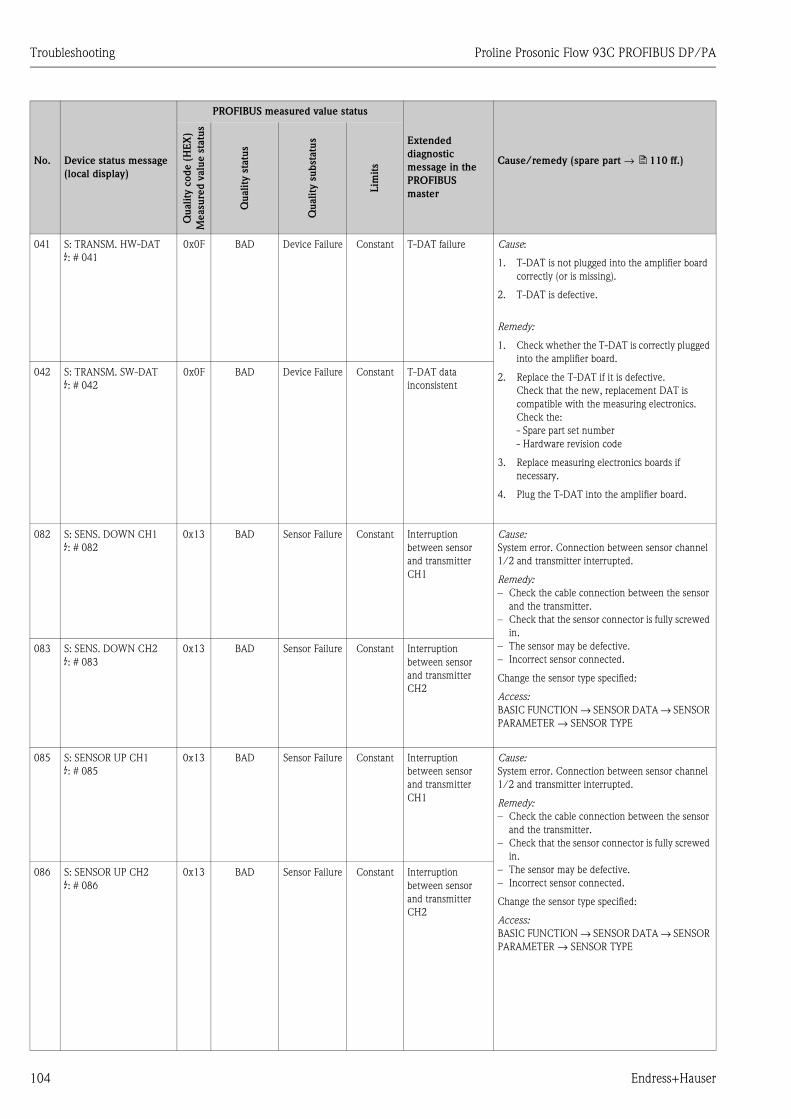
Troubleshooting Proline Prosonic Flow 93C PROFIBUS DP/PA
104 Endress+Hauser
041 S: TRANSM. HW-DAT
$: # 041
0x0F BAD Device Failure Constant T-DAT failure Cause:
1. T-DAT is not plugged into the amplifier board
correctly (or is missing).
2. T-DAT is defective.
Remedy:
1. Check whether the T-DAT is correctly plugged
into the amplifier board.
2. Replace the T-DAT if it is defective.
Check that the new, replacement DAT is
compatible with the measuring electronics.
Check the:
- Spare part set number
- Hardware revision code
3. Replace measuring electronics boards if
necessary.
4. Plug the T-DAT into the amplifier board.
042 S: TRANSM. SW-DAT
$: # 042
0x0F BAD Device Failure Constant T-DAT data
inconsistent
082 S: SENS. DOWN CH1
$: # 082
0x13 BAD Sensor Failure Constant Interruption
between sensor
and transmitter
CH1
Cause:
System error. Connection between sensor channel
1/2 and transmitter interrupted.
Remedy:
– Check the cable connection between the sensor
and the transmitter.
– Check that the sensor connector is fully screwed
in.
– The sensor may be defective.
– Incorrect sensor connected.
Change the sensor type specified:
Access:
BASIC FUNCTION → SENSOR DATA → SENSOR
PARAMETER → SENSOR TYPE
083 S: SENS. DOWN CH2
$: # 083
0x13 BAD Sensor Failure Constant Interruption
between sensor
and transmitter
CH2
085 S: SENSOR UP CH1
$: # 085
0x13 BAD Sensor Failure Constant Interruption
between sensor
and transmitter
CH1
Cause:
System error. Connection between sensor channel
1/2 and transmitter interrupted.
Remedy:
– Check the cable connection between the sensor
and the transmitter.
– Check that the sensor connector is fully screwed
in.
– The sensor may be defective.
– Incorrect sensor connected.
Change the sensor type specified:
Access:
BASIC FUNCTION → SENSOR DATA → SENSOR
PARAMETER → SENSOR TYPE
086 S: SENSOR UP CH2
$: # 086
0x13 BAD Sensor Failure Constant Interruption
between sensor
and transmitter
CH2
No. Device status message
(local display)
PROFIBUS measured value status
Extended
diagnostic
message in the
PROFIBUS
master
Cause/remedy (spare part → ä 110 ff.)
Qu
ali
ty c
od
e (
HE
X)
Measu
red
valu
e s
tatu
s
Qu
ali
ty s
tatu
s
Qu
ali
ty s
ub
statu
s
Lim
its
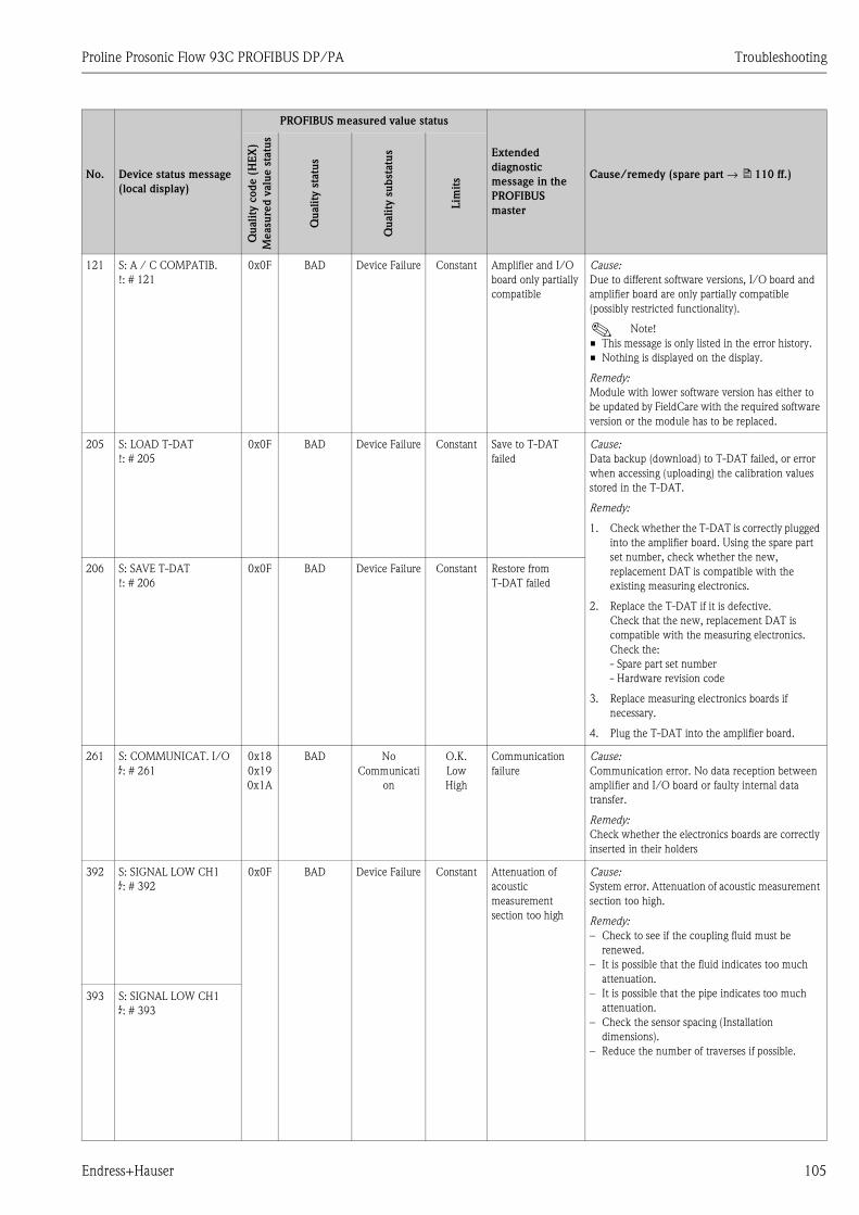
Proline Prosonic Flow 93C PROFIBUS DP/PA Troubleshooting
Endress+Hauser 105
121 S: A / C COMPATIB.
!: # 121
0x0F BAD Device Failure Constant Amplifier and I/O
board only partially
compatible
Cause:
Due to different software versions, I/O board and
amplifier board are only partially compatible
(possibly restricted functionality).
! Note!
• This message is only listed in the error history.
• Nothing is displayed on the display.
Remedy:
Module with lower software version has either to
be updated by FieldCare with the required software
version or the module has to be replaced.
205 S: LOAD T-DAT
!: # 205
0x0F BAD Device Failure Constant Save to T-DAT
failed
Cause:
Data backup (download) to T-DAT failed, or error
when accessing (uploading) the calibration values
stored in the T-DAT.
Remedy:
1. Check whether the T-DAT is correctly plugged
into the amplifier board. Using the spare part
set number, check whether the new,
replacement DAT is compatible with the
existing measuring electronics.
2. Replace the T-DAT if it is defective.
Check that the new, replacement DAT is
compatible with the measuring electronics.
Check the:
- Spare part set number
- Hardware revision code
3. Replace measuring electronics boards if
necessary.
4. Plug the T-DAT into the amplifier board.
206 S: SAVE T-DAT
!: # 206
0x0F BAD Device Failure Constant Restore from
T-DAT failed
261 S: COMMUNICAT. I/O
$: # 261
0x18
0x19
0x1A
BAD No
Communicati
on
O.K.
Low
High
Communication
failure
Cause:
Communication error. No data reception between
amplifier and I/O board or faulty internal data
transfer.
Remedy:
Check whether the electronics boards are correctly
inserted in their holders
392 S: SIGNAL LOW CH1
$: # 392
0x0F BAD Device Failure Constant Attenuation of
acoustic
measurement
section too high
Cause:
System error. Attenuation of acoustic measurement
section too high.
Remedy:
– Check to see if the coupling fluid must be
renewed.
– It is possible that the fluid indicates too much
attenuation.
– It is possible that the pipe indicates too much
attenuation.
– Check the sensor spacing (Installation
dimensions).
– Reduce the number of traverses if possible.
393 S: SIGNAL LOW CH1
$: # 393
No. Device status message
(local display)
PROFIBUS measured value status
Extended
diagnostic
message in the
PROFIBUS
master
Cause/remedy (spare part → ä 110 ff.)
Qu
ali
ty c
od
e (
HE
X)
Measu
red
valu
e s
tatu
s
Qu
ali
ty s
tatu
s
Qu
ali
ty s
ub
statu
s
Lim
its
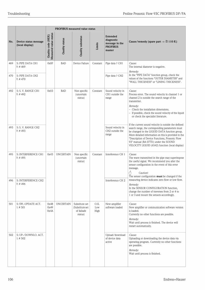
Troubleshooting Proline Prosonic Flow 93C PROFIBUS DP/PA
106 Endress+Hauser
469 S: PIPE DATA CH1
$: # 469
0x0F BAD Device Failure Constant Pipe data ? CH1 Cause:
The internal diameter is negative.
Remedy:
In the "PIPE DATA" function group, check the
values of the functions "OUTER DIAMETER" and
"WALL THICKNESS" or "LINING THICKNESS".
470 S: PIPE DATA CH2
$: # 470
Pipe data ? CH2
492 S: S. V. RANGE CH1
$: # 492
0x03 BAD Non specific
(uncertain
status)
Constant Sound velocity in
CH1 outside the
range
Cause:
Process error. The sound velocity in channel 1 or
channel 2 is outside the search range of the
transmitter.
Remedy:
– Check the installation dimensions.
– If possible, check the sound velocity of the liquid
or check the specialist literature.
If the current sound velocity is outside the defined
search range, the corresponding parameters must
be changed in the LIQUID DATA function group.
More detailed information on this is provided in the
"Description of Device Functions, Prosonic Flow
93" manual (BA 077D) under the SOUND
VELOCITY LIQUID (6542) function (local display)
493 S: S. V. RANGE CH2
$: # 493
Sound velocity in
CH2 outside the
range
495 S: INTERFERENCE CH1
$: # 495
0x43 UNCERTAIN Non specific
(uncertain
status)
Constant Interference CH 1 Cause:
The wave transmitted in the pipe may superimpose
the useful signal. We recommend you alter the
sensor configuration in the event of this error
message.
" Caution!
The sensor configuration must be changed if the
measuring device indicates zero flow or low flow.
Remedy:
In the SENSOR CONFIGURATION function,
change the number of traverses from 2 or 4 to
1 or 3 and mount the sensors accordingly.
496 S: INTERFERENCE CH2
$: # 496
Interference CH 2
501 S: SW.-UPDATE ACT.
!: # 501
0x48
0x49
0x4A
UNCERTAIN Substitute set
(Substitute set
of failsafe
status)
O.K.
Low
High
New amplifier
software loaded
Cause:
New amplifier or communication software version
is loaded.
Currently no other functions are possible.
Remedy:
Wait until process is finished. The device will
restart automatically.
502 S: UP-/DOWNLO. ACT.
!: # 502
Upload/download
of device data
active
Cause:
Uploading or downloading the device data via
operating program. Currently no other functions
are possible.
Remedy:
Wait until process is finished.
No. Device status message
(local display)
PROFIBUS measured value status
Extended
diagnostic
message in the
PROFIBUS
master
Cause/remedy (spare part → ä 110 ff.)
Qu
ali
ty c
od
e (
HE
X)
Measu
red
valu
e s
tatu
s
Qu
ali
ty s
tatu
s
Qu
ali
ty s
ub
statu
s
Lim
its
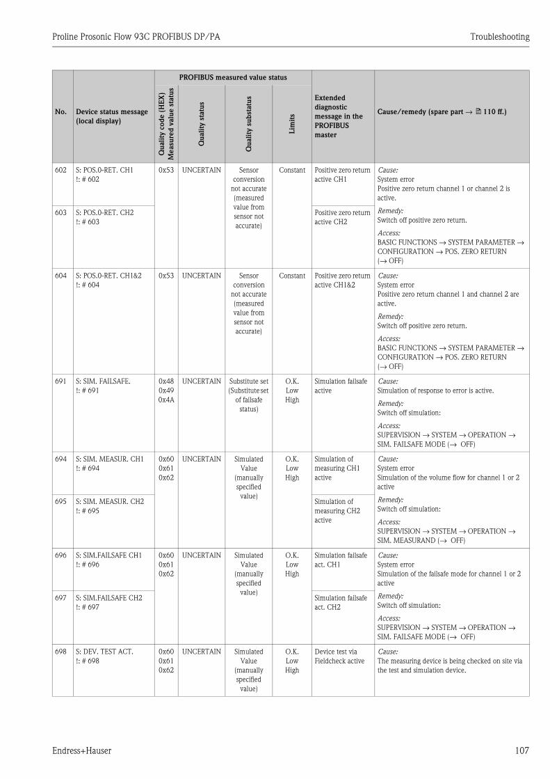
Proline Prosonic Flow 93C PROFIBUS DP/PA Troubleshooting
Endress+Hauser 107
602 S: POS.0-RET. CH1
!: # 602
0x53 UNCERTAIN Sensor
conversion
not accurate
(measured
value from
sensor not
accurate)
Constant Positive zero return
active CH1
Cause:
System error
Positive zero return channel 1 or channel 2 is
active.
Remedy:
Switch off positive zero return.
Access:
BASIC FUNCTIONS → SYSTEM PARAMETER →
CONFIGURATION → POS. ZERO RETURN
(→ OFF)
603 S: POS.0-RET. CH2
!: # 603
Positive zero return
active CH2
604 S: POS.0-RET. CH1&2
!: # 604
0x53 UNCERTAIN Sensor
conversion
not accurate
(measured
value from
sensor not
accurate)
Constant Positive zero return
active CH1&2
Cause:
System error
Positive zero return channel 1 and channel 2 are
active.
Remedy:
Switch off positive zero return.
Access:
BASIC FUNCTIONS → SYSTEM PARAMETER →
CONFIGURATION → POS. ZERO RETURN
(→ OFF)
691 S: SIM. FAILSAFE.
!: # 691
0x48
0x49
0x4A
UNCERTAIN Substitute set
(Substitute set
of failsafe
status)
O.K.
Low
High
Simulation failsafe
active
Cause:
Simulation of response to error is active.
Remedy:
Switch off simulation:
Access:
SUPERVISION → SYSTEM → OPERATION →
SIM. FAILSAFE MODE (→ OFF)
694 S: SIM. MEASUR. CH1
!: # 694
0x60
0x61
0x62
UNCERTAIN Simulated
Value
(manually
specified
value)
O.K.
Low
High
Simulation of
measuring CH1
active
Cause:
System error
Simulation of the volume flow for channel 1 or 2
active
Remedy:
Switch off simulation:
Access:
SUPERVISION → SYSTEM → OPERATION →
SIM. MEASURAND (→ OFF)
695 S: SIM. MEASUR. CH2
!: # 695
Simulation of
measuring CH2
active
696 S: SIM.FAILSAFE CH1
!: # 696
0x60
0x61
0x62
UNCERTAIN Simulated
Value
(manually
specified
value)
O.K.
Low
High
Simulation failsafe
act. CH1
Cause:
System error
Simulation of the failsafe mode for channel 1 or 2
active
Remedy:
Switch off simulation:
Access:
SUPERVISION → SYSTEM → OPERATION →
SIM. FAILSAFE MODE (→ OFF)
697 S: SIM.FAILSAFE CH2
!: # 697
Simulation failsafe
act. CH2
698 S: DEV. TEST ACT.
!: # 698
0x60
0x61
0x62
UNCERTAIN Simulated
Value
(manually
specified
value)
O.K.
Low
High
Device test via
Fieldcheck active
Cause:
The measuring device is being checked on site via
the test and simulation device.
No. Device status message
(local display)
PROFIBUS measured value status
Extended
diagnostic
message in the
PROFIBUS
master
Cause/remedy (spare part → ä 110 ff.)
Qu
ali
ty c
od
e (
HE
X)
Measu
red
valu
e s
tatu
s
Qu
ali
ty s
tatu
s
Qu
ali
ty s
ub
statu
s
Lim
its
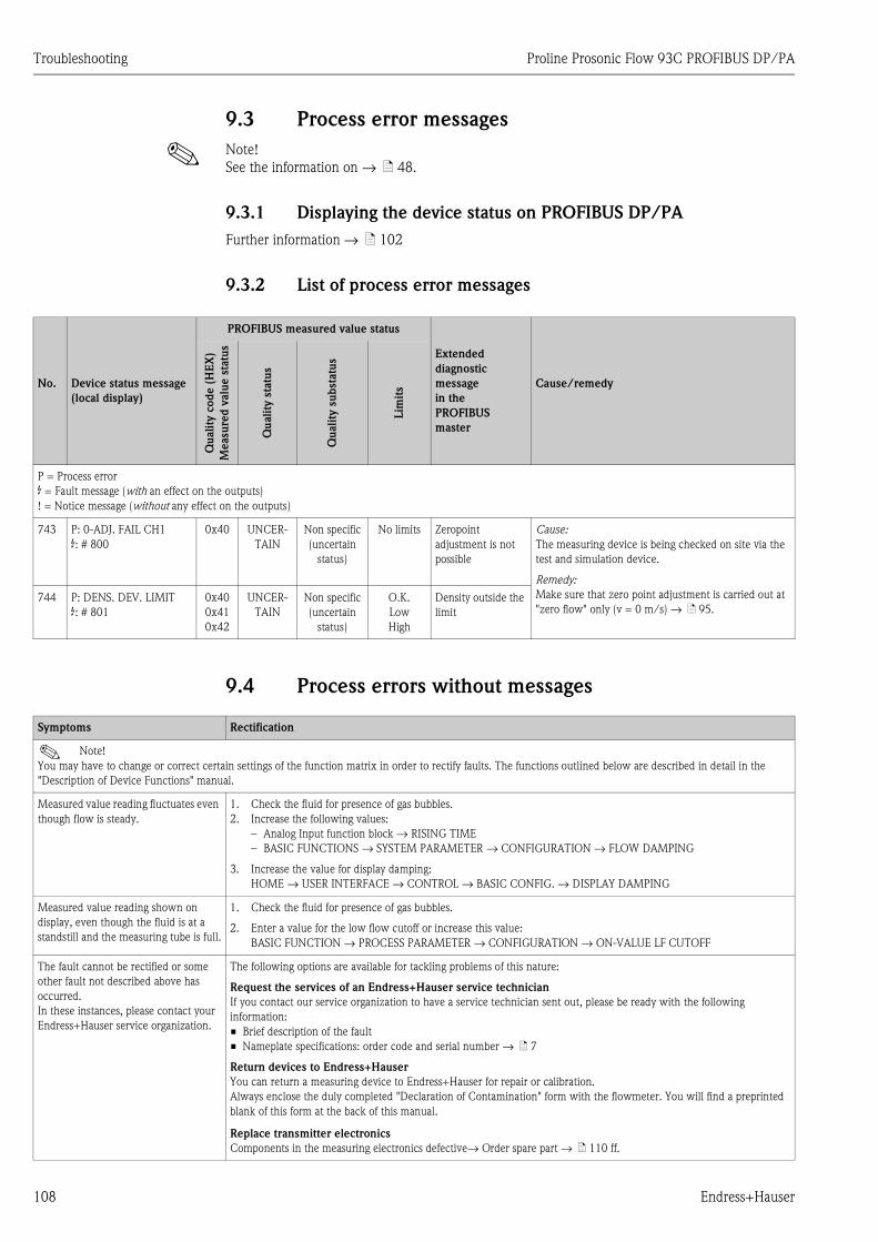
Troubleshooting Proline Prosonic Flow 93C PROFIBUS DP/PA
108 Endress+Hauser
9.3 Process error messages
! Note!
See the information on → ä 48.
9.3.1 Displaying the device status on PROFIBUS DP/PA
Further information → ä 102
9.3.2 List of process error messages
9.4 Process errors without messages
No. Device status message
(local display)
PROFIBUS measured value status
Extended
diagnostic
message
in the
PROFIBUS
master
Cause/remedy
Qu
ali
ty c
od
e (
HE
X)
Measu
red
valu
e s
tatu
s
Qu
ali
ty s
tatu
s
Qu
ali
ty s
ub
statu
s
Lim
its
P = Process error
$ = Fault message (with an effect on the outputs)
! = Notice message (without any effect on the outputs)
743 P: 0-ADJ. FAIL CH1
$: # 800
0x40 UNCER-
TAIN
Non specific
(uncertain
status)
No limits Zeropoint
adjustment is not
possible
Cause:
The measuring device is being checked on site via the
test and simulation device.
Remedy:
Make sure that zero point adjustment is carried out at
"zero flow" only (v = 0 m/s) → ä 95.744 P: DENS. DEV. LIMIT
$: # 801
0x40
0x41
0x42
UNCER-
TAIN
Non specific
(uncertain
status)
O.K.
Low
High
Density outside the
limit
Symptoms Rectification
! Note!
You may have to change or correct certain settings of the function matrix in order to rectify faults. The functions outlined below are described in detail in the
"Description of Device Functions" manual.
Measured value reading fluctuates even
though flow is steady.
1. Check the fluid for presence of gas bubbles.
2. Increase the following values:
– Analog Input function block → RISING TIME
– BASIC FUNCTIONS → SYSTEM PARAMETER → CONFIGURATION → FLOW DAMPING
3. Increase the value for display damping:
HOME → USER INTERFACE → CONTROL → BASIC CONFIG. → DISPLAY DAMPING
Measured value reading shown on
display, even though the fluid is at a
standstill and the measuring tube is full.
1. Check the fluid for presence of gas bubbles.
2. Enter a value for the low flow cutoff or increase this value:
BASIC FUNCTION → PROCESS PARAMETER → CONFIGURATION → ON-VALUE LF CUTOFF
The fault cannot be rectified or some
other fault not described above has
occurred.
In these instances, please contact your
Endress+Hauser service organization.
The following options are available for tackling problems of this nature:
Request the services of an Endress+Hauser service technician
If you contact our service organization to have a service technician sent out, please be ready with the following
information:
• Brief description of the fault
• Nameplate specifications: order code and serial number → ä 7
Return devices to Endress+Hauser
You can return a measuring device to Endress+Hauser for repair or calibration.
Always enclose the duly completed "Declaration of Contamination" form with the flowmeter. You will find a preprinted
blank of this form at the back of this manual.
Replace transmitter electronics
Components in the measuring electronics defective→ Order spare part → ä 110 ff.

Proline Prosonic Flow 93C PROFIBUS DP/PA Troubleshooting
Endress+Hauser 109
9.5 Response of outputs to errors
! Note!
The failsafe mode of the current, pulse and frequency outputs can be customized by means of
various functions in the function matrix. More detailed information on this is provided in the
"Description of Device Functions" manual.
You can use positive zero return to reset the signals of the current, pulse and frequency outputs to
their fallback value, or reset measured value transmission via fieldbus to "0", for example when
measuring has to be interrupted while a pipe is being cleaned. This function takes priority over all
other device functions. This function has priority over all other device functions; simulations are
suppressed, for example.
Failsafe mode of outputs
Process/system error present Positive zero return activated
" Caution!
System or process errors defined as "Notice messages" have no effect whatsoever on the outputs. See the information on Page 48 ff.
Current output MIN. CURRENT
Depending on the option selected in the CURRENT SPAN function (see "Description of
Device Functions" manual), the current output is set to the value of the lower signal on
alarm level.
MAX. CURRENT
Depending on the option selected in the CURRENT SPAN function (see "Description of
Device Functions" manual), the current output is set to the value of the upper signal on
alarm level.
HOLD VALUE
Measured value displayed is based on the last measured value saved before the error
occurred.
ACTUAL VALUE
Measured value displayed is based on the current flow measurement. The fault is ignored.
Output signal corresponds to "zero flow".
Pulse output FALLBACK VALUE
Signal output → No pulses
HOLD VALUE
The last valid measured value (before the error occurred) is output.
ACTUAL VALUE
The fault is ignored, i.e. the measured value is output as normal on the basis of the current
flow measurement.
Output signal corresponds to "zero flow".
Frequency output FALLBACK VALUE
Signal output → 0 Hz
FAILSAFE LEVEL
Output of the frequency specified in the FAILSAFE VALUE function.
HOLD VALUE
The last valid measured value (before the error occurred) is output.
ACTUAL VALUE
The fault is ignored, i.e. the measured value is output as normal on the basis of the current
flow measurement.
Output signal corresponds to "zero flow".
Relay output In the event of a fault or power supply failure: Relay → deenergized
The "Description of Device Functions" manual contains detailed information on relay
switching response for various configurations such as error message, flow direction, limit
value, etc.
No effect on the relay output
PROFIBUS → ä 102 −
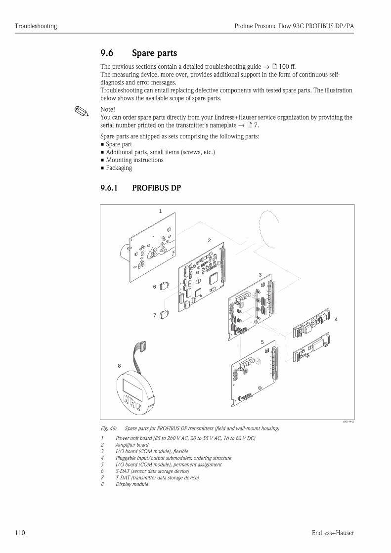
Troubleshooting Proline Prosonic Flow 93C PROFIBUS DP/PA
110 Endress+Hauser
9.6 Spare parts
The previous sections contain a detailed troubleshooting guide → ä 100 ff.
The measuring device, more over, provides additional support in the form of continuous self-
diagnosis and error messages.
Troubleshooting can entail replacing defective components with tested spare parts. The illustration
below shows the available scope of spare parts.
! Note!
You can order spare parts directly from your Endress+Hauser service organization by providing the
serial number printed on the transmitter's nameplate → ä 7.
Spare parts are shipped as sets comprising the following parts:
• Spare part
• Additional parts, small items (screws, etc.)
• Mounting instructions
• Packaging
9.6.1 PROFIBUS DP
a0014442
Fig. 48: Spare parts for PROFIBUS DP transmitters (field and wall-mount housing)
1 Power unit board (85 to 260 V AC, 20 to 55 V AC, 16 to 62 V DC)
2 Amplifier board
3 I/O board (COM module), flexible
4 Pluggable input/output submodules; ordering structure
5 I/O board (COM module), permanent assignment
6 S-DAT (sensor data storage device)
7 T-DAT (transmitter data storage device)
8 Display module
INPUT/O
UTPUT4
INPUT/O
UTPUT3
1234
WENO
1234
WENO
1234
WENO
1234
WENO
1
2
3
4
8
6
7
5
1234
1234
WENO
WENO
1234
1234
WENO
WENO
1234
1234
WENO
WENO
1234
1234
WENO
WENO
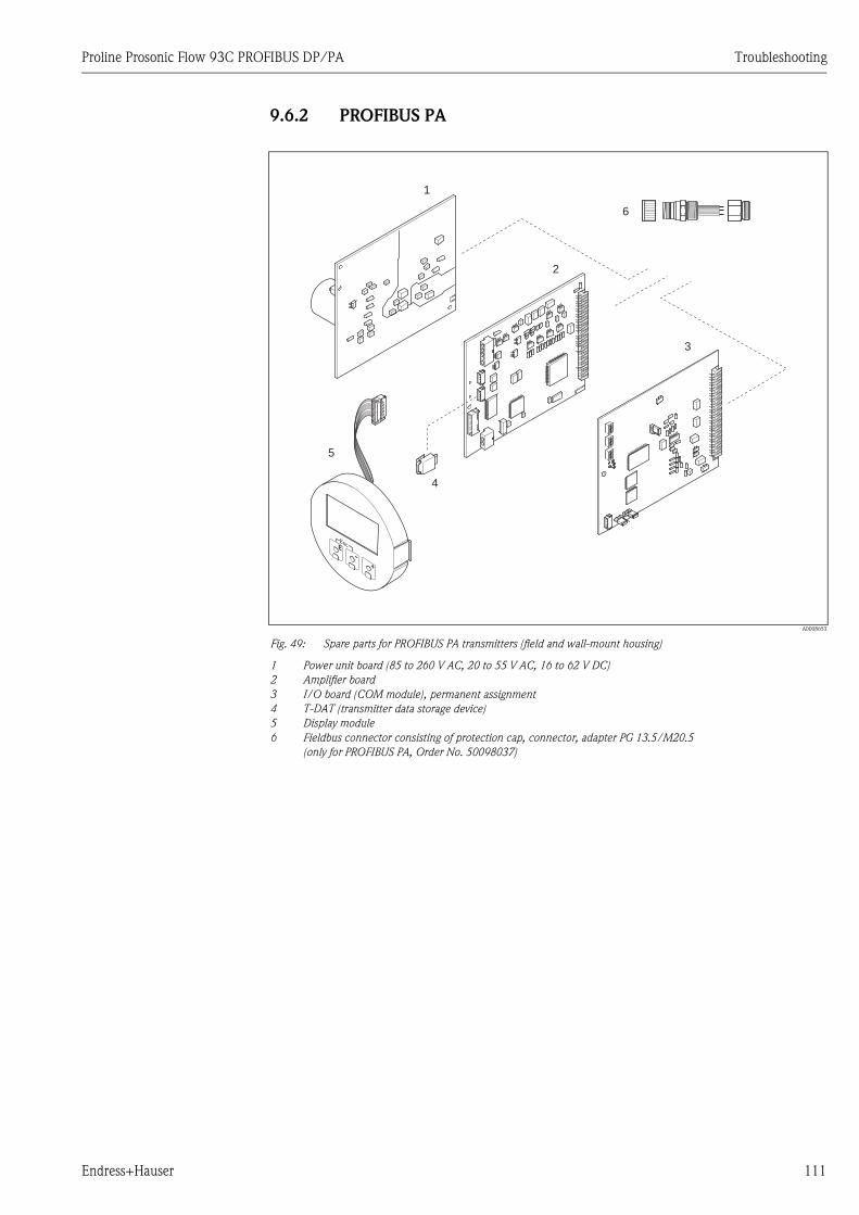
Proline Prosonic Flow 93C PROFIBUS DP/PA Troubleshooting
Endress+Hauser 111
9.6.2 PROFIBUS PA
A0008653
Fig. 49: Spare parts for PROFIBUS PA transmitters (field and wall-mount housing)
1 Power unit board (85 to 260 V AC, 20 to 55 V AC, 16 to 62 V DC)
2 Amplifier board
3 I/O board (COM module), permanent assignment
4 T-DAT (transmitter data storage device)
5 Display module
6 Fieldbus connector consisting of protection cap, connector, adapter PG 13.5/M20.5
(only for PROFIBUS PA, Order No. 50098037)
1
2
3
4
5
6
Troubleshooting Proline Prosonic Flow 93C PROFIBUS DP/PA
112 Endress+Hauser
9.6.3 Installing and removing electronics boards
# Warning!
• Risk of electric shock. Exposed components carry dangerous voltages. Make sure that the power
supply is switched off before you remove the cover of the electronics compartment.
• Risk of damaging electronic components (ESD protection). Static electricity can damage electronic
components or impair their operability. Use a workplace with a grounded working surface,
purposely built for electrostatically sensitive devices.
• If you cannot guarantee that the dielectric strength of the device is maintained in the following
steps, then an appropriate inspection must be carried out in accordance with the manufacturer’s
specifications.
" Caution!
Use only original Endress+Hauser parts.
Installing and removing printed circuit boards → Fig. 50:
1. Loosen the screws and open the housing cover (1).
2. Loosen the screws securing the electronics module (2). Then push up electronics module and
pull it as far as possible out of the wall-mount housing.
3. Disconnect the following cable connectors from amplifier board (7):
– Signal cable connector (7.1)
– Plug of exciting current cable (7.2):
Gently disconnect the plug, i.e. without moving it back and forward.
– Ribbon cable plug (3) of the display module
4. Remove the cover (4) from the electronics compartment by loosening the screws.
5. Remove the boards (6, 7, 8):
Insert a thin pin into the hole provided (5) for the purpose and pull the board clear of its holder.
6. Remove submodules (8.2) (optional):
No tools are required for removing the submodules (outputs) from the I/O board. Installation
is also a no-tools operation.
" Caution!
Only certain combinations of submodules on the I/O board are permissible → ä 32.
The individual slots are marked and correspond to certain terminals in the connection
compartment of the transmitter:
"INPUT / OUTPUT 3" slot = terminals 22/23
"INPUT / OUTPUT 4" slot = terminals 20/21
7. Installation is the reverse of the removal procedure.
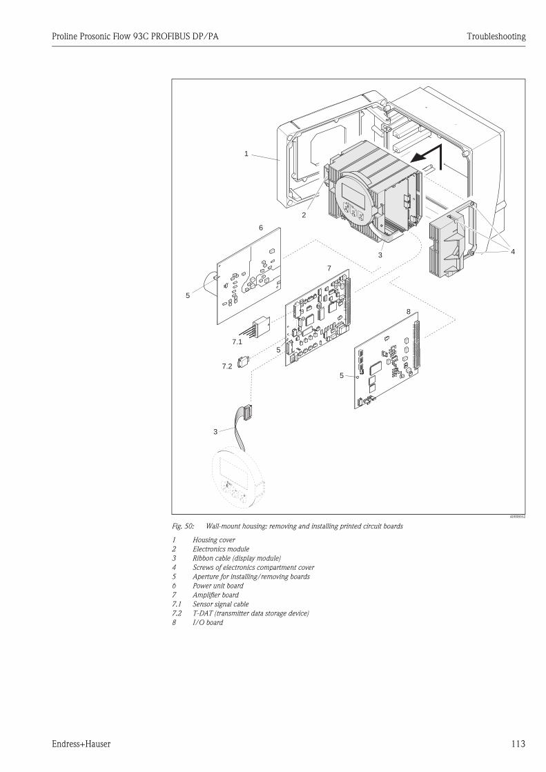
Proline Prosonic Flow 93C PROFIBUS DP/PA Troubleshooting
Endress+Hauser 113
A0008652
Fig. 50: Wall-mount housing: removing and installing printed circuit boards
1 Housing cover
2 Electronics module
3 Ribbon cable (display module)
4 Screws of electronics compartment cover
5 Aperture for installing/removing boards
6 Power unit board
7 Amplifier board
7.1 Sensor signal cable
7.2 T-DAT (transmitter data storage device)
8 I/O board
6
7
3
3 4
1
2
5
7.2
7.1
5
8
5
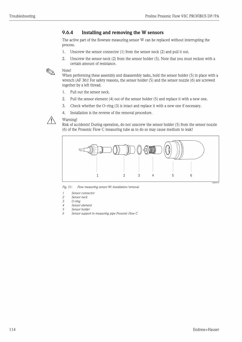
Troubleshooting Proline Prosonic Flow 93C PROFIBUS DP/PA
114 Endress+Hauser
9.6.4 Installing and removing the W sensors
The active part of the flowrate measuring sensor W can be replaced without interrupting the
process.
1. Unscrew the sensor connector (1) from the sensor neck (2) and pull it out.
2. Unscrew the sensor neck (2) from the sensor holder (5). Note that you must reckon with a
certain amount of resistance.
! Note!
When performing these assembly and disassembly tasks, hold the sensor holder (5) in place with a
wrench (AF 36)! For safety reasons, the sensor holder (5) and the sensor nozzle (6) are screwed
together by a left thread.
1. Pull out the sensor neck.
2. Pull the sensor element (4) out of the sensor holder (5) and replace it with a new one.
3. Check whether the O–ring (3) is intact and replace it with a new one if necessary.
4. Installation is the reverse of the removal procedure.
# Warning!
Risk of accidents! During operation, do not unscrew the sensor holder (5) from the sensor nozzle
(6) of the Prosonic Flow C measuring tube as to do so may cause medium to leak!
A0008753
Fig. 51: Flow measuring sensor W: installation/removal
1 Sensor connector
2 Sensor neck
3 O-ring
4 Sensor element
5 Sensor holder
6 Sensor support in measuring pipe Prosonic Flow C
1 2 3 4 5 6
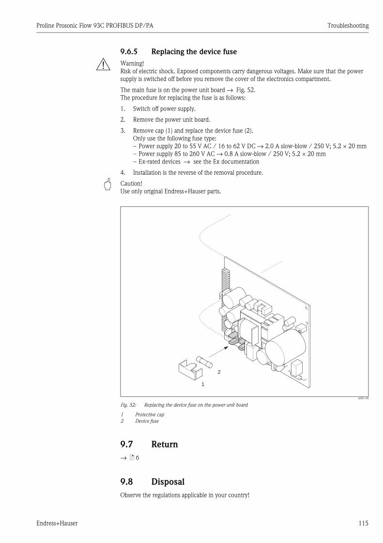
Proline Prosonic Flow 93C PROFIBUS DP/PA Troubleshooting
Endress+Hauser 115
9.6.5 Replacing the device fuse
# Warning!
Risk of electric shock. Exposed components carry dangerous voltages. Make sure that the power
supply is switched off before you remove the cover of the electronics compartment.
The main fuse is on the power unit board → Fig. 52.
The procedure for replacing the fuse is as follows:
1. Switch off power supply.
2. Remove the power unit board.
3. Remove cap (1) and replace the device fuse (2).
Only use the following fuse type:
– Power supply 20 to 55 V AC / 16 to 62 V DC → 2.0 A slow-blow / 250 V; 5.2 × 20 mm
– Power supply 85 to 260 V AC → 0.8 A slow-blow / 250 V; 5.2 × 20 mm
– Ex-rated devices → see the Ex documentation
4. Installation is the reverse of the removal procedure.
" Caution!
Use only original Endress+Hauser parts.
a0001148
Fig. 52: Replacing the device fuse on the power unit board
1 Protective cap
2 Device fuse
9.7 Return
→ ä 6
9.8 Disposal
Observe the regulations applicable in your country!
1
2
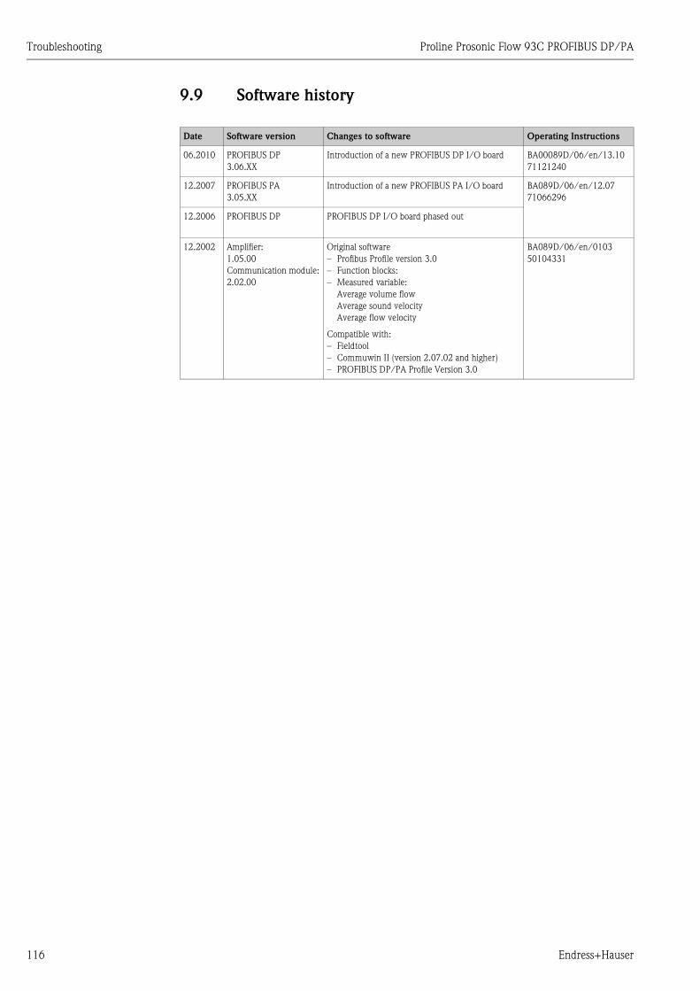
Troubleshooting Proline Prosonic Flow 93C PROFIBUS DP/PA
116 Endress+Hauser
9.9 Software history
Date Software version Changes to software Operating Instructions
06.2010 PROFIBUS DP
3.06.XX
Introduction of a new PROFIBUS DP I/O board BA00089D/06/en/13.10
71121240
12.2007 PROFIBUS PA
3.05.XX
Introduction of a new PROFIBUS PA I/O board BA089D/06/en/12.07
71066296
12.2006 PROFIBUS DP PROFIBUS DP I/O board phased out
12.2002 Amplifier:
1.05.00
Communication module:
2.02.00
Original software
– Profibus Profile version 3.0
– Function blocks:
– Measured variable:
Average volume flow
Average sound velocity
Average flow velocity
Compatible with:
– Fieldtool
– Commuwin II (version 2.07.02 and higher)
– PROFIBUS DP/PA Profile Version 3.0
BA089D/06/en/0103
50104331
Proline Prosonic Flow 93C PROFIBUS DP/PA Technical data
Endress+Hauser 117
10 Technical data
10.1 Quick technical data guide
10.1.1 Applications
• Measuring the flow rate of liquids in closed piping systems.
• Applications in measuring, control and regulation technology for monitoring processes.
10.1.2 Function and system design
Measuring principle Prosonic Flow operates on the principle of transit time difference.
Measuring system The measuring system consists of a transmitter and sensors.
Transmitter:
• Prosonic Flow 93C Inline PROFIBUS DP/PA
Measuring tube Prosonic Flow C with measuring sensors Prosonic Flow W:
• Prosonic Flow C (for water and wastewater applications)
for nominal diameters DN 300 to 2000 (12" to 78")
10.1.3 Input
Measured variable Flow velocity
(transit time difference proportional to flow velocity)
Measuring range Typically v = 0 to 10 m/s (0 to 33 ft/s)
Operable flow range Over 150 : 1
Input signal Status input (auxiliary input):
U = 3 to 30 V DC, Ri = 3 kΩ, galvanically isolated.
Switch level: ±3 to ±30 VDC, independent of polarity
10.1.4 Output
Output signal PROFIBUS DP interface:
• PROFIBUS DP in accordance with IEC 61158, galvanically isolated
• Profile Version 3.0
• Data transmission rate: 9.6 kBaud to 12 MBaud
• Automatic data transmission rate recognition
• Signal coding: NRZ code
• Bus address can be configured via miniature switches, via the local display (optional) or operating
program
Technical data Proline Prosonic Flow 93C PROFIBUS DP/PA
118 Endress+Hauser
PROFIBUS PA interface:
• PROFIBUS PA in accordance with IEC 61158 (MBP), galvanically isolated
• Profile Version 3.0
• Data transmission rate: 31.25 kBaud
• Current consumption: 11 mA
• Permitted supply voltage: 9 to 32 V
• Bus connection with integrated reverse polarity protection
• Error current FDE (Fault Disconnection Electronic): 0 mA
• Signal coding: Manchester II
• Bus address can be configured via miniature switches, via the local display (optional) or operating
program
Current output
Active/passive selectable, galvanically isolated, time constant selectable (0.05 to 100 s),
Full scale value adjustable, temperature coefficient typ. 0.005% o.f.s./°C, resolution: 0.5 μA
• Active: 0/4 to 20 mA, RL < 700 Ω• Passive: 4 to 20 mA; supply voltage VS 18 to 30 V DC; Ri ≥ 150 Ω
Pulse/frequency output:
Active/passive selectable, galvanically isolated
• Active: 24 V DC, 25 mA (max. 250 mA during 20 ms), RL > 100 Ω• Passive: open collector, 30 V DC, 250 mA
• Frequency output: full scale frequency 2 to 10000 Hz (fmax = 12500 Hz), on/off ratio 1:1,
pulse width max. 2 s
• Pulse output: pulse value and pulse polarity selectable,
pulse width configurable (0.05 to 2000 ms)
Signal on alarm PROFIBUS DP/PA
Status and alarm messages in accordance with PROFIBUS Profile Version 3.0
Current output:
Failsafe mode selectable (for example NAMUR recommendation NE 43)
Pulse/frequency output:
Failsafe mode selectable
Relay output:
De-energized by fault or power supply failure
Proline Prosonic Flow 93C PROFIBUS DP/PA Technical data
Endress+Hauser 119
10.1.5 Power supply
Electrical connections → ä 25 ff.
Supply voltage 85 to 260 V AC, 45 to 65 Hz
20 to 55 V AC, 45 to 65 Hz
16 to 62 V DC
Measuring sensors are powered by the transmitter.
Cable entry Power supply and signal cables (inputs/outputs):
• Cable entry M20 × 1.5 (8 to 12 mm, 0.31 to 0.47 in)
• Cable gland for cables with Ø 6 to 12 mm (Ø 0.24 to 0.47 in)
• Thread for cable entries, ½" NPT, G ½"
Sensor cable connection (→ å 18 on → ä 31):
A special cable gland makes it possible to guide both sensor cables (per channel) into the connection
compartment at the same time
• Threaded adapter 1/2" NPT, G 1/2"
• Thread for cable entries, ½" NPT, G ½"
Cable specifications Only use the connecting cables supplied by Endress+Hauser.
Different versions of the connecting cables are available → ä 98 ff.
Prosonic Flow W
• Cable material made of PVC (standard) or PTFE (for higher temperatures)
• Cable length: 5 to 60 m (16.4 to 196.8 ft)
! Note!
To ensure correct measuring results, route the connecting cable well clear of electrical machines
and switching elements.
Power consumption AC: < 18 VA (incl. sensor)
DC: < 10 W (incl. sensor)
Switch-on current:
• max. 13.5 A (< 50 ms) at 24 V DC
• max. 3 A (< 5 ms) at 260 V AC
Power supply failure Lasting min. 1 power cycle:
EEPROM and T-DAT save measuring system data if the power supply fails
Potential equalization For potential equalization, no special measures are necessary. With regard to devices suitable for
potentially explosive atmospheres, please refer to the information in the Ex-specific supplementary
documentation.
10.1.6 Performance characteristics
Reference operating
conditions
• Fluid temperature: +20 to +30 °C
• Ambient temperature: +22 °C ± 2 K
• Warm-up period: 30 minutes
• Sensors and transmitter are grounded.
• The measuring sensors are correctly installed.
Technical data Proline Prosonic Flow 93C PROFIBUS DP/PA
120 Endress+Hauser
Maximum measured error For flow velocities of > 0.3m/s (1 ft/s) and a Reynolds number of > 10000, the system accuracy is:
! Note!
The Prosonic Flow 93 C Inline sensor is also available without factory flow calibration.
The error limits without calibration are ±1.5 % o.r. ± 3 mm/s
Repeatability ±0.3 % for flow velocities > 0.3 m/s (1 ft/s)
10.1.7 Operating conditions: installation
Installation instructions Any orientation (vertical, horizontal)
Restrictions and other installation instructions → ä 13 ff.
Inlet and outlet run Version → ä 15
Length of connecting cable Shielded cables are available in the following lengths:
5 m (16.4 ft), 10 m (32.8 ft), 15 m (49.2 ft) and 30 m (98.4 ft)
Route the cables well clear of electrical machines and switching elements.
10.1.8 Operating conditions: environment
Ambient temperature range • Prosonic Flow 93 transmitter:
–20 to +60 °C (–4 to +140 °F)
• Measuring tube Prosonic Flow C with measuring sensors Prosonic Flow W:
–10 to +80 °C (+14 to +176 °F)
• PVC sensor cable:
–20 to +70 °C (–4 to +158 °F)
! Note!
• Install the transmitter in a shady location.
Avoid direct sunlight, particularly in warm climatic regions.
• At ambient temperatures below –20 °C (–4 °F) the readability of the display may be impaired.
• In the case of heated pipes, or pipes with cold fluids, it is permitted to completely insulate the
measuring tube with the mounted ultrasonic sensors.
Storage temperature The storage temperature corresponds to the ambient temperature range of the transmitter, the
measuring tube, the sensors and the corresponding sensor cable → ä 120.
Degree of protection • Prosonic Flow 93C transmitter:
IP 67 (NEMA 4X)
• Prosonic Flow W flow sensors:
IP 68 (NEMA 6P)
Shock resistance Following IEC 68–2–31
Electromagnetic compatibility
(EMC)
In accordance with IEC/EN 61326 and NAMUR Recommendation NE 21
Nominal diameter Guaranteed error limits of the device Report
DN 300 to 2000 (12 to 80") ±0.5 % o.r. ± 3 mm/s Factory measurement report
o.r. = of reading

Proline Prosonic Flow 93C PROFIBUS DP/PA Technical data
Endress+Hauser 121
10.1.9 Operating conditions: process
Medium temperature range Measuring tube Prosonic Flow C with measuring sensors Prosonic Flow W:
–10 to +80 °C (+14 to +176 °F)
! Note!
Drinking Water Approval: 0 to +60 °C (+32 to +140 °F)
Limiting medium pressure
range (nominal pressure)
Perfect measurement requires that the static fluid pressure is higher than vapor pressure.
The maximum nominal pressure is PN 16 (16 bar / 232 psi).
Pressure loss There is no pressure loss.
Pressure loss occurs if adapters are used upstream and downstream of the device. The corresponding
values can be taken from the chart → ä 16.
10.1.10 Mechanical construction
Design / dimensions The dimensions and lengths of the sensor and transmitter are provided in the separate "Technical
Information" document on the device in question. This can be downloaded as a PDF file from
www.endress.com. A list of the "Technical Information" documents available is provided on
→ ä 117.
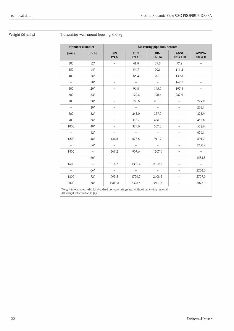
Technical data Proline Prosonic Flow 93C PROFIBUS DP/PA
122 Endress+Hauser
Weight (SI units) Transmitter wall-mount housing: 6.0 kg
Nominal diameter Measuring pipe incl. sensors
[mm} [inch] DIN
PN 6
DIN
PN 10
DIN
PN 16
ANSI
Class 150
AWWA
Class D
300 12" – 41.8 59.6 77.2 –
350 14" – 54.7 70.1 111.2 –
400 16" – 66.4 90.3 139.6 –
– 18" – – – 162.7 –
500 20" – 96.8 145.9 197.8 –
600 24" – 120.4 196.6 287.9 –
700 28" – 183.6 251.3 – 229.9
– 30" – – – – 265.1
800 32" – 245.0 327.0 – 323.9
900 36" – 313.7 456.3 – 455.6
1000 40" – 379.0 587.3 – 552.6
– 42" – – – – 626.1
1200 48" 434.6 678.6 941.7 – 894.7
– 54" – – – – 1280.2
1400 – 569.2 907.6 1267.6 – –
– 60" – – – – 1584.5
1600 – 818.7 1381.4 2012.0 – –
– 66" – – – – 2268.0
1800 72" 993.5 1726.7 2608.2 – 2707.0
2000 78" 1508.2 2393.6 3601.3 – 3073.9
Weight information valid for standard pressure ratings and without packaging material.
All weight information in [kg]
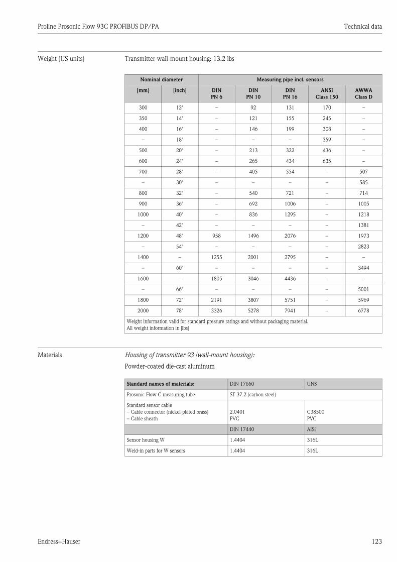
Proline Prosonic Flow 93C PROFIBUS DP/PA Technical data
Endress+Hauser 123
Weight (US units) Transmitter wall-mount housing: 13.2 lbs
Materials Housing of transmitter 93 (wall-mount housing):
Powder-coated die-cast aluminum
Nominal diameter Measuring pipe incl. sensors
[mm} [inch] DIN
PN 6
DIN
PN 10
DIN
PN 16
ANSI
Class 150
AWWA
Class D
300 12" – 92 131 170 –
350 14" – 121 155 245 –
400 16" – 146 199 308 –
– 18" – – – 359 –
500 20" – 213 322 436 –
600 24" – 265 434 635 –
700 28" – 405 554 – 507
– 30" – – – – 585
800 32" – 540 721 – 714
900 36" – 692 1006 – 1005
1000 40" – 836 1295 – 1218
– 42" – – – – 1381
1200 48" 958 1496 2076 – 1973
– 54" – – – – 2823
1400 – 1255 2001 2795 – –
– 60" – – – – 3494
1600 – 1805 3046 4436 – –
– 66" – – – – 5001
1800 72" 2191 3807 5751 – 5969
2000 78" 3326 5278 7941 – 6778
Weight information valid for standard pressure ratings and without packaging material.
All weight information in [lbs]
Standard names of materials: DIN 17660 UNS
Prosonic Flow C measuring tube ST 37.2 (carbon steel)
Standard sensor cable
– Cable connector (nickel-plated brass)
– Cable sheath
2.0401
PVC
C38500
PVC
DIN 17440 AISI
Sensor housing W 1.4404 316L
Weld-in parts for W sensors 1.4404 316L
Technical data Proline Prosonic Flow 93C PROFIBUS DP/PA
124 Endress+Hauser
10.1.11 Human interface
Display elements • Liquid crystal display: illuminated, four lines each with 16 characters
• Custom configuration for presenting different measured values and status variables
• 3 totalizers
• At ambient temperatures below –20 °C (–4 °F) the readability of the display may be impaired.
Operating elements • Local operation with three optical sensor keys (S/O/F)
• Application-specific Quick Setup menus for straightforward commissioning
Language groups Language groups available for operation in different countries:
• Western Europe and America (WEA):
English, German, Spanish, Italian, French, Dutch and Portuguese
• Eastern Europe/Scandinavia (EES):
English, Russian, Polish, Norwegian, Finnish, Swedish and Czech.
• South and Eastern Asia (SEA):
English, Japanese, Indonesian
• China (CN):
English, Chinese
! Note!
You can change the language group via the operating program "FieldCare".
Remote operation Operation via PROFIBUS DP or PROFIBUS PA
10.1.12 Certificates and approvals
CE mark The measuring system is in conformity with the statutory requirements of the EC Directives.
Endress+Hauser confirms successful testing of the device by affixing to it the CE mark.
C-Tick mark The measuring system complies with the EMC requirements of the "Australian Communications
and Media Authority (ACMA)".
Ex approval Information on the currently available Ex-rated versions (ATEX, FM, CSA, etc.) can be supplied by
your Endress+Hauser Sales Center on request. All information relevant to explosion protection is
available in separate documents that you can order as necessary.
PROFIBUS DP/PA
certification
The flowmeter has successfully passed all the test procedures carried out and is certified and
registered by the PNO (PROFIBUS User Organization). The device thus meets all the requirements
of the following specifications:
• Certified in accordance with PROFIBUS Profile Version 3.0 (device certification number: available
on request)
• The measuring device can also be operated with certified devices of other manufacturers
(interoperability).
Proline Prosonic Flow 93C PROFIBUS DP/PA Technical data
Endress+Hauser 125
Other standards and
guidelines
• EN 60529
Degrees of protection provided by enclosures (IP code)
• EN 61010–1
Safety requirements for electrical equipment for measurement, control and laboratory use
• IEC/EN 61326
"Emission in accordance with Class A requirements".
Electromagnetic compatibility (EMC requirements).
• NAMUR NE 21
Electromagnetic compatibility (EMC) of industrial process and laboratory control equipment
• NAMUR NE 43
Standardization of the signal level for the breakdown information of digital transmitters with
analog output signal.
10.1.13 Ordering information
The Endress+Hauser service organization can provide detailed ordering information and
information on the order codes on request.
10.1.14 Accessories
Various accessories, which can be ordered separately from Endress+Hauser, are available for the
transmitter and the sensor → ä 98.
10.1.15 Documentation
• Flow measurement (FA005)
• Technical Information for Prosonic Flow 93C (TI108D)
• Description of Device Functions for Prosonic Flow 93C PROFIBUS DP/PA (BA090D)
• Ex supplementary documentation (Control–Drawing) for FM, CSA
Proline Prosonic Flow 93C PROFIBUS DP/PA Index
126 Endress+Hauser
Index
AAccessories. . . . . . . . . . . . . . . . . . . . . . . . . . . . . . . . . . . . 98
Acyclic data transmission . . . . . . . . . . . . . . . . . . . . . . . . . 94
Ambient temperature range . . . . . . . . . . . . . . . . . . . . . . 120
Applications . . . . . . . . . . . . . . . . . . . . . . . . . . . . . . . . . . . . 5
Applicator (selection and configuration software) . . . . . . . 99
Approvals . . . . . . . . . . . . . . . . . . . . . . . . . . . . . . . . . . . . . 11
BBlock model
PROFIBUS DP . . . . . . . . . . . . . . . . . . . . . . . . . . . . . . 72
PROFIBUS PA. . . . . . . . . . . . . . . . . . . . . . . . . . . . . . . 83
Blocks . . . . . . . . . . . . . . . . . . . . . . . . . . . . . . . . . . . . . . . 46
Bus structure
PROFIBUS DP . . . . . . . . . . . . . . . . . . . . . . . . . . . . . . 25
CCable entry
Technical data . . . . . . . . . . . . . . . . . . . . . . . . . . . . . 119
Cable specifications
PROFIBUS DP . . . . . . . . . . . . . . . . . . . . . . . . . . . . . . 25
PROFIBUS PA. . . . . . . . . . . . . . . . . . . . . . . . . . . . . . . 27
Cable type
PROFIBUS DP . . . . . . . . . . . . . . . . . . . . . . . . . . . . . . 25
PROFIBUS PA. . . . . . . . . . . . . . . . . . . . . . . . . . . . . . . 27
CE mark (Declaration of Conformity) . . . . . . . . . . . . . . 9, 11
Certificates. . . . . . . . . . . . . . . . . . . . . . . . . . . . . . . . . . . . 11
Cleaning
Exterior cleaning. . . . . . . . . . . . . . . . . . . . . . . . . . . . . 97
Code entry (function matrix) . . . . . . . . . . . . . . . . . . . . . . 47
Commissioning
Current output . . . . . . . . . . . . . . . . . . . . . . . . . . . . . . 54
Quick Setup . . . . . . . . . . . . . . . . . . . . . . . . . . . . . . . . 59
Relay output . . . . . . . . . . . . . . . . . . . . . . . . . . . . . . . . 55
Zero point adjustment . . . . . . . . . . . . . . . . . . . . . . . . . 95
Communication
Quick Setup . . . . . . . . . . . . . . . . . . . . . . . . . . . . . . . . 60
Connection
See Electrical connection
C-Tick mark. . . . . . . . . . . . . . . . . . . . . . . . . . . . . . . . . . . 11
Current output
Configuration active/passive . . . . . . . . . . . . . . . . . . . . 54
Technical data . . . . . . . . . . . . . . . . . . . . . . . . . . . . . 118
Cyclic data exchange
PROFIBUS PA. . . . . . . . . . . . . . . . . . . . . . . . . . . . . . . 83
Cyclic data transmission PROFIBUS DP
AI module (Analog Input) . . . . . . . . . . . . . . . . . . . . . . 74
CONTROL_BLOCK . . . . . . . . . . . . . . . . . . . . . . . . . . 78
DISPLAY_VALUE module . . . . . . . . . . . . . . . . . . . . . . 78
EMPTY_MODULE . . . . . . . . . . . . . . . . . . . . . . . . . . . 79
SETTOT_MODETOT_TOTAL module . . . . . . . . . . . . 77
SETTOT_TOTAL module . . . . . . . . . . . . . . . . . . . . . . 76
TOTAL module. . . . . . . . . . . . . . . . . . . . . . . . . . . . . . 75
Cyclic data transmission PROFIBUS PA
AI module (Analog Input) . . . . . . . . . . . . . . . . . . . . . . 85
CONTROL_BLOCK . . . . . . . . . . . . . . . . . . . . . . . . . . 89
DISPLAY_VALUE module . . . . . . . . . . . . . . . . . . . . . . 89
EMPTY_MODULE . . . . . . . . . . . . . . . . . . . . . . . . . . . 90
SETTOT_MODETOT_TOTAL module . . . . . . . . . . . . 88
SETTOT_TOTAL module . . . . . . . . . . . . . . . . . . . . . . 87
TOTAL module . . . . . . . . . . . . . . . . . . . . . . . . . . . . . . 86
DData backup . . . . . . . . . . . . . . . . . . . . . . . . . . . . . . . . . . . 62
Data transmission
Acyclic PROFIBUS DP/PA. . . . . . . . . . . . . . . . . . . . . . 94
Cyclic PROFIBUS PA. . . . . . . . . . . . . . . . . . . . . . . 72, 83
Declaration of Conformity (CE mark) . . . . . . . . . . . . . . . . 11
Degree of protection . . . . . . . . . . . . . . . . . . . . . . . . . . . . 120
Prosonic Flow W flowrate measuring sensors (IP68). . . 40
Designated use . . . . . . . . . . . . . . . . . . . . . . . . . . . . . . . . . . 5
Device address, configuring
PROFIBUS DP. . . . . . . . . . . . . . . . . . . . . . . . . . . . . . . 52
PROFIBUS PA . . . . . . . . . . . . . . . . . . . . . . . . . . . . . . . 57
Device description data
PROFIBUS DP. . . . . . . . . . . . . . . . . . . . . . . . . . . . . . . 49
PROFIBUS PA . . . . . . . . . . . . . . . . . . . . . . . . . . . . . . . 50
Device designation . . . . . . . . . . . . . . . . . . . . . . . . . . . . . . . 7
Device functions
See "Description of Device Functions" manual
Device status, display . . . . . . . . . . . . . . . . . . . . . . . . . . . 102
Display
Local display . . . . . . . . . . . . . . . . . . . . . . . . . . . . . . . . 43
Disposal . . . . . . . . . . . . . . . . . . . . . . . . . . . . . . . . . . . . . 115
Down pipes . . . . . . . . . . . . . . . . . . . . . . . . . . . . . . . . . . . 14
EElectrical connection
Length of connecting cable . . . . . . . . . . . . . . . . . . . . . 18
Error messages
Confirming error messages . . . . . . . . . . . . . . . . . . . . . 48
Process error (application error) . . . . . . . . . . . . . . . . . 108
System error (device error) . . . . . . . . . . . . . . . . . . . . 102
Error types (system and process errors) . . . . . . . . . . . . . . . 48
Ex approval . . . . . . . . . . . . . . . . . . . . . . . . . . . . . . . . . . 124
Exterior cleaning . . . . . . . . . . . . . . . . . . . . . . . . . . . . . . . 97
FFault message . . . . . . . . . . . . . . . . . . . . . . . . . . . . . . . . . . 48
FieldCare . . . . . . . . . . . . . . . . . . . . . . . . . . . . . . . . . . 49, 99
Fieldcheck (tester and simulator). . . . . . . . . . . . . . . . . . . . 99
Frequency output
Technical data. . . . . . . . . . . . . . . . . . . . . . . . . . . . . . 118
Function check . . . . . . . . . . . . . . . . . . . . . . . . . . . . . . . . . 58
Function description
See "Description of Device Functions" manual
Function groups . . . . . . . . . . . . . . . . . . . . . . . . . . . . . . . . 46
Functions . . . . . . . . . . . . . . . . . . . . . . . . . . . . . . . . . . . . . 46
Fuse, replacing . . . . . . . . . . . . . . . . . . . . . . . . . . . . . . . . 115
FXA193 . . . . . . . . . . . . . . . . . . . . . . . . . . . . . . . . . . . . . . 99
Proline Prosonic Flow 93C PROFIBUS DP/PA Index
Endress+Hauser 127
GGrounding . . . . . . . . . . . . . . . . . . . . . . . . . . . . . . . . . . . . 29
Groups . . . . . . . . . . . . . . . . . . . . . . . . . . . . . . . . . . . . . . . 46
HHardware write protection
PROFIBUS DP . . . . . . . . . . . . . . . . . . . . . . . . . . . . . . . 51
PROFIBUS PA . . . . . . . . . . . . . . . . . . . . . . . . . . . . . . . 56
Hazardous substances . . . . . . . . . . . . . . . . . . . . . . . . . . . . . 6
HOME position (display operating mode) . . . . . . . . . . . . . . 43
IIcons. . . . . . . . . . . . . . . . . . . . . . . . . . . . . . . . . . . . . . . . . 45
Incoming acceptance. . . . . . . . . . . . . . . . . . . . . . . . . . . . . 12
Inlet and outlet run . . . . . . . . . . . . . . . . . . . . . . . . . . . . . 120
Inlet run . . . . . . . . . . . . . . . . . . . . . . . . . . . . . . . . . . . . . . 15
Input signal . . . . . . . . . . . . . . . . . . . . . . . . . . . . . . . . . . . 117
Installation . . . . . . . . . . . . . . . . . . . . . . . . . . . . . . . . . . . 120
See Installation conditions
Installation conditions
Dimensions . . . . . . . . . . . . . . . . . . . . . . . . . . . . . . . . . 13
Down pipes . . . . . . . . . . . . . . . . . . . . . . . . . . . . . . . . . 14
Inlet/outlet run . . . . . . . . . . . . . . . . . . . . . . . . . . . . . . 15
Orientation (vertical, horizontal) . . . . . . . . . . . . . . . . . 14
Vibrations . . . . . . . . . . . . . . . . . . . . . . . . . . . . . . . . . . 15
Installation instructions . . . . . . . . . . . . . . . . . . . . . . . . . . 120
Installing the Prosonic Flow C measuring tube . . . . . . . . . . 19
Installing the wall-mount housing . . . . . . . . . . . . . . . . . . . 22
IP 67 mounting instructions
See Degree of protection
IP 68 mounting instructions
See Degree of protection
LLanguage groups . . . . . . . . . . . . . . . . . . . . . . . . . . . . . . . 124
Length of connecting cable . . . . . . . . . . . . . . . . . . . . . . . 120
Length of connecting cable (sensor cable) . . . . . . . . . . . . . 18
Local display
See Display
MMaintenance . . . . . . . . . . . . . . . . . . . . . . . . . . . . . . . . . . . 97
Material load diagram . . . . . . . . . . . . . . . . . . . . . . . . . . . 121
Materials. . . . . . . . . . . . . . . . . . . . . . . . . . . . . . . . . . . . . 123
Measured value status, display. . . . . . . . . . . . . . . . . . . . . 102
Measured variables . . . . . . . . . . . . . . . . . . . . . . . . . . . . . 117
Measuring principle. . . . . . . . . . . . . . . . . . . . . . . . . . . . . 117
Measuring system . . . . . . . . . . . . . . . . . . . . . . . . . . . . . . . . 7
Module
AI (Analog Input)
PROFIBUS DP . . . . . . . . . . . . . . . . . . . . . . . . . . . . 74
PROFIBUS PA . . . . . . . . . . . . . . . . . . . . . . . . . . . . 85
CONTROL_BLOCK
PROFIBUS DP . . . . . . . . . . . . . . . . . . . . . . . . . . . . 78
PROFIBUS PA . . . . . . . . . . . . . . . . . . . . . . . . . . . . 89
DISPLAY_VALUE
PROFIBUS DP . . . . . . . . . . . . . . . . . . . . . . . . . . . . 78
PROFIBUS PA . . . . . . . . . . . . . . . . . . . . . . . . . . . . 89
EMPTY_MODULE
PROFIBUS DP . . . . . . . . . . . . . . . . . . . . . . . . . . . . 79
PROFIBUS PA . . . . . . . . . . . . . . . . . . . . . . . . . . . . 90
SETTOT_MODETOT_TOTAL
PROFIBUS DP . . . . . . . . . . . . . . . . . . . . . . . . . . . . 77
PROFIBUS PA . . . . . . . . . . . . . . . . . . . . . . . . . . . . 88
SETTOT_TOTAL
PROFIBUS DP . . . . . . . . . . . . . . . . . . . . . . . . . . . . 76
PROFIBUS PA . . . . . . . . . . . . . . . . . . . . . . . . . . . . 87
TOTAL
PROFIBUS DP . . . . . . . . . . . . . . . . . . . . . . . . . . . . 75
PROFIBUS PA . . . . . . . . . . . . . . . . . . . . . . . . . . . . 86
Mounting instructions
IP 67 . . . . . . . . . . . . . . . . . . . . . . . . . . . . . . . . . . . . . . 39
NNameplate
Connections. . . . . . . . . . . . . . . . . . . . . . . . . . . . . . . 9–10
Sensor . . . . . . . . . . . . . . . . . . . . . . . . . . . . . . . . . . . . . . 8
Notice message . . . . . . . . . . . . . . . . . . . . . . . . . . . . . . . . . 48
OOperable flow range . . . . . . . . . . . . . . . . . . . . . . . . . . . . 117
Operating conditions . . . . . . . . . . . . . . . . . . . . . . . . . . . . 120
Operation
FieldCare . . . . . . . . . . . . . . . . . . . . . . . . . . . . . . . . . . . 49
Function matrix . . . . . . . . . . . . . . . . . . . . . . . . . . . . . . 46
Operational safety . . . . . . . . . . . . . . . . . . . . . . . . . . . . . . . . 5
Order code
Accessories . . . . . . . . . . . . . . . . . . . . . . . . . . . . . . . . . 98
Sensor . . . . . . . . . . . . . . . . . . . . . . . . . . . . . . . . . . . . . . 9
Transmitter . . . . . . . . . . . . . . . . . . . . . . . . . . . . . 7–8, 10
Ordering information. . . . . . . . . . . . . . . . . . . . . . . . . . . . 125
Outlet run . . . . . . . . . . . . . . . . . . . . . . . . . . . . . . . . . . . . . 15
Output signal. . . . . . . . . . . . . . . . . . . . . . . . . . . . . . . . . . 118
PROFIBUS DP . . . . . . . . . . . . . . . . . . . . . . . . . . . . . . 117
PROFIBUS PA . . . . . . . . . . . . . . . . . . . . . . . . . . . . . . 118
Proline Prosonic Flow 93C PROFIBUS DP/PA Index
128 Endress+Hauser
PPost-installation check (checklist). . . . . . . . . . . . . . . . . . . . 24
Power consumption. . . . . . . . . . . . . . . . . . . . . . . . . . . . . 119
Power supply (supply voltage) . . . . . . . . . . . . . . . . . . . . . 119
Power supply failure . . . . . . . . . . . . . . . . . . . . . . . . . . . . 119
Pressure loss
Adapters (reducers, expanders). . . . . . . . . . . . . . . . . . . 16
Printed circuit boards (installation/removal)
Wall-mount housing . . . . . . . . . . . . . . . . . . . . . . . . . 112
Process error
Definition . . . . . . . . . . . . . . . . . . . . . . . . . . . . . . . . . . 48
Process error messages . . . . . . . . . . . . . . . . . . . . . . . . . . 108
PROFIBUS DP
Bus structure . . . . . . . . . . . . . . . . . . . . . . . . . . . . . . . . 25
Cable specifications . . . . . . . . . . . . . . . . . . . . . . . . . . . 25
Cable type . . . . . . . . . . . . . . . . . . . . . . . . . . . . . . . . . . 25
Configuration examples . . . . . . . . . . . . . . . . . . . . . . . . 80
Device address, configuring . . . . . . . . . . . . . . . . . . . . . 52
Device description data . . . . . . . . . . . . . . . . . . . . . . . . 49
Hardware write protection . . . . . . . . . . . . . . . . . . . . . . 51
Output signal . . . . . . . . . . . . . . . . . . . . . . . . . . . . . . . 117
Spur . . . . . . . . . . . . . . . . . . . . . . . . . . . . . . . . . . . . . . 26
Terminal assignment . . . . . . . . . . . . . . . . . . . . . . . . . . 32
PROFIBUS PA
Cable specifications . . . . . . . . . . . . . . . . . . . . . . . . . . . 27
Cable type . . . . . . . . . . . . . . . . . . . . . . . . . . . . . . . . . . 27
Configuration examples . . . . . . . . . . . . . . . . . . . . . . . . 91
Cyclic data exchange . . . . . . . . . . . . . . . . . . . . . . . . . . 83
Device address, configuring . . . . . . . . . . . . . . . . . . . . . 57
Device description data . . . . . . . . . . . . . . . . . . . . . . . . 50
Hardware write protection . . . . . . . . . . . . . . . . . . . . . . 56
Output signal . . . . . . . . . . . . . . . . . . . . . . . . . . . . . . . 118
Spur . . . . . . . . . . . . . . . . . . . . . . . . . . . . . . . . . . . . . . 28
Terminal assignment . . . . . . . . . . . . . . . . . . . . . . . . . . 32
Programming mode
Disabling . . . . . . . . . . . . . . . . . . . . . . . . . . . . . . . . . . . 47
Enabling . . . . . . . . . . . . . . . . . . . . . . . . . . . . . . . . . . . 47
Prosonic Flow C
Installation. . . . . . . . . . . . . . . . . . . . . . . . . . . . . . . . . . 19
Pulse output
See Frequency output
QQuick Setup
Commissioning . . . . . . . . . . . . . . . . . . . . . . . . . . . . . . 59
Communication . . . . . . . . . . . . . . . . . . . . . . . . . . . . . . 60
Quick technical data guide. . . . . . . . . . . . . . . . . . . . . . . . 117
RRegistered trademarks . . . . . . . . . . . . . . . . . . . . . . . . . . . . 11
Relay output . . . . . . . . . . . . . . . . . . . . . . . . . . . . . . . . . . . 55
Repair . . . . . . . . . . . . . . . . . . . . . . . . . . . . . . . . . . . . . . . . . 6
Returning devices . . . . . . . . . . . . . . . . . . . . . . . . . . . . . . . . 6
SSafety icons . . . . . . . . . . . . . . . . . . . . . . . . . . . . . . . . . . . . 6
Safety instructions. . . . . . . . . . . . . . . . . . . . . . . . . . . . . . . . 5
Serial number . . . . . . . . . . . . . . . . . . . . . . . . . . . . . . . . 7–10
Service interface FXA193 . . . . . . . . . . . . . . . . . . . . . . . . . 99
Shielding . . . . . . . . . . . . . . . . . . . . . . . . . . . . . . . . . . . . . 29
Shielding of the cable connection/T-box . . . . . . . . . . . . . . 38
Signal on alarm. . . . . . . . . . . . . . . . . . . . . . . . . . . . . . . . 118
Software
Amplifier display . . . . . . . . . . . . . . . . . . . . . . . . . . . . . 58
Spare parts . . . . . . . . . . . . . . . . . . . . . . . . . . . . . . . . . . . 110
Spur
PROFIBUS DP. . . . . . . . . . . . . . . . . . . . . . . . . . . . . . . 26
PROFIBUS PA . . . . . . . . . . . . . . . . . . . . . . . . . . . . . . . 28
Standards, guidelines . . . . . . . . . . . . . . . . . . . . . . . . . . . 124
Status input
Technical data. . . . . . . . . . . . . . . . . . . . . . . . . . . . . . 117
Storage . . . . . . . . . . . . . . . . . . . . . . . . . . . . . . . . . . . . . . . 12
Supplementary Ex documentation. . . . . . . . . . . . . . . . . . . . 5
Supply voltage (power supply). . . . . . . . . . . . . . . . . . . . . 119
System error
Definition . . . . . . . . . . . . . . . . . . . . . . . . . . . . . . . . . . 48
System error messages . . . . . . . . . . . . . . . . . . . . . . . . . . 102
TT-DAT
Save/load (data back-up, e.g. for replacing devices) . . . 62
T-DAT (HistoROM) . . . . . . . . . . . . . . . . . . . . . . . . . . . . . 96
Temperature ranges
Ambient temperature range . . . . . . . . . . . . . . . . . . . . 120
Storage temperature . . . . . . . . . . . . . . . . . . . . . . . . . 120
Terminal assignment
PROFIBUS DP. . . . . . . . . . . . . . . . . . . . . . . . . . . . . . . 32
PROFIBUS PA . . . . . . . . . . . . . . . . . . . . . . . . . . . . . . . 32
Terminating resistors . . . . . . . . . . . . . . . . . . . . . . . . . . . . 53
Transmitter
Electrical connection . . . . . . . . . . . . . . . . . . . . . . . . . . 33
Installing the wall-mount housing . . . . . . . . . . . . . . . . 22
Length of connecting cable (sensor cable) . . . . . . . . . . 18
Troubleshooting and remedy. . . . . . . . . . . . . . . . . . . . . . 100
WWall-mount housing, mounting . . . . . . . . . . . . . . . . . . . . 22
Weight
SI units . . . . . . . . . . . . . . . . . . . . . . . . . . . . . . . . . . . 122
US units . . . . . . . . . . . . . . . . . . . . . . . . . . . . . . . . . . 123
Wiring
See Electrical connection
Writes (max.) . . . . . . . . . . . . . . . . . . . . . . . . . . . . . . . . . . 71
ZZero point adjustment. . . . . . . . . . . . . . . . . . . . . . . . . . . . 95
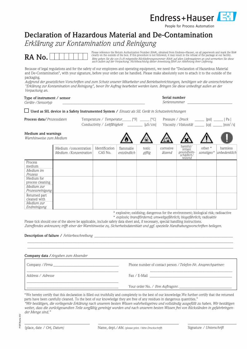
P/S
F/K
onta
XIV
Because of legal regulations and for the safety of our employees and operating equipment, we need the "Declaration of Hazardous Materialand De-Contamination", with your signature, before your order can be handled. Please make absolutely sure to attach it to the outside of thepackaging.Aufgrund der gesetzlichen Vorschriften und zum Schutz unserer Mitarbeiter und Betriebseinrichtungen, benötigen wir die unterschriebene"Erklärung zur Kontamination und Reinigung", bevor Ihr Auftrag bearbeitet werden kann. Bringen Sie diese unbedingt außen an derVerpackung an.
Serial number
Seriennummer ________________________Type of instrument / sensor
Geräte-/Sensortyp ____________________________________________
Process data/Prozessdaten Temperature _____ [°F] [°C]
Conductivity / ________
_____
Leitfähigkeit
/
[μS/cm]
Temperatur Pressure _____ [psi] [ Pa ]
Viscosity _____ [cp] [mm /s]
_____
_____
/
/
Druck
Viskosität2
corrosiveätzend
harmlessunbedenklich
other *sonstiges*
toxicgiftig
Processmedium
IdentificationCAS No.
flammableentzündlich
harmful/irritant
gesundheits-schädlich/
reizend
Medium /concentrationMedium /Konzentration
Returned partcleaned with
Medium forprocess cleaning
Medium and warnings
Warnhinweise zum Medium
* explosive; oxidising; dangerous for the environment; biological risk; radioactive* explosiv; brandfördernd; umweltgefährlich; biogefährlich; radioaktiv
Please tick should one of the above be applicable, include safety data sheet and, if necessary, special handling instructions.Zutreffendes ankreuzen; trifft einer der Warnhinweise zu, Sicherheitsdatenblatt und ggf. spezielle Handhabungsvorschriften beilegen.
Description of failure / Fehlerbeschreibung __________________________________________________________________________
______________________________________________________________________________________________________________
______________________________________________________________________________________________________________
“We hereby certify that this declaration is filled out truthfully and completely to the best of our knowledge.We further certify that the returnedparts have been carefully cleaned. To the best of our knowledge they are free of any residues in dangerous quantities.”“Wir bestätigenw
bestätigen, die vorliegende Erklärung nach unserem besten Wissen wahrheitsgetreu und vollständig ausgefüllt zu haben. Wireiter, dass die zurückgesandten Teile sorgfältig gereinigt wurden und nach unserem besten Wissen frei von Rückständen in gefahrbringen-
der Menge sind.”
(place, date / Ort, Datum)
Company data /Angaben zum Absender
Company / ________________________________
_________________________________________________
Address /
_________________________________________________
_________________________________________________
Firma ___
Adresse
Phone number of contact person /
____________________________________________
Fax / E-Mail ____________________________________________
Your order No. / ____________________________
Telefon-Nr. Ansprechpartner:
Ihre Auftragsnr.
Medium zurEndreinigung
Medium zurProzessreinigung
Medium imProzess
Used as SIL device in a Safety Instrumented System / Einsatz als SIL Gerät in Schutzeinrichtungen
RA No.
Erklärung zur Kontamination und ReinigungDeclaration of Hazardous Material and De-Contamination
Please reference the Return Authorization Number (RA#), obtained from Endress+Hauser, on all paperwork and mark the RA#clearly on the outside of the box. If this procedure is not followed, it may result in the refusal of the package at our facility.
Bitte geben Sie die von E+H mitgeteilte Rücklieferungsnummer (RA#) auf allen Lieferpapieren an und vermerken Sie dieseauch außen auf der Verpackung. Nichtbeachtung dieser Anweisung führt zur Ablehnung ihrer Lieferung.
Name, dept./Abt. (please print / )bitte Druckschrift Signature / Unterschrift

www.endress.com/worldwide
BA00089D/06/EN/13.10
71121240
FM+SGML6.0 ProMoDo