Iridium Coaxial Repeater System - Satellite Phone Store
26
Document No 9301702-A1 Iridium Coaxial Repeater Operation Manual Page 1 Iridium Coaxial Repeater System Operation Manual © 2020, Foxcom. All rights reserved. Other trademarks referenced are the property of their respective owners. All specifications are subject to change without prior notice. Rev A1/ May 2020 Israel Corporate HQ, 16 Hataasia Street, Har Tov A Ind. Zone, Beit Shemesh 99052. Tel: +972-2-589-9888 Fax: +972-2-589-9898 US Sales Office, 1315 Outlet Center Drive, Smithfield, North Carolina 27577. Tel: 609-228-8104/9 Fax: 201-289-7093 www.foxcom.com | [email protected]
-
Upload
khangminh22 -
Category
Documents
-
view
4 -
download
0
Transcript of Iridium Coaxial Repeater System - Satellite Phone Store

Document No 9301702-A1 Iridium Coaxial Repeater Operation Manual Page 1
Iridium Coaxial Repeater System
Operation Manual
© 2020, Foxcom. All rights reserved. Other trademarks referenced are the property of their respective owners.
All specifications are subject to change without prior notice. Rev A1/ May 2020
Israel Corporate HQ, 16 Hataasia Street, Har Tov A Ind. Zone, Beit Shemesh 99052. Tel: +972-2-589-9888 Fax: +972-2-589-9898
US Sales Office, 1315 Outlet Center Drive, Smithfield, North Carolina 27577. Tel: 609-228-8104/9 Fax: 201-289-7093
www.foxcom.com | [email protected]

Iridium Coaxial Repeater Operation Manual
Document No 9301702-A1 Iridium Coaxial Repeater Operation Manual Page 2
Table of Contents
1 Important Information ................................................................................ 5
1.1 Warranty and Repair .................................................................................. 5
General Warranty ...................................................................................... 5
Specific Product Warranty Instructions ......................................................... 5
Returns .................................................................................................... 5
Limitations of Liabilities .............................................................................. 5
Reporting Defects ...................................................................................... 6
Precautions ............................................................................................... 6
2 Introduction to the Iridium Repeater System ............................................ 8
2.1 System Components ................................................................................... 9
Indoor Equipment ...................................................................................... 9
Outdoor Unit ...................................................................................................... 10
2.2 Product Drawing ....................................................................................... 11
Power Amplifier Outdoor Unit .................................................................... 11
/ODU LED Description .............................................................................. 11
ODU Connector and Module Identification .................................................. 12
RF Connector Layout................................................................................ 13
2.3 Connection Diagram ................................................................................. 14
System Diagram for Single Zone Version .................................................... 14
System Diagram for Dual Zone Version ...................................................... 15
3 Installation ................................................................................................. 16
3.1 Setting Up the Indoor Equipment ............................................................. 16
Placing the Indoor Antenna ...................................................................... 16
3.2 Setting Up the Outdoor Unit ..................................................................... 16
Installing the Outdoor Unit ....................................................................... 16
Connecting the Input/Output/Power Cables ................................................ 18
Mounting the Outdoor Antennas ................................................................ 19
Powering the Outdoor Iridium Unit ............................................................ 19
3.3 Testing and Optimizing the System .......................................................... 20
Setting Up the Downlink at 3 Meters from the Indoor Antenna...................... 20
Setting Up the Downlink at 5 Meters from the Indoor Antenna...................... 21
Setting Up the Downlink at 10 meters from the Indoor Antenna .................... 21
Setting Up the Uplink at 5 meters from the Indoor Antenna.......................... 22
4 Product Technical Description ................................................................... 23
4.1 System Specifications ............................................................................... 23
4.2 Model Dimensions ..................................................................................... 24
Outdoor Unit ........................................................................................... 24
4.3 ODU DC Connector Assembly.................................................................... 25

Iridium Coaxial Repeater Operation Manual
Document No 9301702-A1 Iridium Coaxial Repeater Operation Manual Page 3
5. Troubleshooting the Iridium Coaxial Repeater ........................................ 26
5.1. Troubleshooting the Iridium Repeater ..................................................... 26

Iridium Coaxial Repeater Operation Manual
Document No 9301702-A1 Iridium Coaxial Repeater Operation Manual Page 4
List of Figures
Figure 1: Omni Antenna........................................................................................................... 9
Figure 2: Hangar Antenna ....................................................................................................... 9
Figure 3: Coax Cable ............................................................................................................... 9
Figure 4: ODU System........................................................................................................... 10
Figure 5: Pole Mount ............................................................................................................. 10
Figure 6: Coax Cable ............................................................................................................. 10
Figure 7: Outdoor Repeater Unit – Top View ........................................................................ 11
Figure 8: ODU Single Zone Internal Module with OD5 Housing ........................................... 12
Figure 9: ODU Dual Zone Internal Module with OD5 Housing ............................................. 13
Figure 10: System Diagram for Single Zone ......................................................................... 14
Figure 11: System Diagram for Dual Zone ............................................................................ 15
Figure 12: Hanging the Outdoor Unit on a Pole .................................................................... 17
Figure 13: Close-up of washer on pole mount ...................................................................... 17
Figure 14: Grounding the Unit ............................................................................................... 18
Figure 15: Manual Gain Adjustment ...................................................................................... 20
Figure 16: Setting Up the Downlink at 3M ............................................................................. 21
Figure 17: Setting Up the Downlink at 5M ............................................................................. 21
Figure 18: Setting Up the Downlink at 10M ........................................................................... 22
Figure 19: Setting Up the Uplink at 5M ................................................................................. 22
Figure 20: Model Dimensions for Outdoor Unit ..................................................................... 24
Figure 21: ODU DC Connector Assembly ............................................................................. 25

Iridium Coaxial Repeater System Manual
Revision: A Page: 5
This page contains proprietary information belonging to Global Foxcom
1 Important Information
This is the Operation Manual for Iridium Coaxial Repeater system.
1.1 Warranty and Repair Global Foxcom performs testing and inspection to verify the quality and reliability of our products.
Global Foxcom uses every reasonable precaution to ensure that each unit meets specifications before
shipment. Customers are asked to advise their incoming inspection, assembly, and test personnel as to
the precautions required in handling and testing our products. Many of these precautions are to be
found in this manual.
The products are covered by the following warranties:
General Warranty
Global Foxcom warrants to the original purchaser all standard products sold by Global Foxcom to be
free of defects in material and workmanship for 24 months from date of shipment from Global Foxcom.
During the warranty period, Foxcom will repair or replace any product that Global Foxcom proves to
be defective. This warranty does not apply to any product which has been subject to alteration, abuse,
improper installation or application, accident, electrical or environmental over-stress, negligence in use, storage, transportation or handling.
Specific Product Warranty Instructions
All Global Foxcom products are warranted against defects in workmanship, materials and construction,
and to no further extent. Any claim for repair or replacement of units found to be defective on incoming
inspection by a customer must be made within 30 days of receipt of shipment, or within 30 days of discovery of a defect within the warranty period.
This warranty is the only warranty made by Global Foxcom and is in lieu of all other warranties,
expressed or implied. Global Foxcom sales agents or representatives are not authorized to make commitments on warranty returns.
Returns
In the event that it is necessary to return any product against above warranty, the following procedure
shall be followed:
1. Return authorization is to be received from Global Foxcom prior to returning any unit. Advise
Global Foxcom of the model, serial number, and discrepancy. The unit may then be forwarded to
Global Foxcom, transportation prepaid. Devices returned collect or without authorization may not be accepted.
2. Prior to repair, Global Foxcom will advise the customer of our test results and any charges for
repairing customer-caused problems or out-of-warranty conditions, etc.
3. Repaired products are warranted for the balance of the original warranty period, or at least 90 days
from date of shipment.
Limitations of Liabilities
Global Foxcom's liability on any claim, of any kind, including negligence for any loss or damage
arising from, connected with, or resulting from the purchase order, contract, quotation, or from the
performance or breach thereof, or from the design, manufacture, sale, delivery, installation, inspection,
operation or use of any equipment covered by or furnished under this contact, shall in no case exceed the purchase price of the device which gives rise to the claim.

Iridium Coaxial Repeater Operation Manual
Document No 9301702-A1 Iridium Coaxial Repeater Operation Manual Page 6
EXCEPT AS EXPRESSLY PROVIDED HEREIN, GLOBAL FOXCOM MAKES NO WARRANTY, EXPRESSED
OR IMPLIED, WITH RESPECT TO ANY GOODS, PARTS AND SERVICES PROVIDED IN CONNECTION WITH
THIS AGREEMENT INCLUDING, BUT NOT LIMITED TO, THE IMPLIED WARRANTIES OF
MERCHANTABILITY AND FITNESS FOR A PARTICULAR PURPOSE. GLOBAL FOXCOM SHALL NOT BE
LIABLE FOR ANY OTHER DAMAGE INCLUDING, BUT NOT LIMITED TO, INDIRECT, SPECIAL OR
CONSEQUENTIAL DAMAGES ARISING OUT OF OR IN CONNECTION WITH FURNISHING OF GOODS,
PARTS AND SERVICE HEREUNDER, OR THE PERFORMANCE, USE OF, OR INABILITY TO USE THE
GOODS, PARTS AND SERVICE.
The Company's exclusive warranty and the remedy provided for breach there of shall not apply to:
1. Any Product used or operated other than pursuant to the Company's written instructions,
2. Damage or deficiencies resulting from accident, alteration, modification, misuse, tampering,
negligence, improper maintenance, installation or abuse,
3. Use of any Product other than at the Installation Site,
4. Use of any Product that is defective or damaged due to misuse, accident, or neglect, or due
to external electrical stress, lightning or other acts of nature,
5. Use of any Product by a person who is not any authorized employee of the Customer, or
6. Used other than as explicitly authorized in writing by the Company.
Reporting Defects
The units were inspected before shipment and found to be free of mechanical and electrical defects.
Examine the units for any damage which may have been caused in transit. If damage is discovered, file
a claim with the freight carrier immediately. Notify Global Foxcom as soon as possible.
Note: Keep all packing material until you have completed the inspection.
Precautions
1.1.6.1 PERSONAL SAFETY
Applying power to the transmitter unit will create a laser energy source operating in Class I as defined
by IEC 825-1. Use either an infrared viewer, optical power meter or fluorescent screen for optical output verification.
1.1.6.2 AC POWER HAZARD
The rackmount power supply line is EMI filtered. The chassis is connected to earth ground in
compliance with safety requirements. Always use the 3-prong AC plug with earth ground to avoid
possibility of electrical shock hazard to personnel.
1.1.6.3 GROUNDING
See section 2.3.2 for instructions on how to connect of the ODU’s main grounding point. Do not
attempt to install the ODU before grounding the unit at this point.
The unit should be installed according to NEC/CEC.
1.1.6.4 EQUIPMENT SAFETY
To avoid damaging your product, please observe the following:
1. The transmitter input and receiver output are DC coupled and can withstand external DC. Do not exceed 25V DC bias.

Iridium Coaxial Repeater Operation Manual
Document No 9301702-A1 Iridium Coaxial Repeater Operation Manual Page 7
2. The input of the outdoor unit transmitter (L-Band uplink) and may have an optional built-in
bias for inserting DC power up the coax to the LNB. Make certain any equipment or test equipment connected to the transmitter input can withstand this bias.
3. Do not allow any dirt or foreign material to get into the optical connector bulkheads. This
may cause damage to the polished optical connector end faces.
4. The optical fiber jumper cable bend radius is 3 cm. smaller radii can cause excessive optical
loss and/or fiber breakage.
5. If multiple chassis are installed in a Rack allow sufficient room for adequate ventilation;
otherwise the units may overheat causing possible safety hazard or equipment damage.
6. Make sure the unit is grounded!

Iridium Coaxial Repeater Operation Manual
Document No 9301702-A1 Iridium Coaxial Repeater Operation Manual Page 8
2 Introduction to the Iridium Repeater System
The Iridium satellite constellation is a large group of satellites providing voice and
data coverage to satellite phones, pagers and integrated transceivers over the Earth's
entire surface.
Iridium communication uses TDMA & FDMA together with DE-QPSK/DE-BPSK
modulation to cover the frequency range of 1616-1626.5MHz.
Iridium terminals need open line-of-sight to the open sky to function. Units will not
work consistently indoors, or under forest cover.
Iridium has a very powerful paging channel that can ring the phone indoors, but the
customer may have to walk outdoors to take the call. [Wikipedia]
Global Foxcom’s Coaxial repeater is a Bi-Directional repeater transport system that
can be used for Iridium satellite signals.
Global Foxcom’s Iridium repeater system helps create virtual Iridium satellite
coverage inside a building, a bunker or an enclosed facility.
Global Foxcom offers a full SATELLITE repeater solution, which includes a separate or
integrated GPS system as well as Inmarsat. For more information, contact Global
Foxcom sales.

Iridium Coaxial Repeater Operation Manual
Document No 9301702-A1 Iridium Coaxial Repeater Operation Manual Page 9
2.1 System Components The Iridium coaxial repeater consists of the following components (images below):
Indoor Equipment
Dual ceiling mount distribution Omni antennas [PN: 4700012] for non-hangar applications
Figure 1: Omni Antenna
OR
Dual ceiling mount distribution Dome antennas [PN: 7505010] for hangar applications
Figure 2: Hangar Antenna
Dual 20Meter (60 feet) low loss coax cable [PN: 4201843].
Figure 3: Coax Cable

Iridium Coaxial Repeater Operation Manual
Document No 9301702-A1 Iridium Coaxial Repeater Operation Manual Page 10
Outdoor Unit
ODU enclosure equipped with high power amplifier, LNA Amplifier, AC-DC Power supply and
mounting kit [PN: I8012151].
Figure 4: ODU System
Figure 5: Pole Mount
Dual Iridium antennas with pole mount kit [PN: 4700012].
2 x 5M low loss N(M) to TNC(M) coax cables [PN: 4201835].
Note: The Part Number is dependent on the connectors.
Figure 6: Coax Cable

Iridium Coaxial Repeater Operation Manual
Document No 9301702-A1 Iridium Coaxial Repeater Operation Manual Page 11
2.2 Product Drawing
Power Amplifier Outdoor Unit
Figure 7: Outdoor Repeater Unit – Top View
ODU LED Description
LED Name LED Function
P.S 1 Indicates that Power supply unit is receiving AC and is putting out DC

Iridium Coaxial Repeater Operation Manual
Document No 9301702-A1 Iridium Coaxial Repeater Operation Manual Page 12
ODU Connector and Module Identification
Figure 8: ODU Single Zone Internal Module with OD5 Housing

Iridium Coaxial Repeater Operation Manual
Document No 9301702-A1 Iridium Coaxial Repeater Operation Manual Page 13
Figure 9: ODU Dual Zone Internal Module with OD5 Housing
The Iridium outdoor repeater contains Uplink and Downlink LNA & Post amplifier,
Power amplifier, BP RF filters and AC to DC PS.
RF Connector Layout
A sticker on the right side of the repeater unit provides information on each of the RF
connectors used.
RF 1
RF2
U/L output to outdoor antenna
D/L input from outdoor antenna
Gain D/L
Gain U/L
RF 3
RF 4
U/L input from indoor antenna
D/L output to indoor antenna

Iridium Coaxial Repeater Operation Manual
Document No 9301702-A1 Iridium Coaxial Repeater Operation Manual Page 14
2.3 Connection Diagram
System Diagram for Single Zone Version
The following diagram shows a single zone version with one set of indoor antennas.
Figure 10: System Diagram for Single Zone

Iridium Coaxial Repeater Operation Manual
Document No 9301702-A1 Iridium Coaxial Repeater Operation Manual Page 15
System Diagram for Dual Zone Version
The following diagram shows a dual zone version with two sets of indoor antennas.
Installation and operation of the dual zone version is similar to the single zone
system.
Figure 11: System Diagram for Dual Zone
Iridium Coaxial Repeater Operation Manual
Document No 9301702-A1 Iridium Coaxial Repeater Operation Manual Page 16
3 Installation
3.1 Setting Up the Indoor Equipment
Placing the Indoor Antenna
Indoor antennas must be installed with a minimum distance of 2 meters
between them.
Max cable length between the outdoor unit and the indoor antennas is
dependent on the cable type used.
When using LMR 300 the max length supported is 20meters (60 feet).
When using LMR 400 the max length supported is 40meters (120 feet).
3.2 Setting Up the Outdoor Unit
The repeater unit is equipped with a built-in AC-DC power supply. The power supply
accepts 100-220VAC 50-60Hz and provides stable 24VDC to the internal components.
AC current consumption is below 1Amp.
Installing the Outdoor Unit
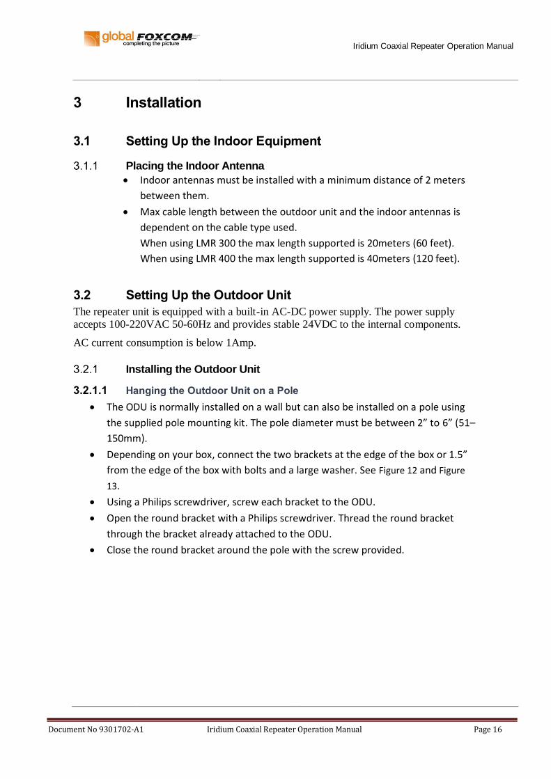
3.2.1.1 Hanging the Outdoor Unit on a Pole
The ODU is normally installed on a wall but can also be installed on a pole using
the supplied pole mounting kit. The pole diameter must be between 2” to 6” (51–
150mm).
Depending on your box, connect the two brackets at the edge of the box or 1.5”
from the edge of the box with bolts and a large washer. See Figure 12 and Figure
13.
Using a Philips screwdriver, screw each bracket to the ODU.
Open the round bracket with a Philips screwdriver. Thread the round bracket
through the bracket already attached to the ODU.
Close the round bracket around the pole with the screw provided.

Iridium Coaxial Repeater Operation Manual
Document No 9301702-A1 Iridium Coaxial Repeater Operation Manual Page 17
Figure 12: Hanging the Outdoor Unit on a Pole
Figure 13: Close-up of washer on pole mount

Iridium Coaxial Repeater Operation Manual
Document No 9301702-A1 Iridium Coaxial Repeater Operation Manual Page 18
3.2.1.2 Hanging the Outdoor Unit on a Wall
Caution: The ODU is heavy! Make sure that the wall can support its weight (5 kg.). Suitable
bolts must be used. Global Foxcom recommends that the ODU be installed on a
concrete wall.
1. Verify the holes on the provided drill sheet match the wall ears on your box.
2. Using the drill sheet, drill four holes (5/16”) through the markings indicated on the
paper.
3. Using the drilled holes as a guide, place the ODU on the wall.
4. Using four screws, secure the ODU to the wall.
Connecting the Input/Output/Power Cables
WARNING: UNIT MUST BE GROUNDED BEFORE APPLYING POWER
To ground the unit, assemble the ground assembly.
Figure 14: Grounding the Unit

Iridium Coaxial Repeater Operation Manual
Document No 9301702-A1 Iridium Coaxial Repeater Operation Manual Page 19
Mounting the Outdoor Antennas
WARNING: ANTENNA MUST BE CONNECTED BEFORE APPLYING POWER
Using one supplied 5Meter RF COAX cable, connect the receiver (Downlink)
antenna to Downlink input RF port (RF2).
Using a second supplied 5Meter RF coax cable connect the transmitting (Uplink)
antenna to the Uplink Output RF port (RF1).
Using the supplied 20Meter RF coax cable connect the transmitting indoor
(Downlink) antenna to the Downlink Output RF port (RF4).
Using the supplied 20Meter RF coax cable connect the receiving indoor (Uplink)
antenna to the Uplink Input RF port (RF3).
Note 1: Outdoor antennas must be installed with a minimum of 6 meters from one another.
Note 2: It is recommended to place the Outdoor transmitting antenna 2 feet higher than the
height of the Outdoor receiving antenna.
Note 3: The outdoor antennas MUST be tilted from each other by 10 degrees
Note 4: Make sure that outdoor unit is installed in an area that does not include any
radiating antennas.
A radiating antenna placed nearby (below 10 meters) can affect system performance.
Powering the Outdoor Iridium Unit 1. Apply AC power.
2. The ODU PS1 PWR LED should be “ON”.

Iridium Coaxial Repeater Operation Manual
Document No 9301702-A1 Iridium Coaxial Repeater Operation Manual Page 20
3.3 Testing and Optimizing the System
Use a hand held Iridium device to check signal level.
The Iridium repeater unit is equipped with two gain adjustment knobs. The U/L (Uplink)
signal is what the indoor phone is sending to the Iridium Satellite. The D/L (Downlink) is
the signal from the Iridium Satellite coming into the building.
The knobs have several settings allowing modification to system gain. When the knob is
in the 5 O’clock position the system is at its default factory optimized position for both
U/L (45.4) and D/L (49.4).
Figure 15: Manual Gain Adjustment
The units are pre-set from the factory for optimal gain and performance.
Because ceiling height and size of the room are all different, the manual gain
adjustment will make it easy to set up and get the best out of the units for
your room.
First, try the units without changing the settings.
Second, whenever aligning a system, ALWAYS start with the Downlink path.
After that, adjust the Uplink, where the goal is to achieve the best possible
Up:Down ratio.
Setting Up the Downlink at 3 Meters from the Indoor Antenna
1. Stand about 3 meters (approximately 9–10 feet) from the Indoor Antenna.
2. Check the signal quality on your Iridium phone.
3. Wait 30–60 seconds to verify levels.
How many bars do you have_________? You should be seeing 4–5 bars. If the
signal is lower, change the “DOWNLINK” knob one position Clockwise.
For example, if the knob was at “0” move it to “+2”.
4. Check the signal quality on your Iridium phone. Wait 30–60 seconds to verify
levels. Do this until you get 5 bars.

Iridium Coaxial Repeater Operation Manual
Document No 9301702-A1 Iridium Coaxial Repeater Operation Manual Page 21
Figure 16: Setting Up the Downlink at 3M
Setting Up the Downlink at 5 Meters from the Indoor Antenna
1. Stand about 5 meters (approximately 15–16 feet) from the Indoor Antenna.
2. Check the signal quality on your Iridium phone.
3. Wait 30–60 second to verify levels.
How many Bars do you have_________? You should be seeing 4–5 bars. If the
signal is lower, change the “DOWNLINK” knob one position Clockwise.
For example, if the knob was at “0” move it to “+2”.
4. Check the signal quality on your Iridium phone. Wait 30–60 second to verify
levels. Do this until you get 5 bars.
Figure 17: Setting Up the Downlink at 5M
Setting Up the Downlink at 10 meters from the Indoor Antenna
1. Stand about 10 meters (approximately 30 feet) from the Indoor Antenna.
2. Check the signal quality on your Iridium phone.
3. Wait 30–60 second to verify levels. How many Bars do you have_________? By
this point we should see 3–4 bars.
You should NOT adjust the gain level for the downlink at this point.
Step #1 setting up the Downlink.
Stand about 3 meter, approximately 9-10 feet from the Indoor Antenna.
Check the signal quality on your iridium phone, wait 30-60 second to verify levels. How
many Bars do you have_________. You should be seeing 4-5 bars. If the signal is lower,
change the “DOWNLINK” knob one position Clockwise, for example it was at “0” move it
to “+2”. Check the signal quality on your iridium phone, wait 30-60 second to verify levels.
Do this until you get 5 Bars.
Indoor
Antennas3 meters
Step #2 setting up the Downlink.
Stand about 5 meter, approximately 15-16 feet from the Indoor Antenna.
Check the signal quality on your iridium phone, wait 30-60 second to verify levels. How
many Bars do you have_________. You should be seeing 4-5 bars. If the signal is lower,
change the “DOWNLINK” knob one position Clockwise, for example it was at “0” move it to
“+2”. Check the signal quality on your iridium phone, wait 30-60 second to verify levels. Do
this until you get 5 Bars.
Indoor
Antennas
3 meters
5 meters

Iridium Coaxial Repeater Operation Manual
Document No 9301702-A1 Iridium Coaxial Repeater Operation Manual Page 22
Figure 18: Setting Up the Downlink at 10M
Setting Up the Uplink at 5 meters from the Indoor Antenna
1. Go back to the 5 meter mark.
2. Check the signal quality on your Iridium phone.
3. Wait 30–60 second to verify levels. You should see 4–5 bars.
4. Make a call while looking at the phone.
Do the bars drop drastically? If so, we need to decrease power on the Uplink.
5. Change the knob one position Counter-Clockwise.
For example, if the knob was at “0” move it to “-2”.
6. Check the signal quality on your Iridium phone.
Wait 30–60 second to verify levels. Do this until you get 5 bars.
Figure 19: Setting Up the Uplink at 5M
At this point all levels should be adjusted and you will be able to use the phones at least
10 meters from the Indoor Antenna.
Step #3 setting up the Downlink.
Stand about 10 meter, approximately 30 feet from the Indoor Antenna.
Check the signal quality on your iridium phone, wait 30-60 second to verify levels. How
many Bars do you have_________. By this point we should be seeing 3-4 bars. You should
NOT adjust the gain level for the downlink at this point.
Indoor
Antennas
3 meters
5 meters
10 meters
Step #4 setting up the Uplink.
Go abck to the 5 meter mark.
Check the signal quality on your iridium phone, wait 30-60 second to verify levels. You
should be seeing 4-5 bars.
Make a call, but look at the phone, do the bars drop drastically? If so, we need to
decrease power on the Uplink.
Change the knob one position Counter-Clockwise, for example it was at “0” move it to
“-2”. Check the signal quality on your iridium phone, wait 30-60 second to verify levels.
Do this until you get 5 Bars.
Indoor
Antennas
3 meters
5 meters
At this point all levels should be adjusted and we will be able to use the phones at
least 10 meters from the Antennas.

Iridium Coaxial Repeater Operation Manual
Document No 9301702-A1 Iridium Coaxial Repeater Operation Manual Page 23
4 Product Technical Description
4.1 System Specifications
Iridium Coaxial Repeater Specifications
Downlink
Frequency range 1616-1626.5MHz
ODU input/IDU output VSWR 1:1.6
ODU RF input signal range [total power] up to –20dBm
Downlink gain (±10dB Adjustable)
Noise figure <5dB
Uplink
Frequency range 1616-1626.5MHz
IDU input/ODU output VSWR 1:1.6
IDU RF input signal range [total power] up to –20dBm
Uplink gain (±10dB Adjustable)
Noise figure <5dB
Indoor coax length support 10m
Physical Specifications Repeater unit
RF connectors Dual N-Type Female
Dimensions 14” x 6” x 3”
Operating temperature -30 to +55° C
Electrical Specifications
Power 24 V DC

Iridium Coaxial Repeater Operation Manual
Document No 9301702-A1 Iridium Coaxial Repeater Operation Manual Page 24
4.2 Model Dimensions
Outdoor Unit
Figure 20: Model Dimensions for Outdoor Unit

Iridium Coaxial Repeater Operation Manual
Document No 9301702-A1 Iridium Coaxial Repeater Operation Manual Page 25
4.3 ODU DC Connector Assembly
Pin Function
A +24 VDC
B Negative
C Ground
A B
C
Figure 21: ODU DC Connector Assembly

Iridium Coaxial Repeater Operation Manual
Document No 9301702-A1 Iridium Coaxial Repeater Operation Manual Page 26
5. Troubleshooting the Iridium Coaxial Repeater
5.1. Troubleshooting the Iridium Repeater
Problem Possible Cause
Unable to put out a call with a good signal bar (Phone reset itself when trying to dial)
1. Bad cable connections
2. Uplink Gain is too high or too low
Signal bar show low signal level 1. Bad cable connection
2. Low gain on downlink path.
Note: Make sure a cellular transmitting antenna is not mounted in close proximity to the
Iridium antenna system (<10Meter)
Note: Make sure transmitting and receiving outdoor antennas are mounted at least 4
meters from each other.