SmartApplications User Guide - Manuals (Repeater Builder)
178
P/N 340-0027-002 REV H SmartBits Performance Analysis System SmartApplications User Guide Version 2.50 January 2002
-
Upload
khangminh22 -
Category
Documents
-
view
1 -
download
0
Transcript of SmartApplications User Guide - Manuals (Repeater Builder)

P/N 340-0027-002 REV H
SmartBitsPerformance Analysis System
SmartApplicationsUser Guide
Version 2.50January 2002

Spirent Communications, Inc.(800) 886-8842 Toll Free(818) 676-2300 Phone(818) 881-9154 FAX
Copyright 2002 Spirent Communications, Inc. All Rights Reserved.
The information contained in this document is the property of Spirent Communications, and is furnished for use byrecipient only for the purpose stated in the Software License Agreement accompanying the document. Except as per-mitted by such License Agreement, no part of this publication may be reproduced, stored in a retrieval system, ortransmitted, in any form or by any means, without the prior written permission of Spirent Communications, Inc.
Disclaimer
The information contained in this document is subject to change without notice and does not represent a commitmenton the part of Spirent Communications. The information in this document is believed to be accurate and reliable,however, Spirent Communications assumes no responsibility or liability for any errors or inaccuracies that mayappear in the document.
Trademarks
AST II, ScriptCenter, SmartApplications, SmartBits, SmartCableModem, SmartFabric, SmartFlow,SmartLib, SmartMetrics, SmartMulticastIP, SmartSignaling, SmartTCP, SmartVoIPQoS,SmartWindow, SmartxDSL, TeraMetrics, TeraMobileIP, TeraRouting Tester, TeraVPN, VAST, andWebSuite are trademarks or registered trademarks of Spirent Communications, Inc.
All other trademarks and registered trademarks are the property of their respective owners.
Warranty
Spirent Communications warrants to recipient that hardware which it supplies with this document (“Product”) will befree from significant defects in materials and workmanship for a period of twelve (12) months from the date ofdelivery (the “Warranty Period”), under normal use and conditions.
Defective Product under warranty shall be, at Spirent Communications’ discretion, repaired or replaced or a creditissued to recipient’s account for an amount equal to the price paid for such Product provided that: (a) such Product isreturned to Spirent Communications after first obtaining a return authorization number and shipping instructions,freight prepaid, to Spirent Communications’ location in the United States; (b) recipient provide a written explanation ofthe defect claimed; and (c) the claimed defect actually exists and was not caused by neglect, accident, misuse, improperinstallation, improper repair, fire, flood, lightning, power surges, earthquake or alteration. Spirent Communicationswill ship repaired Product to recipient, freight prepaid, within ten (10) working days after receipt of defective Product.Except as otherwise stated, any claim on account of defective materials or for any other cause whatsoever willconclusively be deemed waived by recipient unless written notice thereof is given to Spirent Communications withinthe Warranty Period. Product will be subject to Spirent Communications’ standard tolerances for variations.
TO THE EXTENT PERMITTED BY APPLICABLE LAW, ALL IMPLIED WARRANTIES, INCLUDING BUT NOTLIMITED TO IMPLIED WARRANTIES OF MERCHANTABILITY, NONINFRINGEMENT AND FITNESS FOR APARTICULAR PURPOSE, ARE HEREBY EXCLUDED, AND THE LIABILITY OF SPIRENT COMMUNICATIONS INC., IFANY, FOR DAMAGES RELATING TO ANY ALLEGEDLY DEFECTIVE PRODUCT SHALL BE LIMITED TO THEACTUAL PRICE PAID BY THE PURCHASER FOR SUCH PRODUCT. IN NO EVENT WILL SPIRENTCOMMUNICATIONS INC. BE LIABLE FOR COSTS OF PROCUREMENT OF SUBSTITUTE PRODUCTS OR SERVICES,LOST PROFITS, OR ANY SPECIAL, DIRECT, INDIRECT, CONSEQUENTIAL, OR INCIDENTAL DAMAGES,HOWEVER CAUSED AND ON ANY THEORY OF LIABILITY, ARISING IN ANY WAY OUT OF THE SALEAND/OR LICENSE OF PRODUCTS OR SERVICES TO RECIPIENT EVEN IF ADVISED OF THEPOSSIBILITY OF SUCH DAMAGES AND NOTWITHSTANDING ANY FAILURE OF ESSENTIAL PURPOSEOF ANY LIMITED REMEDY.
ii SmartApplications User Guide

Contents
About this Guide 1
Purpose . . . . . . . . . . . . . . . . . . . . . . . . . . . . . . . . . . . . . . . . . . . . . . . . . . . . . . . . . . . . . . . . . . . . . . 2Audience . . . . . . . . . . . . . . . . . . . . . . . . . . . . . . . . . . . . . . . . . . . . . . . . . . . . . . . . . . . . . . . . . . . . . 2Manual Contents . . . . . . . . . . . . . . . . . . . . . . . . . . . . . . . . . . . . . . . . . . . . . . . . . . . . . . . . . . . . . . . 2Conventions Used in This Guide. . . . . . . . . . . . . . . . . . . . . . . . . . . . . . . . . . . . . . . . . . . . . . . . . . . 3Related Manuals . . . . . . . . . . . . . . . . . . . . . . . . . . . . . . . . . . . . . . . . . . . . . . . . . . . . . . . . . . . . . . . 3Online Help . . . . . . . . . . . . . . . . . . . . . . . . . . . . . . . . . . . . . . . . . . . . . . . . . . . . . . . . . . . . . . . . . . . 4How to Contact Us. . . . . . . . . . . . . . . . . . . . . . . . . . . . . . . . . . . . . . . . . . . . . . . . . . . . . . . . . . . . . . 4
Chapter 1 SmartApplications Overview 5
What is SmartApplications? . . . . . . . . . . . . . . . . . . . . . . . . . . . . . . . . . . . . . . . . . . . . . . . . . . . . . . 6What are SmartCards and Modules? . . . . . . . . . . . . . . . . . . . . . . . . . . . . . . . . . . . . . . . . . . . . . . . . 7Supported Cards and Modules. . . . . . . . . . . . . . . . . . . . . . . . . . . . . . . . . . . . . . . . . . . . . . . . . . . . . 7
Chapter 2 Basic Test Theory 9
General Testing Methodology . . . . . . . . . . . . . . . . . . . . . . . . . . . . . . . . . . . . . . . . . . . . . . . . . . . . 10Test Terminology . . . . . . . . . . . . . . . . . . . . . . . . . . . . . . . . . . . . . . . . . . . . . . . . . . . . . . . . . 10Address Learning for SmartCards . . . . . . . . . . . . . . . . . . . . . . . . . . . . . . . . . . . . . . . . . . . . . 11
Throughput Test Methodology . . . . . . . . . . . . . . . . . . . . . . . . . . . . . . . . . . . . . . . . . . . . . . . . . . . 12Acceptable Loss Throughput. . . . . . . . . . . . . . . . . . . . . . . . . . . . . . . . . . . . . . . . . . . . . . . . . 13
Latency Test Methodology . . . . . . . . . . . . . . . . . . . . . . . . . . . . . . . . . . . . . . . . . . . . . . . . . . . . . . 14Packet Loss Rate Test Methodology . . . . . . . . . . . . . . . . . . . . . . . . . . . . . . . . . . . . . . . . . . . . . . . 16Back-to-Back Test Methodology. . . . . . . . . . . . . . . . . . . . . . . . . . . . . . . . . . . . . . . . . . . . . . . . . . 17
Chapter 3 Install and Connect 19
Install SmartApplications . . . . . . . . . . . . . . . . . . . . . . . . . . . . . . . . . . . . . . . . . . . . . . . . . . . . . . . 20System Requirements . . . . . . . . . . . . . . . . . . . . . . . . . . . . . . . . . . . . . . . . . . . . . . . . . . . . . . 20Installing from the CD . . . . . . . . . . . . . . . . . . . . . . . . . . . . . . . . . . . . . . . . . . . . . . . . . . . . . . 21
Launch SmartApplications. . . . . . . . . . . . . . . . . . . . . . . . . . . . . . . . . . . . . . . . . . . . . . . . . . . . . . . 21
Chapter 4 Basic Navigation and Tools 23
Features of the Main Window . . . . . . . . . . . . . . . . . . . . . . . . . . . . . . . . . . . . . . . . . . . . . . . . . . . . 24Menus . . . . . . . . . . . . . . . . . . . . . . . . . . . . . . . . . . . . . . . . . . . . . . . . . . . . . . . . . . . . . . . . . . 25Launch Buttons . . . . . . . . . . . . . . . . . . . . . . . . . . . . . . . . . . . . . . . . . . . . . . . . . . . . . . . . . . . 28Toolbar Buttons . . . . . . . . . . . . . . . . . . . . . . . . . . . . . . . . . . . . . . . . . . . . . . . . . . . . . . . . . . . 29Port Selection Area . . . . . . . . . . . . . . . . . . . . . . . . . . . . . . . . . . . . . . . . . . . . . . . . . . . . . . . . 31
Charting Test Results. . . . . . . . . . . . . . . . . . . . . . . . . . . . . . . . . . . . . . . . . . . . . . . . . . . . . . . . . . . 33
SmartApplications User Guide iii

Contents
iv
Chapter 5 Set Up Tests 35
Summary of Steps to Set up a Test . . . . . . . . . . . . . . . . . . . . . . . . . . . . . . . . . . . . . . . . . . . . . . . . 36Connect the Device Under Test . . . . . . . . . . . . . . . . . . . . . . . . . . . . . . . . . . . . . . . . . . . . . . . . . . . 36SmartBits Connection Setup . . . . . . . . . . . . . . . . . . . . . . . . . . . . . . . . . . . . . . . . . . . . . . . . . . . . . 37
Connect Using a Serial Port. . . . . . . . . . . . . . . . . . . . . . . . . . . . . . . . . . . . . . . . . . . . . . . . . . 38Connect Using an Ethernet Port . . . . . . . . . . . . . . . . . . . . . . . . . . . . . . . . . . . . . . . . . . . . . . 40Making the Connection . . . . . . . . . . . . . . . . . . . . . . . . . . . . . . . . . . . . . . . . . . . . . . . . . . . . . 41Linking Multiple SmartBits Chassis . . . . . . . . . . . . . . . . . . . . . . . . . . . . . . . . . . . . . . . . . . . 42Multi-User Access . . . . . . . . . . . . . . . . . . . . . . . . . . . . . . . . . . . . . . . . . . . . . . . . . . . . . . . . . 43Reserving Cards. . . . . . . . . . . . . . . . . . . . . . . . . . . . . . . . . . . . . . . . . . . . . . . . . . . . . . . . . . . 44
Starting and Stopping a Test . . . . . . . . . . . . . . . . . . . . . . . . . . . . . . . . . . . . . . . . . . . . . . . . . . . . . 46Set Up Test Configurations . . . . . . . . . . . . . . . . . . . . . . . . . . . . . . . . . . . . . . . . . . . . . . . . . . . . . . 48
Test Configuration Options . . . . . . . . . . . . . . . . . . . . . . . . . . . . . . . . . . . . . . . . . . . . . . . . . . 49Preference Tab. . . . . . . . . . . . . . . . . . . . . . . . . . . . . . . . . . . . . . . . . . . . . . . . . . . . . . . . . . . . 55Offered vs. Intended Load . . . . . . . . . . . . . . . . . . . . . . . . . . . . . . . . . . . . . . . . . . . . . . . . . . . 58Saving a Test Configuration . . . . . . . . . . . . . . . . . . . . . . . . . . . . . . . . . . . . . . . . . . . . . . . . . 59
Select Test Ports . . . . . . . . . . . . . . . . . . . . . . . . . . . . . . . . . . . . . . . . . . . . . . . . . . . . . . . . . . . . . . 60Hub, Slot, and Port Numbering . . . . . . . . . . . . . . . . . . . . . . . . . . . . . . . . . . . . . . . . . . . . . . . 61Allowed Port Pair Combinations . . . . . . . . . . . . . . . . . . . . . . . . . . . . . . . . . . . . . . . . . . . . . . 61Running 1 to 1 Tests . . . . . . . . . . . . . . . . . . . . . . . . . . . . . . . . . . . . . . . . . . . . . . . . . . . . . . . 64Running 1 to Many/Many to 1 Tests . . . . . . . . . . . . . . . . . . . . . . . . . . . . . . . . . . . . . . . . . . . 66
Configure Test Ports . . . . . . . . . . . . . . . . . . . . . . . . . . . . . . . . . . . . . . . . . . . . . . . . . . . . . . . . . . . 67Configuring Multiple Ports at Once . . . . . . . . . . . . . . . . . . . . . . . . . . . . . . . . . . . . . . . . . . . 68Configuring a Ports Individually . . . . . . . . . . . . . . . . . . . . . . . . . . . . . . . . . . . . . . . . . . . . . . 70Configuring Ethernet Ports . . . . . . . . . . . . . . . . . . . . . . . . . . . . . . . . . . . . . . . . . . . . . . . . . . 71Configuring Token Ring Ports . . . . . . . . . . . . . . . . . . . . . . . . . . . . . . . . . . . . . . . . . . . . . . . 74Configuring ATM Ports. . . . . . . . . . . . . . . . . . . . . . . . . . . . . . . . . . . . . . . . . . . . . . . . . . . . . 79Configuring WAN Ports . . . . . . . . . . . . . . . . . . . . . . . . . . . . . . . . . . . . . . . . . . . . . . . . . . . . 96
Router Testing . . . . . . . . . . . . . . . . . . . . . . . . . . . . . . . . . . . . . . . . . . . . . . . . . . . . . . . . . . . . . . . 115Set up Next Hop Tests . . . . . . . . . . . . . . . . . . . . . . . . . . . . . . . . . . . . . . . . . . . . . . . . . . . . . . . . . 117Set Up IP/UDP/IPX Protocols . . . . . . . . . . . . . . . . . . . . . . . . . . . . . . . . . . . . . . . . . . . . . . . . . . . 119Set up ATM 1-to-Many/Many-to-1 Tests with PVC CLIP . . . . . . . . . . . . . . . . . . . . . . . . . . . . . 123
Chapter 6 Run Tests 125
Test Phases. . . . . . . . . . . . . . . . . . . . . . . . . . . . . . . . . . . . . . . . . . . . . . . . . . . . . . . . . . . . . . . . . . 126Device Under Test Initialization . . . . . . . . . . . . . . . . . . . . . . . . . . . . . . . . . . . . . . . . . . . . . 126Load Generation . . . . . . . . . . . . . . . . . . . . . . . . . . . . . . . . . . . . . . . . . . . . . . . . . . . . . . . . . 126
Viewing Test Results . . . . . . . . . . . . . . . . . . . . . . . . . . . . . . . . . . . . . . . . . . . . . . . . . . . . . . . . . . 127Results Window by Test Tab. . . . . . . . . . . . . . . . . . . . . . . . . . . . . . . . . . . . . . . . . . . . . . . . 127Viewing the Results of Previous Configurations . . . . . . . . . . . . . . . . . . . . . . . . . . . . . . . . 129Viewing and Printing Test Reports . . . . . . . . . . . . . . . . . . . . . . . . . . . . . . . . . . . . . . . . . . . 130
Generating HTML Test Reports . . . . . . . . . . . . . . . . . . . . . . . . . . . . . . . . . . . . . . . . . . . . . . . . . 133Viewing and Printing ASCII Text Report Files . . . . . . . . . . . . . . . . . . . . . . . . . . . . . . . . . . . . . 136
Sample Reports – Throughput Test . . . . . . . . . . . . . . . . . . . . . . . . . . . . . . . . . . . . . . . . . . . 137Sample Reports – Latency Test . . . . . . . . . . . . . . . . . . . . . . . . . . . . . . . . . . . . . . . . . . . . . . 140Sample Reports – Packet Loss Test. . . . . . . . . . . . . . . . . . . . . . . . . . . . . . . . . . . . . . . . . . . 143Sample Reports – Back-to-Back Test . . . . . . . . . . . . . . . . . . . . . . . . . . . . . . . . . . . . . . . . . 146
Viewing Log Contents . . . . . . . . . . . . . . . . . . . . . . . . . . . . . . . . . . . . . . . . . . . . . . . . . . . . . . . . . 149
SmartApplications User Guide

Contents
Chapter 7 Test Examples 151
Throughput Test — Example . . . . . . . . . . . . . . . . . . . . . . . . . . . . . . . . . . . . . . . . . . . . . . . . . . . 152Setup — Throughput Test Example . . . . . . . . . . . . . . . . . . . . . . . . . . . . . . . . . . . . . . . . . . 152Results — Throughput Test Example . . . . . . . . . . . . . . . . . . . . . . . . . . . . . . . . . . . . . . . . . 154Sample Test Log . . . . . . . . . . . . . . . . . . . . . . . . . . . . . . . . . . . . . . . . . . . . . . . . . . . . . . . . . 155Sample Test Report . . . . . . . . . . . . . . . . . . . . . . . . . . . . . . . . . . . . . . . . . . . . . . . . . . . . . . . 156
Latency Test — Example . . . . . . . . . . . . . . . . . . . . . . . . . . . . . . . . . . . . . . . . . . . . . . . . . . . . . . 157Sample Test Configuration . . . . . . . . . . . . . . . . . . . . . . . . . . . . . . . . . . . . . . . . . . . . . . . . . 157Sample Test Results Window for Latency . . . . . . . . . . . . . . . . . . . . . . . . . . . . . . . . . . . . . 158
Packet Loss Test — Example . . . . . . . . . . . . . . . . . . . . . . . . . . . . . . . . . . . . . . . . . . . . . . . . . . . 159Sample Test Configuration . . . . . . . . . . . . . . . . . . . . . . . . . . . . . . . . . . . . . . . . . . . . . . . . . 159Sample Results Window . . . . . . . . . . . . . . . . . . . . . . . . . . . . . . . . . . . . . . . . . . . . . . . . . . . 160
Back-to-Back Test — Example . . . . . . . . . . . . . . . . . . . . . . . . . . . . . . . . . . . . . . . . . . . . . . . . . . 161Sample Test Configuration . . . . . . . . . . . . . . . . . . . . . . . . . . . . . . . . . . . . . . . . . . . . . . . . . 161Sample Results Window . . . . . . . . . . . . . . . . . . . . . . . . . . . . . . . . . . . . . . . . . . . . . . . . . . . 162
Glossary 163
Acronyms and Abbreviations . . . . . . . . . . . . . . . . . . . . . . . . . . . . . . . . . . . . . . . . . . . . . . . 163Terminology . . . . . . . . . . . . . . . . . . . . . . . . . . . . . . . . . . . . . . . . . . . . . . . . . . . . . . . . . . . . 166
Index 169
SmartApplications User Guide v

vi
SmartApplications User Guide
About this Guide
In About this Guide...
This portion of the user guide contains the following sections:
• Purpose.....2
• Audience.....2
• Manual Contents.....2
• Conventions Used in This Guide.....3
• Related Manuals.....3
• Online Help.....4
• How to Contact Us.....4
SmartApplications User Guide 1

About this GuidePurpose
2
PurposeThis user guide provides information on all procedures required to perform tests usingSmartApplications 2.50 application software. This includes details on softwareinstallation, test setup, and test result interpretation.
AudienceThis user guide is for users of SmartApplications 2.50 software. It is assumed that users ofthis guide are familiar with Microsoft Windows and SmartBits equipment, and have anintermediate knowledge level of data communications theory.
Manual ContentsThis guide contains the following chapters:
Chapter Title Description
1 SmartApplications Overview Provides an overview of SmartApplications.
Basic Test Theory Explains general theory of operation and rules for testing.
3 Install and Connect Lists system requirements and explains how to connect your PC tothe SmartBits and DUT.
4 Basic Navigation and Tools Describes the SmartApplications main window and resultswindows, including menus and task buttons.
5 Set Up Tests Explains procedures required to set up SmartApplications tests.
6 Run Tests Explains procedures to start, stop, and run tests, and view reports.
7 Test Examples Provides sample test scenarios and explains test results.
SmartApplications User Guide

About this GuideConventions Used in This Guide
Conventions Used in This GuideThis guide uses the following conventions:
• Italics are used for document names and special terms.
• Menu options, field names, and tab names are bolded.
• Paths are shown with “greater than” symbols: Test > Setup Options > Throughput.In this example, you would click on the Test menu option, then on the Setup Optionsselection, and then on the Throughput tab.
• Directory and file names are shown in Helvetica.
• The terms packet and frame are used interchangeably.
• The term card is used to refer generally to any SmartCard or module for SmartBitssystems.
Notes, cautions, and other important user information are shown as follows:
Note: Includes related information and tips.
! Caution: Includes related precautions.
Important: Includes related important.
Warning: Includes related warnings to prevent damage to equipment and or injury.
Related ManualsAdditional SmartBits documentation that is related to this User Guide include:
• SmartBits Getting Started
• SmartBits System Overview and Reference
• Using GPS with SmartBits
SmartApplications User Guide 3

About this GuideOnline Help
4
Online HelpSmartApplications provides online Help for all windows and tabs. You can access onlineHelp in two ways:
• Press the F1 key from the window about which you wish information.
• From the menu bar, select Help > Contents to view the entire contents of the Helpfile or Help > Search for Help On to search by a specific topic or word.
Chart Facility Help
SmartApplications includes a chart facility that can be used to represent test resultsgraphically. The facility contains a separate Help file called First Impression. If youaccess Help from a chart-related window in either of the ways listed above, you will viewchart-related Help only. Once you return to the Results window, you can viewSmartApplications Help.
How to Contact UsTechnical support is available Monday through Friday between 07:00 and 18:00 PacificStandard Time.
To obtain technical support for any product, please contact our Technical SupportDepartment using any of the following methods:
Phone: +1 800.886.8842 (available in the U.S. and Canada)
+1 818.676.2589
Fax: +1 818.880.9154
E-mail: [email protected]
In addition, the latest versions of application Help files, application notes, and softwareand firmware updates are available on our website at:
http://www.spirentcom.com
Company Address
Spirent Communications of Calabasas26750 Agoura RoadCalabasas, CA 91302USA
+1 818.676.2300
SmartApplications User Guide

1
SmartApplications OverviewIn this Chapter
This chapter contains the following sections:
• What is SmartApplications?.....6
• What are SmartCards and Modules?.....7
• Supported Cards and Modules.....7
SmartApplications User Guide 5

Chapter 1: SmartApplications OverviewWhat is SmartApplications?
6
What is SmartApplications?SmartApplications is an easy-to-use suite of tests for LAN switches and routersconnecting to Ethernet, ATM, Wide Area Network (WAN), or Token Ring networks. Itenables you to test how well a device performs with either packet-based or stream-basednetwork traffic, as simulated by the SmartBits system. You can assess the performance ofa device under test (DUT) with up to 768 ports.
SmartApplications tests are based on:
• RFC 1242, Benchmarking Terminology for Network Interconnection Devices, editedby Scott Bradner ([email protected])
• An informational document, Benchmarking Methodology for Network InterconnectDevices, edited by Scott Bradner
• RFC 2544, Benchmarking Methodology for Network Interconnect Devices, edited byScott Bradner and Jim McQuaid ([email protected])
RFC 1242 and RFC 2544 outline the following tests for network devices:
• Throughput
• Latency
• Frame Loss Rate
• Back-to-Back
These tests are implemented in SmartApplications.
RFC 1242 also contains a complete definition of the terms for which the tests are named.RFC 2544 describes how to measure and test performance, including specific formats inwhich to report test results and maximum frame rates to use with specific frame sizes.
RFC 1242 and RFC 2544 are available at www.ietf.org.
The informational document is available at the NDTL ftp site: ndtl.harvard.edu.
SmartApplications User Guide

Chapter 1: SmartApplications OverviewWhat are SmartCards and Modules?
What are SmartCards and Modules?SmartCards and modules are custom-designed printed circuit boards (PCBs) that fit withina SmartBits chassis to generate, capture, and analyze network packet data.
SmartBits systems use two types of cards and modules, depending on chassis type.
SmartCards are designed to fit into the SMB-2000 and SMB-200 chassis.
Modules are designed to fit into the SMB-6000B and SMB-600 chassis. They provide ahigher port density than do SmartCards.
For simplicity, the term card is sometimes used to refer to any SmartCard or module in aSmartBits system.
Supported Cards and ModulesSmartApplications 2.50 may be used with the follow SmartCards and modules.
Table 1-1. Supported SmartCards and Modules
Chassis Network Topology SmartCard or Module
SMB-6000 10/100Mb Ethernet LAN-6100A 100Mb Ethernet TP
LAN-6101A 10/100Base-TX SmartMetrics
Gigabit Ethernet LAN-6200A(s) 1000Base-SX
LAN-6201A(s) 1000Base-SX SmartMetrics
LAN-6201B 1000Base-X GBIC SmartMetrics
SMB-600/6000B 10/100Mb Ethernet LAN-3100A 10/100Base-TX SmartMetrics
LAN-3101A 10/100Base-TX TeraMetrics
LAN-3102A 10/100Base-TX SmartMetrics
LAN-3111A 100Base-FX SmartMetrics
LAN-3302A 10/100Base-T TeraMetrics
10/100/1000Mb EthernetandGigabit Ethernet
LAN-3200A(s) 1000Base-SX
LAN-3201As 1000Base-SX SmartMetrics
LAN-3201B 1000Base-X GBIC SmartMetrics
LAN-3300A 10/100/1000Base-T SmartMetrics
SmartApplications User Guide 7

Chapter 1: SmartApplications OverviewSupported Cards and Modules
8
Chassis Network Topology SmartCard or Module
SMB-600/6000B(continued)
10/100/1000Mb EthernetandGigabit Ethernet(continued)
LAN-3301A 10/100/1000Base-T TeraMetrics
LAN-3310A 1000Base-X GBIC SmartMetrics
LAN-3311A 1000Base-X GBIC TeraMetrics
SMB-200/2000 ATM AT-9015 1.544Mb T1
AT-9020 2.048Mb E1
AT-9025 25Mb
AT-9034(B) 34Mb E3
AT-9045B 45Mb DS3
AT-9155(C)(Cs) 155Mb
AT-9622(s) 622Mb
Gigabit Ethernet GX-1405B(s) 1Gb Ethernet Fiber
GX-1420A 1Gb Copper Ethernet TP
GX-1420B 100Mb/1Gb Copper Ethernet TP
10Mb Ethernet ML-5710 100Mb SmartMetrics Ethernet and USB(only Ethernet mode is supported)
ST-6410 10Mb Full Duplex Ethernet TP
100Mb Ethernet ML-7710 100Mb SmartMetrics VLAN Ethernet TP
ML-7711 100Mb SmartMetrics VLAN Ethernet Fiber
SX-7210 100Mb Ethernet VLAN MII
SX-7410B 100Mb Ethernet VLAN TP
SX-7411 100Mb Ethernet VLAN Fiber
Token Ring TR-8405 4/16 Token Ring
WAN WN-3405 8Mb V.35 Frame Relay
WN-3415 1.544Mb T1 Frame Relay
WN-3420A 2.048Mb E1 Frame Relay
Table 1-1. Supported SmartCards and Modules (continued)
SmartApplications User Guide

Basic Test Theory
2In this Chapter...
This chapter contains the following sections:
• General Testing Methodology.....10
• Throughput Test Methodology.....12
• Latency Test Methodology.....14
• Packet Loss Rate Test Methodology.....16
• Back-to-Back Test Methodology.....17
SmartApplications User Guide 9

Chapter 2: Basic Test TheoryGeneral Testing Methodology
10
General Testing MethodologyEach SmartApplications test has two features in common:
• Each test measures device forwarding capabilities, and
• Each requires a pair of SmartBits SmartCards to test frame forwarding: one card is thetransmitter, the other is the receiver.
Before testing a device you must:
1 Identify the number of the ports you want to test.
2 Ensure that each port to be tested has a unique MAC address.
You can chose multiple packet sizes and test durations, as specified in the RFC.
SmartApplications logs test results into individual standard ASCII files that you can viewor print with standard utilities.
Test Terminology
Test The term test refers to the test type, such as Throughput or Latency, run for a specificframe size.
Iteration An iteration occurs when SmartApplications varies the transmission rate, based on the lastfailed rate, while maintaining the frame size. The specified test resolution and number ofrepetitions determines the accuracy of results.
Trial A trial is a set of iterations for a specific frame size, with varying transmission rates.Within a test, trials are used to determine the optimal rate of traffic for that frame size. It ispossible to have multiple trials for one frame size. Detailed results display multiple trialresults. You specify the number of trials in the Setup Test Configuration window.
Figure 2-1 illustrates these terms.
Figure 2-1. Trial and Iterations for a Sample Test Configuration
Sample Test Configuration
SmartApplications User Guide

Chapter 2: Basic Test TheoryGeneral Testing Methodology
Address Learning for SmartCardsSmartApplications assumes that the device under test (DUT) has no knowledge of anyforwarding or routing required. To initialize the DUT’s forwarding tables, the SmartBitssends learning packets.
You can also instruct the SmartBits to send learning packets between every test trial, torefresh a device forwarding table before addresses are eliminated by aging.
Table 2-1 shows the makeup of the learning packets that are sent.
Table 2-1. Learning Packet Contents
Packet Area Size (Bytes) How Used
Destination 6 MAC address.
Source 6 MAC address.
Protocol Variable Matching user selection of IP, UDP, IPX, or 32 bytes ofAll zeros or All 0xFF.
Test Specific 12 Packet Loss and Back-to-BackSix bytes of the SmartBits stamp in an ASCII string(NETCOM), and six bytes of the destination address.
ThroughputA six-byte incrementing counter with six bytes ofdestination MAC address.
LatencyA six-byte decrementing counter with six bytes ofdestination MAC address.
Rest of Packet n Length varies, depending on the fill pattern for theselected protocol type.
CRC 4 Error detection.
SmartApplications User Guide 11
Chapter 2: Basic Test TheoryThroughput Test Methodology
12
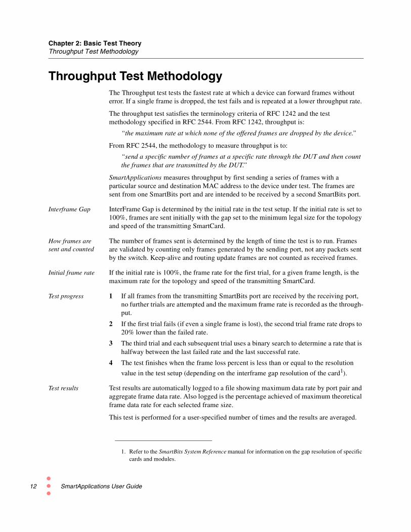
Throughput Test MethodologyThe Throughput test tests the fastest rate at which a device can forward frames withouterror. If a single frame is dropped, the test fails and is repeated at a lower throughput rate.
The throughput test satisfies the terminology criteria of RFC 1242 and the testmethodology specified in RFC 2544. From RFC 1242, throughput is:
“the maximum rate at which none of the offered frames are dropped by the device.”
From RFC 2544, the methodology to measure throughput is to:
“send a specific number of frames at a specific rate through the DUT and then countthe frames that are transmitted by the DUT.”
SmartApplications measures throughput by first sending a series of frames with aparticular source and destination MAC address to the device under test. The frames aresent from one SmartBits port and are intended to be received by a second SmartBits port.
Interframe Gap InterFrame Gap is determined by the initial rate in the test setup. If the initial rate is set to100%, frames are sent initially with the gap set to the minimum legal size for the topologyand speed of the transmitting SmartCard.
How frames aresent and counted
The number of frames sent is determined by the length of time the test is to run. Framesare validated by counting only frames generated by the sending port, not any packets sentby the switch. Keep-alive and routing update frames are not counted as received frames.
Initial frame rate If the initial rate is 100%, the frame rate for the first trial, for a given frame length, is themaximum rate for the topology and speed of the transmitting SmartCard.
Test progress 1 If all frames from the transmitting SmartBits port are received by the receiving port,no further trials are attempted and the maximum frame rate is recorded as the through-put.
2 If the first trial fails (if even a single frame is lost), the second trial frame rate drops to20% lower than the failed rate.
3 The third trial and each subsequent trial uses a binary search to determine a rate that ishalfway between the last failed rate and the last successful rate.
4 The test finishes when the frame loss percent is less than or equal to the resolution
value in the test setup (depending on the interframe gap resolution of the card1).
Test results Test results are automatically logged to a file showing maximum data rate by port pair andaggregate frame data rate. Also logged is the percentage achieved of maximum theoreticalframe data rate for each selected frame size.
This test is performed for a user-specified number of times and the results are averaged.
1. Refer to the SmartBits System Reference manual for information on the gap resolution of specificcards and modules.
SmartApplications User Guide

Chapter 2: Basic Test TheoryThroughput Test Methodology
Acceptable Loss ThroughputIn some cases, differences in clock tolerances between the DUT port and the SmartBitsport will cause Throughput test results to show frame loss. This frame loss does not reflectthe capability of the switch or router, but rather is the result of these clocking variances.
To compensate for this, you can run a SmartApplications Throughput test in a modetermed Acceptable Loss Throughput. When this mode is selected, you specify whatpercentage of frame loss is to be discounted when evaluating the test’s success or failure.
If you enable Acceptable Loss Throughput (by setting a loss value), the SmartApplicationsmain window changes to show the alternate test mode (Figure 2-2). The Throughput TestResults window and Test Report also include information on the acceptable lossperformance.
See “Set Up Test Configurations” on page 48 for details on setting values.
Figure 2-2. Throughput Test with Acceptable Loss
Throughput with Acceptable Loss enabled
SmartApplications User Guide 13

Chapter 2: Basic Test TheoryLatency Test Methodology
14
Latency Test MethodologyThe Latency test measures latency as defined in RFC 1242, as described below for bothstore-and-forward devices and bit-forwarding devices.
How SmartAppscalculates latency
The sending SmartCard sends a burst of frames at a user-specified frame size through theDUT at a user-specified throughput rate. In the middle of the burst stream, it inserts oneframe with an identifying trigger (tag). The time when the trigger frame is fullytransmitted is the Transmit Timestamp. The time the receiving SmartCard recognizes thetrigger frame is the Receive Timestamp. SmartApplications calculates latency as:
(Receive Timestamp) minus (Transmit Timestamp) = Latency
Specifically, SmartApplications first measures the cut-through rate and then calculates thestore and forward rate with this calculation:
(Cut-through Rate) minus (Frame Bit Time) = Store and Forward Rate
The Latency test is performed at a user-specified frame rate.
Cut-through(bit-forwarding)latencycalculation
For cut-through device measurements, SmartApplications calculates latency as FIFO (firstin-first out), meaning that it calculates the difference between the time that the end of thefirst bit of a transmitted frame reaches the DUT’s input port (Transmit Timestamp) andthe time the first bit of the same frame is seen on the DUT's output port (ReceiveTimestamp).
If NA (“Not Applicable”) appears in either of the columns labeled S&F (Store &Forward) in the test Results window, this is because the S&F calculation is zero or less,indicating that the DUT is a cut-through device.
Store andforward latencycalculation
For store and forward device measurements, SmartApplications calculates latency asLIFO (last in-first out), meaning it calculates the difference between the time that the endof the last bit of a transmitted frame reaches the DUT’s input port (Transmit Timestamp)and the time that the end of the first bit of the same frame leaves the DUT’s output port(Receive Timestamp).
Note:1) It is recommended that you run the Throughput test before you run the Latency test inorder to obtain the optimum throughput rate of the DUT. Then use the throughput rateobtained from the Throughput test for the Max Rate in the Latency test. Using a provenoptimum rate prevents the tagged frame from being lost due to performance rate issues. Ifthe tagged frame is not received, you may see a very large number for the RcvByte field ofthe Log file.
2) SmartApplications always measures latency and yields results for both store andforward devices and bit-forwarding (cut-through) devices regardless of the DUT. Whenviewing results, use the result that is appropriate for your type of device.
SmartApplications User Guide

Chapter 2: Basic Test TheoryLatency Test Methodology
SmartMetricsCompensationMode
This mode enables SmartApplications to render the same latency results as would beproduced by other SmartBits applications (such as SmartWindow) in SmartMetrics mode,when the transmitter and receiver are running at different speeds.
With the option is disabled, the Latency test runs as usual, with the trigger pattern at theusual offset in the frame. In this case, however, if the transmitter and receiver are runningat different speeds, the latency result will be different from what it would be in aSmartMetrics test run through (for example) SmartWindow.
In contrast, when this option is enabled, the trigger pattern is offset to the same position inthe frame where the Signature field would be placed in a SmartMetrics test. As a result,SmartApplications can produce the same latency result as a SmartMetrics application.
The SmartMetrics Compensation mode makes it possible to maintain continuity with pastresults, when this is desired.
You can enable SmartMetrics Compensation Mode by selecting Setup > TestConfiguration from the main menu, the opening the Latency tab on the Setup TestConfiguration window.
Limits on LatencyTesting
The following limitation applies to latency tests using 10/100Mb cards in the SMB-200 orSMB-2000. With these cards and chassis, the latency test duration is limited to 112seconds when the packet size is 64 bytes and you are testing at 100% rate in the 100Mbmode.
Use the SmartMetrics Compensation Modewhen you wish to make test results fromSmartApplications compatible with resultsfrom SmartMetrics tests run using otherSmartBits applications, such as SmartWindowor SmartFlow, when the transmitter andreceiver are running at different speeds.
SmartApplications User Guide 15

Chapter 2: Basic Test TheoryPacket Loss Rate Test Methodology
16
Packet Loss Rate Test MethodologyThis test measures the percentage of frames lost by the DUT that should have beenforwarded, based on the total number of packets sent.
The Frame Loss Rate test satisfies the terminology criteria of RFC 1242 and the testmethodology specified in RFC 2544. From RFC 1242, Frame Loss Rate is:
“percentage of frames that should have been forwarded by a network device understeady state (constant) load that were not forwarded due to a lack of resources.”
The test allows for varying frame sizes from 64 bytes to 1518 bytes for Ethernet ports, andup to 8188 for Token Ring ports.
From RFC 2544, the methodology to measure frame loss is to:
“Send a specific number of frames at a specific rate through the DUT to be tested andcount the frames that are transmitted by the DUT.”
How frames arecounted
Frames are validated by counting only frames generated by the sending port, not anypackets sent by the switch. Keep-alive and routing update frames are not counted asreceived frames.
How the test runs The Frame Loss Rate test operates in essentially the same manner as the Throughput test.
1 First a packet burst is performed at the maximum possible rate for a user-specifiedperiod of time.
2 After all packets are sent, the receiving port is queried to determine how many packetswere received.
3 The number of packets not received is determined and the percentage of loss is calcu-lated, based on the total number of packets sent.
Note: For Many-to-1/1-to-Many test configurations between ATM and Ethernet or ATMand Frame Relay: If the DUT bundles multiple streams into one virtual circuit,SmartApplications counters reflect the number of packets received on a per virtual circuitbasis (not per stream).
This test is performed a user-specified number of times and the results averaged.
SmartApplications User Guide

Chapter 2: Basic Test TheoryBack-to-Back Test Methodology
Back-to-Back Test MethodologyBack-to-Back tests the buffering capability of the device under test.
The Back-to-Back test satisfies the terminology criteria of RFC 1242 and the testmethodology specified in RFC 2544. From RFC 1242, the Back-to-Back test is performedby:
“fixed length frames presented at a rate such that there is the minimum legal separa-tion (maximum rate) for a given medium between frames over a sort to medium periodof time, starting from an idle state.”
The test allows for varying frame sizes from 64 bytes to 1518 bytes for Ethernet ports, and8188 bytes for Token Ring ports.
From RFC 2544, the methodology to measure back-to-back frames is to:
“Send a burst of frames with minimum inter-frame gaps to the DUT and count thenumber of frames forwarded by the DUT.”
How frames arecounted
Frames are validated by counting only frames generated by the sending port, not anypackets sent by the switch. Keep-alive and routing update frames are not counted asreceived frames.
How the test runs The Back-to-Back test operates in essentially the same manner as the Throughput test.
1 First a packet burst is performed for a user-specified period.
2 If all packets are received at the receiving port, the test is successful and testing isstopped.
3 If even one packet is lost, the number of packets sent in the burst is halved and retried.
4 If all packets are successfully received at this point, the packet burst is then chosenhalfway between the successful and unsuccessful trials, and retried.
5 This pattern repeats until the actual number of packets that can be forwarded in a burstis determined.
This test is performed a user-specified number of times and the results are averaged.
SmartApplications User Guide 17

18
SmartApplications User Guide
Install and Connect
3In this Chapter...
This chapter contains the following sections:
• Install SmartApplications.....20
• Launch SmartApplications.....21
SmartApplications User Guide 19
Chapter 3: Install and ConnectInstall SmartApplications
20
Install SmartApplicationsIt is assumed that you are familiar with Microsoft Windows and basic SmartBitsoperation.
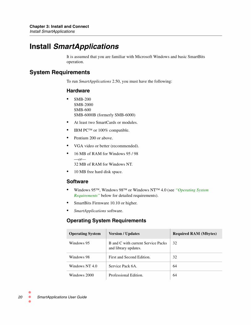
System RequirementsTo run SmartApplications 2.50, you must have the following:
Hardware
• SMB-200SMB-2000SMB-600SMB-6000B (formerly SMB-6000)
• At least two SmartCards or modules.
• IBM PC or 100% compatible.
• Pentium 200 or above.
• VGA video or better (recommended).
• 16 MB of RAM for Windows 95 / 98—or—32 MB of RAM for Windows NT.
• 10 MB free hard disk space.
Software
• Windows 95, Windows 98 or Windows NT 4.0 (see “Operating SystemRequirements” below for detailed requirements).
• SmartBits Firmware 10.10 or higher.
• SmartApplications software.
Operating System Requirements
Operating System Version / Updates Required RAM (Mbytes)
Windows 95 B and C with current Service Packsand library updates.
32
Windows 98 First and Second Edition. 32
Windows NT 4.0 Service Pack 6A. 64
Windows 2000 Professional Edition. 64
SmartApplications User Guide

Chapter 3: Install and ConnectLaunch SmartApplications
Installing from the CDSmartApplications is provided on one CD-ROM disk. To install the program, refer to theinstructions on the CD case.
Installation Using AutoPlay
AutoPlay (if enabled) will automatically begin the installation process.
1 Insert the SmartApplications installation CD in the CD-ROM drive. The Install Shieldwindow is displayed.
2 Select Install SmartApplications [Ver#].
3 Follow the instructions until all SmartBits software is installed.
If AutoPlay is Not Enabled
If AutoPlay is disabled or your PC does not support an automatic installation process, youcan use the following alternative procedure.
1 From the Start Menu, select Run.
2 When the Run dialog box appears, type:
<cd-rom drive>:\SETUP
—in the Command Line, then click OK.
3 Follow the instructions displayed as the installation program installs the software.
Launch SmartApplicationsFrom the Start menu, select Programs > SmartBits Applications > SmartApplications.The SmartApplications main window displays.
How to Close SmartApplications
To close SmartApplications, click the Close button at the top right corner of the screen.
or
Select File > Exit from the menu bar.
SmartApplications User Guide 21

22
SmartApplications User Guide
Basic Navigation and Tools
4In this Chapter
This chapter contains the following sections:
• Features of the Main Window.....24
• Charting Test Results.....33
SmartApplications User Guide 23

Chapter 4: Basic Navigation and ToolsFeatures of the Main Window
24
Features of the Main WindowSmartApplications provides a dynamic main window that changes according to theselections you make—for example, selecting a 1-to-Many or 1-to-1 test type.
Figure 4-1 highlights the key elements.
Figure 4-1. Main Window Elements
Connection Status
A connection status indicator (bottom right of main window) and the status messageConnected shows when SmartApplications is connected to the SmartBits. Whendisconnected, the light is grey and the message Disconnected displays.
Menu Bar
Tool Bar
Connection
Test Launchbuttons
Port Selectionarea
Card Attributesarea
status
SmartApplications User Guide

Chapter 4: Basic Navigation and ToolsFeatures of the Main Window
Menus
File Menu
These menu options allow you to create and manage configuration files.
• NewOpens the default SmartApplications test configuration (.sig) file. If you changed thedefault values, this option allows you to reset the values to the defaults.
• OpenOpens a previously saved SmartApplications test configuration (.sig) file.
• SaveSaves the current settings as a .sig file.
• Save AsSaves the current test configuration under a new name.
• View Results FileOpens the Results window. Once the Results window opens you can view results forthe current configuration or for saved results for any previous configuration.
• PrintPrints the current configuration file.
• Print SetupAllows the user to select the printer and setup printer options.
• [ path ]Use this option to load a .sig (configuration) file that you defined and save previously.
• ExitCloses SmartApplications.
Actions Menu
These menu options allow you to connect or disconnect to the SmartBits chassis.
• ConnectEstablishes the logical connection from your PC to the SmartBits chassis.
• DisconnectBreaks the logical connection from your PC to the SmartBits chassis.
Note: You define the connection type in the Setup SmartBits Connections dialog (selectSetup > SmartBits Connections from the main menu). You must first disconnectSmartApplications from the SmartBits chassis to gain access this dialog.
SmartApplications User Guide 25

Chapter 4: Basic Navigation and ToolsFeatures of the Main Window
26
Setup Menu
Some of these options are active only when SmartApplications is disconnected from theSmartBits chassis.
The Setup menu contains the following options:
• Test ConfigurationOpens the Setup Test Configuration window. Use this to specify test parameters suchas test duration, learning packet information, and global test preferences.
• All SmartCardsOpens the Setup All SmartCards window. Use this to specify setup information for allSmartCards from one window, instead of by individual card attribute tab, as well as tomake test-by-test or global changes (such as the speed) to all cards. You can alsoaccess the Network IPs window and Token Ring Properties window from thiswindow.
• ATM Traffic Descriptor TypeOpens the Traffic Configuration window. Use this to specify call-setup broadbandcapabilities and forward and backward traffic descriptor specifications.
• HTML Reports SetupOpens the HTML Report Setup window. Use this when you wish to have test reportsgenerated in HTML format and to specify the report output path, filename, and(optionally) comments.
• SmartBits ConnectionsOpens the Setup SmartBits Connections window. Use this to define the IP address andTCP port number for IP network connections between SmartApplications andSmartBits chassis, as well as to select either Serial (COM) port or IP as the activeconnection type.
• SmartCards ReservationEnables you to change the Reserved or Available status of slots when multiple usersare running tests on the same chassis.
Run Menu
The Run menu allows you to select one test to start running or to start all tests running insuccession. (You can also use the test launch buttons on the main window to start a test.)
• ThroughputRun the Throughput test (see “Throughput Test Methodology” on page 12).
• LatencyRun the Latency test (see “Latency Test Methodology” on page 14).
• Packet LossRun the Packet Loss test (see “Packet Loss Rate Test Methodology” on page 16).
SmartApplications User Guide

Chapter 4: Basic Navigation and ToolsFeatures of the Main Window
• Back to BackRun the Back-to-Back test (see “Back-to-Back Test Methodology” on page 17).
• AllRun all four tests.
Help Menu
This menu contains two options:
• ContentsOpens SmartApplications online Help.
• About SmartApplicationsDisplays the current application version number, firmware number, SmartBitsProgramming Library version used, and the serial number of the SmartBits controller.
From the About window, you can also access the SmartBits Controller and CardInformation window (below), It displays firmware version and other information forthe SmartBits chassis and installed cards. (You must have SmartApplications con-nected to the chassis to have access to this window.)
SmartApplications User Guide 27

Chapter 4: Basic Navigation and ToolsFeatures of the Main Window
28
Launch ButtonsYou can start any SmartApplications test by clicking on its launch button:
• Throughput
• Latency
• Packet Loss
• Back-to-back
You can also start individual tests by selecting Run > <test name> from the menu bar.
To run all tests in sequence, select Run > All.
Test Launchbuttons
SmartApplications User Guide

Chapter 4: Basic Navigation and ToolsFeatures of the Main Window
Toolbar Buttons
Table 4-1 Toolbar Buttons
Button Description
Opens an existing configuration file.
Saves the current configuration to a file.
Prints the current configuration file.
Connects SmartApplications to the SmartBits chassis. This allows you to displaythe card attributes for the SmartCards in the chassis.
Disconnects SmartApplications from the SmartBits chassis.
Note: To set up IP or serial port connections, you must disconnectSmartApplications from the chassis.
Displays the Setup SmartBits Connections window. Use this to set up IP andserial (COM) port connections and to select the active connection type.
Displays the SmartCard Status window. Use this to check the status of cards andto reserve or release ports in multi-user configurations.
Displays the Setup Test Configuration window. Use this to specify testconfigurations and preferences.
Displays the Set Up All SmartCards window. Use this to configure the attributesfor all ports or multiple ports in one window.
Continues
SmartApplications User Guide 29

Chapter 4: Basic Navigation and ToolsFeatures of the Main Window
30
Button Description
Accesses the About SmartApplications window, which displays the currentapplication version number, firmware number, SmartBits Programming Librarynumber used, and the serial number of the SmartBits controller.
From the About window, click on Card Versions to obtain chassis and cardinformation, such as firmware version.
Table 4-1 Toolbar Buttons (continued)
SmartApplications User Guide

Chapter 4: Basic Navigation and ToolsFeatures of the Main Window
Port Selection AreaUse the Port Selection pane to specify the ports to be included in a test and the test type.
The test type may be 1 to 1 (one-to-one) or 1 to M (one-to-many).
Checking Bi-directional causes the selected port pairs to transmit simultaneously in bothdirections, as in full-duplex operation.
Checking Reverse Tx & Rx port reverses the transmission direction, so that a Many-to-1test can be run.
Selecting Ports for 1-to-1 Tests1 Select the 1 to 1 radio button. The main window displays the 1-to-1 port selection pane.
2 Select at least one pair of Source and Destination ports.
3 Check Bi-directional if you want the selected port pair(s) to transmit and receivesimultaneously.
—or—
Check Reverse Tx & Rx port to reverse the transmission direction.
SmartApplications User Guide 31

Chapter 4: Basic Navigation and ToolsFeatures of the Main Window
32
Selecting Ports for 1 to Many Tests1 Select the 1 to M radio button. The main window displays the 1 to M port selection pane.
Note: 1 to Many and Many to 1 tests are not compliant with RFC 2544.
2 Select the direction for the test using one of the direction buttons. The Source andDestination fields will change locations depending on the direction you select.Note: If you change the direction, the Destination MAC and SmartCard MACaddresses on the card attributes tab remain unchanged. Ensure that you enter thecorrect destination MAC address for the DUT.
3 Select Source card(s) and Destination card(s).
The last card that you select in the Source (Many to 1), or Destination (1 to Many) orAvailable Ports field will be the card whose attributes appear as the second tab, asillustrated in this Destination Index example:
SmartApplications User Guide

Chapter 4: Basic Navigation and ToolsCharting Test Results
Charting Test ResultsOnce a test has finished running, you can present the results of the test in graph form. Youcan create a wide variety of charts to graphically represent test results by using the ChartWizard. Charts range from 2D or 3D pie and bar charts to Gantt charts. You can alsocustomize titles, layouts, legends, and axes. The Chart Wizard is a separate chartingfacility provided with SmartApplications.
Note: To understand how a test derives the results that are shown, refer to the appropriatedescription of test methodology in this manual. See Chapter 2, “Basic Test Theory” andthe section for the test you are running.
To create a chart from the appropriate Results window tab do these steps:
1 Select the rows and columns you want to appear on the chart. To do this, click on thefirst cell and then hold down the Shift key and click on the last cell to include. Theblock of cells will be highlighted.
2 Click the Create Chart button to display the Chart Wizard.
SmartApplications User Guide 33

Chapter 4: Basic Navigation and ToolsCharting Test Results
34
3 Select the type of chart you want to create from the Chart Wizard. The chart will beattached to the spreadsheet.
4 Double click on the outside of the chart to access the Format Chart window and cus-tomize the format.
For more information about how to use the Chart Wizard, refer to the Chart Wizard'sonline help user guide. To access the online Help click the Help button from the ChartWizard window. The online Help system is called First Impression.
SmartApplications User Guide

Set Up Tests
5In this chapter...
This chapter contains the following sections:
• Summary of Steps to Set up a Test.....36
• Connect the Device Under Test.....36
• SmartBits Connection Setup.....37
• Set Up Test Configurations.....48
• Select Test Ports.....60
• Configure Test Ports.....67
• Router Testing.....115
• Set up Next Hop Tests.....117
• Set Up IP/UDP/IPX Protocols.....119
• Set up ATM 1-to-Many/Many-to-1 Tests with PVC CLIP.....123
SmartApplications User Guide 35

Chapter 5: Set Up TestsSummary of Steps to Set up a Test
36
Summary of Steps to Set up a TestHere is a brief overview of the steps to set up SmartApplications tests. See the followingsections for detailed procedures.
Note: If you are testing a router, you must check the Router Test box at the Test Setupwindow Preference tab.
Connect the Device Under TestIf possible, connect the same-numbered ports on the SmartBits and the device under tests(DUT). That is, connect SmartBits port 1 to DUT port 1, port 2 to port 2, and so on.
To verify that the cable is connected correctly, check that the device link light is on.
Note: For complete information about setting up the hardware and your SmartBitschassis, refer to the related Installation manual and to the SmartBits System Referencemanual.
Step Task Refer to: Page
1 If running SmartApplications for the firsttime, set up the communications portbetween the PC and the SmartBits chassis.
“SmartBits Connection Setup” 37
2 Set up the test configuration and preferences. “Set Up Test Configurations” 48
3 Select the ports for the test(s) and the trafficdirection.
“Select Test Ports” 60
4 Configure the ports. “Configure Test Ports” 67
5 Run the test. Chapter 6, “Run Tests” 125
6 Review test results. Chapter 7, “Test Examples” 151
SmartApplications User Guide

Chapter 5: Set Up TestsSmartBits Connection Setup
SmartBits Connection SetupSmartApplications needs to know the communications port your PC is using to connect tothe SmartBits chassis. To define this, select Setup > SmartBits Connections... from themain menu.
Note: The SmartBits Connections option is active only when SmartApplications isdisconnected from a SmartBits chassis. Connection status is shown on the status bar.
The SmartBits Connections dialog enables you to manage both serial and IP connections.
• Serial(Default) For point-to-point connections. See “Connect Using a Serial Port” on page38 for more information.
• EthernetRequires a network card in your PC, and a SmartBits chassis with Ethernetcapabilities (SMB 200/2000 or SMB-600/6000B. Allows you to runSmartApplications over an Ethernet connection (including the Internet) from your PC.See “Connect Using an Ethernet Port” on page 40 for more information.
Use this pane to definenew connections.
The Connection List displays allconnections that are already defined.
Click to move up or down in the listor to delete an entry.
SmartApplications User Guide 37

Chapter 5: Set Up TestsSmartBits Connection Setup
38
Connect Using a Serial PortUse the following steps to set up a serial (COM) port connection between the PC and theSmartBits chassis.
1 Choose Setup > SmartBits Connections...
2 In the Add SmartBits Connections pane, click the Serial radio button.
3 In the Comm Port list, select the COM port you have used to connect the PC to theSmartBits.
By default, the selected port is COM2 at 38400 bps. The list shows only availableCOM ports. If the list does not include an installed COM port (for example, COM1),this may be caused by the following:
• You have a serial mouse connected to that port.
• The port is opened by another currently running program.
4 Use the Speed list to select the baud rate for the port.
SmartBits supports connections up to 38400 bps (the default). Some PCs may havetrouble keeping up with baud rates above 9600 bps. SmartApplications attempts toconnect to SmartBits at all possible baud rates, then sets the final baud rate to the rateselected.
5 Optionally, use the Description field to define a name for the connection.
6 Click Add.
The new entry appears in the Connection List.
SmartApplications User Guide

Chapter 5: Set Up TestsSmartBits Connection Setup
Serial Connection Problems
If SmartApplications cannot establish the serial-port communication link, sometroubleshooting may be required. Refer to your SmartBits 200/2000 Installation Manualor SmartBits 600/6000B Installation Manual for detailed information on the possibilitieslisted below.
• An invalid COM port was selected from the drop-down Comm Port list in the SetupSmartBits Connections dialog. The COM port may already be in use by anotherWindows application, or there may not be hardware available to support it. In thiscase, try another COM Port.
• The wrong type of cable was used to interconnect the PC and the SmartBits chassis.
Ensure that the RS-232 cables connecting the PC serial port to the SmartBits chassis(as well as any succeeding SmartBits chassis) are properly chosen, connected, and ter-minated. Ensure that cable is not a null modem cable.
• The port is configured incorrectly. Ensure that the Speed setting in the SetupSmartBits Connections dialog is consistent with the baud rate on the SmartBitschassis.
SmartApplications User Guide 39

Chapter 5: Set Up TestsSmartBits Connection Setup
40
Connect Using an Ethernet PortA configured SmartBits chassis has an IP address that was set either through:
• SmartWindow or HyperTerminal for the SMB 200/2000
• HyperTerminal for the SMB 600/6000B.
This enables you to connect to the SmartBits by using an Ethernet network connection.
Note: Refer to your SmartBits 200/2000 Installation Manual or SmartBits 600/6000BInstallation Manual for the steps to assign the IP address.
Use the following steps to define the IP address in SmartApplications. You can control upto 16 different chassis from one SmartApplications instance (and can define many more IPaddresses, if necessary).
1 Choose Setup > SmartBits Connections...
2 In the Add SmartBits Connections pane, click the IP radio button.
3 Set the IP address of the SmartBits chassis. The factory assigns the TCP port number16385 to the chassis.
4 Optionally, use the Description field to define a name for the connection.
5 Click Add.
The new entry appears in the Connection List.
SmartApplications User Guide

Chapter 5: Set Up TestsSmartBits Connection Setup
Making the ConnectionOnce you have set up the connection type, you are ready to connect SmartApplications tothe SmartBits chassis.
1 Choose Actions > Connect, or click on the Connect SmartBits button on the toolbar.
The SmartBits Connection Confirmation dialog lists all the connections that are cur-rently selected (checked in the Setup SmartBits Connections dialog).
SmartApplications will try to connect first using the 1: link or address in the list. If itcannot establish that connection, it tries the 2: entry, then following entries (if neces-sary).
2 If connection is successful, the Connected indicator appears in the lower right cornerof the main window. If Disconnected is shown, SmartApplications is not connected.In this case, review all connections for conformance with instructions in your Smart-Bits Installation manual.
SmartApplications User Guide 41
Chapter 5: Set Up TestsSmartBits Connection Setup
42
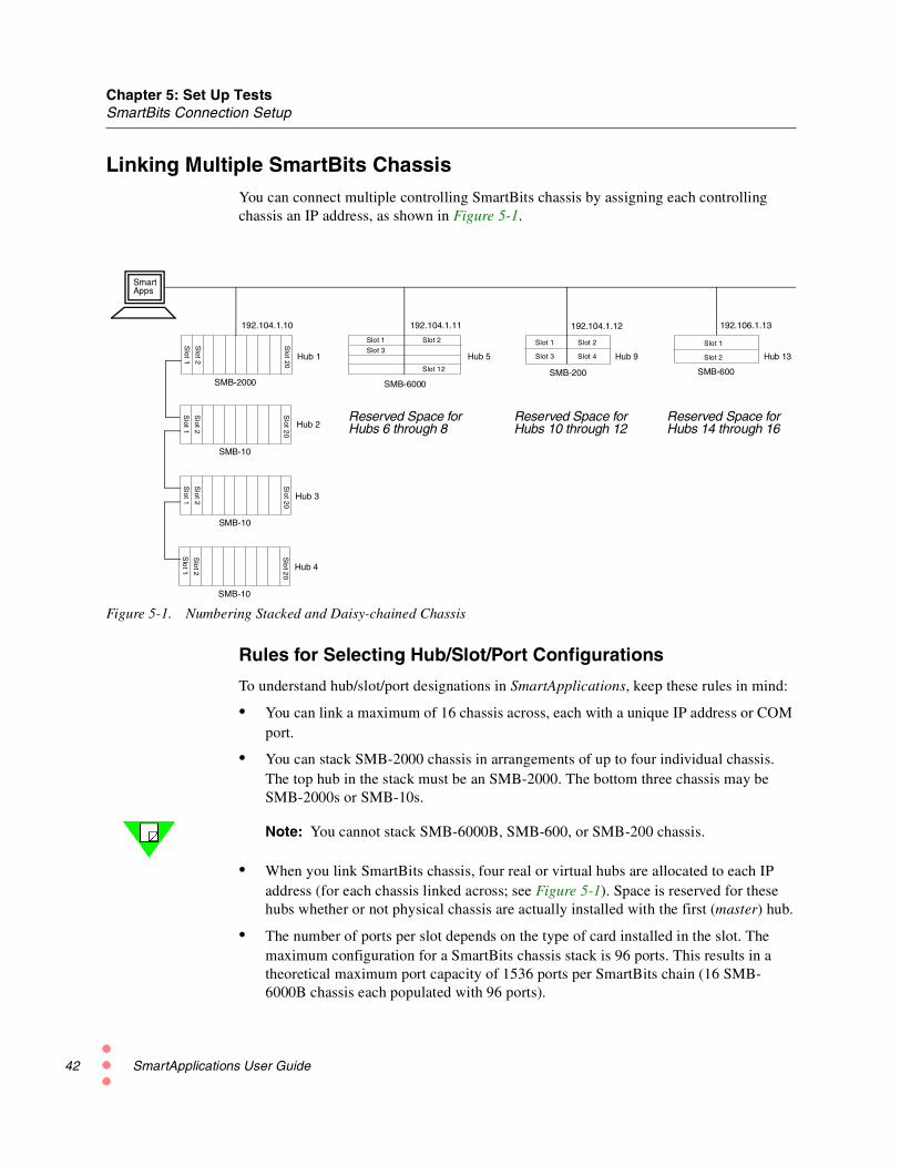
Linking Multiple SmartBits ChassisYou can connect multiple controlling SmartBits chassis by assigning each controllingchassis an IP address, as shown in Figure 5-1.
Figure 5-1. Numbering Stacked and Daisy-chained Chassis
Rules for Selecting Hub/Slot/Port Configurations
To understand hub/slot/port designations in SmartApplications, keep these rules in mind:
• You can link a maximum of 16 chassis across, each with a unique IP address or COMport.
• You can stack SMB-2000 chassis in arrangements of up to four individual chassis.The top hub in the stack must be an SMB-2000. The bottom three chassis may beSMB-2000s or SMB-10s.
Note: You cannot stack SMB-6000B, SMB-600, or SMB-200 chassis.
• When you link SmartBits chassis, four real or virtual hubs are allocated to each IPaddress (for each chassis linked across; see Figure 5-1). Space is reserved for thesehubs whether or not physical chassis are actually installed with the first (master) hub.
• The number of ports per slot depends on the type of card installed in the slot. Themaximum configuration for a SmartBits chassis stack is 96 ports. This results in atheoretical maximum port capacity of 1536 ports per SmartBits chain (16 SMB-6000B chassis each populated with 96 ports).
SmartApps
192.104.1.11 192.106.1.13
Hub 1
SMB-2000 SMB-6000SMB-200
Hub 5 Hub 9 Hub 13
SMB-600
Hub 2
Slot
1
Slot
20
Slot
2
SMB-10
Slot
1
Slot
20
Slot
2
SMB-10
Slot
1
Slot
20
Slot
2 Hub 3
SMB-10
Slo
t1
Slo
t20
Slo
t2 Hub 4
Slot 1 Slot 2
Reserved Space forHubs 6 through 8
Reserved Space forHubs 10 through 12
Reserved Space forHubs 14 through 16
Slot 1 Slot 2
Slot 4Slot 3
Slot 1
Slot 2
192.104.1.12
Slot 3
Slot 12
192.104.1.10
SmartApplications User Guide

Chapter 5: Set Up TestsSmartBits Connection Setup
• Hub/slot/port information appears in port selection dialogs and window, and in testreports. Information displays in the format [xx,xx,xx]. For example, [05,04,03]represents hub 5, slot 4, port 3.
• The arrangement of hub/slot/port information in the connection list is based on theorder in which IP addresses are arranged on the list. For example, with the chassisillustrated above, the IP address for Hub 13 (192.106.1.13) is listed fourth in theconnection list. If this IP address had been listed first, Hub 13 would be Hub 1. The IPaddress listed next would then become Hub 5, and so on.
Synchronizing Clocks in Local or Remote Chassis
You can synchronize the clocks in multiple SmartBits that are local to one another orremote from each other. Doing this enables you to start and stop tests simultaneously atthe SmartBits chassis. Local synchronization is done through cable interconnections.Remote synchronization makes use of a GPS (Global Positioning System), whichbecomes the clock source for each chassis, providing each SmartBits with an atomicclock.
Localsynchronization
For the steps to synchronize local chassis, refer to your SmartBits Installation Manual.
Remotesynchronization
For information on how to set up the GPS receiver, including cabling information, refer tothe Application Note #15 — Using GPS with SmartBits. It accompanies the GPS unit.
Note: Before running a latency test between two remote SmartBits chassis in GPS mode,endure that the GPS receiver has been on for several hours. This is necessary for the GPSreceiver components to be locked on. If you fail to do this, SmartApplications may senderror messages.
Multi-User AccessIf a SmartBits chassis is multi-user-capable, it allows up to ten users to connectsimultaneously. When SmartApplications is connected to a multi-user chassis, it lists theinstalled cards and shows their current status as either Reserved or Available. You mustreserve a card to be able to use it in your test.
An SMB-6000B chassis is always capable of multi-user connections. An SMB-2000chassis must display a Multi-user Ready identifying sticker to be multi-user capable. TheSMB-200 is a single-user-only chassis.
On an SMB-2000, the multi-user sticker indicates that:
• An SMB-2000 multi-user-compliant backplane is installed.
• Chassis firmware 6.50 or later is installed.
Note: Any SMB-2000 chassis can be factory-refitted to become multi-user compliant.
SmartApplications User Guide 43

Chapter 5: Set Up TestsSmartBits Connection Setup
44
Reserving CardsIn a multi-user test environment, you must reserve cards or modules before you can usethem in tests. To do this:
• Check card status.
• Reserve available cards for your use.
• When done, release the cards.
To check card status:
To check the card availability:
• Click the Reserve/Release SmartCards toolbar button on the SmartApplicationsmain window.
—or—
• Select Setup > SmartCard Reservation.
The SmartCard Status window displays information like that shown in Figure 5-2 onpage 44.
3 Click the tab for the controller (chassis) you wish to view.
Each controller tab shows the hub, slot, and number of each port, the card model number,and the status of the port: Reserved or Available. In the Hub column, a blue light indicatesReserved, and a green light indicates Available.
Figure 5-2. SmartCard Status Window
SmartApplications User Guide

Chapter 5: Set Up TestsSmartBits Connection Setup
To reserve cards:
To reserve an available card from a controller tab in the SmartCard Status window:
1 Click on the port you wish to reserve to highlight it.
2 Click Reserve.
SmartApplications automatically updates the controller field to show your selection.You can also click Refresh to update the field.
3 When you are finished reserving cards, click Close.
To release cards:
To release a card you have reserved:
1 Open the appropriate controller tab in the SmartCard Status window.
2 Click on the port you wish to release to highlight it.
3 Click Release.
SmartApplications automatically updates the controller field to show your selection.You can also click Refresh to update the field.
4 Click Close when finished.
SmartApplications User Guide 45

Chapter 5: Set Up TestsStarting and Stopping a Test
46
Starting and Stopping a TestThe remainder of this chapter describes how to set up test configurations to use in testing(see “Set Up Test Configurations” on page 48 and following).
To start a test:
Once you have set up test parameters and selected the ports to test, you can start the test inseveral ways:
• Click the appropriate launch button on the main SmartApplications window
• Select Run from the menu bar.
To start one or more tests automatically:
You can set one or more tests to run automatically each time you launchSmartApplications.
1 Select Setup > Test Configuration.
2 Open the Preference tab, the use the Application Options pane to select the tests youwish to run.
The next time you open SmartApplications, the selected tests will begin runningautomatically.
SmartApplications User Guide

Chapter 5: Set Up TestsStarting and Stopping a Test
Note: If you check Stop on Error in the Test Options pane of the Preference tab, the testwill stop running when it encounters an error conditions (for example, Latency packet notreceived).
If you want the test to continue to run regardless of errors, leave this option unchecked.
If you plan to run a long test, we recommend that you do not check this option.
To stop a test:
To stop a test that is running, click the Stop button in the Results window.
Click the Stop button in the Results window to halt a test.
SmartApplications User Guide 47

Chapter 5: Set Up TestsSet Up Test Configurations
48
Set Up Test ConfigurationsTo set up test configurations:
1 Select Setup > Test Configurations from the main menu.
2 Use the Test Configuration tab Figure 5-3) to set options for tests.
Figure 5-3. Test Configuration Tab with Test Options
Note: Remember that SmartApplications enables you to save test configurations to a filefor future use. See “File Menu” on page 25 for options.
The Setup Test Configuration dialog includes two tabs:
• Test Configuration See “Test Configuration Options” on page 49
• Preference See “Preference Tab” on page 55
SmartApplications User Guide

Chapter 5: Set Up TestsSet Up Test Configurations
Test Configuration OptionsThe Test Configuration tab (Figure 5-4) includes panes to define General test parameters;the handling of Learning Packets; and individual test parameters.
Figure 5-4. Setup Areas on the Test Configuration Tab
General OptionsUse the fields in the General pane to specify the range of packet sizes to be transmittedduring the test. Standard packet sizes are in multiples of 64 bytes. (Click on Sizes to viewthe list of standard sizes.)
Tests do not necessarily run until the maximum (Stop At) packet size is sent. If the StepSize value increments the packet size to a value larger than the Stop At value, the test stopsat the Stop At value. For example, if you set the fields as follows:
Start From 64
Stop At 200
Step Size 64
—the test will send packets of 64, 128, and 192 bytes, then stop. It will not send 256-bytepackets (larger than Stop At), and will it not send 200-byte packets (not in the Step Sizeincrement sequence).
General test
Learning
Individual testparameters
packets
parameters
SmartApplications User Guide 49

Chapter 5: Set Up TestsSet Up Test Configurations
50
Start From Enter or select the size of the smallest packet to send. The default size is 64 bytes.
Stop At Enter or select the size of the largest packet to send. The default size is 1518 bytes.
Step Size Enter or select the number of bytes that the current packet size will be incremented witheach test. For example if the step size is 10 bytes, the first test transmits packets that are 64bytes, and the next test transmits packets that are 74 bytes.
Use Custom UncheckedRuns tests according to settings in the Test Configuration tab.Default custom sizes are: 64, 128, 256, 512, 1024, 1280 and 1518.
CheckedRuns tests according to the packet sizes specified at the Custom Packet Sizes window.Enables the Sizes button.
Setting anAcceptable LossPercentage
If you select Use Custom, you can set a level of acceptable frame loss for each frame sizesent during the test. (See “Acceptable Loss Percentage (%) (per port)” on page 53 for anexplanation of this option. Also see “Acceptable Loss Throughput” on page 13 for ageneral description of this option for Throughput tests.)
Click on Sizes. In the Custom Packet Sizes window, use the Acceptable Loss (%) columnto set an acceptable level of frame loss for each frame size, as needed for your test.
Figure 5-5. Setting Acceptable Loss for Custom Packet Sizes
Use the Acceptable Loss (%) column to specify whatpercentage of frame loss should be discounted duringeach trail of a Throughput test.
SmartApplications User Guide

Chapter 5: Set Up TestsSet Up Test Configurations
Learning Packets Options
Learning packets are used by the DUT to build its forwarding tables of MAC addresses forthe sending and receiving SmartBits ports. You can send cause learning packets to be sentonce for the test or between every test trial, to refresh the DUT’s forwarding tables beforeaddresses are eliminated by aging.
Learning Mode Select the mode by which SmartApplications sends out learning packets to update thedevice's forwarding tables. Possible modes:
NeverNever send learning packets to the device under test.
OnceSend learning packets once at the beginning of each test. For example, if you select packetsizes of 64 and 128 bytes, SmartApplications sends learning packets before the 64-bytetest and again before the 128-byte packet test.
Every TrialSend learning packets before each trial. For example: You wish to test at a packet size of64 bytes, starting at 50% and incrementing 10% each trial. Learning packets will be sentbefore the 50% trial, before the 60% trial, and so on.
LearningRetries
Enter or select the number of times SmartApplications should retry sending learningpackets before it starts the actual test. Some devices require more packets to learn anaddress. This value is used to loop on the transmission of the learning packets. There is aone-second delay between retries.
Note: If the DUT shows signs of flooding during testing, consider increasing the defaultvalues in the Learning Packets pane or increasing the aging timer in the DUT.
Individual Test Options
Open the tab for each test that you want to run and set test parameters.
Duration (sec) Enter or select the length in seconds for which you want to run each trial of the test. It isthe amount of time that SmartBits will send data for each packet for the selected test.Possible values range from 1 to 999 seconds.
Note: For 100Mb cards, do not use a value greater than 110 seconds, orSmartApplications will send the error message “Parameter out of range.” when you runthe test.
SmartApplications User Guide 51

Chapter 5: Set Up TestsSet Up Test Configurations
52
Number ofTrials
Enter or select the number of times that you want SmartApplications to repeat the selectedtest(s). Values range from 1 to 25 for each packet length. After all tests, SmartApplicationsaverages the results before reporting a summary of all trials for each test.
Initial Rate (%) The rate at which packets will be transmitted at the start of a trial.
Step Rate (%) Does not apply to the Throughput test.
The percentage that the test increments with each trial. Step rate specifies how quickly thetest rate will increase after a trial finishes. Select or enter an integer or decimal value. Theminimum decimal value you can enter is .1.
Min. Rate (%) Does not apply to Latency tests.
The rate at which transmission trials will stop. Select or enter an integer or decimal value.The minimum decimal value you can enter is .1.
Max. Rate (%) The maximum rate at which each packet size should be transmitted. Select or enter aninteger or decimal value. The minimum decimal value you can enter is .1.
When selecting this rate for the Latency test, the Latency measurement should be at therate where the Throughput test passed. Setting a value of 100% may not be measuring thetrue latency of your device under test. Set this value accordingly. For example, if youknow a particular device cannot exceed 90% of wire speed, set the maximum to 90% tosave time.
Note: Run the Throughput test before the Latency test to obtain the DUT’s maximumthroughput rate. Then use that throughput rate for the Max Rate in the Latency test. Usinga proven rate prevents the tagged frame from being lost due to rate (gap size) issues.
Resolution (%) Applies only to the Throughput test.
Resolution determines the exactness of the test result. Lower settings yield a more preciseresult but usually results in longer test times.
How Resolution Affects Test Progress
If you set the resolution to 2%, testing will stop when the difference between the lastsuccessful test and the last unsuccessful test is less than 2%. If the initial trial failed at100%, the second trial might run at 50%. Assuming no packets were dropped at 50%, thenext trial would increase to 75%. Again assuming no lost packets, the rate of the next trialmight increase to 87.5%, and so on. Eventually, you might run a trial at 98.2%. Since theresolution was set to 2%, testing would stop here, because 100 – 98.2 is 1.8%, which isless than 2%. If the resolution had been set to 1% another trial would be run, since 1.8% isgreater than 1%.
SmartApplications User Guide

Chapter 5: Set Up TestsSet Up Test Configurations
AcceptableLossPercentage (%)(per port)
Applies only to the Throughput test.
This option provides a way to compensate for frame loss caused by differences in clocktolerances at the DUT port and the SmartBits port. Such variances in clocking can cause aThroughput test to show frame loss that is caused not by the operation of the switch orrouter, but rather by these discrepancies in clock timing.
When you select Acceptable Loss Percentage (per port), the Throughput Test launchbutton on the SmartApplications main window changes to show the selected mode(Figure 5-6). The test result reports also show how the specified acceptable loss hasfigured into the test (see “Sample Reports – Throughput Test” on page 137).
Figure 5-6. Throughput Test Launch Button with Acceptable Loss Enabled
SmartApplications considers the last trial a success if frame loss did not exceed thespecified percentage. The test then continues according to the settings of other testoptions, such as Number of Trials and Resolution (%).
SettingAcceptable Lossfor each framesize
When you set a value to this option, the percentage applies to all frame sizes generatedthrough the port for the test. You can also specify an acceptable loss percentage for eachframe size sent during the test. To do this, select Use Custom in the Test Configurationwindow, then click on Sizes to open the Custom Packet Sizes dialog. Use that dialog to seta percentage value for each frame size, as desired (see “Use Custom” on page 50).
Throughput with Acceptable Loss has been selected.
SmartApplications User Guide 53

Chapter 5: Set Up TestsSet Up Test Configurations
54
Customizing Test PacketsYou can select packet sizes other than the standard by selecting Use Custom on the TestConfiguration tab. Click Sizes to open the Custom Packet Sizes dialog (Figure 5-7).
Figure 5-7. Custom Packet Sizes Dialog
The default values are the seven packet sizes specified for Ethernet testing in Section 9.1of RFC 1242.
To change thenumber packetsizes:
Enter or select a new value in the Number of Sizes field. The maximum number of packetsizes is 25. To enter a custom value for a packet size, click on a Packet Size field and typein a value.
Click OK to close the window and make your selected sizes the current settings.
Click Cancel to close the window without making changes.
Click Default to revert to the seven default packet sizes.
SettingAcceptable Loss(%) per framesize
Use the Acceptable Loss (%) column to specify what degree of frame loss should bediscounted, for each frame size, when running the test.
See “Acceptable Loss Percentage (%) (per port)” on page 53 for an explanation of thisoption, as it applies to all frame sizes generated during the test.
SmartApplications User Guide
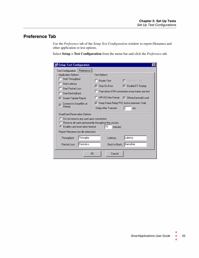
Chapter 5: Set Up TestsSet Up Test Configurations
Preference TabUse the Preference tab of the Setup Test Configuration window to report filenames andother application or test options.
Select Setup > Test Configuration from the menu bar and click the Preference tab.
SmartApplications User Guide 55

Chapter 5: Set Up TestsSet Up Test Configurations
56
Preference Tab Fields
Table 5-1 describes the fields on the Preference tab.
Table 5-1. Preference Tab Fields.
Pane Field Description
Application Options Start Throughput Check to start this test automatically when you startSmartApplications.
Start Latency Check to start this test automatically when you startSmartApplications.
Start Packet Loss Check to start this test automatically when you startSmartApplications.
Start Back to Back Check to start this test automatically when you startSmartApplications.
Create TabularReport
Check to generate reports in tabular format with results bypacket size running horizontally across the page. Uncheck ifyou want to use the non-tabular format.
Connect to SmartBitsat Startup
Check to automatically connect to the SmartBits chassiswhen SmartApplications starts. This speeds up applicationstartup time.
Test Options Router Test Check if you are testing a router. This enables the Next HopTest checkbox.
Stop On Error Checked: When errors are encountered, the test stops anderror messages display, to enable you to correct thecondition.
Unchecked: Errors are ignored and the test continues. Errormessages are logged to the results file. Leave this boxunchecked if you want the test to run regardless of errorconditions.
Next Hop Test Enables you to test the Next Hop gateway address.
Disable ET Display Checked: The SmartBits does not try to track updates forthe front panel of an attached ET-1000.
Unchecked: Uncheck only if your test bay includes an ET-1000 controller and you want to track ET-1000 countersthrough the front panel display.
SmartApplications User Guide

Chapter 5: Set Up TestsSet Up Test Configurations
Test Options(continued)
Tear down ATMconnection everyframe size test
When testing ATM cards, disconnect the stream andconnection for each trial.
VPI-VCI Hex Format When testing ATM cards, check to view VPI and VCIvalues in hex format.
Offered (actual) Load You can run each test using either an “Intended” method ofloading the device under test (DUT) or an “Offered Load”method of loading the DUT.
Checked: “Offered Load” method is enabled.
Unchecked: “Intended” method is enabled.
See “Offered vs. Intended Load” on page 58 for furtherinformation on this option.
Note: On LAN-3300A/3301A modules, the Latency test isnot supported when Offered Load is enabled (checked). Torun the Latency test with these modules, disable this option.
Keep Frame RelayPVC Active betweenTrials
When testing ATM cards, check to prevent the teardown ofthe PVC between tests (when changing from one packetsize to the next) or between trials (changing from one framerate to the next).
Delay After Transmit Select the number of seconds to wait after all Tx cards havefinished transmitting.
SmartCardReservation Options
— Select the option for reserving or releasing cards in multi-user environments. You can elect to reserve one to all cardsthroughout the session, or no cards, when you connect to amulti-user chassis.
Optionally, specify a reservation timeout by using theMinutes field. If you do this, the timer starts each time youconnect. If the timeout occurs, all reserved cards arereleased.
Report Filenames(no file extension)
— You can accept the default filenames for test results (asshown in the field for each test) or specify a differentfilename.
Table 5-1. Preference Tab Fields.
Pane Field Description
SmartApplications User Guide 57

Chapter 5: Set Up TestsSet Up Test Configurations
58
Offered vs. Intended LoadYou can run any test using either an Intended method of loading the device under test(DUT) or an Offered Load method of loading the DUT. The Offered (actual) Loadcheckbox on the Preference tab selects the method. When checked, the “Offered Load”method is enabled (default). When unchecked, the “Intended” method is enabled.
The Intended transmit rate is derived by calculating the number of frames per second,based on configured load, for the duration of the test.
Offered Load is supported in SmartApplications 2.50 and later. It takes into account thepossibility that flow control from the DUT may cause the transmitting SmartBits port tosend fewer frames than attempted—for example, because the port is held off by Pausecommands from the DUT. When Offered Load is selected, performance measurements arebased on this actual transmit rate (“Offered Load”). In previous versions, measurementswere based on the derived (“Intended”) rate. Here, “derived” and “intended” refer to therate attempted based on the configured frame size and rate, with respect to the line rate.Because Offered Load reflects the actual transmit rate, the resulting performancemeasurements may be considered “more accurate” than those obtained by using the“Intended” method.
Note: Latency tests are not supported on the LAN-3300A/3301A modules when Offered(actual) Load is enabled. To run Latency tests with these modules, disable Offered(actual) Load.
Use this checkboxto select how theDUT should beloaded during thetest: by either the“Intended” methodor “Offered Load”method.
SmartApplications User Guide

Chapter 5: Set Up TestsSet Up Test Configurations
Saving a Test ConfigurationYou can save your test configurations in a .sig file. Doing this can save considerabletime—for example, in editing protocol header fields—and it is highly recommended.
To save your test setup to a file
Select File > Save As and enter the file name.
The last saved configuration becomes the default configuration for any future tests.
To load the file later
Select File > Open and select the file.
SmartApplications User Guide 59

Chapter 5: Set Up TestsSelect Test Ports
60
Select Test PortsIn any test, one or more source ports generate traffic to the device under test (DUT), andone or more destination ports receive and check the frames received from the DUT. Youmust select at least two ports for any test: one source port and one destination port.
The port configuration needed for a test depends on its type:
• 1 to 1 tests use only port pairs.
• 1 to Many tests use a single source port and multiple destination ports.
• Many to 1 tests use a multiple source ports and one destination port.
For any test type, you use the arrow buttons to add and remove ports from the port lists. Atstartup, SmartApplications queries the SmartBits to determine what cards are installed,and it lists them in the Available Ports list box.
Use the arrowbuttons to add andremove ports fromthe port list for atest.
SmartApplications User Guide

Chapter 5: Set Up TestsSelect Test Ports
Hub, Slot, and Port NumberingWhen you connect SmartApplications to a chassis, the Source and Destination port listsidentify the installed ports in the “hub/slot/port” format. These three values are:
Hub# The SmartBits chassis number (in multi-chassis setups).
Slot# The slot where the card or module is inserted.
Port# The port on the card or module.
For all three values in the hub/slot/port triplet, numbering starts at 01.
Note: Slot numbers increment sequentially whether or not ports are physically installed.
SMB-200/2000 Port Numbering
The SMB-200 and SMB-2000 chassis accept single-width cards with one port, as well asdouble-width cards with one to four ports. Each slot is numbered on the chassis, and onmulti-port cards each port is numbered on the card face.
Refer to “Linking Multiple SmartBits Chassis” on page 42 for additional information.
SMB-600/6000B Port Numbering
The SMB-600 and SMB-6000B chassis accept modules with one to eight ports.Each module slot is numbered on the chassis. The two modules that occupy each slot aredesignated A and B, with the A module on the left and the B module on the right.
Ports are numbered from left to right on the module face.
Refer to “Linking Multiple SmartBits Chassis” on page 42 for additional information.
Allowed Port Pair CombinationsYou can use SmartApplications to test mixed topologies or matched topologies.
Table 5-2 and Table 5-3 list the possible combinations of card types for the 1 to 1 test andthe 1 to Many/Many to 1 test.
SmartApplications User Guide 61

Chapter 5: Set Up TestsSelect Test Ports
62
1 to 1 Test: Allowed Card Combinations
The 1 to 1 test topology provides results for all four tests, using all currently availablecards and modules, with exceptions listed below.
Table 5-2. 1 to 1 Tests: Allowed Card (Port-pair) Combinations
TO
FROM Ethernet Token Ring ATM WAN
Ethernet Y Y1
1 Router testing only.
Y2
2 Ethernet to ATM supports all four tests using LANE 1.0 SVCs or Classical IP PVCs.
Y3
3 Frame Relay cards support only one DLCI.
Token Ring Y1 Y N Y
ATM Y4
4 ATM to Ethernet does not support Latency or Back-to-Back tests. Throughput and PacketLoss tests are supported, but only using LANE SVCs or Classical IP PVCs.
N Y5
5 ATM to ATM supports Throughput, Packet Loss, and Latency tests, for router or ATMswitch testing. The Back-to-Back test is not supported. Latency measurements are based onthe first frame in the burst, not the frame in the midst of the burst.
Y1,6
6 ATM to Frame Relay supports only the Throughput and Packet Loss tests, and you must useClassical IP PVCs.
WAN Y3 Y Y1,3,7
7 Frame Relay to ATM supports all tests, and you must use Classical IP PVCs.
Y3
SmartApplications User Guide

Chapter 5: Set Up TestsSelect Test Ports
1 to Many/Many to 1 Test: Allowable Card Combinations
The 1 to Many/Many to 1 test topology provides results only for the Packet Loss andBack-to-Back tests, using all currently available cards and modules, with the exceptionslisted below.
Notes:
ATM to Ethernet or ATM to WAN:If the DUT bundles multiple streams into one virtual circuit, SmartApplications countersreflect the number of packets received for each virtual circuit (not per stream).
WAN Cards:WAN ports may be used only on the “many” side of a 1 to Many/Many to 1 test topology.They may not be used on the “one” side.
Table 5-3. 1 to Many/Many to 1 Tests: Allowed Card Combinations
TO
FROM Ethernet Token Ring ATM WAN
Ethernet Y Y1
1 Router testing only.
Y2
2 Ethernet to ATM supports all four tests using LANE 1.0 SVCs or Classical IP PVCs.
Y3
3 Frame Relay cards support only one DLCI.
Token Ring Y1 Y N Y
ATM Y4
4 ATM to Ethernet does not support Latency or Back-to-Back tests. Throughput and PacketLoss tests are supported, but only using LANE SVCs or Classical IP PVCs.
N Y5
5 ATM to ATM supports the Packet Loss test for PVC CLIP only.
Y6
6 Router testing only, with ATM to Frame Relay using PVC CLIP only.
WAN N/A N/A N/A N/A
SmartApplications User Guide 63

Chapter 5: Set Up TestsSelect Test Ports
64
Running 1 to 1 TestsThe 1 to 1 test sends test traffic between port pairs: from source port to destination port.
To run a 1 to 1 test:
1 Click the 1 to 1 radio button.
2 Select a port number from the Source list box, and another port number from the Des-tination list box.
3 With both ports highlighted, click the > button to add the port pair to the Test Pairslist box.
4 Select Bi-directional to cause the selected port pairs to transmit simultaneously inboth directions, as in full-duplex operation.
Note: When you run bi-directional Latency tests, SmartApplications determines resultsfor only one direction. For example, if you select source Port 1 and destination Port 3, theresults would reflect the Port 1 to Port 3 direction only.
SmartApplications User Guide

Chapter 5: Set Up TestsSelect Test Ports
Bi-directional Traffic
Checking Bi-directional causes the selected port pairs to transmit simultaneously in bothdirections, for full duplex implementations. This option (available only for 1 to 1 tests) isnot recommended when the transmitting and receiving cards have different link speedsand/or network topology.
As an example, if you test a router using a port pair made up of one Ethernet port and oneATM port, bi-directional results would not be meaningful, because the percentage oftraffic offered on each side would not be equal.
Bi-directional tests in half-duplex mode: Performing bi-directional throughput tests inhalf-duplex mode at high rates will result in line collisions. Excessive collisions willeffectively increase the total transmission time which may render the test results invalid.When this occurs, throughput is calculated based on the intended load as opposed to theactual offered load.
Bi-directional Latency tests: When you run bi-directional Latency tests,SmartApplications determines results for only one direction. For example, if you selectsource port 1 and destination port 3, the test results will reflect only the port 1-to-port 3direction.
SmartApplications User Guide 65

Chapter 5: Set Up TestsSelect Test Ports
66
Running 1 to Many/Many to 1 TestsThe 1 to Many test sends test traffic from one port to many ports. The r Many-to-1 testsends test traffic from many ports to one port. With a 1 to Many configuration, onlyPacket Loss and Back-to-back test results are available.
To run a 1 to Many or Many to 1 test
1 Click the 1 to M radio button.
2 Click a direction button to select one port to many, or many ports to one.
3 Select one or more ports from the Available Ports list box. and click the < button. Theports appear in the Source or Destination list box, depending on the direction youselect. (The figure above shows the Destination box.)
If you change the test direction, the Destination MAC and Source MAC addressesshown in the card attributes tab remain unchanged. Ensure that you enter the correctdestination MAC address for the DUT (see figure).
For configurations between ATM and Ethernet or ATM and Frame Relay: If theDUT bundles multiple streams into one virtual circuit, SmartApplications counters reflectthe number of packets received on a per virtual circuit basis (not per stream).
Directionbuttons
MAC addresses oncard attributes tab
SmartApplications User Guide

Chapter 5: Set Up TestsConfigure Test Ports
Configure Test PortsYou can configure the SmartBits test ports in two ways:
1 Configure ports individually by using the port attribute tabs in the main window.
2 Configure multiple ports by selecting Setup > All SmartCards and using the SetupAll SmartCards window. This is a faster and more convenient method if your test willinclude many ports, because it allows global changes.
SmartApplications stores the last four setup configuration (.sig) files that were used in aSMARTAPP.INI file in your Windows directory. Each time you open SmartApplications,the last configuration file is recalled automatically.
You can configure test portsindividually, by using theport attributes tabs in themain window.
Or, select Setup > AllSmartCards to configureall ports (or multiple ports)at one time.
SmartApplications User Guide 67

Chapter 5: Set Up TestsConfigure Test Ports
68
Configuring Multiple Ports at OnceYou can use the Setup All SmartCards window to configure the attributes for multipleports. Select Setup > All SmartCards from the SmartApplications main window:
Changing Cell Values
Certain cells are locked and their field values cannot be modified. These fields arehighlighted in yellow in the Setup All SmartCards window.
To modify unlocked cells, use the following steps, depending on field type.
To modify Speed, Duplex, and Protocol fields:
1 Click on a cell to outline it.
2 Right click on the cell to display the popup menu and select a value.
Note: On LAN-3300A/3301A modules:
• Half-duplex currently is not supported.
• When selecting speed values, High specifies Gigabit (1000Mbps), Low speci-fies 100Mbps. To set 10Mbps, use the card attributes tab.
SmartApplications User Guide
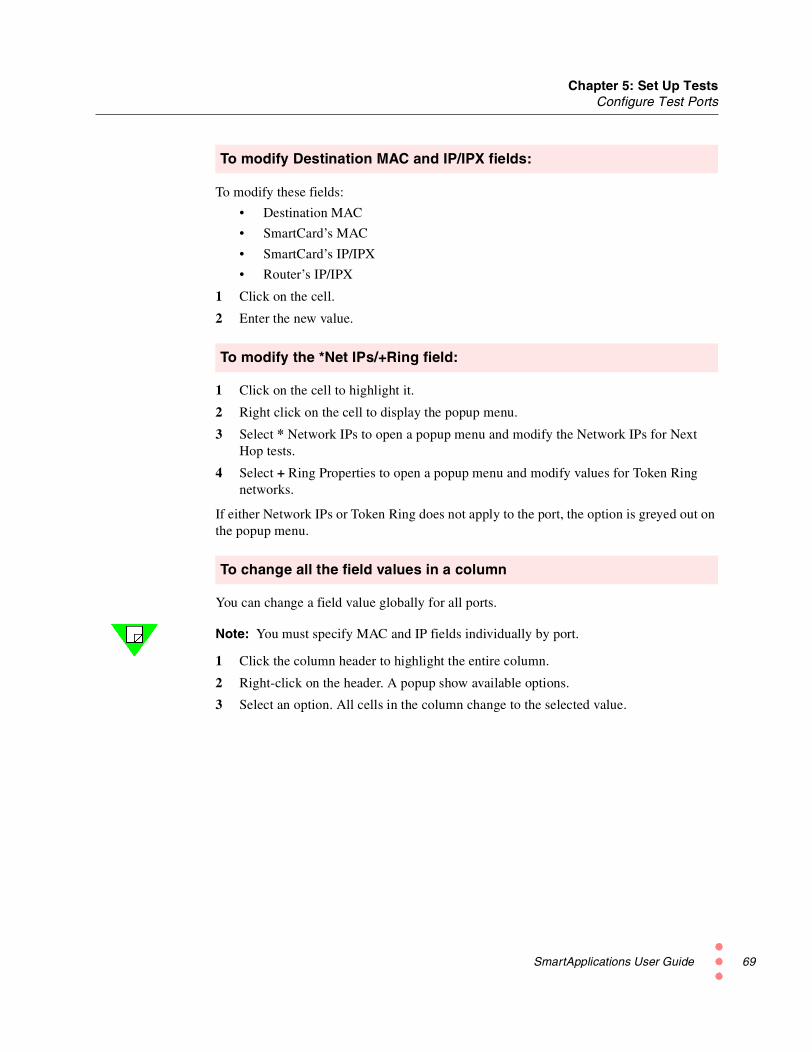
Chapter 5: Set Up TestsConfigure Test Ports
To modify Destination MAC and IP/IPX fields:
To modify these fields:
• Destination MAC
• SmartCard’s MAC
• SmartCard’s IP/IPX
• Router’s IP/IPX
1 Click on the cell.
2 Enter the new value.
To modify the *Net IPs/+Ring field:
1 Click on the cell to highlight it.
2 Right click on the cell to display the popup menu.
3 Select * Network IPs to open a popup menu and modify the Network IPs for NextHop tests.
4 Select + Ring Properties to open a popup menu and modify values for Token Ringnetworks.
If either Network IPs or Token Ring does not apply to the port, the option is greyed out onthe popup menu.
To change all the field values in a column
You can change a field value globally for all ports.
Note: You must specify MAC and IP fields individually by port.
1 Click the column header to highlight the entire column.
2 Right-click on the header. A popup show available options.
3 Select an option. All cells in the column change to the selected value.
SmartApplications User Guide 69

Chapter 5: Set Up TestsConfigure Test Ports
70
Configuring a Ports IndividuallyYou can configure ports individually by using the port attributes tabs in the main window.Each tab displays options appropriate to the network topology of the selected port (see thefollowing sections for descriptions of options).
1 Select the ports for the test from the main window (if not yet done). The tabs displaythe two ports (source and destination) you selected last.
Note: Ensure that these are the ports you wish to use in your test.
2 Select each tab in turn, and define the following:
• MAC addresses. For routers, this is the MAC address of the local router port. Ifyou are doing 1 to Many/Many to 1 tests, you must define addresses for each cardin the test.
• All other information relevant to the selected port type, such as:
– Next hop network IPs for Next Hop tests.
– Token Ring properties for Token Ring cards.
– Line and ELAN parameters for ATM cards.
– Line or LMP or Address information for WAN cards.
Use the port attributes tabsto configure test ports oneby one.
SmartApplications User Guide

Chapter 5: Set Up TestsConfigure Test Ports
Configuring Ethernet PortsWhen you select an Ethernet port, the port attribute tab displays Ethernet setup options.
Note: For Ethernet cards, SmartApplications sends out Ethernet 802.3 test frames.
Ethernet Options (Port Attributes Tab)
Table 5-4 lists the options on the port attribute tab for an Ethernet port.
Table 5-4. Ethernet Options (Port Attributes Tab)
Field Description
Card Type The card type, such as Fast Card for 100Mb.
Card Model The card model number, such as ML-7710.
Signal Rate The port’s transmission rate in megabits per second. You set the rate for each port in a pairseparately. For Ethernet cards, possible values are: 10, 100, and 1000.
Duplex The port’s duplex mode. Possible values for Ethernet are Full and Half.
Note: Half-duplex currently is not supported on the LAN-3300A/3301A modules.
Protocol Select the protocol for the port.
The protocol you select shows or hides other fields on the tab. If you select IP or UDP, theSmartCard's IP and Router's IP fields appear. If you select IPX, the Source Net andDestination Net fields appear.
When testing a router, you must select either IP, UDP, or IPX. Options such as the All 0soption refer to the packet contents (excluding MAC addresses).
Note: You must set the same protocol within a port pair. For example, you cannot configurethe transmitting port for IP and the receiving port for UDP.
SmartApplications User Guide 71

Chapter 5: Set Up TestsConfigure Test Ports
72
Destination MAC Specify the MAC addresses used. Default addresses correspond to the port numbers. Forexample, for Ports 1 and 2 the Destination MAC are 000000000001 and 000000000002respectively. To specify a different MAC address, enter a different value in the field. Repeatthis process until all the addresses are specified correctly for your test pairs.
Special conditions• When testing a router, this value is the MAC address of the local router port.
• When testing a switch, this value is the MAC address of the destination SmartCard.
SmartCard MAC The MAC address of the sending port.
SmartCard's IP Enter the IP address of the port displayed on the tab. The SmartCard IP address should havethe same network address as the router port to which the port is connected, but with adifferent host address.
Router's IP Enter the IP address of the router port to which the port is connected. If you are testing aswitch, you can use the default value.
Note: If you change direction in the port selection area of the main window, theDestination MAC and SmartCard MAC and SmartCard's IP addresses remain unchanged inthe port attributes tab for each port. Be sure to verify that these fields reflect the correctaddresses.
Source Net The 4-byte network address of the transmitting port.
Destination Net The 4-byte network address of the router port (for router testing) or receiving port (forswitch testing).
Flow Control Enables traffic flow control.
Note: This field appears only for SX-7x10 and GX-1405 SmartCards. When this box ischecked and the SmartCard receives a pause frame, the card will stop transmitting for thenumber of slot times specified in the pause frame. Default is Off (unchecked).
Auto Negotiation Auto-negotiation (AN) provides a means for the communicating interfaces at each end of alink (the link partners) to exchange information about their speed and duplex capabilities,and so to achieve the best possible mode of operation. The information exchanged in theAN protocol is kept in memory registers termed MII registers. Values for this option are:
Continues –>
Table 5-4. Ethernet Options (Port Attributes Tab) (continued)
Field Description
SmartApplications User Guide
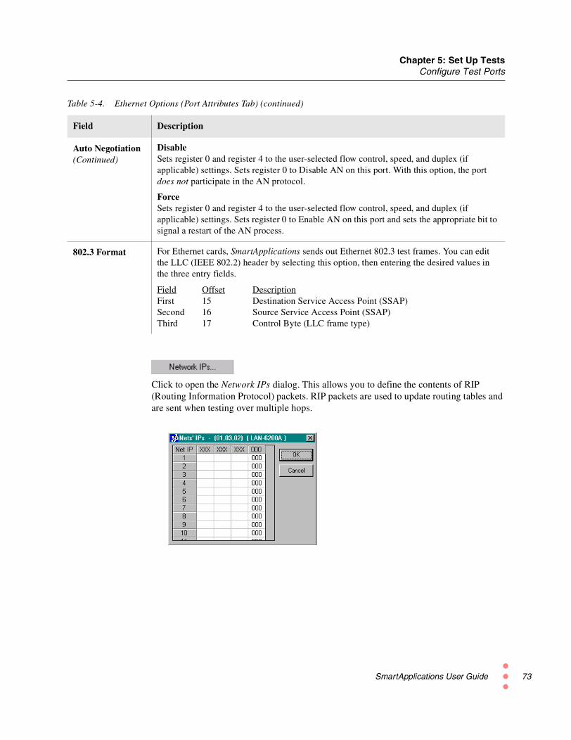
Chapter 5: Set Up TestsConfigure Test Ports
Click to open the Network IPs dialog. This allows you to define the contents of RIP(Routing Information Protocol) packets. RIP packets are used to update routing tables andare sent when testing over multiple hops.
Auto Negotiation(Continued)
DisableSets register 0 and register 4 to the user-selected flow control, speed, and duplex (ifapplicable) settings. Sets register 0 to Disable AN on this port. With this option, the portdoes not participate in the AN protocol.
ForceSets register 0 and register 4 to the user-selected flow control, speed, and duplex (ifapplicable) settings. Sets register 0 to Enable AN on this port and sets the appropriate bit tosignal a restart of the AN process.
802.3 Format For Ethernet cards, SmartApplications sends out Ethernet 802.3 test frames. You can editthe LLC (IEEE 802.2) header by selecting this option, then entering the desired values inthe three entry fields.
Field Offset DescriptionFirst 15 Destination Service Access Point (SSAP)Second 16 Source Service Access Point (SSAP)Third 17 Control Byte (LLC frame type)
Table 5-4. Ethernet Options (Port Attributes Tab) (continued)
Field Description
SmartApplications User Guide 73

Chapter 5: Set Up TestsConfigure Test Ports
74
Configuring Token Ring PortsWhen you select a Token Ring port and the Show Card Attribute box is checked, the portattribute tab displays Token Ring setup options.
Token Ring Options (Port Attribute Tab)
Table 5-5 lists the options on the port attribute tab for a Token Ring port.
Table 5-5. Token Ring Options (Port Attributes Tab)
Field Description
Card Type Displays the card type, in this case Token Ring.
Card Model Displays the card model number (TR-8405).
Signal Rate Select the transmission rate in megabits per second. For Token Ringcards, possible values are 4 and 16.
Duplex Select the duplex mode. For Token Ring both TXI or TKP areallowed.
Protocol Select the protocol for the port.
The protocol you select shows or hides other fields on the tab. Forexample, if you select IP or UDP, the SmartCard's IP and Router'sIP fields are displayed. If you select IPX, the Source Net andDestination Net fields are displayed.
When testing a router, you must select either IP, UDP, or IPX.Options such as the All 0s option refer to the packet contents(excluding MAC addresses).
Note: You must set the same protocol within a port pair. Forexample, you cannot configure the transmitting card with IP and thereceiving card with UDP.
SmartApplications User Guide

Chapter 5: Set Up TestsConfigure Test Ports
Buttons – Status Pane
This pane on the tab for a Token Ring port shows the port’s current status (for example,whether Early Token Release is enabled). It reflects the settings from the Token RingProperties window.
Network IPsClick to open the Network IPs dialog. This allows you to define the contents of RIP(Routing Information Protocol) packets. RIP packets are used to update routing tables andare sent when testing over multiple hops.
PropertyClick to open the Token Ring Properties dialog, which allows you to define the propertiesof the Token Ring port (see “Defining Token Ring Properties” on page 76).
Destination MAC For router testing, this is the MAC address of the local router port.The SmartCard's MAC destination address must be set to be theMAC address of the router port to which the card is connected.
For switch testing using 1 to Many or Many to 1 tests, this is theMAC address of the destination port.
SmartCard MAC The port’s MAC address. MAC addresses are 48 bits long, usuallywritten as 6 bytes in hexadecimal. For simplicity, set this to matchthe port number in the SmartBits system. For example, port 1 wouldbe 00 00 00 00 00 01 for the transmitter and port 2 would be 00 00 0000 00 02 for the receiver.
SmartCard's IP (This field and the Router’s IP field appear when you select IP orUDP in the Protocol field.)
Enter the port’s IP address. The SmartCard’s IP address should havethe same network address as the router port to which the port isconnected, but with a different host address.
Router's IP Enter the IP address of the router's port to which the port isconnected. If testing a switch, this field can be the packet contents.
Source Net The 4-byte network address of the transmitting port.
Destination Net The 4-byte network address of the router port (for router testing) orreceiving port (for switch testing).
Table 5-5. Token Ring Options (Port Attributes Tab) (continued)
Field Description
SmartApplications User Guide 75

Chapter 5: Set Up TestsConfigure Test Ports
76
Defining Token Ring Properties
To specify properties for the Token Ring port, click the Property button on the portattributes tab for a Token Ring port. This opens the Token Ring Properties window.
Table 5-6 lists the options in this dialog.
Table 5-6. Token Ring Properties Dialog
Field Description
Send Monitor Polls Enables the card to send out standby monitor polls in response toactive monitor polls.
Allow Early TokenRelease
For 16MHz operation only, allows the SmartCard to release atoken prior to receiving its own transmitted frame back. This canimprove throughput, especially for small frames.
Use SRA Select to create the source routing field for Token Ring frames.The fields used to enter source routing information become active.
When SRA is enabled, the source address for the frame isautomatically modified (before transmission) so that its uppermostbit indicates to the network that the frame contains source routinginformation. You must ensure that the field contents are correct—for example, the length specification must be valid for it to beinterpreted correctly by the network devices.
Port When selected, configures the SmartCard port as a Media AdapterUnit (MAU) port.
SmartApplications User Guide

Chapter 5: Set Up TestsConfigure Test Ports
Source Route Addressing Area
The control bytes (first two bytes) in the Designators field are automatically updatedwhen you select any combination of options in this area of the window.
Table 5-7 lists the Source Route Addressing fields.
Station When selected, configures the SmartCard port as a station.
LLC test frames Select this radio button to use LLC test frames in the test.
SNAP frames Select this radio button to use SNAP frames in the test.
Table 5-7. Source Route Addressing Fields
Field Description
Designators Defines how you want to route source packets. Enter hexadecimalvalues directly into this field or make selections from the otherfields in the Source Route Addressing area. As you select otherfields the Designators field reflects the changes in hexadecimalcode for:
SRA field length Enter or select the length of the routing information field in bytes,including the control field. Range: 2 to 30 bytes.
Largest frameallowed
Enter or select the largest frame size that can be transmittedbetween two communicating stations on a specific route.Available values are: 516, 1470, 2052, 4472, 8144, 11407, 17800,and Broadcast. The Broadcast setting is normally used in explorerframes.
Table 5-6. Token Ring Properties Dialog (continued)
Field Description
SRA LengthLargest frame allowedAddress Control => 2-byte control fieldReturn PathDirection
SmartApplications User Guide 77

Chapter 5: Set Up TestsConfigure Test Ports
78
Access Control This bit specifies the route through the network that the frameshould travel. Options are:
BroadcastSelect this radio button if you want the frame transmitted alongevery route in the network to the destination station (oftenresulting in many copies of the frame).When you select Broadcast, the Number of Hops field displays.Select this option to test the Token Ring source routing number ofbytes that will be in the system offset.
Non-BroadcastSelect this radio button if you want the segment number fields tocontain the specified route through the network that the frame is totravel.
System OffsetEnter the number of bytes offset by the source routing informationinserted by the DUT into each frame.
Return Path This bit defines a single path return or return through all availablepaths. Options are:
All routes returnSelect this radio button for a single path return.
Single path returnSelect this radio button for return through all available paths.
Direction This bit determines whether the of ring numbers and bridgenumbers in the routing information field are read from left to rightor right to left by the network devices.
Outgoing SRASelect this radio button for the bridge to interpret the routinginformation field from left to right
Return SRASelect this radio button for the bridge to interpret the routinginformation field from right to left.
Table 5-7. Source Route Addressing Fields (continued)
Field Description
SmartApplications User Guide

Chapter 5: Set Up TestsConfigure Test Ports
Configuring ATM PortsWhen you select an ATM port, the port attribute tab display ATM options.
Summary of Steps to Configure an ATM Port
Use the following steps to configure an ATM port using the port attributes tab:
1 Set up the line parameters. Click Line Param to open the Port Configuration win-dow.
2 Set up the protocol. Click ELAN Param to open the ELAN Registration window.
3 Add and configure at least one ELAN from the ELAN Registration window.
4 Specify the MAC addresses for the local router port and the SmartCard, and otheroptions, by using the port attributes tab.
Note: See “Set up ATM 1-to-Many/Many-to-1 Tests with PVC CLIP” on page 123 foradditional information on setting up ATM tests.
ATM Options (Port Attributes Tab)
Table 5-8 lists the options on the port attributes tab for an ATM port.
Table 5-8. ATM Options (Port Attributes Tab)
Field Description
Card Model Displays the model number of the card, such as AT-9025.
ELAN Name This field is displayed if you select SVC for the Connection Typefield and 802.3 for the Encapsulation type.
Select the name of the ELAN you want to use for the test. This fieldis blank if you have not yet set up any ELANs. Click the ELANParam button to access the ELAN Registration window to set upELANs.
SmartApplications User Guide 79

Chapter 5: Set Up TestsConfigure Test Ports
80
VPI-VCI This field is displayed if you select PVC for the Connection Typefield. Enter the contents in decimal or hexadecimal of the headerportion of the cell.
Connection Type The type of virtual circuit for the connection between the SmartBitschassis and the device under test. This field controls the optionsavailable in the Encapsulation field. The possible values forConnection Type are:
SVCSwitched Virtual Circuit. The connection is established only whenneeded.
PVCPermanent Virtual Circuit. The connection is permanentlyestablished.
SmartCard's IP (This option is active when you select PVC for the Connection Typefield.) Enter the port’s IP address. The SmartCard’s IP address musthave the same network number and subnet address as the router portto which the port is connected. Use the IP address of the outer portwith its last digit modified as the IP source address of the port.
Destination IP (This option is active when you select PVC for the Connection Typefield.) Enter the IP address of the receiving SmartCards.
Encapsulation The possible values for this field depend upon the value set forConnection Type, as follows:
If Connection Type is PVC, the possible values for Encapsulationare:
• SNAP
• Classic IP
• VC Mux Routed
If Connection Type is SVC, the possible values for Encapsulationare:
• SNAP
• 802.3 (Ethernet)
• Classic IP
• VC Mux Routed
For Bridged RFC 1483: Select SNAP.
Continues –>
Table 5-8. ATM Options (Port Attributes Tab) (continued)
Field Description
SmartApplications User Guide

Chapter 5: Set Up TestsConfigure Test Ports
Buttons
Line ParamClick this button to access the Port Configuration window, to specify physical interfaceparameters such as framing and loopback, as well as other ATM protocol information.
ELAN ParamClick this button to access the ELAN Registration window, to specify LAN Emulationclient information and to register ELANs.
Encapsulation(continued)
For RFC 1577 or Routed RFC 1483 (using Routed SNAP, IP, orUDP protocols): Select Classic IP.
VC Mux Routed: VC Multiplexing creates a binding between anATM VC and the type of the network protocol carried on that VC.Thus, there is no need for protocol identification information to becarried in the payload of each AAL5 CPCS-PDU. This reducespayload overhead and can reduce per-packet processing. VCmultiplexing can improve efficiency by reducing the number of cellsneeded to carry PDUs of certain lengths. (RFC2684).
SNAP (Subnetwork Access Protocol) uses the subnetwork andperforms data transfer, connection management, and QoS selection.
Fill Pattern The protocol to use for the payload. If you selected PVC for theConnection Type, the fill pattern is IP or UDP.
Destination MAC For switch testing in 1 to Many / Many to 1 tests, this is the MACaddress of the destination port.
For router testing, this is the MAC address of the local router port. Ifyou do not specify an address, you will get zero throughput. TheSmartCard's MAC destination address must be the MAC address ofthe router port to which the port is connected—for example, a MACdestination of 08 00 02 06 89 22 for the transmitter and 08 00 02 1227 22 for the receiver.
SmartCard MAC The MAC address of the SmartCard. MAC addresses are 48 bitslong, usually written as 6 bytes in hexadecimal. For simplicity, setthis to match the port number in the SmartBits system. For example,port 1 would be 00 00 00 00 00 01 for the transmitter and port 2would be 00 00 00 00 00 02 for the receiver.
Table 5-8. ATM Options (Port Attributes Tab) (continued)
Field Description
SmartApplications User Guide 81

Chapter 5: Set Up TestsConfigure Test Ports
82
Defining ATM Line Parameters
Use the Port Configuration dialog to define the physical interface for the ATM card. Itcontains the following tabs:
Line ParamsUse this tab to specify physical interface parameters, such as framing and loopback. See“Line Params Tab” on page 83.
SSCOPUse this tab to specify the UNI version and timer values for SSCOP. See “SSCOP Tab”on page 87.
UNIUse this tab to specify the UNI version and various timer values for UNI. Currently usedfor point-to-point only, the UNI configuration offers the standard user-side timers and aspecial testing teardown timer. See “UNI Tab” on page 89.
ILMIUse this tab to define the method used by an ATM card to acquire its 20-byte ATMaddress from the network device to which it is connected. See “ILMI Tab” on page 91.
SmartApplications User Guide

Chapter 5: Set Up TestsConfigure Test Ports
Line Params Tab
Table 5-9 lists the options on the Line Params tab of the ATM Port Configuration dialog.
Table 5-9. Line Params Tab — ATM Port Configuration Dialog
Field Description
FramingMode
Select to define the physical layer of the frame. Possible values are:
• AT-9025 25 Mbps SmartCard
ATM 25 Indicates direct cell mapping at 25.6 Mbps.
• AT-9015 DS1 SmartCard
• DS1 Cell - Maps the ATM cells directly into the DS1 frame withno intermediate mapping.
• DS1 PLCP - Maps the ATM cells into PLCP frames and maps thePLCP frames into the DS1 frame.
• AT-9020 E1 SmartCard
• E1 Cell - Maps the ATM cells directly into the E1 frame with nointermediate mapping.
• E1 PLCP - Maps the ATM cells into PLCP frames and maps thePLCP frames into the E1 frame.
• AT-9034B E3 SmartCard
• E3 Cell - Maps the ATM cells directly into an E3 G.832 framewith no intermediate mapping.
• E3 PLCP - Maps the ATM cells into the PLCP frames and mapsthe PLCP frames into an E3 G.751 frame.
• AT-9045 DS3 SmartCard
• DS3 Cell - Maps the ATM cells directly into the DS3 frame withno intermediate mapping.
• DS3 PLCP - Maps the ATM cells into PLCP frames and maps thePLCP frames into the DS3 frame.
• AT-9155C ATM OC-3c 155 Mbps
• OC3 - For SONET, OC-3c type of optical carrier line.
• STM1 - Enables the European STM 1 framing method (equiva-lent to OC-3c)
• AT-9622 ATM OC-12c 622 Mbps SmartCard
• OC12 - For SONET, OC-12c type of optical carrier line. TheSmartCard maps the ATM cells directly into a SONET OC-12cframe.
• STM4 - Enables the European STM-4 framing method (equiva-lent to OC-12c). The SmartCard maps the ATM cells directly intoan STM-4 frames.
SmartApplications User Guide 83

Chapter 5: Set Up TestsConfigure Test Ports
84
Tx ClockSource
This field does not apply to the AT-9025 SmartCard, which uses only aninternal clock. Specifies the clock against which you want to run the tests.Possible values are:
InternalUses an internally generated clock as the transmit clock.
LoopbackUses the recovered (received) clock as the transmit clock.
Loopback Specifies the type of loopback to be used. Possible values are:
DisabledNo loopback is used. This is the normal operating mode of the device.
LocalLoops card output back to the card's input.
RemoteTraffic returns to the remote machine.
Errored CellsHandling
Specifies the action to take for cells with errors. Possible values are:
Drop Errored CellsDrops all cells that have a header error as determined by the HEC byte.
Receive Errored CellsReceives all cells even if they have errors.
Receive and Correct Errored CellsReceives and corrects all cells with single-bit header errors.
Table 5-9. Line Params Tab — ATM Port Configuration Dialog (continued)
Field Description
SmartApplications User Guide

Chapter 5: Set Up TestsConfigure Test Ports
Buildout This field applies only to the AT-9015 DS1 and AT-9045 DS3SmartCards. Select to change possible values for the electrical output ofthe SmartCard to either:
1 Accommodate the length of the cable with which you are testing or,
2 Specify the amount of attenuation to apply to the signal.
AT-9015 DS1
• Cable Lengths
• <=133 FeetPulse shaping for cable lengths up to 133 feet.
• >133, <=266 FeetPulse shaping for cable lengths more than 133 feet and up to 266feet.
• >266, <=399 FeetPulse shaping for cable lengths more than 266 feet and up to 399feet.
• >399, <=533 FeetPulse shaping for cable lengths more than 399 feet and up to 533feet.
• >533, <=655 FeetPulse shaping for cable lengths more than 533 feet and up to 655feet.
• Buildout Attenuation Values
• -7.5 dBPulse shaping to generate -7.5 dB of attenuation.
• -15.0 dBPulse shaping to generate -15.0 dB of attenuation.
• -22.5 dBPulse shaping to generate -22.5 dB of attenuation.
AT-9045 DS3
• Cable Length
• <= 225 FeetPulse shaping for cable lengths up to 225 feet.
• >225 FeetPulse shaping for cable lengths more than 225 feet.
Table 5-9. Line Params Tab — ATM Port Configuration Dialog (continued)
Field Description
SmartApplications User Guide 85

Chapter 5: Set Up TestsConfigure Test Ports
86
Line Coding This field applies only to AT-9015 DS1 and AT-9020 E1 SmartCards.Select the type of encoding to be used for the line. The possible values are:
AMIUses AMI line encoding.
B8ZSDS1 mode using B8ZS line encoding. (AT-9015 only).
HDB3E1 mode using HDB3 line encoding (AT-9020) only.
LineFraming
This field applies only to the AT-9015 SmartCard. Select the framingmode for the physical layer. The possible values are:
D4Uses D4 line framing.
ESFUses Extended Super Frame line framing.
CellScrambling
When checked, the payload of the cells is scrambled to facilitate celldelineation. Most ATM devices require this feature to be on.
HEC Coset When checked, exclusive ORs the HEC with the bit pattern 0x55. MostATM devices require this feature to be on.
Idle CellHeader
Specifies the header contents (4-bytes in hexadecimal) of the ATM idlecell payload that is transmitted when no data cells are being transmitted.
Table 5-9. Line Params Tab — ATM Port Configuration Dialog (continued)
Field Description
SmartApplications User Guide

Chapter 5: Set Up TestsConfigure Test Ports
SSCOP Tab
Table 5-10 lists the options on the SSCOP tab of the ATM Port Configuration dialog.
Click the Default button to reset all timers to the SmartApplications default values.
Table 5-10. SSCOP Tab — ATM Port Configuration Dialog
Field Description
Max. CC Enter the maximum number of transmissions of a BGN, END, ER, to RS
PDU. Valid maximum value is 2 32 -1 (over 4 billion).
Max PD Enter the maximum number of SD PDUs that may be sent before sending aPOLL PDU. Value must be in the following range: 1 ≤ Max PD ≤ 25.
Max.STAT
Enter the maximum number of list elements placed in a STAT PDU. Valuemust be an odd number in the following range: 3 ≤ Max STAT ≤ 67.
Max.Reseq
Enter the maximum receive resequencing queue depth in the followingrange: 1 ≤ Max Reseq ≤ 16.
Max. Rx.Windows
Enter the maximum number of unacknowledged SD PDUs that may bereceived. Value must be in the following range: 1 ≤ Max Rx Windows ≤ 32.
Timer CC Enter the interval between transmission of BGN, END, RS, and ER PDUs aslong as acknowledgment to these PDUs has not been received.
TimerKeep Alive
Enter the maximum time spent in the transient phase where POLL or STATPDUs may be lost.
SmartApplications User Guide 87

Chapter 5: Set Up TestsConfigure Test Ports
88
Timer Idle Enter the maximum time spent in IDLE phase before reverting to transientphase.
Timer NoResponse
Enter the maximum time interval during which at least one STAT PDU mustbe received. Default is 10,000 ms for UNI 3.0; 7,000 ms for UNI 3.1.
Timer Poll Enter the interval between transmission of POLL PDUs. Default is 100 msfor UNI 3.0; 750 ms for UNI 3.1.
Note: Timer values must not be zero.
Table 5-10. SSCOP Tab — ATM Port Configuration Dialog (continued)
Field Description
SmartApplications User Guide

Chapter 5: Set Up TestsConfigure Test Ports
UNI Tab
Table 5-11 lists the options on the UNI tab of the ATM Port Configuration dialog.Table 5-12 on page 90 lists the UNI timers.
Click the Default button to reset all timers to the SmartApplications default values.
Table 5-11. UNI Tab — ATM Port Configuration Dialog
Field Description
Version Possible values are 3.0 User or 3.1 User (for SmartBits ATM cards).
Txx UNI timers. See Table 5-12 for descriptions.
Note: T398 and T399 will be implemented in a future release.
Teardown Enter the timer value (mandatory). This value is the time between teardowns(call release requests) when resetting tests. A minimum of 10 milliseconds isrecommended to avoid test failure.
Note: Timer values must not be zero.
SmartApplications User Guide 89

Chapter 5: Set Up TestsConfigure Test Ports
90
Table 5-12. UNI Timers
TimerDefaultTimeout State of Call Cause for Start and Stop
T303 4s Call initiated Start: SETUP sent.Stop: CONNECT, CALL PROCEEDING, orRELEASE COMPLETE received.
T308 30s Release Request Start: RELEASE sent.Stop: RELEASE COMPLETE or RELEASEreceived.
T309 10s Any stable state Start: SAAL disconnection. Calls in the active stateare not lost.Stop: SAAL reconnected.
T310 10s Outgoing CallProceeding
Start: CALL PROCEEDING started.Stop: CONNECT or RELEASE received.
T313 4s Connect Request Start: CONNECT sent.Stop: CONNECT ACKNOWLEDGE received.
T316 2 min. Restart Request Start: RESTART sent.Stop: RESTART ACKNOWLEDGE received.
T317 < T316 Restart Start: RESTART received.Stop: Internal clearing of call references.
T322 4s Any call state Start: STATUS ENQUIRY sent.Stop: STATUS, RELEASE, or RELEASECOMPLETE received.
SmartApplications User Guide
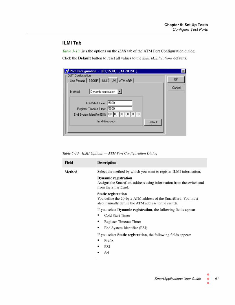
Chapter 5: Set Up TestsConfigure Test Ports
ILMI Tab
Table 5-13 lists the options on the ILMI tab of the ATM Port Configuration dialog.
Click the Default button to reset all values to the SmartApplications defaults.
Table 5-13. ILMI Options — ATM Port Configuration Dialog
Field Description
Method Select the method by which you want to register ILMI information.
Dynamic registrationAssigns the SmartCard address using information from the switch andfrom the SmartCard.
Static registrationYou define the 20-byte ATM address of the SmartCard. You mustalso manually define the ATM address to the switch.
If you select Dynamic registration, the following fields appear:
• Cold Start Timer
• Register Timeout Timer
• End System Identifier (ESI)
If you select Static registration, the following fields appear:
• Prefix
• ESI
• Sel
SmartApplications User Guide 91

Chapter 5: Set Up TestsConfigure Test Ports
92
Cold StartTimer
Defines the interval between ILMI Cold Start TRAP requests sent tothe switch when no network prefix has been registered. Default is5000 ms.
RegisterTimeout Timer
Defines retransmission interval of address registration SET requestswhen no acknowledgement is received from the switch.
End SystemIdentifier (ESI)
Six bytes in the 20-byte ATM address for identifying the end station(SmartCard in this case) on a particular user-to-network interface.The first five bytes are user-definable. SmartApplicationsautomatically sets the sixth byte to a value that represents a specificSmartCard.
Note: Timer values must not be zero.
Prefix The first 13-bytes of the ATM address.
Sel This field is disabled.
Table 5-13. ILMI Options — ATM Port Configuration Dialog (continued)
Field Description
SmartApplications User Guide

Chapter 5: Set Up TestsConfigure Test Ports
ATM ARP Tab
Table 5-13 lists the options on the ILMI tab of the ATM Port Configuration dialog.
Table 5-14. ATM ARP Options — ATM Port Configuration Dialog
Field Definition
ARP Server ATMAddress
The ATM address of the ATM ARP Server that must be running inthe system under test. This address must be a valid address of theATM ARP Server for Classical IP services to work properly.Right-click on the field to copy/paste contents.
Inter ARP Gap The time in seconds between successive ARP requesttransmissions. It is recommended that you keep this value largerthan 0 to avoid flooding the ATM ARP server with excessive ARPrequests.
Inter Call Gap The time in seconds between successive call setup for calls tryingto resolve the same destination IP address. It is recommended thatyou keep this value larger than 0 to avoid overloading theswitching device under test.
ARP Retries Number of ARP retries to attempt before giving up.
SmartApplications User Guide 93

Chapter 5: Set Up TestsConfigure Test Ports
94
Defining ATM ELAN Parameters
To configure the ATM port, you must add and register an ELAN, if none exists. Beforeyou register an ELAN, ensure that:
1 ILMI is up or has already obtained the ATM address of the SmartCard.
2 SSCOP/UNI is up (that is, SSCOP in Data Transfer Ready State, and SAAL in Connectedstate). The LEC has to set up SVCs to communicate with the LECS and LES.
You define and register ELANs by using the ELAN Registration window. Table 5-15 liststhe fields in the window.
SmartApplications User Guide

Chapter 5: Set Up TestsConfigure Test Ports
Table 5-15. Options in the ELAN Registration Window
Field Description
ELAN Name Select the name of an ELAN that you want to join. The name mustexactly match (case-sensitive) one of the ELAN names specified onthe device under test.
MAC Address The 6-byte MAC address of the LAN Emulation Client on the ATMSmartCard.
ELAN Type LANE 802.3 is the only type currently supported.
ELANMTU Specify the maximum transmission unit of this ELAN.
ARP Retry Count Number of ARP retries to attempt before giving up.
Expected ARPResp. Time
Time to wait before retrying to send another LE_ARP or expiring(time out).
Init Method Select the ELAN initialization method to match the setting of thedevice under test. The possible methods are:
NormalDefault method. The LEC (LAN emulation client) on the ATMSmartCard attempts to contact the LECS (LAN emulation clientserver) at the default address specified by the ATM Forum to obtainaddressing information of the LES and BUS.
LECS DirectAllows you to directly input the ATM address of the LECS. Use thisfield if LECS does not reside at the default address specified by theATM Forum.
LES DirectAllows you to input the ATM address of the LES. This method canbe used when no LECS service is available and the ATM address ofthe LES is known.
LEC/LES Address This field is greyed out if you select Normal for the Init Methodfield. Enter the ATM address of the LEC or LES.
SmartApplications User Guide 95

Chapter 5: Set Up TestsConfigure Test Ports
96
Configuring WAN PortsWhen you select an WAN port, the port attribute tab display WAN options.
Table 5-16 lists the options on the port attribute tab for a WAN port.
Table 5-16. WAN Options (Port Attributes Tab)
Field Description
Card Type Displays the type of SmartCard for that port, in this case Frame Relay.
Card Model Displays the model number of the card, such as WN-3405.
Protocol Select the protocol for the port.
Values such as All 0s refer to the packet contents.
If you select IP or UDP for this field, the Smart Card’s IP andDestination IP fields appear.
If you select IPX, the Source Net and Destination Net fields appear.
You must assign the same protocol within a port pair. For example, youmay not configure the transmitting port for IP and the receiving port forUDP.
SmartCard'sIP
Enter the IP address of the SmartCard port. The SmartCard’s IP addressmust have the same network number and subnet address as the routerport to which the port is connected. Use the IP address of the router portwith its last digit modified as the IP source address of the port.
Destination IP Enter the IP address of the receiving SmartCard.
Source Net The 4-byte network address of the transmitting card.
Destination Net The 4-byte network address of the router port (for router testing) orreceiving port (for switch testing).
SmartApplications User Guide

Chapter 5: Set Up TestsConfigure Test Ports
DestinationMAC
For switch testing using 1 to Many or Many to 1 tests, this is the MACaddress of the destination port.
For router testing, this is the MAC address of the local router port. Ifyou do not specify an address, you will get zero throughput. TheSmartCard's MAC destination address must be set to the MAC addressof the router port to which the card is connected—for example, thedestination MAC address is 08 00 02 06 89 22 for the transmitter and 0800 02 12 27 22 for the receiver.
SmartCardMAC
The MAC address of the SmartCard. MAC addresses are 48 bits long,usually written as 6 bytes in hexadecimal. For simplicity, set this tomatch the port number in the SmartBits system. For example,transmitting port 1 would be 00 00 00 00 00 01 and receiving port 2would be 00 00 00 00 00 02.
Table 5-16. WAN Options (Port Attributes Tab) (continued)
Field Description
SmartApplications User Guide 97

Chapter 5: Set Up TestsConfigure Test Ports
98
Line Mode This field is the same as the Line Physical Mode field on the Line tab ofWAN Port Setup window. If you change the value at the WAN PortSetup window, the new value will be displayed here.
WN-3405 SmartCard
Select how you want to define the equipment mode (according to theV.35 specification) within the Frame Relay User/Network interface.Normally, the SmartCard is configured as DTE.
DTEUser side (also referred to as CPE or Customer Premises Equipment).
DCENetwork side
WN-3415 SmartCard
Select how you want to define the equipment mode within the FrameRelay User/Network interface. Normally, the SmartCard is configuredas CSU/DSU.
CSU/DSUChannel Service Unit/Data Service Unit (also known as CustomerPremises Equipment). Defines the SmartCard port as residing on thecustomer (subscriber) side of the T1/E1 connection.
NETNetwork side. Defines the SmartCard port as residing on the networkside of the T1/E1 connection.
WN-3420 SmartCard
Select how you want to define the electrical characteristics of the T1interface. Normally, the SmartCard is configured as CSU/DSU.
CPEChannel Service Unit/Data Service Unit (also known as CustomerPremises Equipment). Defines the SmartCard port to emulate thecustomer (subscriber) side of the T1/E1 connection.
NETNetwork side. Defines the SmartCard port to emulate the network sideof the T1/E1 connection.
Table 5-16. WAN Options (Port Attributes Tab) (continued)
Field Description
SmartApplications User Guide

Chapter 5: Set Up TestsConfigure Test Ports
Line Rate Applies only to the V.35 interface of the WN-3405 SmartCard.
This field is the same as the Line Rate (kbps) field on Line tab of theWAN Port Setup window. If you change the value at the WAN PortSetup window, the new value will be displayed here.
Select a line rate from 19.2 to 8192 Kbps. This value sets the internalclock rate.
EncapsulationType
Select an encapsulation type to be used for the Frame Relay payload.This field is the same as the Encapsulation Type field on Address tab ofthe WAN Port Setup window. If you change the value at the WAN PortSetup window, the new value will be displayed here
NoneNo encapsulation is used to send traffic. Select when source anddestination ports both use Frame Relay.
BridgedSelect if the device you are testing is a bridge.
RoutedSelect if the device you are testing is a router.
DLCI The Data Link Connection Identifier for this PVC.
Table 5-16. WAN Options (Port Attributes Tab) (continued)
Field Description
SmartApplications User Guide 99

Chapter 5: Set Up TestsConfigure Test Ports
100
Defining WAN Port Parameters
As part of configuring a WAN port, you must specify the port’s physical parameters. Youdo this using WAN Port Setup window. This window includes the following tabs:
EncapsulationUse to select either Frame Relay or Point-to-Point Protocol (PPP).
Line (WN-3405, WN-3415 T1, WN-3420 E1)Use to configure the physical characteristics of the port.
EIA Leads (WN-3405 only)Use to select or deselect control signals on the V.35 line interface.
LMI (Frame Relay only)Use to select a Link Management Interface (LMI) signaling protocol.
AddressUse to configure protocol addresses.
Line tab in WAN Port Setup window for WN-3415 SmartCard
SmartApplications User Guide

Chapter 5: Set Up TestsConfigure Test Ports
Line Tab (WN-3405)
With a WN-3405 Frame Relay SmartCard, use the Line tab of the WAN Port Setupwindow to define the line rate and other physical characteristics.
Specify the line mode (DTE or DCE) first, then line encoding. If you use the WANSmartCards to both send and receive data, use the Line Clock options to synchronize thesending SmartCard's data with the receiving SmartCard's clock.
Note: In a SmartCard test pair, you must configure one card as a DCE and one as a DTE.
Line Physical Mode
Select how you want to define the equipment mode (according to the V.35 specification)within the Frame Relay User/Network interface. Normally you configure the SmartCardas a DTE.
• DTE
User side (also referred to as CPE or Customer Premises Equipment).
• DCE
Network side
Line Clock
Select these radio buttons to synchronize the sending card with the clock on the receivingcard on a WN-3405 SmartCard.
• Tx Clock Src
Select the transmit clock source for the SmartCard. SmartApplications automaticallyselects the External (default) radio button for Clock if you select DTE or the Inter-nal radio button if you select DCE.
• Rx Clock Src
Select the type of clock source for the receiving SmartCard. If you select DTE Smart-Applications automatically selects the External radio button for the Line Clock. Ifyou select DCE you must select which source you want for the clock.
• Internal − The SmartCard provides the clock internally for the receiving Smart-Card.
• External (SCTE - 113) − Circuit 113 by default, a function (signal) on a V.35connector pin, provides the clock for the receiving SmartCard.
SmartApplications User Guide 101

Chapter 5: Set Up TestsConfigure Test Ports
102
• Tx Clock Polarity
Select how you want the source port to transmit data in relation to clock timing. Sincethe HDLC controller transmits data on rising edges only, when you change the clockpolarity to Falling Edge, the clock phase shifts 180 degrees with respect to the data.
• Rising Edge − Rising edge of the transmit clock coincides with the boundary of abit cell.
• Falling Edge − Rising edge of the transmit clock coincides with the middle (cen-ter) of a bit cell. Select this option only if you use an external or isolated (buff-ered) copy of the transmit clock.
• Rx Clock Polarity
Select the edge of the receive clock on which to sample received data.
• Rising Edge − Samples received data on the rising edge of the receive clock.
• Falling Edge − Samples received data on the falling edge of the receive clock.
Line Rate (kbps)Select a line rate from 19.2 to 8192 Kbps. This value applies to the V.35 interface. Thevalue in this field sets the internal clock rate.
Other
Use these fields to specify additional parameters, such as line encoding and CRC, on aWN-3405 SmartCard:
• Encoding
Select the encoding type for the V.35 interface. Possible values:
• NRZ − Non-return to zero.
• NRZI − Non-return to zero inverted.
• Min. Flags Between Frames
Select the number of flags (7E hexadecimal pattern) to be inserted between transmit-ted frames. The maximum value is 127.
• CRC Enabled
Check this box to enable HDLC frame CRC generation. This field applies to transmit-ting traffic only. When receiving traffic, the SmartCard always checks for CRC char-acters.
• Checked − Enables the CRC (cyclic redundancy check). If checked, you canselect either 16-bit or 32-bit CRC generation.
• Unchecked − Disables CRC generation. The SmartCard's receive path still looksfor CRCs at the selected (but greyed out) size.
SmartApplications User Guide

Chapter 5: Set Up TestsConfigure Test Ports
• Zero Insertion/Deletion
Check this box to enable HDLC bit stuffing. This field applies to transmitting trafficonly. When receiving traffic, the SmartCard always performs bit unstuffing.
• Checked − Enables HDLC zero-bit stuffing for transmitting data and zero-bitunstuffing for receiving data, to help distinguish a byte of data from a flag byte.
• Unchecked − Disables zero-bit stuffing and transmits raw (unencoded) data. TheSmartCard's receive path still performs bit unstuffing.
SmartApplications User Guide 103
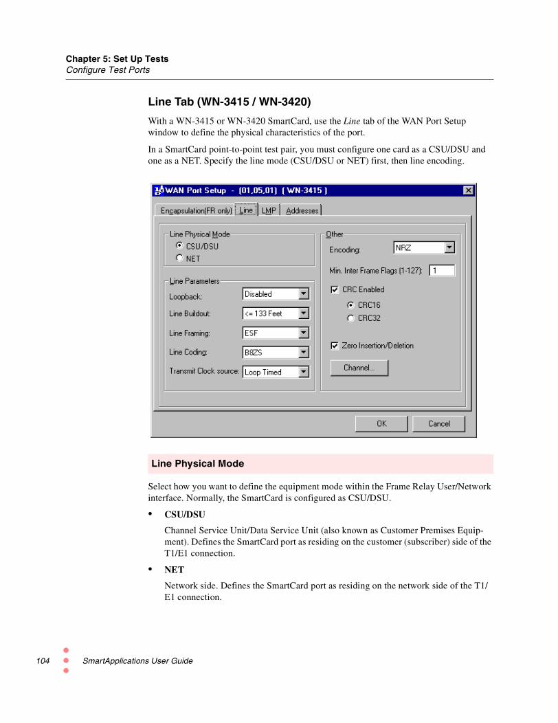
Chapter 5: Set Up TestsConfigure Test Ports
104
Line Tab (WN-3415 / WN-3420)
With a WN-3415 or WN-3420 SmartCard, use the Line tab of the WAN Port Setupwindow to define the physical characteristics of the port.
In a SmartCard point-to-point test pair, you must configure one card as a CSU/DSU andone as a NET. Specify the line mode (CSU/DSU or NET) first, then line encoding.
Line Physical Mode
Select how you want to define the equipment mode within the Frame Relay User/Networkinterface. Normally, the SmartCard is configured as CSU/DSU.
• CSU/DSU
Channel Service Unit/Data Service Unit (also known as Customer Premises Equip-ment). Defines the SmartCard port as residing on the customer (subscriber) side of theT1/E1 connection.
• NET
Network side. Defines the SmartCard port as residing on the network side of the T1/E1 connection.
SmartApplications User Guide

Chapter 5: Set Up TestsConfigure Test Ports
Line Parameters
• Loopback
Specifies the type of loopback to be used.
• Disabled − No loopback is used. This is the normal operating mode of the device.
• Local − Loops the SmartCard's output back to the SmartCard's input.
• Remote − Loops the SmartCard's input back to the SmartCard's output.
• Buildout
Select to change the electrical output of the SmartCard to either 1) accommodate thelength of the cable with which you are testing or 2) specify the amount of attenuationto apply to the signal.
For the WN-3420 only: Select the type of cable with which you are testing:Coax Normal, Cat-5 Normal, Coax High Loss, Cat-5 High Loss.
Possible values for Buildout Cable Length:
<=133 Feet Pulse shaping for cable lengths up to 133 feet.
>133, <=266 Feet Pulse shaping for cable lengths more than 133 ft. and up to 266 ft.
>266, <=399 Feet Pulse shaping for cable lengths more than 266 ft. and up to 399 ft.
>399, <=533 Feet Pulse shaping for cable lengths more than 399 ft. and up to 533 ft.
>533, <=655 Feet Pulse shaping for cable lengths more than 533 ft. and up to 655 ft.
Possible values for Buildout Attenuation:
-7.5 dB Pulse shaping to generate -7.5 dB of attenuation.
-15.0 dB Pulse shaping to generate -15.0 dB of attenuation.
-22.5 dB Pulse shaping to generate -22.5 dB of attenuation.
• Line Framing
Select the framing mode for the physical layer. Possible values:
• D4 − Uses D4 (Super Frame) line framing.
• ESF − Uses Extended Super Frame line framing.
• Line EncodingSelect the type of encoding to be used for the line. Possible values:
• AMI − Uses AMI (Alternate Mark Inversion) line encoding.
• B8ZS − Uses B8ZS line encoding. (WN-3415 only)
• HDB3 − E-1 mode using HDB3 line encoding. (WN-3420 only)
Transmit Clock SourceSpecifies the clock against which you want to run the tests.
• Internal − Uses the SmartCard's internally generated clock as the transmit clock.
• Loop Timed − Uses the received clock as the transmit clock.
SmartApplications User Guide 105

Chapter 5: Set Up TestsConfigure Test Ports
106
Other
Use these fields to specify additional parameters, such as line encoding and CRC.
• Encoding
Select the type of encoding to be used for the line. Possible values:
• NRZ − Non-return to zero.
• NRZI − Non-return to zero inverted.
• Min. Flags Between Frames
Select the number of flags (7E hexadecimal pattern) to be inserted between transmit-ted frames. The maximum value is 127.
• CRC Enabled
Check this box to enable HDLC frame CRC generation. This field applies to transmit-ting traffic only. When receiving traffic, the SmartCard always checks for CRC char-acters.
• Checked − Enables the CRC (cyclic redundancy check). If checked, you canselect either 16-bit or 32-bit CRC generation.
• Unchecked − Disables CRC generation. The SmartCard's receive path still looksfor CRCs at the selected (but greyed out) size.
• Zero Insertion/Deletion
Check this box to enable HDLC bit stuffing. This field applies to transmitting trafficonly. When receiving traffic, the SmartCard always performs bit unstuffing.
• Checked − Enables HDLC zero-bit stuffing for transmitting data and zero-bitunstuffing for receiving data, to help distinguish a byte of data from a flag byte.
• Unchecked − Disables zero-bit stuffing and transmits raw (unencoded) data. TheSmartCard's receive path still performs bit unstuffing.
SmartApplications User Guide

Chapter 5: Set Up TestsConfigure Test Ports
Channel Selection
Use the Channel Selection dialog box for Fractional T1 and E1. Select up to 24 channelsper SmartCard pair. This is the maximum number of 64 kbps circuits allowed on the T1line to transmit and receive frames. If you select all of the channels, the line’s entirebandwidth is used.
To select all channels
Click the Select All button.
To clear all channel selections
Click the Clear All button.
To select a range of channels
• Hold down the left mouse button and drag the mouse.
• Right click within the highlighted area. Use the popup menu to check or uncheck theitems you wish.
SmartApplications User Guide 107

Chapter 5: Set Up TestsConfigure Test Ports
108
Synchronizing WAN SmartCard Clocks
To transmit data, you must synchronize the clocks in the sending and receiving ports inthe test pair. Lack of synchronization can cause aborted frames and/or CRC errors whentransmitting flags, because the receiving SmartCard can mistake the flags for a frame orabort sequence.
The following conditions can disrupt clock synchronization:
• Two ports in a test pair not set to the same clock polarity
• Delays from mismatched cables
• Induced noise
• Internal delays
• Long cables (over 10 feet)
Note: Bit cell width shrinks as frequency rises. Since cable and internal delays are afunction of the cable length, they are constant.
In DTE mode, some routers may try to recover their transmit clocks based on incomingdata. If this occurs, the falling edges of the transmit clock (which is derived from thereceive clock) may have excessive jitter. To avoid this, select Falling Edge for the receiveclock so that the sampling edge coincides with the middle of the bit cell period.
SmartApplications User Guide

Chapter 5: Set Up TestsConfigure Test Ports
LMP Tab
Use the LMP tab of the WAN Port Setup window to define the characteristics of the LinkManagement Interface protocol. All the displayed values are industry-standard defaults. Ifyou modify these default values, you can restore them by clicking the Defaults button.
Table 5-17 lists the options on the LMP tab of the WAN Port Setup window.
Table 5-17. LMP Tab (WAN Port Setup Dialog)
Field Description
Link ManagementProtocol
Select an LMP signaling method. The signaling method must matchwhat is configured in the connected device.
Logical Port Type Select the UNI DTE (User Side) or the UNI DCE (Network Side).
When connecting to a Frame Relay Switch, this value normally willbe UNI DTE.
If LMP is enabled and you configure the port as CSU/DSU, set thisfield to UNI DTE. If you configure the port as NET, set this field toUNI DCE.
DTE Full PollingCycle
Sets the number of polling cycles to complete before a Full PollingStatus Inquiry Message is sent by the DTE.
SmartApplications User Guide 109

Chapter 5: Set Up TestsConfigure Test Ports
110
Monitored EventsCount
Sets the number of Reliability Error events or In-Channel SignalingProtocol Error events that can occur before a link is consideredinactive.
DTE LinkIntegrityVerificationTimer
Sets the frequency in seconds that Status Inquiry Messages are sentwhen configured as a DTE.
DCE PollingVerificationTimer
Sets the time that the interface waits for a Status Inquiry Messagebefore counting an error when configured as a DCE.
Table 5-17. LMP Tab (WAN Port Setup Dialog) (continued)
Field Description
SmartApplications User Guide

Chapter 5: Set Up TestsConfigure Test Ports
EIA Leads (WN-3405)
These radio buttons correspond to the physical pins on the connector.
Table 5-18 describes these options.
Table 5-18. EIA Leads Tab (WAN Port Setup Window)
Field Description
DCE Use these radio buttons to turn on or off:
• Data Set Ready (DSR)
• Clear to Send (CTS)
• Data Carrier Detect (DCD).
These signals apply only when Physical Line Mode is set to DCE.
DTE Use these radio buttons to turn on or off
• Data Terminal Ready (DTR)
• Request to Send (RTS)
These signals apply only when Physical Line Mode is set to DTE.
Note: The following signals are currently not supported:
• Test Mode (TM)
• Remote Loopback (RL)
• Local Loopback (LL)
SmartApplications User Guide 111

Chapter 5: Set Up TestsConfigure Test Ports
112
Address Tab
Use the Addresses tab to define IP and MAC addresses for the port and gateway.
Table 5-19 lists the options on this tab.
Table 5-19. Address Tab (WAN Port Setup Window)
Field Description
MAC Address Enter a source MAC address for sending Ethernet protocol frames,when the selected encapsulation type is Bridged (Ethernet).
IP Address Enter an IP address for sending IP protocol frames.
Netmask Enter a subnet mask.
Gateway Enter the next hop IP address for the network.
Ping Target Enter the target IP address for the Ping packets.
Send Ping packet When checked, Ping packets will be sent to the Ping Target at therate in seconds that you enter in the a Ping Freq field.
Send SNMPpacket
When checked, SNMP Management packets will be sent to theGateway at the rate (in seconds) you enter in the SNMP Freq field.
SmartApplications User Guide

Chapter 5: Set Up TestsConfigure Test Ports
Send RIP packet When checked, RIP broadcast packets will be sent to out on all PVCson the above subnet at the rate (in seconds) you enter in the RIP Freqfield.
Reply to all ARPrequests
When checked, ARP replies will be sent in response to all ARPrequests not destined for configured streams on the specified IPaddress or the IP address configured for the card.
Table 5-19. Address Tab (WAN Port Setup Window) (continued)
Field Description
SmartApplications User Guide 113

Chapter 5: Set Up TestsConfigure Test Ports
114
Encapsulation (FR only) Tab
Use the Encapsulation (FR only) tab to select the encapsulation type as Frame Relay orPPP.
Table 5-20 lists the options on this tab.
Table 5-20. Encapsulation (FR only) Tab (WAN Port Setup Window)
Field Description
Frame Relay Click to select Frame Relay.
PPP Click to select Point-to-Point Protocol (PPP).
SmartApplications User Guide

Chapter 5: Set Up TestsRouter Testing
Router TestingTo test routers with SmartApplications, you use procedures that are similar to those usedto test other devices, with the following differences:
Switch Testing
When testing a switch, you select the test ports in the card attribute tab of the mainwindow. Normally you can use the default protocol settings. This is not true for routerdevices.
Router Testing
SmartApplications needs more information since the DUT is routing the IP/IPX packetsrouted to the destination port. To test routers successfully, you must manually edit the IP/IPX headers by using the Network IPs window. The Next Hop test is an additional testyou can perform with a router.
Preliminary Setup for Router Testing
Before testing a router, do the following:
• Check Router Test on the Preference tab in the Test Setup window.
• If you want to do a Next Hop test:
1 Check the Next Hop Test box in the on the Preference tab.
2 Click the Network IPs button on the card attributes tab to access the Network IPswindow, where you enter next-hop IP addresses.
• Obtain the MAC and IP addresses of the router ports involved in the test, and enterthem on the port attributes tab in the main window.
Router Test Configuration Fields
The port attributes tab contains fields that are specific to router tests. These are describedin Table 5-21 on page 116.
SmartApplications User Guide 115

Chapter 5: Set Up TestsRouter Testing
116
How the Router Test RunsARP learningpackets
At the beginning of each test repetition, every port involved in the test sends out a packetto its test pair partner (using the test pair's MAC address). This should cause the routerunder test to initiate an ARP exchange on the receiving ports to determine their MACaddresses. All involved ports are set to recognize this ARP request when it comes in (byusing SmartCard triggers), and to respond with an appropriate ARP Reply (by using theSmartCard Echo transmission mode). From that point, the router tables should be updatedand the test can continue.
Traffic throughthe router
The transmitting port routes IP, UDP or IPX packets to the receiving port via the router tothe MAC and IP addresses specified on the card attributes tab on the main window.
Table 5-21. Router Test Configuration Fields
Field Description
Protocol The protocol for the port. Your selection here shows or hides otheroptions, as follows:
• If you select IP for the Protocol field, the SmartCard's IP fieldappears.
• If you select IP or UDP, the Router’s IP fields appears.
• If you select IPX, the Source Net and Destination Net fieldsappear.
For router testing, select either IP, UDP, or IPX.
SmartCard’s IP This field appears when you select IP or UDP for the Protocol field.The IP addresses are entered in this field using dotted decimalnotation. The SmartCard IP address must have the same networkaddress, with a different host address, as the router port to which theSmartCard is connected. For example, the SmartCard IP might be192.168.100.2 for the transmitter and 146.72.1.2 for the receiver.
Router's IP This field appears when you select IP or UDP for the Protocol field.The DUT IP address must be the IP address of the router portconnected to the card—for example, the DUT IP address for thetransmitter matches the router port IP, which is 192.168.100.1. Also,the DUT IP for the receiver matches the IP of the connected routerport, which in this example is 146.72.1.1.
Source Net The 4-byte network address of the transmitting card.
Destination Net The 4-byte network address of the router port (for router testing) orreceiving card.
Destination MAC The SmartCard's MAC destination address must be set to the MACaddress of the router port to which the card is connected.
SmartApplications User Guide

Chapter 5: Set Up TestsSet up Next Hop Tests
Set up Next Hop TestsThe Next Hop test assesses a router's ability to recognize the next hop address in packetsand update its routing table accordingly. In Next Hop tests, all receiving ports act asvirtual router ports whose IP addresses you define in the Network IPs window.
How the Test Works
Figure 5-8 illustrates the topology for a Next Hop test.
At the start of each test, the receiving port sends the router a RIP packet. This contains thevirtual router port (host) addresses you defined in the Network IPs window. These are theaddresses of the networks you want the card to advertise. The router updates its routing tablewith these IP addresses (this is known as the learning phase).
Once the router's has updated its routing table, the transmitting SmartCard sends packetscontaining the host addresses (from the Network IPs) window to the router.
Figure 5-8. Diagram of Next Hop Topology
SmartApplications User Guide 117

Chapter 5: Set Up TestsSet up Next Hop Tests
118
Setting up the Test
To run a Next Hop test, you must enter the network IPs of the virtual routers (receivingports). Use these steps:
1 Check the Next Hop Test box in the Test Setup window.
2 In the SmartApplications main window, select IP or UDP or for the Protocol field.
3 Click the Network IPs button on the port attributes tab.
The Network IPs window displays.
4 Enter up to 15 valid network IP addresses. The network IP is formatted as a RIPpacket. The first three bytes represent a network address for a Class C IP address. Thelast byte represents the host address and is not modifiable.
SmartApplications User Guide

Chapter 5: Set Up TestsSet Up IP/UDP/IPX Protocols
Set Up IP/UDP/IPX ProtocolsWhen you select a Layer 3 protocol of IP, UDP, or IPX in the Protocol field on a portattribute tab, you must specify IP addresses for additional fields.
• If you select IP or UDP protocols, these fields are:
• SmartCards's IP
• Router's IP
• If you select IPX protocol, these fields are:
• Source Net
• Destination Net
For example, the figure below shows the SmartCard’s IP and Router’s IP fields in the portattributes tab for a Gigabit card when IP has been set as the port protocol.
The following sections describe how to set IP addresses in different test situations.
To set up a Layer 3 protocol address
1 For routers:Determine the MAC and IP addresses for each router port you are using in the test.Enter them into the Destination MAC and Router IP fields respectively. MACaddresses are in hexadecimal.
For switches:You can use the default values.
Note: You must set the same protocol for a port pair. For example, you cannot configurethe transmitting port for IP and the receiving port for UDP.
2 Enter the SmartCard’s IP. Use the same network address as for the attached routerport, but with a different host address.
SmartApplications User Guide 119

Chapter 5: Set Up TestsSet Up IP/UDP/IPX Protocols
120
Editing IPX Frame Format
You can customize IPX frame formats to define distant MAC addresses with distant IPXnetwork addresses, by using the port attributes tab in the main window:
Follow these steps:
1 Select IPX from the protocol pull-down menu.
2 Click the Edit button. The IPX Header window displays:
3 Enter the appropriate Hop type and socket values.
4 Close the IPX Header window by clicking the X button.
IPX requires that you provide a full address, including the distant network and the distant MAC.
SmartApplications User Guide

Chapter 5: Set Up TestsSet Up IP/UDP/IPX Protocols
Editing UDP Frame Format
To customize the UDP format, follow these steps:
1 Select UDP from the protocol drop-down menu.
2 Click the Edit button. The UDP Header window displays:
3 Enter the source (SrcPort) and destination (DstPort) port numbers in the correspond-ing UDP fields.
4 Close the UDP Header window by clicking the X button.
Example of Assigning Addresses for Protocols
Let us say you want to connect two SX-7410 SmartCards in Ports 1 and 2 to two ports of arouter. This example demonstrates how you might assign addresses for the protocols onthe card attribute tab.
1 Obtain the following addresses for the router's Port 1:
MAC address: 00 00 A5 E3 91 00
IP address: 146.72.1.1
2 Enter the router's IP and MAC Destination on the appropriate port attribute tab.
3 Attach the SmartCard in Port 1 to the router's Port 1.
4 Assign the SmartCard's Port 1 IP address with the same network address but with adifferent host address as the router's Port 1. SmartApplications automatically assignsthe SmartCard's MAC address.
SmartCard Port 1: 146.72.1.2
Smart Card MAC address: 00 00 00 00 00 01
5 You obtain the following addresses for the router's Port 2:
MAC address: 00 00 A5 E2 91 00
IP address: 192.168.100.1
6 Enter the router's IP and MAC Destination on the appropriate port attribute tab.
7 Assign the SmartCard's Port 2 these addresses (for consistency):
SmartCard Port 2: 192.168.100.2
Smart Card MAC address: 00 00 00 00 00 02
SmartApplications User Guide 121

Chapter 5: Set Up TestsSet Up IP/UDP/IPX Protocols
122
SmartApplications automatically issues the ARP exchanges to set up the router's ARPtable. The port attribute tab for Port 1 would look like this:
SmartApplications User Guide

Chapter 5: Set Up TestsSet up ATM 1-to-Many/Many-to-1 Tests with PVC CLIP
Set up ATM 1-to-Many/Many-to-1 Tests with PVC CLIPSmartApplications can perform 1-to-Many or Many-to-1 tests using ATM PVCs withClassical IP encapsulation. When you set key parameters on the transmitting and receivingcards correctly, SmartApplications will automatically generate the needed streams,incrementing the VPI-VCI value and the Source IP Address in each stream.
Here is an example, with one transmitting port sending to three receiving ports.
Figure 5-9. Setting up PVC CLIP 1-to-Many or Many-to-1 Tests
With this one port-to-three-port configuration, SmartApplications will generate threestreams from the transmitting Card 1. In each stream, it will automatically increment theVPI-VCI value in the cell header and the last octet of the Source IP address.
Setup Example
To set up this kind of test, use the parameters on the card attribute tab.
Figure 5-10 on page 124 illustrates the card attributes tab for the sending SmartCard andthe first receiving SmartCard. The following values have been set for the sending card:
• Connection Type = PVC
• Encapsulation = Classic IP
• VPI-VCI = 00 0800
• SmartCard’s IP = 192.168.81.2 (Source IP address)
• Destination IP = 192.168.1.74 (Target IP address for the first receiving card)
SmartCard 1VPI-VCI: 0/800Source IP: 192.168.81.2
SmartCard 2VPI-VCI: 0/800Source IP: 192.168.1.74
SmartCard 3VPI-VCI: 0/801Source IP: 192.168.1.78
SmartCard 4VPI-VCI: 0/802Source IP: 192.168.1.84
1 to Many
DUT
Resulting Test Streams Sent from SmartCard 1Stream VPI-VCI Source IP Address
1 0/800 192.168.81.2
2 0/801 192.168.81.3
3 0/802 192.168.81.4
AT-9015 SmartCard
AT-9015 SmartCards
SmartApplications User Guide 123
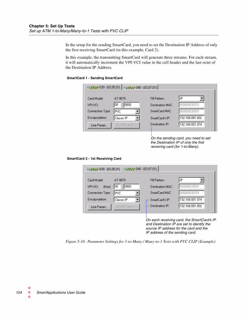
Chapter 5: Set Up TestsSet up ATM 1-to-Many/Many-to-1 Tests with PVC CLIP
124
In the setup for the sending SmartCard, you need to set the Destination IP Address of onlythe first receiving SmartCard (in this example, Card 2).
In this example, the transmitting SmartCard will generate three streams. For each stream,it will automatically increment the VPI-VCI value in the cell header and the last octet ofthe Destination IP Address.
Figure 5-10. Parameter Settings for 1-to-Many / Many-to-1 Tests with PVC CLIP (Example)
SmartCard 1 - Sending SmartCard
SmartCard 2 - 1st Receiving Card
On the sending card, you need to setthe Destination IP of only the firstreceiving card (for 1-to-Many).
On each receiving card, the SmartCard’s IPand Destination IP are set to identify thesource IP address for the card and theIP address of the sending card.
SmartApplications User Guide

Run Tests
6This chapter explains the different phases of the test process and how to view, save, orprint test results.
In this chapter...
This chapter contains the following sections:
• Test Phases.....126
• Viewing Test Results.....127
• Generating HTML Test Reports.....133
• Viewing and Printing ASCII Text Report Files.....136
• Viewing Log Contents.....149
SmartApplications User Guide 125

Chapter 6: Run TestsTest Phases
126
Test PhasesWhen you start a test, it goes through several phases, including:
• Initialization of the DUT
• Learning phase
• Load generation
Device Under Test InitializationWhen the test starts, SmartApplications first sends out learning packets so that the switchor bridge can learn which addresses are local and which addresses need to be forwarded.After the learning sequence, the actual load testing begins.
Learning Phase Adjustments
Some DUTs fail to update forwarding tables when the default number of learning packetsis sent (the default is 3). If the DUT does not update the forwarding table correctly usingthe default number of packets, you can increase the number of learning packets that aresent through the DUT, between the SmartBits transmitting and receiving ports.
To increase the number of learning packets:
1 Select Setup > Test Configuration.
2 In the Test Configuration window, increase the value in the Learning Retries field.(The default value is 3.) This parameter determines how many retries will be made(with a one-second delay between retries) before determining if a single packet can beforwarded correctly.
Note: When testing routers, SmartApplications initiates an ARP exchange to update therouter’s ARP table before starting the learning phase.
Load Generation
The test now runs on the DUT, starting with the first selected packet size and followingthe defined test methodology.
All selected ports run concurrently.
SmartApplications User Guide

Chapter 6: Run TestsViewing Test Results
Viewing Test ResultsYou can view test results on the Results window in several ways:
• Individual test tab — View results by test as the test runs.
• Reports tab — View a report of the test once it finishes.
• Log tab — View a running record of all repetitions of each trial of all tests.
Results Window by Test Tab
As soon as a test starts, SmartApplications displays the Results window for that test.Figure 6-1 is an example of the Results window for the Acceptable Loss Throughput test,with a chart showing test results.
Note: You can also open the Results window by selecting File > View Results File fromthe main menu.
Figure 6-1. Results Window
Test setup
Counters
Overall test results
Tabs open different Results windows, by test type
SmartApplications User Guide 127

Chapter 6: Run TestsViewing Test Results
128
The Results window displays results as the test runs and until it finishes. It shows:
• The test setup, as specified in the Test Configuration window (upper part of window)
• Test counters (middle part)
• Overall test results (status bar at bottom of window)
To view the results of a different test:
Click one of tabs at the bottom of the Results window.
Note: For latency test results, SmartApplications measures and yields results for bothstore-and-forward devices and bit-forwarding (cut-through) devices, regardless of theDUT’s actual characteristics. Use the results that are appropriate for the device type.
When the test is complete, the word Ready displays in the lower-left corner of thewindow, and final results display in the lower-right portion.
Results Window — Menu Options and ButtonsYou can use the following menu options and buttons in the Results window.
Table 6-1. Results Window — Menu Bar Options
Action Menu Bar Option Button
Opens a previously saved Results file. Open Results File
Saves the information in the Results window to a file. Save Results File
Copies the information in the Results window to theclipboard. You can paste the information to anapplication such as MS Notepad or MS Excel.
Copy Result
Prints the contents of the active tab on the Resultswindow.
Print Result
Stops the test.t Stop Test
Starts the test running. Start Test
Opens the Chart Wizard window, after you haveselected data to chart.
Create Chart
SmartApplications User Guide

Chapter 6: Run TestsViewing Test Results
Results Window — Status Bar Fields
Table 6-2 lists the fields on the status bar of the Results window.
Note: The Passed and Failed fields are not used in the Latency and Packet Loss tests.
Viewing the Results of Previous ConfigurationsYou can view and print the test results that you saved from other configurations while stillin the current configuration.
To view the results of previous configurations:
1 Select File > View Results File from the menu bar. The Results window displays.
2 Select File > Open.
3 Select the .vts file containing the test results you want to view.
4 Click the Open button.
5 Click on a test tab to view test results.
Or, click one of the other tabs at the bottom of the Results window.
Table 6-2. Results Window — Status Bar Fields
Field Description
Frame size Size of frames being sent in this test.
Trial Number of the current trial.
Rep Number of repetition for the current trial.
Passed Percentage of traffic that passed the test without any packet loss.
Current Rate at which the current trial/repetition is being run.
Failed Last rate at which packet loss occurred.
SmartApplications User Guide 129

Chapter 6: Run TestsViewing Test Results
130
Viewing and Printing Test ReportsSmartApplications provides two types of report for each test type you run in a session:
• Detail report
• Summary report
In both report types, results are appended by packet size following each test trial. You canproduce individual reports for just one packet size.
Detail Reports
The detail report contains all results for every trial of each test type run during the testsession. For every packet size tested, SmartApplications appends the results of each trialto a report table when the trial completes. You can view this table online or print it.
If you run all tests at once, the detail report contains results for all four tests. One reporttable can hold up to 16384 rows (equivalent to many reports).
What the detailreport shows
Detail reports show, by packet size, the test progress including:
• Current trial number
• Operation in process (transmitting, receiving, retrieving data)
• Current rate
• Passed rate
• Approximate percent of completion
Detail reportformats
Detail reports are available in two formats:
• Tabular (default)Displays results in columns by frame size.
• Non-tabularDisplays results in sequence by frame size.
SmartApplications User Guide

Chapter 6: Run TestsViewing Test Results
To change to the non-tabular report format:
• Select Setup > Test Configuration from the main menu (see Figure 6-2 onpage 131).
• Open the Preference tab.
• Uncheck the Create Tabular Report checkbox.
Figure 6-2. Specifying the Non-tabular Report Format
To view a detail report online
• Click the Reports tab of the Results window.
To print a detail report
• Select File > Print from the menu bar.
Note: For tabular reports only: You can only print data that is visible on your screen. Ifthe visible data on your screen exceeds physical page parameters, select File > PageSetup from the menu bar and adjust your margins.
Uncheck CreateTabular Report togenerate reports inthe non-tabularformat (see“Viewing andPrinting TestReports” on page130 for examples foreach test type.
SmartApplications User Guide 131

Chapter 6: Run TestsViewing Test Results
132
Summary Reports
SmartApplications also generates a summary report for each test type run during a session.These reports summarize the results for each packet size (as in the Scott Bradner resultformat).
For each test setup, SmartApplications appends the results by packet size to the summaryreport at the end of a trial.
See Figure 6-9 on page 139 for an example of the summary report for a Throughput test.
Note: You must use an editor such as MS Notepad to view or print summary reports.
To create a separate report for each packet size:
1 Select Setup > Test Configuration...
2 Rename the file in the Report Filenames pane of the Preference tab.
SmartApplications User Guide

Chapter 6: Run TestsGenerating HTML Test Reports
Generating HTML Test ReportsYou can generate test results in HTML format.
To generate an HTML Report:
1 Select Setup > HTML Reports Setup... from the main menu.
2 Use the HTML Reports Setup dialog to set up the report output.
3 Check the Enable HTML Report checkbox to enable the HTML report.
The HTML Report Output Path field specifies the default location of the generatedHTML files. By default, these files are placed into a folder named html in the samedirectory that contains the SmartApplications executable. You can also have themwritten to another directory, if you wish. To do this, enter the desired path in theHTML Report Output Path field.
Figure 6-3. Setting the Path for an HTML Report
The HTML Report Index File Name identifies the default index file, index.html. Thisfile contains links to the individual test result files. These are the files that are createdeach time the test is run, or for each test iteration by packet size.
These links are in the following format (see Figure 6-4 on page 134 for an example):
<month><date><hour><minutes><seconds>
SmartApplications User Guide 133

Chapter 6: Run TestsGenerating HTML Test Reports
134
Figure 6-4. Example of HTML File Name Links
4 Use the Test Comment field to specify a Test Comment (see Figure 6-4 onpage 134). The contents of the Vendor Name and Product Name fields can be set inthe SmartApplications main window (Figure 6-5). (These fields also are used forASCII test reports.)
SmartApplications generates all other field information automatically.
Figure 6-5. Setting the Vendor Name and Product Name for Reports
Figure 6-6 on page 135 shows a sample HTML test report.
Use these fields to set a “VendorName” and “Product Name” toappear in test reports.
SmartApplications User Guide

Chapter 6: Run TestsGenerating HTML Test Reports
Figure 6-6. Sample HTML Test Report
SmartApplications User Guide 135

Chapter 6: Run TestsViewing and Printing ASCII Text Report Files
136
Viewing and Printing ASCII Text Report FilesYou can print a detail report that contains the results of one test at a particular packet size.SmartApplications assigns default filenames to individual report files (Table 6-3).
In each file name .nnn is a hexadecimal number representing the test frame size. Forexample, if you run a Packet Loss test in which packet size is 64 bytes, the filename willbe PACKETLO.040 where 040 is the hexadecimal equivalent of 64 decimal.
To change the default file names:
You can change these default names (excluding the file extension):
1 Select Setup > Test Configuration...
2 Rename the file in the Report Filenames pane of the Preference tab.
Notes:
1 Summary reports use the file extension .ndt.
2 If you repeat a test at the same packet size, SmartApplications overwrites the firstdetail report. To avoid this, rename the report file before repeating the test.
To print an individual test report (including a summary report):
1 Open an editor such as MS Notepad.
2 Select the file you want to print using File > Open.
3 Select File > Print.
Table 6-3. Default File Names for SmartApplications Tests
Test Type Default File Name
Throughput THROUGHP.nnn
Latency LATENCY.nnn
Packet Loss (Ethernet only) PACKETLO.nnn
Back-to-Back (Ethernet only) BAKTOBAK.nnn
SmartApplications User Guide

Chapter 6: Run TestsViewing and Printing ASCII Text Report Files
Sample Reports – Throughput TestFigure 6-7 is an example of the report for the Acceptable Loss Throughput test in thetabular format.
Figure 6-8 on page 138 shows the test report in the non-tabular format.
Figure 6-9 on page 139 is an example of the summary report.
Figure 6-7. Sample Detail Report for Throughput Test – Tabular Format
This format shows test results withpacket sizes arranged in column format.
SmartApplications User Guide 137

Chapter 6: Run TestsViewing and Printing ASCII Text Report Files
138
Figure 6-8. Sample Detail Report for Throughput Test – Non-tabular Format
This format shows test results withpacket sizes arranged in sequence.
SmartApplications User Guide

Chapter 6: Run TestsViewing and Printing ASCII Text Report Files
Figure 6-9. Sample Summary Report for Throughput Test
The summary report shows overallresults by packet size.
SmartApplications User Guide 139

Chapter 6: Run TestsViewing and Printing ASCII Text Report Files
140
Sample Reports – Latency TestFigure 6-10 is an example of the Latency test report in the tabular format.
Figure 6-8 on page 138 shows an example of the test report in the non-tabular format.
Figure 6-9 on page 139 is an example of the summary report.
Figure 6-10. Sample Detail Report for Latency Test – Tabular Format
SmartApplications User Guide

Chapter 6: Run TestsViewing and Printing ASCII Text Report Files
Figure 6-11. Sample Detail Report for Latency Test – Non-tabular Format
SmartApplications User Guide 141

Chapter 6: Run TestsViewing and Printing ASCII Text Report Files
142
Figure 6-12. Sample Summary Report for Latency Test
SmartApplications User Guide

Chapter 6: Run TestsViewing and Printing ASCII Text Report Files
Sample Reports – Packet Loss TestFigure 6-13 is an example of the Packet Loss test report in the tabular format.
Figure 6-14 on page 144 shows the test report in the non-tabular format.
Figure 6-15 on page 145 is an example of the summary report.
Figure 6-13. Sample Detail Report for Packet Loss Test – Tabular Format
SmartApplications User Guide 143
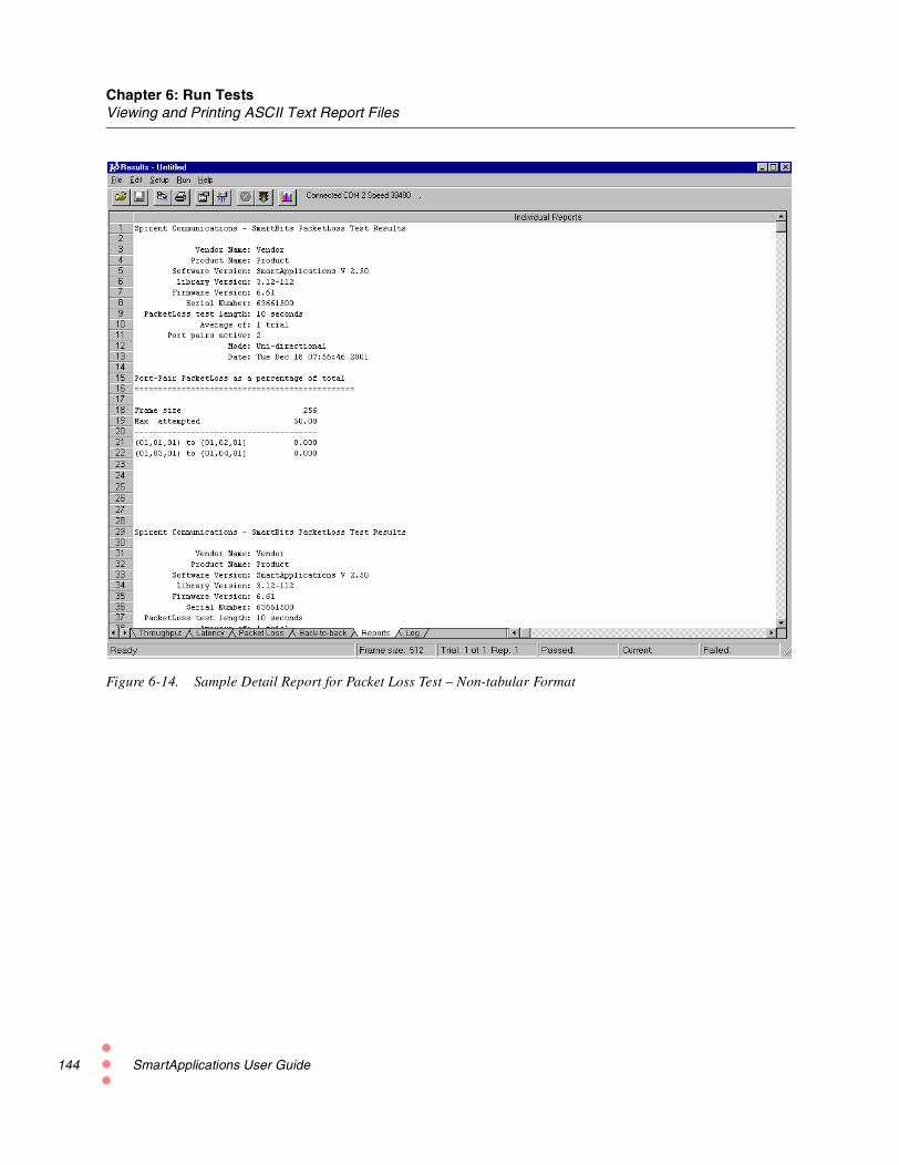
Chapter 6: Run TestsViewing and Printing ASCII Text Report Files
144
Figure 6-14. Sample Detail Report for Packet Loss Test – Non-tabular Format
SmartApplications User Guide

Chapter 6: Run TestsViewing and Printing ASCII Text Report Files
Figure 6-15. Sample Summary Report for Packet Loss Test
SmartApplications User Guide 145

Chapter 6: Run TestsViewing and Printing ASCII Text Report Files
146
Sample Reports – Back-to-Back TestFigure 6-16 is an example of the Back-to-Back test report in the tabular format.
Figure 6-17 on page 147 shows the test report in the non-tabular format.
Figure 6-18 on page 148 is an example of the summary report.
Figure 6-16. Sample Detail Report for Back-toBack Test – Tabular Format
SmartApplications User Guide

Chapter 6: Run TestsViewing and Printing ASCII Text Report Files
Figure 6-17. Sample Detail Report for Back-toBack Test – Non-tabular Format
SmartApplications User Guide 147

Chapter 6: Run TestsViewing and Printing ASCII Text Report Files
148
Figure 6-18. Sample Summary Report for Back-toBack Test
SmartApplications User Guide

Chapter 6: Run TestsViewing Log Contents
Viewing Log ContentsThe SmartApplications log file provides detailed results for each test, as well as a runningrecord of what happened during the test. See Figure 6-19 for an example.
To view the log file, open the Log tab of the Results window.
Note: Always check the test log to make sure that the test has run correctly.
Figure 6-19. Sample Log File
SmartApplications User Guide 149

150
SmartApplications User Guide
Test Examples
7This chapter presents examples of the four SmartApplications tests, illustrating sample testconfigurations for routers or switches. Although they will not match your test environmentexactly, they demonstrate how to run a test and how results should look. Naturally, youshould set up your test configurations to meet your specific requirements.
Note: All the examples described here apply to a router or switch. If the device under testis a router, be sure to select Router Test on the Preference tab of the Test Setup window.
In this chapter...
This chapter contains the following sections:
• Throughput Test — Example.....152
• Latency Test — Example.....157
• Packet Loss Test — Example.....159
• Back-to-Back Test — Example.....161
SmartApplications User Guide 151
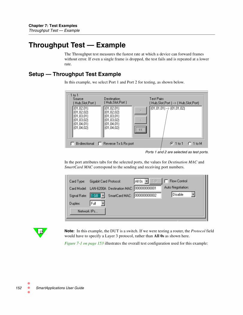
Chapter 7: Test ExamplesThroughput Test — Example
152
Throughput Test — ExampleThe Throughput test measures the fastest rate at which a device can forward frameswithout error. If even a single frame is dropped, the test fails and is repeated at a lowerrate.
Setup — Throughput Test ExampleIn this example, we select Port 1 and Port 2 for testing, as shown below.
In the port attributes tabs for the selected ports, the values for Destination MAC andSmartCard MAC correspond to the sending and receiving port numbers.
Note: In this example, the DUT is a switch. If we were testing a router, the Protocol fieldwould have to specify a Layer 3 protocol, rather than All 0s as shown here.
Figure 7-1 on page 153 illustrates the overall test configuration used for this example:
Ports 1 and 2 are selected as test ports.
SmartApplications User Guide

Chapter 7: Test ExamplesThroughput Test — Example
Figure 7-1. Test Configuration for Example
Test setup This example uses the following setup:
• Initial Rate is 100%.
• Maximum rate is 100%.
• Minimum rate is 50%.
• Resolution is .5%.
• Acceptable Loss Percentage is not enabled (zero value).
To save time, frame sizes vary from a minimum of 64 bytes to a maximum of 128 bytes,with a step size of 64.
How the test runs The test will run twice: once with 64-byte packets, and once with 128-byte packets. It willstart running at 100% and fall back if any packets are lost. The minimum rate is 50%.
Note: The rates in this example were selected to minimize the number of tests run. ForEthernet, RFC 1242 actually recommends frame sizes of 64, 128, 256, 512, 1024, 1280,and 1518 bytes (these are the default sizes in the Sizes list when you select Use Custom).
SmartApplications User Guide 153

Chapter 7: Test ExamplesThroughput Test — Example
154
Results — Throughput Test ExampleThe Results window appears as soon as the test starts. Figure 7-2 is an example of theResults window for the Throughput test. In this case, it shows that the trial succeeded atthe first frame size and is continuing with the second frame size.
Because we selected two packet sizes (64 and 128 bytes), only two trials are shown.
Figure 7-2. Throughput Test Results Window (Example)
The current rate to which the test dropped.
The rate at which the test failed (if applicable).
This trial finished.
This trial is still running.
SmartApplications User Guide

Chapter 7: Test ExamplesThroughput Test — Example
Sample Test LogThe test log shows packets received and packets transmitted. Figure 7-3 illustrates the logfor this example. When there is a failure in a trial iteration, that field is shown in red.
Figure 7-3. Sample Test Log for Throughput Test
The difference between the number of packets transmitted and thenumber of packets-with-triggers received indicates the packet loss.
Click on the Log tab to open the test log.
SmartApplications User Guide 155

Chapter 7: Test ExamplesThroughput Test — Example
156
Sample Test ReportFigure 7-4 illustrates the Test Report for the Throughput test example.
Figure 7-4. Sample Test Report
Click on the Reports tab to open the test report.
SmartApplications User Guide

Chapter 7: Test ExamplesLatency Test — Example
Latency Test — ExampleIn Latency tests, the Min. Rate field does not apply.
Sample Test ConfigurationThe Setup Test Configuration dialog (Figure 7-5) shows the settings used in this example.
Figure 7-5. Test Setup for Latency Test Example
Test setup This test uses the following setup:
• 64-byte packets and 128-byte packets.
• Each trial will last 100 seconds (the RFC default), and there will be two trials (theRFC default is 20).
• Learning Packets will be sent once before each test.
• Initial Rate is 50%, Step Rate is 25%, and Max Rate is 100%.
How the test runs These settings will cause the test to run in six trials: with 64-byte packets at 50%, 75% and100%, and with 128-byte packets at 50%, 75% and 100%. The Latency test does not stepdown in percentage of transmission. For example, if Initial Rate is 100%, Minimum Rate50%, and Step Rate 25%, the test will run only at 100%.
Note: Rates in this example were selected to minimize the number of tests run. RFC 1242specifies a minimum of 20 repetitions (Number of Trials) with a stream duration of 100seconds. Recommended frame sizes for Ethernet are 64, 128, 256, 512, 1024, 1280, and1518 (these are the default sizes in the Sizes list when you select Use Custom).
SmartApplications User Guide 157

Chapter 7: Test ExamplesLatency Test — Example
158
Sample Test Results Window for LatencyFigure 7-6 illustrates the Results window for this example of the Latency test, with the teststill in progress. Test results are displayed for both cut-through and store-and-forwarddevices. Use the measurement that is appropriate for your device type.
Figure 7-6. Sample Results Window for Latency Test
The 64-byte tests are complete at 50%, 75% and 100%, with a latency time of 0.1microseconds for all rates. The 50% test with 128-byte packets is also complete with alatency of 0.1 microsecond.
The status bar at the bottom of the window displays current activity:
• Performing triggers setup for the selected ports.
• Frame size being transmitted (128 bytes)
• Current trial count (1 of 2)
• Current rate (75.13%)
Note: Passed and Failed status indications are not used in the Latency test.
Use the Status bar to view current activity as the test runs.
These Status bar fields are not used in a Latency test.
SmartApplications User Guide

Chapter 7: Test ExamplesPacket Loss Test — Example
Packet Loss Test — ExampleThe Packet Loss Test measures the percentage of frames lost by the DUT that should havebeen forwarded.
Sample Test ConfigurationFigure 7-7 shows the settings used for this example of the Packet Loss test.
Figure 7-7. Test Setup for Packet Loss Test Example
Test setup This test uses the following setup:
• 64-byte packets and 128-byte packets.
• Each trial will last 10 seconds, and there will be one trial.
• Learning Packets will be sent once before each test.
• Initial Rate is 50%, Step Rate is 10%, and Max Rate is 100%.
How the test runs This test setup results in 12 trials: 64-byte packets are sent first at the 50% rate, then atrates that increase in 10% increments. Then 128-byte packets are sent in the same way.
Note: Rates in this example were selected to minimize the number of tests run. Therecommended frame sizes for Ethernet are 64, 128, 256, 512, 1024, 1280 and 1518 bytes(these are the default sizes in the Sizes list when you select Use Custom).
SmartApplications User Guide 159

Chapter 7: Test ExamplesPacket Loss Test — Example
160
Sample Results WindowFigure 7-8 illustrates the Results window for this example of a Packet Loss Test, with thetest still in progress.
Figure 7-8. Sample Test Results for Packet Loss Test
In this example the first trial ran at 50% with 64-byte packets and no packet loss. The lossrate (0.000% lost) is shown in each this column identifying the port pair.
Subsequent trials ran at 10% higher rates, with 64-byte packets, and there was no packetloss until the 90% rate, when .924% of the transmitted packets were lost. The next rate(with 64-byte frames) also showed packet loss of .034%.
The Status bar shows that trials at the 128 frame size are just beginning, with test setup inprogress.
SmartApplications User Guide

Chapter 7: Test ExamplesBack-to-Back Test — Example
Back-to-Back Test — ExampleThe Back-to-Back test assesses the buffering capability of the device under test.
Sample Test ConfigurationFigure 7-8 shows the settings used for this example of the Back-to-Back test.
Test setup This test uses the following setup:
• 50 trials with a duration of two seconds each trial.
• Start at the 50% rate.
• Increase in 25% steps to a maximum of 100%.
• Start with 64-byte packets.
• Increase by 64 bytes in each trial to a maximum of 128-byte packets.
Note: Rates in this example were selected to minimize the number of tests run. RFC 1242actually recommends at least 50 trials with a required minimum duration of two secondswith frame sizes for Ethernet of 64, 128, 256, 512, 1024, 1280 and 1518 bytes (these arethe default sizes in the Sizes list when you select Use Custom).
SmartApplications User Guide 161

Chapter 7: Test ExamplesBack-to-Back Test — Example
162
Sample Results WindowFigure 7-9 illustrates the Results window for the sample Back-to-Back test, with the teststill in progress. For this test, results show the number of frames in the longest burst thatthe DUT handled without dropping a packet.
In this example, we used a jumper wire to connect the two ports under test. Therefore theresults shown here represent only the maximum number of frames of that size that can betransmitted at the test rate.
Figure 7-9. Sample Test Results for Back-to-Back Test
SmartApplications User Guide

Glossary
This glossary has two parts:
• “Acronyms and Abbreviations” expands short terms that appear in this document.
• “Terminology” defines longer terms in this document, as well as in networkingtechnology and standards generally.
Acronyms and Abbreviations
Acronym /Abbreviation
Definition
AMI Alternate Mark Inversion.
ATM Asynchronous Transfer Mode. Transfer mode in whichinformation is organized into cells.
CPE Customer Premise Equipment.
CRC Cyclic Redundancy Check.
CSU Channel Service Unit.
CTS Clear to Send.
DCD Date Carrier Detect.
DLCI Data Link Connection Identifier.
DSR Data Set Ready.
DSU Data Service Unit.
DTR Data Terminal Ready.
DUT Device Under Test.
ELAN Emulated Local Area Network. A group of ATM and legacydevices registered with the LES that constitute a logicalnetwork.
SmartApplications User Guide 163
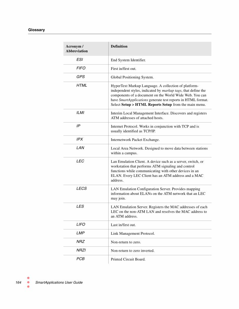
Glossary
164
ESI End System Identifier.
FIFO First in/first out.
GPS Global Positioning System.
HTML HyperText Markup Language. A collection of platform-independent styles, indicated by markup tags, that define thecomponents of a document on the World Wide Web. You canhave SmartApplications generate test reports in HTML format.Select Setup > HTML Reports Setup from the main menu.
ILMI Interim Local Management Interface. Discovers and registersATM addresses of attached hosts.
IP Internet Protocol. Works in conjunction with TCP and isusually identified as TCP/IP.
IPX Internetwork Packet Exchange.
LAN Local Area Network. Designed to move data between stationswithin a campus.
LEC Lan Emulation Client. A device such as a server, switch, orworkstation that performs ATM signaling and controlfunctions while communicating with other devices in anELAN. Every LEC Client has an ATM address and a MACaddress.
LECS LAN Emulation Configuration Server. Provides mappinginformation about ELANs on the ATM network that an LECmay join.
LES LAN Emulation Server. Registers the MAC addresses of eachLEC on the non-ATM LAN and resolves the MAC address toan ATM address.
LIFO Last in/first out.
LMP Link Management Protocol.
NRZ Non-return to zero.
NRZI Non-return to zero inverted.
PCB Printed Circuit Board.
Acronym /Abbreviation
Definition
SmartApplications User Guide

Glossary
PPP Point-to-Point Protocol.
PVC Permanent Virtual Circuit. A dedicated channel betweenendpoints through an ATM network used for long-term datatransfer.
RFC Request For Comments. Document series used as the primarymeans for communicating information about the Internet.
RIP Routing Information Protocol.
RTS Request to Send.
SMB SmartBits.
SNAP Subnetwork Access Protocol.
SRA Source Route Addressing.
SVC Switched Virtual Circuit. A connection established throughsignaling with user-defined endpoints when the call isinitiated.
UDP User Datagram Protocol. Connectionless transport layerprotocol in the TCP/IP protocol stack.
VCI/VPI Virtual Channel Identifier/Virtual Path Identifier. Aconnection in the form of a channel which has beensuccessfully initialized and on which data is ready to betransmitted and received. Provides mapping information forrouting cells from a source to destination.
WAN Wide Area Network.
Acronym /Abbreviation
Definition
SmartApplications User Guide 165
Glossary
166
Terminology
Acceptable Loss ThroughputA mode for the Throughput test. It enables you to specify how much frame loss should beconsidered acceptable when judging the trial successful or failed. This makes it possible tocompensate for frame loss caused by small differences in clock tolerances between theSmartBits port and the DUT port.
Back-to-Back testTests the buffering capability of the device under test (DUT).
bi-directionalPort pairs transmitting simultaneously in both directions, as in full-duplex operation.
card
In this manual, refers generally to any SmartCard or module for a SmartBits system.
frame
A data pattern that a stream transmits.
hub
The SmartBits chassis that contains SmartCards or modules.
iterationAn iteration is when SmartApplications, while maintaining the frame size, varies thetransmission rate based on the last failed rate. The resolution and number of repetitionsdetermines the accuracy of results.
latencyDelay between the time a device receives a frame and the time that frame is forwarded outthe destination port.
MAC addressA 6-byte IEEE identifier for hardware devices, sometimes called a hardware address.
Next Hop test
Tests a router’s ability to recognize the next hop address and update its routing table withthis address.
Packet Loss test
Measures the percentage of frames lost by the device under test (DUT) that should havebeen forwarded.
port
In a SmartBits chassis, the port on a SmartCard or module.
slotOn a SmartBits chassis, a slot is where the SmartCard or module is inserted.
SmartApplications User Guide

Glossary
streamA software engine on SmartBits cards that transmits a frame pattern repeatedly.
testRefers to the test (such as Throughput or Latency) run for a particular frame size.
Throughput test
Tests the fastest rate at which a device can forward frames without error.
trial
One set of iterations for a specific fame size and varying transmission rates. Tests use trialsto determine the optimal rate of traffic for that frame size.
SmartApplications User Guide 167

168
SmartApplications User Guide
Index
Numerics1-to-1 tests
running 31, 641-to-Many/Many-to-1 tests
running 66selecting ports for 32
AAcceptable Loss Throughput 13Actions menu 25addresses, learning 11allowable port pair combinations 61ATM
1-to-Many/Many-to-1 tests with PVC CLIP 123ATM ARP tab 93configuring ports 79ELAN 94ILMI tab 91Line Params tab 83PVC CLIP 123SSCOP tab 87UNI tab 89
auto negotiation 72
BBack-to-Back test
methodology 17scenario 161
baud rate 38bi-directional testing 31, 64
Ccard
defined 7card attributes, viewing 31Channel Selection window 107
T-1/E-1 107chart of results 33Classical IP (CLIP) 123clocks
polarity (WN-3405) 102synchronizing in remote chassis 43synchronizing WAN ports 108transmit clock source (ATM) 84transmit clock source (WAN) 101, 105
Configuration Tab options 51configurations, viewing previous 129configuring
ATM ports 79duplex 68Ethernet ports 71Frame Relay ports 96multiple ports at one time 68pair of ports at a time 70protocol 68speed 68test ports 67test setups 48Token Ring ports 74WAN ports 96
connectingmultiple chassis 42the device under test 36to the Ethernet port 40to the serial port 38
creating a chart of results 33
Ddetail reports 130
EE-1 channel selection 107encapsulation 100, 114Ethernet port
connecting to 40linking multiple Smartbits controllers 42
examplesassigning addresses for protocols 121Back-to-Back test 161how test configuration settings work 52Latency test 157Packet Loss test 159Throughput test 152
FFile menu 25flow control 58, 72fractional T-1/E1 channel selection 107Frame Relay 100
configuring 96
SmartApplications User Guide 169

Index
170
GGeneral Area options (Test Configuration tab) 49general testing methodology 10GPS 43
HHelp menu 27HTML test reports 133hub/slot/port designations 42
Iidentifying ports 61ILMI parameters (ATM) 91individual reports
viewing and printing 133, 136Intended Load 58invalid COM Port 39IP protocol 119IPX protocol 119
LLAN-3300A/3301A
duplex setting 68speed setting 68
Latency testmethodology 14scenario 157
Launch buttons 28learning packets 11, 51line clock options 101line parameters
ATM 83WAN cards 101, 104
Mmain window 25
port selection area 31toolbar 29
methodologyBack-to-Back test 17general 10Latency test 14Packet Loss test 16Throughput test 12
modulesdefined 7
multiple chassislinking 42synchronizing clocks with GPS 43
NNetwork IPs window 73Next Hop test
setting up 118null modem cable 39
OOffered Load 58online Help 4
PPacket Loss test
methodology 16scenario 159
packet sizes, customizing 54port numbering 61ports
configuring ATM 79configuring Ethernet 71configuring individually 70configuring multiple 68configuring Token Ring 74configuring WAN 96
PPP 100, 114Preference tab 55printing individual reports 133, 136protocols 119PVC CLIP (Classical IP) 123
Rreports
ASCII text report files 133, 136detail 130HTML 133viewing and printing 133, 136
reserving SmartCards 44Results window
Back to Back test 162Latency test 158menu options and buttons 128Packet Loss test 160Throughput test 154viewing 154
RFC 2544 12router
Next Hop tests 118testing 115
RS-232 cable 39Run menu 26
Ssample configuration
Latency test 157Throughput test 152
saving a test configuration 59selecting test ports 60setting up a test, summary 36setting up test configurations 48Setup menu 26Setup SmartBits Connections window 26SmartApplications
overview 6SmartBits chassis
connecting to 39
SmartApplications User Guide

Index
SmartBits Connections option 26SmartCard Status window 44SmartCards and modules
defined 7source routing
Token Ring 74SSCOP parameters (ATM) 87stopping a test 47store and forward 14support 4synchronizing clocks in remote chassis 43synchronizing WAN card clocks 108system requirements 20
TT-1 channel selection 107technical support 4test
bi-directional 31defined 10load generation 126NextHop 117phases 126setup summary 36stopping 47
test configuration 48test configurations
saving 59tab 48
test resultsviewing 127viewing previous configurations 129
Throughput testmethodology 12report sample 139scenario 152
Token Ring portsconfiguring 74
Token Ring Properties window 76toolbar buttons 29trial
defined 10
UUDP protocol 119UNI parameters (ATM) 89User Guide
audience 2content overview 2conventions used 3purpose 2related manuals 3
Vviewing
test results 127viewing test results 154virtual port numbering 61
WWAN 165
configuring ports 96WAN Port Setup
Address Tab 112EIA Leads Tab (WN-3405) 111Encapsulation Tab 114Line Tab (WN-3405) 101Line Tab (WN-3415/WN-3420) 104LMP Tab 109
WAN portsconfiguring 96setup 100
SmartApplications User Guide 171