Human Builder - BND TechSource
322
Human Builder Preface Using this Guide Where to Find More Information Conventions What's New? Getting Started Standard Manikin Creation Creating a Forearm/Hand Model Changing Manikin Display Attributes User Tasks Using Forward Kinematics Assigning Descriptions (Memos) Using the Copy/Paste Function Using the Inverse Kinematics Modes Applying Standard Poses Making the Manikin Stand Positioning the Manikin with the Compass Using the Posture Editor Using the Reset, Mirror Copy, and Swap Functions Global Posture Reset Global Posture Swap Local Posture Reset Local Posture Mirror Copy Local Posture Swap 1 Page Human Builder Version 5 Release 13
-
Upload
khangminh22 -
Category
Documents
-
view
1 -
download
0
Transcript of Human Builder - BND TechSource
Human Builder
Preface
Using this Guide
Where to Find More Information
Conventions
What's New?
Getting Started
Standard Manikin Creation
Creating a Forearm/Hand Model
Changing Manikin Display Attributes
User Tasks
Using Forward Kinematics
Assigning Descriptions (Memos)
Using the Copy/Paste Function
Using the Inverse Kinematics Modes
Applying Standard Poses
Making the Manikin Stand
Positioning the Manikin with the Compass
Using the Posture Editor
Using the Reset, Mirror Copy, and Swap Functions
Global Posture Reset
Global Posture Swap
Local Posture Reset
Local Posture Mirror Copy
Local Posture Swap
1Page Human Builder Version 5 Release 13
Vision Posture Reset
Accessing the Graphical Properties of Segments
Changing the Color of a Segment
Changing the Properties of Ellipses
Changing the Properties of Segments
Changing the Transparency of the Surfaces
Accessing the Graphical Properties Toolbar
Whole Manikin Graphical Properties
Accessing Other Vision Options
Using Posture Undo/Redo
Retrieving Center of Gravity Coordinates
Redefining the Manikin Referential
Using Global Collision Detection
Using the Place Mode
Manikin Save/Update/Reload Enhancements
Using the Vision Function
Type Field
Field of View Tab
Distance Tab
Window Display Tab
Interactive Positioning with the Reach Mode
Redefining the Offset for Inverse Kinematics
Attaching an Object to a Manikin Segment
Using Manikin Constraint Commands
Contact Constraints
Coincidence Constraints
Fix On Constraints
Fix Constraints
Inverse Kinematics Behaviors
Using the Reach Envelope
Using Manikin Simulation Commands
Using the Shuttle Command
2Page Human Builder Version 5 Release 13
Using the Simulation Command
Using the Compile Simulation Command
Using the Generate Video Command
Using the Replay Command
Using the Track Command
The Recorder Toolbar
The Player Toolbar
The Track Dialog Box
Using the Play Simulation Command
Using the Clash Command
Manikin Catalog Management
Manikin Workspace Analysis
Distance and Band Analysis
Arc Through 3 Points Analysis
Measure Between Analysis
How to Do a Safe Save in ENOVIA LCA from CATIA V5
Workbench Description
Human Builder Menu Bar
Manikin Tools Toolbar
Manikin Posture Toolbar
Manikin Workbench Access Toolbar
Manikin Simulation Toolbar
Manikin Constraints Toolbar
Manikin Workspace Analysis Toolbar
Glossary
Index
3Page Human Builder Version 5 Release 13
PrefaceHuman Builder is based on a best-in-class human modeling system which, for many years, has permitted detailed investigation into human-centered design issues in the context of a workplace before it physically exists. Human Builder provides very accurate simulation of humans and their interactions with products to ensure they will operate naturally in a workplace tailored to their tasks. The Human Builder product specifically focuses on creating and manipulating digital humans for "first level" human-product interaction analysis.
Human Builder consists of a number of advanced tools for creating, manipulating and analyzing how manikins (based on the 5th, 50th and 95th percentile value) can interact with a product. The manikins can then be used to assess the suitability of a product for form, fit and function. The manikins can be intuitively created and manipulated in conjunction with the digital mockup to check features such as reach and vision. A simple-to-use interface ensures that first-level human factors studies can be undertaken by non-human factors specialists.
Tools contained within the Human Builder product include manikin generation, gender specification, percentile specification, direct kinematics and inverse kinematics manipulation techniques, animation generation, monocular, binocular and ambinocular vision simulation, as well as vision output cones.
Using this GuideWhere to Find More Information
Conventions
4Page Human Builder Version 5 Release 13
Using this GuideThis book describes how to use the Human Builder product. Before you read it, you should be familiar with basic concepts such as document windows, standard tool bars, and view tool bars.
If you are new user, start with the tutorial in the Getting Started section.
The User Tasks section of the book provides procedures for using the features of the Human Builder product.
A Workbench Description section describes each functional icon or command in the workbenches.
The Glossary provides definitions of terms specific to Human Builder and related products.
5Page Human Builder Version 5 Release 13
Where to Find More InformationAfter reading Human Builder, we recommend that you also read:● Human Posture Analysis
● Human Measurements Editor
● Human Activity Analysis
● Conventions
6Page Human Builder Version 5 Release 13
ConventionsCertain conventions are used in CATIA, ENOVIA & DELMIA documentation to help you recognize and understand important concepts and specifications.
Graphic Conventions
The three categories of graphic conventions used are as follows:● Graphic conventions structuring the tasks
● Graphic conventions indicating the configuration required
● Graphic conventions used in the table of contents
Graphic Conventions Structuring the Tasks
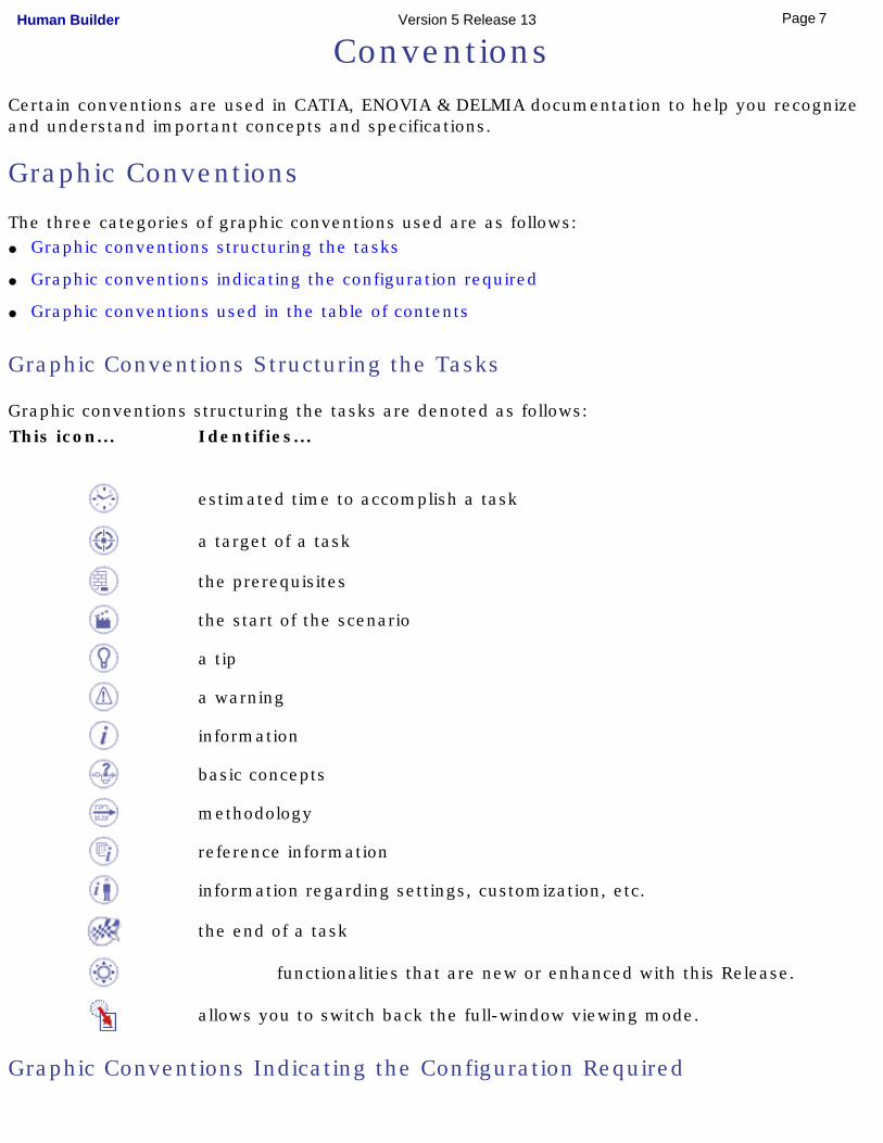
Graphic conventions structuring the tasks are denoted as follows:This icon... Identifies...
estimated time to accomplish a task
a target of a task
the prerequisites
the start of the scenario
a tip
a warning
information
basic concepts
methodology
reference information
information regarding settings, customization, etc.
the end of a task
functionalities that are new or enhanced with this Release.
allows you to switch back the full-window viewing mode.
Graphic Conventions Indicating the Configuration Required
7Page Human Builder Version 5 Release 13
Graphic conventions indicating the configuration required are denoted as follows:
This icon... Indicates functions that are...
specific to the P1 configuration
specific to the P2 configuration
specific to the P3 configuration
Graphic Conventions Used in the Table of Contents
Graphic conventions used in the table of contents are denoted as follows:
This icon... Gives access to...
Site Map
Split View mode
What's New?
Overview
Getting Started
Basic Tasks
User Tasks or the Advanced Tasks
Workbench Description
Customizing
Reference
Methodology
Glossary
Index
Text Conventions
The following text conventions are used:
The titles of CATIA, ENOVIA and DELMIA documents appear in this manner throughout the text. File -> New identifies the commands to be used. Enhancements are identified by a blue-colored background on the text.
How to Use the Mouse
8Page Human Builder Version 5 Release 13
The use of the mouse differs according to the type of action you need to perform.Use this
mouse button...Whenever you read...
● Select (menus, commands, geometry in graphics area, ...)
● Click (icons, dialog box buttons, tabs, selection of a location in the document window, ...)
● Double-click
● Shift-click
● Ctrl-click
● Check (check boxes)
● Drag
● Drag and drop (icons onto objects, objects onto objects)
● Drag
● Move
● Right-click (to select contextual menu)
9Page Human Builder Version 5 Release 13
What's New?
New Functionalities
Manipulating the manikin with a 3D mouse in inverse kinematics (IK) modeThe 3D mouse, a tool in addition to the regular mouse and and keyboard, makes positioning the manikin easier.
Enhanced Functionalities
Catalog managementAdditional data types can now be saved within catalogs and there is greater flexibility in the use of catalogs. The icons for catalog management in the Tools have changed.
Removed Functionalities
The Load Library and Save in Library commands are removed. All existing libraries must be converted to catalogs.
10Page Human Builder Version 5 Release 13
Getting StartedThis tutorial provides an overview of Human Builder functionality. It provides a step-by-step scenario showing you how to use key functions. The tasks described in this section are:
Standard Manikin CreationCreating a Forearm/Hand Model
Changing Manikin Display Attributes
11Page Human Builder Version 5 Release 13
Standard Manikin Creation
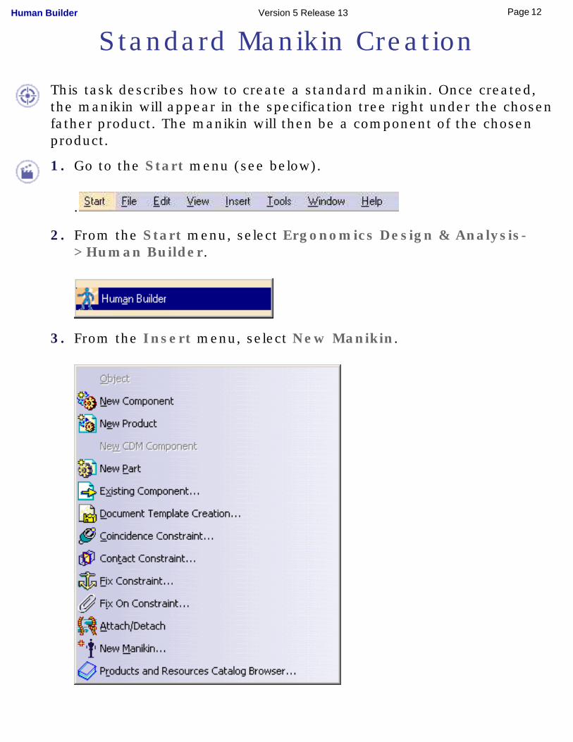
This task describes how to create a standard manikin. Once created, the manikin will appear in the specification tree right under the chosen father product. The manikin will then be a component of the chosen product.
1. Go to the Start menu (see below).
.
2. From the Start menu, select Ergonomics Design & Analysis->Human Builder.
3. From the Insert menu, select New Manikin.
12Page Human Builder Version 5 Release 13
OR
Select the Manikin Creation button in the Manikin Tools
toolbar.
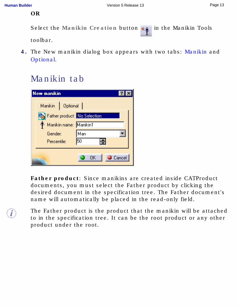
4. The New manikin dialog box appears with two tabs: Manikin and Optional.
Manikin tab
Father product: Since manikins are created inside CATProduct documents, you must select the Father product by clicking the desired document in the specification tree. The Father document's name will automatically be placed in the read-only field.
The Father product is the product that the manikin will be attached to in the specification tree. It can be the root product or any other product under the root.
13Page Human Builder Version 5 Release 13
Please note that the Father product cannot be another manikin.
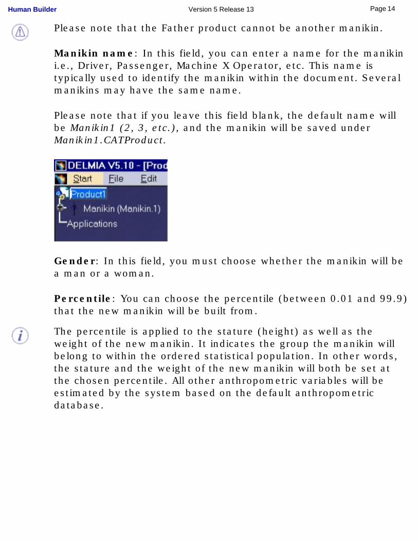
Manikin name: In this field, you can enter a name for the manikin i.e., Driver, Passenger, Machine X Operator, etc. This name is typically used to identify the manikin within the document. Several manikins may have the same name.
Please note that if you leave this field blank, the default name will be Manikin1 (2, 3, etc.), and the manikin will be saved under Manikin1.CATProduct.
Gender: In this field, you must choose whether the manikin will be a man or a woman.
Percentile: You can choose the percentile (between 0.01 and 99.9) that the new manikin will be built from.
The percentile is applied to the stature (height) as well as the weight of the new manikin. It indicates the group the manikin will belong to within the ordered statistical population. In other words, the stature and the weight of the new manikin will both be set at the chosen percentile. All other anthropometric variables will be estimated by the system based on the default anthropometric database.
14Page Human Builder Version 5 Release 13
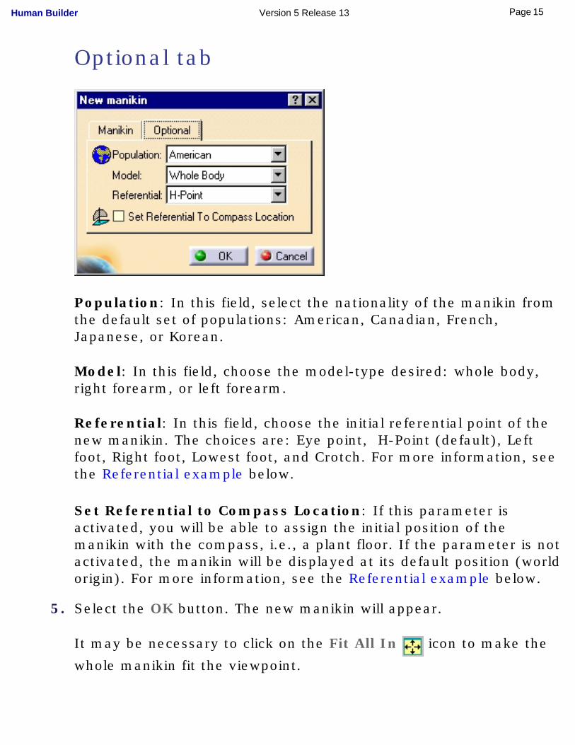
Optional tab
Population: In this field, select the nationality of the manikin from the default set of populations: American, Canadian, French, Japanese, or Korean.
Model: In this field, choose the model-type desired: whole body, right forearm, or left forearm.
Referential: In this field, choose the initial referential point of the new manikin. The choices are: Eye point, H-Point (default), Left foot, Right foot, Lowest foot, and Crotch. For more information, see the Referential example below.
Set Referential to Compass Location: If this parameter is activated, you will be able to assign the initial position of the manikin with the compass, i.e., a plant floor. If the parameter is not activated, the manikin will be displayed at its default position (world origin). For more information, see the Referential example below.
5. Select the OK button. The new manikin will appear.
It may be necessary to click on the Fit All In icon to make the
whole manikin fit the viewpoint.
15Page Human Builder Version 5 Release 13
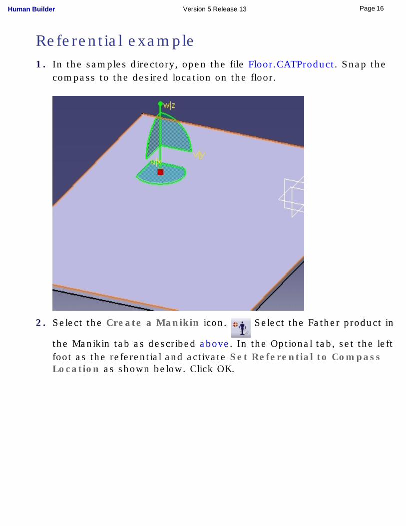
Referential example1. In the samples directory, open the file Floor.CATProduct. Snap the
compass to the desired location on the floor.
2. Select the Create a Manikin icon. Select the Father product in
the Manikin tab as described above. In the Optional tab, set the left foot as the referential and activate Set Referential to Compass Location as shown below. Click OK.
16Page Human Builder Version 5 Release 13
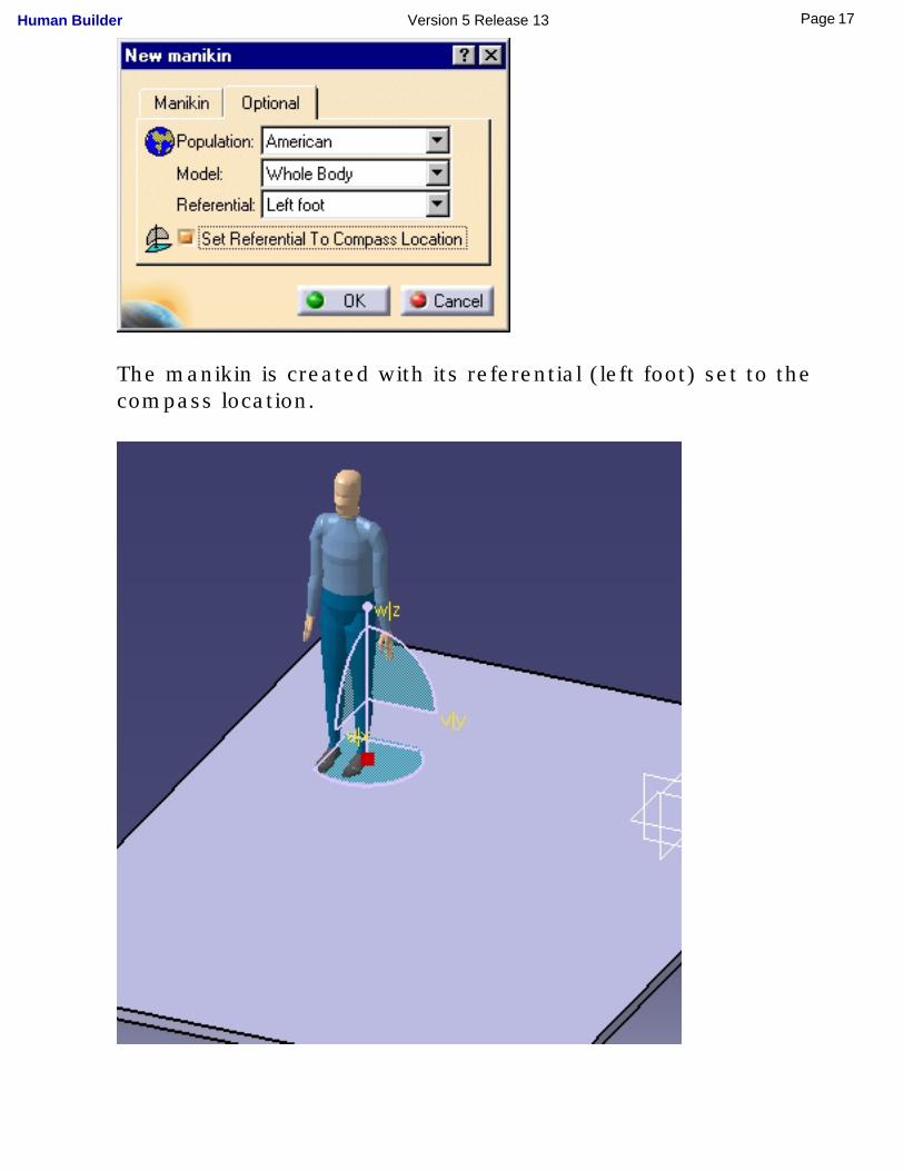
The manikin is created with its referential (left foot) set to the compass location.
17Page Human Builder Version 5 Release 13

18Page Human Builder Version 5 Release 13
Creating a Forearm/Hand Model
This task describes how to create a forearm model with fully-articulated hand.
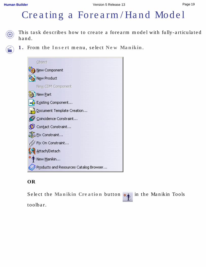
1. From the Insert menu, select New Manikin.
OR
Select the Manikin Creation button in the Manikin Tools
toolbar.
19Page Human Builder Version 5 Release 13
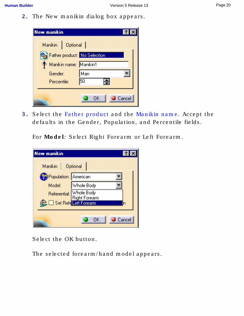
2. The New manikin dialog box appears.
3. Select the Father product and the Manikin name. Accept the defaults in the Gender, Population, and Percentile fields.
For Model: Select Right Forearm or Left Forearm.
Select the OK button.
The selected forearm/hand model appears.
20Page Human Builder Version 5 Release 13
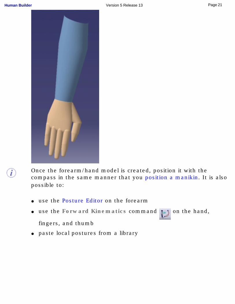
Once the forearm/hand model is created, position it with the compass in the same manner that you position a manikin. It is also possible to:
● use the Posture Editor on the forearm
● use the Forward Kinematics command on the hand,
fingers, and thumb
● paste local postures from a library
21Page Human Builder Version 5 Release 13
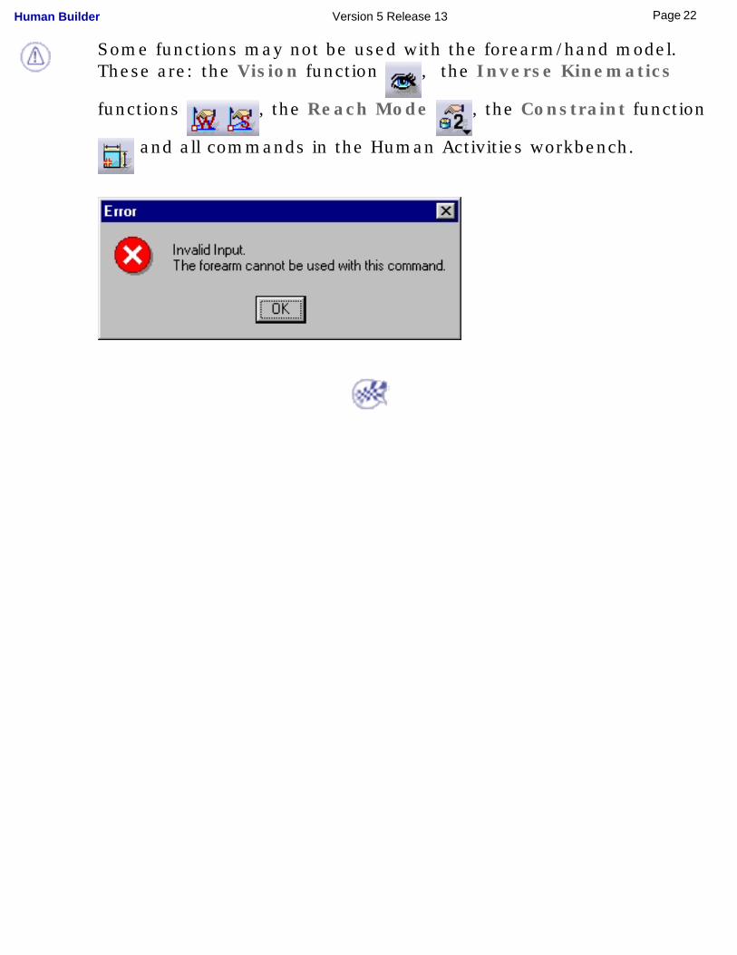
Some functions may not be used with the forearm/hand model. These are: the Vision function , the Inverse Kinematics
functions , the Reach Mode , the Constraint function
and all commands in the Human Activities workbench.
22Page Human Builder Version 5 Release 13
Changing Manikin Display Attributes
This task describes how to set and edit manikin display attributes.
In the toolbar, select the Display Attributes icon and in the 3D
view or the specification tree, select a manikin. The Display Attributes dialog box appears displaying the following choices:
Rendering
● Segments
● Ellipses
● Surfaces
● Resolution
Vision● Line of sight
● Peripheral cone
● Central cone
● Cone type
Others● Center of gravity
23Page Human Builder Version 5 Release 13
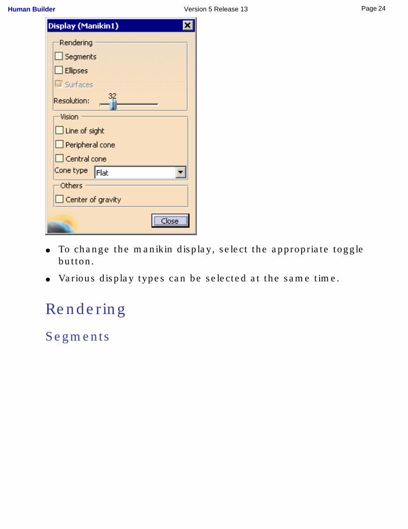
● To change the manikin display, select the appropriate toggle button.
● Various display types can be selected at the same time.
Rendering
Segments
24Page Human Builder Version 5 Release 13
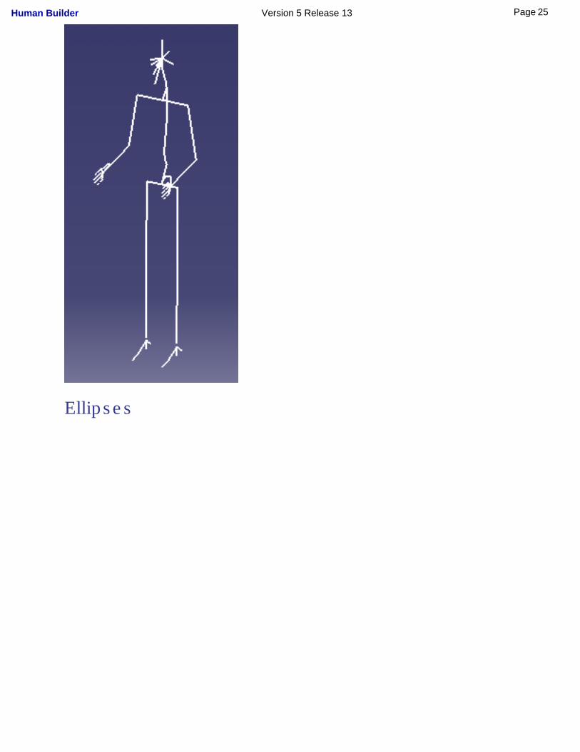
Ellipses
25Page Human Builder Version 5 Release 13
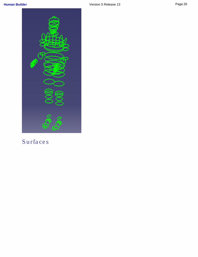
Surfaces
26Page Human Builder Version 5 Release 13
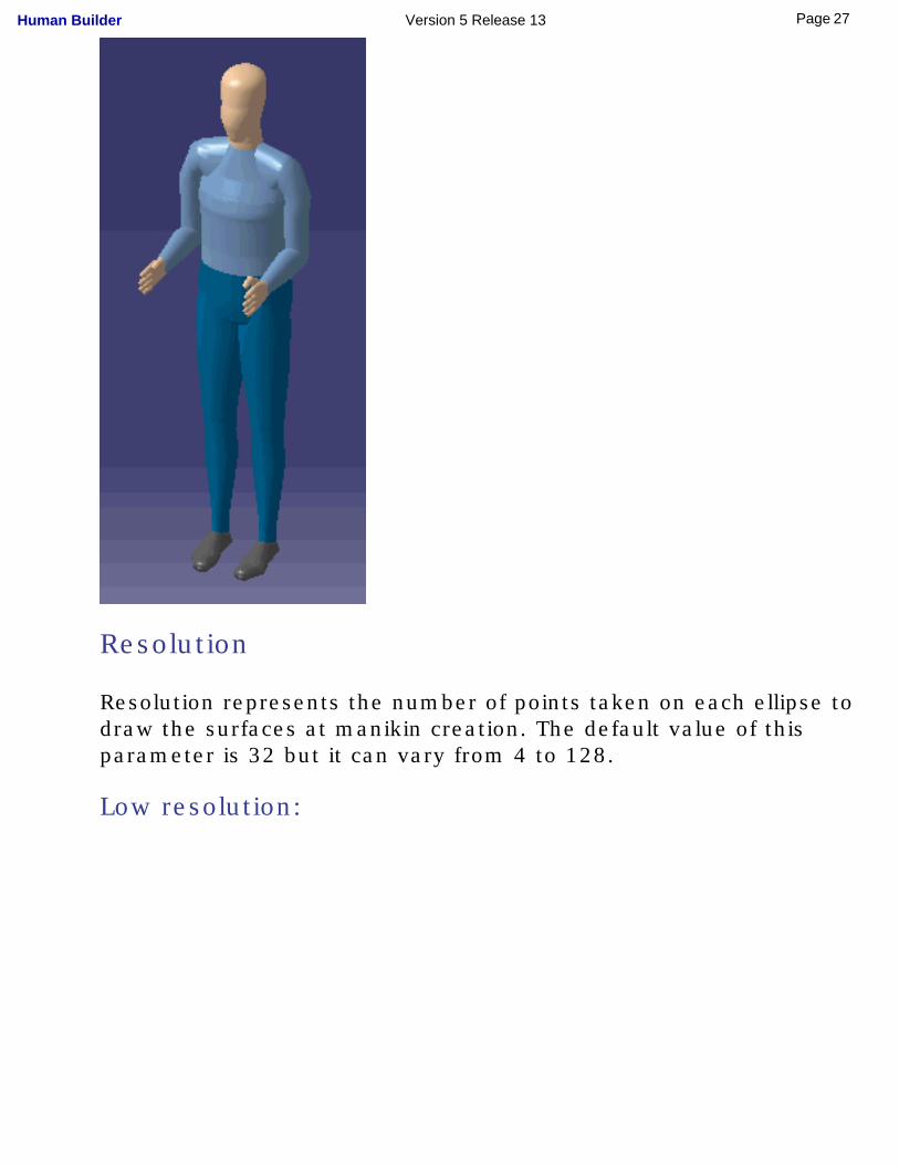
Resolution
Resolution represents the number of points taken on each ellipse to draw the surfaces at manikin creation. The default value of this parameter is 32 but it can vary from 4 to 128.
Low resolution:
27Page Human Builder Version 5 Release 13
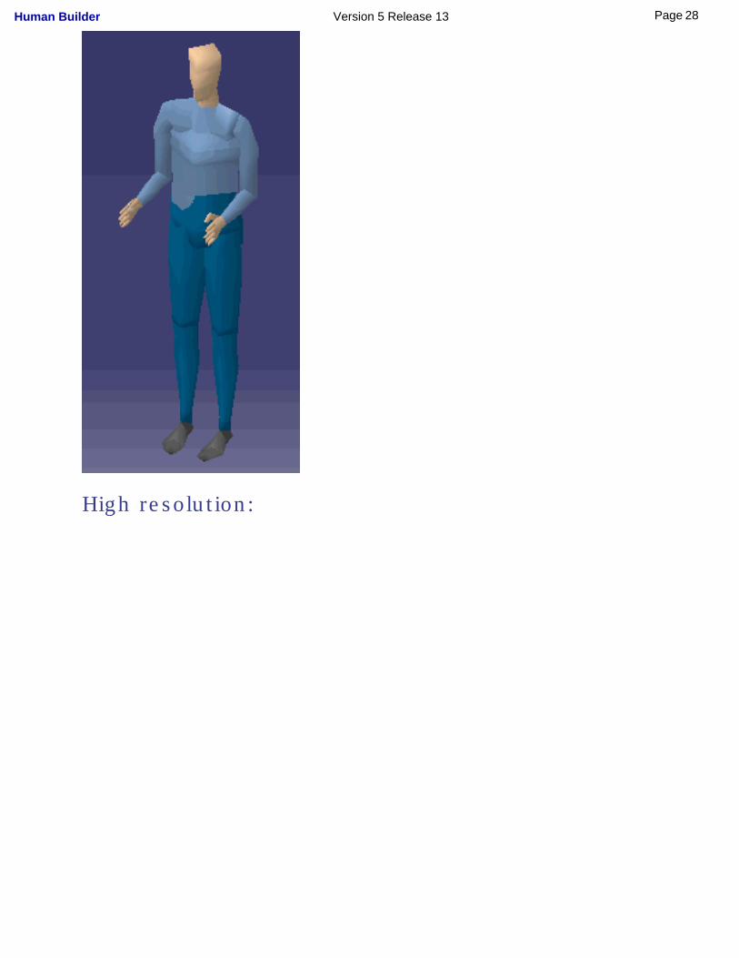
High resolution:
28Page Human Builder Version 5 Release 13
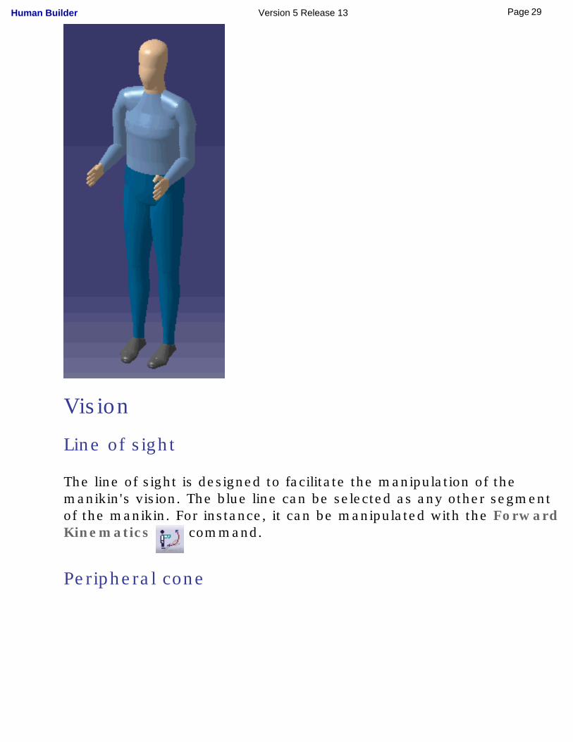
Vision
Line of sight
The line of sight is designed to facilitate the manipulation of the manikin's vision. The blue line can be selected as any other segment of the manikin. For instance, it can be manipulated with the Forward Kinematics command.
Peripheral cone
29Page Human Builder Version 5 Release 13
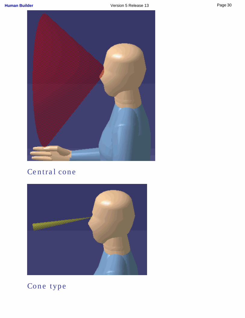
Central cone
Cone type
30Page Human Builder Version 5 Release 13
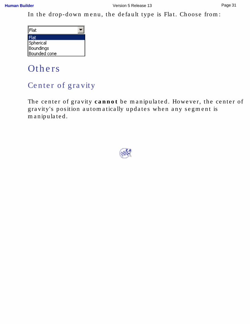
In the drop-down menu, the default type is Flat. Choose from:
Others
Center of gravity
The center of gravity cannot be manipulated. However, the center of gravity's position automatically updates when any segment is manipulated.
31Page Human Builder Version 5 Release 13
User TasksThese are the tasks that a user performs using Human Builder:
Using Forward KinematicsAssigning Descriptions (Memos)Using the Copy/Paste Function
Using the Inverse Kinematics ModesApplying Standard PosesMaking the Manikin Stand
Positioning the Manikin with the CompassUsing the Posture Editor
Using the Reset, Mirror Copy, and Swap FunctionsAccessing the Graphical Properties of Segments
Accessing Other Vision OptionsUsing Posture Undo/Redo
Retrieving Center of Gravity CoordinatesRedefining the Manikin ReferentialUsing Global Collision Detection
Using the Place ModeManikin Save/Update/Reload Enhancements
Using the Vision FunctionInteractive Positioning with the Reach ModeRedefining the Offset for Inverse KinematicsAttaching an Object to a Manikin Segment
Using Manikin Constraint CommandsInverse Kinematics Behaviors
Using the Reach EnvelopeUsing Manikin Simulation Commands
Manikin Catalog ManagementManikin Workspace Analysis
How to Do a Safe Save in ENOVIA LCA from CATIA V5
32Page Human Builder Version 5 Release 13
Using Forward Kinematics
This task describes how to control the manikin's movements using forward kinematics with the available manipulators as well as the Undo/Redo command.
1. In the toolbar, select the Forward Kinematics icon .
Note that this icon must be unselected by clicking on it again in order to access another function.
2. Select the manikin's part that you wish to move by clicking it with the left mouse button. Two arrows appear: one indicates the direction of the motion and the other indicates the rotation axis for the active degree of freedom.
33Page Human Builder Version 5 Release 13
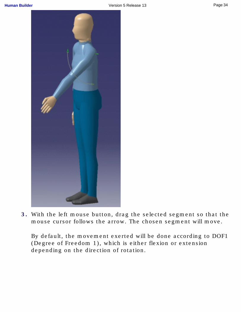
3. With the left mouse button, drag the selected segment so that the mouse cursor follows the arrow. The chosen segment will move.
By default, the movement exerted will be done according to DOF1 (Degree of Freedom 1), which is either flexion or extension depending on the direction of rotation.
34Page Human Builder Version 5 Release 13
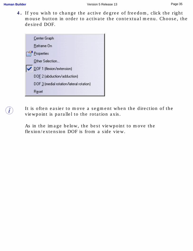
4. If you wish to change the active degree of freedom, click the right mouse button in order to activate the contextual menu. Choose, the desired DOF.
It is often easier to move a segment when the direction of the viewpoint is parallel to the rotation axis.
As in the image below, the best viewpoint to move the flexion/extension DOF is from a side view.
35Page Human Builder Version 5 Release 13
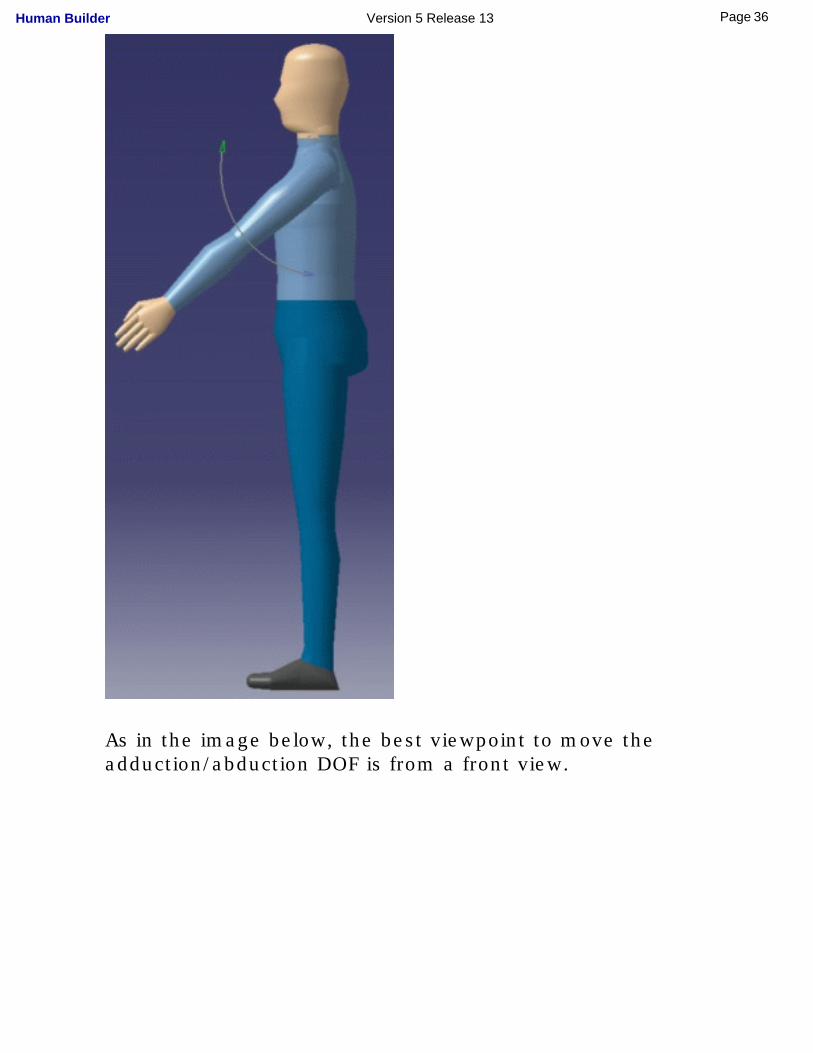
As in the image below, the best viewpoint to move the adduction/abduction DOF is from a front view.
36Page Human Builder Version 5 Release 13
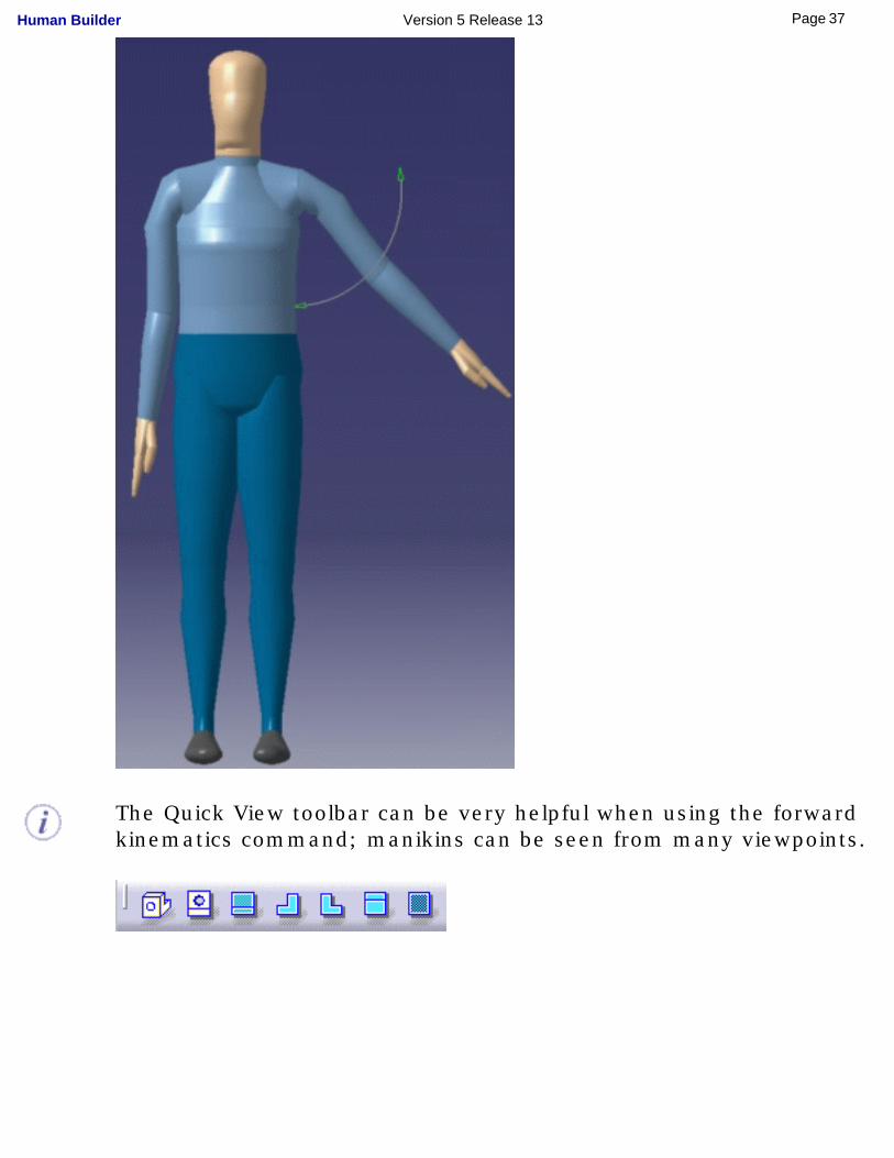
The Quick View toolbar can be very helpful when using the forward kinematics command; manikins can be seen from many viewpoints.
37Page Human Builder Version 5 Release 13
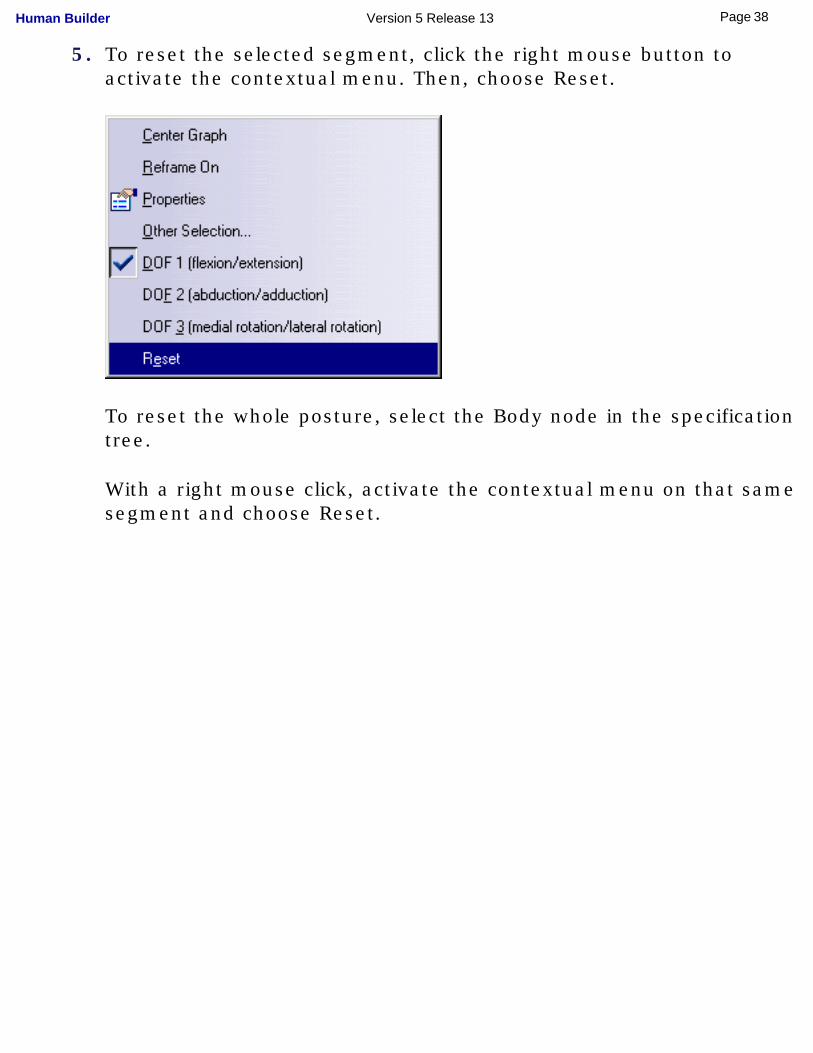
5. To reset the selected segment, click the right mouse button to activate the contextual menu. Then, choose Reset.
To reset the whole posture, select the Body node in the specification tree.
With a right mouse click, activate the contextual menu on that same segment and choose Reset.
38Page Human Builder Version 5 Release 13
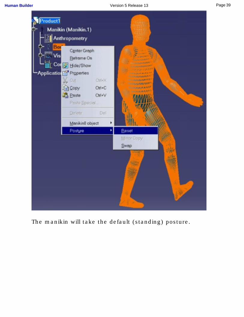
The manikin will take the default (standing) posture.
39Page Human Builder Version 5 Release 13
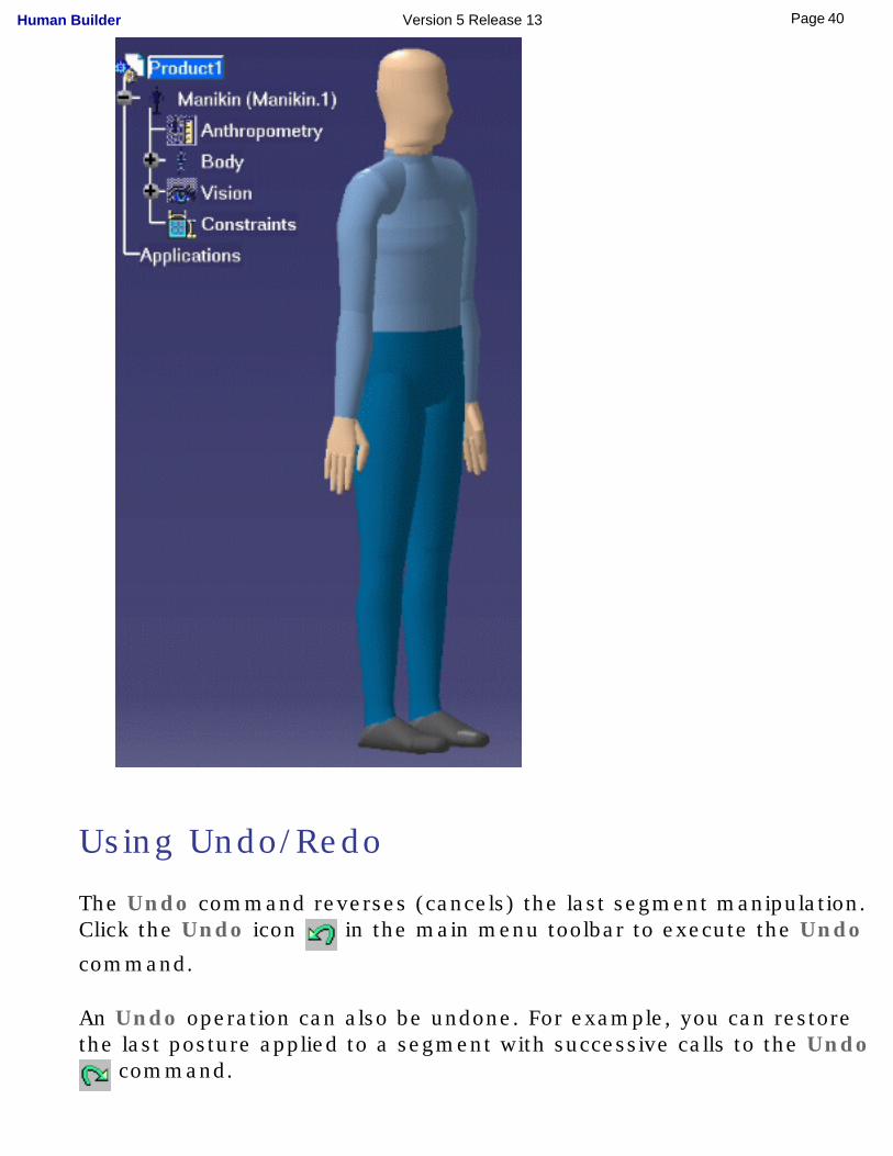
Using Undo/Redo
The Undo command reverses (cancels) the last segment manipulation. Click the Undo icon in the main menu toolbar to execute the Undo
command.
An Undo operation can also be undone. For example, you can restore the last posture applied to a segment with successive calls to the Undo
command.
40Page Human Builder Version 5 Release 13
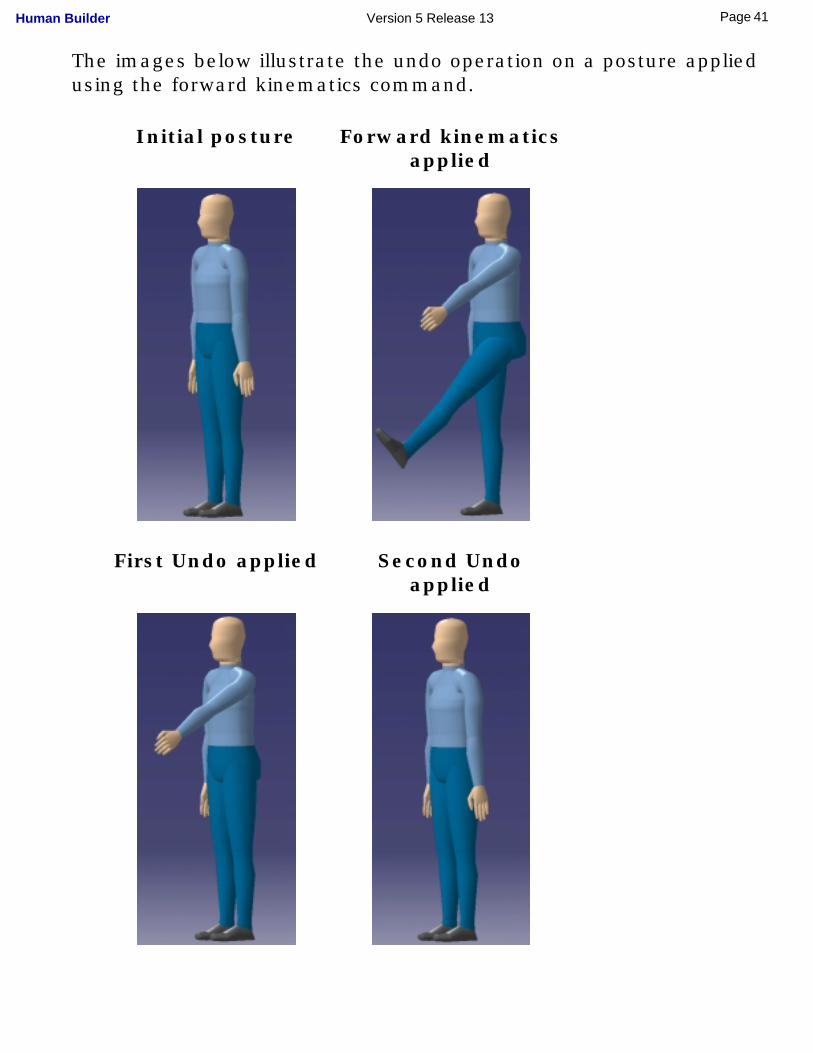
The images below illustrate the undo operation on a posture applied using the forward kinematics command.
Initial posture Forward kinematics applied
First Undo applied Second Undo applied
41Page Human Builder Version 5 Release 13
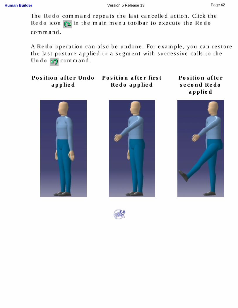
The Redo command repeats the last cancelled action. Click the Redo icon in the main menu toolbar to execute the Redo
command.
A Redo operation can also be undone. For example, you can restore the last posture applied to a segment with successive calls to the Undo command.
Position after Undo applied
Position after first Redo applied
Position after second Redo
applied
42Page Human Builder Version 5 Release 13
Assigning Descriptions (Memos)
This task describes how to create a memo that will be assigned to the manikin.
The Human Measurements Editor enables you to add descriptions of the manikin's anthropometry or of an anthropometric variable. This is a convenient way for you to keep a history on the variables and to determine where, when, and why they have been modified.
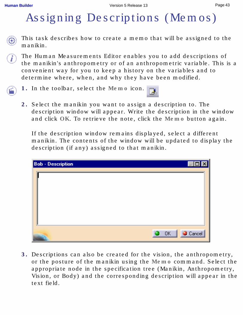
1. In the toolbar, select the Memo icon.
2. Select the manikin you want to assign a description to. The description window will appear. Write the description in the window and click OK. To retrieve the note, click the Memo button again.
If the description window remains displayed, select a different manikin. The contents of the window will be updated to display the description (if any) assigned to that manikin.
3. Descriptions can also be created for the vision, the anthropometry, or the posture of the manikin using the Memo command. Select the appropriate node in the specification tree (Manikin, Anthropometry, Vision, or Body) and the corresponding description will appear in the text field.
43Page Human Builder Version 5 Release 13

44Page Human Builder Version 5 Release 13
Using the Copy/Paste Function
This task describes the Copy/Paste function used with manikin parts.
In the specification tree, select a manikin. Click the right mouse button to activate the contextual menu. Select Copy.
Select a product or another manikin. From the contextual menu, select Paste.
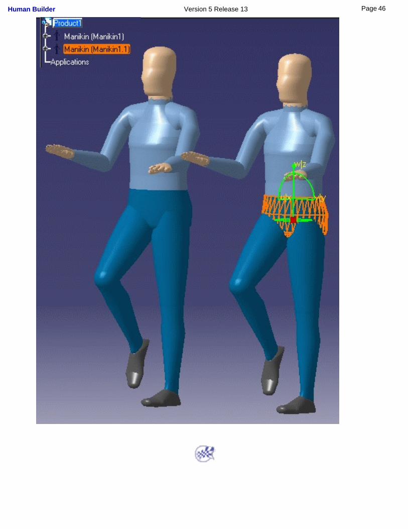
The parameters of the first manikin are copied onto the second manikin, or a new manikin is created and placed under the selected product, as shown in the image below.
45Page Human Builder Version 5 Release 13
46Page Human Builder Version 5 Release 13
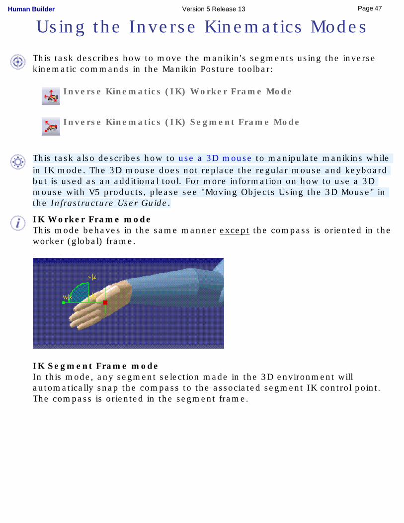
Using the Inverse Kinematics Modes
This task describes how to move the manikin's segments using the inverse kinematic commands in the Manikin Posture toolbar:
Inverse Kinematics (IK) Worker Frame Mode
Inverse Kinematics (IK) Segment Frame Mode
This task also describes how to use a 3D mouse to manipulate manikins while in IK mode. The 3D mouse does not replace the regular mouse and keyboard but is used as an additional tool. For more information on how to use a 3D mouse with V5 products, please see "Moving Objects Using the 3D Mouse" in the Infrastructure User Guide.
IK Worker Frame modeThis mode behaves in the same manner except the compass is oriented in the worker (global) frame.
IK Segment Frame modeIn this mode, any segment selection made in the 3D environment will automatically snap the compass to the associated segment IK control point. The compass is oriented in the segment frame.
47Page Human Builder Version 5 Release 13
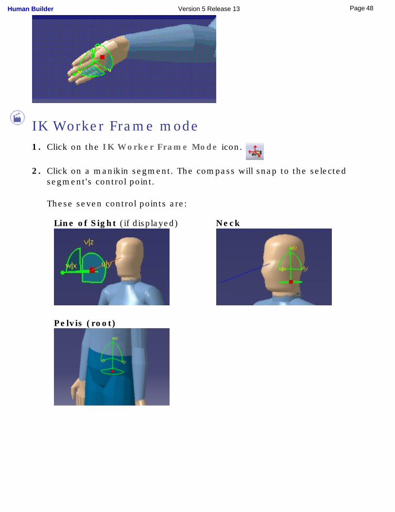
IK Worker Frame mode1. Click on the IK Worker Frame Mode icon.
2. Click on a manikin segment. The compass will snap to the selected segment's control point.
These seven control points are:
Line of Sight (if displayed)
Neck
Pelvis (root)
48Page Human Builder Version 5 Release 13
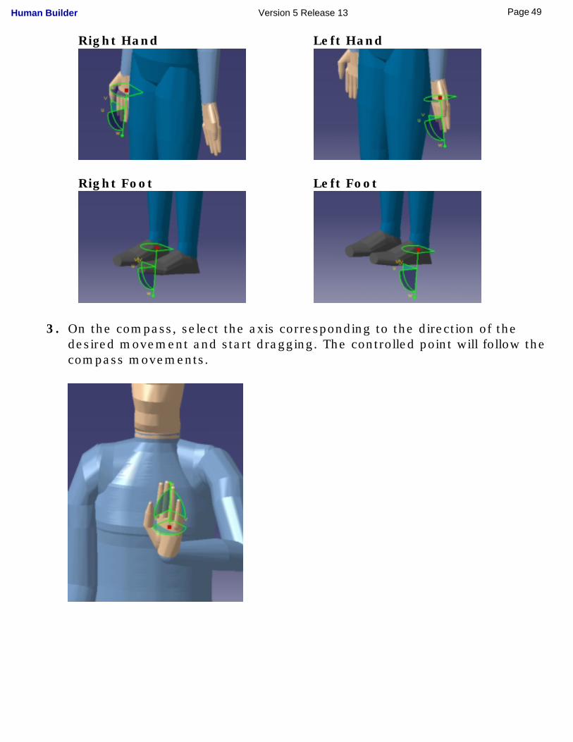
Right Hand Left Hand
Right Foot Left Foot
3. On the compass, select the axis corresponding to the direction of the desired movement and start dragging. The controlled point will follow the compass movements.
49Page Human Builder Version 5 Release 13
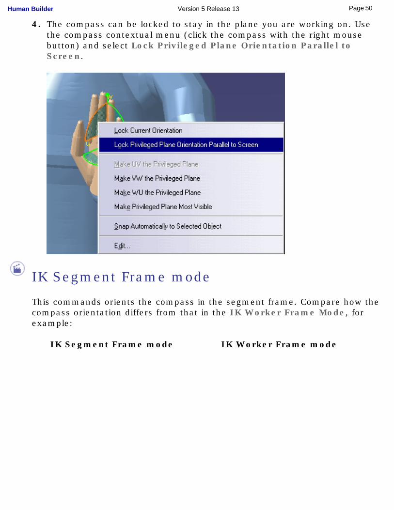
4. The compass can be locked to stay in the plane you are working on. Use the compass contextual menu (click the compass with the right mouse button) and select Lock Privileged Plane Orientation Parallel to Screen.
IK Segment Frame mode
This commands orients the compass in the segment frame. Compare how the compass orientation differs from that in the IK Worker Frame Mode, for example:
IK Segment Frame mode IK Worker Frame mode
50Page Human Builder Version 5 Release 13
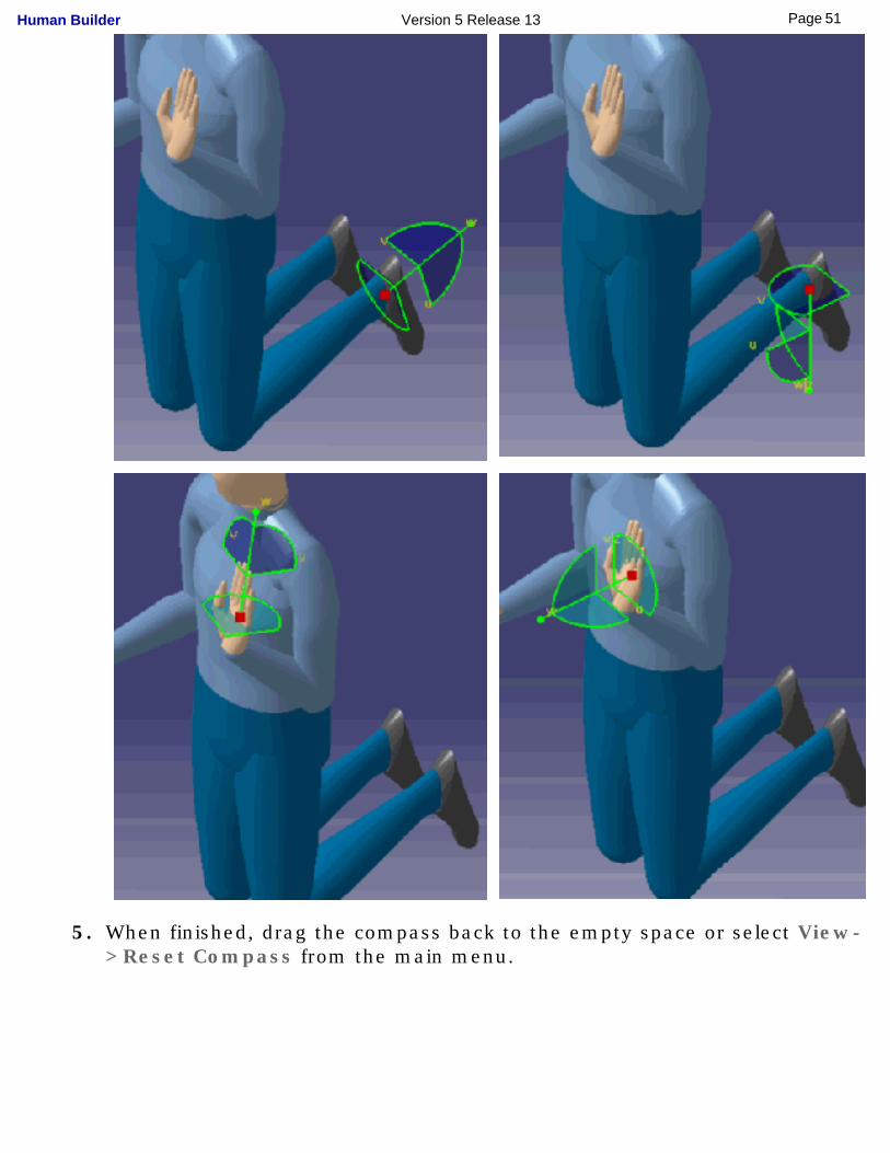
5. When finished, drag the compass back to the empty space or select View->Reset Compass from the main menu.
51Page Human Builder Version 5 Release 13
Using the 3D mouse for IK mode
The 3D mouse, supported by V5, is a new method for moving the manikin in IK mode.
IK Worker Frame mode
The manikin coordinate system is used as the reference when using the 3D mouse to manipulate the compass in this mode. The spatial representation appears as if the user is standing behind the manikin, placing his hand on the top of the manikin's hand, foot, etc. When you push the 3D mouse button forward, the selected segment (foot, hand, head, etc.) will move forward. Moving the mouse upward produces an elevation, etc.
All rotations are blocked in IK Worker Frame mode.
IK Segment Frame mode
In this mode, the 3D mouse is used to produce rotations of any segment. The spatial representation appears as if the user is standing behind the manikin, placing his hand in the same orientation as the manikin's hand, foot, head, etc.
52Page Human Builder Version 5 Release 13
Applying Standard Poses
This task describes how to easily apply standard poses to a manikin without using the compass.
This feature is particularly intended for positioning the spine as a whole in order to apply squatting, stooping, twisting, leaning, and adjusted elbow postures.
● Use the Restore Posture button in each tab of the Standard
Pose dialog box to return the manikin to the posture it had before entering the tab.
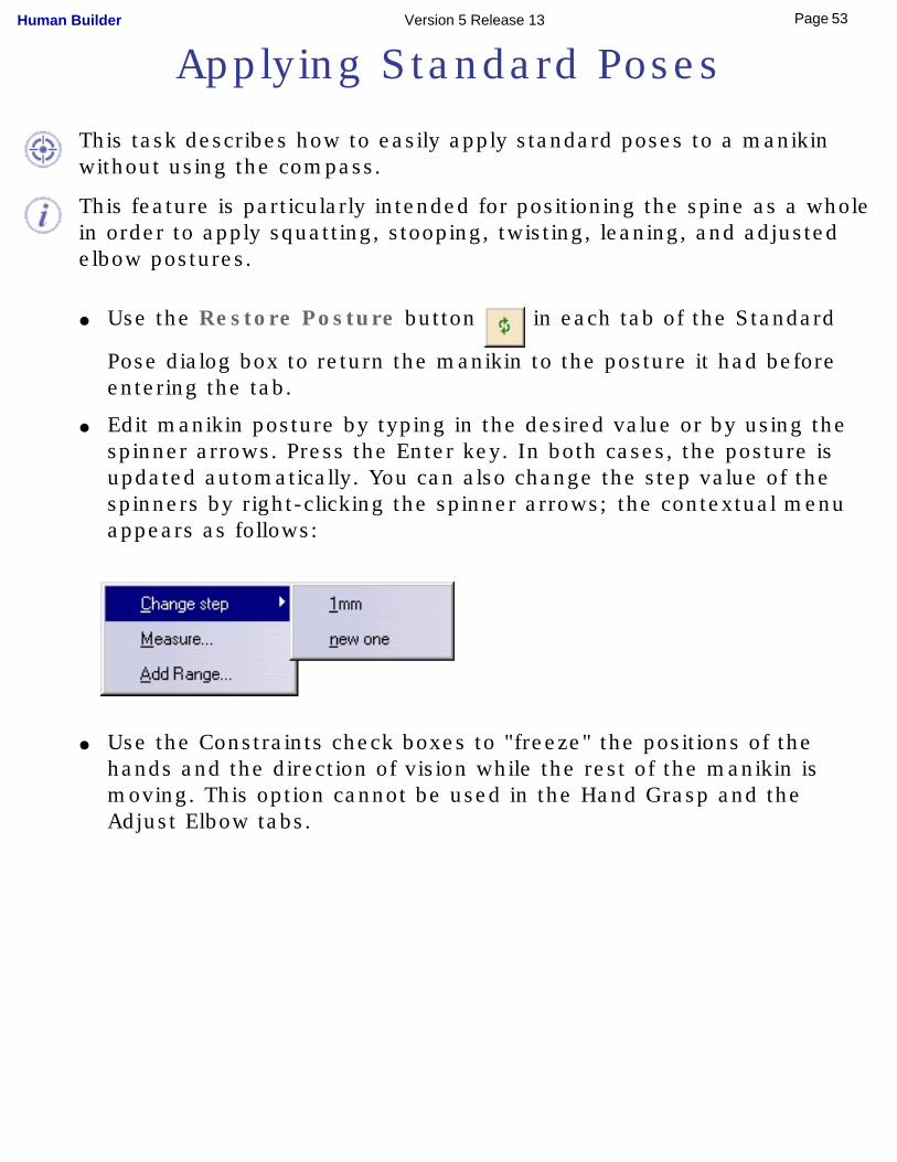
● Edit manikin posture by typing in the desired value or by using the spinner arrows. Press the Enter key. In both cases, the posture is updated automatically. You can also change the step value of the spinners by right-clicking the spinner arrows; the contextual menu appears as follows:
● Use the Constraints check boxes to "freeze" the positions of the hands and the direction of vision while the rest of the manikin is moving. This option cannot be used in the Hand Grasp and the Adjust Elbow tabs.
53Page Human Builder Version 5 Release 13
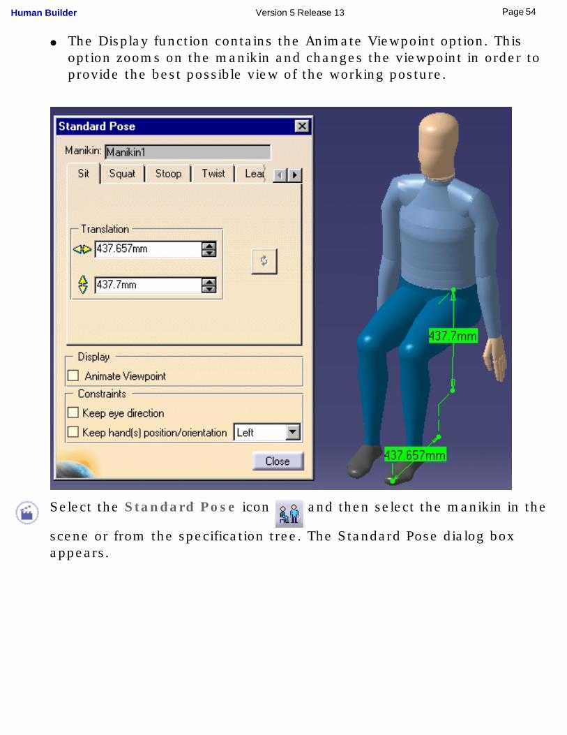
● The Display function contains the Animate Viewpoint option. This option zooms on the manikin and changes the viewpoint in order to provide the best possible view of the working posture.
Select the Standard Pose icon and then select the manikin in the
scene or from the specification tree. The Standard Pose dialog box appears.
54Page Human Builder Version 5 Release 13
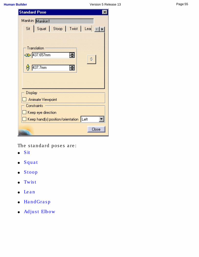
The standard poses are:● Sit
● Squat
● Stoop
● Twist
● Lean
● HandGrasp
● Adjust Elbow
55Page Human Builder Version 5 Release 13
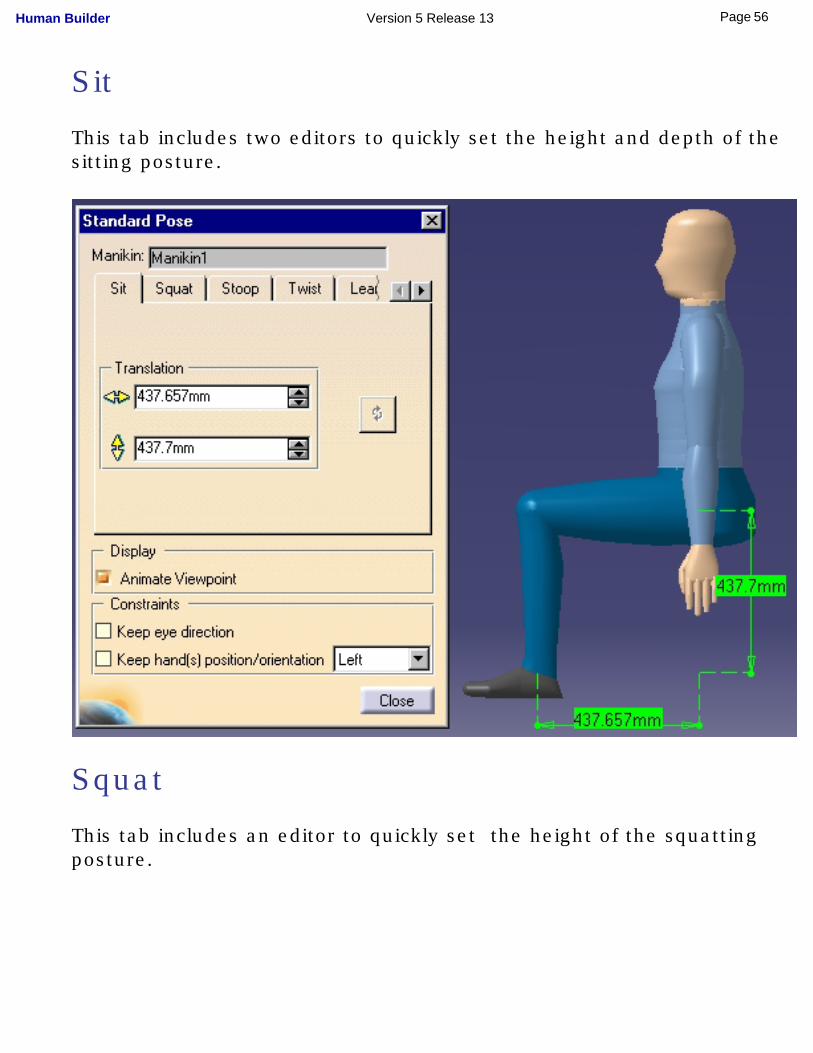
Sit
This tab includes two editors to quickly set the height and depth of the sitting posture.
Squat
This tab includes an editor to quickly set the height of the squatting posture.
56Page Human Builder Version 5 Release 13
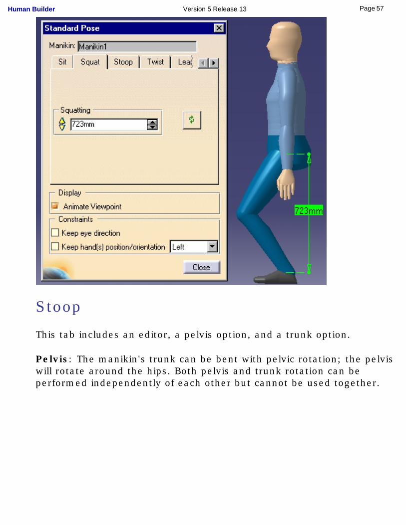
Stoop
This tab includes an editor, a pelvis option, and a trunk option.
Pelvis: The manikin's trunk can be bent with pelvic rotation; the pelvis will rotate around the hips. Both pelvis and trunk rotation can be performed independently of each other but cannot be used together.
57Page Human Builder Version 5 Release 13
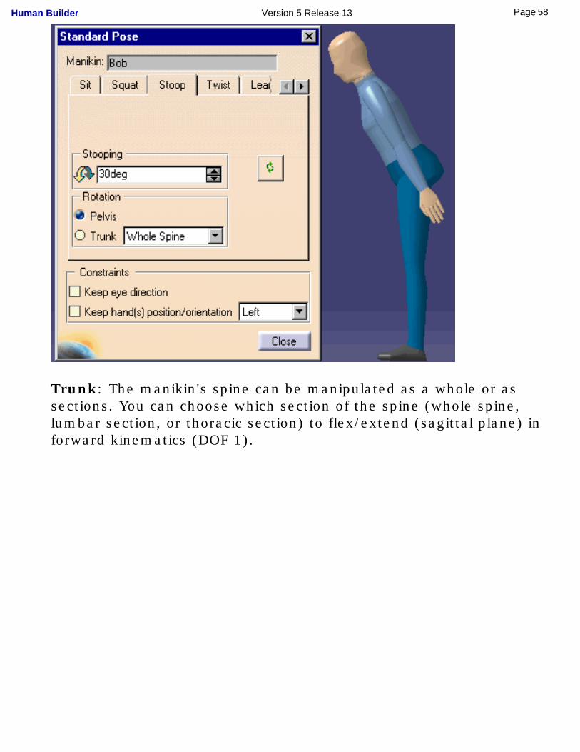
Trunk: The manikin's spine can be manipulated as a whole or as sections. You can choose which section of the spine (whole spine, lumbar section, or thoracic section) to flex/extend (sagittal plane) in forward kinematics (DOF 1).
58Page Human Builder Version 5 Release 13
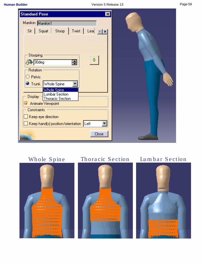
Whole Spine Thoracic Section Lumbar Section
59Page Human Builder Version 5 Release 13
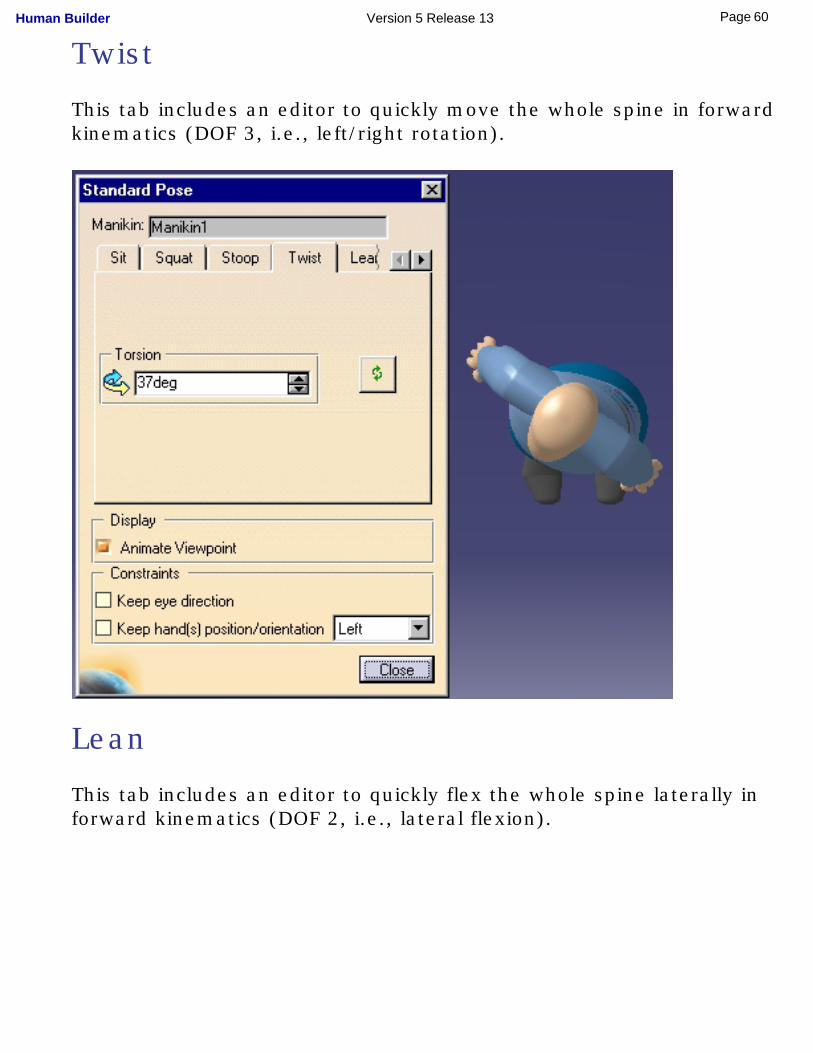
Twist
This tab includes an editor to quickly move the whole spine in forward kinematics (DOF 3, i.e., left/right rotation).
Lean
This tab includes an editor to quickly flex the whole spine laterally in forward kinematics (DOF 2, i.e., lateral flexion).
60Page Human Builder Version 5 Release 13
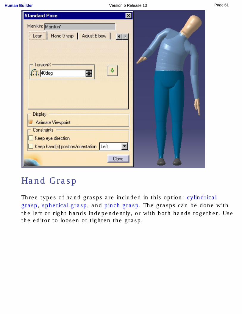
Hand Grasp
Three types of hand grasps are included in this option: cylindrical grasp, spherical grasp, and pinch grasp. The grasps can be done with the left or right hands independently, or with both hands together. Use the editor to loosen or tighten the grasp.
61Page Human Builder Version 5 Release 13
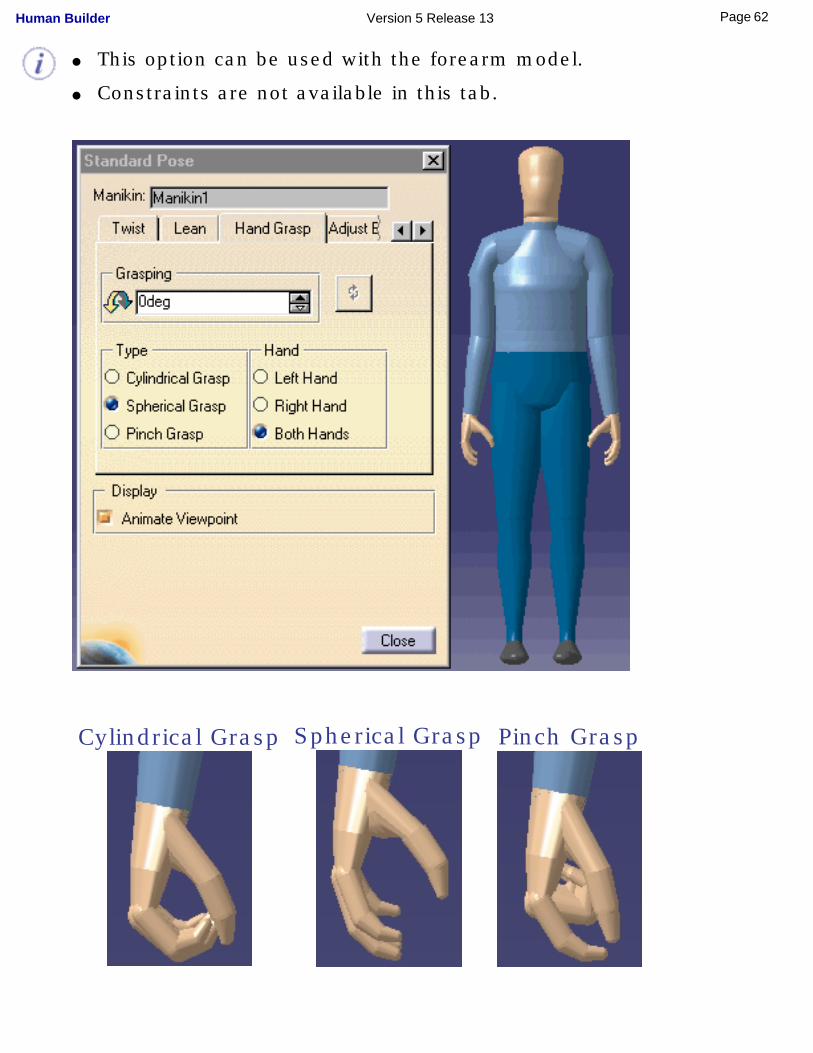
● This option can be used with the forearm model.
● Constraints are not available in this tab.
Cylindrical Grasp
Spherical Grasp
Pinch Grasp
62Page Human Builder Version 5 Release 13
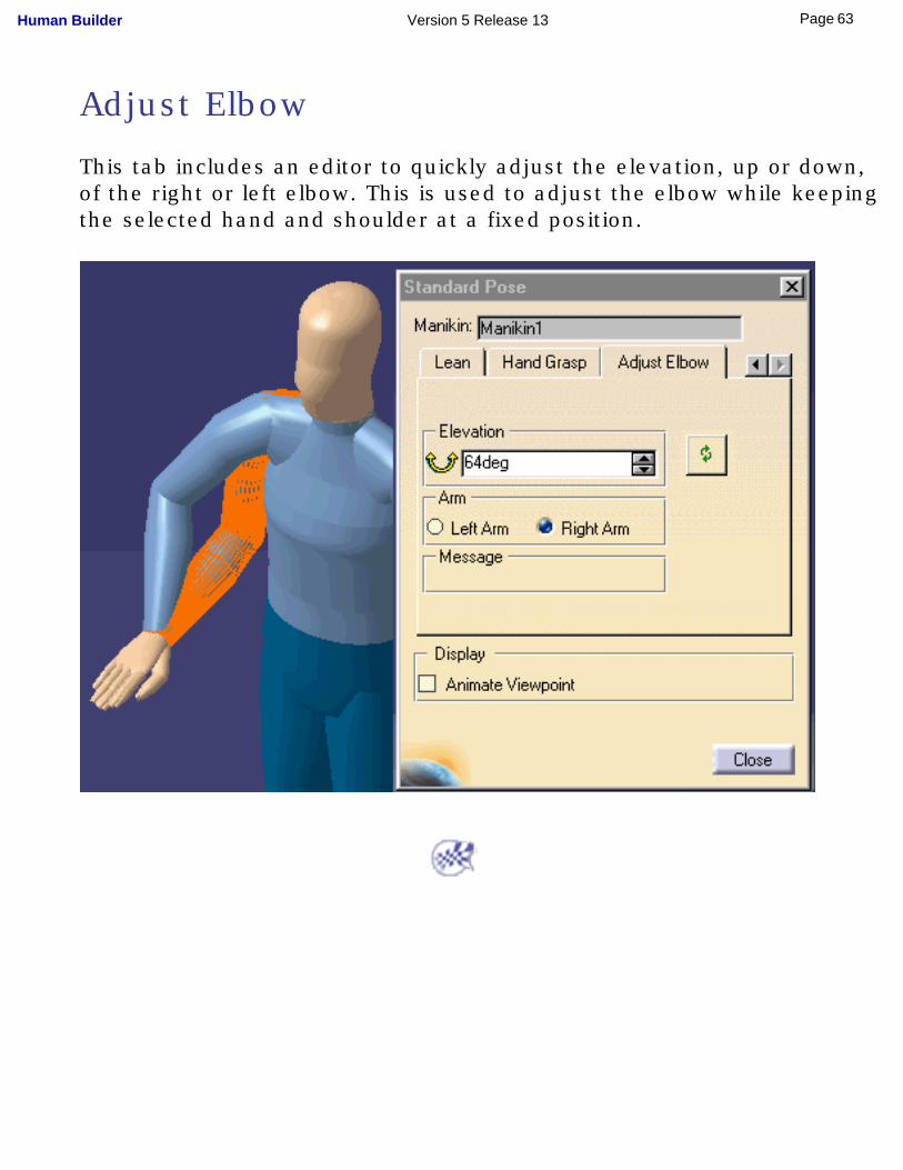
Adjust Elbow
This tab includes an editor to quickly adjust the elevation, up or down, of the right or left elbow. This is used to adjust the elbow while keeping the selected hand and shoulder at a fixed position.
63Page Human Builder Version 5 Release 13
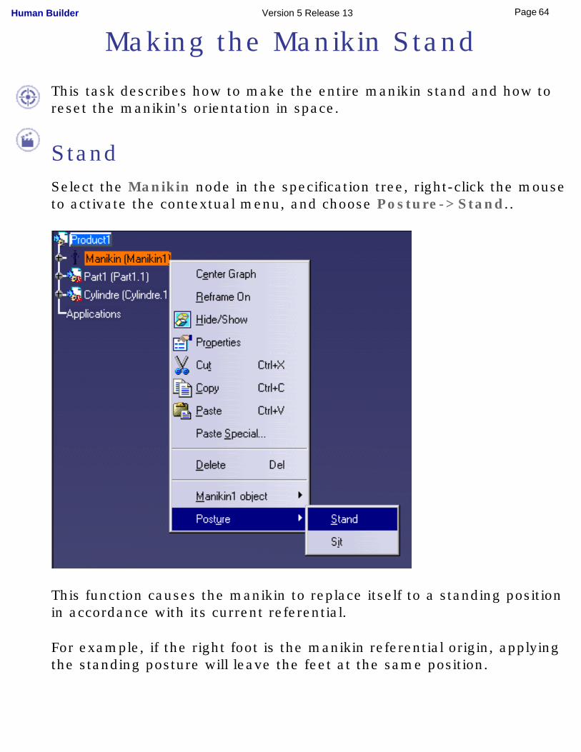
Making the Manikin Stand
This task describes how to make the entire manikin stand and how to reset the manikin's orientation in space.
StandSelect the Manikin node in the specification tree, right-click the mouse to activate the contextual menu, and choose Posture->Stand..
This function causes the manikin to replace itself to a standing position in accordance with its current referential.
For example, if the right foot is the manikin referential origin, applying the standing posture will leave the feet at the same position.
64Page Human Builder Version 5 Release 13
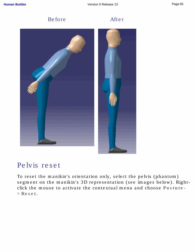
Before After
Pelvis resetTo reset the manikin's orientation only, select the pelvis (phantom) segment on the manikin's 3D representation (see images below). Right-click the mouse to activate the contextual menu and choose Posture->Reset.
65Page Human Builder Version 5 Release 13
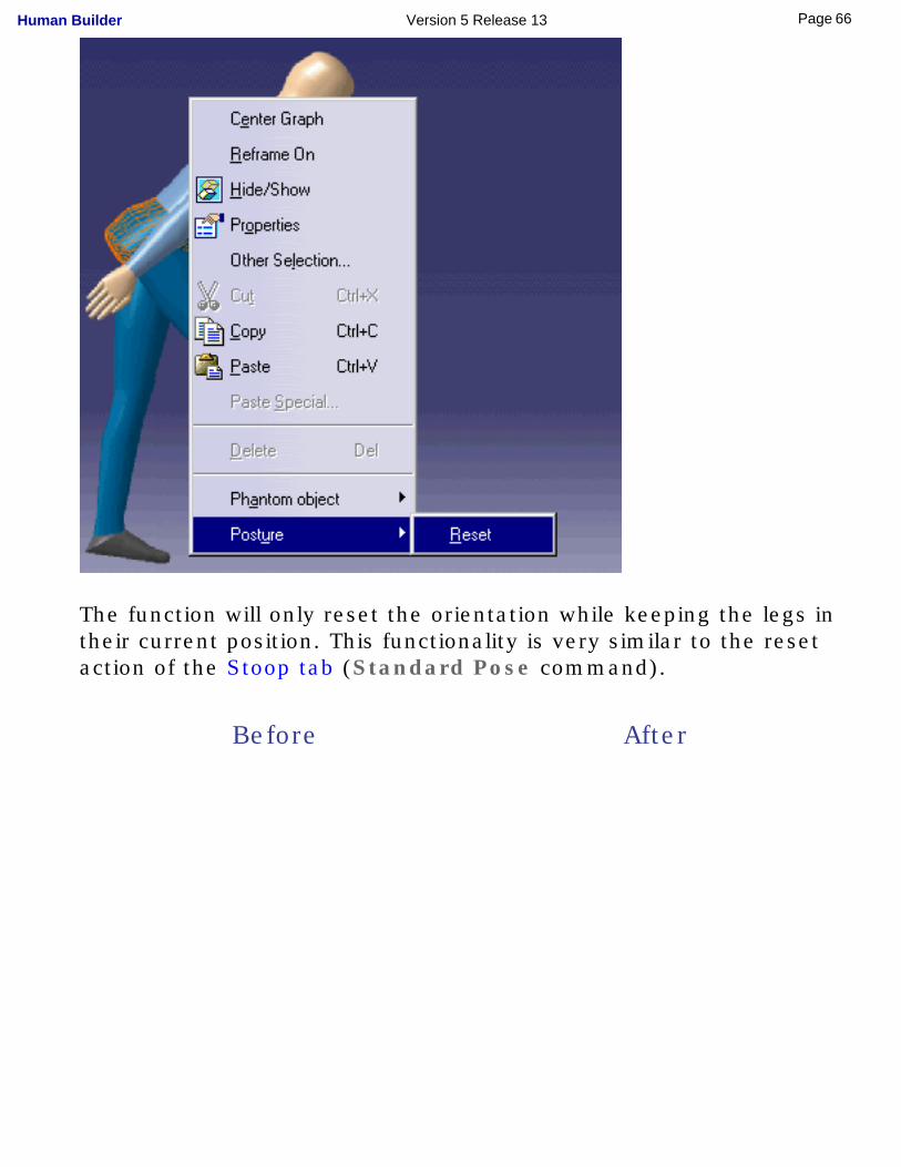
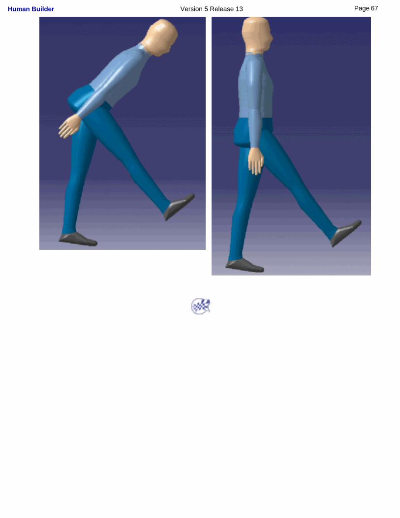
The function will only reset the orientation while keeping the legs in their current position. This functionality is very similar to the reset action of the Stoop tab (Standard Pose command).
Before After
66Page Human Builder Version 5 Release 13
67Page Human Builder Version 5 Release 13
Positioning the Manikin with the Compass
This task describes how to move the manikin around the scene.
1. In the specification tree, activate the manikin's father product by double-clicking on it.
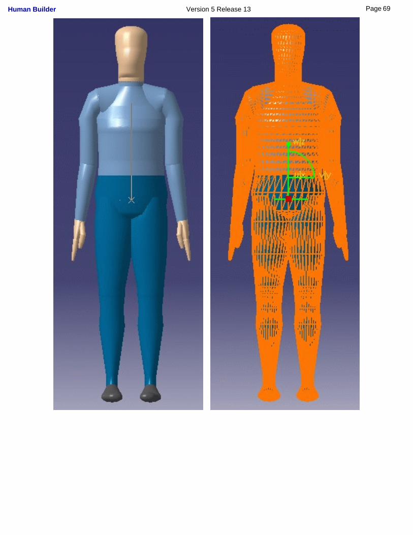
2. Select the compass and drag in on the manikin you wish to move.
Note that the snap is successful only if the compass turns green.
3. Select a plane on the compass and drag it or rotate it. The whole manikin will follow the move.
68Page Human Builder Version 5 Release 13
69Page Human Builder Version 5 Release 13
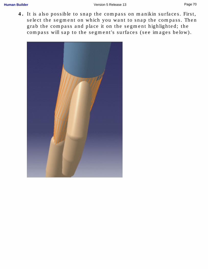
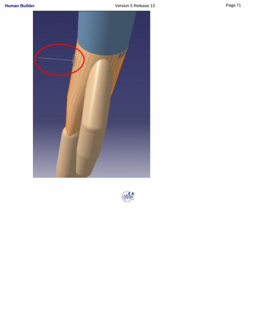
4. It is also possible to snap the compass on manikin surfaces. First, select the segment on which you want to snap the compass. Then grab the compass and place it on the segment highlighted; the compass will sap to the segment's surfaces (see images below).
70Page Human Builder Version 5 Release 13
71Page Human Builder Version 5 Release 13
Using the Posture Editor
This task describes the functions of the Posture Editor and how to use them to move manikin segments.
The Posture Editor is a tool used to move manikin segments in forward kinematics. The segments or degrees of freedom (DOF) are moved one step at a time. This tool allows you to give a precise value to each degree of freedom of every joint.
The manikin's structure consists of 68 articulated joints with 6 coupled joints (range of motion can depend on the position of a neighbor joint).
Select the Posture Editor icon. The Posture Editor dialog box is
displayed on the screen when the manikin is selected.
72Page Human Builder Version 5 Release 13
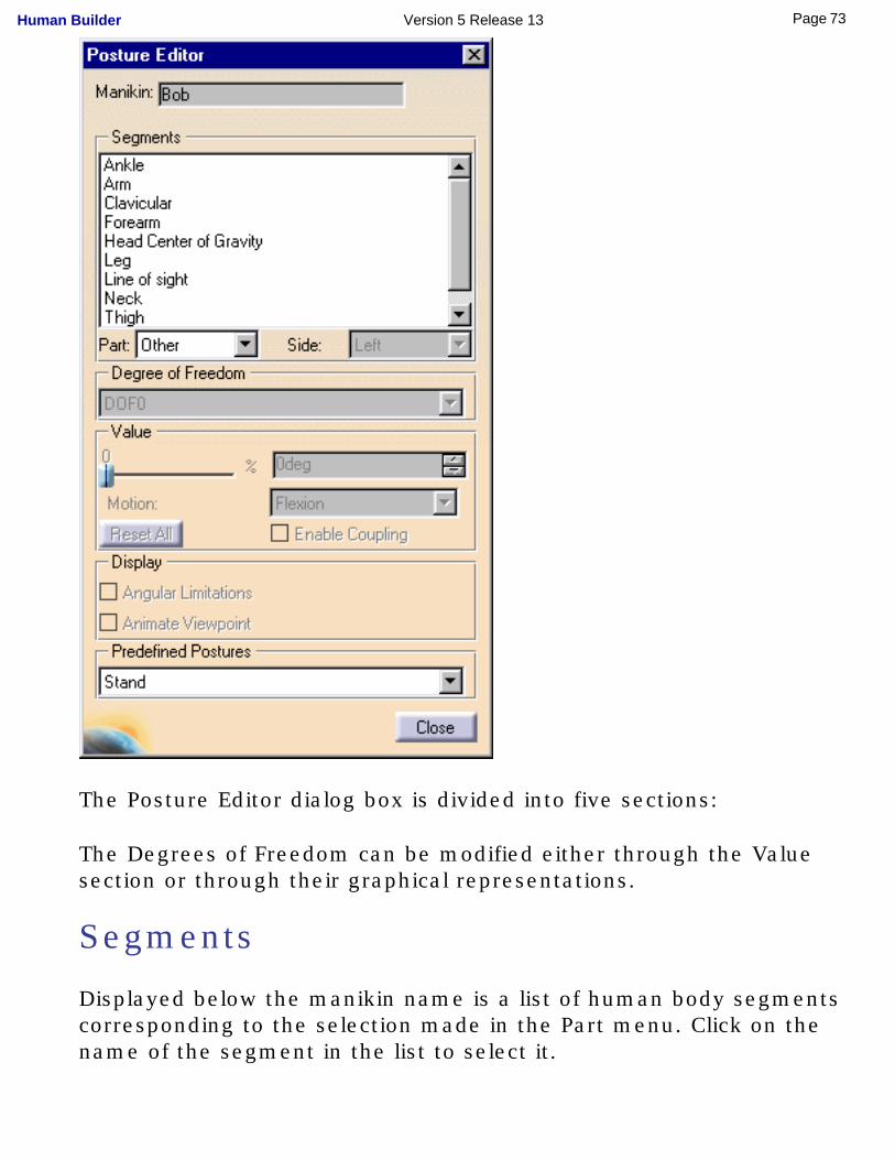
The Posture Editor dialog box is divided into five sections:
The Degrees of Freedom can be modified either through the Value section or through their graphical representations.
Segments
Displayed below the manikin name is a list of human body segments corresponding to the selection made in the Part menu. Click on the name of the segment in the list to select it.
73Page Human Builder Version 5 Release 13
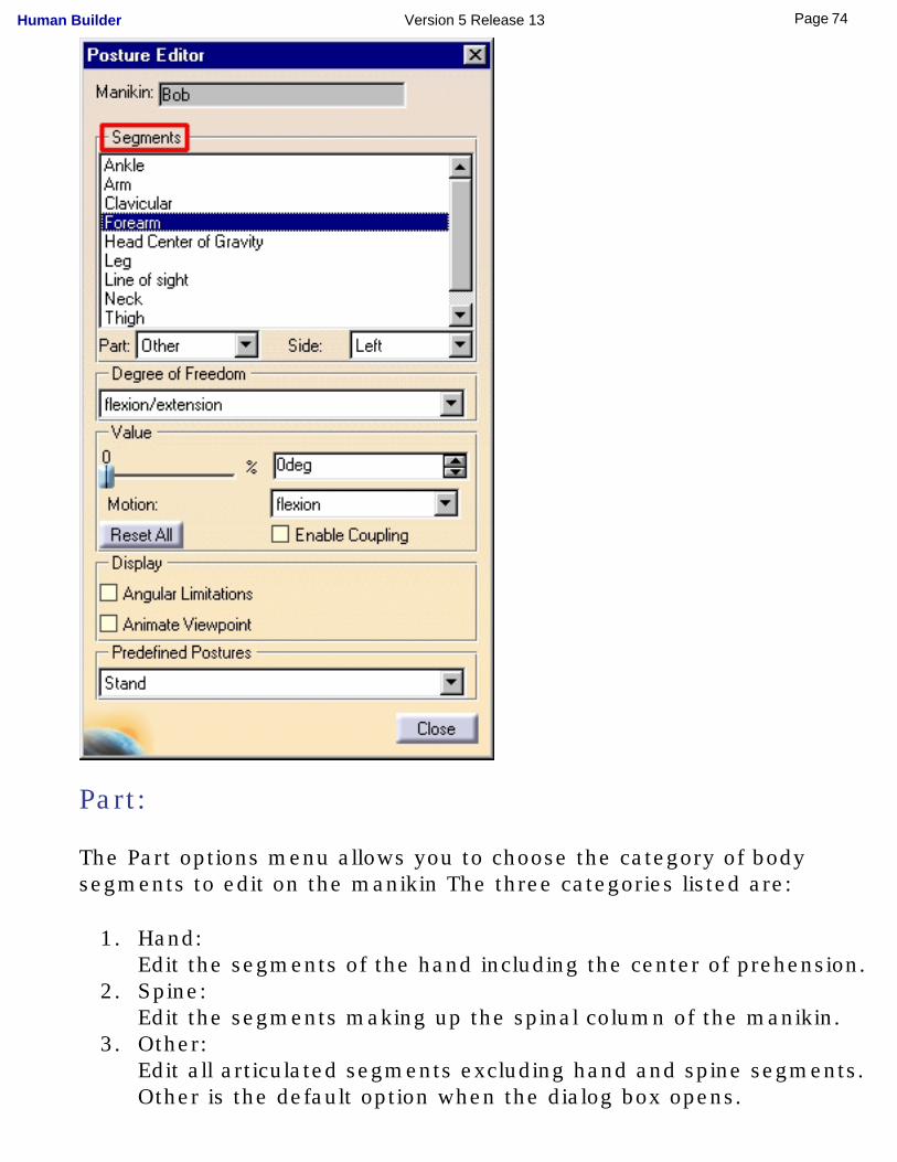
Part:
The Part options menu allows you to choose the category of body segments to edit on the manikin The three categories listed are:
1. Hand:Edit the segments of the hand including the center of prehension.
2. Spine:Edit the segments making up the spinal column of the manikin.
3. Other:Edit all articulated segments excluding hand and spine segments. Other is the default option when the dialog box opens.
74Page Human Builder Version 5 Release 13
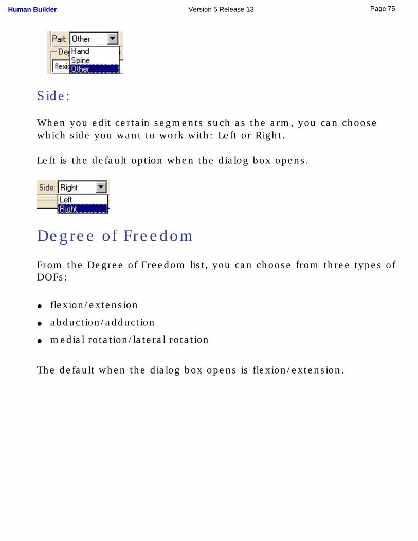
Side:
When you edit certain segments such as the arm, you can choose which side you want to work with: Left or Right.
Left is the default option when the dialog box opens.
Degree of Freedom
From the Degree of Freedom list, you can choose from three types of DOFs:
● flexion/extension
● abduction/adduction
● medial rotation/lateral rotation
The default when the dialog box opens is flexion/extension.
75Page Human Builder Version 5 Release 13

A segment can have up to three DOFs. Examples of possible segment DOFs are:
● The forearm has two DOFs: ❍ flexion/extension
❍ pronation/supination
● The arm has three DOFs ❍ flexion/extension
❍ abduction/adduction
❍ medial rotation/lateral rotation
76Page Human Builder Version 5 Release 13
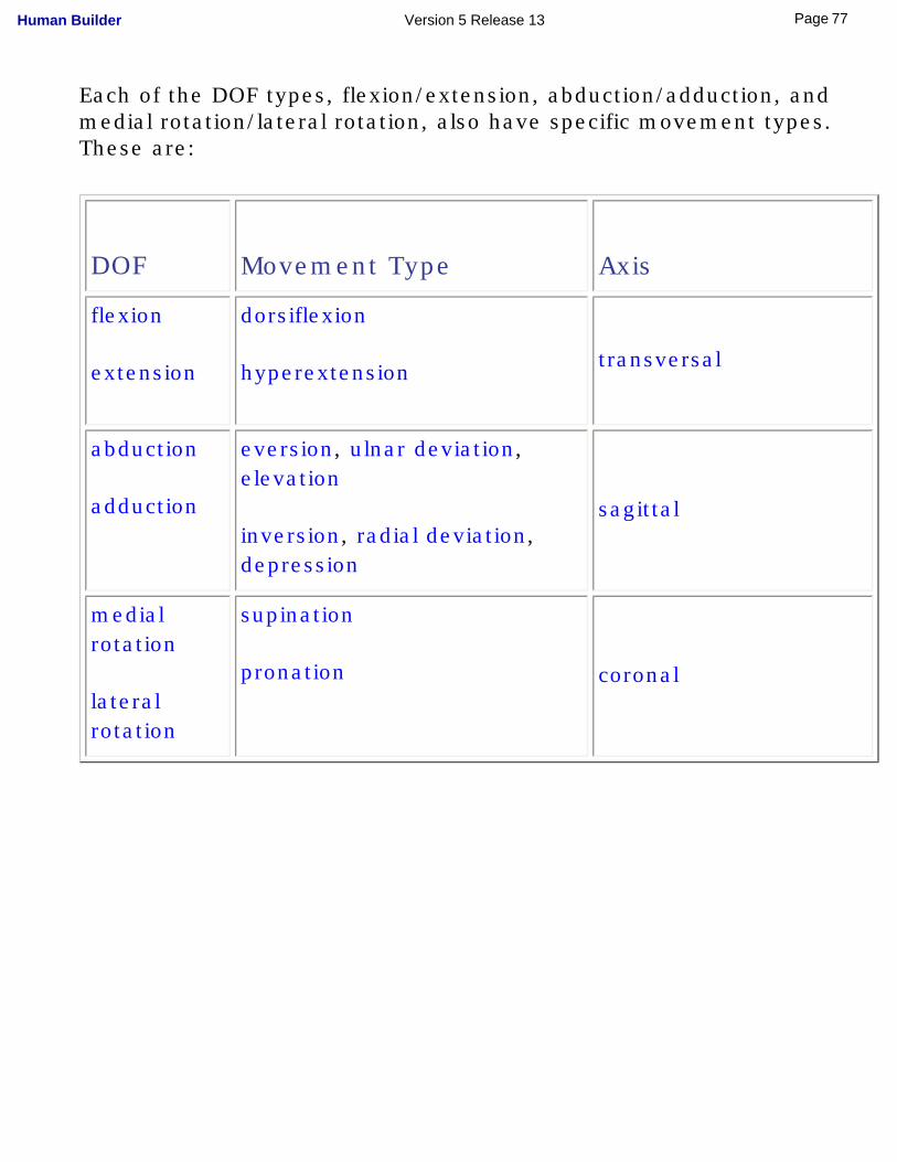
Each of the DOF types, flexion/extension, abduction/adduction, and medial rotation/lateral rotation, also have specific movement types. These are:
DOF Movement Type Axis
flexion
extension
dorsiflexion
hyperextension
transversal
abduction
adduction
eversion, ulnar deviation, elevation
inversion, radial deviation, depression
sagittal
medial rotation
lateral rotation
supination
pronation coronal
77Page Human Builder Version 5 Release 13
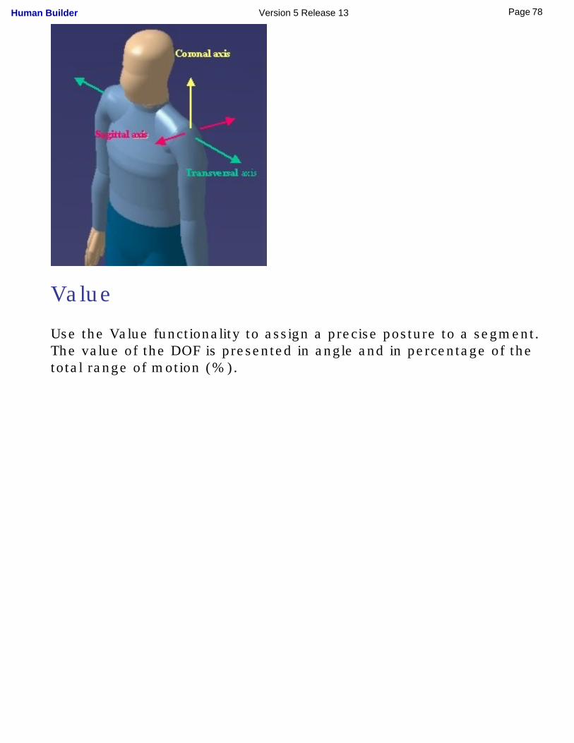
Value
Use the Value functionality to assign a precise posture to a segment. The value of the DOF is presented in angle and in percentage of the total range of motion (%).
78Page Human Builder Version 5 Release 13
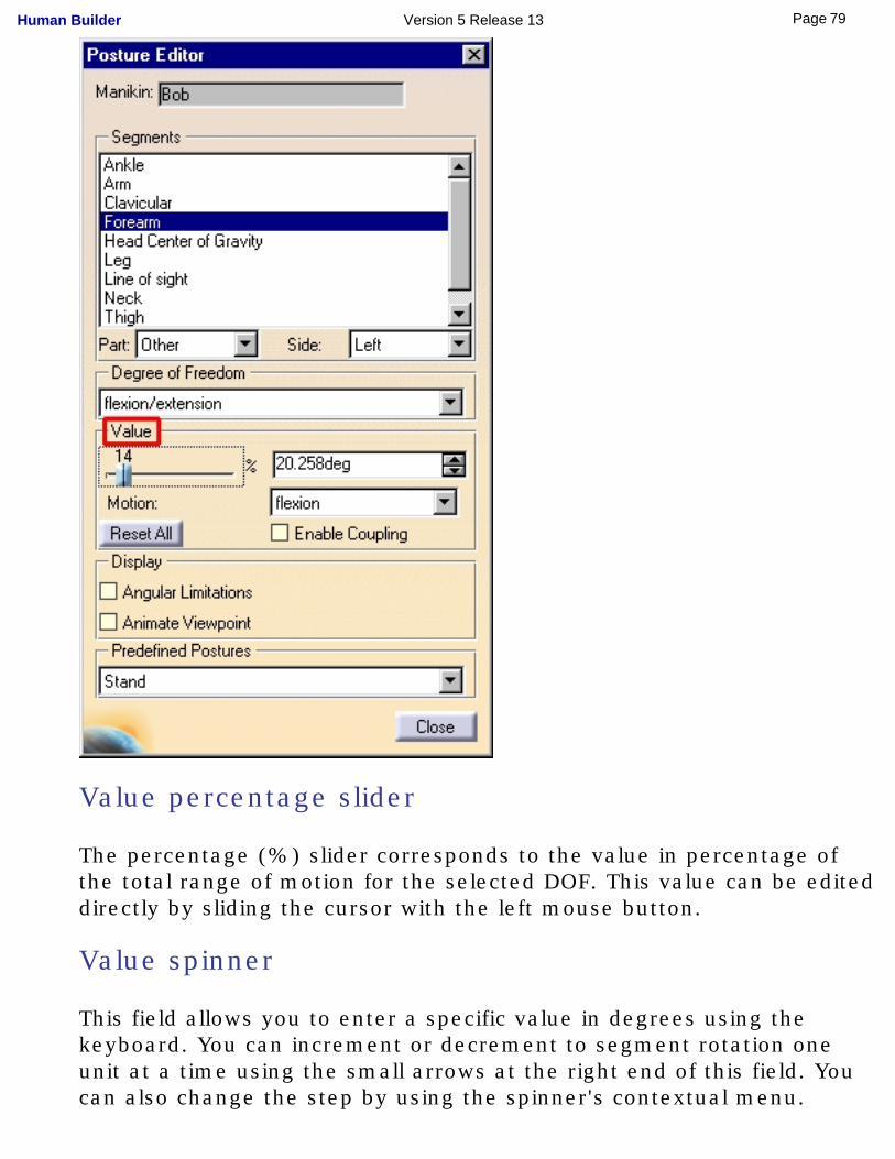
Value percentage slider
The percentage (%) slider corresponds to the value in percentage of the total range of motion for the selected DOF. This value can be edited directly by sliding the cursor with the left mouse button.
Value spinner
This field allows you to enter a specific value in degrees using the keyboard. You can increment or decrement to segment rotation one unit at a time using the small arrows at the right end of this field. You can also change the step by using the spinner's contextual menu.
79Page Human Builder Version 5 Release 13
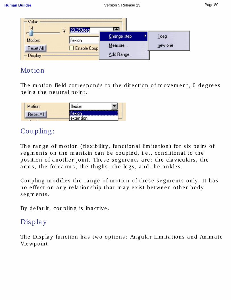
Motion
The motion field corresponds to the direction of movement, 0 degrees being the neutral point.
Coupling:
The range of motion (flexibility, functional limitation) for six pairs of segments on the manikin can be coupled, i.e., conditional to the position of another joint. These segments are: the claviculars, the arms, the forearms, the thighs, the legs, and the ankles.
Coupling modifies the range of motion of these segments only. It has no effect on any relationship that may exist between other body segments.
By default, coupling is inactive.
Display
The Display function has two options: Angular Limitations and Animate Viewpoint.
80Page Human Builder Version 5 Release 13
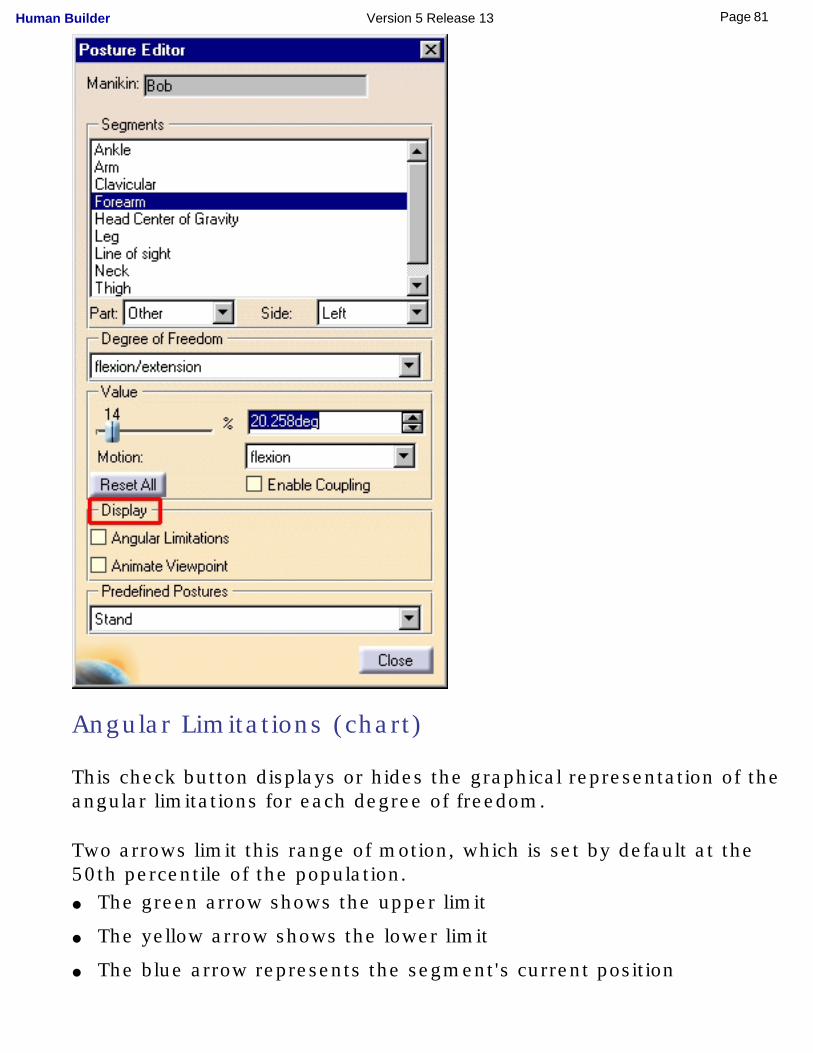
Angular Limitations (chart)
This check button displays or hides the graphical representation of the angular limitations for each degree of freedom.
Two arrows limit this range of motion, which is set by default at the 50th percentile of the population.● The green arrow shows the upper limit
● The yellow arrow shows the lower limit
● The blue arrow represents the segment's current position
81Page Human Builder Version 5 Release 13
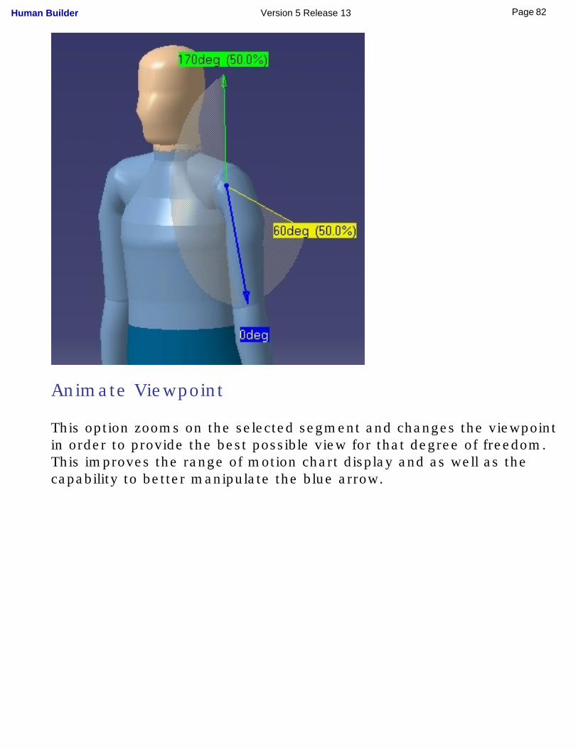
Animate Viewpoint
This option zooms on the selected segment and changes the viewpoint in order to provide the best possible view for that degree of freedom. This improves the range of motion chart display and as well as the capability to better manipulate the blue arrow.
82Page Human Builder Version 5 Release 13
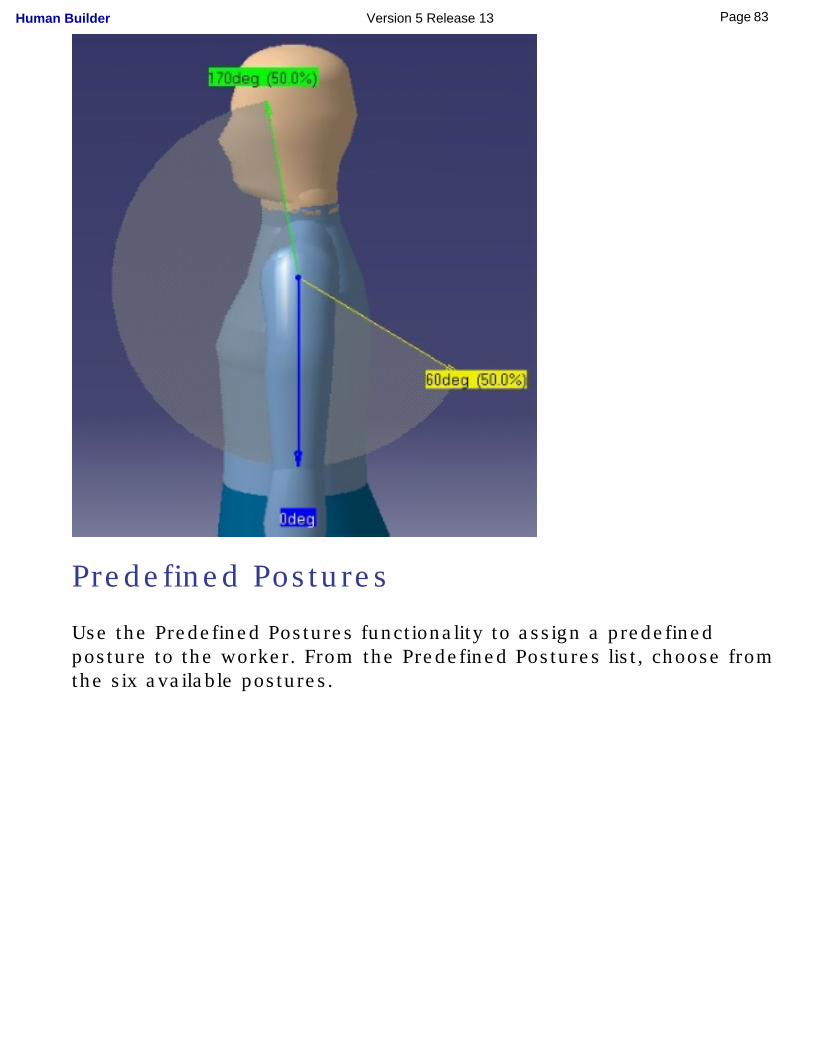
Predefined Postures
Use the Predefined Postures functionality to assign a predefined posture to the worker. From the Predefined Postures list, choose from the six available postures.
83Page Human Builder Version 5 Release 13
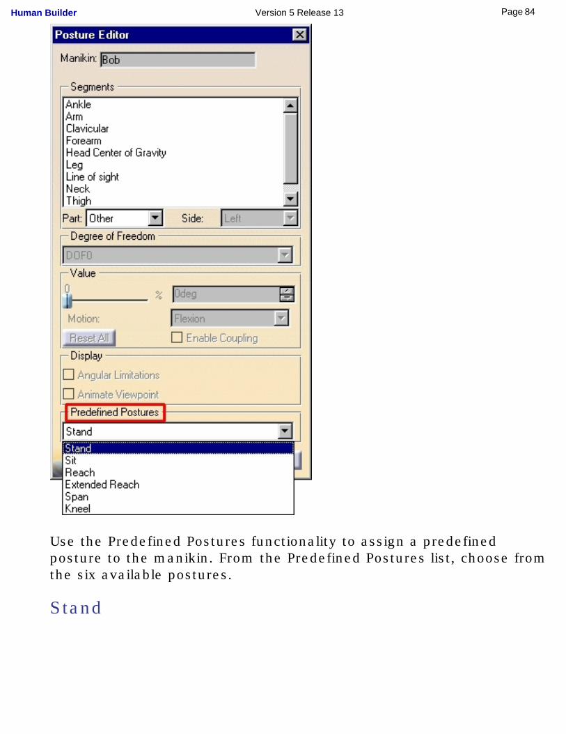
Use the Predefined Postures functionality to assign a predefined posture to the manikin. From the Predefined Postures list, choose from the six available postures.
Stand
84Page Human Builder Version 5 Release 13
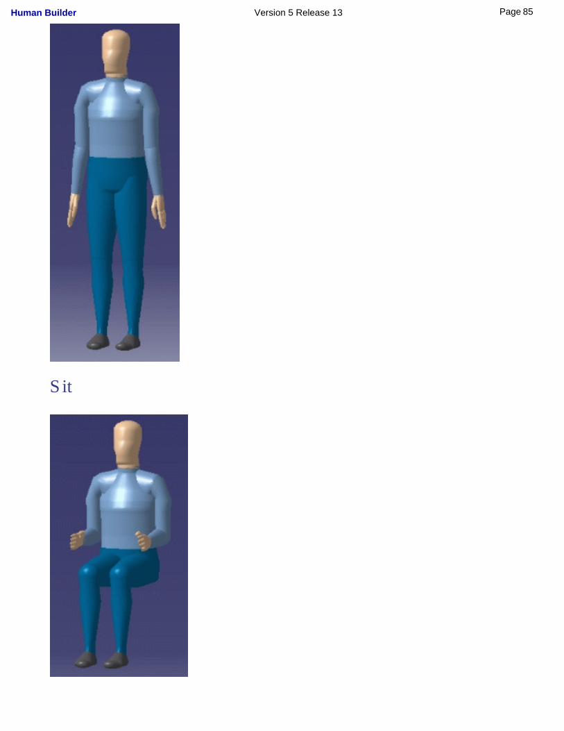
Sit
85Page Human Builder Version 5 Release 13
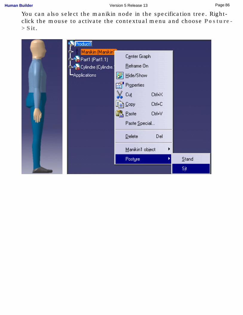
You can also select the manikin node in the specification tree. Right-click the mouse to activate the contextual menu and choose Posture->Sit.
86Page Human Builder Version 5 Release 13
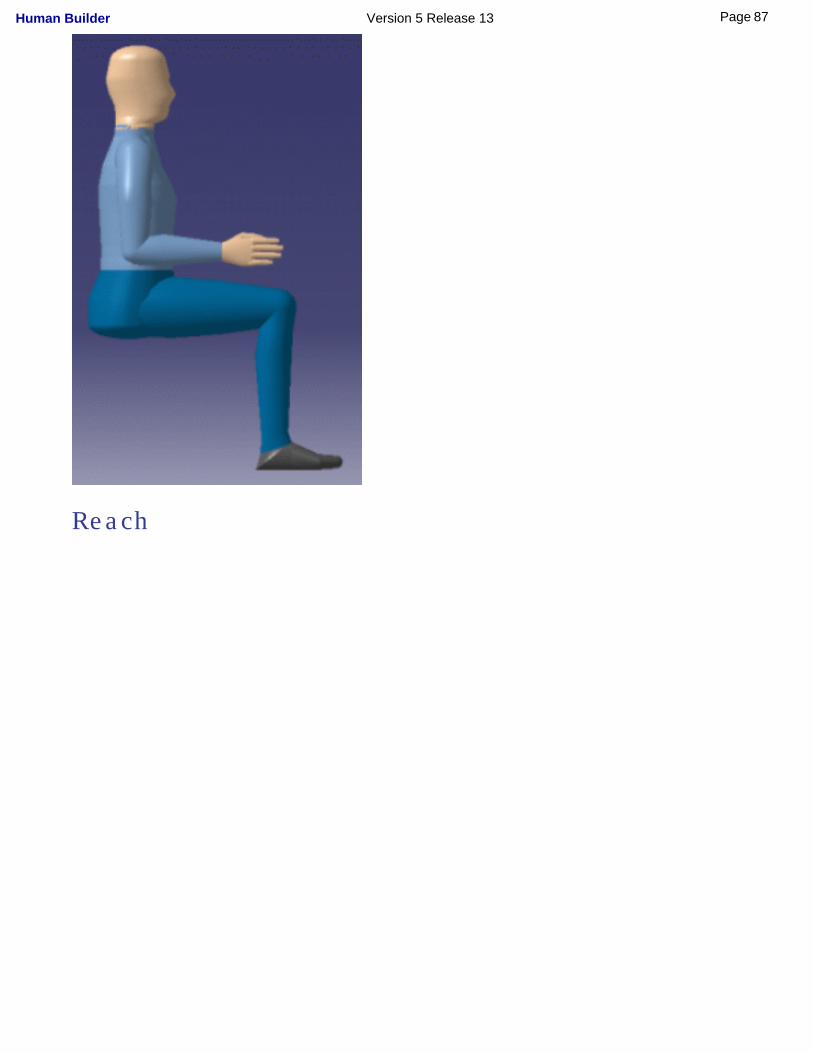
Reach
87Page Human Builder Version 5 Release 13
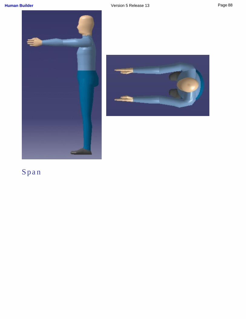
Span
88Page Human Builder Version 5 Release 13
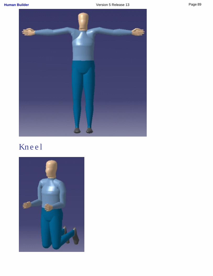
Kneel
89Page Human Builder Version 5 Release 13

90Page Human Builder Version 5 Release 13

Using the Reset, Mirror Copy, and Swap Functions
These tasks describe posture functionality:
Global Posture ResetGlobal Posture SwapLocal Posture Reset
Local Posture Mirror CopyLocal Posture SwapVision Posture Reset
91Page Human Builder Version 5 Release 13
Global Posture Reset
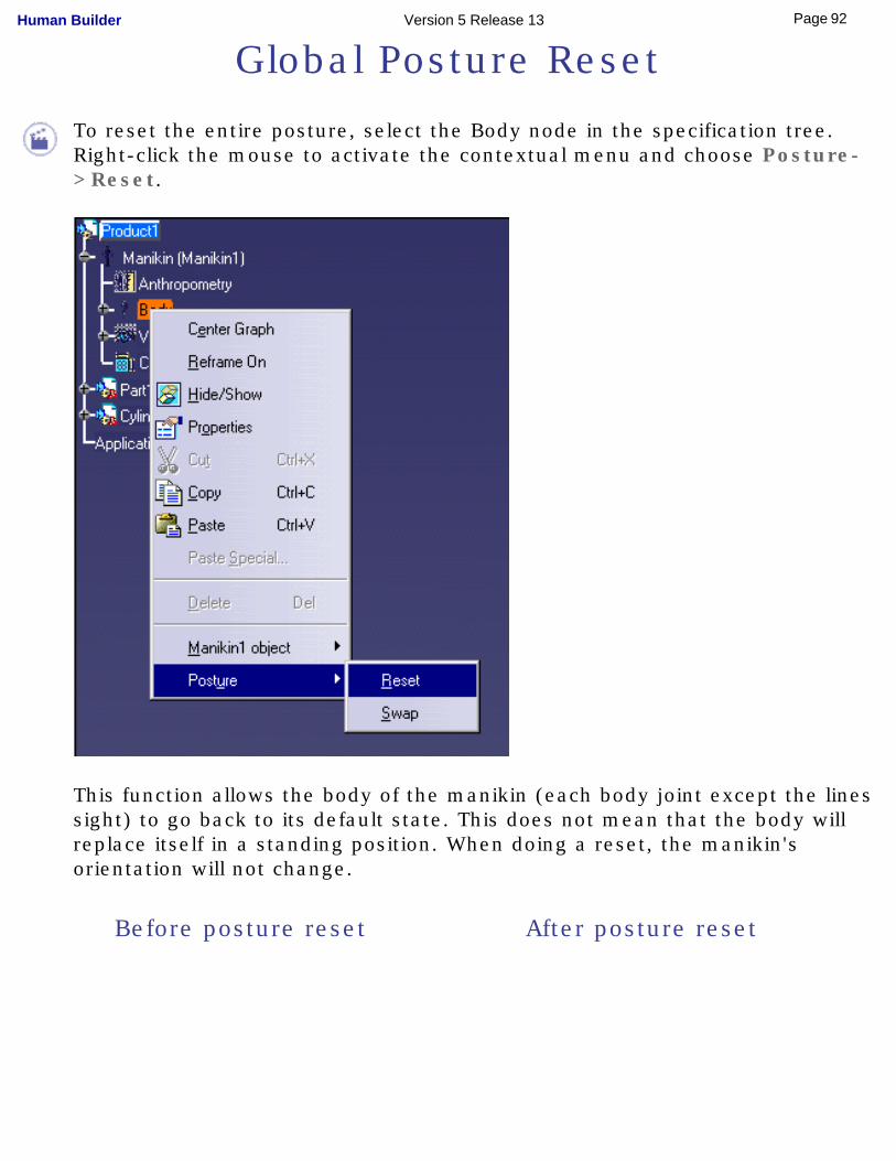
To reset the entire posture, select the Body node in the specification tree. Right-click the mouse to activate the contextual menu and choose Posture->Reset.
This function allows the body of the manikin (each body joint except the lines sight) to go back to its default state. This does not mean that the body will replace itself in a standing position. When doing a reset, the manikin's orientation will not change.
Before posture reset After posture reset
92Page Human Builder Version 5 Release 13
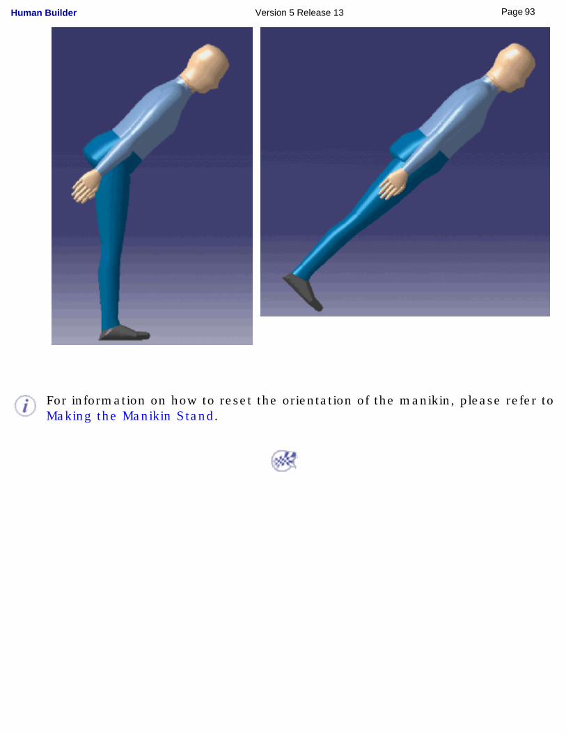
For information on how to reset the orientation of the manikin, please refer to Making the Manikin Stand.
93Page Human Builder Version 5 Release 13
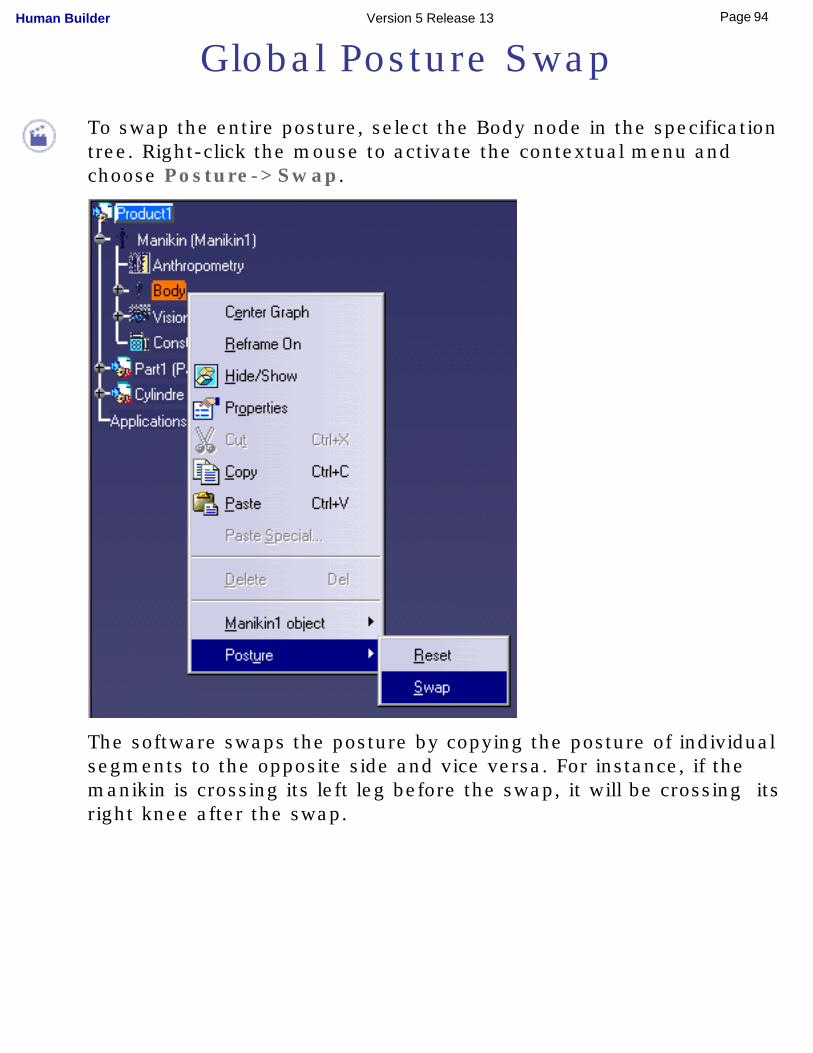
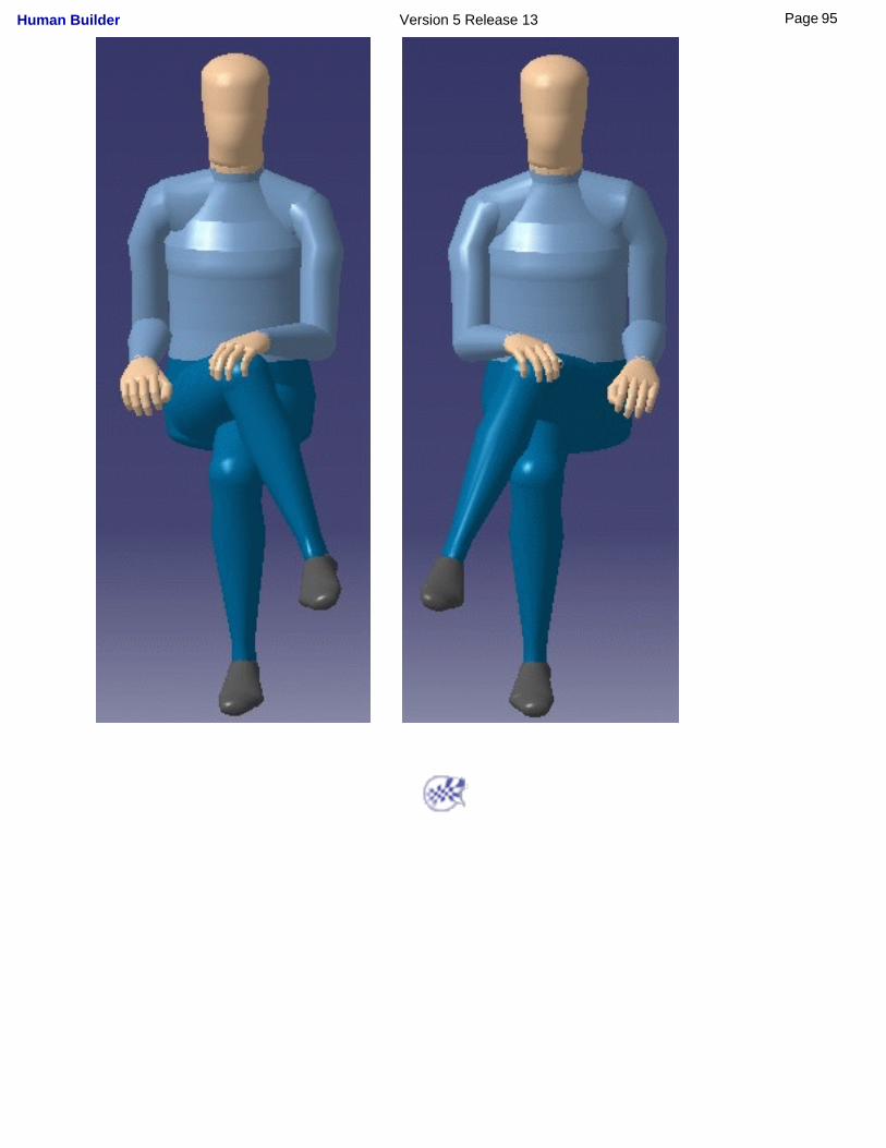
Global Posture Swap
To swap the entire posture, select the Body node in the specification tree. Right-click the mouse to activate the contextual menu and choose Posture->Swap.
The software swaps the posture by copying the posture of individual segments to the opposite side and vice versa. For instance, if the manikin is crossing its left leg before the swap, it will be crossing its right knee after the swap.
94Page Human Builder Version 5 Release 13
95Page Human Builder Version 5 Release 13
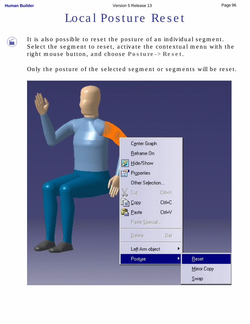
Local Posture Reset
It is also possible to reset the posture of an individual segment. Select the segment to reset, activate the contextual menu with the right mouse button, and choose Posture->Reset.
Only the posture of the selected segment or segments will be reset.
96Page Human Builder Version 5 Release 13

97Page Human Builder Version 5 Release 13
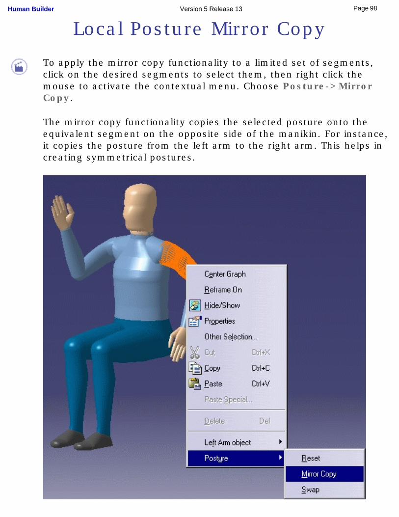
Local Posture Mirror Copy
To apply the mirror copy functionality to a limited set of segments, click on the desired segments to select them, then right click the mouse to activate the contextual menu. Choose Posture->Mirror Copy.
The mirror copy functionality copies the selected posture onto the equivalent segment on the opposite side of the manikin. For instance, it copies the posture from the left arm to the right arm. This helps in creating symmetrical postures.
98Page Human Builder Version 5 Release 13

Please note that the mirror copy functionality can only be applied to segments that have an equivalent segment on the other side of the manikin. Therefore, no mirror copy is possible on the neck segment since there is no right or left neck.
99Page Human Builder Version 5 Release 13
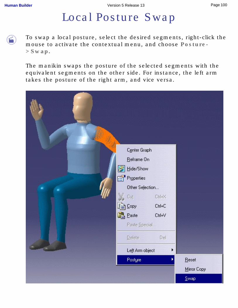
Local Posture Swap
To swap a local posture, select the desired segments, right-click the mouse to activate the contextual menu, and choose Posture->Swap.
The manikin swaps the posture of the selected segments with the equivalent segments on the other side. For instance, the left arm takes the posture of the right arm, and vice versa.
100Page Human Builder Version 5 Release 13

101Page Human Builder Version 5 Release 13
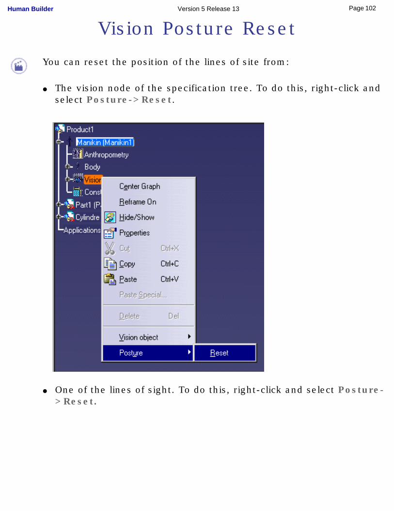
Vision Posture Reset
You can reset the position of the lines of site from:
● The vision node of the specification tree. To do this, right-click and select Posture->Reset.
● One of the lines of sight. To do this, right-click and select Posture->Reset.
102Page Human Builder Version 5 Release 13
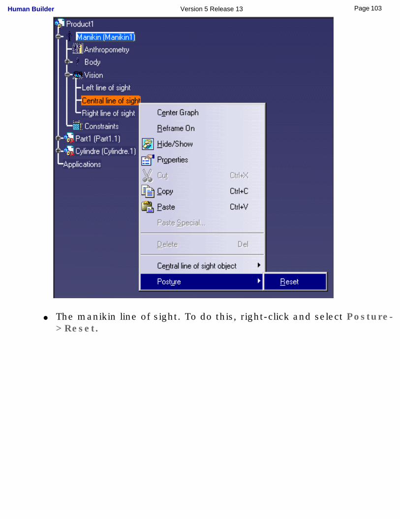
● The manikin line of sight. To do this, right-click and select Posture->Reset.
103Page Human Builder Version 5 Release 13
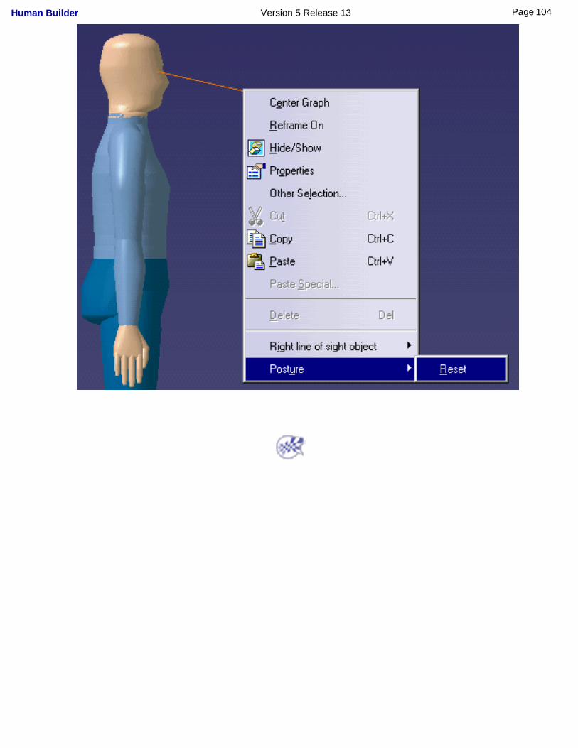
104Page Human Builder Version 5 Release 13

Accessing the Graphical Properties of Segments
The following tasks describe how to access the graphical properties of segments as well as the following:
Changing the Color of a SegmentChanging the Properties of Ellipses
Changing the Properties of SegmentsChanging the Transparency of the SurfacesAccessing the Graphical Properties Toolbar
Whole Manikin Graphical Properties
105Page Human Builder Version 5 Release 13
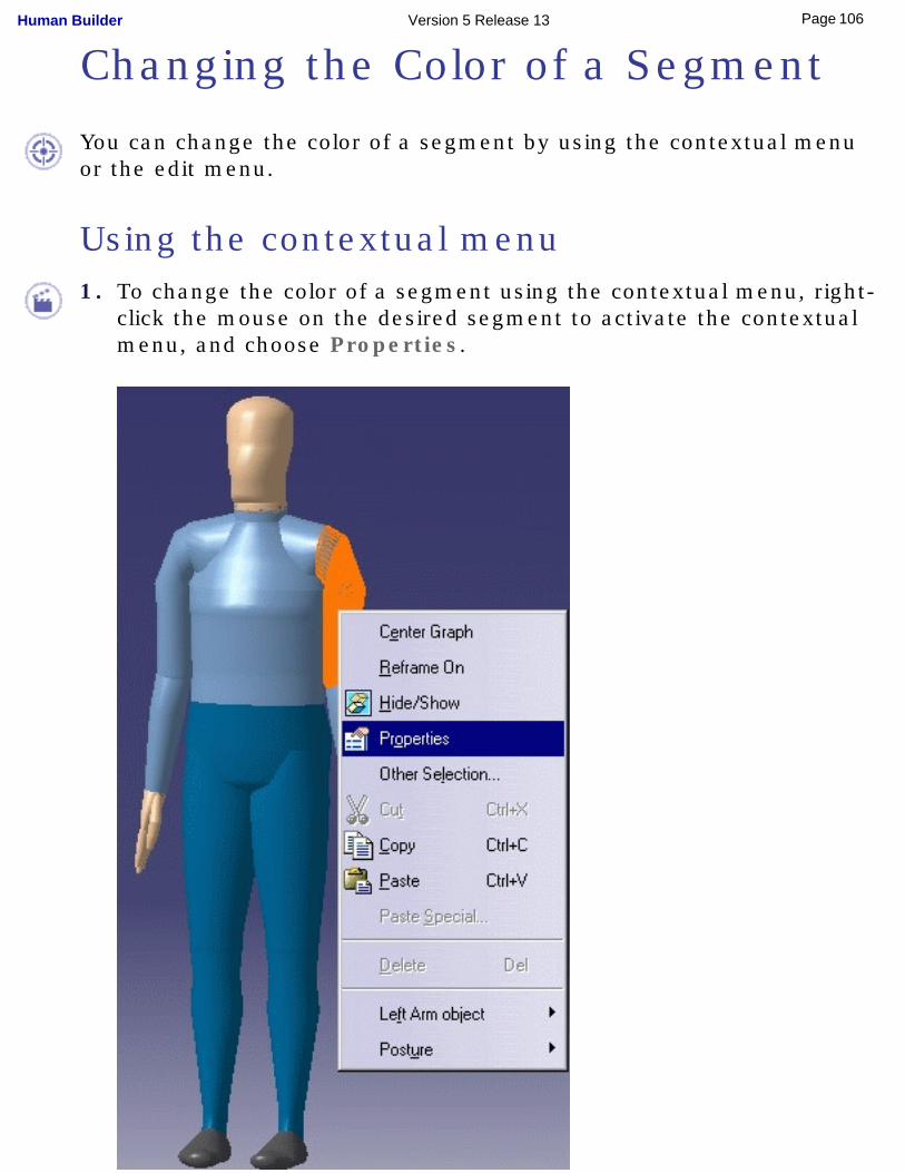
Changing the Color of a Segment
You can change the color of a segment by using the contextual menu or the edit menu.
Using the contextual menu1. To change the color of a segment using the contextual menu, right-
click the mouse on the desired segment to activate the contextual menu, and choose Properties.
106Page Human Builder Version 5 Release 13
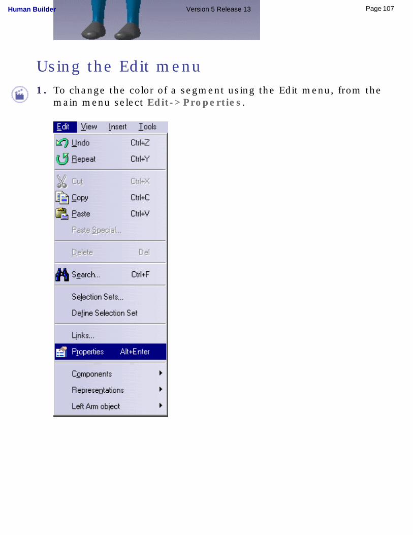
Using the Edit menu1. To change the color of a segment using the Edit menu, from the
main menu select Edit->Properties.
107Page Human Builder Version 5 Release 13
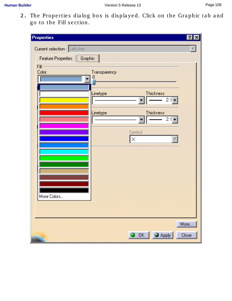
2. The Properties dialog box is displayed. Click on the Graphic tab and go to the Fill section.
108Page Human Builder Version 5 Release 13
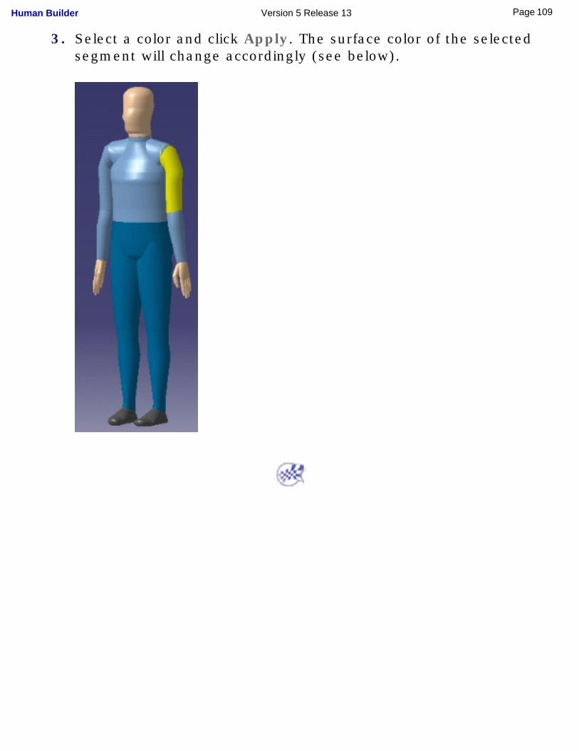
3. Select a color and click Apply. The surface color of the selected segment will change accordingly (see below).
109Page Human Builder Version 5 Release 13
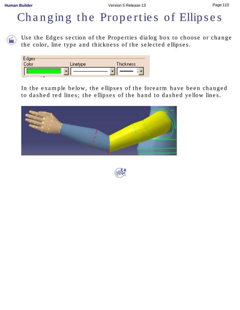
Changing the Properties of Ellipses
Use the Edges section of the Properties dialog box to choose or change the color, line type and thickness of the selected ellipses.
In the example below, the ellipses of the forearm have been changed to dashed red lines; the ellipses of the hand to dashed yellow lines.
110Page Human Builder Version 5 Release 13
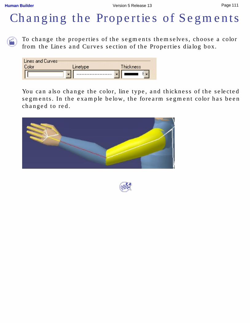
Changing the Properties of Segments
To change the properties of the segments themselves, choose a color from the Lines and Curves section of the Properties dialog box.
You can also change the color, line type, and thickness of the selected segments. In the example below, the forearm segment color has been changed to red.
111Page Human Builder Version 5 Release 13
Changing the Transparency of the Surfaces
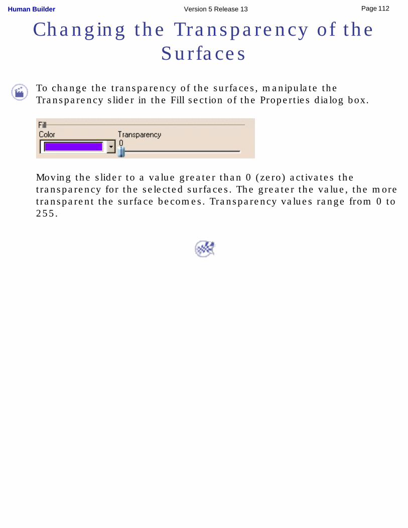
To change the transparency of the surfaces, manipulate the Transparency slider in the Fill section of the Properties dialog box.
Moving the slider to a value greater than 0 (zero) activates the transparency for the selected surfaces. The greater the value, the more transparent the surface becomes. Transparency values range from 0 to 255.
112Page Human Builder Version 5 Release 13
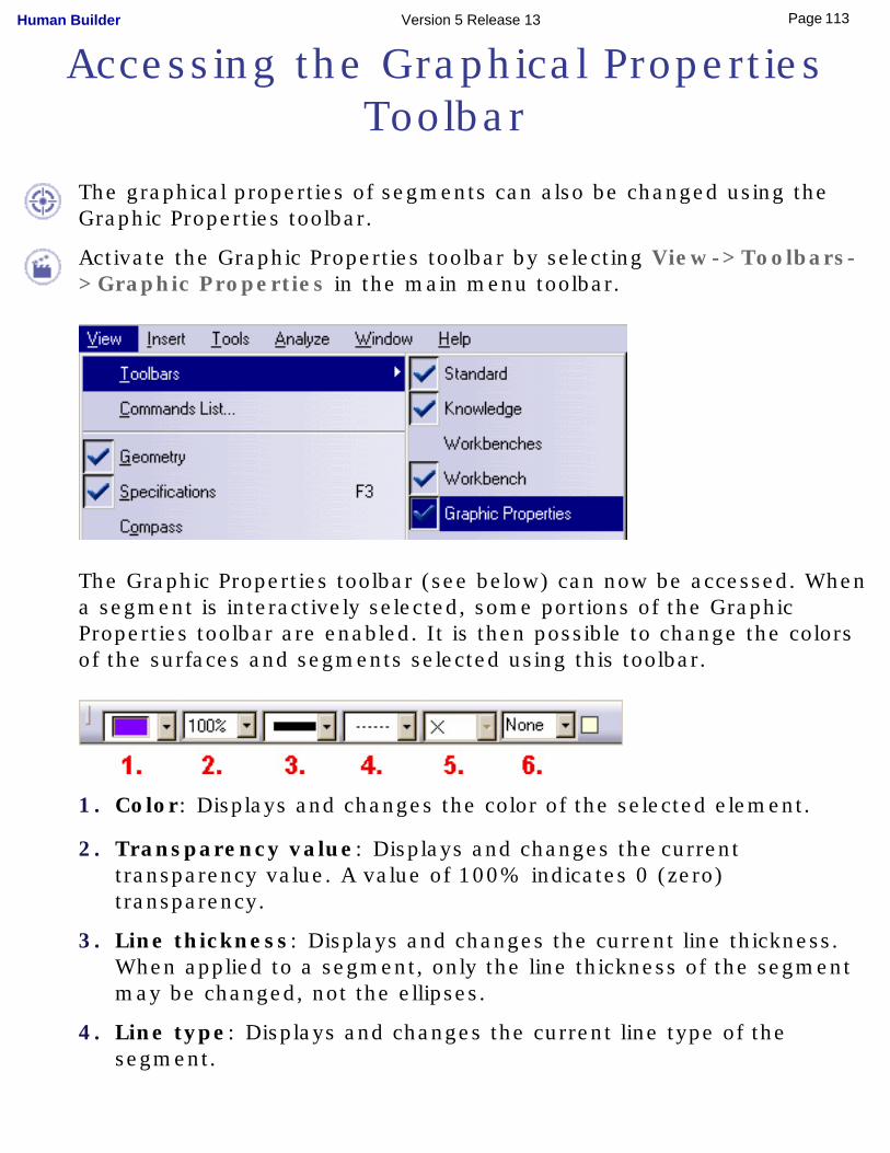
Accessing the Graphical Properties Toolbar
The graphical properties of segments can also be changed using the Graphic Properties toolbar.
Activate the Graphic Properties toolbar by selecting View->Toolbars->Graphic Properties in the main menu toolbar.
The Graphic Properties toolbar (see below) can now be accessed. When a segment is interactively selected, some portions of the Graphic Properties toolbar are enabled. It is then possible to change the colors of the surfaces and segments selected using this toolbar.
1. Color: Displays and changes the color of the selected element.
2. Transparency value: Displays and changes the current transparency value. A value of 100% indicates 0 (zero) transparency.
3. Line thickness: Displays and changes the current line thickness. When applied to a segment, only the line thickness of the segment may be changed, not the ellipses.
4. Line type: Displays and changes the current line type of the segment.
113Page Human Builder Version 5 Release 13

5. Disabled: not used with manikin segments.
6. Disabled: not used with manikin segments.
114Page Human Builder Version 5 Release 13

Whole Manikin Graphical Properties
It is also possible to access and change the graphical properties of the manikin as a whole. To do this, select the Manikin node in the specification tree and, from the main menu toolbar, choose Edit->Properties.
This will apply the chosen graphical properties to the entire manikin and will override any properties set for individual segments.
115Page Human Builder Version 5 Release 13
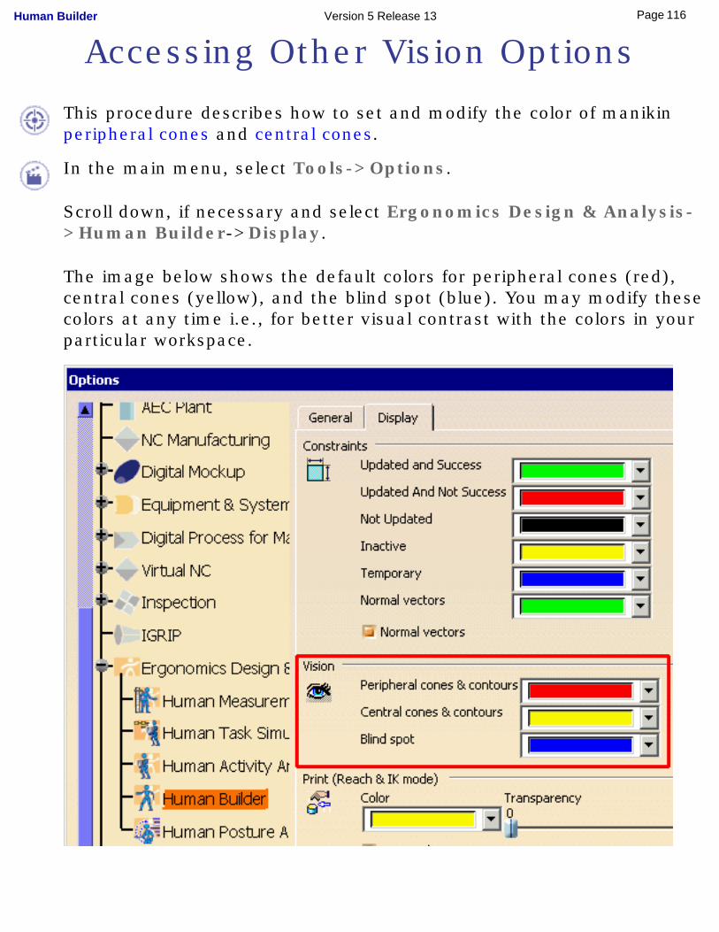
Accessing Other Vision Options
This procedure describes how to set and modify the color of manikin peripheral cones and central cones.
In the main menu, select Tools->Options.
Scroll down, if necessary and select Ergonomics Design & Analysis->Human Builder->Display.
The image below shows the default colors for peripheral cones (red), central cones (yellow), and the blind spot (blue). You may modify these colors at any time i.e., for better visual contrast with the colors in your particular workspace.
116Page Human Builder Version 5 Release 13

117Page Human Builder Version 5 Release 13
Using Posture Undo/Redo
The posture Undo/Redo feature allows you to reverse (cancel) the last posture applied to the manikin.
Undo
Click the Undo icon in the main menu toolbar to execute the Undo
command.
An Undo operation can also be undone. For example, you can restore the last posture with successive calls to the Redo command.
The images below show the state of the manikin after applying the Undo command to a particular posture.
Initial position Posture applied Undo applied
118Page Human Builder Version 5 Release 13
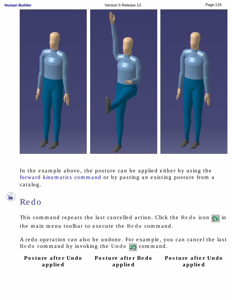
In the example above, the posture can be applied either by using the forward kinematics command or by pasting an existing posture from a catalog.
Redo
This command repeats the last cancelled action. Click the Redo icon in
the main menu toolbar to execute the Redo command.
A redo operation can also be undone. For example, you can cancel the last Redo command by invoking the Undo command.
Posture after Undo applied
Posture after Redo applied
Posture after Undo applied
119Page Human Builder Version 5 Release 13
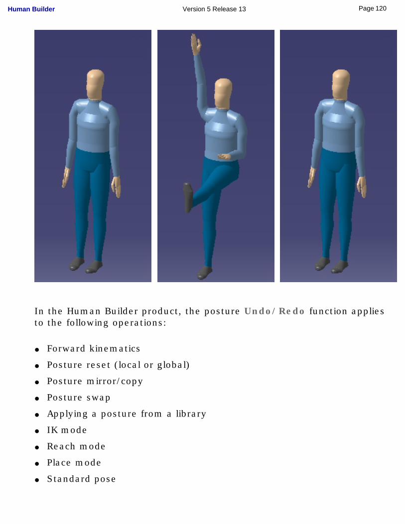
In the Human Builder product, the posture Undo/Redo function applies to the following operations:
● Forward kinematics
● Posture reset (local or global)
● Posture mirror/copy
● Posture swap
● Applying a posture from a library
● IK mode
● Reach mode
● Place mode
● Standard pose
120Page Human Builder Version 5 Release 13

121Page Human Builder Version 5 Release 13
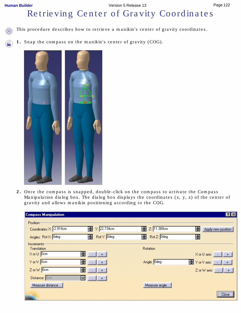
Retrieving Center of Gravity Coordinates
This procedure describes how to retrieve a manikin's center of gravity coordinates.
1. Snap the compass on the manikin's center of gravity (COG).
2. Once the compass is snapped, double-click on the compass to activate the Compass Manipulation dialog box. The dialog box displays the coordinates (x, y, z) of the center of gravity and allows manikin positioning according to the COG.
122Page Human Builder Version 5 Release 13

123Page Human Builder Version 5 Release 13
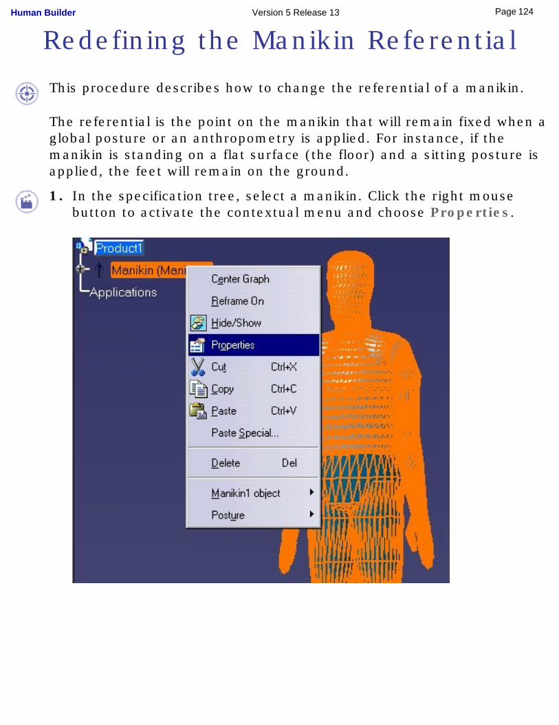
Redefining the Manikin Referential
This procedure describes how to change the referential of a manikin.
The referential is the point on the manikin that will remain fixed when a global posture or an anthropometry is applied. For instance, if the manikin is standing on a flat surface (the floor) and a sitting posture is applied, the feet will remain on the ground.
1. In the specification tree, select a manikin. Click the right mouse button to activate the contextual menu and choose Properties.
124Page Human Builder Version 5 Release 13
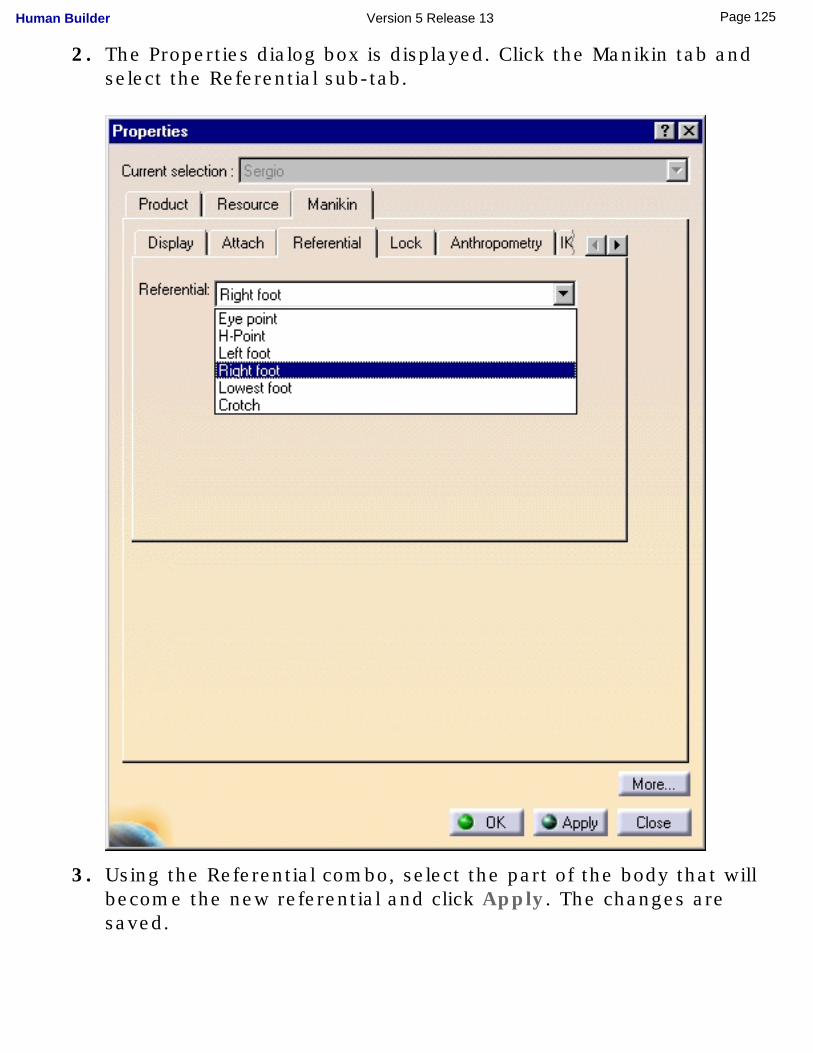
2. The Properties dialog box is displayed. Click the Manikin tab and select the Referential sub-tab.
3. Using the Referential combo, select the part of the body that will become the new referential and click Apply. The changes are saved.
125Page Human Builder Version 5 Release 13
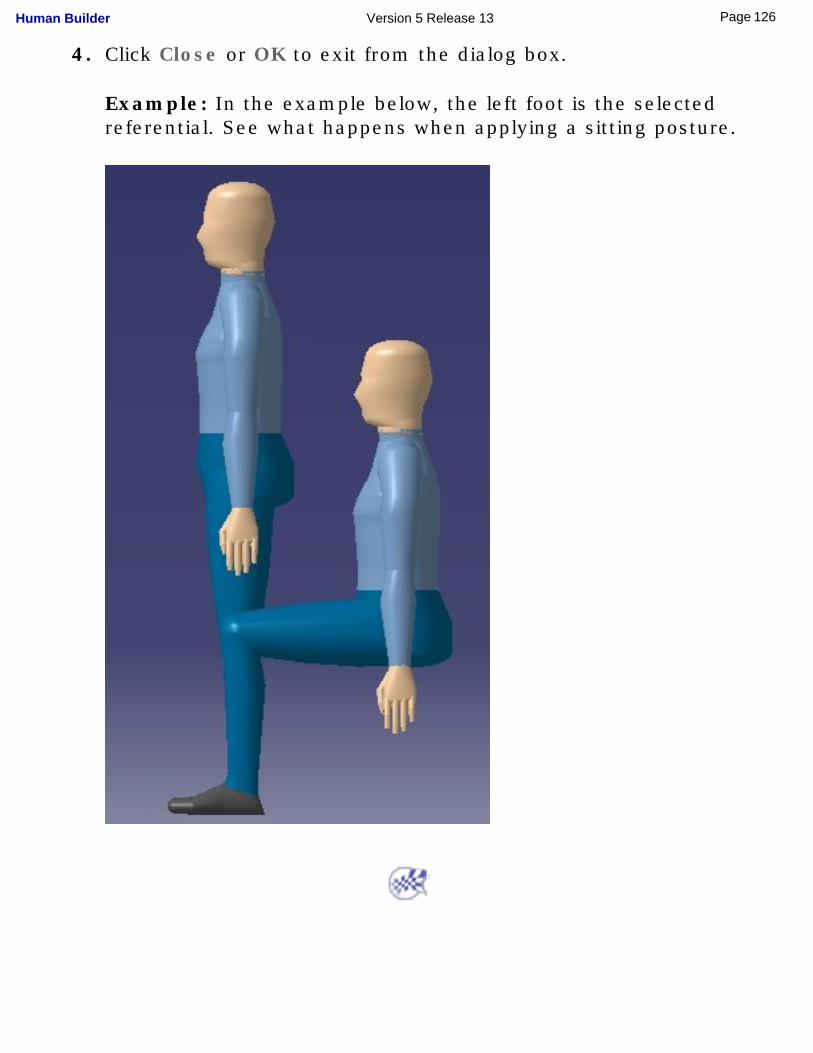
4. Click Close or OK to exit from the dialog box.
Example: In the example below, the left foot is the selected referential. See what happens when applying a sitting posture.
126Page Human Builder Version 5 Release 13
Using Global Collision Detection
This procedure describes how to use global collision detection. This command can be activated in the following manipulation modes:
● Forward Kinematics
● the Posture Editor
● Inverse Kinematics mode
● Reach Mode
● Place mode
● Standard Pose
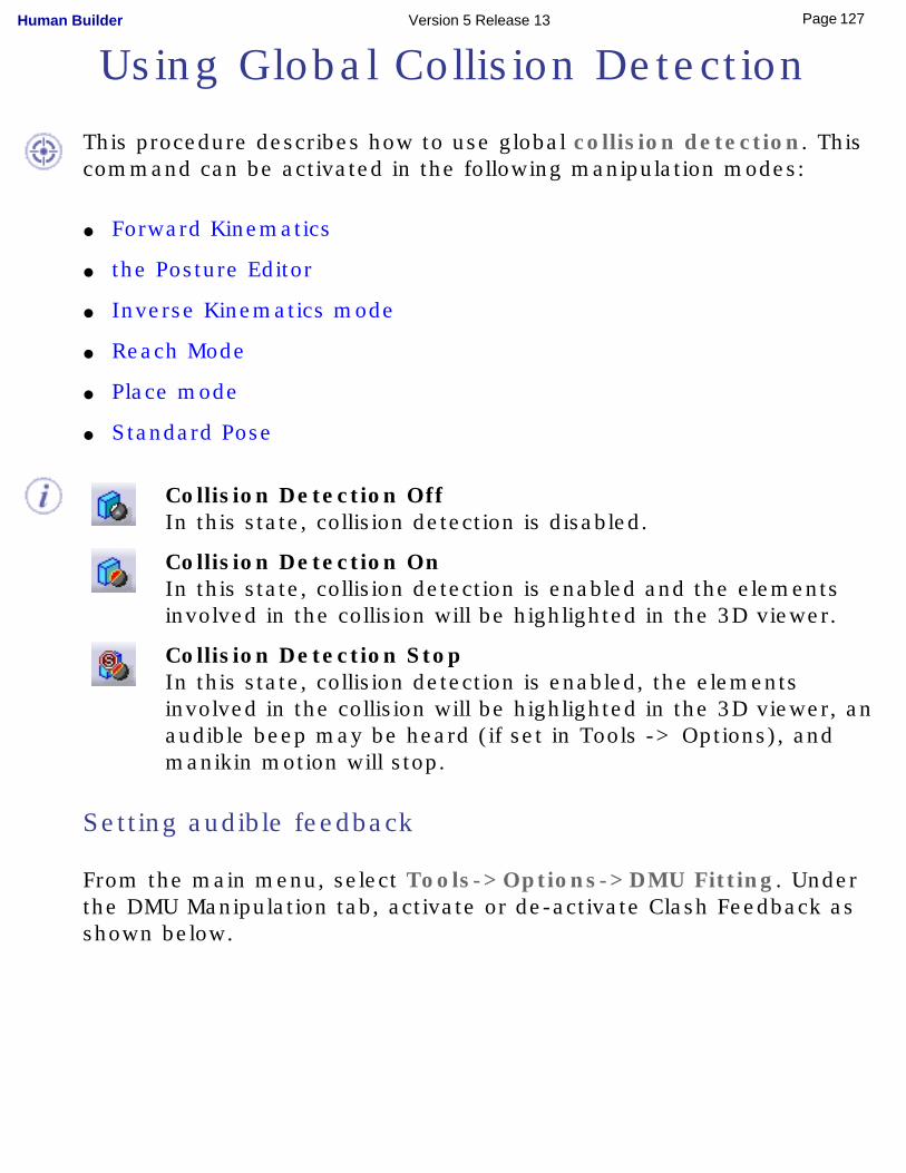
Collision Detection OffIn this state, collision detection is disabled.
Collision Detection OnIn this state, collision detection is enabled and the elements involved in the collision will be highlighted in the 3D viewer.
Collision Detection StopIn this state, collision detection is enabled, the elements involved in the collision will be highlighted in the 3D viewer, an audible beep may be heard (if set in Tools -> Options), and manikin motion will stop.
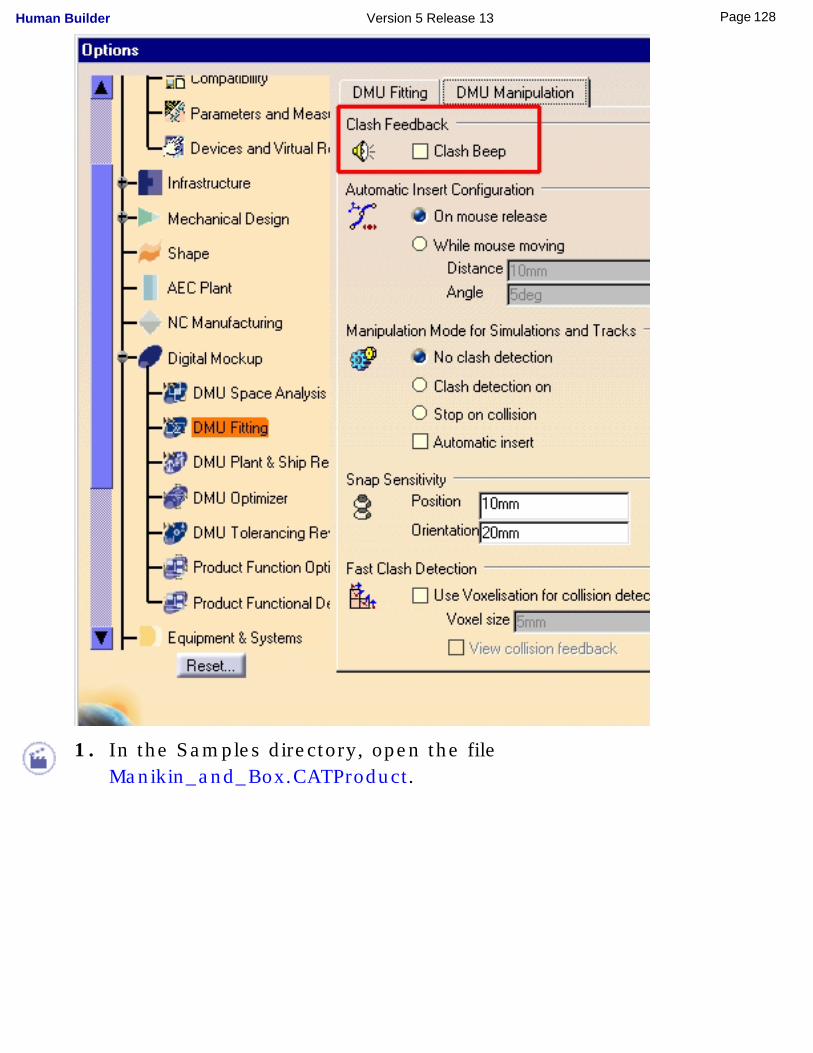
Setting audible feedback
From the main menu, select Tools->Options->DMU Fitting. Under the DMU Manipulation tab, activate or de-activate Clash Feedback as shown below.
127Page Human Builder Version 5 Release 13
1. In the Samples directory, open the file Manikin_and_Box.CATProduct.
128Page Human Builder Version 5 Release 13
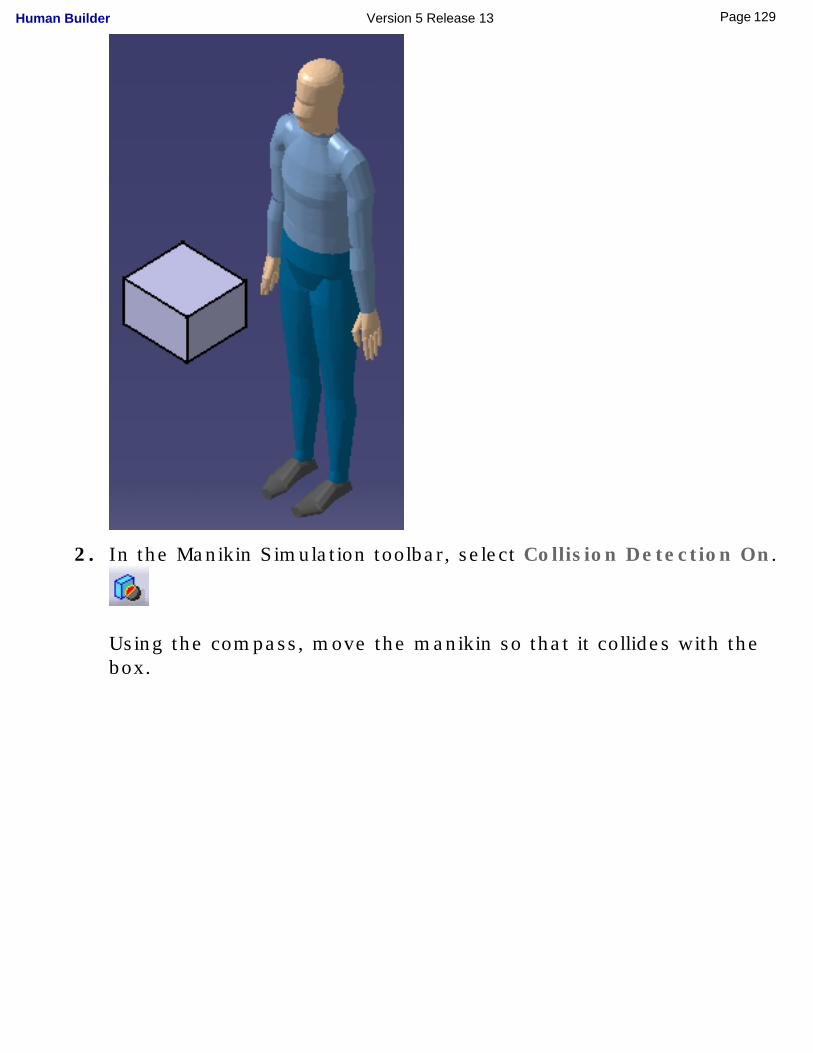
2. In the Manikin Simulation toolbar, select Collision Detection On.
Using the compass, move the manikin so that it collides with the box.
129Page Human Builder Version 5 Release 13
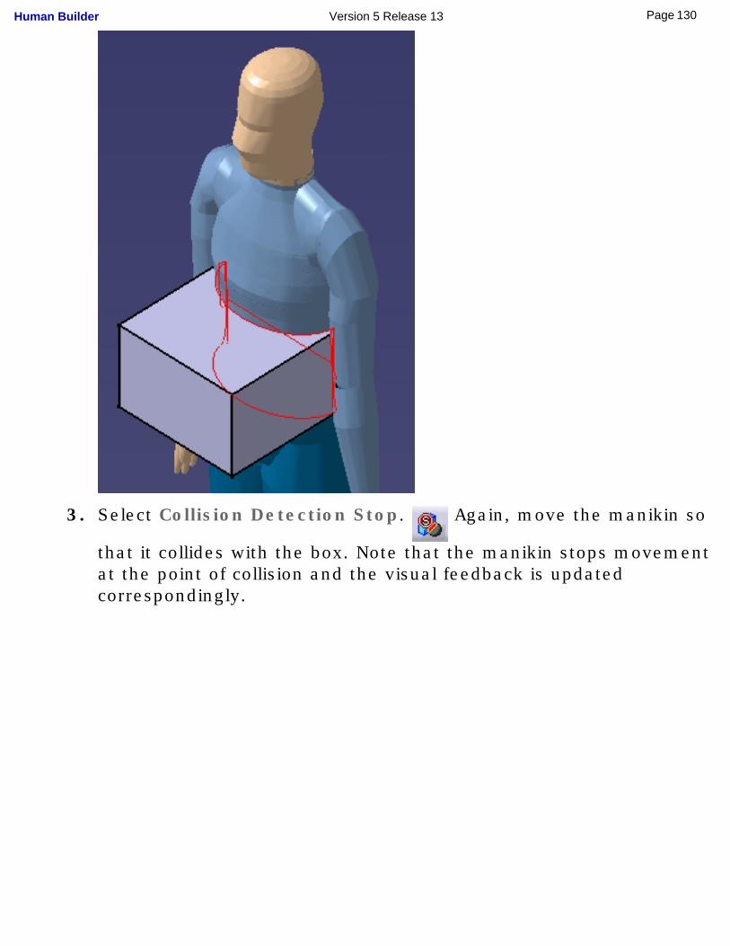
3. Select Collision Detection Stop. Again, move the manikin so
that it collides with the box. Note that the manikin stops movement at the point of collision and the visual feedback is updated correspondingly.
130Page Human Builder Version 5 Release 13
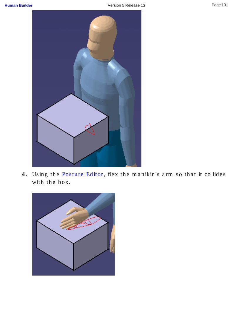
4. Using the Posture Editor, flex the manikin's arm so that it collides with the box.
131Page Human Builder Version 5 Release 13

132Page Human Builder Version 5 Release 13
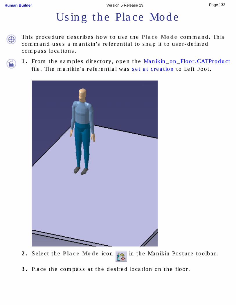
Using the Place Mode
This procedure describes how to use the Place Mode command. This command uses a manikin's referential to snap it to user-defined compass locations.
1. From the samples directory, open the Manikin_on_Floor.CATProduct file. The manikin's referential was set at creation to Left Foot.
2. Select the Place Mode icon in the Manikin Posture toolbar.
3. Place the compass at the desired location on the floor.
133Page Human Builder Version 5 Release 13
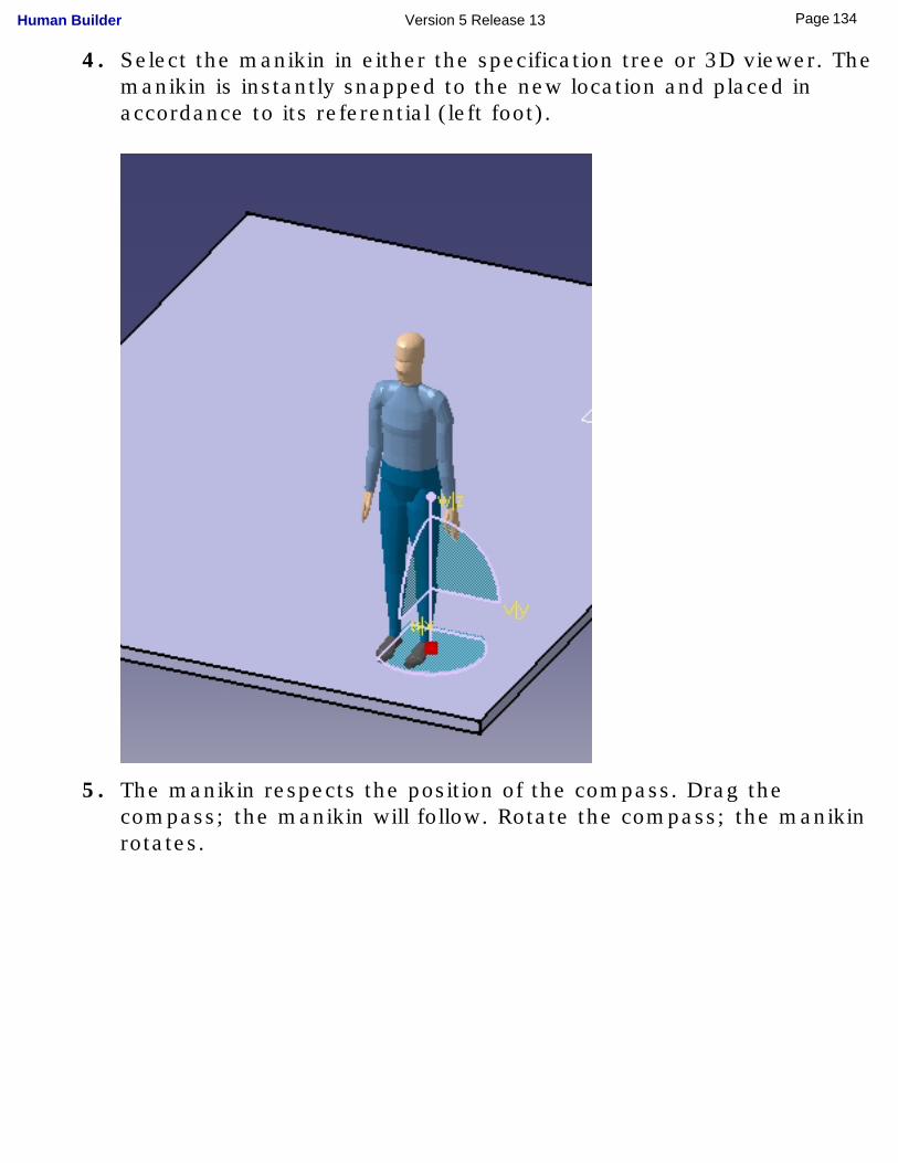
4. Select the manikin in either the specification tree or 3D viewer. The manikin is instantly snapped to the new location and placed in accordance to its referential (left foot).
5. The manikin respects the position of the compass. Drag the compass; the manikin will follow. Rotate the compass; the manikin rotates.
134Page Human Builder Version 5 Release 13
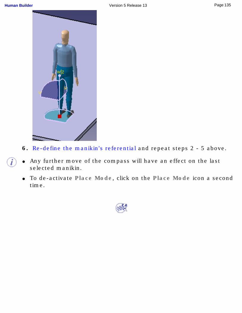
6. Re-define the manikin's referential and repeat steps 2 - 5 above.
● Any further move of the compass will have an effect on the last selected manikin.
● To de-activate Place Mode, click on the Place Mode icon a second time.
135Page Human Builder Version 5 Release 13
Manikin Save/Update/Reload Enhancements
This task describes the new storage management principles involving manikins in the Human family of products.
Prior to V5R11, when saving a manikin created under its parent product, the saving process contained at least two distinct operations: ● the document containing the manikin had to be saved;
● the document containing the parent product had to be saved.
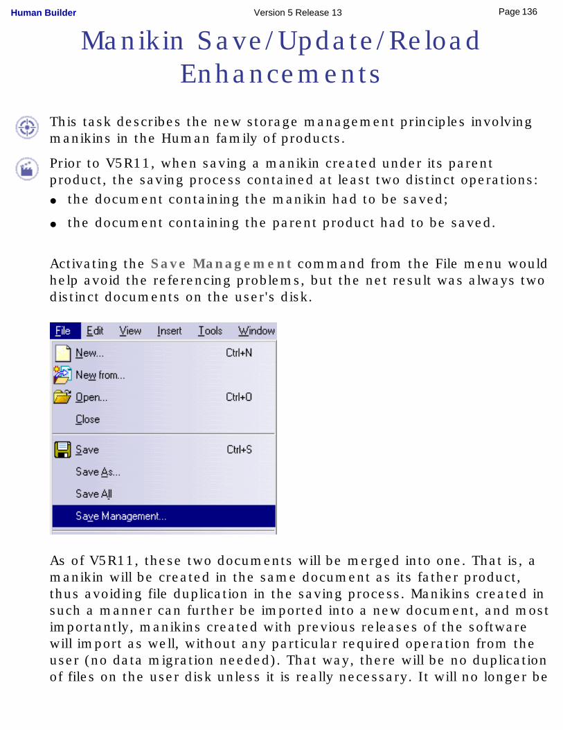
Activating the Save Management command from the File menu would help avoid the referencing problems, but the net result was always two distinct documents on the user's disk.
As of V5R11, these two documents will be merged into one. That is, a manikin will be created in the same document as its father product, thus avoiding file duplication in the saving process. Manikins created in such a manner can further be imported into a new document, and most importantly, manikins created with previous releases of the software will import as well, without any particular required operation from the user (no data migration needed). That way, there will be no duplication of files on the user disk unless it is really necessary. It will no longer be
136Page Human Builder Version 5 Release 13
possible to create each manikin in its distinct document, as was the case prior to Release 11.
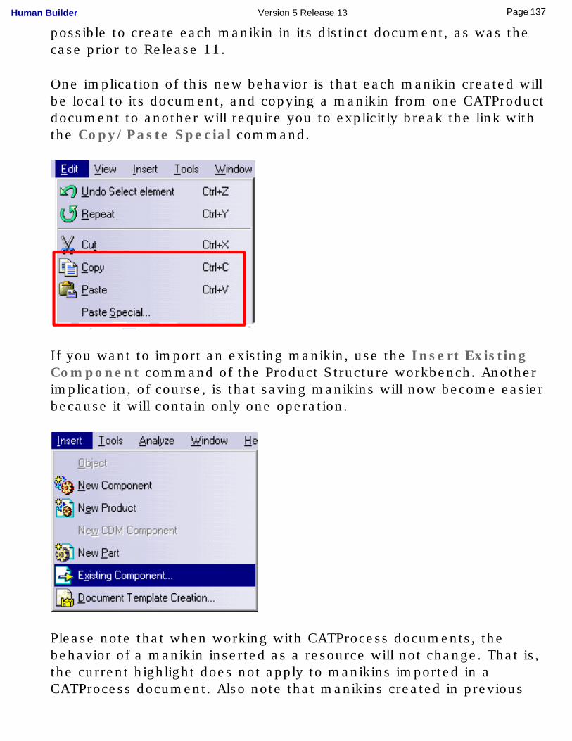
One implication of this new behavior is that each manikin created will be local to its document, and copying a manikin from one CATProduct document to another will require you to explicitly break the link with the Copy/Paste Special command.
If you want to import an existing manikin, use the Insert Existing Component command of the Product Structure workbench. Another implication, of course, is that saving manikins will now become easier because it will contain only one operation.
Please note that when working with CATProcess documents, the behavior of a manikin inserted as a resource will not change. That is, the current highlight does not apply to manikins imported in a CATProcess document. Also note that manikins created in previous
137Page Human Builder Version 5 Release 13

releases of Human Builder (those in their standalone documents) will continue to behave as such (they will not be merged with the document they are imported in). Only new manikins created in R11 will have the new behavior.
138Page Human Builder Version 5 Release 13
Using the Vision Function
This task describes the Vision function and how to set and edit manikin vision attributes. Using this function, you will see a scene through the manikin's eyes, displayed in a separate window.
Just like humans, a manikin can see its environment. Manikin vision can be with both eyes or limited to only one eye. Even the blind spot is simulated.
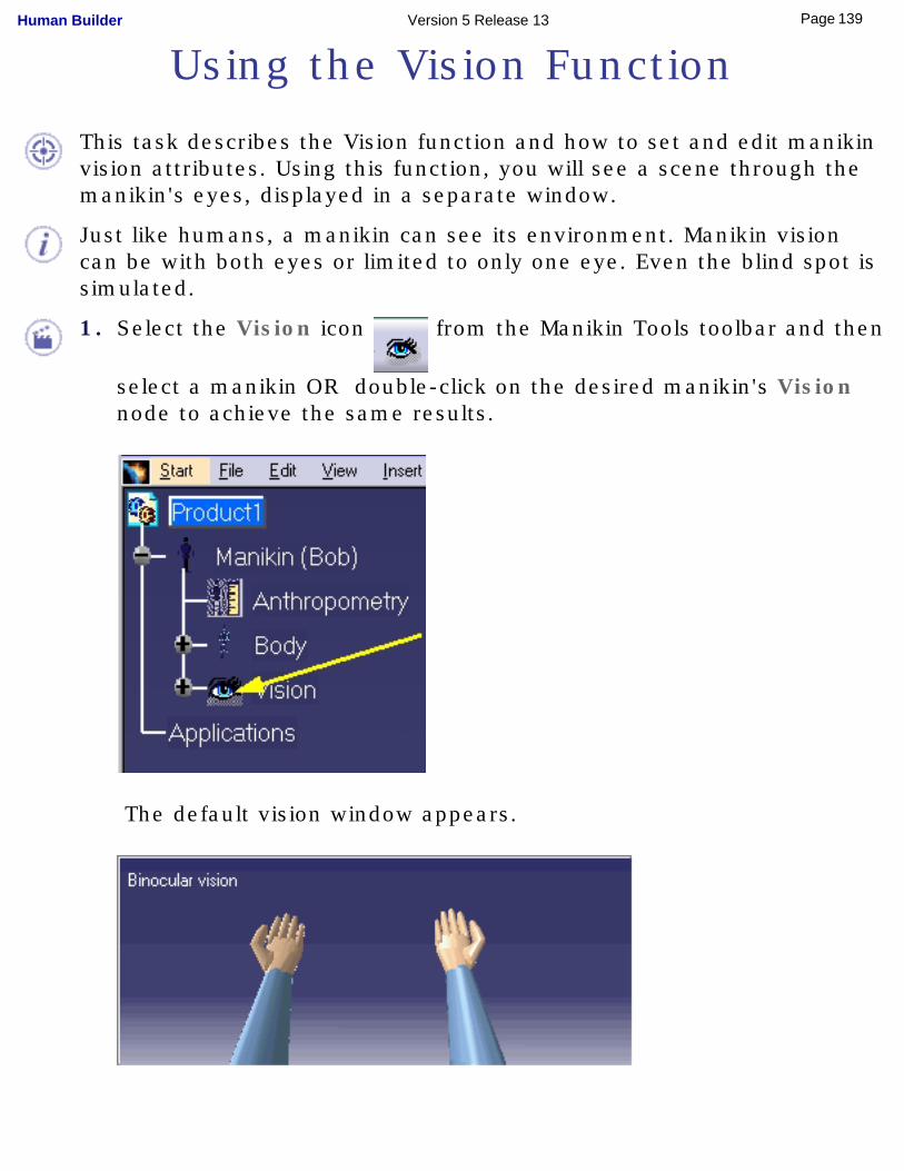
1. Select the Vision icon from the Manikin Tools toolbar and then
select a manikin OR double-click on the desired manikin's Vision node to achieve the same results.
The default vision window appears.
139Page Human Builder Version 5 Release 13
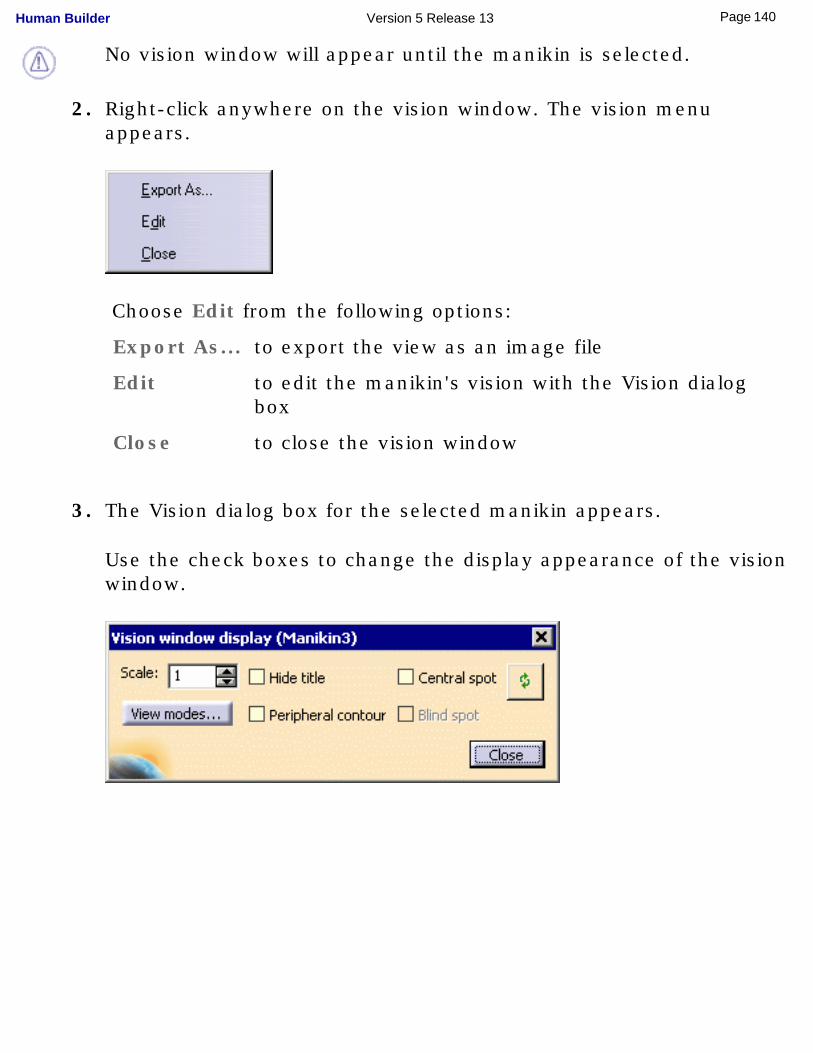
No vision window will appear until the manikin is selected.
2. Right-click anywhere on the vision window. The vision menu appears.
Choose Edit from the following options:
Export As... to export the view as an image file
Edit to edit the manikin's vision with the Vision dialog box
Close to close the vision window
3. The Vision dialog box for the selected manikin appears.
Use the check boxes to change the display appearance of the vision window.
140Page Human Builder Version 5 Release 13
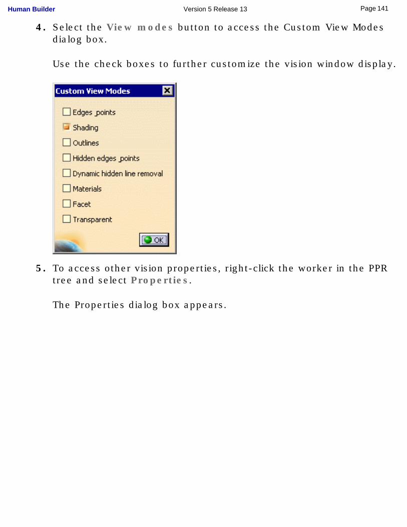
4. Select the View modes button to access the Custom View Modes dialog box.
Use the check boxes to further customize the vision window display.
5. To access other vision properties, right-click the worker in the PPR tree and select Properties.
The Properties dialog box appears.
141Page Human Builder Version 5 Release 13
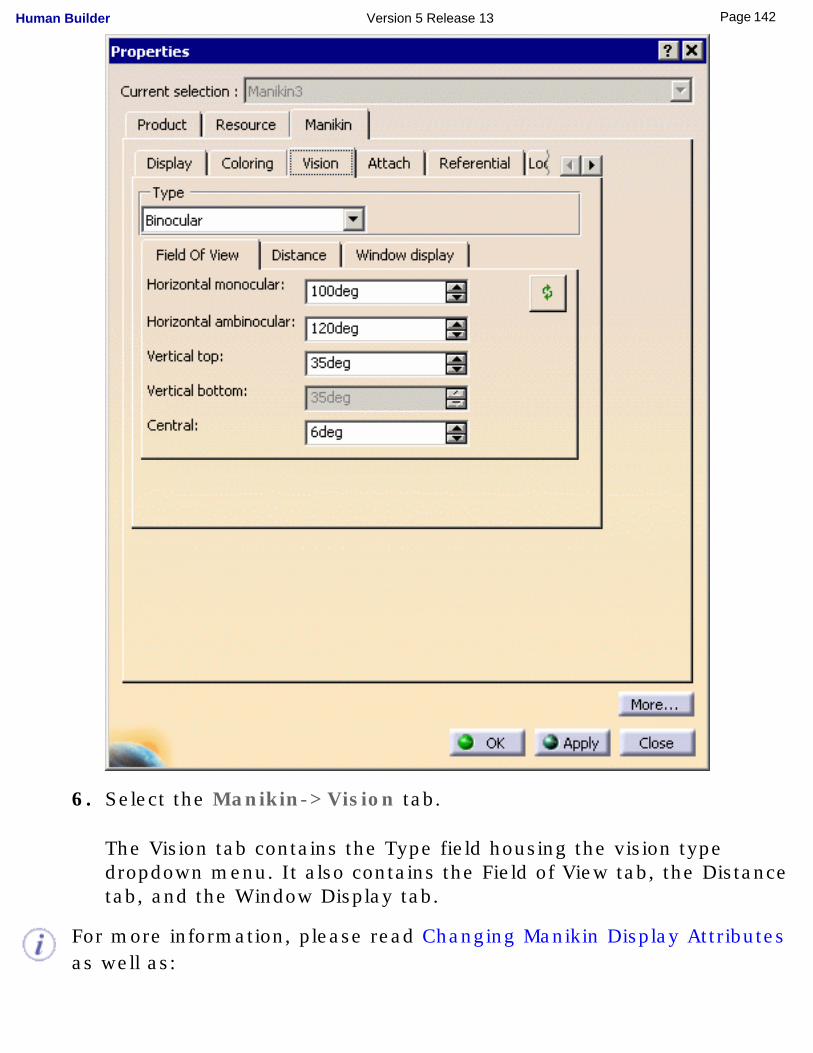
6. Select the Manikin->Vision tab.
The Vision tab contains the Type field housing the vision type dropdown menu. It also contains the Field of View tab, the Distance tab, and the Window Display tab.
For more information, please read Changing Manikin Display Attributes as well as:
142Page Human Builder Version 5 Release 13

Type FieldField of View Tab
Distance TabWindow Display Tab
143Page Human Builder Version 5 Release 13
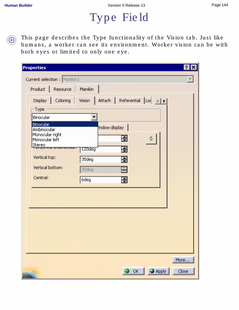
Type Field
This page describes the Type functionality of the Vision tab. Just like humans, a worker can see its environment. Worker vision can be with both eyes or limited to only one eye.
144Page Human Builder Version 5 Release 13
The Type options menu allows you to choose between five different representations of vision. The vision window displays each vision type selected.
The five types of vision are:● Binocular
● Ambinocular
● Right monocular
● Left monocular
● Stereo
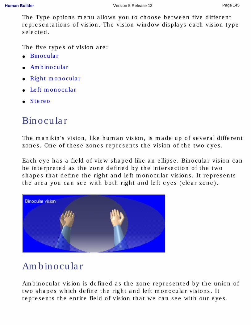
Binocular
The manikin's vision, like human vision, is made up of several different zones. One of these zones represents the vision of the two eyes.
Each eye has a field of view shaped like an ellipse. Binocular vision can be interpreted as the zone defined by the intersection of the two shapes that define the right and left monocular visions. It represents the area you can see with both right and left eyes (clear zone).
Ambinocular
Ambinocular vision is defined as the zone represented by the union of two shapes which define the right and left monocular visions. It represents the entire field of vision that we can see with our eyes.
145Page Human Builder Version 5 Release 13
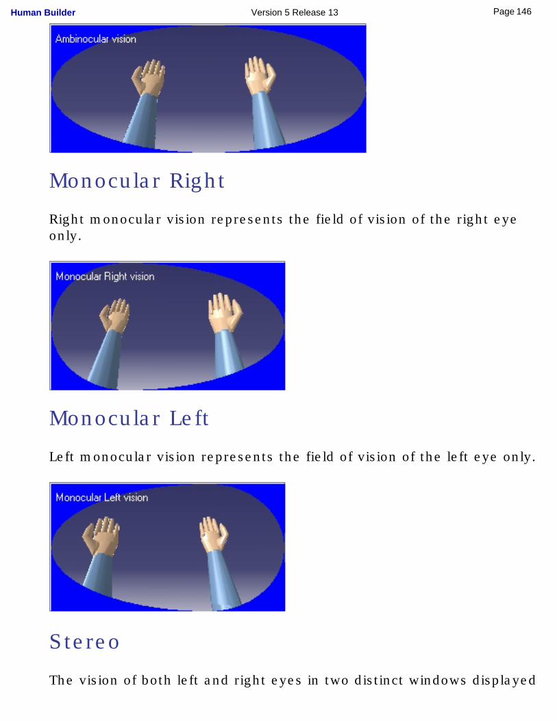
Monocular Right
Right monocular vision represents the field of vision of the right eye only.
Monocular Left
Left monocular vision represents the field of vision of the left eye only.
Stereo
The vision of both left and right eyes in two distinct windows displayed
146Page Human Builder Version 5 Release 13
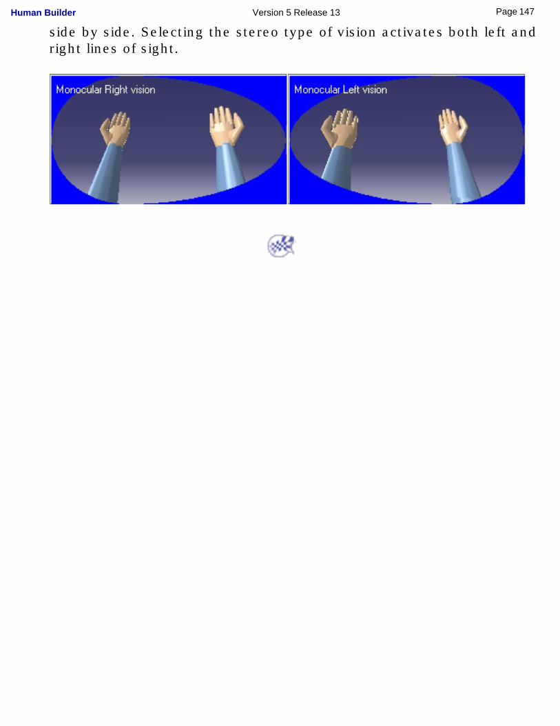
side by side. Selecting the stereo type of vision activates both left and right lines of sight.
147Page Human Builder Version 5 Release 13
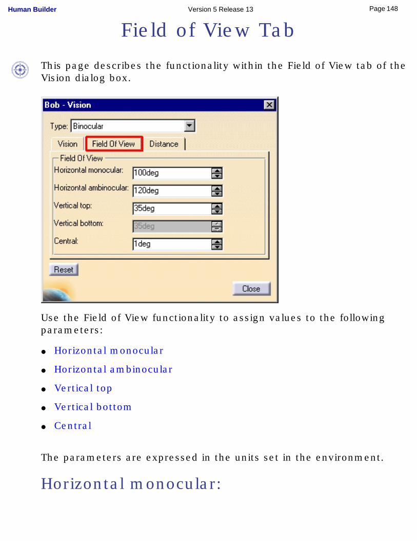
Field of View Tab
This page describes the functionality within the Field of View tab of the Vision dialog box.
Use the Field of View functionality to assign values to the following parameters:
● Horizontal monocular
● Horizontal ambinocular
● Vertical top
● Vertical bottom
● Central
The parameters are expressed in the units set in the environment.
Horizontal monocular:
148Page Human Builder Version 5 Release 13
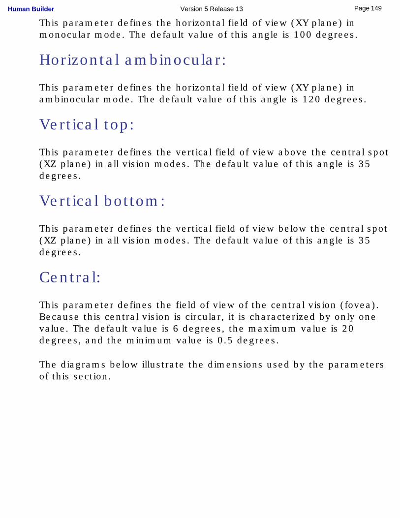
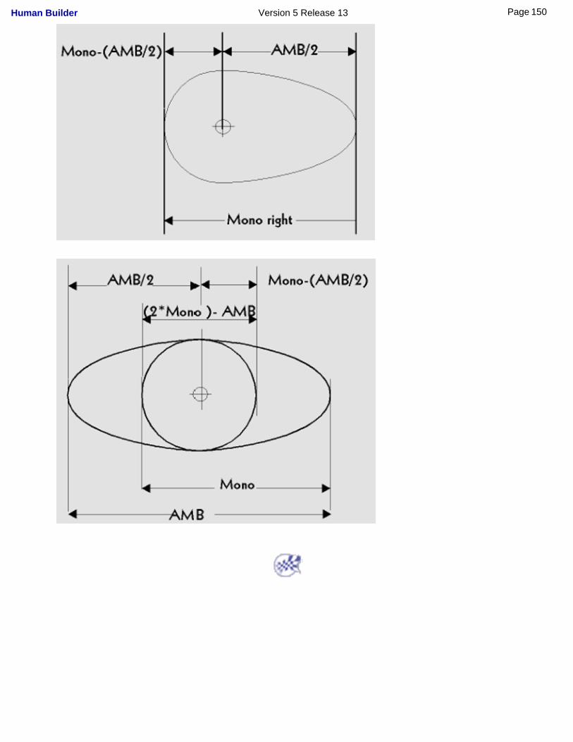
This parameter defines the horizontal field of view (XY plane) in monocular mode. The default value of this angle is 100 degrees.
Horizontal ambinocular:
This parameter defines the horizontal field of view (XY plane) in ambinocular mode. The default value of this angle is 120 degrees.
Vertical top:
This parameter defines the vertical field of view above the central spot (XZ plane) in all vision modes. The default value of this angle is 35 degrees.
Vertical bottom:
This parameter defines the vertical field of view below the central spot (XZ plane) in all vision modes. The default value of this angle is 35 degrees.
Central:
This parameter defines the field of view of the central vision (fovea). Because this central vision is circular, it is characterized by only one value. The default value is 6 degrees, the maximum value is 20 degrees, and the minimum value is 0.5 degrees.
The diagrams below illustrate the dimensions used by the parameters of this section.
149Page Human Builder Version 5 Release 13
150Page Human Builder Version 5 Release 13
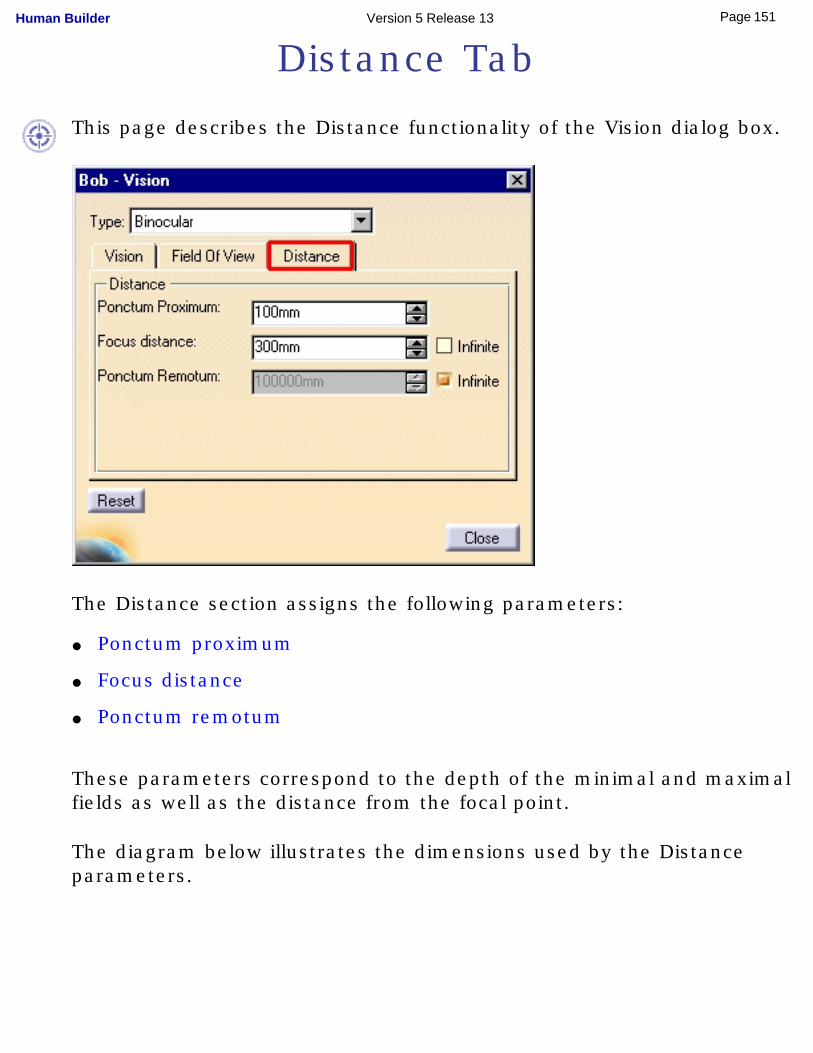
Distance Tab
This page describes the Distance functionality of the Vision dialog box.
The Distance section assigns the following parameters:
● Ponctum proximum
● Focus distance
● Ponctum remotum
These parameters correspond to the depth of the minimal and maximal fields as well as the distance from the focal point.
The diagram below illustrates the dimensions used by the Distance parameters.
151Page Human Builder Version 5 Release 13
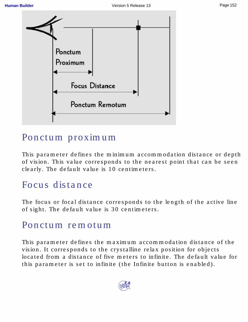
Ponctum proximum
This parameter defines the minimum accommodation distance or depth of vision. This value corresponds to the nearest point that can be seen clearly. The default value is 10 centimeters.
Focus distance
The focus or focal distance corresponds to the length of the active line of sight. The default value is 30 centimeters.
Ponctum remotum
This parameter defines the maximum accommodation distance of the vision. It corresponds to the crystalline relax position for objects located from a distance of five meters to infinite. The default value for this parameter is set to infinite (the Infinite button is enabled).
152Page Human Builder Version 5 Release 13
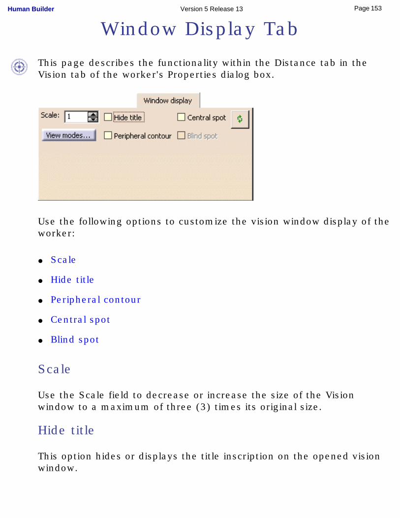
Window Display Tab
This page describes the functionality within the Distance tab in the Vision tab of the worker's Properties dialog box.
Use the following options to customize the vision window display of the worker:
● Scale
● Hide title
● Peripheral contour
● Central spot
● Blind spot
Scale
Use the Scale field to decrease or increase the size of the Vision window to a maximum of three (3) times its original size.
Hide title
This option hides or displays the title inscription on the opened vision window.
153Page Human Builder Version 5 Release 13
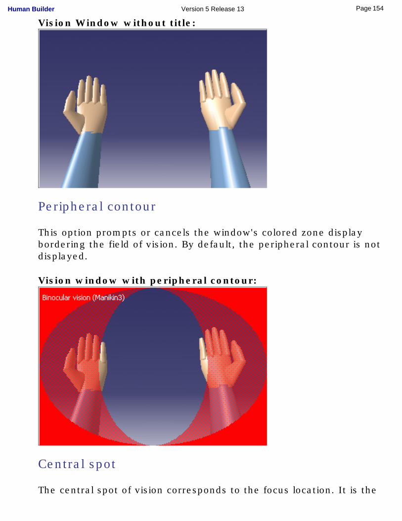
Vision Window without title:
Peripheral contour
This option prompts or cancels the window's colored zone display bordering the field of vision. By default, the peripheral contour is not displayed.
Vision window with peripheral contour:
Central spot
The central spot of vision corresponds to the focus location. It is the
154Page Human Builder Version 5 Release 13
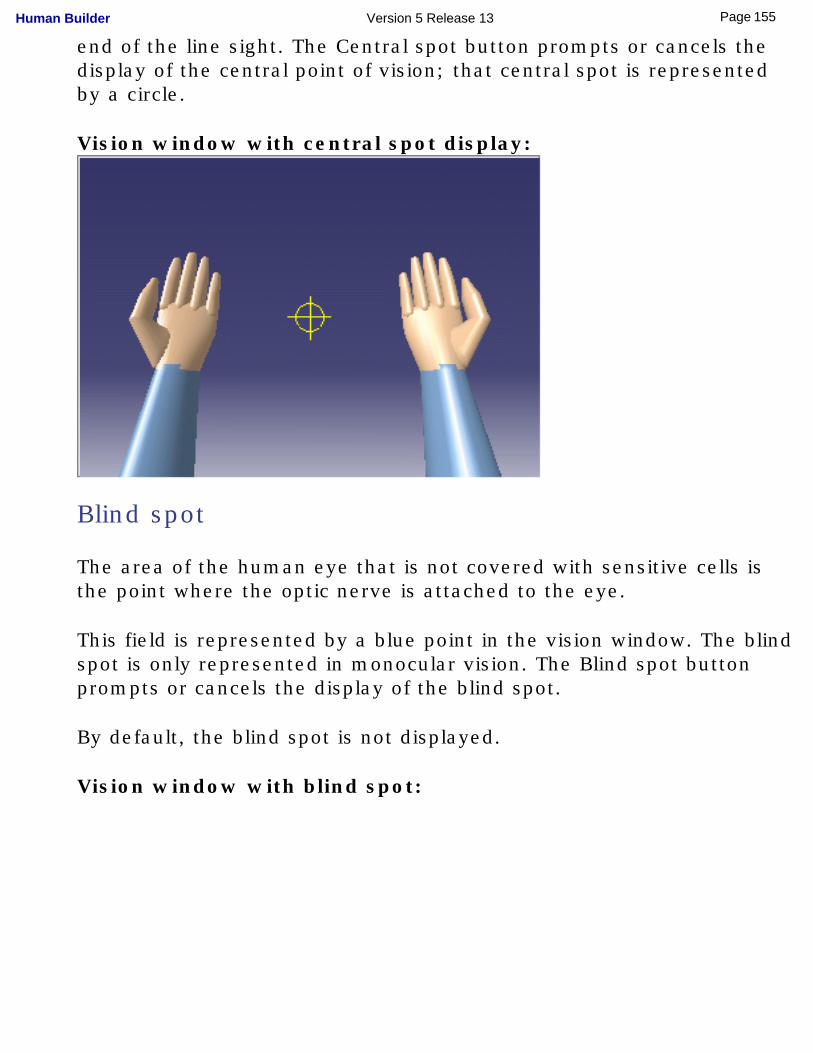
end of the line sight. The Central spot button prompts or cancels the display of the central point of vision; that central spot is represented by a circle.
Vision window with central spot display:
Blind spot
The area of the human eye that is not covered with sensitive cells is the point where the optic nerve is attached to the eye.
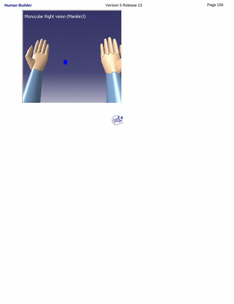
This field is represented by a blue point in the vision window. The blind spot is only represented in monocular vision. The Blind spot button prompts or cancels the display of the blind spot.
By default, the blind spot is not displayed.
Vision window with blind spot:
155Page Human Builder Version 5 Release 13
156Page Human Builder Version 5 Release 13
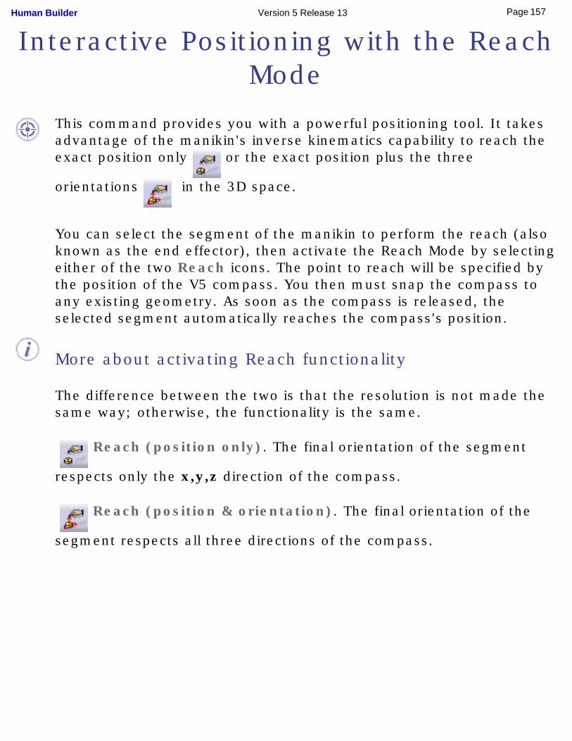
Interactive Positioning with the Reach Mode
This command provides you with a powerful positioning tool. It takes advantage of the manikin's inverse kinematics capability to reach the exact position only or the exact position plus the three
orientations in the 3D space.
You can select the segment of the manikin to perform the reach (also known as the end effector), then activate the Reach Mode by selecting either of the two Reach icons. The point to reach will be specified by the position of the V5 compass. You then must snap the compass to any existing geometry. As soon as the compass is released, the selected segment automatically reaches the compass's position.
More about activating Reach functionality
The difference between the two is that the resolution is not made the same way; otherwise, the functionality is the same.
Reach (position only). The final orientation of the segment
respects only the x,y,z direction of the compass.
Reach (position & orientation). The final orientation of the
segment respects all three directions of the compass.
157Page Human Builder Version 5 Release 13
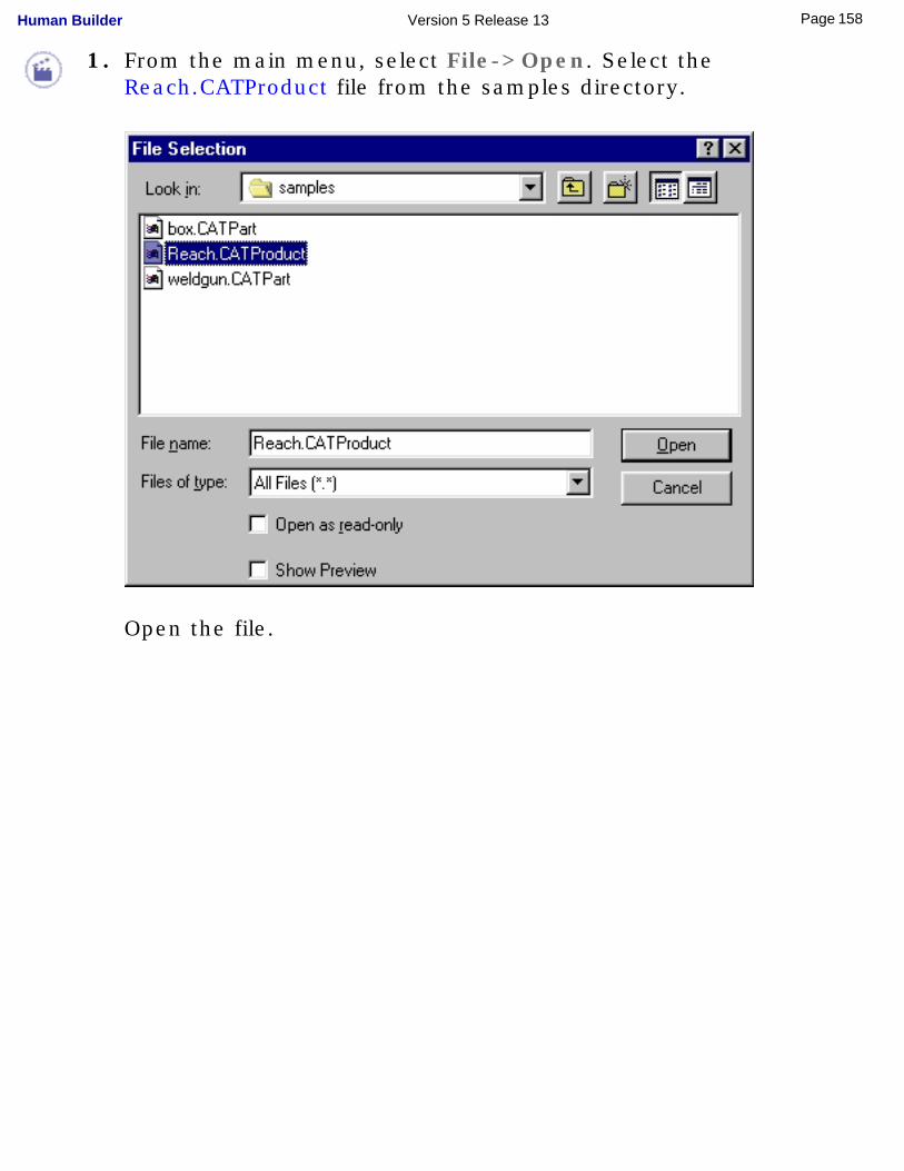
1. From the main menu, select File->Open. Select the Reach.CATProduct file from the samples directory.
Open the file.
158Page Human Builder Version 5 Release 13
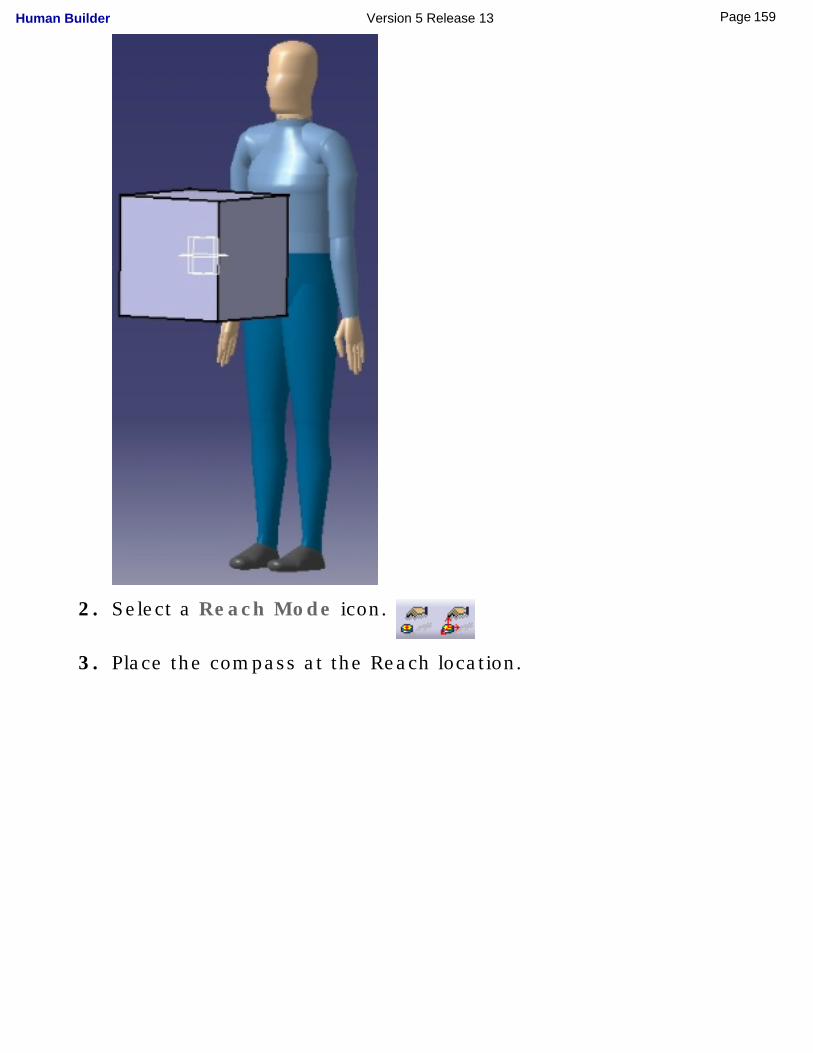
2. Select a Reach Mode icon.
3. Place the compass at the Reach location.
159Page Human Builder Version 5 Release 13
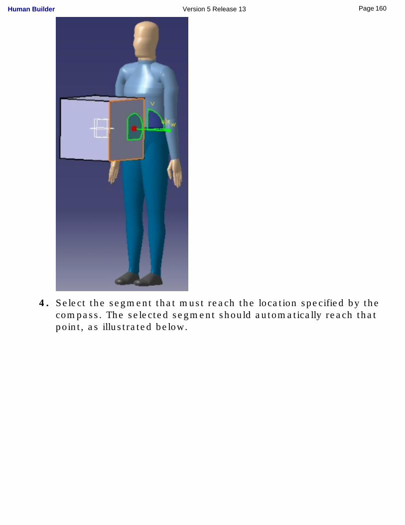
4. Select the segment that must reach the location specified by the compass. The selected segment should automatically reach that point, as illustrated below.
160Page Human Builder Version 5 Release 13
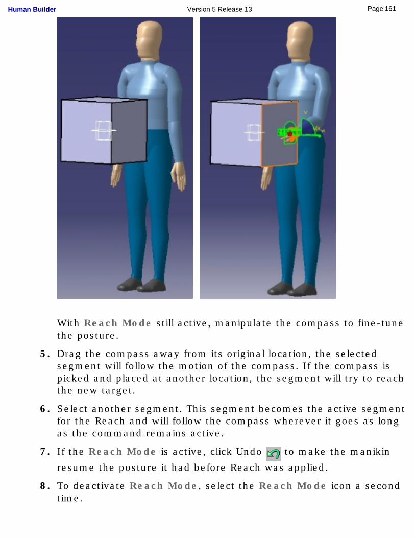
With Reach Mode still active, manipulate the compass to fine-tune the posture.
5. Drag the compass away from its original location, the selected segment will follow the motion of the compass. If the compass is picked and placed at another location, the segment will try to reach the new target.
6. Select another segment. This segment becomes the active segment for the Reach and will follow the compass wherever it goes as long as the command remains active.
7. If the Reach Mode is active, click Undo to make the manikin
resume the posture it had before Reach was applied.
8. To deactivate Reach Mode, select the Reach Mode icon a second time.
161Page Human Builder Version 5 Release 13
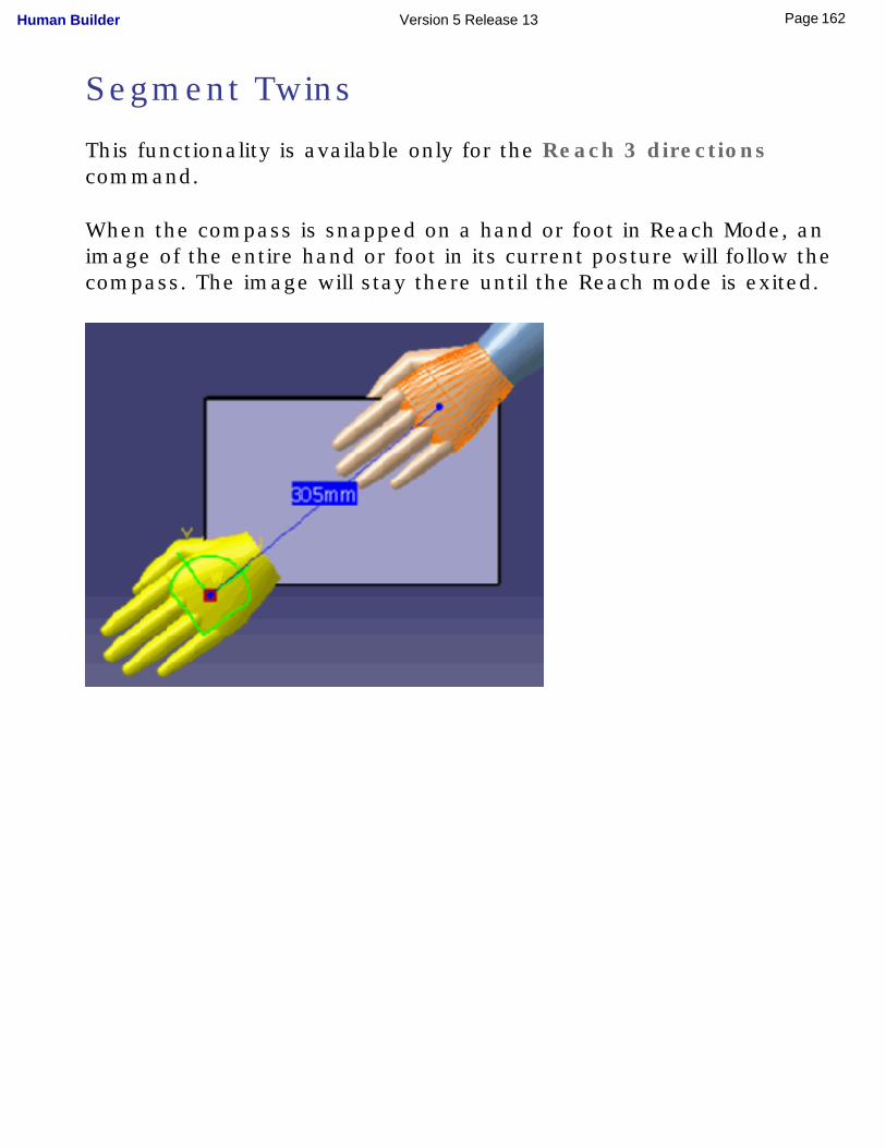
Segment Twins
This functionality is available only for the Reach 3 directions command.
When the compass is snapped on a hand or foot in Reach Mode, an image of the entire hand or foot in its current posture will follow the compass. The image will stay there until the Reach mode is exited.
162Page Human Builder Version 5 Release 13
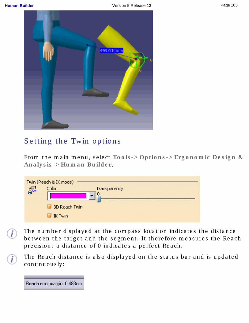
Setting the Twin options
From the main menu, select Tools->Options->Ergonomic Design & Analysis->Human Builder.
The number displayed at the compass location indicates the distance between the target and the segment. It therefore measures the Reach precision: a distance of 0 indicates a perfect Reach.
The Reach distance is also displayed on the status bar and is updated continuously:
163Page Human Builder Version 5 Release 13

164Page Human Builder Version 5 Release 13
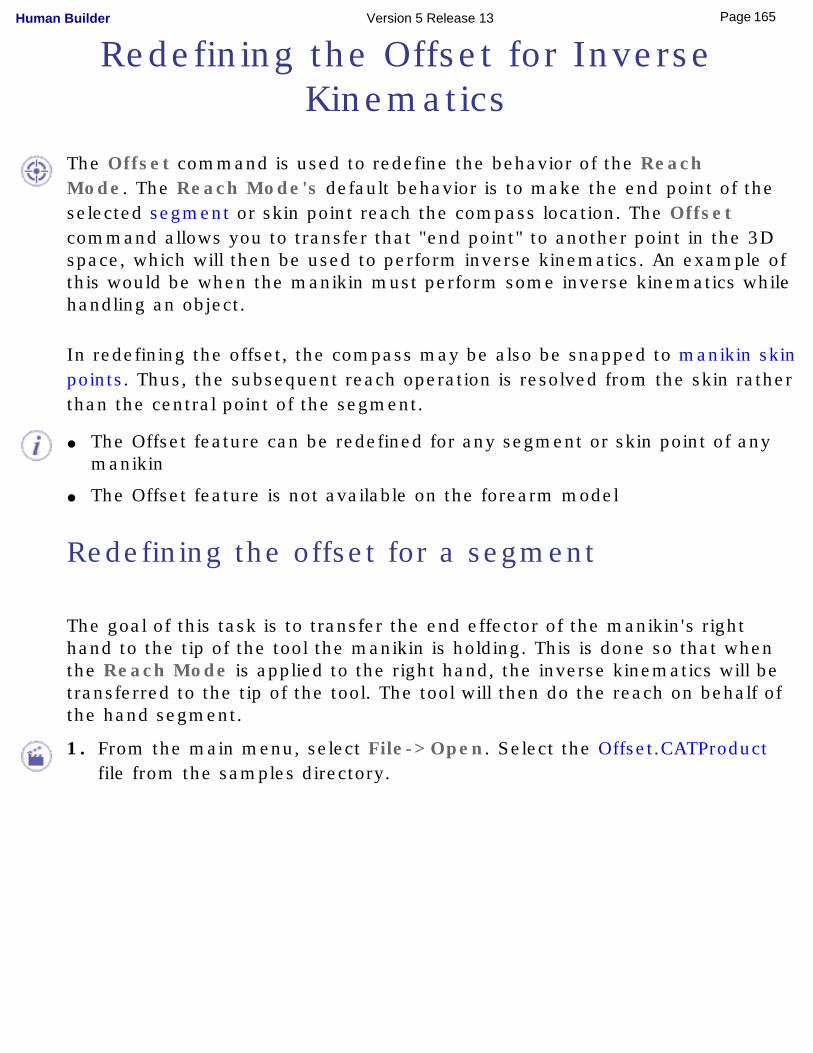
Redefining the Offset for Inverse Kinematics
The Offset command is used to redefine the behavior of the Reach Mode. The Reach Mode's default behavior is to make the end point of the selected segment or skin point reach the compass location. The Offset command allows you to transfer that "end point" to another point in the 3D space, which will then be used to perform inverse kinematics. An example of this would be when the manikin must perform some inverse kinematics while handling an object.
In redefining the offset, the compass may be also be snapped to manikin skin points. Thus, the subsequent reach operation is resolved from the skin rather than the central point of the segment.
● The Offset feature can be redefined for any segment or skin point of any manikin
● The Offset feature is not available on the forearm model
Redefining the offset for a segment
The goal of this task is to transfer the end effector of the manikin's right hand to the tip of the tool the manikin is holding. This is done so that when the Reach Mode is applied to the right hand, the inverse kinematics will be transferred to the tip of the tool. The tool will then do the reach on behalf of the hand segment.
1. From the main menu, select File->Open. Select the Offset.CATProduct file from the samples directory.
165Page Human Builder Version 5 Release 13
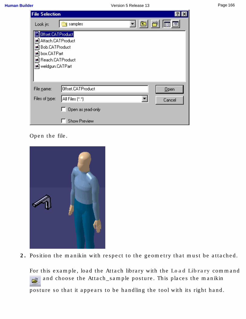
Open the file.
2. Position the manikin with respect to the geometry that must be attached.
For this example, load the Attach library with the Load Library command and choose the Attach_sample posture. This places the manikin
posture so that it appears to be handling the tool with its right hand.
166Page Human Builder Version 5 Release 13
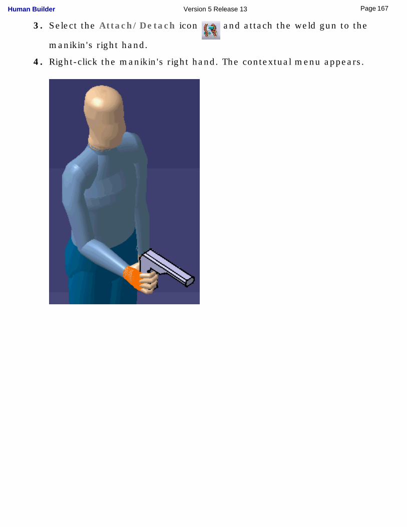
3. Select the Attach/Detach icon and attach the weld gun to the
manikin's right hand.
4. Right-click the manikin's right hand. The contextual menu appears.
167Page Human Builder Version 5 Release 13
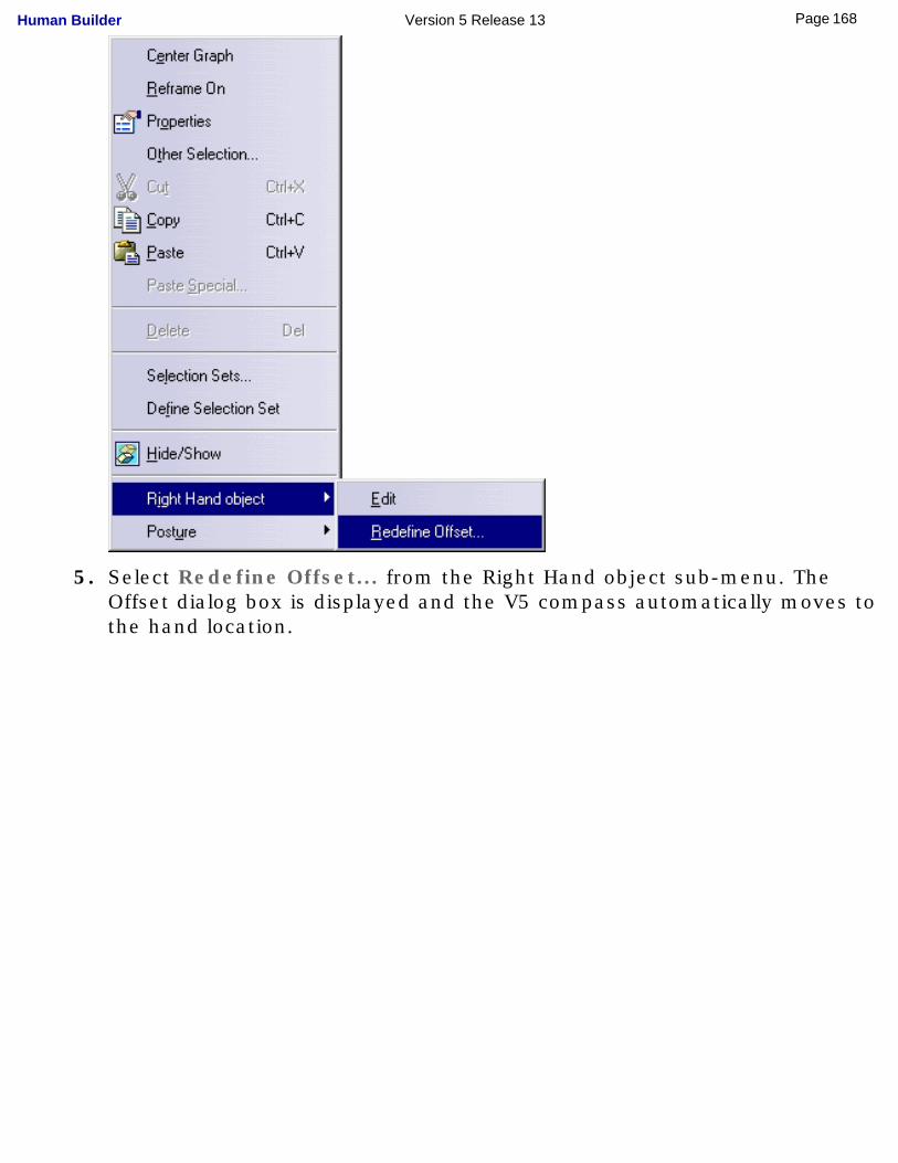
5. Select Redefine Offset... from the Right Hand object sub-menu. The Offset dialog box is displayed and the V5 compass automatically moves to the hand location.
168Page Human Builder Version 5 Release 13
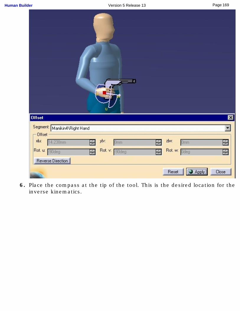
6. Place the compass at the tip of the tool. This is the desired location for the inverse kinematics.
169Page Human Builder Version 5 Release 13
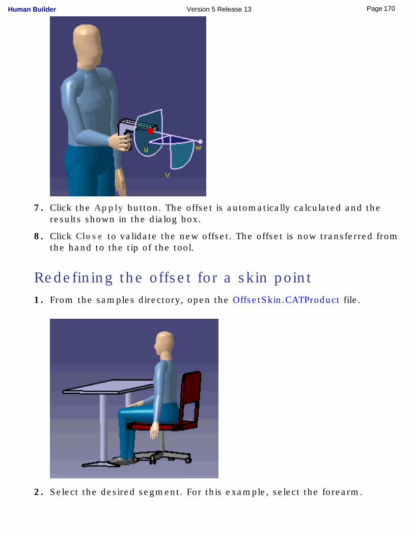
7. Click the Apply button. The offset is automatically calculated and the results shown in the dialog box.
8. Click Close to validate the new offset. The offset is now transferred from the hand to the tip of the tool.
Redefining the offset for a skin point1. From the samples directory, open the OffsetSkin.CATProduct file.
2. Select the desired segment. For this example, select the forearm.
170Page Human Builder Version 5 Release 13
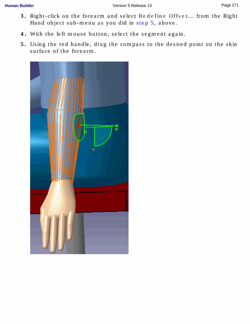
3. Right-click on the forearm and select Redefine Offset... from the Right Hand object sub-menu as you did in step 5, above.
4. With the left mouse button, select the segment again.
5. Using the red handle, drag the compass to the desired point on the skin surface of the forearm.
171Page Human Builder Version 5 Release 13
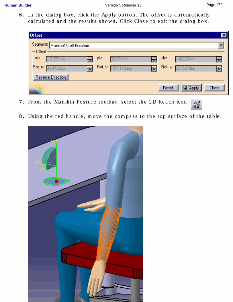
6. In the dialog box, click the Apply button. The offset is automatically calculated and the results shown. Click Close to exit the dialog box.
7. From the Manikin Posture toolbar, select the 2D Reach icon.
8. Using the red handle, move the compass to the top surface of the table.
172Page Human Builder Version 5 Release 13
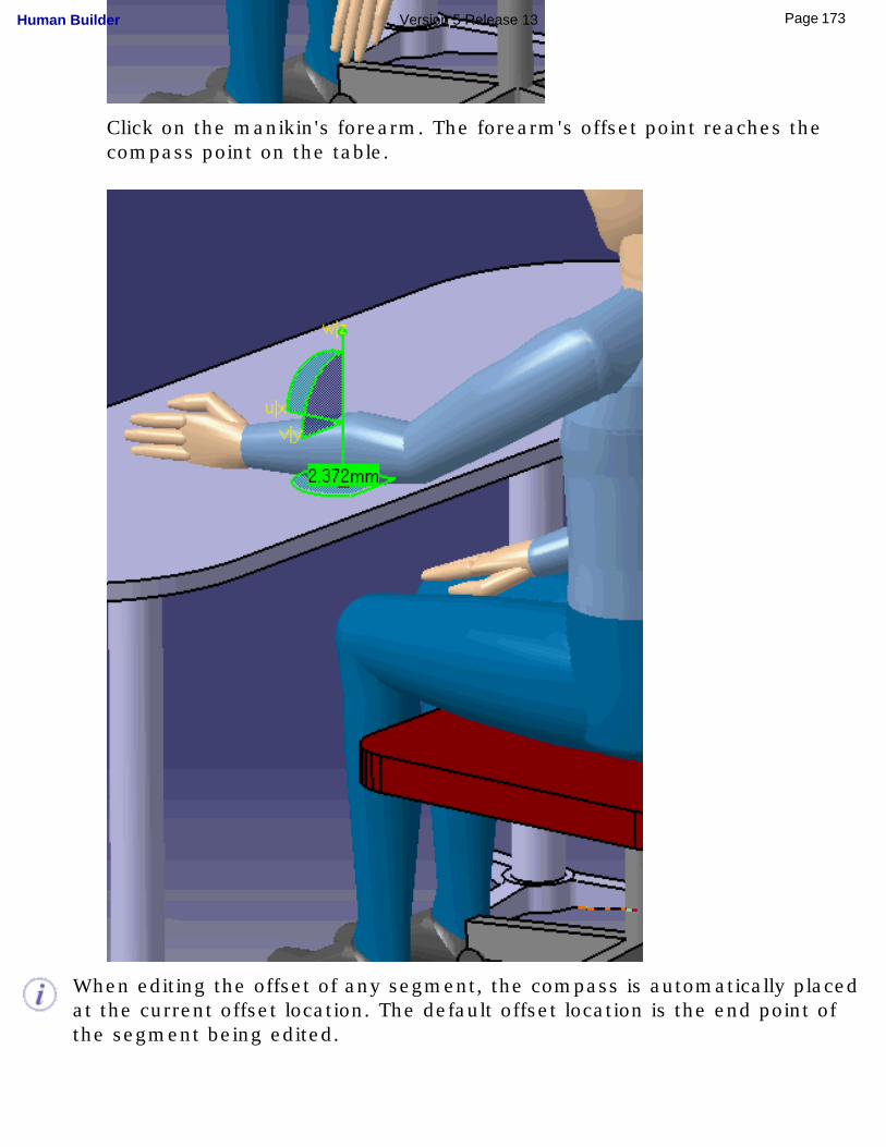
Click on the manikin's forearm. The forearm's offset point reaches the compass point on the table.
When editing the offset of any segment, the compass is automatically placed at the current offset location. The default offset location is the end point of the segment being edited.
173Page Human Builder Version 5 Release 13
To reset the offset back to its default value, open the Offset dialog box on the segment and click the Reset button. Click Close to close the dialog box.
The Reverse Direction button reverses the current orientation of the compass. This feature is typically used when the geometry is manipulated in design mode where the compass goes inside the geometry when snapped to an object.
174Page Human Builder Version 5 Release 13
Attaching an Object to a Manikin Segment
The attach function creates a one-way relationship between a manikin segment and one or more objects in its environment. The attached object becomes a slave to the segment. Once attached, this object will move with the same matrix as its master segment.
This task is divided into three parts:
● Attaching an object to a manikin segment
● Checking existing attaches on a specific manikin
● Detaching an object from a manikin segment
● It is important to note that the attach is a one-way relationship; the object follows the segment, not the opposite. If the object is moved (i.e., using the compass) after the attach is made, the segment will not follow the object's motion.
● When doing any attach, the compass may be snapped to manikin skin points, not just the central point of a segment.
● Refer to the status bar for information and instructional prompts.
Attaching an object to a manikin segment
175Page Human Builder Version 5 Release 13
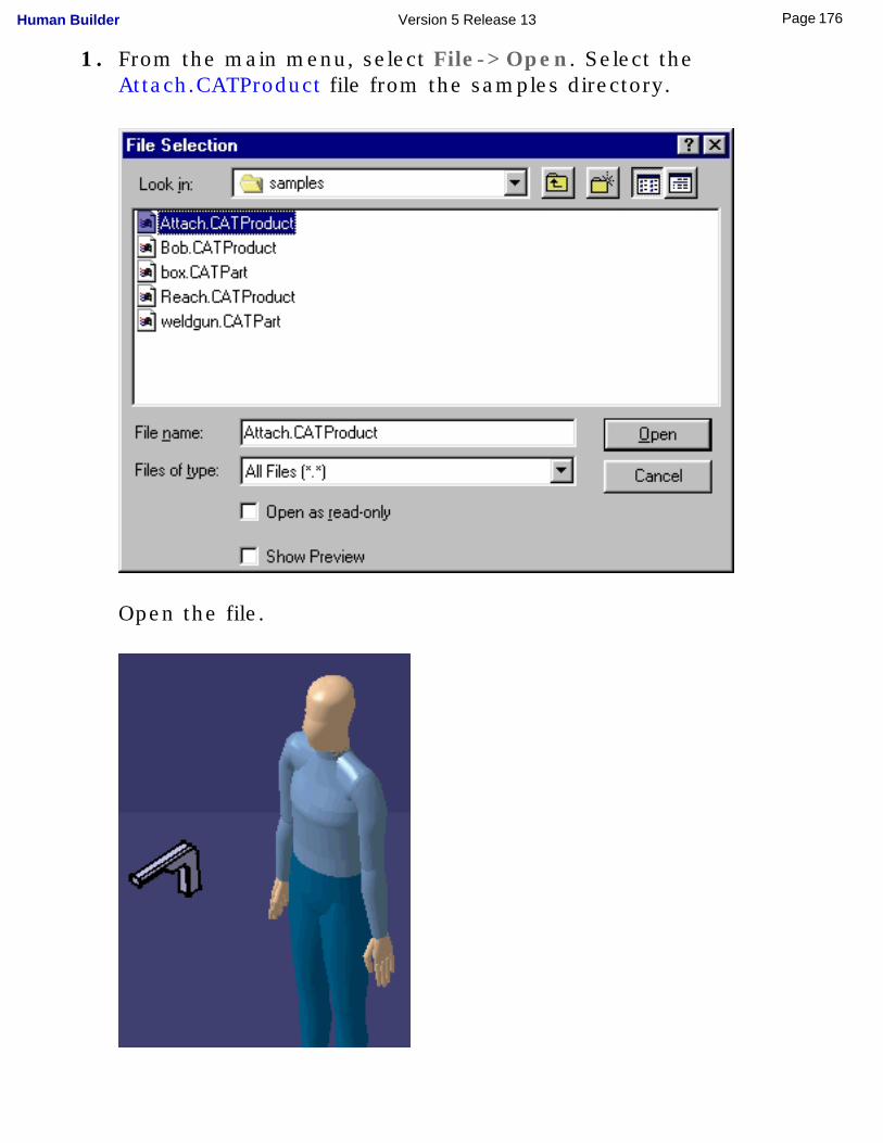
1. From the main menu, select File->Open. Select the Attach.CATProduct file from the samples directory.
Open the file.
176Page Human Builder Version 5 Release 13
2. Position the manikin with respect to the geometry that must be attached.
For this example, load the Attach library with the Load Library command and choose the Attach_sample posture. This places
the manikin posture so that it appears to be handling the tool with its right hand.
3. Select the Attach/Detach icon.
4. Select the object to attach (in this case, the tool).
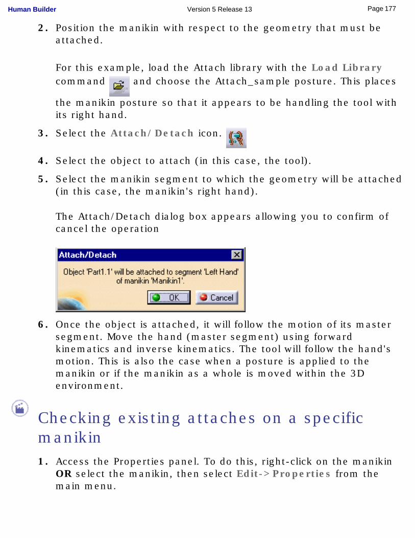
5. Select the manikin segment to which the geometry will be attached (in this case, the manikin's right hand).
The Attach/Detach dialog box appears allowing you to confirm of cancel the operation
6. Once the object is attached, it will follow the motion of its master segment. Move the hand (master segment) using forward kinematics and inverse kinematics. The tool will follow the hand's motion. This is also the case when a posture is applied to the manikin or if the manikin as a whole is moved within the 3D environment.
Checking existing attaches on a specific manikin1. Access the Properties panel. To do this, right-click on the manikin
OR select the manikin, then select Edit->Properties from the main menu.
177Page Human Builder Version 5 Release 13
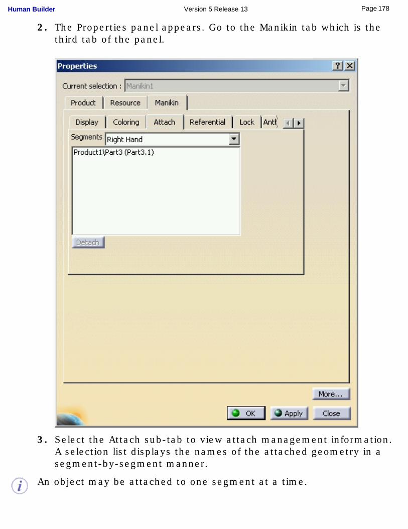
2. The Properties panel appears. Go to the Manikin tab which is the third tab of the panel.
3. Select the Attach sub-tab to view attach management information. A selection list displays the names of the attached geometry in a segment-by-segment manner.
An object may be attached to one segment at a time.
178Page Human Builder Version 5 Release 13
Several objects may be attached to a single segment.
Detaching an object from a manikin segment
There are two ways to detach an object from a segment:● through the Properties panel
● with the Attach/Detach command
Detaching through the Properties Panel
1. Access the manikin Properties Panel. To do this, right-click on the manikin OR select the manikin, then select Edit->Properties from the main menu.
2. The Properties panel appears. Go to the Manikin tab which is the third tab of the panel.
179Page Human Builder Version 5 Release 13
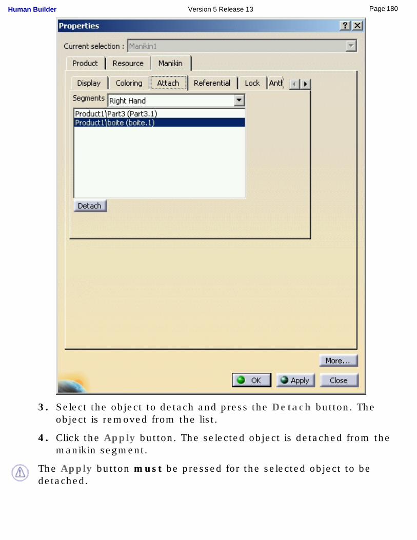
3. Select the object to detach and press the Detach button. The object is removed from the list.
4. Click the Apply button. The selected object is detached from the manikin segment.
The Apply button must be pressed for the selected object to be detached.
180Page Human Builder Version 5 Release 13
Detaching with the Attach/Detach command
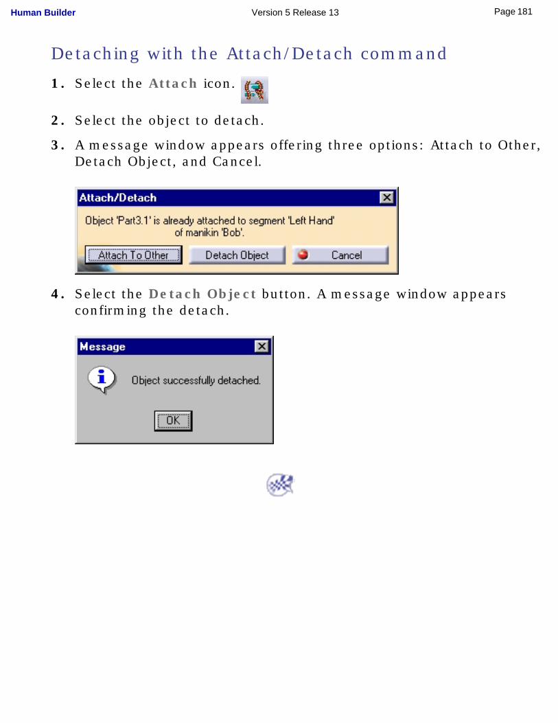
1. Select the Attach icon.
2. Select the object to detach.
3. A message window appears offering three options: Attach to Other, Detach Object, and Cancel.
4. Select the Detach Object button. A message window appears confirming the detach.
181Page Human Builder Version 5 Release 13
Using Manikin Constraint Commands
The commands in the Manikin Constraints toolbar give you the capability to constrain the manikin in its environment. With constraints, the manikin can perform inverse kinematics (IK) to calculate the necessary posture needed to reach multiple specific targets.
A constraint will always belong to one manikin. At any given time, the list of constraints on a manikin will appear underneath that manikin in the specification tree. Inactive constraints will also be listed.
At any time, you may update the active constraints at each modification in the workspace (automatic update), or only update the active constraints when needed (manual update).
By default, constraint update mode is set in the Manual mode and you must select the Update icon in the Manikin Constraints toolbar
each time you want to update the active constraints and resolve the inverse kinematics.
In Automatic mode, the inverse kinematics will react as soon as the configuration of the environment changes; when the objects move, the inverse kinematics updates in real time.
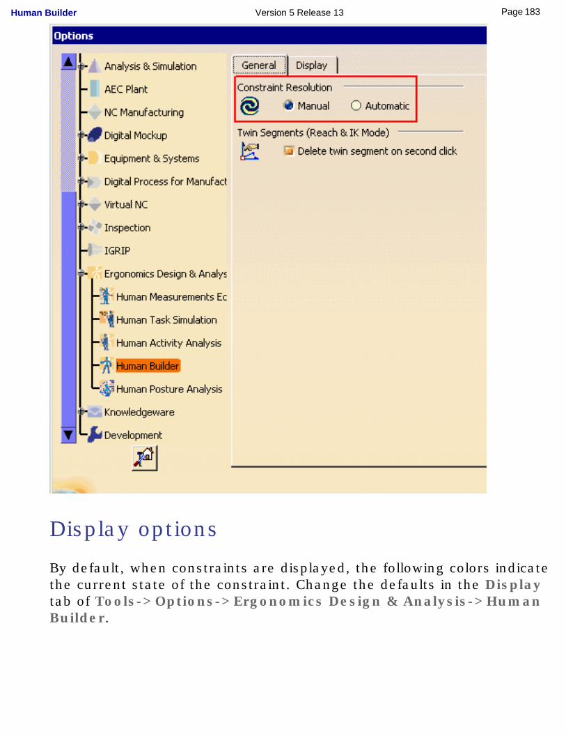
General options
As shown in the image below, you can change the update mode at any time by selecting Tools->Options->Ergonomics Design & Analysis->Human Builder. The Manual and Automatic update options are available in the General tab under the Constraint Resolution heading.
182Page Human Builder Version 5 Release 13
Display options
By default, when constraints are displayed, the following colors indicate the current state of the constraint. Change the defaults in the Display tab of Tools->Options->Ergonomics Design & Analysis->Human Builder.
183Page Human Builder Version 5 Release 13
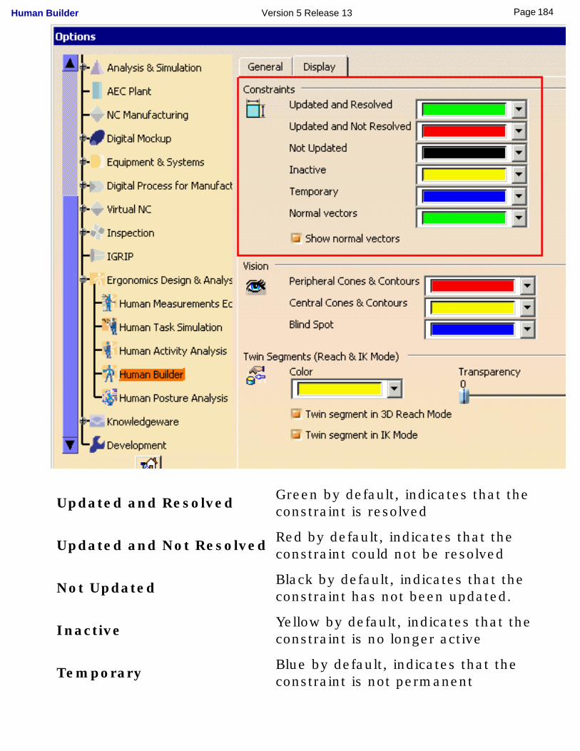
Updated and Resolved Green by default, indicates that the
constraint is resolved
Updated and Not Resolved Red by default, indicates that the constraint could not be resolved
Not Updated Black by default, indicates that the constraint has not been updated.
Inactive Yellow by default, indicates that the constraint is no longer active
Temporary Blue by default, indicates that the constraint is not permanent
184Page Human Builder Version 5 Release 13
Using macros
It is now also possible to record your operations relating to constraints into a VBScript macro. The macros provide the following capabilities:
● ability to create all types of constraints between any manikin segment and a part in its environment
● ability to update these constraints
● ability to activate or deactivate these constraints
● ability to change the type of a constraint, or the segment relationship of a constraint
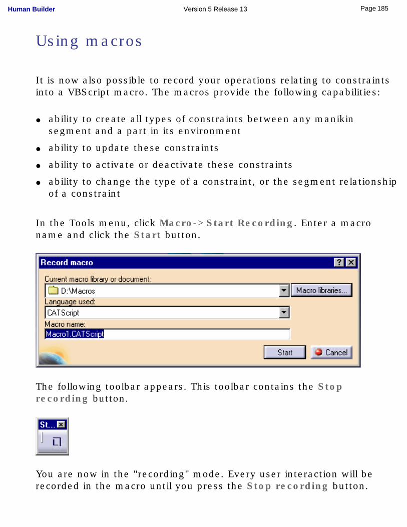
In the Tools menu, click Macro->Start Recording. Enter a macro name and click the Start button.
The following toolbar appears. This toolbar contains the Stop recording button.
You are now in the "recording" mode. Every user interaction will be recorded in the macro until you press the Stop recording button.
185Page Human Builder Version 5 Release 13
Creating constraints
1. From the samples directory, open the Manikin_and_Box.CATProduct file.
For this procedure the constraint update mode is set at the default Manual mode.
2. Select one of the constraint commands from the Manikin Constraint toolbar:
Contact Constraint
Coincidence Constraint
Fix Constraint
Fix On Constraint
Updating constraints 3. Select the Update icon to resolve the active IK constraints.
The constraints and normal vectors are now green indicating that they are resolved.
186Page Human Builder Version 5 Release 13
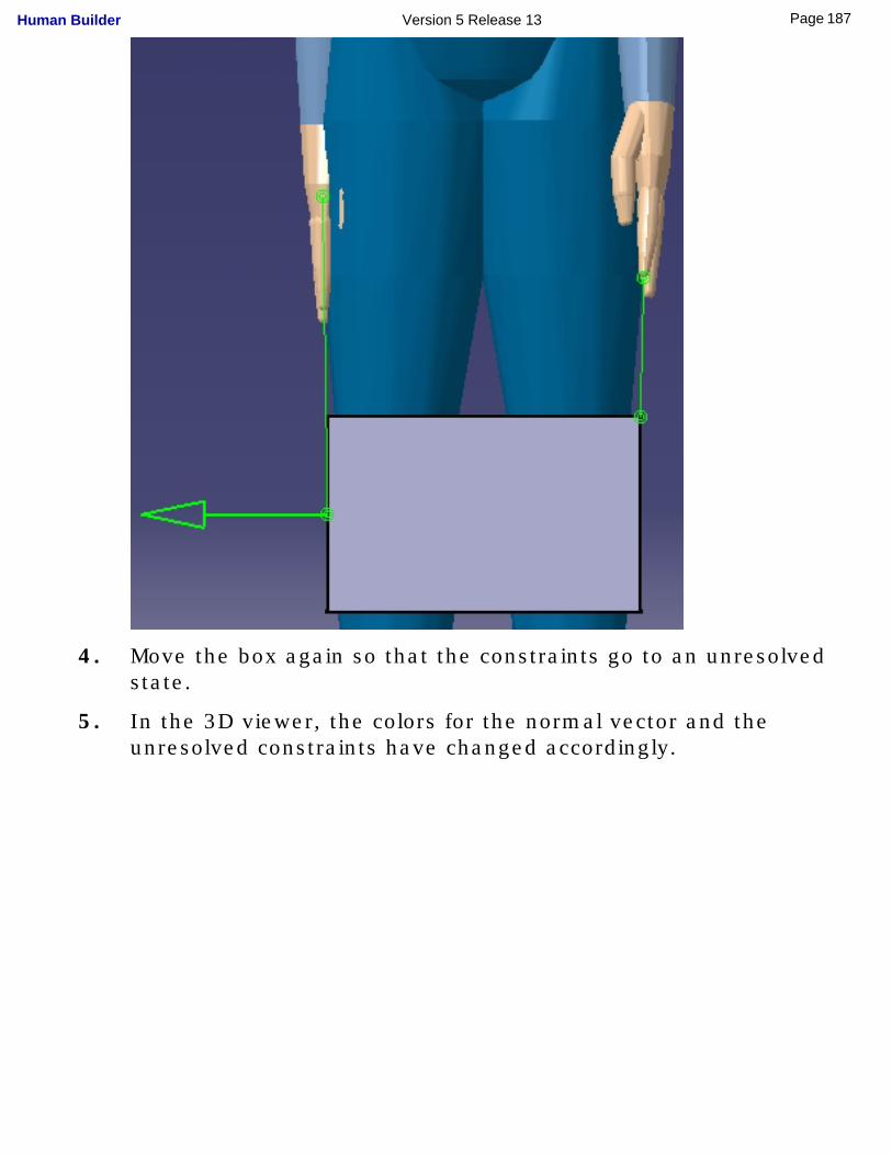
4. Move the box again so that the constraints go to an unresolved state.
5. In the 3D viewer, the colors for the normal vector and the unresolved constraints have changed accordingly.
187Page Human Builder Version 5 Release 13
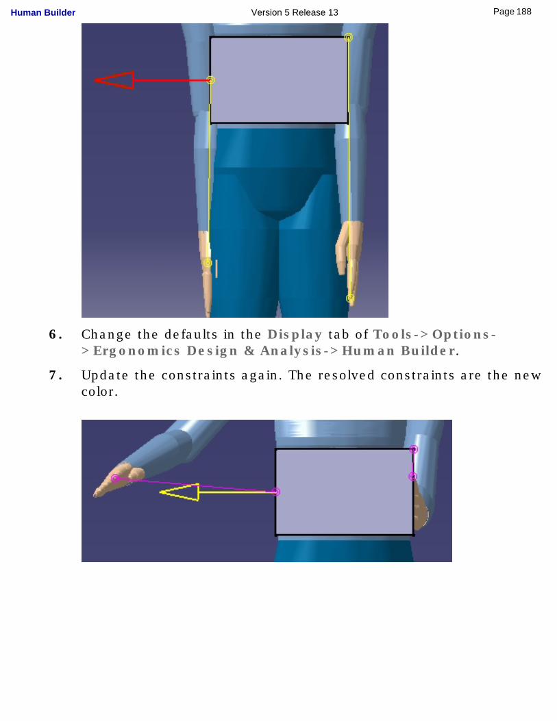
6. Change the defaults in the Display tab of Tools->Options->Ergonomics Design & Analysis->Human Builder.
7. Update the constraints again. The resolved constraints are the new color.
188Page Human Builder Version 5 Release 13
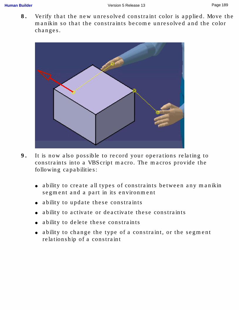
8. Verify that the new unresolved constraint color is applied. Move the manikin so that the constraints become unresolved and the color changes.
9. It is now also possible to record your operations relating to constraints into a VBScript macro. The macros provide the following capabilities:
● ability to create all types of constraints between any manikin segment and a part in its environment
● ability to update these constraints
● ability to activate or deactivate these constraints
● ability to delete these constraints
● ability to change the type of a constraint, or the segment relationship of a constraint
189Page Human Builder Version 5 Release 13
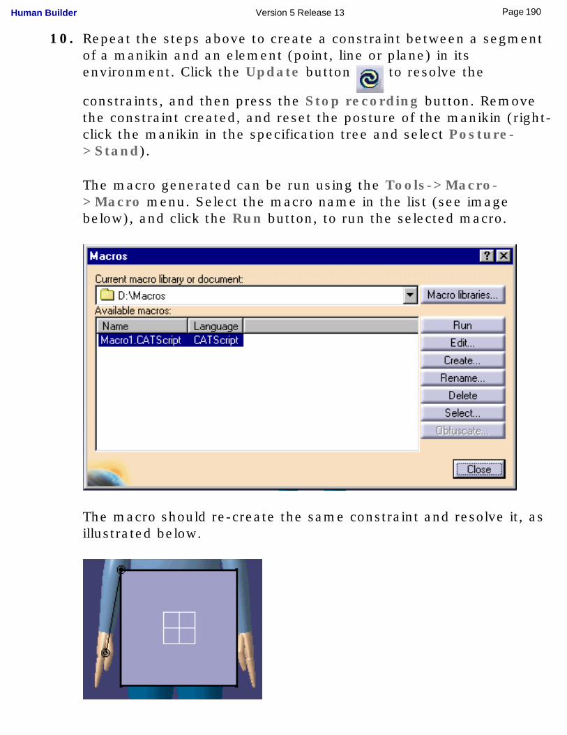
10. Repeat the steps above to create a constraint between a segment of a manikin and an element (point, line or plane) in its environment. Click the Update button to resolve the
constraints, and then press the Stop recording button. Remove the constraint created, and reset the posture of the manikin (right-click the manikin in the specification tree and select Posture->Stand).
The macro generated can be run using the Tools->Macro->Macro menu. Select the macro name in the list (see image below), and click the Run button, to run the selected macro.
The macro should re-create the same constraint and resolve it, as illustrated below.
190Page Human Builder Version 5 Release 13
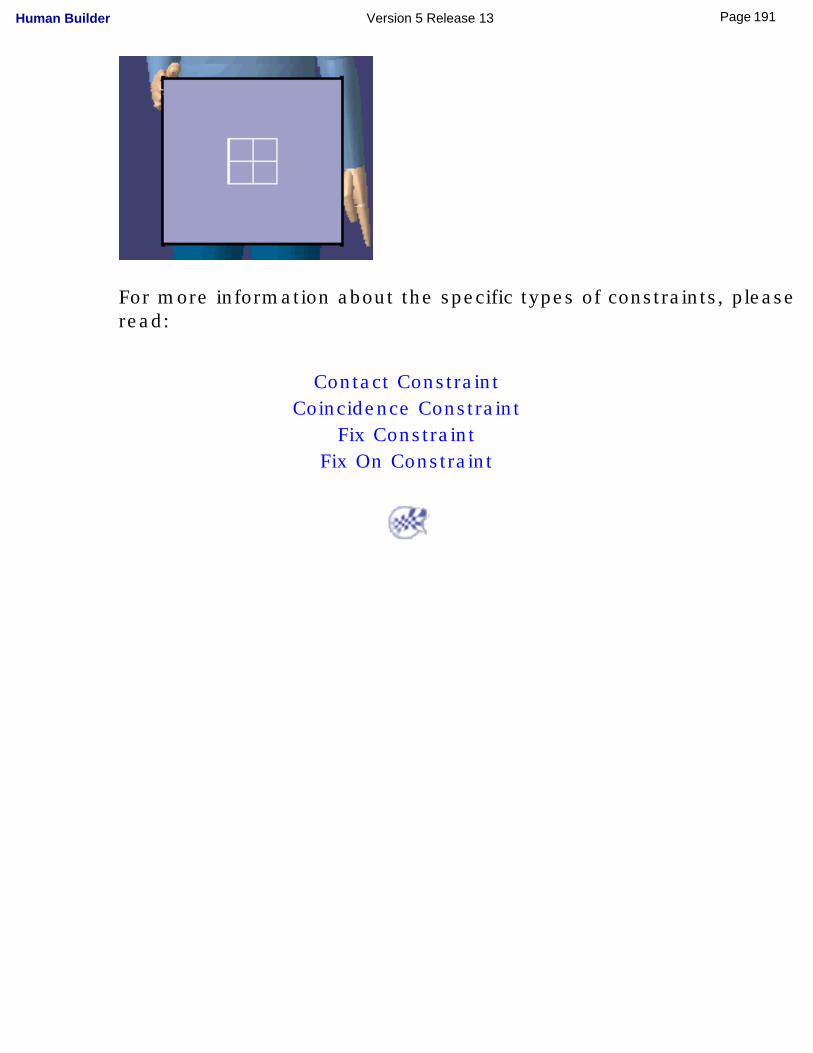
For more information about the specific types of constraints, please read:
Contact ConstraintCoincidence Constraint
Fix ConstraintFix On Constraint
191Page Human Builder Version 5 Release 13
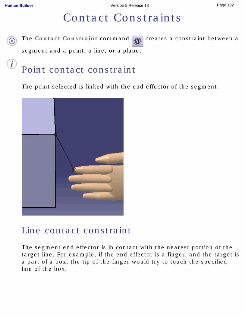
Contact Constraints
The Contact Constraint command creates a constraint between a
segment and a point, a line, or a plane.
Point contact constraint
The point selected is linked with the end effector of the segment.
Line contact constraint
The segment end effector is in contact with the nearest portion of the target line. For example, if the end effector is a finger, and the target is a part of a box, the tip of the finger would try to touch the specified line of the box.
192Page Human Builder Version 5 Release 13
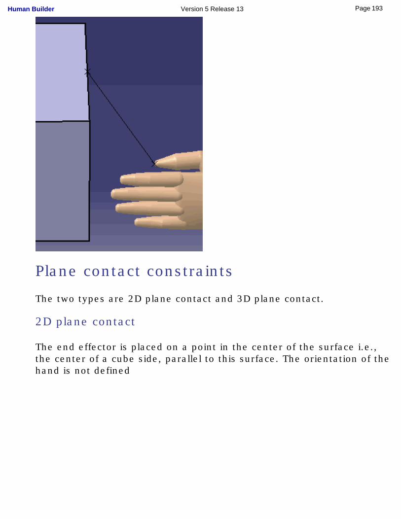
Plane contact constraints
The two types are 2D plane contact and 3D plane contact.
2D plane contact
The end effector is placed on a point in the center of the surface i.e., the center of a cube side, parallel to this surface. The orientation of the hand is not defined
193Page Human Builder Version 5 Release 13
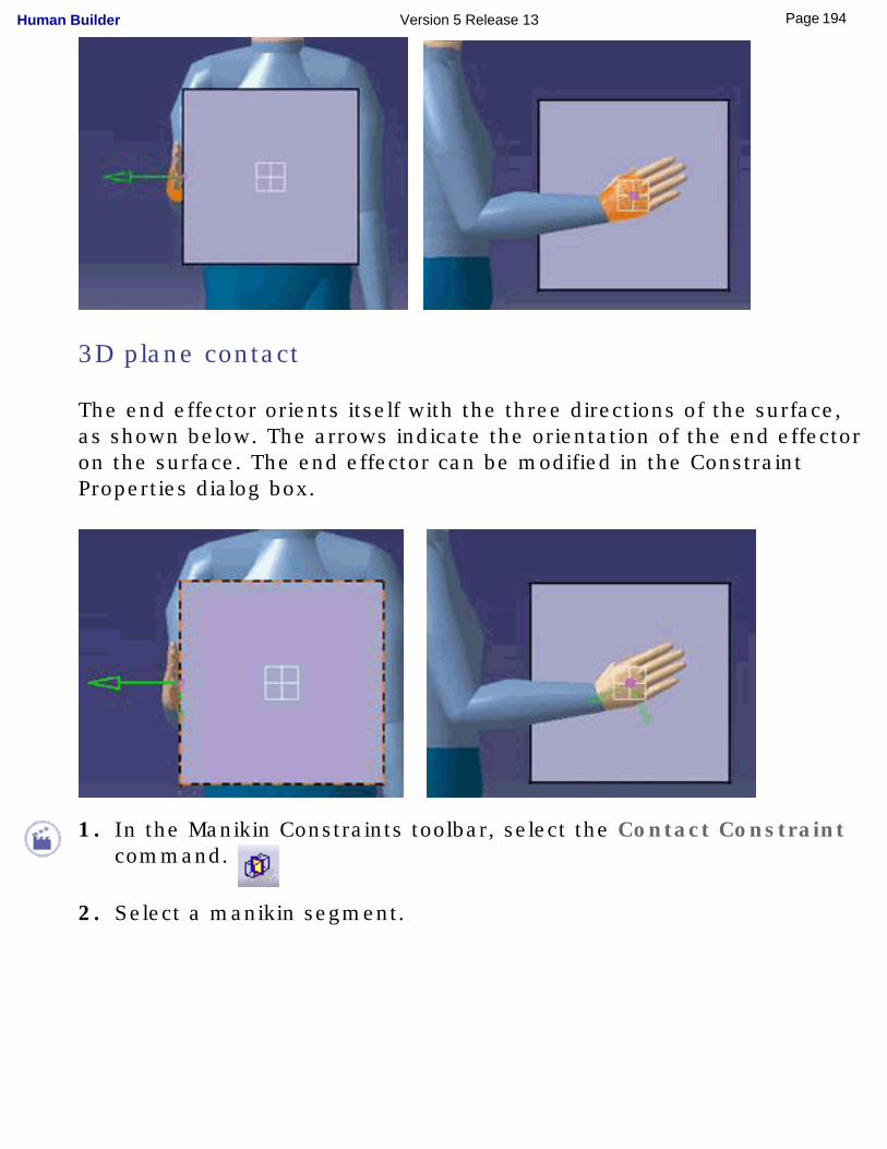
3D plane contact
The end effector orients itself with the three directions of the surface, as shown below. The arrows indicate the orientation of the end effector on the surface. The end effector can be modified in the Constraint Properties dialog box.
1. In the Manikin Constraints toolbar, select the Contact Constraint command.
2. Select a manikin segment.
194Page Human Builder Version 5 Release 13
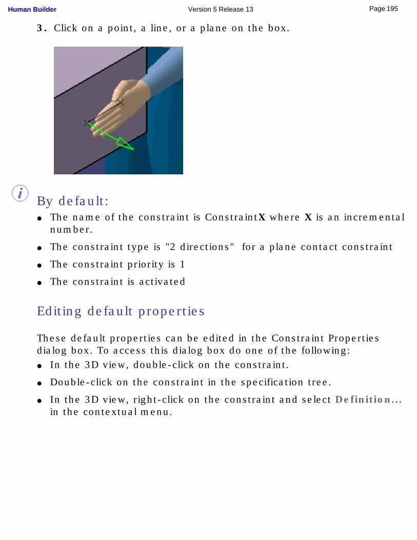
3. Click on a point, a line, or a plane on the box.
By default:● The name of the constraint is ConstraintX where X is an incremental
number.
● The constraint type is "2 directions" for a plane contact constraint
● The constraint priority is 1
● The constraint is activated
Editing default properties
These default properties can be edited in the Constraint Properties dialog box. To access this dialog box do one of the following:● In the 3D view, double-click on the constraint.
● Double-click on the constraint in the specification tree.
● In the 3D view, right-click on the constraint and select Definition... in the contextual menu.
195Page Human Builder Version 5 Release 13
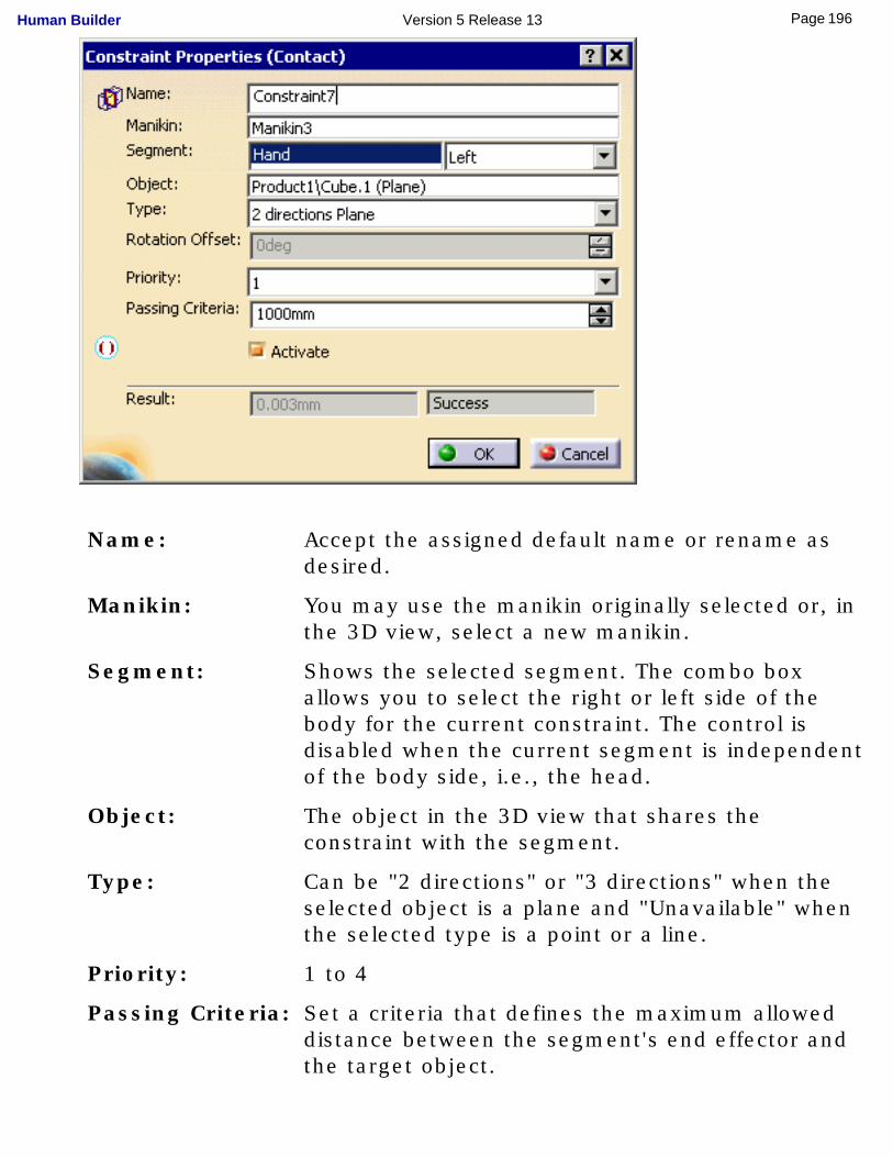
Name: Accept the assigned default name or rename as desired.
Manikin: You may use the manikin originally selected or, in the 3D view, select a new manikin.
Segment: Shows the selected segment. The combo box allows you to select the right or left side of the body for the current constraint. The control is disabled when the current segment is independent of the body side, i.e., the head.
Object: The object in the 3D view that shares the constraint with the segment.
Type: Can be "2 directions" or "3 directions" when the selected object is a plane and "Unavailable" when the selected type is a point or a line.
Priority: 1 to 4
Passing Criteria: Set a criteria that defines the maximum allowed distance between the segment's end effector and the target object.
196Page Human Builder Version 5 Release 13
Result: Shows the actual distance between the segment's end effector and the target object. The text "Success" or "Failed" is displayed depending whether the distance (length of constraint) is superior or inferior to that amount.
197Page Human Builder Version 5 Release 13
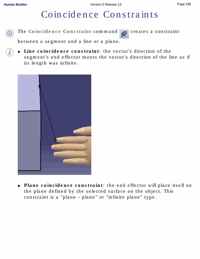
Coincidence Constraints
The Coincidence Constraint command creates a constraint
between a segment and a line or a plane.
● Line coincidence constraint: the vector's direction of the segment's end effector meets the vector's direction of the line as if its length was infinite.
● Plane coincidence constraint: the end effector will place itself on the plane defined by the selected surface on the object. This constraint is a "plane - plane" or "infinite plane" type.
198Page Human Builder Version 5 Release 13
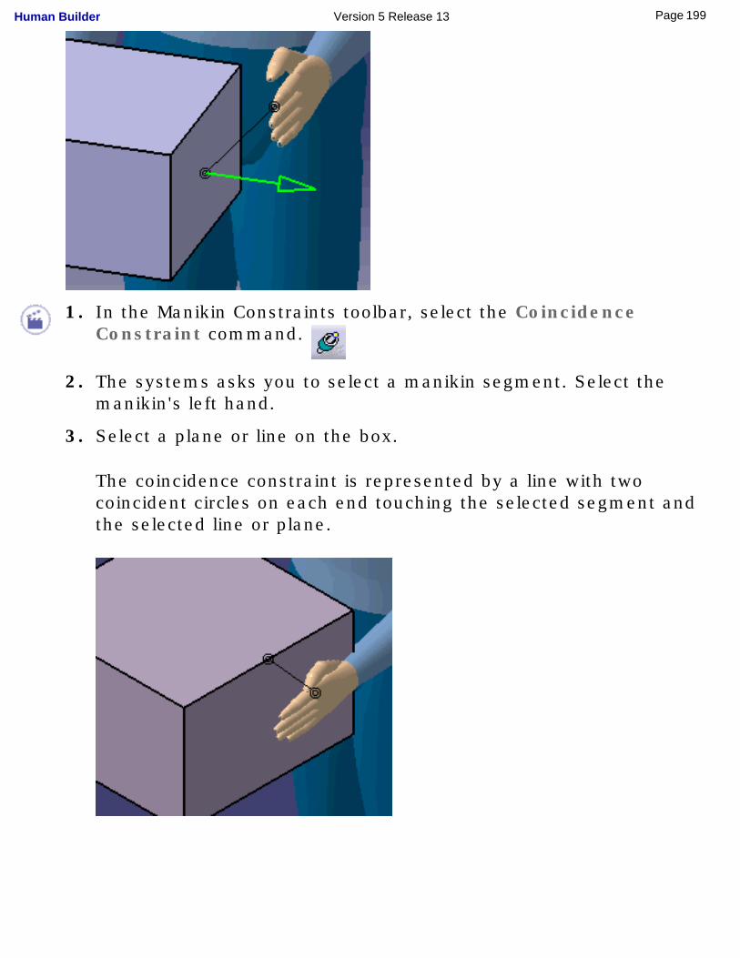
1. In the Manikin Constraints toolbar, select the Coincidence Constraint command.
2. The systems asks you to select a manikin segment. Select the manikin's left hand.
3. Select a plane or line on the box.
The coincidence constraint is represented by a line with two coincident circles on each end touching the selected segment and the selected line or plane.
199Page Human Builder Version 5 Release 13
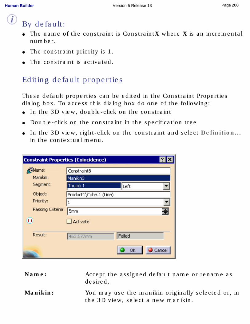
By default:● The name of the constraint is ConstraintX where X is an incremental
number.
● The constraint priority is 1.
● The constraint is activated.
Editing default properties
These default properties can be edited in the Constraint Properties dialog box. To access this dialog box do one of the following:● In the 3D view, double-click on the constraint
● Double-click on the constraint in the specification tree
● In the 3D view, right-click on the constraint and select Definition... in the contextual menu.
Name: Accept the assigned default name or rename as desired.
Manikin: You may use the manikin originally selected or, in the 3D view, select a new manikin.
200Page Human Builder Version 5 Release 13
Segment: Shows the selected segment. The combo box allows you to select the right or left side of the body for the current constraint. The control is disabled when the current segment is independent of the body side, i.e., the head.
Object: The object in the 3D view that shares the constraint with the segment.
Priority: 1 to 4
Passing Criteria: Set a criteria that defines the maximum allowed distance between the segment's end effector and the target object.
Result: Shows the actual distance between the segment's end effector and the target object. The text "Success" or "Failed" is displayed depending whether the distance (length of constraint) is superior or inferior to that amount.
201Page Human Builder Version 5 Release 13
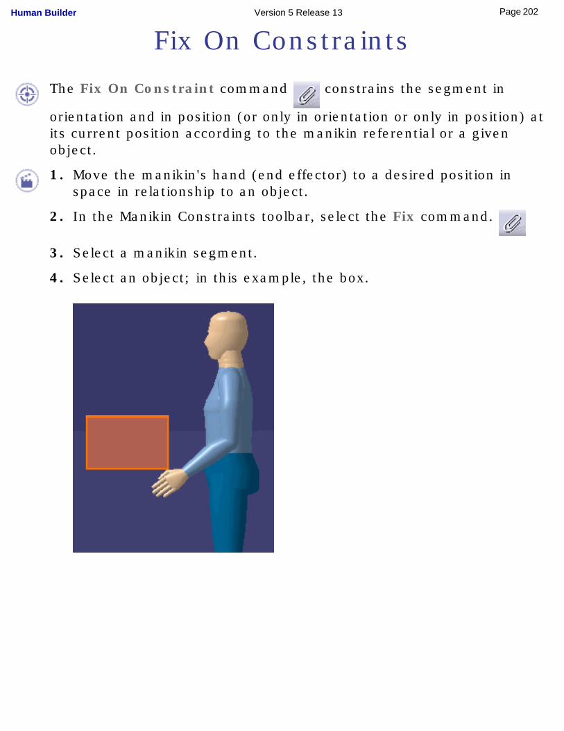
Fix On Constraints
The Fix On Constraint command constrains the segment in
orientation and in position (or only in orientation or only in position) at its current position according to the manikin referential or a given object.
1. Move the manikin's hand (end effector) to a desired position in space in relationship to an object.
2. In the Manikin Constraints toolbar, select the Fix command.
3. Select a manikin segment.
4. Select an object; in this example, the box.
202Page Human Builder Version 5 Release 13
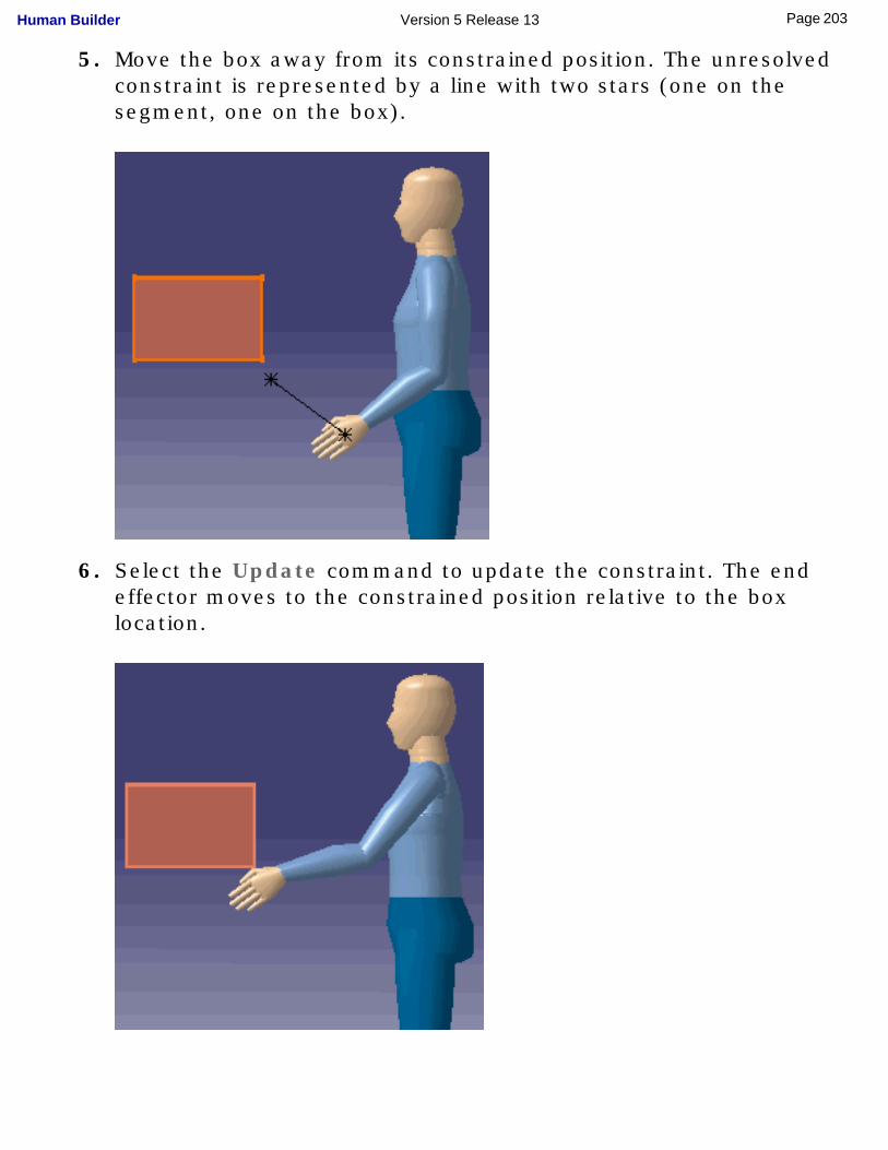
5. Move the box away from its constrained position. The unresolved constraint is represented by a line with two stars (one on the segment, one on the box).
6. Select the Update command to update the constraint. The end effector moves to the constrained position relative to the box location.
203Page Human Builder Version 5 Release 13
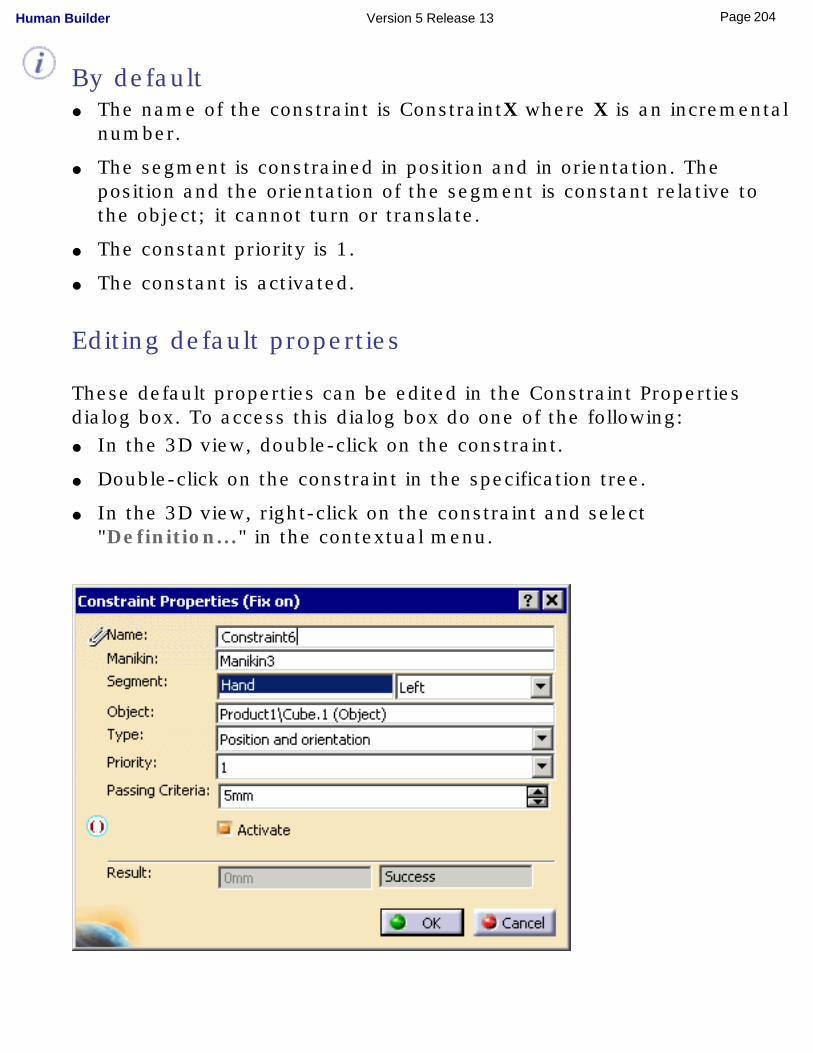
By default● The name of the constraint is ConstraintX where X is an incremental
number.
● The segment is constrained in position and in orientation. The position and the orientation of the segment is constant relative to the object; it cannot turn or translate.
● The constant priority is 1.
● The constant is activated.
Editing default properties
These default properties can be edited in the Constraint Properties dialog box. To access this dialog box do one of the following:● In the 3D view, double-click on the constraint.
● Double-click on the constraint in the specification tree.
● In the 3D view, right-click on the constraint and select "Definition..." in the contextual menu.
204Page Human Builder Version 5 Release 13
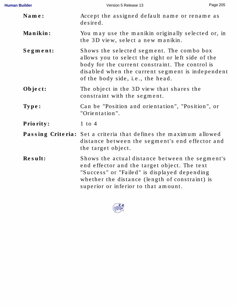
Name: Accept the assigned default name or rename as desired.
Manikin: You may use the manikin originally selected or, in the 3D view, select a new manikin.
Segment: Shows the selected segment. The combo box allows you to select the right or left side of the body for the current constraint. The control is disabled when the current segment is independent of the body side, i.e., the head.
Object: The object in the 3D view that shares the constraint with the segment.
Type: Can be "Position and orientation", "Position", or "Orientation".
Priority: 1 to 4
Passing Criteria: Set a criteria that defines the maximum allowed distance between the segment's end effector and the target object.
Result: Shows the actual distance between the segment's end effector and the target object. The text "Success" or "Failed" is displayed depending whether the distance (length of constraint) is superior or inferior to that amount.
205Page Human Builder Version 5 Release 13
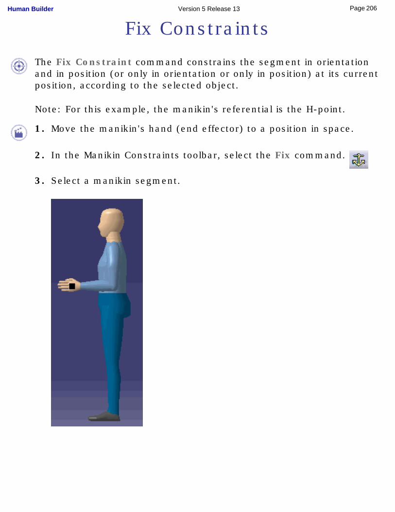
Fix Constraints
The Fix Constraint command constrains the segment in orientation and in position (or only in orientation or only in position) at its current position, according to the selected object.
Note: For this example, the manikin's referential is the H-point.
1. Move the manikin's hand (end effector) to a position in space.
2. In the Manikin Constraints toolbar, select the Fix command.
3. Select a manikin segment.
206Page Human Builder Version 5 Release 13
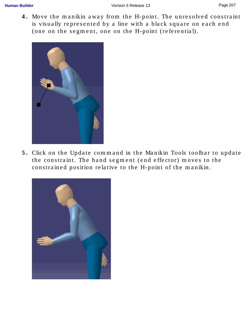
4. Move the manikin away from the H-point. The unresolved constraint is visually represented by a line with a black square on each end (one on the segment, one on the H-point (referential).
5. Click on the Update command in the Manikin Tools toolbar to update the constraint. The hand segment (end effector) moves to the constrained position relative to the H-point of the manikin.
207Page Human Builder Version 5 Release 13
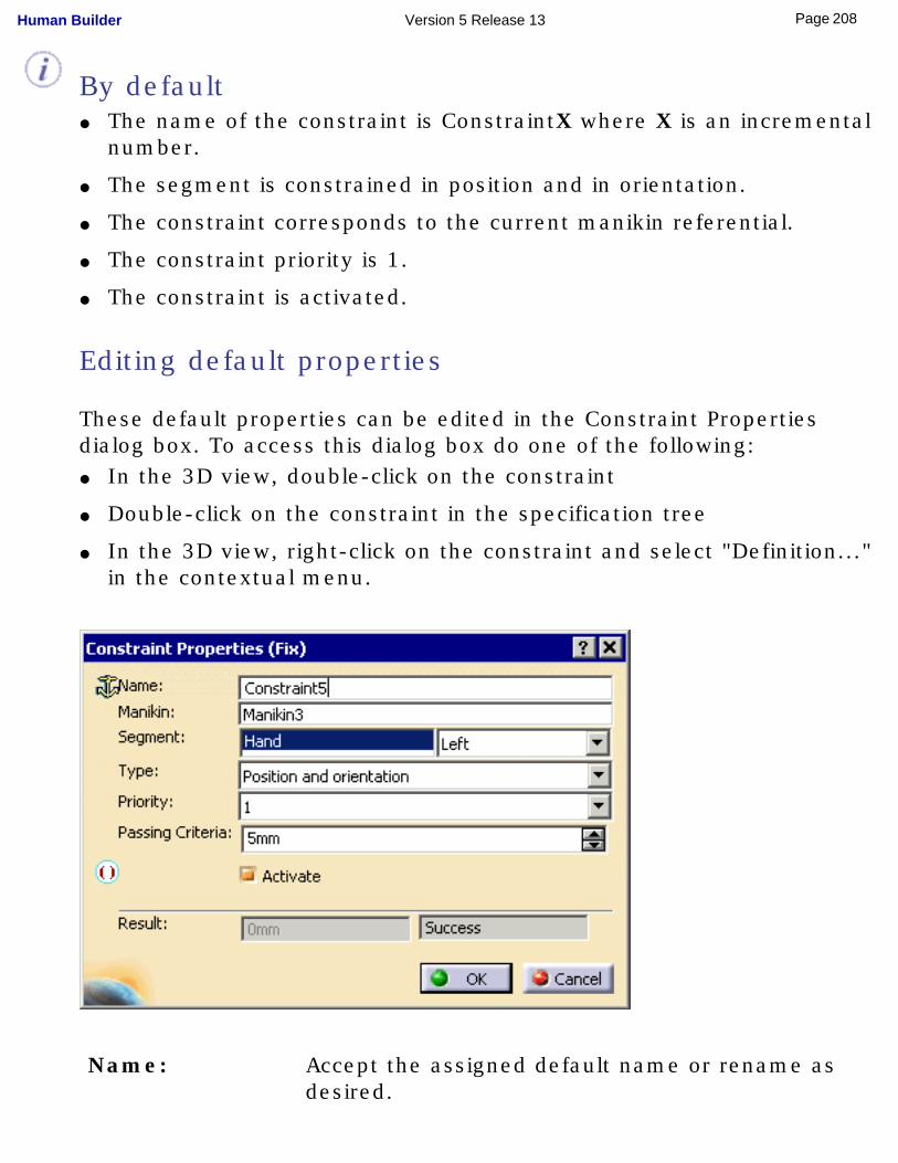
By default● The name of the constraint is ConstraintX where X is an incremental
number.
● The segment is constrained in position and in orientation.
● The constraint corresponds to the current manikin referential.
● The constraint priority is 1.
● The constraint is activated.
Editing default properties
These default properties can be edited in the Constraint Properties dialog box. To access this dialog box do one of the following:● In the 3D view, double-click on the constraint
● Double-click on the constraint in the specification tree
● In the 3D view, right-click on the constraint and select "Definition..." in the contextual menu.
Name: Accept the assigned default name or rename as desired.
208Page Human Builder Version 5 Release 13
Manikin: You may use the manikin originally selected or, in the 3D view, select a new manikin.
Segment: Shows the selected segment. The combo box allows you to select the right or left side of the body for the current constraint. The control is disabled when the current segment is independent of the body side, i.e., the head.
Object: The object in the 3D view that shares the constraint with the segment.
Type: Can be "Position and orientation", "Position", or "Orientation".
Priority: 1 to 4
Passing Criteria: Set a criteria that defines the maximum allowed distance between the segment's end effector and the target object.
Result: Shows the actual distance between the segment's end effector and the target object. The text "Success" or "Failed" is displayed depending whether the distance (length of constraint) is superior or inferior to that amount.
209Page Human Builder Version 5 Release 13
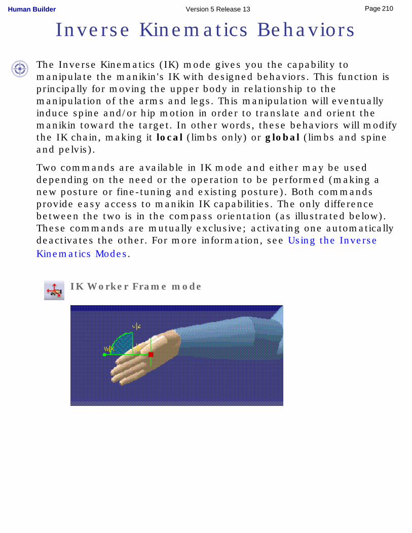
Inverse Kinematics Behaviors
The Inverse Kinematics (IK) mode gives you the capability to manipulate the manikin's IK with designed behaviors. This function is principally for moving the upper body in relationship to the manipulation of the arms and legs. This manipulation will eventually induce spine and/or hip motion in order to translate and orient the manikin toward the target. In other words, these behaviors will modify the IK chain, making it local (limbs only) or global (limbs and spine and pelvis).
Two commands are available in IK mode and either may be used depending on the need or the operation to be performed (making a new posture or fine-tuning and existing posture). Both commands provide easy access to manikin IK capabilities. The only difference between the two is in the compass orientation (as illustrated below). These commands are mutually exclusive; activating one automatically deactivates the other. For more information, see Using the Inverse Kinematics Modes.
IK Worker Frame mode
210Page Human Builder Version 5 Release 13
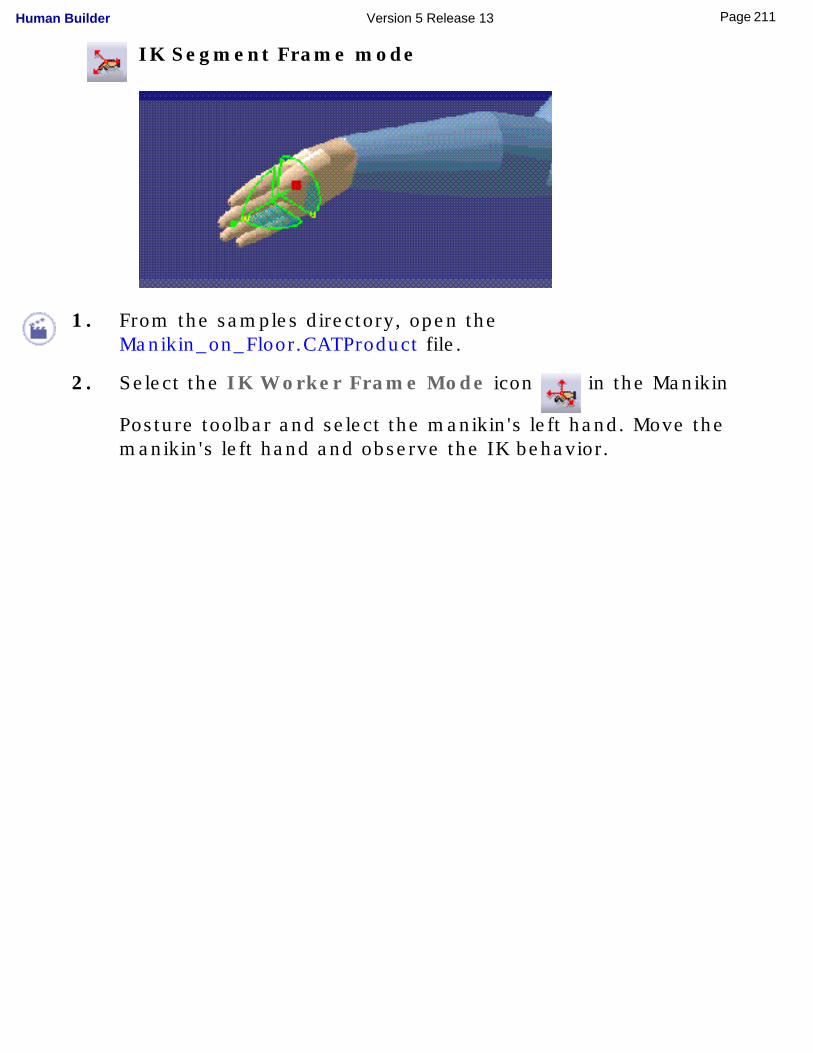
IK Segment Frame mode
1. From the samples directory, open the Manikin_on_Floor.CATProduct file.
2. Select the IK Worker Frame Mode icon in the Manikin
Posture toolbar and select the manikin's left hand. Move the manikin's left hand and observe the IK behavior.
211Page Human Builder Version 5 Release 13
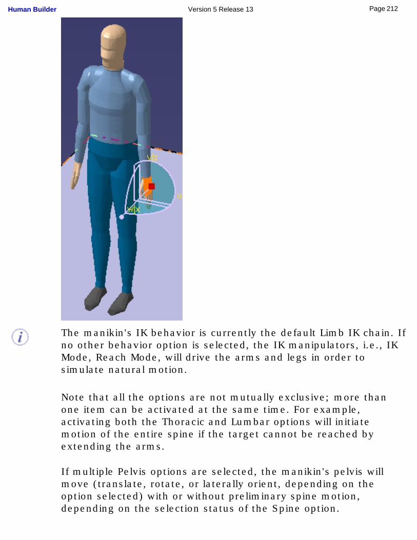
The manikin's IK behavior is currently the default Limb IK chain. If no other behavior option is selected, the IK manipulators, i.e., IK Mode, Reach Mode, will drive the arms and legs in order to simulate natural motion.
Note that all the options are not mutually exclusive; more than one item can be activated at the same time. For example, activating both the Thoracic and Lumbar options will initiate motion of the entire spine if the target cannot be reached by extending the arms.
If multiple Pelvis options are selected, the manikin's pelvis will move (translate, rotate, or laterally orient, depending on the option selected) with or without preliminary spine motion, depending on the selection status of the Spine option.
212Page Human Builder Version 5 Release 13
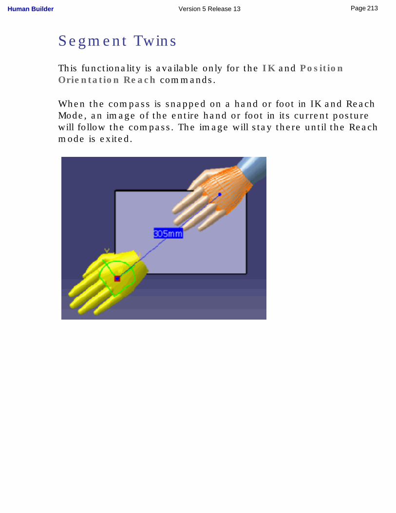
Segment Twins
This functionality is available only for the IK and Position Orientation Reach commands.
When the compass is snapped on a hand or foot in IK and Reach Mode, an image of the entire hand or foot in its current posture will follow the compass. The image will stay there until the Reach mode is exited.
213Page Human Builder Version 5 Release 13
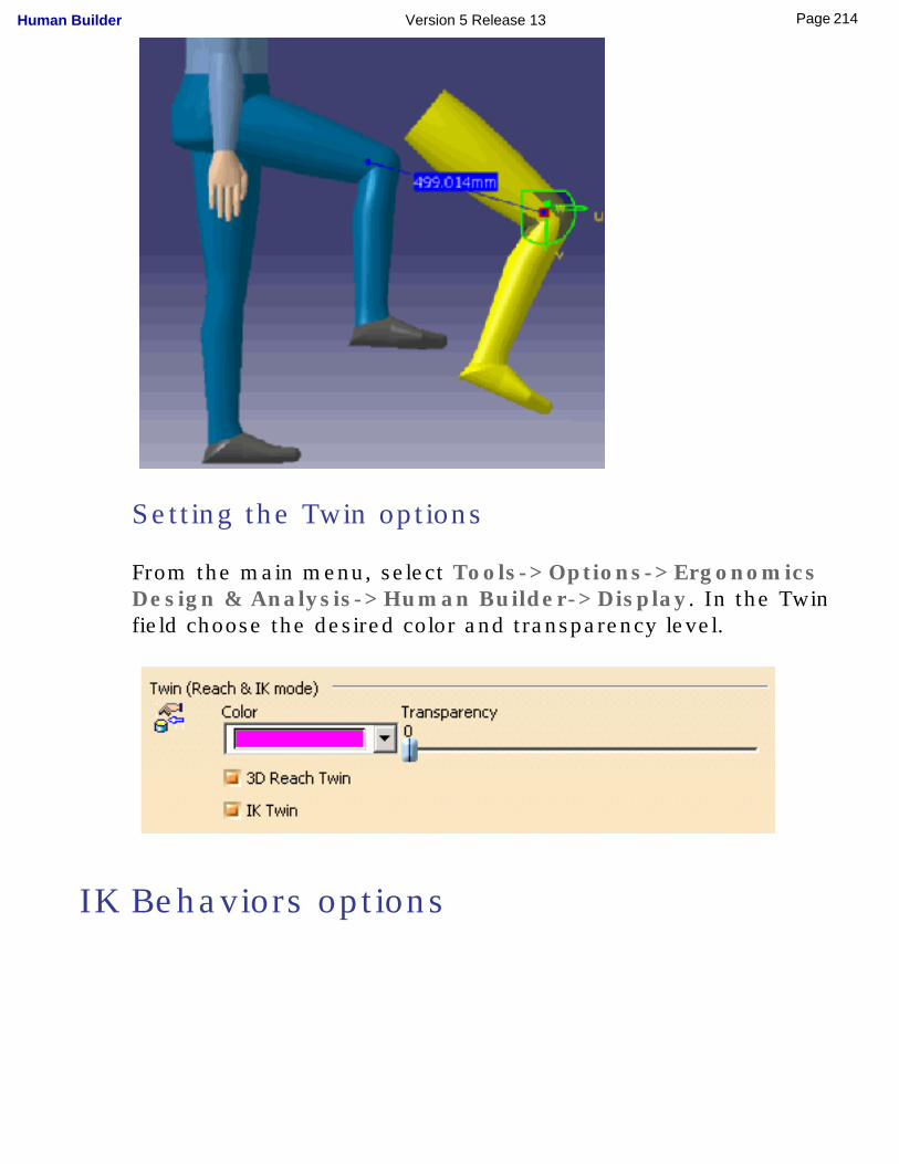
Setting the Twin options
From the main menu, select Tools->Options->Ergonomics Design & Analysis->Human Builder->Display. In the Twin field choose the desired color and transparency level.
IK Behaviors options
214Page Human Builder Version 5 Release 13
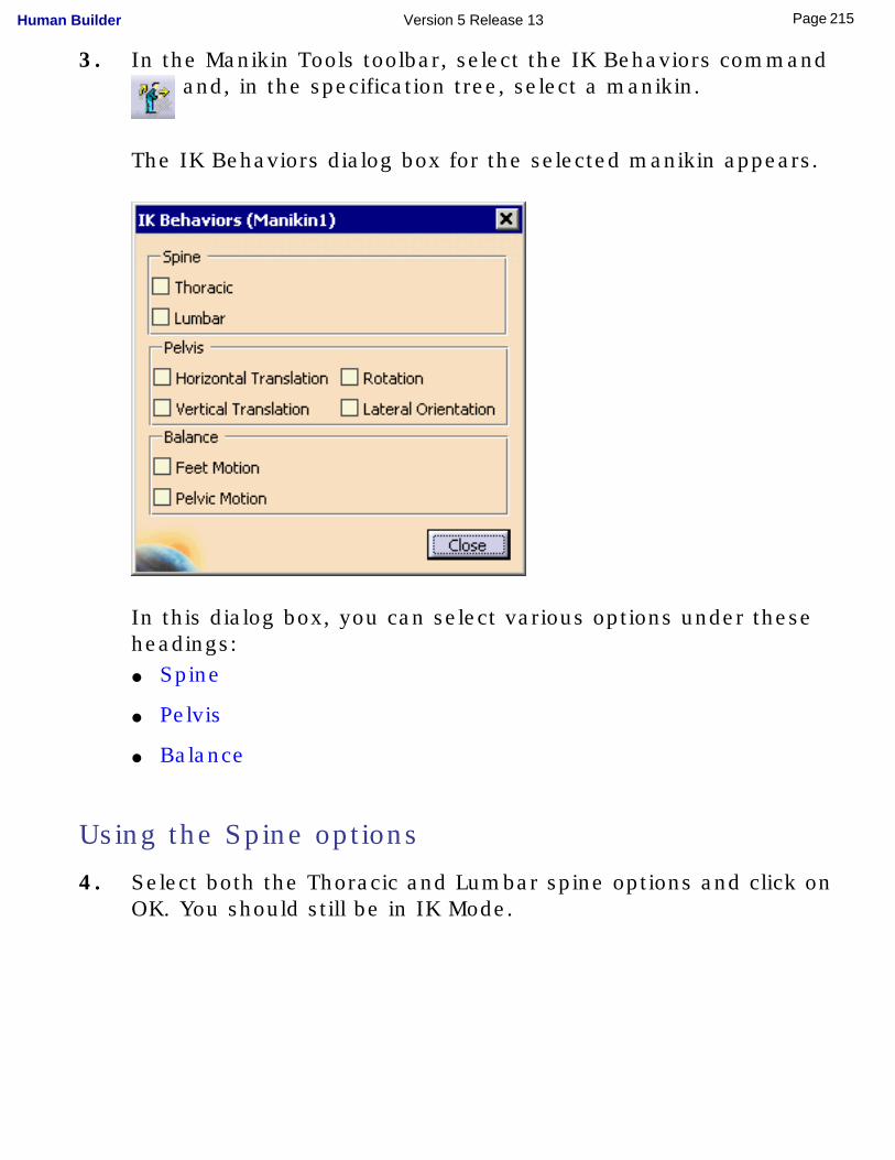
3. In the Manikin Tools toolbar, select the IK Behaviors command and, in the specification tree, select a manikin.
The IK Behaviors dialog box for the selected manikin appears.
In this dialog box, you can select various options under these headings:● Spine
● Pelvis
● Balance
Using the Spine options
4. Select both the Thoracic and Lumbar spine options and click on OK. You should still be in IK Mode.
215Page Human Builder Version 5 Release 13
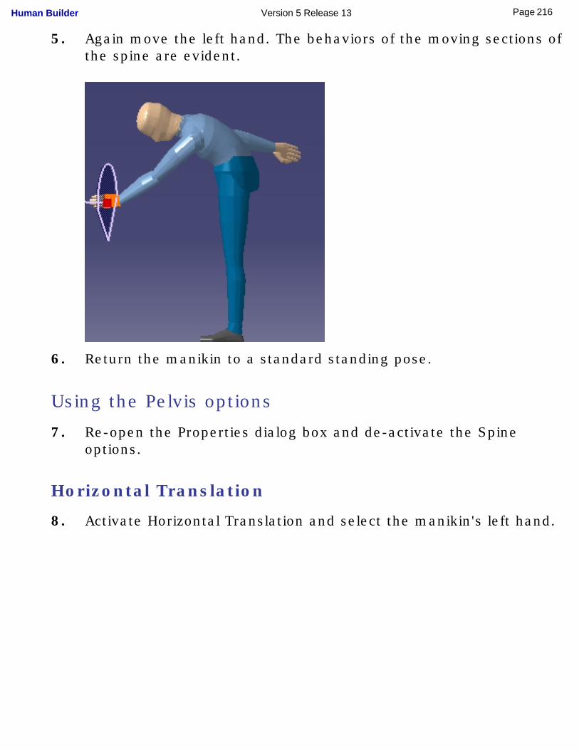
5. Again move the left hand. The behaviors of the moving sections of the spine are evident.
6. Return the manikin to a standard standing pose.
Using the Pelvis options
7. Re-open the Properties dialog box and de-activate the Spine options.
Horizontal Translation
8. Activate Horizontal Translation and select the manikin's left hand.
216Page Human Builder Version 5 Release 13
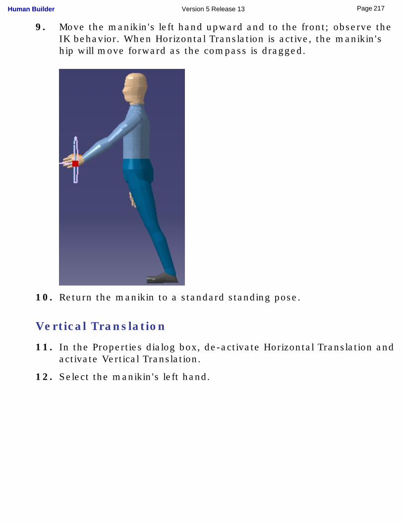
9. Move the manikin's left hand upward and to the front; observe the IK behavior. When Horizontal Translation is active, the manikin's hip will move forward as the compass is dragged.
10. Return the manikin to a standard standing pose.
Vertical Translation
11. In the Properties dialog box, de-activate Horizontal Translation and activate Vertical Translation.
12. Select the manikin's left hand.
217Page Human Builder Version 5 Release 13
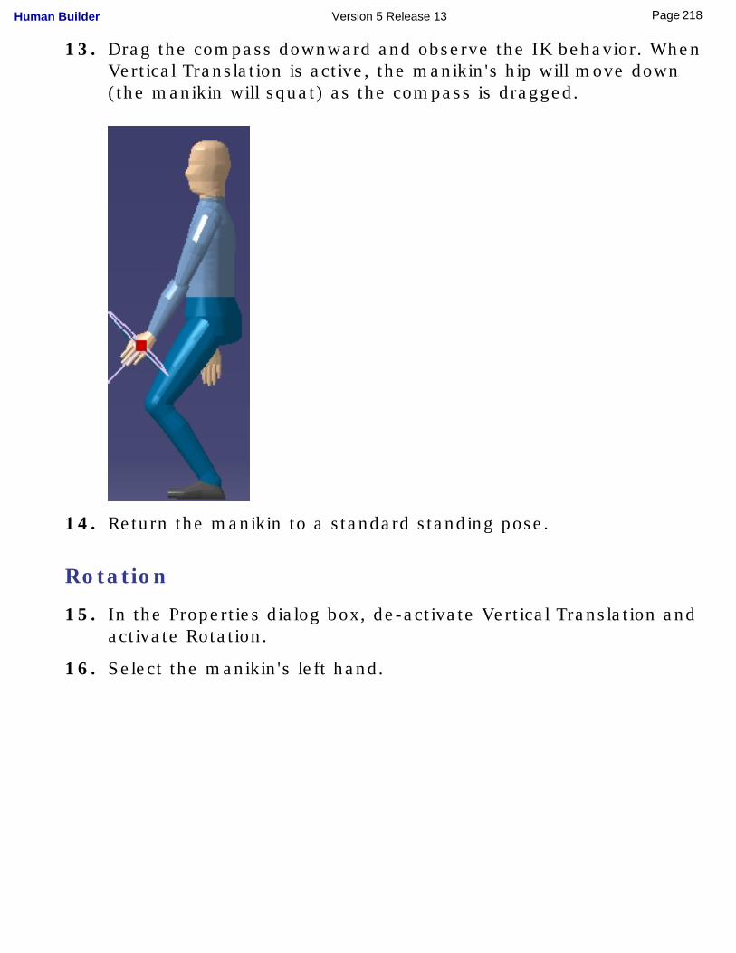
13. Drag the compass downward and observe the IK behavior. When Vertical Translation is active, the manikin's hip will move down (the manikin will squat) as the compass is dragged.
14. Return the manikin to a standard standing pose.
Rotation
15. In the Properties dialog box, de-activate Vertical Translation and activate Rotation.
16. Select the manikin's left hand.
218Page Human Builder Version 5 Release 13
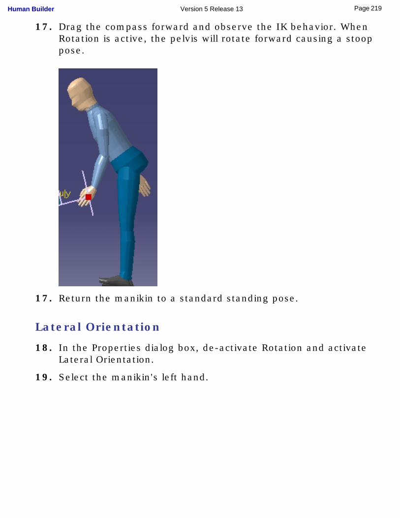
17. Drag the compass forward and observe the IK behavior. When Rotation is active, the pelvis will rotate forward causing a stoop pose.
17. Return the manikin to a standard standing pose.
Lateral Orientation
18. In the Properties dialog box, de-activate Rotation and activate Lateral Orientation.
19. Select the manikin's left hand.
219Page Human Builder Version 5 Release 13
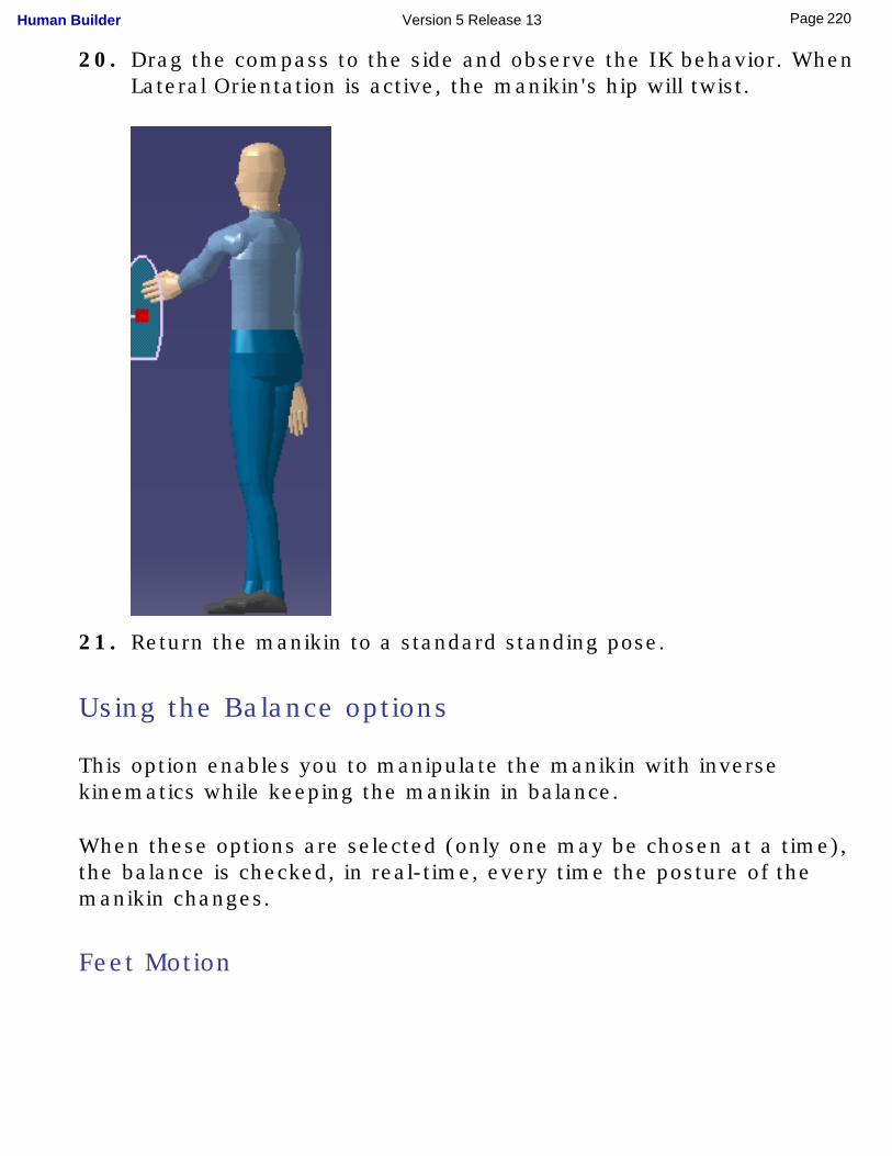
20. Drag the compass to the side and observe the IK behavior. When Lateral Orientation is active, the manikin's hip will twist.
21. Return the manikin to a standard standing pose.
Using the Balance options
This option enables you to manipulate the manikin with inverse kinematics while keeping the manikin in balance.
When these options are selected (only one may be chosen at a time), the balance is checked, in real-time, every time the posture of the manikin changes.
Feet Motion
220Page Human Builder Version 5 Release 13
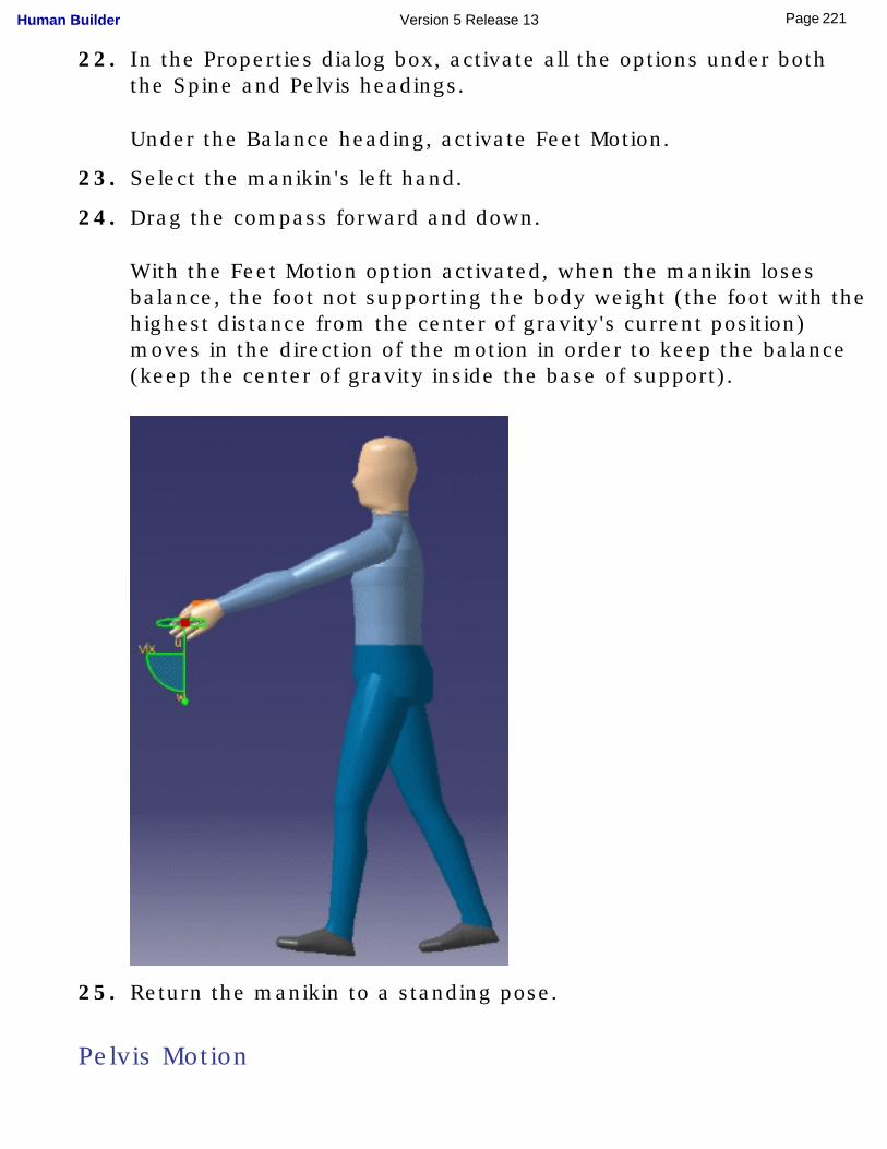
22. In the Properties dialog box, activate all the options under both the Spine and Pelvis headings.
Under the Balance heading, activate Feet Motion.
23. Select the manikin's left hand.
24. Drag the compass forward and down.
With the Feet Motion option activated, when the manikin loses balance, the foot not supporting the body weight (the foot with the highest distance from the center of gravity's current position) moves in the direction of the motion in order to keep the balance (keep the center of gravity inside the base of support).
25. Return the manikin to a standing pose.
Pelvis Motion
221Page Human Builder Version 5 Release 13
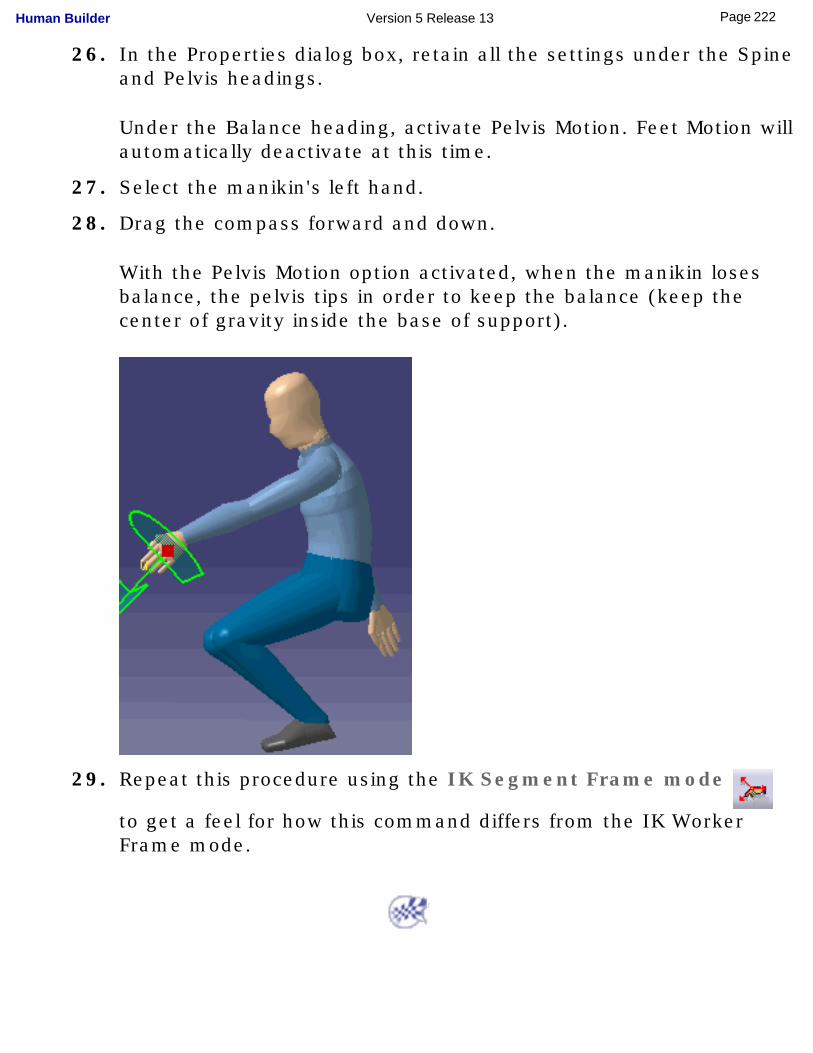
26. In the Properties dialog box, retain all the settings under the Spine and Pelvis headings.
Under the Balance heading, activate Pelvis Motion. Feet Motion will automatically deactivate at this time.
27. Select the manikin's left hand.
28. Drag the compass forward and down.
With the Pelvis Motion option activated, when the manikin loses balance, the pelvis tips in order to keep the balance (keep the center of gravity inside the base of support).
29. Repeat this procedure using the IK Segment Frame mode
to get a feel for how this command differs from the IK Worker Frame mode.
222Page Human Builder Version 5 Release 13
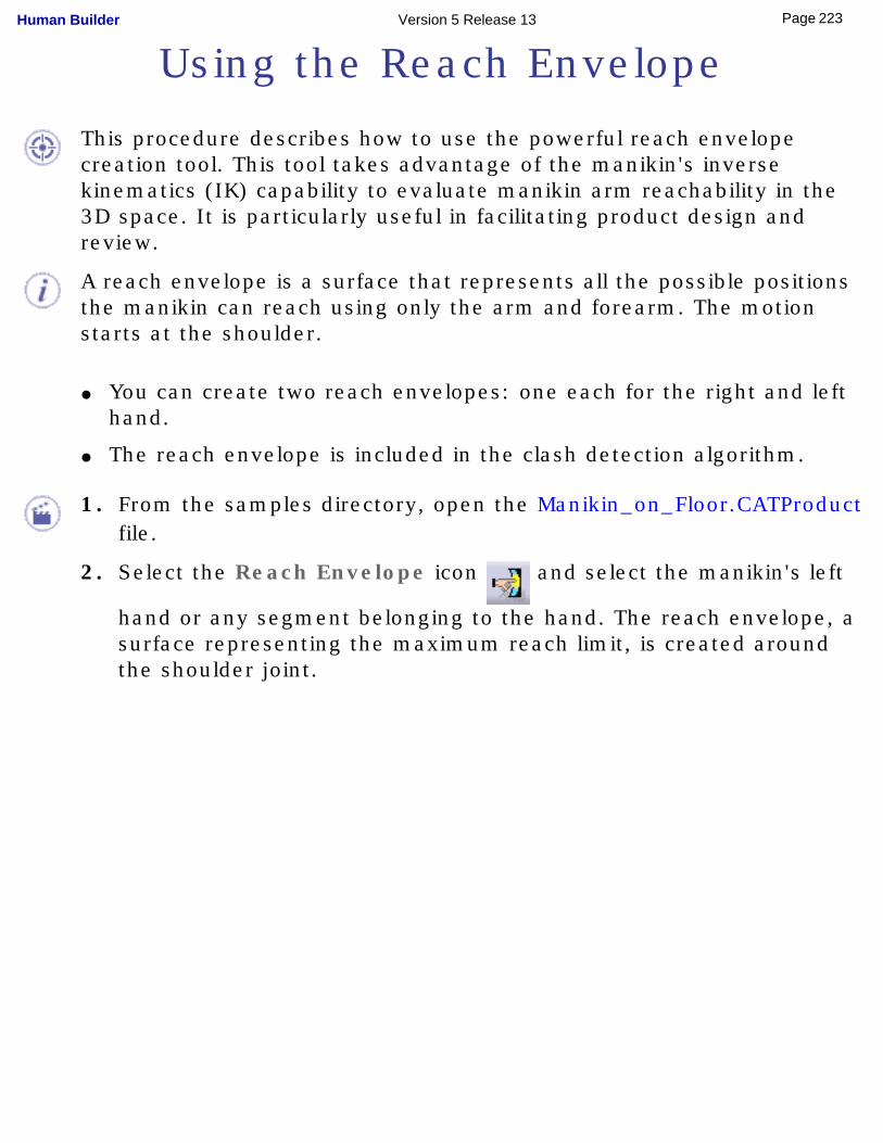
Using the Reach Envelope
This procedure describes how to use the powerful reach envelope creation tool. This tool takes advantage of the manikin's inverse kinematics (IK) capability to evaluate manikin arm reachability in the 3D space. It is particularly useful in facilitating product design and review.
A reach envelope is a surface that represents all the possible positions the manikin can reach using only the arm and forearm. The motion starts at the shoulder.
● You can create two reach envelopes: one each for the right and left hand.
● The reach envelope is included in the clash detection algorithm.
1. From the samples directory, open the Manikin_on_Floor.CATProduct file.
2. Select the Reach Envelope icon and select the manikin's left
hand or any segment belonging to the hand. The reach envelope, a surface representing the maximum reach limit, is created around the shoulder joint.
223Page Human Builder Version 5 Release 13
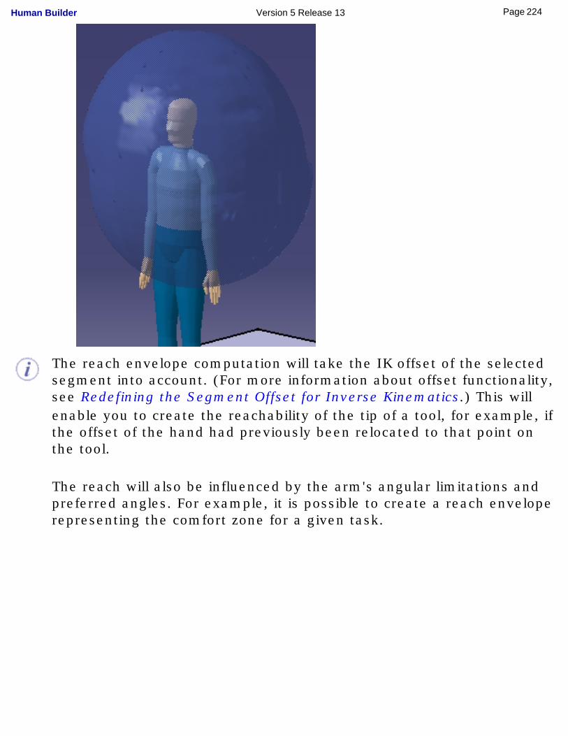
The reach envelope computation will take the IK offset of the selected segment into account. (For more information about offset functionality, see Redefining the Segment Offset for Inverse Kinematics.) This will enable you to create the reachability of the tip of a tool, for example, if the offset of the hand had previously been relocated to that point on the tool.
The reach will also be influenced by the arm's angular limitations and preferred angles. For example, it is possible to create a reach envelope representing the comfort zone for a given task.
224Page Human Builder Version 5 Release 13
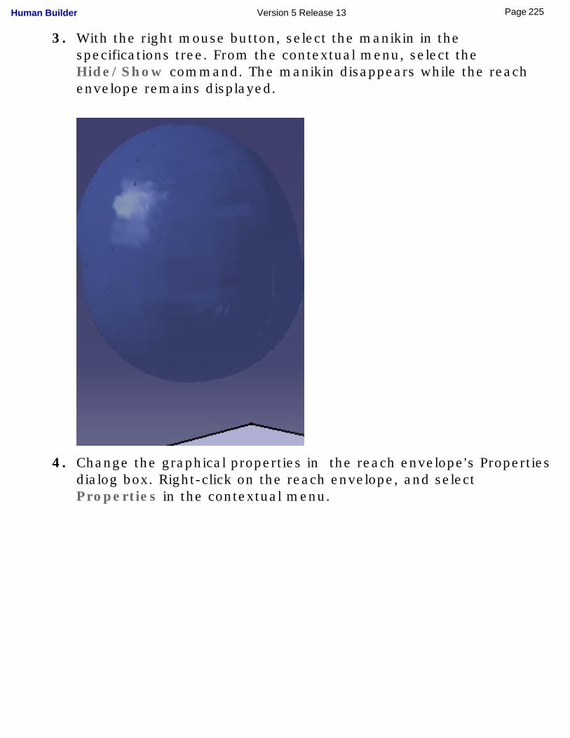
3. With the right mouse button, select the manikin in the specifications tree. From the contextual menu, select the Hide/Show command. The manikin disappears while the reach envelope remains displayed.
4. Change the graphical properties in the reach envelope's Properties dialog box. Right-click on the reach envelope, and select Properties in the contextual menu.
225Page Human Builder Version 5 Release 13
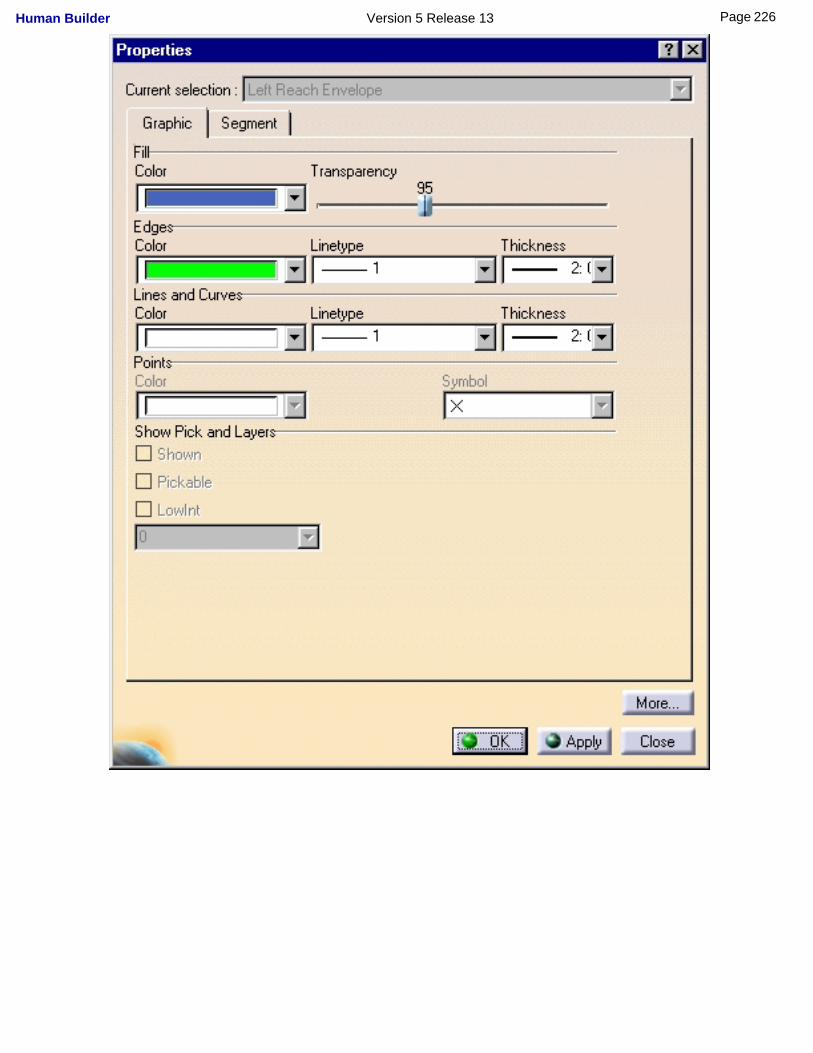
226Page Human Builder Version 5 Release 13
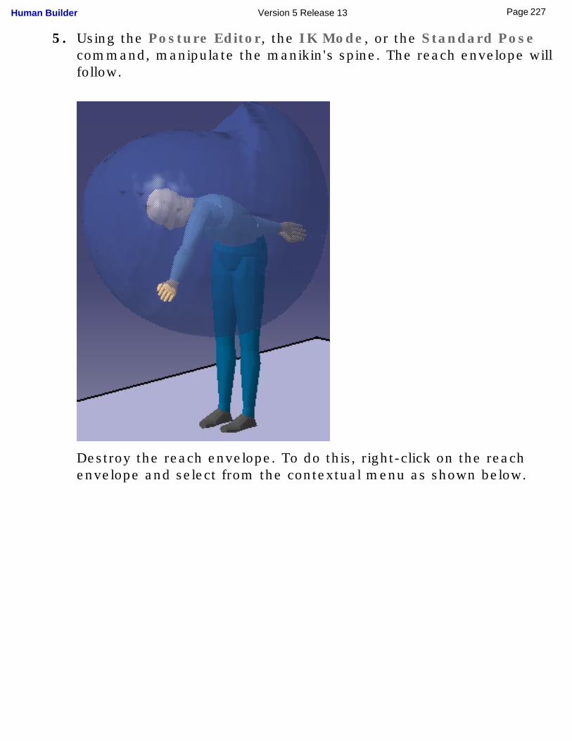
5. Using the Posture Editor, the IK Mode, or the Standard Pose command, manipulate the manikin's spine. The reach envelope will follow.
Destroy the reach envelope. To do this, right-click on the reach envelope and select from the contextual menu as shown below.
227Page Human Builder Version 5 Release 13
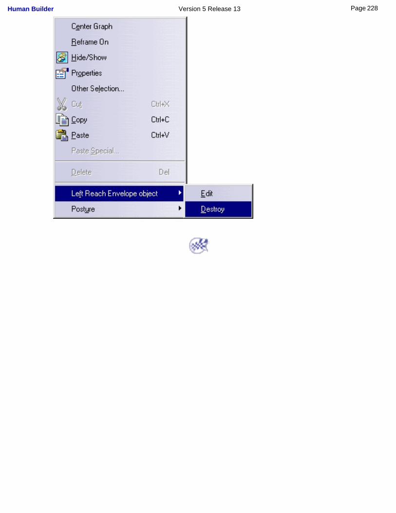
228Page Human Builder Version 5 Release 13
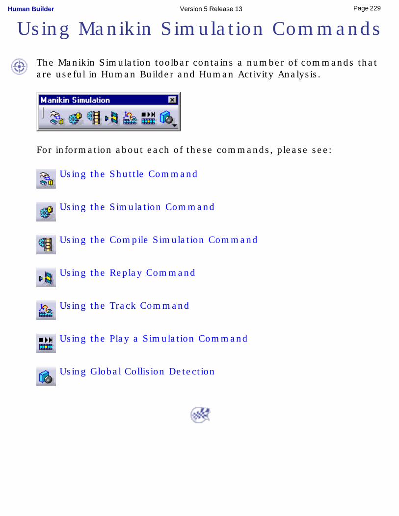
Using Manikin Simulation Commands
The Manikin Simulation toolbar contains a number of commands that are useful in Human Builder and Human Activity Analysis.
For information about each of these commands, please see:
Using the Shuttle Command
Using the Simulation Command
Using the Compile Simulation Command
Using the Replay Command
Using the Track Command
Using the Play a Simulation Command
Using Global Collision Detection
229Page Human Builder Version 5 Release 13
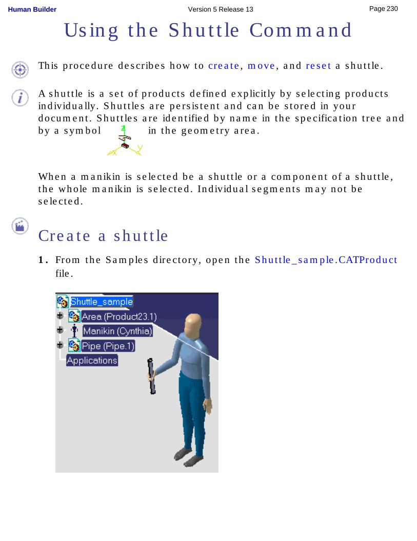
Using the Shuttle Command
This procedure describes how to create, move, and reset a shuttle.
A shuttle is a set of products defined explicitly by selecting products individually. Shuttles are persistent and can be stored in your document. Shuttles are identified by name in the specification tree and by a symbol in the geometry area.
When a manikin is selected be a shuttle or a component of a shuttle, the whole manikin is selected. Individual segments may not be selected.
Create a shuttle1. From the Samples directory, open the Shuttle_sample.CATProduct
file.
230Page Human Builder Version 5 Release 13
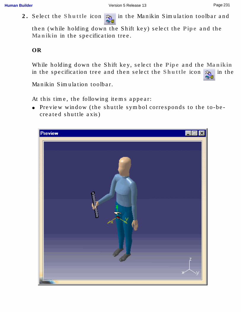
2. Select the Shuttle icon in the Manikin Simulation toolbar and
then (while holding down the Shift key) select the Pipe and the Manikin in the specification tree.
OR
While holding down the Shift key, select the Pipe and the Manikin in the specification tree and then select the Shuttle icon in the
Manikin Simulation toolbar.
At this time, the following items appear:● Preview window (the shuttle symbol corresponds to the to-be-
created shuttle axis)
231Page Human Builder Version 5 Release 13
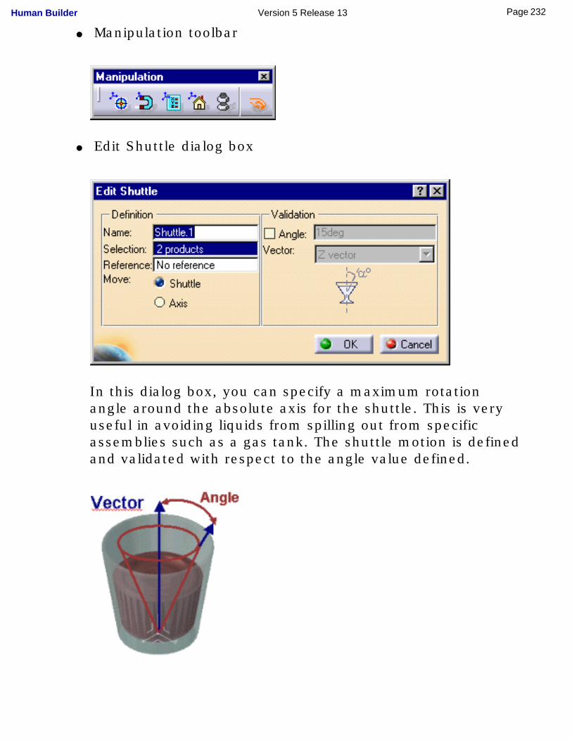
● Manipulation toolbar
● Edit Shuttle dialog box
In this dialog box, you can specify a maximum rotation angle around the absolute axis for the shuttle. This is very useful in avoiding liquids from spilling out from specific assemblies such as a gas tank. The shuttle motion is defined and validated with respect to the angle value defined.
232Page Human Builder Version 5 Release 13
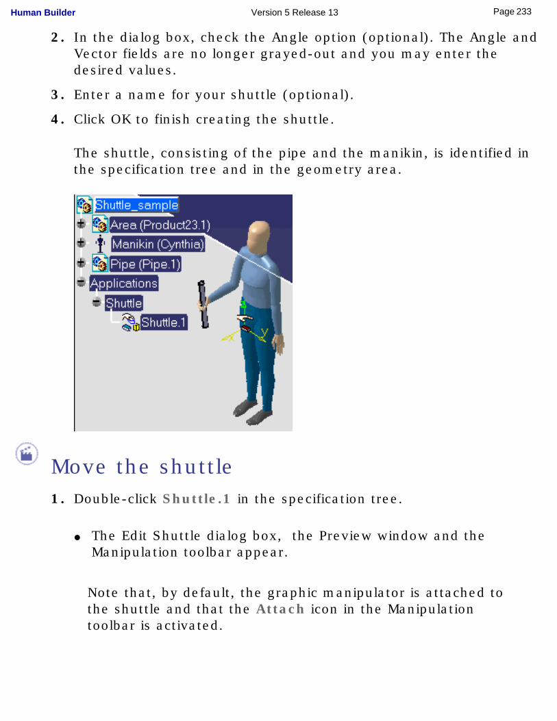
2. In the dialog box, check the Angle option (optional). The Angle and Vector fields are no longer grayed-out and you may enter the desired values.
3. Enter a name for your shuttle (optional).
4. Click OK to finish creating the shuttle.
The shuttle, consisting of the pipe and the manikin, is identified in the specification tree and in the geometry area.
Move the shuttle1. Double-click Shuttle.1 in the specification tree.
● The Edit Shuttle dialog box, the Preview window and the Manipulation toolbar appear.
Note that, by default, the graphic manipulator is attached to the shuttle and that the Attach icon in the Manipulation toolbar is activated.
233Page Human Builder Version 5 Release 13
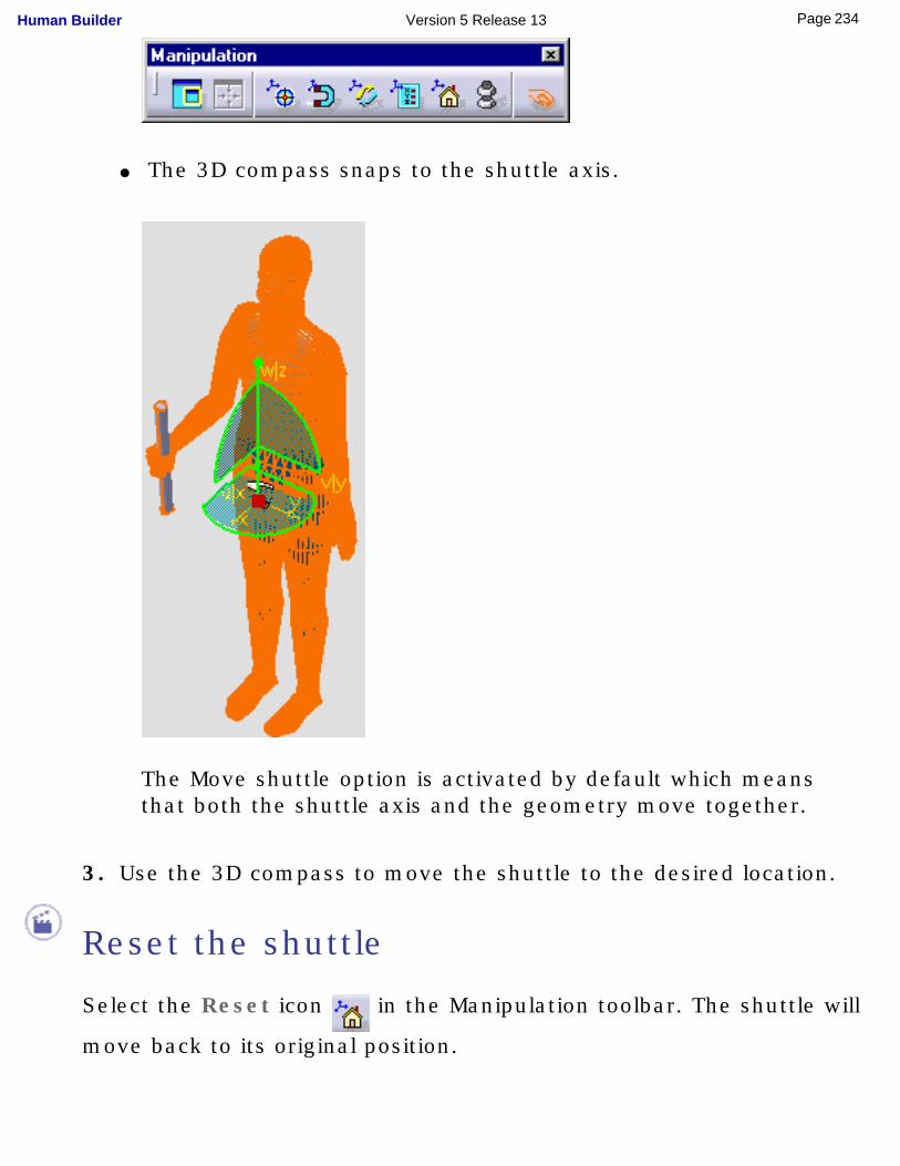
● The 3D compass snaps to the shuttle axis.
The Move shuttle option is activated by default which means that both the shuttle axis and the geometry move together.
3. Use the 3D compass to move the shuttle to the desired location.
Reset the shuttle
Select the Reset icon in the Manipulation toolbar. The shuttle will
move back to its original position.
234Page Human Builder Version 5 Release 13

235Page Human Builder Version 5 Release 13
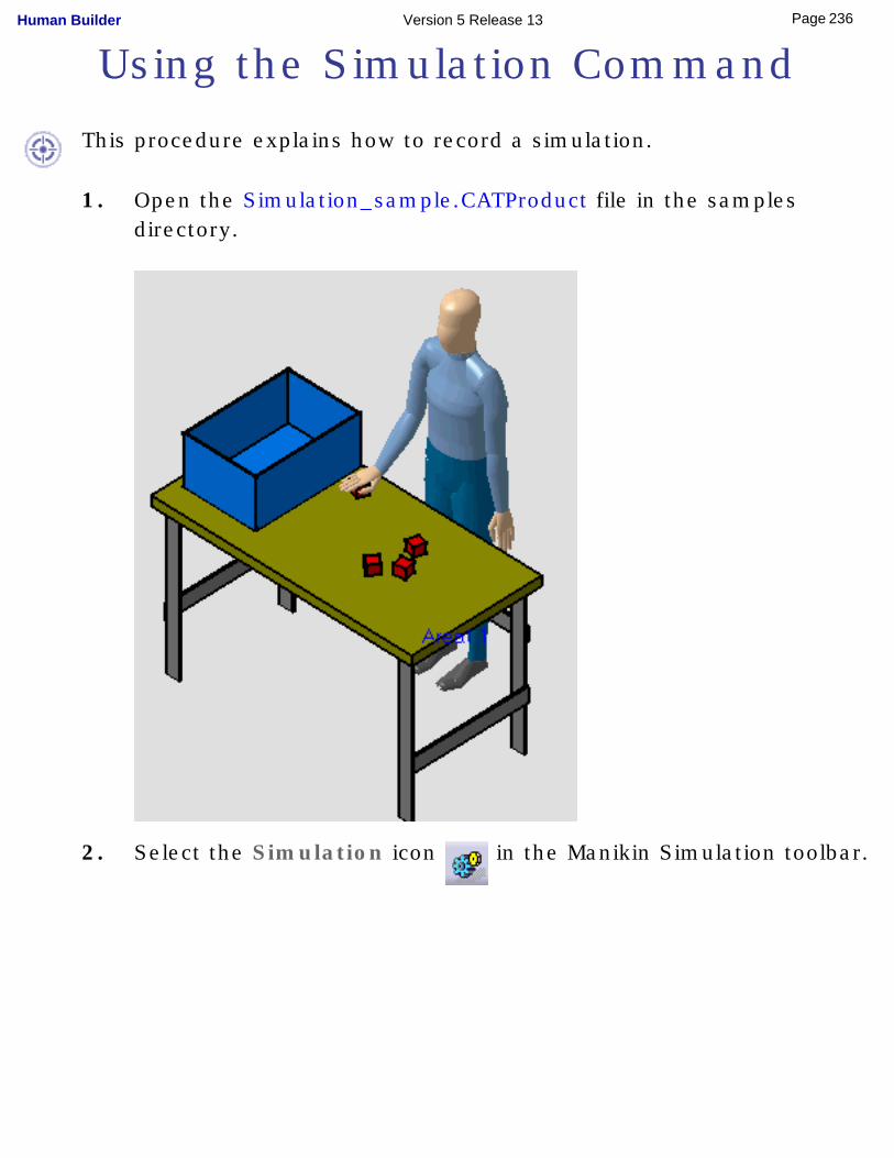
Using the Simulation Command
This procedure explains how to record a simulation.
1. Open the Simulation_sample.CATProduct file in the samples directory.
2. Select the Simulation icon in the Manikin Simulation toolbar.
236Page Human Builder Version 5 Release 13
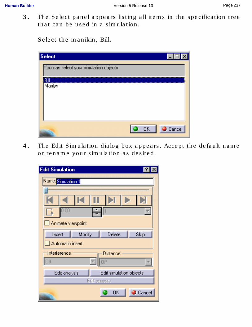
3. The Select panel appears listing all items in the specification tree that can be used in a simulation.
Select the manikin, Bill.
4. The Edit Simulation dialog box appears. Accept the default name or rename your simulation as desired.
237Page Human Builder Version 5 Release 13
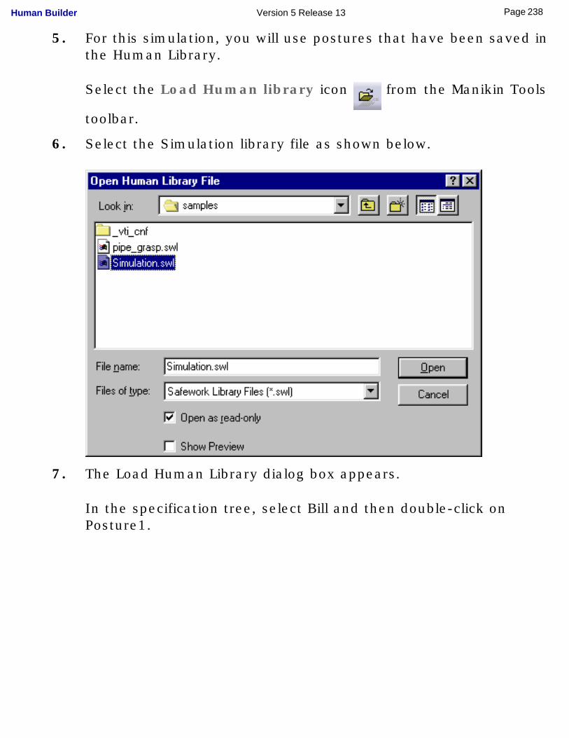
5. For this simulation, you will use postures that have been saved in the Human Library.
Select the Load Human library icon from the Manikin Tools
toolbar.
6. Select the Simulation library file as shown below.
7. The Load Human Library dialog box appears.
In the specification tree, select Bill and then double-click on Posture1.
238Page Human Builder Version 5 Release 13
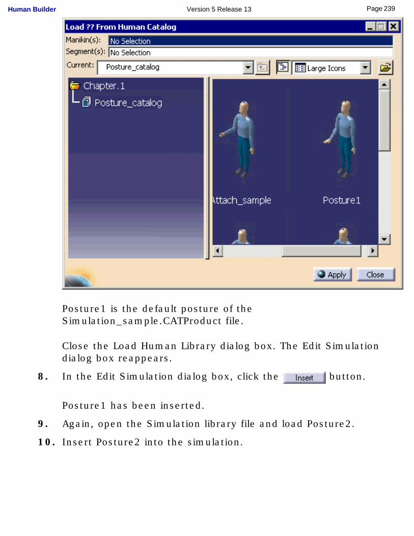
Posture1 is the default posture of the Simulation_sample.CATProduct file.
Close the Load Human Library dialog box. The Edit Simulation dialog box reappears.
8. In the Edit Simulation dialog box, click the button.
Posture1 has been inserted.
9. Again, open the Simulation library file and load Posture2.
10. Insert Posture2 into the simulation.
239Page Human Builder Version 5 Release 13
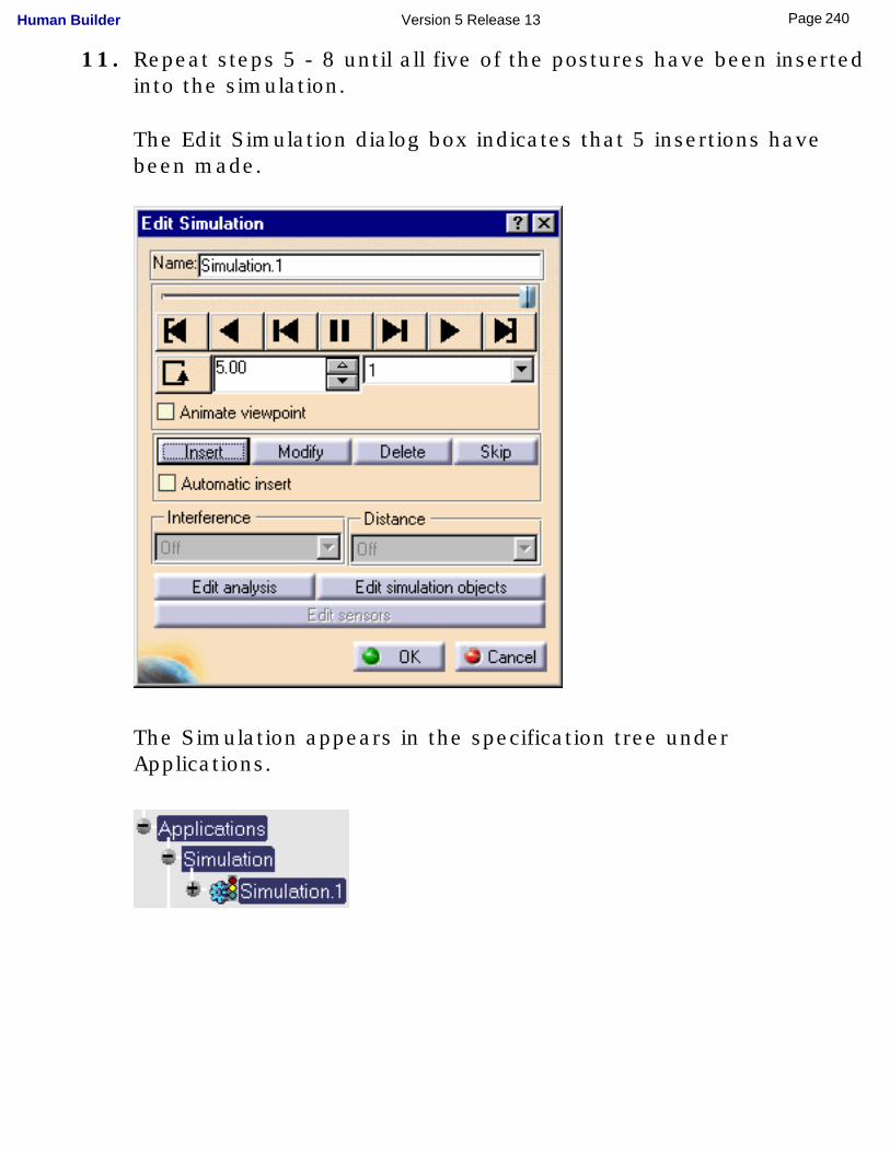
11. Repeat steps 5 - 8 until all five of the postures have been inserted into the simulation.
The Edit Simulation dialog box indicates that 5 insertions have been made.
The Simulation appears in the specification tree under Applications.
240Page Human Builder Version 5 Release 13
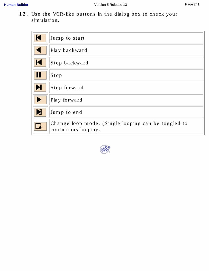
12. Use the VCR-like buttons in the dialog box to check your simulation.
Jump to start
Play backward
Step backward
Stop
Step forward
Play forward
Jump to end
Change loop mode. (Single looping can be toggled to continuous looping.
241Page Human Builder Version 5 Release 13
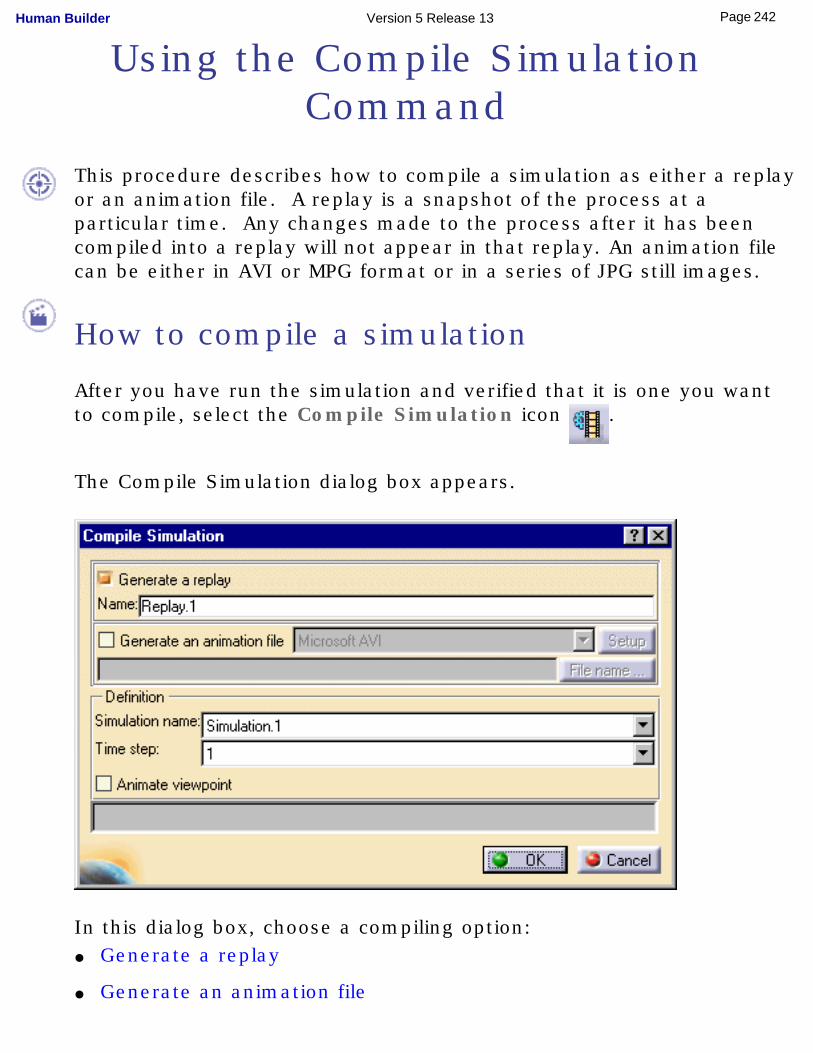
Using the Compile Simulation Command
This procedure describes how to compile a simulation as either a replay or an animation file. A replay is a snapshot of the process at a particular time. Any changes made to the process after it has been compiled into a replay will not appear in that replay. An animation file can be either in AVI or MPG format or in a series of JPG still images.
How to compile a simulation
After you have run the simulation and verified that it is one you want to compile, select the Compile Simulation icon .
The Compile Simulation dialog box appears.
In this dialog box, choose a compiling option:● Generate a replay
● Generate an animation file
242Page Human Builder Version 5 Release 13
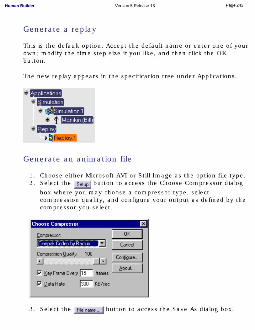
Generate a replay
This is the default option. Accept the default name or enter one of your own; modify the time step size if you like, and then click the OK button.
The new replay appears in the specification tree under Applications.
Generate an animation file
1. Choose either Microsoft AVI or Still Image as the option file type.2. Select the button to access the Choose Compressor dialog
box where you may choose a compressor type, select compression quality, and configure your output as defined by the compressor you select.
3. Select the button to access the Save As dialog box.
243Page Human Builder Version 5 Release 13
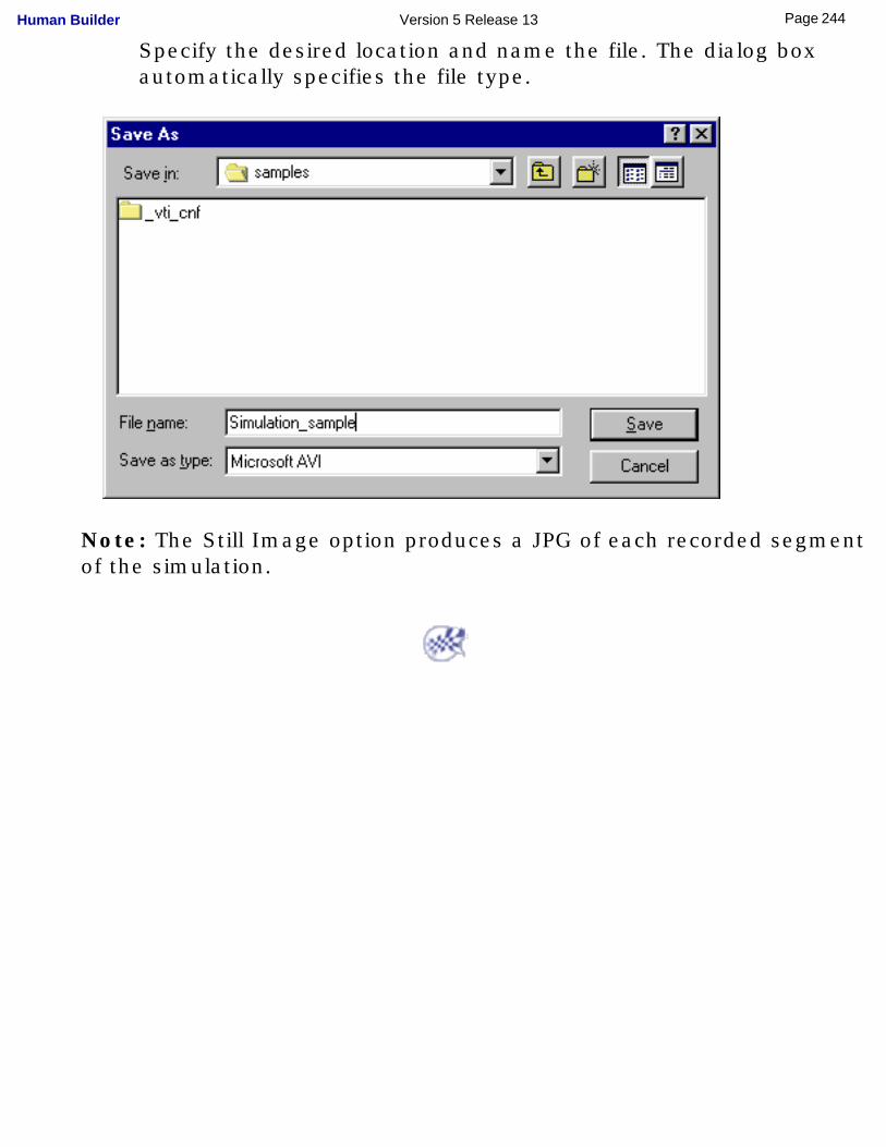
Specify the desired location and name the file. The dialog box automatically specifies the file type.
Note: The Still Image option produces a JPG of each recorded segment of the simulation.
244Page Human Builder Version 5 Release 13
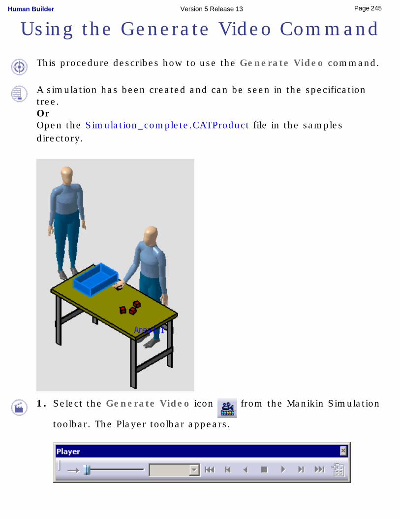
Using the Generate Video Command
This procedure describes how to use the Generate Video command.
A simulation has been created and can be seen in the specification tree.OrOpen the Simulation_complete.CATProduct file in the samples directory.
1. Select the Generate Video icon from the Manikin Simulation
toolbar. The Player toolbar appears.
245Page Human Builder Version 5 Release 13
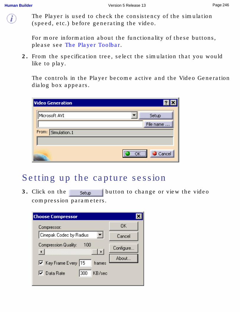
The Player is used to check the consistency of the simulation (speed, etc.) before generating the video.
For more information about the functionality of these buttons, please see The Player Toolbar.
2. From the specification tree, select the simulation that you would like to play.
The controls in the Player become active and the Video Generation dialog box appears.
Setting up the capture session 3. Click on the button to change or view the video
compression parameters.
246Page Human Builder Version 5 Release 13
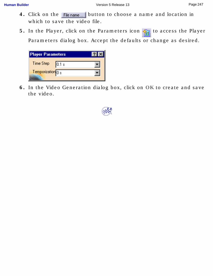
4. Click on the button to choose a name and location in which to save the video file.
5. In the Player, click on the Parameters icon to access the Player
Parameters dialog box. Accept the defaults or change as desired.
6. In the Video Generation dialog box, click on OK to create and save the video.
247Page Human Builder Version 5 Release 13
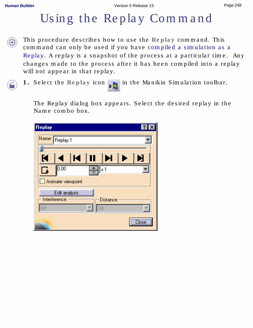
Using the Replay Command
This procedure describes how to use the Replay command. This command can only be used if you have compiled a simulation as a Replay. A replay is a snapshot of the process at a particular time. Any changes made to the process after it has been compiled into a replay will not appear in that replay.
1. Select the Replay icon in the Manikin Simulation toolbar.
The Replay dialog box appears. Select the desired replay in the Name combo box.
248Page Human Builder Version 5 Release 13
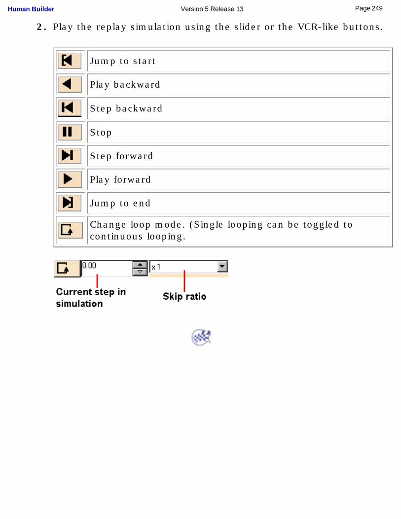
2. Play the replay simulation using the slider or the VCR-like buttons.
Jump to start
Play backward
Step backward
Stop
Step forward
Play forward
Jump to end
Change loop mode. (Single looping can be toggled to continuous looping.
249Page Human Builder Version 5 Release 13
Using the Track Command
This procedure demonstrates how to use the Track command.
A track is the route of a moving object. Objects can be:
● products
● shuttles
● section planes
● lights
● cameras
● the seven Inverse Kinematic (IK) control points of a manikin. They are:
Note: A manikin's seven IK control points are the:
● line of sight (if displayed)
● neck
● pelvis (root)
● right and left hands
● right and left feet
For more information, see Using the Inverse Kinematics Mode.
Attach the object to the segment
250Page Human Builder Version 5 Release 13
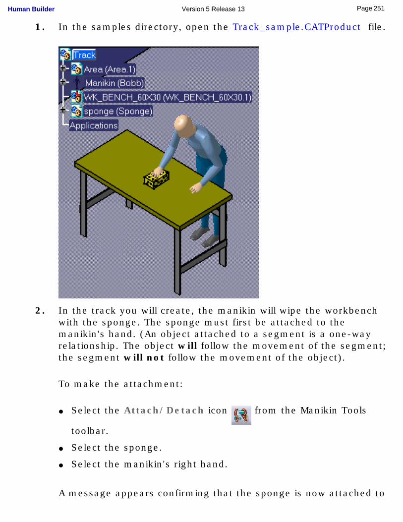
1. In the samples directory, open the Track_sample.CATProduct file.
2. In the track you will create, the manikin will wipe the workbench with the sponge. The sponge must first be attached to the manikin's hand. (An object attached to a segment is a one-way relationship. The object will follow the movement of the segment; the segment will not follow the movement of the object).
To make the attachment:
● Select the Attach/Detach icon from the Manikin Tools
toolbar.
● Select the sponge.
● Select the manikin's right hand.
A message appears confirming that the sponge is now attached to
251Page Human Builder Version 5 Release 13

manikin Bobb's right hand.
Record the track3. Select the Track command from the Manikin Simulation
toolbar.
At this time, the following items appear. Click on the links for more detailed information.● Recorder toolbar
● Player toolbar
● Track dialog box
252Page Human Builder Version 5 Release 13
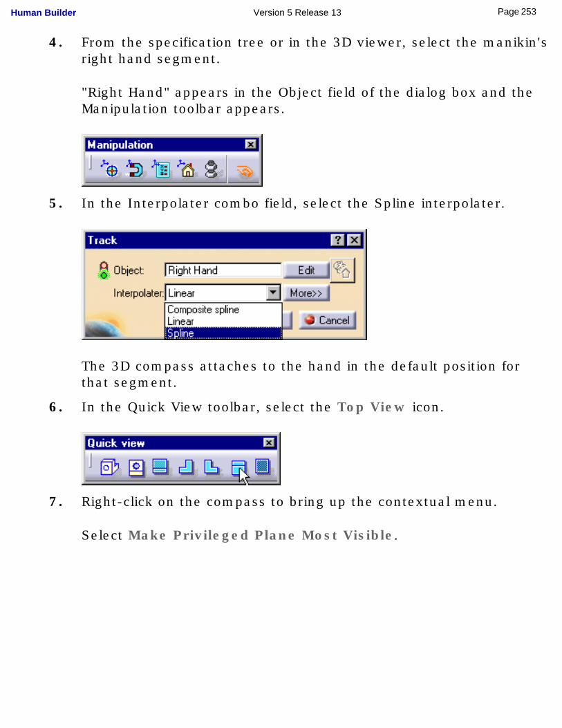
4. From the specification tree or in the 3D viewer, select the manikin's right hand segment.
"Right Hand" appears in the Object field of the dialog box and the Manipulation toolbar appears.
5. In the Interpolater combo field, select the Spline interpolater.
The 3D compass attaches to the hand in the default position for that segment.
6. In the Quick View toolbar, select the Top View icon.
7. Right-click on the compass to bring up the contextual menu.
Select Make Privileged Plane Most Visible.
253Page Human Builder Version 5 Release 13
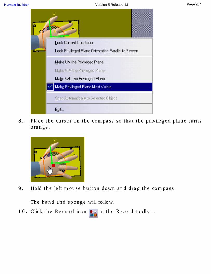
8. Place the cursor on the compass so that the privileged plane turns orange.
9. Hold the left mouse button down and drag the compass.
The hand and sponge will follow.
10. Click the Record icon in the Record toolbar.
254Page Human Builder Version 5 Release 13
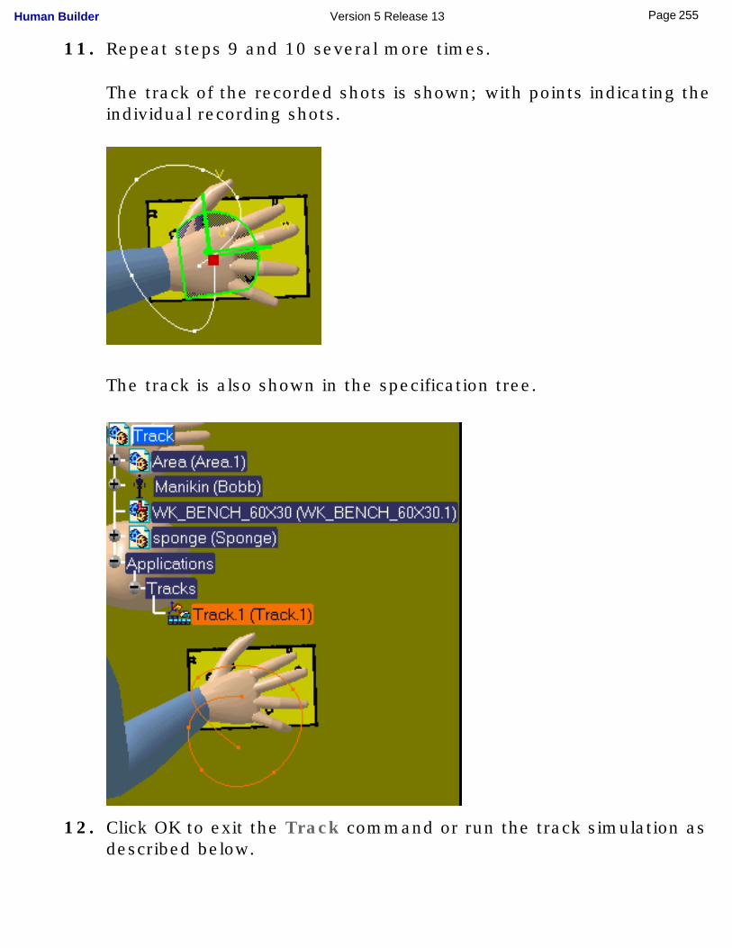
11. Repeat steps 9 and 10 several more times.
The track of the recorded shots is shown; with points indicating the individual recording shots.
The track is also shown in the specification tree.
12. Click OK to exit the Track command or run the track simulation as described below.
255Page Human Builder Version 5 Release 13
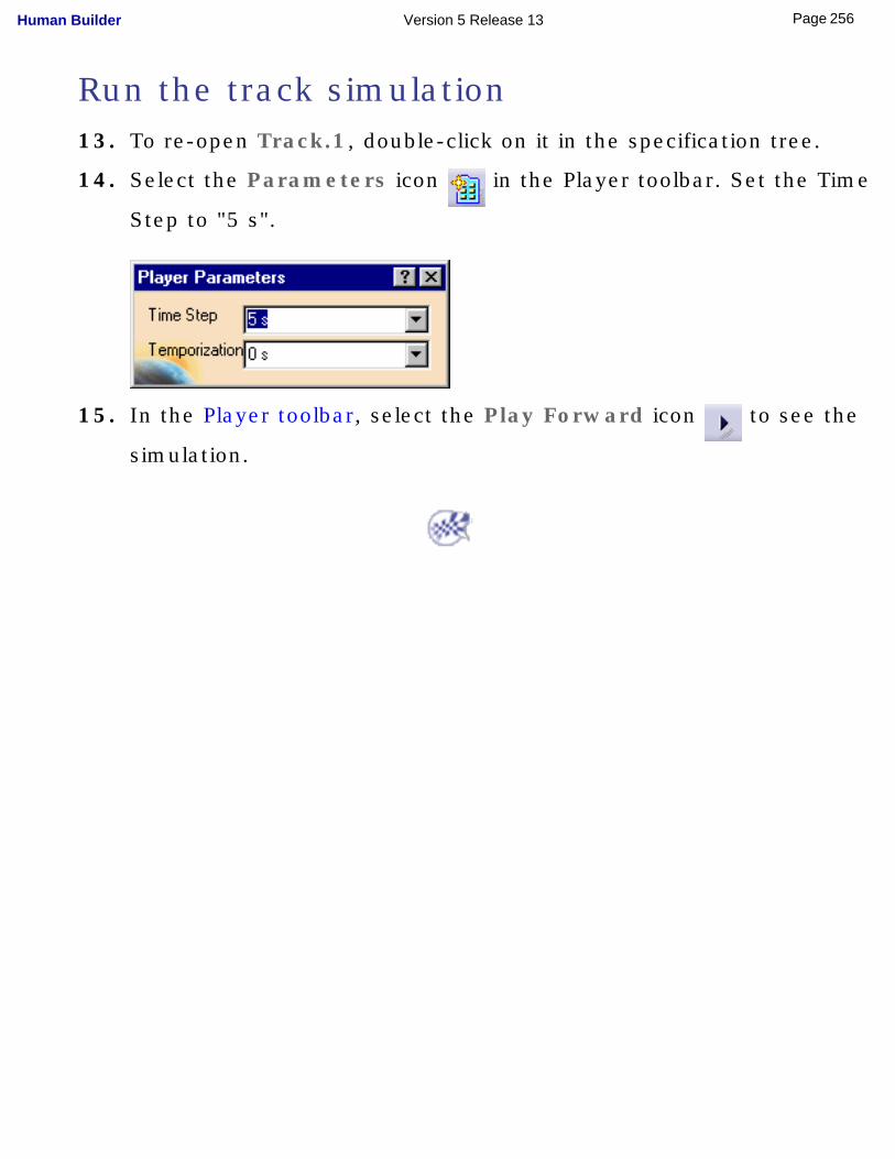
Run the track simulation13. To re-open Track.1, double-click on it in the specification tree.
14. Select the Parameters icon in the Player toolbar. Set the Time
Step to "5 s".
15. In the Player toolbar, select the Play Forward icon to see the
simulation.
256Page Human Builder Version 5 Release 13
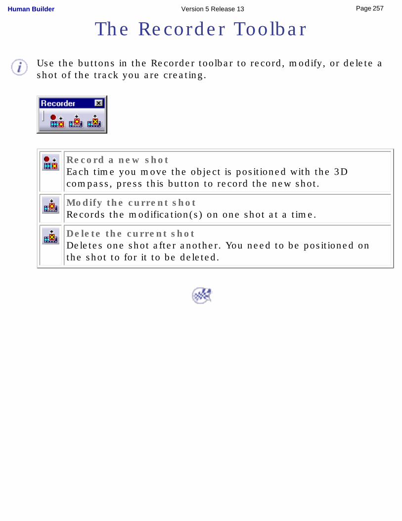
The Recorder Toolbar
Use the buttons in the Recorder toolbar to record, modify, or delete a shot of the track you are creating.
Record a new shotEach time you move the object is positioned with the 3D compass, press this button to record the new shot.
Modify the current shotRecords the modification(s) on one shot at a time.
Delete the current shotDeletes one shot after another. You need to be positioned on the shot to for it to be deleted.
257Page Human Builder Version 5 Release 13
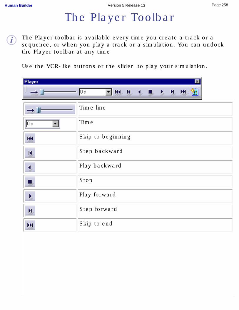
The Player Toolbar
The Player toolbar is available every time you create a track or a sequence, or when you play a track or a simulation. You can undock the Player toolbar at any time
Use the VCR-like buttons or the slider to play your simulation.
Time line
Time
Skip to beginning
Step backward
Play backward
Stop
Play forward
Step forward
Skip to end
258Page Human Builder Version 5 Release 13
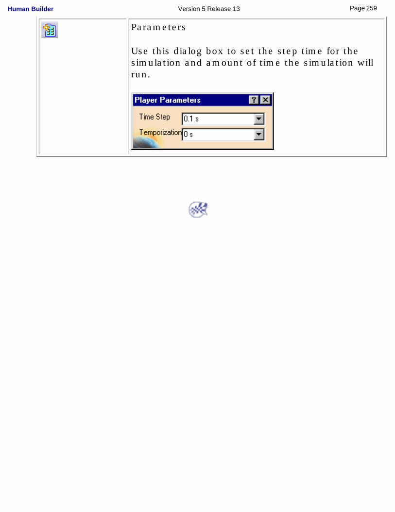
Parameters
Use this dialog box to set the step time for the simulation and amount of time the simulation will run.
259Page Human Builder Version 5 Release 13
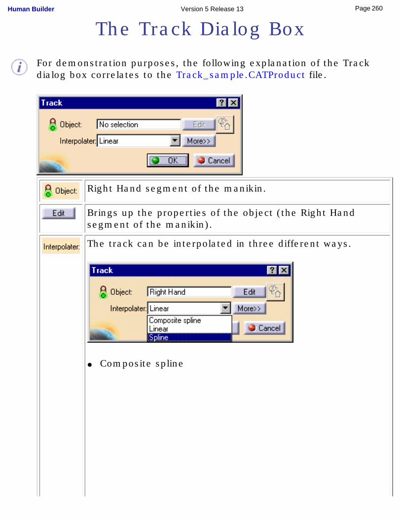
The Track Dialog Box
For demonstration purposes, the following explanation of the Track dialog box correlates to the Track_sample.CATProduct file.
Right Hand segment of the manikin.
Brings up the properties of the object (the Right Hand segment of the manikin).
The track can be interpolated in three different ways.
● Composite spline
260Page Human Builder Version 5 Release 13
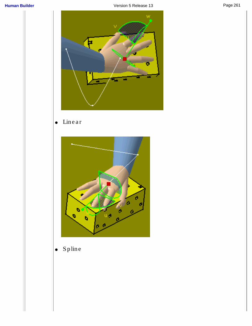
● Linear
● Spline
261Page Human Builder Version 5 Release 13
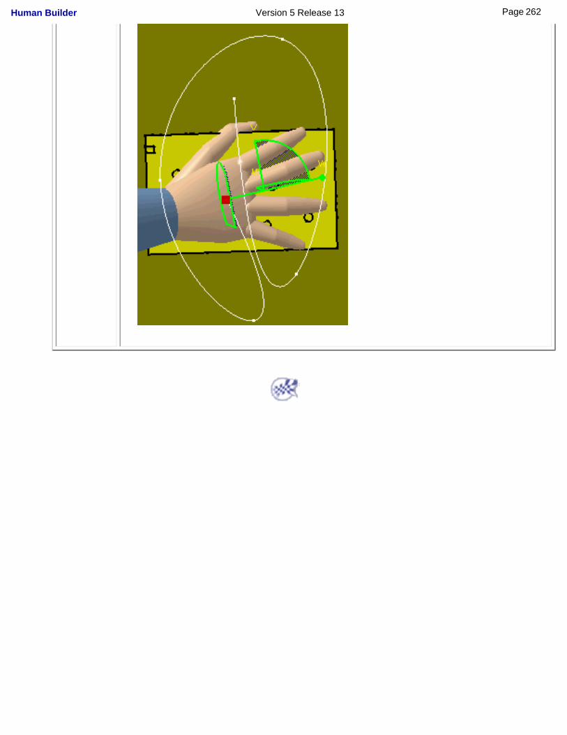
262Page Human Builder Version 5 Release 13
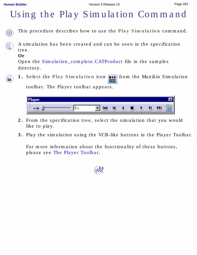
Using the Play Simulation Command
This procedure describes how to use the Play Simulation command.
A simulation has been created and can be seen in the specification tree.OrOpen the Simulation_complete.CATProduct file in the samples directory.
1. Select the Play Simulation icon from the Manikin Simulation
toolbar. The Player toolbar appears.
2. From the specification tree, select the simulation that you would like to play.
3. Play the simulation using the VCR-like buttons in the Player Toolbar.
For more information about the functionality of these buttons, please see The Player Toolbar.
263Page Human Builder Version 5 Release 13
Using the Clash Command
The Clash command is used to verify whether items collide. By
running a simulation, you can see whether collisions are detected. For more information on this command, see Creating a Clash (Interference) Check in the 3D Simulation for Manufacturing User Guide.
264Page Human Builder Version 5 Release 13

Manikin Catalog ManagementThis procedure describes the use and management of manikin catalogs including the following tasks:● Creating a new catalog document
❍ Create a new catalog
❍ Create a new family
❍ Save the catalog document
● Storing manikin attributes in a catalog file
● Converting .swl files into catalog files
● Reusing manikin attributes from a catalog file
In addition to manikin postures, manikin attributes can now be saved within catalogs. These attributes include:● posture and position
● anthropometry
● vision
● angular limitations
● preferred angles (previously could be saved in a library only)
These manikin attributes are selected from a list in the Save in Human Catalog dialog box. A specific icon on the preview image is added depending on the manikin attribute referenced.
It is no longer possible to open .swl library files. Existing libraries must be converted into catalog files.
Creating a new catalog document
Create a new catalog
265Page Human Builder Version 5 Release 13
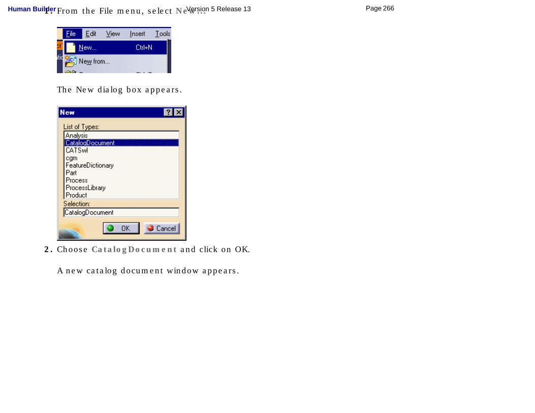
1. From the File menu, select New...
The New dialog box appears.
2. Choose CatalogDocument and click on OK.
A new catalog document window appears.
266Page Human Builder Version 5 Release 13
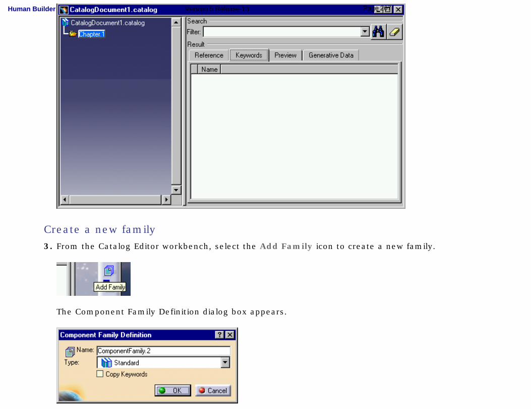
Create a new family
3. From the Catalog Editor workbench, select the Add Family icon to create a new family.
The Component Family Definition dialog box appears.
267Page Human Builder Version 5 Release 13
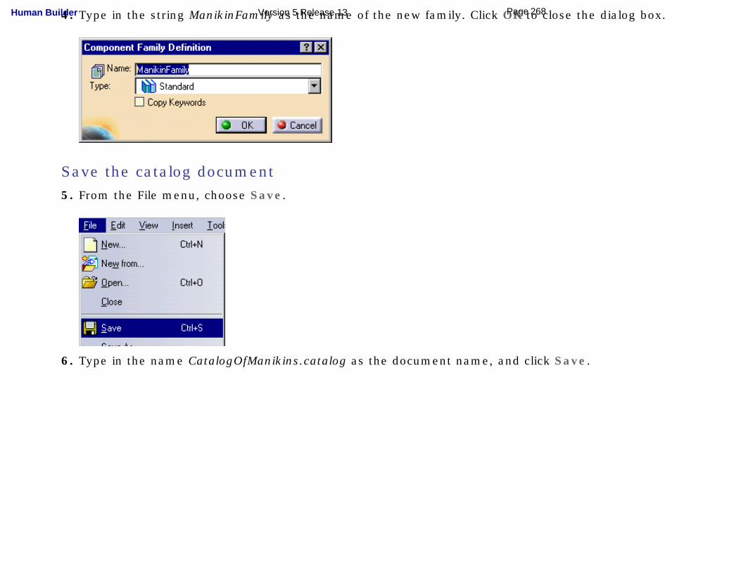
4. Type in the string ManikinFamily as the name of the new family. Click OK to close the dialog box.
Save the catalog document
5. From the File menu, choose Save.
6. Type in the name CatalogOfManikins.catalog as the document name, and click Save.
268Page Human Builder Version 5 Release 13
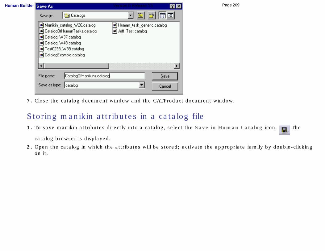
7. Close the catalog document window and the CATProduct document window.
Storing manikin attributes in a catalog file 1. To save manikin attributes directly into a catalog, select the Save in Human Catalog icon. The
catalog browser is displayed.
2. Open the catalog in which the attributes will be stored; activate the appropriate family by double-clicking on it.
269Page Human Builder Version 5 Release 13
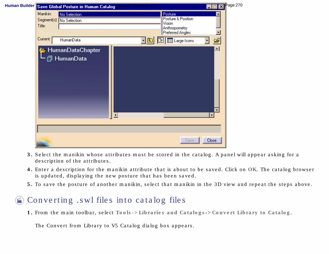
3. Select the manikin whose attributes must be stored in the catalog. A panel will appear asking for a description of the attributes.
4. Enter a description for the manikin attribute that is about to be saved. Click on OK. The catalog browser is updated, displaying the new posture that has been saved.
5. To save the posture of another manikin, select that manikin in the 3D view and repeat the steps above.
Converting .swl files into catalog files 1. From the main toolbar, select Tools->Libraries and Catalogs->Convert Library to Catalog.
The Convert from Library to V5 Catalog dialog box appears.
270Page Human Builder Version 5 Release 13
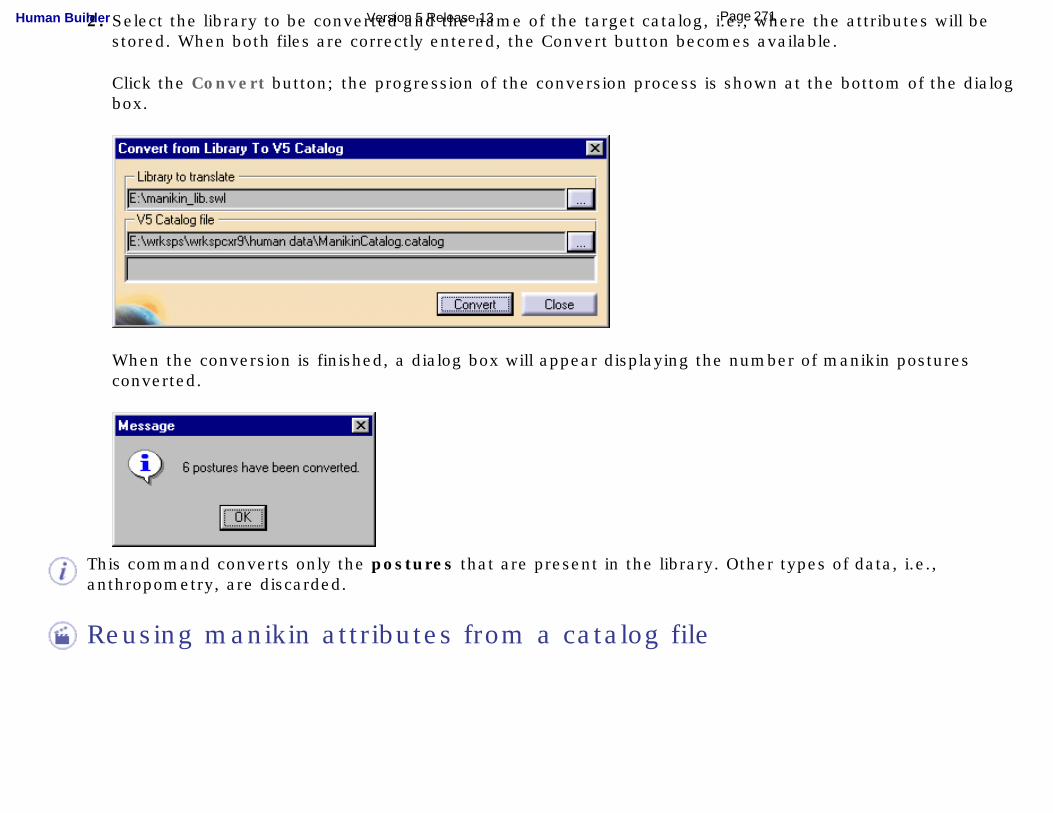
2. Select the library to be converted and the name of the target catalog, i.e., where the attributes will be stored. When both files are correctly entered, the Convert button becomes available.
Click the Convert button; the progression of the conversion process is shown at the bottom of the dialog box.
When the conversion is finished, a dialog box will appear displaying the number of manikin postures converted.
This command converts only the postures that are present in the library. Other types of data, i.e., anthropometry, are discarded.
Reusing manikin attributes from a catalog file
271Page Human Builder Version 5 Release 13
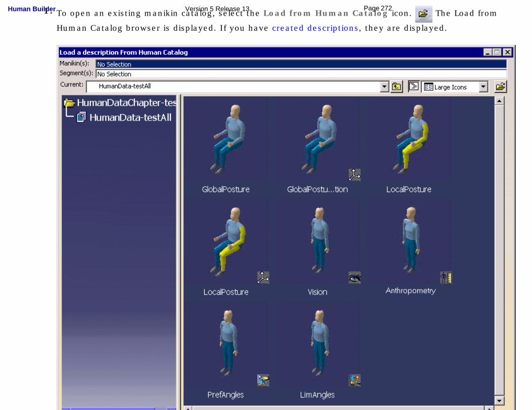
1. To open an existing manikin catalog, select the Load from Human Catalog icon. The Load from
Human Catalog browser is displayed. If you have created descriptions, they are displayed.
272Page Human Builder Version 5 Release 13
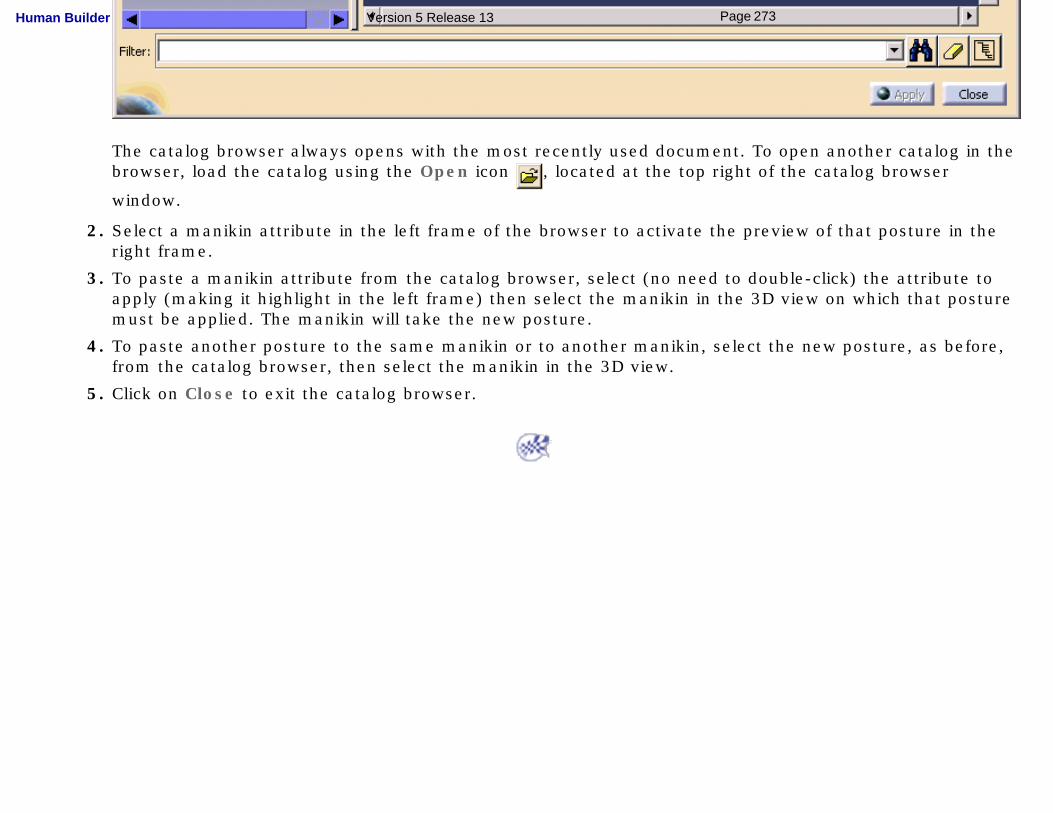
The catalog browser always opens with the most recently used document. To open another catalog in the browser, load the catalog using the Open icon , located at the top right of the catalog browser
window.
2. Select a manikin attribute in the left frame of the browser to activate the preview of that posture in the right frame.
3. To paste a manikin attribute from the catalog browser, select (no need to double-click) the attribute to apply (making it highlight in the left frame) then select the manikin in the 3D view on which that posture must be applied. The manikin will take the new posture.
4. To paste another posture to the same manikin or to another manikin, select the new posture, as before, from the catalog browser, then select the manikin in the 3D view.
5. Click on Close to exit the catalog browser.
273Page Human Builder Version 5 Release 13
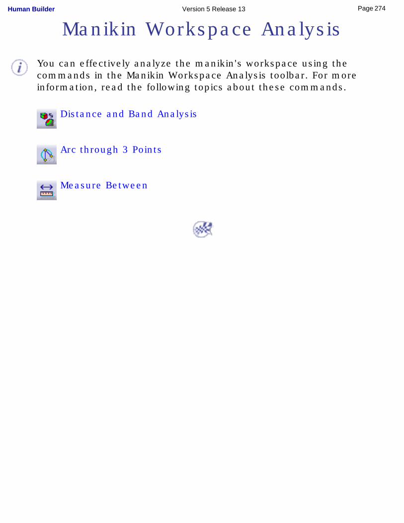
Manikin Workspace Analysis
You can effectively analyze the manikin's workspace using the commands in the Manikin Workspace Analysis toolbar. For more information, read the following topics about these commands.
Distance and Band Analysis
Arc through 3 Points
Measure Between
274Page Human Builder Version 5 Release 13
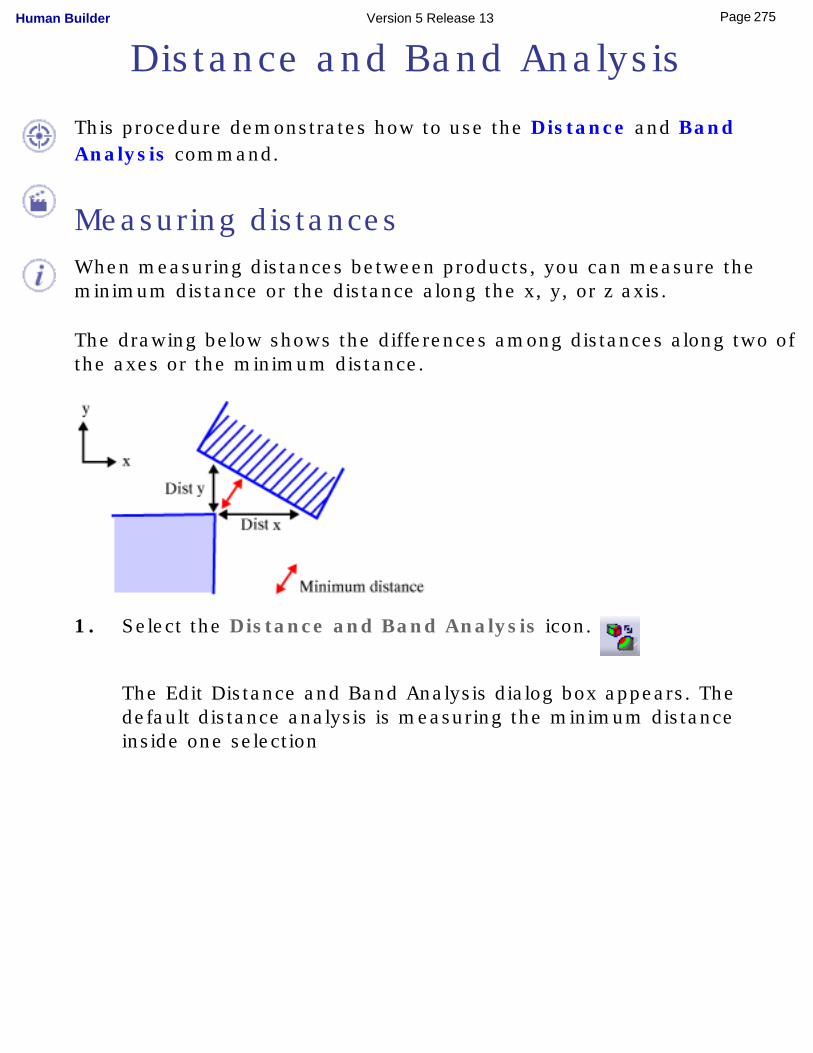
Distance and Band Analysis
This procedure demonstrates how to use the Distance and Band Analysis command.
Measuring distancesWhen measuring distances between products, you can measure the minimum distance or the distance along the x, y, or z axis.
The drawing below shows the differences among distances along two of the axes or the minimum distance.
1. Select the Distance and Band Analysis icon.
The Edit Distance and Band Analysis dialog box appears. The default distance analysis is measuring the minimum distance inside one selection
275Page Human Builder Version 5 Release 13
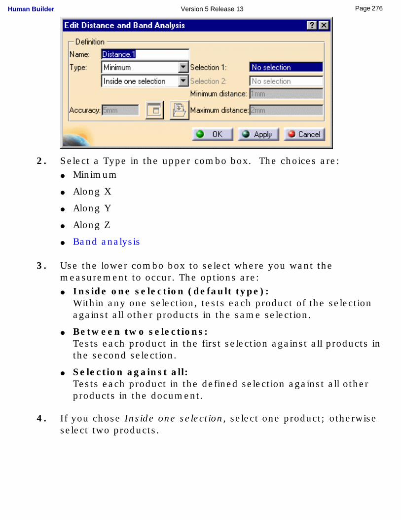
2. Select a Type in the upper combo box. The choices are: ● Minimum
● Along X
● Along Y
● Along Z
● Band analysis
3. Use the lower combo box to select where you want the measurement to occur. The options are: ● Inside one selection (default type):
Within any one selection, tests each product of the selection against all other products in the same selection.
● Between two selections: Tests each product in the first selection against all products in the second selection.
● Selection against all: Tests each product in the defined selection against all other products in the document.
4. If you chose Inside one selection, select one product; otherwise select two products.
276Page Human Builder Version 5 Release 13
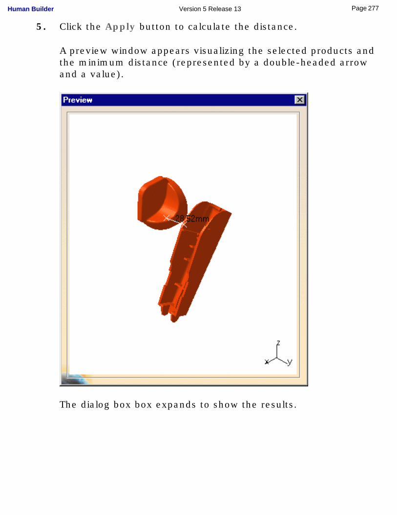
5. Click the Apply button to calculate the distance.
A preview window appears visualizing the selected products and the minimum distance (represented by a double-headed arrow and a value).
The dialog box box expands to show the results.
277Page Human Builder Version 5 Release 13
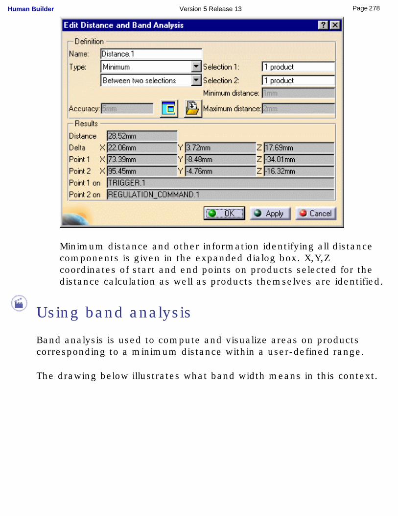
Minimum distance and other information identifying all distance components is given in the expanded dialog box. X,Y,Z coordinates of start and end points on products selected for the distance calculation as well as products themselves are identified.
Using band analysis
Band analysis is used to compute and visualize areas on products corresponding to a minimum distance within a user-defined range.
The drawing below illustrates what band width means in this context.
278Page Human Builder Version 5 Release 13
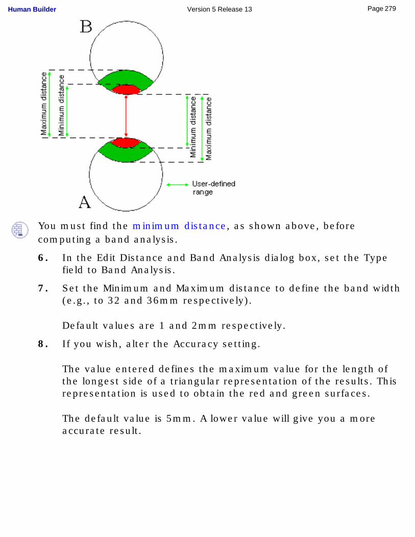
You must find the minimum distance, as shown above, before computing a band analysis.
6. In the Edit Distance and Band Analysis dialog box, set the Type field to Band Analysis.
7. Set the Minimum and Maximum distance to define the band width (e.g., to 32 and 36mm respectively).
Default values are 1 and 2mm respectively.
8. If you wish, alter the Accuracy setting.
The value entered defines the maximum value for the length of the longest side of a triangular representation of the results. This representation is used to obtain the red and green surfaces.
The default value is 5mm. A lower value will give you a more accurate result.
279Page Human Builder Version 5 Release 13
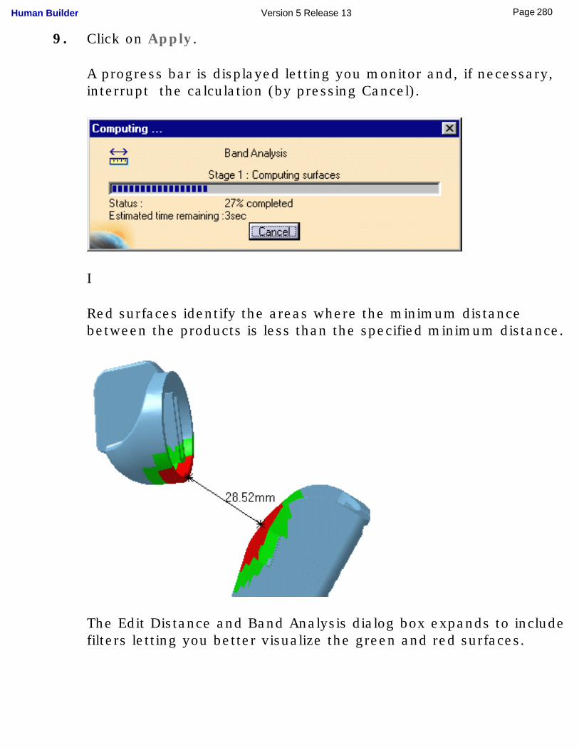
9. Click on Apply.
A progress bar is displayed letting you monitor and, if necessary, interrupt the calculation (by pressing Cancel).
I
Red surfaces identify the areas where the minimum distance between the products is less than the specified minimum distance.
The Edit Distance and Band Analysis dialog box expands to include filters letting you better visualize the green and red surfaces.
280Page Human Builder Version 5 Release 13
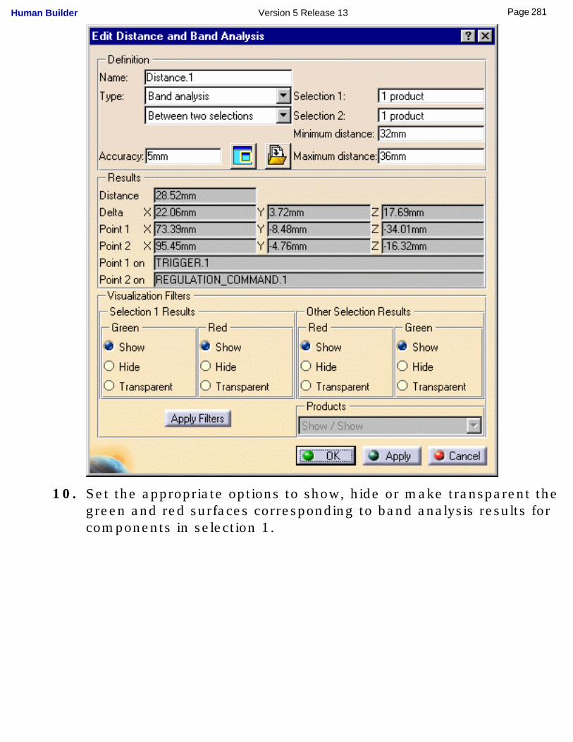
10. Set the appropriate options to show, hide or make transparent the green and red surfaces corresponding to band analysis results for components in selection 1.
281Page Human Builder Version 5 Release 13
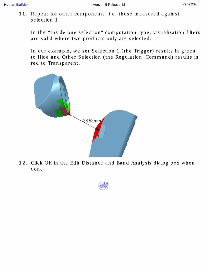
11. Repeat for other components, i.e. those measured against selection 1.
In the "Inside one selection" computation type, visualization filters are valid where two products only are selected.
In our example, we set Selection 1 (the Trigger) results in green to Hide and Other Selection (the Regulation_Command) results in red to Transparent.
12. Click OK in the Edit Distance and Band Analysis dialog box when done.
282Page Human Builder Version 5 Release 13
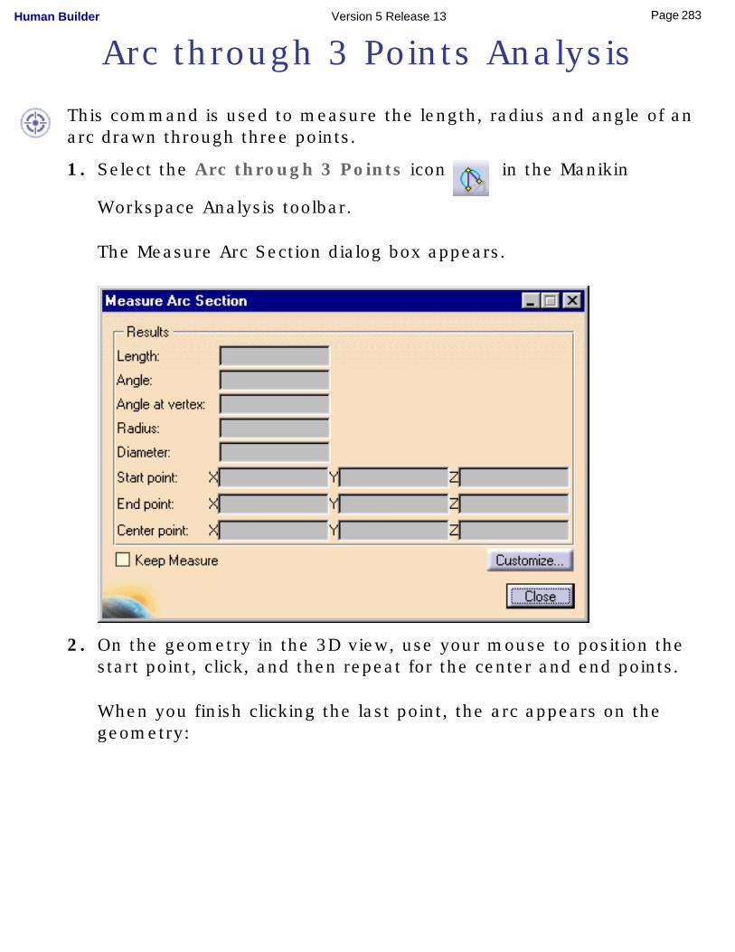
Arc through 3 Points Analysis
This command is used to measure the length, radius and angle of an arc drawn through three points.
1. Select the Arc through 3 Points icon in the Manikin
Workspace Analysis toolbar.
The Measure Arc Section dialog box appears.
2. On the geometry in the 3D view, use your mouse to position the start point, click, and then repeat for the center and end points.
When you finish clicking the last point, the arc appears on the geometry:
283Page Human Builder Version 5 Release 13
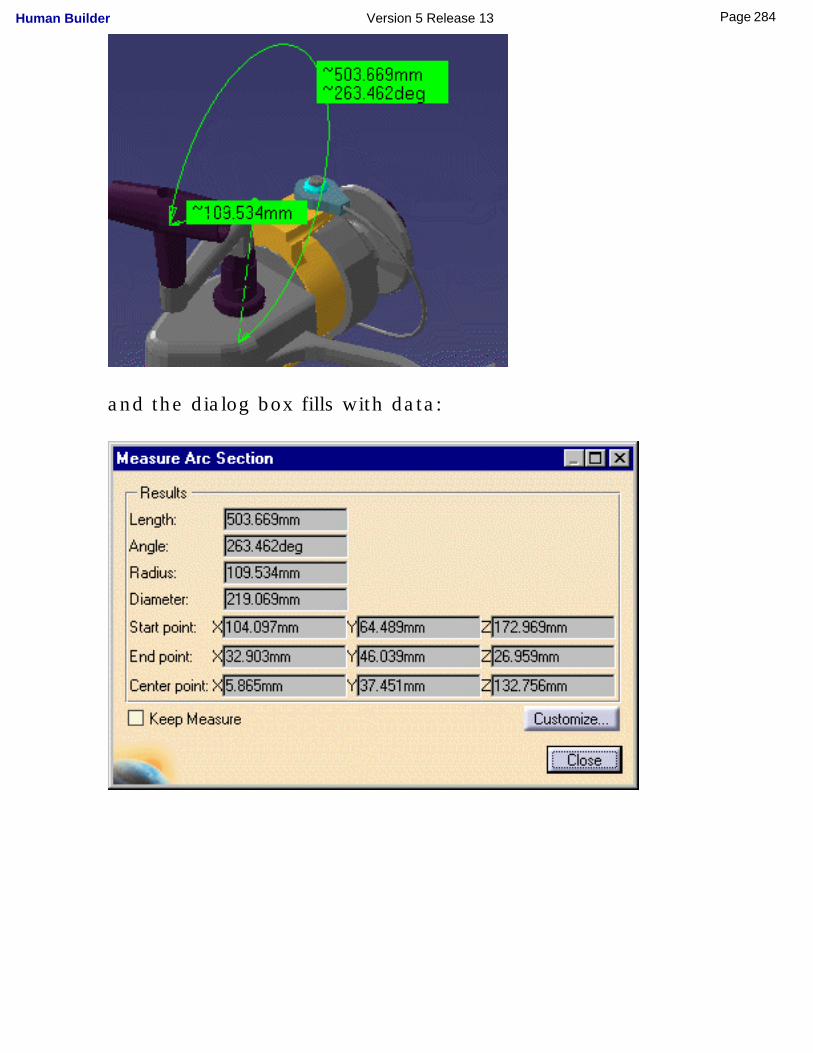
and the dialog box fills with data:
284Page Human Builder Version 5 Release 13
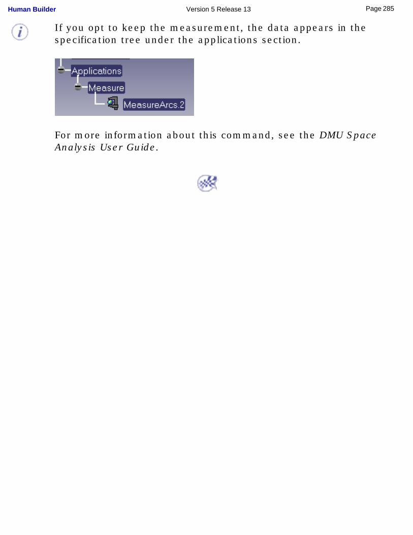
If you opt to keep the measurement, the data appears in the specification tree under the applications section.
For more information about this command, see the DMU Space Analysis User Guide.
285Page Human Builder Version 5 Release 13
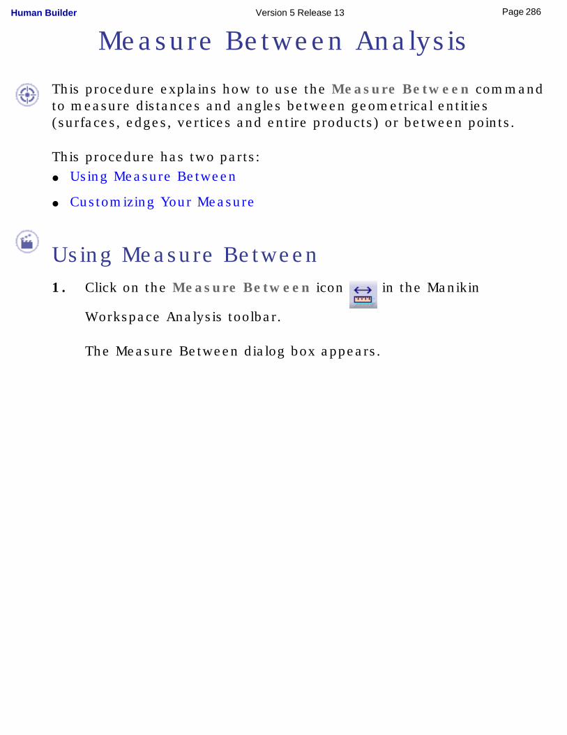
Measure Between Analysis
This procedure explains how to use the Measure Between command to measure distances and angles between geometrical entities (surfaces, edges, vertices and entire products) or between points.
This procedure has two parts:● Using Measure Between
● Customizing Your Measure
Using Measure Between1. Click on the Measure Between icon in the Manikin
Workspace Analysis toolbar.
The Measure Between dialog box appears.
286Page Human Builder Version 5 Release 13
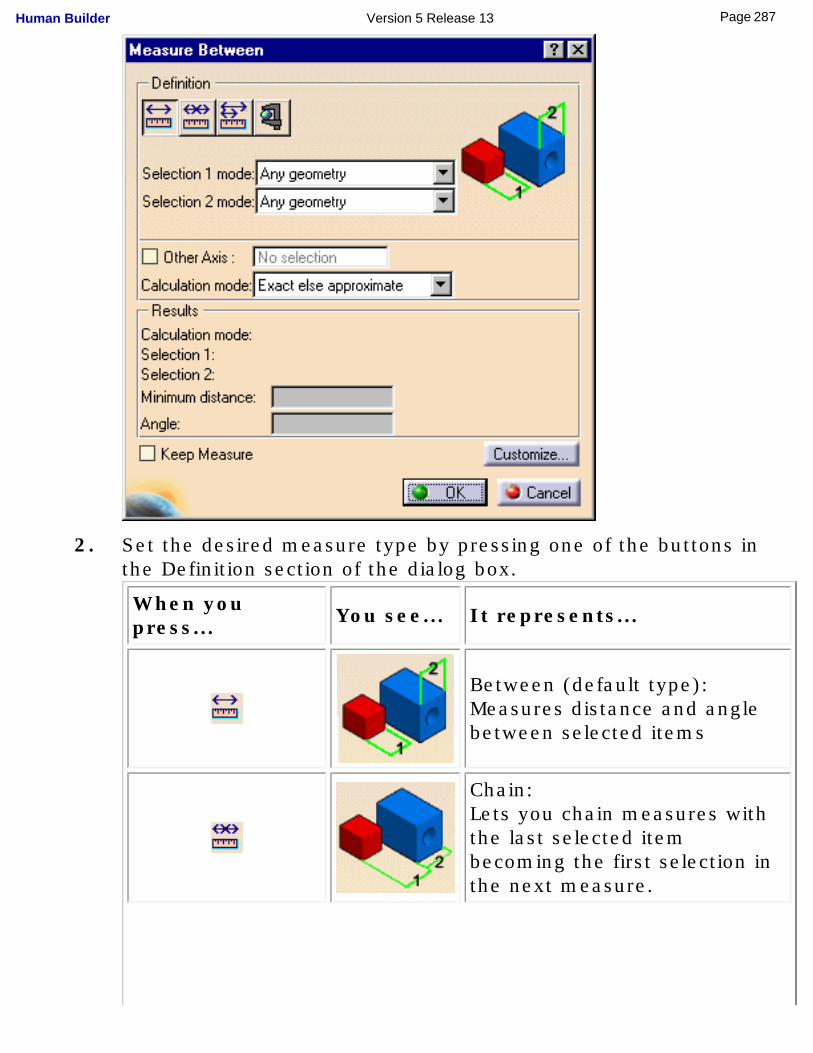
2. Set the desired measure type by pressing one of the buttons in the Definition section of the dialog box.
When you press... You see... It represents...
Between (default type):Measures distance and angle between selected items
Chain: Lets you chain measures with the last selected item becoming the first selection in the next measure.
287Page Human Builder Version 5 Release 13
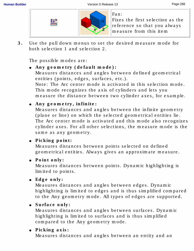
Fan: Fixes the first selection as the reference so that you always measure from this item
3. Use the pull down menus to set the desired measure mode for both selection 1 and selection 2.
The possible modes are:● Any geometry (default mode):
Measures distances and angles between defined geometrical entities (points, edges, surfaces, etc.).Note: The Arc center mode is activated in this selection mode.This mode recognizes the axis of cylinders and lets you measure the distance between two cylinder axes, for example.
● Any geometry, infinite: Measures distances and angles between the infinite geometry (plane or line) on which the selected geometrical entities lie. The Arc center mode is activated and this mode also recognizes cylinder axes. For all other selections, the measure mode is the same as any geometry.
● Picking point: Measures distances between points selected on defined geometrical entities. Always gives an approximate measure.
● Point only: Measures distances between points. Dynamic highlighting is limited to points.
● Edge only: Measures distances and angles between edges. Dynamic highlighting is limited to edges and is thus simplified compared to the Any geometry mode. All types of edges are supported.
● Surface only: Measures distances and angles between surfaces. Dynamic highlighting is limited to surfaces and is thus simplified compared to the Any geometry mode.
● Picking axis: Measures distances and angles between an entity and an
288Page Human Builder Version 5 Release 13
infinite line perpendicular to the screen.Simply click to create an infinite line perpendicular to the screen.
● Intersection: Measures distances between intersection points between two edges or an edge and a surface. In this case, two selections are necessary to define selection 1 and selection 2 items.
● Edge limits: Measures distances between endpoints or midpoints of edges. Endpoints only are proposed on curved surfaces.
● Arc center: Measures distances between the centers of arcs.
● Coordinate: Measures distances between coordinates entered for selection 1 and/or selection 2 items.
4. Set the calculation mode.
The choices are:● Exact else approximate (default mode):
Measures access exact data and wherever possible true values are given. If exact values cannot be measured, approximate values are given (identified by a ~ sign).
● Exact:Measures access exact data and true values are given. Note that you can only select exact items in the geometry area or specification tree.In certain cases, in particular if products are selected, a warning dialog box informs you that the exact measure could not be made.
● Approximate:Measures are made on tessellated objects and approximate values are given (identified by a ~ sign).
289Page Human Builder Version 5 Release 13
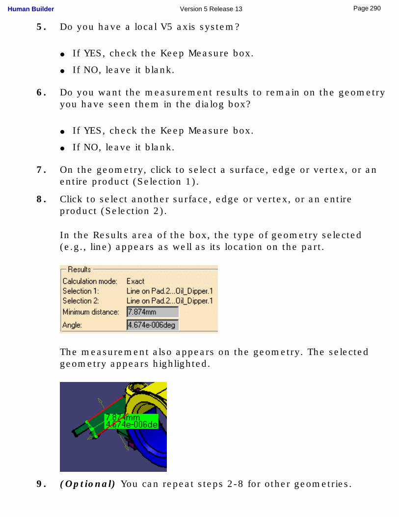
5. Do you have a local V5 axis system?
● If YES, check the Keep Measure box.
● If NO, leave it blank.
6. Do you want the measurement results to remain on the geometry you have seen them in the dialog box?
● If YES, check the Keep Measure box.
● If NO, leave it blank.
7. On the geometry, click to select a surface, edge or vertex, or an entire product (Selection 1).
8. Click to select another surface, edge or vertex, or an entire product (Selection 2).
In the Results area of the box, the type of geometry selected (e.g., line) appears as well as its location on the part.
The measurement also appears on the geometry. The selected geometry appears highlighted.
9. (Optional) You can repeat steps 2-8 for other geometries.
290Page Human Builder Version 5 Release 13
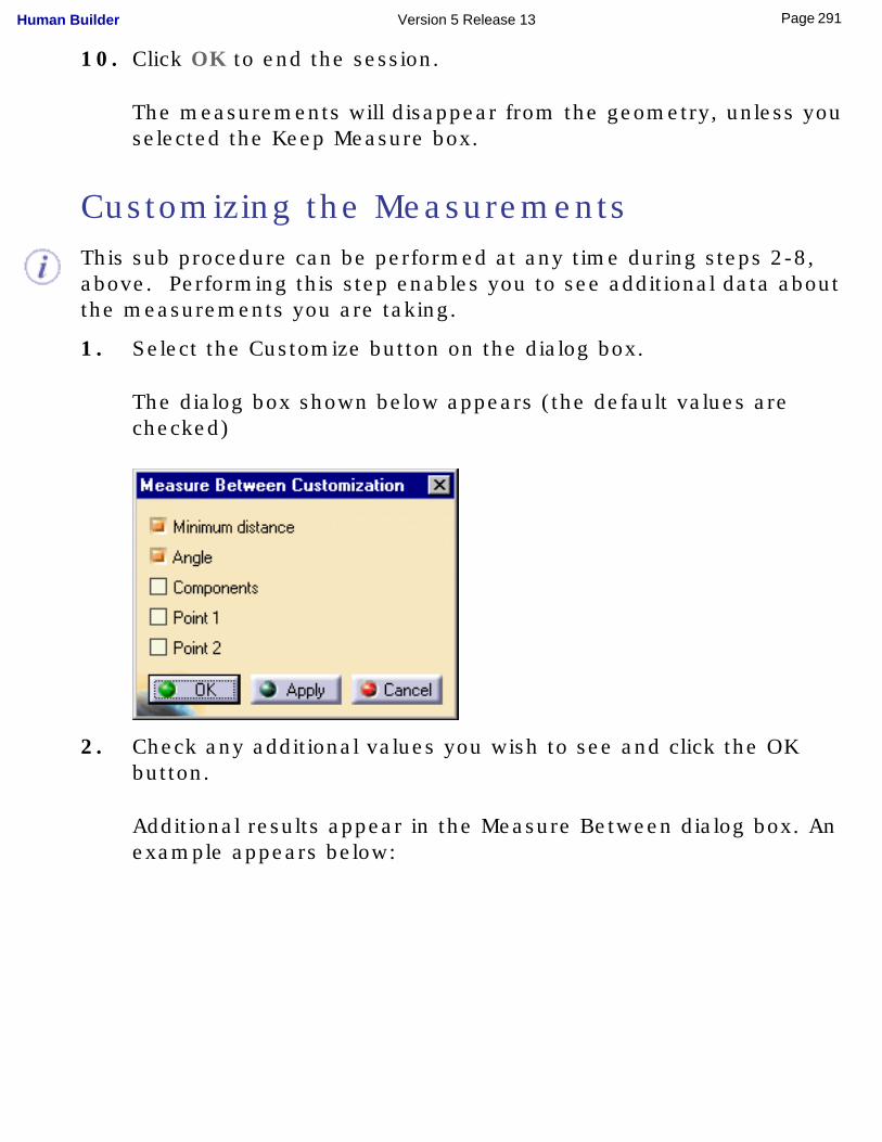
10. Click OK to end the session.
The measurements will disappear from the geometry, unless you selected the Keep Measure box.
Customizing the MeasurementsThis sub procedure can be performed at any time during steps 2-8, above. Performing this step enables you to see additional data about the measurements you are taking.
1. Select the Customize button on the dialog box.
The dialog box shown below appears (the default values are checked)
2. Check any additional values you wish to see and click the OK button.
Additional results appear in the Measure Between dialog box. An example appears below:
291Page Human Builder Version 5 Release 13
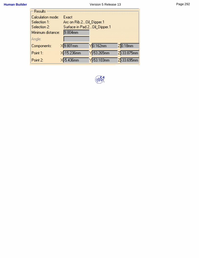
292Page Human Builder Version 5 Release 13
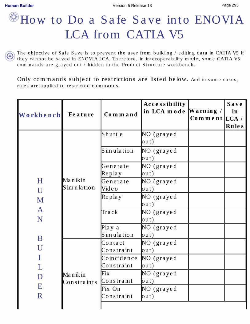
How to Do a Safe Save into ENOVIA LCA from CATIA V5
The objective of Safe Save is to prevent the user from building / editing data in CATIA V5 if they cannot be saved in ENOVIA LCA. Therefore, in interoperability mode, some CATIA V5 commands are grayed out / hidden in the Product Structure workbench.
Only commands subject to restrictions are listed below. And in some cases, rules are applied to restricted commands.
Workbench Feature Command
Accessibility in LCA mode Warning /
Comment
Save in
LCA / Rules
HUMAN BUILDER
Manikin Simulation
Shuttle NO (grayed out)
Simulation NO (grayed out)
Generate Replay
NO (grayed out)
Generate Video
NO (grayed out)
Replay NO (grayed out)
Track NO (grayed out)
Play a Simulation
NO (grayed out)
Manikin Constraints
Contact Constraint
NO (grayed out)
Coincidence Constraint
NO (grayed out)
Fix Constraint
NO (grayed out)
Fix On Constraint
NO (grayed out)
293Page Human Builder Version 5 Release 13
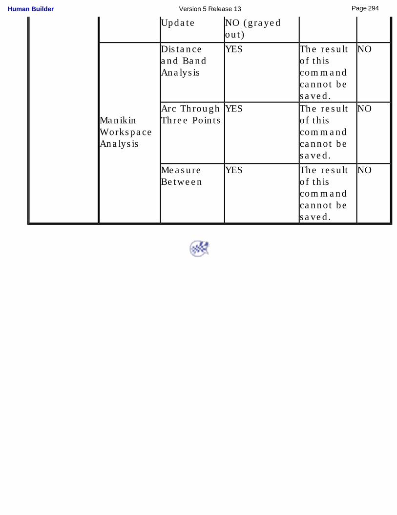
Update NO (grayed out)
Manikin Workspace Analysis
Distance and Band Analysis
YES The result of this command cannot be saved.
NO
Arc Through Three Points
YES The result of this command cannot be saved.
NO
Measure Between
YES The result of this command cannot be saved.
NO
294Page Human Builder Version 5 Release 13
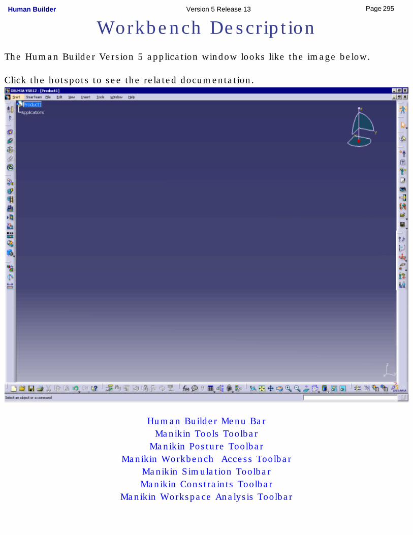
Workbench DescriptionThe Human Builder Version 5 application window looks like the image below.
Click the hotspots to see the related documentation.
Human Builder Menu BarManikin Tools Toolbar
Manikin Posture ToolbarManikin Workbench Access Toolbar
Manikin Simulation ToolbarManikin Constraints Toolbar
Manikin Workspace Analysis Toolbar
295Page Human Builder Version 5 Release 13
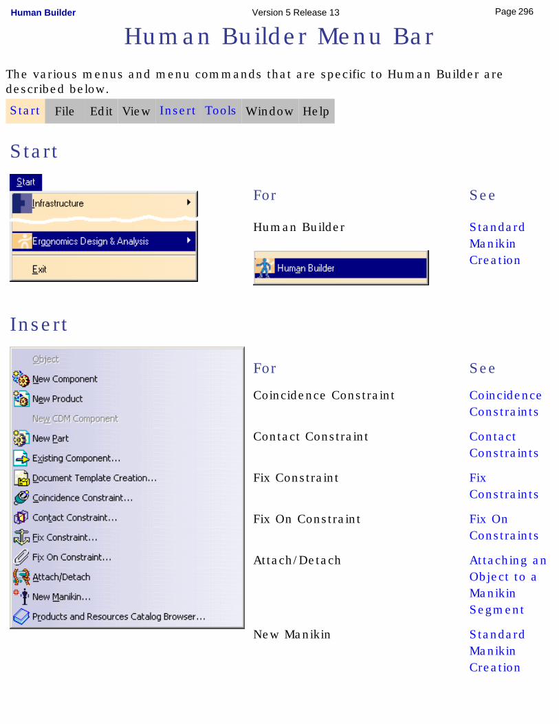
Human Builder Menu BarThe various menus and menu commands that are specific to Human Builder are described below.
Start File Edit View Insert Tools Window Help
Start
For
Human Builder
See
Standard Manikin Creation
Insert
For See
Coincidence Constraint Coincidence Constraints
Contact Constraint Contact Constraints
Fix Constraint Fix Constraints
Fix On Constraint Fix On Constraints
Attach/Detach Attaching an Object to a Manikin Segment
New Manikin Standard Manikin Creation
296Page Human Builder Version 5 Release 13
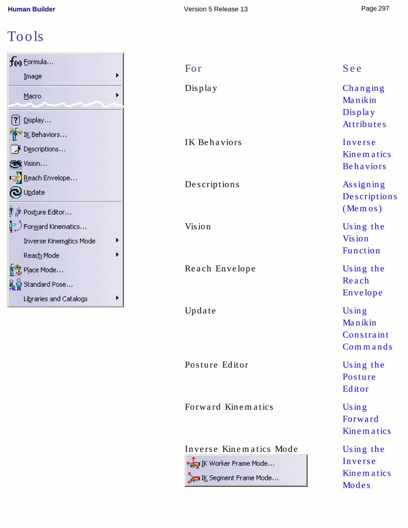
Tools
For See
Display Changing Manikin Display Attributes
IK Behaviors Inverse Kinematics Behaviors
Descriptions Assigning Descriptions (Memos)
Vision Using the Vision Function
Reach Envelope Using the Reach Envelope
Update Using Manikin Constraint Commands
Posture Editor Using the Posture Editor
Forward Kinematics Using Forward Kinematics
Inverse Kinematics Mode Using the Inverse Kinematics Modes
297Page Human Builder Version 5 Release 13
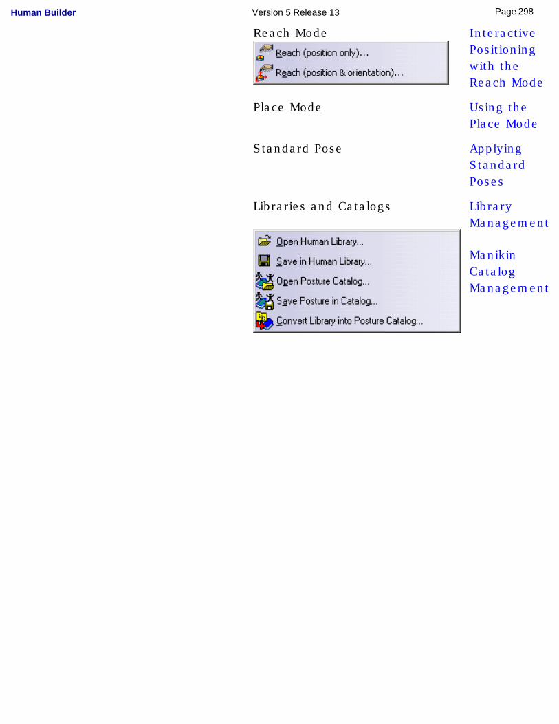
Reach Mode Interactive Positioning with the Reach Mode
Place Mode Using the Place Mode
Standard Pose Applying Standard Poses
Libraries and Catalogs Library Management
Manikin Catalog Management
298Page Human Builder Version 5 Release 13
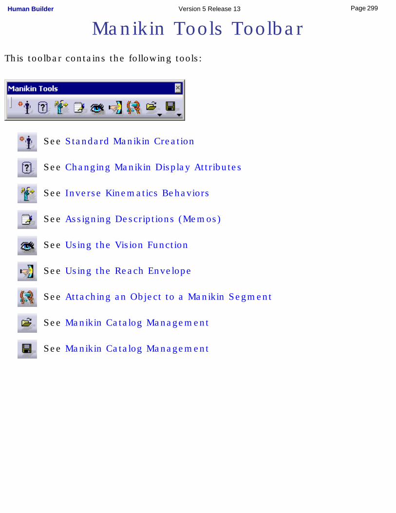
Manikin Tools ToolbarThis toolbar contains the following tools:
See Standard Manikin Creation
See Changing Manikin Display Attributes
See Inverse Kinematics Behaviors
See Assigning Descriptions (Memos)
See Using the Vision Function
See Using the Reach Envelope
See Attaching an Object to a Manikin Segment
See Manikin Catalog Management
See Manikin Catalog Management
299Page Human Builder Version 5 Release 13
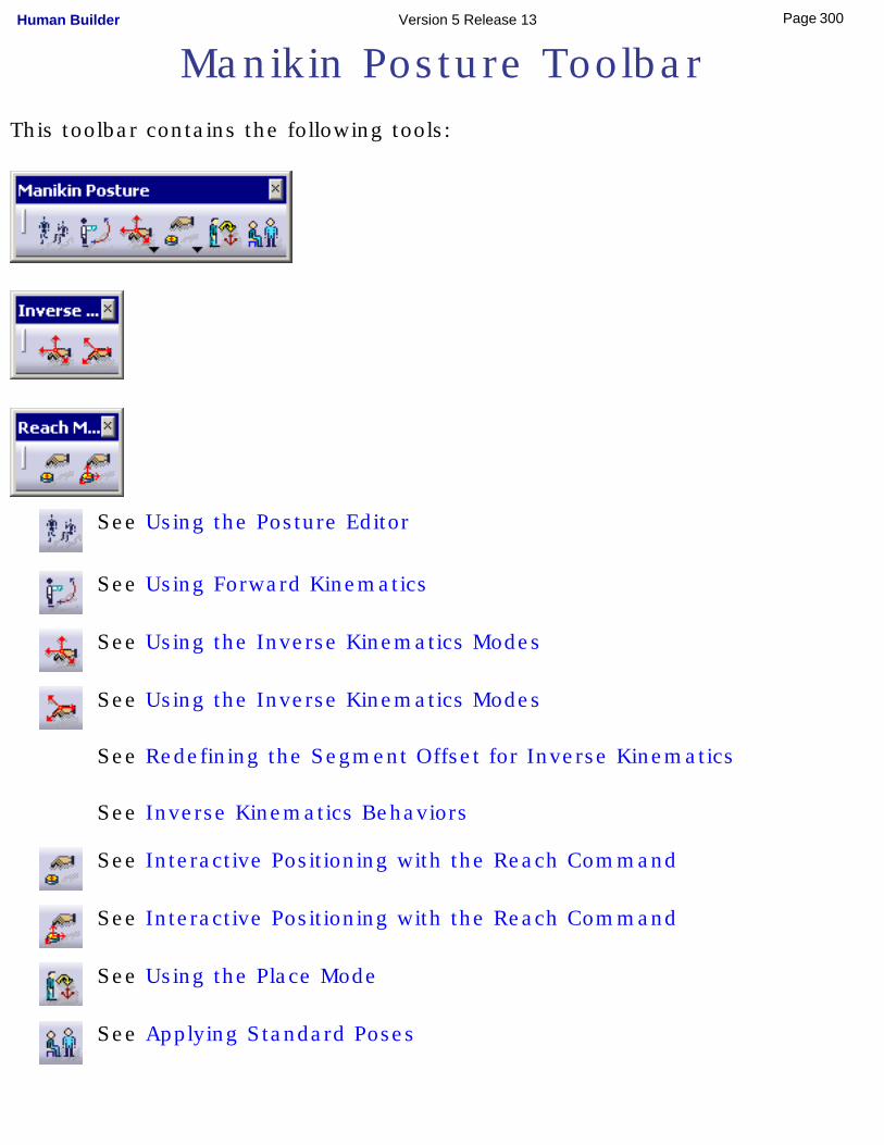
Manikin Posture ToolbarThis toolbar contains the following tools:
See Using the Posture Editor
See Using Forward Kinematics
See Using the Inverse Kinematics Modes
See Using the Inverse Kinematics Modes
See Redefining the Segment Offset for Inverse Kinematics
See Inverse Kinematics Behaviors
See Interactive Positioning with the Reach Command
See Interactive Positioning with the Reach Command
See Using the Place Mode
See Applying Standard Poses
300Page Human Builder Version 5 Release 13

301Page Human Builder Version 5 Release 13
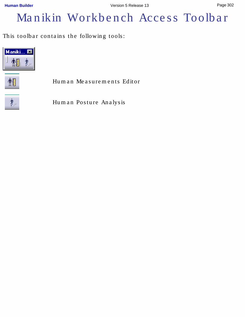
Manikin Workbench Access ToolbarThis toolbar contains the following tools:
Human Measurements Editor
Human Posture Analysis
302Page Human Builder Version 5 Release 13
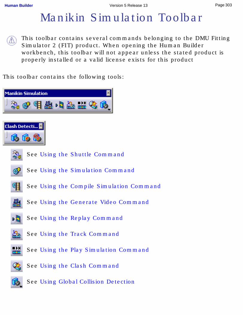
Manikin Simulation Toolbar
This toolbar contains several commands belonging to the DMU Fitting Simulator 2 (FIT) product. When opening the Human Builder workbench, this toolbar will not appear unless the stated product is properly installed or a valid license exists for this product
This toolbar contains the following tools:
See Using the Shuttle Command
See Using the Simulation Command
See Using the Compile Simulation Command
See Using the Generate Video Command
See Using the Replay Command
See Using the Track Command
See Using the Play Simulation Command
See Using the Clash Command
See Using Global Collision Detection
303Page Human Builder Version 5 Release 13

See Using Global Collision Detection
See Using Global Collision Detection
304Page Human Builder Version 5 Release 13
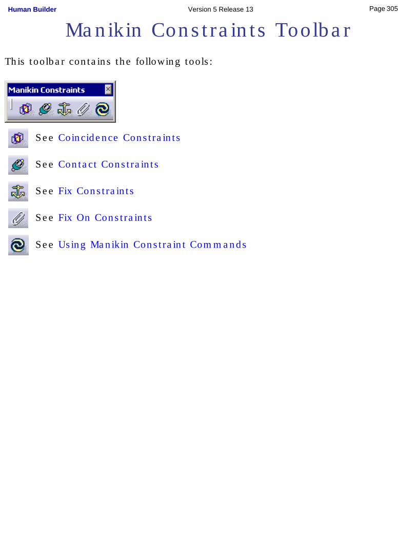
Manikin Constraints ToolbarThis toolbar contains the following tools:
See Coincidence Constraints
See Contact Constraints
See Fix Constraints
See Fix On Constraints
See Using Manikin Constraint Commands
305Page Human Builder Version 5 Release 13
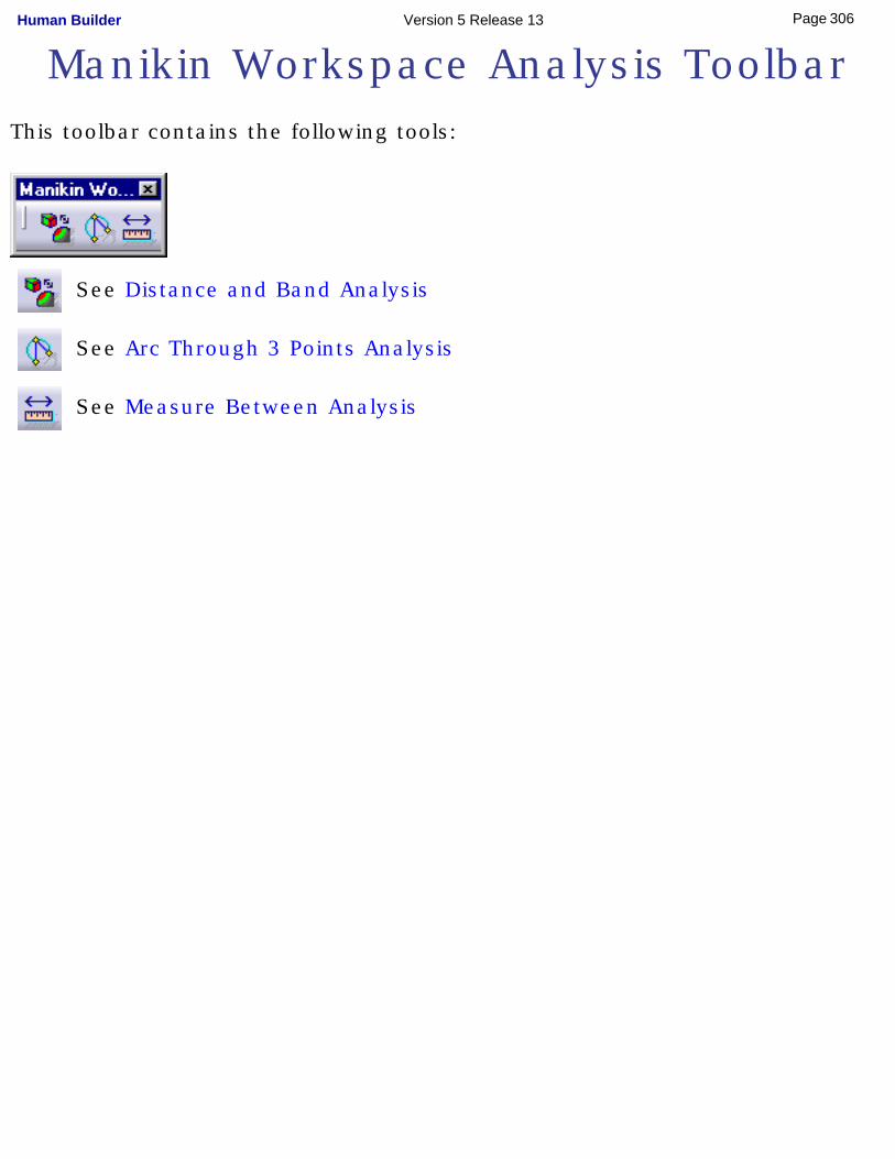
Manikin Workspace Analysis ToolbarThis toolbar contains the following tools:
See Distance and Band Analysis
See Arc Through 3 Points Analysis
See Measure Between Analysis
306Page Human Builder Version 5 Release 13
Glossary
A
abduction The movement of a limb away from the median, or midline, of the body.
adduction The movement of a limb toward the median, or midline, of the body.
ambinocular vision The zone defined by the union of two shapes that define the right and left monocular visions. The entire field of vision that can be seen with both eyes.
angular limitations The manikin's joint limitations.
anthropometry The study of proportional relationships between the shape, weight and size of body segments.
B
binocular vision The zone defined by the intersection of the two shapes that define the right and left monocular visions. The zone that can be seen by both the right and left eyes.
blind cone The 3D graphical representation of the mathematical model bordering the eye's blind spot. Available for monocular vision only.
blind spot The area of the eye where the optic nerve is attached.
307Page Human Builder Version 5 Release 13
C
center of gravity That point at the exact center of an object's mass.
central cone The 3D graphical representation used to create a model that represent the mathematical model of the central point.
central spot of vision Corresponds to the focus location. The end of the line of sight.
constraint The relationship of a manikin to its surrounding environment.
coronal axis The vertical axis perpendicular to the transverse plane that is dividing the body into superior and inferior portions.
COG See center of gravity.
D
degree(s) of freedom Each linear or rotary movement along or about a given axis. Manikin segments can have up to three DOFs.
depression Shoulder adduction movement.
DOF Degree(s) of freedom
dorsiflexion Ankle upward flexion movement
E
308Page Human Builder Version 5 Release 13
elevation Shoulder abduction movement
eversion Ankle abduction movement
extension The act of straightening a limb at a joint.
F
father product The product the manikin will be attached to in the specification tree. It can be the root product or any other product under the root.
flexion The act of bending a limb at a joint, thus forming an angle.
fovea The fovea of the eye is a small pit in the center of the retina that contains cones but no rods. When looking directly at a point, its image falls on the fovea. The fovea covers an angle of about 2 degrees. Visual acuity is normally greatest for images on the fovea.
H
hyperextension Extending the extremity beyond anatomical position.
I
inversion Ankle adduction movement
L
309Page Human Builder Version 5 Release 13
lateral rotation The rotation of a body part away from the median, or midline, of the body.
left monocular vision The field of vision of the left eye only
line of sight Designed to facilitate the manipulation of the manikin's field of vision. It can be selected as any other segment of the manikin.
M
manikin A virtual human.
medial rotation The rotation of a body part toward the median, or midline, of the body.
monocular vision The field of vision from one eye only.
P
peripheral cone The 3D graphical representation of the mathematical model bordering the human field of vision. The tip of the cone corresponds to the origin of the line of sight, i.e. the eyes.
plantar flexion Ankle flexion movement in the direction of the sole of the foot.
ponctum proximum The minimum accommodation distance or depth of vision; the nearest point that can be seen clearly.
ponctum remotum The maximum accommodation distance of the vision; the crystalline relax position for objects located from five meters to infinity.
310Page Human Builder Version 5 Release 13
postural score A function used to evaluate the manikin's posture.
posture The position of the whole manikin (global posture) or of parts of the manikin such as hand posture (local posture).
product tree Process/ Product/ Resource (PPR) tree. The PPR tree is a 2D view of the process. It lists all the products and resources required to make a specific product. It also lists, in hierarchical form, the actions required to perform the process that produces the product.
pronation The movement of the forearm so that the hand rests palm down on a surface.
R
radial deviation Wrist adduction movement (toward the radial bone, on the thumb side of the arm).
range of motion The range of translation and rotation of a joint for each of its degrees of freedom.
reach envelope A surface that represents all the possible surfaces the manikin can reach using only the arm and forearm. The motion starts at the shoulder.
right monocular vision The field of vision of the right eye only.
rotation A circular or turning movement of a body part, such as the back or head, around its axis.
S
311Page Human Builder Version 5 Release 13
sagittal axis Horizontal axis in the anterior-posterior orientation. This axis is perpendicular to the coronal plane that is dividing the body into anterior and posterior portions.
segment A section of the manikin such as forearm, neck, thigh, ankle, etc.
shuttle An element representing the object to be fitted or unfitted from an assembly. It is composed of an axis and list of models. The shuttle can be moved about to simulate the fitting or unfitting of the object within the assembly.
specification tree Area of the document window reserved for viewing the design specifications of a part, presented in the form of a tree structure.
stereo vision The vision of both left and right eyes in two distinct windows displayed side by side. This type of display is use for special needs such as vision in a stereo head mounted display.
supination The movement of the forearm so that the hand rests palm up on a surface.
T
transversal axis Horizontal axis in the left-right orientation. This axis is perpendicular to the sagittal plane that is dividing the body into left and right portions.
U
ulnar deviation Wrist abduction movement (toward the ulna bone, on the little finger side of the arm).
312Page Human Builder Version 5 Release 13

V
visual field The entire area that can be seen when the eye is forward, including peripheral vision.
313Page Human Builder Version 5 Release 13
Index
Numerics3D mouse for IK mode, using a
Aadjust elbow, applying analysis
Arc through 3 Points
Distance and Band
Measure Between applying
cylindrical grasp
pinch grasp
spherical grasp
assigning descriptions (memos)
Bblind spot
Ccatalog management
converting *.swl files into catalog files
reusing manikin attributes from a catalog file
314Page Human Builder Version 5 Release 13
storing manikin attributes in a catalog file
catalog management, manikin
center of gravity coordinates, retrieving
central spot collision detection
off
on
setting audible feedback for
stop commands
Arc through 3 Points
Attach/Detach
Collision Detection (Off)
Collision Detection (On)
Collision Detection (Stop)
Compile Simulation
Copy/Paste
Display Attributes
Distance and Band Analysis
Forward Kinematics
Generate Video
IK Behaviors
Insert Constraint
Inverse Kinematics Mode
Inverse Kinematics Segment Frame mode
Inverse Kinematics Worker Frame mode
Manikin Creation
Measure Between
Memo
Place Mode
315Page Human Builder Version 5 Release 13
Play Simulation
Posture Editor
Reach Envelope
Replay
Shuttle
Simulation
Standard Pose
Track
Undo/Redo
Update
Vision
compass, positioning the manikin with
Compile Simulation command
constraints, managing
copy/paste function, using creation of standard
manikin
cylindrical grasp
hand grasp
Ddescriptions, assigning
display attributes, changing
Distance and Band Analysis
Eellipses, changing the properties of
316Page Human Builder Version 5 Release 13
FForward Kinematics, using
GGenerate Video command
global collision detection, using graphical properties of whole
manikin
Graphical Properties toolbar
Hhand grasp
hand grasp, applying types of
IIK Behaviors command Insert
menu bar
interactive positioning with the Reach Mode command
inverse kinematics manipulator
Inverse Kinematics Segment Frame mode
inverse kinematics, redefining the segment offset for Inverse Kinematics
inverse kinematics, using a 3D mouse for
317Page Human Builder Version 5 Release 13
Llean
standard poses, applying
lean, applying
Mmanikin
display attributes, changing
Manikin Posture toolbar
Manikin Tools toolbar
Manikin Workbench Access toolbar
memos, assigning
menu bar
Ooffset feature
Pperipheral contour
pinch grasp
hand grasp
Place Mode, using
Play Simulation command
poses, applying standard positioning with the compass
manikin
318Page Human Builder Version 5 Release 13
Posture Editor dialog box
degree of freedom
display
predefined postures
segments
value
Posture Editor, using
posture functionality posture functionality,
global posture reset
global posture swap
local posture mirror copy
local posture reset
local posture swap
vision posture reset
posture undo/redo, using
Rreach envelope, using
Reach Mode commands referential, redefining
manikin
Replay command
Ssegment
attaching an object to
changing the color of
319Page Human Builder Version 5 Release 13
segment offset feature
segment twins segment, attaching an object to
manikin segments,
changing the properties of
graphical properties of
moving with inverse kinematics
Shuttle command
Simulation command sit
standard poses, applying
sit, applying
spherical grasp
hand grasp squat
standard poses, applying
squat, applying
standard poses, applying
standard poses, applying adjust elbow Start
menu bar stoop
standard poses, applying
stoop, applying
surfaces, changing the transparency of
Ttoolbar
Manikin Posture
320Page Human Builder Version 5 Release 13
toolbar,
Graphical Properties
Manikin Tools
Manikin Workbench Access toolbars
Manikin Workspace Analysis Tools
menu bar
Track command
twins, segment twist
standard poses, applying
twist, applying type functionality
Vision dialog box,
UUndo/Redo command, using
VVision dialog box,
distance functionality
distance functionality, focus distance
distance functionality, ponctum proximum
distance functionality, ponctum remotum
field of view functionality
field of view functionality, central
field of view functionality, horizontal ambinocular
321Page Human Builder Version 5 Release 13
field of view functionality, horizontal monocular
field of view functionality, vertical bottom
field of view functionality, vertical top
type functionality, ambinocular
type functionality, binocular
type functionality, left monocular
type functionality, right monocular
type functionality, stereo
vision function, using
vision options vision window
blind spot option
central spot
hide title option
peripheral contour option
scale option
Wwhole manikin graphical properties
workbench description
322Page Human Builder Version 5 Release 13