
MCS GRAPHICS BUILDER - Micro Control Systems
56
MCS Total Solution for all your Control Needs Energy Efficient and RoHS Compliant 5580 Enterprise Pkwy. Fort Myers, FL 33905 Office: 239-694-0089 Fax: 239-694-0031 www.mcscontrols.com MCS GRAPHICS BUILDER Revision 3.4.2 - 2019-08-06
-
Upload
khangminh22 -
Category
Documents
-
view
3 -
download
0
Transcript of MCS GRAPHICS BUILDER - Micro Control Systems

MCS TotalSolutionfor all yourControlNeeds Energy Efficient and RoHS Compliant
5580 Enterprise Pkwy.Fort Myers, FL 33905
Office: 239-694-0089Fax: 239-694-0031
www.mcscontrols.com
MCS GRAPHICS BUILDER
Revision 3.4.2 - 2019-08-06

MCS-Graphics Builder REVISION 3.4.2
2
The MCS Commitment is to provide practical solutions for the industries needs and to be both a leader and partner in the effective use of
microprocessor controls.
Micro Control Systems, Inc.5580 Enterprise ParkwayFort Myers, Florida 33905
PH:(239) 694-0089 FAX:(239) 694-0031www.mcscontrols.com
All information contained within this document is considered to be proprietary information of Micro Control Systems, Inc. No information or data from this document shall be published, used, reproduced, transmitted, or disclosed to others outside your organization without the prior expressed written consent of Micro Control Systems, Inc. This document and the information contained herein shall be treated as proprietary. Reasonable provisions shall be provided to ensure that this information remains proprietary by your employees, agents, and other personnel that may have access to this document. Copyright ©2019
Revision / Disclaimer
Date Author Description of Changes01-8/18-2016 DEW Setup Manual
02-04-2016 DEW Update to 3.10 screen shots, add Graph section
02-16-18-2016 DEW Update to 3.1.2 screen shots
03-01-2016 DEW Update to 3.1.5 screen shots
05-02-16 DEW Update to 3.2.0 screen shots
01-19-17 DEW Update to 3.3.0 screen shots
03-21-17 DEW Update Set Point Key list
07-09-2019 DEW Update to version 3.4.2 Graphics Builder
Revisions

MCS-Graphics Builder REVISION 3.4.2
3
TABLE OF CONTENTS Chapter - 1. GRAPHICS AND MCS-CONNECT ................................................................................5
1.1. GRAPHICS USING MCS GRAPHIC BUILDER ...........................................................................................5
1.2. MCS GRAPHICS BUILDER PC Requirements ...........................................................................................5
Chapter - 2. ABOUT GRAPHICAL INTERFACE ................................................................................6
Chapter - 3. MCS GRAPHIC BUILDER .................................................................................................8
3.1. Main Screens ................................................................................................................................................8
Chapter - 4. DESCRIPTION OF IMAGES, BUTTONS, POINTS ..................................................9
Chapter - 5. SIZING FOR IMAGES .......................................................................................................10
5.1. Image sizing is important ............................................................................................................................10
Chapter - 6. IMAGES, POINTS, BUTTONS and Gauges ............................................................11
6.1. UNDERSTANDING EDITABLE/NON EDITABLE IMAGES ........................................................................11
6.2. EDITABLE IMAGES USED (sizes can be changed) ..................................................................................11
6.3. NON-EDITABLE IMAGES USED ...............................................................................................................11
6.4. GAUGES ....................................................................................................................................................12
Chapter - 7. INSTALLING THE MCS GRAPHIC BUILDER .........................................................13
7.1. Files Associated with MCS GRAPHICS-BUILDER .....................................................................................13
7.2. Starting MCS GRAPHICS-BUILDER ..........................................................................................................13
7.3. STARTING MCS-GRAPHIC-BUILDER .....................................................................................................14
7.4. STARTING MCS-CONNECT .....................................................................................................................16
Chapter - 8. UNDERSTANDING IMAGE SIZING ............................................................................17
Chapter - 9. SELECT POINT, COPY AND DELETE BUTTONS ................................................18
Chapter - 10. DESCRIPTION OF THE MENU TABS ........................................................................19
10.1. Menu Tabs ..................................................................................................................................................19
Chapter - 11. MAKING CHANGES TO THE TEMPLATE ...............................................................44
11.1. OPEN THE SUPPLIED TEMPLATE TO MAKE CHANGES .......................................................................44
Chapter - 12. POINTS TO DISPLAY .......................................................................................................48
12.1. CHANGING POINTS THAT ARE DISPLAYED IN THE GRAPHICS ..........................................................48
13.13. SITE DOCUMENTS (Button shown on right) .............................................................................................49
Chapter - 14. STORING DOCUMENTS .................................................................................................49
Chapter - 15. STATUS BUTTON ..............................................................................................................50
15.1. CLICKING ON STATUS BUTTON ..............................................................................................................50
Chapter - 16. ADDENDUM A .....................................................................................................................51
16.1. MCS CONFIG SUMMARY REPORT FOR INPUT AND OUTPUT SENSORS ..........................................51

MCS-Graphics Builder REVISION 3.4.2
4
Chapter - 17. ADDENDUM B .....................................................................................................................52
17.1. CODES NEEDED FOR MCS GRAPHICS BUILDER .................................................................................52
17.2. MCS GRAPHICS BUILDER SET POINT ADDRESSES ............................................................................52
Chapter - 18. ADDENDUM C .....................................................................................................................53
18.1. MCS GRAPHICS BUILDER STATE ADDRESSES ....................................................................................53
Chapter - 19. ADDENDUM D- Troubleshooting ...............................................................................54
19.1. Gauges - Track and Sections .....................................................................................................................54
19.2. Using the Copy Button ................................................................................................................................54
19.3. Graphs ........................................................................................................................................................54
MCS-Graphics Builder REVISION 3.4.2
5
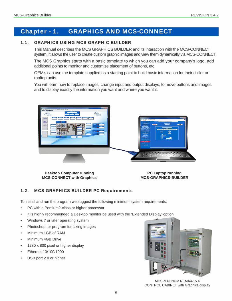
Chapter - 1. GRAPHICS AND MCS-CONNECT 1.1. GRAPHICS USING MCS GRAPHIC BUILDER
This Manual describes the MCS GRAPHICS BUILDER and its interaction with the MCS-CONNECT system. It allows the user to create custom graphic images and view them dynamically via MCS-CONNECT.The MCS Graphics starts with a basic template to which you can add your company’s logo, add additional points to monitor and customize placement of buttons, etc.OEM’s can use the template supplied as a starting point to build basic information for their chiller or rooftop units.You will learn how to replace images, change input and output displays, to move buttons and images and to display exactly the information you want and where you want it.
1.2. MCS GRAPHICS BUILDER PC Requirements
To install and run the program we suggest the following minimum system requirements:• PC with a Pentium2-class or higher processor• It is highly recommended a Desktop monitor be used with the ‘Extended Display’ option.• Windows 7 or later operating system• Photoshop, or program for sizing images• Minimum 1GB of RAM• Minimum 4GB Drive• 1280 x 800 pixel or higher display• Ethernet 10/100/1000• USB port 2.0 or higher
MCS-MAGNUM NEMA4-15.4CONTROL CABINET with Graphics display
PC Laptop running MCS-GRAPHICS-BUILDER
Desktop Computer runningMCS-CONNECT with Graphics

MCS-Graphics Builder REVISION 3.4.2
6
Chapter - 2. ABOUT GRAPHICAL INTERFACEThe Graphical interface is a combination of computer programs, Javascript, HTML, CSS, and XML which builds the screens showing your compressors in real time graphics.
Graphical user interfaces are build to show the important status information for your unit.
Multiple screens can be built to help you see and monitor the operation of the chiller, rooftop unit, its compressors, sensors, and relays.
It provides you with an easy-to-grasp overview of its systems ‘in real time’.
USERS ARE ABLE TO CLICK ON BUTTONS TO SEE DIFFERENT
OVERVIEWS AS WELL AS THE STATE OF THE UNIT
WITH THE GRAPHIC BUILDER POINT VALUES CAN BE PLACED CLOSE TO THE GRAPHICS SO YOU CAN BETTER UNDERSTAND WHAT YOU ARE VIEWING
POINTS ARE DISPLAYED SHOWING CURRENT VALUES AND STATUS OF
THE UNIT

MCS-Graphics Builder REVISION 3.4.2
7
In addition to loading the Graphics onto your MCS High Resolution Touch you can view the Graphics using your desktop remotely. Remote monitoring via MCS-Connect and the ‘Graphical user interface’ will increase the value of your installations. It enables the user to view the system without the need to be at the site if you are connected remotely.It also aids the user to troubleshoot failures and have the appropriate equipment on hand before going to the unit’s site.MCS-Connect and the ‘Graphic Interface’ provides a dynamic, easy to understand man machine interface, but more importantly you have better control of your chillers and rooftop units and can monitor all parameters in real time through MCS-CONNECT.Each ‘Graphic Package’ screen can be different depending on how you want to display information in real time mode.
Changes to setpoints, relays, etc. can be made at the MCS-Connect status screen if you have the proper authorization.
SYSTEM OVERVIEWTHIS WINDOW SHOWS
STATUS OF THE COMPRESSORSUNIT IS UNLOADED
STATUS OF STEPS WTD, STEPS ON,AMBIENT TEMP, ETC.
MCS-Graphics Builder REVISION 3.4.2
8
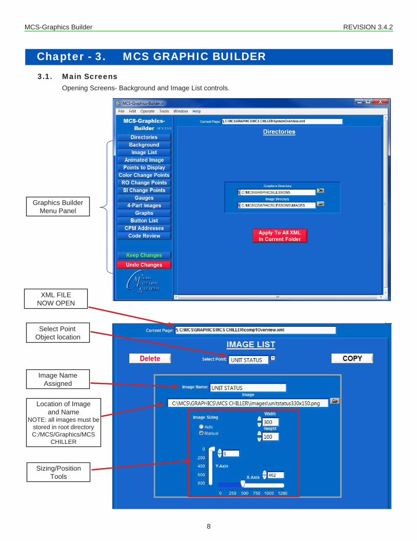
Chapter - 3. MCS GRAPHIC BUILDER3.1. Main Screens
Opening Screens- Background and Image List controls.
Graphics BuilderMenu Panel
Select PointObject location
Image Name Assigned
Sizing/Position Tools
Location of Image and Name
NOTE: all images must bestored in root directoryC:/MCS/Graphics/MCS
CHILLER
XML FILE NOW OPEN

MCS-Graphics Builder REVISION 3.4.2
9
Chapter - 4. DESCRIPTION OF IMAGES, BUTTONS, POINTS
BUTTONS
POINTS DISPLAYED (Reading and Status of Unit)
IMAGES(CHILLER AND LOGOS
IMAGE CHANGE POINTS
ANIMATED GRAPHICS
Fan Blades TurningGears Turning

MCS-Graphics Builder REVISION 3.4.2
10
Chapter - 5. SIZING FOR IMAGES5.1. Image sizing is important
You should have available a software program that can size your images, logos prior to importing into the MCS GRAPHICS BUILDER. Photoshop is an excellent program or use Windows Photo Gallery which is free from Microsoft. Images can be re-sized once placed in the GRAPHICS BUILDER if they are not the correct size you want, but it helps to get them close to the right size.
Image of Chiller used in TemplateOriginal size: 1941 x 849 pixels
Chiller size in Graphic BuilderSize: 950 x 475 pixels

MCS-Graphics Builder REVISION 3.4.2
11
Chapter - 6. IMAGES, POINTS, BUTTONS and Gauges6.1. UNDERSTANDING EDITABLE/NON EDITABLE IMAGES
Images placed in your graphics are broken into different categories as shown below.Some images are ’EDITABLE’ while other images cannot be changes in size. RO (Relay Outputs) and SI (Sensor Inputs) are ‘NON EDITABLE’ images.The reason is that MCS-CONNECT controls the placement of the sizes for RO (Relay Outputs) and SI (Sensor Inputs) points based on the points we are displaying.WHILE IT’S POSSIBLE TO USE YOUR OWN IMAGES IN YOUR GRAPHICS, NON-EDITABLE IMAGES MUST BE SIZED AS PER THE SAMPLES IN OUR TEMPLATE.Stored in the template image folder supplied with MCS-GRAPHIC-BUILDER you will find the sample images.
6.2. EDITABLE IMAGES USED (sizes can be changed)
6.3. NON-EDITABLE IMAGES USEDYOU CANNOT RE-SIZE THE IMAGES SHOWN BELOW.
Green On Green On Red Off Red Off Red Lockout Manual Manual
MCS-Graphics Builder REVISION 3.4.2
12
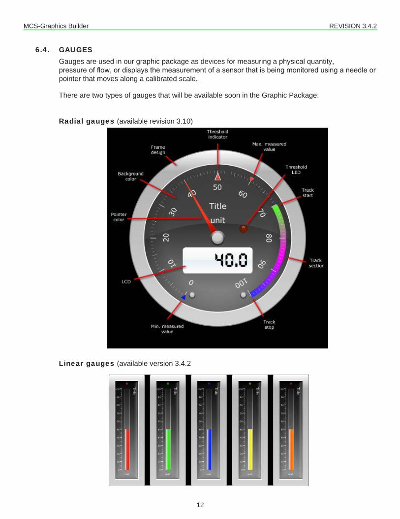
6.4. GAUGESGauges are used in our graphic package as devices for measuring a physical quantity, pressure of flow, or displays the measurement of a sensor that is being monitored using a needle or pointer that moves along a calibrated scale.
There are two types of gauges that will be available soon in the Graphic Package:
Radial gauges (available revision 3.10)
Linear gauges (available version 3.4.2

MCS-Graphics Builder REVISION 3.4.2
13
Chapter - 7. INSTALLING THE MCS GRAPHIC BUILDER7.1. Files Associated with MCS GRAPHICS-BUILDER
The Graphics Builder is a software program designed to be installed on a PC running Windows 7 or later operating system.Software will consist of the following files after installation:1. MCS-XML-BUILDER-Version 3.xxx.exe Application program2. MCS-XML-BUILDER-Version 3.xxx.ini Configuration setting3. MCS-XML-BUILDER-Version 3.xxx alias Desktop Aliases File4. MCS Folder (Main folder on C:/ drive
a. Sub Folder (MCS CHILLER for demo)1. Graphics (sub folder)2. Images (sub folder)3. Names of XML files that have been build (SystemOverview.xml)
7.2. Starting MCS GRAPHICS-BUILDER1. Download Software from http://www.mcscontrols.com/Documents/MCS/Graphics and save to
your hard drive.2. OPEN FOLDER ‘INSTALLER/VOLUME/SETUP.EXE3. CLICK ON ‘SETUP.EXE’ TO LOAD SOFTWARE ONTO YOUR COMPUTER’S HARD DRIVE.4. ACCEPT THE DEFAULT DIRECTORY FOR INSTALLATION AS SHOWN ON SCREEN BELOW.5. AFTER SOFTWARE IS INSTALLED, CONFIRM THAT FILES WERE INSTALLED CORRECT.

MCS-Graphics Builder REVISION 3.4.2
14
7.3. STARTING MCS-GRAPHIC-BUILDER
1. CLICK ON WINDOWS ICON ON DESKTOP AND GO TO ALL PROGRAMS.
2. CLICK ON MCS-GRAPHICS-BUILDER TO OPEN.
2
3
2. Once the MCS-GRAPHICS BUILDER is open you will see the first screen (2).
3. Click OPEN EXISTING GRAPHICS FILE
4. CLICK ON ‘FILE FOLDER ON RIGHT’ TO LOAD AN EXISTING GRAPHIC FILE.
5. Click ‘GO’.
4
5
6
6. Navigate to: C:\MCS\GRAPHICS\lessons and select systemoverview.xml
CONTINUE TO NEXT PAGE TO CONTINUE TO LOAD GRAPHIC FILES

MCS-Graphics Builder REVISION 3.4.2
15
7. If Graphics were created before April 2016, you will see the following popup
8. The Graphics Directory and Image directory must be set to continue9. Now at the main screen of the builder, we can set our directories.
✔ Graphics Directory: The directory that contains the XML files and images✔ Image Directory: The directory located in the graphics directory that contains images and
animations.
10. Navigate to: C:\MCS\GRAPHICS\lessons and select:a. LESSONS (Graphics Directory)b. IMAGES (in the Lessons directory, choose Images as your image directory)
MCS-GRAPHICS-BUILDER is now ready for viewing and editing ‘LESSIONS\systemview.xml
CONTINUE TO SETUP AND OPEN MCS-CONNECT
7
8
9 10

MCS-Graphics Builder REVISION 3.4.2
16
7.4. STARTING MCS-CONNECT NOW OPEN MCS-CONNECT ON YOUR COMPUTER(LAPTOP) TO BE ABLE TO VIEW THE FILE(S) YOU WILL CREATE IN MCS-GRAPHICS-BUILDER.
1. START MCS-CONNECT ON YOUR COMPUTER2. CLICK ON ‘OFFLINE/LOAD ON OFFIINE XML FILE/ENABLE AUTO SCREEN REFRESH’This will enable MCS-CONNECT to refresh the screen every time you make a change in MCS GRAPHICS BUILDER.

MCS-Graphics Builder REVISION 3.4.2
17
Images can be inserted using ‘AUTO SIZING’ but in most cases you will want to resize the image to fit your area.It is a good idea to bring the image that you will be using into a program like Microsoft Paint and ‘RESIZE’ the image to fit the area you will be placing the image into. You can use either the percentage or pixelsadjustment to resize the image.
The ‘CHILLER’ image we used in our Graphics Builder template was 840 x 420 pixels.Once you have the image placed close to the size you have allotted, you can use ‘MANUAL’ to size the image.
Click on ‘MANUAL’ to size your image
Use the Width and Height controls to size your image, remember to try to keep the image in proportions to the original size.Once you get your size close, use the up and down arrows to make small adjustments.
‘X AXIS’ and ‘Y AXIS’– Position of the image can be controlled by using the X and Y Axis controls.‘X’ moves the image left to right‘Y’ moves the image up and downClick on the ‘arrow’ and drag the arrow to move the image across your page. Use the up and down arrows to make slight adjustments.‘X’ small arrow on bottom moves the image ‘RIGHT’‘Y’ small arrow on bottom moves the image ‘UP’
Chapter - 8. UNDERSTANDING IMAGE SIZING

MCS-Graphics Builder REVISION 3.4.2
18
Several tabs have buttons that say Delete, Copy, and have a Select Point dropdown. The tabs that have it are highlighted
Chapter - 9. SELECT POINT, COPY AND DELETE BUTTONS
Delete buttonDeletes current item
Select Point Dropdown list that
lists all current items for selected tab.
Allows you to choose item to edit.
Copy buttonCopies all values
and creates a new item named ‘New’ which can then be
renamed.
MCS-Graphics Builder REVISION 3.4.2
19
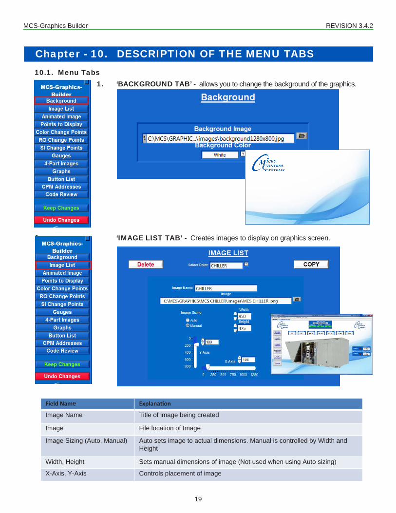
Chapter - 10. DESCRIPTION OF THE MENU TABS10.1. Menu Tabs
1. ‘BACKGROUND TAB’ - allows you to change the background of the graphics.
2. ‘IMAGE LIST TAB’ - Creates images to display on graphics screen.
Field Name Explanation
Image Name Title of image being created
Image File location of Image
Image Sizing (Auto, Manual) Auto sets image to actual dimensions. Manual is controlled by Width and Height
Width, Height Sets manual dimensions of image (Not used when using Auto sizing)
X-Axis, Y-Axis Controls placement of image

MCS-Graphics Builder REVISION 3.4.2
20
Menu Tabs Continued
3. ‘ANIMATED IMAGE TAB’ - images used for showing ‘ON AND OFF MOTION’
Still Image - EVAV OFF Animated Image - EVAV RUNNING
Screen 1 Screen 2
For example: Screen 1 shows ‘STILL IMAGE’ EVAV OFF’ Screen 2 shows ‘ANIMATED IMAGE - EVAV RUNNING’
Field Name ExplanationPoint Name Title of animated image being createdID Type, ID ID Type is the type of point (Relay Outputs, Analog Outputs, Sensor Inputs, etc.) ID
is the number of the point to display ( See Graphics ID key list)State1, State 2(ON, OFF, RUN, STOP, OK, TRIPPED, etc.)
State 1 is the state that the still image should be displayed, State 2 is the state that the animated image should be displayed
Still Image, Animated Image The still image is usually used to display when in the “OFF” position, the animated image is usually used to display when in the “ON” position
Image Sizing (Auto, Manual) Auto sets image to actual dimensions. Manual is controlled by Width and Height
Width, Height Sets manual dimensions of image (Not used when using Auto sizing)
X-Axis, Y-Axis Controls placement of image

MCS-Graphics Builder REVISION 3.4.2
21
Menu Tabs Continued
4. ‘POINTS TO DISPLAY TAB’ - Creates a text box that displays current value of point selected. Optional background image for point can be set.
Field Name ExplanationPoint Name Title of point being createdID Type, ID ID Type is the type of point (Relay Outputs, Analog Outputs, Sensor Inputs, etc.) ID is the
number of the point to display ( See Graphics ID key list)Is Editable, Auth Level Is Editable can be set to true or false. When set to true it allows the user to change values
through the graphics screen as long as Auth level is reachedMultiboard Address, Not used? Multiboard Address is used in graphics that read multiple controllers, address is set to
Network Address of the controller. If only reading one controller, select not used.
Field Name ExplanationImage File location of ImageImage Sizing (Auto, Manual) Auto sets image to actual dimensions. Manual is controlled by Width and HeightWidth, Height Sets manual dimensions of image (Not used when using Auto sizing)X-Offset, Y-Offset Controls placement of background image in reference to the text box

MCS-Graphics Builder REVISION 3.4.2
22
Points to Display (continued)
Field Name ExplanationAuto, On, Off Labels Indicates what to display for each state for Digital Sensors X-Offset, Y-Offset Controls placement of header in reference to the text box
Width, Height Sets dimensions of header text
Font Size Font size for the header text
Header Color Color chooser to select header text color
Field Name ExplanationFont Size Font size for text inside text boxWidth, Height Sets dimensions of the text box
X-Axis, Y-Axis Controls placement of entire point (header, background image, text box)
Header Color Color chooser to select header text color

MCS-Graphics Builder REVISION 3.4.2
23
Points to Display (continued)
For example: below we are displaying points (data) from a compressor. Points are received every few seconds from the controller and updated on your graphics.
The MCS GRAPHICS BUILDER allows you to position information on the graphics where it
easily identifies with the function allowing for quick identification of
potential problems.
Position of background image
(blue box)
Position of name
Size of text box

MCS-Graphics Builder REVISION 3.4.2
24
Menu Tabs Continued
1. ‘COLOR CHANGE POINTS TAB’ - in the example below Green is showing in the Run/Stop, Red in Alarm and Yellow Warning. If the unit was stopped, the color would change to a preset color in the graphic builder such as Red. These are easily changed in the MCS GRAPHICS BUILDER.
Field Name ExplanationPoint Name Title of point being createdID Type, ID ID Type is the type of point (Relay Outputs, Analog Outputs, Sensor Inputs, etc.) ID
is the number of the point to display ( See Graphics ID keylist)Is Editable, Auth Level Is Editable can be set to true or false. When set to true it allows the user to change
values through the graphics screen as long as Auth level is reachedMultiboard Address, Not used? Multiboard Address is used in graphics that read multiple controllers, address is set
to Network Address of the controller. If only reading one controller, select not used.

MCS-Graphics Builder REVISION 3.4.2
25
Color Change Points (continued)
Field Name Explanation
Font, style and size Allows user to change font, style and size
X-Offset, Y-Offset Controls placement of text
Color Allows changing color for State 1 and State 2
Field Name ExplanationAuto, On, Off Labels Indicates what to display for each state for Digital Sensors X-Offset, Y-Offset Controls placement of header in reference to the text box
Width, Height Sets dimensions of header text
Font, Size and style Font size and style for the header text
Header Color Color chooser to select header text color
Field Name ExplanationImage Choose background image to use
Image Sizing Changes xy position and width and height
Auto, Manual Auto brings exact size of stored image, manual lets you override size
MCS-Graphics Builder REVISION 3.4.2
26
Menu Tabs Continued
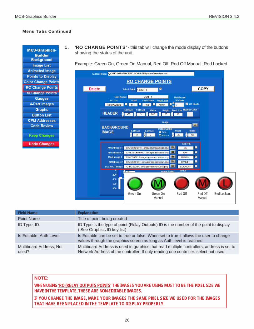
1. ‘RO CHANGE POINTS’ - this tab will change the mode display of the buttons showing the status of the unit.
Example: Green On, Green On Manual, Red Off, Red Off Manual, Red Locked.
Field Name ExplanationPoint Name Title of point being createdID Type, ID ID Type is the type of point (Relay Outputs) ID is the number of the point to display
( See Graphics ID key list)Is Editable, Auth Level Is Editable can be set to true or false. When set to true it allows the user to change
values through the graphics screen as long as Auth level is reachedMultiboard Address, Not used?
Multiboard Address is used in graphics that read multiple controllers, address is set to Network Address of the controller. If only reading one controller, select not used.
NOTE:WHEN USING ‘RO (RELAY OUTPUTS POINTS’ THE IMAGES YOU ARE USING MUST TO BE THE PIXEL SIZE WE HAVE IN THE TEMPLATE, THESE ARE NON-EDITABLE IMAGES.IF YOU CHANGE THE IMAGE, MAKE YOUR IMAGES THE SAME PIXEL SIZE WE USED FOR THE IMAGES THAT HAVE BEEN PLACED IN THE TEMPLATE TO DISPLAY PROPERLY.
Green On Green On Red Off Red Off Red Lockout Manual Manual

MCS-Graphics Builder REVISION 3.4.2
27
RO Change Points (Continued)
Field Name ExplanationAuto, On, Off Labels Indicates what to display for each state for Digital Sensors X-Offset, Y-Offset Controls placement of header in reference to the state indicator image
Width, Height Sets dimensions of header text
Font Size Font size for the header text
Header Color Color chooser to select header text color
Field Name ExplanationImage File location of ImageImage Sizing (Auto, Manual) Auto sets image to actual dimensions. Manual is controlled by Width and HeightWidth, Height Sets manual dimensions of image (Not used when using Auto sizing)X-Offset, Y-Offset Controls placement of background image in reference to the state indicator image
Field Name ExplanationAUTO, MAN, LOCKOUT images
Images to display when each state is met. See reference below.
Image Sizing (Auto, Manual) Auto sets image to actual dimensions. Manual is controlled by Width and HeightWidth, Height Sets manual dimensions of image (Not used when using Auto sizing)X-Axis, Y-Axis Controls placement of entire point (header, background image, state indicator
image)
Green On Green On Red Off Red Off Red Lockout Manual Manual

MCS-Graphics Builder REVISION 3.4.2
28
Menu Tabs Continued
1. ‘SI CHANGE POINTS TAB’ - Used for Digital sensors, displays an image for each state (Auto, On, Off). If set to editable, it can be used to change the state of the sensor if auth level is reached.
NOTE:WHEN USING ‘SI (SENSOR INPUT POINTS’ THE IMAGES YOU ARE USING MUST TO BE THE PIXEL SIZE WE HAVE IN THE TEMPLATE, THESE ARE NON-EDITABLE IMAGES.IF YOU CHANGE THE IMAGE, MAKE YOUR IMAGES THE SAME PIXEL SIZE WE USED FOR THE IMAGES THAT HAVE BEEN PLACED IN THE TEMPLATE TO DISPLAY PROPERLY.
Field Name ExplanationPoint Name Title of point being createdID Type, Point ID Type is the type of point (Sensor Inputs), Point is the number of the sensor ( See
Graphics ID key list)Is Editable, Auth Level Is Editable can be set to true or false. When set to true it allows the user to change
values through the graphics screen as long as Auth level is reachedMultiboard Address, Not used? Multiboard Address is used in graphics that read multiple controllers, address is set
to Network Address of the controller. If only reading one controller, select not used.

MCS-Graphics Builder REVISION 3.4.2
29
SI Change Points (continued)
Field Name ExplanationAuto Label, Auto state image Auto State Image file location to image to display when Auto state is met.On Label, MANON state image MANON State Image file location to image to display when MANON state is
met.Off Label, MANOFF state image MANOFF State Image file location to image to display when MANONFF state
is met.Image Sizing (Auto, Manual) Auto sets image to actual dimensions. Manual is controlled by Width and
HeightWidth, Height Sets dimensions of image
X-Axis, Y-Axis Controls placement of image

MCS-Graphics Builder REVISION 3.4.2
30
Menu Tabs Continued
‘GUAGES TAB’- Gauges have many features as you will see in the MCS-GRAPHICS BUILDER. For the purpose of this lesson we will setup one gauge only to get you started. In a custom installation, as shown in our manual, you can setup a screen with multiple gauges to monitor your chiller.
DESCRIPTION OF GAUGE BUTTONS AND THEIR FUNCTIONS
1. Click on ‘Gauge Name’ to create a new Gauge.
2. In Gauge Name field, enter ‘WTR IN’ for the name of our first gauge as an example.
MCS-Graphics Builder REVISION 3.4.2
31
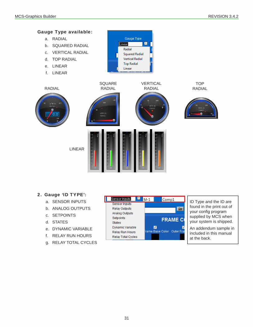
Gauge Type available:a. RADIALb. SQUARED RADIALc. VERTICAL RADIALd. TOP RADIALe. LINEARf. LINEAR
2. Gauge ‘ID TYPE’:a. SENSOR INPUTSb. ANALOG OUTPUTSc. SETPOINTSd. STATESe. DYNAMIC VARIABLEf. RELAY RUN HOURSg. RELAY TOTAL CYCLES
TOP RADIALRADIAL
SQUARE RADIAL
VERTICAL RADIAL
ID Type and the ID are found in the print out of your config program supplied by MCS when your system is shipped.An addendum sample in included in this manual at the back.
LINEAR

MCS-Graphics Builder REVISION 3.4.2
32
8. BACKGROUND IMAGE, COLOR, EDITABLE COLORS, FRAME COLORS
a. BACKGROUND IMAGE - you can add a background to your gauge as shown in the screen shot below.
b. BACKGROUND COLOR - our default shows a linen background in black, here we changed to a white background with black ticks. Again, you have the options to change the colors how you want them.
In this example, we added a background from our images (textbutton115x55.png) blue background. We are showing a Section solid bar to indicate safe zone in green, caution zone in yellow and unsafe zone in red.The Graphic Builder allows you to display your gauges how you want them to alert you to any problems.
Default Linen backgroundNew White background

MCS-Graphics Builder REVISION 3.4.2
33
c. EDITABLE COLORS - allows you to change the ‘GLOW COLOR’, TICK MARK COLOR, TICK LABEL COLOR, LABEL COLOR AND THE TEXTURE COLOR of your gauge.
d. FRAME COLORS - you can change the FRAME BASE COLOR, OUTER COLOR and INNER FRAME COLOR.
9. ATTRIBUTES - allow you to make changes to various parts of your gauges, changing the frame design, knob size and color, and point color and size. Click on each to see the options available.
In our samples we added the LCD and LED so we could show the numbers better. This can be enabled or disabled.
You also can display your numbers in the gauge, HORIZONTAL, NORMAL or TANGENT.
TANGENTHORIZONTAL NORMAL

MCS-Graphics Builder REVISION 3.4.2
34
10. TRACK AND SECTION DISPLAYS a. TRACK - allows you to setup a series of three (3) numbers to show a ‘GRADIENT’ track
around your gauge as seen in the sample below.
b. SECTIONS- instead of ‘TRACK’, you can change your display to ‘SECTIONS’ which will display a solid instead of the gradient as seen below.
Example settings:
0. set start range at ‘0’ and end at ‘50’ - BLUE1. set start range at ‘50’ and end at ‘100’ - GREEN2. set start range at ‘100’ and end at ‘300’ - RED

MCS-Graphics Builder REVISION 3.4.2
35
Menu Tabs Continued
1. ‘FOUR-PART IMAGES TAB’ - To show an animated object, you will need four images of the same object.
MCS-Graphics Builder REVISION 3.4.2
36
Menu Tabs Continued
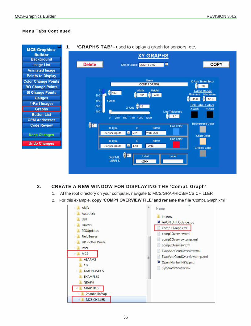
1. ‘GRAPHS TAB’ - used to display a graph for sensors, etc.
2. CREATE A NEW WINDOW FOR DISPLAYING THE ‘Comp1 Graph’ 1. At the root directory on your computer, navigate to MCS/GRAPHICS/MCS CHILLER2. For this example, copy ‘COMP1 OVERVIEW FILE’ and rename the file ‘Comp1 Graph.xml’
MCS-Graphics Builder REVISION 3.4.2
37
Menu Tabs Continued
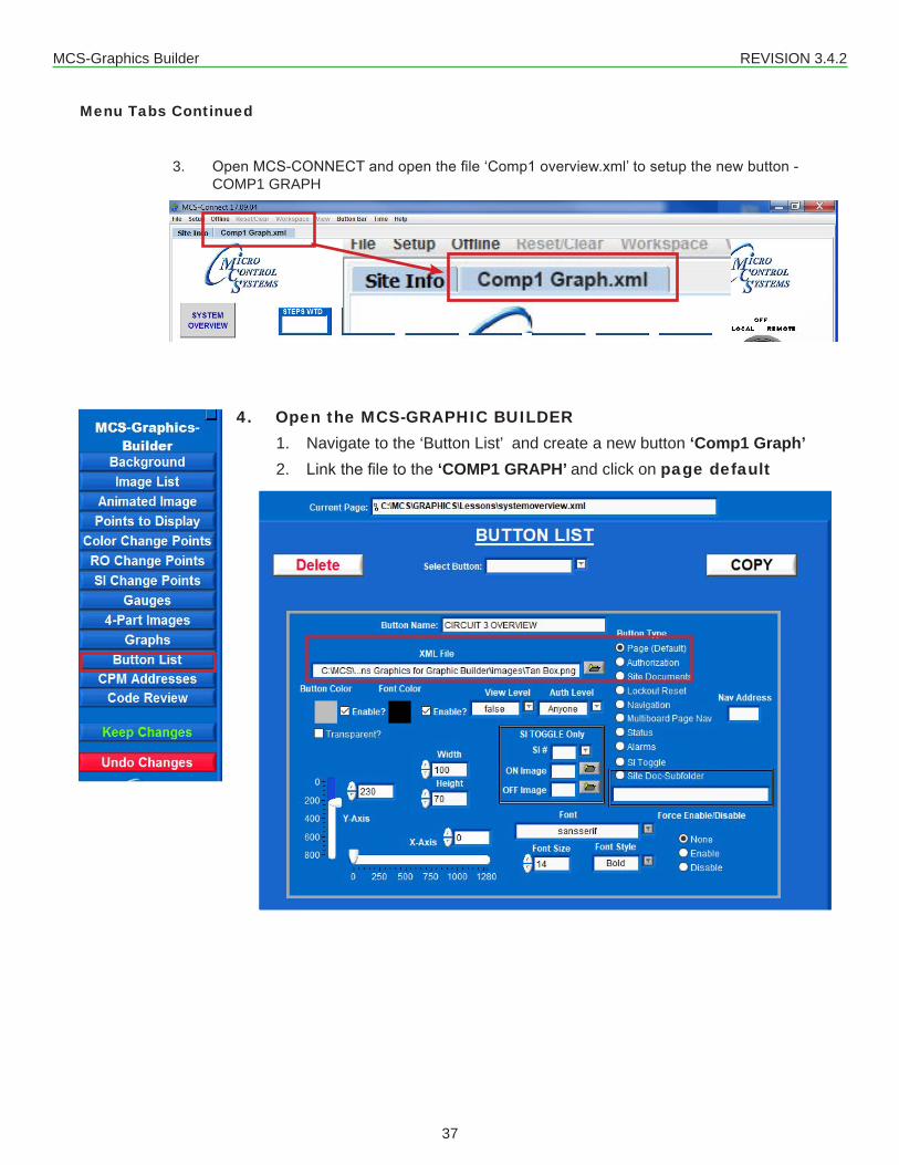
3. Open MCS-CONNECT and open the file ‘Comp1 overview.xml’ to setup the new button - COMP1 GRAPH
4. Open the MCS-GRAPHIC BUILDER1. Navigate to the ‘Button List’ and create a new button ‘Comp1 Graph’2. Link the file to the ‘COMP1 GRAPH’ and click on page default

MCS-Graphics Builder REVISION 3.4.2
38
3. For this example, position the button as per the screen shown below
5. Navigate to the ‘GRAPH MENU TAB’1. Name your new Graph – ‘Comp1 Graph’2. Set up the position and size for the graph, Time, text colors and sensors you
want to view.
NOTE: IF YOU NEED THE GRAPH TO BE LARGER FOR BETTER VIEWINGMOVE THE POINTS TO DISPLAY TO THE RIGHT MORE AS SHOWN IN THE NEXT SCREEN

MCS-Graphics Builder REVISION 3.4.2
39
3. Click on the new ‘Comp1 Graph’ to display the screen below.

MCS-Graphics Builder REVISION 3.4.2
40
Menu Tabs Continued
1. ‘BUTTON LIST TAB’ - allows you to change the box background and type color on your buttons. You also can set authorization. See inset sample.
• Button Name - Name of the button being created.
• XML File File - location of the xml file to link button to. Only used for Page Type – Page (default).
• Button Color, Enable? - Color of the button being created. If Enable? is unchecked then default color scheme is used.
• Font Color, Enable? - Font color of the button being created. If Enable? is unchecked then default font color is used.
• Transparent? - Makes the button transparent if checked
• Font Size - Font size of the text inside the button
• View Level - Authorization level to be able to view button. Default is set to Anyone

MCS-Graphics Builder REVISION 3.4.2
41
• Auth Level - Authorization level to be able to press button. Default is set to Anyone
2. PAGE TYPE (Button List continued)
• Page(Default) - Sets button to navigate to .xml file specified.
• Authorization - Creates Authorization button that can be accessed from the graphics screen.
• Site Documents - Creates button that opens Site Documents folder on MCS-TOUCH.
• Lockout Reset - Creates button that will navigate to another chillers graphics. Nav Address must be a specified network address for controller.
• Navigation - Creates button that will navigate to another chillers graphics. Nav Address must be specified network address for controller.
• Multiboard Page Nav - Creates button that will navigate to another chillers specific graphic screen. Nav address and XML file must be set. Nav Address must be specified network address for controller.
• Status - Creates button that will navigate back to the MCS-Connect Status screen.
• Alarms - Create a Button which will pop up the Alarms on unit you are monitoring.
• SI Toggle - Create an ON/OFF button using a Sensor
• Site Doc-Subfolder - Similar to the Site documents button, can access other sub folders in the Site Documents folder on the MCS-TOUCH. Must fill in box with sub folder path. Example on the next page.
• Force Enable/Disable - Allows you to force a button to stay enabled (clickable), or disabled (greyed out). This overrides the is current page tag when set to Enable or Disable. None is the default (normal operation).
NEW in 3.3.0
NEW in 3.4.2
NEW in 3.3.0
MCS-Graphics Builder REVISION 3.4.2
42
Menu Tabs Continued
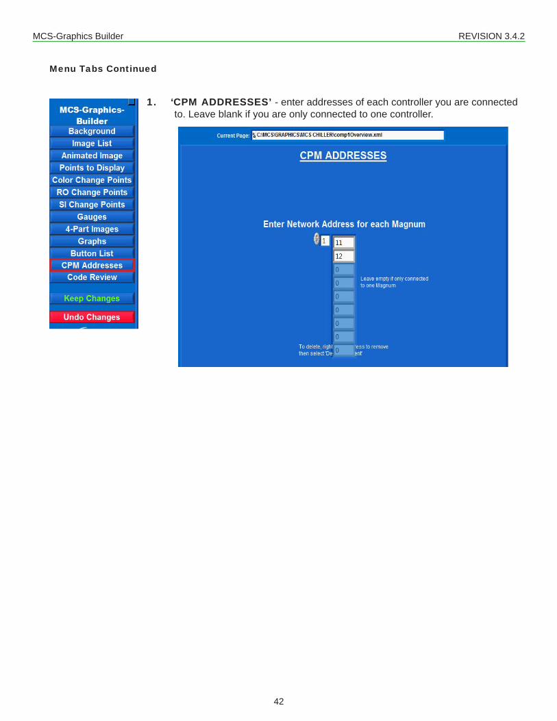
1. ‘CPM ADDRESSES’ - enter addresses of each controller you are connected to. Leave blank if you are only connected to one controller.

MCS-Graphics Builder REVISION 3.4.2
43
Menu Tabs Continued
1. ‘CODE REVIEW TAB’ - XML code used. Must be authorized to make changes.

MCS-Graphics Builder REVISION 3.4.2
44
Chapter - 11. MAKING CHANGES TO THE TEMPLATE11.1. OPEN THE SUPPLIED TEMPLATE TO MAKE CHANGES
Lets make some changes in the placement of some of the points and buttons.
SYSTEM OVERVIEW TEMPLATE
MCS-Graphics Builder REVISION 3.4.2
45
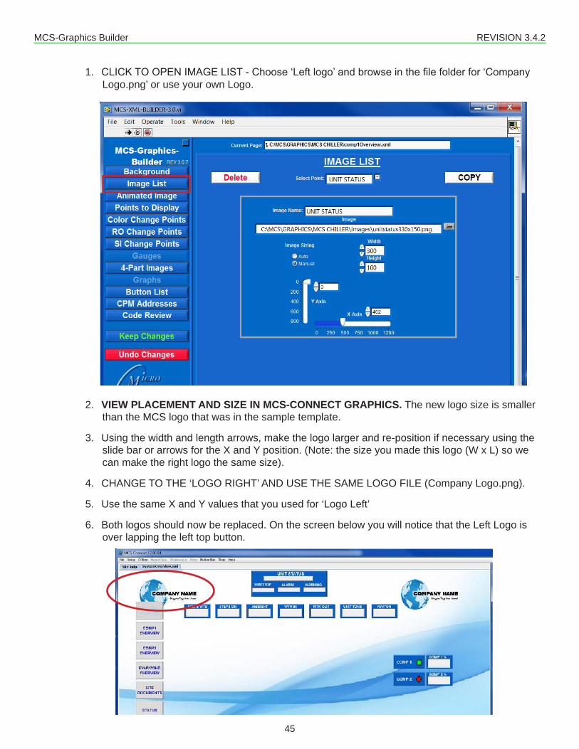
1. CLICK TO OPEN IMAGE LIST - Choose ‘Left logo’ and browse in the file folder for ‘Company Logo.png’ or use your own Logo.
2. VIEW PLACEMENT AND SIZE IN MCS-CONNECT GRAPHICS. The new logo size is smaller than the MCS logo that was in the sample template.
3. Using the width and length arrows, make the logo larger and re-position if necessary using the slide bar or arrows for the X and Y position. (Note: the size you made this logo (W x L) so we can make the right logo the same size).
4. CHANGE TO THE ‘LOGO RIGHT’ AND USE THE SAME LOGO FILE (Company Logo.png).
5. Use the same X and Y values that you used for ‘Logo Left’
6. Both logos should now be replaced. On the screen below you will notice that the Left Logo is over lapping the left top button.
MCS-Graphics Builder REVISION 3.4.2
46
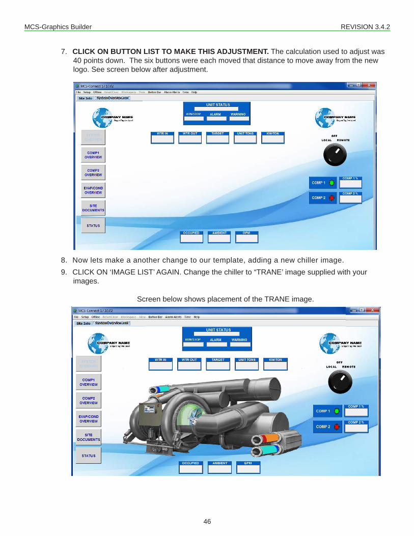
7. CLICK ON BUTTON LIST TO MAKE THIS ADJUSTMENT. The calculation used to adjust was 40 points down. The six buttons were each moved that distance to move away from the new logo. See screen below after adjustment.
8. Now lets make a another change to our template, adding a new chiller image. 9. CLICK ON ‘IMAGE LIST’ AGAIN. Change the chiller to “TRANE’ image supplied with your
images.
Screen below shows placement of the TRANE image.

MCS-Graphics Builder REVISION 3.4.2
47
10. We only have one compressor to monitor, so lets drop the second comp2.
THIS WILL REQUIRE 5 STEPS TO REMOVE THE COMP21. Open ‘POINTS TO DISPLAY’, CLICK ON ‘COMP2%’ AND DELETE.2. OPEN ‘IMAGE LIST’, CLICK ON ‘COMP2’ AND DELETE.3. OPEN ‘IMAGE CHANGE POINTS’, CLICK ON ‘COMP2’ AND DELETE.4. OPEN ‘BUTTON LIST’, CLICK ON ‘COMP2 OVERVIEW’ AND DELETE.5. NOW WE NEED TO MOVE THE BUTTONS UP OR DOWN TO FILL THE MISSING AREA.
Screen below shows changes made to your graphics
MCS-Graphics Builder REVISION 3.4.2
48
Chapter - 12. POINTS TO DISPLAY12.1. CHANGING POINTS THAT ARE DISPLAYED IN THE GRAPHICS
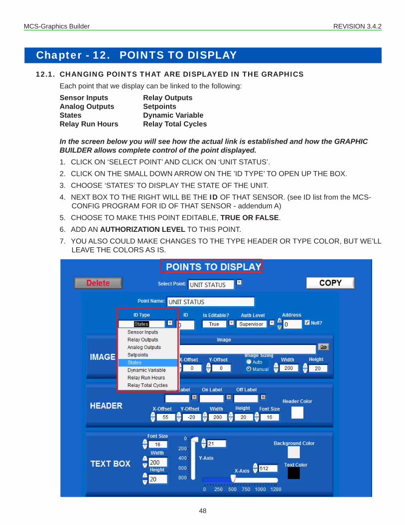
Each point that we display can be linked to the following:Sensor Inputs Relay OutputsAnalog Outputs SetpointsStates Dynamic VariableRelay Run Hours Relay Total Cycles In the screen below you will see how the actual link is established and how the GRAPHIC BUILDER allows complete control of the point displayed.1. CLICK ON ‘SELECT POINT’ AND CLICK ON ‘UNIT STATUS’. 2. CLICK ON THE SMALL DOWN ARROW ON THE ’ID TYPE’ TO OPEN UP THE BOX. 3. CHOOSE ‘STATES’ TO DISPLAY THE STATE OF THE UNIT.4. NEXT BOX TO THE RIGHT WILL BE THE ID OF THAT SENSOR. (see ID list from the MCS-
CONFIG PROGRAM FOR ID OF THAT SENSOR - addendum A)5. CHOOSE TO MAKE THIS POINT EDITABLE, TRUE OR FALSE.6. ADD AN AUTHORIZATION LEVEL TO THIS POINT. 7. YOU ALSO COULD MAKE CHANGES TO THE TYPE HEADER OR TYPE COLOR, BUT WE’LL
LEAVE THE COLORS AS IS.

MCS-Graphics Builder REVISION 3.4.2
49
Chapter - 14. STORING DOCUMENTS13.13. SITE DOCUMENTS (Button shown on right)
You can setup a button as shown on the screen above, so that when clicked will link you to a file stored on your computer’s hard drive. This can be used for storing the manuals, electrical drawings, etc.NOTE: YOU MUST BE CONNECTED TO A LIVE CONTROLLER TO SEE THESE DOCUMENTS.
FOLDERS AND SUB FOLDERS MUST BE SETUP AS THE SCREEN ABOVE.1. Site Documents is stored in the MCS FOLDER, IN THE SUB FOLDER ‘GRAPHICS’ AND IN
THE SUB FOLDER ‘Site Documents’. 2. THIS IS WHERE ALL YOUR DOCUMENTS SHOULD BE PLACED.
NOTE: Site_Document sub folder has an underscore.
IT IS IMPORTANT TO FOLLOW THE GUIDELINE ABOVE FOR NAMING OF FILESTHE TOUCHSCREEN USES LINUX FOR THE OPERATING SYSTEM

MCS-Graphics Builder REVISION 3.4.2
50
Chapter - 15. STATUS BUTTON15.1. CLICKING ON STATUS BUTTON
The ‘STATUS’ button on the left side of our template, when clicked, will redirect you to MCS-CONNECT STATUS OF THE UNIT YOU ARE CONNECTED TO.

MCS-Graphics Builder REVISION 3.4.2
51
Chapter - 16. ADDENDUM A16.1. MCS CONFIG SUMMARY REPORT FOR INPUT AND OUTPUT SENSORS
Output and Input Information for Magnum
S:\! Customer Jobs\5580 Enterprise pkwy\AAON LL105 Heatpump\CFG\LL105 Heatpump_Rev_E.cfgCONFIG DATE = 12/14/15 at 05:09 PM PRINT DATE = 1/15/16 10:31 AM
Output and Input Information for Magnum # Output Name Type # Input Name Type Digital or OffSet # AO Name M-1 COMP 1 Step w\ EXV M-1 WTR IN MCST100 0 M-1 COMP1 SPD%M-2 CHAM INJ 1 Standard M-2 WTR OUT MCST100 0 M-2 COMP2 SPD%M-3 REV VLV 1 Standard M-3 SUCT PSI 1 MCS-200 0 M-3 EXV 1% M-4 MTR INJ 1 User Logic M-4 DISC PSI 1 MCS-500 0 M-4 EXV 2% M-5 SPAREM-5 Standard M-5 OIL PSI 1 MCS-500 0 M-6 SPAREM-6 Standard M-6 AMPS 1 CT-300 0 M-7 CHW PUMP 1 Standard M-7 S-TpRvVlv1 MCST100 0 M-8 CHW PUMP 2 Standard M-8 DISC TMP 1 MCST100 0 M-9 VEST FAN Standard M-9 MTR TMP 1 PT1000 0 M10 SPARE M-10 Standard M10 MTR FLT 1 DIGITAL Closed=OFF
M11 OIL LVL 1 DIGITAL Closed=OFFM12 Cmp1VfdFlt DIGITAL Closed=OFFM13 HI PSI SW1 DIGITAL Closed=OFFM14 DISABLE 1 DIGITAL Open=OFFM15 RUN/STOP DIGITAL Open=OFFM16 EMG/STOP DIGITAL Closed=OFF
1-1 COMP 2 Step w\ EXV 1-1 SUCT PSI 2 MCS-200 0 1-1 CND1 VFD% 1-2 CHAM INJ 2 Standard 1-2 DISC PSI 2 MCS-500 0 1-2 CND2 VFD% 1-3 REV VLV 2 Standard 1-3 OIL PSI 2 MCS-500 0 1-3 BLD PUMP1%1-4 MTR INJ 2 User Logic 1-4 AMPS 2 CT-300 0 1-4 BLD PUMP2%1-5 CMP2 SV1 User Logic 1-5 S-TpRvVlv2 MCST100 0 1-6 CMP2 SV2 User Logic 1-6 DISC TMP 2 MCST100 0 1-7 CND FAN1-1 Standard 1-7 MTR TMP 2 PT1000 0 1-8 CND FAN1-2 Standard 1-8 MTR FLT 2 DIGITAL Closed=OFF1-9 CND FAN2-1 Standard 1-9 OIL LVL 2 DIGITAL Closed=OFF1-10 CND FAN2-2 Standard 1-10 Cmp2VfdFlt DIGITAL Closed=OFF
1-11 HI PSI SW2 DIGITAL Closed=OFF1-12 DISABLE 2 DIGITAL Open=OFF1-13 PHASELOSS DIGITAL Open=OFF1-14 AMBIENT MCST100 0 1-15 VEST TMP MCST100 0 1-16 UNIT AMPS CT-500 0
2-1 [email protected] User Logic 2-1 WATER GPM User Defined 0 2-2 [email protected] User Logic 2-2 BLDPMP IN MCS-200 2 2-3 [email protected] User Logic 2-3 BLDPMPOUT MCS-500 0 2-4 SPARE2-4 Standard 2-4 BPVFD1 FLT DIGITAL Closed=OFF2-5 SPARE2-5 Standard 2-5 BPVFD2 FLT DIGITAL Closed=OFF2-6 SPARE2-6 Standard 2-6 CND1 COIL MCST100 0 2-7 SPARE2-7 Standard 2-7 CND2 COIL MCST100 0 2-8 SPARE2-8 Standard 2-8 CND1 V FLT DIGITAL Closed=OFF2-9 SPARE2-9 Standard 2-9 CND2 V FLT DIGITAL Closed=OFF2-10 SPARE2-10 Standard 2-10 Cmp2DltPsi User Logic 0
2-11 SPARE2-11 SPARE 0 2-12 SPARE2-12 SPARE 0 2-13 SPARE2-13 SPARE 0 2-14 SPARE2-14 SPARE 0 2-15 SPARE2-15 SPARE 0 2-16 HEAT ENABL BMS_SI 0
3-1 SPARE3-1 Standard 3-1 CMP1 L-TMP MCST100 0 3-2 SPARE3-2 Standard 3-2 CMP1 L-PSI MCS-500 0 3-3 SPARE3-3 Standard 3-3 CMP2 L-TMP MCST100 0 3-4 SPARE3-4 Standard 3-4 CMP2 L-PSI MCS-500 0 3-5 SPARE3-5 Standard 3-5 MCS VOLT A 600VAC4 0 3-6 SPARE3-6 Standard 3-6 MCS VOLT B 600VAC4 0 3-7 SPARE3-7 Standard 3-7 MCS VOLT C 600VAC4 0 3-8 SPARE3-8 Standard 3-8 COOL+OCCUP User Logic 0 3-9 SPARE3-9 Standard 3-9 HEAT+OCCUP User Logic 0 3-10 SPARE3-10 Standard 3-10 COOL/HEAT User Logic 0
3-11 SV1 ON> User Logic 0 3-12 SV1 ON< User Logic 0 3-13 SV2 ON> User Logic 0 3-14 SV2 ON< User Logic 0 3-15 EVP PSI IN User Defined 0 3-16 EVP P-OUT User Defined 0
4-1 SPARE 4-1 Standard 4-1 SUCT SH 1 User Logic 0 4-2 SPARE 4-2 Standard 4-2 SUCT SH 2 User Logic 0 4-3 SPARE4-3 Standard 4-3 DISC SH 1 User Logic 0 4-4 SPARE4-4 Standard 4-4 DISC SH 2 User Logic 0 4-5 SPARE4-5 Standard 4-5 EVP IN-OUT User Logic 0 4-6 SPARE4-6 Standard 4-6 SPARE4-6 SPARE 0 4-7 SPARE4-7 Standard 4-7 SPARE4-7 SPARE 0 4-8 SPARE4-8 Standard 4-8 EVAP DIFF User Defined 0 4-9 SPARE4-9 Standard 4-9 R PWR 1+2 User Logic 0 4-10 SPARE4-10 Standard 4-10 UNIT TONS TONS-1Dec 0
4-11 KW/TON User Logic 0 4-12 E TMP DIFF User Logic 0 4-13 PUMP DIFF User Logic 0 4-14 WATER FLOW User Logic 0 4-15 COOL ENABL BMS_SI 0 4-16 OCCUPIED BMS_SI 0
EACH MCS CONFIG WILL BE DIFFERENT DEPENDING HOW YOUR CONTROLLER IS SETUP.
THIS SAMPLE IS THE MCS CONFIG FOR THE TEMPLATE OF THE
UNIT WE ARE CONTROLLING FOR THIS EXAMPLE.
MCS-Graphics Builder REVISION 3.4.2
52
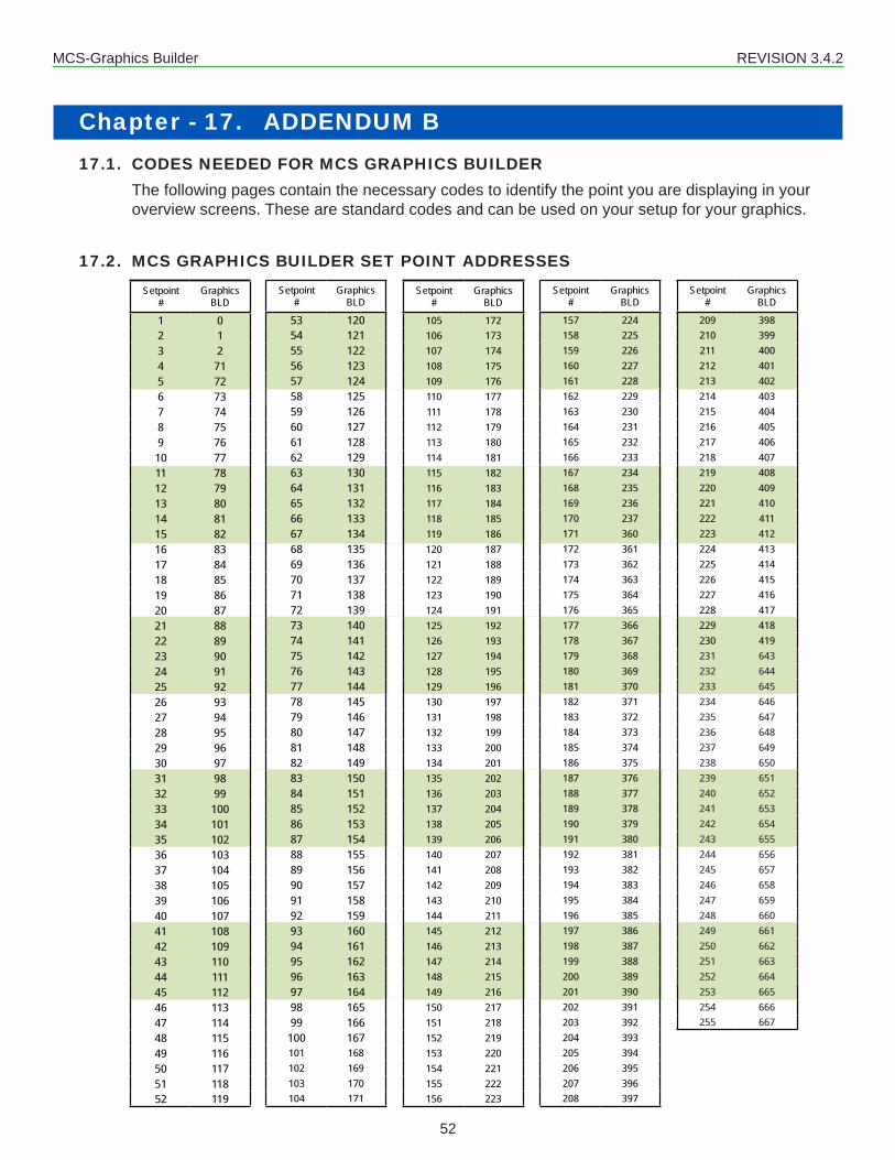
Chapter - 17. ADDENDUM B17.1. CODES NEEDED FOR MCS GRAPHICS BUILDER
The following pages contain the necessary codes to identify the point you are displaying in your overview screens. These are standard codes and can be used on your setup for your graphics.
17.2. MCS GRAPHICS BUILDER SET POINT ADDRESSESSetpoint
# Graphics
BLD
1 02 13 24 715 726 737 748 759 7610 7711 7812 7913 8014 8115 8216 8317 8418 8519 8620 8721 8822 8923 9024 9125 9226 9327 9428 9529 9630 9731 9832 9933 10034 10135 10236 10337 10438 10539 10640 10741 10842 10943 11044 11145 11246 11347 11448 11549 11650 11751 11852 119
Setpoint #
Graphics BLD
105 172106 173107 174108 175109 176110 177111 178112 179113 180114 181115 182116 183117 184118 185119 186120 187121 188122 189123 190124 191125 192126 193127 194128 195129 196130 197131 198132 199133 200134 201135 202136 203137 204138 205139 206140 207141 208142 209143 210144 211145 212146 213147 214148 215149 216150 217151 218152 219153 220154 221155 222156 223
Setpoint #
Graphics BLD
53 12054 12155 12256 12357 12458 12559 12660 12761 12862 12963 13064 13165 13266 13367 13468 13569 13670 13771 13872 13973 14074 14175 14276 14377 14478 14579 14680 14781 14882 14983 15084 15185 15286 15387 15488 15589 15690 15791 15892 15993 16094 16195 16296 16397 16498 16599 166100 167101 168102 169103 170104 171
Setpoint #
Graphics BLD
157 224158 225159 226160 227161 228162 229163 230164 231165 232166 233167 234168 235169 236170 237171 360172 361173 362174 363175 364176 365177 366178 367179 368180 369181 370182 371183 372184 373185 374186 375187 376188 377189 378190 379191 380192 381193 382194 383195 384196 385197 386198 387199 388200 389201 390202 391203 392204 393205 394206 395207 396208 397
Setpoint #
Graphics BLD
209 398210 399211 400212 401213 402214 403215 404216 405217 406218 407219 408220 409221 410222 411223 412224 413225 414226 415227 416228 417229 418230 419231 643232 644233 645234 646235 647236 648237 649238 650239 651240 652241 653242 654243 655244 656245 657246 658247 659248 660249 661250 662251 663252 664253 665254 666255 667
MCS GRAPHICS BUILDER SET POINT ADDRESS

MCS-Graphics Builder REVISION 3.4.2
53
18.1. MCS GRAPHICS BUILDER STATE ADDRESSES
UNIT GPH COMPRESSOR GPH CONDENSER GPH HEATING GPHSTATE BLD # STATE BLD # STATE BLD # STATE BLD #
UNIT 0 CIRCUIT 1 20 CIRCUIT 1 40 HEATING 60OCCUPPIED 1 CIRCUIT 2 25 CIRCUIT 2 45 REHEAT 65EVAP FAN 10 CIRCUIT 3 30 CIRCUIT 3 50 CIRCUIT 1 70COOLING 15 CIRCUIT 4 35 CIRCUIT 4 55 CIRCUIT 2 75
CIRCUIT 3 80CIRCUIT 4 85PRE COOL 90
UNIT GPH COMPRESSOR GPH C OMPRESSOR GPH C OMPRESSOR GPHSTATE BLD # STATE BLD # STATE BLD # STATE BLD #
UNIT 0 CIRCUIT 1 0 CIRCUIT 8 7 CIRCUIT 15 14LWC 9 CIRCUIT 2 1 CIRCUIT 9 8 CIRCUIT 16 15
CIRCUIT 3 2 CIRCUIT 10 9 CIRCUIT 17 16CIRCUIT 4 3 CIRCUIT 11 10 CIRCUIT 18 17CIRCUIT 5 4 CIRCUIT 12 11 CIRCUIT 119 18CIRCUIT 6 5 CIRCUIT 13 12 CIRCUIT 20 19CIRCUIT 7 6 CIRCUIT 14 13
MCS GRAPHICS BUILDER MICROMAG STATE ADDRESS(CONFIG V 12)
MCS GRAPHICS BUILDER MAGNUM STATE ADDRESS(CONFIG V 11, 14 AND 17)
Chapter - 18. ADDENDUM C

MCS-Graphics Builder REVISION 3.4.2
54
Chapter - 19. ADDENDUM D- Troubleshooting19.1. Gauges - Track and Sections
• To delete extra ‘ELEMENTS’ - if you have too many Tracks or Sections - right click with your mouse - ‘DELETE ELEMENT”
19.2. Using the Copy Button• Use the copy button to make an additional image. When you click the copy button you will see
the word ‘NEW’ in the ‘POINT NAME FIELD’. Rename new to the name you want for the point.• Remember the copy is under the original position, Change the X and Y coordinates to the new
position.
19.3. Graphs• When you are viewing your graph in MCS-CONNECT overview screen, you can right click on
the graph and click on ‘PROPERTIES’ to make changes to the background color, etc.

MCS-Graphics Builder REVISION 3.4.2
55
PAGE LEFT BLANK

MCS-Graphics Builder REVISION 3.4.2
56
Providing HVAC/R Control Solutions Worldwide
5580 Enterprise Pkwy. Fort Myers, FL 33905Office: (239) 694-0089Fax: (239) 694-0031
www.mcscontrols.com