
2009 NOVEMBER SUPPLEMENT TO - Engine Builder ...
31
2009 NOVEMBER SUPPLEMENT TO: MAGAZINE
-
Upload
khangminh22 -
Category
Documents
-
view
2 -
download
0
Transcript of 2009 NOVEMBER SUPPLEMENT TO - Engine Builder ...

2009NOVEMBER
SUPPLEMENT TO:
MAGAZINE


2 The Shelby 427Following her debut in “Gone In 60 Seconds” one famous Shelby Mustang GT500 createdinstant demand for clones. However, some customers soon found what looked like the original didn’t run like it. What started out as a troubled 427 has since become a monstrousShelby 511 under the watchful eyes of Snake Charmers George Anderson and Sean Sawyer.Editor Doug Kaufman explains how this story of redemption has all the makings of its ownHollywood script.
8 The CAT 3208 DieselWhether in city tractor trailers, garbage trucks, marine applications, power plants, school buses orconstruction equipment, if it needed a medium duty diesel engine, the Caterpillar 3208 was the one.And just because they’re a few years old, Contributing Editor Roy Berndt finds that there’s no “CashFor Cat” program and these powerplants are still very much rebuildable.
18 The Chrysler HemiChrysler didn’t invent the hemispherical chamber, but did make the Hemi engine famous.The Hemi was legendary, and that performance bloodline has certainly continued with thenewest generation of the engine. Contributing Editor Doug Anderson looks at what madethe Hemi so good and what you’ll experience when you’re faced with one that doesn’t workso well.
FEATURES
www.enginebuildermag.com | ENGINE BUILDER 1
ADVERTISER CIRCLE # PAGE#
DURA-BOND 129 3CENGINE & PERFORMANCE WAREHOUSE 130 4CHASTINGS 119 19HOT ROD & RESTORATION SHOW 103 3MAHLE CLEVITE INC. 101,109 2C, 9MELLING ENGINE PARTS 115 14-15
ADVERTISER INFORMATION CENTER

2 ENGINE BUILDER | November Engine Rebuilding Tech Guide 2009
n 1974, America watched 93 carsget destroyed in a 34-minute carchase. “Gone In 60 Seconds,” anindependent film written, pro-duced and directed by and star-
ring Toby Halicki was an otherwise for-gettable ’70s movie.
The plot revolved around MandrianPace (Halicki) and his car thief cronies andthe 48 cars that they needed to steal tomeet the demands of a South Americandrug lord. Most of the actors in the moviewere Halicki’s family and friends or actualmembers of the emergency services theywere portraying, not professional actors.
The real stars of the movie, however,were not the men and women overactingand stumbling through dialogue. Theywere, in fact, the 48 classic, high-end muscle and luxury carsthat Pace was to steal in less than a week. Cars ranging froma 1930 Hudson Great 8 to Billy Joel’s 1959 Rolls RoycePhantom V to Richard Petty’s 1972 Plymouth Barracuda
were targeted by the gang. Each car on the list was referredto only by a woman’s name, but none was as coveted as theyellow 1973 Mustang Mach 1 codenamed Eleanor.
The climactic 34-minute chase scene in the movie wasdestructive, dangerous and downright awesome, and caused
significant physical damage to Halicki himself (in fact,production of the movie had to stop several times whilehe recovered from injuries he sustained as he performedhis own driving stunts). But it also is credited with settingthe bar for future cinematic megadestructo-chases (The“Blues Brothers,” for example) and is still considered oneof the greatest car chases of all time.
In 2000, “Gone In 60 Seconds” was remade with anew leading thief (Nicholas Cage as Memphis Raines) anew premise for the thefts and a new list of 50 cars thathad to be stolen in just one night. Again, Eleanor was thereal star of the movie but this time the leading lady was apepper gray with black stripes 1967 Shelby Mustang GT500.
This version of the film was even more forgettable andhad a less impressive climactic chase than the original, butit did one thing very well. It made the GT 500 – andspecifically, Eleanor – a superstar.
IB Y D O U G K A U F M A N , E D I T O R
Gessford Machine took the original Shelby 427 engines and boredand stroked them to produce 511 cubic inches.
In 2001 a group of Texas businessmen came to an agreement with ShelbyAutomotive, Inc. to begin building 1967 and 1968 Mustang GT 500Es asShelby Continuation Vehicles.
2-7 Shelby:Layout 1 11/17/09 8:36 AM Page 2


“The car became a huge hit and in 2001 a group of Texasbusinessmen came to an agreement with Shelby AutomotiveInc to begin building 1967 and 1968 Mustang GT 500Es asShelby Continuation Vehicles, and Unique Performance wasborn” explains Sean Sawyer of Revved AutomotiveConcepts in Rhome, TX. “These vehicles were built undera licensing agreement that gave them a Shelby continuationserial number and included them in the Shelby registry.There were to be 400 Windsor stroker-powered vehicles and75 Stroker Supercharged FE-powered vehicles to celebratethe original 1967 Shelby Super Snake.
Legal wrangling ensued over the next several years as thegroup that owned the rights to the movie sued Shelby andUnique Performance for trademark infringement on the“Eleanor” name. Eventually all references to these cars asEleanor by Shelby and Unique Performance ceased and theywere referred to only as a “GT 500 E.” Currently the onlycompany licensed to build cars and call them “Eleanor” isClassic Recreations in Yukon, OK which builds a licensed“Gone in Sixty Seconds” edition of these cars with the bless-ing of the group that owns the name.
Although the Unique Performance cars were built withtop of the line components, Sawyer says, many of those partsrequired extensive modification to fit or were not the cor-rect part for the application in which they were being used.“We began to redesign many of the vehicle systems once werealized that we weren’t just experiencing parts failures butcomplete system failures due to poor design.
“I hired in to Unique Performance in late 2006 to han-dle post delivery customer service, technical support, and tobuild a quality control program,” Sawyer says. “Over the nextfew months this quickly snowballed into building a warran-
ty department, a tuning depart-ment, and recruiting Jason Delago,the newly hired head of the“Special Projects” group to helpre-engineer the cars to fix the mul-titude of production issues wewere experiencing with cars in thefield and in cars that had been sentback for warranty repairs.”
The first 23 Super Snakes uti-lized Shelby 468 cid superchargedengines built with Shelby alu-minum 427 FE blocks, heads andintake manifolds. Later theyreceived Shelby-licensed 482 cidsupercharged FE engines built byKeith Craft Racing with Shelbyaluminum blocks, portedEdelbrock heads and portedEdelbrock intake manifolds.
“The early 468 engines havesome internal issues, such as acompression ratio of 10.5 or 11:1
used with a supercharger that can produce 8 lbs. that requireus to rebuild every one of the early engines to a more boostfriendly level,” says Sawyer. “We also offer an upgrade toCNC ported Edelbrock heads that have a much higher air-flow than the stock Shelby head.”
Rebuilding a Classic –And a ReptutationSawyer says it was a tough road unraveling the issues withthese vehicles. “UP started building the FE-powered SuperSnakes in 2003 and by 2006 the people working here beforeus had still not been able to figure out the problems with the
4 ENGINE BUILDER | November Engine Rebuilding Tech Guide 2009
When they first started slithering, the Super Snakes could barely make 400 hp at the wheels witha 750 crank hp rating and would overheat in anything above 85 degrees. Once the Gessford Gangcame on board, they were pumping out close to 600 hp and 600 ft.lbs at the wheels and hadredesigned air intakes, cooling systems, ignition systems, correct blow-through carburetors andreplumbed fuel systems.
This engine (and its identical twin, which will be going into anoth-er Revved GT 500SE) will be force-fed by a Procharger F1-Rcentrifugal supercharger and will be intercooled. Fuel manage-ment will be handled by a FAST XFI sequential fuel injectionsystem with distributorless ignition operated by a FAST XIMmodule. A carburetor box will house the throttle body to retainthe vintage supercharged look.
2-7 Shelby:Layout 1 11/17/09 8:36 AM Page 4

www.enginebuildermag.com | ENGINE BUILDER 5
vehicles. They experienced overheating, poor drivability, lackof power, carburetors flooding out, starters and flywheelsgrinding off teeth, the list goes on and on – it really was amess for these owners. We started symptom by symptom andeventually re-engineered every system that UP bolted on theengine.”
Sawyer says one of his best moves was to get in contactwith George Anderson at Gessford Machine in Hastings, NE.The 2004 Engine Builder Machine Shop of the Year andIndependent Authorized Shelby Automobile Dealer has beenin business for 54 years and building winning Shelby 427s fordecades. “We started working with George and Neil Grofftrying to figure out the problems with the Super Snake 427FE engines. Being the FE experts, they helped us through alot of the issues we were dealing with on the cars.”
Still working at Unique Performance, Sawyer, Delago andtheir crew had fixed most of the chronic Super Snake ail-ments by mid-summer of 2007 with the addition of Gessfordpower. “When we started, the Super Snakes would overheatin anything above 85 degrees and were barely making 400 hpat the wheels with a 750 crank hp rating,” laments Sawyer.“By November of 2007 we had them making close to 600hp and 600 ft.lbs at the wheels with redesigned air intakes,cooling systems, ignition systems, correct blow-through car-buretors and replumbed fuel systems. We were finally able todrive them in stop and go traffic in 100 degree Texas weath-er without overheating and with enough horsepower tomake a grown man giggle like a schoolgirl. We also upgrad-ed the drivability with additional oil coolers, new alignmentspecs, improved clutch components, and working parkingbrakes among others to make them solid street drivable carswith usable horsepower.”
Unfortunately, although the cars had shown a remarkable
turnaround in quality Unique Performance’s customers soonfelt like they had been targeted by Mandrian Pace orMemphis Raines. “We found out the hard way that the busi-ness was too far gone,” Sawyer says.
In early November 2007, the Farmers Branch policedepartment raided Unique Performance and impounded
every vintage vehicle on the prop-erty as part of a VIN tamperinginvestigation. “The only thing Iknow that has been proven to thisdate is that when UniquePerformance had been restoringthe shells they were not transferringthe physical VIN numbers over tothe new aprons as is commonrestoration practice when replacingan apron,” Sawyer explains. “Thisgave the police enough reason toquestion whether there was fraudinvolved.”
Although the cars were trackedthrough production and each carbuilt with its owner’s selectedoptions, the police feared that sincethere were not intact VINs on manyof the shells the company couldhave been swapping shells and titles.
“Unique Performance had been
The aluminum Edelbrock 427 6008 cylinder heads were pressure checked and the valves andseats were ground to the following specs: intake: 20/30/45 degrees and exhaust: 30/45degrees. Gessford used Fel-Pro 1020 head gaskets that are .041˝ thick designed for use with alu-minum FE heads.
The Edelbrock 76cc heads were machined for bigger Ferrea valves(intakes from 2.09˝ to 2.190˝ and exhaust from 1.655˝ to1.700˝) and CNC ported and flowed.
2-7 Shelby:Layout 1 11/17/09 8:36 AM Page 5

struggling with finances for quite sometime at that point and it seems thepolice impound put the final nail in thecoffin,” says Sawyer. “They closed thedoors approximately 2 weeks later. Intheir 6 year run they produced approx-imately 32-34 Super Snakes andbetween 100-150 GT500Es,GT350SRs, Foose Camaros, and FooseChallengers.” It was rumored therewere nearly 130 contracts for cars thatwere unfulfilled.
By virtue of his attention to many ofthese customers over the previous yearand gaining their trust by treating themwith respect and helping them withtheir vehicles, Sean Sawyer continuedto receive phone calls. Soon they werereferring their friends who also hadtaken their high-end custom vehicles tohim for help.
“Revved Automotive Conceptscame to life simply on the principle thatif you treat people the way you wouldwant to be treated that they will keepcoming back to you. In early 2008, we
helped severalcustomers gettheir vehicles outof the policeimpound andc o m p l e t e l yo v e r h a u l e dthem,” saysSawyer. “Wenot only havesteady businessupgrading exist-ing UniquePe r fo r mancevehicles but wealso have threecontracts tobuild new“Super Snakes”from clients thathad cars onorder withU n i q u ePerformance.”R e v v e dA u t o m o t i veConcepts hasrecently reachedan agreement
with Shelby Licensing to further helpformer Unique Performanceclients by completing thebuild of their vehicles with allof Revved’s upgraded com-ponents and build processesand have it recognized as aShelby Continuation Vehiclewith the moniker ofGT500SE.
“Our first of these cars willbe a red with white stripesGT500SE Super Snake with aShelby 427 engine that hasbeen bored and stroked toproduce 511 cubic inches,”says Sawyer. “Completed bythe masters at Gessford, theworkup of parts is a collabora-tion between my shop fore-man Jason Delago workingwith Neil up at Gessford.They worked together onresearching with manufactur-ers on the best parts to use,compression ratio, cam specs,
blower and intercooler choice. Ourgoal is a conservative 1,000hp and1,000 ft.lbs. of torque with around 8-10lbs. of boost. The blower we are using iscapable of nearly 30 lbs. for those clientswho wish to push the envelope.Realistically the engine is built to han-dle considerably more horsepower butwe wanted an engine that would be anice driver as well as scare the hell outof anyone brave enough to mash thethrottle.”
The recipe for Gessford’s team tobuild the 511 mill is as follows, accord-ing to George Anderson. “We startedout with CSX Shelby Signature BigBore 4.375˝ blocks from Robert Riceat Shelby Engines in Gardena, CA.Rice provides the blocks slightly underfinal specification on the cylinder bores,which Russ Kennedy finishes atGessford to the custom Arias Pistons.These pistons, designed for use with ablower to our design standards have -62 cc D cup, and run .005˝ below thedeck with a 1.320˝ compression dis-tance. Each cylinder’s swept volume is63.890 cubic inches.
“The crankshaft is a Scat 511 SteelBillet 4.250˝ racing crank mated to a set
6 ENGINE BUILDER | November Engine Rebuilding Tech Guide 2009
How do you stroke a 427 to a 511? Start with CSX ShelbySignature Big Bore 4.375˝ blocks from Robert Rice at Shelby Enginesin Gardena, CA. The blocks are provided slightly under final specifica-tion on the cylinder bores, which Russ Kennedy finishes at Gessford tothe custom Arias Pistons. These pistons, designed for use with a blowerto our design standards have -62 cc D cup, and run .005˝ below thedeck with a 1.320˝ compression distance. Each cylinder’s swept volumeis 63.890 cubic inches. Add a 4.250˝ stroker billet Scat crankshaft and 6.700˝ Oliver BB Chevy rods. Incorporate a Felpro 1020 head gas-ket that is .041˝ thick and run the piston .005˝ below the deck witha 1.320˝ compression distance on the pistons.
The complete build list for the Shelby 511s can be foundon our Web site at www.enginebuildermag.com. Buildlist courtesy of Revved Automotive Concepts, Rhome,TX and Gessford Machine, Hastings, NE.
2-7 Shelby:Layout 1 11/17/09 8:36 AM Page 6

www.enginebuildermag.com | ENGINE BUILDER 7
of Oliver Max Rod 6.700˝ I-Beam 454 BB Chevy connect-ing rods. An Innovators West aluminum harmonic balancercompletes the rotating assembly.
MAHLE Clevite H-series performance engine bearingsin the main and rod bearing locations, as well as Hastings pis-ton rings designed for use with supercharged engines werespecified as well.”
The Gessford staff includes Neil Groff, Master EngineBuilder, Gessford veteran since 1992; Bert Wright, carbuilder/installer for all the CSX cars and other specialty carssince 1994; Russ Kennedy, block prep and machinist, withGessford since 1989; Matt Schmidt, who handles the crank-shaft work and all the engine balancing since 1990; TonyPowell, cylinder heads, Gessford employee since 2000;Shannon Fowler, Shop Foreman and specialty machinist whocan make and fix anything and has been at Gessford since1992; and George Anderson, who bought Gessford Machinefrom Jim Gessford in 1991. “I spent every dime I had from1967-1969 with Jim building and racing a 1967 Mustangwith a 390 in it,” Anderson says, underscoring his experiencewith these iconic cars.
Gessford used Fel-Pro 1020 head gaskets that are .041˝thick designed for use with aluminum FE heads. TheEdelbrock 76cc heads were machined for bigger Ferreavalves (intakes from 2.09˝ to 2.190˝ and exhaust from 1.655˝to 1.700˝) and CNC ported and flowed.
“The Comp Cams hydraulic roller camshaft is customdesigned by Chris Mays at Comp,” says Anderson. “CompBeehive springs, Jesel Rockers, Smith Brother Pushrods andall McLeod Clutch Components were used as well.”
A Pro-Gear Double Roller Extreme Duty timing set,Melling High Volume oil pump, MSD ignition componentsand ported Edelbrock Victor EFI intake manifold wereamong the other aftermarket parts used. The engine wasassembled using ARP fasteners.
“This engine (and its identical twin, which will be goinginto another Revved GT 500SE) will be force-fed by aProcharger F1-R cetrifugal supercharger and will be inter-cooled,” says Sawyer. “Fuel management will be handled bya FAST XFI sequential fuel injection system with distribu-torless ignition operated by a FAST XIM module. We havecustom machined pieces to make this system work on an FE-based engine with a stand-alone crank trigger and utilizing amodified distributor for a cam signal. A carburetor box willbe used to house the throttle body to retain the vintagesupercharged look. We are fabricating our own 3˝ exhaustsystem with a rocker pass through for the side exit exhaust.”
So after the trouble this customer has already gonethrough to get his car the first time AND the second time,what is the engine going to cost? While he wouldn’t be spe-cific, Sawyer hints at a $32,000-plus price tag for the enginebefore the forced induction and EFI. Our guess? The wholepowerplant will land somewhere around the $40k range.
That’s a lot of money, and Sawyer admits that the engine
is overbuilt – in a good way. “We don’t believe in buildingsomething that looks good but isn’t functional. We overbuildeverything to make it handle anything you want it to do,” saysSawyer. “Most of our clients have been down the road ofowning cars like this that spend more time in the shop thanon the road. By the time they come to us they understandthat it needs to be done right – or not at all. The long-terminvestment value of these vehicles as genuine Shelby’s far out-weighs the upfront investment for the upgrades.”
Of course, you don’t have to build to this level to have thislevel of professionalism. “With the technology available tocustom car and engine builders today there is no reason whya 750 hp muscle car can’t be completely streetable,” concludesSawyer. “Much of what we do in this industry comes downto thinking outside the box. The term ‘bolt-on part’ is a mis-nomer – there is nothing bolt on in this business; you can’topen a catalog and order parts to build vehicles like this with-out properly planning out the systems, choosing the rightparts, and spending the time to do it right. Know what yourend goal for the vehicle is before you start.”
And, as the collaboration between Gessford and Revvedproves, taking the time to do it better can give some prettyfantastic results as well. EBTG
The crankshaft is a Scat 511 steel billet 4.250˝ racing crank matedto a set of Oliver Max Rod 6.700˝ I-Beam 454 BB Chevy con-necting rods. An Innovators West aluminum harmonic balancer com-pletes the rotating assembly.
For more information on this particular engine build, including addition-al photos and a complete build list of parts and specifications, visitwww.enginebuildermag.com. For information on Revved AutomotiveConcepts, visit www.revvedautoconcepts.com and for GessfordMachine, visit www.gessford.com. This article first appeared in theAugust 2009 issue of Engine Builder.
2-7 Shelby:Layout 1 11/17/09 8:36 AM Page 7

he 3208 Caterpillar engine was the last of a longline of engines developed as a partnership betweenCaterpillar and Ford. Since information from
Caterpillar is always held very tight within the family it wasvery hard to get an accurate history of how the relationship allcame about, so if I’m a bit off in my timeline, forgive me. Iassure you, it won’t affect the content of this article.
The bottom line is, Ford had a truck line with mammoth477 and 534 cid gasoline engines and realized it needed adiesel for its fleet vehicles if they wanted to stay in the game.Somewhere in the late 1960s or early ’70s Caterpillar seemedto have an interest in getting into the medium duty fleet truckengine business, or Ford coerced them into it – opinions varyas to which is the most likely scenario. The point is, Ford hadthe trucks and Cat had the engines.
From 1968-1974 The Ford 6000 series trucks used theCaterpillar 1140 150 hp and 1145 175 hp diesel engines. Inthat same time, the 7000 and 8000 series had the Cat 1150 200hp diesel. These early renditions were considered inexpensive“throw away” engines. There were very few oversize or under-size parts available, at least from the OEM. Obviously thosewere different times and certainly part of a much more vibranteconomy, however the entrepreneurial spirit of engine reman-
ufacturers and the automotive aftermarket never accepted the“disposable engine” mentality and so the story continued.
The 1160 was in the 8000 series Ford back in 1968 as wellbut became a lot more popular in 1970-1974. Then in 1975the 3208 showed up in 7000 and 8000 series trucks and in the’80s gained phenomenal popularity. There was hardly a cityfleet anywhere in the country that did not have a Ford with a3208. Whether in city tractor trailers or garbage trucks theywere everywhere. They also gained popularity in marine appli-cations, power plants, school buses and construction equip-ment: if it needed a medium duty diesel engine, the 3208 wasthe one.
Ford and Caterpillar hit a home run with this combination,a partnership that lasted all the way through 1990. If mysources are correct 1992 saw the end of production, but thereare still a lot of these engines out there. As I said, Cat plays a lotof things close to the vest, so I was never able to get exact pro-duction numbers so I can only venture a guess about howmany of them are still being used. Especially in today’s frugaleconomy, and I have not heard of a “Cash for Cat” program.
There is one thing that I would highly recommend,though, if you have any intention of working on, repairing orremanufacturing a 3208 or any Caterpillar engine: buy theCaterpillar manual. Caterpillar manuals are stellar and you willnever find better information or specifications but they are jus-tifiably proud of them and you will pay a premium.
With all that in mind, let’s dive right in and look at thepieces of the 3208.
Cylinder BlocksAll of the images on the left of Figure 1 (left) are of the non-turbo block. On the right is the engine block for the tur-bocharged 3208. Surprisingly, there are not a lot of differencesbetween the two – but there are enough that you’ll need tokeep them separate from each other.
The turbo block has two vents for the lifter chambers of theblock that the non-turbo does not have. The inset photos onthe bottom left of each block in Figure 1 show the rear lowerextremity of the “V” of both blocks. The non-turbo block isplain and just follows suit with the rest of the casting. Thecounter bored and threaded hole (red circle) is where thecamshaft thrust bolt is installed. The turbo block on the righthas a cast and machined turbocharger mounting flange in therear of the block at the bottom of the “V” with oil feed and
TB Y R O Y B E R N D T, C O N T R I B U T I N G E D I T O R
Figure 1 These images show the differences between the twocylinder blocks used in the Caterpillar 3208 engines. On the leftare the blocks used in non-turbo applications, and on the right isthe block for the turbocharged 3208 Caterpillar engines. The frontventing and the rear turbo mounting in the “V” are the generaloverall differences, shown in the right photo.
8 ENGINE BUILDER | November Engine Rebuilding Tech Guide 2009
8-17 CAT:Layout 1 11/17/09 8:37 AM Page 8


Above photos show oil cooler cover (left) and cooler core (right) forthe 3208 oil cooler found on the low-horsepower turbo and somenon-turbo off-road 3208 engines. To assemble this cooler requires theuse of a plastic divider (shown at right). The short plastic divider(top) gets placed between the plates in the middle of the cooler corewhich would be in-between the two inlet and outlet pipes of thecooler base shown above.
Above, the cover (left) and cooler core (right) for a standard non-turbo engine are shown. This assembly has to be matched with acooler base that has openings for the three studs to pass through.These bases are shown at the bottom of the page, on the left.
Dividers: theupper divider is forlow HP turboengines (shortcooler). The lowerdivider is for highHP turbo engines(long cooler).
The oil coolers used on the Cat 3208 all incorporated a cooler by-pass valve and later styles also had a filter by-pass valve.From left to right, you’ll see the cooler by-pass valve for early non-turbo oil coolers. The filter by-pass is part of the oil filter). In themiddle, you’ll see the cooler by-pass and filter by-pass used in laternon-turbo and low-horsepower turbo oil coolers (short cooler). Onthe right, the cooler by-pass and filter by-pass used in 250 HP andup turbo engines (long cooler).
Above, the components for an oil cooler used primarily on 250horsepower and up turbo Cat 3208 engines are shown. On the leftis the cover; on the right is the core. This configuration requires theuse of the long plastic divider as shown above right. The proper baseis shown below right. To determine the right cooler refer to engineS/N and arrangement number. Watch for correct installation ofdivider to get maximum cooling.
On the left is the cooler base for the non-turbo/low horsepowerturbo as seen from inside. On the right is the exterior of the base.
The oil coolers on the Caterpillar 3208 came in three different varieties. Depending on the application and engine specification, the cooler cores can come with or without mounting studs (early style versus late style) as shown here.
The oil cooler bases need to be matched up with the cores. To assemble a core without studs to a cooler base with openings for the tree studs, the base can be modified by plugging the holes with pipe plugs.
All cooler incorporate a cooler by-pass valve and later styles also a filter by-pass valve.
On the left is the long cooler base found on the higher horsepowerturbo as seen from inside. On the right is the exterior of this base.
10 ENGINE BUILDER | November Engine Rebuilding Tech Guide 2009
8-17 CAT:Layout 1 11/17/09 8:37 AM Page 10

drain back in between the mountingbolt holes. In the rear of the blocks youcan see the last cam bearing bore and themain oil galley plug threaded bore justabove it and you get a better view of thebreadth of the mounting boss.
You also need to pay attention to the#1 main bearing housing bore registerin the block. If it has a center bearing tablocator (Figure 2, above) you will usethe three hole main bearing since thatregister also has a groove cut into it. If ithas the offset bearing locator tab in themain bearing housing bore the blockwill have a plain single hole main bear-ing bore register.
Turbo blocks also have piston-cool-ing jets/nozzles that feed off of the mainbearings (see Figure 3, right). You mayfind non-turbo blocks that have beenmachined for these nozzles but actuallyhave plugs installed.
Early 3208 non-turbo blocks had aslightly steeper main bearing cap partingline angle. I was unable to determine aserial number break as to when that hap-pened but if you’re salvaging main capsfor block repairs you will want to beaware of it (see Figure 4, above, farright). One worldly piece of advice onmain caps: they need to be tight in theregister in the main saddle. If you have acap that is loose (one that slides in andout with little or no resistance), it hasstretched and is out of round. If you havea main cap that is “kind of” loose but stillmeasures in spec, you will probably havea premature main bearing failure at thatlocation. If the caps are tight enough thatyou need to struggle to get them out ofthe register, preferably having to wigglethem back and forth, you will be perfect.
If you need to, reclaim the register
area of the cap and mill the register faceback to a dimension that will keep thecap good and tight in the block register.Then align bore the block, but remem-ber that you have a stacked gear trainwith this engine, so you shouldn’t bemoving centerlines if you want yourgears to work.
I know that this information is a“feel” dimension and I have not givenyou a specific press fit but I am unawarethat there ever was a published specifica-tion, I can only share a “school of hardknocks” lesson.
CrankshaftsThe 3208 engine utilizes a forged steelcrankshaft with true ground radii – theyare not rolled. Pick this crankshaft uponce and you will know why they arenot. There was no scrimping on metal
on this Caterpillar crank. You can havean 8- or 10-bolt flywheel flange (Figure5, below) and they both have the samebolt pattern. If you use an 8-bolt fly-wheel on a 10-bolt crankshaft be sure toinstall two plugs with sealer into theunoccupied holes or you will leak oilbadly.
There is a somewhat unique oiling tothis crankshaft the connecting rod oilholes jointo onec o m m o noil passagec o m i n gfrom themain jour-nal to therear of it.So the 1-2rod throwis oiled by#2 main,and so on.Therefore,
the #1 main bearing journal does notfeed any connecting rods and does nothave an oil hole in it. Crankshaft thrustendplay is controlled at the #4 mainbearing position and it uses one singlebearing half that is flanged to controlcrankshaft endplay. This engine is exter-nally balanced so make certain that fly-wheel index is correct.
Camshafts andlifters In its first iteration, the 3208 was a natu-rally aspirated engine with a flat tap-pet/lifter camshaft made of cast iron.Take a look at Figure 6 (page 12) andyou’ll see this camshaft in the middle(letter B). The end of the camshaft has aninset photo to help you identify the lobeprofile.
The second camshaft was the flat tap-pet cam in the turbocharged engines andis identified by the letter A. Again thelobe profile is superimposed on the endof the camshaft. Take note of the muchgentler lobe peak profile – this is also acast iron camshaft. The last and finalcamshaft (letter C) was the roller liftercamshaft. Made of steel, this camshaft is
www.engine-builder.com | ENGINE BUILDER 11
Figure 2 The top left bearing has three oilfeed holes that are fed by the groove machinedinto the No.1 main bearing saddle. The bear-ing also has a bearing tab locater in the cen-ter of the bearing (red circle) and is not offsetin the lower bearing that is fed by a singlehole main bearing register and has the groovein the bearing.
Figure 4 Early 3208 engine blocks had aslightly steeper angle to the main cap andblock parting line. If you’re ever salvagingmain caps make sure you have the correctone.
Figure 5 Forged steel crankshaft for 3208 engine with a possible 8 or 10 boltflywheel flange.
Figure 3 Turbo blocks used piston coolingjets or nozzles that feed off the main bear-ings (red arrow). Some non-turbo blockshave been machined for these nozzles buthave plugs installed.
8-17 CAT:Layout 1 11/17/09 8:37 AM Page 11

hardened to withstand the point contact of the roller lifter. The lifters are readily identified by their appearance and
there is nothing too confusing about these (see Figure 7, left).In the center isthe roller lifterand on theright is the flatlifter. The rollerlifter is used incombinationwith the steelcamshaft. Theroller lifter issecured in thelifter bore witha clip to pre-vent it fromturning. These
are mechanical lifters only: there are no hydraulic lifters used ina 3208 engine.
Connecting RodsThere are three different connecting rods used in the 3208, andas with all the other components what you’ll use depends onwhat you have. Figure 8 (below) explains the differences.
The first series connecting rod is shown on the left. This
rod is used with a piston that has straight-sided wrist pin boresin the ID of the piston (see Figure 11 on page 13 for pistondescriptions). The second connecting rod was a tapered pinconnecting rod used with pistons that had additional materialup under the piston crown creating a tapered wrist pin boss onthe ID of the piston. Many remanufacturers today willmachine straight pin boss rods to a tapered pin rod to reducepart numbers and rod core management for naturally aspirat-ed engines. You can put a tapered rod into a straight pin pistonbut not vice-versa.
A word to the wise, however: even if you purchase the cor-rect fixture tooling to install the tapered pin bushings you stillrun the risk of having a bushing turn in the rod eye (as a war-ranty) due to bushing distress and distortion. Heat the pin eyeand nitrogen the bushing, index the bushing and drop it in therod. The last connecting rod on the right is the turbo rod. Thisone features an enhanced beam and increased strength.
Cylinder HeadsThe cylinder head for the 3208 is pretty uncomplicated andyet complex. The only real difference between the head cast-ing for a turbo and non-turbo engine is that the lift bracket
holes on the cylinder head are different. The non-turbo cylin-der head is 3/8˝ x 16 pitch thread and the turbo head is 1/2˝x 13 (Figure 9, above). That is the simple part, however whenit comes to the valves, springs and valve seat inserts, that isdependent on the serial and arrangement number.
Early 3208 engines used 6 ID dash lines on the head of thebolt and were torqued at 95 ft.lbs. while the 7 dash (one markis a letter) head bolts are torqued to 110 and 120 ft.lbs.,depending on their location.
Fuel InjectorsThere have been three fuel injectors used on the 3208 engine(as shown in Figure 10, page 13). The one on the far left isreferred to as the “S” injector because it was the injector usedon the “40S” serial number series engines. You must use thehold down shown with this injector. It is .500˝ tall with asmooth OD of the spacer barrel. You will also need to use .063˝ID fuel lines that you can identify by the smooth OD line nutalso shown.
12 ENGINE BUILDER | November Engine Rebuilding Tech Guide 2009
Figure 7 The 3208 roller lifter (shown in theleft two images) is held in the lifter bore with aclip so that it will not rotate. The flat lifter is onthe right.
Figure 6 There are 3 camshafts for the 3208. Left to right, wehave (A) flat tappet turbo; (B) non-turbo flat tappet; and (C) rollerlifter turbo.
Figure 8 There were three different connecting rods used in the3208 engines. On the left is the straight pin rod as seen by the pinbushing side view inset photo showing the rod housing bore. Thecenter rod is the tapered pin rod and the rod on the right is theturbo rod.
Figure 9 If the engine mounting bracket holes (arrows) are 3/8˝ x16 thread size it is a non-turbo cylinder head. If they are 1/2˝ x13 it is a turbo head. Early head bolts had 6 ID lines on the headof the bolt and the later bolts had 7 lines. They use differenttorques.
8-17 CAT:Layout 1 11/17/09 8:37 AM Page 12

www.enginebuildermag.com | ENGINE BUILDER 13
The injector and components shown in the center belongto the “Y” injector because its use was primarily with the 32Yserial number series engines, although it did bleed into the51Z engines as well and some turbo engines (02Z and 03Z).This injector requires a different hold down with a spacer thatis .475˝ tall as indicated by the groove on the OD of the bar-rel. This injector also uses the .063˝ ID fuel line with thesmooth line nut. Another quick identifier for these two injec-tors is the black gas seal on the “S” injector and the yellow sealon the “Y” injector (an easy way to remember is “Y” for yel-low seal).
The “7000” series injector is completely different inappearance and there is no chance of mixing this one up. Thisinjector must use a .072˝ ID fuel line that can be identified bythe “Notched” fuel line nut as shown. When this injector isused in the lower horsepower naturally aspirated 3208 engineit will have an injector tip orifice diameter of .290 mm andwhen used in the higher horsepower turbo engine the injec-tor tip orifice has a diameter of .315 mm. Other diameters oforifice sizes are also used for various different specific applica-tions.
Pistons and RingsThe piston bottoms shown in Figure 11 (below) show the
straight pin bore piston on the left that can be used with eithera straight pin or tapered pin connecting rod. The piston on theright has the tapered pin bore and, as you can see, there is asubstantial amount of additional support for the piston head.Only the tapered pin bore connecting rod can be used with
this piston. The piston on the left of Figure 12 (below) is a non-turbo
piston with a fuel swirl bowl volume of approximately 54cc,while the piston on the right for the turbo is approximately59cc. Mixing them up can render poor results in runability.
The pistons shown are all three-ring pistons. Caterpillarproduced a three-ring piston only for some turbo applicationbut never for a naturally aspirated engine. Instead, two-ringpistons were used in these versions. The two-ring piston wasonly available as a conventional type ring groove while thethree-ring pistons use a top Keystone ring (see illustration).Use the three-ring piston as your choice of piston: it’s a supe-rior replacement for the two ring and you’ll never use a tworing in place of a three ring. Naturally aspirated pistons come
with three different compression ratios: 16.5:1, 17.5:1 and18.2:1. Turbo pistons primarily have a compression ratio of16.5:1, though there are some lower horsepower turboengines for California applications, which have a 17.5:1 com-pression ratio.
Gear TrainIn Figure 13 (page 16) you can see that the CAT 3208 usedone of three camshaft drive gears and three different typeinjection pump timing advance units. On the left, the narrowdrive pin set for the advance unit (notice how close the pinsare to the center hole of the gear) shows these gears are for anaturally aspirated engine. The unit in the center has the widerpin location for the cam advance unit and is used for tur-bocharged applications. Note that both of these timing gearshave a higher count of teeth and a shallower profile. The gearon the far right is the last rendition with fewer teeth and amuch more aggressive tooth pattern and was used for highhorsepower applications.
There are only two crank and injection pump timing gears.As shown in Figure 14 (page 16) you’ll find either a finetooth or a coarse tooth gear in this position.
The 3208 diesel engine had three different oil pump gears.As shown in Figure 15 (page 16) from left to right, the earlyshallow gear oil pump corresponds with the like front coverand pump bushing. The center gear is the taller, higher volumeoil pump with the matching front cover and bushing as well.
Figure 12The piston on the left fits naturally aspirated 3208engines and has approximately 54cc fuel swirl bowl. The turbo pis-ton on the right is approximately 59cc. Three-ring pistons use akeystone top compression ring.
Figure 10The set of components on the left are for “S” injectors.The components in the center are for “Y” injectors and those on theright are for the 7000 series fuel injectors.
Figure 11The piston on the left is a straight pin bore used withstraight pin or tapered pin rod (see the matching connecting rod inFigure 8). The piston on the right has the tapered pin bore for usewith tapered rod only
8-17 CAT:Layout 1 11/17/09 8:37 AM Page 13


Both of these gears have the higher count shallow profile teethand the last gear is the same height, however, it has the coarse,more aggressive tooth pattern. Since many of these compo-nents may potentially be changed out in the field, knowing theappearance of all of the variations could save a lot of grief andsorrow because an incorrect tooth pattern component wasinstalled. The oil pump tooth pattern always has to be matchedto the crank gear pattern. However you may find the toothpattern can split between coarse and fine pattern on the sameengine. Example: Crank gear, cam gear and oil pump fine gear
pattern and advance gearand injection pump gearhave a coarse pattern orvice versa.
Fuel Injection Pump TimingAdvance Unit:The 3208 Caterpillar engine has a fuel injection pump drivegear that is driven off the front of the camshaft. This drive gearwill usually be an injection pump timing advance unit as well.This gear may also be zero advanced, used primarily in con-stant speed engine applications.
When “0” advanced is used in naturally aspirated engines itis a solid gear and for turbo engines it will appear as any otheradvance unit, except it is marked as “0”. In naturally aspiratedengine applications there are 3°, 5° or 8° advance units used.Turbo engines use 3.5° or 8° advance units.
The dowel size and spacing are different between anadvance gear for a naturally aspirated and turbo engine (see
gear train info). The turbo dowels are bigger in diameter andfurther apart. The advance unit in the lower portion photo asshown in Figure 16 (below) is an assembled advance assem-bly for a naturally aspirated engine that is 5° advanced, as evi-
denced by the 5 that may be scribed or stamped into the coverplate. Note the four red dots: these are the location of the 4rivets that, when drilled out, expose the internals of theadvance unit as shown in the upper portion of Figure 18. Thefour red circles at the top are those same drilled rivet locations.The upper portion shows a turbo advance gear, size of theholes in the slides and spacing.
The weights (two red arrows) show the two sliding taperedparallels (note the 5 stamped on them) that are driven by twoslides between them. Those two slides are driven by the twodowels off the front of the camshaft timing gear. As centrifugalforce of the unit’s rotation speed increases the weights pushagainst the force of the springs which will cause the slides tomake a change in the angle correlation between the injectionpump camshaft and the engine camshaft, thus advancing theinjection pump timing the amount indicated on the face plate.
The light blue arrows show the resistance springs. As shownin the inset image what looks like one spring is actually two,one fitting inside of the other. These can break and withoutdrilling this unit open youwill never know, until youget improper advance ofthe injection pump result-ing in poor power or pos-sible white smoking. Thegreen double arrowshows you the center hubof the unit that has nar-row ledges which centersin the cover plates. Youcan also see that if the nar-row ledges fracture (insetimage right) that will alsoresult in improperadvance action.
These units were notdesigned to be disassem-bled but to be replaced, soif you are not inclined todrill and rivet, my sugges-tion is to replace. Justbecause it worked before
16 ENGINE BUILDER | November Engine Rebuilding Tech Guide 2009
Figure 15 There are three 3208 oil pump gears. The initial pump ison the left, then the higher volume pump and finally, on the right, isthe coarse tooth option.
Figure 14 At left, youcan see the two crankshaftand injection pump drivegears. On the left of eachphoto you see the highercount shallower profile teethvs. the more aggressivetooth pattern on the right.
Figure 16The fuel injection timingadvance unit can advance the injectionpump timing in different amounts ornot at all, depending on the horse-power and application.
Figure 13 This photo shows the cam gear and injection pumptiming advance units for the 3208. On the left are the componentsfor the naturally aspirated 3208. In the center is the same for tur-bocharged engines. On the right is the cam gear and advance unitexample for the high HP engine with coarse, deep-cut teeth.
8-17 CAT:Layout 1 11/17/09 8:37 AM Page 16

does not mean that it will work again after the reman process.Lubrication oil for the timing advance unit comes from drilledholes that connect with the front bearing for the enginecamshaft. The function of the advance unit can be checkedwith a dynamic timing device.
TurbosEarly 3208 engines used a Schwitzer turbo that required a riserthat bolted to the block and the turbo then bolted to the riser(see Figure 17, below). This riser required ports for oil flowfor the turbo and added an additional surface that could poten-tially have a leak. It sat higher and required more hood clear-ance. Air Research designed a turbo specific to the 3208 thatmounted directly to the block and sat lower down into the val-
ley (see Figure 18, below). Again the serial number andarrangement number will tell you which one that you have.They do not interchange without making a lot of modifica-tions.
BellhousingsFigure 19 (right) shows the three most common bellhousingsused on the 3208 engine. Bellhousing A is used on both turboand non-turbo applications. It is an SAE 2 and is double-drilledat the top on the inside (which would be on the bottom of theimage) this bell housing uses a paper gasket seal to the block. Bis the early design SAE 2 used with non-turbo engines and issingle drilled at the top for mounting bolts and also uses a papergasket to the block. C is the latest light weight bell housing
used and is also a SAE 2 and double drilled at the top and usessealer only between the bell housing and block.
There are some SAE 3 bell housings used in off-road appli-cations and of course the serial number and arrangement num-ber will give you that information. It is absolutely critical thatthe bell housing be dial indicated in relationship to the crank-shaft for alignment prior to final torque. Failure to do so willresult in bell housing fracture.
Oil Coolers The oil coolers on the Caterpillar 3208 came in three differ-ent varieties. Depending on the application and engine speci-fication, the cooler cores can come with or without mountingstuds (early style versus late style). A chart that clearly explainsall the different configurations is found on page 10 of this issue.A larger version can be downloaded at the Tech Guide sectionof our Web site (www.enginebuildermag.com). The oil cooler basesneed to be matched up with the cores. To assemble a core
without studs to a cooler base with openings for the tree studs,the base can be modified by plugging the holes with pipeplugs. All coolers incorporate a cooler by-pass valve and laterstyles also a filter by-pass valve.
Closing The 3208 engine can be a good contribution in your reman-ufacturing product line as evidenced by Reviva, inMinneapolis, MN, to whom I am again indebted for their hos-pitality, expertise and general attitude of sharing, a standard thatmany can aspire to. Their continued pursuit of excellence inthe use of Kaizen and Six-Sigma implementation is awesometo watch in action.
I also would like to take an opportunity to make specialmention of and thanks to Franz Riesterer for his knowledgeand insight of the 3208 engine. EBTG
www.enginebuildermag.com | ENGINE BUILDER 17
Figure 19 The above images show the 3 most common bellhousingsused in the Cat 3208. A (left) fits turbo and non-turbo engines,SAE 2, double-drilled. Version B (right) is the early design for 3208non-turbo engines, SAE 2, not double-drilled, Version C (center) isthe latest design flywheel housing, very lightweight, SAE 2, double-drilled, required in some applications.
Figure 17 The Schwitzer turbo used on the early 3208 enginesrequired the riser adaptor (as seen in inset).
Figure 18 Air Research designed a turbo specifically for the 3208Cat that mounted directly to the block and tucked into the valley.
About the AuthorRoy Berndt is an ASE Master Machinist and co-author of SAEdocuments and Standards. He is Program Manager forPROFormance Powertrain Products, a PER in Springfield, MO.This article originally appeared in the September 2009 issue ofEngine Builder magazine.
8-17 CAT:Layout 1 11/17/09 8:37 AM Page 17

Chrysler made the Hemiengine famous. Theydidn’t invent the hemi-
spherical chamber, but they werethe first to build an engine with ahemi chamber for an American carback in 1951. They originallycalled it the “Double Rocker ShaftV8,” but it soon became “theHemi.” It made a lot more powerthan the rest of the car engines thatwere available at that time, so somepeople say Chrysler started the“horsepower wars” with the Hemi.What made it so good?
•It had better volumetric effi-ciency because it had good portsand bigger valves that opened awayfrom the walls.
•It had a low “surface-to-vol-ume ratio” which gave it betterthermal efficiency so it made morepower.
So, with the best chamber, plen-ty of cubes, generous ports and
better airflow, it was a winner –except that it was heavy (a 392 cidChrysler weighed 737 pounds),more complicated and moreexpensive to build – so it eventual-ly lost out to the big wedge motorslike the 383, 400 and the 440 cid
Chrysler has built three differ-ent families ofHemi motorssince 1951.There were 12different enginesin the first gen-eration thatranged from a241 cid Dodgeto the 392 cidChrysler andspanned almostten years from1951 through1958.
The onlyengine in the
second generation was the leg-endary 426 that was built from1964 through 1971. It was origi-nally intended to be used for racingat NHRA and NASCAR tracks,but it ended up on the streetbecause NASCAR told Chryslerthat they had to sell at least 500
CBY DOUG ANDERSON, CONTR IBUT ING ED ITOR [email protected]
18 ENGINE BUILDER | November Engine Rebuilding Tech Guide 2009
The 6.1L block has four pads that are machined and drilled forthe piston cooling jets that spray oil on the bottoms of the pis-tons.
All of the Hemi blocks were designed for MDS so the fourholes in the valley must be plugged if the engine doesn’t haveMDS.
All of the bolt bosses that are circled MUST be drilled so theengine will work for all applications including the 4x4Durango.
18-28 Hemi:Layout 1 11/17/09 8:38 AM Page 18

cars with the “street hemi” tomake it legal for the Daytona 500that year. It died in ’71 becauseNASCAR had outlawed it on thetrack and the emissions policefrowned on it for the street.
So, with that background inmind, it shouldn’t come as a sur-prise that back in the late ’90s,when Chrysler realized that theywould need a new engine withmore power and torque for theirtrucks, they decided to build the
third generation Hemi for the2003 Ram pickups. Since then,it’s been used in their sport utili-ty vehicles, Jeeps and RWD cars,too. There are purists who say it’snot a real Hemi because it hassquish areas on both sides of thechamber, but it’s close enough forthe rest of us. It has a hemi-shaped chamber with the valvescanted toward the middle of thecylinder, four rocker shafts withgood valvetrain geometry and
generous ports.And, it incorpo-rates some moderntechnology includ-ing aluminumheads, dual sparkplugs, roller liftersand a “multi-dis-placement system”(MDS) that deacti-vates four cylindersunder light loads.So, you can have
3 4 5h pand still get 21mpg on the road –at least that’s whatI got on my 4WDHemi pickup on a100-mile trip withthe cruise set at 68mph.
So, let’s take alook at this newHemi includingboth the 5.7L andthe 6.1L, startingwith the blocks.
BlocksThere are two different blocks inthis family, one for the 5.7L andone for the 6.1L. Both are adeep-skirted design with pow-dered metal main caps that arecrossbolted for strength. The decksurfaces have large openings foreasy sand shakeout after casting.That’s important becauseC h r y s l e rdesigned the
block without core plugs to elim-inate the possibility of any longterm coolant leaks.
5.7L Block The block for the 2003-’07
5.7L is a 53021319AC/AG/CBcasting. All of these blocks haveprovisions for MDS and they allhave 10 bolt bosses on the driver’sside, but some of them may ormay not be drilled and tapped,depending on the original appli-cation.
Rebuilders should drill andtap all 10 of them so that oneblock will fit in everything,including the 4x4 Durango thathangs the front differential off theengine.
6.1L BlockThe block for the 6.1L is a
5037388AB casting that has“6.1L” cast on the side of theblock. It’s unique because it has abigger bore and there’s a large,
20 ENGINE BUILDER | November Engine Rebuilding Tech Guide 2009
All the 6.1 blocks are clearly marked on the side.
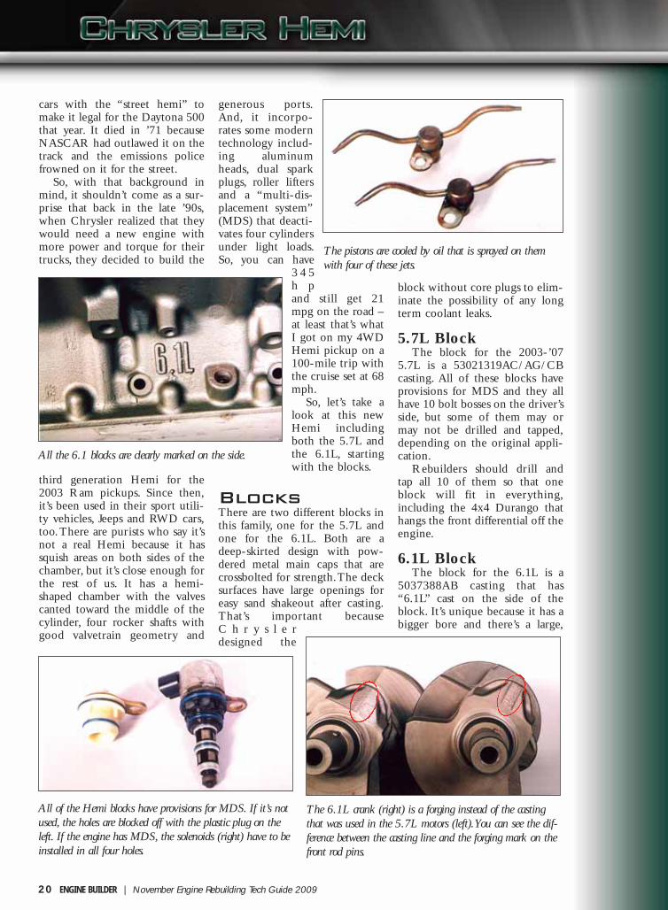
The pistons are cooled by oil that is sprayed on themwith four of these jets.
All of the Hemi blocks have provisions for MDS. If it’s notused, the holes are blocked off with the plastic plug on theleft. If the engine has MDS, the solenoids (right) have to beinstalled in all four holes.
The 6.1L crank (right) is a forging instead of the castingthat was used in the 5.7L motors (left). You can see the dif-ference between the casting line and the forging mark on thefront rod pins.
18-28 Hemi:Layout 1 11/17/09 8:38 AM Page 20

rectangular oil gallery in the crankcase that’s drilledand machined for the four “piston oil cooling jets.”The 6.1L block can’t be bored oversize according toChrysler.
CranksThere are two different cranks, too. They’re internal-ly balanced and they both have the same3.58˝stroke, but the one for the 6.1L is forged steelinstead of cast iron like the one for the 5.7L motor.
5.7L CrankThe ’03-’07 crank is a 53021300AA casting. It
has three bolt holes in a circular pattern for thecrank sensor that’s located behind the last counter-weight.
6.1L CrankThere isn’t a “casting number” on the forged
crank for the 6.1L, but we did find “2MK” stampedon the one we had, so that may be how it’s identi-fied. It’s easy to pick it out anyway, because it’s aforging and it has a four bolts for the crank sensorinstead of the three that are found on the 5.7Lcrank.
RodsThe 5.7L and 6.1L each have their own rods, too.They’re both forged, powdered metal with crackedcaps that are held on with cap screws. They don’thave “casting numbers” on them, but they’re easy totell apart once you’ve seen them side by side.Chrysler says that the rod bolts aren’t reusable.
5.7L RodThe 5.7L rod is press fit with the hole in the
small end measuring 0.945˝. It weighs 597 grams+/-5 grams.
6.1L RodThe 6.1L is stronger in every way with thicker
beams and more material on both ends. It has a full-floating pin and it measures 0.985˝ on the small endwith the bushing installed. It weighs 653 grams +/-5 grams.
PistonsMahle makes the OEM piston for the 5.7L. It’s avery contemporary, lightweight design (413 grams)with short skirts that are coated with Grafal® toreduce friction and noise.
The piston rings are narrow (1.5 mm/1.5mm/1.5 mm/3.0 mm) and the ring pack is locatedvery close to the top of the piston. Moving the topland up within 3.0 mm of the crown reducedcrevice volume and emissions, but the top ringgroove had to be hard anodized in order to stand up
to the heat and pressure that would cause microw-elding and ring groove poundout otherwise.
www.enginebuildermag.com | ENGINE BUILDER 21
The crank sensor wheel for the 6.1L (left) has four holesinstead of the three found on the crank for the 5.7L.
The sensor wheel for the 6.1L (top) is noticeably thickerthan the one for the 5.7L, too.
The flange for the crank sensor on the 6.1L has four boltholes instead of the three that were used on the 5.7L crank.
The crank sensor for the 5.7L (right) is considerably differ-ent than the one used on the 4.7L (left) and all the otherChrysler engines.
18-28 Hemi:Layout 1 11/17/09 8:38 AM Page 21

We haven’t seen the piston forthe 6.1L, but we would expect it tobe similar in design, except that ithas a bigger bore and a full-floatingpin.
Aftermarket pistons are availableas well.
CamsAll the cams for these motors arebig and heavy, because the valveaction is pretty aggressive and
Chrysler didn’t wantto allow any camdeflection.
The original camswere a hollowassembled design,but we’ve also seenboth cast iron andbillet versions forthe 5.7L. The camsfor the 6.1L are allbillets. These camscan be identified bythe full part numberthat’s on the barrelor the last three dig-its of the part num-ber that are locatedon the back of thecam. In mid ’04,Chrysler also addedan ID ring to thecam with groovesmachined on thebarrel in front of the
#5 journal. Unfortunately, wedon’t know how to decipher all thecodes yet, but we’re working on it.
5.7L CamThere have been several cams
used in the 5.7L, depending on theyear and whether or not theengine has MDS.
The cam for the engines with-out MDS went from a53021730AB to ’AC to ’BA andhas been superseded to the
53022064AA.The MDS cam went from a
53021731AB to ’AD to ’AE beforeit was superseded by a53022065AA that’s now a53022065AB. The cams with and
without MDS aren’t interchange-able because there are differentprofiles on the lobes for the cylin-ders with MDS according to ourcam supplier. The specs call for 253degrees of intake duration and253.7 degrees of exhaust durationat .006˝ with 34 degrees of overlap.Lift at the valve is 0.472˝ for theintake and 0.460˝ for the exhaust.
6.1L CamAll of the 6.1L engines came
without MDS so there is only one
22 ENGINE BUILDER | November Engine Rebuilding Tech Guide 2009
The caps for the 6.1L (right) are rein-forced so they can handle the 425 hpSRT applications.
The Hemi rods are all powdered metal with cracked caps,but the ones for the 6.1L (right) are considerably strongerand they’re bushed on the small end.
The lightweight, OEM Mahle pistonhas narrow rings, Grafal®-coated skirtsand a hard anodized top ring groove.
The 5.7L cams may be hollow (left), cast iron (middle) or billet steel (right). All thecams for the 6.1L motors are billets. You can tell the difference by looking at the bar-rel on each one.
18-28 Hemi:Layout 1 11/17/09 8:38 AM Page 22

cam used for them. It has someserious lift, about 0.050˝ more thanthe 5.7L, so the lobes are almost astall as the journals. Chrysler says ithas 283 degrees of duration on theintake and 286 degrees on theexhaust at .006˝ and 50 degreesoverlap, so it’s pretty aggressivecompared to the 5.7L cam.
Lifters AndYokesChrysler uses two different liftersfor the Hemi motors, one for thecylinders without MDS and onefor the cylinders that have MDS.They’re easy to tell apart becausethe flat sides near the top of theregular lifters are 0.040˝ narrower(0.7265˝ compared to 0.7665˝)than they are on the MDS lifters.And, the MDS lifters have a holeon the side of the body for the pinthat disables the lifter for the MDSmode.
The lifters are held in place byfour plastic yokes that have fourlifters in each one. There are threedifferent versions, one for theengines without MDS and two dif-ferent ones for the engines withMDS. Each MDS engine has twoof them that say “MDS Front” andtwo that say “MDS Rear.” Theyboth have two big holes for the
MDS lifters and two smaller holesfor the regular lifters so you can’tinstall them in the wrong placewhen assembling an engine withMDS.
MDS Plugsand SolenoidsThe Hemi block was originallydesigned for MDS, so the fourholes in the valley must have eitherthe MDS solenoids (p/n53032152AC) or the plastic plugs(p/n 53032221AA) that block offthe MDS oil passages.
Pushrods The short ones are for the intakesand the long ones are for theexhausts. Both of the pushrods forthe 5.7L are approximately 4.0 mmlonger than the ones for the 6.1Lbecause of the difference in the lift
at the lobe.
Rocker ArmsThe Hemi has four rocker armshafts per engine, two intakes andtwo exhausts. The intakes have an“I” cast on the rocker arm sothey’re easy to identify, but you canalso tell them apart by noting thelocation of the pushrod socket. Theshafts are fully assembled with therockers along with the bolts andspacers. Just a word of caution: Ifyou break off one of the tabs thathold the bolt and spacer in placeduring assembly, it could (will!)end up inside the engine.
When we started building theseengines, we noticed that there werethree different configurations ofthe rocker shaft assemblies, so wetracked down a Chrysler engineerto find out why. The originaldesign had metal spacers betweenthe rockers to hold them in placeduring assembly. In early ’05, theystarted using “C” clips to locate therockers for assembly. Then inFebruary ’07, they changed their
www.enginebuildermag.com | ENGINE BUILDER 23
The roller lifters are located with fourplastic yokes. There are three differentyokes, one for engines without MDS,one for “MDS front” and one for“MDS rear” They are easily identifiedby the markings found on them.
The MDS lifter (right) is unique. It’sbigger on top (.7665˝ vs. .7265˝ acrossthe flats) and has an extra oil hole inthe body.
The intake and exhaust rocker arms are different. Note the difference in the locationof the pushrod sockets.
The exhaust rockers aren’t marked butthe intakes have a raised “I” on them.
18-28 Hemi:Layout 1 11/17/09 8:38 AM Page 23

24 ENGINE BUILDER | November Engine Rebuilding Tech Guide 2009
assembly process so they didn’t need the “C” clip any-more. Don’t be surprised when you see the three dif-ferent versions and don’t worry about which one youuse when building an engine, but make sure you usethem in matching sets so the installer doesn’t start ask-ing questions when he sees two or three different ver-sions on the same engine.
Cylinder HeadsThe cylinder heads can be a bit more confusingbecause Chrysler used the same casting on both sides,but machined it so it only fits on one side. Some headsare drilled for EGR and some aren’t, and others havethree holes on one end that may or may not bedrilled. Here’s what we know:
5.7L Heads The front of the head used on the passenger side of
the ’03 engines (c/n 53021616AJ/BA) had a flat padwith two bolt holes, but the EGR hole wasn’t drilled.All of the ’04s (and maybe a few late ’03s) had theholes drilled for the EGR valve.
The left head (c/n 53021616AJ/BA) has a triangu-lar pad with provisions for three bolt holes around thecore plug on the front of the head. These three holesaren’t always drilled, but they should be because theyare needed for some applications. The bolt holes forthe middle two exhaust ports are angled from the backto the front with the top bolt hole at the back of theport on the driver’s side and at the front of the port onthe passenger side.
6.1L HeadsThe 6.1L engine has its own unique heads that
both have the same 5037369AA casting number. Theyhave bigger intake ports without the eyebrows for theinjectors, “D” shaped exhaust ports, and bigger valves(2.08˝/1.60˝ vs 2.0˝/1.55˝) that are lighter, too. Boththe intake and exhaust valves are hollow, and the
exhaust valves are sodi-um-filled for better heattransfer. The valve springsfor the intake and exhaustare not interchangeablebecause the intakes have ahigher installed heightand they’re both matchedto the specific weights ofthe intake and exhaustvalves. These springs areunique to the 6.1L, sothey can’t be used on the5.7L motors. The revisedchamber has widerquench areas so it’s slight-ly smaller, too.The head on the passen-
The original rocker arms (right) had spacers between them andthe later ones (middle) used “C” clips to hold them in placeduring assembly. The current ones don’t need anything to holdthem in place because Chrysler changed its build procedures.
Purists say the new Hemi (right) isn’t a REAL hemi, becauseit has squish areas on both sides of the chamber, unlike thechamber for the original Hemi (left).
The heads for the 6.1 have bigger valves and more quench on both sides of the chamber.
18-28 Hemi:Layout 1 11/17/09 8:38 AM Page 24

ger side is always drilled for EGR and the one on theleft should always be drilled for the accessory mount.
So, that’s the story on the major components, butthere are a few other things you should know aboutthese engines:
Oil Pumps and OilingThe 6.1L has a different oil pump that provides the
extra oil needed for the piston cooling jets. It’s a p/n5037687AA instead of the p/n 53021622AF that’sused on the 5.7L engine.
The lifters areoiled through thepushrods. Oilgoes from thepump to the cambearings andthen up throughthe heads to therocker shaftsbefore it goesthrough therockers anddown thepushrods to thelifters. Thisaccomplishes twothings: 1) the oilpassages in thevalley can beused to deacti-vate the MDSlifters, and 2) thepushrods providea reservoir of oilto help prevent“morning sick-
ness” (i.e., noisylifters at startup).
Chrysler callsfor a minimumoil pressure of 4psi at idle. That’snot much, butthe service man-ager at a localChrysler dealertold me thatthey have hadHemi motorsturn on thecheck enginelight when thecustomer usedanything otherthan the 5W20motor oil that’sspecified forthese engines.
Piston Oil CoolerJetsThe 6.1L has four of the piston oil cooling jets.They’re available under p/n 5037524AB. They shouldbe replaced if they’re plugged or damaged in any way.
Crank SensorsThe 5.7L and 6.1L engines have their own uniquecrank sensors. The one for the 6.1L is thicker (.295˝vs. .250˝) and is held on with four bolts instead of thethree found on the 5.7L. The bad news is that none ofthe crank sensors are available separately; you have tobuy a crank to get a sensor because Chrysler balances
the crank with the sensor on it andthey believe that the balance will beadversely affected if the crank sensoris changed.
Head GasketsThe head gaskets for the 5.7L can bephysically installed either side, butthey will leak if they’re on the wrongside, so they’re marked with a “R” or“L.”
The head gaskets for the 6.1L areinterchangeable, but they must beinstalled with “UP” facing up in orderto avoid coolant problems.
EGR Block-OffPlateMost rebuilders are drilling all theheads for EGR and sending a block-
www.enginebuildermag.com | ENGINE BUILDER 25
The exhaust ports for the 6.1L (left) are“D”-shaped instead of square like theones for the 5.7L (right).
The intake ports for the 6.1L (left) aremuch bigger than the ones for the 5.7Land they don’t have the “eyebrows” forthe injectors.
The intake ports on the “old Hemi”(right) are pretty impressive even whenthey’re compared to the ones on the“new Hemi” (left). It’s no wonder theold Hemi motors ran so well.
Check out the exhaust ports on the new(left) and the old (right) Hemi heads.
18-28 Hemi:Layout 1 11/17/09 8:38 AM Page 25

off plate (p/n 6034826) with the engine for the ’03trucks that didn’t have EGR.
Multi-DisplacementSystem (MDS)MDS deactivates four cylinders simultaneously whenthe vehicle is cruising down the road under light load.The Hemi has a separate oil gallery in the valley with
four solenoids that apply pressure to the pins in thesides of the eight MDS lifters on cylinders 1, 4, 6 and7 to disable them.
When they are disabled, the lifter body continuesto go up and down, but the plunger inside the lifterremains stationary, so the valves stay closed. Theexhaust gases that are trapped in each cylinder arecompressed on the compression and exhaust strokes sothey help push the pistons back down on the intakeand power strokes. The injectors are shut off so there’s
no problem with fuel wash down.The computer can activate anddeactivate the solenoids in 40 mil-liseconds so the transition is seam-less.
Chrysler says MDS reduces emis-sions and improves fuel economy by6 percent overall, depending ondriving habits, but it definitelymakes a big difference in mileagebetween 40 and 70 mph under lightload. It’s worth noting that MDSisn’t available with a manual trans-mission because they need thetorque converter to “cushion” thetransition and make it “seamless.” It’sinteresting technology – and it
works well on the Hemi.
26 ENGINE BUILDER | November Engine Rebuilding Tech Guide 2009
Some applications use the three holes on the driver’s side head(right) for an accessory mount so it’s best to drill them on everyhead. Some rebuilders drill all the heads on the passenger sidefor EGR (left) and send a block-of plate with the engine forthe ’03 pickups.
The bolt holes for the exhaust manifold are reversed on themiddle two cylinders, depending on which side the head is on.The head on the top is for the passenger side and the one onthe bottom fits on the drivers’ side.
All of the ’04 Hemi motors (and possibly even a few of the ’03s) had two bolt holesand an open passage on the front of the right head for EGR (right).
Here’s a “new 345 Hemi” head beside an “old 352 Hemi”head. The new one is lighter because it’s aluminum and it’ssmaller, too.
18-28 Hemi:Layout 1 11/17/09 8:38 AM Page 26

6.1L SRTThe 6.1L engine is used in all of
Chrysler’s “SRT8” vehicles includ-ing the Chrysler 300, DodgeCharger, Dodge Magnum, DodgeChallenger and Jeep GrandCherokee. It’s a serious enginewith 425 hp and 420 ft.lbs. oftorque. It has a bigger bore(4.055˝), a higher compressionratio (10.3:1), a cam with more lift(+@ .050˝) and more duration(+30 degrees), bigger ports, biggervalves, a forged crank, strongerrods, a high volume oil pump, pis-ton cooling jets, and a differenttiming set along with several othersubtle upgrades and changes.
Crate MotorsThe 5.7L/345 cid and 6.4L/392cid Hemis are both available as
crate motors with either the facto-ry fuel injection or a carburetor.And, there are several companies inthe aftermarket that are supportingthese engines with additional per-formance parts and electronics, somore and more of them are show-ing up in street rods and older cars.
Bore andStrokeThe bore and stroke varies,depending on which engine youhave:
• 5.7L: 3.92˝ bore x 3.58˝ stroke• 6.1L: 4.055˝ bore x 3.58˝
www.enginebuildermag.com | ENGINE BUILDER 27
345 HEMI – MDS & EGR Applications
(1) There may be a few late ’03 Ram pickups with EGR, so ask the customer before shipping the motor.(2) We believe that all the ’07 applications carry over to ’08, too, but we haven't researched it completely at this time.
Here’s my truck ... it’s a Hemi.
18-28 Hemi:Layout 1 11/17/09 8:39 AM Page 27

stroke• 6.7L: 4.055˝ bore x 3.795˝
stroke
The 2008 and2009 HemiWe haven’t researched the ’08Hemi thoroughly, but we believeit’s the same as the ’07, especiallysince there were extensivechanges made to it in ’09. The ’09Hemi has an active dual-stageintake manifold and variable camtiming, so it’s got 390 hp and 407ft.lbs. of torque now. That’s notbad for a pickup truck motorthat’s rated at 20 mpg on thehighway, thanks to MDS.
The 345 vs The 354It’s interesting to make some
comparisons between the new5.7L and the original 354 cidHemi motor.
• The new 5.7L weighs 533pounds, 164 pounds less than theold 354 cid that tipped the scalesat 697 pounds. Most of the differ-ence is found in the two alu-minum heads that weigh 100pounds less, but Chrysler took
some weight out of the block andthe rest of the engine, too. By theway, at 533 pounds, it weighsabout the same as a small blockChevy!
• The intake and exhaust portson the 354 cid are impressive.Take a look at the pictures andcaptions. It’s no wonder it ran sogood.
• The valves on the 354” were1.94˝/1.75˝ compared to2.0˝/1.53˝ on the 5.7L.
• The 1955 Chrysler 300 wasnamed that because the 331 cidHemi was the first domestic carengine to make 300 horsepower.Now, the 5.7L makes 390 hp in apickup truck – and that’s with thecurrent SAE ratings that are con-siderably less favorable than theywere in 1955, and it’s dealing
with some stiff emission stan-dards. my, how the times havechanged.
So that’s the story of the “newHEMI.” It’s a well-designed,durable package that makes someserious horsepower and torque,and does it with reasonable fueleconomy while meeting currentemissions standards. It doesn’thave any weak points, but thereare over 2 million of them outthere already, and they’re startingto filter in the door, so we can allexpect to do more and more ofthem as the population grows andthe engines get some miles onthem. EBTG
Hemi® is a registered trademark ofChrysler Corporation.
GRAFAL® is a registered trade-mark of MAHLE.
28 ENGINE BUILDER | November Engine Rebuilding Tech Guide 2009
Chrysler HEMI Casting Numbers
(1) The bolt holes on the two center exhaust ports angle from the back to the front when looking at the upper hole.(2) The bolt holes on the two center exhaust ports angle from the front to the back when looking at the upper hole.
About the AuthorDoug Anderson is Manager of Technical Services for Grooms Engines, located inNashville, TN. He has authored numerous technical articles on engine rebuilding forEngine Builder magazine for more than 19 years. Anderson has also made many tech-nical presentations on engine building at AERA and PERA conventions and seminars.This article was first published in the March 2009 issue of Engine Builder magazine.To find Doug’s other articles visit us online at www.enginebuildermag.com.
18-28 Hemi:Layout 1 11/17/09 8:39 AM Page 28