Handbuch Fiberoptic Repeater OZD Modbus Plus G12
74
Handbuch Fiberoptic Repeater OZD Modbus Plus G12 … Manual Fiber-Optic Repeater OZD Modbus Plus G12 … Manuel Interface pour Fibre Optique OZD Modbus Plus G12 … Port 1 System Port 1 Port 2 Port 3 i OZD Modbus Plus Hirschmann. Simply a good Connection.
-
Upload
khangminh22 -
Category
Documents
-
view
2 -
download
0
Transcript of Handbuch Fiberoptic Repeater OZD Modbus Plus G12
HandbuchFiberoptic Repeater OZD Modbus Plus G12 …
ManualFiber-Optic Repeater OZD Modbus Plus G12 …
ManuelInterface pour Fibre Optique OZD Modbus Plus G12 …
Port 1
System
Port 1
Port 2
Port 3
i OZDModbus Plus
Hirschmann. Simply a good Connection.

Seite / Page / Page
Deutsch 1 – 24
English 25 – 48
Français 49 – 70

1
Handbuch Fiberoptic Repeater OZD Modbus Plus G12 …
Port 1
System
Port 1
Port 2
Port 3
i OZDModbus Plus
Deuts
ch

2 Version 04 07/2014
Die beschriebenen Leistungsmerkmale sind nur dannverbindlich, wenn sie bei Vertragsschluss ausdrücklichvereinbart wurden. Wir haben den Inhalt der Druckschriftauf Über ein stim mung mit der beschriebenen Hard- undSoftware geprüft. Dennoch können Abwei chungen nichtausgeschlossen werden, so dass wir für die vollständigeÜbereinstimmung keine Gewähr übernehmen. Die Anga-ben in der Druckschrift werden jedoch regelmäßig über-prüft. Notwendige Korrekturen sind in den nachfolgendenAuflagen enthalten. Für Ver besserungsvorschläge sindwir dankbar.
Technische Änderungen vorbehalten.
Weitergabe sowie Vervielfältigung dieser Unter lage, Ver-wertung und Mitteilung ihres Inhalts ist nicht gestattet,soweit nicht ausdrücklich zugestanden. Zuwiderhand -lungen verpflichten zu Schadensersatz. Alle Rechte vor-behalten, insbesondere für den Fall der Patenterteilungoder GM-Eintragung.
© Hirschmann Automation and Control GmbH 2014
All Rights Reserved
HinweisWir weisen darauf hin, dass der Inhalt dieser Betriebs -anleitung nicht Teil einer früheren oder bestehenden Vereinbarung, Zusage oder eines Rechtsverhältnisses istoder diese abändern soll. Sämtliche Verpflichtungen von Hirschmann ergeben sich aus dem jeweiligen Kaufver-trag, der auch die vollständige und allein gültige Gewähr-leistungsregel enthält. Diese vertrag lichen Gewährlei-stungsbestimmungen werden durch die Ausführungendieser Betriebs anlei tung weder erweitert noch beschränkt.
Wir weisen außerdem darauf hin, dass aus Gründen derÜbersichtlichkeit in dieser Betriebs anleitung nicht jedenur erdenkliche Problemstellung im Zusammenhang mitdem Einsatz dieses Gerätes beschrieben werden kann.Sollten Sie weitere Informationen be nötigen oder solltenbesondere Probleme auftreten, die in der Betriebsanlei-tung nicht ausführlich genug behandelt werden, könnenSie die erforderliche Auskunft über den Hirsch mann- Vertragspartner in Ihrer Nähe oder direkt bei Hirschmann(Adresse siehe im Abschnitt „Hinweis zur CE-Kennzeich-nung“) anfordern.
Sicherheitstechnische HinweiseDieses Handbuch enthält Hinweise, die Sie zu Ihrer persönlichen Sicherheit, sowie zur Ver meidung vonSachschäden beachten müssen. Die Hinweise sinddurch ein Warndreieck her vorgehoben und je nachGefährdungsgrad folgendermaßen dargestellt:
z Gefahr!bedeutet, dass Tod, schwere Körper ver letzungoder erheblicher Sach schaden eintreten werden,wenn die entsprechenden Vorsichtsmaßnahmennicht getroffen werden.
z Warnung!bedeutet, dass Tod, schwere Körper verletzungoder erheblicher Sach schaden eintreten können,wenn die entsprechenden Vorsichtsmaßnahmennicht getroffen werden.
z Vorsicht!bedeutet, dass eine leichte Körper ver letzung oderein Sachschaden ein tre ten können, wenn die ent -sprechenden Vorsichtsmaßnahmen nicht getroffenwerden.
Hinweis: ist eine wichtige Information über das Produkt, die Hand-habung des Produktes oder den jeweiligen Teil der Doku - mentation, auf den besonders aufmerksam gemacht werden soll.
Anforderung an die Qualifikation des PersonalsHinweis: Qualifiziertes Personal im Sinne dieser Betriebs anleitungbzw. der Warnhinweise sind Personen, die mit Aufstel-lung, Montage, Inbetriebsetzung und Betrieb dieses Produktes vertraut sind und die über die ihrer Tätigkeitentsprechenden Qualifikationen verfügen, wie z.B.:
– Ausbildung oder Unterweisung bzw. Berech ti gung,Stromkreise und Geräte bzw. Systeme gemäß denaktuellen Standards der Sicher heitstechnik ein- undauszuschalten, zu erden und zu kennzeichnen;
– Ausbildung oder Unterweisung gemäß den aktuellenStandards der Sicherheitstechnik in Pflege undGebrauch angemessener Sicherheitsausrüstungen;
– Schulung in erster Hilfe.
Allgemeine Sicherheits vorschriften� Dieses Gerät wird mit Elektrizität betrieben. Beachten
Sie genauestens die in der Be triebs anleitung vorge-schriebenen Sicherheitsanforderungen an die anzu -legenden Spannungen!
� Achten Sie auf die Übereinstimmung der elektrischenInstallation mit lokalen oder nationalen Sicherheitsvor-schriften.
z Warnung!Bei Nichtbeachten der Warnhinweise könnenschwere Körper verletzungen und/oder Sach -schäden auftreten.

3Version 04 07/2014
Nur entsprechend qualifiziertes Per sonal sollte andiesem Gerät oder in dessen Nähe arbeiten. DiesesPer sonal muss gründlich mit allen War nungen undInstand haltungsmaß nahmen gemäß dieser Betriebs -anleitung vertraut sein. Der einwandfreie und sichere Betrieb dieses Gerätes setzt sachgemäßen Transport, fachge-rechte Lagerung und Montage sowie sorgfältigeBedienung und Instandhaltung voraus.Nehmen Sie nur unbeschädigte Teile in Betrieb.
z Warnung!Eventuell notwendige Arbeiten an der Elektroinstal-lation dürfen nur von einer hierfür ausgebildetenFachkraft durch geführt werden.
z Warnung!OZD Modbus Plus G12:LASERSTRAHLUNGNICHT DIREKT MIT OPTISCHEN INSTRUMENTENBETRACHTEN.LASERKLASSE 1M nach IEC 60825-1 (2007).OZD Modbus Plus G12-1300: Die zugängliche optische Strahlungsleistung dereingesetzten Komponenten besitzt unter vernünfti-gerweise vorhersehbaren Umständen keinerleiGefährdungspotential.LASER KLASSE 1 nach IEC 60825-1 (2007).
Bestimmungsgemäßer GebrauchBitte beachten Sie folgendes:
z Warnung!Das Gerät darf nur für die im Katalog und in dertechnischen Beschreibung vorgesehenen Einsatz-fälle und nur in Verbindung mit von Hirschmannemp fohlenen bzw. zugelassenen Fremd gerätenund -komponenten verwendet werden. Der ein-wandfreie und sichere Betrieb des Produktes setztsachge mäßen Transport, sach gemäße Lage rung,Aufstellung und Montage sowie sorgfältige Bedie-nung und Instand haltung voraus.
Sicherheitshinweise Versorgungsspanung� Schalten Sie ein Gerät nur ein, wenn das Gehäuse
verschlossen ist.
z Warnung!Die Geräte dürfen nur an die auf dem Typschildaufgedruckte Versorgungs spannung angeschlossenwerden.Die Geräte sind für den Betrieb mit Sicherheits-kleinspannung ausgelegt. Entsprechend dürfen andie Versorgungsspannungsanschlüsse sowie anden Meldekontakt nur PELV-Span nungskreise
oder wahlweise SELV-Spannungskreise mit denSpannungs beschränkungen gemäß IEC/EN 60950angeschlossen werden.
� Für den Fall, dass Sie das Modul mit einer Fremd-spannung betreiben: Versorgen Sie das System nurmit einer Sicherheitsklein spannung nach IEC/EN60950.
Relevant für Nordamerika:� Das Gerät darf nur an eine Versorgungs span nung der
Klasse 2 angeschlossen werden, die den Anforderun-gen des National Electrical Code, Table 11(b) ent-spricht. Wenn die Versorgung redundant erfolgt (zweiverschiedene Spannungs quellen), müssen die Vers -orgungsspan nungen zusammen den Anforderungen des National Electrical Code, Table 11(b) entsprechen.
� Nur Kupferdraht/Leiter der Klasse 60/75°C oder 75°Cverwenden.
Sicherheitshinweise Umgebung
z Warnung!Das Gerät darf nur bei der angege benen Umge-bungstemperatur und bei der angegebenen relativen Luft feuchtig keit (nicht kondensierend)betrieben werden.
� Wählen Sie den Montageort so, dass die in den Tech-nischen Daten angegebenen klima tischen Grenzwerteeingehalten werden.
� Verwendung nur in einer Umgebung mit Verschmut-zungsgrad 2 (IEC 60664-1).
Sicherheitshinweis Gehäuse
z Warnung!Das Öffnen des Gehäuses bleibt ausschließlichden von Hirschmann autorisierten Technikern vorbehalten.
Zugrundeliegende Normen und StandardsDie Geräte erfüllen folgende Normen und Standards: – EN 61000-6-2:2001 Fachgrundnorm –
Störfestigkeit Industriebereich– EN 55022:1998 + A1 2000 – Funkstöreigenschaften
für Einrichtungen der Informationstechnik– EN 60950:1997 – Sicherheit von Einrichtungen
der Informationstechnik– EN 60825-1 Sicherheit von Lasereinrichtungen– FCC 47 CFR Part 15:2000 – Code of Federal
Regulations– ANSI/ISA 12.12.01-2012, Nonincendive Electrical
Equipment for Use in Class I and II, Division 2 andClass III, Division 1 and 2 Hazardous (Classified) Loca-tions.

4 Version 04 07/2014
– C22.2 No. 142-M1987 and CSA C22.2 No. 213-M1987,Non-incendive Control Equipment for Use in Class I,Division 2 Hazardous Locations.
Hinweis zur CE-Kennzeichnung
7 Die Geräte stimmen mit den Vorschriften der folgenden Europäischen Richtlinie überein:
89/336/EWG Richtlinie des Rates zur Angleichung der Rechts vor -schrif ten der Mitgliedstaaten über die elektromagneti-sche Verträglichkeit (geän dert durch RL 91/263/EWG,92/31/EWG und 93/68/EWG).
Voraussetzung für die Einhaltung der EMV-Grenzwerteist die strikte Einhaltung der in der Beschreibung undBetriebs anleitung angegebenen Aufbaurichtlinien.
Die EU-Konformitätserklärung wird gemäß der obenge-nannten EU-Richtlinien für die zustän digen Behörden zurVerfügung gehalten bei:
Hirschmann Automation and Control GmbHStuttgarter Strasse 45 – 5172654 NeckartenzlingenDeutschlandTelefon +49 (0)1805 14-1538E-Mail [email protected]
Das Produkt ist einsetzbar im Wohnbereich (Wohnbe-reich, Geschäfts- und Gewerbebereiche sowie Klein -betriebe) sowie im Industriebereich.
– Störfestigkeit: EN 61000-6-2:1999
– Störaussendung: EN 55022:1998 Class A
Warnung!Dies ist eine Einrichtung der Klasse A. Diese Einrich-tung kann im Wohnbereich Funkstörungen verursa-chen; in diesem Fall kann vom Betreiber verlangtwerden, angemessene Maßnahmen durchzuführenund dafür aufzukommen.
FCC-VORSCHRIFTEN
Dieses Gerät entspricht Teil 15 der FCC-Vorschriften. Der Betrieb unterliegt den folgenden Bedingungen:
(1) Dieses Gerät darf keine schädlichen Störeinflüsseerzeugen, und
(2) dieses Gerät muss alle empfangenen Störeinflüssetolerieren, einschließlich Störungen, die unerwünschteEinflüsse auf den Betrieb haben können.
Hinweis: Es wurde nach entsprechender Prüfung fest-gestellt, daß dieses Gerät den Anforderungen an ein Digi-
talgerät der Klasse A gemäß Teil 15 der FCC-Vorschriftenentspricht. Diese Anforderungen sind darauf ausgelegt,einen angemessenen Schutz gegen Funkstörungen zubieten, wenn das Gerät im gewerblichen Bereich einge-setzt wird. Das Gerät erzeugt und verwendet Hochfre-quenzen und kann diese auch ausstrahlen, und wenn esnicht entsprechend dieser Betriebsanleitung installiertund benutzt wird, kann es Störungen des Funkverkehrsverursachen. Der Betrieb dieses Gerätes in einem Wohn -bereich kann ebenfalls Funkstörungen verursachen; derBenutzer ist in diesem Fall verpflichtet, Funkstörungenauf seine Kosten zu beseitigen.
RELEVANT FÜR DEN EINSATZ IN NORDAMERIKA:DIESE GERÄTE SIND OFFENE GERÄTE, DIE IN EINEFÜR DIE UMGEBUNG GEEIGNETE UMHÜLLUNG EIN-GEBAUT WERDEN MÜSSEN.
Nur OZD Modbus Plus G12:
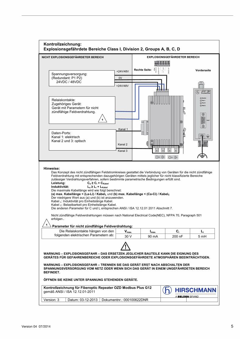
DIESE GERÄTE SIND AUSSCHLIESSLICH GEEIGNETFÜR DIE VERWENDUNG IN EXPLOSIONSGEFÄHRDE-TEN BEREICHEN DER KLASSE I, DIVISION 2, GRUPPENA, B, C UND D SOWIE IN NICHT EXPLOSIONSGEFÄHR-DETEN BEREICHEN.
DIE VERDRAHTUNG MUSS DEN ANFORDERUNGEN ANDIE VERDRAHTUNGSVERFAHREN DER KLASSE I, DIVI-SION 2 ENTSPRECHEN UND DIE GESETZLICHENBESTIMMUNGEN ERFÜLLEN.
BEACHTEN SIE BEIM EINSATZ IN EXPLOSIONSGE-FÄHRDETEN BEREICHEN DER KLASSE I, DIVISION 2DIE KONTROLLZEICHNUNG NR. 000100622DNR AUFDER NÄCHSTEN SEITE.
C-TickAustralia/New Zealand
This product meets the requirements of theAS/NZS 3548 standard.
N1337
Recycling Hinweis
, Dieses Produkt ist nach seiner Ver wendung ent-sprechend den aktuellen EntsorgungsvorschriftenIhres Land kreises /Landes /Staates als Elek tronik -schrott einer geordneten Ent sorgung zuzuführen.
5Version 04 07/2014
� �
� � ����������� ����������������
� ��������������� ���������������������� ���������� ���� ���
�������
��
���������������� !���"#��$���$ �%&��'���������������($$�)���*�$����+)�����#$�,)��)��)�����������������������������������-��$�!��
������� ����������!� "��#!�������������$�����������������%��&�������'���(��#���"���������!� "��#!��������'�����!��������������!�������� ���!)������(��#���������*�����!���"�����!�$������ �����������!�� ��#�������%�����!����'���!���+�������&�����������������!����������������"������������$��� !� �(�.����/���(0����'�1��*��&�!� �(�.����/���(0���������,��������&���#����-����-�������&����!��.�2(3�4("5��(0���&� ��6�2�(7��3�8��(0��������203�4("5��(0���&� ��6�2�(7��3�8��(0��������������������/�������0�1�����0&1������ �-���������&���2.�3���$�'�#�����4��!����#������&������&��� .������&��$�������4��!����#������&�������������������������"�� �����2��������!����5�3�6�3���������7���7����&��!���8���5��!� "��#!��������'�����!�������"��������!�5�������4��������� ���054 1+�5����87+���������!�97������������
����������(�(4�����%9���������9�'%&�� �����'*��'�(���� !�����:�����$���$��!#�����'�������
������������$����!��������������&.�:4("5� 4("5� ��� ���;7�%� <7���� �77���� 9��=�
����
;,�<��=������������,���=���������������� �������������������������������������������������� �������������������������������������������� �������������������������������������������������������� ����� ������������������������������������������� ��������������������������������� ����������������������������������������������������������� !�"#�$�%�&'����(!��)��"��!)!*�!��������+($,���$,��-.����#>��5�3�6�3���������7�?�7���
�%������.�;� ����.�7;?��?�7�;� ��$�������.�777�77@���5:� � ��
��������������������������� �������������������������������� �
-
-
���+!�,!��!�!"#�!��!��!/�
��������
���������������;�
7%�
A�B%6BC%�
:�����$���$�.�D���!)������(��#.�(��#��������������"�����!� "��#!��������'�����!�����
�������������������������������������������������
- �
A�B%6BC%�
����?����.��������.����$����!�������������;.������!�
���������'���������.���0:�������.������1�������B%� �6�BC%� �����������

6 Version 04 07/2014
Inhalt
1 Einführung . . . . . . . . . . . . . . . . . . . . . . . . . . . . . . . . . . . . . . . . . . . . . . . . . . . . . . . . . . 7
2 Netztopologien . . . . . . . . . . . . . . . . . . . . . . . . . . . . . . . . . . . . . . . . . . . . . . . . . . . . . . . . . . 9
2.1 Optischer Ring mit Redundanz (HIPER-Ring) . . . . . . . . . . . . . . . . . . . . . . . . . . . . . . . . . . . . . . . . 92.2 Linientopologie ohne Redundanz . . . . . . . . . . . . . . . . . . . . . . . . . . . . . . . . . . . . . . . . . . . . . . . . . . 11
3 Inbetriebnahme . . . . . . . . . . . . . . . . . . . . . . . . . . . . . . . . . . . . . . . . . . . . . . . . . . . . . . . . . . 13
3.1 Aufbaurichtlinien . . . . . . . . . . . . . . . . . . . . . . . . . . . . . . . . . . . . . . . . . . . . . . . . . . . . . . . . . . . . . . 133.2 Anschliessen der optischen Busleitungen . . . . . . . . . . . . . . . . . . . . . . . . . . . . . . . . . . . . . . . . . . . 153.3 Montieren der Repeater . . . . . . . . . . . . . . . . . . . . . . . . . . . . . . . . . . . . . . . . . . . . . . . . . . . . . . . . . 153.4 Anschliessen der elektrischen Busleitungen . . . . . . . . . . . . . . . . . . . . . . . . . . . . . . . . . . . . . . . . . 173.5 Anschliessen der Spannungsversorgung . . . . . . . . . . . . . . . . . . . . . . . . . . . . . . . . . . . . . . . . . . . . 173.6 Anschliessen der Meldekontaktleitungen . . . . . . . . . . . . . . . . . . . . . . . . . . . . . . . . . . . . . . . . . . . . 18
4 LED-Anzeigen . . . . . . . . . . . . . . . . . . . . . . . . . . . . . . . . . . . . . . . . . . . . . . . . . . . . . . . . . . 19
5 Hilfe bei Betriebsstörungen . . . . . . . . . . . . . . . . . . . . . . . . . . . . . . . . . . . . . . . . . . . . . . . . 20
6 Technische Daten . . . . . . . . . . . . . . . . . . . . . . . . . . . . . . . . . . . . . . . . . . . . . . . . . . . . . . . . . 21
7 Applikationsunterstützung . . . . . . . . . . . . . . . . . . . . . . . . . . . . . . . . . . . . . . . . . . . . . . . . . 23
Inhalt

7
1 Einführung
Version 04 07/2014
1 Einführung
Der Fiberoptic Repeater OZD Modbus Plus G12 … ist fürden Ein satz in optischen Modbus Plus-Feldbusnetzenvor gesehen. Er ermöglicht die Umsetzung von elektrischen in optischeModbus Plus Schnittstellen und umgekehrt.
Sie können die Repeater in bestehende elektrische Mod-bus Plus-Feldbus netze integrieren. Ebenso ist ein voll-ständiger Auf bau eines optischen Modbus Plus-Feldbus-netzes in Linien- oder Ringtopologie mit OZD ModbusPlus G12 … Repeatern möglich.
Der mechanische Aufbau besteht aus einem kompakten,stabilen Metallgehäuse, welches wahlweise auf einerHutschiene oder auf einer beliebigen, ebenen Unterlagemontierbar ist.
Bei der Inbetriebnahme sind keine Einstellarbeiten not-wendig.
Ports
Der Repeater verfügt über drei voneinander unab hängigeKanäle (Ports), welche wiederum aus einem Sender- undEmpfängerteil bestehen.Der Port 1 ist als 9poliger Sub-D-Anschluss (female), diePorts 2 und 3 als optische BFOC/2,5 (ST ®) Buchsenausgeführt.
Spannungsversorgung
Die Betriebsspannungsversorgung erfolgt durch +24 VDC bis +48 VDC Gleichspannung. Zur Erhöhung der Betriebs sicherheit ist eine redundanteBetriebs span nungs versorgung aus zwei ge trenntenQuellen vorgesehen. Hierzu können die beiden Betriebs-spannungen an zwei verschiedenen Klemmen des 5poligen Klemmblocks zugeführt werden. Beide Anschlüsse sind über Dioden entkoppelt, umRückspeisung oder Zerstörung durch Verpolung zu verhindern. Eine Lastverteilung zwischen den Quellen besteht nicht.Bei redundanter Einspeisung muss das Netzgerät mit derhöheren Ausgangsspannung den Busadapter alleine versorgen.
Meldekontakt
Über einen Meldekontakt (Relais mit potentialfreien Kontakten) sind verschiedene Störungsfälle der Repeater signalisierbar. Die Anschlüsse des Meldekontaktes sindebenfalls am 5poligen Klemmblock herausgeführt.
LEDs
Vier zweifarbige Leuchtdioden signalisieren den aktuellenBetriebszustand und eventuelle Betriebsstörungen.
5poliger Klemm-block für Betriebs-spannungsver-sorgung und Meldekontakt
LED Anzeigen
Erd-schraube
Port 1elektrisch,Sub-D-Anschluss
Port 3optisch,BFOC/2,5Buchse
Port 2optisch,BFOC/2,5Buchse
Port 1
System
Port 1
Port 2
Port 3
i OZDModbus Plus
Abb. 1: Fiberoptic Repeater OZD Modbus Plus G12 … mit Lage der einzelnen Ports, des Klemmblocks, der LED-Anzeigen und der Erdschraube

1 Einführung
8 Version 04 07/2014
Glasfasertechnik
Der Einsatz der Glasfaserübertragungstechnik ermöglichtsehr große Reichweiten und bewirkt einen optimalenSchutz vor EMV-Einwirkungen sowohl auf die Übertra-gungsstrecke als auch – wegen der Potential trennung –auf die Repeater selbst.
Übertragungsgeschwindigkeit
Der Fiberoptic Repeater OZD Modbus Plus G12 … arbeitet mit der Übertragungsgeschwindigkeit 1 MBit/s.
Signalregenerierung
Der Fiberoptic Repeater OZD Modbus Plus G12 … rege-neriert die Signalform und Amplitude der empfangenenDaten. Durch diese Funktion ist es möglich, beliebig vieleRepeater über LWL-Verbindungen zu kaskadieren.
Redundanz
Durch redundante Signalübertragung wird eine sehr hoheÜbertragungssicherheit gewährleistet.Durch redundante Betriebsspannungsversorgung kanndie Betriebssicherheit noch weiter erhöht werden.
Modbus Plus-Protokoll
In einer Netztopologie entsprechend Abb. 2, 3 und 4(Kap. 2) muss am Master und in den Endgeräten eine Antwortzeit berücksichtigt werden. Jeder optische Port erhält die Daten, die abgeschicktwerden, vom nächsten angeschlossenen Gerät zurück.Diese Rückmeldung dient zur Leitungsüberwachung undRingkontrolle. Die Antwortzeit setzt sich zusammen aus der Laufzeit in der Glasfaser (5 ns/m), der Laufzeit durch einenRepeater (< 1 µs) und einer gerätespezifischen Pausen-zeit von 5 µs:
tAntwort = (2 • l [m] • 5 ns/m) + 1 µs + 5 µs= (10 µs/km • l [km]) + 1 µs + 5 µs
wobei
l = größte vorkommende Länge zwischen zweibenachbarten OZD Modbus Plus G12 … .
Beispiel:
Bei einer maximalen Distanz zwischen zwei benachbartenOZD Modbus Plus G12 … von 2,3 km ergibt sich die folgende Antwortzeit:
tAntwort = (2 • 2300 m • 5 ns/m) + 1 µs + 5 µs= (10 µs/km • 2,3 km) + 1 µs + 5 µs= 29 µs
Modnet, Modbus und Modbus Plus – die Unterschiede
Mit Modnet wurde von der ehemaligen Firma AEG einkomplettes Kommunikationssystem für die Automatisie-rungstechnik angeboten. Es handelt sich dabei nicht umein einzelnes Bussystem, sondern um ein Kommunika -tionssystem mit drei Leistungsklassen. Bedingt durch die unterschiedlichen Anforderungen erstrecken sichdiese Leistungsklassen vom Einsatz im prozessnahenSystembereich bis hin zu übergeordneter Backbone -kommuni kation.
Leistungsklasse 1:objektnahe Kommunikation Modnet1/M+
Leistungsklasse 2:Systemkommunikiation Modnet1/P, Modnet1/IS,
Modnet1/SFB
Leistungsklasse 3:Backbonekommunikation Modnet3/MMSE
Dabei gilt:
Modnet1/M+: Low-cost-Bus, Modbus PlusModnet1/P: Systemfeldbus nach Profibus-NormModnet1/IS: System- und Sensor-Aktuator-Bus
nach Interbus-NormModnet1/SFB: Systemfeldbus nach Bitbus-NormModnet3/MMSE: Kommunikationssystem für über -
geordnete Ebenen nach IEEE 802.3und MAP (MMS auf Ethernet)
Modbus ist eine weit verbreitete definierte Nachrichten-struktur für die Master-Slave Kommunikation. Eine Mod-busnachricht, gesendet vom Master zum Slave, enthältdie Adresse vom angesprochenen Slave, den Befehl, dieDaten und eine Fehlerchecksumme. Modbus RTU undModbus ASCII sind unterschiedliche Datencodierungen.Da nur das Datenformat definiert ist, kann jedes beliebigeMedium (RS232, RS422, RS485 Kupferkabel, Lichtwel-lenleiter, Funk, …) dafür benutzt werden. Als Lichtwellen-leiter-Umsetzer eignen sich OZDV 24…, OZDV 114 undOZD 485 … .
Modbus Plus ist eine komplette Protokoll- und Netz-werkdefinition. Modbus Plus verwendet die ModbusBefehlsstruktur, aber es überträgt die Befehle zusammenmit einem Token, welches schnell von einem Netzwerk-teilnehmer zu nächsten weitergegeben wird. ModbusPlus definiert wie das Token weitergereicht wird, wieBefehlswiederholungen durchgeführt werden, wie dieDaten auf Fehler überprüft werden und wie diese Fehlerdann angezeigt werden und natürlich die gesamte Aus-führung der physikalischen Schnittstelle, das betrifft auchdie Kabel und die Netzinfrastruktur (Tabs, Bridges,Abschlusswiderstand, …). Ziel dabei ist ein richtiges„plug and play“ Feldbussystem.

2.1 Optischer Ring mit Redundanz (HIPER-Ring)
9
2 Netztopolgien
Version 04 07/2014
2 Netztopolgien
2.1 Optischer Ring mit Redundanz (HIPER-Ring*)
Abb. 2: Netzstruktur in redundanter optischer Zweifaser-Ringtopologie
Modbus Plus-Busleitung
LWL-Kabel
Endgerät(e)/Bussegment(e)
Endgerät(e)/Bussegment(e)
Endgerät(e)/Bussegment(e)
Endgerät(e)/Bussegment(e)
Port 3
SE
OZD Modbus Plus G12 …
Port 2
SE
Por
t 1
Port 3
SE
Port 2
SE
OZD Modbus Plus G12 …
Por
t 1
Port 3
SE
OZD Modbus Plus G12 …
Port 2
SE
Por
t 1
Port 3
SE
OZD Modbus Plus G12 …
Port 2
SE
Por
t 1
Diese Netztopologie wird bei einer optischen Verbindungvon Endgeräten oder Bussegmenten angewendet. Durch den Einsatz einer redundanten Verbindung mitOZD Modbus Plus G12 … Repeatern ist eine hohe Aus -fall sicherheit gewährleistet.
In einem HIPER-Ring können beliebig viele Repeaterbetrieben werden. Für eine sichere und zuverlässigeFunktion der Ringredundanz ist es notwendig, dass anjedem OZD Modbus Plus G12 … Repeater am elektri-schen Port (Port 1) mindestens ein aktives Endgerätangeschlossen ist.
Der Ausfall eines LWL-Kabels zwischen zwei beliebigenOZD Modbus Plus G12 …-Repeatern hat keine Auswir-kung auf die Verfügbarkeit des Netzes. Die Repeater erkennen den Totalausfall einer optischenStrecke. Die Port-LED der unterbrochenen Strecke wirdausgeschaltet und durch Aufleuchten der roten System-LED und Abfall des Meldekontaktes wird der Ausfall signalisiert.
Die Duplex LWL-Kabel der beiden optischen Kanäle sindsinnvollerweise auf unterschiedlichen Wegen zu verlegen.
* HIPER-Ring = Hirschmann Performance Redundancy Ring

2 Netztopolgien 2.1 Optischer Ring mit Redundanz (HIPER-Ring)
10 Version 04 07/2014
Abb. 3: Alternative Verkabelungstechnik einer Netzstruktur in redundanter optischer Zweifaser-Ringtopologie
Modbus Plus-Busleitung
LWL-Kabel
Endgerät(e)/Bussegment(e)
Port 3
SE
OZD Modbus Plus G12 …
Port 2
SE
Por
t 1
Endgerät(e)/Bussegment(e)
Port 3
SE
OZD Modbus Plus G12 …
Port 2
SE
Por
t 1
Endgerät(e)/Bussegment(e)
Port 3
SE
OZD Modbus Plus G12 …
Port 2
SE
Por
t 1
Endgerät(e)/Bussegment(e)
Port 3
SE
OZD Modbus Plus G12 …
Port 2
SE
Por
t 1
Endgerät(e)/Bussegment(e)
Port 3
SE
OZD Modbus Plus G12 …
Port 2
SE
Por
t 1
Ergeben sich beim Aufbau eines redundanten optischenRings in der Praxis durch zu lange LWL-Tei l strecken Probleme, so kann die Verkabelung auch wie in Abbil-dung 3 ausgeführt werden.Hierbei ist, räumlich gesehen, jeder Repeater mit dem
übernächsten Repeater miteinander zu verbinden. Am Anfang und am Ende einer so erzeugten Linie sindjeweils zwei benachbarte Repeater miteinander zu verbinden. Somit sind einzelne, „überlange“ LWL-Teil-strecken vermeidbar.

2.2 Linientopologie ohne Redundanz
11
2 Netztopolgien
Version 04 07/2014
Abb. 4: Linientopologie ohne Redundanz
Modbus Plus-Busleitung
LWL-Kabel
Endgerät(e)/Bussegment(e)
Endgerät(e)/Bussegment(e)
Endgerät(e)/Bussegment(e)
Endgerät(e)/Bussegment(e)
Port 3
SE
OZD Modbus Plus G12 …
Port 2
SE
Por
t 1
Port 3
SE
Port 2
SE
OZD Modbus Plus G12 …
Por
t 1
Port 3
SE
OZD Modbus Plus G12 …
Port 2
SE
Por
t 1
Port 3
SE
OZD Modbus Plus G12 …
Port 2
SE
Por
t 1
Diese Netztopologie wird bei einer optischen Verbindungvon Endgeräten oder Bussegmenten angewendet.
In einer optischen Linie können beliebig viele Repeaterbetrieben werden. Für eine sichere und zuverlässigeFunktion der Ringredundanz ist es notwendig, dass anjedem OZD Modbus Plus G12 … Repeater am elektri-schen Port (Port 1) mindestens ein aktives Endgerätangeschlossen ist.
Der erste und letzte Repeater der Linie sollte mit einem„optischen Kurzschluss“ (siehe Abb. 4) abgeschlossensein. Hierzu werden Ein- und Ausgang der freien Portsjeweils über ein kurzes LWL-Kabel mit BFOC-Steck -verbindern verbunden.
2.2 Linientopologie ohne Redundanz

2 Netztopolgien
12 Version 04 07/2014

3.1 Aufbaurichtlinien
13
3 Inbetriebnahme
Version 04 07/2014
3 Inbetriebnahme
Entstörung von geschalteten Induktivitäten
� Geschaltete Induktivitäten mit LöschgliedernbeschaltenDas Schalten von Induktivitäten, z.B. in Relais undLüftern, erzeugt Störspannungen, deren Höhe einVielfaches der geschalteten Betriebsspannungbeträgt. Diese Störspannungen können elektroni-sche Geräte beeinflussen.Die Störspannungen von Induktivitäten müssen ander Emmisionsquelle durch Beschalten mit Lösch-gliedern (Dioden- oder RC-Beschaltung) begrenztwerden. Verwenden Sie nur Entstörmittel, die fürdie von Ihnen verwendeten Relais bzw. Lüfter vor-gesehen sind.
� SchrankbeleuchtungVerwenden Sie für die Schrankbeleuchtung Glüh-lampen, z. B. LINESTRA-Lampen. Vermeiden Sieden Einsatz von Leuchtstofflampen, weil dieseLampen Störfelder erzeugen. Wenn auf Leucht-stofflampen nicht verzichtet werden kann, sind diein Abb. 5 gezeigten Maßnahmen zu treffen.
Elektromagnetische Verträglichkeit (EMV)
Die Elektromagnetische Verträglichkeit (EMV) umfasstalle Fragen der elektrischen, magnetischen und elektro -magnetischen Ein– und Abstrahleffekte.Um Störbeeinflussungen in elektrischen Anlagen zu vermeiden, müssen diese Effekte auf ein Mindestmaß
begrenzt werden. Zu den Begrenzungsmaßnahmen gehö-ren wesentlich der konstruktive Aufbau und der fachgerechte Anschluss von Busleitungen sowie die Entstörung von geschalteten Induktivitäten.
3.1 Aufbaurichtlinien
Schirmgitter über der Lampe
geschirmte Leitung
metallgekapselter Schalter
Netzfilter oder geschirmte Netzleitung
Abb. 5: Maßnahmen zur Entstörung von Leuchtstofflampen im Schrank
Räumliche Anordnung von Geräten und Leitungen
� Störbeeinflussung durch Abstand reduzierenEine ebenso einfache wie wirksame Möglichkeit zurReduzierung von Störbeeinflussungen besteht inder räumlichen Trennung von störenden undgestörten Geräten bzw. Leitungen. Induktive undkapazitive Störeinkopplungen nehmen im Quadratdes Abstandes der beteiligten Elemente ab. Dasheißt, eine Verdoppelung des Abstandes reduziertdie Störauswirkung um den Faktor 4. WerdenAnordnungsgesichtspunkte bereits in der Planungs -phase eines Gebäudes bzw. des Schaltschrankes
�
berücksichtigt, lassen sie sich im allgemeinen sehrkostengünstig realisieren.
� Bitte beachten Sie:Zwischen einem OZD Modbus Plus G12 … undeinem leistungsschaltenden Element (z.B. Schütz,Relais, Temperaturregler, Schalter, usw.) ist einMindest abstand von 15 cm einzuhalten. Dieser Mindestabstand ist zwischen den Außen-kanten der Komponenten zu messen und in allenRichtungen um einen OZD Modbus Plus G12 …einzu halten.

3 Inbetriebnahme 3.1 Aufbaurichtlinien
14 Version 04 07/2014
Ausführung von Schirmanschlüssen
Beachten Sie beim Auflegen von Leitungsschirmen bittedie folgenden Punkte:
� Befestigen Sie die Schirmgeflechte mit Kabel -schellen aus Metall.
� Die Schellen müssen den Schirm großflächigumschließen und guten Kontakt ausüben (sieheAbb. 6).
� Kontaktieren Sie die Modbus Plus-Leitungen nurüber den Kupfergeflechtschirm, nicht über den Al-Folienschirm. Der Folienschirm ist zur Erhöhung der Reißfestigkeit einseitig auf eine Kunststofffolie aufgebracht und damit nichtleitend!
� Die Schirme aller Leitungen, die von außen in einenSchrank führen, müssen am Eintrittsort in dieSchrankhülle abgefangen und großflächig mit derSchrankerde kontaktiert werden.
� Beim Entfernen der Leitungsmäntel ist darauf zuachten, dass der Geflechtschirm der Leitungennicht verletzt wird. Ideal für eine gute Kontaktierungvon Erdungselementen miteinander sind verzinnteoder galvanisch stabilisierte Oberflächen. Bei ver-zinkten Oberflächen müssen die erforderlichenKontakte durch eine geeignete Verschraubungsichergestellt werden. Lackierte Oberflächen anden Kontakt stellen sind ungeeignet.
� Schirmabfangungen/-kontaktierungen dürfen nichtals Zugentlastung verwendet werden. Der Kontaktzur Schirmschiene könnte sich verschlechtern oderabreißen.
� Die Stromversorgungsleitungen (+24 VDC und m/0 V)des OZD Modbus Plus G12 … dürfen nicht zusam-men mit leistungsführenden Leitungen (Lastkreisen)im selben Kabelkanal verlegt werden. Die Leitungen (+24 VDC und m/0 V) sollten mitein-ander verdrillt werden.
� Normempfehlungen zur räumlichen Anordnung vonGeräten und LeitungenEmpfehlungen zur räumlichen Anordnung von Ge -räten und Leitungen mit dem Ziel, eine möglichstgeringe gegenseitige Beeinflussung zu gewähr -leisten, enthält EN 50174–2.
� Umgang mit BusleitungsschirmenBeachten Sie die folgenden Maßnahmen bei derSchirmung von Leitungen:
� - Verwenden Sie durchgängig geschirmte ModbusPlus-Leitungen. Die Schirme dieser Leitungenmüssen eine ausreichende Deckungsdichte desSchirmes aufweisen, um die gesetzlichen Anfor-derungen an die Störabstrahlung und -einstrah-lung zu erfüllen.
�
- Legen Sie die Schirme von Busleitungen immerbeidseitig auf. Nur durch den beidseitigen Anschlussder Schirme erreichen Sie die gesetzlichen Anfor-derungen an die Störabstrahlung und -einstrah-lung Ihrer Anlage (CE-Zeichen).
� - Befestigen Sie den Schirm der Busleitung amSteckergehäuse oder an den dafür vorgesehenenKabelschellen.
� - Bei stationärem Betrieb ist es empfehlenswert, die geschirmte Leitung unterbrechungsfrei abzu -isolieren und auf die Schirm-/Schutzleiterschieneaufzulegen.
Hinweis:
Bei Potentialdifferenzen zwischen den Erdungspunk-ten kann über den beidseitig angeschlossenen Schirmein unzulässig hoher Ausgleichsstrom fließen. TrennenSie zur Behebung des Problems auf keinen Fall denSchirm der Busleitung auf! Folgende Lösung ist zulässig:Verlegen Sie parallel zur Busleitung eine zusätzlichePotentialausgleichsleitung, die den Schirmstrom über-nimmt.
Abb. 6: Befestigen von geschirmten Leitungen mit Kabel -schellen und Schlauchbindern (schematische Darstellung)

3.2 Anschließen der optischen Busleitungen
15
3 Inbetriebnahme
Version 04 07/2014
� Verbinden Sie die einzelnen Repeater über ein DuplexLWL-Kabel mit BFOC/2,5 (ST ®) Steckverbindern.
� Beachten Sie die maximale Länge der LWL-Kabelsowie die möglichen Fasertypen, die in den Techni-schen Daten angegeben sind.
� Achten Sie darauf, dass jeweils ein optischer Eingang aund ein optischer Ausgang J mitein ander ver bundensind („Überkreuz-Verbindung“).Auf der unteren Frontplatte sind die zusammenge -hörigen BFOC Buchsen der beiden Ports gekenn-zeichnet.
� Sorgen Sie für eine ausreichende Zugentlastung der LWL-Kabel und beachten Sie deren minimalenBiegeradien.
� Verschließen Sie nicht belegte BFOC-Buchsen mitden mitgelieferten Schutzkappen. Einfallendes Um -gebungslicht kann das Netz, insbesondere bei hoherUmgebungshelligkeit, stören.Eindringender Staub kann die optischen Komponen-ten unbrauchbar machen.
I
J
I
J
Port 2
Port 3
Abb. 7: Ansicht der Repeaterunterseite mit den optischen Ports 2 und 3
Der Fiberoptic Repeater OZD Modbus Plus G12 … ist ent -weder auf einer 35 mm Hutschiene nach IEC 60715:1981 + A1: 1995 oder direkt auf einer ebenen Unterlagemontierbar.
� Wählen Sie den Montageort so, dass die in den tech-nischen Daten angegebenen klimatischen Grenzwerteeingehalten werden.
� Achten Sie auf genügend Raum zum Anschluss derBus- und Versorgungsleitungen.
� Schließen Sie zur leichteren Montage der LWL-Kabeldiese vor der Montage der Repeater an.
� Montieren Sie die Repeater möglichst auf einer nieder -ohmig und niederinduktiv geerdeten Hutschiene oderMon tageplatte.
Port 1
Erd-schraube
Abb. 8: Lage der Erdschraube
Bei einer isoliert montierten Hutschiene oder Montage-platte muss der Repeater direkt über die Erdschraubenieder ohmig und niederinduktiv geerdet werden.
3.2 Anschließen der optischen Busleitungen
3.3 Montieren der Repeater

3 Inbetriebnahme 3.3 Montieren der Repeater
16 Version 04 07/2014
Montieren auf eine Hutschiene
� Hängen Sie die oberen Rasthaken des Repeaters indie Hutschiene ein und drücken Sie die Unterseite,wie in der Abbildung 9 gezeigt, auf die Schiene, bissie einrastet.
� Die Demontage erfolgt durch Zug am Ver riege lungs -schieber nach unten.
Montieren auf eine Montageplatte
Der Repeater ist mit drei Durch gangsbohrungen versehen.Diese ermöglichen die Montage auf einer beliebigen
ebenen Unterlage, z. B. auf der Montageplatte einesSchaltschrankes.
� Versehen Sie die Montageplatte mit drei Bohrungenentsprechend dem Bohrschema in Abb. 10.
� Befestigen Sie die Repeater mit Maschinenschrauben(z. B. M 3 x 40).
� Sorgen Sie für eine zuverlässige elektrische Verbin-dung zwischen Repeatergehäuse und Montageplatte.Unterlegen Sie die Schraubenköpfe mit Zahnschei-ben, um die vorhandene Lackierung zu durchstoßen.
Verriegelungs-schieber
Zahnscheibe
Port 1
System
Port 1
Port 2
Port 3
i OZDModbus Plus 61,2 mm
40,6
mm
81,2
mm
Ø 3 mm
Ø 3 mm
Abb. 9: Montage eines Repeaters auf einer Hutschiene Abb. 10: Montage eines Repeaters auf einer Montageplatte

3.4 Anschließen der elektrischen Busleitungen
17
3 Inbetriebnahme
Version 04 07/2014
z Warnung!
� Die Schirmung des Sub-D-Steckverbinders be stehtaus Metall zur sicheren Erdstromableitung und mussdaher mit dem Schirmblech des kabelseitigen Stek-kers leitend verbunden sein.
� Verbinden Sie Modbus Plus-Repeater nicht überMod bus Plus-Busleitungen mit Anlagen teilen, die auf einem anderen Erdpotential liegen. Spannungs-unterschiede > 500 V können zu einer Zerstörung der
Repeater oder Fehlfunktion der Anlage führen!
� Schließen Sie keine Modbus Plus-Busleitungen an,die ganz oder teilweise außerhalb von Gebäuden ver-legt sind. Andernfalls können z.B. Blitzeinschläge inder Um gebung zur Zerstörung der Repeater führen. Führen Sie Busverbindungen, die Gebäude ver lassen,mit LWL-Kabeln aus!
� Versorgen Sie den Modbus Plus-Repeater nur miteiner stabilisierten Sicherheitskleinspannung nachIEC 950/EN 60950/VDE 0805 von +24 V bis maximal +48 V +10%.
� Zur Erhöhung der Betriebs sicherheit ist eine redundante Betriebs span nungs versorgung aus verschiedenen Quellen vorgesehen. Die Be triebs -spannungen lassen sich über zwei Wege zuführen:
– Klemme +24 V/48 V des Klemmblocks
– Klemme +24 V/48 V* des Klemmblocks
Der gemeinsame Minusanschluss in der Mitte desKlemmblocks ist mit m (0 V) bezeichnet.
� Die beiden Spannungen dürfen beliebige – auch verschiedene – Werte innerhalb der angegebenenGrenzen +24 V/+48 V haben.
� Falls keine Meldekontaktleitungen an den Klemm-block angeschlossen werden (siehe 3.6): Fixieren Sie den Klemmblock durch Verschrauben des Befestigungsflansches.
6 / frei
7 / frei
8 / frei
9 / frei
Shield / 1
Data / 2
Data / 3
frei / 4
frei / 5
Abb. 11: Port 1 – Anschlussbelegung Sub-D-Steckverbinder
� Verwenden Sie als Modbus Plus-Busleitung nur dafürzugelassene abgeschirmte, verdrillte Zweidrahtleitun-gen (shielded twisted pair), z.B. Modicom „SuperCable“, FT4, FT6.
� Die elektrische Modbus Plus-Schnittstelle (Port 1) ist als 9poliger Sub-D-Anschluss (female) aus geführt. Die Pinbelegung entspricht dem Modbus Plus Standard.
� Verwenden Sie zum Anschluss eines Endgerätes eine
Leitung, die mit 9poligen Sub-D Steckerverbindern (male) konfektioniert ist. Länge max. 100 m.
� Der elektrische Port ist intern nicht terminiert.Die externe Terminierung ist im oder am Steck ver -binder der Busleitung laut Modbus Plus Standard vorzunehmen.
� Fixieren Sie den Busanschlussstecker durch verschrauben.
3.4 Anschließen der elektrischen Busleitungen
3.5 Anschließen der Spannungs versorgung

3 Inbetriebnahme 3.5 Anschließen der Spannungs versorgung
18 Version 04 07/2014
� Am 5poligen Klemmblock an der Repeateroberseitestehen potentialfreie Anschlüsse eines Relais als Meldekontakt zur Verfügung. Bei korrekter Funktion des OZD Modbus Plus G12 …ist der Relaiskontakt geöffnet.Im Fehlerfall und bei Spannungsausfall ist der Relais-kontakt für mindestens 500 ms geschlossen.
� Folgende Störungsfälle des Netzes und der Repeatersind an eine Kontrollzentrale signalisierbar:
Versorgungsspannung– fehlt (bei redundanter Versorgung:
Ausfall aller Versorgungsspannungen)
Interner Gerätefehler
Empfangsdaten– Ausfall der Empfangsdaten am Port 2 und/oder
Port 3 (z.B. Kabelbruch)– Transceiver Port 1 defekt– über 500 ms keinerlei Datenverkehr an allen Ports
� Grenzwerte des Relaiskontaktes– maximale Schaltspannung: 60 VDC; 42 VAC– maximaler Schaltstrom: 1,0 A– maximale Schaltleistung: 30 W
� Die an das Relais angeschlossene Spannung musseiner Sicherheitskleinspannung nach IEC 950/EN 60 950/VDE 0805 entsprechen.
� Bitte achten Sie unbedingt auf die korrekte An schluss - belegung des 5poligen Klemmblocks. Sorgen Sie füreine ausreichende elektrische Iso lierung der Anschluss -leitungen der Meldekontakte. Eine Fehlbelegung kannzu einer Zerstörung der Repeater führen.
� Fixieren Sie den Klemmblock durch Verschrauben desBefestigungsflansches.
Befestigungs-flansch
+24 V/48 V
0 V
+24 V/48 V*
Error
Abb. 13: Meldekontakt – Anschlussbelegung 5poliger Klemmblock
Abb. 12: Betriebsspannungsversorgung – Anschluss belegung 5poligerKlemmblock
Befestigungs-flansch
+24 V/48 V
0 V
+24 V/48 V*
Error
3.6 Anschließen der Meldekontaktleitungen

19
4 LED-Anzeigen
Version 04 07/2014
4 LED-Anzeigen
System
grün: Repeater in Betrieb, Datenverkehr findet statt
rot: – Ausfall der Empfangsdaten am Port 2und/oder Port 3 (z.B. Kabelbruch)
– über 500 ms keinerlei Datenverkehr anallen Ports
aus: – fehlende Versorgungsspannung– interner Gerätefehler
Port 1 (elektrisch)
grün: Eingangssignal liegt an
orange: über 500 ms kein Eingangssignal an allen Ports
aus: momentan kein Eingangssignal an diesem Port
Port 2 (optisch)
grün: Eingangssignal liegt an
orange: über 500 ms kein Eingangssignal an allen Ports
aus: momentan kein Eingangssignal an diesem Port
Port 3 (optisch)
grün: Eingangssignal liegt an
orange: über 500 ms kein Eingangssignal an allen Ports
aus: momentan kein Eingangssignal an diesem Port
Abb. 14: LED-Anzeigen auf der Frontplatte
Port 1
System
Port 1
Port 2
Port 3
i OZDModbus Plus

5 Hilfe bei Betriebsstörungen
20 Version 04 07/2014
5 Hilfe bei Betriebsstörungen
LED-Anzeige
System � aus
� rot
Port 1 � aus
� orange
Port 2 � aus
� orange
Port 3 � aus
� orange
Mögliche Fehlerursachen
– Versorgungsspannung ausgefallen– interner Gerätefehler
– keine Empfangsdaten am Port 2 und/oder Port 3, z.B. Kabelbruch– Port 1 defekt– alle 3 Ports sind über 500 ms ohne Eingangssignal
– momentan kein Eingangssignal an diesem Port
– alle 3 Ports sind über 500 ms ohne Eingangssignal
– momentan kein Eingangssignal an diesem Port
– alle 3 Ports sind über 500 ms ohne Eingangssignal
– momentan kein Eingangssignal an diesem Port
– alle 3 Ports sind über 500 ms ohne Eingangssignal
Meldekontakt
meldet
meldet
meldet
meldet
meldet
Hinweis
Die LED-Anzeigen der Port-LEDs lassen im Falle „aus“ nicht auf einen Fehler schließen.

21
6 Technische Daten
Version 04 07/2014
6 Technische Daten
Repeater OZD Modbus Plus G12 OZD Modbus Plus G12-1300Bestell-Nr. 943 740-021 943 821-021Spannungs-/StromversorgungBetriebsspannung +24 VDC –20 % … +48 VDC +10 %, verpolungssicher,
galvanisch vom Gehäuse getrennt, SicherheitskleinspannungStromaufnahme bei +24 VDC 150 mA
bei +48 VDC 85 mALeistungsaufnahme bei +24 VDC 3,6 W
bei +48 VDC 4,0 WMeldekontakt
Maximale Schaltspannung 30 VDC; 42 VAC (Sicherheitskleinspannung)Maximaler Schaltstrom 1,0 A (ohmsche Last)
SignalübertragungÜbertragungsgeschwindigkeit 1 MBit/sKaskadiertiefe beliebigSignaldurchlaufzeit <1 µs (beliebiger Eingang/Ausgang)Elektrischer PortEin-/Ausgangssignal Modbus Plus-PegelPIN-Belegung Port 1 siehe Kap. 3.4Länge Modbus Plus-Kabel 100 mAnschlussmöglichkeit max. 31 EndgeräteGalvanische Trennung
– Schirm / Gehäuse nein– Datenleitungen / Schirm ja
Optische SchnittstelleWellenlänge typ. 860 nm 1310 nmEinkoppelbare optische Leistung
– in Faser E 10/125 – –19 dBm– in Faser G 50/125 –15 dBm –17 dBm– in Faser G 62,5/125 –14 dBm –17 dBm– in Faser S 200/230 (HCS ®) –10 dBm –
Empfindlichkeit Empfänger –25 dBm –27 dBmÜberbrückbare Entfernung mit 2 dB 1) bzw. 3 dB 2)
Systemreserve/Streckendämpfung– mit Faser E 10/125 (0,5 dB/km) – 0 - 8 km*/8 dB 1)
– mit Faser G 50/125 (1,0 dB/km) – 0 - 7 km/10 dB 2)
– mit Faser G 62,5/125 (1,0 dB/km) – 0 - 7 km/10 dB 2)
– mit Faser G 50/125 (3,0 dB/km) 0 - 2,3 km/10 dB 2) –– mit Faser G 62,5/125 (3,5 dB/km) 0 - 2,3 km/11 dB 2) –– mit Faser S 200/230 (HCS ®) (8,0 dB/km) 0 - 1,5 km/15 dB 2) –
Optischer Steckverbinder BFOC/2,5 (ST ®)
* Die Entfernung zwischen zwei OZD Modbus Plus G12-1300 darf wegen den speziellen Anforderungen der Ring -redundanz nicht größer als 8 km sein.

6 Technische Daten
22 Version 04 07/2014
Repeater OZD Modbus Plus G12 OZD Modbus Plus G12-1300Bestell-Nr. 943 740-021 943 821-021Elektromagnetische Verträglichkeit (EMV)Störfestigkeit für Industriebereich nach EN 61000-6-2:2001
Elektrostatische Entladung (ESD) erfüllt EN 61000-4-2; 4 kV contact discharge, 8 kV air discharge Elektromagnetisches Feld erfüllt EN 61000-4-3; 10 V/m (80 MHz - 1000 MHz)Schnelle Transienten (Burst) erfüllt EN 61000-4-4; 2 kV power line, 1 kV data lineStoßspannung (Surge) erfüllt EN 61000-4-5; 1 kV data lineLeitungsgeführte Störspannungen erfüllt EN 61000-4-6; 10 V (150 kHz - 80 MHz)
Störaussendung erfüllt EN 55022; Class Aerfüllt FCC CFR47 Part 15; Class A
Klimatische UmgebungsbedingungenUmgebungstemperatur 0 °C bis +60 °C (IEC 60068-2-1, IEC 60068-2-2)Lagerungstemperatur –40 °C bis +70 °C (IEC 60068-2-14)Relative Luftfeuchtigkeit <95 %, nicht kondensierend (IEC 60068-2-30)Mechanische UmgebungsbedingungenSchwingen Betrieb 10 bis 58 Hz, 0,075 mm Auslenkung;
58 bis 150 Hz, 10 m/s2 (1 g) Beschleunigung (IEC 60068–2–6)Schwingen Transport 5 bis 9 Hz, 3,5 mm Auslenkung;
9 bis 500 Hz, 10 m/s2 (1 g) Beschleunigung
Schutzart IP 40Masse ca. 620 gAbmessungen (B × H × T) 40 × 133 × 77 mmGehäusewerkstoff Zink-Druckguss

23
7 Applikationsunterstützung
Version 04 07/2014
7 Applikationsunterstützung
Kontaktadresse für technische Unterstützung
Hirschmann Automation and Control GmbH Stuttgarter Strasse 45 - 5172654 NeckartenzlingenDeutschlandTel.: +49 (0)1805 14-1538Fax: +49 (0)7127 14-1551E-Mail: [email protected]: http://www.hirschmann.com

7 Applikationsunterstützung
24 Version 04 07/2014

25
Port 1
System
Port 1
Port 2
Port 3
i OZDModbus Plus
ManualFiber-Optic Repeater OZD Modbus Plus G12 …
Englis
h

26 Version 04 07/2014
We have checked that the contents of the technicalpublication agree with the hardware and software des-cribed. However, it is not possible to rule out devia tionscompletely, so we are unable to guarantee completeagree ment. However, the details in the technical publica-tion are checked regularly. Any cor rections which provenecessary are contained in subsequent editions. We aregrateful for suggestions for improvement.
We reserve the right to make technical modifications.
Permission is not given for the circulation or reproductionof this document, its use or the passing on of its contentsunless granted expressly. Contravention renders the perpetrator liable for compensation for damages. Allrights reserved, in particular in the case of patent grantor registration of a utility or design.
© Hirschmann Automation and Control GmbH 2014
All Rights Reserved
NoteWe would point out that the content of these operatinginstructions is not part of, nor is it intended to amend anearlier or existing agree ment, permit or legal relation-ship.All obliga tions on Hirschmann arise from the respectivepurchasing agreement which also contains the full war-ranty conditions which have sole appli cability. Thesecontractual warranty conditions are neither extended norrestricted by com ments in these operating instructions.
We would furthermore point out that for reasons of simplicity, these operating instructions cannot describeevery conceivable problem associated with the use ofthis equipment. Should you require further information orshould particular problems occur which are not treated insufficient detail in the operating instructions, you canrequest the necessary information from your local Hirsch - mann sales partner or directly from the Hirschmann office (address: refer to chapter entitled ”Notes on CEidentification“).
Safety InstructionsThis manual contains instructions which must be observedto ensure your own personal safety and to avoid damageto devices and machinery. The instructions are high -lighted with a warning triangle and are shown as fol lows according to the degree of endangerment:
z Danger!means that death, serious injury or considerabledamage to property will result if the appropriatesafety measures are not taken.
z Warning!means that death, serious injury or considerabledamage to property can result if the appropriatesafety measures are not taken.
z Caution!means that light injury or damage to property canresult if the appropriate safety measures are nottaken.
Note: is an important piece of information about the product,how to use the product, or the relevant section of thedocumentation to which particular attention is to bedrawn.
Staff qualification requirementsNote: Qualified personnel, as understood in this manual and inthe warning signs, are persons who are familiar with thesetup, assembly, startup, and operation of this productand are appropriately qualified for their job. This includes,for example, those persons who have been:
– trained or directed or authorized to switch on and off,to ground and to label power circuits and devices orsystems in accordance with current safety engineeringstandards
– trained or directed in the care and use of appropriatesafety equipment in accordance with the current standards of safety engineering
– trained in providing first aid.
General Safety Instructions� This device is electrically operated. Adhere strictly to
the safety requirements relating to voltages applied tothe device as described in the operating instructions!
� Make sure that the electrical installation meets localor nationally applicable safety regulations.
z Warning!Failure to observe the information given in the warnings could result in serious injury and/or majordamage.Only personnel that have received appropriate training should operate this device or work in itsimmediate vicinity. The personnel must be fullyfamiliar with all of the warnings and maintenancemeasures in these operating instructions. Correct transport, storage, and assembly as wellas careful operation and maintenance are essentialin ensuring safe and reliable operation of this device.Never start operation with damaged components!

27Version 04 07/2014
z Warning!Any work that may have to be per formed on theelectrical installation should be performed by fully qualified technicians only.
z Warning!OZD Modbus Plus G12:LASER RADIATIONDO NOT VIEW DIRECTLY WITH OPTICALINSTRUMENTS.CLASS 1M LASERPRODUCT in accordance withIEC 60825-1 (2007).OZD Modbus Plus G12-1300: The optical radiated power of the com po nentsused in this device does not represent a potentialhealth hazard of any description under normal,fore seeable conditions.CLASS 1 LASERPRODUCT in accordance withIEC 60825-1 (2007).
Certified usagePlease observe the following:
z Warning!The device may only be employed for the purposesdescribed in the catalog and technical description,and only in conjunction with external devices andcomponents recommended or approved byHirsch mann. The product can only be operatedcorrectly and safely if it is transported, stored,installed and assembled properly and correctly. Furthermore, it must be operated and servicedcarefully.
Safety Guidelines Power Supply� Switch the basic devices on only when the housing is
closed.
z Warning!The devices may only be connected to the supplyvoltage shown on the type plate.The devices are designed for operation with asafety extra-low voltage.Thus, they may only beconnected to the supply voltage connec tions andto the signal contact with PELV circuits or alterna -tively SELV circuits with the voltage restrictions inaccordance with IEC/EN 60950.
� For the case where the module is operated withexternal power supply: Use only a safety extra-lowvoltage in accordance with IEC/EN 60950 to powerthe system.
Relevant for North America:� The subject unit is to be suppplied by a Class 2 power
source complying with the requirements of the National
Electrical Code, table 11(b). If power is redundant sup-plied (two individual power sources) the power sourcestogether should comply with the requirements of theNational Electrical Code, table 11(b).� Use 60/75°C or 75°C copper(Cu) wire/conductor only.
Safety Guidelines Environment
z Warning!The device may only be operated in the listedambient temperature range at the listed relative air humidity (non-condensing).
� The installation location is to be selected so as toensure compliance with the climatic limits listed in the Technical Data.
� To be used in a Pollution Degree 2 environment only(IEC 60664-1).
Safety Guideline Housing
z Warning!Only technicians authorized by Hirsch mann arepermitted to open the housing.
Based specifications and standardsThe devices fulfil the following specifications and standards: – EN 61000-6-2:2001 Generic standards – Immunity for
industrial environments– EN 55022:1998 + A1 2000 – Information technology
equipment – Radio disturbance characteristics– EN 60950:1997 – Safety of Information Technology
Equipment (ITE)– EN 60825-1 Safety of laser products– FCC 47 CFR Part 15:2000 – Code of Federal
Regulations– ANSI/ISA 12.12.01-2012, Nonincendive Electrical
Equipment for Use in Class I and II, Division 2 andClass III, Division 1 and 2 Hazardous (Classified) Loca-tions.
– C22.2 No. 142-M1987 and CSA C22.2 No. 213-M1987,Non-incendive Control Equipment for Use in Class I,Division 2 Hazardous Locations.

28 Version 04 07/2014
Notes on CE identification
7 The devices comply with the regulations of thefollowing European directive:
89/336/EECCouncil Directive on the harmonization of the legal regu-lations of member states on electromagnetic compatibility(amended by Directives 91/263/EEC, 92/31/EEC and93/68/EEC).
The precondition for compliance with EMC limit values isstrict adherence to the construc tion guidelines specifiedin the description and operating instructions.
The EU declaration of conformity is kept available for theresponsible authorities in accordance with the above-mentioned EU directives at:
Hirschmann Automation and Control GmbHStuttgarter Strasse 45 – 5172654 NeckartenzlingenGermanyTelefon +49 (0)1805 14-1538E-Mail [email protected]
The product can be used in the residential sphere (residential sphere, business and trade sphere and small companies) and in the industrial sphere.
– Interference immunity: EN 61000-6-2:1999
– Radio interference level: EN 55022:1998 Class A
Warning!This is a Class A device. This equipment may causeradio interference if used in a residential area; in thiscase it is the operator s responsibility to take appro-priate measures.
FCC RULES (Relevant for North America)
This device complies with part 15 of the FCC Rules.Operation is subject to the following two conditions:
(1) This device may not cause harmful interference, and (2) this device must accept any interference received,including interference that may cause undesired operation.
Note: This equipment has been tested and found to comply with the limits for a Class A digital device, pursuant to part 15 of the FCC Rules. These limits aredesigned to provide reasonable protection against harmful interference when the equipment is operated in a commercial environment. This equipment generates,uses, and can radiate radio frequency energy and, if notinstalled and used in accordance with the instructionmanual, may cause harmful interference to radio commu-
nications. Operation of this equipment in a residentialarea is likely to cause harmful interference in which casethe user will be required to correct the interference at hisown expense.
RELEVANT FOR USE IN NORTH AMERICA:THESE DEVICES ARE OPEN-TYPE DEVICES THAT ARETO BE INSTALLED IN AN ENCLOSURE SUITABLE FORTHE ENVIRONMENT.
Only OZD Modbus Plus G12:
THIS EQUIPMENT IS SUITABLE FOR USE IN CLASS I, DIVISION 2, GROUPS A, B, C AND D OR NON-HAZAR-DOUS LOCATIONS ONLY.
WIRING MUST BE IN ACCORDANCE WITH CLASS I,DIVISION 2 WIRING METHODS AND IN ACCORDANCEWITH THE AUTHORITY HAVING JURISDICTION.
FOR USE IN CLASS I DIVISION 2 HAZARDOUS LOCATIONS REFER TO THE CONTROL DRAWING NO. 000100622DNR ON THE NEXT PAGE.
C-TickAustralia/New Zealand
This product meets the requirements of theAS/NZS 3548 standard.
N1337
Recycling Note
, After its use, this product has to be processed as electronic scrap and disposed of according tothe pre vailing waste disposal regulations of yourcommunity/district /country/state.

29Version 04 07/2014
� �
� � ������������ �����
� ��������������� ���������������������� ���������� ���� ���
�������
��
��� �������������������������������������������������� �����!���"�#"��"�����������������������������������$����
���������������������� ������������������������ !����������������������������������� �������������!������!!������������������������� �������������!��!������������� �����������!�����������������!!������������!� �����������������������������!�����������!����%�� ���&����'����(�$�����������%�� ���&����'����(�$�������"�������#�����������!���#�������������!����� !$�)�*�+�,-���(�$��$�.�/�0�)��1��*�2���(�$������)(*�+�,-���(�$��$�.�/�0�)��1��*�2���(�$��������� �����������%�&�����%#&��!���������� �#���'$����������������������������!�����#���� �#��� $�����������������������������!�����#����(���� )��������!�����')��������!������������������*�+�,�+���������-���-���!������.���*����������������� ������������!���!�#�� ������������������� ������*�������/��������� ����%*/ &0�*����.-0��������1-����
���������������$����$�3�$��������.�4���+$�$��������2����� ����!����������������������
���� ����/������������!$�5+�,� �+�,� ��� ���3-�4� 5-���� �--���� 1��6�
����
��������6�784�������������6�# � �����3���9���:4��7� �:�9��:4����� �#��� 9�3��������������� �������784���57�� :�4�7�7-����������6�784�������������6������ �������7� �7;�4:7� ���7�4��7�����#77���� ��7���33���� �7���7����<����� ��#7����1�������-������� ��47����7��7�7����7�-���������������=��.�>���3�($��!�����$!$��$������:��(���4�����? ��������������*�+�,�+���������-�)�-���
�2���$�3� 7��$��-�3)��)-3� 7�������*��$�---�--8��7*2� � ��
���������������� ���������������������������������� �
?
?
3�������$����./����$��
��������
��������� �������3�
-4�
9�:4,:;4�
2����� ����!$��!!��������������!$�/<������� ��������������������� ��������������!��
�������������������������������������������������
? �
9�:4,:;4�
7������!$� ��������$����������� �������������3$���������
�� ���������$��%2�������$������&�������:47 �,�:;47 ������������

30 Version 04 07/2014
Contents
1 Introduction . . . . . . . . . . . . . . . . . . . . . . . . . . . . . . . . . . . . . . . . . . . . . . . . . . . . . . . . . . 31
2 Network Topologies . . . . . . . . . . . . . . . . . . . . . . . . . . . . . . . . . . . . . . . . . . . . . . . . . . . . . . . . 33
2.1 Redundant optical ring (HIPER-Ring) . . . . . . . . . . . . . . . . . . . . . . . . . . . . . . . . . . . . . . . . . . . . . . . 332.2 Line topology without redundancy . . . . . . . . . . . . . . . . . . . . . . . . . . . . . . . . . . . . . . . . . . . . . . . . . 35
3 Start-Up . . . . . . . . . . . . . . . . . . . . . . . . . . . . . . . . . . . . . . . . . . . . . . . . . . . . . . . . . . 35
3.1 Installation guidelines . . . . . . . . . . . . . . . . . . . . . . . . . . . . . . . . . . . . . . . . . . . . . . . . . . . . . . . . . . 373.2 Connection of optical bus lines . . . . . . . . . . . . . . . . . . . . . . . . . . . . . . . . . . . . . . . . . . . . . . . . . . . 393.3 Mounting repeaters . . . . . . . . . . . . . . . . . . . . . . . . . . . . . . . . . . . . . . . . . . . . . . . . . . . . . . . . . . . . 393.4 Connection of electrical bus lines . . . . . . . . . . . . . . . . . . . . . . . . . . . . . . . . . . . . . . . . . . . . . . . . . 413.5 Connection of power supply . . . . . . . . . . . . . . . . . . . . . . . . . . . . . . . . . . . . . . . . . . . . . . . . . . . . . 413.6 Connection of signaling contact lines . . . . . . . . . . . . . . . . . . . . . . . . . . . . . . . . . . . . . . . . . . . . . . 42
4 LED Indicators . . . . . . . . . . . . . . . . . . . . . . . . . . . . . . . . . . . . . . . . . . . . . . . . . . . . . . . . . . 43
5 Troubleshooting . . . . . . . . . . . . . . . . . . . . . . . . . . . . . . . . . . . . . . . . . . . . . . . . . . . . . . . . . . 44
6 Technical Data . . . . . . . . . . . . . . . . . . . . . . . . . . . . . . . . . . . . . . . . . . . . . . . . . . . . . . . . . . 45
7 Application Support . . . . . . . . . . . . . . . . . . . . . . . . . . . . . . . . . . . . . . . . . . . . . . . . . . . . . . . 47
Contents

31
1 Introduction
Version 04 07/2014
1 Introduction
The Fiber-Optic Repeater OZD Modbus Plus G12 … is designed for use in optical Modbus Plus field bus net-works. It permits conversions of electrical Modbus Plus inter -faces into optical Modbus Plus interfaces and vice versa.
The repeaters can be integrated into existing electricalModbus Plus field bus networks. OZD Modbus PlusG12 … repeaters can also be used to configure a com -plete optical Modbus Plus field bus network with line or ring topology.
The mechanical structure comprises a compact, rigidmetal housing which can either be mounted on a DIN rail or on any flat base.
No adjustment is necessary during start-up.
Ports
The repeater has three mutually independent channels(ports), each of which in turn consists of a transmitterand a receiver.Port 1 is a 9-pin Sub-D connector (female). Ports 2 and 3are optical BFOC/2.5 (ST ®) sockets.
Power supply
The operating voltage is +24 VDC to +48 VDC. A redundant power supply from two separate sources isprovided to increase operational reliability. The two ope-rating voltages can be supplied to two different terminalsof the 5-pole terminal block.Both connections are decoupled via diodes in order toprevent feedback or destruction resulting from polarityreversal.There is no load distribution between the sources. Withredundant supply, only the power supply unit with thehigher output voltage provides the bus adapter withpower.
Signaling contact
Various repeater malfunctions can be indicated via a signaling contact (relay with floating contacts). The connections of the signaling contact also terminateat the 5-pole terminal block.
LEDs
Four two-color LEDs indicate the current operating status and any malfunctions.
Port 1
System
Port 1
Port 2
Port 3
i OZDModbus Plus
5-poleterminal block for operating voltage supply and signaling contact
LED indicators
Groundingscrew
Port 1Electrical,Sub-Dconnector
Port 3Optical,BFOC/2.5socket
Port 2Optical,BFOC/2.5socket
Fig. 1: Fiber-Optic Repeater OZD Modbus Plus G12 … . The illustration shows the position of the individual ports, the terminal block, the LED indicators, and the grounding screw.

1 Introduction
32 Version 04 07/2014
Fiber-optic technology
The implementation of fiber-optic technology permitsvery long transmission ranges and provides optimumprotection against EMI effects both along the trans -mission link and (owing to the electrical isolation) at therepeaters themselves.
Transmission rate
The Fiber-Optic Repeater OZD Modbus Plus G12 …functions at a transmission rate of 1 MBit/s.
Signal regeneration
The Fiber-Optic Repeater OZD Modbus Plus G12 …regenerates the signal shape and amplitude of the received data. This function permits as many repeaters as required tobe cascaded via optical links.
Redundancy
Redundant signal transmission ensures a very highdegree of transmission reliability.Redundant operating voltage supply can increase operational reliability even further.
Modbus Plus protocol
In a network topology as shown in Fig. 2, 3 and 4 (Ch. 2), aresponse time must be taken into consideration at themaster and in the data terminal equipment. The data which is sent out, is returned to each opticalport by the neighboring device. This status signal is usedto monitor the output and the rings.The response time is composed of the transfer time inthe optical fiber (5 ns/m), the transfer time through arepeater (< 1µs) and a device-specific pause time of 5 µs:
tresponse = (2 • l [m] • 5 ns/m) + 1 µs + 5 µs= (10 µs/km • l [km]) + 1 µs + 5 µs
where
l = maximum length occuring between two adjacentOZD Modbus Plus G12 … .
Example:
At a maximum distance between two adjacent OZDModbus Plus G12 … of 2.3 km, the response time is asfollows:
tresponse = (2 • 2300 m • 5 ns/m) + 1 µs + 5 µs= (10 µs/km • 2.3 km) + 1 µs + 5 µs= 29 µs
Modnet, Modbus and Modbus Plus - the differences
With Modnet a complete communication system forautomation engineering was offered by the former AEG.This is not a single bus system but a communicationsystem with three performance classes. Due to the different requirements, these performance classes rangefrom usage in proximity to the process, to superordinatebackbone communication.
Performance class 1:Communication in Modnet1/M+proximity to object
Performance class 2:System communication Modnet1/P, Modnet1/IS,
Modnet1/SFB
Performance class 3:Backbone communication Modnet3/MMSE
Here the following applies:
Modnet1/M+: Low cost bus, Modbus PlusModnet1/P: System field bus in accordance
with Profibus standardModnet1/IS: System and sensor-actuator bus in
accordance with Interbus standardModnet1/SFB: System field bus in accordance
with Bitbus standardModnet3/MMSE: Communication system for super-
ordinate levels in accordance withIEEE 802.3 and MAP (MMS onEthernet)
Modbus is a widely used, defined message structure formaster-slave communication. A Modbus message, sentfrom the master to the slave, contains the address of theslave, the command, the data, and an error checksum.Modbus RTU and Modbus ASCII are different data codes.As only the data format is defined, any medium can beused (RS232, RS422, RS485 copper cable, optical fiber,radio, …). Suitable optical fiber converters are OZDV 24…,OZDV 114 and OZDV 485… .
Modbus Plus is a complete protocol and network definition. Modbus Plus uses the Modbus commandstructure, but it transmits the commands together with atoken that is passed rapidly from one network user to thenext. Modbus Plus defines how the token is forwarded,how commands are repeated, how the data is checkedfor errors, and how these errors are then indicated, andof course the complete design of the physical interface,this also relates to the cable and the network infrastruc-ture (tabs, bridges, terminating resistors, …). The objective here is a real ”plug and play“ field bussystem.

2.1 Redundant optical ring (HIPER-Ring*)
33
2 Network Topologies
Version 04 07/2014
2 Network Topologies
2.1 Redundant optical ring (HIPER-Ring*)
Fig. 2: Network structure in redundant optical two-fiber ring topology
Modbus Plus bus line
Fiber optic cable
Terminal unit(s)/bus segment(s)
Terminal unit(s)/bus segment(s)
Terminal unit(s)/bus segment(s)
Terminal unit(s)/bus segment(s)
Port 3
SE
OZD Modbus Plus G12 …
Port 2
SE
Por
t 1
Port 3
SE
Port 2
SE
OZD Modbus Plus G12 …
Por
t 1
Port 3
SE
OZD Modbus Plus G12 …
Port 2
SE
Por
t 1
Port 3
SE
OZD Modbus Plus G12 …
Port 2
SE
Por
t 1
This network topology is used in the case of an opticallink between data terminal units or bus segments. The implementation of a redundant link with OZD ModbusPlus G12 … repeaters ensures a high degree of reliability.
As many repeaters as required can be operated in aHIPER-Ring. For the safe and reliable operation of thering redundancy, it is necessary that at least one activeterminal unit is connected to the electrical port (Port 1) of each OZD Modbus Plus G12 … Repeater.
The failure of an optical cable between any two OZDModbus Plus G12 … repeaters does not affect the avail -ability of the network. The repeaters detect total failure of an optical link. Theport LED of the faulty link is deactivated and the failure is indicated by illumination of the red system LED and response of the signaling contact.
It is advisable to install the duplex optical cables of thetwo optical channels along different routes.
* HIPER-Ring = Hirschmann Performance Redundancy Ring
2 Network Topologies 2.1 Redundant optical ring (HIPER-Ring*)
34 Version 04 07/2014
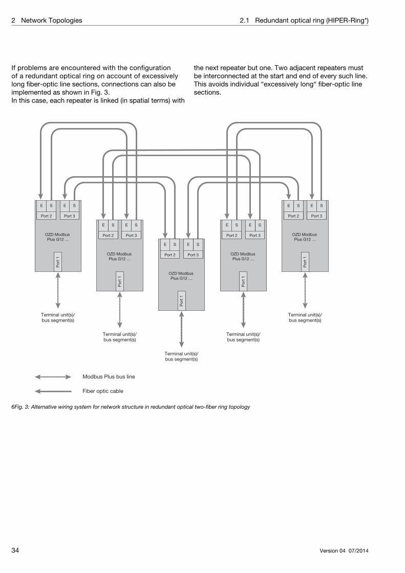
6Fig. 3: Alternative wiring system for network structure in redundant optical two-fiber ring topology
Modbus Plus bus line
Fiber optic cable
Terminal unit(s)/bus segment(s)
Port 3
SE
OZD Modbus Plus G12 …
Port 2
SE
Por
t 1
Terminal unit(s)/bus segment(s)
Port 3
SE
OZD Modbus Plus G12 …
Port 2
SE
Por
t 1
Terminal unit(s)/bus segment(s)
Port 3
SE
OZD Modbus Plus G12 …
Port 2
SE
Por
t 1
Terminal unit(s)/bus segment(s)
Port 3
SE
OZD Modbus Plus G12 …
Port 2
SE
Por
t 1
Terminal unit(s)/bus segment(s)
Port 3
SE
OZD Modbus Plus G12 …
Port 2
SE
Por
t 1
If problems are encountered with the configuration of a redundant optical ring on account of excessivelylong fiber-optic line sections, connections can also beimplemented as shown in Fig. 3.In this case, each repeater is linked (in spatial terms) with
the next repeater but one. Two adjacent repeaters mustbe interconnected at the start and end of every such line.This avoids individual “excessively long“ fiber-optic linesections.

2.2 Line topology without redundancy
35
2 Network Topologies
Version 04 07/2014
Fig. 4: Line topology without redundancy
Modbus Plus bus line
Fiber optic cable
Terminal unit(s)/bus segment(s)
Terminal unit(s)/bus segment(s)
Terminal unit(s)/bus segment(s)
Terminal unit(s)/bus segment(s)
Port 3
SE
OZD Modbus Plus G12 …
Port 2
SE
Por
t 1
Port 3
SE
Port 2
SE
OZD Modbus Plus G12 …
Por
t 1
Port 3
SE
OZD Modbus Plus G12 …
Port 2
SE
Por
t 1
Port 3
SE
OZD Modbus Plus G12 …
Port 2
SE
Por
t 1
This network topology is used in the case of an opticallink between data terminal units or bus segments.
As many repeaters as required can be operated in anoptical line. For the safe and reliable operation of the ring redundancy, it is necessary that at least one activeterminal unit is connected to the electrical port (Port 1) of each OZD Modbus Plus G12 … Repeater.
The first and last repeater in the line should be terminatedwith an “optical short-circuit“ (see Fig. 4). In this case,each input and output of the free ports are connected toBFOC connectors via a short length of optical cable.
2.2 Line topology without redundancy

2 Network Topologies
36 Version 04 07/2014

3.1 Installation guidelines
37
3 Start-Up
Version 04 07/2014
3 Start-Up
Interference suppression of switched inductances
� Suppressing switched inductances with fuses:Switching inductances, e.g. in relays and fans,generates interference voltages which are manytimes higher than the switched operating voltage.These interference voltages can affect electronicdevices. The interference voltages of inductances must belimited at their source of emission by means offuses (by connecting diodes or RC elements). Onlyuse interference suppressors which are intendedfor the used relays and fans.
� Cabinet lighting:Use filament lamps (e.g. LINESTRA lamps) for thecabinet lighting. Do not use fluorescent lampsbecause they generate interference fields. If the use of fluorescent lamps cannot be avoided, theinterference suppression measures shown in Fig. 5must be implemented.
Electromagnetic compatibility (EMC)
Electromagnetic compatibility (EMC) covers all aspectsregarding the effects of radiated and received electrical,magnetic, and electromagnetic emissions. In order to prevent interference in electrical systems,
these effects must be reduced to a minimum.The structural design and correct connection of bus linesas well as the interference suppression of switchedinductances play a major role in limiting interference.
3.1 Installation guidelines
Shield grid over lamp
Shielded cable
Metal-encased switch
Mains filter or shielded mains cable
Fig. 5: Interference suppression of fluorescent lamps in cabinet
Arrangement of devices and cables
� Reducing interference by providing adequatespace:A simple yet effective way of reducing interferenceis to separate devices and cables causing inter -ference from those affected by interference. Inductive and capacitive interference injectiondecreases by the square of the distance betweenthe elements concerned. This means that doublingthe distance reduces the interference by a factor of 4.If the arrangement of the various elements in a building or in the switch cabinet is taken into con -sideration at the planning stage, the cost of thenecessary interference suppression measures isgenerally very low.
� Please note:Between an OZD Modbus Plus G12 … and a powerswitching element (e.g. contactor, relay, temperatureregulator, switch, etc.) a minimum separation of15 cm is to be maintained. This minimum separation is to be measured bet-ween the outer edges of the components and in alldirections around an OZD Modbus Plus G12 … . The power supply wires (+24 VDC and m/0 V) forthe OZD Modbus Plus G12 … must not be laid inthe same cable duct as cables for load circuits. The wires (+24 VDC and m/0 V) should be twistedtogether.

3 Start-Up
38 Version 04 07/2014
3.1 Installation guidelines
Shield connections
Always observe the following points when installing busline shielding:
� Secure the shield braid using metal cable clamps. � The clamps must fully enclose the shield and make
good contact (see Fig. 6). � Only connect the Modbus Plus bus lines via the
copper braid shield, and not via the aluminum foilshield. One side of the foil shield is attached to aplastic film to increase its tearing strength, and istherefore non-conductive!
� The shields of all cables which are routed into acabinet from the outside must be clamped at thepoint of entry inside the cabinet and connected tothe cabinet ground with a large contact surfacearea.
� When removing the cable jackets, it is important toensure that the braid shield of the cables is notdamaged. Tin-plated or galvanically stabilized surfaces are ideal for optimum contacting betweengrounding elements. With zinc-plated surfaces, suitable threaded connections must be provided forthe required contacts. Painted surfaces at the con-tact points are unsuitable.
� Shield clamps/contact points should not be usedas strain relief devices. Contact with the shield buscould otherwise deteriorate or break completely.
� Standard recommendations for the arrangement ofdevices and cables:EN 50174–2 contains recommendations for arran-ging devices and cables which are aimed at redu-cing mutual interference to a minimum.
� Using bus line shields:It is important to observe the following when shielding bus lines:
� - Use only fully shielded Modbus Plus bus lines.The shields of these lines must be of sufficientthickness to satisfy the legal requirements forinterference radiated and interference received.
� - Always attach the shields at both ends of the buslines. The legal requirements vis-à-vis interferenceradiated and interference received for your systemwill only be satisfied if shields are connected atboth ends (CE symbol).
� - Attach the shield for the bus line at the connectorplug housing or at the cable clamps provided.
� - In the case of steady-state operation, it is advisableto strip the shielded line entirely and connect itwith the shielding bus/protective conductor rail.
Note:
If differences in potential occur between the groun-ding points, an inadmissibly high compensating current could flow across the shielding connected atboth ends. Never eliminate this problem by removingthe shielding from the bus line! The following solution is permissible:Lay an additional equipotential bonding cable parallelto the bus line. This additional cable will carry theshield current.
Fig. 6: Securing shielded lines using cable clamps and tubeclips (schematic diagram)

� Use a duplex fiber-optic cable with BFOC/2.5 (ST ®)connectors to connect the individual repeaters.
� Pay attention to the maximum cable length of thefiber-optic cable as well as the possible types offibers specified in the Technical Data.
� Make sure that each optical input a is connected toan optical output J at the opposite end (“cross-overlink“).The corresponding BFOC sockets of the two ports aremarked on the lower front panel.
� Ensure sufficient strain relief for the fiber-optic cablesand pay attention to their minimum bending radii.
� Unused BFOC sockets are to be covered with theprotective caps supplied. Incident ambient light and,in particular, great ambient brightness, can affect thenetwork.The penetration of dust may impair operation of theoptical components
I
J
I
J
Port 2
Port 3
Fig. 7: View of underside of repeater with optical ports 2 and 3
The repeater OZD Modbus Plus G12 … can either bemounted on a 35 mm DIN rail as per IEC 60715: 1981 +A1: 1995 or directly on a flat surface.
� The installation location is to be selected so as toensure compliance with the climatic limit values givenin the Technical Data.
� Make sure there is sufficient space for connection ofthe bus and power supply lines.
� To facilitate installation of the fiber-optic cables, they are to be connected before the repeaters aremounted.
� If possible, the repeaters should only be installed on amounting plate or DIN rail with low-impedance and
Port 1
Groundingscrew
Fig. 8: Position of grounding screw
low-inductance grounding. If the mounted DIN railand mounting plate are insulated, the repeater mustbe provided with a low-impedance and low-inductan-ce ground connection directly via the groundingscrew.
3.2 Connection of optical bus lines
39
3 Start-Up
Version 04 07/2014
3.2 Connection of optical bus lines
3.3 Mounting repeaters

3 Start-Up 3.2 Mounting repeaters
40 Version 04 07/2014
Mounting on DIN rail
� Engage the upper snap-in hooks of the repeater in the DIN rail and press the underside (as shown in Fig. 9) onto the rail until it engages.
� Disassembly involves pulling down the locking slide.
Mounting on mounting plate
The repeater has three through-holes to permit mountingto any flat surface, e.g. on the mounting plate of a switchcabinet.
� Make three holes in the mounting plate corres pondingto the drilling template in Fig. 10.
� Secure the repeaters with machine bolts (e.g. M 3 x 40).
� Ensure reliable electrical connection between therepeater housing and the mounting plate. Place toothed washers under the bolt heads to pierce thevarnish.
Lockingslide
Toothed washer
Port 1
System
Port 1
Port 2
Port 3
i OZDModbus Plus 61.2 mm
40.6
mm
81.2
mm
Ø 3 mm
Ø 3 mm
Fig. 9: Mounting repeater on DIN rail Fig. 10: Mounting repeater on mounting plate

3.4 Connection of electrical bus lines
41
3 Start-Up
Version 04 07/2014
� The Modbus Plus repeater should only be suppliedwith a regulated safety extra-low voltage to IEC 950/EN 60950/VDE 0805 of +24 V to max. +48 V +10%.
� To enhance operational reliability, a redundant supplyfrom various sources is provided. The operating voltages can be supplied in two ways:
– via terminal +24 V/48 V of the terminal block
– via terminal +24 V/48 V* of the terminal block
The common negative connection in the middle of theterminal block is indicated by m (0 V).
� The two voltages can have any (even different) valueswithin the specified limits of +24 V/+48 V.
� If no signaling contact lines are connected to the terminal block (see 3.6):Secure the terminal block by screwing on the flange.
6 / n.c.
7 / n.c.
8 / n.c.
9 / n.c.
Shield / 1
Data / 2
Data / 3
n.c. / 4
n.c. / 5
Fig. 11: Port 1 - assignment of Sub-D connector
� Only use approved shielded twisted pair cable for Modbus Plus bus wiring, e.g., Modicom ”SuperCable“, FT4, FT6.
� The electrical Modbus Plus interface (Port 1) is a 9-pole Sub-D connector (female).The pin assignment complies with the Modbus PlusStandard.
� A line which is fitted with 9-pole Sub-D connectors
(male) should be used to connect data terminal equip-ment. Max. length 100 m.
� The electrical port must not be internally termi nated.The external termination must be provided in or on the connector of the bus line in accordance with theModbus Plus Standard.
� The bus connection plug should be secured usingscrews.
3.4 Connection of electrical bus lines
3.5 Connection of power supply
z Warning!
� The shielding of the Sub-D connector is made ofmetal to ensure safe ground current conduction andmust therefore be conductively connected to theshielding plate of the connector attached to thecable.
� Modbus Plus bus lines must not be used to connectModbus Plus repeaters to system components towhich a different ground potential is being applied.
Voltage differences > 500 V could destroy the repeaters or cause the system to malfunction!
� Modbus Plus bus lines which are completely or partiallyinstalled outdoors should not be connected, other -wise any lightning strikes in the immediate vicinitycould destroy the repeaters. Optical cables should be used for bus connectionswhich are routed out of buildings!

3 Start-Up 3.5 Connection of power supply
42 Version 04 07/2014
� Floating contacts of a relay are provided as signalingcontact at the 5-pole terminal block.If the OZD Modbus Plus G12 … is functioning correctly,the relay contact is open.If a fault or power failure occurs, the relay is closed for at least 500 ms.
� The following network and repeater faults can besignaled at a master station:
Supply voltage– No voltage supply (with redundant supply: failure of
all supply voltages)
Internal device fault
Received data– Failure of receiving data at Port 2 and/or Port 3
(e.g. cable breakage)– Transceiver Port 1 faulty– No data received at any port for over 500 ms
� Limit values of relay contact– Max. switching voltage 60 VDC; 42 VAC– Max. switching current: 1.0 A– Max. switching capacity: 30 W
� The voltage connected to the relay must correspondto a safety extra-low voltage to IEC 950/EN 60 950/VDE 0805.
� Always ensure that the correct assignment is providedfor the 5-pole terminal block. Make sure that the connecting leads of the signaling contacts are ade -quately insulated. Incorrect assignment can result indestruction of the repeaters.
� Secure the terminal block by screwing on the flange
Securingflange
+24 V/48 V
0 V
+24 V/48 V*
Error
Fig. 13: Signaling contact - assignment of 5-pole terminal block
Fig. 12: Operating voltage supply - assignment of 5-pole terminal block
Securingflange
+24 V/48 V
0 V
+24 V/48 V*
Error
3.6 Connection of signaling contact lines
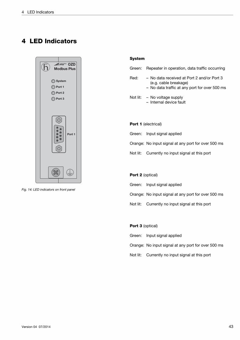
43
4 LED Indicators
Version 04 07/2014
4 LED Indicators
System
Green: Repeater in operation, data traffic occurring
Red: – No data received at Port 2 and/or Port 3 (e.g. cable breakage)
– No data traffic at any port for over 500 ms
Not lit: – No voltage supply– Internal device fault
Port 1 (electrical)
Green: Input signal applied
Orange: No input signal at any port for over 500 ms
Not lit: Currently no input signal at this port
Port 2 (optical)
Green: Input signal applied
Orange: No input signal at any port for over 500 ms
Not lit: Currently no input signal at this port
Port 3 (optical)
Green: Input signal applied
Orange: No input signal at any port for over 500 ms
Not lit: Currently no input signal at this port
Fig. 14: LED indicators on front panel
Port 1
System
Port 1
Port 2
Port 3
i OZDModbus Plus

5 Troubleshooting
44 Version 04 07/2014
5 Troubleshooting
LED indicator
System � Not lit
� Red
Port 1 � Not lit
� Orange
Port 2 � Not lit
� Orange
Port 3 � Not lit
� Orange
Possible causes
– Failure of supply voltage– Internal device fault
– No data received at Port 2 and/or Port 3, e.g. cable breakage– Port 1 faulty– No input signal received at any of the 3 ports for over 500 ms
– Currently no input signal at this port
– No input signal received at any of the 3 ports for over 500 ms
– Currently no input signal at this port
– No input signal received at any of the 3 ports for over 500 ms
– Currently no input signal at this port
– No input signal received at any of the 3 ports for over 500 ms
Signaling contact
Signal
Signal
Signal
Signal
Signal
Note
“Unlit“ port LEDs do not indicate a fault.

45
6 Technical Data
Version 04 07/2014
6 Technical Data
Repeater OZD Modbus Plus G12 OZD Modbus Plus G12-1300Ord. code 943 740-021 943 821-021Voltage/power supplyOperating voltage +24 VDC –20 % … +48 VDV +10 %, non-interchangeable,
electrically isolated from the housing, safety extra-low voltageCurrent input for +24 V 150 mA
for +48 V 85 mAPower consumption for +24 V 3.6 W
for +48 V 4.0 WSignaling contact
Maximum switch voltage 30 VDC; 42 VAC (safety extra-low voltage)Maximum switch current 1.0 A (resistive load)
Signal transmissionTransmission rate 1 MBit/sCascadability As requiredSignal processing time <1 µs (any input/output)Electrical portInput/output signal Modbus Plus levelPIN assignment of Port 1 See Section 3.4Length of Modbus Plus cable 100 mConnection capability Max. 31 terminal data devicesElectrical isolation
– Shielding/housing No– Data lines/shielding Yes
Optical interfaceTyp. wavelength 860 nm 1310 nmLaunchable optical power
– into fiber E 10/125 –19 dBm– into fiber G 50/125 –15 dBm –17 dBm– into fiber G 62.5/125 –14 dBm –17 dBm– into fiber S 200/230 (HCS ®) –10 dBm –
Receiver sensitivity –25 dBm –27 dBmTransmission distance with 2 dB 1) or 3 dB 2)
system reserve/ line attenuation– with fiber E 10/125 (0.5 dB/km) – 0 - 8 km*/8 dB 1)
– with fiber G 50/125 (1.0 dB/km) – 0 - 7 km/10 dB 2)
– with fiber G 62,5/125 (1.0 dB/km) – 0 - 7 km/10 dB 2)
– with fiber G 50/125 (3.0 dB/km) 0 - 2.3 km/10 dB –– with fiber G 62.5/125 (3.5 dB/km) 0 - 2.3 km/11 dB –– with fiber S 200/230 (HCS ®) (8.0 dB/km) 0 - 1.5 km/15 dB –
Optical connector BFOC/2.5 (ST ®)
* Because of the the ring redundancy‘s specific requirements, the distance between two OZD Modbus Plus G12-1300 must not exceed 8 km .

6 Technical Data
46 Version 04 07/2014
Repeater OZD Modbus Plus G12 OZD Modbus Plus G12-1300Ord. code 943 740-021 943 821-021Electromagnetic compatibility (EMC)Immunity for industrial environments according EN 61000-6-2:2001
Electrostatic discharge (ESD) Satisfies EN 61000-4-2; 4 kV contact discharge, 8 kV air discharge Electromagnetic field Satisfies EN 61000-4-3; 10 V/m (80 MHz - 1000 MHz)Fast transients (burst) Satisfies EN 61000-4-4; 2 kV power line, 1 kV data lineSurge SatisfiesEN 61000-4-5; 1 kV data lineLine-conducted disturbances Satisfies EN 61000-4-6; 10 V (150 kHz - 80 MHz)
Interference emissions Satisfies EN 55022; Class ASatisfies FCC CFR47 Part 15; Class A
Climatic ambient conditionsAmbient temperature 0 °C to +60 °C (IEC 60068-2-1, IEC 60068-2-2)Storage temperature –40 °C to +70 °C (IEC 60068-2-14)Relative humidity <95 %, non-condensing (IEC 60068-2-30)Mechanical ambient conditionsVibration (during operation) 10 to 58 Hz, 0.075 mm displacement;
58 to 150 Hz, 10 m/s2 (1 g) acceleration (IEC 60068–2–6)Vibration (during transport) 5 to 9 Hz, 3.5 mm displacement;
9 to 500 Hz, 10 m/s2 (1 g) acceleration
Protection class IP 40Weight approx. 620 gDimensions (W × H × D) 40 × 133 × 77 mmHousing material Die-cast zinc

47
7 Application Support
Version 04 07/2014
7 Application Support
Contact address for technical support
Hirschmann Automation and Control GmbH Stuttgarter Strasse 45 - 5172654 NeckartenzlingenGermanyTel.: +49 (0)1805 14-1538Fax: +49 (0)7127 14-1551E-Mail: [email protected]: http://www.hirschmann.com

7 Application Support
48 Version 04 07/2014

49
Port 1
System
Port 1
Port 2
Port 3
i OZDModbus Plus
ManuelInterface pour Fibre Optique OZD Modbus Plus G12 …
Fra
nçais

50 Version 04 07/2014
Nous avons vérifié la concordance du contenu de l’im primé avec les matériels et logiciels décrits. Des différen ces n’étant cependant pas exclues, nous negarantissons pas une con cordance totale. Les informations de l’imprimé font néanmoins l’objet devérifications régu lières. Les corrections nécessaires setrouvent dans les tirages ultérieurs. Merci pour toute suggestion d’amélioration.
Sous réserve de modifications techniques.
Sauf autorisation expresse, la transmission de ce docu-ment, sa reproduction, utilisation et communication deson contenu sont interdits. Tout manquement à cetterègle expose son auteur au versement de dommages etintérêts. Tous droits réservés, en particulier en cas dedélivrance de brevets ou d’enregistrement de modèled’utilité.
© Hirschmann Automation and Control GmbH 2014
Tous droits réservés
RemarqueNous attirons votre attention sur le fait que le contenu du présent mode d’emploi n’est pas partie intégranted’accords, engagements ou rapport juridiques passés ouprésents, et ne saurait donc modifier de tels accords,engage ments ou rapports. Toutes les obligations incom -bant à Hirschmann découlent du contrat de vente conclulors de l’acquisition de l’appareil, où figurent égalementles clauses intégrales, et seules valables, de garantie.Cette garantie contractuelle n’est ni élargie ni restreintepar le présent mode d’emploi.
Nous signalons également que pour des raisons de clarté dans ce mode d’emploi, il n’est pas possible dedécrire toutes les problématiques concevables en liaisonavec l’utilisation de cet appareil. Si vous avez besoind’informations complémentaires ou si vous êtes con-fronté à des problèmes particuliers qui ne sont pastraités suffisamment en détails dans ce mode d’emploi,vous pouvez contacter le distributeur Hirschmann devotre région ou directement Hirschmann pour obtenir lerenseignement requis (consulter la section ”Remarquesur le marquage CE“ pour l’adresse).
Remarques relatives à la sécuritéCe manuel contient des remarques que vous devezobserver pour votre sécurité personnelle ainsi que pouréviter des dommages matériels. Ces remarques sontmises en évidence par un panneau triangulaire d’avertis-sement et représentées comme suit en fonction du degréde risque:
z Danger!Ce symbole signale les mesures de précautiondont le non-respect entraîne inévitablement lamort, des blessures graves ou des dommagesmatériels considérables.
z Avertissement!Ce symbole signale les mesures de précautiondont le non-respect peut entraîner la mort, desblessures graves ou des dommages matérielsconsidér ables.
z Attention!Ce symbole signale les mesures de précautiondont le non-respect peut entraîner des blessureslégères ou desdommages matériels.
Remarque: Ce symbole signalise une information importante sur le produit, le maniement du produit ou la partie de ladocumentation demandant une attention particulière.
Exigences relatives à la qualification dupersonnelRemarque: Dans ce mode d’emploi ou dans les avertisse ments, onentend par ”personnel qualifié“ les personnes familiariséesavec l’installation, le montage et la mise en service de ceproduit et disposant des qualifications correspondant àleur activité, comme:
– une formation, une instruction ou une habi litation quiles autorisent à brancher/débrancher, mettre à la terreou repérer des circuits électriques, des appareils oudes systèmes conformément aux normes actuelles dela technique de sécurité;
– une formation ou une instruction conforme aux normesactuelles de la technique de sécurité en matièred’entretien et d’utilisation des équipements de sécurité;
– une formation de secouriste.
Consignes générales de sécurité� Cet appareil fonctionne à l’électricité. Observez
scrupuleusement les exigences de sécurité prescritesdans ce mode d’emploi en fonction des tensions àmettre en œuvre.
� Vérifiez la conformité de l’installation électrique avecles consignes locales ou nationales de sécurité.
z Avertissement!Une non-observation des avertisse ments est sus-ceptible de provoquer des blessures graves et/oudes dom mages matériels. Seul du personnel qualifié est autorisé à travaillersur cet appareil ou à proximité. Ce personnel doitêtre parfaitement familiarisé avec tous les avertis

51Version 04 07/2014
sements et mesures d’entretien conformément àce mode d’emploi. Le fonctionnement exempt dedéfauts et sûr de cet appareil suppose un trans-port adéquat, un stockage et un montage dans lesrègles de l’art ainsi qu’une utilisation et une main-tenance soigneuses.
z Avertissement!Les travaux éventuellement nécessaires surl’installation électrique ne doivent être effectuésque par du personnel spécialisé formé à cet effet.
z Avertissement!OZD Modbus Plus G12:LASER RADIATIONDO NOT VIEW DIRECTLY WITH OPTICALINSTRUMENTSCLASS 1M LASERPRODUCT in accordance withIEC 60825-1 (2007).OZD Modbus Plus G12-1300:Selon toutes les circonstances normalement prévi-sibles, la puissance de rayonnement optiqueaccessible des composants utilisés ne possèdeaucun potentiel de risque.CLASS 1 LASERPRODUCT in accordance withIEC 60825-1 (2007).
Utilisation conformeVeuillez tenir compte des points suivants:
z Avertissement!L’utilisation de l’appareil n’est autorisée que dansle cadre des cas d’utilisation prévus dans le cata-logue et la descrip tion technique et seulement enliaison avec les composants et appareils externesrecommandés ou agréés par Hirschmann. Le fonctionnement exempt de défauts et sûr du pro-duit suppose un transport adéquat, un stockage,une mise en place et un montage appropriés, ainsiqu’une utilisation et une maintenance soigneuses.
Consignes de sécurité tension d’alimentation� Ne mettez l’appareil en marche que lorsque le boîtier
est fermé.
z Avertissement!Raccordez les appareils uniquement à la tensiond’alimentation apposée sur la plaque signalétique. Les appareils sont conçus pour fonctionner àbasse tension de sécurité. En conséquence, seulsdes circuits de tension PELV ou bien des circuitsSELV avec les restrictions de tension conformé-ment à IEC/EN 60950 peuvent être raccordés auxconnexions d’alimen tation ainsi qu’au contact designalisation.
� Pour le cas où vous devez exploiter le module avecune tension d’origine indépendante: n’alimentez lesystème qu’avec une basse tension de sécurité selonIEC/EN 60950.
Concerne l’Amérique du Nord:� Ce produit est conçu pour être alimenté par une sour-
ce d’alimentation de classe 2 répondant aux exigen-ces du code électrique national, tableau 11(b). En casde fourniture redondante du courant (deux sourcesindividuelles de courant), les sources de courantmises ensemble doivent répondre aux exigences ducode électrique national 11(b).
� Utiliser uniquement un conducteur cuivre (Cu)60/75°C ou 75°C.
Consignes de sécurité sur le milieu d’utilisation
z Avertissement!Il est interdit de faire fonctionner l’appareil à unetempérature ambiante et à une humidité relative(sans con densation) autres que celles indiquéesdans les caractéristiques techniques.
� Sélectionnez le site de montage de telle sorte que leslimites climatiques mention nées dans les caractéri-stiques techniques soient respectées.
� Utilisation seulement dans un environnement d’undegré de pollution 2 (IEC 60664-1).
Consigne de sécurité du boîtier
z Avertissement!L’ouverture du boîtier est exclusivement réservéeaux techniciens agréés par Hirschmann.
Normes et standards appliquésLes appareils répondent aux normes et standards suivants: – EN 61000-6-2:2001 Normes génériques –
Immunité pour les environments industries– EN 55022:1998 + A1 2000 – Appareils de traitement
de l’information – Caractéristiques des pertu bationsradioélectriques
– EN 60950:1997 – Matériels de traitement de l’informa -tion - Sécurité
– EN 60825-1 Sécurité des appareils à laser– FCC 47 CFR Part 15:2000 – Code of Federal
Regulations– ANSI/ISA 12.12.01-2012, Nonincendive Electrical
Equipment for Use in Class I and II, Division 2 andClass III, Division 1 and 2 Hazardous (Classified) Loca-tions.
– C22.2 No. 142-M1987 and CSA C22.2 No. 213-M1987,Non-incendive Control Equipment for Use in Class I,Division 2 Hazardous Locations.

52 Version 04 07/2014
Remarque relative au marquage CE
7 Les appareils répondent aux consignes de ladirective européenne suivante:
89/336/CEE Directive du conseil concernant le rapprochement deslégislations des états membres sur la compatibilitéélectro magnétique (modifiée par les directives91/263/CEE 92/31/CEE et 93/68/CEE).
La condition du respect des limites CEM est le respectstrict des directives de montage indiquées dans ladescription et manuel d'utilisation.
Conformément aux directives UE susmentionnées, ladéclaration de conformité UE est mise à la dispositiondes autorités compétentes à:
Hirschmann Automation and Control GmbHStuttgarter Strasse 45 – 5172654 NeckartenzlingenAllemagneTéléphone +49 (0)1805 14-1538E-Mail [email protected]
Le produit est utilisable en zone d’habitation (zone rési-dentielle, zone d’activité ou artisanale, ainsi que petiteset moyennes entreprises) ainsi qu’en zone industrielle.- Résistance aux interférences:
EN 61000-6-2:1999- Emission d’interférences:
EN 55022:1998 Class A
Avertissement!Ceci est une installation de classe A. Cette installationpeut provoquer des émissions parasites en zonerésidentielle; dans ce cas, il peut être demandé àl’exploitant, de prendre à sa charge les mesuresappropriées.
Règlement de la FCC
Cet appareil est conforme à la section 15 du règlementde la FCC. Son exploitation doit remplir les deux conditi-ons suivantes:
(1) Cet appareil ne doit émettre aucune interférence nui-sible et(2) Cet appareil doit accepter toute interférence reçue, ycompris les interférences pouvant affecter son fonc-tionnement.
Remarque: cet équipement a subi des tests et a étédéclaré conforme aux limites imposées aux appareils
numériques de classe A, en vertu de la section 15 durèglement de la FCC. Ces limites ont été prévues pourassurer une bonne protection contre les interférencesnuisibles dans les installations chez les particuliers. Cetéquipement génère, utilise et peut émettre une énergieradiofréquence et, s’il n’est pas installé et utilisé confor-mément au mode d’emploi, peut produire des interféren-ces affectant les communications radio. Cependant, iln’est pas garanti qu’aucune interférence ne se produiralors de son utilisation dans une zone résidentielle, danslequel cas l’utilisateur est tenu de remédier aux inter-férences à ses propres frais.
ADAPTÉ POUR UNE UTILISATION ENAMÉRIQUE DU NORD:CES DISPOSITIFS SONT DES DISPOSITIFS DE TYPEOUVERT QUI DOIVENT ETRE INSTALLES DANS UNEENVELOPPE ADAPTEE A L'ENVIRONNEMENT.
Seulement OZD Modbus Plus G12:
UNIQUEMENT POUR UTILISATION DANS DES EMPLA-CEMENTS DANGEREUX DE CLASSE I, DIVISION 2,GROUPES A, B, C, D OU DES EMPLACEMENTS NONDANGEREUX.
LE CABLAGE DOIT ETRE CONFORME AUX REGLES DECABLAGE CLASSE I, DIVISION 2 ET CONFORME AL'AUTORITE AYANT JURIDICTION.
POUR UTILISATION DANS DES EMPLACEMENTS DAN-GEREUX DE CLASSE I, DIVISION 2, REPORTEZ-VOUS ALA SCHEMA DE CONTROLE N° 000100622DNR A LAPAGE SUIVANTE.
C-TickAustralia/New Zealand
This product meets the requirements of theAS/NZS 3548 standard.
N1337
Remarque relative au recyclage
, En fonction de son utilisation, ce produit doit suivrela filière régulière d’élimination en tant que déchet électronique selon les consignes d’éliminationactuelles de votre district /pays /état.

53Version 04 07/2014
� �
� � ����������� �����
� ��������������� ���������������������� ���������� ���� ���
�������
��
��������������������������������� ������������ !��"#"�"$�%!� �$�����!�&!��!������������������������������������'�����
������������������������������� ��� �������������������������!���������"�����!���#$������������������� ��� ���������������������!���#$������������������� ��� ������������������� ���#�%��!������!������ ��#&��� ����������������� #� �������� ����������� �������� ��# '���� $���������� ��������� ���������(�� � ���������� �������"�(��� ���)��"�*���+,�� ����"#"�(��� ���)��"�*���+,����������������"�������������������)����#�����#������������(��� ��*����+�-�.��$ �������/�����+,��0�-��1�".�2��+,������-,.��$ �������/�����+,��0�-��1�".�2��+,�������*������������ ������������,�-���,�-� !�����$���� �������+�!�����������������#�������������������������� #�� ����� �+�������������������#�������������������������� #���� ����� ������(�� ������ ����� ���������� �%��.�/�0�/���������1���1��� ������2����� ������� ������������ ��� ����������������� ����*���)�������# �������#������� ����.�������3�����$���,.4 -'�.����21'��������51����
���������3����4�������+,�� ������"��$�"5�����,�����4�� 6.7� 7��84��/��93�4.94.7�94����8�:;784��3�4 78/<�4����/=�.7��+�
6���� ���� �"� �"�>1�=� ?1���� �11���� 5��@�
����
������ ���7�� �89���:�;3��� ���7�����9&�� �9� ��������9�����3������3�9���<<�������:�3� �9����������9� � ��������������3�������������=���9;��9����������3�������;3��� &���/�������� ���7�� �89���:�;3��� ���7����3����������������:�89 3������� ��:�� ������ ��������9������:����3������ �����9�� ����>�����:����3�������9���������������=���9��/�����3����96� ������89: ��������9������ ���?����@(������$��A���$��� ��5����$������(�(����$��"'����>���$�,���3����=B%�������#����%��.�/�0�/���������1�A�1��� �8#*��+�>� 9��+�1>A��A�1�>� 9��������B�+�111�11C��9.8� � ��
��3����������������=���9;������������������������������� �
B
B
<���5�$������<�����$"����
�������
�������� �����>�
1=�
D�E=0EF=�
���� ������ �+�3$��������� ���#�+�3$��������%������(�� ������������ ��� �������������������
�������������������������������������������������
B �
D�E=0EF=�
��� ��� �����#� �+� �������+�#�����$��� ���������>�+����$����
���������������� ����+���,8�������+������-�������E=9 �0�EF=9 �����������

54 Version 04 07/2014
Sommaire
1 Introduction . . . . . . . . . . . . . . . . . . . . . . . . . . . . . . . . . . . . . . . . . . . . . . . . . . . . . . . . . . 55
2 Topologies de réseaux . . . . . . . . . . . . . . . . . . . . . . . . . . . . . . . . . . . . . . . . . . . . . . . . . . . . . 57
2.1 Boucle optique avec redondance (HIPER-Ring) . . . . . . . . . . . . . . . . . . . . . . . . . . . . . . . . . . . . . . 572.2 Topologie de lignes sans redondance . . . . . . . . . . . . . . . . . . . . . . . . . . . . . . . . . . . . . . . . . . . . . . 59
3 Mise en service . . . . . . . . . . . . . . . . . . . . . . . . . . . . . . . . . . . . . . . . . . . . . . . . . . . . . . . . . . 59
3.1 Instructions de montage . . . . . . . . . . . . . . . . . . . . . . . . . . . . . . . . . . . . . . . . . . . . . . . . . . 613.2 Raccordement de lignes de bus optiques . . . . . . . . . . . . . . . . . . . . . . . . . . . . . . . . . . . . . 633.3 Montage des Interfaces . . . . . . . . . . . . . . . . . . . . . . . . . . . . . . . . . . . . . . . . . . . . . . . . . . . 633.4 Raccordement des lignes de bus électrique . . . . . . . . . . . . . . . . . . . . . . . . . . . . . . . . . . . 653.5 Raccordement de la tension d’alimentation . . . . . . . . . . . . . . . . . . . . . . . . . . . . . . . . . . . . 653.6 Raccordement des lignes de contact de défaut . . . . . . . . . . . . . . . . . . . . . . . . . . . . . . . . 66
4 Affichages par DEL . . . . . . . . . . . . . . . . . . . . . . . . . . . . . . . . . . . . . . . . . . . . . . . . . . . . . . . . 67
5 Dépannage . . . . . . . . . . . . . . . . . . . . . . . . . . . . . . . . . . . . . . . . . . . . . . . . . . . . . . . . . . 68
6 Caractéristiques techniques . . . . . . . . . . . . . . . . . . . . . . . . . . . . . . . . . . . . . . . . . . . . . . . . 69
7 Références utiles . . . . . . . . . . . . . . . . . . . . . . . . . . . . . . . . . . . . . . . . . . . . . . . . . . . . . . . . . 70
Sommaire

55
1 Introduction
Version 04 07/2014
1 Introduction
L’interface pour fibres optiques OZD Modbus Plus G12 … a été conçu pour être utilisé dans des réseaux de bus de terrain Modbus Plus. Il permet de convertir des signaux Modbus Plus électriques en signaux Modbus Plusoptiques et inversement.
Il est possible d’intégrer les Interfaces dans des réseaux de bus électrique de terrain existants. Il est égalementpossible de monter intégralement un réseau ModbusPlus optique dans des topologies de ligne ou de boucleavec des Interfaces OZD Modbus Plus G12 … .
Du point de vue mécanique, l’appareil se compose d’unboîtier métallique compact et robuste qui peut êtremonté au choix sur un rail DIN ou sur un support platquelconque.
Il est inutile d’effectuer des réglages pour réaliser la miseen service.
Ports
L’interface est équipé de trois canaux indépendants(ports), composés à leur tour d’un émetteur et d’unrécepteur.Le port 1 est un connecteur Sub-D (femâle) à 9 pôles, les ports 2 et 3 sont des connecteurs optiques BFOC/2,5 (ST ®).
Alimentation en tension
L’alimentation en tension de fonctionnement est réalisée aumoyen d’une tension continue de +24 VDC à +48 VDC. Une alimentation en tension de fonctionnement redon-dante issue de deux sources différentes est prévue pouraugmenter la sécurité de fonctionnement. A cet effet, lesdeux tensions de fonctionnement peuvent être reliées àdeux bornes différentes du bornier 5 pôles. Les deux raccordements sont découplés grâce à desdiodes, afin d’éviter toute alimentation de retour oudestruction par inversion des pôles. Une répartition des charges n’est pas réalisée entre lessources. Dans le cas d’une alimentation redondante,l’appareil secteur doit alimenter à lui seul l’adaptateur de bus au moyen d’une tension de sortie plus élevée.
Contact de signalisation
Un contact de signalisation permet de signaler certainesdéfaillances du Interface (relais à contacts sans potentiel).Les raccordements du contact de signalisation sontégalement réalisés sur le bornier 5 pôles.
DEL
Quatre diodes électroluminescentes bicolores signalentl’état de fonctionnement actuel et les éventuelles défaillances de fonctionnement.
Port 1
System
Port 1
Port 2
Port 3
i OZDModbus Plus
Bornier 5 pôles pour alimentation en tension de fonctionnement et contact de signalisation
Affichage par LED
Vis de terre
Port 3Optique,BFOC/2,5Connecteur
Port 2Optique,
BFOC/2,5Connecteur
Port 1électrique, raccordement sub-D
Fig. 1: Interface pour fibre optique OZD Modbus Plus G12 …, position des différents ports, du bornier, des DEL et de la vis de terre

1 Introduction
56 Version 04 07/2014
Technique de fibre optique
L’utilisation de la technique de transmission par fibres de verre permet de couvrir une très grande portée etoffre une protection optimale contre les effets de la compatibilité électromagnétique, aussi bien sur le trajetde transmission que sur l’interface lui-même – en raisonde la séparation de potentiel.
Vitesse de transmission
L’interface pour fibre optique OZD Modbus Plus G12 …fonctionne à la vitesse de transmission de 1 MBit/s.
Régénération du signal
L’interface pour fibre optique OZD Modbus Plus G12 …régénère la forme de signal et l’amplitude des donnéesreçues. Grâce à cette fonction, il est possible de relier en cascade un nombre quelconque d’interfaces aumoyen de connexions par guides d’ondes lumineuses.
Redondance
Une sécurité de transmission très élevée est obtenuegrâce à la transmission redondante du signal. La sécurité de fonctionnement peut être encore augmentéegrâce à une tension d’alimentation redondante.
Protocole Modbus Plus
Dans une topologie correspondant aux figures 2, 3 et 4(chapitre 2), un temps de réponse doit être pris en comptesur le maître et sur les terminaux.Les données transmises sont retournées à chaque portoptique par l’appareil suivant. Ce retour permet de surveiller la ligne et de contrôler la boucle.Le temps de réponse se compose du temps écoulé dansla fibre optique (5 ns/m), du temps passé dans un Inter -face (<1 µs) et un temps de repos de 5 µs dépendant del’appareil.
tréponse = (2 • l [m] • 5 ns/m) + 1 µs + 5 µs= (10 µs/km • l [km]) + 1 µs + 5 µs
avec
l = distance maximale entre deux interface OZD Modbus Plus G12 … voisin.
Exemple:
Dans le cas d’une distance maximale entre deux OZDModbus Plus G12 … voisin de 2,3 km, on obtiendra letemps de réponse suivant:
tréponse = (2 • 2300 m • 5 ns/m) + 1 µs + 5 µs= (10 µs/km • 2,3 km) + 1 µs + 5 µs= 29 µs
Les différences entre Modnet, Modbus et Modbus Plus
L’ancienne société AEG a mis sur le marché le Modnet,un système de communication complet pour la techniqued’automatisation. Ce système n’est pas seulement unsimple système de bus, mais un système de communi-cation avec trois classes de performance. Selon les différentes exigences des installations, ces classes deperformance s’appliquent depuis le domaine de systèmesproches du processus jusqu’aux structures de communi-cation backbone.
Classe 1:Communication objet Modnet1/M+
Classe 2:Communication système Modnet1/P, Modnet1/IS,
Modnet1/SFBClasse 3:
Communication backbone Modnet3/MMSE
Il s’agit de:
Modnet1/M+: Low-cost-Bus, Modbus PlusModnet1/P: Bus de système terrain selon
norme ProfibusModnet1/IS: Bus de système et bus de capteur-
actionneur selon norme InterbusModnet1/SFB: Bus de système terrain selon
norme BitbusModnet3/MMSE: Système de communication pour
niveaux supérieurs selon IEEE802.3 et MAP (MMS sur Ethernet)
Modbus est une structure d’information définie pour lacommunication maître-esclave, largement répandue. Uneinformation Modbus, transmise du maître à l’esclave,contient l’adresse de l’esclave en question, l’ordre, lesdonnées et une somme de contrôles d’erreurs. ModbusRTU et Modbus ASCII sont différents codages de données.Comme seul le format de données est défini, un moyenquelconque (RS232, RS422, RS485 câble cuivre, fibresoptiques) peut être utilisé. Les convertisseurs fibres-optiquesOZDV 24 … , OZDV 114 et OZD 485 .., conviennent.
Modbus Plus est une définition complète de protocoleet de réseau. Modbus utilise la structure de commandeModbus, mais il transmet les commandes accompagnéesd'un Token, qui est rapidement transmis par un participantdu réseau au suivant. Modus Plus définit de quelle façonle Token est transmis, comment les renouvellements decommande sont effectués, comment les données et leserreurs sont contrôlées et comment ces erreurs sontensuite affichées et naturellement l’exécution complètedes interfaces physiques, ceci concerne également lescâbles et l’infrastructure du réseau (tabs, bridges, rési-stance terminale, …). L’objectif est un véritable systèmede bus de terrain ”plug and play“.

2.1 Boucle optique avec redondance (HIPER-Ring)
57
2 Topologies de réseaux
Version 04 07/2014
2 Topologies de réseaux
2.1 Boucle optique avec redondance (HIPER-Ring*)
Fig. 2: Structure de réseau dans une topologie de boucle biphasée optique redondante
Ligne de bus Modbus Plus
Câble à fibres optiques
Terminal (terminaux)/Segment(s) de bus
Terminal (terminaux)/Segment(s) de bus
Terminal (terminaux)/Segment(s) de bus
Terminal (terminaux)/Segment(s) de bus
Port 3
SE
OZD Modbus Plus G12 …
Port 2
SE
Por
t 1
Port 3
SE
Port 2
SE
OZD Modbus Plus G12 …
Por
t 1
Port 3
SE
OZD Modbus Plus G12 …
Port 2
SE
Por
t 1
Port 3
SE
OZD Modbus Plus G12 …
Port 2
SE
Por
t 1
Cette topologie de réseau est utilisée pour réaliser uneliaison optique de terminaux ou de segments de bus. Il est possible d’obtenir une grande sécurité contre lesdéfaillances en utilisant une liaison redondante avec lesInterfaces OZD Modbus Plus G12 … .
Le nombre d’interfaces possible dans un HIPER-Ringn’est pas limité. Pour obtenir une fonction sûre et fiablede la redondance de la boucle, il est nécessaire qu’àchaque Repeater OZD Modbus Plus G12 …, soit raccordéau moins un appareil terminal actif, au port électrique(port 1).
La défaillance d’un câble à fibres optiques entre deuxInterfaces OZD Modbus Plus G12 … quelconques n’a aucune influence sur la disponibilité du réseau.Les Interfaces identifient la défaillance totale d’une voieoptique. Les DEL de port de la voie interrompue sontdésactivées et la défaillance est signalée par l’allumage de la DEL système rouge et le déclenchement du contactde signalisation de défaut.
Les câbles à fibres optiques duplex des deux canauxoptiques doivent être donc posés sur des voies différentes.
* HIPER-Ring = Hirschmann Performance Redundancy Ring

2 Topologies de réseaux 2.1 Boucle optique avec redondance (HIPER-Ring)
58 Version 04 07/2014
Fig. 3: Technique de câblage alternative d’une structure de réseau dans une topologie de boucle biphasée optique redondante
Ligne de bus Modbus Plus
Câble à fibres optiques
Terminal (terminaux)/Segment(s) de bus
Port 3
SE
OZD Modbus Plus G12 …
Port 2
SE
Por
t 1
Terminal (terminaux)/Segment(s) de bus
Port 3
SE
OZD Modbus Plus G12 …
Port 2
SE
Por
t 1
Terminal (terminaux)/Segment(s) de bus
Port 3
SE
OZD Modbus Plus G12 …
Port 2
SE
Por
t 1
Terminal (terminaux)/Segment(s) de bus
Port 3
SE
OZD Modbus Plus G12 …
Port 2
SE
Por
t 1
Terminal (terminaux)/Segment(s) de bus
Port 3
SE
OZD Modbus Plus G12 …
Port 2
SE
Por
t 1
Si des problèmes surgissent en pratique lors de l’établis-sement d’une boucle optique redondante, dus à des trajets partiels de cables à fibres optiques trop longs, il est également possible d’exécuter le câblage de lafaçon indiquée sur la figure 3.
Chaque Interface doit être, vu dans l’espace, raccordé à la suite du prochain Interface. Les Interfaces voisins doivent être reliés entre eux au début et à la fin d’uneligne de ce genre. De cette manière, il est possible d’éviter de réaliser des voies partielles de cables fibresoptiques trop longs.

2.2 Topologie de ligne sans redondance
59
2 Topologies de réseaux
Version 04 07/2014
Fig. 4: Topologie de ligne sans redondance
Ligne de bus Modbus Plus
Câble à fibres optiques
Terminal (terminaux)/Segment(s) de bus
Terminal (terminaux)/Segment(s) de bus
Terminal (terminaux)/Segment(s) de bus
Terminal (terminaux)/Segment(s) de bus
Port 3
SE
OZD Modbus Plus G12 …
Port 2
SE
Por
t 1
Port 3
SE
Port 2
SE
OZD Modbus Plus G12 …
Por
t 1
Port 3
SE
OZD Modbus Plus G12 …
Port 2
SE
Por
t 1
Port 3
SE
OZD Modbus Plus G12 …
Port 2
SE
Por
t 1
Cette topologie de réseau est utilisée pour raccorder demanière optique des terminaux ou des segments de bus.
Le nombre d’interfaces possible dans une ligne à fibresoptiques n’est pas limité. Pour obtenir une fonction sûreet fiable de la redondance de la boucle, il est nécessairequ’à chaque Repeater OZD Modus Plus G12 …, soit raccordé au moins un appareil terminal actif, au portélectrique (port 1).
Le premier et le dernier Interface de la ligne doit être terminés par un ”court-circuit optique“ (voir la figure 4).Pour ce faire, les entrées et les sorties des ports libressont reliées avec des connecteurs BFOC au moyen decâbles à fibres optiques courts.
2.2 Topologie de ligne sans redondance

2 Topologies de réseaux
60 Version 04 07/2014

3.1 Instructions de montage
61
3 Mise en service
Version 04 07/2014
3 Mise en service
Blindage d'inductances sous tension
� Mettre en place des extinctions d'arc pour inductances sous tension. La mise en circuit d'inductances, comme dans lesrelais ou ventilateurs, génère des tensions parasitesdont la valeur dépasse de loin la tension de service.Ces tensions parasites peuvent avoir des répercus-sions sur les appareils électroniques. Les tensions parasites d'inductances doivent êtreréduites à la source d'émission au moyen d'extinc-tions d'arc (câblage de diodes ou RC). N'utilisezque des moyens d'élimination de parasites conçuspour votre relais ou ventilateur.
� Eclairage de l'armoire de commande Utilisez pour l'éclairage de l'armoire de commandedes ampoules à incandescence comme celles parex. de la marque LINESTRA. Evitez l'utilisation detubes fluorescents car ceux-ci sont générateurs dechamps parasites. Le cas échéant, procédez à unmontage conforme à la Fig. 5.
Compatibilité électromagnétique (CEM)
La compatibilité électromagnétique (CEM) se rapporteaux effets de radiations électriques, magnétiques et électromagnétiques. Afin d'éviter toutes influences parasites dans les installa-tions électriques, ces effets de radiation doivent être
réduits au maximum. Ceci peut être obtenu en prenantcertaines mesures importantes comme un montage correct et un raccord conforme des câbles de bus ainsique le blindage d'inductances sous tension.
3.1 Instructions de montage
grille-écran au dessus de l'ampoule
câble blindé
commutateur entière-ment blindé au métal
filtre réseau ou alimentation secteur blindée
Fig. 5: Mesures antiparasitage pour tubes fluorescents dansl'armoire de commande
Disposition des appareils et câblages
� Evitez les effets parasites en réduisant les écartsentre les composants. Une manière efficace deréduire ces effets parasites est de séparer physi-quement les appareils ou câblages qui sont sour-ces ou font l'objet de parasites. Les effets parasitesinductifs et capacitifs diminuent proportionnelle-ment au carré de la distance des éléments concernés. En doublant l'écart entre les éléments,les effets parasites diminuent d'un facteur 4. Si lesinstructions de disposition des composants sontprises en compte dès la construction du bâtiment,notamment pour l'armoire de commande, lescoûts de mise aux normes sont généralementrestreints.
� Veuillez observer les points suivants :Il convient de respecter une distance minimum de15 cm entre un OZD Modbus Plus G12 … et unélément commutant un circuit de puissance (par ex.contacteur électromagnétique, relais, régulateur detempérature, commutateur, etc.).Cette distance minimum est à mesurer entre lesbords extérieurs des composants et elle est à res -pecter tout autour d’un OZD Modbus Plus G12 … .Les câbles d’alimentation électrique (+ 24 VDC etm/0 V) du OZD Modbus Plus G12 … ne doiventpas être posés dans le même canal de câbles avecles câbles conducteurs des circuits de puissance (circuits de charge).Les câbles (+ 24 VDC et m/0 V)devraient être torsadés ensemble.

3 Mise en service 3.1 Instructions de montage
62 Version 04 07/2014
Modèles de raccords de blindage
Veillez aux points suivants lors de la pose des blindagesde câbles:
� Fixez les tresses de blindage au moyen de serre-câbles métalliques.
� Les serre-câbles doivent entourer généreusementle blindage et garantir un bon contact (voir Fig. 6).
� Etablissez le contact aux câbles Modbus Plus uni-quement via un blindage à tresse de fils de cuivre et non via un blindage à feuille d'aluminium. Pourplus de résistance, la feuille d'aluminium est apposéed'un côté sur une feuille en PVC et n'est donc pas conductrice!
� Les blindagesdes câbles menant de l'extérieur versune armoire doivent tous passés dans une gaine,située à l'entrée de cette armoire, puis entrer encontact sur une surface suffisamment importanteavec la terre de l'armoire.
� Il est important de veiller à ne pas détériorer la tresse de blindage en dénudant les câbles. Lesrevêtements étamés ou galvanisés permettent uncontact idéal entre les composants de mise à laterre. En cas de revêtements étamés, les contactsnécessaires doivent être fixés en les vissant demanière adéquate. Les revêtements peints ne sontpas admissibles au niveau des contacts.
� Ne pas exercer de tension au niveau des gaines deblindage ou des contacts de mise à la terre. Lecontact au rail de blindage pourrait se détériorer oucéder.
� Recommandations conformes à la norme de l'affectation dans l'espace des appareils et câblages La norme EN 50174–2 contient les recommandationsconcernant l'affectation dans l'espace d'appareilset câblages dans le but de garantir une influenceréciproque moindre.
� Utilisation avec cable blindéVeillez à respecter les instructions suivantes pour le blindage de câbles:
� - Utilisez seulement des câbles Modbus Plus blindés.Les câbles doivent disposer d'une épaisseur decouverture de blindage suffisante pour répondreaux exigences légales en vigueur en matière detenue aux emissions et radiations.
� - Posez toujours les blindages de câbles de busdans les deux directions. Seul un raccord auxdeux extrémités des blindages correspond auxexigences en vigueur quant aux radiations parasites de votre installation (marquage CE).
� - Fixez le blindage du câble de bus au boîtier duconnecteur ou au serre-câble prévu à cet effet.
� - En cas d'utilisation fixe, il est recommandé d'isoler sans coupure les câbles blindés et de les poser sur les rails de blindage ou de protec-tion de câbles.
Remarque:
En cas de différences de potentiel entre les points demise à la terre, un fort courant compensateur nonadmissible peut traverser le blindage raccordé auxdeux extrémités. Ne jamais séparer le blindage ducâble de bus dans le but d'éliminer la cause du problème! Elimination du problème possible: Effectuez, parallèlement au câble de bus, une liaisonéquipotentielle prenant en charge le courant du blindage.
Fig. 6: Fixation des câbles blindés à l'aide de serre-câbles et decolliers de serrage (représentation schématique)

3.2 Raccordement des lignes de bus optiques
63
3 Mise en service
Version 04 07/2014
� Raccorder les différents Interfaces au moyen d’uncâble à fibres optiques duplex doté de connecteursBFOC/2,5 (ST ®).
� Respecter la longueur maximale du câble à fibresoptiques et les modèles de fibres pouvant être utilisés, indiqués dans les caractéristiques techni-ques.
� Tenir compte qu’une entrée a et une sortie optique Jsont reliées entre elles (”liaison croisée“). Les connecteurs BFOC correspondant aux deux portssont indiquées sous la face avant.
� Veiller à ce que le câble à fibre optique ne soit passoumis à une traction trop importante et respecterson rayon de courbure minimum.
� Fermer les connecteurs BFOC non occupées avec lescapuchons fournis. La lumière de l’environnementpouvant déranger le réseau, particulièrement si elleest très vive. La présence de poussière peut rendre les composantsoptiques inutilisables.
I
J
I
J
Port 2
Port 3
Fig. 7: Vue de la face inférieure du Interface avec les ports optiques 2 et 3
L’interface pour fibre optique OZD Modbus Plus G12 …peut être monté soit sur un rail DIN de 35 mm selon IEC 60715:1981 + A1: 1995, ou directement sur un support plat.
� Choisir l’emplacement de montage de manière à ceque les valeurs climatiques limites indiquées dans lescaractéristiques techniques soient respectées.
� S’assurer qu’il reste suffisamment de place pour raccorder les lignes de bus et d’alimentation.
� Les raccorder avant de monter l’interface pour monterplus facilement les câbles fibres optiques.
� Monter si possible l’interface sur un rail DIN ou sur uneplaque de montage à basse impédance et de basseinductance. Dans le cas d’un rail DIN ou d’une plaque
Port 1
Port 3
Vis de terre
Fig. 8: Position de la vis de terre
de montage isolés, il faut que l’interface soit mis à laterre à basse impédance et basse inductance aumoyen de la vis de terre.
3.2 Raccordement des lignes de bus optiques
3.3 Montage des Interfaces

3 Mise en service 3.3 Installation
64 Version 04 07/2014
Montage sur un rail DIN
� Suspendre le crochet de verrouillage supérieur duInterface dans le rail DIN et exercer une pression surla partie inférieure du profilé, de la manière indiquéesur la figure 9, jusqu’à ce qu’il s’enclenche.
� Pour effectuer le démontage, le coulisseau de verrouillage est tiré vers le bas.
Montage sur une plaque de montage
L’interface est équipé de trois trous de passage. Il permettent d’effectuer un montage sur un support
plat quelconque, la plaque de montage d’une armoire de commande par exemple.
� Réaliser trois orifices dans la plaque de montage,conformément au schéma de perçage représenté sur la figure 10.
� Fixer les Interfaces au moyen de vis d’assemblage (par exemple M 3 x 40).
� Réaliser une liaison électrique fiable entre le boîtierd’Interface et la plaque de montage. Les têtes de visdoivent être munies de rondelles type grower afind’assurer une bonne mise à la terre.
Coulisseau de verrouillage
Rondelle type grower
Port 1
System
Port 1
Port 2
Port 3
i OZDModbus Plus 61,2 mm
40,6
mm
81,2
mm
Ø 3 mm
Ø 3 mm
Fig. 9: Montage du Interface sur un rail DIN Fig. 10: Montage du Interface sur une plaque de montage

3.4 Raccordement des lignes de bus électrique
65
3 Mise en service
Version 04 07/2014
� Alimenter exclusivement l’interface Modbus Plus aumoyen d’une basse tension de sécurité stabiliséeselon les normes IEC 950/EN 60950/VDE 0805,comprise entre + 24 V à +48 V +10% maximum.
� Pour augmenter la sécurité de fonctionnement, il fautprévoir une tension d’alimentation de fonctionnementqui proviendra de plusieurs sources. Les tensionsd’alimentation peuvent être exécutées de deuxmanières :
– Borne +24 V/48 V du bornier
– Borne +24 V/48 V* du bornier
Le raccordement négatif commun au centre du bornier est signalé par le symbole m (0 V).
� Les deux tensions peuvent présenter des valeursquelconques – différentes également – comprisesentre les limites +24 V/48 V indiquées.
� Si des lignes de contact de signalisation ne sont pas raccordées au bornier (voir le point 3.6), fixer le bornier en vissant la bride de fixation.
6 / libre
7 / libre
8 / libre
9 / libre
shield / 1
data / 2
data / 3
libre / 4
libre / 5
Fig. 11: Port 1 – Affectation des broches et raccordements
� N’utilisez comme câbles de bus, pour Modbus Plus,que des câbles double-brins torsadés et blindés(shielded twisted pair), homologués à cette applicationpar exemple z.B. Modicom ”Super Cable“, FT4, FT6.
� L’interface électrique Modbus Plus (port 1) est unconnecteur sub-D (femelle) à 9 pôles. L’affectationdes broches correspond au standard Modbus Plus.
� Pour raccorder un terminal, utiliser une ligne
confectionnée avec des connecteurs Sub-D 9 pôles (mâle). Longueur maximum de 100 m.
� Le port électrique n’est pas terminé sur le plan inter-ne. La terminaison externe doit être réalisée selon le standard Modbus Plus.
� Fixer le connecteur de raccordement de bus aumoyen des vis.
3.4 Raccordement des lignes de bus électrique
3.5 Raccordement de la tension d’alimentation
z Avertissement!
� Le blindage du connecteur Sub-D est en métal afind’assurer une évacuation du courant de terre entoute sécurité et doit donc être relié à la tôle desécurité de la prise placée du côté du câble.
� Ne pas relier l’interface Modbus Plus à des élémentsdu système au moyen de lignes de bus Modbus Plus,appliquées sur un autre potentiel de terre. Les diffé -rences de tension > 500 V peuvent détruire l’inter -face ou provoquer des dérangements sur le système.
� Ne pas raccorder de lignes Modbus Plus poséesentière ment ou partiellement en dehors de bâtiments.La foudre qui tomberait par exemple dans les environspour rait provoquer la destruction du Interface. Les liaisons de bus qui quittent le bâtiment doiventêtre exécutées au moyen de câbles à fibres optiques.

3 Mise en service 3.5 Raccordement de la tension d’alimentation
66 Version 04 07/2014
� Le raccordement du contact, libre de potentiel, du office de contact de défaut se trouvent sur le bornierà 5 pôles, sur la partie supérieure de I’interface.Lorsque l’OZD Modbus Plus G12 … fonctionne cor-rectement, le contact de relais est ouvert. Dans le casd’une erreur ou en cas de chute de tension, le contactreste ferme pour 500 ms au minimum.
� Les cas de défaillance du réseau et des Interfacessuivants peuvent être signalés sur une centrale decontrôle:
Tension d’alimentation– manque (dans le cas d’une alimentation redondante:
défaillance de toutes les tensions d’alimentation)
Erreur d’appareil interne
Données de réception– Défaillance des données de réception sur le port
2 et/ou le port 3 (par exemple bris de câble).– Récepteur-transmetteur port 1 défectueux– Aucune transmission de données sur tous les
ports pendant 500 ms.
� Valeurs limite du contact de relais– Tension de commutation max.: 60 VDC; 42 VAC– Courant de commutation max.: 1,0 A– Puissance de commutation max.: 30 W
� La tension appliquée sur le relais doit être une bassetension de sécurité conforme à la norme IEC 950/EN 60 950/VDE 0805.
� Veiller impérativement à ce que l’occupation des raccordements soit correcte sur le bornier à 5 pôles.S’assurer que l’isolation électrique des lignes de raccordement des contacts de signalisation est suffisante. Une occupation incorrecte peut provoquerla destruction de l’interface.
� Fixer le bornier en vissant la bride de fixation.
Bride defixation
+24 V/48 V
0 V
+24 V/48 V*
Erreur
Fig. 13: Contact de signalisation – occupation du raccordement 5 pôlessur le bornier
Fig. 12: Tension d’alimentation et schéma de raccordement 5 pôles surle bornier
Bride defixation
+24 V/48 V
0 V
+24 V/48 V*
Erreur
3.6 Raccordement des lignes de contacts de défaut

67
4 Affichages par DEL
Version 04 07/2014
4 Affichages par DEL
Système
Vert: L’interface fonctionne, l’échange des donnéesest en cours
Rouge: – Défaillance des données de réception sur le port 2 et/ou sur le port 3 (par ex. bris de câble)
– Aucun échange de données sur tous les portspendant une durée de 500 ms
Eteinte: – Tension d’alimentation absente– Erreur interne à l’appareil
Port 1 (électrique)
Vert: Le signal d’entrée est appliqué
Orange: Aucun signal d’entrée sur tous les ports pendant500 ms
Eteinte: Pas de signal d’entrée à ce moment sur ce port
Port 2 (optique)
Vert: Le signal d’entrée est appliqué
Orange: Aucun signal d’entrée sur tous les ports pendant500 ms
Eteinte: Pas de signal d’entrée à ce moment sur ce port
Port 3 (optique)
Vert: Le signal d’entrée est appliqué
Orange: Aucun signal d’entrée sur tous les ports pendant500 ms
Eteinte: Pas de signal d’entrée à ce moment sur ce port
Fig. 14: Affichages par DEL sur la plaque frontale
Port 1
System
Port 1
Port 2
Port 3
i OZDModbus Plus

5 Dépannage
68 Version 04 07/2014
5 Dépannage
Affichage DEL
Système � Eteinte
� Rouge
Port 1 � Eteinte
� Orange
Port 2 � Eteinte
� Orange
Port 3 � Eteinte
� Orange
Erreur possible
– Tension d’alimentation défaillante– Erreur interne de l’appareil
– Pas de données de réception sur le port 2 et/ou sur le port 3, par ex bris de câble
– Port 1 défectueux– Pas de signal d’entrée sur les 3 ports pendant 500 ms
– Actuellement aucun signal sur ce port
– Aucun signal d’entrée sur les 3 ports pendant 500 ms
– Actuellement aucun signal sur ce port
– Aucun signal d’entrée sur les 3 ports pendant 500 ms
– Actuellement aucun signal sur ce port
– Aucun signal d’entrée sur les 3 ports pendant 500 ms
Contact de signalisation
Ouvert (N.O)
Ouvert (N.O)
Ouvert (N.O)
Ouvert (N.O)
Ouvert (N.O)
Remarque
Dans le cas ”Eteinte“, l’allumage des diodes électroluminescentes des ports ne veut pas dire que l’on soit en présence d’une erreur.

69
6 Caractéristiques techniques
Version 04 07/2014
6 Caractéristiques techniques
Repeater OZD Modbus Plus G12 OZD Modbus Plus G12-1300N° de cde. 943 740-021 943 821-021Alimentation de tension/en courantTension de service +24 VDC –20 % … +48 VDC +10 %, protégée contre inversion de
pôles, isolation galvanique du boîtier, basse tension de sécuritéConsommation de courant à +24 V 150 mA
à +48 V 85 mAPuissance absorbée à +24 V 3,6 W
à +48 V 4,0 WContact de signalisation
Tension de commutation maximale 30 VDC; 42 VAC (basse tension de sécurité)Courant de commutation maximal 1,0 A (charge ohmique)
Transmission des signauxVitesse de transmission 1 MBit/sNombre d’interfaces quelconqueTemps de passage du signal <1 µs (entrée/sortie quelconque)Canal électriqueSignal d’entrée/sortie niveau Modbus PlusAffectation des broches, canal 1 voir chapitre 3.4Longueur câble Modbus Plus 100 mPossibilités de raccordement 31 terminaux maximum par interfaceIsolation galvanique
– Blindage/boîtier non– Ligne de données/blindage oui
Interface optiqueLongueur d’ondes 860 nm 1310 nmPuissance optique à coupler
– dans fibre E 10/125 – –19 dBm– dans fibre G 50/125 –15 dBm –17 dBm– dans fibre G 62,5/125 –14 dBm –17 dBm– dans fibre S 200/230 (HCS ®) –10 dBm –
Sensibilité du récepteur –25 dBm –27 dBmDistance de transmission maximale avec réserve de système 2 dB 1) au 3 dB 2) /affaiblissement de propagation
– avec fibre E 10/125 (0,5 dB/km) – 0 - 8 km*/8 dB 1)
– avec fibre G 50/125 (1,0 dB/km) – 0 - 7 km/10 dB 2)
– avec fibre G 62,5/125 (1,0 dB/km) – 0 - 7 km/10 dB 2)
– avec fibre G 50/125 (3,0 dB/km) 0 - 2,3 km/10 dB –– avec fibre G 62,5/125 (3,5 dB/km) 0 - 2,3 km/11 dB –– avec fibre S 200/230 (HCS ®) (8,0 dB/km) 0 - 1,5 km/15 dB –
Connecteur optique BFOC/2,5 (ST ®)
* La distance entre deux OZD Modbus Plus G12-1300 ne doit pas dépasser 8 km à cause des exigences spécialesde la redondance de la boucle.

6 Caractéristiques techniques
70 Version 04 07/2014
Repeater OZD Modbus Plus G12 OZD Modbus Plus G12-1300N° de cde. 943 740-021 943 821-021Compatibilité électromagnétique (CEM)Immunité pour les environnements industriels selon EN 61000-6-2:2001
décharges électrostatiques (ESD) conforme selon EN 61000-4-2; 4 kV contact discharge, 8 kV air discharge
champ électromagnetique conforme selon EN 61000-4-3; 10 V/m (80 MHz - 1000 MHz)transitoires rapides en salves (burst) conforme selon EN 61000-4-4; 2 kV power line, 1 kV data lineondes de choc (surge) conforme selon EN 61000-4-5; 1 kV data lineperturbations conduites conforme selon EN 61000-4-6; 10 V (150 kHz - 80 MHz)
Emission d’interférence conforme selon EN 55022; Class Aconforme selon FCC CFR47 Part 15; Class A
Conditions climatiques ambiantesTempérature ambiante 0 °C à +60 °C (IEC 60068-2-1, IEC 60068-2-2)Température de stockage –40 °C bis +70 °C (IEC 60068-2-14)Humidité relative de l’air <95 %, sans condensation (IEC 60068-2-30)Conditions mécaniques ambiantesVibrations en fonctionnement 10 à 58 Hz, déviation de 0,075 mm;
58 à 150 Hz, accélération de 10 m/s2 (1 g) (IEC 60068–2–6)Vibrations pendant le transport 5 à 9 Hz, déviation de 3,5 mm;
9 à 500 Hz, accélération de 10 m/s2 (1 g)
Type de protection IP 40Poids env. 620 gDimensions (L × H × P) 40 × 133 × 77 mmMatériau du boîtier zinc moulé sous pression
7 Références utiles
Adresse de l'assistance technique
Hirschmann Automation and Control GmbH Stuttgarter Strasse 45 - 5172654 NeckartenzlingenAllemagneTel.: +49 (0)1805 14-1538Fax: +49 (0)7127 14-1551E-Mail: [email protected]: http://www.hirschmann.comr


Hirschmann Automation and Control GmbH Stuttgarter Strasse 45 – 5172654 NeckartenzlingenDeutschland / Germany / AllemagneTel.: +49 (0)1805 14-1538Fax: +49 (0)7127 14-1551E-Mail: [email protected]: http://www.hirschmann.com
039 648-001-04-0714 Printed in Germany