Handbuch/Manual HiDMux2700 - Pepperl+Fuchs
92
ISO9001 3 HART Multiplexer Master HiDMux2700 PROCESS AUTOMATION MANUAL
-
Upload
khangminh22 -
Category
Documents
-
view
3 -
download
0
Transcript of Handbuch/Manual HiDMux2700 - Pepperl+Fuchs

ISO9001
3
HART MultiplexerMasterHiDMux2700
PROCESS AUTOMATION
MANUAL

With regard to the supply of products, the current issue of the following document is applicable: The General Terms of Delivery for Products and Services of the Electrical Industry, published by the Central Association of the Electrical Industry (Zentralverband Elektrotechnik und Elektroindustrie (ZVEI) e.V.) in its most recent version as well as the
supplementary clause: "Expanded reservation of proprietorship"
HART Multiplexer Master HiDMux2700

HART Multiplexer Master HiDMux2700Content
2018
-06
1 Introduction . . . . . . . . . . . . . . . . . . . . . . . . . . . . . . . . . . . . . . . . . . . . . . . . . . . 51.1 Manufacturer . . . . . . . . . . . . . . . . . . . . . . . . . . . . . . . . . . . . . . . . . . . . . . . 51.2 Content of this Document. . . . . . . . . . . . . . . . . . . . . . . . . . . . . . . . . . . . . 51.3 Target Group, Personnel . . . . . . . . . . . . . . . . . . . . . . . . . . . . . . . . . . . . . 61.4 Symbols Used . . . . . . . . . . . . . . . . . . . . . . . . . . . . . . . . . . . . . . . . . . . . . . 6
2 Product Specifications . . . . . . . . . . . . . . . . . . . . . . . . . . . . . . . . . . . . . . . . . . 72.1 Function . . . . . . . . . . . . . . . . . . . . . . . . . . . . . . . . . . . . . . . . . . . . . . . . . . . 7
3 System Description . . . . . . . . . . . . . . . . . . . . . . . . . . . . . . . . . . . . . . . . . . . . . 83.1 The Basic Principles of HART Communication . . . . . . . . . . . . . . . . . . . 83.2 Possible Applications . . . . . . . . . . . . . . . . . . . . . . . . . . . . . . . . . . . . . . . . 93.3 Integration into Operating Software . . . . . . . . . . . . . . . . . . . . . . . . . . . 103.4 System Structure. . . . . . . . . . . . . . . . . . . . . . . . . . . . . . . . . . . . . . . . . . . 10
4 Mounting and Installation . . . . . . . . . . . . . . . . . . . . . . . . . . . . . . . . . . . . . . . 144.1 DIN Mounting Rail, on the User Side. . . . . . . . . . . . . . . . . . . . . . . . . . . 144.2 Mounting the Termination Boards. . . . . . . . . . . . . . . . . . . . . . . . . . . . . 154.3 Mounting the Multiplexer Master. . . . . . . . . . . . . . . . . . . . . . . . . . . . . . 184.4 Connecting the Multiplexer Master . . . . . . . . . . . . . . . . . . . . . . . . . . . . 204.5 Termination Board Connection . . . . . . . . . . . . . . . . . . . . . . . . . . . . . . . 214.6 Information Regarding Electromagnetic Compatibility . . . . . . . . . . . 24
5 Commissioning . . . . . . . . . . . . . . . . . . . . . . . . . . . . . . . . . . . . . . . . . . . . . . . 255.1 Data Access to the Connected Field Devices . . . . . . . . . . . . . . . . . . . 255.2 Configuration of the Multiplexer Master. . . . . . . . . . . . . . . . . . . . . . . . 25
3
2018
-06
HART Multiplexer Master HiDMux2700Content
6 Configuration . . . . . . . . . . . . . . . . . . . . . . . . . . . . . . . . . . . . . . . . . . . . . . . . . 316.1 Introduction to PACTware Operating Software. . . . . . . . . . . . . . . . . . 316.2 Software Components . . . . . . . . . . . . . . . . . . . . . . . . . . . . . . . . . . . . . . 326.3 PACTware Main Window . . . . . . . . . . . . . . . . . . . . . . . . . . . . . . . . . . . . 346.4 Connecting with the Device . . . . . . . . . . . . . . . . . . . . . . . . . . . . . . . . . . 366.5 Inserting the Communication DTM . . . . . . . . . . . . . . . . . . . . . . . . . . . . 376.6 Inserting the Multiplexer Devices . . . . . . . . . . . . . . . . . . . . . . . . . . . . . 406.7 Displaying Device Information and Setting Parameters . . . . . . . . . . 426.8 HART Scan . . . . . . . . . . . . . . . . . . . . . . . . . . . . . . . . . . . . . . . . . . . . . . . . 506.9 Manually Adding a Multiplexer Master and Multiplexer Slave . . . . . 596.10 Adding DTMs Manually. . . . . . . . . . . . . . . . . . . . . . . . . . . . . . . . . . . . . . 62
7 Operation . . . . . . . . . . . . . . . . . . . . . . . . . . . . . . . . . . . . . . . . . . . . . . . . . . . . 637.1 Device Functions. . . . . . . . . . . . . . . . . . . . . . . . . . . . . . . . . . . . . . . . . . . 637.2 Software Functions. . . . . . . . . . . . . . . . . . . . . . . . . . . . . . . . . . . . . . . . . 667.3 Diagnosis and Troubleshooting . . . . . . . . . . . . . . . . . . . . . . . . . . . . . . 74
8 Dismounting, Maintenance, and Repair . . . . . . . . . . . . . . . . . . . . . . . . . . . 808.1 Dismounting the Multiplexer Master. . . . . . . . . . . . . . . . . . . . . . . . . . . 818.2 Dismounting the Termination Boards . . . . . . . . . . . . . . . . . . . . . . . . . 82
9 Appendix. . . . . . . . . . . . . . . . . . . . . . . . . . . . . . . . . . . . . . . . . . . . . . . . . . . . . 849.1 Supported HART Commands . . . . . . . . . . . . . . . . . . . . . . . . . . . . . . . . 849.2 Bibliography . . . . . . . . . . . . . . . . . . . . . . . . . . . . . . . . . . . . . . . . . . . . . . 889.3 Glossary . . . . . . . . . . . . . . . . . . . . . . . . . . . . . . . . . . . . . . . . . . . . . . . . . . 89
4

HART Multiplexer Master HiDMux2700Introduction
2018
-06
1 Introduction1.1 Manufacturer
1.2 Content of this DocumentThis document contains information that you need in order to use your product throughout the applicable stages of the product life cycle. These can include the following:• Product identification• Delivery, transport, and storage• Mounting and installation• Commissioning and operation• Maintenance and repair• Troubleshooting• Dismounting• Disposal
The documentation consists of the following parts:• Present document• Instruction manual• DatasheetAdditionally, the following parts may belong to the documentation, if applicable:• EU-type examination certificate• EU declaration of conformity• Attestation of conformity• Certificates• Control drawings• Additional documents
Pepperl+Fuchs GmbHLilienthalstraße 200, 68307 Mannheim, GermanyInternet: www.pepperl-fuchs.com
Note!This document does not substitute the instruction manual.
Note!For full information on the product, refer to the instruction manual and further documentation on the Internet at www.pepperl-fuchs.com.
5

2018
-06
HART Multiplexer Master HiDMux2700Introduction
1.3 Target Group, PersonnelResponsibility for planning, assembly, commissioning, operation, maintenance, and dismounting lies with the plant operator.Only appropriately trained and qualified personnel may carry out mounting, installation, commissioning, operation, maintenance, and dismounting of the product. The personnel must have read and understood the instruction manual and the further documentation.Prior to using the product make yourself familiar with it. Read the document carefully.
1.4 Symbols UsedThis document contains symbols for the identification of warning messages and of informative messages.
Warning MessagesYou will find warning messages, whenever dangers may arise from your actions. It is mandatory that you observe these warning messages for your personal safety and in order to avoid property damage.Depending on the risk level, the warning messages are displayed in descending order as follows:
Informative Symbols
ActionThis symbol indicates a paragraph with instructions. You are prompted to perform an action or a sequence of actions.
Danger!This symbol indicates an imminent danger.Non-observance will result in personal injury or death.
Warning!This symbol indicates a possible fault or danger.Non-observance may cause personal injury or serious property damage.
Caution!This symbol indicates a possible fault.Non-observance could interrupt the device and any connected systems and plants, or result in their complete failure.
Note!This symbol brings important information to your attention.
6
HART Multiplexer Master HiDMux2700Product Specifications
2018
-06
7
2 Product Specifications2.1 Function
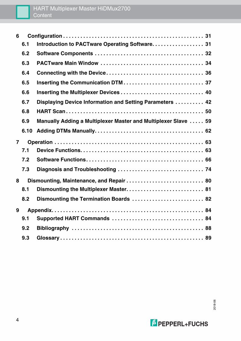
The HART multiplexer master HiDMux2700 is used to establish a HART connection to analog field devices and thereby maintain the conventional analog 4 mA to 20 mA circuits. The device acts as a gateway between the field devices and the control side.A maximum of 32 analog field devices can be connected to the HART multiplexer master.The device can be used as a primary or secondary master.The device can be used in the Zone 2 explosion-hazardous area or in the non-explosion hazardous area.The device is mounted on a termination board. There are a number of different termination boards which are specifically tailored to the individual control systems.The device is supplied with power through the termination board via Power Rail or via terminals with 24 V DC.Through the termination board, the device is connected to a maintenance station or to the process control system via an RS-485 interface. The transfer rate is max. 57600 baud.The device address and the transfer rate are set via DIP switch.The supply, the analog signals, and the RS-485 interface are galvanically isolated from each other. The individual HART channels are decoupled. This does not affect the 4 mA to 20 mA signal.Using the configuration software, you can search for available field devices automatically and query the HART variables of the field devices automatically.
Figure 2.1 Assembly of the HiDMux2700 HART multiplexer master
PWR
HART TXFAULT
OFFON
HiDMux2700HART
LED green:Power supply
Switch 1 ... 8
LED yellow:HART transmission
LED red:Fault
Place forlabeling

2018
-06
HART Multiplexer Master HiDMux2700System Description
3 System Description3.1 The Basic Principles of HART Communication
The HART protocol is supported by many conventional 4 mA to 20 mA field devices that use it to enable digital communication for configuration and maintenance purposes. Many of the device parameters, and the measured value itself, can be digitally transferred to and from the device. This digital communication runs in parallel to the 4 mA to 20 mA signal on the same line. This is enabled via current modulation, which is superimposed on the desired signal.
Figure 3.1
The high-frequency HART signal consists of the sine frequencies 1200 Hz and 2200 Hz. The average value of the signal is 0 and can therefore be filtered through the standard circuit of the analog input. This does not affect the analog signal.The HART protocol is a master-slave protocol. This means that a field device responds only when it is addressed. Burst mode is an exception. The message duration is a few hundred milliseconds, meaning that two to three messages can be transferred per second.The HART commands are divided into 3 groups:• Universal commands
These commands must be supported by all field devices.• Common practice commands
These commands correspond to common practice and are suitable for many field devices.• Device-specific commands
These commands are only suitable for certain field devices.All three types of commands are used in the HART multiplexer system. This document includes a list of commands. See chapter 9.1.
+0.5 mA
-0.5 mA
0
1200 Hz 2200 Hz"1" "0"
20 mA
4 mA
Analogsignal
C = CommandR = Response
Time (seconds)
HART signal
C
R
C RC
R
Note!Additional information can be found in /1/, /2/, /3/, see chapter 9.2.
8

HART Multiplexer Master HiDMux2700System Description
2018
-06
3.2 Possible ApplicationsGeneral ApplicationsIn process engineering plants, many field devices are distributed over a large area. The characteristic values of these field devices must be monitored and logged or adjusted if process variables are changed.The HART multiplexer master from Pepperl+Fuchs enables communication between a computer or a process control system and field devices that support the HART protocol. The following figure shows the basic system structure.
Figure 3.2 Basic structure
HART-compatible field devices allow information such as the measuring range and device address to be saved in the field device itself. Access to this data is usually achieved with a handheld. This means that a connection to the field device must be established manually for each value to be changed.If certain data has to be logged as part of quality assurance processes, this increases the effort for the process control system. For example, the relevant data has to be requested cyclically and saved in a database by the system.The HART multiplexer master establishes the connection between the computer and the HART-compatible field devices. All access to the field device takes place parallel to the transmission of the 4 mA to 20 mA signal and therefore has no effect on the processing of measured values by the process control system. The system provides a subordinate service level. The HART multiplexer master can also detect measured values. For field devices that are mounted in explosion-hazardous areas, the connection takes place on the non-hazardous side of the control unit.Pepperl+Fuchs offers corresponding control units, e. g. HiC2031, HiC2025. The HART multiplexer master can also be connected to control units from other manufacturers. Existing plants can therefore be extended very easily, taking full advantage of the HART communication.The HART multiplexer system can be composed of a maximum of 31 HART multiplexer masters, which are operated via an RS-485 interface. A maximum of 32 analog field devices can be connected to each HART multiplexer master. One computer can therefore be used to address up to a maximum of 992 field devices.Operation using a handheld is still possible, since the HART protocol accepts two masters in one system, e. g. a computer and a handheld.
PWR
HART TXFAULT
OFFON
HiDMux2700HART
Field devicesHostComputer-based
maintenance stationor process control system
HART communication 1 HART communication 2
HART multiplexer master
9

2018
-06
HART Multiplexer Master HiDMux2700System Description
Maintenance StationA computer is often used as a maintenance station to operate and maintain the HART multiplexer system. The computer is used to fulfill parameterization functions or logging functions independently of the process control system. For this computer, operating software that fulfills the required purpose is available from various manufacturers. See chapter 3.3.However, in some cases, no computer is used as a maintenance station. Instead, the process control system communicates with the field devices directly via an RS-485 interface using the HART multiplexer master. The low speed of the HART communication imposes limitations on this method of operation.
3.3 Integration into Operating SoftwareThe full functionality of the HART multiplexer system unfolds through the integration into modern asset management systems such as PACTware (open source), SIMATIC PDM (Siemens), AMS (Fisher-Rosemount), Cornerstone (Applied System Technologies), and Valve Manager (Neles Automation). These operating tools integrate the device functions of the devices in the multiplexer system into a standardized interface and convenient operation in the form of menu commands. However, the representation and designation of the functions in the individual operating tools may vary greatly. A representation that is valid generally is not possible at this point.Information regarding the configuration, parameterization, operation, and diagnostic options of the HART multiplexer system can be found in the manual "Installation and Configuration Device Type Manager (DTM)".
3.4 System StructureThe field devices and the HART multiplexer master are connected to the process control system using termination boards. The following chapters describe three basic connection options. These connection options serve as examples, as there are many other connection options.
The following accessories are available for the HART multiplexer system: • Universal termination boards, referred to as generic termination boards• Control-system specific termination boards• HART cordset HIACA-UNI-FLK34-FLK34-*M* for connecting a
HART communication board to a termination board of the H-System• Interface converter in different variants depending on the available interfaces• Cordset for the connection between the termination board and the process control system.
This cordset is available in different variants depending on the available interfaces and the control system manufacturer.
Note!For further information about the connection layout of the termination boards used, see the corresponding datasheets.
Note!Additional information you can find under www.pepperl-fuchs.com.
10
HART Multiplexer Master HiDMux2700System Description
2018
-06
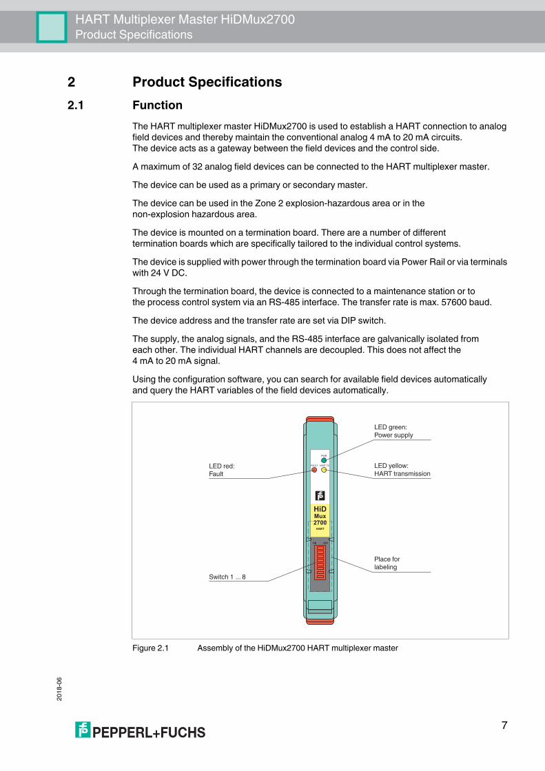
3.4.1 External MountingThe multiplexer master is mounted to a termination board. The termination board forwards the signals via screw terminals. The termination board establishes the connection to the multiplexer master in parallel or in series. This type of mounting is independent of the process control system used or any existing field barriers.
Figure 3.3
PW
R
HART
TX
FAUL
T
OFF
ONHiD
Mux
2700
HART
Converter
Up to 16field devices
DCS
Connection viasystem connector
Computer-basedmaintenance station
HART signal/4 mA ... 20 mA signal
RS-485connection
HART Termination Board
Field Termination Assembly (FTA)
24 V DC
11
2018
-06
HART Multiplexer Master HiDMux2700System Description
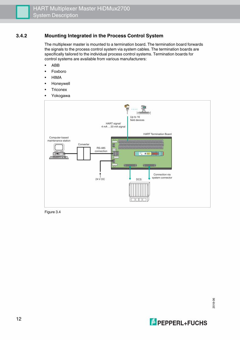
3.4.2 Mounting Integrated in the Process Control SystemThe multiplexer master is mounted to a termination board. The termination board forwards the signals to the process control system via system cables. The termination boards are specifically tailored to the individual process control systems. Termination boards for control systems are available from various manufacturers:• ABB• Foxboro• HIMA• Honeywell• Triconex• Yokogawa
Figure 3.4
PW
R
HART
TX
FAUL
T
OFF
ONHiD
Mux
2700
HART
Up to 16field devices
DCS
Connection viasystem connector
HART signal/4 mA ... 20 mA signal
Converter
Computer-basedmaintenance station
RS-485connection
24 V DC
HART Termination Board
12

HART Multiplexer Master HiDMux2700System Description
2018
-06
3.4.3 Mounting Integrated in the H-SystemIf you use this connection option, the signals can be transferred directly from the termination boards of the H-system to the multiplexer master via a system connector.
Figure 3.5
PWR
HART TX FAULT
OFF ON
HiDMux2700Hart
Converter
Up to 16field devices
DCS
Connection viasystem connector
Computer-basedmaintenance station
HART signal/4 mA ... 20 mA signal
DIN mounting rail
RS-485connection
TerminationBoard
HARTCommunication
Board
24 V DC
13

2018
-06
HART Multiplexer Master HiDMux2700Mounting and Installation
4 Mounting and Installation
4.1 DIN Mounting Rail, on the User SideThe termination boards are mounted on a 35 mm DIN mounting rail according to EN 60715.
Figure 4.1 Example: DIN mounting rail (35 mm x 7.5 mm)
Danger!Explosion hazard from damaged electronic components Premature wear of electronic components in a device that was previously used in a general electrical installation can cause sparks that can ignite the surrounding potentially explosive atmosphere.Never install devices that have already been operated in general electrical installations in electrical installations used in combination with hazardous areas!
Danger!Explosion hazard from pollutionAn excessively polluted surface of the device can become conductive and consequently ignite a surrounding potentially explosive atmosphere.Ensure that you install the device only in environments with a pollution degree 2 or better according to IEC/EN 60664–1.
14

HART Multiplexer Master HiDMux2700Mounting and Installation
2018
-06
4.2 Mounting the Termination Boards
Mounting the Termination Board with Screw MountingThe termination boards are mounted on the 35 mm DIN mounting rail.1. Snap the termination board (2) onto the DIN mounting rail (1).2. Tighten the mounting screws (3).
The termination board (2) is now properly mounted and secured.
Figure 4.2 Termination board mounting
Warning!Risk of short circuitWorking on live parts can cause injuries and can compromise the function and the electrical safety of the device.• Before working on the device, always disconnect the supply voltage.• Connect the device to the supply voltage only after completion of the work.
1 DIN mounting rail2 Termination board
1
2
15

2018
-06
HART Multiplexer Master HiDMux2700Mounting and Installation
Figure 4.3 Termination board fixing
Mounting the Termination Board without Screw MountingThe termination boards are mounted on the 35 mm DIN mounting rail.Snap the termination board (2) onto the DIN mounting rail (1).
The termination board (2) is now properly mounted and secured.
Figure 4.4 Termination board mounting
1 DIN mounting rail2 Termination board3 Fastening screw
1 2 3
1 DIN mounting rail2 Termination board
12
16
HART Multiplexer Master HiDMux2700Mounting and Installation
2018
-06
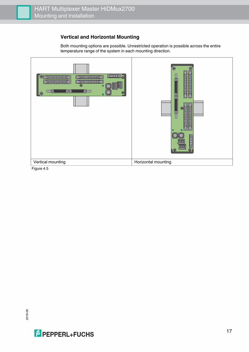
Vertical and Horizontal MountingBoth mounting options are possible. Unrestricted operation is possible across the entire temperature range of the system in each mounting direction.
Vertical mounting Horizontal mountingFigure 4.5
17
2018
-06
HART Multiplexer Master HiDMux2700Mounting and Installation
4.3 Mounting the Multiplexer MasterMounting in a Non-Hazardous AreaMounting the Multiplexer Master on the Termination BoardMount the multiplexer master as described in the following section.
Mounting in Areas that Require Equipment Protection Level GcDanger!Explosion hazard from insufficient type of protectionThe usage of modules with termination boards with insufficient type of protection can cause sparks or other hazards for potentially explosive atmospheres that can ignite the surrounding atmosphere.Only use the modules in the hazardous area if the termination boards are also approved for the hazardous area.
Danger!Explosion hazard from live wiring of circuitsIf you connect or disconnect energized circuits in a potentially explosive atmosphere, sparks can ignite the surrounding atmosphere.Only connect or disconnect energized circuits in the absence of a potentially explosive atmosphere.
Danger!Explosion hazard from wrong mountingThe device safety can be impaired by external environmental influences and by mechanical stress. That can lead to sparking that can ignite a surrounding potentially explosive atmosphere.Mount the device in a surrounding enclosure that complies with IEC/EN 60079–0and that is rated with the degree of protection IP54 according to IEC/EN 60529.
18

HART Multiplexer Master HiDMux2700Mounting and Installation
2018
-06
Mounting the Multiplexer Master on the Termination Board1. Push the Quick Lok bar (1) into the upper position.2. Center the pins (2) above the contact elements of the termination board.
Note the connection direction of the device.3. Center the locking pins (3) above the locking elements of the termination board.4. Carefully push the device into the contacts and locking elements.5. Push the red Quick Lok bar (1) down on either side of the device.
The device is now mounted.
Figure 4.6 Mounting of an H-System isolated barrier
1 Quick Lok Bar2 Coding pins3 Adjustment pins
1
2
3
3
19

2018
-06
HART Multiplexer Master HiDMux2700Mounting and Installation
4.4 Connecting the Multiplexer Master
The circuits are connected to the multiplexer master via the termination board. When the multiplexer master is mounted to the termination board, the circuits are closed. See chapter 4.5.
Figure 4.7 Connection of the HiDMux2700 HART multiplexer master
Danger!Explosion hazard from using of non-intrinsically safe circuits in intrinsically safe circuitsUsing non-intrinsically safe devices in intrinsically safe circuits suspends the type of protection. This can ignite the surrounding potentially explosive atmosphere.Do not use HART multiplexer devices and HART termination boards in intrinsically safe circuits.
Danger!Explosion hazard from live wiring of circuitsIf you connect or disconnect energized circuits in a potentially explosive atmosphere, sparks can ignite the surrounding atmosphere.Only connect or disconnect energized circuits in the absence of a potentially explosive atmosphere.
HiDMux2700
12
RS 485... ...
32
Zone 2Div. 2
HART
+- 24 V DC1a, 1b
2a, 2b
Termination Board
20
HART Multiplexer Master HiDMux2700Mounting and Installation
2018
-06
4.5 Termination Board ConnectionDanger!Explosion hazard from using of non-intrinsically safe circuits in intrinsically safe circuitsUsing non-intrinsically safe devices in intrinsically safe circuits suspends the type of protection. This can ignite the surrounding potentially explosive atmosphere.Do not use HART multiplexer devices and HART termination boards in intrinsically safe circuits.
Danger!Explosion hazard from live wiring of circuitsIf you connect or disconnect energized circuits in a potentially explosive atmosphere, sparks can ignite the surrounding atmosphere.Only connect or disconnect energized circuits in the absence of a potentially explosive atmosphere.
Danger!Explosion hazard from exposed conductorsExposed conductors of inadequately attached cables can cause sparks that can ignite the surrounding potentially explosive atmosphere.When installing the device ensure that the cables are adequately attached.
Danger!Danger to life from electric shockAbsent or insufficient insulation can result in electric shock.Only connect circuits that provide protection against electric shock (e. g. SELV or PELV).
Danger!Danger to life from electric shockAbsent or insufficient insulation can result in electric shock.• Maintain sufficient distance between the connection lines, terminals, housing, and the
environment.• Insulate connection lines, terminals, and the housing from the environment.
21

2018
-06
HART Multiplexer Master HiDMux2700Mounting and Installation
Connecting Circuits1. Connect the field circuit, see chapter 4.5.1.2. Connect the control circuit, see chapter 4.5.2.3. Connect the power supply.4. Connect the HART communication, see chapter 4.4.
4.5.1 Connecting Field Devices to the Termination BoardPepperl+Fuchs provides special termination boards. Various connection options are available for these termination boards. See the manual "H-System – Isolators and Termination Boards."Connecting the Termination Board and Field Devices1. Connect the HART-compatible field devices to the termination board using screw terminals
or spring terminals. See chapter 3.4.1 and 3.4.2.Observe the tightening torque for the terminal screws. The tightening torque is 0.5 Nm to 0.6 Nm.or
2. Control units are mounted on the termination board. Connect the field devices to the control unit using screw terminals or spring terminals. See chapter 3.4.3.Observe the tightening torque for the terminal screws. The tightening torque is 0.5 Nm to 0.6 Nm.
4.5.2 Connecting the Process Control System to the Termination BoardPepperl+Fuchs provides special termination boards. Various connection options are available for these termination boards.Connecting the Termination Board and Process Control System1. Connect the process control system to the termination board using screw terminals
or spring terminals. See chapter 3.4.1.Observe the tightening torque for the terminal screws. The tightening torque is 0.5 Nm to 0.6 Nm.or
2. Connect the process control system to the termination board via a manufacturer-specific system connector. See chapter 3.4.2 and 3.4.3.
Danger!Danger to life from incorrect installationIncorrect installation of cables and connection lines can compromise the function and the electrical safety of the device.• Observe the permissible core cross section of the conductor.• When using stranded conductors, crimp wire end ferrules on the conductor ends.• Use only one conductor per terminal.• When installing the conductors the insulation must reach up to the terminal.• Observe the tightening torque of the terminal screws.
22

HART Multiplexer Master HiDMux2700Mounting and Installation
2018
-06
4.5.3 Connecting the Termination Boards to a ComputerThe multiplexer master is connected to the computer via the RS-485 interface on the termination board.Note!Information on the assignment of the terminals can be found in the datasheets for the termination boards.
Terminal Description MeaningGND Shield Cable shieldingNet A RxD/TxD - (RS-485 B–) RS-485 differential signalNet B RxD/TxD + (RS-485 B+)
Table 4.1 Example connector assignment for the terminals of HiATB01-HART-*X* termination board
Caution!Risk of electric shock or property damage due to inadequate groundingIf the cable shield is not connected to the protective earth correctly, this may result in potential equalization currents. These currents may injure operating personnel or cause property damage. Ground the cable shield at only one end of the line. Observe the applicable laws, standards, and directives for the operating location.
Note!To connect the termination board and computer, you need an interface converter. Different interface converters are required depending on the connection on your computer. We recommend the following converters:• Interface converter from RS-485 to RS-232: Telebyte model 285, from Telebyte• Interface converter from RS-485 to RJ45, Com-Server++, from W&T• Interface converter from RS-485 to USB: I-7561-CR, from ICP
23

2018
-06
HART Multiplexer Master HiDMux2700Mounting and Installation
Connecting a Termination Board to a Computer1. Connect a computer or a process control system to the terminals of the termination board.
Observe the tightening torque for the terminal screws. The tightening torque is 0.5 Nm to 0.6 Nm.Do not exceed a maximum cable length of 1200 m. Use a shielded, twisted, two-strand cable.
2. In the case of long cable lengths and high baud rates, install a terminator at each end of the RS-485 line. Use terminators from 120 to 220 .If the RS-485 line ends at the termination board and is not routed to other devices, use the second RS-485 connection to connect a terminator.If you use an interface converter, install a terminator on the interface converter and an interface converter at the other end of the line.
In the case of short cable lengths and low baud rates, no terminators are required. Observe the RS-485 specifications.
3. Connect additional participants to the second RS-485 connection.Observe the tightening torque for the terminal screws. The tightening torque is 0.5 Nm to 0.6 Nm.Do not exceed a maximum cable length of 1200 m. Use a shielded, twisted, two-strand cable.
4.6 Information Regarding Electromagnetic CompatibilityThe device is intended for use in electrically conductive and grounded switch cabinets.Shielding Cables1. Shield cables that are leaded into the switch cabinet.2. Connect the switch cabinet and shield directly in the cable gland.3. Lead unshielded cables (e. g. supply lines) into the switch cabinet via filter.
24

HART Multiplexer Master HiDMux2700Commissioning
2018
-06
5 CommissioningChecklist for CommissioningThe commissioning of the multiplexer master is summarized in the following checklist. The steps required for commissioning the multiplexer master refer to the chapters where the respective procedure is described.1. Installation of field devices2. Selection and connection of the termination boards see chapter 3.43. Selection and connection of the control units4. Connection of the process control system see chapter 4.5.25. Connection of the multiplexer master see chapter 4.46. Connection of the maintenance station.
If necessary, use interface converters, see chapter 4.5.3.Observe the polarity of the RS-485 connection, see chapter 4.5.3.Specify the RS-485 address and the baud rate.
7. Wait for the switch-on process, see chapter 5.2.4.8. Perform parameterization, see chapter 5.2.5.9. Specify the multiplexer devices used in the module table, see chapter 7.1.2.10. Build signal loops, see chapter 7.1.5.11. If desired, activate the scan function, see chapter 7.1.6.
5.1 Data Access to the Connected Field DevicesThe operating tool used determines how data on the connected field devices is accessed.The field devices are generally found in a project tree beneath the multiplexer slaves. The multiplexer master integrates the slave unit with slave address 0. Device data, device parameters, and device diagnoses can be accessed via the project tree. For the structure of a project tree, see chapter 6.8.The data, parameter, and diagnostic windows display the data of the underlying HART commands that differ according to the field device. Only universal commands and common practice commands have the same function for all devices. The information about the devices themselves, the process values, and some diagnostic information can thus be represented in a uniform manner.
5.2 Configuration of the Multiplexer Master5.2.1 Connection to the Maintenance Station or to the
Process Control SystemThe connection to the maintenance station or to the process control system is via a multidrop-enabled RS-485 interface, see chapter 4.5.3. The baud rate for this interface can be set via the DIP switch. The device address for communication via RS-485 is also set via the DIP switch.When setting the address, make sure that no address is assigned more than once, as otherwise this may lead to communication faults and even communication failure. The baud rate set must match that of the maintenance station.
25

2018
-06
HART Multiplexer Master HiDMux2700Commissioning
5.2.2 DIP Switch Settings
The device is equipped with 8 DIP switches on the front.DIP switch 8 is used for device testing by the manufacturer and must therefore always be in the off position.
DIP switches 6 and 7 determine the baud rate of the RS-485 interface.
Danger!Explosion hazard from sparking when using operating elementsUsing operating elements in a potentially explosive atmosphere can cause sparks that can ignite the surrounding atmosphere. Only use operating elements (e. g., switch, slider, button, etc.) in the absence of a potentially explosive atmosphere.
DIP switch 8 MeaningPosition Off Normal state
Table 5.1
DIP switch 6 7 MeaningPosition Off Off 9600 baud
On Off 19200 baudOff On 38400 baudOn On 57600 baud
Table 5.2
26

HART Multiplexer Master HiDMux2700Commissioning
2018
-06
DIP switches 1 to 5 define the RS-485 address. A value is assigned to each of the DIP switches. The address is calculated from the sum of the values.
DIP switch 1 2 3 4 5 MeaningPosition On Off Off Off Off 1
Off On Off Off Off 2On On Off Off Off 3Off Off On Off Off 4On Off On Off Off 5Off On On Off Off 6On On On Off Off 7Off Off Off On Off 8On Off Off On Off 9Off On Off On Off 10On On Off On Off 11Off Off On On Off 12On Off On On Off 13Off On On On Off 14On On On On Off 15Off Off Off Off On 16On Off Off Off On 17Off On On Off On 18On On Off Off On 19Off Off On Off On 20On Off On Off On 21Off On On Off On 22On On On Off On 23Off Off Off On On 24On Off Off On On 25Off On Off On On 26On On Off On On 27Off Off On On On 28On Off On On On 29Off On On On On 30On On On On On 31
Table 5.3
Note!Briefly disconnect the device from the power supply to apply the values set using the DIP switches.
27

2018
-06
HART Multiplexer Master HiDMux2700Commissioning
Factory Setting
5.2.3 LED IndicationThe device is equipped with three LEDs which are located on the front of the housing. The LEDs have the following meanings:
LED indication during the initialization process
LED indication during the scanning process
Faulty LED indication during commissioning
DIP switch 1 2 3 4 5 6 7 8 MeaningPosition Off Off Off Off Off Off Off Off Manufacturer test disabled
Baud rate 9600 baudRS-485 address 0
Table 5.4
Note!In the factory setting, the address 0 is set. Ensure that you do not assign any addresses more than once.
Color MeaningRed Fault indication, detected during the initialization processGreen Operating indicationYellow HART communication with a field device
Table 5.5
Color Status MeaningRed Off Initialization processGreen FlashesYellow Off
Table 5.6
Color Status MeaningRed Off Scanning processGreen LitYellow Flashes
Table 5.7
Note!For further information about the scanning process, see chapter 5.2.4.
Color Status MeaningRed Flashes If all three LEDs flash one after the other, DIP switch 8 (test) is in
the on position. Turn the switch to off and repeat commissioning.Green FlashesYellow Flashes
Table 5.8
28
HART Multiplexer Master HiDMux2700Commissioning
2018
-06
5.2.4 Switch-On BehaviorWhen the power supply has been switched on, the multiplexer master performs an initialization process with a self-test. The process is indicated by a flashing green LED. Any faults detected are indicated by a red LED. The multiplexer devices defined in the multiplexer table (command 157) are then scanned for any available HART-compatible field devices. This process is indicated by the flashing yellow LED.Once the multiplexer master has completed the scanning process, a list of the field devices connected is saved in the device.
The factory setting for the number of message repetitions is set to 2. The search duration is between approximately 30 seconds and several minutes in the case of maximum configuration. On completion of this phase, the yellow LED goes out. Volatile data is set to its default setting. Data stored in non-volatile memory is retained.
Note!If a field device is connected to the multiplexer device during operation, a scan must be performed afterwards so that the field device can be addressed via HART. This scanning process is triggered automatically when the multiplexer device is switched on, see chapter 7.1.5. The process can also be started manually in the maintenance station, see chapter 7.2.1. The duration of the scan process dependent:• on the number of connected HART-compatible field devices• on the loop search type, see chapter 9.1, command 153,• on the number of message repetitions in the case of a fault, or• on whether the query has been answered.
29

2018
-06
HART Multiplexer Master HiDMux2700Commissioning
5.2.5 Device Parameters, Parameterization
For the identification and parameterization of the multiplexer master, just like other HART field devices, the multiplexer master contains certain parameters that are saved in the non-volatile memory. The following list shows these parameters and how the parameterization must be performed.• Unique device identification, see commands 0 and 11
The device identification provides information about the device (type, type ID, serial number, revision numbers), and the manufacturer. The device identification cannot be changed.
• Message, see commands 12 and 17Under this parameter, any text of up to 32 characters can be stored in the device.
• Tag, description, and date, see commands 13 and 18A tag (8 characters), a measuring point description (16 characters), and a date can be stored under these parameters.
• Number of preambles in message responses, see command 59This parameter is used to define the number of preambles inserted in the message responses. The default setting is 4, the adjustment range is 2 to 20.
• Number of message repeats, see commands 144 and 145The number of message repeats can be set separately for repeats in the event of communication faults and in the event of response code Busy. The adjustment range is 0 to 11 repeats in each case. In the event of communication faults, the default setting is 2. For response code Busy, the default setting is 0.
• Scan command, see chapter 7.1.7 and commands 146 and 147Of the existing scan parameters, only the scan command is stored in non-volatile memory. The command indicates which HART command (1, 2, or 3) is to be a scan command to the field devices.
• Master type (primary or secondary master), see command 151This sets the priority for access to the HART field device. A primary master always initiates a connection to a field device. A secondary master initiates a connection to a field device only if the primary master does not access the field device. The default setting for the multiplexer master is primary master. A typical example of a secondary master is a handheld.
• Loop search type, see command 153The multiplexer master currently does not support multidrop with HART, i. e., only one HART field device is connected to each HART channel. During construction of the signal loop (scanning process, see chapter 7.1.5), the connected field devices are either always searched on polling address 0 (single analog) or on polling addresses 0 to 15 in preparation for multidrop operation. In multidrop operation, the first polling address found is addressed (single unknown).
• Module table, see chapter 7.1.2 and command 157This document includes a list of commands. See chapter 9.1.
Caution!Potential device malfunction from change of device functionChanges in the device function can lead to device malfunction. The function of the device is no longer guaranteed.Before transferring the new device function, make sure that the changed device function does not cause a danger to the device and the plant.
30

HART Multiplexer Master HiDMux2700Configuration
2018
-06
6 Configuration
6.1 Introduction to PACTware Operating SoftwareFDT ConceptThe FDT concept (FDT – Field Device Tool) created a standard that can be used to integrate devices in various user interfaces (framework applications such as PACTware). The FDT concept enables open and continuous device operation from the control level to the field, regardless of the bus systems used. The FDT concept specifies the data exchange between the device-specific driver and the framework application. Every communicating device has a device-specific driver (DTM) that is integrated in the framework application.
PACTwareTM Operating SoftwarePACTware (PACTware – Process Automation Configuration Tool) is a manufacturer-independent operating software for devices. In the past, it was often necessary to use multiple manufacturer-specific programs to be able to operate different devices. PACTware enables you to operate any number of devices with just this software. PACTware is not only a configuration tool, it also offers an interface to HART-compatible field devices as well as to bus systems such as PROFIBUS, MODBUS, and ControlNet. PACTware offers many features that allow users to simplify the plant documentation, to create trend curves, and to monitor signals using HART data.
Device and Communication DTMThe DTM (DTM – Device Type Manager) contains all the data and functions of a device. Every DTM contains its own user interface optimized for the device. The device and communication DTMs can be integrated in any FDT frame application, such as PACTware.The DTM offers almost no restriction with regard to display and user guidance. This means that all available device functions can be operated according to the user's needs. Operation is supported by graphics. The DTM technology enables consistent operation of a device in all FDT systems.Pepperl+Fuchs generates DTMs for HART-compatible devices by converting the device description (DD) of these devices for use with PACTware.
Caution!Potential device malfunction from change of device functionChanges in the device function can lead to device malfunction. The function of the device is no longer guaranteed.Before transferring the new device function, make sure that the changed device function does not cause a danger to the device and the plant.
Note!The steps are described using the FDT framework program PACTware 4.1 as an example.
31

2018
-06
HART Multiplexer Master HiDMux2700Configuration
Essentially, there are two different types of DTM:• Device DTMs
Device DTMs are DTMs for configuring field devices such as transmitter power supplies, signal converters, and trip amplifiers.
• Communication DTMsCommunication DTMs are required for communication with a device via a point-to-point connection or via any network structures. The communication DTMs are available for various interfaces, such as an RS-232 interface or a USB interface.
6.2 Software ComponentsTo configure the device with a user program, you need the following software components:• Microsoft® .NET Framework 3.5 or higher• PACTware 4.1 or higher
In accordance with FDT Specification 1.2, PACTware is used as a framework program for DTMs supplied by manufacturers of the field devices as configuration software.
• HART multiplexer DTMThe DTM collection comprises all device DTMs required for the parameterization of multiplexer devices. The DTMs are used to establish communication with the field devices using communication protocols such as the HART protocol or PROFIBUS protocol.
• DTM HART CommThis package contains the HART communication DTM, which is necessary for communication between the host and the HART multiplexer DTM.
• DTMs of the field devicesThe manufacturers of field devices provide specific DTMs which allow access to all functions of the respective devices and therefore allow detailed parameterization. For further information, please contact the manufacturer of the field devices used.
• Generic HART DTMThe Generic HART DTM provides the basic HART functionalities of the field devices. If no matching device DTM is available, the Generic HART DTM is used for basic parameterization. Therefore, we recommend that this DTM is always available.
Figure 6.1 Software components
Master Slave Master Slave
DTM HART Comm HART Multiplexer DTM
PWR
HART TXFAULT
OFFON
HiDMux2700HART
Field devicesHostComputer-based
maintenance stationor process control system
HART communication 1 HART communication 2
HART multiplexer master
Field device DTMs
Note!The latest software components can be found online at www.pepperl-fuchs.com in the product selector under Products > Software.
32

HART Multiplexer Master HiDMux2700Configuration
2018
-06
Installing Software Components1. Install Microsoft® .NET Framework.2. Install PACTware.3. Install the HART multiplexer DTM.4. Install the DTM HART Comm.5. Install the field device-specific DTMs from the manufacturer of the field device.6. Install the Generic HART DTM if necessary.Note!The cross-device properties of the software are described in the manual "Installation and Configuration Device Type Manager (DTM)". You can download this manual free of charge from our website www.pepperl-fuchs.com in the product selector under Products > Software > PACTware > Product list > PACTware 4.1 > Documents.The following section describes only the device-specific settings for the HART multiplexer master HiDMux2700.
33
2018
-06
HART Multiplexer Master HiDMux2700Configuration
6.3 PACTware Main WindowThe main window is divided into the project window and the editing window.
Project window In the project window, you build the current project tree of your system by adding the various components. In the project window, select the device you want to edit, monitor, diagnose, or simulate. The selected object is highlighted in a different color.
Editing window In the editing window, various windows required for editing your system are opened.In the first processing step, the selection window with the drivers and devices or the device catalog for the structure of the system is shown.For the configuration and parameterization, the corresponding windows for the drivers and devices are opened in the editing window.For subsequent operation, the menus for diagnosis, measured value, trend, or simulation are opened in the editing window. In addition, the communication monitor for the communication protocol can be opened.
Menu bar The menu bar contains the following drop-down menus:• File: Here you can create a new project, save the current project, or load an
existing project.• Edit: Contains the copy, cut, and paste functions.• View: Here you can display or hide various symbol and status bars, as well as
the device catalog, fault monitoring, etc.• Project: Contains the basic project functions, such as loading device(s), writing
to device(s), reading the device status.• Device: Contains the functions for editing the device data of the device currently
selected in the project tree. Here you can also establish or disconnect the connection to the selected device.
• Extras: Here you can manage the device catalog, the users, the options, and the add-ins.
• Window: Here you can open the various current view windows.• Help: The PACTware help is called up.
Command bar The command bar is located below the menu bar and contains buttons for all important functions for adding, removing, and editing components within the project. You can also read the device status, edit the device data, and establish or disconnect the connection to the system.
34
HART Multiplexer Master HiDMux2700Configuration
2018
-06
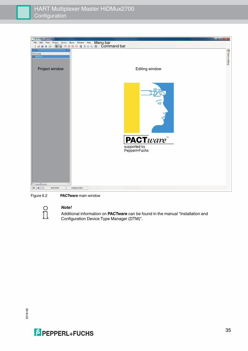
Figure 6.2 PACTware main window
Note!Additional information on PACTware can be found in the manual "Installation and Configuration Device Type Manager (DTM)".
Project window Editing window
Command barMenu bar
35

2018
-06
HART Multiplexer Master HiDMux2700Configuration
6.4 Connecting with the DeviceConnecting the Computer to the Device1. Mount the device. See chapter 4.2. Connect the device to the power supply.3. Connect the computer and the device via an interface converter. See chapter 4.5.3.4. Start PACTware as described in the manual "Installation and Configuration Device Type
Manager (DTM)." The PACTware main window is displayed. See chapter 6.3.
Enabling Memory-Optimized OperationIn combination with the DTMs for the multiplexer master, we recommend enabling the Memory-optimized operation option.1. Open the Extras > Options menu.2. Enable Use memory-optimized project management.3. Confirm your selection with OK.
You have enabled the memory-optimized operation.
36
HART Multiplexer Master HiDMux2700Configuration
2018
-06
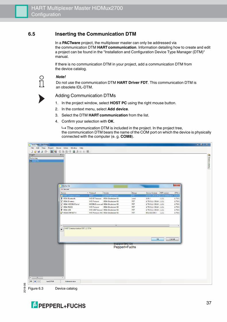
6.5 Inserting the Communication DTMIn a PACTware project, the multiplexer master can only be addressed via the communication DTM HART communication. Information detailing how to create and edit a project can be found in the "Installation and Configuration Device Type Manager (DTM)" manual.If there is no communication DTM in your project, add a communication DTM from the device catalog.
Adding Communication DTMs1. In the project window, select HOST PC using the right mouse button.2. In the context menu, select Add device.3. Select the DTM HART communication from the list.4. Confirm your selection with OK.
The communication DTM is included in the project. In the project tree, the communication DTM bears the name of the COM port on which the device is physically connected with the computer (e. g. COM8).
Figure 6.3 Device catalog
Note!Do not use the communication DTM HART Driver FDT. This communication DTM is an obsolete IDL-DTM.
37

2018
-06
HART Multiplexer Master HiDMux2700Configuration
Setting Parameters1. In the project window, double-click the communication DTM. It bears the name of
the COM port on which the device is physically connected with the computer (e. g. COM8).2. Close the Parameters window by clicking the OK button.
If you have made changes to parameters, these changes will be saved.The following parameters are adjustable:• Communication interface:
Select the option HART multiplexer as the interface.• Serial interface:
Select the COM port to which the multiplexer master is connected.• Baud rate:
Select the baud rate according to the settings of the DIP switches on the multiplexer master, see chapter 5.2.2.
• RTS control:Depending on the type of interface converter used, switching the request-to-send control on or off may be necessary to switch cleanly between receive and transmit mode.
• HART protocol:Master: 2 HART masters may be connected to a HART signal loop, whereby the parameterization must differentiate between the primary master and the secondary master. This setting is defined here.Preamble: In accordance with the HART standard, a corresponding number of FF characters must be sent in advance as a preamble. The number of characters is defined here.Number of communication retries: Number of repeated attempts to make contact in the event of an fault.
• Address scan: start address and end address:Here you can set the address range in which the HART communication DTM should search for the multiplexer devices connected to the RS-485 interface.
• Communication timeout:Here you can set how long the HART communication DTM should search for the multiplexer devices connected to the RS-485 interface.
38

HART Multiplexer Master HiDMux2700Configuration
2018
-06
Figure 6.4 HART communication parameter window
39

2018
-06
HART Multiplexer Master HiDMux2700Configuration
6.6 Inserting the Multiplexer DevicesThe connected multiplexer devices can be scanned in the communication DTM via the Additional functions > Scanlist function.Updating the Scan List1. In the project window, right-click to select the HART communication DTM (e. g. COM8).2. In the context menu select Additional functions.3. Select Scanlist.4. Start the scan by clicking Update.
The scan list is updated and displayed.
Figure 6.5 HART communication window, scan list
40

HART Multiplexer Master HiDMux2700Configuration
2018
-06
The multiplexer devices must be added to the project manually.Adding Multiplexer Devices via the Device Catalog1. Open the device catalog by clicking View > Device catalog.2. Use drag-and-drop to move the Mux 2700G DTM from the device catalog to
the HART communication DTM (e. g. COM8) in the project tree. The HiDMux2700 DTM is then added to the project.
Adding Multiplexer Devices via the Context Menu1. In the project window, right-click to select the HART communication DTM (e. g. COM8).2. In the context menu, select Add device.3. Select the Mux 2700G DTM from the list and confirm by clicking OK.
The HiDMux2700 DTM is then added to the project.Note!To establish the connection to a device in the project tree or to disconnect the connection, right-click to select the corresponding device in the project window. In the context menu, select Connect or Disconnect.Alternatively, you can select the device in the project window and click the corresponding field in the command bar.
41

2018
-06
HART Multiplexer Master HiDMux2700Configuration
6.7 Displaying Device Information and Setting Parameters6.7.1 Loading Device Data
Loading Data and Establishing a Connection1. In the project window, right-click to select multiplexer master HiDMux2700.2. Select Load from device in the context menu.3. If no connection has been established previously, a window opens and you are asked
whether you want to establish the connection to the device. Select Yes. The connection to the multiplexer master is established and the device data can
be read.
Figure 6.6 Load data from device
42

HART Multiplexer Master HiDMux2700Configuration
2018
-06
6.7.2 Device InformationGeneral information about the device is displayed in the General menu:Displaying Device Information1. Use the mouse to double-click the multiplexer master HiDMux2700 in the project window.2. In the editing window, open the Configuration > General menu.
The General window is displayed.3. Click Apply to confirm your selection.4. Select Revert to reset your selection.InformationGeneral, unchangeable information about the device is displayed in the Information section:• Manufacturer: Manufacturer of the multiplexer device (Pepperl+Fuchs).• Device ID: Type designation of the device.• Device type ID: This number identifies the type of device and is unique depending on
the manufacturer. Together with the manufacturer ID, the device type ID can be used to identify the device type uniquely.
• Serial number: The serial number of the device.• Hardware revision: Hardware revision of the multiplexer master.• Software revision: Software revision of the multiplexer master.• Device revision: The revision of the devices supported.• Date: The date on which the device parameters were last changed.• Configuration changed: Indicates whether a parameter has been changed in
the configuration of the device, see chapter 7.2.5.IdentificationIdentification information is displayed in the Identification section. This information can be changed and saved by the user.• Tag: Tag for the identification of the multiplexer master.• Descriptor: Description for the multiplexer master.• Message: Communication without any special function which can be used freely by
the user (e. g. for identification).
43

2018
-06
HART Multiplexer Master HiDMux2700Configuration
Figure 6.7 General window (device information)
44

HART Multiplexer Master HiDMux2700Configuration
2018
-06
6.7.3 Parameterizing CommunicationDisplaying Communication Parameters1. Use the mouse to double-click the multiplexer master HiDMux2700 in the project window.2. In the editing window, open the Configuration > Communication menu.
The Communication window is displayed.3. Click Apply to confirm your selection.4. Select Revert to reset your selection.The communication parameters between the host, the HART multiplexer system, and the field device are displayed and set in the Communication menu:
Figure 6.8
Communication with the Multiplexer MasterIn this case, the communication between the host and the HART multiplexer system (HART communication 1) is described.The Communication to host HART master (as field device) section displays the following information about the device:• Address: The RS-485 address of the multiplexer master is displayed here.• Unique identifier: The unique, non-variable long address of the multiplexer master.• HART revision: HART revision under which the multiplexer master is operated.• Minimum number of preambles: Minimum number of preambles.
PWR
HART TXFAULT
OFFON
HiDMux2700HART
Field devicesHostComputer-based
maintenance stationor process control system
Data request Cyclic data request
HART multiplexer master
Cache data(Command caching)
HART communication 1 HART communication 2
45

2018
-06
HART Multiplexer Master HiDMux2700Configuration
Communication with the Field DevicesIn this case, the communication between the HART multiplexer system and the field devices (HART communication 2) is described.The Communication to field devices (as HART master) section displays the information listed below. This information can be changed and saved by the user.• Master type: 2 HART masters may be connected to a HART signal loop, whereby
the parameterization must differentiate between the primary master and the secondary master. The setting at this point indicates whether the multiplexer master addresses the field devices as the primary or secondary HART master.
• Retries on "Busy": Number of repeat attempts to establish communication with the field device if the field device reports Busy.
• Retries on error: Number of repeat attempts to establish communication with the field device if an fault occurs.
• Loop scan address range: This defines the address range in which the field devices on the individual signal loops are searched for, see chapter 6.7.4:• Scan address 0 only: The multiplexer master uses only address 0 to search
for connected devices.• Scan addresses 0 to 15: The multiplexer master searches for all polling addresses
between 0 and 15 and identifies the first device to respond.
Figure 6.9 Communication window
46

HART Multiplexer Master HiDMux2700Configuration
2018
-06
6.7.4 Command Caching FunctionCyclical Data RetrievalWith cyclical data retrieval, the HART multiplexer master periodically retrieves data from the connected field devices and stores the data in its internal memory. If the process control system queries the data of the field devices, this data can be forwarded more quickly. The data is no longer read directly from the field device. Instead, it is read directly from the memory of the multiplexer master. See chapter 6.7.3Displaying the Command Caching Function Settings1. Use the mouse to double-click the multiplexer master HiDMux2700 in the project window.2. In the editing window, open the Configuration > Command caching menu.
The Command caching window is displayed.3. Click Apply to confirm your selection.4. Select Revert to reset your selection.The command parameters for the multiplexer master are displayed and set in the Command caching menu:• Mode: This switches the Command caching function on or off.
• Disabled: The function is switched off.• Default caching: The function is switched on. This is the default setting.
The commands selected are cached, see below.• HART command: Here you can use a drop-down menu to select which values are to be
read out from the field devices:• Command 1 - Read Primary Variable: Only the primary variable of the field device is
read out.• Command 2 - Read Loop Current and Percent Of Range: The current value in mA
is read out.• Command 3 - Read Dynamic Variables and Loop Current: All variables of the
field device are read out.
47

2018
-06
HART Multiplexer Master HiDMux2700Configuration
Figure 6.10 Command caching window
48
HART Multiplexer Master HiDMux2700Configuration
2018
-06
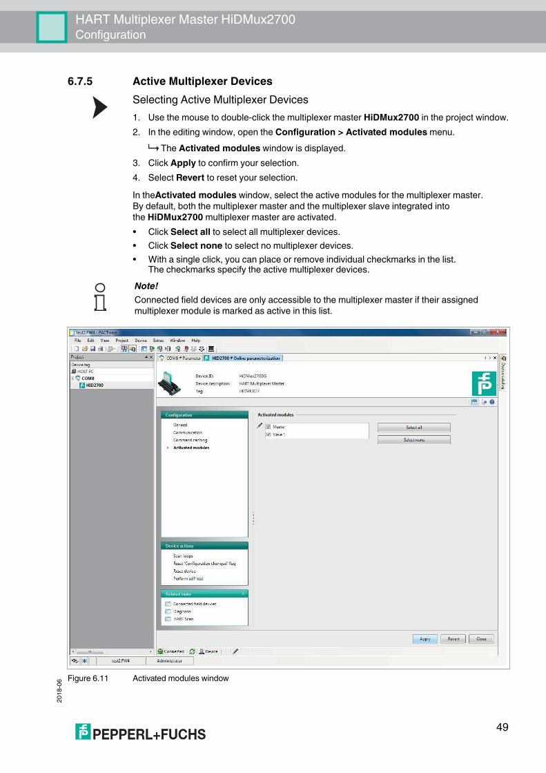
6.7.5 Active Multiplexer DevicesSelecting Active Multiplexer Devices1. Use the mouse to double-click the multiplexer master HiDMux2700 in the project window.2. In the editing window, open the Configuration > Activated modules menu.
The Activated modules window is displayed.3. Click Apply to confirm your selection.4. Select Revert to reset your selection.In theActivated modules window, select the active modules for the multiplexer master. By default, both the multiplexer master and the multiplexer slave integrated into the HiDMux2700 multiplexer master are activated.• Click Select all to select all multiplexer devices.• Click Select none to select no multiplexer devices.• With a single click, you can place or remove individual checkmarks in the list.
The checkmarks specify the active multiplexer devices.
Figure 6.11 Activated modules window
Note!Connected field devices are only accessible to the multiplexer master if their assigned multiplexer module is marked as active in this list.
49

2018
-06
HART Multiplexer Master HiDMux2700Configuration
6.8 HART Scan6.8.1 Starting the HART Scan Function
The HART scan function can read in the entire project structure connected to the serial interface:• Multiplexer master• Multiplexer slave• Field devicesStarting the HART Scan Function via Menu1. Use the mouse to double-click the multiplexer master HiDMux2700 in the project window.2. In the editing window, open the Related tasks > HART scan menu.
The HART scan window is displayed.Starting the HART Scan Function via Context Menu1. In the project window, right-click to select the multiplexer master HiDMux2700.2. In the context menu, select Additional functions.3. In the dropdown list, select HART scan.
The HART scan window is displayed.
Figure 6.12 HART Scan function
Note!Under certain circumstances, the HART scan function is not supported by all frame applications or is subject to restrictions.
50

HART Multiplexer Master HiDMux2700Configuration
2018
-06
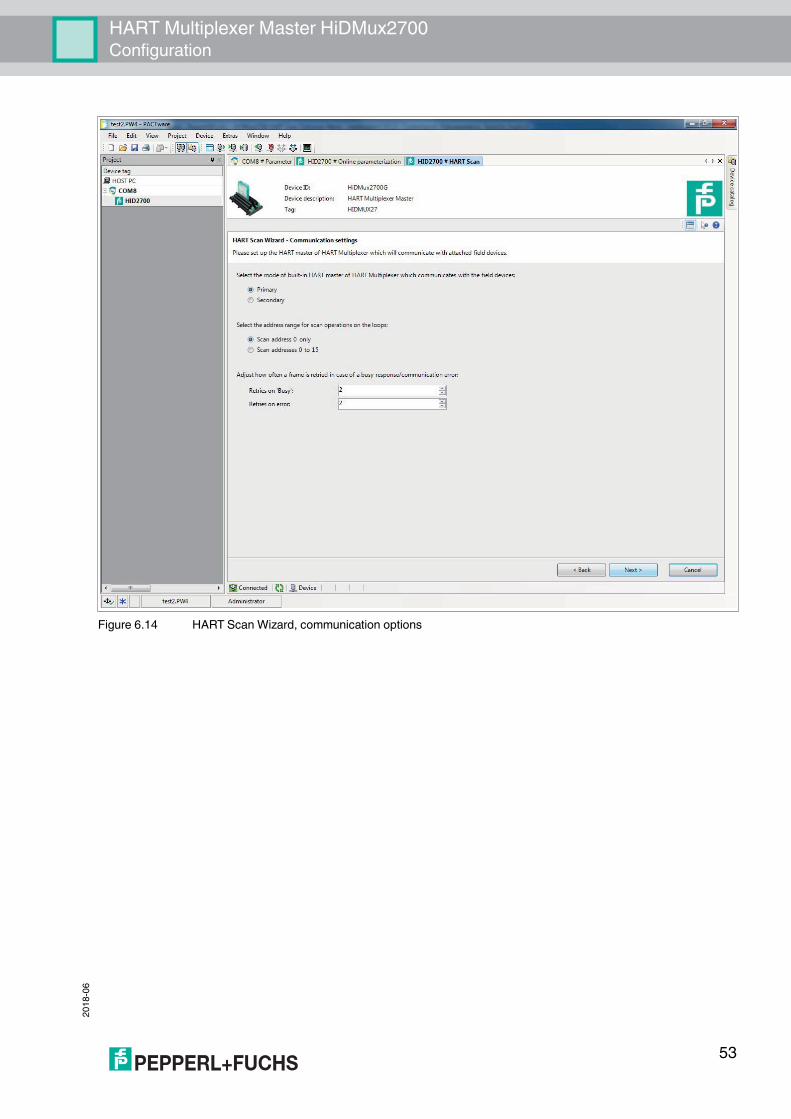
6.8.2 Executing the HART Scan FunctionPerforming a HART Scan1. In the HART scan wizard section in the HART scan window, select one of the following
options, see Figure 6.13:• First commissioning: Select this option to create a complete basic setup of
the FDT project. Devices included in the FDT project, such as the multiplexer master, multiplexer slave, and field devices, including the communication settings, are recorded and analyzed. If you select this option, you have to define additional settings in the next steps, see Figure 6.14:• Primary or secondary: 2 HART masters may be connected to a HART signal loop,
whereby the parameterization must differentiate between the primary master and the secondary master. Select one of the options.
• Scan address 0 only: Select this option if you want the multiplexer master to use only the address 0 to search for connected devices.
• Scan addresses 0 to 15: Select this option if you want the multiplexer master to search for all connected devices with polling addresses between 0 and 15.
• Retries on "Busy": Number of repeat attempts to establish communication with the field device if the field device reports Busy.
• Retries on error: Number of repeat attempts to establish communication with the field device if an fault occurs.
• Update modules: Select this option if a module has been removed or added.• Update field devices: Select this option if field devices have been removed or added.• Update FDT project: Select this option to adapt the FDT project to the current
HART topology.
2. Click Next to confirm and continue with the HART scan. Before the HART scan starts, you can select which active multiplexer devices are to
be searched, see chapter 6.7.5.If you select the option Automatic, all multiplexer devices to which field devices are connected are automatically detected and activated.If you select the option Manual, you can enable/disable the check boxes to define which active multiplexer devices are to be searched.
3. Confirm your selection by clicking Next to start the HART scan. The HART scan is executed. Depending on the selected settings and the number
of field devices, a complete HART scan may take from a few seconds to several hours.
Note!Depending on the selected settings and the number of field devices, a complete HART scan may take up to several hours, because additional addresses are queried and the individual channels are addressed multiple times.Recommendation:Initially, select Scan address 0 only and keep the number of Retries on "Busy" and the number of Retries on error as low as possible. If field devices are missing after the HART scan, amend the settings and scan again.
51

2018
-06
HART Multiplexer Master HiDMux2700Configuration
Figure 6.13 HART Scan Wizard
52
HART Multiplexer Master HiDMux2700Configuration
2018
-06
Figure 6.14 HART Scan Wizard, communication options
53

2018
-06
HART Multiplexer Master HiDMux2700Configuration
Reading In the XML File for Detection of the Sub Device TypeIf a manufacturer has released several devices that have the same manufacturer ID and device type ID, a third identification attribute is required for unique identification. This attribute is referred to as a sub device type. The attribute is defined in the FDT specification and can be detected by any DTM. However, the identification attribute is not defined in the HART protocol and is not recognized in device communication. The file that is read at this point converts the identification attribute so that this information can be read in the DTM. This file must be provided by the device manufacturer.1. Open the Explorer by clicking the Open file button under the Mapping file field.2. Select the required XML file.
The file path of the XML file is displayed in the Mapping file field.3. Alternatively, you can enter the file path of the XML file in the Mapping file field directly.
Figure 6.15 HART Scan Wizard
54

HART Multiplexer Master HiDMux2700Configuration
2018
-06
6.8.3 Results of the HART ScanAs the result of the HART scan, a table is output containing the following information about the field devices found:
Loop Device data Match result Assigned DTM DTM action ApplySlave and loop address of the field device
Name and data of the field device
Specifies whether the HART scanwizard has found a suitable DTM
Suggested DTM Specifies what the HART scanwizard will do with the selected DTM
Select this check box to apply the changes for this field device.
Table 6.1 Results table for the HART scan
Match result ExplanationSingle green checkmark The assigned DTM matches the device exactly.Two green checkmarks There are multiple DTMs which match the
field device data.Single gray checkmark The Generic HART DTM has been assigned to
the device as no device-specific DTM has been found.Yellow warning triangle The assigned DTM does not match the device.
Table 6.2 Explanation of the match result
DTM action ExplanationYellow star No DTM has been assigned to the field device yet.
A new DTM will be created in the project tree.Pin The DTM previously assigned to the device will be
replaced by the new DTM selected.Red cross The field device for this DTM which exists in
the project is missing. The DTM will be removed from the project tree.
Table 6.3 Explanation of the DTM action
55

2018
-06
HART Multiplexer Master HiDMux2700Configuration
Figure 6.16 HART Scan result
Click on a row in the table to select the corresponding field device and to display additional options in the lower section of the editing window:In the Assigned DTM dropdown list, you can manually select which DTM is to be used for the field device:
Figure 6.17
56

HART Multiplexer Master HiDMux2700Configuration
2018
-06
In the table below, the data read out from the field device and the data contained in the selected DTM is compared. This allows a comparison between the field device data and the DTM:
Figure 6.18
Confirm your selection by clicking Next to complete the HART scan. The HART topology determined in the HART scan can then be added to the device tree in the project window. You will be prompted to save the project to store the modified HART topology.Note!Some manufacturers have different DTMs for the same device family. In this case, you have to select the correct DTM from the dropdown list.
Note!Some DTMs do not make this information available, meaning that automatic assignment is not possible.
57

2018
-06
HART Multiplexer Master HiDMux2700Configuration
After completion of the HART scan, the devices are added to the device tree in the project window.
Figure 6.19
58

HART Multiplexer Master HiDMux2700Configuration
2018
-06
6.9 Manually Adding a Multiplexer Master and Multiplexer SlaveIn addition to the multiplexer master, the HART multiplexer master HiDMux2700 integrates a multiplexer slave with slave address 0. This allows the connection of up to 32 field devices.The multiplexer master (channel 1) addresses the field devices at terminals 1 to 16. The multiplexer slave (channel 2) addresses the field devices at terminals 16 to 32.The multiplexer master and multiplexer slave must first be inserted in the project tree below the actual HiDMux2700 DTM, in order to be able to add field devices.Example: A field device is connected to terminal 24. To make communication via PACTware possible, the multiplexer slave must be added to the project tree on channel 2.Adding the Multiplexer Master and Multiplexer Slave via the Device Catalog1. Open the device catalog by clicking View > Device catalog2. Use drag-and-drop to move the Mux 2700 Slave DTM from the device catalog under
the HiDMux2700 DTM in the project tree.3. Select the channel of the HART multiplexer master HiDMux2700 to which the new
multiplexer slave should be added (channel 1: master, channel 2: slave 1) and click OK to confirm.
Figure 6.20 Selection menu for assigning the multiplexer slave
The Mux 2700 Slave DTM is added to the project.
59

2018
-06
HART Multiplexer Master HiDMux2700Configuration
Adding the Multiplexer Master and Multiplexer Slave via the Context Menu1. In the project window, right-click to select the HiDMux2700 DTM.2. In the context menu, select Add device.3. Select the Mux 2700 Slave DTM from the list and confirm by clicking OK.
Figure 6.21 Manual insertion of the multiplexer master and multiplexer slave
4. Select the channel of the HART multiplexer master HiDMux2700 to which the new multiplexer slave should be added (channel 1: master, channel 2: slave 1) and click OK to confirm.
Figure 6.22 Selection menu for assigning the multiplexer slave
The Mux 2700 Slave DTM is added to the project.
60

HART Multiplexer Master HiDMux2700Configuration
2018
-06
Note!To establish the connection to a device in the project tree or to disconnect the connection, right-click to select the corresponding device in the project window. In the context menu, select Connect or Disconnect.Alternatively, you can select the device in the project window and click the corresponding field in the command bar.
61
2018
-06
HART Multiplexer Master HiDMux2700Configuration
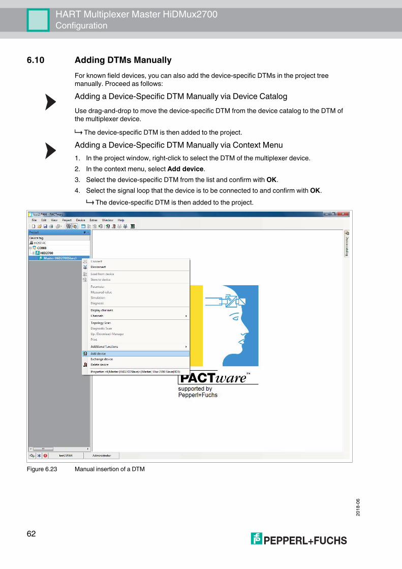
6.10 Adding DTMs ManuallyFor known field devices, you can also add the device-specific DTMs in the project tree manually. Proceed as follows:Adding a Device-Specific DTM Manually via Device CatalogUse drag-and-drop to move the device-specific DTM from the device catalog to the DTM of the multiplexer device.
The device-specific DTM is then added to the project.Adding a Device-Specific DTM Manually via Context Menu1. In the project window, right-click to select the DTM of the multiplexer device.2. In the context menu, select Add device.3. Select the device-specific DTM from the list and confirm with OK.4. Select the signal loop that the device is to be connected to and confirm with OK.
The device-specific DTM is then added to the project.
Figure 6.23 Manual insertion of a DTM
62

HART Multiplexer Master HiDMux2700Operation
2018
-06
7 Operation
7.1 Device FunctionsThe software functions described in this chapter are usually integrated in the operating software of the process control system, i. e., the software functions are generally not enabled or disabled via the described HART commands. Instead, the operating software contains functions (menu commands) that take over these processes. Nevertheless, the underlying HART commands are described because the functions may have different names in the individual user interfaces and the underlying basic functions may not always be apparent from the name. For a list of the commands supported, see chapter 9.1.
All Functions at a GlanceThe following list shows all the functions of the multiplexer master at a glance:• 32 channels• Up to 992 signal loops per interface• Automatic search of all existing HART-compatible field devices (scan)• Switchable, independent, cyclical querying of the HART variables (command caching)• Acts as the primary or secondary multiplexer master• Fast RS-485 interface (multidrop) with up to 56700 baud• Integrated modem• Approved for Zone 2
Danger!Explosion hazard from live wiring of circuitsIf you connect or disconnect energized circuits in a potentially explosive atmosphere, sparks can ignite the surrounding atmosphere.Only connect or disconnect energized circuits in the absence of a potentially explosive atmosphere.
Danger!Explosion hazard from sparking when using operating elementsUsing operating elements in a potentially explosive atmosphere can cause sparks that can ignite the surrounding atmosphere. Only use operating elements (e. g. switch, slider, button, etc.) in the absence of a potentially explosive atmosphere.
63

2018
-06
HART Multiplexer Master HiDMux2700Operation
7.1.1 Number of ChannelsIn addition to the multiplexer master, the HART multiplexer master HiDMux2700 integrates a multiplexer slave with slave address 0. In doing so, the HART multiplexer master provides 32 channels for connecting field devices or control units that support digital communication according to the HART specification.
7.1.2 Multiplexer Table (Module Table)The multiplexer master must be labeled as present in a multiplexer table, see chapter 9.1, command 157. Only modules defined as present in this table are included in communication. The multiplexer table consists of 16 bits, 1 bit for each multiplexer address. The default setting is module 0 (multiplexer master) and 1 activated.
7.1.3 InterfaceThe multiplexer master acts as a transparent gateway between the maintenance station and the field devices. The maintenance station is typically a computer with appropriate software, see chapter 3.2. The maintenance station can address up to 31 multiplexer masters via an RS-485 connection with a speed of up to 57600 baud. Since each multiplexer master can address up to 32 field devices, each RS-485 interface can communicate with up to 992 field devices.
7.1.4 HART CommunicationAs a digital communication system for maintenance and configuration purposes, the HART protocol is supported by many field devices with conventional analog 4 mA to 20 mA circuits. The HART signal is modulated to the analog current as an FSK signal, see chapter 3.1. The modulator/demodulator circuit (modem) required is integrated in the multiplexer device. Only one HART-compatible field device can be connected to each HART connection of the multiplexer device – there is no multidrop functionality.Special procedures with regard to the HART communication:• On the host side (RS-485), the extended address is always used, except in the case of
command 0.• On the field device side, either the polling address or the extended address is used
depending on the need.• The primary master and secondary master operating modes and the corresponding
time responses are supported on the field device side.• On the host side, only the commands 0 to 3 and 11 to 13 are accepted from the
secondary host. Other commands are not accepted or are ignored.• Commands to connected field devices are only accepted from the primary host.• Extended messages and messages in burst mode are detected and used but are not
generated by the multiplexer device itself.• A response buffer is available for a delayed response telegram. A message with an
initiating command that requires a long execution time can be temporarily stored here.
64

HART Multiplexer Master HiDMux2700Operation
2018
-06
7.1.5 Constructing the Signal Loop/Scan (Software Function)When the power supply to the device is switched on, the device searches the multiplexer devices listed in the multiplexer table for the connected HART field devices (command 0 and 4 1) and, in doing so, generates the internally required access tables. This process can also be performed by the maintenance station connected, as is necessary for communication with newly connected HART-compatible field devices. The length of this process depends:• on the number of multiplexer devices connected• on the number of connected HART-compatible field devices• on the loop search type, see chapter 9.1, command 153,• on the number of message repetitions in the case of a fault, or• on whether the query has been answered.With 32 field devices the duration is between 30 s and 60 s (e. g. with the use of only one multiplexer).
During the scanning process, only certain read commands (commands 0, 1, 2, 3, 11, 12, 13, 48, 129) are accepted by the maintenance station. All other commands result in the response Busy until the scanning process is concluded.
7.1.6 Cyclical Data Retrieval/Command Caching (Software Function)The multiplexer master can read cyclical data from up to 32 field devices. To do this, the scan option (command 137) must be set for the field device and the scan function in the multiplexer must be activated (command 149, function 1). The Scan command option (command 147) defines which data is to be transferred, see chapter 9.1.
If the scan function is activated, the field devices on which the scan option is activated are regularly checked for data. To do this, the scan command that reads one or more variables from the field device is executed. If a field device does not respond, it is designated as Disappeared (command 129) but it remains in the search list. This means that the field device will be searched for again during the next cycle. If a field device has disappeared but responds correctly during one of the next search commands, it is designated as Appeared. If another field device has responded instead, the Mismatched status appears.
1 Command 4 is also used for field devices that support only older HART specifications up to command 4.
Note!In the DTM, the parameters for the signal loop construction can be parameterized in the Communication menu in the Communication to field devices (as HART master) section. For a detailed description, see chapter 6.7.3.
Note!In the DTM, the scan function for cyclic data retrieval can be activated and parametrized in the Command caching menu. For a detailed description, see chapter 6.7.4.
65

2018
-06
HART Multiplexer Master HiDMux2700Operation
7.1.7 Variant of the Scan Function (Special Scan Function)The special scan function (command 149, function 2) uses an additional parameter that defines the minimum length of expected data bytes. This parameter can be different for each signal loop but it must be set for each signal loop to be scanned.
The scanning process itself takes place as described in the chapter above. However, the response of the field device is compared with the expected data length. If the length of the response is below the specified minimum data length, the response is rejected. If the minimum data length is 0, the response is always stored.
7.2 Software Functions7.2.1 Field Device List
Scanning Signal Loops1. Use the mouse to double-click the multiplexer master HiDMux2700 in the project window.2. In the editing window, open the Device actions > Scan loops menu.
The Scan loops for field devices window is displayed.In the Scan loops for field devices window, you can start a scan to identify all field devices connected to the multiplexer master. Proceed as follows:• In the left-hand area, select the signal loops that you want to search. If you select slave 1,
all signal loops of slave 1 are scanned.• Selecting the Scan selected loops button starts the scan of the signal loops. The scan
may take several minutes.Once the signal loops have been scanned, you will find further information about the connected field devices in the field device list, see chapter 7.2.2.
Note!The special scan function cannot be parameterized via the DTM. It can only be parameterized via HART commands from the host.
66

HART Multiplexer Master HiDMux2700Operation
2018
-06
Figure 7.1 Scan loops window
67

2018
-06
HART Multiplexer Master HiDMux2700Operation
7.2.2 Field Device ListSelecting the Field Device List1. Use the mouse to double-click the multiplexer master HiDMux2700 in the project window.2. In the editing window, open the Related tasks > Connected field devices menu.
The Connected field devices window is displayed.In the Connected field devices window, a table detailing information on the field devices connected to the multiplexer master is shown:
Table column ExplanationModules Module to which the field device is connectedLoop Signal loop in which the field device is connectedPolling address Polling address of the field deviceUnique ID Unique, unchanging address of the field deviceDevice type Device typeManufacturer Manufacturer of the field deviceHART revision HART revision under which the field device is operatedLong tag Long device tag of the field deviceTag Tag for identification of the field deviceDescriptor Description for the field deviceDate Date of the last change to the identification informationMessage Any user-created message/comment
Table 7.1 Explanation of the field device list
68
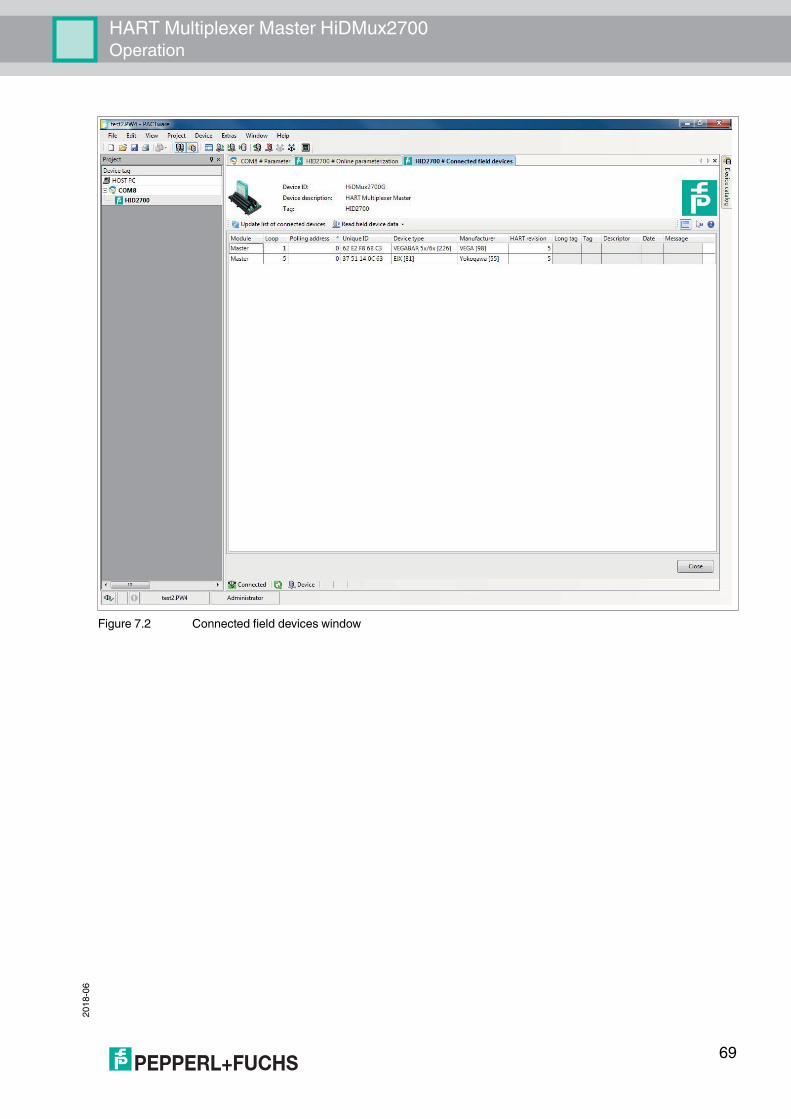
HART Multiplexer Master HiDMux2700Operation
2018
-06
Figure 7.2 Connected field devices window
69
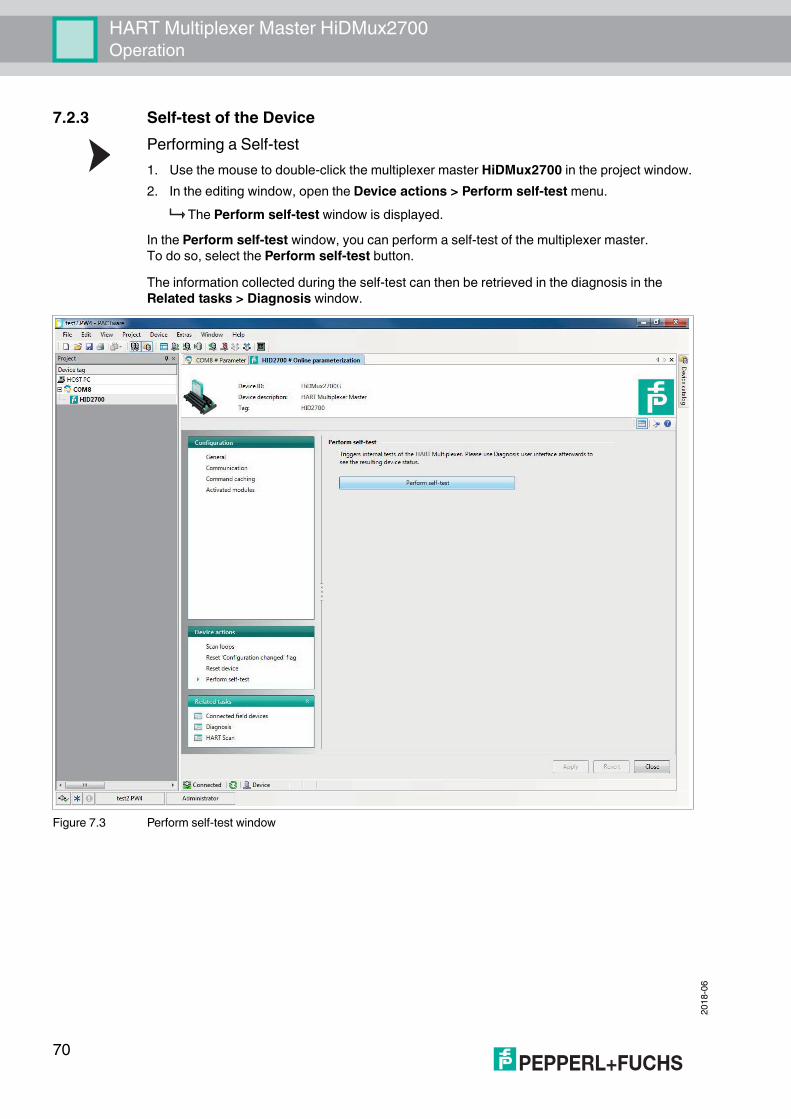
2018
-06
HART Multiplexer Master HiDMux2700Operation
7.2.3 Self-test of the DevicePerforming a Self-test1. Use the mouse to double-click the multiplexer master HiDMux2700 in the project window.2. In the editing window, open the Device actions > Perform self-test menu.
The Perform self-test window is displayed.In the Perform self-test window, you can perform a self-test of the multiplexer master. To do so, select the Perform self-test button.The information collected during the self-test can then be retrieved in the diagnosis in the Related tasks > Diagnosis window.
Figure 7.3 Perform self-test window
70

HART Multiplexer Master HiDMux2700Operation
2018
-06
7.2.4 Device DiagnosisSelecting a Diagnosis1. Use the mouse to double-click the multiplexer master HiDMux2700 in the project window.2. In the editing window, open the Related tasks > Diagnosis menu.
The Diagnosis window is displayed.In the Diagnosis window, detailed diagnostic information regarding the multiplexer master and the field devices connected to it can be retrieved.In the System overview section, the device tree is displayed on the left-hand side with the connected devices. Click on a device to select it.The right-hand section displays device-specific, detailed diagnostic information.Select the Update diagnosis button above the System overview section to update the diagnostic information.
Figure 7.4 Diagnosis window
Note!For a precise explanation of the diagnostic information, see chapter 7.3.
71

2018
-06
HART Multiplexer Master HiDMux2700Operation
7.2.5 Configuration Flag ResetResetting the Configuration Flag1. Use the mouse to double-click the multiplexer master HiDMux2700 in the project window.2. In the editing window, open the
Device actions > Reset "Configuration changed" flag menu. The Reset "Configuration changed" flag window is displayed.
The "Configuration changed" flag is a flag of the standard HART device status. It is always set when a parameter has been changed in the configuration of the device.In the Reset "Configuration changed" flag window, you can reset the "Configuration changed" flag. To do this, select the Reset "Configuration changed" flag button.
Figure 7.5 Reset "Configuration changed" flag window
72
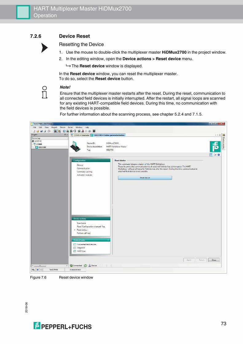
HART Multiplexer Master HiDMux2700Operation
2018
-06
7.2.6 Device ResetResetting the Device1. Use the mouse to double-click the multiplexer master HiDMux2700 in the project window.2. In the editing window, open the Device actions > Reset device menu.
The Reset device window is displayed.In the Reset device window, you can reset the multiplexer master. To do so, select the Reset device button.
Figure 7.6 Reset device window
Note!Ensure that the multiplexer master restarts after the reset. During the reset, communication to all connected field devices is initially interrupted. After the restart, all signal loops are scanned for any existing HART-compatible field devices. During this time, no communication with the field devices is possible.For further information about the scanning process, see chapter 5.2.4 and 7.1.5.
73

2018
-06
HART Multiplexer Master HiDMux2700Operation
7.3 Diagnosis and TroubleshootingThis chapter provides operating instructions to be used if faults occur and describes the possible causes of such faults. Faults and failures are reported via the following means:• LED indication, see chapter 7.3.1• Status/response code, see chapter 7.3.2• Extended device status, see chapter 7.3.3
7.3.1 LED IndicationAfter you have switched the device on, the following fault states can occur during the initialization process:
Red Green Yellow Cause Corrective actionOff Off Off • No power supply present.
• LED(s) faulty.• Check the power supply.• Switch on DIP switch 8, briefly
disconnect the power supply. LEDs flash one after the other.
On On On Device hardware fault (CPU, ROM) Send the device to Pepperl+Fuchs for repair.
On Off Off Device hardware fault (CPU, ROM) Send the device to Pepperl+Fuchs for repair.
On On Off • Device hardware fault (CPU, ROM)
• Device parameterization (command 161) faulty.
• Send the device to Pepperl+Fuchs for repair.
• Parameterize the device again. If this is not successful, the device must be sent to Pepperl+Fuchs for repair.
Table 7.2
74

HART Multiplexer Master HiDMux2700Operation
2018
-06
7.3.2 Status/Response CodeTwo status bytes, known as the Response code, are included in each field device message. These include three types of information:• Communication faults• Command responses• Device statusDependent on bit 7, the first two types are contained in the first byte of the status. The device status is always transferred in the second byte.
Structure of the First Byte (Communication Fault)If bit 7 is set (1), the first status byte contains a summary of communication faults. This information is coded bit by bit.If bit 7 is deleted (0), the first status byte contains a summary of command responses. This information is numbered and not coded bit by bit.
Communication FaultsThe byte contains information concerning the receipt of a message. The individual bits indicate a detected fault, which has resulted in the message not being accepted. It is therefore not possible to provide a response to the message. This problem can only be avoided by:• Repeating the command,• Checking the connection,• Using terminators, or• Reducing the baud rate.
Bit Meaning7 6 5 4 3 2 1 01 Communication fault, if bit 7 = 1, coded bit by bit1 1 Parity fault1 1 Overflow fault1 1 Message fault1 1 Checksum fault1 0 Always 0 (reserved) 1 1 Receive buffer overflow1 1 (Undefined)
Table 7.3
75

2018
-06
HART Multiplexer Master HiDMux2700Operation
Command ResponsesThe first byte contains information regarding the execution of a command. The command-specific response code documents the execution of the command.In contrast to the communication faults, the command responses are not coded bit by bit and are instead numbered from 0 to 127.For command responses reported by multiplexer devices, two instances are warnings (codes 8 and 31). In these cases the processing of the command is continued. In other cases, there are faults indicating that the initiating command could not be correctly executed. The meaning of the codes is explained in the following table.
Code Designation Meaning Can occur in the case of a command
2 Invalid selection Invalid selection: The selected code/index is not permitted.
147, 149, 151, 153
3 Passed parameter too large
The parameter value was too large. 59, 129, 155
4 Passed parameter too small
The parameter value was too small. 59
5 Too few data bytes received
The message has no faults but contains fewer bytes than expected for the execution of the command.
17, 18, 59, 129 to 141, 145, 147, 149, 151, 153, 154, 155, 157
8 Warning Here (132): Preamble length is not within the range of 5 to 20 and has been set to 5 or 20
132
9 1st parameter too large The first of the two parameters is too large. 14511 2nd parameter too large The second of the two parameters is too
large. 145
16 Access restricted The command was ignored because the current state of the device does not permit the correct execution of the command.
6, 17, 18, 38, 41, 42, 48, 59, 106, 128 to 157
17 Too many items requested
Too many items have been requested. 131, 132, 133, 135 to 141, 154
31 Warning Here (137): Scan value has not been changed as it is identical.
137
32 Busy The device is executing a function that cannot be interrupted by this command.
6, 17, 18, 38, 41, 42, 59, 106, 128, 130 to 157
64 Command not implemented
Command does not exist and therefore cannot be executed. This fault message is also output if an fault occurs that cannot be specified more precisely by the device.
almost all
65 Not specified Parameter is not within the permissible range.
132, 137
Table 7.4
Note!Additional information can be found in /1/, see chapter 9.2.
76

HART Multiplexer Master HiDMux2700Operation
2018
-06
Structure of the Second Byte (Device Status)If a communication fault is reported in the first byte (bit 7 = 1), the second byte described here has no significance (always 0). Otherwise it contains the overall status of the field device, i. e. regardless of the commands. The individual bits have the following meanings:
Bit Designation Meaning Action7 Malfunction of
the field deviceHardware fault. The extended device status may provide further information, see chapter 7.3.3.
• Read extended device status, see chapter 7.3.3.
• Check LEDs, see chapter 7.3.1.• Parameterize device again.
6 Configuration changed.
A write command has been executed.
This bit can be deleted using command 38.
5 Switch-on process is running.
The power supply has been switched on or a reset has been triggered. Volatile data is reset to the default setting.
Wait for the switch-on process and then parameterize the device.
4 Extended device status available.
Further status messages are available and can be called up, see chapter 7.3.3.
Read extended device status, see chapter 7.3.3.
3 Analog output current cannot be changed (primary variable).
The primary variable is set to the requested value and no longer follows the process.
Always 1Has no function on the multiplexer device as there is no analog output.
2 Analog output current has reached its limit (primary variable).
The primary variable is outside its limit values and therefore no longer corresponds to the process value.
Always 0Has no function on the multiplexer device.
1 Variable (not the primary) outside the range.
The data detected by the sensor – not the data for the primary variable – lies outside the operating range. The extended device status may provide further information, see chapter 7.3.3.
Always 0Has no function on the multiplexer device.
0 Primary variable outside the range.
Primary variable outside the range. The measured value detected by the sensor is outside the operating range.
Always 0Has no function on the multiplexer device.
Table 7.5
Note!Additional information can be found in /1/, see chapter 9.2.
77

2018
-06
HART Multiplexer Master HiDMux2700Operation
7.3.3 Extended Device StatusThe extended device status can be retrieved using command 48. The command provides 5 byte of information which are arranged thematically:
First ByteThe operation is currently in progressThe byte indicates which operation is currently running. The information is coded bit by bit. The coding is shown in the following table:
Second ByteHardware faultThe byte indicates which operation is currently running. The information is coded bit by bit. The coding is shown in the following table:
Bit Operation in progress Meaning7 Reset Switch-on operation is running and must be
completed.6 Rebuild Rebuild operation is running and must be
completed.5 Internal EEPROM write
operationSwitching off the power supply may result in the loss of parameterization.
4 Scan Scanning process is running and must be completed.
3 Self-test (command 41) Performs the device self-test, such as when switching on the supply voltage. If no fault occurs, the status message Malfunction is deleted if the message has been set.
2 to 0 Reserved Reserved.Table 7.6
Bit Detected hardware fault Meaning/remedial action7 Signal loop OR link of all detected hardware faults in
the signal loops. Check the field devices and their cabling, then run Scan loops, see chapter 7.2.1.
6 ROM fault Send the device to Pepperl+Fuchs for repair.5 EEPROM fault Send the device to Pepperl+Fuchs for repair.4 to 0 Reserved Reserved.
Table 7.7
78

HART Multiplexer Master HiDMux2700Operation
2018
-06
Third ByteScan faultThe byte indicates an OR link for all the faults detected during the scanning process.Example: If one field device is detected as Disappeared and another as Mismatched, these two bits are set at the same time. The bit by bit coded information is shown in the following table:
Bit Status Meaning Action7 Reserved Reserved.6 Searching Field device is searched for due
to the Disappeared report.• Check the cabling.• Check the field device.
5 Disappeared Field device is no longer responding.
4 Appeared Field device is responding again.
Check the cabling.
3 Mismatched Another field device has responded instead.
Field device was replaced with another field device. Check the field device, rebuild signal loops.
2 to 0 Reserved Reserved.Table 7.8
Note!Additional information can be found in /1/, see chapter 9.2.
79

2018
-06
HART Multiplexer Master HiDMux2700Dismounting, Maintenance, and Repair
8 Dismounting, Maintenance, and Repair
Disconnecting Circuits1. Disconnect the power supply.2. Disconnect the field circuit.3. Disconnect the control circuit.4. Disconnect the HART communication.
Danger!Explosion hazard from live wiring of circuitsIf you connect or disconnect energized circuits in a potentially explosive atmosphere, sparks can ignite the surrounding atmosphere.Only connect or disconnect energized circuits in the absence of a potentially explosive atmosphere.
Danger!Explosion hazard from changing the fuseThe changing of the fuse under voltage can cause sparks. This can ignite the surrounding potentially explosive atmosphere.De-energize the device before changing the fuse.
Danger!Danger to life from using damaged or repaired devices.Using a defective or repaired device can compromise its function and its electrical safety.• Do not use a damaged or polluted device.• The device must not be repaired, changed or manipulated.• If there is a defect, always replace the device with an original device from Pepperl+Fuchs.
80

HART Multiplexer Master HiDMux2700Dismounting, Maintenance, and Repair
2018
-06
8.1 Dismounting the Multiplexer MasterDismounting the Multiplexer Master from the Termination Board1. Pull the red Quick Lok bar (1) up on each side of the device.2. Carefully pull the device out from the contacts and locking elements.
Figure 8.1 Dismounting of an H-System isolated barrier
1 Quick Lok Bar2 Coding pins3 Adjustment pins
1
2
3
3
81

2018
-06
HART Multiplexer Master HiDMux2700Dismounting, Maintenance, and Repair
8.2 Dismounting the Termination Boards
Dismounting the Termination Board with Screw Mounting1. Loosen the fastening screws (3).2. Remove the termination board (2) from the DIN mounting rail (1).
Figure 8.2 Termination board fixing
Warning!Risk of short circuitWorking on live parts can cause injuries and can compromise the function and the electrical safety of the device.• Before working on the device, always disconnect the supply voltage.• Connect the device to the supply voltage only after completion of the work.
1 DIN mounting rail2 Termination board3 Fastening screw
1 2 3
82

HART Multiplexer Master HiDMux2700Dismounting, Maintenance, and Repair
2018
-06
Figure 8.3 Termination board dismounting
Dismounting the Termination Board without Screw MountingUse for dismounting of the device a suitable slotted screwdriver1. Insert the screwdriver (4) into the groove of the mounting slider (3).2. Pull back the mounting slider (3) with the screwdriver (4) until the mounting slider (3)
releases the DIN mounting rail (1).3. Repeat these steps for the other mounting sliders of the device.4. Remove the termination board (2) from the DIN mounting rail (1).
Figure 8.4 Termination board dismounting
1 DIN mounting rail2 Termination board
1
2
1 DIN mounting rail2 Termination board3 Mounting slider4 Slotted screwdriver
12
3
4
83

2018
-06
HART Multiplexer Master HiDMux2700Appendix
9 Appendix9.1 Supported HART Commands
The following tables show the HART commands supported by the HART multiplexer system. The HART commands are divided into 3 groups:• Universal commands• Common practice commands• Device-specific commands
9.1.1 Universal Commands
Note!The universal commands and common practice commands are described in detail in /1/, see chapter 9.2. At this point, only the functions are explained, not the underlying data structures of the HART protocol.
Command Action Meaning0 Read unique device
identification.A 12 byte device identification is given in response.
1 Read HART variables (data). Commands are only supported by the HART multiplexer system for compatibility purposes and have no significance. However, in the field devices (e. g. scan function) they have the following meanings:• 1: Read primary variable.• 2: Read primary variable as a current (mA) and
percentage of the measuring range.• 3: Read primary variable as a current (mA) and four
(pre-defined) dynamic variables.
2
3
6 Set polling address. This command will not be accepted and the messages Access restricted or Busy will be returned.
11 Read unique device identification using the tags.
A 12 byte device identification is given in response if the specified tag corresponds to the tag stored in the HART multiplexer system.
12 Read message. The 32-digit message is read, see also command 17.
13 Read the tag, description, and date.
Read the 8-digit tag, the 16-digit description, and the date.
17 Save message. The 32-digit message is written, see also command 12.18 Save the tag, description,
and date.Save an 8-digit tag, a 16-digit description, and a date.
Table 9.1
84
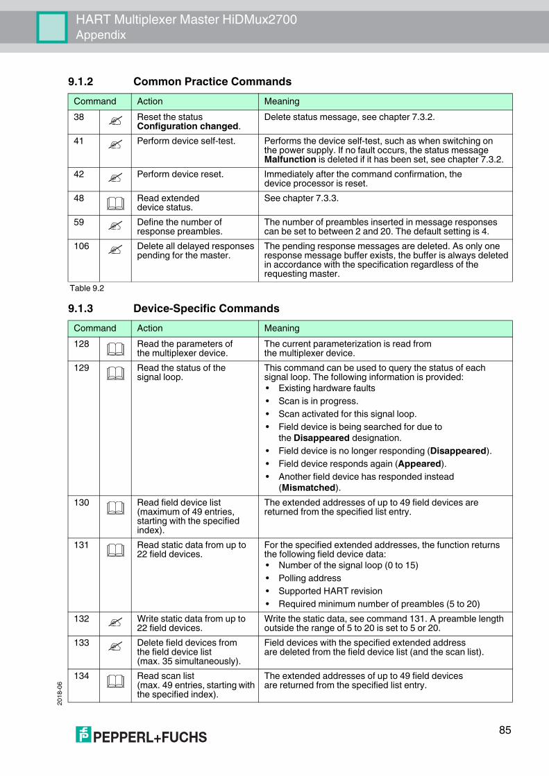
HART Multiplexer Master HiDMux2700Appendix
2018
-06
9.1.2 Common Practice Commands
9.1.3 Device-Specific Commands
Command Action Meaning38 Reset the status
Configuration changed.Delete status message, see chapter 7.3.2.
41 Perform device self-test. Performs the device self-test, such as when switching on the power supply. If no fault occurs, the status message Malfunction is deleted if it has been set, see chapter 7.3.2.
42 Perform device reset. Immediately after the command confirmation, the device processor is reset.
48 Read extended device status.
See chapter 7.3.3.
59 Define the number of response preambles.
The number of preambles inserted in message responses can be set to between 2 and 20. The default setting is 4.
106 Delete all delayed responses pending for the master.
The pending response messages are deleted. As only one response message buffer exists, the buffer is always deleted in accordance with the specification regardless of the requesting master.
Table 9.2
Command Action Meaning128 Read the parameters of
the multiplexer device.The current parameterization is read from the multiplexer device.
129 Read the status of the signal loop.
This command can be used to query the status of each signal loop. The following information is provided:• Existing hardware faults• Scan is in progress.• Scan activated for this signal loop.• Field device is being searched for due to
the Disappeared designation.• Field device is no longer responding (Disappeared).• Field device responds again (Appeared).• Another field device has responded instead
(Mismatched).130 Read field device list
(maximum of 49 entries, starting with the specified index).
The extended addresses of up to 49 field devices are returned from the specified list entry.
131 Read static data from up to 22 field devices.
For the specified extended addresses, the function returns the following field device data:• Number of the signal loop (0 to 15)• Polling address• Supported HART revision• Required minimum number of preambles (5 to 20)
132 Write static data from up to 22 field devices.
Write the static data, see command 131. A preamble length outside the range of 5 to 20 is set to 5 or 20.
133 Delete field devices from the field device list (max. 35 simultaneously).
Field devices with the specified extended address are deleted from the field device list (and the scan list).
134 Read scan list (max. 49 entries, starting with the specified index).
The extended addresses of up to 49 field devices are returned from the specified list entry.
85
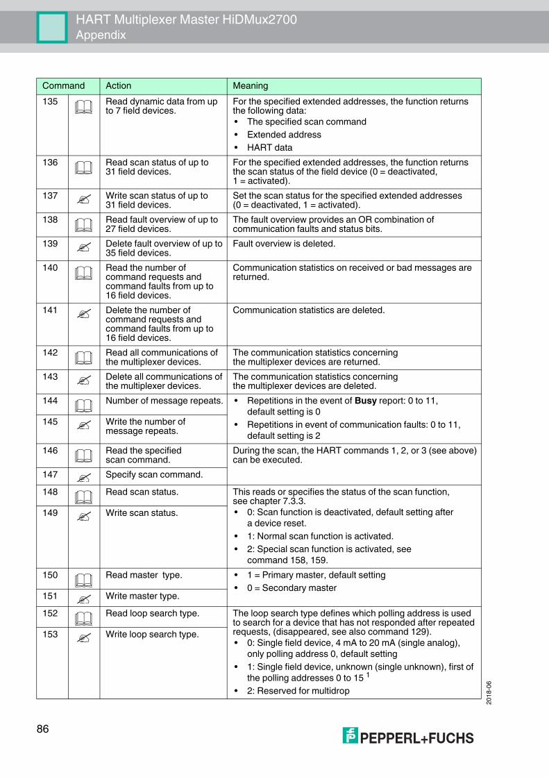
2018
-06
HART Multiplexer Master HiDMux2700Appendix
135 Read dynamic data from up to 7 field devices.
For the specified extended addresses, the function returns the following data:• The specified scan command• Extended address• HART data
136 Read scan status of up to 31 field devices.
For the specified extended addresses, the function returns the scan status of the field device (0 = deactivated, 1 = activated).
137 Write scan status of up to 31 field devices.
Set the scan status for the specified extended addresses (0 = deactivated, 1 = activated).
138 Read fault overview of up to 27 field devices.
The fault overview provides an OR combination of communication faults and status bits.
139 Delete fault overview of up to 35 field devices.
Fault overview is deleted.
140 Read the number of command requests and command faults from up to 16 field devices.
Communication statistics on received or bad messages are returned.
141 Delete the number of command requests and command faults from up to 16 field devices.
Communication statistics are deleted.
142 Read all communications of the multiplexer devices.
The communication statistics concerning the multiplexer devices are returned.
143 Delete all communications of the multiplexer devices.
The communication statistics concerning the multiplexer devices are deleted.
144 Number of message repeats. • Repetitions in the event of Busy report: 0 to 11, default setting is 0
• Repetitions in event of communication faults: 0 to 11, default setting is 2
145 Write the number of message repeats.
146 Read the specified scan command.
During the scan, the HART commands 1, 2, or 3 (see above) can be executed.
147 Specify scan command.148 Read scan status. This reads or specifies the status of the scan function,
see chapter 7.3.3.• 0: Scan function is deactivated, default setting after
a device reset.• 1: Normal scan function is activated.• 2: Special scan function is activated, see
command 158, 159.
149 Write scan status.
150 Read master type. • 1 = Primary master, default setting• 0 = Secondary master151 Write master type.
152 Read loop search type. The loop search type defines which polling address is used to search for a device that has not responded after repeated requests, (disappeared, see also command 129).• 0: Single field device, 4 mA to 20 mA (single analog),
only polling address 0, default setting• 1: Single field device, unknown (single unknown), first of
the polling addresses 0 to 15 1
• 2: Reserved for multidrop
153 Write loop search type.
Command Action Meaning
86

HART Multiplexer Master HiDMux2700Appendix
2018
-06
154 Scan up to 83 specified signal loops.
see chapter 7.1.5 and 7.2.1.
155 Pass through host command to the device and response to the host.
This enables any command to be sent to a field device and its response evaluated by the multiplexer device without any changes.
156 Read multiplexer table. (16 multiplexer devices)
Reads the specified multiplexer table, see command 157.
157 Write multiplexer table. (16 multiplexer devices)
Determines which multiplexer devices (multiplexer master and up to 15 multiplexer slaves) are assigned (2 byte, coded bit by bit).
158 Read special scan parameters.
The current special parameters and the field device data (if available) for the specified signal loop is provided. These include:• Number of the signal loop• Fault flag (0 = OK, 1 = special scan is not active)• Polling address, always 0, as there is no multidrop• The minimum number of data bytes for the special scan• The scan command used• Extended address• Number of available data bytes• Data byte content
159 Write special scan parameters.
For the specified signal loop and the polling address (must always be 0), the minimum number of data bytes (0 to 62) and the scan command to be used can be written.
160 Read delay period for channel change.
When changing the communication channel (0 to 255), the multiplexer can include a waiting period (0 ms to 300 ms) before HART commands are sent to the channel.161 Write delay period for
channel change.Table 9.3
1 The search process is 16 times longer with no field device connected, as all 16 polling addresses are checked.
Command Action Meaning
87

2018
-06
HART Multiplexer Master HiDMux2700Appendix
9.2 Bibliography/1/HART Communication Foundation: HART Communication Protocol SpecificationHCF_SPEC-13, Revision 7.5https://fieldcommgroup.org/hart-specifications
/2/HART Communication Foundation: HART Application GuideHCF_LIT-039 Rev. 7.1https://fieldcommgroup.org/technologies/hart/documents-and-downloads-hart
/3/Romilly BowdenHART Field Communications Protocol: A Technical Overview, 2007Fisher-Rosemount
88

HART Multiplexer Master HiDMux2700Appendix
2018
-06
9.3 GlossaryAddressIn communication systems, an address is used to identify the device to which a message is addressed. HART uses two addressing modes: a polling address in the range 0 to 15 and the extended address consisting of 38 bit. The polling address 0 is reserved for 4 mA to 20 mA analog field devices in point-to-point connections. The polling addresses 1 to 15 are reserved for field devices in multidrop connections.
Broadcast modeSee burst mode
Burst modeA communication mode in which the multiplexer master instructs field devices to continuously transmit process values – for example, the primary variable – to the multiplexer master without further instruction. The multiplexer master recognizes and supports this mode but does not put field devices in this mode itself.
Extended addressSee Address
DTMThe DTM (DTM – Device Type Manager) contains all the data and functions of a device. Every DTM contains its own user interface optimized for the device. The device and communication DTMs can be integrated in any FDT frame application, such as PACTware.The DTM offers almost no restriction with regard to display and user guidance. This means that all available device functions can be operated according to the user's needs. Operation is supported by graphics. The DTM technology enables consistent operation of a device in all FDT systems.Pepperl+Fuchs generates DTMs for HART-compatible devices by converting the device description (DD) of these devices for use with PACTware.Essentially, there are two different types of DTM:• Device DTMs
Device DTMs are DTMs for configuring field devices such as transmitter power supplies, signal converters, and trip amplifiers.
• Communication DTMsCommunication DTMs are required for communication with a device via a point-to-point connection or via any network structures. The communication DTMs are available for various interfaces, such as an RS-232 interface or a USB interface.
89

2018
-06
HART Multiplexer Master HiDMux2700Appendix
FDTThe FDT concept (FDT – Field Device Tool) created a standard that can be used to integrate devices in various user interfaces (framework applications such as PACTware). The FDT concept enables open and continuous device operation from the control level to the field, regardless of the bus systems used. The FDT concept specifies the data exchange between the device-specific driver and the framework application. Every communicating device has a device-specific driver (DTM) that is integrated in the framework application.
FSKAbbreviation for Frequency Shift Keying. Method of encoding the digital information 0 or 1 with two different frequencies.
HARTAbbreviation for Highway Addressable Remote Transducer. Designation for communication according to the HART protocol. HART is a master-slave system.
HostHigher-level system, e. g., maintenance station, computer, or process control system.
Polling addressSee Address
MasterA device (e. g., the control system) in a master-slave system which initiates all transmission requests and commands.
Master-slave systemCommunication system in which a master initiates all transmission requests and commands and a slave responds to the transmission requests and commands.
MultidropIn contrast to point-to-point connections, several (field) devices may be connected to one segment (core pair). To allow each device to be addressed individually, the device must have a unique address. As communication can only take place with one field device at a time, cycle times increase in proportion to the number of field devices. In HART multidrop operation, field devices fix their current consumption at 4 mA to enable parallel operation of up to 15 devices.
Multi masterHART allows the connection of two masters, a primary master and a secondary master. The main station is configured as the primary master. This is generally the control system or the main control. A second station is configured as secondary master. This can be a handheld or a maintenance station. The difference between the primary and secondary masters is the priority of access, i. e., the primary master has a higher priority than the secondary master. Messages sent by the masters are characterized by a master bit so that the masters can assign the message responses to their own messages.
90
HART Multiplexer Master HiDMux2700Appendix
2018
-06
PACTwareTM
PACTware (PACTware – Process Automation Configuration Tool) is a manufacturer-independent operating software for devices. In the past, it was often necessary to use multiple manufacturer-specific programs to be able to operate different devices. PACTware enables you to operate any number of devices with just this software. PACTware is not only a configuration tool, it also offers an interface to HART-compatible field devices as well as to bus systems such as PROFIBUS, MODBUS, and ControlNet. PACTware offers many features that allow users to simplify the plant documentation, to create trend curves, and to monitor signals using HART data.
Point-to-point connectionIn point-to-point connections, only two communication participants can be connected to one segment (core pair). A point-to-point connection is, for example, the master-slave connection of multiplexer device to field device.
Primary variableThis variable is a process measured value of the field device. The unit differs according to the HART command (see commands 1, 2 and 3). The primary variable of a pressure transducer may be, for example, the measured process pressure in bar.
Primary masterSee Multi master
Secondary variableThis variable is a further, additional process measured value of the field device. Up to 4 additional values are supported via HART. This variable can only be read using HART command 3.
Secondary masterSee Multi master
SlaveA device in a master-slave system that receives commands from a master. A slave cannot initiate a transmission request.
Smart field deviceIntelligent, programmable field device with microprocessor and memory which is able to perform calculations, integrated diagnostics, and fault reports and can communicate with a remote control.
TagUnique identifier of the C&I point (Control and Instrumentation technology) of the field device within a process plant.
91

Subject to modifications Copyright PEPPERL+FUCHS • Printed in Germany
www.pepperl-fuchs.com
Worldwide HeadquartersPepperl+Fuchs GmbH68307 Mannheim · GermanyTel. +49 621 776-0E-mail: [email protected]
For the Pepperl+Fuchs representative closest to you check www.pepperl-fuchs.com/contact
PROCESS AUTOMATION –PROTECTING YOUR PROCESS
DOCT-0250E06/2018