In situ evaluation of ground heat exchanger performances ...
Upload
independentCategory
view
1download
0
International Journal of Heat and Mass Transfer 47 (2003) 111–124
www.elsevier.com/locate/ijhmt
Dendritic fins optimization for a coaxial two-streamheat exchanger
J. Bonjour a,*, L.A.O. Rocha b, A. Bejan b, F. Meunier a
a Laboratoire du Froid (E.A. 21), CNAM, 292 rue Saint Martin, 75141 Paris Cedex 03, Franceb Department of Mechanical Engineering and Materials Science, Duke University, Box 90300, Durham, NC 27708-0300, USA
Received 15 November 2002
Abstract
This paper documents the fundamental relation between the maximization of global performance and the maleable
(morphing) architecture of a flow system with global constraints. The example is the coaxial two-stream heat exchanger
with flow through a porous bed in the annular space. It is shown that the constraints force the design toward heat
exchangers with finite axial length, where additional improvements are derived from installing high-conductivity fins
across the porous bed. The maximization of global performance is achieved through the optimization of the config-
uration of plate fins. Configurations with radial fins are optimized analytically and numerically. Configurations with
branched fins are optimized numerically. It is shown that the best configuration (radial vs. branched) depends on the
size of the heat exchanger cross-section. When the size is small, the best is the radial pattern. When the size exceeds a
certain threshold, the best configuration is the optimized branched tree of fins.
� 2003 Elsevier Ltd. All rights reserved.
Keywords: Constructal design; Geometry optimization; Heat exchangers; Temperature swing adsorption; Fins; Tree networks
1. Introduction
In this paper we consider the fundamental problem
of squeezing into a fixed volume the highest heat transfer
rate that can be made to occur between two streams at
different initial temperatures. This is a problem of great
importance in the compaction and miniaturization of
every flow system that requires heat exchangers. The
approach that we have chosen is to allow the configu-
ration of the heat exchanger to vary, and to select its
architectural features such that the heat exchanger per-
forms best at a global level. This work is an extension of
the constructal design method [1], according to which
the flow architecture of a system is free to vary and is
deduced from a principle of global performance maxi-
mization subject to global constraints.
* Corresponding author. Tel.: +33-1-58-80-85-51; fax: +33-1-
40-27-25-95/20-47.
E-mail address: [email protected] (J. Bonjour).
0017-9310/$ - see front matter � 2003 Elsevier Ltd. All rights reserv
doi:10.1016/S0017-9310(03)00406-X
The coaxial heat exchanger selected for optimization
in this paper is important because of its wide applica-
bility: it is one of the simplest two-stream arrangements
known [2,3]. In addition, it is a device that promises to
play an important role in the development of efficient
systems for temperature swing adsorption (TSA) [4–7].
This application served as stimulus for the present work,
and for this reason we describe it in some detail.
Temperature swing adsorption processes are gas-
separation processes based on a periodic variation of the
temperature of an adsorbent porous bed. The adsorp-
tion occurs at a low temperature and the bed regenera-
tion at a high temperature. TSA is usually recommended
for purification (when a small fraction of the gas stream
must be adsorbed, typically <10% by weight) rather than
for bulk separation (high fractions) [8]. TSA cycle times
are usually quite long (from several hours to several
days) and are characterized by high energy consump-
tion, which makes the cycle optimization (mass flow
rates, temperature level, bed geometry) a subject of great
importance.
ed.

Nomenclature
A area, m2
B group of geometric parameters, m3 K/W,
Eq. (11)
cp specific heat at constant pressure, J/kgK
CV group of parameters that accounts for
overall size, m4, Eq. (24)
D0 thickness of radial fin, m
D1 thickness of peripheral (branched) fin, m
H height, m
k porous bed thermal conductivity, W/mK
kf fin thermal conductivity, W/mK
L length, m
L0 length of radial fin, m
L1 length of peripheral (branched) fin, m
m mass, kg
_mm mass flow rate, kg/s
n number of heat exchangers
N number of fins
q000 heat transfer rate per unit volume, W/m3
r radial position, m
R radius, mbRR dimensionless radius, Eq. (32)
u volume averaged velocity, m/s
t thickness, m
T temperature, K
TSA temperature swing adsorption
V volume, m3
Vf fin volume, m3
x, y cartesian coordinates, m
Greek symbols
a porous bed thermal diffusivity, m2/s
b angle, rad
e effectiveness
q density, kg/m3
/ metal volume fraction
Subscripts
end end of fin
f fin
h hot spot
in inlet
min minimal
out outlet
s shell
t central tube
Superscript
ð~Þ dimensionless variables, Eqs. (30)
112 J. Bonjour et al. / International Journal of Heat and Mass Transfer 47 (2003) 111–124
Most of the TSA processes use hot gas or steam for
the regeneration phase. However, in the case of direct
heating with steam, the adsorbent must be dried after
the regeneration. In addition, if the adsorbate is miscible
with water, a secondary unit must be used to separate
the water. The hot gas technique leads to a diluted de-
sorbed phase and, consequently, low condensation
temperatures must be reached if the purpose of the
process is to reuse the adsorbate. This is the reason why
several alternative processes have been developed re-
cently for the purpose of avoiding direct heating. These
processes use Joule heating generated by the electrical
resistance of the adsorbent [9], microwaves [10], ther-
moelectric devices [11], and indirect heating [12]. Indi-
rect cooling and heating tend to shorten the cycle times,
and this usually leads to higher energy performance [13].
TSA processes with indirect cooling and heating
usually employ a column made of concentric tubes. The
column is heated during the regeneration step and cooled
during the adsorption step. The outer surface of the outer
tube is insulated in order to reduce heat losses. Radial
fins can be located on the outer surface of the inner tube,
to enhance the global heat transfer coefficient and to
decrease the nonuniformity in temperature and ad-
sorbed-phase concentration. Short cycle times and high
adsorption capacities require high global heat transfer
coefficients during the heating and cooling periods. This
recommends the use of a finned geometry on the porous
bed side, where the heat transfer coefficients range from
10 to 50 W/m2 K [14]. In addition, boiling or condensa-
tion inside the inner tube is preferable, because of high
heat transfer coefficients: they range from 4000 to 7000
W/m2 K, as measured in a simulated adsorption column
by Mativet [15] and Mativet et al. [16].
Two main requirements drive the development of
TSA technology: the need to reduce the adsorbent in-
ventory, and the need to improve the overall process
efficiently. Consequently, heat exchange optimization is
a key issue because it reduces the regeneration time,
improves the global effectiveness, and reduces the inert
mass inventory.
In this paper, we explore the relationship between
heat exchanger performance and the architecture of the
fins that are distributed through the packed bed: radial
fins vs. dendritic fins. In Sections 2 and 3 we begin with
an analytical model of a coaxial heat exchanger with fins
in the annular space. In Section 4 we include in the
model the global constraints of fixed total volume and
fin material, which points the design configuration in the
direction of tubes of finite length, and annular spaces
with embedded fins. The smallest construction detail is
introduced as a manufacturing constraint in Section 5.
Optimizations for fixed effectiveness and several heat
exchangers in parallel are performed in Sections 6 and 7.

J. Bonjour et al. / International Journal of Heat and Mass Transfer 47 (2003) 111–124 113
The optimization of cross-sectional configurations with
radial and dendritic fins is pursued numerically in Sec-
tion 8. The paper concludes with a design example, and
a discussion of the role of dendritic flow structures in
maximizing the global performance of heat exchangers.
2. Heat exchanger configuration
The objective of the following analysis is the opti-
mization of the geometry of the two-stream heat ex-
changer shown in Fig. 1. One stream flows through a
small-diameter tube placed on the centerline of a cylin-
drical shell of radius R and length L. The annular spaceis a packed bed through which the second stream flows
axially. For simplicity, we assume that the tube on the
centerline is isothermal and at the low temperature Tmin.This low temperature is maintained by a stream that
evaporates as it flows at constant pressure through the
tube.
The second stream is single-phase, and enters the
annulus at the high temperature Tin. The flow rate, or thevolume averaged axial velocity u is specified. The tem-perature of this stream drops while in contact with the
Tmin tube, and reaches its lowest temperature at theoutlet, Tout. The effectiveness, or the total heat transferrate between the two streams is maximal when Tout isminimal. To achieve this level of performance is the
objective of the optimization of flow geometry, which is
described next.
The geometry of the cylindrical structure is compli-
cated by the installation of a number (N ) of radial high-conductivity plate fins of thickness t. These serve twofunctions, to enhance the heat transfer between the two
streams, and to provide rigidity for the assembly. In
sum, the geometry of the device is represented by the
parameters R, L, N and t. There are two global para-meters that may serve as constraints in the optimization,
the total volume of the heat exchanger,
V ¼ pR2L ð1Þ
and the total volume of the fin material,
Vf ¼ NtRL ð2Þ
Fig. 1. Coaxial two-stream heat exc
The latter can also be represented by the volume fraction
occupied by the fins,
/ ¼ VfV
¼ NtpR
ð3Þ
An alternative to the Vf constraint is the total mass ofthe heat exchanger,
m ¼ ðqfNtRþ qs2pRts þ qtAtÞL ð4Þ
where qf , qs, ts, qt andAt are the density of finmaterial, thedensity and thickness of the outer shell of radius R, andthe density and cross-sectional area of the central tube.
3. Elemental volume
In this section we establish analytically the relation-
ship between the global thermal conductance of the heat
exchanger and the geometry of the apparatus. The
model consists of the following steps:
First, we expect the fluid flow to be oriented practi-
cally in the axial direction, such that the velocity profile
is as in plug flow. In this volume-averaged and time-
averaged view of the packed bed, each streamline is
parallel to the centerline. The flow does not feel the re-
tarding effect of the solid walls.
Second, we assume that the axial temperature gra-
dient (oT=ox) along a streamline (at fixed r and angularposition b) is the same at every point in a x¼ constantcross-section. This is an approximation that is more
accurate downstream from the entrance, and when the
flow length is long. In the present analysis, this as-
sumption serves the following purpose: each streamline
that pierces the x¼ constant plane, deposits energy atthe point of intersection at a uniform volumetric rate q000
[W/m3],
q000 ¼ qcpu�� oT
ox
�ð5Þ
where q and cp are the fluid density and specific heat atconstant pressure, and u is the volumetrically averagedvelocity in the x direction. The flow distributes q000 uni-formly over the disc of radius R. Later, this heat current
hangers with radial plate fins.

114 J. Bonjour et al. / International Journal of Heat and Mass Transfer 47 (2003) 111–124
finds its way to the heat sink (Tmin) by first reaching thefins and flowing along them toward the center.
Third, thermal diffusion in the axial direction is ne-
glected. The outer surface of the shell of radius R is in-sulated, and conduction along the shell in the angular
direction is assumed negligible.
Fourth, we assume that the number of fins is suffi-
ciently large that we may approximate the disc as a fan
of N elemental wedges of the type shown in Fig. 2. Thisdecomposition of the temperature field in a disc with
uniform heat generation was used earlier in [17]. The
element is an isosceles triangle of height R and base
2pR=N . Heat is added at the rate q000 at every point ðr; yÞ.First, each heat current flows by thermal diffusion in the
y direction through the packed bed. The effective ther-mal conductivity of the porous bed saturated with fluid
is k. Later, the heat current makes a 90-degree turn, andflows along the nearest radial fin toward the center. The
conductivity of the fin material is kf .By solving and matching the two thermal diffusion
problems associated with the k and kf materials, weobtain an approximate description of the temperature
distribution over the elemental volume and the disc as a
whole. The attractive feature of this result is that it ex-
presses in closed form the relationship between the
temperature field and the geometry of the element. The
conduction along the plate fin is governed by the energy
conservation equation
d
drkf tdTdr
� �þ 2pr
Nq000 ¼ 0 ð6Þ
where the second term represents the rate of heat addi-
tion per unit of radial length. Note that 2pr=N is the
total vertical length (in the k domain) over which theadded heat current is integrated. By integrating Eq. (6)
twice and invoking the boundary conditions dT=dr ¼ 0
Fig. 2. Elemental volume cente
at r ¼ R, and T ¼ Tmin at r ¼ 0, we obtain the temper-ature distribution along the fin,
T � Tmin ¼pq000
Nkf tR2r�
� r3
3
�ð7Þ
The highest fin temperature is at the r ¼ R end, whereT ¼ Tend:
Tend � Tmin ¼2pq000R3
3Nkf tð8Þ
The thermal diffusion in the y direction is driven bytemperatures that are higher than the fin temperature.
The highest temperature (Th) occurs in the bed at r ¼ R,in the two corners of the elemental triangle. The tem-
perature variation in the y direction is parabolic, from That y ¼ 2pR=ð2NÞ, where oT=oy ¼ 0 (symmetry), to Tendat y ¼ 0, where oT=oy reaches its highest value. Bysolving the thermal diffusion problem with uniform heat
addition between y ¼ 0 and y ¼ 2pR=ð2NÞ we obtain
Th � Tend ¼q000
2kpRN
� �2ð9Þ
Adding Eqs. (8) and (9) we find an estimate for the
overall temperature difference over the element, which is
the same as over the disc cross-section,
ThðxÞ � Tmin ¼ q000ðxÞB ð10Þ
In this expression, function B accounts for the elementgeometry,
B ¼ p2R2
2kN 2þ 2pR3
3Nkf tð11Þ
The axial variation of the peak cross-sectional tem-
perature, ThðxÞ, is obtained by eliminating q000 between Eq.(11) and Eq. (5), in which oT=ox ¼ oTh=ox. Integrating
red around one plate fin.

J. Bonjour et al. / International Journal of Heat and Mass Transfer 47 (2003) 111–124 115
the resulting equation starting from Th ¼ Th;in at x ¼ 0,we find the exponential decay function
ThðxÞ � TminTh;in � Tmin
¼ exp�� x
qcpuB
�ð12Þ
In particular, the highest temperature in the exit plane is
Th;out ¼ ThðLÞ,Th;out � TminTh;in � Tmin
¼ exp�� L
qcpuB
�ð13Þ
The dimensionless group formed on the left side is ap-
proximately the same as 1� e, where e is the effective-ness of the heat exchanger, because Th;in ffi Tin andTh;out ffi Tout. This group decreases (the effectiveness in-creases) when the geometry-dependent group B=L de-creases. This direction––the direction of smaller B=Lvalues obtained through changes in geometry––is the
direction explored in the next sections.
4. Fixed total volume and fin material
We orient our search for better geometries by starting
with the volume constraint (1) and the associated fin
material constraint (3). The length L can be eliminatedfrom the B=L expression, and the result is
BL¼ pR4
Vp2
2kN 2
�þ 2
3kf/
�ð14Þ
Fig. 3. Design space when the total volume a
At constant V and /, small B=L values are obtainedwhen R is small and N is large. In view of Eq. (3), a smallR also means a small Nt value. These two directions,small R and large N , are indicated in Fig. 3. If the finthickness cannot be smaller than a certain value (tmin),which is dictated by mechanical strength requirements
and the availability of fin plate material, then the t ¼ tminconstraint means
RPNtminp/
ð15Þ
This inequality limits the (R;N ) domain only to theupper wedge shown in Fig. 3. The desirability of the
smallest R and the largest N recommends the designs
that fall on the straight dashed line, along which
N ¼ pR/tmin
ð16Þ
Which end of this line is desirable, small (R;N ) versuslarge (R;N), is indicated by the B=L expression (14),which after using Eq. (16) becomes
BL¼ p
Vt2minR
2
2k/2
�þ 2R4
3kf/
�ð17Þ
This expression shows that in order to obtain a small
B=L we need to place the design in the limit R ! 0.
Furthermore, because of the volume constraint (1), in
the same limit we must have L ! 1. In this limit, theheat exchanger is very long and narrow, and the fins are
nd the volume of fin material are fixed.

116 J. Bonjour et al. / International Journal of Heat and Mass Transfer 47 (2003) 111–124
absent. This limit is unrealistic because the L ! 1 fea-
ture is prohibited by the pumping power requirement of
operating the device. The power for pumping the fluid
through the packed bed is proportional to L.We reached the important conclusion that a device
such as the heat exchanger of Fig. 1 must be a finite-
length device. The finite length is another name for the
pumping power constraint. Better thermal contact be-
tween the two streams must be achieved in ways other
than stretching the device axially ad infinitum. The use
of radial plate fins is one such method. The coaxial heat
exchanger with radial plate fins emerges as an important
(basic, necessary) configuration for a finite-length heat
exchanger. This is the configuration on which we focus
in the next section.
5. Fixing the smallest construction detail of the cross-
section
In this section, we consider an important constraint
in design, namely, the smallest structural detail that can
be constructed. The cross-section geometry is accounted
for by the B value, which should be small. If in Eq. (11)all the parameters are free to vary, then to minimize Bmeans to minimize R, maximize N , and maximize t. Thisdirection is not permissible, because it means that the
entire cross-section is being filled by fin material.
If, in addition, we consider the fin volume fraction
constraint (3), then the B expression becomes
B ¼ p2R2
2kN 2þ 2R2
3kf/ð18Þ
In this case, to achieve a small B means to use a small Rand a large N , i.e., a progressively finer structure. This isthe limit that brings to light the real-life constraint in the
manufacturing of the cross-sectional design. The con-
struction features cannot be smaller than a certain size.
By construction features we mean not only the fin size
(R) but also the distance (2pR=N ) between two lines ofattachment to the outer shell. This point of view is also
consistent with the recognition of the smallest fin
thickness constraint, t ¼ tmin, Eq. (15).The constraint that covers the above ideas is the
statement that the cross-sectional area of the elemental
system of Fig. 2 is fixed,
A ¼ pR2
Nð19Þ
This area and the fin volume fraction / are fixed, but theshape of the element [the ratio ð2pR=NÞ=R, or N ] is freeto vary. The B function (11) assumes the form
B ¼ A2
2kR2þ 2R2
3kf/ð20Þ
where the fin length R represents the lone degree of
freedom. The B function reaches its minimum at
R0 ¼3kf/4k
� �1=4A1=2 ð21Þ
which corresponds to
N0 ¼p23/
kfk
� �1=2ð22Þ
In conclusion, to maximize the thermal conductance
of the A element means to select N , or to optimize theclustering of A-size channels into the radial arrangementchosen in Fig. 1. For example, if we use k ¼ 0:3Wm�1 K�1 for the packed bed, kf ¼ 60 Wm�1 K�1 for
the fin material, and / ¼ 0:1 for the fin volume fraction,then the optimal number of fins is N0 ffi 12. The samenumber of fins was selected for the construction of a
TSA column the thermal behavior of which was ana-
lyzed in [14]. Additional details on the column geometry
and the performance of the TSA process are given in
[18].
The optimized cluster also has a certain, deduced
(not assumed) radial dimension, R0. With L already fixedfrom pumping power requirements, this means that the
size of the heat exchanger of the type shown in Fig. 1 is
fixed. Larger sizes can be constructed by clustering more
A-size elements, but this is possible only if the excesselements are arranged on the outside of the optimized
central number, N0. The fins of the external elementswould have to be connected to the N0 radial fins, and inthis way the fin structure becomes a tree. This direction
is illustrated in Fig. 4, and is explored later in Section 8.
6. Fixed effectiveness
An alternative is to approach the design from the
point of view of the user who specifies a priori the de-
sired values for effectiveness (e), total volume (V ), platefin thickness (t), and volume averaged velocity (u). Inthis case the geometric unknowns are R, N , L and /,however, as we show in this section, only one of these
variables can serve as degree of freedom in the design.
The heat exchanger behavior is governed by Eqs. (1),
(3), (13) and (18), with the observation that (1� e) canbe written on the left side of Eq. (13). Note also that by
using the general B expression (18), we free the designfrom the A constraint and optimization described in
Section 5. Indeed, the approach described next is an
alternative to the A-constrained optimization.The analysis consists of two steps. First, we eliminate
B between Eqs. (13) and (18), and then we use Eq. (1) toeliminate L. The result of combining Eqs. (1), (13) and(18) is a single equation

Fig. 4. The stepwise transition from a design with N0 radial elements of size A, to a larger structure with branched elements of size A.
J. Bonjour et al. / International Journal of Heat and Mass Transfer 47 (2003) 111–124 117
p3R4
2N 2þ 2p2R5
3ðkf=kÞNt¼ aV
u½� lnð1� eÞ� ð23Þ
where a ¼ k=ðqcpÞ is the equivalent thermal diffusivity ofthe porous bed as a fluid-saturated porous medium.
Note that k is the thermal conductivity of the porous bedwith the fluid in the pores, and qcp is the heat capacity ofthe fluid alone. Eq. (23) relates the specified data (V , e, t,u) to two variables (R;N ), while Eqs. (1) and (3) deliverthe required (corresponding) values of L and /.In summary, Eq. (23) relates R to N , and this means
that in this case the assumed radial geometry (Fig. 1) has
only one degree of freedom, R or N . The term on the
right side of Eq. (23) is a constant that rules the ‘‘scaling
up’’ of the design. The geometric effect of increasing the
overall size is not felt through V alone, rather, it is thespecial group of parameters CV (V , e, u, a), which ac-counts for increasing sizes:
CV ¼ aVu½� lnð1� eÞ� ð24Þ
The two terms on the left side of Eq. (23) have the
same qualitative behavior with respect to R and N . De-pending on which of the terms dominates, R is propor-tional to N 1=2C1=4V or ðNtCVÞ1=5. The radius dependsweakly on the overall volume (CV), and on the selectednumber of radial plate fins. To illustrate this behavior, in
Fig. 5 we have plotted Eq. (23) for the case V ¼ 3:65dm3, e ¼ 0:9, u ¼ 0:09 m s�1 and a ¼ 2:5� 10�4 m2 s�1,
which is represented by CV ¼ 440:3 cm4. We also as-
sumed t ¼ 0:1 cm, k ¼ 0:3 Wm�1 K�1 and kf ¼ 60Wm�1 K�1. Fig. 5 confirms that R increases weakly withN . The corresponding solid volume fraction / increasesas R increases, indicating that weight considerations
(/ 1) will limit the design freedom when R exceeds a
certain order of magnitude. The figure also shows that
the corresponding flow length (L) and the smallest areadetail of the flow cross-section (A) decrease rapidly as Rincreases. The decreasing A stresses the importance ofrecognizing the manufacturing constraint (19), which
was described in Section 5.
7. Several heat exchangers in parallel
Consider now the idea of increasing the performance
of the process by using several heat exchangers in par-
allel. Fig. 6 shows three of the coaxial heat exchangers
treated until now (Fig. 1). The total mass flow rate is
fixed,
_mm ¼ npR2qu ð25Þ
where n is the number of heat exchangers. The totalvolume is also fixed,
V ¼ npR2L ð26Þ
This volume constraint replaces Eq. (1). The objective
continues to be the maximization of the effectiveness e.Eq. (13) can be combined with Eqs. (25) and (26) to
show that the quantity that must be maximized is
� lnð1� eÞ ¼ V_mmcpB
ð27Þ
This expression shows that the number of parallel
units has no effect on performance when _mm and V are
fixed. The only route to increasing e is by minimizing B.The design of the geometric configuration of the heat
exchanger cross-section is all that matters. This finding
stresses further the importance of the B minimization

Fig. 6. The use of several heat exchangers in parallel.
Fig. 5. Example of the relation between design features when the effectiveness, volume and volume-averaged fluid velocity (stream 1,
Fig. 1) are fixed.
118 J. Bonjour et al. / International Journal of Heat and Mass Transfer 47 (2003) 111–124
method described in Section 5. We continue that ap-
proach in the next section.
8. Numerical optimization of the cross-sectional configu-
ration
The numerical optimization of the cross-sectional
configuration consisted of simulating the temperature
field in many configurations, calculating the overall
thermal resistance, and selecting the configuration that
minimizes the thermal resistance. We started with the
design with radial plate fins (Fig. 1), and assumed that
the fins are numerous so that the cross-sectional area
associated with one fin (A) is approximated by the tri-
angle shown in Fig. 2. Symmetry allowed us to perform
calculations in only half of the triangular A domain, Fig.7. Heat deposition at the uniform rate q000, Eq. (5), occurs
in the packed bed of conductivity k. The fin of half-thickness t=2 has the conductivity kf , and no heat gen-eration.
The conduction equations for points inside the k andkf regions are, in order,
o2eTTo~xx2
þ o2eTTo~yy2
þ 1 ¼ 0 ð28Þ
o2eTTo~xx2
þ o2eTTo~yy2
¼ 0 ð29Þ
where the dimensionless variables are
ð~xx; ~yy; eHH ; eRR;~ttÞ ¼ ðx; y;H ;R; tÞA1=2
eTT ¼ T � Tminq000A=k
ð30Þ
The three sides of the triangular A=2 domain are adia-batic. For the continuity of heat flux between the k andkf regions (at ~yy ¼ ~tt=2) we write

Fig. 7. Computational domain for the optimization of the design with radial plate fins.
J. Bonjour et al. / International Journal of Heat and Mass Transfer 47 (2003) 111–124 119
oeTTo~yy
!k
¼ kfk
oeTTo~yy
!kf
ð31Þ
The highest temperature (Th) always occurs in the cornerthat does not touch the fin. The dimensionless maximum
temperature eTTh represents the global thermal conduc-tance of the A=2 domain, and of the entire disk shapedcross-section.
Eqs. (28) and (29) were solved using a finite element
code [19]. We used quadrilateral elements with biqua-
dratic interpolation functions. The grid was nonuniform
in both ~xx and ~yy, and varied from one geometry to the
next. The appropriate mesh size was determined by
successive refinements, until the further grid doubling of
the number of grid points in both directions ðNx;NyÞ metthe criterion jðeTT j
h � eTT jþ1h Þ=eTT j
h j < 10�5. Here eTT jh repre-
sents the hot-spot temperature calculated using the
current mesh size and eTT jþ1h corresponds to the mesh
where Nx and Ny were doubled. Table 1 gives an example
of how grid independence was achieved. The results
presented in this section were obtained by using
Nx ¼ 129 and Ny ¼ 97. We further tested the accuracy ofour finite element procedure by conducting similar cal-
culations in a rectangular domain, and comparing the
results with those published by Ledezma et al. [20]. The
agreement between the two sets of results is within
0.02%.
We solved the conduction problem in many configu-
rations (b=2, kf=k, /), where b=2 represents the shape ofthe A=2 triangle. We approximated b=2 ¼ tanðH=RÞ ffiH=R, which is consistent with the ‘‘many fins’’ assumption
Table 1
Numerical tests showing the achievement of grid independence
( eHH ¼ 0:4, / ¼ 0:1, and kf=k ¼ 100)Nx Ny
eTTh jðT jh � T jþ1
h Þ=T jh j
17 9 0.44600316 2.4585· 10�433 25 0.44591466 4.7430· 10�565 49 0.44589351 1.0406· 10�5129 97 0.44588887 2.2425· 10�6257 195 0.44588787
made at the start of this section––the assumption that
one sector can be approximated by a triangle. Fig. 8
confirms that the thermal resistance can be minimized by
selecting the shape of the triangular area, or the number
of radial plate fins, b=2 ¼ p=N0. The shape optimizednumerically is reported in Fig. 9, next to the analytical
version of the same result, Eq. (22), or b=2 ¼ 2ð3/kf=kÞ�1=2. The lower part of Fig. 9 shows the correspondingresults for the minimized thermal resistance, eTTh;min.Taking the numerical results as reference, we see that the
analytical solution of Section 5 becomes more accurate
as the group /kf=k increases.The purpose of the numerical work on the radial fins
configuration (Fig. 7) was to develop the numerical
procedure, and to test it. This gave us the numerical
capability of optimizing considerably more complicated
configurations, such as the branched fins shown on the
right side of Fig. 4. The first step in this direction is the
optimization of the sector shown in Fig. 10, where each
central fin has two branches, or more appropriately, two
tributaries of heat flow by conduction. We fixed the area
fraction occupied by fin material, / ¼ Af=A, where Af isthe area occupied by fin material (Af ¼ L0D0 þ 2L1D1),and A is the total area of the sector (A ¼ 2H1R). The two-media composite is characterized by two parameters,
and kf=k, or / and the group /kf=k. We also fixed thesmallest construction element, which is the area allo-
cated to one of the small fins, A1 ffi L1H1 when the totalnumber of fins is sufficiently large. The heat flow con-
figuration has three degrees of freedom: L0=L1, D0=D1and
bRR ¼ R
A1=21ð32Þ
where unlike in the nondimensionalization used in Eqs.
(30), bRR is based on A1=21 as length scale.
Heat conduction in the domain of Fig. 10 was sim-
ulated numerically by solving Eqs. (28)–(31), with the
observation that A1 replaces A in Eq. (30). The boundaryconditions are adiabatic everywhere except at x ¼ y ¼ 0,where eTT ¼ 0. The temperature field was determined fora large number of configurations (D0=D1, L0=L1, bRR), and

Fig. 8. The minimization of the overall thermal resistance in the element of Fig. 7.
120 J. Bonjour et al. / International Journal of Heat and Mass Transfer 47 (2003) 111–124
in each case the hot-spot temperature eTTh was recorded.The objective was to search for the configuration in
which the overall thermal resistance eTTh is minimum.The search was conducted systematically, in three
nested loops. The first and second loops consisted of
varying D0=D1 and, respectively, L0=L1 in search of theeTTh minimum. The D0=D1 and L0=L1 values were changedin steps of 0.1. To verify the validity of the results, the
search was performed by varying L0=L1 first, and D0=D1second, and the minimum was found to be the same as in
Fig. 11. The parameter /kf=k was set equal to 30, be-cause this represents the order of magnitude that cor-
responds to the values used in the experimental examples
cited earlier in the paper.
The third loop consisted of varying bRR. Fig. 11 showshow the optimal results respond to changes in bRR. Theratios ðD0=D1Þopt and ðL0=L1Þopt reach a plateau when bRRbecomes greater than approximately 10. Another inter-
esting feature is the ‘‘transition’’ found at bRR ffi 4. WhenbRR is smaller than this critical value, the designs with
purely radial fins are better than the optimized designs
with branched fins. The minimized overall thermal re-
sistance eTTh;min decreases smoothly as bRR crosses the bRR ffi 4transition.
9. Design example
Future work may focus on the use of the methodology
of this paper in design. Here we present one example.
Consider the sizing of an actual adsorption column for a
TSA process. The column is made of n smaller columns(called ‘‘units’’, e.g., Fig. 1), which are assembled into a
‘‘package’’, as shown in Fig. 12. The following assump-
tions serve as constraints:
(a) The volume of activated carbon that fills all the units
is fixed at V ¼ 4 m3, because it is dictated by the ob-
jectives of the TSA process. This volume corre-
sponds to a weight of 2 tons, which is a typical
size used in industry.
(b) The plate fins are made of copper (kf ¼ 400 W/mK)with a thickness of 1 mm.
(c) The heat exchanger effectiveness is 0.9.
(d) The fluid velocity is fixed at 0.09 m/s.
(e) The length of the unit should not exceed 5 m, and, in
addition, the length/diameter ratio of each unit
should be approximately 5, which is the usual aspect
ratio in adsorption columns.
(f) The other physical parameters are assumed to have
the same values as in the example given at the end
of Section 6.
According to the conclusion of Section 7, to optimize
the package of n columns means to optimize a single unit,the volume of which is Vn ¼ V =n. Table 2 presents themain characteristics of the package and the units. These
depend on the number of units, the necessary unit dia-
meter, length and aspect ratio, and also on the number of
fins in each unit and the solid volume fraction /.

Fig. 9. The optimized shape of the element of Fig. 7, and the minimized thermal resistance.
Fig. 10. Computational domain for the optimization of the design with branched plate fins.
J. Bonjour et al. / International Journal of Heat and Mass Transfer 47 (2003) 111–124 121
For the total package, Table 2 shows the total metal
volume, aspect ratio, mass of metallic fins, mass of the
metallic jackets of the units, and the total mass (fins and
jackets). The fin density is 8900 kg/m3 (copper), and that
of the jacket is 7800 kg/m3 (stainless steel of thickness 2
mm). The fluid is air, with k ¼ 0:3 W/mK. The copper

Fig. 11. The effect of the overall size (bRR) on the optimized architecture and performance determined numerically.
Fig. 12. Arrangement of n units into a package.
Table 2
The main characteristics of packages and corresponding units in Fig. 12
n R (m) L (m) N / Vpack (m3) bRR mfins (kg) mjackets (kg) mtotal (kg)
1 0.5 5 40 0.0237 4 5.83 843.7 39.0 882.7
2 0.4 4 27 0.0215 8 4.25 765.4 50.0 815.4
3 0.35 3.5 22 0.0205 6.33 2.65 729.8 57.4 787.2
4 0.317 3.17 19 0.0198 5.84 2.46 704.9 62.8 767.7
7 0.26 2.6 15 0.0191 5.05 2.18 680.0 74.0 754.0
14 0.209 2.09 12 0.0188 5.02 1.95 669.3 95.6 764.9
122 J. Bonjour et al. / International Journal of Heat and Mass Transfer 47 (2003) 111–124
conductivity is kf ¼ 400 W/mK. The group /kf=k variesfrom 32 to 25, hence the representative value
(/kf=k ¼ 30) used in Fig. 11.
When n ¼ 1, the package consists of a single unit thevolume of which is that of the adsorbent, but it requires
an unreasonably large number of fins (N ¼ 40). In-
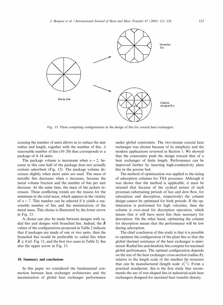
Fig. 13. Three competing configurations in the design of fins for coaxial heat exchangers.
J. Bonjour et al. / International Journal of Heat and Mass Transfer 47 (2003) 111–124 123
creasing the number of units allows us to reduce the unit
radius and length, together with the number of fins. Areasonable number of fins (10–20) thus corresponds to a
package of 4–14 units.
The package volume is maximum when n ¼ 2, be-cause in this case half of the package does not actually
contain adsorbent (Fig. 12). The package volume de-
creases slightly when more units are used. The mass of
metallic fins decreases when n increases, because themetal volume fraction and the number of fins per unit
decrease. At the same time, the mass of the jackets in-
creases. These conflicting trends are the reason for the
minimum in the total mass, which appears in the vicinity
of n ¼ 7. This number can be selected if it yields a rea-sonable number of fins and the minimization of the
metal mass. This choice is illustrated by the lower arrow
in Fig. 13.
A choice can also be made between designs with ra-
dial fins and designs with branched fins. Indeed, the bRRvalues of the configurations proposed in Table 2 indicate
that if packages are made of one or two units, then the
branched fins would be preferable to radial fins whenbRRJ 4 (cf. Fig. 11, and the first two cases in Table 2). See
also the upper arrow in Fig. 13.
10. Summary and conclusions
In this paper we considered the fundamental con-
nection between heat exchanger architecture and the
maximization of global heat exchanger performance
under global constraints. The two-stream coaxial heat
exchanger was chosen because of its simplicity and the
modern applications reviewed in Section 1. We showed
that the constraints push the design toward that of a
heat exchanger of finite length. Performance can be
improved further by inserting high-conductivity plate
fins in the porous bed.
The method of optimization was applied to the sizing
of adsorption columns for TSA processes. Although it
was shown that the method is applicable, it must be
stressed that because of the cyclical nature of such
processes (alternating periods of fast and slow flow, for
adsorption and desorption, respectively) the column
design cannot be optimized for both periods. If the op-
timization is performed for high velocities, then the
column is over-sized for desorption operation, which
means that it will have more fins than necessary for
desorption. On the other hand, optimizing the column
for desorption means that the performance will be low
during adsorption.
The chief conclusion of this study is that it is possible
to optimize the configuration of the plate fins so that the
global thermal resistance of the heat exchanger is mini-
mized. Radial fins and dendritic fins compete formaximal
global performance. The optimal configuration depends
on the size of the heat exchanger cross-section (radius R),relative to the length scale of the smallest fin structure
that can be manufactured (length scale A1=21 ). From a
practical standpoint, this is the first study that recom-
mends the use of tree-shaped fins in industrial-scale heat
exchangers designed for maximal heat transfer density.

124 J. Bonjour et al. / International Journal of Heat and Mass Transfer 47 (2003) 111–124
References
[1] A. Bejan, Shape and Structure, from Engineering toNature,
Cambridge University Press, Cambridge, UK, 2000.
[2] S. Kakac, A.E. Bergles, F. Mayinger (Eds.), Heat Ex-
changers: Thermal-Hydraulic Fundamentals and Design,
Hemisphere, Washington, DC, 1981.
[3] R.K. Shah, A.C. Mueller, Heat exchangers, in: W.M.
Rohsenow, J.P. Hartnett, E. Ganic (Eds.), Handbook of
Heat Transfer Applications, 2nd ed., McGraw-Hill, New
York, 1985 (Chapter 4).
[4] F. Meunier, Adsorption for environment, in: 7th Conf.
Fundamentals of Adsorption (FOA7), Nagasaki, Japan,
May 20–25, 2001.
[5] R. Kumar, M. Huggahalli, S. Deng, M. Andrecovitch,
Trance impurity removal from air, in: Annual AIChE
Meeting, Los Angeles, CA, November 12–17, 2000.
[6] J.J. Nowobilski, Perforated plate fluid distributor and its
associated fixed bed vessel, US Patent No. 5,298,226,
March 29, 1994.
[7] J.J. Nowobilski, J.S. Schneider, Particle loader, US Patent
No. 5,324,159, June 28, 1994.
[8] G.E. Keller, Gas-adsorption processes: state of the art, in:
Industrial Gas Separations, ACS Symp. Ser. 223, 1983.
[9] M. Baudu, P. Le Cloirec, G. Martin, Thermal regeneration
by Joule effect of activated carbon used for air treatment,
Environ. Technol. 13 (1992) 423–435.
[10] E.J. Mezey, S.T. Dinovo, Adsorbent regeneration and gas
separation utilizing microwave heating, US Patent No.
4,322,394, 12 August 1980.
[11] M. Bonnissel, L. Luo, D. Tondeur, Fast thermal swing
adsorption using thermoelectric devices and new adsor-
bent, in: F. Meunier (Ed.), Proceedings of the 6th Conf.
Fundamentals of Adsorption (FOA6), Elsevier, Paris,
1998, pp. 1065–1070.
[12] A. Salden, T. Boger, G. Eigenberger, A combined vacuum
and temperature swing adsorption process for the removal
and recovery of organic components from waste-air-
systems, in: F. Meunier (Ed.), Proceedings of the 6th
Conf. Fundamentals of Adsorption (FOA6), Elsevier,
Paris, 1998, pp. 915–920.
[13] M.M. Davis, M.D. LeVan, Experiments on optimization
of thermal swing adsorption, Ind. Eng. Chem. Res. 28
(1989) 778–785.
[14] J. Bonjour, A. Mativet, J.B. Chalfen, F. Meunier, Identi-
fication du coefficient de transfert de chaleur par convec-
tion �aa travers un milieu poreux, 3�eemes Journ�eees
Tunisiennes sur les Ecoulement et les Transferts, Mahdia,
Tunisia, November 2000.
[15] A. Mativet, Etude Exp�eerimentale d’un proc�eed�ee de chaffa-
uge et de refroidissement par changement de phase du
fluide caloporteur, Doctoral Thesis, Univ. Paris XI, 1997.
[16] A. Mativet, F. Meunier, J.B. Chalfen, C. Marvillet,
Experimental study of heat transfer during film condensa-
tion in transient conditions in a vertical smooth tube, Exp.
Heat Transfer 12 (1999) 247–263.
[17] L.A.O. Rocha, S. Lorente, A. Bejan, Constructal design
for cooling a disc-shaped area by conduction, Int. J. Heat
Mass Transfer 45 (2002) 1643–1652.
[18] J. Bonjour, J.B. Chalfen, F. Meunier, Temperature swing
adsorption process with indirect heating and cooling, Ind.
Eng. Chem. Res. 41 (23) (2002) 5802–5811.
[19] FIDAP, Theory Manual, Vol. 7.0, Fluid Dynamics Inter-
national, Evanston, IL, 1993.
[20] G.A. Ledezma, A. Bejan, M.R. Errera, Constructal tree
networks for heat transfer, J. Appl. Phys. 82 (1997) 89–100.
Copyright © 2022 FDOKUMEN