Louver Fin Heat Exchanger Performance Using Deluge ...
11
Purdue University Purdue e-Pubs International Refrigeration and Air Conditioning Conference School of Mechanical Engineering 2012 Enhancement of Round Tube and Flat Tube- Louver Fin Heat Exchanger Performance Using Deluge Water Cooling Yunho Hwang [email protected] Sahil Popli Reinhard Radermacher Follow this and additional works at: hp://docs.lib.purdue.edu/iracc is document has been made available through Purdue e-Pubs, a service of the Purdue University Libraries. Please contact [email protected] for additional information. Complete proceedings may be acquired in print and on CD-ROM directly from the Ray W. Herrick Laboratories at hps://engineering.purdue.edu/ Herrick/Events/orderlit.html Hwang, Yunho; Popli, Sahil; and Radermacher, Reinhard, "Enhancement of Round Tube and Flat Tube-Louver Fin Heat Exchanger Performance Using Deluge Water Cooling" (2012). International Reigeration and Air Conditioning Conference. Paper 1264. hp://docs.lib.purdue.edu/iracc/1264
-
Upload
khangminh22 -
Category
Documents
-
view
0 -
download
0
Transcript of Louver Fin Heat Exchanger Performance Using Deluge ...

Purdue UniversityPurdue e-PubsInternational Refrigeration and Air ConditioningConference School of Mechanical Engineering
2012
Enhancement of Round Tube and Flat Tube-Louver Fin Heat Exchanger Performance UsingDeluge Water CoolingYunho [email protected]
Sahil Popli
Reinhard Radermacher
Follow this and additional works at: http://docs.lib.purdue.edu/iracc
This document has been made available through Purdue e-Pubs, a service of the Purdue University Libraries. Please contact [email protected] foradditional information.Complete proceedings may be acquired in print and on CD-ROM directly from the Ray W. Herrick Laboratories at https://engineering.purdue.edu/Herrick/Events/orderlit.html
Hwang, Yunho; Popli, Sahil; and Radermacher, Reinhard, "Enhancement of Round Tube and Flat Tube-Louver Fin Heat ExchangerPerformance Using Deluge Water Cooling" (2012). International Refrigeration and Air Conditioning Conference. Paper 1264.http://docs.lib.purdue.edu/iracc/1264

2331, Page 1
International Refrigeration and Air Conditioning Conference at Purdue, July 16-19, 2012
Enhancement of Round Tube-Louver Fin Heat Exchanger Performance
Using Deluge Water Cooling
Sahil POPLI, Yunho HWANG*, Reinhard RADERMACHER
Center for Environmental Energy Engineering Department of Mechanical Engineering, University of Maryland 4164 Glenn L. Martin Hall Bldg., College Park, MD 20742, USA
* Corresponding Author Tel: (301) 405 5247, E-mail: [email protected]
ABSTRACT An experimental study has been conducted to evaluate the performance of a compact round-tube louver-fin condenser, each with frontal areas of 0.25 m2 in both dry and wet conditions. Deluge water cooling is achieved by incorporating a perforated bottom plate-type water distributor on top of the round tube heat exchanger. Water is used as a refrigerant, and enters the heat exchanger tubes at 35°C temperature. Ambient air and deluge cooling water are both maintained at 22°C temperature. Heat exchanger capacity and air-side pressure drop are measured with the heat exchanger angle set at 0° and 21° from vertical, with a frontal air velocity of 1.4 m/s and 3.5 m/s without deluge water cooling, and a frontal air velocity of 1.4 m/s with deluge water cooling. For both heat exchangers, the capacity was significantly enhanced with the use of deluge water cooling and with the heat exchanger angle set at 21° from vertical.
1. INTRODUCTION Compact round tube heat exchangers with plain plate or louver fin geometry are widely used as condensers and coolers in power generation, air-conditioning, refrigeration and process cooling applications. Typically air flows over the tube bundle through fin-side of the heat exchanger and condenses or cools the heat transfer fluid circulating through tube-side. Since heat transfer in such heat exchangers is constrained on air-side due to high thermal resistance, enhanced fin surfaces are typically utilized to increase fin-tube heat exchanger performance (Wang et al., 1999). Extended surfaces are often incorporated with a series of flow interruptions such as louvers and off-strips that induce turbulent mixing of air flow and prevent growth of thermal boundary layer from leading edge (Chang and Wang, 1997). Due to low manufacturing cost louver fins are more commonly used to enhance heat transfer in fin tube heat exchangers.
However, at high ambient air-conditions air-cooled even louvered fin round-tube heat exchangers do not provide sufficient cooling capacity and higher condenser temperature reduces thermodynamic cycle efficiency by up to 1% for every degree increase in condensing temperature (Leidenfrost et al., 1979). In addition, further increase in fin density provides marginal increase in capacity at the cost of considerable increase in air-side pressure drop. One way to enhance heat transfer in louvered fin round-tube heat exchangers is to utilize deluge or spray water cooling (Yank and Clark, 1975). The water forms a thin film over heat exchanger tubes which enhances air-side heat transfer through latent heat of evaporation at the interface and forced convection in liquid film. This forms the objective of work presented in this paper which experimentally evaluates round tube louver-fin heat exchanger performance as hybrid condenser in dry conditions and wet conditions using deluge water cooling. Condenser capacity of round tube heat exchanger has been experimentally evaluated in dry conditions by several authors in the past including, Rich (1973), Elmahdy and Biggs (1979), Senshu et al. (1981), Gray and Webb (1986), Kang et al. (1994), Wang et al. (1996), and Yan and Sheen (2000). Rich (1973) experimentally tested a four row heat exchanger and found that both heat transfer and friction factor to be independent of fin pitch. It was also found that heat exchanger capacity reduces with increase in number of tube rows at low Re and increases slightly for high Re numbers.

2331, Page 2
International Refrigeration and Air Conditioning Conference at Purdue, July 16-19, 2012
Elmahdy and Biggs (1979) presented an empirical correlation of dry case heat transfer in flat plate round tube condenser with multi-row staggered tube valid over 200 to 2,000 air side Re. Senshu et al. (1981) conducted experiments on two-row round tube heat exchanger and found the effect of longitudinal and transverse fin pitch on heat transfer coefficient to be insignificant. Wang et al. (1996) found the effect of fin spacing on heat transfer capacity and effect of fin thickness on both heat transfer capacity and air-side pressure drop to be negligible. Yan and Sheen (2000) reported an increase in both heat exchanger capacity and air-side pressure drop for heat exchangers with smaller fin pitch. Therefore, there is an agreement that smaller fin pitch increases air-side pressure drop while heat transfer capacity is relatively unaffected. Kang et al. (1994) experimentally determined effect of fin spacing and geometry on condenser heat transfer and air-side pressure drop for slotted plain fin, wavy fin and plain plate fin heat exchangers with 2.0, 2.6 and 3.2 mm fin spacing for all fin geometries. Highest and lowest dry case condenser capacity was obtained for slotted plain fin and plain plate fin configuration, respectively. In comparison to condenser performance data of round tube heat exchanger in dry conditions, published experimental studies in wet conditions is limited in the open literature. Yank and Clark (1975) experimentally investigated the effect of spray cooling 1.26 to 2.52 ml/s water and ethylene glycol mixture on heat transfer capacity and air-side pressure drop of plain-finned, louvered, and perforated fin heat exchangers with 3.94 copper fins per cm. It was found that spray cooling does not affect pressure drop and heat transfer coefficient is enhanced by approximately 40% and 45% for air Reynold numbers of 1,000 and 500, respectively. The authors attributed a lower enhancement in condenser capacity at higher Reair=1,000 to break up of liquid film on fin surface. Furthermore as spraying both water and ethylene glycol provided similar improvement in heat exchanger condenser capacity, it was concluded that thin film formation contributes more towards condenser capacity enhancement than latent heat of vaporization. COP enhancement and energy saving of approximately 211% and 58% was reported by Vrachopoulos et al. (2007) for typical refrigeration systems utilizing spray cooled round tube heat condensers. Leidenfrost et al. (1979) developed a mathematical model to evaluate condenser capacity of evaporative cooled plate-fin round-tube heat exchanger at different air and wetting water flow rates. It was found that the condenser capacity could be increased by a factor of approximately three and five for saturated inlet air and low inlet air humidity respectively in wetting conditions and refrigeration cycle COP could be increased by up to 37%. Therefore, it is established that deluge or spray water cooling could enhance heat transfer capacity of fin tube heat exchangers that could enhance power plant efficiency, refrigeration cycle COPs and offer substantial energy savings. However, there is no experimental study which focuses on condenser performance of compact round tube louver fin heat exchangers in hybrid conditions. Therefore, the objective of this paper is to experimentally evaluate condenser heat transfer capacity and air-side pressured drop for round tube louver fin heat exchangers in both dry and wet conditions and investigate the effect of wetting on heat exchanger heat transfer louvered-fin surfaces.
2. EXPERIMENTAL FACILITY OVERVIEW This section describes the experimental facility presented in Figure 1 used for testing the condenser performance of round-tube louvered-fin heat exchanger in dry and wet conditions. The experimental setup mainly consists of air-side, refrigerant-side and wetting-water side loop which are discussed in Sections 2.1, 2.2 and 2.3, respectively. Table 1 presents the specifications for off-the-shelf round-tube louvered-fin test heat exchanger which is mounted in the test section of the experimental setup shown in Figure 1. 2.1 Air-side Loop The schematic of air-side loop in experimental facility which is a typical calorimetric wind-tunnel consisting of an axial fan, nozzles, air-mixer, guide vanes, visualization section, heat exchanger and wetting water drain is presented in Figure 2. Variable frequency drive (VFD) controlled the speed of axial fan, which drives the air-flow out of the wind tunnel at the desired test case velocity. Heat exchanger was installed in the wind-tunnel with a provision of varying angle of inclination of heat exchanger with vertical from approximately 0° to 60° as shown in Figure 2. Relative humidity (RH) and temperature of air were recorded at inlet and outlet of heat exchanger using a PT 100 RH sensor and a 3x3 T-type thermocouple grid respectively. Air mixer, guide vane and settling means were installed to ensure uniform flow and accurate measurement of RH and temperature measurement at the outlet.

2331, Page 3
International Refrigeration and Air Conditioning Conference at Purdue, July 16-19, 2012
Figure 1: Experimental facility used for testing the condenser performance of round-tube louvered-fin heat exchanger in dry and wet conditions.
Table 1: Specifications for round tube heat exchanger.
Parameter Value Tube Configuration Staggered Divergent
Number of Tube Banks 4 Number of Tubes per Bank 20
Tube Length (mm) 454 Tube Outer Diameter (mm) 10.6
Tube Thickness (mm) 0.35 Tube Horizontal Spacing (mm) 17.8
Tube Vertical Spacing (mm) 22.9 Fins per Inch 16
Fin Thickness (mm) 0.18 Heat Exchanger Length (mm) 406 Heat Exchanger Width (mm) 101
Figure 2: Schematic of air-side loop in experimental facility

2331, Page 4
International Refrigeration and Air Conditioning Conference at Purdue, July 16-19, 2012
The differential pressure across the heat exchanger and nozzles was measured using differential pressure transducer in accordance with ASHRAE Standard 41.2 (1987). The differential pressure across the nozzles was then used to calculate the air velocity and flow rate. Heat exchanger was sealed at the walls of test section to prevent bypass of air-flow and entire air-side loop is closed to minimize energy-losses.
2.2 Refrigerant Loop Schematic of refrigerant-side loop in experimental facility is presented in Figure 3. Hot water used as heat transfer fluid enters the test heat exchanger at 35°C and is cooled by air flowing through louver fins across the condenser tubes in dry case tests. When wetting water was used a two-phase flow of air and wetting water cools the heat transfer fluid flowing through condenser tubes. Temperature of hot water was measured at inlet and outlet of test exchanger using high precision PT 100 resistance temperature detector (RTD). Tap water was used as hot water fluid. Valve V2 provided water used for priming the centrifugal pump prior to start-up. A 0.75 kW VFD controlled centrifugal pump drives flow through hot-water loop which consists of a water filter placed before turbine flow meter. The desired temperature at test exchanger inlet was maintained using heat supplied by a typical R-22 heat pump cycle using 4 kW fixed speed compressor, and a 4 kW auxiliary heater. Heat pump cycle was incorporated with a bypass valve between the compressor outlet and evaporator outlet, which enabled reducing the capacity of test heat exchanger condenser without changing the speed of the compressor by allowing certain amount of refrigerant to bypass from the compressor discharge line back to suction line. A 15 kW water chiller was utilized to cool overheated water and serves as additional temperature control along with bypass and temperature control valves.
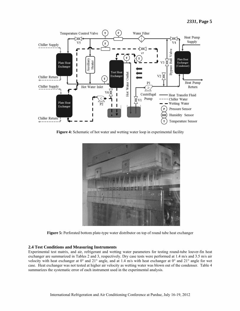
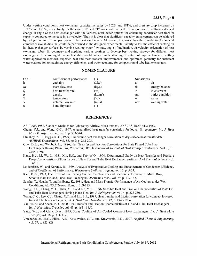
Figure 3: Schematic of hot water loop in experimental facility 2.3 Wetting-Water Loop Figure 4 presents the schematic of hot water and wetting water loop in experimental facility. Deluge water required for testing condenser performance in wet conditions was distributed evenly over test round tube heat exchanger using a perforated bottom tray-type applicator shown in Figure 5 which was designed to allow 0.16 l/s wetting water to fall over heat exchanger tubes. Tap water was used as wetting water fluid. Valve V6 provided water used for priming the centrifugal pump prior to start-up. Temperature of wetting water was measured at inlet and outlet of test exchanger using high precision PT 100 RTD. A 0.25 kW fixed speed centrifugal pump drives flow through wetting-water loop which also consists of a turbine flow meter. The wetting water flow can be controlled using ball-valve V7 shown in Figure 4. Wetting water can be cooled or kept at a constant inlet temperature using a 15 kW vapor compression water chiller.
2331, Page 5
International Refrigeration and Air Conditioning Conference at Purdue, July 16-19, 2012
Figure 4: Schematic of hot water and wetting water loop in experimental facility
Figure 5: Perforated bottom plate-type water distributor on top of round tube heat exchanger
2.4 Test Conditions and Measuring Instruments Experimental test matrix, and air, refrigerant and wetting water parameters for testing round-tube louver-fin heat exchanger are summarized in Tables 2 and 3, respectively. Dry case tests were performed at 1.4 m/s and 3.5 m/s air velocity with heat exchanger at 0° and 21° angle, and at 1.4 m/s with heat exchanger at 0° and 21° angle for wet case. Heat exchanger was not tested at higher air velocity as wetting water was blown out of the condenser. Table 4 summarizes the systematic error of each instrument used in the experimental analysis.

2331, Page 6
International Refrigeration and Air Conditioning Conference at Purdue, July 16-19, 2012
Table 2: Experimental test matrix for round-tube louver-fin heat exchanger
Test No. Case Air Velocity (m/s) Angle1 1 Dry 1.4 0° 2 Dry 3.5 0° 3 Wet 1.4 0° 4 Dry 1.4 21° 5 Dry 3.5 21° 6 Wet 1.4 21°
Note: 1. Angle of heat exchanger with the vertical.
Table 3: Air, refrigerant and wetting water parameters for testing round-tube louver-fin heat exchanger
Parameter Average Value Unit Air Parameters
Inlet temperature 294.5 to 295.1 K
Heat exchanger frontal air velocity 1.2 m/s 3.5 m/s
Heat exchanger angle with vertical 0°, 21° degrees Refrigerant Parameters
Inlet temperature 308 to 308.4 K Mass flow rate 2.9 m3/s*(104)
Wetting-Water Parameters Inlet temperature 294.5 to 295.1 K Mass flow rate 1.6 m3/s*(104)
Table 4: The systematic error of each instrument used in the experiment
Instrument Type Range Systematic Uncertainty
Unit
Water mass flow meter Turbine 0.63 to 6.3 ±1% full scale m3/s*(104) Wetting water mass flow meter Turbine 1.1 to 10.1 ±1% full scale m3/s*(104)
RTD PT 100 173 to 673 ±0.06 K Thermocouple T-Type 73 to 623 ±0.5 K
Relative humidity sensor PT 100 0 to 90 ±2 % Differential pressure transducer Strain 0 to 1245.0 ±1% full scale Pa
3. Results and Discussion
Experimentally measured air, refrigerant and wetting-water parameters such as flow rate, temperature and relative humidity are used to calculate condenser heat transfer capacity in dry and wet conditions. Experimental test conditions for each test in Table 2 are summarized in Table 3. Dry case air-side capacity, , , is calculated using Equation (1).
, ∗ ∗ ∗ , , (1)
Both dry and wet case refrigerant-side capacity, , is calculated using Equation (2).
∗ (2)
Equation (3) is used to calculate dry case energy balance, , .

2331, Page 7
International Refrigeration and Air Conditioning Conference at Purdue, July 16-19, 2012
(3)
Wet case air-side capacity, , , is calculated using Equation (4).
, ∗ ∗ 1 (4)
Wetting-water capacity, , is calculated using Equation (5).
∗ , , , ∗ , (5)
Equation (6) is used to calculate dry case energy balance, , .
(6)
The total uncertainty of measured variables such as air-aide pressure drop is calculated using the sum of systematic error of each instrument as summarized in Table 4 and random error which is the standard deviation of measured variable. Round tube heat exchanger capacity, air-side pressure drop and energy balance along with measurement uncertainty is presented in Table 5. The energy balance in both dry and wet case studies was found to be less than 5%.
Table 5: Round tube heat exchanger capacity, air-side pressure drop and energy balance along with measurement uncertainty.
S. No Case Air Velocity (m/s) Angle1 Heat Exchanger
Capacity (W) Air-side Pressure
Drop (Pa) Energy Balance
(%) 1 Dry 1.4 0° 2912± 211 27±13 4.2 2 Dry 3.5 0° 5069±203 132±14 3.0 3 Wet 1.4 0° 7652±227 64±14 2.0 4 Dry 1.4 21° 2953±228 29±13 1.2 5 Dry 3.5 21° 5128±230 137±14 4.2 6 Wet 1.4 21° 8311±291 67±14 0.6
A comparison of heat exchanger capacity and air-side pressure drop at 0° and 21° angle for both dry and wet conditions at different air-velocities is presented in Figures 6 and 7, respectively. As shown in Figures 6 and 7, increasing air velocity from 1.4 m/s to 3.5 m/s enhances the condenser heat transfer capacity and air-side pressure drop by approximately 74% and 380%, respectively, for both 0° and 21° angle of heat exchanger with the vertical. The capacity increase is achieved at the cost of a substantial increase in air-side pressure drop. Therefore, it is clear that increasing air velocity to 3.5 m/s is not a good option to enhance heat exchanger condenser capacity. It is also observed that in dry conditions, changing the angle of heat exchanger has a negligible effect on heat transfer capacity and on air-side pressure drop for round tube louver-fin heat exchanger. Deluge water cooling was provided to condenser by wetting water at approximately 22°C which flowed through a perforated bottom tray type applicator installed on top of test heat exchanger. At 1.4 m/s air velocity deluge water cooling enhances heat transfer capacity of the heat exchanger by approximately 162% and 181% and air-side pressure drop by approximately 137% and 135% for 0° and 21° angle, respectively with the vertical. As a result it is concluded that increasing the heat exchanger angle enhances heat transfer rate of the condenser due to enhanced drainage of wetting water through narrow fin spacing. Similar to the dry case results, changing the angle of heat exchanger resulted in a negligible change in air-side pressure drop for round tube louver-fin heat exchanger tested at 1.4 m/s in both dry and wet conditions.

2331, Page 8
International Refrigeration and Air Conditioning Conference at Purdue, July 16-19, 2012
Figure 6: Comparison of round tube heat exchanger capacity at 0° and 21° angle for both dry and wet conditions at
different air-velocities.
Figure 7: Comparison of round tube heat exchanger airside pressure drop at 0° and 21° angle for both dry and wet
conditions at different air-velocities.
5. CONCLUSIONS Round tube louver fin compact heat exchanger condenser’s capacity and air-side pressure drop are experimentally evaluated in both dry and wet conditions. It is found that under dry conditions increasing the air velocity from 1.4 to 3.5 m/s enhances heat exchanger capacity and air-side pressure drop by approximately 74 % and 380%, respectively in case of both 0° and 21° angle with vertical. Thus increasing the air velocity in dry conditions causes a much higher pressure drop that does not justify the increase in heat exchanger capacity. Furthermore, in dry conditions there is no significant effect of angle of inclination on both heat exchanger capacity and air-side pressure drop.
0
1
2
3
4
5
6
7
8
9
10
Dry Case (1.4 m/s) Dry Case (3.5 m/s) Wet Case (1.4 m/s)
Hea
t E
xch
ange
r C
apac
ity
(kW
)0° Angle 21° Angle
0
20
40
60
80
100
120
140
160
Dry Case (1.4 m/s) Dry Case (3.5 m/s) Wet Case (1.4 m/s)
Air
-sid
e P
ress
ure
Dro
p (
Pa)
0° Angle 21° Angle
2331, Page 9
International Refrigeration and Air Conditioning Conference at Purdue, July 16-19, 2012
Under wetting conditions, heat exchanger capacity increases by 162% and 181%, and pressure drop increases by 137 % and 135 %, respectively for the case of 0° and 21° angle with vertical. Therefore, use of wetting water and change in angle of the heat exchanger with the vertical, offer better options for enhancing condenser heat transfer capacity compared to increase in air velocity. Thus, it is clear that significant capacity enhancement can be achieved by deluge cooling of compact round tube heat exchangers. Moreover, this work lays the foundation for several comprehensive studies that could be performed in the designed experimental facility to test the effect of wetting on hot heat exchanger surfaces by varying wetting water flow rate, angle of inclination, air velocity, orientation of heat exchanger tubes, fin geometry and applying various coatings to develop best wetting strategy for different heat exchangers. It is envisaged that such studies would enhance understanding of water hold up mechanisms, wetting water application methods, expected heat and mass transfer improvements, and optimized geometry for sufficient water evaporation to maximize energy efficiency, and water economy for compact round tube heat exchangers.
NOMENCLATURE COP coefficient of performance (–) Subscripts h enthalpy (J/kg) a air
mass flow rate (kg/s) eb energy balance heat transfer rate (W) in inlet stream
ρ density (kg/m3) out outlet condition T temperature (°C) w water V volume flow rate (m3/s) ww wetting water x humidity ratio (–)
REFERENCES ASHRAE, 1987, Standard Methods for Laboratory Airflow Measurement, ANSI/ASHRAE 41.2-1987. Chang, Y.J., and Wang, C.C., 1997, A generalized heat transfer correlation for louver fin geometry, Int. J. Heat
Mass Transfer, vol. 40, no. 3: p. 533-544. Elmahdy, A. H., Biggs, R. C., 1979, Finned tube heat exchanger correlation of dry surface heat transfer data,
ASHRAE Transactions, vol. 85, no.2: p. 262-273. Gray, D. L., and Webb, R L., 1986, Heat Transfer and Friction Correlations for Plate Finned Tube Heat
Exchangers Having Plain Fins, Proceeding 8th International Journal of Heat Transfer Conference, Vol. 6, p. 2745-2750.
Kang, H.J., Li, W., Li, H.Z., Xin, R.C., and Tao, W.Q., 1994, Experimental Study on Heat Transfer and Pressure Drop Characteristics of Four Types of Plate Fin and Tube Heat Exchanger Surfaces, J. of Thermal Science, vol. 3, no. 1.
Leidenfrost, W., and Korenic, B., 1979, Analysis of Evaporative Cooling and Enhancement of Condenser Efficiency and of Coefficient of Performance, Warme-und Stoffubertragung, vol. 12, p. 5-23.
Rich, D. G., 1973, The Effect of Fin Spacing On the Heat Transfer and Friction Performance of Multi Row, Smooth Plate Fin-and-Tube Heat Exchangers, ASHRAE Trans., vol. 79, p. 137-145.
Senshu, T., Hatada, T. and Ishibane, K., 1981, Heat and Mass Transfer Performance of Air Coolers under Wet Conditions, ASHRAE Transactions, p. 109-115.
Wang, C. C., Chang, Y. J., Hsieh, Y. C. and Lin, Y. T., 1996, Sensible Heat and Friction Characteristics of Plate Fin and Tube Heat Exchangers Having Plane Fins, Int. J. Refrigeration, vol. 4, p. 223 230.
Wang, C. C., Lee, C.J., Chang, C.T., and Lin, S.P., 1999, Heat transfer and friction correlation for compact louvered fin and tube heat exchangers, Int. J. Heat Mass Transfer, vol. 42, p. 1945-1956.
Yan, W. M. and Sheen, P. J., 2000, Heat Transfer and Friction Characteristics of Fin-and Tube, Heat Exchangers, Int. J. Heat Mass Transfer, vol. 43, p. 1651-1659.
Yang, W.J., and Clark, D.W., 1975, Spray Cooling of Air-Cooled Compact Heat Exchangers, Int. J. Heat Mass Transfer, vol. 18, p. 311-317.
Vrachopoulos, M.G., Filios, A.E., Kotsiovelos, G.T., and Kravvaritis, E.D., 2007, Applied Thermal Engineering, vol. 27, p. 823-828.

2331, Page 10
International Refrigeration and Air Conditioning Conference at Purdue, July 16-19, 2012
ACKNOWLEDGEMENT
We gratefully acknowledge the support of this effort from the sponsors of the Alternative Cooling Technologies and Applications Consortium, the Center for Environmental Energy Engineering (CEEE) at the University of Maryland, and Güntner AG.