Corrections on LIFPA velocity measurements in microchannel with moderate velocity fluctuations
Upload
khangminh22Category
view
3download
0
Designs 2021, 5, 58. https://doi.org/10.3390/designs5040058 www.mdpi.com/journal/designs
Article
Expanded Microchannel Heat Exchanger: Finite
Difference Modeling
David Denkenberger 1, Joshua M. Pearce 2, Michael Brandemuehl 3, Mitchell Alverts 4,* and John Zhai 3
1 Department of Mechanical Engineering and the Alaska Center for Energy and Power, University of Alaska
Fairbanks, Fairbanks, AK 99775, USA; [email protected] 2 Department of Electrical & Computer Engineering, Western University, London, ON N6A 3K7, Canada;
[email protected] 3 Civil, Environmental, and Architectural Engineering Department, University of Colorado at Boulder,
Boulder, CO 80309, USA; [email protected] (M.B.); [email protected] (J.Z.) 4 Department of Mechanical Engineering, University of Alaska Fairbanks, Fairbanks, AK 99775, USA
* Correspondence: [email protected]
Abstract: A finite difference model of a heat exchanger (HX) considered maldistribution, axial
conduction, heat leak, and the edge effect, all of which are needed to model a high effectiveness HX.
An HX prototype was developed, and channel height data were obtained using a computerized
tomography (CT) scan from previous work along with experimental results. This study used the
core geometry data to model results with the finite difference model, and compared the modeled
and experimental results to help improve the expanded microchannel HX (EMHX) prototype
design. The root mean square (RMS) error was 3.8%. Manifold geometries were not put into the
model because the data were not available, so impacts of the manifold were investigated by varying
the temperature conditions at the inlet and exit of the core. Previous studies have not considered
the influence of heat transfer in the manifold on the HX effectiveness when maldistribution is
present. With no flow maldistribution, manifold heat transfer increases overall effectiveness
roughly as would be expected by the greater heat transfer area in the manifolds. Manifold heat
transfer coupled with flow maldistribution for the prototype, however, causes a decrease in the
effectiveness at high flow rate, and an increase in effectiveness at low flow rate.
Keywords: microchannel heat exchangers; maldistribution; heat transfer; polymers;
finite difference; heat exchanger design
1. Introduction
Heat exchangers (HXs) are ubiquitous in modern life [1] and have a market size
predicted to reach over $20 billion U.S. dollars by 2024 [2]. There has been substantial
interest in improving heat exchanger performance by utilizing microchannel-based HX
[3–6]. Even with improved performance, minimizing economic costs are a core driver of
specific applications. For example, an emerging application, solar water pasteurization,
demands low-cost HX and has the potential to save the lives of thousands of children a
day [7–9]. Another important application can be found in absorption cycles, which can
utilize waste heat from diesel engines, such as those found on ships [10].
One of the ways gaining prominence for reducing the costs of products is applying
the open-source paradigm of technical development to hardware [11–14]. An open-source
polymer laser welder has been developed [15], heat transfer in polymer HX using it was
studied [16] and recent work [17] has also provided a low-cost method of making a
polymer-based expanded microchannel HX (EMHX). EMHX modeling is more
complicated than conventional microchannel HX [18]. A study performed a computed
tomography (CT) scan to examine a prototype polymer-based EMHX such as this, and it
Citation: Denkenberger, D.;
Pearce, J.M.; Brandemuehl, M.;
Alverts, M.; Zhai, J. Expanded
Microchannel Heat Exchanger:
Finite Difference Modeling. Designs
2021, 5, 58. https://doi.org/10.3390/
designs5040058
Academic Editor: Bogdan Diaconu
Received: 10 August 2021
Accepted: 15 September 2021
Published: 22 September 2021
Publisher’s Note: MDPI stays
neutral with regard to jurisdictional
claims in published maps and
institutional affiliations.
Copyright: © 2021 by the authors.
Licensee MDPI, Basel, Switzerland.
This article is an open access article
distributed under the terms and
conditions of the Creative Commons
Attribution (CC BY) license
(http://creativecommons.org/licenses
/by/4.0/).
Designs 2021, 5, 58 2 of 20
indicates significant flow maldistribution due to channel height variations [19]. There
have been significant improvements in the modeling of micro-channel HX, which can be
used to drive the development of EMHX [4,20–31]. Recently, a paper [32] developed a
finite difference model that can be applied to this EMHX that was scanned, allowing for a
comparison between modeled and experimental heat transfer characteristics when
maldistribution is present.
The performance of a HX is characterized by its effectiveness, η, defined as the ratio
of the actual heat transfer rate to the maximum heat transfer rate.
η = �
���� . (1)
Here we use effectiveness to mean the approach to the ideal temperature, which can
be applied to the HX as a whole, or individual channels. The actual heat transfer rate is:
Q = C� �T�,� − T�,�� = C� �T�,� − T�,��, (2)
where the heat capacity rates, CH and CC, are defined using mass flow rate and specific
heat.
C� = m� C�,� , C� = m� C�,�. (3)
The maximum heat transfer rate is:
Q��� = C��� (T�,� − T�,�), (4)
where Cmin is the minimum heat capacity rate between the hot and cold side.
The number of transfer units or NTU is defined as the ratio of the heat transfer rate
between the fluids to the minimum heat capacity rate. NTU represents the heat transfer
ability of a heat exchanger normalized by heat transfer area. A high NTU value indicates
a low flow rate.
NTU = � �
���� . (5)
Here A is the heat transfer area and U is the overall heat transfer coefficient. If
channels in an HX vary in size, then fluid velocity will be greater in some channels. The
channels with greater fluid velocity will have a smaller NTU, which means the fluid in
these channels will not cool down as much. The mechanisms producing channel
irregularity include non-uniform fouling [33], two phase flow [34], thermally induced
maldistribution caused by unequal thermal expansion coefficients [35], and non-uniform
spacing of fins [36].
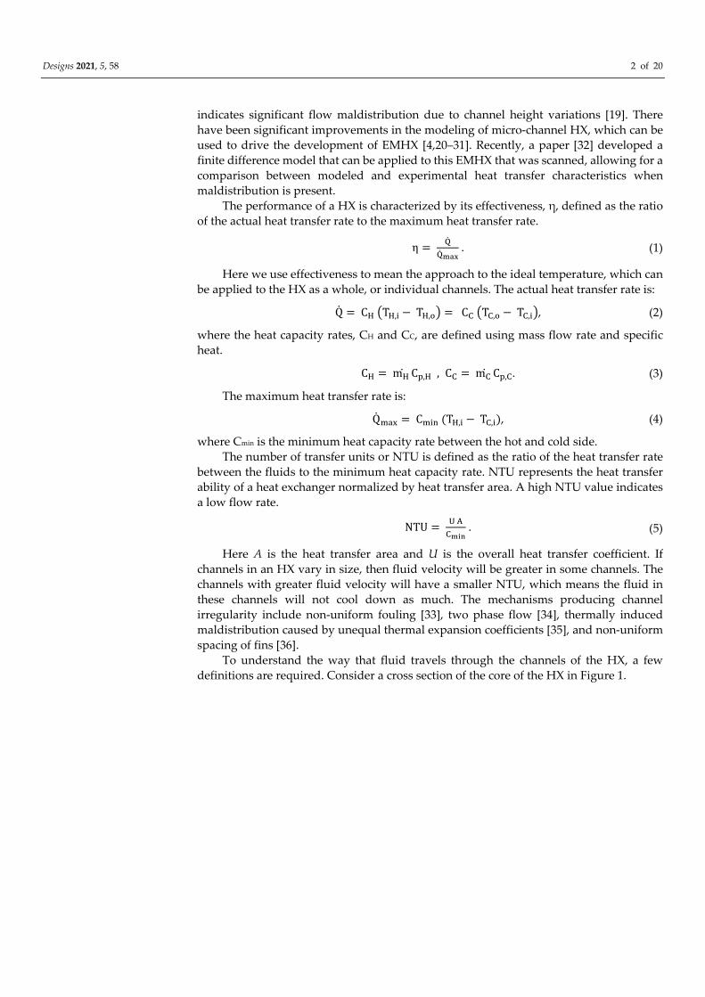
To understand the way that fluid travels through the channels of the HX, a few
definitions are required. Consider a cross section of the core of the HX in Figure 1.
Designs 2021, 5, 58 3 of 20
Figure 1. HX cross section and manifold flow patterns.
Designs 2021, 5, 58 4 of 20
When the flow is uniform, the flow rate is the same for each channel (hot and cold
alike because it is balanced flow). Now, consider the cold and hot channels of a cross
section as separate groups. Positive correlation is defined as a group of cold and hot
channels having the same flow maldistribution, e.g., the right-side channels have lower
flow rate for both cold and hot. Negative or anti-correlation is defined by hot channels
having the opposite flow rate trend as the cold channels, e.g., the cold channels on the
right side having lower flow rate than the cold channels on the left, but the hot channels
on the left side having lower flow rate than the hot channels on the right. Uncorrelated
flow occurs when the flow rates of the hot and cold channels show neither positive nor
negative correlation, which could mean that one temperature of channels has constant
flow rate and the other temperature of channels could have any pattern.
Microchannels (<1 mm hydraulic diameter) that are smooth and contain a liquid with
negligible viscous heat generation have the same physics as traditional laminar
correlations [37–41]. Therefore, traditional laminar correlations are used for this paper.
Axial conduction is the conduction of heat in the direction of fluid flow, by both the
fluid and the HX material [42,43]. This can be a significant source of ineffectiveness for
high effectiveness HXs. The ineffectiveness due to axial conduction can be added as post-
processing for a large range of configurations [44].
The heat leak is the gain or loss of heat from the environment. As a first
approximation, the heat leak ineffectiveness can be added as a linear term to the other
ineffectivenesses [45].
Edge effects are considered in that the channels near the edge have fewer neighbors
and thus do not transfer as much heat, giving those channels a lower NTU. This edge
effect actually penetrates to channels not on the exterior as well and can be important even
for 80 layers [46].
Large temperature variations in the HX can significantly change the properties of the
fluid and the wall [47]. However, the prototype HX for this paper has small temperature
variations, so these effects are not considered.
A number of papers discussed flow maldistribution due to the manifold [48–51].
Different paths of the fluid in the manifold (see Figure 1) have different flow resistances,
so channels have varying flow rates in the HX core. The problem of manifold heat transfer
not being the same for all fluid paths has not been analyzed [52]. The present paper
addresses this analysis by varying the boundary conditions at the HX core based on
different manifold heat transfer characteristics to examine the effect on each fluid path in
the core. With improvement to the model using the conclusions of the analysis, better fit
between the modeled and experimental results can be achieved and design of
microchannel heat exchangers can be improved by taking into account manifold heat
transfer with maldistribution.
2. Materials and Methods
2.1. The Advanced Model
The advanced model is a finite difference model that calculates the flow in each
channel of the HX based on the height of each channel as a function of its length. The
advanced model takes into account edge effects, heat transfer between all neighboring
channels, axial conduction, and heat leak. Edge effects and heat transfer between
neighboring channels are considered with a transverse heat flux term, see Figure 2 and
Equation (6):
Designs 2021, 5, 58 5 of 20
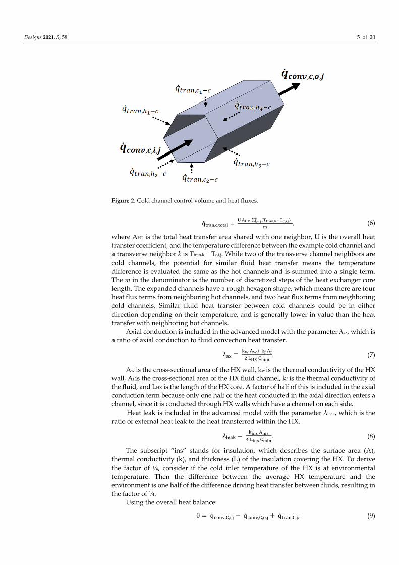
Figure 2. Cold channel control volume and heat fluxes.
q����,�,����� = � ��� ∑ (�����,����,�,�)
����
�, (6)
where AHT is the total heat transfer area shared with one neighbor, U is the overall heat
transfer coefficient, and the temperature difference between the example cold channel and
a transverse neighbor k is Ttran,k − Tc,i,j. While two of the transverse channel neighbors are
cold channels, the potential for similar fluid heat transfer means the temperature
difference is evaluated the same as the hot channels and is summed into a single term.
The m in the denominator is the number of discretized steps of the heat exchanger core
length. The expanded channels have a rough hexagon shape, which means there are four
heat flux terms from neighboring hot channels, and two heat flux terms from neighboring
cold channels. Similar fluid heat transfer between cold channels could be in either
direction depending on their temperature, and is generally lower in value than the heat
transfer with neighboring hot channels.
Axial conduction is included in the advanced model with the parameter λax, which is
a ratio of axial conduction to fluid convection heat transfer.
� = �� ��� �� ��
� ��� ����. (7)
Aw is the cross-sectional area of the HX wall, kw is the thermal conductivity of the HX
wall, Af is the cross-sectional area of the HX fluid channel, kf is the thermal conductivity of
the fluid, and LHX is the length of the HX core. A factor of half of this is included in the axial
conduction term because only one half of the heat conducted in the axial direction enters a
channel, since it is conducted through HX walls which have a channel on each side.
Heat leak is included in the advanced model with the parameter λleak, which is the
ratio of external heat leak to the heat transferred within the HX.
��� = ���� ����
� ���� ����. (8)
The subscript “ins” stands for insulation, which describes the surface area (A),
thermal conductivity (k), and thickness (L) of the insulation covering the HX. To derive
the factor of ¼, consider if the cold inlet temperature of the HX is at environmental
temperature. Then the difference between the average HX temperature and the
environment is one half of the difference driving heat transfer between fluids, resulting in
the factor of ¼.
Using the overall heat balance:
0 = q����,�,�,� − q����,�,�,� + q����,�,�, (9)
Designs 2021, 5, 58 6 of 20
where the flux of each convective side is:
q����,�,�,� = V� A�� ρ� C�,� T�,���, (10)
q����,�,�,� = V� A�� ρ� C�,� T�,�. (11)
The average velocity of fluid is V, the cross-sectional area is A, the fluid density is ρ,
the fluid specific heat is Cp, and T is fluid temperature.
These equations are solved using MATLAB (The MathWorks, Inc, Natick, MA, USA)
for multiple cases, which validate the model. A case with only two channels (no
maldistribution or edge effect) compared the advanced model to a simple NTU model,
shown in Equation (12):
η = �� �����(���)
��� �����(���), (12)
C = ����
����. (13)
The advanced model exactly reached the NTU result when the number of cells in the
model approached infinity. A case with edge effect but no maldistribution was compared
to results from a plate heat exchanger by Shah and Focke [53]. Results extrapolated from the
advanced model for comparison with a plate heat exchanger were within 0.1% of Shah and
Focke. Last, cases with maldistribution and axial conduction compared the advanced model
to analytical results using the Peclet number (Pe) and the irregularity parameter (ε):
Pe = �� ��� �� ��,�
� ���, (14)
ε = 1 − � �
�, (15)
where the Peclet number is the ratio of convective heat transfer to transverse heat transfer
as previously defined, and ±a is the channel diameter variation. The advanced model results
shared good agreement with this analytical method. Tables 1 and 2 show the default input
and output of the MATLAB calculations. See [32] for more details on validation.
Table 1. Default MATLAB Input.
Parameter Unit Value
Channel Height m 0.0023
HX Length m 0.1
Pe - 41–690
Table 2. Default MATLAB Output.
Parameter Unit Value
U W/m2-K) 480
h W/(m2-K) 960
NTU - 3.6–180
Re - 0.25–10.7
V m/s 0.000098–0.0043
Δx m 0.0021–0.033
λax - 0.00018–0.0130
λleak - 0.000070–0.0112
2.2. Heat Exchanger Prototype
The prototype HX was fabricated out of low-density polyethylene (LDPE) sheets that
were 28 µm thick [17] on an open-source polymer laser welding system [15]. The sheets
were laser welded together in a pattern that would create both the core and the manifolds
of the HX. The HX was expanded with air and fixed into shape. The channels were
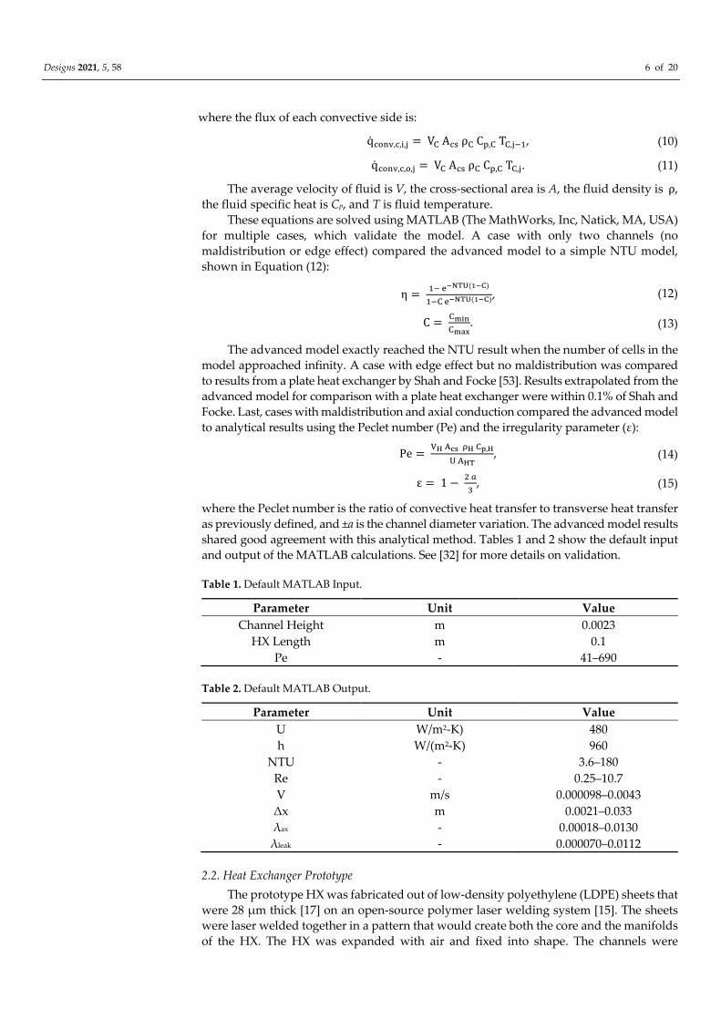
Designs 2021, 5, 58 7 of 20
nominally smooth hexagons with a hydraulic diameter of 2.1 mm in a pattern similar to a
honeycomb, shown in Figure 3. The HX was tested with water-to-water flow at a variety
of flow rates driven by a water head. The expansion process was not perfect, so a CT scan
was used to ascertain the core channel heights as a function of their length [19].
Figure 3. A 70-channel model with 14 columns and 5 rows.
The present paper applies the advanced model to the prototype and discusses the
results against experimental data. The conclusions note that this model can be applied to
other HXs.
2.3. Heat Exchanger Manifold
The manifold was not included in the discretized model because of a lack of CT scan
data. The monotonically varying flow rates across the HX in the flow correlation studies
[32] could be thought to be due to manifold maldistribution, although the manifold is not
explicitly modeled. This section reviews other possible impacts of the manifold for an
idealized HX to extract the concepts with the goal of improving the advanced model’s fit
to the experimental data.
One impact of the manifold is the heat transfer that occurs in it. For the prototype,
the heat transfer area in the manifold is approximately 70% the size of the heat transfer
area in the core. Therefore, the boundary condition at the core of the cold-water inlet could
be significantly hotter, and the hot water inlet could be significantly colder due to heat
transfer in the manifold.
For the ideal case of no flow maldistribution, the temperatures of the inlet boundary
conditions to the core were varied linearly between two values. Since the cold is entering
in the side tube, the first channel will have nearly the same temperature as the tube (see
Figure 4).
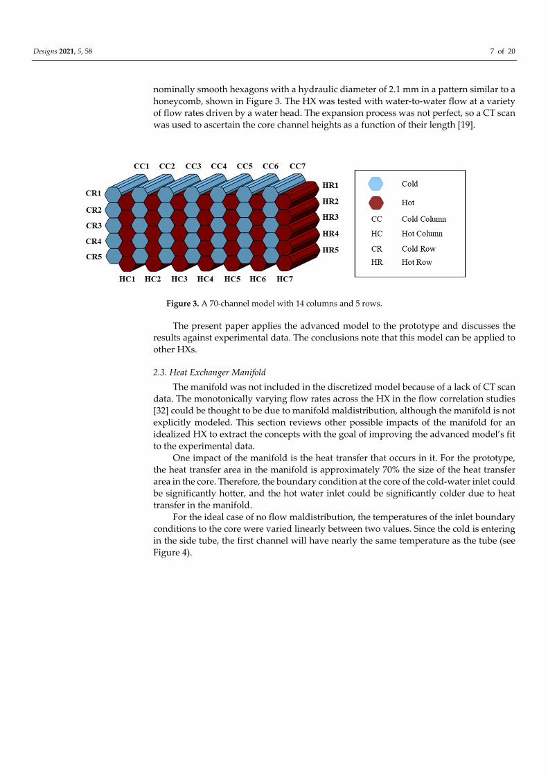
Designs 2021, 5, 58 8 of 20
Figure 4. Manifold heat transfer, symmetric temperature boundary conditions (numbers are
normalized temperatures, red lines and bold numbers correspond to the hot side).
However, the water that goes to the far channel will warm up as it goes through the
manifold. The hot inlet is not so straightforward. The path length for the hot flow in the
manifold is the same for each channel. However, the side of the HX where the cold flow
entered directly into the core will be cooler than the other side of the HX. Therefore, on
the cooler side of the HX, the hot flow will cool down more. The extreme case would be
the hot flow cooling down as much as the maximum that the cold flow warmed up
(symmetric temperature boundary conditions) (see Figure 4). The other extreme case is
the hot flows all warming up the same (asymmetric temperature boundary conditions)
(see Figure 5).
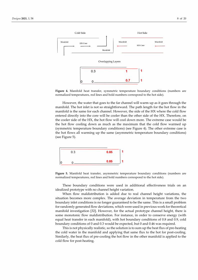
Figure 5. Manifold heat transfer, asymmetric temperature boundary conditions (numbers are
normalized temperatures, red lines and bold numbers correspond to the hot side).
These boundary conditions were used in additional effectiveness trials on an
idealized prototype with no channel height variation.
When flow maldistribution is added due to real channel height variations, the
situation becomes more complex. The average deviation in temperature from the two
boundary inlet conditions is no longer guaranteed to be the same. This is a small problem
for randomly generated flow deviations, which were used in previous work for theoretical
manifold investigation [32]. However, for the actual prototype channel height, there is
some monotonic flow maldistribution. For instance, in order to conserve energy (with
equal heat transfer in each manifold), with hot boundary conditions of 0.8 and 0.9, cold
boundary conditions of 0 and 0.3 would be expected, but 0 and 0.46 was required.
This is not physically realistic, so the solution is to sum up the heat flux of pre-heating
the cold water in the manifold and applying that same flux to the hot for post-cooling.
Similarly, the heat flux of pre-cooling the hot flow in the other manifold is applied to the
cold flow for post-heating.
Designs 2021, 5, 58 9 of 20
3. Results
3.1. Flow Maldistribution with Measured Height Data
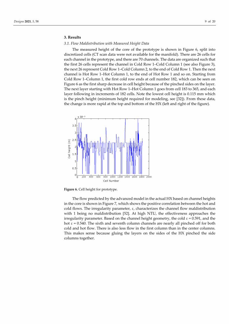
The measured height of the core of the prototype is shown in Figure 6, split into
discretized cells (CT scan data were not available for the manifold). There are 26 cells for
each channel in the prototype, and there are 70 channels. The data are organized such that
the first 26 cells represent the channel in Cold Row 1–Cold Column 1 (see also Figure 3),
the next 26 represent Cold Row 1–Cold Column 2, to the end of Cold Row 1. Then the next
channel is Hot Row 1–Hot Column 1, to the end of Hot Row 1 and so on. Starting from
Cold Row 1–Column 1, the first cold row ends at cell number 182, which can be seen on
Figure 6 as the first sharp decrease in cell height because of the pinched sides on the layer.
The next layer starting with Hot Row 1–Hot Column 1 goes from cell 183 to 365, and each
layer following in increments of 182 cells. Note the lowest cell height is 0.115 mm which
is the pinch height (minimum height required for modeling, see [32]). From these data,
the change is more rapid at the top and bottom of the HX (left and right of the figure).
Figure 6. Cell height for prototype.
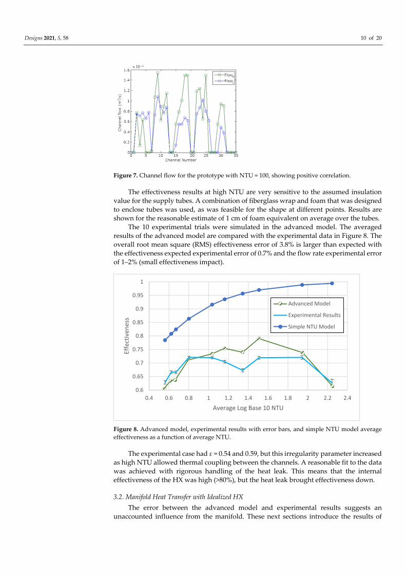
The flow predicted by the advanced model in the actual HX based on channel heights
in the core is shown in Figure 7, which shows the positive correlation between the hot and
cold flows. The irregularity parameter, ε, characterizes the channel flow maldistribution
with 1 being no maldistribution [52]. At high NTU, the effectiveness approaches the
irregularity parameter. Based on the channel height geometry, the cold ε = 0.591, and the
hot ε = 0.540. The sixth and seventh column channels are nearly all pinched off for both
cold and hot flow. There is also less flow in the first column than in the center columns.
This makes sense because gluing the layers on the sides of the HX pinched the side
columns together.
Designs 2021, 5, 58 10 of 20
Figure 7. Channel flow for the prototype with NTU = 100, showing positive correlation.
The effectiveness results at high NTU are very sensitive to the assumed insulation
value for the supply tubes. A combination of fiberglass wrap and foam that was designed
to enclose tubes was used, as was feasible for the shape at different points. Results are
shown for the reasonable estimate of 1 cm of foam equivalent on average over the tubes.
The 10 experimental trials were simulated in the advanced model. The averaged
results of the advanced model are compared with the experimental data in Figure 8. The
overall root mean square (RMS) effectiveness error of 3.8% is larger than expected with
the effectiveness expected experimental error of 0.7% and the flow rate experimental error
of 1–2% (small effectiveness impact).
Figure 8. Advanced model, experimental results with error bars, and simple NTU model average
effectiveness as a function of average NTU.
The experimental case had ε = 0.54 and 0.59, but this irregularity parameter increased
as high NTU allowed thermal coupling between the channels. A reasonable fit to the data
was achieved with rigorous handling of the heat leak. This means that the internal
effectiveness of the HX was high (>80%), but the heat leak brought effectiveness down.
3.2. Manifold Heat Transfer with Idealized HX
The error between the advanced model and experimental results suggests an
unaccounted influence from the manifold. These next sections introduce the results of
0.6
0.65
0.7
0.75
0.8
0.85
0.9
0.95
1
0.4 0.6 0.8 1 1.2 1.4 1.6 1.8 2 2.2 2.4
Effe
ctiv
enes
s
Average Log Base 10 NTU
Advanced Model
Experimental Results
Simple NTU Model
Designs 2021, 5, 58 11 of 20
effectiveness trials at varying inlet temperatures that mimic specific conditions in the
manifold, first without channel height variation in the HX.
The cases of NTU = 5 and NTU = 100 correspond to an advanced model effectiveness
of 79% and 98%. Since the manifold takes up about 40% of the total heat transfer area, but
part of it produces cross flow, which is not as effective, each manifold effectiveness was
assumed to be 15%. Therefore, the cold effectiveness in the entry manifold would be 0% and
30% for all cases. The hot effectiveness in the entry manifold would be 0% and 30% for the
symmetric case. For the asymmetric case, the hot effectiveness would be 15% and 15%.
The case of NTU = 5 was run first in the advanced model. The case of cold
effectiveness in the entry manifold at 15% and 15% and hot effectiveness in the entry
manifold at 15% and 15% is not physically realistic for the expanded HX (“equal case”),
but it provides an interesting starting point. The overall η = 85.3%, which is consistent
with η = 79% from the advanced model between the modified boundary conditions (not
shown in graphs).
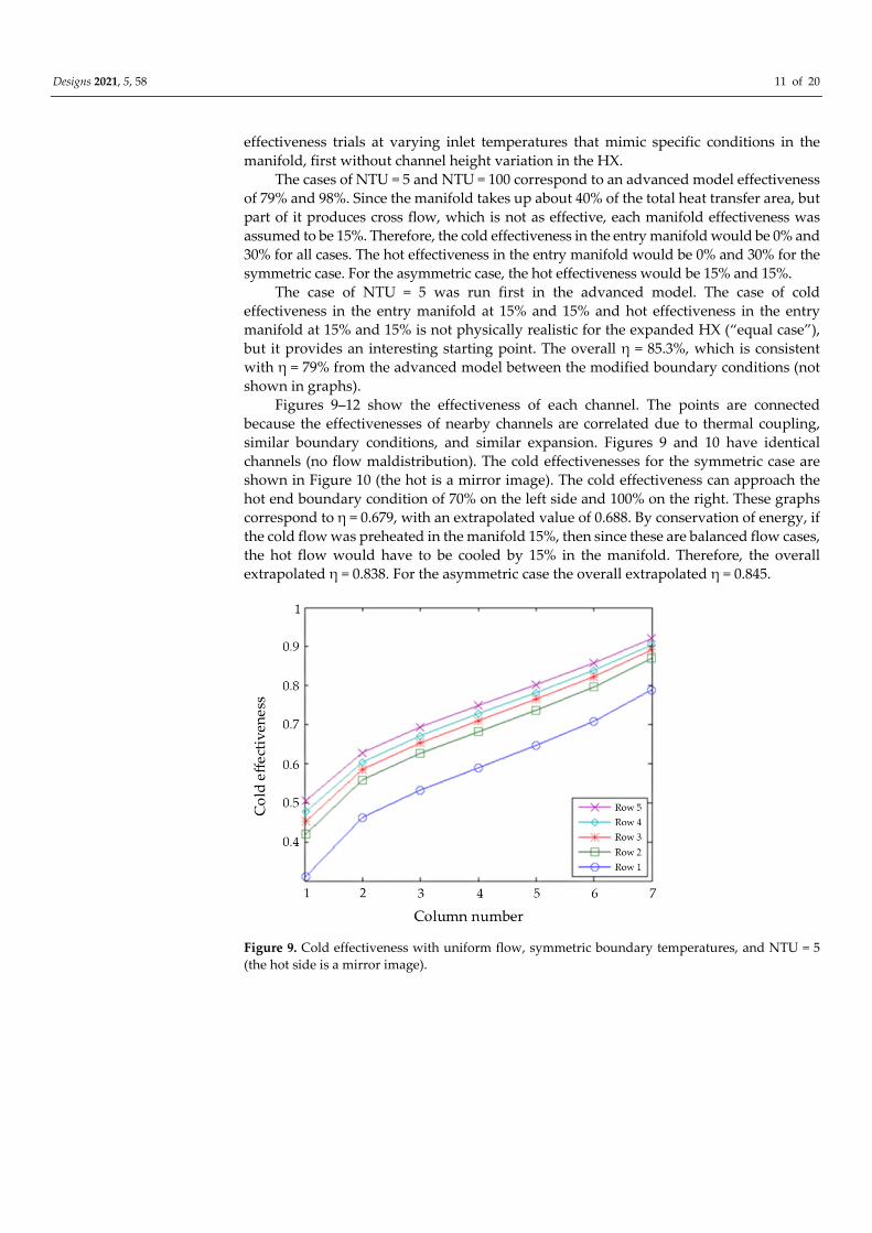
Figures 9–12 show the effectiveness of each channel. The points are connected
because the effectivenesses of nearby channels are correlated due to thermal coupling,
similar boundary conditions, and similar expansion. Figures 9 and 10 have identical
channels (no flow maldistribution). The cold effectivenesses for the symmetric case are
shown in Figure 10 (the hot is a mirror image). The cold effectiveness can approach the
hot end boundary condition of 70% on the left side and 100% on the right. These graphs
correspond to η = 0.679, with an extrapolated value of 0.688. By conservation of energy, if
the cold flow was preheated in the manifold 15%, then since these are balanced flow cases,
the hot flow would have to be cooled by 15% in the manifold. Therefore, the overall
extrapolated η = 0.838. For the asymmetric case the overall extrapolated η = 0.845.
Figure 9. Cold effectiveness with uniform flow, symmetric boundary temperatures, and NTU = 5
(the hot side is a mirror image).
Designs 2021, 5, 58 12 of 20
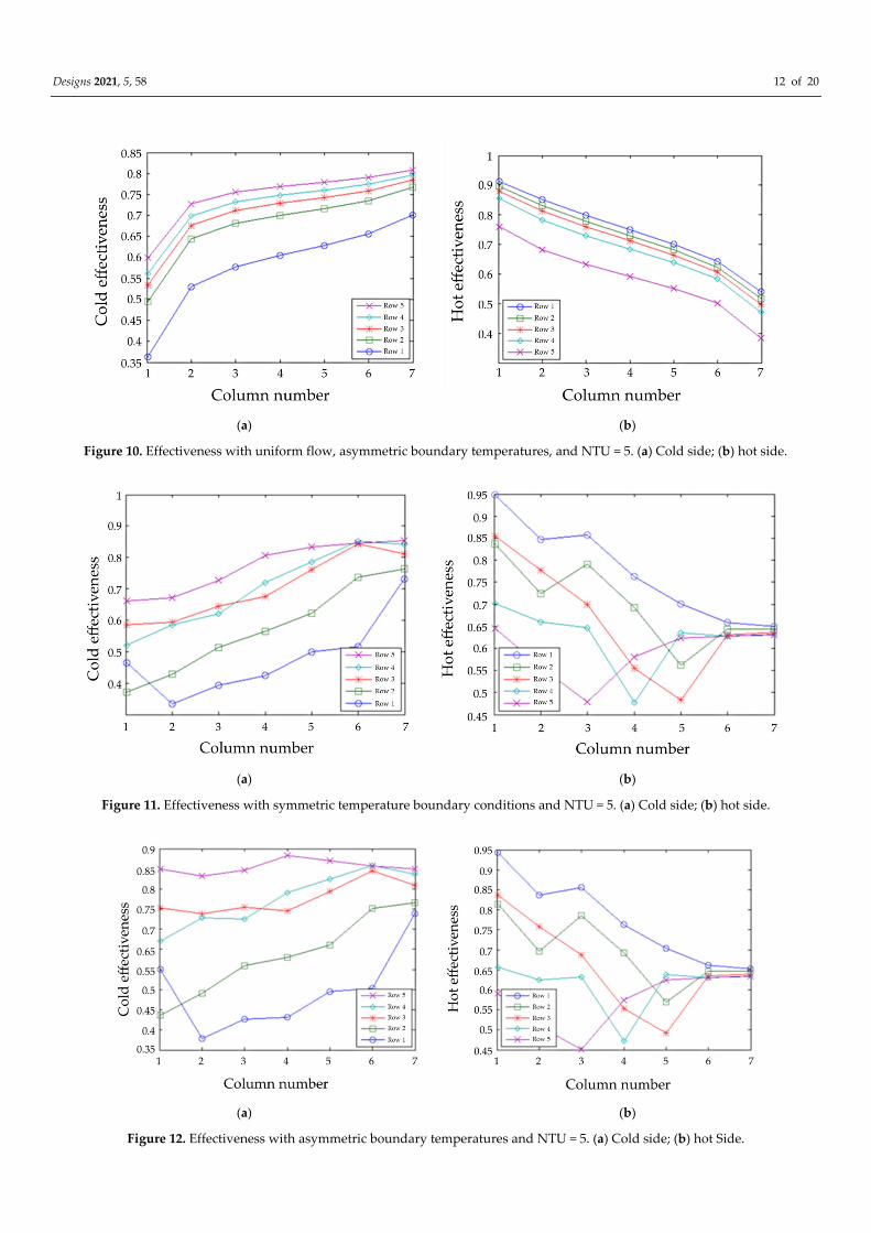
(a) (b)
Figure 10. Effectiveness with uniform flow, asymmetric boundary temperatures, and NTU = 5. (a) Cold side; (b) hot side.
(a) (b)
Figure 11. Effectiveness with symmetric temperature boundary conditions and NTU = 5. (a) Cold side; (b) hot side.
(a) (b)
Figure 12. Effectiveness with asymmetric boundary temperatures and NTU = 5. (a) Cold side; (b) hot Side.
Designs 2021, 5, 58 13 of 20
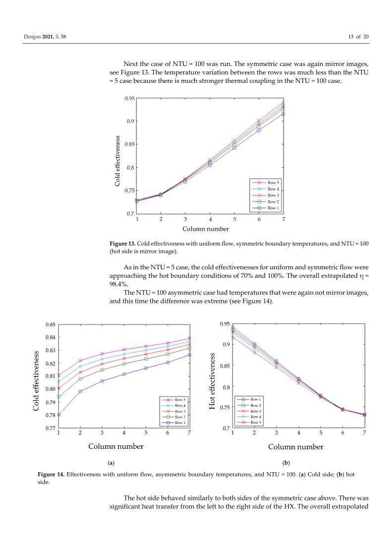
Next the case of NTU = 100 was run. The symmetric case was again mirror images,
see Figure 13. The temperature variation between the rows was much less than the NTU
= 5 case because there is much stronger thermal coupling in the NTU = 100 case.
Figure 13. Cold effectiveness with uniform flow, symmetric boundary temperatures, and NTU = 100
(hot side is mirror image).
As in the NTU = 5 case, the cold effectivenesses for uniform and symmetric flow were
approaching the hot boundary conditions of 70% and 100%. The overall extrapolated η =
98.4%.
The NTU = 100 asymmetric case had temperatures that were again not mirror images,
and this time the difference was extreme (see Figure 14).
(a) (b)
Figure 14. Effectiveness with uniform flow, asymmetric boundary temperatures, and NTU = 100. (a) Cold side; (b) hot
side.
The hot side behaved similarly to both sides of the symmetric case above. There was
significant heat transfer from the left to the right side of the HX. The overall extrapolated
Designs 2021, 5, 58 14 of 20
effectiveness for the asymmetric case is 98.5%, which again is slightly higher than the
symmetric effectiveness, again due to lower entropy production.
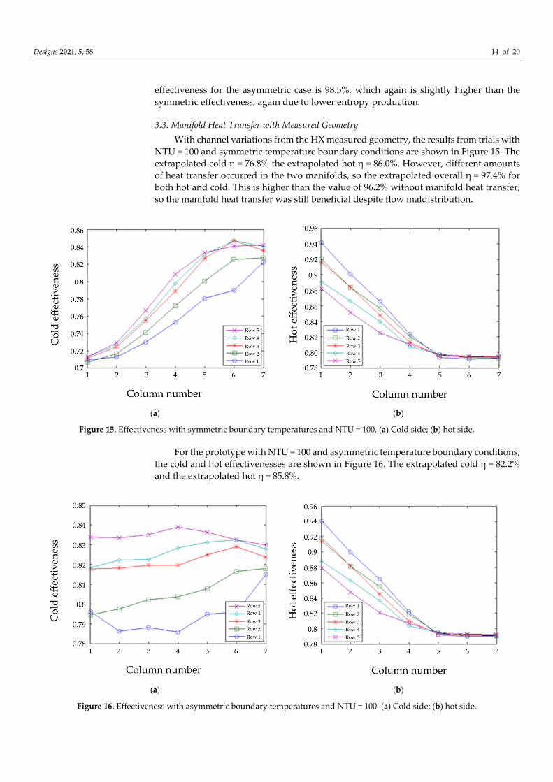
3.3. Manifold Heat Transfer with Measured Geometry
With channel variations from the HX measured geometry, the results from trials with
NTU = 100 and symmetric temperature boundary conditions are shown in Figure 15. The
extrapolated cold η = 76.8% the extrapolated hot η = 86.0%. However, different amounts
of heat transfer occurred in the two manifolds, so the extrapolated overall η = 97.4% for
both hot and cold. This is higher than the value of 96.2% without manifold heat transfer,
so the manifold heat transfer was still beneficial despite flow maldistribution.
(a) (b)
Figure 15. Effectiveness with symmetric boundary temperatures and NTU = 100. (a) Cold side; (b) hot side.
For the prototype with NTU = 100 and asymmetric temperature boundary conditions,
the cold and hot effectivenesses are shown in Figure 16. The extrapolated cold η = 82.2%
and the extrapolated hot η = 85.8%.
(a) (b)
Figure 16. Effectiveness with asymmetric boundary temperatures and NTU = 100. (a) Cold side; (b) hot side.

Designs 2021, 5, 58 15 of 20
Again, different amounts of heat transfer occurred in the two manifolds, so the
extrapolated overall η = 97.2% for both hot and cold. This is lower than the value of 97.4%
for correlated, which is surprising. Perhaps this is due to this specific maldistribution
producing more entropy for the uncorrelated case.
For the prototype with NTU = 5 and symmetric temperature boundary conditions,
the cold and hot effectivenesses are shown in Figure 11. The extrapolated cold η = 56.2%
and the extrapolated hot η = 65.5%. However, different amounts of heat transfer occurred
in the two manifolds, so the extrapolated overall η = 76.8% for both hot and cold. This is
lower than the value of 79.0% without manifold heat transfer, so surprisingly the manifold
heat transfer was detrimental with maldistribution.
For the prototype with NTU = 5 and asymmetric temperature boundary conditions,
the cold and hot effectivenesses are shown in Figure 12. The extrapolated cold η = 59.9%
and the extrapolated hot η = 63.6%. Again, different amounts of heat transfer occurred in
the two manifolds, so the extrapolated overall η = 75.2% for both hot and cold. As for NTU
= 100, this is lower than the value of 76.8% for correlated. Manifold heat transfer decreased
the overall effectiveness even more in this case.
The conclusion for manifold heat transfer coupled with flow maldistribution for the
prototype is that the manifold heat transfer increases effectiveness at high NTU and
decreases effectiveness at low NTU.
4. Discussion
Examining the trials with uniform flow and NTU = 5, Figures 9 and 10, the
effectiveness is significantly higher than the similar case with no manifold heat transfer,
but lower than the “equal case.” This is reasonable because heat transfer between the
columns would produce entropy, and the outlet temperatures not being equal cause
mixing, producing more entropy. For the asymmetric case, the temperatures are not
mirror images, as expected (Figure 10). The effectiveness is also greater than the
symmetric case, which makes sense because there is less entropy production. It is
reasonable that the highest effectiveness achieved is the hot left because it is approaching
the most extreme temperature of the cold inlet. The cold effectivenesses on both the left
and the right are approaching 85% (hot inlet), but the right approaches are closer because
it is already preheated in the manifold.
As for the symmetric NTU = 100 cases (Figures 13 and 15), one would expect an
approach within 1% of the boundary conditions because of the very high NTU. However,
only 93% was achieved on the hot side, but 73% was achieved on the cold side, which is
higher than the boundary condition. This means that heat was actually flowing from the
"cold" channels to the "hot" channels. That is to say, the flow did not violate the laws of
thermodynamics but due to maldistribution the “cold” channels actually became warmer
than the “hot” channels. This also explains the very small temperature deviation between
rows where this occurred. This is because there is a very small temperature difference
between the hot and cold channels, so it did not matter as much that row 1 for cold flow
and row 5 for hot flow only have half as many neighbors, because less heat is being
transferred regardless of the number of neighbors.
On the cold side of the asymmetric NTU = 100 cases (Figures 14 and 16), one would expect
a very close approach (within 1%) to the boundary condition with high NTU, thus yielding
near η = 85%. This was true on the right side, but not for the left. The left started out at a colder
temperature, but still one could think that the approach should have been closer. This can be
explained by the transfer of heat from the left side to the right side of the HX.
The overall conclusion for varying the temperature boundary conditions with no
flow maldistribution is that manifold heat transfer increases overall effectiveness roughly
what would be expected by the greater heat transfer area in the manifolds.
Another impact of the manifold in addition to altering boundary conditions is the much
higher flow resistance for the bent channels. The bent channels are those that enter one side of
the HX, turn 90° to flow axially, and then exit the other side of the HX in a Z type pattern. The
Designs 2021, 5, 58 16 of 20
straight channels enter one end of the HX and exit the other end of the HX without turning.
The relative impact of some of the core channels being pinched would be smaller in this case
of bent flow. Therefore, the flow maldistribution on the bent side would be decreased. The
current maldistribution on the hot and cold sides is correlated because of the significant
pinching on the edges of the HX for both hot and cold. Reducing the flow variation on the
bent side would still maintain positive correlation, but it would be less positively correlated.
This would reduce the effectiveness somewhat.
A further impact of the manifold is flow maldistribution to the channels. With the Z-
type flow, the flow resistance of each channel should be similar. However, there could be
significant variations in the flow resistance for different channels in the manifold. This
could occur in a uniform way, for instance by having significantly higher flow on one side
of the HX than the other. In this case, the heat would have to conduct a much greater
distance to smooth out the temperature differences. The Peclet number Pe is the ratio of
convective heat transfer to diffusive heat transfer; in this case the latter is the transverse
heat transfer. Therefore, the equivalent Pe would be significantly greater with this
increased conduction distance.
If heat is conducted from the neighbor of a channel to the neighbor on the opposite
side, the Nusselt number should be one (laminar flow). This is about one fourth the case
of heating or cooling from all sides of one channel. Therefore, the thermal coupling
between channels on opposite sides of the HX would be significantly less. This further
reduces the gradient in effectiveness from NTU = 5 to NTU = 100.
It could be possible that the amount of maldistribution changed with flow rate. If
maldistribution were significantly higher at high NTU, then the effectiveness could
saturate more. A reason for this is the changing pressure experienced by the HX at
different flow rates. At 0.01 atm., most of the 100 mm water driving pressure drop at high
flow occurred in the manifold for the bent flow. It takes approximately 0.02 atm to inflate
the channels to 1 mm high. With some assumptions about the width and length of the
pinches, the average height for the bent flow in the manifold was estimated to be
approximately 0.2 mm. This is consistent with the observation that the manifold did not
contract in a measurable way in the axial direction. Since the pinches in the manifold are
only ~0.2 mm, a 0.01 atm change in pressure due to flow rate could have significant effects
on the maldistribution.
5. Conclusions
A finite difference model of a HX considered the edge effect, maldistribution, axial
conduction, and heat leak. This advanced model is discretized so that it modeled the
effects of maldistribution from the first principles, and it has been validated for multiple
cases. Data for the channel height as a function of length in the core of the HX were
obtained via CT scan. The results run on this core geometry were compared to the
experimental results on an expanded microchannel HX. The RMS error was 3.8%.
Though the manifold geometries were not put into the model (because the data were
not available), manifold heat transfer was approximated by varying the temperature
boundary conditions on the core for the advanced model. With no flow maldistribution,
manifold heat transfer increases the overall effectiveness roughly what would be expected
by the greater heat transfer area in the manifolds.
However, manifold heat transfer coupled with flow maldistribution for the
prototype causes a decrease in the effectiveness at low NTU, and an increase in
effectiveness at high NTU.
Another impact of the manifold is the much higher flow resistance for the bent
channels. This would reduce the effectiveness somewhat. A further impact of the manifold
is flow maldistribution to the channels. The equivalent Pe would be significantly greater,
so the effectiveness would saturate more at high NTU.
If heat is conducting from the neighbor of a channel to the neighbor on the opposite
side, the Nusselt number should be one if the channels were square. This is approximately
Designs 2021, 5, 58 17 of 20
one fourth the case of heating or cooling from all sides of one channel. Thus, the thermal
coupling between channels on opposite sides of the HX would be significantly less. This
further reduces the increase in effectiveness from NTU = 5 to NTU = 100.
It could be possible that the amount of maldistribution changed with flow rate. If
maldistribution were significantly higher at high NTU, then the effectiveness could
saturate more.
Therefore, with further refinements of the advanced model, a better fit to the
experimental data may be achieved. If manifold geometry could be obtained,
improvements to microchannel heat exchanger modelling could be made by computing
manifold heat transfer.
Author Contributions: Conceptualization, D.D.; methodology, D.D., J.M.P., M.B. and J.Z.; software,
D.D.; validation, D.D; formal analysis, D.D.; data curation, D.D.; writing—original draft preparation,
D.D.; writing—review and editing, J.M.P., M.B., M.A., and J.Z.; visualization, D.D. and M.A.; supervision,
J.M.P., M.B., and J.Z.; project administration, J.M.P., M.B., and J.Z.; funding acquisition, D.D., J.M.P., M.B.,
and J.Z. All authors have read and agreed to the published version of the manuscript.
Funding: Support for this project was received from the American Society of Heating, Refrigeration,
and Air Conditioning Engineers Graduate Research Fellowship, the Office of Naval Research, the M.J.
Murdock Charitable Trust, and the University of Colorado at Boulder Technology Transfer Office
Proof of Concept Grant. J.P would like to acknowledge support from the Thompson Endowment.
These funding sources had negligible influence on the research and publication process.
Acknowledgments: Ray Radebaugh, Ben Goebel, Kyle Jones, Joshua Klina and Moncef Krarti
provided valuable feedback.
Conflicts of Interest: The authors declare no conflict of interest. The funders had no role in the
design of the study; in the collection, analyses, or interpretation of data; in the writing of the
manuscript, or in the decision to publish the results.
Abbreviations
a
A
ax
C
C
conv
cs
Cp
Channel diameter, m
Area, m2
Axial, subscript
Heat capacity rate, J/K
Cold, subscript
Convection, subscript
Cross section, subscript
Specific heat, J/kg-K
EMHX
f
h
H
HT
HX
i
ins
j
k
k
L
leak
m m
max
min
Expanded microchannel heat exchanger
Fluid, subscript
Convective heat transfer coefficient, W/m2-K
Hot, subscript
Heat transfer, subscript
Heat exchanger
In, subscript
Insulation, subscript
Axial direction, subscript
Thermal conductivity, W/m-K
Series index variable, subscript
Length, m
Environmental leak, subscript
Number of discretized steps
Mass flow rate, kg/s
Maximum, subscript
Minimum, subscript
Designs 2021, 5, 58 18 of 20
NTU
o
Pe
Re q
T
tran
U
V
w
Δx
Number of transfer units
Out, subscript
Peclet number
Reynold’s number
Heat transfer rate, W
Temperature, °C
Transverse direction, subscript
Overall heat transfer coefficient, W/m2-K
Velocity, m/s
Wall, subscript
Cell step size, m η Effectiveness
� ���
ρ ε
Axial conduction
Heat leak
Density, kg/m3
Irregularity
References
1. Master, B.I.; Chunangad, K.S.; Boxma, A.J.; Kral, D.; Stehlík, P. Most Frequently Used Heat Exchangers from Pioneering
Research to Worldwide Applications. Heat Transf. Eng. 2006, 27, 4–11, doi:10.1080/01457630600671960.
2. Markets and Markets. Available online: https://www.marketsandmarkets.com/Market-Reports/heat-exchanger-market-
750.html (accessed on 18 January 2021).
3. Jiang, P.-X.; Fan, M.-H.; Si, G.-S.; Ren, Z.-P. Thermal–Hydraulic Performance of Small Scale Micro-Channel and Porous-Media
Heat-Exchangers. Int. J. Heat Mass Transf. 2001, 44, 1039–1051, doi:10.1016/S0017-9310(00)00169-1.
4. Dixit, T.; Ghosh, I. Review of Micro- and Mini-Channel Heat Sinks and Heat Exchangers for Single Phase Fluids. Renew. Sustain.
Energy Rev. 2015, 41, 1298–1311, doi:10.1016/j.rser.2014.09.024.
5. Bhutta, A.; Mahmood, M.; Hayat, N.; Bashir, M.H.; Khan, A.R.; Ahmad, K.N.; Khan, S. CFD Applications in Various Heat
Exchangers Design: A Review. Appl. Therm. Eng. 2012, 32, 1–12, doi:10.1016/j.applthermaleng.2011.09.001.
6. Ramesh, K.N.; Sharma, T.K.; Rao, G.A.P. Latest Advancements in Heat Transfer Enhancement in the Micro-Channel Heat Sinks:
A Review. Arch. Comput. Methods Eng 2020, 28, 1–31, doi:10.1007/s11831-020-09495-1.
7. UNICEF. Excluded and Invisible; The State of the World’s Children; UNICEF: New York, NY, USA, 2005.
8. Pearce, J.M.; Denkenberger, D. Numerical Simulation of the Direct Application of Compound Parabolic Concentrators to a
Single Effect Basin Solar Still. In Proceedings of the Solar Cookers and Food Processing 2006 International Conference, Granada,
Spain, 2006; Vol. 118, p 7.
9. Denkenberger, D.C.; Pearce, J.M. Design Optimization of Polymer Heat Exchanger for Automated Household-Scale Solar Water
Pasteurizer. Designs 2018, 2, 11, doi:10.3390/designs2020011.
10. Tao, C.; Lee, H.; Hwang, Y.; Radermacher, R.; Chun, H. Performance Investigation of Engine Waste Heat Powered Absorption
Cycle Cooling System for Shipboard Applications. Appl. Therm. Eng. 2015, 90, 820–830,
doi:10.1016/j.applthermaleng.2015.07.070.
11. Daniel, K.F.; Peter, J.G. Open-Source Hardware Is a Low-Cost Alternative for Scientific Instrumentation and Research. Mod.
Instrum. 2012, 1, 2, doi:10.4236/mi.2012.12002.
12. Pearce, J.M. Cut Costs with Open-Source Hardware. Nature 2014, 505 618–618, doi:10.1038/505618d.
13. Pearce, J.M. Quantifying the Value of Open Source Hardware Development. Mod. Econ. 2015, 6, 1–11,
doi:10.4236/me.2015.61001.
14. Pearce, J.M. Open-Source Lab: How to Build Your Own Hardware and Reduce Research Costs; Elsevier: Amsterdam, The Netherlands, 2013.
15. Laureto, J.J.; Dessiatoun, S.V.; Ohadi, M.M.; Pearce, J.M. Open Source Laser Polymer Welding System: Design and
Characterization of Linear Low-Density Polyethylene Multilayer Welds. Machines 2016, 4, 14, doi:10.3390/machines4030014.
16. Arie, M.A.; Shooshtari, A.H.; Tiwari, R.; Dessiatoun, S.V.; Ohadi, M.M.; Pearce, J.M. Experimental Characterization of Heat
Transfer in an Additively Manufactured Polymer Heat Exchanger. Appl. Therm. Eng. 2017, 113, 575–584,
doi:10.1016/j.applthermaleng.2016.11.030.
17. Denkenberger, D.C.; Brandemuehl, M.J.; Pearce, J.M.; Zhai, J. Expanded Microchannel Heat Exchanger: Design, Fabrication,
and Preliminary Experimental Test. Proc. Inst. Mech. Eng. Part. A J. Power Energy 2012, 226, 532–544,
doi:10.1177/0957650912442781.
18. Balasubramanian, K.; Lee, P.S.; Jin, L.W.; Chou, S.K.; Teo, C.J.; Gao, S. Experimental Investigations of Flow Boiling Heat Transfer
and Pressure Drop in Straight and Expanding Microchannels—A Comparative Study. Int. J. Therm. Sci. 2011, 50, 2413–2421,
doi:10.1016/j.ijthermalsci.2011.07.007.
Designs 2021, 5, 58 19 of 20
19. Denkenberger, D.C.; Brandemuehl, M.J.; Pearce, J.M.; Zhai, J. Expanded Microchannel Heat Exchanger: Nondestructive
Evaluation. Heat Transf. Eng. 2019, 40, 1671–1679, doi:10.1080/01457632.2018.1496976.
20. Harpole, G.M.; Eninger, J.E. Micro-Channel Heat Exchanger Optimization. In Proceedings of the Seventh IEEE Semiconductor
Thermal Measurement and Management Symposium, Phoenix, AZ, USA, 12–14 February 1991; pp. 59–63,
doi:10.1109/STHERM.1991.152913.
21. Kawano, K.; Sekimura, M.; Minakami, K.; Iwasaki, H.; Ishizuka, M. Development of Micro Channel Heat Exchanging. JSME
Int. J. Ser. B Fluids Therm. Eng. 2001, 44, 592–598, doi:10.1299/jsmeb.44.592.
22. Harris, C.; Kelly, K.; Wang, T.; McCandless, A.; Motakef, S. Fabrication, Modeling, and Testing of Micro-Cross-Flow Heat
Exchangers. J. Microelectromechanical Syst. 2002, 11, 726–735, doi:10.1109/JMEMS.2002.806025.
23. Shaoi, B.; Wang, L.; Li, J.; Sun, Z. Application of Thermal Resistance Network Model in Optimization Design of Micro-channel
Cooling Heat Sink. Int. J. Numer. Methods Heat Fluid Flow 2009, 19, 535–545, doi:10.1108/09615530910938425.
24. Majnis, M.F.; Fung, C.K. Computational Fluid Dynamic Simulation Analysis of Effect of Microchannel Geometry on Thermal
and Hydraulic Performances of Micro Channel Heat Exchanger. ARFMTS 2019, 62, 198–208.
25. Gomse, D.; Kochenburger, T.M.; Grohmann, S. Modeling of Two-Phase Heat Exchangers with Zeotropic Fluid Mixtures. J. Heat
Transf. 2018, 140, 5, doi:10.1115/1.4038852.
26. Hegde, P.; Seetharamu, K.N.; Quadir, G.A.; Aswathanarayana, P.A.; Abdullah, M.Z.; Zainal, Z.A. Thermal Analysis of Micro-
channel Heat Exchangers with Two-phase Flow Using FEM. Int. J. Numer. Methods Heat Fluid Flow 2005, 15, 43–60,
doi:10.1108/09615530510571949.
27. Raghuraman, D.R.S.; Thundil Karuppa Raj, R.; Nagarajan, P.K.; Rao, B.V.A. Influence of Aspect Ratio on the Thermal
Performance of Rectangular Shaped Micro Channel Heat Sink Using CFD Code. Alex. Eng. J. 2017, 56, 43–54,
doi:10.1016/j.aej.2016.08.033.
28. Nonino, C.; Savino, S.; Giudice, S.D. FEM for the 3-D Analysis of Conjugate Conduction-Convection Heat Transfer in Cross-
Flow Micro Heat Exchangers. J. Numer. Methods Heat Fluid Flow 2015, 25, 1322–1339, doi:10.1108/HFF-07-2014-0232.
29. Nonino, C.; Savino, S. Numerical Investigation on the Performance of Cross-Flow Micro Heat Exchangers. Int. J. Numer. Methods
Heat Fluid Flow 2016, 26, 745–766, doi:10.1108/HFF-09-2015-0393.
30. Ariyo, D.O.; Bello-Ochende, T. Constructal Design of Two-Phase Stacked Microchannel Heat Exchangers for Cooling at High
Heat Flux. Int. Commun. Heat Mass Transf. 2021, 125, 105294, doi:10.1016/j.icheatmasstransfer.2021.105294.
31. Hasan, M.I.; Hasan, H.M.; Abid, G.A. Study of the Axial Heat Conduction in Parallel Flow Microchannel Heat Exchanger.
Journal of King Saud University—Engineering Sciences 2014, 26 122–131, doi:10.1016/j.jksues.2012.12.004.
32. Denkenberger, D.C.; Brandemuehl, M.J.; Zhai, J.; Pearce, J.M. Finite Difference Heat Exchanger Model: Flow Maldistribution
with Thermal Coupling. Heat Transf. Eng. 2021, 42, 889–903, doi:10.1080/01457632.2020.1756060.
33. Bossan, D.; Grillot, J.M.; Thonon, B.; Grandgeorge, S. Experimental Study of Particulate Fouling in an Industrial Plate Heat
Exchanger. JEH(T) 1995, 2, 167-175, doi:10.1615/JEnhHeatTransf.v2.i1-2.180.
34. Hoysall, D.C.; Keniar, K.; Garimella, S. Addressing Two-Phase Flow Maldistribution in Microchannel Heat and Mass
Exchangers. J. Heat Transf. 2018, 140, 11, doi:10.1115/1.4040706.
35. Haseler, L.E. Layer Pattern Effects in Plate-Fin Heat Exchangers. Am. Soc. Mech. Eng. Heat Transf. Div. 1987, 75, 119–125.
36. Mondt, J. Effects of Nonuniform Passages on Deepfold Heat Exchanger Performance. J. Eng. Gas. Turbines Power 1977, 99 657–
663.
37. Papautsky, I.; Ameel, T.; Frazier, A.B. A Review of Laminar Single-Phase Flow in Microchannels. In Proceedings of 2001 ASME
International Mechanical Engineering Congress and Exposition; New York, NY, USA, November 11-16, 2001. 2, 3067–3075.
38. Rostami, A.; Mujumdar, A.; Saniei, N. Flow and Heat Transfer for Gas Flowing in Microchannels: A Review. Heat Mass Transf.
2002, 38, 359–367.
39. Kandlikar, S.G. History, Advances, and Challenges in Liquid Flow and Flow Boiling Heat Transfer in Microchannels: A Critical
Review. J. Heat Transf. 2012, 134, 3, doi:10.1115/1.4005126.
40. Kandlikar, S.G.; Colin, S.; Peles, Y.; Garimella, S.; Pease, R.F.; Brandner, J.J.; Tuckerman, D.B. Heat Transfer in Microchannels—
2012 Status and Research Needs. J. Heat Transf. 2013, 135, 9, doi:10.1115/1.4024354.
41. Morini, G.L. Single-Phase Convective Heat Transfer in Microchannels: A Review of Experimental Results. Int. J. Therm. Sci. 2004,
43, 7, 631–651.
42. Chiou, J. The Advancement of Compact Heat Exchanger Theory Considering the Effects of Longitudinal Heat Conduction and
Flow Nonuniformity. In Proceedings of the Symposium on Compact Heat Exchangers, New York, NY, USA, 1980; Volume 10, pp.
101–121.
43. Radebaugh, R. Heat Transfer Issues in Cryogenic Catheters. In Microscale Heat Transfer Fundamentals and Applications; Springer:
New York, NY, USA, 2005; pp. 445–464.
44. Chowdhury, K.; Sarangi, S. Performance of Cryogenic Heat Exchangers with Heat Leak from the Surroundings. In Advances in
Cryogenic Engineering; Springer: New York, NY, USA, 1984; pp. 273–280.
45. Polley, G.T.; Abu-Khader, M.M. Compensating for End Effects in Plate-and-Frame Heat Exchangers. Heat Transf. Eng. 2005, 26,
3–7.
46. Heggs, P.J.; Scheidat, H.-J. Thermal Performance of Plate Heat Exchangers with Flow Maldistribution; ASME: New York, NY, USA,
1992, 201, 87–93.

Designs 2021, 5, 58 20 of 20
47. Wen, J.; Li, Y. Study of Flow Distribution and Its Improvement on the Header of Plate-Fin Heat Exchanger. Cryogenics 2004, 44,
823–831.
48. Selimovic, F.; Bruun, T.; Sundén, B. Computational Analysis of Gas Flow and Heat Transport Phenomena. In Monolithic
Structures for High Temperature Processes; American Society of Mechanical Engineers: New York, NY, USA, 2005; pp. 87–96.
49. Smith, E.M. Advances in Thermal Design of Heat Exchangers: A Numerical Approach: Direct-Sizing, Step-Wise Rating, and Transients;
1st ed.; Wiley: Hoboken, NJ, USA, 2005.
50. Zou, Y.; Tuo, H.; Hrnjak, P.S. Modeling Refrigerant Maldistribution in Microchannel Heat Exchangers with Vertical Headers
Based on Experimentally Developed Distribution Results. Appl. Therm. Eng. 2014, 64, 172–181,
doi:10.1016/j.applthermaleng.2013.12.033.
51. Nellis, G. A Heat Exchanger Model That Includes Axial Conduction, Parasitic Heat Loads, and Property Variations. Cryogenics
2003, 43, 523–538.
52. Gotovsky, M.; Fedorovich, E.; Firsova, E.; Blagoveshchensky, A.; Mizonov, N.; Piskunov, V.; Vinokurov, V. Thermal
Effectiveness of Heat Exchangers: Effect of Manufacturing Inaccuracies and Deformation of Tube Bundles. Heat Transf. Eng.
1985, 6, 52–57.
53. Shah, R.; Focke, W. Plate heat exchangers and their design theory. Heat Transf. Equip. Des. 1988, 227.
Copyright © 2022 FDOKUMEN