Dendritic fins optimization for a coaxial two-stream heat exchanger
Upload
khangminh22Category
view
2download
0
Publications (NSTD) Nuclear Science & Technology Division
12-31-2004
High Temperature Heat Exchanger Project: Quarterly Progress High Temperature Heat Exchanger Project: Quarterly Progress
Report October 1, 2004 through December 31, 2004 Report October 1, 2004 through December 31, 2004
Anthony Hechanova University of Nevada, Las Vegas, [email protected]
Follow this and additional works at: https://digitalscholarship.unlv.edu/hrc_nstd_pubs
Part of the Heat Transfer, Combustion Commons, and the Materials Science and Engineering
Commons
Repository Citation Repository Citation Hechanova, A. (2004). High Temperature Heat Exchanger Project: Quarterly Progress Report October 1, 2004 through December 31, 2004. 1-50. Available at:Available at: https://digitalscholarship.unlv.edu/hrc_nstd_pubs/7
This Grant is protected by copyright and/or related rights. It has been brought to you by Digital Scholarship@UNLV with permission from the rights-holder(s). You are free to use this Grant in any way that is permitted by the copyright and related rights legislation that applies to your use. For other uses you need to obtain permission from the rights-holder(s) directly, unless additional rights are indicated by a Creative Commons license in the record and/or on the work itself. This Grant has been accepted for inclusion in Publications (NSTD) by an authorized administrator of Digital Scholarship@UNLV. For more information, please contact [email protected].
High Temperature Heat Exchanger Project
Under Financial Assistance DE-FG-04-01AL67358, Amendment 007
Awarded by the United States of America Acting Through the United States Department of Energy
Quarterly Progress Report October 1, 2004 through December 31, 2004
The UNLV Research Foundation 4505 Maryland Parkway
P. O. Box 452036 Las Vegas, NV 89154-2036
Anthony E. Hechanova, Ph.D. Project Manager (702) 895-1457
(702) 895-2354 (FAX) [email protected]

UNLV Research Foundation High Temperature Heat Exchanger (HTHX) Project
Quarterly Report (October 1, 2004 to December 31, 2004)
1.0 HTHX FY05 1st Quarter Highlights
• UNLV hosted an NHI Systems Interface Meeting on Dec. 16 and a UNLVRF HTHX Kickoff Meeting on Dec. 17. The purpose of the meetings was to coordinate the FY05 research and development effort of the UNLV Research Foundation portion of the Nuclear Hydrogen Initiative among the DOE, national program technical directors and the UNLVRF collaborators. Collaborators also had the opportunity to discuss their research program plan and update their progress. It was decided that these type of collaboration meetings were very useful and they will be held quarterly at the various collaborator sites. The next meeting will be in March in Salt Lake City hosted by Ceramatec, Inc.
• HTHX Computational Design. The work on the three-dimensional numerical simulations for both the rectangular and curved fin edge cases for the baseline heat exchanger using UC Berkeley dimensions with He-Flinak as the working fluids continued. Simulations indicate that temperature dependent physical properties do not significantly affect the flow and heat transfer results. The mesh independence investigation for CFD calculations of high temperature heat exchanger was completed and investigations of correctness for periodic boundary conditions for upper and lower walls were completed, both showing satisfactory results. Turbulence modeling had a pronounced effect on the helium channel heat exchanger channels with rectangular fin edges (23% difference in the pressure drop results) while other results were not significantly affected.
• Metallic Materials Testing. Tensile properties of Alloy C-22, Alloy C-276 and Waspaloy have been determined at ambient temperature, 450 and 600oC in the presence of nitrogen. The evaluation of the stress corrosion cracking (SCC) susceptibility of all three alloys in a 90oC aqueous solution containing sulfuric acid and sodium iodide under a constant-loading condition was completed. Fractographic evaluations of the tested tensile specimens by scanning electron microscopy (SEM) was also performed. Based on the review of literature gathered from numerous materials-related meetings held at ORNL and UNLV during the quarter, additional materials have been identified for material testing: Incoloy 800H, Incoloy 800HT, AL 610, Niobium (Nb)-1 Zirconium (Zr), Nb-7.5 Tantalum (Ta), and Zr 705.
• LSI C-C/Si-C Composite Material Studies. The high-pressure helium permeation tests on a CVD SiC and Pyrolytic Carbon coated fiber sample were performed up to 5.5 MPa. The coating layer kept good hermeticity as no helium bubbles were observed on the sample surface. The sample, however, failed about five minutes later, while experiencing a tensile stress of 276 MPa before breaking (which is much higher than 9 MPa maximum tensile stress typically found from unit cell stress analysis). This test directly verified that CVD carbon coated SiSiC material can keep helium hermeticity under high pressure and stress well beyond the working pressure and stress expected for NGNP.

• Thermal design studies. Unit cell isothermal stress analyses were performed. The highest compressive stress was around 85 MPa, and tensile stress is around 60 to 70 MPa. Compressive stresses concentrate at the root and the edges of the salt plate; tensile stresses concentrate at the root and edge of the gas plate. Composite material usually has much higher compressive strength than tensile strength. Therefore, measures should be considered to reduce the maximum tensile stress because the fiber reinforced SiC usually only has a tensile strength from 90 MPa to 140 MPa.
• HIx Materials Screening. The immersion coupon test system is up and running. Screening of materials of construction candidate has started December 12. A second testing system was designed to accommodate larger specimens, be computer-controlled, and include a thermocouple feed through to the chamber to directly monitor the HIx temperature.
• GA HTHX Study. General Atomics completed their High Temperature Heat Exchanger Study. Major conclusions include selection of He at a pressure greater than 5 MPa as the optimal fluid to be used as a heat transport system fluid and initial designs and sizings for key HTHXs.
• MIT Catalyst Alloys. Alloy 800 plus Pt alloys have been received and characterized prior to conversion to wrought material by a series of rolling/annealing steps. The Alloy 800-Pt compositions are Alloy-800 plus 2, 5, 15, and 30 percent Pt with the Fe concentration reduced as Pt is added. Alloy 617 plus Pt has been received and is undergoing characterization. Alloys are in the process of being turned into buttons.

2.0 UNLV Design and Testing Group The University of Nevada, Las Vegas Design and Testing Group supports the following two activities in the UNLVRF High Temperature Heat Exchanger (HTHX) Project:
• HTHX Thermal Systems Design • Scaled HTHX Tests
2.1 HTHX Thermal Systems Design 2.1.1 HTHX Thermal Systems Design Objective and Scope The HTHX design studies have the following objectives and scope:
• Work with the U.S. Department of Energy Office of Nuclear Energy, Science and Technology (DOE NE) nuclear hydrogen research and development program elements on high temperature systems studies for hydrogen production.
• Identify the range of HTHX applications for Gen IV hydrogen production. • Develop thermal systems concepts/designs and overall heat/mass balances for the
range of Gen IV power conversion and hydrogen production concepts. • Develop design specifications for the intermediate heat exchanger and other HTHXs
used in the conceptual designs. • Undertake thermal hydraulic systems numerical modeling to establish and analyze
temperature, pressure, and flow rate requirements. • Perform thermal, thermal hydraulic, and structural analyses for selected advanced
HTHX concepts for hydrogen production. • Deliver detailed design for candidate intermediate heat exchanger concepts and
materials for hydrogen production requirements.
2.1.2 HTHX Thermal Systems Design Highlights • 3-D Model Development of a Baseline Compact HTHX. The work on the three-
dimensional numerical simulations for both the rectangular and curved fin edge cases for the baseline heat exchanger using UC Berkeley dimensions with He-Flinak as the working fluids were continued.
• Since there is a large temperature difference expected between the heat exchanger surface and the fluids the effect of temperature dependent physical properties was incorporated in the numerical simulations. The results were compared to similar numerical simulations in the laminar flow with constant material properties. It was found that the influence of temperature dependent physical properties did not significantly affect the flow and heat transfer.
• From the simulation results it was evident that the Flinak molten salt gives a good heat transfer performance like flibe (an earlier candidate molten salt) but with a reduced pressure drop.
• The mesh independence investigation for CFD calculations of high temperature heat exchanger was completed. The investigations of correctness for periodic boundary conditions for upper and lower walls were completed. The conclusions from the investigations are that the temperature, velocity and pressure distributions are the same for truncated and nonrounded geometries therefore the solutions are correct and the periodic boundary conditions applied reasonably.

• The calculations of the flow in the heat exchanger with rounding at the bottom of the fins (with manufacturing geometrical effects (MGE)) were completed for the laminar and turbulent cases. These effects influence the laminar case significantly for pressure drop in MS side (17%) and negligibly small for other parameters (pressure drop in He side and temperature drops for MS and He sides). For the turbulent case the manufacturing geometrical effects influence on resulting parameters is very strong for pressure drop in MS side (17%) and He side (26%). For the temperature the influence is negligibly small (less than 3%).
• The mesh for the thermal-stress analysis for the heat exchanger geometry (rectangular case) was performed using ANSYS 8.0 (see Figure 3). The thermal-stress analysis for the rectangular geometry was performed. The boundary conditions for temperature were applied using CFD results. The analysis gives the temperature for MS side equal to 900 K and the temperature for He side equal to 1000 K.
• It was found that the affect of turbulence was more pronounced on the helium channel heat exchanger channels with rectangular fin edges. There was a 23% difference in the pressure drop results for the rectangular fin channels while there was only 1% difference in the pressure drop results for the helium channel with curved fin edges. There was not much of an effect on the overall thermal performance from either type of heat exchanger channel and there was a 1% difference in the thermal performance between the straight and curved fin edge cases which again reinstated that the curved fin edge channels are the better of the two considering the overall performance and pumping power requirements.
• Model Development for H2SO4 Decomposer. Research continued on the sulfuric acid decomposer heat exchanger. The General Atomics Reports “High Pressure Catalytic Metal Reactor in a Simulated Solar Central Receiver,” “Solar Production of Hydrogen Using the Sulfur-Iodine Thermo chemical Water Splitting Cycle,” and “Decomposition of Sulfuric Acid Using Solar Thermal Energy” were reviewed. FLUENT 6.1 was selected for CFD analysis because it can handle both volumetric and wall surface reactions. Initially some time has been spent on going through the FLUENT User Guide and manual for the better understanding of different reaction models, to know how FLUENT solves the reaction flows, and also the inputs required to model the problem.
2.1.3 HTHX Thermal Systems Design Technical Summary
Baseline Compact High Temperature Heat Exchanger The work on the three-dimensional numerical simulations for both the rectangular and curved fin edge cases for the baseline heat exchanger using UC Berkeley dimensions with He-Flinak as the working fluids were continued. Since there is a large temperature difference expected between the heat exchanger surface and the fluids the effect of temperature dependent physical properties was incorporated in the numerical simulations. Simple polynomial equations were formed to capture the effect of the property change with respect to temperature. The geometry, dimensions, boundary

conditions, physical conditions, and other inputs were similar to the ones used in the previous numerical simulations. The results of the numerical simulations with temperature dependent physical properties were compared to similar numerical simulations in the laminar flow with constant material properties. It was found that the influence of temperature dependent physical properties did not affect the flow and heat transfer for the helium side for both rectangular and curved fin edge heat exchanger channels. Kays and London (in their book Compact Heat Exchangers) discuss the effects of temperature dependent fluid properties on fluid flow and heat transfer. According to them, all transport properties for gases vary with temperature to a considerable degree. However, for liquids the only property that is highly temperature dependent is viscosity and it varies more with temperature than any of the gas properties. In the current case, helium is a gas while molten salt is a liquid so in order to clear any ambiguity in numerical simulations it was decided to perform numerical simulations with a laminar flow model and variable material properties. From the simulation results it was quite clear that the Flinak molten salt gives a good heat transfer performance like flibe (an earlier candidate molten salt) but with a reduced pressure drop. Thus using Flinak increases the overall performance of the heat exchanger design. The inlet Reynolds numbers for the helium and molten salt were calculated as 2282 and 75, respectively, while the Reynolds numbers at the outlet were calculated as 2873 and 281 for helium and molten salt, respectively. The Reynolds numbers at the outlet was calculated by judging the maximum possible outlet temperatures for the helium and molten salts as 885 K and 1200 K respectively. It can be said that the outlet temperatures are judged not to go below the above specified values in worst case scenarios. The above test calculations were performed to decide whether the flow regimes are going to oscillate but it can be seen that the helium side is going to be in the transitional region while the molten salt is going to stay laminar. From the manuals of FLUENT, it was figured out how to perform numerical simulations with turbulent flow on the helium side and laminar flow on the molten salt side. It was decided to initially use the K-omega turbulence model which is available in FLUENT, since the helium side is in the transition region this turbulence model also has a separate module to handle transition flows and molten salt fluid zone needs to be specified as a laminar zone. The results of the numerical simulations with temperature dependent physical properties were compared (Tables 1 and 2) to similar numerical simulations in the laminar flow with constant material properties. It was found that the influence of temperature dependent physical properties did not affect the flow and heat transfer for the helium side for both rectangular and curved fin edge heat exchanger channels. But the temperature dependent physical properties did affect the pressure drop for the molten salt side by about 9% for both rectangular and curved fin edge heat exchanger channels. According to the literature and other sources the influence of temperature dependent physical properties can be neglected if their effect is less than 10%. Due to the limitations in the computer resources, it was decided

to use constant material properties during the numerical simulations with turbulence model. The temperature dependent physical properties had some effect on the molten-salt channel flow, but its affect on the overall performance was found to be insignificant. The effect of temperature dependent physical properties can be neglected taking into consideration the amount of computational time it would take for a numerical model comprising of temperature dependent physical properties and turbulence.
Table 1. Heat Exchanger Overall Performance from CFD Calculations for Curved Fin Edge
Case
Property
Constant material properties
Variable material properties
% Difference
Helium side pressure drop ( kPa)
16.7
16.7
0
Molten Salt side pressure drop (kPa)
7.8
8.6
10
LMTD (K) 39 39 0 Thermal Power (MW)
50.8
50.9
0.2
Table 2. Heat Exchanger Overall Performance from CFD Calculations for rectangular fin
edge case
Property
Constant material properties
Variable material properties
% Difference
Helium side pressure drop ( kPa)
18.7
18.6
0.5
Molten Salt side pressure drop (kPa)
8.5
9.3
9
LMTD (K) 39 39 0 Thermal Power (MW)
50.8
50.9
0.2
The mesh independence investigation for CFD calculations of high temperature heat exchanger was completed. Two kinds of meshes were chosen: (1) a mesh with thickening in the wall zones (which was used for the actual calculations); and, (2) a uniform mesh. For the

mesh with thickening in the wall zones, three mesh types were chosen for the investigations: coarse mesh (3540 nodes, 2508 hexahedral cells), normal mesh (22419 nodes, 18392 hexahedral cells) and fine mesh (73182 nodes, 69954 hexahedral cells). For the uniform mesh, four mesh types were chosen for the investigations: coarser mesh (12849 nodes, 10080 hexahedral cells), coarse mesh (39661 nodes, 33480 hexahedral cells), normal mesh (89665 nodes, 78720 hexahedral cells) and fine mesh (288049 nodes, 263520 hexahedral cells). The investigations of correctness for periodic boundary conditions for upper and lower walls were completed. The calculations were performed for one section. The three geometries were used: truncated geometry, nonrounded geometry and rounded geometry. The calculated results for the truncated geometry and nonrounded geometry should be the same and the comparisons should confirm the correctness of using periodic boundary conditions for upper and bottom walls. The conclusions from the investigations are that the temperature, velocity and pressure distributions are the same for truncated and nonrounded geometries therefore the solutions are correct and the periodic boundary conditions applied reasonably; the manufacturing geometrical effects (rounded geometry) influence on resulting parameters (pressures, velocities, temperatures) is detected therefore it is important to include the geometrical effects to the calculated model for future investigations. The calculations of the flow in the heat exchanger with rounding at the bottom of the fins (with manufacturing geometrical effects (MGE)) were completed for the laminar and turbulent cases. The geometry of the heat exchanger (one section) is shown in Figure 1. The results of the calculations were compared with the results for geometry without MGE (the geometry for one section is shown in Figure 2). The results of the comparisons are shown in Tables 3 to 6.
Figure 1. Geometry of single section or module (with MGE)

Figure 2. Geometry of single section or module (without MGE)
Table 3. Parameters distribution on the He side (laminar case)
Property Without MGE With MGE Difference Pressure drop 16.7 kPa 17.3 kPa 3.5 % Temperature drop 377 K 382 K 1.2 %
Table 4. Parameters distribution on the MS side (laminar case)
Property Without MGE With MGE Difference Pressure drop 7.84 kPa 6.47 kPa -17 % Temperature drop 418 K 422 K 0.94 %
Table 5. Parameters distribution on the He side (turbulent case)
Property Without MGE With MGE Difference Pressure drop 16.9 kPa 21.2 kPa 26 % Temperature drop 369 K 379 K 2.6 %
Table 6. Parameters distribution on the MS side (turbulent case)
Property Without MGE With MGE Difference Pressure drop 7.84 kPa 6.47 kPa -17 % Temperature drop 418 K 426 K 2 %

The manufacturing geometrical effects influence on resulting parameters for the laminar case is very strong for pressure drop in MS side (17%) and negligibly small for other parameters (pressure drop in He side and temperature drops for MS and He sides). For the turbulent case the manufacturing geometrical effects influence on resulting parameters is very strong for pressure drop in MS side (17%) and He side (26%). For the temperature the influence is negligibly small (less than 3%). Journal files for the heat exchanger geometry mesh creation (without gaps) were developed using Pascal code for the rectangular and rounded cases. Now it is possible to create such journal files using the code for the different geometrical parameters (such as fin length, fin thickness, etc.). The mesh for the thermal-stress analysis for the heat exchanger geometry (rectangular case) was performed using ANSYS 8.0 (see Figure 3). The thermal-stress analysis for the rectangular geometry was performed. The boundary conditions for temperature were applied using CFD results. The analysis gives the temperature for MS side equal to 900 K and the temperature for He side equal to 1000 K. The resulting temperature distribution is shown in Figure 4. The results for displacements and Von Mises stress distribution are shown in Figures 5 and 6.
Figure 3. Computational meshes for the thermal stress analysis

Figure 4. Temperature distributions for the rectangular case
Figure 5. Displacements

Figure 6. Von Mises stresses After some literature review and some initial study about the capabilities of the different turbulence models for the numerical simulations for both cases of heat exchanger geometry it was decided to use the K-omega turbulence model. It has the capability to capture eddies, vortices and other flow physics in the transition region, which are expected in the heat exchanger flow channels. The helium side was alone simulated as turbulent flow while the molten-salt side was specified to be a laminar zone. For the present case since the helium channel flow is expected to be in the lower transition region the turbulence intensity was specified as 1%. The other boundary conditions, heat transfer model were the same to the ones that were used for the previous numerical simulations. Figures 7 and 8 show the velocity and temperature contours for helium channel with curved fin edges based on turbulent flow model. Figure 9 shows temperature contours for MS channel with curved fin edges based on turbulent flow model.

Figure 7. Velocity contours for helium channel with curved fin edges based on turbulent flow model
Figure 8. Temperature contours for helium channel with curved fin edges based on turbulent flow model

Figure 9. Temperature contours for MS channel with curved fin edges and Turbulent flow
It was found that the affect of turbulence was more pronounced on the helium channel heat exchanger channels with rectangular fin edges. Table 5 shows that there was a 23% difference in the pressure drop results for the rectangular fin channels while there was only 1% difference in the pressure drop results for the helium channel with curved fin edges. There was not much of an effect on the overall thermal performance from either type of heat exchanger channel and there was a 1% difference in the thermal performance between the straight and curved fin edge cases which again reinstated that the curved fin edge channels are the better of the two considering the overall performance and pumping power requirements.

Table 7. Heat Exchanger Overall Performance comparison from CFD models Calculations for Rectangular Fin Edge Case
Property
Laminar Model
Turbulence Model
% Difference
Helium side pressure drop ( kPa)
18.7
23
23
Molten Salt side pressure drop (kPa)
8.5
8.5
N/A
LMTD (K) 39 39 13.5 Thermal Power (MW)
50.8
51.4
1.2
Sulfuric Acid Decomposer The General Atomics Reports “High Pressure Catalytic Metal Reactor in a Simulated Solar Central Receiver,” “Solar Production of Hydrogen Using the Sulfur-Iodine Thermo chemical Water Splitting Cycle,” and “Decomposition of Sulfuric Acid Using Solar Thermal Energy” were reviewed. It is important to know the flow of the sulfuric acid and the chemical reactions taking place as it is going through the different parts of the plant. Sulfuric acid goes through the boiler where it dissociates in to sulfur trioxide and water. That mixture is fed to super heater which increases the temperature of the products, from there the mixture reaches the decomposer where sulfur trioxide is further decomposed in to sulfur dioxide and oxygen in the presence of catalyst. Water vapor remains the same through out the journey. The analysis of the problem includes both volumetric and wall surface reactions. FLUENT 6.1 can handle both volumetric and wall surface reactions. So a decision has been taken to use the FLUENT 6.1 for Computational Fluid Dynamic analysis and GAMBIT 2.1 was chosen as modeling software. Initially some time has been spent on going through the FLUENT User Guide and manual for the better understanding of different reaction models, to know how FLUENT solves the reaction flows, and also the inputs required to model the problem. Since the decomposer is a cross flow type heat exchanger so the temperature of the individual tubes are constant through out their length. Only one tube has been taken for initial calculations. Temperature of the tubes for calculations is taken as 1143K (870oC). The inlet temperature of the mixture coming in to the reactor tube is taken as 873K (600oC) and the operating pressure is taken as 0.7 MPa from the GA reports. Individual species along with the mixture properties are taken from the GA reports. Activation energy for the dissociation of sulfur trioxide in the presence of catalyst was taken from a journal article “Analysis of

Sulfur-iodine Thermo Chemical Cycle for Solar Hydrogen Production. Part I: Decomposition for Sulfuric Acid,” Huang and Raissi. Grid has been created for the reactor tube using GAMBIT 2.1. As an initial step only volumetric reaction is considered and the flow is assumed to be laminar. The results of the simulation are shown in Table 8. Dissociation of sulfur trioxide is shown in Figure 10, where mass fraction of sulfur trioxide decreases from inlet to out let.
Table 8. Simulation results for the different chemical compositions
INLET OUTLET
Mass Fraction of SO3 0.7844 0 Mass Fraction of H2O 0.1849 0.1844 Mass Fraction of SO2 0.0239 0.6521 Mass Fraction of O2 1.41E-08 0.1553 Temperature (K) 873 1159 Pressure (Pa) 1000000 999700 Velocity (m/s) 12.5 9.33
Figure 10 Mass fraction of sulfur trioxide along the volumetric tune reaction 2.2 Scaled HTHX Tests 2.2.1 Scaled HTHX Tests Objective and Scope The Scaled HTHX Tests have the following objectives and scope:
• Work with DOE NE R&D program to identify highest priority candidates for HTHX designs for Gen IV hydrogen production.

• Design and fabricate scaled HTHX section designs. • Conduct heat transfer and performance testing of HTHX components for lab-scale
and pilot plant conditions. • Interface with Very High Temperature Reactor demonstration project.
2.2.2 Scaled HTHX Tests Highlights • Heat Exchanger Experimental Plan Proposal. The UNLV Department of
Mechanical Engineering has submitted a proposal defining a scope of work to be started in spring term 2005 if approved.
2.2.3 Scaled HTHX Tests Technical Summary UNLV Mechanical Engineering Professors Samir Moujaes and Robert Boehm have developed a proposal to start an HTHX Testing program to complement the current Materials and Design groups. The proposal is under review by the UNLV Research Foundation.

3.0 UNLV Materials Selection and Characterization Group 3.1 Introduction Selection of structural metallic materials and alloys for high-temperature heat exchangers (HTHX) to generate hydrogen using nuclear power source poses a major challenge to scientific and engineering communities. These materials must possess excellent resistance to numerous environment-induced degradation and superior high-temperature metallurgical properties. Three different water splitting cycles namely, sulfur-iodine(S-I), calcium-bromine (Ca-Br) and high-temperature electrolysis (HTE) have recently been proposed to generate hydrogen. A brief description of each cycle has been given in the preceding quarterly report. Since the inception of this project, preliminary experimental work involving three nickel-base alloys, namely Alloy C-22, Alloy C-276 and Waspaloy had been initiated. Tensile properties of all three alloys have been determined at ambient temperature, 450 and 600oC in the presence of nitrogen using the existing MTS machine at UNLV’s Mechanical Engineering Department. Further, the evaluation of the stress corrosion cracking (SCC) susceptibility of all three alloys in a 90oC aqueous solution containing sulfuric acid and sodium iodide under a constant-loading condition has been completed in the UNLV’s Materials Performance Laboratory. Fractographic evaluations of the tested tensile specimens by scanning electron microscopy (SEM) have also been performed. Based on the review of literature gathered from numerous materials-related meetings held at ORNL and UNLV during the past few months, three additional engineering alloys have been identified. They are Incoloy 800H, Incoloy 800HT and AL 610. Machining of tensile and polarization specimens of Incoloy 800H is in progress for the desired metallurgical and corrosion testing. In addition, requests for three other alloys namely, Niobium (Nb)-1 Zirconium (Zr), Nb-7.5 Tantalum (Ta), and Zr 705 have been made for their procurement. 3.2 Accomplishments
● SCC testing under constant-loading conditions involving smooth and notched cylindrical specimens of all three alloys has been completed in an aqueous environment containing sulfuric acid and sodium iodide at 90oC. No failures have yet been observed with smooth specimens at applied stresses corresponding to 95 percent of the materials’ YS values. The threshold stresses (σth) for SCC using the notched specimens of Alloys C-22 and C-276 were in the vicinity of 70 percent of their room-temperature YS values. For Waspaloy, the magnitude of σth using the notched specimens was at around 60 percent of its YS value.
● SCC testing using the slow-strain-rate technique is in progress. ● Quotations for equipment needed to perform the desired mechanical, corrosion and
electrochemical testing have been submitted to the UNLV Research Foundation for approval and subsequent procurement. The Gamry potentiostat has been received.

The high-temperature autoclave is yet to be ordered. The Instron testing machine is scheduled to be delivered sometime during May 2005.
● Significant interactions took place with research personnel at General Atomics (GA)
that resulted in one collaborative research proposal to address numerous materials-related issues for successful applications in HTHX. Two graduate students have been working in this collaborative research project. A second proposal aimed at evaluating crack growth in structural materials in the presence of HIx environment is also being considered for collaborative work with GA.
● Sample preparations using many types of structural materials are in progress for
evaluation of the desired metallurgical and corrosion properties.

4.0 University of California, Berkeley
4.1 LSI C-C/Si-C Composite and Other Composite Material Study During the 2004 fourth quarter, UCB experimental work is continually focused on helium permeation testing on carbon-coated fiber reinforced SiSiC composite. Hyper-Therm HTC, Inc. performed CVD carbon coating for the second batch of two SiSiC coupons. The main purpose of CVD carbon coating is to seal the surface to be hermetic (the fiber-reinforced samples have sufficient interconnected porosity to allow them to leak). The leak-tight coatings are necessary for chopped carbon fiber materials to be used for HTHX. The coupons were coated with CVD SiC followed by a thinner CVD PyC coating of 5-10 µm. This time the carbon layers were more uniform and thicker. The samples obtained a larger weight gain and therefore thicker coatings from CVD SiC and PyC coating process. Accordingly we improved our high-pressure helium equipment to allow the use of higher helium pressure on the samples. Some safety upgrades were finished before performing higher pressure coupon failure tests. The high-pressure helium permeation tests (test fixture shown in Fig. 11) on a CVD SiC and Pyrolytic Carbon coated fiber sample were performed in November. The highest testing pressure was 5.5 MPa. The coating layer kept good hermeticity under this pressure. No helium bubbles were observed on the sample surface (as shown in Fig. 12), even though some baseline leaks started to be detected from the fittings of the test fixture. The sample, however, failed about five minutes later, as shown in Fig. 13. Subsequent calculation showed the sample was experiencing a tensile stress of 276 MPa before breaking, which is much higher than 9 MPa maximum tensile stress (under 10 MPa He) typically found from our unit cell stress analysis. This test directly verified that CVD carbon coated SiSiC material can keep helium hermeticity under high pressure and stress well beyond the working pressure and stress expected for NGNP. After these successful high-pressure helium permeation tests, we are preparing strain measurements to obtain precise material properties that will be used in mechanical strength analysis. The measurement will be performed in January.

Figure 11. UCB helium permeation test fixture.
Figure 12. No bubble observed under helium pressure up to 5.5 MPa.
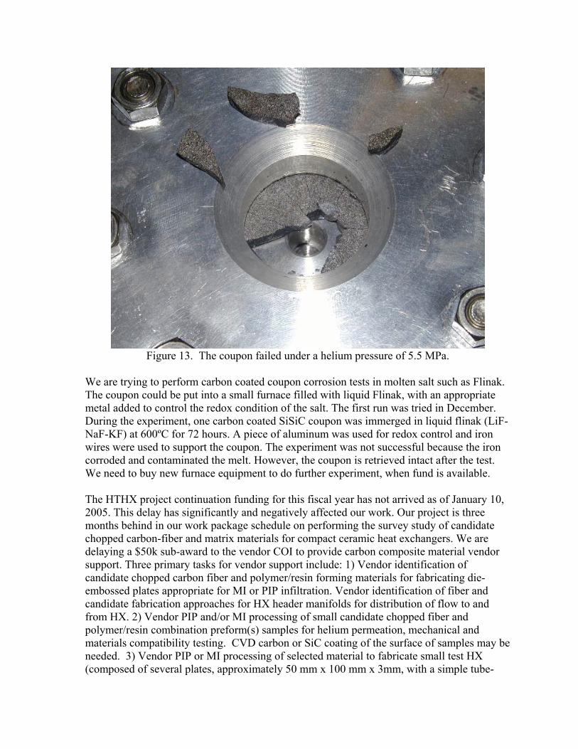
Figure 13. The coupon failed under a helium pressure of 5.5 MPa. We are trying to perform carbon coated coupon corrosion tests in molten salt such as Flinak. The coupon could be put into a small furnace filled with liquid Flinak, with an appropriate metal added to control the redox condition of the salt. The first run was tried in December. During the experiment, one carbon coated SiSiC coupon was immerged in liquid flinak (LiF-NaF-KF) at 600ºC for 72 hours. A piece of aluminum was used for redox control and iron wires were used to support the coupon. The experiment was not successful because the iron corroded and contaminated the melt. However, the coupon is retrieved intact after the test. We need to buy new furnace equipment to do further experiment, when fund is available. The HTHX project continuation funding for this fiscal year has not arrived as of January 10, 2005. This delay has significantly and negatively affected our work. Our project is three months behind in our work package schedule on performing the survey study of candidate chopped carbon-fiber and matrix materials for compact ceramic heat exchangers. We are delaying a $50k sub-award to the vendor COI to provide carbon composite material vendor support. Three primary tasks for vendor support include: 1) Vendor identification of candidate chopped carbon fiber and polymer/resin forming materials for fabricating die-embossed plates appropriate for MI or PIP infiltration. Vendor identification of fiber and candidate fabrication approaches for HX header manifolds for distribution of flow to and from HX. 2) Vendor PIP and/or MI processing of small candidate chopped fiber and polymer/resin combination preform(s) samples for helium permeation, mechanical and materials compatibility testing. CVD carbon or SiC coating of the surface of samples may be needed. 3) Vendor PIP or MI processing of selected material to fabricate small test HX (composed of several plates, approximately 50 mm x 100 mm x 3mm, with a simple tube-

type inlet and outlet manifold). CVD carbon or SiC coating of inside surfaces of HX may be required. Our collaborator at DLR, German manufactured several plates based on wood-based composite with carbon fiber reinforcement. They are going to fabricate single plates with small flow channels. The slot widths and depths will range between 0.5 mm to 5 mm, which is close to our compact plate fin heat exchanger design. Additionally, they are preparing samples (D50 mm) with the pitch carbon fiber reinforcement for our gas-tightness tests. They will send us those samples for free.
4.2 Thermal Design Study and Review During the quarter covering July to September, we intensively focused our work on integrated HX designs and isothermal stress analysis and achieved significant progress, such as inlet and outlet distribution structure design, helium plate and molten salt plates design, and bulk mechanical properties basing on unit cell isothermal stress analysis. We also obtained overall average stresses for the whole heat exchanger structure. Basing on these results, our unit cell isothermal stress analysis was repeated. Fig. 14 shows the compressive stress concentration and Fig. 15 shows the tensile stress concentration. These results are based on the whole HX stress distribution, the minimum principal stress distribution comes from a uniform average stress of 13.5 MPa on all sides and the maximum principal stress distribution comes from a uniform average stress of 6 MPa. 13.5 MPa and 6 MPa are the minimum and maximum pressure in the region corresponding to the unit cell when the whole exchanger analysis was run. A 4.75-MPa (13.5 MPa minus 9 MPa pressure difference between molten salt and helium) model corresponding to the average stress obtained by superimposing the strain from the whole exchanger analysis with the strain due to internal pressure difference was also run. That analysis shows about 15 MPa lower compressive stress. Increasing the round size from 0.375mm to 0.5mm reduces stress by about 10 MPa. Including the effect of strain from the helium reduces the stress by about 10 to 15 MPa. After considering these effects, the highest compressive stress is still around 85 MPa, and tensile stress is around 60 to 70 MPa. Compressive stresses concentrate at the root and the edges of the salt plate; tensile stresses concentrate at the root and edge of the gas plate. Composite material usually has much higher compressive strength than tensile strength. Therefore, we need to consider to take measures to reduce the maximum tensile stress because the fiber reinforced SiC usually only has a tensile strength from 90 MPa to 140 MPa. The measures may include: • larger rounds; • thicker fins; • staggering helium channel fins and molten salt channel fins in both cross-direction and
flow direction; • reducing cross direction fin pitch. For example, when we half the cross direction fin pitch, the compressive stress drops from 110 MPa (without considering larger rounds and internal pressure effect) to 60 MPa and tensile stress drops from 70 MPa to 30 MPa.

Figure 14. Compressive stress distribution in a unit cell
Figure 15. Tensile stress distribution in a unit cell

5.0 General Atomics Corrosion Testing - Materials for Hydrogen Iodide Decomposition 5.1 Research Progress and Accomplishments The project commenced on October 11, 2004. There are two tasks associated with the project and each one of them carries a milestone.
Task 1: Construction Materials Screening
Milestone 1: on track
The immersion coupon test system was disassembled and moved from its temporary location to its new location in the new S-I test facilities (Fig. 16). The HWA had to be revised and a new safety inspection was carried out in November. The temperature profile of the system was verified to ensure that the re-assembling of the system did not lead to any variation.
The test system is up and running. Screening of materials of construction candidate has started again on 12/12/04. A test schedule is listed in Table 9.
Task 2: Processing Effects on Corrosion Properties
Milestone 2: on track
We have finished a preliminary design review. System 2 will work on the same principle as system 1 except the following changes:
test chamber will be larger to accommodate larger specimens
the system will be controlled by a computer
there will be a thermocouple feed through to the chamber to directly monitor the temperature of HIx
A schematic of the system layout is shown in Fig. 17. The location of the new system will be next to system 1 (Fig. 16). Figure 18 shows the design testing with the thermocouple fed through to the chamber. The pressure of the system was stable at the test temperature for 24 hours. This successfully validates this portion of the design.
Procurement of parts is underway and the Hazardous Work Authorization (HWA) in progress. All parts are expected to be in house by early February.

Table 9. Schedule for materials screening and accelerated test plan
Material Start Date Finish Date
Hours
Nb 12/13/04 12/20/04 120Graphite 1/5/05 1/10/05 120Nb-1%Zr 1/11/05 1/17/05 120Zircalloy 705 1/18/05 1/25/05 120SiC (sintered) 1/26/05 1/31/05 120Mo-Re 2/1/05 2/7/05 120C-276 2/8/05 2/14/05 120Nb-10%Hf 2/15/05 2/21/05 120Haynes 188 2/22/05 2/28/05 120Candidate #1 @ feed conditions 3/1/05 3/7/05 120Candidate #2 @ feed conditions 3/8/05 3/14/05 120Candidate #3 @ feed conditions 3/15/05 3/21/05 120One spare week 3/22/05 3/28/05 Candidate #1 @ boiler conditions (350ºC) 3/29/05 4/28/05 700Candidate #2 @ boiler conditions (350ºC) 4/29/05 5/30/05 700Candidate #3 @ boiler conditions (350ºC) 5/31/05 6/30/05 700
Temp. Controller
Set upEnclosure
System 2Location
Figure 16. Immersion corrosion coupon test set up in the new S-I facility. Location of test system 2 is also outlined.

NHe OUT
GaugePres.ReliefValve
Valve
Furnace
Valve
Blow Disk
PressureVessel
DAQIN
V1 V2
CPU
Control loop hook up for Immersion Corrosion Test
INPUT OUTPUTTC1: Vessel over temp cutoff V1: He IN valveTC2-4: Furnace TC (3 zones) V2: He OUT valveTC5: Vessel mid-rid temp A1: Furnace powerP1: Vessel pressure transducer
OUT
FurnaceController
P1
A1
TC2 - 4
TC5PowerCutoff
TC1
Figure 17. Control loop for system 2.

Figure 18. System stability and functional test with thermocouple fed through to the chamber.

6.0 General Atomics High Temperature Heat Exchanger Study The High Temperature Heat Exchanger Study by General Atomics was completed on December 31, 2004. Their Final Report is provided below. 6.1 Introduction and Summary The UNLV Research Foundation (High Temperature Heat Exchanger) HTHX project is intended to establish a public-private partnership to develop and evaluate innovative high temperature heat exchangers for hydrogen production. The partnership focused initially on the evaluation of two hydrogen production technologies (thermally assisted electrolysis and the sulfur-iodine thermochemical cycle) that couple with a nuclear reactor power source to split the water molecule into its constituent parts. However, advanced high temperature heat exchangers are important to all hydrogen concepts and the range of processes that the U.S. Department of Energy (DOE) will consider may be broadened (e.g. Ca-Br Cycle) in the next few years. Heat exchangers are the key energy conversion components for thermally-driven hydrogen production. Heat exchangers are used in many commercial applications, and numerous types of units can be purchased from a large number of manufacturers. The performance requirements and component designs for these commercial applications are straightforward. However, commercial units and standard designs will almost certainly be inadequate for the high temperatures and aggressive chemical environments anticipated in the processes required for the NHI. Highly reactive and corrosive chemicals at very high temperature, and possibly high pressure, will require specialized materials and fabrication processes to assure safety and durability over long periods and many process cycles. During the past year, GA identified the operating requirements (temperatures, pressures and heat duty) for all of the High Temperature Heat Exchangers (HTHXs) required by both the Sulfur-iodine (S-1) and High Temperature Electrolysis (HTE) hydrogen production processes proposed to be demonstrated in the Next Generation Nuclear Power (NGNP) project. Additionally, GA prepared an evaluation of candidate heat transfer fluids for transferring the nuclear heat from the reactor plant to the hydrogen production processes. Helium was recommended as the heat transport fluid. As a design screening process, three of the more challenging HTHXs were selected for initial sizing and layout from the several identified. This initial work was limited to the use of metallic heat exchanger materials. The three heat exchangers chosen for initial sizing and layout were (1) the S-l process decomposer, (2) the S-l process recuperator, and (3) the HTE process steam generator/superheater. As part of the sizing and layout work, candidate configurations and fabrication materials were chosen based on satisfaction of requirements. For the decomposer, a U-tube heat exchanger concept was chosen; for the recuperator, a Heatrix style heat exchanger was chosen; and for the HTE steam generator/ superheater, a helical coil bundle heat exchanger was chosen.

6.2 Heat Transfer Fluid The main criteria for selection of heat transfer fluid were identified to be:
- Heat exchange surface area of high-temperature intermediate heat exchanger; - Coolant flow rate; - Capacity for fluid pumping; - Compatibility with structural materials.
The candidate fluids considered for the heat transfer fluid are as follows:
- Gases: (helium, carbon dioxide, nitrogen, hydrogen, nitrogen, air and argon); - Liquid metals and their alloys (sodium, potassium, NaK, lithium, lead, bismuth, and
lead-bismuth alloy); - Molten salts (Li2BeF4,0.58NaF-0.42ZrF4, and 0.42LiF-0.29NaF-0.29ZrF4).
The main thermophysical characteristics determining heat transfer properties of the heat transfer fluid under operating conditions are: density, specific heat capacity, heat conductivity, viscosity. In addition, for fluids that are solid at normal atmospheric conditions, melting and boiling temperatures need to be taken into account. 6.2.1 Gas Fluids Table 10 provides a comparison of gaseous coolants based on thermophysical characteristics and relative circulation capacity needed to pump the gas (with equal heat exchange surface areas). The comparison shows that hydrogen has the best combination of thermophysical properties among all gases. However, hydrogen is not a good candidate for the heat transfer fluid because of its high explosion danger in case of a leak from the heat transfer system. Additionally, under high temperature and pressure conditions, hydrogen embrittlement can be caused requiring the use of special materials or surface treatments for containment of the hydrogen. The next best gaseous heat transfer fluid is helium. Helium was chosen many years ago as the coolant for high temperature gas reactors because of these characteristics. There is now considerable experience available in design and operation of high-temperature reactors with helium coolant in addition to experience with equipment and systems typical for a heat transfer system using helium as the heat transfer fluid. One important experience baseline that exists with helium is on-line helium purification. The experience indicates purification of a small by-pass steam of the helium heat transport fluid, as typically done in the primary coolant systems of high temperature reactors, will be sufficient to maintain tritium in the heat transfer fluid to acceptable levels.

Table 10. THERMOPHYSICAL PARAMETERS OF GASEOUS COOLANTS AND RELATIVE CIRCULATION CAPACITIES AT 0.1 MPA AND 673° K Parameter H2 He N2 Air CO2 Ar Molecular mass 2 4 28 28.95 44 39.95 Density, kg/m3 0.035 0.072 0.491 0.508 0.771 0.724 Specific heat capacity, Cp.lO3, J/(kg•K)
14.58
5.193
1.09
1.07
1.06
0.603
Heat conductivity coefficient, λ•103, W/(m•K)
348 287 50.7 52.1 47.2 33.9
Dynamic viscosity, m•106, Pa s
15.4 34.3 30.9 33 30.2 41.1
Prandtl number 0.644 0.648 0.659 0.68 0.71 0.628 Relative circulation capacity needed for pumping
1
5.1
34.41
34.06
38.12
128.7
6.2.2 Liquid metal fluids Liquid metals (sodium, potassium, NaK, lithium, lead, bismuth, and lead-bismuth alloy) also have good combination of thermophysical properties. At present, there is considerable experience in applying sodium both in the primary and secondary circuits of fast reactors including experience with equipment and systems typical for a sodium coolant heat transfer circuit. However, liquid metals such as sodium, potassium, sodium-potassium alloy are not capable of transferring high temperature heat because they have low boiling temperatures (below 900°C). Application of other liquid metals that have high boiling temperatures also have relatively high melting temperatures. The use of these fluids would require:
- Equipping the heat transfer circuit with a special heating system that would heat the circuit up before filling it with coolant. This system would need to be in a standby mode during the whole operating period to keep the temperature in the circuit above the freezing point in case of reactor shutdown;
- Developing a special technology and design of auxiliary equipment (purification system, drainage and washing system) for servicing, repair, and replacement of secondary circuit equipment and heat exchanger components.
6.2.3 Molten salts Table 11 provides a comparison of the thermophysical properties of molten salts with high pressure helium. The most important difference is the volumetric heat capacity, ρcp, of molten salts is over two orders of magnitude greater than that of high-pressure helium.

Table 11. THERMOPHYSICAL PROPERTIES OF HELIUM AND THREE REFERENCE MOLTEN SALTS (approximate values at average intermediate loop temperature of 700°C), (ρ-density, cp -specific heat, k-thermal conductivity, ν-viscosity). Material
Tmelt, °C
Tboil, °C
ρ, kg/m3
Cp, kJ/kg°C
ρcp, kJ/m3°C
k, W/m°C
νx106, m2/s
Li2BeF4 (Flibe)
459
1,430
1,940
2.34
4.540
1.0
2.9
0.58NaF- 0.42ZrF4
500
1,290
3,140
1.17
3,670
2.1
0.53
0.42UF- 0.29NaF- 0.29ZrF4
460
?
2706
1.47
3,978
2.1
1.64
Helium (7.5 MPa)
—
—
3.8
5.2
20
0.29
11.0
The much higher volumetric thermal capacity (ρcp) of molten salts, compared to high-pressure helium, has a large effect upon the relative heat transfer capability. In general, a molten salt system would use piping 1/5 the diameter, and pumping power 1/20 of those required for high-pressure helium. These large differences in pumping power and pipe size would tend to reduce the capital cost of the heat transfer system. However, because molten salts are solid at normal atmospheric conditions, the heat transfer system would require the same type of complex heating and auxiliary equipment identified above for the liquid metal heat transfer system. These requirements would tend to offset the lower capital cost associated with pumping power and pipe size. Significant R&D would be required for use of a molten salt as the heat transfer fluid. Representative required R&D activities include the following:
- Validation of salt coolant chemical stability under maximal operating temperatures, up to ~950°C;
- Development of coolant operation technology (purification, control, maintaining stable chemical composition, etc.) and its implementation at the plant;
- Validation of corrosion/erosion resistance of materials used in the heat transfer circuit and heat exchange equipment under operating conditions
- Tests on thermophysical properties and heat exchanger effectiveness. There are two other important considerations regarding the use of a molten salt that need to be taken into account. The first of these is the potential for ingress of the molten salt into the primary circuit. This could potentially happen if the pressure in the heat transfer circuit is ever higher than in the primary circuit. Such events would result in long-term outage of the plant while the secondary coolant is removed from the primary circuit. The second important consideration is at the interface with the hydrogen production facility. For the Sulfur-lodine hydrogen production process, the heat transfer system interfaces with a heat exchanger for transfer of the heat into a sulfuric acid decomposition process. Should

there ever be a leak of the fluoride salt into the process, HF would be formed which would have a catastrophic effect on the hydrogen production process. 6.2.4 Selection A final consideration in selection of the heat transfer fluid relates to the proximity of the hydrogen production plant to the nuclear reactor plant. If the hydrogen plant were located distant from the nuclear plant, there would be a potential incentive for the use of a molten salt as the heat transfer fluid to minimize piping and pumping power costs. If, on the other hand, the hydrogen plant can be sited close to the nuclear plant, helium heat transfer fluid would have merit. Preliminary evaluations indicate there are no strong reasons for the hydrogen plant to be located distant from the nuclear plant. The key reasons for this are: - The safety characteristics of the nuclear plant are such that it would have no impact on the hydrogen plant. - The hydrogen inventories of the hydrogen plant(s) are sufficiently limited to impose no threat to the nuclear plant. - Environmental effects of the hydrogen plant (e.g. fumes) are amiable to control by proven measures routinely used in chemical process plants (such as a berm between the nuclear and hydrogen plant. In summary, - Liquid metals are not viable candidates for the heat transport fluid because of either relatively low boiling temperatures (~900°C) or high melting temperatures. - Molten salts are attractive because of their high volumetric heat capacity but because of their relatively high melting temperature would require significant auxiliary systems that offset the heat transfer capacity benefit. - Molten salts would also require significant R&D efforts on chemical stability, operational technology, corrosion/erosion and thermophysical properties. - There are significant risks interfacing a molten salt heat transfer system with the nuclear and hydrogen production plants - There is considerable experience in using helium for heat transfer in high temperature reactors, including helium purification that can be used to satisfy tritium control requirements. - Helium would be compatible for interfacing with both the nuclear and hydrogen plants without significant risk. - The hydrogen production plant can be sited close to the nuclear plant to minimize the quantity of large diameter piping required for the use of helium as the heat transport fluid. Based on the results of these largely qualitative evaluations, the conclusion has been reached the most optimal fluid to be used as heat transport system fluid is helium at a pressure of > 5Mpa.

6.3 Sl Process High Temperature Heat Exchangers 6.3.1 Selection A review was completed to identify the range of High Temperature Heat Exchanger (HTHX) applications required by the sulfur-iodine (S-l) process for hydrogen production using nuclear energy. The primary reference used in identifying the HTHXs required by the S-l process is Reference 1. Based on the information in this report, the HTHXs in the S-l hydrogen production process are in the sulfuric acid decomposition section and hydrogen iodide decomposition section. The criteria used for identification of the HTHXs in the S-l process was for either one of the working fluids to have a temperature greater than 400°C. Eleven (11) such HTHXs were identified. A listing of these heat exchangers along with their heat loads are provided in Table 12 for two plant configurations: 1) a full scale plant using the thermal output of 2400 MWt and, 2) a plant using 50 MWt output proposed for hydrogen production demonstration as part of
the Next Generation Nuclear Power (NGNP) project. The full-scale plant would be able to generate 4200 mole of hydrogen per second. The NGNP hydrogen demonstration would produce 87.5 mole of hydrogen/second. The E200 series heat exchangers listed in Table 12 are part of the sulfuric acid decomposition section. The E300 series heat exchangers are part of the hydrogen iodide decomposition section. All of the heat exchangers except the E206 Recuperator and the E202-1 Preheater/Cooler use heat from the nuclear power plant as the heat source. The inlet and outlet temperatures, pressures and molar composition for each of the eleven heat exchangers is presented in Tables 13, 14 and 15. The required heat supply to the hydrogen production process can be divided into three sectors according to the temperature required by the process. The highest temperature heat is required by the sulfuric acid decomposer, vaporizer and preheater (components E207, E205, and E204). This sector uses 47.02% of the heat supplied by the nuclear heat source. The next sector consists of the flash heaters used in the isobaric concentration of sulfuric acid (components E202-2, E202-3, and E202-4). This sector uses 14.78% of the heat supplied by the nuclear heat source. The final sector consists of the sulfuric acid preheater (component E215), and the reboiler (component E306) and condensate reheater (component E307) in the hydrogen iodide reactive still. The remaining heat supplied to this sector is 38.20% of the nuclear heat source

Table 12. HEAT LOADS OF HIGH TEMPERATURE HEAT EXCHANGERS
4200 mol H2/s from 2400 MWt
87.5 mol H2/s from 50 MWt
E207 Decomposer 613.56 MW 12.78MW E206 Recuperator 3@ 120.36 MW ea. 7.52 MW E205 Vaporizer 464.00 MW 9.67 MW E204 Vaporizer Preheater 50.90 MW 1.06MW E202-4 Stage 4 Flash Heater 95.52 MW 1.99MW E202-3 Stage 3 Flash Heater 99.74 MW 2.08 MW E202-2 Stage 2 Flash Heater 159.48 MW 3.32 MW E215 Preheater 4 @ 17.92 MWea. 1.49MW E202-1 Preheater/Cooler 4 @ 50.52 MW ea. 4.21 MW
E306 Reactive Still Reboiler 40 @ 20.37 MW ea. 16.98MW E307 Condensate Reheater 40 @ 0.76 MW ea. 0.63 MW
Table 13. MOLAR COMPOSITION OF H2S04 HEAT EXCHANGERS WITH
INTERNAL HEAT SOURCES Molar Composition (%)Heat Exchanger (quantity) Phase H2O H2SO4 SO3 O 2 SO2E206 Recuperator (3) Cold inlet 7.09 bar 411 C V 27.8 52.3 19.9 - - Cold outlet 7.09 bar 523.7 C V 48.1 9.4 42.5 - - Hot inlet 7.09 bar 827 C V 45.8 0.1 15.5 12.9 25.7Hot outlet 7.09 bar 431 C V 40.7 9.4 7.6 14.1 28.2E205 Preheater/Cooler (4) Cold inlet 35.46 bar 299 C L+V 76.2 23.7 - - 0.1Cold outlet 35.46 bar 330 C L+V 76.2 23.7 - - 0.1Hot inlet 7.09 bar 431 C V 40.7 9.4 7.6 14.1 28.2Hot outlet 7.09 bar 349.4 C L+V 35.8 18.5 - 15.2 30.5 An alternative flow scheme for the S-l process was developed that more closely matches the temperature requirements of the hydrogen production process by adding a turbine, precooler and compressor to the system. The standard and alternative flow schemes are depicted in Figures 19 and 20. The heat loads and working fluid temperatures are presented in Tables 13 and 14. In the alternative flow scheme designated as Case 2, the process equipment is reduced in half because half of the heat supplied by the reactor goes to the turbine, precooler and compressor. A net electrical output of 14.29 MW is produced while rejecting 11.22 MW to the environment via the precooler. The Case 2 scheme may provide added flexibility in operating the hydrogen production process. Conceivably during startup and shutdown, the working fluid can be diverted from the vaporizer and sent directly to the turbine. The precooler can also be useful during plant upsets since it can be used to dump excess heat that the process is unable to use.

Table 14. MOLAR COMPOSITION OF N2804 HEAT EXCHANGERS SUPPLIED WITH REACTOR HEAT
Molar Composition (%)Heat Exchanger (quantity) Phase H2O H2SO4 SO3 O 2 SO2E207 Decomposer Cold inlet 7.09 bar 523.7 C V 48.1 9.4 42.5 - - Cold outlet 7.09 bar 827 C V 45.8 0.1 15.5 12.9 25.7E205 Vaporizer Cold inlet 7.09 bar 411 C L 9.8 90.2 - - - Cold outlet 7.09 bar 411 C L+V 27.8 52.3 19.9 - - E204 Vaporizer Preheater Cold inlet 7.09 bar 361 C L 9.8 90.2 - - - Cold outlet 7.09 bar 411 C L 9.8 90.2 - - - E202-4 Stage 4 Flash Heater Cold inlet 35.46 bar 358 C L 63.9 36.1 - - >>0.1Cold outlet 35.46 bar 371 C L+V 63.9 36.1 - - >>0.1E202-3 Stage 3 Flash Heater Cold inlet 35.46 bar 346 C L 67.5 32.5 - - >>0.1Cold outlet 35.46 bar 358 C L+V 67.5 32.5 - - >>0.1E202-2 Stage 2 Flash Heater Cold inlet 35.46 bar 330 C L 72.2 27.8 - - >0.1Cold outlet 35.46 bar 346 C L+V 72.2 27.8 - - >0.1E215 Preheater (4) Cold inlet 35.46 bar 275.6 C L 76.2 23.7 - - 0.1Cold outlet 35.46 bar 299 C L+V 76.2 23.7 - - 0.1 Table 15. MOLAR COMPOSITION OF HI HEAT EXCHANGERS SUPPLIED WITH
REACTOR HEAT Molar Composition (%) Heat Exchanger (quantity) Phase HI I2 H2O H2 E306 Reboiler (40) Cold inlet 22 bar 262 C L 9.9 38.1 52.1 - Cold outlet 22 bar 31 OC L+V 8.6 38.1 52.5 0.8 E305 Condensate Reheater (40) Cold inlet 22 bar 25 C L 22.9 - 77.1 - Cold outlet 22 bar 221 C L 22.9 - 77.1 - The log mean temperature difference (LMTD) is also included in Tables 13 and 14. For Case 2, the LMTD for the Reactive Still Boiler is only 25°C with only a 5.2°C difference between the hot side outlet and the cold side inlet temperatures. This temperature difference may be too small and may need to be increased. Case 2 also requires that the working fluid transferring heat to the hydrogen production process is a gas. The flow scheme does not account for pressure losses through the heat exchangers or any bypass losses in the turbine or compressor.

Figure 19. Working Fluid Flow Scheme – Case 1
Figure 20. Working Fluid Flow Scheme – Case 2

Table 16. WORKING FLUID FLOW SCHEME - CASE 1
revised Q (MW)
Cold Tin
Cold Tout
Hot Tin(C)
Hot Tout
LMTD (C)
E207 Decomposer 12.78 559.3 952 975 807.6 94.68 E205 Vaporizer 9.67 411 411 807.6 680.9 329.18 E204 Vaporizer Preheater 1.06 361 411 680.9 667.0 287.59 E202-4 Stage 4 Flash H
1.99 358 371 667.0 641.0 289.44 E202-3 Stage 3 Flash H
2.08 346 358 641.0 613.7 275.28 E202-2 Stage 2 Flash 3.32 330 346 613.7 570.2 253.73 E215 Preheater 1.49 275.6 299 570.2 550.6 273.12 E306 Reactive Still 16.98 262 310 550.6 328.3 135.21 E307 Condensate 0.63 25 221 328.3 320.0 185.56 Heat to Process 50.00
TABLE 17. WORKING FLUID FLOW SCHEME - CASE 2
Heat Load
Cold Tin
Cold Tout
Hot Tin(C)
Hot Tout
LMTD (C)
E207 Decomposer 6.26 559.3 952 975 890.1 115.45 TURBINE 28.02 890.1 510.2 E205 Vaporizer 4.74 411 411 510.2 446.0 61.62 E204 Vaporizer Preheater 0.52 361 411 446.0 439.0 53.64 E202-4 Stage 4 Flash 0.97 358 371 439.0 425.7 67.85 E202-3 Stage 3 Flash 1.02 346 358 425.7 411.9 66.84 E202-2 Stage 2 Flash 1.63 330 346 411.9 389.9 62.86 E215 Preheater 0.73 275.6 299 389.9 380.0 97.46 E306 Reactive Still 8.32 262 310 380.0 267.2 24.92 E307 Condensate 0.31 25 221 267.2 263.0 117.01 PRECOOLER 11.22 263 110.9 COMPRESSOR -13.73 110.9 297.1 Heat to Process 24.49 Heat Rejected 11.22 Network 14.29 Total 50.00

21
6.3.2 Initial Sizing The two heat exchangers selected for initial sizing were those which have the most demanding pressure and temperature operating requirements. The heat exchangers selected are the S-l process decomposer (E207) and recuperator (E206). The operating requirements used for the two S-l process HTHXs are those presented in Table 13 for the standard configuration. For these initial sizing calculations, metallic heat exchangers were assumed. The heat transfer fluid used for transfer of heat from the nuclear reactor was assumed to be helium, as recommended in Section 2. S-l Process Decomposer. HTHX E207 Two alternative metallic materials were investigated for fabrication of HTHX E207, Inconel 617 and niobium. Both of these materials have good properties for fabrication of the heat exchanger using conventional manufacturing techniques (forming, forging, welding, etc). High temperature material property data is also available for both of these materials. A conventional U-tube type heat exchanger configuration was assumed for the initial sizing analyses primarily due to the pressure and temperature requirements and the need for use of a catalyst in the decomposition process. An alternative configuration considered was a Heatrix style heat exchanger but was not selected for these initial sizing analyses due to the potential difficulties perceived for incorporation of the catalyst. The incorporation of a catalyst in tubes was considered to be practical. The initial sizing analyses resulted in the conclusion that to obtain a practical design for HTHX E207 using Inconel 617 as the fabrication material would require that the pressure of the helium used to transfer heat from the nuclear reactor could be no higher than about 1.75 MPa, as compared to the reference selected helium pressure of 7.5 MPa. If niobium were used for the fabrication material, the sizing analyses concluded that the helium pressure could be held at the reference value of 7.5 MPa. A layout of the resultant U-tube heat exchanger design for fabrication from niobium is contained in Figure 21. The process mixture flow rate is 11.5 kg/s and the helium flow rate is 14.7 kg/s. The pressure drop on the helium side is 0.015 MPa and on the mixture side the pressure drop is also 0.015 MPa. The heat duty of the heat exchanger is 12.78 MW. The heat exchanger consists of 4574 U-tubes with an inside diameter of 10.16 mm and a wall thickness of 3.647 mm. The total tube length including tube sheet is 9.34 m which provides a surface area of 1776.5 m2. The tube sheet thickness is 1.127m. It should be noted that while the niobium heat exchanger satisfies the technical requirements, it might not satisfy economic goals because of the high cost of niobium. Subsequent design evaluations, for HTHX E207, should include investigations of how the catalyst is to be incorporated. Such investigations might result in a Heatrix style heat exchanger, or other novel designs, being found that are more functionally and economically attractive.

22
S-l Process Recuperator. HTHX E206 There is no need for incorporation of a catalyst in E206 and the pressure requirements for E206 are modest. As a result of these considerations, the initial sizing analyses were performed for a Heatrix style heat exchanger fabricated from Inconel 617. A reasonable heat exchanger design was concluded to be practical for these material and configuration design choices. An initial design layout for HTHX E206 is contained in Figure 22. The mixture flow rate is 11.5 kg/s and the heat load is 9.94 MW. The Heatrix style heat exchanger consists of 4 modules with 3 mm diameter coolant channels spaced 3.9 mm horizontally and 2.4 mm vertically. The total number of flow paths on either the hot or cold side is 60,588 with a heat transfer surface area of 176.6 m2.
Figure 21. Initial design layout for decomposer HTHX E207 fabricated from niobium

23
Figure 22. Initial design layout for recuperator HTHX E206 6.4 HTE Process High Temperature Heat Exchangers The HTE hydrogen production process uses solid oxide fuel cells (SOFC) to split water into hydrogen and oxygen at high temperature. A process flow diagram for a typical HTE process is shown in Figure 23. There are four high temperature heat exchangers within this process. The primary process heat exchangers (HX2 and HX4) receive heat from either an intermediary or tertiary fluid loop and transfers this heat to the working fluid of the HTE

24
process. These two heat exchangers receive their heat ultimately from the nuclear power plant through one or more intermediate heat exchangers. The other two high temperature heat exchanger within this process are recuperators that recover some of the heat from the hydrogen and oxygen process streams leaving the SOFC. The recuperators superheat the steam coming out of HX2 before returning the steam back to HX4 for the final amount of additional superheating of the steam.
Figure 23. Typical High Temperature Electrolysis (HTE) Flow Diagram Inlet and outlet conditions for the high temperature heat exchangers were scaled from the 500 kW pilot plant design in Reference 2. The HTE primary process heat exchangers are estimated to have a hot side fluid inlet temperature of 900°C and a hot side outlet temperature of 400°C. The helium inlet pressure is 7 MPa. The intermediary temperature between HX2 and HX4 is 783°C. The cold side outlet temperature of the process heat exchanger will be 850°C. The process fluid through HX2 will be water but the process fluid through HX4 will be composed of 90% H2O and 10% H2 on a molar basis. The cold side inlet temperature to HX2 will be ~264°C which is the saturation temperature at 5 MPa. The quality of the inlet water is 11.17%. Initial sizing was completed for both the steam generator, HX2 and superheater, HX4 in the HTE process. A helical coil heat exchanger configuration was chosen, similar to the designs of steam generators that have been previously developed for High Temperature Gas-cooled Reactor (HTGR) steam generators. The heat transfer fluids are basically the same (helium and water) but the HTE temperatures are higher. Because of the higher temperatures, Inconel 617 was been chosen for the helical coils. 214Cr-1 Mo was chosen for the heat exchanger vessel, the same as the reference material for the Modular High Temperature Gas-cooled

25
Reactor (MHTGR) because, by design, the vessel can be maintained at the helium outlet temperature. An initial layout of the HTE steam generator is contained in Figure 24. The steam exiting HX2 is slightly superheated at a temperature of 299.5°C. After exiting the recuperators, the steam/hydrogen mixture returns at a temperature of 662°C. The mixture is further superheated to 850°C before being transported to the SOFC for electrolysis. The steam generator HX2 has a heat duty of 36 MW and the final superheater HX4 has a heat duty of 11 MW. The helium flow rate is 18.1 kg/s. The water flow rate through both HX2 and HX4 is 22.8 kg/s. The flow rate through HX4 also include hydrogen at a rate of 0.2782 kg/s. Both HX2 and HX4 consist of 117 tubes in a helical bundle. The tube inside diameter is 21.5809 mm and the outside diameter is 25.4 mm. The tube length in the HX2 steam generator is 23.44 m. The tube length in the HX4 superheater is 19.93 m. The tubes have both a transverse and longitudinal pitch of 35.56 mm. Both bundles have an inside diameter of 0.72 m and an outside diameter of 1.65 m. The steam generator HX2 has a depth of 2.09 m. The superheater HX4 has a depth of 1.71 m. 6.5 References 1. Brown, L. C., G. E. Besenbruch, R. D. Lentsch, K. R. Schultz, J. F. Funk, P. S. Pickard,
A. C. Marshall, and S. K. Showalter, "High Efficiency Generation of Hydrogen Fuels Using Nuclear Power," General Atomics report GA-A24285, Rev. 1, December 2003.
2. Stoots, Carl M., James E. O'Brien, and J. Stephen Herring, "Facility Requirements for a 500 kW Pilot-Scale High-Temperature Electrolysis Plant," INEEL Draft Report, November 2004.

26
Figure 24. Initial Design Layout of HTE Heat Exchangers HX2 and HX4.

27
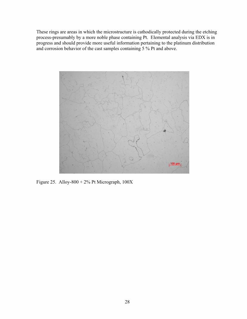
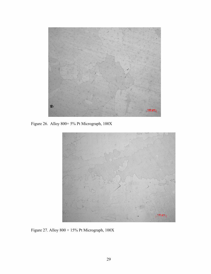
7.0 MIT Catalyst Alloys 7.1 Alloy 800 Plus Platinum Alloys At the start of the quarter, focus was on the characterization of the initial batch of Alloy-800 +Pt alloy buttons obtained from Huntington Alloys (Division of Special Metals, Inc., Huntington West VA). The Base chemistry of Alloy 800 is as follows (in wt%): 21Cr-32.5Ni-0.38Ti-0.38Al-0.05C-Bal Fe. The Alloy 800-Pt compositions are Alloy-800 plus 2Pt, 5Pt, 15Pt, and 30Pt with the Fe concentration reduced as Pt is added. These materials have are being characterized in the as-cast condition prior to conversion to wrought material by a series of rolling/annealing steps. Samples of each material were mounted and polished using standard metallographic techniques. It was anticipated that chemical or electrochemical etching of these materials would be difficult due to the presence of both dissolved Pt and the probable presence of Pt-based precipitates. Indeed the presence of Pt in the alloys manifests itself by making the surfaces very electroactive. In the case of the high Pt alloys the presence of second phase precipitates that are very cathodic to the matrix material made etching difficult. Initial etching practice involved the use of glyceregia (3 parts glycerol, 3 parts HCl, 1 part HNO3) on the cast Alloy 800 HT + 2% Pt sample. Though glyceregia works well as a mild etchant for Fe-Ni base super alloys, it created corrosion artifacts on the surface of the above mentioned sample within 10 seconds. In order to gain more control over the etching process, the 2% Pt sample was re-polished and etched with a weak glyceregia etchant (12 parts glycerol, 3 parts HCl, 1 part HNO3). The weaker etchant allowed for the development of a high quality as-cast microstructural image of the 2% Pt sample by slowing the etching process. The same weak glyceregia etchant was used to etch the 5% Pt sample and produced good results for imaging. For the cast samples containing 15% and 30% Pt the etchant was weakened again by a factor of 2 (24 parts glycerol, 3 parts HCl, 1 part HNO3). The etched microstructure of each cast sample was imaged at 50 x, 100 x, and 200 x. Figures 25-28 show micrographs at 100X magnification. These images show that the microstructure of each cast sample is composed of a dendritic structure as would be expected. The clarity of the inter-dendritic boundaries decreases as the mass percent of platinum increases within the material. Relatively few inter-dendritic boundaries were developed in the 30% Pt cast sample compared to the other samples. Orange blocky particles between 1-15 µm in size are present in each microstructure. The size shape and color of these deposits indicate that they are probably titanium carbonitrides. In many cases, these carbonitrides are aligned in rows that indicate solidification patterns within the dendritic microstructures. At 5% Pt concentration and higher, images reveal varying amounts of discoloration throughout the solidification microstructures. These regions of contrast exist across dendrite boundaries as well as within individual dendrite structures. Darker regions indicate where the etchant preferentially attacked the surface of the material. In the 5% Pt sample very large (20-100 µm) deposits formed that caused rings of heavily corroded material upon etching. Within the microstructures of the 15% Pt and 30% Pt samples, there is a somewhat uniform distribution of particles surrounded by rings of lighter contrast than the surrounding medium.
28
These rings are areas in which the microstructure is cathodically protected during the etching process-presumably by a more noble phase containing Pt. Elemental analysis via EDX is in progress and should provide more useful information pertaining to the platinum distribution and corrosion behavior of the cast samples containing 5 % Pt and above.
Figure 25. Alloy-800 + 2% Pt Micrograph, 100X
29
Figure 26. Alloy 800+ 5% Pt Micrograph, 100X
Figure 27. Alloy 800 + 15% Pt Micrograph, 100X

30
Figure 28. Alloy 800 + 30% Pt Micrograph, 100X. These alloys have been fully characterized in the as-cast condition. The buttons have been sectioned as illustrated in Figure 29. The small side sections are being used for characterization of the as-cast microstructure. The larger sections are being further machined to rectangular shape. We are in the process of converting these buttons into wrought material by rolling. The individual button samples have been inserted into pre-machined locations in alloy 800 plate material and spot welded in place. The plate/alloy button combinations are being rolled to 50% reduction with an intermediate anneal at 1050°C after 25% reduction and final anneals at 1050°C.

31
Figure 29. Typical sectioning regime for alloy buttons.
7.2 Alloy 617 Plus Platinum Alloys The series of alloy 617 plus Pt alloys that were contracted from Huntington Alloys, Inc. have been received. The base chemistry of alloy 617 is (in wt%) 22Cr-55Ni-12.5Co-9Mo-0.07C. The alloys were ordered with a nominal 2, 5, 15, and 30 wt% Pt content respectively. These materials are in the process of being characterized in the as-cast condition. We are in the process of converting these buttons into wrought material by rolling. The individual button samples have been inserted into pre-machined locations in alloy 800 plate material and spot welded in place. The plate/alloy button combinations are being rolled to 50% reduction with an intermediate anneal at 1050°C after 25% reduction and final anneals at 1050°C. 7.3 Other Progress A rolling mill has been procured from the Department of Materials Science and Engineering and moved to the laboratory. The mill has been installed and is being tested for operation.

32
8.0 Development of an Efficient Ceramic High Temperature Heat Exchanger by Ceramatec, Inc. With the delay of the finalized contract, the Ceramatec, Inc. start date was also delayed to Dec 2004; thus, resulting in a compression of work of the proposed research program. The modified completion dates were proposed in the Dec 17, 2004 kick-off meeting. Although the completion of early tasks has been delayed, through accelerated effort, the project schedule should be in line by April 2005 and the overall work plan should be completed as scheduled by September 30, 2005.
8.1 Research Accomplishments Preliminary information concerning the operating conditions were obtained at the kickoff meeting at UNLV on December 17, and subsequently from General Atomics on December 23. This information will be used to determine acceptable ranges of material parameters, such as thermal conductivity, corrosion resistance, elastic modulus, strength, etc. Ceramatec has begun to process hot-pressed SiC strength and corrosion samples. The flow sheet for the 15 atm SI process has been received from B. Wong of General Atomics; the 70 atm process flow sheet is expected next quarter. We are reviewing these flow sheets to extract the operating and performance criteria for the high temperature heat exchanger. Concepts for the preliminary Revision 1.0 Design have been initiated. These concepts will mature with the definition of process conditions and performance expectations. A preliminary cost model has been developed for similar applications, high temperature heat exchanger for micro-turbines. This model can be modified and scaled according to the preliminary Revision 1.0 Design that will be the basis for the development.
Copyright © 2022 FDOKUMEN