Optimisation of a waste heat exchanger for ballast water treatment
12
-
Upload
teknologimalaysia -
Category
Documents
-
view
3 -
download
0
Transcript of Optimisation of a waste heat exchanger for ballast water treatment

Scientia Iranica B (2015) 22(3), 871{882
Sharif University of TechnologyScientia Iranica
Transactions B: Mechanical Engineeringwww.scientiairanica.com
Research Note
Optimisation of a waste heat exchanger for ballastwater treatment
R. Balajia;� and O. Yaakobb
a. Malaysian Maritime Academy (ALAM), Window delivery 2051, Masjid Tanah Post O�ce, 78300, Melaka, Malaysia.b. Faculty of Mechanical Engineering, Universiti Teknologi Malaysia, 81310, Skudai, Malaysia.
Received 19 April 2014; accepted 28 September 2014
KEYWORDSBallast watertreatment;Exhaust gases;Waste heat recovery;Heat exchanger;Optimisation.
Abstract. Ballast Water Treatment systems, which are type approved and commerciallyavailable, require improvements to meet stricter standards, and heat treatment could bea viable additional option. Considering the waste heat potential on a ship, a systemharvesting the engine exhaust heat may be envisaged for which a heat exchanger could bevital. Design optimisation of a heater, employing the exhaust gases of an engine as utility uid, and ballast sea water as the process uid, was achieved using Lagrangian methods,keeping the annual cost as the objective function. Limiting the number of variables, optimalvalues were calculated with cost considerations for utility uid and also pumping costs forutility and process uids. In all, four optimum designs and three comparative designs weredeveloped. Heat balance data from an operational tanker, speci�c fuel consumption valuesand fuel costs were considered for the design. The thermodynamic and geometric designswere worked out using computer based software for a comparison. Designs were comparedon the basis of annual cost, optimum exit temperature of shell side uid, optimum mass ow of tube side uid and heat exchanger e�ectiveness. It is demonstrated that an optimalheat exchanger design can be obtained with simple optimisation procedures.© 2015 Sharif University of Technology. All rights reserved.
1. Introduction
Transportation of non-native species in the ballastwater of ships is an environmental issue for whichindustry has yet to �nd a suitable solution in termsof e�ciency and economy of cost. While the ballastwater convention is nearing full rati�cation, BallastWater Treatment (BWT) systems based on varioustechnologies are also emerging. All available sys-tems are compliant to requirements and yet are notgeared up to meet the stricter standards of someadministrative regulations. The Environmental Pro-tection Agency of the United States [1] assessed andreported that only �ve combination systems show
*. Corresponding author. Tel.: +60 6 388 2214;Fax: +60 6 387 6700E-mail address: [email protected] (R. Balaji)
promise of meeting stricter standards, and has sug-gested that improvements may be achieved with in-novative combinations. Heat treatment has beenresearched and some heat-based systems are already ono�er. Though apprehension regarding su�cient wasteheat availability for treatment prevails, research intoharvesting shipboard heat is warranted, consideringthe high cost of other BWT options. Research onheat treatment has shown species mortality at lowto medium temperature ranges [2-5]. Also, Mesbahiet al. [6] modelled and tested a thermal system athigh temperature ranges for heat treatment of ballastwater.
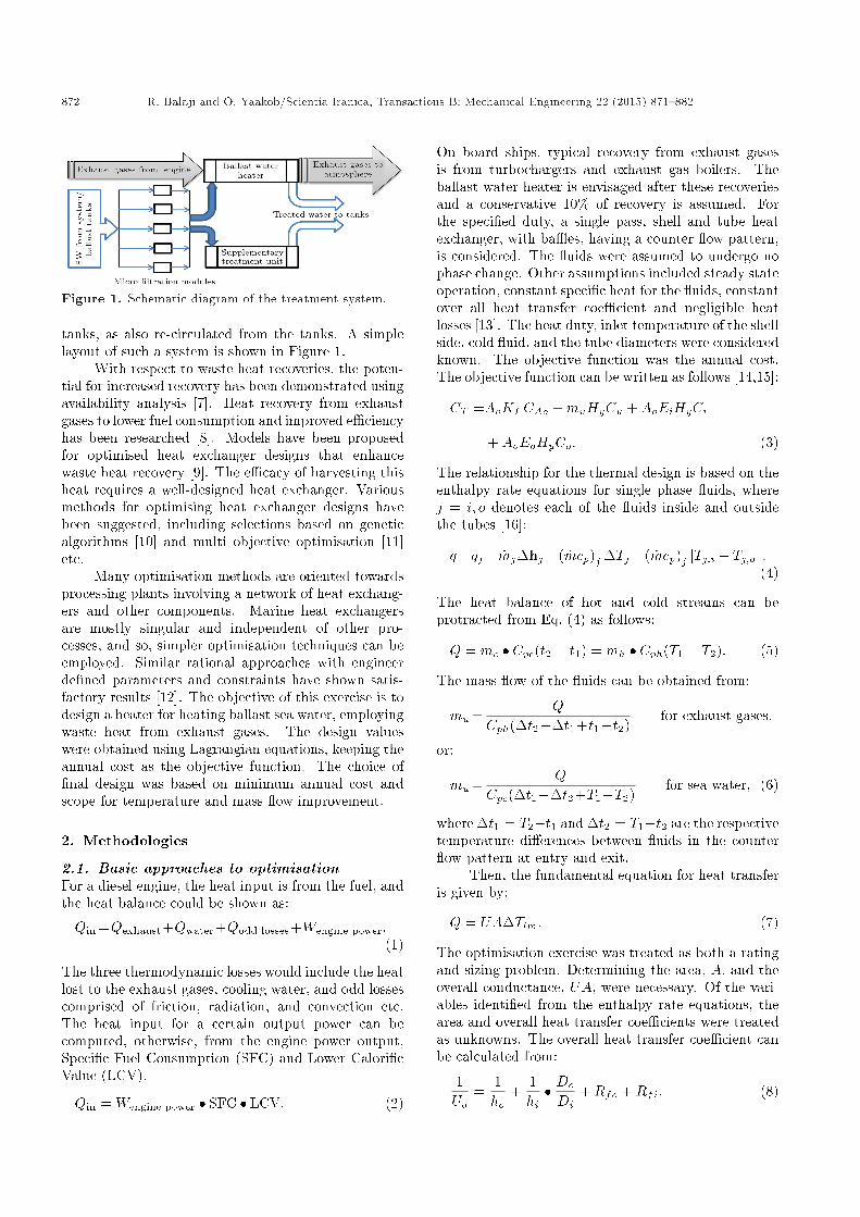
Typical shipboard waste heat sources includecooling water and steam system rejections. The seawater receiving all these rejections can be furtherheated using the engine exhaust heat. Sea water canbe routed from the main sea water circuit to the ballast
872 R. Balaji and O. Yaakob/Scientia Iranica, Transactions B: Mechanical Engineering 22 (2015) 871{882
Figure 1. Schematic diagram of the treatment system.
tanks, as also re-circulated from the tanks. A simplelayout of such a system is shown in Figure 1.
With respect to waste heat recoveries, the poten-tial for increased recovery has been demonstrated usingavailability analysis [7]. Heat recovery from exhaustgases to lower fuel consumption and improved e�ciencyhas been researched [8]. Models have been proposedfor optimised heat exchanger designs that enhancewaste heat recovery [9]. The e�cacy of harvesting thisheat requires a well-designed heat exchanger. Variousmethods for optimising heat exchanger designs havebeen suggested, including selections based on geneticalgorithms [10] and multi objective optimisation [11]etc.
Many optimisation methods are oriented towardsprocessing plants involving a network of heat exchang-ers and other components. Marine heat exchangersare mostly singular and independent of other pro-cesses, and so, simpler optimisation techniques can beemployed. Similar rational approaches with engineerde�ned parameters and constraints have shown satis-factory results [12]. The objective of this exercise is todesign a heater for heating ballast sea water, employingwaste heat from exhaust gases. The design valueswere obtained using Lagrangian equations, keeping theannual cost as the objective function. The choice of�nal design was based on minimum annual cost andscope for temperature and mass ow improvement.
2. Methodologies
2.1. Basic approaches to optimisationFor a diesel engine, the heat input is from the fuel, andthe heat balance could be shown as:
Qin =Qexhaust+Qwater+Qodd losses+Wengine power:(1)
The three thermodynamic losses would include the heatlost to the exhaust gases, cooling water, and odd lossescomprised of friction, radiation, and convection etc.The heat input for a certain output power can becomputed, otherwise, from the engine power output,Speci�c Fuel Consumption (SFC) and Lower Calori�cValue (LCV).
Qin = Wengine power � SFC � LCV: (2)
On board ships, typical recovery from exhaust gasesis from turbochargers and exhaust gas boilers. Theballast water heater is envisaged after these recoveriesand a conservative 10% of recovery is assumed. Forthe speci�ed duty, a single pass, shell and tube heatexchanger, with ba�es, having a counter ow pattern,is considered. The uids were assumed to undergo nophase change. Other assumptions included steady stateoperation, constant speci�c heat for the uids, constantover all heat transfer coe�cient and negligible heatlosses [13]. The heat duty, inlet temperature of the shellside, cold uid, and the tube diameters were consideredknown. The objective function was the annual cost.The objective function can be written as follows [14,15]:
CT =AoKFCAo +muHyCu +AoEiHyCi
+AoEoHyCo: (3)
The relationship for the thermal design is based on theenthalpy rate equations for single phase uids, wherej = i; o denotes each of the uids inside and outsidethe tubes [16]:
q=qj = _mj�hj=( _mcp)j �Tj =( _mcp)j jTj;i � Tj;oj :(4)
The heat balance of hot and cold streams can beprotracted from Eq. (4) as follows:
Q = mc � Cpc(t2 � t1) = mh � Cph(T1 � T2): (5)
The mass ow of the uids can be obtained from:
mu=Q
Cph(�t2��t1+t1�t2)for exhaust gases;
or:
mu=Q
Cpc(�t1��t2+T1�T2)for sea water; (6)
where �t1 = T2�t1 and �t2 = T1�t2 are the respectivetemperature di�erences between uids in the counter ow pattern at entry and exit.
Then, the fundamental equation for heat transferis given by:
Q = UA�Tlm: (7)
The optimisation exercise was treated as both a ratingand sizing problem. Determining the area, A, and theoverall conductance, UA, were necessary. Of the vari-ables identi�ed from the enthalpy rate equations, thearea and overall heat transfer coe�cients were treatedas unknowns. The overall heat transfer coe�cient canbe calculated from:
1Uo
=1ho
+1hi� Do
Di+Rfo +Rfi: (8)
R. Balaji and O. Yaakob/Scientia Iranica, Transactions B: Mechanical Engineering 22 (2015) 871{882 873
The overall heat transfer coe�cient equation is furthersimpli�ed combining the fouling factors:
Uo =�Do
Dihi+
1ho
+Rdw��1
: (9)
The Logarithmic Mean Temperature Di�erence,LMTD, is calculated from:
�Tlm =F (T1 � t2)� (T2 � t1)
lnhT1�t2T2�t1
i : (10)
The heat duty is then:
Q = FUoAo(�t2 ��t1)ln(�t2=�t1)
: (11)
A correction factor, F , is applied for counter currentheat exchangers, depending on the number of tube andshell passes of the process uids. Though the tubeside uid ow may be assumed unidirectional, the shellside ow is rather mixed, due to the guided ow of theba�es. But, for counter ow heat exchangers, this canbe assumed as unity.
Eq. (11) can be written as:
1UoAo
=F (�t2 ��t1)Q ln(�t2=�t1)
: (12)
Substituting for Uo from Eq. (9):
F (�t2 ��t1)Q ln(�t2=�t1)
=1Ao
�Do
Dihi+
1ho
+Rdw�: (13)
This can also be expressed as:
F (�t2 ��t1)Q ln(�t2=�t1)
� 1Ao
�Do
Dihi+
1ho
+Rdw�
= 0:(14)
Substituting Eq. (6) for mu in Eq. (3), the objectivefunction is written as follows, where Eq. (15a) is forexhaust gas and Eq. (15b) for sea water:
CT =AoKFCAo +QHyCu
Cpu(�t2 ��t1 + t1 � t2)
+AoEiHyCi +AoEoHyCo; (15a)
CT =AoKFCAo +QHyCu
Cpu(�t1 ��t2 + T1 � T2)
+AoEiHyCi +AoEoHyCo: (15b)
The power losses inside and outside the tubes, Ei andEo, are related to the friction factors and respective
heat transfer coe�cients. They are represented asfollows [17,14]:
Ei = ih3:5i ; (16)
Eo = oh4:75o : (17)
Substituting these, the objective function may bewritten as Eq. (18a) or (18b), respectively, for exhaustgas or sea water:
CT =AoKFCAo +QHyCu
Cpu(�t2 ��t1 + t1 � t2)
+Ao ih3:5i HyCi +Ao oh4:75
o HyCo; (18a)
CT =AoKFCAo +QHyCu
Cpu(�t1 ��t2 + T1 � T2)
+Ao ih3:5i HyCi +Ao oh4:75
o HyCo: (18b)
The objective function is assumed to have been struc-tured on four variables of �t2, Ao, hi and ho ofwhich only three can be independent. If three ofthe variables, say Ao, hi and ho, are known, thetemperature di�erence, �t2, can be found.
2.2. Optimisation by calculus methodIn optimisation techniques, calculus methods can beconveniently employed, where the expressions arecontinuous and di�erentiable [18]. With the useof Lagrangian multipliers, optimal candidate pointsmay be obtained, where the problem is equality con-strained [19]. With Eq. (14), the objective function(18a) or (18b) can be expressed as an unconstrainedproblem with �, the Lagrangian multiplier. Eqs. (19a)and (19b) represent exhaust gases and sea water,respectively:
CT =AoKFCAo +QHyCu
Cpu(�t2 ��t1 + t1 � t2)
+Ao ih3:5i HyCi +Ao oh4:75
o HyCo
+ ��F (�t2 ��t1)Q ln(�t2=�t1)
� 1Ao
�Do
Dihi+
1ho
+Rdw��
; (19a)
CT =AoKFCAo +QHyCu
Cpu(�t1 ��t2 + T1 � T2)
+Ao ih3:5i HyCi +Ao oh4:75
o HyCo
+ ��F (�t2 ��t1)Q ln(�t2=�t1)
� 1Ao
�Do
Dihi+
1ho
+Rdw��
: (19b)
874 R. Balaji and O. Yaakob/Scientia Iranica, Transactions B: Mechanical Engineering 22 (2015) 871{882
The obtained expressions are di�erentiable, with re-spect to the four chosen variables, resulting in the fol-lowing simultaneous equations. Solving the equationsand eliminating �, the optimum values can be obtained:
@CT@hi
= 3:5Ao opt ih2:5i optHyCi+
�Do
Ao optDih2i opt
= 0;(20)
@CT@ho
=4:75Ao opt oh3:75o optHyCo
+�Do
Ao optDih2o opt
= 0; (21)
@CT@Ao
= KFCAo + ih3:5i optHyCi + oh4:75
o optHyCo
+�
A2o opt
�Do
Dihi opt+
1ho opt
+Rdw�
= 0; (22)
@CT@�t2
=�
�FQ ln(�t2=�t1)
�+�
F (�t1 ��t2)Q�t2 ln(�t2=�t1)2
�+
CuHyQCpu(�t1 ��t2 + t1 � t2)2 = 0; (23a)
@CT@�t2
=�
�FQ ln(�t2=�t1)
�+�
F (�t2 ��t1)Q�t2 ln(�t2=�t1)2
�+
CuHyQCpu(�t1 ��t2 + t1 � t2)2 = 0: (23b)
Eqs. (23a) and (23b) represent the derivations forexhaust gas and sea water, respectively. The values ofrespective variables will be the optimum values. Thesequences of further calculations are as follows. Thesystem of �ve equations, Eqs. (14) and (20) to (23a) or(23b), is solved for �ve unknowns, i.e. the four variables(hi, ho, Ao and �t2) and the Lagrangian multiplier, �.Substituting these values in Eq. (9), the optimum valuefor overall heat transfer coe�cient, Uo opt, is obtained.With hi opt and ho opt values, the friction power losses,Ei and Eo, are calculated from Eqs. (16) and (17). Thedimensionless factors are obtained from the followingequations:
i = Bi
"12200D1:5
i �1:83i (�wi=�i)0:63
Do�2i k2:33i c1:17
pi
#; (24)
o =Bonb
NrNcNt
2boDcD0:75
o F 4:75s �1:42
fo
�a4:75o �2
ok3:17fo c1:58
pfo
!: (25)
The next step is to calculate the optimum temperaturedi�erence, �t2 opt, at the warm end. Then, theoptimum area, Ao opt, is calculated from Eq. (11). Theother values are obtained from the following equations.
The optimum cross sectional area of the tubes isobtained from:
Si opt =wi
Gi opt: (26)
The optimum mass velocity of uid ow in the tubes,Gi opt, is obtained from [15]:
Gi =
"hiD0:2
i �0:8i
0:023ki
�kicpi�i
�1=3��wi�i
�0:14#1:25
: (27)
Similarly, the optimum values for the shell side param-eters are calculated.
The optimum value of the number of tubes isobtained from:
Nt opt = 4npSi opt
�D2i
: (28)
Then, the optimum value of the length of the tube isfound from:
L opt =Ao opt
�DoNt opt: (29)
The optimum value for the shell-side free ow area isfound from:
S opt =wo
Gs opt: (30)
The power losses due to friction are then calculated.For turbulent ow and ows in a uniform cross sectionwith no sudden contraction or enlargement, the lossescan be obtained as follows [15]:
�pi =�i2fiG2
iLnp�iDi�i
; (31)
where the correction factor is:
�i = 1:02��i�wi
�0:14
;
and for turbulent ow in the tubes, the friction factoris obtained from:
fi =0:046
(Ret)0:2 =0:046
(DiG=�i)0:2 :
Power losses in the shell side are calculated from:
�po =Bo2f 0NrG2
s�o
: (32)
The friction coe�cient for turbulent ow across thetubes is obtained from:
f 0 = bo�DoGo�fo
��0:15
;
and for staggered tubes,
bo = 0:23 +0:11
(XT � 1)1:08 :
R. Balaji and O. Yaakob/Scientia Iranica, Transactions B: Mechanical Engineering 22 (2015) 871{882 875
2.3. Calculations using computer basedsoftware
The calculations using software were based only onthermodynamic properties, and the results were ori-ented towards the geometric design of the heat ex-changer. These results, which involve no cost function,were compared to those obtained from optimisation,based on cost as the objective function. Values ofimportant variables were veri�ed with those obtainedfrom Lagrangian equations. The principal approachesare explained below.
The heat transfer coe�cient for tube side, hi, iscalculated from:
hi =ktDi
Nut: (33)
This is based on the general Sieder-Tate equation,hiD=k [15]. The value will depend on the owcharacteristic being turbulent, viscous or in transition.For determining the nature of the ow and the Nusseltnumber, the Reynolds number is calculated. A correc-tion for the Nusselt number may be applied, dependingon if the uid is liquid or gas.
Ret =�twtDi
�t: (34)
The shell side heat transfer coe�cient is obtainedsimilarly from the Nusselt number and thermal con-ductivity.
ho =ksl0 Nus: (35)
The uid stream on the shell side ows over half thecircumference of the tube. The characteristic lengthof this stream ow, l0, is taken as �Do=2. Then, theequation becomes:
ho =ks
(�=2)DoNus: (36)
The calculation of shell side Nusselt number involvesa series of corrections. The mean Nusselt number isobtained by applying correction factors to the idealvalue of Nusselt number for the tube bundle. The idealvalue is obtained by applying correction factors for thetube rows and for change in physical properties of the uid's boundary layer while owing over the tube sur-face. The ideal value depends on the values calculatedfor laminar and turbulent ows and applying furthercorrections for tube arrangement being staggered or in-line. To determine the nature of the ow, the Reynoldsnumber needs to be calculated. Due to the exhaustiveprocedure, the equations used in the software are notexplained herein.
Since it was possible to give values to a numberof geometric parameters while using the software,
Figure 2. Shell side pressure drop regions.
Figure 3. Path of leakage streams in shell side cross owsections.
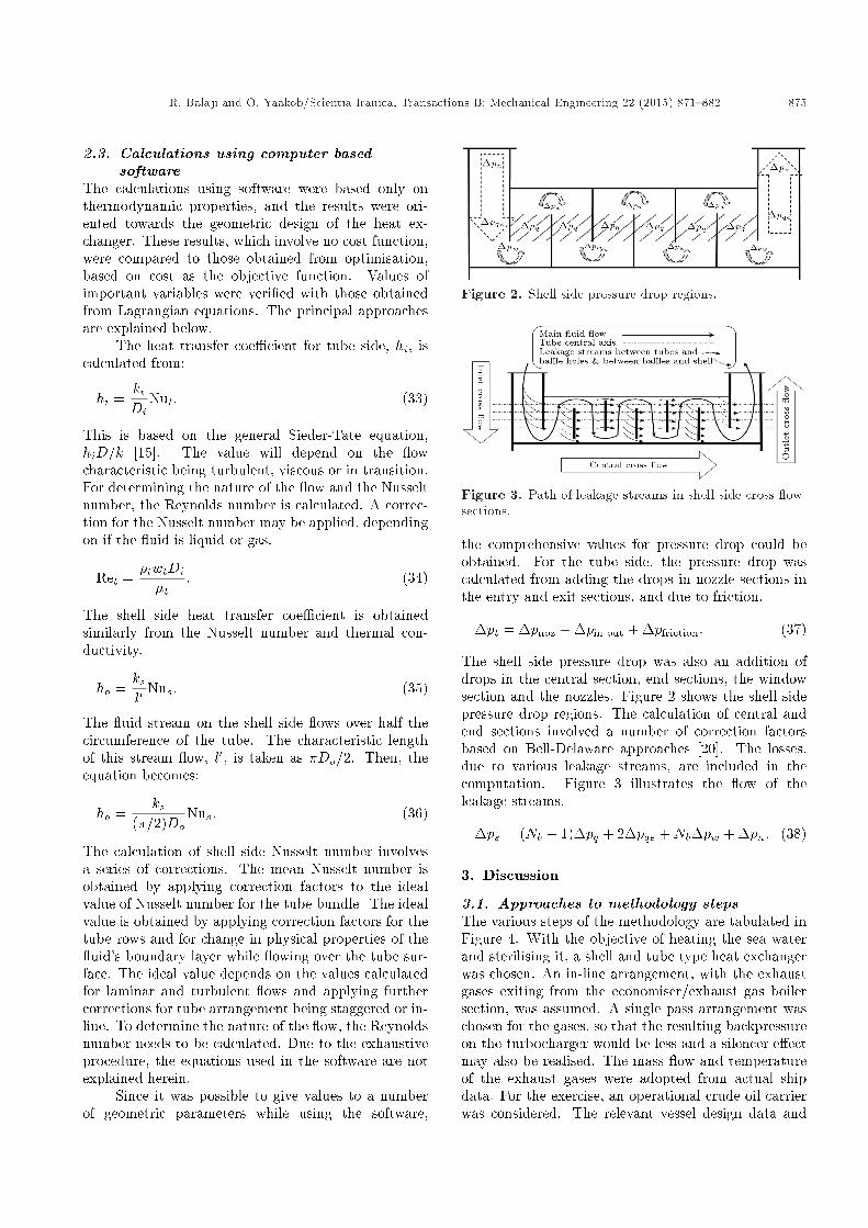
the comprehensive values for pressure drop could beobtained. For the tube side, the pressure drop wascalculated from adding the drops in nozzle sections inthe entry and exit sections, and due to friction.
�pt = �pnoz + �pin out + �pfriction: (37)
The shell side pressure drop was also an addition ofdrops in the central section, end sections, the windowsection and the nozzles. Figure 2 shows the shell sidepressure drop regions. The calculation of central andend sections involved a number of correction factorsbased on Bell-Delaware approaches [20]. The losses,due to various leakage streams, are included in thecomputation. Figure 3 illustrates the ow of theleakage streams.
�ps = (Nb � 1)�pq + 2�pqe +Nb�pw + �pn: (38)
3. Discussion
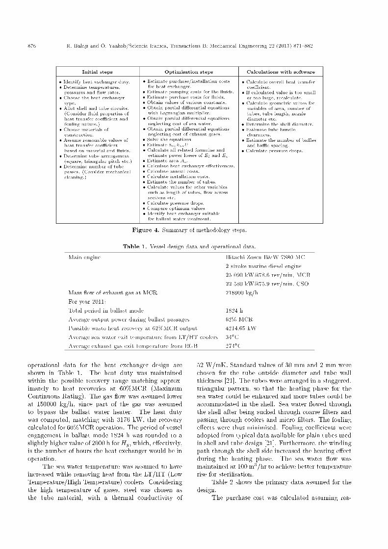
3.1. Approaches to methodology stepsThe various steps of the methodology are tabulated inFigure 4. With the objective of heating the sea waterand sterilising it, a shell and tube type heat exchangerwas chosen. An in-line arrangement, with the exhaustgases exiting from the economiser/exhaust gas boilersection, was assumed. A single pass arrangement waschosen for the gases, so that the resulting backpressureon the turbocharger would be less and a silencer e�ectmay also be realised. The mass ow and temperatureof the exhaust gases were adopted from actual shipdata. For the exercise, an operational crude oil carrierwas considered. The relevant vessel design data and
876 R. Balaji and O. Yaakob/Scientia Iranica, Transactions B: Mechanical Engineering 22 (2015) 871{882
Figure 4. Summary of methodology steps.
Table 1. Vessel design data and operational data.
Main engine Hitachi Zosen B&W 7S80 MC2 stroke marine diesel engine25 090 [email protected] rev/min, MCR22 580 [email protected] rev/min, CSO
Mass ow of exhaust gas at MCR 218900 kg/hFor year 2011:Total period in ballast mode 1824 hAverage output power during ballast passages 62% MCRPossible waste heat recovery at 62%MCR output 4214.65 kWAverage sea water exit temperature from LT/HT coolers 34�CAverage exhaust gas exit temperature from EGB 274�C
operational data for the heat exchanger design areshown in Table 1. The heat duty was maintainedwithin the possible recovery range matching approx-imately to heat recoveries at 60%MCR (MaximumContinuous Rating). The gas ow was assumed lowerat 150000 kg/h, since part of the gas was assumedto bypass the ballast water heater. The heat dutywas computed, matching with 3176 kW, the recoverycalculated for 60%MCR operation. The period of vesselengagement in ballast mode 1824 h was rounded to aslightly higher value of 2000 h for Hy, which, e�ectively,is the number of hours the heat exchanger would be inoperation.
The sea water temperature was assumed to haveincreased while removing heat from the LT/HT (LowTemperature/High Temperature) coolers. Consideringthe high temperature of gases, steel was chosen asthe tube material, with a thermal conductivity of
52 W/mK. Standard values of 30 mm and 2 mm werechosen for the tube outside diameter and tube wallthickness [21]. The tubes were arranged in a staggered,triangular pattern, so that the heating phase for thesea water could be enhanced and more tubes could beaccommodated in the shell. Sea water owed throughthe shell after being sucked through coarse �lters andpassing through coolers and micro �lters. The foulinge�ects were thus minimised. Fouling coe�cients wereadopted from typical data available for plain tubes usedin shell and tube design [21]. Furthermore, the windingpath through the shell side increased the heating e�ectduring the heating phase. The sea water ow wasmaintained at 100 m3/hr to achieve better temperaturerise for sterilisation.
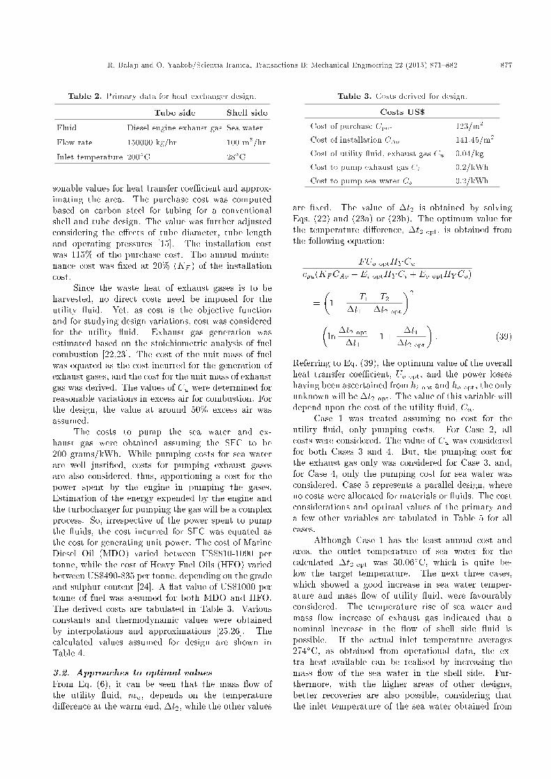
Table 2 shows the primary data assumed for thedesign.
The purchase cost was calculated assuming rea-
R. Balaji and O. Yaakob/Scientia Iranica, Transactions B: Mechanical Engineering 22 (2015) 871{882 877
Table 2. Primary data for heat exchanger design.
Tube side Shell side
Fluid Diesel engine exhaust gas Sea water
Flow rate 150000 kg/hr 100 m3/hr
Inlet temperature 200�C 28�C
sonable values for heat transfer coe�cient and approx-imating the area. The purchase cost was computedbased on carbon steel for tubing for a conventionalshell and tube design. The value was further adjustedconsidering the e�ects of tube diameter, tube lengthand operating pressures [15]. The installation costwas 115% of the purchase cost. The annual mainte-nance cost was �xed at 20% (KF ) of the installationcost.
Since the waste heat of exhaust gases is to beharvested, no direct costs need be imposed for theutility uid. Yet, as cost is the objective functionand for studying design variations, cost was consideredfor the utility uid. Exhaust gas generation wasestimated based on the stoichiometric analysis of fuelcombustion [22,23]. The cost of the unit mass of fuelwas equated as the cost incurred for the generation ofexhaust gases, and the cost for the unit mass of exhaustgas was derived. The values of Cu were determined forreasonable variations in excess air for combustion. Forthe design, the value at around 50% excess air wasassumed.
The costs to pump the sea water and ex-haust gas were obtained assuming the SFC to be200 grams/kWh. While pumping costs for sea waterare well justi�ed, costs for pumping exhaust gasesare also considered, thus, apportioning a cost for thepower spent by the engine in pumping the gases.Estimation of the energy expended by the engine andthe turbocharger for pumping the gas will be a complexprocess. So, irrespective of the power spent to pumpthe uids, the cost incurred for SFC was equated asthe cost for generating unit power. The cost of MarineDiesel Oil (MDO) varied between US$810-1090 pertonne, while the cost of Heavy Fuel Oils (HFO) variedbetween US$490-835 per tonne, depending on the gradeand sulphur content [24]. A at value of US$1000 pertonne of fuel was assumed for both MDO and HFO.The derived costs are tabulated in Table 3. Variousconstants and thermodynamic values were obtainedby interpolations and approximations [25,26]. Thecalculated values assumed for design are shown inTable 4.
3.2. Approaches to optimal valuesFrom Eq. (6), it can be seen that the mass ow ofthe utility uid, mu, depends on the temperaturedi�erence at the warm end, �t2, while the other values
Table 3. Costs derived for design.
Costs US$Cost of purchase Cpur 123/m2
Cost of installation CAo 141.45/m2
Cost of utility uid, exhaust gas Cu 0.04/kg
Cost to pump exhaust gas Ci 0.2/kWh
Cost to pump sea water Co 0.2/kWh
are �xed. The value of �t2 is obtained by solvingEqs. (22) and (23a) or (23b). The optimum value forthe temperature di�erence, �t2 opt, is obtained fromthe following equation:
FUo optHY Cucpu(KFCAo + Ei optHY Ci + Eo optHY Co)
=�
1 +T1 � T2
�t1 ��t2 opt
�2
�ln
�t2 opt
�t1� 1 +
�t1�t2 opt
�: (39)
Referring to Eq. (39), the optimum value of the overallheat transfer coe�cient, Uo opt, and the power losseshaving been ascertained from hi opt and ho opt, the onlyunknown will be �t2 opt. The value of this variable willdepend upon the cost of the utility uid, Cu.
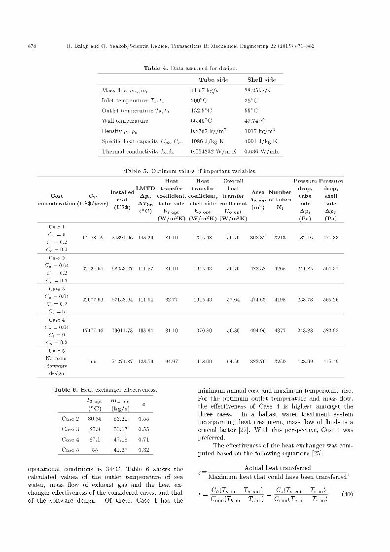
Case 1 was treated assuming no cost for theutility uid, only pumping costs. For Case 2, allcosts were considered. The value of Cu was consideredfor both Cases 3 and 4. But, the pumping cost forthe exhaust gas only was considered for Case 3, and,for Case 4, only the pumping cost for sea water wasconsidered. Case 5 represents a parallel design, whereno costs were allocated for materials or uids. The costconsiderations and optimal values of the primary anda few other variables are tabulated in Table 5 for allcases.
Although Case 1 has the least annual cost andarea, the outlet temperature of sea water for thecalculated �t2 opt was 30.06�C, which is quite be-low the target temperature. The next three cases,which showed a good increase in sea water temper-ature and mass ow of utility uid, were favourablyconsidered. The temperature rise of sea water andmass ow increase of exhaust gas indicated that anominal increase in the ow of shell side uid ispossible. If the actual inlet temperature averages274�C, as obtained from operational data, the ex-tra heat available can be realised by increasing themass ow of the sea water in the shell side. Fur-thermore, with the higher areas of other designs,better recoveries are also possible, considering thatthe inlet temperature of the sea water obtained from
878 R. Balaji and O. Yaakob/Scientia Iranica, Transactions B: Mechanical Engineering 22 (2015) 871{882
Table 4. Data assumed for design.
Tube side Shell side
Mass ow mh;mc 41.67 kg/s 28.25kg/s
Inlet temperature T1; t1 200�C 28�COutlet temperature T2; t2 132.5�C 55�CWall temperature 66.45�C 47.74�CDensity �i; �o 0.8767 kg/m3 1017 kg/m3
Speci�c heat capacity Cph; Cpc 1086 J/kg K 4001 J/kg K
Thermal conductivity ki; ko 0.034232 W/m K 0.636 W/mK
Table 5. Optimum values of important variables.
Costconsideration
CT(US$/year)
Installedcost
(US$)
LMTD�po
�Tlm(�C)
Heattransfer
coe�cient,tube sidehi opt
(W/m2K)
Heattransfer
coe�cient,shell sideho opt
(W/m2K)
Overallheat
transfercoe�cientUo opt
(W/m2K)
AreaAo opt
(m2)
Numberof tubesNt
Pressuredrop,tubeside�pi(Pa)
Pressuredrop,shellside�po(Pa)
Case 1Cu = 0Ci = 0:2Co = 0:2
14153.16 51391.96 148.26 81.10 1315.43 56.70 363.32 3213 182.16 427.33
Case 2Cu = 0:04Ci = 0:2Co = 0:2
22124.65 68233.27 111.67 81.10 1315.43 56.70 482.38 4266 241.85 567.37
Case 3Cu = 0:04Ci = 0:2Co = 0
22077.93 67138.94 111.64 82.77 1315.43 57.64 474.65 4198 238.78 565.26
Case 4Cu = 0:04Ci = 0Co = 0:2
17477.46 70011.78 108.64 81.10 1370.80 56.80 494.96 4377 248.88 583.92
Case 5No costs;Softwaredesign
n.a 54274.37 123.70 94.97 1418.00 64.50 383.70 3250 423.69 415.49
Table 6. Heat exchanger e�ectiveness.
t2 opt
(�C)mu opt
(kg/s)"
Case 2 80.85 53.21 0.55
Case 3 80.9 53.17 0.55
Case 4 87.1 47.16 0.71
Case 5 55 41.67 0.32
operational conditions is 34�C. Table 6 shows thecalculated values of the outlet temperature of seawater, mass ow of exhaust gas and the heat ex-changer e�ectiveness of the considered cases, and thatof the software design. Of these, Case 4 has the
minimum annual cost and maximum temperature rise.For the optimum outlet temperature and mass ow,the e�ectiveness of Case 4 is highest amongst thethree cases. In a ballast water treatment systemincorporating heat treatment, mass ow of uids is acrucial factor [27]. With this perspective, Case 4 waspreferred.
The e�ectiveness of the heat exchanger was com-puted based on the following equations [25]:
"� Actual heat transferredMaximum heat that could have been transferred
;
" =Ch(Th in � Th out)Cmin(Th in � Tc in)
=Cc(Tc out � Tc in)Cmin(Th in � Tc in)
; (40)

R. Balaji and O. Yaakob/Scientia Iranica, Transactions B: Mechanical Engineering 22 (2015) 871{882 879
Table 7. Values of important variables (t2 �xed).
Costconsideration
CT(US$/year)
Installedcost
(US$)
LMTD�Tlm(�C)
Heattransfer
coe�cient,tube sidehi opt
(W/m2K)
Heattransfer
coe�cient,shell sideho opt
(W/m2K)
Overallheat
transfercoe�cientUo opt
(W/m2K)
AreaAo opt
(m2)
Numberof tubesNt
Pressuredrop,tubeside�pi(Pa)
Pressuredrop,shellside�po(Pa)
Case 6Cu = 0:04Ci = 0:2Co = 0:2
20302.73 61622.85 123.67 81.10 1315.43 56.70 435.61 4220 239.24 561.25
Case7Cu = 0Ci = 0:2Co = 0
16924.19 60620.26 123.67 82.77 1315.43 57.64 428.56 4100 233.23 552.11
Case 8Cu = 0Co = 0Co = 0:2
12427.60 61515.90 123.67 81.10 1370.80 56.80 434.90 4200 238.80 560.28
where Cmin is the lesser of Ch = mhCph and Cc =mcCpc.
In the optimisation cases, although the numberof optimum ba�es worked to two, they were increasedto three to give better support for the tube bundleand counter vibration e�ects. This increased thepressure drops nominally. For tube side pressuredrop computations, the values of optimal tubes wereadjusted to the �rst decimal, thus accommodating tubesheet thickness. The projected pressure drop valuesare attributed to frictional losses only. But, with thesoftware calculations, losses could be computed forother factors also. The total losses on the tube sidewere 1347 Pa and 52505 Pa for the shell side. However,e�ects due to changes in kinetic energy and verticalhead etc. were not considered.
For comparison, three additional designs werederived assuming �xed target temperature and mass ow, but for varying cost considerations. Table 7 showsthe cases. The heat exchanger e�ectiveness worked to0.39 in these cases. While the areas are almost thesame, Case 8 has the least annual cost. Comparedto this, Case 4 works to an extra area of 60.06 m2
with an additional installed cost of US$8495.88. IfCase 5, having the least area, is to be taken as thereference, Case 4 works to an extra 111.26 m2, withan increased installed cost of US$15737.42. If theannual cost consideration in Eq. (3) for the exhaustgas in Case 4 is presumed to be a saving, since onlywaste heat is harvested, the recovery period for thisextra increase in installation cost works out to be 4.7years. If all costs are neglected, Case 5 has the mostcompact design. For similar thermodynamic variables,if annual cost is considered, Case 8 is preferable. Whileother cases, except Case 1, are also viable, maximumscope for better heat recovery is sighted with Case
4 only for the purposeful heat treatment of ballastwater.
Process streams involving many components inthe network may require time consuming complextechniques such as genetic algorithms [28,29], simulatedannealing [30], nonlinear approaches [31] and variouseconomics based approaches [32,33]. Without suchmethods, a rational approach to optimisation usingcalculus methods has been demonstrated to obtain afew viable designs.
4. Conclusions
From the exercises, the practical design of a heaterfor treating ballast sea water using exhaust gases hasbeen realised. For the present purpose of harvestingwaste heat for ballast water treatment, scope forfurther improvements include switching the shell andtube side uids and �nned tubular heat exchangerdesigns. Limitations of heat availability and owdepend on ship type, and designs may be workedupon for other ship types. Increased realisationof waste heat will give a competitive edge to heattreatment methods, not only in costs but also inenhancing the treatment potential of combination typesystems.
Acknowledgment
The authors wish to thank MISC Berhad and its edu-cational subsidiary, the Malaysian Maritime Academy,for their support.
Nomenclature
Ao opt Optimum area, m2

880 R. Balaji and O. Yaakob/Scientia Iranica, Transactions B: Mechanical Engineering 22 (2015) 871{882
Ao Outside area of tubes available for heattransfer, m2
Bo Friction correction factor for change incross section and ow reversal
CAo Installed cost of heat exchanger,US$/m2
CT Total annual variable costs for heatexchanger including operational costs,US$
Ci Cost to pump uid inside the tubes(exhaust gas), US$/kWh
Co Cost to pump uid on the shell side(sea water), US$/kWh
Ch Heat capacity of hot stream, W/KCc Heat capacity of cold stream, W/KCph Speci�c heat of hot uid (exhaust gas),
J/kg KCpc Speci�c heat of cold uid (sea water),
J/kg KCpur Cost of purchase, US$/m2
Cu Cost of utility uid, US$/kgDc Clearance between tubes giving
smallest area for shell side uid owDi Inside diameter of tube, mmDo Outside diameter of tube, mmEi Power loss inside tubes/m2
Eo Power loss outside tubes/m2
Fs Bypass factor, shell sideGi opt Mass velocity (optimum) inside tubes,
kg/m2 sGi Mass velocity inside tubes, kg/m2sGo Mass velocity shell side, kg/m2sGs opt Mass velocity (optimum) shell side,
kg/m2sHy Number of hours of heat exchanger
operation/yearKF Fixed charges including
maintenance/year as a fractionof installed cost (percent)
L opt Optimum length of tube, mNb Number of ba�esNc Number of clearances between tubes
for shell side uid owNr Tube rows across which shell side uid
owsNt opt Optimum number of tubesNt Number of tubesNus Nusselt number, shell sideNut Nusselt number, tube side
Qexhaust Heat energy lost to exhaust gases, kWQin Heat energy input, kWQodd losses Heat energy lost due to other factors,
kWQwater Heat energy lost to cooling water, kWRdw Fouling resistance, combined (tube,
scale & dirt), m2K/WRet Reynolds number, tube side uidRfi Inside fouling resistance (tube side),
m2K/WRfo Outside fouling resistance (shell side),
m2K/WSi opt Optimum cross sectional area inside
tubes/pass, m2
T1 Inlet temperature of tube side uid(exhaust gas), �C
T2 Outlet temperature of tube side uid(exhaust gas), �C
Uo opt Optimum overall heat transfercoe�cient
Uo Overall heat transfer coe�cient,W/m2K
Wengine power Useful energy output, kWXT Ratio of transverse pitch to tube
diametera0 Constant for evaluating outside heat
transfer coe�cientb0 Constant for calculating shell side
friction factorcpi Speci�c heat, inside tube, J/kg K
f 0 Friction factor, shell side owfi Fanning friction factor, tube side owhi opt Optimum heat transfer coe�cient,
tube side, W/m2K
hi Heat transfer coe�cient, W/m2Kho opt Optimum heat transfer coe�cient,
shell side, W/m2K
ho Heat transfer coe�cient, W/m2Kkfo Thermal conductivity at �lm
temperature, W/mKki Thermal conductivity, inside tube,
W/mKko Thermal conductivity, outside tube,
W/mKks Thermal conductivity, shell side,
W/mKkt Thermal conductivity, tube side,
W/mK
l0 Characteristic length of stream ow, m
R. Balaji and O. Yaakob/Scientia Iranica, Transactions B: Mechanical Engineering 22 (2015) 871{882 881
mh Mass ow of hot uid (exhaust gas),kg/s
mc Mass ow of cold uid (sea water),kg/s
mu Mass ow of utility uid, kg/snb Number of ba�e spaces (number of
ba�es + 1)np Number of tube passest1 Inlet temperature of shell side uid
(sea water), �Ct2 Outlet temperature of shell side uid
(sea water), �Cwi Mass ow inside tubes, kg/swo Mass ow outside tubes kg/swt Mass ow, tube side, kg/s�t1 (T2 � t1) temperature di�erence at
tube exit/shell entry, �C�t2 (T1 � t2) temperature di�erence at
tube entry/shell exit, �C�i Friction correction factor for sudden
change in tube section and ow reversal�fo Absolute viscosity of shell side uid at
�lm temperature, Pas�i; �t Absolute viscosity of tube side uid,
Pas�wi Absolute viscosity of tube side uid at
wall temperature, Pas�i Density, inside tube, kg/m3
�o Density, outside tube, kg/m3
�t Density, tube side, kg/m3
i Dimensional factor for estimatingpower loss inside tubes
o Dimensional factor for estimatingpower loss outside tubes
�i Correction factor for friction, and tubeside
" Heat exchanger e�ectiveness�Tlm Logarithmic mean temperature
di�erence, �C�pi Pressure drop at tube side, Pa�po Pressure drop at shell side, Pa�pfriction Pressure drop due to friction in tubes,
Pa�pinout Pressure drop at inlet and outlet
sections, Pa�pn Pressure drop in nozzles on shell side,
Pa�pnoz Pressure drop in nozzles on tube side,
Pa
�pq Pressure drop in central sections ofshell, Pa
�pqe Pressure drop in end sections of shell,Pa
�pw Pressure drop in window sections ofshell, Pa
A Total surface area, m2
F LMTD correction factorL Length of tube, mLCV Lower Calori�c Value of fuel, MJ/kgQ Heat duty of heat exchanger, WSFC Speci�c Fuel Consumption,
grams/kWhU Overall heat transfer coe�cient,
W/m2K� Lagrangian multiplier
Subscript
i; o Inside (tube); Outside (shell)t; s Tube side; shell sideh; c Hot uid; cold uidopt Optimum value
References
1. EPA Report \E�cacy of ballast water treatment sys-tems: A report by EPA science advisory board", (USEnvironmental Protection Agency-Scienti�c AdvisoryBoard Report)", http://www.epa.gov/sab (2011).
2. Sobol, Z., Wladyslaw, K. and Bohdan, W. \Systemfor destruction of microorganisms occurring in ballastwaters", Paper presented at IMO MEPC 38 (1995).
3. Ballast Trial Report, Ballast Water Trial on M.VSandra Marie, A Trial of Prentice-Thronton HeatTreatment System for Ballast Water. (Report pro-vided by Manufacturer, Hi Tech Marine International)(1997).
4. Rigby, G., Hallegrae�, G. and Sutton, C. \Novel bal-last water heating technique o�ers cost-e�ective treat-ment to reduce the risk of global transport of harmfulmarine organisms", Mar. Ecol. Prog. Ser., 191, pp.289-293 (Inter-Research (IR), Germany, (1999).
5. Thornton, G. \Ballast water decontamination-usingheat as a biocide", Sea Australia Conf. Sydney, Aus-tralia (1-3 Feb 2000).
6. Mesbahi, E., Norman, R.A., Vourdachas, A. andQuilezBadia, G. \Design of a high-temperature ther-mal ballast water treatment system", Proc. of theIMechE, Part M: J. Engineering for Maritime Envi-ronment, 221, pp. 31-4 (2007).
7. Rakopoulos, C.D. and Giakoumis, E.G. \Availabilityanalysis of a turbocharged diesel engine operating
882 R. Balaji and O. Yaakob/Scientia Iranica, Transactions B: Mechanical Engineering 22 (2015) 871{882
under transient load conditions", Energy, 29, pp.1085-1104 (2004).
8. Hountalas, D.T., Katsonas, C.O. and Kouremenos,D.A. \Study of available exhaust gas heat recoverytechnologies for HD diesel engine applications", Int. Jof Alternative Propulsion, 1(2/3), pp. 228-249 (2007).
9. S�oylemez, M.S. \On the thermo economical optimisa-tion of heat pipe heat exchanger HPHE for waste heatrecovery", Energy Conversion and Management, 44,pp. 2509-2517 (2003).
10. Rajasekharan, S. and Kannadasan, T. \Optimisationof shell and tube heat exchangers using modi�edgenetic algorithm", International Journal of Controland Automation, 3(4), pp. 1-10 (2010).
11. Sanaye, S. and Hajabdollahi, H. \Multi-objective op-timisation of shell and tube heat exchangers", AppliedThermal Engineering, 30, pp. 1937-1945 (2010).
12. Costa, A.L.H. and Queiroz, E.M. \Design optimisationof shell and tube heat exchangers", Applied ThermalEngineering, 28, pp. 1798-1805 (2008).
13. Green, D.W. and Perry, R.H., Perry's Chemical Engi-neers' Handbook, 8th Edn., Section 11, The McGrawHill Companies, New York (2008).
14. Edgar, T.F., Himmelblau, D.M. and Lasdon, L.S.,Optimisation of Chemical Processes, 2nd Edn., pp.422-429, The McGraw Hill Companies, New York(2001).
15. Peters, M.S., Timmerhaus, K.D. and West, R.E., PlantDesign and Economics for Chemical Engineers, 5thEdn., McGraw Hill Companies, New York (2003).
16. Shah, R.K., and Sekuli�c, D.P., Fundamentals of HeatExchanger Design, Chapter 2, pp. 78-96, John Wiley& Sons, New York (2003).
17. Cichelli, M.T. and Brinn, M.S. \How to design theoptimum heat exchanger", Chem. Eng., p. 196 (1956).
18. Jaluria, Y., Design and Optimisation of Thermal Sys-tems, 2nd Edn., Chapter 7, pp. 440-441, CRC Press,Taylor & Francis Group, Boca Raton, Florida (2008).
19. Ravindran, A., Ragsdell, K.M. and Reklaitis, G.V.,Engineering Optimisation, 2nd Edn., John Wiley &Sons, New Jersey (2006).
20. Serna, M. and Jiminez, A. \A compact formulation ofthe Bell-Delaware method for heat exchanger designand optimisation", Trans IChemE, Part A, 83(A5),pp. 539-550 (2005).
21. Towler, G. and Sinnot, R., Chemical Engineering De-sign, Butterworth-Heinemann, Elsevier Inc., California(2008).
22. Joel, R., Basic Engineering Thermodynamics, 5thEdn., Addison Wesley Longman, Harlow (1996).
23. Ganesan, V., Internal Combustion Engines, 2nd Edn.,Tata McGraw-Hill Publishing Company Limited, NewDelhi (2003).
24. Marine Engineers Review, Bunkering-Bunker Prices,p. 16 (April 2012).
25. Lienhard, J.H. IV and Lienhard, J.H.V., A HeatTransfer Textbook, 4th Edn., Phlogiston Press, Mas-sachusetts (2011).
26. Branan, C.R., Rules of Thumb for Chemical Engineers,3rd Edn., Gulf Publishing Company, Houston (2002).
27. Balaji, R. and Yaakob, O. \An analysis of shipboardwaste heat availability for ballast water treatment",Journal of Marine Engineering and Technology, 11(2),pp. 15-29 (2012).
28. Tayal, M.C., Yan, F. and Diwekar, U.M. \Optimisationof heat exchangers: A genetic algorithm framework",Ind. Eng. Chem. Res., 38, pp. 456-467 (1999).
29. Xie, G.N., Sunden, B. and Wang, Q.W. \Optimisationof compact heat exchangers by a genetic algorithm",Applied Thermal Engineering, 28, pp. 895-906 (2008).
30. Khalfe, N.M., Lahiri, S.K. and Wadhwa, S.K. \Sim-ulated annealing technique to design minimum costheat exchanger", Chemical Industry and ChemicalEngineering Quarterly, 17(4), pp. 409-427 (2011).
31. Ravagnani, M.A.S.S. and Caballero, J.A. \A MINLPmodel for the rigorous design of shell and tube heat ex-changers using the TEMA standards", Trans. IChemEPart A, 85(A10), pp. 1423-1435 (2007).
32. Azad, A.V. and Amidpour, M. \Economic opti-misation of shell and tube heat exchanger basedon constructal theory", Energy, doi:10.1016/j.energy.2010.11.041 (2010).
33. Caputo, A.C., Pelagagge, P.M. and Salini, P. \Heat ex-changer design based on economic optimisation", Ap-plied Thermal Engineering, 28, pp. 1151-1159 (2008).
Biographies
Rajoo Balaji graduated in Marine Engineering (1976-80) from Marine Engineering College (DMET-MERI),Kolkata, India. He holds a Master's degree in MaritimeManagement and pursues doctoral research with Uni-versiti Teknologi Malaysia.
Omar bin Yaakob is currently a Chartered Engineerand Professor in the Department of Marine Technologyin the Faculty of Mechanical Engineering at UniversitiTeknologi, Malaysia. His research interests includesmall boat design, unmanned systems, marine environ-mental issues and oceanographic data management.