Accurate Directional Borehole Drilling: A Case Study at ... - CDC

Accepted Manuscript
Heat dissipation effect on a borehole heat exchanger coupled with a Heat Pump
J. Darkwa, W. Su, D.H.C. Chow
PII: S1359-4311(13)00499-7
DOI: 10.1016/j.applthermaleng.2013.07.011
Reference: ATE 4925
To appear in: Applied Thermal Engineering
Received Date: 19 March 2013
Revised Date: 3 July 2013
Accepted Date: 7 July 2013
Please cite this article as: J. Darkwa, W. Su, D. Chow, Heat dissipation effect on a boreholeheat exchanger coupled with a Heat Pump, Applied Thermal Engineering (2013), doi: 10.1016/j.applthermaleng.2013.07.011.
This is a PDF file of an unedited manuscript that has been accepted for publication. As a service toour customers we are providing this early version of the manuscript. The manuscript will undergocopyediting, typesetting, and review of the resulting proof before it is published in its final form. Pleasenote that during the production process errors may be discovered which could affect the content, and alllegal disclaimers that apply to the journal pertain.

MANUSCRIP
T
ACCEPTED
ACCEPTED MANUSCRIPT
1
Heat dissipation effect on a borehole heat exchanger coupled with a Heat Pump
J. Darkwa, W. Su and DHC. Chow
Centre for Sustainable Energy Technologies (CSET) The University of Nottingham Ningbo China
199 Taikang East Road Ningbo 315100, P. R. China
Tel: +86 574 88180255; Fax: +86 574 88180313 Email: [email protected]
Abstract
Thermal performance evaluation of a ground-coupled heat exchanger has been undertaken to
assess the extent of heat dissipation into the ground and its long term effect on the cooling
performance of a heat pump system. Simulation results were compared with operational data
over a 3-year period and found to be in good agreement. However the annual average energy
being dissipated into the borehole was found to be about 4.5 times more than the amount
being extracted thus raising concern about long term effectiveness of the borehole as a heat
sink. Even though, there was a slight decline in the energy dissipation rate during the third
year, the result does not provide adequate evidence to support creeping soil degradation
process in the borehole over such a relatively short period. Since the performance of each
ground-coupled heat exchanger appears to be influenced by its location, more research is
needed to acquire better and wider understanding of the effect of heat dissipation and soil
degradation processes in borehole systems.
Keywords: Heat dissipation; Borehole Heat Exchanger; Ground Source Heat Pump (GSHP).

MANUSCRIP
T
ACCEPTED
ACCEPTED MANUSCRIPT
2
Nomenclature C1ε,C2 Constants cp Specific heat (J/kg K) d Pipe diameter (m) E Total energy (J/kg) Gb Generation of turbulence kinetic energy due to buoyancy (J/s m3) Gk Generation of turbulence kinetic energy due to the mean velocity gradients (J/s m3) gi Component of the gravitational vector in the ith direction h Specific sensible enthalpy (J/kg) hs Specific sensible enthalpy for solid component (J/kg)
Specific sensible enthalpy of species (J/kg)
k Thermal conductivity ( W/m K)
Effective thermal conductivity ( W/m K)
Mass flow rate of fluid (kg/s)
np Number of pipes in boreholes p Pressure (Pa) Prt Turbulent Prandtl number for energy σk, σε Turbulent Prandtl numbers for and models
Qc Maximum cooling load (kW) Qh Maximum heating load (kW) Re Reynolds number S Modulus of the mean rate-of-strain tensor
Sk, Sε, Sij User-defined source terms T Temperature (K) t Time (s) V Velocity (m/s)
v Component of the flow velocity parallel to the gravitational vector (m/s)
u Component of the flow velocity perpendicular to the gravitational vector
ui,uj,uk Velocity for different direction (m/s)
x Length (m)
xi,xj,xk Length in different direction (m)
Yj Mass fraction of species
Greek letter β Thermal expansion coefficient ε Dissipation rate µ Dynamic viscosity (Pa s)
µt Turbulent viscosity (Pa s)
ρ Density (kg/m3)
τ Deviatoric stress tensor
Subscripts
o Outside
su Summer
wi Winter

MANUSCRIP
T
ACCEPTED
ACCEPTED MANUSCRIPT
3
1.0 Introduction
One of the energy and environmental issues dominating most global policies is how to
reduce energy consumption in buildings since the sector is responsible for about 40% of total
global energy consumption and carbon emissions [1].
The potential of ground source heat pumps (GSHPs) are widely recognised as
efficient technologies that could play an important role in providing heating and cooling for
buildings [2-7]. GSHPs may be coupled with either vertical U-tubes or horizontal heat
exchangers in order to dissipate or extract heat from the earth. The overall thermal
performance of a GSHP is therefore dependent on factors such as the geometric configuration
of the heat exchanger and thermophysical properties of the surrounding soil. To this end a
number of theoretical and experimental studies have been carried out towards determining the
main factors affecting the performances of ground heat exchangers (GHEs). For instance,
Seong-Kyun et al. [8] developed a dynamic model for borehole heat exchangers. The model
was validated on a number of installations and found to be fairly predictable in the
assessment of the performance of GHEs. Yang et al. [9] investigated the effect of fluid
temperature variation and heat transfer rates between two adjacent legs of a U-tube heat
exchanger and obtained a validation error of less than 6%. Oppelt et al. [10] developed a
model for the simulation of borehole filling (grout) of double U-pipe heat exchangers in
relation to location of pipe shanks and achieved an error of 6% and 9% for a minimal and
maximal shank spacing respectively. Georgios et al. [11] developed models for evaluating
complex temperature variation around GHEs. Other theoretical approaches for evaluating the
performance of heat exchangers have also been investigated [12-14] but they all have
limitations in terms of the ground and GHE conditions at different locations.

MANUSCRIP
T
ACCEPTED
ACCEPTED MANUSCRIPT
4
Regarding experimental studies, Jun et al. [15] identified soil type and associated
thermal resistance as the dominant factors affecting thermal performance of a ground heat
exchanger. Pahud et al. [16] showed that thermal resistance on a double-U-pipe heat
exchanger could be reduced by about 30% when quartz sand is used instead of bentonite.
Aristodimos et al. [17] also revealed that de-bonding at the interface between borehole pipes
and grouting material do have significant impact on ground heat exchangers. As a result they
recommended a grouting material with low shrinkage properties for overcoming the de-
bonding phenomenon. Studies carried out by Jun et al. [15] further showed that ground heat
exchangers with wider shank spacing have better thermal performance than closely spaced
shanks. Diao et al. [18] also established that the performance of ground heat exchangers
could significantly be affected by groundwater.
There have however been growing concerns about the long term effectiveness of
GHEs due to the relatively higher rates of heat dissipation into the ground as compared with
the extraction rates in cooling dominated situations. This is due to the fact that as heat is
added to or removed from the ground, the surrounding soil temperature changes. If the total
annual heating load does not balance the total annual cooling load, then there will be a net
change in the ground temperature after each year of operation. After many years of operation,
the ground will become a poorer source of heat sink in an unbalanced system, and therefore,
the overall cooling performance of a GSHP system would be affected.
These concerns have led to recent guidelines for tests procedures as reported in
ASHRAE 2007 [19] and by Sanner et al. [20] in an effort to establish effective tests methods
necessary for designing and sizing of ground- coupled heat pump systems. Meanwhile some
heat mitigation techniques have been proposed and evaluated. For example, Li et al. [21]
investigated a novel multi-function ground source heat pump system for mitigating the
excessive heat in the soil and achieved a reasonable level of heat reduction. Wei et al. [22]

MANUSCRIP
T
ACCEPTED
ACCEPTED MANUSCRIPT
5
evaluated an integrated solar-earth source heat pump system with a heat storage water tank
and achieved a reduction of about 14.5% in the heat rejection rate as compared with
conventional ground source heat pump. Sagia et al. [23] also showed that a cooling tower
could be used to mitigate the excessive heat load in a Hybrid Ground Source Heat Pump
system. However in all these test and evaluation cases, the results were influenced by factors
such as geological condition, geographical location and the end use of the heat recovered
from the systems thus making each case a unique system. For the benefit of achieving further
understanding and contributing to wider knowledge of heat mitigation concepts in borehole
designs, this study evaluates the thermal performance of a typical cooling dominated ground-
coupled heat pump system.
2.0 Ground Coupled Heat Exchanger System
Fig 1 shows the schematic diagram of a reversible heat pump coupled with the
vertical U-bend close loop pipe heat exchangers. The system was fully commissioned in 2008
in the Centre for Sustainable Energy Technologies (CSET) building at the University of
Nottingham Ningbo China. The installation is also part of an integrated ground source heat
pump (GSHP) system for providing water supply to a radiant panel circuit in the building at
15oC in summer and 45oC in the winter period. The basic specifications for the system are:
• Heating capacity = 65 kW
• Cooling capacity = 55kW
• Electrical power input during cooling = 10.5 kW
• Electrical power input during heating = 15 kW
• Heating coefficient of performance (COP) = 4.3
• Cooling COP = 5.2:
• Depth of each borehole: 70 m;

MANUSCRIP
T
ACCEPTED
ACCEPTED MANUSCRIPT
6
• Specific heat factor (winter) for each borehole: 30 W/m
• Specific heat factor (summer) for each borehole : 50 W/m
• Total number of boreholes: 20.
• Distance between boreholes: 4.3 m
• Heat transfer fluid in borehole pipes: water
3.0 Borehole investigation
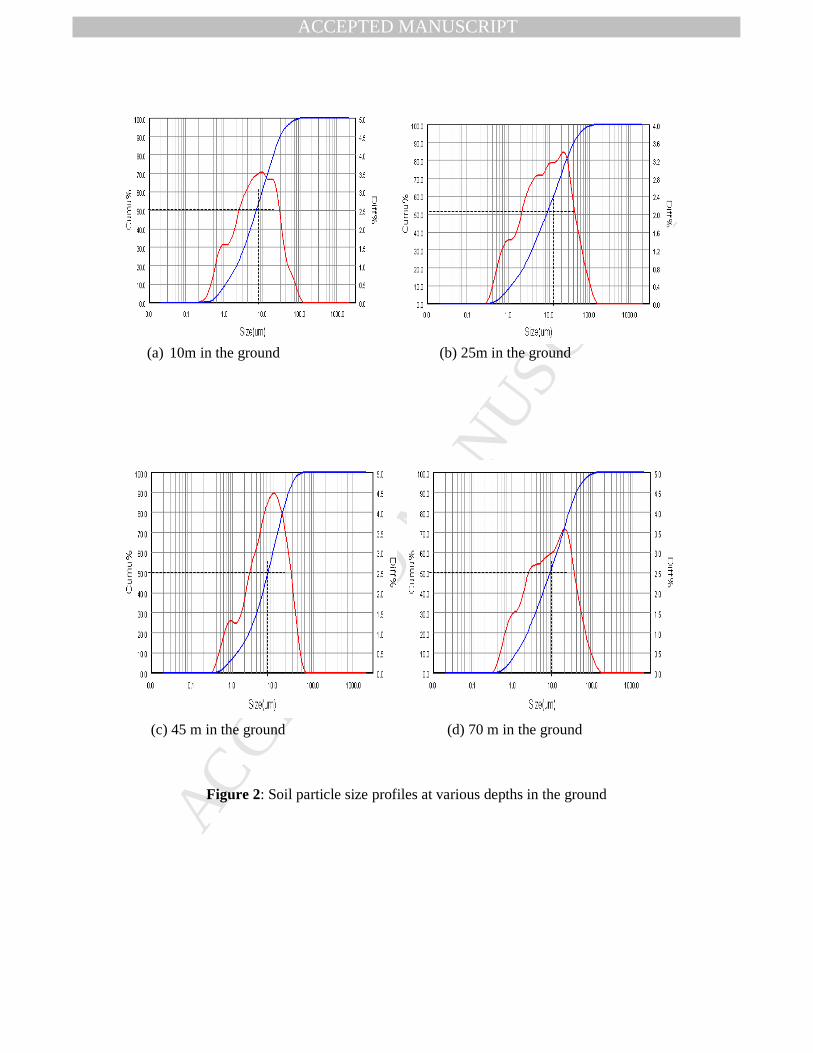
3.1 Soil particle sizing
In general, textural classification of a soil is a relevant criterion for determining the
type of soil and assessing its thermal performance since smaller size particles do retain heat
better than larger ones [24-25]. Soil particle size distribution information also provides
estimates for properties such as permeability, water holding capacity strength and stability.
According to the USDA soil textural classification system [26] a soil particle size fraction of
less than 2µm is defined as clay; 2µm-50µm is classified as silt; 50µm-2000µm as sand. A
Particle Size Analyser, (Bettersize type 2000), was therefore used to determine the size of the
individual samples extracted at various depths of 10m, 25m, 45m and 70m inside the
borehole. The test results are presented in Fig. 2 and based on the USDA soil textural system
it is clear from the summary in Table 1 that, the soil is mainly of the silt type.
3.2 Soil thermophysical properties
Even though the soil particle sizing procedure indicated that the soil samples are of
the same type it was considered necessary to ascertain their thermophysical properties since
varying soil conditions could affect the performance of the heat exchanger. Therefore a KD2
Pro Thermal Properties Analyser was used to obtain the relevant data from the samples. The
Analyser consists of a handheld controller and sensors that can be inserted into subject soil
MANUSCRIP
T
ACCEPTED
ACCEPTED MANUSCRIPT
7
specimen to measure the thermal properties. As shown in Table 2 the results were slightly
different from location to location which could be attributed to soil conditions. However, the
mean values were found to be fairly comparable with the individual results. Normally in the
design of GHEs, effective or average thermal properties over the length of the borehole are
usually sought. Therefore the mean values could be taken as the representative data for the
soil within the borehole. The specifications for both the Particle size Analyzer and the KD2
Pro are presented in Table 3.
4.0 Theoretical analysis
4.1 Physical model of borehole
Figs 3a and 3b show the plan and sectional views of a borehole containing double U-
tube pipes. The pipes are encased in a high conductivity geothermal grouting material
designed to improve the efficiency and performance of the loop systems. This was achieved
by matching the thermal conductivity of the surrounding soil and creating a permanent
flexible seal to prevent aquifer contamination.
4.2 Governing equations
The governing equations associated with each component of the borehole are
expressed as follows:
(i) Solid (Grout, pipe and soil)
Since there is no internal heat generation in the solid components the general energy equation
as defined in FLUENT Software [27] is expressed as;
(1)
Where
(2)

MANUSCRIP
T
ACCEPTED
ACCEPTED MANUSCRIPT
8
(ii) Fluid (Water)
Water is an incompressible fluid and therefore the governing equations are based on the
continuity and energy conservation equations [28].
Continuity equation in vector form:
(3)
Energy conservation equation:
The energy equation is dependent on the type of flow in the pipe and can be
determined by Reynolds’ equation as;
Re (4)
From the flow data, Re was calculated as 7640 which makes it a turbulent type of flow since it
is greater than 2000. For this reason the realizable k-epsilon (k-ε) model [28] was selected
being the commonest model used for solving all turbulence models. It also has the advantage
of providing accurate and superior performance for flows involving rotation and boundary
layers under strong adverse pressure gradients. The modelled transport equations for and
are therefore expressed as:
Turbulent kinetic energy (k-equation)
(5)
Dissipation (ε-equation)
(6)
In accordance with Boussinesq hypothesis [29];
(7)
(8)

MANUSCRIP
T
ACCEPTED
ACCEPTED MANUSCRIPT
9
(9)
In FLUENT and by default, is taken as zero in the dissipation ε-equation.
Other terms are given as;
; ;
(10)
In this flow model, the buoyant shear layers are perpendicular to the gravitational vector and
therefore, = 0.
The model constants are given as;
, , ,
The dissipation modelled energy equation is obtained as [30];
(11)
Where, [26], and [31] are expressed as:
(12)
(13)
(14)
(15)
(16)
Where
= 298.15 K
Prt = 0.85

MANUSCRIP
T
ACCEPTED
ACCEPTED MANUSCRIPT
10
4.3 Simulation
By considering identical conditions for the pipes in the boreholes, a Fluent Software
Version 6.3 was used to simulate the thermal behaviour of the system based on the data in
Table 4 and the following assumptions.
• Fluid temperature variation was considered along the pipe length only.
• There is no phase change taking place in the fluid or significant radiation in the pipe
• Conduction was the main heat transfer mode in the pipe, grout and soil.
• Convection was considered in the fluid
Boundary and initial conditions
The simulation was carried out for July and January being the hottest and coldest
periods respectively for the location of the borehole. Based on investigation by Darkwa et al.
[32] the ground temperature was taken as 15.6℃. The initial fluid inlet temperature for July
was fixed at 27℃ and for January at 10.5℃.
5.0 Results and Discussions
Fig. 4 represents the static temperature variation along the full length of the heat
exchanger pipe. Analysis of the curves show an average differential temperature of 4o C

MANUSCRIP
T
ACCEPTED
ACCEPTED MANUSCRIPT
11
between the inlet and outlet fluid for July (summer period) and about 2.5o C for January
(winter period). Now using these results and data from Tab. 4, the theoretical heat dissipation
and extraction rates may be obtained as follows:
Heat extraction (Qe) rate in January;
Qe = x np x Cp x ∆Twi (16)
= (0.12 x 40)*4.2 x 2.5 = 50.4 kW
Heat dissipation (Qd) rate in July;
Qd = x np x Cp x ∆Tsu (17)
= (0.12 x 40)*4.2 x 4 = 80.6 kW
The above results show about 38% imbalance between heat dissipation and extraction rates.
For the purpose of comparison, the theoretical heat dissipation and extraction rates were also
calculated based on the National Chinese Design Guide [33] and data from the GSHP [34] as
follows:
Heat extracted (Qe);
(18)
= 65* = 49 kW
Heat dissipated (Qd)
(19)
= 55* = 66 kW
The above results show 26% imbalance between heat dissipation rate and extraction rates.

MANUSCRIP
T
ACCEPTED
ACCEPTED MANUSCRIPT
12
In order to validate the theoretical results, selected operational data of the integrated
GSHP system for the coldest (January) and the hottest (July) periods for the years 2009-2011
were used. The data obtained showed similar trends in all the years for the inlet (Ti) and
outlet fluid temperatures (To) as presented in the examples for the year 2009 in Figs. 5 & 6.
Analysis of the results gave the mean differential temperatures in January/July as 3o C/ 4.2o C
for 2009, 3o C/ 4.17o C for 2010 and 2.9o C/ 3.87o C for 2011. These are fairly comparable
with the simulated data which was obtained as 2.5o C/ 4o C.
Based on these data and the fluid flow rate, the corresponding mean heat
extraction/dissipation rates were also obtained as 60.5 kW/84.6 kW for 2009, 60.5 kW/84.1
kW for 2010 and 58.5 kW/78 kW for 2011. By comparison, they do not appear to be too far
off from the simulated value of 50.4 kW/80.6 kW but slightly higher than the calculated
value of 49 kW/66 kW obtained with the National Chinese Design Guide. The percentage of
heat imbalance between heat dissipation and extraction rates ranges from 25% - 28% which is
less than the simulated value of 38% but matches well with the calculated result of 26%. Figs.
7 - 9 show the profiles of the cumulative energy extracted and dissipated for the monitored
period based on an 8-hour daily operation. By taking the annual operating heating period to
be 60 days and cooling period as 200 days for the GSHP system, the yearly energy dissipated
and extracted were obtained as summarised in Table 5 and presented in Fig. 10.
The results clearly indicate that a considerable higher proportion of energy is
dissipated into the borehole as against the amount being extracted. By using the operational
data, the corresponding specific heat factor per meter for each borehole for January (winter)/
July (summer) periods were also obtained as 43.2 W/ 60.4 W for 2009, 43.2 W/60 W for
2010 and 41.8 W/ 55.7 W for 2011. These are not too far off from the design data given as 30
W/m for winter and 50 W/m for summer. However the energy analysis shows that the annual

MANUSCRIP
T
ACCEPTED
ACCEPTED MANUSCRIPT
13
average energy being dissipated into the borehole is about 4.5 times more than the amount
being extracted. The concern is that this level of energy dissipation intensity could reduce the
heat storage capacity of the surrounding soil in the borehole and in turn impact on the
effectiveness of the ground heat exchangers and the cooling performance of the GSHP
system.
6.0 Conclusions
The study has shown that even though the manufacturers estimate the life span of the
GSHP to be about 20 years, it is highly unlikely that its current coefficient of performance
would be sustained over the projected operating life. There was however not enough evidence
to support creeping soil degradation process in the borehole over such a relatively short
period of operation of the GSHP system. The specific findings are highlighted as follows;
• The theoretical mean differential inlet and outlet fluid temperature were obtained as
2.5o C for January and 4o C for July. These compare well with the experimental results
which were obtained as 2.9o C - 3o C for January and 3.87o C- 4.2o C for July.
• The amount of energy dissipated was obtained as 449.3 GJ – 487.3 GJ as against
101.1 GJ - 104.5 GJ per year of energy extracted thus creating about 77-78.6% heat
retention rate in the surrounding soil.
The study has given further insight into the thermal behaviour of borehole heat
exchangers and the need for an integrated heat mitigation approach in the design of cooling
dominated ground coupled heat pumps systems. Some of the design concepts could for
instance include secondary heat recovery and storage systems depending on the location and
end use application. In the absence of any known method for establishing the life span of

MANUSCRIP
T
ACCEPTED
ACCEPTED MANUSCRIPT
14
bore heat exchangers and the fact that the performance of each ground-coupled heat
exchanger appears to be influenced by location, more research is needed to acquire better and
wider understanding of the effect of heat dissipation and soil degradation processes in
borehole systems.
Acknowledgments
The authors wish to thank the Ningbo Science and Technology Bureau, China for
supporting this research under the Key Laboratory of Integrated Thermal Energy Storage
Technologies (ITEST) for buildings project.
References
[1] http://www.environmentalleader.com/2009/04/27/building-sector-needs-to-reduce-energy use-60-by-2050/
[2] H. Yang, P. Cui, Z. Fang, Vertical-borehole ground-coupled heat pumps: A review of models and systems, Appl Energy 87 (2010) 16–27
[3] KJ. Chua, SK. Chou, WM. Yang, Advances in heat pump systems: A review, Appl Energy 87 (2010) 3611–3624
[4] A. Dragi, M. Komatina, Sustainable sub-geothermal heat pump heating in Serbia, Renew Sust Energ Rev 15 (2011) 3534–3538
[5] A. Hepbaslia, MT. Balta, A study on modelling and performance assessment of a heat pump system for utilizing low temperature geothermal resources in buildings, Build Environ 42 (2007) 3747–3756.
[6] A. Hepbasli, O. Akdemir, E. Hancioglu, Experimental study of a closed loop vertical ground source heat pump system, Energy Convers Manag 44 (2003) 527–548
[7] YA. Kara, B. Yuksel, Evaluation of low temperature geothermal energy through the use of heat pump, Energy Convers Manag 42 (2001) 773-781
[8] S-K, Kim, B. Gwang-Ok, L. Kang-Kun, S. Yoonho, Field-scale evaluation of the design of borehole heat exchangers for the use of shallow geothermal energy, Energy 35 (2010) 491–500
[9] W. Yang, M. Shi, G. Liu, Z. Chen, A two-region simulation model of vertical U-tube ground heat exchanger and its experimental verification, Appl Energy 86 (2009) 2005–2012
[10] T. Oppelt, I. Riehl, U. Gross, Modelling of the borehole filling of double U-pipe heat exchangers, Geothermics 39 (2010) 270–276
[11] F. Georgios, S. Kalogirou, Ground heat exchangers—A review of systems, models and applications, Renew Energ 32 (2007) 2461–2478
[12] A-M. Gustafsson, L. Westerlund, Simulation of the thermal borehole resistance in groundwater filled borehole heat exchanger using CFD technique, Int J Energ Env 1 (2010) 399-410.
[13] J. Raymond, R. Therrien, L. Gosselin, R. Lefebvre, A Review of Thermal Response Test Analysis Using Pumping Test Concepts, Ground Water 49 (2011) 932–945.
[14] M. Li, ACK. Lai, Heat-source solutions to heat conduction in anisotropic media with application to pile and borehole ground heat exchangers, Appl Energy (2012) in press.

MANUSCRIP
T
ACCEPTED
ACCEPTED MANUSCRIPT
15
[15 L. Jun, Z. Xu, G. Jun, Y. Jie, Evaluation of heat exchange rate of GHE in geothermal heat pump systems, Renew Energ 34 (2009) 2898–2904
[16] D. Pahuda, B. Matthey, Comparison of the thermal performance of double U-pipe borehole heat exchangers measured in situ, Energ and Buildings 33 (2001) 503-507
[17] AJ. Philippacopoulos, ML. Berndt, Influence of debonding in ground heat exchangers used with geothermal heat pumps, Geothermics 30 (2001) 527–545
[18] N. Diao, Q. Li, Z. Fang, Heat transfer in ground heat exchangers with groundwater advection, Int J Therm Sci 43 (2004) 1203–1211
[19] ASHRAE 2007, Geothermal Energy, In ASHRAE Handbook. Heating, Ventilation, and Air-conditioning Applications, ed. ASHRAE. Atlanta: American Society of Heating, Refrigeration and Air-conditioning Engineers.
[20] B. Sanner, G. Hellstrom, JD. Spitler, SEA. Gehlin, 2005, Thermal response test- current status and world-wide application, Proceedings of the World Geothermal Congress, Antalya, Turkey.
[21] S. Li, Soil temperature distribution around a U-tube heat exchanger in a multi-function ground source heat pump system, Appl Therm Eng 29 (2009) 3679–3686
[22] WB. Yang, MH. Shi, H. Dong, Numerical simulation of the performance of a solar-earth source heat pump system, Appl Therm Eng 26 (2006) 2367–2376
[23] Z. Sagia, C. Rakopoulos, E. Kakaras, Cooling dominated Hybrid Ground Source Heat Pump System application, Appl Energy 94(2012) 41–47
[24] A. Misra, B.R Becker and B.A Fricke, Development of correlations for soil thermal conductivity, Int Commun Heat Mass 19 (1992) 59-68
[25] http://www.dcd.com/insights/novdec_2005_13.html [26] http://nesoil.com/properties/texture/sld011.htm [27] Inc., A., ed. Fluent 6.3 User Guide. 2007. Chapter 13.2.1 [28] Inc., A., ed. Fluent 6.3 User Guide. 2007. Chapter 9.2 [29] [Inc., A., ed. Fluent 6.3 User Guide. 2007. Chapter 12.4.3 [30] Inc., A., ed. Fluent 6.3 User Guide. 2007. Chapter 12.2.4 [31] Inc., A., ed. Fluent 6.3 User Guide. 2007. Chapter 12.4.7 [32] J. Darkwa, G. Kokogiannakis, G. Suba, Effectiveness of an intensive green roof in a
sub-tropical region, Building Serv Eng Res Technol (2012), DOI: 10.1177/0143624412462144.
[33] Design Standard for Energy Efficiency of Residential Buildings in Hot Summer and Cold Winter Zone, JG149—2003, Chongqing University Press, Chongqing, 2001.
[34] http://www.vicot.com.cn/english/PRODUCTS/ShowArticle.asp?ArticleID=50

MANUSCRIP
T
ACCEPTED
ACCEPTED MANUSCRIPT
Research Highlights
• Theoretical and experimental fluid differential temperatures were in good agreement
• Theoretical results were obtained as 2.5o C/ 4o C for January/July
• Experimental results were 2.9o C - 3o C/ 3.87o C- 4.2o C for January/July
• Mean annual energy dissipated was 4.5 times more than the amount extracted
• There was not enough evidence to support creeping soil degradation in the borehole

MANUSCRIP
T
ACCEPTED
ACCEPTED MANUSCRIPT
Figure captions
Figure 1: Ground coupled heat pump system
Figure 2: Soil particle size profiles at various depths in the ground
Figure 3a: Plan view of borehole
Figure 3b: View of section X-X
Figure 4: Temperature variation along the pipe
Figure 5: Inlet and outlet water temperature profiles in Jan. 2009
Figure 6: Inlet and outlet water temperature profiles in July 2009
Figure 7: Energy extracted/dissipated on selected days for Jan/July 2009
Figure 8: Energy extracted/dissipated on selected days for Jan/July 2010
Figure 9: Energy extracted/dissipated on selected days for Jan/July 2011
Figure 10: Annual energy extracted/dissipated for 2009-2011

MANUSCRIP
T
ACCEPTED
ACCEPTED MANUSCRIPT
Table captions
Table 1: Soil particle size
Table 2: Soil thermal properties
Table 3: Equipment Specification
Table 4: Simulation Data
Table 5: Summary of energy extracted and dissipated

MANUSCRIP
T
ACCEPTED
ACCEPTED MANUSCRIPT
*D50 represents the mean particle size as measured by the Particle Analyser equipment.
It means that 50% by volume of the sample are finer and 50% are larger than D50.
Table 1: Soil particle size Sample Depth (m)
10 25 45 70
Grain size (*D50 µm)
7 8.5 7.5 9
Soil type Silt Silt Silt Silt

MANUSCRIP
T
ACCEPTED
ACCEPTED MANUSCRIPT
Table 2: Soil thermal properties
Soil sample
depth (m)
Conductivity (k)
W/(m·K)
Resistivity (r)
°C·cm/W
Thermal diffusivity
(α) mm²/s
Volumetric specific heat
(Cp ) MJ/m³·K
% Error
Mean Temp. (°C)
10 1.293 77.3 0.281 4.606 0.16 22.93 25 1.097 91.2 0.266 4.125 0.21 22.82 45 1.270 78.8 0.330 3.843 0.42 20.85 70 1.259 79.4 0.461 2.729 0.62 23.34
Mean value 1.229 81.68 0.334 3.839 0.35 22.48

MANUSCRIP
T
ACCEPTED
ACCEPTED MANUSCRIPT
Table 3: Equipment Specification
Equipment Type Measured parameters Resolution Accuracy
Bettersize Particle Analyser
2000 Particle size 1-2600µm
<±3% <±3%
Thermal Properties Analyser
KD2 Pro
Conductivity (k) W/(mK) Resistivity (r) °C·cm/W Volumetric specific heat (Cp ) MJ/m³·K Thermal diffusivity (α) mm²/s
±0.01 W/(mK) 50°C·cm/W 0.5 MJ/(m3K) 0.1mm2/s
± 10% ± 10% ± 10% ± 10%

MANUSCRIP
T
ACCEPTED
ACCEPTED MANUSCRIPT
*High density polyethylene
Table 4: Simulation Data Item Internal
dia.(di) m
Bore dia.(db) mm
Borehole depth (D) m
Thermal conductivity (k) W/mK
Mass Flow rate (ṁ) kg/s
Density
(�)
kg/m3
Thermal diffusivity (α) mm²/s
Specific heat capacity (Cp) kJ/(kg K)
2 x Pipe *(HDPE)
25 - - 0.46 - 950 - -
Soil - - - 1.23 - 1900 0.33 2.02 Fluid (Water)
- - - 0.614 0.12 1000 - 4.2
Grout - - - 2.25 - 2500 0.52 1.39 20 No. Bore holes
- 900 70 - - - - -

MANUSCRIP
T
ACCEPTED
ACCEPTED MANUSCRIPT
.
Table 5: Summary of energy extracted and dissipated
Year Daily energy extracted
(kWh)
Daily energy dissipated
(kWh)
Yearly energy extracted (GJ/year)
Yearly energy dissipated (GJ/year)
Energy Dissipation ratio
2009 484 676.8 104.5 487.3 4.7:1 2010 484 672.8 104.5 484.4 4.6:1 2011 468 624 101.1 449.3 4.4:1

MANUSCRIP
T
ACCEPTED
ACCEPTED MANUSCRIPT
Figure 1: Ground coupled heat pump system
Heat Pump
Cooling/ Heating radiant ceiling
20 Nos. Boreholes
Geothermal Pumps Loa
d
circ
ulat
ing
pu
mps
MANUSCRIP
T
ACCEPTED
ACCEPTED MANUSCRIPT
(a) 10m in the ground (b) 25m in the ground
(c) 45 m in the ground (d) 70 m in the ground
Figure 2: Soil particle size profiles at various depths in the ground

MANUSCRIP
T
ACCEPTED
ACCEPTED MANUSCRIPT
Figure 3a: Plan view of borehole Figure 3b: View of section X-X
Grout
Outlet pipes
X
Inlet pipes
X

MANUSCRIP
T
ACCEPTED
ACCEPTED MANUSCRIPT
Figure 4: Temperature variation along the pipe

MANUSCRIP
T
ACCEPTED
ACCEPTED MANUSCRIPT
Figure 5: Inlet and outlet water temperature profiles in Jan. 2009
To
Ti

MANUSCRIP
T
ACCEPTED
ACCEPTED MANUSCRIPT
Figure 6: Inlet and outlet water temperature profiles in July 2009
To
Ti

MANUSCRIP
T
ACCEPTED
ACCEPTED MANUSCRIPT
Figure 7: Energy extracted/dissipated on selected days for Jan/July 2009

MANUSCRIP
T
ACCEPTED
ACCEPTED MANUSCRIPT
Figure 8: Energy extracted/dissipated on selected days for Jan/July 2010

MANUSCRIP
T
ACCEPTED
ACCEPTED MANUSCRIPT
Figure 9: Energy extracted/dissipated on selected days for Jan/July 2011

MANUSCRIP
T
ACCEPTED
ACCEPTED MANUSCRIPT
Figure 10: Annual energy extracted/dissipated for 2009-2011
Copyright © 2022 FDOKUMEN