
Heat exchanger technology and applications: ground source ...
Upload
independentCategory
view
5download
0
Chemical Engineering Science 62 (2007) 2386–2396www.elsevier.com/locate/ces
Coiled flow inverter as a heat exchanger
Vimal Kumar, Monisha Mridha, A.K. Gupta, K.D.P. Nigam∗
Department of Chemical Engineering, Indian Institute of Technology, Delhi, Hauz Khas, New Delhi 110016, India
Received 25 August 2006; received in revised form 9 January 2007; accepted 14 January 2007Available online 1 February 2007
Abstract
In the present work attempts are made to investigate the hydrodynamics and heat-transfer characteristics of a coiled flow inverter (CFI) asheat exchanger at the pilot plant scale. The experiments are carried out in counter-current mode operation with hot fluid in the tube side andcold fluid in the shell side. Experimental study is made over a range of Reynolds numbers from 1000 to 16,000 using water in the tube sideof the heat exchanger. The shell side fluids used are either cooling water or ambient air. The coiled flow inverter is made up of coils and 90◦bends and inserted in a closed shell. The shell side is fitted with three types of baffles to provide high turbulence and avoid channeling inthe shell side. The bulk mean temperatures at various downstream positions are reported for different flow rate on tube side, as well as theheat transfer efficiency of the heat exchanger is also reported. Pressure drop and overall heat-transfer coefficient is calculated at various tubeand shell side process conditions. The outer and inner heat-transfer coefficients are determined using Wilson plot technique. The results showthat at low Reynolds numbers, heat-transfer is 25% higher as compared to coiled tubes. At high Reynolds numbers, the configuration has lessinfluence on heat transfer. New empirical correlations are developed for hydrodynamic and heat-transfer predictions in the coiled flow inverter.� 2007 Elsevier Ltd. All rights reserved.
Keywords: Coiled flow inverter (CFI); Coiled tube; Bends; Heat transfer; Friction factor
1. Introduction
Heat transfer is an essential component of nearly all industrialprocesses, ranging from power production, chemical and foodindustries, electronics, environment engineering, waste heatrecovery, manufacture industry, air-conditioning, refrigerationand space applications. Consequences of improper heat-transferinclude non-reproducible processing conditions and loweredproduct quality, resulting in the need for more elaborate down-stream process system and increased heat-transfer area. Despiteits importance, however, heat-transfer performance is seldomcharacterized rigorously for industrial systems. Detailed char-acterization is important, particularly in laminar flows, whichhave a serious potential to lead to inhomogeneity and poorlymixed regions within the flow systems. In case of laminar flowcondition, the heat-transfer is low as compared to turbulent flowconditions. In a turbulent or unstable flow, on the other hand,the heat transfer is higher due to transverse fluctuations in the
∗ Corresponding author. Tel./fax: +91 11 26591020.E-mail address: [email protected] (K.D.P. Nigam).
0009-2509/$ - see front matter � 2007 Elsevier Ltd. All rights reserved.doi:10.1016/j.ces.2007.01.032
fluid velocity. In the process industry the turbulence betweenthe fluid elements is increased by using either inserts or internalgrooves for enhancing the mixing and heat-transfer (Naumanet al., 2002, 2003). The inserts and internal also leads intohigher wall shear stresses and pressure drop since they intro-duce an additional no-slip surface or roughness, which resultsinto larger pumping costs. Therefore, it is advantageous to con-sider devices, which do not increase the pressure drop and alsonot affect the smoothness of the inner wall, but provide en-hancement in the degree of fluid mixing.
Secondary flow in a plane normal to the principal flowdirection is very effective to enhance fluid mixing and heat-transfer. In the coiled tubes, the modification of the flow is dueto the centrifugal forces caused by the curvature of the tube,which produce a secondary flow field with a circulatory motionpushing the fluid particles toward the core region of the tube(Fig. 1a). Because of the stabilizing effects of this secondaryflow, laminar flow persists too higher Reynolds number valuein helical coils as compared to straight tubes. Consequently, thedifferences in heat and mass transfer performance between coilsand straight tubes are particularly distinct in the laminar flowregion. Dean (1927, 1928) was the first to investigate flow in

V. Kumar et al. / Chemical Engineering Science 62 (2007) 2386–2396 2387
centrifugalforce
centrifugalforce
centrifugalforce
centrifugalforce
Dean roll-cells
a b
Regular flow (Dean flow) Alternate Dean flow
Fig. 1. Generation of spatially chaotic particle paths in coiled tube by insertinga 90◦ bend. (Source: Kumar and Nigam, 2005; Castelain et al., 2000)
helically coiled circular tubes, and found that a pair of sym-metric vortices was formed on the cross-sectional plane due tocentrifugal force. The strength of secondary flow is character-ized by Dean number
NDe = NRe√�
, (1)
where � is the curvature ratio and is defined as the ratio of coildiameter to tube diameter i.e., � = D/d. Extensive reviews onflow fields in curved ducts were reported by Berger et al. (1983),Shah and Joshi (1987), Nandakumar and Masliyah (1986) andSaxena and Nigam (1986).
1.1. Chaotic configuration (combination of coils and bends)
There is global heat-transfer enhancement in the helicalcoiled tube; still the isotherms of temperature for differentfluids contain segregated cold and hot regions. The Dean rollcells divide the cross-section into two zones in each of whichthe isotherm forms the closed curves. Fluid particles inside theDean roll cells are prevented from approaching the hot walls;thus mixing is poor, giving rise to a heterogeneous tempera-ture field. Therefore in the coiled tubes, heat and mass transfercan be further enhanced by inserting some perturbation in thegeometry.
Techniques commonly used to enhance mixing often involvethe generation of turbulent flow. In some cases, however, flu-ids with long molecular chains can be damaged by high shearstresses, and also energy is lost by turbulent agitation. In theregular laminar regime, mixing is induced mainly by molec-ular diffusion. The idea of generating a spatial (Lagrangian)chaotic behaviour from a deterministic flow by simple geomet-rical perturbations has attracted much attention in recent years.Saxena and Nigam (1984, 1986) proposed a new technique,“bending of helical coils,” to cause multiple flow inversion atlow flow rates. For the case of fully developed secondary flow,a 90◦ bend induces a flow inversion, which narrows the RTDfor equal arm lengths before and after the bend (Fig. 1b). Theyassessed their device by the fact that even at a Dean numberof 3 the value of the dispersion number as low as 0.0013 was
obtained under the condition of significant molecular diffusionand in the case of negligible molecular diffusion the value ofdimensionless time at which the first element of tracer appearedat outlet was as high as 0.85.
Jones et al. (1989), Acharya et al. (1992, 1994a,b), Ducheneet al. (1995) and Peerhossaini and Le Guer (1992) presented analternative regime in laminar flow that has dispersive propertiesclose to a turbulent regime using the phenomenon of chaoticadvection. In chaotic advection, the fluid–particle trajectoriesare chaotic and enhance mixing, consequently increasing heattransfer. Such tools were addressed in Mokrani et al. (1997).The details of the chaotic and temporal flows are discussed byAcharya et al. (1992) and Chagny et al. (2000).
In the present work, chaotic flow is generated by the phe-nomenon of flow inversion by inserting 90◦ bends between reg-ular coil tubes. The axis of each coil is rotated by 90◦ withrespect to the neighbouring coil; this makes the generation ofroll-cells in a plane perpendicular to the previous one, due tothe reorientation of the centrifugal forces. This geometrical per-turbation is the main cause of flow inversion phenomenon.
The aim of the present work is to characterize the perfor-mance of a coiled flow inverter (CFI) as heat exchanger fora water–water or water–air (tube side fluid–shell side fluid)counter-current flow system experimentally on the pilot plantscale. The effect of the fluid flow rate on the heat transfer andhydrodynamics were studied in the tube as well as in the shellside of the heat exchanger. In the present work bent coils wereconsidered as tube side which is inserted into a cylindrical shell.The shell of the heat exchanger is comprised of three types ofbaffles. These features along with the pilot plant scale study arebeing reported first time, which is not considered in the pre-vious literature. The most important information in the designof the heat exchanger is the pressure drop and the heat-transfercoefficient. Based on the fitting of experimental data, new cor-relations of the heat-transfer coefficient and friction factor forthe CFI are proposed for practical applications.
2. Experimental study
The purpose of the study is to determine experimentallythe hydrodynamics and fully developed heat-transfer variationswith flow rates in the CFI as heat exchanger. Experiments onthe heat exchanger were carried out in order to obtain a mea-sure of their relative performance in terms of heat transfer andpressure drop and the results obtained were compared with thedata reported in the literature for coiled tube. Since the exper-iments were carried out over a range of Reynolds numbers,therefore the comparison was made based on the inner heat-transfer coefficient as well as the pressure drop in this range.The pressure drops and heat-transfer experimental data analy-sis were also carried out in shell side of the heat exchanger.
2.1. Experimental apparatus
A schematic diagram of the heat exchanger test facility isshown in Fig. 2. The test facility was composed of a primary hot
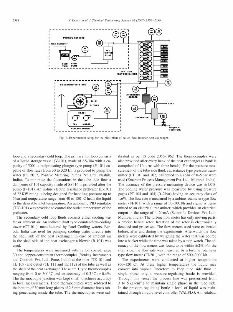
2388 V. Kumar et al. / Chemical Engineering Science 62 (2007) 2386–2396
Fig. 2. Experimental setup for the pilot plant of coiled flow inverter heat exchanger.
loop and a secondary cold loop. The primary hot loop consistsof a liquid storage vessel (V-101), made of SS-304 with a ca-pacity of 500 l, a reciprocating plunger type pump (P-101) ca-pable of flow rates from 30 to 320 1/h is provided to pump thewater (PL 2017, Positive Metering Pumps Pvt. Ltd., Nashik,India). To minimize the fluctuations in the tube side flow adampener of 10 l capacity made of SS316 is provided after thepump (P-101). An in-line electric resistance preheater (E-101)of 22 KW rating is being designed for handling pressure up to5 bar and temperature range from 40 to 180 ◦C heats the liquidto the desirable inlet temperature. An automatic PID regulator(TIC-101) was provided to control the outlet temperature of thepreheater.
The secondary cold loop fluids consists either cooling wa-ter or ambient air. An induced draft type counter-flow-coolingtower (CT-101), manufactured by Patel Cooling waters, Bar-oda, India was used for pumping cooling water directly intothe shell side of the heat exchanger. In case of ambient airin the shell side of the heat exchanger a blower (B-101) wasused.
The temperatures were measured with Teflon coated, gage30 and copper-constantan thermocouples (Yenkay Instrumentsand Controls Pvt. Ltd., Pune, India) at the inlet (TE 101 andTE 109) and outlet (TE 111 and TE 112) of the tube as well asthe shell of the heat exchanger. These are T type thermocouplesranging from 0 to 300 ◦C and an accuracy of 0.3 ◦C or 0.4%.The thermocouple junction was kept small to achieve accuracyin local measurements. These thermocouples were soldered tothe bottom of 30 mm long pieces of 2.5 mm diameter brass tub-ing penetrating inside the tube. The thermocouples were cal-
ibrated as per IS code 2056-1962. The thermocouples werealso provided after every bank of the heat exchanger (a bank iscomprised of 16 turns with three bends). For the pressure mea-surement of the tube side fluid, capacitance type pressure trans-mitter (PT 101 and 102) calibrated to a span of 0–5 bar wereused (Emerson Process Management Pvt. Ltd., Mumbai, India).The accuracy of the pressure-measuring device was ±1.0%.The cooling water pressure was measured by using pressuregages (PT 104 and 104) (0–2 bar) having an accuracy class of1.6%. The flow rate is measured by a turbine rotameter type flowmeter (FI-101) with a range of 30–300 l/h and signal is trans-mitted to an electrical transmitter, which provides an electricaloutput in the range of 4–20 mA (Scientific Devices Pvt. Ltd.,Mumbai, India). The turbine flow meter has only moving parts,a precise helical rotor. Rotation of the rotor is electronicallydetected and processed. The flow meters used were calibratedbefore, after and during the experiments. Afterwards the flowmeters were calibrated by weighing the water that was pouredinto a bucket while the time was taken by a stop-watch. The ac-curacy of the flow meters was found to be within ±2%. For theshell side, the flow rate was measured by a turbine rotametertype flow meter (FI-201) with the range of 500–3000 l/h.
The experiments were conducted at higher temperature(60–120 ◦C). At these higher temperatures the liquid mayconvert into vapour. Therefore to keep tube side fluid insingle phase only a pressure-regulating bottle is provided.Through this vessel the process line was pressurized from3 to 5 kg/cm2 g to maintain single phase in the tube side.In the pressure-regulating bottle a level of liquid was main-tained through a liquid level controller (VALFLO, Ahmedabad,
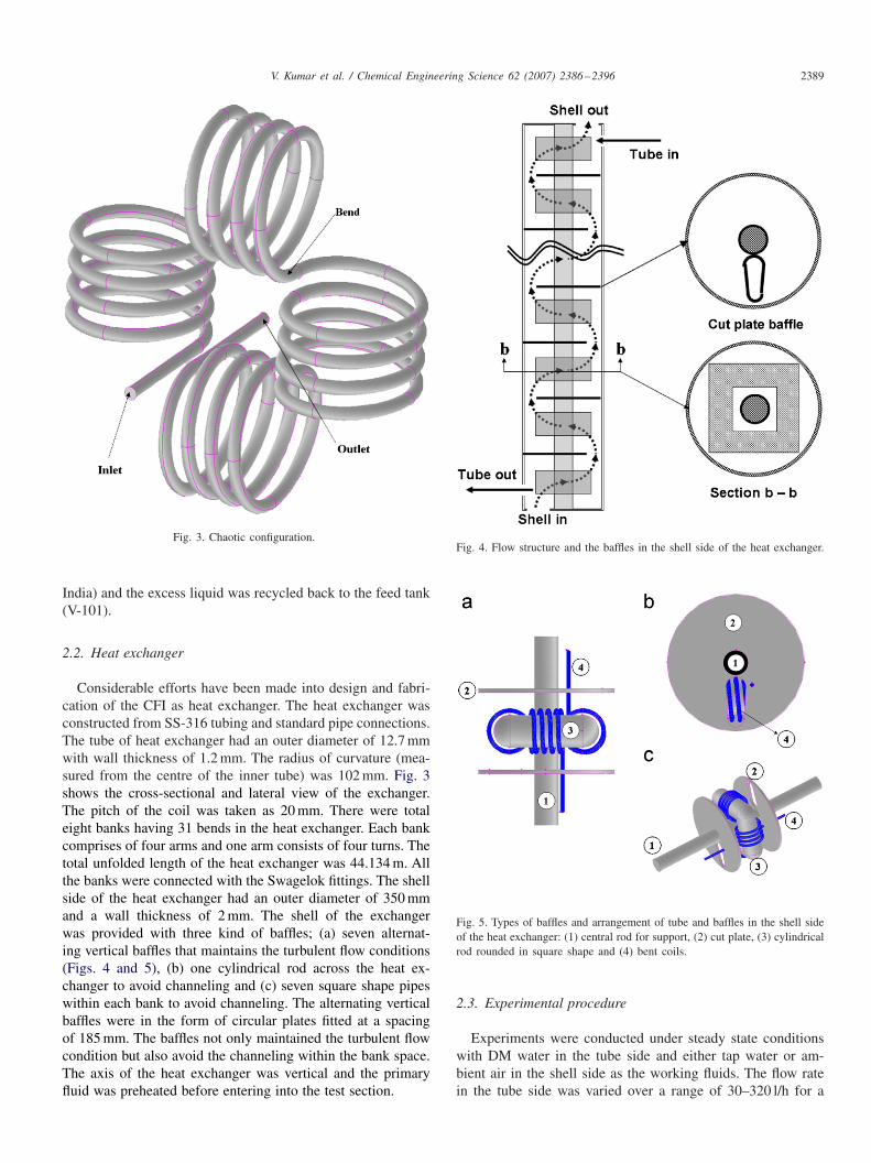
V. Kumar et al. / Chemical Engineering Science 62 (2007) 2386–2396 2389
Fig. 3. Chaotic configuration.
India) and the excess liquid was recycled back to the feed tank(V-101).
2.2. Heat exchanger
Considerable efforts have been made into design and fabri-cation of the CFI as heat exchanger. The heat exchanger wasconstructed from SS-316 tubing and standard pipe connections.The tube of heat exchanger had an outer diameter of 12.7 mmwith wall thickness of 1.2 mm. The radius of curvature (mea-sured from the centre of the inner tube) was 102 mm. Fig. 3shows the cross-sectional and lateral view of the exchanger.The pitch of the coil was taken as 20 mm. There were totaleight banks having 31 bends in the heat exchanger. Each bankcomprises of four arms and one arm consists of four turns. Thetotal unfolded length of the heat exchanger was 44.134 m. Allthe banks were connected with the Swagelok fittings. The shellside of the heat exchanger had an outer diameter of 350 mmand a wall thickness of 2 mm. The shell of the exchangerwas provided with three kind of baffles; (a) seven alternat-ing vertical baffles that maintains the turbulent flow conditions(Figs. 4 and 5), (b) one cylindrical rod across the heat ex-changer to avoid channeling and (c) seven square shape pipeswithin each bank to avoid channeling. The alternating verticalbaffles were in the form of circular plates fitted at a spacingof 185 mm. The baffles not only maintained the turbulent flowcondition but also avoid the channeling within the bank space.The axis of the heat exchanger was vertical and the primaryfluid was preheated before entering into the test section.
Fig. 4. Flow structure and the baffles in the shell side of the heat exchanger.
Fig. 5. Types of baffles and arrangement of tube and baffles in the shell sideof the heat exchanger: (1) central rod for support, (2) cut plate, (3) cylindricalrod rounded in square shape and (4) bent coils.
2.3. Experimental procedure
Experiments were conducted under steady state conditionswith DM water in the tube side and either tap water or am-bient air in the shell side as the working fluids. The flow ratein the tube side was varied over a range of 30–320 l/h for a
2390 V. Kumar et al. / Chemical Engineering Science 62 (2007) 2386–2396
constant shell side flow rate. The shell side flow rates werevaried from 800 to 2500 l/h. Temperature data were recordedat every 10 s. Temperature measurements from the 300 s of thestable system were used, with temperature reading fluctuationswithin ±0.15 ◦C. Though the type-T thermocouples had limitsof error of 0.5 ◦C, when placed in a common water solution thereadings at steady state were all within ±0.1 ◦C. All the ther-mocouples were constructed from the same roll of thermocou-ple wire, and hence the repeatability of temperature readingsis high. Similarly for the heat-transfer study in the shell side,the tube side flow rate was kept constant at 220 l/h and varia-tion in the shell side flow rate is made. At the inlet of the outertube of the heat exchanger the cooling water temperature was26–28 ◦C, and it rises by 4–5 ◦C at the outlet of the outer tube.During the experiments the ambient temperature was 27–28 ◦C,therefore, there was not much heat loss from the outer wall ofthe heat exchanger.
2.4. Calculation of heat-transfer coefficient
The heat-transfer study was carried out for both shell and tubeside, which was done by measuring the overall heat-transfercoefficients. The total thermal resistance between the two flu-ids was due to the inner and outer heat-transfer coefficients, aswell as the resistance of the tube wall, which is very small. Thecriterion for thermal equilibrium of the whole system was ver-ified for each experiment before recording the measurements;measurements were taken when the heat balance was within5%. This takes into account the heat-transfer losses from theshell to the surrounding air. To check the heat balance, the pri-mary and secondary heat fluxes were compared. The primaryand secondary heat flux is determined as
q = mt cp,t (tin − tout) = mscp,s(Tin − Tout), (2)
where the subscript ‘s’ refers to the shell fluid and ‘t’ refersfor tube side. Since the secondary fluid is the cold one, thesecondary heat flux is negative. The fluid properties were de-termined at mean inlet–outlet temperature. The criterion forthermal equilibrium is then written as
qs − qt
qt
× 100� ± 5%. (3)
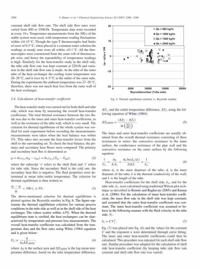
The above-mentioned criterion for thermal equilibrium isplotted against the Reynolds number in Fig. 6. The figure rep-resents the thermal equilibrium criterion for various processconditions in the tube side as well as in the shell side of the heatexchanger. The values scatter within ±5%. When the thermalequilibrium state is verified, the heat exchangers can be char-acterized by temperature and pressure loss measurements. Theoverall heat-transfer coefficient was calculated from the tem-perature data and the flow rates using White (1984) equationand is given below:
Uo = q
A0�TLMTD, (4)
where A0 is the surface area and �TLMTD is the log-mean tem-perature difference, based on the inlet temperature difference,
-20
-10
0
10
20
0 5000 10000 15000 20000
Reynoldsnumber (Tube side)
(qs - q
t)/q
t x 1
00
Qs = 800 kg/hr
Qs = 1000 kg/hr
Qs = 1500 kg/hr
Qs = 2000 kg/hr
Fig. 6. Thermal equilibrium criterion vs. Reynolds number.
�T1, and the outlet temperature difference, �T2, using the fol-lowing equation of White (1984):
�TLMTD = (�T2 − �T1)
ln(
�T2�T1
) . (5)
The inner and outer heat-transfer coefficients are usually ob-tained from the overall thermal resistance consisting of threeresistances in series: the convective resistance in the innersurface, the conductance resistance of the pipe wall and theconvective resistance on the outer surface by the followingequation:
1
Uo
= A0
Aihi
+ A0 ln(do/di)
2�kL+ 1
ho
, (6)
where do is the outer diameter of the tube; di is the innerdiameter of the tube; k is the thermal conductivity of the wall;and L is the length of the tube.
Heat-transfer coefficients for the shell side, ho, and for thetube side, hi , were calculated using traditional Wilson plot tech-nique as described in Rennie and Raghavan (2005) and Kumaret al. (2006). For the calculation of inner heat-transfer coeffi-cient, the mass flow rate in the shell side was kept constant;and assumed that the outer heat-transfer coefficient was con-stant. The inner heat-transfer coefficient was assumed to be-have in the following manner with the fluid velocity in the tubeside, Vi :
hi = CV ni . (7)
Eq. (7) was placed into Eq. (6) and the values for the constantC and the exponent n were determined through curve fitting.The inner and outer heat-transfer coefficients could then becalculated. This procedure was repeated for each shell side flowrate. Similar procedure was adopted for the calculation of shellside heat-transfer coefficient (by keeping tube side flow rateconstant and shell side flow rate was varied).
V. Kumar et al. / Chemical Engineering Science 62 (2007) 2386–2396 2391
2.5. Fluid flowing in shell side: the equivalent diameter
When a fluid flows in a conduit having other than a circularcross-section, such as the present shell side of heat exchangerconsisting of baffles, it was convenient to express heat-transfercoefficients and friction factors by the similar equations andcurves used for pipes and tubes. To permit this type of repre-sentation for outer heat-transfer it has been found advantageousto employ an equivalent diameter De concept. The equivalentdiameter is four times the hydraulic radius, and the hydraulicradius is, in turn, the radius of a pipe equivalent to the annuluscross-section. The hydraulic radius was obtained as the ratioof the flow area to the wetted perimeter. It can be seen fromFigs. 3 and 4 that the flow path is very complex, thereforethe equivalent diameter was calculated by using analogy frompacked bed as
De = 4rh = 4 ∗ void volume
wetted surface, (8)
where void volume is shell volume minus the tube and baf-fles volume, wetted surface is the surface used in heat transferand pressure-drop studies. The wetted surface for heat transferand pressure drops are different. For heat transfer the wettedperimeter is the outer circumference of the chaotic configu-ration with diameter do. Therefore, the heat transfer in shellside is
De = 4rh = 4 ∗ void volume
wetted surface= 4 ∗ void volume
�doL. (9)
In pressure-drop calculations the friction not only results fromthe resistance of the outer pipe but was also affected by theouter surface of the inner pipe and the baffles. The total wettedperimeter is �(doLs +DiLs + dbLb) and for the pressure dropin annuli
D′e = 4 ∗ void volume
Frictional wetted perimeter
= 4 ∗ void volume
�(doLs + DiLs + dbLb), (10)
where db and Lb are the baffles diameter and length,respectively.
3. Result and discussion
The heat exchanger has been analysed in terms of tempera-ture variation along the downstream length and heat exchangerefficiency before discussing the friction factor and fully de-veloped heat-transfer coefficient in the tube and shell side,respectively.
3.1. Variation of bulk mean temperature at various banks
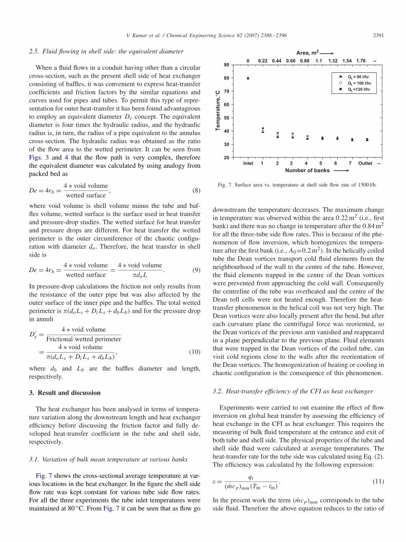
Fig. 7 shows the cross-sectional average temperature at var-ious locations in the heat exchanger. In the figure the shell sideflow rate was kept constant for various tube side flow rates.For all the three experiments the tube inlet temperatures weremaintained at 80 ◦C. From Fig. 7 it can be seen that as flow go
Inlet 1 2 3 4 5 6 7 Outlet --
20
30
40
50
60
70
80
900 0.22 0.44 0.66 0.88 1.1 1.32 1.54 1.76 --
Area, m2
Tem
pera
ture
,°C
Number of banks
Qt = 80 l/hr
Qt = 100 l/hr
Qt =120 l/hr
Fig. 7. Surface area vs. temperature at shell side flow rate of 1500 l/h.
downstream the temperature decreases. The maximum changein temperature was observed within the area 0.22 m2 (i.e., firstbank) and there was no change in temperature after the 0.84 m2
for all the three-tube side flow rates. This is because of the phe-nomenon of flow inversion, which homogenizes the tempera-ture after the first bank (i.e., A0=0.2 m2). In the helically coiledtube the Dean vortices transport cold fluid elements from theneighbourhood of the wall to the centre of the tube. However,the fluid elements trapped in the centre of the Dean vorticeswere prevented from approaching the cold wall. Consequentlythe centreline of the tube was overheated and the centre of theDean roll cells were not heated enough. Therefore the heat-transfer phenomenon in the helical coil was not very high. TheDean vortices were also locally present after the bend, but aftereach curvature plane the centrifugal force was reoriented, sothe Dean vortices of the previous arm vanished and reappearedin a plane perpendicular to the previous plane. Fluid elementsthat were trapped in the Dean vortices of the coiled tube, canvisit cold regions close to the walls after the reorientation ofthe Dean vortices. The homogenization of heating or cooling inchaotic configuration is the consequence of this phenomenon.
3.2. Heat-transfer efficiency of the CFI as heat exchanger
Experiments were carried to out examine the effect of flowinversion on global heat transfer by assessing the efficiency ofheat exchange in the CFI as heat exchanger. This requires themeasuring of bulk fluid temperature at the entrance and exit ofboth tube and shell side. The physical properties of the tube andshell side fluid were calculated at average temperatures. Theheat-transfer rate for the tube side was calculated using Eq. (2).The efficiency was calculated by the following expression:
� = qt
(mcp)mm(Tin − tin). (11)
In the present work the term (mcp)mm corresponds to the tubeside fluid. Therefore the above equation reduces to the ratio of
2392 V. Kumar et al. / Chemical Engineering Science 62 (2007) 2386–2396
0.5
0.6
0.7
0.8
0.9
1
1.1
2000 7000 12000 17000
Reynolds number
ε =
(to
ut
- ti
n)/
(Tin
- t
in)
He
at
ex
ch
na
ge
r e
ffic
ien
cy
,
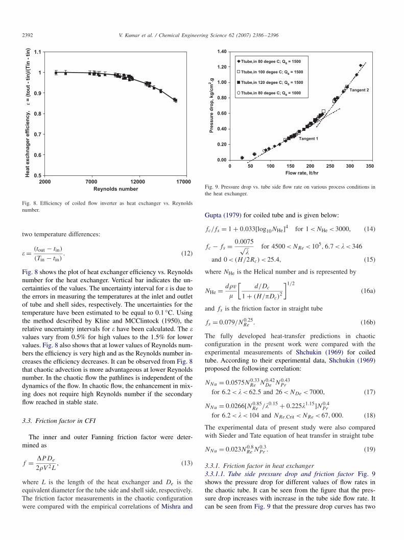
Fig. 8. Efficiency of coiled flow inverter as heat exchanger vs. Reynoldsnumber.
two temperature differences:
� = (tout − tin)
(Tin − tin). (12)
Fig. 8 shows the plot of heat exchanger efficiency vs. Reynoldsnumber for the heat exchanger. Vertical bar indicates the un-certainties of the values. The uncertainty interval for � is due tothe errors in measuring the temperatures at the inlet and outletof tube and shell sides, respectively. The uncertainties for thetemperature have been estimated to be equal to 0.1 ◦C. Usingthe method described by Kline and MCClintock (1950), therelative uncertainty intervals for � have been calculated. The �values vary from 0.5% for high values to the 1.5% for lowervalues. Fig. 8 also shows that at lower values of Reynolds num-bers the efficiency is very high and as the Reynolds number in-creases the efficiency decreases. It can be observed from Fig. 8that chaotic advection is more advantageous at lower Reynoldsnumber. In the chaotic flow the pathlines is independent of thedynamics of the flow. In chaotic flow, the enhancement in mix-ing does not require high Reynolds number if the secondaryflow reached in stable state.
3.3. Friction factor in CFI
The inner and outer Fanning friction factor were deter-mined as
f = �PDe
2�V 2L, (13)
where L is the length of the heat exchanger and De is theequivalent diameter for the tube side and shell side, respectively.The friction factor measurements in the chaotic configurationwere compared with the empirical correlations of Mishra and
0.00
0.20
0.40
0.60
0.80
1.00
1.20
1.40
0 50 100 150 200 250 300 350
Flow rate, lt/hr
Pre
ss
ure
dro
p, k
g/c
m2.g
Ttube,in 80 degee C; Qs = 1500
Ttube,in 100 degee C; Qs = 1500
Ttube,in 120 degee C; Qs = 1500
Ttube,in 80 degee C; Qs = 1000
Tangent 1
Tangent 2
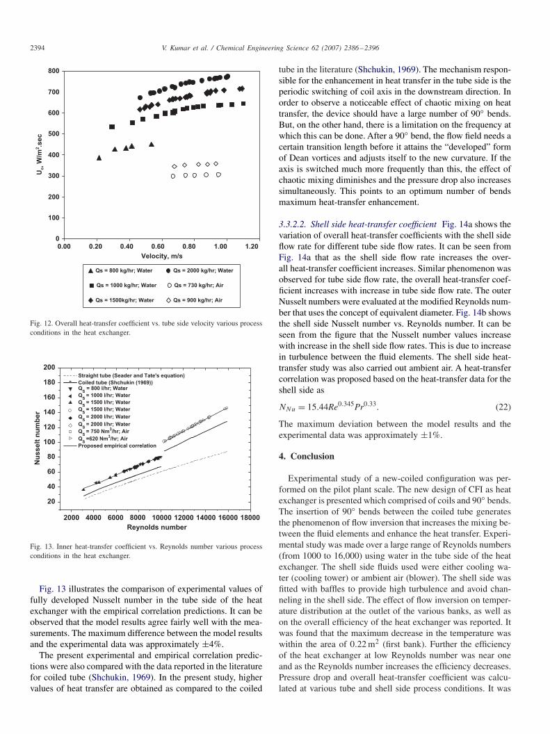
Fig. 9. Pressure drop vs. tube side flow rate on various process conditions inthe heat exchanger.
Gupta (1979) for coiled tube and is given below:
fc/fs = 1 + 0.033[log10NHe]4 for 1 < NHe < 3000, (14)
fc − fs = 0.0075√�
for 4500 < NRe < 105, 6.7 < � < 346
and 0 < (H/2Rc) < 25.4, (15)
where NHe is the Helical number and is represented by
NHe = d�v
�
[d/Dc
1 + (H/�Dc)2
]1/2
(16a)
and fs is the friction factor in straight tube
fs = 0.079/N0.25Re . (16b)
The fully developed heat-transfer predictions in chaoticconfiguration in the present work were compared with theexperimental measurements of Shchukin (1969) for coiledtube. According to their experimental data, Shchukin (1969)proposed the following correlation:
NNu = 0.0575N0.33Re N0.42
De N0.43Pr
for 6.2 < � < 62.5 and 26 < NDe < 7000, (17)
NNu = 0.0266[N0.85Re /�0.15 + 0.225�1.15]N0.4
Pr
for 6.2 < � < 104 and NRe.Crit < NRe < 67, 000. (18)
The experimental data of present study were also comparedwith Sieder and Tate equation of heat transfer in straight tube
NNu = 0.023N0.8Re N0.3
Pr . (19)
3.3.1. Friction factor in heat exchanger3.3.1.1. Tube side pressure drop and friction factor Fig. 9shows the pressure drop for different values of flow rates inthe chaotic tube. It can be seen from the figure that the pres-sure drop increases with increase in the tube side flow rate. Itcan be seen from Fig. 9 that the pressure drop curves has two

V. Kumar et al. / Chemical Engineering Science 62 (2007) 2386–2396 2393
100001000
0.01
0.1
Straight tube Straight tube
Coiled tube
Coiled tube
f
Reynolds number
Tt,in
= 80 °°C;Qs
= 1000 l/hr
Tt,in
= 120 °°C;Qs
= 1500 l/hr
Tt,in
= 100 °°C;Qs
= 1500 l/hr
Tt,in
= 80 °°C;Qs
= 1500 l/hr
Proposed empirical correlation
Fig. 10. Friction factor vs. Reynolds number on various process conditionsin the heat exchanger.
slopes, which shows the transition in the flow regime fromlaminar regime to turbulent regime. From the experimentalmeasurements of pressure drop in tube side a new empiricalcorrelation is developed for friction factor predictions in theheat exchanger. The correlation for tube side was developed fortwo different ranges of Reynolds number as
fCHE,1 = fs(1 + 0.0456N0.603De ) for NRe < 10, 000, (20a)
fCHE,2 = fs(1 + 0.3377N0.042De ) for NRe > 10, 000, (20b)
where fCHE,1.2 are friction factor in the tube side of heatexchanger.
Fig. 10 shows the experimental predictions in the tube side atvarious process conditions of tube and shell side of the heat ex-changer. The percentage error of the proposed correlation withexperimental data was within ±10%. Fig. 10 also illustratesthe comparison of present predictions of friction factor in heatexchanger with the experimental data for coiled tube (Mishraand Gupta (1979)) and straight tube. It can be seen from the
0
0.05
0.1
0.15
0.2
0.25
0.3
0.35
0.4
0 500 1000 1500 2000
Flow rate, lt/hr
Pre
ssu
re d
rop
, kg
/cm
2
0.0070
0.0080
0.0090
0.0100
0.0110
0.0120
3000 4000 5000 6000 7000 8000 9000
Reynolds number
Fri
cti
on
facto
r
Bent Coil heat Exchanger
Straigh tube
Fig. 11. (a) Pressure drop and (b) friction factor in the shell side of the heat exchanger.
figure that the friction factor in the tube side of the heat ex-changer is higher as compared to the coiled tube and straighttube, respectively.
3.3.1.2. Shell side friction factor Fig. 11a shows pressure dropvs. flow rate in the shell side. It can be seen from the Fig. 11athat as the flow rate in the shell side increases the pressure dropincreases linearly. Based on the definition of the equivalent di-ameter the friction factor in the shell side of the heat exchangeris analysed. The experimental predictions of friction factor inthe shell side of heat exchanger are shown in Fig. 11. Thefriction factor in the shell side decreases with decrease in theReynolds number. The friction factor in the CFI is also com-pared with the straight tube friction factor. The friction factorin the CFI is higher as compared to the straight tube, whichis due to the presence of baffles in the shell side of the heatexchanger. To the best of our knowledge, this is the first studymade at pilot scale in the CFI as heat exchanger with consid-ering baffles in the shell side.
3.3.2. Fully developed heat transferFig. 12 shows the overall heat-transfer coefficient (Uo) for
different values of flow rates in the chaotic tube and in the shellside. It can be seen from the figure that the overall heat-transfercoefficient increases with increase in the tube side flow rate fora constant flow rate in the shell side. About 30% increase inthe overall heat-transfer coefficient was observed over two-foldchange in the tube side flow rate. It can also be concluded fromFig. 12 that the overall heat-transfer coefficient increases withincrease in the flow rate in the shell side for a constant tubeside flow rate.
3.3.2.1. Inner Nusselt number Based on the experimental mea-surements new empirical correlations was developed for twodifferent range of Reynolds number as
NNu = 0.08825N0.7Re N0.4
Pr �−0.1 for NRe < 10, 000, (21a)
NNu = 0.0271N0.85Re N0.4
Pr �−0.1 for NRe > 10, 000. (21b)
2394 V. Kumar et al. / Chemical Engineering Science 62 (2007) 2386–2396
0
100
200
300
400
500
600
700
800
0.00 0.20 0.40 0.60 0.80 1.00 1.20
Velocity, m/s
Uo, W
/m2.s
ec
Qs = 800 kg/hr; Water
Qs = 1000 kg/hr; Water
Qs = 1500kg/hr; Water
Qs = 2000 kg/hr; Water
Qs = 730 kg/hr; Air
Qs = 900 kg/hr; Air
Fig. 12. Overall heat-transfer coefficient vs. tube side velocity various processconditions in the heat exchanger.
2000 4000 6000 8000 10000 12000 14000 16000 18000
20
40
60
80
100
120
140
160
180
200
Nu
ss
elt
nu
mb
er
Reynolds number
Straight tube (Seader and Tate's equation)
Coiled tube (Shchukin (1969))Q
S = 800 l/hr; Water
QS
= 1000 l/hr; Water
QS
= 1500 l/hr; Water
QS
= 1500 l/hr; Water
QS
= 2000 l/hr; Water
QS
= 2000 l/hr; Water
QS
= 750 Nm3/hr; Air
QS
=620 Nm3/hr; Air
Proposed empirical correlation
Fig. 13. Inner heat-transfer coefficient vs. Reynolds number various processconditions in the heat exchanger.
Fig. 13 illustrates the comparison of experimental values offully developed Nusselt number in the tube side of the heatexchanger with the empirical correlation predictions. It can beobserved that the model results agree fairly well with the mea-surements. The maximum difference between the model resultsand the experimental data was approximately ±4%.
The present experimental and empirical correlation predic-tions were also compared with the data reported in the literaturefor coiled tube (Shchukin, 1969). In the present study, highervalues of heat transfer are obtained as compared to the coiled
tube in the literature (Shchukin, 1969). The mechanism respon-sible for the enhancement in heat transfer in the tube side is theperiodic switching of coil axis in the downstream direction. Inorder to observe a noticeable effect of chaotic mixing on heattransfer, the device should have a large number of 90◦ bends.But, on the other hand, there is a limitation on the frequency atwhich this can be done. After a 90◦ bend, the flow field needs acertain transition length before it attains the “developed” formof Dean vortices and adjusts itself to the new curvature. If theaxis is switched much more frequently than this, the effect ofchaotic mixing diminishes and the pressure drop also increasessimultaneously. This points to an optimum number of bendsmaximum heat-transfer enhancement.
3.3.2.2. Shell side heat-transfer coefficient Fig. 14a shows thevariation of overall heat-transfer coefficients with the shell sideflow rate for different tube side flow rates. It can be seen fromFig. 14a that as the shell side flow rate increases the over-all heat-transfer coefficient increases. Similar phenomenon wasobserved for tube side flow rate, the overall heat-transfer coef-ficient increases with increase in tube side flow rate. The outerNusselt numbers were evaluated at the modified Reynolds num-ber that uses the concept of equivalent diameter. Fig. 14b showsthe shell side Nusselt number vs. Reynolds number. It can beseen from the figure that the Nusselt number values increasewith increase in the shell side flow rates. This is due to increasein turbulence between the fluid elements. The shell side heat-transfer study was also carried out ambient air. A heat-transfercorrelation was proposed based on the heat-transfer data for theshell side as
NNu = 15.44Re0.345Pr0.33. (22)
The maximum deviation between the model results and theexperimental data was approximately ±1%.
4. Conclusion
Experimental study of a new-coiled configuration was per-formed on the pilot plant scale. The new design of CFI as heatexchanger is presented which comprised of coils and 90◦ bends.The insertion of 90◦ bends between the coiled tube generatesthe phenomenon of flow inversion that increases the mixing be-tween the fluid elements and enhance the heat transfer. Experi-mental study was made over a large range of Reynolds numbers(from 1000 to 16,000) using water in the tube side of the heatexchanger. The shell side fluids used were either cooling wa-ter (cooling tower) or ambient air (blower). The shell side wasfitted with baffles to provide high turbulence and avoid chan-neling in the shell side. The effect of flow inversion on temper-ature distribution at the outlet of the various banks, as well ason the overall efficiency of the heat exchanger was reported. Itwas found that the maximum decrease in the temperature waswithin the area of 0.22 m2 (first bank). Further the efficiencyof the heat exchanger at low Reynolds number was near oneand as the Reynolds number increases the efficiency decreases.Pressure drop and overall heat-transfer coefficient was calcu-lated at various tube and shell side process conditions. It was

V. Kumar et al. / Chemical Engineering Science 62 (2007) 2386–2396 2395
300
400
500
600
700
800
900
0 500 1000 1500 2000 2500
Flow rate (l/hr)
Qt = 150 l/hr
Qt = 220 l/hr
Qt = 300 l/hr
0
50
100
150
200
250
300
350
400
450
0 1000 2000 3000
Reynolds number
Nu
ss
elt
nu
mb
er
Experimental data
Proposed correlaton
Ou
ter
he
at
tra
ns
fer
co
eff
icie
nt
(W/m
2.°
C)
Fig. 14. (a) Overall heat transfer heat coefficient and (b) Nusselt number in the shell side of the heat exchanger.
observed that the overall heat-transfer coefficient increases withincrease in the tube side Reynolds number for a constant flowrate in the shell side. Similar trends in the variation of overallheat-transfer coefficient were observed for different flow ratesin the shell side for a constant flow rate in the chaotic tube. Anew empirical correlation was developed for friction factor andheat transfer for shell and tube of the heat exchanger. The in-ner heat transfer in the heat exchanger was compared with thecoiled tube heat-transfer data reported in the literature. It wasobserved that at low Reynolds number the heat transfer was25% higher and at higher Reynolds number it was 12% higheras compared to the coiled tube data reported in the literature.
Notation
a radius of the helical pipe, mA area, m2
C constant in Eq. (6)Cp specific heat, kJ/(kg K)d diameter of tube, mh heat-transfer coefficient, W/m2 KH pitch, mk thermal conductivity, W/m KL length of heat exchanger, mLMTD log-mean temperature difference, K or ◦Cn exponent in Eq. (6)NDe Dean number (=NRe/
√�)
NDe∗ modified Dean number, dimensionlessNNu Nusselt numberNPr Prandtl numberNRe Reynolds number (=�U0dh/�)
p pressure, N/ m2
q heat-transfer rate, J/sRc radius of the coil, mT temperature, K�T1 temperature difference at inlet K�T2 temperature difference at outlet Ku0 inlet velocity, m/s
U overall heat-transfer coefficient, W/m2 Kv velocity, m/s
Greek letters
� curvature ratio, D/d
� density of fluid, kg/m3
� dynamicviscosity, kg/ms
Subscripts
CFI coiled flow invertert tube sides shell side
Acknowledgement
The authors gratefully acknowledge the Ministry of Chemi-cal and Fertilizers, GOI, India for funding the project.
References
Acharya, N., Sen, M., Cheng, H.-C., 1992. Experimental and numericalinvestigation of heat transfer enhancement in coiled tubes by chaoticmixing. Ph.D. Dissertation, University of Notre Dam, Notre Dam, IN.
Acharya, N., Sen, M., Cheng, H.-C., 1994a. Thermal entrance length andNusselt numbers in coiled tubes. International Journal of Heat and MassTransfer 37, 336–340.
Acharya, N., Sen, M., Cheng, H.-C., 1994b. Analysis of heat transferenhancement in coiled-tube heat exchangers. International Journal of Heatand Mass Transfer 44, 3189–3199.
Berger, S.A., Talbot, L., Yao, L.S., 1983. Flow in curved pipes. AnnualReview of Fluid Mechanics 15, 461–512.
Castelain, C., Berger, D., Legentilhomme, P., Mokrani, A., Peerhossaini,H., 2000. Experimental and numerical characterisation of mixing in asteady spatially chaotic flow by means of residence time distributionmeasurements. International Journal of Heat and Mass Transfer 43,3687–3700.
Chagny, C., Castelain, C., Peerhossaini, H., 2000. Chaotic heat transfer forheat exchanger design and comparison with a regular regime for a largerange of Reynolds numbers. Applied Thermal Engineering 20, 1615–1648.
Dean, W.R., 1927. Notes on the motion of fluid in a curved pipe. PhilosophicalMagazine 4, 208–233.

2396 V. Kumar et al. / Chemical Engineering Science 62 (2007) 2386–2396
Dean, W.R., 1928. The stream line motion of fluid in a curved pipe.Philosophical Magazine 5, 673–695.
Duchene, Ch., Peerhossaini, H., Michard, P.J., 1995. On the velocity fieldand tracer patterns in a twisted duct flow. Physics of Fluids 7, 1307–1317.
Jones, S.W., Thomas, O.M., Aref, H., 1989. Chaotic advection by laminarflow in twisted pipe. Journal of Fluid Mechanics 209, 335–357.
Kumar, V., Nigam, K.D.P., 2005. Numerical simulation of steady flow fieldsin coiled flow inverter. International Journal of Heat and Mass Transfer48, 4811–4828.
Kumar, V., Saini, S., Sharma, M., Nigam, K.D.P., 2006. Pressure drop and heattransfer study in tube-in-tube helical heat exchanger. Chemical EngineeringScience 61, 4403–4416.
Mishra, P., Gupta, S.N., 1979. Momentum transfer in curved pipes. I.Newtonian fluids. Industrial & Engineering Chemistry Process Design andDevelopment 18, 130–137.
Mokrani, A., Castelain, C., Peerhossaini, H., 1997. The effects of chaoticadvection on heat transfer. International Journal of Heat and Mass Transfer40, 3089–3104.
Nandakumar, K., Masliyah, J.H., 1986. Swirling flow and heat transfer incoiled and twisted pipes. In: Mujumdar, A.S., Masliyah, R.A. (Eds.),Advances in Transport Process, vol. 4. Wiley Eastern.
Nauman, E.B., Kothari, D., Nigam, K.D.P., 2002. Static mixers to promoteaxial mixing. Chemical Engineering Research & Design 80, 1–5.
Nauman, E.B., Thakur, R.K., Vial, Ch., Nigam, K.D.P., Djelveh, G., 2003.Static mixers in the process industries. Chemical Engineering Research &Design 81, 787–826.
Peerhossaini, H., Le Guer, Y., 1992. Effect of curvature plane orientation onvortex distortion in curved channel flow. In: Andereck, C.D., Hayot, F.(Eds.), Ordered and Turbulent Patterns in Taylor-Couette Flow. PlenumPress, New York, pp. 263–272.
Rennie, T.J., Raghavan, G.S.V., 2005. Experimental studies of a double-pipe helical heat exchanger. Experimental Thermal and Fluid Science 29,919–924.
Saxena, A.K., Nigam, K.D.P., 1984. Coiled configuration for flow inversionand its effect on residence time distribution. A.I.Ch.E. Journal 30,363–368.
Saxena, A.K., Nigam, K.D.P., 1986. Residence time distribution in straightand curve tubes. In: Cheremisinoff, N.P. (Ed.), Encyclopedia of FluidMechanics, vol. 1. Gulf Publishing, USA, p. 675.(Chapter 22).
Shah, R.K., Joshi, S.D., 1987. Convective heat transfer in curved ducts.In: Kakac, S., Shah, R.K., Aung, W. (Eds.), Handbook of SinglephaseConvective Heat Transfer. Wiley Interscience, New York, pp. 5.1–5.46.
Shchukin, V.K., 1969. Correlation for experimental data on heat transfer incurved pipes. Thermal Engineering 16, 72–76.
White, F.M., 1984. Heat Transfer. Addison-Wesley Publishing Company Inc.,New York, NY.
Copyright © 2022 FDOKUMEN