Assessment of Existing Bond Models for Externally ... - MDPI
Upload
independentCategory
view
0download
0
P. R. Solomon A Coal-Fired Heat Exchanger for M. A. Serio an Externally Fired Gas Turbine
J. E. Cosgrove Significant improvements in efficiency for electricity generation from coal can be achieved by cycles that employ a high-temperature, highly recuperative gas turbine topping cycle. The principal difficulty of employing a gas turbine in a coal-fired
D. S. Pines power generation system is the possible erosion and corrosion ofthe high-temperature rotating gas turbine components caused by the coal's inorganic and organically bound constituents (ash, sulfur, and alkali metals). One route to overcome this
Y. Zhao problem is the development of an externally fired gas turbine system employing a coal fired heat exchanger. The solution discussed in this paper is the design of a
Advanced Fuel Research. Inc.• Radiatively Enhanced, Aerodynamically Cleaned Heat-Exchanger (REACHcEx87 Church Street. changer). The REACH-Exchanger is fired by radiative and convective heat transfer
East Hartford. CT 06108 from a moderately clean fuel stream and radiative heat transfer from the flame of a much larger uncleaned fuel stream, which supplies most of the heat. The approach is to utilize the best ceramic technology available for high-temperature parts of the
R. C. Buggeln REACH-Exchanger and to shield the high-temperature suifaces from interaction with coal minerals by employing clean combustion gases that sweep the tube suiface exposed to the coal flame. This paper presents a combined experimental! computaS. J. Sham roth tional study to assess the viability of the REACH-Exchanger concept. Experimental results indicated that the REACH-Exchanger can be effectively fired using radiation
Scientific Research Associates. Inc.. from the coal flame. Both computation and experiments indicate that the ceramic 50 Nye Road. heat exchanger can be aerodynamically protected by a tertiary stream with an accept
Glastonbury. CT 06033 ably low flow rate.
stream introduced at the burner outer diameter. This clean burning stream also provides flow management to shield the ceramic
1 Introduction
The combined pressures to establish energy security, improve heat exchangers from the coal's inorganic and organically pollution control, and reduce global warming are encouraging bound constituents. the development of cleaner, more efficient technologies to convert coal into electricity. Significant improvements in efficiency 2 REACH-Exchanger Concept can be achieved by cycles that employ a high-temperature, The solution discussed in this paper is the design of a Radiahighly recuperative gas turbine topping cycle. The principal tively Enhanced, Aerodynamically Cleaned Heat-Exchangerdifficulty of employing a gas turbine in a coal-fired power gener (REACH-Exchanger) [5]. The REACH-Exchanger is fired by ation system is th.e possible erosion and corrosion of the high radiative and convective heat transfer from a moderately clean temperature rotating gas turbine components caused by the fuel stream and radiative heat transfer from the flame of a much coal's inorganic and organically bound constituents (ash, sulfur, larger uncleaned fuel stream, which supplies most of the heat. and alkali metals). One route to overcome this problem is the The approach is to utilize the best ceramic technology available development of an externally fired gas turbine system em for high-temperature parts of the REACH-Exchanger and to ploying a coal-fired heat-exchanger. The chief advantage of shield the high-temperature surfaces from interaction with coal this route is that the problems caused by the coal's inorganic minerals by employing clean combustion gases that sweep the constituents are switched from the high-temperature rotating tube surface exposed to the coal flame. parts of the gas turbine to the high-temperature stationary parts The proposed REACH-Exchanger and coal burner configuraof a heat exchanger. The technology barrier is that ceramics are tion are shown schematically in Fig. 1. Several such units are required because of the high temperature, but state-of-the-art integrated into a High-Temperature Advanced Furnace (HImaterials are either mechanically and thermally deficient TAF) shown in Fig. 2. In the base case system considered, the (Alz03 ), or mechanically durable (SiC), but susceptible to oxi REACH-Exchanger receives air preheated to 1280°F (693°C) dation or to corrosion from the coal's ash, sulfur, or alkali. The elsewhere in the furnace using a metal heat exchanger. The key issue is, then, the development of methods to fire a high temperature is raised to 2111°F (1155°C) in the.REACH-Extemperature heat exchanger with coal in such a way that the changer and further heated in an in-duct burner to 2530°Fpotential damage from the inorganic constituents is minimized. (1388°C) before introduction to the gas turbine. In this system, Several such systems are currently under development [1-4]. 80 percent of the energy to the REACH-Exchanger is supplied
The present paper addresses a combined experimental/com by radiation. The clean stream can be natural gas or volatileputational study of an innovative technique for firing high-tem products of pyrolysis, low Btu gas from coal carbonization, or perature heat exchangers in which heat exchangers placed near products of coal gasification. The uncleaned stream can be coal the furnace outer diameter are fired by radiant energy from a or char. central coal flame and convective energy from a clean burning There are several questions that must be answered to deter
mine the technical feasibility of a power generating cycle employing the REACH-Exchanger/HITAF concept. Contributed by the International Gas Turbine Institute for publication in the
ASME JOURNAL OF ENGINEERING FOR GAS TURBINES AND POWER. Manuscript received by the International Gas Turbine Institute July 1. 1993. Associated Tech Can the REACH-Exchanger be effectively fired using ranical Editor: H. L. Julien. diation from the coal flame?
22 I Vol. 118, JANUARY 1996 Transactions of the ASME
I

from Out to Preheater
In·Duet Burner
t
Air In
Clean Fuel Burner
Ceramic Tubes
Fig. 1 HITAF/REACH-Exchanger burner
2 Can it be aerodynamically protected using a practical mass flow rate of gas?
3 Does the REACH-Exchanger/HITAF concept lead to a high efficiency practical power generation cycle?
4 Can a ceramic heat exchanger be economically and reliably fabricated?
Two projects were funded by DoE to provide answers to the first two questions. An experimental project [6] was pursued under the Small Business Innovation Research (SBIR) program. A theoretical project [7] was pursued to examine the aerody-
Air from Co-.preuor at eso-F
~ + SDPerh7tedSteam~
Air at 2Ul-F to In-n.ct BaNer
Fig. 2 HITAF showing two REACH-Exchanger burner units
Journal of Engineering for Gas Turbines and Power
1.0 la
0.8
0.6
0.4
0.2
0.0 6500' 5500
1.0. b
0.8 Q) ~ = ....= ....'5 I"l
I 5500 4500 3500 2500 1500 500
Wavenumbers (em-I)
Fig. 3 Emittance spectra at elevated temperatures for Dupont Lanxide material number 91-X-1096: (a) (1033°F) 556°C; (b) (1881°F) 1027"C; (c) (2653"F) 1456°C
namic cleaning using two-phase computational fluid dynamic methods.
3 Experimental The objective of the experimental program was to test the
proposed REACH-Exchanger in a well-instrumented laboratory facility and assess its advantages in a power generating system. The work was performed in a 0.5 million Btu/hr (0.15 MW) coal combustion facility previously described [8, 9]. The facility was modified to allow firing of dry coal and to include a heat exchanger and in-situ FT-IR diagnostics to measure flame radiation and flame constituent concentrations. The facility was then employed in a series of tests to determine the heat-exchanger efficiency. A second series of tests examined the efficiency of aerodynamically protecting the heat exchanger surface.
Ceramics. The spectral emittances of three ceramic heatexchanger materials were determined at elevated temperatures using an FT-IR based emissometer developed by AFR [1012]. The samples were provided by DuPont Lanxide Composites, Inc., and are fabricated from SiC particulate reinforced alumina. Figure 3 displays the emittance spectra of material designation number 91-X-1096 at 1033°F (556°C), 1881°F (l027°C). and 2653~ (1456°C). Heat-exchanger tubes (length, 2 ft (0.61 m), o.d. = 2 in. (0.05 m) of material number 91-X-1096 were supplied for the REACH-Exchanger tests.
JANUARY 1996, Vol. 118 I 23
~ Flow
Disp<.sal
To Vacuum
Pump
Exhaust Fan
Screw FeederCyclone Separator
-~t Filter
Tertiery Air --,
Refractory Wall I ._ t Heat. 1n 2Vl =::J-Situ
Exch~]J =r.m
T I--~.--I 24"
Exhaust1 . ~ t Steel Wall
Propane Oxygen COlDpressecI. ,- Sir -, (LPG) Air
I.. -42" .1
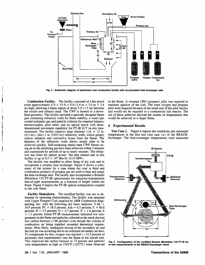
Fig. 4 Schematic diagram of pulverized coal combustion facility with incorporated heat exchanger tube
Combustion Facility. The facility consisted of a fire-proof room approximately 8 ft x 10 ft x 8 ft (2.4 m X 3.0 m X 2.4 m) high, allowing a flame region of about 5 ft (1.5 m) between the nozzle and exhaust stack. The CWF is burned in a downfired geometry. The facility included a specially designed flame gun containing refractory walls for flame stability, a water/gas cooled isokinetic gas and particle collector for material balance, ,thermocouples, pitot tubes, and an optical bench with threedimensional movement capability fo~ FT-IR E/T in-situ measurements. The facility employs large diameter (i.d. = 12 in. (0.3 m», thin (1 in. 0.025 m» refractory walls, which greatly reduce radiation and convective losses from the flame. The thinness of the refractory walls allows steady state to be achieved quickly. Self-sustaining steady-state CWF flames using air as the atomizing gas have been achieved within 5 minutes and maintained for periods of up to ninety minutes. The refractory has holes for optical access. The heat release rate in this facility is up to 0.5 X 10⁶ Btu/hr (0.15 MW).
The facility was modified to allow firing of dry coal and to incorporate a ceramic heat exchanger. Figure 4 shows a schematic of the system for a case where dry coal is fired and combustion products of propane gas are used to heat and purge the heat exchange area. The facility also incorporated a Bomem Michelson 110 FT-IR spectrometer for emission/transmission line-of-sight measurements as a function of height within the flame. Figure 5 depicts the FT -IR optical configuration coupled to the coal flame.
Facility Shakedown. The modified facility was run to determine its operating characteristics. The facility was operated with Upper Freeport Coal supplied by ABB Combustion Engineering, Inc. with the following dry basis analyses: V.M. = 34.9 percent; FC = 58.5 percent; Ash = 6.3 percent; C = 80.8 percent; H = 5.5 percent; 0 = 4.7 percent; N = 1.6 percent; S = 1.1 percent. Initial FT-IR measurements indicated low temperatures in the flame and particles collected in the stack showed low carbon burnout «66 percent) even though the volume of combustion air being supplied exceeded theoretical requirements. Most likely, inadequate mixing of the secondary air and the fuel jet was occurring due to an oversized secondary air duct. To compensate for this, oxygen was injected ( -12.5 percent of necessary fuel requirements) into the flame at the nozzle exit. This improved the carbon burnout to 73 percent and particle/ soot temperatures as high as 2781°F (1527°C) were observed
24 I Vol. 118, JANUARY 1996
in the flame. A constant LPG (propane) pilot was required to maintain ignition of the coal. The extra oxygen and propane pilot were required because of the small size of the pilot facility and would not be required in a commercial size reactor. The use of these additives allowed the studies of temperatures that would be achieved in a larger flame.
4 Experimental Results
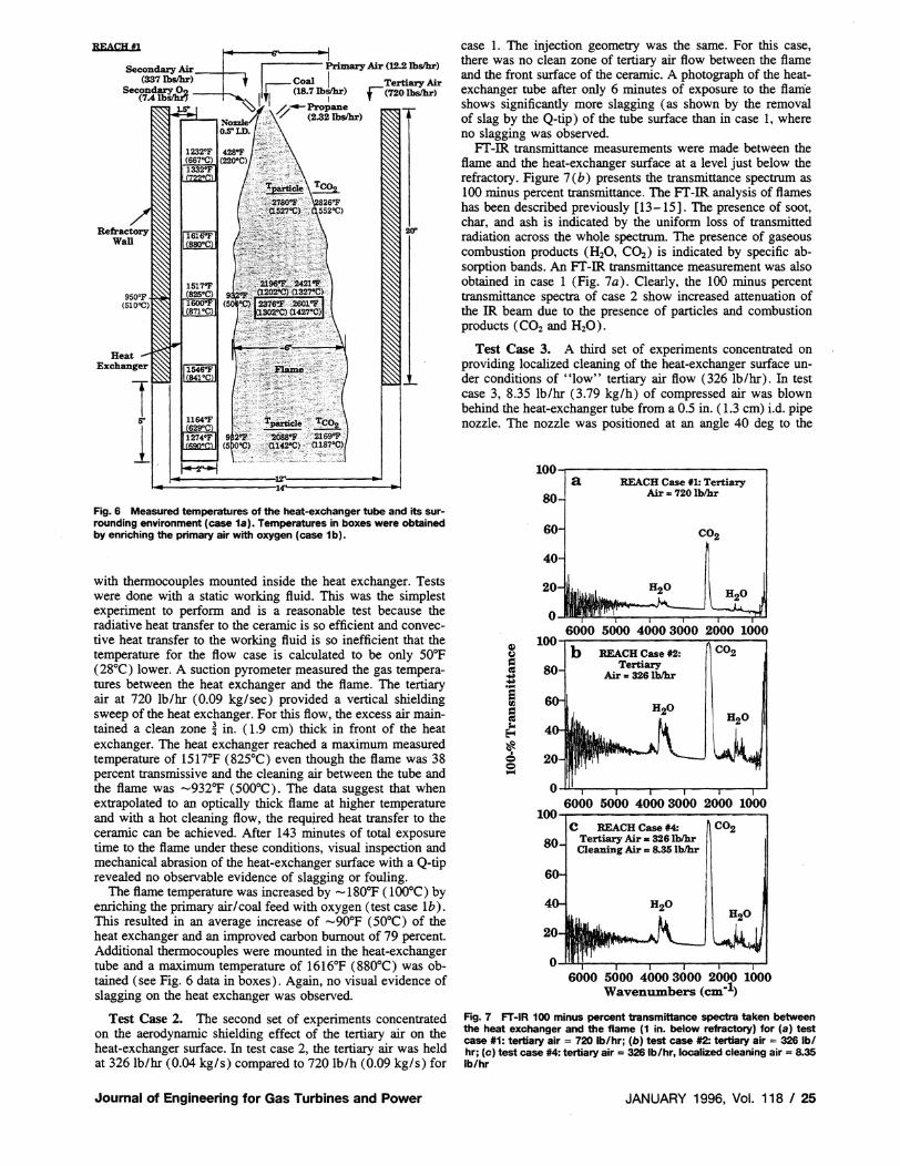
Test Case 1. Figure 6 depicts the conditions and measured temperatures in the first test (test case 1a) of the REACHExchanger. The heat-exchanger temperatures were measured
F'Ig.5 Configuration of the modified Bomem Michelson 110 FT-IR for in-situ measurements of the REACH· Exchanger flame
Transactions of the ASME
,,'OHm "I:=E.Secondary Air Primary Air (12.2lbs1hr)
(337 lbsIhr) t ISecond 0 Coal Tertiary Air (7.4 ~ 11.1 (18.7 ~) r (720 Ibsfhr)
~~...\~--Propane Noule/I' " (2.32 Ibsfhr) O.5"LD.
Fig. 6 Measured temperatures of the heat-exchanger tube and its surrounding environment (case 1a). Temperatures in boxes were obtained by enriching the primary air with oxygen (case 1b).
with thennocouples mounted inside the heat exchanger. Tests were done with a static working fluid. This was the simplest experiment to perfonn and is a reasonable test because the radiative heat transfer to the ceramic is so efficient and convective heat transfer to the working fluid is so inefficient that the temperature for the flow case is calculated to be only 50°F (28°C) lower. A suction pyrometer ~easured the gas temperatures between the heat exchanger and the flame. The tertiary air at 720 lb/hr (0.09 kg/sec) provided a vertical shielding sweep of the heat exchanger. For this flow, the excess air maintained a clean zone ~ in. (1.9 cm) thick in front of the heat exchanger. The heat exchanger reached a maximum measured temperature of 1517°F (825°C) even though the flame was 38 percent transmissive and the cleaning air between the tube and the flame was -932°F (500°C). The data suggest that when extrapolated to an optically thick flame at higher temperature and with a hot cleaning flow, the requ~ed heat transfer to the ceramic can be achieved. After 143 minutes of total exposure time to the flame under these conditions, visual inspection and mechanical abrasion of the heat-exchanger surface with a Q-tip revealed no observable evidence of slagging or fouling.
The flame temperature was increased by -180°F ( 100°C) by enriching the primary air/coal feed with oxygen (test case Ib). This resulted in an average increase of -90°F (50°C) of the heat exchanger and an improved carbon burnout of 79percent. Additional thennocouples were mounted in the heat-exchanger tube and a maximum temperature of 1616°F (880°C) was obtained (see Fig. 6 data in boxes). Again, no visual evidence of slagging on the heat exchanger was observed.
Test Case 2. The second set of experiments concentrated on the aerodynamic shielding effect of the tertiary air on the heat-exchanger surface. In test case 2, the tertiary air was held at 3261b/hr (0.04 kg/s) compared to 720 lb/h (0.09 kg/s) for
Journal of Engineering for Gas Turbines and Power
case 1. The injection geometry was the same. For this case, there was no clean zone of tertiary air flow between the flame and the front surface of the ceramic. A photograph of the heatexchanger tube after only 6 minutes of exposure to the flame shows significantly more slagging (as shown by the removal of slag by the Q-tip) of the tube surface than in case 1, where no slagging was observed.
FT-IR transmittance measurements were made between the flame and the heat-exchanger surface at a level just below the refractory. Figure 7 (b) presents the transmittance spectrum as 100 minus percent transmittance. The FT-IR analysis of flames has been described previously [13-15]. The presence of soot, char, and ash is indicated by the unifonn loss of transmitted radiation across the whole spectrum. The presence of gaseous combustion products (H20, CO2 ) is indicated by specific absorption bands. An FT-IR transmittance measurement was also obtained in case 1 (Fig. 7a). Clearly, the 100 minus percent transmittance spectra of case 2 show increased attenuation of the IR beam due to the presence of particles and combustion products (C02 and H20).
Test Case 3. A third set of experiments concentrated on providing localized cleaning of the heat-exchanger surface under conditions of "low" tertiary air flow (326 lb/hr). In test case 3, 8.35 lb/hr (3.79 kg/h) of compressed air was blown behind the heat-exchanger tube from a 0.5 in. (1.3 cm) i.d. pipe nozzle. The nozzle was positioned at an angle 40 deg to the
100~--------------------~ a REACH Case #1: Tertiary
Air = 720 Iblhr80
60 CO2
40
20 H 20
o 6000 5000 4000 3000 2000 1000
~ REACH Case #2: nCO2 Tertiary
! Air co 3261blhr
·5 III
~ e ~
S
H20
6000 5000 4000 3000 2000 1000 Wavenumbers (em-I)
Fig.7 FT-IR 100 minus percent transmittance spectra taken between the heat exchanger and the flame (1 in. below refractory) for (a) test case #1: tertiary air = 720 Ib/hr; (b) test case #2: tertiary air = 326 Ibl hr; (e) test case #4: tertiary air = 326lb/hr, localized cleaning air'" 8.35 Ib/hr
JANUARY 1996. Vol. 118 I 25

REACH #3
Secondary Air~ . Primary1Air[8.8lbs1hr airl (337 lbslhr) S.3lbs1hr OzJSecon~_02 g~ lbsk.) Tertiary Air1+ (7.4lbS1hrJ I I ~326 lbsIhr)
~ ,lj--Propane I " (2.32 lbsIhr) ,
Note: Length of expo -5 minutes
Fig. 8 Configuration of case #3 localized cleaning
tube nonnal, 7 in. (17.8 cm) above tube bottom as shown in Fig. 8. A sharp contrast between the fouled section of the tube and the clean section is observed in Fig. 9. The figure shows that the heat-exchanger remains clean only where the nozzle air sweeps the back and side of the tube in the lower left comer.
Test Case 4. The results of test case 3 warranted relocating the localized cleaning air to a higher position along the heatexchanger tube. In test case 4 (Fig. 10), the nozzle was mounted 16 in. (40.6 cm) above the tube bottom. Blowing 8.35 lb/hr (3.79 kg/h) at this higher position allowed the shielding sweep to surround the heat-exchanger and resulted in a much cleaner heat-exchanger surface, comparable to the cleaning results achieved using a "high" tertiary air flow (test case 1). FT-IR transmission measurements (Fig. 7 c) showed a decrease in IR attenuation due to particles, CO2 , and H20. The combustion product concentrations were lower than that of case 2 (Fig. 7 b), but higher than in case 1 (Fig. 7a).
Fig. 9 Photograph of heat exchanger tube after -6 minutes exposure of case #3 conditions. Note the clean region of the tube in the lower left comer where the nozzle air sweeps the tube.
26 I Vol. 118, JANUARY 1996
REACHt4
Secondary Air~(3371bslhr) Second!!rY_02
(7.4lbSlhrJ ~
Note: Length of ezp. -6 minutes
Fig. 10 Configuration of case #4 localized cleaning
Test Case 5. In test case 5, the air nozzle from case 4 was replaced by a propane torch with a 1 in. (2.5 cm) i.d. nozzle in order to reduce some of the convective heat losses associated with the "cool" tertiary air. The flame was positioned so as to maximize the distribution of its heat along the length of the tube which resulted in the flame impinging on the tube at a very high angle (65 deg) to the nonnal of the tube. The propane flow rate was 0.74 lb/hr (0.34 kg/h) along with an undetermined flow of air induced by the venturi action of the torch. Under low tertiary air conditions (test case Sa), the heat-exchanger tube reached a maximum temperature of 1967°F (l075°C); however, a layer of slag was deposited on the tube. Under high tertiary air conditions (test case 5b) the tube reached a maximum temperature of 1742°F (950°C) and no slagging was observed.
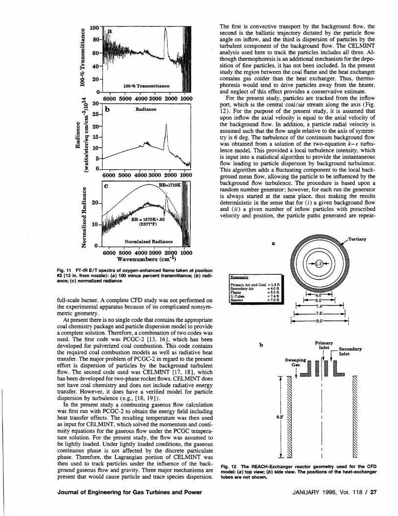
FT-IR Characterization of the Flame. FT-IR measurements of temperatures for particles and CO2 for concentrations for particles, soot, and CO2 , for the fraction of ignited particles and for the radiance intensity in the flame were obtained. The method is described in [13-15]. The transmittance data indicated that the flame was not opaque ( average transmittance -40 percent). The nonnalized radiance data, which are compared to Planck functions, show flame temperatures in the range 20l2OP (1 100°C) to 2822°F (1550°C). The maximum particle temperature observed was 278l oF (l527°C) in test case la. Figure 11 depicts the transmittance (expressed as 100 minus percent transmittance), radiance, and nonnalized radiance spectra calculated to obtain these measurements 13 in. (33 cm) from the burner/nozzle for test case lb.
5 CFD Modeling of Aerodynamic Cleaning Two-phase computational fluid dynamics (CFD) was em
ployed to investigate potential strategies for injecting a cleansing stream into the HITAF/REACH-Exchanger to protect the heat-exchanger elements from coal particles and corrosive coal combustion products. The CFD study was done for a candidate
Transactions of the ASME
8
~ .~
1:11
rf:: ~
~ 20 100·% Transmittance
~ 6000 5000 4000 3000 2000 1000Cb 30~----------------------~ ~ Ib Radiance
":' 25 ~
8 e 20 ~ Col ... =" 15 1~ ~ l 10
! ~
5...III O~~--~---r--~--~--~~
6000 5000 4000 3000 2000 1000
C ~BB=1710 lim I
<II
~
~ "CS <II .~
1:11 -~
Normlaized Radiance ~ 6000 5000 4000 3000 2000 1000
Wavenumbers (em-I)
Fig.11 FT-IR EfT spectra of oxygen-enhanced flame taken at position #2 (13 in. from nozzle): (a) 100 minus percent transmittance; (b) radiance; (e) normalized radiance
full-scale burner. A complete CFD study was not performed on the experimental apparatus because of its complicated nonsymmetric geometry.
At present there is no single code that contains the appropriate coal chemistry package and particle dispersion model to provide a complete solution. Therefore, a combination of two codes was used. The first code was PCGC-2 [13, 16], which has been developed for pulverized coal combustion. This code contains the required coal combustion models as well as radiative heat transfer. The major problem of PCGC-2 in regard to the present effort is dispersion of particles by the background turbulent flow. The second code used was CELMINT [17, 18], which has been developed for two-phase rocket flows. CELMINT does not have coal chemistry and does not include radiative energy transfer. However, it does have a verified model for particle dispersion by turbulence (e.g., [18, 19]).
In the present study a combusting gaseous flow calculation was first run with PCGC-2 to obtain the energy field including heat transfer effects. The resulting temperature was then used as input for CELMINT, which solved the momentum and continuity equations for the gaseous flow under the PCGC temperature solution. For the present study, the flow was assumed to be lightly loaded. Under lightly loaded conditions, the gaseous continuous phase is not affected by the discrete particulate phase. Therefore, the Lagrangian portion of CELMINT was
The first is convective transport by the background flow, the second is the ballistic trajectory dictated by the particle flow angle on inflow, and the third is dispersion of particles by the turbulent component of the background flow. The CELMINT analysis used here to track the particles includes all three. Although thermophore sis is an additional mechanism for the deposition of fine particles, it has not been included. In the present study the region between the coal flame and the heat exchanger contains gas colder than the heat exchanger. Thus, thermophoresis would tend to drive particles away from the heater, and neglect of this effect provides a conservative estimate.
For the present study, particles are tracked from the inflow port, which is the central coal/air stream along the axis (Fig. 12). For the purpose of the present study, it is assumed that upon inflow the axial velocity is equal to the axial velocity of the background flow. In addition, a particle radial velocity is assumed such that the flow angle relative to the axis of symmetry is 6 deg. The turbulence of the continuum background flow was obtained from a solution of the two-equation k- € turbulence model. This provided a local turbulence intensity, which is input into a statistical algorithm to provide the instantaneous flow leading to particle dispersion by background turbulence. This algorithm adds a fluctuating component to the local background mean flow, allowing the particle to be influenced by the background flow turbulence. The procedure is based upon a random number generator; however, for each run the generator is always started at the same place, thus making the results deterministic in the sense that for (i) a given background flow and (ii) a given number of inflow particles with prescribed velocity and position, the particle paths generated are repeat-
a
~
Primary Air and Coal = 1.3 n Secondary Air 4,0 n Flame 5.01\ I--~-::I U·Tubes 7.4 it ~4.0---J Reactor 7.6 n f--5.0'---j I
I" 7.4 •I.. .. I7.S'
I.. 9.0' .. I
Primaryb Inlet Seconda
9.2'
1then used to track particles under the influence of the back
Fig. 12 The REACH-Exchanger reactor geometry used for the CFDground gaseous flow and gravity. Three major mechanisms are model: (a) top view; (b) side view. The pOSitions of the heat-exchanger present that would cause particle and trace species dispersion. tubes are not shown.
Journal of Engineering for Gas Turbines and Power JANUARY 1996, Vol. 118 I 27

No Tertiary Flow
J Overall
Closeup
Fig. 13 Velocity vector plots case #1 (no tertiary flow)
able. However, if a new particle is added between two existing Velocity vector plots for two of the five cases are shown in particles, the new particle path, in general, will not be confined Figs. 13 and 14, both for the overall flow field and a "closeto the region between the two original particle paths. This is up" of the recirculation zone. The direction of flow is shown by important in interpreting the plots. In addition, due to the ran the direction of arrows plotted on the figure and the amplitude is dom nature of the process, there is always a chance that any represented by the length of the arrows. Particle paths were run single particle may follow an unexpected path. for particles originating in the primary stream. Particle path
The initial radial velocity is most important for the large results for Case I are shown in Fig. 15. In Figs. 13-15, the particles, as it provides the initial particle momentum, which is inflow at the top of the furnace is at the left, the axis of symmetry modified with time by the background flow drag force and at the bottom, the outer wall at the top and outflow at the right. turbulence. It is less important for small particles since their The plots have been rotated by 90 deg from their physical low mass (i.e., low momentum) makes them come to equilib orientation for ease of viewing. Gravity is in the left-to-right rium with the background flow more quickly. In contrast, the direction. Particle paths were calculated for particle radii of 10 background turbulence has more influence on the smaller parti iJ-m, 30 iJ-m, and 100 iJ-m and each result is shown separately. cles. This provides a random, instantaneous flow field, which For each case, particles were injected at twenty-four separate influences the particles via a random drag force and those parti inlet locations. Many thousands of particles were injected at cles having lower momentum, i.e., the smaller particles, are . each inlet location and the trajectory of each particle was determore subject to these turbulent fluctuations. mined by its interaction with the background flow. The interac
The calculations were carried out for a single burner with the tion had both a mean and a random component and each trajecgeometry shown in Fig. 12. The calculation assumes a primary tory shown represents the statistical average of all particles stream mass flux of 10.9 x 10³ lb/hr (1.37 kg/ s), a secondary entering the flow from the specific injection location. mass flux of 39.3 x 10³ Ib/hr(4.96kg/s), and a tertiary stream Figures 13 and 15 show the base case; no tertiary injection. mass flux of 11.1 x 10³ lb/hr (l.40 kg/s) for the second and The development of the flow field shows the primary and secthird cases considered. Five sets of calculations were performed. ondary jets mixing with the quiescent flow and the resulting The first had no tertiary injection; the second had tertiary injec recirculation region are evident in Fig. 13. In these plots, veloction from an annulus located at the top of the furnace near the ity vectors near the centerline are omitted, as they were large outer edge; the third had flow injected from a slit at the outer and obscured the rest of the plot. Figure 15 shows particle diameter wall located approximately one-half way along the trajectories for the base case. In assessing the results, note that length of the furnace. The fourth had tertiary flow injected from the heat exchanger is to be placed at 80 percent of the furnace both top and outer walls. The fifth had injection from the top radius. For no tertiary flow, it is clear that the entire range of and two places on the outer walls. Both the forth and fifth cases particles considered presents a problem. The particles would be had twice the total tertiary injection of cases 2 and 3. Gravity dangerously close to the heat exchanger at approximately 40 was included in the calculation. The furnace radius was approxi percent of the length (for 10 iJ-m), 60 percent (for 30 iJ-m), and mately 4.5 ft (1.4 m) and the length 30 ft (9.2 m). 40 percent (for 100 iJ-m), respectively.
28 I Vol. 118, JANUARY 1996 Transactions of the ASME
----- ----- ---- ----~ ~ = a= -=-=== = ..., ~ -= = = - ~ ~ ~ ~;;:; ~:r--= ~ ~ --- --- ---..,--""---.--_./0 "," ____ ".
./ ' J--. ...,
Overall
-=~ ==ilEa :;:::;:;~ _ ~ _
- ....... ~ l .,..
Side Injection Port
(I f' ~ ~ ~~~~~
\ .I
Closeup
Fig. 14 Velocity vector plots case #3 (tertiary flow: side injection)
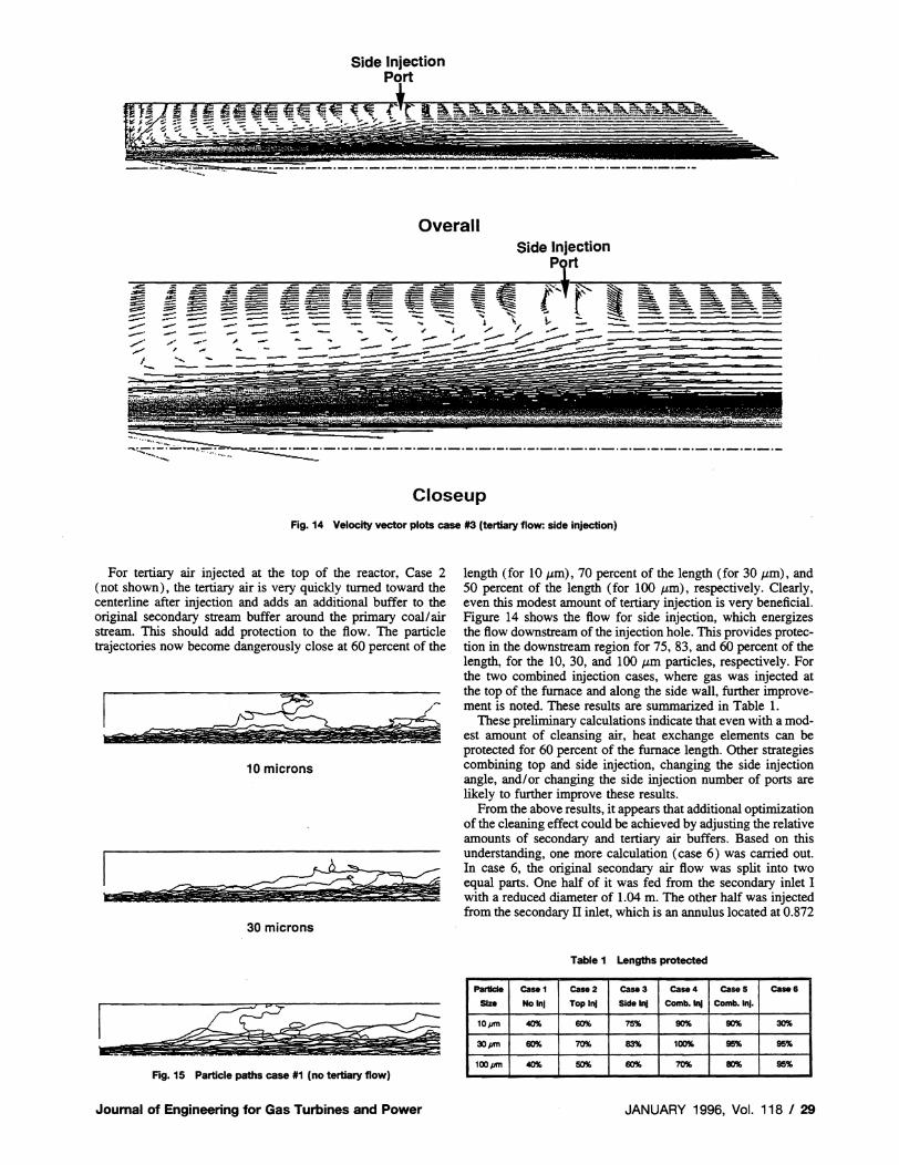
For tertiary air injected at the top of the reactor, Case 2 (not shown), the tertiary air is very quickly turned toward the centerline after injection and adds an additional buffer to the original secondary stream buffer around the primary coal/air stream. This should add protection to the flow. The particle trajectories now become dangerously close at 60 percent of the
!iiI_d. &~Il~~ 10 microns
'a Ii! ~~~??~~-
30 microns
Fig. 15 Particle paths case #1 (no tertiary flow)
Journal of Engineering for Gas Turbines and Power
length (for 10 11m), 70 percent of the length (for 30 J.Lm), and 50 percent of the length (for 100 J.Lm), respectively. Clearly, even this modest amount of tertiary injection is very beneficial. Figure 14 shows the flow for side injection, which energizes the flow downstream of the injection hole. This provides protection in the downstream region for 75, 83, and 60 percent of the length, for the 10, 30, and 100 J.Lm particles, respectively. For the two combined injection cases, where gas was injected at the top of the furnace and along the side wall, further improvement is noted. These results are summarized in Table 1.
These preliminary calculations indicate that even with a modest amount of cleansing air, heat exchange elements can be protected for 60 percent of the furnace length. Other strategies combining top and side injection, changing the side injection angle, and/or changing the side injection number of ports are likely to further improve these results.
From the above results, it appears that additional optimization of the cleaning effect could be achieved by adjusting the relative amounts of secondary and tertiary air buffers. Based on this understanding, one more calculation (case 6) was carried out. In case 6, the original secondary air flow was split into two equal parts. One half of it was fed from the secondary inlet I with a reduced diameter of 1.04 m. The other half was injected from the secondary II inlet, which is an annulus located at 0.872
Table 1 Lengths protected
Parllc:le Case I case 2 case 3 case 4 caseS Case 6 SIze No Inl Top Inj Sid. In! Comb. In! Comb.lnl·
SO'l(, SO'l(,101'f1l 40% 60% 75% 30%
301'f1I 60% 70% 83% 100% 95% 95%
lool'f1l 40% 50% 60% 70% 80% 95'lI.
JANUARY 1996, Vol. 118 I 29

----------- -
VELOCITY VECTOR PLOTS
Two Injector Tertiary Flow
Overall
- - - -' -------- - - ------- -------.=::=~~-.:::,-.-
:-:::-~~:~---~--~ ~=~
Closeup Fig.16 Velocity vector plots case #6 (two secondary injections)
meters from the center line of the reactor cylinder. There is no side injection.
The velocity vector plots are given in Fig. 16. The flow patterns obtained were considerably different from those obtained in the previously run cases. The large recirculation normally obtained on the outer wall was not observed. As expected, two small recirculation zones were formed in the base regions, but these zones are small and have little effect on the flow pattern. As indicated in Table I, the results for Case 6 are the most promising for larger particles. For the 10 p,m case one particle does penetrate the region of the heat exchanger. This design controls particle transport mechanism No. 1 very well, but the small particles that are mostly affected by the turbulence can still cause fouling problem. Better turbulence control could be achieved by design modifications in both geometry and firing schemes.
In addition, although not shown here, results have been obtained to show the sensitivity of the calculations to inlet primary stream flow angle and turbulence level. As expected, in general, although anomalies do appear due to the statistical nature, reducing the inlet primary stream flow angle reduces particle spread and increasing turbulence increases primary stream spread.
6 Conclusions A combined experimental/computational study has been per
formed to assess the viability of a coal-fired heat exchanger for an externally fired gas turbine. Experimental results indicated
that the REACH-Exchanger can be effectively fired using radiation from the coal flame. Both computation and experiments indicate that the ceramic heat exchanger can be aerodynamically protected by a tertiary stream with an acceptably low flow rate. This work provides affirmative answers to two of the major questions regarding REACH-Exchanger efficiency and viability.
• The program results demonstrate that the radiative heat exchange is extremely effective. Heat-exchanger temperatures up to 1967"F (l075°C) were achieved in a coal flame whose temperature was boosted using propane addition, even though the flame was not optically thick ( -60 percent) at a lower temperature than would be achieved in the HIT AF. The data suggest that when extrapolated to an optically thick flame at the higher temperature expected in the HIT AF, the required heat transfer to the ceramic can be achieved.
• Both experiments and modeling show that aerodynamic shielding can be accomplished with a practical amount of clean gas (less than 20 percent of the total flow) to sweep the surface of the heat exchanger.
Acknowledgments
This work was supported under Contract Nos. DE-AC2292PC92196 and DE-FG05-92ER81323 from the U.S. Department of Energy. Dr. Clifford Smith is the Contract Monitor.
30 I Vol. 118, JANUARY 1996 Transactions of the ASME

We wish to thank DuPont Lanxide Composites, Inc., for supplying the test ceramics.
References 1 Zabolotny, E. R., Vivenzio, T. A., and LeHaye. P'" Proceedings of the
American Power Conference, 52nd Annual Meeting, Chicago, n.., Apr. 23-25, 1990.
2 LeHaye, P. G., and Zabolotny, E., Proc. IGTI, Vol. 4, 1989, p. 263. 3 Foster Wheeler Development Corporation, "Development of a High-Per
formance Coal-Fired Power Generating System With Pyrolysis Gas and CharFired High Temperature Furnace (HITAF)," Quarterly Progress Report (3), for U.S. DoE/PETC Contract No. DE-AC22-9IPClIS4, 1992.
4 United Technologies Research Center, "Coal-Fired High Performance Power Generating System," Quarterly Progress Report, for U.S. DoE/PETC Contract No. DE-AC22-92PC911SS, July I-Sept. 30, 1992.
5 Solomon, P. R., Bates, S. c., Carangelo, R. M., and Hamblen, D. G., "Coal Fired Heating Apparatus and Method," patent application, 1991.
6 Solomon, P. R., Serio, M. A., Cosgrove, J. E., Pines, D. S., and Zhang, Y., "An Advanced Coal Fired Heat Exchanger/Gas Turbine Topping Cycle for a High Efficiency Power Plan," Final Report for U.S. Department of Energy, Contract No. DE-FGOS-92ER81323, May, 1993.
7 Advanced Fuel Research, Inc., "Feasibility Study for an Advanced Coal Fired Heat-Exchanger/Gas Turbine Topping Cycle for a High Efficiency Power Plant," DoE Contract #DE-AC22-92PC92196.
8 Solomon, P. R., Best, P. E., Chien, P. L., and Goodman, R. M., "A Laboratory Combustion Facility for Evaluation of CWF," 6th International Workshop on Coal-Liquid and Alternate Fuels Technology, Halifax, Canada, 1986.
9 Solomon, P. R., Chien, P. L., and Best, P. E., "Measurement and Optimization of Combustion Performance of Coal Water Fuels," US DOE Contract No. DE-ACOI-8SER80320 Final Report, 1986.
10 Markham, J. R., Solomon, P. R., and Best, P. E., "A FT-JR Based Instrument for Measuring Spectral Emittance of Material at High Temperature," Review of SCienlijic Instruments. Vol. 61. 1991. p. 3700. .
II Markham, J. R., Best, P. E., Solomon, P. R., and Yu, Z. Z., "Measurement of Radiative Properties of Ash and Slag by FT-IR Emission and Reflection Spectroscopy," ASME Journal of Heat Transfer, Vol. 114, 1992, p. 458.
12 Markham, J. R., Kinsella, K., Carangelo, R. M., Brouillette, C. R., Carangelo, M. D .. Best, P. E., and Solomon, P. R., "A Bench Top FT-JR Instrument for Simultaneously Measuring Surface Spectral Emittance and Temperature," Review of Scienlijic Instrument, in press, 1993.
13 Solomon, P. R., Markham, J. R., Zhang, Y. P., Carangelo, R. M., Brewster, B. S., and Smoot, L. D., "The Study of a Coal Flame by FT-IR Emission/ Transmission Tomography and Comprehensive Modeling," Sci-Mix Poster Session, ACS Meeting, Washington, DC, 1990.
14 Solomon, P. R., Chien, P. L., Carangelo, R. M., Best, P. E., and Markham., J. R., Proc. The 22nd Symposium (Int.) on Combustion, The Combustion Institute, Pittsburgh, PA, 1988, p. 211.
15 Markham, 1. R., Zhang, Y. P., Carangelo, R. M., and Solomon, P. R., FTIR Emission/Transmission Tomography of a Coal Flame. The 23rd Symposium (Int) on Combustion, The Combustion Institute, 1990, pp. 1869-1875.
16 Smith, P. J., Smoot, L. D., and Fletcher, T. H., "User's Manual for a Computer Program for 2-Dimensional Coal Gasification of Combustion (PCGC2)," Interim Report Vol. n prepared for U.S. DoEIMETC Contract No. DEAC21-8IMCI6518, Combustion Laboratory, Brigham Young University, Oct. 1983; see also Smoot, L. D., and Brewster, B. S., "User's Manual for 1990 Version of Pulverized Coal Gasification and Combustion 2-Dimensional (87PCGC-2)," rev., ACERC, Brigham Young University, July 1991.
17 Sabnis, J. S., de Jong, F. J., and Gibeling, H. J., "Calculation of Particle Trajectories in Solid-Rocket Motors With Arbitrary Acceleration," J. Prop. Power, Vol. 8, Sept.-Oct., 1992.
18 Sabnis, J. S., Choi, S. K., Buggeln, R. c., and Gibeling, H. J., "Computation of Two-Phase Shear Layer Flow Using an Eulerian-Lagrangian Analysis," AIAA Paper No. 88-3202, 1988.
19 Sabnis, J. S., and de Jong, F. J., "Calculation of the Two-Phase Flow in an Evaporating Spray Using an Eulerian-Lagrangian Analysis," AIAA Paper No. 90-0447, 1990.
Journal of Engineering for Gas Turbines and Power JANUARY 1996, Vol. 118 I 31
Copyright © 2022 FDOKUMEN