Dendritic fins optimization for a coaxial two-stream heat exchanger
Upload
khangminh22Category
view
6download
0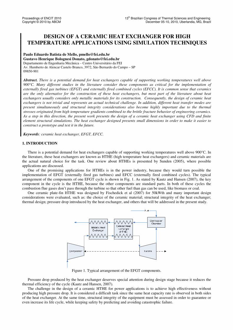
Proceedings of ENCIT 2010 13th Brazilian Congress of Thermal Sciences and Engineering
Copyright © 2010 by ABCM December 05-10, 2010, Uberlandia, MG, Brazil
DESIGN OF A CERAMIC HEAT EXCHANGER FOR HIGH
TEMPERATURE APPLICATIONS USING SIMULATION TECHNIQUES
Paulo Eduardo Batista de Mello, [email protected]
Gustavo Henrique Bolognesi Donato, [email protected] Departamento de Engenharia Mecânica – Centro Universitário da FEI
Av. Humberto de Alencar Castelo Branco, 3972, São Bernardo do Campo – SP
09850-901
Abstract. There is a potential demand for heat exchangers capable of supporting working temperatures well above
900°C. Many different studies in the literature consider these components as critical for the implementation of
externally fired gas turbines (EFGT) and externally fired combined cycles (EFCC). It is common sense that ceramics
are the only alternative for the construction of these heat exchangers, but most part of the literature about heat
exchangers usually considers only metallic materials for its construction. Consequently, the design of ceramic heat
exchangers is not trivial and represents an actual technical challenge. In addition, different heat transfer modes are
present simultaneously and structural integrity considerations also become highly important due to the thermal
stresses originated from high temperature gradients combined to the brittle fracture behavior of engineering ceramics.
As a step in this direction, the present work presents the design of a ceramic heat exchanger using CFD and finite
element structural simulations. The heat exchanger designed presents small dimensions in order to make it easier to
construct a prototype and test it in the future.
Keywords: ceramic heat exchanger, EFGT, EFCC.
1. INTRODUCTION
There is a potential demand for heat exchangers capable of supporting working temperatures well above 900°C. In
the literature, these heat exchangers are known as HTHE (high temperature heat exchangers) and ceramic materials are
the actual natural choice for the task. One review about HTHEs is presented by Sunden (2005), where possible
applications are discussed.
One of the promising applications for HTHEs is in the power industry, because they would turn possible the
implementation of EFGT (externally fired gas turbines) and EFCC (externally fired combined cycles). The typical
arrangement of the components of one EFGT cycle is shown in Fig. 1. As stated by Kautz and Hansen (2007), the key
component in the cycle is the HTHE, because the other components are standard parts. In both of these cycles the
combustion flue gases don’t pass through the turbine so that other fuel than gas can be used, like biomass or coal.
One ceramic plate-fin HTHE was designed by Fischedick et al (2007) for 50kWth and many important design
considerations were evaluated, such as: the choice of the ceramic material; structural integrity of the heat exchanger;
thermal design; pressure drop introduced by the heat exchanger, and others that will be addressed in the present study.
Figure 1. Typical arrangement of the EFGT components.
Pressure drop produced by the heat exchanger deserves special attention during design stage because it reduces the
thermal efficiency of the cycle (Kautz and Hansen, 2007).
The challenge in the design of a ceramic HTHE for power applications is to achieve high effectiveness without
producing high pressure drop. It is considered a difficult task since the same heat capacity rate is observed in both sides
of the heat exchanger. At the same time, structural integrity of the equipment must be assessed in order to guarantee or
even increase its life cycle, while keeping safety by predicting and avoiding catastrophic failure.
Proceedings of ENCIT 2010 13th Brazilian Congress of Thermal Sciences and Engineering
Copyright © 2010 by ABCM December 05-10, 2010, Uberlandia, MG, Brazil
2. OBJECTIVES
The design of a ceramic heat exchanger is presented and discussed in the present work. The design is conducted
considering a very small heat exchanger that could be tested in a laboratory bench work, producing useful data for the
validation of the presented design methodology. The final prototype should have external dimensions smaller than 100
mm.
The design of the heat exchanger is aiming at a particular application: the EFGT, but it doesn’t consider significant
pressure differences between the hot and cold sides, which would introduce one extra difficulty for the future
experimental tests. Besides, other characteristics of the application are maintained: air is the fluid in both sides of the
heat exchanger and the flow rate is the same for the hot and cold sides. This condition, as discussed later, will present
limitations to the effectiveness that can be obtained for the heat exchanger.
The thermal design of the heat exchanger is conducted using CFD simulations. The temperature distribution in the
walls of the ceramic material is then used as input for structural simulations using the finite element method.
3. MATERIAL SELECTION
The material selection for the construction of a ceramic heat exchanger to be used in the power industry should
consider many factors, some of them discussed by Fischedick et al (2007). In the present work, considering the
validation purposes of the prototype to be constructed, some of those factors are less important and can be neglected.
So, sintered alumina (Al2O3) was selected based on its low cost, high thermal stability and feasible construction. Once
the present design approach is experimentally validated, it will be easy to change material properties and evaluate the
influence over the heat exchanger’s performance and behavior.
The main thermal and mechanical properties considered for the alumina are presented by Table 1. Here, k represents
the thermal conductivity, E represents the elastic modulus, ν is the Poisson’s ratio, σuts is the ultimate tensile strength
(adopted balanced for tension and compression σuts=σucs) and α is the thermal expansion coefficient from 0 ºC. In all
analyses that follow, material is assumed to be isotropic and homogeneous.
Table 1 – Thermal and mechanical properties considered for the Sintered Alumina (Al2O3) at 500°C (NIST, 2010).
k [W/m K] E [GPa] N σuts=σucs [MPa] α [10-6
K-1
]
11.4 390 0.237 267 7.1
4. THERMAL DESIGN
In the work of Fischedick et al (2007), the thermal design of the HTHE was conducted by using correlations for the
Colburn and friction factors for offset strip fins. These correlations were obtained from experiments by Manglik and
Bergles (1995).
The present work uses CFD simulations for the thermal design task. This choice can be justified by the possibility of
considering the heat conduction in the ceramic material coupled with the convective heat transfer, technique known as
conjugate heat transfer. This type of simulation is particularly important since it can provide the temperature
distribution in the ceramic material as a result that can be used as input to the structural design.
The number of transfer units (NTU) method is used for the present analysis and design. The theory related to NTU
can be found in many texts from literature. It states that the effectiveness ε depends on the number of heat transfer units
NTU and the heat capacity rates of the hot and cold flows Cr. This dependence is summarized by Eq. (1).
( )rC,NTUεε = (1)
The number of transfer units (NTU) and the ratio between heat capacity rates are given by Eq. (2) and (3),
respectively.
minC
UANTU =
(2)
max
minr
C
CC =
(3)
Here, U is the overall heat transfer coefficient, A is the heat transfer area, and Cmin and Cmax are the minimum and
maximum capacity rates.
Proceedings of ENCIT 2010 13th Brazilian Congress of Thermal Sciences and Engineering
Copyright © 2010 by ABCM December 05-10, 2010, Uberlandia, MG, Brazil
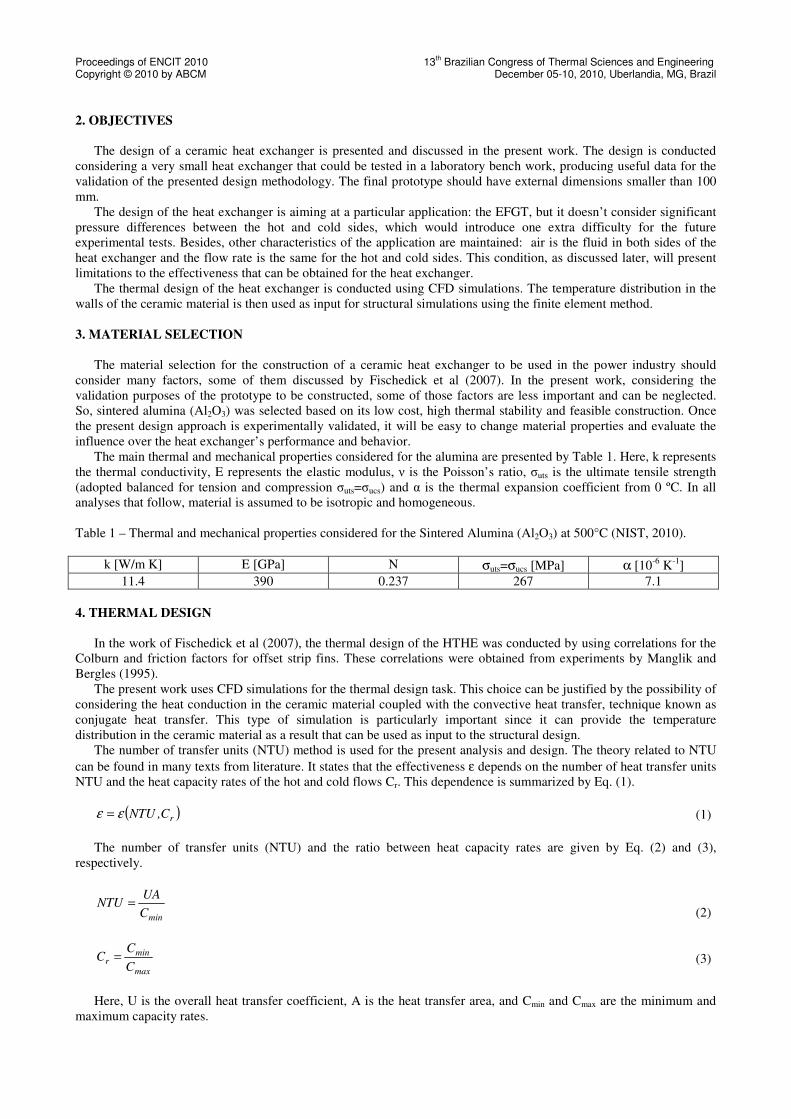
The literature presents many relations and graphs that permit to obtain the dependence summarized by Eq. (1) for
many different configurations of heat exchangers. The present analysis is focused on cross-flow heat exchangers. Figure
2 graphically presents the effectiveness for this particular configuration. It is important to observe that the condition
where both heat capacity rates are equal (and Cr = 1) is the condition that demands more heat transfer area in order to
achieve a given effectiveness.
Figure 2. Effectiveness of a cross-flow heat exchanger.
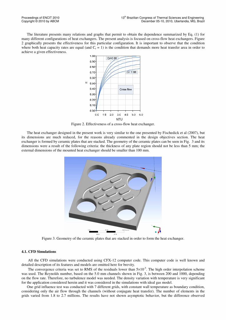
The heat exchanger designed in the present work is very similar to the one presented by Fischedick et al (2007), but
its dimensions are much reduced, for the reasons already commented in the design objectives section. The heat
exchanger is formed by ceramic plates that are stacked. The geometry of the ceramic plates can be seen in Fig. 3 and its
dimensions were a result of the following criteria: the thickness of any plate region should not be less than 5 mm; the
external dimensions of the mounted heat exchanger should be smaller than 100 mm.
Figure 3. Geometry of the ceramic plates that are stacked in order to form the heat exchanger.
4.1. CFD Simulations
All the CFD simulations were conducted using CFX-12 computer code. This computer code is well known and
detailed description of its features and models are omitted here for brevity.
The convergence criteria was set to RMS of the residuals lower than 5×10⁻⁵
. The high order interpolation scheme
was used. The Reynolds number, based on the 5.0 mm channels shown in Fig. 3, is between 200 and 1000, depending
on the flow rate. Therefore, no turbulence model was needed. The density variation with temperature is very significant
for the application considered herein and it was considered in the simulations with ideal gas model.
One grid influence test was conducted with 7 different grids, with constant wall temperature as boundary condition,
considering only the air flow through the channels (without conjugate heat transfer). The number of elements in the
grids varied from 1.8 to 2.7 millions. The results have not shown asymptotic behavior, but the difference observed
Proceedings of ENCIT 2010 13th Brazilian Congress of Thermal Sciences and Engineering
Copyright © 2010 by ABCM December 05-10, 2010, Uberlandia, MG, Brazil
between the highest and lowest heat transfer rate was smaller than 2.8% (182.4 W and 187.5 W respectively). It
produced differences over the effectiveness of 3.7%, considered satisfactory.
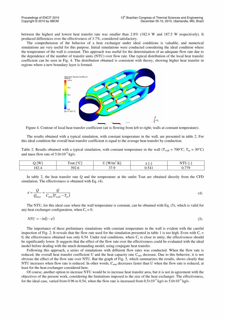
The comprehension of the behavior of a heat exchanger under ideal conditions is valuable, and numerical
simulations are very useful for this purpose. Initial simulations were conducted considering the ideal condition where
the temperature of the wall is constant. This approach was useful for the determination of an adequate flow rate due to
the dependence of the number of transfer units (NTU) over flow rate. One typical distribution of the local heat transfer
coefficient can be seen in Fig. 4. The distribution obtained is consistent with theory, showing higher heat transfer in
regions where a new boundary layer is formed.
Figure 4. Contour of local heat transfer coefficient (air is flowing from left to right; walls at constant temperature).
The results obtained with a typical simulation, with constant temperature in the wall, are presented in table 2. For
this ideal condition the overall heat transfer coefficient is equal to the average heat transfer by conduction.
Table 2: Results obtained with a typical simulation, with constant temperature in the wall (Twall = 700°C; Tin = 30°C)
and mass flow rate of 5.0×10⁻⁴
kg/s.
Q [W] Tout [°C] U [W/m2 K] ε [-] NTU [-]
182.4 392.6 37.9 0.541 0.779
In table 2, the heat transfer rate Q and the temperature at the outlet Tout are obtained directly from the CFD
simulation. The effectiveness is obtained with Eq. (4).
( )inwallminmax TTC
Q
Q
Q
−==ε
(4)
The NTU, for this ideal case where the wall temperature is constant, can be obtained with Eq. (5), which is valid for
any heat exchanger configuration, when Cr = 0.
( )ε−−= 1lnNTU (5)
The importance of these preliminary simulations with constant temperature in the wall is evident with the careful
inspection of Fig. 2. It reveals that the flow rate used for the simulation presented in table 1 is too high. Even with Cr =
0, the effectiveness obtained was only 0.54. Under real conditions, where Cr is close to unity, the effectiveness should
be significantly lower. It suggests that the effect of the flow rate over the effectiveness could be evaluated with the ideal
model before dealing with the much demanding model, using conjugate heat transfer.
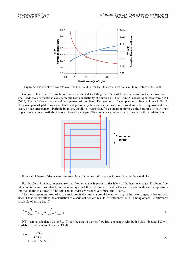
Following this approach, a series of simulations with different flow rates was conducted. When the flow rate is
reduced, the overall heat transfer coefficient U and the heat capacity rate Cmin decrease. Due to this behavior, it is not
obvious the effect of the flow rate over NTU. But the graph of Fig. 5, which summarizes the results, shows clearly that
NTU increases when flow rate is reduced. In other words, Cmin decreases faster than U when the flow rate is reduced, at
least for the heat exchanger considered here.
Of course, another option to increase NTU would be to increase heat transfer area, but it is not in agreement with the
objectives of the present work, considering the limitations imposed to the size of the heat exchanger. The effectiveness,
for the ideal case, varied from 0.96 to 0.54, when the flow rate is increased from 0.5×10⁻⁴
kg/s to 5.0×10⁻⁴
kg/s.
Proceedings of ENCIT 2010 13th Brazilian Congress of Thermal Sciences and Engineering
Copyright © 2010 by ABCM December 05-10, 2010, Uberlandia, MG, Brazil
0.00
10.00
20.00
30.00
40.00
50.00
60.00
0.0
0.5
1.0
1.5
2.0
2.5
3.0
3.5
0.0 1.0 2.0 3.0 4.0 5.0
U (W
/m2
K)
Overa
ll h
eat
tran
sfer
coef
fici
en
t
NTU
Nu
mb
er
of Tr
an
sfer
Un
its
Mass flow rate (x 10-4 kg/ s)
Figure 5. The effect of flow rate over the NTU and U, for the ideal case with constant temperature in the wall.
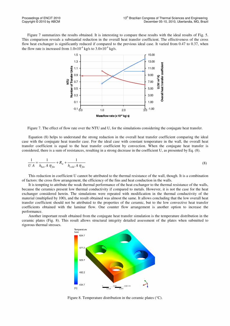
Conjugate heat transfer simulations were conducted including the effect of heat conduction in the ceramic walls.
The steady state simulations considered the heat conductivity of alumina k = 11.4 W/m K, according to data from NIST
(2010). Figure 6 shows the stacked arrangement of the plates. The geometry of each plate was already shown in Fig. 3.
Only one pair of plates was simulated and periodicity boundary conditions were used in order to approximate the
stacked plate arrangement. Periodic boundary condition means that, for calculation purposes, the bottom side of the pair
of plates is in contact with the top side of an adjacent pair. This boundary condition is used only for the solid domain.
Figure 6. Scheme of the stacked ceramic plates. Only one pair of plates is considered in the simulation.
For the fluid domains, temperatures and flow rates are imposed in the inlets of the heat exchanger. Different flow
rate conditions were simulated, but maintaining equal flow rates on cold and hot sides for each condition. Temperatures
imposed to the inlet flows of the cold and hot sides are respectively 30°C and 1000°C.
The most important result of each simulation is the temperature of the air leaving the heat exchanger, in hot and cold
sides. These results allow the calculation of a series of derived results: effectiveness, NTU, among others. Effectiveness
is calculated using Eq. (6).
( )cold,inhot,inminmax TTC
Q
Q
Q
−==ε
(6)
NTU can be calculated using Eq. (7), for the case of a cross flow heat exchanger with both fluids mixed and Cr = 1,
available from Kays and London (1984).
( )1
1
2−
−−
=
NTUexp
NTU
NTUε
(7)
Proceedings of ENCIT 2010 13th Brazilian Congress of Thermal Sciences and Engineering
Copyright © 2010 by ABCM December 05-10, 2010, Uberlandia, MG, Brazil
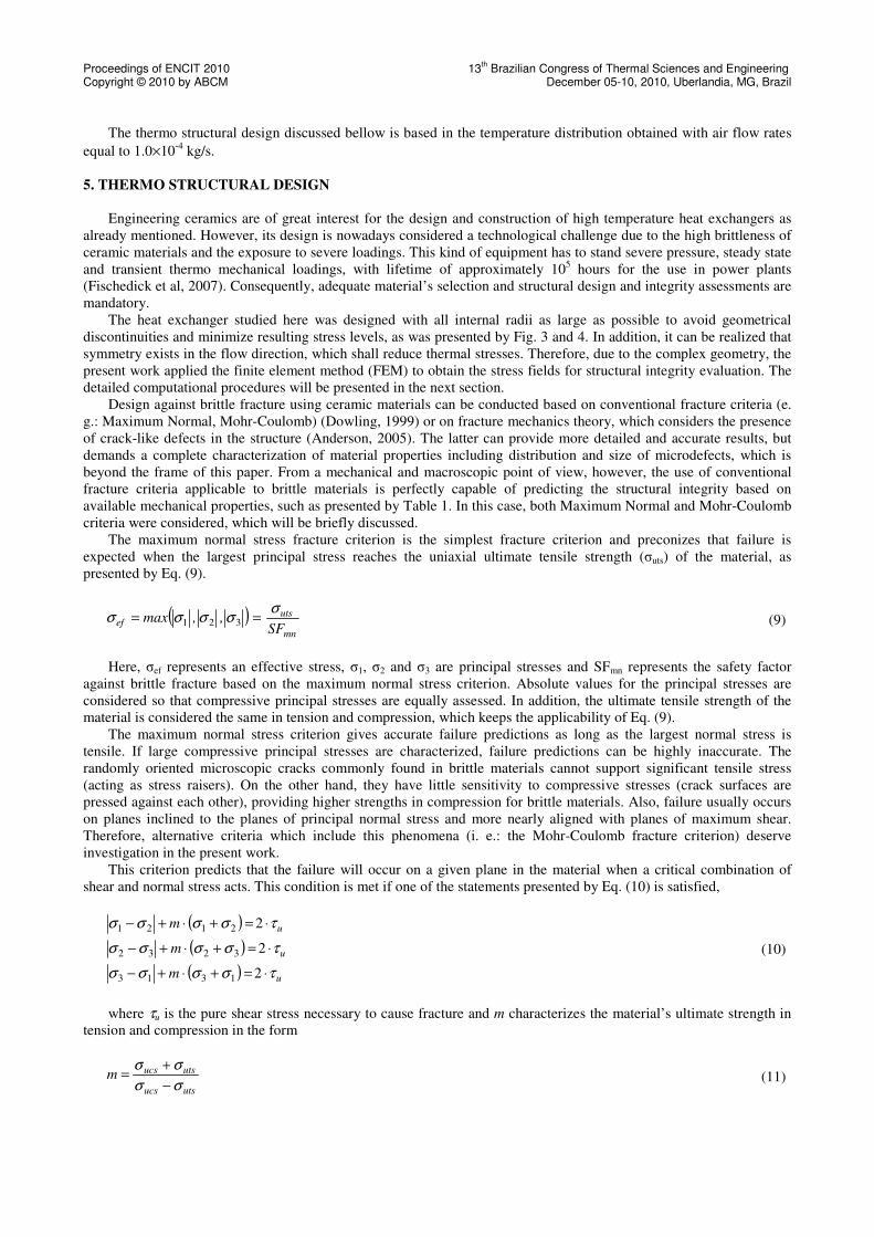
Figure 7 summarizes the results obtained. It is interesting to compare these results with the ideal results of Fig. 5.
This comparison reveals a substantial reduction in the overall heat transfer coefficient. The effectiveness of the cross
flow heat exchanger is significantly reduced if compared to the previous ideal case. It varied from 0.47 to 0.37, when
the flow rate is increased from 1.0×10⁻⁴
kg/s to 3.0×10⁻⁴
kg/s.
-1.00
1.00
3.00
5.00
7.00
9.00
11.00
13.00
15.00
-0.1
0.1
0.3
0.5
0.7
0.9
1.1
1.3
1.5
0.0 1.0 2.0 3.0
U (W
/m2
K)
Overa
ll h
eat
tran
sfer
coef
fici
en
t
NTU
Nu
mb
er
of Tr
an
sfer
Un
its
Mass flow rate (x 10-4 kg/ s)
Figure 7. The effect of flow rate over the NTU and U, for the simulations considering the conjugate heat transfer.
Equation (8) helps to understand the strong reduction in the overall heat transfer coefficient comparing the ideal
case with the conjugate heat transfer case. For the ideal case with constant temperature in the wall, the overall heat
transfer coefficient is equal to the heat transfer coefficient by convection. When the conjugate heat transfer is
considered, there is a sum of resistances, resulting in a strong decrease in the coefficient U, as presented by Eq. (8).
fincold
w
finhot AhR
AhAU ηη
111++=
(8)
This reduction in coefficient U cannot be attributed to the thermal resistance of the wall, though. It is a combination
of factors: the cross flow arrangement, the efficiency of the fins and heat conduction in the walls.
It is tempting to attribute the weak thermal performance of the heat exchanger to the thermal resistance of the walls,
because the ceramics present low thermal conductivity if compared to metals. However, it is not the case for the heat
exchanger considered herein. The simulations were repeated with modification in the thermal conductivity of the
material (multiplied by 100), and the result obtained was almost the same. It allows concluding that the low overall heat
transfer coefficient should not be attributed to the properties of the ceramic, but to the low convective heat transfer
coefficients obtained with the laminar flow. One counter flow arrangement is another option to increase the
performance.
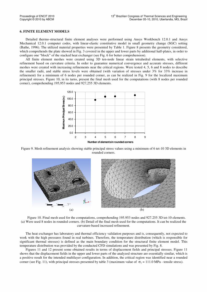
Another important result obtained from the conjugate heat transfer simulation is the temperature distribution in the
ceramic plates (Fig. 8). This result allows structural integrity detailed assessment of the plates when submitted to
rigorous thermal stresses.
Figure 8. Temperature distribution in the ceramic plates (°C).
Proceedings of ENCIT 2010 13th Brazilian Congress of Thermal Sciences and Engineering
Copyright © 2010 by ABCM December 05-10, 2010, Uberlandia, MG, Brazil
The thermo structural design discussed bellow is based in the temperature distribution obtained with air flow rates
equal to 1.0×10⁻⁴
kg/s.
5. THERMO STRUCTURAL DESIGN
Engineering ceramics are of great interest for the design and construction of high temperature heat exchangers as
already mentioned. However, its design is nowadays considered a technological challenge due to the high brittleness of
ceramic materials and the exposure to severe loadings. This kind of equipment has to stand severe pressure, steady state
and transient thermo mechanical loadings, with lifetime of approximately 105 hours for the use in power plants
(Fischedick et al, 2007). Consequently, adequate material’s selection and structural design and integrity assessments are
mandatory.
The heat exchanger studied here was designed with all internal radii as large as possible to avoid geometrical
discontinuities and minimize resulting stress levels, as was presented by Fig. 3 and 4. In addition, it can be realized that
symmetry exists in the flow direction, which shall reduce thermal stresses. Therefore, due to the complex geometry, the
present work applied the finite element method (FEM) to obtain the stress fields for structural integrity evaluation. The
detailed computational procedures will be presented in the next section.
Design against brittle fracture using ceramic materials can be conducted based on conventional fracture criteria (e.
g.: Maximum Normal, Mohr-Coulomb) (Dowling, 1999) or on fracture mechanics theory, which considers the presence
of crack-like defects in the structure (Anderson, 2005). The latter can provide more detailed and accurate results, but
demands a complete characterization of material properties including distribution and size of microdefects, which is
beyond the frame of this paper. From a mechanical and macroscopic point of view, however, the use of conventional
fracture criteria applicable to brittle materials is perfectly capable of predicting the structural integrity based on
available mechanical properties, such as presented by Table 1. In this case, both Maximum Normal and Mohr-Coulomb
criteria were considered, which will be briefly discussed.
The maximum normal stress fracture criterion is the simplest fracture criterion and preconizes that failure is
expected when the largest principal stress reaches the uniaxial ultimate tensile strength (σuts) of the material, as
presented by Eq. (9).
( )mn
utsef
SF,,max
σσσσσ == 321 (9)
Here, σef represents an effective stress, σ1, σ2 and σ3 are principal stresses and SFmn represents the safety factor
against brittle fracture based on the maximum normal stress criterion. Absolute values for the principal stresses are
considered so that compressive principal stresses are equally assessed. In addition, the ultimate tensile strength of the
material is considered the same in tension and compression, which keeps the applicability of Eq. (9).
The maximum normal stress criterion gives accurate failure predictions as long as the largest normal stress is
tensile. If large compressive principal stresses are characterized, failure predictions can be highly inaccurate. The
randomly oriented microscopic cracks commonly found in brittle materials cannot support significant tensile stress
(acting as stress raisers). On the other hand, they have little sensitivity to compressive stresses (crack surfaces are
pressed against each other), providing higher strengths in compression for brittle materials. Also, failure usually occurs
on planes inclined to the planes of principal normal stress and more nearly aligned with planes of maximum shear.
Therefore, alternative criteria which include this phenomena (i. e.: the Mohr-Coulomb fracture criterion) deserve
investigation in the present work.
This criterion predicts that the failure will occur on a given plane in the material when a critical combination of
shear and normal stress acts. This condition is met if one of the statements presented by Eq. (10) is satisfied,
( ) um τσσσσ ⋅=+⋅+− 22121 ( ) um τσσσσ ⋅=+⋅+− 23232 ( ) um τσσσσ ⋅=+⋅+− 21313
(10)
where τu is the pure shear stress necessary to cause fracture and m characterizes the material’s ultimate strength in
tension and compression in the form
utsucs
utsucsmσσ
σσ
−
+=
(11)
Proceedings of ENCIT 2010 13th Brazilian Congress of Thermal Sciences and Engineering
Copyright © 2010 by ABCM December 05-10, 2010, Uberlandia, MG, Brazil
6. FINITE ELEMENT MODELS
Detailed thermo-structural finite element analyses were performed using Ansys Workbench 12.0.1 and Ansys
Mechanical 12.0.1 computer codes, with linear-elastic constitutive model in small geometry change (SGC) setting
(Bathe, 1996). The utilized material properties were presented by Table 1. Figure 8 presents the geometry considered,
which comprehends the plate showed in Fig. 3 covered in the upper and lower parts by additional half-plates, in order to
configure one “block” of the stacked heat exchanger (see Fig. 6 for better comprehension).
All finite element meshes were created using 3D ten-node linear strain tetrahedral elements, with selective
refinement based on curvature criteria. In order to guarantee numerical convergence and accurate stresses, different
meshes were created with increasing refinements near the critical regions. Were tested 4, 5, 6 and 8 nodes to describe
the smaller radii, and stable stress levels were obtained (with variation of stresses under 3% for 33% increase in
refinement) for a minimum of 6 nodes per rounded corner, as can be realized in Fig. 9 for the localized maximum
principal stresses. Figure 10, in its turns, present the final mesh used for the computations (with 8 nodes per rounded
corner), comprehending 195,953 nodes and 927,255 3D elements.
0.0
20.0
40.0
60.0
80.0
100.0
120.0
2 3 4 5 6 7 8 9
Maxi
mu
n P
rin
cip
al S
tress
(σ
1)
Number of elements in rounded corners
Figure 9. Mesh refinement analysis showing stable principal stress values using a minimum of 6 tet-10 3D elements in
rounded corners.
(a) (b)
Figure 10. Final mesh used for the computations, comprehending 195.953 nodes and 927.255 3D tet-10 elements.
(a) Were used 8 nodes in rounded corners. (b) Detail of the final mesh used for the computations. It can be realized the
curvature-based increased refinement.
The heat exchanger has laboratory and thermal efficiency validation purposes and is, consequently, not expected to
work with the high pressures found in real turbines. Therefore, the temperature distribution (which is responsible for
significant thermal stresses) is defined as the main boundary condition for the structural finite element model. This
temperature distribution was provided by the conducted CFD simulations and was presented by Fig. 8.
Figures 11 and 12 present some obtained results in terms of displacement fields and principal stresses. Figure 11
shows that the displacement fields in the upper and lower parts of the analyzed structure are essentially similar, which is
a positive result for the intended multilayer configuration. In addition, the critical region was identified near a rounded
corner (see Fig. 11), with principal stresses presented by table 3 (maximum value of σ1 = 111.0 MPa - tensile stress).
Proceedings of ENCIT 2010 13th Brazilian Congress of Thermal Sciences and Engineering
Copyright © 2010 by ABCM December 05-10, 2010, Uberlandia, MG, Brazil
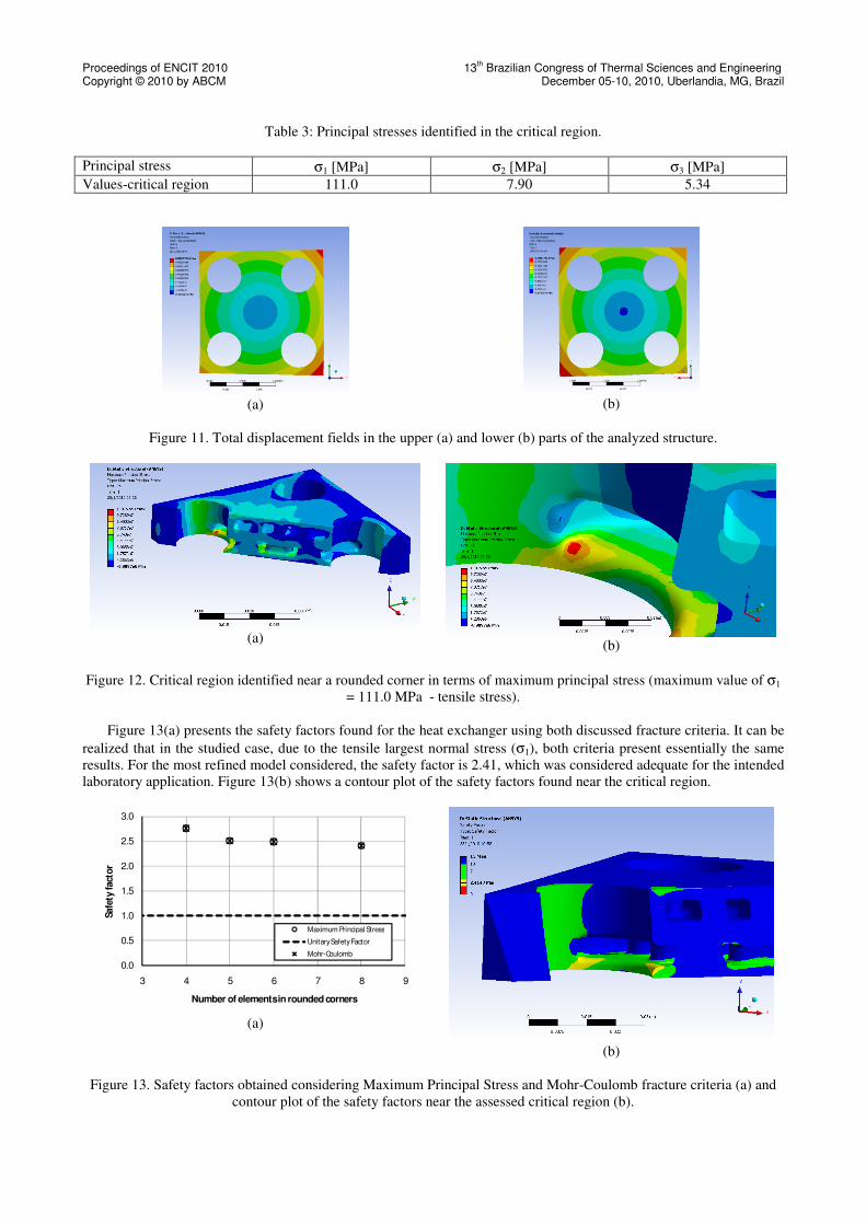
Table 3: Principal stresses identified in the critical region.
Principal stress σ1 [MPa] σ2 [MPa] σ3 [MPa]
Values-critical region 111.0 7.90 5.34
(a)
(b)
Figure 11. Total displacement fields in the upper (a) and lower (b) parts of the analyzed structure.
(a)
(b)
Figure 12. Critical region identified near a rounded corner in terms of maximum principal stress (maximum value of σ1
= 111.0 MPa - tensile stress).
Figure 13(a) presents the safety factors found for the heat exchanger using both discussed fracture criteria. It can be
realized that in the studied case, due to the tensile largest normal stress (σ1), both criteria present essentially the same
results. For the most refined model considered, the safety factor is 2.41, which was considered adequate for the intended
laboratory application. Figure 13(b) shows a contour plot of the safety factors found near the critical region.
0.0
0.5
1.0
1.5
2.0
2.5
3.0
3 4 5 6 7 8 9
Safe
ty fact
or
Number of elements in rounded corners
Maximum Principal Stress
Unitary Safety Factor
Mohr-Coulomb
(a)
(b)
Figure 13. Safety factors obtained considering Maximum Principal Stress and Mohr-Coulomb fracture criteria (a) and
contour plot of the safety factors near the assessed critical region (b).
Proceedings of ENCIT 2010 13th Brazilian Congress of Thermal Sciences and Engineering
Copyright © 2010 by ABCM December 05-10, 2010, Uberlandia, MG, Brazil
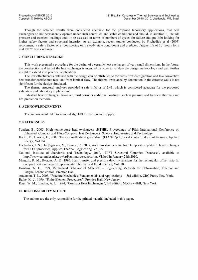
Though the obtained results were considered adequate for the proposed laboratory applications, real heat
exchangers do not permanently operate under such controlled and stable conditions and should, in addition: i) include
pressure and transient loadings and; ii) be assessed in terms of numbers of cycles for failure (fatigue life) looking for
higher safety factors and structural integrity. As an example, recent studies conducted by Fischedick et al (2007)
recommend a safety factor of 8 (considering only steady state conditions) and predicted fatigue life of 105 hours for a
real EFCC heat exchanger.
7. CONCLUDING REMARKS
This work presented a procedure for the design of a ceramic heat exchanger of very small dimensions. In the future,
the construction and test of the heat exchanger is intended, in order to validate the design methodology and gain further
insight to extend it to practical applications.
The low effectiveness obtained with the design can be attributed to the cross flow configuration and low convective
heat transfer coefficients resultant from laminar flow. The thermal resistance by conduction in the ceramic walls is not
significant for the design simulated.
The thermo structural analyses provided a safety factor of 2.41, which is considered adequate for the proposed
validation and laboratory applications.
Industrial heat exchangers, however, must consider additional loadings (such as pressure and transient thermal) and
life-prediction methods.
8. ACKNOWLEDGEMENTS
The authors would like to acknowledge FEI for the research support.
9. REFERENCES
Sunden, B., 2005, High temperature heat exchangers (HTHE), Proceedings of Fifth International Conference on
Enhanced, Compact and Ultra-Compact Heat Exchangers: Science, Engineering and Technology.
Kautz, M., Hansen, U., 2007, The externally-fired gas-turbine (EFGT-Cycle) for decentralized use of biomass, Applied
Energy, Vol. 84.
Fischedick, J. S., Dreiβigacker, V., Tamme, R., 2007, An innovative ceramic high temperature plate-fin heat exchanger
for EFCC processes, Applied Thermal Engineering, Vol. 27.
National Institute of Standards and Technology, 2010, “NIST Structural Ceramics Database”, available at
http://www.ceramics.nist.gov/srd/summary/scdaos.htm. Visited in January 28th 2010.
Manglik, R. M., Bergles, A. E., 1995, Heat transfer and pressure drop correlations for the rectangular offset strip fin
compact heat exchanger, Experimental Thermal and Fluid Science, Vol. 10.
Dowling, N. E., 1999, Mechanical Behavior of Materials – Engineering Methods for Deformation, Fracture and
Fatigue, second edition, Prentice Hall.
Anderson, T. L., 2005, “Fracture Mechanics: Fundamentals and Applications” – 3rd edition, CRC Press, New York.
Bathe, K., J., 1996, “Finite Element Procedures”, Prentice Hall, New Jersey.
Kays, W. M., London, A. L., 1984, “Compact Heat Exchangers”, 3rd edition, McGraw-Hill, New York.
10. RESPONSIBILITY NOTICE
The authors are the only responsible for the printed material included in this paper.
Copyright © 2022 FDOKUMEN