
Modeling a Direct Contact Heat Exchanger for a ... - POLITesi

Open Journal of Modelling and Simulation (OJMSi), 2013, 17, 41-21
doi:10.4236/jsea.2013.28004 Published Online October 2013 (http://www.scirp.org/journal/jsea)
1
CFD Simulation and Experimental Comparison of a Copper Wire Woven
Finned Heat Exchanger to an Aluminium Flat Plate Finned Heat Exchanger
Dr John White
School of Mechanical Engineering, University of Birmingham UK.
Email:[email protected]
Received September 5th
, 2013; Revised October 10th
, 2013; Accepted October 17th
, 2013
Copyright © 2013 John White. This is an open access article distributed under the Creative Commons Attribution
License, which permits unrestricted use, distribution, and reproduction in any medium, provided the original work is
properly cited.
ABSTRACT
The performance of the adsorption cooling system is assessed in terms of the heat transfer coefficients of adsorbent bed
heat exchanger. These parameters in-turn determine the specific cooling capacity (SCC) and the coefficient of the per-
formance (COP) of the adsorption cooling system. It was observed that the overall heat transfer coefficients of the heat
exchanger have a direct linear relation with the hot water inlet temperatures.
Keywords: Adsorption, CFD, Modelling, Silica gel, velocity
1. Introduction
An Adsorption cooling system is promising technology
since it incorporates environmentally benign refrigerants
and the industrial waste heat or low grade solar energy
instead of mechanical power. However the low value of
performance parameters (COP and SCP), high initial cost
and the operating pressure, which is quite low these are the
main issues that hold back the widespread application of
the adsorption cooling systems. One of the efficient ways
to improve the low SCP and COP of this system is the
appropriate selection of the design and operating
parameters of an adsorbent bed. The heat exchanger used
as part of the adsorption system is one of the influential
parameter in the heat transfer performance of an adsorption
cooling system.
Studies relevant to this research span the last few dec-
ades. Chang et.al (2005) [1] experimental study that in-
vestigated the heat transfer efficiency of flat tube heat
exchanger concluded that the flat tube heat exchanger
thinner improves the mass transfer performance.
InRiffel et.al (2007) [2] investigated the heat transfer
effects of shell and tube heat exchanger for a solar ad-
sorption cooling with an aim to improve the optimum
performance of the system. Twenty years prior to this,
Beecher and Fagan (1987) [3] designed and tested a heat
exchanger for a surface temperature condition and in Ito
et al.( 1977,) [4] applied the constant heat flux condition.
They measured the heat transfer coefficient (h) since the
fin efficiency (η) could be assumed as 100%.
2. The Motivation for Heat Transfer Enhancement of
the Adsorbent Bed Heat Exchanger
The study of improving heat exchanger heat transfer ef-
ficiency has gained serious momentum over recent years
due to increased demands by adsorption cooling industry
for heat exchange equipment that is less expensive to
build, and that operates better than standard heat ex-
change devices savings in heat exchanger materials.
There is demand too, for adsorption cooling design with
heat exchangers that are more compact and lightweight.
One way to increase the heat transfer of the heat ex-
changer and accomplish a lightweight design could be by
changing the design configuration to increase the surface
area, without increasing the size of the heat exchangers.
There are three basic ways of accomplishing this [7,8]:
a. Increase the operational heat transfer surface
area by using wire type copper finned compact
heat exchanger. This change of design configu-
ration and materials could considerably change

CFD Simulation and Experimental Comparison of a Copper Wire Woven Finned Heat Exchanger to an Aluminium Flat
Plate Finned Heat Exchanger.
2
the heat transfer coefficient see table .1 for
thermal conductivity of copper [7].
Increase heat transfer without significantly changing area.
This can be accomplished by using a special channel
shape, such as a wavy or corrugated channel, which
would provide mixing due to secondary flows and
boundary-layer separation within the channel. Vortex
b. generators also increase heat transfer coefficient
without a significant area increase by creating
longitudinally spiralling vortices exchange fluid
between the wall and core regions of the flow,
resulting in increased heat transfer [1-7].
c. Increase both heat transfer coefficient and sur-
face area of a heat exchanger by. Interrupted
fins (i.e., offset strip and louvered fins) act in
this way. These surfaces increase the effective
surface area, and enhance heat transfer through
repeated growth and destruction of the bounda-
ry layers [1, 2-7].
The use of any one of these heat transfer method men-
tioned could substantially increase the heat transfer fin
efficiency and the motivation behind the design of new a
adsorbent bed compact copper wire woven heat ex-
changer.
2.1 The heat exchange fin performance
Heat exchanger fin performance can be explained by
three different methods. The first is fin effectiveness this
is the ratio of the heat exchanger fin heat transfer to the
heat transfer of the tube without fin [8]. The second is
the fin efficiency and is defined as the ratio of the heat
transferred through the actual fin to that transferred
through a perfect fin.
A perfect fin is thought to be one made of a perfect or
infinite conductor material. A perfect conductor has an
infinite thermal conductivity, so in theory, the entire fin
is at the base material heat transfer temperature [5, 8].
The equation for this is
(1)
Where is the heat exchanger fin cross-sectional area at
the root. Fin performance can also be considered by heat
exchanger fin efficiency this is the ratio of the heat ex-
changer fin heat transfer to the heat transfer of the fin if
the entire fin were at the root heat [5-8].
The fin efficiency as
(2)
This equation is equivalent to the surface area of the
heat exchanger fin. The third method of heat exchanger
fin performance can be explained as its entire surface
efficiency.
(3)
where is the overall area and is the sum of the
heat transfer of the overall heat exchanger fins [7,9].
2.2 Common flat plat fin heat exchanger used in a
adsorbent bed
Figure.1 common type of flat fin heat exchanger used in
adsorption cooling system

CFD Simulation and Experimental Comparison of a Copper Wire Woven Finned Heat Exchanger to an Aluminium Flat
Plate Finned Heat Exchanger.
3
2.3 Different type of heat exchanger fin configuration
that could be used in adsorbent beds
Figure .2 some of the many varieties of finned tubes [7]
Lienhard IV, et al, 2005 A Heat Transfer Textbook Third
Edition.
figure .2 has eight different types of heat exchanger that
could be used in an adsorbent bed to improve heat trans-
fer and reduced the size of the heat exchangers (1) and (2)
are typical circular fins. (3) and (4) serrated circular fins
and dimpled spirally wound circular fins, both are design
to improve convection (5) wire wound copper coil fin
design to improve convection and increase surface area.
(6) bristle fins, (7) spirally wound and (8) machined from
base metal are also design to improve convection and
increasing surface area.
2.4 Comparison of aluminum flat fins heat exchang-
ers to copper wire woven fins heat exchanger
This section discusses a CFD simulation comparison
study on a wire woven copper coil fin and a flat plat fin
comparing the heat transfer performance. The CFD
boundary conditions and properties taken from test rig
experimental data research papers and Lienhard IV et al
2005 [1-7].
An important design aspect of adsorbent bed heat ex-
changer technology is deciding what materials are ap-
propriate for the design of adsorbent bed heat exchanger.
The common choice is aluminium alloy 1050A or 6063A
flat fins. These types of aluminium have one of the high-
est thermal conductivity values, see table 6.1. Thus is a
good material for removing heat from a system to an
external environment. In the case of an adsorbent bed,
the heat exchanger is packed with porous adsorbent ma-
terial and so the extended fins are used to increase and
decrease the heat transfer rate from the fluid inside the
heat exchanger to the surface of the porous adsorbent.
The porous adsorbent affects thermal conductivity of flat
fins heat exchange. To overcome this problem, the heat
exchanger designers design the heat exchanger fins larg-
er to improve the heat transfer. This is one of the causes
for the bulky size adsorption cooling system. One way
designers could solve this problem is by changing the
material and design configuration of the heat exchanger
of the adsorbent bed.
In this chapter a copper wire woven fins heat exchanger
is used for the adsorbent bed. Copper has around twice
the thermal conductivity of aluminium see table for the
properties of copper heat exchangers materials [1, 4-7].
Table 1 thermal conductivity
Copper wire fins heat exchanger is a small diameter wire
fins. It has better rates of heat transfer than aluminium flat
plate fins heat exchanger. The performance advantages of
copper over aluminium as a heat transfer material include
greater heat exchange, better long-term durability and
resistance to corrosion.
Wire wound fins heat exchangers are made from one
continuous piece of wire wound helically and root
soldering onto a copper tube. The root soldering
eliminates air gaps between the fins and the copper tube
[7-11].
3. Discussion
3.1 Approaches for Heat Transfer CFD Modelling
In this study, it was assumed that the temperature and
pressure may have some variation throughout the whole
adsorbent bed and the system may have some heat losses
to the environment. The following assumptions are made
before establishing the CFD model:

CFD Simulation and Experimental Comparison of a Copper Wire Woven Finned Heat Exchanger to an Aluminium Flat
Plate Finned Heat Exchanger.
4
The temperature and pressure may have some
variation in the silica gel adsorption bed.
The water is adsorbed uniformly by the silica
gel.
The vapour inside the adsorption bed is saturated
vapour.
The system has no heat losses to the environment
In the (CFD) Computational fluid dynamics simulation
the heat source temperature variation was taken from
30°C to 85ºC. A CFD simulation computer program was
constructed to analyse the influence of hot and cooling
water temperature on the adsorption/desorption
performance of silica gel.
3.2 How the CFD Simulation was completed
In this phase of the model design the major entities are
defined. The outer wall to the model is established, as
well as, the internal structure, solid particles and fluid
regions. Several entities, such as heat exchanger and sil-
ica gel are added to the geometry. Before exporting the
fundamental geometry it is important all curves are de-
fined as so-called B-Spline curves. These are mathemat-
ical descriptions of the specific curves. This conversion
is necessary to be able to have the surface mesh form to
the exact contours of the created geometry.
3.3 Boundary Conditions
The boundary conditions determine the flow and thermal
variables on the boundaries of the physical model. There
are a number of classifications of boundary conditions:
Flow inlet and exit boundaries: pressure inlet,
velocity inlet, pressure outlet.
Heat exchanger fins wall, repeating, and limit
boundaries: fins wall, symmetry.
Internal fluid, solid
Internal face boundaries: porous, fins wall,
interior.
In the model, velocity was assigned to the flow inlet of the
adsorbent bed; this boundary condition defines a flow
velocity at the inlet of the bed. The flow exit boundary is
defined as a pressure outlet and the outlet pressure is
defined as atmospheric pressure. The bed and packing
interior are defined as boundaries. The fins wall
boundaries separate the fluid zone and vapour in between
the silica gel granules from the fins wall zones [9, 18].
With the determination of the boundary conditions the
physical model can be defined by a numerical solution.
It was then necessary to determine how the solution will
be established. This was be done by setting the iteration
parameters. With all boundary conditions defined, a
number of additional parameters and solving schemes
where selected. An initial condition was assigned to the
model and was used to help speed the convergence of the
computation.
The computation is an iterative process that solves the
governing equations for flow and energy in each
simulated cell. Depending on the complexity of the model
and the computer resources available, CFD simulation can
take anywhere from minutes to days [6]. The results of the
simulation can be viewed and manipulated with
post-processing software once the simulation has
converted to a solution.
3.4 Mesh
One of the most important parts of CFD modelling is the
construction of the mesh topology. It has to be chosen
with enough detail to describe the processes accurately
and with a degree of smoothness that enables solution
within a satisfactory period of time. When an optimal
density has been found, refining this will increase the
model size without displaying more flow detail [9, 18].
When it is coarsened the mesh will obscure, possibly
essential, parts of the flow detail. The mesh determines a
large part of creating an acceptable simulation.
3.5 Mesh Variations
This was created to focus on silica gel to silica gel contact
points and silica gel-wall contact points. The study of the
silica gel geometry in Flow simulation was also made to
compare the results from CFD codes. When actual contact
points are created, both surfaces that are contacting have
one common node [9, 18]. In surface mesh creation this
can be defined and does not pose any problems.
The 3D mesh can be created relatively easily by merging a
number of nodes on the contacting surfaces. When,
however, a solution is iterated convergence problems
occur with the fluid elements around the contact point. In
a laminar case, the solution parameters can be adjusted to
get a converging solution, in a turbulent case this becomes
impossible [9].

CFD Simulation and Experimental Comparison of a Copper Wire Woven Finned Heat Exchanger to an Aluminium Flat
Plate Finned Heat Exchanger.
5
Figure 3 contact point at reduced by 2%
After it was found that actual contact points, as they were
designed, with the Silica gel geometry, a turbulent
solution of the model used for the CFD validation could
not be established, a number of models were created to
make a comparison between several sizes of gaps between
the silica gel in the packing. Eventually, the appropriate
gaps, facilitating both a turbulent flow solution, as well as,
a sufficient stagnant fluid film around the silica gel for
heat transfer to be simulated was created.
4. CFD Porous Medium Methodology
When using CFD it is possible to apply the porous me-
dium simulation method to predict the effect heat trans-
fer has on porous adsorbents. For the porous medium
simulation method the CFD model has a mass of cells
representing the fluid inlet [7]. This is followed by the
porous adsorbent units which are used to model fluid
flow through porous adsorbent [12, 13]. Full flow field
predictions are possible with the porous adsorbent simu-
lation method because the resistance of the porous ad-
sorbent to flow is described by the equations:
(4)
where the coefficient values and are assigned
temperature dependent values that describe the perfor-
mance of a porous adsorbent. High values of and
preclude flow at right angles to the porous adsorbent.
Upstream and downstream of the water vapour flow field
is solved using the usual Reynolds averaged Navier–
Stokes methodology.
4.1 Fluid Flow Fundamentals
For iteration CFD solvers use generalised fluid flow and
energy balances based on the Navier Stokes equations.
The balances are generalised so the user can influence
which elements are added in the balance and which are
not. [9, 18] The number of balances to be solved is also
user defined; it can be advantageous to not solve all bal-
ances initially. The generalised balances that are used by
the Flow simulation commercial CFD package are the
Navier Stokes equations for conservation of mass and
momentum, when it is set to calculate laminar flow
without heat transfer. Additional equations are solved for
heat transfer [8].
4.2 Solving the CFD Problem
When a mesh is completed with its density and all other
complications resolved, the actual computational part of
CFD can be started. At this point the completed geome-
try can be imported in the solver and the CFD simulation
is started. Again, a series of steps are to be performed;
first, the boundary conditions on the system need to be
set, next the process iteration parameters need to be set.
With the boundary conditions defined the simulation is
performed. The final step in obtaining the desired data is
the post-processing of the data in which the desired data
sets are taken from the simulation data [7, 10].
4.3 Post-Processing the Simulation Data
When the simulation has converged the last data set is
stored as a final solution. This data set has a record of the
status of all elements in the model, temperature, densities,
pressures, flow aspects, etc. To be able to interpret the
data it needs to be ordered and reduced to comprehensi-
ble sizes [5,7-9]. This displaying of the data is called
post-processing and makes it possible to compare the
different simulations with each other and with external
data. There was as many ways of displaying the data as
there were data points so it was important to select the
data representation that was required for the desired data
comparison.
Some of the standard options available are contour plots
and velocity vector plots. Contour plots will give a plot
in the defined data point collection; this can be a plane or
a volume, of contours of another variable. For example, a
plane can be defined as a constant x coordinate plane
(y-z plane), a contour plot can be made showing temper-
ature contours in this plane.
In the same plane a velocity contour plot can be made
showing absolute velocities of the fluid in the defined
plane [7, 9].

CFD Simulation and Experimental Comparison of a Copper Wire Woven Finned Heat Exchanger to an Aluminium Flat
Plate Finned Heat Exchanger.
6
5. BET Adsorption Equations
The concept of the BET adsorption equation is an expan-
sion of the Langmuir theory, which is an equation for
monolayer molecular adsorption to multilayer adsorption
with the following assumption:
The BET equation [7] (2):
(
)
(
)
(5)
P and P0 are the balance and the diffusion force of
adsorbents temperature of the adsorption v is the adsorbed
[10]. Vapour capacity and vm is the monolayer adsorbed
vapour amount.
c is expressed by (6.3):
(6)
E1 is the adsorption for the first layer, and EL is that for
the second layers [10].
6. Heat Transfer in the Two Different Types of Heat
Exchangers
The wire woven fin and flat fin heat exchanger have sil-
ica gel embedded between the fin spaces. Figure .4,
shows the different heat transfer phenomena taking place.
The phenomena of heat transfer in an adsorption bed are
examined based on the following assumptions:
• Conduction inside the silica gel,
• Convective heat transfer,
• Silica gel, Fin Conduction and radiation,
• Pressure drop.
Figure 4 Different heat transfer taken into account in the
packed bed modelling approach.
6.1 The thermal heat transfer of packed beds
Modelling the thermal heat transfer in a porous adsorbent
bed includes two main studies (i) conduction between
porous adsorbents and (ii) heat transfer through adsorbed
water vapour and between porous adsorbent. The geom-
etry of a common joint is shown in Figure 4 where
spherical porous adsorbent are placed in contact. The gap
between the contacting bodies is filled with a water va-
pour heat is transferred from one sphere adsorbent to
another.
The heat transfer through a porous adsorbent bed can be
affected by various variables. The type of porous adsor-
bent, the packing size, the packing ratio, the inlet water
and vapour temperature, the velocity of the vapour fluid,
also the type of refrigerant fluid used in the evaporator.
These various variables will have an significant effect on
the heat transfer phenomenon occurring in the porous
adsorbent bed. [1-3].
Another area of particular difficulty in the modelling of
heat transfer in a porous adsorbent bed is the heat trans-
fer near the heat exchanger fins wall. Experimental data
used in CFD simulation modelling are taken from ther-
mocouples fixed to the surface of the heat exchanger fins.
However, due to physical limitations the thermocouples
near to the fins it can sometime be difficult to obtain ac-
curate experimental recordings because of the adsorbent
packing near the fins wall.

CFD Simulation and Experimental Comparison of a Copper Wire Woven Finned Heat Exchanger to an Aluminium Flat
Plate Finned Heat Exchanger.
7
6.2 Near- Heat Exchanger Fins Wall Small Section
Geometries
As mentioned before, computational fluid dynamics
modelling is constrained by the available computational
power and the required accuracy. In all modelling cases
an appropriate balance between the two has to be found.
For more accurate modelling a more detailed computa-
tional model has to be used, which increases the strain on
the simulations. To be able to get more detailed views of
certain areas in the simulation model, or to be able to
simulate a specific section quicker, geometry can be cre-
ated of a segment of the overall simulation model.
Since the major concern in this study is to find the per-
formance of heat transfer from the heat exchanger fins to
the porous adsorbent granules for two different types of
heat exchangers, i.e., copper wire woven fins and alu-
minium flat plate, segment geometry can be used to gen-
erate simulation results more quickly, due to its limited
size. One segment of fins with porous adsorbent spheres
was simulated in order to predict the heat transfer from
fin to porous adsorbents granules. Three dimensional
model of a fins and silica gel adsorbent model can pre-
dict the distribution of the thermal heat transfer between
fins and porous silica gel during heating desorption heat
phases.
7 Heat Transfer Equations
The heat transfer equation is given as
(
)
(
)
(
)
(7)
The initial condition for Eq. (4) is
(8)
and the boundary conditions are as follows: on the x, y
and z symmetries,
(9)
on the surfaces of silica gel
(10)
where qr is heat loss by radiation on the surface of the
fins of the heat exchanger which is
calculated based on the Stefan–Boltzmann law:
(11)
The water vapour rate sv is,
(12)
where fv is the water vapour generation rate for the con-
trol volume.
The latent heat of vaporisation of water hfg which can be
calculated by the following formula [7 , 14].
(13)
The Fick’s second law of diffusion can be used to de-
scribe mass transfer phenomenon.
(
) (14)
For mass transfer through the silica gel porous medium,
Eq. (11) can be rewritten as
(
)
(15)
Since concentration is proportional to the partial pressure,
when considering water vapour through a porous medi-
um, concentration can be normally expressed as the
equilibrium relationship in terms of partial pressure
[7-12]. Noting that for an ideal gas the concentration
units can be converted to partial pressure units as fol-
lows:
(16)
Then the inner mass transfer rate is

CFD Simulation and Experimental Comparison of a Copper Wire Woven Finned Heat Exchanger to an Aluminium Flat
Plate Finned Heat Exchanger.
8
(17)
The mass transfer happens in the area within the adsor-
bent bed where water vapour is actually being adsorbed
on the silica gel. The mass transfer moves from the input
end toward the output end of the adsorbent bed during
operation. That is, as the silica gel near the input be-
comes saturated with water vapour, the vapour moves
toward the output end of the bed where the silica gel is
not yet saturated.
(18)
And the boundary conditions are as follows: on the x, y
and z symmetries,
(19)
on the surfaces,
(20)
The vapour transport within the silica gel surface can be
treated as vapour movement through the porous medium
[4], which can be expressed as a transfer of vapour in the
pores with inner vapour generation rate.
(
(
)
(
)
(
))
(21)
where kv is the mass transfer coefficient of vapour in the
vapour-filled pores, which is given by
(22)
8. Results
8.1 Comparative study
In heat exchangers there may be different thermal heat
transfer owing to different type of heat exchanger design,
creating different behaviour in the heat exchanger.
Therefore, CFD thermal heat transfer simulation analysis
will help the design engineer to predict the behaviour of
the different types of heat exchanger performance.
The thermal heat transfer CFD simulation performance
results from a 3D CFD simulation model of a wire woven
finned heat exchanger and 3D CFD simulation model of
flat fin heat exchanger shown in figure 5 and 6 were
compared. The heat exchanger with the capability of
transferring more heat to its tip will have greater heat
transfer efficiency.
8.2 Experimental Setup and Procedure
The experiment apparatus used to measure the different
types of heat exchanger fin efficiency consists of
adsorbent bed hot water tank and a water pump as shown
in figure 5. This experimental apparatus was design to
perform heat transfer testing of heat exchangers. The
adsorbent bed section is removable this is to allow
changing of the different heat exchanger.
Figure 5 Heat exchanger test rig.
There is one adsorbent bed in the test apparatus and the
function of the bed is to house the heat exchanger. In the
apparatus of the experiment the heat exchanger is attached
to the hot water tank so as to allow the hot water to be
pump into the bed. The heat is conducted along each fin
and is transferred by natural convection to the adsorbent
packing.
Thermocouples are embedded at intervals along each fin
so that temperature is known at selected points as shown
in figure 5. It is at these points where the convection
coefficient will be determined. Temperature readings
were monitored at 60 seconds intervals to determine the
efficiency of the different heat exchanger fin as shown in
table .2.

CFD Simulation and Experimental Comparison of a Copper Wire Woven Finned Heat Exchanger to an Aluminium Flat
Plate Finned Heat Exchanger.
9
Figure 6 Setting up wire fin for heat transfer
experiment.
The heat transfer coefficient and the effectiveness of the
flat plate finned heat exchanger and wire woven heat
exchanger are found based on different correlations from
the experimental test rig results figure 7 show the flat
finned heat exchanger.
Figure 7 Setting up wire fin for heat transfer
experiment.
Table.2 shows the heat exchanger heat transfer efficiency
test at temperature of 85°C.
Table .2
The highlighted column indicates the values used for
CFD simulation of the hot water cycle.
9 Computational Fluid Dynamics Simulation of the
two Different Heat Exchangers
9.1 The Physical Models
The flow and thermal variables on the boundaries of the
physical model there are a number of classifications of
boundary conditions:
1 Flow inlet and exit boundaries: Temperature
inlet, velocity inlet, temperature outlet.
2 Heat exchanger fins wall, repeating, and limit
boundaries: fins wall, symmetry.
3 Internal fluid, solid
4 Internal face boundaries: porous, fins wall,
interior
In the model, velocity was assigned to the flow inlet of the
adsorbent bed; this boundary condition defines a flow
velocity at the inlet of the bed. The flow exit boundary is
defined as a pressure outlet and the outlet pressure is
defined as atmospheric pressure. The bed and packing
interior are defined as boundaries. The fins wall
boundaries separate the fluid zone and vapour in between
the silica gel granules from the fins wall zones [9]. With
the determination of the boundary conditions the physical
model can be defined by a numerical solution. It was
then necessary to determine how the solution will be
established. This was be done by setting the iteration

CFD Simulation and Experimental Comparison of a Copper Wire Woven Finned Heat Exchanger to an Aluminium Flat
Plate Finned Heat Exchanger.
10
parameters. With all boundary conditions defined, a
number of additional parameters and solving schemes
where selected. An initial condition was assigned to the
model and was used to help speed the convergence of the
computation.
The computation is an iterative process that solves the
governing equations for flow and energy in each
simulated cell. Depending on the complexity of the model
and the computer resources available, CFD simulation can
take anywhere from minutes to days [10]. The results of
the simulation can be viewed and manipulated with
post-processing software once the simulation has
converted to a solution.
One of the most important parts of CFD modelling is the
construction of the mesh topology. It has to be chosen
with enough detail to describe the processes accurately
and with a degree of smoothness that enables solution
within a satisfactory period of time. When an optimal
density has been found, refining this will increase the
model size without displaying more flow detail [11-14].
When it is coarsened the mesh will obscure, possibly
essential, parts of the flow detail. The mesh determines a
large part of creating an acceptable simulation see
figures.8 and figures 9 illustrates the stages followed to
achieve the results that was discussed in this section.
Figure.8 CFD porous adsorbent simulation methodology
Figure.6.8 Define the Engineering Goal
9.2 Creating the Silica Gel Porous Medium
To create a silica gel porous medium for the adsorption
bed the need is to, first specify the porous medium’s
properties (porosity, permeability type, etc.) in the
Engineering Database and then apply the porous medium
to the spheres in the packed bed assembly. The data
shown in figure 9 were those specified in this simulation.
Figure 9 Creating the Silica Gel Porous Medium in
CFD Cosmos flow simulation.
For the porous medium simulation method the CFD
model has a mass of cells representing the fluid inlet [12].
This is followed by the porous adsorbent units which are
used to model fluid flow through porous adsorbent [7-12].
Full flow field predictions are possible with the porous
adsorbent simulation method because the resistance of the
porous adsorbent to flow is described by the equations:
(23)
where the coefficient values α and β are assigned
temperature dependent values that describe the
performance of a porous adsorbent. High values of α and
β preclude flow at right angles to the porous adsorbent.
Upstream and downstream of the water vapour flow field
is solved using the usual Reynolds averaged Navier–
Stokes methodology.
9.3 Thermophysical Properties
Once the model was modelled, boundary conditions were
assigned to each section of the model and were used to
simulate the actual conditions set by the adsorption
cooling system. Examples of common boundary

CFD Simulation and Experimental Comparison of a Copper Wire Woven Finned Heat Exchanger to an Aluminium Flat
Plate Finned Heat Exchanger.
11
conditions include velocity inlet, pressure inlet, pressure
outlet, temperature profile.
Table 3 Thermophysical properties of copper tube
Table 4 Thermo-physical properties of silica gel.
Table 5 Thermo-physical properties of alumina fins
10 Surface area and Volume of Flat Fin Results
Generated by CFD
For most finned heat exchangers heat transfers are
determined by the materials thermal conductivity and the
structures surface area to volume ratio. As mentioned,
before increasing the surface of a heat exchanger wills
also increases the heat transfer of the heat exchangers. To
study the surface area to volume ratio and heat transfer of
heat exchangers, two different types of heat exchangers
ware selected and compared.
The length and the height of the aluminium flat fin are
32mm length and 32mm height as shown in figure 10.
Figure 10 Drawings dimension for aluminium flat
finned heat exchanger used to generate volume and
surface area of fin.
Figure 11 Single flat fin volume and surface area
generated by assigning mass properties to 3D CAD
model.
A mesh was created to focus on silica gel to silica gel
contact points and silica gel heat exchanger fin wall
contact points. The study of the silica gel geometry in
Flow simulation was also made to compare the results
from CFD codes. When actual contact points are created,

CFD Simulation and Experimental Comparison of a Copper Wire Woven Finned Heat Exchanger to an Aluminium Flat
Plate Finned Heat Exchanger.
12
both surfaces that are contacting have one common node
[15].
In surface mesh creation this can be defined and does not
pose any problems. The 3D mesh was created relatively
easily by merging a number of nodes on the contacting
surfaces. When, however, a solution is iterated
convergence problems occur with the fluid elements
around the contact point. In a laminar case, the solution
parameters were adjusted to get a converging solution
[7,15-17].
Figure 12 Aluminium flat plat finned heat exchanger
figure (c) and (d) presents the flat fin mesh.
The fin root temperature was set from 85○C and the model
was run until the solution approached the steady state
behaviour after 750 seconds. The fin root temperature
changed from 85○C to 73
○C as heat was conducted to the
top edge of the fin.
This shows a reduction in temperature of the aluminium
flat plat fin was by 12°C. This reduction in temperature is
partly due to the heat transfer from the aluminium fin to
porous adsorbent see figure 13 and 14.
Figure.13 The contour thermal heat transfer
temperature of the flat finned heat exchanger the
centre of the fin is 85°C and fin edge is at 73°C.
Figure 14 Changes of fin heat transfer efficiency over
time due to the heat transfer of the heat exchanger the
temperature decreases as it flows through the flat
plate fin.
Temperature distribution figure 14 presents the tempera-
ture supplied along the length of the rectangular fin. A
higher incline can be detected near the base of the fin due
to the concentrated temperature difference between fin
surface and the surrounding porous adsorbents covering
the fins.
10.1 Surface area and Volume of Wire Fin Results
Generated by CFD
Figure. 15 Drawing dimension for copper wire woven
finned heat exchanger used to generate volume and
surface area of fin.
CFD Simulation and Experimental Comparison of a Copper Wire Woven Finned Heat Exchanger to an Aluminium Flat
Plate Finned Heat Exchanger.
13
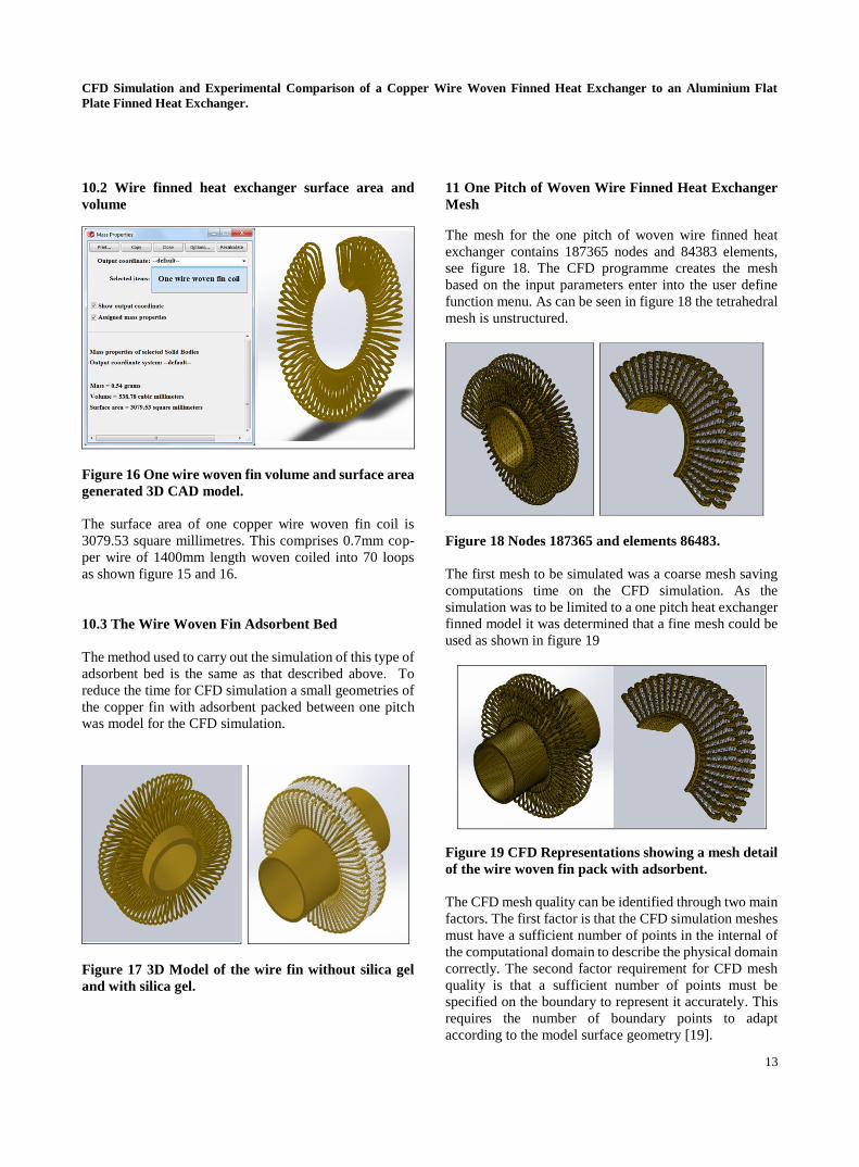
10.2 Wire finned heat exchanger surface area and
volume
Figure 16 One wire woven fin volume and surface area
generated 3D CAD model.
The surface area of one copper wire woven fin coil is
3079.53 square millimetres. This comprises 0.7mm cop-
per wire of 1400mm length woven coiled into 70 loops
as shown figure 15 and 16.
10.3 The Wire Woven Fin Adsorbent Bed
The method used to carry out the simulation of this type of
adsorbent bed is the same as that described above. To
reduce the time for CFD simulation a small geometries of
the copper fin with adsorbent packed between one pitch
was model for the CFD simulation.
Figure 17 3D Model of the wire fin without silica gel
and with silica gel.
11 One Pitch of Woven Wire Finned Heat Exchanger
Mesh
The mesh for the one pitch of woven wire finned heat
exchanger contains 187365 nodes and 84383 elements,
see figure 18. The CFD programme creates the mesh
based on the input parameters enter into the user define
function menu. As can be seen in figure 18 the tetrahedral
mesh is unstructured.
Figure 18 Nodes 187365 and elements 86483.
The first mesh to be simulated was a coarse mesh saving
computations time on the CFD simulation. As the
simulation was to be limited to a one pitch heat exchanger
finned model it was determined that a fine mesh could be
used as shown in figure 19
Figure 19 CFD Representations showing a mesh detail
of the wire woven fin pack with adsorbent.
The CFD mesh quality can be identified through two main
factors. The first factor is that the CFD simulation meshes
must have a sufficient number of points in the internal of
the computational domain to describe the physical domain
correctly. The second factor requirement for CFD mesh
quality is that a sufficient number of points must be
specified on the boundary to represent it accurately. This
requires the number of boundary points to adapt
according to the model surface geometry [19].

CFD Simulation and Experimental Comparison of a Copper Wire Woven Finned Heat Exchanger to an Aluminium Flat
Plate Finned Heat Exchanger.
14
11.1 One pitch of wire woven finned heat exchanger
with adsorbent packing
Figure 20 Displays the heat transfer efficiency of the
wire fin heat exchanger root contour temperature is at
85°C and the fin tip temperature is at 81°C.
Figure 20 and 21 presents the temperature supplied along
the length of the wire woven fin. A higher incline can be
detected near the base of the fin due to the concentrated
temperature difference between fin surface and the
surrounding porous adsorbents covering the fins.
Figure 21 Changes of fin heat transfer efficiency over
time due to the heat transfer of the heat exchanger the
temperature decreases as it flows through the wire
woven fin.
The CFD simulation method for the wire woven fin was
as described for the flat fin heat exchanger. The fin root
temperature of the wire fin was set from 85○C and the
model was run until the solution approached the steady
state behaviour (after 750 seconds), as shown in figure 21.
The fin root temperature decreased to 81○C from 85
○C as
the heat transferred to the top edge of the wire fin. This
shows the change in temperature of the wire woven fin
was by 4°C. This low reduction in temperature is to some
extent to do with the heat exchanger been design from a
continuous wire copper coil, which contributes to the
good heat transfer, also, being made of copper and not
aluminium increase the heat transfer to the adsorbent. The
thermal conductivity of copper compared to aluminium is
shown in table .1.
12 Model Validations
Several checks were performed in order to verify the
generated results the adsorbent bed heat transfer
performance was observed to ensure that the results
satisfied the boundary conditions. The resulting file
generated by Cosmos flow upon the completion of each
run was carefully examined and analysed. The surface
area to volume ratio of the heat exchangers was verified
by comparing simulation result to surface area to volume
simulation. The heat transfer results were compared to
data from experiment.
13 Conclusions
CFD as a design tool for adsorbent bed design proves to
be useful in estimating wall to fluid heat transfer
parameters. It makes possible the modelling of a realistic
case of an adsorbent bed using wire woven fin and flat fin
heat exchangers. From the simulation comparisons of the
copper wire woven finned and aluminium flat finned heat
exchangers the wire finned heat exchanger has three
advantages over the aluminium flat fin.
The first advantage was the greater surface area as seen in
figure 16 the second was a better heat transfer efficiency
as seen in figure 21 and the third advantage was the
smaller volume of the heat exchanger as showed in figure
16.
It was observed from CFD simulation carried out on heat
transfer on contact points between fin and porous
adsorbents that the contact points between the adsorbent
and heat exchanger had a significant effect to heat
transfer. A poor heat transfer flow distribution can result
in a lower heat transfer rate. Therefore, the optimisation of
flow distribution is an essential step in heat exchanger
design optimisation. CFD methods have demonstrated to
have great potential in predicting the performance of both
existing and newly developed adsorbent beds designs.
REFERENCES
[1] Chang W.-S, Wang C.-C and Shieh C.-C (2005) Ex-
perimental study of a solid adsorption cooling system
using flat-tube heat exchangers as adsorption bed Ap-
plied Thermal Engineering 27 2195–2199.
[2] Riffel, D.B. , Belo, F. A., (2007) Simulation of a
Shell-and-Tube Heat Exchanger for Solar Adsorption

CFD Simulation and Experimental Comparison of a Copper Wire Woven Finned Heat Exchanger to an Aluminium Flat
Plate Finned Heat Exchanger.
15
Chiller., Heat SET, Heat Transfer in Component and
Systems for Sustainable Energy Technologies, 18-20
April, Chambery, France
[3] Beecher, D. T. and Fagan, T. J. (1987) Effect of fin
pattern on the air-side heat transfer coefficient in plate
finnedtube heat exchangers, ASHRAE Trans, Vol. 93, pp.
1961-1984.
[4] White, J. (2012)“Computational Fluid Dynamics
Modelling and Experimental Study on a Single Silica
Gel Type B”, Modelling and Simulation in Engineer-
ing,Hindawi Publishing Corporation. Published online
January 2012, vol. 2012, Article ID598479, 9 pages,
[5] Anikeenko, A.V., Medvedev, N.N., Kovalev, M.K.,
and Melgunov M.S., (2009) ,“Simulation of gas diffusion
in porous layers of varying structure,” Journal of Struc-
tural Chemistry, vol. 50, no. 3, pp. 403–410,
[6]Murakami, 5., Kato,S., Ito,K., and Zhu, Q., (2003)
“Modeling and CFD prediction for diffusion and adsorp-
tion within room with various adsorption isotherms,”
Indoor Air, vol. 13, no. 6, pp. 20–27
[7] Lienhard, IV J. H., and Lienhard, V. J. H., (2005). “A
Heat Transfer Text Book,” 3rd, Edition, Phlogiston Press,
New York, p. 164,612,
[8] Yovanovich M.M., Marotta E.E.,( 2003) Thermal
spreading and contact resistances, in: A. Bejan, D. Kraus
(Eds.), Heat Transfer Handbook, John Wiley and Sons
Inc., Hoboken, New York, USA, (Chapter 4).
[9] Pozrikidis, C. (1997) Introduction to Theoretical and
Computational Fluid Dynamics. New York/Oxford,
Oxford University Press
[10]Lambert, M. A., and Jones, B. J., 2006, "Automotive
Adsorption Air Conditioner Powered by Exhaust Heat.
Part 1: Conceptual and Embodiment Design," Proceed-
ings of the Institution of Mechanical Engineers, Part
D: Journal of Automobile
[11] Inaba. H., Seo. J. K., Horibe. A. (2004) Numerical
study on adsorption enhancement of rectangular adsorp-
tion bed. Heat and Mass Transfer, Volume 41, Number 2
pp. 133-146
[12] Liou. M-F. (2005) “A Numerical Study of Transport
Phenomena in Porous Media Department of Mechanical
and Aerospace Engineering” Case Western Reserve
University” PhD, Thesis.
[13] Murakami, 5. Kato,S., Ito,K., and Zhu, Q., (2003)
“Modeling and CFD prediction for diffusion and adsorp-
tion within room with various adsorption isotherms,”
Indoor Air, vol. 13, no. 6, pp. 20–27
[14] Augier .F, Laroche .C., Brehon. E. (2008) Applica-
tion of Computational Fluid Dynamics to Fixed Bed
Adsorption Calculations: University of Science and
Technology, Beijing.
[15] Rahimi, M. and Mohseni, M. (2008) CFD model-
ling of the effect of absorbent size on absorption perfor-
mance of a packed bed column in Korean Journal of
Chemical Engineering, vol. 25, no. 3, pp. 395–401.
[16] Murakami, S, Kato, S., Ito, K. and Zhu Q. (2003)
Modelling and CFD prediction for diffusion and adsorp-
tion within room with various adsorption isotherms. In
Indoor Air 13, Supplement 6, pp.20-27.
[17] Rogers GFC, Mayhew YR. (1988) Thermodynamic
and Transport Properties of Fluids: SI Units (4th Edition)
ISBN-10: 0631902651
[18] Jiyuan Tu, Guan H.Y and Chaoqun Liu (2008)
Computational Fluid Dynamics A Practical Ap-
proach, Butterworth Heinemann Publication ISBN
978-0-7506-8563-4
[19] White, J. (2012) “A CFD Simulation on How the
Different Sizes of Silica Gel Will Affect the Adsorption
Performance of Silica Gel”,Modelling and Simulation in
Engineering,Hindawi Publishing Corporation. Published
online January 2012 vol. 2012, Article ID 651434, 2
Pages.
Copyright © 2022 FDOKUMEN