Comparison of athletic performances across disciplines20141020
Upload
khangminh22Category
view
2download
0
© INRS, Centre - Eau Terre Environnement, 2018Tous droits réservésISBN : 978-2-89146-916-6 (version électronique)Dépôt légal - Bibliothèque et Archives nationales du Québec, 2019 Dépôt légal - Bibliothèque et Archives Canada, 2019

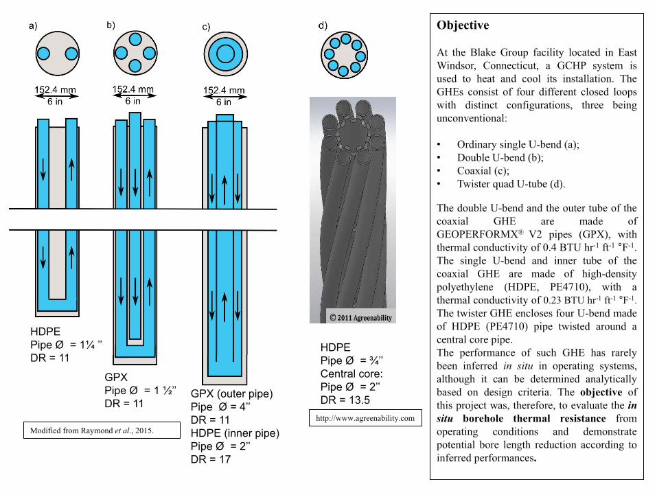
Introduction Ground coupled heat pump systems (GCHP), made of a ground heat exchanger (GHE) and a heat pump unit, are recognized has an efficient and environmentally friendly technology to heat and cool residential and commercial buildings. Borehole thermal resistance, which is the ability of the GHE to resist heat transfer, is one of the important parameters considered in the design of such system to determine the required heat exchanger length. Selecting appropriate materials and pipe configuration to optimize the borehole thermal resistance can help to decrease the borehole length (Raymond et al., 2015). Versaprofiles has consequently developed a thermally enhanced pipe available in single U, double U and coaxial pipe configurations to reduce the borehole thermal resistance (Raymond, 2013). This GEOPERFORMX® V2 pipe is charged with nanoparticles increasing the thermal conductivity of the polyethylene matrix by 75% when compared to a conventional HDPE pipe.
http://versaprofiles.com/en/geothermal

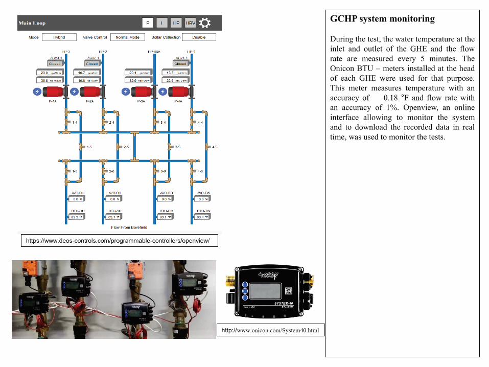
Methodology—Heat extraction tests Heat extraction tests including three steps were conducted in the four GHE to evaluate their in situ performances: 1. Initial circulation: the tested GHE is
isolated from the system and water is circulated without heat extraction or injection to determine the initial temperature of the ground;
2. Heat extraction: the full-building loads are transferred to the tested GHE to evaluate its performance under the peak conditions and determine the in situ borehole thermal resistance;
3. Thermal recovery: building loads are redirected to the other three GHEs and water is kept circulating in the tested GHE to monitor the thermal recovery and determine the ground thermal conductivity.
The heat carrier fluid circulating in the system is a mix of water and propylene glycol with a concentration of 12 vol.%. The filling material of the boreholes is a thermally enhanced grout made of bentonite and graphite with a thermal conductivity of 1.2 BTU hr-1 ft-1 °F˗1.
30
35
40
45
50
0 50 100 150 200 250
Tem
pera
ture
(°F)
Time (h)
Steps of the heat extraction tests
Mean Temperature
1. Initial circulation
2. Heat extraction
3. Thermal recovery
Fluid properties from GLHEPro 5.0
Fluid type: Propylene Glycol/Water Fluid concentration: 12 % Average temperature at peaks conditions: 68 °F
Freezing Point Density Volumetric Heat Capacity Conductivity Viscosity
°F lb ft-3 Btu °F-1 ft-3 BTU hr-1 ft-1 °F-1 lb m ft-1 h-1 23.03 63.24 60.8 0.305 3.85

Calculation of the heat extraction rate The heat extraction rates q (BTU h-1) imposed to the GHE during each test was calculated hourly from de measured flow rate (ft3 min-1) and the fluid temperature (°F) at the inlet and outlet of the GHE: where q’ is the flow rate (ft3 min-1), ρf (lb ft-3) is the fluid density and cf is the volumetric heat capacity of the fluid (Btu ft-3 °F˗1). The heat extraction rate during the three steps of each test was used to perform an hourly simulation with GLHEPro, where the inlet and outlet temperatures at each time step are calculated. The simulated temperature was manually matched to the observed temperature to infer the initial ground temperature, the in situ borehole thermal resistance and the ground thermal conductivity.
f,i f,o f fq q T T c= − ρ,( )
0
20000
40000
60000
80000
100000
120000
0 50 100 150 200 250
BTU
/h
Time (h)
Heat extraction rate at the three steps of the tests
1. Initial circulation
2. Heat extraction
3. Thermal recovery
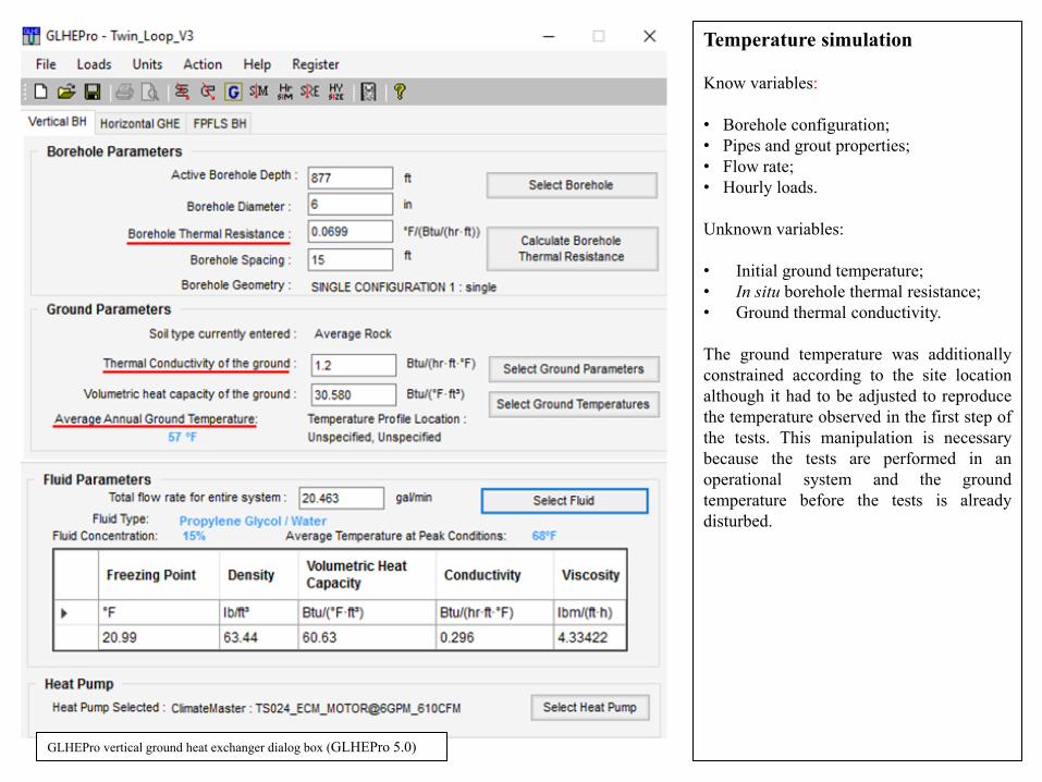
Temperature simulation Know variables: • Borehole configuration; • Pipes and grout properties; • Flow rate; • Hourly loads. Unknown variables: • Initial ground temperature; • In situ borehole thermal resistance; • Ground thermal conductivity. The ground temperature was additionally constrained according to the site location although it had to be adjusted to reproduce the temperature observed in the first step of the tests. This manipulation is necessary because the tests are performed in an operational system and the ground temperature before the tests is already disturbed.
GLHEPro vertical ground heat exchanger dialog box (GLHEPro 5.0)

Borehole thermal resistance and ground thermal conductivity The borehole thermal resistance was initially calculated with GLHEPro based on the borehole configuration and the ground, grout and fluid properties. The Multipole method (Claesson and Hellström, 2011; Bennett et al, 1987) is used to calculate the local borehole thermal resistance in GLHEPro. The Multipole method is an analytical solution for conductive heat transfer between any number of pipes and the surrounding ground (Spitler et al., 2016). An initial ground thermal conductivity was additionally defined to perform a first hourly simulation.
The simulated temperature was compared to the observed temperature and the least square difference is computed for all the duration of each test. The ground thermal conductivity was gradually varied to reproduce the observed temperature. Finally, the borehole thermal resistance was manually varied to reduce the least square difference between the observed and calculated temperatures. The estimated thermal conductivity and borehole thermal resistance were used to size GHCP for four different buildings located in different climate zones.
Borehole thermal resistance calculator (GLHEPro 5.0)

Pipes thermal conductivity measurements A thermal conductivity scanner (TCS) was used to measure the thermal conductivity of pipe samples. This instrument has a moving optical head with an infrared heat source and temperature sensors allowing to scan thermal properties along the sample (Jorand et al., 2013). The range of thermal conductivity evaluation is 0.2 to 25 W m-1 K-1 with an accuracy of 3%. The thermal conductivity is measured along a scan line that has been painted with black enamel to ensure proper infrared absorption to heat the sample (Raymond et al., 2017). When cylindrical samples with a diameter inferior to 80 mm, it is necessary to correct the measurement. Thermal conductivity measures in cylindrical samples are 6% less than thermal conductivity measure in a flat surface (Popov et al., 2003). Then, a correction needs to be applied to the measured thermal conductivity. The power of the heat source was set a 15% (10.6 W) to create a temperature difference of approximately 3 °C. HDPE and GPX pipe samples with longitudes between 29 and 45 cm were used for the analysis.
Scanner unit
Pipe sample during a thermal conductivity measurement
-10 40 90 140 190 240
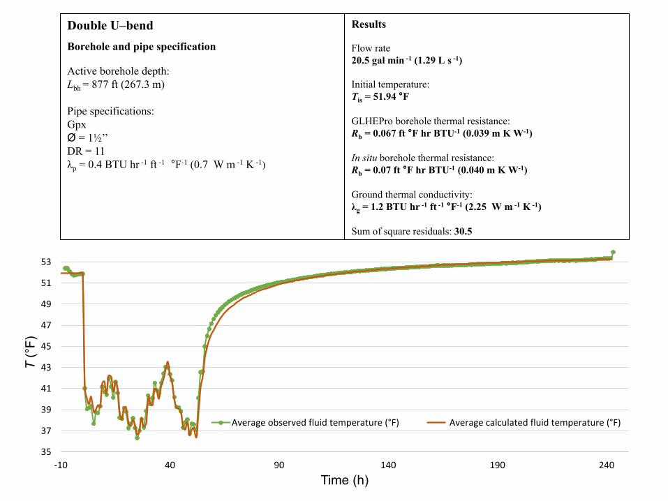
Results
Flow rate 20.5 gal min -1 (1.29 L s -1) Initial temperature: Tis = 51.94 °F GLHEPro borehole thermal resistance: Rb = 0.067 ft °F hr BTU-1 (0.039 m K W-1) In situ borehole thermal resistance: Rb = 0.07 ft °F hr BTU-1 (0.040 m K W-1) Ground thermal conductivity: λg = 1.2 BTU hr -1 ft -1 °F˗1 (2.25 W m -1 K -1) Sum of square residuals: 30.5
Double U–bend
Borehole and pipe specification
Active borehole depth: Lbh = 877 ft (267.3 m) Pipe specifications: Gpx Ø = 1½’’ DR = 11 λp = 0.4 BTU hr -1 ft -1 °F˗1 (0.7 W m -1 K -1)
35
37
39
41
43
45
47
49
51
53
-10 40 90 140 190 240
T (°
F)
Time (h)
Average observed fluid temperature (°F) Average calculated fluid temperature (°F)

Results
Flow rate 21.5 gal min -1 (1.30 L s -1) Initial simulated temperature: Tis = 55.4 °F GLHEPro borehole thermal resistance: Rb = 0.1302 ft °F hr BTU-1 (0.075 m K W-1) In situ borehole thermal resistance: Rb = 0.155 ft °F hr BTU-1 (0.090 m K W-1) Ground thermal conductivity: λ = 1.4 BTU hr -1 ft -1 °F ˗1 (2.4 W m -1 K -1) Sum of square residuals: 49.3
Coaxial test 1: lower flow rate
Borehole and pipe specification
Active borehole depth: Lbh = 1054 ft (321.3 m) Pipe specifications: Inner pipe HDPE, Ø = 2 ’’ DR = 11 λp = 0.23 BTU hr -1 ft -1 °F˗1 (0.4 W m -1 K -1) Outer pipe GPX, Ø = 4’’ DR = 17 λp = 0.4 BTU hr -1 ft -1 °F˗1(0.7 W m -1 K -1)
28303234363840424446485052545658
-70 -20 30 80 130 180
T (°
F)
Time (h)
Average observed fluid temperature (°F) Average calculated fluid temperature (°F)
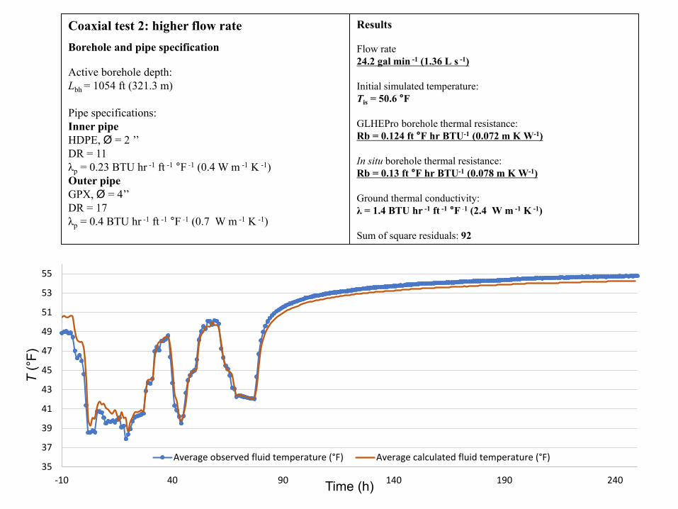
Results
Flow rate 24.2 gal min -1 (1.36 L s -1) Initial simulated temperature: Tis = 50.6 °F GLHEPro borehole thermal resistance: Rb = 0.124 ft °F hr BTU-1 (0.072 m K W-1) In situ borehole thermal resistance: Rb = 0.13 ft °F hr BTU-1 (0.078 m K W-1) Ground thermal conductivity: λ = 1.4 BTU hr -1 ft -1 °F ˗1 (2.4 W m -1 K -1) Sum of square residuals: 92
Coaxial test 2: higher flow rate
Borehole and pipe specification
Active borehole depth: Lbh = 1054 ft (321.3 m) Pipe specifications: Inner pipe HDPE, Ø = 2 ’’ DR = 11 λp = 0.23 BTU hr -1 ft -1 °F ˗1 (0.4 W m -1 K -1) Outer pipe GPX, Ø = 4’’ DR = 17 λp = 0.4 BTU hr -1 ft -1 °F ˗1 (0.7 W m -1 K -1)
35
37
39
41
43
45
47
49
51
53
55
-10 40 90 140 190 240
T (°
F)
Time (h)
Average observed fluid temperature (°F) Average calculated fluid temperature (°F)

Results
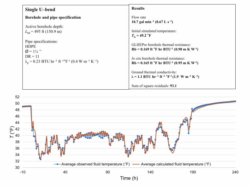
Flow rate 11.27 gal min -1 (0.71 L s -1) Initial simulated temperature: Tis = 46.3 °F GLHEPro borehole thermal resistance: Rb = 0.106 ft °F hr BTU-1 (0.061 m K W-1) In situ borehole thermal resistance: Rb = 0.094 ft °F hr BTU-1 (0.054 m K W-1) Ground thermal conductivity: λ = 1.6 BTU hr -1 ft -1 °F ˗1 (2.8 W m -1 K -1) Sum of square residuals: 93.3
Twister
Borehole and pipe specification
Active borehole depth (twisted): Lbh = 446.3 ft (136 m) Borehole depth: Lb = 441 (134.4 m) Pipe specifications: HDPE, Ø = ¾’’ DR = 13.5 λp = 0.23 BTU hr -1 ft -1 °F ˗1 (0.4 W m -1 K -1) The twister configuration is not available in GLHEPro. The simulations were performed with a double U-bend configuration with pipe diameter = 1 ½“to represent the volume of the 8 pipes and defined an active borehole length 1.2% higher than the borehole depth to take into account the additional length of the twisted pipes.
39
41
43
45
47
49
51
8 28 48 68 88 108 128 148 168
T (°
F)
Time (h)
Average observed fluid temperature (°F) Average calculated fluid temperature (°F)


Buildings Loads The annual loads of four different buildings located in distinct climatic zones were used to design GCHP systems with four GHE configurations tested and the in situ borehole thermal resistance. The building loads for the large office, the hospital and the large hotel were taken from the database of the Office of Energy Efficiency & Renewable Energy (EERE). The loads for the high school were provided by Versaprofils. The peak load duration tool Available in GLHEPro V.5 was used to estimate the peak duration and determine the monthly load profiles. The maximal fluid temperature was defined 17 °C above the average annual ground temperature of the climate zone and the minimum 6 °C below the average annual ground temperature as recommended in ASHRAE (2011) guidelines. The grout thermal conductivity was assumed to be 1.2 BTU hr-1 ft-1 °F-1. The selected space between the boreholes was 15 ft. The ground thermal conductivity was set as 1.23 BTU hr-1 ft-1 °F -1, representing the average thermal conductivity estimated at the single U-bend, double U-bend and the coaxial GHEs. The value estimated at the twister loop was not considered because it seems to be affected by the groundwater flow and this phenomenon was not observed at the other boreholes.
-600
-200
200
600
1000
0 2000 4000 6000 8000Load
s (k
Wh)
Time (h)
Large Office Hartfort, CT
Climate zone: 5A
-300
-100
100
300
0 2000 4000 6000 8000
Load
s (k
Wh)
Time (h)
High school Bridgehampton,NY Climate zone: 4A
-200
0
200
400
0 2000 4000 6000 8000Load
s (k
Wh)
Time (h)
Large hotel Bangor, ME
Climate zone: 6A
Heating
Cooling
-600
-100
400
900
1400
0 2000 4000 6000 8000
Load
s (k
Wh)
Time (h)
Hospital Denver, CO
Climate zone: 5B

Sizing calculation results with GLHEPro GCHP systems were size to cover the cooling and heating building needs using GLHEPro. Length intervals were defined to design each systems according to the typical length used in the industry for each of the GHE configuration: • Single U-bend: 500 – 700 ft; • Double U-bend: 700 – 900 ft; • Coaxial: 900 – 1000 ft; • Twister: 500 – 700 ft. The single U-bend GHE was used as a reference case to calculate the relative GHE length reduction in the other cases.
Sizing results with GLHEPro Single U-bend
Double U-bend
Coaxial Twister Systems parameters Inner Outer Pipe thermal conductivity (Btu hr-1 ft-1 °F-1) 0.23 0.4 0.23 0.4 0.23
Pipe size (in) 1.25 1.5 2 4 0.75
In situ borehole thermal resistance (hr ft °F BTU-1) 0.18 0.07 0.155 0.094
Large Office Number of boreholes (-) 120 75 70 100 Borehole distribution (-) 10 x 12 3 x 25 5 x 14 10 x 10 GHE length (ft) 606 734 922 612 Borehole length (ft) - - - 619 Total GHE length (ft) 72749 55085 64504 61174 GHE length reduction (%) 24 11 16
Secondary school Number of boreholes (-) 96 64 54 75 Borehole distribution (-) 8 x 12 4 x 16 6 x 9 3 x 25 GHE length (ft) 583 716 940 594 Borehole length (ft) - - - 602 Total GHE length (ft) 55935 45832 50758 44579 GHE length reduction (%) 18 9 20
Hospital Number of boreholes (-) 132 96 72 120 Borehole distribution (-) 11 x 12 6 x 16 4 x 18 10 x 12 GHE length (ft) 619 759 940 656 Borehole length (ft) - - - 664 Total GHE length (ft) 81738 72845 67645 78701 GHE length reduction (%) 11 17 5
Large hotel Number of boreholes (-) 56 35 32 45 Borehole distribution (-) 7 x 8 5 x 7 4 x 8 5 x 9 GHE length (ft) 600 762 955 643 Borehole length (ft) - - - 650 Total GHE length (ft) 33600 26660 30567 28919 GHE length reduction (%) 21 9 14
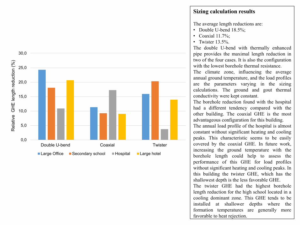
Sizing calculation results The average length reductions are: • Double U-bend 18.5%; • Coaxial 11.7%; • Twister 13.5%. The double U-bend with thermally enhanced pipe provides the maximal length reduction in two of the four cases. It is also the configuration with the lowest borehole thermal resistance. The climate zone, influencing the average annual ground temperature, and the load profiles are the parameters varying in the sizing calculations. The ground and gout thermal conductivity were kept constant. The borehole reduction found with the hospital had a different tendency compared with the other building. The coaxial GHE is the most advantageous configuration for this building. The annual load profile of the hospital is almost constant without significant heating and cooling peaks. This characteristic seems to be easily covered by the coaxial GHE. In future work, increasing the ground temperature with the borehole length could help to assess the performance of this GHE for load profiles without significant heating and cooling peaks. In this building the twister GHE, which has the shallowest depth is the less favorable GHE. The twister GHE had the highest borehole length reduction for the high school located in a cooling dominant zone. This GHE tends to be installed at shallower depths where the formation temperatures are generally more favorable to heat rejection.
0,0
5,0
10,0
15,0
20,0
25,0
30,0
Double U-bend Coaxial Twister
Rel
ativ
e G
HE
leng
th re
duct
ion
(%)
Large Office Secondary school Hospital Large hotel
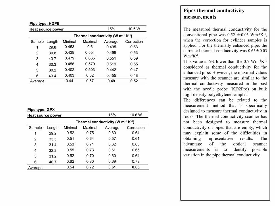
Pipes thermal conductivity measurements The measured thermal conductivity for the conventional pipe was 0.52 ±0.03 Wm-1K-1, when the correction for cylinder samples is applied. For the thermally enhanced pipe, the corrected thermal conductivity was 0.65±0.03 Wm-1K-1. This value is 6% lower than the 0.7 Wm-1K-1 considered as thermal conductivity for the enhanced pipe. However, the maximal values measure with the scanner are similar to the thermal conductivity measured in the past with the needle probe (KD2Pro) on bulk high-density polyethylene samples. The differences can be related to the measurement method that is specifically designed to measure thermal conductivity in rocks. The thermal conductivity scanner has not been designed to measure thermal conductivity on pipes that are empty, which may explain some of the difficulties in obtaining representative results. The advantage of the optical scanner measurements is to identify possible variation in the pipe thermal conductivity.
Pipe type: HDPE Heat source power 15% 10.6 W
Thermal conductivity (W m-1 K-1) Sample Length Minimal Maximal Average Correction
1 29.8 0.453 0.6 0.495 0.53 2 30.8 0.438 0.554 0.499 0.53 3 43.7 0.479 0.665 0.551 0.59 4 30.3 0.456 0.579 0.519 0.55 5 30.2 0.402 0.503 0.442 0.47 6 43.4 0.403 0.52 0.455 0.48
Average 0.44 0.57 0.49 0.52
Pipe type: GPX Heat source power 15% 10.6 W
Thermal conductivity (W m-1 K-1) Sample Length Minimal Maximal Average Correction
1 29.2 0.52 0.75 0.60 0.64 2 33.5 0.51 0.64 0.57 0.61 3 31.4 0.53 0.71 0.62 0.65 4 32.2 0.55 0.73 0.61 0.65 5 31.2 0.52 0.70 0.60 0.64 6 40.7 0.62 0.80 0.69 0.73
Average 0.54 0.72 0.61 0.65
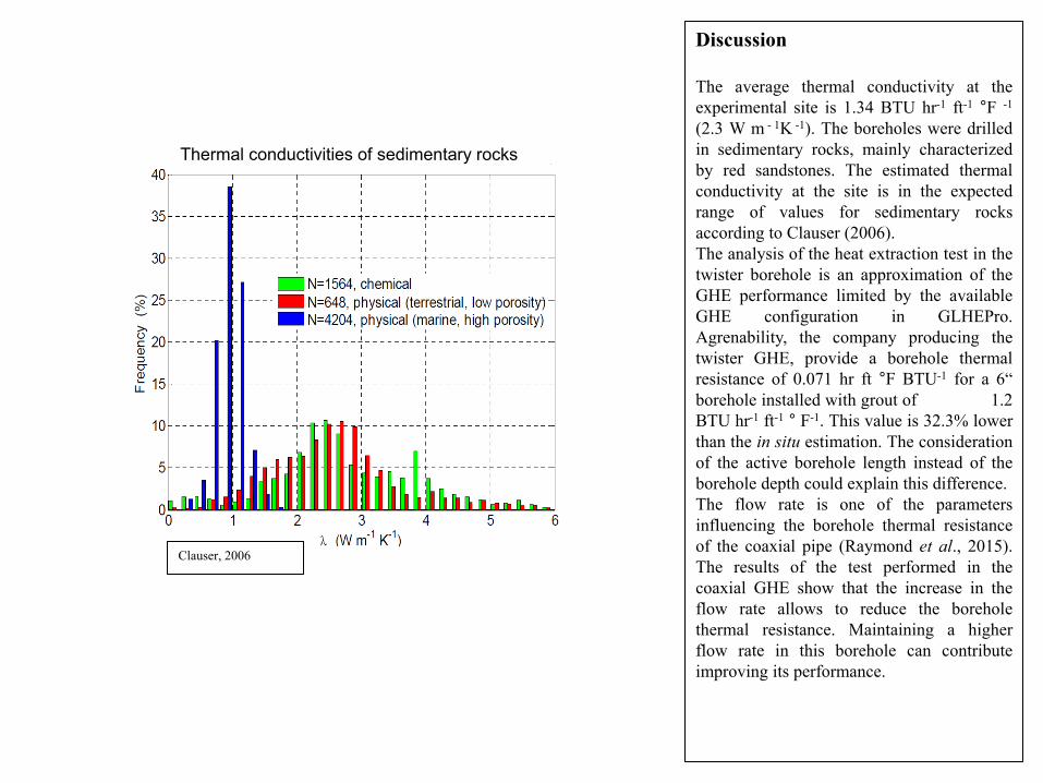
Clauser, 2006
Thermal conductivities of sedimentary rocks
Discussion The average thermal conductivity at the experimental site is 1.34 BTU hr-1 ft-1 °F -1 (2.3 W m - 1K -1). The boreholes were drilled in sedimentary rocks, mainly characterized by red sandstones. The estimated thermal conductivity at the site is in the expected range of values for sedimentary rocks according to Clauser (2006). The analysis of the heat extraction test in the twister borehole is an approximation of the GHE performance limited by the available GHE configuration in GLHEPro. Agrenability, the company producing the twister GHE, provide a borehole thermal resistance of 0.071 hr ft °F BTU-1 for a 6“ borehole installed with grout of 1.2 BTU hr-1 ft-1 ° F-1. This value is 32.3% lower than the in situ estimation. The consideration of the active borehole length instead of the borehole depth could explain this difference. The flow rate is one of the parameters influencing the borehole thermal resistance of the coaxial pipe (Raymond et al., 2015). The results of the test performed in the coaxial GHE show that the increase in the flow rate allows to reduce the borehole thermal resistance. Maintaining a higher flow rate in this borehole can contribute improving its performance.

Conclusions The double U-bend with the thermally enhanced pipe appears to be the most advantageous configuration to reduce the borehole thermal resistance. The double U-bend is also the configuration providing the higher borehole length reduction when compared to the single U-bend. The variation of the flow rate in the heat extraction tests shows that the increase in the flow rate had a positive effect in the borehole thermal resistance of the coaxial ground heat exchanger, having interesting heat exchange performances. However, the borehole length reduction found with the different borehole configurations varied depending on the building type. In future work the influence of the load profiles in the sizing calculation could be studied to evaluate if there is a ground heat exchanger configuration more advantageous according to the building requirements. The thermal conductivity measurement with the scanner allowed to validate the increase of thermal conductivity of the pipes and contribute to identify possible heterogeneity in the pipe thermal conductivity.
Acknowledgment This project was supported by the Mitacs Accelerate program. Mitacs, Versaprofils and Blake Group are acknowledged to found this research. Professor Jeffrey Spitler at Oklahoma State University is kindly acknowledged for providing a non-commercial license of GLHEPRO to conduct the work presented in this report. Jeff Harrison is acknowledged to carry out the heat extraction test. Mathieu Brousseau, Jean-Francois Lavoie and Jasmin Raymond are acknowledged to support the development of the project.

References ASHRAE, 2011. ASHRAE Handbook - HVAC Applications. Si edition ed., American Society of Heating, Refrigerating and Air-Conditioning Engineers, Atlanta, GA. Bennet, J., J. Claesson, and G. Hellström. 1987. Multipole Method to Compute the Conductive Heat Flows to and Between Pipes in a Composite Cylinder, Notes on Heat Transfer 3-1987, Department of Building Technology and Mathematical Physics, University of Lund, Sweden. Claesson, J. and G. Hellström. 2011. Multipole method to calculate borehole thermal resistances in a borehole heat exchanger. HVAC&R Research, 17(6):895-911. Clauser, C., 2006. Geothermal Energy, In: K. Heinloth (Ed), Landolt-Börnstein, Group VIII: “Advanced Materials and Technologies”, Vol. 3 “Energy Technologies”, Subvol. C “Renewable Energies”, 480 – 595, Springer Verlag, Heidelberg-Berlin. Jorand, R., Vogt, C., Marquart, G. and Clauser, C.: Effective thermal conductivity of heterogeneous rocks from laboratory experiments and numerical modeling. J. Geophys. Res. Solid Earth. V. 118 (2013). p. 5225–5235. Office of Energy Efficiency & Renewable Energy (EERE). Available at http://www1.eere.energy.gov/buildings/commercial/ref_b.uildings.html Popov, Y., Pohl, J., Romushkevich, R., Tertychnyi, V. and Soffel, H., 2003. Geothermal characteristics of the Ries impact structure. Geophysical Journal International, 154(2), pp.355-378. Raymond, J., Comeau, F.-A., Malo, M., Blessent, D., & López Sánchez, I. J. (2017). The Geothermal Open Laboratory: a free space to measure thermal and hydraulic properties of geological materials. Paper presented at the IGCP636 Annual Meeting, Santiago de Chile. Raymond, J., Mercier, S., & Nguyen, L., 2015. Designing coaxial ground heat exchangers with a thermally enhanced outer pipe. Geothermal Energy, 3(1), 7. doi:10.1186/s40517-015-0027-3 Raymond, J., 2013. GEOPERFORMX - HDPD pipe with increased thermal conductivity for geothermal applications (pp. 4). Saint-Lazare-de-Bellechasse (QC), Canada: Versaprofiles. Spitler, J.D., Marshall, C., Manickam, A., Dharapuram, M., Delahoussaye, R.D., Yeung, K.W.D., Young, R., Bhargava, M., Mokashi, S., Yavuzturk, C., Haider, M., Xu, X., Cullin, J., Dickinson, B., Lee, E., Grundmann, R., 2016. Users’ Guide for GLHEPro 5.0 for Windows. Technical Report. School of Mechanical and Aerospace Engineering. Oklahoma State University, Stillwater, Oklahoma, United States.
Copyright © 2022 FDOKUMEN