Optimal Design of an Air-to-Air Heat Exchanger with Cross ...
20
applied sciences Article Optimal Design of an Air-to-Air Heat Exchanger with Cross-Corrugated Triangular Ducts by Using a Particle Swarm Optimization Algorithm Caihang Liang 1, *, Xiaoman Tong 1 , Tengyue Lei 1 , Zhenxing Li 2 and Guoshan Wu 3 1 School of Mechano-Electronic Engineering, Guilin University of Electronic Technology, Guilin 541004, China; [email protected] (X.T.); [email protected] (T.L.) 2 Department of Environmental Engineering, Shan Xi University, Taiyuan 030006, China; [email protected] 3 Department of Energy and Built Environment, Guilin University of Aerospace Technology, Guilin 541004, China; [email protected] * Correspondence: [email protected]; Tel.: +86-773-229-2386 Academic Editor: Takahiko Miyazaki Received: 22 March 2017; Accepted: 17 May 2017; Published: 26 May 2017 Abstract: Air-to-air heat exchangers with cross-corrugated triangular ducts are widely used in various industrial fields to recover waste heat. The geometric parameters of the heat exchangers greatly affect the performance and total annual cost of these systems. In this study, the effectiveness-number of transfer units (ε-NTU) method was utilized to develop the thermal mathematical model, which was verified by comparing it with previous research. The configuration parameters of the heat exchanger were optimized in this study. The particle swarm optimization (PSO) algorithm was applied using both single and multi-objective algorithm. The colburn factor (j factor), friction factor (f factor), and comprehensive thermal hydraulic performance index (JF factor) were considered as objective functions to be optimized using a single objective and multi-objective algorithm. Then, the entropy generation rate and total annual cost were optimized by using a multi-objective PSO algorithm. In addition, to identify the influential geometric parameters, a global sensitivity analysis was performed. The sensitivity analysis showed that the apex angle θ, channel height H, and heat exchanger height L h influenced the performance and annual total cost of these systems. Keywords: cross-corrugated triangular ducts; air-to-air heat exchanger; particle swarm analysis (PSO); global sensitivity analysis 1. Introduction Air-to-air heat exchangers with cross-corrugated triangular ducts are widely used in many applications, such as electronic cooling, aerospace, air conditioning and refrigeration, petroleum refineries, automobiles, and chemical industries. Figure 1 shows the schematic of the air-to-air heat exchanger with cross-corrugated triangular ducts, where the two unmixed cross flows exchange heat through the corrugated plate. Flat plates are corrugated to form a series of parallel equilateral triangular ducts. Sheets of the same corrugated plates are then stacked together to form a 90 ◦ orientation angle, which guarantees the same flow pattern for the fluid on both side. Compared with air-to-air heat exchangers with other channel ducts, the air-to-air heat exchangers with cross-corrugated triangular ducts have some advantages like higher heat exchange capacity, higher mechanical strength and more compact size [1]. In recent years, the heat exchangers with cross-corrugate triangular ducts have attracted attention owing to their advantages. Many researchers have investigated the characteristics of heat transfer and flow of the cross-corrugated heat exchangers to enhance the heat transfer and decrease the pressure Appl. Sci. 2017, 7, 554; doi:10.3390/app7060554 www.mdpi.com/journal/applsci
-
Upload
khangminh22 -
Category
Documents
-
view
0 -
download
0
Transcript of Optimal Design of an Air-to-Air Heat Exchanger with Cross ...
applied sciences
Article
Optimal Design of an Air-to-Air Heat Exchangerwith Cross-Corrugated Triangular Ducts by Usinga Particle Swarm Optimization Algorithm
Caihang Liang 1,*, Xiaoman Tong 1, Tengyue Lei 1, Zhenxing Li 2 and Guoshan Wu 3
1 School of Mechano-Electronic Engineering, Guilin University of Electronic Technology, Guilin 541004, China;[email protected] (X.T.); [email protected] (T.L.)
2 Department of Environmental Engineering, Shan Xi University, Taiyuan 030006, China; [email protected] Department of Energy and Built Environment, Guilin University of Aerospace Technology,
Guilin 541004, China; [email protected]* Correspondence: [email protected]; Tel.: +86-773-229-2386
Academic Editor: Takahiko MiyazakiReceived: 22 March 2017; Accepted: 17 May 2017; Published: 26 May 2017
Abstract: Air-to-air heat exchangers with cross-corrugated triangular ducts are widely used in variousindustrial fields to recover waste heat. The geometric parameters of the heat exchangers greatly affectthe performance and total annual cost of these systems. In this study, the effectiveness-number oftransfer units (ε-NTU) method was utilized to develop the thermal mathematical model, which wasverified by comparing it with previous research. The configuration parameters of the heat exchangerwere optimized in this study. The particle swarm optimization (PSO) algorithm was applied usingboth single and multi-objective algorithm. The colburn factor (j factor), friction factor (f factor),and comprehensive thermal hydraulic performance index (JF factor) were considered as objectivefunctions to be optimized using a single objective and multi-objective algorithm. Then, the entropygeneration rate and total annual cost were optimized by using a multi-objective PSO algorithm.In addition, to identify the influential geometric parameters, a global sensitivity analysis wasperformed. The sensitivity analysis showed that the apex angle θ, channel height H, and heatexchanger height Lh influenced the performance and annual total cost of these systems.
Keywords: cross-corrugated triangular ducts; air-to-air heat exchanger; particle swarm analysis (PSO);global sensitivity analysis
1. Introduction
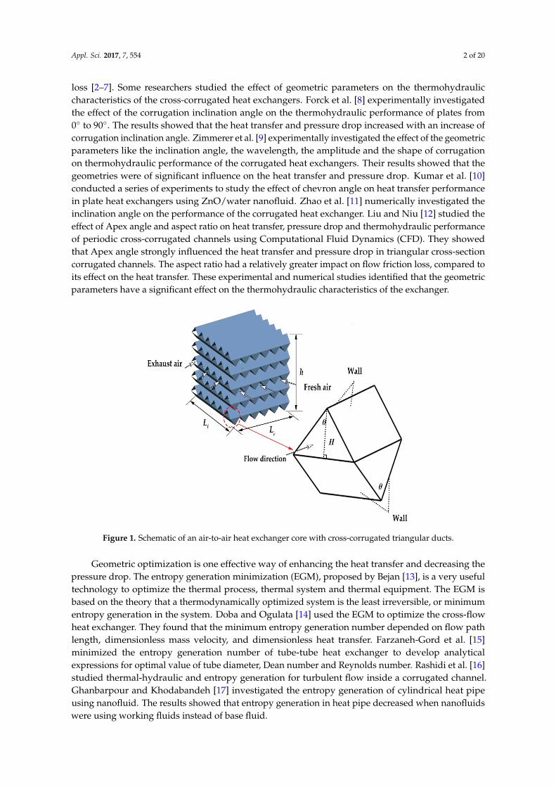
Air-to-air heat exchangers with cross-corrugated triangular ducts are widely used in manyapplications, such as electronic cooling, aerospace, air conditioning and refrigeration, petroleumrefineries, automobiles, and chemical industries. Figure 1 shows the schematic of the air-to-air heatexchanger with cross-corrugated triangular ducts, where the two unmixed cross flows exchange heatthrough the corrugated plate. Flat plates are corrugated to form a series of parallel equilateral triangularducts. Sheets of the same corrugated plates are then stacked together to form a 90 orientation angle,which guarantees the same flow pattern for the fluid on both side. Compared with air-to-air heatexchangers with other channel ducts, the air-to-air heat exchangers with cross-corrugated triangularducts have some advantages like higher heat exchange capacity, higher mechanical strength and morecompact size [1].
In recent years, the heat exchangers with cross-corrugate triangular ducts have attracted attentionowing to their advantages. Many researchers have investigated the characteristics of heat transfer andflow of the cross-corrugated heat exchangers to enhance the heat transfer and decrease the pressure
Appl. Sci. 2017, 7, 554; doi:10.3390/app7060554 www.mdpi.com/journal/applsci
Appl. Sci. 2017, 7, 554 2 of 20
loss [2–7]. Some researchers studied the effect of geometric parameters on the thermohydrauliccharacteristics of the cross-corrugated heat exchangers. Forck et al. [8] experimentally investigatedthe effect of the corrugation inclination angle on the thermohydraulic performance of plates from0 to 90. The results showed that the heat transfer and pressure drop increased with an increase ofcorrugation inclination angle. Zimmerer et al. [9] experimentally investigated the effect of the geometricparameters like the inclination angle, the wavelength, the amplitude and the shape of corrugationon thermohydraulic performance of the corrugated heat exchangers. Their results showed that thegeometries were of significant influence on the heat transfer and pressure drop. Kumar et al. [10]conducted a series of experiments to study the effect of chevron angle on heat transfer performancein plate heat exchangers using ZnO/water nanofluid. Zhao et al. [11] numerically investigated theinclination angle on the performance of the corrugated heat exchanger. Liu and Niu [12] studied theeffect of Apex angle and aspect ratio on heat transfer, pressure drop and thermohydraulic performanceof periodic cross-corrugated channels using Computational Fluid Dynamics (CFD). They showedthat Apex angle strongly influenced the heat transfer and pressure drop in triangular cross-sectioncorrugated channels. The aspect ratio had a relatively greater impact on flow friction loss, compared toits effect on the heat transfer. These experimental and numerical studies identified that the geometricparameters have a significant effect on the thermohydraulic characteristics of the exchanger.
Appl. Sci. 2017, 7, 554 2 of 20
thermohydraulic characteristics of the cross-corrugated heat exchangers. Forck et al. [8] experimentally investigated the effect of the corrugation inclination angle on the thermohydraulic performance of plates from 0° to 90°. The results showed that the heat transfer and pressure drop increased with an increase of corrugation inclination angle. Zimmerer et al. [9] experimentally investigated the effect of the geometric parameters like the inclination angle, the wavelength, the amplitude and the shape of corrugation on thermohydraulic performance of the corrugated heat exchangers. Their results showed that the geometries were of significant influence on the heat transfer and pressure drop. Kumar et al. [10] conducted a series of experiments to study the effect of chevron angle on heat transfer performance in plate heat exchangers using ZnO/water nanofluid. Zhao et al. [11] numerically investigated the inclination angle on the performance of the corrugated heat exchanger. Liu and Niu [12] studied the effect of Apex angle and aspect ratio on heat transfer, pressure drop and thermohydraulic performance of periodic cross-corrugated channels using Computational Fluid Dynamics (CFD). They showed that Apex angle strongly influenced the heat transfer and pressure drop in triangular cross-section corrugated channels. The aspect ratio had a relatively greater impact on flow friction loss, compared to its effect on the heat transfer. These experimental and numerical studies identified that the geometric parameters have a significant effect on the thermohydraulic characteristics of the exchanger.
Figure 1. Schematic of an air-to-air heat exchanger core with cross-corrugated triangular ducts.
Geometric optimization is one effective way of enhancing the heat transfer and decreasing the pressure drop. The entropy generation minimization (EGM), proposed by Bejan [13], is a very useful technology to optimize the thermal process, thermal system and thermal equipment. The EGM is based on the theory that a thermodynamically optimized system is the least irreversible, or minimum entropy generation in the system. Doba and Ogulata [14] used the EGM to optimize the cross-flow heat exchanger. They found that the minimum entropy generation number depended on flow path length, dimensionless mass velocity, and dimensionless heat transfer. Farzaneh-Gord et al. [15] minimized the entropy generation number of tube-tube heat exchanger to develop analytical expressions for optimal value of tube diameter, Dean number and Reynolds number. Rashidi et al. [16] studied thermal-hydraulic and entropy generation for turbulent flow inside a corrugated channel. Ghanbarpour and Khodabandeh [17] investigated the entropy generation of cylindrical heat pipe using nanofluid. The results showed that entropy generation in heat pipe decreased when nanofluids were using working fluids instead of base fluid.
The design of air-to-air heat exchanger involves many geometric and operating variables. These geometric and operating variables are a part of the search for an exchanger geometry that meets the
Figure 1. Schematic of an air-to-air heat exchanger core with cross-corrugated triangular ducts.
Geometric optimization is one effective way of enhancing the heat transfer and decreasing thepressure drop. The entropy generation minimization (EGM), proposed by Bejan [13], is a very usefultechnology to optimize the thermal process, thermal system and thermal equipment. The EGM isbased on the theory that a thermodynamically optimized system is the least irreversible, or minimumentropy generation in the system. Doba and Ogulata [14] used the EGM to optimize the cross-flowheat exchanger. They found that the minimum entropy generation number depended on flow pathlength, dimensionless mass velocity, and dimensionless heat transfer. Farzaneh-Gord et al. [15]minimized the entropy generation number of tube-tube heat exchanger to develop analyticalexpressions for optimal value of tube diameter, Dean number and Reynolds number. Rashidi et al. [16]studied thermal-hydraulic and entropy generation for turbulent flow inside a corrugated channel.Ghanbarpour and Khodabandeh [17] investigated the entropy generation of cylindrical heat pipeusing nanofluid. The results showed that entropy generation in heat pipe decreased when nanofluidswere using working fluids instead of base fluid.

Appl. Sci. 2017, 7, 554 3 of 20
The design of air-to-air heat exchanger involves many geometric and operating variables.These geometric and operating variables are a part of the search for an exchanger geometry thatmeets the heat duty requirement and a given set of design constraints. The conventional optimizationtechniques become very cumbersome and laborious for optimizing the design parameter of the heatexchanger. In recent decades, many researchers have applied intelligent algorithms for optimizationof air-to-air heat exchangers. Wang et al. [18] used a multi-objective genetic algorithm to obtain theoptimal values of the pitch and height of undulated plate and the height of the corrugated plate byusing the Pareto optimal strategy. In their studies, the heat transfer capability and pumping powerwere the objective functions. Mehrgoo and Amidpour [19] investigated the optimum design of theheat recovery steam generator using the genetic algorithm method under the fixed total volumecondition. The total entropy generation was considered as the objective function. Peng and Ling [20]demonstrated the successful application of the genetic algorithm combined with back propagationneural networks for the optimal design of plate-fin heat exchangers. Several investigators used otherintelligent algorithms like the biogeography-based optimization algorithm [21], adaptive simulatedannealing algorithm [22], bees algorithm [23], cuckoo search algorithm [24] and the Jaya algorithm [25],to optimize the heat exchangers.
The particle swarm optimization (PSO) algorithm is a relative recent heuristic search method.It is based on the idea of collaborative behavior and swarming in biological populations.PSO is a population-based search approach, and depends on information sharing among theirpopulation members to enhance their process using a combination of deterministic and probabilistic rule.Recently, some researchers have used the PSO for heat exchanger and thermal system optimization.Weter and Weight [26] used the PSO to solve optimization problems for building design and control.Rao and Patel [27,28] applied the PSO to optimize the cross-flow plate-fin heat exchanger andshell-and-tube heat exchangers. The results demonstrated successful application of PSO techniquesfor the thermodynamic optimization of heat exchangers. Yousefi et al. [29] investigated the optimaldesign of a compact heat exchanger using PSO. Numerical results indicated that the PSO generated theoptimum configuration with higher accuracy and a higher success rate. Dastmalchi et al. [30] employedPSO to determine the optimal micro-finned geometric which maximizes the thermal efficiency ofmicro-finned double pipe heat exchangers.
From the references mentioned above, there are few studies on optimizing the design ofair-to-air heat exchangers with cross-corrugated triangular ducts using the PSO. In the presentwork, the mathematical model of air-to-air heat exchangers with cross-corrugated triangular ductsis developed. The entropy generation rate
.Sgen, and total annual cost Ctotal are considered as the
objection functions by single objective and multi-objective optimization with specified mass flowrate under a given space. To guide the design of air-to-air heat exchangers with cross-corrugatedtriangular ducts, the j factor, f factor, and JF factor are defined as objective functions. The six heatexchanger design parameters: fresh air channel length Lf, exhaust air length Le, channel height H,apex angle θ, heat exchanger height Lh, and plate thickness δplate are considered as the optimizationparameters. In addition, to determine the influential input parameters over defined parameter space,global sensitivity analysis (GSA) should be performed.
2. Mathematical Model
In this section, the following assumptions were made: (1) no heat exchange between the outersurface and the surrounding environment occurred; (2) air was assumed to be the working fluid, andthe thermal physical properties were assumed to be constant and ideal gases [24]; (3) the configurationparameters of the flow channels on the fresh air side and the exhaust air side were assumed to beidentical, except for the total channel length; (4) The numbers of plate plies on each side were assumedto be identical. These assumptions were made for each calculation in this study.

Appl. Sci. 2017, 7, 554 4 of 20
2.1. Entropy Generation Analysis
Based on the EGM technique, the.Sgen (entropy generation rate of the air-to-air exchanger)
is expressed in terms of the temperature and pressure using the ideal gas model on both sides ((Ra, cp)fand (Ra, cp)e), as shown in Equation (1) [31]:
.Sgen = (
.mcp)f[ln
TfoTfi− (
Ra
cp)f ln
PfoPfi
] + (.
mcp)e[lnTeo
Tei− (
Ra
cp)e ln
Peo
Pei] (1)
where Ra is ideal gas constant, cp is specific heat at constant pressure,.
m is mass flow rate. T and Pare temperature and pressure, respectively. Subscripts i, and o mean inlet and outlet, respectively.Subscripts f, e, mean fresh air, exhaust air, respectively. Equation (1) indicates that
.Sgen is generated by
two behaviors of the heat exchanger: heat transfer and fluid flow.
2.1.1. Heat Transfer
The heat transfer behavior of the core is summarized by the classical ε-NTU method.The parameter ε is the effectiveness of the heat exchanger. The effectiveness ε of the cross-flow heatexchanger with both fluids unmixed is shown in Equation (2) [32].
ε = 1− exp
NTU0.22
cR[exp(−cRNTU0.78)− 1]
(2)
where cR and the number of transfer units (NTU) are defined as follows:
cR =min[(
.mcp)f, (
.mcp)e]
max[(.
mcp)f, (.
mcp)e](3)
NTU =KAtotal
c(4)
c = min[(.
mcp)f, (.
mcp)e] (5)
The parameter Atotal is the total heat transfer area. It is twice as large as the total area of thecorrugated triangular plates in the heat exchanger. The parameter A is the total area of the corrugatedtriangular plates, which is calculated as follows:
A = Acyc ·Lf
2H · tanθ
2
· Le
2H · tanθ
2
· Lh2H + 2δplate
(6)
The parameter Acyc is the surface area of a unitary cell of the core, and Lf, Le and Lh are thefresh air channel length, exhaust air channel length and height of the heat exchanger, respectively.In addition, the H, θ and δplate are channel height, apex angle and thickness of plate, respectively.
The total heat transfer coefficient K in Equation (4) is expressed in Equation (7):
K =1
1hf
+δplate
λplate+
1he
(7)
where λplate is thermal conductivity of the plate. The parameters hf and he are convective heat transfercoefficients of the fresh air and exhaust air, respectively. The convective heat transfer coefficient h isdefined by Equation (8):
h =λaNu
Dh(8)
Appl. Sci. 2017, 7, 554 5 of 20
The parameter Nu is the Nusselt number. Zhang [33] developed a correlation of the corrugatedtriangular ducts under uniform heat flux boundary conditions.
Nu = 0.274Re0.569Pr0.333 (9)
The Colburn factor j, is a heat transfer performance index of the heat exchanger, which is definedin Equation (10).
j =Nu
Re · Pr1/3 (10)
The heat transfer rate is expressed in Equation (11):
Q = εc(Tfi − Tei) (11)
In addition, the heat balance between the two streams is calculated as follows:Q = (
.mcp)f(Tfi − Tfo)
Q = (.
mcp)e(Teo − Tei)(12)
Then, the outlet temperatures of two sides are expressed as follows:
Tfo = Tfi −εc(Tfi − Tei)
(.
mcp)f
Teo = Tei +εc(Tfi − Tei)
(.
mcp)e
(13)
2.1.2. Fluid Flow
The outlet pressures (Pfo and Peo) refer to the analysis of the pressure drops experienced by thetwo streams. The Reynolds number Re is defined in Equation (14).
Re =ρavmDh
µ(14)
The parameter vm is the area-weighted mean velocity in the inlet (m/s). µ is dynamic viscosity(Pa s). The parameter Dh is the hydraulic diameter of the channel and is defined in Equation (15) [1].
Dh =4Vcyc
Acyc(15)
The parameters Vcyc and Acyc are the volume and surface area of the channel, respectively.
Acyc = 4 · (2H · tanθ
2) · H
cos θ2
(16)
Vcyc = 2 · (H2 · θ
2) · (2H · tan
θ
2) (17)
The correlation friction factor f is used by the correlations of Zhang [33], presented as follows:
f = 6.536Re−0.421 (18)
Pressure drop of channels is associated with the air density, area-weighted mean velocity, channellength L and hydraulic diameter, thus the outlet pressures (Pfo and Peo) of the heat exchanger areexpressed as follows:

Appl. Sci. 2017, 7, 554 6 of 20
Pfo = Pfi −12
ffρav2mLf
Dh(19)
Peo = Pei −12
feρav2mLe
Dh(20)
In addition, the comprehensive thermal hydraulic performance index JF is defined in Equation (21) [34].
JF =j
f 1/3 (21)
2.2. Total Annual Cost
For the optimal design of heat exchanger, the total annual cost is an important factor that needs tobe considered. The total annual cost of the air-to-air heat exchanger is composed of the investmentcost and the operating cost of fans. The total annual cost of the exchanger is as follows:
Ctotal = Cinv + Cope (22)
where Cinv and Cope are the investment cost and the operating cost, respectively. The investment costis calculated by [24]:
Cinv = φ · CA · Aσ (23)
where the parameter CA is the cost for per unit area. φ, the annual cost coefficient, is calculatedas follows:
φ =α
1− (1 + α)−y (24)
the parameters α and y represent the inflation rate and the depreciation time, respectively.The operating cost calculation is shown in the following formula [24]:
Cope =κ·τ·∆Pf·
.Qf
3600η
+κ·τ·∆Pe·
.Qe
3600η
. (25)
The parameters κ, τ, and η are the electric cost, operation time per year, and fan efficiency. The costcoefficients in this study are listed in Table 1.
Table 1. Cost coefficients of the air-to-air heat exchanger with cross-corrugated triangular ducts.
Economic Parameters Values
Depreciation time, y (year) 10Inflation rate, α 0.1
Cost per unit area, CA ($ m−2) 20Exponent of non-liner of increase factor, σ 0.6
Electric price, κ ($ kW−1 h−1) 0.15Yearly running time, τ (h year−1) 5000
Fan efficiency, η 0.6
3. Modeling Validation
In this section, the mathematical model is validated by comparing it with the literature data [2].The validated results are listed in Table 2. The exterior dimensions are 462 × 185 × 185 mm, and theinternal character dimensions are a channel height of Lh = 2.8 mm, an apex angle of θ = π/2, and a platethickness of δplate = 100 µm. The operating parameters are air flow rates of
.Qf (
.Qe) = 150 m3/h and
Appl. Sci. 2017, 7, 554 7 of 20
the thermal conductivity of the triangular corrugated plate, λplate = 0.127 W/(m K). The fresh airtemperature and exhaust air temperature are 308 K and 300 K, respectively.
Table 2. Comparison and validation of model parameters.
Properties Values
Literature Study [2] Present Study Error
Re 532 499 6.20%f 0.503 0.478 5.16%
∆P (Pa) 53 52.6 4.97%Nu 10.44 9.318 10.75%
hf, he (W m−2 K−1) 63.2 56.4 10.7%εs 0.86 0.80 6.97%
From Table 2, the simulation results agreed well with the calculation results from [2].
4. Optimization Methods
4.1. Particle Swarm Optimization
Particle swarm optimization (PSO), developed by Kennedy and Eberhart [35], is an evolutionarycomputation technique for solving global optimization problems. The ‘swarm intelligence’ has beenwidely applied to solve multivariable optimal design problems and shows good properties: it is easierto understand, easier to realize, faster in search velocity and quite suitable for real value processing.
This computational technique was derived from the study of predatory behavior. The synchronyof the animal’s behavior is maintained by optimal distances between the individual members andtheir neighbors. Thus, velocity is important for adjusting the optimal distances between the individualmembers. For foraging, the individuals update their velocities by two factors: their previous experienceand the experience of the other members. The two factors are expressed by the self-cognition termand social cognition term in the velocity equation, respectively. In this artificial intelligence algorithm,a particle represents a potential solution, and each particle corresponds to a fitness value determinedby the fitness function. The velocity of particles determines the direction and distance of the particlemovement, and the speed of the particle is dynamically adjusted according to the experience of themovement of all of the particles. Then, the optimization of the individuals in the solution space canbe obtained. The characteristics of the particles are represented by three indexes: position, velocity,and fitness.
The updates of the particles are accomplished using the following equations [35]:
vξd,Iter+1 = ωvξd,Iter + b1r1(pbestξd,Iter − Xξd,Iter) + b2r2(gbestξd,Iter − Xξd,Iter) (26)
Zξd,Iter+1 = Zξd,Iter + vξd,Iter+1 (27)
The velocity, position, personal best, and group best of particle ξ are respectivelyexpressed as the D-dimensional vectors, vξ =
(vξ1, vξ2, . . . , vξD
)T , Zξ =(Xξ1, Xξ2, . . . , XξD
)T ,
pbestξ =(
pbestξ1, pbestξ2, . . . , pbestξD)T, and gbestξ =
(gbestξ1, gbestξ2, . . . , gbestξD
)T. The parameterIter represents the current number of iterations, d = 1, 2, . . . , D and ξ = 1, 2, . . . , n. The parameters b1
and b2 denote the cognitive and social parameters, respectively, which represent the weighting of thestochastic acceleration terms that pull each particle toward ‘pbest’ and ‘gbest’ positions. Low valuesof the acceleration factor allow particles to roam far from target regions before being tugged back,while high values result in abrupt movement toward, or passing through target regions. Kennedyand Eberhart suggested that b1 = b2 = 2 could be better to trade off the two factors. The parameters r1
and r2 are the random numbers and they range from 0 to 1. The parameter ω represents the inertiaweight, and at the beginning of the iteration, a larger inertia weight makes the algorithm maintain

Appl. Sci. 2017, 7, 554 8 of 20
stronger global search ability. In the latter iteration, a smaller inertia weight creates more accuratelocal searching. In this study, we use a commonly used empirical formula, and it is expressed inEquation (28) [36]:
ω = ωstart − (ωstart −ωend)(Iter
Itermax)
2(28)
ωstart is 0.9 and ωend is 0.4. Figure 2 is a flowchart of PSO algorithm. In the present work,PSO algorithm is run by considering the following parameters:
Particle dimension: D = 6Number of particles: n = 50Maximum number of generations: Itermax = 200Variation of inertial weight: 0.4 ≤ ω ≤ 0.9Cognitive parameter: b1 = 2Social parameter: b2 = 2Maximum velocity: vmax= 5
Appl. Sci. 2017, 7, 554 8 of 20
ωstart is 0.9 and ωend is 0.4. Figure 2 is a flowchart of PSO algorithm. In the present work, PSO algorithm is run by considering the following parameters:
Particle dimension: D = 6 Number of particles: n = 50 Maximum number of generations: = 200 Variation of inertial weight: 0.4 ≤ ω ≤ 0.9 Cognitive parameter: b1 = 2 Social parameter: b2 = 2 Maximum velocity: = 5
The fitness function calculation is conducted by determining the objective function. The particle update is determined by the procedure termination criteria ‘if (Iter > Itermax)’. Then, the best global optimal values are recorded.
Figure 2. Flowchart of the particle swarm optimization (PSO) algorithm.
4.2. Objective Functions and Constraints
In present work, j factor, f factor, JF factor, entropy generation rate and total annual cost Ctotal are optimization goals and presented as follows:
)()()( 16543211hplateef1 XFx ,x ,x ,x ,x ,xFL ,δ H, θ, ,L ,LFj === (29)
)()()( 26543212hplateef2 XFx ,x ,x ,x ,x ,xFL ,δ H, θ, ,L ,LFf === (30)
)()()( 36543213hplateef3 XFx ,x ,x ,x ,x ,xFL ,δ H, θ ,L ,LFJF === (31)
4 f e plate h 4 1 2 3 4 5 6 4( ) ( )gen ( )S F= = = L , L , θ, H, δ , L F x , x , x , x , x , x F X (32)
)()()( 56543215hplateef5total XFx ,x ,x ,x ,x ,xFLδ H, θ, ,L ,LFC , === (33)
Figure 2. Flowchart of the particle swarm optimization (PSO) algorithm.
The fitness function calculation is conducted by determining the objective function. The particleupdate is determined by the procedure termination criteria ‘if (Iter > Itermax)’. Then, the best globaloptimal values are recorded.
4.2. Objective Functions and Constraints
In present work, j factor, f factor, JF factor, entropy generation rate.Sgen and total annual cost Ctotal
are optimization goals and presented as follows:

Appl. Sci. 2017, 7, 554 9 of 20
j = F1(Lf, Le, θ, H, δplate, Lh) = F1(x1, x2, x3, x4, x5, x6) = F1(X) (29)
f = F2(Lf, Le, θ, H, δplate, Lh) = F2(x1, x2, x3, x4, x5, x6) = F2(X) (30)
JF = F3(Lf, Le, θH, δplate, Lh) = F3(x1, x2, x3, x4, x5, x6) = F3(X) (31).Sgen = F4(Lf, Le, θ, H, δplate, Lh) = F4(x1, x2, x3, x4, x5, x6) = F4(X) (32)
Ctotal = F5(Lf, Le, θ, H, δplate, Lh) = F5(x1, x2, x3, x4, x5, x6) = F5(X) (33)
The optimization objective in present work is to obtain the jmax, f min, and JFmax, minimum.Sgen,
and minimum Ctotal. The values x1, x2, x3, x4, x5 and x6 in Equation (29) to Equation (33) are theoptimized variables in the objective functions, and correspond to Lf, Le, θ, H, δplate and Lh.
The design variables and the constraint conditions are listed in Table 3.
Table 3. Range of variables.
Variables Constraints
Lf 0.15–0.5 mLe 0.15–0.5 mθ π/10–9π/10 radH 0.002–0.01 m
δplate 0.001–0.002 mLh 0.1–0.7 m
In present study, to take in to account the effect of constraint violation during the optimizationprocess, an arbitrarily large value (known as penalty function) is also added. The fitness function isdefined as Equation (34) [37]:
f itness = Φ(X) =
Ft(X) x is in the feasible region
Ft(X) + (−1)ΩM12∑
u=1[gu(X)]2 x is out of the feasible region
(34)
where the penalty coefficient M = 500, gu(X) is penalty function. Ω equal to 0 or 1 depend on theobjective function Ft. In this work, when the objective function aim at achieving f min, minimum
.Sgen
and minimum Ctotal, Ω = 0, and Ω = 1 when Ft is to obtain jmax and JFmax.
5. Sensitivity Analysis
A variance-based technique is used to test the sensitivity of the parameters [38]. The model canbe represented by:
Y = Ft(x1, x2, ..., x6) (35)
The optimized variables x1, x2, ..., x6 are analyzed. Ft stands for the objective function F1, F2, F3,F4 and F5 in Section 4.2. The parameter Y is the model output.
The total variance of Ψ(Y) is expressed as follows [39]:
Ψ(Y) =6
∑p=1
Ψp + ∑1≤p<q≤6
Ψpq + ... + Ψ1,2,...,6 (36)
The parameter Ψp in Equation (36) is an index measuring the main effect of the parameter xp,which is expressed in Equation (37):
Ψp = Ψ[E(Y∣∣xp)] (37)

Appl. Sci. 2017, 7, 554 10 of 20
Equation (37) determines the total sensitivity index for the pth parameter and is the sum of alleffects involving the parameter xp. The parameter STp considers the interactions between the pthparameter and the other parameters. The total sensitivity index is denoted by the symbol STp, which isdefined in Equation (38).
STp = 1−Ψ_p
Ψ(Y)(38)
The parameter Ψ_p is the sum of all of the variance terms that do not include the index p.The sensitivity index is computed using a Monte Carlo method [40]. The principle is to randomly
generate samples of parameters within their permissible ranges and to estimate Ψ(Y), Ψp and Ψ_p
as follows:(1) Choose a base sample dimension N.(2) Generate two random input sample matrices M1 and M2 with the dimensions of N × 6.
M1 =
x11 x12 · · · x1i · · · x16
x21...
xN1
x22...
xN2
· · ·
· · ·
x2i...
xNi
· · ·
· · ·
x26...
xN6
M2 =
x′11 x′12 · · · x′1i · · · x′16x′21
...x′N1
x′22...
x′N2
· · ·
· · ·
x′2i...
x′Ni
· · ·
· · ·
x′26...
x′N6
(3) Define a matrix Np formed from all of the M2 columns, except the pth column, which is taken
from matrix M1. The matrix NTp is complementary to Np.
Np =
x′11 x′12 · · · x1p · · · x′16x′21
...x′N1
x′22...
x′N2
· · ·
· · ·
x2p...
xNp
· · ·
· · ·
x′26...
x′N6
NTp =
x11 x12 · · · x′1p · · · x16
x21...
xN1
x22...
xN2
· · ·
· · ·
x′2p...
x′Np
· · ·
· · ·
x26...
xN6
(4) Calculate the model output, such as the objective function value for all of the input values inthe sample matrices M1, by obtaining three column vectors of the model outputs with dimensionsN × 1, expressed as:
Y = Θ(M1) . . . Y′T = Θ(NTp) (39)
(5) Compute the sensitivity indices based on the scalar products of the above defined vectors ofthe model outputs:
Θ0 =1N
N
∑q=1
Y(q) (40)
The parameter Θ0 is the mean value of Y.The total variance is calculated using Equation (41) to Equation (43).
Ψ =1N
N
∑q=1
(Y(q))2−Θ2
0 (41)
Ψp =1N
N
∑q=1
Y(q)Y′(q) −Θ20 (42)
Ψ_p =1N
N
∑q=1
Y(q)Y′(q)T −Θ20 (43)
6. Results and Discussion
6.1. Thermal Hydraulic Performance Optimization
The fresh air channel length Lf, exhaust air channel length Le, apex angle θ, channel height H,plate thickness δplate, and height Lh of the heat exchanger are the optimized parameters. The j factor,

Appl. Sci. 2017, 7, 554 11 of 20
f factor, and JF factor are the objective functions optimized using PSO with single-objective andmulti-objective optimization. The physical parameters are listed in Table 4.
Table 4. Physical parameters held constant during the optimal design of the heat exchanger.
Physical Parameters Values Physical Parameters Values
cpf 1.005 kJ kg−1 K−1 .Qf 100 m3 h−1
cpe 1.005 kJ kg−1 K−1 .Qe 100 m3 h−1
Prf 0.701 µf 1.86 × 10⁻⁵ Pa sPre 0.701 µe 1.86 × 10⁻⁵ Pa sPfi 1.014 × 10⁵ Pa ρa 1.165 Kg m−3
Pei 1.014 × 10⁵ Pa λa 0.0263 × 10⁻³ KW m−1 K−1
Tfi 308 K λplate 2.4 × 10⁻⁴ KW m−1 K−1
Tei 300 K Ra 0.287 kJ kg−1 K−1
6.1.1. Single Objective Optimization
The j factor is an index of thermal performance of the heat exchanger. The f factor is directlyrelated to the pressure drop in the fresh air channels and exhaust air channels. The JF factor is the heattransfer enhancement comprehensive performance index.
The optimal values of the design parameters with single objective optimization presented inTable 5 are the best optimization results of the 50 operations. The best heat transfer enhancementcomprehensive performance is obtained by fresh air channel length Lf = 0.3673 m, exhaust air channellength Le = 0.3662 m, apex angle θ = 0.7553 rad, channel height H = 0.0032 m, plate thicknessδplate = 0.0006 m, and heat exchanger height Lh = 0.5299 m.
Table 5. Optimal results of the thermal hydraulic performance with single objective optimization.
Lf (m) Le (m) θ (rad) H (m) δplate (m) Lh (m) Objectives
0.3431 0.3468 0.3322 0.0058 0.0004 0.4086 max j factor 3.7463 × 10⁻²
0.1730 0.1730 2.6452 0.0079 0.0017 0.1299 min f factor 1.6932 × 10⁻¹
0.3673 0.3662 0.7553 0.0032 0.0006 0.5299 max JF factor 3.8407 × 10⁻²
6.1.2. Multi-Objective Optimization
The j factor and f factor are two mutually conflicting indices to unilaterally evaluate thethermal hydraulic performance of a heat exchanger. There is no set of design parameters thatsimultaneously yields the maximum j factor and the minimum f factor. The PSO algorithm withmulti-objective optimization is introduced to search the geometric design parameters to determine theappropriate trade-off of the two objectives. Five sets of representative selected parameters are listedin Table 6. Each of the optimal solutions is a trade-off of the two conflicting objective functions atan appropriate level. These results can be selected by the designer based on the project’s limits and theavailable investment.
Table 6. Selected optimal design parameters of j factor and f factor.
Lf (m) Le (m) θ (rad) H (m) δplate (m) Lh (m) j Factor f Factor
0.5000 0.4755 0.3787 0.0021 0.0003 0.6730 0.0772 1.89650.4933 0.4818 0.4630 0.0024 0.0003 0.6689 0.0665 1.64020.4832 0.4768 0.5660 0.0025 0.0005 0.6611 0.0577 1.42640.4536 0.4285 0.7252 0.0033 0.0005 0.6188 0.0440 1.09590.4140 0.4061 0.8728 0.0044 0.0008 0.5522 0.0331 0.8302

Appl. Sci. 2017, 7, 554 12 of 20
6.1.3. Sensitivity Analysis of the Geometric Design Parameters on the Thermal Hydraulic Performance
Figure 3 shows the global sensitivity analysis of design variables. The apex angle θ, channelheight H, and exchanger height Lh have an influence on the thermal hydraulic performance of theair-to-air heat exchanger with cross-corrugated triangular ducts.
Appl. Sci. 2017, 7, 554 12 of 20
height H, and exchanger height Lh have an influence on the thermal hydraulic performance of the air-to-air heat exchanger with cross-corrugated triangular ducts.
Figure 3. Global sensitivity analysis of the geometric design parameters on the thermodynamic performance.
To understand how these significant design parameters affect the thermal hydraulic performance indexes of the air-to-air heat exchanger, Figure 4 shows how the j factor, f factor, and JF factor vary with the three key design parameters. For the three results, only one input parameter is varied, while the other input parameters remain constant. This indicate that all the indexes, j factor, f factor, and JF factor, decrease with an increasing apex angle θ and channel height H and increase with an increasing heat exchanger height Lh. A bigger apex angle θ or a larger channel height H results in a bigger cross-sectional area and reduce the heat transfer area when all the other parameters are fixed. These changes create lower heat transfer efficiency and a smaller pressure drop. A larger Lh leads to more air inlets when the volume flow rate and all of the other parameters are fixed, resulting in a reduction of the air flow in per channel. In addition, the heat transfer area is increased. These changes create a larger heat transfer area and a greater pressure loss.
(a)
0
0.01
0.02
0.03
0.04
j
0
0.2
0.4
0.6
0.8
f
0 0.001 0.002 0.003 0.004 0.005 0.006 0.007 0.008 0.009 0.010
0.01
0.02
0.03
0.04
JF
H (m)
Figure 3. Global sensitivity analysis of the geometric design parameters on the thermodynamic performance.
To understand how these significant design parameters affect the thermal hydraulic performanceindexes of the air-to-air heat exchanger, Figure 4 shows how the j factor, f factor, and JF factor varywith the three key design parameters. For the three results, only one input parameter is varied,while the other input parameters remain constant. This indicate that all the indexes, j factor, f factor,and JF factor, decrease with an increasing apex angle θ and channel height H and increase withan increasing heat exchanger height Lh. A bigger apex angle θ or a larger channel height H results ina bigger cross-sectional area and reduce the heat transfer area when all the other parameters are fixed.These changes create lower heat transfer efficiency and a smaller pressure drop. A larger Lh leadsto more air inlets when the volume flow rate and all of the other parameters are fixed, resulting ina reduction of the air flow in per channel. In addition, the heat transfer area is increased. These changescreate a larger heat transfer area and a greater pressure loss.
Appl. Sci. 2017, 7, 554 12 of 20
height H, and exchanger height Lh have an influence on the thermal hydraulic performance of the air-to-air heat exchanger with cross-corrugated triangular ducts.
Figure 3. Global sensitivity analysis of the geometric design parameters on the thermodynamic performance.
To understand how these significant design parameters affect the thermal hydraulic performance indexes of the air-to-air heat exchanger, Figure 4 shows how the j factor, f factor, and JF factor vary with the three key design parameters. For the three results, only one input parameter is varied, while the other input parameters remain constant. This indicate that all the indexes, j factor, f factor, and JF factor, decrease with an increasing apex angle θ and channel height H and increase with an increasing heat exchanger height Lh. A bigger apex angle θ or a larger channel height H results in a bigger cross-sectional area and reduce the heat transfer area when all the other parameters are fixed. These changes create lower heat transfer efficiency and a smaller pressure drop. A larger Lh leads to more air inlets when the volume flow rate and all of the other parameters are fixed, resulting in a reduction of the air flow in per channel. In addition, the heat transfer area is increased. These changes create a larger heat transfer area and a greater pressure loss.
(a)
0
0.01
0.02
0.03
0.04
j
0
0.2
0.4
0.6
0.8
f
0 0.001 0.002 0.003 0.004 0.005 0.006 0.007 0.008 0.009 0.010
0.01
0.02
0.03
0.04
JF
H (m)
Figure 4. Cont.

Appl. Sci. 2017, 7, 554 13 of 20
Appl. Sci. 2017, 7, 554 13 of 20
(b)
(c)
Figure 4. Graph of the variation of the j factor, f factor, and JF factor with three key variables, (a) channel height; (b) apex angle; and (c) heat exchanger height.
6.2. Thermal-Economic and Irreversibility Optimization
The entropy generation analysis is from the point of view of energy balance to evaluate the performance of a heat exchanger. The entropy generation rate and total annual cost are the two objectives optimized by the multi-objective PSO to achieve the design parameters that produce the lowest possible total annual cost and the minimum entropy generation rate.
The fresh air channel length Lf, exhaust air channel length Le, apex angle θ, channel height H, plate thickness δplate, and height Lh of the heat exchanger are the optimization parameters. The range of these parameters is listed in Table 3 in Section 3, and they are the same as those used in the thermal hydraulic performance optimization. The assumptions are made in Section 2, and the physical parameters held constant in Table 4 remained unchanged during the optimization. In addition, the parameters needed for the total annual cost evaluation are given in Table 1.
The results of the Pareto-optimal points of the entropy generation rate and the total annual cost are shown in Figure 5. The entropy generation rate decreases with an increase in the total annual cost, which means if any one of smaller entropy generation rates replaces another it will always sacrifice quality of total annual cost. Similarly, five of the representative selected optimal design parameters are given in Table 7. A thinner plate thickness, larger channel length, and larger heat exchanger height tend to balance the entropy generation rate and total annual cost.
0.02
0.04
j0
0.4
0.8
1.2
f
0 0.5 1 1.5 2 2.5 30
0.02
0.04
JF
θ (rad)
0
0.005
0.01
0.015
0.02
j
0
0.5
1
f
0 0.1 0.2 0.3 0.4 0.5 0.6 0.7 0.80
0.01
0.02
JF
Lh (m)
Figure 4. Graph of the variation of the j factor, f factor, and JF factor with three key variables, (a) channelheight; (b) apex angle; and (c) heat exchanger height.
6.2. Thermal-Economic and Irreversibility Optimization
The entropy generation analysis is from the point of view of energy balance to evaluatethe performance of a heat exchanger. The entropy generation rate and total annual cost are thetwo objectives optimized by the multi-objective PSO to achieve the design parameters that producethe lowest possible total annual cost and the minimum entropy generation rate.
The fresh air channel length Lf, exhaust air channel length Le, apex angle θ, channel height H,plate thickness δplate, and height Lh of the heat exchanger are the optimization parameters. The rangeof these parameters is listed in Table 3 in Section 3, and they are the same as those used in thethermal hydraulic performance optimization. The assumptions are made in Section 2, and the physicalparameters held constant in Table 4 remained unchanged during the optimization. In addition,the parameters needed for the total annual cost evaluation are given in Table 1.
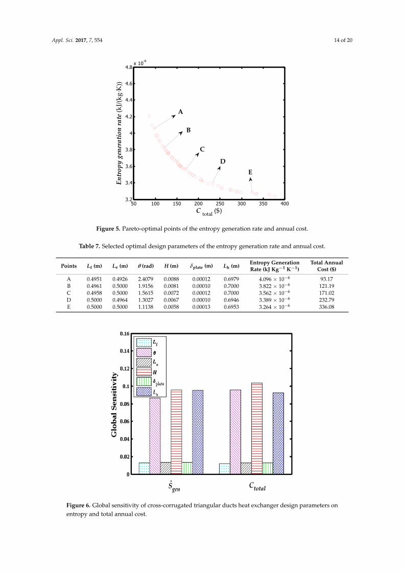
The results of the Pareto-optimal points of the entropy generation rate and the total annual costare shown in Figure 5. The entropy generation rate decreases with an increase in the total annual cost,which means if any one of smaller entropy generation rates replaces another it will always sacrificequality of total annual cost. Similarly, five of the representative selected optimal design parameters aregiven in Table 7. A thinner plate thickness, larger channel length, and larger heat exchanger heighttend to balance the entropy generation rate and total annual cost.
A global sensitivity analysis results are shown in Figure 6. The bars representing the apex angle,channel height, and heat exchanger height are outstanding in the histogram.
Appl. Sci. 2017, 7, 554 14 of 20
Appl. Sci. 2017, 7, 554 14 of 20
Table 7. Selected optimal design parameters of the entropy generation rate and annual cost.
Points fL (m)
eL (m)
θ (rad)
H (m)
plateδ
(m) hL
(m) Entropy Generation
Rate (kJ Kg−1 K−1)
Total Annual Cost
($) A 0.4951 0.4926 2.4079 0.0088 0.00012 0.6979 4.096 × 10⁻⁶ 93.17 B 0.4961 0.5000 1.9156 0.0081 0.00010 0.7000 3.822 × 10⁻⁶ 121.19 C 0.4958 0.5000 1.5615 0.0072 0.00012 0.7000 3.562 × 10⁻⁶ 171.02 D 0.5000 0.4964 1.3027 0.0067 0.00010 0.6946 3.389 × 10⁻⁶ 232.79 E 0.5000 0.5000 1.1138 0.0058 0.00013 0.6953 3.264 × 10⁻⁶ 336.08
Figure 5. Pareto-optimal points of the entropy generation rate and annual cost.
A global sensitivity analysis results are shown in Figure 6. The bars representing the apex angle, channel height, and heat exchanger height are outstanding in the histogram.
Figure 6. Global sensitivity of cross-corrugated triangular ducts heat exchanger design parameters on entropy and total annual cost.
50 100 150 200 250 300 350 4003.2
3.4
3.6
3.8
4
4.2
4.4
4.6
4.8x 10
-6
C total ($)
Entr
opy
gene
rati
on ra
te (k
J/(kg
·K))
A
B
C
DE
Figure 5. Pareto-optimal points of the entropy generation rate and annual cost.
Table 7. Selected optimal design parameters of the entropy generation rate and annual cost.
Points Lf (m) Le (m) θ (rad) H (m) δplate (m) Lh (m) Entropy GenerationRate (kJ Kg−1 K−1)
Total AnnualCost ($)
A 0.4951 0.4926 2.4079 0.0088 0.00012 0.6979 4.096 × 10⁻⁶ 93.17B 0.4961 0.5000 1.9156 0.0081 0.00010 0.7000 3.822 × 10⁻⁶ 121.19C 0.4958 0.5000 1.5615 0.0072 0.00012 0.7000 3.562 × 10⁻⁶ 171.02D 0.5000 0.4964 1.3027 0.0067 0.00010 0.6946 3.389 × 10⁻⁶ 232.79E 0.5000 0.5000 1.1138 0.0058 0.00013 0.6953 3.264 × 10⁻⁶ 336.08
Appl. Sci. 2017, 7, 554 14 of 20
Table 7. Selected optimal design parameters of the entropy generation rate and annual cost.
Points fL (m)
eL (m)
θ (rad)
H (m)
plateδ
(m) hL
(m) Entropy Generation
Rate (kJ Kg−1 K−1)
Total Annual Cost
($) A 0.4951 0.4926 2.4079 0.0088 0.00012 0.6979 4.096 × 10⁻⁶ 93.17 B 0.4961 0.5000 1.9156 0.0081 0.00010 0.7000 3.822 × 10⁻⁶ 121.19 C 0.4958 0.5000 1.5615 0.0072 0.00012 0.7000 3.562 × 10⁻⁶ 171.02 D 0.5000 0.4964 1.3027 0.0067 0.00010 0.6946 3.389 × 10⁻⁶ 232.79 E 0.5000 0.5000 1.1138 0.0058 0.00013 0.6953 3.264 × 10⁻⁶ 336.08
Figure 5. Pareto-optimal points of the entropy generation rate and annual cost.
A global sensitivity analysis results are shown in Figure 6. The bars representing the apex angle, channel height, and heat exchanger height are outstanding in the histogram.
Figure 6. Global sensitivity of cross-corrugated triangular ducts heat exchanger design parameters on entropy and total annual cost.
50 100 150 200 250 300 350 4003.2
3.4
3.6
3.8
4
4.2
4.4
4.6
4.8x 10
-6
C total ($)
Entr
opy
gene
rati
on ra
te (k
J/(kg
·K))
A
B
C
DE
Figure 6. Global sensitivity of cross-corrugated triangular ducts heat exchanger design parameters onentropy and total annual cost.

Appl. Sci. 2017, 7, 554 15 of 20
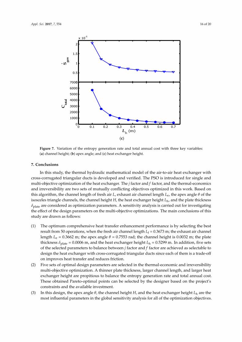
To effectively show how these key design parameters affect the entropy generation rate and totalannual cost in this design, three charts are made that demonstrate the two objectives changing withthe three key parameters. For the three parameters, only one input parameter is varied, while the otherinput parameters are fixed. Figure 7a–c indicates the entropy generation rate and total annual costchange with H, θ, and Lh, respectively. The entropy generation rate and total annual cost decrease withthe increasing variables and tend to fixed values.
Appl. Sci. 2017, 7, 554 15 of 20
To effectively show how these key design parameters affect the entropy generation rate and total annual cost in this design, three charts are made that demonstrate the two objectives changing with the three key parameters. For the three parameters, only one input parameter is varied, while the other input parameters are fixed. Figure 7a–c indicates the entropy generation rate and total annual cost change with H, θ, and Lh, respectively. The entropy generation rate and total annual cost decrease with the increasing variables and tend to fixed values.
(a)
(b)
0
0.3
0.6
0.9
1.2
1.5x 10
-5
S gen
0 0.001 0.002 0.003 0.004 0.005 0.006 0.007 0.008 0.009 0.010
1000
2000
3000
4000
Cto
tal
·
H (m)
0
0.5
1
1.5
x 10-5
S gen
0 0.5 1 1.5 2 2.5 30
1000
2000
3000
4000
5000
6000
Cto
tal
θ (rad)
·
Figure 7. Cont.
Appl. Sci. 2017, 7, 554 16 of 20Appl. Sci. 2017, 7, 554 16 of 20
(c)
Figure 7. Variation of the entropy generation rate and total annual cost with three key variables: (a) channel height; (b) apex angle; and (c) heat exchanger height.
7. Conclusions
In this study, the thermal hydraulic mathematical model of the air-to-air heat exchanger with cross-corrugated triangular ducts is developed and verified. The PSO is introduced for single and multi-objective optimization of the heat exchanger. The j factor and f factor, and the thermal-economics and irreversibility are two sets of mutually conflicting objectives optimized in this work. Based on this algorithm, the channel length of fresh air L, exhaust air channel length Le, the apex angle θ of the isosceles triangle channels, the channel height H, the heat exchanger height Lh, and the plate thickness δplate are considered as optimization parameters. A sensitivity analysis is carried out for investigating the effect of the design parameters on the multi-objective optimizations. The main conclusions of this study are drawn as follows:
(1) The optimum comprehensive heat transfer enhancement performance is by selecting the best result from 50 operations, when the fresh air channel length Lf = 0.3673 m; the exhaust air channel length Le = 0.3662 m; the apex angle θ = 0.7553 rad; the channel height is 0.0032 m; the plate thickness δplate = 0.0006 m, and the heat exchanger height Lh = 0.5299 m. In addition, five sets of the selected parameters to balance between j factor and f factor are achieved as selectable to design the heat exchanger with cross-corrugated triangular ducts since each of them is a trade-off on improves heat transfer and reduces friction.
(2) Five sets of optimal design parameters are selected in the thermal-economic and irreversibility multi-objective optimization. A thinner plate thickness, larger channel length, and larger heat exchanger height are propitious to balance the entropy generation rate and total annual cost. These obtained Pareto-optimal points can be selected by the designer based on the project’s constraints and the available investment.
(3) In this design, the apex angle θ, the channel height H, and the heat exchanger height Lh are the most influential parameters in the global sensitivity analysis for all of the optimization objectives.
Acknowledgments: This project was jointly supported by The National Natural Science Foundation of China, No. 51566002, Guangxi Colleges and The University Key Lab of Unmanned Aerial Vehicle (UAV), No. WRJ2015KF04, and by the Innovation Project of Guet Graduate Education, Guilin, China, No. 2016YJCX96.
0
0.5
1
1.5
2
x 10-5
S gen
0 0.1 0.2 0.3 0.4 0.5 0.6 0.70
1000
2000
3000
4000
5000
6000
7000
Cto
tal
·
Lh (m)
Figure 7. Variation of the entropy generation rate and total annual cost with three key variables:(a) channel height; (b) apex angle; and (c) heat exchanger height.
7. Conclusions
In this study, the thermal hydraulic mathematical model of the air-to-air heat exchanger withcross-corrugated triangular ducts is developed and verified. The PSO is introduced for single andmulti-objective optimization of the heat exchanger. The j factor and f factor, and the thermal-economicsand irreversibility are two sets of mutually conflicting objectives optimized in this work. Based onthis algorithm, the channel length of fresh air L, exhaust air channel length Le, the apex angle θ of theisosceles triangle channels, the channel height H, the heat exchanger height Lh, and the plate thicknessδplate are considered as optimization parameters. A sensitivity analysis is carried out for investigatingthe effect of the design parameters on the multi-objective optimizations. The main conclusions of thisstudy are drawn as follows:
(1) The optimum comprehensive heat transfer enhancement performance is by selecting the bestresult from 50 operations, when the fresh air channel length Lf = 0.3673 m; the exhaust air channellength Le = 0.3662 m; the apex angle θ = 0.7553 rad; the channel height is 0.0032 m; the platethickness δplate = 0.0006 m, and the heat exchanger height Lh = 0.5299 m. In addition, five setsof the selected parameters to balance between j factor and f factor are achieved as selectable todesign the heat exchanger with cross-corrugated triangular ducts since each of them is a trade-offon improves heat transfer and reduces friction.
(2) Five sets of optimal design parameters are selected in the thermal-economic and irreversibilitymulti-objective optimization. A thinner plate thickness, larger channel length, and larger heatexchanger height are propitious to balance the entropy generation rate and total annual cost.These obtained Pareto-optimal points can be selected by the designer based on the project’sconstraints and the available investment.
(3) In this design, the apex angle θ, the channel height H, and the heat exchanger height Lh are themost influential parameters in the global sensitivity analysis for all of the optimization objectives.

Appl. Sci. 2017, 7, 554 17 of 20
Acknowledgments: This project was jointly supported by The National Natural Science Foundation of China,No. 51566002, Guangxi Colleges and The University Key Lab of Unmanned Aerial Vehicle (UAV),No. WRJ2015KF04, and by the Innovation Project of Guet Graduate Education, Guilin, China, No. 2016YJCX96.
Author Contributions: The paper was a collaborative effort of all authors. Caihang Liang proposed the designideas, made very useful comments and suggestions, contributed to the English editing and revised the article;Xiaoman Tong performed the simulation and wrote the paper; Tengyue Lei analyzed the data, Zhenxing Li andGuoshan Wu gave some academic advice.
Conflicts of Interest: The authors declare no conflict of interest.
Nomenclature
A area (m2)b1 cognitive parameter (for PSO algorithm)b2 social parameter (for PSO algorithm)c minimum heat capacity (kJ)cR ratio of minimum heat capacity to maximize heat capacitycp specific heat at constant pressure (kJ kg−1 K−1)CA cost for per unit area ($ m−2)Cinv the investment cost ($ year−1)Cope the operating cost ($ year−1)Ctotal total annual cost ($ year−1)Dh hydrodynamic diameter (m)f friction factorfitness fitness valuegbest group best of particle the population (for PSO algorithm)gu(x) penalty functionh convective heat coefficient (KW m−2)H channel height (m)Iter iterationsj Colburn factorJF comprehensive thermal hydraulic performance indexK convective heat transfer coefficient (kW m−2 K−1)L length (m).
m mass flow rate (kg s−1)M penalty coefficientn particle population (for PSO algorithm)Nu Nusselt numberNTU number of heat transfer unitspbest personal best of the population (for PSO algorithm)P pressure (Pa)Pr Prandtl numberQ heat duty (W).
Q air flow rate (m3 h−1)r1, r2 random numbers range from 0 to 1 (for PSO algorithm)R idea gas constant (KJ kg−1 K−1))Re Reynolds number.Sgen entropy generation rate (kW kg−1 K−1)STp total sensitivity indexT temperature (K)v velocity (for PSO algorithm)V volume (m3)y depreciation timeZ particle’s position (for PSO algorithm)

Appl. Sci. 2017, 7, 554 18 of 20
Greek lettersα inflation rateδ thickness (m)ε effectivenessη fan efficiencyθ apex angle (rad)κ the electric cost ($ KW−1 h−1)λ thermal conductivity (kW m−1 K−1)µ dynamic viscosity (Pa s)ξ number of particles (for PSO algorithm)ρ density (kg m−3)σ exponent of non-liner of increase factorτ yearly running time (h year−1)φ annual cost coefficientΨ(Y) total variance functionΨp, Ψ_p total varianceω inertial weight (for PSO algorithm)Subscriptsa aircyc cyclice exhaust airf fresh airh vertical directioni inletm meano outlets sensible heat
References
1. Zhang, L.Z. Heat and mass transfer in a total heat exchanger: Cross-corrugated triangular ducts withcomposite supported liquid membrane. Numer. Heat Transf. A Appl. 2008, 53, 1195–1210. [CrossRef]
2. Li, Z.X.; Zhong, T.S.; Niu, J.L.; Xiao, F.; Zhang, L.Z. Conjugate heat and mass transfer in a total heat exchangerwith cross-corrugated triangular ducts and one-step made asymmetric membranes. Int. J. Heat Mass Transf.2015, 84, 390–400. [CrossRef]
3. Zhang, L.Z.; Chen, Z.Y. Convective heat transfer in cross-corrugated triangular ducts under uniform heatflux boundary conditions. Int. J. Heat Mass Transf. 2011, 54, 597–605. [CrossRef]
4. Lee, J.; Lee, K.-S. Flow characteristics and thermal performance in chevron type plate heat exchangers. Int. J.Heat Mass Transf. 2014, 78, 699–706. [CrossRef]
5. Fernandes, C.S.; Dias, R.P.; Nóbrega, J.M.; Maia, J.M. Friction factors of power-law fluids in chevron-typeplate heat exchangers. J. Food Eng. 2008, 89, 441–447. [CrossRef]
6. Tsai, Y.-C.; Liu, F.-B.; Shen, P.-T. Investigations of the pressure drop and flow distribution in a chevron-typeplate heat exchanger. Int. Commun. Heat Mass Transf. 2009, 36, 574–578. [CrossRef]
7. Li, Z.; Gao, Y. Numerical study of turbulent flow and heat transfer in cross-corrugated triangular ducts withdelta-shaped baffles. Int. J. Heat Mass Transf. 2017, 108, 658–670. [CrossRef]
8. Focke, W.W.; Zachariades, J.; Olivier, I. The effect of the corrugation inclination angle on the thermohydraulicperformance of plate heat exchangers. Int. J. Heat Mass Transf. 1985, 28, 1469–1479. [CrossRef]
9. Zimmerer, C.; Gschwind, P.; Gaiser, G.; Kottke, V. Comparison of heat and mass transfer in different heatexchanger geometries with corrugated walls. Exp. Therm. Fluid Sci. 2002, 26, 269–273. [CrossRef]
10. Kumar, V.; Tiwari, A.K.; Ghosh, S.K. Effect of chevron angle on heat transfer performance in plate heatexchanger using zno/water nanofluid. Energy Convers. Manag. 2016, 118, 142–154. [CrossRef]
11. Zhao, Y.; Wu, Y.; Cheng, H.; Zhu, G. Numerical simulation of corrugated inclination angle on the performanceof plate heat exchanger. In Proceedings of the 2014 International Conference on Mechatronics, Electronic,Industrial and Control Engineering, Shenyang, China, 15–17 November 2014; Volume 5, pp. 1268–1271.

Appl. Sci. 2017, 7, 554 19 of 20
12. Liu, X.P.; Niu, J.L. Effects of geometrical parameters on the thermohydraulic characteristics of periodiccross-corrugated channels. Int. J. Heat Mass Transf. 2015, 84, 542–549. [CrossRef]
13. Bejan, A. Second-law analysis in heat transfer and thermal design. In Advances in Heat Transfer; James, P.H.,Thomas, F.I., Eds.; Elsevier: New York, NY, USA, 1982; Volume 15, pp. 1–58.
14. Ogulata, R.T.; Doba, F. Experiments and entropy generation minimization analysis of a cross-flow heatexchanger. Int. J. Heat Mass Transf. 1998, 41, 373–381. [CrossRef]
15. Farzaneh-Gord, M.; Ameri, H.; Arabkoohsar, A. Tube-in-tube helical heat exchangers performanceoptimization by entropy generation minimization approach. Appl. Therm. Eng. 2016, 108, 1279–1287. [CrossRef]
16. Rashidi, S.; Akbarzadeh, M.; Masoodi, R.; Languri, E.M. Thermal-hydraulic and entropy generation analysisfor turbulent flow inside a corrugated channel. Int. J. Heat Mass Transf. 2017, 109, 812–823. [CrossRef]
17. Ghanbarpour, M.; Khodabandeh, R. Entropy generation analysis of cylindrical heat pipe using nanofluid.Thermochim. Acta 2015, 610, 37–46. [CrossRef]
18. Wang, L.M.; Deng, L.; Ji, C.L.; Liang, E.K.; Wang, C.X.; Che, D.F. Multi-objective optimization of geometricalparameters of corrugated-undulated heat transfer surfaces. Appl. Energy 2016, 174, 25–36. [CrossRef]
19. Mehrgoo, M.; Amidpour, M. Constructal design and optimization of a dual pressure heat recovery steamgenerator. Energy 2017, 124, 87–99. [CrossRef]
20. Peng, H.; Ling, X. Optimal design approach for the plate-fin heat exchangers using neural networkscooperated with genetic algorithms. Appl. Therm. Eng. 2008, 28, 642–650. [CrossRef]
21. Hadidi, A.; Nazari, A. Design and economic optimization of shell-and-tube heat exchangers usingbiogeography-based (bbo) algorithm. Appl. Therm. Eng. 2013, 51, 1263–1272. [CrossRef]
22. Khan, T.A.; Li, W. Optimal design of plate-fin heat exchanger by combining multi-objective algorithms. Int. J.Heat Mass Transf. 2017, 108, 1560–1572. [CrossRef]
23. Zarea, H.; Moradi Kashkooli, F.; Mansuri Mehryan, A.; Saffarian, M.R.; Namvar Beherghani, E. Optimaldesign of plate-fin heat exchangers by a bees algorithm. Appl. Therm. Eng. 2014, 69, 267–277. [CrossRef]
24. Wang, Z.; Li, Y. Irreversibility analysis for optimization design of plate fin heat exchangers usinga multi-objective cuckoo search algorithm. Energy Convers. Manag. 2015, 101, 126–135. [CrossRef]
25. Rao, R.V.; Saroj, A. Constrained economic optimization of shell-and-tube heat exchangers using elitist-jayaalgorithm. Energy 2017, 128, 785–800. [CrossRef]
26. Wetter, M.; Wright, J. A comparison of deterministic and probabilistic optimization algorithms for nonsmoothsimulation-based optimization. Build. Environ. 2004, 39, 989–999. [CrossRef]
27. Patel, V.K.; Rao, R.V. Design optimization of shell-and-tube heat exchanger using particle swarm optimizationtechnique. Appl. Therm. Eng. 2010, 30, 1417–1425. [CrossRef]
28. Rao, R.V.; Patel, V.K. Thermodynamic optimization of cross flow plate-fin heat exchanger using a particleswarm optimization algorithm. Int. J. Therm. Sci. 2010, 49, 1712–1721. [CrossRef]
29. Yousefi, M.; Enayatifar, R.; Darus, A.N.; Abdullah, A.H. A robust learning based evolutionary approachfor thermal-economic optimization of compact heat exchangers. Int. Commun. Heat Mass Transf. 2012, 39,1605–1615. [CrossRef]
30. Dastmalchi, M.; Sheikhzadeh, G.A.; Arefmanesh, A. Optimization of micro-finned tubes in double pipe heatexchangers using particle swarm algorithm. Appl. Therm. Eng. 2017, 119, 1–9. [CrossRef]
31. Bejan, A. Method of entropy generation minimization, or modeling and optimization based on combinedheat transfer and thermodynamics. Rev. Gén. Therm. 1996, 35, 637–646. [CrossRef]
32. Lienhard, J.H. A Heat Transfer Textbook; Phlogiston Press: Cambridge, MA, USA, 2008.33. Zhang, L.Z. Numerical study of periodically fully developed flow and heat transfer in cross-corrugated
triangular channels in transitional flow regime. Numer. Heat Transf. A Appl. 2005, 48, 387–405. [CrossRef]34. Jamshidi, N.; Farhadi, M.; Sedighi, K.; Ganji, D.D. Optimization of design parameters for nanofluids flowing
inside helical coils. Int. Commun. Heat Mass Transf. 2012, 39, 311–317. [CrossRef]35. Kennedy, J.; Eberhart, R. Particle Swarm Optimization. In Proceedings of the IEEE International Conference
on Neural Networks, Perth, Australia, 27 November–1 December 1995; pp. 1942–1948.36. Ghorbani, B.; Mafi, M.; Shirmohammadi, R.; Hamedi, M.-H.; Amidpour, M. Optimization of operation
parameters of refrigeration cycle using particle swarm and nlp techniques. J. Nat. Gas Sci. Eng. 2014, 21,779–790. [CrossRef]
37. Kaveh, A.; Mahdavi, V.R. A hybrid CBO-PSO algorithm for optimal design of truss structures with dynamicconstraints. Appl. Soft Comput. 2015, 34, 260–273. [CrossRef]

Appl. Sci. 2017, 7, 554 20 of 20
38. Sobol, I.M. Sensitivity analysis for non-linear mathematical models. Math. Model. Comput. Exp. 1993, 1,407–414.
39. Saltelli, A.; Tarantola, S.; Campolongo, F. Sensitivity analysis as an ingredient of modeling. Stat. Sci. 2000, 15,377–395.
40. Homma, T.; Saltelli, A. Importance measures in global sensitivity analysis of nonlinear models. Reliab. Eng.Syst. Saf. 1996, 52, 1–17. [CrossRef]
© 2017 by the authors. Licensee MDPI, Basel, Switzerland. This article is an open accessarticle distributed under the terms and conditions of the Creative Commons Attribution(CC BY) license (http://creativecommons.org/licenses/by/4.0/).