
THERMODYNAMIC PERFORMANCE EVALUATION OF AN AIR-AIR HEAT PIPE HEAT EXCHANGER
11
THERMODYNAMIC PERFORMANCE EVALUATION OF AN AIR-AIR HEAT PIPE HEAT EXCHANGER by Mohan Jagadeesh Kumar MANDAPATI a* , Kaushik SUBHASH CHANDRA b , and Garg SAT NARAYAN b a School of Mechanical and Building Sciences, VIT University, Vellore, Tamil Nadu, India b Centre for Energy Studies, IIT Delhi, New Delhi, India Original scientific paper DOI: 10.2298/TSCI121214123K In this paper, heat transfer analysis for an air-air heat exchanger was experimen- tally carried out to find its thermal performance and effectiveness. Air-air heat exchanger equipped with finned heat pipes was considered for the experimentation. Mass flow rate of air was considered in between 0.24 to 0.53 kg/s. The temperature at the condenser side of the heat pipe heat exchanger was kept constant at around 23 °C and at the evaporator part it was varied from 88 to 147 °C. The performance of heat pipe heat exchanger was evaluated at different mass flow rate of air, in terms of effectiveness and compared with its corresponding value found by theoreti- cal analysis. Key words: heat pipe heat exchanger, thermodynamic performance, heat transfer coefficient, effectiveness, Reynolds number Introduction With the advent of the modern hi-tech era, the demand for energy is increasing at a rapid rate. Because of this, in a few years' time the world is bound to face an energy crisis. In lieu of this fact it becomes our utmost duty to save as much of energy as possible. Hence, we should always try to identify areas for possible energy saving. One such possible area of work lies in air-conditioning systems as, in these systems, the waste heat transfer rate is poor. Thus, by work- ing in this area, we would be able to contribute towards energy saving. In air-conditioning appli- cations the incoming fresh air can be pre-cooled using the outgoing exhaust air to reduce the cooling load. But the amount of heat transfer between hot and cold fluids in air-air waste heat re- covery systems is not high due to the fact that the air side heat transfer coefficient is low. Hence, many heat transfer devices have been developed for increasing the air side heat transfer coeffi- cient. The chief of these is heat pipe. The heat pipe concept was first put forward by Gaugler [1] of the General Motor cor- poration, Ohio, USA. However, the heat pipe as proposed by Gaugler [1] was not developed be- yond the patent stage, and it was not patented until Grover [2] rediscovered the heat pipe. The work proposed by Grover [2] includes theoretical analysis and presents results of experiments carried out on stainless steel heat pipes with a wire mesh wick and sodium, lithium and silver as Mandapati, M. J. K., et al.: Thermodynamic Performance Evaluation of an Air-Air Heat ... THERMAL SCIENCE: Year 2014, Vol. 18, No. 4, pp. 1343-1353 1343 * Corresponding author; e-mail: [email protected]
Transcript of THERMODYNAMIC PERFORMANCE EVALUATION OF AN AIR-AIR HEAT PIPE HEAT EXCHANGER
THERMODYNAMIC PERFORMANCE EVALUATION OF AN AIR-AIRHEAT PIPE HEAT EXCHANGER
by
Mohan Jagadeesh Kumar MANDAPATI a*, Kaushik SUBHASH CHANDRA b,and Garg SAT NARAYAN b
a School of Mechanical and Building Sciences, VIT University, Vellore, Tamil Nadu, Indiab Centre for Energy Studies, IIT Delhi, New Delhi, India
Original scientific paperDOI: 10.2298/TSCI121214123K
In this paper, heat transfer analysis for an air-air heat exchanger was experimen-tally carried out to find its thermal performance and effectiveness. Air-air heatexchanger equipped with finned heat pipes was considered for the experimentation.Mass flow rate of air was considered in between 0.24 to 0.53 kg/s. The temperatureat the condenser side of the heat pipe heat exchanger was kept constant at around23 °C and at the evaporator part it was varied from 88 to 147 °C. The performanceof heat pipe heat exchanger was evaluated at different mass flow rate of air, interms of effectiveness and compared with its corresponding value found by theoreti-cal analysis.
Key words: heat pipe heat exchanger, thermodynamic performance, heat transfercoefficient, effectiveness, Reynolds number
Introduction
With the advent of the modern hi-tech era, the demand for energy is increasing at a
rapid rate. Because of this, in a few years' time the world is bound to face an energy crisis. In lieu
of this fact it becomes our utmost duty to save as much of energy as possible. Hence, we should
always try to identify areas for possible energy saving. One such possible area of work lies in
air-conditioning systems as, in these systems, the waste heat transfer rate is poor. Thus, by work-
ing in this area, we would be able to contribute towards energy saving. In air-conditioning appli-
cations the incoming fresh air can be pre-cooled using the outgoing exhaust air to reduce the
cooling load. But the amount of heat transfer between hot and cold fluids in air-air waste heat re-
covery systems is not high due to the fact that the air side heat transfer coefficient is low. Hence,
many heat transfer devices have been developed for increasing the air side heat transfer coeffi-
cient. The chief of these is heat pipe.
The heat pipe concept was first put forward by Gaugler [1] of the General Motor cor-
poration, Ohio, USA. However, the heat pipe as proposed by Gaugler [1] was not developed be-
yond the patent stage, and it was not patented until Grover [2] rediscovered the heat pipe. The
work proposed by Grover [2] includes theoretical analysis and presents results of experiments
carried out on stainless steel heat pipes with a wire mesh wick and sodium, lithium and silver as
Mandapati, M. J. K., et al.: Thermodynamic Performance Evaluation of an Air-Air Heat ...THERMAL SCIENCE: Year 2014, Vol. 18, No. 4, pp. 1343-1353 1343
* Corresponding author; e-mail: [email protected]
working fluids. In due course of time, interest in heat pipes as a means of heat transfer increased
with considerable amount of work done. As a result, these devices began to be used in applica-
tions such as in rotary heat exchanger [3], waste heat recovery systems in automobiles [4] and in
hospitals [5], latent heat storage systems [6-9], energy storage in wind power systems [10],
aeroponic system [11], nuclear reactor [12, 13], thermionic converters [14, 15], and electronics
cooling applications [16]. Review of the application of heat pipes in modern heat exchangers
can be found in Vasiliev[17].
The thermal performance of the heat recovery systems using heat pipe heat exchanger
is dependent on the effectiveness of the heat pipe heat exchanger which in turn depends on input
heat transfer rate, the evaporator length, working fluid and its filling ratio [18-20]. Investiga-
tions were carried out to find the thermal performance and effectiveness of heat recovery sys-
tems using heat pipe heat exchanger [21-25]. Heat pipe heat exchangers were theoretically de-
signed and validated with experimental analysis to find their optimum effectiveness for low
temperature field applications [5] and air-air waste heat recovery systems [21-23]. It was found
that the optimum effectiveness was obtained when the fresh air inlet temperature is near the op-
erating temperature of the heat pipes. Heat pipe heat exchanger was modeled analytically using
NTU method [24] and by numerical simulations using CFD [25].
This paper focuses on heat pipe as a means of waste heat recovery as it is not only
highly effective but also economically viable. It presents experimental testing of a horizontal
air-air heat pipe exchanger carried out at different mass flow rates of hot and cold fluids. The ef-
fectiveness of air-air heat pipe heat exchanger in recovering waste heat was explored. The mea-
sured performance of the heat pipe heat exchanger has been compared with the theoretical re-
sults obtained by its sizing.
Performance evaluation of heat pipe heat exchanger
Performance evaluation of heat pipe heat exchanger is necessary to show that the heat
pipe meets the requirements laid down during the design. A considerable number of variables
including effectiveness, orientation with respect to gravity, vapor temperature, evaporator heat
flux, etc. can be investigated experimentally by benchmark testing.
Experimental set-up
The experimental set-up used is
shown in figs. 1 and 2. The set-up
consists of a circumferentially fin-
ned tube heat pipe heat exchanger
installed in a two sided rectangular
air duct of size 0.65 × 0.3 × 0.196 m3.
Heat pipe heat exchanger consisted
of condenser, adiabatic, and evapo-
rator sections. Condenser section
(0.3 m × 0.3 m) of the heat pipe
exchanger is placed on one side of
the air duct and evaporation section
(0.3 × 0.3 m2) on the other side. The
two sides of the duct were connected
at one end by a U bend where an
Mandapati, M. J. K., et al.: Thermodynamic Performance Evaluation of an Air-Air Heat ...1344 THERMAL SCIENCE: Year 2014, Vol. 18, No. 4, pp. 1343-1353
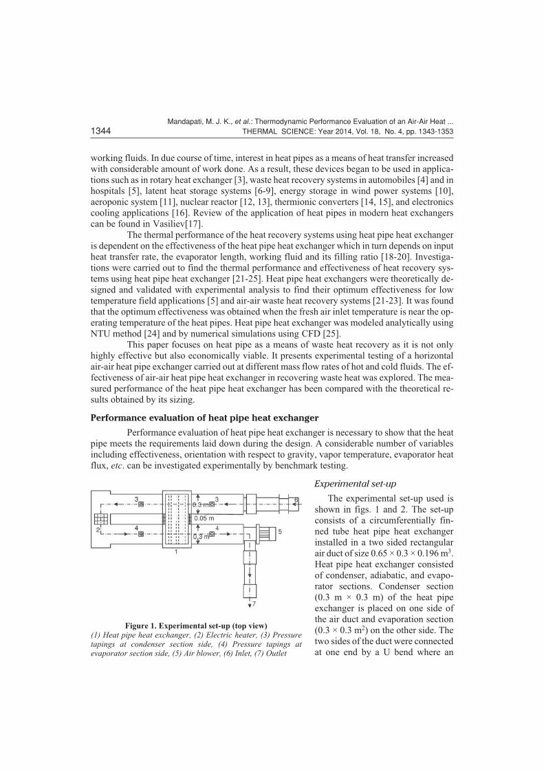
Figure 1. Experimental set-up (top view)(1) Heat pipe heat exchanger, (2) Electric heater, (3) Pressuretapings at condenser section side, (4) Pressure tapings atevaporator section side, (5) Air blower, (6) Inlet, (7) Outlet
electric coil heater was fixed. At the
exit section of the duct, air blower
with variable speed control was pro-
vided to create air movement through
the air duct. Pressure difference in
the duct across the condenser and
evaporator sections of the heat pipe
heat exchanger was measured with
the help of pressure gauges. At the
exit section of the duct, air blower
with variable speed control was pro-
vided to create air movement through
the air duct. Pressure difference in the duct across the condenser and evaporator sections of the
heat pipe heat exchanger was measured with the help of pressure gauges.
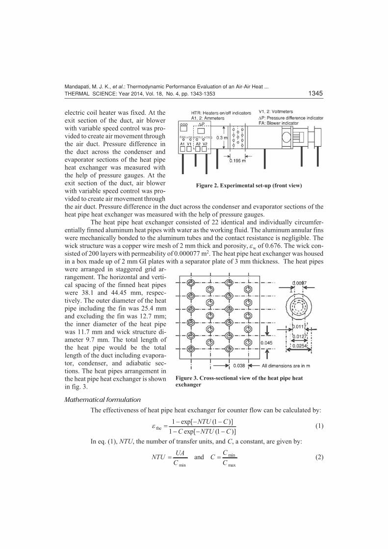
The heat pipe heat exchanger consisted of 22 identical and individually circumfer-
entially finned aluminum heat pipes with water as the working fluid. The aluminum annular fins
were mechanically bonded to the aluminum tubes and the contact resistance is negligible. The
wick structure was a copper wire mesh of 2 mm thick and porosity, ew of 0.676. The wick con-
sisted of 200 layers with permeability of 0.000077 m2. The heat pipe heat exchanger was housed
in a box made up of 2 mm GI plates with a separator plate of 3 mm thickness. The heat pipes
were arranged in staggered grid ar-
rangement. The horizontal and verti-
cal spacing of the finned heat pipes
were 38.1 and 44.45 mm, respec-
tively. The outer diameter of the heat
pipe including the fin was 25.4 mm
and excluding the fin was 12.7 mm;
the inner diameter of the heat pipe
was 11.7 mm and wick structure di-
ameter 9.7 mm. The total length of
the heat pipe would be the total
length of the duct including evapora-
tor, condenser, and adiabatic sec-
tions. The heat pipes arrangement in
the heat pipe heat exchanger is shown
in fig. 3.
Mathematical formulation
The effectiveness of heat pipe heat exchanger for counter flow can be calculated by:
e the �� � �
� � �
1 1
1 1
exp[ ( )]
exp[ ( )]
NTU C
C NTU C(1)
In eq. (1), NTU, the number of transfer units, and C, a constant, are given by:
NTUUA
CC
C
C� �
min
min
max
and (2)
Mandapati, M. J. K., et al.: Thermodynamic Performance Evaluation of an Air-Air Heat ...THERMAL SCIENCE: Year 2014, Vol. 18, No. 4, pp. 1343-1353 1345
Figure 2. Experimental set-up (front view)
Figure 3. Cross-sectional view of the heat pipe heatexchanger

In eq. (2):
C m c m c C m c m cmin maxmin( � , � ) max( � , �� �hf hf cf cf hf hf cfand cf ) (3)
The suffixes hf and cf represent air on evaporator and condenser side, respectively.
In eq. (2), UA, the product of overall heat transfer coefficient and overall heat transfer
area, is given by:
UAR
�1
S(4)
In eq. (4), SR, the total thermal resistance exiting across the heat pipe heat exchanger,
is given by:
SR R R R R R R R� � � � � � � �( ) ( )conv sca cond hf conv sca cond cf whf R wcf (5)
RhA
A
Aconv
o
of
fwhere� � � �1
1 1h
h h( ) (6)
RR
Asca
conv
o
�h
(7)
R
r
r
kL Ncond
o
i
t t
�
ln
2p(8)
In eq. (6), the convective heat transfer coefficient, h, can be calculated from eq. (6.4)
given in [26]:
Nu h
p
t
d
� ��
�
��
�
�
�
�hd
k
A
AF
S
S0248 0 6 1 3
0 15
0 075. Re Pr. /
.
.�
���
�
�
1 06.
(9)
In eq. (9), the Reynold's number, the Prandtl number, and F, a constant, are given by:
Re , Pr , ,� � �
�
�
r
m
n
a
u dF
A
A
dd A
A
a h
ff
hc ffand
1
1
4(10)
In eq. (10), A' is the heat transfer area of unit length of the finned tube and Aff – the min-
imum free flow area of the finned tube per unit length; they are given by:
� ��
���
�
� �
��
�
��
�
� �A d
S S
d dd Ac o
pp
of
f f
c f ffand12
2 2dd S d d d Nt c c o f f� � � �( )( )1 d (11)
In eq. (6), A and Af, are given by:
A A A d L N N Ld d
d Npc o� � � � �
��
�
��
�
�f o t f f t t c f f[ ( )]p p1
2
2 2
d d N t (12)
In eq. (6), the fin efficiency, hf, is calculated from:
hd
fe
e f f
e hf cfwhere and or� � �tanh( )
,ml
mlm
h
kl L L
2(13)
Mandapati, M. J. K., et al.: Thermodynamic Performance Evaluation of an Air-Air Heat ...1346 THERMAL SCIENCE: Year 2014, Vol. 18, No. 4, pp. 1343-1353
In eq. (5), Rwhf and Rwcf are the wick resistances on the evaporator and condenser side
of the heat pipe heat exchangers. Assuming that the heat fluxes on condenser and evaporator
sections are low and the heat transfer through the wick is due to conduction process only, Rwhf
and Rwcf are given by:
R
r
r
l k Nk
k k k kwhf, wcf
i
v
e e t
el l w wwhere� �
� � �ln
[( ) ( )(
2
1
p
e l w
l w w l w
�
� � � �
k
k k k k
)
( ) ( )( )1 e(14)
In eq. (14), kl and kw, the thermal conductivities of heat pipe liquid (water) and wick
material (copper), are assumed to be 0.6616 and 396.78 W/mK, respectively.
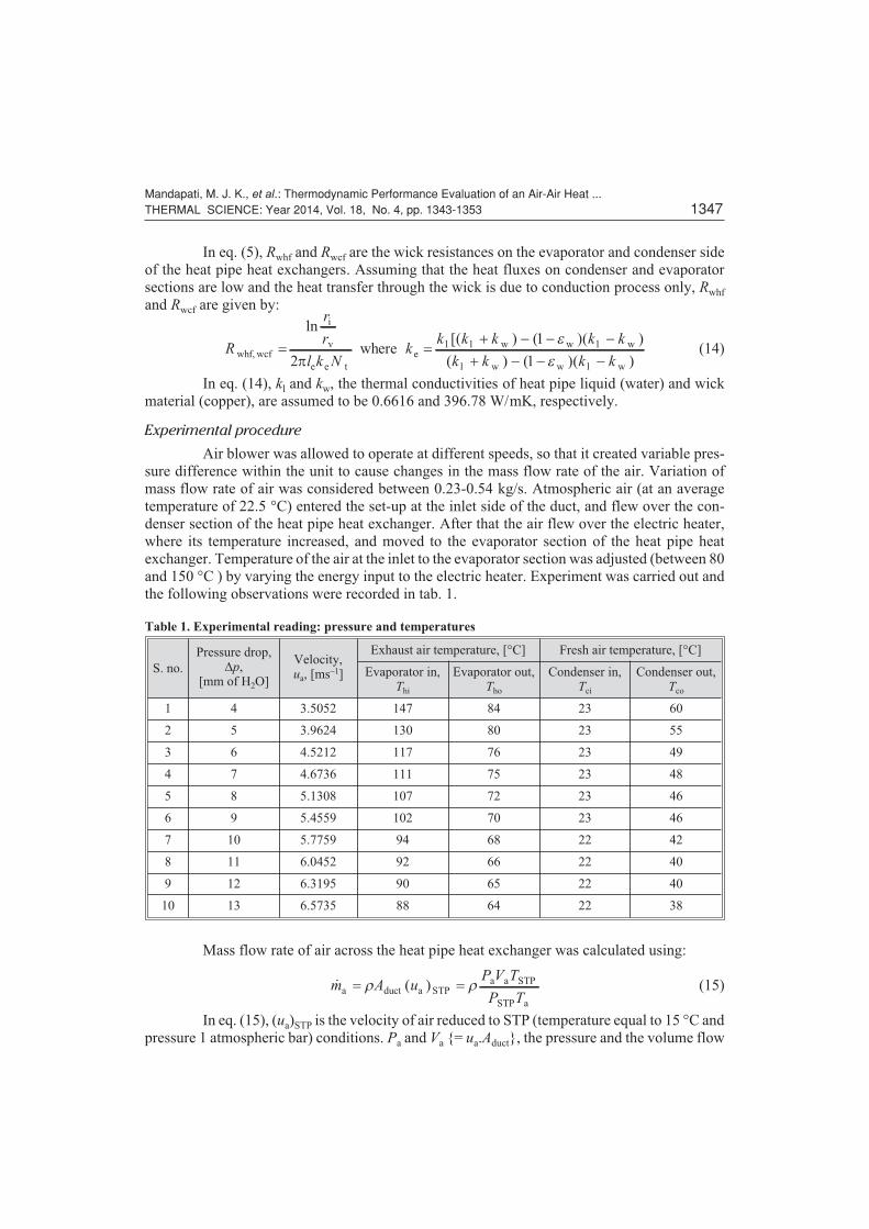
Experimental procedure
Air blower was allowed to operate at different speeds, so that it created variable pres-
sure difference within the unit to cause changes in the mass flow rate of the air. Variation of
mass flow rate of air was considered between 0.23-0.54 kg/s. Atmospheric air (at an average
temperature of 22.5 °C) entered the set-up at the inlet side of the duct, and flew over the con-
denser section of the heat pipe heat exchanger. After that the air flew over the electric heater,
where its temperature increased, and moved to the evaporator section of the heat pipe heat
exchanger. Temperature of the air at the inlet to the evaporator section was adjusted (between 80
and 150 °C ) by varying the energy input to the electric heater. Experiment was carried out and
the following observations were recorded in tab. 1.
Table 1. Experimental reading: pressure and temperatures
S. no.
Pressure drop,Dp,
[mm of H2O]
Velocity,ua, [ms–1]
Exhaust air temperature, [°C] Fresh air temperature, [°C]
Evaporator in,Thi
Evaporator out,Tho
Condenser in,Tci
Condenser out,Tco
1 4 3.5052 147 84 23 60
2 5 3.9624 130 80 23 55
3 6 4.5212 117 76 23 49
4 7 4.6736 111 75 23 48
5 8 5.1308 107 72 23 46
6 9 5.4559 102 70 23 46
7 10 5.7759 94 68 22 42
8 11 6.0452 92 66 22 40
9 12 6.3195 90 65 22 40
10 13 6.5735 88 64 22 38
Mass flow rate of air across the heat pipe heat exchanger was calculated using:
� ( )m A uP V T
P Ta duct a STP
a a STP
STP a
� �r r (15)
In eq. (15), (ua)STP is the velocity of air reduced to STP (temperature equal to 15 °C and
pressure 1 atmospheric bar) conditions. Pa and Va {= ua.Aduct}, the pressure and the volume flow
Mandapati, M. J. K., et al.: Thermodynamic Performance Evaluation of an Air-Air Heat ...THERMAL SCIENCE: Year 2014, Vol. 18, No. 4, pp. 1343-1353 1347
rate of air, were measured from the experiment. Ta is the average of temperatures at the inlet of
evaporator and condenser sections. Property values of air were considered corresponding to the
temperature, Ta.
Assuming that the heat pipe heat exchanger configuration is reduced to a double pipe
concentric counter flow type of heat exchanger, the actual quantity of heat transfer between
evaporator and condenser side can be calculated by:
Q UA T UAT T
T
T
T T Tact LMTDin out
in
out
in hi co
ln
� ��
� �DD D
D
D
D; and out ho ciDT T T� � (16)
The maximum quantity of heat that can be transferred between evaporator and con-
denser sides, is given by:
Q C T Tmax min ( )� �hi ci (17)
Effectiveness of heat pipe heat exchanger is given by:
eexp
max
�Q
Q
act (18)
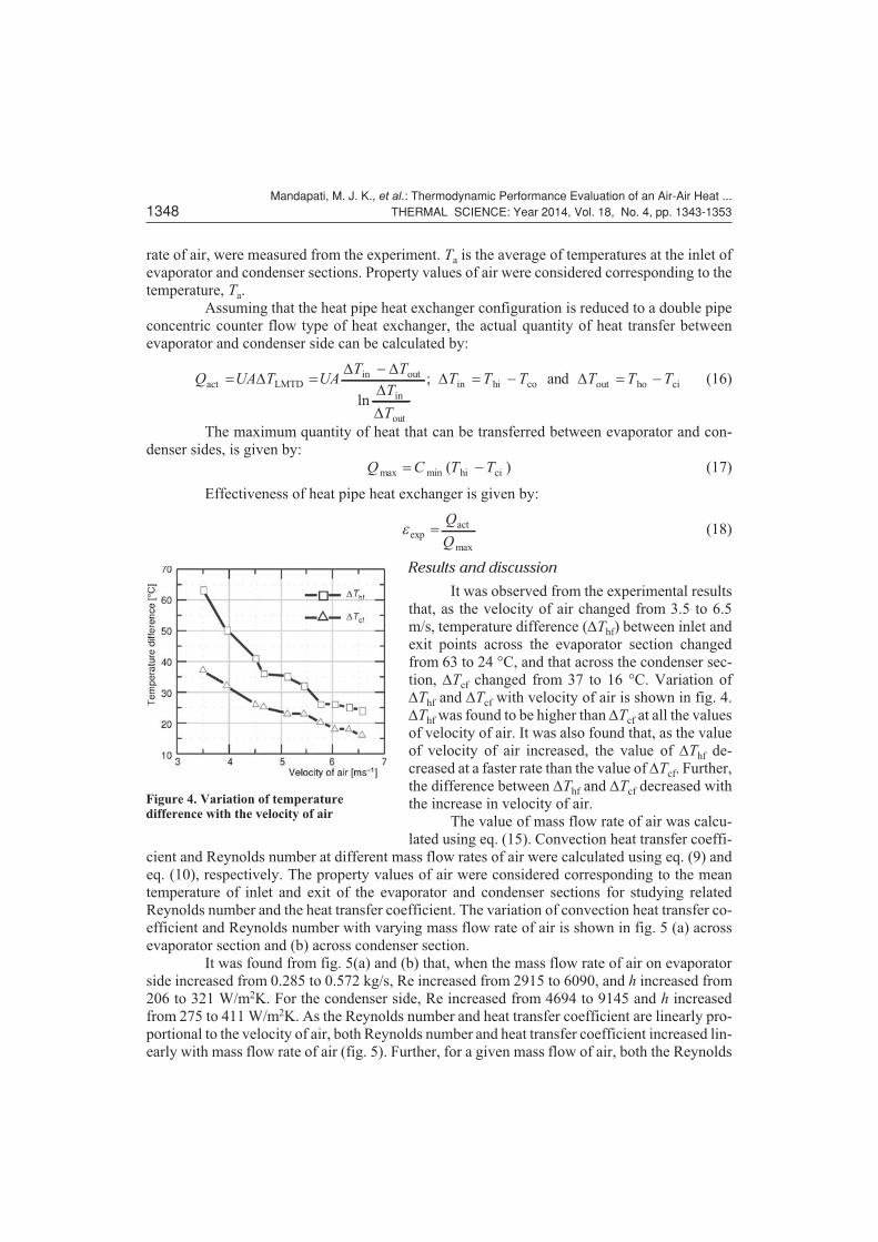
Results and discussion
It was observed from the experimental results
that, as the velocity of air changed from 3.5 to 6.5
m/s, temperature difference (DThf) between inlet and
exit points across the evaporator section changed
from 63 to 24 °C, and that across the condenser sec-
tion, DTcf changed from 37 to 16 °C. Variation of
DThf and DTcf with velocity of air is shown in fig. 4.
DThf was found to be higher than DTcf at all the values
of velocity of air. It was also found that, as the value
of velocity of air increased, the value of DThf de-
creased at a faster rate than the value of DTcf. Further,
the difference between DThf and DTcf decreased with
the increase in velocity of air.
The value of mass flow rate of air was calcu-
lated using eq. (15). Convection heat transfer coeffi-
cient and Reynolds number at different mass flow rates of air were calculated using eq. (9) and
eq. (10), respectively. The property values of air were considered corresponding to the mean
temperature of inlet and exit of the evaporator and condenser sections for studying related
Reynolds number and the heat transfer coefficient. The variation of convection heat transfer co-
efficient and Reynolds number with varying mass flow rate of air is shown in fig. 5 (a) across
evaporator section and (b) across condenser section.
It was found from fig. 5(a) and (b) that, when the mass flow rate of air on evaporator
side increased from 0.285 to 0.572 kg/s, Re increased from 2915 to 6090, and h increased from
206 to 321 W/m2K. For the condenser side, Re increased from 4694 to 9145 and h increased
from 275 to 411 W/m2K. As the Reynolds number and heat transfer coefficient are linearly pro-
portional to the velocity of air, both Reynolds number and heat transfer coefficient increased lin-
early with mass flow rate of air (fig. 5). Further, for a given mass flow of air, both the Reynolds
Mandapati, M. J. K., et al.: Thermodynamic Performance Evaluation of an Air-Air Heat ...1348 THERMAL SCIENCE: Year 2014, Vol. 18, No. 4, pp. 1343-1353
Figure 4. Variation of temperaturedifference with the velocity of air

number and heat transfer coefficient values for air on the condenser section side were higher
than those of air on the evaporator section. As the temperature range on the cold air side (i. e. at
the condenser section) is lower than that on the hot air side (i. e. at the evaporator section), the
more for the cold air. As a result, for the same mass flow rate of air, the Reynolds number and
heat transfer coefficient values are more on the condenser section.
The value of UA, the product of overall heat transfer coefficient and overall surface
area, is calculated using eq. (4), and total thermal resistance for heat flow was calculated using
eq. (5). Figure 6(a) shows the variation of various thermal resistances across the heat pipe heat
exchanger and the total thermal resistance for different mass flow rate of air for hot air section
and (b) cold air section.
It was found on the evaporator section side that, as the mass flow rate of air increased,
Rconv decreased from 0.13·10–4 to 0.93·10–4 K/W, Rsca decreased from 0.37·10–4 to 0.28 ·10–4
K/W. However, on the condenser side, as the mass flow rate of air increased, Rconv decreased
from 0.11·10–4 to 0.075·10–4 K/W, Rsca decreased from 0.31·10–4 to 0.23·10–4 K/W. It can be
seen from fig. 5 that Rcond (= 0.0942·10–4 K/W) and Rwhf (= 34.1·10–4 K/W) were independent of
the mass flow rate of air. The convection thermal resistance decreased with the increasing mass
Mandapati, M. J. K., et al.: Thermodynamic Performance Evaluation of an Air-Air Heat ...THERMAL SCIENCE: Year 2014, Vol. 18, No. 4, pp. 1343-1353 1349
Figure 5. Variation of heat transfer coefficient and Reynolds number with mass flow rate of air
Figure 6. Variation of thermal resistances with mass flow rate of air
flow rate of air for both condenser and evaporator section of the heat pipe heat exchanger. This
is true as the convection heat transfer coefficient increases with the mass flow rate; hence, the
convective thermal resistance decreased. It can also be found from fig. 6 that values of Rconv and
Rsca are more for the evaporation section of the heat pipe exchanger compared to those of con-
denser section. This is because of the fact that temperature limits on the evaporator section are
higher than those on the condenser section.
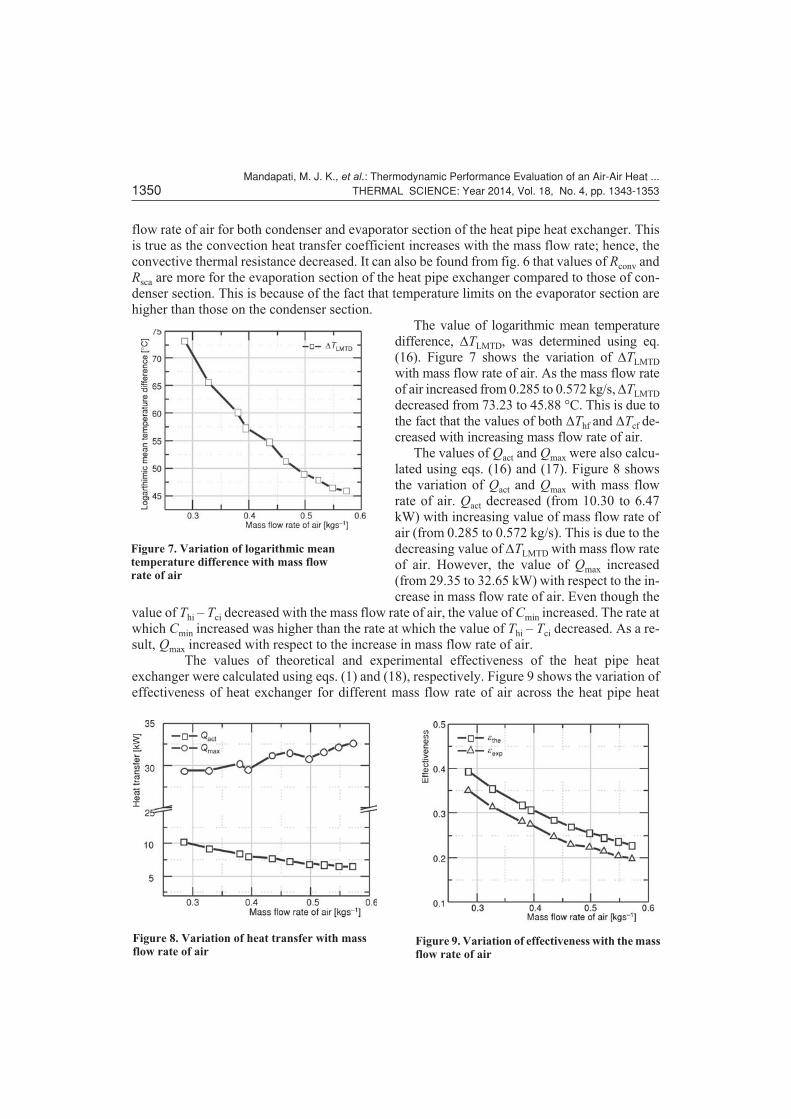
The value of logarithmic mean temperature
difference, DTLMTD, was determined using eq.
(16). Figure 7 shows the variation of DTLMTD
with mass flow rate of air. As the mass flow rate
of air increased from 0.285 to 0.572 kg/s, DTLMTD
decreased from 73.23 to 45.88 °C. This is due to
the fact that the values of both DThf and DTcf de-
creased with increasing mass flow rate of air.
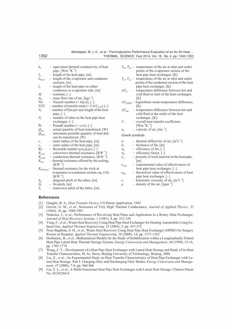
The values of Qact and Qmax were also calcu-
lated using eqs. (16) and (17). Figure 8 shows
the variation of Qact and Qmax with mass flow
rate of air. Qact decreased (from 10.30 to 6.47
kW) with increasing value of mass flow rate of
air (from 0.285 to 0.572 kg/s). This is due to the
decreasing value of DTLMTD with mass flow rate
of air. However, the value of Qmax increased
(from 29.35 to 32.65 kW) with respect to the in-
crease in mass flow rate of air. Even though the
value of Thi – Tci decreased with the mass flow rate of air, the value of Cmin increased. The rate at
which Cmin increased was higher than the rate at which the value of Thi – Tci decreased. As a re-
sult, Qmax increased with respect to the increase in mass flow rate of air.
The values of theoretical and experimental effectiveness of the heat pipe heat
exchanger were calculated using eqs. (1) and (18), respectively. Figure 9 shows the variation of
effectiveness of heat exchanger for different mass flow rate of air across the heat pipe heat
Mandapati, M. J. K., et al.: Thermodynamic Performance Evaluation of an Air-Air Heat ...1350 THERMAL SCIENCE: Year 2014, Vol. 18, No. 4, pp. 1343-1353
Figure 7. Variation of logarithmic meantemperature difference with mass flowrate of air
Figure 8. Variation of heat transfer with massflow rate of air
Figure 9. Variation of effectiveness with the massflow rate of air

exchanger. ethe decreased (from 0.39 to 0.23) with increasing value of mass flow rate of air (from
0.285 to 0.572 kg/s). Similarly, the value of eexp decreased (from 0.35 to 0.2) with respect to the
increase in mass flow rate of air. It was found from fig. 8 that rate at which Qmax increased was
higher than rate at which Qact decreased, hence the value of eexp decreased with the increase in
mass flow rate of air.
The theoretical and experimental values of effectiveness were well in agreement with
each other. The difference between the two was decreasing with increasing mass flow rate of air,
which is due to at higher mass flow rates the rate at which eexp decreased was lower than the rate
which ethe decreased. The average percentage difference between the theoretical and experimen-
tal values of effectiveness was found to be 12.5%.
Conclusion
In this paper, experimental heat transfer analysis for an air-air heat exchanger has been car-
ried out to find its thermal performance and effectiveness. The measured performance of the
heat pipe heat exchanger has been compared with the theoretical results obtained by its sizing. It
was observed from the experimental results that, as the velocity of air was increased, the temper-
ature difference between inlet and exit sides across the evaporator and condenser sections de-
creased.
As the Reynolds number and heat transfer coefficients are directly proportional to the
velocity of air flow, it was found that convective heat transfer coefficient and Reynolds number
increased linearly with increasing mass flow rate of air for both condenser and evaporator sec-
tions of the heat pipe heat exchanger. As the mass flow rate of air increased, the thermal resis-
tance for the convective heat transfer and thermal resistance offered by the scaling decreased.
However, the thermal resistance for conduction heat transfer and thermal resistance offered by
the wick structure in the heat pipe are independent of the mass flow rate of air as they are de-
pendent on the material property. Even though mass flow rate of air affects the convective ther-
mal resistance and resistance offered by the scaling factor, the overall thermal resistance across
the heat pipe heat exchanger did not significantly change with the mass flow rate of air. As the
temperature difference available at the condenser and evaporator sections decreased, the value
of logarithmic mean temperature difference decreased with corresponding increase in mass flow
rate. The actual quantity of heat transferred decreased with increasing mass flow rate of air.
Mandapati, M. J. K., et al.: Thermodynamic Performance Evaluation of an Air-Air Heat ...THERMAL SCIENCE: Year 2014, Vol. 18, No. 4, pp. 1343-1353 1351
Nomenclature
A – the total surface area of the heat pipe heat– exchanger, [m2]
Aduct – cross-sectional area of the duct, [m2]Af – the fin surface area, [m2]Aff – the minimum free flow area of the finned
– tube per unit length, [m2]Ap – the primary surface area available, [m2]A' – the heat transfer area of unit length of the
– finned tube, [m2]C – a constant equal to the ratio of specific
– heat capacities, [–]Cmin – minimum heat capacity of either hot or
– cold fluid, [W°C–1]Cmax – maximum heat capacity of either hot or
– cold fluid, [W°C–1]
chf,cf – specific heat of hot and cold fluids,– [Jkg–1K–1]
dc – diameter of the heat pipe with fin, [m]dh – hydraulic diameter, [m]do – outer diameter of the heat pipe, [m]F – constant, [–]H – convective heat transfer coefficient,
– [Wm–2K–1]K – thermal conductivity of the heat pipe and
– fin material, [Wm–1K–1]kl – thermal conductivity of heat pipe
– working fluid, [Wm–1K–1]kw – thermal conductivity of heat pipe wick
– material, [Wm–1K–1]
References
[1] Gaugler, R. S., Heat Transfer Device, US Patent Application, 1942[2] Grover, G. M., et al., Structures of Very High Thermal Conductance, Journal of Applied Physics, 35
(1964), 10, pp. 1990-1991[3] Niekawa, J., et al., Performance of Revolving Heat Pipes and Application to a Rotary Heat Exchanger,
Journal of Heat Recovery Systems, 1 (1981), 4, pp. 331-338[4] Yang, F., et al., Waste Heat Recovery Using Heat Pipe Heat Exchanger for Heating Automobile Using Ex-
haust Gas, Applied Thermal Engineering, 23 (2003), 3, pp. 367-372[5] Noie-Baghban, S. H., et al., Waste Heat Recovery Using Heat Pipe Heat Exchanger (HPHE) for Surgery
Rooms in Hospital, Applied Thermal Engineering, 20 (2000), 14, pp. 1271-1282[6] Horbaniuc, B., et al., Mathematical Models for the Study of Solidification within a Longitudinally Finned
Heat Pipe Latent Heat Thermal Storage System, Energy Conversion and Management, 40 (1999), 15-16,pp. 1765-1774
[7] Wang, Z. Y., Development of a Heat Pipe Heat Exchanger with Latent Heat Storage and Study of its HeatTransfer Characteristics, M. Sc. thesis, Beijing University of Technology, Beijing, 2004
[8] Liu, Z., et al., An Experimental Study on Heat Transfer Characteristics of Heat Pipe Exchanger with La-tent Heat Storage. Part I: Charging Only and Discharging Only Modes, Energy Conversion and Manage-ment, 47 (2006), 7-8, pp. 944-966
[9] Liu, Z. L., et al., A Multi-Functional Heat Pipe Heat Exchanger with Latent Heat Storage, Chinese PatentNo. 03242284.9
Mandapati, M. J. K., et al.: Thermodynamic Performance Evaluation of an Air-Air Heat ...1352 THERMAL SCIENCE: Year 2014, Vol. 18, No. 4, pp. 1343-1353
ke – equivalent thermal conductivity of heat– pipe, [Wm–1K–1]
Lt – length of the heat pipe, [m]Lhf,cf – length of the evaporator and condenser
– sections, [m]le – length of the heat pipe on either
– condenser or evaporator side, [m]M – constant, [–]�ma – mass flow rate of air, [kgs–1]
Nu – Nusselt number (= hdh/k), [–]NTU – number of transfer units (= UA/Cmin), [–]Nf – number of fins per unit length of the heat
– pipe, [–]Nt – number of tubes in the heat pipe heat
– exchanger, [–]Pr – Prandtl number (= u/a), [–]Qact – actual quantity of heat transferred, [W]Qmax – maximum possible quantity of heat that
– can be transferred, [W]ri – inner radius of the heat pipe, [m]ro – outer radius of the heat pipe, [m]Re – Reynolds number (ruadh/m), [–]Rconv – convective thermal resistance, [KW–1]Rcond – conduction thermal resistance, [KW–1]Rsca – thermal resistance offered by the scaling,
– [KW–1]Rwhf,wcf – thermal resistance by the wick at
– evaporator or condenser section, eq. (14),– [KW–1]
Sd – diagonal pitch of the tubes, [m]SF – fin pitch, [m]St – transverse pitch of the tubes, [m]
Thi, Tho – temperature of the air at inlet and outlet– points of the evaporator section of the– heat pipe heat exchanger, [K]
Tci, Tco – temperature of the air at inlet and outlet– points of the condenser section of the heat– pipe heat exchanger, [K]
DTin – temperature difference between hot and– cold fluid at inlet of the heat exchanger,– [K]
DTLIMD – logarithmic mean temperature difference,– [K]
DTout – temperature difference between hot and– cold fluid at the outlet of the heat– exchanger, [K]
U – overall heat transfer coefficient,– [Wm–2K–1]
ua – velocity of air, [ms–1]
Greek symbols
a – thermal diffusivity of air, [m2s–1]df – thickness of fin, [m]hf – efficiency of fin, [–]ho – efficiency factor, [–]ew – porosity of wick material in the heat pipe,
– [m]eexp – experimental value of effectiveness of
– heat pipe heat exchanger, [–]ethe – theoretical value of effectiveness of heat
– pipe heat exchanger, [–]u – kinematic viscosity of air, [m2s–1]r – density of the air, [kgm–3]

[10] Lui, Q. G., et al., A Novel Heat Pipe Thermal Energy Storage Unit for Wind-Power Heating Systems, XinNengyuan (New Energy Sources), 14 (1992), 1, pp. 11-3
[11] Srihajonga, N., et al., Heat Pipe as a Cooling Mechanism in an Aeroponic System, Applied Thermal Engi-neering, 26 (2006), 2-3, pp. 267-276
[12] Mochizuki, M., et al., Nuclear Reactor Must Need Heat Pipe for Cooling, 10th IHPS, Taipai, Taiwan, 2011,pp. 8-12
[13] Steven, J. Mullet, Secondary Coolant System Design and Decay Heat Removal of the Heat Pipe-Encapsu-lated Nuclear Heat Source Reactor, M. Sc. thesis, University of California, Berkeley, Cal., USA, 2008
[14] Veltkamp, W. B., Design and Testing of a Heat Pipe Cooled Thermionic Energy Converter, Proceedings,Energy Conversion Engineering Conf., Washington, DC., 1989, Vol. 2, pp. 1171-1175
[15] Fitzpatrick, G. O., et al., Close Spaced Thermionic Converters with Active Spacing Control and Heat-PipeIsothermal Emitters, Proceedings, Energy Conversion Engineering Conf., Washington, DC., 1996, Vol. 2,pp. 920-927
[16] Saengchandr, B., Nitin, V. Afzulpurkar, A Novel Approach for Cooling Electronics Using Combined HeatPipe Thermoelectric Module, American J. of Engineering and Applied Sciences, 2 (2009) 4, pp. 603-610
[17] Vasiliev, L. L., Review: Heat Pipes in Modern Heat Exchangers, Applied Thermal Engineering, 25 (2005),1, pp. 1-19
[18] Francisco, M., et al., Design and Experimental Study of a Mixed Energy Recovery System Heat Pipe andIndirect Evaporative Equipment for Air Conditioning, Energ. Buildings, 35 (2003), 10, pp. 1021-1030
[19] Ong, K. S., Md. Haider-E-Alahi, Performance of a R-137 a Filled Thermosyphon, Applied Thermal Engi-neering, 23 (2003), 18, pp. 2373-2381
[20] Noie, S. H., Heat Transfer Characteristics of a Two-Phase Closed Thermosyphon, Applied Thermal Engi-neering, 25 (2005), 4, pp. 495-506
[21] Mostafa, A., et al., Heat Pipe Heat Exchanger for Heat Recovery in Air Conditioning, Applied ThermalEngineering, 27 (2007), 4, pp. 795-801
[22] Hagens, H., et al., Air Heat Exchangers with Long Heat Pipes: Experiments and Predictions, AppliedThermal Engineering, 27 (2007), 14-15, pp. 2426-2434
[23] Liu, G., et al., The Application of Heat Pipe Heat Exchanger in Exhaust Gas Heat Recovery System and ItsThermodynamic Analysis, Proceedings, 8th International Heat Pipe Conf., Beijing, 1992, pp. 582-585
[24] Tan, J. O., Liu, C. Y., Predicting the Performance of a Heat Pipe Heat Exchanger Using the NTU Method,Int. J. Heat Fluid Flow, 11 (1990), 4, pp. 376-379
[25] Song. L., et al., Numerical Study of Heat Pipe Application in Heat Recovery Systems, Applied ThermalEngineering, 25 (2005), 1, pp. 127-133
[26] Mi Sandar Mon, Numerical Investigation of Air Side Heat Transfer and Pressure Drop in Circular FinnedTube Heat Exchangers, Ph. D. thesis, Wärmetechnik und Thermodynamik, Technische UniversitätBergakademie Freiberg, Germany, 2003
Paper submitted: December 14, 2012Paper revised: September 4, 2013Paper accepted: September 4, 2013
Mandapati, M. J. K., et al.: Thermodynamic Performance Evaluation of an Air-Air Heat ...THERMAL SCIENCE: Year 2014, Vol. 18, No. 4, pp. 1343-1353 1353