Expanded polystyrene geofoam in pavement construction
11
Review Expanded polystyrene geofoam in pavement construction Abbas Mohajerani ⇑ , Matthew Ashdown, Luqmaan Abdihashi, Majidreza Nazem Civil and Infrastructure Engineering, School of Engineering, RMIT University, Melbourne, Australia highlights Expanded polystyrene (EPS) has offered solutions to many construction problems. Manufacturing process, physical and mechanical properties of EPS are reviewed. Applications of EPS as lightweight fill in pavement construction with case studies. Design and construction issues and areas for research for the application of EPS. Limitations and quality assurance for the use of EPS in pavements are explored. article info Article history: Received 25 June 2017 Received in revised form 16 September 2017 Accepted 19 September 2017 Available online 26 September 2017 Keywords: Expanded polystyrene Geofoam Lightweight construction materials Pavement construction Expanded polystyrene properties Expanded polystyrene construction issues abstract Expanded polystyrene (EPS) has offered solutions to many civil engineering problems associated with pavement construction. Issues, such as the construction of pavements on low bearing capacity subgrade soils (such as peats and clays), or in regions with severe winters, and the construction of pavements over underground services, have all been overcome with the use of EPS geofoam. This material is used for many pavement applications. These include the use of EPS geofoam as a lightweight fill, as a thermal insulator, a vibration dampener, and for the protection of underground services. Unfortunately, there are a number of barriers that are stopping the use of EPS geofoam from becoming standard worldwide. More has to be done to develop and proliferate technical knowledge to avoid the inefficient, and even the incorrect use of EPS geofoam. There is also room for research in the development of new and innovative applications for the use of EPS geofoam, and for the development of updated standards and test proce- dures. To facilitate research in these areas, this review paper discusses the design considerations, limita- tions, and quality assurance procedures for the use of EPS in pavement applications, while paying special attention to the areas of weakness for which recommendations are made. Furthermore, this review paper details historic case studies in which EPS was used, as well as discusses the mechanical properties of EPS, and, finally, its manufacturing process. Ó 2017 Elsevier Ltd. All rights reserved. Contents 1. Introduction ......................................................................................................... 439 2. Material properties.................................................................................................... 440 2.1. Manufacture of EPS geofoam ...................................................................................... 440 2.2. Density ........................................................................................................ 440 2.3. Compressive strength ............................................................................................ 441 2.4. Young’s Modulus and Poisson’s ratio ................................................................................ 441 2.5. Shear strength .................................................................................................. 441 2.6. Creep and durability ............................................................................................. 441 2.7. Thermal resistance, chemical resistance, and moisture absorption ........................................................ 442 2.8. Environmental considerations ..................................................................................... 442 3. Design considerations ................................................................................................. 442 3.1. Flexural strength and bearing capacity .............................................................................. 442 https://doi.org/10.1016/j.conbuildmat.2017.09.113 0950-0618/Ó 2017 Elsevier Ltd. All rights reserved. ⇑ Corresponding author. E-mail address: [email protected] (A. Mohajerani). Construction and Building Materials 157 (2017) 438–448 Contents lists available at ScienceDirect Construction and Building Materials journal homepage: www.elsevier.com/locate/conbuildmat
-
Upload
khangminh22 -
Category
Documents
-
view
3 -
download
0
Transcript of Expanded polystyrene geofoam in pavement construction

Construction and Building Materials 157 (2017) 438–448
Contents lists available at ScienceDirect
Construction and Building Materials
journal homepage: www.elsevier .com/locate /conbui ldmat
Review
Expanded polystyrene geofoam in pavement construction
https://doi.org/10.1016/j.conbuildmat.2017.09.1130950-0618/� 2017 Elsevier Ltd. All rights reserved.
⇑ Corresponding author.E-mail address: [email protected] (A. Mohajerani).
Abbas Mohajerani ⇑, Matthew Ashdown, Luqmaan Abdihashi, Majidreza NazemCivil and Infrastructure Engineering, School of Engineering, RMIT University, Melbourne, Australia
h i g h l i g h t s
� Expanded polystyrene (EPS) has offered solutions to many construction problems.� Manufacturing process, physical and mechanical properties of EPS are reviewed.� Applications of EPS as lightweight fill in pavement construction with case studies.� Design and construction issues and areas for research for the application of EPS.� Limitations and quality assurance for the use of EPS in pavements are explored.
a r t i c l e i n f o
Article history:Received 25 June 2017Received in revised form 16 September2017Accepted 19 September 2017Available online 26 September 2017
Keywords:Expanded polystyreneGeofoamLightweight construction materialsPavement constructionExpanded polystyrene propertiesExpanded polystyrene construction issues
a b s t r a c t
Expanded polystyrene (EPS) has offered solutions to many civil engineering problems associated withpavement construction. Issues, such as the construction of pavements on low bearing capacity subgradesoils (such as peats and clays), or in regions with severe winters, and the construction of pavements overunderground services, have all been overcome with the use of EPS geofoam. This material is used formany pavement applications. These include the use of EPS geofoam as a lightweight fill, as a thermalinsulator, a vibration dampener, and for the protection of underground services. Unfortunately, thereare a number of barriers that are stopping the use of EPS geofoam from becoming standard worldwide.More has to be done to develop and proliferate technical knowledge to avoid the inefficient, and even theincorrect use of EPS geofoam. There is also room for research in the development of new and innovativeapplications for the use of EPS geofoam, and for the development of updated standards and test proce-dures. To facilitate research in these areas, this review paper discusses the design considerations, limita-tions, and quality assurance procedures for the use of EPS in pavement applications, while paying specialattention to the areas of weakness for which recommendations are made. Furthermore, this review paperdetails historic case studies in which EPS was used, as well as discusses the mechanical properties of EPS,and, finally, its manufacturing process.
� 2017 Elsevier Ltd. All rights reserved.
Contents
1. Introduction . . . . . . . . . . . . . . . . . . . . . . . . . . . . . . . . . . . . . . . . . . . . . . . . . . . . . . . . . . . . . . . . . . . . . . . . . . . . . . . . . . . . . . . . . . . . . . . . . . . . . . . . . 4392. Material properties. . . . . . . . . . . . . . . . . . . . . . . . . . . . . . . . . . . . . . . . . . . . . . . . . . . . . . . . . . . . . . . . . . . . . . . . . . . . . . . . . . . . . . . . . . . . . . . . . . . . 440
2.1. Manufacture of EPS geofoam . . . . . . . . . . . . . . . . . . . . . . . . . . . . . . . . . . . . . . . . . . . . . . . . . . . . . . . . . . . . . . . . . . . . . . . . . . . . . . . . . . . . . . 4402.2. Density . . . . . . . . . . . . . . . . . . . . . . . . . . . . . . . . . . . . . . . . . . . . . . . . . . . . . . . . . . . . . . . . . . . . . . . . . . . . . . . . . . . . . . . . . . . . . . . . . . . . . . . . 4402.3. Compressive strength . . . . . . . . . . . . . . . . . . . . . . . . . . . . . . . . . . . . . . . . . . . . . . . . . . . . . . . . . . . . . . . . . . . . . . . . . . . . . . . . . . . . . . . . . . . . 4412.4. Young’s Modulus and Poisson’s ratio . . . . . . . . . . . . . . . . . . . . . . . . . . . . . . . . . . . . . . . . . . . . . . . . . . . . . . . . . . . . . . . . . . . . . . . . . . . . . . . . 4412.5. Shear strength . . . . . . . . . . . . . . . . . . . . . . . . . . . . . . . . . . . . . . . . . . . . . . . . . . . . . . . . . . . . . . . . . . . . . . . . . . . . . . . . . . . . . . . . . . . . . . . . . . 4412.6. Creep and durability . . . . . . . . . . . . . . . . . . . . . . . . . . . . . . . . . . . . . . . . . . . . . . . . . . . . . . . . . . . . . . . . . . . . . . . . . . . . . . . . . . . . . . . . . . . . . 4412.7. Thermal resistance, chemical resistance, and moisture absorption . . . . . . . . . . . . . . . . . . . . . . . . . . . . . . . . . . . . . . . . . . . . . . . . . . . . . . . . 4422.8. Environmental considerations . . . . . . . . . . . . . . . . . . . . . . . . . . . . . . . . . . . . . . . . . . . . . . . . . . . . . . . . . . . . . . . . . . . . . . . . . . . . . . . . . . . . . 442
3. Design considerations . . . . . . . . . . . . . . . . . . . . . . . . . . . . . . . . . . . . . . . . . . . . . . . . . . . . . . . . . . . . . . . . . . . . . . . . . . . . . . . . . . . . . . . . . . . . . . . . . 442
3.1. Flexural strength and bearing capacity . . . . . . . . . . . . . . . . . . . . . . . . . . . . . . . . . . . . . . . . . . . . . . . . . . . . . . . . . . . . . . . . . . . . . . . . . . . . . . 442
A. Mohajerani et al. / Construction and Building Materials 157 (2017) 438–448 439
3.2. Buoyancy and seismic loading . . . . . . . . . . . . . . . . . . . . . . . . . . . . . . . . . . . . . . . . . . . . . . . . . . . . . . . . . . . . . . . . . . . . . . . . . . . . . . . . . . . . . 4433.3. Settlement . . . . . . . . . . . . . . . . . . . . . . . . . . . . . . . . . . . . . . . . . . . . . . . . . . . . . . . . . . . . . . . . . . . . . . . . . . . . . . . . . . . . . . . . . . . . . . . . . . . . . 4433.4. Pavement composition considerations. . . . . . . . . . . . . . . . . . . . . . . . . . . . . . . . . . . . . . . . . . . . . . . . . . . . . . . . . . . . . . . . . . . . . . . . . . . . . . . 443
4. Design applications . . . . . . . . . . . . . . . . . . . . . . . . . . . . . . . . . . . . . . . . . . . . . . . . . . . . . . . . . . . . . . . . . . . . . . . . . . . . . . . . . . . . . . . . . . . . . . . . . . . 443
4.1. Lightweight fill design . . . . . . . . . . . . . . . . . . . . . . . . . . . . . . . . . . . . . . . . . . . . . . . . . . . . . . . . . . . . . . . . . . . . . . . . . . . . . . . . . . . . . . . . . . . 4434.2. Noise/vibration dampening. . . . . . . . . . . . . . . . . . . . . . . . . . . . . . . . . . . . . . . . . . . . . . . . . . . . . . . . . . . . . . . . . . . . . . . . . . . . . . . . . . . . . . . . 4444.3. Protection to underground services . . . . . . . . . . . . . . . . . . . . . . . . . . . . . . . . . . . . . . . . . . . . . . . . . . . . . . . . . . . . . . . . . . . . . . . . . . . . . . . . . 4444.4. Thermal insulation . . . . . . . . . . . . . . . . . . . . . . . . . . . . . . . . . . . . . . . . . . . . . . . . . . . . . . . . . . . . . . . . . . . . . . . . . . . . . . . . . . . . . . . . . . . . . . 4455. Limitations . . . . . . . . . . . . . . . . . . . . . . . . . . . . . . . . . . . . . . . . . . . . . . . . . . . . . . . . . . . . . . . . . . . . . . . . . . . . . . . . . . . . . . . . . . . . . . . . . . . . . . . . . . 445
5.1. Inadequate design or improper construction practice . . . . . . . . . . . . . . . . . . . . . . . . . . . . . . . . . . . . . . . . . . . . . . . . . . . . . . . . . . . . . . . . . . 4455.2. Flammability . . . . . . . . . . . . . . . . . . . . . . . . . . . . . . . . . . . . . . . . . . . . . . . . . . . . . . . . . . . . . . . . . . . . . . . . . . . . . . . . . . . . . . . . . . . . . . . . . . . 4455.3. Differential icing . . . . . . . . . . . . . . . . . . . . . . . . . . . . . . . . . . . . . . . . . . . . . . . . . . . . . . . . . . . . . . . . . . . . . . . . . . . . . . . . . . . . . . . . . . . . . . . . 4456. Construction considerations . . . . . . . . . . . . . . . . . . . . . . . . . . . . . . . . . . . . . . . . . . . . . . . . . . . . . . . . . . . . . . . . . . . . . . . . . . . . . . . . . . . . . . . . . . . . 445
6.1. Site preparation . . . . . . . . . . . . . . . . . . . . . . . . . . . . . . . . . . . . . . . . . . . . . . . . . . . . . . . . . . . . . . . . . . . . . . . . . . . . . . . . . . . . . . . . . . . . . . . . . 4456.2. Compaction . . . . . . . . . . . . . . . . . . . . . . . . . . . . . . . . . . . . . . . . . . . . . . . . . . . . . . . . . . . . . . . . . . . . . . . . . . . . . . . . . . . . . . . . . . . . . . . . . . . . 4466.3. Handling and UV protection . . . . . . . . . . . . . . . . . . . . . . . . . . . . . . . . . . . . . . . . . . . . . . . . . . . . . . . . . . . . . . . . . . . . . . . . . . . . . . . . . . . . . . . 4466.4. Layout and placement. . . . . . . . . . . . . . . . . . . . . . . . . . . . . . . . . . . . . . . . . . . . . . . . . . . . . . . . . . . . . . . . . . . . . . . . . . . . . . . . . . . . . . . . . . . . 4467. Quality assurance . . . . . . . . . . . . . . . . . . . . . . . . . . . . . . . . . . . . . . . . . . . . . . . . . . . . . . . . . . . . . . . . . . . . . . . . . . . . . . . . . . . . . . . . . . . . . . . . . . . . . 446
7.1. Record keeping . . . . . . . . . . . . . . . . . . . . . . . . . . . . . . . . . . . . . . . . . . . . . . . . . . . . . . . . . . . . . . . . . . . . . . . . . . . . . . . . . . . . . . . . . . . . . . . . . 4467.2. Testing and sampling . . . . . . . . . . . . . . . . . . . . . . . . . . . . . . . . . . . . . . . . . . . . . . . . . . . . . . . . . . . . . . . . . . . . . . . . . . . . . . . . . . . . . . . . . . . . 4468. Case studies . . . . . . . . . . . . . . . . . . . . . . . . . . . . . . . . . . . . . . . . . . . . . . . . . . . . . . . . . . . . . . . . . . . . . . . . . . . . . . . . . . . . . . . . . . . . . . . . . . . . . . . . . 446
8.1. Flom bridge embankment reconstruction, Oslo, Norway . . . . . . . . . . . . . . . . . . . . . . . . . . . . . . . . . . . . . . . . . . . . . . . . . . . . . . . . . . . . . . . . 4468.2. Interstate 15 reconstruction, Salt Lake City, USA . . . . . . . . . . . . . . . . . . . . . . . . . . . . . . . . . . . . . . . . . . . . . . . . . . . . . . . . . . . . . . . . . . . . . . 4478.3. Matlingeweg Street reconstruction, Rotterdam, The Netherlands . . . . . . . . . . . . . . . . . . . . . . . . . . . . . . . . . . . . . . . . . . . . . . . . . . . . . . . . . 4479. Conclusion . . . . . . . . . . . . . . . . . . . . . . . . . . . . . . . . . . . . . . . . . . . . . . . . . . . . . . . . . . . . . . . . . . . . . . . . . . . . . . . . . . . . . . . . . . . . . . . . . . . . . . . . . . 447References . . . . . . . . . . . . . . . . . . . . . . . . . . . . . . . . . . . . . . . . . . . . . . . . . . . . . . . . . . . . . . . . . . . . . . . . . . . . . . . . . . . . . . . . . . . . . . . . . . . . . . . . . . 448
1. Introduction
Expanded polystyrene (EPS) is a polymeric geosynthetic mate-rial with a cellular closed cell structure. Its manufacture involvesthe heating of expandable beads of polystyrene with steam, andthe placement of these heated expanded polystyrene beads intomoulds to create prismatic blocks of EPS [1]. These blocks are man-ufactured for use in a variety of civil engineering applications. Oneof its primary applications is in pavement construction to counterthe issue of low bearing capacity subgrade soils, an application thathas been very successful, and, consequently, has been widelyadopted and utilised for more than four decades [2]. Other applica-tions of EPS include thermal insulation, compressible inclusion,slope stability, bridge abutment construction, stadium seating con-struction, and even noise/vibration dampening [3–5].
There are a number of attributes that make expanded polystyr-ene a suitable material for pavement construction. Firstly, EPS is anultra lightweight material that has a density of approximately1/100th of other conventional fill materials (see Table 1). Thismeans that EPS can be used in a lightweight fill application, whereit is used in the place of low bearing capacity foundation soils orheavy fill materials, to prevent the associated issue of unacceptablerates of settlement. Also, EPS has a small Poisson’s ratio, and a highself-sustaining character, resulting in reduced lateral pressurewhen used as a backfill material for structures like retaining walls.Other benefits include the savings that can be made in cost andtime during construction. Significant cost savings can also be made
Table 1Range in densities of typical lightweight fills [19].
Lightweight Fill Type Range in Density
Geofoam (EPS) 12–35Foamed concrete 335–770Wood fibre 550–960Shredded tyres 600–900Expanded Shale and Clay 600–1040Fly-ash 1120–1440Boiler Slag 1000–1750Air Cooled Slag 1100–1500
from the decreased maintenance costs due to the low settlementassociated with EPS geofoam, since the volume of soft soil thatneeds to be removed can be reduced (some scenarios), and sincethe costly task of utility relocation can be avoided entirely (con-struction can be done over utilities). In addition, savings in con-struction times can be made since construction can continueduring adverse weather conditions, since the time needed forunderlying soils to consolidate is eliminated, and since the instal-lation is rapid [6–8].
The first application of EPS geofoam in pavement constructiontook place in Germany in the 1950s during an investigation thatassessed the suitability of EPS geofoam as a pavement insulator. Inthis investigation, Styropor boards were used in place of conven-tional frost protection. Despite its success in this application, theuse of EPS geofoam in pavement insulation was restricted specifi-cally to highlands and mountainous areas where severe winterswould demand the implementation of frost protection measures[9]. Later, EPS geofoam was adopted as a lightweight fill materialin road construction following the findings of an investigation con-ductedby theNorwegianPublicRoadsAuthority [10]. Their researchhighlighted the ability of expanded polystyrene to withstand therepetitive stresses that are typically induced by a road structure,and, as a result, recommended it for use as a lightweightfillmaterial.In line with these findings, the Norwegian Public Roads Authorityadopted this material as a lightweight fill in 1972 during the con-struction of a road embankment in Norway (the Flom Bridge) [11].It was a landmark project where EPS geofoam was used to success-fully eliminate the unacceptable settlement of the road structure,which was constructed atop low bearing capacity subgrade soils.
Later, EPS geofoam were utilized successfully all around theworld in geotechnical applications, in countries such as Norway,the Netherlands, the US, Malaysia and Japan [12]. Interestingly,the use of EPS geofoam has become widespread in Japan, whereit initially was introduced as a lightweight fill material in 1985[13], only for it to account for half the total geofoam use worldwideby 1995 [7]. Other types of materials such as foamed recycled glassand recycled plastic granules have also been recommended aslightweight road construction materials [43,44].

Fig. 1. EPS geofoam manufacturing process [12].
Table 2EPS geofoam densities [20].
ASTM C 578 Type Density kg/m3 ASTM D 6817 Type
I 15 EPS15II 22 EPS22VIII 18 EPS19IX 29 EPS29XI 12 EPS12
Table 3Nominal densities of rigid cellular polystyrene – moulded (RC/PS-M) [21].
Class Nominal Density kg/m3
L 11SL 13.5SL 16M 19H 24VH 28
440 A. Mohajerani et al. / Construction and Building Materials 157 (2017) 438–448
2. Material properties
2.1. Manufacture of EPS geofoam
The manufacture of expanded polystyrene involves two pro-cesses, pre-expansion, and moulding. The pre-expansion processinvolves the placement of polystyrene beads into a container thatis then heated by steam at a temperature between 80 �C and110 �C. The original polystyrene beads expand into spheres com-monly referred to as ‘pre-puff’, which are approximately 50 timeslarger than the original polystyrene beads. These new spheres arethen used for the second stage of EPS geofoam manufacture(moulding). Before proceeding, the pre-puff is cooled so that itcan stabilise in a process that usually takes several hours. After-wards, the pre-puff is placed into a mould that is heated by steamso that the pre-puff may soften and expand further. Later the EPSblocks are released from the mould and are left for several days
Table 4Minimum compressive resistance requirements, and, in turn, flexural strength capacities
Physical Property ASTM D 6817 Type
EPS12 EPS15
Compressive Resistance at 1% Strain (kPa) 15 25Compressive Resistance at 5% Strain (kPa) 35 55Compressive Resistance at 10% Strain (kPa) 40 70Flexural Strength (kPa) 69 172
to ‘season’. The seasoning must be completed to allow for the out-gassing of the blowing agent used in the manufacture, and to allowfor the swelling and the dimensional changes that are associatedwith the cooling process to complete [1]. The entire process isdepicted in Fig. 1 [7].
Two processes that are executed after block manufacture arecutting and trimming, which are done at the factory prior to trans-portation. Trimming involves the slicing of thin pieces of materialoff one or more faces of the EPS geofoam blocks to ensure that theymeet particular dimensional tolerances; the EPS geofoam blocksshould not exceed a ±0.5 tolerance in terms of flatness, squareness,length, width, or thickness [14]. This process is necessary sincethere are a number of problems associated with improper mould-ing. EPS blocks that are not moulded correctly can have distortedshapes that can pose significant issues if unattended. These dis-torted blocks will not experience full contact on their full-faceareas when they are laid, which is an issue since calculationsassume full contact between all horizontal block surfaces; the con-sequence being that the actual stresses will be underestimated,and that localised stress concentrations will arise. This can poten-tially lead to serviceability failure in the mode of excessive totaland differential settlement [15]. Another issue from impropermoulding is concavity. If it is excessive, water may pool on theEPS blocks, and may be absorbed by the blocks. This will resultin an increase in the unit weight of the blocks inducing pressurethat may cause settlement and pavement reconditioning [16]. Cut-ting, on the other hand, involves cutting a full length of EPS blockin two or more portions. This is done so that blocks can meet thesize requirement to be laid in a particular layout arrangement. Cut-ting has become increasingly more common nowadays (as recentas the 90s) as moulds have increased in length relative to oldermoulds [15].
2.2. Density
Expanded polystyrene is a material with a very low density. Ithas a density that is as little as 1/100th of conventional fill materi-als (see Table 1), making it an excellent fill material [17]. Interest-
of various EPS types as per ASTM D6817 [8].
EPS19 EPS22 EPS29 EPS39
40 50 75 10390 115 170 241110 135 200 276207 240 345 414

Table 5Chemical resistance of EPS geofoam [8].
EPS is resistant to: Chemicals that may damage EPS:
Alkalis HydrocarbonsDilute inorganic acids Chlorinated hydrocarbonsGypsum plaster Organic solventsMost alcohols KetonesPortland cement EthersSilicone oil EstersSolvent-free bitumen Diesel and gasoline
Concentrated acidsVegetable oilsParaffinAnimal fats and oils
A. Mohajerani et al. / Construction and Building Materials 157 (2017) 438–448 441
ingly, the engineering properties of expanded polystyrene aredirectly related to density. This includes compressive strength,Young’s Modulus, and creep behaviour. As a result, it is importantto use an EPS block that has a suitable density [18]. For this reason,EPS blocks of densities that range between 16 and 32 kg/m3 aretypically used in pavement construction, even though densitiesof 100 kg/m3 can be achieved [7].
Expanded polystyrene is typically manufactured to standarddensities, which vary from country to country, and according tothe standards in place. Some of the typical densities availablearound the world are displayed in Tables 2 & 3 [16].
2.3. Compressive strength
Compression is the predominant mode of loading for EPS ingeotechnical applications; therefore, the compressive strength isan incredibly important parameter [22]. Interestingly, the com-pressive strength of EPS is given by the compressive stress at astrain of 10%, as stipulated by the ATSM standards (see Table 4for typical values). This is the case since expanded polystyrenedoes not fail in the typical rupture fashion when placed undercompressive load; rather it crushes one-dimensionally into solidpolystyrene [4]. Horvath also confirms that the compressivestrength of EPS provides no insight into creep behaviour. Conse-quently, he suggests that designers should design within the elas-tic range of EPS so as to keep the long-term compressive strainwithin an acceptable range. This is defined at the 1% compressivestrain in a rapid loading test. In this range, creep effects are negli-gible [23].
2.4. Young’s Modulus and Poisson’s ratio
The Young’s Modulus of expanded polystyrene is related to thedensity of the block used, much like the compressive strength andcreep behaviour. Currently, it is calculated determined by uniaxialcompression tests on 50 mm samples according to ASTM D 1621,EN 826, and ISO 844 [20]. However, currently, there is little agree-ment amongst researchers in respect of the values for the Young’sModulus for EPS blocks of varying densities. This may be due to thelack of a standard test procedure [12].
Poisson’s ratio relates the lateral and longitudinal strains expe-rienced by a material when subjected to a vertical load. It is a func-tion of density; increasing linearly with the density of the blockwhen stress-strain behaviour is linear, but decreasing rapidly forgreater strains [16]. For EPS geofoam, when behaviour is in theelastic range, Poisson’s ratio is approximately equal to 0.12 [8].
Research conducted in Japan by EDO-EPS has provided an equa-tion that can be used to calculate Poisson’s ratio [23]. It can be seenbelow in Eq. (1):
m ¼ 0:0056qþ 0:0024 ð1Þwhere
m = Poisson’s ratio of EPSq = Density of EPS (kg/m3)
2.5. Shear strength
The shear strength of expanded polystyrene can be broken intotwo different types; these are the internal and external shearstrengths. The former relates to the sliding resistance of an EPSblock, whilst the latter, the external shear strength, relates to thesliding resistance at the interface between the EPS blocks, and alsothe sliding resistance at the interface between the EPS blocks andother materials [16].
Through investigations conducted by BASF, it was discoveredthat there is a direct relationship between the internal shear
strength and density. A greater density EPS block will haveincreased shear strength. Also, the internal shear strength of anEPS geofoam specimen can be determined by the rapid loading ofthe specimen. In this rapid loading test, the specimen is loadeduntil the maximum shear stress is reached [22].
The first sub-category of external shear strength, which is theshear strength at the EPS/EPS interface, can be calculated withthe following modified Mohr-Coulomb equation, as shown in Eq.(2) [22]. From the equation, it can be observed that the shearstrength at this interface is dependent on the stress generated bythe weight of the EPS blocks and the pavement system. Also, it isimportant to note that when excessive horizontal loading is antic-ipated, it may be necessary to install mechanical connectors toensure that the blocks do not shift laterally [24].
se ¼ rn tanðuÞ ð2Þ
wherese = external shear resistance at the EPS/EPS interface (kPa)rn = normal stress at the EPS/EPS interface (kPa)u = EPS/EPS interface friction angle (degrees)
It is recommended that the designer uses the ASTM D5321 testprocedure for the determination of friction angle [22]. The frictionangle can typically range from between 27� and 32� [23].
The second sub-category of external shear strength, the shearstrength at the interface between the EPS geofoam and other mate-rials, can also be calculated using the modified Mohr-Coulomb the-ory equation provided earlier in Eq. (2). The only difference is thefrictional angle that is used. This is the case since the frictionalangle varies for different materials. However, it is acceptable forthe designer to assume 30� for the frictional angle for a geofoam/sand interface [25]. Furthermore, it has been determined that theinterface angle is 55� for an EPS/geomembrane interface, and 25�for an EPS/geotextile interface [22].
2.6. Creep and durability
The continual load applied to the EPS geofoam blocks in thepavement structure, post construction, is the source of creep beha-viour and is of primary concern to the designer. This continualload, which comes from the dead load of the pavement structure,causes the closing of the gaps between the EPS geofoam blocks,potentially resulting in the beginning of the time-dependent creepof the pavement structure. Interestingly, the severity of this creepis directly related to the magnitude of the continuously appliedload [20]. Furthermore, it has been observed that once the long-term continuous loading exceeds the 2% compressive strain limit,creep deformation behaviour will be induced. To avoid this, thedesigner should make the design according to the linear portionof the compressive stress/compressive strain curve [26].

442 A. Mohajerani et al. / Construction and Building Materials 157 (2017) 438–448
The durability of expanded polystyrene has already been wellestablished. Tests performed on Norway on samples exhumedfrom historic EPS geofoam projects (up to 24 years old) showedno signs of material deterioration. The compressive strength testsconducted on these samples showed that there was no overallreduction in compressive strength, and that the recorded creepmeasurements were deemed minor. The study also suggested thatthe 100-year lifetime of EPS blocks in civil engineering applicationswould hold true provided that buoyancy forces are accounted for,the EPS blocks are protected from agents that can dissolve them(protected from petrol/diesel fuels, etc.), and that the applied deadloads are not greater than 30–50% of the material’s strength [27].The only deterioration that was observed was from the absorptionof water over the long-term; an occurrence that is undesirablesince water absorption leads to decreased thermal efficiency andincreased stiffness of the EPS geofoam [23].
It is important to note that prolonged exposure to UV radiationcan affect the durability of EPS geofoam product. If in the presenceof UV light for a period of several months, or up to several years,the EPS blocks will discolour and become chalky and brittle. Thiscan easily be overcome by reducing the exposure of the materialto UV radiation to a period no greater than a month, or by coveringthe EPS if prolonged exposure is anticipated [7].
One problem that has been associated with the use of EPS geo-foam products is the issue of insects tunnelling through buried EPSblocks. Some burrowing insects have been observed to tunnelthrough the EPS blocks despite the foam having no nutritionalvalue [7]. However, the issue has not been deemed significant, asthere has been no known instance of infestation. Consequently,the ASTM D6817 standards and the NCHRP guidelines do not stip-ulate the use of an insecticide. Ultimately, the decision to use aninsecticide is in the hands of the designer [28].
2.7. Thermal resistance, chemical resistance, and moisture absorption
Expanded Polystyrene consists of only 2% polystyrene, the other98% being air. Since the entrapped air is a poor thermal conductor,expanded polystyrene is an excellent insulation material. Its R-value, which is a measure of the thermal resistivity of a material,is within the range of 0.5–0.8 cubic-metre degree Celsius per Watt(m3 �C/W). This is several times greater than the R-value of soil,which is typically only a meagre 0.1 m3 �C/W. In addition, it hasalso been reported that the R-value of expanded polystyreneincreases with density, reaching a maximum at a density of35 kg/m3 [12], and that the thermal resistance decreases withwater absorption [29].
A number of chemicals can dissolve EPS geofoam, and for pave-ment construction applications, fuels from motor vehicles are theprinciple concern. Fuels, such as diesel and petrol, can dissolvethe EPS blocks when spills occur. However, this issue can easilybe overcome by placing a geomembrane, or other suitable materialover the EPS for protection [1]. The chemicals that EPS blocks are,and are not resistant to, are listed below in Table 5.
Expanded polystyrene can absorb some water despite its closedcell structure, which is attributable to many different factors. These
Table 6ASTM D6817 physical property requirements of EPS geofoam [7].
Physical Property ASTM D6817 Type
EPS12 EPS15
Compressive Resistance at 1% Strain (kPa) 15 25Compressive Resistance at 5% Strain (kPa) 35 55Compressive Resistance at 10% Strain (kPa) 40 70Flexural Strength (kPa) 69 172
factors include the thickness of the EPS geofoam, the density of theEPS geofoam, the phase of the water (liquid/vapour), the presenceof water only in the vapour phase, the presence of water only in theliquid phase, and, finally, time [1].
2.8. Environmental considerations
Expanded Polystyrene has become more popular than otherfoams of similar engineering properties for a number of reasons.These reasons include the fact that the manufacture of EPS geo-foam has not been linked to the depletion of the earth’s ozone sinceits manufacture does not involve the use of CFC, HCFC, or similarblowing agents, and, unlike other foams, the manufacture of EPSdoes not result in the release of formaldehyde, an environmentallyunfriendly gas [1]. Furthermore, expanded polystyrene is consid-ered to be non-harmful. Consequently, it has been adopted as amaterial for the manufacture of eating utensils, food containers,and beverage cups [7].
3. Design considerations
This section addresses the considerations that the designermust appreciate when designing pavement structures with EPS.This section also discusses some of the important geotechnicalparameters that must be calculated for the design of pavementsusing EPS. For a more detailed design procedure, the designershould see the NCHRP Report 529.
3.1. Flexural strength and bearing capacity
The flexural strengths and compressive strains of the variousEPS products available in the US are given in the table below inTable 6. These values come from ASTM D6817 code and do notrequire calculation.
The bearing capacity of the EPS geofoam is an important param-eter that must be calculated when designing pavement structures,as the EPS geofoam can fail in bearing, potentially causing exces-sive vertical settlements in the pavement system, and even dam-age to adjacent properties. The ultimate bearing capacity of EPScan be calculated using Eq. (3), which is presented below:
qult ¼ cNc þ cDfNq þ cBWNc ð3Þwhere
c = Mohr-Coulomb shear strength parameter termed cohesion,kN/m2,Nc, Nc, Nq = Terzaghi’s bearing capacity factors,c = Unit weight of soil, kN/m3,BW = Bottom width of embankment, m, andDf = Depth of embedment, m
Eq. (3) can be further simplified into Eq. (4). This is possible asthe EPS geofoam blocks are generally placed atop soft saturatedcohesive soils. This means that, the internal the cohesion (c) canbe equated to the undrained shear strength (su). Also, this simpli-fication is possible when the length of an embankment is assumed
EPS19 EPS22 EPS29 EPS39
40 50 75 10390 115 170 241110 135 200 276207 240 345 414
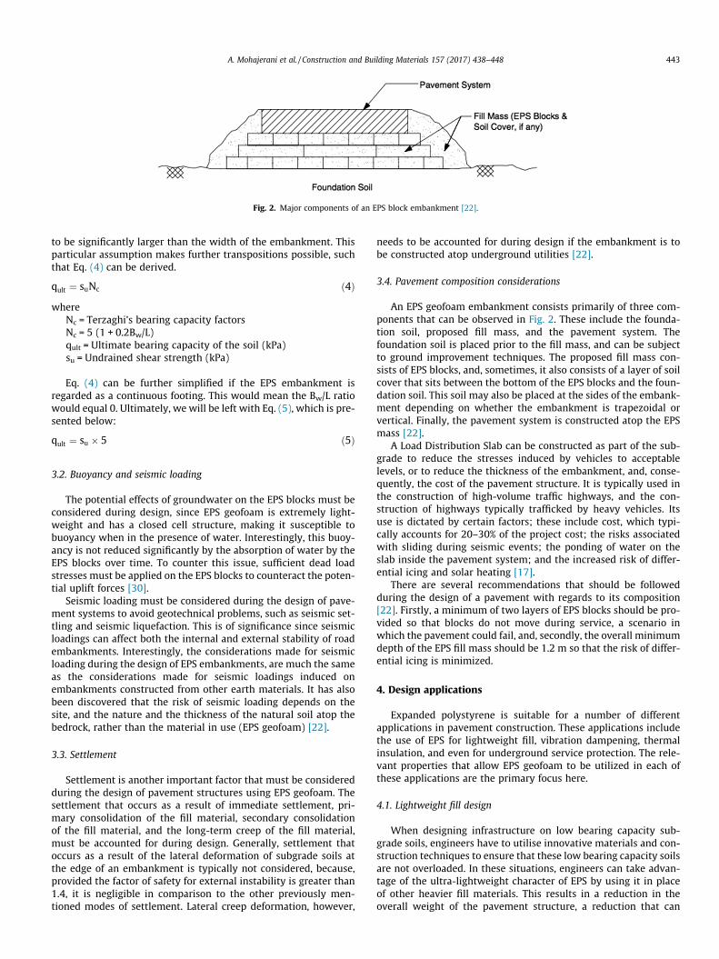
Fig. 2. Major components of an EPS block embankment [22].
A. Mohajerani et al. / Construction and Building Materials 157 (2017) 438–448 443
to be significantly larger than the width of the embankment. Thisparticular assumption makes further transpositions possible, suchthat Eq. (4) can be derived.
qult ¼ suNc ð4Þwhere
Nc = Terzaghi’s bearing capacity factorsNc = 5 (1 + 0.2Bw/L)qult = Ultimate bearing capacity of the soil (kPa)su = Undrained shear strength (kPa)
Eq. (4) can be further simplified if the EPS embankment isregarded as a continuous footing. This would mean the Bw/L ratiowould equal 0. Ultimately, we will be left with Eq. (5), which is pre-sented below:
qult ¼ su � 5 ð5Þ
3.2. Buoyancy and seismic loading
The potential effects of groundwater on the EPS blocks must beconsidered during design, since EPS geofoam is extremely light-weight and has a closed cell structure, making it susceptible tobuoyancy when in the presence of water. Interestingly, this buoy-ancy is not reduced significantly by the absorption of water by theEPS blocks over time. To counter this issue, sufficient dead loadstresses must be applied on the EPS blocks to counteract the poten-tial uplift forces [30].
Seismic loading must be considered during the design of pave-ment systems to avoid geotechnical problems, such as seismic set-tling and seismic liquefaction. This is of significance since seismicloadings can affect both the internal and external stability of roadembankments. Interestingly, the considerations made for seismicloading during the design of EPS embankments, are much the sameas the considerations made for seismic loadings induced onembankments constructed from other earth materials. It has alsobeen discovered that the risk of seismic loading depends on thesite, and the nature and the thickness of the natural soil atop thebedrock, rather than the material in use (EPS geofoam) [22].
3.3. Settlement
Settlement is another important factor that must be consideredduring the design of pavement structures using EPS geofoam. Thesettlement that occurs as a result of immediate settlement, pri-mary consolidation of the fill material, secondary consolidationof the fill material, and the long-term creep of the fill material,must be accounted for during design. Generally, settlement thatoccurs as a result of the lateral deformation of subgrade soils atthe edge of an embankment is typically not considered, because,provided the factor of safety for external instability is greater than1.4, it is negligible in comparison to the other previously men-tioned modes of settlement. Lateral creep deformation, however,
needs to be accounted for during design if the embankment is tobe constructed atop underground utilities [22].
3.4. Pavement composition considerations
An EPS geofoam embankment consists primarily of three com-ponents that can be observed in Fig. 2. These include the founda-tion soil, proposed fill mass, and the pavement system. Thefoundation soil is placed prior to the fill mass, and can be subjectto ground improvement techniques. The proposed fill mass con-sists of EPS blocks, and, sometimes, it also consists of a layer of soilcover that sits between the bottom of the EPS blocks and the foun-dation soil. This soil may also be placed at the sides of the embank-ment depending on whether the embankment is trapezoidal orvertical. Finally, the pavement system is constructed atop the EPSmass [22].
A Load Distribution Slab can be constructed as part of the sub-grade to reduce the stresses induced by vehicles to acceptablelevels, or to reduce the thickness of the embankment, and, conse-quently, the cost of the pavement structure. It is typically used inthe construction of high-volume traffic highways, and the con-struction of highways typically trafficked by heavy vehicles. Itsuse is dictated by certain factors; these include cost, which typi-cally accounts for 20–30% of the project cost; the risks associatedwith sliding during seismic events; the ponding of water on theslab inside the pavement system; and the increased risk of differ-ential icing and solar heating [17].
There are several recommendations that should be followedduring the design of a pavement with regards to its composition[22]. Firstly, a minimum of two layers of EPS blocks should be pro-vided so that blocks do not move during service, a scenario inwhich the pavement could fail, and, secondly, the overall minimumdepth of the EPS fill mass should be 1.2 m so that the risk of differ-ential icing is minimized.
4. Design applications
Expanded polystyrene is suitable for a number of differentapplications in pavement construction. These applications includethe use of EPS for lightweight fill, vibration dampening, thermalinsulation, and even for underground service protection. The rele-vant properties that allow EPS geofoam to be utilized in each ofthese applications are the primary focus here.
4.1. Lightweight fill design
When designing infrastructure on low bearing capacity sub-grade soils, engineers have to utilise innovative materials and con-struction techniques to ensure that these low bearing capacity soilsare not overloaded. In these situations, engineers can take advan-tage of the ultra-lightweight character of EPS by using it in placeof other heavier fill materials. This results in a reduction in theoverall weight of the pavement structure, a reduction that can

Fig. 4. EPS subgrade in pavement system [12].
444 A. Mohajerani et al. / Construction and Building Materials 157 (2017) 438–448
serve as a major solution to the settlement issue association withpavement structures that are constructed in poor soil conditions[2,8].
The use of expanded polystyrene as a lightweight fill is not lim-ited to pavement construction. It is also applicable for:
� Approach fill for bridge abutments� Bridge underfill� Slope stabilisation� Construction of ‘compensating foundation’ on compressiblesoils
� Rail embankment construction, and other types of embankmentconstruction
� Retaining or buried wall backfill
4.2. Noise/vibration dampening
A considerable amount of research has been conducted on theapplication of expanded polystyrene in vibration dampening. Stud-ies have focused on the vibration dampening ability of expandedpolystyrene in filled trenches and wave barriers. Despite thisresearch, expanded polystyrene has not been used practically inthis application yet. More research must be done before practicalapplications can go ahead [31]. In addition, currently, there areno engineering design methods available for the design of EPSfilled wave barriers despite a number of published studies [32].
Many investigations have verified the suitability of expandedpolystyrene in vibration dampening. Itoh et al. [33] investigatedthe ability of EPS geofoam barriers in the reduction of ground wavevibration. They reported that materials with low impedance, likeEPS geofoam, are very effective at reducing the amplitude of waves.In another study, completed by Murillo et al. [34], it was observedthat the depth, the width, and the location of an EPS geofoam bar-rier had a significant influence on vibration attenuation. Alzawiand El Naggar [32] also investigated the vibration damping abilityof an EPS geofoam in-filled barrier with respect to its location,geometry, and soil properties. They reported that the barriers per-formed better in stiff soils, and that deeper trenches are requiredfor significant vibration dampening when the trench barrier ismoved closer to the source of the vibration.
A recent study by Liyanapathirana et al. [31] investigated thesuitability of EPS geofoam in-filled wave barriers for ground vibra-tion dampening. The process involved placing a geofoam in-filledwave barrier between an existing pile and a new driven pile(source of vibration) so that the effect of EPS foam in vibrationattenuation could be assessed.
The findings showed that:
� The depth, width, and length of the wave barrier are importantfactors that dictate the efficiency of the wave barrier in all thesoils studied (Ariake Clay, Bangkok Clay, Singapore Marine
Fig. 3. a) Lightweight cover/embankment over pip
Clay). It was found that changes in the length and depth wouldincrease the dampening ability of the wave barrier, whilstchanges in the width would either dampen or amplify theground vibrations.
� When the wave barrier is closest to the driven pile, or the exist-ing pile, the vibration dampening of the EPS wave barrier is atits lowest. It is highest when it is in the middle.
� The results clearly showed that when Egeofoam/Esoil is less than0.1, the attenuation ability of EPS increases significantly.
� There is a significant wave scattering effect between the geo-foam barrier and the existing pile when the barrier is movedcloser to the existing pile. Consequently, it was concluded thatmore research has to be done in respect of this wave scatteringeffect before EPS foam barriers are used in practice.
4.3. Protection to underground services
Materials with a compressible inclusion can be used for a vari-ety of applications; one of these applications is for the protection ofunderground pipes, culverts, and tunnels. This application takesadvantage of the ability of expanded polystyrene to be significantlymore compressible than the other materials it is in contact with.This allows the expanded polystyrene to deform more readily thanthe other components that lay beneath it [35], which means thatany underlying services, typically in the form of pipes or culverts,will experience reduced vertical and horizontal loads. This applica-tion is not new and has been used in Norway since 1988 [36].
Currently, there are four methods in which EPS can be utilizedto protect underground services from excessive loads. These meth-ods include the construction of lightweight embankments, imper-fect trenches, slot cover trench systems, and, finally, beam coversystems [37]. The last two methods are not discussed as they arecurrently still under research. Only the lightweight embankment
e or culvert b) imperfect trench method [37].

A. Mohajerani et al. / Construction and Building Materials 157 (2017) 438–448 445
and imperfect trench methods are discussed here; these two meth-ods are depicted in Fig. 3.
The first method, the lightweight embankment system, is simi-lar to the construction of EPS embankments. The principle differ-ence here is that the EPS blocks are used to reduce the overallstresses that are acting on the underground services. This is doneto protect pipes and culverts from potential damage that is usuallycaused by the stresses that are typically induced by vertical grounddisplacement, and by the various types of settlement. The othermethod, the imperfect trench method, involves the placement ofan EPS block above the underground service [37]. In this applica-tion, the EPS geofoam block acts as compressible inclusion. It cre-ates a positive arching over the pipeline/culvert, and, as a result,compresses, ultimately, mobilizing the shear strength in the soilto reduce the vertical earth pressure on the pipeline or culvert [36].
4.4. Thermal insulation
As mentioned earlier, the thermal insulation properties ofexpanded polystyrene were established long ago when EPS geo-foam was first trialled in Germany (in the 1950s) as a pavementinsulator. In this application, EPS geofoam blocks were used inplace of conventional frost protection with great success [9]. Itwas observed that EPS geofoam was a suitable thermal insulator,and, consequently, was adopted for use for the thermal insulationof pavements in countries with severe winters and deeply pene-trating ground frosts [26].
In these same cold climates, EPS can be used in pavement con-struction as insulation to end the issue of the seasonal freezing andthawing of soils. This involves the placement of a layer of EPS geo-foam blocks in the pavement system as a subgrade, as depicted inFig. 4, so that the temperature changes in the soil during the severewinters can be limited [17]. This is paramount since the soil canheave (swell upwards), potentially causing substantial damage tothe pavement structures.
5. Limitations
There are a number of considerations that must be consideredwhen designing with expanded polystyrene. The designer mustappreciate the limitations of expanded polystyrene, and the poten-tial pitfalls associated with its design and applications so that fail-ure can be avoided. This section addresses these limitations andpotential pitfalls and provides recommendations accordingly.
5.1. Inadequate design or improper construction practice
As a result of the lack of financial support for the ongoingresearch, education, and standard development for the use ofexpanded polystyrene in pavement construction, designers havebeen left in a situation where they have to proactively seek currentand correct technical information. This is an unfortunate situationas the designer may receive incomplete or possibly inaccuratetechnical information. This can lead to inefficient or incorrectdesign, and, possibly, to the failure of the EPS geofoam in the pro-ject application. This has been the case in the US where there hasbeen a trend of failures for some widely used EPS geofoam applica-tions. Consequently, Horvath addressed this issue in one of hispapers [38], in which he identified a number of reasons for thistrend of EPS failures in the United States. They all relate to impro-per design and construction practices, including:
� Designs being completed according to incomplete or incorrectinformation. This can be as a result of a lack of a reliable stan-dard. The implication of this is the potential for an EPS materialof insufficient strength to be selected for the design.
� Damage caused to EPS blocks during construction. This can bethrough the modes of mishandling, incorrect storage, over-stressing by construction equipment, and even flotation as aresult of improper placement due to the action of air and water.
� Lack of oversight by a government or industry body. Manydeveloped nations (e.g. Japan) with widespread EPS use havebeen almost failure free thanks to the oversight by govern-ment/industry bodies.
5.2. Flammability
As a material, expanded polystyrene is inherently flammable. Itis still flammable even after the outgassing of the flammable blow-ing agent after the block moulding stage. This parameter, however,can be quantified using a parameter known as the oxygen index(OI), which can be defined as the minimum percentage of oxygenrequired for maintaining the combustion of an ignited material.EPS geofoam has an OI index of 18%, which is less than the 21%required to maintain combustion in atmospheric air, and as aresult, is deemed a flammable material [15].
Despite this, it should be noted that properly aged EPS geofoamblocks are not inherently dangerous. There are no special precau-tions that are to be implemented during shipping, storage, orinstallation, aside from the typical protocols of storing and han-dling the material in a way that it is protected from heat andflames. Additionally, it is recommended that storage areas are des-ignated non-smoking areas with proper signage [15].
However to address this issue, manufacturers have produced aflame retardant EPS geofoam product that has an OI of 24%.Although the material is no longer flammable, it can still melt at150 �C [17]. Unsurprisingly the use of this fire-retardant EPS isnot a universal practice, as designers may opt out of its use dueto the increased cost of the material, and as a result of questionsthat have been raised concerning its environmental safety [15].
5.3. Differential icing
The difference in the thermal properties of a pavement systemover EPS geofoam, and a pavement system over natural soil varyconsiderably, and, as a result, differential icing can occur. Differen-tial icing is defined as the formation of ice on a section of pavementconstructed on a non-earthen material whilst the pavement sys-tem above the natural earth material is ice-free [25]. This is anissue since there is an increased chance of car accidents, as driverswill not anticipate the icy conditions of an adjacent stretch whenthey are driving on an ice-free stretch of road.
However, over the years, a number of suggestions have beenmade to overcome these issues. These include the placing of a suf-ficient thickness of soil between the EPS mass and the top of thepavement, and the use of a sub-base material that has sufficient‘fines’ and a high heat capacity. A material with fines is desiredsince they can retain water [17].
6. Construction considerations
6.1. Site preparation
Proper site preparation is paramount for the correct installationof EPS blocks. To ensure internal stability, and to avoid the onset ofstress concentrations and the rocking of EPS blocks, the site shouldbe as level as possible. This is essential since the laying of the EPSlayers becomes increasingly more problematic with each subse-quent layer when the site is not level [17]. Other site preparationprocedures that should be adhered to include:

446 A. Mohajerani et al. / Construction and Building Materials 157 (2017) 438–448
� Keeping the area upon which the EPS blocks are to be laid freefrom accumulated water or ice.
� Ensuring the site has sufficient drainage during construction toavoid the potential hydrostatic uplift of the EPS blocks as aresult of heavy rainfall.
� Ensuring the sub-grade upon which the EPS blocks are to be laidis free from debris and vegetation.
6.2. Compaction
There are a number of guidelines governing the compaction ofthe soil atop the EPS fill mass. Firstly, EPS geofoam should not becompacted or driven over by construction machinery. This is toavoid mechanical damage, which is unrepairable. Secondly, com-paction of EPS geofoam can only begin when it is covered by atleast 200 mm of acceptable fill material, or covered by a 200 mmcapping layer. In addition to this, vibratory compaction equipmentshould not be used for compaction within 500 mm vertically, and2 m laterally of the EPS fill mass [39].
6.3. Handling and UV protection
Due care must be taken when transporting and handling EPSblocks as they can easily be damaged, and since any incurred dam-age is permanent. Damage can occur during transportation as aresult of EPS blocks being tied down with straps on flatbed trailers.If sufficient protection is not provided where the straps make con-tact with the EPS, the EPS blocks can crush or be completely brokenoff at the corners due to the load applied. Damage can also come inthe form of puncture holes in the EPS blocks as a result of the var-ious instruments used to grip the blocks. These issues can be over-come by using strap protection, and by using friction grip devicesto handle the blocks (or other lifting methods) [15].
As discussed earlier, expanded polystyrene becomes yellow,chalky, and brittle after prolonged exposure to UV radiation. Con-sequently, the construction contractor should keep the exposureof expanded polystyrene to UV ratio to a minimum. Exposureshould not exceed a period greater than a month [28].
6.4. Layout and placement
Expanded polystyrene blocks should be placed in a staggeredarrangement, in layers that are perpendicular to each other. Thiswill increase the strength of the pavement, as the sub-grade wouldbe continuous, as opposed to being disjointed [39]. It is also impor-tant to use shear connectors as they prevent the possibility of theblocks sliding, which can lead to slope failure under seismic load-ing. Without shear connectors, the blocks can slide, thereby creat-ing gaps between the blocks [3].
Fig. 5. Recommended locations for sam
7. Quality assurance
Quality assurance, in the form of laboratory testing, must becompleted to ensure that the quality of EPS blocks used in theintended geo-technical application is acceptable. These proceduresmust be undertaken irrespective of the size of the EPS geofoamproject. The quality assurance procedure typically involves thetesting samples of production EPS geofoam to measure theirgeotechnical parameters [15].
7.1. Record keeping
All the EPS geofoam blocks that are delivered to the site shouldhave self-adhesive labels or barcode labels. These labels shoulddetail the manufacturing history and the supplier’s informationso that it can be traced back if necessary. It is also important thatthe parameters that pertain to the construction are detailed; theseinclude parameters, such as density, the mass of the block, and thedimensions of the block, etc. Other information that should be dis-played includes the name of the supplier, the date of manufacture,and the period of seasoning [17].
7.2. Testing and sampling
The location of the sample within the EPS block to be tested isthe most important aspect of the sampling process. The means ofextracting the sample (hot-wires or handsaw, etc.) is not signifi-cant as long as the sample is somewhat larger than the intendeddimensions for the final specimen. The sampling location is of par-ticular importance since the EPS blocks are not uniform in densityafter moulding, and since the mechanical properties tend to varythroughout the block. Consequently, a proper sampling proceduremust be adhered to so that the weakest sections of the EPS blockare sampled and ultimately tested.
Fig. 5 shows the standard locations of the test specimens; theseare the possible locations from which the weakest sample of EPSgeofoam can be obtained. This practice has been used for decades,and, consequently, has been enlisted into some standards. Thesamples are later trimmed according to the intended test specimendimensions, ideally by using a jig and hot wire cutters. Finally, thetest specimens are subjected to force displacement, uniaxial com-pression, and flexure tests to determine the relevant geotechnicalparameters needed for design [15].
8. Case studies
8.1. Flom bridge embankment reconstruction, Oslo, Norway
Major research conducted in Norway concluded that EPSgeofoam could sustain the repetitive stresses typically inducedby a pavement structure. Following these findings, the Norwegian
pling of EPS blocks for testing [15].

Fig. 6. EPS geofoam blocks being used as lightweight fill [27].
A. Mohajerani et al. / Construction and Building Materials 157 (2017) 438–448 447
Public Roads Authority adopted EPS geofoam as a lightweight fillmaterial in the construction of embankments in 1972. This firsttook place during the reconstruction of the Flom Bridge embank-ment, a bridge embankment that, on average, experienced200 mm of settlement a year prior to its reconstruction. In this pro-ject, the settlement was effectively halted when EPS geofoam wasused in place of other traditional fill materials [10,27] (Fig. 6).
The tests conducted on 24-year-old EPS geofoam blocks thatwere exhumed from the Flom Bridge project showed no materialdeterioration effects. These results were a part of a long-termmon-itoring plan investigating the long-term performance of EPS geo-foam blocks in embankment construction in Norway. Theinvestigation was carried out to observe if any changes to thematerial properties of the EPS blocks would occur over time. Thiswas done through the testing of the strength, density, and waterabsorption of the exhumed EPS blocks, and, finally, through theinvestigation of any creep effects [27].
8.2. Interstate 15 reconstruction, Salt Lake City, USA
In 1997, the Utah Department of Transportation undertook a$1.5 billion project for the reconstruction of the Interstate I-15.The project involved the widening of the embankments of a nar-row 27-kilometre corridor. The reconstruction of this highwaywas undertaken in May 1997 and was completed in July 2001, intime for the Winter Olympic Games of 2002 [40].
EPS geofoam was utilised in two different applications for pave-ment construction in this project. Firstly, it was used as a light-weight fill material, and, secondly, for underground utilityprotection. Since extensive sections of the highway were con-structed atop compressible clays, and clayey silts, which could befound in thicknesses of up to 25 m, EPS geofoam blocks were usedas a lightweight fill. Also, these compressible soils would typicallybegin to consolidate on the virgin compression load when only 2-3 m of an embankment is constructed atop it; a phenomenon thatwould not be triggered by a super lightweight material like EPSgeofoam, hence its use. Also, underground utilities, such as high-pressure gas lines, water mains, and communication pipes, tra-versed many areas of ramped embankments. To protect theseunderground services from settlement, EPS geofoam was used toreduce the loads applied on these services [40].
The long-term testing completed on this project reinforced thesuitability of EPS geofoam in pavement construction. The observedlong-term creep effects and settlement effects were minor. Only a15 mm settlement affected the pavement structure, and a total
creep deformation of 0.2–0.4% was observed 10 years post-construction (on the 3300 South Street site). Furthermore, it wasconcluded that creep behaviour in the 50-year period would bewithin the maximum expected values [41].
8.3. Matlingeweg Street reconstruction, Rotterdam, The Netherlands
The Matlingeweg Street reconstruction is a notable project, aproject that was studied in detail by Duskov [42]. The constructionof this roadway involved the construction of two sections of road,one section of road with only one layer of (500 mm thick) EPSblocks, and the other section of road with two layers of EPS blocks.This was done in an attempt to reduce the stresses applied on thepoor bearing capacity subgrade soils beneath the EPS blocks. Afteronly one month of service, significant cracks were observed, largeenough that the road system was regarded as having failed. Inter-estingly it was observed that the cracking had only occurred in thesection of placement constructed upon a single layer of EPSgeofoam.
A forensic study investigated the cause of failure for the Matlin-geweg Street reconstruction project. The study showed that theEPS blocks had shifted vertically as much as 5 mm, and shifted hor-izontally as much as 20 mm, causing significant gaps between theEPS blocks. Ultimately, it was concluded that the cause of thismovement was a result of poor block contact during construction.As a result, Horvath [30] suggested the use of at least two layers ofEPS blocks in lightweight fill applications, especially for fills thatwould be subjected to dynamic and seismic loading (i.e. by trafficloading). Horvath made this recommendation since the ability ofan assembly of EPS blocks to act as a mass depends on the blockinter-locking from the layout of the blocks, and from the inter-block sliding friction. To achieve this behaviour, it is essential thattwo layers of EPS blocks be used, with special consideration givento the layout of the blocks [30].
9. Conclusion
Expanded polystyrene appears to be a versatile material thatcan be used in a myriad of geotechnical engineering applications,particularly in pavement construction. This is possible due to theinteresting mechanical properties of EPS geofoam. Most notably,its lightweight character, which allows it to be an excellent fillmaterial, its low thermal conductivity, which makes it a suitablepavement insulator in cold climates, its compressibility, whichfacilitates its application in the protection of underground services,

448 A. Mohajerani et al. / Construction and Building Materials 157 (2017) 438–448
and finally, its vibration dampening qualities that makes it a poten-tial vibration dampener.
For the application of the EPS geofoam in pavement construc-tion, there are a number of areas for improvement, and for poten-tial research. They mostly pertain to the improvement of currentapplications and the development of new applications for thematerial in pavement construction, and the preparation ofresources to aid designers in their design process. This is essentialto further proliferating the use of this material in pavement con-struction, to developing more innovative solutions to some majorpavement construction issues, and towards ensuring that design-ers are confident and capable of preparing safe designs. These areasof improvement have been summarised below.
� Research on the new experimental methods for EPS geofoam inunderground service protection.o Four methods have been developed so far, two of which are
currently in use, and the other two that are still underresearch.
� Research on the vibration dampening ability of EPS.o The vibration dampening ability of EPS geofoam has not
been studied sufficiently. Also, no standards or guidelineshave been developed for the design of vibration dampeningEPS-in filled trenches.
� Research on new potential applications for EPS.� The development of updated guidelines and other designmaterials.o This is important to ensure that the designer has adequate
information. This will minimise the risk of improper orincorrect design of EPS geofoam in the different projectapplications.
� Development of updated standards and test procedures.� Research into the repair of damaged EPS.
o Any damage inflicted on EPS geofoam is permanent.Research into the repair of damaged EPS blocks should beconsidered.
References
[1] J.S. Horvath, Expanded polystyrene (EPS) geofoam: an introduction to materialbehavior, Geotext. Geomembr. 13 (4) (1994) 263–280.
[2] X. Huang, D. Negussey, EPS Geofoam Design Parameters for PavementStructures, Geo-Frontiers 2011: Advances in Geotechnical Engineering, 2011,pp. 4544–4554.
[3] J.C. Barrett, A.J. Valsangkar, Effectiveness of connectors in geofoam blockconstruction, Geotext. Geomembr. 27 (3) (2009) 211–216.
[4] J.S. Horvath, Geofoam and geocomb: lessons from the second millennium ADas insight for the future. Paper presented at the Proc., 13th GRI Conf., 1999.
[5] R.M. Koerner, Designing with Geosynthetics, Prentice Hall, Upper Saddle River,New Jersey, 1998.
[6] L.-K. Lin, L.-H. Chen, R.H. Chen, Evaluation of geofoam as a geotechnicalconstruction material, J. Mater. Civ. Eng. 22 (2) (2010) 160–170.
[7] T. Stark, D. Arellano, J. Horvath, D. Leshchinsky, Geofoam applications in thedesign and construction of highway embankments, 2004, Retrieved from.
[8] T. Stark, S.F. Bartlett, D. Arellano, Expanded Polystyrene (EPS) GeofoamApplications & Technical Data, EPS Industry Alliance, Crofton, 2012.
[9] G. Beinbrech, R. Hillmann, EPS in road construction—current situation inGermany, Geotext. Geomembr. 15 (1) (1997) 39–57.
[10] T.E. Frydenlund, R. Aaboe, Long term performance and durability of EPS as alightweight filling material. Paper presented at the 3ª Conference InternationalEPS Geofoam 2001, 2001.
[11] S. Alfheim, K. Flåte, G. Refsdal, N. Rygg, K. Aarhus, The first EPS geoblock roadembankment–1972. Fra EPS konferansen: ‘‘th International Conference onGeofoam Blocks in Construction Applications”, Lillestrøm. til, 6, 2011.
[12] A.F. Elragi, Selected engineering properties and applications of EPS geofoam,2000.
[13] G. Miki, EPS construction method in Japan. Paper presented at the Proceedingsof International Symposium on EPS (Expanded Poly-Styrol) ConstructionMethod (EPS Tokyo’96), 1996.
[14] ASTM International (2011), Standard Specification for Rigid CellularPolystyrene Geofoam. ASTM D6817-11. West Conshohocken, PA, 2011.
[15] J.S. Horvath, Manufacturing quality issues for block-molded expandedpolystyrene geofoam. Research Rep. No. CEEN/GE-2011, 2, 2011.
[16] E.L. Santiago, An investigation of expanded polystyrene geofoam mechanicalproperties. Universidad Politecnica Puerto Rico (Puerto Rico), 2014.
[17] D. Arellano, Guidelines for the Use of Expanded Polystyrene (EPS)-BlockGeofoam for the Function of Lightweight Fill in Road Embankment Projects.University of Illinois at Urbana-Champaign, 2005.
[18] A.W. Stuedlein, Instrumentation, Performance, and Numerical Modeling ofLarge Geofoam Embankment Structures, 2003
[19] V. Elias, J. Welsh, J. Warren, R. Lukas, Ground Improvement TechnicalSummaries. U.S. Department of Transportation Federal HighwayAdministration, vol. 1, 2-2, Washington DC, 1999.
[20] X. Huang, Evaluation of EPS geofoam as subbase/subgrade material inpavement structures. Syracuse University, 2006.
[21] Standards Australia 1992, Rigid cellular plastics sheets for thermal insulation –Part 3: Rigid Cellular Polystyrene – Moulded (RC/PS-M), AS 1366.3-1992.Available from: Australian Standards. [Accessed 23 May 2017].
[22] T. Stark, D. Arellano, J. Horvath, D. Leshchinsky, Guideline and RecommendedStandard for Geofoam Applications in Highway Embankments, TransportationResearch Board, 2004.
[23] J.S. Horvath, Geofoam geosynthetic: past present future, Electron. J. Eng. 1(1995).
[24] A. Corporation, GeoGripper Plate. American Foam Manufacturers, 2011.[25] J.S. Horvath, Geomaterials research project-geofoam and geocomb
geosynthetics: a bibliography through the second millennium AD. Res. Rpt.No. CGT-2001, 1, 2001.
[26] B. Plastics, Styropor – Highway Construction/Ground Insulation: RigidStyropor Foam as a Lightweight Construction BASF Material for HighwayFoundations, BASF, Ludwigshafen, Germany, 1998.
[27] R. Aabøe, T. Frydenlund, 40 years of experience with the use of EPS geofoamblocks in road construction. Paper presented at the 4 Conference EPS 2011Norway, 2011.
[28] R.M. Koerner, Designing with Geosynthetics (Vol. 1), Xlibris Corporation, 2012.[29] D. Negussey, Properties and Applications of Geofoam. Society of the Plastic
Industry, 1997.[30] J.S. Horvath, Lessons learned from failures involving geofoam in roads and
embankments. Research Rep. No. CE/GE-99, 1, 1999.[31] D. Liyanapathirana, S.D. Ekanayake, Application of EPS geofoam in attenuating
ground vibrations during vibratory pile driving, Geotext. Geomembr. 44 (1)(2015) 59–69.
[32] A.M.A. Alzawi, H. El Naggar, Vibration isolation using in-filled geofoam trenchbarriers. The University of Western Ontario, 2011.
[33] K. Itoh, X. Zeng, M. Koda, O. Murata, O. Kusakabe, Centrifuge simulation ofwave propagation due to vertical vibration on shallow foundations andvibration attenuation countermeasures, J. Vib. Control 11 (6) (2005) 781–800.
[34] C. Murillo, L. Thorel, B. Caicedo, Ground vibration isolation with geofoambarriers: Centrifuge modeling, Geotext. Geomembr. 27 (6) (2009) 423–434.
[35] J.S. Horvath, The compressible inclusion function of EPS geofoam, Geotext.Geomembr. 15 (1–3) (1997) 77–120.
[36] J. Vaslestad, M.S. Sayd, T.H. Johansen, L. Wiman, Load reduction and arching onburied rigid culverts using EPS Geofoam. Design method and instrumentedfield tests, 2011.
[37] S.F. Bartlett, B.N. Lingwall, J. Vaslestad, Methods of protecting buried pipelinesand culverts in transportation infrastructure using EPS geofoam, Geotext.Geomembr. 43 (5) (2015) 450–461.
[38] J.S. Horvath, Emerging trends in failures involving EPS-block geofoam fills, J.Perform. Constr. Facil. 24 (4) (2010) 365–372.
[39] D. Thompsett, A. Walker, R. Radley, B. Grieveson, Design and construction ofexpanded polystyrene embankments: practical design methods as used in theUnited Kingdom, Constr. Build. Mater. 9 (6) (1995) 403–411.
[40] S. Bartlett, D. Negussey, M. Kimble, M. Sheeley, Use of geofoam as super-lightweight fill for I-15 reconstruction. Paper presented at the TransportationResearch Board 79th Annual Meeting, Washington, DC, 2000.
[41] S. Bartlett, D. Negussey, C. Farnsworth, A. Stuedlein, Construction and Long-Term Performance of Transportation Infrastructure Constructed Using EPSGeofoam on Soft Soil Sites in Salt Lake Valley, Utah. Paper presented at the 4thInternational Conference on the use of EPS Geofoam Blocks in ConstructionApplications, 2011.
[42] M. Duškov, Measurements on a flexible pavement structure with an EPSgeofoam sub-base, Geotext. Geomembr. 15 (1–3) (1997) 5–27.
[43] A. Arulrajah, E. Zaghoubi, Y.C. Wong, S. Horpibulsuk, Recycled plastic granulesand demolition wastes as construction materials: resilient moduli andstrength characteristics, Constr. Build. Mater. 147 (2017) 639–647.
[44] A. Arulrajah, M.M. Disfani, F. Maghoolpilehrood, S. Horpibulsuk, A. Udonchai,M. Imteaz, Y.J. Du, Engineering and environmental properties of foamedrecycled glass as a lightweight engineering material, J. Cleaner Prod. 94 (2015)369–375.