GENEREX Comprehensive User Manuals
309
v.: 2022-04-25 / FW 2.06 Copyright of the European Union is effective (Copyright EU) (c) 2022 GENEREX Systems GmbH, Hamburg, Germany, All rights reserved TEL +49(40)22692910 - EMAIL [email protected] - WEB www.generex.de (This and all other product datasheets are available for download.) 1 GENEREX Comprehensive User Manuals English UPS WEB/SNMP MANAGER CS141 SENSORMANAGER & Accessories BACS Battery Analyze & Care System
-
Upload
khangminh22 -
Category
Documents
-
view
20 -
download
0
Transcript of GENEREX Comprehensive User Manuals
v.: 2022-04-25 / FW 2.06
Copyright of the European Union is effective (Copyright EU) (c) 2022 GENEREX Systems GmbH, Hamburg, Germany, All rights reserved TEL +49(40)22692910 - EMAIL [email protected] - WEB www.generex.de (This and all other product datasheets are available for download.)
1
GENEREX Comprehensive User Manuals
English
UPS WEB/SNMP MANAGER CS141
SENSORMANAGER & Accessories
BACS Battery Analyze & Care System

v.: 2022-04-25 / FW 2.06
Copyright of the European Union is effective (Copyright EU) (c) 2022 GENEREX Systems GmbH, Hamburg, Germany, All rights reserved TEL +49(40)22692910 - EMAIL [email protected] - WEB www.generex.de (This and all other product datasheets are available for download.)
2
Copyright Statement for Intellectual Property and Confidential Information The information contained in this manual is non-conditional and may be changed without due notice. Although Generex has
attempted to provide accurate information within this document, Generex assumes no responsibility for the accuracy of this
information.
Generex shall not be liable for any indirect, special, consequential, or accidental damage including, without limitations, lost
profits or revenues, costs of replacement goods, loss or damage to data arising out of the use of this document.
Generex the manufacturer of the BACS products undertakes no obligations with this information. The products that are
described in this brochure are given on the sole basis of information to its channel partners for them to have a better
understanding of the Generex products.
GENEREX allows its channel partners to transfer information contained in this document to third persons, either staff within their
own Company or their own customers, either electronically or mechanically, or by photocopies or similar means. GENEREX
states that the content must not be altered or adapted in any way without written permission from GENEREX.
It is agreed that all rights, title and interest in the GENEREX’s trademarks or trade names (whether or not registered) or goodwill
from time to time of GENEREX or in any intellectual property right including without limitation any copyright, patents relating to
the Products, shall remain the exclusive property of GENEREX.
GENEREX will undertake to deal promptly with any complaints about the content of this document. Comments or complaints
about the document should be addressed to GENEREX Systems GmbH.
Copyright of the European Union is effective (Copyright EU).
Copyright (c) 1995-2021 GENEREX GmbH, Hamburg, Germany. All rights reserved.

v.: 2022-04-25 / FW 2.06
Copyright of the European Union is effective (Copyright EU) (c) 2022 GENEREX Systems GmbH, Hamburg, Germany, All rights reserved TEL +49(40)22692910 - EMAIL [email protected] - WEB www.generex.de (This and all other product datasheets are available for download.)
3
Introduction
Thank you for trusting the CS141 Webmanager – the most powerful solution for critical resource management.
Since the CS141 was designed to be a full-fledged, standalone manager, its task is not limited to gathering and sharing information. It also accomplishes numerous tasks in measurement controlling devices dealing directly with critical resource management. Furthermore, the CS141 comes with a full-featured message management system. The CS141 cannot only answer requests coming from higher-level systems - it can also independently inform responsible employees in case of an emergency incident as well as initiating emergency measures based predetermined parameters:
The CS141 can automatically activate basic or advanced emergency systems, shut down servers and workstations. Even automatic restart at predetermined conditions is configurable. In addition to standard technologies such as SNMP and Modbus, the CS141 relies on using the powerful RCCMD software solution. By doing so, even the emergency behavior of complex, fully virtualized server landscapes are realizable.
Thanks to RFC1628 the CS141 provides more flexibility than ever
This feature provides new possibilities to integrate third-party UPS systems. Thanks to the new RFC1628 compliant UPS interface, administrators can use the CS141 to poll any SNMP card that supports these standards. Simply use the SNMP-card installed inside your UPS and display the current status natively inside CS141.
This will allow administrators to use the powerful products made by GENEREX in combination of UPS-Systems that are normally not compatible.
Note
Due to the fact the CS141 Web Manager can act as a stand-alone system for managing, it can be used flexibly in many areas, even outside the functionality described in this guide. This manual therefore describes the fundamentally implemented functionality according to UPS systems. However, the enormous flexibility and the possibility of communicating with higher and lower-level systems using standardized interfaces allows the adaption to very different possibilities to use.
About this manual This manual is more than just a small leaflet – it is written to explain and show all functions of a CS141 – you will notice, this device is very powerfull and flexible, you are not limited to use this device as a UPS monitoring card. You can monitor, control, switch or communicate to any parent or child system inside complex IT systems. This manual is written to show you what you can do with a CS141 and explains how to configure the device – in some cases you will not find some menus described in this manual. Here are some possible reasons:
- The function is not enabled, you need a new firmware. - Additional devices are needed - Your CS141 model does not support the function you are looking for - During the ongoing development progress, sometimes functions will be
automated or moved to other menus in order to increase the usability. This manual is devided into three parts:
- CS141 - BACS
If this is your first CS141, this manual will guide you step by step through all menus and explain nearly everything you need to ensure emergency power and use the noticfication functions. What you need to know: Each model of the CS141 family can handle RCCMD – the CS141 is the RCCMD sender, and the RCCMD software client is the according receiver. BACS mor than “just an option” – it is a powerful battery management solution that may operate as a standalone system. If you are interested in battery management, this chapter is very interesting – but be carefull: Working with batteries inside a UPS system is for experienced or special trained technical who are familiar with all symbols and functions as well as how batteries work. With BACS, you can manage your batteries and optimize your entire UPS solutioin as well as increasing the battery performance and life time.

v.: 2022-04-25 / FW 2.06
Copyright of the European Union is effective (Copyright EU) (c) 2022 GENEREX Systems GmbH, Hamburg, Germany, All rights reserved TEL +49(40)22692910 - EMAIL [email protected] - WEB www.generex.de (This and all other product datasheets are available for download.)
4
Table of Contents
Part 1: CS141 Introduction Model Overview Delivery notes Function overview CS141 Hardware Layout Appendix Interface Assignment External D-SUB 9-pin male Network integration of the CS141 Preperations Preparation at the CS41 Preparing the Workstation Using DHCP Finding CS141 in networks / MAC address Netfinder Basic SettingsConfiguration Installation examples Required Ports Default Passwords Menu structure of the CS141 Enhanced and optional menus Differences in operation modes
Basic login passwords Setup Wizard IP-address settings and hostname Location and contact settings Provided services Date and time Tutorial: How to set up a custom time server User management RADIUS Server RADIUS with Microsoft NPS / Cisco ISE 802.1X RADIUS Support System overview Switching to operational mode
Mail Settings
Email settings Advanced Mail Options Test Mail Settings The most common error message Email traps
Modbus Modbus as single-master-protcol Differences between CS141 Modbus and Professional Pinout of the modbus connection The modbus termination PIN Modbus over RS232/RS485 and Modbus over IP Modbus functions codes Modbus error code table Configuration of modbus Tutorial: Working with MODBUS adresses SNMP
What is SNMP Setting up SNMP V2 Setting up trap receiver Tesing Trap receiver with SNMP v2 Setting up SNMP v3 Using Trap settings with SNMP v3 Restarting the SNMP Agent

v.: 2022-04-25 / FW 2.06
Copyright of the European Union is effective (Copyright EU) (c) 2022 GENEREX Systems GmbH, Hamburg, Germany, All rights reserved TEL +49(40)22692910 - EMAIL [email protected] - WEB www.generex.de (This and all other product datasheets are available for download.)
5
Bacnet What is BACnet? Using BACnet with the CS141 Remote Syslog What is remote syslog Setting up remote syslog Setting up TLS certificates for remote Syslog Checklist: remote Syslog problems About the use of SYSLOG UPS Configuration
General COM Port Settings The pipe through function Configuration of a UPS Battery Health Level (%) feature RFC 1628 UPS Interface UPS monitoring screen UPS functions UPS event handling The intention of a job Managing jobs Available jobs Tutorial: The WOL packet UPS Shutdown definition How to configure a job Time management of jobs Adding jobs to several events Delete jobs Counter Events
Custom Thresholds
What are Custom Thresholds Difference Warning/Alarm Levels Example scenario: Custom Thresholds Exemplary excerpt: Custom Thresholds Tutorial: Custom thresholds
CS141 RCCMD Server
What is RCCMD Available RCCMD Commands Configuration of RCCMD Setting up the IP address for RCCMD Timing for RCCMD jobs Variables for RCCMD traps
Sensors and additional devices
SM_T_H_COM Standalone Sensor General COM Port Settings Setting up a sensor Sensor monitoring screen Event handling for sensors Sensor related system events Setting up a job for sensor events
SENSORMANAGER SENSORMANAGER: - Sensor matrix SENSORMANAGER - Adding analog sensors SENSORMANAGER - Sensor event vs matrix event SENSORMANAGER - Setting up the logical connection SENSORMANAGER - Digital inputs SENSORMANAGER - Linking digital inputs and analog sensors SENSORMANAGER - Switching an output SENSORMANAGER - Tutorial: Example scenario: aquarium SENSORMANAGER - Possibilities of the sensor matrix

v.: 2022-04-25 / FW 2.06
Copyright of the European Union is effective (Copyright EU) (c) 2022 GENEREX Systems GmbH, Hamburg, Germany, All rights reserved TEL +49(40)22692910 - EMAIL [email protected] - WEB www.generex.de (This and all other product datasheets are available for download.)
6
Alarm device / buzzer GSM modem CON_AUX4 and CON_R_AUX4
Scheduler
How the scheduler works Setting up scheduled Jobs
Web Server
Safety instructions HTTP settings PORT settings Force HTTPs HTTP refresh time Simple monitor Tutorial: Creating a PEM-File
Diagnostics Logfiles
Event Log Data log Data log Diagram UPS Alert history
Tools
Reboot Tracer Network Scan Privacy Notice: Network Scans Evaluation of data Deleting data Tutorial: Complete data deletion Changing Logo
Data backup and updates Creating backups
Restore configuration from a backup Restore network data Performing a firmware update Changing the OEM firmware
If nothing works ...
Rebooting without login Performing a firmware update directly The rescue mode on the CS141 Rescue mode on the CS141 Mini
Part 2: BACS What is BACS?
What is BACS? What is the advantage of BACS EQUALIZATION: maintain individual charging / discharging Upgrade CS141 to a BACS system
BACS Installation Guide Please read carefully before starting with working on batteries:
How to use the BACS manual Fundamentals when working on batteries
Mandatory additional components
BACS C module BACS measuring cable BACS bus cable

v.: 2022-04-25 / FW 2.06
Copyright of the European Union is effective (Copyright EU) (c) 2022 GENEREX Systems GmbH, Hamburg, Germany, All rights reserved TEL +49(40)22692910 - EMAIL [email protected] - WEB www.generex.de (This and all other product datasheets are available for download.)
7
Installation examples
BACS installation examples BACS Bus topology BACS Splitting box Technical data of the BACS Splitting Box BACS installation with two webmanager
Battery preparation
Battery preparation Things to be followed during initial installation Connection BC5 measuring cables Connecting BC4B measuring cables Mounting BACS modules Maintenance: Replacing a BACS module / Replacing the internal temperature sensor
Initial BACS configuration
General battery data Number of battery strings Two Jars / Cells per module: Differences when using NiCd Basic setting of a BACS module Offset values Impedance measuring intervals External current sensor Premium feature: Ampere Multiplier Discharge detection: Thresholds for current sensor
Initial BACS module setup Addressing the BACS modules BACS Programmer restart conditions Defining an address range for module reset General Module setup Adress range setup conditions BACS Programmer single mode BACS Error: HW Revision / Calibration error
BACS Programmer software tool
How to connenct a computer Preparing BACS installation Operating modes: Automatic mode Operating mode: Manual mode Line check Receive Line Check
GX_R_AUX
How it works Connectors Addressing the GX_R_AUX Configuration of the GX_R_AUX GX_R_AUX as battery breaker Normally Open / Normally Closed contacts Defining a job to a BACS event Communicate with third party devices via Outputs / Inputs
BACS functions
BACS Buzzer BACS Relay
BACS alarm threshold
Overvoltage Deep discharge Threshold definition Battery voltage Battery temperature Internal resistance of the battery Maximum voltage deviation between batteries Voltage deviation per string Current deviation per string Alarm delay

v.: 2022-04-25 / FW 2.06
Copyright of the European Union is effective (Copyright EU) (c) 2022 GENEREX Systems GmbH, Hamburg, Germany, All rights reserved TEL +49(40)22692910 - EMAIL [email protected] - WEB www.generex.de (This and all other product datasheets are available for download.)
8
Battery strings and thermal runaway
Define BACS battery strings BACS strings vs battery breaker What is a thermal runaway? Mandatory preconditions for BACS thermal runaway functions Max. module temperature difference Max current per string Above conditions are true since
Log files
BACS Log files
Initial Start up: Pause Equalizing on Schedule
What is an unformed battery? Why pause Equalizing during initial start up? How to use a scheduled equalization pause Equalization Pause Example 1 Equalization Pause Example 2 Equalization Pause Example 3 Tutorial: BACS Equalization paused by system BACS Trouble Shooting List
Part 3 :
Appendix
CS141 / BACS Hardening Guide Hardware Layout CS141 Differences to the CS121 Interface Description Pin COM2 Mini-DIN 8 pol
Modbus addresses
Section OEM: ABB/NEWAVE UPS Type Concept Power Section OEM: MASTERGUARD SectionOEM: Centièl Section OEM: RITTAL PMC Extension Section OEM: Netminder for all LT and MD types Section OEM: Netminder EON Section OEM: Netminder for all other types Section OEM : AEG Protect 3. M 2.0 Section OEM: AEG Protect 3.31, 5.31, 8.31 Section OEM: AEG Protect 2.33, 3.33, 4.33, 5.33, 8.33, blue Section OEM: POWERTRONIX Section OEM: Socomec UPS Section MHD Modular / Multimatic Modular / AEG Protect 1. Modular, ENIGMA Section Borri 4000 Std. Panel / E-Tec 310 to 380 (m) / SALICRU SLC NX/DL/CUBE Section Inform UPS / Pyramid DSP/Online DSP Section Transfer Switches (All Transfer Switch vendors, except PILLER, STS TUMEL) Section STS TUMEL Transfer Switch Section OEM TRIMOD Section: EverExceed Inverter
Parameters for UPSMAN Software and BACS UPSMAN Status Bytes - Standard Device Status Bits BACS Parameters
Last, but not least:
Copyright and licenses

v.: 2022-04-25 / FW 2.06
Copyright of the European Union is effective (Copyright EU) (c) 2022 GENEREX Systems GmbH, Hamburg, Germany, All rights reserved TEL +49(40)22692910 - EMAIL [email protected] - WEB www.generex.de (This and all other product datasheets are available for download.)
9
Model overview
Device Function Remarks
CS141L SNMP adapter external adapter
CS141SC SNMP adapter Slot Adapter for UPS with slot
CS141LM SNMP adapter External adapter with MODBUS output (RS485)
CS141SCM SNMP adapter Slot adapter with MODBUS output (RS485)
CS141BSC SNMP adapter Slot adapter BUDGET-Modell (No COM2- und AUX-port)
CS141R_2 SNMP adapter Slot adapter for PILLER/CTA/RIELLO/AROS UPS Italy
CS141MINI SNMP adapter Slot adapter for UPS models with MINI Slot
Additional devices based on CS141:
Device Function Remarks
BACSKIT_B4 Battery management External adapter
BACSKIT_BSC4 Battery management Slot adapter
Device Features Supported UPS devices
CS141L Additional Mini DIN 8 COM Port for RS232. AUX Port for Digital Input/Output. Remote RAS Management optional.
Over 1400 UPS models from over 80 different manufacturers are supported
CS141SC Additional Mini DIN 8 COM Port for RS232. AUX Port for Digital Input/ Output. Remote RAS Management optional.
All devices with basic slot SC
CS141LM Additional Mini device. AUX Port for Digital Input/ Output. Remote RAS Management optional.
Over 1400 UPS models from over 80 different manufacturers are supported
CS141SCM Additional RS485. AUX Port for Digital Input/ Output. Remote RAS Management optional.
All devices with basic Slot SC
CS141BSC Slot Budget variant of the CS141. UPS Manage-ment via LAN. No AUX Port for floating contacts. No COM2 Port for Pipe-through, sensors, etc.
All devices with basic Slot SC
CS141R_2 Additional Mini DIN 8 COM Port for RS232. Riello and Aros UPS with Netman Slot
CS141MINI Additional Mini DIN 8 COM Port for RS232. UPS devices with MINI Slot (Soltec, Voltronic, etc.)
All CS141s can manage UPS systems providing a native serial protocol. Furthermore, the CS141 can be easily integrated into existing SNMP systems. All models of the CS141 family provide an own unique web server with configurable event management for automating job executions based on the status of the UPS.
All models of the CS141 family provide an own unique web server with configurable event management for automating job executions based on the status of the UPS, including:
- email notification - Full RCCMD functionality - shutdown commands, - logfile entries, shutdown of the UPS, - graphical log files, - shutdown and wake-up -commands (WOL)
In addition, the CS141 can also be individually configured using a scheduler to trigger job executions for many events, e.g.: - battery testing - calibration - UPS or system shutdown / restore. The CS141 provides a wide range of network management features to inform and alert required persons before a critical incident occurs. The CS141 can even monitor other SNMP devices and thanks to its built in RCCMD solution, combine them to an intelligent power resource management. Each adapter has 2 years warranty as well as free updates for 3 years. All devices are manufactured in Germany and the USA
v.: 2022-04-25 / FW 2.06
Copyright of the European Union is effective (Copyright EU) (c) 2022 GENEREX Systems GmbH, Hamburg, Germany, All rights reserved TEL +49(40)22692910 - EMAIL [email protected] - WEB www.generex.de (This and all other product datasheets are available for download.)
10
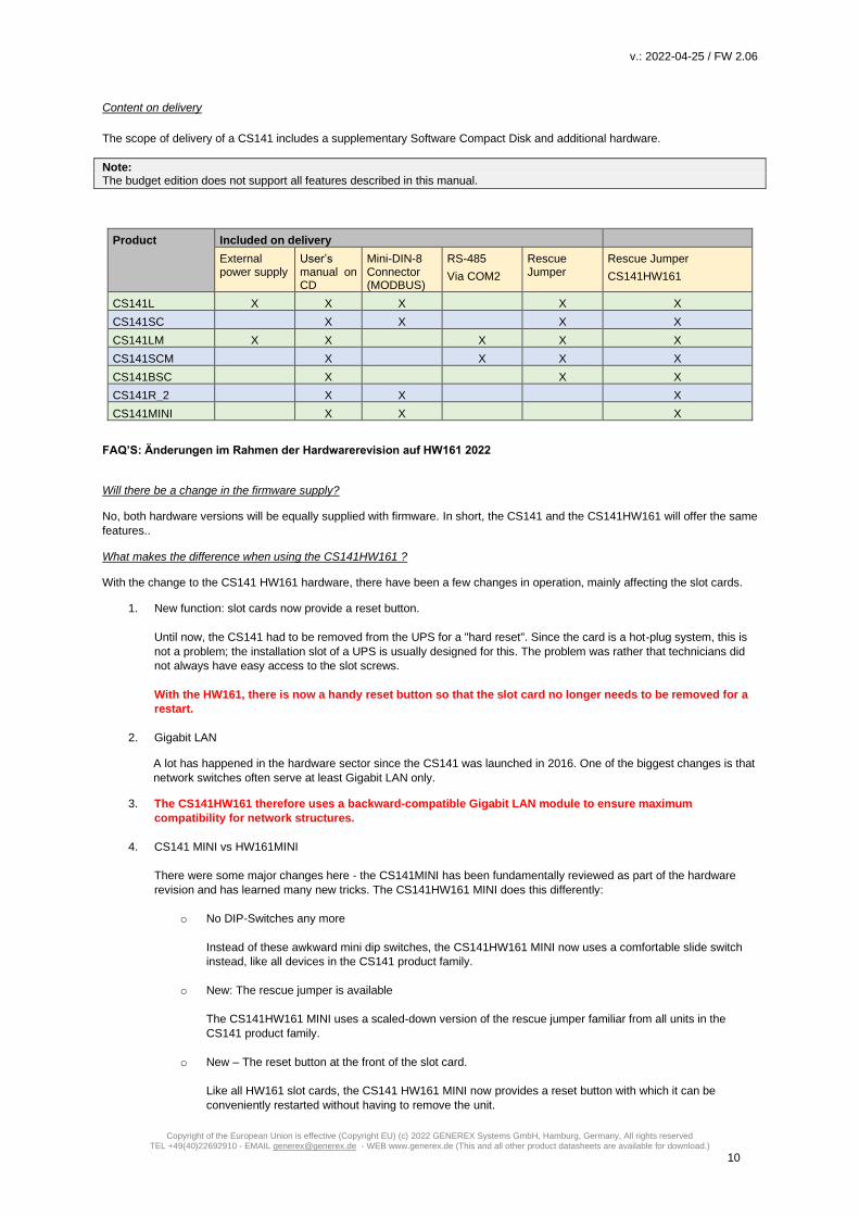
Content on delivery
The scope of delivery of a CS141 includes a supplementary Software Compact Disk and additional hardware.
Note: The budget edition does not support all features described in this manual.
Product Included on delivery
External power supply
User’s manual on CD
Mini-DIN-8 Connector (MODBUS)
RS-485
Via COM2
Rescue Jumper
Rescue Jumper
CS141HW161
CS141L X X X X X
CS141SC X X X X
CS141LM X X X X X
CS141SCM X X X X
CS141BSC X X X
CS141R_2 X X X
CS141MINI X X X
FAQ’S: Änderungen im Rahmen der Hardwarerevision auf HW161 2022
Will there be a change in the firmware supply?
No, both hardware versions will be equally supplied with firmware. In short, the CS141 and the CS141HW161 will offer the same
features..
What makes the difference when using the CS141HW161 ?
With the change to the CS141 HW161 hardware, there have been a few changes in operation, mainly affecting the slot cards.
1. New function: slot cards now provide a reset button.
Until now, the CS141 had to be removed from the UPS for a "hard reset". Since the card is a hot-plug system, this is
not a problem; the installation slot of a UPS is usually designed for this. The problem was rather that technicians did
not always have easy access to the slot screws.
With the HW161, there is now a handy reset button so that the slot card no longer needs to be removed for a
restart.
2. Gigabit LAN
A lot has happened in the hardware sector since the CS141 was launched in 2016. One of the biggest changes is that
network switches often serve at least Gigabit LAN only.
3. The CS141HW161 therefore uses a backward-compatible Gigabit LAN module to ensure maximum
compatibility for network structures.
4. CS141 MINI vs HW161MINI
There were some major changes here - the CS141MINI has been fundamentally reviewed as part of the hardware
revision and has learned many new tricks. The CS141HW161 MINI does this differently:
o No DIP-Switches any more
Instead of these awkward mini dip switches, the CS141HW161 MINI now uses a comfortable slide switch
instead, like all devices in the CS141 product family.
o New: The rescue jumper is available
The CS141HW161 MINI uses a scaled-down version of the rescue jumper familiar from all units in the
CS141 product family.
o New – The reset button at the front of the slot card.
Like all HW161 slot cards, the CS141 HW161 MINI now provides a reset button with which it can be
conveniently restarted without having to remove the unit.
v.: 2022-04-25 / FW 2.06
Copyright of the European Union is effective (Copyright EU) (c) 2022 GENEREX Systems GmbH, Hamburg, Germany, All rights reserved TEL +49(40)22692910 - EMAIL [email protected] - WEB www.generex.de (This and all other product datasheets are available for download.)
11
o New: The mini-DIN connector has been replaced by a modern RJ12 interface.
At the same time, the CS141HW161 MINI has also learned a few new tricks:
Instead of the hard-wired MINI-DIN connector, the CS141HW161MINI uses a special adapter connector that
provides both a MINI-DIN connector and an RJ-12 connector.
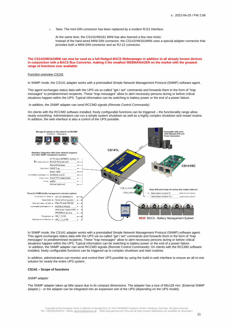
The CS141HW161MINI can now be used as a full-fledged BACS Webmanager in addition to all already known devices in conjunction with a BACS Bus Converter, making it the smallest WEBMANAGER on the market with the greatest range of functions ever available!
Function overview CS141
In SNMP mode, the CS141 adapter works with a preinstalled Simple Network Management Protocol (SNMP) software agent. This agent exchanges status data with the UPS via so-called "get / set" commands and forwards them in the form of "trap
messages" to predetermined recipients. These "trap messages" allow to alert necessary persons during or before critical
situations happen within the UPS. Typical information can be switching to battery power or the end of a power failure.
In addition, the SNMP adapter can send RCCMD signals (Remote Control Commands): On clients with the RCCMD software installed, freely configurable functions can be triggered – the functionality range allow nearly everything. Administrators can run a simple system shutdown as well as a highly complex shutdown and restart routine. In addition, the web interface is also a control of the UPS possible.
In SNMP mode, the CS141 adapter works with a preinstalled Simple Network Management Protocol (SNMP) software agent. This agent exchanges status data with the UPS via so-called "get / set" commands and forwards them in the form of "trap messages" to predetermined recipients. These "trap messages" allow to alert necessary persons during or before critical situations happen within the UPS. Typical information can be switching to battery power or the end of a power failure. In addition, the SNMP adapter can send RCCMD signals (Remote Control Commands): On clients with the RCCMD software installed, freely configurable functions can be triggered up to complex shutdown and start routines In addition, administrators can monitor and control their UPS possible by using the build in web interface to ensure an all-in-one solution for nearly the entire UPS system.
CS141 – Scope of functions
SNMP adapter The SNMP adapter takes up little space due to its compact dimensions. The adapter has a size of 69x126 mm. (External SNMP adapter.) - or the adapter can be integrated into an expansion slot of the UPS (depending on the UPS model).

v.: 2022-04-25 / FW 2.06
Copyright of the European Union is effective (Copyright EU) (c) 2022 GENEREX Systems GmbH, Hamburg, Germany, All rights reserved TEL +49(40)22692910 - EMAIL [email protected] - WEB www.generex.de (This and all other product datasheets are available for download.)
12
Premium function: the SNMP Traps The basic task of the adapter is to communicate alarm states of the UPS to an according monitoring station (traps) or to provide UPS data if monitoring stations poll. With this function, e.g. the power supply and battery status of a UPS are monitored by an SNMP management station. Additionally, the CS141 provides functions for simulating and testing trap messages during configuration procedure.
Remote Control:
Due to the fact the CS141 is capable to configure it is possible to trigger different remote-controlled actions. Administrators can perform battery tests, bypass the UPS batteries or configure UPS behavior
Note:
Depending on the UPS you are using, provided functions may differ.
Compatibility according to third party network management systems
The SNMP adapter is compatible with all common network management systems. All SNMP systems providing the compilation of a MIB - or already contain the Management Information Base (MIB) / Request for Comment 1628 (RFC) for UPS systems - can be operated with CS141. Full RCCMD support: Due to the fact the CS141 is a full manager and not just an SNMP-Card to collect and provide data, the entire network shutdown routine can be configured to react as fast as possible: Thanks to integrated RCCMD support, the CS141 offers a flexible and fast way to operate even the most complex shutdown solutions. By the usage of standardized network technologies and protocols, the RCCMD server transfers control commands that are executed by the clients in real time. RS-232 / pipe-through: In some cases, different networks without any connections have to be configured to use the same UPS. With the new pipe-through capability administrators can connect two CS141 and let the communication of the UPS work with both devices: By doing so, two different CS141 can communicate to according networks without additional hardware. RS232 UPS interface: The CS141 provides a standard RS232 interface to allow establishing a serial connection to any UPS providing this standard.
Note: Please use only the original UPS communication cable supplied with the UPS. In case of using a contact UPS, choose the special designed cable of the manufacture. If you have any questions regarding special connection cables, refer your UPS dealer.
Real-time logfile support:
The CS141 provides a proven compilation of logfiles to reconstruct a complete timeline in case of critical incidents. This logfile is accessible via UNMS, UPSMAN, WebGUI and FTP or can be send via mail to configured mail-accounts.
Advanced mailing capabilities
Each model of the CS141 family provides the capability to connect to any mail server using standardized encryption technologies.
Unique and special hardened web interface: The unique build-in Web server of the CS141 displays all information about the device itself, connected sensor and external hardware. The software module UPSView inside the CS141 can also be used to display a graphical representation of these data. To Access the web interface administrators and technicians may just use common browsers (Edge, Firefox, Chrome, Safari etc.). MODBUS: Modbus is the standard protocol used in industrial applications for monitoring and building management. All devices of the CS141 family therefore provide as standard a MODBUS over IP interface. In addition, CS141 with COM2 connector provide MODBUS over RS232 (CS141L & SC) and Modbus over RS485 (CS141L, SCM).

v.: 2022-04-25 / FW 2.06
Copyright of the European Union is effective (Copyright EU) (c) 2022 GENEREX Systems GmbH, Hamburg, Germany, All rights reserved TEL +49(40)22692910 - EMAIL [email protected] - WEB www.generex.de (This and all other product datasheets are available for download.)
13
SNMP:
The SNMP (Simple Network Management Protocol) is a standard protocol for monitoring installations via IP networks. The protocol is defined and standardized in RFC specifications. UPS systems generally use the RFC 1628 specification as MIB, which defines UPS-specific devices. The adapter communicates via SNMP using the UPS standard MIB RFC 1628. This MIB is supported by most SNMP software products. Therefore, it is usually not necessary to insert an own MIB into the SNMP software. Systems that do not yet include this standard UPS MIB can download the RFC1628 from our website and compile the MIB subsequently. To do this, copy the MIB file into the corresponding MIB directory of your SNMP station and compile this file. First, however, search for a UPS MIB in the MIB tree. This should correspond to an RFC1628 standard MIB.
UPSTCP:
The most common way to communicate with the CS141 adapter is TCP. CS141 includes UPSTCP, which provides you with a complete API interface to integrate your adapter into the network. This interface is supplied on request to manufacturers of software to enable their own integration. A ll other users use TCP for access via a web interface (UPSVIEW, UPSMON, UNMS) or SNMP or MODBUS over IP.
BACnet
BACnet is another major standard that is mainly used in large building infrastructures. With BACnet, complex nesting and overlapping device structures can be monitored. "BACnet over IP" is based on TCP/IP, but extends the protocol with parts necessary for building management. The CS41 can be seamlessly connected to any network via BACnet over IP.
Remote Syslog
With Remote Syslog, the CS141 / BACS WEBMANAGER logfile options are aimed at system administrators who manage log files via central interfaces in the network and evaluate them automatically and sort them according to interesting incidents.
Tools for network analysis
The CS141 WEBMANAGER provides all the tools needed to carry out even complex network analyses on site.
Malfunctions in the local network segment can thus be systematically spotted and finally identified - benefit from the unique possibilities of being able to investigate all connected devices as well as the surrounding network on site.
.

v.: 2022-04-25 / FW 2.06
Copyright of the European Union is effective (Copyright EU) (c) 2022 GENEREX Systems GmbH, Hamburg, Germany, All rights reserved TEL +49(40)22692910 - EMAIL [email protected] - WEB www.generex.de (This and all other product datasheets are available for download.)
14
Network integration of the CS141
All models of the CS141 family are configured exclusively through the specially designed web interface.
In order to facilitate the initial configuration or a quick on-site intervention, the CS141 family Web Manager is preset to the hard-coded IP address 10.10.10.10:
:
In factory default setting, the sliding switch is in the center position and the CS141 is in configuration mode. Due to its more compact design, the CS141 MINI brakes the standard and uses on-board dip switches instead of a sliding switch: Both dip-switches set to off position activates the configuration mode. In this mode, some functions such as IP address data are configurable, but available only as soon as CS141 is switched to regular operating mode.
The following table lists regular operating modes:
Note
Die CS141HW161 Produktserie verwendet keine DIP-Switche mehr, um den Betriebsmodus zu wechseln. Es werden ausschließlich die Schiebeschalter bzw. der Rescue-Pin verwendet.
Sliding switch center position / DIP 1 + 2 OFF:
Enables configuration mode. After reboot the hard-coded IP address 10.10.10.10
is active.
Sliding switch to the right / Dip 1 OFF + 2 DIP 2 ON: Automatic IP addressing: DHCP is activated and an IP address is set automatically. Check the MAC address of your CS141 to identify the IP address in the DHCP server table.
. Sliding switch to the left / DIP 1 ON + DIP 2 OFF:
Use of the IP address values manually configured. If DHCP is used, the IP
address needs to be blocked for single usage.
CS141 Mini special feature:
Both Dip-Switches ON:
Enables the rescue-mode for advanced system maintenance operation.
v.: 2022-04-25 / FW 2.06
Copyright of the European Union is effective (Copyright EU) (c) 2022 GENEREX Systems GmbH, Hamburg, Germany, All rights reserved TEL +49(40)22692910 - EMAIL [email protected] - WEB www.generex.de (This and all other product datasheets are available for download.)
15
Initial configuration 10.10.10.10
Preparation at the CS41
Prior to commissioning, ensure the slide switch on the front is set to center position. In case of CS141Mini, both Dip switches of the CS141 MINI has to be set in OFF position. After start up, the CS141 can be runs in configuration mode, available at IP address 10.10.10.10.
Note: Changing the mode via the hardware switches requires a reboot of the CS141. You can perform the restart in two ways: By removing the power supply (hardware reset) Using the Restart feature to be found inside the Tools menu (Software Reset) This operation does not apply the UPS the CS141 is connected to - the functionality will be kept up independently to the CS141.
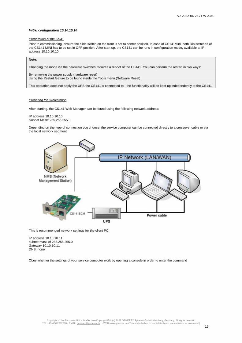
Preparing the Workstation
After starting, the CS141 Web Manager can be found using the following network address: IP address 10.10.10.10 Subnet Mask: 255.255.255.0 Depending on the type of connection you choose, the service computer can be connected directly to a crossover cable or via the local network segment.
This is recommended network settings for the client PC: IP address 10.10.10.11 subnet mask of 255.255.255.0 Gateway 10.10.10.11 DNS: none
Obey whether the settings of your service computer work by opening a console in order to enter the command

v.: 2022-04-25 / FW 2.06
Copyright of the European Union is effective (Copyright EU) (c) 2022 GENEREX Systems GmbH, Hamburg, Germany, All rights reserved TEL +49(40)22692910 - EMAIL [email protected] - WEB www.generex.de (This and all other product datasheets are available for download.)
16
PING 10.10.10.10.
If the
settings are correct, the CS141 will respond accordingly. As soon as the CS141 answers correctly, open a web browser. The CS141 web interface will be accessible by typing http://10.10.10.10 Adding a route Within larger installations with well-defined domain services, it may be helpful temporarily editing the routing table. In case of using a route, ensure the CS141 is located within the same network segment and is therefore directly accessible Example: Adding a route into a Windows-driven Computer:
1. Run the command console cmd as administrator This is important due to the fact, Windows requires a user with local administration rights to add a route.
2. Enter the following command: route add 10.10.10.10 <IP address of your system> Windows will accept the command and return OK
In order to check the new rout, enter the command route print
Under active routes, 10.10.10.10 should be seen. As an additional test, use the command ping 10.10.10.10 to verify the CS141 web manager is responding as expected.
Note: In configuration mode, only one CS141 with the default IP address of 10.10.10.10 can be operated. If you connect several devices at the same time this way, a network conflict is unavoidable.
Using the DHCP Option
The DHCP mode Since the models of the CS141 family can fulfill many functions due to their flexibility, it is a very realistic scenario that you need to commission several devices at the same time within an installation procedure - Unfortunately there is no fixed IP address that can be assigned for the moment. To avoid a network conflict, activate the DHCP mode for automatic IP address assigning: Slide the slide switch to the right, i.e. to the outer edge of the CS141. For the CS141 Mini, set dip switch 1 to OFF and move dip switch 2 to ON. Next reboot, the web manager will boot in DHCP mode according to the hardware configuration and obtain an IP address from your network.

v.: 2022-04-25 / FW 2.06
Copyright of the European Union is effective (Copyright EU) (c) 2022 GENEREX Systems GmbH, Hamburg, Germany, All rights reserved TEL +49(40)22692910 - EMAIL [email protected] - WEB www.generex.de (This and all other product datasheets are available for download.)
17
Required information for finding CS141 in DHCP-Mode
To identify the devices, please note the MAC address including location data before proceeding hardware installation. The MAC address can be found on any CS141 web manager as a unique sticker:
Ensure a suitable DHCP server is available for this operating mode, otherwise the card will not be able to get valid IP address data automatically. CS141 MINI and CS141 / R2
Due to the compact design, the lable sticker of CS141 MINI and the CS141 / R2 differ and shows only the last three octets of
the MAC address.
The MAC address of a GENEREX- network interface starts with these address values:
00-30-d6-xx-xx-xx
The last thre values can be found at the lable sticker on the back of the CS141 MINI or CS141 R2:
A common bar code scanner that can handle QR codes or a smartphone with a QR- Code app will display the complete MAC
address.
Note
Please notice that you use the sticker on the back. This will show the last three octets of the MAC address. When on installation
site, you can simply figure out the MAC address:
In this case, the MAC address is 00-30-d6-13-73-78

v.: 2022-04-25 / FW 2.06
Copyright of the European Union is effective (Copyright EU) (c) 2022 GENEREX Systems GmbH, Hamburg, Germany, All rights reserved TEL +49(40)22692910 - EMAIL [email protected] - WEB www.generex.de (This and all other product datasheets are available for download.)
18
Netfinder: Search for IP-addresses used with CS141 devices
The Netfinder is a software tool that can display all CS121 and CS141 devices that can be reached inside a specific network segment. It is available at the local support CD and at www.generex.de. To perform a quick search for valid IP addresses, use the tool Netfinder.
The default search generally refers to the network segment the service computer resides. To scan other networks and subnets for CS121 or CS141 installations, it is necessary to specify the appropriate IP address ranges.
The GENEREX Netfinder software provides a detailed overview of all devices in the network and allows quick and easy access to the web console of the respective manager.
Note: In DHCP mode, IP addresses may change sporadically depending on the network configuration. Therefore, several Webmanager monitored by a parent system such as UNMS II should receive a fixed IP address. In any other case, technicians can easily detect and access installed devices by using Netfinder.
Configuring the CS141 device
Differences between configuration mode, rescue mode and operation mode
Each model of the CS141 family will be configured exclusively by an intuitive web interface. Independently to this common ground, the web managers offer four valid operating states, which fundamentally differ from each other.

v.: 2022-04-25 / FW 2.06
Copyright of the European Union is effective (Copyright EU) (c) 2022 GENEREX Systems GmbH, Hamburg, Germany, All rights reserved TEL +49(40)22692910 - EMAIL [email protected] - WEB www.generex.de (This and all other product datasheets are available for download.)
19
1. The configuration mode
The configuration mode is the default preset on delivery: The slide switch is in center position and the dip switches of the CS141Mini are both set to OFF. The web manager can be reached via hardware-coded preset IP address 10.10.10.10 and allows all system-relevant settings Since the CS141 generally uses the preset IP address in configuration mode, this mode allows importing backup data and to be adjusted after restart without harming the network.
2. Operating mode Depending on the setting, the sliding switch will be set to left or right position. In case of CS141Mini, Dip switch 1 or 2 is switched on The CS141 can be run in two different operation modes: In manual mode, enter the IP address information. Please note that incorrect settings may cause address conflicts on the network or the settings made may not work. The data required for manual mode can be obtained from local system administrators.
Note: In manual mode, the data is entered by technicians and thus permanently assigned. The CS141 will use this data to make itself known in the network. assigning an address twice will cause a network conflict. In this case, switching back to configuration mode at any time is possible to reach the Web Manager at the default IP address 10.10.10.10.
In DHCP mode, the CS141 automatically inherits settings assigned by a server and uses them for the IP address settings. The web server takes over the administration of the IP address data. After the startup process, the web manager can be found using the tool Netfinder.
Tipp: As a rule, DHCP-assigned IP addresses via automatic mode are reserved for specific time. DHCP clients therefore ask after 50% of this time window whether the IP address is still valid or will be assigned to another client. How statically the DHCP server allocates IP addresses is a decision the system administrators make. Due to this fact another IP address can be re-assigned after booting or a CS141 seems to be lost during regular operation.
When selecting the operating mode, the function of the CS141 within the network should be considered: If the Web Manager runs as an active element within shutdown solutions or in conjunction with higher-level monitoring structures, a manually assigned IP address makes sense, since an authenticated and fixed IP address must be configured. As another advantage the CS141 starts faster with preconfigured IP addresses if the DHCP server is not available.
3. The rescue mode In this mode, an additional jumper is set and the slide switch center position. The Webmanager can access two ROMs for booting. Therefore, this failsafe design is able to contain the current firmware as well as the last state before the firmware update including the configuration file. When the web manager is set to rescue mode, the logic starts from the last known state and is initially fully operational again but indicates in the general system information that the web manager is in rescue mode. The rescue mode represents a manually chosen emergency operation state and is intended to repeat a faulty flash process. Before you start
Installation examples
The CS141 was designed to provide a maximum of flexibility and freedom during the installation - as a result the CS141 match the tasks of modern UPS systems as well as expectations coming with it.

v.: 2022-04-25 / FW 2.06
Copyright of the European Union is effective (Copyright EU) (c) 2022 GENEREX Systems GmbH, Hamburg, Germany, All rights reserved TEL +49(40)22692910 - EMAIL [email protected] - WEB www.generex.de (This and all other product datasheets are available for download.)
20
Case one:
The central role of the UPS is to ensure emergency power until the server shut down securely during main power loss. The complete shutdown routine is controlled by the CS141, as this is a full-fledged manager that can act independently. As an alternative to the CS141, the shutdown routine can also be initiated via the UPSMan software. Further servers need only one more RCCMD license. Two separate networks It becomes more difficult as soon as emergency power coming one UPS has to ensure the shutdown of two servers inside separate networks without linking possibilities:
In this case, the UPS becomes a central role inside the network’s emergency power security. Since the VLANs represent physically separated own network segments, only one server can be secured by the CS141. The UPSMan software will secure the second server: Once Installed directly on the server, it communicates with the UPS via the COM port of the server and offers the same functionality as the CS141 including a full support of RCCMD. Therefore VLAN 2 represents a "software only" solution that does not require a CS141 as additional hardware.

v.: 2022-04-25 / FW 2.06
Copyright of the European Union is effective (Copyright EU) (c) 2022 GENEREX Systems GmbH, Hamburg, Germany, All rights reserved TEL +49(40)22692910 - EMAIL [email protected] - WEB www.generex.de (This and all other product datasheets are available for download.)
21
The required RS232 connection is not available or the installation of software is not possible? Just use servers providing 2 network cards:
If you have chosen a solution with two network cards and the UPS provides a usable RS232 interface, this solution allows future installations - even complete closed up networks are possible. Pipe Through
In some companies, physical separation of the networks is essential, but the UPS does not offer the option of operating RS232
and slot parallelly. In this case, the signal can be looped by the pipe-through function: This feature allows two CS141 jointly
perform the same function inside of complete separated networks. Furthermore, different CS141 versions can be combined as
desired - Even the combination CS141 / UPSMan software is possible for a maximum of flexibility.

v.: 2022-04-25 / FW 2.06
Copyright of the European Union is effective (Copyright EU) (c) 2022 GENEREX Systems GmbH, Hamburg, Germany, All rights reserved TEL +49(40)22692910 - EMAIL [email protected] - WEB www.generex.de (This and all other product datasheets are available for download.)
22
Complex structures
In this example, VLAN 1 and VLAN 2 were logically linked by a router to allow one CS141 sending RCCMD commands to all servers inside of VLAN 1 and VLAN2. At the same time, the Pipe Through function allows the same signal coming from the UPS to a third CS141 physically installed inside LAN3. Due to this fact, the CS141 can completely control LAN3 and ensure a shutdown routine using RCCMD. LAN 4 is connected to the UPSMan software via the RS232 interface and the server itself can act like a CS141 including full RCCMD functionality. This example demonstrates a complex system:
- two complete separated networks
- two logical linked networks
- on central UPS solution to provide auxiliary power in case of main power is down.
Each CS141 or UPSMan is completely informed about the current UPS alarm state. Furthermore, each network can be managed for its own without harming others.
Note.
The UPSMAN software also handles communication via USB - If your UPS supports parallel operation, it is possible to combine USB, Slot and RS232.
Required Ports
The CS141 provides many functions to communicate with network nodes. For the communication so called "ports" are needed. Some of these ports are international standards within your EDP, others must be configured exclusively for the CS141. The following list contains all ports entered by default for the CS141:
Description Port TCP UDP Is CS141 confuration menu available?
Echo 7 X X No
WOL 7 oder 9 - X YES
ftp-data 20 X - No
SFTP 22 X - No
http 80 X - YES
https 443 X - YES
SNMP CS141 Geräte Listener 161 - X No
SNMP Management Software Listener 162 - X No
SMTP 25 x - YES
RCCMD 6003 X - YES

v.: 2022-04-25 / FW 2.06
Copyright of the European Union is effective (Copyright EU) (c) 2022 GENEREX Systems GmbH, Hamburg, Germany, All rights reserved TEL +49(40)22692910 - EMAIL [email protected] - WEB www.generex.de (This and all other product datasheets are available for download.)
23
UPSMan/ UNMS 5769 X - YES
SNMP Trap 162 - X No
Time (rfc868) 37 X - No
Time (sntp) 123 X - Nein
Modbus over IP 502 X - YES
BACnet 47808 oder 47809 - X YES
Remote Syslog 601 X - YES
RADIUS 1812 X - JA
For some functions, the port assignment is dynamic and must be managed or specified by the network administrator depending
on the network. If you require additional ports, this is listed at the appropriate place within this documentation. The number of
the port to be used can be obtained from the responsible network administrator.
Note This user guide covers all the menus that you can encounter when configuring a CS141. Basically, it is written for firmware version 1.62 and subsequent versions with a special eye on SITEMANAGER 6and SITEMONITOR 6. Many menus will be available for all products of the CS141 family and the configuration method is similar. Once you understood the concept, you will be able configure any device of the CS141 family intuitively. If you cannot find a menu, there are several reasons: - The CS141 you are using does not offer this feature - The firmware version you are using is older so the feature this manual describes is not available - The configuration menu is present, but has been delayed by the ongoing development process
Basic settings and passwords
After you enter the IP address, the CS141 responds with its web interface and prompts for a password There are three users with different system rights to choose from. The users are predefined, the passwords can be freely defined: User: admin Password: cs141-snmp ... System administrator, complete menu tree accessible User: engineer Password: engineer ... Technician, administrative restricted system access User: guest Password: guest … guest account, only status indicators visible To start initial configuration, log in with user admin and default password cs141-snmp
Note: Modern web browsers are designed to display websites as fast as possible. Among other things, special techniques are used to pre-load images, pages and query masks are loaded into a buffer for a faster review. In some cases, this web browser behavior may result in screen errors. If these phenomena occur, update the browser by pressing CTRL + F5 or clear the cache of the web browser and deactivate additionally installed tools and addons, which could obstruct the presentation.

v.: 2022-04-25 / FW 2.06
Copyright of the European Union is effective (Copyright EU) (c) 2022 GENEREX Systems GmbH, Hamburg, Germany, All rights reserved TEL +49(40)22692910 - EMAIL [email protected] - WEB www.generex.de (This and all other product datasheets are available for download.)
24
CS141 configuration menu overview, FW 2.06
This is the CS141 menu tree without expansion modules.
If you connect additional modules in order to extend functionality, corresponding menus are automatically displayed after
installing and activating the functions.
This menu tree shows all basic functions each CS141 model provides:

v.: 2022-04-25 / FW 2.06
Copyright of the European Union is effective (Copyright EU) (c) 2022 GENEREX Systems GmbH, Hamburg, Germany, All rights reserved TEL +49(40)22692910 - EMAIL [email protected] - WEB www.generex.de (This and all other product datasheets are available for download.)
25
Extended menu trees
Depending on the CS141 model and available additional modules, additional menus are available. Please note that not every
model can provide the following menus:
Sensor menus
Depending on the type of sensor, the following menus will be added automatically:
1. Standalone sensor on COM 2
After selecting sensor at COM 2 Sensor and as sensor type SM / T or the combination sensor SM / TH, following menus will
appear automatically:
Sensor monitoring screen
System Tab: Devices
Sub menu: Sensors
Configure measuring range, alarm marker, operating range
Configure jobs to the alarm marker
2. SENSORMAN2 at COM 2
After selecting sensor at COM 2 Sensor and as sensor type SENSORMAN2, following menus will appear automatically:
With the sensor matrix, an additional function is available that allows to combine single sensor events to collective events.
v.: 2022-04-25 / FW 2.06
Copyright of the European Union is effective (Copyright EU) (c) 2022 GENEREX Systems GmbH, Hamburg, Germany, All rights reserved TEL +49(40)22692910 - EMAIL [email protected] - WEB www.generex.de (This and all other product datasheets are available for download.)
26
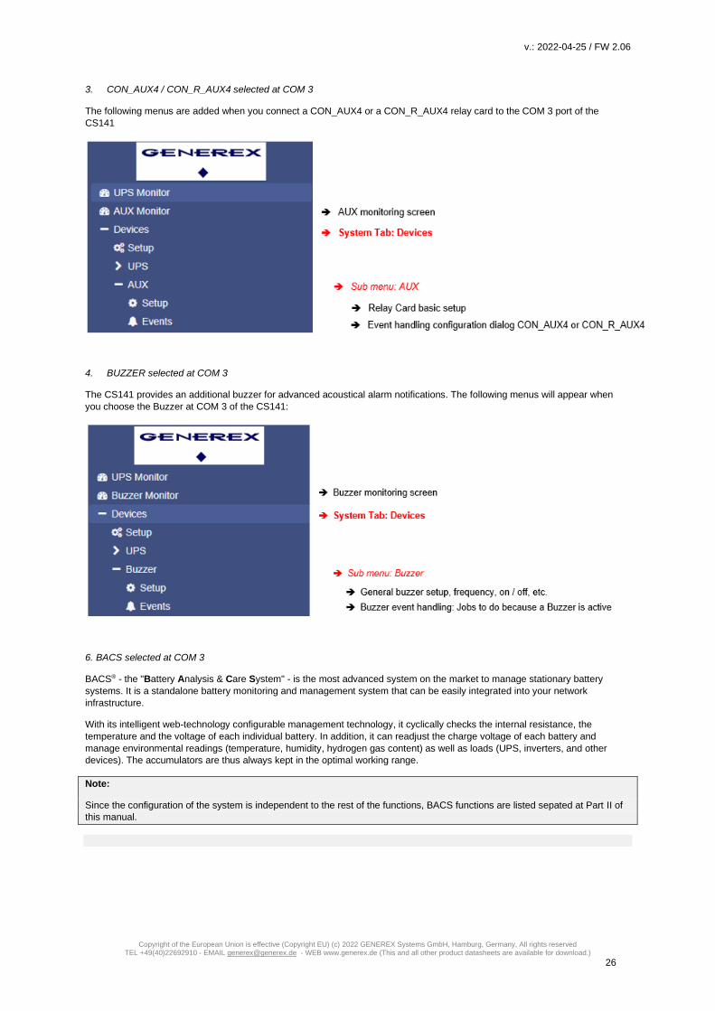
3. CON_AUX4 / CON_R_AUX4 selected at COM 3
The following menus are added when you connect a CON_AUX4 or a CON_R_AUX4 relay card to the COM 3 port of the
CS141
4. BUZZER selected at COM 3
The CS141 provides an additional buzzer for advanced acoustical alarm notifications. The following menus will appear when
you choose the Buzzer at COM 3 of the CS141:
6. BACS selected at COM 3
BACS® - the "Battery Analysis & Care System" - is the most advanced system on the market to manage stationary battery
systems. It is a standalone battery monitoring and management system that can be easily integrated into your network
infrastructure.
With its intelligent web-technology configurable management technology, it cyclically checks the internal resistance, the
temperature and the voltage of each individual battery. In addition, it can readjust the charge voltage of each battery and
manage environmental readings (temperature, humidity, hydrogen gas content) as well as loads (UPS, inverters, and other
devices). The accumulators are thus always kept in the optimal working range.
Note:
Since the configuration of the system is independent to the rest of the functions, BACS functions are listed sepated at Part II of
this manual.

v.: 2022-04-25 / FW 2.06
Copyright of the European Union is effective (Copyright EU) (c) 2022 GENEREX Systems GmbH, Hamburg, Germany, All rights reserved TEL +49(40)22692910 - EMAIL [email protected] - WEB www.generex.de (This and all other product datasheets are available for download.)
27
The Setup Wizard
For this configuration step, navigate to the following menu:
When you use the CS141 for the first time, the welcome screen will automatically start with the wizard. Please note that you cannot switch through the masks directly, you need to follow by pressing next.
The Setup Wizard helps to set up a basic configuration: General Provides basic information about the location to be installed, system language, responsibilities and temperature scale. Network Enter the network configuration - The necessary data can be obtained from the local administrator. Date & Time Provide basic information about the date, time, and time server UPS Setup Enter information about the UPS the CS141 shall be connected to Review Check data before you finish the configuration process before finishing.
Note:
The Setup Wizard simply summarizes basic settings and provides a quick and convenient solution that can be used to make or
change basic settings. If you want to perform the configuration completely manually, click here Cancel - You can always restart
the Setup Wizard in the configuration menu.
But be careful: Some entries such as UPS configuration have dependencies to advanced configuration entries the Wizard does
not include.

v.: 2022-04-25 / FW 2.06
Copyright of the European Union is effective (Copyright EU) (c) 2022 GENEREX Systems GmbH, Hamburg, Germany, All rights reserved TEL +49(40)22692910 - EMAIL [email protected] - WEB www.generex.de (This and all other product datasheets are available for download.)
28
Configuration mode: Basic settings For this configuration step, navigate to the following menu:
Most settings can be done as long as the CS141 is in configuration mode. Depending on your network settings there could be a problem when performing tests and forwarding functions - they are often not possible on hardware preset 10.10.10.10. Due to this fact it is a good choice to configure all basic settings inside configuration mode and switch to normal mode before starting advanced UPS configuration.
How to configure network settings, open Network:
Under Configure, enter the IP address data the system shall use. Active shows the current IP address settings used by the system. It is possible to change the following settings
On first startup, the CS141 will get hard-coded information. The required IP address information to enter the operational mode correctly can be obtained by contacting the responsible network administrator. Press Apply to save your settings.
Note: At this point, the web browser redirects you to the new IP address. Since the CS141 is still in configuration mode, you will receive an error message from your web browser. In this case, ensure to work with the IP 10.10.10.10 and press CTRL F5 to refresh the web browser.
For a first configuration, the Network menu is the only setting you currently need to make in Configuration mode. It is possible to carry out all other settings in regular operating mode.

v.: 2022-04-25 / FW 2.06
Copyright of the European Union is effective (Copyright EU) (c) 2022 GENEREX Systems GmbH, Hamburg, Germany, All rights reserved TEL +49(40)22692910 - EMAIL [email protected] - WEB www.generex.de (This and all other product datasheets are available for download.)
29
DHCP mode during initial configuration While booting in DHCP mode, an according server assigns an IP address to the CS141 device. This IP address can be found comfortable by using the freeware tool Netfinder. Therefore, it is easy to identify the device by the MAC address shown by Netfinder and the address label glued on the CS141 device:
The function open device opens a separate web browser and inserts the IP address automatically. After login, it is possible to access network settings and change the IP address. after rebooting the device with manual mode setting, new IP address setting is active. By switching back to DHCP mode, these settings are completely ignored and the CS141 falls back to server-assigned address.
The advantage is as many CS141 into the network at the same time without much effort, which are immediately accessible without the possibility of an address conflict. The disadvantage is the fact that in DHCP mode the IP addresses can change dynamically, which means that higher-level or docked shutdown solutions may no longer be able to access or output errors.
How a DNS – entry works
Basically, there are two methods to address a target system. Either you directly specify the IP address: the CS141 will then address the system directly without involving other system services or server. Or, instead of an IP address, it is possible to use a host name: by doing so, the CS141 will send a request to a responsible DNS service and ask for the IP address assigned to the host name. Both methods come with their own advantages and disadvantages
- While identifying the target server goes relatively well when host names (e.g. database-steelcolossus.intra) are used, this method depends on a functioning network: The CS141 needs the DNS server if, for example, the build in RCCMD service is configured to transmit certain control signals to a desired RCCMD client - for each RCCMD command, the responsible DNS server must first be contacted and asked for the IP address of the host. If a network breaks into individual segments as a result of a malfunction, a segment without a valid DNS server will not be able to use host names.
- Using an IP address is a little more independent to a certain extent, because there is no need for a DNS server. The target IP and network segment is already known, and the RCCMD control signals will function accordingly in the event of a network disturbance close to the DNS server. On the other hand, this method requires fixed IP addresses. If a DHCP server dynamically manages and reassigns IP addresses according to its function, the CS141 job management can hold out-dated information about the target IP address - in case of an emergency, the CS141 may send valid RCCMD commands, but address the wrong target.
Why does the CS141 not communicate its host name to a DNS server, although I have entered the IP address of the server at the DNS settings? By system / network design, this is not the task of a CS141. If you set the CS141 to DHCP, it contacts the DHCP server during the boot process and communicates for the host name it would like to use. The DHCP server may accept the request, assigns an IP address and, depending on the configuration, will either comply with the request, i.e. forward the host name to the DNS server. Since a DHCP can also overwrite a host name, the result depends on the configuration of the network, e.g.:
- The IP address is assigned, but no automatic DNS entry is available. - The IP address is assigned and the host name request of the CS141 is available via DNS. - The IP address is assigned and the host name request of the CS141 is overwritten.
Note: If you reserve or block the IP address within the DHCP server and configure the CS141 to use a manual IP address setup, the CS141 will not "register" at system start-up: The fact that the CS141 starts with its own IP address and that the reservation in the DHCP server ensures that the IP address is not assigned elsewhere does not necessarily mean that the DNS server also automatically gets a lookup entry - this to check is a task of an administrator.

v.: 2022-04-25 / FW 2.06
Copyright of the European Union is effective (Copyright EU) (c) 2022 GENEREX Systems GmbH, Hamburg, Germany, All rights reserved TEL +49(40)22692910 - EMAIL [email protected] - WEB www.generex.de (This and all other product datasheets are available for download.)
30
Advanced basic settings For this configuration step, navigate to the following menu:
Enter Location settings
Location data can be read by any software supporting this feature. If used in larger installations with many devices, location data will help to associate installed devices.
Apply will save the settings and restart according services to activate the new settings instantly. Netfinder will find the new name next to the IP address:
Regional settings
Under Language, select your preferred system language. Supported languages are German, English, Chinese (Simple), French,
Spanish, Polish, Portuguese
Under Temperatures, select the unit of measure in which to display the temperatures.
The Difference between Fahrenheit / Celsius Although initially defined by the freezing point of water (and later melting point of ice), the Celsius scale is officially derived among Kelvin scale: Zero on the Celsius scale (0 ° C) corresponds to 273.15 K, with a temperature difference of 1 ° C which is equivalent to a difference of 1° K - the size of the unit in each scale is the similar. Therefore 100 ° C, the previously defined boiling point of water, equates to 373.15K. Due to the fact the Celsius scale is an interval system, but not a ratio system, means it follows a relative and not an absolute scale. This is indicated by the fact that a temperature interval between 20 ° C and 30 ° C is the same as between 30 ° C and 40 ° C, but essentially 40 ° C does not have twice the air heat energy like 20 ° C. A temperature difference of 1 ° C therefore corresponds to a temperature difference of 1.8 ° F.
v.: 2022-04-25 / FW 2.06
Copyright of the European Union is effective (Copyright EU) (c) 2022 GENEREX Systems GmbH, Hamburg, Germany, All rights reserved TEL +49(40)22692910 - EMAIL [email protected] - WEB www.generex.de (This and all other product datasheets are available for download.)
31
There both scales are used worldwide, it is important to know in advance which measurement scale to use for configuration.
Note The CS141 recalculates the values when rescaling the scale and adjusts the settings automatically - but a higher-level system configured to Fahrenheit will inevitably receive incorrect information from a web manager set to Celsius. This small problem may lead into a big impact, especially if teams are placed inside an international co-operation. As an example, on December 12, 1998, the Mars Climate Orbiter has entered as programmed the mars orbit, but 170 kilometers lower than planned. Investigations found the reason for this incident: There was a communication issue between two different groups of NASA scientists who performed the trajectory calculations - one used inches and the other meters. They simply forgot to communicate this small fact…: „The „root cause “… was the failed translation of English units into metric units in a segment of ground-based, navigation-related mission software … “
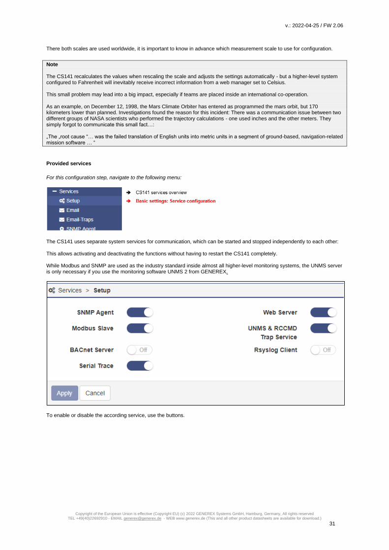
Provided services
For this configuration step, navigate to the following menu:
The CS141 uses separate system services for communication, which can be started and stopped independently to each other: This allows activating and deactivating the functions without having to restart the CS141 completely. While Modbus and SNMP are used as the industry standard inside almost all higher-level monitoring systems, the UNMS server is only necessary if you use the monitoring software UNMS 2 from GENEREX.
To enable or disable the according service, use the buttons.

v.: 2022-04-25 / FW 2.06
Copyright of the European Union is effective (Copyright EU) (c) 2022 GENEREX Systems GmbH, Hamburg, Germany, All rights reserved TEL +49(40)22692910 - EMAIL [email protected] - WEB www.generex.de (This and all other product datasheets are available for download.)
32
Webserver to increase security, the configuration by using SSH console is no longer allowed, the integrated web server is the only communication option for configuring the CS141. Disabling HTTP will restart the device without starting the web interface. By disabling, no further configuration is possible. The CS141 therefore issues a direct alert before disabling this option. Ensure your configuration is done perfectly - Disabling the HTTP Server cannot be withdrawed without physical access to the device. Why it is possible to deactivate this server? In some cases, it is necessary to ensure a minimum of possible interactions. The CS141 takes care even in this seldom cases: Depending on its configuration only additional sftp-access is possible in order to download data logs. Therefore, the admin password can be known without consequences of network security.
Note: The rescue system on the CS141 has not only saved the last firmware, but also the last configuration before your update. If you intend to deactivate the http functionality, it is recommended to perform a firmware update before this last configuration step: By doing it, you will be able to access the system by its build-in rescue mode.
SNMP The Simple Network Management Protocol (SNMP) is a network protocol developed by the IETF to monitor and control network elements from a central station. The protocol controls the communication between the monitored devices and the monitoring station. Thereby SNMP describes the structure of the data packets that can be sent as well as the entire communication process. It was designed to ensure any network-capable device can be implemented into monitoring systems. Possible tasks of network management using SNMP include: - monitoring of network components, - Remote control and remote configuration of network components - Error detection and error notification. With its simplicity, modularity and versatility, SNMP has become the standard supported by most management programs as well as endpoints. If you want to use SNMP in your network, leave the check mark active for this function. Modbus Fieldbuses are bus systems that connect field devices like sensors or actuators inside a complex operating scenario to allow communication to an according full-automated managing system. If several communication partners send their information over the same line, it is necessary to ensure communication about fixed rules:
- who (identifier) - what (measure, command) and - when (initiative)
To ensure this communication, there are standardized protocols to be used. Some historical facts: The Modbus protocol was launched in 1979 by Gould-Modicon for communicating with its programmable logic controllers and has become an unofficial standard for industrial usage due to its open protocol standard. Since 1999, fieldbuses have been standardized worldwide in the IEC 61158 standard (Digital data communication for measurement and control - Fieldbus for use in industrial control systems). The second generation of fieldbus technology is based on real-time Ethernet. For more information, please refer to the chapter “Modbus” in this manual. Modbus-tables are appendixed.

v.: 2022-04-25 / FW 2.06
Copyright of the European Union is effective (Copyright EU) (c) 2022 GENEREX Systems GmbH, Hamburg, Germany, All rights reserved TEL +49(40)22692910 - EMAIL [email protected] - WEB www.generex.de (This and all other product datasheets are available for download.)
33
BACnet Server BACnet (Building Automation and Control Networks) is a network protocol, standardized by ASHRAE, ANSI and ISO 16484-5 for building automation. For more information about the possibilities and configuration, please refer to the chapter "BACnet" in this manual. Serial Trace The tool box at System>Tools a CS141 provides offer beneath others a serial UPS tracer for visualizing and evaluation of communication problems between the CS141 and the UPS. However, this communication takes place via port 4000. With this slider, it is possible to selectively open (on) or close (off) port 4000. UNMS & RCCMD Trap Service The UNMS & RCCMD Trap Service was specially developed for communication with the universal network management software from GENEREX. The powerful successor UNMS 2 communicates with the CS141 via UPSTCP on port 5769. The UPS server service activates or deactivates the availability to communicate via this port. RSyslog Client Remote syslog is a popular method of sending locally stored log files in a standardized format to a central network node, called a syslog receiver, regardless of the device or manufacturer. This slider enables / disables the Remote syslog service.
Date and time
For this configuration step, navigate to the following menu:
Surprisingly some system critical duties like logging or running recurring tasks require a reliable Realtime-clock. For this reason, the CS141 provides an own system clock but also offers the ability to query external NTP servers. For maximizing failure security, the CS141 can even set und read the internal clock of the UPS if supported. Automatic time adjustment
If the network settings are set correctly and CS141 gets an internet connection, you can use the default server settings. In case of a local time server inside a closed-up network segment, the CS141 provides to use an IP address instead of name services. If internal time services used, we recommend the option to enter an IP address although a DNS-Service is available: If DNS lookup fails, the NTP synchronization will not run.
Note: A time server normally provides preformatted time containing information about used time zones. The CS141 calculates the real system time itself from the time zone setting. If you operate your own time server, this time zone must be adjusted accordingly.

v.: 2022-04-25 / FW 2.06
Copyright of the European Union is effective (Copyright EU) (c) 2022 GENEREX Systems GmbH, Hamburg, Germany, All rights reserved TEL +49(40)22692910 - EMAIL [email protected] - WEB www.generex.de (This and all other product datasheets are available for download.)
34
Pressing Apply will save the settings and restarts the time server service inside the CS141 without rebooting. As soon as the time service accepted the new settings, the first-time synchronization follows.
Tutorial: How to set up a custom time server
In order to use a custom time server, a PC needs an NTP service.
Important: Please note in case of using a Microsoft Windows operating system: From professional Edition, Windows operating systems offer an integrated NTP service. Unfortunately, this internal NTP service provided by Microsoft Windows is not compatible for using with CS141.
Numerous freeware tools located on the Web, which can provide this service, too - therefore it is not necessary to use Microsoft's internal NTP service. These individual providers differ in the points - User guidance - Installation - Pricing for additional features - Supported Operating Systems - .. A well-made little tool is NTP for Windows, we exemplify in this manual. Due to the fact this is a freeware tool, the download source may differ after writing this manual. Step 1: Download the tool from the Internet: Possible download sources would be The download area of the news service heise.de
https://www.heise.de/download/product/ntp-fuer-windows-49605/download Meinberg, provider of this tool:
https://www.meinberg.de/german/sw/ntp.htm Please note, download links may differ and even change after writing this manual. After download, the tool can be easily installed.

v.: 2022-04-25 / FW 2.06
Copyright of the European Union is effective (Copyright EU) (c) 2022 GENEREX Systems GmbH, Hamburg, Germany, All rights reserved TEL +49(40)22692910 - EMAIL [email protected] - WEB www.generex.de (This and all other product datasheets are available for download.)
35
Step 2: Start the installation routine. The installer guides you through the complete installation:
Please note that the features selected and working this example may not match your network. If you are not sure if these settings are correct or have trouble after installing, refer local system administrator team.
NTP Tool needs an account to provide time services – Normally you can use this option:
- Use SYSTEM Account The tool asks to create a configuration file during installation. This is necessary for operation therefore you need to allow it - the tool will create and configure this file for you.
Note: After installation, you should restart NTP for Windows using the option Start as administrator. Otherwise, it could cause problems during operation. If you are not authorized to use this option, please contact your local system administrator.
v.: 2022-04-25 / FW 2.06
Copyright of the European Union is effective (Copyright EU) (c) 2022 GENEREX Systems GmbH, Hamburg, Germany, All rights reserved TEL +49(40)22692910 - EMAIL [email protected] - WEB www.generex.de (This and all other product datasheets are available for download.)
36
Testing the NTP server tool
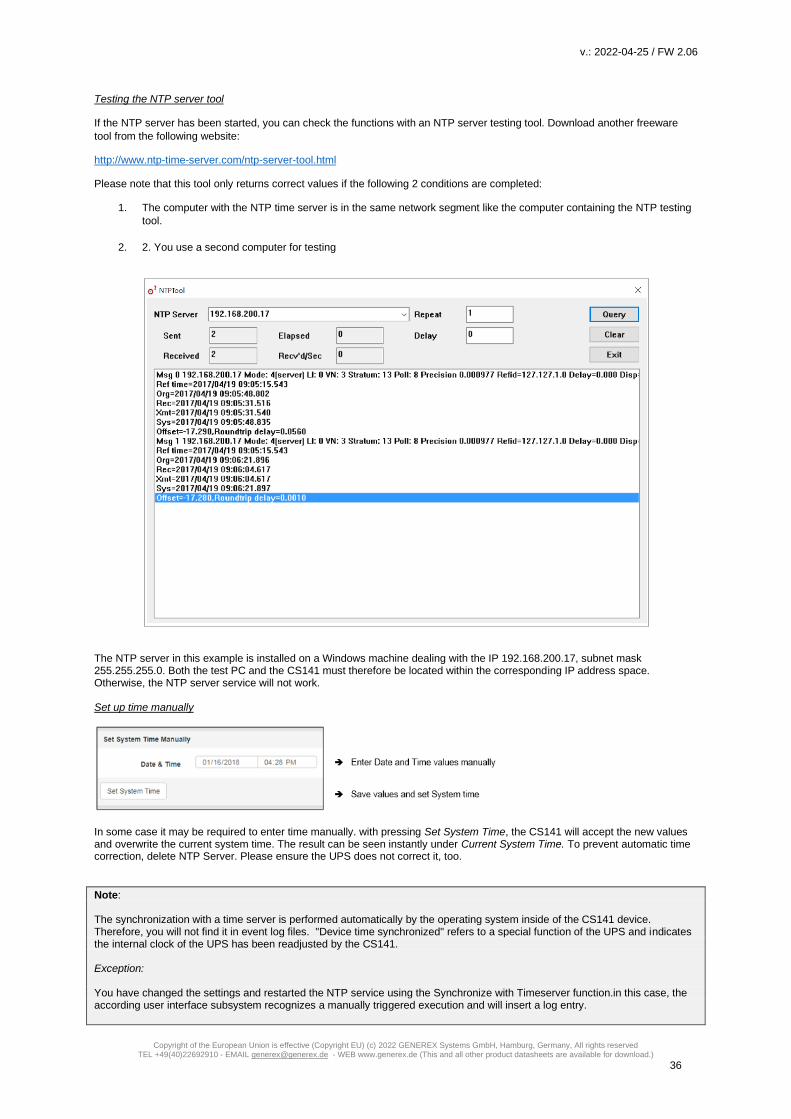
If the NTP server has been started, you can check the functions with an NTP server testing tool. Download another freeware
tool from the following website:
http://www.ntp-time-server.com/ntp-server-tool.html
Please note that this tool only returns correct values if the following 2 conditions are completed:
1. The computer with the NTP time server is in the same network segment like the computer containing the NTP testing
tool.
2. 2. You use a second computer for testing
The NTP server in this example is installed on a Windows machine dealing with the IP 192.168.200.17, subnet mask 255.255.255.0. Both the test PC and the CS141 must therefore be located within the corresponding IP address space. Otherwise, the NTP server service will not work. Set up time manually
In some case it may be required to enter time manually. with pressing Set System Time, the CS141 will accept the new values and overwrite the current system time. The result can be seen instantly under Current System Time. To prevent automatic time correction, delete NTP Server. Please ensure the UPS does not correct it, too.
Note: The synchronization with a time server is performed automatically by the operating system inside of the CS141 device. Therefore, you will not find it in event log files. "Device time synchronized" refers to a special function of the UPS and indicates the internal clock of the UPS has been readjusted by the CS141. Exception: You have changed the settings and restarted the NTP service using the Synchronize with Timeserver function.in this case, the according user interface subsystem recognizes a manually triggered execution and will insert a log entry.

v.: 2022-04-25 / FW 2.06
Copyright of the European Union is effective (Copyright EU) (c) 2022 GENEREX Systems GmbH, Hamburg, Germany, All rights reserved TEL +49(40)22692910 - EMAIL [email protected] - WEB www.generex.de (This and all other product datasheets are available for download.)
37
User Management
For this configuration step, you need the following menu:
The user management of the CS14 allows a multi-layered adaptation to the respective security requirements of a network. Administrators can choose between 3 different basic strategies to decide as freely as possible whether and how the login should be possible:
Local Authentication only In this operating mode, the CS141 uses only the users configured on the respective unit. Changes must be made manually by an administrator or by the "Super User" on each single device. RADIUS, then Local authentication With this setup, a RADIUS server is asked first. If RADIUS is not available, the CS141 checks whether the requested user is known in the internal (local) user pool. RADIUS Only When operating with RADIUS Only mode, the CS141 will completely ignore the internal database - only users and passwords that are stored at the associated RADIUS server are valid.
Note: The Super User “admin” comes with a special role User: admin Password: cs141-snmp This is the only preset user that cannot be changed or locked up. Should there be widespread network malfunctions, the super user "admin" grants a logon that comes with additional tools for extensive network diagnostics. Ensure to choose a save password for this user!

v.: 2022-04-25 / FW 2.06
Copyright of the European Union is effective (Copyright EU) (c) 2022 GENEREX Systems GmbH, Hamburg, Germany, All rights reserved TEL +49(40)22692910 - EMAIL [email protected] - WEB www.generex.de (This and all other product datasheets are available for download.)
38
The internal (local) user management console
With the internal (local) user administration, user names, passwords and administrative levels are directly specified by administrators within the respective CS141. Except for the super user "admin", it is possible to define freely user name as well as the user role.
Note: Name versus Role - what is the difference? The CS141 distinguishes between the user name / password and a pre-configured user role. The user role decides which menus are displayed to the user’s name created by an administrator: For example, it is not relevant for a technician to be allowed changing settings on the mail server or the IP address. In order to avoid misconfiguration, these menus are completely hidden for the corresponding user role "Engineer" and therefore blocked for the technician.
Preset Users The preset users grant a quick start. They can be adapted to the respective operating scenario as required. Der Super User „admin“ User admin Default Password: cs141-snmp This user is unique and cannot be deleted or deactivated. Users with this clearance level not only have administrative access, but also receive valuable diagnostic tools for extensive network analyses. The super user admin is also the only user with absolute password control The Engineer User engineer Default Password: engineer The technician has a user account restricted to his area of responsibility. He has access to the functions that concern technical action. He has the ability to carry out an initial configuration of available devices, as well take over advanced technical settings. The Customer
User customer Default Password: customer The customer has access to the system monitors and can also view and download the collected log files. The administrative functions with which the data can be deleted, among other things, are not accessible. Guest access User guest Default Password: guest The guest access enables pure viewing of the system monitors without being allowed to trigger further functions. The special feature of this user is that the password query can be deactivated if required.

v.: 2022-04-25 / FW 2.06
Copyright of the European Union is effective (Copyright EU) (c) 2022 GENEREX Systems GmbH, Hamburg, Germany, All rights reserved TEL +49(40)22692910 - EMAIL [email protected] - WEB www.generex.de (This and all other product datasheets are available for download.)
39
Locking user release levels
This menu allows you to deny access to certain user groups
(user roles) across the board.
Special function: Allow user profile "Anonymous Guests” To use the guest access without a password, set a check mark at Anonymous authentication. This function can be used by a higher-level monitoring software such as GENEREX's UNMS II, e.g., to display necessary data for monitoring without a password request. Optional user role: The „Administrator“
The administrator can be set up exclusively by a super user. The "administrator" then offers a slightly graded version of the super user - it has far-reaching system rights and can perform all the day-to-day tasks of an administrator. In contrast to the Super User "admin", the Administrator can be managed by a RADIUS server.
Note: A RADIUS user role "administrator" cannot be called "admin" like the super user - the CS141 will reject this login constellation on principle to avoid confusion between users and user roles.
How to use guest /anonymous login
The guest access can be used for Normally, the CS141 only provides information via its web interface if a user successfully logs in - a deep link to view the UPS monitor directly is treated accordingly:
After activating Anonymous authentication, it is possible to view the monitoring screens directly – it is even possible to create a small html page and set up an I-frame to show it inside larger websites or content management systems. This html code may help you to create the html website: <html><head></head> <body> <center> <p>I-Frame zu der USV mit der IP xxx </p> <br><hr><br> <iframe src="http://<Ihre IP>/www/devices/ups/page" height="600" width="850" name="iFrame" title="IFrame zu meiner USV"></iframe> </center> </body></html> As a result, the UPS monitoring screen will appear inside your html document:

v.: 2022-04-25 / FW 2.06
Copyright of the European Union is effective (Copyright EU) (c) 2022 GENEREX Systems GmbH, Hamburg, Germany, All rights reserved TEL +49(40)22692910 - EMAIL [email protected] - WEB www.generex.de (This and all other product datasheets are available for download.)
40
Possible deep links:
http://10.10.10.10/www/devices/ups/page Opens the UPS monitoring screen
http://10.10.10.10/www/devices/sensor/page Opens the Sensor monitoring screen
http://10.10.10.10/www/devices/bacs/page Opens the BACS monitoring screen.
Note:
By using the web query directly, you will notice the URL inside your web browser will change. This is because you start a page
request, but the web server on the CS141 responds with a different page and will redirect you automatically: Since the page
behavior is dynamically, the response page may change accordingly. However, the HTML request is standardized with these
three deep links and will be served as long as the Anonymous login is active.
Create, delete and edit local users …
Add a user...
To open the configuration dialogue for creating users, click under "Local users" on Then simply create the user and specify the user role:
At "User Name", it is possible to freely type any user:
- James T, Kirk - Joardy La’Forge - User_%&lannmaP
However, the CS141 will obey the exact spelling including upper/lower case and spaces.
Edit a user …
Click on the edit- symbol to open the according menu:

v.: 2022-04-25 / FW 2.06
Copyright of the European Union is effective (Copyright EU) (c) 2022 GENEREX Systems GmbH, Hamburg, Germany, All rights reserved TEL +49(40)22692910 - EMAIL [email protected] - WEB www.generex.de (This and all other product datasheets are available for download.)
41
The user will be changed on the fly. If the user is logged in for the moment, the new settings are active on reboot or logout.
Delete a user …
To delete a user, simply click on the recycle bin next to the user. If you delete the user, you are currently using, your username
will become invalid when you log out.
The RADIUS – Server
Firmware 2.02 or higher is required for this function. The necessary firmware update can be downloaded free of charge at www.generex.de . This function is available directly after the firmware update. What the hell is „RADIUS “?
RADIUS is the abbreviation for Remote Authentication Dial-In User Service. In principle, the point is that with a growing number
of end devices such as printers, access points, switches, routers, etc. in conjunction with more and more staff that dynamically
access the configuration menus, someday the point is reached where the time required for setting up, deleting and re-encrypting
users becomes time intensive ... With a functioning RADIUS, one can centralize the necessary approvals and no longer have to
maintain users and their approvals locally on the respective end devices.
Roughly speaking, it works like this:
The end device is informed of "its" RADIUS server, where it can ask whether a user exists and which authorization a requested
user holds within the network. The RADIUS server accepts the request, compares its user database and responds accordingly.
As a result, an end device does not have to maintain its own user database, which of course also has to be maintained
exclusively in case of staff or passwords change.
A little more practical:
Imagine the following work order:
15 access points from different manufacturers, on which 3 users must be decrypted, 2 users receive other approvals and 1 user
is added. For the administrator, this means that he has to handle 15*6 users, i.e., he has to change a total of 90 user data, has
to log in exclusively to each end device, and thus, in the worst case, needs 15 passwords and has to choose between "admin",
"administrator", "root", etc... An immense effort that arises for just 6 users.
With a RADIUS server, there are ultimately only 6 users, which are also stored centrally. In this case, the end devices do not
have to be touched at all, as they ask the RADIUS server who is allowed to log in.
From a certain network size / number of end devices and staff strength onward, it makes sense to consider using RADIUS
servers.

v.: 2022-04-25 / FW 2.06
Copyright of the European Union is effective (Copyright EU) (c) 2022 GENEREX Systems GmbH, Hamburg, Germany, All rights reserved TEL +49(40)22692910 - EMAIL [email protected] - WEB www.generex.de (This and all other product datasheets are available for download.)
42
Configuring a CS141 to use a RADIUS server
Necessary prerequisites:
1. A RADIUS-Server that is running
2. Access data and, if applicable, certificates
3. Network connection for the CS141 and local administrative access (Super User or “Administrator”)
Step 1 – Configure a Radius-Server
For this configuration example, we use the FreeRADIUS for Windows, as it is relatively easy to set up and is quickly ready for
operation even for inexperienced users. For more in-depth configurations and the RADIUS server you use, please contact the
corresponding technical support for your product. The FreeRADIUS for Windows is available via download from the Internet.
Setting up a RADIUS user at the server:
In this configuration, we assume that the IP address is well-known, and the RADIUS server is installed in the following directory:
C:\FreeRADIUS.net
In this directory, you will find the *.exe -file to start the RADIUS server …
Please ensure to run this program „as administrator “, otherwise you may run into problems when running the server program.
The necessary configuration files can all be found in the following directory:
C:\FreeRADIUS.net\etc\raddb
Here, the file "users.conf" is particularly interesting.
For best use, I recommend a good code editor like Notepad
2+, Sublime or something like that, they work very well:
Two users have been entered in this example. The following
specifications currently apply to the CS141:
Administrative-User
This is the local CS141 user role „Administrator “.
Login-User
This is the local CS141 user role „Engineer “.
Customer, Guest, etc. are currently not supported, they will be added with the next firmware updates.
Note:
Feel free to add as many uses as you want – it is your RADIUS server.
Furthermore, this may be nice to know:
The machine account for the CS141:
This is the account that the CS141 needs when it wants to
log on to the RADIUS server. Without this account, the
CS141 will not be able to ask the RADIUS server for custom
users - the RADIUS server will drop the query without a
reason.
However, this account is also specified in the file
"users.conf". In this example, the user’s name and password
with which the CS141 logs on to the RADIUS server is called:
- User: FreeRADIUS.net-Client
- Password: demo

v.: 2022-04-25 / FW 2.06
Copyright of the European Union is effective (Copyright EU) (c) 2022 GENEREX Systems GmbH, Hamburg, Germany, All rights reserved TEL +49(40)22692910 - EMAIL [email protected] - WEB www.generex.de (This and all other product datasheets are available for download.)
43
The Pre-Shared Key (Shared Secret at the C141)
In addition, the CS141 will ask for a "pre-shared key", which
can be found in the file "clients.conf":
In this case the pre-shared key is
"testing456"
And is valid for the network 192.168.150.0/24 - You may
have to adapt this setting to fit to your network. Why you
need this configuration: Only if the CS141 first transmits this
key before the request, the RADIUS server will feel
compelled to process this request. In all other cases, the
RADIUS server will simply drop this request.
From now, you have all the information needed for the configuration of the CS141.
Note:
After each configuration work, do not forget to restart the RADIUS server, otherwise the new configurations will not be available.
The "Debug-Mode":
Before you can configure the CS141, it is a good idea to ensure that the RADIUS server is configured and, of course, it will start.
The debug mode is a very good help for this:
When you start this mode, a CMD window opens in which the RADIUS server shows what it is currently doing and - very
interesting - why a connection was refused.
The startup routine will finish with "Ready to process requests":
If the window closes again immediately, then something is wrong with the RADIUS server, probably something is missing or
wrong with your custom settings.

v.: 2022-04-25 / FW 2.06
Copyright of the European Union is effective (Copyright EU) (c) 2022 GENEREX Systems GmbH, Hamburg, Germany, All rights reserved TEL +49(40)22692910 - EMAIL [email protected] - WEB www.generex.de (This and all other product datasheets are available for download.)
44
Step 2: Setting up the RADIUS Client
When the RADIUS server is running, it will be possible to configure and test the CS141
At RADIUS Servers, click the edit - symbol to open the configuration dialogue. The CS141
supports up to two RADIUS servers, which are queried one after the other.
IP address, Port and Shared Secret
IP address of the RADIUS-Server
The Port the RADIUS-Server is listening
The pre-shared key of the RADIS server.
- IP address: Enter the valid IP address of the RADIUS server.
- Port: Enter the port on which your RADIUS server is currently listening.
- Shared Key: This key is used to authenticate the response of the RADIUS server - without this key, the server
drops a request on principle.
Select your encryption method Encryption has become a technical standard within modern networks. The CS141 therefore supports numerous encryption methods and can thus be adapted to the most diverse requirements within the network infrastructure. Please note that you may need additional certificates and do more configuration work that this example configuration describes. If you plan other encryption methods, please refer to the local responsible system administrator.
Setting up Timeouts and Retries
The timeout is set in seconds and defines how long the CS141 waits
until it considers the request is lost. The default value is 30 seconds.
With the Retries, it is possible to set how often the request should be
repeated before the CS141 finally gives up and asks the second RADIUS server.
Please note that timeout and retries are working together may lead to users waiting a very long time for a response in case of
RADIUS is not accessible.
The Radius Client User / the machine account
In order to be able to communicate with the RADIUS server, the
CS141 requires its own valid account, via which the CS141 can
connect to the RADIUS server to ask for valid user IDs.
For valid login data, please refer to the responsible system
administrator.
Test, Save and Cancel
Entries can only be saved after all data has been entered correctly
and the connection test to the RADIUS server has been
successful.
Step 3: Handing over the login control
1. Switch from Local Authentification Only to RADIUS, then Local Authentification:
2. And press “apply”.

v.: 2022-04-25 / FW 2.06
Copyright of the European Union is effective (Copyright EU) (c) 2022 GENEREX Systems GmbH, Hamburg, Germany, All rights reserved TEL +49(40)22692910 - EMAIL [email protected] - WEB www.generex.de (This and all other product datasheets are available for download.)
45
From now, you will be able to test your RADIUS configuration. If something is wrong, the local Super User “admin” is still active
and availale. If something is wrong, just disable the RADIUS server for this CS141.
RADIUS with Microsoft NPS and Cisco ISE
Admittedly, this guide goes into a lot of detail about FreeRADIUS, which won't help you much with Microsoft NPS or Cisco ISE,
...
The difference between Microsoft NPS / Cisco ISE and Freeradius is as follows:
In FreeRADIUS, the user role is stored as a STRING, whereas both the Microsoft NPS and the Cisco ISE work with the
INTEGER:
RADIUS 802.1X
The basic principle
Normally, there is a network-compatible device on one side that wants to log on to a network. It does not matter whether this is
done via WLAN or "cable". As soon as the connection is established, the device either asks for an IP address from the network
or logs on directly with a manually assigned (static) IP address.
However, with an active Port Access Entitiy, or PAE for short, this is not so "straightforward", as the access requirements are
changed:
A special port to the network is opened exclusively for a network-compatible device (the "Sublicant") if the device can prove its
right to exist in the network. The router does not decide this itself, but forwards the sublicant's request to a responsible authority.
In its function as an "authenticator", the router first clarifies whether the requesting device is allowed to access the network at all:
A supplicant needs permission from the responsible server to enter the network at all, and only if the according server agrees will
a port be opened for the client, through which it can then use the network for further communication.
In this way, one ensures in the first instance from a central location - in this case a RADIUS server - that only devices that are
also authorized by the administrator have access to a LAN.

v.: 2022-04-25 / FW 2.06
Copyright of the European Union is effective (Copyright EU) (c) 2022 GENEREX Systems GmbH, Hamburg, Germany, All rights reserved TEL +49(40)22692910 - EMAIL [email protected] - WEB www.generex.de (This and all other product datasheets are available for download.)
46
Confiuration of the 802.1X Support
For this configuration step, please update to firmware version 2.06 or higher. You need the following menue item:
Opens the Tab “System” Configure 802.1X Support
Additional documentation:
- Chapter „The RADIUS server “, within this document: -> CLICK HERE <-
In this chapter we explain how to set up a basic RADIUS test server and use it to test the functions of the CS141.
- Technical documentation of Switches / Routers used for 802.1x
In addition to a RADIUS server, the operation of EAP requires the use of specially configured hardware. The
configuration instructions can be found in the documentation of the respective device.
Setting up CS141 for 802.1x
Enable / Disable 802.1X
User and Password as configured within the
RADIUS Server
Show / Hide Password
Enable / Disable enchryption
Choose the encryption method
The CS141 uses a machine account to log on to the network as a sublicant. Depending on the network, an encryption method
can also be selected to increase communication between all participants.
Note:
Which encryption method you need to use, depends largely on your network - this information can be obtained from the
administrator responsible for your network
The release level as a guest is already completely sufficient:

v.: 2022-04-25 / FW 2.06
Copyright of the European Union is effective (Copyright EU) (c) 2022 GENEREX Systems GmbH, Hamburg, Germany, All rights reserved TEL +49(40)22692910 - EMAIL [email protected] - WEB www.generex.de (This and all other product datasheets are available for download.)
47
What does this setting have to do with the RADIUS settings within the menue "Users"?
In Short: Nothing.
802.1X is an independent function with which you can generally define the access of the device to a network. Therefore, you do
not have to grant administrative access to the CS141 as shown above, it is sufficient that the CS141 is generally authorized to
use a port for 802.1X:
By doing so, it is possibe configuring the device in order to meet the requirenments
a. Use General access limitation via RADIUS 802.1X port acces.
b. Running the CS141 with only locally configured user restrictions.
c. Running with RADIUS users only
d. Running generally RADIUS users only but using local users in case of no RADIUS is available
Detailed configuration instructions for the RADIUS server can be found in the chapter "RADIUS server" in this manual.
Advanced system overview
For this configuration step, navigate to the following menu:
After completing all basic settings, the advanced system overview will list available information about your CS14. The system overview is divided into several sections: System overview
If there are questions or some issues during installation, our technical support will help as fast as possible. Please note, our support needs at least following information:
- Firmware - UPS model and type - Uptime since last reboot

v.: 2022-04-25 / FW 2.06
Copyright of the European Union is effective (Copyright EU) (c) 2022 GENEREX Systems GmbH, Hamburg, Germany, All rights reserved TEL +49(40)22692910 - EMAIL [email protected] - WEB www.generex.de (This and all other product datasheets are available for download.)
48
Network settings
MAC-Address of yourCS141
Configured IP Address
Configured Subnet Mask
Configured Gateway
Configured DNS-Server
The network settings show the current configuration:
MAC address: The Media Access Control is a worldwide unique address to identify a network device. This
address is given by the manufacturer and cannot be changed.
IP-Address: Shows current IP address assigned to this device. In configuration mode, the default IP
10.10.10.10 is set, even if the IP address configured by administrators differs.
Gateway: Defines the network device that is allowed to accept and serve requests to the Internet. By
default, the configuration mode uses IP 10.10.10.1
DNS The DNS server provides the translation of names and IP addresses into reachable destinations
within networks. In configuration mode, it is the IP 10.10.10.1
Connectivity
Devices according to COM 1
Services this CS141 device provides
Connectivity allows a general overview of the options the CS141 currently provides.
Devices thereby merely indicates a UPS can be connected hardwarely to the CS141, but not the kind of model. Services define
the software-related services installed and started on the CS141 to communicate with additional devices as well as software.
Switch to operating mode
After completing basic configurations, move the slider to the desired position or set the DIP switches accordingly to enable
regular operating mode. After reboot, the device will run in desired mode. if necessary, the device can fall back to configuration
mode by setting DIP Switches or sliding switch into configuration mode. Note that the current switch position will generally take
effect after rebooting CS141.
The table below shows the regular operation modes available to the CS141 family.
Sliding switch to center position / DIP switch 1+2 OFF: After booting, the CS141 will run in configuration mode. Hard-coded default IP address 10.10.10.10 is active.
Sliding switch to right position/ DIP 1 OFF + DIP 2 ON:
After booting DHCP is active and IP address will be assigned automatically. To
identify assigned IP address check MAC address of CS 141.
.
Sliding switch to left position / DIP 1 to ON + DIP 2 OFF:
After booting, manually configured network settings will take effect.

v.: 2022-04-25 / FW 2.06
Copyright of the European Union is effective (Copyright EU) (c) 2022 GENEREX Systems GmbH, Hamburg, Germany, All rights reserved TEL +49(40)22692910 - EMAIL [email protected] - WEB www.generex.de (This and all other product datasheets are available for download.)
49
In general, there are three different options to restart the device:
Option 1 – the cold boot
Briefly disconnect power by pulling the power plug or removing the card from the slot. The device will then boot to the
appropriate operating state with the new hardware setting.
Option 2 - Reboot by software
For this step, please switch to the following menu:
The toolbox is restricted for administration usage only. After login as hard-coded user admin using default password cs141-snmp, you will be allowed to use the toolbox with extended support features. Please note: The default password is only active in case of no other password was set. Afterwards it is possible to us the CS141 reboot option. In both cases the UPS will not be restarted, but it only affects the CS141 - your power supply is ensured.
Option 3 (CS141HW161 only)
With 2022 onwards, the Slot Cards of the CS141HW161 introduced a Reset button:
- CS141HW161 SC - CS141HW161 SCM - CS141HW161 BSC - CS141HW161 MINI / R2
To restart these Webmanager modules just push the reset button – this will not delete your current saved configuration, it will reboot the WEBMANAGER directly:
- Put the sliding switch into the position of the intended operation mode - Press the Reset Button
The CS141HW161 will reboot and take over your desired hardware setting.

v.: 2022-04-25 / FW 2.06
Copyright of the European Union is effective (Copyright EU) (c) 2022 GENEREX Systems GmbH, Hamburg, Germany, All rights reserved TEL +49(40)22692910 - EMAIL [email protected] - WEB www.generex.de (This and all other product datasheets are available for download.)
50
System notifications
Setting up email services
For this configuration step, navigate to the following menu:
The CS141 provides a variety of options to interact with the environment, external devices, and the network itself. For this, the necessary services must be configured. One basic feature is the automatic notification via email and email traps. Due to the fact the CS141 does not provide a complete mail server, a valid email account must be configured.
Mail server Enter the mail server to be used. To ensure a maximum of flexibility, the CS141 allows an appropriate IP address as well as an URL of external mail provider. Administrators can choice between additional external provider or use own mail servers.
Note: The fact, your CS141 has a connection to the Internet to access external accounts of large mail providers does not mean an external provider will allow a usage for free. Sometimes they start to block service mails without stating reasons or failure message. It just stops working. In this case, it may be necessary to switch to another provider.
SMTP Port Defines the port used by a mail client to communicate with the mail server. Basically, the ports are standardized. In some cases, administrators need to choose own ports configurations to ensure communication; The necessary access data must be obtained from the local administrator. Connection Security Select the encryption type used by the CS141 for sending the emails: None no encryption required If available STARTTLS Force encryption SSL / TLS Sender Email Address Enter the mail address to be shown as sender Email authentication – user and password Depending on its configuration, email servers either use the e-mail address as their username or their own user ID and password to receive e-mails. For the valid access data, please contact the local network supervisor.

v.: 2022-04-25 / FW 2.06
Copyright of the European Union is effective (Copyright EU) (c) 2022 GENEREX Systems GmbH, Hamburg, Germany, All rights reserved TEL +49(40)22692910 - EMAIL [email protected] - WEB www.generex.de (This and all other product datasheets are available for download.)
51
Advanced Error Log Options
The CS141 offers the possibility to send mail traffic as a blind carbon copy, too. For some cases, this facilitates the analysis for example, if the sequence of an event has to be examined. With this menu, administrators may specify:
- What else should be sent - The format to be use - When it should be sent
Format In some cases, mails will be stored by using database systems. This option enables sending mails compatible formatted. Log This setting toggles the conditions whether a sent mail will be registered by event log. Administrators can choose: Errors only Mails that indicate errors are recorded in the event log Always Each mail is recorded as "sent" in the event log Never The mails are sent but not recorded in the event log.
Note: Under circumstances, automatically sending a copy for all emails may cause a flood of messages - each message will be sent as a copy again. You may find a similar problem with logging the complete email traffic: Too many entries in the event log quickly lead to confusing data as soon as you search for special entries within a time window.
With Apply, the settings are transferred to the configuration and the service for sending mails is restarted.
Test mail settings
This function will be available after successful saving mail configuration. It allows to send a test mail to any valid mail address to test the connectivity:
With the test fuction, the CS141 will send an Email to a mail receiver of your choice. By doing so, it is possible to test both: Sender and Receiver of a Mail Job.
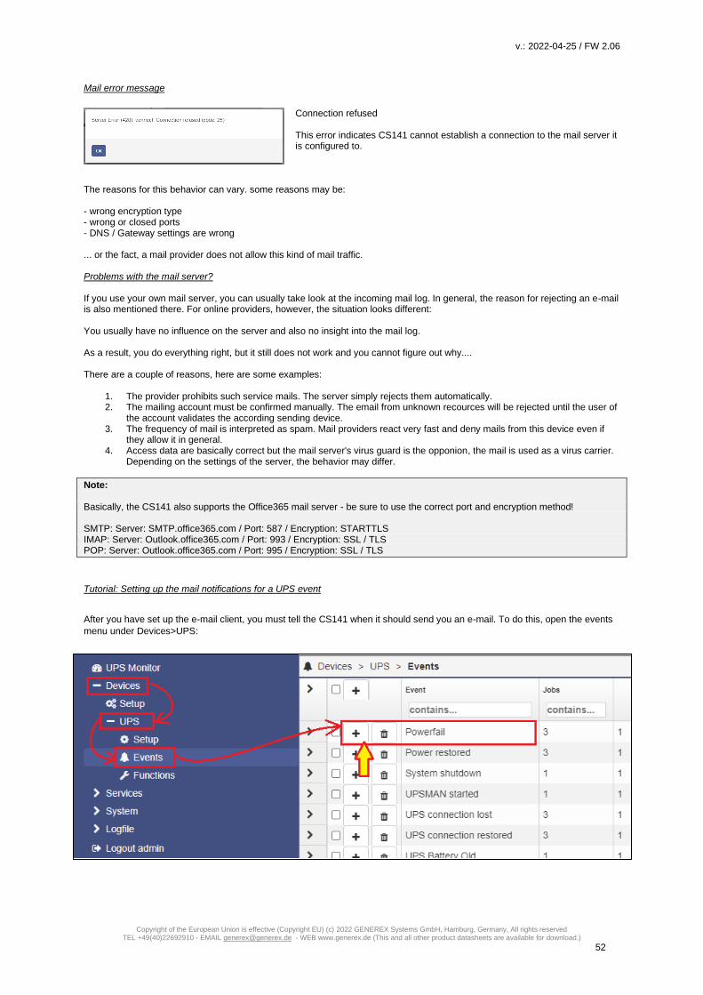
v.: 2022-04-25 / FW 2.06
Copyright of the European Union is effective (Copyright EU) (c) 2022 GENEREX Systems GmbH, Hamburg, Germany, All rights reserved TEL +49(40)22692910 - EMAIL [email protected] - WEB www.generex.de (This and all other product datasheets are available for download.)
52
Mail error message
Connection refused This error indicates CS141 cannot establish a connection to the mail server it is configured to.
The reasons for this behavior can vary. some reasons may be: - wrong encryption type - wrong or closed ports - DNS / Gateway settings are wrong ... or the fact, a mail provider does not allow this kind of mail traffic. Problems with the mail server? If you use your own mail server, you can usually take look at the incoming mail log. In general, the reason for rejecting an e-mail is also mentioned there. For online providers, however, the situation looks different: You usually have no influence on the server and also no insight into the mail log. As a result, you do everything right, but it still does not work and you cannot figure out why.... There are a couple of reasons, here are some examples:
1. The provider prohibits such service mails. The server simply rejects them automatically. 2. The mailing account must be confirmed manually. The email from unknown recources will be rejected until the user of
the account validates the according sending device. 3. The frequency of mail is interpreted as spam. Mail providers react very fast and deny mails from this device even if
they allow it in general. 4. Access data are basically correct but the mail server's virus guard is the opponion, the mail is used as a virus carrier.
Depending on the settings of the server, the behavior may differ.
Note: Basically, the CS141 also supports the Office365 mail server - be sure to use the correct port and encryption method! SMTP: Server: SMTP.office365.com / Port: 587 / Encryption: STARTTLS IMAP: Server: Outlook.office365.com / Port: 993 / Encryption: SSL / TLS POP: Server: Outlook.office365.com / Port: 995 / Encryption: SSL / TLS
Tutorial: Setting up the mail notifications for a UPS event
After you have set up the e-mail client, you must tell the CS141 when it should send you an e-mail. To do this, open the events
menu under Devices>UPS:

v.: 2022-04-25 / FW 2.06
Copyright of the European Union is effective (Copyright EU) (c) 2022 GENEREX Systems GmbH, Hamburg, Germany, All rights reserved TEL +49(40)22692910 - EMAIL [email protected] - WEB www.generex.de (This and all other product datasheets are available for download.)
53
All possible system events for the selected UPS model are listed witin in the system events overview - from here, it is possible to
define what should happen if a certain event occurs. If you want to receive an e-mail for the event "Power failure", click on + to
add the corresponding job. At the drop-down menu, select the job "E-mail" to get the according job dialogue.
Receiver Under Receiver, define, who should receive a mail. The CS141 also provides several addressees, separated by a comma: [email protected],[email protected], kirk@... Subject Enter a subject that will later appear in your mail programme as may subject. Text This is a free form text field. Feel free to type anything that may be important for this mail, e.g. a code block for filtering functions, references to further documentation, important telephone numbers, location information, security guidelines (e.g. gas, acid, etc.), access controls, etc. Insert System Variables System variables are so-called "wildcards" that are replaced in the mail by the currently available values. With this option, it is possible to place the most relevant and latest measurement data in one mail that may help technical staff with evaluation of the incident. Eventlog / Datalog
If desired, the CS141 can also attach the internal event log that was available until the e-mail was sent. The data log shows the
discharge/charge data of the UPS,
Note: Using the timing function, it is possible to assign different mails to an event with an accurate time delay for an accurate mail documentation of the incident.

v.: 2022-04-25 / FW 2.06
Copyright of the European Union is effective (Copyright EU) (c) 2022 GENEREX Systems GmbH, Hamburg, Germany, All rights reserved TEL +49(40)22692910 - EMAIL [email protected] - WEB www.generex.de (This and all other product datasheets are available for download.)
54
Email-Traps
Mail trap messages are automatically generated by industrial systems for information and status reports. Retrieved and evaluated by a corresponding recipient they are very useful inside semi- or full-automated infrastructures. The difference to a normal email is that there is no option to enter custom text or define a different recipient. A valid mail account must be deposited to send mail traps. For details, please refer the Chapter Configuring UPS In some cases, administrators need to use different mail accounts - if they choose to one Email account, CS141 offers to copy registration data directly from standard mail configuration:
By pressing copy from Email, the CS141 fetches the data already entered without passwords: The password of the mail account needs to be verified by entering manually.
Tutorial: Email-Traps
Trap messages are a very popular way to automatically get information from a network. The concept provides that a device sends its status in the form of a standardized data packet as soon as its current status changes. Among other things, the transmitted data strongly depends on the device and its function. the key feature of a trap message: The type of transmission is unidirectional - the packet is sent and there is no acknowledgment of receipt. If the device can send the packet, the task is completed. Since the messages are sent only in case of status changes, the destinated monitoring tool normally assumes that the last received status received is valid. Especially in weaker networks or in networks, where many messages of this kind are sent. This is an advantage as soon as either a large number of devices have to be monitored or the network is poorly developed: Both the required computing power and the amount of status data inside a network can be minimized.

v.: 2022-04-25 / FW 2.06
Copyright of the European Union is effective (Copyright EU) (c) 2022 GENEREX Systems GmbH, Hamburg, Germany, All rights reserved TEL +49(40)22692910 - EMAIL [email protected] - WEB www.generex.de (This and all other product datasheets are available for download.)
55
The CS141 is capable to send trap messages to a monitoring software like the UNMS II in order to indicate a status change of a UPS. Now, there is a problem: A network grows and for technical reasons, some segments cannot provide a permanent network connection until expensive major network installation works will be done …
Does the argument of a better connectivity justify the costs of a network implementation or is there a better solution? With Email-Traps, the CS141 offers an interesting way to meet this situation:

v.: 2022-04-25 / FW 2.06
Copyright of the European Union is effective (Copyright EU) (c) 2022 GENEREX Systems GmbH, Hamburg, Germany, All rights reserved TEL +49(40)22692910 - EMAIL [email protected] - WEB www.generex.de (This and all other product datasheets are available for download.)
56
The CS141 uses the e-mail function in order to send an according message if the system status changes - a timestamp ensures
that an outdated data package will be registrated but not used for the current system status monitoring. The mail server holds
the e-mail until a connection is possible - and forwards this mail to a custom e-mail address a UNMS II can access.
The UNMS II is the recipient. It will look for incoming mails and handle them like trap messages.
Note: The advantage is the fact that local connection options can be used to ensure a basic communication between a device and a monitoring system. The focus is set on ensuring communication - the communication speed depends on the local infrastructure that is available: The UNMS II displays incoming information directly on arrival, but can not determine when a valid e-mail arrives from a remote system.
Modbus
Field buses are bus systems that connect field devices like sensors or actuators to communicate with a parent automation device. If several communication participants send their information through the same line, it is necessary to determine who (identifier) will send what (measure, command) at a specified time (initiative). To ensure this communication, standardized protocols will be used. The Modbus protocol was launched in 1979 by Gould-Modicon for communicating with their own programmable logic controllers, and has become an unofficial standard in the industry due to the fact it is an open protocol. Since 1999, fieldbuses have been standardized worldwide in the IEC 61158 standard (Digital data communication for measurement and control - Fieldbus for use in industrial control systems). The second generation of fieldbus technology is based on real-time Ethernet.
Note: For further information, please refer to the Modbus manual, downloadable from the GENEREX website, visit www.generex.de.
Modbus providing devices Modbus is a protocol for serial communication. The data is transmitted using 16-bit registers (integer) or data byte status information. Using Modbus has many advantages:
- The basic structure of Modbus has never really changed to ensure best compatibility over the years. The number of unified devices provides a stable platform for integration, maintenance and configuration.
- This open protocol has been established as an unofficial standard in many industrial machines worldwide. As soon as a device supports Modbus, it can usually be integrated into an existing Modbus network.
Modbus can be used as single-master protocol The master controls the entire transmission and monitors accidental occurring timeouts. The connected slave devices may only send telegrams if requested by the master. For remote control and monitoring of equipment, the Modbus interface in each CS141 can read measuring’s, events, status information and other things within the master-slave protocol.
Note: If you do not find readings you are looking for, do not assume this could be an error. As an example, if you are looking for rare or custom UPS functions, it is possible that the according UPS communicates this to the CS141 via SNMP, but the manufacturer does not store a Modbus address for these readings. As a consequence, the CS141 will show it with its own web interface, but cannot serve your Modbus query.
Difference between CS141 Modbus and CS141 Professional Each device of the CS41 family is capable to handle Modbus
over IP. The Modbus devices have an RS485 interface instead
of the standard mini-DIN connector for sensors, specially
designed for Modbus infrastructures.
Modbus Pin assignment
As a default, a Modbus plug is installed od delivery. The plug
can be removed and later simply assembled to ensure a fast
and intuitive wiring procedure.

v.: 2022-04-25 / FW 2.06
Copyright of the European Union is effective (Copyright EU) (c) 2022 GENEREX Systems GmbH, Hamburg, Germany, All rights reserved TEL +49(40)22692910 - EMAIL [email protected] - WEB www.generex.de (This and all other product datasheets are available for download.)
57
Please note the plug alignment:
Before wiring, ensure the terminal strips are at top of the cable slots - not below them.
By doing so, the following PIN assignment can be used:
To insert an appropriate cable, pull back the spring mechanism - the clamp will automatically lock the cable at the desired
position.
The Modbus Terminator-PIN
Another difference with the CS141 Professional: The CS141
Modbus adapter is capable to drive a real RS485 Modbus protocol
- not only Modbus over IP. In case of operating within a real
Modbus environment, you can easily integrate the CS141 Modbus
adapter.
Since Modbus expects termination resistors on both the first and
last devices in the bus network, the CS141 Modbus offers an
optional 120-ohm resistor that can be enabled by setting a PINS.
As a default, this PIN is set to OFF - the CS141 is configured not
to be the last device within the Modbus network. If required, this
pin can be set manually.
Note:
In general, the CS141 MODBUS will query the UPS via SNMP and provide appropriate MODBUS addresses and values. Due to
this fact, the UPS can be queried via MODBUS. Technically, the UPS is not connected to the Modbus network natively.
However, the Modbus controller will not be able to recognize this fact.
Modbus über RS485, RS232 und Modbus over IP
As mentioned, all devices of the CS141 family can master MODBUS queries - the difference is in the details: While the CS141
Modbus version comes with an RS485 interface for native integration into a modbus infrastructure, the CS141 professional
version uses a point-to-point connection via RS232 and provides the information via Modbus over IP:
Since Modbus via RS232 is usually used when you want to transfer Modbus data from the UPS to another system or special
monitoring software, No terminating resistors are necessary for this connection type.
Due to this fact, the hardware layout of the boards changes if compared:
CS141 Modbus CS141 Professional
If compared to each other, the CS141 Modbus can be easilly distinguished from the CS141 Professional.
Since the external interface and the query via LAN can interfere with each other caused by differences in query timing, the
parallel use of Modbus over IP and via internal interfaces is not possible - you need to choose between the query options. With
these operating conditions Modbus over IP is available:
PIN Description
1 GND
2 RS485 A+
3 RS485 B -
Terminal strip

v.: 2022-04-25 / FW 2.06
Copyright of the European Union is effective (Copyright EU) (c) 2022 GENEREX Systems GmbH, Hamburg, Germany, All rights reserved TEL +49(40)22692910 - EMAIL [email protected] - WEB www.generex.de (This and all other product datasheets are available for download.)
58
1. The external Modbus interface has been explicitly deactivated on the CS141-SCM / LM - since this interface is an
exclusive BUS interface, it is therefore a dedicated menu:
2. Bei dem CS141 Professional verwendet einen multifultionalen Mini-DIN-Anschluss. Modbus over RS-232 ist daher
lediglich eine Anschlussoption, die ausgewählt werden kann:
Please note:
Depending on the scope of function, the CS141 will provide different menu entries.In addition to the device setup, the Modbus
service must be enabled:
Modbus function codes
The CS141 supports the following function codes: 01H - Read Coils 02H - Read Discrete Inputs 03H - Read Holding Registers 04H - Read Input Registers 05H - Write Single Coil

v.: 2022-04-25 / FW 2.06
Copyright of the European Union is effective (Copyright EU) (c) 2022 GENEREX Systems GmbH, Hamburg, Germany, All rights reserved TEL +49(40)22692910 - EMAIL [email protected] - WEB www.generex.de (This and all other product datasheets are available for download.)
59
Please note that the actual function codes depend on the UPS connected to the CS141, because the UPS must support
commands of this type. In general, the functions 03H and 04H are normally supported by standard UPS systems, whereby the
CS141 makes no difference between these two functions. Since the CS141 supports polling speeds of up to 38400 baud, it can
be flexibly integrated into an existing system.
Modbus error codes
Except for broadcast messages, where the master device sends a request to slave devices, a master always expects a unique
and valid response from the according requested slave. If the reply does not meet the specifications, the packet is discarded with
a corresponding error message.
The following possible events may occur when a master device requests data from its slaves:
1. The slave responds accordingly with a valid data packet.
The Master will react accordingly.
2. The slave device does not receive the request from the master.
This event occurs, for example, in the event of a communication error. Since the request was not answered from the
master's point of view, the master reacts with a corresponding timeout.
3. Messages from the master or the slave are invalid
Such a phenomenon is an example for a forgotten termination resistors thy have not been set. Data is sent, but there
are clearly errors in parity, LRC or CRC within the data packet. Since invalid packets are dropped by devices, the slave
will usually reject to respond. The master generally notifies in case of an incorrect response a corresponding timeout.
4. The request a slave receives is valid, but cannot answer
If the slave unit receives a request without a communication error, but a readout is not possible due to e.g. a non-
existent register, the slave units' response is a specific exception message to inform the master unit about the reason
for the error.
Possible error codes coming with a CS141
o 02H llegal Data Address
The data address received with the valid request cannot be processed due to a wrong or not existing the
address.
o 03H Illegal Data Value
A value that was included in the request is not a permissible value for the slave.
o 06H Slave device busy
The slave has received a valid request, but is currently busy with a time-intensive or time-critical process.
Since of this fact, the CS141 is for the moment not able to process the request - the master will not declare
a timeout, but will repeat the request at a later time again.

v.: 2022-04-25 / FW 2.06
Copyright of the European Union is effective (Copyright EU) (c) 2022 GENEREX Systems GmbH, Hamburg, Germany, All rights reserved TEL +49(40)22692910 - EMAIL [email protected] - WEB www.generex.de (This and all other product datasheets are available for download.)
60
How to configure Modbus
For this configuration step, navigate to the following menu:
Since Modbus is standardized, the basic configuration is intuitive to handle. To configure the Modbus agent, go to services and
open Modbus.
TCP Port 502 The TCP port 502 is a static port setting within the Modbus standard that cannot be changed or customized without leaving standards - This port value is hardcoded inside the CS141 source code. Slave Address The Modbus slave is the ID that make a Modbus device addressable. The Slave ID mentioned by a master's query will cause this device to answer This ID may be customized, but only exist once inside a Modbus network.
Note: Doubling a Modbus Slave Address will not result in a complete network short-circuit - if the ID is requested by a Modbus master, both addressed slave devices will respond. This will cause the Modbus Master to display misleading data accordingly or assumes a timeout due to the fact the data packets are not valid. In this case, check the uniqueness of the slave address and, if necessary, assign a free Modbus address.
Baud Rate The baud rate defines the data transmission speed for Modbus queries and answers. Please note that the polling speed through the master must be identical to the answering speed configured at the slave to avoid communication lost issues. Parity When transmitting data in the form of a bit stream, the parity bit will ensure an error detection can be performed. The value of the parity bit is calculated by the transmitter and communicated to the receiver accordingly. The receiver of the data stream uses the same mathematical algorithm to verify valid data and find corrupt data packets. Thereby Sender and receiver must therefore agree beforehand on how to perform the parity calculation: The parity calculation can be interpreted as even or odd.

v.: 2022-04-25 / FW 2.06
Copyright of the European Union is effective (Copyright EU) (c) 2022 GENEREX Systems GmbH, Hamburg, Germany, All rights reserved TEL +49(40)22692910 - EMAIL [email protected] - WEB www.generex.de (This and all other product datasheets are available for download.)
61
Example: even parity
If devices agree to calculate with even parity, the number of all "1 bits" will be counted within the data word. The task of the parity bit is to set the result to an even number: Therefore, if the number of bits to be checked within a data packet is even, the parity bit must be transferred as 0, otherwise the total count will be not an even value. Differently configured devices would therefore declare an odd or an even value valid and discard other data packets accordingly as invalid. Der CS141 offers three options: n No parity control o Odd parity control e Even parity control By default, the CS141 is shipped with the value n for no parity check. Stop Bit A stop bit defines the end of a data word within a data stream and is used in asynchronous data transfer: Usually, a corresponding start bit is sent before a data word transmission starts. Start/Stop bits allow a receiving device to recognize the beginning as well as the end of a data word inside a data stream. In principle, it is also a high signal, but the level of the signal differs from the subsequent data word. At the end, depending on the configuration, one or two stop bits are set to determine the explicit end of this data word. As a consequence, no valid data word can be present between stop bits and the next start bit: The receiving device will recognize these data as discardable and ignores them accordingly. If data transfer issues cause a synchronization lost, the device will look for predefined bit chains for re-synchronization.
Note:
If more than one Modbus device is on the same ID, they will all start sending data to serve the master's query.
Amongst other things, the start and stop bits within the network will begin cross talking, causing problems with the assignment of
valid and invalid data packets.
The Stop Bit function defines whether the CS141 should send one or two corresponding stop bits Mit der Funktion Stop Bit definieren Sie, ob der CS141 einen oder zwei entsprechende Stop Bits senden soll. Apply/Cancel This function saves the entered data and restarts the corresponding services on the fly. A complete reboot of the CS411 is not necessary:
- Apply: Save changes and restart the service as required - Cancel: Withdraw settings and return to current state.
Note:
The standard UPS Modbus addresses can be found in the appendix of this manual starting on page XXX.
The CS141 uses a valid Modbus reading range from 0-65535. Some Programs like "Modbus Poll" use the same range. Other
Modbus polling clients may use 1 - 65536 - in this case, you need to correct this by adding 1 to the original value.

v.: 2022-04-25 / FW 2.06
Copyright of the European Union is effective (Copyright EU) (c) 2022 GENEREX Systems GmbH, Hamburg, Germany, All rights reserved TEL +49(40)22692910 - EMAIL [email protected] - WEB www.generex.de (This and all other product datasheets are available for download.)
62
Using Modbus over IP and Modbus RS 232/485 simultanously
As a standard, the CS141 is configured to use either Modbus over IP or Modbus over RS 232 / 485 to serve a modbus master in order to ensure both, a fast and a stable connection without any timeouts:
- As long as the hardware interface is disabled or assigned to other devices, Modbus over IP will start. - If COM 2 (or the Modbus interface) is enabled, Modbus over IP will be automatically disabled by design.
For technical reasons, it may be necessary to use both operating modes in parallel - in this case the CS141 can be configured to serve both connection methods at the same time. How to use Modbus over IP and Modbus RS 232 / 485 simultanously
Note: In some cases, queries running in parallel from different signal sources may cause a timing problem - caused by sporadic time lags, a Modbus master will incorrectly report a timeout. If you are using the simultaneous Modbus operation mode, please ensure to adapt the master's time window so the CS141 has enough time to send an answer.
To activate the Simultan Modbus Request Mode, these menus must be configured:
Set COM 2 to “Modbus”
o For the CS141 SCM, activate the Modbus Interface
o For the CS141 SC / L, enable Modbus R232
Enable the Modbus service
Configure the interface
Stepp 1: Activate the hardware interface
At Devices, select Modbus at COM 2.
Stepp 2: Prepare the Modbus Service
At Services > Setup, set the “Modbus sliding switch” to OFF and press Apply. Wait some seconds and enable the service.
Please note, the service will only start with click on “Apply”. There is no need to restart the device.
Stepp 3: Configure the interface
At Services>Modbus, search for “Activate TCP/IP and Serial simulatnously:
Click apply to confirm the settings. The CS141 will restart the service into simltanous operating mode.

v.: 2022-04-25 / FW 2.06
Copyright of the European Union is effective (Copyright EU) (c) 2022 GENEREX Systems GmbH, Hamburg, Germany, All rights reserved TEL +49(40)22692910 - EMAIL [email protected] - WEB www.generex.de (This and all other product datasheets are available for download.)
63
Short tutorial: How MODBUS addressing works
When you take a look at the numbers you will notice that this number may tell you ultimately everything. The difficulty is to
interprete the number to identify a unique problem and without further explanation, this is a little bit difficult ...
Before you start...
Modbus slavles use a HEX value to send information to a modbus master. After receiving this HEX value, it will be converted
into a decimal number. Each HEX value or decimal value stands for a very specific UPS status, which can be interpreted
accordingly if a modbus list is available (That's why you need a "MODBUS LIST", you will find this lists in the appendix of this
manual).
Example:
UPS_SB_OUTPUT_ACT = 0X0004 -> 4 = Inverter on = UPS OK
The query takes place by a pre configured time window configured at the master. As long as the slave gets a valid request, it will
answer accordingly- in this case 0X0004. This means, everything is fine with the UPS.
After some time, the master queries again and receives the following answer:
UPS_SB_BACKUP_MODE = 0x0008 -> 8 battery power
On request, the Modbus slave replies with this status: „The UPS is currently running on batteries “
If the reason is an known error status, the CS141 will provide information about the reason, too:
UPS_SB_INVERTER_FAILURE = 0x0200 -> 512 Inverter Error
For the sake of simplicity and to shorten answers, the modbus slave adds the two HEX values and sends a single collective status report.
As a consequence, the decimal system status jumps from 4 to 524: 4 [inverter on], 8 [system on battery] + 512 [inverter error] on request. Since each status can only exist once a time, a unique status report can be interpreted from the result How does it work in practice now - a logical numerical example
As an example, the Modbus master asks the CS141 at address 109 for a status value and receives the number 56. This number does not mean anything at first, unless the correct list for the interpretation of the number has been stored for address 109. In this case, this list provides all required information about general status information coming with address 109 to interpret the "number 56":
UPS Status Hex-Value Dec-Value Description
UPS_SB_BYPASS_MODE 0x0001 1 power piped thru
UPS_SB_SHUTDOWN 0x0002 2 shutdown ups
UPS_SB_OUTPUT_ACT 0x0004 4 inverter on = UPS OK
UPS_SB_BACKUP_MODE 0x0008 8 battery power
UPS_SB_BATTERY_LOW 0x0010 16 low battery err
UPS_SB_OVER_TEMP 0x0020 32 over temp err
UPS_SB_TEST_ACT 0x0040 64 test in progress
UPS_SB_INPUT_HIGH 0x0080 128 over power err
UPS_SB_OUTPUT_HIGH 0x0100 256 over load err
UPS_SB_INVERTER_FAILURE 0x0200 512 Inverter error
UPS_SB_BATTERY_BAD 0x0400 1024 Battery error
UPS_SB_ECO_MODE 0x0800 2048 eco - bypass
UPS_SB_INVERTER_WARN 0x1000 4096 eco - bypass
UPS_SB_UPS_FAILED 0x2000 8192 prser flag
UPS_SB_COMM_LOST 0x4000 16384 for snmp
UPS_SB_DVG_ALARM 0x8000 32768 SiteManager/SiteMonitor

v.: 2022-04-25 / FW 2.06
Copyright of the European Union is effective (Copyright EU) (c) 2022 GENEREX Systems GmbH, Hamburg, Germany, All rights reserved TEL +49(40)22692910 - EMAIL [email protected] - WEB www.generex.de (This and all other product datasheets are available for download.)
64
1. The Test in Progress status will use a count 64, this status cannot be. 2. Since the value of the answer is an even number, the status "1" is dropped.. 3. The values 2, 4, 8, 16 and 32 are specified within the modbus list and may only be used once.
- Since 2+4+8+16 is not 56, status 32 must be included (56-32=24) - Furthermore, 2+4+8 is not 24, therefore the next value we are looking for, is 16 (24-16=8) - Finally 2+4 is not 8, the last valid available number must be 8.
Because all other combinations are invalid, the current system status can be found within 32 / 16 /8 – all three numbers can be found within the modbus list as seen above. Other device, same procedure: The GENEREX BACS:Modbus list As seen in the figure on the right, the basic principle is similar: In the end, the configured Modbus list decides about available addresses and how to use the values coming with them. By the way, in some cases, it is necessary to use mathematical formulas for calculating a usable value from a Modbus number. If necessary, it will be explained with the Modbus list coming from a vendor. Current and Voltage values Current and voltage are measured values, but the interpretation of the number follows the same principles. Once both, the register and the meaning of the value, is known, the returned number can be easily evaluated to determine a requested system status. Keep in mind to follow the instructions how a number is to be interpreted and refer to the documentation to convert numbers into measurement data. If in doubt, please contact the technical support of the according device.
SNMP
For this configuration step, navigate to the following menu:
Developed by the IETF the Simple Network Management Protocol is designed for monitoring and controlling network elements from a central station. The protocol controls the communication traffic between monitored devices and monitoring stations: SNMP describes the structure of the data packets that can be sent as well as the entire communication process. The CS141 can fully be integrated into a network with SNMP monitoring. The build-in SNMP agent regulates both - receiving and sending corresponding requests.
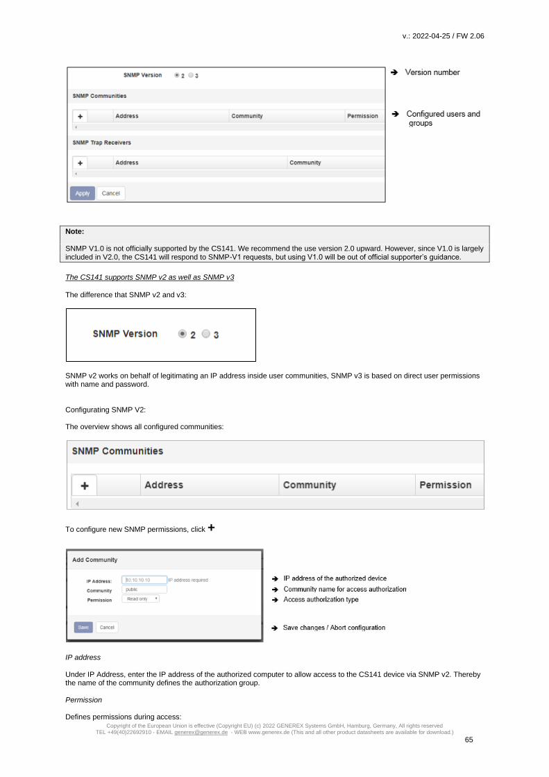
v.: 2022-04-25 / FW 2.06
Copyright of the European Union is effective (Copyright EU) (c) 2022 GENEREX Systems GmbH, Hamburg, Germany, All rights reserved TEL +49(40)22692910 - EMAIL [email protected] - WEB www.generex.de (This and all other product datasheets are available for download.)
65
Note: SNMP V1.0 is not officially supported by the CS141. We recommend the use version 2.0 upward. However, since V1.0 is largely included in V2.0, the CS141 will respond to SNMP-V1 requests, but using V1.0 will be out of official supporter’s guidance.
The CS141 supports SNMP v2 as well as SNMP v3
The difference that SNMP v2 and v3:
SNMP v2 works on behalf of legitimating an IP address inside user communities, SNMP v3 is based on direct user permissions with name and password. Configurating SNMP V2: The overview shows all configured communities:
To configure new SNMP permissions, click +
IP address Under IP Address, enter the IP address of the authorized computer to allow access to the CS141 device via SNMP v2. Thereby the name of the community defines the authorization group. Permission Defines permissions during access:

v.: 2022-04-25 / FW 2.06
Copyright of the European Union is effective (Copyright EU) (c) 2022 GENEREX Systems GmbH, Hamburg, Germany, All rights reserved TEL +49(40)22692910 - EMAIL [email protected] - WEB www.generex.de (This and all other product datasheets are available for download.)
66
Read only Devices dealing inside this permission group have read-only permissions Read/Write Devices dealing inside this authorization group can read and write /delete data packets.
Set up trap receivers
Set up trap receivers What are SNMP traps for? In principle, an agent monitoring a system can unsolicited send a so-called trap packet to its management station should this be required. Among other things, the status of the monitored device is communicated. On the other hand, the agent can receive and service requests from his manager. There are two ports required by default: Port 161 Required by the agent on the device to receive the requests Port 162 Required by the management station to receive messages If these ports are blocked, the communication will not work. Configuring trap receivers on the CS141 The advantage of the trap messages is that the CS141 can automatically inform about changes in the UPS.
To add a new trap receiver, click +,
Since trap messages are sent exclusively to inform about status
changes, no read / write operations permissions are required.
Enter the recipient's IP address as well as a valid community.
With Save button, CS141 takes over the settings and the SNMP
agent will be restarted. The CS141 will not need to be rebooted.

v.: 2022-04-25 / FW 2.06
Copyright of the European Union is effective (Copyright EU) (c) 2022 GENEREX Systems GmbH, Hamburg, Germany, All rights reserved TEL +49(40)22692910 - EMAIL [email protected] - WEB www.generex.de (This and all other product datasheets are available for download.)
67
Trap receiver test
The newly set-up trap receivers can then be tested: For an SMNP test, each device of the CS141 product family provides a practical test tool to check if the trap receiver is online and available: Simply select a trap from the list of available traps and click on the test button. Your receiver should first display the trap and then remove it from the list of active system events.
Tipp:
Trap messages are automatically generated messages that do not request confirmation - a device that sends trap messages
generally does not know whether the messages have arrived. Consequently, it will not be possible to log any information about
receipt.
Configurating SNMP v3
The overview shows all configured users:
Since SNMPv3 is user-based, you need to configure single users instead of communities. Click + to configure a new user:
User
SNMP v3 dispenses with the possibility of setting up authorized IP addresses and user groups. Administrators need to add a
local user inside the CS141 device.
Read-only / Read Write

v.: 2022-04-25 / FW 2.06
Copyright of the European Union is effective (Copyright EU) (c) 2022 GENEREX Systems GmbH, Hamburg, Germany, All rights reserved TEL +49(40)22692910 - EMAIL [email protected] - WEB www.generex.de (This and all other product datasheets are available for download.)
68
As a standard, any user gets the permission for both - reading and writing. In some cases, this may be not allowed by
administrators. To prevent SNMP users from writing data, activate the option Read only
SNMP v3: Security Level description
Authentication
Defines security level and password control to access the CS141 device using SNMP v3:
No security no passwords or encryption is required
Authenticities Single password request.
Authentication and Privacy The connection is additionally encrypted and two passwords are required.
Passwort für die Abfrage von Daten auf Benutzerebene
Maximale Passwortlänge: 16 Zeichen
Privacy Enhanced: The connection ist encryptedr
Maximum Password length: 16 characters
MD5 – Message-Digest Algorythm
With this method, a 128-bit hash value is generated from a message (e.g. a password), which can be used to check the transmission for correctness relatively easily. The advantage is the low computing power required for the process.
SHA – Secure Hash Algorythm
Basically, it does the same thing, is a little more flexible, but proceeds differently. This method refers to a group of standardized cryptological hash functions that calculate ahas value that cannot be traced back to the end..
Which of the two methods you must select for authentication depends on the specifications of the respective network operator.
Privay Options
In addition to the authentication, you can encrypt the data transmission via the privacy options:
DES – Data Enchryption Standard
DES is a very widely used standard that uses a symmetric encryption algorithm. An identical key is used for both encryption and decryption.
AES – Advanced Enchryption Standard
AES is also widely used and also belongs to the symmetric encryption methods. As the successor to DES, however, it has the advantage that it is more flexible and the hash value cannot be calculated back. However, since other algorithms are used here, it is not possible to decrypt DES-encrypted data with AES.
Which methods should I set?
The respective encryption methods differ fundamentally and are not compatible with each other. Since all methods with their concepts are largely considered "secure" at the current state, the specifications of the respective network advertising operator in which you want to integrate the CS141 must be observed for the correct settings. The following combinations are possible:
- MD5 / DES - MD5 / AES - SHA / DES - SHA / AES
You will receive the necessary access data from the responsible network supervisor / administrator.
Note:
Please note that in addition to the correct access data, the encryption type must also be identical, otherwise no connection will
be established.

v.: 2022-04-25 / FW 2.06
Copyright of the European Union is effective (Copyright EU) (c) 2022 GENEREX Systems GmbH, Hamburg, Germany, All rights reserved TEL +49(40)22692910 - EMAIL [email protected] - WEB www.generex.de (This and all other product datasheets are available for download.)
69
Configure TRAP receiver dealing with SNMP v3
To set up a trap receiver dealing with SNMP v3, you need to create a suitable user. This user can then be selected as the trap recipient in SNMP v3.
Trap receiver test
After configuration work is done, use the test function to test the SNMP v3 trap receiver:
To do this, simply select the desired trap and press the test button.
The test message should be displayed immediately at the corresponding receiving system after pressing the test button.
Note:
As with SNMP v2, the trap messages are automatically generated messages that do not request confirmation - a device that
sends trap messages, generally does not know whether the messages have arrived. Consequently, it will not be possible to log
any information about a receipt.
Restarting SNMP agent
This function is available up to firmware 1.78. With firmware 1.80, this feature is an automated background process. No configuration is required. For this configuration step, navigate to the following menu:
Within a specific and non-standard operating environment, the SNMP agent may stop responding as expected. The CS141 therefore provides a sub system to ensure the SNMP agent is running and alive.

v.: 2022-04-25 / FW 2.06
Copyright of the European Union is effective (Copyright EU) (c) 2022 GENEREX Systems GmbH, Hamburg, Germany, All rights reserved TEL +49(40)22692910 - EMAIL [email protected] - WEB www.generex.de (This and all other product datasheets are available for download.)
70
In case of the SNMP agent suddenly dies, these options are available:
No action the recovery service will not bother the SNMP agent with something like restarting. Restart the recovery service will restart the SNMP agent if it does not answer. Delay [Min] time delay until the Recovery service will restart the agent.
Note: In some cases, SNMP v1 queries may cause a hung up of the SNMP agent. Although not officially supported, the CS141 can work with the appropriate SNMP v.1 queries. The agent recovery service ensures that the agent is automatically restarted in case of doubt.
BACNET
With firmware release 1.88, the official BACnet standard is supported. You will find this menu only ofter running an update to at
least this firmware version.
Some facts about BACnet
Where is BACnet from?
In 1987, the American Society of Heating Refrigeration and AirConditioning Engineering - known as ASHRAE - founded the
standard project committee SPC2 135P - members of this committee included companies like Andover Controls, Honeywell,
Johnson Controls, Trane and many others. The thankless task of this convened committee was to define a communication
protocol for the monitoring, regulation and energy management of buildings. However, in December 1995 and after some back
and forth as well as several submitted designs a solution was found: BACnet was adopted as the ASHRAE / ANSI standard by
the American National Standards Institute. Just three years later, the standard was initially adopted by Europe as DIN V ENV
1805-1. BACnet has become one of the most widely used standard in America and thanks to its flexibility, extensive building
management, automation can be implemented and easily expanded by new devices.
The future of BACnet: BACnet over IP
With BACnet over IP, BACnet goes on:
Existing IT infrastructures can be used, which significantly reduces costs for implementation. Ultimately, you only need a few
BACnet-compatible network infrastructure devices like routers and switches with today's standard RJ45 ports.
Requirements
BACnet over IP is based on existing TCP / IP structures, but extends these by a lot of functions that are required in building
automation. It is important that a BACnet device only works if the corresponding infrastructure supports routing the BACnet
extendet protocol - for example, routers and switches must also be able to handle BACnet over IP. Alternativly, BACnet-
compatible routers must be installed to connect BACnet segments with each via common network hardware. For the exact
configuration of the existing BACnet infrastructure, please contact your local system administrator.
Required ports to use BACnet over IP
BACnet uses the UDP protocol and usually these standard ports:
- 47808 or 47809
Note:
Unlike e.g. Modbus, the standard ports do not follow standards in port binding. Due to this fact, BACnet does not specify any
port that must be used for devices:
You can set up any port for your BACnet system that fits to your IT infrastructure. However, more modern BACnet port objects
require support in the areas 47808 - 47823 (0xBAC0 - 0xBACF) and for the dynamic port areas 49152 - 65535
Please refer to your local system administrator for the correct port settings.

v.: 2022-04-25 / FW 2.06
Copyright of the European Union is effective (Copyright EU) (c) 2022 GENEREX Systems GmbH, Hamburg, Germany, All rights reserved TEL +49(40)22692910 - EMAIL [email protected] - WEB www.generex.de (This and all other product datasheets are available for download.)
71
CS141 BACNET settings
For this configuration step, you need the following menus:
BACnet over IP does not work “out of the box” - some configuration work is required. To do this, open the menu services and
click on BACnet. The following configuration menu will be presented:
Object Instance Number
The instance number is an unsigned decimal number that can be between 0 and 4,194,302. Each device in a BACnet network
is assigned a unique instance number. Please note, devices in different physical network segments that can communicate with
each other are in the same BACnet network - they cannot have the same instance number! Do not neglect the uniqueness of
the instance number just because you are installing MS / TP devices. MS / TP devices also have MAC addresses and must
communicate with BACnet / IP devices via a gateway:
They still have to use a unique BACnet instance numbers that are not allowed to be duplicated anywhere else.
Note:
With BACnet over IP, the CS141 assigns the ID’s for device values dynamically and provides them on request with the
necessary value descriptions. Since the internal device ID's may change after reconfiguration, a kind of a fixed and pre-defined
"BACnet ID list" like a Modbus list is not practicable or used for BACnet over IP.
APDU Timeout
APDU are the "Application Layer Protocol Data Units", the current data packet that is running through your BACnet network.
The timeout is the time in milliseconds that the CS141 waits before assuming the loss of a data packet. Why the data packed is
lost, can be very different and depends on the network setup.
Device Description
Enter a small description of the function of this device. When querying the CS141 with a BACnet browser, this information is
displayed as "device description".
Device Location
Enter the physical location of the device. In case of problems, you will know where this device is installed.

v.: 2022-04-25 / FW 2.06
Copyright of the European Union is effective (Copyright EU) (c) 2022 GENEREX Systems GmbH, Hamburg, Germany, All rights reserved TEL +49(40)22692910 - EMAIL [email protected] - WEB www.generex.de (This and all other product datasheets are available for download.)
72
Model Name
This is a free text description of the connected devices, e.g. the UPS or the registration number of a BACS system, etc. This
field can be used to provide additional information for technical staff via BACnet.
UDP Port
As a default setting, the CS141 uses port 47808.However, since BACnet does not have any port restrictions by caused by
standards, you may assign a port of your choice to fit the CS141 to your existing IT infrastructure
Enable / Disable BACnet
After configuration work is done, enable/disable BACnet support at Services> Configuration by setting the slider for BACnet to
ON. The CS141 will enable the corresponding service and start providing BACnet data as configured.
Remote SYSLOG
What is Remote Syslog?
With an organically growing network, the number devices that create locally stored log files grows. Since each devices follows
his own method to provide local log file data, it is a big problem to collect and centralize these data for network error analyzes.
Remote Syslog follows the idea that as many systems as possible not only manage their log files locally, but also store them in
a standardized data format on a central syslog server:
By doing so, higher level management systems are able to automatically access the files search for problems and errors within
a network and, if necessary, to initiate appropriate measures.
Rsyslog configuration inside the CS141
For this configuration step, you need the following menus:
Rsyslog does not work “out of the box” - some configuration work is required. To do this, open the menu services and click on
Setup to start the initial configuration:
To do this, slide the remote syslog switch from Off to On and confirm your configuration. The service starts and after starting
process is finished the according configuration menu is available. Give the RSyslog service some seconds and than proceed to
it's configuration menu by clicking "RSyslog":

v.: 2022-04-25 / FW 2.06
Copyright of the European Union is effective (Copyright EU) (c) 2022 GENEREX Systems GmbH, Hamburg, Germany, All rights reserved TEL +49(40)22692910 - EMAIL [email protected] - WEB www.generex.de (This and all other product datasheets are available for download.)
73
Remote syslog server IP
With remote syslog, the CS141 sends the locally stored status reports to the IP address of the RSyslog server. Please note you
cannot address directories or "network drives" directly. For the valid IP address, refer to the local system administrator.
Remote syslog server port
In addition to the IP address, a remote syslog server normally uses a pre-defined port for listening status logs. The default port
for using rsyslog is 601. Since this is not an official standard port for rsyslog, the port for the used server may differ. If
necessary, refer to the local administrator and change the port setting according to the requirements of the network.
Accept only TLS connection / Reject expired TLS certificates
The CS141 can be advised to use encrypted communication only. If checked, the CS141 will reject expired certificates for
communication. These functions are only available if you have imported a valid certificate. Please note that with the use of TLS
encryption, further configuration on the corresponding syslog server is necessary.
Importing a TLS –certificate for RSYSLOG
What kind of TLS certificate is needed?
Note:
The short tutorial "Creating a *.pem file" in this manual shows you how to create a valid certificate. All you need to do is
renaming the certificate into rsyslog.pem. To read the according chapter, click on the following link. This link will forward you to
the according chapter:
-> Click to read the Tutorial <-
A pem file is required for operation with TLS encryption. Make sure that both the rsyslog server and the CS141use the same
certificate, otherwise the encrypted communication cannot take place.
At the CS141, upload and install the certificate
by placing the file at the upload box:
Place the fila via drag’n’drop and click on
upload.
If the certificate has been successfully
uploaded, the CS141 will show a
corresponding message.
After installing the certificate, these additional functions are available: - Accept only TLS connection - Reject expired TLS certificates
Activate the check boxes and save the
configuration.
The CS141 takes over your settings and automatically restart the necessary syslog service.

v.: 2022-04-25 / FW 2.06
Copyright of the European Union is effective (Copyright EU) (c) 2022 GENEREX Systems GmbH, Hamburg, Germany, All rights reserved TEL +49(40)22692910 - EMAIL [email protected] - WEB www.generex.de (This and all other product datasheets are available for download.)
74
Check list: If the communication with the rsyslog server does not start
1. Check IP address and server port
Larger and well-secured networks may have restricted port access on network devices like managable switches. As a
consequence, the communication is not possible. Please check the internal firewall of the server as well as any 3rd
party security solution if the CS141 is allowed to communicate and by the way, check the IP address and port setting
whether they are correct.
2. Check network infrastructure
So-called V-LANS are often used in larger networks. Physical ports located on the same switch are stitched to a
restricted instance and seperated from other ports of the switch. As a consequence, your server may be logically in a
complete other network segment but connected to the same switch like the CS141. If your server is in a different
network segment, no communication can take place. Check if the all routers and switches are connected and
configured as required.
3. Check the certificate(s)
Damaged and incorrectly created certificates (pem-files) mean that no communication can take place. Also make sure
that the sender and recipient use matching *.pem files, otherwise TLS will not work.
About the use of SYSLOG
What is the basic idea behind remote syslog? Anyone who has to manage large networks will find that, especially in the event of a fault, many networked devices produce numerous log files and thus also reveal information about the origin and, of course, the course of a network fault. When evaluating the data, one quickly runs into problems like:
1. organically grown structures have a lot of different network devices in use 2. Log files are not standardized, each manufacturer follows its own ideas. 3. The local storage space of the network devices is limited, with very different consequences 4. Depending on the manufacturer, there are software tools that allow analysis, but the tool is limited to "its" network
products 5. Many devices are coming with many passwords which, in the worst case, also have to be entered individually
because radius functions are either not implemented at all or a radius server is not available due to the network malfunction.
This list can be extended at will, but in short: in this case, data evaluation will take an unnecessarily long time, and just collecting and preparing data data (e.g., copying from a custom tool, downloading and open local log files and manually entering it into a database) will take most of the time. The solution here is "remote syslog", a function that a good device like the professional CS141 should naturally support: The idea is that the locally stored log files are also transmitted as a standardized format to a central data log collector - the so-called syslog server. The syslog server simply receives these data and provides them for 3rd party diagnostic software to decide what shall happen after automatic evaluation. What do I achieve with that? Beneath saving tons of time that collecting data for evaluation will cost, nearly unlimited memory - All devices of the CS141 product family offer plenty of space for storing system events locally. When this memory is exhausted, the oldest entry is deleted and the newest entry is added. With Syslog, you can also transmit the status messages directly to an external server and thus collect uninterrupted event chains over an almost unlimited period of time. Why is there no CS141 syslog list of things that will be transmitted? This would be very difficult, as the CS141 supports many 1000 UPS models from almost all manufacturers on the market, and, depending on the type, can also have additional building management functions. Since many manufacturers and suppliers now use their own terminology for "their" functions, there are no standardized entries available. The CS141 therefore takes its own event log as a blueprint: as soon as you activate remote syslog, everything that is written in there is automatically forwarded as a system status to a syslog server in almost real time. If the syslog server is not available, this is noted accordingly in the CS141 locally. By doing so, you will never again loose a system status message.

v.: 2022-04-25 / FW 2.06
Copyright of the European Union is effective (Copyright EU) (c) 2022 GENEREX Systems GmbH, Hamburg, Germany, All rights reserved TEL +49(40)22692910 - EMAIL [email protected] - WEB www.generex.de (This and all other product datasheets are available for download.)
75
Hey, what does „nearly real time “mean? If the entry appears in the event log by any internal operating system service, the syslog service in CS141 tries to send the entry once to a central collector. If this is not possible, e.g., because the central collector cannot be reached due to a malfunction, the entry is saved locally but not sent again. Instead, a note appears in the event log for this period that there is a malfunction. Is it possible to edit the log entries to get a general log file logic for my diagnostic programs?
Yes, all log files that depends on a system event can be adapted by adding or editing the job log. As an example, just open the "power failure" event and edit the job "log" to fit to „your" syslog search term. If, as in the example on the right, you change the job "Log" so that "sysog_USV_15" appears first, then exactly THAT will also be transmitted to the syslog server, as it will be written as a job in the local event log when executed. Which text you use afterwards is entirely up to you. In this way, you can also equip any available analogue and digital inputs with a job and provide a unique "diagnosis code" so that you can easily find and assign the corresponding error messages afterwards. The C141 adapts this exactly to your specifications: What is written in the event log, is transmitted exactly as it is.
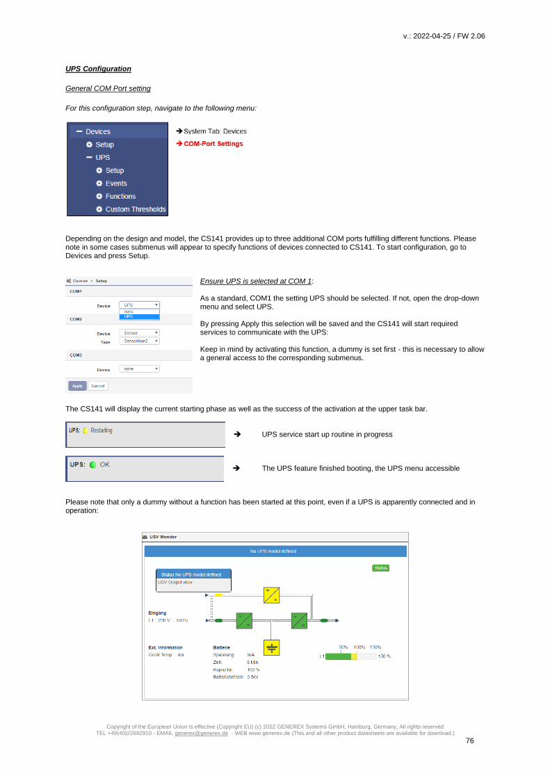
v.: 2022-04-25 / FW 2.06
Copyright of the European Union is effective (Copyright EU) (c) 2022 GENEREX Systems GmbH, Hamburg, Germany, All rights reserved TEL +49(40)22692910 - EMAIL [email protected] - WEB www.generex.de (This and all other product datasheets are available for download.)
76
UPS Configuration
General COM Port setting
For this configuration step, navigate to the following menu:
Depending on the design and model, the CS141 provides up to three additional COM ports fulfilling different functions. Please note in some cases submenus will appear to specify functions of devices connected to CS141. To start configuration, go to Devices and press Setup.
Ensure UPS is selected at COM 1: As a standard, COM1 the setting UPS should be selected. If not, open the drop-down menu and select UPS. By pressing Apply this selection will be saved and the CS141 will start required services to communicate with the UPS: Keep in mind by activating this function, a dummy is set first - this is necessary to allow a general access to the corresponding submenus.
The CS141 will display the current starting phase as well as the success of the activation at the upper task bar.
UPS service start up routine in progress The UPS feature finished booting, the UPS menu accessible
Please note that only a dummy without a function has been started at this point, even if a UPS is apparently connected and in operation:

v.: 2022-04-25 / FW 2.06
Copyright of the European Union is effective (Copyright EU) (c) 2022 GENEREX Systems GmbH, Hamburg, Germany, All rights reserved TEL +49(40)22692910 - EMAIL [email protected] - WEB www.generex.de (This and all other product datasheets are available for download.)
77
UPS pipe through function
The COM port 2 is flexible and provides to connect various devices
to fulfill different functionalities:
- Sensors
- Modbus
- External modems
- UPS Signal piping
In companion to UPS configuration, the Pipe-Through functionality of
the CS141 offers an advantage in UPS signal usage:
The signal received from the UPS can be piped through the CS141
and will be available 1:1 at COM port 2.
Due to this fact administrators can harmonize emergency shutdown
solutions even if they need to use two different and physically
separated networks:
Physically separated network resources can be managed for their
own and use simultaneously the same UPS solution.
The configuration of Pipe Through is done on the Web Manager
connected to the UPS. The second Web Manager is configured as
described on COM 1 but is connected to the COM2 port of the first
Web Manager instead of the UPS.
Note:
When using the pipe-through function, be sure to set the correct COM2 port to Pipe Through. Furthermore, set the same UPS
with identical values on both CS141s.
All other settings may differ.

v.: 2022-04-25 / FW 2.06
Copyright of the European Union is effective (Copyright EU) (c) 2022 GENEREX Systems GmbH, Hamburg, Germany, All rights reserved TEL +49(40)22692910 - EMAIL [email protected] - WEB www.generex.de (This and all other product datasheets are available for download.)
78
Configuration of a UPS
For this configuration step, navigate to the following menus:
Proceed to submenu UPS and click on Setup to enter the basic UPS configuration menu. This configuration dialog allows to choose the UPS your CS141 is installed to – recommended values will be entered automatically by selecting a UPS:
In some cases, the UPS protocol does not provide the appropriate data. The CS141 will, based on the data situation,
independently calculate the corresponding battery life runtime. In general, these settings do not need to be changed if you can
select a UPS model directly from the list - optimized configuration settings will be displayed after selecting the UPS.
if your UPS operates with a system configuration that differs to the basic model, it is possible that you need to adjust these
default values: In this case, please refer to your local UPS dealer or the UPS manufacturer of the UPS to get the correct values.
Entering wrong values may cause heavy system failures
Note:
By default, OEM ID 12 / GENEREX SYSTEMS is set. If you want to use a UPS from a manufacturer that is not listed, take a
look at the download area of www.generex.de - Search for the firmware for your UPS and install it as a regular firmware update.
Afterwards the corresponding UPS models are available.

v.: 2022-04-25 / FW 2.06
Copyright of the European Union is effective (Copyright EU) (c) 2022 GENEREX Systems GmbH, Hamburg, Germany, All rights reserved TEL +49(40)22692910 - EMAIL [email protected] - WEB www.generex.de (This and all other product datasheets are available for download.)
79
Adjustable information about the installed UPS
Model
Defines listed default setting of a UPS including the corresponding communication protocol. When your UPS is listed and
communication has been established, telemetry of the UPS typically provides all the necessary data that the CS141 needs to
calculate and display autonomy times.
Please note that changing the UPS model will also reset the configuration of the UPS events. The CS141 therefore offers the possibility to create a corresponding backup of the event configuration beforehand: Cancel: Do not make any changes to the system Do not save: Continue without backup Save: Create a Backup of the event handling
Power (VA)
Defines the maximum power in VA the selected UPS in can provide. Exceeding the maximum may cause the UPS getting
damaged or even destroyed
Load (VA)
This value defines the maximum load connected to the UPS. Even the possibility is given, exceeding the power VA value can
damage or destroy the UPS as well as the installed batteries.
The maximum possible value is less or equal to the value entered at Power (VA).
Hold Time (min)
If main power fails, the batteries of a UPS will ensure this operating time if 100% load is used. The real-life uptime is determined
dynamically by the percent of usage: of you use 50% the hold time will raise accordingly.
Note:
Behind the values of power (VA), load (VA), holding time and battery charging time, a mathematical formula is stored - this will
allow the CS141 to calculate independently battery operating time and trigger corresponding system events. Thus, allow to use
the CS141 even if the UPS protocol cannot provide real-time data - as an example, if a UPS only communicates via switchable
contacts or only basic operating states can be detected.
Baud Rate
Different protocols provide different speeds of data transmission. The baud rate defines the speed at which data can be sent
and received. An incorrect baud rate can cause communication problems between the CS141 and the UPS.
Cable Type
UPS manufacturers sometimes use specially designed cables for their models. In addition to these in-house developments,
there are standardized cable types. These cable types can be used to map different functions and switching states.
UPS-ID If large UPS systems use more than one UPS module, these modules can be queried directly via a unique ID. „0“is hereby a
something like a broadcast to allow the CS141 search and manage capability to figure out the number of UPS modules. If you
change this value, you only get the exact module with this special ID. Otherwise the CS141 will manage all available modules
and display them at the monitoring screen.
Battery installation date
The lifespan of batteries running inside a UPS is limited - regular battery maintenance also requires replacement. In order to
keep track of larger installations, you may enter the date when the batteries start into operation.
Battery too old after
If entered, the CS141 automatically indicates regular operating period for the installed batteries will expire. By default, the
CS141 logs in with appropriate system notes after 48 months. Editing this value will extend or shorten the default time period
until the CS141 will start sending maintenance notifications.
System shutdown time
In principle, the system shutdown time is he last emergency shutdown event that will be executed just before the UPS itself will
shut down itself to prevent battery damage. This value can be used to trigger the according system event. Please note that this
value is an emergency shutdown – it is not suitable to ensure a regular system shutdown.

v.: 2022-04-25 / FW 2.06
Copyright of the European Union is effective (Copyright EU) (c) 2022 GENEREX Systems GmbH, Hamburg, Germany, All rights reserved TEL +49(40)22692910 - EMAIL [email protected] - WEB www.generex.de (This and all other product datasheets are available for download.)
80
Apply / Cancel
Apply allows you to save and restart the UPS service on the CS141. Cancel will abort the configuration process and withdraw all settings – they need to be entered again.
Battery Health Level feature
The battery health level will be automatically provided by CS141 inside the UPS configuration menu if the UPS connected to the CS141 principally carries out battery testing but does not return a reporting value for "Battery test passed / faulty". Thus, the result needs to be determined by comparing two measurements: Before battery test starts, the battery voltage will be recorded. This value will be compared with the battery voltage to be found after finishing the battery test. The Battery Health Level (%) setting defines the maximum percentage deviation these two values may differ. On exceeding this value, a battery failure will be displayed. The default setting for this test is 10% deviation - but can be specified with a custom value between 5% and 30%.
Premium feature: The RFC1628 UPS interface
In some cases, UPS manufacturers supply systems that the CS141 cannot communicate to. As an example, known problems
are the card does not fit to the slot, or that the data stream sent by the UPS is not compatible formatted:
UPS manufacturers have installed their own SNMP card, which offers similar functions but may not be compatible to your
flexible and powerful GENEREX software environment. To ensure compatibility, the CS141 Web Manager offers the option to
connect to any card via SNMP. The condition is that the RFC 1628 MIB is supported by the target card. In order to use this
function, it is first necessary to configure a corresponding SNMP Agent at the target UPS.
After that enter the access data in the CS141 UPS menu. The CS141 will restart required services an establish a connection to
the destination card.

v.: 2022-04-25 / FW 2.06
Copyright of the European Union is effective (Copyright EU) (c) 2022 GENEREX Systems GmbH, Hamburg, Germany, All rights reserved TEL +49(40)22692910 - EMAIL [email protected] - WEB www.generex.de (This and all other product datasheets are available for download.)
81
Setting up the target SNMP card with SNMP v2
Model
Choose SNMP UPS-RFC 128 compliant as UPS model
SNMP-Version
Depending on the configuration of your target SNMP card, choose SNMP version 1 or 2
SNMP Community
Enter the SNMP Community configured at target SNMP card
Save/Abort
Abort will withdraw all settings, save will restart required services. After restarting the services CS141 will automatically establish
a communication to target SNMP card.
Note:
What is the difference between the RF1628 UPS interface and the APC Smart Network?
In principle, the APC card can handle the RFC1628 standard - you will be able to query basic information about the UPS.
However, the APC cards often uses their own OIDs. These OIDs are specific to AP and not conform to the RFC1628 standards.
Therefore, it is recommended to use the APC Smart network setting instead of RFC1628 interface.
Setting up the destination card using SNMP v3 at CS141
The CS141 supports SNMP v1, v2, and v3 in this mode. Enter the access data for the destination card according to your configuration and click Apply

v.: 2022-04-25 / FW 2.06
Copyright of the European Union is effective (Copyright EU) (c) 2022 GENEREX Systems GmbH, Hamburg, Germany, All rights reserved TEL +49(40)22692910 - EMAIL [email protected] - WEB www.generex.de (This and all other product datasheets are available for download.)
82
UPS with center tab
Tipp: The CS141 will provide this function in case of using a UPS with center tab support.
What is a ‘Center Tap‘ Modern UPS systems divide their single battery pack into two symmetrical pack parts and use a center tap. Bay using a center tap, they increase the nominal efficiency:
Measurement difference and charge difference The measurement when using a center tap is basically a way of looking at it:
You measure from the UPS to the center tab and then on the other side from the center tab back to the UPS. Since the batteries
all remain connected in series, two phenomena can be noticed when there are voltage problems: If a battery has a problem on
the negative string, the general voltage for all batteries will decrease.
The individual measurements of the string will show mor details:
1. The total voltatge for all batteries drops. 2. Measured from the UPS to the center tab at the negative string will indicate the missing string voltage. 3. Measured from the center tab back to the UPS on the positive side shows that all batteries work as desired.
Ideally, a UPS can show itself in which battery site a problem could generally exist - there is no need of inspecting all batteries. Where the problems with the UPS start A UPS has a blind spot. Although it can measure the differences, dealing with the measurements is a litte bit limited: Since batteries age individually even with the same type of use, the measurement data of the two strings will drift apart at the latest with the natural aging process. As soon as a certain threshold value is exceeded, a UPS system reports a general battery fault, but usually too late: It is no longer possible to estimate how many batteries have hidden defects due to the imbalance. Most of the time the UPS fails due to the hidden drifting process in an unfortunate moment. The CS141 can monitor precisely these “hidden drift processes” and issue warnings and alarms in good time if there are questionable values, thus providing the responsible maintenance staff with valuable additional time windows for maintenance work.
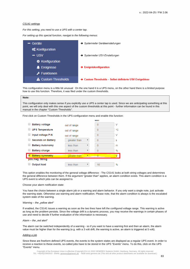
v.: 2022-04-25 / FW 2.06
Copyright of the European Union is effective (Copyright EU) (c) 2022 GENEREX Systems GmbH, Hamburg, Germany, All rights reserved TEL +49(40)22692910 - EMAIL [email protected] - WEB www.generex.de (This and all other product datasheets are available for download.)
83
CS141 settings For this setting, you need to use a UPS with a center tap.
For setting up this special function, navigat to the following menus:
This configuration menu is a little bit unusual: On the one hand it is a UPS menu, on the other hand there is a limited purpose
how to use this function. Therefore, it was filed under the custom thresholds.
Note:
This configuration only makes sense if you explicitly use a UPS a center tap is used. Since we are anticipating something at this
point, we will only deal with this one aspect of the custom thresholds at this point - further information can be found in this
manual in the chapter "Custom Thresholds".
First click on Custom Thresholds in the UPS configuration menu and enable this function:
This option enables the monitoring of the general voltage difference - The CS141 looks at both string voltages and determines
the general difference between them. If the argument "greater than" applies, an alarm condition exists. This alarm condition is a
UPS event to which jobs can be assigned to.
Choose your alarm notification state:
You have the choice between a single alarm job or a warning and alarm behavior. If you only want a single note, just activate
the warning state. Otherwise use warning and alarm notification. Please note, that the alarm condition is always is the escalated
system state of the warning.
Warning – the „yellow alert“
If enabled, the CS141 issues a warning as soon as the two lines have left the configured voltage range. This warning is active
as long as the problem persists. Since the voltage drift is a dynamic process, you may receive the warnings in certain phases of
use and need to decide if further evaluation of the information is necessary.
Alarm – the „red alert“
The alarm can be switched independently of a warning - so if you want to have a warning first and then an alarm, the alarm
value must be higher than for the warning (e.g. with a 3 volt drift, the warning is active, an alarm is triggered at 5 volt).
Adding a job
Since these are freeform defined UPS events, the events to the system states are displayed as a regular UPS event. In order to
receive a reaction to these events, so-called jobs have to be stored in the UPS "Events" menu. To do this, click on the UPS
"Events" menu.
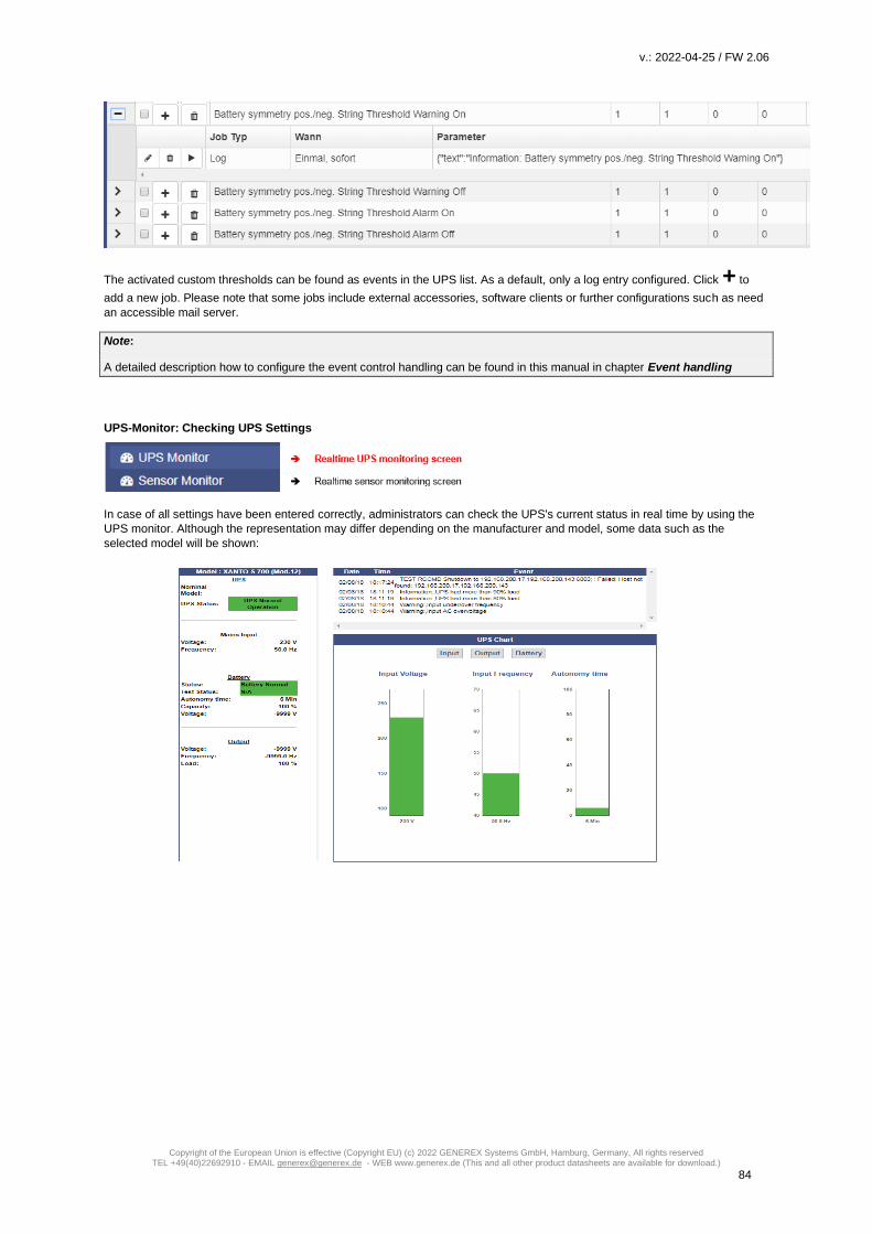
v.: 2022-04-25 / FW 2.06
Copyright of the European Union is effective (Copyright EU) (c) 2022 GENEREX Systems GmbH, Hamburg, Germany, All rights reserved TEL +49(40)22692910 - EMAIL [email protected] - WEB www.generex.de (This and all other product datasheets are available for download.)
84
The activated custom thresholds can be found as events in the UPS list. As a default, only a log entry configured. Click + to
add a new job. Please note that some jobs include external accessories, software clients or further configurations such as need
an accessible mail server.
Note:
A detailed description how to configure the event control handling can be found in this manual in chapter Event handling
UPS-Monitor: Checking UPS Settings
In case of all settings have been entered correctly, administrators can check the UPS's current status in real time by using the
UPS monitor. Although the representation may differ depending on the manufacturer and model, some data such as the
selected model will be shown:

v.: 2022-04-25 / FW 2.06
Copyright of the European Union is effective (Copyright EU) (c) 2022 GENEREX Systems GmbH, Hamburg, Germany, All rights reserved TEL +49(40)22692910 - EMAIL [email protected] - WEB www.generex.de (This and all other product datasheets are available for download.)
85
Overview – the color code
The upper status bar offers an overview of all connected devices. The color scheme is based on the typical colors of a traffic
light. In general, a distinction is made between 4 different system states, which are correspondingly highlighted with a color
code. What exactly applies is described in a short text next to the marker.
The colors of the markers will change as followed:
1. Initialization phase of devices and services
The services are currently starting and search for devices. This notice can be seen both, when commissioning additional modules or when restarting the CS141 for some reasons, as an example a reboot caused by a firmware update.
The initialization phase has been completed and no device was found. A blue marker means that the connection was never established. Please check wiring and operating state of the according devices. In some cases, you also may check your configuration work.
2. Notifications and alarm conditions during normal operating mode
Devices and alarms are within the specified parameters, everything OK.
There is an event that deviates from normal operation and should be observed, e.g. A running UPS test, temperatures reach remarkable values, initialization of devices and services is carried out after a restart, etc.
A device reports an alarm state or the conditions for a configured alarm behavior have been met. Communication Lost with a red marker means that an existing connection to a device has broken down.

v.: 2022-04-25 / FW 2.06
Copyright of the European Union is effective (Copyright EU) (c) 2022 GENEREX Systems GmbH, Hamburg, Germany, All rights reserved TEL +49(40)22692910 - EMAIL [email protected] - WEB www.generex.de (This and all other product datasheets are available for download.)
86
UPS functions
For this configuration step, navigate to the following menu:
The UPS Functions menu contains options to perform tests sequences or to configure build-in special functions a UPS may provide. They are tailored to the UPS model used to represent its functionality. As a consequence, the functions displayed for this menu item can vary - some UPSs only allow the on / off state as well as a single test-button, others provide more functionality. The following functions represent typical menu entries:
Custom Test The Custom Test is an on-battery function test using a self-defined time in minutes. Battery Test The battery test checks whether the UPS works properly and the batteries take over. This test usually takes about 15 seconds. This test will not show how long the batteries will be able to take over. Full Test The Full Test will test the batteries until they are depleted. This test can take a long time depending on power and load. The CS141 also accurately measures and determines the runtime under load. Please note UPS systems require stable load of at least 25% to perform a full test. Self test With this test, the UPS checks its own electrical functionality
Note:
In some cases, a UPS command may seem to fail or an error message may appear. This behavior is based on the fact a UPS
receives and confirms a command, but without doing it until pre-conditions are fulfilled. As an example, there must be a
minimum charge for a particular battery test - otherwise the UPS returns an error message as a result. This result will be logged
accordingly as "error". In reverse cases, it is possible the UPS sends a positive feedback despite errors but indicates an error on
the front display itself.
Due to these facts in sometimes the behavior of a UPS system is unique and for some cases unfortunately not predictable.

v.: 2022-04-25 / FW 2.06
Copyright of the European Union is effective (Copyright EU) (c) 2022 GENEREX Systems GmbH, Hamburg, Germany, All rights reserved TEL +49(40)22692910 - EMAIL [email protected] - WEB www.generex.de (This and all other product datasheets are available for download.)
87
UPS Control settings
Depending on design and model, some UPS systems support additional functions to be used for verifying the performance of
the UPS. The scope of functionality and configuration possibilities varies considerably and depends on both the manufacturer as
well as the model to be used.
Typical functions a UPS may provide:
Switchable output
Depending on the design, some UPS systems support switchable output ports.
Note:
Depending on the performance class, UPS systems are equipped differently. Due to this fact, the scope of functions varies.
Event handling
For this configuration step, navigate to the following menu:
There are many incidents that may require the operation of a UPS. In other cases, devices connected to the UPS may be harmed by different events. These events could be as an example - the failure of the main power supply, - the restoration of the main power supply, - a defect from inside the UPS prevents taking over to autonomous battery mode - batteries are depleted and main power is still missing As a full-fledged manager, the CS141 has the ability to respond to incidents independently, inform responsible personal and even manage event chains to provide a complete shutdown solution inside complex interdependent networks.

v.: 2022-04-25 / FW 2.06
Copyright of the European Union is effective (Copyright EU) (c) 2022 GENEREX Systems GmbH, Hamburg, Germany, All rights reserved TEL +49(40)22692910 - EMAIL [email protected] - WEB www.generex.de (This and all other product datasheets are available for download.)
88
What is the intention of a jobs for an event?
System events are highly dependent on the UPS model to be used and vary in both - designation as well as abundance of possibilities. Furthermore, administrators will find interesting conceptional issues according to the interplay of events and counter-events: An event receives an action, a job. This job will be executed when the event occurs. These jobs differ in central role as well as its direct function:
- Information These jobs can be executed as often as desired and only fulfill the purpose of the information. Depending on the configuration, information can be sent once or cyclically as long as an event is pending - the nature of the event does not matter. If the situation changes and the event does not come to fruition, an according job will not continue.
- Action These jobs are designed to switch, trigger, start emergency routines, etc. These jobs are triggered as soon as an event occurs. They differ from information jobs due to the fact administrators have to terminate these jobs by using corresponding counter- rotating jobs. In some cases, there are counter-events to be used, others need to be configured manually.
Note: It is important to understand the difference As long as a power failure occurs, a mail with log files is appendixed to should be sent every 5 minutes. Once the power failure is eliminated, no more email is written. On the other hand, a job to close potential-free contact as soon as a power failure is detected is executed. This cannot be reverted - even if the main power comes back, the contact remains in closed position. If a warning light is switched via this contact, it would light up until this contact is deliberately opened. A counter-job is needed in case of main power returns. The following example shows why it is important to understand the difference: If the temperature sensor measures critical temperatures, the CS141 will send e-mails and simultaneously close the contact of an air conditioner. As soon as the temperature drops below the critical level, CS141 stops sending e-mails - but the air conditioner needs to run until the temperature has returned to normal condition. This will not work if the contact automatically opens in case of critical temperature is no longer given: You need to use an active job to switch off the air conditioning system as soon as a certain temperature has been reached. It becomes problematic if a power failure causes two UPS systems running on separated power input circuits to send a server shutdown command: As soon as both systems send a valid shutdown command, the server shuts down immediately - even if both UPS systems report a power failure time-separated. If they do not cancel the shutdown command after their respective individual problems were resolved, the server will shut down due the fact, both UPS systems seems to report problems.
Event handling: Defining a job The jobs can be configured at any time. In order to test a job, two conditions need to be adjusted according to the job:
1. Jobs according to e-mails require valid e-mail account data 2. Jobs based on the TCP / IP settings require a valid network configuration
Before continuing configuration ensure all access data are available for configuration, network settings are correct, and that the CS141 is in the regular operating mode inside your network.

v.: 2022-04-25 / FW 2.06
Copyright of the European Union is effective (Copyright EU) (c) 2022 GENEREX Systems GmbH, Hamburg, Germany, All rights reserved TEL +49(40)22692910 - EMAIL [email protected] - WEB www.generex.de (This and all other product datasheets are available for download.)
89
Managing jobs
Under Devices, open the UPS submenu and go to Events. Please note that both the functions as well as designation will differ by usage of different UPS systems. These are the icons the CS141 provides:
Open /close tables
Edit an existing job
Test an existing job
Symbols providing two functions:
delete
Checkbox to select multiple jobs or events
Add a job
Note: Dual function symbols have two different meanings: Depending on where you serve them, they refer to ALL events or to a specific event or job. This dual functionality allows you to add a specific event to specific or all system events without the need of entering each job individually.
Setting up a job Managing jobs for a system event always follows the same rules - as an example, the following system events are selected:
Select > to open the job table:
For the event Power failure, a total of 3 jobs are already configured. These jobs were loaded as a recommended default configuration when selecting a UPS. To change or remove, just click on the corresponding icon. The CS141 allows to delete all jobs within a system event: By doing so, activate the checkbox in the line for power failure and press the symbol for deleting events. After pressing all jobs associated with this one event will be deleted from the list.

v.: 2022-04-25 / FW 2.06
Copyright of the European Union is effective (Copyright EU) (c) 2022 GENEREX Systems GmbH, Hamburg, Germany, All rights reserved TEL +49(40)22692910 - EMAIL [email protected] - WEB www.generex.de (This and all other product datasheets are available for download.)
90
Note: Deleted jobs cannot be retrieved, they must be recreated or restored by using a backup. To prevent accidental deletion, administrators will be prompted to confirm their decision to delete all entries inside an event...
To add a job to the power failure event, press + at the event line. This will trigger the configuration dialog who will guide you
through configuration process.
The following jobs are currently available:
Log Inserts a free definable message into the event log. Email* CS141 will send an email. Email Trap* CS141 will send Trap Mails RCCMD Shutdown* CS141 will transmit a shutdown signal to one or more RCCMD clients. RCCMD Message* CS141 will send an RCCMD message to one or more RCCMD clients. RCCMD Execute* CS141 will send a command to execute a custom file. UPS Shutdown*** Turn off UPS AUX** CS141 will trigger external relays. Buzzer** If a buzzer is connected, CS141 can activate it by using this job. RCCMD Trap* CS141 will send an RCCMD trap message. Send WOL Wake On LAN - The CS141 will send so-called magic packet to a network device. Send SMS** If a GSM modem is connected, CS141 will be able to send SMS. AUX: Switch Outlets*** As an example, the UPS can be instructed to disconnect the live outlets after a full discharge of
the batteries and run a time-delayed release to guarantee a minimum charge of the batteries.. WAKEUP If two UPS are running in redundancy mode, this custom RCCMD command can be used to
withdraw an RCCMD shutdown command
* Additional software may be necessary. ** This feature may require additional equipment and accessories. *** This function is only available to a limited extent: although some UPS systems fundamentally support the functionality,
they respond very differently to this job: Some UPS systems accept and confirm this job, but ultimately decide themselves about execution and timing.
Tutorial: WOL - The „Magic Packet “
What is the „Magic Packet “? In principle, the "Magic Packet" is a standardized data package containing 4x FF. This data packet is sent directly to the MAC address of a network card. Most modern network interface cards support this basic function natively, but for more network functionality, an operating system is usually mandatory. Preconditions to be met for setting up a working WOL system restart:
1. Depending on your network configuration, these ports must be open:
Port 7 – UDP Port 9 – UDP
2. Operating system and/or the hardware oft he according taget system must be configured to handle WOL-Signals.
Where is the configuration made on the target system?
In principle, there are two basic scenarios:
Configuration work at the operating system It is possible to specify whether the operating system allows the a "Magic Packet". If allowed, the operating system can be configured to wake up from hibernation mode. The condition is, however, that the operating system is still running at this point, albeit in some kind of deep sleep mode. If the hardware is turned off physically or a complete power loss happens, the hibernation state of the operating system is gone with the power loss. Configuration work at the BIOS In the BIOS setting, the reception of the "Magic Packet" is controlled directly via hardware settings - the network card itself manages the reception and starts the hardware. However, as soon as the computer is just in a hibernation mode, the hardware is not responsible to manage a restart - the hibernated operating system has to trigger and manage the wake up. The network card will only start the hardware via WOL in case of a complete power loss during hibernation mode.

v.: 2022-04-25 / FW 2.06
Copyright of the European Union is effective (Copyright EU) (c) 2022 GENEREX Systems GmbH, Hamburg, Germany, All rights reserved TEL +49(40)22692910 - EMAIL [email protected] - WEB www.generex.de (This and all other product datasheets are available for download.)
91
Note:
Virtualized systems are a little bit awkward, because the network interfaces are normally virtualized: The Possibility to pass a
WOL signal through a physical network interface in order to start a virtual machine depends on the scope of functions the
virtualization solution itself provides. If in doubt, please contact the technical support of the corresponding virtualization solution.
OK, … but which settings must be carried out?
That depends on what you want to achieve. If your (physical) computer normally needs to wake up from hybernation mode, the network options of the operating system must be configured to manage WOL packets. When the computer is usually switched off, powering up is managed by the hardware. You need to configure the hardware: If you want to ensure an identical result in both cases, then it is recommended to carry out both settings accordingly
3. Setting up the CS141
All devices of the CS141 family use colons as separators for the MAC address values.:
Example:
Create multiple single jobs to power up different devices via WOL. It is not possible to set up one job with different MAC addresses.
Note: Since the WOL signal is sent to the MAC address of a network card, the IP address and the subnet mask do not matter, as they are used by higher system authorities. These higher network authorities must be up and running first.The port only becomes interesting in case of the WOL signal has to be routed across networks by a router to other network nodes. Usually port 7 or port 9 is used for this function, but you have to keep in mind that the ports are managed by the system administrator of the network and can be freely adapted to his preferences and security approvals. In other cases, it is possible that the network hardware may use a hard coded port number and blocks all other signals as a kind of intrusion. In case of your WOL-Signal does not work, check the local IT infrastructure if the WOL signal was filtered or blocked by other network devices.
UPS Shutdown definition
Why is the job UPS shutdown a little bit tricky? A UPS performs a UPS shutdown to protect the batteries from a deep discharge. The UPS is physically shut down and turned
off. The time when a UPS performs this action or how it reacts to a triggered action by scheduler or via UPS functions already
varies even between the models within a manufacturer - in addition, each manufacturer uses its own definitions for to protect
batteries. But due to the fact the UPS has been physically turned off, counter events cannot be configured.

v.: 2022-04-25 / FW 2.06
Copyright of the European Union is effective (Copyright EU) (c) 2022 GENEREX Systems GmbH, Hamburg, Germany, All rights reserved TEL +49(40)22692910 - EMAIL [email protected] - WEB www.generex.de (This and all other product datasheets are available for download.)
92
Configuring UPS Shutdown
Shutdown time in seconds Defines how long the UPS should maintain operation before shutting down itself. Restore time in seconds When the main power supply is restored, the UPS waits for the preset value in seconds until it starts up again. Type With this setting the UPS will be turned off or turn on. Two different settings are possible:
1 The UPS switches off the outputs but remains in operation mode. 2 The UPS shuts down and turns off completely until the main power is restored.
How to use the job UPS Shutdown This job cannot map both settings together. Depending on the desired operation modes, at least two jobs are required. As an example, it is possible to use different jobs to complete the following sequence:
- Switch off outputs after 3 minutes - Shutdown the UPS after 4 minutes - Turn on the UPS 2 minutes after the main power supply is restored - Activate the outputs 15 minutes later
Note that the shutdown time and the restore time must be correctly nested for both jobs. In this case, enter either a 1 or a 2 depending on the desired event.
Search and display jobs
The Search function is a quick method to find jobs configured within events. The CS141 provides two basic options: Event contains… Search for a UPS event. By typing a part of an event all events according to the text fragment are listed. Jobs Lists events containing a number of jobs defined by this value. As an example, if you want to know how many events contain 3 jobs, enter 3. All events containing this number of jobs will be listed.
Configure a Job
Press + at an event to open the job configuration dialog.

v.: 2022-04-25 / FW 2.06
Copyright of the European Union is effective (Copyright EU) (c) 2022 GENEREX Systems GmbH, Hamburg, Germany, All rights reserved TEL +49(40)22692910 - EMAIL [email protected] - WEB www.generex.de (This and all other product datasheets are available for download.)
93
Different jobs provide different parameters to be configured
Example 1: Log – Enter the text CS141 shows at Event Log?
Example 2: RCCMD execute – Due to the fact RCCMD needs IP address data, the parameters will change.
Note:
The parameters adapt dynamically to fit to the according job. If the job typr does not support a parameter, it will not be provided
for configuration
Wildcard parameters: Addidtiol information about the system state
Choose the desired status information parameter and press select.
The CS141 will automatically insert the corresponding function in the text field. Select as many parameters as wanted one after
the other. In case of a corresponding function cannot be served because the according function is not supported by the UPS,
the message will show NA for not available.
Job timing
The CS141 provides many system events a job can be assigned to. Some jobs allow to configure advanced timing:

v.: 2022-04-25 / FW 2.06
Copyright of the European Union is effective (Copyright EU) (c) 2022 GENEREX Systems GmbH, Hamburg, Germany, All rights reserved TEL +49(40)22692910 - EMAIL [email protected] - WEB www.generex.de (This and all other product datasheets are available for download.)
94
Immediately, once as soon as an event happens, this job is executed at once and not repeated. After XXX seconds: The CS141 will wait a pre-defined time in seconds and then execute the job. If the event
is no longer active before time is up, the job will not be executed. Repeat all XXX seconds: The job is repeated cyclically until the event no longer is no longer active. After XXX seconds on battery: The event forces the UPS will to switch to autonomous mode. The job will be executed
if the UPS remains a pre-defined time in this state. For example, if 300 seconds are set, this job will only be executed if the UPS operates in autonomous reaches 300 seconds.
At XXX seconds remaining time: The job is executed when the remaining UPS operating time is reached or undershot.
Note based on the current load this time value becomes flexible. Time management of jobs The time management of jobs to be performed is difficult since one has to distinguish conceptually between two different points of view. The following example according to the event power failure illustrates the differences: In case of a power outage, the UPS will take over power and protect the servers until ...
1. The batteries are depleted 2. Main power is available again
As soon as the UPS runs into autonomous mode, it will start two different timers: A linearly advancing time in seconds starting at 0. If a job is to be executed after 45 seconds, it will only be executed if the event is pending for at least 45 seconds. If the event is terminated before consequently the job is not executed. A relative clock that counts backwards depending on the connected load currently used. This becomes tricky if the UPS will operate with a load of 100% If some of the machines connected to the UPS will be shut down after 3 minutes and cause the load to drop to 50%, it will take effect this way: Because of dropping load, the clock would jump from 4 minutes to 7.5 minutes. Both methods to count come with specific advantages and disadvantages: The first counter gives a clear time window to sequent jobs but ignores the actual remaining time of the UPS: If there are several small power failures in a row, a server shutdown would not work with a time delay of 5 minutes if battery power is left to ensure power a maximum of 4 minutes. The second counter is difficult to calculate and varies depending to the current load. As a consequence, there may be a time lag
to execute configured tasks: 5 minutes remaining time cannot be achieved over a longer period of time, if the circumstances
increase the remaining time - for example some systems will be shut down at 7 minutes remaining time. On the other hand, a
predetermined Sequence of events can get mixed up as soon as the circumstances correct UPS uptime down and cause
normally sequentially configured jobs simultaneously getting triggered.
Note: Basically, a shutdown using remaining time is useful, since the actually existing battery charge can be included. If a special order must be observed for jobs, it makes sense to use the linearly forwarding clock for scheduling.

v.: 2022-04-25 / FW 2.06
Copyright of the European Union is effective (Copyright EU) (c) 2022 GENEREX Systems GmbH, Hamburg, Germany, All rights reserved TEL +49(40)22692910 - EMAIL [email protected] - WEB www.generex.de (This and all other product datasheets are available for download.)
95
Adding jobs to several events
Under circumstances, a configuration requires multiple events be assigned the same job. To assign these jobs to more than one event, it is possible to select each event individually and to define this job.
To speed up the process select the events that should receive the same
job. Then click on the upper +.
By doing so, the same job is created inside the selected events. Activating the checkbox at the top row will advice the CS141 to add a job
is to all events. To start the job configuration dialog, click +.
Delete a job
If system events are no longer used inside a configuration, administrators should remove these jobs to prevent unexpected incidents.:
- Delete a job
Open event tab by clicking >
Choose the job you want to do delete and press the small trash icon. The job will be deleted immediately.
- Delete all jobs within an event
To delete all jobs inside an event, choose the checkbox of the desired event tab. Than press the small trash icon. By doing so, all jobs listed inside this event will be deleted immediately. accidentally deleted jobs need to be configured again.
Note: The CS141 allows to add, edit and delete any job. The event list itself is hard-coded and depends to the UPS you are using. Events cannot be deleted or edited by any user.
Counter events
Some jobs must be explicitly withdrawn when an adverse event occurs: - Information of responsible persons / "all-clears" - Further actions - Advised server shut downs - ... The configuration of a counter job follows the same pattern as the creation of a job. According to this context, for some jobs time management becomes a significant role: Since the UPS comes back from autonomous mode to normal mode, it will take amount of time to recharge the batteries in order to run all jobs as configured. Example scenario:

v.: 2022-04-25 / FW 2.06
Copyright of the European Union is effective (Copyright EU) (c) 2022 GENEREX Systems GmbH, Hamburg, Germany, All rights reserved TEL +49(40)22692910 - EMAIL [email protected] - WEB www.generex.de (This and all other product datasheets are available for download.)
96
Due to a power failure the UPS has switched to autonomous mode and will hold all connected devices for 60 minutes at 100% load. With 30 minutes remaining, many computers automatically shut down, reducing the load to 20%. The remaining time will be corrected upwards accordingly. Since all systems are shut down only after 5 minutes of remaining time, but the power failure at 6 minutes has been eliminated, normality returns. In this case, the CS141 can restart all computers shut down to protect the remaining time via Wake on LAN (WOL) - this absolutely useful for automated restart of networks after power failure. In this scenario, if all connected computers were to be restarted automatically, this means that the UPS could withstand 20% load for 6 minutes at the next power failure - but 100% load must be delivered. Since this cannot work, the WOL packet must be delayed in time to give the UPS the ability to charge a minimum of batteries.
Note: It is possible to create up to 50 jobs per event. In some cases, individual jobs may contradict each other or undo desired jobs accidentally by using counter jobs.
Custom Thresholds
For this configuration step, proceed to the following menus:
In some cases, UPS models allow you to customize the limits for some UPS-specific events. The CS141 supports these features if the UPS provides such an option. Otherwise you will be informed by a corresponding system message. The configuration is done via two menus:
- Custom Thresholds to define and customize settings
- vent menu to assign jobs
Differences between Warning and Alarm Levels
The Custom Thresholds are identical for Warning and Alarm Levels - but they are listed separately in the UPS event menu. Furthermore, they will be listed inside log files as a Warning or Alarm. This will allow to configure warning and alarm behavior containing different values. These conditions can be set up: out of range the event – regardless of alarm or warning - is triggered if the measured value falls below or exceeds
entered values. less than the event - regardless of alarm or warning - is triggered if the measured value falls below configured values. greater than the event - regardless of alarm or warning - is triggered if measured value exceeds configured values.

v.: 2022-04-25 / FW 2.06
Copyright of the European Union is effective (Copyright EU) (c) 2022 GENEREX Systems GmbH, Hamburg, Germany, All rights reserved TEL +49(40)22692910 - EMAIL [email protected] - WEB www.generex.de (This and all other product datasheets are available for download.)
97
Example: How to configure UPS temperature Custom Thresholds
Electrical devices operate safely between a minimum and a maximum temperature grade. Running a device exceeding these
conditions may cause issues. These issues may vary starting from simple defects up to acute fire hazards.
In order to be able to intervene in time, therefore, a predetermined temperature value must be compared with the measured
temperatures.
As an example, the manufacturer of a device specifies the "safe operating temperature" between + 5 ° C and + 39 ° C:
The CS141 can configured to warn if these values will be exceeded - the condition out of range first defines the safe
temperature range.
As mentioned, two menus are required to configure Custom Thresholds:
- Custom Thresholds: The first setting is made under Custom Thresholds where the appropriate values are set.
Enabling the checkbox UPS Temperature will include measuring values according to the UPS. For the argument out of range you need to specify both - the lowest temperature value and the highest temperature value.
Note: Since this is the warning, it should be sent before reaching critical values. Due to the fact the minimum of + 5 ° C and a maximum of + 39 °C is predefined by manufacturer, the values for warning levels must be corrected accordingly. In this example the decision is made to use 5°C: Min: 10°C Max: 34°C
Save your entries and move to the next menu:
- USP events Search for temperature threshold entries to be found at UPS events. Unlike the Custom Thresholds menu, each Threshold is displayed as regular system events and shows all possible states:
Since Custom Thresholds can be configured like regular UPS events, all jobs are available. If necessary, counter jobs can be defined according to temperature.
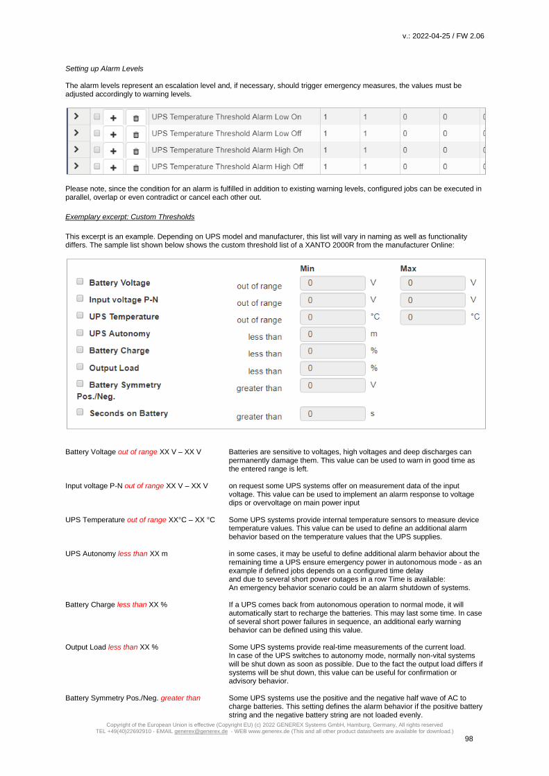
v.: 2022-04-25 / FW 2.06
Copyright of the European Union is effective (Copyright EU) (c) 2022 GENEREX Systems GmbH, Hamburg, Germany, All rights reserved TEL +49(40)22692910 - EMAIL [email protected] - WEB www.generex.de (This and all other product datasheets are available for download.)
98
Setting up Alarm Levels The alarm levels represent an escalation level and, if necessary, should trigger emergency measures, the values must be adjusted accordingly to warning levels.
Please note, since the condition for an alarm is fulfilled in addition to existing warning levels, configured jobs can be executed in parallel, overlap or even contradict or cancel each other out.
Exemplary excerpt: Custom Thresholds
This excerpt is an example. Depending on UPS model and manufacturer, this list will vary in naming as well as functionality differs. The sample list shown below shows the custom threshold list of a XANTO 2000R from the manufacturer Online:
Battery Voltage out of range XX V – XX V Batteries are sensitive to voltages, high voltages and deep discharges can
permanently damage them. This value can be used to warn in good time as the entered range is left.
Input voltage P-N out of range XX V – XX V on request some UPS systems offer on measurement data of the input
voltage. This value can be used to implement an alarm response to voltage dips or overvoltage on main power input
UPS Temperature out of range XX°C – XX °C Some UPS systems provide internal temperature sensors to measure device
temperature values. This value can be used to define an additional alarm behavior based on the temperature values that the UPS supplies.
UPS Autonomy less than XX m in some cases, it may be useful to define additional alarm behavior about the
remaining time a UPS ensure emergency power in autonomous mode - as an example if defined jobs depends on a configured time delay and due to several short power outages in a row Time is available: An emergency behavior scenario could be an alarm shutdown of systems.
Battery Charge less than XX % If a UPS comes back from autonomous operation to normal mode, it will
automatically start to recharge the batteries. This may last some time. In case of several short power failures in sequence, an additional early warning behavior can be defined using this value.
Output Load less than XX % Some UPS systems provide real-time measurements of the current load.
In case of the UPS switches to autonomy mode, normally non-vital systems will be shut down as soon as possible. Due to the fact the output load differs if systems will be shut down, this value can be useful for confirmation or advisory behavior.
Battery Symmetry Pos./Neg. greater than Some UPS systems use the positive and the negative half wave of AC to
charge batteries. This setting defines the alarm behavior if the positive battery string and the negative battery string are not loaded evenly.

v.: 2022-04-25 / FW 2.06
Copyright of the European Union is effective (Copyright EU) (c) 2022 GENEREX Systems GmbH, Hamburg, Germany, All rights reserved TEL +49(40)22692910 - EMAIL [email protected] - WEB www.generex.de (This and all other product datasheets are available for download.)
99
Seconds on Battery greater than XX s in some cases, a voltage drop is recorded, for example in case of large
industrial plants are put into operation. In some cases, it may happen that a UPS switches to autonomous mode for one or several seconds. With this value an additional warning could be realized to verify a "genuine autonomy case".
Note: Pay close attention to the arguments associated with the thresholds: Greater than, less than, in range, out of range - since arguments are taken literally as a condition, the warning and alarm behavior will be done according to the configuration: As an example, if the output load warning is less than 67%, it will also issue a warning if it drops to 43%. On the other hand, 67% will not warn due to the fact the value has to be below 67%
Tutorial: Custom Thresholds
Problem description Although the CS141 recognizes the UPS correctly, contactors are to be activated via potential-free contacts. This shall switch off external devices as soon as the charge of the batteries drops below a configured value. This configuration can be realized indirectly: If a CON_R_AUX4 is connected to CS141, the potential-free outputs can be used to control the contactors - it is possible to switch through (ON) and block (OFF). This will allow to implement the control of the contactors without tricky issues. It will be difficult if the UPS does not offer suitable events: As a consequence, these events are not displayed inside the UPS event menu. Using Custom Thresholds will allow this configuration: The key to this configuration is the fact this function depicts a user definable job as a UPS event: Setting 71% for Warning Levels and 61% for Alarm Levels, you can subsequently assign appropriate behavior in the UPS events:
- if the battery charge drops to 70%, the first devices are switched off.
- If the battery charge drops to 60%, the next devices are turned off. The counter events are set to Warning OFF or Alarm Off.
As the batteries are charging, the devices should start after battery charge reaches similar values for shutdown.
- From 61% the first device list will be switched on - From 71% the second device list will be switched on.
Since there is no AND connection to the Power Fail, there are basically two possibilities to run these jobs: 1. Once 2. Repeat as lob as the event is active Note you have a difference of 1% between ON and OFF. Due to the fact the value needs to drop below the values, it is technically not possible to switch exactly ON and OFF at 70% or 60%. A decision is needed whether you wish to switch ON the devices at 60/70% or off You need to define your jobs exactly: Turning off the same devices 70% and to on position at 61% could cause conflicts between events and jobs, devices should therefore be consistently configured separately What will happen between 0% – 71% Depending on the configuration, independent to any power fail the devices will stay off, shutdown or restart between 0% and 71% battery charge. Above 71% the devices will run as long as no power fail will cause the battery charge to drop at 70%. Since the current load has no influence on the percentage of battery load, the flexible remaining time does not affect this setting. The percentages of the current battery charge are basically used.

v.: 2022-04-25 / FW 2.06
Copyright of the European Union is effective (Copyright EU) (c) 2022 GENEREX Systems GmbH, Hamburg, Germany, All rights reserved TEL +49(40)22692910 - EMAIL [email protected] - WEB www.generex.de (This and all other product datasheets are available for download.)
100
Note: A detailed description of the CON_R_AUX4 can be found at chapter Sensors
CS141 as RCCMD Server device
Ever heard something about RCCMD?
RCCMD (Remote Console Command) is the world's most successful shutdown solution for heterogeneous networks and is the best method to ensure initiating multiple messages and shutdown sequences. The solution integrates even the UPS to set up an all-in-one monitoring and messaging solution: The RCCMD clients listen on port 6003 for incoming messages of RCCMD server module. This module is a general part of - UPSMAN software - CS121 - CS141 - RCCMD licensed UPS manager. An RCCMD server controls the RCCMD clients inside networks. The functional scope ranges from monitoring, notifications up to a structured shutdown of a multiple server environment. RCCMD even considers mutual dependencies.
Note:
The RCCMD client is not freeware; a separate license is available and can be obtained worldwide from licensed resellers, OEM
partners or directly ordered at www.generex.de. The license itself is unlimited valid, the service scope includes 2 years of free
updates from the date of purchase.
Available RCCMD commands for the CS141
As mentioned, CS141 provides an RCCMD server.
The RCCMD commands are defined as jobs via the system events. There are four different categories available:
RCCMD Shutdown
The RCCMD shutdown sends a signal to an RCCMD client. The
RCCMD client advice the server to initiate the shutdown sequence.
RCCMD Message
An RCCMD message is a notification text that can be sent to an
RCCMD receiver. This text will be displayed on the screen using a
separate message box.
RCCMD Execute
If scripts have to be executed in advance for a shutdown, they can
be triggered by using the execute command. RCCMD offers not only
ready-made commands but also the possibility to start own scripts.
RCCMD Trap
Trap messages are pure informational messages that can be sent to
RCCMD clients. The client receives these text messages and
displays them inside a pop-up message box.
Note:
An initiated RCCMD shutdown cannot be withdrawn. However, within the RCCMD client, you can also define so-called
redundancies and limit IP addresses that are authorized to send an RCCMD signals. By doing so, as an example, two UPSs
need to advice a server shutdown. In this case the RCCMD execute wakeup will withdraw a server shutdown command.

v.: 2022-04-25 / FW 2.06
Copyright of the European Union is effective (Copyright EU) (c) 2022 GENEREX Systems GmbH, Hamburg, Germany, All rights reserved TEL +49(40)22692910 - EMAIL [email protected] - WEB www.generex.de (This and all other product datasheets are available for download.)
101
Configure an RCCMD-Job
RCCMD uses IP addressing to communicate within a network as well as a single network segment.
the following parameters can be adjusted:
Set up IP address for RCCMD
Broadcast messages
Activating this checkbox will trigger an RCCMD broadcast job will be sent. Each RCCMD client installed in this network segment
is addressed and responds by shutting down and turning off the computer. There is no distinction between host, virtual machine,
single server or workstation.
Limiting IP addressing
A broadcast message is not always the best method for shutting down networks...
To address a particular machine within your network, enter the IP address of the device. In fact, only addressed computer -
physically or virtual devices - will receive the RCCMD message.
The CS141 provides both:
creating a single job for each RCCMD client as well as combining several IP addresses to create a device group job.
… One job, one IP address …
… several IP-addresses to configure a group job.

v.: 2022-04-25 / FW 2.06
Copyright of the European Union is effective (Copyright EU) (c) 2022 GENEREX Systems GmbH, Hamburg, Germany, All rights reserved TEL +49(40)22692910 - EMAIL [email protected] - WEB www.generex.de (This and all other product datasheets are available for download.)
102
For several IP addresses, please ensure the correct syntax: 192.168.3.1,192.168.3.18, ...
The IP addresses will be written without space between the individual entries. Otherwise you will receive a corresponding error
message.
Note:
Broadcast messages and individual IP addressed or collective addressed messages are mutually exclusive: You can configure
the RCCMD client to accept commands by single IP addresses. But the client cannot be configured to differ between a
broadcast message and a single message. If you want to shut down devices and device groups first and then send a broadcast,
you need to create several jobs with a corresponding time delay.
Port selection
As a default port, RCCMD uses port 6003. The
RCCMD client is listening on this port for a valid
RCCMD command.
If your RCCMD client has been assigned a
different port during installation and
configuration, ensure sender and receiver are
using the same ports.
RCCMD Job Timing
The CS141 provides many system events a job can be assigned to. Some jobs allow to configure advanced timing:
Immediately, once as soon as an event happens, this job is executed at once and not repeated. After XXX seconds: The CS141 will wait a pre-defined time in seconds and then execute the job. If the event
is no longer active before time is up, the job will not be executed. Repeat all XXX seconds: The job is repeated cyclically until the event no longer is no longer active. After XXX seconds on battery: The event forces the UPS will to switch to autonomous mode. The job will be executed
if the UPS remains a pre-defined time in this state. For example, if 300 seconds are set, this job will only be executed if the UPS operates in autonomous reaches 300 seconds.
At XXX seconds remaining time: The job is executed when the remaining UPS operating time is reached or undershot.
Note based on the current load this time value becomes flexible
RCCMD commands
Der RCCMD Shutdown
The RCCMD shutdown is predefined and advices the addressed RCCMD client to shut down the operating system and turn off
the device. Adjustable options include broadcast, sending to individual IP addresses and the port used for RCCMD.

v.: 2022-04-25 / FW 2.06
Copyright of the European Union is effective (Copyright EU) (c) 2022 GENEREX Systems GmbH, Hamburg, Germany, All rights reserved TEL +49(40)22692910 - EMAIL [email protected] - WEB www.generex.de (This and all other product datasheets are available for download.)
103
The RCCMD Message
The RCCMD message is a text message that can be defined freely. The text box automatically shifts with the entered text as
soon as you reach the right margin. This message will then appear as an alert on a computer the RCCMD client is installed to.
RCCMD also displays a warning box on the taskbar.
RCCMD Executes
An extensive feature within RCCMD is the possibility to run own executables and batch files on a target computer.
This function is useful if scripts have to be executed right before a shutdown is triggered. It is necessary to move the file to be
executed to the installation directory of the RCCMD client. Afterwards, the CS141 provides to execute this script directly.
Note: The screenshot shows the command helloworld.bat has been entered. In this case, the RCCMD client on the PC with the IP address 192.168.3.1 would try to start the file hallowelt.bat directly. If you want to use other directories, you need to specify them accordingly: C:\skript\helloworld.bat Please note, it is tricky to run a script on a PC that shall trigger scripts on a third device.

v.: 2022-04-25 / FW 2.06
Copyright of the European Union is effective (Copyright EU) (c) 2022 GENEREX Systems GmbH, Hamburg, Germany, All rights reserved TEL +49(40)22692910 - EMAIL [email protected] - WEB www.generex.de (This and all other product datasheets are available for download.)
104
Die RCCMD Traps
RCCMD traps are pure messages that are intended to inform about the current status of the UPS. A special data packet is
generated, which can be received, read and interpreted by the corresponding programme.
Setting up Trap parameters
Select the desired parameter and press Select. The CS141 will automatically insert the corresponding function in the text field.
You can select as many parameters as you like one after the other. If the corresponding function cannot be sent because the
UPS cannot provide this data or the necessary additional hardware is not connected, the message is inserted accordingly with a
NA (Not Available) instead of the value.

v.: 2022-04-25 / FW 2.06
Copyright of the European Union is effective (Copyright EU) (c) 2022 GENEREX Systems GmbH, Hamburg, Germany, All rights reserved TEL +49(40)22692910 - EMAIL [email protected] - WEB www.generex.de (This and all other product datasheets are available for download.)
105
Sensors and devices For this configuration step, navigate to the following menu items:
Depending on used model, the CS141 offers to connect external sensors and devices sensors. These CS141 models support the connection of sensors:
- CS141 SC - CS141 L - CS141 R2 - CS141 Mini
SM_T_H_COM Standalone Sensor
This example shows how to configure the SMT_H_COM standalone sensor, a combined temperature and relative humidity sensor available for CS141. The supplied standard length of the cable to connect the sensor to CS141 is 1.8 meters. If required, cable length up to 30m can be used. Wiring the external sensor Connect CS141 COM 2 to SM_T_H_COM. CS141 does not require to reboot. Basic Setup Configuration Under Devices / Setup, go to Configuration and change the setting at COM2 from none to Sensor.
After changing, define type of sensor connected to CS 141.
In this case, select SM_T_H_COM:
Press Apply to start the corresponding service. The status bar indicates the process.
While Sensor is restarting, the according menus will be prepared. Please wait until the Sensor mark is set to “OK” before
entering the configuration dialog of the sensor.
Configuration of zhe SM_T_H_ COM combi sensor
Under the main tab Devices, open the sub menu Sensors and click on Setup. This will open the Sensor configuration dialog.

v.: 2022-04-25 / FW 2.06
Copyright of the European Union is effective (Copyright EU) (c) 2022 GENEREX Systems GmbH, Hamburg, Germany, All rights reserved TEL +49(40)22692910 - EMAIL [email protected] - WEB www.generex.de (This and all other product datasheets are available for download.)
106
Name
At Name, enter the name, a description or an installation place of the sensor. The Name will appear at the sensor monitoring screen.
Thresholds Low / High und Alarm functions
The SM_T_H_COM combinated sensor provides two different sensor types. The temperature sensor opereates between -25 ° C and +100 ° C. The humidity sensor measures humidity range 0% and 100%. After installing the sensor, the maximum sensor range will be shown without a range restriction or notification markers. In order to define an alarm behavior, the CS141 needs information about the critical values and if necessary, a configured measuring range. Please note the following rules during configuration: 1. The pre-alarm must be lower than the critical alarm setting. 2. The relative humidity is a minimum of 0% and a maximum of 100% 3. The coldest temperature value is -25 ° C and the highest value + 100 ° C
Note: As long as the checkboxes for the according alarm is not set, the respective alarm marker. Due to this fact it is possible to configure notification and alarm values and test the settings before activating.
Offset - Settings
Although the SM_T_H_COM is already a calibrated sensor, the operating environment may require different values. The correction values will be defined via offset settings: These values will be added or substracted from the value the sensor provide. This allow to harmonize the sensor values with callibrated external measurings and to adapt the sensor for special operating conditions.
Sensor-related system events
The CS141 provides defining system jobs via connected sensors. The available system events refer to the measured values of the connected sensors. The following events are available for SM_T_H_COM. SM_T_H_COM Temperature High The value at Threshold (high) defines the upper critical temperature limit. If this temperature is exceeded, a corresponding alarm behavior can be triggered. SM_T_H_COM Temperature Low The value Threshold (low) defines the lower critical temperature limit. If this temperature is undershot, a corresponding alarm behavior can be triggered. SM_T_H_COM Temperature Normal Defined by the values for the upper and lower temperature limits. If no limits are entered, any displayed temperature will be displayed as "normal.
v.: 2022-04-25 / FW 2.06
Copyright of the European Union is effective (Copyright EU) (c) 2022 GENEREX Systems GmbH, Hamburg, Germany, All rights reserved TEL +49(40)22692910 - EMAIL [email protected] - WEB www.generex.de (This and all other product datasheets are available for download.)
107
SM_T_H_COM Humidity High The value is defined by Threshold (high) for the relative humidity and determines the upper critical limit for humidity. If this value is exceeded, a corresponding alarm behavior can be triggered. SM_T_H_COM Humidity Low The value is defined via Threshold (low) for the relative humidity and determines the lower critical limit for humidity. If this value is undershot, a corresponding alarm behavior can be triggered. SM_T_H_COM Humidity Normal Defined by the values for the upper and lower relative humidity. If no limits are entered, any displayed humidity will be displayed as "normal". SM_T_H_COM Connection Lost If the connection between the CS141 and the SM_T_H_COM tears off, a corresponding alarm behavior can be triggered via this system event. SM_T_H_COM Connection Restored The counter event to Connection Lost: The connection has been restored; a corresponding alarm behavior can be triggered via this system event.
Event classification
At the sub menu Sensors, click on the menu Events:
All sensor events use the same event classification:
- Temperature / Humidity High
- Temperature / Humidity HighPreAlarm
- Temperature / Humiditiy normal
- Temperature / Humidity LowPreAlarm
- Temperature / Humidity Low
Click > to open the general job list. With +, the job configuration dialog will be triggered to add a new job to the current job list.
Note:
For detailed informationen about how to manage jobs, refer the following chapter: Managing jobs
Defining a counter job
Please note that depending on the configuration, some executable jobs require a so-called counter job, while other jobs merely
do not need to be executed because the event is no longer pending. This job is configured by triggering it when the
corresponding new event occurs - e.g. the contact is automatically closed when "Temperature: High" is reached and reopened
as a counter event when "Temperature: Normal" is reached. Meanwhile, a mail notification is sent every 5 minutes as long as
the Temperature High event is pending.
At this point, do not confuse a counter-event with a counter-job - one is an event that is pending, the other is acorresponding job
that, triggered for any event chain - job and event are relative to each other.

v.: 2022-04-25 / FW 2.06
Copyright of the European Union is effective (Copyright EU) (c) 2022 GENEREX Systems GmbH, Hamburg, Germany, All rights reserved TEL +49(40)22692910 - EMAIL [email protected] - WEB www.generex.de (This and all other product datasheets are available for download.)
108
Sensor monitor: Check configuration
For this screen, open the following menu:
Once completed all settings, the sensor data will be shown at Sensor Monitor:
The yellow line represents the value of the Threshold (low). The upper line represents the Threshold (high). As soon as the value exceeds or falls below these lines, the color changes to red and a corresponding job can be triggered for the according sensor event. If you use pre-alarms and alarm settings, the Sensor monitor will show the according marker.
Tipp: Sollten Sie mehrere Sensoren benötigen, bietet der CS141 über den Sensormanager die Möglichkeit, bis zu 8 Umweltkontrollsensoren zu betreiben. Die genaue Konfiguration entnehmen Sie bitte der Installations- und Konfigurationsanleitung des SENSORMANAGERS, welche Sie unter www.generex.de im Downloadbereich erhalten können.
SENSORMANAGER
The SENSOR MANAGER is an optional accessory to extend the functionality of the CS141: The GENEREX sensors / actuators can easily be connected to the SENSOR MANAGER, required RJ12 connection cables are included on delivery. The sensor can be configured via the web interface of the CS141 / BACSWEBMANAGER. Any third-party sensor or actuator that are conform with required specifications, can be used with the SENSORMANAGER. SENSORMANAGER_II application examples: Monitoring of sensor data Temperature, humidity, electr.. Electricity, electr. Voltage, electr. performance and other analogue measurements. Monitoring of contacts: Door contacts, fire detectors, motion detectors, water detectors, glass breakage sensors and other potential-free signaling contacts. Switching: Switching of optical and acoustic actuators such as flashing lights, warning horns u. relay contacts SENSORMANAGER_II input signals:

v.: 2022-04-25 / FW 2.06
Copyright of the European Union is effective (Copyright EU) (c) 2022 GENEREX Systems GmbH, Hamburg, Germany, All rights reserved TEL +49(40)22692910 - EMAIL [email protected] - WEB www.generex.de (This and all other product datasheets are available for download.)
109
Up to 8 analog inputs (0-10VDC o. 0 / 4-20mA) Up to 4 digital inputs (potential-free contacts) SENSORMANAGER_II output signals: Up to 4 digital output signals (open collector / 12VDC max 30mA) SENSORMANANAGER_II PIN assignment of the Rj12 connection sockets INPUT 1: Pin 1 9-24VDC, output according to input of supply voltage, default delivery: 12VDC power supply Pin 2 Analog input channel 1 (0-10VDC o. 0/4-20mA) Pin 3 Analog input channel 2 (0-10VDC o. 0/4-20mA) Pin 4 Ground (GND) Pin 5 Digital output (Open-Collector 9-24VDC/max. 30mA, Default on delivery: 12VDC) Pin 6 Digital input (min./max. 9-24V via Pin 1) INPUT 2: Pin 1 9-24VDC, output according to input of supply voltage, default delivery: 12VDC power supply Pin 2 Analog input channel 3 (0-10VDC o. 0/4-20mA) Pin 3 Analog input channel 4 (0-10VDC o. 0/4-20mA) Pin 4 Ground (GND) Pin 5 Digital output (Open-Collector 9-24VDC/max. 30mA, Default on delivery: 12VDC) Pin 6 Digital output (min./max. 9-24V via Pin 1) INPUT 3: Pin 1 9-24VDC, output according to input of supply voltage, default delivery: 12VDC power supply Pin 2 Analog input channel 5 (0-10VDC o. 0/4-20mA) Pin 3 Analog input channel 6 (0-10VDC o. 0/4-20mA) Pin 4 Ground (GND) Pin 5 Digital output (Open-Collector 9-24VDC/max. 30mA, default on delivery: 12VDC) Pin 6 Digital input (min./max. 9-24V via Pin 1) INPUT 4: Pin 1 9-24VDC, output according to input of supply voltage, default delivery: 12VDC power supply Pin 2 Analog input channel 7 (0-10VDC o. 0/4-20mA) Pin 3 Analog input channel 8 (0-10VDC o. 0/4-20mA) Pin 4 Masse (GND) Pin 5 Digital output (Open-Collector 9-24VDC/max. 30mA, Default on delivery: 12VDC) Pin 6 Digital input (min./max. 9-24V via Pin 1)
Note: The voltage provided by pin 1, pin 5 and pin 6 is defined by the power supply unit used on the SENSOR MANAGER. The SENSOR MANAGER itself operates at an operating voltage of 9-24V. If a 12 V power supply is connected, 12 VDC will be offered on these pins accordingly. When connecting external devices, pay attention to the maximum permissible voltage that may be applied: Overvoltage can damage or even destroy connected devices. In case of undervoltage, however, connected devices may deliver wrong results. On delivery the SENSOR MANAGER comes with a standard power supply providing 12 VDC.
Pin number: Funktion:
1 9-24VDC, output according to input of supply voltage,
default delivery: 12VDC power supply
2 Analog input channel x (0-10VDC o. 0/4-20mA)
3 Analog input channel x (0-10VDC o. 0/4-20mA)
4 Ground (GND)
5 Digital output (Open-Collector 9-24VDC/max. 30mA,
Default on delivery: 12VDC )
6 Digitalinput (min./max. 9-24V via Pin 1)

v.: 2022-04-25 / FW 2.06
Copyright of the European Union is effective (Copyright EU) (c) 2022 GENEREX Systems GmbH, Hamburg, Germany, All rights reserved TEL +49(40)22692910 - EMAIL [email protected] - WEB www.generex.de (This and all other product datasheets are available for download.)
110
Analog inputs: Each of the 4 SENSORMANAGER_II physical RJ-12 connectors provide 2 analog inputs on pin 2 and pin 3. Administrators wishing to connect a third-party device, must set the signal (0-10VDC o. 0 / 4-20mA) of the third-party device to PIN 2 or pin 3 and pin 4 (ground / GRD). Digital inputs: Each of the 4 physical RJ-12 connections of the SENSORMANAGER_II provides a digital input on pin 6. For Administrators who wish to connect a third-party device: The high signal (12VDC) from pin 1 must be routed to pin 6 via the signaling contact of the third-party device. Digital outputs: Each of the SENSORMANAGER's 4 physical RJ-12 ports provides a digital output on pin 5. Administrators who wish to connect a third-party device: The device must be connected to pin 5 (open collector output: + 12VDC / max.30mA) and pin 4 (Ground / GND) are connected.
Note: How to use third-party sensors Due to the fact third-party devices do not have the standardized RJ12 port, our Connection Terminal SM_CON is an easy-to use possibility to connect these devices to the CS141. By using the SM_CON it is possible to adapt open line ends to the Rj12 connector directly - No custom plug
Connecting sensors / actuators to the SENSORMANAGER_II The sensors / actuators for the SENSORMANAGER II can be connected directly to the SENSORMANAGER II RJ12 sockets- ensure to use the original RJ12 cables supplied with the according sensor. The SENSORMANANAGER II provides to connect several sensors / actuators to one physical port. The system design provides following wiring options: 1. A maximum of two analog sensors per port 2. A maximum of one more digital sensor per port 3. A maximum of one digital actuator per port The sensor manager supports a total installation of 8 analog and 4 digital sensors as well as up to 4 digital actuators.
Sensor connection scenarios: SENSORMANAGER_II. The SENSORMANAGER II provides various options to connect sensors. The Daisy Chain: Connection
The daisy chain is a sequential arrangement of sensors and actuators. The signal is transmitted from the sensor manager through the first sensor to the second sensor. In this installation example, a digital third sensor is attached to the second sensor. Please note that no further digital sensor can be attached to the sensor 3. The Splitting Plug SPSMRJ connection
If sensors needs be installed in different areas, the signal distribution can be splitted into two wirings. The optional splitting plug will splitt the signal accordingly. Please note that the sensor manager can only serve two analog sensors per port.

v.: 2022-04-25 / FW 2.06
Copyright of the European Union is effective (Copyright EU) (c) 2022 GENEREX Systems GmbH, Hamburg, Germany, All rights reserved TEL +49(40)22692910 - EMAIL [email protected] - WEB www.generex.de (This and all other product datasheets are available for download.)
111
Combined connections: Daisy Chain and Splitting Plug SPSMRJ
This installation constellation extends the existing installation by an actuator and a digital sensor: The port on the sensor manager is maxed out utilizing a total of 4 devices: Please note the system design: This installation design provides the maximum of two analog sensors and one digital sensor as well as one digital output per sensor manager port. SENSORMANAGER II: Available sensors These sensors are currently available for SENSORMANAGER_II: GENEREX-Analog-Sensors: SM_T (Temperature sensor -> 1 analog channel required) SM_T_H (Combined sensor: Temperature and humidity -> 2 analog channels required) SM_VMC (True RMS AC voltage sensor -> 1 analog channel required SM_CSxxxA (AC- current sensor -> 1 analog channel required) GENEREX-Digital-Input-Sensors SM_HYG2 (water and humidity sensor -> 1 digital input required) SM_Glas (Glas breach detector -> 1 digital input required) SM_MD (motion detector -> 1 digital input required) SM_SD (Smoke - und fire dector -> 1 digital input required) SM_DC (door contact alarm detector -> 1 digital input required) SM_H2 (Hydrogen Sensor -> 2 digital inputs required) Digital GENEREX-Actuators: SM_IO (Ralais-Box -> 1 digital output required) SM_BUZ (accustical alarm buzzer -> 1 digital output required) SM_Flash (flash light -> 1 digital output required)
SENSORMANAGER_II – Installation and configuration Before you start … The configuration must be saved to the PIC processor of the SENSOR MANAGER. This will be done by the CS141 automatically if pressing save buttons. If a configured SENSOR MANAGER needs to be replaced, the configuration stored in the CS141 must be written to the new PIC processor by applying again. A spare parted SENSORMANAGER will not work without writing the new configuration. SENSORMANAGER_II: Connecting to CS141
Use the supplied cable to connect the COM1 of the SENSOR MANAGER II to the COM 2 of the CS141. Log into the CS141 and go to general COM port settings. Configure the comport for sensormanager usage. Then connect the power supply to the SENSORMANAGER: Two LED's are installed on the underside of the SENSOR MANAGER: one should now light continuously and signal the operational readiness. The second LED flashes only when the CS141 makes a request to the SENSORMANAGER.
After the SENSORMANAGER is ready for configuration, open sensor manager configuration menu at CS141 and start configurating your sensors and devices.

v.: 2022-04-25 / FW 2.06
Copyright of the European Union is effective (Copyright EU) (c) 2022 GENEREX Systems GmbH, Hamburg, Germany, All rights reserved TEL +49(40)22692910 - EMAIL [email protected] - WEB www.generex.de (This and all other product datasheets are available for download.)
112
Note: The CS141 will only make a request to the SENSORMANAGER if it is configured accordingly. The LED on the sensor manager will only flash when a request has been received or is answered by the SENSORMANAGER.
Please note that the sensor manager is a stand-alone device with its own power supply. In case of main power supply is not
available will cause disabling the connected sensors and actuators. The CS141 will notice this fact and can be configured to send
custom alarm messages for sensor lost issues.
When using a SENSORMANAGER, ensure both, CS141 and SENSORMANAGER are secured by independent power supply
(UPS) for full operationality in case of main power issues.
Sensor matrix
For this configuration step, proceed to the following menus
A special feature of the sensor manager is the possibility to link logically all available sensors and contacts via a matrix.
Because the matrix does not tell you which sensors and digital inputs you want to use for linking to each other, there are
numerous ways to map your operating scenario - as an example, a pressure sensor monitoring a pipe can be used with a
temperature sensor on a corresponding pump in the first instance. With a second instance, different sets of sensor markers can
be combined to trigger a unique alarm behavior.
How does the sensor matrix work?
As already described, the matrix is a link of individual instances that build on each other
1. Sensors and Inputs -> Individual single configuration and event management
2. Matrix marker -> Links logically individual sensors and digital inputs to a collective marker
3. Output switcher -> Links logically single alarm marker to switch an output
Each of these three instances has its own events, which can be assigned with jobs via the event control inside the sensor
menu.:
Adding analog sensors
At system tab Sensors, open Setup to entert he sensor configuration dialog:
Name
Enter a name or a description that will be shown at the alarm matrix as well as the sensor monitor.
Sensortype
Determine the type of sensor. To do this, select one of the predefined sensor types from the list. For third-party sensors, please
consult the appropriate user manual to enable connection. Please note that some sensors are so-called combinated sensors -
two sensors in one housing. These require both channels and no further sensors can be connected.
Unit
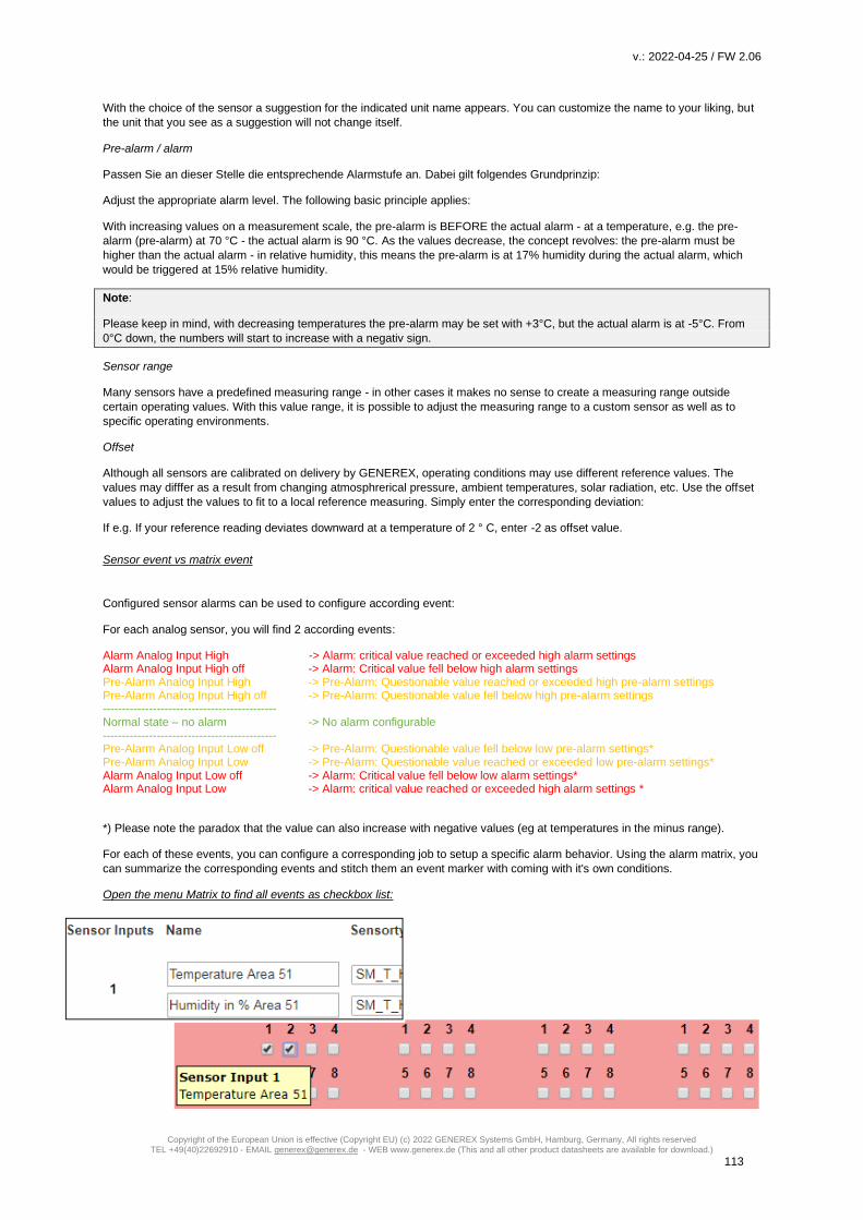
v.: 2022-04-25 / FW 2.06
Copyright of the European Union is effective (Copyright EU) (c) 2022 GENEREX Systems GmbH, Hamburg, Germany, All rights reserved TEL +49(40)22692910 - EMAIL [email protected] - WEB www.generex.de (This and all other product datasheets are available for download.)
113
With the choice of the sensor a suggestion for the indicated unit name appears. You can customize the name to your liking, but
the unit that you see as a suggestion will not change itself.
Pre-alarm / alarm
Passen Sie an dieser Stelle die entsprechende Alarmstufe an. Dabei gilt folgendes Grundprinzip:
Adjust the appropriate alarm level. The following basic principle applies:
With increasing values on a measurement scale, the pre-alarm is BEFORE the actual alarm - at a temperature, e.g. the pre-
alarm (pre-alarm) at 70 °C - the actual alarm is 90 °C. As the values decrease, the concept revolves: the pre-alarm must be
higher than the actual alarm - in relative humidity, this means the pre-alarm is at 17% humidity during the actual alarm, which
would be triggered at 15% relative humidity.
Note:
Please keep in mind, with decreasing temperatures the pre-alarm may be set with +3°C, but the actual alarm is at -5°C. From
0°C down, the numbers will start to increase with a negativ sign.
Sensor range
Many sensors have a predefined measuring range - in other cases it makes no sense to create a measuring range outside
certain operating values. With this value range, it is possible to adjust the measuring range to a custom sensor as well as to
specific operating environments.
Offset
Although all sensors are calibrated on delivery by GENEREX, operating conditions may use different reference values. The
values may difffer as a result from changing atmosphrerical pressure, ambient temperatures, solar radiation, etc. Use the offset
values to adjust the values to fit to a local reference measuring. Simply enter the corresponding deviation:
If e.g. If your reference reading deviates downward at a temperature of 2 ° C, enter -2 as offset value.
Sensor event vs matrix event
Configured sensor alarms can be used to configure according event:
For each analog sensor, you will find 2 according events:
Alarm Analog Input High -> Alarm: critical value reached or exceeded high alarm settings Alarm Analog Input High off -> Alarm: Critical value fell below high alarm settings Pre-Alarm Analog Input High -> Pre-Alarm: Questionable value reached or exceeded high pre-alarm settings Pre-Alarm Analog Input High off -> Pre-Alarm: Questionable value fell below high pre-alarm settings --------------------------------------------- Normal state – no alarm -> No alarm configurable --------------------------------------------- Pre-Alarm Analog Input Low off -> Pre-Alarm: Questionable value fell below low pre-alarm settings* Pre-Alarm Analog Input Low -> Pre-Alarm: Questionable value reached or exceeded low pre-alarm settings* Alarm Analog Input Low off -> Alarm: Critical value fell below low alarm settings* Alarm Analog Input Low -> Alarm: critical value reached or exceeded high alarm settings *
*) Please note the paradox that the value can also increase with negative values (eg at temperatures in the minus range).
For each of these events, you can configure a corresponding job to setup a specific alarm behavior. Using the alarm matrix, you
can summarize the corresponding events and stitch them an event marker with coming with it's own conditions.
Open the menu Matrix to find all events as checkbox list:

v.: 2022-04-25 / FW 2.06
Copyright of the European Union is effective (Copyright EU) (c) 2022 GENEREX Systems GmbH, Hamburg, Germany, All rights reserved TEL +49(40)22692910 - EMAIL [email protected] - WEB www.generex.de (This and all other product datasheets are available for download.)
114
At sensor configuration, you can enter a name for each channel. After entering a name press apply and change tot he menu
„Matrix“: The recently entered name will it will be displayed automatically as soon as you move the mouse over the according
channel checkbox.
Setting up the logical connection
Using the logic link, the condition can be defined to set the marker to a logical On: And Both conditions must be Or At least on of the configured conditions are met. Inverted mode As a standard, the marker is pre-configured to switch to ON as long as the conditions for ON are met. The inverted turn this switching behavior from OFF to ON: The marker ist always at High (ON) positition and will will switch to Low (Off).
Digital inputs
In addition to analog inputs, the SENSORMANAGER can manage up to 4 ditigal inputs. The inputs
Diese Eingänge werden entsprechend der Konfiguration auf Aktiv geschaltet und können im Alarmverhalten als NC (Normally
Closed) oder NO (Normally Open) – Kontakt definiert werden.
Linking digital inputs
The marker only looks whether the result of the digital input is "High (On)" or "Low (Off)" - The
type of contact is unimportant for the marker. like the analog inputs, name of the digital input will
be shown by mouse over action. The linking of the digital inputs follows the same principle as
with the sensors.
Linking digital inputs and analog sensors
Simply select the appropriate digital inputs with the analog inputs. Press Apply to save the setting and restart the services for
the sensors.
Switching an output
Outputs will be switched in case of conditions met via the defined alarm markers:
In contrast to the markers, however, no pre-alarms are used - if the marker is set to high, the output will be switched depending
on its switching logic. The CS141 matrix provides combining up to 8 markers individually and assign them with an AND / OR
combination. The output will be switched:
1. As soon as only one of the configured marker are set to high. („OR“)
2. As soon as all configured marker are in high state („AND“)
Fallback of the output to normal state
the output is only switched as long as the condition has been fulfilled exactlyhereby the corresponding logical link will decide
which condition leads to the drop of the output:
In a restrictive AND operation, only one marker to off will force the output to off.
With an OR operation, the output remains at ON state until each marker is turned off.

v.: 2022-04-25 / FW 2.06
Copyright of the European Union is effective (Copyright EU) (c) 2022 GENEREX Systems GmbH, Hamburg, Germany, All rights reserved TEL +49(40)22692910 - EMAIL [email protected] - WEB www.generex.de (This and all other product datasheets are available for download.)
115
Keep in mind that the markers conditions for an on/off state will not be checked by output switching control – This control only
checks logically the markers state and act according to it.
Tutorial: Example scenario: aquarium
In this simple example the cross reference between a cracked disc and a leaking aquarium wil be described. It shall show you
how markers, inputs and outputs will be linked and work together. The total scope of scenarios can reach very high complexity
and fitted even to very custom problems….
Huge aquariums with large glass panels are dependent on ensuring the structural integrity. If a glas panel is damaged or
cracked, a corresponding alarm must be issued automatically. For this purpose, the sensor manager offers a digital input:
The method this crack sensor uses to detect a cracked glass is a secondary question as the SENSOR MANAGER also supports
the connection of third-party sensors. If necessary, connect an additional relay box to each sensor manager input: With the
SM_IO box, managing all 4 inputs and outputs is made intuitive.
In this scenario, a glass crack sensor would close a switch and thus report a problem to digital input 1.
The second essential value is the water level of our aquarium, which requires intervention drops below a certain amount of
water. In this case, a level sensor is used, which closes a digital contact at a filing level of 80%:
This input clearly indicates that the water level has dropped, but not why it happened - normally this will be caused by natural
evaporation.
The cross reference:
Using the matrix, you can now handle both events in conjunctionto each other:
In this case, marker 1 would be set active if both inputs are closed at the same time: The idea is that a glass crack alarm is
present AND the level has dropped below 80% - in this case someone should be informed at once.
In the Events menu, fsearch for Alarm Marker 1:
In diesem Beispiel soll eine SMS geschrieben werden, sobald
beide Bedingungen erfüllt sind:
In this example, an SMS should be sent as soon as both conditions
are met:
At the moment the marker is activated, the CS141 will issue an
emergency SMS if a GSM modem or alternatively an IP modem is
available. Thus, both individual input events have been directly
connected, other jobs are possible that will be repeated as long as
this marker status is present.
The marker status will be terminated with two basic conditions:
1. The water level has been corrected
2. The glass damage has been fixed
Since these two conditions are coupled by an AND link, this marker is triggered only when both conditions are met.

v.: 2022-04-25 / FW 2.06
Copyright of the European Union is effective (Copyright EU) (c) 2022 GENEREX Systems GmbH, Hamburg, Germany, All rights reserved TEL +49(40)22692910 - EMAIL [email protected] - WEB www.generex.de (This and all other product datasheets are available for download.)
116
Using several markers
This marker can handle two basic problems:
A dropping water level below 80% and some kind of cracking glass. And yes, if this happens simultanously, it is possible that
water leaks. Due to the fact, 20% water inside an observation room can be very many water, a third sensor may be usefull:
This sensor will find water or increased humidity levels at visitors observation room - something that can only be caused by a
cracked aquarium windows (or something visitor- caused).
With the matrix settings, a second sensor can be configured:
This marker defines that there is a glass breach alert present and water is found at visitors observation room., dass ein
Glasbruchproblem vorliegt und im Besucherraum zudem Wasser auftritt.
The Or connection
Okay, from now on the emergency conditions are set:
1. Glass breach and water level drops below 80%
2. Glass breach and water found at visitors observation room
Es However, it may now be the case that the water level drops and / or water is reported in the visitors' area without an obvious
glass breakage. This may happen and someone need to mainenance this issue, but it is not really critical. In some cases it
could be wanted.
To show this scenario, a third marker can combine both conditions with an OR:
This basic marker can be used as a non-critical overview lookup:
1. Water level below 80%
2. Unusual Humiditiy or liquids found at visitors observation room
With the OR operation, these two conditions can occur independently of each other - in both cases, the marker is set to high –
on the other hand, this marker will only fall back to off position if all standard maintenance work is done.
Switching outputs
In this example scenario, many trigger points are included. For the matrix, these issues are configured:
- Glass breach and dropping water level
- Glass breach and water/liquids at visitors observation room
- Dropping water level or water/liquids at visitors observation room
Die kritischen Probleme sind hierbei mit festen UND-Bedingungen verknüpft, da ein schnelles Handeln erforderlich ist. Die
Eskalationsstufe ist, dass alle 3 Ereignisse aufeinandertreffen: Es gibt ein Glasbruchproblem, der Beobachtungsraum läuft voll
Wasser und der Füllstand auf 80% gesunken ist.

v.: 2022-04-25 / FW 2.06
Copyright of the European Union is effective (Copyright EU) (c) 2022 GENEREX Systems GmbH, Hamburg, Germany, All rights reserved TEL +49(40)22692910 - EMAIL [email protected] - WEB www.generex.de (This and all other product datasheets are available for download.)
117
The critical issues here are linked to fixed AND conditions because quick action is required. All three problems together means,
visitors can be endangered: There is a glass break problem, the observation room will be filled by water and the water level has
dropped below 80%. Perfect for automatic emergency procedures - all critical l markers can be summarized and linked to an
output:
As long as marker 1 and marker to are set to ON (high), output 1 will be triggered: :
This output can inform ordinate and subordinate monitoring systems via alarm contacts, switch of switch off sockets near the
floor, etc. Via the event "Output 1 On", any additional job chains can be created inside for advanced automatic emergency
measures.
Fallbackt o normal state
The output will be switched off in case of one of these markers fall back to normal state.
Note
As with the configuration of the markers, you can create an And / Or dependencity between up to 8 different markers. As an
examle, this function is useful if a machine may only be startet if preconditions like pressure, temperature, etc. met specific
operating values. By using the matrix, the output that unlocks the start button will not be released until all conditions have been
met..

v.: 2022-04-25 / FW 2.06
Copyright of the European Union is effective (Copyright EU) (c) 2022 GENEREX Systems GmbH, Hamburg, Germany, All rights reserved TEL +49(40)22692910 - EMAIL [email protected] - WEB www.generex.de (This and all other product datasheets are available for download.)
118
Combination of sensors coming with the sensor matrix

v.: 2022-04-25 / FW 2.06
Copyright of the European Union is effective (Copyright EU) (c) 2022 GENEREX Systems GmbH, Hamburg, Germany, All rights reserved TEL +49(40)22692910 - EMAIL [email protected] - WEB www.generex.de (This and all other product datasheets are available for download.)
119
Buzzer
The CS141_BUZ is an acoustic alarm to be used with the CS141 SNMP adapter (CS141 SC or CS141 L). The CS141_BUZ is
based on a piezo element using an internal power supply. Due to this fact, no separate power supply is required. The volume is
about 85 db. The CS121_BUZ provides an RJ12 to be directly connected to CS141. Furthermore, an RJ12 socket for the output
of PINs 1, 2, 3 to use external devices.
In addition, the acoustic signal of the buzzer can be remotely reset by closing a potential-free contact via the two-poled contact
terminal block. Furthermore, a LED indicates a manually switched off alarm. This LED will stay blinking until it will be triggered by
CS141 to normal state.
Technical data:
voltage usage: 12 – 15 VDC
power usage: ca. 30mA
Volume: ca. 85 dB
Connection type: wired, RJ12, 6_5, 5_m
Dimensions: 70 x 70 x 40 mm
Connect to CS141:
Use enclosed cable to connect the buzzer CS141_BUZ to AUX Port of CS141.
Configure the buzzer:
Step: 1
Under Devices/Setup, select Buzzer at COM and press Apply.

v.: 2022-04-25 / FW 2.06
Copyright of the European Union is effective (Copyright EU) (c) 2022 GENEREX Systems GmbH, Hamburg, Germany, All rights reserved TEL +49(40)22692910 - EMAIL [email protected] - WEB www.generex.de (This and all other product datasheets are available for download.)
120
Step 2
Under Devices you find the buzzer alarm menu:
Apply transfers the current setting to the system configuration. Selected functions will be displayed at the BUZZER MONITOR.
Furthermore, in the upper status bar the buzzer will be shown as operational.
Step 3:
Select an event the buzzer shall toggle – as an example buzzer alarm if recognizes a power fail
Press + to open job configuration dialog:
Under Job select Buzzer:
Relays on
Additionally, the buzzer provides a relay for external
connections to be switched.
Buzzer on
In case of a power fail the buzzer will be triggered. As soon
as main power returned back, the event "Power restored"
needs a job to switch off buzzer.

v.: 2022-04-25 / FW 2.06
Copyright of the European Union is effective (Copyright EU) (c) 2022 GENEREX Systems GmbH, Hamburg, Germany, All rights reserved TEL +49(40)22692910 - EMAIL [email protected] - WEB www.generex.de (This and all other product datasheets are available for download.)
121
Events according to a buzzer
Search for the buzzer event menu:
At BUZZER ON click + to start job the configuration dialog
Choose the job to be executed, because the buzzer was triggered.
Depending on your setting, a corresponding action will be triggered in
addition to the triggered buzzer and simultaneously noted in the event
log.
Note: You can define structured job chains by different devices connected to the CS141: Therefore, it is possible to select the BUZZER from inside the AUX menu and trigger it and use this system state to trigger the next event accordingly. In that case, the AUX event handling will trigger the buzzer and then the next event.
Events related to other devices Events for this device can be performed by any device connected to the CS141. As example, an SMS is triggered by an alarm transmitter - a buzzer - because the alarm relay has jumped to ON:

v.: 2022-04-25 / FW 2.06
Copyright of the European Union is effective (Copyright EU) (c) 2022 GENEREX Systems GmbH, Hamburg, Germany, All rights reserved TEL +49(40)22692910 - EMAIL [email protected] - WEB www.generex.de (This and all other product datasheets are available for download.)
122
At the event RELAIS ON, click + to start the configuration dialog: Under Job, select the job to be executed because the buzzer's relay has been triggered. Depending on your setting, a corresponding action will be triggered in addition to the triggered buzzer.
Note: If installed, you can also select the BUZZER via the AUX menu and may it have triggered accordingly. In that case, the AUX event will trigger the buzzer. The fact the buzzer is triggered will be able to trigger the next event. This behavior allows you to define as many individual events as well as event chains. You can even configure time delays ...

v.: 2022-04-25 / FW 2.06
Copyright of the European Union is effective (Copyright EU) (c) 2022 GENEREX Systems GmbH, Hamburg, Germany, All rights reserved TEL +49(40)22692910 - EMAIL [email protected] - WEB www.generex.de (This and all other product datasheets are available for download.)
123
GSM-Modem
A GSM modem provides the ability to notify responsible persons via SMS as an additional security measure. This is useful to help
staff reducing response time.
GSM-T61 3GT61
Technical data:
GSM-T61 Power supply: 12 – 15 VDC Power consumption: ca. 30mA Dimensions: 70 x 70 x 40 mm 3GT61 Power supply: 12 V Power consumption: ca. 50mA Dimensions 70 x 70 x 40mm
Setting up the SIM card
There is no option to store access data for the SIM card inside the GSM modem or at the CS141. The SIM card must be configured
accordingly by a network-compatible device to ensure no dial-in data ("without PIN") will be required for operation: The
corresponding configuration guide for your SIM card can be obtained from your mobile service provider as well as from the
operating instructions of the device selected for the configuration.
Insert / remove the SIM card
Once the SIM card has been configured appropriately to be used with the GSM modem, it can be inserted into the device. Please
note that you insert the SIM card with the contacts upwards with slight pressure until it locks in place by a spring mechanism. To
remove, press the SIM card to unlock the mechanism:
The card pops out and can be removed.

v.: 2022-04-25 / FW 2.06
Copyright of the European Union is effective (Copyright EU) (c) 2022 GENEREX Systems GmbH, Hamburg, Germany, All rights reserved TEL +49(40)22692910 - EMAIL [email protected] - WEB www.generex.de (This and all other product datasheets are available for download.)
124
How the GSM modem works
SMS modems provide the ability to notify responsible contact persons or administrative personal independently to any other
automatic notification procedures in a very direct way. Due to the fact the GSM modem is a standalone device, it will work even
in worst case scenarios when the intranet of a company is not available.
If emergency situations occur, it will help to shorten reaction time chain essentially.
In cooperation with other auxiliary devices, the GSM modem can be configured for numerous events:
- Critical temperature measurements - Door contacts / access control and unauthorized entry - Parent and child system failures - Emergency ventilation usage - …
Please note that a GSM modem is intended for sending short messages and is not designed to connect to the CS141 via the local
mobile network. Currently the following options are supported:
• A GSM-Modem as serial standalone device
• IP/SMS-Gateway SMS communication

v.: 2022-04-25 / FW 2.06
Copyright of the European Union is effective (Copyright EU) (c) 2022 GENEREX Systems GmbH, Hamburg, Germany, All rights reserved TEL +49(40)22692910 - EMAIL [email protected] - WEB www.generex.de (This and all other product datasheets are available for download.)
125
CS141: Setting up the GSM modem for serial usage
For this configuration step, navigate to the following menu
Connect the COM port of the modem to COM2 interface of the CS141 and connect the power adapter. After connecting, open the
CS141 system tab Devices. At COM-Port 2, Select GSM Modem
The GSM modem symbol should appear in the upper bar and show the quality of the signal accordingly:
In addition, the CS141 will display the system tab GSMModem:
Serial COM port connection
To use a serial connected GSM modem, select com as operating mode.
If necessary, adjust the values for baud rate parity and stop bit. Please
note:
default values in normally represent the optimal setting and do not need to
be changed.
Job configuration using an SMS Under UPS event handling, choose the event Powerfail.
Press + to begin with the job configuration dialog

v.: 2022-04-25 / FW 2.06
Copyright of the European Union is effective (Copyright EU) (c) 2022 GENEREX Systems GmbH, Hamburg, Germany, All rights reserved TEL +49(40)22692910 - EMAIL [email protected] - WEB www.generex.de (This and all other product datasheets are available for download.)
126
Choose the job Send SMS. SMS text allows you to enter a small text message. Under Phone, enter the mobile phone number of the SMS receiver. Ensure there are no spacers at the phone number you entered. Use Timing to configure how often an SMS should be sent. Press Save to finish job configuration. The example dialog screenshot job will be triggered in case of a power fail occurs and send an SMS. If several parties need to be informed, define a separate job for each mobile number.
When you need an sms if other devices are triggered
Any device that is listed with a system event can be used to trigger an sms job. In this example, a buzzer will be used to trigger
an sms.
At the event RELAY ON, click +
As Job, choose SMS, enter the text message and a
valid phone number.
As a consequence, the event chain will be shown
as followed:
Because there is a power fail, the buzzer is on and
the relay is on. Because the Relay is on, the SMS
will be sent with a custom text and logged
accordingly

v.: 2022-04-25 / FW 2.06
Copyright of the European Union is effective (Copyright EU) (c) 2022 GENEREX Systems GmbH, Hamburg, Germany, All rights reserved TEL +49(40)22692910 - EMAIL [email protected] - WEB www.generex.de (This and all other product datasheets are available for download.)
127
Note:
These event chains are very capable: In theory, it is possible to set up very complex event chains, where a job triggers the next
event, etc. – you can use inputs and outputs to communicate all over the IT without the need of a network: “High/Low” or “ON/OFF”
can trigger many thins and produce complex notification alerts.
But be carful when using long event chains: They may brake if a single device is not avaible or configured accordingly.
CON_AUX4 and CON_R_AUX4
There is more than one method to communicate with parent and child systems: The
external devices CON_AUX4 and CON_R_AUX4 provide input as well as outputs to
get information as well controlling third-party devices:
To start configuration, define COM3 as AUX port. Type will be used to toggle
between CON_AUX4 and CON_R_AUX4.
Configuration
Once the AUX service has been started, the general operability is displayed accordingly in the upper bar. Please wait until the
service is ready to use before accessing the configuration menu - it will appear automatically as a sub menu at Devices.
Depending on whether a CON_AUX4 or CON_R_AUX4 has been connected, the configuration screen will differ:
Figure 1: Configuration menu – CON_AUX4
Figure 2: Configuration menu – CON_R_AUX4 Port
1: Port
Current port number
2 Name
Since the cable of the target device can be up to 60 meters, define a name or location. The field Name is freely editable.
3 Output
The ports can be configured as an output to switch potential-free contacts. This function is only available at CON_R_AUX4.
5 NC normally closed
Determine if the input / output normally contains an open or closed contact. Among other things, this function defines the alarm
behavior
Switch on cs141 Powerup

v.: 2022-04-25 / FW 2.06
Copyright of the European Union is effective (Copyright EU) (c) 2022 GENEREX Systems GmbH, Hamburg, Germany, All rights reserved TEL +49(40)22692910 - EMAIL [email protected] - WEB www.generex.de (This and all other product datasheets are available for download.)
128
The port is automatically switched on if the CS141 is starts or after reboot.
7 Power up delay
During CS141 boots, the port will be turned on after predefined seconds. This allows a time-delayed startup or switching through
potential-free contacts during a restart.
8 Apply / Cancel
Apply will save the configuration and restart the service – a reboot is not necessary. Cancel will abort configuration dialog
without saving data.
Define jobs to an AUX-Port
Under devices, navigate to AUX Event configuration menu:
Click + to start the configuration dialog.
Possible jobs and timing configuration is similar to UPS event configuration

v.: 2022-04-25 / FW 2.06
Copyright of the European Union is effective (Copyright EU) (c) 2022 GENEREX Systems GmbH, Hamburg, Germany, All rights reserved TEL +49(40)22692910 - EMAIL [email protected] - WEB www.generex.de (This and all other product datasheets are available for download.)
129
This example will trigger a job in case of AUX Port 1 is set to high. (on)
Trigger AUX Ports to high/low (on/off):
The AUX ports can be triggered as a job:
As an example, open Event Powerfail at UPS event handling. Select job AUX. Choose the port number that should change a
state in case of a power fail occurs. Under Command, select the state the AUX port should be switched to.
Note:
The port state to be switched to is completely independent to the actual switching state. If the port is set to high/on and you
switch the port to high, it will be switched accordingly again. Timing configuration is similar to other jobs
Switch an output
With CON_R_AUX 4, it is possible to switch a potential-free relay contact on activation:
Manually switched
Manual switching on / off of a port
Each channel defined as output can be manually switched by pressing the Switch on button at AUX monitor.

v.: 2022-04-25 / FW 2.06
Copyright of the European Union is effective (Copyright EU) (c) 2022 GENEREX Systems GmbH, Hamburg, Germany, All rights reserved TEL +49(40)22692910 - EMAIL [email protected] - WEB www.generex.de (This and all other product datasheets are available for download.)
130
AUX status monitor
For monitoring, CS141 provides an AUX Status Monitor. To open the AUX Status Monitor, select AUX Monitor from the top-level
menu:
Figure: CON_R_AUX 4 AUX Monitor: Port 1 is inverted, port 2 is output and port 3/4 is default
1: Port Port number shows the current port. 2: Usage Usage shows whether the used port is configured as input or output. 3: Inverted Inverted provides information about the behavior of how the connected device should be interpreted. There are two valid states: Inverted: No The connected contact must normally be closed. Inverted: Yes The contact is normally considered "open". This function can thus be used to invert the alarm behavior. 4: State State displays the current switching state. Please note this state will change according to the LEDs at CON_AUX4 and CON_R_AUX4. Due to the fact web technology is used, there is a time delay based on refreshing time of the browser. 5: Switch on /off If a port is defined as output, this button will toggle the current state of the output.

v.: 2022-04-25 / FW 2.06
Copyright of the European Union is effective (Copyright EU) (c) 2022 GENEREX Systems GmbH, Hamburg, Germany, All rights reserved TEL +49(40)22692910 - EMAIL [email protected] - WEB www.generex.de (This and all other product datasheets are available for download.)
131
Scheduler For this configuration step, navigate to the following menu:
Regardless of all system events, the models of the CS141 series offer the possibility to run jobs at freely definable times.
These so-called scheduled jobs can be used, for example, to control subordinate systems, to restart computers, to perform
battery tests, etc.
Configuration menu for scheduled jobs
As factory default configuration, no job is defined. They need to be defined by administrators or engineers
Press +:to start scheduled task configuration dialog
The job configuration dialog is similar to UPS event job configuration dialog. Timing configuration differs due to the fact these jobs have to be triggered independently to UPS alarm states: Start: enter date and time the job will be executed the first time. Repeat toggles the job repeating behavior These values are valid: One time: only one execution Daily: Every day depending on system time Weekly: Once a Week depending on system time Monthly: Once a month depending on system time
Note:
In some cases, jobs can be set ups can vary according the configuration of connected devices.

v.: 2022-04-25 / FW 2.06
Copyright of the European Union is effective (Copyright EU) (c) 2022 GENEREX Systems GmbH, Hamburg, Germany, All rights reserved TEL +49(40)22692910 - EMAIL [email protected] - WEB www.generex.de (This and all other product datasheets are available for download.)
132
Webserver
For this configuration step, navigate to the following menus:
Note: If possible, do not disable the web server! In order to fit to some high security-compliance conditions, it may be desirable that the web interface of CS141 has to be switched off after configuration work. The CS141 operates exactly "as configured". But it will be a little bit awkward if you need to change or add settings afterwards.
For security reasons, there is no console access. Configuration work will be done via a standardized web interface. Webserver setting
HTTP or HTTPs - Port settings Setting up the HTTP port The international standard for web access is port 80 - normally this port does not have to be changed. Anyway, since this is not a fixed standard, your IT infrastructure manager may use settings that differs. If this is necessary, you may use this setting to fit to your IT infrastructure right here. Please note, if you use a custom port setting, you need to name the according port for web access.
o 192.168.3.1:85 In this example, the WEBMANAGER will only be accessible at the IP 192.168.3.1 and the port 85. With port 80, you would run into an error message that is generated by your web browser.
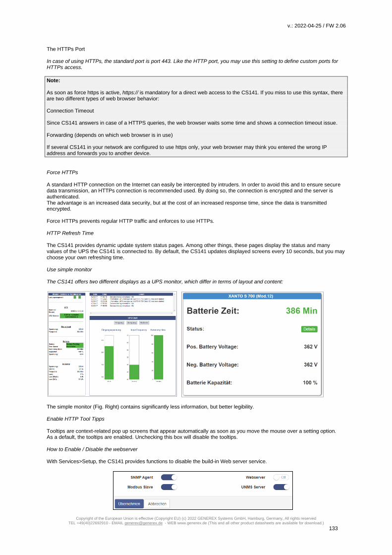
v.: 2022-04-25 / FW 2.06
Copyright of the European Union is effective (Copyright EU) (c) 2022 GENEREX Systems GmbH, Hamburg, Germany, All rights reserved TEL +49(40)22692910 - EMAIL [email protected] - WEB www.generex.de (This and all other product datasheets are available for download.)
133
The HTTPs Port
In case of using HTTPs, the standard port is port 443. Like the HTTP port, you may use this setting to define custom ports for HTTPs access.
Note: As soon as force https is active, https:// is mandatory for a direct web access to the CS141. If you miss to use this syntax, there are two different types of web browser behavior: Connection Timeout Since CS141 answers in case of a HTTPS queries, the web browser waits some time and shows a connection timeout issue. Forwarding (depends on which web browser is in use) If several CS141 in your network are configured to use https only, your web browser may think you entered the wrong IP address and forwards you to another device.
Force HTTPs A standard HTTP connection on the Internet can easily be intercepted by intruders. In order to avoid this and to ensure secure data transmission, an HTTPs connection is recommended used. By doing so, the connection is encrypted and the server is authenticated. The advantage is an increased data security, but at the cost of an increased response time, since the data is transmitted encrypted. Force HTTPs prevents regular HTTP traffic and enforces to use HTTPs. HTTP Refresh Time The CS141 provides dynamic update system status pages. Among other things, these pages display the status and many values of the UPS the CS141 is connected to. By default, the CS141 updates displayed screens every 10 seconds, but you may choose your own refreshing time. Use simple monitor The CS141 offers two different displays as a UPS monitor, which differ in terms of layout and content:
The simple monitor (Fig. Right) contains significantly less information, but better legibility. Enable HTTP Tool Tipps Tooltips are context-related pop up screens that appear automatically as soon as you move the mouse over a setting option. As a default, the tooltips are enabled. Unchecking this box will disable the tooltips. How to Enable / Disable the webserver With Services>Setup, the CS141 provides functions to disable the build-in Web server service.

v.: 2022-04-25 / FW 2.06
Copyright of the European Union is effective (Copyright EU) (c) 2022 GENEREX Systems GmbH, Hamburg, Germany, All rights reserved TEL +49(40)22692910 - EMAIL [email protected] - WEB www.generex.de (This and all other product datasheets are available for download.)
134
Please note that the complete user interface is linked to the web server - afterwards you cannot carry out any further
configuration as well as accessing the monitoring screens. For an access of the user interface, resetting the device to
factory defaults is mandatory.
Tutorial: Once upon a time, you switched the web server to off…
And now you want to take a look at the monitoring screens and they are gone. Any you do not really know what to do? This
tutorial shows you how to reset your CS141 and start over again – the CS141 is not locked up completely …
Use Backups
“Disable the web server” is very powerful, so it takes a little bit planning before you set the web server restrictively to "OFF": As
soon as the web server has been disabled, it will be a little awkward to add some configuration at the CS141 – the current
configuration interface is gone. But if you have a backup file you may be able to recover nearly the complete configuration of
your device. Which final backup / restore strategy you choose, depends on what you want to achieve.
In principle, there are two basic scenarios:
1. You need to change configuration regularly
Make the full data backup before you disable the web server. You can easily create the backup via the System>
Backup configuration.
2. Change a single device that runs “as configured” by a new one
Create a backup file after disabling of the web server. Since the configuration interface is offline, you cannot press
System>Backup to create it. So just enter:
http(s)://<your IP address>/backup
You will be asked for the standard user name admin and the current password (Standard: cs141-snmp).
Note:
In both cases, the rule is that a backup should only be used with device that comes with the same or a newer firmware version.
An older firmware may not work as expected because changes during a firmware update may change the format of backup file,
add features or something like that. The older firmware version may not know how to handle these changes.
Einspielen des Backups
After you have switched off the web server, you can no longer change the configuration. If you do not have a backup now, you
will have to completely reconfigure the CS141 after resetting the configuration.
Otherwise it works as followed:
1. Reset the CS141:
At your web browser, enter this command:
http(s)://<you IP address>/update
Even the web server is already disabled, some functions will still work. One of these functions is the direct call of the update
window:
Marking „Reset to factory default will advise the CS141:
o Delete the basic device configuration
o Keep the network settings

v.: 2022-04-25 / FW 2.06
Copyright of the European Union is effective (Copyright EU) (c) 2022 GENEREX Systems GmbH, Hamburg, Germany, All rights reserved TEL +49(40)22692910 - EMAIL [email protected] - WEB www.generex.de (This and all other product datasheets are available for download.)
135
After flashing, the CS141 will restart and the web interface is available. Open System>Backup and use drag and drop to place
the backup file.
2. Change the device 1:1 by another device / spare part
Open the flash routine as described, and then insert the backup file. Since you have a backup file with a disable web
server, the backup will lock up the user interface! You cannot change settings. The new device will run as configured
like your old device. Ensure to use all backup file items.
o If you want to refresh a broken configuration file, just use the complete backup file.
o If you want to change the device by a spare part, please note, that you need to depower the original device
before powering up the spare part. Otherwise you may get an IP address conflict.
Tutorial: How to create a .pem-file
There are many ways to create a key and a certificate. A comfortable freeware tool is X Certificate and Key Management. This tool offers not only the possibility to create valid certificates but also the option to include necessary keys. After creating, these files can be exported to be used with the CS141. In addition, this tool comes with a small database to manage all keys as well as certificates easily. This tool is not the only one of its kind, but highly recommended:
- Easy to use - Fast key and certificate creation (administration - This tool is available for Windows, Apple and Linux.
Create certificate and key Step 1. Download and Installation The tool is available through several download sources, a good and clear download link is presented here:
https://hohnstaedt.de/xca/ Please note that download links may change over time and need to be adjusted accordingly. The setup file includes an installer that guides through the installation process.
Step 2 Create database (example: Windows version, Linux and Apple may vary slightly) After installation, click on File and create a new database. It is not necessary to enter a password to protect the database .
This database can be stored and re-opened for later usage.
Step 3: Create and export a private key Go to private Keys and press the button New Key:

v.: 2022-04-25 / FW 2.06
Copyright of the European Union is effective (Copyright EU) (c) 2022 GENEREX Systems GmbH, Hamburg, Germany, All rights reserved TEL +49(40)22692910 - EMAIL [email protected] - WEB www.generex.de (This and all other product datasheets are available for download.)
136
Click Create to complete this process. The key will be provided in the database containing a corresponding message.
This key is the first of two required parts to create a valid PEM file.
After creating, export this key. Remember to rename the export file name to server.pem:
There is no need for special editing tools required - Edit this file with a regular text editor and attach the certificate.
Step 4: Creating / exporting the certificate The second part of the PEM file contains the necessary certificate to operate the CS141 with force HTTPS mode. To create the certificate, open Certificate signing request click on "New request" This will begin the certificate configuration dialog: Most Important are information about holder, extensions and key usage.

v.: 2022-04-25 / FW 2.06
Copyright of the European Union is effective (Copyright EU) (c) 2022 GENEREX Systems GmbH, Hamburg, Germany, All rights reserved TEL +49(40)22692910 - EMAIL [email protected] - WEB www.generex.de (This and all other product datasheets are available for download.)
137
Enter the certificates owner data. Adjust the data according to your company. With Add you hand over these data inputs to the database of the tool. Extensions With extended functions, you can set the validity of the certificate:
Passen Sie diese Daten an, um die Dauer Customize this data to determine the duration of the certificate. Apply with Complete this process. Key Usage. Check both check boxes and mark all modules you wish to include in your new certificate:
If you are not sure of the exact purpose for which you want to use the certificate, in case of doubt, activate all the options offered to you. This will allow the certificate to maximum functionality. After you have entered all data, click OK at the lower right corner
Export the certificate to a .crt file. Stitch together… From now, you should have two different data:

v.: 2022-04-25 / FW 2.06
Copyright of the European Union is effective (Copyright EU) (c) 2022 GENEREX Systems GmbH, Hamburg, Germany, All rights reserved TEL +49(40)22692910 - EMAIL [email protected] - WEB www.generex.de (This and all other product datasheets are available for download.)
138
Open the certificate with an editor and copy the content. The content looks something like this: —–BEGIN CERTIFICATE—– MIIEoDCCA4igAwIBAgIBATANBgkqhkiG9w0BAQsFADCBjTELMAkGA1UEBhMCSEgx […] hQ9t4jit2VSTnv4rIrHoT8j5/yEFpRKg6D/5zmavscl94gUp —–END CERTIFICATE—– It is important that you completely copy the entire file including BEGIN CERTIFICATE and END CERTIFICATE! Otherwise it will not work. open the file server.pem and copy the certificate under the key:
Save this file without changing the file name, the file extension or file type. CS141: Inserting the .pem file Open CS141 and navigate to the certificate web server:
use drag'n'drop to copy server.pem into the field provided by CS141. Upload will start the upload and import process. Once
upload is finished, you can test the certificate by typing:
http: // <your IP address>
https: // <your IP address>
If both inputs respond as desired, you can use Force https to enable explicit encryption.

v.: 2022-04-25 / FW 2.06
Copyright of the European Union is effective (Copyright EU) (c) 2022 GENEREX Systems GmbH, Hamburg, Germany, All rights reserved TEL +49(40)22692910 - EMAIL [email protected] - WEB www.generex.de (This and all other product datasheets are available for download.)
139
Diagnostic: Status LED's
The CS141 offers several options for diagnosis. The fastest method is a quick visual inspection of the LEDs
To perform a quick inspection, take a look at the two LEDs in front of the CS141:
Green LED Red LED Adapter
OFF OFF No Power
OFF AN Boot in progress
OFF SLOW BLINKING Update in progress
AUS FAST BLINKING Update failure
ON ON Communication lost: UPS or external device
SLOW BLINKING OFF Everything is OK with the world
After logging in, the CS141 will display a more detailed overview of the current system state:
A green marker indicates communication without problems.
Please note the setting no UPS device selected will show a dummy screen and the LED will also be green.
A yellow marker is displayed if:
- - The device will initialize and the communication is being established
- - there is a warning behavior. It might be required appropriate intervention in the near future.
If the LED is red, an alarm or critical condition is currently detected:
- The CS141 has lost communication with a connected device
- There is a system critical condition, which requires a timely intervention.
The type of the alarm is displayed in detail.
A blue marker indicates that the device was probably configured correctly, but no initial communication has been established.
A gray marker and the description disabled means that a device has been completely deactivated and cannot provide any data.

v.: 2022-04-25 / FW 2.06
Copyright of the European Union is effective (Copyright EU) (c) 2022 GENEREX Systems GmbH, Hamburg, Germany, All rights reserved TEL +49(40)22692910 - EMAIL [email protected] - WEB www.generex.de (This and all other product datasheets are available for download.)
140
Example: Quick diagnosis using LEDs and marker
At the front of the CS141 both, red and green LED's, are on, but they should be off or just the green one flashing slowly. The UPS is definitely recognized ... and seems to work normally.
As you can see the red and the green LEDs are lit statically. Since it is a slot card, it is plugged into the UPS and is supplied with the necessary information about it.
The yellow plug is the ethernet cable to connect the CS141 to the local network
In this example scenario, the AUX port is the cause of a communication error:
After logging into the CS141, the top status bar displays the following information about enabled devices:
The UPS is set correctly and has made the communication accordingly. The AUX port, on the other hand, is set to initializing. However, since the AUX port has no device connected to CS141, the yellow marker will change from yellow to blue in time, while the LEDs on the front of the CS141 continue to glow green and red statically.
Due to the fact the UPS indicates a green marker and other devices are set to disabled, the AUX-Port will cause trouble.
What you can do:
Once a CON_AUX4 or CON_R_AUX4 device has been connected to the AUX port of the CS141 and successfully initialized, the marker in the status bar will turn to green and provide feedback with OK. Furthermore, the LED status at CS141 will indicate normal operating mode.
If no AUX device is to be used, you can set the AUX port at COM3 to none in the general configuration menu.
In this case, the AUX port will be disabled as well as the AUX marker will be removed from the top status bar.
As a consequence, the LED at CS141 will indicate normal operating mode.
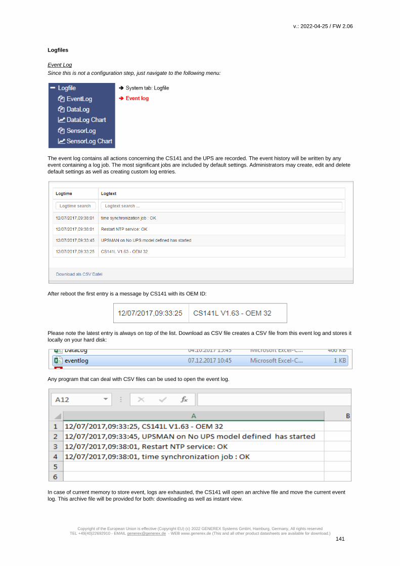
v.: 2022-04-25 / FW 2.06
Copyright of the European Union is effective (Copyright EU) (c) 2022 GENEREX Systems GmbH, Hamburg, Germany, All rights reserved TEL +49(40)22692910 - EMAIL [email protected] - WEB www.generex.de (This and all other product datasheets are available for download.)
141
Logfiles
Event Log
Since this is not a configuration step, just navigate to the following menu:
The event log contains all actions concerning the CS141 and the UPS are recorded. The event history will be written by any
event containing a log job. The most significant jobs are included by default settings. Administrators may create, edit and delete
default settings as well as creating custom log entries.
After reboot the first entry is a message by CS141 with its OEM ID:
Please note the latest entry is always on top of the list. Download as CSV file creates a CSV file from this event log and stores it
locally on your hard disk:
Any program that can deal with CSV files can be used to open the event log.
In case of current memory to store event, logs are exhausted, the CS141 will open an archive file and move the current event
log. This archive file will be provided for both: downloading as well as instant view.

v.: 2022-04-25 / FW 2.06
Copyright of the European Union is effective (Copyright EU) (c) 2022 GENEREX Systems GmbH, Hamburg, Germany, All rights reserved TEL +49(40)22692910 - EMAIL [email protected] - WEB www.generex.de (This and all other product datasheets are available for download.)
142
Note:
Depending on the configuration, the system events in the event log are kept for up to three months. As soon as the running
memory for the current event log file is exhausted, the files are stored alternately in up to two archive files. This generally
provides a monitored period of up to 9 months from initial startup.
Navigate between logfiles
By default, the current event log is displayed
Administrators are able to toggle between the two logs by clicking the button "Show
archived Logfiles" in the upper right corner.
By doing so, the label of this button will change:
To return to the active log file, press the button labeled "Show active log file"
Data Log
Since this is not a configuration step, just navigate to the following menu:
The data log recognizes measurement data of the UPS. Due to the fact these are provided with a time stamp, they can be
combined with the event log:
Analysts can build event chains with additional UPS data.
Like the event log, data log can be exported as CSV file as data backup. The data log stores the entries every 3 minutes and
keeps the entries 8 weeks as the current data log file. After that the actual data log will be moved to an archive file and a new
data log for the current data is opened.
The CS141 provides storing up to 2 independent archive files:
In addition to the current period, there are up to 24 weeks available. After expiry of the time, the oldest archive file is replaced.
As with the event log, administrators can toggle between active log and achieved logfiles.

v.: 2022-04-25 / FW 2.06
Copyright of the European Union is effective (Copyright EU) (c) 2022 GENEREX Systems GmbH, Hamburg, Germany, All rights reserved TEL +49(40)22692910 - EMAIL [email protected] - WEB www.generex.de (This and all other product datasheets are available for download.)
143
Data log Diagram
Since this is not a configuration step, just navigate to the following menu:
With data log Chart CS141 provides a graphical presentation of the battery history:
This feature allows to examine all entries within the data log exclusively. Single entries can be selected by using checkboxes:
In addition to the current values, the CS141 provides selecting specific values from current databases.
As a default, all check marks are set when called. You can use the Unselect All Lines function to remove them and set the
relevant checkmarks.
How to use the calendar
The calendar feature provides a quick
overview of existing time periods that
are selectable. Click the date field to
bring up the calendar:
The dates of the corresponding period
are automatically loaded and
displayed inside the main window.

v.: 2022-04-25 / FW 2.06
Copyright of the European Union is effective (Copyright EU) (c) 2022 GENEREX Systems GmbH, Hamburg, Germany, All rights reserved TEL +49(40)22692910 - EMAIL [email protected] - WEB www.generex.de (This and all other product datasheets are available for download.)
144
Zoom the Chart
The CS141 provides zooming the data and thus obtain a detailed view within the displayed measurement data.
To refine display, drag a frame inside the small window. The main window will
automatically show a detailed view und provide a customized timeline.
The zoom function allows an enlargement of the timeline up to 2 minutes.
This function resets the zoom back to the original scope.
This function updates the current data shown and
refocuses the timeline.
Premium function: The UPS alert history
This menu is only available if your UPS will support the functionality Since this is not a configuration step, just navigate to the following menu:
Not only the CS141 logs events - many UPS systems provide their own internal non-volatile memory to log events as well as
internals. This information can provide very useful insights if irregularities occur after a configuration.
Note
The CS141 adapts itself to functions a UPS provides - The UPS Alert History is only available if your UPS supports this function.
Reading internal event logs of the UPS
Each time the UPS Alert History button is pressed, the event memory of the UPS read
out and displayed accordingly.
Please note that displayed status messages as well as the scope and information value
may vary:
Some UPS models provide more useful information than others.
After reading, UPS data are displayed inside a chronologically arranged history. At the top of the list, you will find the oldest UPS
log entries. At the bottom of the list, the latest entries will be shown.
End determines the last entry of the logfile.

v.: 2022-04-25 / FW 2.06
Copyright of the European Union is effective (Copyright EU) (c) 2022 GENEREX Systems GmbH, Hamburg, Germany, All rights reserved TEL +49(40)22692910 - EMAIL [email protected] - WEB www.generex.de (This and all other product datasheets are available for download.)
145
Exporting UPS data log
If needed for later analysis for statistical and diagnostic purposes, the CS141 provides to export
and save the log as CSV file and save it locally to your hard disk
Note:
The UPS Event Recorder polls the current list from the UPS with each call - These log data will not be cached or saved by
CS141.
Tools
The GENEREX system tools are a collection of useful utilities to help in case of diagnostic problems. To ensure authorized
access only, this menu acquire administrative credentials:
To open the Toolbox, navigate to the following menu:
Reboot
Due to the fact the CS141 accept changes inside the configuration and start or restarts the
corresponding system services in real time, a complete restart is an exceptional situation. In
case of a restart of the CS141, UPS continues its normal mode: A reboot of CS141 does not
affect the UPS. To prevent an accidental triggered reboot, this feature was deliberately
placed inside Tools.
Tracer
The Tracer is a comprehensive diagnostic tool for verifying
communication between the CS141 and the connected devices as
well as for identifying network problems.
Under Device communication information about external devices
connected to CS141 can be queried. To track a device, open the
context menu and select the device you want to monitor. As the screenshot illustrates, the CS141 provides COM 1 / UPS, COM
2 / GSMModem and COM 3 / AUX-Port:
COM 1/ UPS
The tracer will screen the current communication running at the serial RS232 port. Faults or faulty communication are displayed
in real time and can be saved for later evaluation
COM 2 / GSM-Modem
The Tracer queries the communication between the CS141 and the GSM modem and displays the telemetry in real time. Errors
and communication problems can be easily collected and saved for later analysis.

v.: 2022-04-25 / FW 2.06
Copyright of the European Union is effective (Copyright EU) (c) 2022 GENEREX Systems GmbH, Hamburg, Germany, All rights reserved TEL +49(40)22692910 - EMAIL [email protected] - WEB www.generex.de (This and all other product datasheets are available for download.)
146
COM 3 / AUX
A CON_AUX4 or CON_R_AUX4 can be connected via the AUX port. The tracer can interrogate communication with the device
in real time.
Note: The Tracer adapts itself to the choice met under Devices in the configured in general port settings. If sensors or a Sensor manager 2 is configured instead of a GSM modem, the tracer will show these devices.
The button labeled with Trace starts the process. Depending on your browser's configuration an open a new tab will be opened to show the data stream of the communication between the device and the CS141:
The trace ends automatically by closing this tab. Please note that the data will be discarded. To save the data, mark it with the
left mouse button and copy the content with CTRL + C, and insert the information with CTRL + V to a text file.
Available Tracing tool control options
- Clear trace log
Clear trace log deletes the current display - the information cannot be recovered afterwards.
- Save trace log
This function will transfer the current browser content into a standardized text file.
Note
This log file contains the complete time-stamped communication between the CS141 and UPS connected to it: The CS141 asks
and the UPS responds accordingly. Since these entries are time stamped, this communication may be compared to external
events - this valuable information may help finding the cause of an incident.
The telemetry data file is placed in real time inside the memory of the web browser. By closing this window, the trace data file is
automatically terminated and lost. Ensure saving data before closing the window of the web browser.
Trace file evaluation
Open the saved text file. Please note the extended text formatting - Ensure to use a text editor mastering extended text
formatting. As an example, typical applications would be editors like sublime or the editor write by Microsoft Windows.
For a detailed analysis, the official protocol description of the UPS is necessary.
For further details, please refer to the manufacturer of your UPS.
Network-Scan
As special feature the CS141 provides an
integrated network scanner to examine the
LAN for issues and errors. The network
scan provides extensive information for
evaluation about the network the CS141 is
connected to. All data packets are collected in a log file. After network scan, the network log can be downloaded for evaluation.

v.: 2022-04-25 / FW 2.06
Copyright of the European Union is effective (Copyright EU) (c) 2022 GENEREX Systems GmbH, Hamburg, Germany, All rights reserved TEL +49(40)22692910 - EMAIL [email protected] - WEB www.generex.de (This and all other product datasheets are available for download.)
147
Privacy Policy:
Since the network scan records all traffic in this network segment the CS141 is connected to, an evaluation with a
corresponding network tool can be used to find error. Furthermore, deep insights into the network traffic are available, e.g. to log
the user behavior. Technicians should inform the respective responsible person before use.
To perform a network scan, click on the Trace button in the Network line. The tracer will confirm tracing activity with a short fade
in.
The Tracer logs packet data within the LAN segment in real-time and stores it locally on the CS141. The tracer will quit if there
are two conditions:
1. A reboot (expected / unexpected)
2. By pressing the Stop button
After finishing, the data will be downloaded in the form of a packed archive for later evaluation.
3. 4.
Note:
The network tracer is usually very rarely needed. In seldom cases GENEREX technical support needs specific
additional information to locate a problem.
In this case, it is recommended to start the tracer without using filtering options. Furthermore, it turns your CS141 into
a powerful network diagnostic tool that lets you examine your local LAN:
Refer www.tcpdump.org to find extensive tutorials how to define filters in order to use the full potential of the CS141
as a network diagnostic system.
Data evaluation
The data analyzed via diagnostic tools such as Wireshark *:
Downloaded data can be read and analyzed by special diagnostic tools such as Wireshark *:
*Wireshark is not a GENEREX product. It is available at www.wireshark.org
Delete log files
The CS141 collects and logs many data and uses non-volatile memory to store it permanently: These data can then be retrieved via a web browser or evaluated by diagnostic tools. Since the log files may contain very sensitive information about a network state, it is recommended to delete all data before re-using the CS141 Webmanager. Networklog

v.: 2022-04-25 / FW 2.06
Copyright of the European Union is effective (Copyright EU) (c) 2022 GENEREX Systems GmbH, Hamburg, Germany, All rights reserved TEL +49(40)22692910 - EMAIL [email protected] - WEB www.generex.de (This and all other product datasheets are available for download.)
148
Deletes any network trace data Eventlog Deletes all logged data according to events Datalog Deletes additional data of UPS measurements.
Note
Once deleted, the logfiles are gone with the wind! Normally, the CS141 provides enough space to store the data a complete
lifetime cycle. If in doubt, ensure a backup of the data files is available. Please note, there is no option to recover data on the
device itself.
Tutorial: Complete data delete routine
As a web manager, the CS141 provides a large amount of data about installed devices to ensure deep analysis in case of
incidents:
- Battery data - Sensor data - Event Logs - Transmit / receive confirmations - [...]
The exact data collected by the CS141 Webmanager depends on the hardware connected to it as well as the state of
configuration. However, as these data may contain both, very sensitive information about the security concept of an IT
infrastructure and clearly reconstructable chain of events, a complete data deletion is recommended in case of a reorientation to
new tasks.:
As an example, if the CS141 shall be sold, all user traces should be removed completely.
Where are log files stored?
In principle, these log files can be found in two places:
1. The regular operating mode
The current log files are created in real time and managed accordingly. If you intentionally delete these files via the toolbox, they
are lost - data recovery is not possible
2. The Rescue Mode
As soon as you perform a system update in any form, the existing data and configurations are parked in the Rescue Mode as "last known good". The regular operating mode is set back to 0 and starts after a successful flashing with a new set of log files. Due to this fact, the CS141 provides even an emergency data rescue option: After an accidental flash, the rescue mode will allow to access log files as well as the last existing configuration since the previous planned firmware flash. Complete removal of all user traces To completely erase all data, first set the slide switch to center position to enable the configuration mode and its hard-coded IP address 10.10.10.10 and the subnet mask 255.255.255.0. Make sure that you have assigned a suitable IP address to your computer or enter a corresponding route to access the CS141. Carry out two flash updates in a row. Ensure both cases the checkboxes are selected: Factory default and network reset. The first flash update transfers data and configuration from the regular operating mode to the Rescue mode and deletes all data during the subsequent flash process. The second flash update transfers the completely empty configuration from the configuration mode to the rescue mode.
Note Type http://10.10.10.10/update in the browser and run the flash update after entering the current administrator password. On the second pass, the default password cs141-snmp is active

v.: 2022-04-25 / FW 2.06
Copyright of the European Union is effective (Copyright EU) (c) 2022 GENEREX Systems GmbH, Hamburg, Germany, All rights reserved TEL +49(40)22692910 - EMAIL [email protected] - WEB www.generex.de (This and all other product datasheets are available for download.)
149
Change the logo
Some companies do not want foreign logos inside their IT Infrastructure. Therefore, it is possible to change the logo shown on
the upper left side.
How to change the logo
1. Open the graphic program of your choice
2. Create a new picture, maximum size is 200 X 54 PX
3. Edit the logo as your whish
4. When finished, save the logo with filename logo.gif – otherwise it will not work.
5. Open CS141 Toolbox:
Under Tools, you will find the configuration screen:
Use drag and drop to insert the new logo or click to select from a list.
6. Press Upload to insert the new logo.
Before…
… and after

v.: 2022-04-25 / FW 2.06
Copyright of the European Union is effective (Copyright EU) (c) 2022 GENEREX Systems GmbH, Hamburg, Germany, All rights reserved TEL +49(40)22692910 - EMAIL [email protected] - WEB www.generex.de (This and all other product datasheets are available for download.)
150
Data backup and firmware update
For this configuration step, navigate to the following menus
Data backup offers the option of completely backing up the current system configuration in order to quickly perform a recovery if required. The backup and restore will be done in two steps:
Step 1: Perform a backup
Open Backup. Under Save Configuration, click Backup to locally save a backup file to your download directory. Since the backup function is system-critical, CS141 asks for the valid administrator password.
This data backup can be run with any CS141 using a similar or higher OEM firmware version. Please note, renaming the backup
file is subject to some restrictions that may a lead into an invalid restore procedure:
backup-200001707T0416.tar.gz For changing the name of the backup file, please note the hints as followed:
- You need the packed file as downloaded. -The area marked in red cannot be changed - No spaces inside the file name - No special characters
Step 2: Restoring data
Importing a backup will use the same menu:
Use drag'n'drop to place the packed file into the box or left click on the box to open a file browser and double-click on the desired backup file. With Restore, the recovery process will be triggered. During recovery process, CS141 unpacks the file and automatically takes over as a current configuration. After completing the process, you will automatically be logged out and have to re-login with credentials according to the backup.
Restoring network data
If you back up multiple identically configured web managers, you can exclude IP address
settings from recovery. By doing so, previously configured IP address entries will persist
while restoring all other configurations.

v.: 2022-04-25 / FW 2.06
Copyright of the European Union is effective (Copyright EU) (c) 2022 GENEREX Systems GmbH, Hamburg, Germany, All rights reserved TEL +49(40)22692910 - EMAIL [email protected] - WEB www.generex.de (This and all other product datasheets are available for download.)
151
Please note that backups from a CS141 are compatible with any CS141 of the same or later firmware: If you use the backup on
a CS141 with an older firmware, problems may arise. This behavior is reasoned by general improvements as well as new
features older firmware versions cannot work properly with. In some cases, it is possible the backup does not work.
Firmware updates
Firmware updates can be found at www.generex.de by following the download area.
These System updates are regularly provided for the CS141. In addition to general
product enhancements such as increased stability and improvements in operational
and reliability, these updates also regularly provide new features that integrate
seamlessly to existing configurations.
By default, the OEM ID 12 / GENEREX is preinstalled on delivery.
Deviations will result if you have purchased the Web Manager as part of a UPS from a
manufacturer that comes with OEM agreements.
Note:
Due to the fact CS141 is not technically locked, you can install the OEM version of another manufacturer at any time. In case of
another UPS is used, just install an according OEM firmware version.
Under Firmware, select the version you need to use and download it to your computer. Unpacking the file is not necessary.
After downloading, open the web interface of the CS141 and open Update:
Drag the downloaded, packed file directly to the provided window. With Start will trigger the update process. Before triggering
the update with Start button, you can select the following additional options:
Reset to factory settings
This option deletes all configurations during the update and returns the device to the delivery state.
Reset the network to factory settings
This option also resets the network and IP settings to factory defaults.
Note:
These two options are independent to each other to ensure not losing the IP settings. Due to this fact a factory reset using a
remote access to the CS141 is possible. Please note Reset network to factory settings needs to be de-selected if CS141 has to
hold its IP settings
Since the update is interactive, please remain on the page until you are prompted to restart the device. Under system, open
about menu to check the success of the update.
General note: Please read before flashing:
In general we recommend to use the latest firmware version:

v.: 2022-04-25 / FW 2.06
Copyright of the European Union is effective (Copyright EU) (c) 2022 GENEREX Systems GmbH, Hamburg, Germany, All rights reserved TEL +49(40)22692910 - EMAIL [email protected] - WEB www.generex.de (This and all other product datasheets are available for download.)
152
The latest firmware version provides product improvements, new UPS models and bug fixes. Additionally, the ongoing
development process allows to deploy reguarly new functions. This ongoing development process includes to update core
components or file systems, too.
Unfortunately, some changes need are deep inside the core system. With firmware 1.82 such a step is necessary:
1. You can always update to the firmware version 1.82 or later.
2. After the update is finished, a downgrade is only allowed until firmware version 1.82.
If you want to test the new firmware on an existing device first:
In case of a regular firmware update, the update routine will move the currently used firmware version to the rescue system as
so-called "last-known-good". By doing so, you have an optional way for downgrading as long as you have not stored the
firmware 1.82 as rescue mode.
How to use the rescue system can be found in the chapter "Starting the rescue system".
Although we do not recommend to use old firmware versions - if it is necessary that you need an older firmware version, please
contact us: [email protected] - our support team will try help you in this special case.
Changing OEM Firmware
The CS141 Webmanager comes in two different firmware versions:
- GENEREX - ID 12
- OEM version of the manufacturer of your UPS
If you cannot find your UPS in the list of selectable UPSs, it may be necessary to install a different firmware.
For this, it is necessary to understand how you can detect the currently installed firmware and the required firmware:
The current firmware
You can see the current firmware by the logo in the top left corner:
Depending on the manufacturer, you will find the corresponding logo.
Checking firmware version
In the general system information, you will find this entry
The firmware version shows the OEM key:
V1.64 - the current firmware .12 - the currently installed OEM version 171213- read the creation date backwards If you want to operate the CS141 in a UPS of another manufacturer, you will find the necessary firmware on www.generex.de in the download area

v.: 2022-04-25 / FW 2.06
Copyright of the European Union is effective (Copyright EU) (c) 2022 GENEREX Systems GmbH, Hamburg, Germany, All rights reserved TEL +49(40)22692910 - EMAIL [email protected] - WEB www.generex.de (This and all other product datasheets are available for download.)
153
Use the Show Version Info to check if an updated firmware is available for download. Please note that unlike updating within the
same OEM firmware, changing the OEM firmware requires triggering a factory default setting since features and functions may
vary among UPS manufacturers.
Most common problems while configuration and updating
This list contains typical errors that can occur when dealing with firmware updates: Dip-switches / slide switch in wrong position As a result, the CS141 uses either at the configuration mode IP address or an IP address assigned via DHCP. In this case you can no longer reach the CS141. Since the configuration mode on the hardware side has the 10.10.10.10 as a pre-set, it may also cause a network error, since this IP address will be used by any CS141 as a default. Forgot manual IP address assignment or IP address set to factory default The CS141 boots up and tries to get an IP address. If this is not possible, it starts with the default IP 10.10.10.10. Forgotten Reboot Since the CS141 offers the possibility to change the sliding switch on the fly and to carries out the function via software reboot, an update can evidently trigger the change of the IP address and the CS141 is no longer accessible. The reason for this is that the CS141 starts regularly with 10.10.10.10 and points the route to it on the local PC: if you boot the CS141 the first time, set the sliding switch to manual mode, enter IP address data and then perform an update, only the IP settings you entered will be used. As a consequence, it seems CS141 cannot be accessed at the hardcoded IP address 10.10.10.10. Web Browser caching caused issues Modern web browsers use technologies designed to speed up content viewing and improving multimedia experiences: - Speech recognition - Auto-complete names and address data - Automatic login into websites - Personalized commercials - Pre-caching files from websites - Holding website files for faster revisit - and many more … These media files are loaded into a separate browser cache to ensure the fastest and most comfortable possible web experience. The CS141 uses build-in web-based technology. If you use more than one CS141, web browsers sometimes show pre-cashed data: Mixing identical content from different devices can cause strange or illogical error messages.
Note: This is caused by web browsers' behavior. In this case, the browser cache must be deleted.
Force https is active Depending on patch level and web browser used for displaying web-based content, some web browsers tend to detect this condition and automatically add the https. However, others ignore the wrong http query and return a device is not available message or react in a very strange way: https was sometimes automatically enabled, but the https-query will be redirected to another device. In this case, browser logged your surf behavior and assumed that you meant another device that is known to use https. As a result, you enter the IP
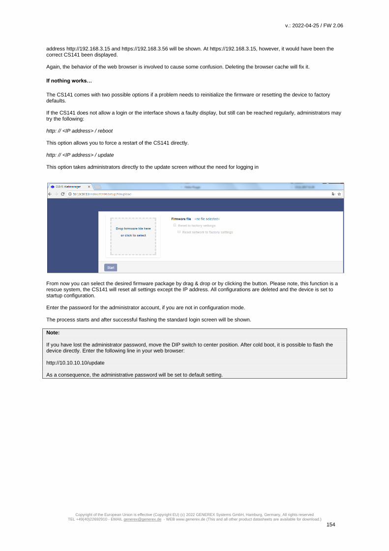
v.: 2022-04-25 / FW 2.06
Copyright of the European Union is effective (Copyright EU) (c) 2022 GENEREX Systems GmbH, Hamburg, Germany, All rights reserved TEL +49(40)22692910 - EMAIL [email protected] - WEB www.generex.de (This and all other product datasheets are available for download.)
154
address http://192.168.3.15 and https://192.168.3.56 will be shown. At https://192.168.3.15, however, it would have been the correct CS141 been displayed. Again, the behavior of the web browser is involved to cause some confusion. Deleting the browser cache will fix it.
If nothing works…
The CS141 comes with two possible options if a problem needs to reinitialize the firmware or resetting the device to factory defaults. If the CS141 does not allow a login or the interface shows a faulty display, but still can be reached regularly, administrators may try the following: http: // <IP address> / reboot This option allows you to force a restart of the CS141 directly. http: // <IP address> / update This option takes administrators directly to the update screen without the need for logging in
From now you can select the desired firmware package by drag & drop or by clicking the button. Please note, this function is a rescue system, the CS141 will reset all settings except the IP address. All configurations are deleted and the device is set to startup configuration. Enter the password for the administrator account, if you are not in configuration mode. The process starts and after successful flashing the standard login screen will be shown.
Note: If you have lost the administrator password, move the DIP switch to center position. After cold boot, it is possible to flash the device directly. Enter the following line in your web browser: http://10.10.10.10/update As a consequence, the administrative password will be set to default setting.

v.: 2022-04-25 / FW 2.06
Copyright of the European Union is effective (Copyright EU) (c) 2022 GENEREX Systems GmbH, Hamburg, Germany, All rights reserved TEL +49(40)22692910 - EMAIL [email protected] - WEB www.generex.de (This and all other product datasheets are available for download.)
155
Starting the rescue system
If this feature is not available, the CS141 offers second option: During flashing, the CS141 saves a complete backup including the configuration of the “last known: good”. This version can be activated by setting the following jumper:
If the jumper is set and the adapter boots, CS141 will run this version as a rescue system based on the last firmware version: Inside the About menu, the firmware version will add the word RESCUE to show its current operational mode.
Rescue mode on CS141 mini
Due to its compact design, the CS141 Mini has no jumper that can be set. To activate the rescue mode, set both DIP switches to the ON position: Run a firmware update and reset the adapter to factory settings. Please note you are not flashing the operating system of the
rescue mode:
You will not see the result until you return to normal operating mode and restart the CS141.
Note:
The CS141HW161 MINI / R2 has been fundamentally technically revised and, like all WEBMANAGERs of the CS141 product
family, now offers the convenient rescue jumper: if your CS141 MINI provides a reset button and the slide switch on the front,
use the rescue jumper for rescue mode.

v.: 2022-04-25 / FW 2.06
Copyright of the European Union is effective (Copyright EU) (c) 2022 GENEREX Systems GmbH, Hamburg, Germany, All rights reserved TEL +49(40)22692910 - EMAIL [email protected] - WEB www.generex.de (This and all other product datasheets are available for download.)
156
PART II - BACS® Battery Analysys & Care System Users manual

v.: 2022-04-25 / FW 2.06
Copyright of the European Union is effective (Copyright EU) (c) 2022 GENEREX Systems GmbH, Hamburg, Germany, All rights reserved TEL +49(40)22692910 - EMAIL [email protected] - WEB www.generex.de (This and all other product datasheets are available for download.)
157
What is BACS®?
BACS® - the "Battery Analysis & Care System" - is the
most advanced system on the market to manage
stationary battery systems. It is a standalone battery
monitoring and management system that can be easily
integrated into your network infrastructure. With its
intelligent web-technology configurable management
technology, it cyclically checks the internal resistance, the
temperature and the voltage of each individual battery. In
addition, it can readjust the charge voltage of each battery
and manage environmental readings (temperature,
humidity, hydrogen gas content) as well as loads (UPS,
inverters, and other devices). The accumulators are thus
always kept in the optimal working range. The ongoing
monitoring and limiting of the individual charging voltages
of each block ensures the estimated maximum battery
availability at any time. After installation, BACS® will
significantly find a way to increase and secure the performance at all lead-based, closed and sealed batteries (AGM, GEL, wet
batteries, maintenance-free), nickel cadmium and lithium-based cells.
The BACS system was designed for the individual monitoring and to control each single accumulator inside a battery system.
BACS regulates the voltage symmetry during charging and provides individual scalable notification options in case of an
asymmetric discharge or similar faults:
- It stops the overcharging of individual batteries and warns in case of pending deep discharges.
The problem that weak accumulators may be damaged by unrecognized overcharging or deep discharging is now
observed. Notifications in time allow counter measures before an incident occurs.
- The BACS unique system architecture provides active charge / Discharge control for each accumulator
The GENEREX BACS EQUALIZATION distributes evenly
the voltage from the charger / UPS is evenly distributed to all accumulators. As a result, a homogeneous voltage is
present across all batteries inside the system. Due to this fact, average lifetime and capacity will be increased
significantly.
- Sulfation problems are no longer a creeping threat
BACS EQUALIZATION minimizes the problems of sulfation through a constant trickle charge. In case the sulfation is in
progress, BACS can detect this as a problem and ask for further assistance by the operator in good time. As a result,
countermeasures like controlled discharging or removal of sulfation can be initiated before the accumulator is severely
damaged.
What is the advantage of BACS?
Manual monitoring and maintenance are expensive and complex - With BACS, they are no longer necessary Since the individual
data of the accumulators are now available it is possible to maintain each accumulator individually at any time. If the BACS
EQUALIZATION repair procedure does not work on one or more accumulators or irreparable defects are detected on a battery, it
is possible to change one cell before the defect has a negative effect on the neighboring cells. The precautionary replacement of
all batteries inside the system is therefore no longer necessary. By doing so, BACS ensures more than the availability of the
battery system:
Its unique technology provides by the constant monitoring and managing of the batteries, the optimum capacity to ensure
emergency operating time.
The data and experiences gained through our unique BACS since 2004 on the realistic behavior of battery systems shows how
to double the average service life time of rechargeable batteries that are installed into UPS systems and why the UPS usage
differs from a single rechargeable battery usage: The estimated life of a single accumulator is determined by the manufacturer -
As an example, he states an estimated life time for a special battery model as 10 years. Since inside large UPS systems very
many accumulators are interconnected, the single battery behavior will change according to the number of batteries in use:
The number of weak batteries with negative influences to neighbored ones will increase statistically.
Due to this fact, the overall behavior of all batteries leads into a significantly reduced time for active usage inside a UPS - the so-
called service life. Astonishingly, this active service time is usually half of the stated battery life time. With BACS, it is possible to
extend the life of any battery running inside a UPS to the manufacturer's statet battery lifetime. BACS offers more than best
economical possibilities in single battery monitoring - it provides reliable data for extensive analysis and long-term studies.
BACS systems are available in 4 versions (2V, 4V, 6V and 12V) for a range of uses ranging from small 7 Ah batteries to large
stationary lead-acid batteries up to 6000 Ah.
In addition, the BACS system has a state-of-the-art alarm threshold system that is continuously under development. BACS collects
readings inside specially designed internal database for battery histories:

v.: 2022-04-25 / FW 2.06
Copyright of the European Union is effective (Copyright EU) (c) 2022 GENEREX Systems GmbH, Hamburg, Germany, All rights reserved TEL +49(40)22692910 - EMAIL [email protected] - WEB www.generex.de (This and all other product datasheets are available for download.)
158
The device determines and stores individual battery values like internal resistance, temperature and voltage. With the optional
BACS CSxxx current sensor, the scope of measured data will be enhanced with additional charge and discharge current
measurements, valuable data for comprehensive long-term analysis. Collected sensor data will be sent directly via its own bus
system to the central control unit, the BACS® WEBMANAGER.
All incoming information will be stored and processed:
After processing sensor data, the BACS® WEBMANAGER provides an intuitive well-structured interface to present the
measurements. In companion to the data presentation and configurable notifications, additional alarm LED and alarm buzzer
ensures that the UPS will be safe during operation. Finally, the BACS® WEBMANAGER has an intuitive user interface via web
browser, which also contains a clearly arranged configuration menu.
EQUALIZATION: How to maintain individual charging / discharging of accumulators
As a continuously running background process, the BACS® WEBMANAGER calculates a so-called "charging voltage point" - A
value each block should have at the instantaneous total voltage. If an accumulator deviates from this average charging voltage,
the BACS WEBMANAGER sends a command to the corresponding BACS module that manages the accumulator. The BACS
Module will manage to adjust the charging voltage to the calculated charging voltage point.
As mentioned, many different values are recorded and monitored - even the average activity and the number of charging and
discharging cycles. If an event occurs during the monitoring which can be classified as serious or dangerous, the BACS
WEBMANAGER can manage alarm notifications provided by direct network alarms as well as email, SMS, SNMP or RCCMD. If
available, even an optional Modem can be used for customizable SMS alarming. In case of being operated inside a Modbus
system, BACS Webmanager will also serve the MODBUS format via one of the serial interfaces and / or via MODBUS over IP
Additional Features
Thanks to optimized memory routines, the BACS WEBMANAGER is capable to record battery data for up to 3 years by using
reliable 32MB internal flash memory. All stored data can be downloaded and archived:
Alarms from the batteries or other devices connected to the UPS are logged with a timestamp - in order to ensure data and time
allocation, the BACS® WEBMANAGER provides automatic time synchronization with free definable time servers as well as
second clock inside the BACS BUS CONVERTER.
Picture: typical setup of a BACS

v.: 2022-04-25 / FW 2.06
Copyright of the European Union is effective (Copyright EU) (c) 2022 GENEREX Systems GmbH, Hamburg, Germany, All rights reserved TEL +49(40)22692910 - EMAIL [email protected] - WEB www.generex.de (This and all other product datasheets are available for download.)
159
CS141 and BACS
To upgrade the CS141 into a full BACS system, you need the BACS Bus Converter
In case of your project involves larger installations with more than 50 batteries, we recommend the BACS Splitting Box. The
Splitting Box allows to divide the installation into individual strings. A further application is the possibility to realize well-
structured clear cabling of the BACS modules.
These devices can be ordered separately, among others, via the GENEREX web shop as well as comfortably worldwide via a
certified GENEREX partner.
What is the difference between the BACS Webmanager Budget and the CS141 in companion with a BACS Bus Converter?
First of all: both devices fulfill exactly the same functions.
The difference is that the combination of a CS141 BACS and a Bus Converter is modularly composed of two separate devices,
while the BACS Webmanager Budget consists of a complete device: While the single device has a more compact design, the
modular solution allows to separate the BACS BUS Converter: Take it along while the CS141 will continues in place its
monitoring and managing works.
In both cases, it is possible to connect a computer in order to use the BACS tools.
BACS WEBMANAGER Kits
The BACS WEBMANAGER BUDGET is the central control unit for
all batteries connected to the BACS bus. The BACS
WEBMANAGER KIT contains a BACS WEBMANAGER, a BACS
CONVERTER, all necessary cables as well as power supply.
The BACS WEBMANAGER can be configured via a special BACS
data cable as well as via a network interface.
Each BACS WEBMANAGER system includes a full-featured SNMP
/ Web UPS Manager on COM 1 and offers a variety of sensors for
access control, temperature and humidity as well as versatile
environmental sensors. Even customer-specific sensors can be
used via the optional SENSORMANAGER.
Upgrade your CS141 into a full-featured BACS Webmanager:
For this configuration step, navigate to the following menu:

v.: 2022-04-25 / FW 2.06
Copyright of the European Union is effective (Copyright EU) (c) 2022 GENEREX Systems GmbH, Hamburg, Germany, All rights reserved TEL +49(40)22692910 - EMAIL [email protected] - WEB www.generex.de (This and all other product datasheets are available for download.)
160
General COM port settings
Under Devices, click on the menu Setup. This will allow to activate the BACS capability and is necessary for further
configuration. Without this setting, the BACS menu is not accessible.
Note:
An easy method to figure out if your CS141 model can be used as a BACS Webmanager:
As soon as your CS141 provides an AUX-Port, your CS141 will support a BACS BUS Converter in general. You just need to
look at the ports. If you cannot access the device physically, you can take a look at the General COM Port settings. If your
CS141 model does not provide an AUX port, COM3 is not available.
BACS can be operated a completely standalone system - independently of your previous UPS configuration. Even it is useful for
BACS to know the current UPS state, it is not required. If you just want to monitor the batteries in standalone mode, you can
disable the UPS functionality by setting COM 1 from UPS to none.
If you want to monitor the alarm behavior of the UPS and already manage your network, let COM 1 be on UPS - BACS will be
operated like an additional feature. These basic settings are mandatory to be set for both - slot card versions and the external
versions of the CS141.
Note:
The UPS with their connected batteries generally stay together! You can not monitor a UPS and connect the BACS-monitored batteries to another UPS. The power source is not important for CS141 as long as the correct UPS is queried: it is crucial that the charge / discharge detection is configured to UPS as well as the associated batteries. Since the BACS Webmanager provides different possibilities to query a UPS it is possibly it is up to you to select the best power source as well as to configure the correct target. You can not use one BACS Webmanager for different Batteriy sites.

v.: 2022-04-25 / FW 2.06
Copyright of the European Union is effective (Copyright EU) (c) 2022 GENEREX Systems GmbH, Hamburg, Germany, All rights reserved TEL +49(40)22692910 - EMAIL [email protected] - WEB www.generex.de (This and all other product datasheets are available for download.)
161
When saving, necessary services are started. After finishing this process, a new BACS menues will be accessible:
Hardware precondition: Connecting the BACS Bus Converter to the CS141
Even the menues are accessible, the BACS Bus Converter needs tob e connected to CS141 before starting configuration. Use
the AUX-Port of the CS141 and the COM 3 Port of the BACS Bus converter to establish a connection between the devices:
From the CS141 AUX-Port ….
… to the COM 3 port of the BACS-Bus Converter
Since the cables are coded, a wiring failure should not be possible. During installing, ensure neither to jam the connectors nor
to use brute force - the contacts may be damaged.
Once communication has been established between
the devices, a relay will click inside the BACS Bus
Converter and a red LED will light up on top, followed
by a buzzer.
Press Mute to temporarily switch off the alarm. You can
not switch off the alarm permanently, after some time it
will be automatically fall back to active state.
In addition, the upper status bar inside the CS141 web
interface will show a "Communication Lost" issue - This
status is normal in this configuration state since there
are no modules installed or somthing is configured.
Using the BACS capabilities of a CS141 SC slot card

v.: 2022-04-25 / FW 2.06
Copyright of the European Union is effective (Copyright EU) (c) 2022 GENEREX Systems GmbH, Hamburg, Germany, All rights reserved TEL +49(40)22692910 - EMAIL [email protected] - WEB www.generex.de (This and all other product datasheets are available for download.)
162
Connect the AUX-Port of the CS141 SC with COM 3 of the BACS Bus Converter. At CS141 SC, configure the COM-Ports as
described. You do not neet to restart the CS141 SC.
Note
If the menu does not appear even though you have switched COM3 to BACS, your web browser may use old files stored at an
internal browser cache. Modern web browsers use caching technologies to increase the display speed of web-based content:
As an example they store alleged static contents for further usage or may pre-cache complete webside contents before
displaying them. In this case, it may lead into presentation failures like missing links or even wrong menus if they has been
moved by a firmware update.
Please clear the browser cache and press CTRL + F5 to refresh the display and the menu should appear.
Now let us talk about your brand-new, worldwide unique BACS® - the "Battery Analysis & Care System":
This grafic illustrates a full-featured and fully equipped BACS system. Due to the fact BACS is scalable it can grow with your
UPS and even easily ported to a new system – if you decide to purchase a new UPS, you can take all the modules from your
old BACS – equipped UPS and install it on your new batteries.
After a quick reconfiguration, BACS will automatically start to learn how your batteries work and what they really need for best
perfomance.
How to read and use the BACS manual
Since BACS is a complete stand-alone system, it can operate on it’s own, too. You do not need to read the complete CS141
manual, but it will help you to understand how the menu structure works and all about the icons used. If you want to use a UPS
and the RCCMD environment, we recommend to start with the CS141 configuration guide and than moving on to your BACS
installation.
If you have worked with the CS141 before
If you are familiar with the menus of the CS141 and know how to add a job as well as how to set up mails, mailtraps, etc. …
well, you do not really need the first part of the manual and will be able to understand and configure the BACS system quickly:
- Events
- Jobs
- Mail / Mailtraps
- Discharge detection
The BACS web interface is designed to provide a fast way to configure it intuitivly. And like the CS141 part inside this manual –
this manual is written to explain.

v.: 2022-04-25 / FW 2.06
Copyright of the European Union is effective (Copyright EU) (c) 2022 GENEREX Systems GmbH, Hamburg, Germany, All rights reserved TEL +49(40)22692910 - EMAIL [email protected] - WEB www.generex.de (This and all other product datasheets are available for download.)
163
BACS Module installation guide
DANGER:
Please keep in mind that batteries, battery racks and current-carrying equipment may be under high voltage - there is a
real danger to life when touching high-voltage components! Working with batteries need your total attentions and
following the rules. „Short cuts“ are just a method to figure out if you can survive your mortal incident...
In the case of non-expert or appropriate handling, there is an acute danger to life when handling modern battery systems. There
are also numerous legal requirements that personnel must meet during installation, operation and maintenance of electrical
systems. For this reason, we ask you to read the following safety instructions carefully and consult in case of doubt experts or at
least specially trained professionals:
Fundamentals when working on battery systems Make sure that the environmental conditions for installing BACS is met.
An incorrect handling can lead to personal and material damage! GENEREX is not responsible or liable for any direct or indirect
damage caused by incorrect handling.
Risk of explosion and fire
Avoid short circuits! Caution: Metal parts of a battery are always charged, so never put metal objects or metal tools on the battery!
Elektrolyte are extremely corrosive liquids.
Leaking electrolytes in a battery are harmful to the health of the eyes and the skin. Heat fumes can be easily inhaled and cause
severe damage to the lungs.
Ask trained and qualified personnel only
Working with batteries installed inside high voltage areas are dangerous and always need special attention. Especially installation
and maintenance procedures should only be performed by these trained personnel or by personnel authorized by the battery
manufacturer - the personnel must be familiar with the handling of batteries as well as necessary precautionary measurements.
Non-expert staff can run into situations with acute danger to their life due to high voltage!
Follow the legal regulations carefully
• ZVEI publication "Instructions for the Safe Handling of Electrolyte for Lead-acid Accumulators."
• ZVEI publication "Safety Data Sheet on Accumulator Acid (Diluted Sulfu¬ric Acid)."
• VDE 0510 Part 2: 2001-12, in accordance with EN 50272-2:2001: "Safety Requirements for Secondary Batteries and Battery Installations - Part 2: Stationary Batteries".
• IEEE Standard 450-2002: "Recommended Practice for Maintenance, Testing and Replacement of Vented Lead Acid Batteries for Stationary Application."
• IEEE Standard 1375-1998: "Guide for Protection of Stationary Battery Systems”
Note The legal requirements may vary depending on country and state. Furthermore, the current legal requirements may be adapted or even changed completly by local regimes over time to include new technologies and scientifc findings or as a direct reaction of incidents dealing with a special technology: If in doubt, contact the local authorities before determining any safety precautions for the installation or operation of a system.
Obey the safety rules when handling electrical conductors and components
• Ensure that all electrical loads and power supplies (chargers) are switched off as well as required fuses and switches are secured before starting maintenance work. This must be done by qualified or specially trained /certified staff.
• Remove all wristwatches, rings, chains, and other metal objects before and working on batteries until work is done and you enter secure marked area.
• Use insulated tools that are certified for the work.
• Wear insulated rubber gloves as well as rubber shoes
• Never place tools or metallic components on the batteries.

v.: 2022-04-25 / FW 2.06
Copyright of the European Union is effective (Copyright EU) (c) 2022 GENEREX Systems GmbH, Hamburg, Germany, All rights reserved TEL +49(40)22692910 - EMAIL [email protected] - WEB www.generex.de (This and all other product datasheets are available for download.)
164
• Make sure that the batteries are not accidentally grounded. If the system is grounded, release the connection: Touching grounded batteries may lead to an electric shock accident.
• Check the correct polarity before wiring a battery. Wrong polarity will lead into damaging including the possibility fire, explosion, corrosive hot gas ....
• Stuffed lead acid batteries contain high explosive gas (hydrogen / air mixture). Never smoke and or provovate sparks near the batteries. Avoid electrostatic discharges - wear cotton clothing and, if necessary or required by local law, ground yourself before maintenance work.
• Always wear the appropriate clothing and take care they are suited to statutory safety and protective arrangements. Avoid areas that are not suited for battery installations Standard modules shall not be used in case of ...
• outdoor or open space usage as well as non-water protected, enclosed spaces.
• dusty rooms or places with high levels of dust.
• in areas of high concentration of saline as well as oxidizing gases.
• the place is next to open fire, spark zones, heat sources or inside heat extreme zones.
• areas that are known for high temperature fluctuations that cannot be normalized by environmental control systems.
• areas that are known for with high vibration or mechanical movements
• areas that are known for gas concentration or other flammable substances
Note In some cases. there is a small and fluently defined borderline that decides about a location is appropriate or inappropriate for installing and operating a BACS system. If in doubt, please contact the GENEREX Support Team, we are happy to advise you about the possibilities as well as environmental conditions to be met. Just write a small mail to our support team: [email protected].
if you need to install BACS and the area is known to deviate from a standard installation for technical or environmental reasons: GENEREX offers especially insulated and sealed modules to handle these installation scenarios.
To be noted during installing a BACS
1. High voltage danger
Do not open the BACS sensor; Do not attach objects to the battery or to the BACS modules! The BACS modules and cables could
be under high voltage!
2. Magnetic fields
Keep in mind that every live wire creates a magnetic field around it. The strength of the magnetic field depends on the current: a
large If insufficient shielded, a UPS system can generate very high electromagnetic interference (EMI). Therefore, avoid the
installation or operation of technical equipment that is susceptible to electromagnetic fields.
Take care for technical staff using a cardiac pacemaker - Magnetic interferences may harm regular functions and even destroy
these vital devices!
3. Trained and BACS qualified technical staff only!
BACS is installed on batteries that can be under high voltage during installation. As soon as the BACS measuring and
connecting cables are connected to the batteries, they may be under high voltage, too. To prevent short circuits, ensure the
system is disconnected before performing any maintenance or installation work in companion with BACS cables. Since a certain
order must be adhered to, special trained and certified BACS technicians are required.
Note Need a BACS training for your technical staff? Speak to us – our BACS training team will be pleased to advise you the best way to get a BACS certification training.
4. Replace damaged batteries before installing BACS for the first time
Damaged are batteries often not determinable by a mere visual inspection. A damage can be found during a measuring the internal resistance - the higher the internal resistance, the worse the current condition of the battery. The problem: If a battery is highly damaged that the internal resistance exceeds maximum possible highness, the charge / discharge current will no longer be able to pass through the battery. Becaus the charge/discharge current must find a way it would seek the path of least resistance:The BACS module. As a consequence, unplanned heat will be generated that can damage or destroy the BACS module over time. Due to this fact, do not continue and use batteries in a battery bank that are already detected externally as defective or if the BACS module measures a very high internal resistance!!

v.: 2022-04-25 / FW 2.06
Copyright of the European Union is effective (Copyright EU) (c) 2022 GENEREX Systems GmbH, Hamburg, Germany, All rights reserved TEL +49(40)22692910 - EMAIL [email protected] - WEB www.generex.de (This and all other product datasheets are available for download.)
165
5. Never mix different BACS module versions as well as BACS types of measurement cables. BACS modules differ technically within the revisions. The according measuring cables were specially adapted to the corresponding revision of the BACS module. If you mix different BACS modules, it will not work in general. In addition, an unfortune combination of different modules may lead into irreversible damages to the cables and BACS modules. Before starting to install cables and modules, ensure that you do not have mixed your stock for installation: Sort modules and measuring cables beforehand.
Rework, maintenance and care
Regularly check the measured values of the modules and the temperature development of the batteries
• … during installation and during the first charge / discharge cycle During its initialization, BACS performs its own diagnostic measurements to find hidden defects that may occur within combination of used and new batteries. Until BACS has fully captured the batteries in order to provide a reliably report defective batteries: As soon as unusual temperature fluctuations and unusual increases are noticed, the according battery should be replaced immediatley.
• … up to 12 hours after complete discharge until depleted Followed by a regular discharge from a power outage, the most common "termal runaways" occur - a massive increase in temperature on damaged batteries that can become so hot that leads into acute fire hazard. Statistically there is the highest risk of battery failure with damage to the electrolyte within the battery can be found significantly inside a time window of 0 to 12 hours after discharge. If the temperature of the battery continues to increase after a discharge instead of staying the same or slowly decreasing, the charging cycle should be stopped immediately and the affected battery replaced. On passing this time window, a battery pack can be regarded as stable - it can be reintegrated into the normal chain of alarm states. The warnings and issues BACS provides should be taken seriously - Respond in good time!
BACS was designed and developed to extend the service life of accumulators in multiples. BACS will not only inform you with
cyclically status messages that somthing was wrong after deviated behavior is detected at the monitored systems. Thanks to the
unique control technology combined with efficient early warning and alarm functions, BACS will inform you before an incident
can harm your system:
You can react before a real incident occurs that may damage your entire system.
Please keep in mind that the protected technologies behind BACS will cushion battery or charge control errors over a period of
time from the first warning, but will not be able to permanently compensate for real defects.
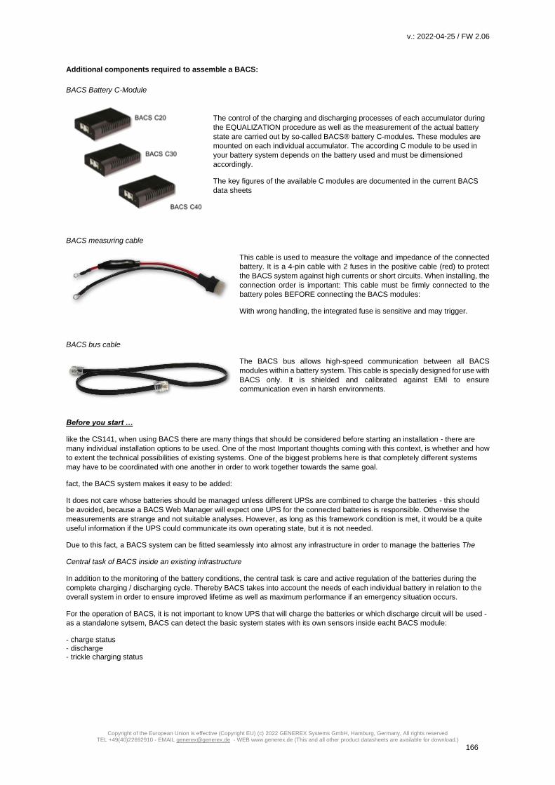
v.: 2022-04-25 / FW 2.06
Copyright of the European Union is effective (Copyright EU) (c) 2022 GENEREX Systems GmbH, Hamburg, Germany, All rights reserved TEL +49(40)22692910 - EMAIL [email protected] - WEB www.generex.de (This and all other product datasheets are available for download.)
166
Additional components required to assemble a BACS:
BACS Battery C-Module
The control of the charging and discharging processes of each accumulator during
the EQUALIZATION procedure as well as the measurement of the actual battery
state are carried out by so-called BACS® battery C-modules. These modules are
mounted on each individual accumulator. The according C module to be used in
your battery system depends on the battery used and must be dimensioned
accordingly.
The key figures of the available C modules are documented in the current BACS
data sheets
BACS measuring cable
This cable is used to measure the voltage and impedance of the connected
battery. It is a 4-pin cable with 2 fuses in the positive cable (red) to protect
the BACS system against high currents or short circuits. When installing, the
connection order is important: This cable must be firmly connected to the
battery poles BEFORE connecting the BACS modules:
With wrong handling, the integrated fuse is sensitive and may trigger.
BACS bus cable
The BACS bus allows high-speed communication between all BACS
modules within a battery system. This cable is specially designed for use with
BACS only. It is shielded and calibrated against EMI to ensure
communication even in harsh environments.
Before you start …
like the CS141, when using BACS there are many things that should be considered before starting an installation - there are
many individual installation options to be used. One of the most Important thoughts coming with this context, is whether and how
to extent the technical possibilities of existing systems. One of the biggest problems here is that completely different systems
may have to be coordinated with one another in order to work together towards the same goal.
fact, the BACS system makes it easy to be added:
It does not care whose batteries should be managed unless different UPSs are combined to charge the batteries - this should
be avoided, because a BACS Web Manager will expect one UPS for the connected batteries is responsible. Otherwise the
measurements are strange and not suitable analyses. However, as long as this framework condition is met, it would be a quite
useful information if the UPS could communicate its own operating state, but it is not needed.
Due to this fact, a BACS system can be fitted seamlessly into almost any infrastructure in order to manage the batteries The
Central task of BACS inside an existing infrastructure
In addition to the monitoring of the battery conditions, the central task is care and active regulation of the batteries during the
complete charging / discharging cycle. Thereby BACS takes into account the needs of each individual battery in relation to the
overall system in order to ensure improved lifetime as well as maximum performance if an emergency situation occurs.
For the operation of BACS, it is not important to know UPS that will charge the batteries or which discharge circuit will be used -
as a standalone sytsem, BACS can detect the basic system states with its own sensors inside eacht BACS module:
- charge status - discharge - trickle charging status

v.: 2022-04-25 / FW 2.06
Copyright of the European Union is effective (Copyright EU) (c) 2022 GENEREX Systems GmbH, Hamburg, Germany, All rights reserved TEL +49(40)22692910 - EMAIL [email protected] - WEB www.generex.de (This and all other product datasheets are available for download.)
167
The following installation examples may give you an insight overview about installation possibilities:
Installation example 1: BACS as a stanalone system
BACS is not able to get system states from the UPS and is limited to the core tasek of monitoring connected batteries and
regulating charging cycles. The sensors of the BACS modules, which are individually connected to each battery, can detect
charging / discharging cycles and provide the necessary data for the control to the BACS.If individual batteries with deviations
become noticeable, the BACS Web Manager can automatically inform about this battery condition before a dangerous incident
occurs. The disadvantage is that the general UPS functions and system status are not available:
BACS can detect that the batteries are discharging but fails to inform about the reason, why this happens.

v.: 2022-04-25 / FW 2.06
Copyright of the European Union is effective (Copyright EU) (c) 2022 GENEREX Systems GmbH, Hamburg, Germany, All rights reserved TEL +49(40)22692910 - EMAIL [email protected] - WEB www.generex.de (This and all other product datasheets are available for download.)
168
Installation example 2 – the complete solution: BACS is connected tot he UPS via RS232
The BACS Webmanager budget is connected to the UPS via the RS232 interface. The BACS modules are supervised by the
BACS Webmanager budget. With this solution all options of BACS and the CS141 are available:
- Extended UPS management
- Freely configurable emergency behavior
- Connection of external sensors
- Emergency server shutdown management
- External Input / Output management
While the UPS monitoring is fully featured, the BACS Wemanager can handle complex jobs according to system events to
protect the entire IT infrastructure, the integrated BACS system protects the batteries from dangerous charging currents to
ensure a reliable and solid emergency power supply.
The BACS Webmanager budget is an all-in-one solution for your entire network.

v.: 2022-04-25 / FW 2.06
Copyright of the European Union is effective (Copyright EU) (c) 2022 GENEREX Systems GmbH, Hamburg, Germany, All rights reserved TEL +49(40)22692910 - EMAIL [email protected] - WEB www.generex.de (This and all other product datasheets are available for download.)
169
Installation example 3: A modular solution that grows with your IT infrastructure
The modular BACS solution provides more than just installable in case of realigning by installing a new UPS controlled
emergency power solution. The modular version can be installed as a UPS manager, and than grows with the tasks even to a
fully featured BACS system that always fits to your UPS. As the modular installation example shows, a BACS bus converter is
set between the BACS modules and the CS141 and activate the according COM Port inside the CS141. The CS141 will start
the BACS capability and provie all menues of a full-fledged BACS System.
The BACS Bus Converter is needed to establish a communication between CS141 and BACS modules. The peculiarity here is
that you can "reuse" already purchased parts, which minimizes the acquisition costs for a full-fledged BACS system.
The existing UPS configuration with the alarm behavior will be enhanced by battery monitoring and management capabilities.
It is up to you to decide …
If you prefer the the CS141as a slot card or as an external box - once the CS141 provides the AUX interface, it can be upgraded
to a BACS system.
With BACS, you can plan your emergency power solution and adapt it to future trends as required.

v.: 2022-04-25 / FW 2.06
Copyright of the European Union is effective (Copyright EU) (c) 2022 GENEREX Systems GmbH, Hamburg, Germany, All rights reserved TEL +49(40)22692910 - EMAIL [email protected] - WEB www.generex.de (This and all other product datasheets are available for download.)
170
Installation example 4: The LAN SNMP solution – if you need UPS information without a direct connection
If you have read the CS141 manual, you will notice this feature at the latest at this point:
Unfortunately, some UPS models are not compatible with the CS141. Causes are, for example, that the interfaces do not exist
or are otherwise occupied, existing slots of the UPS have a different design or simply the manufacturer wants to use their own
system cards. If your UPS uses its own SNMP card or a similar solution, you can use the UPS settings in the BACS Web
Manager to query the signals via SNMP and manage all UPS functions based on this data - each CS141-based model provides
this feature.
Since BACS can use this UPS information as "Discharge Detection", this data is not only interesting for general monitoring, but
also a reliable means to detect the current UPS state:
All you need to do is:
- Open UPS configuration dialog
- Select RFC 1628 smart interface as UPS model
- Enter IP address of the target SNMP card
- Enter SNMP v1 / 2 / 3 credentials
- Configure an according SNMP user at the target card.
The SNMP card will be queried by the CS141 / BACS Webmanager budget and presented at the UPS monitoring screen.
Note
Yes, this feature can be used with the predecessor CS121 or an existing CS141 that is already installed but does not provide an
AUX port, too – if the BACS Webmanager cannot be fittet directly to the UPS, you may use this powerfull feature to adapt the
BACS Webmanager fitting to your existing UPS solution.

v.: 2022-04-25 / FW 2.06
Copyright of the European Union is effective (Copyright EU) (c) 2022 GENEREX Systems GmbH, Hamburg, Germany, All rights reserved TEL +49(40)22692910 - EMAIL [email protected] - WEB www.generex.de (This and all other product datasheets are available for download.)
171
The BACS Bus topology
As well-known from network technology, there are always different ways to connect nodes and devices with each other. You need to choose the best solutioin for the according task and take care not to connect all nodes in a way to set up a network short ciruit... When connecting BACS modules, there less things to be obeyed - the wiring of the BACS modules follows two simple rules: Rule 1: Each ID can only be assigned once One single Strain: On delivery, BACS module and BACS sensors use the basic ID 0. When the BACS Web Manager calls the address 0, all modules are addressed. During initialization via BACS Programmer, the individual BACS modules receive a single unique ID. This ID is once inside this BACS installation. The module installation order does not follow the according row of address ID's: After initialization, the BACS Web Manager queries individual addresses and the addressed module will respond accordingly. Two or more stains: Inside the strain, the ID’s hast o be sorted by a specific order. Between different strains, the pool of numbers must be sorted: Strain 1: Module-ID 1 – 10 Strain 2: Module-ID 11 – 20 Strain 3: Module-ID 21 – 30 Never mix ID module pools between strains! Rule 2: Obeye the maximum cable length The better the signal, the more stable the entire BACS system will finally work
Rule 3: Obeye magnetic interferences
Any live wire produces a magnetic field that affects other metallic objects and conductors. Although the BACS cables are
specially shielded against magnetic influences, the installation site can strongly take effect to the quality of the data signal. If you
have a lot of interference, test for these magnetic interferences.
Connection examples
in genereal, BACS does not tell you how to connect all modules each other - a structured wirinig method will help you to do
maintenance work as well as finding problems during installation. Furthermore, well-structured connection methods will help to
improve reliability when operated. Due to this fact, there are some hints you should need to before wiring. Both, the BACS Bus
Converter as well as the BACS Webmanager Budget provide two ports for a BACS bus. The possibility to select the appropriate
installation type allows different setup scenarios
1. The classic ring topology:
The advantage in the ring topology is the extremely high reliability. The BACS modules can be reached by the manager via two
different directions. Should one cable fail, there is a second redundant connection that can compensate for this.

v.: 2022-04-25 / FW 2.06
Copyright of the European Union is effective (Copyright EU) (c) 2022 GENEREX Systems GmbH, Hamburg, Germany, All rights reserved TEL +49(40)22692910 - EMAIL [email protected] - WEB www.generex.de (This and all other product datasheets are available for download.)
172
Note:
Special feature of ring structures in connection with changing magnetic fields and electromagnetically interfacing pulses
In this manual, you will often be informed about the advantages of a ring structure. Generally speaking, the advantages are
obvious, because with a ring structure, each module always has two uplinks to the BACS Web Manager and can therefore be
reached redundantly.
But as always, there is a disadvantage, too: Electromagnetic Interference (EMI):
In this case, this topology can prove to be counterproductive, because a ring in particular, despite all shielding, is simply a very
good antenna for the reception of electromagnetic waves. Due to the nature of a ring topology, electromagnetc pulses may
create sporadic interference pulses within the BACS Bus cables that may build up over time until the pulses interfere with the
BACS Bus data signal. Unfortunately, it is difficult to predict when this will happen, as there are many spatial, natural and
technical influences (usage behavior, position of the cables, interference pulses from the chargers but also consumers or even
natural influences such as rock formations in underground vaults, ...).
If you encounter such problems, it is recommended to drop the ring topology and use simple bus cabling instead.
2. The classic star cabling:
With this topology, the bus cabling runs in different directions from a central point. it advantage is the more flexible design of the
wiring and the resulting usability of premises.
Since you are not bound by certain conventions, the batteries can be arranged flexible and adapted to the environment:
Each single strain may use the maximum available length.
Due to the fact, a star uses a single line connection type, a cable problem will lead into connection lost alerts.
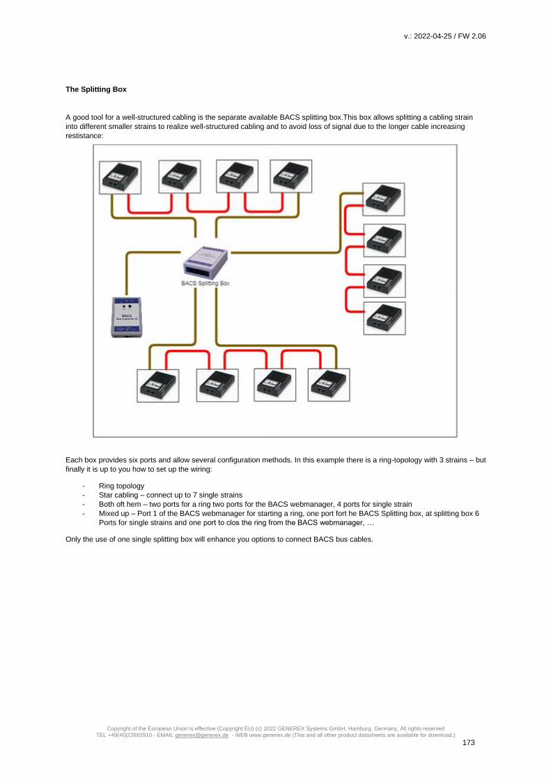
v.: 2022-04-25 / FW 2.06
Copyright of the European Union is effective (Copyright EU) (c) 2022 GENEREX Systems GmbH, Hamburg, Germany, All rights reserved TEL +49(40)22692910 - EMAIL [email protected] - WEB www.generex.de (This and all other product datasheets are available for download.)
173
The Splitting Box
A good tool for a well-structured cabling is the separate available BACS splitting box.This box allows splitting a cabling strain
into different smaller strains to realize well-structured cabling and to avoid loss of signal due to the longer cable increasing
restistance:
Each box provides six ports and allow several configuration methods. In this example there is a ring-topology with 3 strains – but
finally it is up to you how to set up the wiring:
- Ring topology
- Star cabling – connect up to 7 single strains
- Both oft hem – two ports for a ring two ports for the BACS webmanager, 4 ports for single strain
- Mixed up – Port 1 of the BACS webmanager for starting a ring, one port fort he BACS Splitting box, at splitting box 6
Ports for single strains and one port to clos the ring from the BACS webmanager, …
Only the use of one single splitting box will enhance you options to connect BACS bus cables.

v.: 2022-04-25 / FW 2.06
Copyright of the European Union is effective (Copyright EU) (c) 2022 GENEREX Systems GmbH, Hamburg, Germany, All rights reserved TEL +49(40)22692910 - EMAIL [email protected] - WEB www.generex.de (This and all other product datasheets are available for download.)
174
How to use more than one BACS Splitting Box (and the reality of electromagnetic interferences)
The BACS splitting box is a flexible device. With this device, it is possible to:
- Create partial redundancies
- Create partial ring cabling
- Create ring cabling with different splitting boxes
This flexibility allows technicians to be structured as well as flexible about the locations and technicalities of a BACS installation
to maximize reliability:
Example: The diagram shows a combined BACS Bus wiring
The drawing represents a wiring plan, oriented to fit to spatial local possibilities. On a close look, the diagram comes with both, a
simple bus wiring and a ring topology:
The ring starts at the BACS Splitting Box 1 and goes to first from BACS Module No. 5. From there, the ring wiring proceeds its
way via module 6 7 and 8 to the Splitting Box 2, which in turn is directly connected to the Splitting Box 1. By following the wiring,
a small ring is formed up.
Why someone chosed the central ring within the BACS Bus:
Even in case of a broken data cable between the direct connection of Splitting Box 1 and 2, the BACS bus shall continue to run
via Module 8.
Practice, however, put a spanner in how the idea works:
Since the ring topology acts like a perfect antenna, EMI - electro magnetic interference radiation -from a UPS or any high
voltage lines may be accidentally received and therefore form up interferences on the BACS bus over time. Finally, the ring
topology will lead into a sporadic disturbed BACS bus. In this scenario, the BACS bus cable between module 5 and 6 must be
removed to eliminate the interference, because a ring line would be counterproductive.
Note:
The BACS Webmanager is the central monitoring and management device. The BACS bus is designed to ultimately avoid
network short circuits and to provide any number of redundancies. Nevertheless, structured cabling is recommended to ensure
the transparent traceability of an installation
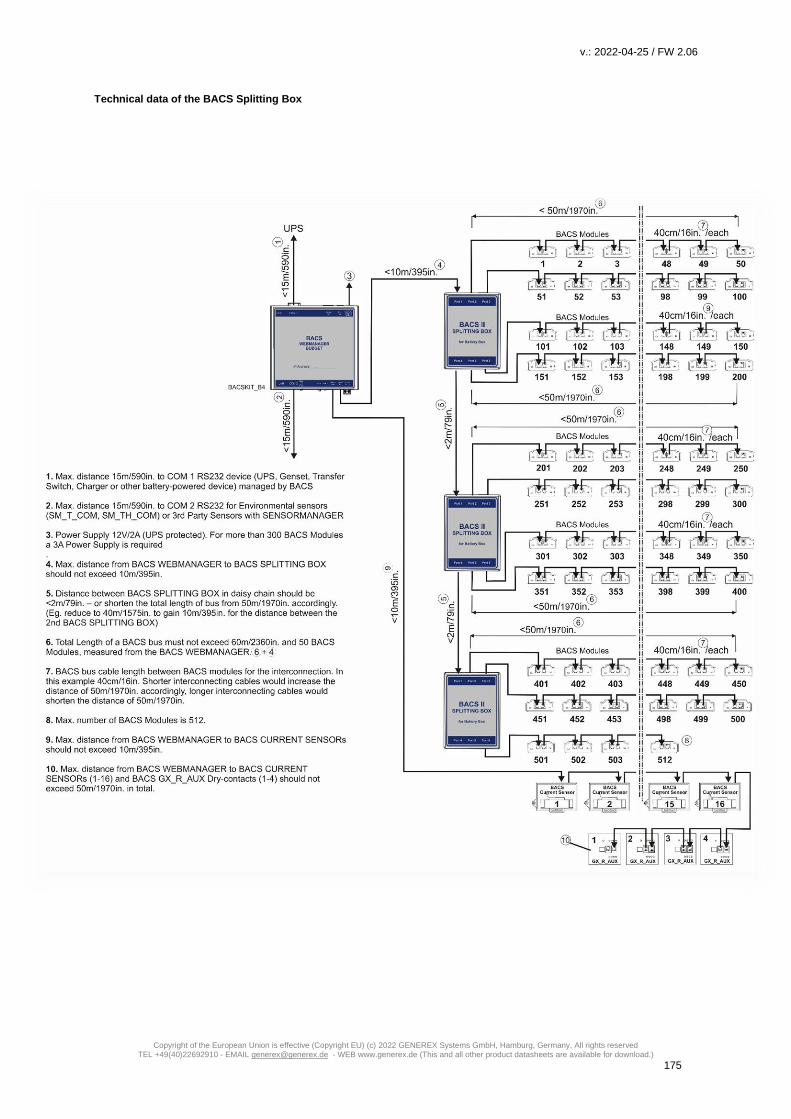
v.: 2022-04-25 / FW 2.06
Copyright of the European Union is effective (Copyright EU) (c) 2022 GENEREX Systems GmbH, Hamburg, Germany, All rights reserved TEL +49(40)22692910 - EMAIL [email protected] - WEB www.generex.de (This and all other product datasheets are available for download.)
175
Technical data of the BACS Splitting Box

v.: 2022-04-25 / FW 2.06
Copyright of the European Union is effective (Copyright EU) (c) 2022 GENEREX Systems GmbH, Hamburg, Germany, All rights reserved TEL +49(40)22692910 - EMAIL [email protected] - WEB www.generex.de (This and all other product datasheets are available for download.)
176
BACS – Installation with 2 or more BACS Webmanagers
The number of batteries a single BACS installation supports is limited to 500 batteries. If more than 500 batteries are in use,
BACS supports the installation and coordination of several BACS webmanagers. In this installation example, two BACS systems
were coordinated with each other to jointly manage a large battery field.
Following this installation method, there are two basic things you need to consider:
1- Each BACS Bus has to be run with it’s own BACS Webmanager
Two BACS web managers are not allowed to to address and gover the same BACS modules - they would interfere
with each other. If you have more than one BACS Web Manager in use, make sure that each BACS network forms a
closed system for itself. The BACS bus itself will not work with an uplink to two different BACS Webmanager.
2- All Batteries inside a BACS installation hast o be charged / used by the same UPS
As soon as the batteries of different UPS systems are charged and discharged, they are completely independent UPS
systems. It would be an invalid battery condition if e.g. A UPS indicates a discharge state, but the monitored battery is
actually charging because it belongs to a completely different UPS with it's own circuit.
In this example one UPS loads all batteries. To unleash the full regulation power of BACS, BACS 1 is connected to the UPS via
RS232 cable while BACS 2 receives UPS data from BACS 1 by LAN via the RFC 1628 smart UPS interface. By doing so, a
numerous redundant reactions and very complex configuration options are possible to think about.
Note
Each BACS Web Manager is also a complete system for UPS and building monitoring. Since an emergency can be more than
just a power outage, you can control all installations like lifts, access control, lights, lifts, etc... A CS141 based system can
perform emergency management of an entire IT network, co-ordinate communication with parent and child systems, and much
more.
With each additional web manager that joins your network, connectivity, control, and monitoring will be increased.

v.: 2022-04-25 / FW 2.06
Copyright of the European Union is effective (Copyright EU) (c) 2022 GENEREX Systems GmbH, Hamburg, Germany, All rights reserved TEL +49(40)22692910 - EMAIL [email protected] - WEB www.generex.de (This and all other product datasheets are available for download.)
177
BACS – Installation bei einer USV mit Mittelabgriff
Modern UPS systems use a center tap, which increases the efficiency of the entire system.
Since the two battery strings are arranged symmetrically, problems with the batteries can be recognized, among other things, by
the fact that the voltage difference in the center tap is ideally 0.0 volts.
So überwacht BACS die Strangspannung bei Mittelabgriff
While the UPS usually does not notice at this ealry point that a general problem could be present, BACS can not only determine
what caused the imbalance on the basis of the individual consideration of each individual battery, but also warn in good time
before all the batteries start charging due to incorrect charging behavior UPS can be affected:
BACS actively intervenes in the charging process and regulates each battery individually, so that the ideal condition of 0.0 volts
can almost be achieved at the center tap.
The result of this is that the drift of the voltage is not just be displayed as a general phenomon, but also the reason be spotted
and investigated by evaluation of the current data situation.
Note:
When using BACS, each battery is looked after individually and any problems are reported - since the quality of the charging
current is checked regardless of the active control and the measurement results, monitoring the string voltage in a UPS with
center tap provides additional protection:
In case of doubt, conclusions can be drawn about the general system status of the UPS itself. Since the individual results can
be evaluated by using the professional analysis software BACS Viewer, all information about UPS and for each individual
battery is available.

v.: 2022-04-25 / FW 2.06
Copyright of the European Union is effective (Copyright EU) (c) 2022 GENEREX Systems GmbH, Hamburg, Germany, All rights reserved TEL +49(40)22692910 - EMAIL [email protected] - WEB www.generex.de (This and all other product datasheets are available for download.)
178
Preparing batteries
Before you can connect the BACS modules, the batteries must be prepared. In addition to the general safety guidelines for work
on live components and live cables, please note the following when handling the BACS power cables: Each BACS measuring
cables provides an own fuse, integrated in the positive pole of the cable.
As soon as faulty currents leave the tolerance range, these fuses trip in order to interrupt the contact between the BACS module
and the associated battery. By doing so, the BACS module will be protected from damage.
Please note, this fuse is not designed to be removed or repaired. The entire cable need to be changed during maintenance work
at the according battery:
Short circuits inside large battery systems are very dangerous depending on battery type, it can lead to explosive gases,
escaping high corrosive acids as well as acid gas. It may also lead into fire feeded by chemistry.
Never try to replace or repair the fuse!
During initial installation, please obeye following: Once load is connected to the BACS cable, current will inevitably flow when as soon as contact with the battery poles is
established. During installation work, an unnoticed repeated brief touching of the battery poles can may trigger fuse while
connecting to the battery. In some cases, the fuse will continue working for the moment but is permanently damaged and will
trigger short time later. For this reason, there is an installation row to be followed:
First connect the cables to the battery poles and then connect the BACS modules to the pre-coded connector. This will prevent
such an internal damage at the fuse.
Since battery connectors may vary depending on model and manufacturer, the basic connection procedure is always the same
procedure:
Connect the BACS measuring cables to the poles of the battery. Ensure not reversing the polarity of the cable, the fuse in the
measuring cable will be triggered immediately and the cable need to be exchanged:
Red cable: Positive pole of the battery
Black cable: Negative pole of the battery
When fitting measuring cables, keep in mind to grant enough space for the later installation of the BACS module:

v.: 2022-04-25 / FW 2.06
Copyright of the European Union is effective (Copyright EU) (c) 2022 GENEREX Systems GmbH, Hamburg, Germany, All rights reserved TEL +49(40)22692910 - EMAIL [email protected] - WEB www.generex.de (This and all other product datasheets are available for download.)
179
As the BACS module among other things provides a built-in temperature sensor the module must attached to the battery in
away that the internal sensor is placed ablut 1-4mm from the battery case. By doing so, the module will be able to measure the
air temperature close to the battery.
Connecting a BC5 measuring cable to terminal ports of batteries at 6V - 16V
When connecting the battery terminals, please observe the torque values specified by the manufacturer, as otherwise you may
damage both the battery and the terminals. Furthermore, please refer the manual of the battery model - depending on the
manufacturer, there may be design differences to the installation examples in this manual.
How to connect the BC4B test cables to 1.2V - 2V bipolar batteries
The BC4B measuring cable provides 4 connectors: two for the positive pole and two for the negative pole. When installing, pay
attention to the color coding as well as the correct connection. Wrong wiring will trigger the measruring cable build-in fuse - the
fuse cannot be repaired or replaced. To avoid damaging the battery as well as the measurement cable, use the torque ratings
tested by the according manufacturer.
How to connect the BC4B test leads to four-pin 1.2V - 2V batteries.
Some manufacturers use batteries with four contact points. Coming witg this design, two contact points are assigned to a
positive or negative pole. Since the BACS measuring cable provvide 4 connectors, they must be fitted accordingly to the battery.

v.: 2022-04-25 / FW 2.06
Copyright of the European Union is effective (Copyright EU) (c) 2022 GENEREX Systems GmbH, Hamburg, Germany, All rights reserved TEL +49(40)22692910 - EMAIL [email protected] - WEB www.generex.de (This and all other product datasheets are available for download.)
180
Mounting the BACS module at the battery
Please not the preconditions ….
- there is no dirt on the surface.
- The surface is free from fats, silicone or other coatings.
- The site is easily accessible for maintenance or subsequent service
- If possible, do not cover any valves or cooling fins
o In the case of sealed batteries, velcro tape can also be attached directly on it if there is no other way. An
AGM valves would in case of opening separate the velcro connection and the pressure escapes.
- For low maintenance batteries and wet cells, keep at least 10 cm distance to the vent pipe
Before installing the BACS modules, carefully read the installation and maintenance instructions for the corresponding battery.
Wiring the BACS module
The BACS cables are coded and standardized, an erroneous connection is normally not possible.
Connect the BACS bus cables to the modules:

v.: 2022-04-25 / FW 2.06
Copyright of the European Union is effective (Copyright EU) (c) 2022 GENEREX Systems GmbH, Hamburg, Germany, All rights reserved TEL +49(40)22692910 - EMAIL [email protected] - WEB www.generex.de (This and all other product datasheets are available for download.)
181
For larger cable lengths and installations, please take care for ...
- the maximum cable length including all modules must not exceed 50 m
- Do not install more than 50 modules per cable harness- If more than 50 batteries are in use, a plitting box is
mandatory to split the battery site into two different strangs.
- not exceeding the total number of 500 modules.
- installing the modules that the connection sockets are not live after connecting the cables.
- avoiding excess cable lengths
Note
keep an eye on logical cable sequences when connecting - BACS does not tell you how to connect all modules or in which
order you address the modules. For technical reasons, a network short circuit is not possible by placing rings within an
installation. Structured cabling and related documentation, however, facilitates system maintenance, especially when individual
modules need to be replaced within the installation.
Furthermore, if using a splitting box and set up several strings, a structured hardware configuration is mandatory to set up the
BACS configuration.
Tutorial: How to mount of BACS BC measuring cables to include monitoring of cell connectors
What is the function of the cell connector? Depending on the type, there are plugged, crimped or screwed transition elements between the individual batteries to connect batteries in series. Due to their function, these connecting elements represent critical areas within the battery system:
- Due to the series connection, the cell connectors pass on the charge and discharge current to the next cell, whereby very large currents can arise depending on the size of the system.
- They are firmly connected to the battery poles and therefore also absorb thermal energy from passing current as well
as the heat generated by the redox reactions within the battery. Both the poles of a battery and the screw connections and connecting elements between batteries are repeatedly exposed to mechanical and thermal loads. In this way, the thermal energy can also be transferred directly from one battery to the neighboring batteries. The connecting elements here are normally standardized components that can be neglected accordingly.
Why you should monitor the connecters between batteries? If failures occur during installation or maintenance, such as torque values not adhered to (incorrectly tightened, over-tightened, etc.) or the usasge of incorrectly dimensioned and damaged connecting elements, it can lead to system-critical failures and even a battery fire within a few minutes. If you now only monitor the battery itself in addition to the general charging current, a problem with the connecting elements between the batteries will not or can only be determined to a limited extent, e.g. due to unusual temperature developments or deviating charging currents, etc.

v.: 2022-04-25 / FW 2.06
Copyright of the European Union is effective (Copyright EU) (c) 2022 GENEREX Systems GmbH, Hamburg, Germany, All rights reserved TEL +49(40)22692910 - EMAIL [email protected] - WEB www.generex.de (This and all other product datasheets are available for download.)
182
While the temperature developments can still be localized, unclean currents are difficult to localize - it is difficult to narrow down exactly which element causes this loss. It may make sense in the highly critical system area to include the connection modules in the battery monitoring.
How to include the connectors between the batteries Clascally, the BACS-Module are installed as followed:
Jede Batterie wird hierbei von einem BACS-Modul betreut und entsprechend geregelt. Grundsätzlich reicht dieser Schutz aus, da ein Problem batteriebezogen auftritt. Dabei werden Neben dem Widerstand auch Innenwiderstand und Temperatur der Batterie gemessen. Sollte es zu einem Problem kommen, wird das entsprechende BACS-Modul diese aufspüren und der Webmanager entsprechend messen. Wenn die Verbindungselemente in die Messung einbezogen werden sollen, muss der Messpunkt für die BACS Messkabel entsprechend angepasst werden: Technisch betrachtet wird immer vom Pluspol einer Batterie zu dessen Minuspol gemessen. In de Reihenschaltung bedeutet dies, dass der der Pluspol der Folgebatterie vom Potentialgefälle her auch dem Minuspol der vorigen Batterie entsprechen muss:
At a serial connectino of
batteries, the netative
pole of a batteriy will be
connected with the
positive pole oft he next
battery.
At a serial connectino of batteries,
the positive pole of a batteriy will be
connected with the negative pole of
the previous battery.
Depending on the
measuring point, the
connector is included
or excluded.

v.: 2022-04-25 / FW 2.06
Copyright of the European Union is effective (Copyright EU) (c) 2022 GENEREX Systems GmbH, Hamburg, Germany, All rights reserved TEL +49(40)22692910 - EMAIL [email protected] - WEB www.generex.de (This and all other product datasheets are available for download.)
183
This results into the following structure:
Do values have to be adjusted in the web manager?
No, the BACS modules themselves always take care of one battery - the deviations that the connecting element generates
because more material that has to be measured are normally less important. In theory, you could change the existing BACS
installation at any time and integrate the cell connectors accordingly.
What can be achieved with this measurement setup - an idealized example system failure analysis Basically, this measurement method ensures that both the battery and the transition to the next battery are checked. In this way, if a current sensor in the string reports a deviating current flow, it is easy to spot the battery with the problem is to be sought for: With the internal rresistance measurement of the batteries, the connector is included: If the measured values reach questionable values, the corresponding module will work independently and make itself noticeable. Otherwise, the problem can be identified by evaluating the data situation:
The entire battery string provides strange fluctuations in the flow of electricity. In this example you can see an unusual internal resistance in BACS module 2. The problem can be narrowed down as followed: BACS-Modul 1 shows no problems: As a result, all screws on battery 1 must be properly tightened. The same applies to the input screw of battery 2, since the connector is measured via the BACS module 1. If this connector were loose, you would have to see it in the measurement results of BACS Module 1.
Measuring range
From positive pole of one
battery to the positive
pole of the next battery

v.: 2022-04-25 / FW 2.06
Copyright of the European Union is effective (Copyright EU) (c) 2022 GENEREX Systems GmbH, Hamburg, Germany, All rights reserved TEL +49(40)22692910 - EMAIL [email protected] - WEB www.generex.de (This and all other product datasheets are available for download.)
184
The same applies to BACS-Modul 3: The measurement extends from the positive pole to the positive pole of the subsequent battery (i.e. battery 4) - so the input screw of the connector coming from battery 2 must also be OK. BACS module 2 reports a strange internal resistance Likewise, there can be no problem with the incoming screw terminal from battery 3, since BACS module 3 monitors the incoming terminal from battery 3 and the incoming terminal from battery 4. There are only a few questions left:
a. Is the outgoing terminal of battery 2 was not attached properly? b. Is there a problem with the connector between battery 2 and battery 3 itself? c. Is the battery 2 itself has a defect?
If you want to be sure, you would now look at the temperature data of the 3 batteries and look for abnormalities: If battery 2 heats up quickly during discharge / charge cycles and is then transferred to battery 3, the fault is clearly with battery No. 2. However, if batteries 2 and 3 heat up evenly above average to the rest, the fault with the cell connector is possible - it heats up very quickly and transfers the heat to the batteries via the battery poles.
Note: Since the connectors are included into BACS, it is possible to general down times of the UPS and search for a problem - you know what you are looking for. If several batteries are affected, this method allows a strategic overview to plan the maintenance work.
Maintenance: Replacing / Repairing a single a BACS module
Part 1 – Replace a single module
This example describes a problem with BACS module 3 Since the module 3 comes with a ring wiring, the modules 2 and 4 are
still available and work properly. By comparison, if module 19 would fail, modules 17 and 18 would have been equally affected -
the connection design is not a ring structure.
However, in case of a failure, the BACS webmanager will report a problem at module 3
How to proceed First open the battery separator to avoid an electric shock, safe your work place and take enough time to obey
the security rules for working on live parts.
1. Identify the harmed BACS module
Locate the BACS module with the associated battery and remove the BACS data cable. It is important in this context
that the exact ID of the BACS module is known so that you do not accidentally replace the wrong module
2. Remove the BACS data and measurement cables
Remove the BACS data cable as well as the measurement cable Please note that the BACS measuring cables
installed on battery side do not need to be removed - the changed BACS module will be re-connected.
3. Install the spare BACS module
First, connect the single BACS module to the BACS Webmanager, Login and enable the BACS programmer. Read
out the current BACS module ID and than program it to “0”. That install the module withini your BACS system, connec
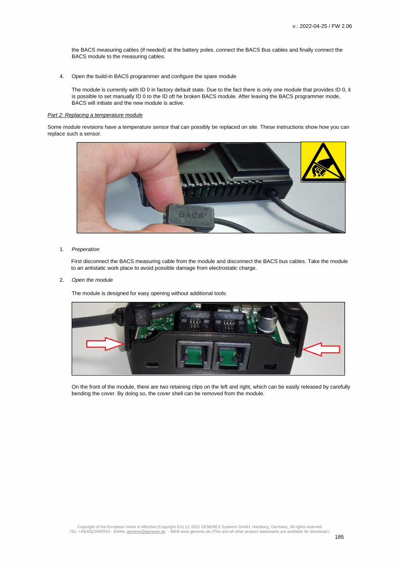
v.: 2022-04-25 / FW 2.06
Copyright of the European Union is effective (Copyright EU) (c) 2022 GENEREX Systems GmbH, Hamburg, Germany, All rights reserved TEL +49(40)22692910 - EMAIL [email protected] - WEB www.generex.de (This and all other product datasheets are available for download.)
185
the BACS measuring cables (if needed) at the battery poles, connect the BACS Bus cables and finally connect the
BACS module to the measuring cables.
4. Open the build-in BACS programmer and configure the spare module
The module is currently with ID 0 in factory default state. Due to the fact there is only one module that provides ID 0, it
is possible to set manually ID 0 to the ID oft he broken BACS module. After leaving the BACS programmer mode,
BACS will initiate and the new module is active.
Part 2: Replacing a temperature module
Some module revisions have a temperature sensor that can possibly be replaced on site. These instructions show how you can
replace such a sensor.
1. Preperation
First disconnect the BACS measuring cable from the module and disconnect the BACS bus cables. Take the module
to an antistatic work place to avoid possible damage from electrostatic charge.
2. Open the module
The module is designed for easy opening without additional tools:
On the front of the module, there are two retaining clips on the left and right, which can be easily released by carefully
bending the cover. By doing so, the cover shell can be removed from the module.

v.: 2022-04-25 / FW 2.06
Copyright of the European Union is effective (Copyright EU) (c) 2022 GENEREX Systems GmbH, Hamburg, Germany, All rights reserved TEL +49(40)22692910 - EMAIL [email protected] - WEB www.generex.de (This and all other product datasheets are available for download.)
186
3. Replacing the temperature sensor
Depending on the type of module, the installation place of the temperature sensor differs:
The internal sensor
The internal sensor is attached at the bottom of the of the housing:
Remove the module board to get access to the sensor. You can then remove the sensor from the shell with a slight
pressure from below. Insert the new sensor. Pay attention to the correct installation direction - in this special case the
sensor board can be assembled the wrong. If assembled correctly, the two clamps on the back of the module board
will press on the contact plates on the sensor board.
The external sensor
You do not need to remove the module board. Just remove the connector oft he sensor cable.
The connector is coded so that it only fits in one direction on the module. When carrying out the work, make sure that
the ESD guidelines are observed to prevent electrostatic discharge during assembly - these can damage electronic
components.
4. Re-assembling the module
Modules with the internal sensor
Place the rear retaining bracket into the module housing and snap the front retaining clips into place with slight
pressure.

v.: 2022-04-25 / FW 2.06
Copyright of the European Union is effective (Copyright EU) (c) 2022 GENEREX Systems GmbH, Hamburg, Germany, All rights reserved TEL +49(40)22692910 - EMAIL [email protected] - WEB www.generex.de (This and all other product datasheets are available for download.)
187
Modules with an external sensor
First place the strain relief at the corresponding recess in the upper module shell:
Then reassemble the module accordingly. Ensure when putting the two shells together, the cable of the external
sensor is behind the plastic web for the module screw to avoid damaging it when using a DIN rail:
Initial BACS Installation: Configuration of BACS
General battery data
Open the general battery configuration dialog and enter required battery data:
During installation and configuration process, you may choose between different procedures - Since each procedure comes with
its specific advantages and disadvantages:

v.: 2022-04-25 / FW 2.06
Copyright of the European Union is effective (Copyright EU) (c) 2022 GENEREX Systems GmbH, Hamburg, Germany, All rights reserved TEL +49(40)22692910 - EMAIL [email protected] - WEB www.generex.de (This and all other product datasheets are available for download.)
188
In this case, it is up to you to decied whether first configure the BACS modules and then set the number of batteries or first
configure the number of batteries and set up the ID of the BACS modules during installation.
How to find general battery data:
Since these data are mandatory for BACS module configuration, please refer the
data sheets of the batteries as well as the name plate attached to the batteries:
In this configuration example, the voltage is 12V with a capacity of 7Ah
Nominal Battery Voltage
Define the voltage each single battery provides. Please note that you may choose between different battery models as lon as
the voltage is identical:
it is not possible to combine different cell voltages!
Capacity per Battery
Enter the capacity of the batteries in ampere hours. Please note that manufacturers decide how to specify this value inside
datasheets. If necessary, convert the values beforehand. This value defines the level of Equalization:
According to the AH value, the BACS modules will be allowed to roll out a maximum Equalizing:
An AH value under 150AH will limit the provided Equalizing power to the size of such smaller batteries, beyond 150AH BACS
will use its full Equalizing power which is available for this module type.
Number of batteries
Define the total number of batteries within your BACS installation.
As an example, if you use 40 batteries inside your system, enter 40. Since each battery gets its own BACS module, The BACS
webmanager will search for a total of 40 BACS modules, starting with ID 1. The ID 0 is not allowed during normal operation.
Number of battery strings
Number of battery strings defines a logical assignment of the configured batteries in combination with built-up batteries. Among
other things, the number of strings is defined by the physical wiring of the batteries. As an example, 20 batteries may be
installed into one positive string and 20 into the according negative string. Such a middle point battery setup requires in BACS a
configuration as “2 strings“ since the charger handles the positive and
the negative string separately. Other installation types would be in
this case of 10 batteries in string 1, 10 batteries in string 2, etc.
Acccording to this context, it is important the physical wiring of the
batteries match the logical structure of the strings. The BACS system
uses the sequential numbering of the BACS modules during
initialization and divides them by the number of battery strings..
If arbitrarily connecting the BACS modules to the batteries and
activate BACS, BACS will logically initialize the BACS modules into a
string with IDs 1-10, followed by IDs 11-20, ...
Physically the BACS modules may form up a shredded string that is
logically correct. As a consequence, BACS would receive wrong
readings and possibly not even start: The strings will be displayed
separately in the BACS monitor and treated accordingly during
regulation.
When assigning the BACS modules, pay attention to the position or
numbering of the batteries in the battery compartment itself to match the logical assignment with the current installation: Ideally
battery no. 1 also received the BACS module with the number 1.

v.: 2022-04-25 / FW 2.06
Copyright of the European Union is effective (Copyright EU) (c) 2022 GENEREX Systems GmbH, Hamburg, Germany, All rights reserved TEL +49(40)22692910 - EMAIL [email protected] - WEB www.generex.de (This and all other product datasheets are available for download.)
189
Something more to take an eye on
For technical reasons, it is not possible to connect and manage an unlimited number of batteries to a single string. From 50
batteries onwards, we recommend to "split" the BACS bus, ie to define two different cable strings per definition in order to keep
the cable length as short as possible.
Note
With String Names it is possible to enter a freeform label for the battery string. you enter a name for up to 16 battery strings
before configuring the BACS modules. However, the number of strings will be define at Number of battery strings. that will be
shown. Entering a name does not automatically increase the number of battery strings.
Two Jars / Cells per module: The configuration NiCd based batteries differs
NiCd - based batteries use a cell voltage of 1.2 V - therefore, with this type of battery, 2 batteries will be managed by a single
BACS module.
Configuration
To handle NiCd correctly, BACS must be informed that in this case 2 batteries are be combined and will be managed by one
module. In order to avoid a configuration failure, this function can only be activated if the nominal battery voltage has been set to
2 volts.
At Devices>BACS>Setup, the according configuration menu can be found:
*) Since you have combined two batteries for measurement and management purposes, the number of batteries is twice as high
as the number of installed BACS modules. That's why you need to enter the number of batteries and not the number of BACS
modules.

v.: 2022-04-25 / FW 2.06
Copyright of the European Union is effective (Copyright EU) (c) 2022 GENEREX Systems GmbH, Hamburg, Germany, All rights reserved TEL +49(40)22692910 - EMAIL [email protected] - WEB www.generex.de (This and all other product datasheets are available for download.)
190
The BACS Monitoring Screen:
After initialization, BACS will not list the number of modules in use, but the number of batteries actually managed by the
modules.
Helpful information about the BACS system
Battery manufacturer and type
Enter the designation as free form text. If usefull, add some information about it's function or the intention of this battery system
or in special cases chemistry used for this battery room. If an incident occurs and rapid interaction is mandatory, this information
can increase the average response time. On the other hand, misleading or poorly documented terms can cost valuable time.
Battery installation date
The battery installation date indicates the date of initial battery installation. Since a system can be upgraded with BACS at any
time, it is important to be familiar with the difference of a battery installation date and the installation date of BACS.
You will usually find the battery installation date on the battery itself as "date of manufacture"
Contact person and phone contact
In case of maintenance work or incidents, responsible staff can be contacted to shorten response time.
Note
If wanted, BACS can send sen general contact information to a custom mail address and contact responsible staff directly.
However, your entry at contact phone cannot be used for automatic SMS notifications - An SMS modem or IP modem must be
configured separately.
BACS module basic setting
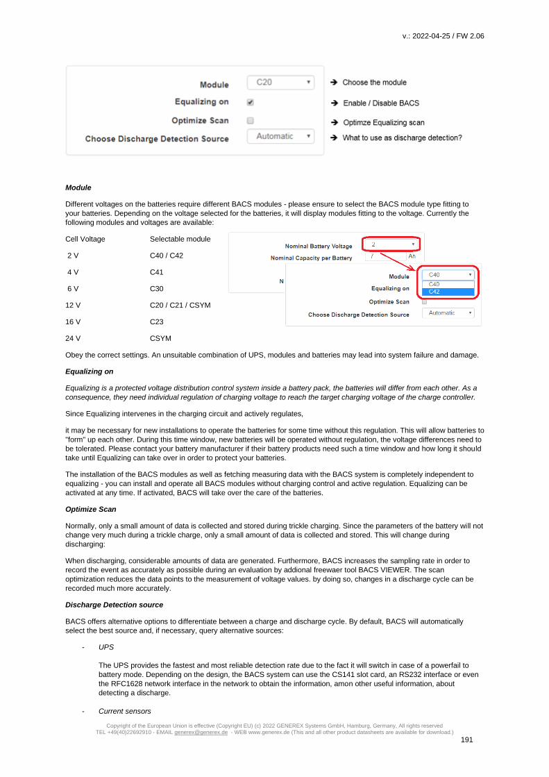
v.: 2022-04-25 / FW 2.06
Copyright of the European Union is effective (Copyright EU) (c) 2022 GENEREX Systems GmbH, Hamburg, Germany, All rights reserved TEL +49(40)22692910 - EMAIL [email protected] - WEB www.generex.de (This and all other product datasheets are available for download.)
191
Module
Different voltages on the batteries require different BACS modules - please ensure to select the BACS module type fitting to
your batteries. Depending on the voltage selected for the batteries, it will display modules fitting to the voltage. Currently the
following modules and voltages are available:
Cell Voltage Selectable module
2 V C40 / C42
4 V C41
6 V C30
12 V C20 / C21 / CSYM
16 V C23
24 V CSYM
Obey the correct settings. An unsuitable combination of UPS, modules and batteries may lead into system failure and damage.
Equalizing on
Equalizing is a protected voltage distribution control system inside a battery pack, the batteries will differ from each other. As a
consequence, they need individual regulation of charging voltage to reach the target charging voltage of the charge controller.
Since Equalizing intervenes in the charging circuit and actively regulates,
it may be necessary for new installations to operate the batteries for some time without this regulation. This will allow batteries to
"form" up each other. During this time window, new batteries will be operated without regulation, the voltage differences need to
be tolerated. Please contact your battery manufacturer if their battery products need such a time window and how long it should
take until Equalizing can take over in order to protect your batteries.
The installation of the BACS modules as well as fetching measuring data with the BACS system is completely independent to
equalizing - you can install and operate all BACS modules without charging control and active regulation. Equalizing can be
activated at any time. If activated, BACS will take over the care of the batteries.
Optimize Scan
Normally, only a small amount of data is collected and stored during trickle charging. Since the parameters of the battery will not
change very much during a trickle charge, only a small amount of data is collected and stored. This will change during
discharging:
When discharging, considerable amounts of data are generated. Furthermore, BACS increases the sampling rate in order to
record the event as accurately as possible during an evaluation by addional freewaer tool BACS VIEWER. The scan
optimization reduces the data points to the measurement of voltage values. by doing so, changes in a discharge cycle can be
recorded much more accurately.
Discharge Detection source
BACS offers alternative options to differentiate between a charge and discharge cycle. By default, BACS will automatically
select the best source and, if necessary, query alternative sources:
- UPS
The UPS provides the fastest and most reliable detection rate due to the fact it will switch in case of a powerfail to
battery mode. Depending on the design, the BACS system can use the CS141 slot card, an RS232 interface or even
the RFC1628 network interface in the network to obtain the information, amon other useful information, about
detecting a discharge.
- Current sensors

v.: 2022-04-25 / FW 2.06
Copyright of the European Union is effective (Copyright EU) (c) 2022 GENEREX Systems GmbH, Hamburg, Germany, All rights reserved TEL +49(40)22692910 - EMAIL [email protected] - WEB www.generex.de (This and all other product datasheets are available for download.)
192
The direction of the magnetic field induced by current flow is a probate method to figure out if the batteries are
currently in state charge, trickle charge or discharging. Although the detection rate is slower than querying the UPS.
Current sensors provide additional measurements of the quality of the discharge current. The current sensor selection
would be the best detection source if a UPS state qwery is impossible.
- BACS sensors
The BACS sensors can also perform a discharge detection:
The modules measure the battery voltages - from the moment the voltage drops below the rated voltage, BACS will
assume a discharge is in progress. Since the batteries take a while to fall from the trickle charge to the rated voltage
and stay there for a while before dropping below this value, it is a reliable but very slow option to figure out if a
discharge is in progress.
Normally, this detection source is selected if neither UPS nor current sensors are available.
Note
A rechargeable battery needs some time to fall from trickle charge values to it's rated voltage. This natural process can be
misinterpreted as "discharge". For this reason, a battery monitoring or management system needs the ability to differ between
this natural process and a battery discharge:
BACS can do this job and will increase the detection and logging rate only if a real discharge is confirmed.
To improve detection rate, additional current sensors are recommended- if BACS detects a voltage loss as well as current flow,
the discharge status is confimed.
Offset values
BACS modules are calibrated on delivery and will give an exact value related to the calibration. However, the BACS system can
not know the general installation location and it may be possible that the calibrated measurement results differ from external
reference measurements due to the installation site. Air pressure, humidity, ambient temperature and other environmental
variables can distort the values collected by BACS:
The calibrated values need to be corrected if necessary.
With the offset values, it is possible to enter correction values coinciding with measurements at the installation location.
Impedance Measurement Interval
Due to the nature of their function, batteries are subjected by a partial hidden aging process - a gradual process that cannot
normally be observed unless continous measurement data on the internal resistance are available by chance. For reliable trend
detection, it is therefore important to regularly measure the internal resistance of the batteries:
These data logs can be used to identify the real internal age of a battery and thus the probability of a total failure.
Since it is possible to compare all BACS-supported batteries directly with one another using the professional BACS Viewer
software, it is possible to identify an unusual increase in impedance and take appropriate countermeasures.
As a default, BACS will automatically take the first measurement at 8 a.m. after initialization or a restart and then repeat every
12 hours. However, you can adapt the start time and repetition intervals to suit your service plan.
Current Sensor

v.: 2022-04-25 / FW 2.06
Copyright of the European Union is effective (Copyright EU) (c) 2022 GENEREX Systems GmbH, Hamburg, Germany, All rights reserved TEL +49(40)22692910 - EMAIL [email protected] - WEB www.generex.de (This and all other product datasheets are available for download.)
193
Each BACS module already provides its own charge / discharge detection.
The detection by the BACS modules arises from the need for batteries to generally have a slight discharge curve and lose their
charge over time.
However, this charge / discharge detection is realized by voltage measurements of the cell. If the voltage drops below a rated
voltage, BACS assumes a discharge is in progress. What the BACS module does not measure is the current flowing through the
individual strings during a battery discharge cycle.
In addition to the charge / discharge detection, the current sensor can also be used to check whether the currents are divided
equally between the parallel battery strings as well as the average quality and stability of the current.
Installing the current sensor
If you want to use a BACS Current Sensor, enable the BACS
CS Current Sensor Connected:
By default, the BACS Web Manager searches for one current
sensor per battery string - the number of BACS strings will
reflect the number of sensors that need to be found. At BACS
monitor, the result will displayed below the according string.
Premium feature: Only One Current Sensor for All Strings
Usually each battery string get its own current sensor to get information about real current flow on all strings. In some cases it is
desirable by customers to use only one current sensor for a general charge / discharge detection. By doing so, BACS need to
know that only one current sensor is installed:
Enable "Only One Current Sensor for All Strings" and press apply to restart BACS.
After restarting BACS, only one sensor will be automatically displayed. If the current senser is installed on a string, the ampere
multiplier value will get approximate overall current value.
Premium feature: Ampere Multiplier – how it works
The ampere multiplier multiplies the measured current by a theoretical factor in order to draw conclusions about the entire
system. The multiplier value to be entered depends two factors:
1. There are several strings in the BACS system - the number of strings determines the multiplier.
2. For various reasons only one current sensor is available
The multiplier can be used this way:
Main string: The current sensor mearusres mail current value = 1
Single string: The current sensor measures the partial current oft he string value = Number of strings
Since the measurements are not very exact In the end, this solution serves only the more accurate charge / discharge detection.
It is not designed to determine more information than an exact charge/discharge detection as well as basic information about
estimated current flow.

v.: 2022-04-25 / FW 2.06
Copyright of the European Union is effective (Copyright EU) (c) 2022 GENEREX Systems GmbH, Hamburg, Germany, All rights reserved TEL +49(40)22692910 - EMAIL [email protected] - WEB www.generex.de (This and all other product datasheets are available for download.)
194
Note
You will get the best results with a combination of current sensors inside each individual BACS string as well as using the
sensors coming with BACS modules. By doing so, more data can be collected and analyzed:
- General voltage - Internal resistance of the batteries - temperature of the batteries - quality and uniformity of the discharge current itself However, BACS offers you different graduated possibilities for discharge detections:
1. UPS status
The UPS knows the current charge or discharge status and will provide this information for the BACS Webmanager.
To choose this option, the BACS Web Manager must be connected to the UPS. Depending on the BACS design, you
can choose between a single device or a modular solution. Even the combination CS141 slot card with BACS BUS
Converter can be used.
In other cases the connection is possible via the RS232 interface. If you use a UPS with SNMP access, it is also
possible to configure an access via the RFC1628 interface and query the data directly via LAN. Current sensors
provide additional current quality detection
2. If no communication to the UPS is possible, you can get accurate information via the current sensors and the BACS
modules.
a. Charge-/Discharge detection
b. Accurate readings on consistent charge and discharge cycles as well as quality and fluctuations of the
current.
In this setup, the BACS modules provide voltage values across the batteries and the current sensors provide values
about the current that actually flows per string.
3. If, for logistical reasons, you can only use one current sensor, it will in principle provide an exact charging and
discharging detection source. But with one current sensor, it is just possible to provides a theoretical overview of the
quality of the current that will flow during charge- / discharge processes.
Obey that the current sensors can be used either on the main line before splitting into single strings or inside a single
string after splitting.
a. The main string
At the main string, the total current is measured. You will recognize a very accurate charge / discharge
detection as well as information about internal fluctuation in the current flow, but you will not be able to get
informationes about the strings that may trigger current flow problems.
b. At the single string
Like a main string installation type, you will find a very accurate charge/discharge detection. The difference
is, that the single string installation will measure the real current at this trand the current sensor is installed
to. You can use the multiplier to approximate the value to reality, but it remains as some kind of rough
estimate. What you can see accurate:
If the value for current drops, the problem has to be found in the string where the sensor is installed to. On
the other hand, if the value increases dramatically, there is a problem in one of the other strings.
Technically, a more exact limitation feasible in this constellation is not possible and the accuracy depends
on the number of strings you have installed - With two strings, it is easy to figure out which string causes
trouble. With three strings, two strings you have possible candidates...
4. You can also completely dispense the connection of a UPS as well as the use of current sensor. The charge /
discharge detection can be fully mapped by the BACS modules. The modules measure the internal resistance and the
voltage of the batteries they are installed on. The modules can measure if a charge cycle or discharge cycle is in
progress. But it will need some time. This possibility, however, ignores the current that will flow during charging and
discharging.

v.: 2022-04-25 / FW 2.06
Copyright of the European Union is effective (Copyright EU) (c) 2022 GENEREX Systems GmbH, Hamburg, Germany, All rights reserved TEL +49(40)22692910 - EMAIL [email protected] - WEB www.generex.de (This and all other product datasheets are available for download.)
195
Reverse Current Direction
The current sensor measures the induced magnetic field coming with directed electron migration through a conductor. Due to
the fact the current sensor can measure bi-directional, the installation direction is crucial:
The magnetic field of this directed electron motion provides information about the direction of electron migration.
With this function, the real magnetic field recognition can be inverted - thus will place charge and discharge recognition into a
correct context. If the current sensor has been installed incorrectly, this function can be used to reverse the current direction and
the sensor can remain in this installation direction.
Thresholds for current sensor discharge detection
The direction of current flow indicates whether the batteries are charging or discharging. In principle, you need to differ between
three charging or discharging states:
1. Discharging
The batteries discharge while granting emergency power.
2. Charging
If batteries drop below a certain voltage level, they must be charged. This battery state can be reached via a natural
discharge process over time or in case of emergency power usage. The charging process is always initiated and
terminated by the UPS / Charger. By "Equalizing", BACS distributes the existing charging current and voltages - Each
battery charge is considered individually to ensure the optimal charging.
3. Trickle charging
Batteries tend to self-discharge over time. This process can not be prevented, but slowed down by proper storage.
The trickle charge hereby serves to maintain the current state of charge. Normally, a trickle charging will not be
displayed.
Depending on the charging behavior of a UPS, certain currents always flow within a system. Due to this fact, it cannot generally
be assumed that a current flow is automatically a charge / discharge cycle. Since only two of the possible states are important
for the current sensor to detect a charge or discharge cycle, it is necessary to define a fixed point at the current intensity for a
charge/discharge cicle.
With the "Thresholds", the values can be adapted to the environment that a clear charge or discharge cycle can be assumed.
The negative sign defines the discharge cicle and the positive sign the charge cicle.

v.: 2022-04-25 / FW 2.06
Copyright of the European Union is effective (Copyright EU) (c) 2022 GENEREX Systems GmbH, Hamburg, Germany, All rights reserved TEL +49(40)22692910 - EMAIL [email protected] - WEB www.generex.de (This and all other product datasheets are available for download.)
196
How to configure the BACS modules
Addressing BACS modules: The BACS programmer
The BACS modules can be configured by using the WINDOWS program BACS PROGRAMMER or via the web interface in the CS141 / BACS WEBMANAGER. To use the BACS programmer in the web interface, navigate to the following menu:
To install, configure, or remove new BACS modules, the BACS system must be put into standby for this time window. First set
the Programmer Input Capability to "On":
Please note that the button generally describes the state that is currently available. While the Programmer is active, BACS
pauses – the current system state can be seen at the top status bar oft he Webmanager:
The top bar shows that the BACS Programmer is now
active and normal BACS operation is paused.
The top bar shows that BACS has started and is in regular
operation and the BACS programmer is off.
Two conditions will disable the BACS programmer and enable regular BACS functions:
1. Cold start or reboot
During a cold start, the device is de-energized briefly and then reboots. A reboot will be adviced ba an administrator
via tools or directly via the web browser reboot command. In both cases, the default startup setting will start without a
the BACS programmer set to on.
2. Enable or disable manually
The BACS Programmer does not have an automatic activation function - it is started manually by an authorized user
and must be terminated accordingly. If you log off as an administrator from the system, the BACS Programmer
remains active, even if you subsequently log in as an engineer.

v.: 2022-04-25 / FW 2.06
Copyright of the European Union is effective (Copyright EU) (c) 2022 GENEREX Systems GmbH, Hamburg, Germany, All rights reserved TEL +49(40)22692910 - EMAIL [email protected] - WEB www.generex.de (This and all other product datasheets are available for download.)
197
Note
Always remember to disable the BACS programs after using. An internal watchdog will permanently look if there is activity on
the BACS bus. After 15 minutes without some kind of activity, this watchdog will assume something is wrong and trigger reboot.
Once you enable the feature, the BACS Web Manager will adjust its BACS status accordingly:
Normal operation and any communication on the BACS bus is paused by user for maintenance work. After finishing
maintenance work, the BACS programmer will be disabled and normal operation starts. The BACS bus watch dog is not part of
the CS141 - it is placed on the BACS Bus Converter and will interpret the entire communication between CS141 and the BACS
modules - and restart the CS141 in case of a communication failure.
Addressing modules
Change the ID
During initial commissioning, the BACS modules must receive a unique ID in order to be able to register with the BACS Web
Manager.In general, these addresses are static, but each BACS module can be resetted to factory default or programmed to
any other ID.
Because reprogramming is possible, setting up an ID follows specific installation rules:
1. Each ID is unique and it is not allowed to set up one ID twice.
Duplicate registrations will produce errors when initializing BACS because the modules can not be uniquely assigned
to a battery.
2. Only sequentially numbered IDs are allowed inside the BACS network.
The IDs are assigned to a specific battery a BACS module is connected to. If 25 BACS modules are expected, 25
batteries are mandatory. You can not "turn on" module ID 26 with a new battery and "turn off" the battery with the
BACS module ID 17. You need to reassign the module-ID 17 to the new battery.
3. The highest ID number defines the number of batteries you want to install.
BACS will not scan for 25 batteries with a connected BACS modules, it will exclusive look for 25 batteries with the
BACS modules ID's 1-25.
Define an address range
Please remark, resetting modules may be necessary as
part of an initial installation - reusing modules for another
BACS installation is possible. In that case, the existing
modules may still have arbitrary ID's from older
installations. On initalisation, all modules need the ID 0.
First define the module ID range you want to reset. You
are free to choose a complete range from 0 - 600 or - if
wanted - limit ther range: 250 - 450.
Check "Reset" and press the Start button to begin. The
BACS Webmanager will reset all modules and set them
to ID 0. The modules will visually display this process by
slowly flashing red.
Note
In some cases, the modules may not have been reset by the BACS Web Manager, as an example, if a cable is damaged or
individual modules are not properly accessed due to external interferences. You can manually reset these modules by holding
down the button on the module itself for about 20 seconds.
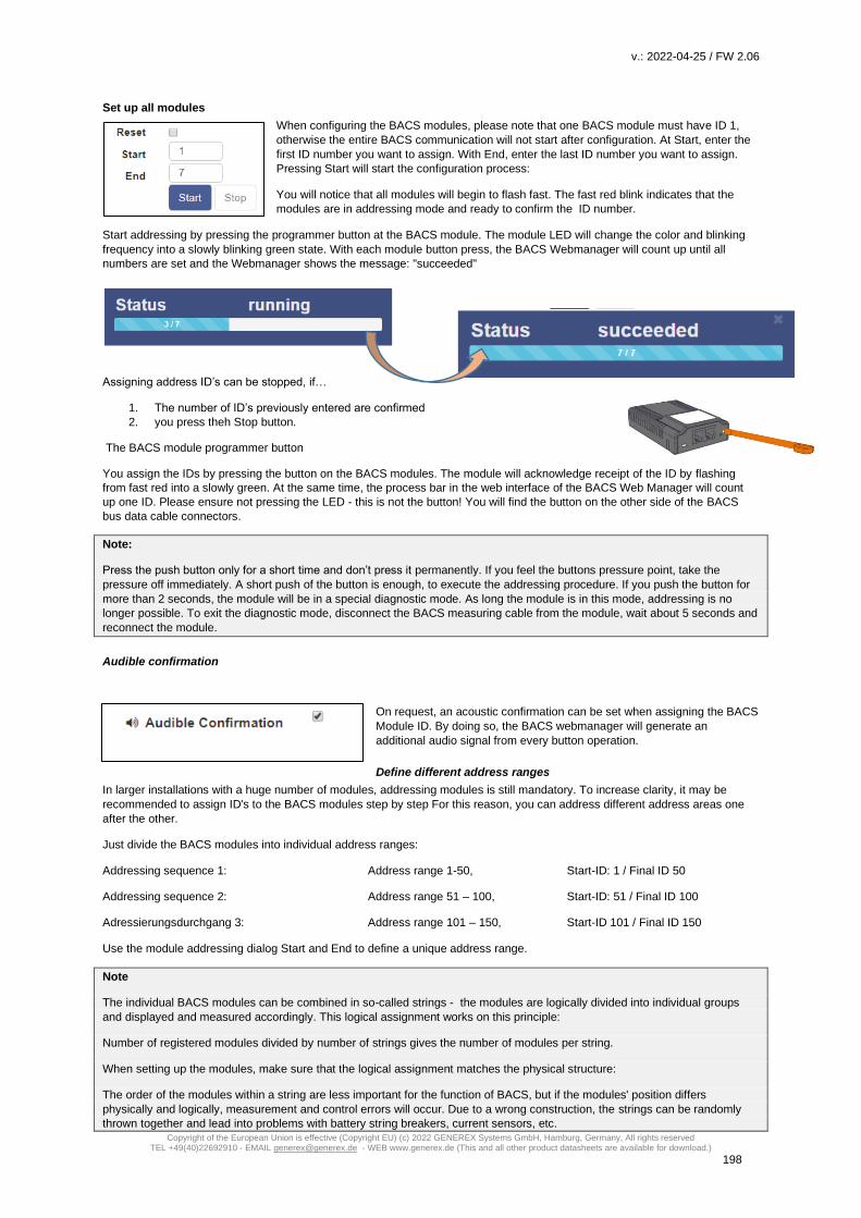
v.: 2022-04-25 / FW 2.06
Copyright of the European Union is effective (Copyright EU) (c) 2022 GENEREX Systems GmbH, Hamburg, Germany, All rights reserved TEL +49(40)22692910 - EMAIL [email protected] - WEB www.generex.de (This and all other product datasheets are available for download.)
198
Set up all modules
When configuring the BACS modules, please note that one BACS module must have ID 1,
otherwise the entire BACS communication will not start after configuration. At Start, enter the
first ID number you want to assign. With End, enter the last ID number you want to assign.
Pressing Start will start the configuration process:
You will notice that all modules will begin to flash fast. The fast red blink indicates that the
modules are in addressing mode and ready to confirm the ID number.
Start addressing by pressing the programmer button at the BACS module. The module LED will change the color and blinking
frequency into a slowly blinking green state. With each module button press, the BACS Webmanager will count up until all
numbers are set and the Webmanager shows the message: "succeeded"
Assigning address ID’s can be stopped, if…
1. The number of ID’s previously entered are confirmed
2. you press theh Stop button.
The BACS module programmer button
You assign the IDs by pressing the button on the BACS modules. The module will acknowledge receipt of the ID by flashing
from fast red into a slowly green. At the same time, the process bar in the web interface of the BACS Web Manager will count
up one ID. Please ensure not pressing the LED - this is not the button! You will find the button on the other side of the BACS
bus data cable connectors.
Note:
Press the push button only for a short time and don’t press it permanently. If you feel the buttons pressure point, take the
pressure off immediately. A short push of the button is enough, to execute the addressing procedure. If you push the button for
more than 2 seconds, the module will be in a special diagnostic mode. As long the module is in this mode, addressing is no
longer possible. To exit the diagnostic mode, disconnect the BACS measuring cable from the module, wait about 5 seconds and
reconnect the module.
Audible confirmation
On request, an acoustic confirmation can be set when assigning the BACS
Module ID. By doing so, the BACS webmanager will generate an
additional audio signal from every button operation.
Define different address ranges
In larger installations with a huge number of modules, addressing modules is still mandatory. To increase clarity, it may be
recommended to assign ID's to the BACS modules step by step For this reason, you can address different address areas one
after the other.
Just divide the BACS modules into individual address ranges:
Addressing sequence 1: Address range 1-50, Start-ID: 1 / Final ID 50
Addressing sequence 2: Address range 51 – 100, Start-ID: 51 / Final ID 100
Adressierungsdurchgang 3: Address range 101 – 150, Start-ID 101 / Final ID 150
Use the module addressing dialog Start and End to define a unique address range.
Note
The individual BACS modules can be combined in so-called strings - the modules are logically divided into individual groups
and displayed and measured accordingly. This logical assignment works on this principle:
Number of registered modules divided by number of strings gives the number of modules per string.
When setting up the modules, make sure that the logical assignment matches the physical structure:
The order of the modules within a string are less important for the function of BACS, but if the modules' position differs
physically and logically, measurement and control errors will occur. Due to a wrong construction, the strings can be randomly
thrown together and lead into problems with battery string breakers, current sensors, etc.

v.: 2022-04-25 / FW 2.06
Copyright of the European Union is effective (Copyright EU) (c) 2022 GENEREX Systems GmbH, Hamburg, Germany, All rights reserved TEL +49(40)22692910 - EMAIL [email protected] - WEB www.generex.de (This and all other product datasheets are available for download.)
199
Changing a single ID of a BACS module
The "Single" function allows you to set and change individual
module IDs of BACS modules.
This function provides 3 different options:
- Switch an ID to another
- Switch an ID to 0
- Swicth an ID from ID 0 to a target ID
The procedure is identic to all three options:
Under Old, enter the current ID that you want to change. Under New, enter the target ID to which you want to set the BACS
module. Unlike standard addressing, this mode requires no action on site at the BACS module.
Resetting module ID‘s
If necessary, the BACS modules can be returned individually or completely to the delivery state. Depending on the procedure,
only the ID will be changed or by pressing the modules button for 20 seconds, the modules will perform a hardware reset and
falls back to the default ID 0.
Resetting all modules or an address range to factory default
This action will reset all specified ID's directly to factory default 0 as soon as you press Start. The modules will visually confirm
the reset with flashing slowly red.
Setting one single ID back to 0
ou can also use this method to specifically reset a BACS module to 0. As a consequence, the BACS module will slowly flash
red. This is useful if you want to exchange a module, but want to reset it to the delivery state for later use within another
installation. This way you make sure that the ID is no longer used before you remove the module.
Finding modules
Large BACS installations can be very confusing for new guys.
In order to locate a specific BACS module within all the strings, the
programmer offers a fast and convenient solution:
Under Query you can optically flash individual modules with a red
flashing. This will help you to find the according battery you wish to
maintenence.
Simply enter the ID of the module you are looking for and click on "Show" - the module will start blinking slowly red/green.
The module you are looking for will blink accordingly. You can choose between these two options
1. Go to the BACS module and press the button.
Pressing the confirmation button on the module itself will release
the search function and the module falls back to normal operation mode.
2. At BACS Webmanager, press OK to confirn search is over.
The module will be triggered by the BACS webmanager to fall back to normal operation.
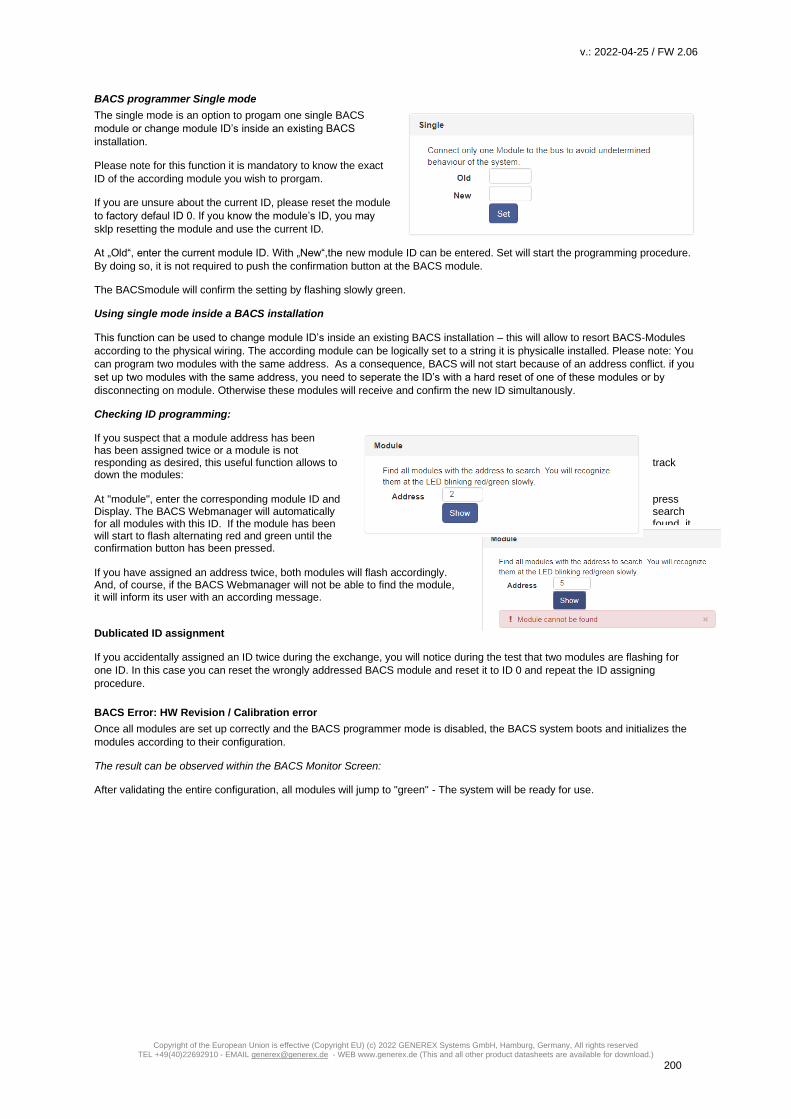
v.: 2022-04-25 / FW 2.06
Copyright of the European Union is effective (Copyright EU) (c) 2022 GENEREX Systems GmbH, Hamburg, Germany, All rights reserved TEL +49(40)22692910 - EMAIL [email protected] - WEB www.generex.de (This and all other product datasheets are available for download.)
200
BACS programmer Single mode
The single mode is an option to progam one single BACS
module or change module ID’s inside an existing BACS
installation.
Please note for this function it is mandatory to know the exact
ID of the according module you wish to prorgam.
If you are unsure about the current ID, please reset the module
to factory defaul ID 0. If you know the module’s ID, you may
sklp resetting the module and use the current ID.
At „Old“, enter the current module ID. With „New“,the new module ID can be entered. Set will start the programming procedure.
By doing so, it is not required to push the confirmation button at the BACS module.
The BACSmodule will confirm the setting by flashing slowly green.
Using single mode inside a BACS installation
This function can be used to change module ID’s inside an existing BACS installation – this will allow to resort BACS-Modules
according to the physical wiring. The according module can be logically set to a string it is physicalle installed. Please note: You
can program two modules with the same address. As a consequence, BACS will not start because of an address conflict. if you
set up two modules with the same address, you need to seperate the ID’s with a hard reset of one of these modules or by
disconnecting on module. Otherwise these modules will receive and confirm the new ID simultanously.
Checking ID programming:
If you suspect that a module address has been has been assigned twice or a module is not responding as desired, this useful function allows to track down the modules: At "module", enter the corresponding module ID and press Display. The BACS Webmanager will automatically search for all modules with this ID. If the module has been found, it will start to flash alternating red and green until the confirmation button has been pressed. If you have assigned an address twice, both modules will flash accordingly. And, of course, if the BACS Webmanager will not be able to find the module, it will inform its user with an according message.
Dublicated ID assignment
If you accidentally assigned an ID twice during the exchange, you will notice during the test that two modules are flashing for
one ID. In this case you can reset the wrongly addressed BACS module and reset it to ID 0 and repeat the ID assigning
procedure.
BACS Error: HW Revision / Calibration error
Once all modules are set up correctly and the BACS programmer mode is disabled, the BACS system boots and initializes the
modules according to their configuration.
The result can be observed within the BACS Monitor Screen:
After validating the entire configuration, all modules will jump to "green" - The system will be ready for use.
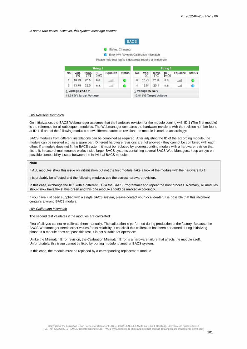
v.: 2022-04-25 / FW 2.06
Copyright of the European Union is effective (Copyright EU) (c) 2022 GENEREX Systems GmbH, Hamburg, Germany, All rights reserved TEL +49(40)22692910 - EMAIL [email protected] - WEB www.generex.de (This and all other product datasheets are available for download.)
201
In some rare cases, however, this system message occurs:
HW Revision Mismatch
On initialization, the BACS Webmanager assumes that the hardware revision for the module coming with ID 1 (The first module)
is the reference for all subsequent modules. The Webmanager compares the hardware revisions with the revision number found
at ID 1. If one of the following modules show different hardware revision, the module is marked accordingly:
BACS modules from different installations can be combined as required. After adjusting the ID of the according module, the
module can be inserted e.g. as a spare part. Different hardware revisions are not allowed - they cannot be combined with each
other. If a module does not fit the BACS system, it must be replaced by a corresponding module with a hardware revision that
fits to it. In case of maintenance works inside larger BACS systems containing several BACS Web Managers, keep an eye on
possible compatibility issues between the individual BACS modules
Note
If ALL modules show this issue on initialization but not the first module, take a look at the module with the hardware ID 1:
It is probably be affected and the following modules use the correct hardware revision.
In this case, exchange the ID 1 with a different ID via the BACS Programmer and repeat the boot process. Normally, all modules
should now have the status green and this one module should be marked accordingly.
If you have just been supplied with a single BACS system, please contact your local dealer: It is possible that this shipment
contains a wrong BACS module.
HW Calibration Mismatch
The second test validates if the modules are calibrated:
First of all: you cannot re-calibrate them manually. The calibration is performed during production at the factory. Because the
BACS Webmanager needs exact values for its reliability, it checks if this calibration has been performed during initializing
phase. If a module does not pass this test, it is not suitable for operation:
Unlike the Mismatch Error revision, the Calibration Mismatch Error is a hardware failure that affects the module itself.
Unfortunately, this issue cannot be fixed by porting module to another BACS system:
In this case, the module must be replaced by a corresponding replacement module.

v.: 2022-04-25 / FW 2.06
Copyright of the European Union is effective (Copyright EU) (c) 2022 GENEREX Systems GmbH, Hamburg, Germany, All rights reserved TEL +49(40)22692910 - EMAIL [email protected] - WEB www.generex.de (This and all other product datasheets are available for download.)
202
The alternative method: Using the BACS Programmer Windows software
The BACS Programmer software can be used with both, the BACS Webmanager budget as well as the BACS Kit. In addition to
the core function of addressing modules and preparing them for operation, the BACS Programmer software also offers
interesting features helpful for error diagnostic and the detection of individual modules within a very large installation.
Preparation
This software is not a network software, you need to connect the BACS Bus Converter to the COM port of your computer.
Note
Modern laptops often do not provide a native COM port anymore. Before your on-site visit, check if your mobile device provides
such a port. If this is not the case, a suitable adapter cable can be used. Normally, this cable will be connected to the USB port
and thus establish a connection between your computer and the BACS Bus Converter.
This standardized accessory for your computer is usually available from specialist retailers.
Ensure to use the supplied cable, a standard cable may fit to the ports but may have internal differences - the software would
consequently suggest problems caused by an inappropriate cable:
Not every Mini-DIN / Sub D 9 pin cable can be used to communicate with the BACS Bus Converter. Mark your cables to be
used to avoid confusion during maintenance work.

v.: 2022-04-25 / FW 2.06
Copyright of the European Union is effective (Copyright EU) (c) 2022 GENEREX Systems GmbH, Hamburg, Germany, All rights reserved TEL +49(40)22692910 - EMAIL [email protected] - WEB www.generex.de (This and all other product datasheets are available for download.)
203
Connecting the BACS Bus Converter
First remove the connection between the CS141 and the BACS Bus Converter. Then connect the COM port
of your computer to the BACS bus converter. The port is labeled on the BACS Bus Converter with From PC
RS232 COM Port.
Note A BACS Bus Converter requires its own power adapter. A popular mistake is to forget this when connecting ... As a consequence, the BACS Programmer will not establish any communication.
Pay attention to possible redundancies when connecting.
RS 232 COM Port
BACS BUS

v.: 2022-04-25 / FW 2.06
Copyright of the European Union is effective (Copyright EU) (c) 2022 GENEREX Systems GmbH, Hamburg, Germany, All rights reserved TEL +49(40)22692910 - EMAIL [email protected] - WEB www.generex.de (This and all other product datasheets are available for download.)
204
You do not necessarily have to decouple the entire BACS system if you want to specifically check a specific section within a large system - but you need to ensure only one BACS Bus Converter will access the tested modules:
In this example, a cable was taken from the BACS 1 and connected via a BACS bus converter to the COM port of the laptop. In this constellation, both BACS bus converters would disturb each other until the segment to be tested is completely decoupled and separated:
The number as well as the module ID's of BACS modules that can be tested is determined by the technician who interrupts the data connection.
Note WIf you are looking for a fault in the cabling, you should check with both, a simple and a ring cabling. If several modules are affected in the middle, you can determine the source of the error exactly from both sides. This allow you to find the affected section. However, if there is only one cable faulty, you will need the simple wiring to locate the faulty cable or module.

v.: 2022-04-25 / FW 2.06
Copyright of the European Union is effective (Copyright EU) (c) 2022 GENEREX Systems GmbH, Hamburg, Germany, All rights reserved TEL +49(40)22692910 - EMAIL [email protected] - WEB www.generex.de (This and all other product datasheets are available for download.)
205
At BACS II Programmer Tool, select the according COM-Port of your Computer the cable is connected to and press Open.
The button label will change to "close" and the BACS Programmer will try to establish a connection to the BACS Bus Converter via the serial connection. Toggle operating mode
Automatic Mode
By default, the BACS Programmer starts in Automatic Mode. In order to prevent accidental incorrect entries, only the functions assigned to a specific operating mode are enabled. The automatic mode is designed for the automatic addressing of BACS modules, the functionality is the same as in the BACS Webmanager
Manual Mode
This mode describes similar functions like the single module address and search tools running on the BACS Webmanager. Search for an address ID of a single module or change module addresses.
Searching for an installed module
This feature will be interesting if you are inside a very large BACS installation and, as an example, you are looking for the BACS module with ID 378. In this case, enter 378 and press Start. The requested module will respond with a red flash within the BACS installation until you click Stop.
Line Check
A premium feature of the BACS programming software is the Line Check:
With the Line Check, BACS cabling can be tested. This test can help you to find points of weakness inside a cabling concept. As an example, this test is helpfull, if o the signal is partial disturbed caused by electromagnetic interferences (EMI) or other influences
duringinstallation not all modules are addressable. o All modules are addressable but not found during initial start up. o sporadic communication lost occurs Operation modes of the line check The BACS Line Check offers two basic functional checks. o Send Line Check

v.: 2022-04-25 / FW 2.06
Copyright of the European Union is effective (Copyright EU) (c) 2022 GENEREX Systems GmbH, Hamburg, Germany, All rights reserved TEL +49(40)22692910 - EMAIL [email protected] - WEB www.generex.de (This and all other product datasheets are available for download.)
206
o Receive Line Check
Note
For the line check tool, it is mandatory that all modules are set to factory default ID 0.
How the send line test works The Send Line Check is a test procedure in which all modules are addressed via a broad cast signal, starting from the BACS BUS Converter. As soon as you start this test, the Send Line Check specifies a current state that the LEDs on the BACS modules should show:
Modules that do not adhere to this guideline can be found easily. If several faults are found within a ring cabling, the outermost fault as well as a non-responding module chain is visible:
in this example, the red marked modules will show connection problems - everything between the broken cables will not be reachable. With this test, one can narrow down the sources of error, but do not clearly determine the reason for this problem. It may be... - a broken cable - a broken module port - a broken port of the module before the error - a broken module itself The disadvantage of ring cabling while running this test, is the fact that a defective BACS module would immediately attract attention, but a single defective cable or a BACS module with a defective cable socket cannot appear. you need at least a completely broken module or two "half-broken" parts to find an issue: By a single cabling defect, the redundancy behavior of the ring cabling would inevitably find all modules in the query. What you can do You can perform a redundancy test on known defects and determine a general availability of all modules. By contrast, the same test running on a simple wiring: You would only reveal the first problem inside a BACS string.

v.: 2022-04-25 / FW 2.06
Copyright of the European Union is effective (Copyright EU) (c) 2022 GENEREX Systems GmbH, Hamburg, Germany, All rights reserved TEL +49(40)22692910 - EMAIL [email protected] - WEB www.generex.de (This and all other product datasheets are available for download.)
207
Again, you need to check whether the reason for the error can be found at the modules or the bus cables. This test reliably detects weaknesses inside an installation and will find all problems. The disadvantage is, you will always find only one problem after the other - this can take a long time.
Note Both tests have their specific advantages and disadvantages. The send test coming with a ring cabling will show the general behavior and conveniently, but can only be used to find failures moderate system failures as well as broken single modules. The same test coming with a simple cabling method without a ring topology can then be used to find all problems but only the first issue in a row. In combination, technicians can first ensure basic operations and guarantee basic availability.
The Receive Line Test
While the Send Line test will take care for general availability of modules and helps to find cabling issues, the Receive Line Test will take care for the quality of the data signal that will reach the BACS Bus Converter: In some cases, the cabling is well done, but the communication does not start or interrupts sporadically. This may cause as an example by strong electromagnetic interferences: EMI – In this case, the signal itself will be compromised by electromagnetic fields that will harm the conductor inside the cable and produces error bits that cannot be compensated. With the receive line test, you can take a look what happens if the last module far away from the BACS Webmanager will send a data package. Preconditions of the test Please note that all modules must use the ID "0"! Otherwise this test will not work properly. If in doubt, use the Automatic Mode to set all modules to the ID "0" in advance. After resetting, proceed to the receive line test

v.: 2022-04-25 / FW 2.06
Copyright of the European Union is effective (Copyright EU) (c) 2022 GENEREX Systems GmbH, Hamburg, Germany, All rights reserved TEL +49(40)22692910 - EMAIL [email protected] - WEB www.generex.de (This and all other product datasheets are available for download.)
208
Starting the Receive Line test
Receive Line Check
The Receive Line Check is no longer supported by the BACS modules with software version 3.4.1. Before the test, please check which hardware revision of the BACS modules you are using. You will find the according label on the underside of the BACS modules. Please note that you cannot mix different versions within one BACS bus. The Receive Line Check can be used to check the quality of the data signal starting from the last module in the chain. The receive line test is a passive testing mode. The BACS Programmer will not query but wait for a specially coded incoming
data packet.
When you start the test, you will not see animations or something like that, BACS programmer will only show a blue center
screen with white letters:
Performing a Receive Line Check
Because you want to know something about a specific route to the BACS programmer, this test will only run with a simple chain connection without any ring wiring.
1. To start the test, unplug the measuring cables to depower the BACS module.
2. Press the button (yes dude, this is not the LED …) and hold it. 3. Repower the module while holding the module button pressed.
4. Release the button. This will start the test.
What happens: This BACS module will start sending 300 signatured data through the cables to the BACS Webmanager or a BACS Bus Converter. This will be done sequential and evenly.

v.: 2022-04-25 / FW 2.06
Copyright of the European Union is effective (Copyright EU) (c) 2022 GENEREX Systems GmbH, Hamburg, Germany, All rights reserved TEL +49(40)22692910 - EMAIL [email protected] - WEB www.generex.de (This and all other product datasheets are available for download.)
209
The BACS programmer will notice this incoming data packets and show the number signature:
Due to the fact the data packages are signated with a unique number, it is possible to examine the quality of the data signal. In
case the data packet is broken or invalid, it will be rejected.
Due to the fact you will notice following:
- The counter does not start, the screen is blank
In this case, no incoming data packets are noticed. If the send line test works as expected, please check if all modules
are at default ID 0. Most common problem: Starting this test is a little bit tricky – you need to hold the button while
inserting the measuring cables to repower the module. When you release the button, the test starts. If the test does
not start, you cannot receive data packets.
- Jumping numbers
Yes, the test started and the last module inside the chain sends his 300 data packets. In this case there are missing
or broken data packets. These packets are lost and will show, in general it may work but there is something wrong
inside the cabling. To find the reason why, you may spit the bac modules in two different strings and repeat the test
until all numbers will be shown evenly.
- It starts counting evenly, but it suddenly stops.
This means, the chain is interrupted physically or something will block all data packets.
- It runs as expected
The numbers will be shown evenly and the countdown starts at 299 and stops with 0. Data quality is OK, all modules
will respond.
Since the data packages are signed, a fault in the data line can be diagnosed very quickly because the display window counts
irregularly or displays jumping numbers. If the meter stops at a number, it can be assumed that the data connection has
collapsed.
Note

v.: 2022-04-25 / FW 2.06
Copyright of the European Union is effective (Copyright EU) (c) 2022 GENEREX Systems GmbH, Hamburg, Germany, All rights reserved TEL +49(40)22692910 - EMAIL [email protected] - WEB www.generex.de (This and all other product datasheets are available for download.)
210
This test starts only if the trigger timing on the last BACS module is consistent. If the test does not start, first make sure that the
test was triggered correctly. Otherwise, the Receive Line Check will indicate a fault in the BACS cabling.
GX_R_AUX
The GX_R_AUX is the digital BACS version of the former CON_R_AUX for the CS121
series, which can be connected directly to the CS141. This device offers switching
relays as Output and dry contacts as Input to connect external devices to the
BACS/CS141 system.
The overall configuration process is similar, but the GX_R_AUX provides some
advantages like the option to integrate up to 4 of these devices into one BACS bus -
this will allow up to 16 inputs and outputs in total.
Due to the fact they are freely configurable, that can be used to switch and monitor
many functions including other systems.
The GX_R_AUX devices are designed to be used a modular. They do not need to be
installed all together at a single place - Install or move them during maintenance work
anywhere within the installation inside the BACS bus.
Due to the fact the GX_R_AUX is supplied with the necessary operating voltage via the BACS bus cabling, there are no further
live cables that need to be installed separately*.
Thanks to the modular concept, the GX_R_AUX is an optional accessory to extend the scope of functions and activities of your
BACS installation by many additional possibilities and can be used for both – the BACS installation as well as advanced CS141
configuration to communicate with child- and parent surveillance and monitoring systems as well as to trigger and monitor third-
party devices. All you need to do is to put the GX_R_AUX to its own little BACS strain.
Note
The GX_R_AUX makes it possible to configure battery systems according to the US standard "International Fire Code IFC
608.3". This standard defines, in case of a malfunction in coming with a possible impending Thermal Runaway threat, the
batteries have to be completely isolated automatically. The use of the GX_R_AUX allows activation of battery separators and
thus meets the requirements of the US Standard International Fire Code IFC 608.3. In case of an impending Thermal Runaway,
the GX_R_AUX can trigger
battery separators or send an opening signal through alarm contacts in order to disconnect the battery system from the charger
so the batteries cannot heat up anymore.
*) For more information, please refer the BACS FAQ at the end of this manual.
Connectors
Screwed Connections 1-14:
Ports 1-14 are located on the side marked as input. Port 1 is located on the left side when viewed directly from above.
Screw terminal layout pins 1 - 14
1. Reserved for future developments. 2. Reserved for future developments 3. Digital Input 1 1 4. +12V (voltage for input 1) 5. Digital Input 2 6. +12V (voltage for input 2) 7. Digit input 3 8. +12V (voltage for input 3) 9. Digital input 4 10. +12V (Versorgung für Eingang 4) 11. Alternative BACS bus +12V voltage 12. Alternative BACS bus data input 13. Alternative BACS bus data output 14. Alternative BACS bus ground
Pin 11 – 14: Alternative BACS Bus
In some cases, it may be necessary to connect BACS devices directly via contacts. To provide this additional function, ports 11
to 14 can be used in case of the device is not connected to the BACS bus via the "BUS 1" or "BUS 2" plug.

v.: 2022-04-25 / FW 2.06
Copyright of the European Union is effective (Copyright EU) (c) 2022 GENEREX Systems GmbH, Hamburg, Germany, All rights reserved TEL +49(40)22692910 - EMAIL [email protected] - WEB www.generex.de (This and all other product datasheets are available for download.)
211
Center console
The address switch: The DIP bank "Address"
In contrast to the BACS modules, the GX_R_AUX must be configured to its own ID. This will be done via the DIP switches.
The following DIP settings are valid:
DIP 1 DIP2 DIP 3 DIP3 GX_R_AUX device ID off off off off GX_R_AUX will be set to ID 1 ON off off off GX_R_AUX will be set to ID 2 off ON off off GX_R_AUX will be set to ID 3 ON ON off off GX_R_AUX will be set to ID 4
Please note that the ID, like a BACS module, requires a unique ID, which must be set consecutively starting with ID 1. The
difference to the BACS module is that the GX_R_AUX ID is set directly via the DIP bank and can not be managed via the BACS
Web Manager - whereby the base address range used differs from the BACS modules.
Therefore, the BACS module with the ID 1 cannot be confused with the GX_R_AUX ID 1.
Connecting the GX_R_AUX to the BACS Bus
The GX_R_AUX can be used everywhere inside a BACS bus - Simply connect the module between two BACS modules. The
GX_R_AUX fits seamlessly into the BACS bus and can be used immediately.
Output connectors
Screwed connectors 15-28
The ports 15-28 are on the side marked as output. Terminal 15 is in direct view from the top on the left side, in opposition to
input 1.
Screwed connectors 15 - 28
15. Relay contact 1 No* 16. Relay contact 1 NC** 17. Relay contact 1 Common 18. Relay contact 2 NO* 19. Relay contact 2 NC** 20. Relay contact 2 Common 21. Relay contact 3 NO* 22. Relay contact 3 NC** 23. Relay contact 3 Common 24. Relay contact 4 NO* 25. Relay contact 4 NC** 26. Relay contact 4 Common 27. Relay contact zukünftige Entwicklungen 28. Relay contact zukünftige Entwicklungen
*NO: normally open contact
**NC: normally closed contact

v.: 2022-04-25 / FW 2.06
Copyright of the European Union is effective (Copyright EU) (c) 2022 GENEREX Systems GmbH, Hamburg, Germany, All rights reserved TEL +49(40)22692910 - EMAIL [email protected] - WEB www.generex.de (This and all other product datasheets are available for download.)
212
Note
If the labels and labels have been removed, you can still clearly identify the numbering of the screw terminals based on the
position of the LEDs: On one side you have 5 LEDs - 4 grouped and one separated. The separate LED is the status indicator.
Align the GX_R_AUX in a way that the 5 LED's are in the upper side.
From now, you can easily numerate the terminals you are looking for:
The upper screw bar is numbered from left to right in ascending order, the first connection on the
left outside defines 1. Furthermore, the upper bar defines the input bar.
The DIP switches are numbered from left to right in this orientation, from left to right: 1, 2, 3, 4
The bottom screw bar starts on the left side with the number 15 and is incremented to the right
continuously. the bottom screw bar defines the outputs
GX_R_AUX Configuration guide
For this configuration step, navigate to the following menu:
Step 1 - Setting up a mandatory GX_R_AUX ID
Set up a corresponding ID - the ID's you choose hast to start with 1 and ends with a number according to the number of
GX_R_AUX you wish to use. Please note the following conditions:
- An ID may only be assigned once
- The first device receives the ID 1, then it is consecutively numbered
- Do not use more than the maximum of 4 GX_R_AUX within one BACS installation.
Step 2 - At BACS Webmanager, open the GX_R_AUX configuration dialog
In the configuration dialog, you can use the BACS Webmanager to specify the number of installed modules:
Enter "0" to disable the function. Otherwise, set the number of used GX_R_AUX modules and click Apply. Due to the fact new
devices have been added to the BACS bus, the web manager must reboot BACS to find and initialize the new devices
accordingly. This procedure will only restart required services, neither the Webmanager itself nor the UPS will reboot.
Note The BACS Webmanager will program the ID of a GX_R_AUX - the ID will be set by the DIP switch bank. After setting up the hardware ID of the GX_R_AUX, the Webmanager will be configurated to search for the specific number of GX_R_AUX that are placed inside the BACS installation. If the estimated number of GX_R_AUX is not found, a corresponding error message will occur. You can follow the success of the initialization in the upper task bar.

v.: 2022-04-25 / FW 2.06
Copyright of the European Union is effective (Copyright EU) (c) 2022 GENEREX Systems GmbH, Hamburg, Germany, All rights reserved TEL +49(40)22692910 - EMAIL [email protected] - WEB www.generex.de (This and all other product datasheets are available for download.)
213
How to set up the outputs of a GX_R_AUX as battery breaker
Under Thermal Runaway, activate the battery breaker functionality
Before configuring the GX_R_AUX outputs and associated events, you need to decide if and how many battery breakers you
need. Open the Thermal Runaway configuration dialog - the battery breaker configuration is mostly done automatically, which
manifests itself in subsequent configurations:
1. According outputs will be labeled automatically
2. Events and jobs assigned to a Thermal Runaway are automatically entered
The total number of required battery breaker depends on the number of strings you configured at BACS general setup.
If you want to use one battery breaker for the complete installation, select the option
Trip single Battery-Breaker for all strings “.
If you want to use a single battery breaker for each string installed in your BACS
System, select the option „Trip separate Battery-Breaker for each string
Press Apply when ready.
Under Setup GX_R_AUX, you will find new entries:
As you can see, BACS auto-labeled your GX_R_AUX Outputs according to your settings. You cannot re-label them - they are
reserved for the battery breakers. Please note: If you use battery breaker, ensure, the NC Contact Flag is not set!
Again, press Apply when ready
How the BACS Webmanager will count the battery breaker:
The first battery breaker will be associated with output 1. From there onwards, all battery breaker will be counted one by one. If
several AUX are in use, the 5th battery interrupter is configured on the 2nd AUX, Port 1. The classification as battery breaker
will exclude any existing configuration - the configured output can only be used for the according battery breaker. Furthermore,
depending on the number of GX_R_AUX devices, an individually configured additional configuration dialog will appear:
Name the inputs and outputs in free text. Theses labels can be found next to the inputs and outputs at the GX_R_AUX -
Monitor:
Normally Open / Normally Closed
If you do not use battery breaker you may use the outputs freely. Depending on your settings, the behavior of the BACS
Webmanager changes when dealing with contacts:
NC / NO input configuration
The inputs provide to connect any potential-free switch contacts. It can be distinguished whether a contact must normally be
closed (NC) or open (NO). By Changing from NO to NC behavior, it is possible to harmonize the contacts to third party devices.
A switching state in opposition to the configuration is provided with a red alarm marker:
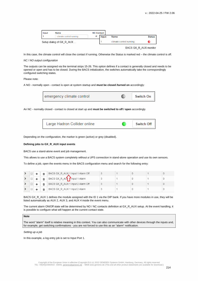
v.: 2022-04-25 / FW 2.06
Copyright of the European Union is effective (Copyright EU) (c) 2022 GENEREX Systems GmbH, Hamburg, Germany, All rights reserved TEL +49(40)22692910 - EMAIL [email protected] - WEB www.generex.de (This and all other product datasheets are available for download.)
214
In this case, the climate control will close the contact if running. Otherwise the Status is marked red – the climate control is off.
NC / NO output configuration
The outputs can be assigned via the terminal strips 15-26. This option defines if a contact is generally closed and needs to be
opened or open and has to be closed. During the BACS initialization, the switches automatically take the correspondingly
configured switching states.
Please note:
A NO - normally open - contact is open at system startup and must be closed /turned on accordingly:
An NC - normally closed - contact is closed at start up and must be switched to off / open accordingly
Depending on the configuration, the marker is green (active) or grey (disabled).
Defining jobs to GX_R_AUX input events
BACS use a stand-alone event and job management. This allows to use a BACS system completely without a UPS connection in stand-alone operation and use its own sensors. To define a job, open the events menu in the BACS configuration menu and search for the following entry:
BACS GX_R_AUX 1 defines the module assigned with the ID 1 via the DIP bank. If you have more modules in use, they will be
listed automatically as AUX 2, AUX 3, and AUX 4 inside the event menu.
The current alarm ON/Off state will be determined by NO / NC contacts definition at GX_R_AUX setup. At the event handling, it
is possible to configure what will happen at the current contact state.
Note
The word "alarm" itself is relative meaning in this context. You can also communicate with other devices through the inputs and,
for example, get switching confirmations - you are not forced to use this as an "alarm" notification.
Setting up a job
In this example, a log entry job is set to Input Port 1.

v.: 2022-04-25 / FW 2.06
Copyright of the European Union is effective (Copyright EU) (c) 2022 GENEREX Systems GmbH, Hamburg, Germany, All rights reserved TEL +49(40)22692910 - EMAIL [email protected] - WEB www.generex.de (This and all other product datasheets are available for download.)
215
To enter a new job, select + at Input 1 Alarm – this will open the job configuration dialog:
1. As Job, choose „Log “:
With the job type, the parameters will be adapted automatically. In this case, you can type a free text messages that will appear
at the event log if GX_R_AUX 1 input port 1 reports a closed alarm contact position:
Timing will allow to define when this job shall be executed. In this case, the job is executed once, at the precise moment when
the defined alarm behavior occurs. For more information, please refer to the chapter event handling at part 1 of this manual.
With save, the job will be written to the configuration file and executed as soon as the according event occurs. You do not need
to restart the CS141 / BACS Webmanager.
Checking the job configuration:
To test the job, unfold the event BACS GX_R_AUX 1 Input 1 Alarm by clicking
Your new job will be displayed:
At this menu, you can edit, delete or test the job. More information can be found at event handling configuration in part 1 of this manual.
Communicate with third party devices via GX_R_AUX outputs
In this example, a third-party monitoring device shall be triggered by AUX output port 1.
1. Choose the event that shall trigger the output and press to start the job configuration dialog
2. As job, choose AUX:
Depending on the number of installed GX_R_AUX modules, you can select an individual port from the list: In this example, GX_R_AUX 1, Port 3 is selected. By doing so, use at GX_R_AUX output screw bar these screw connectors:
21 Relay contact 3 NO*

v.: 2022-04-25 / FW 2.06
Copyright of the European Union is effective (Copyright EU) (c) 2022 GENEREX Systems GmbH, Hamburg, Germany, All rights reserved TEL +49(40)22692910 - EMAIL [email protected] - WEB www.generex.de (This and all other product datasheets are available for download.)
216
22 Relay contact 3 NC** 23 Relay contact Common
The wiring method determines what will happen in case of the command „Set High (On) “:
NO <-> Common On trigger, the contact will be closed NC <-> Common On trigger, the contact will be opened
The standard configuration for these contacts is NO <-> Common. For this example, Port 3 will be closed as soon as the according event will occur.
Timing will allow to define when this job shall be executed. In this case, the job is executed once, at the precise moment when
the defined alarm behavior occurs. For more information, please refer to the chapter for advanced event handling at part 1 of
this manual.
With save, the job will be written to the configuration file and executed as soon as the according event occurs. You do not need
to restart the CS141 / BACS Webmanager.
Checking the job configuration:
At the according event, click to unfold the job list configured to this event:
The new job should be added accordingly:
From here, you can edit, delete and test the job. Results can be seen at the GX_R_AUX monitor as well as event chains may be
triggered.
Note
For the complete description of event handling including all symbols, please refer to page 58 of this manual, chapter:
System event handling

v.: 2022-04-25 / FW 2.06
Copyright of the European Union is effective (Copyright EU) (c) 2022 GENEREX Systems GmbH, Hamburg, Germany, All rights reserved TEL +49(40)22692910 - EMAIL [email protected] - WEB www.generex.de (This and all other product datasheets are available for download.)
217
BACS Functions
For this configuration step, navigate to the following menu:
Each BACS Webmanager offers basic functions that can be switched on or off remotely via the web interface.
BACS Buzzer
This internal alarm provides a clear audible warning signal as soon as there is a problem with your
BACS system or the connected sensors occurs or in the case of a so-called General Alarm.
As a default, the buzzer will be triggered in case of the event „BACS General Alarm “.
BACS Relay
Parallel to the alarm buzzer, BACS provide an internal relay:
With this relay external monitoring systems can be informed that something went
wrong. The internal BACS alarm relay is linked to a general alarm and cannot be
configured:
The relay is a pre-defined normally closed contact, which automatically picks up about
15-20 seconds after system startup and is only reopened in case of a system fault:
1. A BACS General Alarm is in progress
2. The BACS Webmanager or BACS Bus Converter is depowered.
Master alarm will start, if …
- Voltage alarm high/low,
- Temperature alarm high/low
- Impedance alarm high/low
- Communication lost to one or more modules or a system alarm is in progress
- Thermal Runaway alarm
- Equalizing / Balancing Error alarm
- String voltage alarm
Note: If you manually open the relay, it remains open until one of the following conditions is met: - The device restarts (by rebooting via software button or in case of a cold boot). - An active BACS-alarm falls back to normal state (voltage measuremnts reach alarm levels and drops below). - It will be closed via BACS relais functions menu.
BACS alarm thresholds
In principle, there are two points during usage, that may heavily damage the batteries of a UPS system:
Overvoltaged batteries
The overvoltage occurs if a UPS initiates a boost charging cycle to restore emergency power time as fast as possible after a
discharge. As an example, the charging process will be done with a boost charge or operates with predefined charging voltage.
In both cases, the reference charging point is the slowest loading battery to rule the entire charging process.
As result, normal or fast charging batteries are consequently overcharged, leading into average temperature issues and as a
long-term consequence, overcharging the cells in the battery are damaged through the dehydration process coming with
abnormal temperature usage. Overcharging will damage the battery, but this is not enough:

v.: 2022-04-25 / FW 2.06
Copyright of the European Union is effective (Copyright EU) (c) 2022 GENEREX Systems GmbH, Hamburg, Germany, All rights reserved TEL +49(40)22692910 - EMAIL [email protected] - WEB www.generex.de (This and all other product datasheets are available for download.)
218
As a consequence of an overcharge, a battery will heat - this may lead into a dangerous battery overheating and fire issue.
Conversely, a battery damaged by overvoltage can subsequently not meet the requirements set, which leads to different
behavioral characteristics:
- Extended loading time
- Permanently performance decrease
- Temperature increasing with each charge/discharge cycle
- Sporadically dropping below the discharge end voltage
- Lapsing service time
- Overheating and acute fire hazard.
Which defects occur exactly depends on the type of battery as well as the basic conditions. Overloading should, if possible, be
avoided for these reasons.
Deep discharge
During deep discharge, a cell of a battery is discharged during use until a complete depletion. In case of a deep discharge, the
voltage drops below the final discharge voltage, a condition in which a wide variety of defects may occur. Depending on the type
of battery even a single deep discharge can damage the battery internally so that it can lead into a total failure or even a polarity
reversal of the battery contacts.
Reloading damaged battery can be very dangerous because the reaction to the charging current unpredictable:
Although the battery is faulty, it initially appears to be responding normally to the charging process initiated by the UPS - a
creeping malfunction can appear up to 16 hours after charging is complete. Everything may happen, starting at an acute
overheating when starting or during charging process as well as a seemingly sporadic phenomenon during charging that leads
creeping into a fire issue many hours later.
Note
Typically, a UPS will stop operating in time to avoid this deep discharge, but overvoltage or undervoltage that weaken the cells,
cannot be detected the UPS.

v.: 2022-04-25 / FW 2.06
Copyright of the European Union is effective (Copyright EU) (c) 2022 GENEREX Systems GmbH, Hamburg, Germany, All rights reserved TEL +49(40)22692910 - EMAIL [email protected] - WEB www.generex.de (This and all other product datasheets are available for download.)
219
Threshold definitions
For this configuration step, navigate to the following menu:
The BACS thresholds define fixed points within the charge / discharge cycle where intervention becomes necessary before an
acute incident arises.
The following values are monitored during the discharge / charge cycles:
Battery voltage
The voltage measured by a battery during the charge / discharge cycle indicates whether the battery will soon become
overcharged or will run into a deep discharge. These values may differ depending of the specifications made by the battery
manufacturer. In case of the measurements exceed or drop below the pre-defined values, a warning will be issued.
Please note, the limits specified by the BACS are correct for most batteries and should only be changed after consultation with
the battery manufacturer.
Battery temperature
The temperature of a battery will influence the performance and the life of a battery. A battery will heat up during the charge and
discharge cycle. However, if the temperature exceeds the limits, it may lead into different defects. How and when these defects
will manifest, depends on the type of battery.
Internal resistance of the battery
Depending on the design of the battery, the internal resistance changes, in some cases it increases abruptly, in other cases it
drops abruptly. In case of using new batteries, measured values of the internal resistance should always be equal at all
batteries. Thereby the measured value is determined by its carrier material - the type of battery. This means, a deviation of the
internal resistance to other batteries indicates a battery fault.
Why not using voltage measurements?
The voltage is not suited to be used as an indicator for battery failure, because measured voltages of the battery reacts and
follows during a trickle charge the voltage behavior of the charger. With internal resistance (and the indicator for equalizing)
measured values will indicate a problem of the batteries’ chemistry and thus allow to warn in case future problems can be
assumed.
The internal resistance of a battery indicates upcoming problems and should be used for long term monitoring. For warning
level, we recommend 25% deviation from the average value of all batteries.For alarm levels, we recommend 50 % deviation
from the average value of all batteries.

v.: 2022-04-25 / FW 2.06
Copyright of the European Union is effective (Copyright EU) (c) 2022 GENEREX Systems GmbH, Hamburg, Germany, All rights reserved TEL +49(40)22692910 - EMAIL [email protected] - WEB www.generex.de (This and all other product datasheets are available for download.)
220
Attention:
Each battery manufacturer uses an own measuring method to get the impedance values for a data sheet. As a consequence, it
is possible that taking impedance values from the battery manufacturer's data sheet is not suitable to configurate BACS
thesholds:
To ensure save operation, determine impedance values for BACS as described in this manual.
Maximum Voltage deviation between batteries
Batteries must be used regularly, the charge / discharge process is very important for optimal operation.
Despite equalizing / balancing, an unused battery loses its target voltage over time, although it receives a trickle charge from the
UPS. This is a natural process and not a malfunction:
If the fluids in the battery come to rest, gravity affects the fluids inside the battery:
Basically, liquids of different molecular weight in a standing system tend to be arranged according to their molecular weight over
time. The heavy liquid slowly sinks down while the light liquid migrates upwards. As a consequence, the overall concentration
ratio of liquids changes, which impairs the efficiency. How much this natural process will take effect, depends strongly on the
chemicals used as well as the size of a battery - as bigger the battery as stronger this phenomenon will take effect.
The target voltage can be normalized by regular battery use due to the fact the chemical processes cause a circulation and
even distribution of all chemicals. The BACS Webmanager can measure the deviation in 0.1-volt increments and give an
indication if the measured voltage and the target voltage are too drifting apart.
Voltage deviation per string
This feature is similar to comparing individual BACS voltage measurements. However, this function compares the individual
strings within a BACS installation.
Current deviation per string
Unlike the voltage, the charging current divides evenly into the different strings - but the total current will not change. Since all
battery strings work evenly in the network, defects in one string will have a negative impact on all strings. BACS can be adviced
to measure this effect and give feedback to technical staff.
Please note, this setting requires current sensors on each string
Note
What is the difference between warning and alarm?
BACS distinguish between a definitive alarm that requires intervention and a warning:
Both states are quite similar, the different jobs can be freely defined for the corresponding warning or alarm level. Depending on
optional parts and devices attached to BACS as well as the configuration, very delicate automatic processes can be initiated,
ranging from information to the initiation of active emergency measures up to switching and controlling of systems, etc.
In the event of an alarm condition, the acoustic alarm is additionally activated, the alarm LED changes its status and the alarm
contact on the BACS Webmanager is actively opened.
The values are freely definable, but care should be taken to ensure that the values for the warning are always reached well in
advance of the values for an alarm so that there is still enough time for an adequate response.
Alarm Delay
As a consequence of a used emergency power or an extended battery test, battery voltage is in low condition. If the UPS takes
the maximum time for autonomous operation, it possible that the minimum values for the BACS alarm will be triggered.
This option allows to set up an alarm time delay to prevent BACS from sending a false alarm.

v.: 2022-04-25 / FW 2.06
Copyright of the European Union is effective (Copyright EU) (c) 2022 GENEREX Systems GmbH, Hamburg, Germany, All rights reserved TEL +49(40)22692910 - EMAIL [email protected] - WEB www.generex.de (This and all other product datasheets are available for download.)
221
Define BACS Battery strings
For this configuration step please navigate to the following menus
BACS offers the logical assignment of the individual batteries to so-called Battery strings. The number of batteries is divided by the number of specified strings. The result is the logical assignment of the BACS module in single strings. Example: They have 72 batteries and define 6 single strings. The BACS system will present you with 6 battery strings of 12 batteries each, as entered after initialization. Basically, the assignment is made according as followed: 72 batteries divided by 6 strings will take 12 batteries per stand Batteries 1 - 12 String 1 Batteries 13 - 24 String 2 Batteries 25 - 36 String 3 Batteries 37 - 48 String 4 Batteries 49 – 60 String 5 Batteries 61 - 72 String 6
After initialization, you will notice that BACS has renamed the modules:
If you have successfully included module 49, it would now be listed at battery strings 5 as module 1.
Note
The ID of the module has not changed, it remains the BACS module with the unique ID 49. What changed is the display context
at the monitoring screen as well as general presentation of the data. Usually, the installation site and the string are coordinated
so that module and string accordingly fit together.
If no project documentation exists, you can use this to identify the individual strings and search via the BACS Programmer.
Please note: The numbers of current sensors will be defined by the number of strings you define and label. You cannot define a
specified number of current sensors, but you can:
- Use a current sensor for each single BACS string
- Use one current sensor for all BACS strings if installed at the master string
- Use one current sensor installed in one single string and use the multiplicator to get information about all strings
BACS strings vs battery breaker
Furthermore, setting up BACS strings will harm the battery breaker setup:
The BACS Webmanager offers two options:
- One battery breaker for all strings
- One battery breaker for each string
Please note, depending on the number of strings, you may need up to 4 GX_R_AUX modules. The maximum number of battery
breaker is 16.
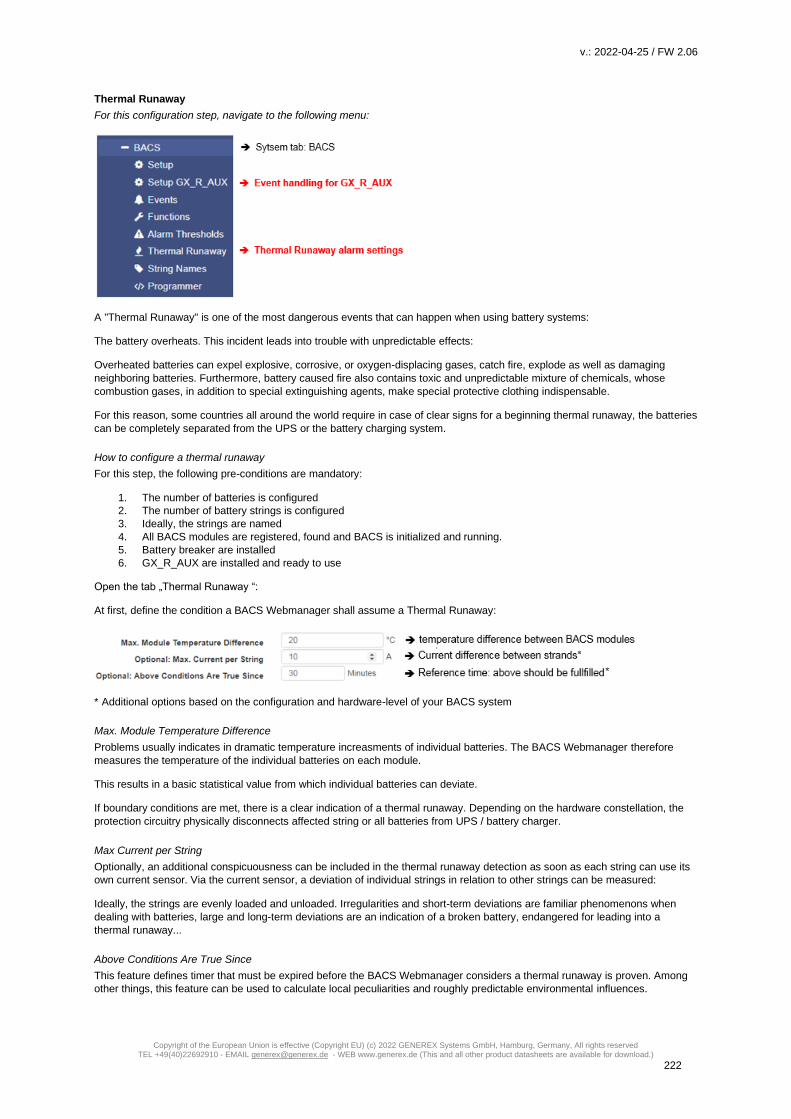
v.: 2022-04-25 / FW 2.06
Copyright of the European Union is effective (Copyright EU) (c) 2022 GENEREX Systems GmbH, Hamburg, Germany, All rights reserved TEL +49(40)22692910 - EMAIL [email protected] - WEB www.generex.de (This and all other product datasheets are available for download.)
222
Thermal Runaway
For this configuration step, navigate to the following menu:
A "Thermal Runaway" is one of the most dangerous events that can happen when using battery systems:
The battery overheats. This incident leads into trouble with unpredictable effects:
Overheated batteries can expel explosive, corrosive, or oxygen-displacing gases, catch fire, explode as well as damaging
neighboring batteries. Furthermore, battery caused fire also contains toxic and unpredictable mixture of chemicals, whose
combustion gases, in addition to special extinguishing agents, make special protective clothing indispensable.
For this reason, some countries all around the world require in case of clear signs for a beginning thermal runaway, the batteries
can be completely separated from the UPS or the battery charging system.
How to configure a thermal runaway
For this step, the following pre-conditions are mandatory:
1. The number of batteries is configured
2. The number of battery strings is configured
3. Ideally, the strings are named
4. All BACS modules are registered, found and BACS is initialized and running.
5. Battery breaker are installed
6. GX_R_AUX are installed and ready to use
Open the tab „Thermal Runaway “:
At first, define the condition a BACS Webmanager shall assume a Thermal Runaway:
* Additional options based on the configuration and hardware-level of your BACS system
Max. Module Temperature Difference
Problems usually indicates in dramatic temperature increasments of individual batteries. The BACS Webmanager therefore
measures the temperature of the individual batteries on each module.
This results in a basic statistical value from which individual batteries can deviate.
If boundary conditions are met, there is a clear indication of a thermal runaway. Depending on the hardware constellation, the
protection circuitry physically disconnects affected string or all batteries from UPS / battery charger.
Max Current per String
Optionally, an additional conspicuousness can be included in the thermal runaway detection as soon as each string can use its
own current sensor. Via the current sensor, a deviation of individual strings in relation to other strings can be measured:
Ideally, the strings are evenly loaded and unloaded. Irregularities and short-term deviations are familiar phenomenons when
dealing with batteries, large and long-term deviations are an indication of a broken battery, endangered for leading into a
thermal runaway...
Above Conditions Are True Since
This feature defines timer that must be expired before the BACS Webmanager considers a thermal runaway is proven. Among
other things, this feature can be used to calculate local peculiarities and roughly predictable environmental influences.

v.: 2022-04-25 / FW 2.06
Copyright of the European Union is effective (Copyright EU) (c) 2022 GENEREX Systems GmbH, Hamburg, Germany, All rights reserved TEL +49(40)22692910 - EMAIL [email protected] - WEB www.generex.de (This and all other product datasheets are available for download.)
223
When finished with configuration, open the GX_R_AUX configuration dialog
Your settings changed thee entries and fixed them to a special functionality:
All you need to do is the definition whether the battery breaker you are using are Normally Open (NO) Contacts or Normally
Closed (NC) contacts. Due to the fact, both concepts are in use, BACS cannot know which type of battery breakers are currently
in use.
Open BACS event handling and search for BACS thermal Runaway String 1, 2 und 3 and unfold them:
The BACS Webmanager automatically added an AUX-Job to switch the battery breaker.
Press the test button to check whether the battery breaker will be triggered and opens accordingly. If not, you need to configure
the NC/NO-Contacts of the BACS GXR_AUX to the correct position and check wiring at the device itself.
Note
If you configure the Thermal Runaway after configuring GX_R_AUX outputs, be sure to check for previously entered events for
plausibility:
You may also need to open the battery interrupters for other reasons, the Thermal Runaway configuration dialog will only work
on a specific scenario and configuration routine automatically:
The outputs are renamed and a preconfigured job is automatically added to the corresponding events. Since the BACS Web
Manager cannot know why you entered these additional conditions, BACS will not remove all your configurations automatically-
It is up to you to check them manually.

v.: 2022-04-25 / FW 2.06
Copyright of the European Union is effective (Copyright EU) (c) 2022 GENEREX Systems GmbH, Hamburg, Germany, All rights reserved TEL +49(40)22692910 - EMAIL [email protected] - WEB www.generex.de (This and all other product datasheets are available for download.)
224
Maintenance: Replacing BACS modules
Unfortunately, even in the best systems, it can occasionally happen that a module shows an abnormality that makes it
necessary to replace it.
Replacing a BACS module is easy, but you need to follow these few rules:
1. Find the module ID of the module you plan to replace
Normally, the BACS WEBMANAGER tells you which module is defect.
2. Program the module to the ID the old module uses.
3. Program the spare parted module to the correct ID. The ID 0 is preset ex works; therefore, you can simply set the ID 0
to the desired ID accordingly via the 'Single Mode' of the BACS Programmer.
4. Replace the old module with new spare part module
Remove the defective BACS module and connect the new BACS module.
5. check if the ID is correct
At the start of BACS,
a. ensure there are no ID duplicates in the BACS bus,
b. ensure, that all BACS modules are continuously numbered
6. Restart BACS - the new module will be detected and queried automatically.
Which BACS module can be used as spare part?
In principle, you can re-arrange all BACS modules as you wish as long as you use only one battery string.
But you cannot mix different hardware revisions of the BACS modules! At the BACS Monitor, the BACS module hardware
revision is provided:
Why is the revision number for this BACS system correct?
During initialization phase of BACS after configuration work is done, the module with ID 1 is read in and all subsequent modules
are compared with this hardware revision version.
By doing so, the BACS system quickly finds the wrong modules.
For more information, please refer tot he chapterl BACS Error: HW / Calibration error
BACS LOG files
The BACS log files provide extensive information about your batteries managed by BACS:
- temperature values - Charge / discharge cycles - Internal resistance of the batteries - Current fluctuations - Operating time - etc
These log files allow deep battery analyzes for both, the current system states and for any single battery state within a battery string. In addition, these valuable data can be used to track the battery life cycle since installation and even make reliable predictions about impending failures - important information for planning of maintenance intervals. The BACS web manager has 30 MB of exclusively reserved memory in order to reliably save all BACS log data. Rotating memory management provides maximizing available log files With rotating storage management, the data is initially stored continuously up to the maximum usable storage size. If the maximum available storage space is reached, the oldest entry is deleted in order to obtain the necessary space for the new data. By doing so, the BACS WEBMANAGER grants a continuous data history.

v.: 2022-04-25 / FW 2.06
Copyright of the European Union is effective (Copyright EU) (c) 2022 GENEREX Systems GmbH, Hamburg, Germany, All rights reserved TEL +49(40)22692910 - EMAIL [email protected] - WEB www.generex.de (This and all other product datasheets are available for download.)
225
Size of the time window before the oldest log files will be erased You can actually only estimate an average time window, because the amount of data is shaped not only by the number of modules, but also by the type of use in combination with unforeseeable incidents. As an example:
- One single BACS module … generates about 700 bytes in one day in normal operation without battery discharge cycles. If your system consists of only 1 module, the memory would need more than 29,000 days before the first day will be deleted to save the latest data.: The local saved battery data log would show about 80 years - this is nearly an average human lifetime. - A standard UPS system with 40 batteries...
will generate with 40 * 700 bytes about 28000 bytes per day in normal operation. The BACS web manager could therefore hold and provide over 1000 days. You can assume that the 2 - 2 1/2 years are available
The crux of the standard application, however, can be found within the definition and the details of a memory calculation. In case of a discharge cycle, the data logging frequency increases in order to ensure traceability and analysis of the discharge:
Due to the increased measuring frequency during the discharge cycle, each BACS module generates approx. 9300 bytes. When we assume a special and very theoretical discharge scenario (normally the batteries are depleted long before), the BACS web manager could record the discharge for a standard UPS with 40-60 batteries in this scenario up to 17-18 hours continuously.
Note: What is such a „theoretical discharge scenario“? Usually, a power failure itself cannot be planned, but the batteries can be found at a foreseeable site when this happens. As soon as the EDP has been shut down, the UPS can also be switched off. How long the UPS will grant emergency power depends on the capacity of the UPS as well as the number of devices that must be feed with emergency power. However, there is also the possibility that you have a mobile EDP system with limited main power usage that comes with the problem a hardware shutdown is not an option (e.g. a tectonic sensor grid). Minor power usage may lead into a very long emergency power operating time via the UPS. In this special scenario, the battery data can provide valuable insights to improve reliability with some limitations.
- A large UPS solution with 120 managed batteries…
When normal operation is active, the BACS WEBMANAGER would generate with 700byte * 120 units an impressive amount of data of up to 84,000 bytes - Keep in mind that these data are not "image files", we are talking about numerical values that are in a table and can be converted into graphic tables if necessary. In this case, the BACS WEBMANAGER B4 can keep this immense amount of battery data for up to 238 days before the oldest files have to be overwritten. The data will be available for about 7-9 months. During a discharge, the measuring frequency is increased as described above. In a very large battery system with up to 120 batteries, a BACS web manager can still hold records of the discharging process between 8-12 hours, the amount of collected data is difficult to imagine.
To save the data permanently, the log files can be exported. How often this is necessary depends on the size and use of the entire system: In the case of very large systems, it is usually sufficient to back up the data about once a month in order to have a closed history of all battery data in an emergency. Data from a very large system, which very often changes to the discharge state due to usage, should be saved more frequently accordingly. What are all these data used for? Yes, why should you keep the data ... a good question! As already mentioned, deep analyzes and a qualified current battery system health status can be generated as well as status reports for time windows needed for the maintenance work. Indicators such as a steadily increasing internal resistance reflect the natural aging process of a battery and indicate the end of use. In case of system malfunction, all these data are also useful for a reconstruction of the incident, because the battery data help to classify the malfunction in a clear and unambiguous timeline. They provide valuable additional insights and help to improve the safety net and demonstrate weak points within the UPS solution.

v.: 2022-04-25 / FW 2.06
Copyright of the European Union is effective (Copyright EU) (c) 2022 GENEREX Systems GmbH, Hamburg, Germany, All rights reserved TEL +49(40)22692910 - EMAIL [email protected] - WEB www.generex.de (This and all other product datasheets are available for download.)
226
Special applications, on the other hand, can be better planned and implemented because, for example, the findings could be used within a simulation program and proof-of-concept studies can be carried out for future UPS concepts. So there are a few reasons to back up this data - the value of this data depends on what you want to do with it.
Note: After a long discharge cycle, it takes a some time for the batteries to be recharged. We recommend picking up and analyzing the data after charging process is finished: Not only for saving data, you can also see directly whether the batteries have been correctly recharged - you will get valuable information about the current state of health of the entire system. You can instruct the BACS WEBMANAGER to inform you as soon as the batteries are fully charged. BACS will inform you if: ... there are complications in which an intervention is inevitable or imminent. ... the loading process was successfully completed.
Retrieve BACS log data
There are different options to get the BACS log files
Via Web interface
For this step you need the following menu:
The BACS log files can be downloaded directly from the BACSLog menu.
For the evaluation, we recommend the professional analysis tool BACS Viewer, which is available as freeware in the download
area of our website www.generex.de.
The BACS WEBMANAGER provides two different options:
:
Download archive
You can call up all available log files directly via the integrated web interface. The data is packed in real time and the download
starts automatically as soon as the file is available. Please note, that the time window to generate the data strongly depends on
the amount of available data.

v.: 2022-04-25 / FW 2.06
Copyright of the European Union is effective (Copyright EU) (c) 2022 GENEREX Systems GmbH, Hamburg, Germany, All rights reserved TEL +49(40)22692910 - EMAIL [email protected] - WEB www.generex.de (This and all other product datasheets are available for download.)
227
Send as Email
For this function, you need to configure the build-in mail client before using this function.
The BACS web manager offers you sending available log files via email to any email address. Since the data attachment can be
up to 20 MB, it is recommeded to limit the amount of data accordingly:
Mailadresse des Empfängers
Tittel der Mail
Eingrenzen der Datenmenge
Mail absenden/ abbrechen
Mail servers are now sensitive to large attachments, since many users have lost the feeling for file sizes - attaching content with
more than 10 MB to emails may cause problems when sending and receiving emails. As a consequence, administrators and
service providers have often reduced the size of the attachments. If the attachment is too large, the email will be sent without
the attachments or emails will be simply refused by the incoming mail server...
With this function you can - based on a daily report - enter the desired number of hours. If you e.g. enter a 7, the BACS will mail
the last 7 hours.
Note
The maximum size of the packed file is 20 MB - the real size of the file and the amount of hours that could be found within the
log file depends on the type of use and the size of the files.
Direct download via SFTP
You can access the data directly via the integrated download server of the BACS WEBMANAGER - use any SFTP client - there is no limitation which client you should use. Access data: IP: <die IP address of your WEBMANAGER> Port: SFTP / Port 22 User: admin Passwort: cs141-snmp or your specific admin passwort
After logging in, open the directory var/log - here you will find all BACS log files.Simply copy the files to your hard drive - you can
later evaluate the log files with professional battery analizing tool BACS-Viewer .
Direct download and evaluation via BACS-Viewer
You may also use
the SFTP client that is an integrated part of the BACS Viewer. To do
this, enter the IP address and the desired time window.
The BACS viewer will automatically connect to the corresponding BACS
web manager and collect the corresponding files.
If wanted the BACS viewer can be instructed to automatically query all
registered BACS web manager when the software starts..
Note:
The BACS viewer software is a powerful freeware battery analysis tool.
You can download the software and manuals from our download area at www.generex.de.

v.: 2022-04-25 / FW 2.06
Copyright of the European Union is effective (Copyright EU) (c) 2022 GENEREX Systems GmbH, Hamburg, Germany, All rights reserved TEL +49(40)22692910 - EMAIL [email protected] - WEB www.generex.de (This and all other product datasheets are available for download.)
228
Pause Equalization on schedule
For this configuration step, you need the following menu:
This hidden function is a little bit difficult to explain without basic information about the production process of a battery – please
read the following information carefully, it will explain you why this function is very powerfull and how set up the most effective
configuration that fits to your batteries …
Depending on the manufacturer and production process, AGM batteries require a few charge / discharge cycles to achieve the
optimum performance for a standby mode of a UPS. The number of chards / discharge cycles you need to form up your
batteries is a technical puzzler:
Basically, there are two different production methods for batteries:
Formed accumulators
As a post production process, formed accumulators were repeatedly charged and discharged. By doing so, the battery
chemistry itself will perform a so-called recombination. Caused by the entropy during the charge / discharge cycle, the
recombination of the battery chemistry will stabilize the internal resistance of the entire accumulator. As a side effect,
the accumulator's capacity will be maximized.
Unformed accumulators
These batteries are produced, packed and sold directly without any post production service. The entire forming
process is a part of the final installation on site. The forming process will be performed by the customer during first
months of usage - as an example, while running battery stress tests or by random power failures. In the end, these
batteries will also reach full capacity as well as a stabilized internal resistance, but it will take much longer than
batteries that are formed before installation on site.
OK, but why does unformed accumulators exist?
There is no legal standard that dictates forming - accordingly, it is a service of battery manufacturers and is a quality feature of
recently produced batteries. As a consequence, it is up to the manufacturer how he wants to produce and sell his batteries:
While some manufacturer only supplies formed batteries as a quality standard, other manufacturer design two different product
lines or produce as cheap as possible.
Note
From a technical point of view, no differences can be observed between the formed and unformed batteries during
commissioning - all accumulators that have been assembled to a battery system have to perform such a formation process. The
difference is that already pre-formed accumulators can finish this process much faster. Please note, the "formation is finished"
can only be seen when evaluating the battery data collected by BACS.
In principle, BACS eliminates generally harmful voltage fluctuations.
As a result, formed batteries are spared and can be used over a very long time - sometimes even beyond the manufacturer's
specifications about the design life of a battery. However, if batteries are unformed at start-up, balancing or equalizing,
especially in the early days, could slow down the formation process enormously, because the accumulators need these voltage
fluctuations.
Determining the optimal time from to hand over the equalization of your BACS system completely, depends, among other
things, on the basic operating mode:
Scenarios with a cyclic usage
In the case of cycling applications, formation takes place automatically as there is generally a regular charge / discharge cycle.
This means BACS can run immediately and your batteries will reach their maximum capacity very quickly.
Scenarios with a stand-by usage
In case of standby applications, the situation differs:

v.: 2022-04-25 / FW 2.06
Copyright of the European Union is effective (Copyright EU) (c) 2022 GENEREX Systems GmbH, Hamburg, Germany, All rights reserved TEL +49(40)22692910 - EMAIL [email protected] - WEB www.generex.de (This and all other product datasheets are available for download.)
229
Because there is no cyclic discharge, the formation is carried out by natural voltage fluctuations of the UPS. As a consequence,
a system that mostly eliminates voltage fluctuations slows down the entire formation process.
How to use „Pause Equalization”
As you can see, only Chuck Norris has an automatic battery forming process because his roundhouse kick will teach the
batteries what they want to do... In all other cases it is technically not possible because the batteries can vary enormously
depending on batch, grade, manufacturer, chemical composition, storage time after production, storage location, etc. It can
actually happen that two batteries from the same manufacturer need completely different time windows until they reach the
formed state - New BACS-controlled UPS systems must be observed individually.
Pause Equalization is thus a kind of "pause function" to facilitate the structured formation or reformation of batteries. To use this
function, open the scheduler and select the job Pause Equalizing:
Setting up Hours and job timing
How many hours you want to pause equalizing is difficult to answer - BACS can facilitate and accompany the formation process
in many ways. Here are 3 examples how to configure the BACS function pause equalizing:
Method 1: As easy as possible
Pause Equalizing for 5 days and repeat the job:
In this case, choose 120 hours and advice the CS141 to repeat once in a week:
The BACS Webmanager will pause equalizing for 120 hours or 5 days. The UPS is this given the chance to advance the battery
formation 5 days a week. Then the BACS Webmanager will enable Equalizing for 2 days and generate comparable data. After
an overall period of 7 days, the job will be re-run … The BACS Web Manager Monitoring will always inform you if something
with the batteries is not working as expected, even if Equalizing is temporarily disabled or pausing.
Use a second job to get status information about the forming process:
On initial start, the BACS Webmanagers integrated
monitoring system starts collecting all required battery data
for a detailed forming status evaluation. Just add a
scheduled mail and the BACS Webmanager will send your
regular status reports including necessary log files. You do
not need dayly reports, getting a status mail once a month
should be enough to decide if the forming process is
finished. If there an additional problem occurs:
BACS will inform you immediately....
During data evaluation, what are you looking for?
As an example, if you start with 40 unformed batteries, you
will notice that each battery will show individual
charge/discharge voltages. This is not an issue, it is
natural for both, pre-formed and unformed batteries. With
each discharge / charge cycle, the voltage curves of all batteries approach each other until they are only about 1V apart. If this
can bee seen, batteries are in sync and the forming process is largely completed. You may quit and delete the scheduled job
"Pause Equalizing" and BACS begins its work.

v.: 2022-04-25 / FW 2.06
Copyright of the European Union is effective (Copyright EU) (c) 2022 GENEREX Systems GmbH, Hamburg, Germany, All rights reserved TEL +49(40)22692910 - EMAIL [email protected] - WEB www.generex.de (This and all other product datasheets are available for download.)
230
With this method, you can evaluate the battery data once a month and are informed about the current state of health of the
batteries. As soon as the battery data reaches formation parameters and indicates that the formation has been completed
successfully, the Pause Euqalizing job can be adjusted or removed accordingly.
Method 2 – during running – faster but time-consuming
You can also instruct the BACS web manager to take control step by step.
If you choose running this way, euqalizing is configured to pause each day for a specific time window. The advantage is that
your UPS system is not on its own for the first few weeks. BACS has an eye on it and equalizing is most of the week enabled.
This method allows to plan special charge/discharge cycles without BACS equalizing provides and speed up the forming
process. As an example, if your batteries have a discharge/charge cicle of about 6 hours, you can plan a “not-equalized time
window of 6 hours” dayly, weekly – you can customize this time window to fit to your conditions.
In this example, the job Pause Equalizing will stop the
equalizing process from 6:00pm Uhr to 11:00pm.
This will provide a unique time window to run a custom
discharge / charge cycle and log the voltage behavior of
the batteries. This method could be very interesting if you
change some batteries and mix some new with old
batteries. Equalizing will save your existing, already
formed batteries and your new batteries have the chance
to form up with all other batteries.
In this example, we will use a periodic message reporting - if you know that equalizing pauses from 6:00 pm to 11:00 pm, you
could create a "formation report" and get the according log files by mail:
In this case, set the je-mail job timing to Weekly and
instruct the BACS WEBMANAGER to generate a status
mail with the current battery data at 23:15 on Mondays,
Wednesdays and Fridays.
As a consequence of a scheduled hour-by-hour formation of batteries, the entire formation process will take some more time:
Technically, the internal battery chemistry is calmed by eliminating the necessary voltage fluctuations associated with
equalization - this will slow down the forming process.
On the other hand, evaluating of data is easier because you can directly compare how the batteries behave. This will allow you
to determine very precisely when there will be no improvement in the voltage values and fully activate the equalization with
pinpoint accuracy. As a side effect, you may train to spot strange measuring data.
Method 3 – Completly scheduled with unique single jobs
If you choose to climb this way, you need some experiences about using batteries and their behavior when equalize them. In
general, the sense of scheduled tasks is to plan jobs and execute them automatically when the time has come to trigger a
function. You may choose between cyclic jobs like sending mails with log files or single jobs like a small text message to your
RCCMD client to remember yourself a single event is pending.
However, the advantage of this method is, that you can design and configure a general road map to form the batteries. As an
example, it may look like this job list:
- Enable Equalizing for 2 days - Send an email with log files for data evaluation - Pause Equalizing for 7 days - Send an email for data evaluation - Enable Equalisation for 3 days - Pause Equalizing for 5 days - Send a mail with log files for data evaluation - Pause Equalizing the next 7 days for some hours - Send a mail with log files for data evaluation - […]

v.: 2022-04-25 / FW 2.06
Copyright of the European Union is effective (Copyright EU) (c) 2022 GENEREX Systems GmbH, Hamburg, Germany, All rights reserved TEL +49(40)22692910 - EMAIL [email protected] - WEB www.generex.de (This and all other product datasheets are available for download.)
231
This will allow you to create a normalized 6-month battery forming procedure. To abort this scheduled task list because the
forming process is finished earlier than expected, just delet this job list.
Note:
Forming new battery systems is an individual matter that largly bases on experience. In general, you can say:
Unformed high-quality batteries reach the final operating state faster than unformed less-quality batteries. But it is alsow
possible that pre-formed low-quality batteries may surprise you very much.
Please keep in mind, each battery system is a unique installation that needs an individual point of view.
Tutorial: BACS deactivated by System
With its management functions, BACS actively intervenes in the control process and thus guarantees the optimal charging
conditions for each individual battery within the according battery string.
The equalizing level is active for 3 of 4 battery strings. BACS manages each single batteries individually and adjusted them
perfectly to the target voltage. However, for the 4th battery string called "String 1 Neg", BACS displays that the equalizing
functions was disabled for some reason.
Why does BACS disable balancing?
BACS regularly checks whether there is an improvement in the voltage - by doing so,
balancing (equalizing) makes sense to the BACS WEBMANAGER, and he will continue
with balancing. With some operating conditions, however, it can always happen that BACS
would be able to manage the charging current individual to each battery in the battery
string, but not without permanent 100% balancing (equalization) and only without any
measurable improvements.
In addition to the classic that a battery simply becomes stubborn for literally inexplicable
and incomprehensible reasons, there are usually 3 scenarios in which BACS can conclude
that equalizing is theoretically possible, but practically examining the batteries should be:
1. New and old batteries or batteries from different manufacturers were mixed
Since BACS adjusts the charging currents individually to the needs of the battery through
balancing, a special feature of BACS is that individual batteries can in principle be
exchanged as you wish. If you decide to use another manufacturer, the performance data
and battery type can be similar, but the internal battery chemistry differs depending on the
grade and mixing ratio or how redox reaction runs during the charging process, etc. Finally,
this can lead into big differences between the stock batteries that simply cannot be
balanced over a long period of time – BACS will assume that exact this single battery will
never fit to the desired battery string.
2. Damaged batteries and wiring problems
While a hidden battery damage can appear again and again as an unpredictable factor,
with this warning message you should take another look at the batteries and the cabling,
especially after maintenance work. Even if the system itself could run without error
notification in its existing configuration, the values collected indicate that something is
fundamentally wrong, because at least one module is always running on 100%.
3. Old batteries
With ongoing aging, batteries will take over a very individual voltage, charging and capacity
behavior and drift apart - in this case, a core task of BACS is to intervene in the charging
cycle and thus create an individually optimized charging environment. As a consequence, the age of the batteries also
increases the intensity with which balancing has to be carried out.

v.: 2022-04-25 / FW 2.06
Copyright of the European Union is effective (Copyright EU) (c) 2022 GENEREX Systems GmbH, Hamburg, Germany, All rights reserved TEL +49(40)22692910 - EMAIL [email protected] - WEB www.generex.de (This and all other product datasheets are available for download.)
232
When the batteries reach the calculated design life, it may become noticeable that BACS has run its balancing up to 100% for
some batteries within a battery string, but without any significant improvements. Although everything is set correctly, BACS will
report this information as “Equalizing deactivated by system” and pauses the equalizing accordingly.

v.: 2022-04-25 / FW 2.06
Copyright of the European Union is effective (Copyright EU) (c) 2022 GENEREX Systems GmbH, Hamburg, Germany, All rights reserved TEL +49(40)22692910 - EMAIL [email protected] - WEB www.generex.de (This and all other product datasheets are available for download.)
233
Trouble Shooting List
This table shows an event overview and generally recommended actions for helping with maintenance work.
EVENT Name Event description Explanation Recommended reaction
BACS started Battery monitoring started BACS System has started and is now managing batteries
For your information.
BACS Discharging Phase
Battery discharging BACS System noted that a discharge has started
Check Charger output status and Battery Breaker
BACS Charging Phase
Battery charging BACS System is back to normal from a previous discharge.
For your information. Watch if batteries charge correctly.
BACS System Alarm
Module communication is lost and the system is in Alarm mode! React immediately!
BACS system is not functional at this status and needs attention
Intervention required: Check communication cable and addressing
BACS System Alarm off
Module communication restored
BACS System communication problems cleared
For your information
BACS Voltage High Alarm
BACS Voltage High Alarm
BACS System detected one or more batteries with voltage out of the configured alarm threshold.
Check battery health and charger
BACS Voltage High Alarm off
BACS Voltage High Alarm reset
BACS System High Alarm cleared For your information.
BACS Voltage Low Alarm
BACS Voltage Low Alarm BACS System detected one or more batteries with voltage out of the configured alarm threshold
Check battery health and charger
BACS Voltage Low Alarm off
BACS Voltage Low Alarm reset
BACS System Low Alarm cleared For your information
BACS Temperature High Alarm
BACS Temperature High Alarm
BACS System detected one or more batteries with temperature out of the configured alarm threshold
Intervention required: Check charger and environmental conditions and watch if temperature increases or comes back to normal. Check if balancing is active and if ampere rating of battery is correctly configured. If both are correct, check battery health to avoid a thermal runaway.
BACS Temperature High Alarm off
BACS Temperature High Alarm reset
BACS System High Alarm cleared - No action
For your information.
BACS Temperature Low Alarm
BACS Temperature Low Alarm
Temperature of one or more modules are beyond the configured alarm threshold.
Check environmental conditions
BACS Temperature Low Alarm off
BACS Temperature Low Alarm reset
BACS System Low Alarm cleared - No action
For your information.
BACS Resistor High Alarm
BACS Resistor High Alarm
Resistance/Impedance of one or more modules are beyond the configured alarm threshold.
Check battery health and voltage level
BACS Resistor High Alarm off
BACS Resistor High Alarm reset
BACS System High Alarm cleared. For your information.
BACS Resistor Low Alarm
BACS Resistor Low Alarm
Resistance/Impedance of one or more modules are beyond the configured alarm threshold
Check battery health and voltage level
BACS Resistor Low Alarm off
BACS Resistor Low Alarm reset
BACS System Low Alarm cleared - No action
For your information.
BACS Voltage Diff High Warning
Voltage difference between single batteries/cells to high
Battery Voltage difference within one or more battery strings are beyond the configured threshold.
check battery health
BACS Voltage Diff High Warning off
Voltage difference between single batteries/cells reset
Battery Voltage difference within one or more battery strings are back to normal
For your information
BACS Battery Breaker open Alarm
Battery breaker/fuse open, no battery protection active!
Battery breaker or Battery fuse has been opened.
Intervention required: Check battery breaker/fuse status immediately in order to prevent loss of load in case of a power outage.
BACS Battery Breaker open Alarm off
Battery breaker/fuse closed
Battery breaker/fuse is normal again, batteries should again pick up charge - no action
For your information, it is recommended to check the battery breakers and fuses
BACS Equalizing Error Alarm
Equalisation error BACS Equalisation Failure automatically stops all balancing functions
Reboot/Coldboot the system and wait for clearance. If the problem cannot be solved by the BACS itself after some hours, call BACS support.

v.: 2022-04-25 / FW 2.06
Copyright of the European Union is effective (Copyright EU) (c) 2022 GENEREX Systems GmbH, Hamburg, Germany, All rights reserved TEL +49(40)22692910 - EMAIL [email protected] - WEB www.generex.de (This and all other product datasheets are available for download.)
234
BACS Equalizing Error Alarm off
Equalisation error reset BACS Equalisation Failure cleared For your information.
BACS Voltage High Warning
BACS Voltage High Warning
BACS System detected one or more batteries with voltage out of configured warning threshold
1. Check if voltage increases or comes back to normal. 2. Check if balancing is active and ampere rating of battery is correctly configured. If both are correct, check battery health
BACS Voltage High Warning off
BACS Voltage High Warning reset
BACS System High Warning cleared. For your information.
BACS Voltage Low Warning
BACS Voltage Low Warning
BACS System detected one or more batteries with voltage out of configured warning threshold.
1. Check if voltage decreases or comes back to normal. 2. Check if balancing is active and ampere rating of battery is correctly configured. If both are correct, check battery health
BACS Voltage Low Warning off
BACS Voltage Low Warning reset
BACS System Low Warning cleared. For your information.
BACS Temperature High Warning
BACS Temperature High Warning
BACS System detected one or more batteries with temperature out of configured warning threshold.
Check charger and environmental conditions and watch if temperature increases or comes back to normal. Check if balancing is active and ampere rating of battery is correctly configured.
BACS Temperature High Warning off
BACS Temperature High Warning reset
BACS System High Warning cleared. For your information.
BACS Temperature Low Warning
BACS Temperature Low Warning
BACS System detected one or more batteries with temperature out of configured warning threshold.
1. Check if temperature decreases or comes back to normal. 2. Check charger and battery breaker and environmental conditions.
BACS Temperature Low Warning off
BACS Temperature Low Warning reset
BACS System Low Warning cleared. For your information.
BACS Resistor High Warning
BACS Resistor High Warning
BACS System detected one or more batteries with impedance out of configured warning threshold
Check if voltage and temperature is correct. If problem persists, call battery service to check battery health
BACS Resistor High Warning off
BACS Resistor High Warning reset
BACS System High Warning cleared For your information.
BACS Resistor Low Warning
BACS Resistor Low Warning
BACS System detected one or more batteries with impedance out of configured warning threshold.
Check if voltage and temperature is correct. If problem persists, call battery service to check battery health
BACS Resistor Low Warning off
BACS Resistor Low Warning reset
BACS System Low Warning cleared. For your information.
BACS General Alarm
General failure/alarm, check website BACS for Alarm details
BACS System detected an Alarm, what trigger always the general alarm.
Check BACS Webinterface and Logfile for Alarm detail and take a look to the recommended action for it.
BACS General Alarm off
General failure/alarm reset
BACS System general alarm cleared. For your information.
BACS Thermal Runaway Alarm
Thermal Runaway conditions TRUE
Thermal runaway risk at this string. Intervention required: Check temperature and voltage and battery health.If battery breaker has been opened, check battery health before closing the breaker
BACS Thermal Runaway Alarm off
Thermal Runaway conditions FALSE - Normal
Thermal runaway alarm cleared For your information: Evaluate data to find the reason why a termal runaway alarm happened.
BACS Discharge Counter Alarm
Discharge Counter beyond configured threshold
Configured number of discharges reached.
Check battery health and decide if more cycles can be accepted
BACS Discharge Counter Alarm off
Discharge Counter reset Discharge Counter has been reset to 0 For your information.
BACS GX_R_AUX 1 Input 1 Alarm Off
GX_R_AUX DigitalInput 1 LOW
Connected dry contact closed/opened, action depends upon connected application.
Action depends on connected application.

v.: 2022-04-25 / FW 2.06
Copyright of the European Union is effective (Copyright EU) (c) 2022 GENEREX Systems GmbH, Hamburg, Germany, All rights reserved TEL +49(40)22692910 - EMAIL [email protected] - WEB www.generex.de (This and all other product datasheets are available for download.)
235
BACS GX_R_AUX 1 Input 1 Alarm
GX_R_AUX DigitalInput 1 HIGH
Connected dry contact closed/opened, action depends upon connected application.
BACS Baseline Impedance Alarm
BACS Baseline Resistor High Alarm
Resistance/Impedance of one or more modules are out of the percentual baseline alarm threshold.
Check battery health and voltage level
BACS Baseline Impedance Alarm Off
BACS Baseline Resistor High Alarm reset
Alarm / warning cleared. For your information.
BACS Baseline Impedance Warning
BACS Baseline Resistor High Warning
Resistance/Impedance of one or more modules are out of the percentual baseline warning threshold.
check battery health and voltage level
BACS Baseline Impedance Warning Off
BACS Baseline Resistor High Warning reset
alarm / warning cleared. For your information.
BACS String Voltage High Alarm
String voltage too high String voltage out of configured threshold. Check Charger and battery health
BACS String Voltage High Alarm Off
String voltage alarm reset alarm / warning cleared. For your information.
BACS String Voltage Low Alarm
String voltage too low String voltage out of configured threshold. Check Charger and battery health
BACS String Voltage Low Alarm Off
String voltage alarm reset alarm / warning cleared For your information.
BACS String Voltage High Warning
String voltage high String voltage out of configured threshold. Check Charger and battery health
BACS String Voltage High Warning Off
String voltage warning reset
alarm / warning cleared For your information.
BACS String Voltage Low Warning
String voltage low String voltage out of configured threshold. Check Charger and battery health
BACS String Voltage Low Warning Off
String voltage warning reset
alarm / warning cleared. For your information.
BACS String Current High Alarm
Positive (Charging) String current too high
String current out of configured alarm threshold. Check Charger and battery health
Check Charger and battery health
BACS String Current High Alarm Off
String current alarm reset alarm / warning cleared For your information.
BACS String Current Low Alarm
Negative (Discharging) String current too high
String current out of configured alarm threshold.
Check Charger and battery health
BACS String Current Low Alarm Off
String current alarm reset alarm / warning cleared For your information.
BACS String Current High Warning
Positive (Charging) String current high
String current out of configured warning threshold.
Check Charger and battery health
BACS String Current High Warning Off
String current warning reset
alarm / warning cleared - no action For your information.
BACS String Current Low Warning
Negative (Discharging) String current high
String current out of configured warning threshold.
Check Charger and battery health
BACS String Current Low Warning Off
String current warning reset
alarm / warning cleared. For your information
BACS Module Revision Alarm
Wrong/Incompatible module revision in BACS bus found
Installation of different BACS module revisions or missing module revision information may trigger this alarm.
This is an installation error, different hardware revision modules has been used. Contact BACS support.
BACS Module Revision Alarm Off
Module revision alarm reset
alarm / warning cleared For your information.

v.: 2022-04-25 / FW 2.06
Copyright of the European Union is effective (Copyright EU) (c) 2022 GENEREX Systems GmbH, Hamburg, Germany, All rights reserved TEL +49(40)22692910 - EMAIL [email protected] - WEB www.generex.de (This and all other product datasheets are available for download.)
236
BACS Equalizing deactivated by System
Balancing/Equalization does not take effect for up to 4 days.
If the balancing/equalisation does not show any effect on one or more modules/batteries, it will be turned off after some time and this warning is triggered
Check battery health
BACS Equalizing deactivated by System Off
Balancing/Equalization restarted - warning reset
alarm / warning cleared For your information.
BACS String Current Deviation Discharge Alarm
Discharge Current difference between strings too high
BACS has noticed there is a problem when string current measurements deviates compared to other strings during a discharge cycle.
Check Charger and battery string health
BACS String Current Deviation Discharge Alarm Off
Discharge Current difference between strings Alarm reset
alarm / warning cleared - no action For your information.
BACS String Current Deviation Charge Alarm
Charge Current difference between strings too high
BACS has noticed there is a problem when string current measurements deviates compared to other strings during a charge cycle after discharging.
Check Charger and battery string health
BACS String Current Deviation Charge Alarm Off
Charge Current difference between strings too high reset
alarm / warning cleared For your information.
BACS String Current Deviation Discharge Warning
Discharge Current difference between strings high
BACS has noticed an unusual high current difference within the battery strings during a discharge cycle.
Check Charger and battery string health
BACS String Current Deviation Discharge Warning Off
Discharge Current difference between strings high reset
alarm / warning cleared For your information.
BACS String Current Deviation Charge Warning
Charge Current difference between strings high
BACS has noticed an unusual high current difference within the battery strings during a charge cycle.
Check Charger and battery string health
BACS String Current Deviation Charge Warning Off
Charge Current difference between strings high reset
alarm / warning cleared For your information.

v.: 2022-04-25 / FW 2.06
Copyright of the European Union is effective (Copyright EU) (c) 2022 GENEREX Systems GmbH, Hamburg, Germany, All rights reserved TEL +49(40)22692910 - EMAIL [email protected] - WEB www.generex.de (This and all other product datasheets are available for download.)
237
FAQ
CS141 FAQ-Frequently asked questions
There is a strange number, …
What does code 400 (Invalid Handle) / 420 (Failed)/ 522 mean?
This problem can occur if the firmware has been updated but the browser still has old data stored in the cache. Press
CTRL + F5 or delete the cache. Restart the WEBMANAGER.
What does code 401 (Access Denied) mean?
“The way is shut. It was made by those who are Dead, and the Dead keep it, until the time comes. The way is shut.”
Mostly you need to check your password or user name.
What does code 403 (Forbidden) mean?
The user role does not provie the required acces rights for this setting or service.
What does code 404 (Not found) mean?
The requested data point could not be processed because the destination was not found..
What does code 415 (No Interface) mean?
The request is generally valid, but is not supported "as is", e.g. because it has been switched off by a setting.
What does code 422 (Invalid Argument) mean?
This error occurs when trying to adapt the configuration of newer firmware versions with an older firmware. Update to
the latest firmware version.
What does code 423 (Pending)?
The requested resource is temporarily blocked. It should be available again in a few minutes. In most cases, a service
(restarts) in the background.
What does code 500 / 503 (Service Unvailable) mean?
This code occurs when the web server or a service is heavily occupied for some reason, had to restart or similar. If
the problem persists after a few minutes or a restart of the adapter, the firmware must be updated / re-installed. This
is recommended in conjunction with a factory reset.
What does code 501 (Not Implemened) mean?
There are two possibilities right here. Either the device is so busy that the function cannot be called, or the request
was so surprisingly "different" that there is no function for it.
What does code 520 (Unexpected) mean?
There should have been a specific value in a request / response, but there was not.
The UPS status shows „Paused“.
When CS141 accesses the Alert History of the UPS, the normal connection must be temporarily stopped. By
switching to another page inside CS141 menu and pressing F5 to restore the display status (if not done automatically)
this should be fixed.
What does issue -1 mean?
This error occurs if no connection to CS141 is currently possible (CS141 reboots, network lost, etc.), but the user tries
to acces configuration screen. In this case the browser uses cached data to show the screen without the possibility to
enter values. In case of a reboot just give the CS141 a little bit more time.
A little bit awkward, butI forgot my password…
This happens to everyone now and then. Take a look at the "Rescue system" chapter - this might help you. If not,
contact [email protected] and we want to find a way to help you.
Why am I logged out when I disable the http tooltips?
Because the tooltips are related to the http service. Changing some values need to l redirect the user after restarting
the build-in http service.
The CON_R_AUX does not establish a connection!

v.: 2022-04-25 / FW 2.06
Copyright of the European Union is effective (Copyright EU) (c) 2022 GENEREX Systems GmbH, Hamburg, Germany, All rights reserved TEL +49(40)22692910 - EMAIL [email protected] - WEB www.generex.de (This and all other product datasheets are available for download.)
238
This device is not supported by the CS141. You need to use the CON_R_AUX4.
I have entries in the log file called "UPSMAN started"
This entry is generated whenever there was a change in the event configuration: Because the changes are applied
immediately, the "UPSMAN service" must be restarted - this will be protocolled.
When accessing the Alert History, I only get an error!
Maybe this function is not supported by the selected UPS. The fact the CS141 supports your UPS does not mean,
your UPS supports all function available at the CS141 for this UPS. This is a little bit complicated to explain:
sometimes the UPS should support a command, but ignores it consequently.
I get the error "Backend busy" when I try to log in!
Please wait a moment and try again with another browser. If the problem persists after 5 minutes, use the / reboot
function. Refer the chapter If nothing works ...
Does the CS141 supports SNMP v1 queries?
Maybe ... yes or no ...
The CS141 has never or will officially support SNMP queries v1.0. On the other hand it does not mean that it can not if
you wish to do that. The only issue that might prevent you using the CS141 the way you want: Due to the fact this is
officially not supported, there will be no official bug fix if you have problems. Inoffically maybe our developers can do
something if they know somethings not working as it should ...
I have questions that are not explained in the manual.
We always strive to improve our documentation. If you have something that is not or insufficiently explained, please
send us a short message to [email protected] - We are happy to help you as fast as possible.
Q: Why the GX_R_AUX need to be in it’s own strain:
In principle, you can put the GX_R_AUX directly into a BACS bus, it would work too. However, in larger installations with many
BACS modules in one string, this could be a problem:
Each BACS module has a galvanic isolation between the control and the communication module. The communication module is
supplied with the necessary operating voltage by the BACS bus. However, the GX_R_AUX requires more power than the BACS
modules, which could cause communication problems inside the complete string. The limit of installed modules before this
occurs is fluent and depends heavily on where insed the string you placed the GX_R_AUX during installation. Therefore, this
type of installation is only conditionally recommendable.
Q I habe 34 BACS modules and unfortunately 38 batteries… Can I just set up 34 batteries?
Well… in the end, yes, BACS will monitor and equalylize 34 batteries. The last 4 batteries will be just loaded. But this is not
recommendable. It will lead into problems with the 4 batteries left:
- No monitoring
- No battery management
The problem is normally not that you can add 4 modules later, the problem is, if BACS is running and working, you may forget to
add the last 4 batteries.
Q: I want to use LDAP with my CS141 – but I cannot find according configuration menus
Yes, because a native LDAP configuration menue does simply not exist and there is no plan for it. But this does not mean there is no method to use a CS141 and LDAP: Historically, RADIUS servers checked the user's information against a locally stored flat file database. Modern RADIUS servers can do this, or can refer to external sources - commonly SQL, Kerberos, LDAP, or Active Directory servers—to verify the user's credentials. This means: With firmware 2.02 onwards:
- just configure the CS141 to refer to a RADIUS server to process the user access authentification - and configure the RADIUS server to use LDAP

v.: 2022-04-25 / FW 2.06
Copyright of the European Union is effective (Copyright EU) (c) 2022 GENEREX Systems GmbH, Hamburg, Germany, All rights reserved TEL +49(40)22692910 - EMAIL [email protected] - WEB www.generex.de (This and all other product datasheets are available for download.)
239
Appendix:
CS141 Hardening Guide
Each product of the CS141 product family (CS141/HW161 WEBMANAGER, SITEMANAGAER and -MONITOR 6, BACSKIT B4)
provides numerous functions coming with "out of the box" settings and standardized configuration when delivered:
- Predefined and generally valid ports
- Pre-installed certificates, if possible
- Quickly configured web access
- Commonly known default passwords
- Standard community names (for example. "public" or "private" for SNMP)
- And much more ...
Due to this fact, it is possible to put these devices into operation and integrate them into an existing network in a short time and,
above all, without in-depth knowledge of network and system administration, as long as generally accepted conventions for a
network infrastructure are met.
However, standardized out-of-the-box configurations also have the disadvantage that a network-compatible device, regardless of
the manufacturer or its function, cannot be operated as "network security approved" in terms of cybersecurity, if only a glance at
the manufacturer's manual can reveal many interesting features that can be used to eavesdrop on or even infiltrate a network.
This chapter shall show how to harden the settings of a CS141 Webmanager Device.
Note:
Not ALL the options or "recommended settings" presented here are necessarily compatible with your network or can be
implemented in this way to meet the framework of the IT security guidelines on site.
If in doubt, refer to your system administrator in charge!
GENERAL RECOMMENDATIONS:
1. Change your passwords regularly
2. Store your system backups secured and deny unauthorized access
3. Keep an eye on the validity of the certificates used
4. use the latest firmware or check regularly if new firmware versions provide
5. improvements and new security options.

v.: 2022-04-25 / FW 2.06
Copyright of the European Union is effective (Copyright EU) (c) 2022 GENEREX Systems GmbH, Hamburg, Germany, All rights reserved TEL +49(40)22692910 - EMAIL [email protected] - WEB www.generex.de (This and all other product datasheets are available for download.)
240
Part 1: How to secure the user management
All devices of the CS141 - product family offer 2 basic login methods, which can be combined if desired. Both methods have their
respective advantages and disadvantag
Local user management:
The CS141 distinguishes between the user name and the "user role". The only user that is preset on the hardware side and
cannot be deactivated is the user "admin" with the user role "Super User":
All other users can be changed, adjusted and deleted:
Security recommendation:
1. Change the password for the super user "admin" to block the default administrative access.The basic rule for a secure
password is :
- Approx. 8-16 characters
- Upper and lower case
- numbers
- Special characters
Click on "Edit user" at "admin:
This is the first step towards operational security; only the user "admin" with a cryptic password is active and can log on to the device.
2. Disable all user roles you do not need:
Once disabled, a user who has been assigned this role can no longer log in.
Special function: Allow Anonmous Guest
This function is deactivated by default. The anonymous guest is only required if you use a UNMS 2 or have implemented direct
displays of the monitoring screens, e.g. with an iFrame or similar.
Note: A user with the user role "Guest" is sufficient to take a "look" at the UPS screens. The user "Customer" may download log files in addition to "Looking", but nothing else.
3. Delete or edit default user names and passwords

v.: 2022-04-25 / FW 2.06
Copyright of the European Union is effective (Copyright EU) (c) 2022 GENEREX Systems GmbH, Hamburg, Germany, All rights reserved TEL +49(40)22692910 - EMAIL [email protected] - WEB www.generex.de (This and all other product datasheets are available for download.)
241
Change both, the name and password for the factory default users "engineer", "customer" and "guest".
Network managed user management
From firmware 2.04, all units of the CS141 product family offer the option to hand over the user management to a RADIUS
server. By doing so, there are 2 different security concepts:
Access-optimised security: RADIUS, then local user authentication
In this mode, user access is managed exclusively via a RADIUS
server as long as a pre-defined RADIUS is available. If the RADIUS
server does not respond, it is possible to log in via locally managed
user - access to the configuration menus is guaranteed at all times.
Security recommendation:
1. Disable the unnecessary user roles.
Unnecessary user roles distributed by the RADIUS server are then rejected by the CS141
2. Edit or delete pre-defined user names (change password and user name).
In case of a RADIUS server is not available, the local user database is automatically active.
3. Enable the function RADIUS then Local Authentification .
Note:
Remember to change the local stored passwords regularly.
Cyber-security-optimised security: Exclusive RADIUS mode
With this operating mode, the local user database is completely
disabled when in normal operating mode- The user management is
exclusively served by a RADIUS server. If local access is needed, the
slide be switched to centre position (configuration mode) and the CS141
needs to restart on site.
Recommendation:
1. The local user management settings are identical to “RADIUS than local”.
2. Enable RADIUS Only.
Note:
The advantage of exclusive RADIUS login is that it is possible to manage both, usernames and passwords directly via a central
server. If the RADIUS server is not accessible, no user can log in. Local access requires presence on site.
RADIUS - R802.1X Port Access
At System>Security, you will also find the option to activate access via R802.1X as access control. In this case, access is
controlled via the port of the network switch and its configuration.
All encryption methods and authentication methods offered at the current status (April / 2022) are considered "secure". If there
are new methods, they will be updated accordingly.

v.: 2022-04-25 / FW 2.06
Copyright of the European Union is effective (Copyright EU) (c) 2022 GENEREX Systems GmbH, Hamburg, Germany, All rights reserved TEL +49(40)22692910 - EMAIL [email protected] - WEB www.generex.de (This and all other product datasheets are available for download.)
242
Recommendation: If R802.1X is in use, enable this function.
Part 2: System and services
General service operation
Unnecessarily running system services may not necessarily be a gateway for hackers, but they are a latent danger because of
the possibility of intercepting data traffic to evaluate points of interest within a network.
Recommendation to increase security
Disable all services you do not need to run.
The fewer system services that require communication run on a network, the less data traffic can be intercepted.
Services in detail
The Email Client
For maximum security, we recommend using an internal mail server to prevent status messages from being processed and tracked
by 3rd party service providers. For the CS141, we recommend using TLS/SSL to directly encrypt the communication between the
CS141 and the mail server.

v.: 2022-04-25 / FW 2.06
Copyright of the European Union is effective (Copyright EU) (c) 2022 GENEREX Systems GmbH, Hamburg, Germany, All rights reserved TEL +49(40)22692910 - EMAIL [email protected] - WEB www.generex.de (This and all other product datasheets are available for download.)
243
Email Traps
This function is only needed in case of a UNMS with email traps is in use, and receiving trap messages via email is wanted. In
all other operating scenarios, you can "switch off" the mail traps by removing the tick.
Mail-Traps recommendation:
Disable email traps if you do not use UNMS. Without UNMS, the data are useless.
The SNMP Agent
With SNMP (Simple Network Management Protocol), all devices of the CS141 product family offer a standardised and popular
option for integration into building management systems. Versions 2 and 3 differ in terms of access security as well as the access
concept.
Maximum security
For maximum security, we recommend the
SNMP agent configured to use version 3,
permission to "Read only".
SNMP v3 offers a user-based access
procedure, where you can freely define
secure passwords.
All offered methods for securing data traffic
are considered to be "secure" at the current
state of the art (April 2022), but we
recommend the combination SHA / AES
here because these use the more modern
methods for encryption.
Please note: MD5 / SHA or DES / AES are
not cross compatible. Which method you
have to use therefore depends on the
network in which you want to operate the
CS141.
If you need to use SNMP v2
SNMP v2 uses community based
communication options. In addition, pre-defined IP addresses can be used to restrict general access to some devices
Recommended settings:
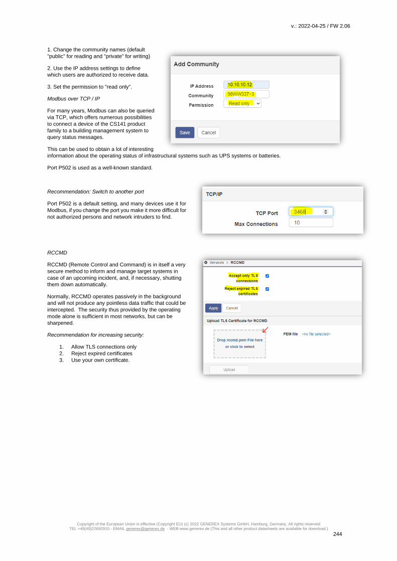
v.: 2022-04-25 / FW 2.06
Copyright of the European Union is effective (Copyright EU) (c) 2022 GENEREX Systems GmbH, Hamburg, Germany, All rights reserved TEL +49(40)22692910 - EMAIL [email protected] - WEB www.generex.de (This and all other product datasheets are available for download.)
244
1. Change the community names (default
"public" for reading and "private" for writing)
2. Use the IP address settings to define
which users are authorized to receive data.
3. Set the permission to "read only".
Modbus over TCP / IP
For many years, Modbus can also be queried
via TCP, which offers numerous possibilities
to connect a device of the CS141 product
family to a building management system to
query status messages.
This can be used to obtain a lot of interesting
information about the operating status of infrastructural systems such as UPS systems or batteries.
Port P502 is used as a well-known standard.
Recommendation: Switch to another port
Port P502 is a default setting, and many devices use it for
Modbus, if you change the port you make it more difficult for
not authorized persons and network intruders to find.
RCCMD
RCCMD (Remote Control and Command) is in itself a very
secure method to inform and manage target systems in
case of an upcoming incident, and, if necessary, shutting
them down automatically.
Normally, RCCMD operates passively in the background
and will not produce any pointless data traffic that could be
intercepted. The security thus provided by the operating
mode alone is sufficient in most networks, but can be
sharpened.
Recommendation for increasing security:
1. Allow TLS connections only
2. Reject expired certificates
3. Use your own certificate.
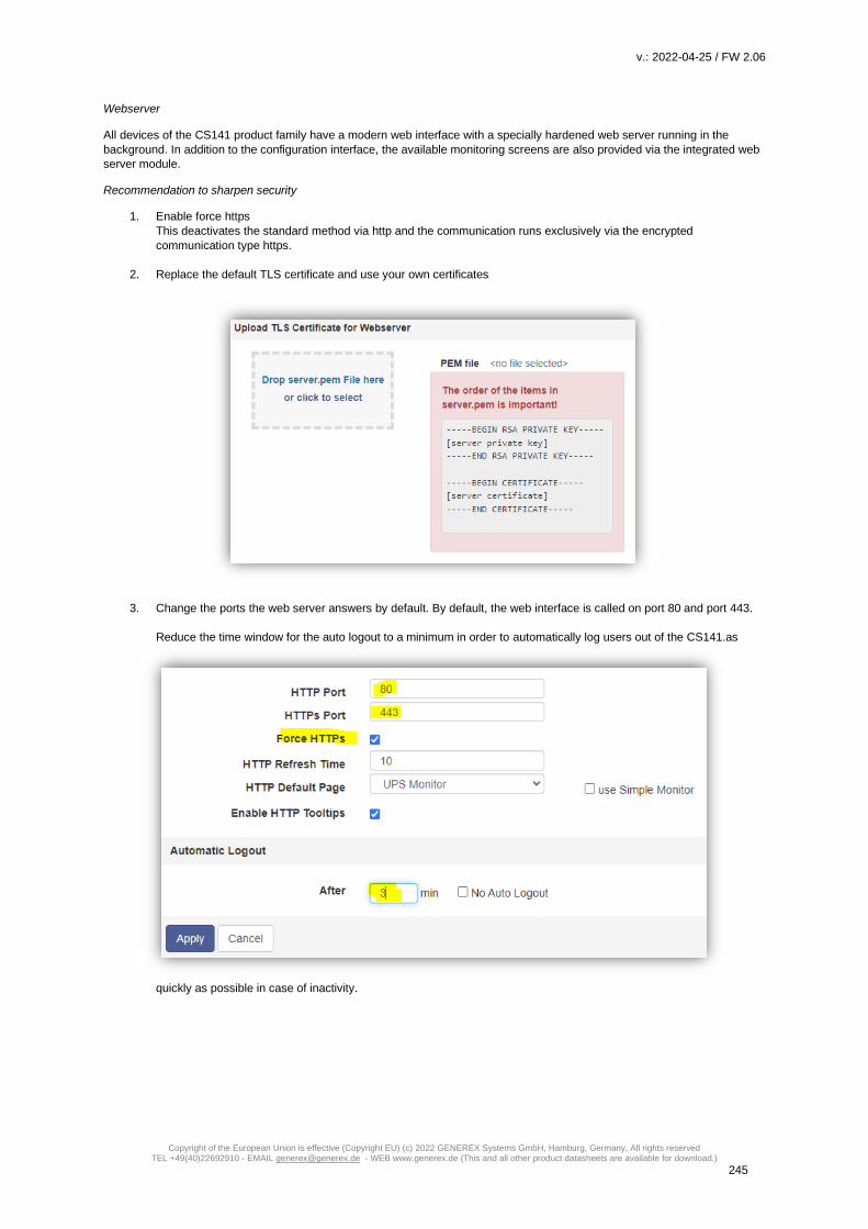
v.: 2022-04-25 / FW 2.06
Copyright of the European Union is effective (Copyright EU) (c) 2022 GENEREX Systems GmbH, Hamburg, Germany, All rights reserved TEL +49(40)22692910 - EMAIL [email protected] - WEB www.generex.de (This and all other product datasheets are available for download.)
245
Webserver
All devices of the CS141 product family have a modern web interface with a specially hardened web server running in the
background. In addition to the configuration interface, the available monitoring screens are also provided via the integrated web
server module.
Recommendation to sharpen security
1. Enable force https
This deactivates the standard method via http and the communication runs exclusively via the encrypted
communication type https.
2. Replace the default TLS certificate and use your own certificates
3. Change the ports the web server answers by default. By default, the web interface is called on port 80 and port 443.
Reduce the time window for the auto logout to a minimum in order to automatically log users out of the CS141.as
quickly as possible in case of inactivity.

v.: 2022-04-25 / FW 2.06
Copyright of the European Union is effective (Copyright EU) (c) 2022 GENEREX Systems GmbH, Hamburg, Germany, All rights reserved TEL +49(40)22692910 - EMAIL [email protected] - WEB www.generex.de (This and all other product datasheets are available for download.)
246
Remote Syslog
By default, the Remote Syslog Client runs with port 601 with a
pre-installed certificate.
This service aims to store locally saved log files centrally copy
directly on a network node, where automatic diagnostic tools
can carry out numerous evaluations.
Recommendation to sharpen security
1. Only activate this function if you are using a syslog
receiver in the network.
2. Enable "Accept only TLS connections".
3. Enable „Reject expired TLS certificates”
4. Use another Remote Syslog port than the default
port 601
Locking up the CS141 to exclude manipulation attempts via the web server - The fully autonomous mode.
This solution is useful if a CS141-based device operates within particularly exposed and vulnerable installations.
All devices of the CS141 product family offer the function to completely "lock" a device and to prohibit further access to the
configuration interface. Internal watchdogs take over the task of restarting individual services or, if necessary, the entire device.
In this case, the device runs 100% autonomously "as configured" - but can no longer be comfortably reconfigured. Please
ensure all configuration work is done before entering the full autonomous mode.
With this configuration, any access is rejected - therefore persons are pro-active prevented in trying to manipulate system settings,
for example, to specifically sabotage important settings in emergency management or hijack mail services for logical spam bombs.
To use this mode, we recommend to create a BACKUP file!
This mode can only be ended by resetting the device to factory mode and deleting the entire configuration. That's why we
recommend to create a backup before entering the autonomous mode by disabling the internal web server. Fast configuration
changes can only be carried out with resetting to factory default, restoring the configuration from a backup, doing the configuration
changes, and finally creating a new backup:

v.: 2022-04-25 / FW 2.06
Copyright of the European Union is effective (Copyright EU) (c) 2022 GENEREX Systems GmbH, Hamburg, Germany, All rights reserved TEL +49(40)22692910 - EMAIL [email protected] - WEB www.generex.de (This and all other product datasheets are available for download.)
247
1. Move the slide switch to the centre position (configuration mode) and restart the CS141.
2. Open a web browser and type 10.10.10.10/ update to open the update routine.
3. Flash the Firmware, remember to enable factory default settings
4. After update, open the backup function and upload your backup file.
5. Do your configuration work.
6. Move the slide switch back to the desired position.
7. Test your settings and changes.
8. Create a new backup file
9. Disable the web server device
Even the web server will not provide a configuration interface, the firmware update service is still available to force a system reset
with the local superuser “admin”.
Note:
Where do I find the latest firmware?
The latest firmware is available free of charge at the download portal of www.generex.de .

v.: 2022-04-25 / FW 2.06
Copyright of the European Union is effective (Copyright EU) (c) 2022 GENEREX Systems GmbH, Hamburg, Germany, All rights reserved TEL +49(40)22692910 - EMAIL [email protected] - WEB www.generex.de (This and all other product datasheets are available for download.)
248
Hardware Layout CS141
1. Slide-Switch for network configuration
2. Network Interface
3. COM2 MINIDIN Connector for RS232
4. COM2 Phoenix Connector for RS485
5. Green and Red Status LED
6. AUX Interface
7. PoE Header
8. Debug Adapter
9. Rescue Jumper: Open = Normal Boot, Close = Rescue Boot
10. NAND Flash
11. CPU
12. RAM
13. USB Interface
14. COM1
15. Slot Interface
16. Power Supply
17. DIP Switch
18. Fuse

v.: 2022-04-25 / FW 2.06
Copyright of the European Union is effective (Copyright EU) (c) 2022 GENEREX Systems GmbH, Hamburg, Germany, All rights reserved TEL +49(40)22692910 - EMAIL [email protected] - WEB www.generex.de (This and all other product datasheets are available for download.)
249
Interface Description
External D-SUB 9-polig male
Pin1: DCD Pin6: DSR
Pin2: RxD Pin7: RTS
Pin3 TxD Pin8: CTS
Pin4 DTR Pin9: RI
Pin5 GND
Slot version: Circuit board connection
Pin Signal name Level Function
1 GND Power Ground
2 8 – 34V DC Power Input
3 COM1 TXD V24 COM1 Transmit Data
4 COM1 RXD V24 COM1 Receive Data
5 SW_GPIO_1 1) 2) 3,3V TTL CS141DMINI: Functionality of DIP-Switch 1
6 SW_GPIO_2 1) 2) 3,3V TTL CS141DMINI: Functionality of DIP-Switch 2
7 POW# Input 1) 3,3V TTL Enable power supply (active low)
8 Bridged with Pin 10
9 GND Signal Ground
10 Bridged with Pin 8
11 COM1 DTR 1) V24 COM1 Data Transmit Ready
12 COM1 RI 1) V24 COM1 Ring Indicator
13 COM3 RXD 1) 2) 5V TTL COM3 Receive Data
14 COM3 TXD 1) 2) 5V TTL COM3 Transmit Data
15 COM2 TXD 1) 2) 3,3V TTL COM2 Transmit Data
16 COM2 RXD 1) 2) 3,3V TTL COM2 Receive Data
17-26 - n.c.
1) Connectable with solder bridge (MINI: resistor bridge)
2) Input with Pull-Up

v.: 2022-04-25 / FW 2.06
Copyright of the European Union is effective (Copyright EU) (c) 2022 GENEREX Systems GmbH, Hamburg, Germany, All rights reserved TEL +49(40)22692910 - EMAIL [email protected] - WEB www.generex.de (This and all other product datasheets are available for download.)
250
Differences to the CS121
• Complete rework of the menu structure: The simplified interface combines a powerful hardware to provide a significant performance boost:
• The powerful successor of the CS121 allows configuration in real-time - necessary system services will be started or stopped as needed. Therefore, a restart is only necessary in exceptional situations.
• Additional hardcoded user accounts according to specialized tasks:
• Engineer and Guest accounts are provided according to their tasks with limited system rights. On request the new guest account can be set up to allow external technicians a quick information overview without the need of password entry.
• The DIP switches known from the CS121 are no longer required and changed by a comfortable slide switch in the front of the device:
The easy-to-use slide switch will change the hardware configuration. Once the configuration state is chosen, a reboot can be done by the removing power connection or software triggered.
• The firmware update can now be carried out inside a common browser via drag & drop. The need for external tools and FTP access is no longer necessary.
• In case of problems with the firmware, updates or reboots can also be carried out without a complete login. To do this, use a common web browser and enter the IP of the device followed by /update. After a successful admin authentication, the firmware can now be updated and optionally resetted to factory settings.
• By default, auto logout is now enabled. On inactivity, the user is logged out of the system after 15 minutes.
• The power consumption of the CS141 has been reduced by a factor of 10 with a power increase and is well below the predecessor model.
Note:
The CS121 has been discontinued in 2015 and replaced by the powerful successor CS141. The Software development was
officially discontinued in 2018 - the current firmware state is frozen. Newer UPS systems and models are not available. If you
use a CS121 with a specific UPS manufacturer for many years, it may happen that your new UPS model is not natively available
even of you use the latest firmware version.
In this case, it is advisable to move to the successor CS14.

v.: 2022-04-25 / FW 2.06
Copyright of the European Union is effective (Copyright EU) (c) 2022 GENEREX Systems GmbH, Hamburg, Germany, All rights reserved TEL +49(40)22692910 - EMAIL [email protected] - WEB www.generex.de (This and all other product datasheets are available for download.)
251
Pin COM2 Mini-DIN 8 pol
Mini DIN 8 socket RS-232:
Pin1: -> DCD Pin2: -> RxD Pin3: -> TxD Pin4: -> DTR Pin5: -> DSR Pin6: -> RTS Pin7: -> CTS Pin8: -> RI shield -> GND
RS-485 (optional):
Pin1 → GND
Pin2: -> RS485/A Pin3: -> RS485/B(-)
AUX-Port (Hardware Revision 1.1 = from Serial numbers 0121-1203, 0122-00198, 0123-00564 onwards) RJ11 6-pol
Pin1: -> +3,3V
Pin2: ->
Pin3: ->
Pin4: -> RxD (COM3 Input)
Pin5: -> TxD (COM3 Output)
Pin6: -> GND

v.: 2022-04-25 / FW 2.06
Copyright of the European Union is effective (Copyright EU) (c) 2022 GENEREX Systems GmbH, Hamburg, Germany, All rights reserved TEL +49(40)22692910 - EMAIL [email protected] - WEB www.generex.de (This and all other product datasheets are available for download.)
252
Modbus addresses
OEM MODBUS Defaultadress (for all products/OEMS, not specified further down in this modbus manual)
Address Type Function Name Description Length
97 U 3 / 4 OUTPUT_VOLT0 Output Voltage Phase 1 in V 1
98 U 3 / 4 OUTPUT_VOLT1 Output Voltage Phase 2 in V 1
99 U 3 / 4 OUTPUT_VOLT2 Output Voltage Phase 3 in V 1
100 U 3 / 4 OUTP0WER0 Outpower Phase 1 % 1
101 U 3 / 4 OUTP0WER1 Outpower Phase 2 % 1
102 U 3 / 4 OUTP0WER2 Outpower Phase 3 % 1
103 U 3 / 4 BATTCAP Battery Capacity % 1
104 S 3 / 4 INVOLT0 Input Voltage Phase 1 V 1
105 S 3 / 4 INVOLT1 Input Voltage Phase 2 V 1
106 S 3 / 4 INVOLT2 Input Voltage Phase 3 V 1
107 S 3 / 4 TEMPDEG Temperature C° 1
108 S 3 / 4 AUTONOMTIME Autonomy Time minutes 1
109 U 3 / 4
STATUS (e. g.
UPS normal = “4”,
Powerfail = “12”,
Battery test running = “68”,
Bypass = “5” )
UPS Status (ASCII HEX) Please note
UPSMAN status bytes table below 1
110 S 3 / 4 BATTVOLT Battery Voltage V 1
111 U 3 / 4 INFREQ0 Input Frequency Hz Phase 1 1
112 U 3 / 4 INFREQ1 Input Frequency Hz Phase 2 1
113 U 3 / 4 INFREQ2 Input Frequency Hz Phase 3 1
114 U 3 / 4 CNT_PF Powerfail Counter 1
115 U 3 / 4 Alarm Battery Bad 1 = active; 0 = not active 1
116 U 3 / 4 Alarm: On Battery 1 = active; 0 = not active 1
117 U 3 / 4 Alarm: Battery Low 1 = active; 0 = not active 1
118 U 3 / 4 Alarm: Battery Depleted 1 = active; 0 = not active 1
119 U 3 / 4 Alarm: Over temperature 1 = active; 0 = not active 1
120 U 3 / 4 Alarm: Input Bad 1 = active; 0 = not active 1
121 U 3 / 4 Alarm: Output Bad 1 = active; 0 = not active 1
122 U 3 / 4 Alarm: Output Overload 1 = active; 0 = not active 1
123 U 3 / 4 Alarm: On Bypass 1 = active; 0 = not active 1
124 U 3 / 4 Alarm: Bypass Bad 1 = active; 0 = not active 1
125 U 3 / 4 Alarm: Output Off as requested. 1 = active; 0 = not active 1
126 U 3 / 4 Alarm: UPS Off as requested. 1 = active; 0 = not active 1
127 U 3 / 4 Alarm: Charger Failed 1 = active; 0 = not active 1

v.: 2022-04-25 / FW 2.06
Copyright of the European Union is effective (Copyright EU) (c) 2022 GENEREX Systems GmbH, Hamburg, Germany, All rights reserved TEL +49(40)22692910 - EMAIL [email protected] - WEB www.generex.de (This and all other product datasheets are available for download.)
253
128 U 3 / 4 Alarm: UPS Output Off 1 = active; 0 = not active 1
129 U 3 / 4 Alarm: UPS System Off 1 = active; 0 = not active 1
130 U 3 / 4 Alarm: Fan Failure 1 = active; 0 = not active 1
131 U 3 / 4 Alarm: fuse failure 1 = active; 0 = not active 1
132 U 3 / 4 Alarm: general fault 1 = active; 0 = not active 1
133 U 3 / 4 Alarm: diagnose test failed 1 = active; 0 = not active 1
134 U 3 / 4 Alarm: communication lost 1 = active; 0 = not active 1
135 U 3 / 4 Alarm: awaiting power 1 = active; 0 = not active 1
136 U 3 / 4 Alarm: shutdown pending 1 = active; 0 = not active 1
137 U 3 / 4 Alarm: shutdown imminent 1 = active; 0 = not active 1
138 U 3 / 4 Alarm: test in progress 1 = active; 0 = not active 1
139 U 3 / 4 AUX Port 1 1 = active (high), 0 = not active (low) 1
140 U 3 / 4 AUX Port 2 1 = active (high), 0 = not active (low) 1
141 U 3 / 4 AUX Port 3 1 = active (high), 0 = not active (low) 1
142 U 3 / 4 AUX Port 4 1 = active (high), 0 = not active (low) 1
143 U 3 / 4 Sensormanager/SMTCOM
sensor 1 Analog value 1
144 U 3 / 4 Sensormanager/SMTHCOM
sensor 2 Analog value 1
145 U 3 / 4 Sensormanager sensor 3 Analog value 1
146 U 3 / 4 Sensormanager sensor 4 Analog value 1
147 U 3 / 4 Sensormanager sensor 5 Analog value 1
148 U 3 / 4 Sensormanager sensor 6 Analog value 1
149 U 3 / 4 Sensormanager sensor 7 Analog value 1
150 U 3 / 4 Sensormanager sensor 8 Analog value 1

v.: 2022-04-25 / FW 2.06
Copyright of the European Union is effective (Copyright EU) (c) 2022 GENEREX Systems GmbH, Hamburg, Germany, All rights reserved TEL +49(40)22692910 - EMAIL [email protected] - WEB www.generex.de (This and all other product datasheets are available for download.)
254
Section OEM: ABB/NEWAVE UPS Type Concept Power
Address Type Function Name Description Length
This is the general UPS modbus address list. It uses the address range 100 – 183:
100 U 3 / 4 OUTP0WER0 Outpower Phase 1 % 1
101 U 3 / 4 OUTP0WER1 Outpower Phase 2 % 1
102 U 3 / 4 OUTP0WER2 Outpower Phase 3 % 1
103 U 3 / 4 BATTCAP Battery Capacity % 1
104 S 3 / 4 INVOLT0 Input Voltage Phase 1 V 1
105 S 3 / 4 INVOLT1 Input Voltage Phase 2 V 1
106 S 3 / 4 INVOLT2 Input Voltage Phase 3 V 1
107 S 3 / 4 TEMPDEG Temperature C° 1
108 S 3 / 4 AUTONOMTIME Autonomy Time minutes 1
109 U 3 / 4
STATUS (e. g.
UPS normal = “4”,
Powerfail = “12”,
Battery test running = “68”, Bypass =
“5” )
UPS Status (ASCII HEX) Please note
UPSMAN status bytes table below 1
110 S 3 / 4 BATTVOLT Battery Voltage V 1
111 U 3 / 4 INFREQ0 Input Frequency Hz Phase 1 1
112 U 3 / 4 INFREQ1 Input Frequency Hz Phase 2 1
113 U 3 / 4 INFREQ2 Input Frequency Hz Phase 3 1
114 U 3 / 4 CNT_PF Powerfail Counter 1
115 U 3 / 4 Alarm Battery Bad 1 = active; 0 = not active 1
116 U 3 / 4 Alarm: On Battery 1 = active; 0 = not active 1
117 U 3 / 4 Alarm: Battery Low 1 = active; 0 = not active 1
118 U 3 / 4 Alarm: Battery Depleted 1 = active; 0 = not active 1
119 U 3 / 4 Alarm: Over temperature 1 = active; 0 = not active 1
120 U 3 / 4 Alarm: Input Bad 1 = active; 0 = not active 1
121 U 3 / 4 Alarm: Output Bad 1 = active; 0 = not active 1
122 U 3 / 4 Alarm: Output Overload 1 = active; 0 = not active 1
123 U 3 / 4 Alarm: On Bypass 1 = active; 0 = not active 1
124 U 3 / 4 Alarm: Bypass Bad 1 = active; 0 = not active 1
125 U 3 / 4 Alarm: Output Off as requested. 1 = active; 0 = not active 1
126 U 3 / 4 Alarm: UPS Off as requested. 1 = active; 0 = not active 1
127 U 3 / 4 Alarm: Charger Failed 1 = active; 0 = not active 1
128 U 3 / 4 Alarm: UPS Output Off 1 = active; 0 = not active 1
129 U 3 / 4 Alarm: UPS System Off 1 = active; 0 = not active 1
130 U 3 / 4 Alarm: Fan Failure 1 = active; 0 = not active 1
131 U 3 / 4 Alarm: fuse failure 1 = active; 0 = not active 1

v.: 2022-04-25 / FW 2.06
Copyright of the European Union is effective (Copyright EU) (c) 2022 GENEREX Systems GmbH, Hamburg, Germany, All rights reserved TEL +49(40)22692910 - EMAIL [email protected] - WEB www.generex.de (This and all other product datasheets are available for download.)
255
Address Type Function Name Description Length
132 U 3 / 4 Alarm: general fault 1 = active; 0 = not active 1
133 U 3 / 4 Alarm: diagnose test failed 1 = active; 0 = not active 1
134 U 3 / 4 Alarm: communication lost 1 = active; 0 = not active 1
135 U 3 / 4 Alarm: awaiting power 1 = active; 0 = not active 1
136 U 3 / 4 Alarm: shutdown pending 1 = active; 0 = not active 1
137 U 3 / 4 Alarm: shutdown imminent 1 = active; 0 = not active 1
138 U 3 / 4 Alarm: test in progress 1 = active; 0 = not active 1
139 U 3 / 4 Manual Bypass Switch Closed 0 = open
1 = closed 1
140 U 3 / 4 OUTPUT_VOLT0 Outputvoltage Phase 1 1
141 U 3 / 4 OUTPUT_VOLT1 Outputvoltage Phase 2 1
142 U 3 / 4 OUTPUT_VOLT2 Outputvoltage Phase 3 1
143 U 3 / 4 OutputCurrent Phase A * 10 Output Current Phase 1 in Ampere devided
by 10 1
144 U 3 / 4 OutputCurrent Phase B * 10 Output Current Phase 1 in Ampere devided
by 10 1
145 U 3 / 4 OutputCurrent Phase C * 10 Output Current Phase 1 in Ampere devided
by10 1
146 U 3 / 4 xid3017 Bits 0-15 Statusbit, for details please contact
NEWAVE 1
147 U 3 / 4 xid3017 Bits 16-31
Statusbit, for details please contact
ABB/NEWAVE 1
148 U 3 / 4 xid645 Bits 0-15 Alarmbit, for details please contact
ABB/NEWAVE 1
149 U 3 / 4 xid645 Bits 16-31 Alarmbit, for details please contact
ABB/NEWAVE 1
150 U 3 / 4 xid645 Bits 32-47 Alarmbit, for details please contact
ABB/NEWAVE 1
151 U 3 / 4 xid645 Bits 48-63 Alarmbit, for details please contact
ABB/NEWAVE 1
152 U 3 / 4 Sensormanager/SMTCOM sensor 1 Analog value 1
153 U 3 / 4 Sensormanager/SMTHCOM sensor 2 Analog value 1
154 U 3 / 4 Sensormanager sensor 3 Analog value 1
155 U 3 / 4 Sensormanager sensor 4 Analog value 1
156 U 3 / 4 Sensormanager sensor 5 Analog value 1
157 U 3 / 4 Sensormanager sensor 6 Analog value 1
158 U 3 / 4 Sensormanager sensor 7 Analog value 1
159 U 3 / 4 Sensormanager sensor 8 Analog value 1
160 U 3 / 4 TrueOutputPower Phase A in KW True Output Power Current Phase 1 in
Kilowatt 1
161 U 3 / 4 TrueOutputPower Phase A in KW True Output Power Current Phase 1 in
Kilowatt 1

v.: 2022-04-25 / FW 2.06
Copyright of the European Union is effective (Copyright EU) (c) 2022 GENEREX Systems GmbH, Hamburg, Germany, All rights reserved TEL +49(40)22692910 - EMAIL [email protected] - WEB www.generex.de (This and all other product datasheets are available for download.)
256
Address Type Function Name Description Length
162 U 3 / 4 TrueOutputPower Phase A in KW True Output Power Current Phase 1 in
Kilowatt 1
163 U 3 / 4 AUX Port 1 1 = active (high), 0 = not active (low) 1
164 U 3 / 4 AUX Port 2 1 = active (high), 0 = not active (low) 1
165 U 3 / 4 AUX Port 3 1 = active (high), 0 = not active (low) 1
166 U 3 / 4 AUX Port 4 1 = active (high), 0 = not active (low) 1
167 U 3 / 4 BATTERYCURRENT Battery Current in Ampere 1
168 U 3 / 4 OUTFREQ0 Output Frequency Phase 1 in Hz 1
169 U 3 / 4 UPSIDMASK&0xFFFF for details please contact NEWAVE 1
170 U 3 / 4 (UPSIDMASK&0xFFFF0000)>>16 for details please contact NEWAVE 1
171 U 3 / 4 AUXINPFREQ0 Auxiliary Input Frequency Phase 1 1
172 U 3 / 4 AUXINPFREQ1 Auxiliary Input Frequency Phase 2 1
173 U 3 / 4 AUXINPFREQ2 Auxiliary Input Frequency Phase 3 1
174 U 3 / 4 AUXINPVOLT0 Auxiliary Input Voltage Phase 1 1
175 U 3 / 4 AUXINPVOLT1 Auxiliary Input Voltage Phase 2 1
176 U 3 / 4 AUXINPVOLT2 Auxiliary Input Voltage Phase 3 1
177 U 3 / 4 BP_FREQ0 Bypass Frequency 1
178 U 3 / 4 BP_VOLT0 Bypass Voltage Phase 1 1
179 U 3 / 4 BP_VOLT1 Bypass Voltage Phase 1 1
180 U 3 / 4 BP_VOLT2 Bypass Voltage Phase 3 1
181 U 3 / 4 (RAWSTATEB&0x8)!=0x8 Statusbit, for details please contact
ABB/NEWAVE
1
182 U 3 / 4 SolaBCOND Battery Condition: 0=good, 1=weak, 2=replace
1
183 U 3 / 4 CONCE_IDENT String Identifying the UPS 1
Note for systems with more then one installed UPS module:
Starting from register 30100, all values coming from the single module #1 are stored sequentially, according to the
sequence adopted for registers 100…166. The values from Module #2 are stored starting at register address 30200 and so
forth, until the last module #30 ranging from 33000 … 33066.
UPS MODULE 1: 30100 - 30166
30100 U 3 / 4 OUTP0WER0 Outpower Phase 1 %
1
30101 U 3 / 4 OUTP0WER1 Outpower Phase 2 %
1
30102 U 3 / 4 OUTP0WER2 Outpower Phase 3 %
1
30103 U 3 / 4 BATTCAP Battery Capacity %
1
30104 S 3 / 4 INVOLT0 Input Voltage Phase 1 V
1
30105 S 3 / 4 INVOLT1 Input Voltage Phase 2 V
1
30106 S 3 / 4 INVOLT2 Input Voltage Phase 3 V
1
30107 S 3 / 4 TEMPDEG Temperature C°
1
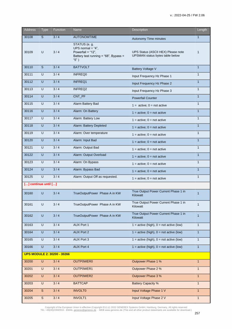
v.: 2022-04-25 / FW 2.06
Copyright of the European Union is effective (Copyright EU) (c) 2022 GENEREX Systems GmbH, Hamburg, Germany, All rights reserved TEL +49(40)22692910 - EMAIL [email protected] - WEB www.generex.de (This and all other product datasheets are available for download.)
257
Address Type Function Name Description Length
30108 S 3 / 4 AUTONOMTIME Autonomy Time minutes
1
30109 U 3 / 4
STATUS (e. g.
UPS normal = “4”,
Powerfail = “12”,
Battery test running = “68”, Bypass =
“5” )
UPS Status (ASCII HEX) Please note UPSMAN status bytes table below
1
30110 S 3 / 4 BATTVOLT Battery Voltage V
1
30111 U 3 / 4 INFREQ0 Input Frequency Hz Phase 1
1
30112 U 3 / 4 INFREQ1 Input Frequency Hz Phase 2
1
30113 U 3 / 4 INFREQ2 Input Frequency Hz Phase 3
1
30114 U 3 / 4 CNT_PF Powerfail Counter
1
30115 U 3 / 4 Alarm Battery Bad 1 = active; 0 = not active
1
30116 U 3 / 4 Alarm: On Battery 1 = active; 0 = not active
1
30117 U 3 / 4 Alarm: Battery Low 1 = active; 0 = not active
1
30118 U 3 / 4 Alarm: Battery Depleted 1 = active; 0 = not active
1
30119 U 3 / 4 Alarm: Over temperature 1 = active; 0 = not active
1
30120 U 3 / 4 Alarm: Input Bad 1 = active; 0 = not active
1
30121 U 3 / 4 Alarm: Output Bad 1 = active; 0 = not active
1
30122 U 3 / 4 Alarm: Output Overload 1 = active; 0 = not active
1
30123 U 3 / 4 Alarm: On Bypass 1 = active; 0 = not active
1
30124 U 3 / 4 Alarm: Bypass Bad 1 = active; 0 = not active
1
30125 U 3 / 4 Alarm: Output Off as requested. 1 = active; 0 = not active
1
[…] continue until […]
30160 U 3 / 4 TrueOutputPower Phase A in KW True Output Power Current Phase 1 in
Kilowatt 1
30161 U 3 / 4 TrueOutputPower Phase A in KW True Output Power Current Phase 1 in
Kilowatt 1
30162 U 3 / 4 TrueOutputPower Phase A in KW True Output Power Current Phase 1 in
Kilowatt 1
30163 U 3 / 4 AUX Port 1 1 = active (high), 0 = not active (low) 1
30164 U 3 / 4 AUX Port 2 1 = active (high), 0 = not active (low) 1
30165 U 3 / 4 AUX Port 3 1 = active (high), 0 = not active (low) 1
30166 U 3 / 4 AUX Port 4 1 = active (high), 0 = not active (low) 1
UPS MODULE 2: 30200 - 30266
30200 U 3 / 4 OUTP0WER0 Outpower Phase 1 % 1
30201 U 3 / 4 OUTP0WER1 Outpower Phase 2 % 1
30202 U 3 / 4 OUTP0WER2 Outpower Phase 3 % 1
30203 U 3 / 4 BATTCAP Battery Capacity % 1
30204 S 3 / 4 INVOLT0 Input Voltage Phase 1 V 1
30205 S 3 / 4 INVOLT1 Input Voltage Phase 2 V 1

v.: 2022-04-25 / FW 2.06
Copyright of the European Union is effective (Copyright EU) (c) 2022 GENEREX Systems GmbH, Hamburg, Germany, All rights reserved TEL +49(40)22692910 - EMAIL [email protected] - WEB www.generex.de (This and all other product datasheets are available for download.)
258
Address Type Function Name Description Length
30206 S 3 / 4 INVOLT2 Input Voltage Phase 3 V 1
30207 S 3 / 4 TEMPDEG Temperature C° 1
30208 S 3 / 4 AUTONOMTIME Autonomy Time minutes 1
30209 U 3 / 4
STATUS (e. g.
UPS normal = “4”,
Powerfail = “12”,
Battery test running = “68”, Bypass =
“5” )
UPS Status (ASCII HEX) Please note
UPSMAN status bytes table below 1
30210 S 3 / 4 BATTVOLT Battery Voltage V 1
30211 U 3 / 4 INFREQ0 Input Frequency Hz Phase 1 1
30212 U 3 / 4 INFREQ1 Input Frequency Hz Phase 2 1
30213 U 3 / 4 INFREQ2 Input Frequency Hz Phase 3 1
30214 U 3 / 4 CNT_PF Powerfail Counter 1
30215 U 3 / 4 Alarm Battery Bad 1 = active; 0 = not active 1
30216 U 3 / 4 Alarm: On Battery 1 = active; 0 = not active 1
30217 U 3 / 4 Alarm: Battery Low 1 = active; 0 = not active 1
30218 U 3 / 4 Alarm: Battery Depleted 1 = active; 0 = not active 1
30219 U 3 / 4 Alarm: Over temperature 1 = active; 0 = not active 1
30220 U 3 / 4 Alarm: Input Bad 1 = active; 0 = not active 1
30221 U 3 / 4 Alarm: Output Bad 1 = active; 0 = not active 1
30222 U 3 / 4 Alarm: Output Overload 1 = active; 0 = not active 1
30223 U 3 / 4 Alarm: On Bypass 1 = active; 0 = not active 1
30224 U 3 / 4 Alarm: Bypass Bad 1 = active; 0 = not active 1
30225 U 3 / 4 Alarm: Output Off as requested. 1 = active; 0 = not active 1
[…] continue until […]
30261 U 3 / 4 TrueOutputPower Phase A in KW True Output Power Current Phase 1 in
Kilowatt 1
30262 U 3 / 4 TrueOutputPower Phase A in KW True Output Power Current Phase 1 in
Kilowatt 1
30263 U 3 / 4 AUX Port 1 1 = active (high), 0 = not active (low) 1
30264 U 3 / 4 AUX Port 2 1 = active (high), 0 = not active (low) 1
30265 U 3 / 4 AUX Port 3 1 = active (high), 0 = not active (low) 1
30266 U 3 / 4 AUX Port 4 1 = active (high), 0 = not active (low) 1
UPS Module 3: 30300 - 30366
30300 U 3 / 4 OUTP0WER0 Outpower Phase 1 % 1
30301 U 3 / 4 OUTP0WER1 Outpower Phase 2 % 1
30302 U 3 / 4 OUTP0WER2 Outpower Phase 3 % 1
30303 U 3 / 4 BATTCAP Battery Capacity % 1
30304 S 3 / 4 INVOLT0 Input Voltage Phase 1 V 1
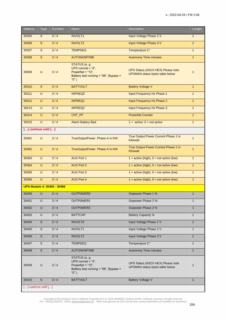
v.: 2022-04-25 / FW 2.06
Copyright of the European Union is effective (Copyright EU) (c) 2022 GENEREX Systems GmbH, Hamburg, Germany, All rights reserved TEL +49(40)22692910 - EMAIL [email protected] - WEB www.generex.de (This and all other product datasheets are available for download.)
259
Address Type Function Name Description Length
30305 S 3 / 4 INVOLT1 Input Voltage Phase 2 V 1
30306 S 3 / 4 INVOLT2 Input Voltage Phase 3 V 1
30307 S 3 / 4 TEMPDEG Temperature C° 1
30308 S 3 / 4 AUTONOMTIME Autonomy Time minutes 1
30309 U 3 / 4
STATUS (e. g.
UPS normal = “4”,
Powerfail = “12”,
Battery test running = “68”, Bypass =
“5” )
UPS Status (ASCII HEX) Please note
UPSMAN status bytes table below 1
30310 S 3 / 4 BATTVOLT Battery Voltage V 1
30311 U 3 / 4 INFREQ0 Input Frequency Hz Phase 1 1
30312 U 3 / 4 INFREQ1 Input Frequency Hz Phase 2 1
30213 U 3 / 4 INFREQ2 Input Frequency Hz Phase 3 1
30314 U 3 / 4 CNT_PF Powerfail Counter 1
30315 U 3 / 4 Alarm Battery Bad 1 = active; 0 = not active 1
[…] continue until […]
30361 U 3 / 4 TrueOutputPower Phase A in KW True Output Power Current Phase 1 in
Kilowatt 1
30362 U 3 / 4 TrueOutputPower Phase A in KW True Output Power Current Phase 1 in
Kilowatt 1
30363 U 3 / 4 AUX Port 1 1 = active (high), 0 = not active (low) 1
30364 U 3 / 4 AUX Port 2 1 = active (high), 0 = not active (low) 1
30365 U 3 / 4 AUX Port 3 1 = active (high), 0 = not active (low) 1
30366 U 3 / 4 AUX Port 4 1 = active (high), 0 = not active (low) 1
UPS Module 4: 30400 - 30466
30400 U 3 / 4 OUTP0WER0 Outpower Phase 1 % 1
30401 U 3 / 4 OUTP0WER1 Outpower Phase 2 % 1
30402 U 3 / 4 OUTP0WER2 Outpower Phase 3 % 1
30403 U 3 / 4 BATTCAP Battery Capacity % 1
30404 S 3 / 4 INVOLT0 Input Voltage Phase 1 V 1
30405 S 3 / 4 INVOLT1 Input Voltage Phase 2 V 1
30406 S 3 / 4 INVOLT2 Input Voltage Phase 3 V 1
30407 S 3 / 4 TEMPDEG Temperature C° 1
30408 S 3 / 4 AUTONOMTIME Autonomy Time minutes 1
30409 U 3 / 4
STATUS (e. g.
UPS normal = “4”,
Powerfail = “12”,
Battery test running = “68”, Bypass =
“5” )
UPS Status (ASCII HEX) Please note
UPSMAN status bytes table below 1
30410 S 3 / 4 BATTVOLT Battery Voltage V 1
[…] cuntinue until […]
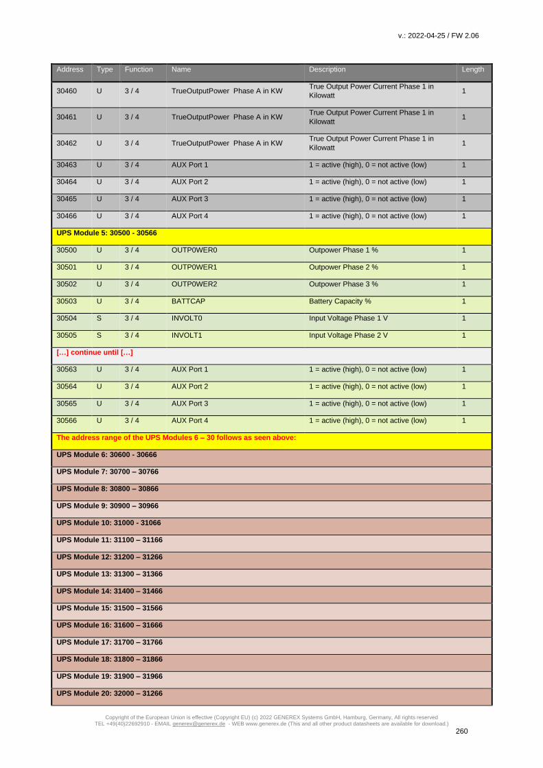
v.: 2022-04-25 / FW 2.06
Copyright of the European Union is effective (Copyright EU) (c) 2022 GENEREX Systems GmbH, Hamburg, Germany, All rights reserved TEL +49(40)22692910 - EMAIL [email protected] - WEB www.generex.de (This and all other product datasheets are available for download.)
260
Address Type Function Name Description Length
30460 U 3 / 4 TrueOutputPower Phase A in KW True Output Power Current Phase 1 in
Kilowatt 1
30461 U 3 / 4 TrueOutputPower Phase A in KW True Output Power Current Phase 1 in
Kilowatt 1
30462 U 3 / 4 TrueOutputPower Phase A in KW True Output Power Current Phase 1 in
Kilowatt 1
30463 U 3 / 4 AUX Port 1 1 = active (high), 0 = not active (low) 1
30464 U 3 / 4 AUX Port 2 1 = active (high), 0 = not active (low) 1
30465 U 3 / 4 AUX Port 3 1 = active (high), 0 = not active (low) 1
30466 U 3 / 4 AUX Port 4 1 = active (high), 0 = not active (low) 1
UPS Module 5: 30500 - 30566
30500 U 3 / 4 OUTP0WER0 Outpower Phase 1 % 1
30501 U 3 / 4 OUTP0WER1 Outpower Phase 2 % 1
30502 U 3 / 4 OUTP0WER2 Outpower Phase 3 % 1
30503 U 3 / 4 BATTCAP Battery Capacity % 1
30504 S 3 / 4 INVOLT0 Input Voltage Phase 1 V 1
30505 S 3 / 4 INVOLT1 Input Voltage Phase 2 V 1
[…] continue until […]
30563 U 3 / 4 AUX Port 1 1 = active (high), 0 = not active (low) 1
30564 U 3 / 4 AUX Port 2 1 = active (high), 0 = not active (low) 1
30565 U 3 / 4 AUX Port 3 1 = active (high), 0 = not active (low) 1
30566 U 3 / 4 AUX Port 4 1 = active (high), 0 = not active (low) 1
The address range of the UPS Modules 6 – 30 follows as seen above:
UPS Module 6: 30600 - 30666
UPS Module 7: 30700 – 30766
UPS Module 8: 30800 – 30866
UPS Module 9: 30900 – 30966
UPS Module 10: 31000 - 31066
UPS Module 11: 31100 – 31166
UPS Module 12: 31200 – 31266
UPS Module 13: 31300 – 31366
UPS Module 14: 31400 – 31466
UPS Module 15: 31500 – 31566
UPS Module 16: 31600 – 31666
UPS Module 17: 31700 – 31766
UPS Module 18: 31800 – 31866
UPS Module 19: 31900 – 31966
UPS Module 20: 32000 – 31266

v.: 2022-04-25 / FW 2.06
Copyright of the European Union is effective (Copyright EU) (c) 2022 GENEREX Systems GmbH, Hamburg, Germany, All rights reserved TEL +49(40)22692910 - EMAIL [email protected] - WEB www.generex.de (This and all other product datasheets are available for download.)
261
Address Type Function Name Description Length
UPS Module 21: 32100 – 32166
UPS Module 22: 32200 – 32266
UPS Module 23: 32300 – 32366
UPS Module 24: 32400 – 32466
UPS Module 25: 32500 – 32566
UPS Module 26: 32600 – 32666
UPS Module 27:32700 – 32766
UPS Module 28: 32800 – 32866
UPS Module 29: 32900 – 32966
UPS Module 30: 33000 – 33066
Section OEM: MASTERGUARD
Address Type Function Name Description Length
97 U 3 / 4 OUTPUT_VOLT0 Output Voltage Phase 1 in V 1
98 U 3 / 4 OUTPUT_VOLT1 Output Voltage Phase 2 in V 1
99 U 3 / 4 OUTPUT_VOLT2 Output Voltage Phase 3 in V 1
100 U 3 / 4 OUTP0WER0 Outpower Phase 1 % 1
101 U 3 / 4 OUTP0WER1 Outpower Phase 2 % 1
102 U 3 / 4 OUTP0WER2 Outpower Phase 3 % 1
103 U 3 / 4 BATTCAP Battery Capacity % 1
104 S 3 / 4 INVOLT0 Input Voltage Phase 1 V 1
105 S 3 / 4 INVOLT1 Input Voltage Phase 2 V 1
106 S 3 / 4 INVOLT2 Input Voltage Phase 3 V 1
107 S 3 / 4 TEMPDEG Temperature C° 1
108 S 3 / 4 AUTONOMTIME Autonomy Time minutes 1
109 U 3 / 4
STATUS (e. g.
UPS normal = “4”,
Powerfail = “12”,
Battery test running = “68”,
Bypass = “5” )
UPS Status (ASCII HEX) Please note
UPSMAN status bytes table below 1
110 S 3 / 4 BATTVOLT Battery Voltage V 1
111 U 3 / 4 INFREQ0 Input Frequency Hz Phase 1 1
112 U 3 / 4 INFREQ1 Input Frequency Hz Phase 2 1
113 U 3 / 4 INFREQ2 Input Frequency Hz Phase 3 1
114 U 3 / 4 CNT_PF Powerfail Counter 1
115 U 3 / 4 Alarm Battery Bad 1 = active; 0 = not active 1
116 U 3 / 4 Alarm: On Battery 1 = active; 0 = not active 1

v.: 2022-04-25 / FW 2.06
Copyright of the European Union is effective (Copyright EU) (c) 2022 GENEREX Systems GmbH, Hamburg, Germany, All rights reserved TEL +49(40)22692910 - EMAIL [email protected] - WEB www.generex.de (This and all other product datasheets are available for download.)
262
117 U 3 / 4 Alarm: Battery Low 1 = active; 0 = not active 1
118 U 3 / 4 Alarm: Battery Depleted 1 = active; 0 = not active 1
119 U 3 / 4 Alarm: Over temperature 1 = active; 0 = not active 1
120 U 3 / 4 Alarm: Input Bad 1 = active; 0 = not active 1
121 U 3 / 4 Alarm: Output Bad 1 = active; 0 = not active 1
122 U 3 / 4 Alarm: Output Overload 1 = active; 0 = not active 1
123 U 3 / 4 Alarm: On Bypass 1 = active; 0 = not active 1
124 U 3 / 4 Alarm: Bypass Bad 1 = active; 0 = not active 1
125 U 3 / 4 Alarm: Output Off as requested. 1 = active; 0 = not active 1
126 U 3 / 4 Alarm: UPS Off as requested. 1 = active; 0 = not active 1
127 U 3 / 4 Alarm: Charger Failed 1 = active; 0 = not active 1
128 U 3 / 4 Alarm: UPS Output Off 1 = active; 0 = not active 1
129 U 3 / 4 Alarm: UPS System Off 1 = active; 0 = not active 1
130 U 3 / 4 Alarm: Fan Failure 1 = active; 0 = not active 1
131 U 3 / 4 Alarm: fuse failure 1 = active; 0 = not active 1
132 U 3 / 4 Alarm: general fault 1 = active; 0 = not active 1
133 U 3 / 4 Alarm: diagnose test failed 1 = active; 0 = not active 1
134 U 3 / 4 Alarm: communication lost 1 = active; 0 = not active 1
135 U 3 / 4 Alarm: awaiting power 1 = active; 0 = not active 1
136 U 3 / 4 Alarm: shutdown pending 1 = active; 0 = not active 1
137 U 3 / 4 Alarm: shutdown imminent 1 = active; 0 = not active 1
138 U 3 / 4 Alarm: test in progress 1 = active; 0 = not active 1
139 U 3 / 4 PXWARN 2
141 U 3 / 4 FAULT CODE 1 1
142 U 3 / 4 FAULT CODE 2 1
143 U 3 / 4 FAULT CODE 3 1
144 U 3 / 4 FAULT CODE 4 1
145 U 3 / 4 BADBATTBLOCK 1 1
146 U 3 / 4 BADBATTBLOCK 1 1
147 U 3 / 4 BADBATTBLOCK 1 1
148 U 3 / 4 BADBATTBLOCK 1 1
149 U 3 / 4 BADBATTBLOCK 1 1
150 U 3 / 4 BADBATTBLOCK 1 1

v.: 2022-04-25 / FW 2.06
Copyright of the European Union is effective (Copyright EU) (c) 2022 GENEREX Systems GmbH, Hamburg, Germany, All rights reserved TEL +49(40)22692910 - EMAIL [email protected] - WEB www.generex.de (This and all other product datasheets are available for download.)
263
Section: OEM: Centiel UPS
Address Type Function Name Description Length
97 U 3 / 4 OUTPUT_VOLT0 1
98 U 3 / 4 OUTPUT_VOLT1 1
99 U 3 / 4 OUTPUT_VOLT2 1
100 U 3 / 4 OUTPOWER0 1
101 U 3 / 4 OUTPOWER1 1
102 U 3 / 4 OUTPOWER2 1
103 U 3 / 4 BATTCAP 1
104 U 3 / 4 INVOLT0 1
105 U 3 / 4 INVOLT1 1
106 U 3 / 4 INVOLT2 1
107 U 3 / 4 TEMPDEG 1
108 U 3 / 4 AUTONOMTIME 1
109 U 3 / 4 STATUS 1
110 U 3 / 4 BATTVOLT 1
111 U 3 / 4 INFREQ0 1
112 U 3 / 4 INFREQ1 1
113 U 3 / 4 INFREQ2 1
114 U 3 / 4 CNT_PF 1
115 U 3 / 4 (SNMPALARMS&0x1) 1
116 U 3 / 4 (SNMPALARMS&0x2)>>1 1
117 U 3 / 4 (SNMPALARMS&0x4)>>2 1
118 U 3 / 4 (SNMPALARMS&0x8)>>3 1
119 U 3 / 4 (SNMPALARMS&0x10)>>4 1
120 U 3 / 4 (SNMPALARMS&0x20)>>5 1
121 U 3 / 4 (SNMPALARMS&0x40)>>6 1
122 U 3 / 4 (SNMPALARMS&0x80)>>7 1
123 U 3 / 4 (SNMPALARMS&0x100)>>8 1
124 U 3 / 4 (SNMPALARMS&0x200)>>9 1
125 U 3 / 4 (SNMPALARMS&0x400)>>10 1
126 U 3 / 4 (SNMPALARMS&0x800)>>11 1
127 U 3 / 4 (SNMPALARMS&0x1000)>>12 1
128 U 3 / 4 (SNMPALARMS&0x2000)>>13 1
129 U 3 / 4 (SNMPALARMS&0x4000)>>14 1
130 U 3 / 4 (SNMPALARMS&0x8000)>>15 1
131 U 3 / 4 (SNMPALARMS&0x10000)>>16 1

v.: 2022-04-25 / FW 2.06
Copyright of the European Union is effective (Copyright EU) (c) 2022 GENEREX Systems GmbH, Hamburg, Germany, All rights reserved TEL +49(40)22692910 - EMAIL [email protected] - WEB www.generex.de (This and all other product datasheets are available for download.)
264
132 U 3 / 4 (SNMPALARMS&0x20000)>>17 1
133 U 3 / 4 (SNMPALARMS&0x40000)>>18 1
134 U 3 / 4 (SNMPALARMS&0x80000)>>19 1
135 U 3 / 4 (SNMPALARMS&0x100000)>>20 1
136 U 3 / 4 (SNMPALARMS&0x200000)>>21 1
137 U 3 / 4 (SNMPALARMS&0x400000)>>22 1
138 U 3 / 4 (SNMPALARMS&0x800000)>>23 1
139 U 3 / 4 AUX1STATE 1
140 U 3 / 4 AUX2STATE 1
141 U 3 / 4 AUX3STATE 1
142 U 3 / 4 AUX4STATE 1
143 U 3 / 4 TEMP1 1
144 U 3 / 4 TEMP2 1
145 U 3 / 4 TEMP3 1
146 U 3 / 4 TEMP4 1
147 U 3 / 4 TEMP5 1
148 U 3 / 4 TEMP6 1
149 U 3 / 4 TEMP7 1
150 U 3 / 4 TEMP8 1
151 U 3 / 4 (MODULEMASK&0xFFFF) 1
152 U 3 / 4 (MODULEMASK&0xFFFF0000)>>16 1
153 U 3 / 4 (RAWSTATEB&0xFFFF) 1
154 U 3 / 4 (RAWSTATEB&0xFFFF0000)>>16 1
155 U 3 / 4 (RAWSTATEA&0xFFFF) 1
156 U 3 / 4 (RAWSTATEA&0xFFFF0000)>>16 1
157 U 3 / 4 (RAWSTATED&0xFFFF) 1
158 U 3 / 4 (RAWSTATED&0xFFFF0000)>>16 1
159 U 3 / 4 EX_OUT_WATT0 1
160 U 3 / 4 EX_OUT_WATT1 1
161 U 3 / 4 EX_OUT_WATT2 1
162 U 3 / 4 CONCE_IDENT 1
163 U 3 / 4 EX_BYP_VOLT0 1
164 U 3 / 4 EX_BYP_VOLT1 1
165 U 3 / 4 EX_BYP_VOLT2 1
166 U 3 / 4 EX_BYP_FREQ0 1
167 U 3 / 4 EX_BYP_FREQ1 1
168 U 3 / 4 EX_BYP_FREQ2 1
169 U 3 / 4 EX_OUT_CURR0 1

v.: 2022-04-25 / FW 2.06
Copyright of the European Union is effective (Copyright EU) (c) 2022 GENEREX Systems GmbH, Hamburg, Germany, All rights reserved TEL +49(40)22692910 - EMAIL [email protected] - WEB www.generex.de (This and all other product datasheets are available for download.)
265
170 U 3 / 4 EX_OUT_CURR1 1
171 U 3 / 4 EX_OUT_CURR2 1
172 U 3 / 4 OUTFREQ0 1
173 U 3 / 4 OUTFREQ1 1
174 U 3 / 4 OUTFREQ2 1
175 U 3 / 4 EX_BATT_CURRPOS 1
176 U 3 / 4 EX_BATT_CURRNEG 1
194 U 3 / 4 CONCE_VERSION 1
Section OEM: RITTAL PMC Extension
Address Type Function Name Description Length
Digital Input Status(DI)
0 bit 2 Bypass working Status 0: Normal, Status 1: Alert 1
1 bit 2 Bypass Interruption Status 0: Normal, Status 1: Alert 1
2 bit 2 Rectifier Failure Status 0: Normal, Status 1: Alert 1
3 bit 2 Inverter Failure Status 0: Normal, Status 1: Alert 1
4 bit 2 Over Temperature Status 0: Normal, Status 1: Alert 1
5 bit 2 Over Load Status 0: Normal, Status 1: Alert 1
6 bit 2 0 Status 0: Normal, Status 1: Alert 1
7 bit 2 Battery Voltage too Low Status 0: Normal, Status 1: Alert 1
8 bit 2 Fuse broken Status 0: Normal, Status 1: Alert 1
9 bit 2 Battery discharging Status 0: Normal, Status 1: Alert 1
10 bit 2 0 Status 0: Floating charge, Status 1: Instant
charging
1
11~30 bit 2 For future expansion 1
After 31 bit 2 Venders own definition 1
Analog Measurement point (AI)
00 word 4 U in R phase input voltage 0.1 Volt
01 word 4 U in S phase input voltage 0.1 Volt
02 word 4 U in T phase input voltage 0.1 Volt
03 word 4 I in R phase input current 0.1A
04 word 4 I in S phase input current 0.1A
05 word 4 I in T phase input current 0.1A
06 word 4 F input frequency 0.1Hz
07 word 4 U out R phase output voltage 0.1 Volt
08 word 4 U out S phase output voltage 0.1 Volt

v.: 2022-04-25 / FW 2.06
Copyright of the European Union is effective (Copyright EU) (c) 2022 GENEREX Systems GmbH, Hamburg, Germany, All rights reserved TEL +49(40)22692910 - EMAIL [email protected] - WEB www.generex.de (This and all other product datasheets are available for download.)
266
09 word 4 U out T phase output voltage 0.1 Volt
10 word 4 I out R phase output current 0.1A
11 word 4 I out S phase output current 0.1A
12 word 4 I out T phase output current 0.1A
13 word 4 P out output power 0.1kVA
14 word 4 P out output power 0.1kW
15 word 4 PF output power factor 0.01Cos
16 word 4 U Bypass, R phase voltage 0.1 Volt
17 word 4 U Bypass, S phase voltage 0.1 Volt
18 word 4 U Bypass, T phase voltage 0.1 Volt
19 word 4 F out output frequency 0.1Hz
20 word 4 U Bat battery voltage 0.1 Volt
21 word 4 I charch Bat battery
charging/discharging
0.1A
22 word 4 Temp 1 battery temperature 0.1degC
23 word 4 Temp 2 battery temperature 0.1degC
24 word 4 Temp 3 battery temperature 0.1degC
25 word 4 Temp 4 battery temperature 0.1degC
26 word 4 Temp 5 UPS shelf temperature 0.1degC
Digital output (DO) (Function 1 to read data; 5 to control the function)
0 bit 1 / 5 UPS Turn On
1 bit 1 / 5 UPS Shut down
2 bit 1 / 5 Alarm Reset
3 bit 1 / 5 Battery Instant Charging
4 bit 1 / 5 Battery Floating Charging
5~10 bit For future expansion
After Vender self-definition
Address Type Function Name Description Length
100 U 3 / 4 OUTPOWER0 True Output Power Current Phase 1 in
Kilowatt
1
101 U 3 / 4 OUTPOWER1 True Output Power Current Phase 2 in
Kilowatt
1
102 U 3 / 4 OUTPOWER2 True Output Power Current Phase 3 in
Kilowatt
1
103 U 3 / 4 BATTCAP Battery Capacity in % 1
104 U 3 / 4 INVOLT0 Input Voltage Phase 1 1
105 U 3 / 4 INVOLT1 Input Voltage Phase 2 1
106 U 3 / 4 INVOLT2 Input Voltage Phase 3 1
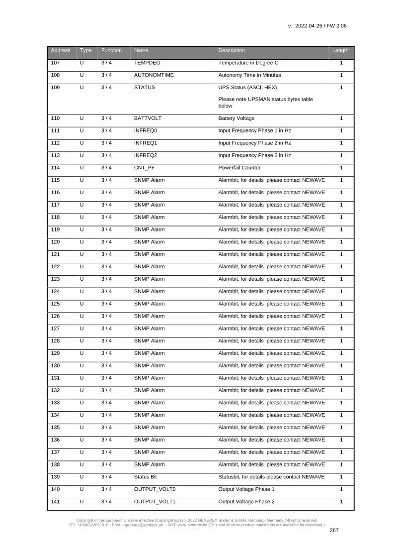
v.: 2022-04-25 / FW 2.06
Copyright of the European Union is effective (Copyright EU) (c) 2022 GENEREX Systems GmbH, Hamburg, Germany, All rights reserved TEL +49(40)22692910 - EMAIL [email protected] - WEB www.generex.de (This and all other product datasheets are available for download.)
267
Address Type Function Name Description Length
107 U 3 / 4 TEMPDEG Temperature in Degree C° 1
108 U 3 / 4 AUTONOMTIME Autonomy Time in Minutes 1
109 U 3 / 4 STATUS UPS Status (ASCII HEX)
Please note UPSMAN status bytes table
below
1
110 U 3 / 4 BATTVOLT Battery Voltage 1
111 U 3 / 4 INFREQ0 Input Frequency Phase 1 in Hz 1
112 U 3 / 4 INFREQ1 Input Frequency Phase 2 in Hz 1
113 U 3 / 4 INFREQ2 Input Frequency Phase 3 in Hz 1
114 U 3 / 4 CNT_PF Powerfail Counter 1
115 U 3 / 4 SNMP Alarm Alarmbit, for details please contact NEWAVE 1
116 U 3 / 4 SNMP Alarm Alarmbit, for details please contact NEWAVE 1
117 U 3 / 4 SNMP Alarm Alarmbit, for details please contact NEWAVE 1
118 U 3 / 4 SNMP Alarm Alarmbit, for details please contact NEWAVE 1
119 U 3 / 4 SNMP Alarm Alarmbit, for details please contact NEWAVE 1
120 U 3 / 4 SNMP Alarm Alarmbit, for details please contact NEWAVE 1
121 U 3 / 4 SNMP Alarm Alarmbit, for details please contact NEWAVE 1
122 U 3 / 4 SNMP Alarm Alarmbit, for details please contact NEWAVE 1
123 U 3 / 4 SNMP Alarm Alarmbit, for details please contact NEWAVE 1
124 U 3 / 4 SNMP Alarm Alarmbit, for details please contact NEWAVE 1
125 U 3 / 4 SNMP Alarm Alarmbit, for details please contact NEWAVE 1
126 U 3 / 4 SNMP Alarm Alarmbit, for details please contact NEWAVE 1
127 U 3 / 4 SNMP Alarm Alarmbit, for details please contact NEWAVE 1
128 U 3 / 4 SNMP Alarm Alarmbit, for details please contact NEWAVE 1
129 U 3 / 4 SNMP Alarm Alarmbit, for details please contact NEWAVE 1
130 U 3 / 4 SNMP Alarm Alarmbit, for details please contact NEWAVE 1
131 U 3 / 4 SNMP Alarm Alarmbit, for details please contact NEWAVE 1
132 U 3 / 4 SNMP Alarm Alarmbit, for details please contact NEWAVE 1
133 U 3 / 4 SNMP Alarm Alarmbit, for details please contact NEWAVE 1
134 U 3 / 4 SNMP Alarm Alarmbit, for details please contact NEWAVE 1
135 U 3 / 4 SNMP Alarm Alarmbit, for details please contact NEWAVE 1
136 U 3 / 4 SNMP Alarm Alarmbit, for details please contact NEWAVE 1
137 U 3 / 4 SNMP Alarm Alarmbit, for details please contact NEWAVE 1
138 U 3 / 4 SNMP Alarm Alarmbit, for details please contact NEWAVE 1
139 U 3 / 4 Status Bit Statusbit, for details please contact NEWAVE 1
140 U 3 / 4 OUTPUT_VOLT0 Output Voltage Phase 1 1
141 U 3 / 4 OUTPUT_VOLT1 Output Voltage Phase 2 1

v.: 2022-04-25 / FW 2.06
Copyright of the European Union is effective (Copyright EU) (c) 2022 GENEREX Systems GmbH, Hamburg, Germany, All rights reserved TEL +49(40)22692910 - EMAIL [email protected] - WEB www.generex.de (This and all other product datasheets are available for download.)
268
Address Type Function Name Description Length
142 U 3 / 4 OUTPUT_VOLT2 Output Voltage Phase 3 1
143 U 3 / 4 OUTPUT_CURR0 Output Current Phase 1 in KW 1
144 U 3 / 4 OUTPUT_CURR1 Output Current Phase 2 in KW 1
145 U 3 / 4 OUTPUT_CURR2 Output Current Phase 3 in KW 1
146 U 3 / 4 Status Bit Statusbit, for details please contact NEWAVE 1
147 U 3 / 4 Status Bit Statusbit, for details please contact NEWAVE 1
148 U 3 / 4 Status Bit Statusbit, for details please contact NEWAVE 1
149 U 3 / 4 Status Bit Statusbit, for details please contact NEWAVE 1
150 U 3 / 4 Status Bit Statusbit, for details please contact NEWAVE 1
151 U 3 / 4 Status Bit Statusbit, for details please contact NEWAVE 1
152 U 3 / 4 TEMP1 SensorManager/SM_T_H_COM Analog
Value
1
153 U 3 / 4 TEMP2 SensorManager/SM_T_H_COM Analog
Value
1
154 U 3 / 4 TEMP3 SensorManager Analog Value 1
155 U 3 / 4 TEMP4 SensorManager Analog Value 1
156 U 3 / 4 TEMP5 SensorManager Analog Value 1
157 U 3 / 4 TEMP6 SensorManager Analog Value 1
158 U 3 / 4 TEMP7 SensorManager Analog Value 1
159 U 3 / 4 TEMP8 SensorManager Analog Value 1
160 U 3 / 4 LOADKVA0 Load Phase 1 in KW 1
161 U 3 / 4 LOADKVA1 Load Phase 2 in KW 1
162 U 3 / 4 LOADKVA2 Load Phase 3 in KW 1
Section OEM: Netminder for all LT and MD types
Address Type Function Name Description Length
100 U 3/4 INVOLT Input Voltage 1
101 U 3/4 OUTPUTVOLT Output Voltage 1
102 U 3/4 BATTVOLT Battery Voltage 1
103 U 3/4 OUTPUTCURR Output Current 1
104 U 3/4 LOADPERC Load (%) 1
105 U 3/4 OUTPUTPOW Output Power in W 1
106 U 3/4 KVA KVA 1
107 U 3/4 FREQUENCY Frequency 1
108 U 3/4 CS141UPSSTAT CS141 UPS Status 1
109 U 3/4 Alarm: Battery Bad 1 = active; 0 = not active 1
110 U 3/4 Alarm: On Battery 1 = active; 0 = not active 1

v.: 2022-04-25 / FW 2.06
Copyright of the European Union is effective (Copyright EU) (c) 2022 GENEREX Systems GmbH, Hamburg, Germany, All rights reserved TEL +49(40)22692910 - EMAIL [email protected] - WEB www.generex.de (This and all other product datasheets are available for download.)
269
111 U 3/4 Alarm: Battery Low 1 = active; 0 = not active 1
112 U 3/4 Alarm: Battery Depleted 1 = active; 0 = not active 1
113 U 3/4 Alarm: Overtemperature 1 = active; 0 = not active 1
114 U 3/4 Alarm: Input Bad 1 = active; 0 = not active 1
115 U 3/4 Alarm: Output Bad 1 = active; 0 = not active 1
116 U 3/4 Alarm: Output Overload 1 = active; 0 = not active 1
117 U 3/4 Alarm: On Bypass 1 = active; 0 = not active 1
118 U 3/4 Alarm: Bypass Bad 1 = active; 0 = not active 1
119 U 3/4 Alarm: Ouput Off As Requested 1 = active; 0 = not active 1
120 U 3/4 Alarm: UPS Off As Requested 1 = active; 0 = not active 1
121 U 3/4 Alarm: Charger Failed 1 = active; 0 = not active 1
122 U 3/4 Alarm: UPS Output Off 1 = active; 0 = not active 1
123 U 3/4 Alarm: UPS System Off 1 = active; 0 = not active 1
124 U 3/4 Alarm: Fan Failure 1 = active; 0 = not active 1
125 U 3/4 Alarm: Fuse Failure 1 = active; 0 = not active 1
126 U 3/4 Alarm: General Fault 1 = active; 0 = not active 1
127 U 3/4 Alarm: Diagnosis Test Failed 1 = active; 0 = not active 1
128 U 3/4 Alarm: Communication Lost 1 = active; 0 = not active 1
129 U 3/4 Alarm: Awaiting Power 1 = active; 0 = not active 1
130 U 3/4 Alarm: Shutdown Pending 1 = active; 0 = not active 1
131 U 3/4 Alarm: Shutdown Imminent 1 = active; 0 = not active 1
132 U 3/4 Alarm: Test In Progress 1 = active ; 0 = not active 1
133 U 3/4 AUX Port 1 1 = active (high) ; 0 = not active (low) 1
134 U 3/4 AUX Port 2 1 = active (high) ; 0 = not active (low) 1
135 U 3/4 AUX Port 3 1 = active (high) ; 0 = not active (low) 1
136 U 3/4 AUX Port 4 1 = active (high) ; 0 = not active (low) 1
137 U 3/4
SensorManager/SMTH_COM,
Sensor 1 Analog Value 1
138 U 3/4
SensorManager/SMTH_COM,
Sensor 2 Analog Value 1
139 U 3/4 SensorManager/Sensor 3 Analog Value 1
140 U 3/4 SensorManager/Sensor 4 Analog Value 1
141 U 3/4 SensorManager/Sensor 5 Analog Value 1
142 U 3/4 SensorManager/Sensor 6 Analog Value 1
143 U 3/4 SensorManager/Sensor 7 Analog Value 1
144 U 3/4 SensorManager/Sensor 8 Analog Value 1
145 U 3/4 Result of the last Battery Test
Value 3 = Battery Test passed, Value 4 =
Battery Test failed 1
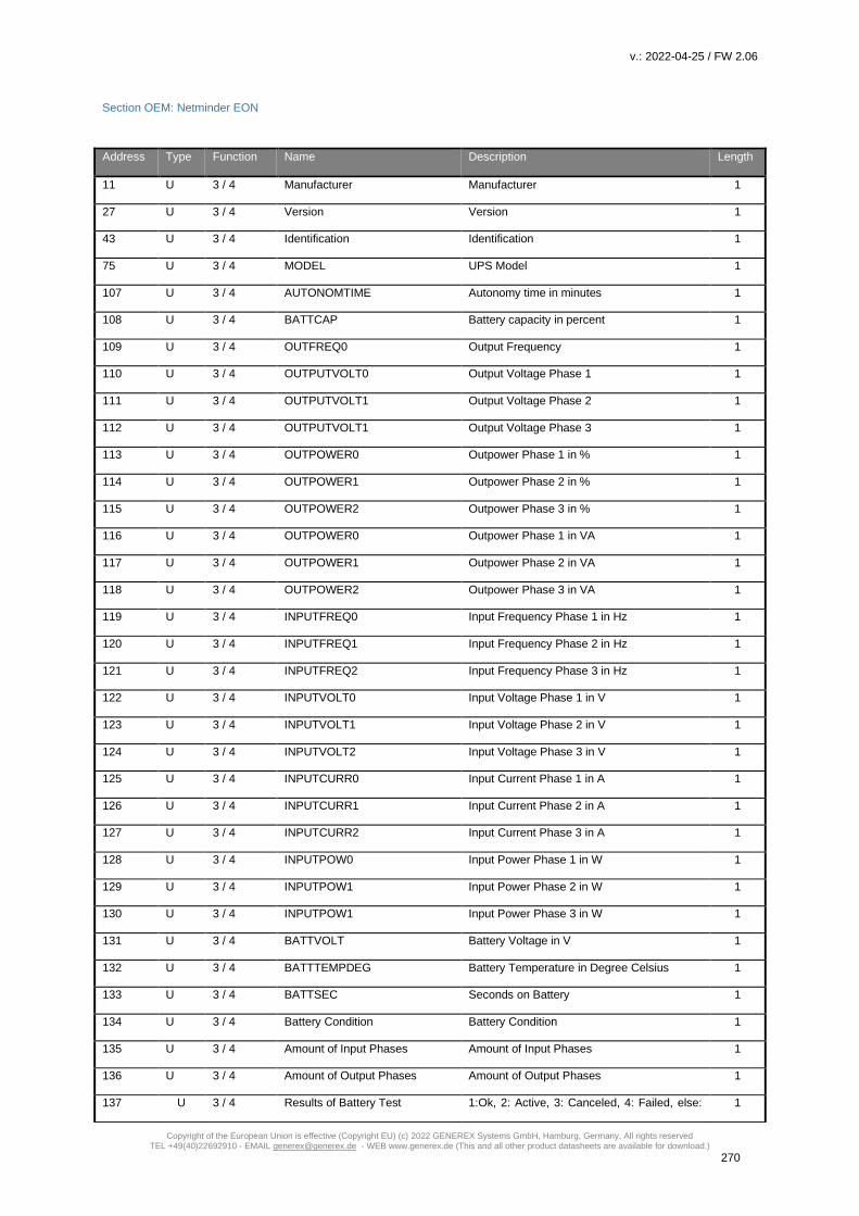
v.: 2022-04-25 / FW 2.06
Copyright of the European Union is effective (Copyright EU) (c) 2022 GENEREX Systems GmbH, Hamburg, Germany, All rights reserved TEL +49(40)22692910 - EMAIL [email protected] - WEB www.generex.de (This and all other product datasheets are available for download.)
270
Section OEM: Netminder EON
Address Type Function Name Description Length
11 U 3 / 4 Manufacturer Manufacturer 1
27 U 3 / 4 Version Version 1
43 U 3 / 4 Identification Identification 1
75 U 3 / 4 MODEL UPS Model 1
107 U 3 / 4 AUTONOMTIME Autonomy time in minutes 1
108 U 3 / 4 BATTCAP Battery capacity in percent 1
109 U 3 / 4 OUTFREQ0 Output Frequency 1
110 U 3 / 4 OUTPUTVOLT0 Output Voltage Phase 1 1
111 U 3 / 4 OUTPUTVOLT1 Output Voltage Phase 2 1
112 U 3 / 4 OUTPUTVOLT1 Output Voltage Phase 3 1
113 U 3 / 4 OUTPOWER0 Outpower Phase 1 in % 1
114 U 3 / 4 OUTPOWER1 Outpower Phase 2 in % 1
115 U 3 / 4 OUTPOWER2 Outpower Phase 3 in % 1
116 U 3 / 4 OUTPOWER0 Outpower Phase 1 in VA 1
117 U 3 / 4 OUTPOWER1 Outpower Phase 2 in VA 1
118 U 3 / 4 OUTPOWER2 Outpower Phase 3 in VA 1
119 U 3 / 4 INPUTFREQ0 Input Frequency Phase 1 in Hz 1
120 U 3 / 4 INPUTFREQ1 Input Frequency Phase 2 in Hz 1
121 U 3 / 4 INPUTFREQ2 Input Frequency Phase 3 in Hz 1
122 U 3 / 4 INPUTVOLT0 Input Voltage Phase 1 in V 1
123 U 3 / 4 INPUTVOLT1 Input Voltage Phase 2 in V 1
124 U 3 / 4 INPUTVOLT2 Input Voltage Phase 3 in V 1
125 U 3 / 4 INPUTCURR0 Input Current Phase 1 in A 1
126 U 3 / 4 INPUTCURR1 Input Current Phase 2 in A 1
127 U 3 / 4 INPUTCURR2 Input Current Phase 3 in A 1
128 U 3 / 4 INPUTPOW0 Input Power Phase 1 in W 1
129 U 3 / 4 INPUTPOW1 Input Power Phase 2 in W 1
130 U 3 / 4 INPUTPOW1 Input Power Phase 3 in W 1
131 U 3 / 4 BATTVOLT Battery Voltage in V 1
132 U 3 / 4 BATTTEMPDEG Battery Temperature in Degree Celsius 1
133 U 3 / 4 BATTSEC Seconds on Battery 1
134 U 3 / 4 Battery Condition Battery Condition 1
135 U 3 / 4 Amount of Input Phases Amount of Input Phases 1
136 U 3 / 4 Amount of Output Phases Amount of Output Phases 1
137 U 3 / 4 Results of Battery Test 1:Ok, 2: Active, 3: Canceled, 4: Failed, else: 1

v.: 2022-04-25 / FW 2.06
Copyright of the European Union is effective (Copyright EU) (c) 2022 GENEREX Systems GmbH, Hamburg, Germany, All rights reserved TEL +49(40)22692910 - EMAIL [email protected] - WEB www.generex.de (This and all other product datasheets are available for download.)
271
not started yet
138 U 3 / 4 Powerfail Powerfail 1
139 U 3 / 4 System Shutdown System Shutdown 1
140 U 3 / 4 UPSMAN started UPSMAN started 1
141 U 3 / 4 UPS Connection lost UPS connection lost 1
142 U 3 / 4 UPS Battery old UPS Battery old 1
143 U 3 / 4 Load >80% Load >80% 1
144 U 3 / 4 Load >90% Load >90% 1
145 U 3 / 4 Overload Overload 1
146 U 3 / 4 Overtemperature Condition Overtemperature Condition 1
147 U 3 / 4 Bypass on Bypass on 1
148 U 3 / 4 Battery low Battery low 1
149 U 3 / 4 Batteries are weak Batteries are weak 1
150 U 3 / 4 General Alarm Condition General Alarm Condition 1
151 U 3 / 4 Input Bad Condition Input Bad Condition 1
152 U 3 / 4 Output Bad Condition Output Bad Condition 1
153 U 3 / 4 Bypass Not Available Bypass Not Available 1
154 U 3 / 4 Low Battery Shutdown Low Battery Shutdown 1
155 U 3 / 4 System off System off 1
156 U 3 / 4 System Shutdown System Shutdown 1
157 U 3 / 4 Charger Failure Charger Failure 1
158 U 3 / 4 Manual Restart Required Manual Restart Required 1
159 U 3 / 4 Output Circuit Breaker Open Output Circuit Breaker Open 1
160 U 3 / 4 Remote Emergency Power off Remote Emergency Power off 1
161 U 3 / 4 Shutdown imminent Shutdown imminent 1
Section OEM: Netminder for all other types
Address Type Function Name Description Length
100 U 3/4 INVOLT Input Voltage (l1-n) 1
101 U 3/4 INVOLT Input Voltage (l2-n) 1
102 U 3/4 INVOLT Input Voltage (l1-l2) 1
103 U 3/4 OUTPUTVOLT Output Voltage (l1-n) 1
104 U 3/4 OUTPUTVOLT Output Voltage (l2-n) 1
105 U 3/4 OUTPUTVOLT Output Voltage /(l1-l2) 1
106 U 3/4 OUTPUTCURR Output Current (l1-n) 1
107 U 3/4 OUTPUTCURR Output Current (l2-n) 1
108 U 3/4 OUTPUTWAT Output Watts (l1-n) 1

v.: 2022-04-25 / FW 2.06
Copyright of the European Union is effective (Copyright EU) (c) 2022 GENEREX Systems GmbH, Hamburg, Germany, All rights reserved TEL +49(40)22692910 - EMAIL [email protected] - WEB www.generex.de (This and all other product datasheets are available for download.)
272
109 U 3/4 OUTPUTWAT Output Watts (l2-n) 1
110 U 3/4 OUTPUTWAT Output Watts (l1-l2) 1
111 U 3/4 OUTPUTWATTOT Output watts (total) 1
112 U 3/4 OUTPUTVA Output VA (l1-n) 1
113 U 3/4 OUTPUTVA Output VA (l2-n) 1
114 U 3/4 OUTPUTVA Output VA (l1-l2) 1
115 U 3/4 OUTPUTVATOT Output VA (total) 1
116 U 3/4 OUTPUTLOAD Output Load (l1-n) 1
117 U 3/4 OUTPUTLOAD Output Load (l2-n) 1
118 U 3/4 OUTPUTFREQ Output Frequency 1
119 U 3/4 BATTVOLT Battery Voltage 1
120 U 3/4 PERCBATT Percentage Battery 1
121 U 3/4 DCCHARGECURR DC Charging Current 1
122 U 3/4 CS141UPSSTAT CS141 UPS Status 1
123 U 3/4 Alarm: Battery Bad 1 = active; 0 = not active 1
124 U 3/4 Alarm: On Battery 1 = active; 0 = not active 1
125 U 3/4 Alarm: Battery Low 1 = active; 0 = not active 1
126 U 3/4 Alarm: Battery Depleted 1 = active; 0 = not active 1
127 U 3/4 Alarm: Overtemperature 1 = active; 0 = not active 1
128 U 3/4 Alarm: Input Bad 1 = active; 0 = not active 1
129 U 3/4 Alarm: Output Bad 1 = active; 0 = not active 1
130 U 3/4 Alarm: Output Overload 1 = active; 0 = not active 1
131 U 3/4 Alarm: On Bypass 1 = active; 0 = not active 1
132 U 3/4 Alarm: Bypass Bad 1 = active; 0 = not active 1
133 U 3/4 Alarm: Ouput Off As Requested 1 = active; 0 = not active 1
134 U 3/4 Alarm: UPS Off As Requested 1 = active; 0 = not active 1
135 U 3/4 Alarm: Charger Failed 1 = active; 0 = not active 1
136 U 3/4 Alarm: UPS Output Off 1 = active; 0 = not active 1
137 U 3/4 Alarm: UPS System Off 1 = active; 0 = not active 1
138 U 3/4 Alarm: Fan Failure 1 = active; 0 = not active 1
139 U 3/4 Alarm: Fuse Failure 1 = active; 0 = not active 1
140 U 3/4 Alarm: General Fault 1 = active; 0 = not active 1
141 U 3/4 Alarm: Diagnosis Test Failed 1 = active; 0 = not active 1
142 U 3/4 Alarm: Communication Lost 1 = active; 0 = not active 1
143 U 3/4 Alarm: Awaiting Power 1 = active; 0 = not active 1
144 U 3/4 Alarm: Shutdown Pending 1 = active; 0 = not active 1
145 U 3/4 Alarm: Shutdown Imminent 1 = active; 0 = not active 1
146 U 3/4 Alarm: Test In Progress 1 = active; 0 = not active 1

v.: 2022-04-25 / FW 2.06
Copyright of the European Union is effective (Copyright EU) (c) 2022 GENEREX Systems GmbH, Hamburg, Germany, All rights reserved TEL +49(40)22692910 - EMAIL [email protected] - WEB www.generex.de (This and all other product datasheets are available for download.)
273
147 U 3/4 AUX Port 1 1 = active (high) ; 0 = not active (low) 1
148 U 3/4 AUX Port 2 1 = active (high) ; 0 = not active (low) 1
149 U 3/4 AUX Port 3 1 = active (high) ; 0 = not active (low) 1
150 U 3/4 AUX Port 4 1 = active (high) ; 0 = not active (low) 1
151 U 3/4 Sensormngr 1 / SMT_COM, Analog Value 1
152 U 3/4 Sensormngr 2 /SMTH_COM, Analog Value 1
153 U 3/4 SensorManager/Sensor 3 Analog Value 1
154 U 3/4 SensorManager/Sensor 4 Analog Value 1
155 U 3/4 SensorManager/Sensor 5 Analog Value 1
156 U 3/4 SensorManager/Sensor 6 Analog Value 1
157 U 3/4 SensorManager/Sensor 7 Analog Value 1
158 U 3/4 SensorManager/Sensor 8 Analog Value 1
159 U 3/4 Result of the last Battery Test
Value 3 = Battery Test passd
Value 4 = Battery Test failed 1
Section OEM : AEG Protect 3. M 2.0
Address Type Function Name Description Length
100 U 3/4 (SNMPALARMS&0x6102)==0 Normal Operation 1
101 U 3/4 (SNMPALARMS&0x100)>>8 On Bypass 1
102 U 3/4 (SNMPALARMS&0x2)>>1 On Battery 1
103 U 3/4 (SNMPALARMS&0x4000)>>14 UPS System Off 1
104 U 3/4 (SNMPALARMS&0x20000)>>17 General Fault 1
105 U 3/4 (SNMPALARMS&0x80000)>>19 Communication Lost 1
106 U 3/4 (SNMPALARMS&0x20)>>5 Input Bad 1
107 U 3/4 (SNMPALARMS&0x1000)>>12 Charger Failed 1
108 U 3/4 (SNMPALARMS&0x1) Battery Bad 1
109 U 3/4 (SNMPALARMS&0x40)>>6 Output Bad 1
110 U 3/4 (SNMPALARMS&0x200)>>9 Bypass Bad 1
111 U 3/4 (SNMPALARMS&0x4)>>2 Low Battery 1
112 U 3/4 (SNMPALARMS&0x8)>>3
Depleted Battery
1
113 U 3/4 (SNMPALARMS&0x10)>>4 Temperature Bad 1
114 U 3/4 (SNMPALARMS&0x80)>>7 Output Overload 1
115 U 3/4 (SNMPALARMS&0x8000)>>15 Fan Failure 1
116 U 3/4 (SNMPALARMS&0x2000)>>13 UPS Output Off 1
117 U 3/4 AUX1STATE 1 = active (high) ; 0 = not active (low) 1
118 U 3/4 AUX2STATE 1 = active (high) ; 0 = not active (low) 1

v.: 2022-04-25 / FW 2.06
Copyright of the European Union is effective (Copyright EU) (c) 2022 GENEREX Systems GmbH, Hamburg, Germany, All rights reserved TEL +49(40)22692910 - EMAIL [email protected] - WEB www.generex.de (This and all other product datasheets are available for download.)
274
119 U 3/4 AUX3STATE 1 = active (high) ; 0 = not active (low) 1
120 U 3/4 AUX4STATE 1 = active (high) ; 0 = not active (low) 1
121 U 3/4 AMBTEMP 1
122 U 3/4 INFREQ0 Input Frequency Hz Phase 1 1
123 U 3/4 INVOLT0 Input Voltage Phase 1 V 1
124 U 3/4 INVOLT1 Input Voltage Phase 2 V 1
125 U 3/4 INVOLT1 Input Voltage Phase 3 V 1
126 U 3/4 INCURR0 Input Current Phase 1 in Ampere 1
127 U 3/4 INCURR1 Input Current Phase 2 in Ampere 1
128 U 3/4 INCURR2 Input Current Phase 3 in Ampere 1
129 U 3/4 EX_BYP_FREQ 1
130 U 3/4 EX_BYP_VOLT0 1
131 U 3/4 EX_BYP_VOLT1 1
132 U 3/4 EX_BYP_VOLT2 1
133 U 3/4
(EX_BATT_VOLTNEG+EX_BATT_
VOLTPOS)*10.0 1
134 U 3/4
(EX_BATT_CURRNEG+EX_BATT_
CURRPOS)*5.0 1
135 U 3/4
MIN(ftoi(BATTCAP),ftoi(EX_BATT_
CAPNEG)) 1
136 U 3/4 AUTONOMTIME Autonomy Time Minutes 1
137 U 3/4 TEMPDEG Temperature C° 1
138 U 3/4 OUTFREQ0 Output Frequency Hz 1
139 U 3/4 OUTPUT_VOLT0 Output Voltage Phase 1 V 1
140 U 3/4 OUTPUT_VOLT1 Output Voltage Phase 2 V 1
141 U 3/4 OUTPUT_VOLT2 Output Voltage Phase 3 V 1
142 U 3/4 OUTPOWER0 Outpower Phase 1 % 1
143 U 3/4 OUTPOWER1 Outpower Phase 2 % 1
144 U 3/4 OUTPOWER2 Outpower Phase 3 % 1
145 U 3/4 EX_OUT_CURR0 1
146 U 3/4 EX_OUT_CURR1 1
147 U 3/4 EX_OUT_CURR2 1
148 U 3/4 EX_OUT_WATT0 1
149 U 3/4 EX_OUT_WATT1 1
150 U 3/4 EX_OUT_WATT2 1

v.: 2022-04-25 / FW 2.06
Copyright of the European Union is effective (Copyright EU) (c) 2022 GENEREX Systems GmbH, Hamburg, Germany, All rights reserved TEL +49(40)22692910 - EMAIL [email protected] - WEB www.generex.de (This and all other product datasheets are available for download.)
275
Section OEM: AEG Protect 3.31, 5.31, 8.31
Address Type Function Name Description Length
100 U 3/4 (FKTSTATUS&0x4102)==0 Normal Operation 1
101 U 3/4 SNMPALARMS&0x100)>>8 On Bypass 1
102 U 3/4 (SNMPALARMS&0x2)>>1 On Battery 1
103 U 3/4 (SNMPALARMS&0x4000)>>14 UPS System Off 1
104 U 3/4 CNT_PF Powerfail Counter 1
105 U 3/4 (SNMPALARMS&0x20000)>>17 General Fault 1
106 U 3/4 (SNMPALARMS&0x80000)>>19 Communication Lost 1
107 U 3/4 (SNMPALARMS&0x20)>>5 Input Bad 1
108 U 3/4 (SNMPALARMS&0x1000)>>12 Charger Failed 1
109 U 3/4 (SNMPALARMS&0x1) Battery Bad 1
110 U 3/4 (SNMPALARMS&0x40)>>6 Output Bad 1
111 U 3/4 (SNMPALARMS&0x200)>>9 Bypass Bad 1
112 U 3/4 (SNMPALARMS&0x4)>>2 Low Battery 1
113 U 3/4 (SNMPALARMS&0x8)>>3 Depleted Battery 1
114 U 3/4 (SNMPALARMS&0x10)>>4 Temperature Bad 1
115 U 3/4 (SNMPALARMS&0x80)>>7 Output Overload 1
116 U 3/4 (SNMPALARMS&0x8000)>>15 Fan Failure 1
117 U 3/4 (SNMPALARMS&0x2000)>>13 UPS Output Off 1
118 U 3/4 AUX1STATE
State AUX Port 1
1 = active (high) ; 0 = not active (low) 1
119 U 3/4 AUX2STATE
State AUX Port 2
1 = active (high) ; 0 = not active (low) 1
120 U 3/4 AUX3STATE
State AUX Port 3
1 = active (high) ; 0 = not active (low) 1
121 U 3/4 AUX4STATE
State AUX Port 4
1 = active (high) ; 0 = not active (low) 1
122 U 3/4 INFREQ0*10.0 Input Frequency Hz Phase 1 1
123 U 3/4 INVOLT0 Input Voltage Phase 1 V 1
124 U 3/4 INVOLT1 Input Voltage Phase 2 V 1
125 U 3/4 INVOLT2 Input Voltage Phase 3 V 1
126 U 3/4 BP_FREQ0*10.0 Output Frequency [Hz] 1
127 U 3/4 BP_VOLT0 Bypass Voltage Phase 1 [V] 1
128 U 3/4 BATTVOLT*10.0 Battery Voltage [V] x 10 1
129 U 3/4 SOLABATTC*10.0 Battery Current [A] x 10 1
130 U 3/4 AUTONOMTIME Autonomy Time in Minutes 1
131 U 3/4 BATTCAP Battery Capacity 1
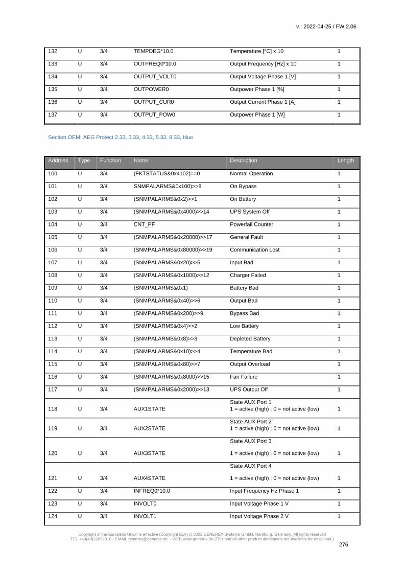
v.: 2022-04-25 / FW 2.06
Copyright of the European Union is effective (Copyright EU) (c) 2022 GENEREX Systems GmbH, Hamburg, Germany, All rights reserved TEL +49(40)22692910 - EMAIL [email protected] - WEB www.generex.de (This and all other product datasheets are available for download.)
276
132 U 3/4 TEMPDEG*10.0 Temperature [°C] x 10 1
133 U 3/4 OUTFREQ0*10.0 Output Frequency [Hz] x 10 1
134 U 3/4 OUTPUT_VOLT0 Output Voltage Phase 1 [V] 1
135 U 3/4 OUTPOWER0 Outpower Phase 1 [%] 1
136 U 3/4 OUTPUT_CUR0 Output Current Phase 1 [A] 1
137 U 3/4 OUTPUT_POW0 Outpower Phase 1 [W] 1
Section OEM: AEG Protect 2.33, 3.33, 4.33, 5.33, 8.33, blue
Address Type Function Name Description Length
100 U 3/4 (FKTSTATUS&0x4102)==0 Normal Operation 1
101 U 3/4 SNMPALARMS&0x100)>>8 On Bypass 1
102 U 3/4 (SNMPALARMS&0x2)>>1 On Battery 1
103 U 3/4 (SNMPALARMS&0x4000)>>14 UPS System Off 1
104 U 3/4 CNT_PF Powerfail Counter 1
105 U 3/4 (SNMPALARMS&0x20000)>>17 General Fault 1
106 U 3/4 (SNMPALARMS&0x80000)>>19 Communication Lost 1
107 U 3/4 (SNMPALARMS&0x20)>>5 Input Bad 1
108 U 3/4 (SNMPALARMS&0x1000)>>12 Charger Failed 1
109 U 3/4 (SNMPALARMS&0x1) Battery Bad 1
110 U 3/4 (SNMPALARMS&0x40)>>6 Output Bad 1
111 U 3/4 (SNMPALARMS&0x200)>>9 Bypass Bad 1
112 U 3/4 (SNMPALARMS&0x4)>>2 Low Battery 1
113 U 3/4 (SNMPALARMS&0x8)>>3 Depleted Battery 1
114 U 3/4 (SNMPALARMS&0x10)>>4 Temperature Bad 1
115 U 3/4 (SNMPALARMS&0x80)>>7 Output Overload 1
116 U 3/4 (SNMPALARMS&0x8000)>>15 Fan Failure 1
117 U 3/4 (SNMPALARMS&0x2000)>>13 UPS Output Off 1
118 U 3/4 AUX1STATE
State AUX Port 1
1 = active (high) ; 0 = not active (low) 1
119 U 3/4 AUX2STATE
State AUX Port 2
1 = active (high) ; 0 = not active (low) 1
120 U 3/4 AUX3STATE
State AUX Port 3
1 = active (high) ; 0 = not active (low) 1
121 U 3/4 AUX4STATE
State AUX Port 4
1 = active (high) ; 0 = not active (low) 1
122 U 3/4 INFREQ0*10.0 Input Frequency Hz Phase 1 1
123 U 3/4 INVOLT0 Input Voltage Phase 1 V 1
124 U 3/4 INVOLT1 Input Voltage Phase 2 V 1

v.: 2022-04-25 / FW 2.06
Copyright of the European Union is effective (Copyright EU) (c) 2022 GENEREX Systems GmbH, Hamburg, Germany, All rights reserved TEL +49(40)22692910 - EMAIL [email protected] - WEB www.generex.de (This and all other product datasheets are available for download.)
277
125 U 3/4 INVOLT2 Input Voltage Phase 3 V 1
126 U 3/4 BP_FREQ0*10.0 Output Frequency [Hz] 1
127 U 3/4 BP_VOLT0 Bypass Voltage Phase 1 [V] 1
128 U 3/4 BP_VOLT1 Bypass Voltage Phase 2 [V] 1
129 U 3/4 BP_VOLT2 Bypass Voltage Phase 3 [V] 1
130 U 3/4 BATTVOLT*10.0 Battery Voltage [V] x 10 1
131 U 3/4 SOLABATTC*10.0 Battery Current [A] x 10 1
132 U 3/4 AUTONOMTIME Autonomy Time in Minutes 1
133 U 3/4 BATTCAP Battery Capacity 1
134 U 3/4 TEMPDEG*10.0 Temperature [°C] x 10 1
135 U 3/4 OUTFREQ0*10.0 Output Frequency [Hz] x 10 1
136 U 3/4 OUTPUT_VOLT0 Output Voltage Phase 1 [V] 1
137 U 3/4 OUTPOWER0 Outpower Phase 1 [%] 1
138 U 3/4 OUTPUT_CUR0 Output Current Phase 1 [A] 1
139 U 3/4 OUTPUT_POW0 Outpower Phase 1 [W] 1
140 U 3/4 OUTPUT_VOLT1 Output Voltage Phase 2 [V] 1
141 U 3/4 OUTPOWER1 Outpower Phase 2 [%] 1
142 U 3/4 OUTPUT_CUR1 Output Current Phase 2 [A] 1
143 U 3/4 OUTPUT_POW1 Outpower Phase 2 [W] 1
144 U 3/4 OUTPUT_VOLT2 Output Voltage Phase 3 [V] 1
145 U 3/4 OUTPOWER2 Outpower Phase 3 [%] 1
146 U 3/4 OUTPUT_CUR2 Output Current Phase 3 [A] 1
147 U 3/4 OUTPUT_POW2 Outpower Phase 3 [W] 1
Section OEM: POWERTRONIX
Adress Name MIZAR ALCOR QUASAR SUPERNOVAE
100 Outpower Phase 1 % x x x
101 Outpower Phase 2 % x x x
102 Outpower Phase 3 % x x x
103 Battery Capacity % x x x
104 Input Voltage Phase 1 V x x x
105 Input Voltage Phase 2 V x x x
106 Input Voltage Phase 3 V x x x
107 Temperature °C not supported x x
108 Autonomy Time minutes x x x
109 UPS Status (ASCII Hex) x x x
110 Battery Voltage V x x x
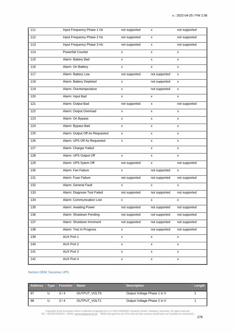
v.: 2022-04-25 / FW 2.06
Copyright of the European Union is effective (Copyright EU) (c) 2022 GENEREX Systems GmbH, Hamburg, Germany, All rights reserved TEL +49(40)22692910 - EMAIL [email protected] - WEB www.generex.de (This and all other product datasheets are available for download.)
278
111 Input Frequency Phase 1 Hz not supported x not supported
112 Input Frequency Phase 2 Hz not supported x not supported
113 Input Frequency Phase 3 Hz not supported x not supported
114 Powerfail Counter x x x
115 Alarm: Battery Bad x x x
116 Alarm: On Battery x x x
117 Alarm: Battery Low not supported not supported x
118 Alarm: Battery Depleted x not supported x
119 Alarm: Overtemperature x not supported x
120 Alarm: Input Bad x x x
121 Alarm: Output Bad not supported x not supported
122 Alarm: Output Overload x x x
123 Alarm: On Bypass x x x
124 Alarm: Bypass Bad x x x
125 Alarm: Output Off As Requested x x x
126 Alarm: UPS Off As Requested x x x
127 Alarm: Charger Failed x x
128 Alarm: UPS Output Off x x x
129 Alarm: UPS Sytem Off not supported x not supported
130 Alarm: Fan Failure x not supported x
131 Alarm: Fuse Failure not supported not supported not supported
132 Alarm: General Fault x x x
133 Alarm: Diagnose Test Failed not supported not supported not supported
134 Alarm: Communication Lost x x x
135 Alarm: Awaiting Power not supported not supported not supported
136 Alarm: Shutdown Pending not supported not supported not supported
137 Alarm: Shutdown Imminent not supported not supported not supported
138 Alarm: Test In Progress x not supported not supported
139 AUX Port 1 x x x
140 AUX Port 2 x x x
141 AUX Port 3 x x x
142 AUX Port 4 x x x
Section OEM: Socomec UPS
Address Type Function Name Description Length
97 U 3 / 4 OUTPUT_VOLT0 Output Voltage Phase 1 in V 1
98 U 3 / 4 OUTPUT_VOLT1 Output Voltage Phase 2 in V 1
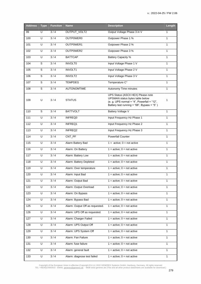
v.: 2022-04-25 / FW 2.06
Copyright of the European Union is effective (Copyright EU) (c) 2022 GENEREX Systems GmbH, Hamburg, Germany, All rights reserved TEL +49(40)22692910 - EMAIL [email protected] - WEB www.generex.de (This and all other product datasheets are available for download.)
279
Address Type Function Name Description Length
99 U 3 / 4 OUTPUT_VOLT2 Output Voltage Phase 3 in V 1
100 U 3 / 4 OUTP0WER0 Outpower Phase 1 % 1
101 U 3 / 4 OUTP0WER1 Outpower Phase 2 % 1
102 U 3 / 4 OUTP0WER2 Outpower Phase 3 % 1
103 U 3 / 4 BATTCAP Battery Capacity % 1
104 S 3 / 4 INVOLT0 Input Voltage Phase 1 V 1
105 S 3 / 4 INVOLT1 Input Voltage Phase 2 V 1
106 S 3 / 4 INVOLT2 Input Voltage Phase 3 V 1
107 S 3 / 4 TEMPDEG Temperature C° 1
108 S 3 / 4 AUTONOMTIME Autonomy Time minutes 1
109 U 3 / 4 STATUS
UPS Status (ASCII HEX) Please note
UPSMAN status bytes table below
(e. g. UPS normal = “4”, Powerfail = “12”,
Battery test running = “68”, Bypass = “5” )
1
110 S 3 / 4 BATTVOLT Battery Voltage V 1
111 U 3 / 4 INFREQ0 Input Frequency Hz Phase 1 1
112 U 3 / 4 INFREQ1 Input Frequency Hz Phase 2 1
113 U 3 / 4 INFREQ2 Input Frequency Hz Phase 3 1
114 U 3 / 4 CNT_PF Powerfail Counter 1
115 U 3 / 4 Alarm Battery Bad 1 = active; 0 = not active 1
116 U 3 / 4 Alarm: On Battery 1 = active; 0 = not active 1
117 U 3 / 4 Alarm: Battery Low 1 = active; 0 = not active 1
118 U 3 / 4 Alarm: Battery Depleted 1 = active; 0 = not active 1
119 U 3 / 4 Alarm: Over temperature 1 = active; 0 = not active 1
120 U 3 / 4 Alarm: Input Bad 1 = active; 0 = not active 1
121 U 3 / 4 Alarm: Output Bad 1 = active; 0 = not active 1
122 U 3 / 4 Alarm: Output Overload 1 = active; 0 = not active 1
123 U 3 / 4 Alarm: On Bypass 1 = active; 0 = not active 1
124 U 3 / 4 Alarm: Bypass Bad 1 = active; 0 = not active 1
125 U 3 / 4 Alarm: Output Off as requested. 1 = active; 0 = not active 1
126 U 3 / 4 Alarm: UPS Off as requested. 1 = active; 0 = not active 1
127 U 3 / 4 Alarm: Charger Failed 1 = active; 0 = not active 1
128 U 3 / 4 Alarm: UPS Output Off 1 = active; 0 = not active 1
129 U 3 / 4 Alarm: UPS System Off 1 = active; 0 = not active 1
130 U 3 / 4 Alarm: Fan Failure 1 = active; 0 = not active 1
131 U 3 / 4 Alarm: fuse failure 1 = active; 0 = not active 1
132 U 3 / 4 Alarm: general fault 1 = active; 0 = not active 1
133 U 3 / 4 Alarm: diagnose test failed 1 = active; 0 = not active 1

v.: 2022-04-25 / FW 2.06
Copyright of the European Union is effective (Copyright EU) (c) 2022 GENEREX Systems GmbH, Hamburg, Germany, All rights reserved TEL +49(40)22692910 - EMAIL [email protected] - WEB www.generex.de (This and all other product datasheets are available for download.)
280
Address Type Function Name Description Length
134 U 3 / 4 Alarm: communication lost 1 = active; 0 = not active 1
135 U 3 / 4 Alarm: awaiting power 1 = active; 0 = not active 1
136 U 3 / 4 Alarm: shutdown pending 1 = active; 0 = not active 1
137 U 3 / 4 Alarm: shutdown imminent 1 = active; 0 = not active 1
138 U 3 / 4 Alarm: test in progress 1 = active; 0 = not active 1
139 U 3 / 4 AUX Port 1 1 = active (high), 0 = not active (low) 1
140 U 3 / 4 AUX Port 2 1 = active (high), 0 = not active (low) 1
141 U 3 / 4 AUX Port 3 1 = active (high), 0 = not active (low) 1
142 U 3 / 4 AUX Port 4 1 = active (high), 0 = not active (low) 1
143 U 3 / 4 Sensormanager/SMTCOM
sensor 1 Analog value 1
144 U 3 / 4 Sensormanager/SMTHCOM
sensor 2 Analog value 1
145 U 3 / 4 Sensormanager sensor 3 Analog value 1
146 U 3 / 4 Sensormanager sensor 4 Analog value 1
147 U 3 / 4 Sensormanager sensor 5 Analog value 1
148 U 3 / 4 Sensormanager sensor 6 Analog value 1
149 U 3 / 4 Sensormanager sensor 7 Analog value 1
150 U 3 / 4 Sensormanager sensor 8 Analog value 1
151 U 3 / 4 INCURR0 Input Current Plase 1 1
152 U 3 / 4 INCURR1 Input Current Plase 2 1
153 U 3 / 4 INCURR2 Input Current Plase 3 1
154 U 3 / 4 OUTFREQ0 Output Frequency Phase 1 1
155 U 3 / 4 EX_OUT_CURR0 External Output Current Phase 1 1
156 U 3 / 4 EX_OUT_CURR1 External Output Current Phase 2 1
157 U 3 / 4 EX_OUT_CURR2 External Output Current Phase 3 1
Section MHD Modular / Multimatic Modular / AEG Protect 1. Modular, ENIGMA
Address Type Function Name Description Length
100 U 3 / 4 OUTPOWER0 Outpower Phase 1 % 1
101 U 3 / 4 OUTPOWER1 Outpower Phase 2 % 1
102 U 3 / 4 OUTPOWER2 Outpower Phase 3 % 1
103 U 3 / 4 BATTCAP Battery Capacity % 1
104 S 3 / 4 INVOLT0 Input Voltage Phase 1 V 1
105 S 3 / 4 INVOLT1 Input Voltage Phase 2 V 1
106 S 3 / 4 INVOLT2 Input Voltage Phase 3 V 1
107 S 3 / 4 TEMPDEG Temperature C° 1
108 S 3 / 4 AUTONOMTIME Autonomy Time minutes 1
109 U 3 / 4 STATUS (e. g. UPS normal = "4",
Powerfail = "12", Battery test
running = "68", Bypass = "5")
UPS Status (ASCII HEX), please note
UPSMAN status bytes table below
1

v.: 2022-04-25 / FW 2.06
Copyright of the European Union is effective (Copyright EU) (c) 2022 GENEREX Systems GmbH, Hamburg, Germany, All rights reserved TEL +49(40)22692910 - EMAIL [email protected] - WEB www.generex.de (This and all other product datasheets are available for download.)
281
Address Type Function Name Description Length
110 U 3 / 4 BATTVOLT Battery Voltage V 1
111 U 3 / 4 INFREQ0 Input Frequency Hz Phase 1 1
112 U 3 / 4 INFREQ1 Input Frequency Hz Phase 2 1
113 U 3 / 4 INFREQ2 Input Frequency Hz Phase 3 1
114 U 3 / 4 CNT_PF Powerfail Counter 1
115 U 3 / 4 (SNMPALARMS&0x1) Alarm Battery Bad 1
116 U 3 / 4 (SNMPALARMS&0x2)>>1 Alarm: On Battery 1
117 U 3 / 4 (SNMPALARMS&0x4)>>2 Alarm: Battery Low 1
118 U 3 / 4 (SNMPALARMS&0x8)>>3 Alarm: Battery Depleted 1
119 U 3 / 4 (SNMPALARMS&0x10)>>4 Alarm: Over temperature 1
120 U 3 / 4 (SNMPALARMS&0x20)>>5 Alarm: Input Bad 1
121 U 3 / 4 (SNMPALARMS&0x40)>>6 Alarm: Output Bad 1
122 U 3 / 4 (SNMPALARMS&0x80)>>7 Alarm: Output Overload 1
123 U 3 / 4 (SNMPALARMS&0x100)>>8 Alarm: On Bypass 1
124 U 3 / 4 (SNMPALARMS&0x200)>>9 Alarm: Bypass Bad 1
125 U 3 / 4 (SNMPALARMS&0x400)>>10 Alarm: Output Off as requested. 1
126 U 3 / 4 (SNMPALARMS&0x800)>>11 Alarm: UPS Off as requested. 1
127 U 3 / 4 (SNMPALARMS&0x1000)>>12 Alarm: Charger Failed 1
128 U 3 / 4 (SNMPALARMS&0x2000)>>13 Alarm: UPS Output Off 1
129 U 3 / 4 (SNMPALARMS&0x4000)>>14 Alarm: UPS System Off 1
130 U 3 / 4 (SNMPALARMS&0x8000)>>15 Alarm: Fan Failure 1
131 U 3 / 4 (SNMPALARMS&0x10000)>>1 Alarm: fuse failure 1
132 U 3 / 4 (SNMPALARMS&0x20000)>>1 Alarm: general fault 1
133 U 3 / 4 (SNMPALARMS&0x40000)>>1 Alarm: diagnose test failed 1
134 U 3 / 4 (SNMPALARMS&0x80000)>>1 Alarm: communication lost 1
135 U 3 / 4 (SNMPALARMS&0x100000)>> Alarm: awaiting power 1
136 U 3 / 4 (SNMPALARMS&0x200000)>> Alarm: shutdown pending 1
137 U 3 / 4 (SNMPALARMS&0x400000)>> Alarm: shutdown imminent 1
138 U 3 / 4 (SNMPALARMS&0x800000)>> Alarm: test in progress 1
139 U 3 / 4 AUX1STATE AUX Port 1 1
140 U 3 / 4 AUX2STATE AUX Port 2 1
141 U 3 / 4 AUX3STATE AUX Port 3 1
142 U 3 / 4 AUX4STATE AUX Port 4 1
143 U 3 / 4 TEMP1 Sensormanager/SMTCOM sensor 1 1
144 U 3 / 4 TEMP2 Sensormanager/SMTHCOM sensor 2 1
145 U 3 / 4 TEMP3 Sensormanager sensor 3 1
146 U 3 / 4 TEMP4 Sensormanager sensor 4 1
147 U 3 / 4 TEMP5 Sensormanager sensor 5 1
148 U 3 / 4 TEMP6 Sensormanager sensor 6 1
149 U 3 / 4 TEMP7 Sensormanager sensor 7 1
150 U 3 / 4 TEMP8 Sensormanager sensor 8 1
151 U 3 / 4 AEESerModulePresent(1) Status data, for details contact Effekta 1
152 U 3 / 4 AEESerModulePresent(2) Status data, for details contact Effekta 1
153 U 3 / 4 AEESerModulePresent(3) Status data, for details contact Effekta 1
154 U 3 / 4 AEESerModulePresent(4) Status data, for details contact Effekta 1
155 U 3 / 4 AEESerModulePresent(5) Status data, for details contact Effekta 1
156 U 3 / 4 AEESerModulePresent(6) Status data, for details contact Effekta 1
157 U 3 / 4 AEESerModuleError(1,1) Status data, for details contact Effekta 1
158 U 3 / 4 AEESerModuleError(1,2) Status data, for details contact Effekta 1
159 U 3 / 4 AEESerModuleError(1,3) Status data, for details contact Effekta 1
160 U 3 / 4 AEESerModuleError(1,4) Status data, for details contact Effekta 1

v.: 2022-04-25 / FW 2.06
Copyright of the European Union is effective (Copyright EU) (c) 2022 GENEREX Systems GmbH, Hamburg, Germany, All rights reserved TEL +49(40)22692910 - EMAIL [email protected] - WEB www.generex.de (This and all other product datasheets are available for download.)
282
Address Type Function Name Description Length
161 U 3 / 4 AEESerModuleError(2,1) Status data, for details contact Effekta 1
162 U 3 / 4 AEESerModuleError(2,2) Status data, for details contact Effekta 1
163 U 3 / 4 AEESerModuleError(2,3) Status data, for details contact Effekta 1
164 U 3 / 4 AEESerModuleError(2,4) Status data, for details contact Effekta 1
165 U 3 / 4 AEESerModuleError(3,1) Status data, for details contact Effekta 1
166 U 3 / 4 AEESerModuleError(3,2) Status data, for details contact Effekta 1
167 U 3 / 4 AEESerModuleError(3,3) Status data, for details contact Effekta 1
168 U 3 / 4 AEESerModuleError(3,4) Status data, for details contact Effekta 1
169 U 3 / 4 AEESerModuleError(4,1) Status data, for details contact Effekta 1
170 U 3 / 4 AEESerModuleError(4,2) Status data, for details contact Effekta 1
171 U 3 / 4 AEESerModuleError(4,3) Status data, for details contact Effekta 1
172 U 3 / 4 AEESerModuleError(4,4) Status data, for details contact Effekta 1
173 U 3 / 4 AEESerModuleError(5,1) Status data, for details contact Effekta 1
174 U 3 / 4 AEESerModuleError(5,2) Status data, for details contact Effekta 1
175 U 3 / 4 AEESerModuleError(5,3) Status data, for details contact Effekta 1
176 U 3 / 4 AEESerModuleError(5,4) Status data, for details contact Effekta 1
177 U 3 / 4 AEESerModuleError(6,1) Status data, for details contact Effekta 1
178 U 3 / 4 AEESerModuleError(6,2) Status data, for details contact Effekta 1
179 U 3 / 4 AEESerModuleError(6,3) Status data, for details contact Effekta 1
180 U 3 / 4 AEESerModuleError(6,4) Status data, for details contact Effekta 1
181 U 3 / 4 AEESerModuleWarning(1) Status data, for details contact Effekta 1
182 U 3 / 4 AEESerModuleWarning(2) Status data, for details contact Effekta 1
183 U 3 / 4 AEESerModuleWarning(3) Status data, for details contact Effekta 1
184 U 3 / 4 AEESerModuleWarning(4) Status data, for details contact Effekta 1
185 U 3 / 4 AEESerModuleWarning(5) Status data, for details contact Effekta 1
186 U 3 / 4 AEESerModuleWarning(6) Status data, for details contact Effekta 1
187 U 3 / 4 AEESerModuleState(1) Status data, for details contact Effekta 1
188 U 3 / 4 AEESerModuleState(2) Status data, for details contact Effekta 1
189 U 3 / 4 AEESerModuleState(3) Status data, for details contact Effekta 1
190 U 3 / 4 AEESerModuleState(4) Status data, for details contact Effekta 1
191 U 3 / 4 AEESerModuleState(5) Status data, for details contact Effekta 1
192 U 3 / 4 AEESerModuleState(6) Status data, for details contact Effekta 1
193 U 3 / 4 AEESerModuleVolt(1) Status data, for details contact Effekta 1
194 U 3 / 4 AEESerModuleVolt(2) Status data, for details contact Effekta 1
195 U 3 / 4 AEESerModuleVolt(3) Status data, for details contact Effekta 1
196 U 3 / 4 AEESerModuleVolt(4) Status data, for details contact Effekta 1
197 U 3 / 4 AEESerModuleVolt(5) Status data, for details contact Effekta 1
198 U 3 / 4 AEESerModuleVolt(6) Status data, for details contact Effekta 1
199 U 3 / 4 AEESerModuleCurr(1) Status data, for details contact Effekta 1
200 U 3 / 4 AEESerModuleCurr(2) Status data, for details contact Effekta 1
201 U 3 / 4 AEESerModuleCurr(3) Status data, for details contact Effekta 1
202 U 3 / 4 AEESerModuleCurr(4) Status data, for details contact Effekta 1
203 U 3 / 4 AEESerModuleCurr(5) Status data, for details contact Effekta 1
204 U 3 / 4 AEESerModuleCurr(6) Status data, for details contact Effekta 1
205 U 3 / 4 seconbat Time on Battery [sec.] 1
206 U 3 / 4 OUTPUT_VOLT0 Output Voltage [V] 1
207 U 3 / 4 E_OUTPOWER*10.0 Enigma total output power [KW] 1
208 U 3 / 4 E_OUTCPOWER*10.0 Enigma total output compl. power [KVA] 1
Section Borri 4000 Std. Panel / E-Tec 310 to 380 (m) / SALICRU SLC NX/DL/CUBE

v.: 2022-04-25 / FW 2.06
Copyright of the European Union is effective (Copyright EU) (c) 2022 GENEREX Systems GmbH, Hamburg, Germany, All rights reserved TEL +49(40)22692910 - EMAIL [email protected] - WEB www.generex.de (This and all other product datasheets are available for download.)
283
Address Type Function Name Description Length
1 U 3 / 4 Manufacturer Manufacturer 1
17 U 3 / 4 Version Version 1
33 U 3 / 4 Identification Identification 1
65 U 3 / 4 Model Model 1
97 U 3 / 4 AUTONOMTIME Autonomy time in minutes 1
98 U 3 / 4 BATTCAP Battery capacity in percent 1
99 U 3 / 4 OUTPUT Output Source 0 Mains, 1 Battery, 2
Bypass
1
100 U 3 / 4 OUTFREQ0 Output Frequency 1
101 U 3 / 4 SOLAWROV0 Outputvoltage Phase 1 in V 1
102 U 3 / 4 SOLAWROV1 Outputvoltage Phase 2 in V 1
103 U 3 / 4 SOLAWROV2 Outputvoltage Phase 3 in V 1
104 U 3 / 4 SOLAWROC0 Output Current Phase 1 in A 1
105 U 3 / 4 SOLAWROC1 Output Current Phase 2 in A 1
106 U 3 / 4 SOLAWROC2 Output Current Phase 3 in A 1
107 U 3 / 4 OUTPOWER0 Outpower Phase 1 % 1
108 U 3 / 4 OUTPOWER1 Outpower Phase 2 % 1
109 U 3 / 4 OUTPOWER2 Outpower Phase 3 % 1
110 U 3 / 4 SOLSETEMPBAD Temperature bad 1
111 U 3 / 4 SOLSEINPUTBAD Input bad 1
112 U 3 / 4 SOLSEOVERLOAD Overload 1
113 U 3 / 4 SOLSEBYPASSFAULT Bypass fault 1
114 U 3 / 4 SOLSECHARGERFAULT Charger fault 1
115 U 3 / 4 SOLSEGENERALFAULT General fault 1
116 U 3 / 4 SOLSESDPENDING Shutdown pending 1
117 U 3 / 4 SOLSETESTRESULT Test result 1
118 U 3 / 4 (SNMPALARMS&0x80000)>>19 Communication Lost Alarm 1
119 U 3 / 4 INFREQ0 Input Frequency Phase 1 in Hz 1
120 U 3 / 4 INFREQ1 Input Frequency Phase 2 in Hz 1
121 U 3 / 4 INFREQ2 Input Frequency Phase 3 in Hz 1
122 U 3 / 4 INVOLT0 Input Voltage Phase 1 in V 1
123 U 3 / 4 INVOLT1 Input Voltage Phase 2 in V 1
124 U 3 / 4 INVOLT2 Input Voltage Phase 3 in V 1
125 U 3 / 4 INCURR0 Input Current Phase 1 in A 1
126 U 3 / 4 INCURR1 Input Current Phase 2 in A 1
127 U 3 / 4 INCURR2 Input Current Phase 3 in A 1
128 U 3 / 4 EX_BYP_VOLT0 Bypass Voltage Phase 1 in V 1

v.: 2022-04-25 / FW 2.06
Copyright of the European Union is effective (Copyright EU) (c) 2022 GENEREX Systems GmbH, Hamburg, Germany, All rights reserved TEL +49(40)22692910 - EMAIL [email protected] - WEB www.generex.de (This and all other product datasheets are available for download.)
284
129 U 3 / 4 EX_BYP_VOLT1 Bypass Voltage Phase 2 in V 1
130 U 3 / 4 EX_BYP_VOLT2 Bypass Voltage Phase 3 in V 1
131 U 3 / 4 EX_BYP_CURR0 Bypass Current Phase 1 in A 1
132 U 3 / 4 EX_BYP_CURR1 Bypass Current Phase 2 in A 1
133 U 3 / 4 EX_BYP_CURR2 Bypass Current Phase 3 in A 1
134 U 3 / 4 EX_BYP_WATT0 Bypass Power Phase 1 [W] 1
135 U 3 / 4 EX_BYP_WATT1 Bypass Power Phase 2 [W] 1
136 U 3 / 4 EX_BYP_WATT2 Bypass Power Phase 3 [W] 1
137 U 3 / 4 EX_BYP_FREQ0 Bypass Frequency [Hz] 1
138 U 3 / 4 EX_INP_WATT0 Input Power Phase 1 [W] 1
139 U 3 / 4 EX_INP_WATT1 Input Power Phase 2 [W] 1
140 U 3 / 4 EX_INP_WATT2 Input Power Phase 3 [W] 1
141 U 3 / 4 BATTVOLT Battery Voltage [V] 1
142 U 3 / 4 TEMPDEG Temperature [°C] 1
143 U 3 / 4 EX_BATT_SECONBATT Time on Battery [sec.] 1
144 U 3 / 4 EX_BATT_CURRPOS positive battery current [A] 1
145 U 3 / 4 BATTCONDITION Flags for battery condition 1
146 U 3 / 4 INPHASES amount of Phases at Input 1
147 U 3 / 4 OUTPHASES amount of Phases at Output 1
148 U 3 / 4 SOLABATTC Battery Current [A] 1
Section Inform UPS / Pyramid DSP/Online DSP
Address Type Function Name Description Length
100 U 3 / 4 OUTP0WER0 Outpower Phase 1 % 1
101 U 3 / 4 OUTP0WER1 Outpower Phase 2 % 1
102 U 3 / 4 OUTP0WER2 Outpower Phase 3 % 1
103 U 3 / 4 BATTCAP Battery Capacity % 1
104 S 3 / 4 INVOLT0 Input Voltage Phase 1 V 1
105 S 3 / 4 INVOLT1 Input Voltage Phase 2 V 1
106 S 3 / 4 INVOLT2 Input Voltage Phase 3 V 1
107 S 3 / 4 TEMPDEG Temperature C° 1
108 S 3 / 4 AUTONOMTIME Autonomy Time minutes 1
109 U 3 / 4
STATUS (e. g.
UPS normal = “4”,
Powerfail = “12”,
Battery test running = “68”, Bypass
= “5” )
UPS Status (ASCII HEX) Please note
UPSMAN status bytes table below 1
110 S 3 / 4 BATTVOLT Battery Voltage V 1

v.: 2022-04-25 / FW 2.06
Copyright of the European Union is effective (Copyright EU) (c) 2022 GENEREX Systems GmbH, Hamburg, Germany, All rights reserved TEL +49(40)22692910 - EMAIL [email protected] - WEB www.generex.de (This and all other product datasheets are available for download.)
285
111 U 3 / 4 INFREQ0 Input Frequency Hz Phase 1 1
112 U 3 / 4 INFREQ1 Input Frequency Hz Phase 2 1
113 U 3 / 4 INFREQ2 Input Frequency Hz Phase 3 1
114 U 3 / 4 CNT_PF Powerfail Counter 1
115 U 3 / 4 Alarm Battery Bad 1 = active; 0 = not active 1
116 U 3 / 4 Alarm: On Battery 1 = active; 0 = not active 1
117 U 3 / 4 Alarm: Battery Low 1 = active; 0 = not active 1
118 U 3 / 4 Alarm: Battery Depleted 1 = active; 0 = not active 1
119 U 3 / 4 Alarm: Over temperature 1 = active; 0 = not active 1
120 U 3 / 4 Alarm: Input Bad 1 = active; 0 = not active 1
121 U 3 / 4 Alarm: Output Bad 1 = active; 0 = not active 1
122 U 3 / 4 Alarm: Output Overload 1 = active; 0 = not active 1
123 U 3 / 4 Alarm: On Bypass 1 = active; 0 = not active 1
124 U 3 / 4 Alarm: Bypass Bad 1 = active; 0 = not active 1
125 U 3 / 4 Alarm: Output Off as requested. 1 = active; 0 = not active 1
126 U 3 / 4 Alarm: UPS Off as requested. 1 = active; 0 = not active 1
127 U 3 / 4 Alarm: Charger Failed 1 = active; 0 = not active 1
128 U 3 / 4 Alarm: UPS Output Off 1 = active; 0 = not active 1
129 U 3 / 4 Alarm: UPS System Off 1 = active; 0 = not active 1
130 U 3 / 4 Alarm: Fan Failure 1 = active; 0 = not active 1
131 U 3 / 4 Alarm: fuse failure 1 = active; 0 = not active 1
132 U 3 / 4 Alarm: general fault 1 = active; 0 = not active 1
133 U 3 / 4 Alarm: diagnose test failed 1 = active; 0 = not active 1
134 U 3 / 4 Alarm: communication lost 1 = active; 0 = not active 1
135 U 3 / 4 Alarm: awaiting power 1 = active; 0 = not active 1
136 U 3 / 4 Alarm: shutdown pending 1 = active; 0 = not active 1
137 U 3 / 4 Alarm: shutdown imminent 1 = active; 0 = not active 1
138 U 3 / 4 Alarm: test in progress 1 = active; 0 = not active 1
139 U 3 / 4 AUX Port 1 1 = active (high), 0 = not active (low) 1
140 U 3 / 4 AUX Port 2 1 = active (high), 0 = not active (low) 1
141 U 3 / 4 AUX Port 3 1 = active (high), 0 = not active (low) 1
142 U 3 / 4 AUX Port 4 1 = active (high), 0 = not active (low) 1
143 U 3 / 4 Sensormanager/SMTCOM sensor
1 Analog value 1
144 U 3 / 4 Sensormanager/SMTHCOM
sensor 2 Analog value 1
145 U 3 / 4 Sensormanager sensor 3 Analog value 1
146 U 3 / 4 Sensormanager sensor 4 Analog value 1
147 U 3 / 4 Sensormanager sensor 5 Analog value 1

v.: 2022-04-25 / FW 2.06
Copyright of the European Union is effective (Copyright EU) (c) 2022 GENEREX Systems GmbH, Hamburg, Germany, All rights reserved TEL +49(40)22692910 - EMAIL [email protected] - WEB www.generex.de (This and all other product datasheets are available for download.)
286
148 U 3 / 4 Sensormanager sensor 6 Analog value 1
149 U 3 / 4 Sensormanager sensor 7 Analog value 1
150 U 3 / 4 Sensormanager sensor 8 Analog value 1
151 U 3 / 4 OUTPUT_VOLT0 Outputvoltage Phase 1 1
152 U 3 / 4 OUTPUT_VOLT1 Outputvoltage Phase 2 1
153 U 3 / 4 OUTPUT_VOLT2 Outputvoltage Phase 3 1
154 U 3 / 4 OUTPUT_CURRENT0 Output Current Phase 1 in Ampere *10 1
155 U 3 / 4 OUTPUT_CURRENT1 Output Current Phase 2 in Ampere *10 1
156 U 3 / 4 OUTPUT_CURRENT2 Output Current Phase 3 in Ampere *10 1
Section Transfer Switches (All Transfer Switch vendors, except PILLER, STS TUMEL)
Address Type Function Name Description Length
1 U 3 / 4 Sources Asynchronous Warning, input current difference, switching
might not be possible
1
2 U 3 / 4 Static Switch A Failure Alarm, switching failure 1
3 U 3 / 4 Static Switch B Failure Alarm, switching failure 1
4 U 3 / 4 On Static Switch A Supplied from input A 1
5 U 3 / 4 On Static Switch B Supplied from input B 1
6 U 3 / 4 On Manual Bypass A Supplied via bypass from input A 1
7 U 3 / 4 On Manual Bypass A Supplied via bypass from input B 1
8 U 3 / 4 Source A Failure Alarm, input A failure, problem with voltage 1
9 U 3 / 4 Source B Failure Alarm, input B failure, problem with voltage 1
10 U 3 / 4 General Fault General alarm 1
11 U 3 / 4 Redundancy Lost Redundancy lost, 1
12 U 3 / 4 Output Overload To much load 1
13 U 3 / 4 Output Failure Output failure 1
Section STS TUMEL Transfer Switch
Address Type Function Name Description Length
100 U 3 / 4 INPVOLT_NET_10 Input Voltage S1 Phase 1 [V] 1
101 U 3 / 4 INPVOLT_NET_11 Input Voltage S1 Phase 2 [V] 1
102 U 3 / 4 INPVOLT_NET_12 Input Voltage S1 Phase 3 [V] 1
103 U 3 / 4 INFREQ_NET_1 Input Frequency S1 [Hz] 1
104 U 3 / 4 INPVOLT_NET_20 Input Voltage S2 Phase 1 [V] 1
105 U 3 / 4 INPVOLT_NET_21 Input Voltage S2 Phase 2 [V] 1
106 U 3 / 4 INPVOLT_NET_22 Input Voltage S2 Phase 3 [V] 1

v.: 2022-04-25 / FW 2.06
Copyright of the European Union is effective (Copyright EU) (c) 2022 GENEREX Systems GmbH, Hamburg, Germany, All rights reserved TEL +49(40)22692910 - EMAIL [email protected] - WEB www.generex.de (This and all other product datasheets are available for download.)
287
107 U 3 / 4 INFREQ_NET_2 Input Frequency S2 [Hz] 1
108 U 3 / 4 STS_SYNCANGLE Synchron Angle 1
109 U 3 / 4 STS_SYNDIFF Synchron Difference 1
110 U 3 / 4 STS_S1BALANCE S1 Phase Balance 1
111 U 3 / 4 STS_S2BALANCE S2 Phase Balance 1
112 U 3 / 4 TEMPDEG Temperature [°C] 1
113 U 3 / 4 OUTPUT_VOLT0 Output Voltage Phase 1 [V] 1
114 U 3 / 4 OUTPUT_VOLT1 Output Voltage Phase 2 [V] 1
115 U 3 / 4 OUTPUT_VOLT1 Output Voltage Phase 3 [V] 1
116 U 3 / 4 EX_OUT_CURR0 Output Current Phase 1 [A] 1
117 U 3 / 4 EX_OUT_CURR1 Output Current Phase 2 [A] 1
118 U 3 / 4 EX_OUT_CURR2 Output Current Phase 3 [A] 1
119 U 3 / 4 OUTPOWER0 Output Power Phase 1 [W] 1
120 U 3 / 4 OUTPOWER1 Output Power Phase 2 [W] 1
121 U 3 / 4 OUTPOWER2 Output Power Phase 3 [W] 1
122 U 3 / 4 STS ALARMS0 Status Byte (for details contact manufacturer) 1
123 U 3 / 4 STS ALARMS1 Status Byte (for details contact manufacturer) 1
124 U 3 / 4 STS_ALARMS2 Status Byte (for details contact manufacturer) 1
125 U 3 / 4 STS_ALARMS3 Status Byte (for details contact manufacturer) 1
126 U 3 / 4 STS_ALARMS4 Status Byte (for details contact manufacturer) 1
127 U 3 / 4 STS_STATUS_S1 Status S1 OK (1:yes / 0:no) 1
128 U 3 / 4 STS_STATUS_S2 Status S2 OK (1:yes / 0:no) 1
129 U 3 / 4 STS_Status_S1_Pref S1 is preferred (1: yes / 0: no) 1
130 U 3 / 4 STS_Status_S2_Pref S2 is preferred (1: yes / 0: no) 1
131 U 3 / 4 STS_Status_Load_Pef Load on Preferred Source (1 yes / 0 no) 1
132 U 3 / 4 STS_Status_Trans Transfer possible (0: yes / 1: no) 1
133 U 3 / 4 STS_Status_GF General Fault (1: yes / 0: no) 1
134 U 3 / 4 STS_Status_OL Overload (1: yes / 0: no) 1
135 U 3 / 4 STS_Status_OF Output Failure (1: yes / 0: no) 1
Section OEM TRIMOD
Address Type Function Name Description Length
100 U 3 / 4 OUTPOWER0 Outpower Phase 1 % 1
101 U 3 / 4 OUTPOWER1 Outpower Phase 2 % 1
102 U 3 / 4 OUTPOWER2 Outpower Phase 3 % 1
103 U 3 / 4 BATTCAP Battery capacity in percent 1
104 U 3 / 4 INVOLT0 Input Voltage Phase 1 in V 1

v.: 2022-04-25 / FW 2.06
Copyright of the European Union is effective (Copyright EU) (c) 2022 GENEREX Systems GmbH, Hamburg, Germany, All rights reserved TEL +49(40)22692910 - EMAIL [email protected] - WEB www.generex.de (This and all other product datasheets are available for download.)
288
105 U 3 / 4 INVOLT1 Input Voltage Phase 2 in V 1
106 U 3 / 4 INVOLT2 Input Voltage Phase 3 in V 1
107 U 3 / 4 TEMPDEG Temperature C° 1
108 U 3 / 4 AUTONOMTIME Autonomy Time minutes 1
109 U 3 / 4 STATUS GENEREX UPS status 1
110 U 3 / 4 BATTVOLT Battery Voltage V 1
111 U 3 / 4 INFREQ0 Input Frequency Hz Phase 1 1
112 U 3 / 4 INFREQ1 Input Frequency Hz Phase 2 1
113 U 3 / 4 INFREQ2 Input Frequency Hz Phase 3 1
114 U 3 / 4 CNT_PF Powerfail Counter 1
115 U 3 / 4 (SNMPALARMS&0x1) Alarmbit,contact legrand / Meta 1
116 U 3 / 4 (SNMPALARMS&0x2)>>1 Alarmbit,contact legrand / Meta 1
117 U 3 / 4 (SNMPALARMS&0x4)>>2 Alarmbit,contact legrand / Meta 1
118 U 3 / 4 (SNMPALARMS&0x8)>>3 Alarmbit,contact legrand / Meta 1
119 U 3 / 4 (SNMPALARMS&0x10)>>4 Alarmbit,contact legrand / Meta 1
120 U 3 / 4 (stoi(TRIMOD_STATUS)&0x8) Alarmbit,contact legrand / Meta 1
121 U 3 / 4 (CBSER2ALARM&0x40)>>6 Alarmbit,contact legrand / Meta 1
122 U 3 / 4 (SNMPALARMS&0x80)>>7 Alarmbit,contact legrand / Meta 1
123 U 3 / 4 (SNMPALARMS&0x100)>>8 Alarmbit,contact legrand / Meta 1
124 U 3 / 4 (stoi(TRIMOD_STATUS)&0x8) Alarmbit,contact legrand / Meta 1
125 U 3 / 4 (SNMPALARMS&0x2000)>>13 Alarmbit,contact legrand / Meta 1
126 U 3 / 4 (SNMPALARMS&0x4000)>>14 Alarmbit,contact legrand / Meta 1
127 U 3 / 4 (SNMPALARMS&0x1000)>>12 Alarmbit,contact legrand / Meta 1
128 U 3 / 4 (SNMPALARMS&0x2000)>>13 Alarmbit,contact legrand / Meta 1
129 U 3 / 4 (SNMPALARMS&0x4000)>>14 Alarmbit,contact legrand / Meta 1
130 U 3 / 4 (SNMPALARMS&0x8000)>>15 Alarmbit,contact legrand / Meta 1
131 U 3 / 4 (SNMPALARMS&0x10000)>>16 Alarmbit,contact legrand / Meta 1
132 U 3 / 4 (SNMPALARMS&0x20000)>>17 Alarmbit,contact legrand / Meta 1
133 U 3 / 4 (stoi(CP_TESTRESULT)==2) Alarmbit,contact legrand / Meta 1
134 U 3 / 4 (SNMPALARMS&0x80000)>>19 Alarmbit,contact legrand / Meta 1
135 U 3 / 4 (SNMPALARMS&0x100000)>>20 Alarmbit,contact legrand / Meta 1
136 U 3 / 4 (CBSER2ALARM&0x200000)>>2 Alarmbit,contact legrand / Meta 1
137 U 3 / 4 (CBSER2ALARM&0x400000)>>2 Alarmbit,contact legrand / Meta 1
138 U 3 / 4 (SNMPALARMS&0x800000)>>23 Alarmbit,contact legrand / Meta 1
139 U 3 / 4 (stoi(TRIMOD_STATUS)&0x10 Alarmbit,contact legrand / Meta 1
140 U 3 / 4 OUTPUT_VOLT0 Outputvoltage Phase 1 1
141 U 3 / 4 OUTPUT_VOLT1 Outputvoltage Phase 2 1
142 U 3 / 4 OUTPUT_VOLT2 Outputvoltage Phase 3 1

v.: 2022-04-25 / FW 2.06
Copyright of the European Union is effective (Copyright EU) (c) 2022 GENEREX Systems GmbH, Hamburg, Germany, All rights reserved TEL +49(40)22692910 - EMAIL [email protected] - WEB www.generex.de (This and all other product datasheets are available for download.)
289
143 U 3 / 4 TRIMOD_OUTCURR0*10.0 Output Current 1 1
144 U 3 / 4 TRIMOD_OUTCURR1*10.0 Output Current 2 1
145 U 3 / 4 TRIMOD_OUTCURR2*10.0 Output Current 3 1
152 U 3 / 4 TEMP1 Sensorman. sensor 1 / SMTCOM 1
153 U 3 / 4 TEMP2 Sensorman. sensor 2 / SMTHCOM 1
154 U 3 / 4 TEMP3 Sensormanager sensor 3 1
155 U 3 / 4 TEMP4 Sensormanager sensor 4 1
156 U 3 / 4 TEMP5 Sensormanager sensor 5 1
157 U 3 / 4 TEMP6 Sensormanager sensor 6 1
158 U 3 / 4 TEMP7 Sensormanager sensor 7 1
159 U 3 / 4 TEMP8 Sensormanager sensor 8 1
160 U 3 / 4 TRIMOD_OUTACTPWR0/1000.0 Output Phase 1 1
161 U 3 / 4 TRIMOD_OUTACTPWR1/1000.0 Output Phase 2 1
162 U 3 / 4 TRIMOD_OUTACTPWR2/1000.0 Output Phase 3 1
163 U 3 / 4 AUX1STATE AUX Port 1 1
164 U 3 / 4 AUX2STATE AUX Port 2 1
165 U 3 / 4 AUX3STATE AUX Port 3 1
166 U 3 / 4 AUX4STATE AUX Port 4 1
Section: EverExceed Inverter
Address Type Function Name Description Length
100 U 3 / 4 TEMPDEG Temperature in Degrees 1
101 U 3 / 4 INFREQ0 Line frequency 1
102 U 3 / 4 INVOLT0 Line voltage 1
103 U 3 / 4 OUTFREQ0 Frequency 1
104 U 3 / 4 OUTPUT_VOLT0 Output voltage 1
105 U 3 / 4 EX_OUT_VA0 Output power 1
106 U 3 / 4 STATUS GENEREX UPS status (see below) 1
107 U 3 / 4 EX_EXTSTATUS Alarm information 1
108 U 3 / 4 STATUS&1 Bypass mode, 1 = on, 0 = off 1
109 U 3 / 4 (STATUS&0x02)>>2 Output active, 1 = on, 0 = off 1
110 U 3 / 4 (STATUS&0x100)>>8 Overload, 1 = on, 0 = off 1
111 U 3 / 4 (STATUS&0x2000)>>13 General alarm, 1 = on, 0 = off 1
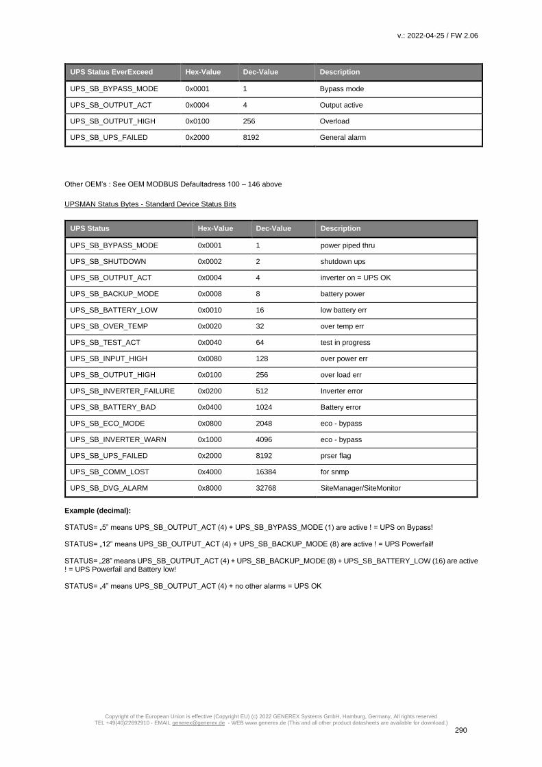
v.: 2022-04-25 / FW 2.06
Copyright of the European Union is effective (Copyright EU) (c) 2022 GENEREX Systems GmbH, Hamburg, Germany, All rights reserved TEL +49(40)22692910 - EMAIL [email protected] - WEB www.generex.de (This and all other product datasheets are available for download.)
290
UPS Status EverExceed Hex-Value Dec-Value Description
UPS_SB_BYPASS_MODE 0x0001 1 Bypass mode
UPS_SB_OUTPUT_ACT 0x0004 4 Output active
UPS_SB_OUTPUT_HIGH 0x0100 256 Overload
UPS_SB_UPS_FAILED 0x2000 8192 General alarm
Other OEM’s : See OEM MODBUS Defaultadress 100 – 146 above
UPSMAN Status Bytes - Standard Device Status Bits
UPS Status Hex-Value Dec-Value Description
UPS_SB_BYPASS_MODE 0x0001 1 power piped thru
UPS_SB_SHUTDOWN 0x0002 2 shutdown ups
UPS_SB_OUTPUT_ACT 0x0004 4 inverter on = UPS OK
UPS_SB_BACKUP_MODE 0x0008 8 battery power
UPS_SB_BATTERY_LOW 0x0010 16 low battery err
UPS_SB_OVER_TEMP 0x0020 32 over temp err
UPS_SB_TEST_ACT 0x0040 64 test in progress
UPS_SB_INPUT_HIGH 0x0080 128 over power err
UPS_SB_OUTPUT_HIGH 0x0100 256 over load err
UPS_SB_INVERTER_FAILURE 0x0200 512 Inverter error
UPS_SB_BATTERY_BAD 0x0400 1024 Battery error
UPS_SB_ECO_MODE 0x0800 2048 eco - bypass
UPS_SB_INVERTER_WARN 0x1000 4096 eco - bypass
UPS_SB_UPS_FAILED 0x2000 8192 prser flag
UPS_SB_COMM_LOST 0x4000 16384 for snmp
UPS_SB_DVG_ALARM 0x8000 32768 SiteManager/SiteMonitor
Example (decimal): STATUS= „5” means UPS_SB_OUTPUT_ACT (4) + UPS_SB_BYPASS_MODE (1) are active ! = UPS on Bypass! STATUS= „12” means UPS_SB_OUTPUT_ACT (4) + UPS_SB_BACKUP_MODE (8) are active ! = UPS Powerfail! STATUS= „28” means UPS_SB_OUTPUT_ACT (4) + UPS_SB_BACKUP_MODE (8) + UPS_SB_BATTERY_LOW (16) are active ! = UPS Powerfail and Battery low! STATUS= „4” means UPS_SB_OUTPUT_ACT (4) + no other alarms = UPS OK

v.: 2022-04-25 / FW 2.06
Copyright of the European Union is effective (Copyright EU) (c) 2022 GENEREX Systems GmbH, Hamburg, Germany, All rights reserved TEL +49(40)22692910 - EMAIL [email protected] - WEB www.generex.de (This and all other product datasheets are available for download.)
291
BACS MODBUS Parameter
Standard BACS – Address Description
Note: the max. number of BACS Modules requestable through MODBUS is 330.
Note: “Type U/S”: this defines whether the answer has an algebraic sign (math. +/-) or not. U means “

v.: 2022-04-25 / FW 2.06
Copyright of the European Union is effective (Copyright EU) (c) 2022 GENEREX Systems GmbH, Hamburg, Germany, All rights reserved TEL +49(40)22692910 - EMAIL [email protected] - WEB www.generex.de (This and all other product datasheets are available for download.)
292
Address Type Function Name Description Length
Note:
“Type U/S”: this defines whether the answer has an algebraic sign (math. +/-) or not. U means
“unsigned”. S means “signed”, this answer may be positive or negative.
1000 U 3 / 4 BACS_Alarm BACS Alarm Flags (see alarm
flag definition below) *4
1
1001 U 3 / 4 BACS_ALARM BACS Alarm Flags (see alarm
flag definition below) *5
1
1002 U 3 / 4 BACS_ALARM BACS Alarm Flags (see alarm
flag definition below) *6
1
1003 U 3 / 4 BACS_NUMSTRINGS Number of BACS Strings 1
1004 U 3/4 BACS_NUMMODULES Total number of BACS modules 1
This address range describes current and voltage of each single string as configured
1010 S 3 / 4 STRING_01_CUR String 1 current in Ampere [A] 1
1011 S 3 / 4 BACS_StrSumVolt String 1 Overall BACS string
voltage
1
1012 S 3 / 4 BACS_StrAvgVolt String 1 Average BACS string
voltage
1
1013 S 3 / 4 BACS_Str_CurrAC String 1 BACS string current 1
1014 <RESERVED> Do not use
1015 S 3 / 4 STRING_02_CUR String 2 current in Ampere [A] 1
1016 S 3 / 4 BACS_StrSumVolt String 2 Overall BACS string
voltage
1
1017 S 3 / 4 BACS_StrAvgVolt String 2 Average BACS string
voltage
1
1018 S 3 / 4 BACS_Str_CurrAC String 2 BACS string current 1
1019 <RESERVED> Do not use
1020 S 3 / 4 STRING_03_CUR String 3 current in Ampere [A] 1
1021 S 3 / 4 BACS_StrSumVolt String 3 Overall BACS string
voltage
1
1022 S 3 / 4 BACS_StrAvgVolt String3 Average BACS string
voltage
1
1023 S 3 / 4 BACS_Str_CurrAC String 3 BACS string current 1
1024 <RESERVED> Do not use

v.: 2022-04-25 / FW 2.06
Copyright of the European Union is effective (Copyright EU) (c) 2022 GENEREX Systems GmbH, Hamburg, Germany, All rights reserved TEL +49(40)22692910 - EMAIL [email protected] - WEB www.generex.de (This and all other product datasheets are available for download.)
293
[…] […] […] […Continue modbus string count until address …] […]
1055 S 3 / 4 STRING_10_CUR String 10 current in Ampere [A] 1
1056 S 3 / 4 BACS_StrSumVolt String 10 Overall BACS string
voltage
1
1057 S 3 / 4 BACS_StrAvgVolt String 10 Average BACS string
voltage
1
1058 S 3 / 4 BACS_Str_CurrAC String 10 BACS string current 1
1059 <RESERVED> Do not use
This address range describes the BACS module modbus address range for module 1-330: Each module section contains 5 measuring values. There is no reserved address between the modules!
1060 S 3 / 4 MODULE_001_ TEMP Module 1 Temperature in Celsius [°C] (see Temfjasdfashfklashf) *1
1
1061 S 3 / 4 MODULE_001_ VOLT Module 1 Voltage in Volt [V] *2
1
1062 S 3 / 4 MODULE_001_ IMPC Module 1 Impedance in milliOhm [mΩ] *3
1
1063 U 3 / 4 MODULE_001_ ALARM Module 1 Alarm flags *6
1
1064 S 3 /4 Module_001_ModBypVoltPc Module 1 Equalizing / Balancing in %
1
1065 S 3 / 4 MODULE_002_ TEMP Module 2 Temperature in Celsius [°C] (see Temfjasdfashfklashf) *1
1
1066 S 3 / 4 MODULE_002_ VOLT Module 2 Voltage in Volt [V] *2
1
1067 S 3 / 4 MODULE_002_ IMPC Module 2 Impedance in milliOhm [mΩ] *3
1
1068 U 3 / 4 MODULE_002_ ALARM Module 2 Alarm flags *6
1
1069 S 3 7 4 Module_002_ModBypVoltPc Module 2 Equalizing / Balancing in %
1
1070 S 3 / 4 MODULE_003_ TEMP Module 3 Temperature in Celsius [°C]
(see Temfjasdfashfklashf) *1
1
1071 S 3 / 4 MODULE_003_ VOLT Module 3
Voltage in Volt [V] *2 1
1072 S 3 / 4 MODULE_003_ IMPC Module 3
Impedance in milliOhm [mΩ]
*3
1
1073 U 3 / 4 MODULE_003_ ALARM Module 3 Alarm flags *6
1
1074 S 3 / 4 Module_003_ModBypVoltPc Module 3 Equalizing / Balancing in %
1
[…] […] […] […Continue modbus BACS module count until address …] […]

v.: 2022-04-25 / FW 2.06
Copyright of the European Union is effective (Copyright EU) (c) 2022 GENEREX Systems GmbH, Hamburg, Germany, All rights reserved TEL +49(40)22692910 - EMAIL [email protected] - WEB www.generex.de (This and all other product datasheets are available for download.)
294
2705 S 3 / 4 MODULE_330_ TEMP Module 330 Temperature in Celsius [°C]
(see Temfjasdfashfklashf) *1
1
2706 S 3 / 4 MODULE_330_ VOLT Module 330
Voltage in Volt [V] *2 1
2707 S 3 / 4 MODULE_330_ IMPC Module 330
Impedance in milliOhm [mΩ]
*3
1
2708 U 3 / 4 MODULE_330_ ALARM Module 330 Alarm flags *6 1
2709 S 3 / 4 Module_330_ModBypVoltPc Module 330
<DESCRIPTION> 1
The following address range describes single string current and voltage for BACS strings 11-16
2710 S 3 / 4 STRING_11_CUR String 11 current in Ampere [A] 1
2711 <RESERVED> Reserved, do not use
2712 <RESERVED> Reserved, do not use
2713 S 3 / 4 String_11_AC String 11 voltage 1
2714 <RESERVED> Reserved, do not use
2715 S 3 / 4 STRING_12_CUR String 12 current in Ampere [A] 1
2716 <RESERVED> Reserved, do not use
2717 <RESERVED> Reserved, do not use
2718 S String_12_AC String 12 voltage 1
2719 <RESERVED> Reserved, do not use
… … … […Continue modbus BACS String count until address …] …
2735 S 3 / 4 STRING_16_CUR String 16 current in Ampere [A] 1
2736 <RESERVED> Reserved, do not use
2737 <RESERVED> Reserved, do not use
2738 S String_12_AC String 12 voltage 1
2739 <RESERVED> Reserved, do not use
This address range describes the BACS module modbus address range for module 331-512:
Each module section contains 5 measuring values. There is no reserved address between the modules!
2740 S 3 / 4 MODULE_331_ TEMP Module 331 Temperature in Celsius [°C]
(see Temfjasdfashfklashf) *1
1
2741 S 3 / 4 MODULE_331_ VOLT Module 331
Voltage in Volt [V] *2 1

v.: 2022-04-25 / FW 2.06
Copyright of the European Union is effective (Copyright EU) (c) 2022 GENEREX Systems GmbH, Hamburg, Germany, All rights reserved TEL +49(40)22692910 - EMAIL [email protected] - WEB www.generex.de (This and all other product datasheets are available for download.)
295
2742 S 3 / 4 MODULE_331_ IMPC Module 331
Impedance in milliOhm [mΩ]
*3
1
2743 U 3 / 4 MODULE_331_ ALARM Module 331 Alarm flags *6 1
2744 S 3 / 4 Module_331_ModBypVoltPc Module 331
Equalizing / Balancing in % 1
2745 S 3 / 4 MODULE_332_ TEMP Module 332 Temperature in Celsius [°C]
(see Temfjasdfashfklashf) *1
1
2746 S 3 / 4 MODULE_332_ VOLT Module 332
Voltage in Volt [V] *2 1
2747 S 3 / 4 MODULE_332_ IMPC Module 332
Impedance in milliOhm [mΩ]
*3
1
2748 U 3 / 4 MODULE_332_ ALARM Module 332 Alarm flags *6 1
2749 S 3 / 4 Module_332_ModBypVoltPc Module 332
Equalizing / Balancing in % 1
… … … […Continue modbus BACS module count until address …] …
3645 S 3 / 4 MODULE_512_ TEMP Module 512 Temperature in Celsius [°C]
(see Temfjasdfashfklashf) *1
1
3646 S 3 / 4 MODULE_512_ VOLT Module 512
Voltage in Volt [V] *2 1
3647 S 3 / 4 MODULE_512_ IMPC Module 512
Impedance in milliOhm [mΩ]
*3
1
3648 U 3 / 4 MODULE_512_ ALARM Module 512 Alarm flags *6 1
3649 S 3 / 4 Module_512_ModBypVoltPc Module 512 Equalizing / Balancing in %
1
This section describes the GX_R AUX alarm status. Depending on the number of GX_R_AUX you have
installed, there are up to 16 possible address numbers.
3650 S 3 / 4 BACSGXRAuxAlarm(0) GX_R_AUX 1 Alarm Status 1 1
3651 S 3 / 4 BACSGXRAuxAlarm(1) GX_R_AUX 1 Alarm Status 2 1
3652 S 3 / 4 BACSGXRAuxAlarm(2) GX_R_AUX 1 Alarm Status 3 1
3653 S 3 / 4 BACSGXRAuxAlarm(3) GX_R_AUX 1 Alarm Status 4 1
3654 S 3 / 4 BACSGXRAuxAlarm(4) GX_R_AUX 2 Alarm Status 1 1
3655 S 3 / 4 BACSGXRAuxAlarm(5) GX_R_AUX 2 Alarm Status 2 1
3656 S 3 / 4 BACSGXRAuxAlarm(6) GX_R_AUX 2 Alarm Status 3 1

v.: 2022-04-25 / FW 2.06
Copyright of the European Union is effective (Copyright EU) (c) 2022 GENEREX Systems GmbH, Hamburg, Germany, All rights reserved TEL +49(40)22692910 - EMAIL [email protected] - WEB www.generex.de (This and all other product datasheets are available for download.)
296
3657 S 3 / 4 BACSGXRAuxAlarm(7) GX_R_AUX 2 Alarm Status 4 1
3658 S 3 / 4 BACSGXRAuxAlarm(8) GX_R_AUX 3 Alarm Status 1 1
3659 S 3 / 4 BACSGXRAuxAlarm(9) GX_R_AUX 3 Alarm Status 2 1
3660 S 3 / 4 BACSGXRAuxAlarm(10) GX_R_AUX 3 Alarm Status 3 1
3661 S 3 / 4 BACSGXRAuxAlarm(11) GX_R_AUX 3 Alarm Status 4 1
3662 S 3 / 4 BACSGXRAuxAlarm(12) GX_R_AUX 4 Alarm Status 1 1
3663 S 3 / 4 BACSGXRAuxAlarm(13) GX_R_AUX 4 Alarm Status 2 1
3664 S 3 / 4 BACSGXRAuxAlarm(14) GX_R_AUX 4 Alarm Status 3 1
3665 S 3 / 4 BACSGXRAuxAlarm(15) GX_R_AUX 4 Alarm Status 4 1
This section describes the GXR_AUX Output status. Depending on the Number of GX_R_AUX you
have installed, there are up to 16 possible address numbers.
3666 S 3 / 4 BACSGXRAuxOutputStatus(0) GX_R_AUX 1 Output Status 1 1
3667 S 3 / 4 BACSGXRAuxOutputStatus(1) GX_R_AUX 1 Output Status 2 1
3668 S 3 / 4 BACSGXRAuxOutputStatus(2) GX_R_AUX 1 Output Status 3 1
3669 S 3 / 4 BACSGXRAuxOutputStatus(3) GX_R_AUX 1 Output Status 4 1
3670 S 3 / 4 BACSGXRAuxOutputStatus(4) GX_R_AUX 2 Output Status 1 1
3671 S 3 / 4 BACSGXRAuxOutputStatus(5) GX_R_AUX 2 Output Status 2 1
3672 S 3 / 4 BACSGXRAuxOutputStatus(6) GX_R_AUX 2 Output Status 3 1
3673 S 3 / 4 BACSGXRAuxOutputStatus(7) GX_R_AUX 2 Output Status 4 1
3674 S 3 / 4 BACSGXRAuxOutputStatus(8) GX_R_AUX 3 Output Status 1 1
3675 S 3 / 4 BACSGXRAuxOutputStatus(9) GX_R_AUX 3 Output Status 2 1
3676 S 3 / 4 BACSGXRAuxOutputStatus(10) GX_R_AUX 3 Output Status 3 1
3677 S 3 / 4 BACSGXRAuxOutputStatus(11) GX_R_AUX 3 Output Status 4 1
3678 S 3 / 4 BACSGXRAuxOutputStatus(12) GX_R_AUX 4 Output Status 1 1
3679 S 3 / 4 BACSGXRAuxOutputStatus(13) GX_R_AUX 4 Output Status 2 1
3680 S 3 / 4 BACSGXRAuxOutputStatus(14 GX_R_AUX 4 Output Status 3 1
3681 S 3 / 4 BACSGXRAuxOutputStatus(15) GX_R_AUX 4 Output Status 4 1

v.: 2022-04-25 / FW 2.06
Copyright of the European Union is effective (Copyright EU) (c) 2022 GENEREX Systems GmbH, Hamburg, Germany, All rights reserved TEL +49(40)22692910 - EMAIL [email protected] - WEB www.generex.de (This and all other product datasheets are available for download.)
297
Note: A value of -1 or -9999 means: This value is currently “Not available” (“N/A”).
*1 - Temperature value definition:
Temperature T in °C e.g.
0xXX → 0 bis 255
0x7F 127 => 24,5°C
0x80 128 => 25°C
0x81 129 => 25,5°C
*2 - Voltage value definition:
Voltage U in V Wert / 1000
e.g. Voltage U in V = 12825 / 1000 = 12,825 V
*3 - Impedance value definition:
Impedance Z in mΩ Wert / 100
e.g. Impedance Z in mΩ = 4372 / 1000 = 43,72 mΩ
*4 – Address 1000 MODBUS/SNMP (hexadecimal) (decimal)
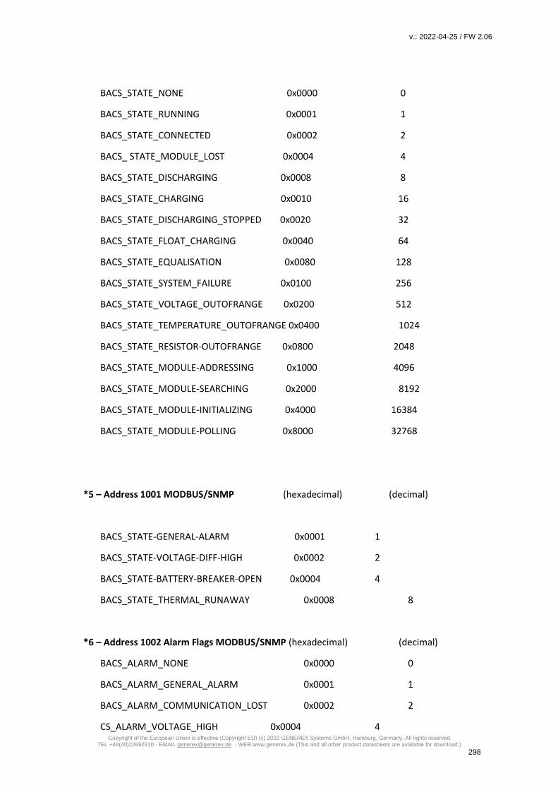
v.: 2022-04-25 / FW 2.06
Copyright of the European Union is effective (Copyright EU) (c) 2022 GENEREX Systems GmbH, Hamburg, Germany, All rights reserved TEL +49(40)22692910 - EMAIL [email protected] - WEB www.generex.de (This and all other product datasheets are available for download.)
298
BACS_STATE_NONE 0x0000 0
BACS_STATE_RUNNING 0x0001 1
BACS_STATE_CONNECTED 0x0002 2
BACS_ STATE_MODULE_LOST 0x0004 4
BACS_STATE_DISCHARGING 0x0008 8
BACS_STATE_CHARGING 0x0010 16
BACS_STATE_DISCHARGING_STOPPED 0x0020 32
BACS_STATE_FLOAT_CHARGING 0x0040 64
BACS_STATE_EQUALISATION 0x0080 128
BACS_STATE_SYSTEM_FAILURE 0x0100 256
BACS_STATE_VOLTAGE_OUTOFRANGE 0x0200 512
BACS_STATE_TEMPERATURE_OUTOFRANGE 0x0400 1024
BACS_STATE_RESISTOR-OUTOFRANGE 0x0800 2048
BACS_STATE_MODULE-ADDRESSING 0x1000 4096
BACS_STATE_MODULE-SEARCHING 0x2000 8192
BACS_STATE_MODULE-INITIALIZING 0x4000 16384
BACS_STATE_MODULE-POLLING 0x8000 32768
*5 – Address 1001 MODBUS/SNMP (hexadecimal) (decimal)
BACS_STATE-GENERAL-ALARM 0x0001 1
BACS_STATE-VOLTAGE-DIFF-HIGH 0x0002 2
BACS_STATE-BATTERY-BREAKER-OPEN 0x0004 4
BACS_STATE_THERMAL_RUNAWAY 0x0008 8
*6 – Address 1002 Alarm Flags MODBUS/SNMP (hexadecimal) (decimal)
BACS_ALARM_NONE 0x0000 0
BACS_ALARM_GENERAL_ALARM 0x0001 1
BACS_ALARM_COMMUNICATION_LOST 0x0002 2
CS_ALARM_VOLTAGE_HIGH 0x0004 4

v.: 2022-04-25 / FW 2.06
Copyright of the European Union is effective (Copyright EU) (c) 2022 GENEREX Systems GmbH, Hamburg, Germany, All rights reserved TEL +49(40)22692910 - EMAIL [email protected] - WEB www.generex.de (This and all other product datasheets are available for download.)
299
BACS_ALARM_VOLTAGE_LOW 0x0008 8
BACS_ALARM_TEMPERATURE_HIGH 0x0010 16
BACS_ALARM_TEMPERATURE_LOW 0x0020 32
BACS_ALARM_RESISTOR_HIGH 0x0040 64
BACS_ALARM_RESISTOR_LOW 0x0080 128
BACS_ALARM_EQUALISATION_ERR 0x0100 256
BACS_ALARM_VOLTAGE_WARN_HIGH 0x0200 512
BACS_ALARM_VOLTAGE_WARN_LOW 0x0400 1024
BACS_ALARM_TEMPERATURE_WARN_HIGH 0x0800 2048
BACS_ALARM_TEMPERATURE_WARN_LOW 0x1000 4096
BACS_ALARM_RESISTOR_WARN_HIGH 0x2000 8192
BACS_ALARM_RESISTOR_WARN_LOW 0x4000 16384
BACS_ALARM_MODREV_INCOMPATIBLE 0x8000 32768

v.: 2022-04-25 / FW 2.06
Copyright of the European Union is effective (Copyright EU) (c) 2022 GENEREX Systems GmbH, Hamburg, Germany, All rights reserved TEL +49(40)22692910 - EMAIL [email protected] - WEB www.generex.de (This and all other product datasheets are available for download.)
300
RFC 1628 MIB Overview
This ist the RFC 1628 MIB overview. At www.generex.de , you can download the MIB file and use it
with your SNMP monitoring system.
ups MIB RFC1628
1.3.6.1.2.1 mib2
1.3.6.1.2.1.33 upsMIB
1.3.6.1.2.1.33.1 upsObjects
1.3.6.1.2.1.33.1.1 upsIdent
1.3.6.1.2.1.33.1.1.1 upsIdentManufacturer
1.3.6.1.2.1.33.1.1.2 upsIdentModel
1.3.6.1.2.1.33.1.1.3 upsIdentUPSSoftwareVersion
1.3.6.1.2.1.33.1.1.4 upsIdentAgentSoftwareVersion
1.3.6.1.2.1.33.1.1.5 upsIdentName
1.3.6.1.2.1.33.1.1.6 upsIdentAttachedDevices
1.3.6.1.2.1.33.1.1.7 upsSerialNumber
1.3.6.1.2.1.33.1.1.8 upsLocation
1.3.6.1.2.1.33.1.1.9 upsSystemContact
1.3.6.1.2.1.33.1.2 upsBattery
1.3.6.1.2.1.33.1.2.1 upsBatteryStatus
1.3.6.1.2.1.33.1.2.2 upsSecondsOnBattery
1.3.6.1.2.1.33.1.2.3 upsEstimatedMinutesRemaining
1.3.6.1.2.1.33.1.2.4 upsEstimatedChargeRemaining
1.3.6.1.2.1.33.1.2.5 upsBatteryVoltage
1.3.6.1.2.1.33.1.2.6 upsBatteryCurrent
1.3.6.1.2.1.33.1.2.7 upsBatteryTemperature
1.3.6.1.2.1.33.1.3 upsInput
1.3.6.1.2.1.33.1.3.1 upsInputLineBads
1.3.6.1.2.1.33.1.3.2 upsInputNumLines
1.3.6.1.2.1.33.1.3.3 upsInputTable
1.3.6.1.2.1.33.1.3.3.1 upsInputEntry
1.3.6.1.2.1.33.1.3.3.1.1 upsInputLineIndex
1.3.6.1.2.1.33.1.3.3.1.2 upsInputFrequency
1.3.6.1.2.1.33.1.3.3.1.3 upsInputVoltage
1.3.6.1.2.1.33.1.3.3.1.4 upsInputCurrent
1.3.6.1.2.1.33.1.3.3.1.5 upsInputTruePower
1.3.6.1.2.1.33.1.4 upsOutput
1.3.6.1.2.1.33.1.4.1 upsOutputSource
1.3.6.1.2.1.33.1.4.2 upsOutputFrequency
1.3.6.1.2.1.33.1.4.3 upsOutputNumLines
1.3.6.1.2.1.33.1.4.4 upsOutputTable
1.3.6.1.2.1.33.1.4.4.1 upsOutputEntry
1.3.6.1.2.1.33.1.4.4.1.1 upsOutputLineIndex
1.3.6.1.2.1.33.1.4.4.1.2 upsOutputVoltage
1.3.6.1.2.1.33.1.4.4.1.3 upsOutputCurrent
1.3.6.1.2.1.33.1.4.4.1.4 upsOutputPower
1.3.6.1.2.1.33.1.4.4.1.5 upsOutputPercentLoad
1.3.6.1.2.1.33.1.5 upsBypass
1.3.6.1.2.1.33.1.5.1 upsBypassFrequency
1.3.6.1.2.1.33.1.5.2 upsBypassNumLines
1.3.6.1.2.1.33.1.5.3 upsBypassTable
1.3.6.1.2.1.33.1.5.3.1 upsBypassEntry
1.3.6.1.2.1.33.1.5.3.1.1 upsBypassLineIndex
1.3.6.1.2.1.33.1.5.3.1.2 upsBypassVoltage
1.3.6.1.2.1.33.1.5.3.1.3 upsBypassCurrent
1.3.6.1.2.1.33.1.5.3.1.4 upsBypassPower
1.3.6.1.2.1.33.1.6 upsAlarm

v.: 2022-04-25 / FW 2.06
Copyright of the European Union is effective (Copyright EU) (c) 2022 GENEREX Systems GmbH, Hamburg, Germany, All rights reserved TEL +49(40)22692910 - EMAIL [email protected] - WEB www.generex.de (This and all other product datasheets are available for download.)
301
1.3.6.1.2.1.33.1.6.1 upsAlarmsPresent
1.3.6.1.2.1.33.1.6.2 upsAlarmTable
1.3.6.1.2.1.33.1.6.2.1 upsAlarmEntry
1.3.6.1.2.1.33.1.6.2.1.1 upsAlarmId
1.3.6.1.2.1.33.1.6.2.1.2 upsAlarmDescr
1.3.6.1.2.1.33.1.6.2.1.3 upsAlarmTime
1.3.6.1.2.1.33.1.6.3 upsWellKnownAlarms
1.3.6.1.2.1.33.1.6.3.1 upsAlarmBatteryBad
1.3.6.1.2.1.33.1.6.3.2 upsAlarmOnBattery
1.3.6.1.2.1.33.1.6.3.3 upsAlarmLowBattery
1.3.6.1.2.1.33.1.6.3.4 upsAlarmDepletedBattery
1.3.6.1.2.1.33.1.6.3.5 upsAlarmTempBad
1.3.6.1.2.1.33.1.6.3.6 upsAlarmInputBad
1.3.6.1.2.1.33.1.6.3.7 upsAlarmOutputBad
1.3.6.1.2.1.33.1.6.3.8 upsAlarmOutputOverload
1.3.6.1.2.1.33.1.6.3.9 upsAlarmOnBypass
1.3.6.1.2.1.33.1.6.3.10 upsAlarmBypassBad
1.3.6.1.2.1.33.1.6.3.11 upsAlarmOutputOffAsRequested
1.3.6.1.2.1.33.1.6.3.12 upsAlarmUpsOffAsRequested
1.3.6.1.2.1.33.1.6.3.13 upsAlarmChargerFailed
1.3.6.1.2.1.33.1.6.3.14 upsAlarmUpsOutputOff
1.3.6.1.2.1.33.1.6.3.15 upsAlarmUpsSystemOff
1.3.6.1.2.1.33.1.6.3.16 upsAlarmFanFailure
1.3.6.1.2.1.33.1.6.3.17 upsAlarmFuseFailure
1.3.6.1.2.1.33.1.6.3.18 upsAlarmGeneralFault
1.3.6.1.2.1.33.1.6.3.19 upsAlarmDiagnosticTestFailed
1.3.6.1.2.1.33.1.6.3.20 upsAlarmCommunicationsLost
1.3.6.1.2.1.33.1.6.3.21 upsAlarmAwaitingPower
1.3.6.1.2.1.33.1.6.3.22 upsAlarmShutdownPending
1.3.6.1.2.1.33.1.6.3.23 upsAlarmShutdownImminent
1.3.6.1.2.1.33.1.6.3.24 upsAlarmTestInProgress
1.3.6.1.2.1.33.1.6.3.25 upsAlarmAuxInput1
1.3.6.1.2.1.33.1.6.3.26 upsAlarmAuxInput2
1.3.6.1.2.1.33.1.6.3.27 upsAlarmAuxInput3
1.3.6.1.2.1.33.1.6.3.28 upsAlarmAuxInput4
1.3.6.1.2.1.33.1.6.3.125 alarmSensorManager1Low
1.3.6.1.2.1.33.1.6.3.126 alarmSensorManager2Low
1.3.6.1.2.1.33.1.6.3.127 alarmSensorManager3Low
1.3.6.1.2.1.33.1.6.3.128 alarmSensorManager4Low
1.3.6.1.2.1.33.1.6.3.129 alarmSensorManager5Low
1.3.6.1.2.1.33.1.6.3.130 alarmSensorManager6Low
1.3.6.1.2.1.33.1.6.3.131 alarmSensorManager7Low
1.3.6.1.2.1.33.1.6.3.132 alarmSensorManager8Low
1.3.6.1.2.1.33.1.6.3.133 alarmSensorManager1High
1.3.6.1.2.1.33.1.6.3.134 alarmSensorManager2High
1.3.6.1.2.1.33.1.6.3.135 alarmSensorManager3High
1.3.6.1.2.1.33.1.6.3.136 alarmSensorManager4High
1.3.6.1.2.1.33.1.6.3.137 alarmSensorManager5High
1.3.6.1.2.1.33.1.6.3.138 alarmSensorManager6High
1.3.6.1.2.1.33.1.6.3.139 alarmSensorManager7High
1.3.6.1.2.1.33.1.6.3.140 alarmSensorManager8High
1.3.6.1.2.1.33.1.6.3.141 alarmUser1
1.3.6.1.2.1.33.1.6.3.142 alarmUser2
1.3.6.1.2.1.33.1.6.3.143 alarmUser3
1.3.6.1.2.1.33.1.6.3.144 alarmUser4
1.3.6.1.2.1.33.1.6.3.145 alarmUser5
1.3.6.1.2.1.33.1.6.3.146 alarmUser6
1.3.6.1.2.1.33.1.6.3.147 alarmUser7
1.3.6.1.2.1.33.1.6.3.148 statusDischarging
1.3.6.1.2.1.33.1.6.3.149 statusCharging
1.3.6.1.2.1.33.1.6.3.150 alarmSensorManagerInput1
1.3.6.1.2.1.33.1.6.3.151 alarmSensorManagerInput2

v.: 2022-04-25 / FW 2.06
Copyright of the European Union is effective (Copyright EU) (c) 2022 GENEREX Systems GmbH, Hamburg, Germany, All rights reserved TEL +49(40)22692910 - EMAIL [email protected] - WEB www.generex.de (This and all other product datasheets are available for download.)
302
1.3.6.1.2.1.33.1.6.3.152 alarmSensorManagerInput3
1.3.6.1.2.1.33.1.6.3.153 alarmSensorManagerInput4
1.3.6.1.2.1.33.1.6.3.154 alarmSensorManagerOutput1
1.3.6.1.2.1.33.1.6.3.155 alarmSensorManagerOutput2
1.3.6.1.2.1.33.1.6.3.156 alarmSensorManagerOutput3
1.3.6.1.2.1.33.1.6.3.157 alarmSensorManagerOutput4
1.3.6.1.2.1.33.1.6.3.158 alarmSensorComLost
1.3.6.1.2.1.33.1.6.3.159 alarmVuesWindalarm
1.3.6.1.2.1.33.1.6.3.160 alarmTransferswitchSourcesAsynchronous
1.3.6.1.2.1.33.1.6.3.161 alarmTransferswitchStaticSwitchAFailure
1.3.6.1.2.1.33.1.6.3.162 alarmTransferswitchStaticSwitchBFailure
1.3.6.1.2.1.33.1.6.3.163 alarmTransferswitchOnStaticSwitchA
1.3.6.1.2.1.33.1.6.3.164 alarmTransferswitchOnStaticSwitchB
1.3.6.1.2.1.33.1.6.3.165 alarmTransferswitchOnManualBypassA
1.3.6.1.2.1.33.1.6.3.166 alarmTransferswitchOnManualBypassB
1.3.6.1.2.1.33.1.6.3.167 alarmTransferswitchSourceAFailure
1.3.6.1.2.1.33.1.6.3.168 alarmTransferswitchSourceBFailure
1.3.6.1.2.1.33.1.6.3.169 alarmTransferswitchGeneralFault
1.3.6.1.2.1.33.1.6.3.170 alarmTransferswitchRedundancyLost
1.3.6.1.2.1.33.1.6.3.171 alarmTransferswitchOutputOverload
1.3.6.1.2.1.33.1.6.3.172 alarmBlackBoxReady
1.3.6.1.2.1.33.1.6.3.173 upsAlarmInputAuxBad
1.3.6.1.2.1.33.1.7 upsTest
1.3.6.1.2.1.33.1.7.1 upsTestId
1.3.6.1.2.1.33.1.7.2 upsTestSpinLock
1.3.6.1.2.1.33.1.7.3 upsTestResultsSummary
1.3.6.1.2.1.33.1.7.4 upsTestResultsDetail
1.3.6.1.2.1.33.1.7.5 upsTestStartTime
1.3.6.1.2.1.33.1.7.6 upsTestElapsedTime
1.3.6.1.2.1.33.1.7.7 upsWellKnownTests
1.3.6.1.2.1.33.1.7.7.1 upsTestNoTestsInitiated
1.3.6.1.2.1.33.1.7.7.2 upsTestAbortTestInProgress
1.3.6.1.2.1.33.1.7.7.3 upsTestGeneralSystemsTest
1.3.6.1.2.1.33.1.7.7.4 upsTestQuickBatteryTest
1.3.6.1.2.1.33.1.7.7.5 upsTestDeepBatteryCalibration
1.3.6.1.2.1.33.1.8 upsControl
1.3.6.1.2.1.33.1.8.1 upsShutdownType
1.3.6.1.2.1.33.1.8.2 upsShutdownAfterDelay
1.3.6.1.2.1.33.1.8.3 upsStartupAfterDelay
1.3.6.1.2.1.33.1.8.4 upsRebootWithDuration
1.3.6.1.2.1.33.1.8.5 upsAutoRestart
1.3.6.1.2.1.33.1.8.6 UpsVarIdIn Read/Write "for internal purpose
only - do not overwrite "
1.3.6.1.2.1.33.1.8.7 UpsVarIdOut Read only "for internal purpose
only"
1.3.6.1.2.1.33.1.9 upsConfig
1.3.6.1.2.1.33.1.9.1 upsConfigInputVoltage
1.3.6.1.2.1.33.1.9.2 upsConfigInputFreq
1.3.6.1.2.1.33.1.9.3 upsConfigOutputVoltage
1.3.6.1.2.1.33.1.9.4 upsConfigOutputFreq
1.3.6.1.2.1.33.1.9.5 upsConfigOutputVA
1.3.6.1.2.1.33.1.9.6 upsConfigOutputPower
1.3.6.1.2.1.33.1.9.7 upsConfigLowBattTime
1.3.6.1.2.1.33.1.9.8 upsConfigAudibleStatus
1.3.6.1.2.1.33.1.9.9 upsConfigLowVoltageTransferPoint
1.3.6.1.2.1.33.1.9.10 upsConfigHighVoltageTransferPoint
1.3.6.1.2.1.33.1.10 sitemanager
1.3.6.1.2.1.33.1.10.1 relais
1.3.6.1.2.1.33.1.10.1.1 relais1
1.3.6.1.2.1.33.1.10.1.2 relais2
1.3.6.1.2.1.33.1.10.1.3 relais3
1.3.6.1.2.1.33.1.10.1.4 relais4

v.: 2022-04-25 / FW 2.06
Copyright of the European Union is effective (Copyright EU) (c) 2022 GENEREX Systems GmbH, Hamburg, Germany, All rights reserved TEL +49(40)22692910 - EMAIL [email protected] - WEB www.generex.de (This and all other product datasheets are available for download.)
303
1.3.6.1.2.1.33.1.10.1.5 relais5
1.3.6.1.2.1.33.1.10.1.6 relais6
1.3.6.1.2.1.33.1.10.1.7 relais7
1.3.6.1.2.1.33.1.10.1.8 relais8
1.3.6.1.2.1.33.1.10.2 digital
1.3.6.1.2.1.33.1.10.2.1 digital1
1.3.6.1.2.1.33.1.10.2.2 digital2
1.3.6.1.2.1.33.1.10.2.3 digital3
1.3.6.1.2.1.33.1.10.2.4 digital4
1.3.6.1.2.1.33.1.10.2.5 digital5
1.3.6.1.2.1.33.1.10.2.6 digital6
1.3.6.1.2.1.33.1.10.2.7 digital7
1.3.6.1.2.1.33.1.10.2.8 digital8
1.3.6.1.2.1.33.1.10.3 analog
1.3.6.1.2.1.33.1.10.3.1 analog1
1.3.6.1.2.1.33.1.10.3.2 analog1Min
1.3.6.1.2.1.33.1.10.3.3 analog1Max
1.3.6.1.2.1.33.1.10.3.4 analog2
1.3.6.1.2.1.33.1.10.3.5 analog2Min
1.3.6.1.2.1.33.1.10.3.6 analog2Max
1.3.6.1.2.1.33.1.10.3.7 analog3
1.3.6.1.2.1.33.1.10.3.8 analog3Min
1.3.6.1.2.1.33.1.10.3.9 analog3Max
1.3.6.1.2.1.33.1.10.3.10 analog4
1.3.6.1.2.1.33.1.10.3.11 analog4Min
1.3.6.1.2.1.33.1.10.3.12 analog4Max
1.3.6.1.2.1.33.1.10.3.13 analog5
1.3.6.1.2.1.33.1.10.3.14 analog5Min
1.3.6.1.2.1.33.1.10.3.15 analog5Max
1.3.6.1.2.1.33.1.10.3.16 analog6
1.3.6.1.2.1.33.1.10.3.17 analog6Min
1.3.6.1.2.1.33.1.10.3.18 analog6Max
1.3.6.1.2.1.33.1.10.3.19 analog7
1.3.6.1.2.1.33.1.10.3.20 analog7Min
1.3.6.1.2.1.33.1.10.3.21 analog7Max
1.3.6.1.2.1.33.1.10.3.22 analog8
1.3.6.1.2.1.33.1.10.3.23 analog8Min
1.3.6.1.2.1.33.1.10.3.24 analog8Max
1.3.6.1.2.1.33.1.10.4 marker
1.3.6.1.2.1.33.1.10.4.1 marker1
1.3.6.1.2.1.33.1.10.4.2 marker2
1.3.6.1.2.1.33.1.10.4.3 marker3
1.3.6.1.2.1.33.1.10.4.4 marker4
1.3.6.1.2.1.33.1.10.4.5 marker5
1.3.6.1.2.1.33.1.10.4.6 marker6
1.3.6.1.2.1.33.1.10.4.7 marker7
1.3.6.1.2.1.33.1.10.4.8 marker8
1.3.6.1.2.1.33.1.11 aux
1.3.6.1.2.1.33.1.11.1 auxPort1
1.3.6.1.2.1.33.1.11.2 auxPort2
1.3.6.1.2.1.33.1.11.3 auxPort3
1.3.6.1.2.1.33.1.11.4 auxPort4
1.3.6.1.2.1.33.1.12 sensorMan
1.3.6.1.2.1.33.1.12.1 sensor1
1.3.6.1.2.1.33.1.12.1.1 sensorMan1Value
1.3.6.1.2.1.33.1.12.1.2 sensorMan1Location
1.3.6.1.2.1.33.1.12.1.3 sensorMan1Unit
1.3.6.1.2.1.33.1.12.1.4 sensorMan1ThresholdLow
1.3.6.1.2.1.33.1.12.1.5 sensorMan1ThresholdHigh
1.3.6.1.2.1.33.1.12.1.6 sensorMan1Scaling
1.3.6.1.2.1.33.1.12.1.7 sensorMan1Offset
1.3.6.1.2.1.33.1.12.2 sensor2

v.: 2022-04-25 / FW 2.06
Copyright of the European Union is effective (Copyright EU) (c) 2022 GENEREX Systems GmbH, Hamburg, Germany, All rights reserved TEL +49(40)22692910 - EMAIL [email protected] - WEB www.generex.de (This and all other product datasheets are available for download.)
304
1.3.6.1.2.1.33.1.12.2.1 sensorMan2Value
1.3.6.1.2.1.33.1.12.2.2 sensorMan2Location
1.3.6.1.2.1.33.1.12.2.3 sensorMan2Unit
1.3.6.1.2.1.33.1.12.2.4 sensorMan2ThresholdLow
1.3.6.1.2.1.33.1.12.2.5 sensorMan2ThresholdHigh
1.3.6.1.2.1.33.1.12.2.6 sensorMan2Scaling
1.3.6.1.2.1.33.1.12.2.7 sensorMan2Offset
1.3.6.1.2.1.33.1.12.3 sensor3
1.3.6.1.2.1.33.1.12.3.1 sensorMan3Value
1.3.6.1.2.1.33.1.12.3.2 sensorMan3Location
1.3.6.1.2.1.33.1.12.3.3 sensorMan3Unit
1.3.6.1.2.1.33.1.12.3.4 sensorMan3ThresholdLow
1.3.6.1.2.1.33.1.12.3.5 sensorMan3ThresholdHigh
1.3.6.1.2.1.33.1.12.3.6 sensorMan3Scaling
1.3.6.1.2.1.33.1.12.3.7 sensorMan3Offset
1.3.6.1.2.1.33.1.12.4 sensor4
1.3.6.1.2.1.33.1.12.4.1 sensorMan4Value
1.3.6.1.2.1.33.1.12.4.2 sensorMan4Location
1.3.6.1.2.1.33.1.12.4.3 sensorMan4Unit
1.3.6.1.2.1.33.1.12.4.4 sensorMan4ThresholdLow
1.3.6.1.2.1.33.1.12.4.5 sensorMan4ThresholdHigh
1.3.6.1.2.1.33.1.12.4.6 sensorMan4Scaling
1.3.6.1.2.1.33.1.12.4.7 sensorMan4Offset
1.3.6.1.2.1.33.1.12.5 sensor5
1.3.6.1.2.1.33.1.12.5.1 sensorMan5Value
1.3.6.1.2.1.33.1.12.5.2 sensorMan5Location
1.3.6.1.2.1.33.1.12.5.3 sensorMan5Unit
1.3.6.1.2.1.33.1.12.5.4 sensorMan5ThresholdLow
1.3.6.1.2.1.33.1.12.5.5 sensorMan5ThresholdHigh
1.3.6.1.2.1.33.1.12.5.6 sensorMan5Scaling
1.3.6.1.2.1.33.1.12.5.7 sensorMan5Offset
1.3.6.1.2.1.33.1.12.6 sensor6
1.3.6.1.2.1.33.1.12.6.1 sensorMan6Value
1.3.6.1.2.1.33.1.12.6.2 sensorMan6Location
1.3.6.1.2.1.33.1.12.6.3 sensorMan6Unit
1.3.6.1.2.1.33.1.12.6.4 sensorMan6ThresholdLow
1.3.6.1.2.1.33.1.12.6.5 sensorMan6ThresholdHigh
1.3.6.1.2.1.33.1.12.6.6 sensorMan6Scaling
1.3.6.1.2.1.33.1.12.6.7 sensorMan6Offset
1.3.6.1.2.1.33.1.12.7 sensor7
1.3.6.1.2.1.33.1.12.7.1 sensorMan7Value
1.3.6.1.2.1.33.1.12.7.2 sensorMan7Location
1.3.6.1.2.1.33.1.12.7.3 sensorMan7Unit
1.3.6.1.2.1.33.1.12.7.4 sensorMan7ThresholdLow
1.3.6.1.2.1.33.1.12.7.5 sensorMan7ThresholdHigh
1.3.6.1.2.1.33.1.12.7.6 sensorMan7Scaling
1.3.6.1.2.1.33.1.12.7.7 sensorMan7Offset
1.3.6.1.2.1.33.1.12.8 sensor8
1.3.6.1.2.1.33.1.12.8.1 sensorMan8Value
1.3.6.1.2.1.33.1.12.8.2 sensorMan8Location
1.3.6.1.2.1.33.1.12.8.3 sensorMan8Unit
1.3.6.1.2.1.33.1.12.8.4 sensorMan8ThresholdLow
1.3.6.1.2.1.33.1.12.8.5 sensorMan8ThresholdHigh
1.3.6.1.2.1.33.1.12.8.6 sensorMan8Scaling
1.3.6.1.2.1.33.1.12.8.7 sensorMan8Offset
1.3.6.1.2.1.33.1.12.9 input1
1.3.6.1.2.1.33.1.12.9.1 input1Value
1.3.6.1.2.1.33.1.12.9.2 input1Location
1.3.6.1.2.1.33.1.12.9.3 input1NCContact
1.3.6.1.2.1.33.1.12.10 input2
1.3.6.1.2.1.33.1.12.10.1 input2Value
1.3.6.1.2.1.33.1.12.10.2 input2Location

v.: 2022-04-25 / FW 2.06
Copyright of the European Union is effective (Copyright EU) (c) 2022 GENEREX Systems GmbH, Hamburg, Germany, All rights reserved TEL +49(40)22692910 - EMAIL [email protected] - WEB www.generex.de (This and all other product datasheets are available for download.)
305
1.3.6.1.2.1.33.1.12.10.3 input2NCContact
1.3.6.1.2.1.33.1.12.11 input3
1.3.6.1.2.1.33.1.12.11.1 input3Value
1.3.6.1.2.1.33.1.12.11.2 input3Location
1.3.6.1.2.1.33.1.12.11.3 input3NCContact
1.3.6.1.2.1.33.1.12.12 input4
1.3.6.1.2.1.33.1.12.12.1 input4Value
1.3.6.1.2.1.33.1.12.12.2 input4Location
1.3.6.1.2.1.33.1.12.12.3 inputNCContact
1.3.6.1.2.1.33.1.12.13 output1
1.3.6.1.2.1.33.1.12.13.1 output1Value
1.3.6.1.2.1.33.1.12.13.2 output1Location
1.3.6.1.2.1.33.1.12.13.3 output1NCContact
1.3.6.1.2.1.33.1.12.14 output2
1.3.6.1.2.1.33.1.12.14.1 output2Value
1.3.6.1.2.1.33.1.12.14.2 output2Location
1.3.6.1.2.1.33.1.12.14.3 output2NCContact
1.3.6.1.2.1.33.1.12.15 output3
1.3.6.1.2.1.33.1.12.15.1 output3Value
1.3.6.1.2.1.33.1.12.15.2 output3Location
1.3.6.1.2.1.33.1.12.15.3 output3NCContact
1.3.6.1.2.1.33.1.12.16 output4
1.3.6.1.2.1.33.1.12.16.1 output4Value
1.3.6.1.2.1.33.1.12.16.2 output4Location
1.3.6.1.2.1.33.1.12.16.3 outputNCContact
1.3.6.1.2.1.33.1.13 sts
1.3.6.1.2.1.33.1.13.1 stsStaticSwitch1On
1.3.6.1.2.1.33.1.13.2 stsStaticSwitch2On
1.3.6.1.2.1.33.1.13.3 stsManualBypass1On
1.3.6.1.2.1.33.1.13.4 stsManualBypass2On
1.3.6.1.2.1.33.1.13.5 stsAutoTransfermode
1.3.6.1.2.1.33.1.13.6 stsSourcesSynchron
1.3.6.1.2.1.33.1.13.7 stsPreferedMains1
1.3.6.1.2.1.33.1.13.8 stsPreferedMains2
1.3.6.1.2.1.33.1.13.9 stsAutostartEnabled
1.3.6.1.2.1.33.1.14 upsInputAux
1.3.6.1.2.1.33.1.14.1 upsInputAuxBads
1.3.6.1.2.1.33.1.14.2 upsInputAuxNumLines
1.3.6.1.2.1.33.1.14.3 upsInputAuxTable
1.3.6.1.2.1.33.1.14.3.1 upsInputAuxEntry
1.3.6.1.2.1.33.1.14.3.1.1 upsInputAuxIndex
1.3.6.1.2.1.33.1.14.3.1.2 upsInputAuxFrequency
1.3.6.1.2.1.33.1.14.3.1.3 upsInputAuxVoltage
1.3.6.1.2.1.33.1.14.3.1.4 upsInputAuxCurrent
1.3.6.1.2.1.33.1.14.3.1.5 upsInputAuxTruePower
1.3.6.1.2.1.33.1.15 additionalValues
1.3.6.1.2.1.33.1.15.1 externalSensor
1.3.6.1.2.1.33.2 upsTraps
1.3.6.1.2.1.33.2.1 upsTrapOnBattery
1.3.6.1.2.1.33.2.2 upsTrapTestCompleted
1.3.6.1.2.1.33.2.3 upsTrapAlarmEntryAdded
1.3.6.1.2.1.33.2.4 upsTrapAlarmEntryRemoved
1.3.6.1.2.1.33.3 upsConformance
1.3.6.1.2.1.33.3.1 upsCompliances
1.3.6.1.2.1.33.3.1.1 upsSubsetCompliance
1.3.6.1.2.1.33.3.1.2 upsBasicCompliance
1.3.6.1.2.1.33.3.1.3 upsFullCompliance
1.3.6.1.2.1.33.3.2 upsGroups
1.3.6.1.2.1.33.3.2.1 upsSubsetGroups
1.3.6.1.2.1.33.3.2.1.1 upsSubsetIdentGroup
1.3.6.1.2.1.33.3.2.1.2 upsSubsetBatteryGroup
1.3.6.1.2.1.33.3.2.1.3 upsSubsetInputGroup

v.: 2022-04-25 / FW 2.06
Copyright of the European Union is effective (Copyright EU) (c) 2022 GENEREX Systems GmbH, Hamburg, Germany, All rights reserved TEL +49(40)22692910 - EMAIL [email protected] - WEB www.generex.de (This and all other product datasheets are available for download.)
306
1.3.6.1.2.1.33.3.2.1.4 upsSubsetOutputGroup
1.3.6.1.2.1.33.3.2.1.6 upsSubsetAlarmGroup
1.3.6.1.2.1.33.3.2.1.8 upsSubsetControlGroup
1.3.6.1.2.1.33.3.2.1.9 upsSubsetConfigGroup
1.3.6.1.2.1.33.3.2.2 upsBasicGroups
1.3.6.1.2.1.33.3.2.2.1 upsBasicIdentGroup
1.3.6.1.2.1.33.3.2.2.2 upsBasicBatteryGroup
1.3.6.1.2.1.33.3.2.2.3 upsBasicInputGroup
1.3.6.1.2.1.33.3.2.2.4 upsBasicOutputGroup
1.3.6.1.2.1.33.3.2.2.5 upsBasicBypassGroup
1.3.6.1.2.1.33.3.2.2.6 upsBasicAlarmGroup
1.3.6.1.2.1.33.3.2.2.7 upsBasicTestGroup
1.3.6.1.2.1.33.3.2.2.8 upsBasicControlGroup
1.3.6.1.2.1.33.3.2.2.9 upsBasicConfigGroup
1.3.6.1.2.1.33.3.2.3 upsFullGroups
1.3.6.1.2.1.33.3.2.3.1 upsFullIdentGroup
1.3.6.1.2.1.33.3.2.3.2 upsFullBatteryGroup
1.3.6.1.2.1.33.3.2.3.3 upsFullInputGroup
1.3.6.1.2.1.33.3.2.3.4 upsFullOutputGroup
1.3.6.1.2.1.33.3.2.3.5 upsFullBypassGroup
1.3.6.1.2.1.33.3.2.3.6 upsFullAlarmGroup
1.3.6.1.2.1.33.3.2.3.7 upsFullTestGroup
1.3.6.1.2.1.33.3.2.3.8 upsFullControlGroup
1.3.6.1.2.1.33.3.2.3.9 upsFullConfigGroup
RFC 1628 MIB – BACS extension
This ist the overview of the RFC 1628 BACS extention. At www.generex.de , you can download the
MIB file and use it with your SNMP monitoring system.
BACS2 MIB
1.3.6.1.2.1 mib2
1.3.6.1.2.1.33 upsMIB
1.3.6.1.2.1.33.5 bacs2
1.3.6.1.2.1.33.5.1 bacsSettings
1.3.6.1.2.1.33.5.1.1 bacsModuleType
1.3.6.1.2.1.33.5.1.2 bacsNumStrings
1.3.6.1.2.1.33.5.1.3 bacsNumBatteries
1.3.6.1.2.1.33.5.1.4 bacsBattCap
1.3.6.1.2.1.33.5.1.5 bacsLogRate1
1.3.6.1.2.1.33.5.1.6 bacsLogRate2
1.3.6.1.2.1.33.5.1.7 bacsImpcPollRate
1.3.6.1.2.1.33.5.1.8 bacsImpcLowAlarm
1.3.6.1.2.1.33.5.1.9 bacsImpcHighAlarm
1.3.6.1.2.1.33.5.1.10 bacsTemperatureLowAlarm
1.3.6.1.2.1.33.5.1.11 bacsTemperatureHighAlarm
1.3.6.1.2.1.33.5.1.12 bacsVoltageLowAlarm
1.3.6.1.2.1.33.5.1.13 bacsVoltageHighAlarm
1.3.6.1.2.1.33.5.1.14 bacsImpcLowWarn
1.3.6.1.2.1.33.5.1.15 bacsImpcHighWarn
1.3.6.1.2.1.33.5.1.16 bacsTemperatureLowWarn
1.3.6.1.2.1.33.5.1.17 bacsTemperatureHighWarn
1.3.6.1.2.1.33.5.1.18 bacsVoltageLowWarn
1.3.6.1.2.1.33.5.1.19 bacsVoltageHighWarn
1.3.6.1.2.1.33.5.1.20 bacsTemperatureUnit
1.3.6.1.2.1.33.5.2 bacsObjects

v.: 2022-04-25 / FW 2.06
Copyright of the European Union is effective (Copyright EU) (c) 2022 GENEREX Systems GmbH, Hamburg, Germany, All rights reserved TEL +49(40)22692910 - EMAIL [email protected] - WEB www.generex.de (This and all other product datasheets are available for download.)
307
1.3.6.1.2.1.33.5.2.1 bacsStatus
1.3.6.1.2.1.33.5.2.2 bacsAvModuleVolt
1.3.6.1.2.1.33.5.2.3 bacsTotalVolt
1.3.6.1.2.1.33.5.2.4 bacsNumModules
1.3.6.1.2.1.33.5.2.5 bacsModuleTable
1.3.6.1.2.1.33.5.2.5.1 bacsModuleEntry
1.3.6.1.2.1.33.5.2.5.1.1 bacsModuleIndex
1.3.6.1.2.1.33.5.2.5.1.2 bacsModuleVoltage
1.3.6.1.2.1.33.5.2.5.1.3 bacsModuleTemperature
1.3.6.1.2.1.33.5.2.5.1.4 bacsModuleBypass
1.3.6.1.2.1.33.5.2.5.1.5 bacsModuleResistance
1.3.6.1.2.1.33.5.2.5.1.6 bacsModuleState
1.3.6.1.2.1.33.5.2.6 bacsNumStrings
1.3.6.1.2.1.33.5.2.7 bacsStringTable
1.3.6.1.2.1.33.5.2.7.1 bacsStringEntry
1.3.6.1.2.1.33.5.2.7.1.1 bacsStringIndex
1.3.6.1.2.1.33.5.2.7.1.2 bacsStringCurrent
1.3.6.1.2.1.33.5.2.7.1.3 bacsStringTotalVolt
1.3.6.1.2.1.33.5.2.7.1.4 bacsStringAverageVolt
1.3.6.1.2.1.33.5.3 bacsAlarms
1.3.6.1.2.1.33.5.3.1 bacsAlarmsPresent
1.3.6.1.2.1.33.5.3.2 bacsAlarmTable
1.3.6.1.2.1.33.5.3.2.1 bacsAlarmEntry
1.3.6.1.2.1.33.5.3.2.1.1 bacsAlarmId
1.3.6.1.2.1.33.5.3.2.1.2 bacsAlarmDescr
1.3.6.1.2.1.33.5.3.2.1.3 bacsAlarmTime
1.3.6.1.2.1.33.5.3.3 bacsWellKnownAlarms
1.3.6.1.2.1.33.5.3.3.1 bacsAlarmSystemError
1.3.6.1.2.1.33.5.3.3.2 bacsAlarmResistWarn
1.3.6.1.2.1.33.5.3.3.3 bacsAlarmResistAlarm
1.3.6.1.2.1.33.5.3.3.4 bacsAlarmVoltage
1.3.6.1.2.1.33.5.3.3.5 bacsAlarmTemperature
1.3.6.1.2.1.33.5.3.3.6 bacsAlarmVoltageHigh
1.3.6.1.2.1.33.5.3.3.7 bacsAlarmVoltageLow
1.3.6.1.2.1.33.5.3.3.8 bacsAlarmTemperatureHigh
1.3.6.1.2.1.33.5.3.3.9 bacsAlarmTemperatureLow
1.3.6.1.2.1.33.5.3.3.10 bacsAlarmResistAlarmHigh
1.3.6.1.2.1.33.5.3.3.11 bacsAlarmResistAlarmLow
1.3.6.1.2.1.33.5.3.3.12 bacsAlarmEqualizing
1.3.6.1.2.1.33.5.3.3.13 bacsAlarmVoltageWarnHigh
1.3.6.1.2.1.33.5.3.3.14 bacsAlarmVoltageWarnLow
1.3.6.1.2.1.33.5.3.3.15 bacsAlarmTemperatureWarnHigh
1.3.6.1.2.1.33.5.3.3.16 bacsAlarmTemperatureWarnLow
1.3.6.1.2.1.33.5.3.3.17 bacsAlarmResistWarnHigh
1.3.6.1.2.1.33.5.3.3.18 bacsAlarmResistWarnLow
1.3.6.1.2.1.33.5.3.3.19 bacsAlarmInitializing
1.3.6.1.2.1.33.5.3.3.20 bacsAlarmCommunicationLost
1.3.6.1.2.1.33.5.3.3.21 bacsAlarmBatteryBreakerOpen
1.3.6.1.2.1.33.5.3.3.22 bacsAlarmThermalRunaway
1.3.6.1.2.1.33.5.3.3.23 bacsAlarmSensorCommunicationLost
1.3.6.1.2.1.33.5.3.3.24 bacsAlarmDischarging
1.3.6.1.2.1.33.5.3.3.25 bacsAlarmDischargingStopped
1.3.6.1.2.1.33.5.3.3.26 bacsAlarmMaxVoltageDiff
1.3.6.1.2.1.33.5.4 bacsTraps
1.3.6.1.2.1.33.5.4.1 bacsTrapAlarmEntryAdded
1.3.6.1.2.1.33.5.4.2 bacsTrapAlarmEntryRemoved
1.3.6.1.2.1.33.5.5 gxRAUX
1.3.6.1.2.1.33.5.5.1 gxRAUX1Input1
1.3.6.1.2.1.33.5.5.2 gxRAUX1Input2

v.: 2022-04-25 / FW 2.06
Copyright of the European Union is effective (Copyright EU) (c) 2022 GENEREX Systems GmbH, Hamburg, Germany, All rights reserved TEL +49(40)22692910 - EMAIL [email protected] - WEB www.generex.de (This and all other product datasheets are available for download.)
308
1.3.6.1.2.1.33.5.5.3 gxRAUX1Input3
1.3.6.1.2.1.33.5.5.4 gxRAUX1Input4
1.3.6.1.2.1.33.5.5.5 gxRAUX1Output1
1.3.6.1.2.1.33.5.5.6 gxRAUX1Output2
1.3.6.1.2.1.33.5.5.7 gxRAUX1Output3
1.3.6.1.2.1.33.5.5.8 gxRAUX1Output4
1.3.6.1.2.1.33.5.5.9 gxRAUX2Input1
1.3.6.1.2.1.33.5.5.10 gxRAUX2Input2
1.3.6.1.2.1.33.5.5.11 gxRAUX2Input3
1.3.6.1.2.1.33.5.5.12 gxRAUX2Input4
1.3.6.1.2.1.33.5.5.13 gxRAUX2Output1
1.3.6.1.2.1.33.5.5.14 gxRAUX2Output2
1.3.6.1.2.1.33.5.5.15 gxRAUX2Output3
1.3.6.1.2.1.33.5.5.16 gxRAUX2Output4
1.3.6.1.2.1.33.5.5.17 gxRAUX3Input1
1.3.6.1.2.1.33.5.5.18 gxRAUX3Input2
1.3.6.1.2.1.33.5.5.19 gxRAUX3Input3
1.3.6.1.2.1.33.5.5.20 gxRAUX3Input4
1.3.6.1.2.1.33.5.5.21 gxRAUX3Output1
1.3.6.1.2.1.33.5.5.22 gxRAUX3Output2
1.3.6.1.2.1.33.5.5.23 gxRAUX3Output3
1.3.6.1.2.1.33.5.5.24 gxRAUX3Output4
1.3.6.1.2.1.33.5.5.25 gxRAUX4Input1
1.3.6.1.2.1.33.5.5.26 gxRAUX4Input2
1.3.6.1.2.1.33.5.5.27 gxRAUX4Input3
1.3.6.1.2.1.33.5.5.28 gxRAUX4Input4
1.3.6.1.2.1.33.5.5.29 gxRAUX4Output1
1.3.6.1.2.1.33.5.5.30 gxRAUX4Output2
1.3.6.1.2.1.33.5.5.31 gxRAUX4Output3
1.3.6.1.2.1.33.5.5.32 gxRAUX4Output4

v.: 2022-04-25 / FW 2.06
Copyright of the European Union is effective (Copyright EU) (c) 2022 GENEREX Systems GmbH, Hamburg, Germany, All rights reserved TEL +49(40)22692910 - EMAIL [email protected] - WEB www.generex.de (This and all other product datasheets are available for download.)
309
Copyright and licenses
The copyright authorization from Generex and other relevant software suppliers must be respected.
Generex and their suppliers reserve the rights to the software components.
In particular the following are prohibited:
• copying and distribution,
• modifications and derivations,
• decompilation, reverse engineering,
Components which fall under GNU General Public License and further Open Source licenses are
integrated into the software. An overview of the integrated Open Source components and a copy of the
current license can be obtained at www.generex.de/legal/sla.
Generex will provide the source code for all components of software licensed under the GNU General
Public License and comparable Open Source licenses.
For source code requests, please email [email protected].