VALTRA_S tractor series - TRUCK Manuals
314
VALTRA_S tractor series Models S232-S262-S292-S322-S352 AGCO S.A. - Beauvais - France - RC B562 104 539 VALTRA is a worldwide brand of AGCO © AGCO 2011 Original Operator's Manual January 2011 No. 4315992M5 Issue 1 Valtra_S - EAME English
-
Upload
khangminh22 -
Category
Documents
-
view
0 -
download
0
Transcript of VALTRA_S tractor series - TRUCK Manuals

VALTRA_S tractor series
Models S232-S262-S292-S322-S352
AGCO S.A. - Beauvais - France - RC B562 104 539VALTRA is a worldwide brand of AGCO© AGCO 2011Original Operator's Manual
January 2011No. 4315992M5
Issue 1Valtra_S - EAME
English


ForewordWe would like to welcome you to the ever-growing number of people who own a Valtra tractor; people whoappreciate quality. We are proud of every tractor that leaves our factories, each being technically advancedand of a high quality.
This Operator Instruction Book contains the specifications for your new tractor. Please ensure that all oper-ators read the instructions and follow them carefully. The pages that follow contain vital information on yourtractor; please read them carefully.
Your Valtra dealer will guarantee you quality servicing and will provide you with all the assistance you need.When it comes to servicing, remember that your dealer knows your tractor best and that he wants you to becompletely satisfied.
Please leave this Operator Instruction Book in the tractor if resold. The subsequent owner will need the in-formation it contains.
All information and specifications in this Book are up to date at the time of publication. However, our ongoingpolicy to improve our products obliges us to reserve the right to make alterations at any time without notice.
Please note that this Book relates to all models and refers to both standard and optional equipment. You maytherefore find details relating to equipment that is not fitted on your tractor.
Valtra, Beauvais

4 Valtra_S - EAME4315992M5 - 1

Valtra_S - EAME 54315992M5 - 1
Table of contents
VALTRA_S tractor series
1 Tractor identification . . . . . . . . . . . . . . . . . . . . . . . . . . . . . . . . . . . . . . . . . . . . . . . . . . . . . . 131.1 Locating serial numbers. . . . . . . . . . . . . . . . . . . . . . . . . . . . . . . . . . . . . . . . . . . . . . . . . . 15
1.1.1 Locating serial numbers . . . . . . . . . . . . . . . . . . . . . . . . . . . . . . . . . . . . . . . . . . . . 151.2 Your tractor identification details . . . . . . . . . . . . . . . . . . . . . . . . . . . . . . . . . . . . . . . . 16
1.2.1 Your tractor identification details . . . . . . . . . . . . . . . . . . . . . . . . . . . . . . . . . . . . . 16
2 Safety instructions and safety points - Warranty. . . . . . . . . . . . . . . . . . . . . . . . 172.1 Introduction . . . . . . . . . . . . . . . . . . . . . . . . . . . . . . . . . . . . . . . . . . . . . . . . . . . . . . . . . . . . . 19
2.1.1 Introduction - Safety instructions . . . . . . . . . . . . . . . . . . . . . . . . . . . . . . . . . . . . . 192.2 Safety — Symbols and terms . . . . . . . . . . . . . . . . . . . . . . . . . . . . . . . . . . . . . . . . . . . . . 20
2.2.1 Safety — Symbols and terms . . . . . . . . . . . . . . . . . . . . . . . . . . . . . . . . . . . . . . . . 202.3 Safety decals and instructions . . . . . . . . . . . . . . . . . . . . . . . . . . . . . . . . . . . . . . . . . . . 21
2.3.1 Checking and replacing the safety decals and instructions . . . . . . . . . . . . . . . . 212.3.2 Presentation and location of the safety decals and instructions . . . . . . . . . . . . 22
2.4 General safety instructions. . . . . . . . . . . . . . . . . . . . . . . . . . . . . . . . . . . . . . . . . . . . . . . 282.4.1 Awareness of the safety instructions and symbols. . . . . . . . . . . . . . . . . . . . . . . 282.4.2 Operator familiarity in the use of the tractor . . . . . . . . . . . . . . . . . . . . . . . . . . . . 282.4.3 Filling the fuel tank . . . . . . . . . . . . . . . . . . . . . . . . . . . . . . . . . . . . . . . . . . . . . . . . . 292.4.4 Getting into and out of the cab . . . . . . . . . . . . . . . . . . . . . . . . . . . . . . . . . . . . . . . 302.4.5 Mandatory procedure before dismounting the tractor . . . . . . . . . . . . . . . . . . . . 30
2.5 Specific recommendations for application of the Machinery Directives
2006/42/EC on agricultural and forestry tractors as defined in 2003/37/EC. . . 312.5.1 Specific recommendations for application of the Machinery Directives
2006/42/EC on agricultural and forestry tractors as defined in 2003/37/EC . . . . 312.6 Special safety instructions for preparing the tractor for use. . . . . . . . . . . . . . . . 32
2.6.1 Protective clothing . . . . . . . . . . . . . . . . . . . . . . . . . . . . . . . . . . . . . . . . . . . . . . . . . 322.6.2 Activated carbon filter information. . . . . . . . . . . . . . . . . . . . . . . . . . . . . . . . . . . . 322.6.3 Safety devices and items . . . . . . . . . . . . . . . . . . . . . . . . . . . . . . . . . . . . . . . . . . . . 342.6.4 Checking the tractor . . . . . . . . . . . . . . . . . . . . . . . . . . . . . . . . . . . . . . . . . . . . . . . . 35
2.7 Specific safety instructions for starting the tractor . . . . . . . . . . . . . . . . . . . . . . . . 372.7.1 Protection of persons other than the operator . . . . . . . . . . . . . . . . . . . . . . . . . . 372.7.2 Start up safely. . . . . . . . . . . . . . . . . . . . . . . . . . . . . . . . . . . . . . . . . . . . . . . . . . . . . 372.7.3 Checks to be carried out after start-up . . . . . . . . . . . . . . . . . . . . . . . . . . . . . . . . . 38
2.8 Specific safety instructions for using the tractor . . . . . . . . . . . . . . . . . . . . . . . . . . 392.8.1 General instructions . . . . . . . . . . . . . . . . . . . . . . . . . . . . . . . . . . . . . . . . . . . . . . . . 392.8.2 Protection of persons other than the operator . . . . . . . . . . . . . . . . . . . . . . . . . . 402.8.3 Overturning. . . . . . . . . . . . . . . . . . . . . . . . . . . . . . . . . . . . . . . . . . . . . . . . . . . . . . . 402.8.4 Tractor towing . . . . . . . . . . . . . . . . . . . . . . . . . . . . . . . . . . . . . . . . . . . . . . . . . . . . 422.8.5 Road use . . . . . . . . . . . . . . . . . . . . . . . . . . . . . . . . . . . . . . . . . . . . . . . . . . . . . . . . . 422.8.6 Emergency hand brake . . . . . . . . . . . . . . . . . . . . . . . . . . . . . . . . . . . . . . . . . . . . . 442.8.7 Power take-off. . . . . . . . . . . . . . . . . . . . . . . . . . . . . . . . . . . . . . . . . . . . . . . . . . . . . 442.8.8 Implements . . . . . . . . . . . . . . . . . . . . . . . . . . . . . . . . . . . . . . . . . . . . . . . . . . . . . . . 452.8.9 Front-end loader . . . . . . . . . . . . . . . . . . . . . . . . . . . . . . . . . . . . . . . . . . . . . . . . . . . 47
2.9 Specific safety instructions for servicing the tractor. . . . . . . . . . . . . . . . . . . . . . . 482.9.1 Pollution warning to observe when servicing the tractor . . . . . . . . . . . . . . . . . . 482.9.2 General instructions . . . . . . . . . . . . . . . . . . . . . . . . . . . . . . . . . . . . . . . . . . . . . . . . 482.9.3 Special instructions for cleaning the tractor . . . . . . . . . . . . . . . . . . . . . . . . . . . . 48
2.10 Protective structures . . . . . . . . . . . . . . . . . . . . . . . . . . . . . . . . . . . . . . . . . . . . . . . . . . . . 502.10.1 Protective structures: use and accreditation . . . . . . . . . . . . . . . . . . . . . . . . . . . . 502.10.2 Cab or ROPS (depending on model). . . . . . . . . . . . . . . . . . . . . . . . . . . . . . . . . . . 502.10.3 Seat belt . . . . . . . . . . . . . . . . . . . . . . . . . . . . . . . . . . . . . . . . . . . . . . . . . . . . . . . . . 502.10.4 Instructor seat . . . . . . . . . . . . . . . . . . . . . . . . . . . . . . . . . . . . . . . . . . . . . . . . . . . . . 51

6 Valtra_S - EAME4315992M5 - 1
Table of contents2.11 Warranty . . . . . . . . . . . . . . . . . . . . . . . . . . . . . . . . . . . . . . . . . . . . . . . . . . . . . . . . . . . . . . . . 52
2.11.1 General . . . . . . . . . . . . . . . . . . . . . . . . . . . . . . . . . . . . . . . . . . . . . . . . . . . . . . . . . . 522.11.2 Pre-delivery inspection and commissioning on the user’s premises . . . . . . . . 522.11.3 Warranty procedure . . . . . . . . . . . . . . . . . . . . . . . . . . . . . . . . . . . . . . . . . . . . . . . . 522.11.4 Procedure to follow if changing region . . . . . . . . . . . . . . . . . . . . . . . . . . . . . . . . 522.11.5 Servicing during and after the warranty period . . . . . . . . . . . . . . . . . . . . . . . . . 53
3 Operation . . . . . . . . . . . . . . . . . . . . . . . . . . . . . . . . . . . . . . . . . . . . . . . . . . . . . . . . . . . . . . . . . . . 553.1 Cab . . . . . . . . . . . . . . . . . . . . . . . . . . . . . . . . . . . . . . . . . . . . . . . . . . . . . . . . . . . . . . . . . . . . . 59
3.1.1 Steering console . . . . . . . . . . . . . . . . . . . . . . . . . . . . . . . . . . . . . . . . . . . . . . . . . . . 593.1.2 Instrument panel . . . . . . . . . . . . . . . . . . . . . . . . . . . . . . . . . . . . . . . . . . . . . . . . . . 603.1.3 Control unit . . . . . . . . . . . . . . . . . . . . . . . . . . . . . . . . . . . . . . . . . . . . . . . . . . . . . . . 643.1.4 Start switch . . . . . . . . . . . . . . . . . . . . . . . . . . . . . . . . . . . . . . . . . . . . . . . . . . . . . . . 653.1.5 Pedals . . . . . . . . . . . . . . . . . . . . . . . . . . . . . . . . . . . . . . . . . . . . . . . . . . . . . . . . . . . 653.1.6 Steering wheel . . . . . . . . . . . . . . . . . . . . . . . . . . . . . . . . . . . . . . . . . . . . . . . . . . . . 663.1.7 Seat . . . . . . . . . . . . . . . . . . . . . . . . . . . . . . . . . . . . . . . . . . . . . . . . . . . . . . . . . . . . . 663.1.8 Right-hand console . . . . . . . . . . . . . . . . . . . . . . . . . . . . . . . . . . . . . . . . . . . . . . . . 713.1.9 Multifunction armrest . . . . . . . . . . . . . . . . . . . . . . . . . . . . . . . . . . . . . . . . . . . . . . 723.1.10 Work lights module . . . . . . . . . . . . . . . . . . . . . . . . . . . . . . . . . . . . . . . . . . . . . . . . 733.1.11 Left-hand console . . . . . . . . . . . . . . . . . . . . . . . . . . . . . . . . . . . . . . . . . . . . . . . . . . 743.1.12 Emergency hand brake . . . . . . . . . . . . . . . . . . . . . . . . . . . . . . . . . . . . . . . . . . . . . 743.1.13 Upper console. . . . . . . . . . . . . . . . . . . . . . . . . . . . . . . . . . . . . . . . . . . . . . . . . . . . . 753.1.14 Air conditioning . . . . . . . . . . . . . . . . . . . . . . . . . . . . . . . . . . . . . . . . . . . . . . . . . . . 763.1.15 Accessories sockets . . . . . . . . . . . . . . . . . . . . . . . . . . . . . . . . . . . . . . . . . . . . . . . . 803.1.16 Sun visor . . . . . . . . . . . . . . . . . . . . . . . . . . . . . . . . . . . . . . . . . . . . . . . . . . . . . . . . . 81
3.2 Reverse station (optional) . . . . . . . . . . . . . . . . . . . . . . . . . . . . . . . . . . . . . . . . . . . . . . . . 823.2.1 Positioning the reverse station . . . . . . . . . . . . . . . . . . . . . . . . . . . . . . . . . . . . . . . 823.2.2 Reverse station adjustments . . . . . . . . . . . . . . . . . . . . . . . . . . . . . . . . . . . . . . . . . 833.2.3 Valtra Shuttle controller . . . . . . . . . . . . . . . . . . . . . . . . . . . . . . . . . . . . . . . . . . . . . 833.2.4 Reverse station driving . . . . . . . . . . . . . . . . . . . . . . . . . . . . . . . . . . . . . . . . . . . . . 843.2.5 Leaving the reverse station . . . . . . . . . . . . . . . . . . . . . . . . . . . . . . . . . . . . . . . . . . 85
3.3 Dash Control Center control screens on the instrument panel . . . . . . . . . . . . . . 863.3.1 Using the instrument panel control screen . . . . . . . . . . . . . . . . . . . . . . . . . . . . . 863.3.2 Dash Control Center screens . . . . . . . . . . . . . . . . . . . . . . . . . . . . . . . . . . . . . . . . . 863.3.3 Dash Control Center on tractor terminal . . . . . . . . . . . . . . . . . . . . . . . . . . . . . . . 88
3.4 Tractor terminal . . . . . . . . . . . . . . . . . . . . . . . . . . . . . . . . . . . . . . . . . . . . . . . . . . . . . . . . . 903.4.1 Accessing the menus . . . . . . . . . . . . . . . . . . . . . . . . . . . . . . . . . . . . . . . . . . . . . . . 903.4.2 Accessing the large driving view . . . . . . . . . . . . . . . . . . . . . . . . . . . . . . . . . . . . . 903.4.3 Symbols in the large driving view . . . . . . . . . . . . . . . . . . . . . . . . . . . . . . . . . . . . 913.4.4 Split driving view . . . . . . . . . . . . . . . . . . . . . . . . . . . . . . . . . . . . . . . . . . . . . . . . . . 973.4.5 Accessing the split driving view . . . . . . . . . . . . . . . . . . . . . . . . . . . . . . . . . . . . . . 973.4.6 Modifying the lower field displays . . . . . . . . . . . . . . . . . . . . . . . . . . . . . . . . . . . . 983.4.7 Lower field displays: Overview . . . . . . . . . . . . . . . . . . . . . . . . . . . . . . . . . . . . . . . 993.4.8 Lower field displays: PTO speed . . . . . . . . . . . . . . . . . . . . . . . . . . . . . . . . . . . . . 1003.4.9 Lower field displays: Engine speed . . . . . . . . . . . . . . . . . . . . . . . . . . . . . . . . . . 1013.4.10 Lower field displays: Hydraulic spool valve settings . . . . . . . . . . . . . . . . . . . . 1013.4.11 Lower field displays: Hydraulic spool valve settings . . . . . . . . . . . . . . . . . . . . 1023.4.12 Lower field displays: Gearbox temperature . . . . . . . . . . . . . . . . . . . . . . . . . . . . 1023.4.13 Lower field displays: Working hydraulic oil temperature . . . . . . . . . . . . . . . . . 1033.4.14 Lower field displays: Linkage . . . . . . . . . . . . . . . . . . . . . . . . . . . . . . . . . . . . . . . 1033.4.15 Lower field displays: Wheel slip . . . . . . . . . . . . . . . . . . . . . . . . . . . . . . . . . . . . . 1043.4.16 Lower field displays: Hours worked . . . . . . . . . . . . . . . . . . . . . . . . . . . . . . . . . . 1043.4.17 Lower field displays: Distance covered . . . . . . . . . . . . . . . . . . . . . . . . . . . . . . . 1053.4.18 Lower field displays: Surface area . . . . . . . . . . . . . . . . . . . . . . . . . . . . . . . . . . . 1053.4.19 Lower field displays: Fuel consumption . . . . . . . . . . . . . . . . . . . . . . . . . . . . . . . 1053.4.20 Lower field displays: Speed regulator . . . . . . . . . . . . . . . . . . . . . . . . . . . . . . . . 1073.4.21 Accessing the hydraulic system settings view . . . . . . . . . . . . . . . . . . . . . . . . . 1083.4.22 Hydraulic system display symbols . . . . . . . . . . . . . . . . . . . . . . . . . . . . . . . . . . . 1093.4.23 Adjusting screen brightness . . . . . . . . . . . . . . . . . . . . . . . . . . . . . . . . . . . . . . . . 1103.4.24 Modifying the units of measurement . . . . . . . . . . . . . . . . . . . . . . . . . . . . . . . . . 1103.4.25 Adjusting the implement width and resetting the counters . . . . . . . . . . . . . . . 110

Valtra_S - EAME 74315992M5 - 1
Table of contents3.5 Automatic U-pilot . . . . . . . . . . . . . . . . . . . . . . . . . . . . . . . . . . . . . . . . . . . . . . . . . . . . . . 112
3.5.1 Presentation . . . . . . . . . . . . . . . . . . . . . . . . . . . . . . . . . . . . . . . . . . . . . . . . . . . . . 1123.5.2 Operating conditions . . . . . . . . . . . . . . . . . . . . . . . . . . . . . . . . . . . . . . . . . . . . . . 1123.5.3 U-Pilot switch operating conditions . . . . . . . . . . . . . . . . . . . . . . . . . . . . . . . . . . 1123.5.4 U-Pilot display. . . . . . . . . . . . . . . . . . . . . . . . . . . . . . . . . . . . . . . . . . . . . . . . . . . . 1133.5.5 U-Pilot display symbols . . . . . . . . . . . . . . . . . . . . . . . . . . . . . . . . . . . . . . . . . . . . 1133.5.6 Programming the U-Pilot. . . . . . . . . . . . . . . . . . . . . . . . . . . . . . . . . . . . . . . . . . . 1163.5.7 U-Pilot programming examples . . . . . . . . . . . . . . . . . . . . . . . . . . . . . . . . . . . . . 1173.5.8 U-Pilot: Using the program . . . . . . . . . . . . . . . . . . . . . . . . . . . . . . . . . . . . . . . . . 1183.5.9 Error codes . . . . . . . . . . . . . . . . . . . . . . . . . . . . . . . . . . . . . . . . . . . . . . . . . . . . . . 119
3.6 Body . . . . . . . . . . . . . . . . . . . . . . . . . . . . . . . . . . . . . . . . . . . . . . . . . . . . . . . . . . . . . . . . . . . 1203.6.1 Opening the bonnet . . . . . . . . . . . . . . . . . . . . . . . . . . . . . . . . . . . . . . . . . . . . . . . 1203.6.2 Adjusting the external rear-view mirrors . . . . . . . . . . . . . . . . . . . . . . . . . . . . . . 121
3.7 Engine . . . . . . . . . . . . . . . . . . . . . . . . . . . . . . . . . . . . . . . . . . . . . . . . . . . . . . . . . . . . . . . . . 1243.7.1 Running-in. . . . . . . . . . . . . . . . . . . . . . . . . . . . . . . . . . . . . . . . . . . . . . . . . . . . . . . 1243.7.2 Filling with fuel . . . . . . . . . . . . . . . . . . . . . . . . . . . . . . . . . . . . . . . . . . . . . . . . . . . 1243.7.3 Start-up . . . . . . . . . . . . . . . . . . . . . . . . . . . . . . . . . . . . . . . . . . . . . . . . . . . . . . . . . 1263.7.4 Start-up sheet . . . . . . . . . . . . . . . . . . . . . . . . . . . . . . . . . . . . . . . . . . . . . . . . . . . . 1273.7.5 Cold weather starting. . . . . . . . . . . . . . . . . . . . . . . . . . . . . . . . . . . . . . . . . . . . . . 1273.7.6 Information on the different modes of the E3 engine with AdBlue/DEF
technology . . . . . . . . . . . . . . . . . . . . . . . . . . . . . . . . . . . . . . . . . . . . . . . . . . . . . . 1273.7.7 Stopping the engine. . . . . . . . . . . . . . . . . . . . . . . . . . . . . . . . . . . . . . . . . . . . . . . 1293.7.8 Engine speed . . . . . . . . . . . . . . . . . . . . . . . . . . . . . . . . . . . . . . . . . . . . . . . . . . . . 1303.7.9 Forward speed calibration . . . . . . . . . . . . . . . . . . . . . . . . . . . . . . . . . . . . . . . . . . 131
3.8 Transmission . . . . . . . . . . . . . . . . . . . . . . . . . . . . . . . . . . . . . . . . . . . . . . . . . . . . . . . . . . . 1323.8.1 General . . . . . . . . . . . . . . . . . . . . . . . . . . . . . . . . . . . . . . . . . . . . . . . . . . . . . . . . . 1323.8.2 Coupler clutch function . . . . . . . . . . . . . . . . . . . . . . . . . . . . . . . . . . . . . . . . . . . . 1323.8.3 Range shifting. . . . . . . . . . . . . . . . . . . . . . . . . . . . . . . . . . . . . . . . . . . . . . . . . . . . 1323.8.4 Power Shuttle . . . . . . . . . . . . . . . . . . . . . . . . . . . . . . . . . . . . . . . . . . . . . . . . . . . . 1343.8.5 Setting speeds . . . . . . . . . . . . . . . . . . . . . . . . . . . . . . . . . . . . . . . . . . . . . . . . . . . 1363.8.6 manual — mode 2 mode . . . . . . . . . . . . . . . . . . . . . . . . . . . . . . . . . . . . . . . . . . . 1373.8.7 semi-automatic - mode 1 mode . . . . . . . . . . . . . . . . . . . . . . . . . . . . . . . . . . . . . 1383.8.8 automatic mode . . . . . . . . . . . . . . . . . . . . . . . . . . . . . . . . . . . . . . . . . . . . . . . . . . 1393.8.9 Tractor towing . . . . . . . . . . . . . . . . . . . . . . . . . . . . . . . . . . . . . . . . . . . . . . . . . . . 140
3.9 Brakes . . . . . . . . . . . . . . . . . . . . . . . . . . . . . . . . . . . . . . . . . . . . . . . . . . . . . . . . . . . . . . . . . 1453.9.1 Brake pedals . . . . . . . . . . . . . . . . . . . . . . . . . . . . . . . . . . . . . . . . . . . . . . . . . . . . . 1453.9.2 Hydraulic trailer brake . . . . . . . . . . . . . . . . . . . . . . . . . . . . . . . . . . . . . . . . . . . . . 1453.9.3 Pneumatic trailer brake . . . . . . . . . . . . . . . . . . . . . . . . . . . . . . . . . . . . . . . . . . . . 1453.9.4 Emergency hand brake . . . . . . . . . . . . . . . . . . . . . . . . . . . . . . . . . . . . . . . . . . . . 1473.9.5 Electromechanically controlled brake on the steering column (ParkLock) . . . 147
3.10 Steering . . . . . . . . . . . . . . . . . . . . . . . . . . . . . . . . . . . . . . . . . . . . . . . . . . . . . . . . . . . . . . . 1493.10.1 Steering . . . . . . . . . . . . . . . . . . . . . . . . . . . . . . . . . . . . . . . . . . . . . . . . . . . . . . . . . 149
3.11 Front axle . . . . . . . . . . . . . . . . . . . . . . . . . . . . . . . . . . . . . . . . . . . . . . . . . . . . . . . . . . . . . . 1513.11.1 Four-wheel drive front axle . . . . . . . . . . . . . . . . . . . . . . . . . . . . . . . . . . . . . . . . . 1513.11.2 Suspended front axle . . . . . . . . . . . . . . . . . . . . . . . . . . . . . . . . . . . . . . . . . . . . . . 1523.11.3 Permissible load on the front axle . . . . . . . . . . . . . . . . . . . . . . . . . . . . . . . . . . . 1533.11.4 Using a scraper. . . . . . . . . . . . . . . . . . . . . . . . . . . . . . . . . . . . . . . . . . . . . . . . . . . 156
3.12 Differential lock . . . . . . . . . . . . . . . . . . . . . . . . . . . . . . . . . . . . . . . . . . . . . . . . . . . . . . . . 1573.12.1 Differential lock. . . . . . . . . . . . . . . . . . . . . . . . . . . . . . . . . . . . . . . . . . . . . . . . . . . 157
3.13 Power take-off . . . . . . . . . . . . . . . . . . . . . . . . . . . . . . . . . . . . . . . . . . . . . . . . . . . . . . . . . 1583.13.1 Front power take-off. . . . . . . . . . . . . . . . . . . . . . . . . . . . . . . . . . . . . . . . . . . . . . . 1583.13.2 Rear power take-off (PTO) . . . . . . . . . . . . . . . . . . . . . . . . . . . . . . . . . . . . . . . . . . 1593.13.3 Interchangeable 540 et1000 rpm PTO (flanged shaft) . . . . . . . . . . . . . . . . . . . . 1603.13.4 Economy PTO . . . . . . . . . . . . . . . . . . . . . . . . . . . . . . . . . . . . . . . . . . . . . . . . . . . . 1623.13.5 PTO external controls. . . . . . . . . . . . . . . . . . . . . . . . . . . . . . . . . . . . . . . . . . . . . . 1623.13.6 Power take-off electronic controls . . . . . . . . . . . . . . . . . . . . . . . . . . . . . . . . . . . 163
3.14 Linkage . . . . . . . . . . . . . . . . . . . . . . . . . . . . . . . . . . . . . . . . . . . . . . . . . . . . . . . . . . . . . . . . 1643.14.1 Electronic controls for front and rear linkage . . . . . . . . . . . . . . . . . . . . . . . . . . 1643.14.2 Rear linkage operation . . . . . . . . . . . . . . . . . . . . . . . . . . . . . . . . . . . . . . . . . . . . . 1653.14.3 Rear linkage controls on the fenders . . . . . . . . . . . . . . . . . . . . . . . . . . . . . . . . . 1683.14.4 Front linkage . . . . . . . . . . . . . . . . . . . . . . . . . . . . . . . . . . . . . . . . . . . . . . . . . . . . . 168

8 Valtra_S - EAME4315992M5 - 1
Table of contents3.15 Linkage . . . . . . . . . . . . . . . . . . . . . . . . . . . . . . . . . . . . . . . . . . . . . . . . . . . . . . . . . . . . . . . . 172
3.15.1 Three-point linkage . . . . . . . . . . . . . . . . . . . . . . . . . . . . . . . . . . . . . . . . . . . . . . . 1723.15.2 Three-point linkage: Top link. . . . . . . . . . . . . . . . . . . . . . . . . . . . . . . . . . . . . . . . 1723.15.3 Three-point linkage: lower links . . . . . . . . . . . . . . . . . . . . . . . . . . . . . . . . . . . . . 1723.15.4 Three-point linkage: lift rods . . . . . . . . . . . . . . . . . . . . . . . . . . . . . . . . . . . . . . . . 1733.15.5 Three-point linkage: stabilisers . . . . . . . . . . . . . . . . . . . . . . . . . . . . . . . . . . . . . . 1733.15.6 Multi-hole drawbar . . . . . . . . . . . . . . . . . . . . . . . . . . . . . . . . . . . . . . . . . . . . . . . . 1743.15.7 Swinging drawbar . . . . . . . . . . . . . . . . . . . . . . . . . . . . . . . . . . . . . . . . . . . . . . . . 1753.15.8 Stud or ball for a semi-mounted trailer . . . . . . . . . . . . . . . . . . . . . . . . . . . . . . . 1773.15.9 4-wheel trailer clevis hitch . . . . . . . . . . . . . . . . . . . . . . . . . . . . . . . . . . . . . . . . . . 1803.15.10 Pick-up hitch . . . . . . . . . . . . . . . . . . . . . . . . . . . . . . . . . . . . . . . . . . . . . . . . . . . . . 180
3.16 Auxiliary hydraulics. . . . . . . . . . . . . . . . . . . . . . . . . . . . . . . . . . . . . . . . . . . . . . . . . . . . . 1823.16.1 General . . . . . . . . . . . . . . . . . . . . . . . . . . . . . . . . . . . . . . . . . . . . . . . . . . . . . . . . . 1823.16.2 Description and use of the couplers . . . . . . . . . . . . . . . . . . . . . . . . . . . . . . . . . . 1823.16.3 Auxiliary hydraulic system controls . . . . . . . . . . . . . . . . . . . . . . . . . . . . . . . . . . 1863.16.4 Activating and deactivating the auxiliary hydraulic system . . . . . . . . . . . . . . . 1873.16.5 Selecting the joystick functions. . . . . . . . . . . . . . . . . . . . . . . . . . . . . . . . . . . . . . 1873.16.6 Using the joystick . . . . . . . . . . . . . . . . . . . . . . . . . . . . . . . . . . . . . . . . . . . . . . . . . 1883.16.7 Using the control levers for the rear spool valves. . . . . . . . . . . . . . . . . . . . . . . 1883.16.8 Using predefined settings . . . . . . . . . . . . . . . . . . . . . . . . . . . . . . . . . . . . . . . . . . 1893.16.9 Description and use of the external controls . . . . . . . . . . . . . . . . . . . . . . . . . . . 1893.16.10 Factory settings for the auxiliary hydraulic system. . . . . . . . . . . . . . . . . . . . . . 1903.16.11 Auxiliary hydraulic system settings . . . . . . . . . . . . . . . . . . . . . . . . . . . . . . . . . . 1913.16.12 Spool valve functions. . . . . . . . . . . . . . . . . . . . . . . . . . . . . . . . . . . . . . . . . . . . . . 1923.16.13 Activating and deactivating position locking . . . . . . . . . . . . . . . . . . . . . . . . . . . 1933.16.14 Activating and deactivating the floating position . . . . . . . . . . . . . . . . . . . . . . . 194
3.17 Wheels and tyres . . . . . . . . . . . . . . . . . . . . . . . . . . . . . . . . . . . . . . . . . . . . . . . . . . . . . . . 1953.17.1 Wheel studs . . . . . . . . . . . . . . . . . . . . . . . . . . . . . . . . . . . . . . . . . . . . . . . . . . . . . 1953.17.2 Adjusting the front wheel track width . . . . . . . . . . . . . . . . . . . . . . . . . . . . . . . . 1953.17.3 Adjusting the 4WD front axle stops . . . . . . . . . . . . . . . . . . . . . . . . . . . . . . . . . . 1963.17.4 Adjusting the rear wheel track width . . . . . . . . . . . . . . . . . . . . . . . . . . . . . . . . . 1973.17.5 Tyres . . . . . . . . . . . . . . . . . . . . . . . . . . . . . . . . . . . . . . . . . . . . . . . . . . . . . . . . . . . 1993.17.6 Dual wheels. . . . . . . . . . . . . . . . . . . . . . . . . . . . . . . . . . . . . . . . . . . . . . . . . . . . . . 1993.17.7 Tyre pressures . . . . . . . . . . . . . . . . . . . . . . . . . . . . . . . . . . . . . . . . . . . . . . . . . . . 2003.17.8 Liquid ballasting . . . . . . . . . . . . . . . . . . . . . . . . . . . . . . . . . . . . . . . . . . . . . . . . . . 200
4 Maintenance . . . . . . . . . . . . . . . . . . . . . . . . . . . . . . . . . . . . . . . . . . . . . . . . . . . . . . . . . . . . . . . 2034.1 Service guide. . . . . . . . . . . . . . . . . . . . . . . . . . . . . . . . . . . . . . . . . . . . . . . . . . . . . . . . . . . 205
4.1.1 Maintenance . . . . . . . . . . . . . . . . . . . . . . . . . . . . . . . . . . . . . . . . . . . . . . . . . . . . . 2054.1.2 Lubrication chart. . . . . . . . . . . . . . . . . . . . . . . . . . . . . . . . . . . . . . . . . . . . . . . . . . 207
4.2 Cab . . . . . . . . . . . . . . . . . . . . . . . . . . . . . . . . . . . . . . . . . . . . . . . . . . . . . . . . . . . . . . . . . . . . 2094.2.1 Air conditioning system: condenser . . . . . . . . . . . . . . . . . . . . . . . . . . . . . . . . . . 2094.2.2 Air conditioning system: checking the air conditioning system . . . . . . . . . . . 2094.2.3 Air conditioning system: dryer . . . . . . . . . . . . . . . . . . . . . . . . . . . . . . . . . . . . . . 2104.2.4 Cab air filters . . . . . . . . . . . . . . . . . . . . . . . . . . . . . . . . . . . . . . . . . . . . . . . . . . . . . 2104.2.5 Cab attachment. . . . . . . . . . . . . . . . . . . . . . . . . . . . . . . . . . . . . . . . . . . . . . . . . . . 2114.2.6 Windscreen washer . . . . . . . . . . . . . . . . . . . . . . . . . . . . . . . . . . . . . . . . . . . . . . . 211
4.3 Engine . . . . . . . . . . . . . . . . . . . . . . . . . . . . . . . . . . . . . . . . . . . . . . . . . . . . . . . . . . . . . . . . . 2124.3.1 Recommended products . . . . . . . . . . . . . . . . . . . . . . . . . . . . . . . . . . . . . . . . . . . 2124.3.2 Fuel . . . . . . . . . . . . . . . . . . . . . . . . . . . . . . . . . . . . . . . . . . . . . . . . . . . . . . . . . . . . 2124.3.3 Biodiesel fuel . . . . . . . . . . . . . . . . . . . . . . . . . . . . . . . . . . . . . . . . . . . . . . . . . . . . 2144.3.4 AdBlue/DEF additive: . . . . . . . . . . . . . . . . . . . . . . . . . . . . . . . . . . . . . . . . . . . . . . 2154.3.5 6-cylinder Sisu engine . . . . . . . . . . . . . . . . . . . . . . . . . . . . . . . . . . . . . . . . . . . . . 2164.3.6 Engine oil level check. . . . . . . . . . . . . . . . . . . . . . . . . . . . . . . . . . . . . . . . . . . . . . 2174.3.7 Draining the engine oil. . . . . . . . . . . . . . . . . . . . . . . . . . . . . . . . . . . . . . . . . . . . . 2174.3.8 Replacing the engine oil filter . . . . . . . . . . . . . . . . . . . . . . . . . . . . . . . . . . . . . . . 2184.3.9 Replacing the centrifugal oil filter (models equipped with Internal EGR) . . . . 2184.3.10 Replacing the urea filter (models equipped with E3 engine with
AdBlue/DEF technology) . . . . . . . . . . . . . . . . . . . . . . . . . . . . . . . . . . . . . . . . . . . 2184.3.11 Fuel system: fuel prefilter . . . . . . . . . . . . . . . . . . . . . . . . . . . . . . . . . . . . . . . . . . 2204.3.12 Fuel system: fuel filter . . . . . . . . . . . . . . . . . . . . . . . . . . . . . . . . . . . . . . . . . . . . . 2214.3.13 Water filter . . . . . . . . . . . . . . . . . . . . . . . . . . . . . . . . . . . . . . . . . . . . . . . . . . . . . . 221

Valtra_S - EAME 94315992M5 - 1
Table of contents4.3.14 Fuel system: bleeding . . . . . . . . . . . . . . . . . . . . . . . . . . . . . . . . . . . . . . . . . . . . . 2234.3.15 Fuel system: injection pump, regulator and injectors. . . . . . . . . . . . . . . . . . . . 2234.3.16 Fuel system: Injection (E3 engine with AdBlue/DEF technology) (optional) . . 2234.3.17 Air filter . . . . . . . . . . . . . . . . . . . . . . . . . . . . . . . . . . . . . . . . . . . . . . . . . . . . . . . . . 2234.3.18 Cooling system . . . . . . . . . . . . . . . . . . . . . . . . . . . . . . . . . . . . . . . . . . . . . . . . . . . 2254.3.19 Checking the fan/alternator/air conditioning Poly-V belt . . . . . . . . . . . . . . . . . 2264.3.20 Replacing the fan/alternator/air conditioning belts . . . . . . . . . . . . . . . . . . . . . . 227
4.4 Transmission . . . . . . . . . . . . . . . . . . . . . . . . . . . . . . . . . . . . . . . . . . . . . . . . . . . . . . . . . . . 2294.4.1 Recommended products . . . . . . . . . . . . . . . . . . . . . . . . . . . . . . . . . . . . . . . . . . . 2294.4.2 Checking the transmission oil level . . . . . . . . . . . . . . . . . . . . . . . . . . . . . . . . . . 2294.4.3 Draining the transmission oil . . . . . . . . . . . . . . . . . . . . . . . . . . . . . . . . . . . . . . . 2294.4.4 Checking the level of the rear final drive units . . . . . . . . . . . . . . . . . . . . . . . . . 2304.4.5 Draining the rear final drives. . . . . . . . . . . . . . . . . . . . . . . . . . . . . . . . . . . . . . . . 2314.4.6 Filtering the transmission hydraulic system . . . . . . . . . . . . . . . . . . . . . . . . . . . 2314.4.7 Checking and cleaning the transmission oil cooler. . . . . . . . . . . . . . . . . . . . . . 2334.4.8 Lubricating the rear PTO shaft . . . . . . . . . . . . . . . . . . . . . . . . . . . . . . . . . . . . . . 2344.4.9 Clutch. . . . . . . . . . . . . . . . . . . . . . . . . . . . . . . . . . . . . . . . . . . . . . . . . . . . . . . . . . . 234
4.5 Brakes . . . . . . . . . . . . . . . . . . . . . . . . . . . . . . . . . . . . . . . . . . . . . . . . . . . . . . . . . . . . . . . . . 2354.5.1 Bleeding the brake system . . . . . . . . . . . . . . . . . . . . . . . . . . . . . . . . . . . . . . . . . 235
4.6 Front power take-off . . . . . . . . . . . . . . . . . . . . . . . . . . . . . . . . . . . . . . . . . . . . . . . . . . . . 2364.6.1 Recommended products . . . . . . . . . . . . . . . . . . . . . . . . . . . . . . . . . . . . . . . . . . . 2364.6.2 Draining oil . . . . . . . . . . . . . . . . . . . . . . . . . . . . . . . . . . . . . . . . . . . . . . . . . . . . . . 2364.6.3 Lubricating the front PTO shaft . . . . . . . . . . . . . . . . . . . . . . . . . . . . . . . . . . . . . . 236
4.7 Front axle and steering . . . . . . . . . . . . . . . . . . . . . . . . . . . . . . . . . . . . . . . . . . . . . . . . . 2374.7.1 Recommended products . . . . . . . . . . . . . . . . . . . . . . . . . . . . . . . . . . . . . . . . . . . 2374.7.2 Four-wheel drive front axle: Checking the front axle beam oil level . . . . . . . . 2374.7.3 Four-wheel drive front axle: draining the oil from the front axle beam . . . . . 2374.7.4 Four-wheel drive front axle: checking the oil level in the final drives . . . . . . . 2384.7.5 Four-wheel drive front axle: draining the oil in the final drives . . . . . . . . . . . . 2384.7.6 Four-wheel drive front axle: lubrication . . . . . . . . . . . . . . . . . . . . . . . . . . . . . . . 239
4.8 Linkage . . . . . . . . . . . . . . . . . . . . . . . . . . . . . . . . . . . . . . . . . . . . . . . . . . . . . . . . . . . . . . . . 2414.8.1 Recommended products . . . . . . . . . . . . . . . . . . . . . . . . . . . . . . . . . . . . . . . . . . . 2414.8.2 Check the linkage shaft oil level . . . . . . . . . . . . . . . . . . . . . . . . . . . . . . . . . . . . . 241
4.9 Linkage . . . . . . . . . . . . . . . . . . . . . . . . . . . . . . . . . . . . . . . . . . . . . . . . . . . . . . . . . . . . . . . . 2424.9.1 Recommended products . . . . . . . . . . . . . . . . . . . . . . . . . . . . . . . . . . . . . . . . . . . 2424.9.2 Three-point linkage: lubrication . . . . . . . . . . . . . . . . . . . . . . . . . . . . . . . . . . . . . 2424.9.3 Auto-hitch: lubrication . . . . . . . . . . . . . . . . . . . . . . . . . . . . . . . . . . . . . . . . . . . . . 2424.9.4 Front linkage: lubrication . . . . . . . . . . . . . . . . . . . . . . . . . . . . . . . . . . . . . . . . . . . 2434.9.5 Ball hitch: lubrication . . . . . . . . . . . . . . . . . . . . . . . . . . . . . . . . . . . . . . . . . . . . . . 245
4.10 Auxiliary hydraulics . . . . . . . . . . . . . . . . . . . . . . . . . . . . . . . . . . . . . . . . . . . . . . . . . . . . 2474.10.1 Recommended products . . . . . . . . . . . . . . . . . . . . . . . . . . . . . . . . . . . . . . . . . . . 2474.10.2 Checking the auxiliary hydraulic system oil level . . . . . . . . . . . . . . . . . . . . . . . 2474.10.3 Draining the auxiliary hydraulic system. . . . . . . . . . . . . . . . . . . . . . . . . . . . . . . 2484.10.4 Filtering the auxiliary hydraulic system . . . . . . . . . . . . . . . . . . . . . . . . . . . . . . . 2484.10.5 Checking and cleaning the auxiliary hydraulic system oil cooler . . . . . . . . . . 249
4.11 Electrical equipment . . . . . . . . . . . . . . . . . . . . . . . . . . . . . . . . . . . . . . . . . . . . . . . . . . . . 2514.11.1 Batteries . . . . . . . . . . . . . . . . . . . . . . . . . . . . . . . . . . . . . . . . . . . . . . . . . . . . . . . . 2514.11.2 Alternator . . . . . . . . . . . . . . . . . . . . . . . . . . . . . . . . . . . . . . . . . . . . . . . . . . . . . . . 2514.11.3 Power socket (ISO) . . . . . . . . . . . . . . . . . . . . . . . . . . . . . . . . . . . . . . . . . . . . . . . . 2514.11.4 Adjusting the headlights . . . . . . . . . . . . . . . . . . . . . . . . . . . . . . . . . . . . . . . . . . . 2524.11.5 Fuse box description . . . . . . . . . . . . . . . . . . . . . . . . . . . . . . . . . . . . . . . . . . . . . . 2524.11.6 Alternator protection . . . . . . . . . . . . . . . . . . . . . . . . . . . . . . . . . . . . . . . . . . . . . . 2594.11.7 Battery isolator . . . . . . . . . . . . . . . . . . . . . . . . . . . . . . . . . . . . . . . . . . . . . . . . . . . 260
4.12 Pressure washing . . . . . . . . . . . . . . . . . . . . . . . . . . . . . . . . . . . . . . . . . . . . . . . . . . . . . . . 2614.12.1 Pressure washing . . . . . . . . . . . . . . . . . . . . . . . . . . . . . . . . . . . . . . . . . . . . . . . . . 261
4.13 Storing your tractor . . . . . . . . . . . . . . . . . . . . . . . . . . . . . . . . . . . . . . . . . . . . . . . . . . . . 2624.13.1 Storing your tractor . . . . . . . . . . . . . . . . . . . . . . . . . . . . . . . . . . . . . . . . . . . . . . . 2624.13.2 Storing AdBlue/DEF additive . . . . . . . . . . . . . . . . . . . . . . . . . . . . . . . . . . . . . . . . 262
4.14 Faults and solutions . . . . . . . . . . . . . . . . . . . . . . . . . . . . . . . . . . . . . . . . . . . . . . . . . . . . 2634.14.1 General table of faults . . . . . . . . . . . . . . . . . . . . . . . . . . . . . . . . . . . . . . . . . . . . . 2634.14.2 Indicator light panel . . . . . . . . . . . . . . . . . . . . . . . . . . . . . . . . . . . . . . . . . . . . . . . 2654.14.3 Indication of faults . . . . . . . . . . . . . . . . . . . . . . . . . . . . . . . . . . . . . . . . . . . . . . . . 269

10 Valtra_S - EAME4315992M5 - 1
Table of contents4.14.4 instrument panel error codes . . . . . . . . . . . . . . . . . . . . . . . . . . . . . . . . . . . . . . . 2714.14.5 Engine error codes . . . . . . . . . . . . . . . . . . . . . . . . . . . . . . . . . . . . . . . . . . . . . . . . 2734.14.6 Error codes for E3 engine with AdBlue/DEF technology. . . . . . . . . . . . . . . . . . 2754.14.7 Transmission error codes . . . . . . . . . . . . . . . . . . . . . . . . . . . . . . . . . . . . . . . . . . 2764.14.8 Four-wheel drive front axle error codes . . . . . . . . . . . . . . . . . . . . . . . . . . . . . . . 2774.14.9 PTO error codes . . . . . . . . . . . . . . . . . . . . . . . . . . . . . . . . . . . . . . . . . . . . . . . . . . 2784.14.10 Hydraulic valve error codes . . . . . . . . . . . . . . . . . . . . . . . . . . . . . . . . . . . . . . . . . 2784.14.11 Multifunction armrest error codes . . . . . . . . . . . . . . . . . . . . . . . . . . . . . . . . . . . 2794.14.12 Headlights module error codes . . . . . . . . . . . . . . . . . . . . . . . . . . . . . . . . . . . . . . 280
5 Technical specifications . . . . . . . . . . . . . . . . . . . . . . . . . . . . . . . . . . . . . . . . . . . . . . . . . . 2815.1 General specifications . . . . . . . . . . . . . . . . . . . . . . . . . . . . . . . . . . . . . . . . . . . . . . . . . . 283
5.1.1 Model S232 . . . . . . . . . . . . . . . . . . . . . . . . . . . . . . . . . . . . . . . . . . . . . . . . . . . . . . 2835.1.2 Model S262 . . . . . . . . . . . . . . . . . . . . . . . . . . . . . . . . . . . . . . . . . . . . . . . . . . . . . . 2835.1.3 Model S292 . . . . . . . . . . . . . . . . . . . . . . . . . . . . . . . . . . . . . . . . . . . . . . . . . . . . . . 2845.1.4 Model S322 . . . . . . . . . . . . . . . . . . . . . . . . . . . . . . . . . . . . . . . . . . . . . . . . . . . . . . 2855.1.5 Model S352 . . . . . . . . . . . . . . . . . . . . . . . . . . . . . . . . . . . . . . . . . . . . . . . . . . . . . . 286
5.2 Cab . . . . . . . . . . . . . . . . . . . . . . . . . . . . . . . . . . . . . . . . . . . . . . . . . . . . . . . . . . . . . . . . . . . . 2875.2.1 Noise levels (dBA) at operator's ears . . . . . . . . . . . . . . . . . . . . . . . . . . . . . . . . . 287
5.3 Engine . . . . . . . . . . . . . . . . . . . . . . . . . . . . . . . . . . . . . . . . . . . . . . . . . . . . . . . . . . . . . . . . . 2885.3.1 Engine specifications . . . . . . . . . . . . . . . . . . . . . . . . . . . . . . . . . . . . . . . . . . . . . . 2885.3.2 Fuel system and air filter . . . . . . . . . . . . . . . . . . . . . . . . . . . . . . . . . . . . . . . . . . . 2885.3.3 Cooling . . . . . . . . . . . . . . . . . . . . . . . . . . . . . . . . . . . . . . . . . . . . . . . . . . . . . . . . . 2885.3.4 Tightening torques . . . . . . . . . . . . . . . . . . . . . . . . . . . . . . . . . . . . . . . . . . . . . . . . 289
5.4 Transmission . . . . . . . . . . . . . . . . . . . . . . . . . . . . . . . . . . . . . . . . . . . . . . . . . . . . . . . . . . . 2905.4.1 Forward speed for all models with transmission in AVT mode . . . . . . . . . . . . 2905.4.2 Gearbox . . . . . . . . . . . . . . . . . . . . . . . . . . . . . . . . . . . . . . . . . . . . . . . . . . . . . . . . . 2905.4.3 Final drives . . . . . . . . . . . . . . . . . . . . . . . . . . . . . . . . . . . . . . . . . . . . . . . . . . . . . . 2905.4.4 Rear differential lock . . . . . . . . . . . . . . . . . . . . . . . . . . . . . . . . . . . . . . . . . . . . . . 291
5.5 Brakes . . . . . . . . . . . . . . . . . . . . . . . . . . . . . . . . . . . . . . . . . . . . . . . . . . . . . . . . . . . . . . . . . 2925.5.1 Brake system technical specifications . . . . . . . . . . . . . . . . . . . . . . . . . . . . . . . . 292
5.6 Front axle and steering. . . . . . . . . . . . . . . . . . . . . . . . . . . . . . . . . . . . . . . . . . . . . . . . . . 2935.6.1 Four-wheel drive front axle . . . . . . . . . . . . . . . . . . . . . . . . . . . . . . . . . . . . . . . . . 2935.6.2 Steering . . . . . . . . . . . . . . . . . . . . . . . . . . . . . . . . . . . . . . . . . . . . . . . . . . . . . . . . . 293
5.7 Power take-off . . . . . . . . . . . . . . . . . . . . . . . . . . . . . . . . . . . . . . . . . . . . . . . . . . . . . . . . . 2955.7.1 Specifications . . . . . . . . . . . . . . . . . . . . . . . . . . . . . . . . . . . . . . . . . . . . . . . . . . . . 2955.7.2 Tightening torques . . . . . . . . . . . . . . . . . . . . . . . . . . . . . . . . . . . . . . . . . . . . . . . . 295
5.8 Linkage . . . . . . . . . . . . . . . . . . . . . . . . . . . . . . . . . . . . . . . . . . . . . . . . . . . . . . . . . . . . . . . . 2965.8.1 Rear linkage . . . . . . . . . . . . . . . . . . . . . . . . . . . . . . . . . . . . . . . . . . . . . . . . . . . . . 296
5.9 Auxiliary hydraulics. . . . . . . . . . . . . . . . . . . . . . . . . . . . . . . . . . . . . . . . . . . . . . . . . . . . . 2975.9.1 Load Sensing system: 175 l/min . . . . . . . . . . . . . . . . . . . . . . . . . . . . . . . . . . . . . 297
5.10 Electrical equipment . . . . . . . . . . . . . . . . . . . . . . . . . . . . . . . . . . . . . . . . . . . . . . . . . . . . 2985.10.1 Electrical equipment technical specifications . . . . . . . . . . . . . . . . . . . . . . . . . . 298
5.11 Wheels and tyres . . . . . . . . . . . . . . . . . . . . . . . . . . . . . . . . . . . . . . . . . . . . . . . . . . . . . . . 2995.11.1 Rim. . . . . . . . . . . . . . . . . . . . . . . . . . . . . . . . . . . . . . . . . . . . . . . . . . . . . . . . . . . . . 2995.11.2 Tyres . . . . . . . . . . . . . . . . . . . . . . . . . . . . . . . . . . . . . . . . . . . . . . . . . . . . . . . . . . . 2995.11.3 Tightening torques . . . . . . . . . . . . . . . . . . . . . . . . . . . . . . . . . . . . . . . . . . . . . . . . 299
5.12 Capacities and dimensions . . . . . . . . . . . . . . . . . . . . . . . . . . . . . . . . . . . . . . . . . . . . . . 3005.12.1 Capacities . . . . . . . . . . . . . . . . . . . . . . . . . . . . . . . . . . . . . . . . . . . . . . . . . . . . . . . 3005.12.2 Dimensions and weights . . . . . . . . . . . . . . . . . . . . . . . . . . . . . . . . . . . . . . . . . . . 3005.12.3 Attachment points: All models with 5 t front linkage . . . . . . . . . . . . . . . . . . . . 3025.12.4 Attachment points: all models without front linkage . . . . . . . . . . . . . . . . . . . . 303
6 Accessories . . . . . . . . . . . . . . . . . . . . . . . . . . . . . . . . . . . . . . . . . . . . . . . . . . . . . . . . . . . . . . . . 3056.1 Cab . . . . . . . . . . . . . . . . . . . . . . . . . . . . . . . . . . . . . . . . . . . . . . . . . . . . . . . . . . . . . . . . . . . . 307
6.1.1 Cab accessories . . . . . . . . . . . . . . . . . . . . . . . . . . . . . . . . . . . . . . . . . . . . . . . . . . 3076.2 Engine . . . . . . . . . . . . . . . . . . . . . . . . . . . . . . . . . . . . . . . . . . . . . . . . . . . . . . . . . . . . . . . . . 308
6.2.1 Engine accessories . . . . . . . . . . . . . . . . . . . . . . . . . . . . . . . . . . . . . . . . . . . . . . . . 3086.3 Front axle and steering. . . . . . . . . . . . . . . . . . . . . . . . . . . . . . . . . . . . . . . . . . . . . . . . . . 309
6.3.1 Front axle and steering accessories . . . . . . . . . . . . . . . . . . . . . . . . . . . . . . . . . . 3096.4 Power take-off . . . . . . . . . . . . . . . . . . . . . . . . . . . . . . . . . . . . . . . . . . . . . . . . . . . . . . . . . 310
6.4.1 Power take-off accessories . . . . . . . . . . . . . . . . . . . . . . . . . . . . . . . . . . . . . . . . . 310

Valtra_S - EAME 114315992M5 - 1
Table of contents6.5 Linkage . . . . . . . . . . . . . . . . . . . . . . . . . . . . . . . . . . . . . . . . . . . . . . . . . . . . . . . . . . . . . . . . 311
6.5.1 Linkage accessories . . . . . . . . . . . . . . . . . . . . . . . . . . . . . . . . . . . . . . . . . . . . . . . 3116.6 Auxiliary hydraulics . . . . . . . . . . . . . . . . . . . . . . . . . . . . . . . . . . . . . . . . . . . . . . . . . . . . 312
6.6.1 Auxiliary hydraulics accessories . . . . . . . . . . . . . . . . . . . . . . . . . . . . . . . . . . . . . 3126.7 Wheels and tyres . . . . . . . . . . . . . . . . . . . . . . . . . . . . . . . . . . . . . . . . . . . . . . . . . . . . . . . 313
6.7.1 Wheels and tyres accessories . . . . . . . . . . . . . . . . . . . . . . . . . . . . . . . . . . . . . . . 313

12 Valtra_S - EAME4315992M5 - 1
Table of contents

Valtra_S - EAME 134315992M5 - 1
1
Table of contents
1. Tractor identification
1.1 Locating serial numbers . . . . . . . . . . . . . . . . . . . . . . . . . . . . . . . . . . . . . . . . . . . . . . . . . . . . . 151.1.1 Locating serial numbers . . . . . . . . . . . . . . . . . . . . . . . . . . . . . . . . . . . . . . . . . . . . . . . 15
1.2 Your tractor identification details . . . . . . . . . . . . . . . . . . . . . . . . . . . . . . . . . . . . . . . . . . . 161.2.1 Your tractor identification details . . . . . . . . . . . . . . . . . . . . . . . . . . . . . . . . . . . . . . . . 16

14 Valtra_S - EAME4315992M5 - 1
1
Table of contents

Valtra_S - EAME 154315992M5 - 1
1
1. Tractor identification
1.1 Locating serial numbers
1.1.1 Locating serial numbersT002048
IMPORTANT: Please quote the serial number of your tractor in all correspondence with your dealer or agent.
I006217Fig. 1.

16 Valtra_S - EAME4315992M5 - 1
1
1. Tractor identification
1.2 Your tractor identification details
1.2.1 Your tractor identification detailsT000866
Model: ________________________________________________________________________________________
_______________________________________________________________________________________________
Serial number: __________________________________________________________________________________
_______________________________________________________________________________________________
Engine serial number: ___________________________________________________________________________
Owner's name: ________________________________________________________________________________
_______________________________________________________________________________________________
Street:_________________________________________________________________________________________
_______________________________________________________________________________________________
Postcode: ______________________________________________________________________________________
Town: _________________________________________________________________________________________
County: ________________________________________________________________________________________
Country: _______________________________________________________________________________________
Dealer code: ___________________________________________________________________________________
Tractor received from (tick one of the following):
Notes: ________________________________________________________________________________________
_______________________________________________________________________________________________
_______________________________________________________________________________________________
_______________________________________________________________________________________________
_______________________________________________________________________________________________
_______________________________________________________________________________________________
_______________________________________________________________________________________________
_______________________________________________________________________________________________
_______________________________________________________________________________________________
_______________________________________________________________________________________________
_______________________________________________________________________________________________
_______________________________________________________________________________________________
_______________________________________________________________________________________________
_______________________________________________________________________________________________
_______________________________________________________________________________________________
� Factory � Other dealer (transfer)

Valtra_S - EAME 174315992M5 - 1
2
Table of contents
2. Safety instructions and safety points - Warranty
2.1 Introduction . . . . . . . . . . . . . . . . . . . . . . . . . . . . . . . . . . . . . . . . . . . . . . . . . . . . . . . . . . . . . . . . 192.1.1 Introduction - Safety instructions . . . . . . . . . . . . . . . . . . . . . . . . . . . . . . . . . . . . . . . . 19
2.2 Safety — Symbols and terms . . . . . . . . . . . . . . . . . . . . . . . . . . . . . . . . . . . . . . . . . . . . . . . . 202.2.1 Safety — Symbols and terms . . . . . . . . . . . . . . . . . . . . . . . . . . . . . . . . . . . . . . . . . . . 20
2.3 Safety decals and instructions. . . . . . . . . . . . . . . . . . . . . . . . . . . . . . . . . . . . . . . . . . . . . . . 212.3.1 Checking and replacing the safety decals and instructions . . . . . . . . . . . . . . . . . . . 212.3.2 Presentation and location of the safety decals and instructions . . . . . . . . . . . . . . . 22
2.4 General safety instructions . . . . . . . . . . . . . . . . . . . . . . . . . . . . . . . . . . . . . . . . . . . . . . . . . . 282.4.1 Awareness of the safety instructions and symbols . . . . . . . . . . . . . . . . . . . . . . . . . . 282.4.2 Operator familiarity in the use of the tractor . . . . . . . . . . . . . . . . . . . . . . . . . . . . . . . 282.4.3 Filling the fuel tank . . . . . . . . . . . . . . . . . . . . . . . . . . . . . . . . . . . . . . . . . . . . . . . . . . . . 292.4.4 Getting into and out of the cab . . . . . . . . . . . . . . . . . . . . . . . . . . . . . . . . . . . . . . . . . . 302.4.5 Mandatory procedure before dismounting the tractor . . . . . . . . . . . . . . . . . . . . . . . 30
2.5 Specific recommendations for application of the Machinery Directives
2006/42/EC on agricultural and forestry tractors as defined in 2003/37/EC. . . . . . 312.5.1 Specific recommendations for application of the Machinery Directives
2006/42/EC on agricultural and forestry tractors as defined in 2003/37/EC . . . . . . . 312.6 Special safety instructions for preparing the tractor for use . . . . . . . . . . . . . . . . . . . 32
2.6.1 Protective clothing . . . . . . . . . . . . . . . . . . . . . . . . . . . . . . . . . . . . . . . . . . . . . . . . . . . . 322.6.2 Activated carbon filter information . . . . . . . . . . . . . . . . . . . . . . . . . . . . . . . . . . . . . . . 322.6.3 Safety devices and items . . . . . . . . . . . . . . . . . . . . . . . . . . . . . . . . . . . . . . . . . . . . . . . 342.6.4 Checking the tractor . . . . . . . . . . . . . . . . . . . . . . . . . . . . . . . . . . . . . . . . . . . . . . . . . . . 35
2.7 Specific safety instructions for starting the tractor . . . . . . . . . . . . . . . . . . . . . . . . . . . 372.7.1 Protection of persons other than the operator. . . . . . . . . . . . . . . . . . . . . . . . . . . . . . 372.7.2 Start up safely . . . . . . . . . . . . . . . . . . . . . . . . . . . . . . . . . . . . . . . . . . . . . . . . . . . . . . . . 372.7.3 Checks to be carried out after start-up . . . . . . . . . . . . . . . . . . . . . . . . . . . . . . . . . . . . 38
2.8 Specific safety instructions for using the tractor . . . . . . . . . . . . . . . . . . . . . . . . . . . . . 392.8.1 General instructions . . . . . . . . . . . . . . . . . . . . . . . . . . . . . . . . . . . . . . . . . . . . . . . . . . . 392.8.2 Protection of persons other than the operator. . . . . . . . . . . . . . . . . . . . . . . . . . . . . . 402.8.3 Overturning . . . . . . . . . . . . . . . . . . . . . . . . . . . . . . . . . . . . . . . . . . . . . . . . . . . . . . . . . . 402.8.4 Tractor towing . . . . . . . . . . . . . . . . . . . . . . . . . . . . . . . . . . . . . . . . . . . . . . . . . . . . . . . 422.8.5 Road use . . . . . . . . . . . . . . . . . . . . . . . . . . . . . . . . . . . . . . . . . . . . . . . . . . . . . . . . . . . . 422.8.6 Emergency hand brake . . . . . . . . . . . . . . . . . . . . . . . . . . . . . . . . . . . . . . . . . . . . . . . . 442.8.7 Power take-off . . . . . . . . . . . . . . . . . . . . . . . . . . . . . . . . . . . . . . . . . . . . . . . . . . . . . . . . 442.8.8 Implements . . . . . . . . . . . . . . . . . . . . . . . . . . . . . . . . . . . . . . . . . . . . . . . . . . . . . . . . . . 452.8.9 Front-end loader . . . . . . . . . . . . . . . . . . . . . . . . . . . . . . . . . . . . . . . . . . . . . . . . . . . . . . 47
2.9 Specific safety instructions for servicing the tractor . . . . . . . . . . . . . . . . . . . . . . . . . . 482.9.1 Pollution warning to observe when servicing the tractor . . . . . . . . . . . . . . . . . . . . . 482.9.2 General instructions . . . . . . . . . . . . . . . . . . . . . . . . . . . . . . . . . . . . . . . . . . . . . . . . . . . 482.9.3 Special instructions for cleaning the tractor . . . . . . . . . . . . . . . . . . . . . . . . . . . . . . . 48
2.10 Protective structures . . . . . . . . . . . . . . . . . . . . . . . . . . . . . . . . . . . . . . . . . . . . . . . . . . . . . . . 502.10.1 Protective structures: use and accreditation . . . . . . . . . . . . . . . . . . . . . . . . . . . . . . . 502.10.2 Cab or ROPS (depending on model). . . . . . . . . . . . . . . . . . . . . . . . . . . . . . . . . . . . . . 502.10.3 Seat belt . . . . . . . . . . . . . . . . . . . . . . . . . . . . . . . . . . . . . . . . . . . . . . . . . . . . . . . . . . . . 502.10.4 Instructor seat . . . . . . . . . . . . . . . . . . . . . . . . . . . . . . . . . . . . . . . . . . . . . . . . . . . . . . . . 51
2.11 Warranty . . . . . . . . . . . . . . . . . . . . . . . . . . . . . . . . . . . . . . . . . . . . . . . . . . . . . . . . . . . . . . . . . . . 522.11.1 General . . . . . . . . . . . . . . . . . . . . . . . . . . . . . . . . . . . . . . . . . . . . . . . . . . . . . . . . . . . . . 522.11.2 Pre-delivery inspection and commissioning on the user’s premises . . . . . . . . . . . 522.11.3 Warranty procedure . . . . . . . . . . . . . . . . . . . . . . . . . . . . . . . . . . . . . . . . . . . . . . . . . . . 522.11.4 Procedure to follow if changing region . . . . . . . . . . . . . . . . . . . . . . . . . . . . . . . . . . . 522.11.5 Servicing during and after the warranty period . . . . . . . . . . . . . . . . . . . . . . . . . . . . 53

18 Valtra_S - EAME4315992M5 - 1
2
Table of contents

Valtra_S - EAME 194315992M5 - 1
2
2. Safety instructions and safety points - Warranty
2.1 Introduction
2.1.1 Introduction - Safety instructionsT000867
Operator Instruction BookNOTE: This Operator Instruction Book is widely published and distributed and the availability of the attach-ments indicated, whether fitted to the basic tractor or as an accessory, may vary depending on the countryor region in which the tractor is used. To find out which attachments are available in a given region, contacta Valtra dealer.
The purpose of this book is to enable the owner and the operator to operate the tractor appropriately undernormal conditions of use. Providing they follow the instructions carefully, the tractor will give many years ofservice in the Valtra tradition.The commissioning of equipment by the Valtra dealer on the user's premises enables the dealer to ensurethat these operating and servicing instructions are properly understood. Always consult the Valtra dealer ifthere is any part of this book that you do not understand. It is important that these instructions are understoodand followed.This book does not cover all operation and safety instructions relevant to the implements and accessoriesthat may be fitted at the time of tractor delivery or later. It is essential that operators use and understand theOperator Instruction Books relating to these implements and accessories.
IMPORTANT: This book must always be kept with the tractor. For extra copies, contact your Valtra dealer.
This chapter in the Operator Instruction Book highlights certain basic safety-related situations which may beencountered during normal operation and servicing of the tractor and provides the information needed to han-dle these situations.This chapter supplements any safety instructions given in other chapters of this book.It may be necessary to take additional precautions, depending on the implements and accessories used andthe working conditions on-site or in the servicing area. Valtra can under no circumstances exercise direct con-trol over the commissioning, operation, inspection, lubrication or servicing of the tractor. It is therefore YOURresponsibility to take suitable safety precautions in such areas.
WARNING:It is your responsibility to read and understand the instructions that appear in this chapter be-fore using the tractor. They must then be strictly adhered to throughout the working day.
Servicing, spare parts, accessories and conditions of useDaily servicing should become a routine, and a logbook of operating hours should be kept.When spare parts are required, it is important to use only genuine Valtra parts. Valtra dealers supply genuineparts and can offer advice concerning their fitting and use. The use of lower quality parts may cause seriousdamage. Customers are advised only to purchase their spare parts from an approved Valtra dealer. In thesame way, you must only use accessories specifically adapted to your tractor.Owing to the considerable variation in operating conditions, it is not possible for the manufacturer to formu-late complete or absolute assertions in its publications concerning the performance or operating methods ofits machines or to accept liability for any loss or damage which may result from such assertions or possibleerrors or omissions.If the tractor is to be used in abnormal conditions which could cause damage (use in deep water or in paddyfields for instance), you should consult your Valtra dealer to obtain special instructions to prevent the warrantyfrom becoming void.These tractors are designed only for usual farming activities (intended use). Use for any other activity is con-sidered to be contrary to the intended use.Strict compliance with the repairs, servicing and operating conditions as specified by Valtra is also an essen-tial component of the intended use.
IMPORTANT: Valtra accepts no responsibility in the event of damage to equipment or personal injury result-ing from improper use.
The tractor must only be used, serviced and repaired by personnel who have full knowledge of their specificfeatures and who are aware of the applicable safety measures (prevention of accidents).Customers are strongly advised to contact a Valtra dealer in the event of after-sales problems and for anyadjustments which may be necessary.

20 Valtra_S - EAME4315992M5 - 1
2
2. Safety instructions and safety points - Warranty
2.2 Safety — Symbols and terms
2.2.1 Safety — Symbols and termsT000869
Signal
TermsThe terms DANGER, WARNING and CAUTION are used with the safety alert symbol. It is essential to learnhow to recognise these safety messages and to follow the recommended safety measures and instructions.
DANGER:indicates an imminently hazardous situation which, if not avoided, will result in DEATH orVERY SERIOUS INJURY.WARNING:indicates a potentially hazardous situation which, if not avoided, could result in DEATH or SE-RIOUS INJURY.CAUTION:indicates a potentially hazardous situation which, if not avoided, may result in MINOR or MOD-ERATE INJURY.
The terms IMPORTANT and NOTE are not directly related to personal safety, but are used to provide addi-tional information and advice on the operation or maintenance of equipment.
IMPORTANT: identifies specific instructions or procedures which, if not strictly applied, could damage or de-stroy the tractor, its equipment or the surrounding area.
NOTE: identifies points of particular interest for the most effective and suitable operation or repair.
This safety alert symbol means CAUTION! BE ALERT! YOURSAFETY DEPENDS ON IT!The safety alert symbol identifies important safety notices onmachines, safety signs, in instruction books or elsewhere. Whenyou see this symbol, be alert to the risk of injury or death. Follow theinstructions in the safety notice.
SAFETY is paramount! Why?– ACCIDENTS DISABLE AND KILL
– ACCIDENTS ARE COSTLY
– ACCIDENTS CAN BE AVOIDED

Valtra_S - EAME 214315992M5 - 1
2
2. Safety instructions and safety points - Warranty
2.3 Safety decals and instructions
2.3.1 Checking and replacing the safety decals and instructionsT000871
WARNING:Never remove or obscure the safety decals and instructions.
Replace any safety decals and instructions that are illegible or missing. Replacement decals are available fromthe dealer in the event of loss or damage. If a second-hand tractor has been purchased, check that all of thesafety decals and instructions are correct, legible and in the correct position. To do this, refer to the sectionon the presentation and location of these decals.

22 Valtra_S - EAME4315992M5 - 1
2
2. Safety instructions and safety points - Warranty
2.3.2 Presentation and location of the safety decals and instructions
T001270

Valtra_S - EAME 234315992M5 - 1
2
2. Safety instructions and safety points - Warranty
I009747Fig. 1.
24 Valtra_S - EAME4315992M5 - 1
2
2. Safety instructions and safety points - Warranty
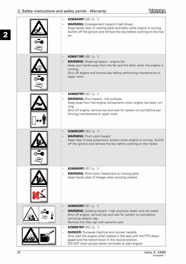
– 4296944M1 ((A) fig. 1)
– WARNING: Entanglement hazard in belt drives.Keep hands clear of rotating parts and belts while engine is running.Switch off the ignition and remove the key before working on the trac-tor.
– 4296971M1 ((B) fig. 1)
– WARNING: Shearing hazard – engine fan.Keep your hands away from the fan and the belts when the engine is running.Shut off engine and remove key before performing maintenance or repair work.
– 4296967M1 ((C) fig. 1)
– WARNING: Burn hazard – hot surfaces.Keep away from hot engine components when engine has been run-ning.Shut off engine, remove key and wait for system to cool before per-forming maintenance or repair work.
– 4296952M1 ((D) fig. 1)
– WARNING: Pinch point hazardKeep clear of axle suspension system when engine is running. Switch off the ignition and remove the key before working on the tractor.
– 4296985M1 ((E) fig. 1)
– WARNING: Pinch point hazard due to moving partsKeep hands clear of linkage when pivoting coolers
– 4298645M1 ((F) fig. 1)
– WARNING: Scalding hazard – high pressure steam and hot water.Shut off engine, remove key and wait for system to cool before removing radiator cap.Remove the filler cap with extreme care.
– 4296981M1 ((G) fig. 1)
– DANGER: Runaway machine and runover hazards.Only start the engine when seated in the seat with the PTO disen-gaged and the transmission in the neutral position.DO NOT short across starter terminals to start engine.
4 296 944 M1
4 296 971 M1
4 296 967 M1
4 296 952 M1
4 296 985 M1
4 298 645 M1
4 296 981 M1

Valtra_S - EAME 254315992M5 - 1
2
2. Safety instructions and safety points - Warranty
– 4296942M1 ((H) fig. 1)
– WARNING: Electric shock hazard – risk of personal injury and compo-nent damage.Remove negative (ground) cable from battery before removing starter solenoid cover and before servicing electrical system.
– 4296979M1 ((I) fig. 1)
– DANGER: Lead-acid battery hazardso Explosive gases;o Corrosive liquid (sulphuric acid);Keep away from all naked flames or sparksShield eyes when working on or around battery.Read safety and operating instructions in the Operator Instruction Book for further information.
– 4296954M1 ((J) fig. 1)
– WARNING:Driveline separation hazard, which may result in personal injury and machine damage.Make sure drawbar / 3-point hitch is in correct position and check length of PTO driveshaft when attaching PTO driven equipment.See Operating section of manual for detailed information.
– 4296975M1 ((K) fig. 1)
– DANGER: Rear overturn hazard, which may result in personal injury or death.Pull only from approved drawbar or lower links of 3-point hitch at hori-zontal position or below.Never pull from above rear axle centerline.
– 4296977M1 ((L) fig. 1)
– DANGER: Entanglement hazard – PTO driveline.Stand clear of rotating shafts.Keep all driveline, tractor and equipment guards in place during opera-tion.
– 4296969M1 ((M) fig. 1)
– WARNING: Crushing hazard between tractor and implement.Stand outside of tractor tire when using external controls for 3-point hitch.Do not stand between tractor and implement.
+ _
4 296 942 M1
4 296 979 M1
C D
B
A
4 296 954 M1
4 296 975 M1
4 296 977 M1
4 296 969 M1

26 Valtra_S - EAME4315992M5 - 1
2
2. Safety instructions and safety points - Warranty
– 4297148M1 ((N) fig. 1)
– WARNING: Falling hazardDo not step on PTO shield.
– 4296946M1 ((O) fig. 1)
– WARNING: Runaway machine and runover hazards.Shut off engine, remove key and apply park brake before leaving the tractor unattended.
– 4296958M1 ((P) fig. 1)
– WARNING: Falling and crushing hazard. Wear the seat belt when using the instructor seatRead the Operator Instruction Book for more information:
– The instructor seat is not intended for use by children.
– The instructor seat must not be used to transport passengers.
– The instructor seat must only be used by service personnel or for training purposes.
– 4296950M1 ((Q) fig. 1)
– WARNING:Avoid personal injury Read the Operator Instruction Book for safety information and operating instructions before operating the tractor.
– 4350916M1 ((R) fig. 1)
– DANGER: Explosion hazard – contents under pressure.Fill accumulators with nitrogen only –other gases may explode.See Operation section of manual for detailed information.
– 4297924M1 ((S) fig. 1)
– DANGER: Electrocution hazardTractors fitted with a front loader: Exercise extreme caution to avoid coming into contact with power lines.
4 297 148 M1
P 4 296 946 M1
4 296 958 M1
4 296 950 M1
4 350 916 M1
4 297 924 M1

Valtra_S - EAME 274315992M5 - 1
2
2. Safety instructions and safety points - Warranty
– 4349217M1 ((T) fig. 1)
– WARNING: Towing
– Carefully read the specific instructions from the Operator Instruction Book before towing the tractor.
– 4350591M1 ((W) fig. 1)
– WARNING: Long axle shafts.Remain at a safe distance from persons and objects when driving with long axle shafts.
– 4365863 M1 ((T) fig. 1)
– WARNING: Hydraulic valvesFor driving on roads, raise the tools to the required height and lock the tractor's hydraulic functions. When the front linkage is not in use, it is essential to lock the hydrau-lic functions.
4 350 591 M1
4 355 863 M1

28 Valtra_S - EAME4315992M5 - 1
2
2. Safety instructions and safety points - Warranty
2.4 General safety instructions
2.4.1 Awareness of the safety instructions and symbolsT000880
Remember that you alone are responsible for safety. Good safety practices protect not only you, but alsobystanders. Before using the tractor, study the instructions given in this book with care, as well as all of thesafety decals and instructions fixed to the tractor: Make them an integral part of your safety procedure. Alsonote all the usual protective measures which should be taken when working and above all, don't forget:Safety depends on you. You can prevent accidents which could cause serious injury or death.
WARNING:In some of the illustrations in this book, the safety panels and guards have been removed forreasons of clarity. Never use the tractor if these parts are not in place. If some of these partshave been removed for repair purposes, they must be refitted before use.
2.4.2 Operator familiarity in the use of the tractorT000881
– WARNING:The operator must not drink alcohol ortake any medication that may affecthis concentration or co-ordination. Iftaking medication, whether pre-scribed or not, the operator must seekmedical advice with regard to his abil-ity to operate machinery safely.
To be able to use your tractor, it is first neces-sary:– to be familiar with operating an agricultural
tractor
– to have been trained in the operation of thetractor that you have just purchased
– to have read and understood this entirebook — always consult the dealer as soonas there is any doubt or lack of understand-ing fig. 1
– find out about the rules and safety regula-tions applicable to the work you are doing.Some regulations specify that no one underthe age of 16 may operate power machin-ery, for example. This includes tractors. It isyour responsibility to know what these reg-ulations are and to observe them in the op-erating area or situation. These rulesinclude, but are not limited, to the safety in-structions relating to correct operation ofthe tractor as described in this book.
– Do not allow children or unqualified persons tooperate the tractor.
– Do not allow children to use the instructor seat.
– The instructor seat is only intended for short pe-riods of use.
I002903Fig. 1.
D-5842a

Valtra_S - EAME 294315992M5 - 1
2
2. Safety instructions and safety points - Warranty
– WARNING:In poor conditions, slow down and beextra careful, and engage 4-wheeldrive if fitted.
It is important to have good knowledge of theoperation of the tractor as well as all of its ac-cessories and attached implements.Remember that rain, snow, ice, loose gravel orsoft ground can change the performance of thetractor.
2.4.3 Filling the fuel tankT001555
– Always switch off the engine before filling up.
– Do not smoke while refuelling the tractor. Keepaway from naked flames fig. 2.
Filling with AdBlue/DEF
Avoid all contact with the eyes, skin and clothing.
– If swallowed. If large quantities of this productare swallowed, seek medical advice immedi-ately. Do NOT induce vomiting unless indicatedto do so by medical staff. Do not administer liq-uid to a person who is unconscious.
– In case of contact with skin, rinse with plenty ofwater and remove contaminated clothing.
– In case of contact with the eyes, rinse immedi-ately under running water. In the event of irrita-tion, seek medical advice.
– If fumes are inhaled, breathe in fresh air andseek medical advice, if necessary.
– Prevent AdBlue/DEF from coming into contactwith other chemical products.
– Urea spillages must not be discharged into thedrains.
I005000Fig. 2.
I006195Fig. 3.

30 Valtra_S - EAME4315992M5 - 1
2
2. Safety instructions and safety points - Warranty
2.4.4 Getting into and out of the cabT000883
– Always use three-point contact with the tractor and face the tractor when mounting and dismounting.(Three-point contact means that both hands and one foot or one hand and both feet are in contact withthe tractor at all times when getting on and off).
– Clean your shoes and wipe your hands before getting on the tractor.
– Use handrails, grab handles, ladders or steps (if fitted) when getting on and off.Do not use the control levers as a handhold.
– Do not step on pedals when getting in and out.
– Never attempt to mount or dismount a moving tractor.
– Never jump off a tractor when it is running except in an emergency.
2.4.5 Mandatory procedure before dismounting the tractorT000902
Before getting out of the cab, whether during the course of or at the end of the working day, always:
1. Immobilise the tractor by applying the parking brake or engaging ParkLock in the locked position (closedpadlock symbol) (depending on option).
2. DANGER:Place the reverse shuttle lever in the neutral position.
3. Disengage the front and rear PTO.
4. Lower the implements to the ground.
5. Turn off engine.
6. Remove the ignition key.

Valtra_S - EAME 314315992M5 - 1
2
2. Safety instructions and safety points - Warranty
2.5 Specific recommendations for application of the Machinery Directives 2006/42/EC on agricultural and forestry tractors as defined in 2003/37/EC.
2.5.1 Specific recommendations for application of the Machinery Directives 2006/42/EC on agricultural and forestry tractors as defined in 2003/37/EC
T006914
Hot surfacesBe careful of surfaces which may be hot, in particular engine and hydraulics components, during operationand servicing.
FOPS (Falling Object Protection Structure)– Alternative 1 (no FOPS available): Protection against falling objects is not provided, unless clearly speci-
fied otherwise.
– Alternative 2 (optional FOPS fitted): Protection against falling objects is provided under OECD-code 10(Energy level 1362 J). If a higher protection level is necessary, additional safety equipment should be in-stalled on the tractor (no original equipment available).
OPS (Operator Protection Structure) – Alternative 1 (no OPS available): Protection against penetrating objects is not provided, unless clearly
specified otherwise.
– Alternative 2 (optional OPS fitted): Protection against penetrating objects is provided under ISO 8084 (Ma-chinery for forestry). Before operating, check if protection is adapted to your work conditions.
Hazardous substances– Alternative 1 (less cab or cab under category 1): Protection against hazardous substances (agricultural
chemicals, etc.) is not provided. Personal protective equipment must be used according to the chemicalmanufacturer’s recommendations.
– Alternative 2 (cab under category 2): Protection against hazardous substances (agricultural chemicals,etc.) is not provided. Personal protective equipment must be used according to the chemical manufac-turer’s recommendations.A protection against dust (category 2 of standard EN 15695) is provided under the following conditions:– all roof hatch, cab doors and cab windows are closed
– cab ventilation is running
– air filter is clean and is serviced under maintenance interval (refer to service guide).
Instructor (passenger) seat– If an instructor (passenger) seat is provided, protection for the occupant of the seat is provided by the
same roll-over protective structure (ROPS) that protects the operator.Always use the seat belt correctly adjusted.

32 Valtra_S - EAME4315992M5 - 1
2
2. Safety instructions and safety points - Warranty
2.6 Special safety instructions for preparing the tractor for use
2.6.1 Protective clothingT000873
Wear all the protective clothing and equipment withwhich you are provided or which is appropriate forcertain working conditions fig. 1.
For example, you may need:– A safety helmet
– Goggles or a face shield
– Ear protection
– A respirator or filter mask
– Inclement weather clothing
– Reflective clothing
– Gloves suitable for the work to be carried out
– Safety footwear
DANGER:Do not wear loose clothing, jewellery orother items and tie up long hair whichcould catch on controls or other parts ofthe tractor.
2.6.2 Activated carbon filter informationT011579
WARNING:Due to the risk of contaminants entering the cab when the door is opened to enter or exit, useof a carbon filter is intended to supplement but not necessarily replace the use of personal pro-tective equipment when operating in an environment containing aerosols and/or vapours, suchas pesticides. The specific chemical manufacturer’s instructions regarding personal protective equipment(PPE) must be followed. If the cab being fitted with this filter does not already have a safety signlike the one included with this filter, install the safety sign in a prominent place inside the cabin view of the operator.
This filter is designed to reduce the concentration of aerosols and vapours entering the cab. To be effective,it must have an effective seal to prevent leakage around the filter and must be used in a cab air system thatdoes not have leaks, especially in the zone between the filter and the fan. In addition, the cab and its venti-lation system must be capable of maintaining a positive pressure inside the cab and an air flow of at least 30cubic meters per hour (18 cubic feet per minute). The cab with carbon filter is intended to be used as only one part of a managed system of occupational healthand safety, as noted below:
Operator Enclosures as Part of an Occupational Health and Safety Management System (OHSMS) Many self-propelled agriculture vehicles have operator enclosures (cabs) for comfort and protection of theoperator and riders. The cab can provide an effective physical barrier between the occupants and the envi-ronment, but that barrier must, by necessity of occupant respiration, allow air to enter and exhaust the cab.This requirement is met by the cab’s heating, ventilation and air-conditioning (HVAC) system. The HVAC system should employ a filter through which air entering the cab is first passed for contaminantreduction. Filters should also be provided in the recirculation air-stream to reduce airborne contaminants al-ready in the cab air space. In either application, these filters must be designed specifically for the HVAC sys-tem within which they are operating. The filters must also incorporate the correct media required to removethe specific air-born contaminant for which it is being employed.
I002858Fig. 1.

Valtra_S - EAME 334315992M5 - 1
2
2. Safety instructions and safety points - WarrantyFor such applications, the HVAC system must be of robust design, manufacture and maintenance. In such asystem, fresh air and cab pressurization requirements are provided by an air supply drawn through a filterwith negligible filter bypass. Even with an appropriate cab and HVAC system, there are other opportunities for contaminates to enter thecab. While outside the cab, a person can become contaminated on his/her body or clothing. Contaminatedobjects can be brought into the cab. Another potential for cab contamination exists when doors or windowsare open in a contaminated environment. In any case, whenever the cab interior has been contaminated, the effectiveness of the cab to provide con-tamination protection will be diminished. Health and safety for agricultural machine operators as well as oth-ers working in, on or around these machines can only be addressed through a comprehensive program. Such a program is defined as an Occupational Health and Safety Management System (OHSMS). While cabsmay be used as an effective engineering control within an OHSMS, this is not intended to imply that the cabalone is appropriate for any specific application. That determination can only be made by those responsible for the OHSMS in a specific application. It is theresponsibility of those charged with managing the use of the vehicle on which the cab is attached to defineand manage an appropriate OHSMS, and ensure that all federal, state and local regulatory requirements arefollowed. Cabs should not be used as a replacement for any other engineering control or PPE that has been specificallyrequired by federal, state or local regulatory authorities.
Hierarchy of ControlsThe Hierarchy of Controls, in their preferred order of action: 1. Elimination
2. Substitution of less hazardous materials, processes, operations or equipment
3. Engineering controls
4. Warnings
5. Administrative controls
6. Personal protective equipment (PPE)
Continuous Improvement CycleCabs should only be used to control operator air contaminant exposures within an OHSMS. This manage-ment system must consider occupational safety and health as a continuous improvement cycle that includesthese on-going processes:1. Management, Leadership and Employee Participation: This step in the cycle involves the formulation of
the management system, the establishment of policy, statements of responsibility and the integration ofthe employees into the management system.
2. Planning: This step is based upon initial and going reviews of the management system and numerousfactors affecting occupational safety and health within an organization. Included in these reviews is a re-view of the hazard, risks and controls and data collected to evaluate the hazards and the efficacy of thecontrol measures. In explanatory comments, exposure measurements are included as part of the assess-ment processes. The results of audits and measurements are also to be reviewed.
3. Implementation and Operation: This section describes the organization components of a occupationalsafety and health program. It describes the hierarchy of controls mentioned above and several broadclasses of management function. Among these requirements are employee training and evaluation ofemployee training. Furthermore, this section requires a written, clearly documented occupational safetyand health program.
4. Evaluation and Corrective Actions: The section specifically requires management processes to monitorand evaluate hazards, risks and their controls. Explanatory comments note that this includes quantitativemeasures of worker exposure. Practically, this involves physically testing the efficiency of the cab beingused as an engineering control within an OHSMS.
5. Management System Review: Management is required to review the management system to ensure itssuitability, adequacy and effectiveness. This cycle includes provisions for exposure monitoring and themonitoring of control measure performance. It is the responsibility of the manager of the safety andhealth program to determine how worker exposure to air contaminants and other hazards are to be con-trolled. It is also the responsibility of this manager to take whatever actions are needed to control work-place hazards. This includes but is not limited to exposure assessment, audits of varies programs suchrespiratory protection, ventilation system maintenance, etc.
Limitations of Cabs Used in Hazardous Environments:

34 Valtra_S - EAME4315992M5 - 1
2
2. Safety instructions and safety points - Warranty While it may seem that respiration (breathing) exposure would present the greatest risk for personal expo-sure to contaminants, this is not the case when working with pesticides. The most prevalent method of ex-posure for applicators and those working around agricultural pesticides is through dermal (skin) contact. Dermal contact with contaminants may occur directly from air-borne contaminants. It may also happen whencontaminants are transferred from one object to another or when air-borne contaminants settle on objectsthat are subsequently contacted. Any surfaces in or out of the cab that have been contaminated are potentialhazards for dermal exposure. Within the cab, seats, upholstery, controls and other surfaces that become contaminated will pose such ahazard. In addition to dermal exposure, a contaminated cab interior will also pose a respiration hazard as thecontaminant may, after settling on a surface, become air-borne once again whereby it may be inhaled. Recirculation filters can be used to help reduce these contaminates from the cab interior air space. When avehicle is operated in an environment where air-born contaminants exist, the cab can be an effective engi-neering control for reduction of exposure risk to persons within it. In order for a cab to be used for this purpose, it must be of appropriate design. It must also be manufactured,maintained, tested and operated according to the specific requirements defined by evaluation of the hazards. No cab should ever be considered an effective engineering control unless it has been qualified as such withina comprehensive OHSMS. While the cab manufacturer can design and manufacture a cab to physical spec-ifications, the cab manufacturer can not qualify the cab as an appropriate engineering control for any specificapplication. Site-specific information is needed to evaluate the appropriateness of control measures. To use the cab tocontrol hazards, the managers of the OHSMS must carefully consider and evaluate the effectiveness of allengineering controls in their specific application.
The Cab as an Engineering ControlThe engineering control requirements of the respiratory protection regulation may be fulfilled by the applica-tion of a cab, but this can only be done properly within an OHSMS. Elements of such a program are:1. Assessment of the hazard with identification of the risk involved.
2. A survey of the machine and the cab involved in the hazardous operation.
3. Reviewing the cab ventilation system and the filter to ensure the filter provides the reduction in contam-inants required.
4. Defining how long the filter can be used in this application.
5. Testing the cab ventilation system to ensure it provides the protection required for the operation to beperformed. This also includes a review of any monitoring equipment to ensure it is working properly.
6. Repair and/or replacement of any defects or defective equipment found.
7. Retesting of the cab air system as required.
8. Recording in the appropriate log book all information regarding the test results, and repairs and replace-ment of parts and/or components.
9. Assessment of the effectiveness of the program at a specified time in the cycle of the activity.
2.6.3 Safety devices and itemsT000874
Ensure that all safety devices and items are fitted as required and are in good condition.
WARNING:The location of all these safety devices and items must be known and their use mastered.Never take off, remove or disconnect any of them.

Valtra_S - EAME 354315992M5 - 1
2
2. Safety instructions and safety points - Warranty
Standard safety devices and items according to country regulations– ROPS (Roll Over Protective Structure)
– Seat belt
– Power take-off guard
– SMV warning triangle
– Signalling lights
– Safety signs
– Fire extinguisher
– First aid kit
WARNING:Also make sure you know the emergencynumbers.
Additional devices and itemsDepending on the work to be carried out, other safety devices and items may be required; for example,guards or additional lights and signs.
2.6.4 Checking the tractorT000872
Check the tractor and ensure that all systems are in good operational condition before beginning the workingday. Pay particular attention to the points mentioned below.
– Check for loose, broken, missing or damaged parts. Ensure that everything has been properly repaired.
– Check that the seat belt is in good condition. If it is not, replace it.
– Check that implements are correctly installed.
– Check that the PTO output speed is in keeping with the implement PTO input speed.
– WARNING:An unbalanced tractor could overturn and cause serious injury or death. Ensure that frontframe counterweights, wheel weights and wheel ballasts are used as recommended by themanufacturer. Do not add extra counterweights to compensate for an overloaded tractor;the load must be reduced instead.
Check to ensure that the tractor is correctly balanced.
– Check the condition and pressure of tyres (absence of cuts and bulges). Replace worn or damaged tyres.
– Check the correct operation of the brake pedals and the parking brake. Adjust if necessary.
– Ensure that all PTO shaft locking devices are engaged.
– Ensure that the tractor PTO guard and the shaft guards are in place and operating correctly.
I002859Fig. 2.

36 Valtra_S - EAME4315992M5 - 1
2
2. Safety instructions and safety points - Warranty
– WARNING:Fuel or hydraulic fluid under pressurecan penetrate the skin or eyes andcause serious physical injury, blind-ness or death.Leaks of pressurised fluid may not bevisible. Use a piece of cardboard orwood to detect leaks. DO NOT USEYOUR BARE HANDS. Wear safety gog-gles for eye protection. If any fluidpenetrates the skin, seek medical ad-vice within a few hours from a doctorfamiliar with this type of injury -.WARNING:Release the pressure of the hydraulicor fuel systems before disconnectingthem.
Check the hydraulic system for the tractor andthe implement as well as the tractor fuel sys-tem: Correct tightening of all the unions; nodamage to the lines, pipes and hoses; hydraulicsystems do not cross one another.Have any leakages or damaged parts repaired orreplaced.
– WARNING:The liquid cooling system builds up pressure as the temperature increases. Stop the engineand let the system cool before removing the radiator filler plug.
Check the engine cooling system and add coolant if required.
– All maintenance procedures must have been complied with.
– Check that the weight of the tractor/implement assembly is less than the tractor total permissible load.
I002860Fig. 3.

Valtra_S - EAME 374315992M5 - 1
2
2. Safety instructions and safety points - Warranty
2.7 Specific safety instructions for starting the tractor
2.7.1 Protection of persons other than the operatorT000884
1. Before starting up, walk all the way round the tractor and any attached equipment. Ensure that no one isunder it, on it or close to it.
2. Warn in advance any persons nearby that the tractor is about to start.
3. Only start up if there is nobody in the vicinity of the tractor/implement assembly. Pay particular attentionto looking out for children.
2.7.2 Start up safelyT000885
General instructions– WARNING:
Before starting the engine, ensure there is plenty of ventilation in the area. Do not operatethe engine in an enclosed space. The exhaust fumes may cause asphyxiation.
– Always start the engine from the operator's seat.
– Adjust the seat.
– For road use, ensure that the tractor brake pedals are locked together.
– Fasten the seat belt.
– Check that the parking brake is applied or that ParkLock is engaged.
– Place the reverse shuttle lever in the neutral position and deactivate the PTO controls.
– Follow the start-up procedures described in the chapter Operation of this book.
– DANGER:Start the engine with the ignition keyand from the operator's seat only. Donot attempt to start the engine byshort-circuiting the starter terminals:the tractor may start in gear and thiscould cause serious injury or death toanyone in the vicinity fig. 1.
I002863Fig. 1.

38 Valtra_S - EAME4315992M5 - 1
2
2. Safety instructions and safety points - Warranty
Starting assistanceWARNING:Never use any starter fluid or aerosolsprays. This could cause an explosion andthe risk of very serious injury.
2.7.3 Checks to be carried out after start-upT000886
Controls and indicator lightsAfter having started the engine, check all the controls and all the indicator lights again. Ensure everything isfunctioning correctly.
WARNING:In case of malfunction of a control or an indicator light, resolve the problem before using thetractor.
Mastering of the tractorMove slowly until you are sure that everything is operating correctly. Be certain that you have full control ofthe steering and brakes. If the differential is locked, unlock it before continuing your route.
I002864Fig. 2.
WARNING

Valtra_S - EAME 394315992M5 - 1
2
2. Safety instructions and safety points - Warranty
2.8 Specific safety instructions for using the tractor
2.8.1 General instructionsT000875
– Tractors and implements are not toys. Always comply with the conditions of use defined by the manu-facturers.
– Never exceed the tractor total permissible weight.
– Always consider the way in which the tractor is to be used and the fact that the centre of gravity of thetractor/implement assembly changes according to the load being transported or towed.
– WARNING:An unbalanced tractor could overturn and cause serious injury or death. Ensure that frontframe counterweights, wheel weights and wheel ballasts are used as recommended by themanufacturer. Do not add extra counterweights to compensate for an overloaded tractor;the load must be reduced instead.
Check to ensure that the tractor is correctly balanced.
– Check that the PTO output speed is in keeping with the implement PTO input speed.
– Keep all parts of your body inside the safety zone defined by the cab or by the protective structure forplatform tractors.
– Operate the controls smoothly — do not jerk the steering wheel or other controls.
– Always operate the controls from the operator's seat.
– Keep a firm grip on the steering wheel at all times, with your thumbs clear of the spokes when drivingthe tractor.
– Operate the tractor smoothly — avoid jerky turns, starts or stops.
– Do not turn at high speed.
– Avoid driving close to ditches and banks.
– Avoid taking slopes that are too steep.
– Reduce speed when negotiating turns and slopes and on rough, slippery or muddy surfaces.
– Carefully observe the areas surrounding the route.
– Ensure you have adequate clearance in all directions for the tractor and the implement.
– When using chemicals, follow the chemical manufacturer's instructions for use and storage carefully.
– Adapt the tractor speed according to visibility, weather conditions and the type of terrain.
– WARNING:If a part breaks, loosens or does not operate correctly:– stop work– switch off the engine– check the machine and make the necessary adjustments and repairs before resuming
work.
– DANGER:Do not attempt to unplug the hydraulic connections or adjust an implement with the enginerunning or the PTO in operation. To do so may result in serious injury or death.

40 Valtra_S - EAME4315992M5 - 1
2
2. Safety instructions and safety points - Warranty
2.8.2 Protection of persons other than the operatorT000876
– WARNING:A tractor is a machine with a single op-erator.Do not permit anyone fig. 1 to ride onthe tractor or implements, includingtrailers, unless the implements arespecially designed to carry passengersduring field work. In the latter case,transport is permitted only for fieldwork, but not for travelling on theroad.In all cases, never allow a child to rideon the tractor or implements.
– When operating, attention to the environment of the tractor/implement assembly.
– Never lift loads above someone.
– Do not allow anyone to stand or pass in front of,under or behind an implement fig. 2.
– Do not allow anyone to stand between the tractor and the implement.
– Keep others away from the working area.
2.8.3 OverturningT000877
Overturning angleDANGER:For your safety, never exceed the maximum angle limits listed in the table below.
NOTE: These angle limits assume a maximum oil level.It is recommended to top up the oil by 15 l when working on slopes of maximum gradient.
I002865Fig. 1.
I002866Fig. 2.
Models Maximum angle: roll/pitch/combinedS232/S262/S292/S322/S352 25°/27°/17°

Valtra_S - EAME 414315992M5 - 1
2
2. Safety instructions and safety points - Warranty
Procedure to follow if the tractor overturnsIf the tractor should overturn, keep the seat belt fas-tened, hold the steering wheel firmly and do not at-tempt to leave the seat until the tractor has come toa complete stop fig. 3. For tractors fitted with a cab,if the doors are obstructed, leave through the rearwindow or roof hatch.
Preventing a lateral overturn– Set the track width to the most appropriate width for the work being carried out.
– Lock the brake pedals together before driving at transport speed.
– Adapt the tractor speed according to visibility, weather conditions and the type of terrain.
– If the tractor is fitted with a front-end loader, carry the bucket and load as low as possible.
– Make wide turns at reduced speed.
– Do not allow the tractor to bounce as this may cause you to lose control.
– Never exceed the tractor total permissible weight.
– Do not brake suddenly. Apply brakes smoothly and gradually.
– WARNING:Do not disengage the clutch or attempt to shift gear after you have started downhill.
When driving down a slope, use the engine brake to slow the tractor down and choose the same gearratio as used when climbing a slope.
– Engage four-wheel drive (if fitted) to enable four-wheel braking.
– Do not work near the edge of ditches and banksas there is a risk of them collapsing. The tractormust always be kept a distance from the edgethat is equal to or greater than the height of thebank or ditch fig. 4.
– Preferably, climb or descend a slope in a straight line, but do not cross it. When this is not possible, ad-here to the following precautions:– Avoid holes and dips when driving downhill
I002867Fig. 3.
I002868Fig. 4.
45°
X
X

42 Valtra_S - EAME4315992M5 - 1
2
2. Safety instructions and safety points - Warranty– Avoid stumps, stones and raised areas when driving uphill
– when turning, avoid turning towards the top of the slope; always slow down and take a wide turn
– keep the heavier end of the tractor facing towards the top of the slope when driving up and down it.
– When driving across a slope with a tractor fitted with implements on one side, these implements must:– always be facing towards the top of the slope
– never be raised
– be left as close as possible to the ground
– When towing a load at transport speed, lock the drawbar in the centre position and use a safety chain.
– Do not use the tractor to round up livestock.
Preventing a rear overturn– WARNING:
Hitching a load to the rear axle or on any other part located above the rear axle may causea rear overturn.
– Do not pull anything using the top link connection or from any point above the centre line of the rear axle.Always use a Valtra-approved drawbar and only use a lockable drawbar pin.
– When using a drawbar for a three point hitch, use the stabilisers and keep the drawbar in the bottom po-sition.
– Use front weights to increase tractor stability when towing heavy loads or to counterbalance the weightof a heavy rear-mounted implement.
– Start off slowly and then gradually increase speed.
– Do not release the clutch suddenly.
– If a heavy load or immovable object is attached to the tractor, incorrect use of the clutch may cause thetractor to overturn.
– If the front end of the tractor starts to lift, disengage the clutch.
– If the tractor is bogged down in mud or frozen to the ground:– do not attempt to drive forward as the tractor could then rotate around its rear wheels and overturn
– lift any attached implements and attempt to reverse If this is not possible, tow the tractor out withanother vehicle.
– If the tractor is stuck in a ditch, if possible, attempt to reverse out. If you must go forward, do so slowlyand carefully.
– A bare tractor or a tractor fitted with a rear implement must climb a slope in reverse gear and descendthe slope in forward gear.
– A tractor fitted with a full loader at the front must climb a slope in forward gear and descend the slope inreverse gear. The loader must be kept as close to the ground as possible.
– Always engage a gear when driving downhill. Do not allow the tractor to coast down the slope with theclutch disengaged or the transmission in neutral.
2.8.4 Tractor towingT000878
Comply with the instructions described in the "Operation" chapter of this book.
2.8.5 Road useT000879
– WARNING:Never allow any passengers to ride on the tractor and implements.
– WARNING:Do not use the work lights when travelling on a road because rear white lights are illegalexcept when reversing and may confuse following drivers.

Valtra_S - EAME 434315992M5 - 1
2
2. Safety instructions and safety points - Warranty– Ensure that all clearance flags and rotary beacons that indicate an abnormal load are in position and are
in working order.
– Clean all the reflectors and the front and rear lights. Ensure that they are in working order.
– Ensure that the tractor and implements are fit-ted with SMV warning triangles and other mark-ings recommended to improve visibility whendriving on roads (unless the regulations stateotherwise) fig. 5.
– Place all implements in the transport position so that they take up minimum space and lock them in po-sition.
– Lock the brake pedals together.
– Disengage the power take-off and the differential lock.
– Observe all current local and national regulations regarding the use of a tractor on the road.
– Depending on the equipment fitted to the tractor and unless regulations state otherwise, use the rotarybeacons or the hazard warning lights day and night.
– Familiarise yourself with the road you will be travelling on.
– Exercise the utmost caution when driving on snow-covered or slippery roads.
– Wait for traffic to clear before entering a public road.
– Beware of blind intersections: Slow down until you have a clear view.
– Do not attempt to push your way through at any intersection.
– Slow down for turns and curves.
– Make wide turns at a moderate speed.
– Signal your intention to slow down, stop or turn.
– Shift to a lower gear before going up or down hills.
– Always drive the tractor in gear. Do not coast with the clutch disengaged or transmission in neutral.
– Do not overlap the lane of traffic for vehicles travelling the other way.Stay in your lane, as close as possible to the roadside.
– If a traffic jam forms behind the tractor, pull off the road and allow the vehicles behind to pass.
– Drive carefully. Anticipate what other drivers might do.
If towing a load– Always anticipate obstacles, especially if the trailed implement is not fitted with brakes.
– Start braking much earlier than usual and slow down gradually.
– Ensure that the load is not concealing the lights or the rotary beacons.
– Take account of your load, especially for high obstacles.
I002869Fig. 5.

44 Valtra_S - EAME4315992M5 - 1
2
2. Safety instructions and safety points - Warranty
2.8.6 Emergency hand brakeT001556
If the brakes fail and in an emergency situation, usethe emergency hand brake located to the left of theoperator fig. 6.
WARNING:Never use this emergency brake as a park-ing brake. For tractors equipped with aParkLock, it is this function that acts as aparking brake: its control is located on thesteering wheel.
IMPORTANT: If the brakes fail, contact your dealerto resolve the problem.
2.8.7 Power take-offT000893
DANGER:Do not attempt to unplug the hydraulic connections or adjust an implement with the enginerunning or the PTO in operation. To do so may result in serious injury or death.
– Ensure that all the PTO shaft guards are in placeand check the presence of all safety decalsfig. 7.
I004991Fig. 6.
I002874Fig. 7.

Valtra_S - EAME 454315992M5 - 1
2
2. Safety instructions and safety points - Warranty
– Ensure that the PTO cap (1) is fitted when thePTO shaft is not in use fig. 8.
– Before hitching, unhitching, cleaning or adjust-ing the implements driven by the PTO, followthe "mandatory procedure before dismountingthe tractor" see §2.4.5, page 30.
– Ensure that there is nobody in the vicinity of theimplement before engaging the PTO.
– For stationary PTO operation, place the trans-mission lever and/or the shuttle lever (both ifthe tractor is fitted with them) in neutral, applythe hand brake or engage ParkLock (dependingon option) and chock the wheels of the tractorand the implement.
– Do not use PTO adapters, reducers or exten-sions as they extend the PTO coupler beyondthe protection offered by the guard.
2.8.8 ImplementsT000894
– Tractors and implements are not toys. Always comply with the conditions of use defined by the manu-facturers.
– DANGER:To avoid serious injury or death due to falling loads resulting from inadvertent raising orroll-back of the loader, do not connect loader hydraulics to any tractor auxiliary valve thathas detents which cannot be locked out or removed, except for the float function in theloader lower circuit. If the tractor is equipped with such a valve, a dedicated, properly con-figured loader valve must be installed.DANGER:A front-end loader with a bucket or forks must be fitted with a holding device. This devicemust prevent the load (bales, fence posts, rolls of fence, wire etc.) from rolling down thelength of the loader arms when the loader is raised, as it could crush the operator. Objectsthat are incorrectly secured may also fall and injure people in the vicinity of the tractor.
When using a loader, avoid sudden stops, starts, turns or changes in direction. Keep loads close to theground when transporting.
– Never lift loads above someone.
– Implements fitted to the three-point hitch or to the side of the tractor make a much larger arc when turn-ing than trailed implements. Ensure there is enough room to manoeuvre in complete safety.
– Only use implements suitably adapted for your tractor.
– Always read the implement instruction books fully for implements to be used with the tractor and complywith the safety instructions they contain.
– Do not modify nor remove any parts of an implement.
– Do not touch the mechanism of an implement nor lean over it or attempt to reach it. Do not allow anyoneelse to do this either.
– Do not allow anyone (including yourself) to stand or pass in front of, under or behind an implement.
– If the tractor is not immobilised according to the "mandatory procedure before dismounting the tractor"see §2.4.5, page 30, never stand or allow any person to stand between the tractor and the implement.
– Always use implements that are capable of safely carrying the load that you wish to place in it.
– Do not overload a trailed implement. Use appropriate weights to maintain tractor stability.
– The top link and the lift rods must never be taken beyond the point where the thread starts to appear.
– When using chemicals, follow the chemical manufacturer's instructions for use and storage carefully.
I002871Fig. 8.
1

46 Valtra_S - EAME4315992M5 - 1
2
2. Safety instructions and safety points - Warranty
– All trailed implements and trailers should beconnected to the tractor by a safety chain (1) .fig. 9 Should a trailed implement accidentally be-come separated from the drawbar during trans-port, this safety chain will help to retain thetrailed implement. Using the appropriateadapter parts, attach the chain to the tractor'sdrawbar anchor or any other specified anchorpoint. Leave only enough slack in the chain to al-low for manoeuvring.The safety chain must have a strength equal orgreater than the weight of the trailed imple-ment: contact your Valtra dealer to obtain a suit-able chain.
– Only tow using the drawbar. Attaching thetrailed implement to another location couldcause the tractor to overturn.
Towing: permissible load and speedWARNING:The stopping distance increases with the speed and weight of the trailed implements, and alsoon a slope. Whether they are fitted with a brake system or not, trailed implements that are tooheavy for the tractor or that are towed at too high a speed may lead to a loss of control. Takeaccount of the total weight of the trailed implement (including the load).
Never tow an implement:– at a speed exceeding the speed limit in force in the relevant country and
– if the true weight of the tractor/implement assembly is greater than the tractor total permissible loadedweight indicated on the name plate.
Towed equipment without brakes:Do not tow equipment that does not have brakes:– at speeds of more than 32 km/h; or
– at speeds above those recommended by the manufacturer; or
– with a mass (weight) that is over 1,5 t (3300 lb) when fully loaded and is more than 1.5 times the mass(weight) of the tractor.
Towed equipment with brakes:Do not tow equipment that has brakes:– at speeds of more than 50 km/h; or
I002872Fig. 9.
1
I002873Fig. 10.

Valtra_S - EAME 474315992M5 - 1
2
2. Safety instructions and safety points - Warranty– at speeds above those recommended by the manufacturer; or
– with a mass (weight) more than 4.5 times the mass (weight) of the tractor when fully loaded;
– at speeds of more than 40 km/h if, when fully loaded, it has a mass (weight) more than 3.0 times themass (weight) of the towing unit.
2.8.9 Front-end loaderT006905
WARNING:The programmable features of the joystick or other control MUST NOT be used to operate aloader. In order to prevent involuntary loader motion, the loader joystick controller must be aself neutralising type. When the operator releases his grip on the joystick, the joystick must re-turn to a non-operational neutral position - except for float detent position in the loader lowerdirection.

48 Valtra_S - EAME4315992M5 - 1
2
2. Safety instructions and safety points - Warranty
2.9 Specific safety instructions for servicing the tractor
2.9.1 Pollution warning to observe when servicing the tractorT000889
IMPORTANT: It is illegal to pollute drains, water courses or soil. Use authorised waste disposal facilities, re-fuse tips or garages providing facilities for the disposal of used oil. If in doubt, contact your local authority foradvice.
2.9.2 General instructionsT000887
– Never service the tractor while the engine isrunning or hot or if the tractor is in motion fig. 1.
– Before making adjustments to or servicing the electrical system, disconnect the battery cables, negative(-) terminal first.
– To prevent risks of fire or explosion, keep batteries and cold weather starting aids away from nakedflames.
– To prevent sparks which could cause explosions, use jump leads according to instructions.
– Consult your Valtra dealer for repairs or adjustments and have the work carried out by trained personnel.
– The implement and/or tractor must be supported on suitable blocks or stands and not on a hydraulic jack.
– Check all nuts and bolts periodically for tightness, especially wheel hub and rim nuts. Tighten to thetorque values stipulated.
– Regularly check the brakes.Ensure that the brakes are uniformly adjusted, especially if a trailer is used.In case of malfunction, consult your dealer.
– Accumulators.The accumulators contain nitrogen and are pressurised. They may become hot and cause burns.Modifications must not be made to the accumulators (by welding, drilling, attempting to open, cuttingetc.).The repair, maintenance and commissioning of the accumulators must only be carried out by trained per-sonnel. Consult your Valtra dealer regarding any maintenance.
2.9.3 Special instructions for cleaning the tractorT000888
– Before cleaning the tractor, always:– follow the "mandatory procedure before dismounting the tractor" see §2.4.5, page 30, and
– remove or put away implements, buckets, chains and hooks.
I002862Fig. 1.

Valtra_S - EAME 494315992M5 - 1
2
2. Safety instructions and safety points - Warranty– Clean steps, pedals and floor. Remove grease or oil. Brush away dust and mud. In winter, scrape away
snow and ice. Remember — slippery surfaces are hazardous.
– When washing the tractor with a jet of water, do not direct the jet straight onto electrical components.
– If using a high-pressure cleaning device, maintain a sufficient distance so as not to damage the paintworkand the sealed sections.
– Keep work surfaces and engine compartments clean.
– After washing, grease the lubrication points, the hinged sections and the bearings.

50 Valtra_S - EAME4315992M5 - 1
2
2. Safety instructions and safety points - Warranty
2.10 Protective structures
2.10.1 Protective structures: use and accreditationT000935
The protective structures (cab, ROPS, seat belts) limit injuries as far as possible in case of an accident or ifthe tractor overturns.They meet all applicable standards for agricultural tractors.
2.10.2 Cab or ROPS (depending on model)T000936
– The cab and ROPS have been designed to be suitable for this tractor series.
– Never weld parts onto the cab or ROPS.
– Never bend or straighten the cab or ROPS.
– Never drill or modify the cab or ROPS to fit accessories or implements.If other controls or displays have to be fitted in the operator's area, contact your Valtra dealer to find outwhat to do.
– Do not attach chains or ropes to the cab or to the ROPS in order to pull or tow anything.
– If the cab or the ROPS has been removed, refit it and tighten the fixings to the specified torque beforeusing the tractor again.
– WARNING:A cab or ROPS damaged as a result of an accident, overturning or other incident must bereplaced before using the tractor again.
2.10.3 Seat beltT000934
– Wearing the seat belt is an important part of thisprotection.
– Always wear the seat belt adjusted correctly.
WARNING:A damaged seat belt must be replaced be-fore using the tractor again.
I002857Fig. 1.

Valtra_S - EAME 514315992M5 - 1
2
2. Safety instructions and safety points - Warranty
2.10.4 Instructor seatT003334
– Use of the instructor seat is exclusively re-served for an instructor or technician. The seatis NOT suitable for children.
– The seat belt must always be worn and cor-rectly adjusted when using the instructor seat.
I009902Fig. 2.

52 Valtra_S - EAME4315992M5 - 1
2
2. Safety instructions and safety points - Warranty
2.11 Warranty
2.11.1 GeneralT000853
When selling new products to its dealers, the manufacturer provides a warranty which, subject to certain con-ditions, guarantees that the goods are free from defects in material and workmanship. Since this book is pub-lished worldwide, it is impossible to detail the exact terms and conditions of warranty that apply to all retailcustomers in all countries. Purchasers of new Valtra equipment should therefore request full details fromtheir supplying dealer.In accordance with the manufacturer's policy of continuous improvement of its products, the manufacturerreserves the right to make alterations to the specifications of machines at any time without notice. The man-ufacturer disclaims all liability for discrepancies which may occur between the specifications of its productsand the descriptions thereof contained in its publications.
2.11.2 Pre-delivery inspection and commissioning on the user’s premises
T000854
The dealer is required to carry out certain activities when supplying a new tractor. These consist of carryingout a full pre-delivery inspection to ensure that the tractor supplied is ready for immediate use, and providingfull instructions to the user on the basic principles of operation and servicing of the tractor. These instructionswill cover instruments and controls, and routine servicing and safety precautions. All persons who will be in-volved in the operation and servicing of the tractor should be present when these instructions are given.
IMPORTANT: Valtra disclaims all liability in the event of any claim resulting from the fitting of non-approvedparts, accessories, implements or attachments or unauthorised modifications or alterations.
2.11.3 Warranty procedureT000855
Correct commissioning on the user's premises and routine servicing help to prevent breakdowns. However,if operating problems do occur during the warranty period, follow this procedure:
– Immediately inform the dealer you purchased the tractor from, stating the model and serial number. It isvery important not to delay, as even if the defect is covered by the original warranty, the coverage mayno longer apply if the repair is not carried out immediately.
– Provide the dealer with as much information as possible. The dealer will need to know how many hoursthe tractor has been in service, what type of work it is used for and the symptoms of the problem.
Routine servicing operations not covered by the warrantyIt should be noted that routine servicing operations such as tuning, brake and clutch adjustment, and the sup-plies used for the tractor servicing (oil, filters, seals, fuel, antifreeze etc.), are not covered by the warranty.
Warning concerning spare partsParts other than Valtra parts are likely to be of lower quality. Valtra disclaims all liability in the event of loss ordamage arising as a result of such parts being fitted. The manufacturer's warranty may also become void ifsuch parts are fitted during the normal warranty period.
2.11.4 Procedure to follow if changing regionT000856
Only the dealer from whom the tractor was purchased is liable for the protection provided by the warranty.Any repairs should, wherever possible, always be carried out by this dealer. If, however, the owner movesto another region or if the tractor is to be used temporarily at a location a long way from the dealer from whomit was bought, it is advisable to ask this dealer for the name and address of the dealer closest to the newaddress and arrange to have the obligations remaining to be fulfilled under the warranty transferred to thisdealer.
If the customer leaves the region covered by the original dealer without having taken these steps, the newdealer will offer its services if needed, but may invoice them at the normal rate unless:– the customer has clearly stated that the warranty period has not expired, and
– the repair dealer has been given the possibility of taking the necessary steps with the selling dealer.

Valtra_S - EAME 534315992M5 - 1
2
2. Safety instructions and safety points - Warranty
2.11.5 Servicing during and after the warranty periodT000857
During the warranty period, all servicing and repair work must be carried out by the dealer, who will carefullycarry out detailed checks of the progress and performance of the new tractor.
To obtain best results from a Valtra tractor, it is important to continue regular servicing and periodic inspec-tions after the warranty has expired. All major overhaul work on the tractor must be carried out by a localdealer; an experienced technician will detect any problems which may arise between one overhaul and thenext. Technicians regularly follow training courses to update their knowledge of the product and servicingand repair techniques, and the use of special tools and modern diagnostic equipment. They receive regularService Bulletins and have access to all the workshop manuals and technical publications required to carryout repairs or servicing in accordance with the quality standards required by Valtra.

54 Valtra_S - EAME4315992M5 - 1
2
2. Safety instructions and safety points - Warranty

Valtra_S - EAME 554315992M5 - 1
3
Table of contents
3. Operation
3.1 Cab . . . . . . . . . . . . . . . . . . . . . . . . . . . . . . . . . . . . . . . . . . . . . . . . . . . . . . . . . . . . . . . . . . . . . . . . 593.1.1 Steering console . . . . . . . . . . . . . . . . . . . . . . . . . . . . . . . . . . . . . . . . . . . . . . . . . . . . . . 593.1.2 Instrument panel . . . . . . . . . . . . . . . . . . . . . . . . . . . . . . . . . . . . . . . . . . . . . . . . . . . . . 603.1.3 Control unit . . . . . . . . . . . . . . . . . . . . . . . . . . . . . . . . . . . . . . . . . . . . . . . . . . . . . . . . . . 643.1.4 Start switch . . . . . . . . . . . . . . . . . . . . . . . . . . . . . . . . . . . . . . . . . . . . . . . . . . . . . . . . . . 653.1.5 Pedals . . . . . . . . . . . . . . . . . . . . . . . . . . . . . . . . . . . . . . . . . . . . . . . . . . . . . . . . . . . . . . 653.1.6 Steering wheel . . . . . . . . . . . . . . . . . . . . . . . . . . . . . . . . . . . . . . . . . . . . . . . . . . . . . . . 663.1.7 Seat . . . . . . . . . . . . . . . . . . . . . . . . . . . . . . . . . . . . . . . . . . . . . . . . . . . . . . . . . . . . . . . . 663.1.8 Right-hand console . . . . . . . . . . . . . . . . . . . . . . . . . . . . . . . . . . . . . . . . . . . . . . . . . . . 713.1.9 Multifunction armrest . . . . . . . . . . . . . . . . . . . . . . . . . . . . . . . . . . . . . . . . . . . . . . . . . 723.1.10 Work lights module . . . . . . . . . . . . . . . . . . . . . . . . . . . . . . . . . . . . . . . . . . . . . . . . . . . 733.1.11 Left-hand console . . . . . . . . . . . . . . . . . . . . . . . . . . . . . . . . . . . . . . . . . . . . . . . . . . . . . 743.1.12 Emergency hand brake . . . . . . . . . . . . . . . . . . . . . . . . . . . . . . . . . . . . . . . . . . . . . . . . 743.1.13 Upper console. . . . . . . . . . . . . . . . . . . . . . . . . . . . . . . . . . . . . . . . . . . . . . . . . . . . . . . . 753.1.14 Air conditioning . . . . . . . . . . . . . . . . . . . . . . . . . . . . . . . . . . . . . . . . . . . . . . . . . . . . . . 763.1.15 Accessories sockets . . . . . . . . . . . . . . . . . . . . . . . . . . . . . . . . . . . . . . . . . . . . . . . . . . . 803.1.16 Sun visor . . . . . . . . . . . . . . . . . . . . . . . . . . . . . . . . . . . . . . . . . . . . . . . . . . . . . . . . . . . . 81
3.2 Reverse station (optional) . . . . . . . . . . . . . . . . . . . . . . . . . . . . . . . . . . . . . . . . . . . . . . . . . . . 823.2.1 Positioning the reverse station . . . . . . . . . . . . . . . . . . . . . . . . . . . . . . . . . . . . . . . . . . 823.2.2 Reverse station adjustments . . . . . . . . . . . . . . . . . . . . . . . . . . . . . . . . . . . . . . . . . . . . 833.2.3 Valtra Shuttle controller . . . . . . . . . . . . . . . . . . . . . . . . . . . . . . . . . . . . . . . . . . . . . . . . 833.2.4 Reverse station driving . . . . . . . . . . . . . . . . . . . . . . . . . . . . . . . . . . . . . . . . . . . . . . . . 843.2.5 Leaving the reverse station . . . . . . . . . . . . . . . . . . . . . . . . . . . . . . . . . . . . . . . . . . . . . 85
3.3 Dash Control Center control screens on the instrument panel . . . . . . . . . . . . . . . . . 863.3.1 Using the instrument panel control screen . . . . . . . . . . . . . . . . . . . . . . . . . . . . . . . . 863.3.2 Dash Control Center screens . . . . . . . . . . . . . . . . . . . . . . . . . . . . . . . . . . . . . . . . . . . . 863.3.3 Dash Control Center on tractor terminal . . . . . . . . . . . . . . . . . . . . . . . . . . . . . . . . . . 88
3.4 Tractor terminal . . . . . . . . . . . . . . . . . . . . . . . . . . . . . . . . . . . . . . . . . . . . . . . . . . . . . . . . . . . . 903.4.1 Accessing the menus . . . . . . . . . . . . . . . . . . . . . . . . . . . . . . . . . . . . . . . . . . . . . . . . . . 903.4.2 Accessing the large driving view . . . . . . . . . . . . . . . . . . . . . . . . . . . . . . . . . . . . . . . . 903.4.3 Symbols in the large driving view . . . . . . . . . . . . . . . . . . . . . . . . . . . . . . . . . . . . . . . 913.4.4 Split driving view . . . . . . . . . . . . . . . . . . . . . . . . . . . . . . . . . . . . . . . . . . . . . . . . . . . . . 973.4.5 Accessing the split driving view . . . . . . . . . . . . . . . . . . . . . . . . . . . . . . . . . . . . . . . . . 973.4.6 Modifying the lower field displays . . . . . . . . . . . . . . . . . . . . . . . . . . . . . . . . . . . . . . . 983.4.7 Lower field displays: Overview . . . . . . . . . . . . . . . . . . . . . . . . . . . . . . . . . . . . . . . . . . 993.4.8 Lower field displays: PTO speed . . . . . . . . . . . . . . . . . . . . . . . . . . . . . . . . . . . . . . . . 1003.4.9 Lower field displays: Engine speed . . . . . . . . . . . . . . . . . . . . . . . . . . . . . . . . . . . . . 1013.4.10 Lower field displays: Hydraulic spool valve settings . . . . . . . . . . . . . . . . . . . . . . . 1013.4.11 Lower field displays: Hydraulic spool valve settings . . . . . . . . . . . . . . . . . . . . . . . 1023.4.12 Lower field displays: Gearbox temperature . . . . . . . . . . . . . . . . . . . . . . . . . . . . . . . 1023.4.13 Lower field displays: Working hydraulic oil temperature . . . . . . . . . . . . . . . . . . . . 1033.4.14 Lower field displays: Linkage . . . . . . . . . . . . . . . . . . . . . . . . . . . . . . . . . . . . . . . . . . 1033.4.15 Lower field displays: Wheel slip . . . . . . . . . . . . . . . . . . . . . . . . . . . . . . . . . . . . . . . . 1043.4.16 Lower field displays: Hours worked . . . . . . . . . . . . . . . . . . . . . . . . . . . . . . . . . . . . . 1043.4.17 Lower field displays: Distance covered . . . . . . . . . . . . . . . . . . . . . . . . . . . . . . . . . . 1053.4.18 Lower field displays: Surface area . . . . . . . . . . . . . . . . . . . . . . . . . . . . . . . . . . . . . . 1053.4.19 Lower field displays: Fuel consumption . . . . . . . . . . . . . . . . . . . . . . . . . . . . . . . . . . 1053.4.20 Lower field displays: Speed regulator . . . . . . . . . . . . . . . . . . . . . . . . . . . . . . . . . . . 1073.4.21 Accessing the hydraulic system settings view . . . . . . . . . . . . . . . . . . . . . . . . . . . . 1083.4.22 Hydraulic system display symbols . . . . . . . . . . . . . . . . . . . . . . . . . . . . . . . . . . . . . . 1093.4.23 Adjusting screen brightness . . . . . . . . . . . . . . . . . . . . . . . . . . . . . . . . . . . . . . . . . . . 1103.4.24 Modifying the units of measurement . . . . . . . . . . . . . . . . . . . . . . . . . . . . . . . . . . . . 1103.4.25 Adjusting the implement width and resetting the counters . . . . . . . . . . . . . . . . . . 110

56 Valtra_S - EAME4315992M5 - 1
3
Table of contents3.5 Automatic U-pilot . . . . . . . . . . . . . . . . . . . . . . . . . . . . . . . . . . . . . . . . . . . . . . . . . . . . . . . . . 112
3.5.1 Presentation . . . . . . . . . . . . . . . . . . . . . . . . . . . . . . . . . . . . . . . . . . . . . . . . . . . . . . . . 1123.5.2 Operating conditions . . . . . . . . . . . . . . . . . . . . . . . . . . . . . . . . . . . . . . . . . . . . . . . . . 1123.5.3 U-Pilot switch operating conditions . . . . . . . . . . . . . . . . . . . . . . . . . . . . . . . . . . . . . 1123.5.4 U-Pilot display. . . . . . . . . . . . . . . . . . . . . . . . . . . . . . . . . . . . . . . . . . . . . . . . . . . . . . . 1133.5.5 U-Pilot display symbols . . . . . . . . . . . . . . . . . . . . . . . . . . . . . . . . . . . . . . . . . . . . . . . 1133.5.6 Programming the U-Pilot . . . . . . . . . . . . . . . . . . . . . . . . . . . . . . . . . . . . . . . . . . . . . . 1163.5.7 U-Pilot programming examples . . . . . . . . . . . . . . . . . . . . . . . . . . . . . . . . . . . . . . . . 1173.5.8 U-Pilot: Using the program . . . . . . . . . . . . . . . . . . . . . . . . . . . . . . . . . . . . . . . . . . . . 1183.5.9 Error codes . . . . . . . . . . . . . . . . . . . . . . . . . . . . . . . . . . . . . . . . . . . . . . . . . . . . . . . . . 119
3.6 Body . . . . . . . . . . . . . . . . . . . . . . . . . . . . . . . . . . . . . . . . . . . . . . . . . . . . . . . . . . . . . . . . . . . . . . 1203.6.1 Opening the bonnet . . . . . . . . . . . . . . . . . . . . . . . . . . . . . . . . . . . . . . . . . . . . . . . . . . 1203.6.2 Adjusting the external rear-view mirrors . . . . . . . . . . . . . . . . . . . . . . . . . . . . . . . . . 121
3.7 Engine . . . . . . . . . . . . . . . . . . . . . . . . . . . . . . . . . . . . . . . . . . . . . . . . . . . . . . . . . . . . . . . . . . . . 1243.7.1 Running-in. . . . . . . . . . . . . . . . . . . . . . . . . . . . . . . . . . . . . . . . . . . . . . . . . . . . . . . . . . 1243.7.2 Filling with fuel . . . . . . . . . . . . . . . . . . . . . . . . . . . . . . . . . . . . . . . . . . . . . . . . . . . . . . 1243.7.3 Start-up . . . . . . . . . . . . . . . . . . . . . . . . . . . . . . . . . . . . . . . . . . . . . . . . . . . . . . . . . . . . 1263.7.4 Start-up sheet . . . . . . . . . . . . . . . . . . . . . . . . . . . . . . . . . . . . . . . . . . . . . . . . . . . . . . . 1273.7.5 Cold weather starting . . . . . . . . . . . . . . . . . . . . . . . . . . . . . . . . . . . . . . . . . . . . . . . . . 1273.7.6 Information on the different modes of the E3 engine with AdBlue/DEF
technology. . . . . . . . . . . . . . . . . . . . . . . . . . . . . . . . . . . . . . . . . . . . . . . . . . . . . . . . . . 1273.7.7 Stopping the engine . . . . . . . . . . . . . . . . . . . . . . . . . . . . . . . . . . . . . . . . . . . . . . . . . . 1293.7.8 Engine speed. . . . . . . . . . . . . . . . . . . . . . . . . . . . . . . . . . . . . . . . . . . . . . . . . . . . . . . . 1303.7.9 Forward speed calibration . . . . . . . . . . . . . . . . . . . . . . . . . . . . . . . . . . . . . . . . . . . . . 131
3.8 Transmission . . . . . . . . . . . . . . . . . . . . . . . . . . . . . . . . . . . . . . . . . . . . . . . . . . . . . . . . . . . . . . 1323.8.1 General . . . . . . . . . . . . . . . . . . . . . . . . . . . . . . . . . . . . . . . . . . . . . . . . . . . . . . . . . . . . 1323.8.2 Coupler clutch function . . . . . . . . . . . . . . . . . . . . . . . . . . . . . . . . . . . . . . . . . . . . . . . 1323.8.3 Range shifting . . . . . . . . . . . . . . . . . . . . . . . . . . . . . . . . . . . . . . . . . . . . . . . . . . . . . . . 1323.8.4 Power Shuttle . . . . . . . . . . . . . . . . . . . . . . . . . . . . . . . . . . . . . . . . . . . . . . . . . . . . . . . 1343.8.5 Setting speeds . . . . . . . . . . . . . . . . . . . . . . . . . . . . . . . . . . . . . . . . . . . . . . . . . . . . . . 1363.8.6 manual — mode 2 mode . . . . . . . . . . . . . . . . . . . . . . . . . . . . . . . . . . . . . . . . . . . . . . 1373.8.7 semi-automatic - mode 1 mode . . . . . . . . . . . . . . . . . . . . . . . . . . . . . . . . . . . . . . . . 1383.8.8 automatic mode . . . . . . . . . . . . . . . . . . . . . . . . . . . . . . . . . . . . . . . . . . . . . . . . . . . . . 1393.8.9 Tractor towing. . . . . . . . . . . . . . . . . . . . . . . . . . . . . . . . . . . . . . . . . . . . . . . . . . . . . . . 140
3.9 Brakes . . . . . . . . . . . . . . . . . . . . . . . . . . . . . . . . . . . . . . . . . . . . . . . . . . . . . . . . . . . . . . . . . . . . 1453.9.1 Brake pedals . . . . . . . . . . . . . . . . . . . . . . . . . . . . . . . . . . . . . . . . . . . . . . . . . . . . . . . . 1453.9.2 Hydraulic trailer brake . . . . . . . . . . . . . . . . . . . . . . . . . . . . . . . . . . . . . . . . . . . . . . . . 1453.9.3 Pneumatic trailer brake . . . . . . . . . . . . . . . . . . . . . . . . . . . . . . . . . . . . . . . . . . . . . . . 1453.9.4 Emergency hand brake . . . . . . . . . . . . . . . . . . . . . . . . . . . . . . . . . . . . . . . . . . . . . . . 1473.9.5 Electromechanically controlled brake on the steering column (ParkLock) . . . . . . 147
3.10 Steering. . . . . . . . . . . . . . . . . . . . . . . . . . . . . . . . . . . . . . . . . . . . . . . . . . . . . . . . . . . . . . . . . . . 1493.10.1 Steering . . . . . . . . . . . . . . . . . . . . . . . . . . . . . . . . . . . . . . . . . . . . . . . . . . . . . . . . . . . . 149
3.11 Front axle . . . . . . . . . . . . . . . . . . . . . . . . . . . . . . . . . . . . . . . . . . . . . . . . . . . . . . . . . . . . . . . . . 1513.11.1 Four-wheel drive front axle . . . . . . . . . . . . . . . . . . . . . . . . . . . . . . . . . . . . . . . . . . . . 1513.11.2 Suspended front axle . . . . . . . . . . . . . . . . . . . . . . . . . . . . . . . . . . . . . . . . . . . . . . . . . 1523.11.3 Permissible load on the front axle . . . . . . . . . . . . . . . . . . . . . . . . . . . . . . . . . . . . . . 1533.11.4 Using a scraper . . . . . . . . . . . . . . . . . . . . . . . . . . . . . . . . . . . . . . . . . . . . . . . . . . . . . . 156
3.12 Differential lock . . . . . . . . . . . . . . . . . . . . . . . . . . . . . . . . . . . . . . . . . . . . . . . . . . . . . . . . . . . 1573.12.1 Differential lock . . . . . . . . . . . . . . . . . . . . . . . . . . . . . . . . . . . . . . . . . . . . . . . . . . . . . . 157
3.13 Power take-off . . . . . . . . . . . . . . . . . . . . . . . . . . . . . . . . . . . . . . . . . . . . . . . . . . . . . . . . . . . . 1583.13.1 Front power take-off . . . . . . . . . . . . . . . . . . . . . . . . . . . . . . . . . . . . . . . . . . . . . . . . . . 1583.13.2 Rear power take-off (PTO) . . . . . . . . . . . . . . . . . . . . . . . . . . . . . . . . . . . . . . . . . . . . . 1593.13.3 Interchangeable 540 et1000 rpm PTO (flanged shaft) . . . . . . . . . . . . . . . . . . . . . . . 1603.13.4 Economy PTO . . . . . . . . . . . . . . . . . . . . . . . . . . . . . . . . . . . . . . . . . . . . . . . . . . . . . . . 1623.13.5 PTO external controls. . . . . . . . . . . . . . . . . . . . . . . . . . . . . . . . . . . . . . . . . . . . . . . . . 1623.13.6 Power take-off electronic controls. . . . . . . . . . . . . . . . . . . . . . . . . . . . . . . . . . . . . . . 163
3.14 Linkage . . . . . . . . . . . . . . . . . . . . . . . . . . . . . . . . . . . . . . . . . . . . . . . . . . . . . . . . . . . . . . . . . . . 1643.14.1 Electronic controls for front and rear linkage. . . . . . . . . . . . . . . . . . . . . . . . . . . . . . 1643.14.2 Rear linkage operation . . . . . . . . . . . . . . . . . . . . . . . . . . . . . . . . . . . . . . . . . . . . . . . . 1653.14.3 Rear linkage controls on the fenders . . . . . . . . . . . . . . . . . . . . . . . . . . . . . . . . . . . . 1683.14.4 Front linkage . . . . . . . . . . . . . . . . . . . . . . . . . . . . . . . . . . . . . . . . . . . . . . . . . . . . . . . . 168

Valtra_S - EAME 574315992M5 - 1
3
Table of contents3.15 Linkage . . . . . . . . . . . . . . . . . . . . . . . . . . . . . . . . . . . . . . . . . . . . . . . . . . . . . . . . . . . . . . . . . . . 172
3.15.1 Three-point linkage . . . . . . . . . . . . . . . . . . . . . . . . . . . . . . . . . . . . . . . . . . . . . . . . . . 1723.15.2 Three-point linkage: Top link . . . . . . . . . . . . . . . . . . . . . . . . . . . . . . . . . . . . . . . . . . . 1723.15.3 Three-point linkage: lower links . . . . . . . . . . . . . . . . . . . . . . . . . . . . . . . . . . . . . . . . 1723.15.4 Three-point linkage: lift rods . . . . . . . . . . . . . . . . . . . . . . . . . . . . . . . . . . . . . . . . . . . 1733.15.5 Three-point linkage: stabilisers . . . . . . . . . . . . . . . . . . . . . . . . . . . . . . . . . . . . . . . . . 1733.15.6 Multi-hole drawbar . . . . . . . . . . . . . . . . . . . . . . . . . . . . . . . . . . . . . . . . . . . . . . . . . . . 1743.15.7 Swinging drawbar . . . . . . . . . . . . . . . . . . . . . . . . . . . . . . . . . . . . . . . . . . . . . . . . . . . 1753.15.8 Stud or ball for a semi-mounted trailer . . . . . . . . . . . . . . . . . . . . . . . . . . . . . . . . . . 1773.15.9 4-wheel trailer clevis hitch . . . . . . . . . . . . . . . . . . . . . . . . . . . . . . . . . . . . . . . . . . . . . 1803.15.10 Pick-up hitch . . . . . . . . . . . . . . . . . . . . . . . . . . . . . . . . . . . . . . . . . . . . . . . . . . . . . . . . 180
3.16 Auxiliary hydraulics. . . . . . . . . . . . . . . . . . . . . . . . . . . . . . . . . . . . . . . . . . . . . . . . . . . . . . . . 1823.16.1 General . . . . . . . . . . . . . . . . . . . . . . . . . . . . . . . . . . . . . . . . . . . . . . . . . . . . . . . . . . . . 1823.16.2 Description and use of the couplers . . . . . . . . . . . . . . . . . . . . . . . . . . . . . . . . . . . . . 1823.16.3 Auxiliary hydraulic system controls . . . . . . . . . . . . . . . . . . . . . . . . . . . . . . . . . . . . . 1863.16.4 Activating and deactivating the auxiliary hydraulic system . . . . . . . . . . . . . . . . . . 1873.16.5 Selecting the joystick functions. . . . . . . . . . . . . . . . . . . . . . . . . . . . . . . . . . . . . . . . . 1873.16.6 Using the joystick . . . . . . . . . . . . . . . . . . . . . . . . . . . . . . . . . . . . . . . . . . . . . . . . . . . . 1883.16.7 Using the control levers for the rear spool valves. . . . . . . . . . . . . . . . . . . . . . . . . . 1883.16.8 Using predefined settings . . . . . . . . . . . . . . . . . . . . . . . . . . . . . . . . . . . . . . . . . . . . . 1893.16.9 Description and use of the external controls . . . . . . . . . . . . . . . . . . . . . . . . . . . . . . 1893.16.10 Factory settings for the auxiliary hydraulic system. . . . . . . . . . . . . . . . . . . . . . . . . 1903.16.11 Auxiliary hydraulic system settings . . . . . . . . . . . . . . . . . . . . . . . . . . . . . . . . . . . . . 1913.16.12 Spool valve functions. . . . . . . . . . . . . . . . . . . . . . . . . . . . . . . . . . . . . . . . . . . . . . . . . 1923.16.13 Activating and deactivating position locking . . . . . . . . . . . . . . . . . . . . . . . . . . . . . . 1933.16.14 Activating and deactivating the floating position . . . . . . . . . . . . . . . . . . . . . . . . . . 194
3.17 Wheels and tyres . . . . . . . . . . . . . . . . . . . . . . . . . . . . . . . . . . . . . . . . . . . . . . . . . . . . . . . . . . 1953.17.1 Wheel studs . . . . . . . . . . . . . . . . . . . . . . . . . . . . . . . . . . . . . . . . . . . . . . . . . . . . . . . . 1953.17.2 Adjusting the front wheel track width . . . . . . . . . . . . . . . . . . . . . . . . . . . . . . . . . . . 1953.17.3 Adjusting the 4WD front axle stops . . . . . . . . . . . . . . . . . . . . . . . . . . . . . . . . . . . . . 1963.17.4 Adjusting the rear wheel track width . . . . . . . . . . . . . . . . . . . . . . . . . . . . . . . . . . . . 1973.17.5 Tyres . . . . . . . . . . . . . . . . . . . . . . . . . . . . . . . . . . . . . . . . . . . . . . . . . . . . . . . . . . . . . . 1993.17.6 Dual wheels. . . . . . . . . . . . . . . . . . . . . . . . . . . . . . . . . . . . . . . . . . . . . . . . . . . . . . . . . 1993.17.7 Tyre pressures . . . . . . . . . . . . . . . . . . . . . . . . . . . . . . . . . . . . . . . . . . . . . . . . . . . . . . 2003.17.8 Liquid ballasting . . . . . . . . . . . . . . . . . . . . . . . . . . . . . . . . . . . . . . . . . . . . . . . . . . . . . 200

58 Valtra_S - EAME4315992M5 - 1
3
Table of contents

Valtra_S - EAME 594315992M5 - 1
3
3. Operation
3.1 Cab
3.1.1 Steering consoleT001269
I007059Fig. 1.
5
4
1
2
3
(1) Instrument panel see §3.1.2, page 60(2) Control unit see §3.1.3, page 64
This assembly controls the direction indicator,windscreen wiper, front and rear windscreenwasher and horn.
(3) Steering wheel adjustment see §3.1.6,page 66
(4) Access controls to Dash Control Centermenus
(5) Power Shuttle control and ParkLock electrohy-draulic brake

60 Valtra_S - EAME4315992M5 - 1
3
3. Operation
3.1.2 Instrument panelT001273
I004902Fig. 2.
4
6
11 12
1
7 8 9 10
3
5
2
13
(1) TachometerThe tachometer shows the engine speed inhundreds of revolutions per minute.
(2) Indicator light and service light panel fig. 3.(3) Indicator light panel for operation of front and
rear PTO/front axle/suspended front axle/dif-ferential lock/high-pressure transmission oil fil-ter blockage fig. 4
(4) Indicator light panel for ParkLock parkingbrake/trailer brake/auxiliary hydraulics temper-ature/engine preheating/transmission hydrau-lics temperature/air filter/auxiliary hydraulicsblockage fig. 5
(5) Light for left-hand turn indicator and turn indi-cator on the 1st trailer.
(6) Light for right-hand turn indicator and indicatoron the 2nd trailer.
(7) Engine coolant temperature(8) AdBlue/DEF additive gauge (E3 engine with
AdBlue/DEF technology only) and batterycharge indicator light
(9) Display for monitoring engine oil pressure andchecking the pressure in the pneumatic brak-ing system.
(10) Fuel gauge for main tank (diesel).(11) Digital display for monitoring primary func-
tions, forward/reverse speed, indicatingPTO/engine speeds/gear range engaged
(12) Digital display for monitoring the Dash ControlCenter functions fig. 9.
(13) Main beams indicator light.

Valtra_S - EAME 614315992M5 - 1
3
3. Operation
Indicator light panel(1) Pressure light for brake (ParkLock) and pneu-
matic brake (red).(2) Engine oil pressure light (red).
This indicator light comes on when the ignitionkey is in the ON position (3) fig. 12, but shouldswitch off when the engine is started and isrunning. If the indicator light stays on when theengine is running, stop the engine and deter-mine the cause of the low pressure or consultyour dealer.
(3) Service indicator light (yellow).This lights up when a service is due. To switchoff this indicator light, go to the Diagnosticsscreen 1 of the Dash Control Center fig. 9 andpress button (15) of the menu access controlsfig. 10 for 5 seconds
(4) General failure alert light (red).This lights up at the same time as the otheralert lights (red).
(5) Steering supply pressure (red).(6) Transmission oil pressure light (red).
If this indicator light comes on during opera-tion, consult your Distributor or Dealer.
(7) Alternator charge light (red).If the indicator light comes on or flashes at aspeed above 1000 rpm when the engine isrunning, determine the cause of the failuresee §4.14.2, page 265 or consult your dealer.
Left-hand indicator light panel(1) Front PTO engaged indicator light (yellow).(2) Suspended front axle engaged indicator light
(green).(3) Four-wheel drive indicator light (green).(4) High-pressure transmission oil filter blockage
indicator light (yellow).(5) Differential lock indicator light (yellow).(6) Rear PTO engaged indicator light (yellow).(7) Left-hand direction indicator light (green).(8) Direction indicator light for the first trailer
(green).
I004253Fig. 3.
7651 32 4
I004903Fig. 4.
4 5 6
1
2
3
87

62 Valtra_S - EAME4315992M5 - 1
3
3. Operation
Right-hand indicator light panel(1) Engine air filter indicator light (yellow).(2) Engine preheater (Grid Heater) temperature in-
dicator light (yellow).(3) Parking brake indicator light (red)(4) Transmission operating temperature indicator
light (red).(5) Blockage indicator light for auxiliary hydraulic
oil filter (yellow).(6) Temperature indicator light for auxiliary hy-
draulic oil (red).(7) Right-hand direction indicator light (green).(8) Direction indicator light for the second trailer
(green).
Monitoring display panel(1) Engine coolant monitoring display (range from
60 °C to 110 °C): Coloured segment display.The green zone shows the normal operatingtemperature range. If it reaches the red zone,stop the hydraulics and the PTO, declutch andaccelerate fully until it returns to the normaloperation zone (green).If the problem persists, check whether thecooler is blocked. If necessary, unblock it afterstopping the engine. If the problem still per-sists, contact your dealer.
(2) Diesel fuel level monitoring display: Colouredsegment display.
(3) (4) Dual-purpose display: monitors urealevel ((3)) (AdBlue/DEF for E3 enginewith AdBlue/DEF technology only) andbattery charge voltage ((4)). To switch from one display to another,use the cancel button ((16)) on theDash Control Center control keypad fig. 10 when the main screen is dis-played.
(5) (6) Dual-purpose display: monitors engineoil pressure ((6)) and pneumatic brak-ing pressure ((5)).To switch from one display to another,use the lower navigation button on theDash Control Center control keypad fig. 10 when the main screen is dis-played.
I004904Fig. 5.
8 7
3
2
1
45 6
I004665Fig. 6.
657075
808488
9692
98100102104106108
110°
60° 1/16
1/2
1/4
3/4
1/1
1 2
I004667Fig. 7.
102030405060708090
100
123456789
10
0.511.52345678
10.5 ≤ V < 1111 ≤ V < 11,511.5 ≤ V < 1212 ≤ V < 12,512.5 ≤ V < 1313 ≤ V < 13,513.5 ≤ V < 1414 ≤ V < 14,514.5 ≤ V < 1515 ≤ V < 15,5
3
4
5
6

Valtra_S - EAME 634315992M5 - 1
3
3. Operation
Main monitoring display(1) Forward/neutral/reverse liquid crystal display(2) Reverse shuttle sensitivity indicator(3) Forward speed display(4) Digital display (linked to the symbols (10)):
– Rear PTO speed
– Engine speed
– Hours worked
– Total engine time.Alternating display of number of hours andhundredths.
These parameters can be selected by pressingbutton (17) on the right-hand side of the steer-ing wheel fig. 10NOTE: Resetting the working time: Displaythe parameter in question, then press and holdthe button (17) for approx. 5 seconds to resetthe display to 0.
(5) Fast range engaged display(6) Low range engaged display(8) Auxiliary hydraulic oil level display(9) Front axle automatic operation indicator(10) Display of symbols according to display (4):
– Rear power take-off (PTO)
– Engine speed
– Hours worked
– Total engine time
(11) Display of rear PTO speed selected:– "AUTO": Automatic mode
– "540": 540 rpm
– "ECO": Economy mode
– "1000": 1000 rpm
Dash Control Center control screen(1) Distance travelled display.(2) Maximum set speed display.(3) Power take-off speed display.(4) PTO speed in automatic mode display.(5) Engine underspeed supervisor display.(6) Quick Steering variable steering display.
I011312Fig. 8.
RPM
RPM
1 2 5 9 8 6
11 12 10 4 3
I011287Fig. 9.
2
1
3
4 65

64 Valtra_S - EAME4315992M5 - 1
3
3. Operation
Access controls to Dash Control Center menu(11) Up scrolling key(12) Down scrolling key(13) Left scrolling key.(14) Right scrolling key.(15) Confirmation key(16) Cancel key.(17) Parameter display selector.
3.1.3 Control unitT001274
(1) Windscreen wiperJ. Intermittent0. OffI. First speedII. Second speed
(2) Left-hand indicator:(A): momentary. Cancels once it is released.(B): locked. Cancels when the steering wheelreturns to the centre (straight line). It is the left-hand indicators that flash.
(3) Right-hand indicator:(A): momentary. Cancels once it is released.(B): locked. Cancels when the steering wheelreturns to the centre (straight line). It is the right-hand indicators that flash.
(4) Horn(5) Headlights flash(6) Headlights position (after engaging main light-
ing) see §3.1.8, page 71.(7) Front and rear windscreen washer
I004852Fig. 10.
11
1413
1516
17
12
I004676Fig. 11.
1
7
2
3
A
A
B
B
4
5
6

Valtra_S - EAME 654315992M5 - 1
3
3. Operation
3.1.4 Start switchT001275
NOTE: The engine runs with the key in position (3). To fully disconnect all electrical equipment, the key mustbe moved back through the accessory position (2) to the stop position (1).
3.1.5 PedalsT001276
(1) Clutch pedal.(2) Brake pedals(3) Brake pedal locking latch.(4) Throttle pedal.
Clutch pedalThe clutch pedal has a safety start switch. The clutch pedal must be depressed fully before operating thestarter switch.
IMPORTANT: Never keep your foot on the clutch pedal or keep it halfway engaged.
Brake pedalsThe two brake pedals can be used either separately or locked together using the latch ((3)).
Throttle pedal.Use of the throttle pedal enables a momentary increase of the engine speed set by the hand throttle.
WARNING:When travelling on the road, only the throttle pedal should be used; the throttle lever shouldbe moved to the idle position so that engine braking can be operational.
I007057Fig. 12.
43
2
1
I004437Fig. 13.
1 42
3

66 Valtra_S - EAME4315992M5 - 1
3
3. Operation
3.1.6 Steering wheelT001277
The steering wheel tilt and height can be adjusted.Both adjustments are made using a singlelever fig. 14:– height adjustment: pull the lever upwards to ad-
just the height ((1))
– tilt angle adjustment: press the lever down-wards to adjust the tilt angle ((2)).
3.1.7 SeatT001278
Different seat models - are fitted according to the options chosen.
Availability of adjustments varies according to the seat option fitted
WARNING:Never adjust the seat when the tractor is in motion.
I007058Fig. 14.
1
2

3. Operation
Valtra_S - EAME 674315992M5 - 1
Page left blank intentionally
3

68 Valtra_S - EAME4315992M5 - 1
3
3. Operation
I004800Fig. 15.
14
1
1
2
3
2
3
8
9
7 6
10
45
7
9
6
8
12
14
14
13
13
4
A1
A2
A
BB
A
11
10
11

Valtra_S - EAME 694315992M5 - 1
3
3. OperationA1 standard seat with automatic adjustment
pneumatic suspensionA2 Valtra Evolution seat with automatic adjust-
ment pneumatic suspension(1) Legroom adjustment(2) Seat depth adjustment(3) Seat tilt adjustment(4) Seat swivel adjustment(5) Vertical shock absorber(6) Seat weight and height adjustment
(7) Lateral shock absorber - Fore/aft shock ab-sorber
(8) Armrest tilt(9) Backrest tilt adjustment(10) Lumbar support adjustment(11) Lumbar support adjustment(12) Seat heater and air conditioning(13) Backrest extension(14) Storage space for books and user instructions(15) Seat belt
Legroom adjustment (1)Move the locking lever up to enable legroom adjustment. After the adjustment has been carried out, the lock-ing lever should be engaged in the required position. It should not be possible to move the operator's seatinto another position when it is locked.
IMPORTANT: Do not lift the locking lever with your leg or calf.
Seat depth adjustment (2)To adjust the depth of the seat, pull the handle on the right upwards while moving the seat backwards orforwards to find the required position.
Seat tilt adjustment (3)To adjust the tilt angle of the seat, pull the handle on the left upwards, while pressing on the seat or releasingpressure on the seat to find a comfortable position.
NOTE: There are two tilt angles, spaced 2.5° apart.
Seat swivel adjustment (4)Pull the locking lever to enable the rotation mechanism and swivel the seat 20° to the right or left (the seatcan be locked in position every 10°). After the adjustment has been carried out, the locking lever should beengaged in the required position. It should not be possible to move the operator's seat into another positionwhen it is locked.
Vertical shock absorber (5)The seat's vertical shock absorber can be adapted to the structure of the road or terrain.Seat comfort is individually adjustable using the rotary switch:1. Low shock absorption
2. Medium shock absorption
3. High shock absorption
In addition to these absorption levels, there are additional intermediate levels located between the referencemarks.
Seat weight and height adjustment (6)Seat with pneumatic adjustment suspensionThe weight adjustment is carried out automatically when the operator sits on the seat. It is not necessary tooperate the handle.The height adjustment is continuously adaptable due to the pneumatic system: Raise or lower the seat bypulling or pressing on the weight adjustment handle. When the upper or lower height limit is reached, theheight adjusts automatically, providing minimum shock absorption travel.Release the handle at the required height or at the upper stop.
IMPORTANT: To avoid causing any damage, activate the compressor for a maximum of one minute whenadjusting the seat height.
Seats with manual adjustment suspensionThe weight adjustment is carried out by pulling or pushing the lever fully until a green mark appears on theindicator light (A) indicating the weight and height.

70 Valtra_S - EAME4315992M5 - 1
3
3. Operation
Lateral shock absorber (7)Under certain conditions of use (driving with a trailer), it is advisable to use the lateral shock absorber; theoperator's seat is then better protected against side-to-side jerks. The lateral shock absorber can be activatedand deactivated using the locking lever:– Position 0: Lateral shock absorber OFF
– Position 1: Lateral shock absorber ON
Fore/aft shock absorber (7)The fore/aft shock absorber allows the operator's seat to be better protected against jerks in the direction oftravel.This suspension is permanently activated and cannot be deactivated by a control component.
Armrest tilt (8)The tilt angle of the armrests can be adjusted by turning the thumb wheel by hand. If the thumb wheel isturned towards the outside of the seat (+), the front of the armrest will be raised. Turning the thumb wheeltowards the inside of the seat (-) will lower the front of the armrest.The armrests can be tilted backwards and their height can be adjusted as necessary. Remove the protectivecover on the left-hand side of the seat (arrow) by unscrewing the hexagonal nut located behind.Adjust the armrests to the required height (5 notches) and retighten the hexagonal nut. Then, refit the pro-tective cover.
Backrest tilt adjustment (9)The seat backrest adjustment mechanism can be enabled by moving the locking lever upwards. After theadjustment has been carried out, the locking lever should be engaged in the required position. It should notbe possible to move the backrest into another position when it is locked. The backrest tilt angle (positionsspaced 2° apart) can be adjusted between -10° and +30°.
Lumbar support adjustment (10) (11)By operating the upper switch ((11)) or the lower switch ((10)), the lumbar support can be individually adjustedin the upper or lower section of the backrest. This adjustment increases seat comfort and operator freedomof movement.– Electrical adjustment version: The curvature of the lumbar adjustment is adjusted by pressing "+" or "-"
on the relevant switch. Stop pressing "+" and release the switch when maximum backrest curvature isreached. If you continue to press the switch, the seat could drop.NOTE: To prevent the loss of air, stop pressing the "+" symbol on the switches as soon as the air cham-bers are completely filled.
– Manual adjustment version: Turn the adjustment thumb wheel in either direction to stiffen or soften theadjustment.
Seat heater and air conditioning (12)The seat active air conditioning ensures the seat remains dry. Moisture from the body is removed when itcomes into contact with the seat. This air conditioning system ensures a more comfortable seat. Press theswitch to activate/deactivate the seat heater or air conditioning.– Position 0: Seat heater and air conditioning OFF
– Position 1: Seat heater ON (air conditioning OFF)
– Position (2): Seat air conditioning ON (heater OFF)
Backrest extension (13)The height of the backrest extension can be adjusted by pulling it up to the upper stop. To remove the back-rest extension, pull firmly upwards past the end stop.
Storage space for books and user instructions (14)The storage compartment or storage pocket (depending on model) is located on the back of the seat. To openthe compartment, first pull the tab ((A)) upwards and then pull the cover backwards ((B)).
Seat belt (15)Wearing the seat belt plays an essential role in protecting the operator.
WARNING:Always wear the seat belt adjusted correctly.

Valtra_S - EAME 714315992M5 - 1
3
3. Operation
3.1.8 Right-hand consoleT001279
I007163Fig. 16.
25
11
14
13
12
16
22
20
24
10
9
8
7
6
18
17
27 264 5
1
33 35 38 39 40
15
23
21
19
41
3634
30 29 28
32
31
37
23
(1) Start switch(2) Hand throttle (engine speed)(3) Selection of pre-set engine speeds 1/2/OFF(4) Engine speed control (+)(5) Engine speed control (-)(6) Power take-off neutral position (N) selector
switch(7) 540 rpm rear power take-off selector switch(8) Economy rear power take-off selector switch(9) 1000 rpm rear power take-off selector switch(10) Rear power take-off automatic mode selector
switch(11) Auto-Guide steering switch(12) Headland mode switch (headland function)(13) Front linkage single/double acting switch.(14) Power socket switch on rear pillar(15) External rear-view mirror defroster switch(16) Hazard warning lights indicator light and
switch(17) Not used
(18) Main lighting, sidelight/dipped light activationswitch
(19) Front axle suspension switch.(20) Front axle suspension setting potentiometer(21) AutoComfort cab suspension switch(22) AutoComfort cab suspension setting potenti-
ometer(23) Quick steering switch (Quick Steering)(24) Quick steering setting potentiometer (Quick
Steering)(25) Access panel to fuse compartment(26) Right and left-hand rear-view mirror electrical
adjustment control(27) Auto-hitch extension and retraction switch(28) Not used(29) Rear power take-off switch(30) Front power take-off switch.(31) Front axle engagement switch(32) Differential lock switch(33) Auto/semi-auto transmission mode switch

72 Valtra_S - EAME4315992M5 - 1
3
3. Operation(34) Hare/Tortoise range mode switch(35) Forward and reverse speed control potentiom-
eter (speed balance)(36) Linkage lifting switch (in parallel with the
switch on the fenders)(37) Linkage lowering switch (in parallel with the
switch on the fenders)
(38) Linkage lowering speed control knob(39) Linkage height control knob(40) Draft control knob(41) Rear linkage active transport control system
control switch
3.1.9 Multifunction armrestT001520
I007062Fig. 17.
2
OFF
Cruise Cruise
OFF
1 -
+
Cruise
max
M1 M3
OFF
M2
1 6 1211109
16
19
20
17
18
14
15
13
24
21
6
28
22 25
23
3 426
27
8
7
5
2
(1) Transmission control(2) 4-function control joystick and additional con-
trols(3) Front/rear switch; works with the control joy-
stick ((2))(4) Stored spool valve flow rates selector switch:
10%, 50% or 100%(5) Three-position switch (lift/stop/lower)(6) Auxiliary hydraulics activation switch(7) Quick soil engagement switch(8) Rear linkage height/depth adjustment thumb
wheel
(9) 3rd spool valve control(10) 4th spool valve control(11) 5th spool valve control(12) 6th spool valve control(13) U-Pilot and speed adjustment/control plate(14) Activation switch for half-turn mode at the end
of a field (U-Pilot)(15) Half-turn mode stop switch (U-Pilot)(16) Stored speed 1 selector switch(17) Stored speed 2 selector switch(18) Stored speeds 1 and 2 OFF switch(19) Switch (+) to increase selected speed 1 or 2

Valtra_S - EAME 734315992M5 - 1
3
3. Operation(20) Switch (-) to decrease selected speed 1 or 2(21) Onboard computer menu navigation control
(see references (22) to (27))(22) Upper navigation button(23) Lower navigation button
(24) Left-hand navigation button(25) Right-hand navigation button(26) Confirmation key(27) Cancel key(28) Onboard computer
3.1.10 Work lights moduleT001516
Controlling the headlightsA keyboard on the right-hand pillar of the cab is used to control the various tractor headlights and rotary bea-con.
(1) Switch and indicator light for main beams onhand rails (available as an option, depending onthe country).
(2) Switch and indicator light for work lights ongrille.
(3) Switch and indicator light for front work lightson hand rails.
(4) Switch and indicator light for rear work lightson fenders.
(5) Switch and indicator light for work lights at rearof roof.
(6) Switch and indicator light for work lights at rearof roof (exterior).
(7) Switch and indicator light for work lights atfront of roof.
(8) Switch and indicator light for rotary beacon.The rotary beacon may be activated automati-cally at 30 km/h (19 mile/h (mph)).To set the automatic activation, the switchmust be pressed until the indicator light goesout (approximately 30 seconds). The rotarybeacon comes on as soon as the speed ex-ceeds 30 km/h (19 mile/h (mph)), but does notswitch off if the speed drops. To deactivate the automatic activation, theswitch must be pressed until the indicator lightcomes on (approximately 30 seconds).
Operation of the lights
I004838Fig. 18.
8
7
2
1
6
5
4
3
I016019Fig. 19.
BB
10
11
1
5
76
3

74 Valtra_S - EAME4315992M5 - 1
3
3. Operation
– Work lights (ref. 1, 5, 10 and 11): These only operate after the side lights have been activated. Their statusis saved when + ignition on is switched off or when the side lights are switched off.
– Work lights in grille (6): When the work lights in the grille are activated, the dipped lights and main beams(7) in the grille are switched off and the dipped lights and main beams on the hand rails are activated (ifthis option is fitted).
– Dipped lights and main beams on grille (7): In the dipped beam position, two exterior lights are on. In mainbeam position, all four lights are on.
– Dipped lights and main beams on hand rails (3) (Optional): Activating the dipped lights and main beamson the hand rail switches off the dipped lights and main beams in the grille.
– Brake lights: These operate when the brakes are applied and when the tractor decelerates quickly.
3.1.11 Left-hand consoleT001280
(1) Main storage tray(2) Instructor seat(3) Can/bottle stand
3.1.12 Emergency hand brakeT001556
If the brakes fail and in an emergency situation, usethe emergency hand brake located to the left of theoperator fig. 6.
WARNING:Never use this emergency brake as a park-ing brake. For tractors equipped with aParkLock, it is this function that acts as aparking brake: its control is located on thesteering wheel.
IMPORTANT: If the brakes fail, contact your dealerto resolve the problem.
I007936Fig. 20.
13
2
I004991Fig. 21.

Valtra_S - EAME 754315992M5 - 1
3
3. Operation
3.1.13 Upper consoleT001282
I004553Fig. 22.
0
1
23
4 2
9
6
8
55
1
7
(1) Adjustable air circulation vents.(2) Interior light (see "Interior light", page 75)(3) Rear windscreen wiper control switch(4) Triflash panel switch on roof (optional)(5) Loudspeakers for radio(6) Air conditioning control module
(7) Radio slot.(8) Console lighting bulb(9) Opening roof hatch (depending on model)(10) Rear right-hand and left-hand air recycling
grilles fig. 24
Interior light0 Off1 Light comes on when opening the left-hand
door2 Permanently on
I003302Fig. 23.
01 2

76 Valtra_S - EAME4315992M5 - 1
3
3. Operation
Rear right-hand and left-hand air recycling grillesWith manual air conditioning:A Outside air enters via the cab filtersB Recirculation10 Rear right-hand and left-hand air recycling
grilles fig. 24
NOTE: With automatic air conditioning, the recirculation shutters are controlled directly via the air condition-ing module (see "Automatic air conditioning", page 77).
3.1.14 Air conditioningT001281
Air conditioning system air flow(A) Main fan air flow
When the air conditioning system is in use, the cab doors and windows must be closed. Switch off the sys-tem before starting up the engine.
IMPORTANT: To prevent seizure of the compressor and keep the cooling system in good condition, the airconditioning must be operated for a few minutes at least once a week, even in winter.
WARNING:Do not attempt to disassemble any part of the air conditioning system.
NOTE: System charge - have the charge of refrigerant gas checked by your dealer once a year.Ensure that the cab air filter is clean.
I004552Fig. 24.
B
A
10
I007083Fig. 25.
A

Valtra_S - EAME 774315992M5 - 1
3
3. Operation
Standard air conditioning(1) Main fan/left-hand side fan control knob(2) Thermostat (minimum/maximum) control
knob(3) Heating (minimum/maximum) control knob
Using the main fan– The fan control knob ((1)) is used to adjust the
fan speed (from 0 to 4) fig. 26.
– The thermostat control knob ((2)) is used to ad-just the air conditioning temperature fig. 26.
– The heating control knob ((3)) is used to adjustthe heating temperature fig. 26.
Automatic air conditioning(1) Manual/automatic fan control(2) Digital display (LCD)(3) Compressor ON/OFF button(4) Defroster button(5) Recirculation button(6) Temperature control knob
Using the main fanThe temperature inside the cab is controlled auto-matically by the air conditioning system, which con-trols the air temperature at the air vents, fan speed,recirculation and compressor operation.The "HI" and "LO" displays and tractor icon indicatethe recirculation status.
Operation when the engine is stoppedWhen the tractor is started, all manual actions car-ried out before stopping the vehicle are stored andare suggested at successive start-ups; except forthe defrosting function.
Pre-selecting the cab temperaturePreselect the required temperature using knob (6).The preselected value is shown on the LCD display(2).
I015053Fig. 26.
00
1
23
4
1 2 3
I007092Fig. 27.
13
4
2
56

78 Valtra_S - EAME4315992M5 - 1
3
3. Operation
Changing the display from Celsius to Fahrenheit1. Switch off the engine ignition
2. Move fan switch (1) to OFF position.
3. Move temperature knob (6) to maximum heatposition (red)
4. Switch on ignition and, within 5 seconds, pressdefroster button (4) and recirculation button (5)simultaneously.
5. The temperature symbol (°C or °F) will appearon the LCD screen.When there is a problem or error, an "E" symbolis displayed to warn the user (contact yourdealer to determine the cause of the problem).
6. Turn the fan control knob (1) to the AUTO posi-tion.
7. Turn the knob ((6)) to adjust the temperatureand confirm the unit of measurement.
NOTE: When there is a problem or error, an "E"symbol is displayed to warn the user (contact yourdealer to determine the cause of the problem).
Maximum temperatureTo reach maximum temperature, adjust the cabtemperature to over 28 °C.– Air conditioning is in ON position (A/C LED is lit)
– "HI" is displayed on the LCD screen.
Minimum temperatureTo reach minimum temperature, adjust the cabtemperature to below 18 °C.– activation of the compressor (A/C LED lit up)
– "LO" is displayed on the LCD screen.
I013596Fig. 28.
1
6
I011869Fig. 29.
I011871Fig. 30.

Valtra_S - EAME 794315992M5 - 1
3
3. Operation
Defrosting functionNOTE: All the adjustable air vents on the ceilingmust be closed to ensure the windscreen and sidewindows are fully defrosted see §3.1.13, page 75
The defrosting function is activated by pressing thedefroster button ((4)). The relevant indicator lightsup. The compressor is activated (A/C LED is lit) "HI"is displayed on the LCD screen.
To switch off the defroster and return to the previ-ous state, press the defroster button again (the LED((4)) is switched off); otherwise it will switch offonce the 3 minutes have passed.
Changing the air flowWhen the fan control knob (1) is in auto position (A),air flow is selected automatically. Air flow changesare gradual.It is possible to manually select a different airflow tothat selected automatically by turning the knob to adifferent position. The air flow changes immedi-ately.Depending on the level of solar radiation, the airflow adjusts automatically if the required tempera-ture is lower than the outside temperature, and theLCD temperature display flashes.Air flow can be adjusted to maintain the tempera-ture inside the cab at pre-selected levels.
Stopping the automatic functionMove fan button 1 to the OFF position ((B)).
Air conditioning buttonThe tractor icon indicates the recirculation functionon the LCD screen after the button ((3)) is pressed.The corresponding indicator light comes on whenthe compressor is activated.When recirculation is in ON position, the air condi-tioning unit is normally on; it can be switched off bypressing the button ((3)).
RecirculationThe regulation in automatic mode varies according to the outside temperature.– If the recirculation button ((5)) is pressed once (ON position), an arrow is displayed inside the tractor icon
on the LCD screen.
I011873Fig. 31.
4
I011875Fig. 32.
1
A
B
I011876Fig. 33.
3 5

80 Valtra_S - EAME4315992M5 - 1
3
3. Operation– If the recirculation button ((5)) is pressed a second time (OFF position), an arrow is displayed outside the
tractor icon on the LCD screen.
– If the recirculation button ((5)) is pressed a third time, automatic control is restored and the letter (A) (au-tomatic) appears in the tractor icon.
– Each time the unit is activated, if the external temperature is higher than a pre-determined level, wait 2minutes to change the air inside the cab before overriding the recirculation function.NOTE: If external temperatures are high, it is advisable to work with the system in recirculation mode,with control knob (1) in automatic position fig. 32.
3.1.15 Accessories socketsT001739
Rear right-hand pillar sockets.(1) 12 volt electrical connector for connecting
monitoring screens, control units and other ac-cessories.
(2) Tractor signal transmittal socket as per ISO11786 standard.Used to transmit signals such as: enginespeed, theoretical and actual forward speedand PTO speed.
(3) Cigarette lighter socket.(4) Power socket in accordance with DIN 4165
standard.(5) 12 volt electrical connector for connecting
monitoring screens, control units and other ac-cessories. The connector is controlled byswitch (14)
I007075
I007079Fig. 34.
1
2
3
4
14
5

Valtra_S - EAME 814315992M5 - 1
3
3. Operation
Identifying the connectorsPillar socket, terminal no.:(1) (15/30) +12 V permanent or controlled by
switch (3) fig. 34 protected by fuseF52 (30 A)
(2) (82) +12 V Ignition On protected by fuseF66 (10 A)
(3) (31) - Earth
Rear pillar socket(1) (15/30) +12 V permanent protected by fuse
F54 (30 A)(2) (82) +12 V Ignition On protected by fuse
F66 (10 A)(3) (31) - Earth
NOTE: A male plug (G 205900900020) which con-nects to the power socket ((1)) is available from yourdealer.
3.1.16 Sun visorT001283
Sun visor for front windscreenThe front sun visor is adjustable by notches.
To change its position, pull the visor ((1)) down-wards until the required position is reached fig. 36.To raise the sun visor, pull the cord ((2)).
I006196Fig. 35.
1
2
3
I004525Fig. 36.
1
2

82 Valtra_S - EAME4315992M5 - 1
3
3. Operation
3.2 Reverse station (optional)
3.2.1 Positioning the reverse stationT008541
IMPORTANT: The engine must be started before positioning the reverse station
DANGER:Before starting the engine, check that the Valtra Shuttle lever is in ParkLock position.
Steering wheel position1. Lift up the main steering wheel to the maximum
to allow the seat to swivel fully
NOTE: Position the reverse station steering col-umn to the right or left to facilitate seat swivel.
Armrest2. With the operator in the normal operator's seat:
Move the handle (1) located on the right-handside of the armrest to release the lock, thenmove the armrest towards you as far as possi-ble (2).
I021318Fig. 1.
I025727Fig. 2.
1
2

Valtra_S - EAME 834315992M5 - 1
3
3. Operation
Seat3. Move the seat back as far as possible.
4. Lift the handle (1) and turn the seat 180° asshown by ref. (2) so it is positioned facing the re-verse station.
IMPORTANT: When the operator's seat is turned, asafety switch is engaged, which allows the reversestation controls to be connected. It must be carriedout with the engine running.
3.2.2 Reverse station adjustmentsT008586
Adjusting the steering columnThe reverse station steering column can be tilted to-wards the operator and also moved left or right.
1. Lift up the handle as shown by ref. (1) to unlockthe steering column and tilt it to the desired po-sition.
2. Lower the handle as shown by ref. (2) to lockthe steering column into place.
3. Moving the steering column: Loosen the thumbwheel under the steering column and move theassembly to the left or right as desired.
3.2.3 Valtra Shuttle controllerT008584
Valtra Shuttle and ParkLockThese functions are used in the same way as those used under normal driving conditions.
I021320Fig. 3.
1
2
I021336Fig. 4.
1
2

84 Valtra_S - EAME4315992M5 - 1
3
3. Operation
1. When sitting in the seat, disengage the Park-Lock (1) to activate the Valtra Shuttle (2),see §3.8.4, page 134.
2. Shifting to manual — mode 2 mode, switch (3): This mode is used exactly as described in therelevant chapter see §3.8.6, page 137.
3.2.4 Reverse station drivingT008562
DANGER: It is forbidden to drive in reverse station position on roads open to normal traffic.When driving in reverse station position, travel speed is limited to 25 km/h in both directions.CAUTION: The operator must remain seated on the seat to be able to use the reverse station functions.Operation of the pedals and Valtra Shuttle lever is the same as in the normal driving positionwithout reverse station.WARNING:The seat belt must be worn and correctly adjusted at all times and the rear window must re-main closed.Check that the steering and brakes are working properly whenever the operator's seat positionis changed.
OperationNOTE: The normal operator's seat is no longer op-erational when the operator switches to reversestation and vice versa.
1. Engage the Valtra Shuttle lever in the desired di-rection of travel and the displays (1) and (2) ap-pear on the Dash Control Center.
2. The indicator light (1) fig. 7 is lit.
I022095Fig. 5.
3
1
2
I021546Fig. 6.
max
M1M3
OFF
M2
Cruise
OFF
1
2

Valtra_S - EAME 854315992M5 - 1
3
3. Operation
Adjusting the steering1. Steering progressivity can be adjusted using the
button (2).
2. Turn it towards (+) to obtain faster steering(about two turns of the steering wheel).
3. Turn it towards (-) to obtain slower steering(about five turns of the steering wheel).
3.2.5 Leaving the reverse stationT008565
ProcedureCAUTION:Before leaving the reverse station, ensure that the Valtra Shuttle lever (1) is in ParkLock posi-tion.
1. Put the steering column (2) back in the verticalposition
2. Move the steering column to the right or left tofacilitate seat swivel
3. Lift up the armrest and turn the seat so it is backin its normal driving position
4. Lower the armrest by engaging the lock and putthe main steering wheel back in its normal driv-ing position.
I021353Fig. 7.
AUTO 2
1
I021601Fig. 8.
1
2

86 Valtra_S - EAME4315992M5 - 1
3
3. Operation
3.3 Dash Control Center control screens on the instrument panel
3.3.1 Using the instrument panel control screenT001536
(1) Dash Control Center control screen (2) Dash Control Center controls
The instrument panel screen initialises when thetractor is started. To access the various menus, sim-ply press the left or right keys on the control keypad
and follow the instructions described in thetable below see §3.3.2, page 86.
3.3.2 Dash Control Center screensT002973
I011352Fig. 1.
21
Screen FunctionMain mode screenDisplays the PTO speed, maximum set speed, distance travelled, whether or not the rear PTO is in automatic mode, whether ASR is engaged or not, variable steering.
Wheel slip control screenThis screen is used to activate/deactivate wheel slip control, to set the maximum permissible wheel slip and to display the actual amount of wheel slip
Activates/deactivates wheel slip control
Increases or decreases the maximum permissible wheel slip (from 0 to 100%)
Front-end loader screenDisplays the loader suspension and shows whether the accessory installed is locked/unlocked"ON": function activated"OFF": function deactivated
To activate/deactivate the front-end loader suspension.
To lock/unlock the accessory installed.
Fuel counter screenDaily counter, quantity of fuel consumed since the last zero reset
Total counter, total quantity of fuel consumedThe daily counter can only be reset to zero by pressing key for 5 sec-onds.
OK
OK
OK
OK

Valtra_S - EAME 874315992M5 - 1
3
3. Operation
Area worked counter screenThis screen displays the distance covered, the area worked and the area worked per hour.
Adjusts the working width of the implement.
Selects the event activation for counting; Never/All the time.Only the distance travelled can be reset to zero; this is done by press-ing the button for 5 seconds.
Diagnostics screen 1Number of hours until next draining procedure
Battery voltage
Engine temperature
Transmission temperature
Diagnostics screen 2Diesel fuel tank level
Auxiliary hydraulic oil tank level
Tank level for a E3 engine with AdBlue/DEF technology (urea)
Pneumatic brake pressure
Brightness/contrast adjustment screenThis screen is used to adjust the brightness and contrast of the instru-ment panel.
Adjusts the instrument panel brightness level.
Adjusts the instrument panel contrast level.
Error code screenThis screen appears as soon as a tractor-related error is active.
Screen showing the different modes of E3 engine with AdBlue/DEF technologysee §3.7.6, page 127
Screen Function
OK
00

88 Valtra_S - EAME4315992M5 - 1
3
3. Operation
3.3.3 Dash Control Center on tractor terminalT003596
DescriptionThe tractor terminal screen ((1)) and its keypad arelocated on the right-hand armrest.
The tractor terminal screen can be used to:– Select the functions required for a variety of
working conditions.
– Monitor fuel consumption, hours worked, thedistance travelled and the area covered.
– Access one of the three factory settings for theauxiliary hydraulic system, or save user settings(maximum 3 settings).
– Provide servicing information, mainly for the re-quirements of the approved servicing agents.
I010368Fig. 2.
1

Valtra_S - EAME 894315992M5 - 1
3
3. Operation
Functions of the Dash Control Center keys(1) Tractor terminal screen(2) OK key(3) Navigation keys(4) ESC key
The keys on the tractor terminal keypad allow theoperator to navigate through different fields on thescreen, modify values and activate the auxiliary hy-draulic system controls.
I010098Fig. 3.
max
M1M3
OFF
M2
Cruise
OFFOFF
1 2
43
Key Function• When pressed once, navigates away from the present field in the required direction.• When held down, rapidly navigates in the required direction.
• When pressed once, activates the required field in order to modify the data. When the OK key is pressed again, the value is saved in the field and the field is deactivated.• When held down, the next screen is opened.
• When pressed once, the activated value increases by one unit.• When held down, the value is increased, for example in increments of 10 (depending on the field selected).• When held down continuously, the value increases up to the maximum limit.
• When pressed once, the activated value decreases by one unit.• When held down, the value is decreased, for example in increments of 10 (depending on the field selected).• When held down continuously, the value decreases down to the minimum limit.
ESC • When a field is activated, the ESC key can be pressed once to reset the original value and deactivate the field.• When pressed once, the previous screen is displayed.• When held down, the most recently selected driving view is displayed.
OK

90 Valtra_S - EAME4315992M5 - 1
3
3. Operation
3.4 Tractor terminal
3.4.1 Accessing the menusT003600
Several information and settings displays can be accessed from the main menu.The ignition must be switched on in order to access the menus.
I010106Fig. 1.
F
2
2
9R
9
7
3
8
5
4
6
1
2
(1) Main menu(2) Settings menu(3) Large driving view(4) Implement width and counters resetting view(5) Split driving view
(6) View for modifying the units of measurementand adjusting screen brightness
(7) Hydraulic system settings view(8) Transmission settings view(9) Maintenance function codes view
1. If the main menu is not displayed, press ESC as many times as necessary until it appears.
2. If the main menu is displayed, press the appropriate arrow key to move through the menu in the requireddirection.
3. Press an arrow key again to access the various views.
3.4.2 Accessing the large driving viewT003601
The large driving view can be accessed from the main menu fig. 2.

Valtra_S - EAME 914315992M5 - 1
3
3. Operation
1. If the main menu is not displayed, press ESC asmany times as necessary to make it appear.
2. If the main menu is displayed, press the up ar-row key. The large driving view is displayed.
3.4.3 Symbols in the large driving viewT003602
The large driving view uses symbols to convey useful information on the working and driving conditions.
I010110Fig. 2.
1
I010112Fig. 3.

92 Valtra_S - EAME4315992M5 - 1
3
3. Operation
Symbols relevant to the reverse shuttle
I010111Fig. 4.
Key Function1- The arrow pointing forwards is displayed when forward travel is engaged. The arrow flashes
when the direction has been selected, but the transmission has been switched off.
2 The arrow pointing backwards is displayed when reverse travel is engaged. The arrow flashes when the direction has been selected, but the transmission has been switched off.
3 P When the parking brake is activated, the symbol (P) is displayed. If the parking brake is acti-vated while the tractor is moving, the symbol (P) will flash until the forward speed drops below the activation speed limit (factory set to 2 km/h).
N The symbol (N) is displayed when the reverse shuttle lever is in the central position (N). The symbol (N) flashes at the same time as the forwards arrow if the reverse shuttle lever is nei-ther in the central position (N) nor the parked position (P).

Valtra_S - EAME 934315992M5 - 1
3
3. Operation
Symbols relevant to the transmission
I011353Fig. 5.
F
2
2
9R 2
1
4
3
1- Automatic engagement of four-wheel drive front axle as soon as the tractor starts moving and when there is a change of direction.When the operator selects or changes direction or starts moving, the four-wheel drive front axle is engaged for the period of time selected. It then reverts to the initial status.This function is active if the box is ticked.It is deactivated if the box is not ticked.The time the four-wheel drive front axle is engaged can be set between 1 and 10 seconds.
2 Manual transmission modeManual mode (Mode 2) is selected from the Dash Control Center menu.This function is active if the box is ticked.It is deactivated if the box is not ticked.To activate manual mode:- Engage the ParkLock by shifting the Valtra Shuttle lever to ParkLock position- The transmission control lever must be in rear positionNOTE: Manual mode will be deactivated if automatic or semi-automatic mode is activated.
3 Aggressiveness of decelerationThis function affects deceleration behaviour.Can be set from 1 (least abrupt) to 4 (most abrupt).NOTE: This function is only available in automatic mode
4 Auxiliary hydraulics assistanceWhen demand for hydraulic oil is greater than the current engine speed can sup-ply, the engine speed automatically increases.This function is active if the box is ticked.It is deactivated if the box is not ticked.NOTE: This function is only available in automatic mode
F R
2

94 Valtra_S - EAME4315992M5 - 1
3
3. Operation
I011354Fig. 6.
2050
55CRUISE
5
3
6
5
8
7
5 Drop in transmission speedAllows you to adjust the drop in engine speed that is to be tolerated before a drop in transmission speed occurs.This can be set from 1 to 10 (0 to 30% drop in engine speed)(1) maintains the speed, (10) allows the engine speed to drop. NOTE: Can only be selected in automatic mode
6 Maximum engine speedSets the maximum engine speedIn automatic mode, engine speed is maintained below the selected value.Engine speed is also limited when using the hand throttle and the stored engine speed (engine Cruise).NOTE: The engine speed limit does not work when the foot throttle is used in semi-automatic and manual modes
7 Forward speed limitSetting the forward speed limit in all modes.This setting can be used when driving on slippery roads or to prevent uninten-tional excess speed.It can be set from 5 km/h to 50 Km/h (depending on the legislation in force in the country) at intervals of 5 km/hNOTE: In automatic mode, for example, the maximum speed limit is set using the transmission control lever.
8 Aggressiveness of Cruise kphAllows you to set the aggressiveness of the Cruise kph curve when engaged.Can be set from 1 (least abrupt) to 4 (most abrupt).
CRUISE

Valtra_S - EAME 954315992M5 - 1
3
3. Operation
I011355Fig. 7.
55
4
3CRUISE
F/R
1
10
9
9 Allows you to set progressivity of the clutch and of direction changes.Allows you to set the start-up cycle.This function also affects the progressivity curve in semi-automatic and manual modes.Can be set from 1 (least abrupt) to 4 (most abrupt).
10 Hydraulic couplingWhen activated, this function automatically adjusts traction in a similar way to a conventional hydraulic coupling.This function is active if the box is ticked.It is deactivated if the box is not ticked.
F/R
1
I010120Fig. 8.
21
1- The symbol that corresponds to mode 1 lights up when semi-active mode is active.
The symbol that corresponds to mode 2 lights up when manual mode is active.
The field is empty in automatic mode.
2 The hydraulic coupler function symbol is lit when the control is activated or oper-ating.

96 Valtra_S - EAME4315992M5 - 1
3
3. Operation
General information symbols
I010148Fig. 9.
21
4 5 6
3
1- When the current is on, the tractor symbol is permanently displayed.
When the system detects a fault in its own operation, the book symbol flashes over the tractor symbol.
2 The hydraulic cylinder flashes on the screen when at least one spool valve has reached the required pressure.
The floating position symbol flashes on the screen when at least one spool valve is in the floating position.
The symbols will flash alternately if at least one spool valve is in the floating posi-tion and at least one spool valve has reached the required pressure.
3 Under normal conditions, with the ignition switched on and the tractor station-ary, the thermometer and outside temperature are displayed. The temperature display is accurate to within approximately one degree. The outside temperature sensor is located at the front of the tractor. Heat from the engine can increase the temperature reading.
kph or mph The accuracy of the forward speed display is:• 0-10: 0.1• 10-15: 0.2• > 15: 1-
4 The U-Pilot (headland) symbol is displayed when this function is active.

Valtra_S - EAME 974315992M5 - 1
3
3. Operation
3.4.4 Split driving viewT003627
The split driving view is divided into three fields -.
The top part of the small driving view shows thesame functions as the large driving view, with theexception of the following functions:– Outside temperature
– Speed regulator
The functions displayed in the two lower fields canbe selected.
3.4.5 Accessing the split driving viewT003653
The split driving view can be accessed from the main menu fig. 11.
5 The forward speed regulator symbol for the memory 1 location and the forward speed programmed are displayed on the screen. The displayed icon indicates that the speed regulator mode is active.
The forward speed regulator symbol for the memory 2 location and the forward speed programmed are displayed on the screen. The displayed icon indicates that the speed regulator mode is active.
6 The engine speed regulator symbol for the memory 1 location and the engine speed programmed are displayed on the screen. The displayed icon indicates that the speed regulator mode is active.
The engine speed regulator symbol for the memory 2 location and the engine speed programmed are displayed on the screen. The displayed icon indicates that the speed regulator mode is active.
I010170Fig. 10.

98 Valtra_S - EAME4315992M5 - 1
3
3. Operation
1. If the main menu is not displayed on the screen,press ESC as many times as necessary.
2. If the main menu is displayed, press the left ar-row key.The split driving view is displayed.
3.4.6 Modifying the lower field displaysT003655
It is possible to select the views shown in the lower fields of the split driving view. It is not possible to showthe same view in both fields at the same time.To change the views in the lower fields, the split driving view must be selected fig. 13.
I010182Fig. 11.
I010170Fig. 12.

Valtra_S - EAME 994315992M5 - 1
3
3. Operation
1. Press OK.The left-hand lower field is activated, and is sur-rounded by a rectangle.
2. Activate the left or right-hand field using the leftand right arrow keys.
3. Select the required view in the field using the upand down arrow keys.
4. Press OK.The selected field remains on the screen.
3.4.7 Lower field displays: OverviewT003658
Several views can be shown in the lower fields of the split driving view.The functions selected for the lower fields are displayed in the following order:
– Front PTO speed
– Rear PTO speed
– Engine speed
– Rear hydraulic spool valve settings
– Front hydraulic spool valve settings
– Gearbox temperature
– Hydraulics temperature
– Position of the front and rear lower links
– Wheel slip
– Hours worked
– Distance covered
– Surface area
– Fuel consumption
– Average fuel consumption in one hour
– Instant fuel consumption in one hour
– Average fuel consumption on the area worked
– Instant fuel consumption on the area worked
– Speed regulator
– Engine and coolant temperature
I010170Fig. 13.

100 Valtra_S - EAME4315992M5 - 1
3
3. Operation
3.4.8 Lower field displays: PTO speedT003671
The PTO rotational speed can be shown in the lower fields of the split driving view. The PTO rotational speeddisplayed is accurate to within 10 rpm.– Front PTO speed
– Rear PTO speed
I010193Fig. 14.
I010189Fig. 15.

Valtra_S - EAME 1014315992M5 - 1
3
3. Operation
3.4.9 Lower field displays: Engine speedT003672
The engine speed can be shown in the lower fieldof the split driving view.The display shows the engine speed and is accurateto within 10 rpm.
3.4.10 Lower field displays: Hydraulic spool valve settingsT003673
The settings of the rear hydraulic spool valves canbe shown in the lower field of the split driving view.
The hydraulic settings of the memory location (M1,M2 or M3) being used are displayed. If one of thefactory settings is being used, the settings of mem-ory location M1 are displayed. If the tractor is fittedwith five rear spool valves, the fifth spool valve isshown in the display with the front hydraulic spoolvalve settings, on the left.
I010197Fig. 16.
I010198Fig. 17.

102 Valtra_S - EAME4315992M5 - 1
3
3. Operation
3.4.11 Lower field displays: Hydraulic spool valve settingsT003675
The settings of the front hydraulics can be shown inthe lower field of the split driving view.
This display is available on tractors fitted with fronthydraulic spool valves. The hydraulic settings of thememory location (M1, M2 or M3) being used aredisplayed on the screen. If one of the factory set-tings is being used, the settings of memory locationM1 are displayed on the screen. If the tractor is fit-ted with five rear spool valves, the fifth spool valveis displayed on the left.
3.4.12 Lower field displays: Gearbox temperatureT003677
The gearbox temperature can be shown in thelower fields of the split driving view.
The gearbox temperature is displayed as follows:– For temperatures lower than +40 °C, the mes-
sage "lo" is displayed.
– For temperatures higher than +40 °C, the actualtemperature is displayed.
– For temperatures higher than +119 °C, the mes-sage "high" is displayed.
IMPORTANT: If the gearbox temperature is perma-nently higher than +90 °C, clean the radiator andcheck the oil level.
I010200Fig. 18.
I010206Fig. 19.

Valtra_S - EAME 1034315992M5 - 1
3
3. Operation
3.4.13 Lower field displays: Working hydraulic oil temperatureT003676
The working hydraulic oil temperature can beshown in the lower fields of the split driving view.
The hydraulic oil temperature is displayed as fol-lows:– For temperatures lower than +40 °C, the mes-
sage "lo" is displayed.
– For temperatures higher than +40 °C, the actualtemperature is displayed.
– For temperatures higher than +119 °C, the mes-sage "high" is displayed.
IMPORTANT: If the hydraulic oil temperature ispermanently higher than +90 °C, clean the radiatorand check the oil level.
3.4.14 Lower field displays: LinkageT003688
The position of the rear lower links can be shown inthe lower field of the split driving view.
The symbol is displayed on the screen, withthe position of the rear lower links displayed as apercentage between 0 and 100.– 0 = The lower links are in low position.
– 50 = The lower links are in central position.
– 100 = The lower links are in high position.
I010204Fig. 20.
I010225Fig. 21.

104 Valtra_S - EAME4315992M5 - 1
3
3. Operation
3.4.15 Lower field displays: Wheel slipT003691
The wheel slip percentage can be shown in thelower fields of the split driving view.
The wheel slip percentage is obtained by comparingthe actual speed provided by the radar against thetheoretical wheel-rotation speed.The radar starts to operate at a speed of 0,3 km/h.For speeds below 0,3 km/h, the value displayed iszero.
3.4.16 Lower field displays: Hours workedT003693
The hours worked can be shown in the lower fieldsof the split driving view. The hours worked can, forexample, be the time spent ploughing a certainarea.
The hours worked are stored in the memory untilthe electrical supply is switched off.The driver can reset the counter to 0.
I010237Fig. 22.
I010203Fig. 23.

Valtra_S - EAME 1054315992M5 - 1
3
3. Operation
3.4.17 Lower field displays: Distance coveredT003694
The distance covered can be shown in the lowerfields of the split driving view.The unit of distance covered (km, miles) can bemodified by changing the unit of length.The distance reading can also be reset.
The distance covered is displayed as follows:– For distances lower than 1 km, the distance in-
dicated is accurate to within ±1 m
– For distances greater than 1 km, but less than orequal to 100 km , the symbol on the screenchanges to km (miles) and the distance indi-cated is accurate to within ±2 decimal places
– Distances greater than 100 km are displayedwith an accuracy of ±1 decimal place
– The maximum distance reading is 999,9 km.
3.4.18 Lower field displays: Surface areaT003695
The surface area can be shown in the lower fieldsof the split driving view.The unit of area (ha, acres) can be modified bychanging the unit of length.The surface area reading can also be reset.
The surface area display shows the surface areacovered.The surface area reading only increases when theimplement is used to work the soil (the linkage isnot in transport position).The surface area worked is saved when the currentis switched off on the tractor.
3.4.19 Lower field displays: Fuel consumptionT003696
Five different fuel consumption settings can be shown in the lower fields of the split driving view.The unit of volume can be selected from litres, UK gallons or US gallons.The fuel consumption information can be reset.
I010244Fig. 24.
I010248Fig. 25.

106 Valtra_S - EAME4315992M5 - 1
3
3. Operation
Total fuel consumption
Average fuel consumption per hour
Instant fuel consumption per hour
I010251Fig. 26.
I010252Fig. 27.
I010254Fig. 28.

Valtra_S - EAME 1074315992M5 - 1
3
3. Operation
Average fuel consumption on the area workedThe unit of area (ha, acres) can be modified bychanging the unit of length.
Instant fuel consumption on the area workedThe unit of area (ha, acres) can be modified bychanging the unit of length.
3.4.20 Lower field displays: Speed regulatorT003699
I010256Fig. 29.
I010257Fig. 30.

108 Valtra_S - EAME4315992M5 - 1
3
3. Operation
The speed regulator can be shown in the lower fieldof the split driving view.
Two memory locations are available for constant engine speed and constant forward speed. The Cruise sta-tus indicators are given in the table below:
1. The numerical value in front of the symbol is the value of the programmed constant engine speed or programmed constant forward speed.
3.4.21 Accessing the hydraulic system settings viewT003700
The hydraulic system settings view can be accessed from the main menu.
1. If the main menu is not displayed, press ESC asmany times as necessary to make it appear.
I010260Fig. 31.
Constant engine speed 1(1
Constant engine speed 2(1
Constant forward speed 1(1
Constant forward speed 2(1
I010110Fig. 32.
1

Valtra_S - EAME 1094315992M5 - 1
3
3. Operation
2. If the main menu is displayed, press the naviga-tion key to the right.The auxiliary hydraulic system settings are dis-played.
3.4.22 Hydraulic system display symbolsT003701
(1) Spool valve number(2) Spool valve status(3) Flow rate defined by spool valve outlet as a
percentage of the maximum flow rate(4) + port: Time counter, auto function (5) - port: Time counter, floating position
Spool valve number– The front spool valves are indicated by an "F" after the number.
– A small arrow in the top or bottom corner indicates there are more than six spool valves. If there are morethan six spool valves, it is possible to scroll through the display by pressing the navigation key upwardsor downwards in order to view the spool valves that are off the screen.
– Memory location M1, M2 or M3 is selected using the selector switch, with the position of the selectorswitch displayed in the top corner.
Spool valve status– = active (unlocked), the spool valve settings are displayed
– = inactive (locked)
– = not in use, error
Flow rate defined as a percentage of the maximum flow rate– The corresponding flow rate is displayed as a bar alongside the percentage.
– The spool valve can be used in single-acting mode when the implement is only connected to a singlequick coupling.
I010261Fig. 33.
I010262Fig. 34.
1 2 3 4 3 5

110 Valtra_S - EAME4315992M5 - 1
3
3. Operation
+ outlet– Duration for which position locking is maintained, from 0 to 60 seconds
– = permanent position locking activated
– empty = no position active
- outlet– Duration for which position locking is maintained, from 0 to 60 seconds
– = permanent position locking activated
– = floating position
– empty = no position active
3.4.23 Adjusting screen brightnessT003703
1. In the main menu, press the down arrow key.
2. Press the navigation key downwards.The view for adjusting the screen brightnessand modifying the units of measurement isshown.
3. Select the screen contrast setting using the ar-row keys.
4. Press OK. The screen brightness value is acti-vated and the line under the value starts toflash. The brightness setting is 1.
5. Adjust the brightness using the up and down ar-row keys.
6. Activate the new value or restore the old value:– To deactivate the field and save the new
brightness value, press OK.
– To deactivate the field and restore the oldbrightness value, press ESC.
3.4.24 Modifying the units of measurementT003704
The units used on the screen can be modified.
IMPORTANT: The units for the tractor terminal screen must be modified separately.
1. In the main menu, press the down arrow key.
2. Press the navigation key downwards.The view for adjusting the screen brightness and modifying the units of measurement is shown.
3. Select the required unit with the arrow keys.
4. Click OK to activate the unit.When a metric/imperial unit of length is changed, the following units are also modified:
3.4.25 Adjusting the implement width and resetting the countersT003705
Adjusting the implement widthThe implement width can be adjusted on the split driving view.
I010268Fig. 35.
Unit Metric ImperialForward speed kph mph
Distance km, m miles, yards
Surface area ha acre
Implement width cm inch

Valtra_S - EAME 1114315992M5 - 1
3
3. Operation
1. Select the split driving view on the screen.
2. Press OK until the implement width and counterresetting view is shown.
3. Select the implement width with the arrowkeys.
4. Press OK.The implement width value is activated and theline under the value starts to flash.
5. Adjust the value with the arrow keys:– To increase the value, press the up arrow
key.
– To decrease the value, press the down ar-row key.
6. Confirm or cancel the setting:– To deactivate the field and save the new
value, press OK.
– To deactivate the field and restore the oldvalue, press ESC.
Resetting the countersThe counters can be reset on the split driving view.
1. Select the split driving view.
2. Press OK until the implement width and counterresetting view is shown.
3. Select the counter to be reset using the arrowkeys.One or all of the counters can be reset.
4. To reset the counter(s), press OK until "000" isdisplayed.
I010270Fig. 36.
I010271Fig. 37.
1

112 Valtra_S - EAME4315992M5 - 1
3
3. Operation
3.5 Automatic U-pilot
3.5.1 PresentationT003721
The purpose of the U-Pilot system is to automate a group of functions that are used on a regular basis. Mak-ing half-turns at headlands is a typical example.The idea behind the system is for the user to perform the whole operating cycle while pressing the requiredswitches. The cycle is recorded in the system memory. The operating cycle can then be started by pressinga single switch.The system also has an online/programmable PAUSE function, which is activated by the activation switch onthe armrest. Pressing the activation switch suspends operation; pressing the switch again resumes opera-tion.The functions carried out by pressing the switches and the distance travelled between the functions are re-corded in the memory. Although the programmed and actual forward speeds may differ, the distances re-main the same and the time intervals are changed.
DANGER:By using U-Pilot, the functions of an operating cycle start automatically. Ensure that no one isin the surrounding danger area.CAUTION:The switches on the side panel do not indicate the status of equipment when the U-Pilot pro-gram is in use.
IMPORTANT: Check that the correct program is selected for the work in question and that all the switchesand controls are in the same position they were in when the program was recorded.
3.5.2 Operating conditionsT003722
Certain conditions must be met in order for U-Pilot to operate correctly.– The forward speed must be between 0,5 km/h and 20 km/h.
– The maximum number of operations for an operational cycle is 30.
– The maximum distance for an operational cycle is 100 m without a pause.
– The maximum distance between the starting points of two consecutive functions is 63,5 m.
– Distance is measured to the nearest 0,5 m. The minimum distance between different functions is 0,5 m,even if the function switches are pressed in closer together than this.
– The maximum duration of a pause is 5 minutes.
3.5.3 U-Pilot switch operating conditionsT003724
(1) U-Pilot activate/record switch(2) U-Pilot engage/pause switch(3) U-Pilot stop switch
The U-Pilot activate/record switch has three posi-tions (OFF/ON/REC):– U-Pilot activate/record switch position (OFF): U-
Pilot is not in use.
– Middle position (ON): U-Pilot is in standbymode.
– Symbol position of the switch is pressed down(REC): U-Pilot starts recording or saving.
I010294Fig. 1.
2
1
3

Valtra_S - EAME 1134315992M5 - 1
3
3. OperationWhen the U-Pilot engage/pause switch is pressed,the recorded program starts. When the switch ispressed during operation, the program is paused.When in Pause mode, the recorded program is re-sumed by pressing the switch. While recording, theprogram is paused if the switch is pressed.If the U-Pilot stop switch is pressed, the recordedprogram is interrupted. U-Pilot then needs to be re-activated by pressing the U-Pilot activate/recordswitch, first switching it to OFF and to then ONagain.
3.5.4 U-Pilot displayT003728
The U-Pilot system display is shown on the tractor terminal screen.
(1) Operation number(2) Total number of operations(3) Distance before the next operation(4) Symbol of next/current operation(5) Symbols of recorded operations
The operation number/total number of operationsand the distance before the next operation are dis-played on the central line of the tractor terminalscreen.The lower line displays the symbols of the recordedoperations (up to 5 symbols can be displayed).The symbol of the next/current operation is dis-played on a dark background.The U-Pilot display automatically appears on thetractor terminal screen when the activate/recordswitch is moved to the central or recording position.Press ESC to return from the U-Pilot display to theprevious operating display. The U-Pilot symbol isdisplayed at the bottom left of the diagnostics sec-tion in the general display on the tractor terminalscreen. This display can be changed for another.To reactivate the U-Pilot display, move the U-Pilotactivation switch to the OFF position and then toON again.
3.5.5 U-Pilot display symbolsT003730
I010295Fig. 2.
1/9 12.5m2.8
1
4 5
2 3
Symbol Operation Switch positions LimitRear linkage upwards Rear hitch, stop or lower 1). 2)
Rear linkage downwards Rear hitch, stop or lower 1). 2)
Rear linkage, floating position acti-vated
Rear hitch, stop or lower
Rear linkage, floating position deacti-vated
Rear hitch, stop or lower
1R + hydraulic spool valve Hydr. ON, joystick pulled back, M3 1). 2)
1R - hydraulic spool valve Hydr. ON, joystick pulled back, M3 1). 2)

114 Valtra_S - EAME4315992M5 - 1
3
3. Operation
2R + hydraulic spool valve Hydr. ON, joystick pulled back, M3 1). 2)
2R hydraulic spool valve Hydr. ON, joystick pulled back, M3 1). 2)
3R + hydraulic spool valve Hydr. ON, M3 1). 2)
3R - hydraulic spool valve Hydr. ON, M3 1). 2)
4R + hydraulic spool valve Hydr. ON, M3 1). 2)
4R - hydraulic spool valve Hydr. ON, M3 1). 2)
5R + hydraulic unit Hydr. ON, M3 1). 2)
5R - hydraulic unit Hydr. ON, M3 1). 2)
6R + hydraulic unit Hydr. ON, M3 1). 2)
6R - hydraulic unit Hydr. ON, M3 1). 2)
1F + hydraulic spool valve Hydr. ON, joystick pulled forward, M3 1). 2)
1F - hydraulic spool valve Hydr. ON, joystick pulled forward, M3 1). 2)
2F + hydraulic spool valve Hydr. ON, joystick pulled forward, M3 1). 2)
2F - hydraulic spool valve Hydr. ON, joystick pulled forward, M3 1). 2)
LF + hydraulic spool valve Hydr. ON, joystick pulled forward, M3 1). 2)
LF - hydraulic spool valve Hydr. ON, joystick pulled forward, M3 1). 2)
Front PTO activated ON position
Front PTO deactivated ON position
Rear PTO activated ON position 1)
Rear PTO deactivated ON position 1)
Speed regulator (constant forward speed) activated
2)
Speed regulator (constant forward speed) activated
2)
Speed regulator (constant engine speed) activated
2)
Symbol Operation Switch positions Limit

Valtra_S - EAME 1154315992M5 - 1
3
3. Operation
1. The system checks these switches are correctly positioned before recording and operation. If the posi-tioning is incorrect, the symbol of the operation flashes on the screen.
2. The system does not check the equipment settings, which must be checked and set by the driver.
3. If these operations are in AUTO mode when recording, the operation is not recorded. If the operation isrecorded and the switch is moved to AUTO position prior to use, the switch position overrides the re-corded position. In this case, the operations recorded for this switch are not carried out.The PTO is an exception to this rule: When it is in AUTO mode, a stop is also recorded when the PTOhas been stopped by raising the rear linkage. When used in AUTO mode, the rear PTO is stopped eitherby the program or by raising the rear linkage, depending on which happens first.
Speed regulator (constant engine speed) activated
2)
Speed regulator deactivated 2)
Front axle (4WD) engaged 3)
Front axle disengaged 3)
Differential lock on 3)
Differential lock disengaged 3)
Power socket connected 1)
Power socket disconnected 1)
Program pause recorded
End of recorded program
Symbol Operation Switch positions Limit

116 Valtra_S - EAME4315992M5 - 1
3
3. Operation
3.5.6 Programming the U-PilotT003736
Description
I010360Fig. 3.
Cru
ise
Cru
ise
Cru
ise
2
OFFO
FF
1
-+
1
3
2
6
2 4 5
(1) U-Pilot activate/record switch on pillar(2) Auxiliary hydraulic system ON/OFF switch(3) Spool valve settings selector
(4) U-Pilot engage/pause switch(5) U-Pilot stop switch(6) Joystick functions selector
Programming1. Activate the U-Pilot by toggling the U-Pilot activate/record switch on the side panel to the central position.
The switch indicator light comes on.
2. When saving the auxiliary hydraulic system settings, check that the switches are in the correct position.– The hydraulic system switch is in the ON position (indicator light on).
– The valves setting selector is in position M3. One of the valve functions must be selected. If no func-tion is selected, the setting cannot be recorded.
– When rear valves 1 and 2 are used, the joystick function selector is in the position.
– When front linkage valves 1F and 2F are used, the joystick function selector is in the position. Ifthe tractor is fitted only with a front-end loader and has no front linkage, the functions of valves 1Fand 2F cannot be recorded.
– If the tractor is fitted with both a front linkage and a front-end loader, only the front linkage functionscan be recorded in the U-Pilot. The symbol side of the 6/2 switch must be pressed in.

Valtra_S - EAME 1174315992M5 - 1
3
3. Operation3. Start recording by pressing the U-Pilot activate/record switch (REC) for less than 2 seconds.
The text "RECORD" is displayed on the central line of the tractor terminal screen.
4. Carry out the operations in the required order.
5. Press the U-Pilot engage/pause switch to insert a pause when all the operations before the turn havebeen recorded.
6. Save the operating cycle.When all the operations have been recorded, press the symbol side of the U-Pilot activate/record switchfor more than 2 seconds to save.The text "SAVED" is displayed on the central line of the screen.The indicator lights of the U-Pilot engage/pause and stop switches come on. The symbols of the savedoperations scroll across the screen.The program is memorised, and it will remain in the memory until a new program is saved in its place.NOTE: The memory can be emptied by starting to record and then saving a program that has no opera-tions.
3.5.7 U-Pilot programming examplesT003744
U-Pilot is mainly used to program a series of operations when a reversible plough is being used, or to movean operation from a switch on the side panel to the armrest.
Example: Using a reversible plough
Example: Moving an operation from a switch on the side panel to the armrest
Plough raised
Front axle (4WD) disengaged
Differential lock disengaged
AVT speed setting 1
Plough reversed
Program pause recorded
Plough lowered
Front axle (4WD) engaged
Differential lock on
AVT speed range 2
End of recorded program
Rear PTO engaged
End of recorded program

118 Valtra_S - EAME4315992M5 - 1
3
3. Operation
3.5.8 U-Pilot: Using the programT003746
IMPORTANT: Check the positions and settings of the other switches before starting the recorded program.Check that it is the correct program for the work in question. Also check that the settings of the auxiliary hy-draulic system in memory location M3 are compatible with the U-Pilot program in question.
– Press the U-Pilot activate/record switch into the ON position to activate the U-Pilot.The symbols of the recorded program scroll across the lower line of the tractor terminal screen. The op-eration number/total number of operations and the distance before the next operation scroll across thecentral line. The indicator lights of the U-Pilot activate/record switch and the U-Pilot stop switch come on.NOTE: The U-Pilot program checks the position of the auxiliary hydraulic system, the linkage, the rearpower take-off (PTO) and the upper connector switches. If a switch in the program is in the wrong posi-tion, its symbol flashes on the screen.
– The symbol disappears when the switch is in the correct position.
– Press the U-Pilot engage/pause switch to start the recorded program.The program start and continues until there is a pause or the end of the recorded program is reached.
– To pause the program, press the U-Pilot engage/pause switch at any point during the program.
– To end a pause, press the U-Pilot engage/pause switch again.
– IMPORTANT: When carrying out a high-risk operation included in the recorded program manually (link-age, PTO, hydraulic system), the program running stops immediately and will not restart unless it is re-activated.
To stop the recorded program immediately, press the U-Pilot stop switch.The text "STOP" is displayed on the tractor terminal screen.It is not possible to resume work with the recorded program.When the recorded program is interrupted, the following actions are triggered:– The hydraulic operations controlled by the recorded program are cancelled.
– Any movement of the linkages is stopped.
– The PTOs are disengaged if they are included in the recorded program.
– The power socket is disconnected.
– The differential lock is disengaged.
– The Cruise function is disengaged.
– The front axle (4WD) status is not changed.
– The word "U-Pilot" is displayed on the screen, along with the error code.
– To cancel the error code, press the ESC button of the tractor terminal. After this interruption, the U-Pilotmust be reactivated.
Flashing symbol Switch settingsHydraulic system ON
Rear joystick
Front joystick
Spool valve settings selector
Rear linkage in stop or raised position
Rear PTO in ON position
Front PTO in activated position

Valtra_S - EAME 1194315992M5 - 1
3
3. Operation– To resume the recorded program after stopping, reactivate the system by switching the U-Pilot acti-
vate/record switch to the OFF position and then to the ON position.
– To start the recorded program from the beginning, press the U-Pilot engage/pause switch again.
3.5.9 Error codesT003751
The U-Pilot error codes indicate operating errors in the U-Pilot.
Code Reason for the errorU-Pilot 01 Recording function or operation cancelled. Forward speed greater than 20 km/h.
U-Pilot 02 The recorded program will not start. Forward speed greater than 20 km/h or lower than 0,5 km/h.
U-Pilot 03 Recording function temporarily cancelled. Forward speed lower than 0,5 km/h.
U-Pilot 04 Not used.
U-Pilot 05 Recording function cancelled. 30-second time limit for forward speed lower than 0,5 km/h exceeded.
U-Pilot 06 Recording function cancelled. 60-second time limit to complete the first opera-tion exceeded.
U-Pilot 07 Recording function cancelled. 60-second time limit to start a new operation exceeded.
U-Pilot 08 Recording function cancelled. The driver has left the seat for more than 5 sec-onds.
U-Pilot 09 Recording function cancelled. Distance between consecutive operations greater than 63,5 m.
U-Pilot 10 Recording function cancelled. The length of the program journey exceeds 100 m without a pause.
U-Pilot 11 Recording function cancelled. The program has more than 30 operations.
U-Pilot 12 Recorded program cancelled. The driver has left the seat for more than 5 sec-onds.
U-Pilot 13 Recorded program cancelled. 10-second time limit for forward speed lower than 0,5 km/h exceeded.
U-Pilot 14 Recorded program cancelled. 300-second time limit for a pause exceeded.
U-Pilot 15 Save operation failed or program deleted.
U-Pilot 16 Faulty operation of the auxiliary hydraulic system spool valve.

120 Valtra_S - EAME4315992M5 - 1
3
3. Operation
3.6 Body
3.6.1 Opening the bonnetT001486
NOTE: If the tractor has a front-end loader, beforeopening the bonnet, see the following paragraph onthe roll-over protective structure for the bonnet.
The bonnet is fitted with two rams for easy openingto provide free access to the engine.To open it, press the lock button fig. 1 and lift thebonnet; a retaining strap restricts the movement.To lift the bonnet fully, release the retaining strap.
I007074
I007081Fig. 1.

Valtra_S - EAME 1214315992M5 - 1
3
3. Operation
Tractors with a front-end loaderBefore opening the bonnet, the front ROPS (1) mustbe fully folded back.To fold back the ROPS, release the lock (2) to posi-tion (3) fig. 2 and pull on the ROPS.
NOTE: Put the ROPS back in position once thebonnet has been closed and locked.
To put the ROPS back in position, push it towardsthe bonnet and put the lock 2 back into position.Check that the lock is in the correct position.
3.6.2 Adjusting the external rear-view mirrorsT008759
Positioning the arms1. The arms supporting the rear-view mirrors are
hinged and must be positioned correctly for rou-tine use of the tractor.
2. Move the hinged arm until it lines up with thetwo marks.
I021984Fig. 2.
1
32
I022271Fig. 3.
2m Britax

122 Valtra_S - EAME4315992M5 - 1
3
3. Operation
Adjusting the arm extensions (depending on model)1. The length of the rear-view mirror arms can be
adjusted to improve rear visibility according tothe size of the implements hitched to the trac-tor.
2. Loosen the notched thumb wheel (2) and movethe extension in the direction required.
3. Retighten the notched thumb wheel to lock thearm extension in place.
Adjusting the rear-view mirrors (depending on model)1. Manual rear-view mirror adjustment Loosen the
notched thumb wheel (1) or the screws (3) in or-der to move the rear-view mirror.
2. Retighten the notched thumb wheel or thescrews to lock the rear-view mirror in place.
3. The rear-view mirror can be manually adjustedon mirrors not fitted with an electric control: Use both hands, diagonally opposed, to turn therear-view mirror in the direction required.NOTE: Depending on the model, it may be nec-essary to loosen the notched thumb wheel (1)or the screws (3) to make the adjustment.
I022675Fig. 4.
2
I022693Fig. 5.
1
3

Valtra_S - EAME 1234315992M5 - 1
3
3. Operation
Manual adjustment of the rear-view mirror with an electric control1. If the mirror electrical adjustment is insufficient,
it may be necessary to manually adjust themounting to obtain the required level of adjust-ment: Loosen the four screws to remove the rear cas-ing of the rear-view mirror
2. Slightly loosen the screws (1) of the mirror sup-port in order to rotate the mirror
3. Make the required horizontal or vertical adjust-ment
4. Retighten the four screws.
5. Refit the rear-view mirror casing.
I027438Fig. 6.
1

124 Valtra_S - EAME4315992M5 - 1
3
3. Operation
3.7 Engine
3.7.1 Running-inT000953
– Experience has shown that the first 50 hours of tractor operation have a significant effect on the perfor-mance and life of the engine.
– From the first operation, the tractor must run with the engine at full load. The engine should be allowedto reach a temperature of 60 °C before being subjected to full load.
– It is quite normal for oil consumption to be relatively high during the running-in period. Therefore, duringrunning-in, the engine oil level must be checked twice a day during the first 50 hours of operation to avoidthe risk of lubrication failure.
– During running-in, check the tightness of all nuts, bolts and screws frequently. The wheel nuts must beretightened daily until their torque has stabilised (see chapter 5).
3.7.2 Filling with fuelT001741
Before filling, ensure that the fuel and additives being used are in compliance with applicable regulations,see §4.3.2, page 212 and see §4.3.4, page 215.
WARNING:Always switch off the engine before filling up.Do not smoke while refuelling the tractor.Keep away from naked flames .Wear suitable gloves when filling up.
I027033Fig. 1.
ULTRA LOW SULFURFUEL ONLY
S ≤ 20 mg / Kg
D
AdBlue ™ or DEF
ONLY
4 355 803 M1

Valtra_S - EAME 1254315992M5 - 1
3
3. Operation
Diesel fuelThe filler port is located on the left-hand side of thetractor.The tank is filled after removing the BLACK plug((1)).Fuel quality:. see §4.3.2, page 212
BiodieselCompatibility with biodiesel, see §4.3.3, page 214
AdBlue/DEF additive (only for E3 engine with AdBlue/DEF technology)The filler port located on the left-hand side of thetractor has a blue plug.Lift the protective cover to access the BLUE fillerplug ((2)).
IMPORTANT: Protective measures to be taken in the event of spillage
– As this fluid is very corrosive, if the tractor is splashed with fluid, wipe off and rinse with water.
– If an electrical connector is splashed with fluid, it must be replaced.
– Crystals of AdBlue/DEF additive may appear on the vehicle in the event of spillage. Rinse immediatelywith water to remove these crystals.
IMPORTANT: Never put AdBlue/DEF in the fuel tank, as the engine and fuel system may become damaged.
IMPORTANT: If the AdBlue/DEF additive is modified or replaced by another fluid, which does not complywith standard DIN 70070, there is a risk that it will not provide the intended result, and it may damage the E3engine with AdBlue/DEF technology.
Level of AdBlue/DEF additiveWhen the AdBlue/DEF level reaches the minimum mark on the tank (it must remain at a minimum of 7 l forthe system to operate correctly), several warnings will appear:– The gauge level bars flash on the instrument panel
I005725Fig. 2.
1
I005726Fig. 3.
2 2
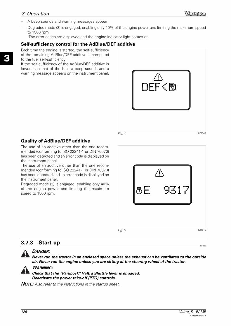
126 Valtra_S - EAME4315992M5 - 1
3
3. Operation– A beep sounds and warning messages appear
– Degraded mode (2) is engaged, enabling only 40% of the engine power and limiting the maximum speedto 1500 rpm. The error codes are displayed and the engine indicator light comes on.
Self-sufficiency control for the AdBlue/DEF additiveEach time the engine is started, the self-sufficiencyof the remaining AdBlue/DEF additive is comparedto the fuel self-sufficiency.If the self-sufficiency of the AdBlue/DEF additive islower than that of the fuel, a beep sounds and awarning message appears on the instrument panel.
Quality of AdBlue/DEF additiveThe use of an additive other than the one recom-mended (conforming to ISO 22241-1 or DIN 70070)has been detected and an error code is displayed onthe instrument panel.The use of an additive other than the one recom-mended (conforming to ISO 22241-1 or DIN 70070)has been detected and an error code is displayed onthe instrument panel.Degraded mode (2) is engaged, enabling only 40%of the engine power and limiting the maximumspeed to 1500 rpm.
3.7.3 Start-upT001286
DANGER:Never run the tractor in an enclosed space unless the exhaust can be ventilated to the outsideair. Never run the engine unless you are sitting at the steering wheel of the tractor.WARNING:Check that the "ParkLock" Valtra Shuttle lever is engaged.Deactivate the power take-off (PTO) controls.
NOTE: Also refer to the instructions in the startup sheet.
I021649Fig. 4.
I011615Fig. 5.

Valtra_S - EAME 1274315992M5 - 1
3
3. OperationProcedure1. Turn the ignition key to the ON position. The indicator lights on the instrument panel should light up.
NOTE: When the ignition is turned on, the TC and DC symbols display alternately on the instrumentscreen. The numbers underneath TC and DC correspond to the program versions installed and are foryour dealer's reference.
2. Depress and hold down the clutch pedal.
3. Turn the key to the preheating position and hold there for 2 seconds.
4. Start the engine and release the key.
5. Release the clutch pedal.
3.7.4 Start-up sheetT001285
3.7.5 Cold weather startingT001463
Engine block preheatingA 1000 W preheater and connection cable are pro-vided to assist cold weather starting. The preheateroperates with a mains power supply of 110 or 220V (depending on option) and in general heats the en-gine coolant in two hours.In extreme cold, it may be required to operate allnight.
WARNING:DO NOT test the heating element unless itis immersed in coolant. It is dangerous toconnect a heating element in the open air,as the heat released can cause injury andthe element could explode.
NOTE: An identical system is available as an optionfor preheating the transmission oil.
AdBlue/DEF additive preheating modeThe AdBlue/DEF additive is preheated by the tractor cooling system.When the tractor is started in cold conditions and the AdBlue/DEF additive is frozen in the tank, the tractor'selectronics switch the system to AdBlue/DEF preheating mode.Preheating mode remains engaged until the AdBlue/DEF additive is available for injection.– The engine idle speed is automatically set to 1200 rpm.
– A message appears on the instrument panel indicating AdBlue/DEF with the thermometer icon, and abeep sounds. This message reappears at regular intervals (approx. every seven minutes).
– Degraded mode (1) is engaged, enabling only 70% of the engine power and limiting the maximum speedto 1700 rpm.
NOTE: AdBlue/DEF additive freezing point: -11 °C
3.7.6 Information on the different modes of the E3 engine with AdBlue/DEF technology
T009027
Normal modeNo display.
I010441Fig. 6.
I022096Fig. 7.

128 Valtra_S - EAME4315992M5 - 1
3
3. Operation
Degraded mode 1When degraded mode 1 is activated, engine power is limited.In this case, only 70% of the engine torque is available and the engine speed is limited to 1700 rpm.
Degraded mode 1 is activated if:– The AdBlue/DEF additive has reached its freezing point of -11 °C
– During the defrosting phase, the temperature of the exhaust fumes exceeds the predefined limit
This mode protects the AdBlue/DEF injection system.But it also warns the operator so that he can use anti-freeze methods in extremely cold weather conditions.Consult your dealer for advice on these procedures.
Degraded mode 1 is deactivated when the AdBlue/DEF injection system has defrosted and the system hasreturned to normal operation.
Degraded mode 2When degraded mode 2 is activated, engine power is limited.In this case, only 40% of the engine torque is available and the engine speed is limited to 1500 rpm.
Degraded mode 2 is activated if:– The level of AdBlue/DEF has reached its minimum
NOTE: The shift from normal mode to degraded mode 2 takes about 1 hour. The reduction in the enginetorque and speed is 1%/min.
– A fault appears on the AdBlue/DEF injection systemNOTE: The shift from normal mode to degraded mode 2 takes about 2 minutes.
Degraded mode 2 is deactivated when the AdBlue/DEF tank is filled to more than 30% or when the fault iscorrected.
Final degraded modeFinal degraded mode limits the engine speed to 800 rpm.
This mode only appears if the tractor has continued to operate in degraded mode 2 for 4 hours.These hours may or may not be consecutive.
Final degraded mode is deactivated when the AdBlue/DEF tank is filled to more than 30%.
Operator informationThe operator is informed of the operating condition of the system on the instrument panel.– Display of the AdBlue/DEF level
– Display of a warning message on the Dash Control Center for the level being too low -
– Display of a warning message on the Dash Control Center for the temperature being too low see §3.7.5,page 127
– Display of fault codes on the Dash Control Center

Valtra_S - EAME 1294315992M5 - 1
3
3. Operation
Display on the Dash Control Center for the level being too low
3.7.7 Stopping the engineT000956
1. After stopping the tractor, allow the engine speed to return to idle.
2. Leave the engine running for several seconds at idle speed. It is necessary to allow the turbocharger toreduce speed.
3. IMPORTANT: Do not stop the engine suddenly when the engine is running at a high speed, because theturbocharger will continue running under its own momentum, but will no longer be lubricated. Slow theengine before stopping it.
Return the ignition key to the "Stop" position.
I022706Fig. 8.
1 2
AdBlue/DEF tank level 20% 15% 10% >0% 0%Hourmeter No No 0:00 1 hour 5 hours
Audible warning No 1 beep 2 beeps 3 beeps 3 beeps
Level display 2 bars 1 bar 1 bar (flash-ing)
No bar No bar
Display of symbol (2) on the Dash Control Center
Yes Yes Yes (flash-ing)
Yes (flash-ing)
Yes (flash-ing)
Message (1) on the Dash Control Cen-ter screen
"15%" "10%" "5% DER-ATING" (flashing)
"0% DER-ATED" (flashing)
"0% LOW IDLE" (flashing)
Erase the message on the Dash Con-trol Center
Yes, but reappears after 15 minutes
No No No No
Engine indicator light No No Yes if fault code
Yes if fault code
Yes if fault code
Fault code No No Yes Yes Yes
Degraded mode No No Degraded 2 Degraded 2 Final degraded
Injection of AdBlue/DEF Yes Yes Yes No No

130 Valtra_S - EAME4315992M5 - 1
3
3. Operation
3.7.8 Engine speedT001525
Hand throttleUsing the hand throttle allows you to vary the en-gine speed and to maintain a constant speed. To dothis, simply turn the button towards (+) or (-) to se-lect a speed . The button remains in this position tomaintain the selected speed.
Foot throttleThe foot throttle is used to control the engine speed as well as the forward speed. When the pedal is re-leased, the engine rpm returns to that preset by the hand throttle.
Choosing the correct gear ratioSelect the ratio which gives the optimum fuel consumption without overloading the engine and the transmis-sion. Bear in mind that soil conditions can vary within a matter of a few yards in the same field. In automaticmode, the system selects the ratio.
Storing engine speedsThis function allows the operator to have perma-nent access to two stabilised engine speeds. Thismeans he can activate stored engine speed Cruise1 when working (e.g. 2160 rpm) and he can acti-vate stored engine speed Cruise 2 when carryingout manoeuvres (e.g. 1350 rpm).
Preselecting the speeds fig. 10– Select the required engine speeds using the foot or hand throttle.
– Keep memory switch Cruise 1 or Cruise 2 pressed down for 1 to 2 seconds. The speed is storedand activated, and is highlighted on the Dash Control Center screen on the armrest (the symbol flasheson the screen when it is ready to be stored). The speeds can then be adjusted until the switch is released.
– Once speed Cruise 1 or Cruise 2 has been selected, you can adjust the value using the (+) and (-)buttons .fig. 9
I007069Fig. 9.
I010003Fig. 10.
1
2

Valtra_S - EAME 1314315992M5 - 1
3
3. Operation– To deactivate a stored engine speed, press switches Cruise 1 or 2, or press OFF.
– To reactivate the function, press the switch for 0.2 seconds to 1 second.
NOTE: When driving with a stored speed active (Cruise 1 or Cruise 2), pressing the brake pedals deactivatesthe stored speed if manual mode is active and if the forward speed is above 20 km/h.
3.7.9 Forward speed calibrationT002597
GeneralThis calibration allows improved precision of forward speed depending on:– the different tyre sizes available
– radar (if fitted)
Procedure1. Mark out a 100 m (depending on the unit of measurement selected) on a firm surface.
2. Start up the tractor, and then press and hold the display selector switch (A) for 15 seconds.NOTE: The daily hourmeter resets to 0 after 5 seconds.
3. "CAL" should appear on the screen fig. 11.
4. Drive the tractor forwards at normal workingspeed.NOTE: The tractor must always be moving be-fore starting out on the measured course; other-wise calibration will be incorrect.
5. Press the display selector switch when crossingthe starting line of the 100 m course.
6. "run" should appear on the screen fig. 12.
7. Press the display selector switch when crossingthe finish line of the course.
8. Press the display selector switch; the constantforward speed (theoretical) measured duringcalibration is displayed.
9. Press the display selector switch again; the ac-tual constant forward speed (radar) measuredduring calibration is displayed on tractors fittedwith radar.
10. Press the display selector switch a final time toreturn the instrument panel to normal operatingmode.
I007510Fig. 11.
KPH
A
I007511Fig. 12.
KPH

132 Valtra_S - EAME4315992M5 - 1
3
3. Operation
3.8 Transmission
3.8.1 GeneralT001287
The AVT transmission is first of all a forward and reverse continuous transmission.
The transmission electronic control system offers different driving modes:– Manual mode
– Semi-automatic mode
– Automatic mode
Power is transmitted hydrostatically or mechanically, or hydrostatically and mechanically.Slow forward travel = Power transmission is mainly hydrostatic/partially mechanical.Fast forward travel = Power transmission is partially hydrostatic/mainly mechanical.
3.8.2 Coupler clutch functionT001288
Clutch functionAlthough the transmission has no forward clutch or coupler, the tractor does have a clutch pedal. This pedalallows traction effort to be controlled (as with standard clutch slip). When an obstacle appears suddenly, thetractor can be stopped rapidly by pressing the clutch and brake pedals, just like a standard tractor.
Coupler functionTraction power is limited at low engine speed thanks to a proportional solenoid valve located on the trans-mission hydrostatic loop.In connection with engine speed, the coupler function is activated by modulating the pressure in the hydro-static system. The coupler function thus replaces the measured action of a clutch pedal.
Coupler function under tractionThe coupler function is activated when the enginespeed drops below 1250 rpm; the pressure in thehydrostatic loop decreases in proportion to the dropin engine speed. Like a coupler, the function limitsengine overload and avoids stalling. The couplerfunction can be activated or deactivated from theDash Control Center screen on the armrestsee §3.3.3, page 88.
NOTE: The coupler function is "ON" by default at start-up, whatever the status when the tractor stops.
3.8.3 Range shiftingT001289
The speed ranges can be selected according to the driving mode.
I010120Fig. 1.
21

Valtra_S - EAME 1334315992M5 - 1
3
3. Operation
There are two ranges :– Slow speed/tortoise range (A) for field use.
– High speed/hare range (B) for road use.
IMPORTANT: Always change to a slow rangewhen working in the field to avoid overheating thetransmission.
1. Depending on the maximum permitted speed in the different coun-tries.
Range shiftingChanges between slow and fast range are madewhen the tractor is moving, via the switch locatedon the right-hand console fig. 3.
Speed limit to be observed– Low-speed range to high-speed range: No re-
striction
– High-speed range to low-speed range: The for-ward speed must be less than 25 km/h.
I009973Fig. 2.
B
A
Slow/Tor-toise
Fast/Hare
Forward 0 km/h to 30 km/h
0 km/h to 50 km/h(1
Reverse 0 km/h to 16 km/h
0 km/h to 38 km/h
I010013Fig. 3.

134 Valtra_S - EAME4315992M5 - 1
3
3. Operation
3.8.4 Power ShuttleT001291
Principle of the Valtra Shuttle leverControl located to the left of the steering wheelThe Valtra Shuttle lever is used to change directionof travel (forward or reverse) without disengagingthe clutch.
DANGER:Use the clutch pedal for all manoeuvring(hitching implements etc.).
I010010Fig. 4.
1
2

Valtra_S - EAME 1354315992M5 - 1
3
3. Operation
Using the Valtra Shuttle lever(1) Electro-mechanical brake (ParkLock): The
ParkLock is engaged when the lever is lockedin the low position
(2) Unlocking the electro-mechanical brake (Park-Lock): Move the lever lock to the left and liftthe lever into the neutral position
(3) Neutral: In this position, the transmission is inthe neutral position and the ParkLock is disen-gaged
(4) Lift the lever lock and move it to the positionfor the required direction of travel.
(5) Forward travel: Move the lever to the for-wards position.Reverse travel: Move the lever to the reverseposition.
NOTE: When the tractor is in motion, each changeto the direction is made using this control withoutdisengaging the clutch.
DANGER:Before leaving the seat, it is essential toengage the parking brake (ParkLock).
Fast shiftingWhen changing the direction of travel, the tractor slows to a halt, then accelerates in the opposite direction.
I007070Fig. 5.
2
5
3 4
1
AV AR
Lever position Corresponding instrument panel screen
Neutral
Forward
Reverse
ParkLock engaged

136 Valtra_S - EAME4315992M5 - 1
3
3. Operation
3.8.5 Setting speedsT001784
It is possible to store two forward speeds (Cruise 1 and Cruise 2 ) in the manual, semi-auto and
auto modes for both directions of travel and to recallthese speeds with ease.
It is possible to set speeds Cruise 1 and Cruise 2 using switches (1) and (2) respectively.
The recorded speeds remain stored in the memoryafter the engine is switched off. Stored speedsCruise 1 and Cruise 2 can be deactivated bypressing buttons Cruise 1 and 2 again, or by press-ing the OFF button.
Conditions to be met for activation.– Clutch pedal not activated
– Forward speed >0,03 km/h .
Deactivation conditions.– Press the OFF switch
– Press the switch corresponding to the speed engaged
– Move the armrest lever or reverse shuttle
– Brakes activated
– Forward speed 0,03 km/h
I010826Fig. 6.
I007911Fig. 7.
2
OFF
CruiseCruise
OFF
1-
+
Cruise

Valtra_S - EAME 1374315992M5 - 1
3
3. Operation
3.8.6 manual — mode 2 modeT001788
This mode can be accessed via the screen on thearmrest.To activate manual — mode 2 mode, place the shut-tle control in ParkLock position and the transmissionlever in minimum position, then press button (1) un-der the shuttle control to open the menu. Tick box(2) and press button (1) again to return to the drivingscreen.The tractor forward speed depends on the positionof the armrest lever.The engine speed depends on the position of thethrottle pedal/hand throttle or the stored speedsCruise 1 and Cruise 2 .
NOTE: Automatic mode is still the default mode atengine start-up.
I014755
I010111
I010003Fig. 8.
2
2
3F/R
5
1
2
1
2

138 Valtra_S - EAME4315992M5 - 1
3
3. Operation
3.8.7 semi-automatic - mode 1 modeT001791
When the tractor is started, press the Cruise 1 orCruise 2 driving mode switch on the armrest.semi-automatic - mode 1 mode is displayed on thearmrest screen.Display (1) appears.
The maximum forward speed setting is set usingthe armrest lever fig. 10.– 0 km/h to 50 km/h (1 in high speed range (B,
hare).
– 0 km/h to 30 km/h in slow speed range (A, tor-toise).
1. maximum permissible speed according to the legislation in force in the different countries
I007911
I010826Fig. 9.
2
OFF
CruiseCruise
OFF
1-
+
Cruise
I010009Fig. 10.
22222222222

Valtra_S - EAME 1394315992M5 - 1
3
3. Operation
NOTE: When you are in semi-automatic - mode 1mode, the status of the transmission lever positionis displayed in zone A and the status of the pedal isdisplayed in zone B.Optimum drive is achieved when the two graphicalzones are at the same level.If this is not possible, move the transmission leverto approach the optimum state.
3.8.8 automatic modeT001793
In this mode, the electronic system manages theengine speed automatically to maintain the requiredforward speed in order to obtain the best level offuel consumption and improved comfort for theuser.However, if the user wishes, he can interrupt theengine speed using the throttle pedal/hand throttleor stored speeds Cruise 1 and Cruise 2 .automatic mode is available in manual — mode 2and semi-automatic - mode 1 mode.To access DTM mode, press the correspondingswitch fig. 12.
When automatic mode is engaged, display (1) disap-pears from the armrest screen and nothing is dis-played fig. 13.
By default, automatic mode manages the enginespeed between 800 and 2260 rpm.However, it is possible to impose an engine workrange, depending on the applications.
NOTE: Auto mode is the default mode on start-up.
I014788Fig. 11.
B
A
I007911Fig. 12.
2
OFF
CruiseCruise
OFF
1-
+
Cruise
I011590Fig. 13.

140 Valtra_S - EAME4315992M5 - 1
3
3. Operation
(A) Engine speed upper limit (selected with en-coder SV1)
(B) Engine speed lower limit (selected with en-coder SV2)
(C) Events to which limits will be applied (selectedby pressing OK); see ref. (1) to (7)
(1) Always(2) PTO active(3) Linkage in working position(4) Spool valve activated(5) PTO active and linkage in working position(6) PTO active and spool valve activated(7) Linkage in working position and spool valve ac-
tivated.
3.8.9 Tractor towingT001295
Towing instructionsWARNING:The following instructions must be adhered to when towing the tractor:If the engine is running:– Position the high/low speed range in neutral– Maximum towing speed 10 km/h (6 mile/h) – Max. towing distance. 8 km (5.0 mile) If the engine is shut down or out of hydraulic fluid:– Position the high/low speed range in neutral– As the gearbox is no longer lubricated when the engine is stopped, transport by trailer is
recommended– Tow the tractor no further than 50 m (164 ft) – DO NOT EXCEED A SPEED OF 5 km/h (3 mile/h)
CAUTION:When towing by hitching onto the front linkage, the pulling force must not exceed 18 t (20 USton).
I005769Fig. 14.
1
5 7
2 3 4
B
A
6

Valtra_S - EAME 1414315992M5 - 1
3
3. Operation
Towing procedure:1. Open the cover plate located on the cab floor
(right-hand side).
2. Remove the protective plate.
3. Place the limp home lever on the control unit.
4. Place the transmission in neutral (middle posi-tion (N))
5. Release the ParkLock brake. see "Releasing the ParkLock", page 144
I007376Fig. 15.
I007379Fig. 16.
I007384Fig. 17.

142 Valtra_S - EAME4315992M5 - 1
3
3. Operation
Limp home modeIf the transmission ratio control is not possible due to a breakdown, the tractor can be driven mechanicallyusing a limp home lever.Maximum speed in the high speed range is 34 km/h in forward travel and 25 km/h in reverse travel.Maximum speed in the low speed range is 15 km/h in forward travel and 11 km/h in reverse travel.
IMPORTANT: When the tractor is stopped, the speed range must be in neutral position (middle position) andthe brake must be engaged.
CAUTION:Once the engine has been started, the transmission is in full working order once a range (highor low) is engaged!The clutch pedal must be engaged with care because any transmission ratio can be preselected.
1. Stop the engine if it is running.
2. Release the ParkLock brake. see "Releasing the ParkLock", page 144
3. Open the cover plate located on the cab floor (right-hand side).
4. Remove the protective plate.
5. IMPORTANT: When shifting range, only usethe limp home lever supplied with the tractorbecause the coupling mechanism in the controlunit may be damaged (max. permissible torque:10 Nm).
Place the limp home lever on the range controland select the limp home range :– clockwise direction, low speed range (tor-
toise)
– anti-clockwise direction, high speed range(hare)
NOTE: It is important not to change rangewhen travelling in limp home mode
6. Declutch and start the tractor while holdingdown the red button (limp home button).
I007380Fig. 18.
I007385Fig. 19.

Valtra_S - EAME 1434315992M5 - 1
3
3. Operation
7. One of the two error codes is displayed on theleft-hand screen (Dash Control Center).
8. IMPORTANT: Keep the clutch pedal depressed.
Release the red button.
9. Place the limp home lever on the control ((1)).
10. Turn the lever in the required direction of travel:– anti-clockwise direction, forward travel
– clockwise, reverse travel
NOTE: Travel speed depends on the rotational value of the lever.
11. Carefully release the clutch pedal. The tractor moves in the previously set direction of travel and reachesthe selected ratio manually.To deactivate limp home mode, stop the tractor and switch off the ignition.
I007386Fig. 20.
ERRORCode TLPH
ERRORCode 4159
I007387Fig. 21.
1
0

144 Valtra_S - EAME4315992M5 - 1
3
3. Operation
Releasing the ParkLock1. DANGER:
The ParkLock parking brake will notoperate once its screws have beenloosened.Before loosening, chock the tractor toprevent the wheels from drifting.
Release the ParkLock parking brake by loosen-ing the right and left-hand brake pots (1) locatedon the top of the rear axle until the hard point isfelt (approximately 9 turns).
I007381Fig. 22.
1

Valtra_S - EAME 1454315992M5 - 1
3
3. Operation
3.9 Brakes
3.9.1 Brake pedalsT001388
WARNING:When driving on the road, the two brake pedals must be locked together. Only the foot throttleshould be used, and the hand throttle lever must be in the engine idle position. Check that thememorised A/B speed is not activated.
– Use the brake pedals locked together whentravelling on the road.The brake acts on the two rear wheels, the frontaxle (4-wheel drive only) and on the trailer brake.
– To lock the brake pedals together, push thelocking lever down.
– Use the brake pedals separately to apply thebrake to just one wheel at a time.Raise the locking lever. Use the brake pedal cor-responding to the side the brake is to be ap-plied.
3.9.2 Hydraulic trailer brakeT001296
WARNING:When using the trailer brake, it is recommended that the brake pedals are locked togethersee §3.9.1, page 145.
Trailer brake system available as an option.
If a trailer equipped with a hydraulic brake system ishitched to the tractor and connected, the trailerbrakes are activated as soon as the operatorpresses the tractor brake pedals.
Connection: Remove the plastic cover and connectthe trailer hose to the union located at the rear ofthe tractor fig. 2.
After disconnecting, refit the cover to prevent anypossible clogging and damage to the contact faces.
3.9.3 Pneumatic trailer brakeT001390
WARNING:Before activating the trailer brake, lock the brake pedals together see §3.9.1, page 145.
I004269Fig. 1.
I004844Fig. 2.

146 Valtra_S - EAME4315992M5 - 1
3
3. Operation
Identification of coupling heads:Black 5 bar to 0 bar, used in a single brake
line (as used on older trailers).Red 7 bar, brake assistance line, used for
dual braking (as used on new trailers).Yellow 0 bar to 7 bar, used in a double brake
line (as used on new trailers).
Pressure available depending on type of braking
Coupling the trailer to the tractor:Remove the cover ref. (1) and connect the head of the trailer connection hose ref. (2), turning it downwardsuntil it engages correctly.
IMPORTANT: Connect the yellow coupling head before the red one in order to avoid an excess of pressurein the system.
Uncoupling the trailer: Carry out the operation in reverse, turning the coupling head upwards and refitting the cover ref. (1) to pre-vent any possible clogging and damage to the contact faces.
IMPORTANT: Disconnect the red coupling head before the yellow one in order to avoid an excess of pres-sure in the system.
Driving the tractor/trailer assemblyWhen driving, it is advisable to activate the corre-sponding display on the Dash Control Center screen fig. 4 to monitor the display of pressure in the sys-tem (in bar) see §3.1.2, page 60, monitoring displaypanel.
WARNING:When starting, wait for the brake controlindicator light to switch off before start-ing to move. If the pressure drops below 4bar, trailer braking is no longer opera-tional, and the brake indicator light willlight up on the instrument panel fig. 4.Stop the tractor carefully and consult yourdealer.
IMPORTANT: The system must be protected byantifreeze at the start of each cold season (temper-atures below +5 °C ).See the chapter on maintenance.
I004829Fig. 3.
1
2
Brake pedals/hand brake not used
Full braking with brake pedal or hand brake lever
Colour of coupling heads
5 bar 0 Black
7 bar 7 bar Red
0 7 bar Yellow
I005781Fig. 4.
4

Valtra_S - EAME 1474315992M5 - 1
3
3. Operation
3.9.4 Emergency hand brakeT001297
If required, it is possible to use the emergency handbrake to slow down or immobilise the tractor.
Operation:1. If forward speed is above 2 km/h and the clutch
pedal is not pressed:Action on the emergency lever will slow thetractor down.
2. If forward speed is above 2 km/h and the clutchpedal is pressed:Action on the emergency lever will stop thetractor.
3. If forward speed is below 2 km/h :Action on the emergency lever will stop thetractor and place the transmission in neutral.
3.9.5 Electromechanically controlled brake on the steering column (ParkLock)
T001489
GeneralA control located on the left of the steering columnis used to engage and disengage the parking brake(ParkLock). ((1)) = engaged position; ((2)) = unlock-ing; ((3)) = disengaged position.
WARNING:To compensate for gravity and to preventthe tractor from moving when starting onan ascent or descent, the brake pedalsmust be applied before releasing the Park-Lock.WARNING:Position the ParkLock control in the en-gaged position (closed padlock symbol)before leaving the operator's seat andswitching off the engine.
I004991Fig. 5.
I010004Fig. 6.
2
1
3

148 Valtra_S - EAME4315992M5 - 1
3
3. Operation
Engaging the brake:1. Pull the lock and push the lever downwards
(closed padlock symbol). The brake is then en-gaged.NOTE: The indicator light ((P)) illuminates onthe instrument panel and the digital display indi-cates the symbol ((P)), representing the parkingposition.
2. The ParkLock engages automatically when theengine is stopped.
Disengaging the brake:IMPORTANT: For the ParkLock to disengage after engine start-up, the electronic control must record aswitch of the control from the engaged position to the disengaged position (closed padlock to the open pad-lock position) fig. 6.If this condition is not met, the ParkLock will remain engaged, even if the control is in the disengaged posi-tion.
1. Pull the lever lock.
2. Lift the lever to shift it to disengaged position.
Manually releasing the ParkLockIn the event of an electronic fault with the ParkLock, it is possible to manually release it in order to move thetractor.
WARNING:Please contact your dealer after manually releasing the ParkLock.
1. DANGER:The ParkLock parking brake will notoperate once its screws have beenloosened.Before loosening, chock the tractor toprevent the wheels from drifting.
Release the ParkLock parking brake by loosen-ing the right and left-hand brake pots (1) locatedon the top of the rear axle until the hard point isfelt (approximately 9 turns).
I004849Fig. 7.
I007381Fig. 8.
1

Valtra_S - EAME 1494315992M5 - 1
3
3. Operation
3.10 Steering
3.10.1 SteeringT001896
GeneralThe steering is hydrostatic, which means there is no mechanical connection between the steering wheel andthe wheels.
The tractor may be fitted with two types of steering: standard and automatic.1. Standard steering
This type of steering comprises a hydraulic steering pump. It is only the action of the steering wheel onthis that controls the flow of oil to activate the steering ram.
2. Electronic power-assisted steeringThis type of steering comprises a pump and an electrohydraulic steering valve. This type of valve offerstwo further options: quick steering (Quick Steering) and automatic steering (Auto-Guide).
CAUTION:When the engine stops, the booster pump no longer feeds the system.If the tractor is stopped, the hydrostatic steering cannot be manoeuvred.If the tractor is in motion, steering is enabled via a pump driven mechanically by the wheels ofthe tractor.However, no hydraulic system can operate efficiently unless:– it is correctly maintained and recommended fluids are used– the tightness of all unions, and the oil level, are regularly checked
WARNING:Do not use quick steering (Quick Steering) or Auto-Guide under normal driving conditions onthe open road.

150 Valtra_S - EAME4315992M5 - 1
3
3. Operation
Quick Steering accelerated steeringThis system enables the operator to reduce thenumber of steering wheel turns to operate thesteering quicker. It disengages automatically above20 Km/h.Switch (A) is used to activate Quick Steering accel-erated steering. An instrument panel display indi-cates that the function is engaged and also displaysthe steering reaction level (1 to 4 levels).The number of steering wheel turns is adjustable byoperating the Quick Steering potentiometer (B.)
Auto-GuideThe system electronically guides the tractor. Theoperator no longer has to make corrections to thesteering while the system is engaged. For more in-formation, please consult the Auto-GuideOperatorInstruction Book.
WARNING:Under no circumstances should the Auto-Guide power-assisted steering system beused to compensate for the operator'slack of concentration.CAUTION:When the system is engaged, the opera-tor must remain seated in the operatorseat at all times. He must remain vigilantand be ready to take back the controls ofhis tractor at any time as required.The system disengages automaticallyabove 30 Km/h
I006109
I010005Fig. 1.
A
B
I007091Fig. 2.

Valtra_S - EAME 1514315992M5 - 1
3
3. Operation
3.11 Front axle
3.11.1 Four-wheel drive front axleT001298
When the front axle is engaged, the front wheels are driven. This function is strongly advised for field workto keep wheel slip to a minimum.
The front axle may be used in accordance with the following operating modes:1. Manual mode
2. Automatic mode
3. US-specific mode
IMPORTANT: So as not to damage the tractor, it is essential to disengage the front axle prior to use on theopen road.
NOTE: At tractor start-up, the front axle is in automatic mode.
Special conditions– The front axle is engaged whenever the tractor is stationary and the front axle indicator light is "OFF".
– If both brake pedals are depressed, the front axle engages to provide 4-wheel braking, regardless of for-ward speed.
– The front axle will engage whenever the differential lock is engaged.
– The front axle engages when the emergency hand brake is applied.
– To move from automatic to manual mode, press the switch for 2 seconds.

152 Valtra_S - EAME4315992M5 - 1
3
3. Operation
Operation1. Manual mode:
To activate manual mode, press the switch (1)once and then press it again for 3 seconds.In manual mode, the 4-wheel drive front axle ispermanently engaged, irrespective of the for-ward speed.In low/tortoise range, the front axle engageswhen the wheel slip ratio is higher than 20%.When the wheel slip percentage drops back be-low 20%, the front axle remains engaged.
2. Automatic mode: To engage the front axle, press the switch (1)briefly. The corresponding indicator (2) lights upon the instrument panel and the front axle in au-tomatic mode symbol (A) appears on the digitaldisplay (3).Once a speed of 18 km/h is reached, the 4-wheel drive front axle is disengaged automati-cally.As soon as the speed drops below 17 km/h, it isautomatically re-engaged.In low/tortoise range, the front axle engageswhen the wheel slip ratio is higher than 20%.When the wheel slip percentage drops back be-low 20%, the front axle remains engaged.
3.11.2 Suspended front axleT001495
The suspended front axle (optional) is designed to improve the operator's comfort by enabling better shockabsorption during road use and also to increase the vehicle's stability at high speeds by improving contactwith the road surface.
The axle suspension can be activated and deactivated by the switch ((4)) located on the right-hand consoleinside the cab fig. 2.
I007080
I007082Fig. 1.
2
3
1

Valtra_S - EAME 1534315992M5 - 1
3
3. Operation
Operation– On starting the engine, the axle suspension re-
mains in the position (activated or deactivated)that it was in when the engine was stopped.
– The suspension is activated by pressing theswitch (4); the indicator light (5) lights up on theinstrument panel and the front axle is raised afew seconds later.
– To deactivate the suspension, press the switch(4); the indicator light (5) goes out.
– The front axle suspension is activated automat-ically when the speed exceeds 30 km/h.
Locking in positionThe suspended front axle can be locked in middle or low position. To do this:– Deactivate the front axle suspension
– Press the switch (4) five times fig. 2 to switch from low position to middle position.
– Press the switch (4) five times fig. 2 to switch from middle position to low position.
3.11.3 Permissible load on the front axleT001368
CAUTION:Version 40 km/hWhen the prescribed tyre types are observed, the maximum loaded weight of the tractor duringroad travel is:– 18000 kgThe maximum distribution (the total load on the front + rear must not exceed 18000 kg) of thisload between the axles may be:– 8000 kg for the front axle– 11500 kg for the rear axle
CAUTION:Version 50 km/hWhen the prescribed tyre types are observed, the maximum loaded weight of the tractor duringroad travel is:– 15000 kgThe maximum distribution (the total load on the front + rear must not exceed 15000 kg) of thisload between the axles may be:– 7000 kg for the front axle– 10500 kg for the rear axle
CAUTION:The tyre size for dual front wheels must never exceed 600/70R28 or have a radius of less than699 mm under load.
I007085Fig. 2.
4
5

154 Valtra_S - EAME4315992M5 - 1
3
3. Operation
The tractor track width ((V)) is measured from thecentre of one wheel to the centre of the other forsingle wheels.For dual wheels, it is measured from the centre ofthe right wheel assembly to the centre of the leftwheel assembly.
The load allowed on the front axle varies with the forward speed, track width adjustment and depends onwhether dual front wheels are used.The graph below shows the different adjustment options.
I011588Fig. 3.
v
v

Valtra_S - EAME 1554315992M5 - 1
3
3. OperationLoaded weight/front track width of tractor/maximum speed
Example 1The front track width of the tractor is set to 2264 mm
Example 2The loaded weight on the front of the tractor is 8000 kg
I011589Fig. 4.
1892 1992 2092 2192 2292 2392 2492 2592
74.5 78.5 82.4
A*
B*
C*
D*
E*
86.4 90.3 94.2 98.2 102.1
in
mm 4000
4500
5000
5500
6000
6500
7000
7500
8000
8500
9000
8818
9921
11023
12125
13228
14330
15432
16535
17637
18739
19841
kg
lb
*A : 9km/h=6 mile/h
*B : 20km/h=12 mile/h
*C : 30km/h=19 mile/h
*D : 40km/h=25 mile/h
*E : 50km/h=31 mile/h
1
2
Maximum forward speed Maximum loaded weight on the front50 km/h 6500 kg
40 km/h 7000 kg
30 km/h 7500 kg
20 km/h 8000 kg
9 km/h 8500 kg
Maximum forward speed Adjusting the front wheel track width50 km/h between the minimum and 1952 mm
40 km/h between 1952 mm and 2062 mm
30 km/h between 2062 mm and 2155 mm
20 km/h between 2155 mm and 2232 mm
9 km/h between 2232 mm and 2305 mm
lower than 9 km/h greater than 2305 mm

156 Valtra_S - EAME4315992M5 - 1
3
3. Operation
3.11.4 Using a scraperT003916
CAUTION:Specific precautions to take when using a scraper:– Limit the size of the rear tyres to 650/85R38 or equivalent that are approved for scraper ap-
plications.– Do not overload the tyres (liquid ballast is not permitted).– Do not lock the front or rear wheels together.– If possible, the tractor used with the scraper should have a fixed front axle or a suspended
front axle fixed in low position.– Scrapers are only authorised for use onS232/S262/S292/S322 models.

Valtra_S - EAME 1574315992M5 - 1
3
3. Operation
3.12 Differential lock
3.12.1 Differential lockT001292
DANGER:Not to be used on the road or when turning.Maximum speed 18 km/h
IMPORTANT: Do not engage the differential lock if a wheel is already spinning.
If wheel slip is anticipated, press the differentiallock switch.The differential lock indicator light ((1)) and the frontaxle indicator light ((2)) come on.The rear and front differentials are locked.The front axle is engaged if it was not already en-gaged beforehand.
Automatic functions of the differential lock:– Disengaging the differential lock does not disengage the front axle.
– When the tractor speed exceeds 18 km/h, the differential lock disengages automatically.It is not automatically re-engaged when the speed drops below 18 km/h.
– When the linkage is placed in the raised position or in transport position, the differential lock is automat-ically disengaged.It is then re-engaged when the linkage is in working position.
– Pressing one of the brake pedals (whether coupled or not) permanently disengages the differential lockunless it is temporarily disengaged by the linkage.
I007086Fig. 1.
1
2

158 Valtra_S - EAME4315992M5 - 1
3
3. Operation
3.13 Power take-off
3.13.1 Front power take-offT001301
This PTO is driven by the engine.
WARNING:Always disengage the PTO before attaching, detaching or adjusting an implement.Take all necessary safety precautions for any operation involving implements that are drivenby the PTO.DANGER:Never go beyond the universal joint shaft.Never use the universal joint shaft as a step.Never wear loose-fitting clothes.Remain at a safe distance from the universal joint shaft.
Table of specifications
Engaging the power take-offPress the selector switch as shown by (A).The PTO engaged indicator light ((C)) comes on andan engaged symbol appears on the digital display.
Disengaging the PTOTo stop the PTO, press the selector switch as shown by (B) .fig. 1
Front power take-off specificationsNumber of selections possible for front PTO 1000 rpm
Maximum permissible power Clockwise: 105 kW
Anti-clockwise: 158 kW
Maximum permissible torque Clockwise: 507 Nm
Anti-clockwise: 762 Nm
Rotational direction 1 clockwise or 1 anti-clockwise (viewed from the front of the tractor)
Engine speed for 1000 rpm PTO 2040 rpm
Ratio 2.04
Clutch type Hydraulics
Splined shaft type Fixed shaft with 6 splines, diameter 35 mm
Fixed shaft with 21 splines, diameter 35 mm
I007087Fig. 1.
C
AB

Valtra_S - EAME 1594315992M5 - 1
3
3. Operation
3.13.2 Rear power take-off (PTO)T001299
GeneralThe PTO can be engaged and disengaged independently of the transmission. The 540 rpm, ECO or 1000 rpmspeeds can be obtained by selecting the appropriate speed on the control plate located on the right-hand con-sole, which illuminates the corresponding indicator light on the instrument panel.
IMPORTANT: Engage the PTO at low engine speed to protect the clutch and transmission.
WARNING:Always disengage the PTO before attaching, detaching or adjusting an implement.Take all necessary safety precautions for any operation involving implements that are drivenby the PTO.DANGER:Never go beyond the universal joint shaft.Do not use the tractor or trailer drawbars as a step.Never use the universal joint shaft as a step.Never wear loose-fitting clothes.Remain at a safe distance from the universal joint shaft.
Selecting the power take-off speed1. To be able to engage the PTO, it is first neces-
sary to select the 540 rpm, ECO or 1000 rpmspeed using the corresponding buttons (1). Theindicator light illuminates on the instrumentpanel and the display appears on the right-handdigital display.The button (N) disengages the PTO if it is acti-vated.
I010011Fig. 2.
IMPORTANT: To avoid damaging imple-ments driven by the PTO, the engine speeds in the table below must be com-plied with.Selected PTO speed
Display Maximum engine speed
540 E rpm ECO 1600 rpm
1000 rpm 1000 rpm 2030 rpm
1000 E rpm
ECO 1600 rpm

160 Valtra_S - EAME4315992M5 - 1
3
3. Operation
Engaging PTO in manual mode:1. Press the selector switch (A). The PTO indicator
light (C) comes on and an engaged symbol ap-pears on the digital display.If no speed is pre-selected before pressing thePTO switch, the PTO will not operate.
2. To stop the PTO, press the selector switch ((B)).
Engaging PTO in automatic mode:This function stops the PTO temporarily and automatically when the linkage control is in Lift position (e.g.operation at headlands).
1. Press the PTO engagement control button ((A))once a PTO speed has been selected. The PTOengaged indicator light ((C)) is illuminated.
2. Move the linkage Lift/Lower switch to Lowerposition.
3. Press the automatic mode engage button (B).The AUTO symbol appears on the armrestscreen. As soon as the linkage is in Lift position,the PTO stops automatically and the indicatorlight ((C)) flashes.As soon as the linkage returns to Lower posi-tion, the PTO is automatically activated and theindicator light ((C)) stays on.The PTO stops operating permanently:– if the lowering control is not re-activated
within 90 seconds,
– or if the forward speed increases to over 25km/h ,
– or if the tractor is stopped (engine stopped).
NOTE: In automatic mode, if the tractor speedis 0 km/h, the PTO will remain stopped regard-less of the position of the linkage control.
3.13.3 Interchangeable 540 et1000 rpm PTO (flanged shaft)T001300
End-fittings that can be fitted:– 35 mm (1" 3/8) shaft with 21 splines
– 35 mm (1" 3/8) shaft with 6 splines
– 45 mm (1" 3/4) shaft with 20 splines
I007088Fig. 3.
C
A B
I007089Fig. 4.
A D
C
B

Valtra_S - EAME 1614315992M5 - 1
3
3. Operation
Changing the shaftIMPORTANT: When changing the spacer (2), the hexagon nuts (1) must be retightened to a torque of 69 Nm.
1. Stop the shaft end fitting ((3)) from rotating us-ing a M16X45 screw ((4)) fitted in the lower sec-tion.
2. Unscrew the nuts ((1)), remove the spacer ((2))and remove the shaft end fitting ((3))
3. Fit the new shaft end fitting in place and refit thespacer.
4. Refit the nuts in place.
5. Retighten the nuts to a torque of 69 Nm.
6. Remove the screw ((4)) to allow the shaft to ro-tate.
I004724
I004725
I004726Fig. 5.
1
3
2
3
4

162 Valtra_S - EAME4315992M5 - 1
3
3. Operation
3.13.4 Economy PTOT001303
The economy PTO is designed to drive lightweightimplements that do not require a large amount ofengine power.The 1000E rpm speed can be obtained at 1600 rpmengine speed; operating the engine at this lowerspeed saves fuel.To engage the economy PTO, press the 1000E but-ton. The indicator light illuminates on the instrumentpanel and the display appears on the right-hand dig-ital display.
3.13.5 PTO external controlsT001302
DANGER:Keep at a safe distance from the PTO drive shaft when operating the external controls.WARNING:The cab PTO must be engaged before it is possible to use the external controls see §3.13.2,page 159.
The external PTO controls are located on the fenders. They are used to stop the rotation and to restart.
(1) Stopping rotationThe PTO indicator light on the instrumentpanel flashes.
(2) RestartingTo re-engage the PTO, press the cab PTO con-trol selector (see §3.13.2, page 159) then theON/OFF switch on the fender (2) for a mini-mum of 6 seconds.
I007090Fig. 6.
I004751Fig. 7.
2 1

Valtra_S - EAME 1634315992M5 - 1
3
3. Operation
3.13.6 Power take-off electronic controlsT001402
NOTE: The PTO electronic controls are designed to protect the tractor and the implement.
– If the main PTO selector switch is on when starting the engine, the PTO is disengaged and the PTO in-dicator light on the instrument panel flashes. No error will be transmitted or displayed. To start the PTO,the PTO selector switch must be moved to the OFF position and then to the ON position.
– Protection against engine stalling: if PTO engagement causes the engine speed to drop more than 50%below the initial speed, the transmission control will turn off the solenoid valve and transmit an error mes-sage via the CAN bus and cause the PTO indicator light on the instrument panel to flash.

164 Valtra_S - EAME4315992M5 - 1
3
3. Operation
3.14 Linkage
3.14.1 Electronic controls for front and rear linkageT001304
The tractor may be fitted with two linkage systems:– A rear linkage, which is fully incorporated into the rear axle.
– A front linkage built into the front of the tractor.
The two linkages are electronically controlled and are equipped with their own hydraulic spool valve.
I010022Fig. 1.
E C D
I
G
H
K
J
A B
F
L
M
(A) Linkage lowering speed control knob(B) Linkage height control knob(C) Draft control knob(D) Rear linkage active transport control system
control switch(E) Linkage raised position switch (in parallel with
the switch on the fenders)(F) Linkage lowering position switch (in parallel
with the switch on the fenders)
(G) Not used(H) Suspended front axle switch(I) Front linkage single/double acting switch.(J) Hydraulics locking control(K) Rear linkage height/depth adjustment thumb
wheel(L) Work/stop/transport switch(M) Quick soil engagement switch

Valtra_S - EAME 1654315992M5 - 1
3
3. Operation
3.14.2 Rear linkage operationT001890
Lifting/lowering in the cabThe rear linkage is controlled by work/stop/transportswitch (L) located on the armrest.When the tractor engine is started, the rear linkageis locked.Use of the rear linkage requires deactivation of thesafety device. This is done by first toggling the lift-ing/lowering switch to the lowering position andthen toggling the switch to the lifting position.
Active suspensionThe rear linkage has an active suspension functionwhen the linkage is in the transport position.To engage this function, simply press the switch lo-cated on the linkage console ((D)).A red LED lights up in the centre of the switch toconfirm activation of the active suspension.
I010034Fig. 2.
L
I010104Fig. 3.
D

166 Valtra_S - EAME4315992M5 - 1
3
3. Operation
Adjusting the depthUsing the potentiometer ((J)) located on the right-hand side of the armrest, it is possible to adjust thedepth of the rear linkage for particularly accuratework conditions.
Two separate ranges are available– Adjustment range from min. 0 to max. 10
– Range in floating position:.
Adjusting the upper stopOn the linkage console, the potentiometer ((B)) isused to adjust the linkage raised position.
I007071Fig. 4.
J
I010039Fig. 5.
B

Valtra_S - EAME 1674315992M5 - 1
3
3. Operation
Adjusting the lowering speedThe potentiometer ((A)) is used to adjust the rearlinkage lowering speed.
It is used to select two separate modes:– Manual mode: Position of potentiometer, 1 to 8
– Automatic mode: Position of potentiometer,Auto
In automatic mode, lowering speed is governed bytwo parameters: the implement load on the linkageand the tractor forward speed.
Adjusting the intermix (draft/position control regulation)On the linkage console, the potentiometer ((C)) isused to adjust the regulation between the draft con-trol and the linkage position control.This function gives priority to the draft control overthe position control and vice versa, or combines thetwo, depending on the hitched implement and thetype of work to be carried out.
I010038Fig. 6.
A
I010037Fig. 7.
C

168 Valtra_S - EAME4315992M5 - 1
3
3. Operation
3.14.3 Rear linkage controls on the fendersT001891
The linkage lifting controls (1) and lowering controls(2) located on the rear left-hand and rear right-handfenders are used to activate the linkage.
NOTE: Use of the external controls requires activa-tion of the hydraulics using the switch (H) .fig. 2However, as soon as the external controls are used,the cab controls are locked.
Use of the external controls requires activation ofthe hydraulics using the switch (L) .fig. 2However, as soon as the external controls are used,the cab controls are locked.
3.14.4 Front linkageT001892
When the front linkage is used, the auxiliary hydrau-lics must be activated by pressing the switch (H, in-dicator light off).
WARNING:When the front linkage is not in use, it isessential to lock the hydraulic functions todeactivate them by pressing the switch(H). The indicator light comes on.For driving on roads, raise the tools to therequired height and lock the tractor's hy-draulic functions.
IMPORTANT: If one of the spool valve controls re-mains in the locked floating position before the en-gine is started, the hydraulic valve will not operateuntil this control is returned to neutral position.
I006189Fig. 8.
12
I010054Fig. 9.
H

Valtra_S - EAME 1694315992M5 - 1
3
3. Operation
Lifting/lowering in the cabThe front linkage is controlled via the joystick (2) lo-cated on the armrest.In order to activate it, the armrest knob (1) must bepositioned on the corresponding symbol .
Single or double acting controlIt is possible to use the front linkage in single or dou-ble acting mode via the switch (E).– Red LED lit: linkage in single acting mode.
– Red LED not lit: linkage in double acting mode.
Setting flow ratesTo adjust the flow rates in the lifting and lowering phases, refer to the appropriate section see §3.16.1,page 182.
I010067Fig. 10.
max
M1 M3
OFF
M2
1
2
I010086Fig. 11.
E

170 Valtra_S - EAME4315992M5 - 1
3
3. Operation
External controlsExternal controls (3) located on the front linkage al-low manoeuvring in order to hitch or unhitch imple-ments
NOTE: They can be unlocked from outside by pressing the lowering control button then the lifting controlbutton.
NOTE: Use of the external controls requires activation of the linkage using the switch (H, indicator light off) .fig. 9
Transport positionThe front linkage arms can be folded into transport position to minimise the space they take up fig. 14.
IMPORTANT: The front linkage arms must be free of implements and equipment in order for them to befolded into transport position.
Operation1. With the front linkage in working position.
Raise the linkage to maximum high position us-ing the external controls.
2. Remove the pins/cotter pins from the holes inthe arms and spacers (1) on the right- and left-hand side.
I008374Fig. 12.
3
I008736Fig. 13.
1

Valtra_S - EAME 1714315992M5 - 1
3
3. Operation
3. Using the external controls, raise the linkage tomaximum high position once more and fit thepins/cotter pins in the holes (2) of the arms andspacers.
4. The linkage in transport position.Remove the pins/cotter pins from the holes (2)in the arms and spacers on the right- and left-hand side.
5. Using the external controls, start lowering thelinkage.Lock the linkage in the working position by in-serting the pins/cotter pins in the holes (1) in thearms and spacers on the right- and left-handside.
I008737Fig. 14.
2
I008737Fig. 15.
2
I008736Fig. 16.
1

172 Valtra_S - EAME4315992M5 - 1
3
3. Operation
3.15 Linkage
3.15.1 Three-point linkageT001306
The tractor is supplied either with lower links fitted with category 3 ball joints or with optional category 3 orcategory 4 quick linkage hitches, depending on the country.
IMPORTANT: To prevent linkage damage when operating trailed attachments, care should be taken whenturning to prevent interference between the drawbar and the linkage.
3.15.2 Three-point linkage: Top linkT001308
(1) Link with category 3 hook(2) Link with category 4 hook(3) Link with category 3 ball joint(4) Hydraulic link with category 3 hook
The top link is fitted on ball joints.It should be adjusted according to the type of implement to be hitched.To adjust the length of the top link, turn the handle.
Connecting the hydraulic top linkThe two hoses of this link must be connected to a spool valve ((+) and (-) connectors).To adjust the length of the ram, operate the relevant spool valve using the control in the cab or on the fender.
3.15.3 Three-point linkage: lower linksT001307
(5) Links with category 3 hook:
(6) Links with category 4 hook:
(7) Link with removable category 3 ball joint
I006076Fig. 1.
1
2 3 4
I006077Fig. 2.
5
6
7

Valtra_S - EAME 1734315992M5 - 1
3
3. Operation
Links with category 3 hook (5)The hooks engage automatically in the ball joints which are fitted to the hitch pins.The normal balls are used for clevis-end hitches.The balls with guide cones are used for single pin linkages.In all cases, ensure that the hooks are correctly locked in place.The hooks can be unlocked for uncoupling from the cab, using specific cables (supplied as an accessory).
Links with category 4 hook (6)The hooks engage automatically in the ball joints which are fitted to the hitch pins.The normal balls are used for clevis-end hitches.The balls with guide cones are used for single pin linkages.In all cases, ensure that the hooks are correctly locked in place.The hooks can be unlocked for uncoupling from the cab, using specific cables (supplied as an accessory).
3.15.4 Three-point linkage: lift rodsT001309
(1) Floating position oblong hole(2) Pin(3) Plate in floating position(4) Plate in locked position
Adjustments1. Lift rod length:
pull upwards then turn the handles to reduce orincrease the length of the lift rods.
2. Lift rod/lower link floating position:Remove the pin and insert the plate vertically (3)in the oblong hole. This position allows verticaloscillation of the lift rod.
3. Lift rod/lower link fixed position:Remove the pin and insert the plate in the bot-tom of the slot sideways (4). This position pre-vents vertical oscillation of the lift rod.
IMPORTANT: Take care to always refit the pins cor-rectly.
3.15.5 Three-point linkage: stabilisersT001310
DescriptionStabilisers are used to restrict the lateral movement of the lower links.
I006079Fig. 3.
1
4
2
3

174 Valtra_S - EAME4315992M5 - 1
3
3. Operation
There are three models:(1) Automatic stabiliser:(2) Stabiliser with manual telescopic adjustment.(3) Stabiliser with shoes:
Automatic stabiliser adjustment procedure1. No adjustment required.
Adjustment procedure for stabilisers with manual telescopic adjustmentIMPORTANT: Do not shorten the lift rods or use the high travel drawbar position once the stabilisers havebeen adjusted to prevent them from being damaged.
1. Screw or unscrew the stabilisers to obtain the required side sway.
2. Start the engine.
3. Set the control panel "Lift/Lower" switch to "Lift" then to "Neutral". Press the selector switch in the "Lift"position until the lower links reach the highest position.
4. Turn off engine.
5. Unscrew the stabilisers until the lower links no longer have any side sway and are centralised.
6. Screw both stabilisers in 1 turn.
Adjustment procedure for stabilisers with shoes1. No adjustment is possible.
3.15.6 Multi-hole drawbarT001003
This is fitted to the lower links and is suitable forlight loads.
I006080Fig. 4.
1
3
2
I003491Fig. 5.

Valtra_S - EAME 1754315992M5 - 1
3
3. Operation
3.15.7 Swinging drawbarT001311
ISO standard
I026890
I006086Fig. 6.
3
Model available: Trailed weight:Category 3 drawbar 25000 kg

176 Valtra_S - EAME4315992M5 - 1
3
3. Operation
Category 2 drawbarCAUTION:40 km/h maximum speed authorised (incompliance with local regulations).
I016329Fig. 7.
AC
B
T
N
Category 2 drawbar
Length T Posi-tion -
PTO speed (rpm)
Number of splines
Vertical static load N
Min. 350 mm ± 10 mm A 540 or 1000 6 or 21 2300 kg
Standard 400 mm ± 10 mm B 540 or 1000 6 or 21 2000 kg
Max. 500 mm ± 10 mm C 540 or 1000 6 or 21 1600 kg
Ø of pin 30 mm
Width of draw-bar
80 mm
Thickness of drawbar
50 mm

Valtra_S - EAME 1774315992M5 - 1
3
3. Operation
Drawbar category 3
Swinging drawbar adjustmentBar with mechanically adjustable retaining pin1. Pull the locking/unlocking handle to release the
retaining pin from the bar.
2. Move the bar to extract or engage it and releasethe handle.
3. Continue to move the bar until the retaining pinautomatically engages in the hole.
4. WARNING:Ensure that the pin is correctly en-gaged before hitching an attachmentto the bar.
3.15.8 Stud or ball for a semi-mounted trailerT001921
This hitch is suitable for trailers transferring a heavy load to the tractor.
I016329Fig. 8.
AC
B
T
N
Drawbar cat-egory 3
Length T Posi-tion -
PTO speed (rpm)
Number of splines
Vertical static load N
Min. 400 mm ± 10 mm A 540 or 1000 6 or 21 2500 kg
Standard 500 mm ± 10 mm B 540 or 1000 6 or 21 2000 kg
Max. Not available C
Ø of pin 40 mm
Width of draw-bar
80 mm
Thickness of drawbar
60 mm
I019220Fig. 9.

178 Valtra_S - EAME4315992M5 - 1
3
3. Operation
Stud or ball on swinging drawbarNOTE: The illustrations provided feature a stud hitch. The operating principle for a ball hitch is identical.
This hitch hook is provided to accommodate two types of interchangeable bar:Swinging drawbar with stud: Maximum vertical load: 3000 kgSwinging drawbar with ball: Maximum vertical load: 3700 kg
1. The stud (A) is fixed to the swinging drawbar.The locking latch (C) must be lowered andlocked using the pin and its retaining pin (B)when a trailer is hitched.
2. To release the trailer, take out the pin and its re-taining pin ((B)) and lift up the latch ((C)).
Stud or ball on interchangeable clevisNOTE: The illustrations provided feature a stud hitch. The operating principle for a ball hitch is identical.
This hitch hook is provided to accommodate two types of interchangeable clevis:A clevis fitted with a hitch stud, maximum vertical load: 3000 kgA clevis fitted with a hitch ball, maximum vertical load: 3700 kg
I006099Fig. 10.
B
A
C
I006100Fig. 11.
C

Valtra_S - EAME 1794315992M5 - 1
3
3. Operation
Fitting1. Remove the retaining pin and retaining clip from
the pivot pin (A).
2. Pivot the pin to free up the space required to in-stall the clevis hitch.
3. Position the clevis by tilting it upwards and plac-ing it correctly in the right and left positioningguides.
4. To remove the clevis, lift by tilting it upwards torelease it from the guides and then pull towardsyou.
Linkage5. After hitching the equipment to be pulled, repo-
sition the pin.
6. Refit the retaining pin and retaining clip in theupper hole of the pivot pin.
Storage space7. After using or changing the clevis, store the part
not being used in the location provided.
I018810Fig. 12.
A
I018811Fig. 13.
I018813Fig. 14.

180 Valtra_S - EAME4315992M5 - 1
3
3. Operation
3.15.9 4-wheel trailer clevis hitchT001923
Automatic clevis, easy adjustment type
This clevis is intended to hitch trailers with fourwheels, which transfer little or no load onto thehitch.The clevis moves along a pin-adjusting scale to ad-just the height setting.
To adjust the clevis height, pull the handle ((A)) up-wards, then raise or lower the clevis to the requiredheight and release the handle.Lift the lever ((B)) to hitch the trailer.
3.15.10 Pick-up hitchT001312
GeneralDesigned to pull trailers which weigh heavily on thetractor and require frequent hitching and unhitching.Maximum vertical static load: 3000 kgMaximum trailed weight: 25200 kg
I006101Fig. 15.
B
A
I006102Fig. 16.

Valtra_S - EAME 1814315992M5 - 1
3
3. Operation
Lowering the hook1. Operate the electronic linkage by pressing the
selector switch ((1)).
2. Raise the linkage to its maximum with the but-ton ((A)), which unlocks the hook.
3. Pull the locking lever (3) fig. 18 to release thehook, then press the lowering switch (B) tolower the hook to the ground.
4. Press the switch (2) fig. 17 in the cab to retractthe hook ram as far as possible.
Lifting the hook1. The electronic linkage must be in operation.
2. Press the linkage lifting button (A) fig. 18 on the hitch control until the hook automatically locks in place.
3. Press the switch (2) fig. 17 in the cab to retract the hook ram, keeping the tractor stationary until thesafety lock engagement has been heard.
4. Lower the hook slightly until the weight of the trailer is supported by the hook.
I008033Fig. 17.
1
2
I006260Fig. 18.
A
B
3

182 Valtra_S - EAME4315992M5 - 1
3
3. Operation
3.16 Auxiliary hydraulics
3.16.1 GeneralT001314
VALTRA_S tractor series /VALTRA_S3 tractor series are available with the 200 l/min, 200 bar hydraulic sys-tem
The tractor may be fitted with a maximum of 9 spool valves, each delivering 100 l/min. It may be fitted withup to:– 6 spool valves at the rear
– 2 spool valves at the front
– 1 spool valve for the front linkage
In this case, the spool valve 1 and 2 controls are used for the rear couplers or the respective front couplers1 and 2, via the front/rear valve selection function.
The spool valve controls are grouped together on the armrest.
IMPORTANT: Do not operate the hydraulics unless the oil is warm. If necessary, allow the engine to run forseveral minutes before use.In the event of the hydraulics overheating, stop the tractor immediately.
3.16.2 Description and use of the couplersT001945
Depending on the configuration of the tractor, the tractor is fitted with rear couplers and front couplers.
These couplers provide a fast and sealed connection of the hoses for the implement being connected.
NOTE: Before connecting an implement to the tractor, check to ensure that the connections are clean.Also check that the oil inside the implement system is not contaminated to ensure that it does not contami-nate the tractor hydraulic functions.
Description of the rear couplersThe rear couplers are fitted with oil recovery units,which are located on the rear right-hand and rearleft-hand trumpet housings. It is recommended thatthese recovery units are checked and drained atregular intervals and under conditions that respectthe environment.
I006124Fig. 1.

Valtra_S - EAME 1834315992M5 - 1
3
3. Operation
A decompression control is fitted to all of the hy-draulic couplers, allowing them to be easily re-moved from the hoses of the connectedimplement.To decompress the couplers, turn the lever in the di-rection shown in fig. 2.
Depending on the configuration of the tractor, theremay be 4 to 6 pairs of couplers at the rear.(1) First pair(2) Second pair(3) Third pair(4) Fourth pair(5) Fifth pair(6) Sixth pair
NOTE: Each spool valve controls one pair of cou-plers.
Description of the front couplersThe tractor may be fitted with 2 pairs of front cou-plers.
I006127Fig. 2.
I006129Fig. 3.
1 6
2 5
3 4
I006126Fig. 4.

184 Valtra_S - EAME4315992M5 - 1
3
3. Operation
The front couplers are fitted with an oil recovery unitlocated behind the tractor front linkage.It is recommended that this recovery unit ischecked and drained at regular intervals and underconditions that respect the environment.
Description of the additional hydraulic unionsTractors are fitted with additional hydraulic unionsfor connecting accessories hitched to the tractor.(1) Direct outlet pressure ((P))(2) Tank return ((T))(3) LS line (Load Sensing) ((LS))(4) Drain return (D)
The drain return (4) allows an implement to be con-nected requiring no loss of load and no return resis-tance.The drain return (4) is connected directly to the aux-iliary hydraulic oil tank. It is used to receive low flowrates.The LS line allows you to have a load sensor on anexternal circuit. It is therefore possible to supply thisdirectly via the variable displacement pump withoutpassing through the spool valves.Thanks to the LS line connection (3), a potato har-vester-loader implement or a self-loading trailer, forexample, will have a flow rate adapted to demandand that can reach the maximum level supplied bythe pump.
Using the couplers and additional unionsThere are different connecting methods, depending on the implement to be connected to the tractor (seeexamples below).
I006125Fig. 5.
I006149Fig. 6.
P
T
BLS
D
162
354
1 4
2
3

Valtra_S - EAME 1854315992M5 - 1
3
3. Operation
Implements fitted with two hydraulic rams and a hydraulic motor at the rear of the tractor(1) Ram 1(2) Ram 2(3) Hydraulic motor(4) Tank return
NOTE: A spool valve can supply a flow rate of up to100 l/min. If necessary, a hydraulic motor may besupplied by two spool valves (total of the two com-bined flow rates) as shown in the diagram.In the above example, the hydraulic motor is pro-vided with a direct tank return.
Implements fitted with two hydraulic rams and a hydraulic motor with leakage return from the motor(1) Ram 1(2) Ram 2(3) Hydraulic motor(4) Tank return(5) Drain return
Implement fitted with the load sensor(1) Direct outlet pressure(2) Tank return(3) Connection to the LS load signal(4) Control unit on the implement (solenoid
valves)
I006225Fig. 7.
P
T
BLS
D
162
354
2
3
1
4
I006150Fig. 8.
P
T
B LS
D
2
1
5
4
3
I006153Fig. 9.
+ -
+ - P
T
BLS
D
162
354
1
3
4
2

186 Valtra_S - EAME4315992M5 - 1
3
3. Operation
Hydraulic motor and flow regulator(1) Direct outlet pressure(2) Tank return(3) Connection to the LS load signal(4) Valve and flow rate control valve
Implements fitted with two hydraulic rams at the front of the tractor(1) Ram 1(2) Ram 2
3.16.3 Auxiliary hydraulic system controlsT003754
(1) ON/OFF switch(2) Factory/recorded settings selector switch(3) Joystick functions selector(4) Joystick (rear spool valves 1 and 2, front spool
valves 1 and 2 and front linkage)(5) Control levers for spool valves 3, 4, 5 and 6
I006156Fig. 10.
P
T
BLS
D
162
354
1
3
4
2
I006173Fig. 11.
1
2
I010388Fig. 12.
max
M1 M3
OFF
M2
1
4
23
5

Valtra_S - EAME 1874315992M5 - 1
3
3. OperationThe properties of the spool valves for the auxiliary hydraulic system can be adjusted on the armrest screen.Adjustment features for the spool valve functions– Position locking: The operation of a spool valve can be locked in the ON position.
– Position locking timer control (programmer setting): The operation of a spool valve can be programmedto stop after a given time. Setting between 0 and 60 seconds.
– Floating position, depending on the port: The spool valve allows an implement to move freely, for exam-ple to follow the contours of the earth.
– Flow rate function: Spool valve flow rate setting.
3.16.4 Activating and deactivating the auxiliary hydraulic systemT003756
The auxiliary hydraulic system can be activated and deactivated.
(1) ON/OFF switch
WARNING:When the hydraulic functions are not inuse, they must be locked by pressing theswitch. The indicator light comes on.To unlock the hydraulic functions, pressthe switch. The indicator light goes out.WARNING:For driving on roads, raise the implementsto the required height and lock the trac-tor's hydraulic functions by pressing theswitch. The indicator light comes on.To unlock the hydraulic functions, pressthe switch. The indicator light goes out.
ActivationTo activate the auxiliary hydraulic system, press the ON/OFF switch.The indicator light on the switch comes on.
NOTE: Only keep the auxiliary hydraulic system activated when necessary.
DeactivationTo deactivate the auxiliary hydraulic system, press the ON/OFF switch again.The indicator light goes out.
IMPORTANT: The OFF function can be used to stop the auxiliary hydraulic system in an emergency.
DANGER:Always keep the auxiliary hydraulic system switched off under normal driving conditions toprevent unwanted movements in the hydraulic steering.
3.16.5 Selecting the joystick functionsT003757
Three different auxiliary hydraulic functions can be selected for the joystick: OFF, rear spool valves or frontspool valves and front linkage.
I010389Fig. 13.
1

188 Valtra_S - EAME4315992M5 - 1
3
3. Operation
(1) Joystick functions selector
– Select OFF to deactivate the joystick.
– Select the icon to control rear spool valves1R and 2R.
– Select the icon to control front spool valves1F and 2F (optional).
3.16.6 Using the joystickT003758
The rear spool valves (1R and 2R) or front spool valves (LF, 1F and 2F) can be controlled with the joystick.The function selector on the armrest is used to choose this option.Rear spool valve 1R or front spool valve LF can be controlled by moving the joystick forwards or backwards.By moving it sideways, rear spool valve 2R or front spool valve 2F can be controlled.
NOTE: To use front spool valve 1F, press the upper button on the joystick (fig. 15).
WARNING:Avoid unnecessarily activating the position-locking settings programmed for the spool valvesused by the joystick. There is a risk of position locking being activated.
IMPORTANT: Do not turn the joystick around its vertical axis, as this can cause damage to it and snap thecables.
1. To activate position locking or the floating posi-tion, push the joystick in the required direction,then to its limit position for less than one sec-ond.
2. Release the joystick.If the joystick is held in its limit position for morethan one second, the flow rate will start to fol-low the movements of the joystick.
3.16.7 Using the control levers for the rear spool valvesT003759
Rear spool valves 3, 4, 5 and 6 can be controlled using the control levers.
– Rear spool valves 3, 4, 5 and 6 are always active when the hydraulic system is activated via the on/offswitch.
– To use the lifting function (+), pull the lever towards you.
I010390Fig. 14.
OFF
1
I015216Fig. 15.

Valtra_S - EAME 1894315992M5 - 1
3
3. Operation– To use the lowering function (-), push the lever away from you.
– To activate position locking or the floating position:– Push the joystick in the required direction, then to the limit position.
Push the joystick harder to move it beyond the maximum flow rate position and lock it in the limitposition. The lever will stay in the limit position even if the programmer is not operating.
– Move the lever back to the central position manually.
3.16.8 Using predefined settingsT003760
User settings or one of the three factory settings can be selected.
(1) Selector switch for factory settings or re-corded settings
(2) Limit positions of factory settings(3) Memory locations
Selecting the settings– Selecting one of the three factory settings using the selector switch
Turn the switch to one of the three positions set in the factory.
– Selecting one of the three settings defined by the user with the selector switchTurn the switch to position M1, M2 or M3.
3.16.9 Description and use of the external controlsT001948
(1) Lifting control"+" outlet on the spool valve
(2) Lowering control"-" outlet on the spool valve
Spool valve no. 1 can be controlled via the externalcontrols located on the fenders by default.To allocate a different spool valve to the externalcontrols, refer to the manual
Before it is possible to use the external controls, un-lock the spool valve controls in the cab.
The spool valve control is active when the button ispressed.Using the external controls locks the spool valvecontrols in the cab.The external controls are inactive as soon as the for-ward speed exceeds 2 km/h. They are reactivatedas soon as the speed drops below 2 km/h.
I010391Fig. 16.
max
M1 M3M2
1
3
12
I006241Fig. 17.
21

190 Valtra_S - EAME4315992M5 - 1
3
3. Operation
3.16.10 Factory settings for the auxiliary hydraulic systemT003761
The factory settings are displayed on the screen when the auxiliary hydraulic system settings have been se-lected and one of the factory settings has been chosen with the selector switch.In the factory settings, the maximum flow rate of all the ports is limited to a fixed value. The driver cannotmodify any of the values in the factory settings.
Low flow rate(1) Selector switch in low flow rate position
Medium flow rate(1) Selector switch in medium flow rate position
I010395Fig. 18.
max
M1 M3M2
OFF
1
I010397Fig. 19.
max
M1 M3M2
OFF
1

Valtra_S - EAME 1914315992M5 - 1
3
3. Operation
Maximum flow rate(1) Selector switch in maximum flow rate position
3.16.11 Auxiliary hydraulic system settingsT003762
One of the three factory settings can be selected, or you can apply your own user settings for the auxiliaryhydraulic system.
1. Press ESC as many times as necessary to dis-play the main menu on the screen.
2. Press the navigation key to the right.The auxiliary hydraulic system settings are dis-played on the screen.
I010398Fig. 20.
max
M1 M3M2
OFF
1
I010405Fig. 21.
1

192 Valtra_S - EAME4315992M5 - 1
3
3. Operation
3. IMPORTANT: When the spool valves for theauxiliary hydraulic system are used with the U-Pilot program, this program follows the settingsof memory location M3.
Select memory location M1, M2 or M3 with theselector switch.The settings are added in the selected memorylocation.NOTE: The selected memory location is dis-played in the top left-hand corner of the screen.
4. Select the number of the spool valve to be ad-justed with the arrow keys.
5. Press OK to activate the spool valve.A line starts to flash underneath it.
6. Adjust the value using the arrow keys.– To increase the value, press the up arrow key.
– To decrease the value, press the down arrow key.
By pressing an arrow key, the following functions are displayed in succession:– Position locking time: 1 to 60 seconds
– Floating position (not in the + port)
– No active function = empty
NOTE: For safety reasons, position locking cannot be activated on spool valves 1F and 2F when usingthe front-end loader. If the tractor is fitted with a change-over switch for the front hitch/front-end loader,the position-locking settings of the spool valves in question are deactivated when the change-over switchis turned towards the front-end loader position.
7. Confirm or cancel the setting:– Press ESC to deactivate the active field and restore the previous value.
– Press OK to deactivate the active field and save the new value.
3.16.12 Spool valve functionsT003763
All standard and additional spool valves fulfil the same functions, except the on/off spool valves on the sidepanel, which are controlled by rocker switches.
I010406Fig. 22.
I010407Fig. 23.
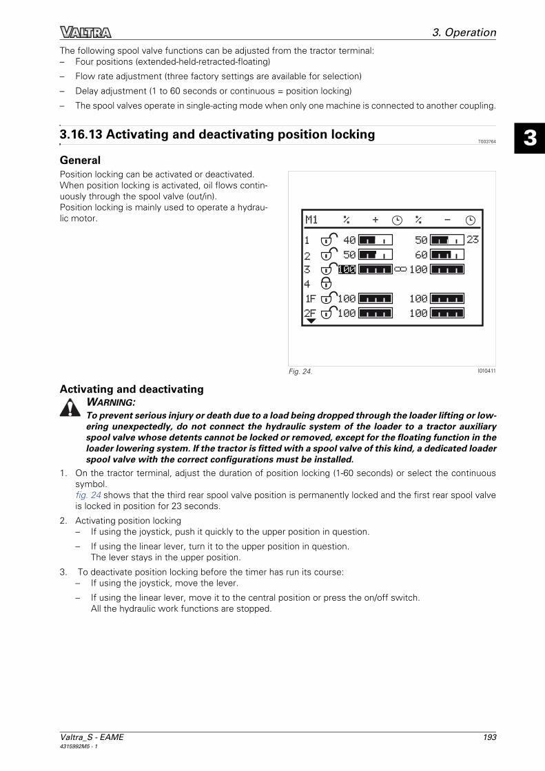
Valtra_S - EAME 1934315992M5 - 1
3
3. OperationThe following spool valve functions can be adjusted from the tractor terminal:– Four positions (extended-held-retracted-floating)
– Flow rate adjustment (three factory settings are available for selection)
– Delay adjustment (1 to 60 seconds or continuous = position locking)
– The spool valves operate in single-acting mode when only one machine is connected to another coupling.
3.16.13 Activating and deactivating position lockingT003764
GeneralPosition locking can be activated or deactivated.When position locking is activated, oil flows contin-uously through the spool valve (out/in).Position locking is mainly used to operate a hydrau-lic motor.
Activating and deactivatingWARNING:To prevent serious injury or death due to a load being dropped through the loader lifting or low-ering unexpectedly, do not connect the hydraulic system of the loader to a tractor auxiliaryspool valve whose detents cannot be locked or removed, except for the floating function in theloader lowering system. If the tractor is fitted with a spool valve of this kind, a dedicated loaderspool valve with the correct configurations must be installed.
1. On the tractor terminal, adjust the duration of position locking (1-60 seconds) or select the continuoussymbol.fig. 24 shows that the third rear spool valve position is permanently locked and the first rear spool valveis locked in position for 23 seconds.
2. Activating position locking– If using the joystick, push it quickly to the upper position in question.
– If using the linear lever, turn it to the upper position in question.The lever stays in the upper position.
3. To deactivate position locking before the timer has run its course:– If using the joystick, move the lever.
– If using the linear lever, move it to the central position or press the on/off switch.All the hydraulic work functions are stopped.
I010411Fig. 24.

194 Valtra_S - EAME4315992M5 - 1
3
3. Operation
3.16.14 Activating and deactivating the floating positionT003765
GeneralThe floating position can be activated and deacti-vated.In floating position, the oil can flow freely and theimplement follows the contours of the earth.
Activating and deactivating1. Set the required port and the floating position using the tractor terminal.
In fig. 25, the second rear valve is in floating position.
2. Activating floating position– If using the joystick, push it quickly to the upper position in question.
– If using the linear lever, turn it to the upper position in question.The lever stays in the upper position.
3. To deactivate the floating position before the timer has run its course:– If using the joystick, move the lever.
– If using the linear lever, move it to the central position or press the on/off switch.All the hydraulic work functions are stopped.
I010408Fig. 25.

Valtra_S - EAME 1954315992M5 - 1
3
3. Operation
3.17 Wheels and tyres
3.17.1 Wheel studsT001011
WARNING:Always tighten the wheel screws and nuts to the correct tightening torque.
Check the tightness of the wheels every day, until there is no longer a variation in the torque provided.After refitting a wheel, check the tightness of the wheel after the first two hours of operation and then everyday.
3.17.2 Adjusting the front wheel track widthT001317
4-wheel driveThe track widths available depend on the type of wheel rim and the tyre dimensions.
1. Fixed steel rims2 track widths can be obtained by reversing the rims:Minimum 1862 mm with a narrow tyre, e.g. 16.9.30 (420/85 R30).Maximum 1952 mm.
2. Adjustable steel rimsEight track widths can be obtained by changing the position of the rim in relation to the disc or by revers-ing the wheels.
When refitting, tighten the nuts progressively to the correct torques, following the recommendations in thetable of tightening torques (see §5.11.3, page 299).
I003509Fig. 1.
Position Rims with cast iron disc
24"
Wheel disc facing inwards (1-) 1543 mm
(2) 1661 mm
(3) 1747 mm
(4) 1865 mm
Wheel disc facing outwards (5) 1953 mm
(6) 2060 mm
(7) 2147 mm
(8) 2264 mm

196 Valtra_S - EAME4315992M5 - 1
3
3. Operation
NOTE: With narrow track widths and with certaintyre fittings, the wheels may touch the bonnetwhen turning at maximum lock. To prevent this, thehubs are fitted with threaded stops (1) fig. 2, whichcan be adjusted to limit the steering angle.
NOTE: The adjustment made in the factory complies with the modification requirements for tractor transport(see §3.17.3, page 196).
3.17.3 Adjusting the 4WD front axle stopsT001942
GeneralCheck and, if necessary, adjust the front axle stops each time the front track width is altered or following awheel and/or tyre change.
Oscillation stop: These stops cannot be adjusted.
Steering angle adjustment screw.(1) Front adjustment screw (2) Rear adjustment screw
I006121Fig. 2.
1
I011971Fig. 3.
I011956Fig. 4.
1
2

Valtra_S - EAME 1974315992M5 - 1
3
3. Operation
Steering angle adjustment procedureNOTE: The front axles are intended for a maximum steering angle of 55°.
1. Place the front of the tractor on a support so that the front axle can swing freely over the entire length ofits high and low travel.
2. Lock the wheels to the right and swing the front axle until it touches the right-hand oscillation stop -,move the axle over the entire length of its oscillation travel so that you can adjust the rear right-hand stopand obtain a minimum clearance of 40 mm between the tyre and nearest point of the immediate envi-ronment (e.g.: body/attachments).NOTE: Screw the stop diagonally opposite (front left-hand) before adjusting the rear right-hand stop toavoid mechanical stress that could prevent the adjustment dimension from being obtained.
3. Bring the front-left hand stop into contact with the front axle and tighten the locknut.
4. Repeat steps 2 and 3 for the opposite side (rear left-hand and front right-hand).
5. Swing the axle right then left to check that no settings have moved, then definitively tighten the stops.
Toe-in checkThe toe-in check requires specific tools; please consult your dealer if a problem occurs.
3.17.4 Adjusting the rear wheel track widthT001318
GeneralThe various track widths are obtained by changing the position of the rim in relation to the disc or by reversingthe wheels.When refitting, tighten the nuts progressively to the correct torques, following the recommendations in thetable of tightening torques (see §5.11.3, page 299).
NOTE: Ensure that a minimum gap of 40 mm remains between the tyres and the inside of the fenders.If the wheels are reversed they must be transferred to the opposite side of the tractor.
REAR TRACK WIDTH VALUES WITH STEEL RIM AND FIXED DISC
Rear axle
D = Rim offset 75 mm, E = Rim disc thickness 15 mm
Disc facing inwards (min/max) Disc facing outwards (min/max)
HA 260 1780 mm / 2112 mm 2106 mm / 2438 mm
D E

198 Valtra_S - EAME4315992M5 - 1
3
3. Operation
Adjustment of wheel position on the right-hand shaft (half-tapered hubs)1. Lift the rear of the tractor to lift the wheels off
the ground and carefully chock the tractor.
2. Loosen the screws (1) of the half-tapered hubsby approximately three turns.
3. Remove the 4 screws (2) and fit into the holes(3).
4. Tighten them alternately until the half-taperedhubs are free of the fixed hub.
5. Adjust the position of the wheel on the shaft ac-cording to the required track width.
6. Refit the screws (3) in their original holes andthen retighten the 6 screws, taking care to alignthe two half tapers.
7. Tighten the screws alternately to the correcttorque on each half taper (see §5.11.3,page 299).
REAR TRACK WIDTH VALUES WITH STEEL RIM AND CAST IRON DISC
Rear axle
D = Rim offset 75 mm, E = Rim disc thickness 15 mm
Disc facing inwards (min/max) Disc facing outwards (min/max)
HA 260A - 1566 mm / 1898 mm C - 2396 mm / 2728 mm
B - 1892 mm / 2224 mm D - 2070 mm / 2402 mm
D E
A B
C D
I006292Fig. 5.
1
3
3
3
3
2
1
2

Valtra_S - EAME 1994315992M5 - 1
3
3. Operation
3.17.5 TyresT001305
Agricultural tyre markings(1) Flange size in inches or millimetres(2) Type of manufacture (e.g. radial)(3) Nominal rim diameter in inches(4) Side/flange size ratio(5) Load capacity index per tyre 121 = 1450 kg;
153 = 3650 kg(6) Speed symbol A8 = 40 km/h(7) Reference pressure: 1,6 bar(8) Tubeless: Without inner tube
3.17.6 Dual wheelsT001014
In general, dual wheels should be used only for reducing soil compaction work (surface treatment work).
When selecting dual wheels that reuse the rims fitted as standard in the factory with a disc thickness lessthan 16 mm, you must obtain additional wheels with a thickness equal to or greater than 16 mm and fit themon the inside and then lock together with the standard rims on the outside.
IMPORTANT: Use a tube type dual wheel kit, which is fitted to the hubs and not to the rims (kit availablefrom your dealer).
The following four criteria must be taken into account when selecting the correct dual rear wheels:1. Soil conditions
2. Traction (narrow wheels)
3. Overall dimensions (2,50 m for road use)
4. Type of tyre
IMPORTANT: The wrong choice of dual wheels has a direct influence on the mechanical components andthe wheel rims of the tractor. Avoid using dual wheels for intensive pulling, even for short periods (haulingout a tractor stuck in the mud etc.).
NOTE: It is preferable to use wide tyres or low-pressure tyres instead of dual wheels.
I008034Fig. 6.
600/6
5
R38 153 A
8/150 B
121 A8 TUBELES
S
12.4
R
28
1
2
4
6
8
7
5
3

200 Valtra_S - EAME4315992M5 - 1
3
3. Operation
Use of dual wheels– Set the inner wheels to minimum track width
fig. 7.NOTE: The use of very wide tyres on dualwheels is not recommended.The most efficient dual wheels arrangementuses two tyres of the same specifications.
– When fitting dual wheels with tyres of differentwidths, the wider wheel must be fitted inside.
– When fitting dual wheels with tyres of the samewidth, the tyre which is more worn must be fit-ted on the outside.
– The tyre pressure of the outer tyres should beslightly reduced by approximately 0,2 bar.
– In clay soil, this distance should be increased inproportion to the tyre size.
IMPORTANT: Dual wheels do not double the loadcapacity of the tractor.
3.17.7 Tyre pressuresT001319
Pressure under loadCheck the tyre pressures every 100 hours. Tyre pressures vary according to make, load and speed as wellas to the type of work being carried out. Refer to the inflation tables issued by the tyre manufacturers.
3.17.8 Liquid ballastingT001016
Steering and braking performance can be considerably affected by attaching implements. To maintain the re-quired ground contact pressure, ensure that the tractor is ballasted correctly. Advice is available from yourDealer.
Tyres with inner tubeThese tyres can be inflated with water mixed with calcium chloride. Refer to your dealer.
WARNING:When preparing a calcium chloride solution for ballasting the tractor tyres with water, NEVERpour the water onto the calcium chloride as this may produce chlorine, which is a toxic and ex-plosive gas. This can be avoided by slowly adding calcium chloride flakes to the water and stir-ring until they are dissolved.
I003510Fig. 7.

Valtra_S - EAME 2014315992M5 - 1
3
3. Operation
Tyres without inner tubes (tubeless):Use a monoethylene glycol-based liquid containing corrosion inhibiting agents other than nitrites (Na No2).Example: Agrilest, Castrol, Lestagel, Igol, etc.

202 Valtra_S - EAME4315992M5 - 1
3
3. Operation

Valtra_S - EAME 2034315992M5 - 1
4
Table of contents
4. Maintenance
4.1 Service guide. . . . . . . . . . . . . . . . . . . . . . . . . . . . . . . . . . . . . . . . . . . . . . . . . . . . . . . . . . . . . . 2054.1.1 Maintenance . . . . . . . . . . . . . . . . . . . . . . . . . . . . . . . . . . . . . . . . . . . . . . . . . . . . . . . . 2054.1.2 Lubrication chart. . . . . . . . . . . . . . . . . . . . . . . . . . . . . . . . . . . . . . . . . . . . . . . . . . . . . 207
4.2 Cab . . . . . . . . . . . . . . . . . . . . . . . . . . . . . . . . . . . . . . . . . . . . . . . . . . . . . . . . . . . . . . . . . . . . . . . 2094.2.1 Air conditioning system: condenser . . . . . . . . . . . . . . . . . . . . . . . . . . . . . . . . . . . . . 2094.2.2 Air conditioning system: checking the air conditioning system. . . . . . . . . . . . . . . 2094.2.3 Air conditioning system: dryer . . . . . . . . . . . . . . . . . . . . . . . . . . . . . . . . . . . . . . . . . 2104.2.4 Cab air filters . . . . . . . . . . . . . . . . . . . . . . . . . . . . . . . . . . . . . . . . . . . . . . . . . . . . . . . . 2104.2.5 Cab attachment. . . . . . . . . . . . . . . . . . . . . . . . . . . . . . . . . . . . . . . . . . . . . . . . . . . . . . 2114.2.6 Windscreen washer . . . . . . . . . . . . . . . . . . . . . . . . . . . . . . . . . . . . . . . . . . . . . . . . . . 211
4.3 Engine . . . . . . . . . . . . . . . . . . . . . . . . . . . . . . . . . . . . . . . . . . . . . . . . . . . . . . . . . . . . . . . . . . . . 2124.3.1 Recommended products . . . . . . . . . . . . . . . . . . . . . . . . . . . . . . . . . . . . . . . . . . . . . . 2124.3.2 Fuel . . . . . . . . . . . . . . . . . . . . . . . . . . . . . . . . . . . . . . . . . . . . . . . . . . . . . . . . . . . . . . . 2124.3.3 Biodiesel fuel . . . . . . . . . . . . . . . . . . . . . . . . . . . . . . . . . . . . . . . . . . . . . . . . . . . . . . . 2144.3.4 AdBlue/DEF additive: . . . . . . . . . . . . . . . . . . . . . . . . . . . . . . . . . . . . . . . . . . . . . . . . . 2154.3.5 6-cylinder Sisu engine . . . . . . . . . . . . . . . . . . . . . . . . . . . . . . . . . . . . . . . . . . . . . . . . 2164.3.6 Engine oil level check . . . . . . . . . . . . . . . . . . . . . . . . . . . . . . . . . . . . . . . . . . . . . . . . . 2174.3.7 Draining the engine oil. . . . . . . . . . . . . . . . . . . . . . . . . . . . . . . . . . . . . . . . . . . . . . . . 2174.3.8 Replacing the engine oil filter . . . . . . . . . . . . . . . . . . . . . . . . . . . . . . . . . . . . . . . . . . 2184.3.9 Replacing the centrifugal oil filter (models equipped with Internal EGR) . . . . . . . 2184.3.10 Replacing the urea filter (models equipped with E3 engine with AdBlue/DEF
technology) . . . . . . . . . . . . . . . . . . . . . . . . . . . . . . . . . . . . . . . . . . . . . . . . . . . . . . . . . 2184.3.11 Fuel system: fuel prefilter . . . . . . . . . . . . . . . . . . . . . . . . . . . . . . . . . . . . . . . . . . . . . 2204.3.12 Fuel system: fuel filter . . . . . . . . . . . . . . . . . . . . . . . . . . . . . . . . . . . . . . . . . . . . . . . . 2214.3.13 Water filter . . . . . . . . . . . . . . . . . . . . . . . . . . . . . . . . . . . . . . . . . . . . . . . . . . . . . . . . . 2214.3.14 Fuel system: bleeding . . . . . . . . . . . . . . . . . . . . . . . . . . . . . . . . . . . . . . . . . . . . . . . . 2234.3.15 Fuel system: injection pump, regulator and injectors . . . . . . . . . . . . . . . . . . . . . . . 2234.3.16 Fuel system: Injection (E3 engine with AdBlue/DEF technology) (optional) . . . . . 2234.3.17 Air filter . . . . . . . . . . . . . . . . . . . . . . . . . . . . . . . . . . . . . . . . . . . . . . . . . . . . . . . . . . . . 2234.3.18 Cooling system . . . . . . . . . . . . . . . . . . . . . . . . . . . . . . . . . . . . . . . . . . . . . . . . . . . . . . 2254.3.19 Checking the fan/alternator/air conditioning Poly-V belt . . . . . . . . . . . . . . . . . . . . 2264.3.20 Replacing the fan/alternator/air conditioning belts . . . . . . . . . . . . . . . . . . . . . . . . . 227
4.4 Transmission . . . . . . . . . . . . . . . . . . . . . . . . . . . . . . . . . . . . . . . . . . . . . . . . . . . . . . . . . . . . . . 2294.4.1 Recommended products . . . . . . . . . . . . . . . . . . . . . . . . . . . . . . . . . . . . . . . . . . . . . . 2294.4.2 Checking the transmission oil level . . . . . . . . . . . . . . . . . . . . . . . . . . . . . . . . . . . . . 2294.4.3 Draining the transmission oil . . . . . . . . . . . . . . . . . . . . . . . . . . . . . . . . . . . . . . . . . . 2294.4.4 Checking the level of the rear final drive units . . . . . . . . . . . . . . . . . . . . . . . . . . . . 2304.4.5 Draining the rear final drives . . . . . . . . . . . . . . . . . . . . . . . . . . . . . . . . . . . . . . . . . . . 2314.4.6 Filtering the transmission hydraulic system . . . . . . . . . . . . . . . . . . . . . . . . . . . . . . 2314.4.7 Checking and cleaning the transmission oil cooler . . . . . . . . . . . . . . . . . . . . . . . . . 2334.4.8 Lubricating the rear PTO shaft . . . . . . . . . . . . . . . . . . . . . . . . . . . . . . . . . . . . . . . . . 2344.4.9 Clutch. . . . . . . . . . . . . . . . . . . . . . . . . . . . . . . . . . . . . . . . . . . . . . . . . . . . . . . . . . . . . . 234
4.5 Brakes . . . . . . . . . . . . . . . . . . . . . . . . . . . . . . . . . . . . . . . . . . . . . . . . . . . . . . . . . . . . . . . . . . . . 2354.5.1 Bleeding the brake system . . . . . . . . . . . . . . . . . . . . . . . . . . . . . . . . . . . . . . . . . . . . 235
4.6 Front power take-off . . . . . . . . . . . . . . . . . . . . . . . . . . . . . . . . . . . . . . . . . . . . . . . . . . . . . . . 2364.6.1 Recommended products . . . . . . . . . . . . . . . . . . . . . . . . . . . . . . . . . . . . . . . . . . . . . . 2364.6.2 Draining oil . . . . . . . . . . . . . . . . . . . . . . . . . . . . . . . . . . . . . . . . . . . . . . . . . . . . . . . . . 2364.6.3 Lubricating the front PTO shaft . . . . . . . . . . . . . . . . . . . . . . . . . . . . . . . . . . . . . . . . . 236
4.7 Front axle and steering. . . . . . . . . . . . . . . . . . . . . . . . . . . . . . . . . . . . . . . . . . . . . . . . . . . . . 2374.7.1 Recommended products . . . . . . . . . . . . . . . . . . . . . . . . . . . . . . . . . . . . . . . . . . . . . . 2374.7.2 Four-wheel drive front axle: Checking the front axle beam oil level . . . . . . . . . . . 2374.7.3 Four-wheel drive front axle: draining the oil from the front axle beam . . . . . . . . 2374.7.4 Four-wheel drive front axle: checking the oil level in the final drives . . . . . . . . . . 238

204 Valtra_S - EAME4315992M5 - 1
4
Table of contents4.7.5 Four-wheel drive front axle: draining the oil in the final drives . . . . . . . . . . . . . . . 2384.7.6 Four-wheel drive front axle: lubrication . . . . . . . . . . . . . . . . . . . . . . . . . . . . . . . . . . 239
4.8 Linkage . . . . . . . . . . . . . . . . . . . . . . . . . . . . . . . . . . . . . . . . . . . . . . . . . . . . . . . . . . . . . . . . . . . 2414.8.1 Recommended products . . . . . . . . . . . . . . . . . . . . . . . . . . . . . . . . . . . . . . . . . . . . . . 2414.8.2 Check the linkage shaft oil level . . . . . . . . . . . . . . . . . . . . . . . . . . . . . . . . . . . . . . . . 241
4.9 Linkage . . . . . . . . . . . . . . . . . . . . . . . . . . . . . . . . . . . . . . . . . . . . . . . . . . . . . . . . . . . . . . . . . . . 2424.9.1 Recommended products . . . . . . . . . . . . . . . . . . . . . . . . . . . . . . . . . . . . . . . . . . . . . . 2424.9.2 Three-point linkage: lubrication . . . . . . . . . . . . . . . . . . . . . . . . . . . . . . . . . . . . . . . . 2424.9.3 Auto-hitch: lubrication . . . . . . . . . . . . . . . . . . . . . . . . . . . . . . . . . . . . . . . . . . . . . . . . 2424.9.4 Front linkage: lubrication . . . . . . . . . . . . . . . . . . . . . . . . . . . . . . . . . . . . . . . . . . . . . . 2434.9.5 Ball hitch: lubrication . . . . . . . . . . . . . . . . . . . . . . . . . . . . . . . . . . . . . . . . . . . . . . . . . 245
4.10 Auxiliary hydraulics. . . . . . . . . . . . . . . . . . . . . . . . . . . . . . . . . . . . . . . . . . . . . . . . . . . . . . . . 2474.10.1 Recommended products . . . . . . . . . . . . . . . . . . . . . . . . . . . . . . . . . . . . . . . . . . . . . . 2474.10.2 Checking the auxiliary hydraulic system oil level . . . . . . . . . . . . . . . . . . . . . . . . . . 2474.10.3 Draining the auxiliary hydraulic system . . . . . . . . . . . . . . . . . . . . . . . . . . . . . . . . . . 2484.10.4 Filtering the auxiliary hydraulic system . . . . . . . . . . . . . . . . . . . . . . . . . . . . . . . . . . 2484.10.5 Checking and cleaning the auxiliary hydraulic system oil cooler . . . . . . . . . . . . . 249
4.11 Electrical equipment . . . . . . . . . . . . . . . . . . . . . . . . . . . . . . . . . . . . . . . . . . . . . . . . . . . . . . . 2514.11.1 Batteries. . . . . . . . . . . . . . . . . . . . . . . . . . . . . . . . . . . . . . . . . . . . . . . . . . . . . . . . . . . . 2514.11.2 Alternator . . . . . . . . . . . . . . . . . . . . . . . . . . . . . . . . . . . . . . . . . . . . . . . . . . . . . . . . . . 2514.11.3 Power socket (ISO) . . . . . . . . . . . . . . . . . . . . . . . . . . . . . . . . . . . . . . . . . . . . . . . . . . . 2514.11.4 Adjusting the headlights . . . . . . . . . . . . . . . . . . . . . . . . . . . . . . . . . . . . . . . . . . . . . . 2524.11.5 Fuse box description . . . . . . . . . . . . . . . . . . . . . . . . . . . . . . . . . . . . . . . . . . . . . . . . . 2524.11.6 Alternator protection . . . . . . . . . . . . . . . . . . . . . . . . . . . . . . . . . . . . . . . . . . . . . . . . . 2594.11.7 Battery isolator . . . . . . . . . . . . . . . . . . . . . . . . . . . . . . . . . . . . . . . . . . . . . . . . . . . . . . 260
4.12 Pressure washing . . . . . . . . . . . . . . . . . . . . . . . . . . . . . . . . . . . . . . . . . . . . . . . . . . . . . . . . . . 2614.12.1 Pressure washing . . . . . . . . . . . . . . . . . . . . . . . . . . . . . . . . . . . . . . . . . . . . . . . . . . . . 261
4.13 Storing your tractor . . . . . . . . . . . . . . . . . . . . . . . . . . . . . . . . . . . . . . . . . . . . . . . . . . . . . . . 2624.13.1 Storing your tractor . . . . . . . . . . . . . . . . . . . . . . . . . . . . . . . . . . . . . . . . . . . . . . . . . . 2624.13.2 Storing AdBlue/DEF additive . . . . . . . . . . . . . . . . . . . . . . . . . . . . . . . . . . . . . . . . . . . 262
4.14 Faults and solutions . . . . . . . . . . . . . . . . . . . . . . . . . . . . . . . . . . . . . . . . . . . . . . . . . . . . . . . 2634.14.1 General table of faults . . . . . . . . . . . . . . . . . . . . . . . . . . . . . . . . . . . . . . . . . . . . . . . . 2634.14.2 Indicator light panel . . . . . . . . . . . . . . . . . . . . . . . . . . . . . . . . . . . . . . . . . . . . . . . . . . 2654.14.3 Indication of faults . . . . . . . . . . . . . . . . . . . . . . . . . . . . . . . . . . . . . . . . . . . . . . . . . . . 2694.14.4 instrument panel error codes . . . . . . . . . . . . . . . . . . . . . . . . . . . . . . . . . . . . . . . . . . 2714.14.5 Engine error codes . . . . . . . . . . . . . . . . . . . . . . . . . . . . . . . . . . . . . . . . . . . . . . . . . . . 2734.14.6 Error codes for E3 engine with AdBlue/DEF technology . . . . . . . . . . . . . . . . . . . . . 2754.14.7 Transmission error codes . . . . . . . . . . . . . . . . . . . . . . . . . . . . . . . . . . . . . . . . . . . . . 2764.14.8 Four-wheel drive front axle error codes . . . . . . . . . . . . . . . . . . . . . . . . . . . . . . . . . . 2774.14.9 PTO error codes . . . . . . . . . . . . . . . . . . . . . . . . . . . . . . . . . . . . . . . . . . . . . . . . . . . . . 2784.14.10 Hydraulic valve error codes . . . . . . . . . . . . . . . . . . . . . . . . . . . . . . . . . . . . . . . . . . . . 2784.14.11 Multifunction armrest error codes . . . . . . . . . . . . . . . . . . . . . . . . . . . . . . . . . . . . . . 2794.14.12 Headlights module error codes . . . . . . . . . . . . . . . . . . . . . . . . . . . . . . . . . . . . . . . . . 280

Valtra_S - EAME 2054315992M5 - 1
4
4. Maintenance
4.1 Service guide
4.1.1 MaintenanceT001320
Interpretation of the table:Initial 50-hour service marked °°: this maintenance instruction is to be carried out by your dealer as part ofthe 50-hour service defined in the Service Record Book.Intervals marked °: regular service intervals marked ° are to be carried out at regular intervals (for example:every day, every 50 hours, every 400 hours etc.).Intervals marked *: For variable intervals marked *, refer to the relevant chapter in this book.
Service guide 50 hrs
400 hrs
800 hrs
1200 hrs
2000 hrs
Every day
GeneralLubricate all points as specified in the Operator Instruction Book*.
°° *
Check the accumulator pressures. Once a year
Check that all guards are in place and that the safety decals are secure and legible.
°° °
Road test the tractor to check all instruments and systems for correct operation.
°° °
Road test the tractor to check the steering and brakes for correct operation.
°° °
After the road test, check for any leaks of oil, fuel or coolant.
°° °
Enquire if the operator has any operational difficul-ties and correct or demonstrate the solution as necessary.
°° °
Complete the owner's Service Record Book. °° °
CabCheck and top up the windscreen washer bottle. °
Clean the cab air filter element. °° °
Change the cab filter elements. °
Check the air conditioning system for correct oper-ation.
°° °
Check the cab tightening torque. °° °
Replace the cab dampers. 4800 hours
EngineCheck the engine oil level. °
Change the engine oil(2. °
Change the engine oil filter(2. °
Change the centrifugal oil filter (Internal EGR engines)(2.
°
Change the fuel prefilter(2. °° °
Change the fuel filter(2. °° °
Bleed the water from the fuel prefilter *
Change the filter element of the fuel/water separa-tion centrifugal prefilter(2.
°° °
Drain any water from the fuel tank °

206 Valtra_S - EAME4315992M5 - 1
4
4. Maintenance
Adjust/set the valve clearances. ° (the 1st
time)
°
Check the operation of the injectors. °
Change the main urea filter (E3 engine with AdBlue/DEF technology).
4000 hours or every 2 years
Change the urea inlet prefilter (E3 engine with AdBlue/DEF technology)
8000 hours or every 2 years
Change the filter inside the metering module E3 engine with AdBlue/DEF technology
If blocked by impurities
Check/clean the dry air filter elements. °
Change the dry air filter elements. °
Check the radiator coolant level. °
Drain, flush and refill the radiator with coolant. °
Check/clean the radiator/cooler fins. °
Check/clean the air conditioning condenser. °
Change the air conditioning dryer. °
Check the tension and condition of the alterna-tor/fan/air conditioning compressor belts.
°° °
Change the alternator/fan/air conditioning compres-sor belts.
°
Transmission and Auxiliary hydraulicsCheck the transmission oil level. °
Check the auxiliary hydraulics oil level °
Change the rear axle/transmission oil. °(1
Change the transmission suction strainer. °(1
Change the transmission high-pressure filter. °° °
Check the oil in the rear final drive units. °
Change the oil in the rear final drive units. °° °
Change the auxiliary hydraulic system return filter. °° °
Change the auxiliary hydraulic system strainer. °
Change the auxiliary hydraulic system oil. °
Change the auxiliary hydraulic system breather. °
Check/lubricate the linkage shaft and only top up if not properly sealed.
°° °
Check all hydraulic systems for correct operation. °° °
Check the clutch pedal and transmission for cor-rect operation.
°° °
Check the clutch fluid level. °° °
Change the clutch fluid, bleed the system. °
BrakesCheck the condition of the brake pipes/com-pressed air tank.
°° °
Bleed the brakes. °
Replace the ParkLock brake pots. After 9 to 10 manual releases of the ParkLock emer-gency release system
Service guide 50 hrs
400 hrs
800 hrs
1200 hrs
2000 hrs
Every day

Valtra_S - EAME 2074315992M5 - 1
4
4. Maintenance
1. NA market: When AGCO Permatran 821XL 10W30 oil is used, the intervals must be reduced to 1000 hours.2. If more than 5% first-generation RME (Rapeseed Methyl Ester) biodiesel is used, the intervals must be halved (e.g. 400 / 2 = 200 hours). With BTL
biodiesel, the intervals do not change.
4.1.2 Lubrication chartT001332
For details of the lubrication frequency, refer to the details contained in the various chapters.
Check the trailer brake valve for correct operation. °° °
Check the operation of the emergency hand brake. °
Check the operation of the ParkLock. °
Front axle and steeringCheck the oil level in the front axle and final drives (4WD).
°
Change the oil in the front axle and final drives (4WD).
°° °
Check the front wheel hubs/steering pivots. °° Once a month
Lubricate the steering pivots/suspended front axle. Once a week
Check the steering and wheel alignment (including tyre wear and damage).
°
Calibrate the suspended front axle. °
Power take-offCheck the PTO for correct operation. °° °
Change the ZUIDBERG front PTO oil. °° °
Clean the "ZUIDBERG" front PTO strainer. °° °
LinkageCheck the auto-hitch for correct operation. °° °
Electrical equipmentCheck the condition of the battery and the electro-lyte level.
°° °
Check the tightness of the battery connections and battery safety.
°° °
Check all the neutral start switches for correct operation.
°° °
Check all the indicator lights, instruments and acoustic alarms for correct operation.
°° °
Check all lights for correct operation and adjust-ment.
°° °
Check all electrically-powered devices (heater/fan, radio, windscreen wipers etc.) for correct opera-tion.
°° °
Check all electronically controlled systems for cor-rect operation.
°° °
Wheels and tyresCheck the torque of all wheel and rim nuts and bolts.
°
Service guide 50 hrs
400 hrs
800 hrs
1200 hrs
2000 hrs
Every day

208 Valtra_S - EAME4315992M5 - 1
4
4. Maintenance
I010486Fig. 1.

Valtra_S - EAME 2094315992M5 - 1
4
4. Maintenance
4.2 Cab
4.2.1 Air conditioning system: condenserT001321
FrequencyCheck the condenser every day and, if necessary, clean using compressed air.
Procedure1. Remove the wing screws ((1)) located on each
side of the condenser.
2. Hold the condenser to one side to facilitatecleaning.
3. After cleaning, refit the wing screws.NOTE: Take care not to damage the various ra-diator grilles.
4.2.2 Air conditioning system: checking the air conditioning systemT001125
FrequencyDANGER:In the event of a leak, wear safety goggles. Escaping refrigerant gas or liquid can cause severeinjuries to the eyes. The R134a refrigerant used in the installation gives off a toxic gas if it comesinto contact with a flame.WARNING:Do not disconnect any part of the air conditioning system. Consult your dealer or agent if a faultoccurs.
1. Operate the air conditioning system for a few minutes every week to keep the whole system in goodcondition and to lubricate the seals.
2. Add charge to the air conditioning system every year at the start of summer (consult your dealer).
I004034Fig. 1.

210 Valtra_S - EAME4315992M5 - 1
4
4. Maintenance
4.2.3 Air conditioning system: dryerT001512
FrequencyReplace the dryer (3) every 1200 hours (consult yourdealer).
4.2.4 Cab air filtersT001322
FrequencyClean the cab air filter(s) every 400 hours, or more frequently if necessary.Replace the cab air filter(s) every 1200 hours, or once a year, whichever occurs first.
WARNING:The air filter element does not provide protection from chemical products. Please ask yourdealer for information concerning the availability of the specific particle filter.
Procedure for standard roof1. To gain access to the cab air filters, turn the locking systems.
2. Open the hatches on each side of the cab roofand extract the filter elements (1).
3. Clean the filters by blowing them with com-pressed air.
4. Before refitting the filters, wipe out the com-partments with a damp cloth to remove dust.
I006928Fig. 2.
3
I004195Fig. 3.
1

Valtra_S - EAME 2114315992M5 - 1
4
4. Maintenance
4.2.5 Cab attachmentT002911
FrequencyThe cab is an integral part of the Roll Over Protection Structure (ROPS) and must be attached correctly for itto work effectively.Ask your dealer or agent to check the tightness of the cab attachment screws/bolts every 400 hours.
CAUTION:The cab conforms to the various international safety standards. The cab must never be drilledor modified to fit accessories or instruments. Welding any item to the cab or repairing the cabis not permitted. If any such operation is carried out, the cab may no longer comply with safetystandards. Only genuine parts may be used, which must be fitted by your dealer or agent.
4.2.6 Windscreen washerT001323
The windscreen washer bottle is located behind theleft-hand step.
FrequencyCheck there is fluid in the tank every day and top up if required.
IMPORTANT: Use a fluid suitable for the lowest temperatures encountered to avoid any damage from freez-ing.
I004752Fig. 4.

212 Valtra_S - EAME4315992M5 - 1
4
4. Maintenance
4.3 Engine
4.3.1 Recommended productsT001420
IMPORTANT: The warranty remains valid only as long as the lubricants used comply with the following clas-sifications, and no other products are used.
Engine oilAGCO oil corresponding to standards: API CI4 or ACEA E7
Recommended SAE viscosity grades (SAE J300d)fig. 1: Viscosity grades depending on ambient temperature conditions
CoolantAntifreeze: Permanent, ethylene/glycol, complying with standard specifications ASTM D3306 (USA) or BS6580-1992 (Europe/UK) or AS 2108-1977 (Australia).
4.3.2 FuelT001051
Reminder of the safety instructionsBefore handling fuel, filling the tank etc., observe the following:– Under no circumstances should petrol, alcohol, paraffin, dieselhol (a mixture of diesel and alcohol) or any
other substance be added to diesel fuel as there is an increased risk of fire or explosion.In a closed container such as a fuel tank, these mixtures are more explosive than pure petrol. Do not usethem. Additionally, dieselhol is not approved due to possible inadequate lubrication of the fuel injectionsystem.
– Clean the filler plug area. Fill the fuel tank at the end of each working day to reduce overnight condensa-tion.
– Never remove the plug or refuel when the engine is running.
– When filling the tank, keep control of the nozzle.
– Do not smoke.
– Do not fill the tank to its full capacity. Allow room for expansion and wipe up spilt fuel immediately.
– If the original plug is lost, replace it with an AGCO plug and tighten securely. A non-AGCO plug may notbe guaranteed to seal.
– Ensure equipment is properly maintained.
I003528Fig. 1.
50-5-10-15-20-25 35302520 45 °C401510
41322314+5-4-13 95867768 1131045950 °F
5W30
10W30
10W40
15W30
15W40
20W40

Valtra_S - EAME 2134315992M5 - 1
4
4. Maintenance
CAUTION:Diesel fuel is flammable. Handle fuel with care. Keep away from flammable sources. Do notsmoke when filling the tank. Do not leave the tractor unattended when filling the tank. Cleanup any spilt fuel after filling the tank. Any material which comes into contact with the fuel mustbe moved to a safe place.If high-pressure fuel comes into contact with eyes, wash immediately with clean water andseek medical help.
Recommended fuel specificationThe fuel used must conform to the standard DIN EN 590.To obtain the correct power and optimum engine performance, use only good quality fuel.
Fuel storageThe utmost care must be taken to keep fuel clean.
– Never clean the inside of containers or other fuel system components with a fluffy cloth.
– The capacity of bulk storage tanks should not betoo large: 10000 l approx.
– The storage tank should be under cover andsupported on a cradle high enough for the trac-tor fuel tank to be filled by gravity. It should havea suitable manhole to provide access for clean-ing. The outlet tap should be about 75 mmabove the bottom of the tank to allow water andsludge to settle. It should have a removablescreen. The storage tank should slope by about4 cm per metre towards the rear (drain plugside).
– Let the fuel settle in the storage tank for 24 hours before use after any servicing or refilling the tank.
– Clean out the storage tanks regularly; normally every five years, more frequently in cold climates.
– Bleed the tanks frequently to drain off any water formed by condensation.
– Rotate fuel stocks to prevent deterioration of old fuel and the accumulation of water or foreign matter.
– Bring in fresh supplies without waiting for stocks to run out; refuelling from the bottom of the tank maycause a blockage.
Advice on the use of fuel in cold weather– In cold weather, diesel fuel increases in viscosity and wax particles form. This may lead to operating prob-
lems if precautions are not taken.
– IMPORTANT: Environmental protection — you must comply with local regulations in force relating to un-derground storage.
Underground storage is preferable.If this is not possible, place the storage tank in a location which is protected from the cold, wind anddamp.
– After filling the storage tank, drain the first 5 litres into a drum before filling the fuel tank. Then return thefuel in the drum to the storage tank.
– Insulate all exposed pipework. Ensure that any pipework is short in length and designed to be disassem-bled if necessary.
– Only stock "winter" quality fuel during the cold weather season.
– Frequently clean the fuel filter bowl.
I003532Fig. 2.

214 Valtra_S - EAME4315992M5 - 1
4
4. Maintenance– Do not puncture the fuel filter.
– Ensure a spare filter is always available. If a blockage occurs, due to fuel waxing, changing the fuel filterwill enable restarting.
4.3.3 Biodiesel fuelT009064
Recommended fuel specificationIMPORTANT: Use of EN 14214 or ASTM D6751 biodiesel fuels is not authorised for E3 engine with Ad-Blue/DEF technology.The chemical composition of biodiesel can damage the system.
Biodiesel fuel is authorised for Tier 3 SisuDiesel engines, except for E3 engine with AdBlue/DEF technology.It must comply with the EN 14214 or ASTM D6751 standard.Rape methyl esters (RME), vegetable oil methyl esters (VOME) and soy methyl esters, together known asfatty acid methyl esters (FAME) are all included in these standards.
NOTE: Unrefined, cold-pressed rapeseed oil, other unesterified vegetable oils or types of fuel such as ethylalcohol and methanol MUST NOT BE USED in these products.This fuel requires a different type of engine design, with precombustion chambers or a specific type of injec-tion system. Moreover, "domestic fuel" must not be used as its quality has been reduced by the refineries. Itcan no longer provide sufficient lubrication and the amount of heavy polycyclic aromatic hydrocarbons hasbeen increased to a critical level.
Fuel storageThe fuel must be stored in compliance with the recommended standards to avoid any water absorption ordeterioration.Fuel must never be stored for more than 12 months. Under certain conditions, fuel deterioration may lead tocorrosion of the metal components and cause the seals to split prematurely.Never store fuel in a tank with a painted inner surface, as biodiesel dissolves many types of paint.
When you fill up the tractor, make sure that the fuel does not run down the side of the filler neck. If there isany spillage, wipe up any traces of fuel immediately.Avoid splashing the hoses with fuel and wipe off any spillage as quickly as possible.
Engine servicing requiredTier 0, 1, 2 and 3 SISU engines, except E3 engine with AdBlue/DEF technology, can function with a mixtureof fuels containing up to 100% biodiesel.When a biodiesel fuel is used in these engines, the replacement cycles for oil, oil filters and fuel filters mustbe halved. An additional water separator must also be installed.Consult your dealer to obtain this additional equipment.
IMPORTANT: The E3 engine with AdBlue/DEF technology cannot function with biodiesel fuel.
General information– If the oil level exceeds the "Max" mark on the dipstick, the engine oil must be replaced.
– If a fuel leak (oil increase/dilution) suddenly worsens, the cause must be identified and corrected.
– Biodiesel can be used pure at start-up temperatures down to approximately -16 °C.Diesel must be used for temperatures below -16 °C.
– If the tractor needs to remain immobilised for at least 4 weeks, use pure diesel during the last hour ofoperation to avoid clogging various components and filters or damaging seals with a weaker resistanceto biodiesel.
– As biodiesel is a very powerful solvent, any residue in the fuel system may become dislodged after usingbiodiesel. The fuel filters must therefore be replaced promptly after the first few times the tank is filledwith biodiesel.
– The low combustion value of biodiesel may lead to a drop in performance of 5% or an increase in fuelconsumption of approximately 10%.
– All older models must be carefully inspected by an approved dealer before using biodiesel. Low compres-sion, a leak from the injectors and coolant temperatures that are too low may lead to dilution of the engineoil. All the hoses and pipes must be checked at least once a year by an approved dealer.

Valtra_S - EAME 2154315992M5 - 1
4
4. Maintenance
Potential consequences of using biodieselUsing biodiesel at levels higher than those recommended can have adverse effects on the engine and thefuel system.The higher the concentration of biodiesel, the more harm these effects will cause.To protect the engine and the fuel system, the tractor must be serviced at the recommended intervals or atshorter intervals if recommended.
– Loss of power and reduced performance
– Fuel leaks from the seals and hoses
– Corrosion of the fuel injection equipment
– Reduced lubrication of the injection pump
– Carbonisation/obstruction of the injectors, leading to diminished fuel spraying
– Filter blockage
– Coating/seizing of the internal injection system components
– Build-up of mud and sediments
– Reduced operating life
Warranty applicationThe normal warranty for the machine remains the same on condition that the information and standards givenabove are complied with and the machine is serviced by an approved dealer according to the servicing sched-ule. Warranty claims are not accepted for paint damage caused by biodiesel. All claims regarding exhaust fumeemissions, increased fuel consumption or reduced performance due to the use of biodiesel are also ex-cluded. Faults caused by the use of any type of fuel are not considered to be manufacturing or materials faults andare not covered by the warranty.
4.3.4 AdBlue/DEF additive:T001271
Recommended additiveThe recommended additive is a urea-based fluid sold under the brand name AdBlue/DEF. AdBlue/DEF must comply with standard ISO 222041-1 or DIN 70070.
AdBlue/DEF is not a hazardous product, but it must be handled with care. In the event of spillage of Ad-Blue/DEF on the vehicle, rinse off with water and wipe with paper or a cloth.
Low temperatures: AdBlue/DEF freezes at -11 °C.Take the necessary storage precautions to avoid the product freezing and to ensure the vehicle can be toppedup at all times.
1. To prevent decomposition of the AdBlue/DEF, avoid prolonged storage or transport at a temperature of approximately -25 °C 2. Check that the product is homogenous before each use.
Constant ambient temperature Retention limit/months Below or equal to 10 °c 36
Below or equal to 25 °c (1 18
Below or equal to 30 °c 12
Below or equal to 35 °c 6
Greater than 35 °c - (2
NOTE: The main factors taken into account to define the limits in this table are the ambient temperature and initial alkalinity of the AdBlue/DEF. The evaporation difference between storage in a ventilated con-tainer and an unventilated container is an additional factor.For a fast and accurate measurement of the concentration of AdBlue/DEF, use a refractometer for AdBlue/DEF.For further information regarding storage and handling conditions, refer to standard ISO 22241.

216 Valtra_S - EAME4315992M5 - 1
4
4. Maintenance
IMPORTANT: If the AdBlue/DEF additive is modified or replaced by another fluid, which does not complywith standards ISO 222041-1 or DIN 70070, there is a risk that it will not provide the intended result and itmay damage the E3 engine with AdBlue/DEF technology.
4.3.5 6-cylinder Sisu engineT001422
(1) Engine oil filter
(2) Oil filler plug(3) Engine oil dipstick(4) Fuel prefilter(5) Fuel filter(6) Centrifugal oil prefilter (models not fitted with
SCR)
I004099Fig. 3.
1
I004100Fig. 4.
6
2 5 3 4

Valtra_S - EAME 2174315992M5 - 1
4
4. Maintenance
(7) Engine oil drain plugs
4.3.6 Engine oil level checkT001562
FrequencyCheck the engine oil level daily.
ProcedureNOTE: This operation is to be carried out when the engine is cold.
NOTE: To avoid unnecessarily heavy oil consumption:– Do not exceed the MAX mark on the dipstick.
– Do not refill until the level reaches the MIN (green) mark on the dipstick.
1. Stand the tractor on level ground, with the front axle suspension disengaged. Stop the engine.
2. Check the oil level using the dipstick.
3. Top up with oil if necessary.
4.3.7 Draining the engine oilT002010
FrequencyDrain the engine oil every 400 hours maximum.In difficult working conditions, the oil may need changing more frequently (every 200 hours for example).
Procedure1. Drain the oil when the engine is warm.
2. Stand the tractor on level ground, with the front axle deactivated. Stop the engine.
3. Undo and remove the plug(s) from the engine sump.NOTE: If there are two drain plugs, it is recommended to undo them to achieve more efficient drainageas there is a separating panel that traps the oil on each side of the sump.
4. IMPORTANT: Do not dispose of the oil in the environment. Always store oil in suitable containers so thatit can be collected and processed by specialist organisations.
Collect the used oil in a container of sufficient size.
5. Refit and tighten the drain plug(s) (torque: 35 Nm).
6. Refill with a recommended oil to the "max" mark.NOTE: Allow time for the oil to settle in the sump before rechecking the level.
7. Start the engine and check that there are no leaks from the drain plug(s).
I004103Fig. 5.
7

218 Valtra_S - EAME4315992M5 - 1
4
4. Maintenance
4.3.8 Replacing the engine oil filterT001423
FrequencyChange the engine oil filter every 400 hours
Procedure1. With the engine switched off, drain the engine oil before replacing the oil filter (see §4.3.7, page 217).
2. Unscrew and discard the complete filter and the worn seal.
3. Fill the new filter slowly with clean oil.
4. Smear a few drops of clean engine oil on the new seal ring, then place the ring in the housing on top ofthe new filter.
5. Screw on the filter until the seal ring touches the filter head, then tighten it a further half-turn by handonly (do not overtighten).
6. Refill with the recommended type of engine oil.
7. Recheck the oil level and top up if necessary.
8. Restart the engine and check that there are no leaks.
4.3.9 Replacing the centrifugal oil filter (models equipped with Internal EGR)
T002011
FrequencyChange the engine oil filter every 400 hours
Procedure1. Stop the engine and wait several minutes to allow the oil from the centrifugal filter to drain back down
into the engine.
2. Unscrew and discard the complete filter and the worn seal.
3. Fill the new filter slowly with clean oil.
4. Smear a few drops of clean engine oil on the new seal ring, then place the ring in the housing on top ofthe new filter.
5. Screw on the filter until the seal ring touches the filter head, then tighten it a further half-turn by handonly (do not overtighten).
6. Refill with engine oil, restart the engine and check that there are no leaks.
4.3.10 Replacing the urea filter (models equipped with E3 engine with AdBlue/DEF technology)
T001440
FrequencyReplace the urea filter every 4000 hours or every 2 years.
ProcedureCAUTION:As this fluid may be corrosive, wear protective gloves when carrying out these operations.

Valtra_S - EAME 2194315992M5 - 1
4
4. Maintenance
1. Remove the urea module (A) located on the topof the tank on the left-hand side.
2. Unscrew the filter carrier (1).
3. Unscrew the filter (3) and discard it.NOTE: Always replace the "O" ring when re-placing the filter.
I004114Fig. 6.
A
I004113Fig. 7.
2 1
I004111Fig. 8.
3

220 Valtra_S - EAME4315992M5 - 1
4
4. Maintenance
4. Fit a new filter on the support until they are incontact and tighten by 1/4 of a turn.NOTE: Do not use mineral oil, silicone oil orgrease to fit the seals. All seals are smearedwith Teflon.
5. Screw the assembly (1) back together andtighten to 20 Nm.
6. When carrying out the second service operationon this module (8000 hours or every two years),replace the inlet filter (2). Use a screwdriver toturn and to extract the filter.
7. Fit the new filter in the tube, positioning it at aninternal distance of 0,2 mm to 0,4 mm from theouter edge of the tube.
8. Refit the assembly onto the tank.
9. In the event of a blockage, replace the filter (4)inside the metering module. Use a screwdriverto turn and extract the filter.Fit the new filter in the tube, positioning it at aninternal distance of 0,2 mm to 0,4 mm from theouter edge of the tube.
4.3.11 Fuel system: fuel prefilterT001426
Draining the water: FrequencyEvery 100 hours or once a week.
Draining the water: Procedure1. Place a container underneath the fuel prefilter.
2. Drain the water by opening the valve at the base of the prefilter. Collect the water and dispose of properlyin accordance with directives on environmental protection.
3. Re-close the valve and then bleed the system (see §4.3.14, page 223).
Replacing the filter element: FrequencyReplace the filter element every 400 hours
Replacing the filter element: ProcedureIMPORTANT: Frequently clean the fuel prefilter bowl. Do not puncture the fuel prefilter.
NOTE: To avoid water condensation in the fuel tank, refill with fuel at the end of the working day.Ensure that a spare prefilter is always available. If a blockage occurs, due to fuel waxing, changing the fuelfilter will enable restarting.
1. Drain the prefilter.
2. Remove and discard the filter element.
3. Refit a new element.
I004113Fig. 9.
2 1
I004257Fig. 10.
4

Valtra_S - EAME 2214315992M5 - 1
4
4. Maintenance4. Bleed the system.
4.3.12 Fuel system: fuel filterT001425
FrequencyReplace the filter element every 400 hours
Procedure1. Drain the filter.
2. Remove and discard the filter element.
3. Refit a new element.
4. Bleed the system (see §4.3.14, page 223).
4.3.13 Water filterT001519
GeneralThis filter prefilters the particles contained in thefuel and is fitted on the left-hand side of the engine.
Self-cleaningSelf-cleaning is necessary if you notice the internal paper element is starting to become blocked.The following symptoms indicate a blockage: Loss of engine power, black smoke from the exhaust, errorcode 97 displayed on the Dash Control Center screen.
1. Stop the engine
I006528Fig. 11.

222 Valtra_S - EAME4315992M5 - 1
4
4. Maintenance
2. Open the bleed screw located on the top of thefilter.
3. Open the drain valve on the transparent con-tainer ((1)):– atmospheric pressure enters the filter
– particles and water droplets are detachedfrom the paper element and the particles fallto the base of the container by gravity.
4. Close the drain valve by pushing and then turn-ing to the left ((2)). The clean fuel above the car-tridge rinses the element and carries the fineparticles and droplets to the transparent con-tainer.drain the fuel to flush out the particles and wa-ter in the paper element and the transparentcontainer
5. Close the air bleed screw and moderatelytighten.
6. Start and run the engine If the engine lackspower, carry out the self-clean operation again.
7. if error code 97 is displayed, replace the filter el-ement
Replacing the filter element: FrequencyReplace the filter element every 400 hours.
I006527Fig. 12.
I006525Fig. 13.
1 2

Valtra_S - EAME 2234315992M5 - 1
4
4. Maintenance
Replacing the filter element: Procedure1. Remove the 4 prefilter cover plate screws
2. Remove and discard the filter ((3)), retaining thepressure maintaining element ((4)).
3. Refit the new filter element
4. Refit the pressure maintaining element
5. Refit the cover plate and moderately tighten
6. Start and run the engine
7. Check that there are no leaks
4.3.14 Fuel system: bleedingT001424
ProcedureTo ensure correct operation of the engine, the fuel system must be in perfect condition and free of air.
1. Switch on the ignition. The electric pump automatically bleeds the system.
2. Start up and allow the engine to run at idle for several minutes.NOTE: Never activate the starter for more than 30 seconds in one go to avoid overheating the starterand discharging the battery.
3. Check there are no leaks
4. Repeat the operation if required.
4.3.15 Fuel system: injection pump, regulator and injectorsT001047
The injection pump, regulator and injectors must be checked and adjusted by the dealer or agent (in accor-dance with the service guide).
4.3.16 Fuel system: Injection (E3 engine with AdBlue/DEF technology) (optional)
T001439
The injection system must be checked and adjusted by the dealer or agent (in accordance with the serviceguide).
4.3.17 Air filterT001427
Cleaning and replacement: FrequencyMain filter– Clean the main filter if the blockage indicator light comes on, or on a daily basis if using in dusty condi-
tions.
– Replace the main filter ((2)) fig. 15 after the blockage indicator light has lit up five times, once a year orevery 1200 hours.
Secondary filter:– Clean the secondary filter after the main filter has been cleaned five times.
– Replace the secondary filter (3) fig. 15 after it has been cleaned five times, once a year or every 1200hours.
I006526Fig. 14.
3
4

224 Valtra_S - EAME4315992M5 - 1
4
4. Maintenance
Cleaning and replacement of the main filter: ProcedureIMPORTANT: Stop the engine before starting work on the filter system.
NOTE: Although the model shown may not fully correspond to your model, the procedure is identical.
CAUTION:Do not use tractor exhaust fumes to blow the main filter or secondary filter out. Never put oilin the main filter or secondary filter. Never use petrol, paraffin or solvents to clean the main fil-ter or secondary filter.Before installing the main or secondary filter, visually check that there are no cuts, tears or dam-age on the surface of the seals; do not install the filter if such damage is visible.
1. Lift the bonnet panel.
2. Remove the main filter ((2)). To access the filter, unlock and remove the cover plate ((1)).
3. Clean the main filter, depending on its condition:– Gently tap the filter on a hard surface to knock out as much dust as possible, then blow through with
compressed air at a maximum pressure of 5 bar while keeping the filter at a suitable distance awayfrom the nozzle.
– After cleaning, check to ensure that the secondary filter (3) is not damaged by illuminating the insideto check that there are no holes, and check the condition of the seals.
4. Carry out the operations in reverse order to refit.
Cleaning and replacement of the secondary filter: ProcedureIMPORTANT: Stop the engine before starting work on the filter system.
NOTE: Although the model shown may not fully correspond to your model, the procedure is identical.
CAUTION:Do not use tractor exhaust fumes to blow the main filter or secondary filter out. Never put oilin the main filter or secondary filter. Never use petrol, paraffin or solvents to clean the main fil-ter or secondary filter.Before installing the main or secondary filter, visually check that there are no cuts, tears or dam-age on the surface of the seals; do not install the filter if such damage is visible.
1. Lift the bonnet panel.
2. IMPORTANT: To clean the secondary filter, do not tap it against a hard surface.
Remove the main filter (2) and the secondary filter (3). To access the filters, unlock and remove the coverplate (1) .fig. 15
3. Carry out the operations in reverse order to refit.
I004091Fig. 15.
1 23

Valtra_S - EAME 2254315992M5 - 1
4
4. Maintenance
4.3.18 Cooling systemT001428
Coolant quality – The coolant quality can have a great effect on the efficiency and life of the cooling system (see §4.3.1,
page 212).
– IMPORTANT: Never use pure water as a coolant.If an incorrect mixture is used, AGCO cannot be held responsible for damage caused.Precautions against freezing: Check the protection level of the mix before the cold season.
The antifreeze/water ratio must always be 40-50% antifreeze to 60-50% water.The minimum 40% antifreeze/60% coolant mixture must be used even in "non-cold" regions to raise theboiling point and protect the system against corrosion.The water used should be clean, soft and non acidic.Avoid the addition of pure water to the system, as this will dilute the mixture.
Checking the level and quality of the coolant1. Visually check the coolant level every day.
2. CAUTION:The quality of the coolant must be checked when the engine is cold.
Check the quality of the mixture regularly, especially before the cold season.
Filling to top up the coolant levelCAUTION:If the engine is very hot, loosen the plug to the first notch before removing it to lower the ex-pansion tank pressure.
IMPORTANT: If the correct procedures are not used, AGCO cannot be held responsible for damage caused.
1. Lift the bonnet to access the expansion tank.
2. Open the expansion tank plug.
3. Fill the expansion tank with coolant up to mid-way between the max/min witness marks .
4. After filling, open the heater tap fully and run theengine at 1000 rpm for several minutes.
5. Switch off the engine, check the level and topup if necessary, without exceeding the mid-waypoint on the tank.Refit the plug.
Draining the cooling systemDrain the system every 1200 hours according to the following procedure.
CAUTION:Wait until the system has completely cooled before draining.
I004092Fig. 16.
MAXI
MINI

226 Valtra_S - EAME4315992M5 - 1
4
4. Maintenance
1. Lift the bonnet to access the expansion tank.
2. Open the expansion tank plug.
3. Place a drip pan underneath the radiator.
4. Remove the drain plug from the radiator and al-low the fluid to drain out completely.
5. Refit the radiator drain plug and fill the system.
6. Fill the system via the expansion tank and thenafter filling, open the heater tap fully and run theengine at 1000 rpm for several minutes.
7. Switch off the engine, check the level and topup if necessary, without exceeding the mid-waypoint on the expansion tank.Refit the plug.
Cleaning the radiatorClean the radiator fins with compressed air every day, depending on the work carried out.
4.3.19 Checking the fan/alternator/air conditioning Poly-V beltT001499
TensionCheck the belt tension every 400 hours
AppearanceExamine the appearance of the belt (on a daily basisor whenever refuelling).– Cross cracks (running across the breadth of the
belt) are permissible.
– Longitudinal cracks (running along the length ofthe belt) that intersect cross cracks are not per-missible.
Replace the belt if it is cracked in an unacceptableway, frayed or if pieces have come off (see §4.3.20,page 227).
I006263Fig. 17.
I004763Fig. 18.
OK
OK

Valtra_S - EAME 2274315992M5 - 1
4
4. Maintenance
4.3.20 Replacing the fan/alternator/air conditioning beltsT001429
FrequencyReplace the belts as soon as they show signs ofwear or every 1200 hours.
Procedure for a Poly-V belt and roller tensioner1. Lift the tensioner to remove and refit the belt.
2. After replacement, check the belt tension andadjust if necessary.
3. After the tensioner has been slackened to re-move/refit the belt, check the torque of the ten-sioner screw 43 Nm.The belts are tensioned by the automatic ten-sioner.
I005127Fig. 19.
I005132Fig. 20.

228 Valtra_S - EAME4315992M5 - 1
4
4. Maintenance
Procedure for a Poly-V belt and spring tensioner 1. Pull the belt manually so as to engage the spe-
cific tension spring retaining tool (4315579M1)(1).
2. Loosen the tension spring support screws (2) torelease the belt and replace it.
3. During refitting, push the end of the tensionsupport (3) as far as it will go and retighten thescrews (2) to a torque of 27 Nm to 37 Nm.
4. Remove the tool (1) to ensure belt tension.Nominal tension value:. 73 NmThe belts are tensioned by the automatic ten-sioner.
I004766Fig. 21.
1
I004767Fig. 22.
1
3
2

Valtra_S - EAME 2294315992M5 - 1
4
4. Maintenance
4.4 Transmission
4.4.1 Recommended productsT001563
IMPORTANT: The warranty remains valid only as long as the lubricants used comply with the following clas-sifications, and no other products are used.
TransmissionSAE 15W40 oil complying with MF specifications CMS M1145.
Hydraulic clutch.Pentosin CHS 11S oil.
Rear final drivesModels S232/S233/S262/S263: SAE 85W90Models S292/S293/S322/S323/S352/S353: SAE 85W140
4.4.2 Checking the transmission oil levelT001409
FrequencyCheck the transmission oil level every day.
Procedure1. Stand the tractor on level ground, with the front
axle suspension disengaged. Stop the engine.
2. Check that the level is between the minimumand maximum marks on the dipstick.
3. Top up if necessary.
4.4.3 Draining the transmission oilT001411
FrequencyDrain and replace the transmission oil every 2000 hours.
I004133Fig. 1.
Maxi Mini

230 Valtra_S - EAME4315992M5 - 1
4
4. Maintenance
ProcedureNOTE: Do not drain until the transmission oil is hot.
1. Stand the tractor on level ground, with the frontaxle suspension disengaged.
2. Place the lower linkage arms in the lowest posi-tion.Stop the engine.
3. Remove the drain plug (1) and the filler plug (A).Wait until the oil has drained out completely.
4. Refit the drain plug (1), then refill the transmis-sion with the recommended oil to the correctlevel.NOTE: Allow time for the oil to settle in thetransmission and the rear axle before recheck-ing the level. After changing the transmissionoil, you MUST bleed the hydraulics and brakesystems. If necessary, consult your nearestdealer.
4.4.4 Checking the level of the rear final drive unitsT001413
FrequencyCheck the oil level in the rear final drives units every 400 hours.
I014629Fig. 2.
1
A

Valtra_S - EAME 2314315992M5 - 1
4
4. Maintenance
ProcedureNOTE: In order to access the plug, it may be necessary to remove the oil recovery bowl.
1. Unscrew the plug (1); the oil level should be31 mm below the filler plug.
2. Top up if necessary.
4.4.5 Draining the rear final drivesT001414
FrequencyDrain and replace the oil in the final drives every 2000 hours.
Procedure1. Remove the drain plug ((1)) and the level plug
for filling (see §4.4.4, page 230).
2. After completely draining the oil, refit the drainplug and then refill the rear final drives to thecorrect level with a recommended oil.NOTE: Allow time for the oil to settle before re-checking the level.
4.4.6 Filtering the transmission hydraulic systemT001412
Replacing the filter strainer: FrequencyReplace the transmission filter strainer ((1)) every 2000 hours.
I004070Fig. 3.
1
I004071Fig. 4.
1

232 Valtra_S - EAME4315992M5 - 1
4
4. Maintenance
Replacing the filter strainer: Procedure1. Unscrew the 3 screws on the retainer plate, re-
move the strainer and discard it.NOTE: If pneumatic braking is fitted, it is nec-essary to move the compressed air tank alongthe sliderail after having removed the upper andlower retaining screws ((A)).
2. Fit the new strainer in its place.
3. Fit the retainer plate and tighten the 3 screws.
Replacing the high-pressure filter: FrequencyReplace the high-pressure filter ((2)) every 800 hours.
I004065Fig. 5.
1
I005121Fig. 6.
A

Valtra_S - EAME 2334315992M5 - 1
4
4. Maintenance
Replacing the high-pressure filter: Procedure1. Unscrew the filter bowl.
Remove the filter element, allow it to drain fullyand discard it.
2. Replace the seal every 800 hours, or as neces-sary.
3. Slide the new filter element into the filter head. NOTE: To prevent contamination of the filter el-ement due to foreign material (mud etc.), do notcompletely remove the protective plastic until itis fitted in place.
4. Refit the filter bowl and screw hand-tight until itlocks.
4.4.7 Checking and cleaning the transmission oil coolerT001408
FrequencyCheck the cooler every day and, if necessary, clean using compressed air.
ProcedureIMPORTANT: Take care not to damage the various radiator grilles.
1. Pull the handle ((1)) downwards to unlock andrelease the radiator assembly.
I004066Fig. 7.
2
I004056Fig. 8.
1

234 Valtra_S - EAME4315992M5 - 1
4
4. Maintenance
2. Clean the transmission oil cooler ((2)) with com-pressed air.
4.4.8 Lubricating the rear PTO shaftT001330
DANGER:Stop the engine before lubricating the rear PTO shaft.
Lubricate the rear PTO shaft every 50 hours. This lubrication protects the rear PTO shaft from corrosion and assists implement hitching.
4.4.9 ClutchT002980
LevelCheck the clutch fluid level at each overhaul and af-ter any work on the system. Remove the flexibleprotection to gain access to the filler bowl.
DrainingDrain the clutch system every 2000 hours.
IMPORTANT: Make sure to check the oil level and bleed the clutch system after performing any work on thesystem. Consult your dealer if necessary.
I004250Fig. 9.
2
I011821Fig. 10.

Valtra_S - EAME 2354315992M5 - 1
4
4. Maintenance
4.5 Brakes
4.5.1 Bleeding the brake systemT001058
FrequencyBleed the brake/piston system every 1200 hours and after every servicing operation.
Bleed screw locations(1) Trailer brake bleed (if option fitted)
(2) Left-hand brake bleed
(3) Right-hand brake bleed
(4) Clutch bleed
I006754Fig. 1.
1
23
4

236 Valtra_S - EAME4315992M5 - 1
4
4. Maintenance
4.6 Front power take-off
4.6.1 Recommended productsT002983
IMPORTANT: The warranty remains valid only as long as the lubricants used comply with the following clas-sifications, and no other products are used.
Front power take-offYou must use Autran DX III/Fluid 9 oil.
4.6.2 Draining oilT002982
FrequencyNOTE: The front PTO functions hydraulically in a separate, independent system. The entire system is cooledby an oil cooler.
Drain the front PTO at 50 hours and then every 400 hours.
Procedure1. Remove the two drain plugs ((1)).
2. Remove the circlip and loosen the screw hold-ing the filter cover plate ((2)). Remove and cleanthe pump filter at each draining.
3. Refit the assembly with a new circlip.
4. In the event of a leak, check the oil level afterunscrewing the plug ((3)). Top up and consultyour dealer.
4.6.3 Lubricating the front PTO shaftT001462
DANGER:Stop the engine before lubricating the front PTO shaft.
Lubricate the front PTO shaft once a week. This lubrication protects the front PTO shaft from corrosion and assists implement hitching.
I007960Fig. 1.
1
3
2

Valtra_S - EAME 2374315992M5 - 1
4
4. Maintenance
4.7 Front axle and steering
4.7.1 Recommended productsT001448
IMPORTANT: The warranty remains valid only as long as the lubricants used comply with the following clas-sifications, and no other products are used.
Front axleOil for DANA front axle: Final drives: API GL5; SAE 85W90Assembled centre housing before tractor serial number V123004: Use an oil that complies with classificationAPI GL4 and is approved in accordance with CMS M1145.Assembled centre housing from tractor serial number V123004: API GL5; SAE 85W90
GreaseGrease: AGCO M.1105 or lithium multi-purpose grease in accordance with the N.L.G.I. indices:– N.L.G.I. number 1: Temperature often drops below 7 °C
– N.L.G.I. number 2: Temperature often ranges from 7 °C to 27 °C
– N.L.G.I. number 3: Temperature often exceeds 27 °C
4.7.2 Four-wheel drive front axle: Checking the front axle beam oil level
T001294
FrequencyCheck the front axle beam oil level every 400 hours.
Procedure1. Stand the front axle on level ground.
2. Unscrew the plug (1) and check the level. Theoil should be level with the lower rim of the fillerplug port. Top up if necessary.
4.7.3 Four-wheel drive front axle: draining the oil from the front axle beam
T001313
FrequencyChange the front axle beam oil every 800 hours.
ProcedureIMPORTANT: Do not dispose of the oil in the environment. Always store oil in suitable containers so that itcan be collected and processed by specialist organisations.
NOTE: Do not drain until the front axle beam oil is hot.
I008041Fig. 1.
1

238 Valtra_S - EAME4315992M5 - 1
4
4. Maintenance
1. Stand the tractor on level ground.
2. Unscrew the drain plug (2) and the filler plug (1)fig. 1. Allow the oil to drain out.
3. Collect the used oil in a container of sufficientsize.
4. Refit and retighten the drain plug.
5. Top up with the recommended oil type to thelower level of the filler port.
6. Refit and retighten the filler plug.
7. Check there are no leaks
4.7.4 Four-wheel drive front axle: checking the oil level in the final drives
T001449
FrequencyCheck the oil level in the front final drives every 400 hours.
Procedure1. Turn the wheel until the plug is horizontally aligned with the centre of the hub (B) fig. 3.
2. Remove the plug and check that the oil level is flush with the plug port.
4.7.5 Four-wheel drive front axle: draining the oil in the final drivesT001450
FrequencyDrain the oil from the front final drives every 800 hours.
Procedure1. Turn the wheel until the plug is located at the
bottom of the hub ((A)).
2. Remove the plug to drain the oil.
3. Horizontally align the plug with the centreline ofthe hub ((B)) and then fill to the correct level.
4. Return the plug to its position and tighten to 90Nm.
I008042Fig. 2.
2
I004142Fig. 3.
A B

Valtra_S - EAME 2394315992M5 - 1
4
4. Maintenance
4.7.6 Four-wheel drive front axle: lubricationT001451
FrequencyCheck/lubricate the front axle pivots once a week.
Lubrication points(1) (2) Pivot pins
(3) Front axle bearings
I004197Fig. 4.
1
2
I004175Fig. 5.
3

240 Valtra_S - EAME4315992M5 - 1
4
4. Maintenance
(4) Suspended front axle support joint
I004176Fig. 6.
4

Valtra_S - EAME 2414315992M5 - 1
4
4. Maintenance
4.8 Linkage
4.8.1 Recommended productsT002931
IMPORTANT: The warranty remains valid only as long as the lubricants used comply with the following clas-sifications, and no other products are used.
Linkage shaftSAE 10W40 or 15W40 oil.
4.8.2 Check the linkage shaft oil levelT001316
FrequencyCheck the linkage shaft oil level every 2000 hours or every 2 years.
Procedure1. Remove the plug located behind the protective
plastic (1).
2. The oil should be level with the port.
3. Top up if necessary.
I007876Fig. 1.
1

242 Valtra_S - EAME4315992M5 - 1
4
4. Maintenance
4.9 Linkage
4.9.1 Recommended productsT001063
IMPORTANT: The warranty remains valid only as long as the lubricants used comply with the following clas-sifications, and no other products are used.
Grease: AGCO M.1105 or lithium multi-purpose grease in accordance with the N.L.G.I. indices:– N.L.G.I. number 1: Temperature often drops below 7 °C
– N.L.G.I. number 2: Temperature often ranges from 7 °C to 27 °C
– N.L.G.I. number 3: Temperature often exceeds 27 °C
4.9.2 Three-point linkage: lubricationT001441
FrequencyCheck/lubricate the linkage mechanism once a week.
Lubrication pointsIMPORTANT: The threaded parts and hitch pins must be correctly protected with grease.
I004170Fig. 1.
1
2
3
4
5
(1) Top link(2) Stabilisers
(3) (4) Lift rods(5) Lift rams
4.9.3 Auto-hitch: lubricationT001442
FrequencyCheck/grease the auto-hitch once a week.
WARNING:Stop the engine before lubricating.CAUTION:The control cable is precision adjusted in our workshops. To avoid any operating problemswhen working on the hitch and/or the cable, consult your dealer or agent.

Valtra_S - EAME 2434315992M5 - 1
4
4. Maintenance
Lubrication points
I014653Fig. 2.
2
1
3
(1) Guides(2) Rear joints
(3) Control cable to be lubricated
4.9.4 Front linkage: lubricationT001455
FrequencyCheck/lubricate the front linkage joints once a week.
IMPORTANT: During extended periods of storage, ram rods (A) fig. 4 should not come into contact with theair (risk of corrosion and subsequent leakage). Rams should be fully retracted or greased.
Lubrication points(1) Ram upper joints
I004174Fig. 3.
1

244 Valtra_S - EAME4315992M5 - 1
4
4. Maintenance
(2) Ram lower joints
(3) Linkage arm pin
I004173Fig. 4.
2
A
A
I004180Fig. 5.
3

Valtra_S - EAME 2454315992M5 - 1
4
4. Maintenance
(4) (5) Linkage unit joints
4.9.5 Ball hitch: lubricationT007346
FrequencyCheck/lubricate the hitch ball once a week.
WARNING:Stop the PTO before lubricating.
I014654Fig. 6.
5
4

246 Valtra_S - EAME4315992M5 - 1
4
4. Maintenance
Lubrication points(1) The grease nipple of the hitch ball can be ac-
cessed from underneath
I018815Fig. 7.

Valtra_S - EAME 2474315992M5 - 1
4
4. Maintenance
4.10 Auxiliary hydraulics
4.10.1 Recommended productsT001559
IMPORTANT: The warranty remains valid only as long as the lubricants used comply with the following clas-sifications, and no other products are used.
Auxiliary hydraulic system10W40 oil complying with MF specifications CMS M1145.
4.10.2 Checking the auxiliary hydraulic system oil levelT001416
FrequencyCheck the auxiliary hydraulic system oil level every day.
ProcedureIMPORTANT: If this indicator light comes on during operation, consult your Distributor or Dealer.
1. Regularly check the auxiliary hydraulic oil levelon the main display screen ((1)).
2. Top up if necessary via the plug (2) located nextto the right-hand step.
I011887Fig. 1.
1
I004083Fig. 2.
2

248 Valtra_S - EAME4315992M5 - 1
4
4. Maintenance
4.10.3 Draining the auxiliary hydraulic systemT001452
FrequencyDrain and replace the oil in the auxiliary hydraulic system every 1200 hours.
ProcedureNOTE: Do not drain until the oil is hot.
1. IMPORTANT: Before opening the filler plug (2),ensure the fender of the tractor and the areaaround the plug (2) are cleaned thoroughly toprevent impurities entering the auxiliary hydrau-lic oil tank.
2. Remove the drain plug (1) and the filler plug (2).Wait until the oil has drained out completely.
3. Refit the drain plug (1).
4. IMPORTANT: Ensure that clean oil from a cleantank is used and that a clean funnel is used forfilling.Oil cleanliness must comply with standard NAS1638 class 10.
Fill the tank through the filler plug (2) with therecommended oil.NOTE: If the oil is taken from a large capacitystorage tank, use a prefilter when filling.
4.10.4 Filtering the auxiliary hydraulic systemT001417
Replacing the 10-micron return filter: FrequencyReplace the 10-micron return filter (2) every 400 hours.
I014650Fig. 3.
2
1

Valtra_S - EAME 2494315992M5 - 1
4
4. Maintenance
Replacing the 10-micron return filter: ProcedureNOTE: It is not necessary to drain the auxiliary oil tank.
1. Place a container underneath the filter to collectthe residual oil from the bottom of the filterbowl (approximately 1 l to 2 l).
2. Loosen the cover plate and rotate it by one quar-ter of a turn to remove it. Remove the filter ele-ment, allow it to drain fully and discard it.
3. Change the cover plate seals every 800 hours,or as necessary.
4. Fit a new filter element on the cover plate sideand fit the assembly into its housing.NOTE: To prevent contamination of the filter el-ement due to foreign material (mud etc.), do notcompletely remove the protective plastic until itis fitted in place.
5. Refit the cover plate, ensuring that the interlockmechanism is correctly positioned and then re-tighten the cover plate until it is locked in place.
6. Refill with oil and check the level.
Replacing the breather: FrequencyReplace the breather located on the left-hand sideon top of the housing every 1200 hours.
4.10.5 Checking and cleaning the auxiliary hydraulic system oil cooler
T001415
FrequencyCheck the auxiliary hydraulic system cooler fins every day and clean them if necessary.
I004148Fig. 4.
2
I008030Fig. 5.

250 Valtra_S - EAME4315992M5 - 1
4
4. Maintenance
ProcedureIMPORTANT: Take care not to damage the various radiator grilles.
1. Clean the cooler (3) with compressed air.
I004249Fig. 6.
3

Valtra_S - EAME 2514315992M5 - 1
4
4. Maintenance
4.11 Electrical equipment
4.11.1 BatteriesT001066
The tractor's electrical circuit operates on 12 V. The negative terminal is the earth.
Wipe the battery top and smear the terminals with liquid paraffin every 400 hours.
WARNING:Batteries produce explosive gases. Sparks, flames, lit cigarettes or any flammable source mustbe kept at a distance. Wear suitable safety goggles when working near batteries.
4.11.2 AlternatorT001498
Ask your dealer or agent to check the alternator every 1200 hours or once a year.
IMPORTANT: The alternator wiring must be disconnected before any arc welding is carried out on the tractoror on an implement which is attached to it.Do not disconnect or reconnect the battery cables when the engine is running.Never operate the engine when the cable linking the alternator and battery is disconnected.Do not attempt to connect any additional electrical equipment, as this may damage components of the ex-isting electrical circuit.
4.11.3 Power socket (ISO)T001447
I004140Fig. 1.
6
1
2
3
4
5
7
1
7
4
62
53
Reference ISO circuit Maximum electrical charge(1-) Left-hand indicator and hazard warning light 4x 21 W
(2) Reversing light Not known
(3) Earth -
(4) Right-hand indicator and hazard warning light 4x 21 W
(5) Right-hand side lights and number plate lights 4x 6 W
(6) Stop lights Not known
(7) Left-hand side lights 20 A

252 Valtra_S - EAME4315992M5 - 1
4
4. Maintenance
4.11.4 Adjusting the headlightsT001070
Adjustment diagram(A) Distance between the headlights and a wall or
a screen(B) Height from the centre of the headlights to the
ground(C) Centre-to-centre distance between headlights(D) Vertical offset
ProcedureNOTE: Do not let your fingers come into direct contact with the iodine bulbs.
1. Position the tractor on a level surface, facing a wall or screen at a distance of 7,5 m.
2. Trace a horizontal line (1) on the wall, corresponding to the height (B).
3. Trace two vertical lines on the wall corresponding to the width (C).
4. Trace a horizontal line (2) on the wall under line (1) at a distance of (D) = 0.1x(B).
5. Adjust each headlight individually by masking the opposite light. Align the upper edge of the lit zone withline (2); align the centre of the lit zone with the corresponding vertical line traced in step 3.
4.11.5 Fuse box descriptionT002121
Functions of the fuse box elements
Fuse power and size
I003563Fig. 2.
F Fuse
SH Shunt (shunts are fuses)
K Relay
X Connector
Amperage Size Colour3 normal
5 min.
7.5 min.
10 min.
10 normal
15 min.
15 normal
20 normal
25 normal
30 normal

Valtra_S - EAME 2534315992M5 - 1
4
4. Maintenance
40 max.
50 max.
60 max.
70 max.
Amperage Size Colour

254 Valtra_S - EAME4315992M5 - 1
4
4. Maintenance
Fuse box
I006388Fig. 3.
K3 K14
K2 K4
K5
F3
F25
F52
F53
F54
F55
F56
F57
F58 F59 F60 F61 F62
K12
F35 F36 F37 F38 F39 F40 F41 F42
F17 F18 F19 F20 F21 F22 F23 F24X63
F43 F44 F45 F46 F47 F48
K13
F63 F64
F65 F66 F67
X268
K25
K28
F71
K27
X117
F70F69
K22 K23 K24
X170
X331X362
K26
K20K19
X324
X162
F49
F50
F51
X377
K16
K17
K18
X360
X361
X64
F26 F27 F28 F29 F30 F31 F32
F4SH1
K7
K1
F1 F2 SH2
K8
K11
F33
K21K10
K9
F34
F5 F6 F7 F8 F9 F10 F11 F12 F13 F14 F15 F16
K6
F68
K15
15
10
3
3
5
10
3
10
5
5
3
5
10
15
15
30
50
50
25
25
25
30
30
30
15
30
20
20
30
25
25
30
25
25
50
50
40
60
30
50
7.5
5
15
10
15
5
10
10
15
15
10
10
10
15
15
15
7.5
7.5
5
3
10
10
10
3
3
7.5
5
7.5
5
5
3
3
3

Valtra_S - EAME 2554315992M5 - 1
4
4. Maintenance
Num. Amp Size Protected functionF1 25 A STD Windscreen wiper control unit
F2 25 A STD Main beams
F3 15 A Min. Dipped lights on grille
F4 10 A Min. Implement connector on right-hand pillar without Isobus
F5 3 A Min. Start switch + ACC(1
F6 3 A Min. K19 relay control circuit
F7 5 A Min. Lighting module + APC(2
F8 10 A Min. Air conditioning compressor
F9 3 A Min. K21 relay control circuit
F10 5 A Min. instrument panel + APC(2
F11 3 A Min. Brake switch
F12 10 A Min. instrument panel + APC(2
F13 3 A Min. Not used
F14 3 A Min. Limp home mode switch
F15 7.5 A Min. Horn
F16 5 A Min. Fuse board earth
F17 10 A Min. Front connector + ACC(1
F18 25 A Min. Not used
F19 7.5 A Min. Autotronic 5 linkage, Autotronic 4 and diagnostic connectors + APC(2
F20 5 A Min. Auto-Guide + APC(2
F21 5 A Min. Autotronic 4 + APC(2
F22 3 A Min. K13 relay control circuit
F23 3 A Min. K12 relay control circuit
F24 3 A Min. Alternator + APC(2
F25 10 A Min. Backlighting for console, cigarette lighter, lighting module, front right-hand and rear left-hand side lights
F26 5 A Min. Starter solenoid
F27 5 A Min. Electric battery isolator + APC(2
F28 3 A Min. K10 and K24 relay control circuit
F29 5 A Min. Lighting module + BAT(3
F30 15 A Min. Electric battery isolator + BAT(3
F31 10 A Min. Radio + BAT(3
F32 15 A Min. Rear windscreen wiper switch, rear windscreen wiper motor, extreme cold weather pump + BAT(3
F33 50 A Max. Fuse board + APC(2
F34 30 A STD Engine controller + BAT(3
F35 10 A Min. Fuse board + ACC(1
F36 7.5 A Min. Autotronic 5 linkage and Autotronic 5 suspended front axle/ParkLock + BAT(3
F37 5 A Min. Auto-Guide + BAT(3
F38 5 A Min. instrument panel + BAT(3
F39 10 A Min. Transmission actuator + BAT(3
F40 15 A Min. Linkage + BAT(3

256 Valtra_S - EAME4315992M5 - 1
4
4. Maintenance
F41 15 A Min. Cab suspension, tractor terminal, ParkLock, + BAT(3
F42 10 A Min. Throttle pedal shuttle, PTO stop on fenders, ignition key, clutch pedal + BAT(3
F43 10 A Min. Electrohydraulic spool valves + BAT(3
F44 15 A Min. Fuel preheater + BAT(3
F45 15 A Min. Heating to feet + BAT(3
F46 7.5 A Min. Electric rear-view mirrors + BAT(3
F47 15 A Min. Pneumatic seat + BAT(3
F48 7.5 A Min. Backlighting for the instrument panel, left-hand front and right-hand rear side lights
F49 30 A STD Cigarette lighter, roof light, radio + BAT(3
F50 30 A STD Trailer connector + BAT(3
F51 15 A STD Dipped lights and side lights + BAT(3
F52 30 A STD Right-hand pillar power socket + BAT(3
F53 20 A STD + BAT(3 to the lighting module for work lights in grille
F54 30 A STD Front right-hand fender power socket + BAT(3
F55 25 A STD Not used (K15 relay power circuit)
F56 30 A STD Engine controller + BAT(3
F57 25 A STD Front linkage power socket + BAT(3
F58 30 A Max. + BAT(3 to the lighting module for the indicator lights and brake lights
F59 50 A Max. Autotronic 4 + BAT(3
F60 50 A Max. Ventilation and additional ventilation + BAT(3
F61 40 A Max. + BAT(3 to the lighting module for the front/rear/step/hand rail work lights and reversing light
F62 60 A Max. Isobus connector + BAT(3
F63 30 A Max. + BAT(3 to the lighting module for the work lights in the roof
F64 50 A Max. Not used
F65 15 A Min. Fuel lift pump + BAT(3
F66 10 A Min. Power socket + APC(2
F67 15 A Min. + BAT(3 for power circuit of functions 3 and 4 on joy-stick with front-end loader option
F68 25 A STD Not used
F69 20 A STD Additional ventilation + BAT(3
F70 50 A Max. Isobus connector + BAT(3
F71 10 A Min. Isobus connector + BAT(3
SH1 25 A STD Not usedNOTE: May only be fitted if the customer wishes to have the work lights and main beams in the grille switched on at the same time. Must be fitted with "SH2"
SH2 25 A STD Not usedNOTE: May only be fitted if the customer wishes to have the work lights and main beams in the grille switched on at the same time. Must be fitted with "SH1"
Num. Amp Size Protected function

Valtra_S - EAME 2574315992M5 - 1
4
4. Maintenance
1. + ACC = + 12 V accessories2. + APC = + 12 V ignition on
K1 Main beam relay (hand rail and grille)NOTE: Must be Tyco model "V23074-A1001-A403"
K2 Dipped lights relay (hand rail and grille)NOTE: Must be Tyco model "V23074-A1001-A403"
K3 Air conditioning compressor relay
K4 Tractor accessories + ACC(1 relay
K5 Electrohydraulic spool valve relay
K6 AVT coupler solenoid valve and limp home mode switch relay
K7 Front windscreen wiper relay (motor and control unit)
K8 Main beams relay
K9 Right-hand pillar power socket relay
K10 Windscreen wiper control unit, radio, extreme cold weather pump and rear windscreen wiper (motor and switch) relay
K11 Dipped lights control unit relay
K12 Relay for:– X166 - Suspended front axle position sensor
– X141 - Suspended cab switch
– X18 - Transmission control module
– X68 - Clutch pedal sensor "BOC"
– Valtra Shuttle lever
– X71 - Throttle pedal sensor
– X94 - PTO switch on left-hand fender
– Safety start switch on X68 - Clutch pedal sensor
K13 Heating to feet, fuel preheater, pneumatic seat, electric rear-view mirrors relay
K14 Battery isolator + ACC(1 relay
K15 Not used
K16 Not used
K17 Relay for 4th function on joystick for front-end loader
K18 Relay for 3rd function on joystick for front-end loader
K19 Engine controller relay
K20 Engine controller relay
K21 Fuse board + APC(2 relay
K22 Ventilation and additional ventilation relay
K23 Isobus connector relay
K24 Not used
K25 Fuel lift pump relay
K26 Not used
K27 Not used
K28 Power socket + APC(2 relay
Num. Amp Size Protected function

258 Valtra_S - EAME4315992M5 - 1
4
4. Maintenance3. + BAT = + 12 V batteries
Rear view of fuse box
I010681Fig. 4.

Valtra_S - EAME 2594315992M5 - 1
4
4. Maintenance
4.11.6 Alternator protectionT002038
GeneralEach alternator is protected by a 225 A fuse located in the battery box.
Replacing a fuseIMPORTANT: Always replace the fuse with another fuse of the same capacity.
1. Remove the cover plate from the battery box toaccess the fuse
2. Remove the two protective rings from eachside of the fuse (1) and then open the fuseholder box (2).
I007824Fig. 5.
I007825Fig. 6.
1
2

260 Valtra_S - EAME4315992M5 - 1
4
4. Maintenance
3. Remove the 2 nuts that hold the fuse in place(3).
4.11.7 Battery isolatorT001315
A device isolates the batteries from all the other electrical equipment on the tractor.This device is located underneath the cab floor at the front right-hand side, above the battery box.
This isolator is programmed for automatic cut-off after a delay of 30 minutes after switching off the ignition.Therefore, the operator does not have to activate the device; this system is self-managed in terms of activa-tion and cut-off, depending on the position of the ignition key.
I007826Fig. 7.
3

Valtra_S - EAME 2614315992M5 - 1
4
4. Maintenance
4.12 Pressure washing
4.12.1 Pressure washingT001076
When pressure washing, protect and do not direct the jet on the following components:– Alternator
– Starter
– Radiator
– Front axle pivot pins
– Inspection cover
– Radar
– Harnesses and electrical connections
– Decals
– Cab door and window seals.

262 Valtra_S - EAME4315992M5 - 1
4
4. Maintenance
4.13 Storing your tractor
4.13.1 Storing your tractorT001077
When the tractor is not used for several months, it is important to follow these precautions to provide properprotection:1. If possible, it is preferable to protect the tractor from inclement weather by storing it under cover.
2. Each linkage must be fully lowered to avoid any pressure building up in the rams.
3. Fill the tank with fuel to prevent any water entering the fuel tank due to condensation.
4. Protect the air inlet and exhaust from humidity.
5. Remove the battery and store it in a dry location.
6. Clean the tractor.
7. Carry out the maintenance indicated in the Operator Instruction Book (oil changes, filters etc.)
8. Lubricate all the points as indicated in the Operator Instruction Book.
9. Use grease to protect metal parts that are not painted (ram rods).
10. If possible, slacken off the engine accessories belt tensioner.
11. Chock the tractor so that the wheels are no longer in contact with the ground.
12. Use cloth to protect the instrument panel and coverings from direct sunlight (only if the tractor is storedoutside).
13. Use water-resistant products (e.g. wax) to protect the tractor from moisture (only if the tractor is storedoutside).
4.13.2 Storing AdBlue/DEF additiveT002017
In order to guarantee the stability of AdBlue/DEF additive (as per DIN 70070 standard), the following storagerecommendations should be followed:1. Use the original container for storage.
2. Keep the container properly closed and in a cool, well-ventilated area.
3. Keep away from heat and direct sunlight.If AdBlue/DEF additive is stored at high temperatures, the solution may crystallise and release an ammo-nia odour.When the tractor is in storage for a long period, the AdBlue/DEF additive tank vent must be plugged.
NOTE: Freezing temperature: -11 °C

Valtra_S - EAME 2634315992M5 - 1
4
4. Maintenance
4.14 Faults and solutions
4.14.1 General table of faultsT002955
The table below gives a brief list of the various checks that can be carried out by the user in the event of asystem fault, prior to contacting the dealer.If the proposed solutions do not resolve the problem, it is recommended that you contact the dealer.
IMPORTANT: For all problems related to an electrical/electronic function, check inside the fuse box toensure that the fuse concerned is in good condition (see §4.11.5, page 252).
The engine will not start.Cause SolutionThere is air inside the fuel system. Contact the dealer.
The fuel system is blocked by impurities. Clean the filter inlet. If necessary, change the filter cartridge.
In very cold conditions: defective cold start device. Ensure that the preheating system is good working order. Contact the dealer.
In winter, below -5 °C: fuel flow blocked by ice or fuel waxing.
Unblock the filter inlet and the diesel filter. Replace with winter fuel.
No starting contact/the starter is defective Check the battery starter connection.
Electrical failure with no current. Check the fuse and the connections.
Other Contact the dealer.
The engine stops Cause SolutionThere is air inside the fuel system. Contact the dealer.
The fuel system is blocked by impurities. Clean the filter inlet. If necessary, replace the filter cartridge.
In winter, below -5 °C: fuel flow blocked by ice or fuel waxing.
Unblock the filter inlet and the diesel filter. Replace with winter fuel.
Other Contact the dealer.
The engine lacks power.Cause SolutionFuel filter and fuel prefilter blocked. Replace the cartridge.
Air hose too flexible. Contact the dealer.
Air filter blocked. Clean the filter.
Other Contact the dealer.
The tractor does not move forwardCause SolutionControl unit not working. Manual limp home mode.
No range engaged. Engage range I or II, if necessary using the limp home lever.
ParkLock not disengaging. Disengage manually and contact the dealer.
Other Contact the dealer.

264 Valtra_S - EAME4315992M5 - 1
4
4. Maintenance
Transmission oil too hotCause SolutionRadiator blocked. Clean the radiator.
Too much force in range II. Change to range I.
Coupler activated for too long. Couple completely.
Turbo coupler function activated for too long. Increase engine speed.
Other Contact the dealer.
The tractor does not reach maximum speedCause SolutionFuel filter blocked. Replace the cartridge.
Charge pressure too low. Check the intake air pressure and check the air filter for blockages.
Other Contact the dealer.
Zero pressure and hydraulic flowCause SolutionAuxiliary tank empty Top up with oil
Other Contact the dealer.
Charge indicator light comes onCause SolutionDefective alternator. Check the alternator. Contact the dealer.
Belt slack. Check the belt tension.
Other Contact the dealer.
No display on the digital displayCause SolutionElectrical failure. Check the fuses and connections. Replace the
fuses.
Other Contact the dealer.
Significant noise from the hydraulic systemCause SolutionThe hydraulic oil is still cold. Operate the engine at average speed for several
minutes before operating the hydraulics.
No oil inside the hydraulic system. Top up in accordance with the specifications.
Other Contact the dealer.
Heater air-blowing function not workingCause SolutionThe air is not delivered to the fan. Check the condition of the cab air filters.
Other Contact the dealer.

Valtra_S - EAME 2654315992M5 - 1
4
4. Maintenance
4.14.2 Indicator light panelT006410
The air conditioning is not workingCause SolutionThe refrigeration compressor is not working: the magnetic clutch is not engaging and the belt is slack or split.
Check the fuses
No Freon in the system. Check the drive belt. Contact the dealer.
Other Contact the dealer.
Air conditioning system lacks efficiencyCause SolutionRadiator blocked. Clean the radiator.
Fresh air filter/ambient air filter blocked. Shake the fresh air filter. Blow air through the ambi-ent air filter and replace it if necessary.
No Freon in the system. Contact the dealer.
Other Contact the dealer.
Front PTO engaged indicator light
Activating condition(s)– Indicator light permanently on = front PTO engaged
Suspended front axle engaged indicator light
Activating condition(s)– Indicator light permanently on = front axle suspension active
– Indicator light flashing = front axle suspension error
Cause(s) Solution(s)Front axle overloaded Remove load from the front axle.
Calibration in progress or failed Contact the dealer.
Error in one of the components Contact the dealer.
4WD front axle engaged indicator light
Activating condition(s)– Indicator light permanently on = 4WD front axle engaged
– Indicator light flashing = 4WD front axle error
Cause(s) Solution(s)Error in one of the components Contact the dealer.

266 Valtra_S - EAME4315992M5 - 1
4
4. Maintenance
High-pressure transmission oil filter blockage indicator light
Activating condition(s)– Indicator light permanently on = filter blocked, if transmission oil temperature is above 49 °C
Cause(s) Solution(s)Filter blocked Change the filter element.
Transmission oil polluted Check the quality of the oil.
High-pressure transmission oil filter blockage switch faulty (error code T4150)
Check the blockage switch.
Differential lock indicator light
Activating condition(s)– Indicator light permanently on = differential lock engaged
– Indicator light flashing slowly = differential lock in automatic mode
– Indicator light flashing quickly = differential lock error
Cause(s) Solution(s)Error in one of the components Contact the dealer.
Rear PTO engaged indicator light
Activating condition(s)– Indicator light flashing slowly = rear PTO pre-engaged
– Indicator light permanently on = rear PTO engaged
– Indicator light flashing quickly = rear PTO error
Cause(s) Solution(s)Error in one of the components Contact the dealer.
Pressure light for brakes (ParkLock) and pneumatic brakes
Activating condition(s)– Indicator light permanently on = pressure in pneumatic or hydraulic brake system too low
Cause(s) Solution(s)Pressure in pneumatic brake system lower than 4 bar
Check the condition of the air connection couplers with the implement, the implement braking system and the pneumatic braking system.
Pressure in ParkLock brake system lower than 70 bar, the ParkLock will not disengage.
Check the hydraulic brake system, and disengage the ParkLock mechanically in order to move the tractor.
Braking pressure sensor faulty Contact the dealer.

Valtra_S - EAME 2674315992M5 - 1
4
4. Maintenance
Engine oil pressure indicator light
Activating condition(s)– Indicator light flashing slowly = engine oil pressure low - warning
– Indicator light permanently on = insufficient engine oil pressure (< 1 bar) - STOP warning
– Indicator light flashing with general failure warning light = engine error
Cause(s) Solution(s)Oil level too low Stop the engine and check the oil level.
Problem in the lubrication system Contact the dealer.
Engine error code Contact the dealer.
Service indicator light
Activating condition(s)– Indicator light permanently on = service due
Cause(s) Solution(s)Service due Perform required service.
To switch off this indicator light, press down the OK and display selector keys of the DOT Matrix key-board for 6 seconds. The service schedule counter is set back to 400 hours. Otherwise contact the dealer.
General failure warning light
Activating condition(s)– Indicator light flashing with engine oil pressure indicator light = engine error - stop the engine
– Indicator light permanently on = major error - stop the tractor
Cause(s) Solution(s)Engine error Contact the dealer.
Major error Contact the dealer.
!
Auxiliary hydraulic oil pressure indicator light
Activating condition(s)– Indicator light flashing = auxiliary hydraulic oil level below 50 l
– Indicator light permanently on = auxiliary hydraulic oil pressure lower than 25 bar or oil level below 30 l
Cause(s) Solution(s)Oil level too low Check the auxiliary hydraulic oil level.
Hydraulic system components faulty Contact the dealer.

268 Valtra_S - EAME4315992M5 - 1
4
4. Maintenance
Transmission oil pressure indicator light
Activating condition(s)– Indicator light flashing = transmission oil pressure greater than 510 bar
– Indicator light flashing = transmission oil pressure lower than 6 bar
Cause(s) Solution(s)Transmission oil level too low Check the transmission oil level.
Incorrect use of the transmission Check the transmission is in Tortoise range for field work.
Transmission module faulty Contact the dealer.
Alternator charge light
Activating condition(s)– Indicator light flashing and engine speed greater than 1000 rpm = one of the two alternators is not
working
– Indicator light permanently on and engine speed greater than 1000 rpm = neither alternator is working
Cause(s) Solution(s)Connection problems in the load circuit Check the connections in the alternator load circuit
back to the battery.
Belt slack or damaged Check the condition and tension of the belts.
Battery faulty Check the condition of the batteries.
Alternator faulty Check the condition of the alternators.
Auxiliary hydraulic oil temperature indicator light
Activating condition(s)– Indicator light permanently on = temperature above 95 °C - stop the engine
– Indicator light flashing = temperature sensor disconnected or short-circuited
Cause(s) Solution(s)Radiators blocked Clean the radiators.
Unusual use of the tractor auxiliary hydraulics Check operation and connections with the imple-ment.
Sensor disconnected or short-circuited Contact the dealer.
Auxiliary hydraulic oil filter blockage indicator light
Activating condition(s)– Indicator light permanently on = filter blocked and auxiliary hydraulic oil temperature above 30 °C
Cause(s) Solution(s)

Valtra_S - EAME 2694315992M5 - 1
4
4. Maintenance
4.14.3 Indication of faultsT001384
Alarm and faults are indicated via the instrument panel.
Depending on the fault or the alarm recognised by the electronic systems, there may be different types ofsignal:– Error code on the Dash Control Center display
– Indicator light(s)
– Audible alarm
– A combination of the three types of signals mentioned above.
Filter blocked Change the filter element.
Auxiliary hydraulic oil polluted Check the quality of the oil.
Faulty auxiliary hydraulic oil filter blockage sensor Contact the dealer.
Transmission oil temperature indicator light
Activating condition(s)– Indicator light permanently on = temperature above 95 °C - stop the engine
Cause(s) Solution(s)Incorrect use of the transmission Use the transmission in Tortoise range for field
work.
Radiators blocked Clean the radiators.
Faulty transmission oil temperature sensor Contact the dealer.
Parking brake indicator light
Activating condition(s)– Indicator light permanently on = parking brake engaged
Grid Heater indicator light
Activating condition(s)– Indicator light permanently on = Grid Heater activated: Preheating when the ignition key is in the pre-
heating position, then post-heating for 40 seconds after the engine has started.
Engine air filter blockage indicator light
Activating condition(s)– Indicator light permanently on = engine air filter blocked
Cause(s) Solution(s)Air filter blocked Clean the air filter.
Air filter blockage switch faulty Contact the dealer.

270 Valtra_S - EAME4315992M5 - 1
4
4. Maintenance
Indicator lightsThe electronic instrument panel comprises severalindicator lights see §3.1.2, page 60.
Error codesIn the event of a problem, all of the error codes canbe seen on the Dash Control Center on the instru-ment panel.When a problem is detected by the electronic sys-tems, an error code appears on the screen in theform of an icon and a letter symbolising the compo-nent concerned.Under certain conditions, in addition to the errorcode displayed, a corresponding indicator lightflashes and an audible signal can be heard.
Depending on the error displayed, you are advisedto check certain major service operations or to con-tact your dealer (see tables of error codes below).
NOTE: Only error codes relating to the automaticair conditioning system are not displayed on theDash Control Center screen. These error codes aredisplayed on the air conditioning control moduleonly.
Failure of the E3 engine with AdBlue/DEF technology systemWhen the system fails, an error code corresponding to this error appears on the instrument panel.Degraded mode is engaged, enabling only 60% of the engine power and limiting the maximum speed to1500 rpm.
I007882Fig. 1.
I007880Fig. 2.
ERROR CODES DISPLAYED ON THE INSTRUMENT PANELDisplay with Dash Control Center Display without Dash
Control Center
instrument panel + Letter D (Dashboard) Letter D (Dashboard)
Engine + Letter E (Engine) Letter E (Engine)
E3 engine with AdBlue/DEF technology
no icon Letter U (Urea) Letter U (Urea)

Valtra_S - EAME 2714315992M5 - 1
4
4. Maintenance
4.14.4 instrument panel error codesT001351
E3 engine with AdBlue/DEF technology +
SPN 1761 FMI 18 (tank low), SPN 1761 FMI 1 (tank empty)
Transmission/4WD/PTO + Letter T (Transmission) Letter T (Transmission)
Lights module + Letter L (Light) Letter L (Light)
ParkLock + Letter P (ParkLock) Letter P (ParkLock)
Front axle + Letters FA (Front Axle) Letters FA (Front Axle)
Linkage + Letters R (Linkage) Letter R (Linkage)
Electrohydraulic + Letters H (Hydraulics) Letter H (Hydraulics)
Hydraulic valves no icon + Letter V (Valves) Letter V (Valves)
Cab + Letters C (Cab) Letter C (Cab)
Auto-Guide + Letter A (Auto-Guide) Letter A (Auto-Guide)
tractor terminal + Letters AR (ARmrest) Letter AR (ARmrest)
Code Description SolutionsD101 Armrest connection not detected Check the connection under the arm-
rest
D121 Alternator regulator Contact the dealer.
D122 Alternator regulator Contact the dealer.
D127 Fuel gauge Contact the dealer.
D128 Fuel gauge Contact the dealer.
D129 Battery voltage too high Contact the dealer.
D130 Battery voltage too low Check that the battery terminals are properly tightened and clean. Contact the dealer.
D133 Throttle pedal potentiometer Contact the dealer.
D134 Throttle pedal potentiometer Contact the dealer.
D135 Valtra Shuttle controller Contact the dealer.
D136 Valtra Shuttle controller Contact the dealer.
D137 Armrest lever potentiometer Contact the dealer.
ERROR CODES DISPLAYED ON THE INSTRUMENT PANELDisplay with Dash Control Center Display without Dash
Control Center

272 Valtra_S - EAME4315992M5 - 1
4
4. Maintenance
D138 Armrest lever potentiometer Contact the dealer.
D139 Clutch pedal Contact the dealer.
D140 Clutch pedal Contact the dealer.
D141 Engine speed signal Contact the dealer.
D142 Top-of-clutch switch Contact the dealer.
D143 Bottom-of-clutch switch Contact the dealer.
D144 Valtra Shuttle controller Contact the dealer.
D145 Valtra Shuttle controller Contact the dealer.
D146 Valtra Shuttle controller Contact the dealer.
D147 Valtra Shuttle controller Contact the dealer.
D148 instrument panel Contact the dealer.
D149 CAN messages Contact the dealer.
D150 CAN messages Contact the dealer.
D151 Tractor speed too high Contact the dealer.
D152 instrument panel Contact the dealer.
D153 instrument panel Contact the dealer.
D154 CAN communications from Autotronic 4 to the instru-ment panel
Contact the dealer.
D155 instrument panel Contact the dealer.
D156 Top-of-clutch switch Contact the dealer.
D157 Engine speed sensor Contact the dealer.
D158 Armrest lever potentiometer Contact the dealer.
D159 Valtra Shuttle controller Contact the dealer.
D160 Valtra Shuttle controller Contact the dealer.
D164 CAN communications from EEM to the instrument panel failed
Contact the dealer.
D170 Throttle lever Contact the dealer.
D181 Auxiliary hydraulics lever Contact the dealer.
D182 Auxiliary hydraulics lever Contact the dealer.
D183 Steering angle sensor Contact the dealer.
D184 Steering angle sensor Contact the dealer.
D185 Keyboard Contact the dealer.
D186 Keyboard Contact the dealer.
D189 9.5 V output Contact the dealer.
D190 9.5 V output Contact the dealer.
D191 Air pressure sensor Contact the dealer.
D192 Air pressure sensor Contact the dealer.
D193 Rapid variable steering ratio potentiometer Contact the dealer.
D194 Rapid variable steering ratio potentiometer Contact the dealer.
D195 instrument panel internal temperature sensor Contact the dealer.
D196 instrument panel internal temperature sensor Contact the dealer.
D197 Auxiliary hydraulic oil temperature sensor Contact the dealer.
D198 Auxiliary hydraulic oil temperature sensor Contact the dealer.
Code Description Solutions

Valtra_S - EAME 2734315992M5 - 1
4
4. Maintenance
4.14.5 Engine error codesT001338
Code Description SolutionsE91 Throttle sensor fault Contact the dealer.
E94 Fuel filter pressure Check the tank level. Check whether a pipe is pinched. Check the condition of the filter (date of last service). Check the operation of the electric charge pump (fuse). Contact the dealer.
E97 Water in fuel Check if there is water inside the fuel sediment bowl. Contact the dealer.
E100 Oil pressure Check the oil level. Contact the dealer.
E102 Boost pressure Check the condition of the air filter. Check the condition of the suction hoses. Contact the dealer.
E105 Inlet manifold temperature Check the condition of the radiators. Check the condition of the ventilation grilles. Contact the dealer.
E107 Air filter pressure Check the condition of the air filter. Contact the dealer.
E110 Coolant temperature Check the coolant level. Check the condition of the ventila-tion grilles. Check the condition of the radiator. Contact the dealer.
E157 Rail pressure Contact the dealer.
E168 Battery voltage Check the condition of the battery connections. Contact the dealer.
E174 Fuel temperature Contact the dealer
E175 Engine oil temperature Check the coolant level. Check the condition of the radiator. Contact the dealer.
E190 Engine speed signal Contact the dealer.
E626 Heater air intake control Contact the dealer.
E629 EEPROM error Contact the dealer.
E898 Required speed outside of range Contact the dealer.
E1136 Fault with ECU temperature sensor Contact the dealer.
E1378 Engine oil drain: delayed for too long Contact the dealer.
E9006 Vehicle CAN off Contact the dealer.
E9008 ID CAN module off Contact the dealer.
E9010 Ambient pressure Contact the dealer.
E9021 5 VDC supply fault Contact the dealer.
E9022 5 VDC supply fault Contact the dealer.
E9023 5 VDC supply fault Contact the dealer.
E9024 Sensor detecting water in the fuel Contact the dealer.

274 Valtra_S - EAME4315992M5 - 1
4
4. Maintenance
E9025 Self-test cut-off paths Contact the dealer.
E9026 Self-test cut-off paths Contact the dealer.
E9027 Self-test cut-off paths Contact the dealer.
E9030 Short circuit ECU main relay 1 Contact the dealer.
E9031 Short circuit ECU main relay 2 Contact the dealer.
E9032 Short circuit ECU main relay 3 Contact the dealer.
E9033 ECU cut-off does not work Contact the dealer.
E9034 ECU cut-off did not work last time Contact the dealer.
E9035 Normal recovery Contact the dealer.
E9036 Total restart after 3 recoveries in 2 seconds Contact the dealer.
E9070 Crankshaft speed signal Contact the dealer.
E9071 Crankshaft speed signal Contact the dealer.
E9072 Crankshaft speed sensor Contact the dealer.
E9080 Cam speed sensor Contact the dealer.
E9081 Cam speed sensor Contact the dealer.
E9082 Cam speed sensor Contact the dealer.
E9083 Cam speed sensor Contact the dealer.
E9090 Engine speed signal evaluation error Contact the dealer.
E9100 Protection upgrade fault Contact the dealer.
E9107 Invalid ECU source address selection Contact the dealer.
E9131 Injector no. 1 error Contact the dealer.
E9132 Injector no. 2 error Contact the dealer.
E9133 Injector no. 3 error Contact the dealer.
E9134 Injector no. 4 error Contact the dealer.
E9135 Injector no. 5 error Contact the dealer.
E9136 Injector no. 6 error Contact the dealer.
E9150 Rail pressure Contact the dealer.
E9151 Rail pressure limiter Contact the dealer.
E9152 Fuel filter pressure Check tank level. Check whether a pipe is pinched. Contact the dealer.
E9153 Fuel filter pressure Check tank level. Check whether a pipe is pinched. Contact the dealer.
E9170 Lift pump control (ECU) Contact the dealer.
E9171 Preheater control Contact the dealer.
E9172 Starter relay control Contact the dealer.
E9173 Starter relay control Contact the dealer.
E9174 MPROP pump control Contact the dealer.
E9230 Engine specification mismatch Contact the dealer.
E9231 Engine serial number mismatch Contact the dealer.
E9233 ID module Contact the dealer.
E9234 ID module Contact the dealer.
E9235 ID module Contact the dealer.
E9236 ID module Contact the dealer.
E9237 ID module Contact the dealer.
Code Description Solutions

Valtra_S - EAME 2754315992M5 - 1
4
4. Maintenance
4.14.6 Error codes for E3 engine with AdBlue/DEF technologyT006417
E9238 ID module Contact the dealer.
E9239 ID module Contact the dealer.
E9240 ID module Contact the dealer.
E9241 ID module Contact the dealer.
E9242 Generated bypass time expired Contact the dealer.
E9243 Maximum ECU bypass time expired Contact the dealer.
E9244 ID module Contact the dealer.
E9303 Cruise control fault Contact the dealer.
E9304 Vehicle speed missing Contact the dealer.
E9305 Incorrect digital input configuration Contact the dealer.
E9306 PTO input error Contact the dealer.
E9310 Fault with external digital input Contact the dealer.
E9311 Fault with external digital input Contact the dealer.
E9312 Torque control input Contact the dealer.
E9317 DCU not present Contact the dealer.
Code Description SolutionsU 168 Battery voltage Contact the dealer
U 441 - U 442 - U 697
Catalyser temperature Contact the dealer
U 698 Discharge pipe heating supply Contact the dealer
U 699 Inlet pipe heating supply Contact the dealer
U 700 Pressure pipe heating supply Contact the dealer
U 1079 Sensor 1 supply voltage Contact the dealer
U 1080 Sensor 2 supply voltage Contact the dealer
U 1387 Urea pressure Contact the dealer
U 1388 Urea pressure sensor Contact the dealer
U 1485 Main relay Contact the dealer
U 1677 Modular heater Contact the dealer
U 1761 Urea tank level sensor Contact the dealer
U 2854 to U 2858 CAN receiver Contact the dealer
U 2859 Urea/heater or condition of exhaust metering Contact the dealer
U 2860 to U 2871 CAN message Contact the dealer
U 2872 Heater ON or DCU error Contact the dealer
U 3031 Urea tank temperature sensor Contact the dealer
U 520201 Supply module temperature Contact the dealer
U 520228 NOx emission control Contact the dealer
U 520239 Heater supply Contact the dealer
U 520243 Urea level Contact the dealer
U 520257 Urea leak Contact the dealer
U 520260 Urea pressure Contact the dealer
U 520276 Supply voltage Contact the dealer
Code Description Solutions

276 Valtra_S - EAME4315992M5 - 1
4
4. Maintenance
4.14.7 Transmission error codesT002950
U 520296 NOx monitoring unit Contact the dealer
U 520308 NOx sensor Contact the dealer
U 520310 Urea tank temperature Contact the dealer
Code Description SolutionsT4107 Fault with transmission oil high pressure sensor Contact the dealer.
T4108 Fault with range position sensor Contact the dealer.
T4124 Fault with parking brake switch Contact the dealer.
T4128 Fault with transmission control module Use limp home mode.Contact the dealer.
T412A Fault with pinion theoretical speed sensor Use limp home mode. Contact the dealer.
T412B Fault with high/low speed (Hare/Tortoise) range selector switch
Contact the dealer
T4131 Fault with collecting shaft speed sensor Use limp home mode. Contact the dealer.
T4142 Fault with collecting shaft speed sensor Use limp home mode. Contact the dealer.
T4144 Fault with engine speed sensor Use limp home mode. Contact the dealer.
T4145 Fault with pinion theoretical speed sensor Use limp home mode. Contact the dealer.
T4150 Fault with transmission filter blockage switch Contact the dealer.
T4153 Transmission oil temperature high Do not continue to drive. Contact the dealer.
T4156 Fault with transmission filter blockage switch Contact the dealer.
T4158 Fault with transmission slip monitor Contact the dealer.
T4159 Fault with engagement of limp home mode or with limp home mode
Contact the dealer.
T4161 Fault with low-speed (Tortoise) range solenoid valve Use limp home mode. Contact the dealer.
T4162 Fault with high-speed (Hare) range solenoid valve Use limp home mode. Contact the dealer.
T4163 Fault with solenoid valve limiting speed to 30 km/h Contact the dealer.
T4164 Fault with coupler function solenoid valve Contact the dealer.
T4172 Fault with transmission filter blockage switch Contact the dealer.
T4173 Fault with transmission oil temperature sensor Contact the dealer.
T4174 Fault with parking brake switch Contact the dealer.
T4182 Fault with pinion theoretical speed sensorFault with collecting shaft speed sensor
Use limp home mode. Contact the dealer.
T4183 Fault with pinion theoretical speed sensorFault with collecting shaft speed sensor
Use limp home mode. Contact the dealer.
T4192 Fault with right-hand brake switch Contact the dealer.
T4193 Fault with left-hand brake switch Contact the dealer.
T41A0 Fault with transmission control module Contact the dealer.
T41A1 Fault with transmission control module Contact the dealer.
Code Description Solutions

Valtra_S - EAME 2774315992M5 - 1
4
4. Maintenance
4.14.8 Four-wheel drive front axle error codesT002952
T41A2 Fault with transmission control module Contact the dealer.
T41A3 Fault with transmission control module Contact the dealer.
T41A4 Fault with transmission control module Contact the dealer.
T41A5 Fault with transmission control module Contact the dealer.
T41A6 Fault with transmission control module Contact the dealer.
T41B0 Fault with CAN network Contact the dealer.
T41B1 Fault with low-speed (Tortoise) range solenoid valve Contact the dealer.
T41B2 Fault with high-speed (Hare) range solenoid valve Contact the dealer.
T41C1 The engine has stalled due to transmission overload Relieve the stress on the transmis-sion and try again.Contact the dealer
T41D1 Calibration error Contact the dealer.
T41D2 Calibration error Contact the dealer.
T41D3 Calibration error Contact the dealer.
T41D4 Calibration error Contact the dealer.
T41D5 Calibration error Contact the dealer.
T41D6 Calibration error Contact the dealer.
T41D7 Calibration error Contact the dealer.
T41D8 Calibration error Contact the dealer.
T41D9 Calibration error Contact the dealer.
T41DA Calibration error Contact the dealer.
T41DB Calibration error Contact the dealer.
T41DC Calibration error Contact the dealer.
T41DD Calibration error Contact the dealer.
T41DE Calibration error Contact the dealer.
T41DF Calibration error Contact the dealer.
T41 E0 Fault with coupler function solenoid valve Contact the dealer.
T41EB Fault with range position sensor Use limp home mode. Contact the dealer.
T41EE Transmission reference curve in program Use limp home mode. Contact the dealer.
T41EF Coupler reference curve in the program Contact the dealer.
T41FF Fault with Autotronic 4 Contact the dealer.
Code Description SolutionsT5131 Fault with 4WD switch Contact the dealer.
T5132 Fault with 4WD switch Contact the dealer.
T5133 Fault with 4WD solenoid valve Contact the dealer.
T5151 Fault with differential lock switch Contact the dealer.
T5153 Fault with differential lock solenoid valve Contact the dealer.
T5154 Fault with left-hand brake switch Contact the dealer.
T5155 Fault with right-hand brake switch Contact the dealer.
T51FF Fault with Autotronic 4 Contact the dealer.
Code Description Solutions

278 Valtra_S - EAME4315992M5 - 1
4
4. Maintenance
4.14.9 PTO error codesT002953
4.14.10 Hydraulic valve error codesT011493
Reading the error code number.The code is represented by a letter followed by three digits. E.g. V149:– V = hydraulic valve
– 1 = No. of the valve concerned
– 49 = No. of the error code
Code Description SolutionsT6101 Fault with PTO ON/OFF switch Contact the dealer.
T6102 Fault with PTO ON/OFF switch on fender Contact the dealer.
T6104 Fault with PTO solenoid valve Contact the dealer.
T6105 Fault with PTO clutch speed sensor Contact the dealer.
T6110 Fault with PTO shaft speed sensor Contact the dealer.
T6115 Fault with neutral switch on PTO control module Contact the dealer.
T6116 Fault with 540 rpm speed switch on PTO control module Contact the dealer.
T6117 Fault with ECO speed switch on PTO control module Contact the dealer.
T6118 Fault with 1000 rpm speed switch on PTO control mod-ule
Contact the dealer.
T611A Fault with 540 rpm PTO speed solenoid valve Contact the dealer.
T611B Fault with ECO PTO speed solenoid valve Contact the dealer.
T611C Fault with 1000 rpm PTO speed solenoid valve Contact the dealer.
T6141 Fault with PTO ON/OFF switch Contact the dealer.
T6143 Fault with PTO ON/OFF switch on fender Contact the dealer.
T6145 Fault with PTO clutch speed sensor Contact the dealer.
T6150 Fault with PTO shaft speed sensor Contact the dealer.
T6155 Fault with neutral switch on PTO control module Contact the dealer.
T6156 Fault with 540 rpm speed switch on PTO control module Contact the dealer.
T6157 Fault with ECO speed switch on PTO control module Contact the dealer.
T6158 Fault with 1000 rpm speed switch on PTO control mod-ule
Contact the dealer.
T6160 Fault with PTO shaft speed sensorFault with PTO clutch speed sensor
Contact the dealer.
T61A1 Fault with PTO ON/OFF switch Contact the dealer.
T61B5 Fault with neutral switch on PTO control module Contact the dealer.
T61B6 Fault with 540 rpm speed switch on PTO control module Contact the dealer.
T61B7 Fault with ECO speed switch on PTO control module Contact the dealer.
T61B8 Fault with 1000 rpm speed switch on PTO control mod-ule
Contact the dealer.

Valtra_S - EAME 2794315992M5 - 1
4
4. Maintenance
Clearing an error code displayed on the Dash Control CenterTo clear an error code displayed on the Dash ControlCenter, press key (16) on the control keypad.
4.14.11 Multifunction armrest error codesT002970
Code
Description Consequences Solutions
V.43 Fault with the spool position sensor cir-cuit
– A "beep" sounds when the error code appears.
– Error code displayed on the Dash Control Center
– All the valves are locked
– Clear the error code on the Dash Control Cen-ter
– Unlock the valves (the valve affected by the error code remains locked).
– To reactivate the valve affected by the error code, stop and restart the engine.If the error code is still present, the valve affected by the error code remains locked.
– Contact the dealer
V.49 The main spool valve does not return to neutral
– None
– Error code displayed on the Dash Control Center
– Clear the error code on the Dash Control Cen-ter
– Contact the dealer
V.52 At start-up, the main spool valve is not in neutral
– None
– Error code displayed on the Dash Control Center
– Clear the error code on the Dash Control Cen-ter
– Contact the dealer
I004852Fig. 3.
11
1413
1516
17
12
Code Description Solutions01 10 V output fault. Armrest Autotronic 5. Contact the dealer.
11 FingerTIP 1 - short circuit to 0 V. Contact the dealer.
12 FingerTIP 1 - short circuit to 12 V. Contact the dealer.

280 Valtra_S - EAME4315992M5 - 1
4
4. Maintenance
4.14.12 Headlights module error codesT001383
21 FingerTIP 2 - short circuit to 0 V. Contact the dealer.
22 FingerTIP 2 - short circuit to 12 V. Contact the dealer.
31 FingerTIP 3 - short circuit to 0 V. Contact the dealer.
32 FingerTIP 3 - short circuit to 12 V. Contact the dealer.
41 FingerTIP 4 - short circuit to 0 V. Contact the dealer.
42 FingerTIP 4 - short circuit to 12 V. Contact the dealer.
51 FingerTIP 5 - short circuit to 0 V. Contact the dealer.
52 FingerTIP 5 - short circuit to 12 V. Contact the dealer.
61 FingerTIP 6 - short circuit to 0 V. Contact the dealer.
62 FingerTIP 6 - short circuit to 12 V. Contact the dealer.
71 Hand throttle - short circuit to 0 V. Contact the dealer.
72 Hand throttle - short circuit to 12 V. Contact the dealer.
81 Rear linkage depth thumb wheel - short circuit to 0 V. Contact the dealer.
82 Rear linkage depth thumb wheel - short circuit to 12 V. Contact the dealer.
91 Transmission lever - short circuit to 0 V. Contact the dealer.
92 Transmission lever - short circuit to 12 V. Contact the dealer.
Code Description Solutions6 One or more bulbs missing on the indicators Identify and replace the missing
bulbs
7 No connection with the keypad Contact the dealer.
8 Checksum error Contact the dealer.
9 CAN connection problem Contact the dealer.
10 Short circuit on front roof lights Contact the dealer.
11 Short circuit on rear roof lights Contact the dealer.
12 Short circuit on brake lights Contact the dealer.
13 Short circuit on reverse light Contact the dealer.
Code Description Solutions

Valtra_S - EAME 2814315992M5 - 1
5
Table of contents
5. Technical specifications
5.1 General specifications . . . . . . . . . . . . . . . . . . . . . . . . . . . . . . . . . . . . . . . . . . . . . . . . . . . . . 2835.1.1 Model S232 . . . . . . . . . . . . . . . . . . . . . . . . . . . . . . . . . . . . . . . . . . . . . . . . . . . . . . . . . 2835.1.2 Model S262 . . . . . . . . . . . . . . . . . . . . . . . . . . . . . . . . . . . . . . . . . . . . . . . . . . . . . . . . . 2835.1.3 Model S292 . . . . . . . . . . . . . . . . . . . . . . . . . . . . . . . . . . . . . . . . . . . . . . . . . . . . . . . . . 2845.1.4 Model S322 . . . . . . . . . . . . . . . . . . . . . . . . . . . . . . . . . . . . . . . . . . . . . . . . . . . . . . . . . 2855.1.5 Model S352 . . . . . . . . . . . . . . . . . . . . . . . . . . . . . . . . . . . . . . . . . . . . . . . . . . . . . . . . . 286
5.2 Cab . . . . . . . . . . . . . . . . . . . . . . . . . . . . . . . . . . . . . . . . . . . . . . . . . . . . . . . . . . . . . . . . . . . . . . . 2875.2.1 Noise levels (dBA) at operator's ears . . . . . . . . . . . . . . . . . . . . . . . . . . . . . . . . . . . . 287
5.3 Engine . . . . . . . . . . . . . . . . . . . . . . . . . . . . . . . . . . . . . . . . . . . . . . . . . . . . . . . . . . . . . . . . . . . . 2885.3.1 Engine specifications . . . . . . . . . . . . . . . . . . . . . . . . . . . . . . . . . . . . . . . . . . . . . . . . . 2885.3.2 Fuel system and air filter . . . . . . . . . . . . . . . . . . . . . . . . . . . . . . . . . . . . . . . . . . . . . . 2885.3.3 Cooling . . . . . . . . . . . . . . . . . . . . . . . . . . . . . . . . . . . . . . . . . . . . . . . . . . . . . . . . . . . . 2885.3.4 Tightening torques . . . . . . . . . . . . . . . . . . . . . . . . . . . . . . . . . . . . . . . . . . . . . . . . . . . 289
5.4 Transmission . . . . . . . . . . . . . . . . . . . . . . . . . . . . . . . . . . . . . . . . . . . . . . . . . . . . . . . . . . . . . . 2905.4.1 Forward speed for all models with transmission in AVT mode . . . . . . . . . . . . . . . 2905.4.2 Gearbox . . . . . . . . . . . . . . . . . . . . . . . . . . . . . . . . . . . . . . . . . . . . . . . . . . . . . . . . . . . . 2905.4.3 Final drives . . . . . . . . . . . . . . . . . . . . . . . . . . . . . . . . . . . . . . . . . . . . . . . . . . . . . . . . . 2905.4.4 Rear differential lock . . . . . . . . . . . . . . . . . . . . . . . . . . . . . . . . . . . . . . . . . . . . . . . . . 291
5.5 Brakes . . . . . . . . . . . . . . . . . . . . . . . . . . . . . . . . . . . . . . . . . . . . . . . . . . . . . . . . . . . . . . . . . . . . 2925.5.1 Brake system technical specifications . . . . . . . . . . . . . . . . . . . . . . . . . . . . . . . . . . . 292
5.6 Front axle and steering. . . . . . . . . . . . . . . . . . . . . . . . . . . . . . . . . . . . . . . . . . . . . . . . . . . . . 2935.6.1 Four-wheel drive front axle . . . . . . . . . . . . . . . . . . . . . . . . . . . . . . . . . . . . . . . . . . . . 2935.6.2 Steering . . . . . . . . . . . . . . . . . . . . . . . . . . . . . . . . . . . . . . . . . . . . . . . . . . . . . . . . . . . . 293
5.7 Power take-off . . . . . . . . . . . . . . . . . . . . . . . . . . . . . . . . . . . . . . . . . . . . . . . . . . . . . . . . . . . . 2955.7.1 Specifications . . . . . . . . . . . . . . . . . . . . . . . . . . . . . . . . . . . . . . . . . . . . . . . . . . . . . . . 2955.7.2 Tightening torques . . . . . . . . . . . . . . . . . . . . . . . . . . . . . . . . . . . . . . . . . . . . . . . . . . . 295
5.8 Linkage . . . . . . . . . . . . . . . . . . . . . . . . . . . . . . . . . . . . . . . . . . . . . . . . . . . . . . . . . . . . . . . . . . . 2965.8.1 Rear linkage . . . . . . . . . . . . . . . . . . . . . . . . . . . . . . . . . . . . . . . . . . . . . . . . . . . . . . . . 296
5.9 Auxiliary hydraulics. . . . . . . . . . . . . . . . . . . . . . . . . . . . . . . . . . . . . . . . . . . . . . . . . . . . . . . . 2975.9.1 Load Sensing system: 175 l/min . . . . . . . . . . . . . . . . . . . . . . . . . . . . . . . . . . . . . . . . 297
5.10 Electrical equipment . . . . . . . . . . . . . . . . . . . . . . . . . . . . . . . . . . . . . . . . . . . . . . . . . . . . . . . 2985.10.1 Electrical equipment technical specifications . . . . . . . . . . . . . . . . . . . . . . . . . . . . . 298
5.11 Wheels and tyres . . . . . . . . . . . . . . . . . . . . . . . . . . . . . . . . . . . . . . . . . . . . . . . . . . . . . . . . . . 2995.11.1 Rim. . . . . . . . . . . . . . . . . . . . . . . . . . . . . . . . . . . . . . . . . . . . . . . . . . . . . . . . . . . . . . . . 2995.11.2 Tyres . . . . . . . . . . . . . . . . . . . . . . . . . . . . . . . . . . . . . . . . . . . . . . . . . . . . . . . . . . . . . . 2995.11.3 Tightening torques . . . . . . . . . . . . . . . . . . . . . . . . . . . . . . . . . . . . . . . . . . . . . . . . . . . 299
5.12 Capacities and dimensions . . . . . . . . . . . . . . . . . . . . . . . . . . . . . . . . . . . . . . . . . . . . . . . . . 3005.12.1 Capacities . . . . . . . . . . . . . . . . . . . . . . . . . . . . . . . . . . . . . . . . . . . . . . . . . . . . . . . . . . 3005.12.2 Dimensions and weights . . . . . . . . . . . . . . . . . . . . . . . . . . . . . . . . . . . . . . . . . . . . . . 3005.12.3 Attachment points: All models with 5 t front linkage . . . . . . . . . . . . . . . . . . . . . . . 3025.12.4 Attachment points: all models without front linkage . . . . . . . . . . . . . . . . . . . . . . . 303

282 Valtra_S - EAME4315992M5 - 1
5
Table of contents

Valtra_S - EAME 2834315992M5 - 1
5
5. Technical specifications
5.1 General specifications
5.1.1 Model S232T001358
5.1.2 Model S262T001359
EngineBrand SisuDiesel
Type 84CTA
Number of cylinders 6
TransmissionGearbox type AVT ML260
Rear axle type HA260
Final drive type HA260
Power take-offPTO type Flanged shaft
Speeds 540 rpm - 1000 rpm Eco
Front axle
Front axle type DANA 770/504 (fixed)DANA 770/612 (suspended)
Synchronisation ratio (value id displayed on the name plate)
1.331
Hydraulics
Hydraulic type Closed centre:175 l per min
Number of spool valves 6 maximum
ElectronicsTransmission control Autotronic 4
Linkage control Autotronic 5
CabAir conditioning Standard or automatic
Roof Standard/High Visibility (optional)
EngineBrand SisuDiesel
Type 84CTA
Number of cylinders 6

284 Valtra_S - EAME4315992M5 - 1
5
5. Technical specifications
5.1.3 Model S292T001360
TransmissionGearbox type AVT ML260
Rear axle type HA260
Final drive type HA260
Power take-offPTO type Flanged shaft
Speeds 540 rpm - 1000 rpm Eco
Front axle
Front axle type DANA 770/504 (fixed)DANA 770/612 (suspended)
Synchronisation ratio (value id displayed on the name plate)
1.331
Hydraulics
Hydraulic type Closed centre:175 l per min
Number of spool valves 6 maximum
ElectronicsTransmission control Autotronic 4
Linkage control Autotronic 5
CabAir conditioning Standard or automatic
Roof Standard/High Visibility (optional)
EngineBrand SisuDieselSisuDieselSisuDieselSISU
Type 84CTA
Number of cylinders 6
TransmissionGearbox type AVT ML260
Rear axle type HA260
Final drive type HA260
Power take-offPTO type Flanged shaft
Speeds 540 rpm - 1000 rpm Eco

Valtra_S - EAME 2854315992M5 - 1
5
5. Technical specifications
5.1.4 Model S322T001361
Front axle
Front axle type DANA 770/504 (fixed)DANA 770/612 (suspended)
Synchronisation ratio (value id displayed on the name plate)
1.331
Hydraulics
Hydraulic type Closed centre:175 l per min
Number of spool valves 6 maximum
ElectronicsTransmission control Autotronic 4
Linkage control Autotronic 5
CabAir conditioning Standard or automatic
Roof Standard/High Visibility (optional)
EngineBrand SisuDiesel
Type 84CTA
Number of cylinders 6
TransmissionGearbox type AVT ML260
Rear axle type HA260
Final drive type HA260
Power take-offPTO type Flanged shaft
Speeds 540 rpm - 1000 rpm Eco
Front axle
Front axle typeDANA 770/504 (fixed)DANA 770/612 (suspended)
Synchronisation ratio (value id displayed on the name plate)
1.331
Hydraulics
Hydraulic type Closed centre:175 l per min
Number of spool valves 6 maximum

286 Valtra_S - EAME4315992M5 - 1
5
5. Technical specifications
5.1.5 Model S352T001362
ElectronicsTransmission control Autotronic 4
Linkage control Autotronic 5
CabAir conditioning Standard or automatic
Roof Standard/High Visibility (optional)
EngineBrand SisuDiesel
Type 84CTA
Number of cylinders 6
TransmissionGearbox type AVT ML260
Rear axle type HA260
Final drive type HA260
Power take-offPTO type Flanged shaft
Speeds 540 rpm - 1000 rpm Eco
Front axle
Front axle type DANA 770/504 (fixed)DANA 770/612 (suspended)
Synchronisation ratio (value id displayed on the name plate)
1.331
Hydraulics
Hydraulic type Closed centre:175 l per min
Number of spool valves 6 maximum
ElectronicsTransmission control Autotronic 4
Linkage control Autotronic 5
CabAir conditioning Standard or automatic
Roof Standard/High Visibility (optional)

Valtra_S - EAME 2874315992M5 - 1
5
5. Technical specifications
5.2 Cab
5.2.1 Noise levels (dBA) at operator's earsT001372
Noise levels (dBA) at operator's ears measured according to EEC Directive 77/311, Appendix 2Model Windows closed Windows openModels S232-S262-S292-S322-S352 71 81

288 Valtra_S - EAME4315992M5 - 1
5
5. Technical specifications
5.3 Engine
5.3.1 Engine specificationsT001341
1. Metric unit
5.3.2 Fuel system and air filterT001343
5.3.3 CoolingT001344
S232 S262 S292 S322 S352Type SisuDiesel 84 CTA
Nominal power ISO hp(1 (kW) at an engine speed of 2200 rpm
240 (177) 265 (195) 290 (213) 320 (236) 340 (250)
Maximum power ISO hp(1 (kW) at an engine speed of 2000 rpm
270 (199) 295 (217) 320 (236) 350 (258) 370 (272)
Maximum torque 1185 Nm 1295 Nm 1400 Nm 1492 Nm 1540 Nm
Number of cylinders 6 6 6 6 6
Turbocharging yes yes yes yes yes
Intercooler air/air air/air air/air air/air air/air
Stroke 145 mm 145 mm 145 mm 145 mm 145 mm
Bore 111 mm 111 mm 111 mm 111 mm 111 mm
Displacement in litres 8.4 8.4 8.4 8.4 8.4
Idle speed 800 800 800 800 800
Maximum speed at no load 2260 2260 2260 2260 2260
Lubrication Gear pump at the bottom of the timing
Valves Controlled by camshaft, valve lifters and rocker arms
Valve clearance - Cold or warm - Inlet
0,35 mm 0,35 mm 0,35 mm 0,35 mm 0,35 mm
Valve clearance - Cold or warm - Exhaust
0,35 mm 0,35 mm 0,35 mm 0,35 mm 0,35 mm
Water separator 1 water separator filter (fitted as an option)
Fuel filter 1 filter
Fuel prefilter 1 prefilter
Injection pump Bosch CP4.2
Fuel injection type Common Rail
Injector type CRIN 3 / 8 holes
Cold weather starting Grid heater with relay controlled by the ECU
Air filter Two-stage, dry element with blockage indicator
Type Pressurised system
Regulation Thermostat, 82 °C opening
Fan Vistronic clutch fan
Belts Poly-V ribbed belts
Water pump Centrifugal, driven by gears

Valtra_S - EAME 2894315992M5 - 1
5
5. Technical specifications
5.3.4 Tightening torquesT001345
Drain plug 35 Nm

290 Valtra_S - EAME4315992M5 - 1
5
5. Technical specifications
5.4 Transmission
5.4.1 Forward speed for all models with transmission in AVT modeT001377
Tractor version 50 km/h**depending on country legislation.
For the 40 km/h version, the speed is electronically controlled.For the 40 km/h version, the tractor reaches maximum speed at 1600 rpm.For the 50 km/h version, the tractor reaches maximum speed at 1900 rpm.
5.4.2 GearboxT001385
5.4.3 Final drivesT001386
Continuous variation modeForward Reverse
Slow speed range (Tortoise) 0,03 km/h to 28 km/h
0,03 km/h to 16 km/h
High speed range (Hare) 0,03 km/h to 40 km/h or 50 km/h depending on ver-sion.
0,03 km/h to 38 km/h
I006017Fig. 1.
38 km/h
(24 mile/h)
16 km/h
(10 mile/h)
50 km/h
(31 mile/h)
40 km/h
(25 mile/h)
28 km/h
(17 mile/h)
0,03 km/h
(0,02 mile/h)
AVT Gearbox with continuous variation in forward and reverse position
Reverse shuttle Power Shuttle
Filtration 1 x 150-micron suction strainer,1 x 15-micron high-pressure filter
Drives Epicyclic, located in the rear axle housings.
Reduction ratios HA 260: 9.2 to 1

Valtra_S - EAME 2914315992M5 - 1
5
5. Technical specifications
5.4.4 Rear differential lockT001387
Type Multidisc
Order Hydraulic, with electric control

292 Valtra_S - EAME4315992M5 - 1
5
5. Technical specifications
5.5 Brakes
5.5.1 Brake system technical specificationsT001391
Type Oil-immersed multidiscs, diameter 254 mm (6 discs per wheel)
Operation Hydraulic with automatic adjustment
Parking brake Electrohydraulic control acting directly on the brake discs
Trailer brake Two versions are available as options:– Hydraulic braking controlled by hydraulic spool valve
– Pneumatic braking controlled by a hydropneumatic valve, system pressure 6,5 bar to 8 bar

Valtra_S - EAME 2934315992M5 - 1
5
5. Technical specifications
5.6 Front axle and steering
5.6.1 Four-wheel drive front axleT001373
5.6.2 SteeringT001374
Clutch mechanism Electro/hydraulic, electric control via button in cab
Differential lock Multidisc with electrohydraulic control
Gear reduction ratios DANA 770: 16.862
Steering type Hydrostatic, controlled by a steering unit
Assistance Hydraulics
Track width Slotted rim, 8 settings:– 1865 mm
– 1747 mm
– 1544 mm
– 1954 mm
– 2061 mm
– 2147 mm
– 2264 mm
Welded rim, 2 settings:– 1862 mm
– 1952 mm
Maximum inner steering angle 55°
Turning radius fig. 1
Tyre Adjusting the front wheel track width
Turning radius R
380/85R30 1800 5010 mm
480/70R30 1800 5280 mm
540/65R30 1800 5530 mm
600/65R28 1800 5750 mm
600/60R30 1800 5910 mm
600/70R28 1800 6000 mm
620/75R30 1800 7210 mm
600/60R30 2000 5110 mm
380/85R30 2000 5110 mm
540/65R30 2000 5110 mm
600/65R28 2000 5110 mm
480/70R30 2000 5110 mm
600/70R28 2000 5380 mm
620/75R30 2000 5940 mm
380/85R34 2260 5850 mm
380/85R34 2286 6290 mm

294 Valtra_S - EAME4315992M5 - 1
5
5. Technical specifications
I008691Fig. 1.
R

Valtra_S - EAME 2954315992M5 - 1
5
5. Technical specifications
5.7 Power take-off
5.7.1 SpecificationsT001349
5.7.2 Tightening torquesT001394
Front power take-off specificationsNumber of selections possible for front PTO 1000 rpm
Maximum permissible power Clockwise: 105 kW
Anti-clockwise: 158 kW
Maximum permissible torque Clockwise: 507 Nm
Anti-clockwise: 762 Nm
Rotational direction Clockwise or anti-clockwise (viewed from the front of the tractor)
Engine speed for 1000 rpm PTO 2040 rpm
Ratio 2.04
Clutch type Hydraulics
Splined shaft type Fixed shaft with 6 splines, diameter 35 mm (1" 3/8)
Fixed shaft with 21 splines, diameter 35 mm (1" 3/8)
Rear power take-off (PTO)Power take-off Proportional to engine speed.
Clutch Electrohydraulic
Type of shaft Flanged
Number of splines – 6 or 21 splines: shaft diameter 35 mm
– 20 splines: shaft diameter 45 mm
PTO speed 1000 rpm at 2030 engine rpm
Economy PTO 1000 rpm obtained at 1600 engine rpm
Maximum power avail-able to the rear PTO out-put at authorised engine speed:
– 540/1000Eco version with 6 or 21-spline shaft: 74 kW
– 540/1000Eco version with 20-spline shaft: 118 kW
– 1000/1000 Eco rpm version with 6 or 21-spline shaft: 132 kW
– 1000/1000 Eco rpm version with 20-spline shaft: S232 = 176 kW; S262 = 193 kW; S292 = 208 kW; S322, S352 = 221 kW
Rear PTO shaft retaining screw 69 Nm

296 Valtra_S - EAME4315992M5 - 1
5
5. Technical specifications
5.8 Linkage
5.8.1 Rear linkageT001395
1. Variable capacity according to lift rod position and linkage type.
Type – 3-point
– Category 3
– Rams 105 mm
Capacity (1 at ball joints over the entire length of travel
9412 kg to 11196 kg
Maximum capacity (1 at ball joints 11142 kg to 12988 kg

Valtra_S - EAME 2974315992M5 - 1
5
5. Technical specifications
5.9 Auxiliary hydraulics
5.9.1 Load Sensing system: 175 l/minT001397
Closed centre hydraulic system with flow and pressure control
Flow rate 175 l/min at an engine speed of 2200 rpm, maximum pressure 200 bar.
Maximum volume of oil that can be used
64 l to fill the tank to 100 l74 l to fill the tank to 116 l
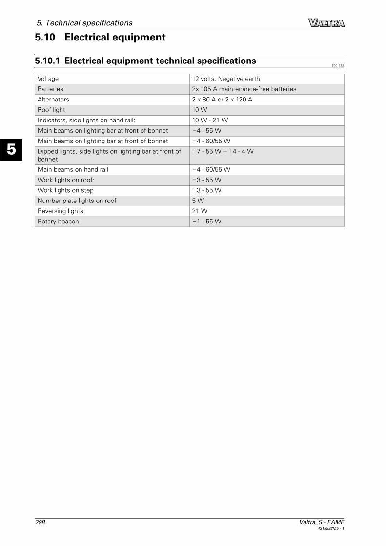
298 Valtra_S - EAME4315992M5 - 1
5
5. Technical specifications
5.10 Electrical equipment
5.10.1 Electrical equipment technical specificationsT001353
Voltage 12 volts. Negative earth
Batteries 2x 10⁵ A maintenance-free batteries
Alternators 2 x 80 A or 2 x 120 A
Roof light 10 W
Indicators, side lights on hand rail: 10 W - 21 W
Main beams on lighting bar at front of bonnet H4 - 55 W
Main beams on lighting bar at front of bonnet H4 - 60/55 W
Dipped lights, side lights on lighting bar at front of bonnet
H7 - 55 W + T4 - 4 W
Main beams on hand rail H4 - 60/55 W
Work lights on roof: H3 - 55 W
Work lights on step H3 - 55 W
Number plate lights on roof 5 W
Reversing lights: 21 W
Rotary beacon H1 - 55 W

Valtra_S - EAME 2994315992M5 - 1
5
5. Technical specifications
5.11 Wheels and tyres
5.11.1 RimT001347
5.11.2 TyresT001348
On an unequal 4-wheel drive tractor, the front wheels are smaller than the rear wheels, so they have to turnslightly faster than the rear wheels.The synchronisation ratio K specifies the difference between the rotation of the front and rear wheels.For total compatibility between the front and rear tyres, apply the synchronisation ratio K (the value is dis-played on the name plate).
The following formula is used to check that your choice of front/rear tyre is correct.The result should be between 1 and 1.05.Calculation formula:1<K x (rolling circumference of the front tyre/rolling circumference of the rear tyre)<1.05
5.11.3 Tightening torquesT001375
Four-wheel drive front axle
Welded steel rim/disc (2 settings depending on the position of the rim on the hub).Mobile steel rim/disc (8 settings depending on the position of the disc on the rim and on the hub).
Rear wheels Welded steel rims/disc (setting depending on the position on the straight shaft).Steel rims/cast iron disc (setting of the disc position on the rim and depending on the position on the straight shaft).
Disc on hub Rim on disc Hub on axle shaftFixed steel rim 640 Nm to 680 Nm 350 Nm to 460 Nm 350 Nm to 460 Nm
Rim with cast iron disc 640 Nm to 680 Nm 250 Nm to 350 Nm 350 Nm to 460 Nm

300 Valtra_S - EAME4315992M5 - 1
5
5. Technical specifications
5.12 Capacities and dimensions
5.12.1 CapacitiesT001326
5.12.2 Dimensions and weightsT001327
Type Model DisplacementFuel tank Internal EGR 460 l
Fuel tank E3 engine with AdBlue/DEF tech-nology
360 l
Additional tank All 230 l
Urea reservoir E3 engine with AdBlue/DEF tech-nology
30 l
Cooling system All 34 l
Engine sump All 21 l
Auxiliary hydraulics All 110 l
Transmission/rear axle All 85 l
Rear final drive (each) All 14 l
Linkage cover plate All 0,5 l
Fixed front axle beam 770/504 15 l
Fixed front axle final drive (each) 770/504 7 l
Suspended front axle beam 770/612 14,5 l
Suspended front axle final drive (each)
770/612 7 l
Clutch fluid All 0,6 l
Refrigerant fluid R134A All 1000 g
Front power take-off All 3,5 l
Windscreen washer bottle All 4,5 l
I006021Fig. 1.
BB
B E
A G
DF
C

Valtra_S - EAME 3014315992M5 - 1
5
5. Technical specifications
I004317Fig. 2.
J
K I
L
H
Reference
Measured specification Dimension/weight
(A) Wheel track 3105 mm
(B) External length with front linkage 4868 mm
External length without front linkage 4745 mm
(C) Height to roof 2357 mm
Height to roof with TopDock 2377 mm
(D) Height to ground – Rear: 1025 mm with 710/85R38 tyres
– Rear : 800 mm with 620/75R30 tyres
(E) Minimum external width 2550 mm
(F) Ground clearance 472 mm
Weight at no load (with full tank, without additional weights)
10300 kg to 11500 kg
Ref-erence
Measured specification Dimension/weightRear axleHA 260
Front axleDANA 770
(G) Distance between flanges – Short shaft: 2439 mm
– Long shaft: 2999 mm
1892 mm
(H) Centre-to-centre distance between studs 335 mm 370,8 mm
(I) Centring diameter 280,8 mm 425 mm
(J) Stud length – Rim with steel disc: 41 mm
– Rim with cast iron disc: 66 mm
47 mm
(K) Stud diameter M22 M22x1.5
(L) Number of studs (per side) 10 12

302 Valtra_S - EAME4315992M5 - 1
5
5. Technical specifications
5.12.3 Attachment points: All models with 5 t front linkageT001328
NOTE: Values x, y and z represent reference point 0 of the tractor.
I003764Fig. 3.
12
YZ
X
10
8 7 6 5 4
0
3 9
13
15 17
11 14 16 19
22
18
23 24
21
140
330300
20
2
1
25
2627
Reference X Y Z1- 3105,1 mm
2 4868,6 mm
3 975 mm
4 512 mm
5 161,3 mm
6 1356,8 mm
7 652,2 mm
8 518 mm
9 592,5 mm
10 M20 -2099 mm ±410 mm 15 mm
11 M20 -2119 mm ±410 mm -41,5 mm
12 M20 -1879 mm ±225 mm -64,9 mm
13 M20 -1879 mm ±225 mm -144,9 mm
14 M20 tapered align-ment screw
-494 mm ±294 mm 15 mm
15 M20 tapered align-ment screw
-454 mm ±284 mm -294,9 mm
16 M20 tapered align-ment screw
-274 mm ±294 mm 15 mm

Valtra_S - EAME 3034315992M5 - 1
5
5. Technical specifications
5.12.4 Attachment points: all models without front linkageT001329
NOTE: Values x, y and z represent reference point 0 of the tractor.
17 M20 tapered align-ment screw
-194 mm ±284 mm -294,9 mm
18 M20 1670,3 mm ±740 mm -280 mm
19 M20 1670,3 mm ±645 mm -280 mm
20 M20 1826,3 mm ±740 mm -280 mm
21 M20 1826,3 mm ±645 mm -280 mm
22 M20 1783,3 mm ±100 mm -437,5 mm
23 M20 1804 mm ±100 mm -440 mm
24 M20 1858,3 mm ±100 mm -437,5 mm
25 140 mm
26 330 mm
27 300 mm
Reference X Y Z
I003763Fig. 4.
1210
8 7 6 5 4 3 9
13
15 17
11 14 16
140
330300
2
1
0
YZ
X
25
2627
19
22
18
23 24
21
20
Reference X Y Z1- 3105,1 mm
2 4744,8 mm
3 975 mm
4 512 mm
5 161,3 mm
6 1356,8 mm

304 Valtra_S - EAME4315992M5 - 1
5
5. Technical specifications
7 652,2 mm
8 395 mm
9 592,5 mm
10 M20 -2099 mm ±410 mm 15 mm
11 M20 -2119 mm ±410 mm -41,5 mm
12 M20 -1879 mm ±225 mm -64,9 mm
13 M20 -1879 mm ±225 mm -144,9 mm
14 M20 tapered align-ment screw
-494 mm ±294 mm 15 mm
15 M20 tapered align-ment screw
-454 mm ±284 mm -294,9 mm
16 M20 tapered align-ment screw
-274 mm ±294 mm 15 mm
17 M20 tapered align-ment screw
-194 mm ±284 mm -294,9 mm
18 M20 1670,3 mm ±740 mm -280 mm
19 M20 1670,3 mm ±645 mm -280 mm
20 M20 1826,3 mm ±740 mm -280 mm
21 M20 1826,3 mm ±645 mm -280 mm
22 M20 1783,3 mm ±100 mm -437,5 mm
23 M20 1804 mm ±100 mm -440 mm
24 M20 1858,3 mm ±100 mm -437,5 mm
25 140 mm
26 330 mm
27 300 mm
Reference X Y Z

Valtra_S - EAME 3054315992M5 - 1
6
Table of contents
6. Accessories
6.1 Cab . . . . . . . . . . . . . . . . . . . . . . . . . . . . . . . . . . . . . . . . . . . . . . . . . . . . . . . . . . . . . . . . . . . . . . . 3076.1.1 Cab accessories . . . . . . . . . . . . . . . . . . . . . . . . . . . . . . . . . . . . . . . . . . . . . . . . . . . . . 307
6.2 Engine . . . . . . . . . . . . . . . . . . . . . . . . . . . . . . . . . . . . . . . . . . . . . . . . . . . . . . . . . . . . . . . . . . . . 3086.2.1 Engine accessories . . . . . . . . . . . . . . . . . . . . . . . . . . . . . . . . . . . . . . . . . . . . . . . . . . . 308
6.3 Front axle and steering. . . . . . . . . . . . . . . . . . . . . . . . . . . . . . . . . . . . . . . . . . . . . . . . . . . . . 3096.3.1 Front axle and steering accessories . . . . . . . . . . . . . . . . . . . . . . . . . . . . . . . . . . . . . 309
6.4 Power take-off . . . . . . . . . . . . . . . . . . . . . . . . . . . . . . . . . . . . . . . . . . . . . . . . . . . . . . . . . . . . 3106.4.1 Power take-off accessories . . . . . . . . . . . . . . . . . . . . . . . . . . . . . . . . . . . . . . . . . . . . 310
6.5 Linkage . . . . . . . . . . . . . . . . . . . . . . . . . . . . . . . . . . . . . . . . . . . . . . . . . . . . . . . . . . . . . . . . . . . 3116.5.1 Linkage accessories . . . . . . . . . . . . . . . . . . . . . . . . . . . . . . . . . . . . . . . . . . . . . . . . . . 311
6.6 Auxiliary hydraulics. . . . . . . . . . . . . . . . . . . . . . . . . . . . . . . . . . . . . . . . . . . . . . . . . . . . . . . . 3126.6.1 Auxiliary hydraulics accessories . . . . . . . . . . . . . . . . . . . . . . . . . . . . . . . . . . . . . . . . 312
6.7 Wheels and tyres . . . . . . . . . . . . . . . . . . . . . . . . . . . . . . . . . . . . . . . . . . . . . . . . . . . . . . . . . . 3136.7.1 Wheels and tyres accessories . . . . . . . . . . . . . . . . . . . . . . . . . . . . . . . . . . . . . . . . . . 313

306 Valtra_S - EAME4315992M5 - 1
6
Table of contents

Valtra_S - EAME 3074315992M5 - 1
6
6. Accessories
6.1 Cab
6.1.1 Cab accessoriesT001018
– Radio fittings (loudspeakers, aerial and wiring).
– Radio
– Top link for attachments (computer).
– Fender extensions.
– Rotary beacon
– Work lights on hand rails

308 Valtra_S - EAME4315992M5 - 1
6
6. Accessories
6.2 Engine
6.2.1 Engine accessoriesT001019
– Engine block preheater (220 V or 110 V according to version)

Valtra_S - EAME 3094315992M5 - 1
6
6. Accessories
6.3 Front axle and steering
6.3.1 Front axle and steering accessoriesT001021
– Front fenders.
– Front weights, 55 kg: 18 hitch weights
– Centre weight for tractors fitted with a front linkage: 345 kgNOTE: The centre weight is not compatible with the front PTO.
NOTE: Removal is not easy and the weight must remain fitted.

310 Valtra_S - EAME4315992M5 - 1
6
6. Accessories
6.4 Power take-off
6.4.1 Power take-off accessoriesT001022
– Power take-off: Consult your dealer for the different types available

Valtra_S - EAME 3114315992M5 - 1
6
6. Accessories
6.5 Linkage
6.5.1 Linkage accessoriesT001023
– 5 t front linkage with automatic hooks
– Rear linkage: Consult your dealer for the different types available
– Weight for front or rear linkage: 1 weight of 900 kg or 1500 kg

312 Valtra_S - EAME4315992M5 - 1
6
6. Accessories
6.6 Auxiliary hydraulics
6.6.1 Auxiliary hydraulics accessoriesT001024
– Additional hydraulic spool valves
– Trailer brake

Valtra_S - EAME 3134315992M5 - 1
6
6. Accessories
6.7 Wheels and tyres
6.7.1 Wheels and tyres accessoriesT001026
– Wheel weights

Valtra_S - EAME 3144315992M5 - 1
6
6. Accessories