Service manuals - daikintech.co.uk
76
Service manual Split Stylish R32 English Service manual Split Stylish R32 CTXA15A2V1B(W)(S)(T) FTXA20A2V1B(W)(S)(T) FTXA25A2V1B(W)(S)(T) FTXA35A2V1B(W)(S)(T) FTXA42A2V1B(W)(S)(T) FTXA50A2V1B(W)(S)(T) RXA42A2V1B RXA50A2V1B RXA20A2V1B RXA25A2V1B RXA35A2V1B
-
Upload
khangminh22 -
Category
Documents
-
view
1 -
download
0
Transcript of Service manuals - daikintech.co.uk

Service manualSplit Stylish R32 English
Service manual
Split Stylish R32
CTXA15A2V1B(W)(S)(T)
FTXA20A2V1B(W)(S)(T)FTXA25A2V1B(W)(S)(T)FTXA35A2V1B(W)(S)(T)FTXA42A2V1B(W)(S)(T)FTXA50A2V1B(W)(S)(T)
RXA42A2V1BRXA50A2V1B
RXA20A2V1BRXA25A2V1BRXA35A2V1B

Disclaimer
Service manual
2(C)(F)TXA15~50A2V1B(W)(S)(T) + RXA42+50A2V1B +
RXA20~35A2V1BSplit Stylish R32
ESIE18-03 – 2018.09
Disclaimer
The present publication is drawn up by way of information only and does not constitute an offer binding upon Daikin Europe N.V.. DaikinEurope N.V. has compiled the content of this publication to the best of its knowledge. No express or implied warranty is given for thecompleteness, accuracy, reliability or fitness for particular purpose of its content and the products and services presented therein.Specifications are subject to change without prior notice. Daikin Europe N.V. explicitly rejects any liability for any direct or indirect damage, inthe broadest sense, arising from or related to the use and/or interpretation of this publication. All content is copyrighted by Daikin Europe N.V..
Table of contents
Service manual
3(C)(F)TXA15~50A2V1B(W)(S)(T) + RXA42+50A2V1B +RXA20~35A2V1BSplit Stylish R32ESIE18-03 – 2018.09
Table of contents
1 Troubleshooting 41.1 To display the error code on the user interface......................... 41.2 To reset the error code via remote controller ............................ 41.3 To reset the error code via outdoor unit .................................... 41.4 To perform a test run................................................................. 4
1.4.1 To perform a test run using the user interface ............ 41.5 Error based troubleshooting ...................................................... 4
1.5.1 A1-00 – PCB abnormality ........................................... 41.5.2 A5-00 – Freeze-up protection / heating peak cut
control ......................................................................... 51.5.3 A6-00 – Indoor unit fan motor abnormality.................. 51.5.4 AH-00 – Streamer unit abnormality............................. 51.5.5 C4-00 – Indoor heat exchanger thermistor
abnormality ................................................................. 51.5.6 C9-00 – Room thermistor abnormality ........................ 51.5.7 CC-00 – Humidity sensor abnormality ........................ 61.5.8 CE-00 – Intelligent thermal sensor abnormality .......... 61.5.9 E1-00 – PCB defect .................................................... 61.5.10 E3-00 – High pressure switch abnormality ................. 61.5.11 E5-00 – Overheat of inverter compressor motor......... 71.5.12 E6-00 – Compressor startup defect ............................ 71.5.13 E7-00 – Fan lock abnormality ..................................... 81.5.14 E8-00 – Input overvoltage abnormality ....................... 81.5.15 EA-00 – Cooling/Heating switch abnormality.............. 81.5.16 F3-00 – Discharge pipe temperature stop
abnormality ................................................................. 81.5.17 F6-00 – Stop due to cooling high pressure ................. 91.5.18 F8-00 – System shutdown due to compressor
internal temperature abnormality ................................ 91.5.19 H0-00 – Current sensor abnormality........................... 91.5.20 H3-00 – High pressure switch defect .......................... 101.5.21 H6-00 – Location detection sensor abnormality.......... 101.5.22 H8-00 – Compressor input abnormality ...................... 101.5.23 H9-00 – Outdoor air thermistor abnormality................ 111.5.24 J3-00 – Discharge pipe thermistor dislocation
abnormality ................................................................. 111.5.25 J6-00 – Outdoor heat exchanger thermistor
abnormality ................................................................. 111.5.26 L3-00 – Electrical component temperature
abnormality ................................................................. 111.5.27 L4-00 – Fin temperature increase abnormality ........... 111.5.28 L5-00 – Output over current abnormality .................... 121.5.29 P4-00 – Fin thermistor abnormality............................. 121.5.30 U0-00 – Shortage of refrigerant .................................. 121.5.31 U2-00 – Main circuit voltage abnormality.................... 131.5.32 U4-00 – Indoor/outdoor transmission abnormality ...... 131.5.33 U5-00 – Transmission malfunction between indoor
unit and remote controller ........................................... 131.5.34 UA-00 – Indoor/outdoor combination abnormality ...... 13
1.6 Symptom based troubleshooting............................................... 151.6.1 Operation does not start ............................................. 151.6.2 Operation sometimes stops ........................................ 151.6.3 Operation starts but the unit does not cool/heat ......... 151.6.4 Operating noise and vibrations ................................... 151.6.5 Abnormal high pressure.............................................. 161.6.6 Abnormal low pressure ............................................... 161.6.7 Indoor fan starts operating but the compressor does
not operate.................................................................. 171.6.8 Operation starts and the unit stops immediately......... 171.6.9 Operation stops, unit cannot start for a while.............. 171.6.10 Unit discharges white mist .......................................... 171.6.11 Swing flap does not operate ....................................... 17
2 Components 182.1 4-way valve ............................................................................... 18
2.1.1 Checking procedures .................................................. 18
2.1.2 Repair procedures ....................................................... 192.2 Compressor................................................................................ 20
2.2.1 Checking procedures ................................................... 202.2.2 Repair procedures ....................................................... 22
2.3 Expansion valve ......................................................................... 232.3.1 Checking procedures ................................................... 232.3.2 Repair procedures ....................................................... 24
2.4 Front panel motor ....................................................................... 262.4.1 Checking procedures ................................................... 262.4.2 Repair procedures ....................................................... 26
2.5 High pressure switch .................................................................. 272.5.1 Checking procedures ................................................... 272.5.2 Repair procedures ....................................................... 27
2.6 Humidity sensor.......................................................................... 282.6.1 Checking procedures ................................................... 282.6.2 Repair procedures ....................................................... 28
2.7 Indoor unit fan motor .................................................................. 292.7.1 Checking procedures ................................................... 292.7.2 Repair procedures ....................................................... 29
2.8 Indoor unit PCB .......................................................................... 302.8.1 Checking procedures ................................................... 302.8.2 Repair procedures ....................................................... 31
2.9 Intelligent thermal sensor ........................................................... 332.9.1 Checking procedures ................................................... 332.9.2 Repair procedures ....................................................... 33
2.10 Inverter PCB............................................................................... 342.10.1 Checking procedures ................................................... 342.10.2 Repair procedures ....................................................... 35
2.11 Main PCB ................................................................................... 352.11.1 Checking procedures ................................................... 352.11.2 Repair procedures ....................................................... 36
2.12 Outdoor unit fan motor ............................................................... 382.12.1 Checking procedures ................................................... 382.12.2 Repair procedures ....................................................... 39
2.13 Plate work................................................................................... 402.13.1 Outdoor unit ................................................................. 402.13.2 Indoor unit .................................................................... 42
2.14 Reactor....................................................................................... 442.14.1 Checking procedures ................................................... 442.14.2 Repair procedures ....................................................... 45
2.15 Streamer unit .............................................................................. 452.15.1 Checking procedures ................................................... 452.15.2 Repair procedures ....................................................... 45
2.16 Swing flap motor......................................................................... 462.16.1 Main swing flap motor .................................................. 462.16.2 Secondary swing flap motor......................................... 47
2.17 Swing raster motor ..................................................................... 482.17.1 Checking procedures ................................................... 482.17.2 Repair procedures ....................................................... 49
2.18 Thermistors ................................................................................ 492.18.1 Refrigerant thermistors ................................................ 492.18.2 Other thermistors ......................................................... 51
2.19 Wifi control PCB ......................................................................... 512.19.1 Checking procedures ................................................... 512.19.2 Repair procedures ....................................................... 51
3 Third party components 523.1 Power supply.............................................................................. 52
3.1.1 Checking procedures ................................................... 523.1.2 Repair procedures ....................................................... 52
3.2 Refrigerant circuit ....................................................................... 533.2.1 Checking procedures ................................................... 533.2.2 Repair procedures ....................................................... 54
3.3 External factors .......................................................................... 553.3.1 Checking procedures ................................................... 553.3.2 Repair procedures ....................................................... 55
4 Maintenance 564.1 To clean the outdoor unit heat exchanger.................................. 564.2 To clean the indoor unit heat exchanger .................................... 56

1 Troubleshooting
Service manual
4(C)(F)TXA15~50A2V1B(W)(S)(T) + RXA42+50A2V1B +
RXA20~35A2V1BSplit Stylish R32
ESIE18-03 – 2018.09
4.3 To clean the air filters ................................................................ 56
5 Technical data 575.1 Detailed information setting mode............................................. 57
5.1.1 Detailed information setting mode: Indoor unit ........... 575.1.2 Detailed information setting mode: Outdoor unit......... 575.1.3 Detailed information setting mode: Remote controller 57
5.2 Wiring diagram .......................................................................... 585.2.1 Wiring diagram: Indoor unit......................................... 585.2.2 Wiring diagram: Outdoor unit ...................................... 59
5.3 Piping diagram .......................................................................... 615.3.1 Piping diagram: Indoor unit ......................................... 615.3.2 Piping diagram: Outdoor unit ...................................... 62
5.4 Component overview................................................................. 645.4.1 Component overview: Indoor unit ............................... 645.4.2 Component overview: Outdoor unit ............................ 66
5.5 Field information report ............................................................. 685.6 Field settings ............................................................................. 71
5.6.1 To control heating only mode...................................... 715.6.2 To adjust target set temperature in heating operation 715.6.3 To control the indoor unit fan during thermostat off .... 715.6.4 To change auto restart ON to OFF ............................. 715.6.5 To control cooling mode only ...................................... 71
5.7 Service tools.............................................................................. 72
1 Troubleshooting
1.1 To display the error code on theuser interface
1 Hold for about 5 seconds.
Result: blinks in the temperature display section.
2 Press repeatedly until a continuous beep is heard.
Result: The code is now displayed on the display.
INFORMATION
▪ A short beep and 2 consecutive beeps indicate non-corresponding codes.
▪ To cancel the code display, hold the cancelbutton for 5 seconds. The code will also disappear fromthe display if the button is NOT pressed within1 minute.
1.2 To reset the error code via remotecontroller
Prerequisite: Problem is solved.
1 Press the ON/OFF button of the remote controller to reset theerror.
1.3 To reset the error code via outdoorunit
Prerequisite: Problem is solved.
1 Perform a power reset to reset the error code.
1.4 To perform a test runPrerequisite: Power supply MUST be in the specified range.
Prerequisite: Test run may be performed in cooling or heatingmode.
Prerequisite: Test run should be performed in accordance with theoperation manual of the indoor unit to make sure that all functionsand parts are working properly.
1 In cooling mode, select the lowest programmable temperature.In heating mode, select the highest programmable temperature.Test run can be disabled if necessary.
2 When the test run is finished, set the temperature to a normallevel. In cooling mode: 26~28°C, in heating mode: 20~24°C.
3 The system stops operating 3 minutes after the unit is turnedOFF.
INFORMATION
▪ Even if the unit is turned OFF, it consumes electricity.
▪ When the power turns back on after a power break, thepreviously selected mode will be resumed.
1.4.1 To perform a test run using the userinterface
1 Press to switch the system on.
2 Press , and simultaneously.
3 Press , select and press .
Result: Test run operation will stop automatically after about30 minutes.
4 To stop operation sooner, press .
1.5 Error based troubleshooting
1.5.1 A1-00 – PCB abnormality
Trigger Effect ResetThe system CANNOTset the internalsettings.
Unit will stopoperating.
Power reset viaoutdoor unit.
To solve the error code
INFORMATION
It is recommended to perform the checks in the listedorder.
1 Check for improper combination of the indoor unit and theoutdoor unit. See the combination table in the Databook formore information.
2 Perform a check of the power supply, connections, wiring,…between the outdoor unit and the indoor unit. See "3.1 Powersupply" on page 52.
Possible cause: Faulty wiring between the outdoor unit andthe indoor unit.
3 Check if the power supply is conform with the regulations. See"3.1 Power supply" on page 52.
Possible cause:▪ Faulty or disturbance of the power supply (imbalance
>10%),▪ Power drop,▪ Short circuit.
4 Perform a check of the indoor unit PCB. See "2.8 Indoor unitPCB" on page 30.
Possible cause: Faulty indoor unit PCB.
INFORMATION
If all procedures listed above have been performed and theproblem is still present, contact the helpdesk.

1 Troubleshooting
Service manual
5(C)(F)TXA15~50A2V1B(W)(S)(T) + RXA42+50A2V1B +RXA20~35A2V1BSplit Stylish R32ESIE18-03 – 2018.09
1.5.2 A5-00 – Freeze-up protection / heatingpeak cut control
Trigger Effect ResetDuring coolingoperation, indoor heatexchangertemperature is below0°C (freeze‑upprotection control).
Unit will stopoperating.
Automatic reset whentemperature is withinrange.
During heatingoperation, indoor heatexchangertemperature is above65°C (heatingpeak‑cut control).
To solve the error code
INFORMATION
It is recommended to perform the checks in the listedorder.
1 Check for objects near the indoor unit that may block theairflow. See "3.3 External factors" on page 55.
Possible cause: Airflow of the indoor unit is blocked.
2 Clean the air filter. See "4 Maintenance" on page 56.
Possible cause: Faulty or dirty air filter.
3 Clean the indoor unit heat exchanger. See "4 Maintenance" onpage 56.
Possible cause: Dirty indoor unit heat exchanger.
4 Perform a check of the indoor unit heat exchanger thermistor.See "2.18 Thermistors" on page 49.
Possible cause: Faulty indoor unit heat exchangerthermistor.
5 Perform a check of the indoor unit PCB. See "2.8 Indoor unitPCB" on page 30.
Possible cause: Faulty indoor unit PCB.
INFORMATION
If all procedures listed above have been performed and theproblem is still present, contact the helpdesk.
1.5.3 A6-00 – Indoor unit fan motor abnormality
Trigger Effect ResetThe rotation speed ofthe fan motor is NOTdetected while theoutput voltage to thefan is at its maximum.
Unit will stopoperating.
Power reset via theoutdoor unit.
To solve the error code
INFORMATION
It is recommended to perform the checks in the listedorder.
1 Perform a check of the indoor unit PCB. See "2.8 Indoor unitPCB" on page 30.
Possible cause: Faulty indoor unit PCB.
2 Perform a check of the indoor unit fan motor. See "2.7 Indoorunit fan motor" on page 29.
Possible cause: Faulty indoor unit fan motor.
INFORMATION
If all procedures listed above have been performed and theproblem is still present, contact the helpdesk.
1.5.4 AH-00 – Streamer unit abnormality
Trigger Effect ResetStreamer unit startselectric dischargewhen operation startsafter approximately90 to 180 seconds.
Unit will NOT stopoperating.
Manual reset via userinterface.
To solve the error code
INFORMATION
It is recommended to perform the checks in the listedorder.
1 Perform a check of the streamer unit. See "2.15 Streamerunit" on page 45.
Possible cause: Faulty streamer unit.
INFORMATION
If all procedures listed above have been performed and theproblem is still present, contact the helpdesk.
1.5.5 C4-00 – Indoor heat exchanger thermistorabnormality
Trigger Effect ResetRefrigerant liquidthermistor detects anopen or short circuitduring compressoroperation.
Unit will stopoperating.
Power reset viaoutdoor unit.
To solve the error code
INFORMATION
It is recommended to perform the checks in the listedorder.
INFORMATION
In case of preferential kWh rate, the indoor unit also needsa power reset.
1 Perform a check of the refrigerant liquid thermistor. See"2.18 Thermistors" on page 49.
Possible cause: Faulty refrigerant liquid thermistor.
2 Perform a check of the indoor unit PCB. See "2.8 Indoor unitPCB" on page 30.
Possible cause: Faulty indoor unit PCB.
INFORMATION
If all procedures listed above have been performed and theproblem is still present, contact the helpdesk.
1.5.6 C9-00 – Room thermistor abnormality
Trigger Effect ResetResistance value isout of range.Temperaturemeasured <–43.6°Cor >90°C.
Unit will stopoperating.
Automatic reset whenresistance is withinrange.

1 Troubleshooting
Service manual
6(C)(F)TXA15~50A2V1B(W)(S)(T) + RXA42+50A2V1B +
RXA20~35A2V1BSplit Stylish R32
ESIE18-03 – 2018.09
To solve the error code
INFORMATION
It is recommended to perform the checks in the listedorder.
1 Perform a check of the room thermistor. See"2.18 Thermistors" on page 49.
Possible cause: Faulty room thermistor.
2 Perform a check of the indoor unit PCB. See "2.8 Indoor unitPCB" on page 30.
Possible cause: Faulty indoor unit PCB.
INFORMATION
If all procedures listed above have been performed and theproblem is still present, contact the helpdesk.
1.5.7 CC-00 – Humidity sensor abnormality
Trigger Effect Reset▪ Disconnected
sensor
▪ Broken sensor
▪ Communicationerror
Unit will stopoperating.
Manual reset via userinterface.
To solve the error code
INFORMATION
It is recommended to perform the checks in the listedorder.
1 Perform a check of the humidity sensor. See "2.6 Humiditysensor" on page 28.
Possible cause: Faulty humidity sensor.
INFORMATION
If all procedures listed above have been performed and theproblem is still present, contact the helpdesk.
1.5.8 CE-00 – Intelligent thermal sensorabnormality
Trigger Effect Reset▪ Disconnected
sensor
▪ Broken sensor
▪ Communicationerror
Unit will stopoperating.
Manual reset via userinterface.
To solve the error code
INFORMATION
It is recommended to perform the checks in the listedorder.
1 Perform a check of the intelligent thermal sensor. See"2.9 Intelligent thermal sensor" on page 33.
Possible cause: Faulty intelligent thermal sensor.
INFORMATION
If all procedures listed above have been performed and theproblem is still present, contact the helpdesk.
1.5.9 E1-00 – PCB defect
Trigger Effect ResetMain PCB detectsthat EEPROM isabnormal.
Unit will stopoperating.
Manual reset via userinterface.Power reset viaoutdoor unit.
To solve the error code
INFORMATION
It is recommended to perform the checks in the listedorder.
INFORMATION
In case of preferential kWh rate, the indoor unit also needsa power reset.
1 Perform a check of the main PCB. See "2.11 Main PCB" onpage 35.
Possible cause: Faulty main PCB.
2 Check if the power supply is conform with the regulations. See"3.1 Power supply" on page 52.
Possible cause:▪ Faulty or disturbance of the power supply (imbalance
>10%),▪ Power drop,▪ Short circuit.
3 Perform a check of the outdoor unit fan motor. See"2.12 Outdoor unit fan motor" on page 38.
Possible cause: Faulty outdoor unit fan motor.
INFORMATION
If all procedures listed above have been performed and theproblem is still present, contact the helpdesk.
1.5.10 E3-00 – High pressure switch abnormality
Trigger Effect ResetHigh pressure switchopens due tomeasured pressure>41.7 bar.
Unit will stopoperating.
Manual reset via userinterface.
High pressure control(measured pressure>38 bar) occurs 16times within300 minutes.
To solve the error code
INFORMATION
It is recommended to perform the checks in the listedorder.
1 Perform a check of the high pressure switch. See "2.5 Highpressure switch" on page 27.
Possible cause: Faulty high pressure switch.
2 Perform a check of the main PCB. See "2.11 Main PCB" onpage 35.
Possible cause: Faulty main PCB.
3 Perform a check of the refrigerant circuit. See "3.2 Refrigerantcircuit" on page 53.

1 Troubleshooting
Service manual
7(C)(F)TXA15~50A2V1B(W)(S)(T) + RXA42+50A2V1B +RXA20~35A2V1BSplit Stylish R32ESIE18-03 – 2018.09
Possible cause:▪ Stop valve is closed,▪ Clogged refrigerant circuit,▪ Refrigerant circuit NOT charged correctly,▪ Humidity in the refrigerant circuit,▪ Non-condensables in the refrigerant circuit,▪ Leaking refrigerant circuit.
4 Perform a check of the outdoor unit fan motor. See"2.12 Outdoor unit fan motor" on page 38.
Possible cause: Faulty outdoor unit fan motor.
INFORMATION
If all procedures listed above have been performed and theproblem is still present, contact the helpdesk.
1.5.11 E5-00 – Overheat of inverter compressormotor
Trigger Effect ResetCompressor overloadis detected.
Unit will NOT stopoperating.
Automatic reset if theunit runs withoutwarning for60 seconds.
To solve the error code
INFORMATION
It is recommended to perform the checks in the listedorder.
1 Perform a check of the discharge pipe thermistor. See"2.18 Thermistors" on page 49.
Possible cause: Faulty discharge pipe thermistor.
2 Perform a check of the outdoor unit fan motor. See"2.12 Outdoor unit fan motor" on page 38.
Possible cause: Faulty outdoor unit fan motor.
3 Perform a check of the compressor. See "2.2 Compressor" onpage 20.
Possible cause: Faulty compressor.
4 Perform a check of the expansion valve. See "2.3 Expansionvalve" on page 23.
Possible cause: Faulty expansion valve.
5 Perform a check of the 4‑way valve. See "2.1 4-way valve" onpage 18.
Possible cause: Faulty 4‑way valve.
6 Perform a check of the main PCB. See "2.11 Main PCB" onpage 35.
Possible cause: Faulty main PCB.
7 Perform a check of the inverter PCB. See "2.10 InverterPCB" on page 34.
Possible cause: Faulty power module = inverter PCB.
8 Perform a check of the refrigerant circuit. See "3.2 Refrigerantcircuit" on page 53.
Possible cause:▪ Stop valve is closed,▪ Clogged refrigerant circuit,▪ Refrigerant circuit NOT charged correctly,▪ Humidity in the refrigerant circuit,▪ Non-condensables in the refrigerant circuit,▪ Leaking refrigerant circuit.
INFORMATION
If all procedures listed above have been performed and theproblem is still present, contact the helpdesk.
1.5.12 E6-00 – Compressor startup defect
Trigger Effect ResetThe motor rotor doesNOT rotate when thecompressor isenergized.
Unit will NOT stopoperating.
Automatic reset aftera continuous run for10 minutes.
Unit will stopoperating
Manual reset via userinterface.
To solve the error code
INFORMATION
It is recommended to perform the checks in the listedorder.
1 Perform a check of the discharge pipe thermistor. See"2.18 Thermistors" on page 49.
Possible cause: Faulty discharge pipe thermistor.
2 Perform a check of the refrigerant circuit. See "3.2 Refrigerantcircuit" on page 53.
Possible cause:▪ Stop valve is closed,▪ Clogged refrigerant circuit,▪ Refrigerant circuit NOT charged correctly,▪ Humidity in the refrigerant circuit,▪ Non-condensables in the refrigerant circuit,▪ Leaking refrigerant circuit.
3 Perform a check of the compressor. See "2.2 Compressor" onpage 20.
Possible cause: Faulty compressor.
4 Perform a check of the main PCB. See "2.11 Main PCB" onpage 35.
Possible cause: Faulty main PCB.
5 Perform a check of the inverter PCB. See "2.10 InverterPCB" on page 34.
Possible cause: Faulty power module = inverter PCB.
6 Perform a check of the 4‑way valve. See "2.1 4-way valve" onpage 18.
Possible cause: Faulty 4‑way valve.
7 Perform a check of the expansion valve. See "2.3 Expansionvalve" on page 23.
Possible cause: Faulty expansion valve.
INFORMATION
If all procedures listed above have been performed and theproblem is still present, contact the helpdesk.

1 Troubleshooting
Service manual
8(C)(F)TXA15~50A2V1B(W)(S)(T) + RXA42+50A2V1B +
RXA20~35A2V1BSplit Stylish R32
ESIE18-03 – 2018.09
1.5.13 E7-00 – Fan lock abnormality
Trigger Effect ResetFan does NOT start15~30 seconds afterON signal.
It can occur that theerror code istriggered when thefan motor is runningcaused by a faultyrotating sensorsignal.
Unit will stopoperating.
Manual reset via userinterface.
To solve the error code
INFORMATION
It is recommended to perform the checks in the listedorder.
1 Perform a check of the outdoor unit fan motor. See"2.12 Outdoor unit fan motor" on page 38.
Possible cause: Faulty outdoor unit fan motor.
2 Perform a check of the inverter PCB. See "2.10 InverterPCB" on page 34.
Possible cause: Faulty power module = inverter PCB.
INFORMATION
If all procedures listed above have been performed and theproblem is still present, contact the helpdesk.
1.5.14 E8-00 – Input overvoltage abnormality
Trigger Effect ResetCompressor runningcurrent exceedsstandard value for2.5 seconds.
Unit will stopoperating.
Manual reset via userinterface.
To solve the error code
INFORMATION
It is recommended to perform the checks in the listedorder.
1 Check the outdoor temperature. See "3.3 External factors" onpage 55.
Possible cause: Outdoor temperature is out of operationrange.
2 Perform a check of the compressor. See "2.2 Compressor" onpage 20.
Possible cause: Faulty compressor.
3 Perform a check of the inverter PCB. See "2.10 InverterPCB" on page 34.
Possible cause: Faulty power module = inverter PCB.
4 Check if the power supply is conform with the regulations. See"3.1 Power supply" on page 52.
Possible cause:▪ Faulty or disturbance of the power supply (imbalance
>10%),▪ Power drop,▪ Short circuit.
INFORMATION
If all procedures listed above have been performed and theproblem is still present, contact the helpdesk.
1.5.15 EA-00 – Cooling/Heating switchabnormality
Trigger Effect ResetRoom thermistor isNOT functioningwithin operationrange.
Unit will NOT stopoperating.
Automatic reset aftera continuousoperation of10 minutes.
If the error occurs toosoon: unit will stopoperating.
Manual reset via userinterface.
To solve the error code
INFORMATION
It is recommended to perform the checks in the listedorder.
1 Perform a check of the 4‑way valve. See "2.1 4-way valve" onpage 18.
Possible cause: Faulty 4‑way valve.
2 Perform a check of the main PCB. See "2.11 Main PCB" onpage 35.
Possible cause: Faulty main PCB.
3 Perform a check of the room thermistor. See"2.18 Thermistors" on page 49.
Possible cause: Faulty room thermistor.
4 Perform a check of the refrigerant circuit. See "3.2 Refrigerantcircuit" on page 53.
Possible cause:▪ Stop valve is closed,▪ Clogged refrigerant circuit,▪ Refrigerant circuit NOT charged correctly,▪ Humidity in the refrigerant circuit,▪ Non-condensables in the refrigerant circuit,▪ Leaking refrigerant circuit.
INFORMATION
If all procedures listed above have been performed and theproblem is still present, contact the helpdesk.
1.5.16 F3-00 – Discharge pipe temperature stopabnormality
Trigger Effect ResetDischarge pipethermistor detects atoo high temperature.
Unit will NOT stopoperating.
Automatic reset whentemperature dropsnormal level.
If the error re-occurstoo soon: unit willstop operating.
Manual reset via userinterface.
To solve the error code
INFORMATION
It is recommended to perform the checks in the listedorder.
1 Perform a check of the refrigerant circuit. See "3.2 Refrigerantcircuit" on page 53.
Possible cause:▪ Stop valve is closed,▪ Clogged refrigerant circuit,▪ Refrigerant circuit NOT charged correctly,▪ Humidity in the refrigerant circuit,▪ Non-condensables in the refrigerant circuit,▪ Leaking refrigerant circuit.

1 Troubleshooting
Service manual
9(C)(F)TXA15~50A2V1B(W)(S)(T) + RXA42+50A2V1B +RXA20~35A2V1BSplit Stylish R32ESIE18-03 – 2018.09
2 Perform a check of the 4‑way valve. See "2.1 4-way valve" onpage 18.
Possible cause: Faulty 4‑way valve.
3 Perform a check of the expansion valve. See "2.3 Expansionvalve" on page 23.
Possible cause: Faulty expansion valve.
4 Perform a check of the main PCB. See "2.11 Main PCB" onpage 35.
Possible cause: Faulty main PCB.
5 Perform a check of all refrigerant thermistors. See"2.18 Thermistors" on page 49.
Possible cause: Faulty refrigerant thermistor(s).
INFORMATION
If all procedures listed above have been performed and theproblem is still present, contact the helpdesk.
1.5.17 F6-00 – Stop due to cooling high pressure
Trigger Effect ResetOutdoor heatexchanger thermistormeasurestemperature>60°C~65°C
Unit will NOT stopoperating.
Automatic reset whentemperature dropsbelow 50°C.
To solve the error code
INFORMATION
It is recommended to perform the checks in the listedorder.
1 Clean the outdoor heat exchanger. See "4 Maintenance" onpage 56.
Possible cause: Dirty outdoor heat exchanger.
2 Perform a check of the refrigerant circuit. See "3.2 Refrigerantcircuit" on page 53.
Possible cause:▪ Stop valve is closed,▪ Clogged refrigerant circuit,▪ Refrigerant circuit NOT charged correctly,▪ Humidity in the refrigerant circuit,▪ Non-condensables in the refrigerant circuit,▪ Leaking refrigerant circuit.
3 Perform a check of the heat exchanger thermistor. See"2.18 Thermistors" on page 49.
Possible cause: Faulty heat exchanger thermistor.
4 Perform a check of the expansion valve. See "2.3 Expansionvalve" on page 23.
Possible cause: Faulty expansion valve.
5 Perform a check of the main PCB. See "2.11 Main PCB" onpage 35.
Possible cause: Faulty main PCB.
6 Perform a check of the outdoor unit fan motor. See"2.12 Outdoor unit fan motor" on page 38.
Possible cause: Faulty outdoor unit fan motor.
INFORMATION
If all procedures listed above have been performed and theproblem is still present, contact the helpdesk.
1.5.18 F8-00 – System shutdown due tocompressor internal temperatureabnormality
Trigger Effect ResetTemperaturedischarge pipethermistor exceedsthe determined limit.
Unit will stopoperating.
Manual reset via userinterface.
To solve the error code
INFORMATION
It is recommended to perform the checks in the listedorder.
1 Perform a check of the refrigerant circuit. See "3.2 Refrigerantcircuit" on page 53.
Possible cause:▪ Stop valve is closed,▪ Clogged refrigerant circuit,▪ Refrigerant circuit NOT charged correctly,▪ Humidity in the refrigerant circuit,▪ Non-condensables in the refrigerant circuit,▪ Leaking refrigerant circuit.
2 Perform a check of the discharge pipe thermistor. See"2.18 Thermistors" on page 49.
Possible cause: Faulty discharge pipe thermistor.
INFORMATION
If all procedures listed above have been performed and theproblem is still present, contact the helpdesk.
1.5.19 H0-00 – Current sensor abnormality
Trigger Effect ResetCompressor voltage(DC) is out of rangebefore start‑up.
Unit will stopoperating.
Manual reset via userinterface.
To solve the error code
INFORMATION
It is recommended to perform the checks in the listedorder.
1 Perform a check of the main PCB. See "2.11 Main PCB" onpage 35.
Possible cause: Faulty main PCB.
2 Perform a check of the inverter PCB. See "2.10 InverterPCB" on page 34.
Possible cause: Faulty power module = inverter PCB.
3 Check if the power supply is conform with the regulations. See"3.1 Power supply" on page 52.
Possible cause:▪ Faulty or disturbance of the power supply (imbalance
>10%),▪ Power drop,▪ Short circuit.
INFORMATION
If all procedures listed above have been performed and theproblem is still present, contact the helpdesk.
1 Troubleshooting
Service manual
10(C)(F)TXA15~50A2V1B(W)(S)(T) + RXA42+50A2V1B +
RXA20~35A2V1BSplit Stylish R32
ESIE18-03 – 2018.09
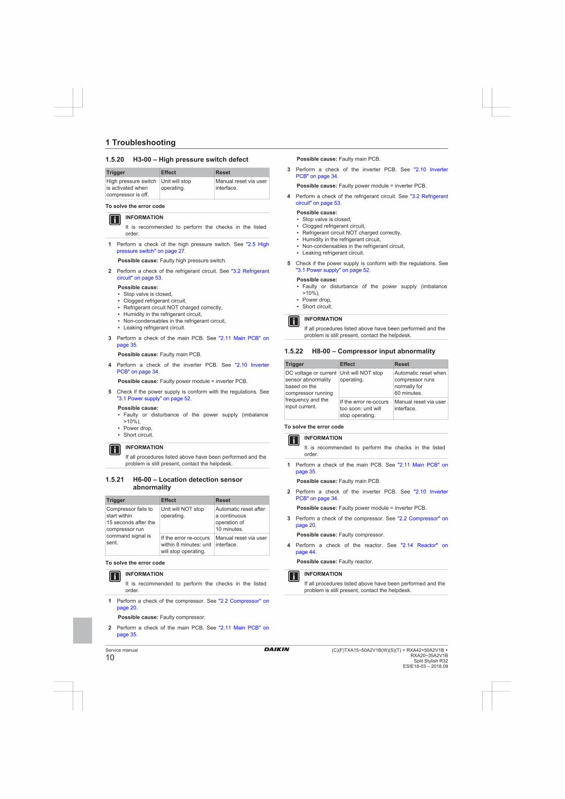
1.5.20 H3-00 – High pressure switch defect
Trigger Effect ResetHigh pressure switchis activated whencompressor is off.
Unit will stopoperating.
Manual reset via userinterface.
To solve the error code
INFORMATION
It is recommended to perform the checks in the listedorder.
1 Perform a check of the high pressure switch. See "2.5 Highpressure switch" on page 27.
Possible cause: Faulty high pressure switch.
2 Perform a check of the refrigerant circuit. See "3.2 Refrigerantcircuit" on page 53.
Possible cause:▪ Stop valve is closed,▪ Clogged refrigerant circuit,▪ Refrigerant circuit NOT charged correctly,▪ Humidity in the refrigerant circuit,▪ Non-condensables in the refrigerant circuit,▪ Leaking refrigerant circuit.
3 Perform a check of the main PCB. See "2.11 Main PCB" onpage 35.
Possible cause: Faulty main PCB.
4 Perform a check of the inverter PCB. See "2.10 InverterPCB" on page 34.
Possible cause: Faulty power module = inverter PCB.
5 Check if the power supply is conform with the regulations. See"3.1 Power supply" on page 52.
Possible cause:▪ Faulty or disturbance of the power supply (imbalance
>10%),▪ Power drop,▪ Short circuit.
INFORMATION
If all procedures listed above have been performed and theproblem is still present, contact the helpdesk.
1.5.21 H6-00 – Location detection sensorabnormality
Trigger Effect ResetCompressor fails tostart within15 seconds after thecompressor runcommand signal issent.
Unit will NOT stopoperating.
Automatic reset aftera continuousoperation of10 minutes.
If the error re-occurswithin 8 minutes: unitwill stop operating.
Manual reset via userinterface.
To solve the error code
INFORMATION
It is recommended to perform the checks in the listedorder.
1 Perform a check of the compressor. See "2.2 Compressor" onpage 20.
Possible cause: Faulty compressor.
2 Perform a check of the main PCB. See "2.11 Main PCB" onpage 35.
Possible cause: Faulty main PCB.
3 Perform a check of the inverter PCB. See "2.10 InverterPCB" on page 34.
Possible cause: Faulty power module = inverter PCB.
4 Perform a check of the refrigerant circuit. See "3.2 Refrigerantcircuit" on page 53.
Possible cause:▪ Stop valve is closed,▪ Clogged refrigerant circuit,▪ Refrigerant circuit NOT charged correctly,▪ Humidity in the refrigerant circuit,▪ Non-condensables in the refrigerant circuit,▪ Leaking refrigerant circuit.
5 Check if the power supply is conform with the regulations. See"3.1 Power supply" on page 52.
Possible cause:▪ Faulty or disturbance of the power supply (imbalance
>10%),▪ Power drop,▪ Short circuit.
INFORMATION
If all procedures listed above have been performed and theproblem is still present, contact the helpdesk.
1.5.22 H8-00 – Compressor input abnormality
Trigger Effect ResetDC voltage or currentsensor abnormalitybased on thecompressor runningfrequency and theinput current.
Unit will NOT stopoperating.
Automatic reset whencompressor runsnormally for60 minutes.
If the error re-occurstoo soon: unit willstop operating.
Manual reset via userinterface.
To solve the error code
INFORMATION
It is recommended to perform the checks in the listedorder.
1 Perform a check of the main PCB. See "2.11 Main PCB" onpage 35.
Possible cause: Faulty main PCB.
2 Perform a check of the inverter PCB. See "2.10 InverterPCB" on page 34.
Possible cause: Faulty power module = inverter PCB.
3 Perform a check of the compressor. See "2.2 Compressor" onpage 20.
Possible cause: Faulty compressor.
4 Perform a check of the reactor. See "2.14 Reactor" onpage 44.
Possible cause: Faulty reactor.
INFORMATION
If all procedures listed above have been performed and theproblem is still present, contact the helpdesk.

1 Troubleshooting
Service manual
11(C)(F)TXA15~50A2V1B(W)(S)(T) + RXA42+50A2V1B +RXA20~35A2V1BSplit Stylish R32ESIE18-03 – 2018.09
1.5.23 H9-00 – Outdoor air thermistorabnormality
Trigger Effect ResetOutdoor air thermistorinput is out of range.
Unit will stopoperating.
Manual reset via userinterface.
To solve the error code
INFORMATION
It is recommended to perform the checks in the listedorder.
1 Perform a check of the outdoor air thermistor. See"2.18 Thermistors" on page 49.
Possible cause: Faulty outdoor air thermistor.
2 Perform a check of the main PCB. See "2.11 Main PCB" onpage 35.
Possible cause: Faulty main PCB.
INFORMATION
If all procedures listed above have been performed and theproblem is still present, contact the helpdesk.
1.5.24 J3-00 – Discharge pipe thermistordislocation abnormality
Trigger Effect ResetDischarge pipethermistor input is outof range.
Unit will stopoperating.
Manual reset via userinterface.
To solve the error code
INFORMATION
It is recommended to perform the checks in the listedorder.
1 Perform a check of the discharge pipe thermistor. See"2.18 Thermistors" on page 49.
Possible cause: Faulty discharge pipe thermistor.
2 Perform a check of the main PCB. See "2.11 Main PCB" onpage 35.
Possible cause: Faulty main PCB.
INFORMATION
If all procedures listed above have been performed and theproblem is still present, contact the helpdesk.
1.5.25 J6-00 – Outdoor heat exchangerthermistor abnormality
Trigger Effect ResetOutdoor heatexchanger thermistorinput is out of range.
Unit will stopoperating.
Manual reset via userinterface.
To solve the error code
INFORMATION
It is recommended to perform the checks in the listedorder.
1 Perform a check of the heat exchanger thermistor. See"2.18 Thermistors" on page 49.
Possible cause: Faulty heat exchanger thermistor.
2 Perform a check of the main PCB. See "2.11 Main PCB" onpage 35.
Possible cause: Faulty main PCB.
INFORMATION
If all procedures listed above have been performed and theproblem is still present, contact the helpdesk.
1.5.26 L3-00 – Electrical component temperatureabnormality
Trigger Effect ResetSwitch boxtemperature is toohigh.
Unit will stopoperating.
Manual reset viaremote controller.
To solve the error code
INFORMATION
It is recommended to perform the checks in the listedorder.
1 Perform a check of the inverter PCB. See "2.10 InverterPCB" on page 34.
Possible cause: Faulty power module = inverter PCB.
2 Perform a check of the outdoor unit fan motor. See"2.12 Outdoor unit fan motor" on page 38.
Possible cause: Faulty outdoor unit fan motor.
3 Check if the power supply is conform with the regulations. See"3.1 Power supply" on page 52.
Possible cause:▪ Faulty or disturbance of the power supply (imbalance
>10%),▪ Power drop,▪ Short circuit.
4 Clean the outdoor heat exchanger. See "4 Maintenance" onpage 56.
Possible cause: Dirty outdoor heat exchanger.
INFORMATION
If all procedures listed above have been performed and theproblem is still present, contact the helpdesk.
1.5.27 L4-00 – Fin temperature increaseabnormality
Trigger Effect ResetRadiating finthermistor measuresa too hightemperature.
Unit will stopoperating.
Manual reset via userinterface.
To solve the error code
INFORMATION
It is recommended to perform the checks in the listedorder.
1 Perform a check of the outdoor unit fan motor. See"2.12 Outdoor unit fan motor" on page 38.
Possible cause: Faulty outdoor unit fan motor.
2 Check if the power supply is conform with the regulations. See"3.1 Power supply" on page 52.

1 Troubleshooting
Service manual
12(C)(F)TXA15~50A2V1B(W)(S)(T) + RXA42+50A2V1B +
RXA20~35A2V1BSplit Stylish R32
ESIE18-03 – 2018.09
Possible cause:▪ Faulty or disturbance of the power supply (imbalance
>10%),▪ Power drop,▪ Short circuit.
3 Perform a check of the inverter PCB. See "2.10 InverterPCB" on page 34.
Possible cause: Faulty power module = inverter PCB.
4 Perform a check of the main PCB. See "2.11 Main PCB" onpage 35.
Possible cause: Faulty main PCB.
5 Check that the silicon grease is applied properly on theradiation fin of the outdoor unit PCB. Adjust if needed.
Possible cause: Silicon grease NOT applied properly on theradiation fin.
INFORMATION
If all procedures listed above have been performed and theproblem is still present, contact the helpdesk.
1.5.28 L5-00 – Output over current abnormality
Trigger Effect ResetAn output overcurrentis detected bychecking the currentthat flows in theinverter DC section.
Unit will stopoperating.
Manual reset via userinterface.
To solve the error code
INFORMATION
It is recommended to perform the checks in the listedorder.
1 Perform a check of the refrigerant circuit. See "3.2 Refrigerantcircuit" on page 53.
Possible cause:▪ Stop valve is closed,▪ Clogged refrigerant circuit,▪ Refrigerant circuit NOT charged correctly,▪ Humidity in the refrigerant circuit,▪ Non-condensables in the refrigerant circuit,▪ Leaking refrigerant circuit.
2 Perform a check of the inverter PCB. See "2.10 InverterPCB" on page 34.
Possible cause: Faulty power module = inverter PCB.
3 Perform a check of the compressor. See "2.2 Compressor" onpage 20.
Possible cause: Faulty compressor.
4 Check if the power supply is conform with the regulations. See"3.1 Power supply" on page 52.
Possible cause:▪ Faulty or disturbance of the power supply (imbalance
>10%),▪ Power drop,▪ Short circuit.
INFORMATION
If all procedures listed above have been performed and theproblem is still present, contact the helpdesk.
1.5.29 P4-00 – Fin thermistor abnormality
Trigger Effect ResetRadiating finthermistor input is outof range.
Unit will stopoperating.
Manual reset via userinterface.
To solve the error code
INFORMATION
It is recommended to perform the checks in the listedorder.
1 Perform a check of the inverter PCB. See "2.10 InverterPCB" on page 34.
Possible cause: Faulty power module = inverter PCB.
2 Perform a check of the main PCB. See "2.11 Main PCB" onpage 35.
Possible cause: Faulty main PCB.
INFORMATION
If all procedures listed above have been performed and theproblem is still present, contact the helpdesk.
1.5.30 U0-00 – Shortage of refrigerant
Trigger Effect ResetRefrigerant shortagedetected.
Unit will stopoperating.
Automatic reset.Power reset viaoutdoor unit.
To solve the error code
INFORMATION
It is recommended to perform the checks in the listedorder.
1 Perform a check of all refrigerant thermistors. See"2.18 Thermistors" on page 49.
Possible cause: Faulty refrigerant thermistor(s).
2 Perform a check of the refrigerant circuit. See "3.2 Refrigerantcircuit" on page 53.
Possible cause:▪ Stop valve is closed,▪ Clogged refrigerant circuit,▪ Refrigerant circuit NOT charged correctly,▪ Humidity in the refrigerant circuit,▪ Non-condensables in the refrigerant circuit,▪ Leaking refrigerant circuit.
3 Perform a check of the compressor. See "2.2 Compressor" onpage 20.
Possible cause: Faulty compressor.
4 Perform a check of the expansion valve. See "2.3 Expansionvalve" on page 23.
Possible cause: Faulty expansion valve.
INFORMATION
If all procedures listed above have been performed and theproblem is still present, contact the helpdesk.

1 Troubleshooting
Service manual
13(C)(F)TXA15~50A2V1B(W)(S)(T) + RXA42+50A2V1B +RXA20~35A2V1BSplit Stylish R32ESIE18-03 – 2018.09
1.5.31 U2-00 – Main circuit voltage abnormality
Trigger Effect ResetPower supplyabnormality or instantpower failure isdetected.
Unit will stopoperating.
Power reset viaoutdoor unit.
To solve the error code
INFORMATION
It is recommended to perform the checks in the listedorder.
INFORMATION
In case of preferential kWh rate, the indoor unit also needsa power reset.
1 Check if the power supply is conform with the regulations. See"3.1 Power supply" on page 52.
Possible cause:▪ Faulty or disturbance of the power supply (imbalance
>10%),▪ Power drop,▪ Short circuit.
2 Perform a check of the compressor. See "2.2 Compressor" onpage 20.
Possible cause: Faulty compressor.
3 Perform a check of the outdoor unit fan motor. See"2.12 Outdoor unit fan motor" on page 38.
Possible cause: Faulty outdoor unit fan motor.
4 Perform a check of the main PCB. See "2.11 Main PCB" onpage 35.
Possible cause: Faulty main PCB.
5 Perform a check of the indoor unit PCB. See "2.8 Indoor unitPCB" on page 30.
Possible cause: Faulty indoor unit PCB.
6 Wait until the compressor restarts.
Possible cause:▪ Momentary drop of voltage,▪ Momentary power failure.
INFORMATION
If all procedures listed above have been performed and theproblem is still present, contact the helpdesk.
1.5.32 U4-00 – Indoor/outdoor transmissionabnormality
Trigger Effect ResetCommunicationfailure betweenoutdoor and indoorunit.
Unit will stopoperating.
Power reset viaoutdoor unit.
To solve the error code
INFORMATION
It is recommended to perform the checks in the listedorder.
INFORMATION
In case of preferential kWh rate, the indoor unit also needsa power reset.
1 Check if the power supply is conform with the regulations. See"3.1 Power supply" on page 52.
Possible cause:▪ Faulty or disturbance of the power supply (imbalance
>10%),▪ Power drop,▪ Short circuit.
2 Perform a check of the power supply, connections, wiring,…between the outdoor unit and the indoor unit. See "3.1 Powersupply" on page 52.
Possible cause: Faulty wiring between the outdoor unit andthe indoor unit.
3 Perform a check of the main PCB. See "2.11 Main PCB" onpage 35.
Possible cause: Faulty main PCB.
4 Perform a check of the outdoor unit fan motor. See"2.12 Outdoor unit fan motor" on page 38.
Possible cause: Faulty outdoor unit fan motor.
5 Perform a check of the indoor unit PCB. See "2.8 Indoor unitPCB" on page 30.
Possible cause: Faulty indoor unit PCB.
INFORMATION
If all procedures listed above have been performed and theproblem is still present, contact the helpdesk.
1.5.33 U5-00 – Transmission malfunctionbetween indoor unit and remote controller
Trigger Effect ResetCommunicationfailure betweenindoor unit and userinterface.
Unit will stopoperating.
Automatic reset.
To solve the error code
INFORMATION
It is recommended to perform the checks in the listedorder.
1 Check for improper combination of the indoor unit and theremote controller. See Business Portal for more information.
2 Check the wiring between the indoor unit and remote controller.See "3.1 Power supply" on page 52.
Possible cause: Faulty wiring between the indoor unit andremote controller.
INFORMATION
If all procedures listed above have been performed and theproblem is still present, contact the helpdesk.
1.5.34 UA-00 – Indoor/outdoor combinationabnormality
Trigger Effect ResetSignal transmissionbetween outdoor andindoor unitabnormality. Impropercombination ofoutdoor and indoorunit.
Unit will stopoperating.
Power reset viaoutdoor unit.
1 Troubleshooting
Service manual
14(C)(F)TXA15~50A2V1B(W)(S)(T) + RXA42+50A2V1B +
RXA20~35A2V1BSplit Stylish R32
ESIE18-03 – 2018.09
To solve the error code
INFORMATION
It is recommended to perform the checks in the listedorder.
INFORMATION
In case of preferential kWh rate, the indoor unit also needsa power reset.
1 Check for improper combination of the indoor unit and theoutdoor unit. See the combination table in the Databook formore information.
2 Perform a check of the power supply, connections, wiring,…between the outdoor unit and the indoor unit. See "3.1 Powersupply" on page 52.
Possible cause: Faulty wiring between the outdoor unit andthe indoor unit.
3 Perform a check of the main PCB. See "2.11 Main PCB" onpage 35.
Possible cause: Faulty main PCB.
4 Perform a check of the indoor unit PCB. See "2.8 Indoor unitPCB" on page 30.
Possible cause: Faulty indoor unit PCB.
INFORMATION
If all procedures listed above have been performed and theproblem is still present, contact the helpdesk.

1 Troubleshooting
Service manual
15(C)(F)TXA15~50A2V1B(W)(S)(T) + RXA42+50A2V1B +RXA20~35A2V1BSplit Stylish R32ESIE18-03 – 2018.09
1.6 Symptom based troubleshooting
1.6.1 Operation does not start
Check DetailWhen the operation lamp is off,there is a power failure.
Check the power supply.
▪ Is the power supply breakerON?
▪ Do other electrical applianceswork?
▪ Is the rated voltage (± 10%) issupplied?
▪ Check the insulation of theelectric system.
Check the type of the indoor unit. Is the indoor unit type compatiblewith the outdoor unit?
Check the transmission betweenindoor and outdoor
▪
Check the outdoor temperature. ▪ Heating operation cannot beused when the outdoortemperature is 18°C WB orhigher.
▪ Cooling operation cannot beused when the outdoortemperature is below –10°C DB.
When the operation lamp blinks,there may be an error code,activating the protection device.
Diagnose with remote controllerindication.
See "1.5 Error basedtroubleshooting" on page 4.
Check the remote controlleraddresses.
Are the address settings for theremote controller and indoor unitcorrect?
Check the operation circuit. ▪ Is the thermal fuse blown.
▪ Are wire size and wireconnections OK?.
Check high pressure switch. Not availableCheck fan motor. ▪ Is the magnetic switch
defective?
▪ Is the overcurrent relaydefective?
Check compressor. ▪ Is the contact defective?
▪ Is the protection thermostatdefective?
▪ Is the compressor itselfdefective?
Check remote controller. ▪ Are the batteries LOW?
▪ Are there incorrect settings?
1.6.2 Operation sometimes stops
Symptom Check DetailOperation sometimesstops
Check the powersupply.
A power failure of 2 to10 cycles stops airconditioner operation.(Operation lampOFF)
Check the outdoortemperature.
Heating operationcannot be used whenthe outdoortemperature is18°C WB or higher,and cooling operationcannot be used whenthe outdoortemperature is below–10°C DB.
Diagnose with remotecontroller indication.
{Jesse Victoor,12/01/201809:43:04: ???}
1.6.3 Operation starts but the unit does notcool/heat
Symptom Check DetailOperation starts andthe unit does notcool/heat
Check for wiring andpiping errors in theconnection betweenthe indoor unit andoutdoor unit.
Not applicable
Check for thermistordetection errors.
Check if thethermistor is mountedsecurely.
Check for faultyoperation of theelectronic expansionvalve.
Set the unit to coolingoperation, and checkthe temperature ofthe liquid pipe to seeif the electronicexpansion valveworks.
Diagnose with remotecontroller indication.
Not applicable
Diagnose by serviceport pressure andoperating current.
Check for refrigerantshortage.
1.6.4 Operating noise and vibrations
Symptom Check DetailOperating noise andvibrations
Check the outputvoltage of the powermodule.
{Jesse Victoor,12/01/201809:41:35: ???}
Check the powermodule.
{Jesse Victoor,12/01/201809:41:35: ???}
Check the installationcondition.
Check if the requiredspaces for installation(specified in theinstallation manual)are provided.

1 Troubleshooting
Service manual
16(C)(F)TXA15~50A2V1B(W)(S)(T) + RXA42+50A2V1B +
RXA20~35A2V1BSplit Stylish R32
ESIE18-03 – 2018.09
Symptom Check Detail{Jesse Victoor,12/01/201809:41:41: ????}
Check refrigerantcharge.
▪ Overcharge
▪ Air in the system
▪ Flushing noise, dueto refrigerantshortage
1.6.5 Abnormal high pressureIn cooling mode
Check item DetailDoes the outdoor unit fan runnormally?
Visual inspection
Is the outdoor unit heatexchanger clogged?
Visual inspection
Is there clogging before or afterthe expansion valve (capillary)?
▪ Check if there is a temperaturedifference before and afterexpansion valve (capillary).
▪ Check if the main valve unit ofexpansion valve operates (bynoise, vibration).
Is the High Pressure Switchnormal?
Check continuity by using atester.
Is the outdoor unit installed undersuch conditions that short circuiteasily occurs?
Visual inspection
Is the piping length ≤5 m? Visual inspectionDoes air enter the refrigerantsystem?
Conduct refrigerant collectionand vacuum drying, and thenadd proper amount refrigerant.
Is the refrigerant overcharged? Conduct refrigerant collectionand vacuum drying, and thenadd proper amount refrigerant.
In cooling mode
Check item DetailDoes the indoor unit fan runnormally?
Visual inspection
Is the indoor unit heat exchangerclogged?
Visual inspection
Is the indoor unit installed undersuch conditions that short circuiteasily occurs?
Visual inspection
Is there clogging before or afterthe expansion valve (capillary)?
▪ Check if there is a temperaturedifference before and afterexpansion valve (capillary).
▪ Check if the main valve unit ofexpansion valve operates (bynoise, vibration).
Is the High Presure Switchnormal?
Check continuity by using atester.
Is the minimum piping lengthrespected?
Visual inspection
Does air enter the refrigerantsystem?
Conduct refrigerant collectionand vacuum drying, and thenadd proper amount refrigerant.
Is the refrigerant overcharged? Conduct refrigerant collectionand vacuum drying, and thenadd proper amount refrigerant.
1.6.6 Abnormal low pressureAbnormally low pressure level is mostly caused by the evaporatorside. The following contents are provided based on field checking ofservice engineer. Further, the number is listed in the order of degreeof influence.
In cooling mode
Check item DetailDoes the outdoor unit fan runnormally?
Visual inspection
Is the indoor unit heat exchangerclogged?
Visual inspection
Is there clogging before or afterthe expansion valve (capillary)?
▪ Check if there is a temperaturedifference before and afterexpansion valve (capillary).
▪ Check if the main valve unit ofexpansion valve operates (bynoise, vibration).
Is the check valve clogged? Check if there is a temperaturedifference before and after checkvalve. If YES, the check valve iscaught.
Is the indoor unit installed undersuch conditions that short circuiteasily occurs?
Visual inspection
Is the refrigerant gas short? Conduct refrigerant collectionand vacuum drying, and thenadd proper amount refrigerant.
In cooling mode
Check item DetailDoes the outdoor unit fan runnormally?
Visual inspection
Is the outdoor unit heatexchanger clogged?
Visual inspection
Is the outdoor unit installed undersuch conditions that short circuiteasily occurs?
Visual inspection
Is there clogging before or afterthe expansion valve (capillary)?
▪ Check if there is a temperaturedifference before and afterexpansion valve (capillary).
▪ Check if the main valve unit ofexpansion valve operates (bynoise, vibration).
Is the check valve clogged? after check valve. If YES, thecheck valve is caught.
Is the refrigerant gas short? Conduct refrigerant collectionand vacuum drying, and thenadd proper amount refrigerant.
1 Troubleshooting
Service manual
17(C)(F)TXA15~50A2V1B(W)(S)(T) + RXA42+50A2V1B +RXA20~35A2V1BSplit Stylish R32ESIE18-03 – 2018.09
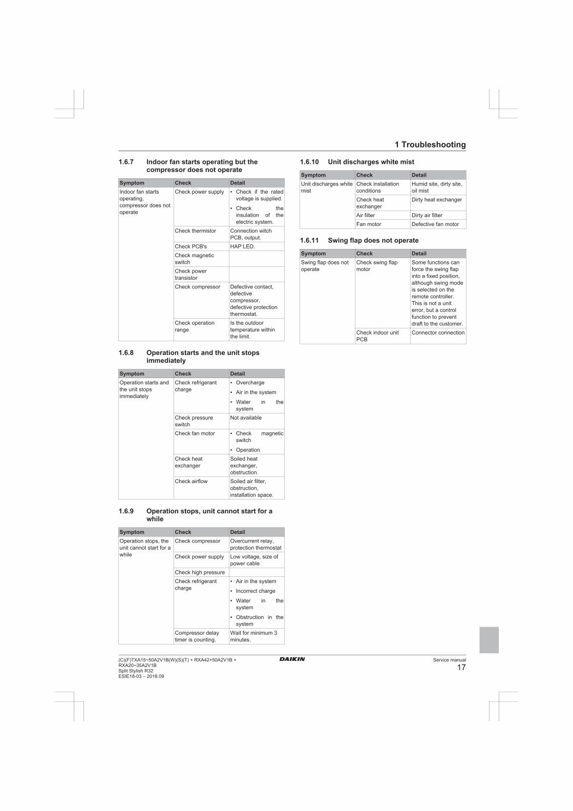
1.6.7 Indoor fan starts operating but thecompressor does not operate
Symptom Check DetailIndoor fan startsoperating,compressor does notoperate
Check power supply ▪ Check if the ratedvoltage is supplied.
▪ Check theinsulation of theelectric system.
Check thermistor Connection witchPCB, output.
Check PCB's HAP LED.Check magneticswitchCheck powertransistorCheck compressor Defective contact,
defectivecompressor,defective protectionthermostat.
Check operationrange
Is the outdoortemperature withinthe limit.
1.6.8 Operation starts and the unit stopsimmediately
Symptom Check DetailOperation starts andthe unit stopsimmediately
Check refrigerantcharge
▪ Overcharge
▪ Air in the system
▪ Water in thesystem
Check pressureswitch
Not available
Check fan motor ▪ Check magneticswitch
▪ OperationCheck heatexchanger
Soiled heatexchanger,obstruction.
Check airflow Soiled air filter,obstruction,installation space.
1.6.9 Operation stops, unit cannot start for awhile
Symptom Check DetailOperation stops, theunit cannot start for awhile
Check compressor Overcurrent relay,protection thermostat
Check power supply Low voltage, size ofpower cable
Check high pressureCheck refrigerantcharge
▪ Air in the system
▪ Incorrect charge
▪ Water in thesystem
▪ Obstruction in thesystem
Compressor delaytimer is counting.
Wait for minimum 3minutes.
1.6.10 Unit discharges white mist
Symptom Check DetailUnit discharges whitemist
Check installationconditions
Humid site, dirty site,oil mist
Check heatexchanger
Dirty heat exchanger
Air filter Dirty air filterFan motor Defective fan motor
1.6.11 Swing flap does not operate
Symptom Check DetailSwing flap does notoperate
Check swing flapmotor
Some functions canforce the swing flapinto a fixed position,although swing modeis selected on theremote controller.This is not a uniterror, but a controlfunction to preventdraft to the customer.
Check indoor unitPCB
Connector connection

2 Components
Service manual
18(C)(F)TXA15~50A2V1B(W)(S)(T) + RXA42+50A2V1B +
RXA20~35A2V1BSplit Stylish R32
ESIE18-03 – 2018.09
2 Components
2.1 4-way valve
2.1.1 Checking procedures
INFORMATION
It is recommended to perform the checks in the listedorder.
To perform a mechanical check of the 4-way valvePrerequisite: Turn OFF the unit via the user interface.
Prerequisite: Turn OFF the respective circuit breaker.
Prerequisite: Remove the required plate work, see "2.13 Platework" on page 40.
1 Disconnect the 4‑way valve connector from the main PCB.
2 Turn ON the power of the unit.
INFORMATION
Default position of the 4‑way valve is Heating mode.
3 Activate Heating operation via the user interface.
Water temperature after platetype heat exchanger of theindoor unit:
Action
Drops 4‑way valve is stuck in coolingposition. Replace the 4‑wayvalve body, see "2.1.2 Repairprocedures" on page 19.
Rises Skip the next step of thisprocedure.
Does NOT rise/drop Perform the next step of thisprocedure.
4 Connect a manifold to one of the service ports of the refrigerantcircuit and check the pressure.
Refrigerant pressuremeasured?
Action
Yes Perform a position check of the4‑way valve, see "2.1.1 Checkingprocedures" on page 18.
No Leaks may be found in therefrigerant circuit. Perform apressure test of the refrigerantcircuit, see "3.2.1 Checkingprocedures" on page 53.
CAUTION
To prevent damage due to liquid entering the compressor,the steps below MUST ONLY be executed once.
CAUTION
Make sure you have a pressure difference of at least 6 barbetween the high and low pressure when performing thistest.
5 Place a round permanent magnet on the core of the solenoidvalve and listen to the 4‑way valve.
Does the 4‑way valve switch? ActionYes Perform an electrical check of the
4‑way valve, see "2.1.1 Checkingprocedures" on page 18.
Does the 4‑way valve switch? ActionNo Replace the 4‑way valve body,
see "2.1.2 Repair procedures" onpage 19.
To perform an electrical check of the 4-way valve1 First perform a mechanical check of the 4‑way valve, see
"2.1.1 Checking procedures" on page 18.
2 Activate Cooling operation via the user interface.
3 Measure the voltage on the 4‑way valve connector pins 1-3.The measured voltage MUST be 220~240 V AC duringswitching and 12 V DC after switching of the 4‑way valve.
Is the measured voltagecorrect?
Action
Yes Skip the next step of thisprocedure.
No Perform the next step of thisprocedure.
4 Disconnect the 4‑way valve connector from the main PCB andmeasure the voltage on the connector pins 1-3 of the connectoron the main PCB. The voltage MUST be 220~240 V AC duringswitching and 12 V DC after switching.
Is the measured voltage on the4‑way valve connector of themain PCB correct?
Action
Yes Replace the 4‑way valve coil, see"2.1.2 Repair procedures" onpage 19.
No Replace the main PCB, see"2.11 Main PCB" on page 35.
5 Disconnect the 4‑way valve connector from the main PCB andmeasure the resistance of the 4‑way valve coil. The resistanceMUST be 1000~2000 Ω.
Is the measured resistancecorrect?
Action
Yes Perform the next step of thisprocedure.
No Replace the 4‑way valve coil, see"2.1.2 Repair procedures" onpage 19.
6 De-activate Cooling and activate Heating operation via the userinterface.
7 Measure the temperature after the plate type heat exchanger.
Does the measuredtemperature rise?
Action
Yes Perform a position check of the4‑way valve, see "2.1.1 Checkingprocedures" on page 18.
No Replace the main PCB, see"2.11 Main PCB" on page 35.
To perform a position check of the 4-way valve1 First perform a mechanical check of the 4‑way valve, see
"2.1.1 Checking procedures" on page 18.
2 Slide a magnet over the front and rear side of the 4‑way valvebody. The magnet MUST be attracted in the positions a or b,but NOT in positions c.

2 Components
Service manual
19(C)(F)TXA15~50A2V1B(W)(S)(T) + RXA42+50A2V1B +RXA20~35A2V1BSplit Stylish R32ESIE18-03 – 2018.09
a a
b b
c c
a Magnet attractedb Magnet attractedc Magnet NOT attracted
Magnet is attracted in thecorrect positions of the 4‑wayvalve?
Action
Yes The 4‑way valve is OK. Return tothe troubleshooting of thespecific error and continue withthe next procedure.
No Replace the 4‑way valve body,see "2.1.2 Repair procedures" onpage 19.
2.1.2 Repair procedures
To remove the 4-way valve coilPrerequisite: Turn OFF the unit via the user interface.
Prerequisite: Turn OFF the respective circuit breaker.
Prerequisite: Remove the required plate work, see "2.13 Platework" on page 40.
Prerequisite: If needed, remove any parts to create more space forthe removal of the 4‑way valve coil.
1 Remove the screw and remove the 4‑way valve coil from the4‑way valve body.
c a ba Screwb 4‑way valve coilc 4‑way valve body
2 Cut all tie straps that fix the 4‑way valve coil harness.
3 Disconnect the 4‑way valve coil connector from the main PCB.
4 To install the 4‑way valve coil, see "2.1.2 Repair procedures" onpage 19.
To remove the 4-way valve bodyPrerequisite: Recuperate the refrigerant from the refrigerant circuit,see "3.2.2 Repair procedures" on page 54.
1 Remove the 4‑way valve coil from the 4‑way valve body, see"2.1.2 Repair procedures" on page 19.
2 Cut the 4‑way valve pipes using a pipe cutter.
cd a b a
a 4‑way valve pipeb 4‑way valvec Puttyd Insulation
3 Remove the 4‑way valve.
4 Keep the putty and the insulation for re-use.
5 To install the 4‑way valve body, see "2.1.2 Repairprocedures" on page 19.
To install the 4-way valve body1 Install the 4‑way valve in the correct location.
2 Wrap a wet rag around the 4‑way valve and solder the 4‑wayvalve pipes to the 4‑way valve.
CAUTION
Overheating the valve will damage or destroy it.

2 Components
Service manual
20(C)(F)TXA15~50A2V1B(W)(S)(T) + RXA42+50A2V1B +
RXA20~35A2V1BSplit Stylish R32
ESIE18-03 – 2018.09
cd a b a
a 4‑way valve pipeb 4‑way valvec Puttyd Insulation
3 Install the putty and the insulation in their original location.
4 Install the 4‑way valve coil on the 4‑way valve body, see"2.1.2 Repair procedures" on page 19.
5 Add refrigerant to the refrigerant circuit, see "3.2.2 Repairprocedures" on page 54.
To install the 4-way valve coil1 Install the 4‑way valve coil on the 4‑way valve body.
c a ba Screwb 4‑way valve coilc 4‑way valve body
2 Install and tighten the screw to fix the 4‑way valve coil.
3 Route the 4‑way valve coil harness towards the main PCB.
4 Connect the 4‑way valve coil connector to the main PCB.
WARNING
When reconnecting a connector to the PCB, do NOT applyforce, as this may damage the connector or connector pinsof the PCB.
5 Fix the 4‑way valve coil harness using new tie straps.
Is the problem solved? ActionYes No further actions required.No Return to the troubleshooting of
the specific error and continuewith the next procedure.
2.2 Compressor
2.2.1 Checking procedures
INFORMATION
It is recommended to perform the checks in the listedorder.
To perform a mechanical check of the compressorPrerequisite: Turn OFF the unit via the user interface.
Prerequisite: Turn OFF the respective circuit breaker.
Prerequisite: Remove the required plate work, see "2.13 Platework" on page 40.
1 Open the compressor insulation.
2 Check the compressor dampers and piping for any damage.
a
a
a Damper
INFORMATION
The compressor dampers may look different.
Compressor dampers andpiping are in a goodcondition?
Action
Yes Perform an electrical check of thecompressor, see "2.2.1 Checkingprocedures" on page 20.
No Replace the compressor, see"2.2.2 Repair procedures" onpage 22.
To perform an electrical check of the compressor1 First perform a mechanical check of the compressor, see
"2.2.1 Checking procedures" on page 20.
2 Open the compressor insulation.
WARNING
The smoothing capacitor MUST discharge below 10 V DCbefore disconnecting the Faston connectors from thecompressor wiring terminals. Risk of electrocution.
3 Remove the cover of the compressor wire terminals.

2 Components
Service manual
21(C)(F)TXA15~50A2V1B(W)(S)(T) + RXA42+50A2V1B +RXA20~35A2V1BSplit Stylish R32ESIE18-03 – 2018.09
a
a Compressor wire terminals cover
4 Disconnect the Faston connectors from the compressor wireterminals U, V and W.
a a
aa Faston connectors
INFORMATION
Note the position of the Faston connectors on thecompressor wire terminals to allow correct connectionduring installation.
5 Measure the resistance between the compressor motorwindings U-V, V-W and U-W. All measurements MUST be thesame.
6 Re-connect the Faston connectors and run the compressor.
7 Measure the current in each phase U-V, V-W and U-W. Allmeasurements MUST be the same.
Compressor motor windingmeasurements are correct?
Action
Yes Perform an insulation check ofthe compressor, see"2.2.1 Checking procedures" onpage 20.
No Replace the compressor, see"2.2.2 Repair procedures" onpage 22.
To perform an insulation check of the compressorPrerequisite: First perform an electrical check of the compressor,see "2.2.1 Checking procedures" on page 20.
Prerequisite: Turn OFF the unit via the user interface.
Prerequisite: Turn OFF the respective circuit breaker.
Prerequisite: Remove the required plate work, see "2.13 Platework" on page 40.
1 Open the compressor insulation.
WARNING
The smoothing capacitor MUST discharge below 10 V DCbefore disconnecting the Faston connectors from thecompressor wiring terminals. Risk of electrocution.
2 Remove the cover of the compressor wire terminals.
a
a Compressor wire terminals cover
3 Disconnect the Faston connectors from the compressor wireterminals U, V and W.
a a
aa Faston connectors
INFORMATION
Note the position of the Faston connectors on thecompressor wire terminals to allow correct connectionduring installation.
4 Set the Megger voltage to 500 V DC or 1000 V DC.
5 Connect the Megger ground test lead directly to the compressorground wire.
2 Components
Service manual
22(C)(F)TXA15~50A2V1B(W)(S)(T) + RXA42+50A2V1B +
RXA20~35A2V1BSplit Stylish R32
ESIE18-03 – 2018.09
CAUTION
Do NOT connect the Megger ground test lead to any otherground wire.
6 Measure the insulation resistance between the followingterminals. The measured insulation resistance MUST be>3 MΩ.
▪ U–ground,▪ V–ground,▪ W–ground.
Compressor insulationmeasurements are correct?
Action
Yes Perform a check of thecompressor overload protection,see "2.2.1 Checkingprocedures" on page 20..
No Replace the compressor, see"2.2.2 Repair procedures" onpage 22.
2.2.2 Repair procedures
To remove the compressorPrerequisite: Turn OFF the unit via the user interface.
Prerequisite: Turn OFF the respective circuit breaker.
Prerequisite: Remove the required plate work, see "2.13 Platework" on page 40.
Prerequisite: Recuperate the refrigerant from the refrigerant circuit,see "3.2.2 Repair procedures" on page 54.
1 If needed, remove any parts to create more space for theremoval of the compressor.
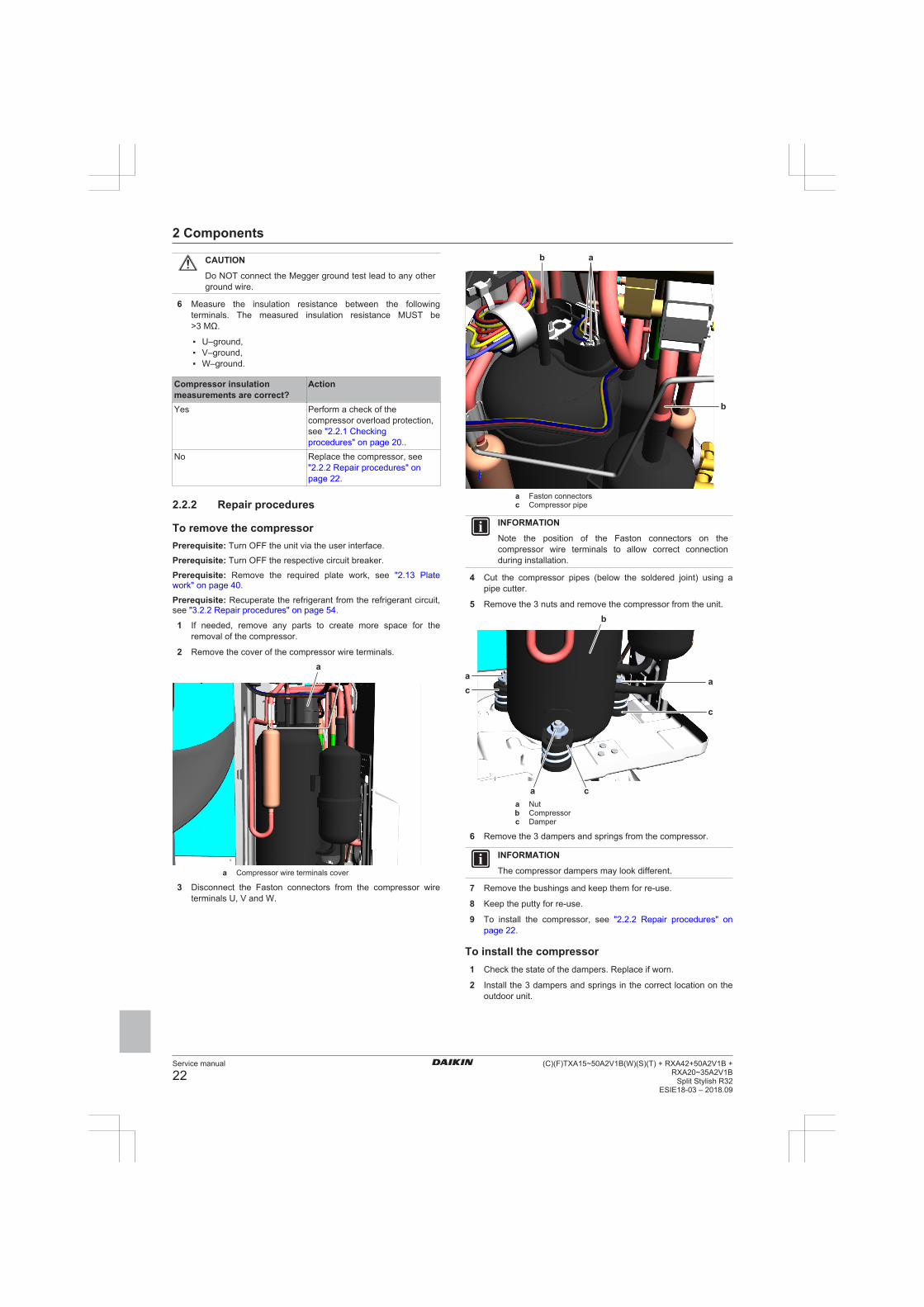
2 Remove the cover of the compressor wire terminals.
a
a Compressor wire terminals cover
3 Disconnect the Faston connectors from the compressor wireterminals U, V and W.
ab
b
a Faston connectorsc Compressor pipe
INFORMATION
Note the position of the Faston connectors on thecompressor wire terminals to allow correct connectionduring installation.
4 Cut the compressor pipes (below the soldered joint) using apipe cutter.
5 Remove the 3 nuts and remove the compressor from the unit.
a
a
a
b
c
c
c
a Nutb Compressorc Damper
6 Remove the 3 dampers and springs from the compressor.
INFORMATION
The compressor dampers may look different.
7 Remove the bushings and keep them for re-use.
8 Keep the putty for re-use.
9 To install the compressor, see "2.2.2 Repair procedures" onpage 22.
To install the compressor1 Check the state of the dampers. Replace if worn.
2 Install the 3 dampers and springs in the correct location on theoutdoor unit.

2 Components
Service manual
23(C)(F)TXA15~50A2V1B(W)(S)(T) + RXA42+50A2V1B +RXA20~35A2V1BSplit Stylish R32ESIE18-03 – 2018.09
a
a
a
b
c
c
c
a Nutb Compressorc Damper
3 Remove the caps from the compression pipe and suction pipe.
CAUTION
The oil in the compressor is hygroscopic. Thereforeremove the caps from the compressor pipes as late aspossible.
4 Wrap a wet rag around the compressor pipes and solder thecompressor pipes to the refrigerant pipes.
ab
b
a Faston connectorsc Compressor pipe
CAUTION
Overheating the compressor pipes (and the oil inside thecompressor pipes) will damage or destroy the compressor.
5 Install the putty in the correct location.
6 Connect the Faston connectors to the compressor wireterminals U, V and W
7 Install the cover of the compressor wire terminals.
a
a Compressor wire terminals cover
8 Add refrigerant to the refrigerant circuit, see "3.2.2 Repairprocedures" on page 54.
Is the problem solved? ActionYes No further actions required.No Return to the troubleshooting of
the specific error and continuewith the next procedure.
2.3 Expansion valve
2.3.1 Checking procedures
INFORMATION
It is recommended to perform the checks in the listedorder.
To perform a mechanical check of the expansionvalvePrerequisite: Power OFF the unit for 3 minutes. Then turn ON theunit and listen to the expansion valve assembly. If the expansionvalve does NOT make a latching sound, continue with the electricalcheck of the expansion valve, see "2.3.1 Checking procedures" onpage 23.
Prerequisite: Turn OFF the unit via the user interface.
Prerequisite: Turn OFF the respective circuit breaker.
Prerequisite: Remove the required plate work, see "2.13 Platework" on page 40.
1 Remove the expansion valve motor from the expansion valvebody, see "2.3.2 Repair procedures" on page 24.
2 Slide the magnet (tool part number 9950038) over theexpansion valve body and gently rotate the magnet clockwise/counterclockwise to manually close/open the expansion valvebody.
Does the expansion valvebody open?
Action
Yes Perform an electrical check of theexpansion valve, see"2.3.1 Checking procedures" onpage 23.
No Replace the expansion valvebody, see "2.3.2 Repairprocedures" on page 24.

2 Components
Service manual
24(C)(F)TXA15~50A2V1B(W)(S)(T) + RXA42+50A2V1B +
RXA20~35A2V1BSplit Stylish R32
ESIE18-03 – 2018.09
To perform an electrical check of the expansionvalvePrerequisite: First perform a mechanical check of the expansionvalve, see "2.3.1 Checking procedures" on page 23.
1 Make sure that the electrical connector of the expansion valvemotor is correctly connected to the main PCB.
2 Disconnect the electrical connector of the expansion valvemotor from the main PCB and measure the continuity betweenthe following pins (windings) using a multi meter. Allmeasurements MUST be approximately the same.
▪ Connector pin 1‑6,▪ Connector pin 2‑6,▪ Connector pin 3‑6,▪ Connector pin 4‑6.
a
a Connector S20
1 or more windings have nocontinuity?
Action
Yes Replace the expansion valvemotor, "2.3.2 Repairprocedures" on page 24.
No Component is OK. Return to thetroubleshooting of the specificerror and continue with the nextstep.
Problem solved?After all checking procedures listed above have been performed:
Is the problem solved? ActionYes No further actions required.No Return to the troubleshooting of
the specific error and continuewith the next procedure.
2.3.2 Repair procedures
To remove the expansion valve motorPrerequisite: Turn OFF the unit via the user interface.
Prerequisite: Turn OFF the respective circuit breaker.
Prerequisite: Remove the required plate work, see "2.13 Platework" on page 40.
Prerequisite: If needed, remove any parts to create more space forthe removal.
1 Pull up the expansion valve motor to remove it from theexpansion valve body.
INFORMATION
It may be needed to turn the expansion valve motor 1/8turn counter clockwise to unlock it.
a
b
a Expansion valve motorb Expansion valve motor harness
a
a Expansion valve motor
INFORMATION
The expansion valve and motor can have a differentconfiguration / layout.
2 Cut all tie straps that fix the expansion valve motor harness.
3 Disconnect the expansion valve motor connector from the mainPCB.
4 To install the expansion valve motor, see "2.3.2 Repairprocedures" on page 24.
To remove the expansion valve bodyPrerequisite: Recuperate the refrigerant from the refrigerant circuit,see "3.2.2 Repair procedures" on page 54.
Prerequisite: If needed, remove any parts to create more space forthe removal.
1 Remove the expansion valve motor, see "2.3.2 Repairprocedures" on page 24.
2 Remove the putty. Keep for re-use.

2 Components
Service manual
25(C)(F)TXA15~50A2V1B(W)(S)(T) + RXA42+50A2V1B +RXA20~35A2V1BSplit Stylish R32ESIE18-03 – 2018.09
a b c
a Puttyb Expansion valve pipec Expansion valve body
a b
a Expansion valve pipeb Expansion valve body
INFORMATION
The expansion valve and motor can have a differentconfiguration / layout.
3 Cut the expansion valve pipes using a pipe cutter.
4 Remove the expansion valve body.
5 To install the expansion valve body, see "2.3.2 Repairprocedures" on page 24.
To install the expansion valve body1 Install the expansion valve body in the correct location.
2 Wrap a wet rag around the expansion valve body and solderthe refrigerant pipes to the expansion valve body.
CAUTION
Overheating the valve will damage or destroy it.
a b c
a Puttyb Expansion valve pipec Expansion valve body
a b
a Expansion valve pipeb Expansion valve body
INFORMATION
The expansion valve and motor can have a differentconfiguration / layout.
3 Reinstall the putty.
4 To install the expansion valve motor, see "2.3.2 Repairprocedures" on page 24.
5 Add refrigerant to the refrigerant circuit, see "3.2.2 Repairprocedures" on page 54.
About the installation of the expansion valvemotor
NOTICE
Select the correct type.
To install the expansion valve motor with clip
1 Install the expansion valve motor on the expansion valve body.
INFORMATION
The expansion valve motor is equipped with a piperetention clip. Install the pipe retention clip over the pipe tolock the expansion valve motor.

2 Components
Service manual
26(C)(F)TXA15~50A2V1B(W)(S)(T) + RXA42+50A2V1B +
RXA20~35A2V1BSplit Stylish R32
ESIE18-03 – 2018.09
b
a
c
a Expansion valve motorb Pipe retention clipc Pipe
2 Route the expansion valve motor harness towards the mainPCB.
3 Connect the expansion valve motor connector to the main PCB.
WARNING
When reconnecting a connector to the PCB, do NOT applyforce, as this may damage the connector or connector pinsof the PCB.
4 Fix the expansion valve motor harness using new tie straps.
Is the problem solved? ActionYes No further actions required.No Return to "2.3.1 Checking
procedures" on page 23 of theexpansion valve and continuewith the next procedure.
To install the expansion valve motor with bracket
1 Install the expansion valve motor on the expansion valve body.
INFORMATION
The expansion valve motor is equipped with a metalbracket. Fit the nipples of the metal bracket into thenotches of the expansion valve body.
bc c d ea
a Expansion valve motorb Metal bracketc Nippled Notche Expanion valve body
2 Route the expansion valve motor harness towards the mainPCB.
3 Connect the expansion valve motor connector to the main PCB.
WARNING
When reconnecting a connector to the PCB, do NOT applyforce, as this may damage the connector or connector pinsof the PCB.
4 Fix the expansion valve motor harness using new tie straps.
Is the problem solved? ActionYes No further actions required.No Return to "2.3.1 Checking
procedures" on page 23 of theexpansion valve and continuewith the next procedure.
2.4 Front panel motor
2.4.1 Checking procedures
To perform an electrical check of the front panelmotorPrerequisite: Turn OFF the unit via the user interface.
Prerequisite: Turn OFF the respective circuit breaker.
Prerequisite: Remove the required plate work, see "2.13 Platework" on page 40.
1 Disconnect the motor connector from the indoor unit PCB.
2 Measure the resistance between the following pins of the motorconnector. The measurements MUST be as shown in the tablebelow.
Pins Measured resistance (Ω)1-2 2351-31-41-52-3 4702-42-53-43-54-5
Front panel motor resistancemeasurements are correct?
Action
Yes Return to the troubleshooting ofthe specific error and continuewith the next procedure.
No Replace the front panel motor,see "2.4.2 Repair procedures" onpage 26.
2.4.2 Repair procedures
To remove the front panel motorPrerequisite: Turn OFF the unit via the user interface.
Prerequisite: Turn OFF the respective circuit breaker.
Prerequisite: Remove the required plate work, see "2.13 Platework" on page 40.
1 Remove the 2 screws and remove the front panel motor fromthe indoor unit.

2 Components
Service manual
27(C)(F)TXA15~50A2V1B(W)(S)(T) + RXA42+50A2V1B +RXA20~35A2V1BSplit Stylish R32ESIE18-03 – 2018.09
a
ab
a Screwb Front panel motor
2 Disconnect the harness from the front panel motor.
3 To install the front panel motor, see "2.4.2 Repairprocedures" on page 26.
To install the front panel motor1 Connect the harness to the front panel motor connector.
2 Install the front panel motor on the indoor unit and tighten usingthe 2 screws.
CAUTION
Make sure the motor axle is well aligned with the slot in thegear when installing the motor.
a
ab
a Screwb Front panel motor
Is the problem solved? ActionYes No further actions required.No Return to the troubleshooting of
the specific error and continuewith the next procedure.
2.5 High pressure switch
2.5.1 Checking procedures
To perform an electrical check of the highpressure switchPrerequisite: Turn OFF the unit via the user interface.
Prerequisite: Turn OFF the respective circuit breaker.
Prerequisite: Remove the required plate work, see "2.13 Platework" on page 40.
1 Disconnect the high pressure switch connector from the PCB.
2 Recuperate the refrigerant from the refrigerant circuit, see"3.2.2 Repair procedures" on page 54.
3 Measure contacts between the pins 1‑2 of the high pressureswitch connector. The switch MUST be open.
4 Measure again contacts between the pins 1‑2 of the highpressure switch connector. The switch MUST be closed.
Both high pressure switchconnector measurements arecorrect?
Then
Yes High pressure switch is OK.Return to the troubleshooting ofthe specific error and continuewith the next procedure.
No Replace the high pressureswitch, see "2.5.2 Repairprocedures" on page 27.
2.5.2 Repair procedures
To remove the high pressure switchPrerequisite: Turn OFF the unit via the user interface.
Prerequisite: Turn OFF the respective circuit breaker.
Prerequisite: Remove the required plate work, see "2.13 Platework" on page 40.
Prerequisite: Recuperate the refrigerant from the refrigerant circuit,see "3.2.2 Repair procedures" on page 54.
Prerequisite: If needed, remove any parts to create more space forthe removal of the high pressure switch.
1 Disconnect the connector from the high pressure switch.
b
a
c
a High pressure switchb Connector

2 Components
Service manual
28(C)(F)TXA15~50A2V1B(W)(S)(T) + RXA42+50A2V1B +
RXA20~35A2V1BSplit Stylish R32
ESIE18-03 – 2018.09
c High pressure switch pipe
2 Cut the high pressure switch pipe using a pipe cutter.
3 Remove the high pressure switch from the unit.
4 To install the high pressure switch, see "2.5.2 Repairprocedures" on page 27.
To install the high pressure switch1 Install the high pressure switch in the correct location.
2 Wrap a wet rag around the high pressure switch and solder thehigh pressure switch pipe to the high pressure switch.
b
a
c
a High pressure switchb Connectorc High pressure switch pipe
CAUTION
Overheating the pressure switch will damage or destroy it.
3 Connect the connector to the high pressure switch.
4 Add refrigerant to the refrigerant circuit, see "3.2.2 Repairprocedures" on page 54.
Is the problem solved? ActionYes No further actions required.No Return to the troubleshooting of
the specific error and continuewith the next procedure.
2.6 Humidity sensor
2.6.1 Checking procedures1 As there is no specific check procedure for this component, first
perform a check of the indoor unit PCB to check if the humiditysensor needs to be replaced. See "2.8.1 Checkingprocedures" on page 30.
After complete check of theindoor unit PCB, is theproblem solved?
Action
Yes No further actions required.No Replace the humidity sensor, see
"2.6.2 Repair procedures" onpage 28.
2.6.2 Repair procedures
To remove the humidity sensorPrerequisite: Turn OFF the unit via the user interface.
Prerequisite: Turn OFF the respective circuit breaker.
Prerequisite: Remove the required plate work, see "2.13 Platework" on page 40.
1 Disconnect the humidity sensor connector from the indoor unitPCB.
2 Carefully click the complete humidity sensor PCB assembly outof the indoor unit.
aa Humidity sensor PCB assembly
3 To install the humidity sensor PCB assembly, see "2.6.2 Repairprocedures" on page 28.
To install the humidity sensor1 Click the humidity sensor PCB assembly on the indoor unit.
aa Humidity sensor PCB assembly
2 Route the humidity sensor harness inside the switch box, alongthe harness retainers.
3 Connect the humidity sensor harness to the appropriateconnector on the indoor unit PCB.

2 Components
Service manual
29(C)(F)TXA15~50A2V1B(W)(S)(T) + RXA42+50A2V1B +RXA20~35A2V1BSplit Stylish R32ESIE18-03 – 2018.09
WARNING
When reconnecting a connector to the PCB, do NOT applyforce, as this may damage the connector or connector pinsof the PCB.
Is the problem solved? ActionYes No further actions required.No Return to the troubleshooting of
the specific error and continuewith the next procedure.
2.7 Indoor unit fan motor
2.7.1 Checking procedures
INFORMATION
It is recommended to perform the checks in the listedorder.
To perform a mechanical check of the DC fanmotor assembly1 Check the friction of the DC fan motor shaft bearing.
Is the DC fan motor shaftfriction normal?
Action
Yes Perform an electrical check of theDC fan motor assembly, see"2.7.1 Checking procedures" onpage 29.
No Replace the DC fan motorassembly, see "2.7.2 Repairprocedures" on page 29.
To perform an electrical check of the DC fan motorassembly1 First perform a mechanical check of the DC fan motor
assembly, see "2.7.1 Checking procedures" on page 29.
2 Measure the resistance between the pins 1-2, 1-3, and 2-3 ofthe DC fan motor connector. All measurements MUST be15~20 Ω.
DC fan motor resistancemeasurements are correct?
Action
Yes Return to the troubleshooting ofthe specific error and continuewith the next procedure.
No Replace the DC fan motor, see"2.7.2 Repair procedures" onpage 29.
2.7.2 Repair procedures
To remove the DC fan motor assemblyPrerequisite: Turn OFF the unit via the user interface.
Prerequisite: Turn OFF the respective circuit breaker.
Prerequisite: Remove the required plate work, see "2.13 Platework" on page 40.
1 Pull the clip and remove the heat exchanger thermistor from itsholder.
2 Remove the screw and remove the cover.
3 Remove the screw to disconnect the grounding wire from theheat exchanger
b a
c
d
e
f
a Grouding wire cover screwb Grounding wire screwc Heat exchanger thermistord Indoor unit PCBe Switch box screwf Switch box
4 Disconnect the connectors of the indoor unit fan motor and thefront wiring from the indoor unit PCB
5 Remove the screw and remove the switch box from the indoorunit.
6 Click the indoor unit fan motor cover out of the indoor unit.
aa Indoor unit fan motor cover
7 Remove the rubber from the indoor unit.
8 Remove the indoor unit fan motor from the indoor unit.
9 To install the indoor unit fan motor, see "2.7.2 Repairprocedures" on page 29.
To install the DC fan motor assembly1 Install the indoor unit fan motor in its correct location on the fan.
2 Install the rubber in front of the fan motor.
3 Click the indoor unit fan motor cover on the indoor unit.

2 Components
Service manual
30(C)(F)TXA15~50A2V1B(W)(S)(T) + RXA42+50A2V1B +
RXA20~35A2V1BSplit Stylish R32
ESIE18-03 – 2018.09
aa Indoor unit fan motor cover
4 Put the switch box in place.
b a
c
d
e
f
a Grouding wire cover screwb Grounding wire screwc Heat exchanger thermistord Indoor unit PCBe Switch box screwf Switch box
5 Route the connectors of the indoor unit fan motor and frontwiring inside the switch box and connect them to the indoor unitPCB.
6 Install and tighten the screw to secure the switch box.
7 Install the heat exchanger thermistor in its holder.
8 Connect the grounding wire to the heat exchanger using thescrew.
9 Install the grounding wire cover using the screw.
Is the problem solved? ActionYes No further actions required.No Return to the troubleshooting of
the specific error and continuewith the next procedure.
2.8 Indoor unit PCB
2.8.1 Checking procedures
INFORMATION
It is recommended to perform the checks in the listedorder.
To perform a power check of the indoor unit PCB1 Measure the voltage between the black and white wires on the
PCB. The measured voltage MUST be 16 V DC.
a ba Black wireb White wire
Is the measured voltage on theindoor unit PCB correct?
Action
Yes Return to "2.8.1 Checkingprocedures" on page 30 of theindoor unit PCB and continuewith the next procedure.
No Adjust the power of the indoorunit PCB, see "2.8.2 Repairprocedures" on page 31.
To perform an electrical check of the indoor unitPCBPrerequisite: Turn OFF the unit via the user interface.
Prerequisite: Turn OFF the respective circuit breaker.
Prerequisite: Remove the required plate work, see "2.13 Platework" on page 40.
1 Turn ON the power of the unit.
2 Measure the voltage between the pins 1‑4 of the connectorS102. The measured voltage MUST be 320 VDC.
a
a Connector S102

2 Components
Service manual
31(C)(F)TXA15~50A2V1B(W)(S)(T) + RXA42+50A2V1B +RXA20~35A2V1BSplit Stylish R32ESIE18-03 – 2018.09
Is the measured voltage on theindoor unit PCB correct?
Action
Yes Return to "2.8.1 Checkingprocedures" on page 30 of theindoor unit PCB and continuewith the next procedure.
No Replace the indoor unit PCB, see"2.8.2 Repair procedures" onpage 31.
To check the HAP LED of the indoor unit PCBPrerequisite: Turn OFF the unit via the user interface.
Prerequisite: Turn OFF the respective circuit breaker.
Prerequisite: Remove the required plate work, see "2.13 Platework" on page 40.
1 Turn ON the power of the unit.
2 Locate the HAP LED on the indoor unit PCB.
aa HAP LED
Does the HAP LED blink inregular intervals (1 secondON/1 second OFF)?
Action
Yes Return to "2.8.1 Checkingprocedures" on page 30 of theindoor unit PCB and continuewith the next procedure.
No Replace the indoor unit PCB, see"2.8.2 Repair procedures" onpage 31.
To check if the correct spare part is installed1 Visit your local spare parts webbank.
2 Enter the model name of your unit and check if the installedspare part number corresponds with the spare part numberindicated in the webbank.
Is the correct spare part for theindoor unit PCB installed?
Action
Yes Return to "2.8.1 Checkingprocedures" on page 30 of theindoor unit PCB and continuewith the next procedure.
No Replace the indoor unit PCB, see"2.8.2 Repair procedures" onpage 31.
To check the wiring of the indoor unit PCB1 Check that all connectors are fully plugged‑in. All colour codes
MUST correspond.
2 Check that no connectors are damaged.
3 Check that the wiring corresponds with the wiring diagram, see"5.2 Wiring diagram" on page 58.
Is the wiring on the indoor unitPCB correct?
Action
Yes Return to "2.8.1 Checkingprocedures" on page 30 of theindoor unit PCB and continuewith the next procedure.
No Adjust the wiring of the indoorunit PCB, see "2.8.2 Repairprocedures" on page 31.
To check the fuse of the indoor unit PCB1 Measure the continuity of the fuse. If no continuity is measured,
the fuse is blown.
aa Fuse
Blown fuse on the indoor unitPCB?
Action
Yes Replace the blown fuse, see"2.8.2 Repair procedures" onpage 31.
No Return to "2.8.1 Checkingprocedures" on page 30 of theindoor unit PCB and continuewith the next procedure.
Problem solved?After all checking procedures listed above have been performed:
Is the problem solved? ActionYes No further actions required.No Return to the troubleshooting of
the specific error and continuewith the next procedure.
2.8.2 Repair procedures
To adjust the power of the indoor unit PCB1 Make sure that the power source is in line with the requirements
described in the databook.
Is the problem solved? ActionYes No further actions required.
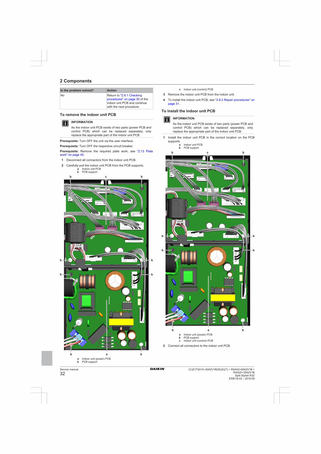
2 Components
Service manual
32(C)(F)TXA15~50A2V1B(W)(S)(T) + RXA42+50A2V1B +
RXA20~35A2V1BSplit Stylish R32
ESIE18-03 – 2018.09
Is the problem solved? ActionNo Return to "2.8.1 Checking
procedures" on page 30 of theindoor unit PCB and continuewith the next procedure.
To remove the indoor unit PCB
INFORMATION
As the indoor unit PCB exists of two parts (power PCB andcontrol PCB) which can be replaced separately, onlyreplace the appropriate part of the indoor unit PCB.
Prerequisite: Turn OFF the unit via the user interface.
Prerequisite: Turn OFF the respective circuit breaker.
Prerequisite: Remove the required plate work, see "2.13 Platework" on page 40.
1 Disconnect all connectors from the indoor unit PCB.
2 Carefully pull the indoor unit PCB from the PCB supports.a Indoor unit PCBb PCB support
a bb
b bc
b
b
b
b
a Indoor unit (power) PCBb PCB support
c Indoor unit (control) PCB
3 Remove the indoor unit PCB from the indoor unit.
4 To install the indoor unit PCB, see "2.8.2 Repair procedures" onpage 31.
To install the indoor unit PCB
INFORMATION
As the indoor unit PCB exists of two parts (power PCB andcontrol PCB) which can be replaced separately, onlyreplace the appropriate part of the indoor unit PCB.
1 Install the indoor unit PCB in the correct location on the PCBsupports.
a Indoor unit PCBb PCB support
a bb
b bc
b
b
b
b
a Indoor unit (power) PCBb PCB supportc Indoor unit (control) PCB
2 Connect all connectors to the indoor unit PCB.

2 Components
Service manual
33(C)(F)TXA15~50A2V1B(W)(S)(T) + RXA42+50A2V1B +RXA20~35A2V1BSplit Stylish R32ESIE18-03 – 2018.09
INFORMATION
Use the wiring diagram and connection diagram for correctinstallation of the connectors, see "5.2 Wiring diagram" onpage 58.
WARNING
When reconnecting a connector to the PCB, do NOT applyforce, as this may damage the connector or connector pinsof the PCB.
Is the problem solved? ActionYes No further actions required.No Return to "2.8.1 Checking
procedures" on page 30 of theindoor unit PCB and continuewith the next procedure.
To adjust the wiring of the indoor unit PCB1 Adjust the wiring according to the wiring diagram and
connection diagram, see "5.2 Wiring diagram" on page 58.
2 Check that all connectors are fully plugged‑in. All colour codesMUST correspond.
3 Check that no connectors are damaged.
Is the problem solved? ActionYes No further actions required.No Return to "2.8.1 Checking
procedures" on page 30 of theindoor unit PCB and continuewith the next procedure.
To remove a fuse of the indoor unit PCB1 Remove the fuse from the PCB.
aa Fuse
2 To install a fuse on the indoor unit PCB, see "2.8.2 Repairprocedures" on page 31.
To install a fuse on the indoor unit PCB1 Install the fuse on the correct location on the PCB.
CAUTION
Make sure the fuse is plugged‑in correctly (contact with thefuse holder).
aa Fuse
Is the problem solved? ActionYes No further actions required.No Return to "2.8.1 Checking
procedures" on page 30 of theindoor unit PCB and continuewith the next procedure.
2.9 Intelligent thermal sensor
2.9.1 Checking procedures1 As there is no specific check procedure for this component, first
perform a check of the indoor unit PCB to check if the intelligentthermal sensor needs to be replaced. See "2.8.1 Checkingprocedures" on page 30.
After complete check of theindoor unit PCB, is theproblem solved?
Action
Yes No further actions required.No Replace the intelligent thermal
sensor, see "2.9.2 Repairprocedures" on page 33.
2.9.2 Repair procedures
To remove the intelligent thermal sensorPrerequisite: Turn OFF the unit via the user interface.
Prerequisite: Turn OFF the respective circuit breaker.
Prerequisite: Remove the required plate work, see "2.13 Platework" on page 40.
1 Disconnect the intelligent thermal sensor connector from theindoor unit PCB.
2 Carefully click the complete intelligent thermal sensor assemblyout of the indoor unit.

2 Components
Service manual
34(C)(F)TXA15~50A2V1B(W)(S)(T) + RXA42+50A2V1B +
RXA20~35A2V1BSplit Stylish R32
ESIE18-03 – 2018.09
a
a Intelligent thermal sensor assembly
3 To install the intelligent thermal sensor assembly, see"2.9.2 Repair procedures" on page 33.
To install the intelligent thermal sensor1 Click the intelligent thermal sensor assembly on the indoor unit.
a
a Intelligent thermal sensor assembly
2 Route the intelligent thermal sensor harness inside the switchbox, along the harness retainers.
3 Connect the intelligent thermal sensor harness to theappropriate connector on the indoor unit PCB.
WARNING
When reconnecting a connector to the PCB, do NOT applyforce, as this may damage the connector or connector pinsof the PCB.
Is the problem solved? ActionYes No further actions required.No Return to the troubleshooting of
the specific error and continuewith the next procedure.
2.10 Inverter PCB
2.10.1 Checking proceduresAs the inverter PCB is integrated in the main PCB of the unit, see"2.11 Main PCB" on page 35 for the other check procedures.
To perform an electrical check of the inverter PCBPrerequisite: Turn OFF the unit via the user interface.
Prerequisite: Turn OFF the respective circuit breaker.
Prerequisite: Remove the required plate work, see "2.13 Platework" on page 40.
1 Open the compressor insulation.
2 Remove the cover of the compressor wire terminals.
3 Measure the voltage between the pins 7‑4 of the connectorS70. Wait until the voltage drops below 10 V DC.
WARNING
The smoothing capacitor MUST discharge below 10 V DCbefore disconnecting the Faston connectors from thecompressor wiring terminals. Risk of electrocution.
4 Disconnect the Faston connectors from the compressor wireterminals U, V and W.
INFORMATION
Note the position of the Faston connectors on thecompressor wire terminals to allow correct connectionduring installation.
5 Connect the Faston connectors to the Inverter Analyzer (SPPnumber 1368521).
6 Turn ON the power of the unit.
7 Locate the switch SW1 on the Inverter Analyzer and press for5 seconds to activate the inverter test.
a
a SW1
8 All LED’s on the Inverter Analyzer must lit.

2 Components
Service manual
35(C)(F)TXA15~50A2V1B(W)(S)(T) + RXA42+50A2V1B +RXA20~35A2V1BSplit Stylish R32ESIE18-03 – 2018.09
9 Turn off the respective circuit breaker.
10 Wait a few minutes and confirm that the LED’s of the InverterAnalyzer are off.
11 Disconnect the Inverter Analyzer from the Faston connectors.
12 Connect the Faston connectors to the wire terminals U, V andW of the compressor.
INFORMATION
Use the notes made during disconnection to connect theFaston connectors to the correct wire terminals of thecompressor.
All LED’s of the inverteranalyzer are lit during invertertest?
Action
Yes Return to Checking proceduresof the inverter PCB and continuewith the next procedure.
No Replace the inverter PCB, seeRepair procedures.
2.10.2 Repair proceduresAs the inverter PCB is integrated in the main PCB of the unit, see"2.11 Main PCB" on page 35 for the repair procedures.
2.11 Main PCB
2.11.1 Checking procedures
INFORMATION
It is recommended to perform the checks in the listedorder.
To perform a power check of the main PCB1 Measure the voltage between the black and white wires shown
below.
Class 20~35
b aa Black wireb White wire
Class 42~50b a
a Black wireb White wire
Is the measured voltage on thePCB correct?
Action
Yes Return to "2.11.1 Checkingprocedures" on page 35 of thePCB and continue with the nextprocedure.
No Adjust the power of the mainPCB, see "2.11.2 Repairprocedures" on page 36.
To check the HAP LED of the main PCBPrerequisite: Turn OFF the unit via the user interface.
Prerequisite: Turn OFF the respective circuit breaker.
Prerequisite: Remove the required plate work, see "2.13 Platework" on page 40.
1 Turn ON the power of the unit.
2 Locate the HAP LED on the main PCB.
Class 20~35a
a HAP LED

2 Components
Service manual
36(C)(F)TXA15~50A2V1B(W)(S)(T) + RXA42+50A2V1B +
RXA20~35A2V1BSplit Stylish R32
ESIE18-03 – 2018.09
Class 42~50a
a HAP LED
Does the HAP LED blink inregular intervals (1 secondON/1 second OFF)?
Action
Yes Return to "2.11.1 Checkingprocedures" on page 35 of themain PCB and continue with thenext procedure.
No Remove the main PCB, see"2.11.2 Repair procedures" onpage 36.
To check if the correct spare part is installed1 Visit your local spare parts webbank.
2 Enter the model name of your unit and check if the installedspare part number corresponds with the spare part numberindicated in the webbank.
NOTICE
Also check that the correct spare part is installed for thecapacity adapter.
Is the correct spare part for thePCB installed?
Action
Yes Return to "2.11.1 Checkingprocedures" on page 35 of themain PCB and continue with thenext procedure.
No Replace the main PCB, see"2.11.2 Repair procedures" onpage 36.
To check the wiring of the main PCB1 Check that all connectors are fully plugged‑in. All colour codes
MUST correspond.
2 Check that no connectors are damaged.
3 Check that the wiring corresponds with the wiring diagram, see"5.2 Wiring diagram" on page 58.
Is the wiring on the main PCBcorrect?
Action
Yes Return to "2.11.1 Checkingprocedures" on page 35 of themain PCB and continue with thenext procedure.
No Adjust the wiring of the mainPCB, see "2.11.2 Repairprocedures" on page 36.
To check the fuse of the main PCB1 Measure the continuity of the fuse. If no continuity is measured,
the fuse is blown.
Class 20~35
a
a Fuse
Class 42~50a
a Fuse
Blown fuse on the main PCB? ActionYes Replace the blown fuse, see
"2.11.2 Repair procedures" onpage 36.
No Return to "2.11.1 Checkingprocedures" on page 35 of themain PCB and continue with thenext procedure.
Problem solved?After all checking procedures listed above have been performed:
Is the problem solved? ActionYes No further actions required.No Return to the troubleshooting of
the specific error and continuewith the next procedure.
2.11.2 Repair procedures
To adjust the power of the main PCB1 Make sure that the power source is in line with the requirements
described in the databook.

2 Components
Service manual
37(C)(F)TXA15~50A2V1B(W)(S)(T) + RXA42+50A2V1B +RXA20~35A2V1BSplit Stylish R32ESIE18-03 – 2018.09
Is the problem solved? ActionYes No further actions required.No Return to "2.11.1 Checking
procedures" on page 35 of thePCB and continue with the nextprocedure.
To remove the main PCBPrerequisite: Turn OFF the unit via the user interface.
Prerequisite: Turn OFF the respective circuit breaker.
Prerequisite: Remove the required plate work, see "2.13 Platework" on page 40.
1 Disconnect all connectors from the main PCB.
Class 20~35
a
a
a
a
a
a Screw
Class 42~50a
aa
aa
a
a Screw
For all models2 Remove the screws from the main PCB.
3 Remove the main PCB from the unit.
4 To install the main PCB, see "2.11.2 Repair procedures" onpage 36.
To install the main PCB1 Apply heat sink compound to the heat sink.
2 Install the main PCB on the correct location in the switch box.
Class 20~35
a
a
a
a
a
a Screw
Class 42~50a
aa
aa
a
a Screw
For all models3 Install and tighten the screws.
4 Connect all connectors to the main PCB.
INFORMATION
Use the wiring diagram and connection diagram for correctinstallation of the connectors, see "5.2 Wiring diagram" onpage 58.
Is the problem solved? ActionYes No further actions required.No Return to "2.11.1 Checking
procedures" on page 35 of thePCB and continue with the nextprocedure.
To adjust the wiring of the main PCB1 Adjust the wiring according to the wiring diagram and
connection diagram, see "5.2 Wiring diagram" on page 58.
2 Check that all connectors are fully plugged‑in. All colour codesMUST correspond.
3 Check that no connectors are damaged.
Is the problem solved? ActionYes No further actions required.

2 Components
Service manual
38(C)(F)TXA15~50A2V1B(W)(S)(T) + RXA42+50A2V1B +
RXA20~35A2V1BSplit Stylish R32
ESIE18-03 – 2018.09
Is the problem solved? ActionNo Return to "2.11.1 Checking
procedures" on page 35 of thePCB and continue with the nextprocedure.
To remove a fuse of the main PCB1 Remove the fuse from the PCB.
Class 20~35
a
a Fuse
Class 42~50a
a Fuse
For all models2 To install a fuse on the main PCB, see "2.11.2 Repair
procedures" on page 36.
To install a fuse on the main PCB1 Install the fuse on the correct location on the PCB.
CAUTION
Make sure the fuse is plugged‑in correctly (contact with thefuse holder).
Class 20~35
a
a Fuse
Class 42~50a
a Fuse
Is the problem solved? ActionYes No further actions required.No Return to "2.11.1 Checking
procedures" on page 35 of thePCB and continue with the nextprocedure.
2.12 Outdoor unit fan motor
2.12.1 Checking procedures
INFORMATION
It is recommended to perform the checks in the listedorder.
To perform a mechanical check of the propellerfan blade assemblyPrerequisite: Turn OFF the unit via the user interface.
Prerequisite: Turn OFF the respective circuit breaker.
Prerequisite: Remove the required plate work, see "2.13 Platework" on page 40.
1 Check the state of the propeller fan blade assembly fordamage, deformations and cracks.

2 Components
Service manual
39(C)(F)TXA15~50A2V1B(W)(S)(T) + RXA42+50A2V1B +RXA20~35A2V1BSplit Stylish R32ESIE18-03 – 2018.09
Is the propeller fan bladeassembly damaged?
Action
Yes Replace the propeller fan bladeassembly, see "2.12.2 Repairprocedures" on page 39.
No Perform a mechanical check ofthe DC fan motor assembly, see"2.12.1 Checking procedures" onpage 38.
To perform a mechanical check of the DC fanmotor assemblyPrerequisite: First perform a mechanical check of the propeller fanblade assembly, see "2.12.1 Checking procedures" on page 38.
1 Check the friction of the DC fan motor shaft bearing.
Is the DC fan motor shaftfriction normal?
Action
Yes Perform an electrical check of theDC fan motor assembly, see"2.12.1 Checking procedures" onpage 38.
No Replace the DC fan motorassembly, see "2.12.2 Repairprocedures" on page 39.
To perform an electrical check of the DC fan motorassembly1 First perform a mechanical check of the DC fan motor
assembly, see "2.12.1 Checking procedures" on page 38.
2 Measure the resistance between the pins 1-2, 1-3, and 2-3 ofthe DC fan motor connector. All measurements MUST be15~20 Ω.
DC fan motor resistancemeasurements are correct?
Action
Yes Return to the troubleshooting ofthe specific error and continuewith the next procedure.
No Replace the DC fan motor, see"2.12.2 Repair procedures" onpage 39.
Problem solved?After all checking procedures listed above have been performed:
Is the problem solved? ActionYes No further actions required.No Return to the troubleshooting of
the specific error and continuewith the next procedure.
2.12.2 Repair procedures
To remove the propeller fan blade assemblyPrerequisite: Turn OFF the unit via the user interface.
Prerequisite: Turn OFF the respective circuit breaker.
Prerequisite: Remove the required plate work, see "2.13 Platework" on page 40.
1 Remove the nut that fixes the propeller fan blade assembly.
a ba Nutb Propeller fan blade assembly
2 Pull and remove the propeller fan blade assembly from the DCfan motor assembly.
3 To install the propeller fan blade assembly, see "2.12.2 Repairprocedures" on page 39.
To remove the DC fan motor assembly1 Remove the propeller fan blade assembly from the DC fan
motor assembly, see "2.12.2 Repair procedures" on page 39.
2 Disconnect the DC fan motor connector from the main PCB.
3 Unlock the ferrite bead.
4 Cut the tie strap.
5 Detach the DC fan motor harness from the switch box.
6 Slightly bend the harness retainers to detach the DC fan motorharness.
7 Remove the 4 screws that fix the DC fan motor assembly.
8 Remove the DC fan motor assembly from the unit.
9 To install the DC fan motor assembly, see "2.12.2 Repairprocedures" on page 39.
To install the DC fan motor assembly1 Install the DC fan motor assembly in the correct location.
2 Fix the DC fan motor assembly to the unit by tightening thescrews.
3 Route the DC fan motor harness through the harness retainersand bend the harness retainers to attach the DC fan motorharness.
4 Attach the DC fan motor harness to the switch box.
5 Install a new tie strap to fix the DC fan motor harness to theswitch box.
6 Connect the DC fan motor connector to the connector on themain PCB.
7 Lock the ferrite bead.
8 Install the propeller fan blade assembly, see "2.12.2 Repairprocedures" on page 39.
To install the propeller fan blade assembly1 Install the propeller fan blade assembly on the DC fan motor
assembly.
CAUTION
Do NOT install a damaged propeller fan blade assembly.

2 Components
Service manual
40(C)(F)TXA15~50A2V1B(W)(S)(T) + RXA42+50A2V1B +
RXA20~35A2V1BSplit Stylish R32
ESIE18-03 – 2018.09
2 Install and tighten the nut to fix the propeller fan bladeassembly.
a ba Nutb Propeller fan blade assembly
Is the problem solved? ActionYes No further actions required.No Return to "2.12.1 Checking
procedures" on page 38 of theoutdoor unit fan motor andcontinue with the next procedure.
2.13 Plate work
2.13.1 Outdoor unit
To remove the refrigerant connection cover
DANGER: RISK OF ELECTROCUTION
DANGER: RISK OF BURNING
1×
1
2
2
1×2
2 1
To remove the top plate
INFORMATION
This procedure is just an example and may differ on somedetails for your actual unit.
Prerequisite: Turn OFF the unit via the user interface.
Prerequisite: Turn OFF the respective circuit breaker.
1 Loosen and remove the screws that fix the top plate.a Screwb Top plate
2 Remove the top plate.
To remove the front plate
INFORMATION
This procedure is just an example and may differ on somedetails for your actual unit.
Prerequisite: Remove the top plate, see "2.13 Plate work" onpage 40.
1 Loosen and remove the screws that fix the front plate.a Screwb Front plate
2 Remove the front plate.
To remove the compressor sound insulation
INFORMATION
This procedure is just an example and may differ on somedetails for your actual unit.
Prerequisite: Remove the front plate, see "2.13 Plate work" onpage 40.
1 Untwist the cord and remove the compressor sound insulation.
a
a Compressor sound insulation
To remove the switch box
INFORMATION
This procedure is just an example and may differ on somedetails for your actual unit.
Prerequisite: Turn OFF the unit via the user interface.
Prerequisite: Turn OFF the respective circuit breaker.
Prerequisite: Remove the required plate work, see "2.13 Platework" on page 40.
1 Remove the insulation on the upper side of the switch box.

2 Components
Service manual
41(C)(F)TXA15~50A2V1B(W)(S)(T) + RXA42+50A2V1B +RXA20~35A2V1BSplit Stylish R32ESIE18-03 – 2018.09
ab
a Insulationb Main PCB
2 Disconnect all connectors from the main PCB.
3 Disconnect the electrical power supply wiring from the wireterminals.
f
a
d
c
b
e
a Electrical power supply wiringb Wire terminalsc Screwsd Wire clampe Screwsf Right side plate assembly
4 Remove the screws that fix the wire clamp.
5 Remove the wire clamp.
6 Remove the screws that fix the right side plate assembly.
7 Cut the cable tie.
a
ba Cable tieb Switch box
8 Lift and remove the switch box from the outdoor unit.
9 To install the switch box, see "2.13 Plate work" on page 40.
To install the switch box
INFORMATION
This procedure is just an example and may differ on somedetails for your actual unit.
1 Install the switch box on the correct location in the outdoor unit.
2 Install the right side plate assembly on the outdoor unit and fix itusing the screws.
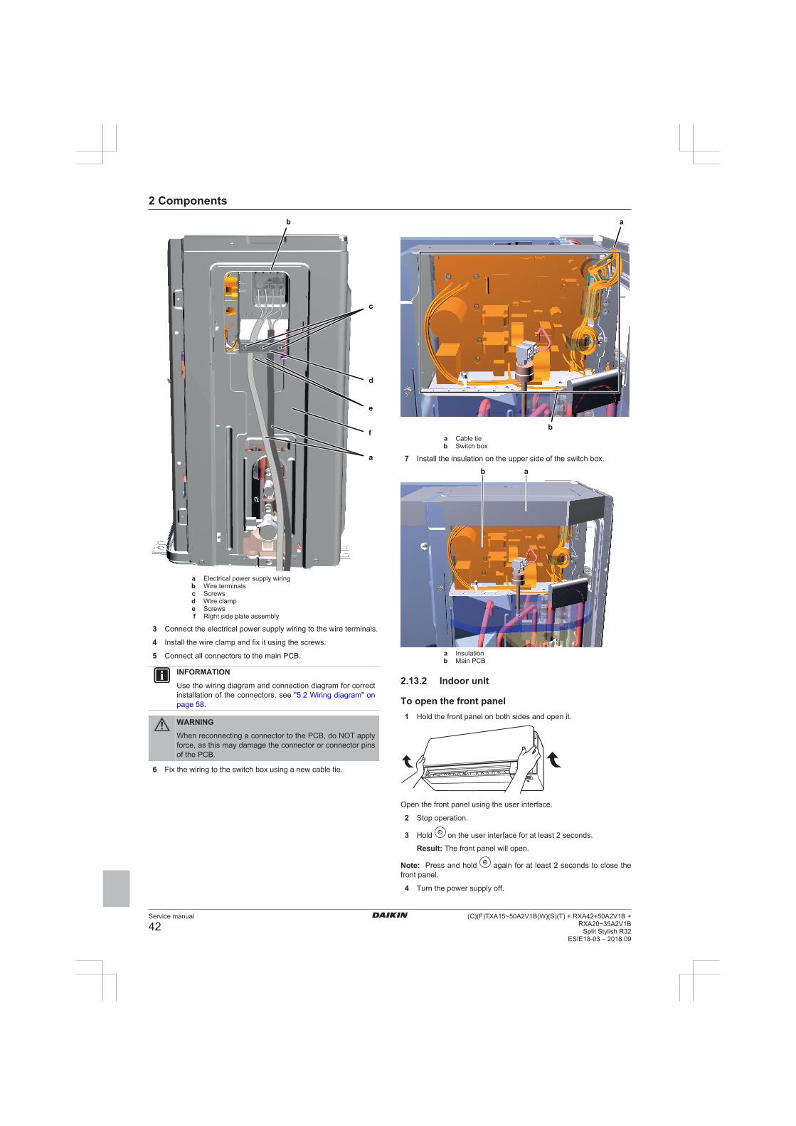
2 Components
Service manual
42(C)(F)TXA15~50A2V1B(W)(S)(T) + RXA42+50A2V1B +
RXA20~35A2V1BSplit Stylish R32
ESIE18-03 – 2018.09
f
a
d
c
b
e
a Electrical power supply wiringb Wire terminalsc Screwsd Wire clampe Screwsf Right side plate assembly
3 Connect the electrical power supply wiring to the wire terminals.
4 Install the wire clamp and fix it using the screws.
5 Connect all connectors to the main PCB.
INFORMATION
Use the wiring diagram and connection diagram for correctinstallation of the connectors, see "5.2 Wiring diagram" onpage 58.
WARNING
When reconnecting a connector to the PCB, do NOT applyforce, as this may damage the connector or connector pinsof the PCB.
6 Fix the wiring to the switch box using a new cable tie.
a
ba Cable tieb Switch box
7 Install the insulation on the upper side of the switch box.
ab
a Insulationb Main PCB
2.13.2 Indoor unit
To open the front panel1 Hold the front panel on both sides and open it.
Open the front panel using the user interface.
2 Stop operation.
3 Hold on the user interface for at least 2 seconds.
Result: The front panel will open.
Note: Press and hold again for at least 2 seconds to close thefront panel.
4 Turn the power supply off.

2 Components
Service manual
43(C)(F)TXA15~50A2V1B(W)(S)(T) + RXA42+50A2V1B +RXA20~35A2V1BSplit Stylish R32ESIE18-03 – 2018.09
5 Pull down both locks on the back of the front panel.
6 Open the front panel until the support fits into the fixing tab.
ad
cb
a Lock (1 on each side)b Backside of the front panelc Fixing tabd Support
INFORMATION
If you CANNOT find the user interface or you use anotheroptional controller. Pull the front panel carefully up by handas shown in the following figure.
To close the front panel1 Set the filters as they were.
2 Lift the front panel slightly and remove the support from thefixing tab.
a
bc
a Backside of the front panelb Fixing tabc Support
3 Close the front panel.
4 Gently press the front panel down until it clicks.
To remove the front panel
INFORMATION
Remove the front panel only in case it MUST be replaced.
1 Open the front panel. See "To open the front panel" on page 42.
2 Open the panel locks located on the back side of the panel(1 on each side).
a a
a Panel lock
3 Push the right arm lightly to the right to disconnect the shaftfrom the shaft slot on the right side.
a
cb
a Armb Shaftc Shaft slot
4 Disconnect the front panel shaft from the shaft slot on the leftside.
acb
a Armb Shaft slotc Shaft
5 Remove the front panel.
6 To re-install the front panel perform the steps in the oppositeorder.
To open the service cover1 Remove 1 screw from the service cover.
2 Pull out the service cover horizontally away from the unit.
ab
ab

2 Components
Service manual
44(C)(F)TXA15~50A2V1B(W)(S)(T) + RXA42+50A2V1B +
RXA20~35A2V1BSplit Stylish R32
ESIE18-03 – 2018.09
a Service cover screwb Service cover
To remove the front grille
CAUTION
Wear protective gloves.
1 Open the front panel. Refer to "To open the front panel" onpage 42.
2 Remove the service cover. Refer to "To open the servicecover" on page 43.
3 Remove the wire harness from the wire clamp and theconnector.
4 Remove the flap by pushing it to the left side and towards you.
5 Remove the 2 screw covers using a long flat plate such as aruler wrapped in a cloth and remove 2 screws.
cd
ba
a Connectorb Wire clampc Screw coverd Long flat plate wrapped in a cloth
6 Push the front grille up and then towards the mounting plate toremove the front grille from the 3 hooks.
a
a Hook
Prerequisite: If working space is limited.7 Insert a flat screwdriver next to the hooks.
8 Pull the front grille up using the flat screwdriver and pushtowards the mounting plate.
ba
a Hookb Flat screwdriver
To re-install the front grille1 Install the front grille and firmly engage the 3 upper hooks.
2 Tighten the 2 screws and put the 2 screw covers back.
3 Re-install the flap.
4 Insert the wire harness back into the connector and secure itwith the wire clamp.
5 Close the front panel. Refer to "To close the front panel" onpage 43.
To remove the electrical wiring box cover1 Remove the front grille.
2 Remove 1 screw from the electrical wiring box.
3 Open the electrical wiring box cover by pulling it to the front.
4 Remove the electrical wiring box cover from the 2 rear hooks.
1
2b
a
c
c
a Screwb Electrical wiring boxc Rear hook
5 To re-install the cover, first attach the electrical wiring box to thehooks, close the electrical wiring box, and re-install the screw.
2.14 Reactor
2.14.1 Checking procedures
To perform an electrical check of the reactorPrerequisite: Turn OFF the unit via the user interface.
Prerequisite: Turn OFF the respective circuit breaker.
Prerequisite: Remove the required plate work, see "2.13 Platework" on page 40.
1 Open the compressor insulation.
2 Remove the cover of the compressor wire terminals.
a
a Compressor wire terminals cover
INFORMATION
The reactor will trip at a temperature of 115°C and willreset at a temperature of 95°C.
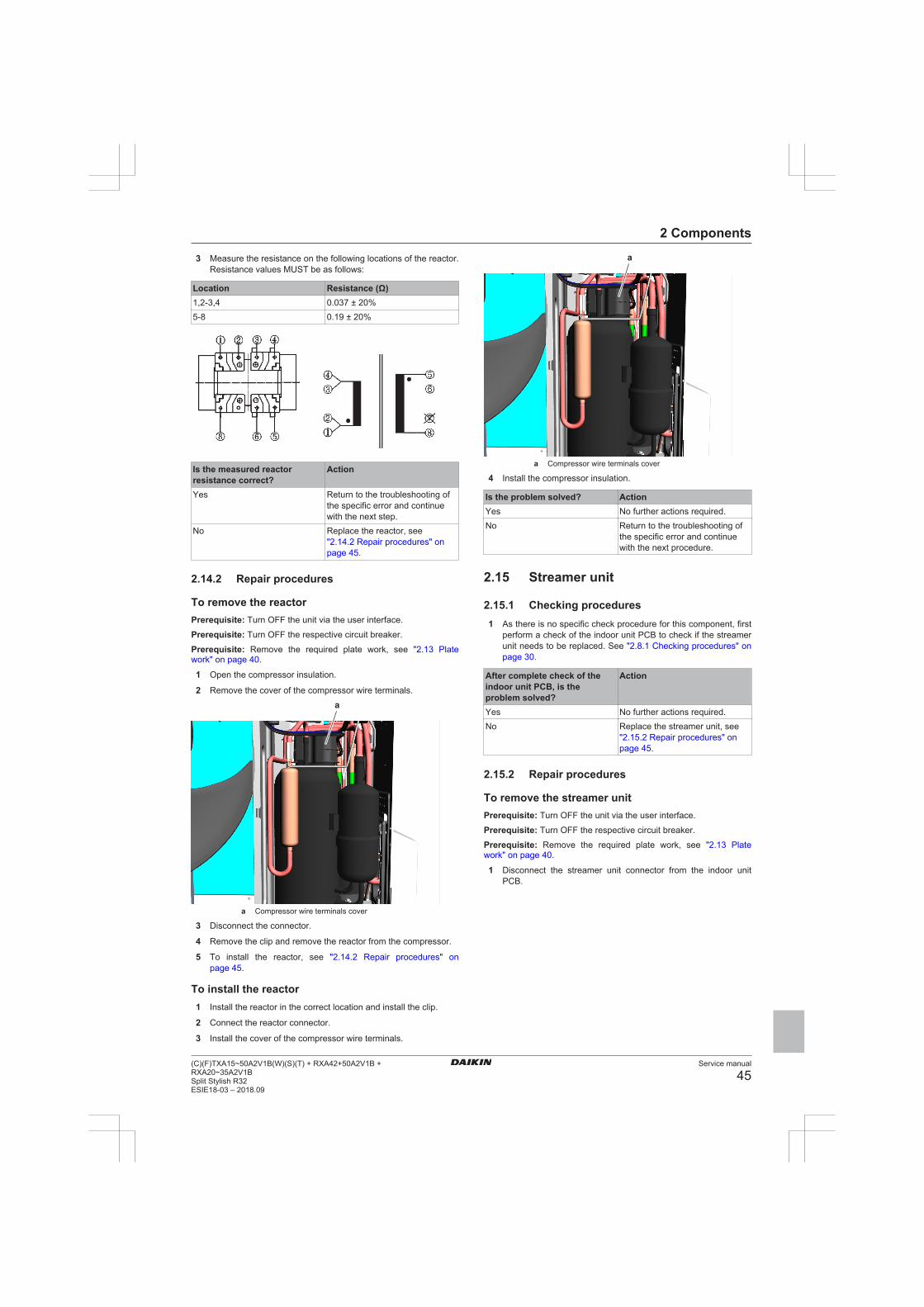
2 Components
Service manual
45(C)(F)TXA15~50A2V1B(W)(S)(T) + RXA42+50A2V1B +RXA20~35A2V1BSplit Stylish R32ESIE18-03 – 2018.09
3 Measure the resistance on the following locations of the reactor.Resistance values MUST be as follows:
Location Resistance (Ω)1,2‑3,4 0.037 ± 20%5‑8 0.19 ± 20%
Is the measured reactorresistance correct?
Action
Yes Return to the troubleshooting ofthe specific error and continuewith the next step.
No Replace the reactor, see"2.14.2 Repair procedures" onpage 45.
2.14.2 Repair procedures
To remove the reactorPrerequisite: Turn OFF the unit via the user interface.
Prerequisite: Turn OFF the respective circuit breaker.
Prerequisite: Remove the required plate work, see "2.13 Platework" on page 40.
1 Open the compressor insulation.
2 Remove the cover of the compressor wire terminals.
a
a Compressor wire terminals cover
3 Disconnect the connector.
4 Remove the clip and remove the reactor from the compressor.
5 To install the reactor, see "2.14.2 Repair procedures" onpage 45.
To install the reactor1 Install the reactor in the correct location and install the clip.
2 Connect the reactor connector.
3 Install the cover of the compressor wire terminals.
a
a Compressor wire terminals cover
4 Install the compressor insulation.
Is the problem solved? ActionYes No further actions required.No Return to the troubleshooting of
the specific error and continuewith the next procedure.
2.15 Streamer unit
2.15.1 Checking procedures1 As there is no specific check procedure for this component, first
perform a check of the indoor unit PCB to check if the streamerunit needs to be replaced. See "2.8.1 Checking procedures" onpage 30.
After complete check of theindoor unit PCB, is theproblem solved?
Action
Yes No further actions required.No Replace the streamer unit, see
"2.15.2 Repair procedures" onpage 45.
2.15.2 Repair procedures
To remove the streamer unitPrerequisite: Turn OFF the unit via the user interface.
Prerequisite: Turn OFF the respective circuit breaker.
Prerequisite: Remove the required plate work, see "2.13 Platework" on page 40.
1 Disconnect the streamer unit connector from the indoor unitPCB.

2 Components
Service manual
46(C)(F)TXA15~50A2V1B(W)(S)(T) + RXA42+50A2V1B +
RXA20~35A2V1BSplit Stylish R32
ESIE18-03 – 2018.09
a
bc
c
a Streamer unit connectorb Streamer unitc Retainer
2 Route the streamer unit harness out of the retainers.
3 Click the streamer unit out of the indoor unit.
4 To install the streamer unit, see "2.15.2 Repair procedures" onpage 45.
To install the streamer unit1 Install the streamer unit in the correct location on the indoor
unit.
a
bc
c
a Streamer unit connectorb Streamer unitc Retainer
2 Route the streamer unit harness inside the switch box andthrough the retainers.
3 Connect the streamer unit connector to the indoor unit PCB.
Is the problem solved? ActionYes No further actions required.No Return to the troubleshooting of
the specific error and continuewith the next procedure.
2.16 Swing flap motor
2.16.1 Main swing flap motor
Checking procedures
Repair procedures
INFORMATION
To replace the motor, the complete gearcase assemblyMUST be replaced.
To remove the swing flap motor gearcase assembly
Prerequisite: Turn OFF the unit via the user interface.
Prerequisite: Turn OFF the respective circuit breaker.
Prerequisite: Remove the required plate work, see "2.13 Platework" on page 40.
1 Remove the main swing flap from the indoor unit (by clicking itout).
2 Remove the 2 screws and remove the swing flap motorgearcase assembly from the indoor unit.

2 Components
Service manual
47(C)(F)TXA15~50A2V1B(W)(S)(T) + RXA42+50A2V1B +RXA20~35A2V1BSplit Stylish R32ESIE18-03 – 2018.09
a
baa Screwb Swing flap motor gearcase assembly
3 Disconnect the swing flap motor harness from the swing flapmotor.
4 To install the swing flap motor gearcase assembly, see "Repairprocedures" on page 46.
To install the swing flap motor gearcase assembly
1 Connect the swing flap motor harness to the swing flap motorconnector.
2 Install the swing flap motor gearcase assembly on the indoorunit and tighten using the 2 screws.
a
baa Screwb Swing flap motor gearcase assembly
3 Install the main swing flap in the indoor unit (by clicking it on).
Is the problem solved? ActionYes No further actions required.No Return to the troubleshooting of
the specific error and continuewith the next procedure.
2.16.2 Secondary swing flap motor
Checking procedures
To perform an electrical check of the swing flap motor
Prerequisite: Turn OFF the unit via the user interface.
Prerequisite: Turn OFF the respective circuit breaker.
Prerequisite: Remove the required plate work, see "2.13 Platework" on page 40.
1 Disconnect the motor connector from the indoor unit PCB.
2 Measure the resistance between the following pins of the motorconnector. The measurements MUST be as shown in the tablebelow.
Pins Measured resistance (Ω)1-2 2351-31-41-52-3 4702-42-53-43-54-5
Swing flap motor resistancemeasurements are correct?
Action
Yes Return to the troubleshooting ofthe specific error and continuewith the next procedure.
No Replace the swing flap motor,see "Repair procedures" onpage 47.
Repair procedures
INFORMATION
To replace the motor, the complete gearcase assemblyMUST be replaced.
To remove the swing flap motor gearcase assembly
Prerequisite: Turn OFF the unit via the user interface.
Prerequisite: Turn OFF the respective circuit breaker.
Prerequisite: Remove the required plate work, see "2.13 Platework" on page 40.
1 Remove the main swing flap from the indoor unit (by clicking itout).
2 Remove the secondary swing flap from the indoor unit (byclicking it out).
3 Remove the right side fan guard from the indoor unit (byclicking it out).
c a
b
a Fan guardb Rocker armc
Swing raster

2 Components
Service manual
48(C)(F)TXA15~50A2V1B(W)(S)(T) + RXA42+50A2V1B +
RXA20~35A2V1BSplit Stylish R32
ESIE18-03 – 2018.09
4 Remove the 3 screws from the swing flap motor gear caseassembly. Do NOT yet remove the assembly from the indoorunit.
aa b
a
a Screwb Swing flap motor gearcase assembly
5 Disconnect the rocker arm from the swing raster.
6 Remove the swing flap motor gear case assembly from theindoor unit.
7 Disconnect the harness from the swing flap motor.
8 Disconnect the harness from the swing raster motor.
9 To install the swing flap motor gearcase assembly, see "Repairprocedures" on page 47.
To install the swing flap motor gearcase assembly
1 Connect the harness to the swing raster motor connector.
2 Install the swing flap motor gearcase assembly on the indoorunit. Install the 3 screws, but do NOT yet tighten them.
aa b
a
a Screwb Swing flap motor gearcase assembly
3 Connect the rocker arm to the swing raster.
c a
b
a Fan guardb Rocker armc
Swing raster
4 Tighten the 3 screws to fix the swing flap motor assembly.
5 Connect the harness to the swing flap motor connector.
6 Install the right side fan guard on the indoor unit (by clicking iton).
7 Install the secondary swing flap in the indoor unit (by clicking iton).
8 Install the main swing flap in the indoor unit (by clicking it on).
Is the problem solved? ActionYes No further actions required.No Return to the troubleshooting of
the specific error and continuewith the next procedure.
2.17 Swing raster motor
2.17.1 Checking procedures
To perform an electrical check of the swing rastermotorPrerequisite: Turn OFF the unit via the user interface.
Prerequisite: Turn OFF the respective circuit breaker.
Prerequisite: Remove the required plate work, see "2.13 Platework" on page 40.
1 Disconnect the motor connector from the indoor unit PCB.
2 Measure the resistance between the following pins of the motorconnector. The measurements MUST be as shown in the tablebelow.
Pins Measured resistance (Ω)1-2 2351-31-41-52-3 4702-42-53-43-54-5

2 Components
Service manual
49(C)(F)TXA15~50A2V1B(W)(S)(T) + RXA42+50A2V1B +RXA20~35A2V1BSplit Stylish R32ESIE18-03 – 2018.09
Front panel motor resistancemeasurements are correct?
Action
Yes Return to the troubleshooting ofthe specific error and continuewith the next procedure.
No Replace the front panel motor,see "2.4.2 Repair procedures" onpage 26.
Swing raster motor resistancemeasurements are correct?
Action
Yes Return to the troubleshooting ofthe specific error and continuewith the next procedure.
No Replace the swing raster motor,see "2.17.2 Repairprocedures" on page 49.
2.17.2 Repair procedures
INFORMATION
To replace the motor, the complete gearcase assemblyMUST be replaced.
As the swing raster motor is integrated in the secondary swing flapmotor gearcase assembly, see "2.16.2 Secondary swing flapmotor" on page 47 for the repair procedures.
2.18 ThermistorsNOTICE
Select the correct type.
2.18.1 Refrigerant thermistors
Checking procedures
INFORMATION
It is recommended to perform the checks in the listedorder.
To perform a mechanical check of the specific thermistor
Prerequisite: Turn OFF the unit via the user interface.
Prerequisite: Turn OFF the respective circuit breaker.
Prerequisite: Remove the required plate work, see "2.13 Platework" on page 40.
1 Locate the thermistor and remove the insulation if needed.Check if there is thermal contact between the thermistor andthe piping or ambient.
Is the thermistor correctlyinstalled (thermal contactbetween the thermistor and thepiping)?
Action
Yes Perform an electrical check of thespecific thermistor, see"Checking procedures" onpage 49.
No Correctly install the thermistor,see "Repair procedures" onpage 50.
To perform an electrical check of the specific thermistor
Prerequisite: First perform a mechanical check of the thermistor,see "Checking procedures" on page 49.
1 Locate the thermistor.
2 Measure the temperature using a contact thermometer.
Name Symbol Location(PCB)
Connector(pins)
Type
Airthermistor
R1T Main S90:1‑2 1
Heatexchangerthermistor
R2T Main S90:3‑4 1
Dischargepipethermistor
R3T Main S90:5‑6 1
Heatexchangerthermistor
R1T Indoor S501:1‑2 1
INFORMATION
The thermistors may vary according to the specific unit.
3 Determine the thermistor resistance that matches the measuredtemperature.
Type 1 thermistor
T °C kΩ T °C kΩ T °C kΩ T °C kΩ–20 197.81 10 39.96 40 10.63 70 3.44–19
–18
–17
–16
–15
–14
–13
–12
–11
186.53
175.97
166.07
156.80
148.10
139.94
132.28
125.09
118.34
11
12
13
14
15
16
17
18
19
38.08
36.30
34.62
33.02
31.50
30.06
28.70
27.41
26.18
41
42
43
44
45
46
47
48
49
10.21
9.81
9.42
9.06
8.71
8.37
8.05
7.75
7.46
71
72
73
74
75
76
77
78
79
3.32
3.21
3.11
3.01
2.91
2.82
2.72
2.64
2.55–10 111.99 20 25.01 50 7.18 80 2.47–9
–8
–7
–6
–5
–4
–3
–2
–1
106.03
100.41
95.14
90.17
85.49
81.08
76.93
73.01
69.32
21
22
23
24
25
26
27
28
29
23.91
22.85
21.85
20.90
20.00
19.14
18.32
17.54
16.80
51
52
53
54
55
56
57
58
59
6.91
6.65
6.41
6.65
6.41
6.18
5.95
5.74
5.140 65.84 30 16.10 60 4.871
2
3
4
5
6
7
8
9
62.54
59.43
56.49
53.71
51.09
48.61
46.26
44.05
41.95
31
32
33
34
35
36
37
38
39
15.43
14.79
14.18
13.59
13.04
12.51
12.01
11.52
11.06
61
62
63
64
65
66
67
68
69
4.70
4.54
4.38
4.23
4.08
3.94
3.81
3.68
3.56
4 Disconnect the thermistor connector from the appropriate PCB.
5 Measure the resistance between the appropriate pins of thethermistor connector.

2 Components
Service manual
50(C)(F)TXA15~50A2V1B(W)(S)(T) + RXA42+50A2V1B +
RXA20~35A2V1BSplit Stylish R32
ESIE18-03 – 2018.09
6 Check that the measured resistance value matches theresistance determined through the measured temperature(earlier step in the procedure). E.g. R1T thermistor:
▪ Measured temperature with contact thermometer: 23.1°C,▪ Resistance value determined through temperature (using the
table for type 1 thermistors):Resistance at 23°C: 21.85 kΩ,Resistance at 24°C: 20.90 kΩ,
▪ Disconnect connector and measure resistance between S90pin 1‑2:Measured resistance: 21.86 kΩ,
▪ Measured resistance value is inside the range. R1Tthermistor passes the check.
INFORMATION
All thermistors have a resistance tolerance of 5%.
INFORMATION
The user interface allows to monitor most thermistors.
If the measured resistance value matches the resistancedetermined through the measured temperature, but thetemperature for the corresponding thermistor is NOTcorrect on the user interface display, replace the applicablePCB.
Does the measured resistanceof the thermistor match withthe temperature determinedresistance?
Action
Yes Thermistor is OK. Return to thetroubleshooting of the specificerror and continue with the nextprocedure.
No Replace the specific thermistor,see "Repair procedures" onpage 50.
Repair procedures
To remove the thermistor
Prerequisite: Turn OFF the unit via the user interface.
Prerequisite: Turn OFF the respective circuit breaker.
Prerequisite: Remove the required plate work, see "2.13 Platework" on page 40.
1 Locate the thermistor that needs to be removed.
2 Cut the tie straps that fix the insulation and the thermistor wire.
c ba
a
f
d ea Tie strapb Insulationc Thermistor wired Clipe Thermistorf Thermistor holder
3 Cut and remove the insulation.
4 Pull the clip that fixes the thermistor.
5 Remove the thermistor from the thermistor holder.
6 Disconnect the thermistor connector from the appropriate PCBand remove the thermistor.
7 To install the thermistor, see "Repair procedures" on page 50.
To install the thermistor
1 Pull the clip and install the thermistor in the specific thermistorholder. Make sure the clip is in the correct position (blocking thethermistor).
c
a b

2 Components
Service manual
51(C)(F)TXA15~50A2V1B(W)(S)(T) + RXA42+50A2V1B +RXA20~35A2V1BSplit Stylish R32ESIE18-03 – 2018.09
e df
fa Clipb Thermistorc Thermistor holderd Insulatione Thermistor wiref Tie strap
2 Connect the thermistor connector to the appropriate PCB.
WARNING
When reconnecting a connector to the PCB, do NOT applyforce, as this may damage the connector or connector pinsof the PCB.
3 Install the insulation around the thermistor.
4 Fix the insulation and the thermistor wire using new tie straps.
Is the problem solved? ActionYes No further actions required.No Return to the troubleshooting of
the specific error and continuewith the next procedure.
2.18.2 Other thermistors
Checking procedures
To perform a mechanical check of the specific thermistor
Prerequisite: Turn OFF the unit via the user interface.
Prerequisite: Turn OFF the respective circuit breaker.
Prerequisite: Remove the required plate work, see "2.13 Platework" on page 40.
1 Locate the thermistor and remove the insulation if needed.Check if there is thermal contact between the thermistor andthe piping or ambient.
Is the thermistor correctlyinstalled (thermal contactbetween the thermistor and thepiping or ambient)?
Action
Yes Perform an electrical check of thespecific thermistor, see"Checking procedures" onpage 51.
No Correctly install the thermistor,see Repair procedures.
Repair proceduresAs the room thermistor is located on the same PCB as the humiditysensor, see "2.6 Humidity sensor" on page 28 for the repairprocedures.
2.19 Wifi control PCB
2.19.1 Checking procedures1 As there is no specific check procedure for this component, first
perform a check of the indoor unit PCB to check if the wificontrol PCB needs to be replaced. See "2.8.1 Checkingprocedures" on page 30.
After complete check of theindoor unit PCB, is theproblem solved?
Action
Yes No further actions required.No Replace the wifi control PCB, see
"2.19.2 Repair procedures" onpage 51.
2.19.2 Repair procedures
To remove the wifi control PCBPrerequisite: Turn OFF the unit via the user interface.
Prerequisite: Turn OFF the respective circuit breaker.
Prerequisite: Remove the required plate work, see "2.13 Platework" on page 40.
1 Disconnect the wifi control PCB connector from the indoor unitPCB.
2 Carefully click the complete wifi control PCB assembly out ofthe indoor unit.
a
a Wifi control PCB assembly
3 To install the wifi control PCB assembly, see "2.19.2 Repairprocedures" on page 51.
To install the wifi control PCB1 Click the wifi control PCB assembly on the indoor unit.

3 Third party components
Service manual
52(C)(F)TXA15~50A2V1B(W)(S)(T) + RXA42+50A2V1B +
RXA20~35A2V1BSplit Stylish R32
ESIE18-03 – 2018.09
a
a Wifi control PCB assembly
2 Route the wifi control PCB harness inside the switch box, alongthe harness retainers.
3 Connect the wifi control PCB harness to the appropriateconnector on the indoor unit PCB.
WARNING
When reconnecting a connector to the PCB, do NOT applyforce, as this may damage the connector or connector pinsof the PCB.
Is the problem solved? ActionYes No further actions required.No Return to the troubleshooting of
the specific error and continuewith the next procedure.
3 Third party components
3.1 Power supply
3.1.1 Checking procedures
To check if the power supply is conform with theregulations1 Check that the power source is in line with the requirements
described in the databook.
Is the power supply conformwith the regulations?
Action
Yes Return to the troubleshooting ofthe specific error and continuewith the next procedure.
No Adjust the power supply, see"3.1.2 Repair procedures" onpage 52.
To check the wiring between the outdoor unit andthe indoor unit1 Check that all connectors are fully plugged‑in. All colour codes
MUST correspond.
2 Check that no connectors are damaged.
3 Check that the wiring corresponds with the wiring diagram, see"5.2 Wiring diagram" on page 58.
Is all wiring between theoutdoor unit and the indoorunit correct?
Action
Yes Return to the troubleshooting ofthe specific error and continuewith the next procedure.
No Adjust the wiring where needed,see "3.1.2 Repair procedures" onpage 52.
To check the wiring between the indoor unit andthe remote controller1 Check that all connectors are fully plugged‑in. All colour codes
MUST correspond.
2 Check that no connectors are damaged.
3 Check that the wiring corresponds with the wiring diagram, see"5.2 Wiring diagram" on page 58.
Is all wiring between theindoor unit and remotecontroller correct?
Action
Yes Return to the troubleshooting ofthe specific error and continuewith the next procedure.
No Adjust the wiring where needed,see "3.1.2 Repair procedures" onpage 52.
3.1.2 Repair procedures
To adjust the power supply1 Make sure that the power source is in line with the requirements
described in the databook.
Is the problem solved? ActionYes No further actions required.No Return to the troubleshooting of
the specific error and continuewith the next procedure.
To adjust the wiring between the outdoor unit andthe indoor unit1 Adjust the wiring according to the wiring diagram and
connection diagram, see "5.2 Wiring diagram" on page 58.
2 Check that all connectors are fully plugged‑in. All colour codesMUST correspond.
3 Check that no connectors are damaged.
Is the problem solved? ActionYes No further actions required.No Return to the troubleshooting of
the specific error and continuewith the next procedure.
To adjust the wiring between the indoor unit andthe remote controller1 Adjust the wiring according to the wiring diagram and
connection diagram, see "5.2 Wiring diagram" on page 58.
2 Check that all connectors are fully plugged‑in. All colour codesMUST correspond.
3 Check that no connectors are damaged.
Is the problem solved? ActionYes No further actions required.

3 Third party components
Service manual
53(C)(F)TXA15~50A2V1B(W)(S)(T) + RXA42+50A2V1B +RXA20~35A2V1BSplit Stylish R32ESIE18-03 – 2018.09
Is the problem solved? ActionNo Return to the troubleshooting of
the specific error and continuewith the next procedure.
3.2 Refrigerant circuit
3.2.1 Checking procedures
INFORMATION
It is recommended to perform the checks in the listedorder.
To check if the stop valve is openPrerequisite: Remove the required plate work, see "2.13 Platework" on page 40.
1 Remove the caps.
a
a
b
ca Capb Liquid stop valvec Gas stop valve
2 Check if the stop valve is completely open.
The refrigerant circuit stopvalve is open?
Action
Yes Return to "3.2.1 Checkingprocedures" on page 53 of therefrigerant circuit and continuewith the next procedure.
No Open the stop valve of therefrigerant circuit, see"3.2.2 Repair procedures" onpage 54.
To check if the refrigerant circuit is cloggedPrerequisite: Turn OFF the unit via the user interface.
Prerequisite: Turn OFF the respective circuit breaker.
1 Wait for the refrigerant to reach the outdoor temperature.
2 Connect a manometer to the service port.
3 Measure the low pressure as a reference.
4 Turn ON the power of the unit.
5 Activate Cooling via the user interface.
6 Again measure the low pressure.
Low pressure lower thanexpected?
Then
Yes Obstruction is possible.No Obstruction is less likely.
7 Using a thermometer, check for a temperature drop of minimum4°C. The obstruction is most likely located where thistemperature drop occurs.
Temperature drop found? ActionYes Replace the clogged part, see
"3.2.2 Repair procedures" onpage 54.
No Return to "3.2.1 Checkingprocedures" on page 53 of therefrigerant circuit and continuewith the next procedure.
To check if the refrigerant circuit is correctlycharged1 Recuperate all refrigerant from the unit, see "3.2.2 Repair
procedures" on page 54.
2 Weigh the recuperated refrigerant.
3 Compare the weight of the recuperated refrigerant with thelogbook of the unit. If the weight does NOT match the logbook,the refrigerant circuit is charged incorrectly.
CAUTION
Make sure that the original calculation of refrigerant iscorrect. (e.g. take into account that due to additionalpiping, additional refrigerant could be required).
Is the refrigerant circuitcharged correctly?
Action
Yes Return to "3.2.1 Checkingprocedures" on page 53 of therefrigerant circuit and continuewith the next procedure.
No Add or recuperate refrigerantuntil correctly charged, see"3.2.2 Repair procedures" onpage 54.
To check for non-condensables in the refrigerantcircuitPrerequisite: Turn OFF the unit via the user interface.
Prerequisite: Turn OFF the respective circuit breaker.
1 Wait for the refrigerant to reach the outdoor temperature.
2 Connect a manometer to the service port.
3 Measure the pressure of the refrigerant. The measuredpressure MUST be in line with the expected pressure at outdoortemperature.
4 If the measured pressure is higher than the expected pressure(at outdoor temperature), other non‑condensables are mixed inthe refrigerant.
Any non‑condensables foundin the refrigerant circuit?
Action
Yes To replace the refrigerant, see"3.2.2 Repair procedures" onpage 54.
No Return to "3.2.1 Checkingprocedures" on page 53 of therefrigerant circuit and continuewith the next procedure.

3 Third party components
Service manual
54(C)(F)TXA15~50A2V1B(W)(S)(T) + RXA42+50A2V1B +
RXA20~35A2V1BSplit Stylish R32
ESIE18-03 – 2018.09
To perform a pressure test of the refrigerant circuit1 Perform a pressure test in line with local legislation.
CAUTION
Perform a pressure test only when leaks are expected.
Is the pressure in therefrigerant circuit correct?
Action
Yes Return to "3.2.1 Checkingprocedures" on page 53 of therefrigerant circuit and continuewith the next procedure.
No Replace the leaking part of therefrigerant circuit, see"3.2.2 Repair procedures" onpage 54.
Problem solved?After all checking procedures listed above have been performed:
Is the problem solved? ActionYes No further actions required.No Return to the troubleshooting of
the specific error and continuewith the next procedure.
3.2.2 Repair procedures
To open the stop valve of the refrigerant circuitPrerequisite: Remove the required plate work, see "2.13 Platework" on page 40.
1 Remove the caps.
a
a
b
ca Capb Liquid stop valvec Gas stop valve
2 Completely open the stop valve by screwing the stop valvescrew counterclockwise.
Is the problem solved? ActionYes No further actions required.No Return to the troubleshooting of
the specific error and continuewith the next procedure.
To replace the clogged/leaking part of therefrigerant circuit1 See the correct procedure for the component that needs to be
repaired.
Is the problem solved? ActionYes No further actions required.No Return to "3.2.1 Checking
procedures" on page 53 of therefrigerant circuit and continuewith the next procedure.
To recuperate the refrigerantPrerequisite: Turn OFF the unit via the user interface.
1 Manually open the expansion valve.
2 Connect the vacuum pump, manifold, recovery unit, andrefrigerant bottle to the service port of the refrigerant circuit asshown below.
HV R
L
c
b
aa Vacuum pumpb Connect flexible hose to service port 3 stop valvec To recovery pumpL Low pressureH High pressureV VacuumR Refrigerant
3 To add refrigerant, see "3.2.2 Repair procedures" on page 54.
Is the problem solved? ActionYes No further actions required.No Return to the troubleshooting of
the specific error and continuewith the next procedure.
To add refrigerant1 See the installer reference guide for the correct procedure.
Is the problem solved? ActionYes No further actions required.

3 Third party components
Service manual
55(C)(F)TXA15~50A2V1B(W)(S)(T) + RXA42+50A2V1B +RXA20~35A2V1BSplit Stylish R32ESIE18-03 – 2018.09
Is the problem solved? ActionNo Perform a pressure test of the
refrigerant circuit, see"3.2.1 Checking procedures" onpage 53.
Repair information
Refrigerant piping handling
▪ Make sure that the applied pressure is never higher than the unitdesign pressure indicated on the nameplate (PS).
▪ Work according to the F‑gas regulation and/or local regulations.
▪ Make sure the correct amount of refrigerant is charged after repairaccording to the F‑gas regulation label on the unit (factory +additional where required).
▪ Make sure to use the appropriate equipment and tools accordingto the refrigerant and unit type.
▪ Charge non‑azeotropic refrigerant (e.g. R410A) always in a liquidstate.
▪ R32 can be charged in gas phase.
▪ Make sure to use a digital scale (no charging cylinder).
▪ Execute correct vacuum drying procedure after repair:
▪ –0.1 MPa / –760 mm Hg / –750 Torr / –1 bar for at least 1 hour.
▪ Connect the unit according to the available service ports.
▪ Use related field setting where necessary to open expansionvalve / solenoid valve.
To perform refrigerant pump down operation
The unit is equipped with an automatic pump down operation whichwill collect all refrigerant from the field piping and indoor unit in theoutdoor unit. To protect the environment, make sure to perform thefollowing pump down operation when relocating the unit.
DANGER: RISK OF EXPLOSION
Pump down – Refrigerant leakage. If you want to pumpdown the system, and there is a leak in the refrigerantcircuit:
▪ Do NOT use the unit's automatic pump down function,with which you can collect all refrigerant from thesystem into the outdoor unit. Possible consequence:Self-combustion and explosion of the compressorbecause of air going into the operating compressor.
▪ Use a separate recovery system so that the unit'scompressor does NOT have to operate.
CAUTION
Some outdoor units are equipped with a low pressureswitch to protect the compressor by switching it off.NEVER short‑circuit the low pressure switch during pumpdown operation.
1 Remove the refrigerant connection cover, see "2.13 Platework" on page 40.
2 Remove the cap from the stop valves.
3 Perform pump down operation, see installer reference guide forthe correct procedure.
4 After 5~10 minutes (after only 1~2 minutes in case temperature<–10°C), close the liquid stop valve using a hexagonal wrench.
5 Check the manifold if vacuum is reached. Close the gas stopvalve and stop forced cooling operation.
Refrigerant piping repair
▪ Make sure to cover open pipe ends during repair so no dust ormoisture can enter.
▪ Make sure to re‑apply insulation removed during repair.
▪ Pipe expansion / flare making:
▪ Remove any burrs on the cut surface using the correct toolsuch as reamer or scraper (note that excessive deburring canthin the pipe walls and cause cracking of the pipe).
▪ Make sure the flare has the correct size (use a flare gauge).
▪ Make sure no particles remain in the piping.
▪ Apply just a drop of refrigerant oil on the inner surface of theflare.
▪ Make sure the flare connection is tightened with the correcttorque (torque values refer to installation manual).
▪ Brazing:
▪ Use the correct brazing tool.
▪ Use a phosphor copper filler metal (silver composition of 0 to2%). Do not use flux material.
▪ Flush the piping before brazing with nitrogen to avoid oxidationof the inside of the copper tubes (nitrogen purity ≥99.99%).
3.3 External factors
3.3.1 Checking procedures
To check the outdoor temperature1 The outdoor unit is designed to operate within a temperature
range of –25°C and 35°C. If the outdoor temperature is outsidethis range, the outdoor unit may stop operating.
Is the outdoor temperaturewithin the operating range?
Action
Yes Return to the troubleshooting ofthe specific error and continuewith the next procedure.
No Wait for the outdoor temperatureto return within the operatingrange.
To check for objects that may block the airflow1 Check for the presence of objects near the indoor unit that may
block the airflow.
Is an object found that mayblock the airflow?
Action
Yes Remove the object, see"3.3.2 Repair procedures" onpage 55.
No Return to the troubleshooting ofthe specific error and continuewith the next procedure.
3.3.2 Repair procedures
To remove objects that may block the airflow1 Remove objects that may block the airflow from the near
environment of the indoor unit.
Is the problem solved? ActionYes No further actions required.No Return to the troubleshooting of
the specific error and continuewith the next procedure.

4 Maintenance
Service manual
56(C)(F)TXA15~50A2V1B(W)(S)(T) + RXA42+50A2V1B +
RXA20~35A2V1BSplit Stylish R32
ESIE18-03 – 2018.09
4 Maintenance
4.1 To clean the outdoor unit heatexchanger
1 Straighten the hair fins.
2 Clear the outdoor unit heat exchanger from dust, leaves,…using a fin-comb or compressed air/N2.
CAUTION
Avoid bending or damaging the hair fins of the outdoor unitheat exchanger during the cleaning process.
Is the problem solved? ActionYes No further actions required.No Return to the troubleshooting of
the specific error and continuewith the next procedure.
4.2 To clean the indoor unit heatexchanger
1 Straighten the hair fins.
2 Clear the indoor unit heat exchanger from dust, leaves,… usinga fin-comb or compressed air/N2.
CAUTION
Avoid bending or damaging the hair fins of the indoor unitheat exchanger during the cleaning process.
Is the problem solved? ActionYes No further actions required.No Return to the troubleshooting of
the specific error and continuewith the next procedure.
4.3 To clean the air filters1 Push the tab at the centre of each air filter, then pull it down.
2 Pull out the air filters.
12
3 Remove the titanium apatite deodorizing filter and silver particlefilter from the tabs.
4 Wash the air filters with water or clean them with a vacuumcleaner.
5 Soak in lukewarm water for about 10 to 15 minutes.
INFORMATION
▪ If the dust does NOT come off easily, wash them with aneutral detergent diluted in lukewarm water. Dry the airfilters in the shade.
▪ It is recommended to clean the air filters every 2weeks.
Is the problem solved? ActionYes No further actions required.No Return to the troubleshooting of
the specific error and continuewith the next procedure.
5 Technical data
Service manual
57(C)(F)TXA15~50A2V1B(W)(S)(T) + RXA42+50A2V1B +RXA20~35A2V1BSplit Stylish R32ESIE18-03 – 2018.09
5 Technical data
5.1 Detailed information setting mode
5.1.1 Detailed information setting mode: Indoor unitSee the installer reference guide on business portal for moreinformation.
5.1.2 Detailed information setting mode: Outdoor unitSee the installer reference guide on business portal for moreinformation.
5.1.3 Detailed information setting mode: Remote controllerSee the installer reference guide on business portal for moreinformation.

5 Technical data
Service manual
58(C)(F)TXA15~50A2V1B(W)(S)(T) + RXA42+50A2V1B +
RXA20~35A2V1BSplit Stylish R32
ESIE18-03 – 2018.09
5.2 Wiring diagram
5.2.1 Wiring diagram: Indoor unit(1) Wiring diagram
English TranslationWiring diagram Wiring diagramIndoor unit Indoor unitOutdoor unit Outdoor unitWi-fi control circuit Wi-fi control circuitStreamer unit Streamer unitStreamer part Streamer partEarth plate Earth plateWireless remote controller Wireless remote controller
(2) Notes
English TranslationConnection
X1M Main terminalField supply
PCB
Protective earth
Field wire
NOTES:
BLK : Black
YLW : Yellow
RED : Red
BLU : Blue
BRN : Brown
WHT : White
Caution
When the main power is turned off and then back on again,operation will resume automatically.
(3) Legend
A*P Printed circuitBS* Button switchC* CapacitorCN*, S, FG ConnectorE1 Heat exchangerF1U FuseH*P Pilot lampH1O BuzzerIES Motion detection sensorK1R Magnetic relayM1F Motor (indoor fan)M1S, M2S, M3S Motor (swing flap)M4S Motor (front panel)R1T, R2T ThermistorR*V VaristorSR Signal receiverS1RH Humidity sensorTC Transmission circuitV1R RectifierX1M Terminal blockZ*C Ferrite core

5 Technical data
Service manual
59(C)(F)TXA15~50A2V1B(W)(S)(T) + RXA42+50A2V1B +RXA20~35A2V1BSplit Stylish R32ESIE18-03 – 2018.09
5.2.2 Wiring diagram: Outdoor unit
See the internal wiring diagram supplied with the unit (on the inside of the top plate). The abbreviations used are listed below.
Class 20~35
(1) Wiring diagram
English TranslationWiring diagram Wiring diagramIndoor IndoorOutdoor OutdoorCondenser CondenserDischarge Discharge
(2) Notes
English TranslationConnection
X1M Main terminalField supplyPCB
Protective earth
Earth
Field wire
NOTES:
BLK : Black
WHT : White
BRN : Brown
RED : Red
GRN : Green
YLW : Yellow
ORG : Orange
BLU : Blue
GRY : Grey
For the power requirements, refer to the nameplate.
(3) Legend
C* CapacitorDB1 Diode bridgeE1, E2, HL1, HN1, S ConnectorFU1, FU2, FU3 FuseIPM* Intelligent power moduleL LiveM1C Compressor motorM1F Fan motorMR* Magnetic relayN NeutralPAM Pulse‑amplitude modulationPCB Printed circuit boardPS Switching power supplyQ1L Overload protectorR1T, R2T, R3T ThermistorS2 -S90 Terminal connectorSA1 Surge arrestorV2, V3, V150 VaristorX11A ConnectorX1M Terminal stripY1E Electronic expansion valveY1S Reversing solenoid valve coilZ*C Ferrite coreZ*F Noise filter

5 Technical data
Service manual
60(C)(F)TXA15~50A2V1B(W)(S)(T) + RXA42+50A2V1B +
RXA20~35A2V1BSplit Stylish R32
ESIE18-03 – 2018.09
Class 42~50
(1) Wiring diagram
English TranslationWiring diagram Wiring diagramIndoor IndoorOutdoor OutdoorCondenser CondenserDischarge Discharge
(2) Notes
English TranslationConnection
X1M Main terminalField supplyPCB
Protective earth
Earth
Field wire
NOTES:
BLK : Black
WHT : White
BRN : Brown
RED : Red
GRN : Green
YLW : Yellow
ORG : Orange
BLU : Blue
GRY : Grey
For the power requirements, refer to the nameplate.
(3) Legend
C* CapacitorD* DiodeDB1 Diode bridgeE1, E2, HL1, HN1, S, U, V, W ConnectorFU1, FU2, FU3 FuseIPM* Intelligent power moduleL LiveM1C Compressor motorM1F Fan motorMR* Magnetic relayN NeutralN = 4, N= 5 Number of passesPAM Pulse‑amplitude modulationPCB Printed circuit boardPS Switching power supplyQ1L Overload protectorR1T, R2T, R3T ThermistorS1PH High pressure switchS2 -S90 Terminal connectorSA1 Surge arrestorV1 , V2, V3 VaristorX11A ConnectorX1M Terminal stripY1E Electronic expansion valveY1S Reversing solenoid valve coilZ*C Ferrite coreZ*F Noise filter

5 Technical data
Service manual
61(C)(F)TXA15~50A2V1B(W)(S)(T) + RXA42+50A2V1B +RXA20~35A2V1BSplit Stylish R32ESIE18-03 – 2018.09
5.3 Piping diagram
5.3.1 Piping diagram: Indoor unit
INFORMATION
The diagrams shown in this manual may be incorrect dueto changes/updates to the unit. Correct diagrams aresupplied with the unit and can also be found in thetechnical data book.
a
b
c
d
R2T
M1F
9.5
e
e
e
f
a Field piping (liquid: Ø6.4 mm flare connection)b Field piping (gas: Ø9.5 mm flare connection)c Crossflow fand Heat exchangere Distributorf Gas header
M1F Fan motorR2T Thermistor (heat exchanger)
HeatingCooling

5 Technical data
Service manual
62(C)(F)TXA15~50A2V1B(W)(S)(T) + RXA42+50A2V1B +
RXA20~35A2V1BSplit Stylish R32
ESIE18-03 – 2018.09
5.3.2 Piping diagram: Outdoor unitClass 20~35
a
b
c
d
e
f
g
h
M1C
M1F
R1T
R2T
R3T
Y1E
Y1S
ee
h
a Field piping (liquid: Ø6.4 mm flare connection)b Field piping (gas: Ø9.5 mm flare connection)c Stop valve (liquid)d Stop valve with service port (gas)e Muffler with filterf Heat exchangerg Accumulatorh Muffler
M1C CompressorM1F FanR1T Thermistor (outdoor air)R2T Thermistor (heat exchanger)R3T Thermistor (compressor discharge)Y1E Electronic expansion valveY1S Solenoid valve (4‑way valve)(ON: cooling)
HeatingCooling
INFORMATION
The diagrams shown in this manual may be incorrect dueto changes/updates to the unit. Correct diagrams aresupplied with the unit and can also be found in thetechnical data book.

5 Technical data
Service manual
63(C)(F)TXA15~50A2V1B(W)(S)(T) + RXA42+50A2V1B +RXA20~35A2V1BSplit Stylish R32ESIE18-03 – 2018.09
Class 42~50
a
b
c
d
e
e
f
h
M1C
R1T
R2T
R3T
Y1E
Y1S
e
ee
i
j
S1PH
M1F
g
a Field piping (liquid: Ø6.4 mm flare connection)b Field piping (gas: Ø12.7 mm flare connection)c Stop valve (liquid)d Stop valve (gas)e Mufflerf Gas receiverg Filterh Muffler with filteri Heat exchangerj Accumulator
M1C CompressorM1F FanR1T Thermistor (outdoor air)R2T Thermistor (heat exchanger)R3T Thermistor (compressor discharge)
S1PH High pressure switchY1E Electronic expansion valveY1S Solenoid valve (4‑way valve)(ON: heating)
HeatingCooling
INFORMATION
The diagrams shown in this manual may be incorrect dueto changes/updates to the unit. Correct diagrams aresupplied with the unit and can also be found in thetechnical data book.

5 Technical data
Service manual
64(C)(F)TXA15~50A2V1B(W)(S)(T) + RXA42+50A2V1B +
RXA20~35A2V1BSplit Stylish R32
ESIE18-03 – 2018.09
5.4 Component overview
5.4.1 Component overview: Indoor unita c
d
b
f egh
a Heat exchangerb Front panel motorC Heat exchanger thermistor R1Te Swing raster motor
f Secondary swing flap motorg Main swing flaph Secondary swing flap

5 Technical data
Service manual
65(C)(F)TXA15~50A2V1B(W)(S)(T) + RXA42+50A2V1B +RXA20~35A2V1BSplit Stylish R32ESIE18-03 – 2018.09
i
j
k
lmno
p
i Streamer unitj Indoor unit PCB
k Switch boxl Wifi control PCB
m Humidity sensor PCB (including room thermistor R2T)n Intelligent thermal sensoro Swing rasterp Main swing flap motor

5 Technical data
Service manual
66(C)(F)TXA15~50A2V1B(W)(S)(T) + RXA42+50A2V1B +
RXA20~35A2V1BSplit Stylish R32
ESIE18-03 – 2018.09
5.4.2 Component overview: Outdoor unitClass 20~35
i
j
k
lm
p
o
a
b
c
d
ef
g
h
na Air thermistor R1Tb Heat exchangerc Expansion valved Heat exchanger thermistor R2Te Muffler with filterf Liquid service portsg Gas service porth 4‑way valve coil
i Main + inverter PCBj Service PCB
k Mufflerl Discharge pipe thermistor R3T
m Accumulatorn Compressoro Fanp Fan motor

5 Technical data
Service manual
67(C)(F)TXA15~50A2V1B(W)(S)(T) + RXA42+50A2V1B +RXA20~35A2V1BSplit Stylish R32ESIE18-03 – 2018.09
Class 42~50k
l
m
n
o
pq
r
a
b
c
e
fh
i
j
dg
d
a Air thermistor R1Tb Heat exchangerc Expansion valved Mufflere Heat exchanger thermistor R2Tf Muffler with filterg Gas receiverh Liquid service portsi Gas service port
j 4‑way valve coilk Main + inverter PCBl Service PCB
m High pressure switchn Discharge pipe thermistor R3To Accumulatorp Compressorq Fanr Fan motor

5 Technical data
Service manual
68(C)(F)TXA15~50A2V1B(W)(S)(T) + RXA42+50A2V1B +
RXA20~35A2V1BSplit Stylish R32
ESIE18-03 – 2018.09
5.5 Field information reportSee next page.

In case a problem occurred on the unit which could not be resolved by using the content of this service manual or in case you have a problemwhich could be resolved but of which the manufacturer should be notified, we advise you to contact your distributor.To facilitate the investigation, additional information is required. Please fill out the following form before contacting your distributor.
FIELD INFORMATION REPORT
Key person informationName: Company name:Your contact details
Phone number: E-mail address:Site address:
Your reference: Date of visit:
Claim informationTitle:Problem description:
Error code: Trouble date:Problem frequency:Investigation steps done:
Insert picture of the trouble.Current situation (solved, not solved,…):
Countermeasures taken:
Comments and proposals:
Part available for return (if applicable):

Application informationApplication (house, apartment, office,…):
New project or reimbursement:Heat emitters (radiators / under floor heating / fan coils /…):
Hydraulic layout (simple schematic):
Unit / Installation informationModel name: Serial number:Installation / commissioning date: Software version hydro PCB A1P
Software version hydro PCB A5PSoftware version user interface: Software version outdoor PCB:Minimum water volume: Maximum water volume:Brine composition and mixture:Brine freeze up temperature:Space heating control (leaving water temperature, room thermostat, external room thermostat):Space heating setpoint:Domestic hot water control (reheat only, schedule only, reheat + schedule):Domestic hot water setpoint:
Provide pictures of the field settings overview (viewable on the user interface).

5 Technical data
Service manual
71(C)(F)TXA15~50A2V1B(W)(S)(T) + RXA42+50A2V1B +RXA20~35A2V1BSplit Stylish R32ESIE18-03 – 2018.09
5.6 Field settings
5.6.1 To control heating only modePrerequisite: Stop operation of the unit.
1 Press , , and simultaneously.
2 Press .
3 Select SU.
4 Press to confirm.
5 Press .
6 Select 19.
7 Press to confirm.
8 Press .
9 Select 1 (0: factory setting, 1: heating only).
10 Press to confirm.
5.6.2 To adjust target set temperature inheating operation
INFORMATION
When there is a big difference between the indoor roomtemperature and the set temperature in heating mode,adjust the target set temperature field setting.
▪ Target temperature = remote controller set temperature +2.5°C. For example:Remote controller set temperature = 20°CTarget temperature = 20°C + 2.5°C = 22.5°CThermo off temperature = 24.5°C
1 Press , , and simultaneously.
2 Press .
3 Select SU.
4 Press to confirm.
5 Press .
6 Select 7.
7 Press to confirm.
8 Press .
9 Select the value to set the desired target temperature:
▪ 0 = –2,0°C▪ 1 = –1,0°C▪ 2 = 0°C (factory setting)▪ 3 = +1,0°C▪ 4 = +2,0°C
10 Press to confirm.
5.6.3 To control the indoor unit fan duringthermostat off
1 Press , , and simultaneously.
2 Press .
3 Select SU.
4 Press to confirm.
5 Press .
6 Select 4.
7 Press to confirm.
8 Press .
9 Select 0 (0: fan ON, 1: fan OFF).
10 Press to confirm.
5.6.4 To change auto restart ON to OFF
INFORMATION
After power failure, the unit will automatically restart(default setting). It is possible to switch OFF auto restart.For example: after a long power failure, generators have tostart‑up. As there is limited energy and the air conditionersdo NOT have priority, it is recommended to switch OFFauto restart.
1 Press , , and simultaneously.
2 Press .
3 Select SU.
4 Press to confirm.
5 Press .
6 Select 10.
7 Press to confirm.
8 Press .
9 Select 0 (0: auto restart OFF, 1: auto restart ON).
10 Press to confirm.
5.6.5 To control cooling mode onlyPrerequisite: Turn OFF the unit via the user interface.
Prerequisite: Turn OFF the respective circuit breaker.
1 Cut the jumper J8 on the user interface of the indoor unit.
J8
2 Turn on the unit using the respective circuit breaker.
3 Turn ON the unit via the user interface.

5 Technical data
Service manual
72(C)(F)TXA15~50A2V1B(W)(S)(T) + RXA42+50A2V1B +
RXA20~35A2V1BSplit Stylish R32
ESIE18-03 – 2018.09
5.7 Service tools1 For an overview of the available service tools, check the
Business Portal: http://www.mydaikin.eu.
2 Go to the tab After-sales support on the left navigation paneand select Technical support.
3 Click the button Service tools. An overview of the availableservice tools for the different products is shown. Also additionalinformation on the service tools (instruction, latest software) canbe found here.


ESIE18-03 2018.09
Cop
yrig
ht 2
018
Dai
kin