
ecoTEC exclusive - FREE BOILER MANUALS
56
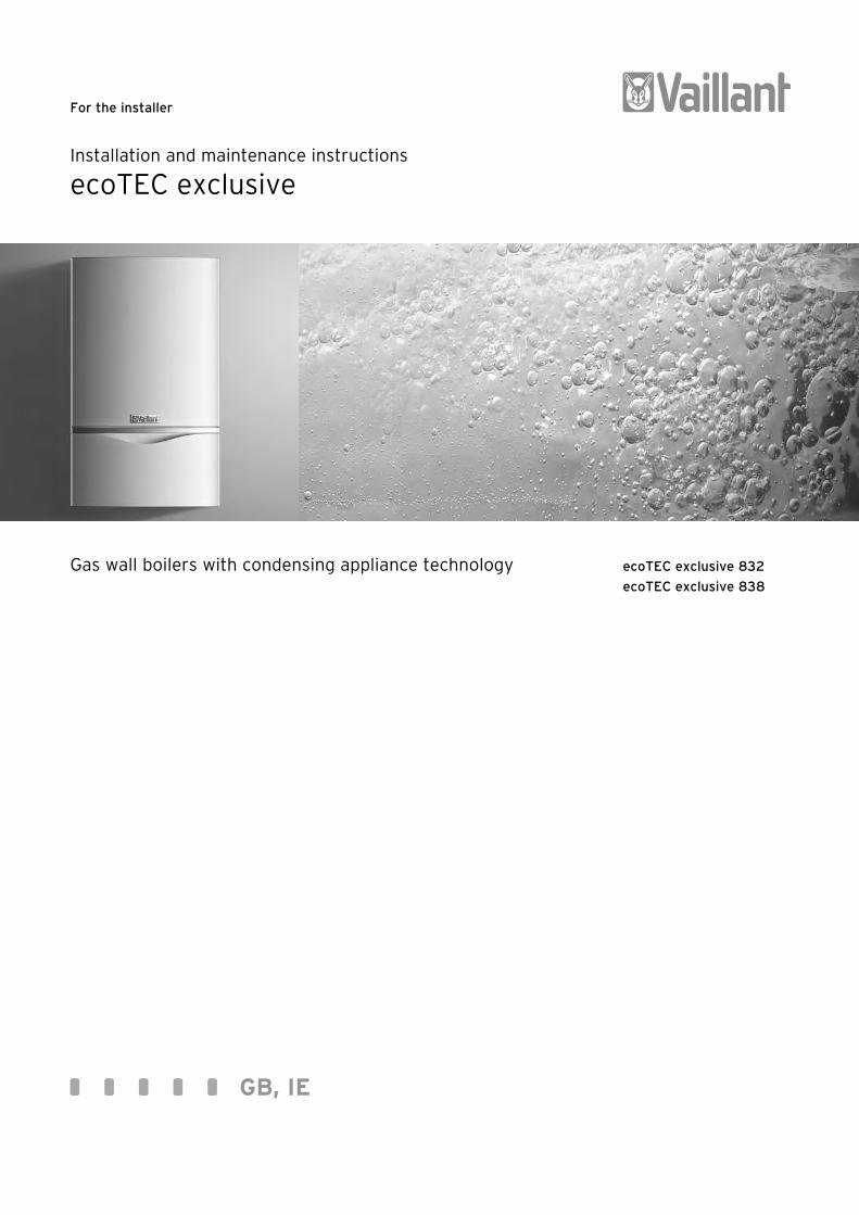
For the installer Installation and maintenance instructions ecoTEC exclusive Gas wall boilers with condensing appliance technology ecoTEC exclusive 832 ecoTEC exclusive 838 GB, IE
-
Upload
khangminh22 -
Category
Documents
-
view
1 -
download
0
Transcript of ecoTEC exclusive - FREE BOILER MANUALS
For the installer
Installation and maintenance instructions
ecoTEC exclusive
Gas wall boilers with condensing appliance technology ecoTEC exclusive 832
ecoTEC exclusive 838
GB, IE

Installation and maintenance instructions ecoTEC exclusive 0020017768_052
Contents
1 Notes on the documentation ........................... 31.1 Storage of the documents ...................................... 31.2 Safety instructions and symbols ........................... 31.3 Validity of the manual ............................................. 3
2 Description of the appliance ........................... 42.1 Design .......................................................................... 42.2 Type overview ............................................................ 42.3 CE label ........................................................................ 42.4 Gas council numbers ................................................ 52.5 Intended use ............................................................... 52.6 Identification plate .................................................... 5
3 Safety instructions and regulations .............. 53.1 Safety instructions ................................................... 53.1.1 Installation and setting ............................................ 53.1.2 If you smell gas .......................................................... 53.1.3 Changes to the surroundings of the
heating device ............................................................ 53.2 Related documents ................................................... 6
4 Assembly ........................................................... 74.1 Scope of delivery ...................................................... 74.1.1 Transporting the appliance .................................... 74.2 Dimensioned drawing and dimensions
for connection ............................................................ 104.3 Installation site .......................................................... 114.4 Required minimum gaps/assembly clearances . 114.5 Mounting the appliance ........................................... 124.6 Removing the front case ......................................... 12
5 Installation ......................................................... 125.1 General instructions for heating system ............ 125.2 Gas connection .......................................................... 125.3 Hot water and cold water connections ............... 135.4 Heating connection .................................................. 145.5 Pressure Relief Valve ............................................... 145.6 Flue pipe ...................................................................... 155.6.1 100 mm standard flue pipe ..................................... 155.6.2 Optional 125 mm flue pipe ...................................... 155.7 Termination of the flue pipe .................................. 155.8 Air connection ............................................................ 165.9 Condensate discharge ............................................. 175.10 Electrical connection ................................................ 175.10.1 Mains connection ...................................................... 175.10.2 Connection of controllers, accessories and
external installation components ......................... 185.10.3 External electrical controllers (non eBUS) ......... 185.10.4 Details for the connection of an external
timer to the connection rail ................................... 195.10.5 Optional plug-in timers by Vaillant ....................... 195.10.6 Wiring diagrams......................................................... 20
6 Start-up .............................................................. 226.1 Filling the installation ............................................... 226.1.1 Filling and bleeding from the heating side ......... 236.1.2 First flushing of the system ................................... 246.1.3 Filling and bleeding from the hot water side ..... 24
6.1.4 Filling the condense trap ........................................ 246.2 Checking the gas setting ......................................... 246.2.1 Checking for tightness of the flue gas
installation and flue gas recirculation ................. 256.2.2 Checking the gas flow rate ..................................... 256.2.3 Checking the gas inlet working pressure ............ 266.3 Checking the equipment function ......................... 276.3.1 Heating ........................................................................ 276.3.2 Hot water function .................................................... 286.3.3 Subsequent flushing through of the
heating system ("hot") ............................................ 286.4 Handing over the appliance to the owner .......... 28
7 Adapting the appliance to the heating system ................................................................ 29
7.1 Selection and setting the parameters ................. 297.2 Overview of the settable installation parameters ... 307.2.1 Setting the heating partial load ............................ 307.2.2 Setting the pump overrun time ............................. 307.2.3 Setting the maximum flow temperature ............. 307.2.4 Setting the return temperature control .............. 307.2.5 Setting the burner anti-cycle time ....................... 317.2.6 Determination of the maintenance
interval/maintenance display ................................ 317.2.7 Setting the pump output ......................................... 327.3 Adjusting the bypass valve ..................................... 32
8 Inspection and maintenance ........................... 338.1 Inspection and maintenance intervals ................. 338.1.1 General inspection and maintenance
instructions ................................................................. 338.1.2 Safety instructions ................................................... 348.1.3 Checking the CO2 concentration ........................... 348.1.4 Adjusting the CO2 concentration
(or the air ratio)......................................................... 358.1.5 Inspection and maintenance work steps............. 368.2 Filling/draining the heating installation .............. 378.2.1 Filling the unit and heating installation ............... 378.2.2 Draining the unit ....................................................... 378.2.3 Draining the entire installation .............................. 378.3 Servicing the compact thermal module .............. 378.3.1 Dismantle compact thermal module .................... 378.3.2 Clean the heat exchanger ....................................... 388.3.3 Checking the burner ................................................. 388.3.4 Installing the burner assembly .............................. 388.4 Maintaining the secondary heat exchanger ....... 398.5 Cleaning the condense trap ................................... 398.6 Checking the expansion vessel .............................. 408.7 Checking the connection pressure
(gas inlet working pressure) .................................. 408.8 Checking CO2 content and adjusting if
necessary .................................................................... 408.9 Test operation............................................................ 40
9 Troubleshooting ................................................ 419.1 Diagnostics ................................................................. 419.1.1 Status codes ............................................................... 419.1.2 Diagnosis codes ......................................................... 42
3Installation and maintenance instructions ecoTEC exclusive 0020017768_05
1 Notes on the documentation
The following information is intended to help you throughout the entire documentation.Further documents apply in combination with this installation and maintenance manual.We accept no liability for any damage caused by failure to observe these instructions.
Other applicable documents• Always observe all installation instructions for
structural parts and components of the system when installing the ecoTEC exclusive. These installation instructions are enclosed with the various system components as well as additional components.
• Also observe all the operating instructions included with the system components.
1.1 Storage of the documentsPlease pass on this operating and installation manual and all other valid documents to the operator of the installation in order for him or her to store it so that it is available whenever it is required.
1.2 Safety instructions and symbolsPlease observe the safety instructions in this manual for the installation of the appliance.The symbols used in the manual are explained below:
d Danger!Immediate danger to life and limb!
e Danger!Risk of death from electric shock!
H Danger!Risk of burns or scalding!
a Caution!Potentially dangerous situation for the product and environment!
h Note!Useful information and instructions.
• Symbol for a necessary task
1.3 Validity of the manualThis installation manual applies exclusively to units with the following part numbers:– 0010002668– 0010002669
The part number of the unit can be obtained from the identification plate.
ContentsNotes on the documentation 1
9.1.3 Error codes ................................................................. 459.1.4 Error memory ............................................................ 459.2 Test programs ............................................................ 469.3 Resetting parameter to factory settings ............ 46
10 Replacing components ..................................... 4710.1 Safety instructions ................................................... 4710.2 Replacing burner ....................................................... 4710.3 Replacing fan or gas fittings .................................. 4710.4 Replacing primary heat exchanger ...................... 4810.5 Replacing electronics and display ........................ 48
11 Vaillant service ................................................. 49
12 Recycling and disposal ..................................... 49
13 Technical data ................................................... 50
AppendixEC declaration of conformity ............................................. 51Benchmark gas boiler commissioning checklist ............ 54

Installation and maintenance instructions ecoTEC exclusive 0020017768_054
2 Description of the appliance
2.1 Design
5
4
2
1
9
10
11
12
13
14
6
7
8
3
Fig. 2.1 Functional elements of ecoTEC exclusive
Legend:1 Expansion vessel 8 Aqua-Sensor2 Air intake pipe 9 Electronics box3 Burner assembly 10 Pump4 Ignition electrode 11 Auto air vent5 Gas Valve 12 Pressure sensor6 Diverter valve 13 Heat exchanger7 Hot water heat exchanger 14 Air / flue gas duct
2.2 Type overview
Appliance type
Designated country(designation in accord-ancewith ISO 3166)
Approvalcategory
Type of gas Nominal heat ratingin kW (heating)
Hot water outputin kW
832 UK (Great Britain) II2H3PNatural gas H G20Liquid gas propane G31
27 31,4
838 UK (Great Britain) II2H3PNatural gas H G20Liquid gas propane G31
30 37,2
Table 2.1 Type summary
2.3 CE labelCE labelling shows that the appliances comply with the basic requirements of the following directives:– Directive 90/396/EEC of the Commission with revisions
"Directive for Harmonisation of Legal Regulations of the Member States for Gas Consumer UNits" (Gas equipment directive)
– Directive 92/42 EEC of the Commission with revisions"Directive Concerning the Efficiency of New Hot Water Heating Boilers Fired by Liquid or Gaseous Fuels“ (Efficiency directive)
– Directive 73/23/EEC of the Commission with revisions"Directive Concerning Electrical Operating Equipment for Use Within Specific Voltage Limits“ (Low voltage directive)
– Directive 89/336/EEC of the Commission with revisions
"Directive Concerning Electromagnetic Compatibility"The units comply with the prototype described in the EU Prototype Test Approval:PIN-No. CE-0085BR0308The units comply with the following standards:– EN 483– EN 625– EN 677– EN 50165– EN 55014– EN 60335-1– EN 60529– EN 61000-3-2– EN 61000-3-3
h Vaillant Ltd. supports the Benchmark Initiative. You will find the Benchmark Logbook on the last page of this instruction manual. It is very important that this document be filled out properly when installing, commissioning and handing-over to the operator of the installation.
2 Description of the appliance
4

5Installation and maintenance instructions ecoTEC exclusive 0020017768_05
Description of the appliance 2Safety instructions and regulations 3
5
2.4 Gas council numbers
Appliance Gas council numbers
ecoTEC exclusive 832 47 044 37ecoTEC exclusive 838 47 044 38
Table 2.2 Gas council numbers
2.5 Intended useThe Vaillant ecoTEC exclusive is a state-of-the-art appliance which has been constructed in accordance with recognised safety regulations. Nevertheless, danger to the life and limb of the user or third parties can still occur or the appliance or other material assets be impaired in the event of improper use.The unit is not intended for use by persons (including children) with reduced physical, sensory or mental capabilities, or lack of experience and/or knowledge, unless they have been given supervision or instruction concerning use of the unit by a person responsible for their safety.Children must be watched to ensure that they do not play with the unit.The unit is intended as a heat producer for closed hot water central heating installations in households. Any other use or extended use is considered to be improper. The manufacturer or supplier is not liable for any resulting damage. The user alone bears the risk. Intended use includes the observance of the operating and installation manual and the adherence to the inspection and maintenance conditions.
a Caution!Any incorrect use is forbidden.
2.6 Identification plateThe identification plate the Valliant ecoTEC exclusive is attached at the factory to the bottom of the appliance.
3 Safety instructions and regulations
3.1 Safety instructions
a Caution!To tighten or loosen screws, only use suitable open-ended spanners (do not use pliers or extensions etc.).Improper use or unsuitable tools can cause damage, such as gas or water leaks.
3.1.1 Installation and settingInstallation, setting work and maintenance and repairs to the unit may only be carries out by an heating engineer approved at the time by the Health and Safety Executive.
3.1.2 If you smell gasIf you smell gas, the following safety instructions must be observed:• Do not actuate any electrical switches in the danger area• Do not smoke in the danger area• Do not use a telephone in the danger area• Close the gas stop cock• Ventilate the danger area• Notify your gas supplier or a suitably qualified heating
engineer.
National phone number for gas emergencies: 0800 1 1 1 999
3.1.3 Changes to the surroundings of the heating device
No changes must be made to the following objects:- the heating device- the gas, air, water and electricity supply pipes- the exhaust pipe- the constructional conditions that could affect the
operational reliability of the device
3.1.4 Important instructions for propane appliancesBleeding the liquid gas tank when installing the system:before installing the device, make sure that the gas tank has been bled. The liquid gas supplier is responsible for the proper bleeding of the tank. Ignition problems can be caused if the tank is not bled properly. In such cases, first contact the person in charge of filling the tank.
Affix tank stickerAffix the enclosed tank sticker (propane quality) on the tank where it is clearly visible or on the bottle cabinet, if possible close to the filler nozzle.
d Danger!Only use propane in accordance with DIN 51622 or EN 437.

Installation and maintenance instructions ecoTEC exclusive 0020017768_056
3.2 Related documentsThe installation of the appliance and any associated hot water system must be in accordance with (but not limited to) the following; COSHH regulations, Gas Safety (Installation and Use) Regulations 1998, Health and Safety Document No. 635 (The Electricity at Work Regulations 1989), BS7671 (IEE Wiring Regulations) and the Water Supply (Water Fitting) Regulations 1999, or The Water Bylaws 2000 (Scotland). It should also be in accordance with the relevant requirements of the Local Authority, Building Regulations, The Building Regulations (Scotland), The Building Regulations (Northern Ireland) and the relevant recommendations of the following British Standards:BS 6700: Services supplying water for domestic use within buildings and their curtilages.BS 6798: Specification for installation of gas fired boilers not exceeding 60 kW input.BS 6891: Specification for installation of low pressure gas pipework up to 28 mm (R1) in domestic premises (2nd family gas).BS 7593: Treatment of water in domestic hot water central heating systems.Institute of Gas Engineers Publication IGE/UP/7/1998: ”Guide for gas installations in timber framed housing”BS. 5482 Pt. 1 Domestic butane and propane gas burning installations.IGE/UP1 Soundness testing and purging of industrial and commercial gas installation.IGE/UP2 Gas installation pipework, boosters and compressors on industrial and commercial premises.IGE/UP10 Installation of gas appliances in industrial and commercial premises.BS. 6644: Installation of gas fired hot water boilers of rated inputs between 60 kW and 2 MW (2nd and 3rd family gases).BS. 5449: Forced circulation hot water central heating systems for domestic premises. Note: only up to 45 kW.BS. 6880: Low temperature hot water heating systems of output greater than 45 kW.Part 1 Fundamental and design considerations.Part 2 Selection of equipment.Part 3 Installation, commissioning and maintenance.BS. 4814: Specification for: Expansion vessels using an internal diaphragm, for sealed hot water heating systems.BS. 5440: Installation and maintenance of flues and ventilation for gas appliances of rated input not exceeding 70 kW net (1st, 2nd and 3rd family gases).Part 1 Specification for installation of flues.Part 2 Specification for installation and maintenance
of ventilation for gas appliances.
European installation directive
a Caution!Installation and maintenance of the unit may only be undertaken by a competent person approved at the time by the Health and Safety Executive in accordance with the "Gas Safety (Installation and Use) Regulations 1998". In IE the installation must comply with the current Version of I.S.813 ‘Domestic Gas Installations’ and the current Building Regulations. The current ETCI Regulations for the installation of electrical equipment must also be observed.
Caution!To tighten or loosen screws, only use suitable open-ended spanners (do not use wrenches or extensions etc.).Improper use or unsuitable tools can cause damage, (such as gas or water leaks.)
3 Safety instructions and regulations
7Installation and maintenance instructions ecoTEC exclusive 0020017768_05
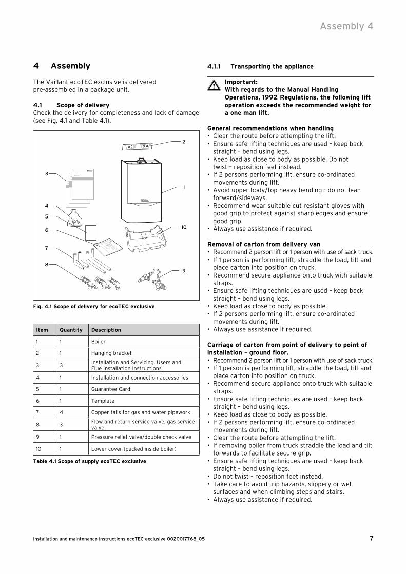
4 Assembly
The Vaillant ecoTEC exclusive is delivered pre-assembled in a package unit.
4.1 Scope of deliveryCheck the delivery for completeness and lack of damage (see Fig. 4.1 and Table 4.1).
1
2
9
3
4
8
7
6
5
10
Fig. 4.1 Scope of delivery for ecoTEC exclusive
Item Quantity Description
1 1 Boiler
2 1 Hanging bracket
3 3Installation and Servicing, Users andFlue Installation Instructions
4 1 Installation and connection accessories
5 1 Guarantee Card
6 1 Template
7 4 Copper tails for gas and water pipework
8 3Flow and return service valve, gas servicevalve
9 1 Pressure relief valve/double check valve
10 1 Lower cover (packed inside boiler)
Table 4.1 Scope of supply ecoTEC exclusive
4.1.1 Transporting the appliance
a Important:With regards to the Manual Handling Operations, 1992 Regulations, the following lift operation exceeds the recommended weight for a one man lift.
General recommendations when handling• Clear the route before attempting the lift.• Ensure safe lifting techniques are used – keep back
straight – bend using legs.• Keep load as close to body as possible. Do not
twist – reposition feet instead.• If 2 persons performing lift, ensure co-ordinated
movements during lift.• Avoid upper body/top heavy bending - do not lean
forward/sideways.• Recommend wear suitable cut resistant gloves with
good grip to protect against sharp edges and ensure good grip.
• Always use assistance if required.
Removal of carton from delivery van• Recommend 2 person lift or 1 person with use of sack truck. • If 1 person is performing lift, straddle the load, tilt and
place carton into position on truck.• Recommend secure appliance onto truck with suitable
straps.• Ensure safe lifting techniques are used – keep back
straight – bend using legs.• Keep load as close to body as possible.• If 2 persons performing lift, ensure co-ordinated
movements during lift.• Always use assistance if required.
Carriage of carton from point of delivery to point of installation – ground floor.• Recommend 2 person lift or 1 person with use of sack truck. • If 1 person is performing lift, straddle the load, tilt and
place carton into position on truck.• Recommend secure appliance onto truck with suitable
straps.• Ensure safe lifting techniques are used – keep back
straight – bend using legs.• Keep load as close to body as possible.• If 2 persons performing lift, ensure co-ordinated
movements during lift.• Clear the route before attempting the lift.• If removing boiler from truck straddle the load and tilt
forwards to facilitate secure grip.• Ensure safe lifting techniques are used – keep back
straight – bend using legs.• Do not twist – reposition feet instead.• Take care to avoid trip hazards, slippery or wet
surfaces and when climbing steps and stairs.• Always use assistance if required.
Assembly 4
Installation and maintenance instructions ecoTEC exclusive 0020017768_058
Carriage of carton from point of delivery to point of installation – first or higher floor, cellar.• Recommend 2-person lift or 1 person with use of sack
truck.• If 1 person is performing lift, straddle the load, tilt and
place carton into position on truck.• Recommend secure appliance onto truck with suitable
straps.• Ensure safe lifting techniques are used – keep back
straight – bend using legs.• Keep load as close to body as possible.• If 2 persons performing lift, ensure co-ordinated
movements during lift.• Avoid upper body/top heavy bending - do not lean
forward/sideways.• Clear the route before attempting the lift.• If removing boiler from truck straddle the load and tilt
forwards to facilitate secure grip.• Ensure safe lifting techniques are used – keep back
straight – bend using legs.• Do not twist – reposition feet instead.• Take care to avoid trip hazards, slippery or wet
surfaces and when climbing steps and stairs.• Always use assistance if required.
Carriage of carton from point of delivery to point of installation – roofspace.• Recommend 2-person lift.• Ensure co-ordinated movements during lift.• Avoid upper body/top heavy bending - do not lean
forward/sideways.• Clear the route before attempting the lift.• Take care to avoid trip hazards, slippery or wet
surfaces and when climbing steps and stairs.• When transferring appliance into roofspace,
recommend 1 person to be in roofspace to receive the appliance and other person to be below to pass up and support appliance.
• Ensure safe lifting techniques are used – keep back straight – bend using legs.
• Keep load as close to body as possible.• Always use assistance if required.• It is assumed safe access, flooring and adequate
lighting are provided in the roof space.• It is recommended a risk assessment of the roof space
area be carried out before moving the appliance into the area to take into account access, stability of flooring, lighting and other factors, and appropriate measures taken.
Unpacking of appliance from carton.• Recommend 2 persons unpack appliance from carton.• Always keep working area clear.• Recommend straps and open carton flaps, then
remove items from the top including the polystyrene packing and remove carton by sliding up over the boiler.
• Ensure safe lifting techniques are used – keep back straight – bend using legs.
• Keep load as close to body as possible.• Always use assistance if required.• Dispose of packaging in a responsible manner.• Recommend wear suitable cut resistant gloves with
good grip to protect against sharp edges and ensure good grip when handling appliance outside packaging.
Positioning of Appliance for Final Installation – noobstructions.• If appliance weight is over 25 kg always use 2 persons
to move where practical.• Fit bracket securely onto wall before lifting appliance
into position.• Obtain firm grip on front and sides of appliance, lift
upwards, ensure stable balance achieved and lift upwards to position in place on bracket.
• Ensure safe lifting techniques are used – keep back straight – bend using legs - when lifting load from floor level.
• Do not twist – reposition feet instead.• Keep boiler as close as possible to body throughout
lift to minimise strain on back.• Ensure co-ordinated movements to ensure equal
spread of weight of load.• Always use assistance if required.• Recommend wear suitable cut resistant gloves with
good grip to protect against sharp edges and ensure good grip when handling appliance.
4 Assembly
9Installation and maintenance instructions ecoTEC exclusive 0020017768_05
Positioning of Appliance for Final Installation – above worktop, foreseeable obstructions etc.• If appliance weight is over 25 kg always use 2 persons
to move where practical.• Fit bracket securely onto wall before lifting appliance
into position.• Obtain firm grip on front and sides of appliance, lift
upwards, onto worktop if practicable.• Ensure stable balance achieved and lift upwards to
position in place on bracket.• If 2 persons positioning onto bracket obtain firm grip
at front and sides/base of boiler.• Ensure coordinated movements during 2 person lifts
to ensure equal spread of weight of load.• Ensure safe lifting techniques are used – keep back
straight – bend using legs - when lifting load from floor level.
• Do not twist – reposition feet instead.• Keep boiler as close as possible to body throughout
lift to minimise strain on back.• Avoid upper body/top heavy bending - do not lean
forward/sideways.• Always use assistance if required.• Recommend wear suitable cut resistant gloves with
good grip to protect against sharp edges and ensure good grip when handling appliance.
Positioning of Appliance for Final Installation – withincompartment etc. restricting installation.• If appliance weight is over 25 kg always use 2 persons
to move where practical.• Fit bracket securely onto wall before lifting appliance
into position.• Obtain firm grip on front and sides of appliance, lift
upwards, onto worktop if practicable.• Ensure stable balance achieved and lift upwards to
drop into place onto bracket.• If 2 persons positioning onto bracket obtain firm grip
at front and sides/base of boiler.• Ensure coordinated movements during 2 person lifts
to ensure equal spread of weight of load.• If 1 person positioning onto bracket recommend obtain
firm grip supporting base of boiler.• Ensure safe lifting techniques are used – keep back
straight – bend using legs - when lifting load from floor level.
• Do not twist – reposition feet instead.• Keep boiler as close as possible to body throughout
lift to minimise strain on back.• Always use assistance if required.• Recommend wear suitable cut resistant gloves with
good grip to protect against sharp edges and ensure good grip when handling appliance.
Positioning of Appliance for Final Installation – in roof space restricting installation.• If appliance weight is over 25 kg always use 2 persons
to move where practical.• Obtain firm grip on front and sides of appliance, lift
upwards, ensure stable balance achieved and lift upwards to drop into place onto bracket.
• If 2 persons positioning onto bracket obtain firm grip at front and sides/base of boiler.
• Ensure co-ordinated movements during 2 person lifts to ensure equal spread of weight of load.
• If 1 person positioning onto bracket recommend obtain firm grip supporting base of boiler.
• Ensure safe lifting techniques are used - keep back straight – bend using legs - when lifting load from floor level.
• Do not twist – reposition feet instead.• Keep boiler as close as possible to body throughout
lift to minimise strain on back.• Always use assistance if required.• Recommend wear suitable cut resistant gloves with
good grip to protect against sharp edges and ensure good grip when handling appliance.
• It is recommended a risk assessment of the roof space area be carried out before moving the appliance into the area to take into account access, stability of flooring, lighting and other factors, and appropriate measures taken.
Assembly 4

Installation and maintenance instructions ecoTEC exclusive 0020017768_0510
4.2 Dimensioned drawing and dimensions for connection
70
1904808
00
2
25
450
7
Ø 20
100 100
Ø 20
5
3
7
Ø 202
0R
1/2
180
46
Fig. 4.2 Dimensions for connection (mm)
Legend:1 Flue connection2 Mounting bracket3 Heating return 4 Cold water connection5 Gas connection6 Hot water connection7 Heating flow
4 Assembly
11Installation and maintenance instructions ecoTEC exclusive 0020017768_05
4.3 Installation siteThe site of erection of the boiler should allow proper connection of the air/exhaust ducting. In addition, there should be adequate room for maintenance work and air circulation around the boiler. The boiler can be installed in any room, however, in rooms with a bath or a shower, the special requirements of BS 7671 (IEE Regulations), the electro-technical stipulations of the Building Standards (Scotland) Regulations and, in IE, the current issue of IS 813 and the current ETCI Stipulations must especially be observed.
e Danger!Danger of death by electric shock! If a room sealed boiler is installed in a room with a bath or a shower, the electrical switches and the boiler controller, which operate at mains voltage must be mounted in locations where any person in the bath or in the shower cannot reach them
In the event of installation in unusual locations, special provisions may have to be made. Detailed instructions for this can be found in BS 5546 and in BS 6798. The boiler must be installed on a flat vertical wall which is adequately robust to carry the weight of the boiler. It is possible to mount onto a wall made of flammable material if the regulations of the Local Authority and the legal building stipulations are fulfilled.In this case however, the unit would have to be mounted in a specially made enclosure. (You can also use an existing cabinet or existing enclosure as long as it can be modified accordingly to suit the new application.) Further details concerning the fundamental characteristics when modifying existing cabinets or enclosures, including the requirements for ventilation, are described in BS 6798. If the boiler is to be installed in a half-timbered house, the installation must be undertaken in accordance with the Institute of Gas Engineers Publication "IGE/UP/7 Edition 2 Gas installation in timber framed and light steel framed buildings". Please note the following instructions before choosing where to install the heater:
a Caution!Do not install the appliance in rooms prone to frost. In rooms with aggressive steam or dust, the appliance must be operated independently of the ventilation!
When choosing the place of installation and while operating the appliance, make sure that the combustion air is free from chemical substances such as e.g. fluorine, chlorine, sulphur, ammonia etc. Sprays, solvents and cleaning agents, paints, adhesives etc. contain these kinds of substances, which - in the worst case scenario - can lead to corrosion, even in the exhaust system, during ambient air dependent operating of the appliance.
Particularly in hairdessing salons, lacquering and finishing workshops, cleaning facilities, etc., the appliance must be operated independently of the ambient air. Otherwise, a separate installation room is required to guarantee that the combustion air supply is free from the above substances.
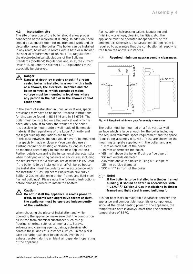
4.4 Required minimum gaps/assembly clearances
min
min 5min 5
min 500**
min
14
516
5/2
46
*
Fig. 4.3 Required minimum gaps/assembly clearances
The boiler must be mounted on a flat, vertical wall surface which is large enough for the boiler including the required minimum space requirement and the space required for assembly (Fig. 4.3). These are shown on the mounting template supplied with the boiler, and are:– 5 mm on each side of the boiler,– 145 mm underneath the boiler,– 165 mm* above the boiler if using a flue pipe of
100 mm outside diameter,– 246 mm* above the boiler if using a flue pipe of
125 mm outside diameter,– 500 mm** in front of the boiler.
h Note!If the boiler is to be installed in a timber framed building, it should be fitted in accordance with “IGE/UP/7 Edition 2 Gas installations in timber framed and light steel framed buildings“.
It is not necessary to maintain a clearance between the appliance and combustible materials or components, since, at the rated heating power of the appliance, the temperature here is always lower than the permitted temperature of 85 °C.
Assembly 4
Installation and maintenance instructions ecoTEC exclusive 0020017768_0512
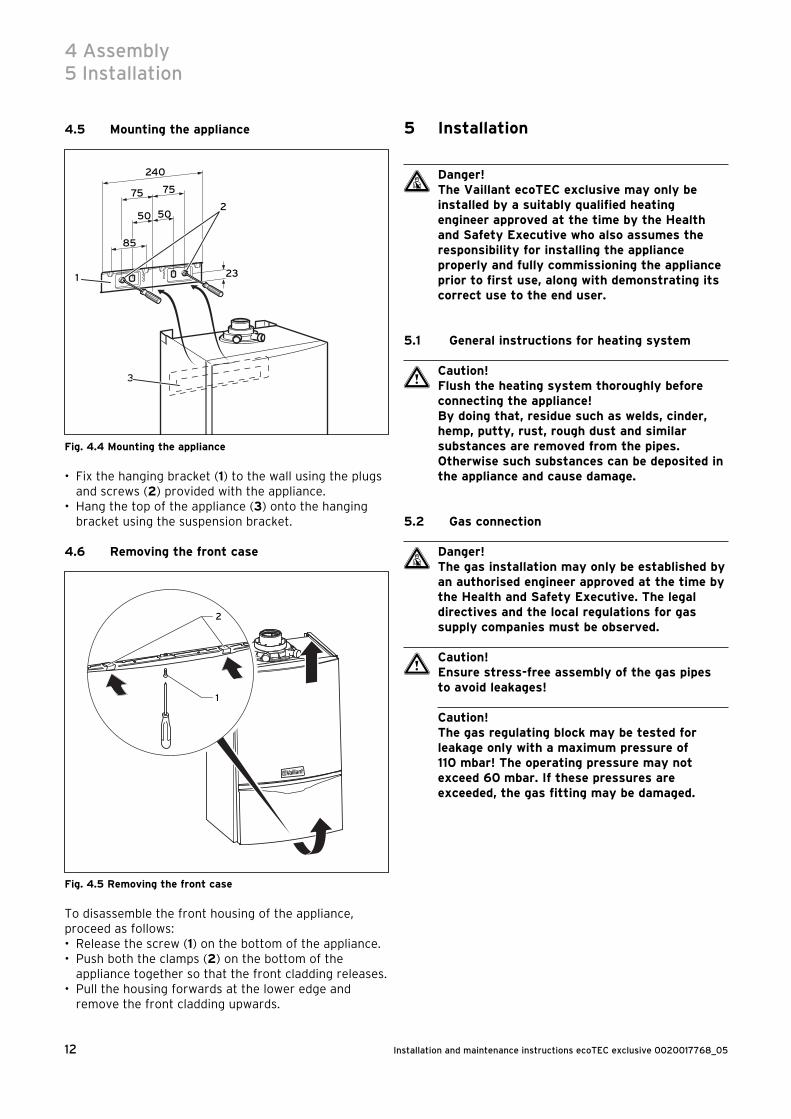
4.5 Mounting the appliance
85
50
240
75 75
23
50
3
1
2
Fig. 4.4 Mounting the appliance
• Fix the hanging bracket (1) to the wall using the plugs and screws (2) provided with the appliance.
• Hang the top of the appliance (3) onto the hanging bracket using the suspension bracket.
4.6 Removing the front case
1
2
Fig. 4.5 Removing the front case
To disassemble the front housing of the appliance, proceed as follows:• Release the screw (1) on the bottom of the appliance.• Push both the clamps (2) on the bottom of the
appliance together so that the front cladding releases.• Pull the housing forwards at the lower edge and
remove the front cladding upwards.
5 Installation
d Danger!The Vaillant ecoTEC exclusive may only be installed by a suitably qualified heating engineer approved at the time by the Health and Safety Executive who also assumes the responsibility for installing the appliance properly and fully commissioning the appliance prior to first use, along with demonstrating its correct use to the end user.
5.1 General instructions for heating system
a Caution!Flush the heating system thoroughly before connecting the appliance!By doing that, residue such as welds, cinder, hemp, putty, rust, rough dust and similar substances are removed from the pipes. Otherwise such substances can be deposited in the appliance and cause damage.
5.2 Gas connection
d Danger!The gas installation may only be established by an authorised engineer approved at the time by the Health and Safety Executive. The legal directives and the local regulations for gas supply companies must be observed.
a Caution!Ensure stress-free assembly of the gas pipes to avoid leakages!
Caution!The gas regulating block may be tested for leakage only with a maximum pressure of 110 mbar! The operating pressure may not exceed 60 mbar. If these pressures are exceeded, the gas fitting may be damaged.
4 Assembly5 Installation
13Installation and maintenance instructions ecoTEC exclusive 0020017768_05
Fig. 5.1 Gas connection
The Vaillant ecoTEC exclusive is supplied for use with natural gas G20 and can only be converted to the use of propane gas G31 by the Vaillant service engineer or a suitably qualified installer approved at the time by the Health and Safety Executive.
The gas connection is to be via 20 mm Ø steel piping. The dynamic gas connection pressure must be at least 19 – 23 mbar for natural gas and 37 mbar for propane gas.• The gas pipe should first be cleaned by blowing out
with compressed air. This prevents damage to the appliance.
• Connect the compression gas service cock and 15 mm copper outlet tail as supplied with the appliance and tighten.
• Connect a gas supply pipe of not less than 15 mm diameter to the copper tail.
• Tighten all connections.(Ensure the gas supply pipework is adequately sized such that a 20 mbar gas pressure is available at the boiler inlet at full flow rate).
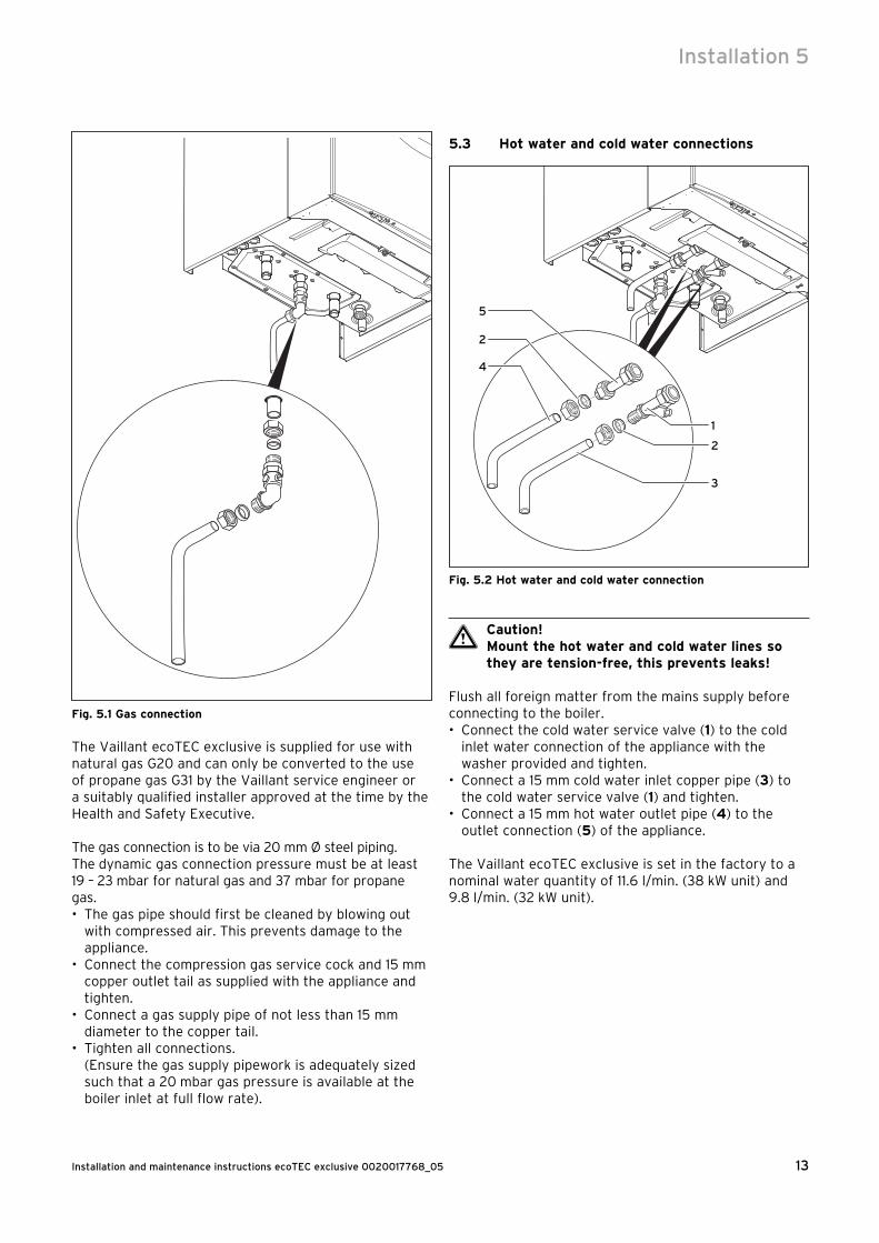
5.3 Hot water and cold water connections
2
4
2
3
1
5
Fig. 5.2 Hot water and cold water connection
a Caution!Mount the hot water and cold water lines so they are tension-free, this prevents leaks!
Flush all foreign matter from the mains supply before connecting to the boiler.• Connect the cold water service valve (1) to the cold
inlet water connection of the appliance with the washer provided and tighten.
• Connect a 15 mm cold water inlet copper pipe (3) to the cold water service valve (1) and tighten.
• Connect a 15 mm hot water outlet pipe (4) to the outlet connection (5) of the appliance.
The Vaillant ecoTEC exclusive is set in the factory to a nominal water quantity of 11.6 l/min. (38 kW unit) and 9.8 l/min. (32 kW unit).
Installation 5
Installation and maintenance instructions ecoTEC exclusive 0020017768_0514
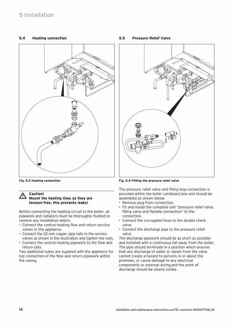
5.4 Heating connection
Fig. 5.3 Heating connection
a Caution!Mount the heating lines so they are tension-free, this prevents leaks!
Before connecting the heating circuit to the boiler, all pipework and radiators must be thoroughly flushed to remove any installation debris.• Connect the central heating flow and return service
valves to the appliance.• Connect the 22 mm copper pipe tails to the service
valves as shown in the illustration and tighten the nuts.• Connect the central heating pipework to the flow and
return tails.Two additional tubes are supplied with the appliance for top connection of the flow and return pipework within the casing.
5.5 Pressure Relief Valve
Fig. 5.4 Fitting the pressure relief valve
The pressure relief valve and filling loop connection is provided within the boiler cardboard box and should be assembled as shown below.• Remove plug from connection.• Fit and install the complete unit "pressure relief valve,
filling valve and flexible connection" to the connection.
• Connect the corrugated hose to the double check valve.
• Connect the discharge pipe to the pressure relief valve.
The discharge pipework should be as short as possible and installed with a continuous fall away from the boiler. The pipe should terminate in a position which ensures that any discharge of water or steam from the valve cannot create a hazard to persons in or about the premises, or cause damage to any electrical components or external wiring,and the point of discharge should be clearly visible.
5 Installation
15Installation and maintenance instructions ecoTEC exclusive 0020017768_05
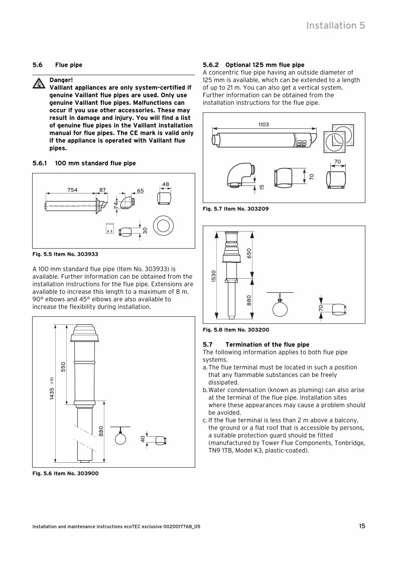
5.6 Flue pipe
d Danger!Vaillant appliances are only system-certified if genuine Vaillant flue pipes are used. Only use genuine Vaillant flue pipes. Malfunctions can occur if you use other accessories. These may result in damage and injury. You will find a list of genuine flue pipes in the Vaillant installation manual for flue pipes. The CE mark is valid only if the appliance is operated with Vaillant flue pipes.
5.6.1 100 mm standard flue pipe
754 87 65
30
74
48
Fig. 5.5 Item No. 303933
A 100 mm standard flue pipe (Item No. 303933) is available. Further information can be obtained from the installation instructions for the flue pipe. Extensions are available to increase this length to a maximum of 8 m. 90° elbows and 45° elbows are also available to increase the flexibility during installation.
143
510
55
0
88
0
40
Fig. 5.6 Item No. 303900
5.6.2 Optional 125 mm flue pipeA concentric flue pipe having an outside diameter of 125 mm is available, which can be extended to a length of up to 21 m. You can also get a vertical system. Further information can be obtained from the installation instructions for the flue pipe.
70
1103
70
15
Fig. 5.7 Item No. 30320915
30
88
06
50
70
Fig. 5.8 Item No. 303200
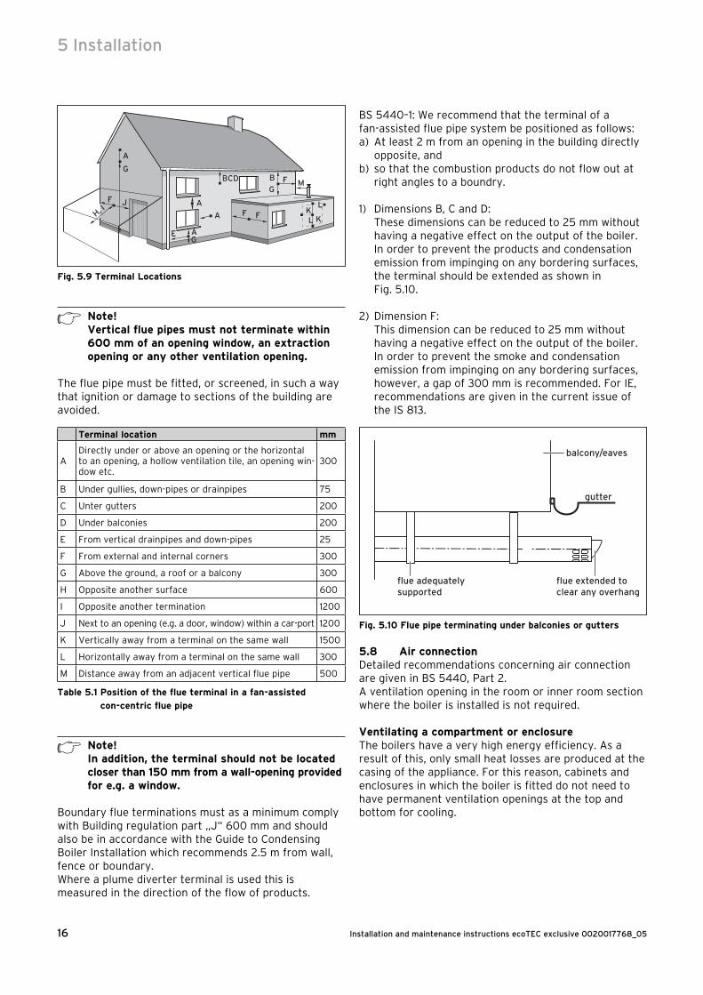
5.7 Termination of the flue pipeThe following information applies to both flue pipe systems.a. The flue terminal must be located in such a position
that any flammable substances can be freely dissipated.
b. Water condensation (known as pluming) can also arise at the terminal of the flue pipe. Installation sites where these appearances may cause a problem should be avoided.
c. If the flue terminal is less than 2 m above a balcony, the ground or a flat roof that is accessible by persons, a suitable protection guard should be fitted (manufactured by Tower Flue Components, Tonbridge, TN9 1TB, Model K3, plastic-coated).
Installation 5
Installation and maintenance instructions ecoTEC exclusive 0020017768_0516
A
BCD
A
G
H, IF J
B F M
L
LK
K
G
G
F F
E
A
A
Fig. 5.9 Terminal Locations
h Note!Vertical flue pipes must not terminate within 600 mm of an opening window, an extraction opening or any other ventilation opening.
The flue pipe must be fitted, or screened, in such a way that ignition or damage to sections of the building are avoided.
Terminal location mm
ADirectly under or above an opening or the horizontal to an opening, a hollow ventilation tile, an opening win-dow etc.
300
B Under gullies, down-pipes or drainpipes 75
C Unter gutters 200
D Under balconies 200
E From vertical drainpipes and down-pipes 25
F From external and internal corners 300
G Above the ground, a roof or a balcony 300
H Opposite another surface 600
I Opposite another termination 1200
J Next to an opening (e.g. a door, window) within a car-port 1200
K Vertically away from a terminal on the same wall 1500
L Horizontally away from a terminal on the same wall 300
M Distance away from an adjacent vertical flue pipe 500
Table 5.1 Position of the flue terminal in a fan-assisted
con-centric flue pipe
h Note!In addition, the terminal should not be located closer than 150 mm from a wall-opening provided for e.g. a window.
Boundary flue terminations must as a minimum comply with Building regulation part „J“ 600 mm and should also be in accordance with the Guide to Condensing Boiler Installation which recommends 2.5 m from wall, fence or boundary.Where a plume diverter terminal is used this is measured in the direction of the flow of products.
BS 5440–1: We recommend that the terminal of a fan-assisted flue pipe system be positioned as follows:a) At least 2 m from an opening in the building directly
opposite, andb) so that the combustion products do not flow out at
right angles to a boundry.
1) Dimensions B, C and D:These dimensions can be reduced to 25 mm without having a negative effect on the output of the boiler. In order to prevent the products and condensation emission from impinging on any bordering surfaces, the terminal should be extended as shown in Fig. 5.10.
2) Dimension F:This dimension can be reduced to 25 mm without having a negative effect on the output of the boiler. In order to prevent the smoke and condensation emission from impinging on any bordering surfaces, however, a gap of 300 mm is recommended. For IE, recommendations are given in the current issue of the IS 813.
Fig. 5.10 Flue pipe terminating under balconies or gutters
5.8 Air connectionDetailed recommendations concerning air connection are given in BS 5440, Part 2.A ventilation opening in the room or inner room section where the boiler is installed is not required.
Ventilating a compartment or enclosureThe boilers have a very high energy efficiency. As a result of this, only small heat losses are produced at the casing of the appliance. For this reason, cabinets and enclosures in which the boiler is fitted do not need to have permanent ventilation openings at the top and bottom for cooling.
5 Installation

17Installation and maintenance instructions ecoTEC exclusive 0020017768_05
5.9 Condensate discharge
7
d
Soakaway
c
6
5
Gulley
a
Internalstackpipe
3
4
3
b
Internaldischarge system
1
2
Fig. 5.11 Condensate discharge
The ecoTEC exclusive units are equipped with a normal water condensate collector where the condensate is continuously diverted into the drain pipe.• Connect the condensate drain (1) of the boiler to a
condensate drain pipe (2) which has a minimum internal diameter of 19 mm (22 mm outside diameter for all external pipes) and which is made from an acid-resistant material (e.g. plastic overflow pipe).
h Note!The drain pipe connected to the condensate drain of the boiler must have a constant gradient (45 mm per metre) and should be installed and terminate within the building to prevent the possibility of freezing up.
The condensate drain pipe should terminate in a suitable location, e.g.:a) The drain pipe should preferably terminate in the
floor of the house in the ventilation duct (at least 450 mm above the duct base). There must be a siphon (3) fitted in the line (mounted in the boiler) producing a connection head of at least 75 mm of water. A ventilation valve (4) must be fitted in the drain pipe in front of the siphon. The connection to the ducting should not allow overflow into another drain pipe or allow overflow from another drain pipe into the condensate drain pipe. This can be achieved by keeping a gap between the pipe branches of at least 110 mm, with a duct diameter of 100 mm, and 250 mm with a duct diameter of 150 mm.
b) Connection into the domestic waste water drain pipe (e.g. a sink or washing machine) with an external termination.
The condensate drain pipe should have a minimum diameter of 22 mm, without length restriction, and also be fitted with a siphon (3) having a connection head of 75 mm (fitted within the boiler already). The connection should be made after the drain siphon if possible. If the installation is only possible in front of the siphon, there must be a ventilation valve between the two siphons. This is normally provided in a drain.
c) Draining into a gully (5) under the grid (6) and above the water level. The external piping should be kept as short as possible to minimise the frost risk, and should be no longer than 3 m.
d) To the condensate absorption point (drainage ditch) (7). The external pipe should have a maximum length of 3 m.
Further information can be obtained from "BS 6798 Specification for installation of gas–fired boilers of rated input not exceeding 70 kW net". The condense trap (1) must be filled with water as described in the relevant chapter before the boiler is commissioned.
5.10 Electrical connection
d Danger!The electrical installation may only be undertaken by an authorised engineer.Risk of fatal electric shock from touching live connections. Always disconnect the power supply first by pulling the plug out of the wall socket. Only after this can the installation be undertaken. Continuous voltage is present on the mains connection terminals L and N, even if the main switch is turned off!
5.10.1 Mains connectionThe appliance is fitted with a 1.0 m long connection cable with mains plug. The three-pole mains plug is fitted with a 3.0 A fuse. The connection cable is wired into the appliance in the factory.Connection to the mains supply shall be made via the fused 3 pin plug to an unswitched shuttered socket, complying to the requirements of BS 1363.
Installation 5
Installation and maintenance instructions ecoTEC exclusive 0020017768_0518
5.10.2 Connection of controllers, accessories and external installation components
The following controllers, accessories and installation components can be connected to the ecoTEC exclusive (see Table 5.2).The installation should be carried out in accordance with the individual instruction manual. The required connections to the electronic system of the boiler (e.g. for external controllers, external sensors etc.) should be undertaken as follows:• Remove the front cover of the device, and lower the
electronic box forward.• Unclip the rear cover of the electronic box and hinge
the cover upwards.• Insert the connection lines of the components to be
connected through the cable openings (1) on the left hand side of the underside of the appliance.
• Then insert the connection lines through the cable openings (2) into the electronic box and cut them to length.
1
2
Fig. 5.12 Opening the switchgear box rear wall
- + 7 8 9 L N 3 4 5
- + 7 8 9 L N 3 4 5
Fig. 5.13 Example for cable routing
• Remove the insulation over a length of 2 - 3 cm and insulate the cores.
• Connect the connection cable in accordance with Table 5.2 and Fig. 5.13 to the relevant screwed terminals in the electronic system.
a Caution!Do not connect mains voltage to the terminals 7, 8, 9! Danger of destroying the electronics!
h Note!There is no provision set in the factory for connection of an installation thermostat for underfloor heating.
Note!Make sure that the connection cables are securely fastened in to the screw terminals.
5.10.3 External electrical controllers (non eBUS)The boiler connections 3, 4 and 5 serve for the connection of external controllers, for example a timer and/or a room thermostat. The connections 3 and 4 are connected to each other in the factory. If external controllers are used, this connection must be removed and the controllers must be connected to connections 3 and 4. The connection 5 is an additional neutral line for external neutral lines, for example for the sensor of a room thermostat.
5 Installation
19Installation and maintenance instructions ecoTEC exclusive 0020017768_05
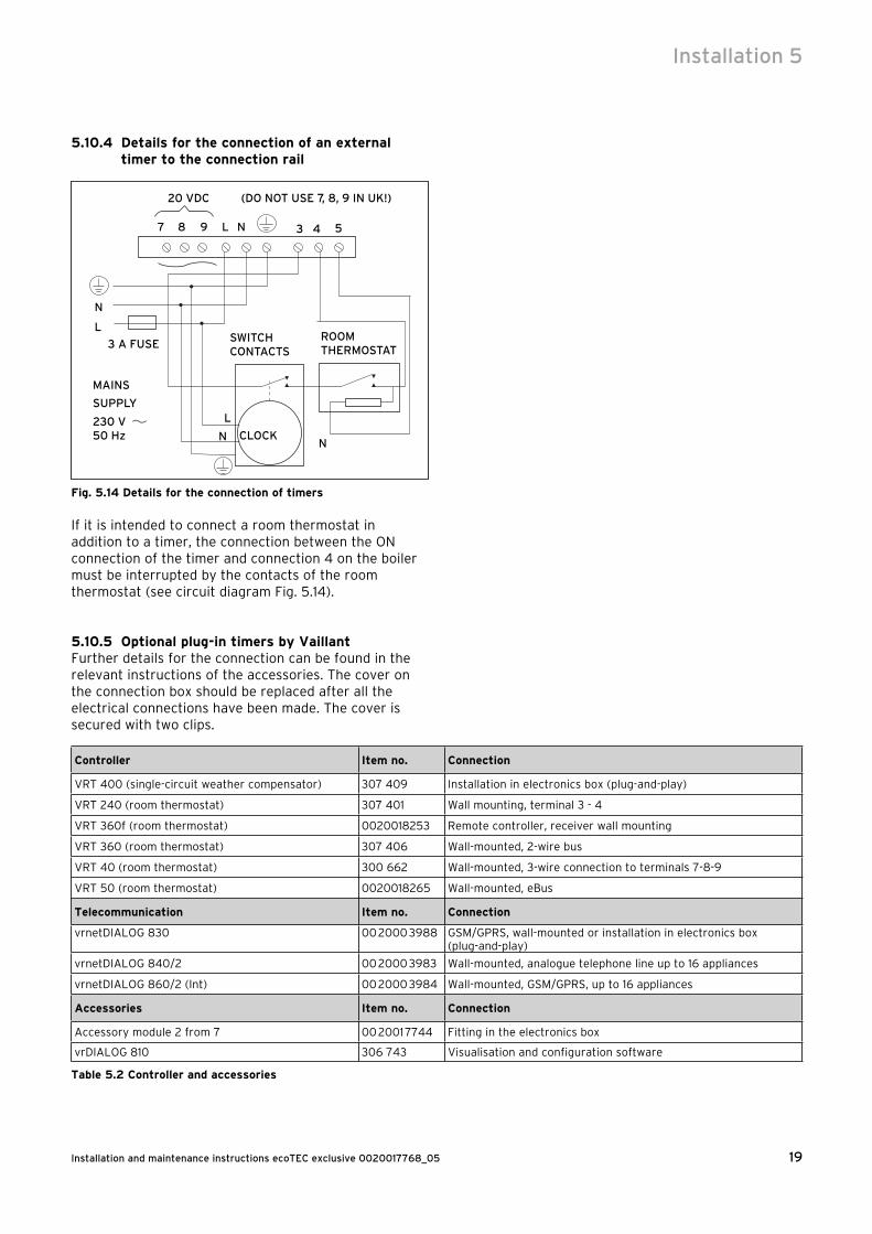
5.10.4 Details for the connection of an external timer to the connection rail
3987
MAINS
SUPPLY
230 V 50 Hz
L
L
L N
N
NN
20 VDC (DO NOT USE 7, 8, 9 IN UK!)
3 A FUSE SWITCH CONTACTS
ROOM THERMOSTAT
CLOCK
4 5
Fig. 5.14 Details for the connection of timers
If it is intended to connect a room thermostat in addition to a timer, the connection between the ON connection of the timer and connection 4 on the boiler must be interrupted by the contacts of the room thermostat (see circuit diagram Fig. 5.14).
5.10.5 Optional plug-in timers by VaillantFurther details for the connection can be found in the relevant instructions of the accessories. The cover on the connection box should be replaced after all the electrical connections have been made. The cover is secured with two clips.
Controller Item no. Connection
VRT 400 (single-circuit weather compensator) 307 409 Installation in electronics box (plug-and-play)
VRT 240 (room thermostat) 307 401 Wall mounting, terminal 3 - 4
VRT 360f (room thermostat) 0020018253 Remote controller, receiver wall mounting
VRT 360 (room thermostat) 307 406 Wall-mounted, 2-wire bus
VRT 40 (room thermostat) 300 662 Wall-mounted, 3-wire connection to terminals 7-8-9
VRT 50 (room thermostat) 0020018265 Wall-mounted, eBus
Telecommunication Item no. Connection
vrnetDIALOG 830 00 2000 3988 GSM/GPRS, wall-mounted or installation in electronics box (plug-and-play)
vrnetDIALOG 840/2 00 2000 3983 Wall-mounted, analogue telephone line up to 16 appliances
vrnetDIALOG 860/2 (Int) 00 2000 3984 Wall-mounted, GSM/GPRS, up to 16 appliances
Accessories Item no. Connection
Accessory module 2 from 7 00 2001 7744 Fitting in the electronics box
vrDIALOG 810 306 743 Visualisation and configuration software
Table 5.2 Controller and accessories
Installation 5

Installation and maintenance instructions ecoTEC exclusive 0020017768_0520
5.10.6 Wiring diagrams
X2
2
Cable harness compact thermal module
Cable harness hydraulics
Connection for external eBUS controller
Room thermostat 24 V:Connection 7, 8 and 9No bi-directional interface (only analogue)
Room thermostat 230 V/50 Hz(Remove bridge when connecting)
Heating pump
Mains connection: 230 V/50 Hz
Igniter
Caution: Do not connect mains voltage! Danger of damage to the electronics!
Diagnosis via eBUS, vrnetDIALOG
Connection accessories module
External sensor
External flow or return sensor
Connection eBUS accessories
Fan
Fuse 2A, slow-response
2nd pump: - circulation pump - storage tank charging pump - 2nd external pump - solar pump
PWM pump
Fig. 5.15 Connection wiring ecoTEC exclusive
5 Installation

21Installation and maintenance instructions ecoTEC exclusive 0020017768_05
X 2 X 20
X 40
X3
1
X41
Switchgear box
Water through flow sensor
Hot water outlet (NTC)
Fan
Ignition electrode Flow temperature sensor (NTC)
Preference changeover valve
Gas valve
Water pressure sensor
Return temperature sensor (NTC)
X 20/5 red
X 20/7 black
X 20/7 black
X 20/8 blue
X 2/12 green
X 2/11 red
X 2/9 black
Pump
X 20/18 red (24 VDC)
X 20/9 blue (Earth)
X 20/16 blue (Earth)
X 20/4 grey (PWM)
X 20/3 black (Hall signal)
X 20/17 red (24 VDC)
X 2/15 brown C
X 2/8 blue D
X 2/16 black A
X 2/7 pink B
X 2/3 red (+ 5V)
X 2/2 black (Earth)
X 2/6 green (Signal)
X 2/5 violet (Signal)
X 2/1 black
Secondary heat exchanger (NTC)
X 2/4 orange
X 2/10 black
Mains plug
Plug connection
X 22
Fig. 5.16 Electronic board layout ecoTEC exclusive
Installation 5
Installation and maintenance instructions ecoTEC exclusive 0020017768_0522
6 Start-up
6.1 Filling the installationMixing additives with the heating water can result in material damage. However, up to now, no incompatibility with Vaillant appliances has been detected with proper use of the following products.• When using additives, follow the additive
manufacturer‘s instructions without exception.Vaillant accepts no liability for the compatibility of any additive or its effectiveness in the entire heating system.
Additives for cleaning purposes(subsequent flushing required)- Fernox F3- Jenaqua 200- Jenaqua 300- Jenaqua 400- Sentinel X 300- Sentinel X 400
Additives intended to remain permanently in the system- Fernox F1- Fernox F2- Jenaqua 100- Jenaqua 110- Sentinel X 100- Sentinel X 200
Additives for frost protection intended to remain permanently in the system- Fernox Antifreeze Alphi 11- Sentinel X 500
• Inform the operator of the necessary measures in case you have used any of these additives.
• Inform the operator of the required procedures for frost protection.
• Observe the applicable national regulations and technical standards for the treatment of filling and top-up water.
Total heating output
Total hardness at 20 l/kW for the smallest boiler heating surface2)
Total hardness at > 20 l/kW < 50 l/kW for the smallest boiler heating surface2)
Total hardness at > 50 l/kW for the smallest boiler heating surface2)
kW mol/m3 mol/m3 mol/m3
< 50 No requirement or < 31) 2 0,02
> 50 to ≤ 200 2 1,5 0,02
> 200 to ≤ 600 1,5 0,02 0,02
> 600 0,02 0,02 0,02
1) with systems equipped with wall-hung boiler and systems with electric heating elements
2) of the specific system volume (nominal capacity in litres/heating output; in case of multiple boiler systems the lowest individual heating output should be used)These data only apply up to 3x the system volume for filling and top-up water. Once this triple system volume is exceeded, the water will have to be treated exactly the same as in case of exceeding the limit values given in table 6.2 (softening, desalination, hardness stabilisation and desludging).
Table 6.1 Guidelines for the heating water: Water hardness
Provided the national regulations and technical standards do not specify any higher requirements, the following applies:• You must treat the heating water - if the total volume of filling and top-up water
exceeds thrice the nominal volume of the heating system over the service life of the system
or - if the limits given in the following tables are not
adhered to.
Heating water qualities
Unit Low-salt saline
Electric conductivity at 25 °C μS/cm < 100 100-1500
Appearance Free of sedimentary substances
pH-value at 25 °C 8,2-10,01) 8,2-10,01)
Oxygen mg/L < 0,1 < 0,02
1) With aluminium and aluminium alloys, the ph value range is restricted from 6.5 to 8.5.
Table 6.2 Guidelines for heating water: Salinity
a Caution!Aluminium corrosion resulting in leakages caused by unsuitable heating water!Unlike materials such as steel, cast iron or copper, aluminium is reactive to alkalised heating water (pH-value > 8,5) which results in significant corrosion.With aluminium, ensure that the pH value of the heating water ranges between 6.5 up to a maximum of 8.5.
6 Start-up
23Installation and maintenance instructions ecoTEC exclusive 0020017768_05
a Caution!Risk of material damage if the heating water is treated with unsuitable frost or corrosion protection agents!Frost and corrosion protection agents may cause changes in the seals, noises during heating and possibly subsequent damage.Do not use any unsuitable frost or corrosion protection agents.
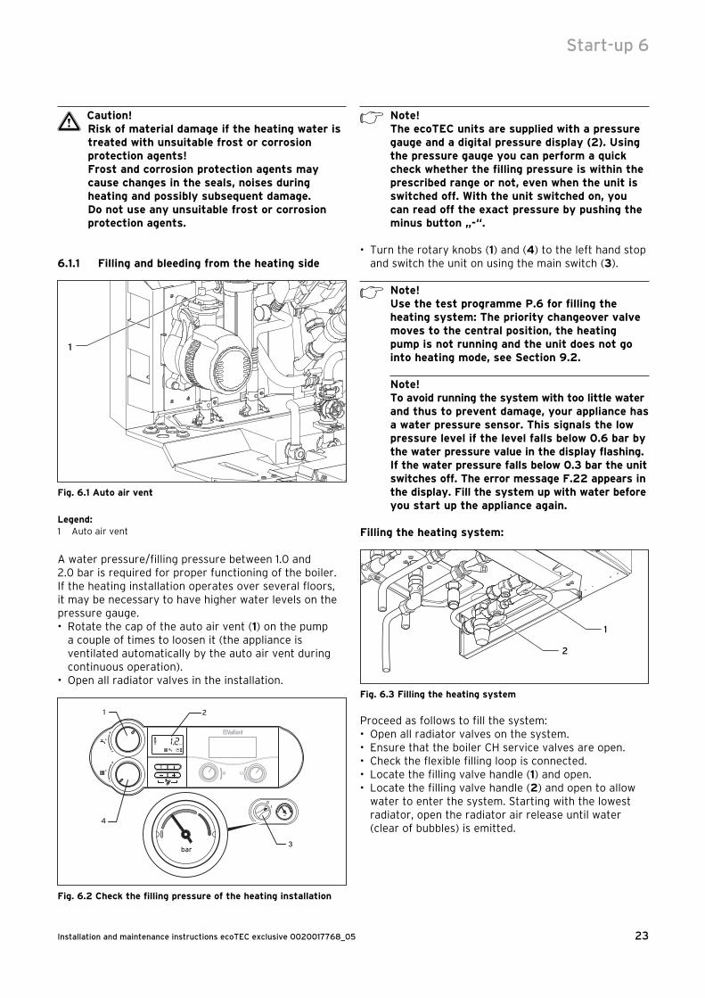
6.1.1 Filling and bleeding from the heating side
1
Fig. 6.1 Auto air vent
Legend:1 Auto air vent
A water pressure/filling pressure between 1.0 and 2.0 bar is required for proper functioning of the boiler. If the heating installation operates over several floors, it may be necessary to have higher water levels on the pressure gauge.• Rotate the cap of the auto air vent (1) on the pump
a couple of times to loosen it (the appliance is ventilated automatically by the auto air vent during continuous operation).
• Open all radiator valves in the installation.
bar
bar
1 2
3
4
Fig. 6.2 Check the filling pressure of the heating installation
h Note!The ecoTEC units are supplied with a pressure gauge and a digital pressure display (2). Using the pressure gauge you can perform a quick check whether the filling pressure is within the prescribed range or not, even when the unit is switched off. With the unit switched on, you can read off the exact pressure by pushing the minus button „-“.
• Turn the rotary knobs (1) and (4) to the left hand stop and switch the unit on using the main switch (3).
h Note!Use the test programme P.6 for filling the heating system: The priority changeover valve moves to the central position, the heating pump is not running and the unit does not go into heating mode, see Section 9.2.
Note!To avoid running the system with too little water and thus to prevent damage, your appliance has a water pressure sensor. This signals the low pressure level if the level falls below 0.6 bar by the water pressure value in the display flashing. If the water pressure falls below 0.3 bar the unit switches off. The error message F.22 appears in the display. Fill the system up with water before you start up the appliance again.
Filling the heating system:
2
1
Fig. 6.3 Filling the heating system
Proceed as follows to fill the system:• Open all radiator valves on the system.• Ensure that the boiler CH service valves are open.• Check the flexible filling loop is connected.• Locate the filling valve handle (1) and open.• Locate the filling valve handle (2) and open to allow
water to enter the system. Starting with the lowest radiator, open the radiator air release until water (clear of bubbles) is emitted.
Start-up 6
Installation and maintenance instructions ecoTEC exclusive 0020017768_0524
• Repeat this at all radiators until the complete system is full, all air locks have been cleared and the boiler pressure gauge reads 1.5 bar. Release any air from the pump by slackening the centre screw. Turn off the filling valve (2) and fully close filling valve (1).
• The boiler is equipped with an automatic air release valve. To allow this to vent the boiler, the cap on the top must be slackened by 1 –2 turns (This cap must be left slackened during boiler operation to ensure any residual air or system gases are released).
• Check the heating system and boiler connections are sound.
h Note!Use the test programme P.0 to vent the boiler and the heating system: The unit does not start in heating mode, the heating pump switches on and off and alternately vents the heating circuit and the hot water circuit, see Section 9.2.
6.1.2 First flushing of the system
h Note!The entire heating system must be flushed through completely at least twice: once cold and once hot, in accordance with the following instructions.
• Check if all radiator thermostat valves and both maintenance cocks on the boiler are open.
• Connect a hose to the drain valve which is located at the lowest position in the heating system.
• Open the 1/2" KFE drain cocks and all the vent valves on the radiators so that the water flows quickly and completely out of the heating system and the boiler, in order to remove the contamination caused during the installation out of the heating system before the boiler is started up.
• Close the 1/2” KFE drain cocks.• Re-fill the heating system with water as described
in Section 6.1.1.• Check that the over-pressure valve in the heating
system is functioning correctly by turning the handle on the valve.
• Check the pressure in the heating system and top up with water if necessary.
• Close filling valve 1 and filling valve 2.
6.1.3 Filling and bleeding from the hot water side• Open the cold water stop cock on the appliance on
the inlet combination.• Fill the hot water system by opening all the hot water
taps until water comes out.• As soon as water comes out of all the hot water taps,
the hot water circuit is filled completely and also vented.
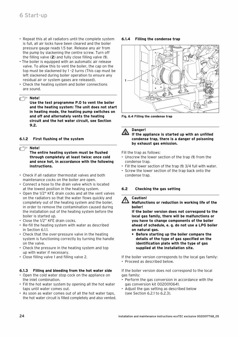
6.1.4 Filling the condense trap
1
Fig. 6.4 Filling the condense trap
d Danger!If the appliance is started up with an unfilled condense trap, there is a danger of poisoning by exhaust gas emission.
Fill the trap as follows:• Unscrew the lower section of the trap (1) from the
condense trap.• Fill the lower section of the trap (1) 3/4 full with water.• Screw the lower section of the trap back onto the
condense trap.
6.2 Checking the gas setting
Caution!Malfunctions or reduction in working life of the boiler!If the boiler version does not correspond to the local gas family, there will be malfunctions or you have to change components of the boiler ahead of schedule, e. g. do not use a LPG boiler on natural gas.• Before starting up the boiler compare the
details of the type of gas specified on the identification plate with the type of gas supplied at the installation site.
If the boiler version corresponds to the local gas family:• Proceed as described below.
If the boiler version does not correspond to the local gas family:• Perform the gas conversion in accordance with the
gas conversion kit 0020010641.• Adjust the gas setting as described below
(see Section 6.2.1 to 6.2.3).
6 Start-up

25Installation and maintenance instructions ecoTEC exclusive 0020017768_05
The combustion of this boiler has been checked, adjusted and preset at the factory for operation on the type of gas defined on the identification plate. No measurement of the combustion is necessary to set up the boiler.• Do not adjust the multifunctional automatic gas valve.• Ensure
- that the boiler has been installed in accordance with these instructions,
- the integrity of the flue system and the flue seals, as described in the flue installation instructions enclosed with this boiler, and as described below,
- a visual check is carried out on the boiler combustion circuit and the relevant seals,
- that any defects have been corrected at this stage.
To further validate the integrity of the flue system and confirm correct operation of the boiler it is possible to conduct flue gas and air measurements on this boiler - for details see Section 6.2.1.
Proceed to put the boiler into operation as follows:• Check the maximum gas flow rate as detailed in
Section 6.2.2.• Check the gas inlet working pressure as detailed in
Section 6.2.3.• Note that you must re-measure the gas flow rate or
the gas inlet working pressure, if changes were required to correct any issues found.
6.2.1 Checking for tightness of the flue gas installation and flue gas recirculation
• Check the integrity off the flue gas installation according to TB 200.
• Should the flue gas installation be longer than 2 m we strongly recommend to check the system for flue gas recirculation as described below.
1
2
Fig. 6.5 Flue gas and air measure points
Legend:1 Flue gas measure point2 Air measure point
• For checking the system for recirculation use the air measure point (2).
• Use the flue gas analyser.• If you detect any CO or CO2 in the fresh air, search for
the flue gas leakage or recirculation.• Correct the defects.• Check again as described before, if there is any CO or
CO2 in the fresh air.• If you cannot correct the defects you must not start
up the boiler.
6.2.2 Checking the gas flow rateThe boiler is fitted with a multifunctional automatic gas valve which ensures that the precise air/gas ratio is provided under all operating conditions. The gas flow rate has been set during production and does not require adjustment. With the front casing fitted check the gas flow rate of the boiler as follows:• Start the boiler by activating the test program P.1 as
described in Section 9.2.• In addition, ensure that maximum heat can be
dissipated into the heating system by turning up the room thermostat.
• Alternatively, fully open the hot water taps to ensure full flow rate through the boiler.
• Wait at least 5 minutes until the boiler has reached its operating temperature.
• Ensure that all other gas appliances in the property are turned off.
• Measure the gas flow rate at the gas meter.• Check that the gas flow rate is as stated in Table 6.3.• If the measured gas flow rate lies outside the
tolerance limits specified in Table 6.3, do not operate the boiler and inform the Vaillant Service Solutions (0870 6060 777).
If the measured gas flow rate is within the tolerance limits shown in Table 6.3, then proceed as follows:• Take the boiler out of operation by
- Pressing the + and i buttons simultaneously and turn down both thermostat control knobs.
- Allow the boiler to cool down by turning off water taps and allow pump overrun to operate for a minimum of two minutes.
• Record the boiler maximum gas flow rate onto the Benchmark gas boiler commissioning checklist.
Start-up 6
BoilerNominal net heat input in kW as per
BS EN 483
Gas flow rateNatural gas in m3/h Propane in kg/h
nominal + 5 % - 10 % nominal + 5 % - 10 %
ecoTEC exclusive 832 32 3,39 3,56 3,05 2,49 2,61 2,24
ecoTEC exclusive 838 38 4,02 4,22 3,62 2,95 3,10 2,66
Table 6.3 Gas flow rates
Installation and maintenance instructions ecoTEC exclusive 0020017768_0526
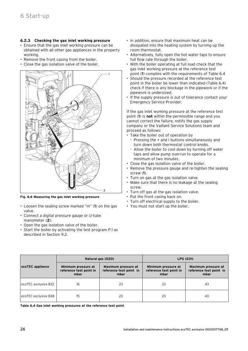
6.2.3 Checking the gas inlet working pressure• Ensure that the gas inlet working pressure can be
obtained with all other gas appliances in the property working.
• Remove the front casing from the boiler.• Close the gas isolation valve of the boiler.
2
1
Fig. 6.6 Measuring the gas inlet working pressure
• Loosen the sealing screw marked “in” (1) on the gas valve.
• Connect a digital pressure gauge or U-tube manometer (2).
• Open the gas isolation valve of the boiler.• Start the boiler by activating the test program P.1 as
described in Section 9.2.
• In addition, ensure that maximum heat can be dissipated into the heating system by turning up the room thermostat.
• Alternatively, fully open the hot water taps to ensure full flow rate through the boiler.
• With the boiler operating at full load check that the gas inlet working pressure at the reference test point (1) complies with the requirements of Table 6.4
• Should the pressure recorded at the reference test point in the boiler be lower than indicated (Table 6.4) check if there is any blockage in the pipework or if the pipework is undersized.
• If the supply pressure is out of tolerance contact your Emergency Service Provider.
If the gas inlet working pressure at the reference test point (1) is not within the permissible range and you cannot correct the failure, notify the gas supply company or the Vaillant Service Solutions team and proceed as follows:• Take the boiler out of operation by
- Pressing the + and i buttons simultaneously and turn down both thermostat control knobs.
- Allow the boiler to cool down by turning off water taps and allow pump overrun to operate for a minimum of two minutes.
• Close the gas isolation valve of the boiler.• Remove the pressure gauge and re-tighten the sealing
screw (1).• Turn on gas at the gas isolation valve.• Make sure that there is no leakage at the sealing
screw.• Turn off gas at the gas isolation valve.• Put the front casing back on.• Turn off electrical supply to the boiler.• You must not start up the boiler.
6 Start-up
ecoTEC appliance
Natural gas (G20) LPG (G31)
Minimum pressure at reference test point in
mbar
Maximum pressure at reference test point in
mbar
Minimum pressure at reference test point in
mbar
Maximum pressure at reference test point in
mbar
ecoTEC exclusive 832 16 23 23 43
ecoTEC exclusive 838 15 23 23 43
Table 6.4 Gas inlet working pressures at the reference test point
27Installation and maintenance instructions ecoTEC exclusive 0020017768_05
If the gas inlet working pressure is within the permissible range, proceed as follows:• Take the boiler out of operation by
- Pressing the + and i buttons simultaneously and turn down both thermostat control knobs.
- Allow the boiler to cool down by turning off water taps and allow pump overrun to operate for a minimum of two minutes.
• Close the gas isolation valve of the boiler.• Remove the pressure gauge and re-tighten the sealing
screw (1).• Open the gas isolation valve of the boiler.• Make sure that there is no leakage at the sealing
screw.• Put the front casing back on.• Reset boiler controls for normal operation.• Record the appliance gas inlet working pressure
(mbar) in the Benchmark gas boiler commissioning checklist.
6.3 Checking the equipment functionAfter installing and checking the gas supply pressure, perform a function check before commissioning the appliance and handing over to the user.• Commission the appliance in accordance with the
instructions in the relevant operating manual.• Check the gas infeed, exhaust gas installation, boiler and
heating installation and the hot water pipes for leaks.• Check the flue pipe for proper installation.• Check over-ignition and that the flame on the burner
is burning evenly.• Check the function of the heating (see Section 6.3.1)
and the hot water preparation (see Section 6.3.2)• Hand the unit over to the user.
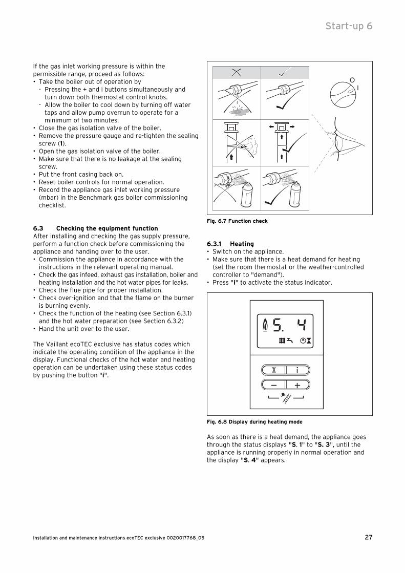
The Vaillant ecoTEC exclusive has status codes which indicate the operating condition of the appliance in the display. Functional checks of the hot water and heating operation can be undertaken using these status codes by pushing the button "i".
Fig. 6.7 Function check
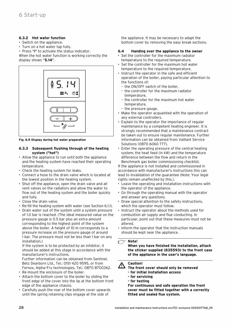
6.3.1 Heating• Switch on the appliance.• Make sure that there is a heat demand for heating
(set the room thermostat or the weather-controlled controller to "demand").
• Press "i" to activate the status indicator.
Fig. 6.8 Display during heating mode
As soon as there is a heat demand, the appliance goes through the status displays "S. 1" to "S. 3", until the appliance is running properly in normal operation and the display "S. 4" appears.
Start-up 6
Installation and maintenance instructions ecoTEC exclusive 0020017768_0528
6.3.2 Hot water function• Switch on the appliance.• Turn on a hot water tap fully.• Press "i" to activate the status indicator.When the hot water function is working correctly the display shows "S.14".
Fig. 6.9 Display during hot water preparation
6.3.3 Subsequent flushing through of the heating system ("hot")
• Allow the appliance to run until both the appliance and the heating system have reached their operating temperature.
• Check the heating system for leaks.• Connect a hose to the drain valve which is located at
the lowest position in the heating system.• Shut off the appliance, open the drain valve and all
vent valves on the radiators and allow the water to flow out of the heating system and the boiler quickly and fully.
• Close the drain valve.• Re-fill the heating system with water (see Section 6.1.1).• Drain water out of the system until a system pressure
of 1.0 bar is reached. (The ideal measured value on the pressure gauge is 0.5 bar plus an extra amount corresponding to the highest point of the system above the boiler. A height of 10 m corresponds to a pressure increase on the pressure gauge of around 1 bar. The pressure must not be less than 1 bar on any installation.) If the system is to be protected by an inhibitor, it should be added at this stage in accordance with the manufacturer's instructions. Further information can be obtained from Sentinel, Betz Dearborn Ltd., Tel.: 0151 420 9595, or from Fernox, Alpha–Fry technologies, Tel.: 0870 8700362.
• Re-mount the enclosure of the boiler.• Attach the bottom cover to the boiler by sliding the
front edge of the cover into the lip at the bottom front edge of the appliance chassis.
• Carefully push the rear of the bottom cover upwards until the spring retaining clips engage at the side of
the appliance. It may be necessary to adapt the bottom cover by removing the easy break sections.
6.4 Handing over the appliance to the owner• Set the controller for the maximum radiator
temperature to the required temperature.• Set the controller for the maximum hot water
temperature to the required temperature.• Instruct the operator in the safe and efficient
operation of the boiler, paying particular attention to the functions of:– the ON/OFF switch of the boiler,– the controller for the maximum radiator
temperature,– the controller for the maximum hot water
temperature,– the pressure gauge.
• Make the operator acquainted with the operation of any external controllers.
• Explain to the operator the importance of regular maintenance by a competent heating engineer. It is strongly recommended that a maintenance contract be taken out to ensure regular maintenance. Further information can be obtained from Vaillant Service Solutions (0870 6060 777).
• Enter the operating pressure of the central heating system, the heat feed (in kW) and the temperature difference between the flow and return in the Benchmark gas boiler commissioning checklist.
If the appliance is not installed and commissioned in accordance with manufacturer's instructions this can lead to invalidation of the guarantee (Note: Your legal rights remain unaffected by this.).• Leave the operating and installation instructions with
the operator of the appliance.• Go through the operating manual with the operator
and answer any questions.• Draw special attention to the safety instructions,
which the operator must follow.• Instruct the operator about the methods used for
combustion air supply and flue conducting. In particular, point out that these measures must not be altered.
• Inform the operator that the instruction manuals should be kept near the appliance.
h Note!When you have finished the installation, attach the sticker supplied (835593) to the front case of the appliance in the user’s language.
a Caution!The front cover should only be removed- for initial installation access - for servicing- for testingFor continuous and safe operation the front cover must be fitted together with a correctly fitted and sealed flue system.
6 Start-up
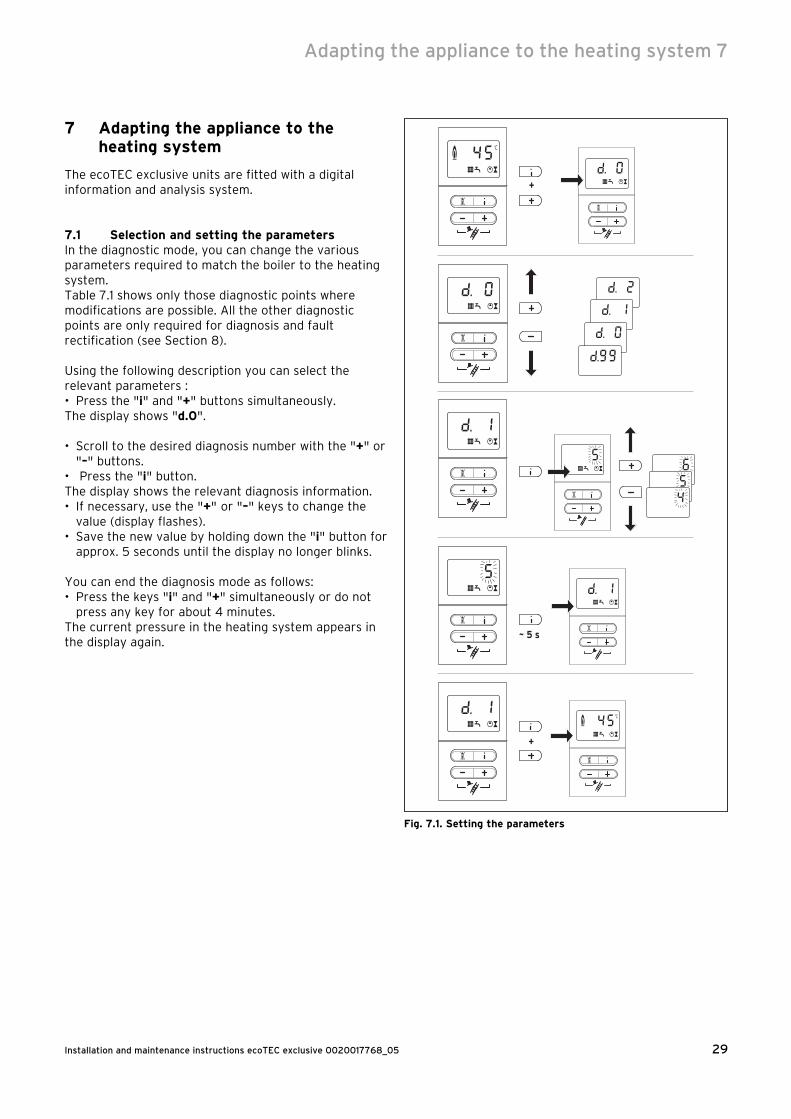
29Installation and maintenance instructions ecoTEC exclusive 0020017768_05
7 Adapting the appliance to the heating system
The ecoTEC exclusive units are fitted with a digital information and analysis system.
7.1 Selection and setting the parametersIn the diagnostic mode, you can change the various parameters required to match the boiler to the heating system.Table 7.1 shows only those diagnostic points where modifications are possible. All the other diagnostic points are only required for diagnosis and fault rectification (see Section 8).
Using the following description you can select the relevant parameters :• Press the "i" and "+" buttons simultaneously.The display shows "d.0".
• Scroll to the desired diagnosis number with the "+" or "–" buttons.
• Press the "i" button.The display shows the relevant diagnosis information.• If necessary, use the "+" or "–" keys to change the
value (display flashes).• Save the new value by holding down the "i" button for
approx. 5 seconds until the display no longer blinks.
You can end the diagnosis mode as follows:• Press the keys "i" and "+" simultaneously or do not
press any key for about 4 minutes.The current pressure in the heating system appears in the display again.
+
+
~ 5 s
Fig. 7.1. Setting the parameters
Adapting the appliance to the heating system 7
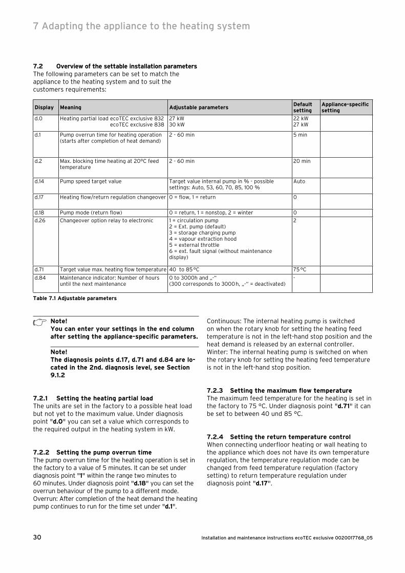
Installation and maintenance instructions ecoTEC exclusive 0020017768_0530
7.2 Overview of the settable installation parametersThe following parameters can be set to match the appliance to the heating system and to suit the customers requirements:
Display Meaning Adjustable parametersDefault setting
Appliance-specific setting
d.0 Heating partial load ecoTEC exclusive 832ecoTEC exclusive 838
27 kW30 kW
22 kW27 kW
d.1 Pump overrun time for heating operation (starts after completion of heat demand)
2 - 60 min 5 min
d.2 Max. blocking time heating at 20°C feed temperature
2 - 60 min 20 min
d.14 Pump speed target value Target value internal pump in % - possible settings: Auto, 53, 60, 70, 85, 100 %
Auto
d.17 Heating flow/return regulation changeover 0 = flow, 1 = return 0
d.18 Pump mode (return flow) 0 = return, 1 = nonstop, 2 = winter 0
d.26 Changeover option relay to electronic 1 = circulation pump2 = Ext. pump (default)3 = storage charging pump4 = vapour extraction hood5 = external throttle6 = ext. fault signal (without maintenance display)
2
d.71 Target value max. heating flow temperature 40 to 85 °C 75 °C
d.84 Maintenance indicator: Number of hours until the next maintenance
0 to 3000h and „-“ (300 corresponds to 3000 h, „-“ = deactivated)
-
Table 7.1 Adjustable parameters
h Note!You can enter your settings in the end column after setting the appliance-specific parameters.
Note!The diagnosis points d.17, d.71 and d.84 are lo-cated in the 2nd. diagnosis level, see Section 9.1.2
7.2.1 Setting the heating partial loadThe units are set in the factory to a possible heat load but not yet to the maximum value. Under diagnosis point "d.0" you can set a value which corresponds to the required output in the heating system in kW.
7.2.2 Setting the pump overrun timeThe pump overrun time for the heating operation is set in the factory to a value of 5 minutes. It can be set under diagnosis point "1" within the range two minutes to 60 minutes. Under diagnosis point "d.18" you can set the overrun behaviour of the pump to a different mode.Overrun: After completion of the heat demand the heating pump continues to run for the time set under "d.1".
Continuous: The internal heating pump is switched on when the rotary knob for setting the heating feed temperature is not in the left-hand stop position and the heat demand is released by an external controller.Winter: The internal heating pump is switched on when the rotary knob for setting the heating feed temperature is not in the left-hand stop position.
7.2.3 Setting the maximum flow temperatureThe maximum feed temperature for the heating is set in the factory to 75 °C. Under diagnosis point "d.71" it can be set to between 40 und 85 °C.
7.2.4 Setting the return temperature controlWhen connecting underfloor heating or wall heating to the appliance which does not have its own temperature regulation, the temperature regulation mode can be changed from feed temperature regulation (factory setting) to return temperature regulation under diagnosis point "d.17".
7 Adapting the appliance to the heating system

31Installation and maintenance instructions ecoTEC exclusive 0020017768_05
7.2.5 Setting the burner anti-cycle time
TFeed(target)
[°C]
Set maximum burner anti-cycle time [min]
1 5 10 15 20 25 30 35 40 45 50 55 60
20 2,0 5,0 10,0 15,0 20,0 25,0 30,0 35,0 40,0 45,0 50,0 55,0 60,0
25 2,0 4,5 9,2 14,0 18,5 23,0 27,5 32,0 36,5 41,0 45,0 50,0 54,5
30 2,0 4,0 8,5 12,5 16,5 20,5 25,0 29,0 33,0 37,0 41,0 45,0 49,5
35 2,0 4,0 7,5 11,0 15,0 18,5 22,0 25,5 29,5 33,0 36,5 40,5 44,0
40 2,0 3,5 6,5 10,0 13,0 16,5 19,5 22,5 26,0 29,0 32,0 35,5 38,5
45 2,0 3,0 6,0 8,5 11,5 14,0 17,0 19,5 22,5 25,0 27,5 30,5 33,0
50 2,0 3,0 5,0 7,5 9,5 12,0 14,0 16,5 18,5 21,0 23,5 25,5 28,0
55 2,0 2,5 4,5 6,0 8,0 10,0 11,5 13,5 15,0 17,0 19,0 20,5 22,5
60 2,0 2,0 3,5 5,0 6,0 7,5 9,0 10,5 11,5 13,0 14,5 15,5 17,0
65 2,0 1,5 2,5 3,5 4,5 5,5 6,5 7,0 8,0 9,0 10,0 11,0 11,5
70 2,0 1,5 2,0 2,5 2,5 3,0 3,5 4,0 4,5 5,0 5,5 6,0 6,5
75 2,0 1,0 1,0 1,0 1,0 1,0 1,0 1,0 1,0 1,0 1,0 1,0 1,0
Table 7.2 Effective burner anti-cycle time
The burner is electronically locked for a specific time after each time it is switched off ("re-start interlock") to avoid frequent switching on and off of the burner (energy losses).The burner anti-cycle time is only activated for the heating operation. Hot water operation during a burner anti-cycle time does not affect the timer.The individual anti-cycle time can be matched to the hydraulic and thermal properties of the heating installation. In the factory the burner anti-cycle time is set to a value of 20 minutes. It can be varied under diagnosis point "d.02" within the range 2 minutes to 60 minutes. The individual effective anti-cycle time is calculated from the momentary target feed temperature and the set maximum burner anti-cycle time.The timer can be reset or cancelled by actuating the appliance main switch. The remaining burner anti-cycle time left after switching off by the controller in heating operation can be called up under diagnosis point "d.67".The individually effective burner anti-cycle times with respect to the feed temperature and the maximum set burner anti-cycle time can be taken from Table 7.2.
7.2.6 Determination of the maintenance interval/maintenance display
The electronics of the ecoTEC exclusive allow you to determine the maintenance intervals for the appliance. This function serves to provide a signal that, after a specific, adjustable, number of burner operating hours, the boiler needs to be serviced. The service signal SEr is shown in the display of the ecoTEC exclusive alternately with the current pressure after expiry of the set number of burner operating hours. The display also appears on the VRT 360 and 400 (accessories).
Heat demandNumber of persons
Burner operating hours to the next inspection/service (dependent upon the type of appliance)
32 kW3 - 44 - 6
2.800 h2.900 h
38 kW4 - 64 - 8
3.000 h3.100 h
Table 7.3 Guide values for operating hours
The operating hours to the next service can be set under diagnosis point "d.84". Guide values can be taken from Table 7.3; these values correspond to an approximate operating time for the appliance of one year.The operating hours can be set in steps of ten from 0 to 3000 h.If there is no number in the diagnosis point "d.84", but there is the symbol "-", then the "maintenance display" is not active.
h Note!After the set number of hours have expired, the service interval must be entered in the diagnosis mode again.
Adapting the appliance to the heating system 7
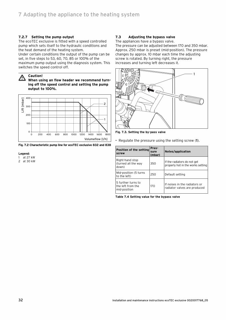
Installation and maintenance instructions ecoTEC exclusive 0020017768_0532
7.2.7 Setting the pump outputThe ecoTEC exclusive is fitted with a speed controlled pump which sets itself to the hydraulic conditions and the heat demand of the heating system.Under certain conditions the output of the pump can be set, in five steps to 53, 60, 70, 85 or 100% of the maximum pump output using the diagnosis system. This switches the speed control off.
a Caution!When using an flow header we recommend turn-ing off the speed control and setting the pump output to 100%.
0
100
200
300
400
0 200 400 600 800 1000 1200 1400 1600 1800
2
1
Volumeflow [l/h]
Lif
t [m
bar
]
Fig. 7.2 Characteristic pump line for ecoTEC exclusive 832 and 838
Legend:1 at 27 kW2 at 30 kW
7.3 Adjusting the bypass valveThe appliances have a bypass valve.The pressure can be adjusted between 170 and 350 mbar. Approx. 250 mbar is preset (mid-position). The pressure changes by approx. 10 mbar each time the adjusting screw is rotated. By turning right, the pressure increases and turning left decreases it.
1
Fig. 7.3. Setting the by-pass valve
• Regulate the pressure using the setting screw (1).
Position of the setting screw
Pres-sure (mbar)
Notes/application
Right-hand stop (turned all the way down)
350If the radiators do not get properly hot in the works setting
Mid-position (5 turns to the left)
250 Default setting
5 further turns to the left from the mid-position
170If noises in the radiators or radiator valves are produced
Table 7.4 Setting value for the bypass valve
7 Adapting the appliance to the heating system
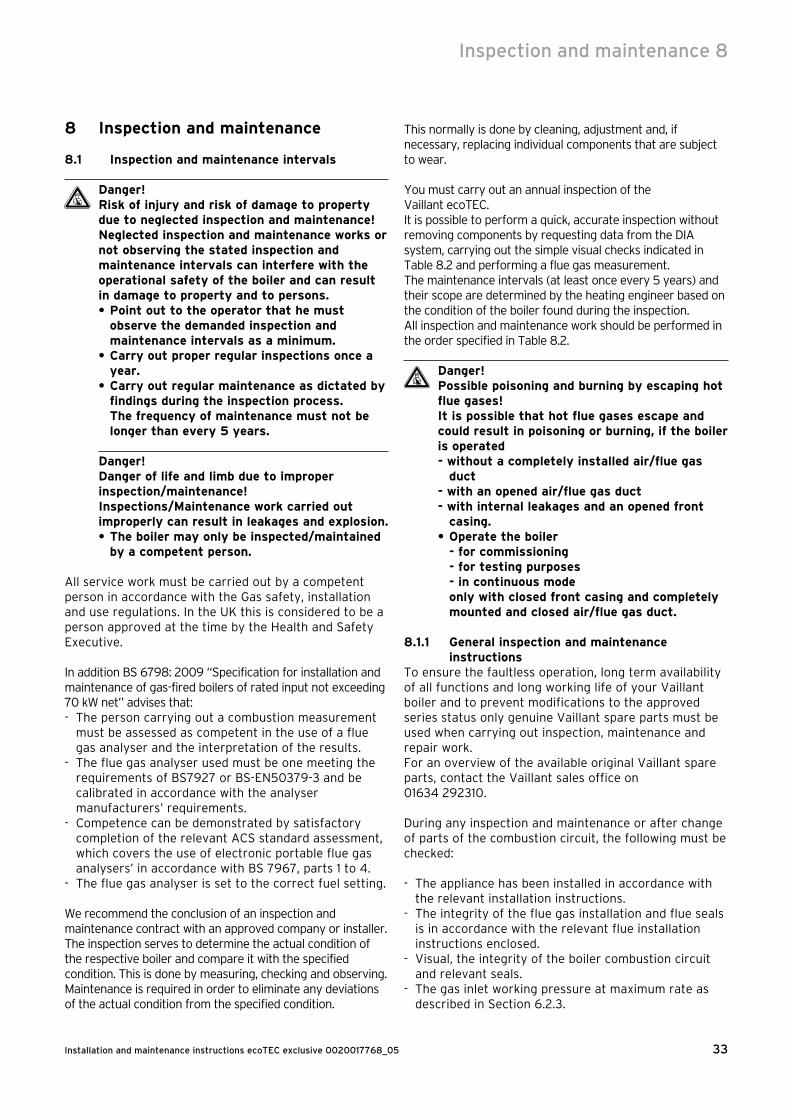
33Installation and maintenance instructions ecoTEC exclusive 0020017768_05
Inspection and maintenance 8
8 Inspection and maintenance
8.1 Inspection and maintenance intervals
Danger!Risk of injury and risk of damage to property due to neglected inspection and maintenance!Neglected inspection and maintenance works or not observing the stated inspection and maintenance intervals can interfere with the operational safety of the boiler and can result in damage to property and to persons.• Point out to the operator that he must
observe the demanded inspection and maintenance intervals as a minimum.
• Carry out proper regular inspections once a year.
• Carry out regular maintenance as dictated by findings during the inspection process.The frequency of maintenance must not be longer than every 5 years.
Danger!Danger of life and limb due to improper inspection/maintenance!Inspections/Maintenance work carried out improperly can result in leakages and explosion.• The boiler may only be inspected/maintained
by a competent person.
All service work must be carried out by a competent person in accordance with the Gas safety, installation and use regulations. In the UK this is considered to be a person approved at the time by the Health and Safety Executive.
In addition BS 6798: 2009 “Specification for installation and maintenance of gas-fired boilers of rated input not exceeding 70 kW net” advises that:- The person carrying out a combustion measurement
must be assessed as competent in the use of a flue gas analyser and the interpretation of the results.
- The flue gas analyser used must be one meeting the requirements of BS7927 or BS-EN50379-3 and be calibrated in accordance with the analyser manufacturers’ requirements.
- Competence can be demonstrated by satisfactory completion of the relevant ACS standard assessment, which covers the use of electronic portable flue gas analysers’ in accordance with BS 7967, parts 1 to 4.
- The flue gas analyser is set to the correct fuel setting.
We recommend the conclusion of an inspection and maintenance contract with an approved company or installer.The inspection serves to determine the actual condition of the respective boiler and compare it with the specified condition. This is done by measuring, checking and observing.Maintenance is required in order to eliminate any deviations of the actual condition from the specified condition.
This normally is done by cleaning, adjustment and, if necessary, replacing individual components that are subject to wear.
You must carry out an annual inspection of the Vaillant ecoTEC.It is possible to perform a quick, accurate inspection without removing components by requesting data from the DIA system, carrying out the simple visual checks indicated in Table 8.2 and performing a flue gas measurement.The maintenance intervals (at least once every 5 years) and their scope are determined by the heating engineer based on the condition of the boiler found during the inspection.All inspection and maintenance work should be performed in the order specified in Table 8.2.
d Danger!Possible poisoning and burning by escaping hot flue gases! It is possible that hot flue gases escape and could result in poisoning or burning, if the boiler is operated- without a completely installed air/flue gas
duct- with an opened air/flue gas duct- with internal leakages and an opened front
casing.• Operate the boiler - for commissioning - for testing purposes - in continuous mode only with closed front casing and completely mounted and closed air/flue gas duct.
8.1.1 General inspection and maintenance instructions
To ensure the faultless operation, long term availability of all functions and long working life of your Vaillant boiler and to prevent modifications to the approved series status only genuine Vaillant spare parts must be used when carrying out inspection, maintenance and repair work.For an overview of the available original Vaillant spare parts, contact the Vaillant sales office on 01634 292310.
During any inspection and maintenance or after change of parts of the combustion circuit, the following must be checked:
- The appliance has been installed in accordance with the relevant installation instructions.
- The integrity of the flue gas installation and flue seals is in accordance with the relevant flue installation instructions enclosed.
- Visual, the integrity of the boiler combustion circuit and relevant seals.
- The gas inlet working pressure at maximum rate as described in Section 6.2.3.

Installation and maintenance instructions ecoTEC exclusive 0020017768_0534
- The gas flow rates as described in Section 6.2.2.- Correctness of electrical, water and gas connections.- Correctness of the water pressure.- The condition of the whole system, in particular the
condition of radiator valves, evidence of leakage from the heating system and dripping taps.
• Correct any faults before proceeding.
8.1.2 Safety instructions
Danger!Danger of life and limb by electric shock!The supply terminals of the boiler are under mains voltage even if the boiler main switch is off.• Don’t touch the supply terminals.• Protect the electronic box from any water or
spray.• Before working on the boiler, turn off the
power and secure against restart.
NoteIf it is necessary to keep the electricity to the boiler switched on for certain inspection and maintenance, this is indicated in the description of the maintenance task.
Always perform the following steps prior to inspection or maintenance work:• Switch off the main switch.• Disconnect the boiler from the power mains by
- disconnecting the mains plug or - de-energising the boiler via an isolating device with a
contact opening of at least 3 mm (e. g. fuses or power switches).
• Further check for electrical isolation of the appliance by use of a test meter.
• Close the gas isolation valve.• Close the service valves in the heating flow and
return.• Remove the front casing from the boiler.• When removing any water carrying components
ensure that water is kept away from all electrical components.
Always perform the following steps after performing any inspection or maintenance work:• Always use new seals and O-rings when parts are
replaced.• Open the service valves in the heating flow and
return.• Reconnect the boiler to the power mains.• Switch the main switch on.• Fill the heating circuit of the boiler to a pressure of
between 1.0 and 2.0 bar if required.• Bleed the heating installation (see Section 6.1.1, Filling
and bleeding from the heating side).• Open the gas isolation valve.
• Check the boiler for gas and water leaks.• If necessary, refill and re-bleed the heating
installation.• Replace the front casing to the boiler.• Carry out a functional check of the boiler
(see Section 6).• Always check earth continuity, polarity and resistance
to earth with a multimeter after any service work and after replacing any electrical component.
8.1.3 Checking the CO2 concentration
NoteChecking/adjustment of the CO2 concentration is required in the following instances: - replacement of gas valve, - conversion to or from Natural Gas/LPG - or if an incorrect combustion is suspected.
1
2
4
3
Fig. 8.1 Measuring the CO2 concentration, specifying the air
ratio (gas setting)
Legend:1 Flue gas analysis point2 Screw3 Air intake pipe4 Main throttle
NoteThe boiler is fitted with a flue gas analysis point (1). A suitable flue gas analyser can be connected to this point to establish the combustion performance of the boiler.
• Remove the front casing.• Start the testing program P.1.• Wait at least 5 minutes until the boiler reaches its
operating temperature.
8 Inspection and maintenance

35Installation and maintenance instructions ecoTEC exclusive 0020017768_05
• Measure the CO2 concentration at the flue gas analysis point (1). Compare the measured value with the corresponding value in Table 8.1.
• If all these points are as required, proceed as described in Section 8.1.5.
• If one of the flue gas values is greater than the acceptable values in Table 8.1, then proceed as described in the following Section 8.1.4.
8.1.4 Adjusting the CO2 concentration (or the air ratio)
d Danger!Increased risk of poisoning due to incorrect settings! Incorrect setting may increase the risk of poisoning.• If one of the flue gas values is greater than
the acceptable values in Table 8.1 then check - the integrity of the complete flue gas
installation - the integrity of the combustion circuit seals - the gas inlet working pressure - the gas flow rate.
If the flue gas value needs to be adjusted, • unfasten the screw (Fig. 8.1, 2) and • fold the air intake pipe (Fig. 8.1, 3) forwards through
90°. Do not remove the air intake pipe.• Specify the required flue gas value if necessary (value
with front casing of boiler removed, see Table 8.1) by turning the screw of the main throttle (Fig. 8.1, 4)
h NoteUse a 4 mm hexagon socket spanner to turn the screw.
• Turn to the left: higher CO2 concentration,• Turn to the right: lower CO2 concentration.
h NoteNatural gas: Only perform the adjustment in increments of 1/8 turn and wait approximately 1 minute after each adjustment until the value stabilises.Liquid gas: Only perform the adjustment in very small increments (approximately 1/16 turns), and wait approximately 1 minute after each adjustment until the value stabilises.
• After performing the adjustments, fold the air intake pipe back up.
• Check the CO2 concentration once again.• If necessary, repeat the setting process.• Push the „i“ button to deactivate the full load mode.
The full load mode is also deactivated if no button is pushed for 15 minutes.
• The adjusting screw shall be sealed after the adjustment.
• Re-secure the air intake pipe with the screw (2).• Put the front casing back on.
Settings Natural gas (H)Tolerance
PropaneTolerance
Unit
CO2 after 5 minutes full load mode with boiler front casing closed
9.2 1,0 10.2 0,5 Vol.–%
CO2 after 5 minutes full load mode with boiler front casing removed
9.0 1,0 10.0 0,5 Vol.–%
Set for Wobbe-Index W0 15 22.5 kWh/m3
CO value with full load < 250 < 250 ppm
CO/CO2 < 0,0031 < 0,0026
Table 8.1 Factory gas settings
d Danger!Risk to life due to poisoning!CO is an extremely toxic gas. Risk to life due to excessive CO concentrations.• If you are not able to adjust the boiler
correctly and the flue gas values remain higher than allowed in Table 8.1, call the Vaillant Service Solutions.
• Do not start up the boiler!
Inspection and maintenance 8
Installation and maintenance instructions ecoTEC exclusive 0020017768_0536
8.1.5 Inspection and maintenance work steps
No. Activity
Column 1 Inspection must be carried out
each year
Column 2Maintenance
must be carried out at regular intervals – but no longer than
5 years
1Check the air flue gas installation for leaks and for proper fixation and ensure it is not blocked or damaged and is fitted correctly, complying with the relevant installation instructions.
x x
2 Carry out a general inspection of the boiler for dirt and dust and clean as necessary. x x
3Visually inspect the complete heat engine for its general condition and for signs of corrosion, sooting or other forms of damage. If damage is evident proceed to column 2.
x x
4Measure the gas flow rate during operation with maximum load (Section 6.2.2). If the gas flow rate complies to the Table 6.3 continue with column 1, if not proceed to column 2.
x x
5Check the gas inlet working pressure (Section 6.2.3) operation with maximum load. If the gas inlet working pressure complies to the Table 6.4 continue with column 1, if not proceed to column 2.
x x
6Check combustion by measuring CO, CO2 and CO/CO2. If the values are outside the tole rances of Table 8.1 proceed to maintenance column 2. You must not proceed with the maintenance if a new burner door seal kit is not available.
x
7Isolate the boiler from the power mains. Check whether the electrical plug connections and the other electrical connections are fitted tightly and correct them if necessary.
x x
8 Close the gas isolation valve and the service valves. x
9Dump the pressure in the boiler on the water side (observe pressure gauge) and check the charge pressure of the expansion vessel. Top up if necessary.
x
10 Remove the compact thermal module. x
11Check the integrity of all combustion circuit seals, especially the burner door seal. If there are any damages repair them before proceeding.
x
12 Clean the heat exchanger. x
13 Check whether the burner is dirty and clean it if necessary. x
14 Check the condensate siphon in the boiler, clean and fill if necessary. x x
15 Check the condensate ducts in the boiler and clean if necessary. x x
16 Install the compact thermal module. Caution: Use new seals and nuts! x
17Open the service valves and fill up the boiler/appliance to approximately 1.0 - 2.0 bar (depending on the static height of the system). Start the bleeding program P.0.
x
18Open the gas isolation valve, reconnect the boiler with the power mains and switch on the boiler.
x x
19Perform a test operation of the boiler and heating installation, including water heating and bleed again if necessary.
x x
20 Check visually the ignition and burner performance. x x
21Check the boiler for leaks of any kind (gas, flue gas, water, condensate) and rectify as necessary.
x x
22If you had problems with the CO, CO2, CO/CO2-values in Step 6 before the maintenance, check them again now (see Table 8.1). If they are outside of the tolerances of Table 8.1 make an adjustment, see Section 8.1.4.
x
23 Complete the gas commission checklist (benchmark book). x x
Table 8.2 Inspection and maintenance steps
8 Inspection and maintenance
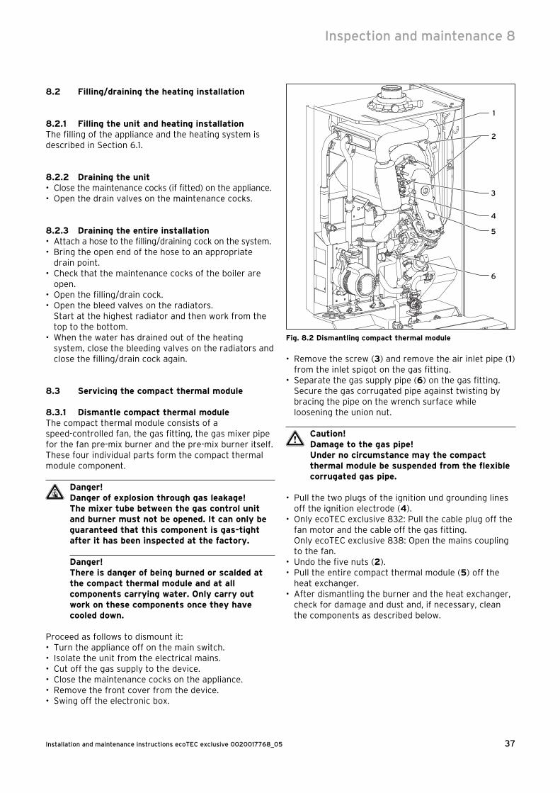
37Installation and maintenance instructions ecoTEC exclusive 0020017768_05
8.2 Filling/draining the heating installation
8.2.1 Filling the unit and heating installationThe filling of the appliance and the heating system is described in Section 6.1.
8.2.2 Draining the unit• Close the maintenance cocks (if fitted) on the appliance.• Open the drain valves on the maintenance cocks.
8.2.3 Draining the entire installation• Attach a hose to the filling/draining cock on the system.• Bring the open end of the hose to an appropriate
drain point.• Check that the maintenance cocks of the boiler are
open.• Open the filling/drain cock.• Open the bleed valves on the radiators.
Start at the highest radiator and then work from the top to the bottom.
• When the water has drained out of the heating system, close the bleeding valves on the radiators and close the filling/drain cock again.
8.3 Servicing the compact thermal module
8.3.1 Dismantle compact thermal moduleThe compact thermal module consists of a speed-controlled fan, the gas fitting, the gas mixer pipe for the fan pre-mix burner and the pre-mix burner itself. These four individual parts form the compact thermal module component.
d Danger!Danger of explosion through gas leakage!The mixer tube between the gas control unit and burner must not be opened. It can only be guaranteed that this component is gas-tight after it has been inspected at the factory.
Danger!There is danger of being burned or scalded at the compact thermal module and at all components carrying water. Only carry out work on these components once they have cooled down.
Proceed as follows to dismount it:• Turn the appliance off on the main switch.• Isolate the unit from the electrical mains.• Cut off the gas supply to the device.• Close the maintenance cocks on the appliance.• Remove the front cover from the device.• Swing off the electronic box.
5
4
3
2
1
6
Fig. 8.2 Dismantling compact thermal module
• Remove the screw (3) and remove the air inlet pipe (1) from the inlet spigot on the gas fitting.
• Separate the gas supply pipe (6) on the gas fitting. Secure the gas corrugated pipe against twisting by bracing the pipe on the wrench surface while loosening the union nut.
a Caution!Damage to the gas pipe!Under no circumstance may the compact thermal module be suspended from the flexible corrugated gas pipe.
• Pull the two plugs of the ignition und grounding lines off the ignition electrode (4).
• Only ecoTEC exclusive 832: Pull the cable plug off the fan motor and the cable off the gas fitting. Only ecoTEC exclusive 838: Open the mains coupling to the fan.
• Undo the five nuts (2).• Pull the entire compact thermal module (5) off the
heat exchanger.• After dismantling the burner and the heat exchanger,
check for damage and dust and, if necessary, clean the components as described below.
Inspection and maintenance 8
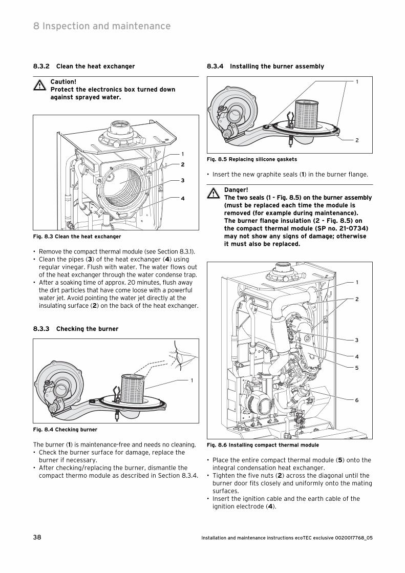
Installation and maintenance instructions ecoTEC exclusive 0020017768_0538
8.3.2 Clean the heat exchanger
a Caution!Protect the electronics box turned down against sprayed water.
1
2
3
4
Fig. 8.3 Clean the heat exchanger
• Remove the compact thermal module (see Section 8.3.1).• Clean the pipes (3) of the heat exchanger (4) using
regular vinegar. Flush with water. The water flows out of the heat exchanger through the water condense trap.
• After a soaking time of approx. 20 minutes, flush away the dirt particles that have come loose with a powerful water jet. Avoid pointing the water jet directly at the insulating surface (2) on the back of the heat exchanger.
8.3.3 Checking the burner
1
Fig. 8.4 Checking burner
The burner (1) is maintenance-free and needs no cleaning.• Check the burner surface for damage, replace the
burner if necessary.• After checking/replacing the burner, dismantle the
compact thermo module as described in Section 8.3.4.
8.3.4 Installing the burner assembly
1
2
Fig. 8.5 Replacing silicone gaskets
• Insert the new graphite seals (1) in the burner flange.
a Danger!The two seals (1 - Fig. 8.5) on the burner assembly (must be replaced each time the module is removed (for example during maintenance).The burner flange insulation (2 - Fig. 8.5) on the compact thermal module (SP no. 21-0734) may not show any signs of damage; otherwise it must also be replaced.
5
4
3
2
1
6
Fig. 8.6 Installing compact thermal module
• Place the entire compact thermal module (5) onto the integral condensation heat exchanger.
• Tighten the five nuts (2) across the diagonal until the burner door fits closely and uniformly onto the mating surfaces.
• Insert the ignition cable and the earth cable of the ignition electrode (4).
8 Inspection and maintenance
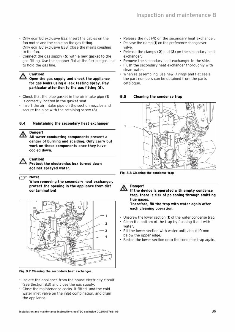
39Installation and maintenance instructions ecoTEC exclusive 0020017768_05
• Only ecoTEC exclusive 832: Insert the cables on the fan motor and the cable on the gas fitting. Only ecoTEC exclusive 838: Close the mains coupling to the fan.
• Connect the gas supply (6) with a new gasket to the gas fitting. Use the spanner flat at the flexible gas line to hold the gas line.
a Caution!Open the gas supply and check the appliance for gas leaks using a leak testing spray. Pay particular attention to the gas fitting (6).
• Check that the blue gasket in the air intake pipe (1) is correctly located in the gasket seat.
• Insert the air intake pipe on the suction nozzles and secure the pipe with the retaining screw (3).
8.4 Maintaining the secondary heat exchanger
d Danger!All water conducting components present a danger of burning and scalding. Only carry out work on these components once they have cooled down.
a Caution!Protect the electronics box turned down against sprayed water.
h Note!When removing the secondary heat exchanger, protect the opening in the appliance from dirt contamination!
4
3
2
1
Fig. 8.7 Cleaning the secondary heat exchanger
• Isolate the appliance from the house electricity circuit (see Section 8.3) and close the gas supply.
• Close the maintenance cocks -if fitted- and the cold water inlet valve on the inlet combination, and drain the appliance.
• Release the nut (4) on the secondary heat exchanger.• Release the clamp (1) on the preference changeover
valve.• Release the clamps (2) and (3) on the secondary heat
exchanger.• Remove the secondary heat exchanger to the side.• Flush the secondary heat exchanger thoroughly with
clean water.• When re-assembling, use new O rings and flat seals,
the part numbers can be obtained from the parts catalogue.
8.5 Cleaning the condense trap
1
Fig. 8.8 Cleaning the condense trap
d Danger!If the device is operated with empty condense trap, there is risk of poisoning through emitting flue gases.Therefore, fill the trap with water again after each cleaning operation.
• Unscrew the lower section (1) of the water condense trap.• Clean the bottom of the trap by flushing it out with
water.• Fill the lower section with water until about 10 mm
below the upper edge.• Fasten the lower section onto the condense trap again.
Inspection and maintenance 8

Installation and maintenance instructions ecoTEC exclusive 0020017768_0540
8.6 Checking the expansion vessel
1
Fig. 8.9 Checking the expansion vessel
h Note!This check need not be performed every year - a check every three years is sufficient.
• The maintenance cocks of the central heating system must be closed.
• Release the pressure from the appliance.• Remove the valve cover from the filling connection
of the expansion vessel.• Check that the internal pressure in the expansion
vessel is between 0.75 and 0.9 bar. If the pressure is less than this, the vessel must be pumped up again using an air pump.
• Refit the valve cover.• Re-pressurise the boiler and the heating system.
8.7 Checking the connection pressure (gas inlet working pressure)
To check the connection pressure proceed as described in Section 6.2.3.
8.8 Checking CO2 content and adjusting if necessary
To check the air figure proceed as described in Section 8.1.3.
8.9 Test operationAlways perform the following checks after completing any inspection/maintenance task:• Commission the appliance in accordance with the
instructions in the relevant operating manual.
Fig. 8.10 Function check
• Check the appliance for gas and water leaks.• Check the flue system for leaks and that it is fixed
properly.• Check over-ignition and that the flame on the burner
is burning evenly.• Check the function of the heating (see Section 6.3.1)
and the hot water preparation (see Section 6.3.2)• Document the inspection/maintenance tasks per-
formed in the form provided in the inspection or maintenance contract.
8 Inspection and maintenance
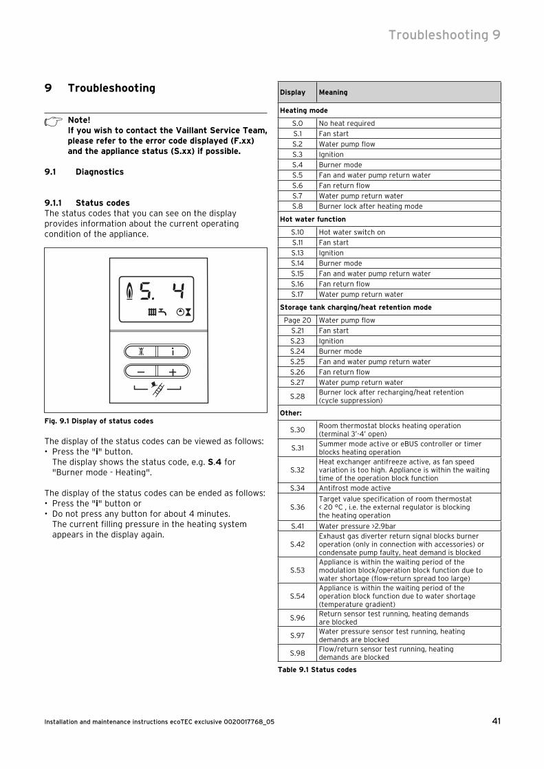
41Installation and maintenance instructions ecoTEC exclusive 0020017768_05
Troubleshooting 9
9 Troubleshooting
h Note!If you wish to contact the Vaillant Service Team, please refer to the error code displayed (F.xx) and the appliance status (S.xx) if possible.
9.1 Diagnostics
9.1.1 Status codesThe status codes that you can see on the display provides information about the current operating condition of the appliance.
Fig. 9.1 Display of status codes
The display of the status codes can be viewed as follows:• Press the "i" button.
The display shows the status code, e.g. S.4 for "Burner mode - Heating".
The display of the status codes can be ended as follows:• Press the "i" button or• Do not press any button for about 4 minutes. The current filling pressure in the heating system
appears in the display again.
Display Meaning
Heating mode
S.0 No heat required
S.1 Fan start
S.2 Water pump flow
S.3 Ignition
S.4 Burner mode
S.5 Fan and water pump return water
S.6 Fan return flow
S.7 Water pump return water
S.8 Burner lock after heating mode
Hot water function
S.10 Hot water switch on
S.11 Fan start
S.13 Ignition
S.14 Burner mode
S.15 Fan and water pump return water
S.16 Fan return flow
S.17 Water pump return water
Storage tank charging/heat retention mode
Page 20 Water pump flow
S.21 Fan start
S.23 Ignition
S.24 Burner mode
S.25 Fan and water pump return water
S.26 Fan return flow
S.27 Water pump return water
S.28Burner lock after recharging/heat retention (cycle suppression)
Other:
S.30Room thermostat blocks heating operation (terminal 3’-4’ open)
S.31Summer mode active or eBUS controller or timer blocks heating operation
S.32Heat exchanger antifreeze active, as fan speed variation is too high. Appliance is within the waiting time of the operation block function
S.34 Antifrost mode active
S.36Target value specification of room thermostat < 20 °C , i.e. the external regulator is blocking the heating operation
S.41 Water pressure >2.9bar
S.42Exhaust gas diverter return signal blocks burner operation (only in connection with accessories) or condensate pump faulty, heat demand is blocked
S.53Appliance is within the waiting period of the modulation block/operation block function due to water shortage (flow-return spread too large)
S.54Appliance is within the waiting period of the operation block function due to water shortage (temperature gradient)
S.96Return sensor test running, heating demands are blocked
S.97Water pressure sensor test running, heating demands are blocked
S.98Flow/return sensor test running, heating demands are blocked
Table 9.1 Status codes
Installation and maintenance instructions ecoTEC exclusive 0020017768_0542
9.1.2 Diagnosis codesIn the diagnosis mode, you can change certain para-meters or display more information.The diagnosis information is divided into two diagnosis levels. The 2nd diagnosis level can be reached only after entering a password.
a Caution!The access to the 2nd diagnosis level may only be used by a qualified heating engineer.
1st diagnosis level• Press the "i" and "+" buttons simultaneously.
The display shows "d.0".• Scroll to the desired diagnosis point of the 1st
diagnosis level using the buttons "+" or "–" (see Table 9.2).
• Press the "i" button.
The display shows the relevant diagnosis information.• If necessary, use the "+" or "–" keys to change the
value (display flashes).• Save the new value by holding down the "i" button for
approx. 5 seconds until the display no longer blinks.
You can end the diagnosis mode as follows:• Press the "i" and "+"
buttons simultaneously or• Do not press any button for about 4 minutes.
The current pressure in the heating system appears in the display again.
2nd diagnosis level• Scroll as described above in the 1st. diagnosis level to
diagnosis number d.97• Change the displayed value to 17 (password) and save
this value.
You are now in the 2nd diagnosis level in which all information from the 1st diagnosis level (see Table 9.2) and the 2nd diagnosis level (see Table 9.3) is displayed.Scroll and change values and exit diagnosis mode as described in the first diagnosis level.
h Note!If you push the buttons "i" and "+" within 4 minutes of leaving the 2nd diagnosis level, you can directly access the 2nd diagnosis level without having to re-enter the password.
9 Troubleshooting
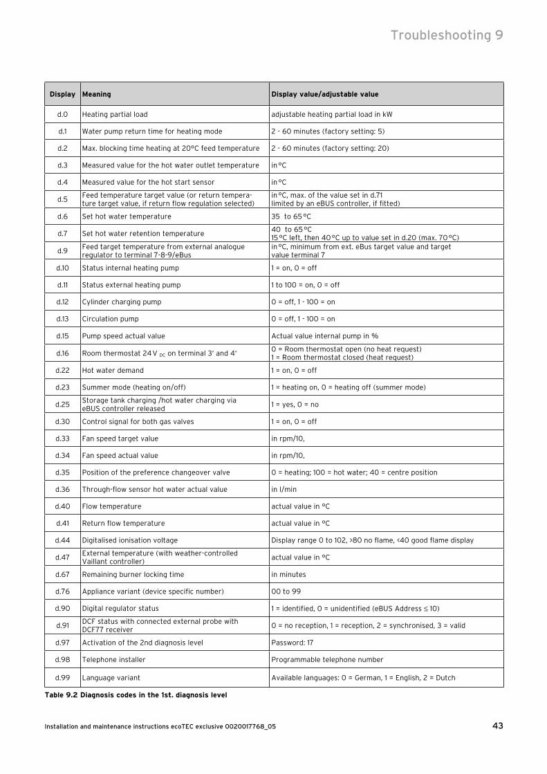
43Installation and maintenance instructions ecoTEC exclusive 0020017768_05
Display Meaning Display value/adjustable value
d.0 Heating partial load adjustable heating partial load in kW
d.1 Water pump return time for heating mode 2 - 60 minutes (factory setting: 5)
d.2 Max. blocking time heating at 20°C feed temperature 2 - 60 minutes (factory setting: 20)
d.3 Measured value for the hot water outlet temperature in °C
d.4 Measured value for the hot start sensor in °C
d.5Feed temperature target value (or return tempera-ture target value, if return flow regulation selected)
in °C, max. of the value set in d.71limited by an eBUS controller, if fitted)
d.6 Set hot water temperature 35 to 65 °C
d.7 Set hot water retention temperature40 to 65 °C15 °C left, then 40 °C up to value set in d.20 (max. 70 °C)
d.9Feed target temperature from external analogue regulator to terminal 7-8-9/eBus
in °C, minimum from ext. eBus target value and target value terminal 7
d.10 Status internal heating pump 1 = on, 0 = off
d.11 Status external heating pump 1 to 100 = on, 0 = off
d.12 Cylinder charging pump 0 = off, 1 - 100 = on
d.13 Circulation pump 0 = off, 1 - 100 = on
d.15 Pump speed actual value Actual value internal pump in %
d.16 Room thermostat 24 V DC on terminal 3‘ and 4‘0 = Room thermostat open (no heat request)1 = Room thermostat closed (heat request)
d.22 Hot water demand 1 = on, 0 = off
d.23 Summer mode (heating on/off) 1 = heating on, 0 = heating off (summer mode)
d.25Storage tank charging /hot water charging via eBUS controller released
1 = yes, 0 = no
d.30 Control signal for both gas valves 1 = on, 0 = off
d.33 Fan speed target value in rpm/10,
d.34 Fan speed actual value in rpm/10,
d.35 Position of the preference changeover valve 0 = heating; 100 = hot water; 40 = centre position
d.36 Through-flow sensor hot water actual value in l/min
d.40 Flow temperature actual value in °C
d.41 Return flow temperature actual value in °C
d.44 Digitalised ionisation voltage Display range 0 to 102, >80 no flame, <40 good flame display
d.47External temperature (with weather-controlled Vaillant controller)
actual value in °C
d.67 Remaining burner locking time in minutes
d.76 Appliance variant (device specific number) 00 to 99
d.90 Digital regulator status 1 = identified, 0 = unidentified (eBUS Address ≤ 10)
d.91DCF status with connected external probe with DCF77 receiver
0 = no reception, 1 = reception, 2 = synchronised, 3 = valid
d.97 Activation of the 2nd diagnosis level Password: 17
d.98 Telephone installer Programmable telephone number
d.99 Language variant Available languages: 0 = German, 1 = English, 2 = Dutch
Table 9.2 Diagnosis codes in the 1st. diagnosis level
Troubleshooting 9
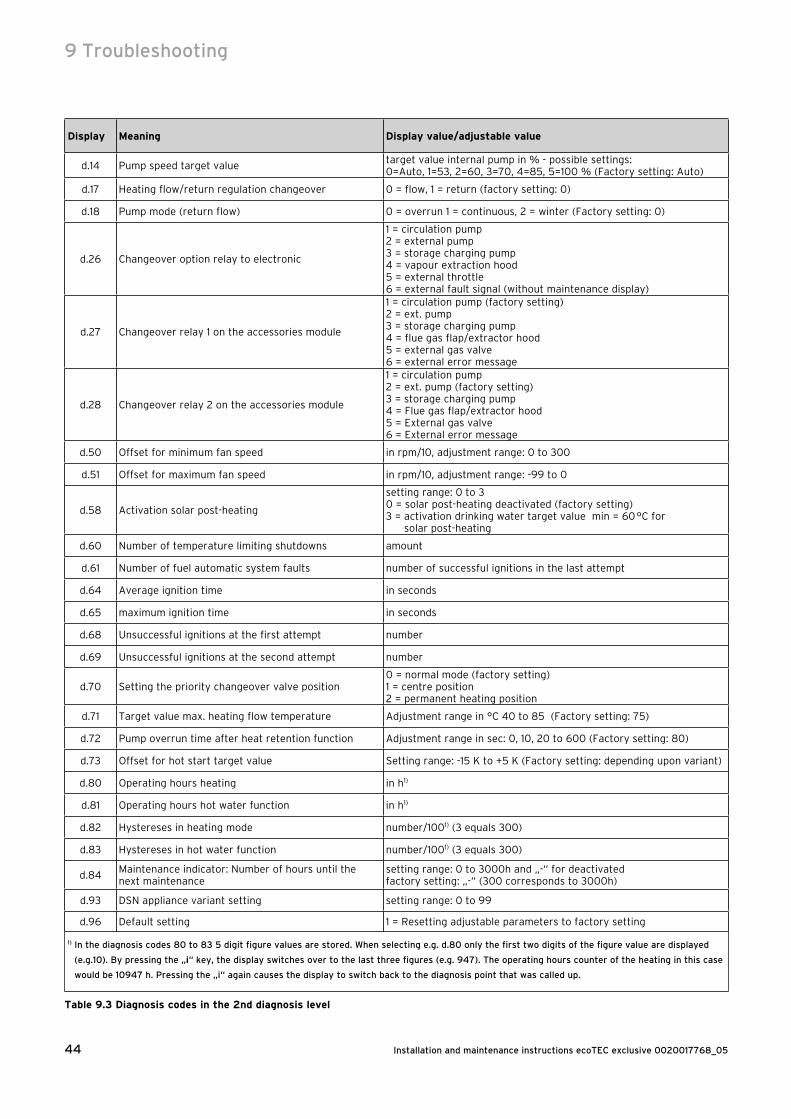
Installation and maintenance instructions ecoTEC exclusive 0020017768_0544
Display Meaning Display value/adjustable value
d.14 Pump speed target valuetarget value internal pump in % - possible settings: 0=Auto, 1=53, 2=60, 3=70, 4=85, 5=100 % (Factory setting: Auto)
d.17 Heating flow/return regulation changeover 0 = flow, 1 = return (factory setting: 0)
d.18 Pump mode (return flow) 0 = overrun 1 = continuous, 2 = winter (Factory setting: 0)
d.26 Changeover option relay to electronic
1 = circulation pump2 = external pump3 = storage charging pump4 = vapour extraction hood5 = external throttle6 = external fault signal (without maintenance display)
d.27 Changeover relay 1 on the accessories module
1 = circulation pump (factory setting)2 = ext. pump3 = storage charging pump4 = flue gas flap/extractor hood5 = external gas valve6 = external error message
d.28 Changeover relay 2 on the accessories module
1 = circulation pump2 = ext. pump (factory setting)3 = storage charging pump4 = Flue gas flap/extractor hood5 = External gas valve6 = External error message
d.50 Offset for minimum fan speed in rpm/10, adjustment range: 0 to 300
d.51 Offset for maximum fan speed in rpm/10, adjustment range: -99 to 0
d.58 Activation solar post-heating
setting range: 0 to 30 = solar post-heating deactivated (factory setting)3 = activation drinking water target value min = 60 °C for
solar post-heating
d.60 Number of temperature limiting shutdowns amount
d.61 Number of fuel automatic system faults number of successful ignitions in the last attempt
d.64 Average ignition time in seconds
d.65 maximum ignition time in seconds
d.68 Unsuccessful ignitions at the first attempt number
d.69 Unsuccessful ignitions at the second attempt number
d.70 Setting the priority changeover valve position0 = normal mode (factory setting)1 = centre position2 = permanent heating position
d.71 Target value max. heating flow temperature Adjustment range in °C 40 to 85 (Factory setting: 75)
d.72 Pump overrun time after heat retention function Adjustment range in sec: 0, 10, 20 to 600 (Factory setting: 80)
d.73 Offset for hot start target value Setting range: -15 K to +5 K (Factory setting: depending upon variant)
d.80 Operating hours heating in h1)
d.81 Operating hours hot water function in h1)
d.82 Hystereses in heating mode number/1001) (3 equals 300)
d.83 Hystereses in hot water function number/1001) (3 equals 300)
d.84Maintenance indicator: Number of hours until the next maintenance
setting range: 0 to 3000h and „-“ for deactivatedfactory setting: „-“ (300 corresponds to 3000h)
d.93 DSN appliance variant setting setting range: 0 to 99
d.96 Default setting 1 = Resetting adjustable parameters to factory setting
1) In the diagnosis codes 80 to 83 5 digit figure values are stored. When selecting e.g. d.80 only the first two digits of the figure value are displayed
(e.g.10). By pressing the „i“ key, the display switches over to the last three figures (e.g. 947). The operating hours counter of the heating in this case
would be 10947 h. Pressing the „i“ again causes the display to switch back to the diagnosis point that was called up.
Table 9.3 Diagnosis codes in the 2nd diagnosis level
9 Troubleshooting
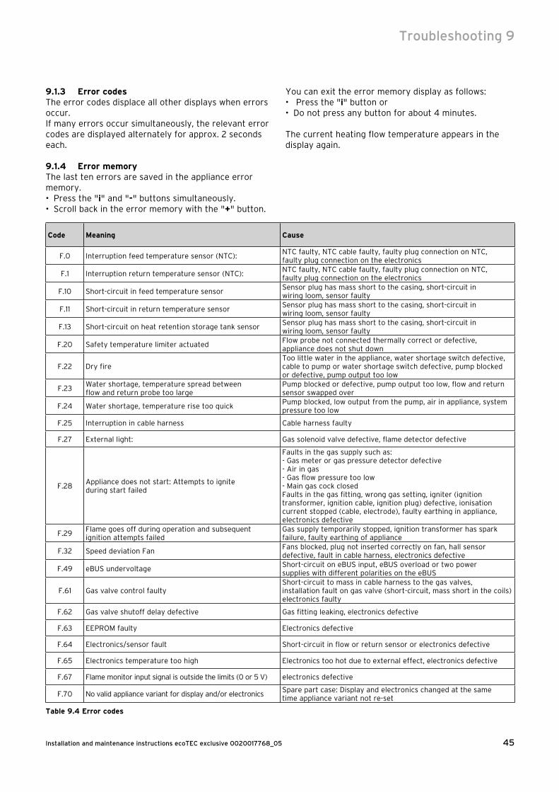
45Installation and maintenance instructions ecoTEC exclusive 0020017768_05
9.1.3 Error codesThe error codes displace all other displays when errors occur.If many errors occur simultaneously, the relevant error codes are displayed alternately for approx. 2 seconds each.
9.1.4 Error memoryThe last ten errors are saved in the appliance error memory.• Press the "i" and "-" buttons simultaneously.• Scroll back in the error memory with the "+" button.
Code Meaning Cause
F.0 Interruption feed temperature sensor (NTC):NTC faulty, NTC cable faulty, faulty plug connection on NTC, faulty plug connection on the electronics
F.1 Interruption return temperature sensor (NTC):NTC faulty, NTC cable faulty, faulty plug connection on NTC, faulty plug connection on the electronics
F.10 Short-circuit in feed temperature sensorSensor plug has mass short to the casing, short-circuit in wiring loom, sensor faulty
F.11 Short-circuit in return temperature sensorSensor plug has mass short to the casing, short-circuit in wiring loom, sensor faulty
F.13 Short-circuit on heat retention storage tank sensorSensor plug has mass short to the casing, short-circuit in wiring loom, sensor faulty
F.20 Safety temperature limiter actuatedFlow probe not connected thermally correct or defective, appliance does not shut down
F.22 Dry fireToo little water in the appliance, water shortage switch defective, cable to pump or water shortage switch defective, pump blocked or defective, pump output too low
F.23Water shortage, temperature spread between flow and return probe too large
Pump blocked or defective, pump output too low, flow and return sensor swapped over
F.24 Water shortage, temperature rise too quickPump blocked, low output from the pump, air in appliance, system pressure too low
F.25 Interruption in cable harness Cable harness faulty
F.27 External light: Gas solenoid valve defective, flame detector defective
F.28Appliance does not start: Attempts to ignite during start failed
Faults in the gas supply such as:- Gas meter or gas pressure detector defective- Air in gas- Gas flow pressure too low- Main gas cock closedFaults in the gas fitting, wrong gas setting, igniter (ignition transformer, ignition cable, ignition plug) defective, ionisation current stopped (cable, electrode), faulty earthing in appliance, electronics defective
F.29Flame goes off during operation and subsequent ignition attempts failed
Gas supply temporarily stopped, ignition transformer has spark failure, faulty earthing of appliance
F.32 Speed deviation FanFans blocked, plug not inserted correctly on fan, hall sensor defective, fault in cable harness, electronics defective
F.49 eBUS undervoltageShort-circuit on eBUS input, eBUS overload or two power supplies with different polarities on the eBUS
F.61 Gas valve control faultyShort-circuit to mass in cable harness to the gas valves, installation fault on gas valve (short-circuit, mass short in the coils) electronics faulty
F.62 Gas valve shutoff delay defective Gas fitting leaking, electronics defective
F.63 EEPROM faulty Electronics defective
F.64 Electronics/sensor fault Short-circuit in flow or return sensor or electronics defective
F.65 Electronics temperature too high Electronics too hot due to external effect, electronics defective
F.67 Flame monitor input signal is outside the limits (0 or 5 V) electronics defective
F.70 No valid appliance variant for display and/or electronicsSpare part case: Display and electronics changed at the same time appliance variant not re-set
Table 9.4 Error codes
You can exit the error memory display as follows:• Press the "i" button or• Do not press any button for about 4 minutes.
The current heating flow temperature appears in the display again.
Troubleshooting 9
Installation and maintenance instructions ecoTEC exclusive 0020017768_0546
Code Meaning Cause
F.71 Constant value feed NTC Feed NTC faulty
F.72 Flow and/or return sensor fault Flow and/or return sensor is faulty (tolerance too great)
F.73Signal water pressure sensor in the wrong range (too low)
Line to water pressure sensor is interrupted or has a short-circuit to 0V or water pressure sensor faulty
F.74Signal water pressure sensor in the wrong range (too high)
Line to water pressure sensor has a short-circuit at 5V / 24V or internal fault in water pressure sensor
F.75No sudden change in pressure was detected on turning on the pump
Water pressure sensor or/and pump defectiveToo little water in the appliance; check adjustable bypass; Connect expansion vessel in return;Air in the appliance
F.76 Interruption in cable harness Cable harness faulty
F.77Condensate pump or return signal from accessory module heating
Condensate pump faulty or return signal from the exhaust gas flap has responded
con No communication with the printed circuit boardCommunication fault between the display and the printed circuit board in the switchgear box
Table 9.4 Error codes (continuation)
9.2 Test programsSpecial functions can be triggered in the appliances by activating various test programs.These programs are given in detail in the Table 9.5.• The test programmes P.0 to P.6 will be started when
"Power ON" is turned on and the "+" button is pressed for 5 seconds simultaneously. The display shows "P.0".
• Press the "+" key to start counting the test pro-gramme number upwards.
• Press the "i" to operate the appliance now and to start the test programme.
• Press "i" and "+" simultaneously to exit the test pro-grams. You can also exit the test programs by not pressing any button for 15 minutes.
Display Meaning
P.0
Bleeding test program The heating circuit and the hot water circuit are bled via the automatic bleeding valve (the cap of the automatic bleeding valve must be released).
P.1Test programme where the appliance is operated in full load after successful ignition.
P.2Test program where the appliance is operated with minimum gas volume (ignition gas volume) after successful ignition.
P.5
Test function for the safety temperature limiter (STL): The burner is switched on with maximum output, the temperature controller is switched off so that the burner heats until the software STL responds by reaching the STL temperature on the flow or return sensor.
P.6Filling/draining programme:The preference changeover valve moves to the centre position. The burners and pump are switched off.
Table 9.5 Test programmes
9.3 Resetting parameter to factory settingsBesides the option to reset individual parameters manually to the factory settings specified in Tables 9.2 and 9.3, you can also reset all parameters simultaneously.• Change the value in the 2nd diagnosis level under
diagnosis point "d.96" to 1 (see Section 9.1.2).
The parameters of all adjustable diagnosis points now correspond to the factory settings.
9 Troubleshooting
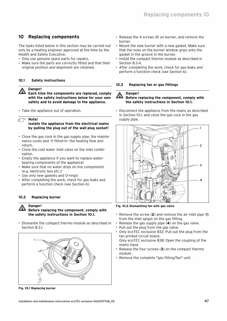
47Installation and maintenance instructions ecoTEC exclusive 0020017768_05
10 Replacing components
The tasks listed below in this section may be carried out only by a heating engineer approved at the time by the Health and Safety Executive.• Only use genuine spare parts for repairs.• Make sure the parts are correctly fitted and that their
original position and alignment are retained.
10.1 Safety instructions
d Danger!Each time the components are replaced, comply with the safety instructions below for your own safety and to avoid damage to the appliance.
• Take the appliance out of operation.
h Note!Isolate the appliance from the electrical mains by pulling the plug out of the wall plug socket!
• Close the gas cock in the gas supply pipe, the mainte-nance cocks and -if fitted-in- the heating flow and return.
• Close the cold water inlet valve on the inlet combi-nation.
• Empty the appliance if you want to replace water-bearing components of the appliance!
• Make sure that no water drips on live components (e.g. electronic box etc.)!
• Use only new gaskets and O-rings!• After completing the work, check for gas leaks and
perform a function check (see Section 6).
10.2 Replacing burner
d Danger!Before replacing the component, comply with the safety instructions in Section 10.1.
• Dismantle the compact thermo module as described in Section 8.3.1.
1
Fig. 10.1 Replacing burner
• Release the 4 screws (1) on burner, and remove the burner.
• Mount the new burner with a new gasket. Make sure that the nose on the burner window grips onto the gasket in the groove in the burner.
• Install the compact thermo module as described in Section 8.3.4.
• After completing the work, check for gas leaks and perform a function check (see Section 6).
10.3 Replacing fan or gas fittings
d Danger!Before replacing the component, comply with the safety instructions in Section 10.1.
• Disconnect the appliance from the mains as described in Section 10.1, and close the gas cock in the gas supply pipe.
4
3
2
1
Fig. 10.2 Dismantling fan with gas valve
• Remove the screw (2) and remove the air inlet pipe (1) from the inlet spigot on the gas fitting.
• Release the gas supply pipe (4) on the gas valve.• Pull out the plug from the gas valve.• Only ecoTEC exclusive 832: Pull out the plug from the
fan printed circuit board.Only ecoTEC exclusive 838: Open the coupling of the mains input.
• Release the four screws (3) on the compact thermo module .
• Remove the complete "gas fitting/fan" unit.
Replacing components 10

Installation and maintenance instructions ecoTEC exclusive 0020017768_0548
10 Replacing components
5
Fig. 10.3 Gas fitting/fan screwed joint
• Release both fixing screws (5) on the gas fitting and remove the fan from the gas fitting.
• Replace the defective component.
a Caution!Mount the gas valve and the fan in the same position as before.
• Screw the fan to the gas fitting. Use the new seals.• Re-install the complete "gas fitting/fan" unit in
reverse sequence.• After completing the work, check for gas leaks and
perform a function check (see Section 6).
10.4 Replacing primary heat exchanger
d Danger!Before replacing the component, comply with the safety instructions in Section 10.1.
• Disconnect the appliance from the mains as described in Section 10.1, and close the gas cock in the gas supply pipe.
• Close the maintenance cocks - if fitted - in the heating flow and return and drain the appliance.
• Dismantle the compact thermo module as described under Section 8.3.1.
1
2
3
4
5
6
Fig. 10.4 Replacing primary heat exchanger
• Remove the clamps (4) on the trap (3), release the fittings on the trap and remove the trap from the primary heat exchanger.
• Remove the adaptor nuts of the trap from the primary heat exchanger.
• Release the return connection (6) and the feed connection (5) on the primary heat exchanger.
• Release the three screws (2) on the primary heat exchanger and remove the primary heat exchanger from the appliance.
• Mount the new primary heat exchanger in reverse order and replace the seals.
• Fill and bleed the appliance and if needed, the plant after installing the new primary heat exchanger.
• After completing the work, check for gas and water leaks and perform a function check (see Section 6).
10.5 Replacing electronics and display
d Danger!Before replacing the component, comply with the safety instructions in Section 10.1.
• Comply with the assembly and installation manuals provided with the spare parts.
Replacing display or electronicsIf you are replacing only one of the two components, the parameter adjustment functions automatically. On turning on the appliance, the new component takes over the previously set parameters from the components that are not replaced.
Replacing display and electronicsWhen replacing both components (spare part case), after being turned on, the appliance goes to fault and displays the error message F.70. • In the second diagnosis level, under the diagnosis
point "d.93" enter the number of appliance variant according to Table 10.1 (see Section 9.1.2).
The electronics is now set to the appliance type and the parameters of all adjustable diagnosis points correspond to the factory settings.
Appliance Number of the appliance variant
ecoTEC exclusive 832 4
ecoTEC exclusive 838 5
Table 10.1 Numbers of the appliance variants

49Installation and maintenance instructions ecoTEC exclusive 0020017768_05
11 Vaillant service
To ensure regular servicing, it is strongly recommended that arrangements are made for a Maintenance Agreement. Please contact Vaillant Service Solutions (0870 6060 777) for further details.
12 Recycling and disposal
Both your Valliant ecoTEC exclusive and its packaging consist mainly of recyclable raw materials.The Vaillant ecoTEC exclusive and all accessories and the packaging must not be disposed of in the household waste. Make sure that the old appliance and any accessories and the transport packaging are disposed of in the proper way.
Vaillant service 11Recycling and disposal 12
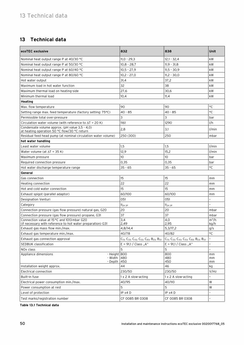
Installation and maintenance instructions ecoTEC exclusive 0020017768_0550
13 Technical data
ecoTEC exclusive 832 838 Unit
Nominal heat output range P at 40/30 °C 11,0 - 29,3 12,1 - 32,4 kW
Nominal heat output range P at 50/30 °C 10,8 - 28,7 11,9 - 31,8 kW
Nominal heat output range P at 60/40 °C 10,5 - 27,9 11,5 - 30,9 kW
Nominal heat output range P at 80/60 °C 10,2 - 27,0 11,2 - 30,0 kW
Hot water output 31,4 37,2 kW
Maximum load in hot water function 32 38 kW
Maximum thermal load on heating-side 27,6 30,6 kW
Minimum thermal load 10,4 11,4 kW
Heating
Max. flow temperature 90 90 °C
Setting range max. feed temperature (factory setting: 75°C) 40 - 85 40 - 85 °C
Permissible total over-pressure 3 3 bar
Circulation water volume (with reference to T = 20 K) 1161 1290 l/h
Condensate volume approx. (pH value 3,5 - 4,0)at heating operation 50 °C flow/30 °C return
2,8 3,1 l/min
Residual feed head pump (at nominal circulation water volume) 250 (300) 250 mbar
hot water handling
Least water volume 1,5 1,5 l/min
Water volume (at T = 35 K) 12,9 15,2 l/min
Maximum pressure 10 10 bar
Required connection pressure 0,35 0,35 bar
Hot water discharge temperature range 35 - 65 35 - 65 °C
General
Gas connection 15 15 mm
Heating connection 22 22 mm
Hot and cold water connection 15 15 mm
Exhaust spigot (parallel adaptor) 60/100 60/100 mm
Designation Venturi 051 051 –
Category II2H 3P II2H 3P –
Connection pressure (gas flow pressure) natural gas, G20 20 20 mbar
Connection pressure (gas flow pressure) propane, G31 37 37 mbar
Connection value at 15 °C and 1013 mbar G20(if necessary with reference to hot water preparation) G31
3,42,49
4,02,95
m3/hkg/h
Exhaust gas mass flow min./max. 4,8/14,4 5,3/17,2 g/s
Exhaust gas temperature min./max. 40/78 40/82 °C
Exhaust gas connection approval C13, C33, C43, C53, C83, B23, B33 C13, C33, C43, C53, C83, B23, B33 –
SEDBUK classification E = 91,1 / Class „A“ E = 91,1 / Class „A“ –
NOx class 5 5 –
Appliance dimensions - Height - Width - Depth
800480450
800480450
mmmmmm
Installation weight approx. 44 46 kg
Electrical connection 230/50 230/50 V/Hz
Built-in fuse 1 x 2 A slow-acting 1 x 2 A slow-acting –
Electrical power consumption min./max. 40/95 40/110 W
Power consumption at rest 5 5 W
Level of protection IP x4 D IP x4 D –
Test marks/registration number CF 0085 BR 0308 CF 0085 BR 0308 –
Table 13.1 Technical data
13 Technical data
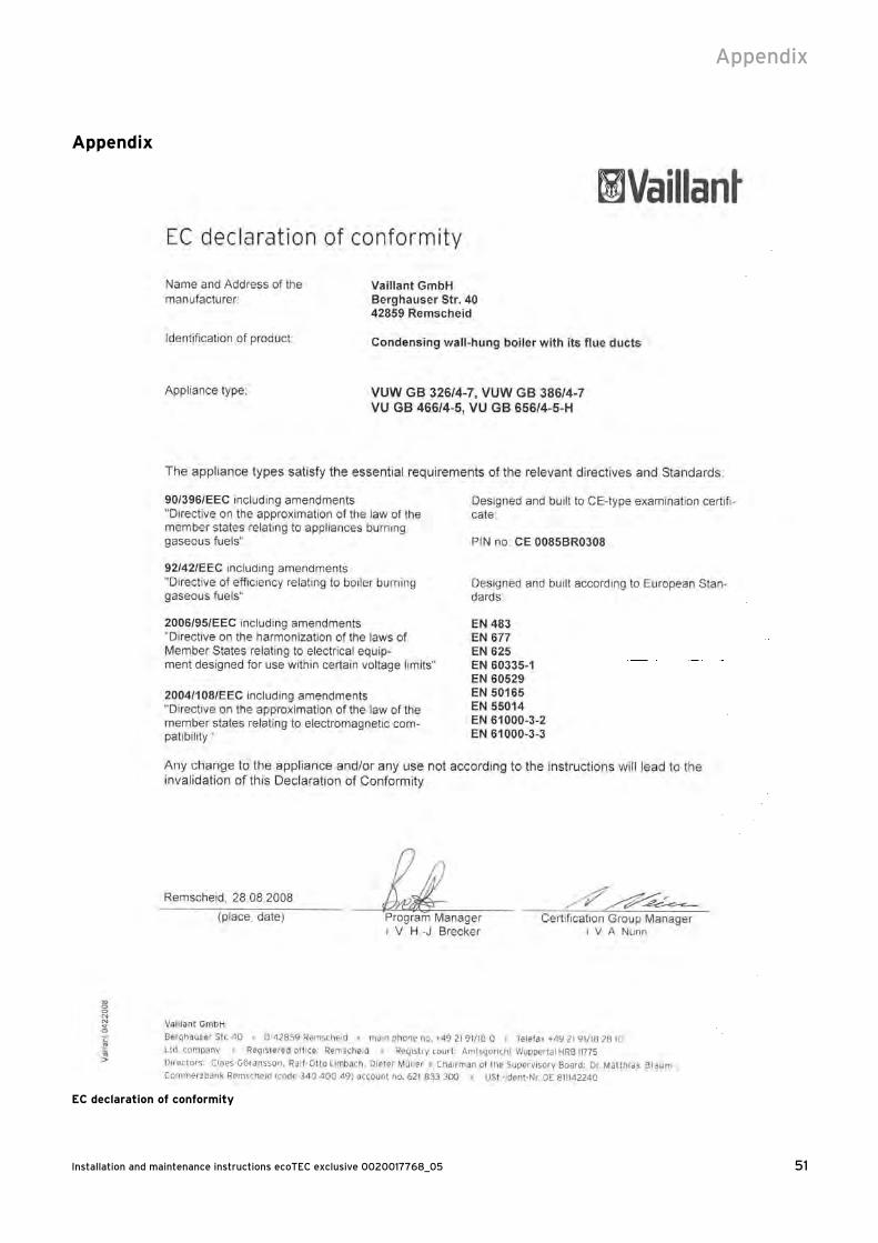
51Installation and maintenance instructions ecoTEC exclusive 0020017768_05
Appendix
EC declaration of conformity
Appendix

Installation and maintenance instructions ecoTEC exclusive 0020017768_0552
Installation,Commissioning and
Service Record
Installation,Commissioning and
Service Record

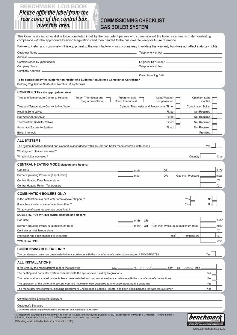
Please affix the label from therear cover of the control box
over this area.

SERVICE INTERVAL RECORDIt is recommended that your heating system is serviced regularly
and that you complete the appropriate Service Interval Record Below .
Service Provider. Before completing the appropriate Service Interval Record below, please ensure you have carried out the serviceas described in the boiler manufacturer’s instructions. Always use the manufacturer ‘s specified spare part when replacing all controls.
SERVICE 1 Date
Energy Efficiency Checklist completed? Yes No
Engineer Name
Company Name
Telephone Number
Engineer ID Number
Comments
Signature
SERVICE 3 Date
Energy Efficiency Checklist completed? Yes No
Engineer Name
Company Name
Telephone Number
Engineer ID Number
Comments
Signature
SERVICE 5 Date
Energy Efficiency Checklist completed? Yes No
Engineer Name
Company Name
Telephone Number
Engineer ID Number
Comments
Signature
SERVICE 7 Date
Energy Efficiency Checklist completed? Yes No
Engineer Name
Company Name
Telephone Number
Engineer ID Number
Comments
Signature
SERVICE 9 Date
Energy Efficiency Checklist completed? Yes No
Engineer Name
Company Name
Telephone Number
Engineer ID Number
Comments
Signature
SERVICE 2 Date
Energy Efficiency Checklist completed? Yes No
Engineer Name
Company Name
Telephone Number
Engineer ID Number
Comments
Signature
SERVICE 4 Date
Energy Efficiency Checklist completed? Yes No
Engineer Name
Company Name
Telephone Number
Engineer ID Number
Comments
Signature
SERVICE 6 Date
Energy Efficiency Checklist completed? Yes No
Engineer Name
Company Name
Telephone Number
Engineer ID Number
Comments
Signature
SERVICE 8 Date
Energy Efficiency Checklist completed? Yes No
Engineer Name
Company Name
Telephone Number
Engineer ID Number
Comments
Signature
SERVICE 10 Date
Energy Efficiency Checklist completed? Yes No
Engineer Name
Company Name
Telephone Number
Engineer ID Number
Comments
Signature
0020008345-06

00
20
017
76
8_0
5 G
BIE
0
62
010
— S
ubje
ct t
o a
lter
ati
on
s