ROTEX Condensing Boiler - Daikin
55
ROTEX Condensing Boiler Installation instructions Wall-mounted Gas Condensing Boiler GW-20 C22 / RKOMB22AAV1H GW-20 C28 / RKOMB28AAV1H GW-20 C33 / RKOMB33AAV1H
-
Upload
khangminh22 -
Category
Documents
-
view
0 -
download
0
Transcript of ROTEX Condensing Boiler - Daikin

ROTEX
Condensing Boiler
Installation instructions Wall-mounted Gas Condensing Boiler
GW-20 C22 / RKOMB22AAV1H GW-20 C28 / RKOMB28AAV1H GW-20 C33 / RKOMB33AAV1H

RO
TEX
CE - D
ECLA
RATIO
N-OF
-CON
FORM
ITYCE
- KON
FORM
ITÄTS
ERKL
ÄRUN
GCE
- DEC
LARA
TION-
DE-C
ONFO
RMITE
CE - C
ONFO
RMITE
ITSVE
RKLA
RING
CE - D
ECLA
RACI
ON-D
E-CO
NFOR
MIDA
DCE
- DIC
HIAR
AZIO
NE-D
I-CON
FORM
ITACE
- ∆HΛ
ΩΣΗ ΣΥ
ΜΜΟΡ
ΦΩΣΗ
Σ
CE - D
ECLA
RAÇÃ
O-DE
-CON
FORM
IDAD
ECE
- ЗАЯ
ВЛЕН
ИЕ-О
-СОО
ТВЕТ
СТВИ
ИCE
- OVE
RENS
STEM
MELS
ESER
KLÆ
RING
CE - F
ÖRSÄ
KRAN
-OM-
ÖVER
ENST
ÄMME
LSE
CE - E
RKLÆ
RING
OM-
SAMS
VAR
CE - I
LMOI
TUS-
YHDE
NMUK
AISU
UDES
TACE
- PRO
HLÁŠ
ENÍ-O
-SHO
DĚ
CE - I
ZJAV
A-O-
USKL
AĐEN
OSTI
CE - M
EGFE
LELŐ
SÉGI
-NYI
LATK
OZAT
CE - D
EKLA
RACJ
A-ZG
ODNO
ŚCI
CE - D
ECLA
RAŢIE
-DE-
CONF
ORMI
TATE
CE - I
ZJAV
A O
SKLA
DNOS
TICE
- VAS
TAVU
SDEK
LARA
TSIO
ONCE
- ДЕК
ЛАРА
ЦИЯ-ЗА
-ϹЪО
ТВЕТ
СТВИ
Е
CE - A
TITIK
TIES-
DEKL
ARAC
IJACE
- ATB
ILSTĪB
AS-D
EKLA
RĀCI
JACE
- VYH
LÁSE
NIE-
ZHOD
YCE
- UYG
UNLU
K-BE
YANI
01are
in co
nform
ity w
ith th
e foll
owing
stan
dard(
s) or
other
norm
ative
docu
ment(
s), pr
ovide
d tha
t thes
e are
used
in ac
corda
nce w
ith ou
rins
tructi
ons:
02de
r/den
folge
nden
Norm
(en) o
der e
inem
ande
ren N
ormdo
kume
nt od
er -do
kume
nten e
ntspri
cht/e
ntspre
chen
, unte
r der
Vorau
ssetz
ung,
daß s
ie ge
mäß u
nsere
n Anw
eisun
gen e
inges
etzt w
erden
:03
sont
confo
rmes
à la/
aux n
orme(s
) ou a
utre(s
) doc
umen
t(s) n
ormati
f(s), p
our a
utant
qu'ils
soien
t utilis
és co
nform
émen
t à no
s ins
tructi
ons:
04co
nform
de vo
lgend
e norm
(en) o
f één
of m
eer a
ndere
bind
ende
docu
mente
n zijn
, op v
oorw
aarde
dat z
e word
en ge
bruikt
overe
enko
mstig
onze
instr
uctie
s:05
están
en co
nform
idad c
on la
(s) si
guien
te(s)
norm
a(s) u
otro(
s) do
cume
nto(s)
norm
ativo
(s), s
iempre
que s
ean u
tilizad
os de
acue
rdo co
nnu
estra
s ins
trucc
iones
:06
sono
confo
rmi a
l(i) se
guen
te(i) s
tanda
rd(s)
o altro
(i) do
cume
nto(i)
a cara
ttere
norm
ativo
, a pa
tto ch
e ven
gano
usati
in co
nform
ità al
leno
stre i
struz
ioni:
07είναι σύμφ
ωνα μ
ε το(α
) ακόλουθο(α
) πρότυπ
ο(α) ή
άλλο
έγγραφ
ο(α) κανονισμ
ών, υπό
την π
ροϋπ
όθεση ό
τι χρησιμ
οποιο
ύνται σύμφω
ναμε
τις οδ
ηγίες
μας:
08es
tão e
m co
nform
idade
com
a(s) s
eguin
te(s)
norm
a(s) o
u ou
tro(s)
doc
umen
to(s)
norm
ativo
(s), d
esde
que
este
s seja
m uti
lizado
s de
acord
o com
as no
ssas
instr
uçõe
s:09
соответст
вуют
следую
щим ста
ндартам или други
м норм
ативны
м докум
ентам,
при условии их
использования
согла
сно наши
минструкциям:
10ov
erhold
er føl
gend
e sta
ndard
(er) e
ller a
ndet/
andre
retni
ngsg
ivend
e do
kume
nt(er)
, foru
dsat
at dis
se a
nven
des
i hen
hold
til vo
reins
truks
er:11
respe
ktive
utru
stning
är u
tförd
i öve
renss
tämme
lse m
ed o
ch fö
ljer f
öljan
de s
tanda
rd(er)
elle
r and
ra no
rmgiv
ande
dok
umen
t, un
der
föruts
ättnin
g att a
nvän
dning
sker
i öve
renss
tämme
lse m
ed vå
ra ins
trukti
oner:
12res
pekti
ve u
tstyr
er i o
veren
sstem
melse
med
følge
nde
stand
ard(er
) elle
r and
re no
rmgiv
ende
dok
umen
t(er),
unde
r foru
tssetn
ing a
v at
disse
bruk
es i h
enho
ld til
våre
instru
kser:
13va
staav
at se
uraav
ien s
tanda
rdien
ja m
uiden
ohje
ellist
en d
okum
enttie
n va
atimu
ksia
edell
yttäe
n, ett
ä nii
tä kä
ytetää
n oh
jeide
mme
muka
isesti
:14
za př
edpo
kladu
, že j
sou v
yužív
ány v
soula
du s
našim
i pok
yny,
odpo
vídají
násle
dujíc
ím no
rmám
nebo
norm
ativn
ím do
kume
ntům:
15u s
kladu
sa sl
ijedećim
stan
dardo
m(im
a) ili d
rugim
norm
ativn
im do
kume
ntom(
ima),
uz uv
jet da
se on
i kori
ste u
sklad
u s na
šim up
utama
:
16me
gfelel
nek a
z aláb
bi sz
abvá
ny(ok
)nak v
agy e
gyéb
irány
adó d
okum
entum
(ok)na
k, ha
azok
at elő
írás s
zerin
t has
ználj
ák:
17sp
ełniają
wymo
gi na
stępu
jącyc
h no
rm i
innyc
h do
kume
ntów
norm
aliza
cyjny
ch, p
od w
arunk
iem ż
e uż
ywan
e są
zgo
dnie
z na
szym
iins
trukc
jami:
18su
nt în
confo
rmita
te cu
urmă
torul
(urmă
toarel
e) sta
ndard
(e) sa
u alt(e
) doc
umen
t(e) n
ormati
v(e), c
u con
diţia
ca ac
estea
să fie
utiliz
ate în
confo
rmita
te cu
instr
ucţiu
nile n
oastr
e:19
sklad
ni z n
asled
njimi
stan
dardi
in dr
ugim
i norm
ativi,
pod p
ogoje
m, da
se up
orablj
ajo v
sklad
u z na
šimi n
avod
ili:20
on va
stavu
ses j
ärgmi
s(t)e
stand
ardi(te
)ga võ
i teist
e norm
atiivs
ete do
kume
ntide
ga, k
ui ne
id ka
sutat
akse
vasta
valt m
eie ju
hend
itele:
21съответст
ват на
следните
стандарти
или
други
норма
тивни
докум
енти
, при
условие
, че
се и
зползват
съгласно
наши
теинструкции
:22
atitin
ka že
miau
nurod
ytus s
tanda
rtus i
r (arba
) kitu
s norm
inius
doku
mentu
s su s
ąlyga
, kad
yra n
audo
jami p
agal
mūsų
nurod
ymus
:23
tad, ja
lietot
i atbi
lstoš
i ražo
tāja n
orādīj
umiem
, atbi
lst se
kojoš
iem st
anda
rtiem
un ci
tiem
norm
atīvie
m do
kume
ntiem
:24
sú v
zhod
e s na
sledo
vnou
(ými) n
ormou
(ami) a
lebo i
ným(
i) norm
atívn
ym(i)
doku
mento
m(am
i), za
pred
pokla
du, ž
e sa p
oužív
ajú v
súlad
esn
ašim
návo
dom:
25ürü
nün,
talim
atları
mıza
göre
kulla
nılma
sı koşu
luyla
aşağıda
ki sta
ndart
lar ve
norm
belirt
en be
lgeler
le uy
umlud
ur:
01Dir
ectiv
es, a
s ame
nded
.02
Direk
tiven
, gem
äß Än
derun
g.03
Direc
tives
, telle
s que
mod
ifiées
.04
Richtl
ijnen
, zoa
ls ge
amen
deerd
.05
Direc
tivas
, seg
ún lo
enme
ndad
o.06
Dirett
ive, c
ome d
a mod
ifica.
07Οδ
ηγιών, όπ
ως έχ
ουν τροπο
ποιηθ
εί.08
Direc
tivas
, con
forme
alter
ação
em.
09Ди
ректи
в со в
семи
поправками
.
10Dir
ektiv
er, m
ed se
nere
ændri
nger.
11Dir
ektiv,
med
föret
agna
ändri
ngar.
12Dir
ektiv
er, m
ed fo
retatt
e end
ringe
r.13
Direk
tiivejä
, sella
isina k
uin ne
ovat
muute
ttuina
.14
v plat
ném
zněn
í.15
Smjer
nice,
kako
je iz
mijen
jeno.
16irá
nyelv
(ek) é
s mód
osítá
saik
rende
lkezé
seit.
17z p
óźnie
jszym
i pop
rawka
mi.
18Dir
ectiv
elor, c
u ame
ndam
entel
e res
pecti
ve.
19Dir
ektiv
e z vs
emi s
preme
mbam
i.20
Direk
tiivid
koos
muu
datus
tega.
21Ди
ректи
ви, с
техните и
зменения
.22
Direk
tyvos
e su p
apild
ymais
.23
Direk
tīvās
un to
papil
dināju
mos.
24Sm
ernice
, v pl
atnom
znen
í.25
Deǧiş
tirilm
iş ha
lleriy
le Yö
netm
elikle
r.
01fol
lowing
the p
rovisio
ns of
:02
gemä
ß den
Vorsc
hrifte
n der:
03co
nform
émen
t aux
stipu
lation
s des
:04
overe
enko
mstig
de be
palin
gen v
an:
05sig
uiend
o las
disp
osicio
nes d
e:06
seco
ndo l
e pres
crizio
ni pe
r:07
με τή
ρηση
των δ
ιατάξεω
ν των
:08
de ac
ordo c
om o
previs
to em
:09
в соответствии с
положе
ниям
и:
10un
der ia
gttag
else a
f bes
temme
lserne
i:11
enlig
t villk
oren i
:12
gitt i
henh
old til
beste
mmels
ene i
:13
noud
attae
n mää
räyks
iä:14
za do
držen
í usta
nove
ní pře
dpisu
:15
prema
odred
bama
:16
köve
ti a(z)
:17
zgod
nie z
posta
nowie
niami
Dyre
ktyw:
18în
urma p
reved
erilor
:
19ob
upoš
tevan
ju do
ločb:
20va
stava
lt nõu
etele:
21следвайки к
лаузите н
а:22
laika
ntis n
uosta
tų, pa
teikia
mų:
23iev
ērojot
prasība
s, ka
s note
iktas
:24
održi
avajú
c usta
nove
nia:
25bu
nun k
oşull
arına
uygu
n olar
ak:
01No
te *
as se
t out
in <A
> and
judg
ed po
sitive
ly by <
B>
acco
rding
to th
e Cert
ificate
<C>.
02Hin
weis
*wie
in <A
> aufg
eführt
und v
on <B
> pos
itiv be
urteilt
ge
mäß Z
ertifik
at<C
>.03
Rema
rque *
tel qu
e défi
ni da
ns <A
> et é
valué
positi
veme
nt pa
r <B
> con
formé
ment
au Ce
rtifica
t<C>
.04
Beme
rk *
zoals
verm
eld in
<A> e
n pos
itief b
eoord
eeld
door
<B> o
veree
nkom
stig Ce
rtifica
at<C
>.05
Nota
*co
mo se
estab
lece e
n <A>
y es
valor
ado
positi
vame
nte po
r <B>
de ac
uerdo
con e
l Ce
rtifica
do<C
>.
06No
ta *
deline
ato ne
l <A>
e giu
dicato
positi
vame
nte
da<B
> sec
ondo
il Cert
ificato
<C>.
07Ση
μείωση
*όπ
ως κα
θορίζ
εται στο
<A> κ
αι κρίνεται
θετικά α
πό
το <B
> σύμφω
να με
το Πι
στοπ
οιητικ
ό<C>
.08
Nota
*tal
como
estab
elecid
o em
<A> e
com
o pare
cer
positi
vo de
<B> d
e aco
rdo co
m o C
ertific
ado<
C>.
09Пр
имечание
*как
указа
но в
<A> и
в соотв
етстви
и сп
олож
ительны
м реш
ением <
B> со
гласно
Свид
етель
ству<
C>.
10Be
mærk
*so
m an
ført i
<A> o
g pos
itivt v
urdere
t af <
B>
ihen
hold
til Cert
ifikat
<C>.
11Inf
ormati
on *
enligt
<A> o
ch go
dkän
ts av
<B> e
nligt
Certif
ikatet
<C>.
12Me
rk *
som
det fr
emko
mmer
i <A> o
g gjen
nom
positi
v be
dømm
else a
v <B>
ifølge
Sertif
ikat<
C>.
13Hu
om *
jotka
on es
itetty
asiak
irjassa
<A> j
a jotk
a <B>
on
hyvä
ksyny
t Sert
ifikaa
tin<C
> muk
aises
ti.14
Pozn
ámka
*jak
bylo
uved
eno v
<A> a
poziti
vně z
jištěn
o <B>
vs
oulad
u sos
vědč
ením
<C>.
15Na
pome
na *
kako
je izl
ožen
o u <A
> i po
zitivn
o ocije
njeno
od
stran
e <B>
prem
a Cert
ifikatu
<C>.
16Me
gjegy
zés *
a(z) <
A> al
apján
, a(z)
<B> ig
azolt
a a m
egfel
elést,
a(z
) <C>
tanús
ítván
y sze
rint.
17Uw
aga *
zgod
nie z
doku
menta
cją <A
>, po
zytyw
ną op
inią
<B> i
Świad
ectw
em<C
>.18
Notă
*aş
a cum
este
stabili
t în <A
> şi a
precia
t poz
itiv
de<B
> în c
onfor
mitat
e cu C
ertific
atul<
C>.
19Op
omba
*ko
t je do
ločen
o v <A
> in o
dobre
no s
stran
i <B>
vskla
du s
certif
ikatom
<C>.
20Mä
rkus *
nagu
on nä
idatud
doku
mend
is <A>
ja he
aks
kiidetu
d <B>
järgi
vasta
valt s
ertifik
aadil
e<C>
.
21Забележк
а *как
то е и
злож
ено в
<A> и
оценено п
олож
ително
от <B
> съгл
асно
Сертиф
иката
<C>.
22Pa
staba
*ka
ip nu
statyt
a <A>
ir ka
ip tei
giama
i nus
pręsta
<B>
paga
l Sert
ifikatą
<C>.
23Pie
zīmes
*kā
norād
īts <A
> un a
tbilsto
ši <B>
pozitī
vajam
vē
rtējum
am sa
skaņā
ar se
rtifikā
tu<C
>.24
Pozn
ámka
*ak
o bolo
uved
ené v
<A> a
pozití
vne z
istené
<B>
vsúla
de s
osve
dčen
ím<C
>.25
Not *
<A>’d
a belir
tildiği
gibi ve
<C>S
ertifik
asına
göre
<B> t
arafın
dan o
lumlu
olarak
değe
rlend
irildiği
gibi.
<A>
1771
55_E
MC
2/03
-201
1
<B>
KIW
A (N
B00
63)
<C>
-
01 a
decla
res un
der it
s sole
resp
onsib
ility th
at the
equip
ment
to wh
ich th
is de
clarat
ion re
lates
:02
derk
lärt a
uf se
ine al
leinig
e Vera
ntwort
ung d
aß di
e Aus
rüstun
g für
die di
ese E
rkläru
ng be
stimm
t ist:
03 f
décla
re so
us sa
seule
resp
onsa
bilité
que l
'équip
emen
t visé
par la
prés
ente
décla
ration
:04
lve
rklaa
rt hier
bij op
eige
n exc
lusiev
e vera
ntwoo
rdelijk
heid
dat d
e app
aratuu
r waa
rop de
ze ve
rklari
ng be
trekk
ing he
eft:
05 e
decla
ra ba
jo su
única
resp
onsa
bilida
d que
el eq
uipo a
l que
hace
refer
encia
la de
clarac
ión:
06 i
dichia
ra so
tto la
prop
ria re
spon
sabil
ità ch
e gli a
ppare
cchi
a cui
è rife
rita qu
esta
dichia
razion
e:07
gδηλώ
νει με
αποκλειστ
ική τη
ς ευθύνη ό
τι ο εξοπ
λισμός σ
τον οπ
οίο αν
αφέρετα
ι η παρούσα
δήλω
ση:
08 p
decla
ra so
b sua
exclu
siva r
espo
nsab
ilidad
e que
os eq
uipam
entos
a qu
e esta
decla
ração
se re
fere:
09 u
заявляет, и
сключ
ительно
под с
вою о
тветст
венность,
что о
борудование,
к кото
рому
относится
насто
ящее
заявление:
10 q
erklæ
rer un
der e
nean
svarl
ig, at
udsty
ret, s
om er
omfat
tet af
denn
e erkl
æring
:11
sde
klarer
ar i e
gens
kap a
v huv
udan
svari
g, att
utrus
tning
en so
m be
rörs a
v den
na de
klarat
ion in
nebä
r att:
12 n
erklæ
rer et
fulls
tendig
ansv
ar for
at de
t utst
yr so
m be
røres
av de
nne d
eklar
asjon
inne
bærer
at:
13 j
ilmoit
taa yk
sinom
aan o
malla
vastu
ullaa
n, ett
ä täm
än ilm
oituk
sen t
arkoit
tamat
laitte
et:14
cpro
hlašu
je ve
své p
lné od
pově
dnos
ti, že
zaříz
ení, k
němu
ž se t
oto pr
ohláš
ení v
ztahu
je:15
yizja
vljuje
pod i
sključiv
o vlas
titom
odgo
vorno
šću d
a opre
ma na
koju
se ov
a izja
va od
nosi:
16 h
teljes
felelős
sége
tuda
tában
kijel
enti,
hogy
a be
rende
zése
k, me
lyekre
e ny
ilatko
zat v
onatk
ozik:
17 m
dekla
ruje n
a włas
ną i w
yłącz
ną od
powie
dzial
ność
, że u
rządz
enia,
który
ch ta
dekla
racja
dotyc
zy:
18 r
decla
ră pe
prop
rie ră
spun
dere
că ec
hipam
entel
e la c
are se
refer
ă ace
astă
decla
raţie:
19 o
z vso
odgo
vorno
stjo i
zjavlja
, da j
e opre
ma na
prav,
na ka
tero s
e izja
va na
naša
:20
xkin
nitab
oma t
äielik
ul va
stutus
el, et
käes
oleva
dekla
ratsio
oni a
lla ku
uluv v
arustu
s:21
bдекларира н
а своя о
тговорност, ч
е оборудването, за
коeто с
е отнася т
ази д
екларация:
22 t
visišk
a sav
o atsa
komy
be sk
elbia,
kad į
ranga
, kuri
ai tai
koma
ši de
klarac
ija:
23 v
ar pil
nu at
bildīb
u apli
ecina
, ka tālā
k apra
kstītā
s iekārt
as, u
z kurā
m att
iecas
šī de
klarāc
ija:
24 k
vyhla
suje
na vl
astnú
zodp
oved
nosť,
že za
riade
nie, n
a ktor
é sa v
zťahu
je tot
o vyh
lásen
ie:25
wtam
amen
kend
i soru
mlulu
ǧund
a olm
ak üz
ere bu
bildi
rinin
ilgili o
lduǧu
dona
nımını
n aşaǧıd
aki g
ibi ol
duǧu
nu be
yan e
der:
EN
6033
5-2-
102,
2P369568-2B
Geo
rg B
lüm
elM
anag
ing
Dire
ctor
1st o
f Apr
il 20
15
RK
OM
BG
22A
AV1*
,RK
OM
BG
28A
AV1*
,RK
OM
BG
33A
AV1*
,RK
OM
B22
AAV
1*,R
KO
MB
28A
AV1*
,RK
OM
B33
AAV
1*,
RH
OB
12A
AV1*
,RH
OB
18A
AV1*
,RH
OB
42A
AV1*
,RH
OB
G12
AAV
1*,R
HO
BG
18A
AV1*
,* =
,
,1,2
,3,..
.,9, A
, B, C
, ...,
Z
Low
Volta
ge 2
006/
95/E
CG
as A
pplia
nces
200
9/14
2/EC
Boile
r Effi
cienc
y re
quire
men
ts 9
2/42
/EEC
Elec
trom
agne
tic C
ompa
tibilit
y 20
04/1
08/E
C*

ROTEX Heating Systems GmbH 3
TABLE OF CONTENTS
1 Safety instructions 5 2 Unit description 5
2.1 General ............................................................................................................................................................................................ 5 2.2 Functioning ...................................................................................................................................................................................... 5 2.3 Operating modes ............................................................................................................................................................................. 5 2.4 PC Interface .................................................................................................................................................................................... 7 2.5 Test programs ................................................................................................................................................................................. 7
3 Main components 8 3.1 Accessories ..................................................................................................................................................................................... 9
4 Installation 10 4.1 Installation measurements ............................................................................................................................................................ 10 4.2 Installation space ........................................................................................................................................................................... 12 4.3 Assembly ....................................................................................................................................................................................... 13
5 Connecting 15 5.1 Connecting CH installation ............................................................................................................................................................ 15 5.2 Connecting DHW installation ......................................................................................................................................................... 17 5.3 Connecting electronically .............................................................................................................................................................. 18 5.4 Connect room thermostat .............................................................................................................................................................. 19 5.5 Connecting gas ............................................................................................................................................................................. 20 5.6 Flue gas output and air input ......................................................................................................................................................... 21 5.7 Outlet systems ............................................................................................................................................................................... 22
6 Commissioning the unit and the Installation 35 6.1 Filling and air purge of unit and installation ................................................................................................................................... 35 6.2 Commissioning the unit ................................................................................................................................................................. 36 6.3 Switching off the unit ..................................................................................................................................................................... 37
7 Setting and adjustment 38 7.1 Direct via operating panel .............................................................................................................................................................. 38 7.2 Parameter settings via the service code ....................................................................................................................................... 39 7.3 Setting maximum CH power .......................................................................................................................................................... 41 7.4 Setting pump setting ...................................................................................................................................................................... 41 7.5 Weather dependent regulation ...................................................................................................................................................... 42 7.6 Conversion to different type of gas................................................................................................................................................ 43 7.7 Gas/air regulation .......................................................................................................................................................................... 43 7.8 Setting gas/air regulation ............................................................................................................................................................... 44
8 Malfunctions 46 8.1 Show last malfunction ................................................................................................................................................................... 46 8.2 Malfunction codes ......................................................................................................................................................................... 46 8.3 Other faults .................................................................................................................................................................................... 47
9 Maintenance 50 10 Technical specifications 52
10.1 Electrical diagram RKOMB22AAV1H, RKOMB28AAV1H & RKOMB33AAV1H ........................................................................... 53 10.2 NTC resistances ............................................................................................................................................................................ 53
11 Warranty conditions 54
© 2015 ROTEX Heating Systems GmbH All rights reserved. The information provided applies to the product in its standard version. ROTEX Heating Systems GmbH can therefore not be held liable for any damages arising from any specifications of the product which deviate from the standard version. The available information has been compiled with the greatest possible care, but ROTEX Heating Systems GmbH can not be held liable for any mistakes in the information, or for any consequences thereof. ROTEX Heating Systems GmbH cannot be held liable for any damage arising from work carried out by third parties. Subject to change.

ROTEX Heating Systems GmbH 4
These installation instructions With these installation instructions, you can safely assemble, install and maintain the unit. Carefully follow the instructions. In case of any doubt, please contact the manufacturer. Keep the installation instructions near the unit. Abbreviations and terms used Description To be referred to as High Efficiency HR Rotex RKOMB22AAV1H, RKOMB28AAV1H, RKOMB33AAV1H
Unit
Unit with piping for central heating CH installation System with pipes for domestic hot water DHW installation Symbols The following symbols are used in this manual:
CAUTION Procedures which - if they are not carried out with the necessary care - may cause damage to the product, the surroundings, the environment or injury.
IMPORTANT Procedures and/or instructions which, if they are not followed, will have a negative effect on the functioning of the unit.
Service and technical support for the installer For information about specific settings, installation, maintenance and repair work, as an installer, please contact your local Rotex dealer
Identification of the product You will find the unit details on the type plate on the bottom of the unit.
• Unit type • Bar code with article number and serial number • Options

ROTEX Heating Systems GmbH 5
1 SAFETY INSTRUCTIONS The manufacturer ROTEX Heating Systems GmbH accepts no liability for damage or injury caused by the failure to (strictly) observe the safety instructions, or negligence during the installation of the Rotex RKOMB*AAV1H wall-mounted gas boiler and any associated accessories. This device is not intended for use by people (including children) with reduced physical, sensory or mental abilities, or lack of experience and knowledge, unless they are given supervision or instructions on the use of the device by a person who is responsible for their safety. The entire installation must meet the applicable local technical and (safety) instructions, for the gas installation, the electrical installation, smoke extraction installation, drinking water installation, and central heating installation.
2 UNIT DESCRIPTION 2.1 General The Rotex RKOMB*AAV1H wall-mounted gas boiler is a closed unit. The unit is intended to provide heat to the water of a CH-installation and the domestic hot water installation. The air supply and combustion gas outlet can be connected to the unit by means of two separate pipes. A concentric connection can be supplied upon demand. The unit was tested in combination with the combi feed through, but the unit may also be connected to combi feed throughs which meet the universal test standards for combi feed throughs. The unit can be connected to a assembly bracket if required, a frame with top connection, and various installation sets. The are provided separately. The Rotex RKOMB*AAV1H wall-mounted gas boilers have the CE quality mark, electrical protection class IP44. It is possible to use the unit solely for warm water, or solely for heating. The system which is not in use, does not need to be connected (see par. 7.2). The unit is delivered for natural gas (G20) as a standard. On request, the unit can also be provided for propane (G31).
2.2 Functioning The Rotex RKOMB*AAV1H wall-mounted gas boiler is a modulating high efficiency boiler. This means that the power is modulated to suit the required heat demand. In the aluminum heat exchanger two separate copper circuits are integrated. The separate circuits for CH and warm water allows the heating and warm water supply to function independently. The hot water supply takes precedence over the heating. Both cannot work at the same time. The unit is fitted with an electronic boiler controller machine, which operates the fan at every heat requirement of the heating or the warm water supply, opens the gas valve, ignites the boiler controller, and continuously monitors and regulates the flame, depending on the requested power.
2.3 Operating modes The operating mode of the unit is indicated by means of a code on the service display of the operating panel.
- Off The unit is not in operation, but is connected to the electricity supply. No response is given to requests for domestic hot water of CH water. The unit frost protection is active. This means that the pump will start running and the exchanger will be heated up if the temperature of the water in the system drops too far. If the frost protection intervenes, the code 7 will be displayed (heating up exchanger). The pressure in the CH installation can also be read from the temperature display in this operating mode (in Bar). Standby The LED at the key is lit and possibly one of the LEDs of the tap comfort function. The unit is ready to respond to a request for CH or tap water.
ROTEX Heating Systems GmbH 6
0 Post-running CH After the end of the CH-operation, the pump will run for a specified time. The post-pumping time is set to the value in par. 7.2 in its factory settings. This setting can be changed. In addition to this, the pump will run automatically 1 time per 24 hours, for 10 seconds, in order to prevent it from getting stuck. This automatic switching on of the pump takes place at the time of the last heating request. In order to change this, the room thermostat needs to be set higher for a moment, at the required time of day.
1 Requested temperature reached The boiler controller may temporarily block the heat request. The boiler controller will then be stopped. The block occurs because the required temperature has been reached. When the temperature has sufficiently decreased, the block will be lifted.
2 Self test Once every 24 hours, the boiler controllery tests the connected sensors. During the test, the controller will not carry out any other tasks.
3 Ventilating When the unit is started, the fan is first brought up to its correct start rpm. When the start rpm is reached, the boiler controller will be ignited. Code 3 is also visible when there is post-fanning after the boiler controller is stopped.
4 Igniting When the fan has reached the start rpm, the boiler controller will be ignited by means of electrical sparks. During the ignition, code 4 is displayed. If the boiler controller does not ignite, a new attempt will be made after approximately 15 seconds. If after 4 ignition attempts, the boiler controller has still not been ignited, the controller will go into down-time.
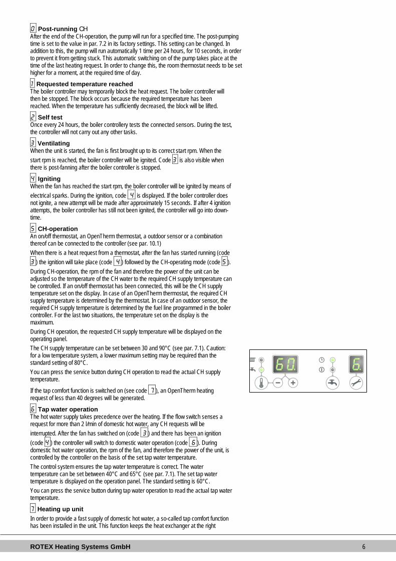
5 CH-operation An on/off thermostat, an OpenTherm thermostat, a outdoor sensor or a combination thereof can be connected to the controller (see par. 10.1) When there is a heat request from a thermostat, after the fan has started running (code 3 ) the ignition will take place (code 4 ) followed by the CH-operating mode (code 5 ). During CH-operation, the rpm of the fan and therefore the power of the unit can be adjusted so the temperature of the CH water to the required CH supply temperature can be controlled. If an on/off thermostat has been connected, this will be the CH supply temperature set on the display. In case of an OpenTherm thermostat, the required CH supply temperature is determined by the thermostat. In case of an outdoor sensor, the required CH supply temperature is determined by the fuel line programmed in the boiler controller. For the last two situations, the temperature set on the display is the maximum. During CH operation, the requested CH supply temperature will be displayed on the operating panel. The CH supply temperature can be set between 30 and 90°C (see par. 7.1). Caution: for a low temperature system, a lower maximum setting may be required than the standard setting of 80°C. You can press the service button during CH operation to read the actual CH supply temperature.
If the tap comfort function is switched on (see code 7 ), an OpenTherm heating request of less than 40 degrees will be generated.
6 Tap water operation The hot water supply takes precedence over the heating. If the flow switch senses a request for more than 2 l/min of domestic hot water, any CH requests will be interrupted. After the fan has switched on (code 3 ) and there has been an ignition (code 4 ) the controller will switch to domestic water operation (code 6 ). During domestic hot water operation, the rpm of the fan, and therefore the power of the unit, is controlled by the controller on the basis of the set tap water temperature. The control system ensures the tap water temperature is correct. The water temperature can be set between 40°C and 65°C (see par. 7.1). The set tap water temperature is displayed on the operation panel. The standard setting is 60°C. You can press the service button during tap water operation to read the actual tap water temperature.
7 Heating up unit In order to provide a fast supply of domestic hot water, a so-called tap comfort function has been installed in the unit. This function keeps the heat exchanger at the right

ROTEX Heating Systems GmbH 7
temperature (this temperature can be set, see par. 7.2). The tap comfort function has the following settings: • On: ( LED on) The tap comfort function of the unit is continuously switched on.
The unit always immediately provides warm water. • Eco: ( LED on) The tap comfort function of the unit is self-learning. The unit will
adjust to the usage pattern of the domestic hot water. This means the heat exchanger will not be kept warm during the night or during longer absences.
• Off: (Both LEDs off) The heat exchanger is not kept warm which means the supply of domestic hot water takes a bit of time. If there is no need for fast delivery of domestic hot water, the tap comfort function can be switched off.
In the settings “on” and “eco” , the unit meets the requirements of the Gaskeur CW standards.
2.4 PC Interface The boiler controller is provided with an interface for a PC. A PC can be connected by means of a special dongle, and the associated software. This facility enables you to follow the behavior of the boiler controller, the unit and the heat installation over a long period.
2.5 Test programs There is an option in the boiler controller, to bring the unit into a test status. Activating a test program, will switch on the unit with a set fan rotations per minute, without the control functions intervening. The safety functions do remain active. The test program is ended by pressing and simultaneously. Test programs Description of program Button combination Display reading Burner on with minimum DHW capacity (see parameter d par. 7.2) and “L”
Burner on with set maximum CH power (see parameter 3 par. 7.2) and (1x) “h”
Burner on with maximum DHW power (see parameter 3 par. 7.2) and (2x) “H”
Switching off test program and Current operation situation
During test mode the following data can be read : • By pressing the + button continuously in the display the CH water pressure is shown. • By pressing the - button continuously in the display the ionisation current is shown.
2.5.1 Frost protection
• The unit is fitted with frost protection in order to prevent it from freezing. If the temperature of the heat exchanger drops too low, the pump will start running until the temperature of the heat exchanger is sufficiently high. If the frost protection intervenes, code 7 will be displayed (heating up exchanger).
• If the installation (or a part thereof) can freeze, the coldest place should be fitted with an (external) frost thermostat on the return pipe. This must be connected in accordance with the electrical diagram (see par. 10.1).
Note When the unit is switched off ( - on the service display) the unit frost protection will remain active, however a heating request from an (external) frost thermostat will be ignored.

ROTEX Heating Systems GmbH 8
3 MAIN COMPONENTS
A. CH pump L. Air supply (only when using twin pipe flue system) B. Gas valve M. Flue gas/air inlet concentric adapter C. Burner controller (incl. operating panel) N. Connection block / terminal strip X4 D. Sensor S1 (flow) O. Condensate drain pan E. Sensor S2 (return) P. Domestic hot water sensor S3 F. Fan Q. Siphon G. Flow sensor R. Heat exchanger H. Pressure sensor central heating S. Operating panel and display I. Connection wire 230 V ~ with earthed plug T. Ionization / ignition pen J. Manual air bleed U. Position of data plate K. Sight glass

ROTEX Heating Systems GmbH 9
3.1 Accessories Description Article numbers B-pack small EKFJS*AA
B-pack middle EKFJM*AA
B-pack large EKFJL*AA
Valve kit EKVK4AA Cover plate EKCP1AA
Outdoor sensor EKOSK1AA 3-Way valve set EK3WV1AA Flue gas adapter Concentric Ø80x125 EKHY090717
Flue gas adapter Parallel 80 mm
EKHY090707
Propane conversion set *KOMB28AAV1 &KOMB33AAV1
EKHY075787
Propane conversion set *KOMB22AAV1 EKPS075867

ROTEX Heating Systems GmbH 10
4 INSTALLATION 4.1 Installation measurements Unit with pipes connected downwards:
Unit + wall mounting strip A = Supply CH G ¾” (ext) B = Return CH G ¾” (ext) C = Gas G ½” (int) D = Tap water cold R ½” E = Tap water warm R ½” F = Condense outlet Ø dn25 (flexible) h= 517mm RKOMB22AAV1H 577mm RKOMB28AAV1H 637mm RKOMB33AAV1H H= 590mm RKOMB22AAV1H 650mm RKOMB28AAV1H 710mm RKOMB33AAV1H Z2 = Smoke gas outlet/air inlet Ø60/100 (concentric)

ROTEX Heating Systems GmbH 11
Unit connected to B-pack:
Unit + B-pack A = Supply CH G ¾” (ext) B = Return CH G ¾” (ext) C = Gas G ½” (int) D = Tap water cold R ½” E = Tap water warm R ½” F = Condense outlet Ø dn25 (flexible) H= 770mm RKOMB22AAV1H 830mm RKOMB28AAV1H 890mm RKOMB33AAV1H Z2 = Smoke gas outlet/air inlet Ø60/100 (concentric)

ROTEX Heating Systems GmbH 12
4.2 Installation space The unit must be installed against a wall with sufficient load bearing capacity. In case of light wall constructions, there is a risk of resonance noises. Within 1 meter of the unit, there must be a earthed wall plug. In order to prevent the condense outlet from freezing, the unit must be installed in a frost-free room. Preferably ensure there is a space of at least 2 cm next to the boiler. No free space is required due to danger of singeing.
4.2.1 Installing in kitchen cabinet The unit can be placed between two kitchen cabinets, or inside a kitchen cabinet. Make sure there is sufficient ventilation at the bottom and the top. If the unit is installed inside a cabinet, ventilation openings of at least 50 cm2 are required.
4.2.2 Removing cover plate and front panel For various activities on the unit, the cover plate and front panel have to be removed from the unit, if they were installed. Do this as follows: • If you are using the cover plate (A), remove it to the front. • Unscrew both screws (1) behind the display window. • Pull the bottom of the front panel (2) forwards. Danger: risk of burning In case of high leaving water set ponts for space heating (eighter a high fixed set point or a high weather-dependent set point at low ambient temperatures), the heat exchanger of the boiler can be very hot, for example 70°C. Beware that in case of a tapping demand, the water can initially have a higher water temperature than requested. In this case, it is recommended to install a thermostatic valve to prevent scalding. This can be done according to the schematics below.
a=boiler, b=DHW from boiler, c= cold water inlet, d=shower, e=thermostatic valve (field supply)

ROTEX Heating Systems GmbH 13
4.3 Assembly The boiler can be hung to the wall using : • the wall suspension strip and a the connection kit EKVK4AA • a B-pack including an expension vessel and a connection kit.
4.3.1 Assembling suspension strip and assembly bracket • Make sure the construction of the wall is suitable for hanging the boiler. • Drill the holes for the suspension strip and the connection kit in the wall
using the template delivered with the boiler. • Mount the suspension strip and the assembly bracket horizontally on the
wall, using the associated attachment materials. • Place the filling loop on the connections of the return and cold water nipple
following the connection kit installation instruction • The boiler can now be placed on the suspension strip simultaniously sliding
the pipes of the boiler into the valves in the assembly bracket.
4.3.2 Assembling B-pack
• Make sure the construction of the wall is suitable for hanging the boiler and B-pack.
• Drill the holes for the B-pack kit in the wall using the template delivered with the boiler.
• Mount the B-pack on the wall using the associated attachment materials. • Place the assembly bracket in the frame as described in the manual
inclued in the B-pack. • Connect the flexible hose on the expension vessel and the conenction on
the return valve. Make sure the seal rings are placed ! • Place the filling loop on the connections of the return and cold water nipple
following the connection kit installation instruction. The boiler can now be placed on B-pack simultaniously sliding the pipes of the boiler into the valves in the assembly bracket.

ROTEX Heating Systems GmbH 14
4.3.3 Assembling unit 1. Unpack the unit. 2. Check the content of the packaging, which consists of:
• Unit (A) • Suspension strip (B) • Sifon (C) + flexible hose • Installation instructions • Operating instructions • Guarantee card
3. Check the unit for any damage: immediately report damages to the supplier. 4. Install the suspension strip. 5. Check whether the compression ring are positioned straight in the couplings of
the assembly bracket. 6. Position the unit: slide it from top to bottom over the suspension strip (B). Make
sure the pipes slide into the compression fittings simultaneously. 7. Tighten the compression fittings onto the assembly bracket.
The nipples and pipes must not rotate with it! 8. Open the display valve and loosen the two screws on the left and right of the
display, and remove the front panel. 9. Assemble the flexible tube (D) onto the outlet of the siphon.
Fill the siphon with water, and slide it as far as possible on top of the condense output connector (E) under the unit.
10. Seal flexible tube (D) of the siphon, if possible together with the overflow pipe of the inlet combination and the overflow valve, to the sewage via open connection (F).
11. Assemble the air supply and the burning gas outlet (see par. 5.5). 12. Assemble the cover and tighten the two screws to the left and the right of the
display, and close the display cover.
4.3.4 Apply cover plate (optional) Suspend the converted top edge of the cover plate from the washers underneath the bottom of the unit, and slide the cover plate as far back as possible. Please note: When installing the boiler in combination with a cover plate, the siphon will extend underneath the cover plate.

ROTEX Heating Systems GmbH 15
5 CONNECTING 5.1 Connecting CH installation 1. Rinse the CH installation carefully. 2. Fit the supply pipe (A) and return pipe (B) to the connection set. 3. All pipes must be assembled with no electrical current, in order to prevent shocks
from the pipes. 4. Existing connections may not be rotated, in order to prevent leakages. The CH installation must be fitted with: • A filling/draining tap (A) in the return pipe, immediately underneath the unit. • A draining tap at the lowest point of the installation. • An overflow valve (B) of 3 bar in the input pipe at a distance of no more than 500
mm from the unit. Between the unit and the overflow valve there may be no valve or constriction.
• An expension vessel in the return pipe (in the B-pack or in the installation). • A check valve, if there are pipes running up, within close distance of the unit. This
prevents a thermo siphon effect from occurring during tap water operation (a non spring-operated return valve, must be assembled vertically).
5.1.1 Thermostatic radiator taps If all radiators are fitted with thermo static or cable radiator taps, a minimum water circulation must be safeguarded. See par. 7.4.
5.1.2 Underfloor heating Underfloor heating distributor with pump If an underfloor heating system is not hydraulically neutral, the underfloor heating pump may generate unwanted circulation over the boiler. For a good functioning of the domestic hot water provision, unwanted circulation over the boiler must be prevented. Connect an underfloor heating system indirectly hydraulically neutrally or provide the CH installation with a two-way valve set 230 V ~ (E). If the underfloor heating pump absorbs heat via the return of the boiler, unwanted circulation can be prevented by means of a check valve (D). Make sure there is a minimal water circulation. See par. 7.3. Connection diagram underfloor heating A. Boiler B. Pump C. Thermostatic control valve D. Check valve spring operated E. Electrical valve 230 V ~ F. Radiators G. Space/clock thermostat H. Maximum thermostat

ROTEX Heating Systems GmbH 16
Underfloor heating distributor without pump Connect the underfloor heating system (D) and set the maximum CH supply temperature of the boiler to the design condition. Fit a clamp thermostat (A) onto the supply tube underneath the boiler. The clamp thermostat with blind cap must be set to a maximum supply temperature of 55°C. Assemble the on/off room thermostat (B) and connect it in series with the clamp thermostat to connector X4 - 6/7 in the unit. See par. 10.1. In this situation, the pump in the boiler is used to bridge the loss of pressure of the underfloor heating system. Using the loss of pressure graph par. 7.4, the maximum loss of pressure of the underfloor heating system can be determined. Make sure there is a minimal water circulation. See par. 7.3. If required, install a by-pass valve (C). In case of a underfloor heating system without pump, we recommend changing the following parameter settings: par. o from 0 to 3. par. P from 5 to 2. Parameter 3 must also be set to its minimum level, or the transmission loss of the property.
5.1.3 Dividing CH installation in groups in case of additional heat sources
Operating principle If the room thermostat switches off the boiler because another heat source (wood heater, open fire etc.), the other rooms may cool down. This can be resolved by splitting the CH installation into two zones. The zone with the external heat source (Z2) can be shut off from the main circuit by means of an electrical shut-off valve. Both zones are fitted with their own room thermostat. Please note: This regulation “external heat source” may only be applied if no extra external boiler has to be heated up (installation type 1). Installation instructions 1. Install the valve in accordance with the connection diagram. 2. Connect the room thermostat of zone 1 to X4 – 6/7. 3. Connect the room thermostat of zone 2 to X4 – 11/12. 4. Change parameter A (see Parameter settings via the service code par. 7.2). Please note: The room thermostat in zone 1 MUST be an on/off thermostat, the room thermostat in zone 2 may be an OpenTherm thermostat or an on/off thermostat. Connection diagram regulation “external heat source” A. Boiler B. Electrical shut-off valve 230 V ~ C. Radiators T1. Room thermostat zone 1 T2. Room thermostat zone 2 Z1. Zone 1 Z2. Zone 2

ROTEX Heating Systems GmbH 17
5.2 Connecting DHW installation 1. Rinse the installation carefully. 2. If required, assemble an inlet combination. 3. Assemble the cold (D) and warm water pipe (C) to the connection set. Comments • If the unit is only used for warm water supply, the heating function can be switched
off using the service code on the operating panel. The CH installation does not need to be connected or filled.
• If the unit is switched off during winter, and is disconnected from the electricity supply, the sanitary water must be drained in order to prevent freezing. To do so, disconnect the tap water connections underneath the unit.
In case of old installations or domestic hot water circuits which can contain small particles, install a filter in the domestic hot water circuit. This pollution could cause a fault during domestic hot water operation. Resistance graph tap circuit unit A. RKOMB22AAV1H B. RKOMB28AAV1H C. RKOMB33AAV1H X. Water pipe pressure (Bar) Y. Flow rate (L/min, tolerance ± 10%)

ROTEX Heating Systems GmbH 18
5.3 Connecting electronically
CAUTION A socket with safety ground must be no further than 1 meter from the unit. The socket must be easily accessible. When installing the unit in damp space, a fixed connection is obligatory, by means of an all-pole main switch with a minimum contact gap of 3 mm. If the mains cable is damaged or requires replacement for any other reason, the replacement mains cable must be ordered from the manufacturer or its representative. In case of any doubt, contact the manufacturer or its representative.
1. Remove the plug from the socket, when working on the electrical circuit. 2. If there is a cover plate (A), remove it to the front. 3. Unscrew both screws (1) behind the display window. 4. Slide the bottom of the front panel (2) forwards, and remove it. 5. Pull the boiler controller forward, the boiler controller unit will tip downwards in the
process. 6. Consult par. 10.1 to make the connections. 7. After the required connections have been made, slide the boiler controller back into
the unit and return the cover plate, if you are using one. 8. After making the required connections, connect the unit to the socket with safety
ground.
5.3.1 Electrical connections Temperature regulation Connector X4 Comments Room thermostat on/off 6 - 7 - Modulating thermostat with comfort function in use
11 - 12
Outdoor temperature sensor
8 - 9 -
Frost thermostat 6 - 7 Parallel over room thermostat

ROTEX Heating Systems GmbH 19
5.4 Connect room thermostat
5.4.1 Room thermostat on/off 1. Connect the room thermostat (see par. 10.1). 2. If necessary, set the feedback resistance of the room thermostat to 0.1 A. If unsure,
measure the electrical current and set it accordingly. The maximum resistance of the thermostat pipe and the room thermostat amounts to a total of 15 Ohm.
5.4.2 Modulating thermostat, Open Therm The unit is suitable for connecting a modulating room thermostat, in accordance with the OpenTherm communication protocol. The most important function of the modulating room thermostat is to calculate the input temperature at a required room temperature, in order to make optimal use of the modulating. At every heating request, the required input temperature is shown on the display of the unit. Connect the modulating thermostat (see par.10.1). If you want to use the tap water on/off switch function of the OpenTherm thermostat, the tap water comfort function must be set to eco or on. For more information, consult the manual of the room thermostat.
5.4.3 Modulating room thermostat, wireless The RKOMB*AAV1H CH boiler is suitbale to communicate wirelessly without sending/receiving module with the Honeywell room thermostats T87RF1003 Round RF, DTS92 and CMS927. The CH boiler and the room thermostat must be appointed to each other: • Press the reset button of the unit for approximately 5 seconds in order to get to the RF-
room thermostat menu. • One of the following codes will be shown on the display of the unit:
1. rF and L / - : the display above the button shows an L alternated by a – red led : flashing The CH boiler has not been appointed. A unit in this operating status, can be linked by using the method of the appropriate room thermostat. The method of appointment depends on the type of room thermostat and is described in the installation and operating instructions of the wireless room thermostat.
2. rF and L / 1 : the display above button shows an L alternated by a 1
red led : off The CH boiler has already been appointed. There is already an existing link with an RF room thermostat. In order to allow a new link to be made, the existing link will h ave to be removed. See: Undo the appointment of an RF room thermostat to the CH boiler.
• Press the reset button to leave the RF room thermostat menu or wait for 1 minute. Testing the connection between the unit and the RF room thermostat
1. Press the reset button of the unit for approximately 5 seconds to access the RF room thermostat menu of the boiler controller.
2. Press the service button 1x. On the display above the button, a t will be shown.
3. Set the room thermostat to the test mode (see the installation and operating instructions of the room thermostat).
4. The red led above the reset button will flash if the appointment has been carried out correctly.
5. Press the reset button of the unit to leave the RF room thermostat menu of the boiler controller. You will automatically exit the test mode 1 minute after the last test message of the RF room thermostat has been received.

ROTEX Heating Systems GmbH 20
Undo the appointment of an RF room thermostat to the CH boiler. • Press the reset button of the unit for approximately 5 seconds to
access the RF room thermostat menu of the CH boiler. • Press the service button 2x. On the display above the button, a C
will be shown. • Press the reset button of the unit again to remove the existing
appointments. The display of the unit will show rF again, with a flashing L / - . If required, an RF room thermostat can be appointed to the unit again.
• Press the reset button of the unit to leave the RF room thermostat menu or wait for 1 minute.
5.4.4 Outdoor temperature sensor The unit is provided with a connection for an outdoor temperature sensor. The outdoor temperature sensor should be used in combination with an on/off room thermostat. In principle, any on/off room thermostat can be combined with an outdoor sensor. Upon request of the room thermostat, the boiler will provide heat up to the maximum set temperature in the boiler has been reached. This maximum set temperature is automatically regulated via the outdoor sensor, in accordance with the set fuel line in the boiler. Connect the room outdoor sensor (see par. 10.1). For the fuel line setting, see the weather dependent regulation (see par. 7.5).
5.5 Connecting gas 1. Fit the gas valve directly on the 1/2" gas connection of the connection set using
appropriate seal. 2. .Place a gas sieve in the connection for the unit if the gas may be
contaminated. 3. Connect the gas pipe in the gas valve using appropriate seal. 4. Check the gas carrying parts for leakages at a pressure of up to 50 mbar. 5. The gas pipe should be fitted pressure free.

ROTEX Heating Systems GmbH 21
5.6 Flue gas output and air input
For the installation of the flue gas output and air input material, we refer to the enclosed basic manual, or contact the manufacturer of the appropriate flue gas output and air input equipment for extensive technical information and specific assembly instructions.
Make sure that the spigot and socket joints of the flue gas output and air input materials seal effectively and will not come loose. Not properly attaching the flue gas output and the air input can lead to dangerous situations or physical injury. Check all parts which transport flue gas or air for air tightness.
5.6.1 Concentric connection 60/100 The boiler is fitted with a flue gas adapter suitable for connecting to a concentric flue gas extractor system with a diameter of 60/100. 1. Fit the concentric pipe for the air supply and burning gas extraction in the adapter.
The built-in gaskets ensure there is an air tight seal.
5.6.2 Concentric connection 80/125 If required, the flue gas adapter 60/100 can be replaced by a version for a flue gas extractor system with a 80/125 diameter. The conversion set for parallel connection can be ordered under EKHY090717. 1. Carefully follow the instruction as provided with the adapter set 80/125. 2. Fit the concentric pipe for the air supply and burning gas extraction in the adapter.
The built-in gaskets ensure there is an air tight seal.
5.6.3 Parallel connection 80/80 If required, the flue gas adapter 60/100 can be replaced by a version for a parallel flue gas extraction system (2 pipes) with a 80 mm diameter. The conversion set for parallel connection can be ordered under EKHY090707. 1. Carefully follow the instruction as provided with the adapter set 80. 2. Fit the pipes for the air supply and burn gas extraction in the input and output of
the unit. The built-in gaskets ensure there is an airtight seal.
5.6.4 Materials to be used: Unit category
Materials Supplier/Test standard
C13 Feedthrough Rotex Other parts Gastec QA or Rotex
C33 Feedthrough Rotex Feedthrough at the Prefab chimney Gastec QA, Rotex or third
parties Other parts In accordance to applicable
national or local legislation C43 All materials Gastec QA or Rotex
At the CLV system Gastec QA C53 Inlet roster Rotex
Other parts and exhaust hood Gastec QA or Rotex C63 All materials and feedthrough Gastec QA Main channel Gastec QA
Other parts Gastec QA C83 Inlet roster Rotex C93 All materials Gastec QA or Rotex

ROTEX Heating Systems GmbH 22
5.7 Outlet systems Please note that not all flue gas configurations described below are permitted in all countries. Therefore observe local regulations prior to installation.
5.7.1 Pipe lengths As the resistance of the flue tube and air supply pipes increases, the power of the unit will decrease. The maximum permitted power reduction is 5%. The resistance of the air supply and the combustion gas outlet depends on the length, diameter and all components of the pipe system. Per unit category, the total permitted pipe length has been indicated for the air supply and the combustion gas outlet.
5.7.2 Permitted pipe lengths in concentric flue tube systems
Permitted pipe lengths when applying concentric 60/100 C13 C33 RKOMB22AAV1H 10 m 11 m RKOMB28AAV1H 10 m 10 m RKOMB33AAV1H 10 m 10 m
Permitted pipe lengths when applying concentric 80/125 C13 C33 C93 RKOMB22AAV1H 29 m 29 m See par. 5.6.13 RKOMB28AAV1H 29 m 29 m See par. 5.6.13 RKOMB33AAV1H 29 m 29 m See par. 5.6.13
Replacement lengths Bend 90° R/D=1 2 m Bend 45° R/D=1 1 m Knee 90° R/D=0.5 4 m Knee 45° R/D=0.5 2 m General assembly: For all outlets, the following assembly applies: 1. Slide the concentric combustion gas outlet pipe and air supply pipe into the unit's
outlet. 2. Slide the concentric pipes into each other.
From the unit, every pipe has to be slid into the previous one. 3. Mount a non-vertical combustion gas outlet pipe on a slope towards the unit
(min. 5mm/m). 4. Fit the assembly brackets in accordance with the assembly instructions of the
supplier of the air supply/flue tube system.
C13
C13
C33
C33
C33

ROTEX Heating Systems GmbH 23
5.7.3 Permitted pipe lengths at parallel air supply and flue tube systems
Permitted pipe lengths when applying Ø80 mm. C13 C33 (*) C43 C53 C83 RKOMB22AAV1H 100 m 100 m 100 m 100 m 100 m RKOMB28AAV1H 85 m 85 m 85 m 85 m 85 m RKOMB33AAV1H 80 m 80 m 80 m 80 m 80 m
(*) Under certain conditions, a greater total length is possible. Also see par. 5.6.9 In case of greater or smaller pipe diameters, the permissible pipe length is greater or smaller respectively. In case of smaller diameters, the following applies: Ø70: 0.59x the permitted pipe length for Ø80 Ø60: 0.32x the permitted pipe length for Ø80 Ø50: 0.15x the permitted pipe length for Ø80 Contact the manufacturer for test calculations for the resistance of the air supply and combustion gas outlet pipe and the wall temperature at the end of the combustion gas outlet pipe. Replacement lengths Bend 90° R/D=1 2 m Bend 45° R/D=1 1 m Knee 90° R/D=0.5 4 m Knee 45° R/D=0.5 2 m Calculation example Pipe Pipe lengths Pipe length total Flue gas outlet L1 + L2 + L3 + 2x2 m 13 m Air supply L4 + L5 + L6 + 2x2m 12 m Note: The total pipe length is: sum of the straight pipe lengths + sum of the replacement pipe lengths of bends/knees amounts to a total of 25 meters. If this value is less than the maximum permitted pipe length, the flue gas outlet meets the requirements on this point.
5.7.4 Passage, materials and insulation supplier per country
CZ FR DE IT BE SP UK PL C13 all materials Rotex C33 all materials Rotex C53 all materials Rotex C43 all materials Rotex C63 all materials (2) (1) (1) (1) (2) (1) (1) (2) C83 all materials Rotex C93 all materials Rotex
(1) Gas exhaust/air intake parts can be bought from a 3rd party. All parts purchased from an external supplier MUST comply with EN14471.
(2) NOT allowed.

ROTEX Heating Systems GmbH 24
5.7.5 General assembly: For all outlets, the following assembly applies: 1. Slide the combustion gas outlet pipe into the air outlet of the unit. 2. Slide the combustion gas outlet pipes into each other.
From the unit, every pipe has to be slid into the previous one. 3. Mount a non-vertical combustion gas outlet pipe on a slope towards the unit
(min. 5mm/m).
For all air supply pipes, the following assembly applies: 4. Slide the air supply pipe into the input of the unit. 5. Mount a non vertical air supply pipe on a slope outward (min. 5mm/m). 6. Place one or more assembly brackets at no more than 1 meter apart. 7. Place an assembly bracket on both sides of each bend. 8. If necessary, apply insulation.
Fit the assembly brackets to the flue gas outlet tube and air supply tube in accordance with the assembly instructions of the supplier of the air supply/flue tube system.
5.7.6 Horizontal facade outlet double pipe feedthrough Unit category: C13
CAUTION Pipes for the connection of the air supply and the combustion gas outlet between the unit and the double pipe feedthrough must have a diameter of Ø 80 mm.
• Horizontal double pipe feedthrough.
Extendable, for a balcony gallery output, by one or two standard pipes (Ø80 mm). Permissible pipe length Air supply and combustion gas outlet pipe including length of the double pipe feedthrough. RKOMB22AAV1H 100 m RKOMB28AAV1H 85 m RKOMB33AAV1H 80 m
combustion gas outlet and air supply pipe For assembly, see par. 5.6.5 General assembly. Double pipe feedthrough assembly 1. Create two grooves of Ø90 mm at the location of the output. 2. Shorten the double pipe feedthrough to the correct length. 3. Slide the input and output pipe into the grooves. 4. Cover the grooves with wall plates. 5. Fit the exhaust rosters onto the input and output pipe. 6. Attach these to the pipes. 7. Fit the double pipe feedthrough ensuring that the air supply is sloped outwards and
the flue gas output is sloped towards the unit.

ROTEX Heating Systems GmbH 25
Assembly of double pipe extension pipe(s) for balcony gallery output If free output is hindered by a roof overhang, balcony, gallery etc., the air supply pipe and combustion gas outlet pipe have to be extended up to at least the front of the overhanging part. If the air supply cannot be disrupted by obstacles, such as a console or divider wall and if the output is not on the edge of a building, the air supply pipe does not need to be extended. 1. Extend the combustion gas outlet pipe, and possibly also the air supply pipe, of
the double pipe feedthrough with a standard combustion gas outlet and air supply pipe at the correct length in accordance with the stated measurements.
2. Slide the combustion gas outlet and possibly also the air supply pipe into the output and input pipe of the double pipe feedthrough.
3. Fit the combustion gas outlet pipe and air supply pipe on a slope towards the unit.
4. Fit the exhaust rosters on both pipes.

ROTEX Heating Systems GmbH 26
5.7.7 Horizontal wall terminal Unit category: C13
CAUTION Pipes for the connection of the air supply and the combustion gas outlet between the unit and the double pipe feedthrough must have a diameter of Ø80 mm. When installing a concentric flue tube system, it must have a diameter of 80/125 mm.
• Horizontal combi feedthrough.
For horizontal facade or roof outlet. • Combi extension pipe.
For extension of a balcony/gallery output. Permitted pipe lengths For parallel: Air supply and combustion gas outlet together, excluding the length of the combi feedthrough. For concentric: total pipe length, excluding the length of the combi feedthrough.
Parallel Concentric 60/100
Concentric. 80/125
RKOMB22AAV1H 100 m 10 m 29 m RKOMB28AAV1H 85 m 10 m 29 m RKOMB33AAV1H 80 m 10 m 29 m
Combustion gas outlet and air supply pipe For assembly, see par. 5.6.5 General assembly. Concentric feedthrough assembly 1. Create a groove at the place of the outlet. 2. Shorten the concentric combi feedthrough to the correct length. 3. Slide the wall feedthrough into the grooves and turn it into such a position that
the flue tube pipe ends up in the highest position. 4. Cover the grooves with wall plates. 5. Fit the combi feedthrough to the boiler directly or via an extension pipe.

ROTEX Heating Systems GmbH 27
Assembly of combi extension pipe for balcony/gallery outlet If free output is hindered by a roof overhang, balcony, gallery etc., the combi feedthrough pipe must be extended until at least the front of the overhanging part. 1. Fit the combi extension pipe onto the combi feedthrough. 2. Shorten the combi feedthrough or the combi extension pipe to the correct
length in accordance with the measurements provided. 3. Fit the exhaust roster and attach it to the inner pipe. 4. Fit the combi feedthrough and combi extension pipe on a slope towards the
unit. Assembly of horizontal roof terminal 5. The outlet can be made on any place on the roof surface. 6. Fit a horizontal feed-through roof panel (D) (suitable for a ø120 mm pipe) at
the location of the outlet. 7. Fit the exhaust roster onto the combi feedthrough and attach it to the inner
pipe. 8. Slide the combi feedthrough (C) from inside to outside through the horizontal
roof feed-through panel, in accordance with the given measurements. 9. Fit the combi feedthrough (C) on a slope towards the unit.

ROTEX Heating Systems GmbH 28
5.7.8 Vertical roof terminal and vertical double pipe flue system Unit category: C33
CAUTION If the vertical combi feedthrough cannot be applied, the air supply and combustion gas outlet must be carried out separately.
• Vertical combi feedthrough
Permitted pipe length For parallel: Air supply and combustion gas outlet together, excluding the length of the combi feedthrough. For concentric: total pipe length, excluding the length of the combi feedthrough.
Parallel Concentric 60/100
Concentric 80/125
RKOMB22AAV1H 100 m 11 m 29 m RKOMB28AAV1H 85 m 10 m 29 m RKOMB33AAV1H 80 m 10 m 29 m
Combustion gas outlet and air supply pipe For assembly, see par. 5.6.5 General assembly. Assembly vertical roof terminal 1. Fit a vertical feed-through panel with scale at the location of the outlet on a
sloped roof. A flat roof requires an adhesive panel for a Ø126 mm pipe.
2. Disassemble the manifold from the combi feedthrough. 3. Slide the combi feedthrough from outside to inside:
In case of a sloped roof, through the vertical feed-through panel with scale. In case of a flat roof, through the adhesive panel.
4. In case of a parallel connection, fit the manifold of the combi feedthrough and secure it with a sheet metal screw or pop rivet.

ROTEX Heating Systems GmbH 29
Vertical double pipe flue system
CAUTION The outputs of the combustion outlet and air supply must be made in the same pressure surface. The air supply from the sloped roof surface and the combustion gas outlet is also possible through a chimney ; the other way round it is not.
1. Fit a standard double-walled combustion gas outlet (Ø80 mm) with Giveg exhaust
hood onto a sloped roof at the location of the outlet. 2. Fit a standard ventilation feedthrough (Ø80 mm) with rain cap in an associated
roof feed though panel for the air supply. 3. Before the combustion gas outlet, fit a standard double-walled combustion gas
outlet (Ø80 mm) with exhaust hood at the location of the outlet. In case of a flat roof or an architectural chimney, fit a standard ventilation feedthrough (Ø80 mm) with rain cap in an associated adhesive roof panel.
CAUTION Two outlets must be at least 200 mm apart.

ROTEX Heating Systems GmbH 30
5.7.9 Roof outlet prefab chimney Unit category: C33 If there is too little space in a shaft, a roof outlet through a prefab chimney may be required. The prefab chimney must be fitted with combustion gas outlet openings of at least 150cm2 per connected unit and must meet the stated minimum measurements. The supplier must guarantee the proper functioning of the prefab chimney in terms of wind damage, ice forming, raining in, recirculation etc.
CAUTION The connection of the air supply and the combustion gas outlet between the unit and the prefab chimney can be constructed in pipes of Ø80 mm.
Permitted pipe lengths at Ø80 mm Air supply and combustion gas outlet pipe: RKOMB22AAV1H 105 m RKOMB28AAV1H 90 m RKOMB33AAV1H 85 m
Combustion gas outlet and air supply pipe For assembly, see par. 5.6.5 General assembly. Prefab chimney assembly The outlet can be made on any place on the sloped or flat roof surface.

ROTEX Heating Systems GmbH 31
5.7.10 Roof outlet and air supply from the facade Unit category: C53
CAUTION The air supply in the facade must be fitted with an inlet grid (A).
Combustion gas outlet (B) through a prefab chimney, or through a double-walled roof through feed Ø80 mm with traction extractor hood. The prefab chimney must be fitted with flue tube openings of at least 150cm2 per connected unit and must meet the stated minimum measurements. The supplier must guarantee the proper functioning of the prefab chimney in terms of wind damage, ice forming, raining in etc. Permitted pipe lengths at Ø80 mm. Air supply and combustion gas outlet pipe including length of the feedthrough. RKOMB22AAV1H 100 m RKOMB28AAV1H 85 m RKOMB33AAV1H 80 m
Combustion gas outlet and air supply pipe For assembly, see par. 5.6.5 General assembly. Horizontal air supply assembly The air supply (A) can be fitted at any place in the facade. 1. At the location of the air supply, create a groove of Ø90 mm. 2. Shorten the air supply pipe to the required length from the wall. 3. Fit the inlet roster and attach it to the pipe. 4. Slide the air supply pipe into the groove and cover the groove with a pipe cover
if necessary. 5. Fit the air supply, at the place of the facade feedthrough, on a slope outward,
in order to prevent raining in. Assembly of vertical combustion gas outlet 1. Fit a feed-through panel with scale on a sloped roof surface at the location of
the outlet. Fit a roof panel suitable for a double-walled combustion gas outlet Ø80 mm (diameter Ø96 mm) in a flat roof.
2. Slide the double-walled combustion gas outlet from outside to inside through the roof through feed. The outlet should end up at least 500 mm above the roof surface.

ROTEX Heating Systems GmbH 32
5.7.11 Air supply from the facade and a roof outlet with communal exhaust system
Unit category: C83 An air supply from the facade and a roof outlet with communal exhaust system is permitted.
IMPORTANT • The air supply in the facade must be fitted with an inlet
roster (A). • The communal output system must be fitted with a traction
extractor hood (B). • If the communal output system is situated in the outdoors,
the output pipe must be double-walled or insulated.
Permitted pipe length Combustion gas outlet pipe between the unit and the communal output system and air supply pipe between the unit and the inlet roster together: RKOMB22AAV1H 100 m RKOMB28AAV1H 85 m RKOMB33AAV1H 80 m
The minimum diameters of the communal output system based on vacuum
Flue tube diameter Number of units
RKOMB22AAV1H RKOMB28AAV1H RKOMB33AAV1H
2 110 130 130 3 130 150 150 4 150 180 180 5 180 200 200 6 200 220 220 7 220 230 230 8 230 250 250 9 240 270 270 10 260 280 280 11 270 290 290 12 280 300 300
Combustion gas outlet and air supply pipe For assembly, see par. 5.6.5 General assembly. Communal combustion gas outlet The output of the combustion gas outlet can be made in any location on the sloping roof surface, providing the outlet in the roof surface has the same orientation as the air supply in the facade. On a flat roof, the outlet of the combustion gas outlet must be made in the “free” outlet area. Fit a condense output. Note The communal outlet is certified in combination with the unit.

ROTEX Heating Systems GmbH 33
5.7.12 Combined flue outlet/air inlet system Unit category : C43
The communal air supply and the communal output of the combustion gases may be carried out concentrically or separately. Permitted pipe length For parallel: Air supply and combustion gas outlet together, excluding the length of the combi feedthrough. For concentric: total pipe length, excluding the length of the combi feedthrough.
Parallel Concentric 60/100
Concentric 80/125
RKOMB22AAV1H 100 m 10 m 29 m RKOMB28AAV1H 85 m 10 m 29 m RKOMB33AAV1H 80 m 10 m 29 m
Combustion gas outlet and air supply pipe For assembly, see par. 5.6.5 General assembly. The minimum diameters of the communal air supply and flue tube system based on addendum 2001-02 inspection requirements no. 138 of Gastec.
RKOMB22AAV1H and RKOMB28AAV1H
RKOMB33AAV1H
Number of units Concentric Parallel Concentric Parallel Flue
outlet
Air inlet
Flue outlet
Air inlet
Flue outlet
Air inlet
Flue outlet
Air inlet
2 135 253 135 214 155 291 155 246 3 157 295 157 249 166 311 166 263 4 166 311 166 263 176 330 176 279 5 175 328 175 278 186 349 186 295 6 184 345 184 292 196 367 196 311 7 193 362 193 306 206 386 206 326 8 201 376 201 318 216 404 216 342 9 210 393 210 332 226 423 226 358 10 219 410 219 347 236 442 236 374 11 228 427 228 361 247 463 247 391 12 237 444 237 375 257 482 257 407 13 246 461 246 389 267 500 267 423 14 255 478 255 404 277 519 277 439 15 264 494 264 418 287 538 287 454 16 272 509 272 431 297 556 297 470 17 281 526 281 445 307 575 307 486 18 290 543 290 459 317 594 317 502 19 299 560 299 473 328 614 328 519 20 308 577 308 488 338 633 338 535
IMPORTANT • A roof outlet through a Combination Air Supply combustion gas
outlet system is permitted. • For the communal combustion gas outlet hood and air supply
hood, a declaration of no objection or a Gas certificate from the Gastec Gas institute is required.
• The passage of the pressure balancing opening at the bottom of the communal air supply and flue gas outlet system is equal to 0.44 times the flue gas outlet surface.

ROTEX Heating Systems GmbH 34
5.7.13 Concentric horizontal flue gas outlet, vertical part air-surrounded by shaft
Unit category : C93 A flue tube system according to C93 (C33) is permitted when using the output material provided by Rotex. Permitted pipe length and system requirements Air supply and combustion gas outlet pipe between unit and concentric horizontal shaft 80/125 with a maximum length of 10 meters. The flue tube must be fitted on a slope towards the boiler. Flue outlet in shaft with 80 mm diameter (rigid or flexible) with a maximum length of 25 meters. When using plastic flue tube material, a minimum temperature class of T120 applies. The transfer bend between concentric and vertical flue connection in the shaft must be supported in the manner instructed by Rotex. The assembly instruction of the manufacturer of the flue tube system must always be followed in full. The minimum interior measurement of the shaft must be 200 x 200 mm. In existing installations, the shaft must be inspected and if necessary cleaned before the new installation is commissioned. Combustion gas outlet and air supply pipe For assembly, see par. 5.6.5 General assembly. Note: The outlet system is certified in combination with the unit.

ROTEX Heating Systems GmbH 35
6 COMMISSIONING THE UNIT AND THE INSTALLATION 6.1 Filling and air purge of unit and installation
6.1.1 CH system 1. Insert the unit's plug into a socket.
The unit may carry out a self-check: 2 (on service display). The unit will then go into the off setting: - (on service display) and the CH pressure is shown on the temperature display.
In case of a CH pressure lower than 0.5 bar, the CH pressure will be displayed flashing on the display. In the off setting, the CH pressure will be displayed.
2. Connect the filling hose to the fill/drain tap and fill the installation with clean drinking water, up to a pressure between 1 and 2 bar if the installation is cold (to be read from the temperature display).
3. Aerate the system with the manual aerator (A). Upon request, an automatic aerator can be fitted onto the unit instead of the manual aerator.
4. Aerate the installation with the manual aerators on the radiators. 5. Top up the CH installation if the pressure has dipped too low due to the aeration. 6. Check all couplings for leaks. 7. Check whether the siphon is filled with water.
WARNING If the siphon is not filled with water, combustion gases may be released into the room.
WARNING If an additive is added to the CH water, it must be suitable for the materials used in the unit, such as copper, brass, stainless steel, steel, plastic and rubber. The additive should preferably have a KIWA/ATA/Atest certification.
6.1.2 DHW provision 1. Open the main tap to bring the DHW section up to pressure. 2. Aerate the exchanger and the pipe system by opening a DHW tap.
Leave the tap open until all air has flowed out of the system. 3. Check all couplings for leaks.
6.1.3 Gas supply 1. Aerate the gas pipe with the initial pressure measuring nipple (D) on the gas block. 2. Check all couplings for leaks. 3. Check the initial pressure and offset pressure (see par. 7.7).

ROTEX Heating Systems GmbH 36
6.2 Commissioning the unit
Reading Operating 1 On/off A On/off button 2 CH operation or setting maximum CH temperature B Tap/ CH button, to set the required temperature 3 Tap operation or setting tap temperature C - button 4 Required temperature CH or tap water in °C / pressure CH water in bar / malfunction code D + button 5 Tap comfort function eco E Tap comfort function off / eco / on 6 Tap comfort function on F Service button / actual temperature during heat request 7 Operating code G Reset button 8 Flashing in case of a malfunction
After the following actions have been completed, the unit may be commissioned. 1. Press the button to commission the unit.
The heat exchanger will be heated up, and on the service display, 3, 4 and 7 appear (Depending on status of external eco switch and/or OpenTherm regulation).
2. Set the pump setting depending on the set maximum power and the water side resistance of the installation. For the water head of the pump and the loss of pressure of the unit: (see par. 7.4).
3. Set the room thermostat higher than the room temperature. The unit will now go into CH operation: 5 on the service display. 4. Fire up the installation. 5. Check the temperature difference between the input and return of the unit and the radiators.
This should be approximately 20°C. Set the maximum power on the service panel for this purpose (see par. 7.3). If necessary, set the pump setting and/or radiator shut-off valves. The standard setting of the pump is setting 3. The minimum feedthrough amounts to: 155 l/h at a set power of 5.4 kW 510 l/h at a set power of 17.8 kW 750 l/h at a set power of 26.2 kW 1150 l/h at a set power of 40.9 kW
6. Switch the unit off. 7. Purge the air from the unit and the installation after cooling down (top up if necessary). 8. Check the heating and the hot water provision for the correct functioning. 9. Instruct the user on the filling, air purging and functioning of the heating and the hot water provision. Comments • The unit is fitted with an electronic boiler controller which ignites the boiler controller
and continuously monitors the flame, at every heat request from the heating or from the hot water provision.
• The circulation pump will run at every heat request for the heating. The pump has a post-running time of 1 minute. The post-running time can be changed upon request (see par. 7.3).
• The pump will run automatically 1 time per 24 hours, for 10 seconds, in order to prevent it from getting stuck. This automatic switching on of the pump takes place 24 hours after the lastheating request. To change the time, the room thermostat must be turned up for a moment at the requested time.
• For the hot water provision, the pump will not run.

ROTEX Heating Systems GmbH 37
6.3 Switching off the unit
CAUTION Drain the unit and the installation, if the mains electricity supply is interrupted and there is a risk of freezing.
1. Remove the plug from the socket. 2. Drain the unit with the filling/draining tap. 3. Drain the installation at the lowest point. 4. Shut the main tap for the water supply from the hot water section. 5. Drain the unit by loosening the domestic hot water couplings under the unit. 6. Empty the siphon.
6.3.1 Frost protection • In order to prevent the condense outlet from freezing, the unit must be installed in a
frost-free room. • The unit is fitted with frost protection in order to prevent it from freezing. If the
temperature of the heat exchanger drops too low, the pump will start running until the heat exchanger has warmed up sufficiently. If there is a risk of the installation (or a part thereof) freezing, the coldest place should be fitted with an (external) frost thermostat on the return pipe. This must be connected in accordance with the wiring diagram (see par. 10.1).
Note If an (external) frost thermostat has been fitted on the installation and has been connected to the unit, it will not be active if the unit on the operating panel is switched off ( - on service display).

ROTEX Heating Systems GmbH 38
7 SETTING AND ADJUSTMENT The functioning of the unit can be influenced by means of the (parameter) settings in the boiler controller. Part of this can be configured directly via the operating panel, another part can only be adjusted by means of the installers code.
7.1 Direct via operating panel The following functions can be operated directly. Unit on/off The button activates the unit. When the unit is active, the green LED above the button will be lit. When the unit is off, one bar will be lit on the service display ( - ) to show the unit is connected to the electricity supply. In this operation setting, the temperature display will also show the pressure in the CH installation (in bar). Summer mode. When parameter q is set to a value unlike 0 summer mode can be activated pressing the
button. In Summer mode the central heating has been shut off while DHW remains active. Summer mode can be activated by pressing the button. again after activating the boiler. On the display [So], [Su] or [Et] appears (the code on the display depends on the setting of parameter q). Summer mode can be deactivated by pressing the button twice. The boiler will then be in normal functional mode again. Tap comfort The tap comfort function can be operated with the tap comfort button and has the following settings: • On: ( LED on) The tap comfort function of the unit is continuously switched on.
The heat exchanger is continuously kept warm. The unit always immediately provides warm water.
• Eco: ( LED on) The tap comfort function of the unit is self-learning. The unit will adjust to the usage pattern of the domestic hot water. This means the heat exchanger will not be kept warm during the night or during longer absences.
• Off: (Both LEDs off.) Off: The heat exchanger is not kept warm which means the supply of domestic hot water takes a bit of time. If there is no desire for domestic hot water, or of immediate supply hereof, the tap comfort function can be switched off.
Resetting Check the nature of the malfunction on the basis of the malfunction codes under par. 8.1 and if possible, resolve the cause of the malfunction before resetting the unit. If a locking malfunction is indicated by means of a flashing LED above the button and a number on the display, the unit can be restarted by pressing the reset button. Change settings of the various functions: Pressing the button for 2 seconds, will take you to the users setting menu (LED at and the number display will start to flash). If you press the button repeatedly, a different function LED will flash each time. When the LED flashes, the appropriate function can be set with the and
button. The set value is displayed on the display. The on/off button closes the settings menu and the changes are not saved. The reset button closes the settings menu and saves the changes. When no button is pressed for 30 seconds, the settings menu will automatically be closed and the changes are saved. Maximum CH supply temperature Press the button until the LED at starts flashing. Use the and - button to enter the temperature between 30°C and 90°C (standard setting 80°C). Tap water temperature Press the button until the LED at starts flashing. Use the and - button to enter the temperature between 40°C and 65°C (standard setting 60°C).

ROTEX Heating Systems GmbH 39
7.2 Parameter settings via the service code The parameters of the boiler controller have been configured in the factory in accordance with the following table. These parameters can only be changed with the service code. Take the following actions to activate the program memory:
1. Press the and the button simultaneously, until a 0 appears on the service display and a 0 on the temperature display. 2. Use the button to enter 15 (service code) on the temperature display. 3. Use the button to set the parameter you wish to configure, on the service display. 4. Use the and button to set the parameter to the required value (visible) on the temperature display. 5. After all the required changes have been entered, press the button until P appears on the service display. The boiler controller has now been reprogrammed. Note Pressing the button will take you out of the menu without saving the parameter changes. Example: Changing boiler from combi to 'hot domestic water only' 1. Press the and the button simultaneously. 2. Use the button to go to 15 . 3. Press the button 1 x. A 0 and a 1 will appear on the display. 4. Use the button to change the 0 to 2. 5. Press the button until P appears. 6. The change has now been implemented. The unit will only respond to a hot water request.
Para- RKOMB*AAV1H meter Setting 22 28 33 Description 0 Service code [15] - - - Access to installers settings, the service code must be entered
(=15) 1 Installation type 0 0 0 0= combi
1= heating and domestic hot water via external storage tank 2= domestic hot water only 3 = heating only
2 CH pump continuous 0 0 0 0= post-running pump only 1= pump continuously active 2-3-5= not active
3 Set maximum CH power 70 70 70 Setting reach set value parameter c up to 85% 3. Maximum capacity modulating CH pump 80 80 80 Setting reach set value parameter c. up to 100% 4 Set maximum hot water power 99 99 99 Setting reach set value parameter d up to 100% (=99 + 1x ) 5 Min. leaving water temperature of the fuel
line 25 25 25 Setting reach 10°C to set value parameter 5
5. Max setting value leaving water temperature via operating panel
90 90 90 Setting reach 30°C to 90°C
6 Min. outdoor temperature of the fuel line -7 -7 -7 Setting reach -9 to 10°C 7 Max. outdoor temperature of the fuel line 25 25 25 Setting reach 15°C to 30°C 8 CH pump post-running time after CH
operation 1 1 1 Setting reach 0 to 15 minutes
9 CH pump post-running time after boiler operation
1 1 1 Setting reach 0 to 15 minutes (n/a for Combi unit)
A Setting three-way valve or shut-off valve MIT
0 0 0 0= powered during CH operation 1= powered during hot water operation and rest 2= three-way valve in CH setting if device not in rest 3= zone regulation 4= External DHW tank pump 5= Powered during CH demand and rest 6= Powered during hot water operation
b Booster 1 1 0 0= off 1= on
C Step-by-step modulation 1 1 1 0= step-by-step modulation off during CH operation 1= step-by-step modulation on during CH operation 2= Power control by Open Therm room thermostat enabled

ROTEX Heating Systems GmbH 40
c Minimum rpm CH 30 30 30 Settings reach 20 – 50% (40%=propane) c. Minimum capacity modulating CH pump 40 40 40 Setting reach 15 to set value par. 3. d Minimum rpm hot water 25 25 25 Settings reach 20 – 50% (40%=propane)
E Min. leaving water temperature at OT
(OpenTherm) or RF thermostat 40 40 40 Settings reach 10 – 60°C
E. Reaction OT and RF room thermostat 1 1 1 0= do not respond to hot water request if requested temperature is lower than the set value par. E 1= respond to hot water request with minimum leaving water temperature limited to set value par. E 2= respond to hot water request with maximum leaving water temperature (on/off function)
F
Start rpm CH 70 70 70 Settings reach 50 – 99% of the set maximum rpm (propane=50%)
F. Start rpm hot water 70 70 70 Settings reach 50 – 99% of the set maximum rpm (propane=50%)
h
Max. rpm fan (* 100 rpm) 45 46 46 Settings reach 40 – 50 (RKOMB22AAV1H, RKOMB28AAV1H and RKOMB33AAV1H) This parameter can be used to set the maximum rpm
n Regulated temperature during boiler operation (Ta)
85 85 85 Setting reach 60°C - 90°C
n. Hot water temperature at Comfort/Eco 0 0 0 Setting reach: 0 or 40°C – 60°C 0= reheating temperature is equal to hot water temperature
O. Wait time CH request response 0 0 0 Settings reach 0 – 15 minutes o Waiting time CH operation after hot water
operation 0 0 0 Settings reach 0 – 15 minutes
o. Number of eco days 3 3 3 Settings reach 0,1 to 10 0 = Comfort function controllable by Open Therm room thermostat 1 – 10 number of eco days
P Anti-recycling time during CH operation 5 5 5 Minimum switch off time on CH operation Can be set to 0 - 15 minutes
P. Reference value hot water 24 30 36 0 = Flow switch applicable 24 = RKOMB22AAV1H 30 = RKOMB28AAV1H 36 = RKOMB33AAV1H
q Summer mode 0 0 0 0 = Summer mode deactivated 1 = Summer mode to be activated by button (code in display : Su) 2 = Summer mode to be activated by button (code in display : So) 3 = Summer mode to be activated by button (code in display : Et)

ROTEX Heating Systems GmbH 41
7.3 Setting maximum CH power The maximum CH power is set to 70% in the factory. If more power is required for the CH installation, the maximum CH power can be changed by adjusting the rpm of the fan. See table: Setting CH power. This table shows the relation between the rpm of the fan and the unit power.
Desired CH power in kW (approx.) Settings on service display (in % maximum rpm) RKOMB*AAV1H
22 28 33 17.8 22.6 26.2 ± 83 14.8 19.1 22.0 70 12.7 16.4 19.0 60 10.6 13.7 15.9 50 8.3 11.0 12.7 40 6.4 8.3 9.6 30 5.4 6.9 7.0 25
Caution: The power is slowly increased when the fire is lit and is lowered when the set leaving water temperature is reached (modulation on Ta).
7.4 Setting pump setting The RKOMB*AAV1H CH boilers are fitted with a modulating A-class pump which modulates on the basis fo the CH power provided. The minimum and maximum capacity of the pump can be adjusted with the parameters 3 and c. Also see par. 7.2. The set value of parameter 3. (max. pump setting) is the percentage of the maximum pump capacity and is linked to the set maximum CH power as set with parameter 3 The set value of parameter c. (min. pump setting) is linked to the minimum CH-power as set with parameter c If the CH load modulates between the minimum and maximum value, the pump capacity will modulate along proportionately.
Pressure loss graph unit CH side A. RKOMB22AAV1H B. RKOMB28AAV1H C. RKOMB33AAV1H

ROTEX Heating Systems GmbH 42
7.5 Weather dependent regulation When connecting an outdoor sensor, the leaving water temperature is automatically regulated dependent on the outdoor temperature, in accordance with the set fuel line. The maximum leaving water temperature (T max) is set via the display. If so desired, the fuel line can be changed by using the service code (see par.7.3).
Fuel line graph X. T outside in °C Y. T leaving water in °C A. Factory setting
(Tmax CH = 80°C, Tmin CH = 25°C, Tmin ex = -7°C, Tmax ex = 25°C) B. Example
(Tmax CH = 60°C, Tmin CH = 25°C, Tmin ex = -7°C, Tmax ex = 25°C)

ROTEX Heating Systems GmbH 43
7.6 Conversion to different type of gas
CAUTION Work on gas carrying parts may only be carried out by a certified installer.
If a unit is connected to a different type of gas than the one it has been set to by the manufacturer, the gas dosing ring must be replaced. Conversion sets for other types of gas are available to order. Converting the dosing ring 1. Switch off the boiler and remove the plug from the socket. 2. Shut the gas valve. 3. Remove the front panel from the unit. 4. Loosen the coupling (A) above the gas block and turn the gas mixing tube (B) backwards. 5. Replace the O-ring (C) and the gas dosing ring (D) by the rings in the conversion set. 6. Reassemble it in reverse order. 7. Open the gas valve. 8. Check whether the gas couplings before the gas block are sealed. 9. Enter the plug in the socket and switch on the boiler. 10. Check whether the gas couplings after the gas block are sealed (during operation). 11. Now check the setting of the gas/air ratio (see par. 7.8). 12. Put a sticker of the configured gas type on top of the existing sticker at the gas block. 13. Put a sticker of the configured gas type at the type plate. 14. Return the front panel onto the unit.
7.7 Gas/air regulation The gas/air regulation has been set at the factory and does not require any adjustments, in principle. The setting can be checked by measuring the CO2 percentage in the combustion gases or by measuring the pressure difference. In case of any disturbance, replacement of the gas block or conversion to a different type of gas, the regulation must be checked and set in accordance with the following table.
CAUTION CO2 check must be carried out with open cover. If the cover is shut, the CO2% may be higher than the values stated in the above table.
Gas type Natural gas H Propane P Gas category 2E/H G20 3P / G31
30 / 37 / 50 CO2% on Low setting (L) ( and ) With open cover See par. 7.8
CO2% at High setting (H) ( and 2x) With open cover See par. 7.8
Initial gas pressure (mbar) 20 50
Gas dosing ring Natural gas H Propane P RKOMB22AAV1H 600 480 RKOMB28AAV1H, RKOMB33AAV1H 655 525

ROTEX Heating Systems GmbH 44
7.8 Setting gas/air regulation The CO2 setting has been set at the factory and does not require any adjustments, in principle. The setting can be checked by measuring the CO2 percentage in the combustion gases. In case of any disturbance of the setting, the replacement of the gas valve or the conversion to a different type of gas must be checked, and if necessary set in accordance with the following instructions. Always check the CO2 percentage when the lid is open. Checking the carbon dioxide setting 1 Switch off the heat pump module with the user interface. 2 Switch off the gas boiler with the button. - appears on the service display. 3 Remove the front panel from the gas boiler. 4 Remove the cover from the sample point (X) and enter an appropriate chimney analysis probe.
IMPORTANT Ensure the start-up procedure of the analysis machine has been completed before inserting the probe in the sample point.
IMPORTANT Wait for the gas boiler to run stable. Faulty measurements may occur if the measuring probe is connected before the boiler is running stable. We recommend you wait for at least 3 minutes.
5 Switch on the gas boiler with the button and create a request for space heating. 6 Select the High setting by twice pressing the and buttons simultaneously. A capital letter
“H” will appear on the service display. The user display will show a Busy symbol. Do NOT carry out a test when a small letter “h” is shown. If this is the case, press and again.
7 Allow the display values to stabilize. Wait at least 3 minutes and compare the CO2 percentage to the values in the following table.
CO2 value at maximum power
Natural gas G20
Natural gas G25 Propane G31 (30/50 mbar)
Propane G31 (37 mbar)
Maximum value 9.6 8.3 10.8 Minimum value 8.4 7.3 9.8 8 Note the CO2 percentage at maximum power. This is important in relation to the following steps.
IMPORTANT It is NOT possible to adjust the CO2 percentage when the test program is being carried out. If the CO2 percentage deviates from the values in the above table, contact your local service department.
9 Select the High setting by once pressing the and buttons simultaneously. “L” appears on the service display. The user display will show a Busy symbol.
10 Allow the display values to stabilize. Wait at least 3 minutes and compare the CO2 percentage to the values in the following table.
CO2 value at minimum power
Natural gas G20
Natural gas G25 Propane G31 (30/50 mbar)
Propane G31 (37 mbar)
Maximum value (a) Minimum value 8.4 7.4 9.4 9.4
(a) CO2 value at maximum power registered at setting High.

ROTEX Heating Systems GmbH 45
11 If the CO2 percentage at maximum and minimum power is within the reach stated in the above tables, the CO2 setting of the boiler is correct. If NOT, adjust the CO2 setting in accordance with the instruction in the following chapter.
12 Switch off the unit by pressing the button and return the sample point to its position. Make sure it is gas tight.
13 Return the front panel to its place.
CAUTION Work on gas carrying parts may ONLY be carried out by qualified, competent individuals.
Adjusting the carbon dioxide setting
IMPORTANT Only adjust the CO2 setting when you have first checked it and you have made sure the adjustment is necessary. No adjustments may be made to the gas valve without prior permission from your local Rotex distributor. In Belgium, the gas valve may NOT be adjusted and/or the seal may NOT be removed or broken. Contact your distributor.
1 Remove the cap (A) which covers the adjuster screw. 2 Turn the screw (B) to the right to increase the CO2 percentage, and to the left to
decrease it. See the following table for the desired value. Measured value at maximum power
Set values CO2 (%) at minimum power (front lid open) Natural gas 2H (G20, 20 mbar)
Propane 3P (G31,30/50/37 mbar)
10.8 - 10.5±0.1 10.6 10.3±0.1 10.4 10.1±0.1 10.2 9.9±0.1 10 9.8±0.1 9.8 9.6±0.1 9.6 9.0±0.1 - 9.4 8.9±0.1 9.2 8.8±0.1 9.0 8.7±0.1 8.8 8.6±0.1 8.6 8.5±0.1 3 After measuring the CO2 percentage and adjusting the setting, replace the cover
cap and the cap of the sample point. Make sure they are gas tight. 4 Select the High setting by twice pressing the and buttons simultaneously.
A capital letter will appear on the service display. 5 Measure the CO2 percentage. If the CO2 percentage still deviates from the
values in the table which indicates the CO2 percentage at maximum power, contact your local distributor.
6 Press + and - simultaneously to leave the test program. 7 Return the front panel to its place.

ROTEX Heating Systems GmbH 46
8 MALFUNCTIONS 8.1 Show last malfunction Use the key to switch the unit off, and press the button. The red malfunction LED is lit continuously, and the latest fault code is shown flashing on the temperature display. If the unit has never detected a locking malfunction, no code will be displayed. The last locking malfunction can be deleted by briefly pressing the button while pressing the button.
8.2 Malfunction codes If the malfunction LED is flashing, the boiler controller detects a fault. A malfunction code will be shown on the temperature display. When the malfunction is rectified, the boiler controller can be restarted by pressing the reset button. The following faults can be distinguished: Temperature display Description Possible cause/solution
• Unit is off. 10, 11, 12, 13, 14 Sensor fault S1 • Air in the installation. Purge the air from
the boiler and CH installation. • Check the connection of ntc on the hot water tube. • Check wiring for break. • Replace S1.
20, 21, 22, 23, 24 Sensor fault S2 • Check wiring for break. • Replace S2.
0 Sensor fault after self-check • Replace S1 and/or S2. 1 Temperature too high • Air in installation. Purge the air from the boiler and CH installation.
• Pump is not running. Insert a screwdriver into the slot of the pump shaft and turn the shaft. Check the wiring between the pump and the boiler controller.
• Too little flow in installation, closed radiators, pump setting too low. 2 Switch S1 and S2 • Check cable harness.
• Replace S1 or S2. 4 No flame signal • Main gas valve not opened.
• Gas supply pressure too low, or disappears. • Condense output blocked. • Check ignition unit and ignition cable. • No or incorrect ignition distance. • Gas block or ignition unit is not receiving electrical current. • Check earthing.
5 Poor flame signal • Condense output blocked. • Gas supply pressure too low, or disappears. • Check ignition unit and ignition cable. • Check setting of gas block. • Check earthing. • Check air supply and gas output for possible recirculation of flue gases.
6 Flame detection error • Replace ignition cable + spark plug. • Replace ignition unit. • Replace boiler controller.
8 Fan rpm is not correct • Fan is coming up against cover insulation. • Wiring between fan and cover. • Check the wiring for faulty contact wire. • Check and/or replace fan. • Replace boiler controller.
27 Short circuit outdoor sensor • Check the wiring of the outdoor sensor. • Replace outdoor sensor. • boiler controller is not suitable for this application. • Replace boiler controller for the appropriate version.
29,30 Gas valve controller fault • Replace boiler controller.
Only replace faulty parts with the original Rotex parts. Failing to fit or incorrectly fitting the sensors S1 and/or S2 may lead to serious damage.

ROTEX Heating Systems GmbH 47
8.3 Other faults 8.3.1 Boiler controller is noisy when igniting Possible causes: Solution: Gas supply pressure too high. Yes The home pressure controller may be faulty. Contact the energy company.
No
Incorrect ignition distance. Yes Check the ignition pin distance. Replace the ignition pin.
No Gas/air regulation not correctly configured. Yes Check the setting, see gas/air regulation.
No
Weak spark. Yes Check the ignition distance. Check and/or replace ignition cable. Replace the ignition unit on the gas block. Replace the ignition pin.
8.3.2 Boiler controller resonates Possible causes: Solution: Gas supply pressure too low. Yes The home pressure controller may be faulty. Contact the gas company.
No Recirculation combustion gases. Yes Check the combustion gas outlet and air supply.
No Gas/air regulation not configured correctly. Yes Check the setting, see gas/air regulation.
No Boiler controller gasket faulty. Yes Replace the boiler controller gasket.
No Boiler controller faulty. Yes Replace the boiler controller.
8.3.3 No heating (CH) Possible causes: Solution:
The service display shows a hyphen ( - ). The boiler is off.
Yes Switch on the boiler with the button.
No
Room thermostat/weather dependent regulation not closed or faulty. Yes
Check the wiring. Check OpenTherm and On/off connection of the unit. Replace the thermostat. Replace the weather-dependent regulation.
No
Pump is not running. Display shows 80 and 1. Yes Check the electricity supply. Check connector X2. Insert a screwdriver into the slot of the pump shaft and turn the shaft. Replace faulty pump.
No
No electrical supply (24 V). Yes Replace the faulty controller. Check the wiring in accordance with the diagram. Check the connector X4. Replace the faulty controller.
Checking mold ignition pin position
Pin must touch test tool Pin must not touch test tool

ROTEX Heating Systems GmbH 48
8.3.4 The power is reduced Possible causes: Solution: At a high level of rpm, the power has decreased by more than 5%. Yes Check the unit, siphon and output system for contamination.
Clean unit, siphon and output system.
8.3.5 CH is not reaching correct temperature Possible causes: Solution: Water pressure in installation is too low Yes Fill up the installation.
No Setting of room thermostat is not correct. Yes Check the setting and adjust if required: Set to 0.1 A.
No
Temperature is set too low. Yes Increase the CH temperature. See Operation CH. If there is an outdoor sensor: Check the outdoor sensor for short circuit: rectify this.
No Pump does not run properly. Pump setting is too low. Yes Increase the pump setting or replace the pump.
No
No flow through the installation. Yes Check whether there is a flow through the installation: at least 2 or 3 radiators must be open.
No The boiler power is not set for the installation. Yes Adjust the power. See Setting maximum CH power.
No No heat transfer due to contamination in the exchanger/installation. Yes Rinse the exchanger/installation on the side of the CH.
8.3.6 No domestic hot water Possible causes: Solution: The service display shows nothing. Yes Check whether the plug is in the socket.
No The service display shows nothing. Yes Check the fuse, see Electrical diagram par. 10.1
No Flow sensor does not work. Yes Replace the flow sensor.
No Tap flow < 1,5 l/min. Yes Increase the tap flow.
No No electricity supply on flow sensor (5V DC). Yes Check the wiring in accordance with the diagram.
No S3 faulty. Yes Replace S3.
No
The thermostatic shower or bath tap is faulty. Yes The thermostatic tap only lets through cold water. This means the tap flow through the boiler remains under 1,5. l/min. Check the thermostatic tap.
8.3.7 DHW water is not reaching the correct temperature Possible causes: Solution/cause:
Tap flow too high. Yes Reduce the tap flow. Check the dosing disk (RKOMB22AAV1H and RKOMB28AAV1H)
No
CH becomes hot during tapping. Yes Unwanted circulation in the CH circuit due to thermosiphon effect or second pump in the CH circuit. Install a check valve in case of thermosiphon effect or a two-way valve in case of a second pump.
DHW water temperature set too low. Yes Increase the DHW water temperature, see par. 7.1.
No Insufficient heat transfer due to lime scale or contamination in the CH boiler on the tap water side.
Yes Remove lime scale or rinse the CH boiler on the tap water side.

ROTEX Heating Systems GmbH 49
8.3.8 CH installation stays warm unwanted Possible causes: Solution/cause:
Room thermostat/weather dependent regulation faulty or short circuited. Yes
Check the wiring. Check OpenTherm and On/off connection of the unit. Replace the thermostat. Replace the weather-dependent regulation.
No
CH installation is heated due to Tap comfort. The service display regularly shows code 7. Yes
Unwanted circulation in the CH circuit due to thermosiphon effect or second pump in the CH circuit. Install a check valve in case of thermosiphon effect or a two-way valve in case of a second pump.
8.3.9 A-label pump LED flashes intermittently red/green Possible causes: Solution: Too high or too low mains voltage. Yes Check the mains voltage.
No Pump temperature is too high. Yes Check the water and ambient temperature.
8.3.10 A-label pump LED flashes red Possible causes: Solution:
Pump stopped. Yes Reset the pump by switching off the unit by pressing the on/off button for at least 20 seconds (attention: if the pump has been set to continuous, the pump can only be reset by pulling the plug from the socket). Replace the pump.

ROTEX Heating Systems GmbH 50
9 MAINTENANCE The unit and the installation must be checked by a certified installer, and cleaned if necessary.
CAUTION Work on gas carrying parts may only be carried out by a certified installer. After work, check the flue gas carrying parts for air tightness. If the unit has just been operational, some parts may be hot.
9.1.1 Disassembly 1. Switch the unit off with the button. 2. Remove the plug from the socket. 3. Shut the gas valve. 4. Open the display valve and loosen the two screws on the left and right of the display,
and remove the front panel. 5. Wait until the unit has cooled down. 6. Unscrew the coupling nut at the bottom of the flue tube to the left. 7. Slide the flue pipe upwards (1) with a turn to the left until the bottom of the pipe
reaches above the coupling of the condense outlet container. Pull the bottom of the pipe forward (2) and remove the pipe by rotating it to the left and down (3).
8. Lift the condense outlet tray from the connection of the siphon (4) on the left, and turn it to the right with the siphon connection over the edge of the lower tray (5). Push down the condense outlet tray at the back from the connection to the heat exchanger (6) and remove it from the unit.
9. Take the connector from the fan and the ignition unit from the gas block. 10. Disconnect the coupling under the gas block. 11. Unscrew the shouldered bolts (Allen bolts) of the front lid and remove it to the front,
complete with gas block and fan (be careful not to damage the boiler controller, insulation plate, gas block, gas pipe and fan). Lay the removed front lid with the foot rests horizontally on a flat surface.
12. The boiler controller and the integrated insulation plate do not require any maintenance (do not need cleaning). Therefore never use a brush or compressed air to clean these parts, in order to avoid dust developing.
13. Disassemble the dam strips which are positioned across the plates of the heat exchanger.
9.1.2 Cleaning 1. Clean the retarders and the plates of the heat exchanger with a brush or vacuum
cleaner, from top to bottom. 2. Clean the bottom of the heat exchanger. 3. Clean the condense outlet tray with water. 4. Clean the siphon with water. 5. Only clean the bottom of the front plate.
CAUTION The integrated insulation plate and boiler controller gasket contain ceramic fibers.

ROTEX Heating Systems GmbH 51
9.1.3 Fitting
When assembling, check the various seals for damages, hardening, (hairline) fractures and/or discoloration. Where necessary, place a new seal. Also check the correct positioning. If retarders are not fitted, or incorrectly fitted, it may lead to serious damage.
1. Place the retarders in the heat exchanger. 2. Check that between the flange of the shoulder bolt and the front plate,
there is a thin layer of ceramic grease. If there is no or insufficient grease, it must be applied (see image).
3. Check whether the seal around the front plate has been fitted correctly. Place the front plate on the heat exchanger and secure it with the special shoulder bolts (Allen bolts). Evenly tighten the shoulder bolts crosswise manually (10 – 12 Nm). For the sequence of tightening, see image. Please note: The front plate in the image has 11 shoulder bolts (RKOMB28AAV1H, RKOMB33AAV1H). The front plate of the RKOMB22AAV1H has 9 shoulder bolts.
4. Evenly manually tighten the boiler controller bolts crosswise. 5. Fit the gas coupling under the gas block. 6. Fit the connector onto the fan and the ignition unit onto the gas block. 7. Fit the condense outlet tray by sliding it into the outlet stump of the switcher
(1), with the siphon connection, before the lower tray. Then turn the condense outlet tray to the left (2) and push it down into the siphon connection (3). Make sure that the rear of the condense outlet tray ends up resting on the tab at the back of the bottom lower tray (A).
8. Fill the siphon with water and fit it onto the connection under the condense outlet tray.
9. Slide the flue gas pipe, while turning it to the left, with its top around the flue gas adapter in the top lid.. Insert the bottom into the condense outlet tray, drag the gasket down and tighten the swivel nut to the right.
10. Open the gas valve and check the gas couplings under the gas block and on the assembly bracket for leakage.
11. Check the CH and the water pipes for leakage. 12. Insert the plug into the socket. 13. Switch the unit on with the button. 14. Check the front lid, the connection of the fan to the front lid and the flue tube
parts for leaks. 15. Check the gas-air regulation (see par. 7.7 ) and check the gas coupling on
the gas block for gas tightness. 16. Assemble the cover and tighten the two screws to the left and the right of the
display, and close the display cover. 17. Check the heating and the hot water provision for correct functioning.

ROTEX Heating Systems GmbH 52
10 TECHNICAL SPECIFICATIONS Unit category C13; C33; C43; C53; C63; C83:C93 Initial gas pressure G20: 20 mbar, G31: 30, 37 or 50 mbar, G25: 25 mbar Suitable for gas IT, ES, CZ : II2H3P
FR : II2Esi3P DE : II2ELL3P BE : I2E(S) PL : II2E3P
Technical data RKOMB*AAV1H 22 28 33 Domestic water Nom. load upper value* kW 6.2 – 24.6 7.9 – 31.1 8.0 – 36.3 Nom. load lower value* kW 5.6 – 22.1 7.1 – 28.0 7.2 – 32.7 Nom. output* kW 6.1 – 21.0 6.6 – 26.2 7.9 – 31.5 Domestic water threshold l/min 2 Domestic water quantity 60°C l/min 6 7.5 9 Domestic water quantity 40°C (mixed) l/min 10 12.5 15 Domestic water temperature °C 60 Effective unit wait time** sec <1 Domestic water side pressure difference kPa See par. 5.2 CH Nom. load upper value*** kW 6.2 – 20.8 7.9 – 26.3 8.0 – 30.3 Nom. load lower value*** kW 5.6 – 18.7 7.1 – 23.7 7.2 – 27.3 Nom. output at 80/60°C*** kW 5.4 – 17.8 6.9 – 22.8 7.1 – 26.3 Nom. output at 50/30°C*** kW 5.9 – 18.5 7.6 – 23.4 7.8 – 27.1 Max. CH water pressure bar 3 Max. CH water temperature °C 90 Other data Gas consumption (G25) m3/h 0.67 – 2.65 0.85 – 3.36 0.86 – 3.93 Gas consumption (G20) m3/h 0.58 – 2.29 0.74 – 2.91 0.75 – 3.39 Gas consumption (G31) m3/h 0.22 – 0.87 0.28 – 1.11 0.28 – 1.29 Pressure loss unit (CH) mH2O See par. 7.4 Electrical data Mains voltage V 230 230 230 Safety class IP IP44 IP44 IP44 Absorbed power: full load W 80 80 80 Absorbed power: standby W 2 2 2 Installation measurements and weight Height mm 590 650 710 Width mm 450 Depth mm 240 Weight kg 30 33 36 * For 2 minutes, the maximum value, then the base value stated in brackets. ** Time needed from beginning of draining in order to achieve a temperature increase of 40K to the hot water outlet of the device based on the
CH hot water flow. *** The maximum CH power is set in the factory. For the set value see the parameter list (par. 7.2 ).
Also see par. 7.3 Setting CH power.

ROTEX Heating Systems GmbH 53
10.1 Electrical diagram RKOMB22AAV1H, RKOMB28AAV1H & RKOMB33AAV1H
A Earth connection exchanger F Fuse (2A T) P1 CH pump S3 DHW sensor B Ignition hood G Gas block + ignition module R Resistance S5 Flow sensor C Boiler controller I Ignition/ionization pin S1 Leaving water sensor S7 CH water pressure sensor E Earth connections M Mains electricity supply S2 Return sensor V Fan
Connector X4 24V=
4-5 External energy saving switch (also see par. 5.3.1)
6-7 On/off room thermostat (0.1A-24Vdc) and/or frost thermostat
8-9 Outdoor sensor (12 kOhm / 25°C)
11-12 OpenTherm room thermostat (6-7 should be open)
Connector X2 230V~ 2-4 Mains supply 230 V (2 = L (brown), 4 = N (blue))
7-8 CH pump (8 = L (brown), 7 = N (blue)
3-5-6 Shut-off valve underfloor heating (3 = L (brown), 5 = Switch (black), 6 = N (blue) (e.g. EK3WV1AA)
Connector X5 Computer interface
10.2 NTC resistances NTC 12 kOhm T [°C] R [ohm] T [°C] R [ohm] T [°C] R [ohm] T [°C] R [ohm] -15 76020 15 18300 45 5522 75 1994 -10 58880 20 14770 50 4609 80 1717 -5 45950 25 12000 55 3863 85 1467 0 36130 30 9805 60 3253 90 1266 5 28600 35 8055 65 2752 95 1096 10 22800 40 6653 70 2337 100 952

ROTEX Heating Systems GmbH 54
11 WARRANTY CONDITIONS The general warranty conditions of Rotex Heating Systems GmbH apply to this product. The warranty is void if it is determined that the faults, damages, or undue wear are attributable to improper use or inexpert treatment or inexpert repair, setting, installation or maintenance, by non-certified installers, or that it was exposed to substances with aggressive chemicals (incl. hair spray) and other damaging substances. The warranty also becomes void when pipes and couplings have been applied in the installation which may cause oxygen diffusion, or the defect is a consequence of lime scale (damaging to the unit and installation). Surface damage as well as transport damage is included under the warranty. The entitlement to warranty becomes void if it cannot be proven that the CH boiler has been subjected to maintenance by a certified installer at least once a year from the commissioning date. The instructions for installation and use which we provide for units must be followed in full. Environment
If the unit is due for replacement, it can usually be taken back by your dealer, following consultation. Should this not be possible, consult your council for the possibilities for recycling or environmentally friendly processing of used materials. Various plastics and metals were used in the manufacturing of the unit. Furthermore, the unit contains electrical components which belong with electronic waste.
Use as intended The unit, as described in this documentation is intended for heating spaces via a central heating installation and/or the supply of hot water. Any other usage falls outside the intended use of the unit. No liability can be accepted on damage arising from incorrect use.

ROTEX producten verdeeld in België door: Daikin Belux - Wavre Avenue Franklin 1B 1300 Wavre Tel. +32 (0)10 23 72 23 Fax +32 (0)10 24 49 10 e-mail [email protected] DAIKIN AIR CONDITIONING ITALY S.p.A. Sede operativa Via Milano, 6 20097 San Donato Milanese MI - Italy Fon +39 02 51619.1 Fax +39 02 51619222 e-mail [email protected] www.rotexitalia.it Numero verde ROTEX 800-886699
Dystrybutorem produktów marki ROTEX w Polsce jest firma: Daikin Airconditioning Poland Sp. z o.o. ul. Taśmowa 7 PL - 02-677 Warszawa Fon +48 22 319 90 00 Fax +48 22 433 51 98 www.rotex.com.pl DAIKIN AC SPAIN S.A. C/Labastida, 2 28034 Madrid Tel. 902 44 00 44 y 91 387 32 23 Correo electrónico: [email protected] www.daikin.es
Produkty ROTEX distribuuje: Daikin Airconditioning Central Europe - Czech Republic spol. s r.o. budova IBC - Pobřežní 3 CZ - 186 00 Praha 8 Fon +420 221 715 700 Fax +420 221 715 701 www.rotex-heating.cz Daikin Airconditioning France SAS ZA du Petit Nanterre 31, rue des Hautes Pâtures Le Narval - Bâtiment B 92737 Nanterre Cedex Fon +33 1 46 69 95 69 Fax +33 1 47 21 41 60 www.daikin.fr
ROTEX Heating Systems GmbH Langwiesenstraße 10 D-74363 Güglingen www.rotex-heating.com
R
OTE
X ·
4P37
4377
1C ;·
885
5170
4 0
4/20
15