Installation manual - Daikin Comfort
53
Installation manual VRV W T-Series water-cooled system air conditioner English Manuel d'installation Climatiseur système refroidi par eau VRV W série T Français Manual de instalación Sistema de climatización condensado por agua VRV W serie T Español Installation manual VRV W T-Series water-cooled system air conditioner RWEQ96TAYD∗ RWEQ120TAYD∗ RWEQ144TAYD∗ RWEQ192TAYD∗ RWEQ216TAYD∗ RWEQ240TAYD∗ RWEQ264TAYD∗ RWEQ288TAYD∗ RWEQ312TAYD∗ RWEQ336TAYD∗ RWEQ360TAYD∗ RWEQ384TAYD∗ RWEQ408TAYD∗ RWEQ432TAYD∗ RWEQ96TATJ∗ RWEQ120TATJ∗ RWEQ144TATJ∗ RWEQ192TATJ∗ RWEQ216TATJ∗ RWEQ240TATJ∗ RWEQ264TATJ∗ RWEQ288TATJ∗ RWEQ312TATJ∗ RWEQ336TATJ∗ RWEQ360TATJ∗ RWEQ384TATJ∗ RWEQ408TATJ∗ RWEQ432TATJ∗ Read these instructions carefully before installation. Keep this manual in a handy place for future reference. This manual should be left with the equipment owner. Please visit http://www.daikinac.com/com/resources/manuals for the most current version of installation instructions. In the event of conflicting information, the online installation instruction is to be used. Veuillez visiter http://www.daikinac.com/content/resources/manuals pour obtenir la version la plus récente des instructions d’installation. En cas de conflit d’informations, les instructions d’installation en ligne doivent être utilisées. Visite http://www.daikinac.com/content/resources/manuals para obtener la versión más actualizada de las instrucciones de instalación. En caso de información conflictiva, se debe utilizar la instrucción de instalación en línea.
-
Upload
khangminh22 -
Category
Documents
-
view
12 -
download
0
Transcript of Installation manual - Daikin Comfort

Installation manual VRV W T-Series water-cooled system air conditioner English
Manuel d'installation Climatiseur système refroidi par eau VRV W série T Français
Manual de instalación Sistema de climatización condensado por agua VRV W serie T Español
Installation manual
VRV W T-Series water-cooled system air conditioner
RWEQ96TAYD∗RWEQ120TAYD∗RWEQ144TAYD∗RWEQ192TAYD∗RWEQ216TAYD∗RWEQ240TAYD∗RWEQ264TAYD∗RWEQ288TAYD∗RWEQ312TAYD∗RWEQ336TAYD∗RWEQ360TAYD∗RWEQ384TAYD∗RWEQ408TAYD∗RWEQ432TAYD∗
RWEQ96TATJ∗RWEQ120TATJ∗RWEQ144TATJ∗RWEQ192TATJ∗RWEQ216TATJ∗RWEQ240TATJ∗RWEQ264TATJ∗RWEQ288TATJ∗RWEQ312TATJ∗RWEQ336TATJ∗RWEQ360TATJ∗RWEQ384TATJ∗RWEQ408TATJ∗RWEQ432TATJ∗
Read these instructions carefully before installation. Keep this manual in a handy place for future reference. This manual should be left with the equipment owner.
Please visit http://www.daikinac.com/com/resources/manuals for the most current version of installation instructions. In the event of conflicting information, the online installation instruction is to be used.
Veuillez visiter http://www.daikinac.com/content/resources/manuals pour obtenir la version la plus récente des instructions d’installation. En cas de conflit d’informations, les instructions d’installation en ligne doivent être utilisées.
Visite http://www.daikinac.com/content/resources/manuals para obtener la versión más actualizada de las instrucciones de instalación. En caso de información conflictiva, se debe utilizar la instrucción de instalación en línea.
00_CV_4P602454-1C.indd 1 2020/07/30 14:32:14

Table of contents
Installation manual
2RWEQ96~432TAYD∗ + RWEQ96~432TATJ∗
VRV W T-Series water-cooled system air conditioner
Table of contents1 Safety considerations 32 Inspection, handling and unpacking the unit 4
2.1 Inspection, handling and unpacking the unit ..................................42.2 Opening the unit .............................................................................52.3 Accessories ....................................................................................52.4 Method for removing shipping plate ...............................................6
3 Identification and system layout 63.1 Standard operation limit ..................................................................63.2 Identification label: Outside unit ......................................................73.3 About the outside unit .....................................................................73.4 System layout .................................................................................73.5 Combining units and options ..........................................................8
3.5.1 About combining units and options ..................................83.5.2 Connection Ratio .............................................................83.5.3 Possible combinations of outside units ............................83.5.4 Outside Unit Combinations ..............................................83.5.5 Possible options for the outside unit ................................9
4 Preparation 94.1 Overview: Preparation ....................................................................94.2 Preparing installation site ...............................................................9
4.2.1 Installation site requirements of the outside unit ..............94.2.2 Securing safety against refrigerant leaks .......................10
4.3 Refrigerant pipe size and allowable length ...................................114.3.1 Selection of piping material ............................................114.3.2 To select the piping size ................................................114.3.3 To select refrigerant branch kits .....................................124.3.4 System piping (length) limitation ....................................134.3.5 Single module and standard multi-outside-unit
combinations ..................................................................144.3.6 Multiple module: Possible layouts ..................................154.3.7 Piping length requirements ............................................15
4.4 Preparing water piping ..................................................................164.4.1 Water quality requirements ............................................164.4.2 Water circuit requirements .............................................174.4.3 Maintenance of plate-type/brazed plate heat
exchanger .....................................................................174.4.4 Variable water flow rate .................................................18
4.5 Field wiring ..................................................................................194.5.1 Safety device requirements ...........................................19
5 Installation 195.1 Unpacking and placing the unit ....................................................19
5.1.1 To open the outside unit ................................................195.1.2 Accessing the control box .............................................19
5.2 Mounting the outside unit .............................................................205.2.1 To provide the installation structure ...............................20
5.3 Refrigerant piping .........................................................................205.3.1 Precautions when connecting refrigerant piping ............205.3.2 Connecting the refrigerant piping ...................................205.3.3 Routing refrigerant piping ...............................................205.3.4 To connect the refrigerant piping to the outside unit ......215.3.5 Multi connection piping kit connection ...........................215.3.6 To connect the refrigerant branching kit ........................215.3.7 Protection against contamination ...................................225.3.8 To braze the pipe end ....................................................225.3.9 Using the stop valve and service port ............................225.3.10 To remove the pinched pipes .........................................23
5.4 Checking the refrigerant piping .....................................................245.4.1 About checking the refrigerant piping ............................245.4.2 Checking refrigerant piping: General guidelines ............245.4.3 Checking refrigerant piping: Setup .................................245.4.4 Air tight test and vacuum drying .....................................25
5.5 To insulate the refrigerant piping ..................................................255.6 Charging refrigerant ......................................................................26
5.6.1 Precautions when charging refrigerant ..........................26
5.6.2 Charging refrigerant .......................................................265.6.3 To determine the additional refrigerant amount .............265.6.4 To charge refrigerant .....................................................295.6.5 Final charge adjustment .................................................305.6.6 Checks after charging refrigerant ...................................30
5.7 Connecting the water piping .........................................................305.7.1 About connecting the water piping .................................305.7.2 Precautions when connecting the water piping ..............305.7.3 To connect the water piping ...........................................305.7.4 To fill the water circuit ....................................................305.7.5 To insulate the water piping ...........................................31
5.8 Connecting the electrical wiring ....................................................315.8.1 Precautions when connecting electrical wiring ..............315.8.2 Field wiring: Overview ....................................................315.8.3 About the electrical wiring ..............................................325.8.4 To route and fix the transmission wiring ........................335.8.5 To connect the transmission wiring ................................335.8.6 To route and fix the power supply ..................................335.8.7 To connect the power supply .........................................345.8.8 To connect the conduit ...................................................345.8.9 To connect the optional wiring .......................................34
6 Checking of device and installation conditions 357 Configuration 36
7.1 Overview: Configuration ...............................................................367.2 Making field settings .....................................................................36
7.2.1 About making field settings ............................................367.2.2 Field setting components ...............................................367.2.3 To access the field setting components .........................367.2.4 To access mode 1 or 2 ..................................................367.2.5 To use mode 1 ...............................................................377.2.6 To use mode 2 ...............................................................377.2.7 Mode 1: Monitoring settings ...........................................377.2.8 Mode 2: Field settings ....................................................387.2.9 To connect the PC configurator to the outside unit ........42
8 Commissioning 428.1 Overview: Commissioning ............................................................428.2 Precautions when commissioning ................................................428.3 Checklist before commissioning ...................................................438.4 About test run ...............................................................................438.5 To perform a test run ....................................................................448.6 Correcting after abnormal completion of the test run ...................448.7 Operating the unit .........................................................................44
9 Maintenance and service 449.1 Overview: Maintenance and service .............................................449.2 Maintenance safety precautions ...................................................44
9.2.1 To prevent electrical hazards .........................................449.3 Maintenance of the plate heat exchanger ....................................45
9.3.1 Daily service and maintenance ......................................459.3.2 Maintenance of plate-type heat exchanger ....................45
9.4 About service mode operation ......................................................469.4.1 To use vacuum mode ....................................................469.4.2 To recover refrigerant ....................................................46
10 Troubleshooting 4610.1 Overview: Troubleshooting ...........................................................4610.2 Solving problems based on error codes .......................................4610.3 Error codes: Overview ..................................................................47
11 Technical data 4911.1 Overview: Technical data .............................................................4911.2 Service space: Outside unit ..........................................................4911.3 Piping diagram: Outside unit ........................................................5011.4 Wiring diagram: Outside unit ........................................................51
01_EN_4P602454-1C.indd 2 2020/07/29 16:16:35

1 Safety considerations
Installation manual
3RWEQ96~432TAYD∗ + RWEQ96~432TATJ∗ VRV W T-Series water-cooled system air conditioner
1 Safety considerationsRead these Safety considerations for Installation carefully before installing an air conditioner or heat pump. After completing the installation, make sure that the unit operates properly during the startup operation.Instruct the customer on how to operate and maintain the unit.Inform customers that they should store this Installation Manual with the Operation Manual for future reference.Always use a licensed installer or contractor to install this product.Improper installation can result in water or refrigerant leakage, electrical shock, fire, or explosion.Meanings of DANGER, WARNING, CAUTION, and NOTESymbols:
DANGER . . . . . . . . Indicates an imminently hazardous situation which, if not avoided, will result in death or serious injury.
WARNING . . . . . . . Indicates a potentially hazardous situation which, if not avoided, could result in death or serious injury.
CAUTION . . . . . . . . Indicates a potentially hazardous situation which, if not avoided, may result in minor or moderate injury. It may also be used to alert against unsafe practices.
NOTE . . . . . . . . . . . Indicates situations that may result in equipment or property-damage accidents only.
INFORMATION . . . This symbol identifies useful tips or additional information.
DANGER▪ Refrigerant gas is heavier than air and replaces
oxygen. A massive leak will result in oxygen depletion, especially in basements, and an asphyxiation hazard will result in serious injury or death.
▪ Do not ground units to water pipes, gas pipes,telephone wires, or lightning rods as incomplete grounding will result a severe shock hazard resulting in severe injury or death. Additionally, grounding to gas pipes will result a gas leak and potential explosion resulting in severe injury or death.
▪ If refrigerantgas leaksduring installation,ventilate thearea immediately. Refrigerant gas will result in producing toxic gas if it comes into contact with fire. Exposure to this gas will result in severe injury or death.
▪ After completing the installation work, check that therefrigerant gas does not leak throughout the system.
▪ Donotinstallunitinanareawhereflammablematerialsare present due to risk of explosions that will result in serious injury or death.
▪ Safelydisposeallpackingandtransportationmaterialsin accordance with federal/state/local laws or ordinances. Packing materials such as nails and other metal or wood parts, including plastic packing materials used for transportation will result in injuries or death by suffocation.
WARNING▪ Only qualified personnel must carry out the installation
work. Installation must be done in accordance with this installation manual. Improper installation could result in water leakage, electric shock, or fire.
▪ When installing the unit in a small room, take measures to keep the refrigerant concentration from exceeding allowable safety limits. Excessive refrigerant leaks, in the event of an accident in a closed ambient space, could result in oxygen deficiency.
▪ Use only specified accessories and parts for installation work. Failure to use specified parts could result in water leakage, electric shocks, fire, or the unit falling.
▪ Install the air conditioner or heat pump on a foundation strong enough that it can withstand the weight of the unit. A foundation of insufficient strength could result in the unit falling and causing injuries.
▪ Take into account strong winds, typhoons, or earthquakes when installing. Improper installation could result in the unit falling and causing accidents.
▪ Make sure that a separate power supply circuit is provided for this unit and that all electrical work is carried out by qualified personnel according to local, state and national regulations. An insufficient power supply capacity or improper electrical construction could result in electric shocks or fire.
▪ Make sure that all wiring is secured, that specified wires are used, and that no external forces act on the terminal connections or wires. Improper connections or installation could result in fire.
▪ When wiring, position the wires so that the control box cover can be securely fastened. Improper positioning of the control box cover could result in electric shocks, fire, or the terminals overheating.
▪ Before touching electrical parts, turn off the unit. ▪ This equipment can be installed with a Ground-Fault
Circuit Interrupter (GFCI). Although this is a recognized measure for additional protection, with the grounding system in North America, a dedicated GFCI is not necessary.
▪ Securely fasten the unit terminal cover (panel). If the terminal cover/panel is not installed properly, dust or water may enter the outside unit and could result in fire or electric shock.
▪ When installing or relocating the system, keep the refrigerant circuit free from substances other than the specified refrigerant (R410A) such as air. Any presence of air or other foreign substance in the refrigerant circuit could result in abnormal pressure rise or rupture, resulting in injury.
▪ Do not change the setting of the protection devices. If the pressure switch, thermal switch, or other protection device is shorted and operated forcibly, or parts other than those specified by Daikin are used, fire or explosion could result.
CAUTION▪ Do not touch the switch with wet fingers. Touching a
switch with wet fingers may result in electric shock.▪ Do not allow children to play on or around the unit or it
may result in injury.▪ The heat exchanger fins are sharp enough to cut, and
may result in injury if improperly used. To avoid injury wear glove or cover the fins when working around them.
01_EN_4P602454-1C.indd 3 2020/07/29 16:16:36

2 Inspection, handling and unpacking the unit
Installation manual
4RWEQ96~432TAYD∗ + RWEQ96~432TATJ∗
VRV W T-Series water-cooled system air conditioner
▪ Do not touch the refrigerant pipes during and immediately after operation as the refrigerant pipes may be hot or cold, depending on the condition of the refrigerant flowing through the refrigerant piping, compressor, and other refrigerant cycle parts. It may result in your hands getting burns or frostbite if you touch the refrigerant pipes. To avoid injury, give the pipes time to return to normal temperature or, if you must touch them, be sure to wear proper gloves.
▪ Install drain piping to proper drainage. Improper drain piping may result in water leakage and property damage.
▪ Insulate piping to prevent condensation.▪ Be careful when transporting the product.▪ Do not turn off the power immediately after stopping
operation. Always wait for at least 5 minutes before turning off the power. Otherwise, water leakage may result.
▪ Do not use a charging cylinder. Using a charging cylinder may cause the refrigerant to deteriorate.
▪ Refrigerant R410A in the system must be kept clean, dry, and tight.(a) Clean and Dry - Foreign materials (including mineral
oils such as SUNISO oil or moisture) should be prevented from getting into the system.
(b) Tight - R410A does not contain any chlorine, does not destroy the ozone layer, and does not reduce the earth’s protection again harmful ultraviolet radiation. R410Acancontributetothegreenhouseeffectifitisreleased. Therefore take proper measures to check for the tightness of the refrigerant piping installation. Read the chapter Refrigerant Piping and follow the procedures.
▪ Since R410A is a blend, the required additional refrigerant must be charged in its liquid state. If the refrigerant is charged in a state of gas, its composition can change and the system will not work properly.
▪ The indoor unit is for R410A. See the catalog for indoor models that can be connected. Normal operation is not possible when connected to other units.
▪ Remote controller (wireless kit) transmitting distance can be shorter than expected in rooms with electronic fluorescent lamps (inverter or rapid start types). Install the indoor unit far away from fluorescent lamps as much as possible.
▪ Indoor and outside units are for indoor installation only.
▪ Do not install the air conditioner or heat pump in the following locations:(a) Where a mineral oil mist or oil spray or vapor is
produced, for example, in a kitchen. Plastic parts may deteriorate and fall off and thusmay result in water leakage.
(b) Where corrosive gas, such as sulfurous acid gas, is produced. Corroding copper pipes or soldered parts may result in refrigerant leakage.
(c) Near machinery emitting electromagnetic waves. Electromagnetic waves may disturb the operation of the control system and cause the unit to malfunction.
(d) Where flammable gas may leak, where there iscarbon fiber, or ignitable dust suspension in theair,or where volatile flammables such as thinner orgasoline are handled. Operating the unit in such conditionsmayresultinafire.
▪ Take adequate measures to prevent the outside unit from being used as a shelter by small animals. Small animals making contact with electrical parts may result in malfunctions, smoke, or fire. Instruct the customer to keep the area around the unit clean.
NOTE▪ Install the power supply and transmission wires for the
indoor and outside units at least 3.5 ft (1 m) away from televisions or radios to prevent image interference or noise. Depending on the radio waves, a distance of 3.5 ft (1 m) may not be sufficient to eliminate the noise.
▪ Dismantling the unit, treatment of the refrigerant, oil and additional parts must be done in accordance with the relevant local, state, and national regulations.
▪ Do not use the following tools that are used with conventional refrigerants: gauge manifold, charge hose, gas leak detector, reverse flow check valve, refrigerant charge base, vacuum gauge, or refrigerant recovery equipment.
▪ If the conventional refrigerant and refrigerator oil are mixed in R410A, the refrigerant result in deterioration.
▪ This air conditioner or heat pump is an appliance that should not be accessible to the general public.
▪ As design pressure is 478 psi (3.3 MPa), the wall thickness of field-installed pipes should be selected in accordance with the relevant local, state, and national regulations.
Codes and RegulationsThis product is designed and manufactured to comply with national codes. Installation in accordance with such codes and/or prevailing local codes/regulations is the responsibility of the installer. The manufacturer assumes no responsibility for equipment installed in violation of any codes or regulations. Rated performance is achieved after 72 hours of operation. Make sure to use a DAIKIN specified checker while measuring sub cooling. Do not use the check valve or the other port to measure it.
2 Inspection, handling and unpacking the unit
2 .1 Inspection, handling and unpacking the unit
This chapter describes what to do after un-boxing the outside unit once it has been delivered on site.
Including:
▪ Unpackingandhandlingtheoutsideunit
▪ Removingtheaccessoriesfromtheunit
▪ Removingthetransportationstay
Keep the following in mind:
▪ At delivery, the unitmust be checked for damage. Any damagemust be reported immediately to the carrier's claims agent.
▪ Bring thepackedunitascloseaspossible to its final installationposition to prevent damage during transport.
▪ Whenhandlingtheunit,takeintoaccountthefollowing:
Fragile, handle the unit with care.
Keep the unit upright in order to avoid compressor damage.
▪ Chooseinadvancethepathalongwhichtheunitistobebroughtin.
01_EN_4P602454-1C.indd 4 2020/07/29 16:16:36

2 Inspection, handling and unpacking the unit
Installation manual
5RWEQ96~432TAYD∗ + RWEQ96~432TATJ∗ VRV W T-Series water-cooled system air conditioner
▪ Lifttheunitpreferablywithacraneand2beltsofatleast16.41ft(5 m) long as shown in the figure below. Always use protectors to prevent belt damage and pay attention to the position of the unit's center of gravity.
d
bd
ac
a Packaging materialb Belt slingc Openingd Protector
NOTE Useabeltslingof≤0.79inch(20mm)widethatadequatelybears the weight of the unit.
▪ Aforkliftcanonlybeusedfortransportaslongastheunitremainson its pallet as shown above.
2 .2 Opening the unit
Relief the unit from its packing material:
▪ Take carenot to damage theunitwhen removing the shrink foilwith a cutter.
▪ Removethe4boltsfixingtheunittoitspallet.
WARNING Tear apart and throw away plastic packaging bags so that nobody, especially children, can play with them. Possible risk: suffocation.
21
3
4×
2 .3 Accessories
3
12
4
2×
Make sure that all accessories are available in the unit.
1× 1× 6×1×a b c d
1× 1× 1×
4×e
f g h2×
i
a Operation manualb Installation manualc Additional refrigerant charge labeld Vinyl tubee Conduit mounting platef Piping accessory bag
g Hoseh Strainer (50 mesh, ANSI-ASME B1.20.1•1-1/4-11.5NPT
female thread, only for water use)i Pipeadaptor(ISO228-1•G1-1/4B→ANSI-ASMEB1.20.1•
1-1/4-11.5NPT)
Accessories: DiametersUnit: inch (mm)
Accessory pipes MBH Øa ØbLiquid pipe▪ Topconnection
ØaØb
96 1/2 (12.7)
3/8 (9.5)
1201/2
(12.7)144
Gas pipe▪ Topconnection
ØaØb
96 1 (25.4)
7/8 (22.2)
1201-1/8 (28.6)144
01_EN_4P602454-1C.indd 5 2020/07/29 16:16:37
3 Identification and system layout
Installation manual
6RWEQ96~432TAYD∗ + RWEQ96~432TATJ∗
VRV W T-Series water-cooled system air conditioner
Unit: inch (mm)Accessory pipes MBH Øa Øb
High pressure/Low pressure gas pipe▪ Topconnection
ØaØb
96 1 (25.4)
3/4 (19.1)
1207/8
(22.2)144
2 .4 Method for removing shipping plate
NOTE If the unit is operated with the transportation stay attached, abnormal vibration or noise may be generated.
The compressor transportation stay must be removed. It is installed under the compressor leg in order to protect the unit during transport. Proceed as shown in the figure and procedure below.
1 Remove the bolt.
2 Lifttheinsulationtoaccessthecompressormountingbolt.
3 Slightly loosen the mounting bolt.
4 Remove the transportation stay as shown in the figure below.
5 Tighten the mounting bolt to 9.1 ft·lbf (12.3 N·m) of torque.
2
23
5
1
(9.1 ft·lbf(12.3 N·m))
3 Identification and system layout
3 .1 Standard operation limit
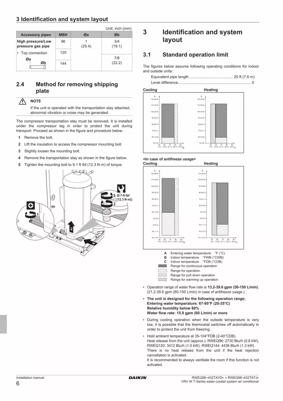
The figures below assume following operating conditions for indoor and outside units: Equivalent pipe length ......................................... 25 ft (7.6 m) Leveldifference.....................................................................0
Cooling Heating
50 (10)
60 (15.6)
70 (21.1)
80 (26.7)
90 (32.2)
100 (37.8)
110 (43.3)
120 (48.9)
60(15.6)
50(10)
70(21.1)
80(26.7)
90(32.2)
AA
CB
50 (10)
60 (15.6)
70 (21.1)
80 (26.7)
90 (32.2)
100 (37.8)
110 (43.3)
120 (48.9)
60(15.6)
50(10)
70(21.1)
80(26.7)
90(32.2)
<In case of antifreeze usage>Cooling Heating
20 (–6.7)
60 (15.6)
70 (21.1)
80 (26.7)
90 (32.2)
100 (37.8)
110 (43.3)
120 (48.9)
10 (–12.2)
60 (15.6)
70 (21.1)
80 (26.7)
90 (32.2)
100 (37.8)
110 (43.3)
50 (10)
50 (10)
40 (4.4)
40 (4.4)
30 (–1.1)
30 (–1.1) 20 (–6.7)
AA
CB
60(15.6)
50(10)
70(21.1)
80(26.7)
90(32.2)
60(15.6)
50(10)
70(21.1)
80(26.7)
90(32.2)
A Entering water temperature °F (°C)B Indoor temperature °FWB (°CWB)C Indoor temperature °FDB (°CDB)
Range for continuous operationRange for operationRange for pull down operationRange for warming up operation
▪ Operation range of water flow rate is 13 .2-39 .6 gpm (50-150 L/min). (21.2-39.6gpm(80-150L/min)incaseofantifreezeusage.)
▪ The unit is designed for the following operation range; Entering water temperature: 67-95°F (20-35°C) Relative humidity below 80% Water flow rate: 15 .9 gpm (60 L/min) or more
▪ During cooling operation when the outside temperature is verylow, it is possible that the thermostat switches off automatically in order to protect the unit from freezing.
▪ Holdambienttemperatureat35-104°FDB(2-40°CDB). Heat release from the unit (approx.): RWEQ96: 2730 Btu/h (0.8 kW), RWEQ120: 3412 Btu/h (1.0 kW), RWEQ144: 4436 Btu/h (1.3 kW) There is no heat release from the unit if the heat rejection cancellation is activated. It is recommended to always ventilate the room if this function is not activated.
01_EN_4P602454-1C.indd 6 2020/07/29 16:16:38

3 Identification and system layout
Installation manual
7RWEQ96~432TAYD∗ + RWEQ96~432TATJ∗ VRV W T-Series water-cooled system air conditioner
3 .2 Identification label: Outside unit
Location
Model identificationExample: RW E Q 96 T A YD ∗
Code ExplanationRW Water-cooled
E Heat pump system
Q Refrigerant R410A
96 Capacity class
T Model series
A Minor model change
YD, TJ Power supply YD: 460 V TJ: 208/230 V
∗ Minor revision
3 .3 About the outside unit
This installation manual concerns the VRV W water-cooled system air conditioner. The unit is full inverter driven, and can be used for cooling, heat pump and heat recovery applications.
Model line up:
Model DescriptionRWEQ96~432 Heat pump and Heat recovery model for
single or multi-use
Depending on the chosen type of unit, some functionality will or will not exist. It will be indicated throughout this installation manual and brought to your attention. Certain features have exclusive model rights.
These units are intended for indoor installation and aimed for heat pump applications including water to air.
The normal operating water inlet temperature must be between 50°F (10°C) and 113°F (45°C). Use of antifreeze/brine will allow extension of operating ranges to 14°F (–10°C) in heating and 23°F (–5°C) in cooling.
3 .4 System layoutINFORMATION Not all combinations of indoor units are allowed.
Heat recovery system1
i
e
c
g
e
c
h
e e
ba
h
gg
g
d
2 3
ef
c
a Unitb Refrigerant pipingc Branch selector unitd Multi branch selector unite VRV indoor unit f Cooling only VRV indoor unit
g User interface (dedicated depending on indoor unit type)h User interface (wireless, dedicated depending on indoor
unit type)i Water system connection
Heat pump system
d d d d e
c c c c
f
g
ba
a Unitb Refrigerant pipingc VRV indoor unit d User interface (dedicated depending on indoor unit type)e User interface (wireless, dedicated depending on indoor
unit type)f Cool/heat selector
g Water system connection
01_EN_4P602454-1C.indd 7 2020/07/29 16:16:38

3 Identification and system layout
Installation manual
8RWEQ96~432TAYD∗ + RWEQ96~432TATJ∗
VRV W T-Series water-cooled system air conditioner
Water system
c
gd f
e
ba
a Unitb Connection to refrigerant systemc Water pipingd Dry coolere Antifreeze loopf Closed cooling towerg Boiler
3 .5 Combining units and options
3 .5 .1 About combining units and optionsNOTE Refer to the technical engineering data for latest options and allowable combinations.
The VRV W T-Series water-cooled system can be combined with several types of indoor units and is intended for R410A use only.
For an overview which units are available you can consult the product catalogue for VRV W T-Series water-cooled system.
An overview is given indicating the allowed combinations of indoor units and outside units. Not all combinations are allowed. They are subject to rules (combination between outside-indoor, single module use, multiple module use, combinations between indoor units, etc.) mentioned in the technical engineering data.
3 .5 .2 Connection Ratio
Connection Ratio = Total capacity index of the indoor units / Capacity index of the outside units
TypeMin . connection ratio
Types of connected outside unitsRWEQ-T type
Single outside units
50%Double outside units
Triple outside units
Type
Max . connection ratioTypes of connected indoor units
When using only FXDQ,
FXMQ-P, FXAQ,
FXSQ07~54T
When using at least one
FXFQ07/09, FXZQ05T, FXSQ05T
All other models
Single outside units150% (*1)
150% (*1) 150% (*1)
Double outside units 130% 130%
Triple outside units 150% (*1) 130% (*2) 130% (*2)
*1. If the operational capacity of indoor units is more than 130%, low airflow operation is enforced in all the indoor units.
*2. 120% for RWEQ432
3 .5 .3 Possible combinations of outside units
Possible single module units
RWEQ96
RWEQ120
RWEQ144
Possible standard combinations of unitsRWEQ192~432 consists of 2 or 3 RWEQ96~144 units.
RWEQ192 = RWEQ96 + 96
RWEQ216 = RWEQ120 + 96
RWEQ240 = RWEQ120 + 120
RWEQ264 = RWEQ120 + 144
RWEQ288 = RWEQ144 + 144
RWEQ312 = RWEQ120 + 96 + 96
RWEQ336 = RWEQ120 + 120 + 96
RWEQ360 = RWEQ120 + 120 + 120
RWEQ384 = RWEQ144 + 120 + 120
RWEQ408 = RWEQ144 + 144 + 120
RWEQ432 = RWEQ144 + 144 + 144
3 .5 .4 Outside Unit CombinationsTotal capacity of indoor units needs to be within the specified range.
<Outside unit> <Total capacity index of indoor units>
RWEQ96 ....................................... 48-124
RWEQ120 ..................................... 60-156
RWEQ144 ..................................... 72-187
RWEQ192 ..................................... 96-249
RWEQ216 .................................... 108-280
RWEQ240 .................................... 120-312
RWEQ264 .................................... 132-343
RWEQ288 .................................... 144-374
RWEQ312 .................................... 156-405
RWEQ336 .................................... 168-436
RWEQ360 .................................... 180-468
RWEQ384 .................................... 192-499
RWEQ408 .................................... 204-530
RWEQ432 .................................... 216-561
NOTE Higher capacity than the above table can be selected, this may affect heating and cooling capacity. For additional information see technical engineering data.
01_EN_4P602454-1C.indd 8 2020/07/29 16:16:39

4 Preparation
Installation manual
9RWEQ96~432TAYD∗ + RWEQ96~432TATJ∗ VRV W T-Series water-cooled system air conditioner
3 .5 .5 Possible options for the outside unitINFORMATION Refer to the technical engineering data for the latest option names.
Refrigerant branching kit
In case of heat pump systemDescription Model name
Refnet header KHRP26M22H9 / KHRP26M22HAKHRP26M33H9 / KHRP26M33HAKHRP26M72H9 / KHRP26M72HAKHRP26M73HU9 / KHRP26M73HUA
Refnet joint KHRP26A22T9 / KHRP26A22TAKHRP26A33T9 / KHRP26A33TAKHRP26M72TU9 / KHRP26M72TUAKHRP26M73TU9 / KHRP26M73TUA
In case of heat recovery systemDescription Model name
Refnet header KHRP25M33H9 / KHRP25M33HAKHRP25M72H9 / KHRP25M72HAKHRP25M73HU9 / KHRP25M73HUA
Refnet joint KHRP25A22T9 / KHRP25A22TAKHRP25A33T9 / KHRP25A33TAKHRP25M72TU9 / KHRP25M72TUAKHRP25M73TU9 / KHRP25M73TUA
For the selection of the optimal branching kit, please refer to "4.3.3 To select refrigerant branch kits" on page 12.
Outside multi connection piping kit
In case of heat pump systemNumber of outside units Model name
2 BHFP22T84U
3 BHFP22T126U
In case of heat recovery systemNumber of outside units Model name
2 BHFP26T84U
3 BHFP26T126U
Cool/heat selectorIn order to control the cooling or heating operation from a central location, the following option can be connected:
Description Model nameCool/heat change over switch KRC19-26A6
Cool/heat change over PCB BRP2A81
With optional fixing box for the switch
KJB111A
INFORMATION The cool/heat selector can only be used when the refrigerant system is configured as heat pump system.
External control adaptor (DTA104A61/62)To instruct specific operation with an external input coming from a central control the external control adaptor can be used. Instructions (group or individual) can be instructed for low noise operation and power consumption limitation operation.
PC configurator cable (999482P3)You can make several commissioning field settings through a personal computer interface. For this option 999482P3 is required which is a dedicated cable to communicate with the outside unit.
4 Preparation
4 .1 Overview: Preparation
This chapter describes what you have to do and know before going on-site.
It contains information about:
▪ Preparingtheinstallationsite
▪ Preparingtherefrigerantpiping
▪ Preparingthewaterpiping
▪ Preparingtheelectricalwiring
4 .2 Preparing installation site
4 .2 .1 Installation site requirements of the outside unit
CAUTION This unit is designed for indoor installation only.
▪ Provide required service space around the unit as stated in thetechnical engineering book or in section "11.2 Service space: Outside unit" on page 49 of this manual.
▪ Ensurethatthefoundationisstrongenoughtosupporttheweightof the unit and the floor is flat to prevent vibration and noise generation.
▪ Make sure the area is well ventilated. Do NOT block anyventilation openings.
▪ Makesuretheunitislevel.
▪ Make sure to install the unit in a machine room that is free ofmoisture. The unit is designed for indoor use only.
▪ Select the location of the unit in such a way that the soundgenerated by the unit does not disturb anyone, and the location is selected according the applicable legislation.
Do NOT install the unit in the following places:
▪ Inpotentiallyexplosiveatmospheres.
▪ In places where there is machinery that emits electromagneticwaves. Electromagnetic waves may disturb the control system, and cause malfunction of the equipment.
▪ In places where there is a risk of fire due to the leakage offlammable gases (example: thinner or gasoline), carbon fiber, ignitable dust.
▪ Inplaceswherecorrosivegas (example:sulphurousacidgas) isproduced. Corrosion of copper pipes or soldered parts may cause the refrigerant to leak.
▪ Inplaceswhereamineraloilmist,sprayorvapormaybepresentin the atmosphere. Plastic parts may deteriorate and fall off or cause water leakage.
NOTE This is a class A product. In a domestic environment this product may cause radio interference in which case the user may be required to take adequate measures.
01_EN_4P602454-1C.indd 9 2020/07/29 16:16:39

4 Preparation
Installation manual
10RWEQ96~432TAYD∗ + RWEQ96~432TATJ∗
VRV W T-Series water-cooled system air conditioner
NOTE The equipment described in this manual may cause electronic noise generated from radio-frequency energy. The equipment complies to specifications that are designed to provide reasonable protection against such interference. However, there is no guarantee that interference will not occur in a particular installation.
It is therefore recommended to install the equipment and electric wires keeping proper distances away from stereo equipment, personal computers, etc.
b
e
cc
a
b d
≥60
inch
(150
0 m
m)
≥40
inch
(1
000
mm
)≥40
inch
(1000
mm)
≥40 inch
(1000 mm)
≥60 inch (1500 mm)
≥60 inch (1500 mm)
≥60 inch (1500 mm)
a Personal computer or radiob Fuse or circuit breakerc User interfaced Indoor unite Outside unit
In places with weak reception, keep distances of 10 ft (3 m) or more to avoid electromagnetic disturbance of other equipment and use conduit tubes for power and transmission lines.
CAUTION Appliance not accessible to the general public, install it in a secured area, protected from easy access.
This unit, both indoor and outside, is suitable for installation in a commercial and light industrial environment.
▪ When installing, take earthquakes into account, improperinstallation may result in the unit turning over.
▪ Takecare that in theeventofawater leak,water cannot causeany damage to the installation space and surroundings.
▪ Wheninstallingtheunitinasmallroom,takemeasuresinordertokeep the refrigerant concentration from exceeding allowable safety limits in the event of a refrigerant leak, refer to "About safety against refrigerant leaks" on page 10.
CAUTION Excessive refrigerant concentrations in a closed room can lead to oxygen deficiency.
▪ Ensure that water cannot cause any damage to the location byadding water drains to the foundation and prevent water traps in the construction.
▪ Installdrainpiping toensureproperdrainageand insulatepipingto prevent condensation. Improper drain piping may result in indoor water leakage and property damage.
4 .2 .2 Securing safety against refrigerant leaks
About safety against refrigerant leaks
The installer and system specialist shall secure safety against leakage according to local regulations or standards. The following standards may be applicable if local regulations are not available.
This system uses R410A as refrigerant. R410A itself is an entirely safe non-toxic, non-combustible refrigerant. Nevertheless care must be taken to ensure that the system is installed in a room which is sufficiently large. This assures that the maximum concentration level of refrigerant gas is not exceeded, in the unlikely event of major leak in the system and this in accordance to the local applicable regulations and standards.
About the maximum concentration levelThe maximum charge of refrigerant and the calculation of the maximum concentration of refrigerant is directly related to the humanly occupied space in to which it could leak.
The unit of measurement of the concentration is lbs/ft³ (kg/m³) (the weight in lbs (kg) of the refrigerant gas in 1 ft³ (1 m³) volume of the occupied space).
Compliance to the local applicable regulations and standards for the maximum allowable concentration level is required.
b
a
a Direction of the refrigerant flowb Room where refrigerant leak has occurred (outflow of all
the refrigerant from the system)
Pay special attention to places such as basements etc., where refrigerant can accumulate, since refrigerant is heavier than air.
To check the maximum concentration levelCheck the maximum concentration level in accordance with steps 1 to 4 below and take whatever action is necessary to comply.
1 Calculate the amount of refrigerant lbs (kg) charged to each system separately.
Formula: A+B=CA Amount of refrigerant in a single unit system (amount of
refrigerant with which the system is charged before leaving the factory).
B Additional charging amount (amount of refrigerant added locally).
C Total amount of refrigerant lbs (kg) in the system.
NOTE Where a single refrigerant facility is divided into 2 entirely independent refrigerant systems, use the amount of refrigerant with which each separate system is charged.
2 Follow local code requirements.
Disposal requirementsDismantling of the unit, treatment of the refrigerant, of oil and of other parts must be done in accordance with relevant local and national legislation.
01_EN_4P602454-1C.indd 10 2020/07/29 16:16:39

4 Preparation
Installation manual
11RWEQ96~432TAYD∗ + RWEQ96~432TATJ∗ VRV W T-Series water-cooled system air conditioner
4 .3 Refrigerant pipe size and allowable length
NOTE The refrigerant R410A requires strict cautions for keeping the system clean, dry and tight.▪ Cleananddry:foreignmaterials(includingmineraloils
or moisture) should be prevented from getting mixed into the system.
▪ Tight:R410Adoesnot contain any chlorine, doesnotdestroy the ozone layer, and does not reduce earth’s protection against harmful ultraviolet radiation. R410A can contribute slightly to the greenhouse effect if it is released. Therefore we should take special attention to check the tightness of the installation.
4 .3 .1 Selection of piping materialNOTE Piping and other pressure containing parts shall comply with the applicable legislation and shall be suitable for refrigerant. Use phosphoric acid deoxidized seamless copper for refrigerant.
NOTE ▪ All field piping must be installed by a licensed
refrigeration technician and must comply with relevant local and national regulations.
▪ After piping work is complete, do not under anycircumstances open the stop valve until "5.8 Connecting the electrical wiring" on page 31. "6 Checking of device and installation conditions" on page 35 are complete.
▪ Do not use flux when brazing the refrigerant piping. Use the phosphor copper brazing filler metal (B-Cu93P-710/795 : ISO 3677) which does not require flux. Flux has extremely negative effect on refrigerant piping systems. For instance, if the chlorine based flux is used, it will cause pipe corrosion or, in particular, if the flux contains fluorine, it will damage the refrigerant oil.
▪ Useonlypipeswhichareclean insideandoutsideandwhichdonot accumulate harmful sulfur, oxidants, dirt, cutting oils, moisture, or other contamination. (Foreign materials inside pipes including oils for fabrication must be 0.14 gr/10 ft (30 mg/10 m) or less.)
▪ Usethefollowingitemsfortherefrigerantpiping.
Material : Jointless phosphor-deoxidized copper pipe.
Size : See "4.3.2 To select the piping size".
Thickness : Select a thickness for the refrigerant piping which complies with national and local laws.
▪ Forpipingwork,followthemaximumtoleratedlength,differenceinheight, and length after a branch indicated in the "4.3.7 Piping length requirements" on page 15.
▪ Outsideunitmulticonnectionpipingkitandrefrigerantbranchkit(sold separately) are needed for connection of piping between outside units (in case of multi system) and piping branches.
▪ Useonlyseparatelysold itemsselectedspecificallyaccording tothe outside unit multi connection piping kit, the refrigerant branch kit selection in the "4.3.3 To select refrigerant branch kits" on page 12.
4 .3 .2 To select the piping sizeINFORMATION Please select the proper pipe sizes depending on the mode of your system. There are 2 possible modes:▪ heatpump,▪ heatrecovery.
Determine the proper size using the following tables and reference figure (only for indication).
In case of heat pump mode
A B B BC
D D
E E E E
x y
b
a
1 2 3 4
b
1~4 VRV indoor unitA~E Pipinga,b Indoor branch kitx,y Outside multi connection kit
In case of heat recovery mode
A B B BC
D E
D* DD
x y
b
a
2
12
3 4 5 6
1
7 8 9
1
E E
b
EE E E E
10 11
E E
b
1 Multi branch selector unit2 Single branch selector unit
3~11 VRV indoor unit12 Cooling only VRV indoor unit
A~E Pipinga,b Indoor branch kitx,y Outside multi connection kit
01_EN_4P602454-1C.indd 11 2020/07/29 16:16:39

4 Preparation
Installation manual
12RWEQ96~432TAYD∗ + RWEQ96~432TATJ∗
VRV W T-Series water-cooled system air conditioner
A, B, C: Piping between outside unit and (first) refrigerant branch kitChoose from the following table in accordance with the outside unit total capacity type, connected downstream.
In case of heat pump modeUnit: inch (mm)
Outside unit capacity type (MBH)
Piping outer diameter sizeGas pipe Liquid pipe
96 7/8 (22.2) 3/8 (9.5)120, 144 1-1/8 (28.6) 1/2 (12.7)192, 216 5/8 (15.9)
240 1-3/8 (34.9)264~336 3/4 (19.1)360~432 1-5/8 (41.3)
In case of heat recovery modeUnit: inch (mm)
Outside unit capacity type (MBH)
Piping outer diameter sizeSuction gas
pipeHigh/low
pressure gas pipe
Liquid pipe
96 7/8 (22.2) 3/4 (19.1) 3/8 (9.5)
120 1-1/8 (28.6) 1/2 (12.7)
144 7/8 (22.2)
192, 216 1-1/8 (28.6) 5/8 (15.9)
240 1-3/8 (34.9)
264~336 3/4 (19.1)
360~432 1-5/8 (41.3) 1-3/8 (34.9)
D: Piping between refrigerant branch kits, branch selector units, or refrigerant branch kit and branch selector unitChoose from the following table in accordance with the indoor unit total capacity type, connected downstream. Do not let the connection piping exceed the refrigerant piping size chosen by the general system model name.
In case of heat pump modeUnit: inch (mm)
Indoor unit capacity index
Piping outer diameter sizeGas pipe Liquid pipe
<54 5/8 (15.9) 3/8 (9.5)
54≤x<72 3/4 (19.1)
72≤x<111 7/8 (22.2)
111≤x<162 1-1/8 (28.6) 1/2 (12.7)
162≤x<230 5/8 (15.9)
230≤x<300 1-3/8 (34.9) 3/4 (19.1)
≥300 1-5/8 (41.3)
In case of heat recovery modeUnit: inch (mm)
Indoor unit capacity index
Piping outer diameter sizeSuction gas
pipeHigh
pressure/low pressure gas
pipe
Liquid pipe
<54 5/8 (15.9) 1/2 (12.7) 3/8 (9.5)
54≤x<72 3/4 (19.1) 5/8 (15.9)
72≤x<111 7/8 (22.2) 3/4 (19.1)
111≤x<162 1-1/8 (28.6) 1/2 (12.7)
162≤x<230 1-1/8 (28.6) 5/8 (15.9)
230≤x<300 1-3/8 (34.9) 3/4 (19.1)
≥300 1-5/8 (41.3)
Example: Downstream capacity for D*=[capacity index of (unit 3 + unit 4 + unit 5 + unit 6 + unit 7 + unit 8 + unit 9)]
E: Piping between refrigerant branch kit or branch selector unit and indoor unit
For heat pump mode and heat recovery modePipe size for direct connection to indoor unit must be the same as the connection size of the VRV indoor units.
Unit: inch (mm)Indoor unit capacity
indexPiping outer diameter size
Gas pipe Liquid pipe05~18 1/2 (12.7) 1/4 (6.4)24~54 5/8 (15.9) 3/8 (9.5)
72 3/4 (19.1)96 7/8 (22.2)
▪ Ifasize-upofthepipingisrequired,refertothetablebelow.
a e
bc
d
a Outside unitb Main pipesc Increased First refrigerant branch kite Indoor unit
Unit: inch (mm)Size up
Outside unit capacity type (MBH)
Liquid piping outer diameter size
96 3/8 → 1/2 (9.5 → 12.7)120, 144 1/2 → 5/8 (12.7 → 15.9)192~240 5/8 → 3/4 (15.9 → 19.1)264~432 3/4 → 7/8 (19.1→ 22.2)
4 .3 .3 To select refrigerant branch kits
Refrigerant refnetsFor piping example, refer to "4.3.2 To select the piping size" on page 11.
▪ When using refnet joints at the first branch counted from theoutside unit side, choose from the following table in accordance with the capacity of the outside unit (example: refnet joint a).
01_EN_4P602454-1C.indd 12 2020/07/29 16:16:39

4 Preparation
Installation manual
13RWEQ96~432TAYD∗ + RWEQ96~432TATJ∗ VRV W T-Series water-cooled system air conditioner
Outside unit capacity type (MBH)
2 pipes 3 pipes
96 KHRP26A33T9
KHRP26A33TA
KHRP25A33T9
KHRP25A33TA
120~216 KHRP26M72TU9
KHRP26M72TUA
KHRP25M72TU9
KHRP25M72TUA
240~432 KHRP26M73TU9
KHRP26M73TUA
KHRP25M73TU9
KHRP25M73TUA
▪ Forrefnetjointsotherthanthefirstbranch(examplerefnetjointb),select the proper branch kit model based on the total capacity index of all indoor units connected after the refrigerant branch.
Indoor unit capacity index
2 pipes 3 pipes
<72 KHRP26A22T9
KHRP26A22TA
KHRP25A22T9
KHRP25A22TA
72≤x<111 KHRP26A33T9
KHRP26A33TA
KHRP25A33T9
KHRP25A33TA
111≤x<246 KHRP26M72TU9
KHRP26M72TUA
KHRP25M72TU9
KHRP25M72TUA
≥246 KHRP26M73TU9
KHRP26M73TUA
KHRP25M73TU9
KHRP25M73TUA
▪ Concerning refnet headers, choose from the following table inaccordance with the total capacity of all the indoor units connected below the refnet header.
Indoor unit capacity index
2 pipes 3 pipes
<72 KHRP26M22H9
KHRP26M22HA (Max. 4 branches)
or
KHRP26M33H9
KHRP26M33HA (Max. 8 branches)
KHRP25M33H9
KHRP25M33HA
72≤x<111 KHRP26M33H9
KHRP26M33HA
111≤x<230 KHRP26M72H9
KHRP26M72HA
KHRP25M72H9
KHRP25M72HA
≥230 KHRP26M73HU9
KHRP26M73HUA
KHRP25M73HU9
KHRP25M73HUA
INFORMATION If not stated otherwise, maximum 8 branches can be connected to a header.
▪ How to choose an outside multi connection piping kit. Choosefrom the following table in accordance with the number of outside units.
Number of outside units Heat pump mode Heat recovery mode2 BHFP22T84U BHFP26T84U
3 BHFP22T126U BHFP26T126U
INFORMATION Reducers or T-joints are field supplied.
NOTE Refrigerant branch kits can only be used with R410A.
4 .3 .4 System piping (length) limitationMake sure the piping installation does not exceed the maximum allowable pipe length, the allowable level difference, and the allowable length after branching. To illustrate the piping length requirements, 6 cases are discussed in the chapters below. They describe both standard and non-standard outside unit combinations.Definitions
Term DefinitionActual piping length Pipe length between outside(a) and indoor
units
Equivalent piping length
Pipe length between outside(a) and indoor units, including the equivalent length of the piping accessories
Total piping length Total piping length, from the outside to all indoor units
(a) If the system is a multi outside installation, re-read "the first outside unit branch as seen from the indoor unit".
Equivalent length of the piping accessories
Accessory Equivalent lengthRefnet joint 1.6 ft (0.5 m)
Refnet header 3.3 ft (1 m)
Single BSQ36-60T∗ 13 ft (4 m)
Single BSQ96T∗ 19 ft (6 m)
Multi BS4-6Q54T∗ 19 ft (6 m)
Multi BS8-12Q54T∗ 33 ft (10 m)
For the equivalent length of BSF-Q54T∗, refer to the table below based on the total capacity of the indoor units to be connected downstream. Also add 14 ft (4.3 m) to the below length when calculating an equivalent length to each indoor unit connected to BSF-Q54T∗.
Total capacity of the indoor units to be
connected downstream
Equivalent length
BSF4Q54T∗ BSF6Q54T∗ BSF8Q54T∗
< 54 1 ft (0.4 m) 1 ft (0.4 m) 1 ft (0.4 m)
54≤×<72 1 ft (0.4 m) 1 ft (0.4 m) 1 ft (0.4 m)
72≤×<111 2 ft (0.7 m) 2 ft (0.7 m) 2 ft (0.7 m)
111≤×<162 5 ft (1.6 m) 7 ft (2.2 m) 7 ft (2.2 m)
162≤×<230 7 ft (2.2 m) 11 ft (3.4 m) 11 ft (3.4 m)
230≤×≤290 14 ft (4.3 m) 19 ft (5.8 m) 19 ft (5.8 m)
System piping (length) limitations
Term Definition DistanceActual piping length Pipe length between outside(a)
and indoor units540 ft (165 m)
Equivalent piping length(b)
Pipe length between outside(a) and indoor units
623 ft (190 m)
Total actual piping length
Total piping length from the outside(a) to all indoor units
980 ft (300 m)
H1 Height difference between outside and indoor units
164 ft (50 m)/ 130 ft (40 m) (b)
H2 Height difference between indoor units
98 ft (30 m)
H3 Height difference between outside units
16 ft (5 m)
(a) In the case of an outside units multi system, "outside unit" should be read as the "first outside unit multi connection piping kit", seen from the indoor units side.
(b) The allowable height difference is 164 ft (50 m) in case the outside unit is positioned higher than the indoor unit, and 130 ft (40 m) in case the outside unit is positioned lower than the indoor unit.
01_EN_4P602454-1C.indd 13 2020/07/29 16:16:39

4 Preparation
Installation manual
14RWEQ96~432TAYD∗ + RWEQ96~432TATJ∗
VRV W T-Series water-cooled system air conditioner
4 .3 .5 Single module and standard multi-outside-unit combinations
In case of heat pump modeConnection with indoor units and air handling units
4
H1
H3
H2
a
a
b
b
2
5
1
3
a Outside unitb VRV indoor unit
Pipe Maximum length (actual/equivalent)Longestpipefromtheoutside unit to the last indoor unit (1+3, 1+2+5)
540 ft (165 m)/623 ft (190 m)(a)
Longestpipeafterthefirstbranch (3, 2+5)
295 ft (90 m)(b)/—
In case of a multi-outside setup: longest pipe from the outside unit to the last multi-outside piping branch (4)
33 ft (10 m)/43 ft (13 m)
Total pipe length (1+2+3+5) 980 ft (300 m)/—(c)
The actual piping length from each indoor units to the nearest refrigerant branch kit
130 ft (40 m)/—
(a) If the equivalent piping length is more than 295 ft (90 m), size up the main liquid piping according to "4.3.2 To select the piping size" on page 11.
(b) If actual piping length of indoor units where difference from the indoor unit nearest to the outside unit is more than 130 ft (40 m), please size up according to "4.3.7 Piping length requirements" on page 15.
(c) In the case of an outside units multi system, "outside unit" should be read as the "first outside unit multi connection piping kit", seen from the indoor units side.
In case of heat recovery mode
Connection with only indoor units
H3
1 5
H1
3 2
4
a
b b
c
d
b
bH2
a Outside unitb VRV indoor unitc Multi branch selector unitd Single branch selector unit
Multi branch selector box is to be considered as a branch, a single branch selector box is not considered as a branch.
Pipe Maximum length (actual/equivalent)Longestpipefromtheoutside unit to the last indoor unit (1+2, 1+3, 1+5)
540 ft (165 m)/623 ft (190 m)(a)
Longestpipeafterthefirstbranch (3, 2, 5)
295 ft (90 m)(b) (c)/—
In case of a multi-outside setup: longest pipe from the outside unit to the last multi-outside piping branch (4)
33 ft (10 m)/43 ft (13 m)
Total pipe length (1+2+3+5) 980 ft (300 m)/—(d) (e)
The actual piping length from each indoor units to the nearest refrigerant branch kit
130 ft (40 m)(c)/—
01_EN_4P602454-1C.indd 14 2020/07/29 16:16:40

4 Preparation
Installation manual
15RWEQ96~432TAYD∗ + RWEQ96~432TATJ∗ VRV W T-Series water-cooled system air conditioner
(a) If the equivalent piping length is more than 295 ft (90 m), size up the main liquid pipings according to "4.3.2 To select the piping size" on page 11.
(b) If actual piping length of indoor units where difference from the indoor unit nearest to the outside unit is more than 130 ft (40 m), please size up according to "4.3.7 Piping length requirements" on page 15.
(c) For Branch Selector unit connected in pass through installation, all three conditions below must be satisfied. 1. Maximum capacity index of connectable indoor units for
BSF6, 8Q54T∗is≤162perBranchSelectorunit.2. Maximum capacity index of connectable indoor units under BranchSelectorunitsconnectedinpassthroughis≤230.
3. Total number of ports of Branch Selector units connected inpassthroughis≤12.
(d) In the case of an outside units multi system, "outside unit" should be read as the "first outside unit multi connection piping kit", seen from the indoor units side.
(e) Total pipe length can be extended to 1640 ft (500 m) when total refrigerant amount is as follows: Singlesystem≤77lb(35kg) Doublesystem≤145lb(66kg) Triplesystem≤150lb(68kg)
4 .3 .6 Multiple module: Possible layouts
▪ The piping between the outside units must be routed level orslightly upward to avoid the risk of oil retention into the piping.
Pattern 1
ab
Pattern 2
ab
ab
ab
a To indoor unitb Piping between outside unitsX Not allowed (oil remains in piping)O Allowed
▪ Ifthepipinglengthbetweentheoutsideunitconnectingpipekitorbetween the outside units exceeds 6.5 ft (2 m), create a rise of 8 inch (200 mm) or more in the suction gas and high/low pressure gas line within a length of 6.5 ft (2 m) from the kit.
▪ Forthegaspiping(bothdischargeandsuctiongaspipingincaseof the heat recovery system) after the branch, install a trap of 8 inch (200 mm) or more using the piping included in the piping kit for connecting the outside unit. Otherwise, the refrigerant may stay in the piping, causing damage to the outside unit.
≥8 inch (200mm)
If Then≤6.5ft(2m) 6.5 ft (2 m)
or less
ab
If Then>6.5 ft (2 m) 6.5 ft (2 m)
or lessRising height: 8 inch (200 mm) or more
ab
a To indoor unitb Piping between outside units
NOTE There are restrictions on the refrigerant pipe connection order between outside units during installation in case of a multiple module system. Install according to following restrictions. The capacities of outside units A, B and C mustfulfillthefollowingrestrictionconditions:A≥B≥C.
a cb
A B C
a To indoor units
b Outside unit multi connecting piping kit (first branch)
c Outside unit multi connecting piping kit (second branch)
4 .3 .7 Piping length requirements
In case of heat pump mode
10 12 13
11 1716987
1
Y
14 156
b
a
a
bc
*b *bbb b
First branchFarthest branch
If actual piping length of indoor units 48 types, 54 types, and 72 types, 96 type where difference from the indoor unit (Y) nearest to the outside unit is more than 130 ft (40 m),
Example:b is neither 48 types nor 54 types nor 72 types nor 96 type *b is 48 types or 54 types or 72 types or 96 type
(6+11)–(6+10)<130 ft (40 m)(7+12+17)–(6+10)<130 ft (40 m)(7+13+17)–(6+10)<130 ft (40 m)(7+8+14)–(6+10)>130 ft (40 m)(7+8+9+15)–(6+10)>130 ft (40 m) (7+8+9+16)–(6+10)>130 ft (40 m) please size up both liquid pipe and gas pipe until the closest branch. (14, 16)
01_EN_4P602454-1C.indd 15 2020/07/29 16:16:41
4 Preparation
Installation manual
16RWEQ96~432TAYD∗ + RWEQ96~432TATJ∗
VRV W T-Series water-cooled system air conditioner
If the actual pipe length difference after the first branch is more than 130 ft (40 m), please size up the piping until the last branch. (Liquidpipe and gas pipe at Heat pump mode) (7, 8, 9). The total piping length:1+(7+8+9+14+16)×2+6+10+11+12+13+15+17)≤980ft(300m)If size exceeds the main pipe size due to size increase, please also size up main pipe according to "4.3.2 To select the piping size" on page 11.
In case of heat recovery mode
B1 B210 12 13
11 1716987
1
Y
146d d
dB3 c B4 dB6*b *bb b
b b
a
a
18 19
15B5 c
*b b
First branchFarthest branch
B1-B6 Branch selector unit
If actual piping length of indoor units 48 types, 54 types, and 72 types, 96 type where difference from the indoor unit (Y) nearest to the outside unit is more than 130 ft (40 m),
Example:b is neither 48 types nor 54 types nor 72 types nor 96 type *b is 48 types or 54 types or 72 types or 96 type
(6+11)–(6+10)<130 ft (40 m)(7+12+17)–(6+10)<130 ft (40 m)(7+13+17)–(6+10)<130 ft (40 m)(7+8+14)–(6+10)>130 ft (40 m)(7+8+9+15)–(6+10)>130 ft (40 m) (7+8+9+16)–(6+10)>130 ft (40 m) (7+8+9+15+18)–(6+10)>130 ft (40 m) (7+8+9+15+19)–(6+10)>130 ft (40 m) please size up both liquid pipe and gas pipe until the closest branch. (14, 16, 18)
If the actual pipe length difference after the first branch is more than 130 ft (40 m), please size up the piping until the last branch. (Liquidpipe only at Heat Recovery mode) (7, 8, 9). The total piping length:1+(7+8+9+14+16+18)×2+6+10+11+12+13+15+17+19)≤980ft(300m)If size exceeds the main pipe size due to size increase, please also size up main pipe according to "4.3.2 To select the piping size" on page 11.
4 .4 Preparing water piping
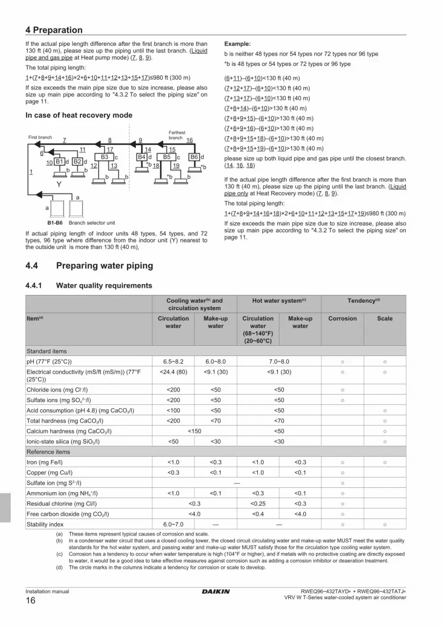
4 .4 .1 Water quality requirements
Cooling water(b) and circulation system
Hot water system(c) Tendency(d)
Item(a) Circulation water
Make-up water
Circulation water
(68~140°F) (20~60°C)
Make-up water
Corrosion Scale
Standard items
pH (77°F (25°C)) 6.5~8.2 6.0~8.0 7.0~8.0 ○ ○
Electrical conductivity (mS/ft (mS/m)) (77°F (25°C))
<24.4 (80) <9.1 (30) <9.1 (30) ○ ○
Chloride ions (mg Cl–/l) <200 <50 <50 ○
Sulfate ions (mg SO42–/l) <200 <50 <50 ○
Acid consumption (pH 4.8) (mg CaCO3/l) <100 <50 <50 ○
Total hardness (mg CaCO3/l) <200 <70 <70 ○
Calcium hardness (mg CaCO3/l) <150 <50 ○
Ionic-state silica (mg SiO2/l) <50 <30 <30 ○
Reference items
Iron (mg Fe/l) <1.0 <0.3 <1.0 <0.3 ○ ○
Copper (mg Cu/l) <0.3 <0.1 <1.0 <0.1 ○
Sulfate ion (mg S2–/l) — ○
Ammonium ion (mg NH4+/l) <1.0 <0.1 <0.3 <0.1 ○
Residual chlorine (mg Cl/l) <0.3 <0.25 <0.3 ○
Free carbon dioxide (mg CO2/l) <4.0 <0.4 <4.0 ○
Stability index 6.0~7.0 — — ○ ○(a) These items represent typical causes of corrosion and scale.(b) In a condenser water circuit that uses a closed cooling tower, the closed circuit circulating water and make-up water MUST meet the water quality
standards for the hot water system, and passing water and make-up water MUST satisfy those for the circulation type cooling water system.(c) Corrosion has a tendency to occur when water temperature is high (104°F or higher), and if metals with no protective coating are directly exposed
to water, it would be a good idea to take effective measures against corrosion such as adding a corrosion inhibitor or deaeration treatment.(d) The circle marks in the columns indicate a tendency for corrosion or scale to develop.
01_EN_4P602454-1C.indd 16 2020/07/29 16:16:41

4 Preparation
Installation manual
17RWEQ96~432TAYD∗ + RWEQ96~432TATJ∗ VRV W T-Series water-cooled system air conditioner
NOTE ▪ ThesupplywaterMUSTbeclean tapwater, industrial
water or clean underground water. Do NOT use purified or softened water.
▪ Do NOT use once-through water. It may causecorrosion.
4 .4 .2 Water circuit requirements
INFORMATION Also read the precautions and requirements in the "General safety precautions" chapter.
NOTE Use water pipes compiled with the local and national codes.
▪ Thewaterpressureresistanceofwaterpipingofthisoutsideunitis 464 psig (3.2 MPa).
▪ The connection port forwater piping is located in the front. Theconnection ports for drain piping are located in the front and back. When using the back port, change the cast iron plug from the back to the front and securely close it.
▪ Inindooruse,pipingworkshouldbesuchthatnowaterdropsonthe outer plate.
▪ The lateralprotrudingsectionof thedrainpipingshouldbeshort(within 15-3/4 inch (400 mm)) and installed in a downward direction. The diameter of drain pipe should be the same as the diameter of unit connection (3/8 inch (9.5 mm)) or more.
▪ Thediameterofwaterpipeshouldbethesameasthediameterofunit connection (1-1/4 inch (31.8 mm)) or more.
▪ Install an air purge valve in the midway of the water piping toprevent cavitation.
▪ Aftercompleting thedrainpipingwork,makesure that thewaterruns smoothly without any clogging by dust.
▪ Donotconnectthedrainoutlettothewateroutlet.
▪ Installastrainer (standardaccessory) in the inletofwaterpipingwithin a distance of 4.9 ft (1.5 m) from the outside unit. (If sand, waste or rust particles are mixed in the water circulation system, metal materials will become corrosive.)
▪ Install insulation on the inlet/outlet of water piping to preventcondensation and freezing. At installing insulation on water in/outlet pipe, use Polyurethane foam thickness 3/16 inch (5 mm) for insulation of water piping socket on heat exchanger.
▪ Installinsulationuptothebaseofheatexchanger.
▪ Install a gate valve for chemical cleaning in an easy position tohandle.
▪ Usewaterpipescompliantwiththelocalandnationalcodes.
▪ Runthewaterpumptoflushinsideofwaterpiping. Then, clean the strainer.
▪ If there is a possibility of freezing, take measures to preventfreezing.
▪ Connectwaterpipingandheatexchangerviapipeadaptor(accessory) (ISO228-1•G1-1/4B→ANSI-ASMEB1.20.1•1-1/4-11.5NPT)
▪ Tighten securely the connection ofwater piping and socketwithtightening torque of 220 ft·lbf (300 N·m) or less. (If a large torque is applied, the unit may be damaged.)
Example:
≥3.1
5 in
ch
(80
mm
)
bm g
de
e
a
jn
k
c
l
if h
a Air purge (field supply)b Water outletc Water inletd Shut-off valve (field supply)e Water connectionf Water piping (field supply)
g Insulation (field supply)h Pipe adaptor (accessory)i Heat exchangerj Strainer (accessory)
k Drain valve (field supply)l Drain connection
m Insulation covern Flow switch (field supply)
4 .4 .3 Maintenance of plate-type/brazed plate heat exchanger
CAUTION A brazed plate-type heat exchanger is used for this unit. Because its structure is different from a conventional type heat exchanger, it must be handled in a different manner.
When designing the equipment
1 Install a strainer (standard accessory) at the water inlet side adjacent to the outside unit in order to prevent any foreign materials such as dust, sand, etc. from entering.
2 Depending on the water quality, scale may stick to the plate-type heat exchanger. In order to remove scale, it is necessary to use chemicals to clean it at regular intervals. To this end, install a gate valve in the water piping. Set up a piping connection port on the piping between this gate valve and the outside unit for cleaning by chemicals.
3 For the purpose of cleaning and water drain-off from the outside unit (water draining during a long period of non-use in winter, draining upon starting of season-off), install an "air discharge valve" and a "water draining plug" at the inlet/outlet ports of water piping. In addition, install an "automatic air discharging valve" at the top of riser piping or at the top of a portion where air tends to stay.
4 Independent of the piping inlet of the outside unit, install a cleanable strainer at a portion close to the pump piping inlet.
5 Carry out complete cooling/thermal insulation of water piping and outside dehumidification. If complete cooling or thermal insulation has not been carried out, any damage may be caused during severe winter due to freezing, in addition to thermal loss.
6 When you stop operation during night or winter, it is necessary to take measures to prevent water-related circuits from natural freezing in the area the ambient temperature drops below 32°F (0°C) (by water drain off, keeping the circulation pump running, warming up by a heater, etc.) Freezing of water related circuits may result in any damage to the plate-type heat exchanger. Therefore, take appropriate measures depending on the circumstances of use.
01_EN_4P602454-1C.indd 17 2020/07/29 16:16:41

4 Preparation
Installation manual
18RWEQ96~432TAYD∗ + RWEQ96~432TATJ∗
VRV W T-Series water-cooled system air conditioner
Before starting a test run
1 Before starting a test run, please make sure that the piping work has been carried out in a proper manner. Especially, make sure that the strainer, air discharge valve, automatic water supply valve, expansion tank and cistern are positioned at their places correctly.
2 After water has been completely filled in, first run the pump only, and then make sure that no air has been caught in the water circulation system and that the water flow rate is correct. If any air has been caught or the flow rate is not enough, the plate-type heat exchanger may freeze. Measure any water pressure loss before and after the outside unit and make sure that the flow rate is as designed. In case of any abnormality, stop the test run immediately and carry out trouble shooting to resolve the trouble.
3 Following the installation manual, carry out a test run of the outside unit.
4 After the test run has been completed, inspect the strainer at the inlet piping of the outside unit. Clean it if it is dirty.
a b c de
f
g h
i
a Water inlet pipingb Strainer (accessory)c Air discharge valve (for joint use with cleaning port) d Cleaning devicee Strainer for pump (field supply)f Automatic air discharge valveg Water outlet pipingh Joint use with water draining plugi Plate-type heat exchanger
4 .4 .4 Variable water flow rate
The RWEQ96~144T∗ models are equipped with the logic to operate with a variable water flow rate function.
ab
c
a Constant flowb Flow regulating valve (field supply)c Inverter pump (field supply)
A system can either be configured as a constant flow system (a), a variable flow system with valve (b) or a variable flow system with a pump (c).
▪ Constant flowsystem(a): thevariablewater flowrate function isnot used.
▪ A pressure independent flow regulating valve (b): the valvecontrols the flow rate of a centralized inverter pump through the unit.
▪ Inverter pump (c): thepumpdirectly controls thewater flow ratethrough the unit.
To activate the variable flow system, change field setting [2-24] to the applicable value. See "7.2 Making field settings" on page 36.
NOTE Make sure that all field supplied equipment for variable flow rate can be switched off together with the outside unit. This is required when cleaning the plate heat exchanger.
NOTE ▪ Makesurethatallfieldsuppliedequipmentforvariable
flow rate meet the minimum hydronic and electric specifications. Failure to do so can result in inefficient operation or even breakdown of the system.
▪ The outside unit is equipped to deliver variable flowsignal to one hydronic pump. Hence it is recommended to install only one hydronic pump per single module of the system.
Size the valve (b) or pump (c) in accordance with the maximum required flow rate A, calculated by the installer of the hydronic system (with respect to the operation range of the outside unit). The typical operation range of the flow rate of the valve/pump is 50% (B) to 100% (A).
The valve/pump input signal is based on a variable 2~9 V DC control output signal coming from the outside unit. The valve or pump should have a linear control characteristic between unit output signal and flow rate according to the example graph below.
0%
BE
D
C
c
a b
A
50%
100%
2 V DC 9 V DCa Valve/pump flow rateb Unit/system flow ratec Valve/pump input signalA Maximum required flow rate (100%)B 50% of the maximum required flow rateC Minimum flow rate (see description below)D Maximum flow rate (see description below)E Hydronic flow rate
Follow the design criteria below to select the correct valve for the system. The valve system maximum required flow rate A is a property of the supplied valve and the 50% flow rate B is directly related to the maximum flow rate of the system.
INFORMATION Some third party valves/pumps have a maximum flow rate defined by the hardware of the system, but a different maximum flow rate can be set to correspond with the maximum input voltage (9 V DC) The installer should ask information to the valve/pump supplier before making the selection.
Design criteria1 Minimum flow rate C:
Model CRWEQ96~144 13.2 gpm (50 l/min)
21.2 gpm (80 l/min)(a)
(a) For antifreeze use
01_EN_4P602454-1C.indd 18 2020/07/29 16:16:41

5 Installation
Installation manual
19RWEQ96~432TAYD∗ + RWEQ96~432TATJ∗ VRV W T-Series water-cooled system air conditioner
2 Maximum flow rate D:
Model DRWEQ96~144 39.6 gpm (150 l/min)
3 Hydronic flow rate E: The value E is the design flow rate calculated by the hydronic
engineer when designing the building system.
Correct valve selection is done when following conditions are met:
(B≥C) AND (E≤A≤D)
For further selection requirements, refer to "4.5 Field wiring" on page 19.
Check the minimum flow rate of the system during commissioning to ensure good operation.During the initialization process of the outside unit, the output signal will trigger a flow rate of B (50%). The installer should make sure that a flow rate can be checked in the individual hydronic system of each unit. If this value is not matching the required flow, the installer should troubleshoot the hydronic system to solve the problem and ensure the correct flow rate.
4 .5 Field wiring
4 .5 .1 Safety device requirements
The power supply must be protected with the required safety devices, i.e. a main switch, a slow blow fuse on each phase and/or a circuit breaker.
Selection and sizing of the wiring should be done in accordance with the applicable legislation based on the information mentioned in the table below.
Model Minimum circuit ampacity
Recommended fuses
RWEQ96TATJ∗ 28.8 A 35 ARWEQ120TATJ∗ 36.5 A 45 ARWEQ144TATJ∗ 44.6 A 50 ARWEQ192TATJ∗ 28.8+28.8 A 35+35 ARWEQ216TATJ∗ 28.8+36.5 A 35+45 ARWEQ240TATJ∗ 36.5+36.5 A 45+45 ARWEQ264TATJ∗ 36.5+44.6 A 45+50 ARWEQ288TATJ∗ 44.6+44.6 A 50+50 ARWEQ312TATJ∗ 28.8+28.8+36.5 A 35+35+45 ARWEQ336TATJ∗ 28.8+36.5+36.5 A 35+45+45 ARWEQ360TATJ∗ 36.5+36.5+36.5 A 45+45+45 ARWEQ384TATJ∗ 36.5+36.5+44.6 A 45+45+50 ARWEQ408TATJ∗ 36.5+44.6+44.6 A 45+50+50 ARWEQ432TATJ∗ 44.6+44.6+44.6 A 50+50+50 ARWEQ96TAYD∗ 13 A 15 ARWEQ120TAYD∗ 16.5 A 20 ARWEQ144TAYD∗ 20.2 A 25 ARWEQ192TAYD∗ 13.0+13.0 A 15+15 ARWEQ216TAYD∗ 13.0+16.5 A 15+20 ARWEQ240TAYD∗ 16.5+16.5 A 20+20 ARWEQ264TAYD∗ 16.5+20.2 A 20+25 ARWEQ288TAYD∗ 20.2+20.2 A 25+25 ARWEQ312TAYD∗ 13.0+13.0+16.5 A 15+15+20 ARWEQ336TAYD∗ 13.0+16.5+16.5 A 15+20+20 ARWEQ360TAYD∗ 16.5+16.5+16.5 A 20+20+20 ARWEQ384TAYD∗ 16.5+16.5+20.2 A 20+20+25 ARWEQ408TAYD∗ 16.5+20.2+20.2 A 20+25+25 ARWEQ432TAYD∗ 20.2+20.2+20.2 A 25+25+25 A
▪ Phaseandfrequency:3~60Hz
▪ Voltage:208/230V(RWEQ96~432TATJ∗),
460 V (RWEQ96~432TAYD∗),
▪ Transmission line section insulated: AWG 18~16, maximumlength is 3280 ft (1000 m). If the total transmission wiring exceeds these limits, it may result in communication error.
NOTE When using residual current operated circuit breakers, be sure to use a high-speed type 300 mA rated residual operating current.
5 Installation
5 .1 Unpacking and placing the unit
5 .1 .1 To open the outside unit
DANGER: RISK OF ELECTROCUTION
DANGER: RISK OF BURNING
To gain access to the unit, front plates need to be opened as follows:
11×
A
B
Once the front plate A is open, the control box can be accessed. See "5.1.2 Accessing the control box" on page 19.
For service purposes, the push buttons on the main PCB need to be accessed. To access these push buttons, the control box cover does not need to be opened. See "7.2.3 To access the field setting components" on page 36.
To install the water piping and field wiring, front plate B has to be removed.
5 .1 .2 Accessing the control box
NOTE Do not apply excessive force when opening the control box cover. Excessive force can deform the cover, resulting in entering of water to cause equipment failure.
01_EN_4P602454-1C.indd 19 2020/07/29 16:16:42

5 Installation
Installation manual
20RWEQ96~432TAYD∗ + RWEQ96~432TATJ∗
VRV W T-Series water-cooled system air conditioner
4× SW8
2
1
5 .2 Mounting the outside unit
5 .2 .1 To provide the installation structure
Make sure the unit is installed level on a sufficiently strong base to prevent vibration and noise.
NOTE When the installation height of the unit needs to be increased, do not use stands to only support the corners.
▪ The preferred installation is on a solid longitudinal foundation(steel beam frame or concrete). The foundation must be larger than the grey marked area.
31.5 inch (800 mm)
23.6 inch (600 mm)
20.3
inch
(516
mm
)
18.9
inch
(480
mm
)
26.2
inch
(665
mm
)
a
Minimum foundationa Anchorpoint(4×)
▪ Secure the unit to its base using foundation bolts. (Use fourcommercially available 7/16 inch (M12) foundation bolts, nuts, and washers.)
▪ Thefoundationboltshouldprotrude13/16inch(20mm)fromthefoundation surface.
13/16
inch
(20 m
m)
5 .3 Refrigerant piping
5 .3 .1 Precautions when connecting refrigerant piping
NOTE ▪ All field piping must be installed by licensed
refrigeration technician and must comply with applicable local and national codes.
▪ Make sure the field piping and connections are notsubjected to stress.
WARNING During tests, NEVER pressurize the product with a pressure higher than the maximum allowable pressure (as indicated on the nameplate of the unit).
WARNING Take sufficient precautions in case of refrigerant leakage. If refrigerant gas leaks, ventilate the area immediately. Possible risks:
▪ Excessive refrigerant concentrations in a closed roomcan lead to oxygen deficiency.
▪ Toxic gas may be produced if refrigerant gas comesinto contact with fire.
WARNING Always recover the refrigerant. Do NOT release them directly into the environment. Use a vacuum pump to evacuate the installation.
NOTE After all the piping has been connected, make sure there is no gas leak. Use nitrogen to perform a gas leak detection.
5 .3 .2 Connecting the refrigerant piping
Before connecting the refrigerant piping, make sure the outside and indoor units are mounted.
Connecting the refrigerant piping involves:
▪ Routingandconnectingtherefrigerantpipingtotheoutsideunit
▪ Protectingtheoutsideunitagainstcontamination
▪ Connecting the refrigerant piping to the indoor units (see theinstallation manual of the indoor units)
▪ Connectingthemulti-connectionpipingkit
▪ Connectingtherefrigerantbranchingkit
▪ Keepinginmindtheguidelinesfor:
▪ Brazing
▪ Usingthestopvalves
▪ Removingthepinchedpipes
5 .3 .3 Routing refrigerant piping
RWEQ_T∗ series units offer flexibility of both front and top refrigerant pipe connections.
The units ship from factory configured for refrigerant pipe installation from top . Remove two screws of the pipe service plate (a), and fit the plate with screws in other position as shown in figure below .
a
Front connection:Use the front connection pipes (optional accessory) to convert the installation to one where the refrigerant piping is connected to the front.
01_EN_4P602454-1C.indd 20 2020/07/29 16:16:43

5 Installation
Installation manual
21RWEQ96~432TAYD∗ + RWEQ96~432TATJ∗ VRV W T-Series water-cooled system air conditioner
a
5 .3 .4 To connect the refrigerant piping to the outside unit
Suction gas side is totally shut.
Liquid
SuctionGas
Liquid
Heat recovery system Heat pump system
Connect
Do not cut the stop valve pipeDo not connect
Connect Connect
SuctionGas
HighPressure
/ LowPressure
Gas
HighPressure
/ LowPressure
Gas
INFORMATION All local inter unit piping are field supplied except the accessory pipes.
NOTE Precautions when connecting field piping. Add brazing material as shown in the figure.
1 1
11
2 2
≤Ø1 inch (25.4 mm) >Ø1 inch (25.4 mm)
NOTE ▪ Be sure to use the supplied accessory pipes when
carrying out piping work in the field.▪ Be sure that the field installed piping does not touch
other pipes, the bottom panel or side panel. Connect the stop valves to the field piping using the accessory pipes supplied with the unit.The connections to the branch kits are the responsibility of the installer (field piping).
5 .3 .5 Multi connection piping kit connection
NOTE Improper installation may lead to malfunction of the outside unit.
▪ Installthejointshorizontally,sothatthecautionlabel(a)attachedto the joint comes to the top.
▪ Donottiltthejointmorethan15°(seeviewA).
▪ Donotinstallthejointvertically(seeviewB).
a a
A B15°15°
a Caution labelX Not allowedO Allowed
▪ Makesurethatthetotallengthofthepipingconnectedtothejointis absolute straight for at least 19-11/16 inch (500 mm). Only if a straight field piping of more than 4-3/4 inch (120 mm) is connected, more than 19-11/16 inch (500 mm) of straight section can be ensured.
A >4-3/4 inch (120 mm)B >19-11/16 inch (500 mm)
AB
5 .3 .6 To connect the refrigerant branching kit
For installation of the refrigerant branching kit, refer to the installation manual delivered with the kit.
▪ Mount the refnet joint so that it branches either horizontally orvertically.
▪ Mounttherefnetheadersothatitbrancheshorizontally.
A
B
±30° a
b c
a
a Horizontal surfaceb Refnet joint mounted verticallyc Refnet joint mounted horizontally
01_EN_4P602454-1C.indd 21 2020/07/29 16:16:45
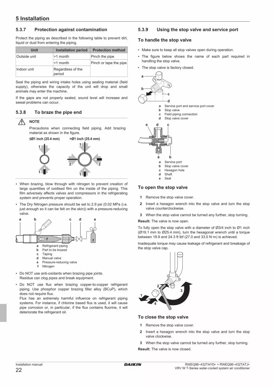
5 Installation
Installation manual
22RWEQ96~432TAYD∗ + RWEQ96~432TATJ∗
VRV W T-Series water-cooled system air conditioner
5 .3 .7 Protection against contaminationProtect the piping as described in the following table to prevent dirt, liquid or dust from entering the piping.
Unit Installation period Protection methodOutside unit >1 month Pinch the pipe
<1 month Pinch or tape the pipe
Indoor unit Regardless of the period
Seal the piping and wiring intake holes using sealing material (field supply), otherwise the capacity of the unit will drop and small animals may enter the machine.
If the gaps are not properly sealed, sound level will increase and sweat problems can occur.
5 .3 .8 To braze the pipe end
NOTE Precautions when connecting field piping. Add brazing material as shown in the figure.
1 1
11
2 2
≤Ø1 inch (25.4 mm) >Ø1 inch (25.4 mm)
▪ When brazing, blow throughwith nitrogen to prevent creation oflarge quantities of oxidised film on the inside of the piping. This film adversely affects valves and compressors in the refrigerating system and prevents proper operation.
▪ TheDryNitrogenpressureshouldbesetto2.9psi(0.02MPa(i.e.just enough so it can be felt on the skin)) with a pressure-reducing valve.a b c d e
ff
a Refrigerant pipingb Part to be brazedc Tapingd Manual valvee Pressure-reducing valvef Nitrogen
▪ DoNOTuseanti-oxidantswhenbrazingpipejoints. Residue can clog pipes and break equipment.
▪ Do NOT use flux when brazing copper-to-copper refrigerantpiping. Use phosphor copper brazing filler alloy (BCuP), which does not require flux.
Flux has an extremely harmful influence on refrigerant piping systems. For instance, if chlorine based flux is used, it will cause pipe corrosion or, in particular, if the flux contains fluorine, it will deteriorate the refrigerant oil.
5 .3 .9 Using the stop valve and service port
To handle the stop valve
▪ Makesuretokeepallstopvalvesopenduringoperation.
▪ The figure below shows the name of each part required inhandling the stop valve.
▪ Thestopvalveisfactoryclosed.
c
d
a
b
a Service port and service port coverb Stop valvec Field piping connectiond Stop valve cover
a b
cde
a Service portb Stop valve coverc Hexagon holed Shafte Seal
To open the stop valve
1 Remove the stop valve cover.
2 Insert a hexagon wrench into the stop valve and turn the stop valve counterclockwise.
3 When the stop valve cannot be turned any further, stop turning.Result: The valve is now open.
To fully open the stop valve with a diameter of Ø3/4 inch to Ø1 inch (Ø19.1 mm to Ø25.4 mm), turn the hexagonal wrench until a torque between 19.9 and 24.3 ft·lbf (27.0 and 33.0 N·m) is achieved.
Inadequate torque may cause leakage of refrigerant and breakage of the stop valve cap.
1
23
4
To close the stop valve1 Remove the stop valve cover.
2 Insert a hexagon wrench into the stop valve and turn the stop valve clockwise.
3 When the stop valve cannot be turned any further, stop turning.Result: The valve is now closed.
01_EN_4P602454-1C.indd 22 2020/07/29 16:16:45

5 Installation
Installation manual
23RWEQ96~432TAYD∗ + RWEQ96~432TATJ∗ VRV W T-Series water-cooled system air conditioner
Closing direction:
To handle the stop valve cover▪ Thestopvalvecover issealedwhere indicatedbythearrow.Do
NOT damage it.▪ After handling the stop valve, tighten the stop valve cover
securely, and check for refrigerant leaks. For the tightening torque, refer to the table below.
To handle the service port▪ Alwaysuseachargehoseequippedwithavalvedepressorpin,
since the service port is a Schrader type valve.▪ After handling the serviceport,make sure to tighten the service
port cover securely. For the tightening torque, refer to the table below.
▪ Checkforrefrigerantleaksaftertighteningtheserviceportcover.
Tightening torquesUnit: ft·lbf (N·m)
Stop valve size
Tightening torque (turn clockwise to close)Shaft
Valve body Hexagonal wrench
Cap (valve lid)
Service port
Ø3/8 inch (Ø9.5 mm)
3.98~4.87 (5.4~6.6)
5/32 inch (4 mm)
9.95~12.2 (13.5~16.5)
8.48~10.3 (11.5~13.9)
Ø1/2 inch (Ø12.7 mm)
5.97~7.30 (8.1~9.9)
13.3~16.2 (18.0~22.0)
Ø5/8 inch (Ø15.9 mm)
9.95~12.2 (13.5~16.5)
1/4 inch (6 mm)
17.0~19.9 (23.1~27.0)
Ø3/4 inch (Ø19.1 mm)
19.9~24.3 (27.0~33.0)
5/16 inch (8 mm)
16.6~20.3 (22.5~27.5)
Ø1 inch (Ø25.4 mm)
5 .3 .10 To remove the pinched pipesNOTE In case of heat pump mode, do NOT remove the pinched pipe of the gas line stop valve.
WARNING Any gas or oil remaining inside the stop valve may blow off the pinched piping .Failure to observe the instructions in procedure below properly may result in property damage or personal injury, which may be serious depending on the circumstances .
Use the following procedure to remove the pinched piping:
1 Remove the valve cover and make sure that the stop valves are fully closed.
a
c
d
b
a Service port and service port coverb Stop valvec Field piping connectiond Stop valve cover
2 Connect the vacuuming/recovery unit through a manifold to the service port of all stop valves.
p< p>
R410AN2
b c e
a fgh
d
AC(1) D
B
a Pressure reducing valveb Nitrogenc Measuring instrumentd Refrigerant R410A tank (siphon system)e Vacuum pumpf Liquidlinestopvalve
g Gas line stop valveh High pressure/low pressure gas line stop valveA Valve AB Valve BC Valve C(1)
D Valve D
(1) Only for heat recovery mode.
NOTE Do not connect the vacuum pump to the suction gas stop valve if the unit is intended to run in heat pump mode. This will increase the risk of unit failure.
3 Recover gas and oil from the pinched piping by using a recovery unit.
CAUTION Do not vent gases into the atmosphere.
4 When all gas and oil is recovered from the pinched piping, disconnect the charge hose and close the service ports
5 Cut off the upper part of the liquid, gas, and high pressure/low pressure gas stop valve pipes along the black line. Use an appropriate tool (e.g. a pipe cutter, a pair of nippers).
01_EN_4P602454-1C.indd 23 2020/07/29 16:16:46

5 Installation
Installation manual
24RWEQ96~432TAYD∗ + RWEQ96~432TATJ∗
VRV W T-Series water-cooled system air conditioner
WARNING
Never remove the pinched piping by brazing.
Any gas or oil remaining inside the stop valve may blow off the pinched piping.
6 Make sure that no particles remain in the pipe. Blow out any particles with compressed air.
5 .4 Checking the refrigerant piping
5 .4 .1 About checking the refrigerant piping
Refrigerant piping works are finished?
The indoor units and/or outside unit were already powered ON?
Use procedure:"Method 2: After power ON".
Finish piping work.
Use procedure:"Method 1: Before power ON (regular method)".
Yes
No
No
Yes
It is very important that all refrigerant piping work is done before the units (outside or indoor) are powered on.
When the units are powered on, the expansion valves will initialize. Thismeansthattheywillclose.Leaktestandvacuumdryingoffieldpiping and indoor units is impossible when this happens.
Therefore, there will be explained 2 methods for initial installation, leak test and vacuum drying.
Method 1: Before power ONIf the system has not yet been powered on, no special action is required to perform the leak test and the vacuum drying.
Method 2: After power ONIf the system has already been powered on, activate setting [2-21] (refer to "7.2.4 To access mode 1 or 2" on page 36). This setting will open field expansion valves to guarantee a R410A piping pathway and make it possible to perform the leak test and the vacuum drying.
NOTE Make sure that all indoor units connected to the outside unit are powered on.
NOTE Wait until the outside unit has finished the initialization to apply setting [2-21].
Leak test and vacuum dryingChecking the refrigerant piping involves:
▪ Checkingforanyleakagesintherefrigerantpiping.
▪ Performingvacuumdryingtoremoveallmoisture,airornitrogenin the refrigerant piping.
If there is a possibility of moisture being present in the refrigerant piping (for example, water may have entered the piping), first carry out the vacuum drying procedure below until all moisture has been removed.
All piping inside the unit has been factory tested for leaks.
Only field installed refrigerant piping needs to be checked. Therefore, make sure that all the outside unit stop valves are firmly closed before performing leak test or vacuum drying.
NOTE Make sure that all (field supplied) field piping valves are OPEN (not outside unit stop valves!) before you start leak test and vacuuming.
For more information on the state of the valves, refer to "5.4.3 Checking refrigerant piping: Setup" on page 24.
5 .4 .2 Checking refrigerant piping: General guidelines
Connect the vacuum pump through a manifold to the service port of all stop valves to increase efficiency (refer to "5.4.3 Checking refrigerant piping: Setup" on page 24).
NOTE Use a 2-stage vacuum pump with a non-return valve or a solenoid valve that can evacuate to 500 microns or less.
NOTE Make sure the pump oil does not flow oppositely into the system while the pump is not working.
NOTE Do not purge the air with refrigerants. Use a vacuum pump to evacuate the installation.
5 .4 .3 Checking refrigerant piping: Setupp< p>
R410AN2
C(1) D
b c e
agh
fd
A B
a Pressure reducing valveb Nitrogenc Weighing scalesd Refrigerant R410A tank (siphon system)e Vacuum pumpf Liquidlinestopvalve
g Gas line stop valveh High pressure/low pressure gas line stop valveA Valve AB Valve BC Valve C(1)
D Valve D
(1) Only for heat recovery mode.
NOTE Do not connect the vacuum pump to the suction gas stop valve if the unit is intended to run in heat pump mode. This will increase the risk of unit failure.
01_EN_4P602454-1C.indd 24 2020/07/29 16:16:46

5 Installation
Installation manual
25RWEQ96~432TAYD∗ + RWEQ96~432TATJ∗ VRV W T-Series water-cooled system air conditioner
Valve State of valveValve A Open
Valve B Open
Valve C Open
Valve D Open
Liquidlinestopvalve Close
Gas line stop valve Close
High pressure/low pressure gas line stop valve
Close
NOTE The connections to the indoor units and all indoor units should also be leak and vacuum tested. Keep any possible (field supplied) field piping valves open as well.
Refer to the indoor unit installation manual for more details. Leak test and vacuum drying should be done before thepower supply is set to the unit. If not, see also the flow chart earlier described in this chapter (see "5.4.1 About checking the refrigerant piping" on page 24).
5 .4 .4 Air tight test and vacuum drying
▪ After finished piping work, carry out air tight test and vacuumdrying.
NOTE ▪ Alwaysusenitrogengasfortheairtightnesstest.
▪ Absolutely do not open the stop valve until the mainpower circuit insulation measurement has been completed. (Measuring after the stop valve is opened will cause the insulation value to drop.)
<Needed tools>
Gauge manifold Charge hose valve
▪ To prevent entry of any impurities and insuresufficient pressure resistance, always use the special tools dedicated for R410A.
▪ Use charge hose that have pushing stick forconnecting to service port of stop valves or refrigerant charge port.
Vacuum pump ▪ The vacuum pump for vacuum drying shouldbe able to lower the pressure to 500 microns.
▪ Take care the pump oil never flow backwardinto the refrigerant pipe during the pump stops.
NOTE ▪ The air-tightness test and vacuum drying should be
done using the service ports of suction gas pipe, high/low pressure gas pipe and liquid pipe stop valve. See the [R410A] Label attached to the front panel of theoutside unit for details on the location of the service port.
▪ See"5.6.4Tochargerefrigerant"onpage29 for details on handling the stop valve.
▪ The refrigerant charge port is connected to unit pipe.When shipped, the unit contains the refrigerant, so use caution when attaching the charge hose.
<Air tight test>Pressurize the suction gas pipe, high/low pressure gas pipe and liquid pipe from the service ports of each stop valve to 550 psi (3.8 MPa) (do not pressurize more than 550 psi (3.8 MPa)). If the pressure does not drop within 24 hours, the system passes the test. If there is a pressure drop, check for leaks, make repairs and perform the air tight test again.
<Vacuum drying>Evacuate the system from the suction gas pipe, high/low pressure gas pipe and liquid pipe stop valve service ports by using a vacuum pump for more than 2 hours and bring the system to 500 microns or less. After keeping the system under that condition for more than 1 hour, check if the vacuum gauge rises or not. If it rises, the system may either contain moisture inside or have leaks.
NOTE During the rainy season, moisture might enter the piping . If working during a rainy season and the work takes long enough for condensation to form inside the pipes, take the following precautions: After evacuating the system for 2 hours, pressurize the system to 375,000 microns (vacuum break) with nitrogen gas and evacuate the system again using the vacuum pump for 1 hour to 500 microns or less (vacuum drying).
If the system cannot be evacuated to 500 microns within 2 hours, repeat the operation of vacuum break and vacuum drying.
Then, after leaving the system in a vacuum for 1 hour, confirm that the vacuum gauge does not rise.
5 .5 To insulate the refrigerant piping
After finishing the leak test and vacuum drying, the piping must be insulated. Take into account the following points:
▪ Makesuretoinsulatetheconnectionpipingandrefrigerantbranchkits entirely.
▪ Alwaysinsulatethesuctiongaspipe,high/lowpressuregaspipe,liquid pipe and pipe connections.
▪ Use heat resistant polyethylene foam which can withstand atemperature of 158°F (70°C) for liquid piping and polyethylene foam which can withstand a temperature of 248°F (120°C) for gas piping.
▪ Reinforcetheinsulationontherefrigerantpipingaccordingtotheinstallation environment.
Ambient temperature
Humidity Minimum thickness
≤86°F(30°C) 75% to 80% RH 0.6 inch (15 mm)
>86°F (30°C) ≥80%RH 0.79 inch (20 mm)
Condensation might form on the surface of the insulation.
▪ If there isapossibility thatcondensationon thestopvalvemightdrip down into the indoor unit through gaps in the insulation and piping because the outside unit is located higher than the indoor unit, this must be prevented by sealing up the connections. See below figure.
3×a
b
a Insulation materialb Caulking etc.
01_EN_4P602454-1C.indd 25 2020/07/29 16:16:46

5 Installation
Installation manual
26RWEQ96~432TAYD∗ + RWEQ96~432TATJ∗
VRV W T-Series water-cooled system air conditioner
5 .6 Charging refrigerant
5 .6 .1 Precautions when charging refrigerant
WARNING ▪ OnlyuseR410Aasrefrigerant.Othersubstancesmay
cause explosions and accidents.
▪ R410A contains fluorinated greenhouse gases. Itsglobal warming potential (GWP) value is 2090. Do NOT vent these gases into the atmosphere.
▪ When charging refrigerant, always use protectivegloves and safety glasses.
NOTE If the power of some units is turned off, the charging procedure cannot be finished properly.
NOTE In case of a multiple module system, turn on the power of all outside units.
NOTE Be sure to turn on the power 6 hours before operation in order to have power running to the crankcase heater and to protect the compressor.
NOTE If operation is performed within 12 minutes after the indoor and outside units are turned on, the compressor will not operate before the communication is established in a correct way between outside unit(s) and indoor units.
NOTE Before starting charging procedures, check if the 7-segment display indication of the outside unit A1P PCB is as normal (see "7.2.4 To access mode 1 or 2" on page 36). If a malfunction code is present, see "10.2 Solving problems based on error codes" on page 46.
NOTE Close the front panel before any refrigerant charge operation is executed. Without the front panel attached the unit cannot judge correctly whether it is operating properly or not.
5 .6 .2 Charging refrigerant
The outside unit is factory charged with refrigerant, but depending on the field piping you have to charge additional refrigerant.
Make sure the outside unit's external refrigerant piping is checked (leak test, vacuum drying).
Charging additional refrigerant typically consists of the following stages:1 Determining how much you have to charge additionally.2 Charging additional refrigerant (pre-charging and/or charging).
5 .6 .3 To determine the additional refrigerant amount
NOTE The refrigerant charge of the system must be less than 210 lbs (100 kg). This means that in case the calculated total refrigerant charge is equal to or more than 209 lbs (95 kg) you must divide your multiple module system into smaller independent systems, each containing less than 209 lbs (95 kg) refrigerant charge. For factory charge, refer to the unit name plate.
In case of heat pump modeFormula: R=[(X1×Ø7/8)×0.249+(X2×Ø3/4)×0.175+(X3×Ø5/8)×0.121+ (X4×Ø1/2)×0.081+(X5×Ø3/8)×0.040+(X6×Ø1/4)×0.015]+[B]
R Additional refrigerant to be charged [in lbs and rounded off
to 1 decimal place]X1 . . .6 Total length [ft] of liquid piping size at Øa
B Parameter [B]C Parameter [C]
* In units of 0.1 kg, additional refrigerant to be charged=R (kg).R=[(X1 ×Φ22.2) × 0.37+(X2 ×Φ19.1) × 0.26+(X3 ×Φ15.9) × 0.18+(X4 ×Φ12.7)×0.12+(X5×Φ9.5)×0.059+(X6×Φ6.4)×0.022]+[B]
In case of heat recovery modeFormula: R=[(X1×Ø7/8)×0.249+(X2×Ø3/4)×0.175+(X3×Ø5/8)×0.121+ (X4×Ø1/2)×0.081+(X5×Ø3/8)×0.040+(X6×Ø1/4)×0.015]×1.04+[A]+[B]
R Additional refrigerant to be charged [in lbs and rounded off
to 1 decimal place]X1 . . .6 Total length [ft] of liquid piping size at Øa
A Parameter [A]B Parameter [B]C Parameter [C]
* In units of 0.1 kg, additional refrigerant to be charged=R (kg).R=[(X1 × Φ22.2) × 0.37+(X2 × Φ19.1) × 0.26+(X3 × Φ15.9) × 0.18+(X4 ×Φ12.7)×0.12+(X5×Φ9.5)×0.059+(X6×Φ6.4)×0.022]×1.04+[A]+[B]
Parameter A . When using more than one multi branch selector unit, add the sum of the individual branch selector unit charge factors.
Model Parameter [A]BSQ36T∗ 0.1 lbs/unit (0.05 kg/unit)
BSQ60T∗ 0.2 lbs/unit (0.1 kg/unit)
BSQ96T∗ 0.4 lbs/unit (0.2 kg/unit)
BS4Q54T∗ 0.7 lbs/unit (0.3 kg/unit)
BS6Q54T∗ 0.9 lbs/unit (0.4 kg/unit)
BS8Q54T∗ 1.2 lbs/unit (0.5 kg/unit)
BS10Q54T∗ 1.6 lbs/unit (0.7 kg/unit)
BS12Q54T∗ 1.8 lbs/unit (0.8 kg/unit)
BSF4Q54T∗ 1.4 lbs/unit (0.65 kg/unit)
BSF6Q54T∗ 1.9 lbs/unit (0.85 kg/unit)
BSF8Q54T∗ 2.2 lbs/unit (1.0 kg/unit)
01_EN_4P602454-1C.indd 26 2020/07/29 16:16:47

5 Installation
Installation manual
27RWEQ96~432TAYD∗ + RWEQ96~432TATJ∗ VRV W T-Series water-cooled system air conditioner
Parameter B . If the total indoor unit capacity connection ratio>85%, charge an additional refrigerant.
Field piping length
Parameter [B]Total
indoor unit capacity
connection ratio
Refrigerant amountTotal outside unit capacity type
RWEQ72-144T type
RWEQ168-288T type
RWEQ312-432T type
<295.3 ft (90 m)
≤85% 0.0
>85%The smaller
of [C] or 5.51 lbs. (2.5 kg)
The smaller of [C] or 6.61 lbs. (3.0 kg)
The smaller of [C] or 7.50 lbs. (3.4 kg)
≥295.3ft(90 m)
≤85% 0.0
>85% 2.20 lbs. (1.0 kg)
INFORMATION Piping length is considered by the distance from the outside unit to the farthest indoor unit.
Parameter [C]
Indoor unit capacity
type
FXMQ type
07 09 12 15 18 24 30 36 48 54
Refrigerant amount (lbs.
(kg)/unit)
0.06 (0.03)
0.03 (0.014)
0.14 (0.06)
0.29 (0.13)
0.25 (0.11)
0.16 (0.07)
0.33 (0.15)
0.25 (0.11)
0.08 (0.04)
0.00 (0.00)
Indoor unit capacity
type
FXFQ typeOthers
07 09 12 15 18 24 30 36 48
Refrigerant amount (lbs.
(kg)/unit)
0.36 (0.16)
0.33 (0.15)
0.30 (0.14)
0.26 (0.12)
0.61 (0.28)
0.53 (0.24)
0.61 (0.28)
0.53 (0.24)
0.36 (0.16)
0.00 (0.00)
Connection ratio requirements . When selecting indoor units, the connection ratio must comply with the requirements shown in "3.5.2 Connection Ratio" on page 8. For more information, see the technical engineering data.
01_EN_4P602454-1C.indd 27 2020/07/29 16:16:47

5 Installation
Installation manual
28RWEQ96~432TAYD∗ + RWEQ96~432TATJ∗
VRV W T-Series water-cooled system air conditioner
Example of refrigerant piping (8 indoor units are connected)
A B C
E
B1 B2 B3
1 2 4 5 6 7
8
3
D
a b c
d
e fg
hi
j
k mn
o
p
H1
H3
H2
sr
: Indoor units (cooling/heating selectable)
: Branch Selector unit (multi): Branch Selector unit (single)
B1B3B2
-1 7
: Indoor unit (cooling only) (*3)
8
REFNET joint (A-E)
,Outside unitOutside unit
First outside unit multi connection piping kit
Example for refrigerant branch using REFNET joint and REFNET header for systems and each pipe length as shown below.
Outside system: RWEQ264TAYD∗ (RWEQ144TAYD∗+RWEQ120TAYD∗)
Total length of liquid piping: 285 ftTotal capacity of indoor unit: 104.5%Branch Selector unitsBS4Q54T∗×1,BSQ60T∗×1,BSQ96T∗×1Indoor unitsFXMQtype:18×1,24×2,36×1,54×1FXFQtype:36×2Other:48×1
Liquidpipinga:Ø3/4×60ft e:Ø1/4×15ft i:Ø3/8×20ft m:Ø3/8×15ft r:Ø1/2×10ftb:Ø5/8×20ft f:Ø3/8×10ft j:Ø3/8×10ft n:Ø3/8×15ft s:Ø1/2×15ftc:Ø1/2×10ft g:Ø3/8×10ft k:Ø3/8×10ft o:Ø3/8×10ftd:Ø3/8×15ft h:Ø3/8×15ft ℓ:Ø3/8×15ft p:Ø3/8×10ft
[A]=0.7×1+0.2×1+0.4×1=1.3lbs.
[C]=0.25×1+0.16×2+0.25×1+0.00×1+0.53×2+0.00×1=1.88lbs.
[B]= Min (6.61 lbs., 1.88 lbs.) = 1.88 lbs.
R=(60×0.175+20×0.121+35×0.081+155×0.040+15×0.015)×1.04+1.3+1.88
= 26.247 ⇒ 26.2 lbs.Round off in units of 0.1 lbs.
FXMQ18×1
BS4Q54T∗×1 BSQ96T∗×1BSQ60T∗×1
FXMQ24×2 FXMQ54×1 Other48×1FXMQ36×1 FXFQ36×2
a b c, r, s d, f, g, h, i, j, k,ℓ,m,n,o,p
e [A] [B]
INFORMATION Piping length is considered by the distance from the outside unit to the farthest indoor unit.
01_EN_4P602454-1C.indd 28 2020/07/29 16:16:47

5 Installation
Installation manual
29RWEQ96~432TAYD∗ + RWEQ96~432TATJ∗ VRV W T-Series water-cooled system air conditioner
5 .6 .4 To charge refrigerant
Follow the steps as described below.
Pre-charging refrigerant 1 Calculate the additional amount of refrigerant to be added using
the formula mentioned in "5.6.3 To determine the additional refrigerant amount" on page 26.
2 The first 22 lbs (10 kg) of additional refrigerant can be pre-charged without outside unit operation:
If ThenThe additional refrigerant amount is smaller than 22 lbs (10 kg)
Perform steps 3~4.
The additional refrigerant charge is larger than 22 lbs (10 kg)
Perform steps 3~6.
3 Pre-charging can be done without compressor operation, by connecting the refrigerant bottle to the service port of the liquid stop valve (open valve B). Make sure that all outside unit stop valves, as well as valves A, C, and D are closed.
NOTE During pre-charging, the refrigerant is charged through the liquid line only. Close valves C, D, and A and disconnect the manifold from the gas line and the high pressure/low pressure gas line.
p< p>
R410AN2
C(1) D
b c e
agh
fd
A B
a Pressure reducing valveb Nitrogenc Weighing scalesd Refrigerant R410A tank (siphon system)e Vacuum pumpf Liquidlinestopvalveg Gas line stop valveh High pressure/low pressure gas line stop valveA Valve AB Valve BC Valve C(1)
D Valve D
(1) Only for heat recovery mode.
NOTE Do not connect the vacuum pump to the suction gas stop valve if the unit is intended to run in heat pump mode. This will increase the risk of unit failure.
4 Do one of the following:
If Then4a The calculated additional
refrigerant amount is reached by above pre-charging procedure
Close valve B and disconnect the manifold from the liquid line.
4b The total amount of refrigerant could not be charged by pre-charging
Close valve B, disconnect the manifold from the liquid line, and perform steps 5~6.
INFORMATION If the total additional refrigerant amount was reached in step 4 (by pre-charging only), record the amount of refrigerant that was added on the additional refrigerant charge label provided with the unit and attach it on the back side of the front panel.
Perform the test procedure as described in "8 Commissioning" on page 42.
Charging refrigerant5 After pre-charging, connect valve A to the refrigerant charge
port and charge the remaining additional refrigerant through this port. Open all outside unit stop valves. At this point, valve A must remain closed!
p< p>
R410A
a c
db
A
a Weighing scalesb Refrigerant R410A tank (siphon system)c Vacuum pumpd Refrigerant charge portA Valve A
INFORMATION For a multi outside unit system, it is not required to connect all charge ports to a refrigerant tank.
The refrigerant will be charged with ±48.6 lbs (22 kg) in 1 hour time at an outside temperature of 86°F DB (30°C DB) or with ±13.3 lbs (6 kg) at an outside temperature of 32°F DB (0°C DB).
If you need to speed up in case of a multiple module system, connect the refrigerant tanks to each outside unit.
NOTE ▪ Therefrigerantchargingportisconnectedtothepiping
inside the unit. The unit's internal piping is already factory charged with refrigerant, so be careful when connecting the charge hose.
▪ Afteradding the refrigerant, donot forget to close thelid of the refrigerant charging port. The tightening torque for the lid is 8.48 to 10.25 ft·lbf (11.5 to 13.9 N·m).
▪ In order to ensure uniform refrigerant distribution, itmay take the compressor ±10 minutes to start up after the unit has started operation. This is not a malfunction.
The remaining additional refrigerant charge can be charged by operating the outside unit by means of the manual refrigerant charge operation mode:
6 Take all the precautions mentioned in "7 Configuration" on page 36 and "8 Commissioning" on page 42 into account.
7 Turn on the power of the indoor units and outside unit.
8 Activate outside unit setting [2-20]=1 to start manual refrigerant charge mode. Refer to "7.2.8 Mode 2: Field settings" on page 38 for details.Result: The unit will start operation.
9 Valve A can be opened. Charging of remaining additional refrigerant can be done.
10 When the remaining calculated additional refrigerant amount is added, close valve A and push BS3 to stop the manual refrigerant charging procedure.
01_EN_4P602454-1C.indd 29 2020/07/29 16:16:47

5 Installation
Installation manual
30RWEQ96~432TAYD∗ + RWEQ96~432TATJ∗
VRV W T-Series water-cooled system air conditioner
INFORMATION The manual refrigerant charge operation will automatically stop within 30 minutes. If charging is not completed after 30 minutes, perform the additional refrigerant charging operation again.
11 Perform the test procedure as described in "8 Commissioning" on page 42.
INFORMATION After charging refrigerant:
▪ Record the additional refrigerant amount on therefrigerant label provided with the unit and attach it to the backside of the front panel.
▪ Perform the test procedure described in"8 Commissioning" on page 42.
INFORMATION Aborting the manual refrigerant charge is possible by pushing BS3. The unit will stop and return to idle condition.
5 .6 .5 Final charge adjustmentIt is not necessary to do this final adjustment normally, but perform the following operation only when if the most adequate refrigerant for the best performance is required.Run the system for 30 minutes in cooling to allow pressures to stabilize, then check subcooling as detailed in the following sections.Subcooling = Condensing_temp.(TC) – (Heat exchanger liquid pipe)Check subcooling for each outside unit by DAIKIN specified checker and calculate the average subcooling of the outside unit using weighted average method. (shown below) To display the specific temperature in the unit, refer to the instructions in the manual that comes with the kit.
Average subcooling = ((C1) x (S1) + (C2) x (S2) + (C3) x (S3) ) / (CT)C1 = O-1 Capacity index (Outside Unit 1)S1 = O-1 Subcooling (Outside Unit 1)C2 = O-2 Capacity index (Outside Unit 2)S2 = O-2 Subcooling (Outside Unit 2)C3 = O-3 Capacity index (Outside Unit 3)S3 = O-3 Subcooling (Outside Unit 3)CT = Total Capacity index of Outside unit
Systems should have a subcooling of following table.Unit: °F (°C)
Capacity index 96 120 144 192 216 240 264
Average subcooling
4.9 (2.7)
7.2 (4.0)
9.9 (5.5)
4.9 (2.7)
6.1 (3.4)
7.2 (4.0)
8.6 (4.8)
Capacity index 288 312 336 360 384 408 432
Average subcooling
9.9 (5.5)
7.6 (4.2)
6.5 (3.6)
7.2 (4.0)
8.3 (4.6)
9.2 (5.1)
9.9 (5.5)
a. If average subcooling is low, add charge to raise subcooling to (Average subcooling)±1.8°F (1°C). (The maximum additional charge is 4.4 lbs/unit. (2 kg/unit))
b. If average subcooling is high, remove charge to lower the subcooling to (Average subcooling)±1.8°F (1°C).
5 .6 .6 Checks after charging refrigerant▪ Areallstopvalvesopen?
▪ Istheamountofrefrigerant,thathasbeenadded,recordedontherefrigerantchargelabel?
NOTE Make sure to open all stop valves after (pre-) charging the refrigerant.
Operating with the stop valves closed will damage the compressor.
5 .7 Connecting the water piping
5 .7 .1 About connecting the water piping
Before connecting the water pipingMake sure the outside and indoor units are mounted.
Typical workflowConnecting the water piping typically consists of the following stages:1 Connecting the water piping of the outside unit.2 Filling the water circuit.3 Insulating the water piping.
5 .7 .2 Precautions when connecting the water piping
INFORMATION Also read the precautions and requirements in the following chapters:
▪ Generalsafetyprecautions
▪ Preparation
5 .7 .3 To connect the water piping
a
ba Condenser water outletb Condenser water inlet
Consult "4.4.2 Water circuit requirements" on page 17 for the correct tightening torque of the water piping connections.
5 .7 .4 To fill the water circuit1 Connect the water supply hose to the fill valve (field supply).
2 Open the fill valve.
3 Run the pump ONLY and make sure that no air has beencaught in the water circulation system otherwise the plate heat exchanger will freeze.
4 Check if the water flow rate is correct, otherwise the plate heat exchanger will freeze. Measure any water pressure loss before and after running the pump and make sure that the flow rate is correct. If not, stop the pump immediately and carry out troubleshooting.
01_EN_4P602454-1C.indd 30 2020/07/29 16:16:48

5 Installation
Installation manual
31RWEQ96~432TAYD∗ + RWEQ96~432TATJ∗ VRV W T-Series water-cooled system air conditioner
5 .7 .5 To insulate the water piping
The outside water piping MUST be insulated to prevent condensation during cooling operation and reduction of the heating and cooling capacity.
See "4.4.2 Water circuit requirements" on page 17 for more information.
5 .8 Connecting the electrical wiring
5 .8 .1 Precautions when connecting electrical wiring
DANGER: RISK OF ELECTROCUTION
WARNING All field wiring and components must be installed by a licensed electrician and must comply with the applicable local and national codes.
WARNING If NOT factory installed, a main switch or other means for disconnection, having a contact separation in all poles providing full disconnection under overvoltage category III condition, MUST be installed in the fixed wiring.
WARNING ▪ Usecopperwiresonly.
▪ Makesurethefieldwiringcomplieswiththeapplicablelocal and national codes.
▪ All fieldwiringmust be performed in accordancewiththe wiring diagram supplied with the product.
▪ NEVER squeeze bundled cables andmake sure theydo not come in contact with the piping and sharp edges. Make sure no external pressure is applied to the terminal connections.
▪ Makesuretoinstallgroundwiring.DoNOTgroundtheunit to a utility pipe, surge absorber, or telephone ground. Incomplete ground may cause electrical shock.
▪ Make sure to use a dedicated power circuit. NEVERuse a power supply shared by another appliance.
▪ Make sure to install the required fuses or circuitbreakers.
Install power cables at least 10 ft (3 m) away from televisions or radios to prevent interference. Depending on the radio waves, a distance of 10 ft (3 m) may not be sufficient.
WARNING ▪ After finishing the electrical work, confirm that each
electrical component and terminal inside the electrical components box is connected securely.
▪ Makesureallcoversareclosedbeforestartinguptheunit.
NOTE Do NOT operate the unit until the refrigerant piping is complete. Running the unit before the piping is ready will break the compressor.
NOTE Only proceed with wiring work after blocking off all power.
NOTE This machine includes an inverter device. Connect ground and leave charge to eliminate the impact on other devices by reducing noise generated from the inverter device and to prevent leaked current from being charged in the outer shell of the product.
NOTE Never connect the power supply in reverse-phase.
NOTE Do NOT install a phase advancing capacitor, because this unit is equipped with an inverter. A phase advancing capacitor will reduce performance and may cause accidents.
NOTE NEVER remove a thermistor, sensor, etc., when connecting power wiring and transmission wiring. (If operated without thermistor, sensor, etc., the compressor may break down.)
5 .8 .2 Field wiring: Overview
In case of heat recovery mode
3
4
5
86
1
2
7
3
1 Field power supply2 Main switch3 Fuse or circuit breaker4 Remote controller5 Outside unit6 Branch selector unit7 Indoor unit8 Cool/heat selector
Power supply wiring Transmission wiring
01_EN_4P602454-1C.indd 31 2020/07/29 16:16:48

5 Installation
Installation manual
32RWEQ96~432TAYD∗ + RWEQ96~432TATJ∗
VRV W T-Series water-cooled system air conditioner
In case of heat pump mode
1
2
3
7
46
5
3
1 Field power supply2 Main switch3 Fuse or circuit breaker4 Remote controller5 Outside unit6 Indoor unit7 Cool/heat selector
Power supply wiring Transmission wiring
These images are intended as examples only. Please follow local and national electrical code.
5 .8 .3 About the electrical wiring
It is important to keep the power supply and the transmission wiring separated from each other. In order to avoid any electrical interference the distance between both wiring should always be at least 1 inch (25.4 mm).
NOTE ▪ Be sure to keep the power line and transmission line
apart from each other. Transmission wiring and power supply wiring may cross, but may not run parallel.
▪ Transmissionwiringandpower supplywiringmaynottouch internal piping (except the inverter PCB cooling pipe) in order to avoid wire damage due to high temperature piping.
▪ Firmlyclosethe lidandarrangetheelectricalwiressoas to prevent the lid or other parts from coming loose.
The transmission wiring outside the unit should be routed in conduit.
Be sure to follow the limits below. If the unit-to-unit cables are beyond these limits, it may result in malfunction of transmission:
Description LimitationMaximum wiring length 3280 ft (1000 m)
Total wiring length 6560 ft (2000 m)
Maximum inter unit wiring length between outside units
98 ft (30 m)
Transmission wiring to cool/heat selector 1640 ft (500 m)
Maximum number of branches for unit-to-unit cabling(a)
16
Maximum number of independent interconnectable systems
10
(a) No branching is allowed after branching (see figure below).
In case of heat recovery mode
b
b
b
b
b
b
e
f
g
g
d
c
a a aA B h
a Outside unitb Indoor unit + Branch selector unitsc Main lined Branch line 1e Branch line 2f Branch line 3
g No branch is allowed after branchh Central user interface (etc...)A Outside/indoor transmission wiringB Main/sub transmission wiring
In case of heat pump mode
a a aA B
b
b
b
b
b
b
h
e
f
g
g
d
c
a Outside unitb Indoor unit c Main lined Branch line 1e Branch line 2f Branch line 3
g No branch is allowed after branchh Central user interface (etc...)A Outside/indoor transmission wiringB Main/sub transmission wiring
For the above wiring, always use vinyl cords with AWG18 to AWG16 sheath or cables (2-core wires). 3-core wire cables are only allowable for the cooler/heater changeover user interface.
01_EN_4P602454-1C.indd 32 2020/07/29 16:16:48

5 Installation
Installation manual
33RWEQ96~432TAYD∗ + RWEQ96~432TATJ∗ VRV W T-Series water-cooled system air conditioner
5 .8 .4 To route and fix the transmission wiringTransmission wiring can be routed through the front side only. Fix it to the upper mounting hole.
A1P
F1 F1F2 F2 Q1 Q2
TO IN/D UNIT TO OUT/D UNIT TO MULTI UNIT
A
A
Fix to the indicated plastic brackets (factory installed).
5 .8 .5 To connect the transmission wiringThe wiring from the indoor units must be connected to the F1/F2 (In-Out) terminals on the PCB in the outside unit.
Tightening torque for the transmission wiring terminal screws:
Screw size Tightening torqueM3.5 (A1P) 0.59~0.71 ft·lbf (0.8~0.97 N·m)
In case of heat recovery mode
F1 F2 F1 F2 Q1 Q2
F1 F1F2 F2 Q1Q2
g
e
TO IN/D UNIT TO OUT/D UNIT TO MULTI UNIT
A1P
Q1 Q2
A1P
Q1 Q2
A1Pa b c
d f
F1 F2 F1 F2 F1 F2 F1 F2TO IN/D
UNITTO OUT/D
UNITTO IN/D
UNITTO OUT/D
UNIT
F1 F2 F1 F2 F1 F2 F1 F2
F1 F2 F1 F2
j
ii
hh
e
a Unit A (main outside unit)b Unit B (sub outside unit)c Unit C (sub outside unit)d Outside unit PCB (A1P)e Main/sub transmission (Q1/Q2)f Outside/indoor transmission (F1/F2)g Outside unit/other system transmission (F1/F2)h Branch selector uniti Indoor unitj Cooling-only VRV indoor unit
In case of heat pump mode
F1 F1F2 F2 Q1 Q2
TO IN/D UNIT TO OUT/D UNIT TO MULTI UNIT
F1 F2 F1 F2 F1 F2
F1 F2 F1 F2 F1 F2
F1 F2 F1 F2 Q1 Q2 Q1 Q2
A1P
e
Q1 Q2
a
h
i
gf
cb d
e f
a Outside unit PCB (A1P)b Unit A (main outside unit)c Unit B (sub outside unit)d Unit C (sub outside unit)e Outside unit/other system transmission (F1/F2)f Outside-outside unit transmission (Q1/Q2)
g Indoor unith Use the conductor of sheathed wire (2 wire) (no polarity)i Terminal board (field supply)
▪ Theinterconnectingwiringbetweentheoutsideunitsinthesamepiping system must be connected to the Q1/Q2 (Out Multi) terminals. Connecting the wires to the F1/F2 terminals results in system malfunction.
▪ ThewiringfortheothersystemsmustbeconnectedtotheF1/F2(Out-Out) terminals of the PCB in the outside unit to which the interconnecting wiring for the indoor units is connected.
▪ The base unit is the outside unit to which the interconnectingwiring for the indoor units is connected.
5 .8 .6 To route and fix the power supplyNOTE When routing ground wires, secure clearance of 1 inch (25.4 mm) or more away from compressor lead wires. Failure to observe this instruction properly may adversely affect correct operation of other units connected to the same ground.
01_EN_4P602454-1C.indd 33 2020/07/29 16:16:49

5 Installation
Installation manual
34RWEQ96~432TAYD∗ + RWEQ96~432TATJ∗
VRV W T-Series water-cooled system air conditioner
The power supply wiring can be routed from the front side. Exit the wiring via the upper mounting hole.
A1P
5 .8 .7 To connect the power supplyNOTE Never connect the power supply to transmission wiring terminal block. Otherwise the entire system may break down.
CAUTION When connecting the power supply, the ground connection must be made before the current-carrying connections are established. When disconnecting the power supply, the current-carrying connections must be separated before the ground connection is. The length of the conductors between the power supply stress relief and the terminal block itself must be as such that the current-carrying wires are tautened before the ground wire is in case the power supply is pulled loose from the stress relief.
Tightening torque for the terminal screws:
Screw size Tightening torqueM8 (Power terminal block) 4.05~5.38 ft·lbf (5.5~7.3 N·m)
M8 (Ground)
NOTE Recommendations when connecting the ground wire:
Wire it so that it comes through the cut out section of the cup washer. (An improper ground connection may prevent a good grounding from being achieved.)
The power supply must be clamped to the plastic bracket using field supplied clamp material.
The green and yellow striped wire must be used for grounding only (refer to the figure below).
dh
e
b
ac
gi
d
f
a Power supply (208/230 V - 3 phase 60 Hz OR 460 V - 3 phase 60 Hz)
b Fuse or circuit breakerc Ground wired Power supply terminal blocke Connecteachpowerwire:REDtoL1,WHTtoL2andBLK
toL3f Groundwire(GRN/YLW).Whenconnectingtheground
wire, it is recommended to perform curling.g Clamp the power supply to the bracket using a field
supplied clamp to prevent external force being applied to the terminal.
h Cup washer.i Vinyl tube (accessory)
5 .8 .8 To connect the conduitPower supply and transmission wiring: Connect it using conduit mounting plates .
Conduit (field supply)
Conduit mounting plate (accessory)
Lock nut (field supply)
Top plate
Top plate
5 .8 .9 To connect the optional wiring
For the optional wiring use insulated wires of a rated voltage of 250 V or higher and a minimal cross section of AWG16 for single core wires and AWG18 for multicore wires.
Variable water flowThe variable water flow output signal is a low voltage control signal which generates an output of 2~9 V DC depending on the required water flow rate through the plate heat exchanger. For more information, see "4.4.4 Variable water flow rate" on page 18.
NOTE The maximum output power of the 2~9 V DC output signal is 50 mW. Exceeding this power can result in damage of the system.
Always use shielded cables with a minimal cross section of AWG18 and a length limited to 328 ft (100 m).
The control line of the valve/pump should be connected to the X2M connector in the electrical switchbox. To connect the valve/pump to the outside unit, also provide a separate 12 V DC power supply (to be installed external of outside unit) (with an output power of at least 50 mW) to the X2M connector.
Connect the valve/pump to: X2M terminals 2 and 3.
01_EN_4P602454-1C.indd 34 2020/07/29 16:16:49

6 Checking of device and installation conditions
Installation manual
35RWEQ96~432TAYD∗ + RWEQ96~432TATJ∗ VRV W T-Series water-cooled system air conditioner
Connect the power source to X2M terminals 1 and 3 (respect the polarity).
BLK
INTERLOCK
TW1IN
TW2OUT
WHT
BLU
BLU
BLU
YLW
ORG
RED
BRN
+ –
1 2 3 4 5 6 7 8 9 10X2M
+– 2~9 V DC
12 V DC
a
b
X2M
a Valve/pumpb Power supply
NOTE Make sure to connect a flow switch to your RWEQ∗T-Series water-cooled system. Running the system with a flow rate below the minimum requirement can result in damage of the system.
InterlockIt is mandatory to connect a flow switch to the interlock circuit of the outside unit. Running the system with a flow rate below the minimum requirement can result in damage of the system. The flow switch should be installed in the main water circuit between the plate heat exchanger and the closed valve. Select a flow switch contact of at least 15 V DC, 1 mA.
Connect the flow switch to: X2M terminals 5 and 6. Failure to do so will result in HJ error.
In case of a multi outside unit system, install one or more flow switches depending on the installation of the water system so that water flow is guaranteed under every condition.
NOTE If the flow switch is installed in a variable water flow system, take into account the inertia of the water flow. If a variable water flow system is used, the flow switch control should be linked to the compressor operation using the multifunction output terminal "b".
Furthermore, when the field setting [2-24-3] is activated, if there is a delay after water pump signal is turned on and flow switch is closed, use a compressor operation signal relay with a time delay and set the time delay accordingly.
Failure to do so will result in unintended "forced thermo off" conditions.
NOTE In case of two or more flow switches installed with field setting [2-24-3] activated (see "7.2.8 Mode 2: Field settings" on page 38), be sure to use the flow switch that close the contact in 5 seconds after the water pump operation request signal turned on.
Failure to do so will result in malfunction.
Example:
X3M
X3M
YLWa
b
c
d
e
ORGREDBRNBLUBLUWHTWHTBLKBLK
BLK
TW1IN
TW2OUT
WHT
BLU
BLU
BLU
YLW
ORG
RED
BRN
010+ -
1 2 3 4 5 6 7 8 9 10
X2M
12345678910 Y
X
X2M
X Relay (close contact when no compressor operation signal) (field supply)
Y Flow switch (open contact when no flow signal) (field supply)
Multifunction outputsTo monitor the outside unit operation or trigger field supplied equipment connected to the outside unit, this RWEQ*T, series is equipped with 5 output contacts.
General contact specifications: 220 V AC, 3 mA-0.5 A.
To connect these output signals, choose the applicable contacts in the X3M terminal of the master outside unit in the table below:
X3M
X3M
YLWabcde
ORGREDBRNBLUBLUWHTWHTBLKBLK
12345678910
Terminal Functiona Error on remote controllerb Compressor operationc Heating operationd Cooling operatione Valve/Pump operation request
6 Checking of device and installation conditions
Be sure to check the followings.
For those doing electrical work1 Make sure there is no faulty transmission wiring or loosening of
a nut. See "5.8.5 To connect the transmission wiring" on page 33.
2 Make sure there is no faulty power wiring or loosening of a nut. See "5.8.7 To connect the power supply" on page 34.
3 Hastheinsulationofthemainpowercircuitdeteriorated? Measure the insulation and check the insulation is above regular value in accordance with relevant local and national regulations.
01_EN_4P602454-1C.indd 35 2020/07/29 16:16:50

7 Configuration
Installation manual
36RWEQ96~432TAYD∗ + RWEQ96~432TATJ∗
VRV W T-Series water-cooled system air conditioner
For those doing pipe work1 Make sure piping size is correct.
See "4.3 Refrigerant pipe size and allowable length" on page 11 and "4.3.3 To select refrigerant branch kits" on page 12.
2 Make sure insulation work is done. See "5.5 To insulate the refrigerant piping" on page 25.
3 Make sure there is no faulty refrigerant piping. See "5.3 Refrigerant piping" on page 20.
7 Configuration
7 .1 Overview: ConfigurationThis chapter describes what you have to do and know to configure the system after it is installed.
It contains information about:
▪ Makingfieldsettings
▪ Usingtheleakdetectionfunction
INFORMATION It is important that all information in this chapter is read sequentially by the installer and that the system is configured as applicable.
DANGER: RISK OF ELECTROCUTION
7 .2 Making field settings
7 .2 .1 About making field settings
INFORMATION The LEDs and buttons are located in the refrigerantmodule.
7 .2 .2 Field setting componentsLocationofthe7-segmentdisplays,buttonsandDIPswitches:
a b
BS1 BS2 DS1 DS2BS3
X27A
BS1 MODE: For changing the set modeBS2 SET: For field settingBS3 RETURN: For field setting
DS1, DS2 DIP switchesa 7-segment displaysb Push buttons
7 .2 .3 To access the field setting componentsIt is not required to open the complete electronic component box to access the push buttons on the PCB and read out the 7-segment display(s).To access you can remove the front inspection cover of the front plate (see figure). Now you can open the inspection cover of the electrical component box front plate (see figure). You can see the three push buttons and the three 7-segment displays and DIP switches.
a
b
c
a Switch box coverb Main PCB with 3 7-segment displays and 3 push buttonsc Access cover
Operate the switches and push buttons with an insulated stick (such as a closed ball-point pen) to avoid touching of live parts.
Make sure to re-attach the inspection cover into the electronic component box cover and to close the front plate's inspection cover after the job is finished. During operation of the unit the front plate of the unit should be attached. Settings are still possible to be made through the inspection opening.
NOTE Make sure that all outside panels, except for the service cover on the control box, are closed while working.
Close the lid of the control box firmly before turning on the power.
7 .2 .4 To access mode 1 or 2
Initialization: default situation
NOTE Be sure to turn on the power 6 hours before operation in order to have power running to the crankcase heater and to protect the compressor.
Turn on the power supply of the outside unit and all indoor units. When the communication between indoor units and outside unit(s) is established and normal, the 7-segment display indication state will be as below (default situation when shipped from factory).
Stage DisplayWhen turning on the power supply: flashing as indicated. First checks on power supply are executed (1~2 min).
When no trouble occurs: lighted as indicated (8~10 min). Ready for operation: blank display indication as indicated.
7-segment display indications: Off
Blinking
On
When above situation cannot be confirmed after 12 min, the malfunction code can be checked on the indoor unit user interface and the outside unit 7-segment display. Solve the malfunction code accordingly. The communication wiring should be checked at first.
01_EN_4P602454-1C.indd 36 2020/07/29 16:16:51

7 Configuration
Installation manual
37RWEQ96~432TAYD∗ + RWEQ96~432TATJ∗ VRV W T-Series water-cooled system air conditioner
AccessBS1 is used to change the mode you want to access.
Access ActionMode 1 Push BS1 one time.
7-segment display indication changes to:
Mode 2 Push BS1 for at least 5 seconds.
7-segment display indication changes to:
INFORMATION If you get confused in the middle of the process, push BS1. Then it returns to idle situation (no indication on 7-segment displays: blank, refer to "7.2.4 To access mode 1 or 2" on page 36.
7 .2 .5 To use mode 1
Mode 1 is used to set basic settings and to monitor the status of the unit.
What HowChanging and accessing the setting in mode 1
Once mode 1 is selected (push BS1 one time), you can select the desired setting. It is done by pushing BS2.
Accessing the selected setting's value is done by pushing BS3 one time.
To quit and return to the initial status
Press BS1.
Example: Checking the content of parameter [1-10] (to know how many indoor units are connected to the system).
[A-B]=C in this case defined as: A=1; B=10; C=the value we want to know/monitor:
1 Make sure the 7-segment display indication is as during normal operation (default situation when shipped from factory).
2 Push BS1 one time.
Result: Mode 1 is accessed:
3 Push BS2 10 times.
Result: Mode 1 setting 10 is addressed:
4 Push BS3 one time; the value which is returned (depending on the actual field situation), is the amount of indoor units which are connected to the system.Result: Mode 1 setting 10 is addressed and selected, return value is monitored information
5 To leave the monitoring function, push BS1 one time.Result: You will return to the default situation when shipped from factory.
7 .2 .6 To use mode 2
The main unit should be used to input field settings in mode 2 . Mode 2 is used to set field settings of the outside unit and system.
What HowChanging and accessing the setting in mode 2
Once mode 2 is selected (push BS1 for more than 5 seconds), you can select the desired setting. It is done by pushing BS2.
Accessing the selected setting's value is done by pushing BS3 1 time.
To quit and return to the initial status
Press BS1.
Changing the value of the selected setting in mode 2
▪ Oncemode2 is selected (push BS1for more than 5 seconds) you can select the desired setting. It is done by pushing BS2.
▪ Accessingtheselectedsetting'svalueis done by pushing BS3 1 time.
▪ Now BS2 is used to select therequired value of the selected setting.
▪ When the required value is selected,you can define the change of value by pushing BS3 1 time.
▪ Press BS3 again to start operationaccording to the chosen value.
Example: Checking the content of parameter [2-12].
[A-B]=C in this case defined as: A=2; B=12; C=the value we want to know/change
1 Make sure the 7-segment display indication is as during normal operation (default situation when shipped from factory).
2 Push BS1 for over 5 seconds.
Result: Mode 2 is accessed:
3 Push BS2 12 times.
Result: Mode 2 setting 12 is addressed:
4 Push BS3 1 time; the value which is returned (depending on the actual field situation), is the status of the setting. In the case of [2-12], default value is "0", which means the function is not active.Result: Mode 2 setting 12 is addressed and selected, return value is the current setting situation.
5 To change the value of the setting, push BS2 till the required value appears on the 7-segment display indication. When achieved, define the setting value by pushing BS3 1 time. To start operation according to the chosen setting, confirm again by pushing BS3.
6 To leave the monitoring function, push BS1 2 times.Result: You will return to the default situation when shipped from factory.
7 .2 .7 Mode 1: Monitoring settings
[1-0]Shows whether the unit you check is a main, sub 1 or sub 2 unit.
Main, sub 1 and sub 2 indications are relevant in multiple module system configurations. The allocation of which outside unit is main, sub 1 or sub 2 are decided by the unit's logic.
01_EN_4P602454-1C.indd 37 2020/07/29 16:16:51

7 Configuration
Installation manual
38RWEQ96~432TAYD∗ + RWEQ96~432TATJ∗
VRV W T-Series water-cooled system air conditioner
The main unit should be used to input field settings in mode 2 .
[1-0] DescriptionNo indication Undefined situation.
0 Outside unit is main unit.1 Outside unit is sub 1 unit.2 Outside unit is sub 2 unit.
[1-2]Shows the status of power consumption limitation operation.
Power consumption limitation reduces the power consumption of the unit compared to nominal operating conditions.
[1-2] Description0 Unit is currently not operating under power
consumption limitations.1 Unit is currently operating under power
consumption limitation.
Power consumption limitation can be set in mode 2. There are two methods to activate power consumption limitation of the outside unit system.
▪ The first method is to enable a forced power consumptionlimitation by field setting. The unit will always operate at the selected power consumption limitation.
▪ The second method is to enable power consumption limitationbased on an external input. For this operation an optional accessory is required.
[1-5] [1-6]Shows:
▪ [1-5]:ThecurrentTe target parameter position.
▪ [1-6]:ThecurrentTc target parameter position.
[1-13]Shows the total number of connected outside units (in case of multiple module system).
It can be convenient to check if the total number of outside units which are installed matches the total number of outside units which are recognized by the system. In case there is a mismatch, it is recommended to check the communication wiring path between outside and outside units (Q1/Q2 communication line).
[1-17] [1-18] [1-19]Shows:
▪ [1-17]:Thelatestmalfunctioncode.
▪ [1-18]:The2ndlastmalfunctioncode.
▪ [1-19]:The3rdlastmalfunctioncode.
When the latest malfunction codes were reset by accident on an indoor unit user interface, they can be checked again through this monitoring settings.
For the content or reason behind the malfunction code see "10.2 Solving problems based on error codes" on page 46, where most relevant malfunction codes are explained. Detailed information about malfunction codes can be consulted in the service manual of this unit.
7 .2 .8 Mode 2: Field settings[2-0]Cool/Heat selection setting.
Cool/Heat selection setting is used in case the optional Cool/Heat selector (KRC19-26A6) is used.
Depending on the outside unit setup (single outside unit setup or multi outside unit setup), the correct setting should be chosen. More details on how to use the Cool/Heat selector option can be found in the manual of the Cool/Heat selector.
[2-0] Cool/Heat selection setting0 (default) Each individual outside unit can select Cool/
Heat operation (by Cool/Heat selector if installed).
1 Master unit decides Cool/Heat operation when outside units are connected in multiple system combination.
2 Sub unit for Cool/Heat operation when outside units are connected in multiple system combination.
[2-8]Te target temperature during cooling operation without variable refrigerant temperature (VRT) control.
[2-8] Te target1 37.4°F (3°C)
2 (default) 42.8°F (6°C)
3 44.6°F (7°C)
4 46.4°F (8°C)
5 48.2°F (9°C)
6 50°F (10°C)
7 51.8°F (11°C)
[2-9]Tc target temperature during heating operation without variable refrigerant temperature (VRT) control.
[2-9] Tc target1 105.8°F (41°C)
2 107.6°F (42°C)
3 109.4°F (43°C)
4 111.2°F (44°C)
5 113°F (45°C)
6 (default) 114.8°F (46°C)
7 120.2°F (49°C)
[2-12]Enable the power consumption limitation via external control adaptor (DTA104A61/62).
If the system needs to be running under power consumption limitation conditions when an external signal is sent to the unit, this setting should be changed. This setting will only be effective when the optional external control adaptor (DTA104A61/62) is installed.
[2-12] Description0 (default) Deactivated.
1 Activated.
[2-20]Manual additional refrigerant charge.
In order to add the additional refrigerant charge amount in a manual way, following setting should be applied. Further instructions regarding the different ways to charge additional refrigerant into your system can be found in chapter "5.6.2 Charging refrigerant" on page 26.
[2-20] Description0 (default) Deactivated.
01_EN_4P602454-1C.indd 38 2020/07/29 16:16:51

7 Configuration
Installation manual
39RWEQ96~432TAYD∗ + RWEQ96~432TATJ∗ VRV W T-Series water-cooled system air conditioner
[2-20] Description1 Activated.
To stop the manual additional refrigerant charge operation (when the required additional refrigerant amount is charged), push BS3. If this function was not aborted by pushing BS3, the unit will stop its operation after 30 minutes. If 30 minutes was not sufficient to add the needed refrigerant amount, the function can be reactivated by changing the field setting again.
[2-21]Refrigerant recovery/vacuuming mode.In order to achieve a free pathway to reclaim refrigerant out of the system or to remove residual substances or to vacuum the system it is necessary to apply a setting which will open required valves in the refrigerant circuit so the reclaim of refrigerant or vacuuming process can be done properly.
[2-21] Description0 (default) Deactivated.
1 Activated.To stop the refrigerant recovery/vacuuming mode, push BS3. If BS3 is not pushed, the system will remain in refrigerant recovery/vacuuming mode.
[2-23]Variable refrigerant temperature (VRT) control
[2-23] VRT control0 (default) Activated both cooling and heating
1 Activated heating only2 Activated cooling only3 Deactivated
[2-24]Water pump/valve control.The setting must be set to the applicable value based on water pump/valve control in installation site. Refer to "5.8.9 To connect the optional wiring" - "Interlock" on page 34 for information on selecting and setting flow switch and compressor operation signal relay.
[2-24] Water pump/valve control1 One pump/valve per module; pump/valve on
secondary units remain ON when secondary units are OFF
2 Water pump/valve control is OFF or one pump/valve per system
3 One pump/valve per module; pump/valve on secondary units are OFF when secondary units are OFF
[2-25]Water volume minimum setting.Field setting of lower limit (%) of water volume control.Set the field setting [2-25] so that the minimum water volume does not go down below 13.2 gpm (50 L /min). When using brine atentering water temperature of 50°F (10°C) or less, set the minimum waterflowlimitto21.2gpm(80L/min)ormore.
[2-25] Flow % of max flow rate DC output (V)— 0%
(thermo-off)2.0
0 10% 2.7
1 20% 3.4
[2-25] Flow % of max flow rate DC output (V)2 30% 4.13 40% 4.8
4 (default) 50% 5.55 60% 6.26 70% 6.97 80% 7.6— 90% 8.3— 100%
(Localmaxflowrate)9.0
When the unit stop or thermo-off, the DC output is 2.0 V.
100% Water (brine) volume
9.0 V
DC Output(2-9 V)
0%
2.0 V
5.5 V
80%
7.6 V
50%
(Default) DC output range5.5-9.0 V
[2-30]Power consumption limitation level (step 1) via the external control adaptor (DTA104A61/62).If the system needs to be running under power consumption limitation conditions when an external signal is sent to the unit, this setting defines the level power consumption limitation that will be applied for step 1. The level is according to the table.
[2-30] Power consumption limitation (approximately)
1 60%
2 65%
3 (default) 70%
4 75%
5 80%
6 85%
7 90%
8 95%
[2-31]Power consumption limitation level (step 2) via the external control adaptor (DTA104A61/62).
If the system needs to be running under power consumption limitation conditions when an external signal is sent to the unit, this setting defines the level power consumption limitation that will be applied for step 2. The level is according to the table.
[2-31] Power consumption limitation (approximately)
1 (default) 40%
2 50%
3 55%
01_EN_4P602454-1C.indd 39 2020/07/29 16:16:51

7 Configuration
Installation manual
40RWEQ96~432TAYD∗ + RWEQ96~432TATJ∗
VRV W T-Series water-cooled system air conditioner
[2-32]Forced, all time, power consumption limitation operation (no external control adaptor is required to perform power consumption limitation).
If the system always needs to be running under power consumption limitation conditions, this setting activates and defines the level power consumption limitation that will be applied continuously. The level is according to the table.
[2-32] Restriction reference0 (default) Function not active.
1 Follows [2-30] setting.
2 Follows [2-31] setting.
[2-34]Indoor unit fan tap setting.
Indoor units fan speed limitation related to connection capacity for energy saving.
[2-34] Indoor unit fan tap setting0 (default) FanspeedislimitedtoLtapwhenindoorunits
capacity≥130%.
1 In heating mode or simultaneous cool/heat mode,fanspeedislimitedtoLtapwhenindoorunitscapacity≥130%.
2 Fan speed follows the setting of remote controllers (not limited by indoor units connection capacity).
[2-42]Interlock error operation setting.
Abnormal indication is enabled after constant time after a circuit (S3S) of the interlock input opened.
[2-42] Interlock error operation setting0 (default) Display OFF
1 5 minutes
2 10 minutes
3 15 minutes
4 20 minutes
5 25 minutes
6 30 minutes
7 35 minutes
[2-47]Te target temperature during heat recovery operation.
[2-47] Te target0 (default) Auto
1 37.4°F (3°C)
2 42.8°F (6°C)
3 44.6°F (7°C)
4 46.4°F (8°C)
5 48.2°F (9°C)
6 50°F (10°C)
7 51.8°F (11°C)
[2-50]Antifreeze type setting.
By changing this setting, you can extend the operation range at the antifreeze side of the unit.
▪ Normal operation range at antifreeze side (default): for usewithwater as heat source medium.
▪ Extendedoperationrangeatantifreezeside(default):forusewithantifreeze as heat source medium.
NOTE By changing this setting to extended operation type, propylene glycol or ethylene glycol must be used as heat source medium to avoid freeze up of the antifreeze circuit or unit itself (cf. operation range). Do not use water in this case!
[2-50] Description0 (default) Water
2 EG 35%
3 EG 45%
4 EG 30%, PG 30%
5 PG 35%
6 EG 40%, PG 40%
7 PG 45%
8 EG 50%, PG 50%
9 EG 10%, PG 10%
10 EG 15%, PG 15%
11 EG 20%, PG 20%
12 EG 25%, PG 25%EG: Ethylene Glycol (wt%)PG: Propylene Glycol (wt%)
[2-57]Lowbrinetemperatureofcooling.
Setting when brine temperature is too low (less than 50°F (10°C)), and high pressure is hard to break out at the time of air conditioner driving.
[2-57] Low brine temperature of cooling0 (default) OFF
1 ON
[2-73]Heat rejection cancellation control setting.
[2-73] Description0 (default) OFF
1 ON (with priority on cooling capacity)
2 ON (with priority on heat rejection cancellation)
Heat rejection cancellation control can be OFF if the mechanical room is already equipped with a ventilation system or air conditioning system for other facilities.
01_EN_4P602454-1C.indd 40 2020/07/29 16:16:51
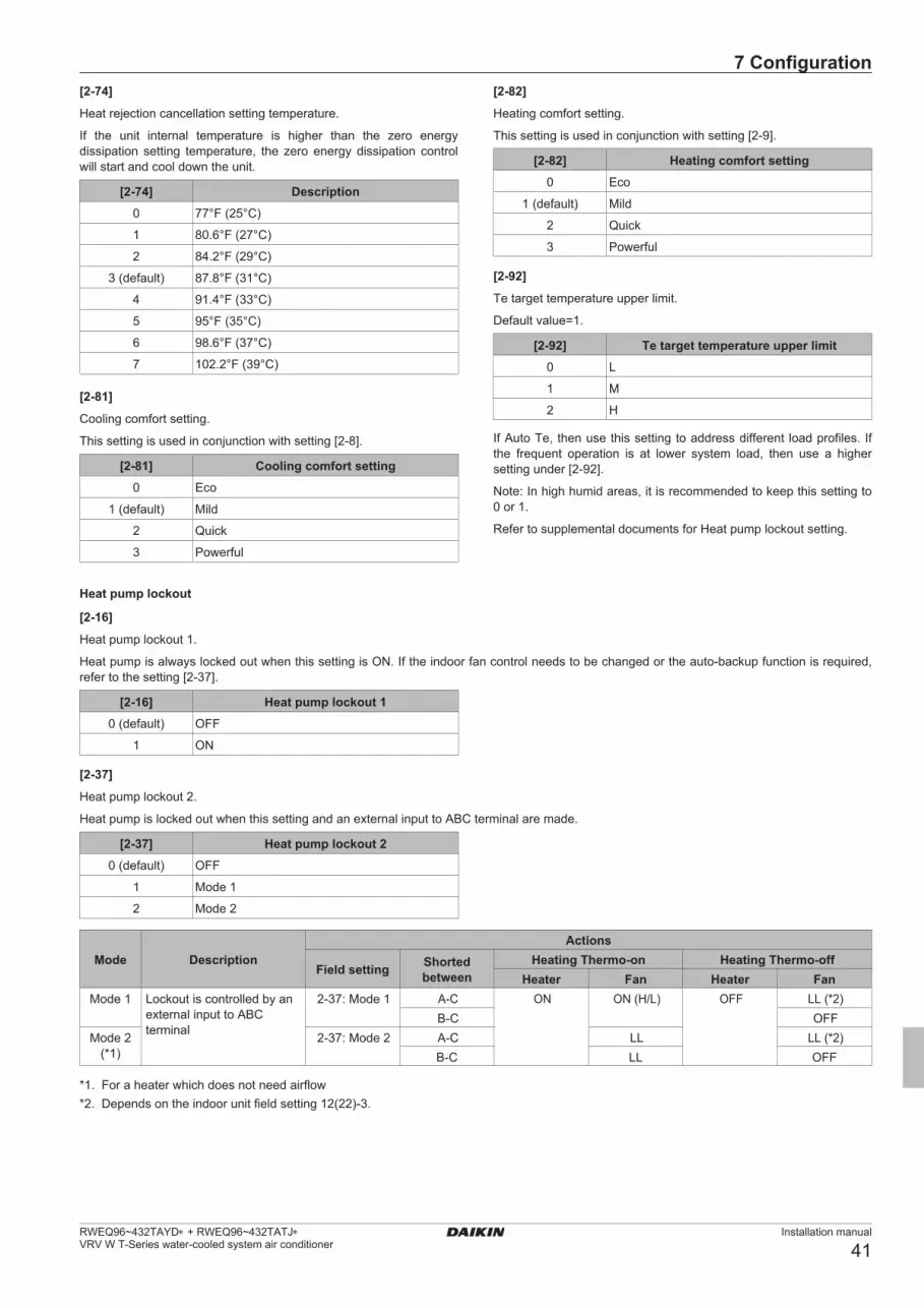
7 Configuration
Installation manual
41RWEQ96~432TAYD∗ + RWEQ96~432TATJ∗ VRV W T-Series water-cooled system air conditioner
Heat pump lockout
[2-16]Heat pump lockout 1.
Heat pump is always locked out when this setting is ON. If the indoor fan control needs to be changed or the auto-backup function is required, refer to the setting [2-37].
[2-16] Heat pump lockout 10 (default) OFF
1 ON
[2-37]Heat pump lockout 2.
Heat pump is locked out when this setting and an external input to ABC terminal are made.
[2-37] Heat pump lockout 20 (default) OFF
1 Mode 1
2 Mode 2
Mode DescriptionActions
Field setting Shorted between
Heating Thermo-on Heating Thermo-offHeater Fan Heater Fan
Mode 1 Lockoutiscontrolledbyanexternal input to ABC terminal
2-37: Mode 1 A-C ON ON(H/L) OFF LL(*2)B-C OFF
Mode 2 (*1)
2-37: Mode 2 A-C LL LL(*2)B-C LL OFF
*1. For a heater which does not need airflow*2. Depends on the indoor unit field setting 12(22)-3.
[2-74]Heat rejection cancellation setting temperature.
If the unit internal temperature is higher than the zero energy dissipation setting temperature, the zero energy dissipation control will start and cool down the unit.
[2-74] Description0 77°F (25°C)
1 80.6°F (27°C)
2 84.2°F (29°C)
3 (default) 87.8°F (31°C)
4 91.4°F (33°C)
5 95°F (35°C)
6 98.6°F (37°C)
7 102.2°F (39°C)
[2-81]Cooling comfort setting.
This setting is used in conjunction with setting [2-8].
[2-81] Cooling comfort setting0 Eco
1 (default) Mild
2 Quick
3 Powerful
[2-82]Heating comfort setting.
This setting is used in conjunction with setting [2-9].
[2-82] Heating comfort setting0 Eco
1 (default) Mild
2 Quick
3 Powerful
[2-92]Te target temperature upper limit.
Default value=1.
[2-92] Te target temperature upper limit0 L
1 M
2 H
If Auto Te, then use this setting to address different load profiles. If the frequent operation is at lower system load, then use a higher setting under [2-92].
Note: In high humid areas, it is recommended to keep this setting to 0 or 1.
Refer to supplemental documents for Heat pump lockout setting.
01_EN_4P602454-1C.indd 41 2020/07/29 16:16:51

8 Commissioning
Installation manual
42RWEQ96~432TAYD∗ + RWEQ96~432TATJ∗
VRV W T-Series water-cooled system air conditioner
Automatic lockoutWhen this setting is made, the auto-backup function will automatically be activated. This will allow the auxiliary or secondary heat source to be automatically activated in the event of a system failure related to outside units.
Error codes capable of auto-backup are listed in the table below. Please be aware that the error codes that are not listed do not auto-backup in order to protect the unit.
Error code (Auto backup possible) Error contents
A3 Drain level control system abnormality
E3 Actuation of high pressure switch
E4 Actuation of low pressure sensor
E5 Inverter compressor motor lock
E9 Electronic expansion valve coil abnormality
F3 Discharge pipe temperature abnormality
F9 Branch Selector unit electronic expansion valve abnormality
H9 Outside unit inside air thermistor (R1T) abnormality
HC Water inlet thermistor (R9T) abnormality
Water outlet thermistor (R10T) abnormality
J3 Discharge pipe thermistor (R12T) abnormalityCompressor body thermistor (R13T) abnormality
J4 Plate heat exchanger gas thermistor (R4T) abnormality
J5 Suction pipe thermistor (R3T) abnormality
J6 Plate heat exchanger liquid thermistor (R7T) abnormality
J7 Receiver outlet liquid pipe thermistor (R6T) abnormalitySubcooling heat exchanger outlet liquid pipe thermistor (R8T) abnormalityInjection pipe thermistor (R11T) abnormality
J9 Subcooling heat exchanger outlet gas pipe thermistor (R5T) abnormalityExhaust heat cancellation heat exchanger gas pipe thermistor (R2T) abnormality
JA High pressure sensor abnormality
JC Lowpressuresensorabnormality
L1 Inverter PCB abnormality
L3 Reactor temperature rise abnormality
L4 Inverter radiation fin temperature rise abnormality
L5 Inverter compressor instantaneous overcurrent
L8 Inverter compressor overcurrent
L9 Inverter compressor startup abnormality
LC Transmission error between inverter PCB and outside unit main PCB
7 .2 .9 To connect the PC configurator to the outside unit
X27A
a bc2
34
5
H JS
T
X27A
A1P
a PCb Cable (999482P3)c Outside unit main PCB
8 Commissioning
8 .1 Overview: CommissioningAfter installation and once the field settings are defined, the installer is obliged to verify correct operation. Therefore a test run must be performed according to the procedures described below.
This chapter describes what you have to do and know to commission the system after it is configured.
Commissioning typically consists of the following stages:1 Checking the "Checklist before commissioning".2 Performing a test run.3 If necessary, correcting errors after abnormal completion of the
test run.4 Operating the system.
8 .2 Precautions when commissioningDANGER: RISK OF ELECTROCUTION
DANGER: RISK OF BURNING
CAUTION Do not perform the test operation while working on the indoor units . When performing the test operation, not only the outside unit, but the connected indoor unit will operate as well. Working on an indoor unit while performing a test operation is dangerous.
CAUTION Do not insert fingers, rods or other objects into the air inlet or outlet. Do not remove the fan guard. When the fan is rotating at high speed, it will cause injury.
INFORMATION During the first running period of the unit, the required power may be higher than stated on the nameplate of the unit. This phenomenon is caused by the compressor, that needs a continuous run time of 50 hours before reaching smooth operation and stable power consumption.
01_EN_4P602454-1C.indd 42 2020/07/29 16:16:51

8 Commissioning
Installation manual
43RWEQ96~432TAYD∗ + RWEQ96~432TATJ∗ VRV W T-Series water-cooled system air conditioner
NOTE Be sure to turn on the power 6 hours before operation in order to have power running to the crankcase heater and to protect the compressor.
During test operation, the outside unit and the indoor units will start up. Make sure that the preparations of all indoor units are finished (field piping, electrical wiring, air purge, ...). See installation manual of the indoor units for details.
8 .3 Checklist before commissioning
After the installation of the unit, first check the following items. Once all below checks are fulfilled, the unit must be closed, only then can the unit be powered up.
You read the complete installation and operation instructions, as described in the installation manual.Installation
Check that the unit is properly installed, to avoid abnormal noises and vibrations when starting up the unit.
Field wiring
Be sure that the field wiring has been carried out according to the instructions described in the chapter "5.8 Connecting the electrical wiring" on page 31, according to the wiring diagrams and according to the applicable legislation.
Power supply voltage
Check the power supply voltage on the local supply panel. The voltage must correspond to the voltage on the nameplate of the unit.
Ground wiring
Be sure that the ground wires have been connected properly and that the ground terminals are tightened.
Insulation test of the main power circuit Using a megger tester for 500 V, check that the insulation resistance of 2MΩ or more is attained by applying avoltage of 500 V DC between power terminals and ground. Never use the megger tester for the transmission wiring.
Fuses, circuit breakers, or protection devices
Check that the fuses, circuit breakers, or the locally installed protection devices are of the size and type specified in the chapter "4.5.1 Safety device requirements" on page 19. Be sure that neither a fuse nor a protection device has been bypassed.
Internal wiring
Visually check the control box and the inside of the unit on loose connections or damaged electrical components.
Pipe size and pipe insulation
Be sure that correct pipe sizes are installed and that the insulation work is properly executed.
Stop valves
Be sure that the stop valves are open on both liquid and gas side.
Damaged equipment Check the inside of the unit on damaged components or squeezed pipes.
Refrigerant leak
Check the inside of the unit on refrigerant leakage. If there is a refrigerant leak, try to repair the leak. If the repair is unsuccessful, call your local dealer. Do not touch any refrigerant which has leaked out from refrigerant piping connections. This may result in frostbite.
Oil leak
Check the compressor for oil leakage. If there is an oil leak, try to repair the leak. If the repairing is unsuccessful, call your local dealer.
Air inlet/outlet Check that the air inlet and outlet of the unit is not obstructed by paper sheets, cardboard, or any other material.
Additional refrigerant charge
The amount of refrigerant to be added to the unit shall be written on the included "Added refrigerant" plate and attached to the rear side of the front cover.
Installation date and field setting
Be sure to keep record of the installation date on the sticker on the rear of the upper front panel and keep record of the contents of the field setting(s).
Inspect the water strainer at the inlet piping of the outside unit. Clean if it is dirty.
The piping work has been carried out according to this document and the applicable legislation. Make sure that following components are positioned at their correct places:
▪ waterstrainer,
▪ airpurgevalve,
▪ automaticwatersupplyvalve,and
▪ expansiontank.
Water circuitMake sure that the water circuit is filled.
Water flowMake sure that the calculated water flow rate can be reached.
Power supply voltage
Check the power supply voltage on the local supply panel. The voltage must correspond to the voltage on the nameplate of the unit.
8 .4 About test runThe procedure below describes the test operation of the complete system. This operation checks and judges following items:
▪ Check for incorrect wiring (communication check with indoorunits).
▪ Checkofthestopvalvesopening.
▪ Judgmentofpipinglength.
▪ Make sure to carry out the system test operation after the firstinstallation. Otherwise, the malfunction code will be displayed on the user interface and normal operation or individual indoor unit test run cannot be carried out.
▪ Abnormalities on indoor units cannot be checked for each unitseparately. After the test operation is finished, check the indoor units one by one by performing a normal operation using the user interface. Refer to the indoor unit installation manual for more details concerning the individual test run.
01_EN_4P602454-1C.indd 43 2020/07/29 16:16:52

9 Maintenance and service
Installation manual
44RWEQ96~432TAYD∗ + RWEQ96~432TATJ∗
VRV W T-Series water-cooled system air conditioner
INFORMATION ▪ Itmaytake10minutestoachieveauniformrefrigerant
state before the compressor starts.
▪ Duringthetestoperation,therefrigerantrunningsoundor the magnetic sound of a solenoid valve may become loud and the display indication may change. These are not malfunctions.
8 .5 To perform a test run1 Close all front panels in order to not let it be the cause of
misjudgment (except the control box inspection opening service cover).
2 Make sure all field settings you want are set; see "7.2 Making field settings" on page 36.
3 Turn ON the power to the outside unit and the connected indoor units.
NOTE Be sure to turn on the power 6 hours before operation in order to have power running to the crankcase heater and to protect the compressor.
4 Make sure the default (idle) situation is existing; see "7.2.4 To access mode 1 or 2" on page 36. Push BS2 for 5 seconds or more. The unit will start test operation.Result: The test operation is automatically carried out, the outside unit display will indicate " " and the indication "test operation" and "central control" will display on the user interface of indoor units.
Steps during the automatic system test run procedure:
Step Description
Control before start up (pressure equalization)
Cooling start up control
Cooling stable condition
Communication check, gas stop valve check
Liquidstopvalvecheck
Pipe length check
Discharge gas stop valve check
Pump down operation
Unit stop
Note: During the test operation, it is not possible to stop the unit operation from a user interface. To abort the operation, press BS3. The unit will stop after ±30 seconds.5 Check the test operation results on the outside unit 7-segment
display.
Completion DescriptionNormal completion No indication on the 7-segment display (idle).
Abnormal completion
Indication of malfunction code on the 7-segment display.Refer to "8.6 Correcting after abnormal completion of the test run" on page 44 to take actions for correcting the abnormality. When the test operation is fully completed, normal operation will be possible after 5 minutes.
8 .6 Correcting after abnormal completion of the test run
The test operation is only completed if there is no malfunction code displayed on the user interface or outside unit 7-segment display. In case of a displayed malfunction code, perform correcting actions as explained in the malfunction code table. Carry out the test operation again and confirm that the abnormality is properly corrected.
INFORMATION Refer to the installation manual of the indoor unit for detailed malfunction codes related to indoor units.
8 .7 Operating the unitOnce the unit is installed and test operation of outside unit and indoor units is finished, the operation of the system can start.For operating the indoor unit, the user interface of the indoor unit should be switched ON. Refer to the indoor unit operation manual for more details.
9 Maintenance and serviceNOTE Maintenance must be done by an authorized installer or service agent.We recommend to do maintenance at least once a year. However, applicable legislation might require shorter maintenance intervals.
9 .1 Overview: Maintenance and service
This chapter contains information about:
▪ Preventingelectricalhazardswhenmaintainingandservicingthesystem
▪ Cleaningtheplateheatexchanger
▪ Therefrigerantrecoveryoperation
9 .2 Maintenance safety precautionsDANGER: RISK OF ELECTROCUTION
DANGER: RISK OF BURNING
NOTE: Risk of electrostatic dischargeBefore performing any maintenance or service work, touch a metal part of the unit in order to eliminate static electricity and to protect the PCB.
9 .2 .1 To prevent electrical hazards
When performing service to inverter equipment:
1 Do not open the electrical component box cover for 10 minutes after the power supply is turned off.
2 Measure the voltage between terminals on the terminal block for power supply with a tester and confirm that the power supply is shut off. In addition, measure points as shown in the figure, with a tester and confirm that the voltage of the capacitor in the main circuit is less than 50 V DC.
01_EN_4P602454-1C.indd 44 2020/07/29 16:16:53

9 Maintenance and service
Installation manual
45RWEQ96~432TAYD∗ + RWEQ96~432TATJ∗ VRV W T-Series water-cooled system air conditioner
208/230 V
1
2
3
3
460 V
1
2
3
3
1 . Terminal block for power supply2 . Tester3 . Faston tab
3 To prevent damaging the PCB, touch a non-coated metal part to eliminate static electricity before pulling out or plugging in connectors.
9 .3 Maintenance of the plate heat exchanger
The performance of a plate heat exchanger may decline due to scale accumulation. It may be damaged by freezing due to the decrease in the flow rate. For this reason, it is necessary to carry out programmed maintenance at regular intervals in order to prevent scale.
9 .3 .1 Daily service and maintenance
1 Management of water qualityThe plate-type heat exchanger has a structure that does not permit dismantling and cleaning, or replacing any parts. Please pay attention carefully to the quality of water to be used for the plate-type heat exchanger in order to prevent corrosion and sticking of scale. The water to be used for the plate-type heat exchanger should have at least the quality as specified in the table of "4.4.1 Water quality requirements" on page 16. When using any corrosion prevention agent, scale depressant agent, etc., such agent should have no corrosive features against stainless steel and copper.
2 Management of condenser water flow rateIf the condenser water flow rate is not enough, it will result in freezing damage to the plate-type heat exchanger. Check for any clogging of the strainer, any air being caught, any reduction in the flow rate due to failure of the circulation pump by measuring the temperature and pressure differences at the inlet and outlet ports of the plate-type heat exchanger. If the aged difference in the temperature or pressure has increased beyond the proper range, the flow rate should have decreased. Stop the operation and remove the cause before restarting the operation.
3 Steps to be taken if a freeze-protection device is activatedIf the freeze-protection device is activated during operation, be sure to remove the cause before restarting the operation. If the freeze-protection device has been once activated, a partial freezing has already occurred. If you restart the operation without removing the cause, the plate-type heat exchanger will be closed and the ice cannot be melted, and in addition, the freezing process will be repeated, resulting in any damage to the plate-type heat exchanger, and this can lead to refrigerant leaking or water entering the refrigerant circuit.
9 .3 .2 Maintenance of plate-type heat exchanger
The performance of a plate-type heat exchanger may decline due to scale accumulation. It may be damaged by freezing due to the drop of flow rate. For this reason, it is necessary to carry out programmed maintenances at a regular interval in order to prevent the scale from being generated.
1 Before entering the season for use, carry out the following inspections:1) Conduct a water quality test and make sure that it is within
the standard.2) Clean the strainer.3) Make sure that the flow rate is correct.4) Make sure that the operational conditions (pressure, flow
rate, outlet temperature, etc.) are normal.
2 Because the plate-type heat exchanger has a structure which does not permit disassembling and cleaning, follow the following procedures for cleaning:1) For maintenance purposes it is required to provide for a
connection port on the water inlet and on the water outlet. You must connect a circulation pump in between these 2 connection ports when cleaning the plate-type heat exchanger with chemicals. For cleaning the scale in the plate-type heat exchanger it is recommended to use a solution with 5% diluted formic, citric, oxalic, acetic or phosphoric acid. Never use hydrochloric, sulfuric or nitric acid because such solutions have a strong corrosive feature.
2) Make sure to provide for a stop valve in front of that inlet water pipe connection port and for a stop valve after the outlet water pipe connection port.
01_EN_4P602454-1C.indd 45 2020/07/29 16:16:53

10 Troubleshooting
Installation manual
46RWEQ96~432TAYD∗ + RWEQ96~432TATJ∗
VRV W T-Series water-cooled system air conditioner
3) Connect the piping for circulation of cleaning chemicals to the inlet and outlet piping of plate-type heat exchanger. Fill the cleaning solution of 122-144°F (50-62°C) for a while in the plate-type heat exchanger. Then, circulate the cleaning solution by a pump for 2-5 hours. The time for cleaning depends on the temperature of cleaning solution or the degree of scale accumulation. Therefore, please watch the change of the dirtiness (color) of cleaning solution to determine the level of removal of scale.
4) After circulating the cleaning solution, discharge the solution from the plate-type heat exchanger, fill the heat exchanger with a solution of 1-2% sodium hydroxide (NaOH) or sodium bicarbonate (NaHCO3). Circulate this solution for 15-20 minutes for neutralization purpose.
5) After the process of neutralization has been completed, rinse the inner part of the plate-type heat exchanger with care using fresh and clean water.
6) When using any cleaning agent sold in the market, check in advance that such agent has no corrosive features against stainless steel and copper.
7) For details of cleaning method, ask the manufacturer of related cleaning agent.
3 After cleaning has been completed, make sure that the unit can be operated in a normal fashion.
9 .4 About service mode operation
Refrigerant recovery operation/vacuuming operation is possible by applying setting [2-21]. Refer to "7.2 Making field settings" on page 36 for details how to set mode 2.
When vacuuming/recovery mode is used, check very carefully what should be vacuumed/recovered before starting. See installation manual of the indoor unit for more information about vacuuming and recovery.
9 .4 .1 To use vacuum mode
1 When the unit is at standstill, set the unit in [2-21]=1.Result: When confirmed, the indoor and outside unit expansion valves will fully open. At that moment the 7-segment display indication= and the user interface of all indoor units indicate “test operation”) and “central control” and the operation will be prohibited.
2 Evacuate the system with a vacuum pump.
3 Press BS3 to stop vacuuming mode.
9 .4 .2 To recover refrigerant
This should be done by a refrigerant reclaimer. Follow the same procedure as for vacuuming method.
DANGER: RISK OF EXPLOSION Pump down – Refrigerant leakage . If you want to pump down the system, and there is a leakage in the refrigerant circuit:
▪ DoNOTusetheunit'sautomaticpumpdownfunction,with which you can collect all refrigerant from the system into the outside unit. Possible consequence: Self-combustion and explosion of the compressor because of air going into the operating compressor.
▪ Use a separate recovery system so that the unit'scompressor does NOT have to operate.
NOTE Make sure to NOT recover any oil while recovering refrigerant. Example: By using an oil separator.
10 Troubleshooting
10 .1 Overview: Troubleshooting
This chapter describes what you have to do in case of problems.
It contains information about:
▪ Solvingproblemsbasedonerrorcodes
10 .2 Solving problems based on error codes
In case of a displayed malfunction code, perform correcting actions as explained in the malfunction code table.
After correcting the abnormality, press BS3 to reset the malfunction code and retry operation.
The malfunction code which is displayed on the outside unit will indicate a main malfunction code and a sub code. The sub code indicates more detailed information about the malfunction code. The malfunction code will be displayed intermittent.
Example:
Code ExampleMain code
Sub code
With an interval of 1 second, the display will switch between main code and sub code.
01_EN_4P602454-1C.indd 46 2020/07/29 16:16:54

10 Troubleshooting
Installation manual
47RWEQ96~432TAYD∗ + RWEQ96~432TATJ∗ VRV W T-Series water-cooled system air conditioner
10 .3 Error codes: OverviewMalfunction code
Contents SolutionMain code
Sub code Master/sub 1/sub 2
E3 01/03/05 ▪ Highpressureswitchisactivated. (S1PH)-A1P (X3A)
▪ Highpressureswitchconnectorsaredetached. -A1P (X3A)
▪ Checkstopvalvessituationorabnormalitiesin(field) piping or waterflow.
▪ Securely connect each connector. Refer to the wiring diagram attached to the back of the control box cover.
02/04/06 ▪ Stopvalvesareclosed.▪ Refrigerantovercharge.
▪ Openstopvalves.▪ Checkrefrigerantamountandrecharge.
E4 01/02/03 Lowpressuremalfunction:▪ Stopvalvesareclosed.▪ Refrigerantshortage.▪ Indoorunitmalfunction
▪ Openstopvalves.▪ Checkrefrigerantamountandrecharge.▪ Check the user interface’s display or transmission
wiring between the outside unit and the indoor unit.
E9 01/05/08 Electronic expansion valve malfunction (Y1E)-A1P (X21A)
Check connection on printed circuit board or actuator.
03/06/09 Electronic expansion valve malfunction (Y2E)-A1P (X22A)
Check connection on printed circuit board or actuator.
04/07/10 Electronic expansion valve malfunction (Y3E)-A1P (X25A)
Check connection on printed circuit board or actuator.
F3 01/03/05 Discharge temperature too high (R12T):▪ Stopvalvesareclosed.▪ Refrigerant shortage.
▪ Open stop valves.▪ Check refrigerant amount and recharge.
20/21/22 Compressor casing temperature too high (R13T): ▪ Stop valves are closed.▪ Refrigerant shortage.
▪ Open stop valves.▪ Check refrigerant amount and recharge.
F6 02 ▪ Stop valves are closed.▪ Refrigerant overcharge.
▪ Open stop valves.▪ Check refrigerant amount and recharge.
H9 01/02/03 Temperature sensor malfunction (R1T)-A4P (X11A)
Check connection on printed circuit board or actuator.
HJ 01/02/03 Water system malfunction ▪ Checkwaterpumpandwaterflow.▪ Checkflowswitchinterlockconnection(X2M
terminals 5, 6).
J3 16/22/2817/23/2956/57/58
Temperature sensor malfunction (R12T)-A1P (X19A)
Check connection on printed circuit board or actuator.
47/49/5148/50/52
Temperature sensor malfunction (R13T)-A1P (X19A)
Check connection on printed circuit board or actuator.
J5 01/03/05 Temperature sensor malfunction (R3T)-A1P (X30A)
Check connection on printed circuit board or actuator.
J6 01/02/03 Temperature sensor malfunction (R7T)-A1P (X30A)
Check connection on printed circuit board or actuator.
J7 01/02/03 Temperature sensor malfunction (R6T)-A1P (X30A)
Check connection on printed circuit board or actuator.
06/07/08 Temperature sensor malfunction (R8T)-A1P (X29A)
Check connection on printed circuit board or actuator.
18/19/20 Temperature sensor malfunction (R11T)-A1P (X18A)
Check connection on printed circuit board or actuator.
J9 01/02/03 Temperature sensor malfunction (R5T)-A1P (X30A)
Check connection on printed circuit board or actuator.
17/18/19 Temperature sensor malfunction (R2T)-A4P (X12A)
Check connection on printed circuit board or actuator.
JA 01/02/03 High pressure sensor malfunction (S1NPH)-A1P (X32A)
Check connection on printed circuit board or actuator.
JC 01/02/03 Lowpressuresensormalfunction (S1NPL)-A1P(X31A)
Check connection on printed circuit board or actuator.
LC 01/06/08 Transmission trouble. A3P (X6A)-A1P (X28A)
Check connection.
P1 01/02/03 Unbalanced power supply voltage. Check if power supply is within the range.
U1 01/05/07 No power supplied to outside unit or indoor unit (Reverse phase/open phase).
Check if the power supply wiring for the outside unit or indoor unit is correctly connected, and correct if necessary.
01_EN_4P602454-1C.indd 47 2020/07/29 16:16:54

10 Troubleshooting
Installation manual
48RWEQ96~432TAYD∗ + RWEQ96~432TATJ∗
VRV W T-Series water-cooled system air conditioner
Malfunction codeContents SolutionMain
codeSub code
Master/sub 1/sub 2
U2 01/08/11 Voltage power shortage. ▪ Checkifpowersupplyiswithintherange.▪ Correctphaseorder.
02/09/12 Reversed or open power supply phase. ▪ Checkifpowersupplyiswithintherange.▪ Correctphaseorder.
U3 01 System test run not yet executed (system operation not possible).
Execute system test run.
05 Test run aborted. Re-execute the test run.0607 Test run aborted due to communication issues. Check the communication wires and re-execute the
test run.08
U4 01 Faulty wiring to Q1/Q2 or indoor- outside. Connect transmission wiring of indoor units to “TO IN/D UNIT (F1, F2)” and transmission wiring of other outside units to “TO OUT/D UNIT (F1, F2)”.
03 Malfunction of connected indoor unit. Check the malfunction code of indoor unit and resolve it.
U7 01 Faulty wiring to Q1/Q2 or indoor- outside. Connect transmission wiring of indoor units to “TO IN/D UNIT (F1, F2)” and transmission wiring of other outside units to “TO OUT/D UNIT (F1, F2)”.
0203
U9 01 ▪ Systemmismatch.Wrongtypeofindoorunitscombined (R407C, Mini-split, etc).
▪ Indoorunitmalfunction.
Check if other indoor units have malfunction and confirm indoor unit mix is allowed.
UA 18 Connection malfunction over indoor units or type mismatch (R407C, Mini-split, etc).
Check if other indoor units have malfunction and confirm indoor unit mix is allowed.
20 Wrong combination of outside units (different series (e.g. RWEQ and RWEYQ), or different type (e.g. P type and T type)).
Correct the units combination.
27 Assembly defect of indoor and outside units (e.g. different models, number of units or part numbers, or different series are mixed).
▪ Checkandmodifythenumberofindoorunitsthatare connected.
▪ Checkthetypeofrefrigerantforindoorandoutsideunits, and replace them with adaptable indoor/outside units in the case of inconsistency.
UH 01 Auto address malfunction (inconsistency) Check if transmission wired unit amount matches with powered unit amount (by monitor mode) or wait till initialization is finished.
UF 01 ▪ Autoaddressmalfunction(inconsistency)▪ Stop valves closed.
▪ Check if transmission wired unit amount matches with powered unit amount (by monitor mode) or wait till initialization is finished.
▪ Open stop valves.
Refer to service manual for full list of error codes.
01_EN_4P602454-1C.indd 48 2020/07/29 16:16:54

11 Technical data
Installation manual
49RWEQ96~432TAYD∗ + RWEQ96~432TATJ∗ VRV W T-Series water-cooled system air conditioner
11 Technical data
11 .1 Overview: Technical dataThis chapter contains information about:
▪ Servicespace▪ Pipingdiagram▪ Wiringdiagram
11 .2 Service space: Outside unit
Make sure the space around the unit is adequate for servicing and the minimum space for ventilation is available (refer to the figure below).
a a
bb
bb
(*1)
cc
bb
F
d (*2)
a ≥19-11/16inch(500mm)b ≥13/16inch(20mm)c ≥35-7/16inch(900mm)d ≥11-13/16inch(300mm)
F Front side
*1 This ventilation space is necessary when heat rejection cancellation is not active.
*2 This space is necessary when refrigerant piping is connected to the top of the unit.
INFORMATION Further specifications can be found in the technical engineering data.
01_EN_4P602454-1C.indd 49 2020/07/29 16:16:54

11 Technical data
Installation manual
50RWEQ96~432TAYD∗ + RWEQ96~432TATJ∗
VRV W T-Series water-cooled system air conditioner
11 .3 Piping diagram: Outside unit
A
C
D
BBB
SV
SV
SV
M
SV
SV
HPS
SV
SV
SENPH
SENPL
4D108945C
A Charge portB Stop valve (with service port Ø0.32 inch flare
connection)C Cooling water inletD Cooling water outlet
Charge port / Service port
Filter
Check valve
Pressure relief valve
Solenoid valve
Capillary tube
Electronic expansion valve
4-way valve
Propeller fan
Port (for sensor)Low/highpressuresensor
High pressure switch
Oil separator
Accumulator
Compressor
Double tube heat exchanger / Plate heat exchanger
Liquidreceiver
Thermistor
01_EN_4P602454-1C.indd 50 2020/07/29 16:16:55

11 Technical data
Installation manual
51RWEQ96~432TAYD∗ + RWEQ96~432TATJ∗ VRV W T-Series water-cooled system air conditioner
11 .4 Wiring diagram: Outside unitThe wiring diagram is delivered with the unit, located at the inside of the service cover.RWEQ96~432TATJ∗ (208/230 V)
L1RL2R
R14T L1B L2B L3B
A2P
A4P
A3P
A1P
A9P
2X71A
1P22 P21 P11 L1B L2B L3B
R1123
12
21X72A
X6A
X63A
X1A
K84R
V1DK1MVU
W
V1R SHT1C1
X4AX41A
V2R
L1A L2A L3AF4UF5U
E1
F2U
R403
V
U
R402
V
U
R401
V
U
F1U F1S
X3M X3M X3M X3M
K1R K2R K3R K4R K5R K6RK7R
K8R1 2 1 2 1 21 2 3 4 1 2 3 41 2
X4A X7A X8AX5A X23AX3A
X12A
X11A
12
12
X16A21 F1U
Z1F1 2 3 4
X15A
X10A
12
21
1 2 3 4 651 2 3 4 65 651 2 3 4 211 2 3 4 1 2 3 4X25AX21A X22A X3AX31A X32A
12
12
56
34
12
12
13
12
12
12
31
12
X7A
X19A
X8A
X9A
X12A
X13A
X15A
X16A
X11A
X17A
Y4S
Y8S
Y1S
Y2S
Y3S
Y5S
Y6S
Y7S
R12T
R13T
-t°
-t°
1 2 53 4 1 2 5 6 7 8 9 103 41 2 5 63 4 1 2 31 2 1 2 53 4 6
1 2 3 4 51 2 3 4 5 1 2 3 4 5
Y3EY1E Y2E MMM1~
M1~
M1~ M S1NPL S1NPH S1PH
P>
OFFON
OFFON
1 2 3 4 1 2 3 4
HAP
K12R
K3R
K4R
K5R
K8R
K9R
K11R
K7R
K13R
BS1 BS2 BS3SEG 1 SEG2 SEG3
321
21
21
21
X28A
X40A
X4A
X2A
123
654
X1A
F1U
F2U
F2F1F2F1 Q1Q242 31 X36AX1M(Note 2)
X66AX101A
X23A X30AX29A X18A
-t° -t° -t°-t° -t°-t°-t°-t° -t°R8TR9T R10T R3T R5T R6TR4TR11T R7T
R15T
3~ 60 Hz208/230 V
PEL1 L2 L3
S1S
S2S
5 6
1 2
1 2 3
1 2 3X2M(Note 2)
X1A
X2M(Note 2)
Z1FQ1RP
A8PX2A
S3S
T1AN=1
L1L2L3
X1M
PE
-t°
-t°
R1T
R2T
M1C MS3~
1 21 2
-t°
PS
K3R
M2FM1F M3F
DS1 DS2
E1HC
7 8 9 10
42 31
X1M (Note 2)
X1A
CBA
X2M(Note 2)
X20A
X37A
21
21
PS
Q1DI
1 2 3 4 5 6 7 8 9 10
Z1F
Y9S
-t°
ABC
Power supply water controloutput
Powersupply
12 V DC
Cool
HeatAircontrolFan
Cool/heat selector
Control box
a b c d e
A1P Main PCBA2P Noise filter PCBA3P Inverter PCBA4P SUB PCBA8P Adapter PCBA9P * Cool/heat selector PCBBS* (A1P) Push buttons (mode, set, return)C* (A3P) CapacitorDS* (A1P) DIP switchE1HC Crankcase heaterF1S (A1P) Surge arrestorF1U (A4P) FuseF*U (A2P) FuseF4U (A2P) FuseF5U (A2P) FuseF*U (A1P) FuseHAP (A1P) RunningLED(servicemonitor–green)K1M (A3P) Magnetic contactorK*R (A*P) Magnetic relayL*R ReactorM1C Motor (compressor)M*F Motor (fan)PS (A1P) Power supplyQ1DI # Ground circuit breakerQ1RP (A1P) Phase reversal detect circuitR1 (A3P) ResistorR*T ThermistorR*V (A2P) VaristorSHT1 (A3P) Shunt (current sensor)S1NPH High pressure sensorS1NPL Lowpressuresensor
S1PH High pressure switch (discharge)S1S Air control switchS2S Cool/heat switchS3S Interlock switchSEG* (A1P) 7-segment displayT1A LeakagecurrentdetectionsensorV1D (A3P) DiodeV1R (A3P) IGBT power moduleV2R (A3P) Diode moduleX66A Connector (remote switching cool/heat selector)X*A PCB connectorX*M Terminal blockX*M (A*P) Terminal block on PCBX*Y ConnectorY*E Electronic expansion valveY*S Solenoid valveZ*C Noise filter (ferrite core)Z*F Noise filter
* Optional# Field supplya Error on remote controllerb Compressor operationc Heating operationd Cooling operatione Water pump operation request
Notes)1. : Field wiring, : Terminal block, : Connector,
: Terminal, : Protective earth (screw), : Noiseless earth.2. Class 2 wire
01_EN_4P602454-1C.indd 51 2020/07/29 16:16:55

11 Technical data
Installation manual
52RWEQ96~432TAYD∗ + RWEQ96~432TATJ∗
VRV W T-Series water-cooled system air conditioner
RWEQ96~432TAYD∗ (460 V)
3~ 60 Hz460 V
PEL1 L2 L3
Q1DI
T1AN=1
OFFON
OFFON
S1S
S2S
PE
X1M
X101AX66A X1M
(Note 2)1 42 3 1 2 53 4X36AF2F1F2F1 Q1Q2 X30AX29A X18AX23A
1 2 53 4 61 2 1 2 5 6 7 8 9 103 41 2 5 63 4 1 2 3
X1A F1UF2U Q1RP
Z1F12
12
56
34
12
12
13
12
12
12
31
12
X7A
X19A
X8A
X9A
X12A
X13A
X16A
X11A
X17AK12R
K3R
K4R
K5R
K8R
K9R
K11R
K7R
K13R
1 2 3 654
Y4S
E1HC
Y8S
Y1S
Y2S
Y3S
Y5S
Y6S
Y7S
1 2 3 4 651 2 3 4 65 651 2 3 4 211 2 3 4 1 2 3 4X25AX21A X22A X3AX31A X32AX20A
21
1 2 3 4 5 1 2 3 4 5 1 2 3 4 5
Y3EY1E Y2E MM M S1PHS1NPL S1NPHP>
R12T
R13T
A3P
A1P
A4P
A2P
A5P
A6P
A7P
A8P
A9P
X28A
X40A
X4A
X37A
X2A
321
21
21
21
21
1 2 3 4 1 2 3 4
BS1 BS2 BS3
SEG 1 SEG2 SEG3
R3T R5T R7TR6TR4T-t° -t° -t°-t°-t°
-t°
-t°
T2SR 2
3
T1R X2YX1Y
1 2 3 4 5 6 7 8 9 10X3M X3M X3M
M1C
R1T
R2T
-t°
-t°
M1~
M1~M2FM1F
X4A X7A X8AX5A X23AX3A1 2 1 2 1 2 1 2 3 41 2
1 21 2 3 4
K1R K2R K3R K4R K5R K6R K7R K8R X15A 21X10A
1 2 3 4 21X1A X14A
HAP
X12A
X11A
12
12
X16A F1U21
1 2 1 2X4A X41A
V2R
K1ML1R
L2RVU
W
P11P21
L12
L11L31L32
122
1X2AX1A
R2R3R77
C32C66
L1L2L3
L1A L2A L3A
F403
U
F401
U
F410
U
F412
UR4
02V
R401
V
U
R400
V
U
R403
V
U
F1SX3Y
L1A L2A L3A
1 2 1 2L1B L2B L3BEZ1F
R1V
F1U
R3V
F2U
R2V
L1B L2B L3B3121 2
12
123X63A
X6AX602AX601A
X2AX1AX2M(Note 2)
1 21 2
35 6
1 2 3X2M(Note 2)
X2M(Note 2)
7 8 9 10
R8TR9T R10TS3S
R11T -t°42 31
X1A
X1M (Note 2)CBAA
BC -t°-t° -t°
Z1FPS
Z1F
X3A X1A
12
F1S
K1R
X2A
X3M
MS3~
V1R
Y9S
X15A
DS1 DS2
U UU
E
U
Cool
HeatAircontrol
Cool/heat selector
Control box
Fan
Power supply water controloutput
Powersupply
12 V DC
output 230 V
a b c d e
A1P Main PCBA2P Noise filter PCBA3P Inverter PCBA4P SUB PCBA5P Filter PCBA6P Reverse phase protection PCBA7P Current limiting detection PCBA8P Adapter PCBA9P * Cool/heat selector PCBBS* (A1P) Push buttons (mode, set, return)C* (A3P) CapacitorDS* (A1P) DIP switchE1HC Crankcase heaterF1S (A2PA5P) Surge arrestorF1U (A4P) FuseF401U (A2P) FuseF403U (A2P) FuseF410U (A2P) FuseF412U (A2P) FuseF*U (A1P) FuseHAP (A1P) RunningLED(servicemonitor–green)K1M (A3P) Magnetic contactorK*R (A*P) Magnetic relayL*R ReactorM1C Motor (compressor)M*F Motor (fan)PS (A1P) Power supplyQ1DI # Ground circuit breakerQ1RP (A1P) Phase reversal detect circuitR*T ThermistorR*V (A5P) VaristorR* (A3P) ResistorS1NPH High pressure sensor
S1NPL LowpressuresensorS1PH High pressure switch (discharge)S1S Air control switchS2S Cool/heat switchS3S Interlock switchSEG1 SEG3 7-segment displayT1A LeakagecurrentdetectionsensorV1R (A3P) IGBT power moduleV2R (A3P) Diode moduleX66A Connector (remote switching cool/heat
selector)X*A PCB connectorX*M Terminal blockX*M (A*P) Terminal block on PCBX*Y ConnectorY*E Electronic expansion valveY*S Solenoid valveZ*C Noise filter (ferrite core)Z*F Noise filter
* Optional# Field supplya Error on remote controllerb Compressor operationc Heating operationd Cooling operatione Water pump operation request
Notes)1. : Field wiring, : Terminal block, : Connector,
: Terminal, : Protective ground (screw), : Noiseless ground.
2. Class 2 wire
01_EN_4P602454-1C.indd 52 2020/07/29 16:16:56

4P602454-1C 2020.08
Daikin Texas Technology Park, 19001 Kermier Road, Waller, TX, 77484, U.S.A.
00_CV_4P602454-1C.indd 2 2020/07/30 14:32:15