Service Manual - Daikin AC KSA
213
Service Manual RZF-A Series Cooling Only 50/60 Hz SiME281906E
-
Upload
khangminh22 -
Category
Documents
-
view
0 -
download
0
Transcript of Service Manual - Daikin AC KSA

ServiceManual
RZF-A SeriesCooling Only 50/60 Hz
SiME281906E

SiME281906E
Introduction ....................................................................................11. Safety Cautions.......................................................................................2
1.1 Warnings and Cautions Regarding Safety of Workers.............................21.2 Warnings and Cautions Regarding Safety of Users.................................8
2. Icons Used ............................................................................................103. Revision History ....................................................................................11
Part 1 General Information ..........................................................121. Model Names and Power Supply..........................................................132. External Appearance.............................................................................143. Functions...............................................................................................154. Specifications ........................................................................................16
Part 2 Refrigerant Circuit.............................................................181. Refrigerant Circuit (Piping Diagrams) ...................................................19
1.1 18/24 Class ............................................................................................191.2 30/36 Class ............................................................................................21
2. Functional Parts Layout ........................................................................232.1 18/24 Class ............................................................................................232.2 30/36 Class ............................................................................................24
Part 3 Remote Controller .............................................................251. Applicable Models .................................................................................26
1.1 Wired Remote Controller........................................................................261.2 Wireless Remote Controller ...................................................................26
2. Names and Functions ...........................................................................272.1 BRC1E62 ...............................................................................................272.2 BRC1E63 ...............................................................................................292.3 BRC1H81 Series ....................................................................................312.4 BRC4C Series ........................................................................................33
3. Main/Sub Setting...................................................................................343.1 Wired Remote Controller (BRC1E62, BRC1E63) ..................................343.2 Wired Remote Controller (BRC1H81 Series) .........................................353.3 When Wireless Remote Controller is Used Together.............................363.4 Address Setting for Wireless Remote Controller....................................37
4. Centralized Control Group No. Setting..................................................404.1 BRC1E62, BRC1E63 .............................................................................404.2 BRC1H81 Series ....................................................................................41
5. Service Settings Menu, Maintenance Menu..........................................425.1 BRC1E62, BRC1E63 .............................................................................425.2 BRC1H81 Series ....................................................................................46
Part 4 Functions and Control .......................................................471. Function Outline ....................................................................................48
1.1 Indoor Unit..............................................................................................481.2 Outdoor Unit ...........................................................................................49
i Table of Contents

SiME281906E
2. Operation Flowchart..............................................................................502.1 Cooling/Dry Operation............................................................................50
3. Indoor Unit Functions ............................................................................513.1 Set Temperature and Control Target Temperature................................513.2 Thermostat Control.................................................................................513.3 Automatic Airflow Rate Control ..............................................................523.4 Drain Pump Control................................................................................523.5 Freeze-Up Prevention Control................................................................523.6 Automatic Restart...................................................................................533.7 Monitoring Control ..................................................................................53
4. Outdoor Unit Control .............................................................................544.1 Overview of Outdoor Unit Controls.........................................................544.2 Abnormal Stop........................................................................................554.3 Restart Standby......................................................................................554.4 Preheating Control on Standby ..............................................................564.5 Startup Control .......................................................................................564.6 Room Temperature Thermostat Control ................................................574.7 Starting Frequency Control ....................................................................574.8 Compressor Step Control.......................................................................584.9 Outdoor Fan Speed Control ...................................................................594.10 Low Noise Control ..................................................................................604.11 Low Pressure Protection Control............................................................604.12 High Pressure Protection Control...........................................................614.13 Discharge Pipe Temperature Control.....................................................624.14 Capacitor Electrical Discharge Control...................................................634.15 Inverter Current Protection Control ........................................................634.16 Forced Thermostat OFF.........................................................................634.17 Cooling Control with Low Outdoor Air Temperature...............................634.18 Overall Current Protection Control .........................................................644.19 Refrigerant Shortage Detection Control .................................................644.20 Piping/Wiring Mismatch Detection Control .............................................644.21 Pump Down Operation ...........................................................................654.22 Oil Return Control...................................................................................654.23 Emergency Operation ............................................................................654.24 Simulated Operation Function................................................................664.25 Test Operation Control ...........................................................................66
Part 5 Field Settings and Test Operation ....................................671. Field Settings with Remote Controller...................................................68
1.1 BRC1E62, BRC1E63 .............................................................................681.2 BRC1H81 Series ....................................................................................701.3 BRC4C Series ........................................................................................711.4 List of Field Settings for Indoor Unit .......................................................721.5 Details of Field Settings for Indoor Unit..................................................741.6 List of Field Settings for Outdoor Unit ....................................................79
2. Field Settings from Demand Adaptor (For 30/36 Class) .......................802.1 i-Demand Function .................................................................................80
3. Field Settings from Outdoor Unit PCB (For 30/36 Class)......................813.1 Setting by BS Buttons ............................................................................813.2 Normal Mode..........................................................................................833.3 Monitor Mode (Mode 1) ..........................................................................84
Table of Contents ii

SiME281906E
3.4 Setting Mode (Mode 2)...........................................................................87
4. Emergency Operation ...........................................................................894.1 Forced Operation ...................................................................................904.2 Emergency Operation when the Remote Controller is Lost ...................91
5. Test Operation ......................................................................................925.1 Checks before Test Operation ...............................................................925.2 Test Operation........................................................................................92
Part 6 Service Diagnosis ..............................................................941. Maintenance Inspection ........................................................................96
1.1 Overview ................................................................................................961.2 Refrigerant Characteristics (R-32)..........................................................991.3 Refrigerant Recovery Method ..............................................................100
2. Symptom-Based Troubleshooting.......................................................1022.1 All Indoor Units .....................................................................................1022.2 Safety Devices .....................................................................................1032.3 Equipment does not operate. ...............................................................1042.4 Indoor fan operates, but compressor does not operate. ......................1062.5 Cooling operation starts but stops immediately....................................1072.6 After unit shuts down, it cannot be restarted for a while.......................1082.7 Equipment operates but does not provide cooling. ..............................1102.8 Equipment discharges white mist.........................................................1122.9 Equipment produces loud noise or vibration. .......................................1132.10 Equipment discharges dust. .................................................................1152.11 Defrost lamp on the receiver for wireless remote controller is
blinking. ................................................................................................116
3. Troubleshooting with LED Indications.................................................1173.1 Indoor Unit............................................................................................1173.2 Outdoor Unit .........................................................................................117
4. Troubleshooting with Remote Controller.............................................1204.1 BRC1E62, BRC1E63 ...........................................................................1204.2 BRC1H81 Series ..................................................................................1214.3 BRC4C Series ......................................................................................122
5. Troubleshooting by Error Code ...........................................................1245.1 Error Codes and Descriptions ..............................................................1245.2 Error Codes - Sub Codes .....................................................................1255.3 Error of External Protection Device ......................................................1295.4 Indoor Unit PCB Abnormality ...............................................................1305.5 Drain Water Level System Abnormality................................................1315.6 Indoor Fan Motor Abnormality..............................................................1325.7 Fan PCB Abnormality...........................................................................1345.8 Humidifier System Abnormality ............................................................1355.9 Defective Capacity Setting ...................................................................1365.10 Transmission Error (between Indoor Unit PCB and Fan PCB) ............1375.11 Thermistor Abnormality ........................................................................1395.12 Combination Error between Indoor Unit PCB and Fan PCB ................1405.13 Remote Controller Thermistor Abnormality ..........................................1415.14 Outdoor Unit PCB Abnormality.............................................................1425.15 High Pressure Abnormality...................................................................1435.16 Low Pressure Abnormality ...................................................................1455.17 Compressor Motor Lock .......................................................................146
iii Table of Contents
SiME281906E
5.18 Outdoor Fan Motor Abnormality ...........................................................1475.19 Electronic Expansion Valve Abnormality..............................................1505.20 Discharge Pipe Temperature Abnormality ...........................................1535.21 High Pressure Switch System Abnormality ..........................................1555.22 Compressor Self-Operating Thermal Protector....................................1565.23 Thermistor System Abnormality ...........................................................1575.24 Outdoor Unit PCB Abnormality.............................................................1585.25 Radiation Fin Temperature Rise ..........................................................1615.26 DC Output Overcurrent ........................................................................1625.27 Compressor Overcurrent......................................................................1645.28 Compressor Startup Abnormality .........................................................1665.29 Transmission Error between Microcomputers
on Outdoor Unit Main PCB...................................................................1685.30 PAM Circuit Error .................................................................................1695.31 Open Phase or Power Supply Voltage Imbalance ...............................1705.32 Power Module Thermistor Abnormality ................................................1715.33 Capacity Setting Abnormality ...............................................................1725.34 Refrigerant Shortage (Warning/Alarm).................................................1735.35 Refrigerant Shortage (Error).................................................................1745.36 Power Supply Voltage Abnormality ......................................................1765.37 Transmission Error between Indoor Unit and Outdoor Unit,
Outdoor Fan Motor Abnormality ...........................................................1795.38 Transmission Error between Indoor Unit and Remote Controller.........1845.39 Transmission Error between Main Remote Controller and
Sub Remote Controller.........................................................................1855.40 Field Setting Switch Abnormality..........................................................1865.41 Centralized Address Setting Error........................................................1885.42 Transmission Error between Centralized Controller and Indoor Unit ...1895.43 Transmission Error between Indoor Unit and Outdoor Unit .................191
6. Check ..................................................................................................1926.1 Thermistor Check .................................................................................1926.2 High Pressure Check ...........................................................................1956.3 Low Pressure Check ............................................................................1956.4 Power Transistor Check .......................................................................1966.5 Fan Motor Connector Check ................................................................1986.6 Electronic Expansion Valve Check.......................................................1996.7 Wet Operation Check ...........................................................................2006.8 Clogged Points Check..........................................................................2016.9 Refrigerant Shortage Check.................................................................2026.10 Refrigerant Overcharge Check.............................................................203
Part 7 Appendix ..........................................................................2041. Wiring Diagrams..................................................................................205
1.1 Indoor Unit............................................................................................2051.2 Outdoor Unit .........................................................................................206
Table of Contents iv

SiME281906E
1 Introduction
1. Safety Cautions.......................................................................................21.1 Warnings and Cautions Regarding Safety of Workers.............................21.2 Warnings and Cautions Regarding Safety of Users.................................8
2. Icons Used ............................................................................................103. Revision History ....................................................................................11
Introduction
SiME281906E Safety Cautions
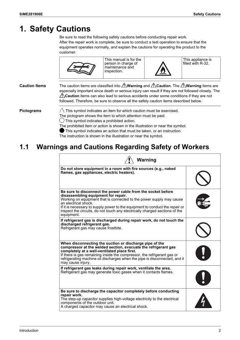
1. Safety CautionsBe sure to read the following safety cautions before conducting repair work.After the repair work is complete, be sure to conduct a test operation to ensure that the equipment operates normally, and explain the cautions for operating the product to the customer.
Caution Items The caution items are classified into Warning and Caution. The Warning items are especially important since death or serious injury can result if they are not followed closely. The
Caution items can also lead to serious accidents under some conditions if they are not followed. Therefore, be sure to observe all the safety caution items described below.
Pictograms This symbol indicates an item for which caution must be exercised.The pictogram shows the item to which attention must be paid.
This symbol indicates a prohibited action.The prohibited item or action is shown in the illustration or near the symbol.
This symbol indicates an action that must be taken, or an instruction.The instruction is shown in the illustration or near the symbol.
1.1 Warnings and Cautions Regarding Safety of Workers
This manual is for the person in charge of maintenance and inspection.
This appliance is filled with R-32.
Warning
Do not store equipment in a room with fire sources (e.g., naked flames, gas appliances, electric heaters).
Be sure to disconnect the power cable from the socket before disassembling equipment for repair.Working on equipment that is connected to the power supply may cause an electrical shock.If it is necessary to supply power to the equipment to conduct the repair or inspect the circuits, do not touch any electrically charged sections of the equipment.
If refrigerant gas is discharged during repair work, do not touch the discharged refrigerant gas.Refrigerant gas may cause frostbite.
When disconnecting the suction or discharge pipe of the compressor at the welded section, evacuate the refrigerant gas completely at a well-ventilated place first.If there is gas remaining inside the compressor, the refrigerant gas or refrigerating machine oil discharges when the pipe is disconnected, and it may cause injury.
If refrigerant gas leaks during repair work, ventilate the area.Refrigerant gas may generate toxic gases when it contacts flames.
Be sure to discharge the capacitor completely before conducting repair work.The step-up capacitor supplies high-voltage electricity to the electrical components of the outdoor unit.A charged capacitor may cause an electrical shock.
Introduction 2

Safety Cautions SiME281906E
Do not turn the air conditioner on or off by plugging in or unplugging the power cable.Plugging in or unplugging the power cable to operate the equipment may cause an electrical shock or fire.
Be sure to wear a safety helmet, gloves, and a safety belt when working in a high place (more than 2 m).Insufficient safety measures may cause a fall.
In case of R-32 / R-410A refrigerant models, be sure to use pipes, flare nuts and tools intended for the exclusive use with the R-32 / R-410A refrigerant.The use of materials for R-22 refrigerant models may cause a serious accident, such as a damage of refrigerant cycle or equipment failure.
Do not mix air or gas other than the specified refrigerant (R-32 / R-410A / R-22) in the refrigerant system.If air enters the refrigerant system, an excessively high pressure results, causing equipment damage and injury.
Caution
Do not repair electrical components with wet hands.Working on the equipment with wet hands may cause an electrical shock.
Do not clean the air conditioner with water.Washing the unit with water may cause an electrical shock.
Be sure to provide an earth / grounding when repairing the equipment in a humid or wet place, to avoid electrical shocks.
Be sure to turn off the power switch and unplug the power cable when cleaning the equipment.The internal fan rotates at a high speed, and may cause injury.
Be sure to conduct repair work with appropriate tools.The use of inappropriate tools may cause injury.
Be sure to check that the refrigerating cycle section has cooled down enough before conducting repair work.Working on the unit when the refrigerating cycle section is hot may cause burns.
Conduct welding work in a well-ventilated place.Using the welder in an enclosed room may cause oxygen deficiency.
Warning
3 Introduction

SiME281906E Safety Cautions
Checking the areaBefore beginning work, conduct safety checks to minimise the risk of ignition. When repairing the refrigerating system, take the following precautions before work.
Work procedureWork shall be conducted under a controlled procedure so as to minimise the risk of working in the presence of R-32 or vapour.
General working areaAll maintenance staff and others working in the local area shall be instructed on the nature of work being carried out.Work in confined spaces shall be avoided.The area around the workspace shall be sectioned off. Ensure that the conditions within the area have been made safe by control of flammable materials.
Checking for presence of refrigerantThe working area shall be checked with an appropriate refrigerant detector before and during work, to ensure the technician is aware of potentially flammable atmospheres.Ensure that the leak detection equipment being used is suitable for use with R-32, i.e. non-sparking, adequately sealed or intrinsically safe.
Fire extinguishing equipmentIf any hot work is to be conducted on the refrigeration equipment or any associated parts, appropriate fire extinguishing equipment shall be made available at hand. Prepare a dry powder or CO2 fire extinguisher adjacent to the working area.
No ignition sourcesDuring work on a refrigeration system which involves exposing any piping work that contains or has contained R-32, any sources of ignition shall not be used in a manner that may lead to the risk of fire or explosion. All possible ignition sources, including cigarette smoking, should be kept at a safe distance from the site of installation, repairing, or removing space. Before starting work, the area around the equipment shall be examined to make sure that there are no flammable hazard or ignition risks. No Smoking signs shall be displayed.
Ventilated areaEnsure that the working area is open or that it is adequately ventilated before work.Adequate ventilation shall be maintained during the entire period of work.The ventilation should disperse any released refrigerant and preferably discharge it into the external atmosphere.
Checking the refrigeration equipmentWhere electrical components are to be changed, the new components shall be fit for the purpose and have the correct specifications.The manufacturer's maintenance and service guidelines shall be followed at all times.If there are any unclear points, consult the manufacturer's technical department for assistance.The following checks shall be applied to any installation work involving R-32: The amount of charge is in accordance with the size of the room where the refrigerant
containing parts are installed; The ventilation machinery and outlets are operating adequately and are not obstructed; If an indirect refrigerating circuit is being used, the secondary circuit shall be checked for
the presence of refrigerant; Marking on the equipment is visible and legible. Markings and signs that are illegible
shall be corrected; Refrigeration pipes or components are installed in a position where they are unlikely to
be exposed to any substance which may corrode refrigerant containing components, or the refrigerant containing components are constructed of materials which are inherently resistant to corrosion or are suitably protected against corrosion.
Introduction 4

Safety Cautions SiME281906E
Checking electrical devicesRepair and maintenance to electrical components shall include initial safety checks and component inspection procedures. In case there is any fault that could endanger safety, no electrical supply shall be connected to the circuit until the fault is satisfactorily dealt with.Initial safety checks shall include: that capacitors are discharged: this shall be done in a safe manner to avoid possibility of
sparking; that no live electrical components and wiring are exposed while charging, recovering or
purging the system; that the equipment is earthed at all times.
Repairs to sealed componentsDuring repairs to sealed components, all electrical supplies shall be disconnected from the equipment being worked upon before the removal of any sealed covers, etc. If it is absolutely necessary to have power supplied to equipment during servicing, continuously operating leak detection shall be installed at the most dangerous point of the system in order to warn of a potentially hazardous situation.Particular attention shall be paid to the following: ensure that working on electrical components does not alter the casing in such a way that affects the level of protection including damage to cables, excessive number of connections, terminals different from the original specification, damage to seals, incorrect fitting of glands, etc.Ensure that the equipment is mounted securely.Ensure that seals or sealing materials have not degraded such that they no longer serve the purpose of preventing the ingression of flammable atmospheres. Replacement parts shall be in accordance with the manufacturer's specifications.The use of silicon sealant may inhibit the effectiveness of some types of leak detection equipment. Intrinsically safe components do not have to be isolated before working on them.
Repair to intrinsically safe componentsDo not apply any permanent inductive or capacitance load to the circuit without ensuring that this will not exceed the permissible voltage and current for the equipment in use.Only intrinsically safe components can be worked on in the presence of a flammable atmosphere.The test apparatus shall be of correct rating.Replace components only with parts specified by the manufacturer. Using other parts may result in ignition of the refrigerant leaked into the atmosphere.
WiringCheck that wiring is not subject to wear, corrosion, excessive pressure, vibration, sharp edges or any other adverse environmental effects. The check shall also take into account the effects of ageing or continuous vibration from sources such as compressors or fans.
Detecting of R-32Under no circumstances shall potential sources of ignition be used in the search for or detection of refrigerant leaks. A halide torch (or any other detector using a naked flame) shall not be used.
5 Introduction

SiME281906E Safety Cautions
Leak detection methodsThe following leak detection methods can be applied for systems containing R-32.Electronic leak detectors shall be used to detect R-32, but the sensitivity may not be adequate or may need re-calibration (detection equipment shall be calibrated in a refrigerant-free area). Ensure that the detector is not a potential source of ignition and that it is suitable for the refrigerant used. Leak detection equipment shall be set to the percentage of the lower flammability limit (LFL) of the refrigerant and calibrated to fit the refrigerant employed. The appropriate percentage of gas (maximum 25%) shall be confirmed.
Leak detection fluids are suitable for use with most refrigerants but the use of detergents containing chlorine shall be avoided as the chlorine may react with the refrigerant and corrode the copper piping work.If a leak is suspected, all naked flames shall be removed or extinguished.If a refrigerant leakage which requires brazing is found, all of the refrigerant shall be recovered from the system, or isolated (by means of shut off valves) in a part of the system remote from the point of the leakage. Oxygen free nitrogen (OFN) shall then be purged through the system both before and during the brazing process.
Removal and evacuationWhen breaking the refrigerant circuit to make repairs or any other purpose, conventional procedures may be used. However, flammability must be taken into consideration. The following procedure shall be adhered to: Remove refrigerant; Purge the circuit with inert gas; Evacuate the inert gas; Purge again with inert gas; Carry out cutting or brazing of the circuit.The refrigerant shall be recovered into the correct recovery cylinders. The system shall be cleaned with OFN to render the unit safe. (= Flushing) This process may need to be repeated several times. Compressed air or oxygen shall not be used for this task.Flushing shall be achieved through breaking the vacuum by filling the system with OFN until the working pressure is achieved, then venting the OFN into the atmosphere, and finally pulling the system down to vacuum again. This process shall be repeated until no refrigerant remains within the system. After the last OFN charge is finished, the system shall be vented down to atmospheric pressure to enable work. This operation is especially important if brazing operations on the piping work are to take place.
Ensure that the outlet for the vacuum pump is not close to any ignition sources and that there is ventilation available.
Charging proceduresIn addition to conventional charging procedures, the following requirements shall be met.Ensure that the charging equipment to be used is not contaminated by different refrigerants. Hoses or lines shall be as short as possible to minimise the amount of refrigerant contained in them. Cylinders shall be kept upright. Ensure that the refrigeration system is earthed before charging the system with
refrigerant. Label the system when charging is complete (if not already). Extreme care shall be taken not to overfill the refrigeration system.Before recharging, the system shall be tested for leakage with OFN. On completion of charging, the system shall be tested before commissioning. Follow up leakage test shall be carried out before leaving the site.
Introduction 6

Safety Cautions SiME281906E
DecommissioningBefore carrying out this procedure, it is essential that the technician is completely familiar with the equipment and all its details. It is recommended to train technicians so that all of the refrigerant is recovered safely. In case analysis is required before re-using the reclaimed refrigerant, an oil and refrigerant sample shall be taken before proceeding with decommissioning. It is essential that electrical power is available before work.(1) Comprehend the equipment and its operation.(2) Isolate the system electrically.(3) Before starting work, ensure that: mechanical handling equipment is available if required, for handling refrigerant
cylinders; protective equipment can be used in compliance with specifications; the recovery process is supervised by a competent person at all times; recovery equipment and cylinders conform to the appropriate standards.
(4) Pump down the refrigerant system, if possible.(5) If vacuum can not be ensured, apply a manifold so that refrigerant can be removed from
various parts of the system.(6) Make sure that the cylinder is situated on the scale before recovery takes place.(7) Start the refrigerant recovery device and operate it in accordance with the manufacturer's
instructions.(8) Do not overfill cylinders. (Do not exceed 80% liquid charge volume).(9) Do not exceed the maximum working pressure of the cylinder, even temporarily.(10)When the cylinders have been filled correctly and the process is completed, make sure
that the cylinders and the equipment are removed from site promptly and all valves on the equipment are closed.
(11)Recovered refrigerant shall not be charged into another refrigeration system before it has been cleaned and checked.
LabellingEquipment shall be labelled stating that it has been decommissioned and emptied of refrigerant. The label shall be dated and signed. Ensure that there are labels on the equipment stating the equipment contains R-32.
Refrigerant recoveryWhen removing refrigerant from a system, either for servicing or decommissioning, it is recommended to conduct training so that all refrigerants can be removed safely.When transferring refrigerant into cylinders, ensure that only appropriate refrigerant recovery cylinders are used.Ensure that the correct number of cylinders for holding the total system charge are available. All cylinders to be used must be designated for the recovered refrigerant and labelled for that refrigerant (i.e. special cylinders for the recovery of refrigerant). Cylinders shall be equipped with a pressure relief valve and associated shut-off valves in good working order. If possible, empty recovery cylinders shall be cooled in a separate place before recovery is conducted.The recovery equipment shall be in good working order with instructions concerning the equipment at hand, and shall be suitable for the recovery of R-32. In addition, a set of calibrated weighing scales shall be available and in good working order. Hoses shall be equipped with leak-free disconnect couplings and in good condition. Before using the recovery device, check that it has undergone proper maintenance, that it is in satisfactory working order, and that any associated electrical components are sealed to prevent ignition in the event of a refrigerant leakage. Consult manufacturer if in doubt.The recovered refrigerant shall be returned to the refrigerant supplier in the correct recovery cylinder, with the relevant Waste Transfer Note attached. Do not mix refrigerants in recovery units and especially not in cylinders.If compressors or compressor oil are to be removed, ensure that the refrigerant melted into the oil has been evacuated to an acceptable level to make certain that R-32 does not remain within the oil. The evacuation process shall be carried out before returning the compressor to the supplier. Only electric heating to the compressor body shall be employed to accelerate this process. Oil drained from the system shall be treated safely.
7 Introduction

SiME281906E Safety Cautions
1.2 Warnings and Cautions Regarding Safety of Users
Warning
Do not store the equipment in a room with fire sources (e.g., naked flames, gas appliances, electric heaters).
Be sure to use parts listed in the service parts list of the applicable model and appropriate tools to conduct repair work. Never attempt to modify the equipment.The use of inappropriate parts or tools may cause an electrical shock, excessive heat generation or fire.
If the power cable and lead wires are scratched or have deteriorated, be sure to replace them.Damaged cable and wires may cause an electrical shock, excessive heat generation or fire.
Do not use a joined power cable or extension cable, or share the same power outlet with other electrical appliances, since it may cause an electrical shock, excessive heat generation or fire.
Be sure to use an exclusive power circuit for the equipment, and follow the local technical standards related to the electrical equipment, the internal wiring regulations, and the instruction manual for installation when conducting electrical work.Insufficient power circuit capacity and improper electrical work may cause an electrical shock or fire.
Be sure to use the specified cable for wiring between the indoor and outdoor units.Make the connections securely and route the cable properly so that there is no force pulling the cable at the connection terminals.Improper connections may cause excessive heat generation or fire.
When wiring between the indoor and outdoor units, make sure that the terminal cover does not lift off or dismount because of the cable.If the cover is not mounted properly, the terminal connection section may cause an electrical shock, excessive heat generation or fire.
Do not damage or modify the power cable.Damaged or modified power cables may cause an electrical shock or fire.Placing heavy items on the power cable, or heating or pulling the power cable may damage it.
Do not mix air or gas other than the specified refrigerant (R-32 / R-410A / R-22) in the refrigerant system.If air enters the refrigerant system, an excessively high pressure results, causing equipment damage and injury.
If the refrigerant gas leaks, be sure to locate the leaking point and repair it before charging the refrigerant. After charging the refrigerant, make sure that there is no leak.If the leaking point cannot be located and the repair work must be stopped, be sure to pump-down, and close the service valve, to prevent refrigerant gas from leaking into the room. Refrigerant gas itself is harmless, but it may generate toxic gases when it contacts flames, such as those from fan type and other heaters, stoves and ranges.
When relocating the equipment, make sure that the new installation site has sufficient strength to withstand the weight of the equipment.If the installation site does not have sufficient strength or the installation work is not conducted securely, the equipment may fall and cause injury.
Introduction 8

Safety Cautions SiME281906E
Check to make sure that the power cable plug is not dirty or loose, then insert the plug into a power outlet securely.If the plug is dusty or has a loose connection, it may cause an electrical shock or fire.
When replacing the coin battery in the remote controller, be sure to dispose of the old battery to prevent children from swallowing it.If a child swallows the coin battery, see a doctor immediately.
Caution
Installation of a leakage breaker is necessary in some cases depending on the conditions of the installation site, to prevent electrical shocks.
Do not install the equipment in a place where there is a possibility of combustible gas leaks.If combustible gas leaks and remains around the unit, it may cause a fire.
Check to see if parts and wires are mounted and connected properly, and if connections at the soldered or crimped terminals are secure.Improper installation and connections may cause excessive heat generation, fire or an electrical shock.
If the installation platform or frame has corroded, replace it.A corroded installation platform or frame may cause the unit to fall, resulting in injury.
Check the earth / grounding, and repair it if the equipment is not properly earthed / grounded.Improper earth / grounding may cause an electrical shock.
Be sure to measure insulation resistance after the repair, and make sure that the resistance is 1 M or higher.Faulty insulation may cause an electrical shock.
Be sure to check the drainage of the indoor unit after the repair.Faulty drainage may cause water to enter the room and wet the furniture and floor.
Do not tilt the unit when removing it.The water inside the unit may spill and wet the furniture and floor.
Warning
9 Introduction

SiME281906E Icons Used
2. Icons UsedThe following icons are used to attract the attention of the reader to specific information.
Icon Type of Information
Description
WarningWarning Warning is used when there is danger of personal injury.
CautionCaution Caution is used when there is danger that the reader,
through incorrect manipulation, may damage equipment, lose data, get an unexpected result or have to restart (part of) a procedure.
NoteNote Note provides information that is not indispensable, but
may nevertheless be valuable to the reader, such as tips and tricks.
ReferenceReference Reference guides the reader to other places in this binder
or in this manual, where he/she will find additional information on a specific topic.
Introduction 10

Revision History SiME281906E
3. Revision HistoryMonth / Year Version Revised contents
10 / 2019 SiME281906E First edition
11 Introduction

SiME281906E
Part 1 General Information 12
1. Model Names and Power Supply..........................................................132. External Appearance.............................................................................143. Functions...............................................................................................154. Specifications ........................................................................................16
Part 1 General Information

Model Names and Power Supply SiME281906E
1. Model Names and Power SupplyIndoor unit Outdoor unit
Power supply intakeType Model name Model name
Middle and high static pressure duct connection type
FDMF18AVMK RZF18AVMK Outdoor unit: 1 phase, 220-240 V, 50/60 HzFDMF24AVMK RZF24AVMK
FDMF30AVMK RZF30AVMK
FDMF36AVMK RZF36AVMK
13 Part 1 General Information

SiME281906E External Appearance
2. External Appearance
Indoor unit
Outdoor unit
FDMF-A
RZF18AVMKRZF24AVMK
RZF30AVMKRZF36AVMK
Part 1 General Information 14

Functions SiME281906E
Note(s)
3. Functions
The controller BRC1H81 series can also be available.BRC1H81 series only allows for basic settings and operation.Advanced settings and operation are performed via the Daikin Control Assistant app.
Category Function Indoor unit FDMF-A
Outdoor unit RZF-A
Remote controller BRC1E62 BRC1E63 BRC4C66
Comfort Setback h h —
Quick start h h v—
DC fan motor (Indoor unit) h h h
Switchable fan speed h (3 steps) h (3 steps) h (2 steps)
Automatic airflow rate h h —
Program dry h h h
Two selectable temperature sensors h h —
Automatic night-time low noise operation h (1) h (1) —
Year-round cooling applicable h (1) h (1) h (1)
Remote controller
Setpoint auto-reset h h —
Setpoint range set h h —
Weekly schedule timer h h —
Off timer (programmed) h h —
On/Off timer — — h
Display automatic OFF — h —
Backlight h h —
Multilingual h h —
Cleanliness Anti-bacterial air filter h (2) h (2) h (2)
Silver ion anti-bacterial drain pan h h h
Work & servicing
Drain pump mechanism h h h
Pre-charged h (1) h (1) h (1)
Long-life filter h (2) h (2) h (2)
Filter sign h h h
Low gas pressure detection h (1) h (1) h (1)
Emergency operation h h h
Self-diagnosis function h h h
Service contact display h h —
Control features
Auto-restart h h h
Control by 2 remote controllers h h h
Group control by 1 remote controller h h h
External command control h (2) h (2) h (2)
Central remote control h (2) h (2) h (2)
Interlock control with Heat Reclaim Ventilator h h h
DIII-NET communication standard h (2) h (2) h (2)
Options High-efficiency filter h (2) h (2) h (2)
Others Anti-corrosion treated heat exchangers h (1) h (1) h (1)
h : Available
— : Not available
1 : For outdoor unit
2 : Option
15 Part 1 General Information

SiME281906E Specifications
4. SpecificationsModel Indoor unit FDMF18AVMK FDMF24AVMK
Outdoor unit RZF18AVMK RZF24AVMKPower supply Indoor unit 1 phase, 220-240 V, 50/60 Hz 1 phase, 220-240 V, 50/60 Hz
Outdoor unit 1 phase, 220-240 V, 50/60 Hz 1 phase, 220-240 V, 50/60 HzPower supply intake Indoor/Outdoor unit side Indoor/Outdoor unit side
Cooling capacity 1 2 kW 5.3 (3.2-5.6) 7.0 (3.2-8.0)Btu/h 18,000 (10,900-19,100) 24,000 (10,900-27,300)kcal/h 4,600 (2,800-4,800) 6,100 (2,800-6,900)
Indoor unit FDMF18AVMK FDMF24AVMKDimensions H×W×D mm 300×1,000×700 300×1,000×700Coil Type Cross fin coil Cross fin coil
Rows×stages×fin pitch 2×16×1.75 3×16×1.5Face area m2 0.249 0.249
Fan Type Sirocco fan Sirocco fanMotor output W 230 230Airflow rate (H/M/L) m3/min 18/15/12.5 23/19.5/16External static pressure Pa Rated 30 (30-50) 3 Rated 30 (30-50) 3
Air filter Nylon filter Nylon filterMass kg 34 35Piping connections
Liquid mm 9.5 (Flare) 9.5 (Flare)Gas mm 15.9 (Flare) 15.9 (Flare)Drain mm VP25 (I.D.25×O.D.32) VP25 (I.D.25×O.D.32)
Remote controller (option) Wired BRC1H81W, BRC1H81K, BRC1H81S BRC1H81W, BRC1H81K, BRC1H81S
Wireless BRC4C66 BRC4C66Outdoor unit RZF18AVMK RZF24AVMKColor Ivory white Ivory whiteDimensions H×W×D mm 595×845×300 595×845×300Coil Type Cross fin coil Cross fin coil
Rows×Stages×Fin pitch 2×26×1.4 2×26×1.4Face area m2 0.499 0.499
Compressor Model 2YC40AXD 2YC40AXDType Hermetically sealed swing type Hermetically sealed swing typeMotor output kW 1.3 1.3
Fan Type Propeller fan Propeller fanMotor output W 60 60Airflow rate m3/min 45 45
Mass kg 40 40Piping connections
Liquid mm 9.5 (Flare) 9.5 (Flare)Gas mm 15.9 (Flare) 15.9 (Flare)Drain mm 18 (Hole) 18 (Hole)
Safety devices High pressure switch, Fuse, OL protection High pressure switch, Fuse, OL protectionCapacity step % Compressor revolution speed control (Inverter type) Compressor revolution speed control (Inverter type)Refrigerant control Electronic expansion valve Electronic expansion valveRefrigerant piping
Max. length m 50 50Max. height difference m 30 30
Refrigerant Model R-32 R-32Charge (factory charge) kg 1.3 (Charged for 15 m) 1.3 (Charged for 15 m)
Refrigerant oil Model FW68DA FW68DACharge L 0.395 0.395
Drawing No. Specification 3D125105 3D125105
Notes:1. The above data are based on the following conditions.
2. Capacities are net, including a deduction for cooling for indoor fan motor heat.
3. Initial setting is standard.
Conversion formulaeBtu/h = kW × 3412kcal/h = kW × 860htgneL gnipiPgnilooC
Indoor: 27°CDB, 19°CWBOutdoor: 35°CDB, 24°CWB
7.5 m(Horizontal)
Part 1 General Information 16

Specifications SiME281906E
Model Indoor unit FDMF30AVMK FDMF36AVMKOutdoor unit RZF30AVMK RZF36AVMK
Power supply Indoor unit 1 phase, 220-240 V, 50/60 Hz 1 phase, 220-240 V, 50/60 HzOutdoor unit 1 phase, 220-240 V, 50/60 Hz 1 phase, 220-240 V, 50/60 HzPower supply intake Indoor/Outdoor unit side Indoor/Outdoor unit side
Cooling capacity 1 2 kW 8.8 (4.5-10.1) 10.0 (5.0-11.2)Btu/h 30,000 (15,400-34,500) 34,000 (17,100-38,200)kcal/h 7,600 (3,900-8,700) 8,600 (4,300-9,600)
Indoor unit FDMF30AVMK FDMF36AVMKDimensions H×W×D mm 300×1,400×700 300×1,400×700Coil Type Cross fin coil Cross fin coil
Rows×stages×fin pitch 3×16×1.75 3×16×1.75Face area m2 0.383 0.383
Fan Type Sirocco fan Sirocco fanMotor output W 300 300Airflow rate (H/M/L) m3/min 32/27/22.5 40/34/28External static pressure Pa Rated 30 (30-80) 3 Rated 50 (50-100) 3
Air filter Nylon filter Nylon filterMass kg 45 45Piping connections
Liquid mm 9.5 (Flare) 9.5 (Flare)Gas mm 15.9 (Flare) 15.9 (Flare)Drain mm VP25 (I.D.25×O.D.32) VP25 (I.D.25×O.D.32)
Remote controller (option) Wired BRC1H81W, BRC1H81K, BRC1H81S BRC1H81W, BRC1H81K, BRC1H81SWireless BRC4C66 BRC4C66
Outdoor unit RZF30AVMK RZF36AVMKColor Ivory white Ivory white
Dimensions H×W×D mm 990×940×320 990×940×320Coil Type Cross fin coil Cross fin coil
Rows×Stages×Fin pitch 2.5×46×1.4 3×46×1.4Face area m2 0.89 0.89
Compressor Model 2YC48AXD 2YC48AXDType Hermetically sealed swing type Hermetically sealed swing typeMotor output kW 1.6 1.6
Fan Type Propeller fan Propeller fanMotor output W 200 200Airflow rate m3/min 65 65
Mass kg 60 61Piping connections
Liquid mm 9.5 (Flare) 9.5 (Flare)Gas mm 15.9 (Flare) 15.9 (Flare)Drain mm 26 (Hole) 26 (Hole)
Safety devices High pressure switch, Fuse, OL protection High pressure switch, Fuse, OL protectionCapacity step % Compressor revolution speed control (Inverter type) Compressor revolution speed control (Inverter type)Refrigerant control Electronic expansion valve Electronic expansion valveRefrigerant piping
Max. length m 50 50Max. height difference m 30 30
Refrigerant Model R-32 R-32Charge (factory charge) kg 2.8 (Charged for 30 m) 2.85 (Charged for 30 m)
Refrigerant oil Model FW68DA FW68DACharge L 0.425 0.425
Drawing No. Specification 3D125105 3D125105
Notes:1. The above data are based on the following conditions.
2. Capacities are net, including a deduction for cooling for indoor fan motor heat.
3. Initial setting is standard.
Conversion formulaeBtu/h = kW × 3412kcal/h = kW × 860htgneL gnipiPgnilooC
Indoor: 27°CDB, 19°CWBOutdoor: 35°CDB, 24°CWB
7.5 m(Horizontal)
17 Part 1 General Information

SiME281906E
Part 2 Refrigerant Circuit 18
1. Refrigerant Circuit (Piping Diagrams) ...................................................191.1 18/24 Class ............................................................................................191.2 30/36 Class ............................................................................................21
2. Functional Parts Layout ........................................................................232.1 18/24 Class ............................................................................................232.2 30/36 Class ............................................................................................24
Part 2 Refrigerant Circuit

Refrigerant Circuit (Piping Diagrams) SiME281906E
1. Refrigerant Circuit (Piping Diagrams)1.1 18/24 Class
Piping diagram: Indoor unit
UnitNo. in piping
diagram
Electric symbol Name Function
Indoor unit
(1) R1T Suction air thermistor Thermostat control, General frequency control
(2) R2T Indoor heat exchanger liquid pipe thermistor
Compressor frequency control (Target Te), Freeze-up control
(3) R3T Indoor heat exchanger middle thermistor
― S1L Float switch When the water level reaches its upper limit, the float switch turns OFF.
Outdoor unit
(4) M1C Compressor Inverter drive unit varies compressor operating frequency to control capacity and other factors.
(5) Y1E Electronic expansion valve Provides control to maintain optimum operating condition for high efficiency.
(6) R1T Outdoor air thermistor Used for startup condition control and for overall current protection control. (Upper limit current depends on the outdoor air temperature)
(7) R2T Discharge pipe thermistor Used for discharge pipe temperature protection during compression operation.
(8) R3T Suction pipe thermistor Used for suction super heat control by electronic expansion valve.
(9) R4T Outdoor heat exchanger distributor pipe thermistor
Used for calculation of outdoor heat exchanger subcooling during cooling operation.
(10) R5T Outdoor heat exchanger middle thermistor
Used for calculation of high pressure during cooling operation. (Calculate Pc by detected temperature and R-32 refrigerant characteristics)
(11) S1PH High pressure switch The switch is activated at high pressure of 4.15 MPa or more to stop the compressor operation.
C: 3D119900A
R1T(1)
R2T(2)
R3T(3)
19 Part 2 Refrigerant Circuit

SiME281906E Refrigerant Circuit (Piping Diagrams)
Piping diagram: Outdoor unit
C: 4D113227B
R1T(6)
(5) Y1E
(11) S1PH
(4) M1C
R5T(10)
R4T(9)
R3T(8)
R2T(7)
Part 2 Refrigerant Circuit 20

Refrigerant Circuit (Piping Diagrams) SiME281906E
1.2 30/36 Class
Piping diagram: Indoor unit
UnitNo. in piping
diagram
Electric symbol Name Function
Indoor unit
(1) R1T Suction air thermistor Thermostat control, General frequency control
(2) R2T Indoor heat exchanger liquid pipe thermistor
Compressor frequency control (Target Te), Freeze-up control
(3) R3T Indoor heat exchanger middle thermistor
— S1L Float switch When the water level reaches its upper limit, the float switch turns OFF.
Outdoor unit
(4) M1C Compressor Inverter drive unit varies compressor operating frequency to control capacity and other factors.
(5) Y1E Electronic expansion valve Provides control to maintain optimum operating condition for high efficiency.
(6) R1T Outdoor air thermistor Used for startup condition control and for overall current protection control. (Upper limit current depends on the outdoor air temperature.)
(7) R2T Discharge pipe thermistor Used for discharge pipe temperature protection during compression operation.
(8) R3T Suction pipe thermistor Used for suction super heat control by electronic expansion valve.
(9) R4T Outdoor heat exchanger liquid pipe thermistor
Used for calculation of outdoor heat exchanger subcooling during cooling operation.
(10) R5T Outdoor heat exchanger middle thermistor
Used for calculation of high pressure during cooling operation. (Calculate Pc by detected temperature and R-32 refrigerant characteristics.)
(11) R7T Power module thermistor Used for calculation of IPM (intelligent power module) temperature. (Calculate IPM temperature by detected radiation fin temperature.)
(12) S1PH High pressure switch The switch is activated at high pressure of 4.15 MPa or more to stop the compressor operation.
C: 3D119900A
R1T(1)
R2T(2)
R3T(3)
21 Part 2 Refrigerant Circuit

SiME281906E Refrigerant Circuit (Piping Diagrams)
Piping diagram: Outdoor unit
R1T
(6)
R5T(10)
R4T(9)
R2T(7)
R3T(8)
(4) M1C
(5) Y1E R7T(11)
C: 3D111939B
(12) S1PH
Part 2 Refrigerant Circuit 22

Functional Parts Layout SiME281906E
2. Functional Parts Layout2.1 18/24 Class
Front view
Back view
Electronic expansionvalve(Y1E)
Inverter fan(M1F)
(R2T)
Compressor(M1C)
(S1PH)
Thermistor (Discharge pipe)
High pressure switch
Thermistor (Suction pipe)(R3T)
C: 1P578063A
C: 1P578063A
(R5T)
Thermistor (Outdoor heat exchanger middle)
(R4T)
Thermistor (Outdoor heat exchanger distributor pipe)
(R1T)Thermistor (Outdoor air)
23 Part 2 Refrigerant Circuit

SiME281906E Functional Parts Layout
2.2 30/36 Class
Front view
Back view
Inverter fan(M1F)
Compressor(M1C)
C: 1P578367AC: 1P578290A
C: 1P578367AC: 1P578290A
(R4T)
Thermistor (Outdoor heat exchanger liquid pipe)
(R5T)
Thermistor (Outdoor heat exchanger middle)
(R1T)Thermistor (Outdoor air)
(R2T)Thermistor (Discharge pipe)
(Y1E)
Electronic expansion valve
(S1PH)High pressure switch
Thermistor (Suction pipe)(R3T)
Part 2 Refrigerant Circuit 24
SiME281906E
25 Part 3 Remote Controller
1. Applicable Models .................................................................................261.1 Wired Remote Controller........................................................................261.2 Wireless Remote Controller ...................................................................26
2. Names and Functions ...........................................................................272.1 BRC1E62 ...............................................................................................272.2 BRC1E63 ...............................................................................................292.3 BRC1H81 Series ....................................................................................312.4 BRC4C Series ........................................................................................33
3. Main/Sub Setting...................................................................................343.1 Wired Remote Controller (BRC1E62, BRC1E63) ..................................343.2 Wired Remote Controller (BRC1H81 Series) .........................................353.3 When Wireless Remote Controller is Used Together.............................363.4 Address Setting for Wireless Remote Controller....................................37
4. Centralized Control Group No. Setting..................................................404.1 BRC1E62, BRC1E63 .............................................................................404.2 BRC1H81 Series ....................................................................................41
5. Service Settings Menu, Maintenance Menu..........................................425.1 BRC1E62, BRC1E63 .............................................................................425.2 BRC1H81 Series ....................................................................................46
Part 3 Remote Controller

SiME281906E Applicable Models
1. Applicable Models1.1 Wired Remote Controller
1.2 Wireless Remote Controller
Type Model name External appearance
FDMF-A
BRC1E62BRC1E63
BRC1H81WBRC1H81KBRC1H81S
Type Model nameExternal appearance
Wireless remote controller Signal receiver unit
FDMF-A BRC4C66
BRC1E62 BRC1E63
Part 3 Remote Controller 26

Names and Functions SiME281906E
2. Names and Functions2.1 BRC1E62
(1) Mode Selector buttonUsed to select the operation mode.
(2) Airflow Setting buttonUsed to indicate the Airflow Rate (Air Volume / Fan Speed) / Airflow Direction screen.
(3) Menu/Enter button� Used to indicate the Main menu.
(For details of Main menu, refer to the operation manual.)
� Used to enter the selected item.
(4) Up button � Used to increase the set temperature.� Used to highlight the item above the
current selection.(The highlighted items will be scrolled through when the button is pressed continuously.)
� Used to change the selected item.
(5) Down button � Used to decrease the set temperature.� Used to highlight the item below the
current selection.(The highlighted items will be scrolled through when the button is pressed continuously.)
� Used to change the selected item.
(6) Right button� Used to highlight the next items on the
right-hand side.� Display contents are changed to next
screen per page.
(7) Left button� Used to highlight the next items on the
left-hand side.� Display contents are changed to
previous screen per page.
(8) ON/OFF button� Press to start the system.� Press this button again to stop the
system.
(9) Operation lamp (Green)This lamp lights up during operation. The lamp blinks if an error occurs.
(10) Cancel button� Used to return to the previous screen.� Press and hold this button for 4
seconds or longer to display Service Settings menu.
(11) LCD (with backlight)The backlight will be lit for about 30 seconds by pressing any button.
27 Part 3 Remote Controller

SiME281906E Names and Functions
Mode Access OperationOn power-up, the message Checking the connection. Please stand by. will be displayed on the remote controller screen. Then that message will disappear and the basic screen will be displayed. To access a mode from the basic screen, refer to the figure below.When any of the operation buttons is pressed, the backlight will come on and remains lit for about 30 seconds. Be sure to press a button while the backlight is on (this does not apply to the On/Off button.)
Basic screen
Main Menu screen
Service Settings screen Maintenance Menu screen
Basic Screen• Operation mode changeover• Temperature setting• Airflow rate• Airflow direction• Menu display• Confirmation of each setting• On• Off• Cancel• Operation lamp
Main Menu• Airflow direction• Quick start• Ventilation• Energy saving options• Schedule• Filter auto clean• Maintenance information• Configuration• Current settings• Clock & calendar• Language
Service Settings Menu• Test operation• Maintenance Contract• Field settings• Min setpoints differential• Group address• Indoor unit AirNet address• Outdoor unit AirNet address• Error history• Indoor unit status• Outdoor unit status• Forced fan ON• Switch main sub controller• Filter indicator
Maintenance Menu• Model name• Operation hours• Indoor unit status• Outdoor unit status• Forced defrost• Error display• Swap unit No.• Addressed sensor value
Pressthe Menu/Enter button once.
Press the Cancel button once.
Press the Cancel button for 4 seconds or more.
Press the Cancel button once.
Press the Cancel button for 4 seconds or more.
Press the Cancel button once.
Part 3 Remote Controller 28

Names and Functions SiME281906E
2.2 BRC1E63
(1) Mode Selector buttonUsed to select the operation mode.
(2) Airflow Setting buttonUsed to indicate the Airflow Rate (Air Volume / Fan Speed) / Airflow Direction screen.
(3) Menu/Enter button� Used to indicate the Main menu.
(For details of Main menu, refer to the operation manual.)
� Used to enter the selected item.
(4) Up button � Used to increase the set temperature.� Used to highlight the item above the
current selection.(The highlighted items will be scrolled through when the button is pressed continuously.)
� Used to change the selected item.
(5) Down button � Used to decrease the set temperature.� Used to highlight the item below the
current selection.(The highlighted items will be scrolled through when the button is pressed continuously.)
� Used to change the selected item.
(6) Right button� Used to highlight the next items on the
right-hand side.� Display contents are changed to next
screen per page.
(7) Left button� Used to highlight the next items on the
left-hand side.� Display contents are changed to
previous screen per page.
(8) ON/OFF button� Press to start the system.� Press this button again to stop the
system.
(9) Operation lamp (Green)This lamp lights up during operation. The lamp blinks if an error occurs.
(10) Cancel button� Used to return to the previous screen.� Press and hold this button for 4
seconds or longer to display Service Settings menu.
(11) LCD (with backlight)The backlight will be lit for about 30 seconds by pressing any button.
29 Part 3 Remote Controller

SiME281906E Names and Functions
Mode Access OperationOn power-up, the message Checking the connection. Please stand by. will be displayed on the remote controller screen. Then that message will disappear and the basic screen will be displayed. To access a mode from the basic screen, refer to the figure below.When any of the operation buttons is pressed, the backlight will come on and remains lit for about 30 seconds. Be sure to press a button while the backlight is on (this does not apply to the On/Off button.)
Press Cancel buttonfor 4 seconds or more.
Press Cancel buttonfor 4 seconds or more.
PressMenu/Enter button once.
Press Cancel button once.
Press Cancel button once.
Press Cancel button once.
Basic screen
Main Menu screen
Service Settings screen Maintenance Menu screen
Basic Screen• Operation mode changeover• Temperature setting• Airflow rate• Airflow direction• Menu display• Confirmation of each setting• On• Off• Cancel• Operation lamp
Main Menu• Circulation airflow• Airflow direction• Individual air direction• Quick start• Ventilation• Energy saving options• Schedule• Filter auto clean• Maintenance information• Configuration• Current settings• Clock & Calendar• Language
The items on each menu vary depending on the connected models.
Service Settings Menu• Test Operation• Maintenance contact• Field settings• Demand• Min setpoints differential• External input interlock• Group address• Indoor unit AirNet address• Outdoor unit AirNet address• Error history• Indoor unit status• Outdoor unit status• Forced fan ON• Switch main sub controller• Filter indicator• Test filter auto clean• Brush/Filter ind• Disable filter auto clean
Maintenance Menu• Model name• Operation hours• Indoor unit status• Outdoor unit status• Forced defrost• Error display• Swap unit No.• Addressed sensor value
Part 3 Remote Controller 30

Names and Functions SiME281906E
Note(s)
Note(s)
2.3 BRC1H81 Series
(1) ON/OFF When OFF, press to turn ON the system. As a result, the status indicator (5) will turn ON too. When ON, press to turn OFF the system. As a result, the status indicator (5) will turn OFF
too.(2) ENTER/ACTIVATE/SET From the home screen, enter the main menu. From the main menu, enter one of the submenus. From their respective submenu, activate an operation/ventilation mode. In one of the submenus, confirm a setting.(3) CYCLE/ADJUST Cycle left. Adjust a setting (default: decrease).(4) CYCLE/ADJUST Cycle right. Adjust a setting (default: increase).
For a full description of the behavior of the status indicator, see the installer and user reference guide.
Home screensDepending on installer configuration, the controller either has a standard or a detailed home screen. In most cases, the standard home screen gives you only the active operation mode, messages (if any), and the setpoint temperature (in case of Cooling, Heating, orAuto operation mode). The detailed home screen gives you all kinds of information through status icons.
(1) Messages(2) Active operation mode(3) Setpoint temperature
The controller is equipped with a power saving function that causes the screen to go blank after a period of inactivity. To make the screen light up again, press one of the buttons.
+-
(3) (2) (4)
(1)
(5)
Standard Detailed
(3)
(1)
(2)
19
(3)
(1)
(2)
31 Part 3 Remote Controller

SiME281906E Names and Functions
Status icons
The Bluetooth® word mark and logos are registered trademarks owned by the Bluetooth SIG, Inc. and use of such marks by Daikin Europe N.V. is under license. Other trademarks and trade names are those of their respective owners.
Icon Description Icon DescriptionSystem operation. Indicates that the system is operating.
Bluetooth. Indicates that the controller is communicating with a mobile device, for use with theDaikin Control Assistant app.
Centralized control. Indicates that the system is controlled by central control equipment (optional accessory) and that control of the system by the controller is limited.
Changeover under centralized control. Indicates that the cooling/heating changeover is under centralized control by another indoor unit, or by an optional cool/ heat selector that is connected to the outdoor unit.
Defrost/Hot start. Indicates that the defrost/hot start mode is active.
Timer. Indicates that the schedule timer or OFF timeris enabled.
Clock not set. Indicates that controller's clock is notset.
Self-cleaning filter operation. Indicates that self-cleaning filter operation is active.
Inspection. Indicates that the indoor or outdoor unit isbeing inspected.
Periodic inspection. Indicates that the indoor oroutdoor unit is being inspected.
Backup. Indicates that in the system an indoor unit isset as backup indoor unit.
Individual airflow direction. Indicates that theindividual airflow direction setting is enabled.
Information. Indicates that the system has amessage to convey. To see the message, go to theinformation screen.
Warning. Indicates that an error occurred, or that anindoor unit component needs to be maintained.
Demand control. Indicates that the system's energyconsumption is being limited, and that it is runningwith restricted capacity. End of demand control. Indicates that the system'senergy consumption is no longer being limited, and that it is no longer running with restricted capacity.
Rotation. Indicates that Rotation mode is active.
Setback. Indicates that the indoor unit is operatingunder setback conditions.
Ventilation. Indicates that a heat reclaim ventilationunit is connected.
Quick Start. Indicates that Quick Start mode is active.
Test operation. Indicates that Test Operation mode is active.
Part 3 Remote Controller 32

Names and Functions SiME281906E
2.4 BRC4C Series
DOWN
FAN
UP
ON OFF
MH L
C
hr.
hr.
TESTMODE
TIMER
RESERVE CANCEL
DOWNUP
TEST
SWING
FAN
TIMETEMP
ON OFF
MH L
C
hr.
hr.
TEST
1
3
4
6
2
5
7
8
10
913
11
1215141617
1
2
3
4
5
6
7
8
H • L • M
˚C
hr. hr.
DISPLAY (SIGNAL TRANSMISSION)
DISPLAY (SET TEMPERATURE)
DISPLAY (PROGRAMMED TIME)
DISPLAY (AIR FLOW FLAP)
DISPLAY TEST (INSPECTION/ TEST)
DISPLAY (FAN SPEED)
ON/OFF BUTTONPress the button and the system will start. Press the button again and the system will stop.
This lights up when a signal is being transmitted.
This display shows the set temperature.
This display shows programmed time of the system start or stop.
The display shows the set fan speed.
When the INSPECTION/TEST button is pressed, the display shows the system mode is in.
13
14
15
16
17
TIMER RESERVE/CANCEL BUTTON
AIR FLOW DIRECTION ADJUST BUTTON
OPERATION MODE SELECTOR BUTTON
FILTER SIGN RESET BUTTONINSPECTION/TEST BUTTON
Press this button to select operation mode.
This button is used only by qualified service persons for maintenance purposes.
11
12
Use this button for programming start and/or stop time. (Operates with the front cover of the remote controller opened.)
PROGRAMMING TIMER BUTTON
TIMER MODE START/STOP BUTTON
9
10
FAN SPEED CONTROL BUTTON
TEMPERATURE SETTING BUTTON
Press this button to select the fan speed, HIGH or LOW, of your choice.
Use this button for setting temperature (Operates with the front cover of the remote controller closed.)
DISPLAY (OPERATION MODE)This display shows the current OPERATION MODE.
33 Part 3 Remote Controller
SiME281906E Main/Sub Setting
Note(s)
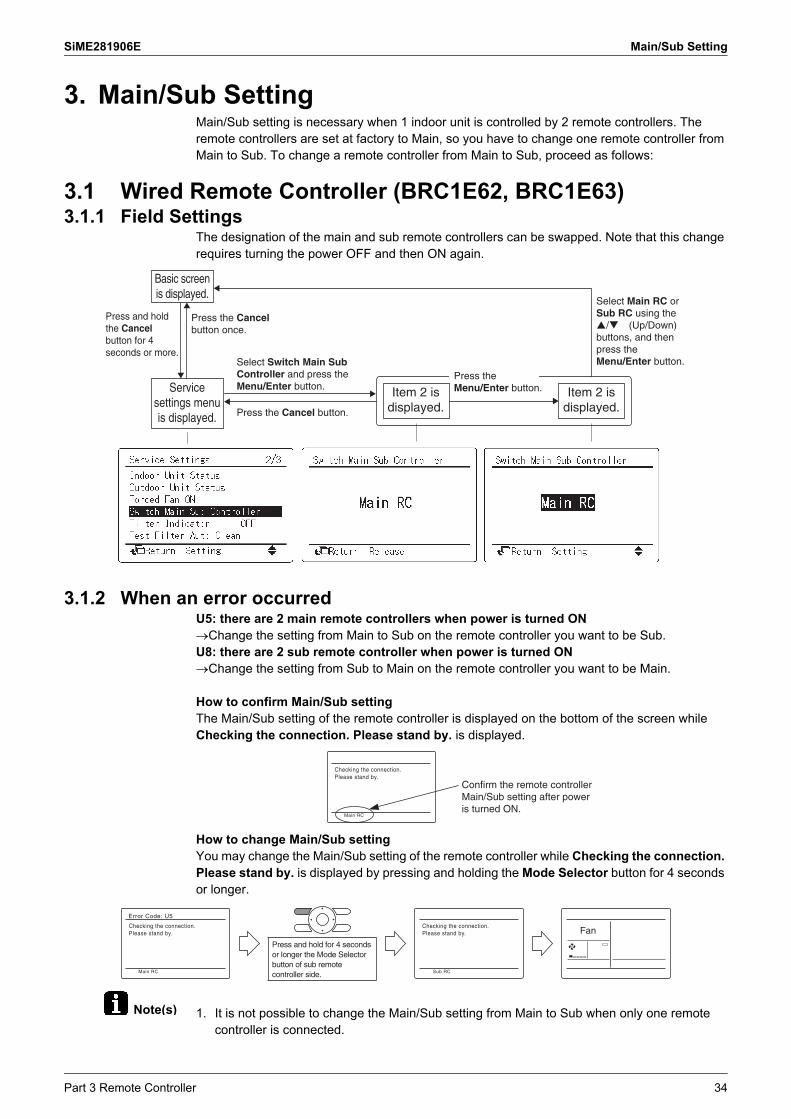
3. Main/Sub SettingMain/Sub setting is necessary when 1 indoor unit is controlled by 2 remote controllers. The remote controllers are set at factory to Main, so you have to change one remote controller from Main to Sub. To change a remote controller from Main to Sub, proceed as follows:
3.1 Wired Remote Controller (BRC1E62, BRC1E63)3.1.1 Field Settings
The designation of the main and sub remote controllers can be swapped. Note that this change requires turning the power OFF and then ON again.
3.1.2 When an error occurredU5: there are 2 main remote controllers when power is turned ONChange the setting from Main to Sub on the remote controller you want to be Sub.U8: there are 2 sub remote controller when power is turned ONChange the setting from Sub to Main on the remote controller you want to be Main.
How to confirm Main/Sub settingThe Main/Sub setting of the remote controller is displayed on the bottom of the screen while Checking the connection. Please stand by. is displayed.
How to change Main/Sub settingYou may change the Main/Sub setting of the remote controller while Checking the connection. Please stand by. is displayed by pressing and holding the Mode Selector button for 4 seconds or longer.
1. It is not possible to change the Main/Sub setting from Main to Sub when only one remote controller is connected.
Select Switch Main Sub Controller and press the Menu/Enter button.Service
settings menu is displayed.
Item 2 is displayed.
Basic screen is displayed.
Press the Cancel button once.
Press and hold the Cancel button for 4 seconds or more.
Press the Cancel button.
Item 2 is displayed.
Press the Menu/Enter button.
Select Main RC or Sub RC using the �/� (Up/Down) buttons, and then press the Menu/Enter button.
Checking the connection.Please stand by.
Main RC
Confirm the remote controller Main/Sub setting after power is turned ON.
Checking the connection.Please stand by.
Error Code: U5
Main RC
Press and hold for 4 seconds or longer the Mode Selector button of sub remote controller side.
Checking the connection.Please stand by.
Sub RC
Fan
Part 3 Remote Controller 34

Main/Sub Setting SiME281906E
2. When 2 remote controllers are being used, it is not possible to change the setting from Main to Sub if one of the remote controllers is already set as Main.
3.2 Wired Remote Controller (BRC1H81 Series)
When using 1 remote controllerOnce the controller is powered, it will automatically start up:If it is the first and only controller that is connected to the indoor unit, it will automatically get designated as master controller.
When using 2 remote controllerFor a second controller to get designated as slave controller, manual action is required.
1. Connect a second controller.
Result: It will start up automatically.
2. Wait for a U5 or U8 error to appear on the screen.3. When the U5 or U8 error appears, press and keep it pressed until "2" appears on the screen.
abc
a c
b
Outdoor unitIndoor unitMaster remote controller
abcd
a c d
b
Outdoor unitIndoor unitMaster remote controllerSlave remote controller
35 Part 3 Remote Controller

SiME281906E Main/Sub Setting
Note(s)
Result: The controller is now designated as slave.
The following functions are not available for slave controllers: Auto operation mode Individual airflow direction Filter auto clean Setback temperature setpoints Draft prevention Duty rotation
3.3 When Wireless Remote Controller is Used TogetherWhen using both a wired and a wireless remote controller for 1 indoor unit, the wired controller should be set to Main. Therefore, the Main/Sub switch (SS1) of the signal receiver PCB must be set to Sub.
Main/Sub Main Sub
Main/Sub switch (SS1)
S
M
S
M
Transmitter assembly
12 3
MS
SS2
SS1
The side painted black indicates the switch knob position.
Part 3 Remote Controller 36

Main/Sub Setting SiME281906E
3.4 Address Setting for Wireless Remote ControllerIf setting multiple wireless remote controllers to operate in one room, perform address setting for the receiver and the wireless remote controller.(This includes an individual remote controller control using the group operation.)(For the wiring for the group operation, please refer to the installation manual attached to the indoor unit and technical guide.)
3.4.1 Setting for Signal Receiver PCBThe address for the receiver is set to 1 at the factory. To change the setting, set the wireless address switch (SS2) on the signal receiver PCB according to the table below.
Unit No. No. 1 No. 2 No. 3
Wireless addressswitch (SS2)
1
2
3
1
2
3
1
2
3Transmitter assembly
12 3
MS
SS2
SS1
The side painted black indicates the switch knob position.
37 Part 3 Remote Controller

SiME281906E Main/Sub Setting
3.4.2 Setting for BRC4C SeriesThe address for the wireless remote controller is set to 1 at the factory. To change the setting, proceed as follows:
1. Press FILTER SIGN RESET button and INSPECTION/TEST button at the same time for 4 seconds to enter field setting mode. (SETTING is indicated on the display.)
2. Press FAN button and select A or b. Each time the button is pressed, the display switches between A and b.
3. Press UP button or DOWN button to select an address from 1-3 as same as the receiver.Address can be set from 1-6, but the receiver does not work with addresses 4-6.
4. Press RESERVE button to confirm the setting.5. Press INSPECTION/TEST button for 1 second to return to normal mode.
Field setting mode
Address
Multiple setting
UP button
DOWN button
FAN button
RESERVE button
FILTER SIGN RESET button
INSPECTION/TEST button
Part 3 Remote Controller 38

Main/Sub Setting SiME281906E
3.4.3 Multiple Settings A/bThe command such as operation mode or temperature setting by this remote controller will be rejected when the target indoor unit operation is restricted as by an external control such as centralized control.Since the setting acceptance is hard to discriminate with such circumstances there are two setting options provided to enable discriminating by a beeping sound according to the operation: “A: Standard” or “b: Multi System”. Set the setting according to the customer's intention.
Remote Controller Indoor Unit
Multiple setting
Display on remote controller
Behavior to the remote controller operation when the functions are restricted as by an external control.
Other than the left
A: Standard (factory set)
All items displayed.
Accepts the functions except restricted. (Sounds one long beep or three short beeps)There may be a difference from the indoor unit status with remote controller display.
Accepts all items transmitted (Sounds two short beeps)The remote controller display agrees with theindoor unit status.b: Multi
SystemDisplay only items transmitted for a while.
<When some restricted functions are included in the transmitted items>Accepts the functions except restricted. (Sounds one long beep or three short beeps)There may be a difference from the indoor unit status with remote controller display.
<When no restricted function is included>Accepts all items transmitted (Sounds two short beeps)The remote controller display agrees with the indoor unit status.
39 Part 3 Remote Controller

SiME281906E Centralized Control Group No. Setting
4. Centralized Control Group No. Setting4.1 BRC1E62, BRC1E63
Group No. Setting (Group)
Group No. Setting (Unit)
Select Group address and then press the Menu/Enter button.
Select the Group Address (Group) and then press the Menu/Enter button.
Press the Cancel button once.
Select the desired Group No. using the �/� (Up/Down) buttons, and then press the Menu/Enter button.
Service settings menu is displayed.
Item 2 is displayed.
Item 2 is displayed.
Item 2 is displayed.
Basic screen is displayed.
Press the Cancel button once.
Press and hold the Cancel button for 4 seconds or more.
Press the Cancel button once.
Press the Menu/Enter button.
Select Group address and then press the Menu/Enter button.
Press the Cancel button once.
Select Group Address (Unit) and then press the Menu/Enter button.
Press the Cancel button once.
Select the desired Group No. using the �/� (Up/Down) buttons, and then press the Menu/Enter button.
Service settings menu is displayed.
Item 2 is displayed.
Item 2 is displayed.
Item 2 is displayed.
Basic screen is displayed.
Press the Cancel button once.
Press and hold the Cancel button for 4 seconds or more.
Press the Menu/Enter button.
Part 3 Remote Controller 40

Centralized Control Group No. Setting SiME281906E
4.2 BRC1H81 Series
Group addressTo control the system with central control equipment, you need to set addresses for: Groups (Group) and/or Units (Group (Unit)).The Group address menu has two levels. You define groups and/or units in the first level, and set or release addresses for those groups and/or units in the second.
First level
Group (Group): A group is a group of indoor units.
Unit (Group (Unit)): A unit is an individual indoor unit.
Define the indoor unit for which you want to set an address.
Second level
Define an address for the indoor unit.
To SET an address, make sure is selected
Apply settings.
To RELEASE an address that was previously set, change to and then apply settings.
41 Part 3 Remote Controller

SiME281906E Service Settings Menu, Maintenance Menu
5. Service Settings Menu, Maintenance Menu5.1 BRC1E62, BRC1E63
Operating the remote controller allows service data to be acquired and various services to be set.
Select the desired item from the Maintenance menu, and then press the Menu/Enter button.
Service settings menu is displayed.
Basic screen is displayed.
Press the Cancel button once.
Press the Cancelbutton.
Press and hold the Cancel button for 4 seconds or more.
Press and hold the Cancel button for 4 seconds or more.
Maintenance menu is
displayed.
Item 2 is displayed.
Press the Cancel button.
Select the desired Unit No. using the / (Up/Down) buttons. The corresponding data will be displayed.
Select an item from Service settings menu and press Menu/Enter button.
Select the desired item from the Item 2 sub menu, and press Menu/Enter button.
Item 2 is displayed.
Item 3 is displayed.Press Cancel button. Press Cancel button.
Part 3 Remote Controller 42

Service Settings Menu, Maintenance Menu SiME281906E
5.1.1 Service Settings MenuService settings menu Item 2 Remarks
Test Operation — —
Maintenance Contact None —
Maintenance Contact —, 0 to 9 (in order)
Field Settings Indoor Unit No. —
Mode No. —
First Code No. —
Second Code No. —
Demand Enable/Disable Enable, Disable
Settings 40%, 70%
Start time (by the unit of 30 minutes)
Ending time (by the unit of 30 minutes)
Min setpoints Differential
None, Single SP, 0 to 8°C —
Group Address Group Address (Group) Gr Addr. Set
Group Address (Unit) Unit No., Gr Addr. Set
Indoor unit Airnet Address
Unit No., Address Set —
Outdoor unit Airnet Address
Unit No., Address Set —
Error History RC Error History Unit No., Error, Date, Time(Up to 10 errors received by the remotecontroller can be displayed.)
Indoor Unit Error History Unit No., Error, Date, Time(Up to 5 errors from the indoor unit errorrecord can be displayed.)
Indoor Unit Status Unit No. —
Th1 Suction air thermistor
Th2 Heat exchanger thermistor
Th3 —
Th4 Discharge air thermistor
Th5 —
Th6 —
Outdoor Unit Status Unit No. —
Th1 Outdoor air thermistor
Th2 Heat exchanger thermistor
Th3 Discharge pipe thermistor
Th4 —
Th5 —
Th6 —
Forced Fan ON Unit No. —
Switch Main Sub controller — —
Filter Indicator — —
Test Filter Auto Clean — —
Brush / Filter Ind — —
Disable Filter Auto Clean
No, Yes —
43 Part 3 Remote Controller

SiME281906E Service Settings Menu, Maintenance Menu
5.1.2 Maintenance MenuMaintenance Menu
Item 2 Remarks
Model Name Unit No. Select the unit number you want to check.
Indoor unit The model names are displayed.(A model code may be displayed instead, depending on the particular model.)Outdoor unit
R-32 mark display BRC1E63 only
Operation Hours
Unit No. Select the unit number you want to check.
Indoor unit operation hours All of these are displayed in hours.
Indoor fan operation hours
Indoor unit energized hours
Outdoor unit operation hours
Outdoor fan 1 operation hours
Outdoor fan 2 operation hours
Outdoor compressor 1 operation hours
Outdoor compressor 2 operation hours
Indoor Unit Status
Unit No. Select the unit number you want to check.
FAN Fan tap
Speed Fan speed (rpm)
FLAP Airflow direction
EV Degree that electronic expansion valve is open (pulse)
MP Drain pump ON/OFF
EH Electric heater ON/OFF
Hu Humidifier ON/OFF
TBF Anti-freezing control ON/OFF
FLOAT FLOAT SWITCH OPEN/CLOSE
T1/T2 T1/T2 external input OPEN/CLOSE
Th1 Suction air thermistor 1
Th2 Indoor liquid pipe thermistor
Th3 —
Th4 —
Th5 —
Th6 —
Outdoor Unit Status
Unit No. Select the Unit No. you want to check.
FAN step Fan tap
COMP Compressor power supply frequency (Hz)
EV1 Degree that electronic expansion valve is open (pulse)
SV1 Solenoid valve ON/OFF
Pe Low pressure (MPa), BRC1E63 only
Pc High pressure (MPa), BRC1E63 only
Th1 —
Th2 —
Th3 —
Th4 —
Th5 —
Th6 —
Error Display Display error ON Displays the error on the screen.
Display error OFF Displays neither errors nor warnings.
Display warning ON Displays a warning on the screen if an error occurs.
Display warning OFF No warning is displayed.
Swap Unit No.
Current Unit No. A unit No. can be transferred to another.
Transfer Unit No.
Part 3 Remote Controller 44

Service Settings Menu, Maintenance Menu SiME281906E
1: Displays suction air temperature after correction for all models.
Maintenance Menu Item 2 Remarks
Addressed Sensor Value
Unit No.: 0 - 15 Select the unit number you want to check.
Code00:01:02:03:04:05:06:07:08:09:
Remote controller thermistor (°C)Suction air thermistor (°C)Heat exchanger liquid pipe thermistor (°C)Heat exchanger gas pipe thermistor (°C)Indoor unit address No.Outdoor unit address No.BS unit address No.Zone control address No.Cooling/Heating batch address No.Demand/low-noise address No.
Data The corresponding data will be displayed, based on the Unit No. and Code selected.
45 Part 3 Remote Controller

SiME281906E Service Settings Menu, Maintenance Menu
5.2 BRC1H81 Series5.2.1 To enter the installer menu
5.2.2 Installer menu
Press and keep it pressed until the information screen appears.The presence of icons on the information screen depends on operation status. The controller may display more or less icons than are indicated here.
From the information screen, press and simultaneously and keep them pressed until you enter the installer menu.
Category Icon Settings Category Icon settings
Screen settings
Brightness Miscellaneous settings
Group address and Airnet address
Contrast Extremal input interlock
Status indicator settings
Intensity Force fan ON
Field settings
Indoor unit field settings
Switch Cooking/Heating master
Remote controller field settings
Information
Part 3 Remote Controller 46

SiME281906E
47 Part 4 Functions and Control
1. Function Outline ....................................................................................481.1 Indoor Unit..............................................................................................481.2 Outdoor Unit ...........................................................................................49
2. Operation Flowchart..............................................................................502.1 Cooling/Dry Operation............................................................................50
3. Indoor Unit Functions ............................................................................513.1 Set Temperature and Control Target Temperature................................513.2 Thermostat Control.................................................................................513.3 Automatic Airflow Rate Control ..............................................................523.4 Drain Pump Control................................................................................523.5 Freeze-Up Prevention Control................................................................523.6 Automatic Restart...................................................................................533.7 Monitoring Control ..................................................................................53
4. Outdoor Unit Control .............................................................................544.1 Overview of Outdoor Unit Controls.........................................................544.2 Abnormal Stop........................................................................................554.3 Restart Standby......................................................................................554.4 Preheating Control on Standby ..............................................................564.5 Startup Control .......................................................................................564.6 Room Temperature Thermostat Control ................................................574.7 Starting Frequency Control ....................................................................574.8 Compressor Step Control.......................................................................584.9 Outdoor Fan Speed Control ...................................................................594.10 Low Noise Control ..................................................................................604.11 Low Pressure Protection Control............................................................604.12 High Pressure Protection Control...........................................................614.13 Discharge Pipe Temperature Control.....................................................624.14 Capacitor Electrical Discharge Control...................................................634.15 Inverter Current Protection Control ........................................................634.16 Forced Thermostat OFF.........................................................................634.17 Cooling Control with Low Outdoor Air Temperature...............................634.18 Overall Current Protection Control .........................................................644.19 Refrigerant Shortage Detection Control .................................................644.20 Piping/Wiring Mismatch Detection Control .............................................644.21 Pump Down Operation ...........................................................................654.22 Oil Return Control...................................................................................654.23 Emergency Operation ............................................................................654.24 Simulated Operation Function................................................................664.25 Test Operation Control ...........................................................................66
Part 4 Functions and Control
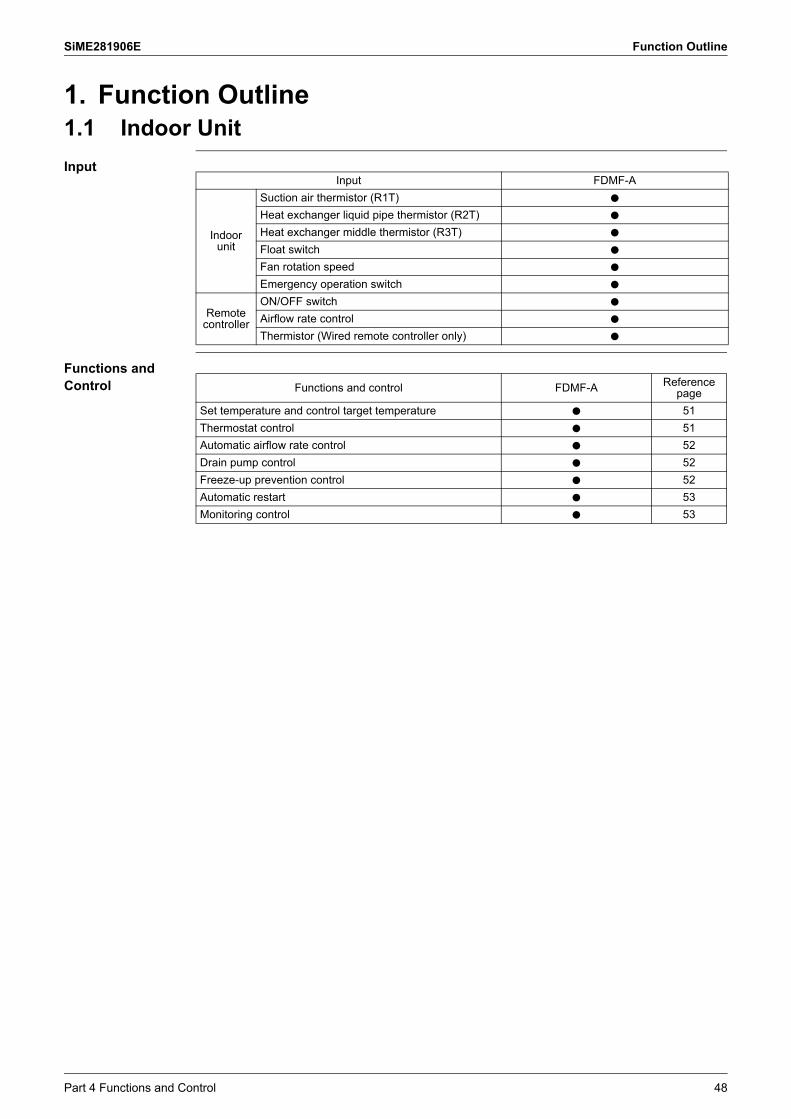
SiME281906E Function Outline
1. Function Outline1.1 Indoor Unit
Input
Functions and Control
Input FDMF-A
Indoor unit
Suction air thermistor (R1T) h
Heat exchanger liquid pipe thermistor (R2T) h
Heat exchanger middle thermistor (R3T) h
Float switch h
Fan rotation speed h
Emergency operation switch h
Remote controller
ON/OFF switch h
Airflow rate control h
Thermistor (Wired remote controller only) h
Functions and control FDMF-A Reference page
Set temperature and control target temperature h 51
Thermostat control h 51
Automatic airflow rate control h 52
Drain pump control h 52
Freeze-up prevention control h 52
Automatic restart h 53
Monitoring control h 53
Part 4 Functions and Control 48

Function Outline SiME281906E
1.2 Outdoor Unit
Input
Functions and Control
Input
Outdoor air thermistor (R1T)
Discharge pipe thermistor (R2T)
Suction pipe thermistor (R3T)
Heat exchanger thermistor (R4T)
Heat exchanger middle thermistor (R5T)
Power module thermistor (R7T) (RZF30/36AVMK only)
High pressure switch (S1PH)
Current transformer
Indoor unit signal
Setting switch
Functions and control Reference page
Stop Abnormal stop 55
Standby Restart standby 55
Preheating control on standby 56
Startup control Startup control 56
Room temperature thermostat control 57
Starting frequency control 57
Function control Compressor step control 58
Outdoor fan speed control 59
Low noise control 60
Protection control Low pressure protection control 60
High pressure protection control 61
Discharge pipe temperature control 62
Capacitor electrical discharge control 63
Inverter current protection control 63
Forced thermostat off 63
Cooling control with low outdoor air temperature 63
Overall current protection control 64
Refrigerant shortage detection control 64
Piping/wiring mismatch detection control 64
Oil return control etc. Pump down operation 65
Oil return control 65
Service function Emergency operation 65
Simulated operation function 66
Test operation control 66
49 Part 4 Functions and Control

SiME281906E Operation Flowchart
2. Operation Flowchart2.1 Cooling/Dry Operation
Power supply ON
Initialize electronic expansion valve
Initialize microcomputer
Preheating control on standby
Remote controller operation judgment
Operation mode judgment
Cooling/Dry
Emergency operation
Thermostat ON judgment
Startup control
Compressor step controlElectronic expansion valve controlLow pressure protection controlHigh pressure protection controlDischarge pipe temperature control
Inverter current protection controlCooling control with low outdoor air temperatureRadiation fin temperature protection control Overall current protection controlSimulated operation function
Normal control
Oil return controlstarting judgment
Oil return control
Oil return controlending judgment
Remote controller
operation OFF judgment
Standby judgment
Abnormal stop judgment
Thermostat OFF judgmentRoom temperature thermostat controlFreeze-up prevention
Restart standby
A
B
B A
Emergency
Cooling/Dry
Error code indication
Part 4 Functions and Control 50

Indoor Unit Functions SiME281906E
Note(s)
3. Indoor Unit Functions3.1 Set Temperature and Control Target Temperature
The relationship between remote controller set temperature and control target temperature is described below.
Examples are given to illustrate a control target temperature that satisfies the remote controller set temperature.
3.2 Thermostat ControlAccording to a difference between the remote controller set temperature and the actually detected room temperature, the thermostat is turned ON or OFF.
Cooling
Program Dry
1: The thermistor for room temperature detection depends on the field setting 10 (20)-2.2: Description of symbolsTr = Detected room temperature – Remote controller set temperature Tro: Detected room temperature at the start of dry operationTr: Detected room temperature
Remote controller set temperature
Control target temperature
14 15 16 17 18 19 20 21 22 23 24 25 26 27 28 29 30 31 32 33 34 35°CTemperature
Cooling
Thermostat OFFΔTr ≥ +0.5ºC
ORNormal operation (Thermostat ON)
• ΔTr ≤ –0.5ºC continues for 1 minute.• ΔTr ≤ –2ºC
Tr – Tro < –1ºC(A)
Tr – Tro ≥ 0ºC(B)
Thermostat OFFDry operation
Tr – TroDifferential
Thermostat OFF
Thermostat ONB
A
Tr
Dry operation Dry operationThermostat OFF
Time
Dry operation startup
51 Part 4 Functions and Control

SiME281906E Indoor Unit Functions
3.3 Automatic Airflow Rate ControlThe automatic airflow rate control (Five steps from H to L) is based on the difference betweencontrol target temperature and set temperature.
3.4 Drain Pump Control Cooling Operation, Dry OperationDrain pump normally ON (both during thermostat ON/OFF).
3.5 Freeze-Up Prevention ControlBased on the judgment to prevent the indoor heat exchanger from freezing, the thermostat is forcedly turned OFF.
When airflow rate is set Automatic airflow rate
Cooling
Thermostat ON Set
The fan tap is determined by the difference between control target temperature
and set temperature.
Thermostat OFF LLThe fan keeps rotating at the speed as just before
the thermostat off
Program Dry Thermostat ON L L
Thermostat OFF OFF OFF
Fan Set M
Stop OFF OFF
HHM
M
MLL
Fan tap
Large← Difference between control target →Smalltemperature and set temperature
<Change in airflow rate under automatic airflow rate control>
Freeze-up prevention control
–3ºC
–5ºC
–1ºC
7ºCCumulative timer cleared after a continuous 20 minutes
4ºC
The thermostat turns OFF after a continuous 1 minute after 8 minutes from startup
Reset after a continuous 10 minutes and cumulative timer cleared after a continuous 10 minutes
Indoor heat exchanger
temperature
The thermostat turns OFF after a cumulative 40 minutes
Part 4 Functions and Control 52

Indoor Unit Functions SiME281906E
3.6 Automatic Restart
Purpose The purpose of the auto-restart function is to automatically resume the same operating mode as when the unit was operating when the power supply is restored after a power failure.
Do not use the "Automatic Restart" function to daily start/stop the unit.
Precautions when turning OFF power When you have to turn OFF the power supply in order to carry out maintenance, make sure
to turn the remote control's ON/OFF switch OFF firstly. If you turn OFF the power supply while the remote control's ON/OFF switch is still ON, the
"automatic restart function" automatically starts the indoor fan immediately and the outdoor fan starts automatically 3 minutes after the power supply is restarted.
Do not start/stop the unit by disconnecting the power supply. Stop the unit by stop commando from the remote controller or optional controller before disconnecting the power supply. Be sure that the compressor and the outdoor unit fans are stopped before disconnecting the power supply so the "Refrigerant Recovery function" has been finished correctly.
When restarting the unit after the power was disconnected for a longer period leave the unit OFF with the power supply connected for about half an hour (See "Preheating Control").
3.7 Monitoring ControlWhen the indoor fan is turned off while the thermostat for cooling or drying is off, even if the room temperature recovers afterwards and becomes the one that turns the thermostat on, the thermistor cannot detect room temperature because the suction air thermistor is installed inside the indoor unit.In order to prevent such a condition, this monitoring control has the function of detecting room temperature by operating the fan at certain intervals when the fan is turned off while the thermostat is off.
53 Part 4 Functions and Control

SiME281906E Outdoor Unit Control
4. Outdoor Unit Control4.1 Overview of Outdoor Unit Controls4.1.1 Cooling 1 (Control while the compressor is OFF)
1. Compressor frequency instruction"0 Hz" shows K1M (magnetic contactor for compressor) is ON."OFF" shows K1M (magnetic contactor for compressor) is OFF.
4.1.2 Cooling 2 (Control at startup and in operation)
Actuator SymbolCompressor OFF
Restart standby Thermostat OFF standby Normal stop Pressure equalization
control prior to startup
Compressor M1C Restart standby 0 Hz (1) OFF (1) 0 Hz (1)
Outdoor fan M1F Restart standby Step 0 Step 0 Pressure equalization control prior to startup
Indoor fanM1F
Instruction not specified
Instruction not specified
Instruction not specified
Control prior to compressor startup (indoor fan)
Electronic expansion valve Y1E Controlled by restart
standby0 pulse 0 pulse Pressure equalization
control prior to startup
Remarks For 3 minutes after compressor is stopped
After restart standby until outdoor unit starts operation (ON) and thermostat ON (OFF)
Outdoor unit in operation: OFF
min. 30 seconds,max. 150 seconds
Actuator Symbol
Compressor ON
Startup control In normal operation
Basic control Protection control Basic control Protection control
Compressor
M1C
Startup control Low pressure protection, High pressure protection, Discharge pipe temperature, Inverter current protection, Overall current protection, Piping/ wiring mismatch detection control
Compressor step control
Low pressure protection, High pressure protection, Discharge pipe temperature, Inverter current protection, Cooling control with low outdoor air temperature, Overall current protection, Refrigerant shortage detection, Piping/ wiring mismatch detection control
Outdoor fanM1F
Startup control Cooling control with low outdoor air temperature
Step 8 Cooling control with low outdoor air temperature
Indoor fan M1F Startup control (indoor fan) – Constant speed
control (indoor fan) –
Electronic expansion valve Y1E Startup control Discharge pipe
temperature controlElectronic expansion valve control
Discharge pipe temperature control
Remarks min. 2 minutes, max. 5 minutes –
Part 4 Functions and Control 54

Outdoor Unit Control SiME281906E
4.1.3 Cooling 3 (Oil return control)
1. Cooling: Wet operation with lower discharge pipe target temperature
4.2 Abnormal StopTo protect the compressor, the thermostat turns off and an error is confirmed after a given number of attempts in cases where the following items read abnormal values.
4.3 Restart StandbyTo prevent compressor from frequent ON/OFF and equalize pressure in refrigerant line, conducts forced thermostat OFF for 3-5 minutes after compressor stopping. Moreover, outdoor fan conducts residual operation for a period of time to expedite equalization and prevent refrigerant stagnation in evaporator.
Actuator Symbol
Compressor ON
Oil return control
Basic control Protection control
Compressor
M1C
Compressor step control, Oil return control High pressure protection, Discharge pipe temperature, Inverter current protection, Overall current protection, Piping/wiring mismatch detection control
Outdoor fan M1F Oil return control Cooling control with low outdoor air temperature
Indoor fan M1F Oil return control (indoor fan) –
Electronic expansion valve Y1E Electronic expansion valve control (1) Discharge pipe temperature control
Remarks –
Item Determination Retry count
Low pressure 0.12 MPa or less for 5 minutes continuously
10 times in 200 minutes
High pressure OCP activated or 3.92 MPa or more for 1 minute continuously
15 times in 300 minutes
Discharge pipe temperature Over 110°C for 15 minutes continuously or over 120°C
10 times in 200 minutes
Power supply Reverse phase power supply 0 times (no retries)
Compressor body temperature Over 123°C 0 times (no retries)
ON
OFF
OFF
ONThermostat OFF
Compressor
Outdoor fan
Residual operation
Restart standby complete
Electronic expansion valve
Operation complete
Moves to “Stop” or “Starting control” after completion of “Restart standby”.
⎫⎪⎪⎪⎪⎪⎪⎪⎬⎪⎪⎪⎪⎪⎪⎪⎪⎭
480 pulse
55 Part 4 Functions and Control

SiME281906E Outdoor Unit Control
4.4 Preheating Control on StandbyIf the compressor is stopped for long periods of time, warm it up to prevent penetration of refrigerant into the compressor oil.
Starting conditions
Ending conditions
4.5 Startup ControlWhen compressor startup, the starting frequency is fixed for specified period of time at low frequency to prevent returning of refrigerant.
• Compressor stopped
& OR&
• Less than 6 hours since power on• 1 hour or more since compressor stopped• Outdoor air temperature not decreasing• Discharge pipe temperature < 40°C
• Thermostat on confirmed
& &OR
• 6 hours or more since power on• Less than 1 hour since compressor stopped• Outdoor air temperature is decreasing• Discharge pipe temperature > 43°C
Controlled by 8 steps according to the cooling load
L tap
OFF
Pressure equalizing
start
Pressure equalizing complete
Startup control
completePressure equalizing control before compressor start
Pressure equalizing electronic expansion valve control
Startup control
Compressor
Outdoor fan
(Remote controller OFF)
8 Step
Set fan speed
0 Hz
0 pulse
(30 ~ 150 sec.)
Electronic expansion valve
Indoor fan (Thermostat OFF)
ON
OFF
Startup frequency
Startup electronic expansion valve control
Part 4 Functions and Control 56

Outdoor Unit Control SiME281906E
4.6 Room Temperature Thermostat ControlThe thermostat turns ON or OFF based on the difference between remote controller set temperature and indoor suction temperature. Thermostat ON conditions: when T +0.5°C Thermostat OFF conditions
T = indoor suction temperature – remote controller set temperature: cooling
4.7 Starting Frequency Control
Outline The compressor will start up with a limited fixed frequency value for a specified period of time in order to prevent liquid back to the compressor, and to limit the starting current.
General The normal startup control time is 2-3 minutes. The maximum starting frequency control time is limited to 5 minutes.
OR
&• ΔT ≤ –0.5˚C continuously for 1 minute• 5 minutes or more since starting
• ΔT ≤ –2˚C (when cooling)• ΔT ≥ +1.5˚C → ΔT ≤ –0.5˚C rapid change
Model name A (Hz)
All outdoor units 141
A Hz
Hz
29.5 Hz
ON 1 2-3 Time (minute)
Normal control
57 Part 4 Functions and Control
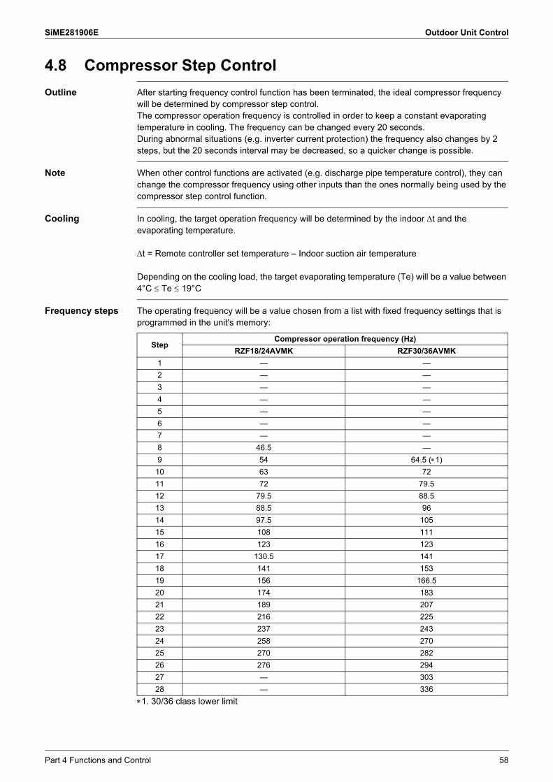
SiME281906E Outdoor Unit Control
4.8 Compressor Step Control
Outline After starting frequency control function has been terminated, the ideal compressor frequency will be determined by compressor step control.The compressor operation frequency is controlled in order to keep a constant evaporating temperature in cooling. The frequency can be changed every 20 seconds.During abnormal situations (e.g. inverter current protection) the frequency also changes by 2 steps, but the 20 seconds interval may be decreased, so a quicker change is possible.
Note When other control functions are activated (e.g. discharge pipe temperature control), they can change the compressor frequency using other inputs than the ones normally being used by the compressor step control function.
Cooling In cooling, the target operation frequency will be determined by the indoor t and the evaporating temperature.
t = Remote controller set temperature – Indoor suction air temperature
Depending on the cooling load, the target evaporating temperature (Te) will be a value between 4°C Te 19°C
Frequency steps The operating frequency will be a value chosen from a list with fixed frequency settings that is programmed in the unit's memory:
1. 30/36 class lower limit
StepCompressor operation frequency (Hz)
RZF18/24AVMK RZF30/36AVMK
1 — —
2 — —
3 — —
4 — —
5 — —
6 — —
7 — —
8 46.5 —
9 54 64.5 (1)
10 63 72
11 72 79.5
12 79.5 88.5
13 88.5 96
14 97.5 105
15 108 111
16 123 123
17 130.5 141
18 141 153
19 156 166.5
20 174 183
21 189 207
22 216 225
23 237 243
24 258 270
25 270 282
26 276 294
27 — 303
28 — 336
Part 4 Functions and Control 58

Outdoor Unit Control SiME281906E
4.9 Outdoor Fan Speed Control
Fan Speed ControlThe outdoor fan speed will be controlled in function of the actual outdoor air temperature, the condensation pressure, pressure difference between low and high pressure and compression ratio.
Fan step tableStep RZF18/24AVMK RZF30/36AVMK
0 0 0
1 200 200
2 250 250
3 320 300
4 390 360
5 430 430
6 515 515
7 620 620
8 940 860
59 Part 4 Functions and Control

SiME281906E Outdoor Unit Control
Note(s)
4.10 Low Noise Control
A. Setting with remote controllerNight-time low noise settingCan be configured using the indoor remote controller field setting mode.By estimating the current time from changes in outdoor temperature, the outdoor fan speed and compressor frequency are automatically controlled for low noise operation during night-time (10 pm to 8 am). (The night-time hours are guidelines.)
B. Setting with demand adapter (sold separately)Low noise setting by external inputWhile the LNOP-COM pins on the X801M terminal block of the demand adapter are shorted, low noise operation takes place by controlling the outdoor fan speed and compressor frequency.
For capacity precedence settingSelecting "Capacity precedence setting" from the field settings mode of the indoor remote controller will set capacity precedence whether in A. or B. operation, so that low-noise operation will switch to normal operation if the air conditioner load increases.Canceling capacity precedence setting with low noise setting in place will give precedence to the low noise mode, continuing low noise operation even if the air conditioner load increases.
4.11 Low Pressure Protection ControlIn order to prevent abnormal low pressures in the system, the below control function will be activated. Low pressure is detected by the pressure sensor.
Frequency RZF18/24AVMK RZF30/36AVMK
A (Hz) 42 72
Normal operation
Lp < 0.12 MPa
Compressor upper limit frequency A Hz
Compressor stop: 0 Hz
Abnormal stop (E4 indication)
Stopped 11 times in 200 minutes
10 times or less stopping in 200 minutes
Lp > 0.15 MPa continues for 30 seconds
Lp < 0.12 MPa continues for 5 minutes
Part 4 Functions and Control 60

Outdoor Unit Control SiME281906E
4.12 High Pressure Protection ControlIn order to prevent abnormal high pressures in the system and hence avoiding activation of the high pressure safety device the below control function will be activated.
Flowchart
As the bearing resistance limit pressure decreases during slow operation of the compressor, the lower limit of frequency is restricted.
In cooling
Parameters
Normal operation
Hp > B MPaCompressor operation
frequency –1 step/10 secondsCompressor operation
frequency +1 step/1 minute
Compressor operation frequency A Hz
Compressor operation frequency +1 step/5 minutes
Hp > C pHaPM ≤ G MPa
OR
Hp < E MPa
Compressor stop
Abnormal stop (E3 indication)
15 times or less stopping in 300 minutes
Hp ≤ F MPa
• Stopped 16 times in 300 minutes
• High pressure switch is activated.• Hp > D MPa for 1 minute
Hp ≥ 2.55 MPaNormal operation
Hp < 2.36 MPaAfter 30 seconds
Compressor frequency lower limit
H Hz
RZF18/24AVMK RZF30/36AVMK
A (Hz) 88.5 88.5
B (MPa) 3.67 3.67
C (MPa) 3.77 3.77
D (MPa) 4.02 4.02
E (MPa) 3.62 3.62
F (MPa) 3.39 3.39
G (MPa) 3.52 3.52
H (Hz) 63 64.5
61 Part 4 Functions and Control

SiME281906E Outdoor Unit Control
4.13 Discharge Pipe Temperature Control
Outline The compressor operating frequency will be controlled in order to avoid abnormal high compressor temperatures (see also electronic expansion valve control).Td: Discharge pipe temperature (°C)
Flowchart
Parameters
Normal operation
•&
OR•&
OR
OR
Td > B °C
Compressor upper limit frequency–1 step/20 seconds
Compressor upper limit frequency+1 step/90 seconds
Compressor upper limit frequencyH Hz
Compressor stop
Abnormal stop (F3 indication)
10 times or less stopping in 200 minutes
Td ≤ B °C
•Upper limit frequency: Maximum frequency
•Td < B °C
•Td ≤ B °C•5 minutes elapsed
•Td < A °C•Td ≥ C °C continues for
5 minutes•300 seconds
•Td ≥ E °C continues for G minutes
•Td ≥ F °C
Stopped 11 timesin 200 minutes
•&•Td > D °C
OR•Td < A °C
RZF18/24AVMK RZF30/36AVMK
A (°C) 70 70
B (°C) 105 105
C (°C) 110 110
D (°C) 115 115
E (°C) 110 110
F (°C) 118 120
G (minutes) 15 15
H (Hz) 97.5 108
Part 4 Functions and Control 62

Outdoor Unit Control SiME281906E
Reference
4.14 Capacitor Electrical Discharge ControlApproximately 1 minute after stopping operation (remote controller stop, abnormal stop, retry-type thermostat OFF causing the compressor or outdoor fan motor to stop) an open-phase waveform will be output for capacitor electrical discharge.After that, the discharge resistor will continue to discharge the capacitor to 0 V. The outdoor unit may hum while this occurs.
4.15 Inverter Current Protection ControlRestricts compressor operation frequency to prevent compressor from tripping due to inverter overcurrent.
4.16 Forced Thermostat OFFThe unit will perform the forced thermostat OFF function in following conditions:
CoolingThermostat OFF due to freeze-up prevention control.Based on the judgment to prevent the indoor heat exchanger from freezing, the thermostat is forcedly turned OFF.
Refer to Freeze-up Prevention Control on page 52 .
4.17 Cooling Control with Low Outdoor Air TemperatureTo ensure the compression ratio (pressure difference between high and low pressure) at low outdoor air temperature conditions in cooling mode, the outdoor fan and target compressor frequency may be varied.
The following condition continues for 2 minutes: Inverter current < Stepping down current
Normal operation Inverter upper limit frequency: Maximum frequency
Inverter current > Stepping down current
Compressor frequency –1 step/6 seconds
Compressor frequency +1 step/2 minutes
RZF18/24AVMK RZF30/36AVMK
P (A) 6.6 15.5
Q (A) 15.5
7.65
Q (A)
7.19
276 321 Hz
Compressor frequency
63 Part 4 Functions and Control

SiME281906E Outdoor Unit Control
4.18 Overall Current Protection ControlMonitors the overall current and restricts the upper limit compressor operating frequency to prevent circuit breakers from exceeding the rated capacity.
Upper limit current (A)Takes the following values depending on the outdoor air temperature.Also varies depending on model.
4.19 Refrigerant Shortage Detection ControlIf insufficient capacity due to insufficient refrigerant is determined, the remote controller will display error code U0 and an abnormal stop will occur.
4.20 Piping/Wiring Mismatch Detection ControlIf the piping and transmission wiring to the outdoor unit does not match that of the connected indoor unit, the remote controller will display error code UF and an abnormal stop will occur.
Normal operation Outdoor unit current ≤ upper limit current valueUpper limit compressor operating frequency: Maximum frequency
Outdoor unit current ≤ upper limit current value
Outdoor unit current > upper limit current value
Upper limit compressor operating frequency –1 step/10 seconds
Upper limit compressor operating frequency +1 step/5 minutes
Outdoor unit current > upper limit current value
&
RZF18/24AVMK RZF30/36AVMK
A 13.2 18.1
B 13.2 18.1
C 8.0 12.8
D 8.0 12.8
DCBA
43 50
Current value (A)
Outdoor air temperature (˚C)
Part 4 Functions and Control 64

Outdoor Unit Control SiME281906E
4.21 Pump Down Operation
Outline Whenever the units need to be moved or removed, perform a pump down operation before disconnecting the field piping. By performing a pump down operation, all of the refrigerant will be collected in the outdoor unit.
Procedure
Cautions Pressing the pump down button (18/24 class: BS1; 30/36 class: BS2) on the outdoor unit PCB may cause the outdoor and indoor fan to start operating automatically.
Be sure to open the stop valves after the pipe work has been finished. Be sure not to operate the unit with closed stop valves, or the compressor may brake down.
4.22 Oil Return Control
Outline When the compressor operates for a certain period of time at low frequency, the oil level in the compressor may become low due to incomplete oil return. To prevent damage to the compressor and in worst case avoid compressor lock, an oil return control will be conducted.
Details During the oil return control the operation frequency of the compressor will be increased for a time period of 5 minutes. Oil recovery operation is only executed in cooling mode.
4.23 Emergency Operation Indoor/outdoor transmission does not take place. Cooling operation is active for 20 minutes and stopped for 10 minutes, repeating this cycle. Other functions take place as per normal control.
Procedure Precautions
1 Confirm that both the liquid and gas stop valves are open. —
2 Press the pump down button (18/24 class: BS1; 30/36 class: BS2) on the outdoor unit PCB for 5 seconds.
Compressor and outdoor fan will start operation automatically. Indoor fan may automatically start running. Pay attention to this.
3 Close the liquid stop valve securely for about 2 minutes after the compressor starts operation.
• Never leave the outdoor unit unattended with opened front panel when power supply is on.• In case the liquid stop valve is not securely closed during compressor operation, pump down operation cannot be executed.Once the compressor operation stops after 2
to 5 minutes, close the gas stop valve securely.
4 Turn off the power supply. When you work alone, carry out after closing the front plate. After turning the power supply off, remove the insulation sheet.
65 Part 4 Functions and Control

SiME281906E Outdoor Unit Control
Note(s)
Note(s)
Reference
4.24 Simulated Operation FunctionIn case of a thermistor error, simulated operation is performed in 2 different ways as shown below even while the error is detected.1. Operation continues while the error code is displayed on the remote controller.
Applicable thermistors Outdoor air thermistor Indoor heat exchanger middle thermistor Indoor unit suction air thermistor Indoor heat exchanger thermistor
2. Operation continues even the error is detected. Only when the “INSPECTION / TEST Operation” button is pressed, the error code is displayed.Applicable thermistors Remote controller thermistor
In case of a thermistor error other than A and B above, an abnormal stop is made and no simulated operation is carried out. Applicable thermistors Suction pipe thermistor Discharge pipe thermistor Heat exchanger distribution pipe thermistor Outdoor heat exchanger middle thermistor
4.25 Test Operation Control
Purpose When operating the units for the first time after installation, the unit will - depending on the selected operation mode - perform a test operation first.
Situation 1
Situation 2
When running in test operation mode, the unit will sense on site installation parameters (e.g.: failure to open stop valves,..) and indicate the applicable error code if required.
If the remote controller shows E3, E4, E5, L8 or U0 as an error code, there is possibility that either the stop valve is closed or the airflow outlet is obstructed.
Check the inter unit branch wiring connection (1-2-3 wiring) when the error code U4 or UF is displayed on the remote controller.
When the error code U2 or A8 is displayed on the remote controller, check for voltage imbalance.
When the error code E3, E4, L4 or L8 is displayed on the remote controller, there is possibility that the airflow outlet is obstructed.
When there is no error code display, cooling operation continues without interruption. (However, this control is once again performed after refrigerant is recovered by means of the pump down switch and at the time of the first operation after the outdoor unit PCB replacement.)
Refer to Test Operation on page 92 .
&• Cooling• First operation after
installation
Cooling operation in test operation for 5 minutes
Normal cooling operation
& • Cooling• Test operation
Cooling operation in test operation for 5 minutes
Cooling operation in forced thermostat ON.
Part 4 Functions and Control 66

SiME281906E
67 Part 5 Field Settings and Test Operation
1. Field Settings with Remote Controller...................................................681.1 BRC1E62, BRC1E63 .............................................................................681.2 BRC1H81 Series ....................................................................................701.3 BRC4C Series ........................................................................................711.4 List of Field Settings for Indoor Unit .......................................................721.5 Details of Field Settings for Indoor Unit..................................................741.6 List of Field Settings for Outdoor Unit ....................................................79
2. Field Settings from Demand Adaptor (For 30/36 Class) .......................802.1 i-Demand Function .................................................................................80
3. Field Settings from Outdoor Unit PCB (For 30/36 Class)......................813.1 Setting by BS Buttons ............................................................................813.2 Normal Mode..........................................................................................833.3 Monitor Mode (Mode 1) ..........................................................................843.4 Setting Mode (Mode 2)...........................................................................87
4. Emergency Operation ...........................................................................894.1 Forced Operation ...................................................................................904.2 Emergency Operation when the Remote Controller is Lost ...................91
5. Test Operation ......................................................................................925.1 Checks before Test Operation ...............................................................925.2 Test Operation........................................................................................92
Part 5 Field Settings and
Test Operation

SiME281906E Field Settings with Remote Controller
1. Field Settings with Remote ControllerIndividual function of indoor unit can be changed from the remote controller. At the time of installation or after service inspection / repair, make the field setting in accordance with the following description.Wrong setting may cause error.(When optional accessory is mounted on the indoor unit, setting for the indoor unit may be required to change. Refer to information in the option handbook.)
1.1 BRC1E62, BRC1E63
1 Press and hold Cancel button for 4 seconds or more.Service settings menu is displayed.
2 Select Field settings in the service settings menu, and press Menu/Enter button.Field settings screen is displayed.
3 Highlight the mode, and select desired mode No. by using (Up/Down) button.
4 In the case of setting per indoor unit during group control (When Mode No. such as 20, 21, 22, 23, 25 are selected), highlight the unit No. and select indoor unit No. to be set by using (Up/Down) button. (In the case of group total setting, this operation is not needed.)In the case of individual setting per indoor unit, current settings are displayed. And, second code No. “ - ” means no function.
5 Highlight second code No. of the first code No. to be changed, and select desired second code No. by using (Up/Down) button. Multiple identical mode number settings are available.In the case of group total setting, all of second code No. which may be set are displayed as “ � ”.“ ��” is changed to second code No. to be set. And, second code No. “ - ” means no function.
Basic screen
Service settings menu screen
Press Menu/Enter button.
Field settings screen
Press Menu/Enter button.
First code No.
Second code No.
(1)
(2)
(3)(4)(5)
(3)(5)
In the case of individual setting per indoor unit
In the case of group total setting
Part 5 Field Settings and Test Operation 68

Field Settings with Remote Controller SiME281906E
CAUTION
Setting confirmation screen
Press Menu/Enter button.
Setting confirmed
� When an optional accessory is installed on the indoor unit, settings of the indoor unit may be changed. See the manual of the optional accessory.
� For field setting details of the outdoor unit, see installation manual attached to the outdoor unit.
6 Press Menu/Enter button. Setting confirmation screen is displayed.
7 Select Yes and press Menu/Enter button. Setting details are determined and field settings screen returns.
8 In the case of multiple setting changes, repeat (3) to (7).
9 After all setting changes are completed, press Cancel button twice.
10 Backlight goes out, and Checking the connection. Please standby. is displayed for initialization. After the initialization, the basic screen returns.
(6)(7)
69 Part 5 Field Settings and Test Operation

SiME281906E Field Settings with Remote Controller
1.2 BRC1H81 SeriesThe controller allows for making field settings related to the indoor unit, and to the controller itself.
Field settings are composed of the following components.
Screen Field settings
Indoor unit ▪ Define a mode by setting a Mode number ▪ Define the unit to which the setting will apply by setting a Unit number▪ Define the setting by setting a SW number
1. Modes (Mode),
2. Units (Unit),
3. Settings (SW),
4. Values for those settings.
Part 5 Field Settings and Test Operation 70
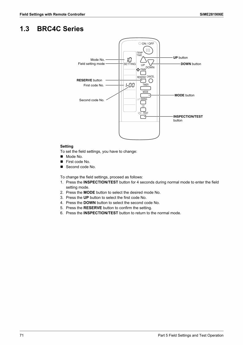
Field Settings with Remote Controller SiME281906E
1.3 BRC4C Series
SettingTo set the field settings, you have to change: Mode No. First code No. Second code No.
To change the field settings, proceed as follows:1. Press the INSPECTION/TEST button for 4 seconds during normal mode to enter the field
setting mode.2. Press the MODE button to select the desired mode No.3. Press the UP button to select the first code No.4. Press the DOWN button to select the second code No.5. Press the RESERVE button to confirm the setting.6. Press the INSPECTION/TEST button to return to the normal mode.
RESERVE button
Mode No.Field setting mode
UP button
DOWN button
First code No.
Second code No.
MODE button
INSPECTION/TEST button
71 Part 5 Field Settings and Test Operation

SiME281906E Field Settings with Remote Controller
Note(s)
1.4 List of Field Settings for Indoor Unit: Factory setting
1. Settings are made simultaneously for the entire group, however, if you select the mode No. inside parentheses, you can also set by each individual unit. Setting changes however cannot be checked except in the individual mode for those in parentheses.
2. The mode numbers inside parentheses cannot be used by wireless remote controllers, so they cannot be set individually. Setting changes also cannot be checked.
3. Do not make settings other than those described above. Nothing is displayed for functions the indoor unit is not equipped with.
4. 88 or Checking the connection. Please stand by. may be displayed to indicate the remote controller is resetting when returning to the normal mode.
5. BRC1H81 series only
Mode No. (Note 2)
First Code No.
Description Second Code No. PageReference
01 02 03 04
10 (20)
0
Filter cleaning sign interval
Long life filter
Approx.2,500 hrs.
Approx.1,250 hrs.
— — 74
Ultra long life filter
Approx.10,000 hrs.
Approx.5,000 hrs.
— — 74
1 Filter type Long life filter
Ultra long life filter
— — 74
2
Thermistor selection Remote controller + Suction air thermistor
Suction air thermistor
— Remote controller thermistor
74
3 Filter cleaning sign Displayed Not displayed — — 74
11 (21)
0
Setting number of the connected indoor units as simultaneous operation system
Pair system (1 unit)
Simultaneous operation system (2 units)
Simultaneous operation system (3 units)
Double twin multi (4 units)
75
1 Simultaneous operation system individual setting
Unified setting
Individual setting
— — 75
2 Fan ON/OFF at thermostat OFF (Cooling)
Keep operating
Stop — — 75
7Airflow adjustment OFF Completion of
airflow adjustment
Start of airflow adjustment
— 76
12 (22)
1 External ON/OFF input Refer to the page on the right for details. 76
5 Auto restart after power failure reset
Disabled Enabled — — 77
6 Airflow Setting when cooling thermostat is OFF
LL tap Set fan speed
— — 77
13 (23) 6 External static pressure Refer to the page on the right for details. 77
15 (25)
3 Drain pump and humidifier interlock selection
Not interlocked
Interlocked — — 78
5Selection for individual ventilation setting by remote controller
— (Normal) Individual — — 78
1b 4 Display of error codes on the remote controller
— Two-digit display
— Four-digit display
78
1c
0 Room temperature display Not displayed Displayed — — 78
01(Note 5)
Thermostat sensor Indoor unit thermistor
Controller thermistor
— — —
12(Note 5)
Window contact B1 Do not use Use — — —
13(Note 5)
Key card contact B2 Do not use Use — — —
1e(Note 5) 02 Setback function No Setback Heating only Cooling only Heating and
Cooling—
Part 5 Field Settings and Test Operation 72

Field Settings with Remote Controller SiME281906E
1.4.1 Applicable Field Settings
h : Available― : Not available
Setting modes FDMF-A
10 (20)
0 Filter cleaning sign interval h
1 Filter type h
2 Thermistor selection h
3 Filter cleaning sign h
11 (21)
0 Setting number of the connected indoor units as simultaneous operation system h
1 Simultaneous operation system individual setting h
2 Fan ON/OFF at thermostat OFF h
7 Airflow adjustment h
12 (22)
1 External ON/OFF input h
5 Auto restart after power failure reset h
6 Airflow setting when cooling thermostat is OFF h
13 (23) 6 External static pressure h
15 (25)3 Drain pump-humidifier interlock selection h
5 Field setting selection for individual ventilation setting by remote controller h
1b 4 Display of error codes on the remote controller h
1c
0 Room temperature display h
01 Thermostat sensor
12 Window contact B1
13 Key card contact B2
1e 02 Setback function
73 Part 5 Field Settings and Test Operation

SiME281906E Field Settings with Remote Controller
1.5 Details of Field Settings for Indoor Unit1.5.1 Filter Cleaning Sign Interval, Filter Type
When the setting 10 (20)-3 is set to 01 (Displayed), filter cleaning sign is displayed on the remote controller after a certain period of operation time. This setting is used to change the display interval of filter cleaning sign when the filter contamination is heavy.The filter cleaning sign interval is determined as follows depending on the combination of Mode No. 10 (20)-0 and 10 (20)-1. Filter cleaning sign interval
: Factory setting
1.5.2 Remote Controller ThermistorSelect the thermistor to control room temperature.
: Factory setting
The Second Code No. is set to 02 at factory setting, where the room temperature is controlled only by the suction air thermistor in the indoor unit.When the Second Code No. is set to 01, the room temperature is controlled by the suction air thermistor in the indoor unit and the remote controller thermistor as indicated in the following figure.
1.5.3 Filter Cleaning SignWhether or not to display the sign after operation of a certain duration can be selected.
: Factory setting
Setting10 (20)-1 01: Long life filter 02: Ultra long life filter
Filter contamination heavy/light 10 (20)-0
Light01
Heavy02
Light01
Heavy02
Model FDMF-A 2,500 hrs. 1,250 hrs. 10,000 hrs. 5,000 hrs.
Mode No.
First Code No.
Second Code No. Contents
10 (20) 2
01 Remote controller thermistor and suction air thermistor for indoor unit
02 Suction air thermistor for indoor unit
04 Remote controller thermistor
20
22
24
26
28
30
32
34
36
211917 23 25 27 29 31 33 35 37
In cooling
Suction air temperature (˚C)
Suction air thermistor
Suction air thermistor
Suction air thermistor
Suction air thermistor
Remote controller thermistor
Remote controller thermistor
Set
tem
pera
ture
(˚C
)
Mode No.
First Code No.
Second Code No. Contents
10 (20) 301 Displayed
02 Not displayed
Part 5 Field Settings and Test Operation 74

Field Settings with Remote Controller SiME281906E
1.5.4 Setting Number of the Connected Indoor Units as Simultaneous Operation System
When using in simultaneous operation system mode, change the second code No. as shown in table below.When using in simultaneous operation system mode, refer to "simultaneous operation system individual setting" to set master and slave units separately.
: Factory setting
1.5.5 Simultaneous Operation System Individual SettingThis setting is used to set the master and slave unit separately.
: Factory setting
1.5.6 Fan ON/OFF at Thermostat OFFWhen the thermostat is OFF, you can stop the indoor fan.
: Factory setting
Airflow Rate (Fan Speed) SettingThe fan speed when cooling thermostat is OFF can be set by combining 11 (21)-2 Fan ON/OFF at Thermostat OFF and 12 (22)-6 Airflow Setting when Cooling Thermostat is OFF as indicated in the following tables.A through C in the tables indicate the contents as below:A: OFF for 6 minutes, and then LL for 1 minuteB: OFF for 6 minutes, and then set fan speed for 1 minuteC: OFF for 6 minutes, and then L for 1 minute
In the case of 11 (21)-2-01 (Keep operating)
In the case of 11 (21)-2-02 (Stop)
Mode No. First Code No. Second Code
No. Contents
11 (21) 0
01 Pair system (1 unit)
02 Simultaneous operation system (2 units)
03 Simultaneous operation system (3 units)
04 Double twin multi (4 units)
Mode No. First Code No. Second Code
No. Contents
11 (21) 101 Unified setting
02 Individual setting
Mode No. First Code No. Second Code
No. Contents
11 (21) 201 Keep operating
02 Stop
Mode No.
Cooling At thermostat OFF
At thermostat OFFDry
12 (22)
First Code No.
6 01
LL
02� 03 04 05
Set fan speed — A B
— A BC C
Second Code No.Field Setting
★: Factory setting
Mode No.
Cooling At thermostat OFF
At thermostat OFFDry
12 (22)
First Code No.
6 01
A
03 04 05
— A B
— A BC C
B
Second Code No.Field Setting
★: Factory setting
02�
75 Part 5 Field Settings and Test Operation
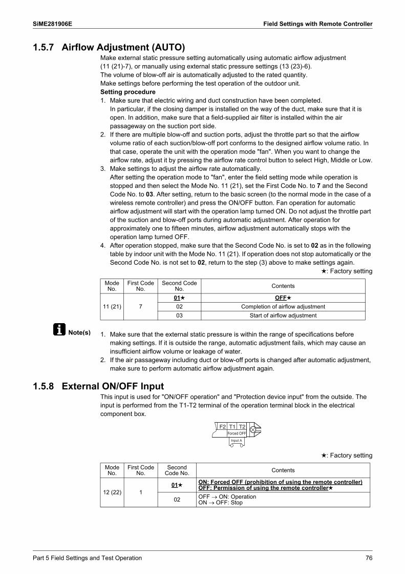
SiME281906E Field Settings with Remote Controller
Note(s)
1.5.7 Airflow Adjustment (AUTO)Make external static pressure setting automatically using automatic airflow adjustment (11 (21)-7), or manually using external static pressure settings (13 (23)-6).The volume of blow-off air is automatically adjusted to the rated quantity.Make settings before performing the test operation of the outdoor unit.Setting procedure1. Make sure that electric wiring and duct construction have been completed.
In particular, if the closing damper is installed on the way of the duct, make sure that it is open. In addition, make sure that a field-supplied air filter is installed within the air passageway on the suction port side.
2. If there are multiple blow-off and suction ports, adjust the throttle part so that the airflow volume ratio of each suction/blow-off port conforms to the designed airflow volume ratio. In that case, operate the unit with the operation mode "fan". When you want to change the airflow rate, adjust it by pressing the airflow rate control button to select High, Middle or Low.
3. Make settings to adjust the airflow rate automatically. After setting the operation mode to "fan", enter the field setting mode while operation is stopped and then select the Mode No. 11 (21), set the First Code No. to 7 and the Second Code No. to 03. After setting, return to the basic screen (to the normal mode in the case of a wireless remote controller) and press the ON/OFF button. Fan operation for automatic airflow adjustment will start with the operation lamp turned ON. Do not adjust the throttle part of the suction and blow-off ports during automatic adjustment. After operation for approximately one to fifteen minutes, airflow adjustment automatically stops with the operation lamp turned OFF.
4. After operation stopped, make sure that the Second Code No. is set to 02 as in the following table by indoor unit with the Mode No. 11 (21). If operation does not stop automatically or the Second Code No. is not set to 02, return to the step (3) above to make settings again.
: Factory setting
1. Make sure that the external static pressure is within the range of specifications before making settings. If it is outside the range, automatic adjustment fails, which may cause an insufficient airflow volume or leakage of water.
2. If the air passageway including duct or blow-off ports is changed after automatic adjustment, make sure to perform automatic airflow adjustment again.
1.5.8 External ON/OFF InputThis input is used for "ON/OFF operation" and "Protection device input" from the outside. The input is performed from the T1-T2 terminal of the operation terminal block in the electrical component box.
: Factory setting
Mode No.
First Code No.
Second Code No. Contents
11 (21) 7
01 OFF
02 Completion of airflow adjustment
03 Start of airflow adjustment
Mode No.
First Code No.
Second Code No. Contents
12 (22) 101 ON: Forced OFF (prohibition of using the remote controller)
OFF: Permission of using the remote controller
02 OFF ON: OperationON OFF: Stop
F2 T1 T2Forced OFF
Input A
Part 5 Field Settings and Test Operation 76

Field Settings with Remote Controller SiME281906E
1.5.9 Auto Restart after Power Failure Reset: Factory setting
For the air conditioners with no setting for the function, the units will be left in the stop condition when the power supply is reset automatically after power failure reset or the main power supply is turned ON again after once turned OFF. However, for the air conditioners with the setting (same as factory setting), the units may start automatically after power failure reset or the main power supply turned ON again (return to the same operation condition as that of before power failure).
For the above reasons, when the unit is set enabling to utilize “Auto restart function after power failure reset”, utmost care should be paid for the occurrence of the following situation.
1.5.10 Airflow Setting when Cooling Thermostat is OFFThis is used to set airflow to LL airflow when cooling thermostat is OFF.
: Factory setting
1.5.11 External Static Pressure SettingsMake external static pressure setting automatically using automatic airflow adjustment (11 (21)-7), or manually using external static pressure settings (13 (23)-6).
Make sure that 11(21)-7 (Airflow adjustment) is set to 01 (OFF).1: FDMF30AVMK only
Mode No.
FirstCode No.
Second Code No. Contents
12 (22) 501 Disabled
02 Enabled
The air conditioner starts operation suddenly after power failure reset or when the main power supply is turned on again. Consequently, the user might be surprised and wonder why this has happened. In service work, for example, turning off the main power switch while the unit is in operation, and turning on the switch again after the work is completed start unit operation (the fan rotates).
Caution
Mode No.
First Code No.
Second Code No. Contents
12 (22) 601 LL tap
02 Set fan speed
FDMF18/24/30AVMK : Factory setting
Mode No.
First Code No.
Second Code No. Contents
13 (23) 6
05 30 Pa
06 40 Pa
07 50 Pa
08 60 Pa (1)
09 70 Pa (1)
10 80 Pa (1)
77 Part 5 Field Settings and Test Operation

SiME281906E Field Settings with Remote Controller
Make sure that 11(21)-7 (Airflow adjustment) is set to 01 (OFF).
1.5.12 Drain Pump and Humidifier Interlock SelectionThis is used to interlock the humidifier with the drain pump. When water is drained out of the unit, this setting is unnecessary.
: Factory setting
1.5.13 Selection for Individual Ventilation Setting by Remote ControllerThis is set to perform individual operation of heat reclaim ventilation using the remote controller/central unit when heat reclaim ventilation is built in.(Switch only when heat reclaim ventilation is built in.)
: Factory setting
1.5.14 Display of Error Codes on the Remote Controller BRC1E SeriesError code (four digits) is displayed for limited products. Select two-digit display if four-digit display is not preferred.
: Factory setting
1.5.15 Room Temperature Display BRC1E SeriesA "Detailed display screen" can be selected as the display screen. This setting is used if you do not want to display "Room temperature display" on the "Detailed display screen".
: Factory setting
FDMF36AVMK : Factory setting
Mode No.
First Code No.
Second Code No. Contents
13 (23) 6
05 50 Pa
06 60 Pa
07 70 Pa
08 80 Pa
09 90 Pa
10 100 Pa
Mode No.
First Code No.
Second Code No. Contents
15 (25) 301 Not interlocked
02 Interlocked
Mode No.
First Code No.
Second Code No. Contents
15 (25) 501 — (Normal)
02 Individual
Mode No.
FirstCode No.
Second Code No. Contents
1b 4
01 ―
02 Two-digit display
03 ―
04 Four-digit display
Mode No.
FirstCode No.
Second Code No. Contents
1c 001 Not displayed
02 Displayed
Part 5 Field Settings and Test Operation 78

Field Settings with Remote Controller SiME281906E
Note(s)
1.6 List of Field Settings for Outdoor Unit: Factory setting
1. Settings are done in a batch for the group. For this reason, when performing group control using the remote controller from one unit to set individual outdoor units, set each unit separately (for each connected indoor unit no.) using the mode number in parentheses. Checking after changing settings can also only be done using the mode numbers in parentheses. (For group batch control, the display will always read 01 even though the settings have been changed.)Furthermore, when performing control with two remote controllers, field settings using a remote controller can only be done using the main remote controller.
2. Do not set any values not shown in the table above.
1.6.1 Night-Time Low Noise SettingThis setting allows automatic switching to low noise operation at night.Start and stop times for low noise operation can also be configured.1. Change the second code number of 16 (26)-0 from 01 to 02 to enable night-time low noise
operation.2. Change the second code number of 16 (26)-1 and select a combination of start time and
stop time if required.However, if the clock of the remote controller is not adjusted, the start time and stop time will be estimated roughly based on outdoor temperatures.
Mode No.
First code No.
Description Second code No. Referencepage01 02 03 04 05
16 (26)(1)
0 Night-time low noise operation
— Automatic low noise activation
— — — 79
1 Start time and stop time of automatic low noise activation
— — 10:00 PM-6:00 AM
— 10:00 PM-8:00 AM
79
2 High sensible cooling setting
— — Server room setting
Anti-frozen+ server room setting (combine)
— —
Night-timeRated operating noise
Operating noise
10:00PM 8:00AM
Night-time low noise operation
6:00AM
Set as stop time
Start time Time set as stop time
79 Part 5 Field Settings and Test Operation
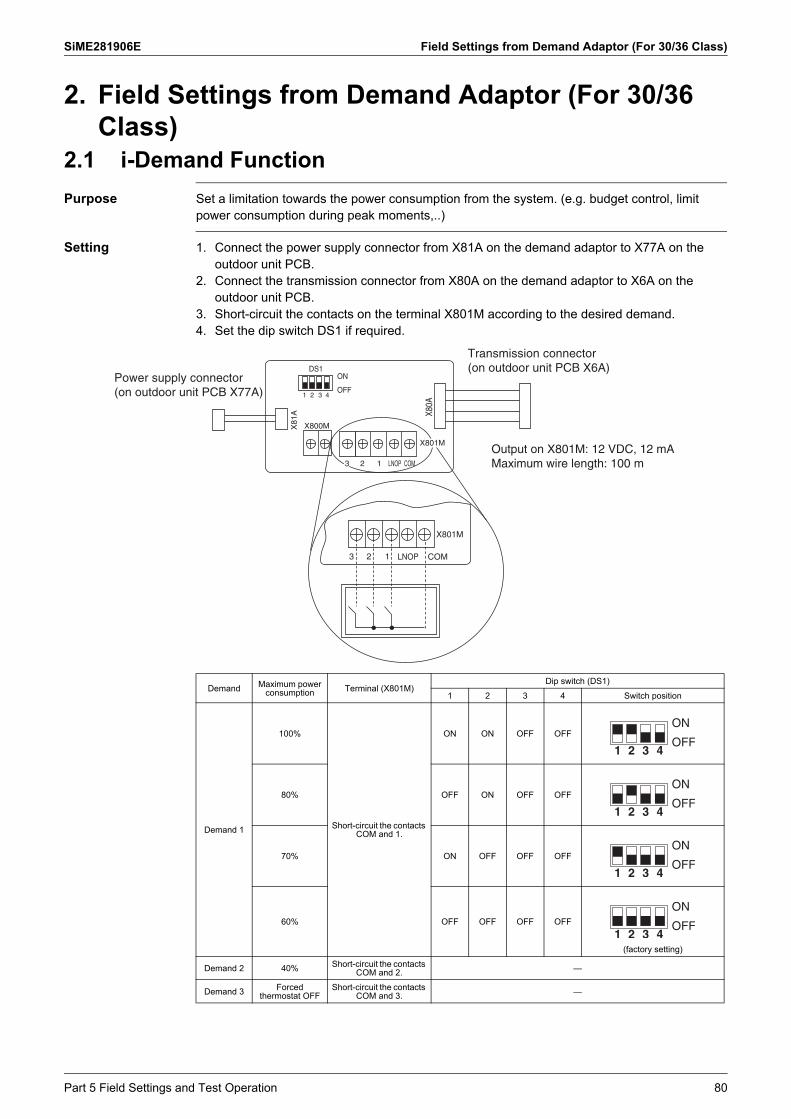
SiME281906E Field Settings from Demand Adaptor (For 30/36 Class)
2. Field Settings from Demand Adaptor (For 30/36 Class)
2.1 i-Demand Function
Purpose Set a limitation towards the power consumption from the system. (e.g. budget control, limit power consumption during peak moments,..)
Setting 1. Connect the power supply connector from X81A on the demand adaptor to X77A on the outdoor unit PCB.
2. Connect the transmission connector from X80A on the demand adaptor to X6A on the outdoor unit PCB.
3. Short-circuit the contacts on the terminal X801M according to the desired demand.4. Set the dip switch DS1 if required.
Power supply connector (on outdoor unit PCB X77A)
Transmission connector (on outdoor unit PCB X6A)
Output on X801M: 12 VDC, 12 mAMaximum wire length: 100 m
3 2 1 LNOP COM
X801M
2 1 LNOP COM
X80A
X800MX81
A
DS1ON
OFF1 2 3 4
X801M
3
Demand Maximum power consumption Terminal (X801M)
Dip switch (DS1)
1 2 3 4 Switch position
Demand 1
100%
Short-circuit the contacts COM and 1.
ON ON OFF OFF
80% OFF ON OFF OFF
70% ON OFF OFF OFF
60% OFF OFF OFF OFF
(factory setting)
Demand 2 40% Short-circuit the contacts COM and 2. —
Demand 3 Forced thermostat OFF
Short-circuit the contacts COM and 3. —
Part 5 Field Settings and Test Operation 80

Field Settings from Outdoor Unit PCB (For 30/36 Class) SiME281906E
3. Field Settings from Outdoor Unit PCB (For 30/36 Class)
3.1 Setting by BS ButtonsThe following settings can be made using the BS buttons on the PCB.In case of a multi outdoor system, make these settings with the master outdoor unit (settings made with a slave unit are disabled).
Normal mode: Blank: If no abnormality is detected and initialization of communication was completed. Flashing combination of letter and number (4 digits): Error code detected by outdoor
control or trouble by communication. Setting mode: Used to make changes to operating status, performance settings or address
setting. Monitor mode: Used to verify contents of settings, quantity of units, current value of some
parameters during operation of outdoor unit.
Mode changing procedure can be selected using the MODE (BS1) button as shown below:
MODE
BS1
SET(TEST)
BS2
RETURN(RESET)
BS3
Used to make setting mode changes.
Used to make field settings.
7 segment display (SEG1-3)BS buttons
Normal mode
Setting mode
Monitor mode
SEG1 SEG2 SEG3
Monitor mode
Press the MODE(BS1) button once
Setting mode
Press and hold the MODE (BS1) button for 5 seconds or more
Press the MODE(BS1) button onceSEG1 SEG2 SEG3 SEG1 SEG2 SEG3 SEG1 SEG2 SEG3
Normal mode
81 Part 5 Field Settings and Test Operation

SiME281906E Field Settings from Outdoor Unit PCB (For 30/36 Class)
Selection between normal mode, monitor mode (Mode 1) and setting mode (Mode 2).
Contents display
Press MODE (BS1) button once.Press MODE (BS1) button for more than 5 sec. Normal mode (Initial condition)
Press RETURN (BS3) button once.
Select a setting item withthe SET (BS2) button.
Select a setting conditionwith the SET (BS2) button.
Press RETURN (BS3) button once.
Setting condition (Contents) display
Press RETURN (BS3) button once.
Press MODE (BS1) button once.
Press MODE (BS1) button once.
Select a check item withthe SET (BS2) button.
Press RETURN (BS3) button once.
Press RETURN (BS3) button once.
SEG1 SEG2 SEG3
Setting mode (Mode 2) Monitor mode (Mode 1)
Part 5 Field Settings and Test Operation 82

Field Settings from Outdoor Unit PCB (For 30/36 Class) SiME281906E
3.2 Normal Mode1. Indoor/outdoor transmission status: Used to check for the initial status of indoor/outdoor
transmission.
2. Descriptions: Used to display an error content.
Initializing
SEG1 SEG2 SEG3
Initializing completed
OFF
ON
Blinking
Normal
Error Error main code
Error sub code
Switching every second
Example: E7-01
SEG1 SEG2 SEG3
83 Part 5 Field Settings and Test Operation

SiME281906E Field Settings from Outdoor Unit PCB (For 30/36 Class)
3.3 Monitor Mode (Mode 1)In the monitor mode, information can be retrieved about current operation status (normal, oil return), outdoor unit class, errors/retries, and cause of stepping-down operation.
3.3.1 How to Retrieve Data
Selecting monitoring item
SEG1 SEG2 SEG3
Normal
Normal
: hold 5 seconds: BLINKS: ON: OFFLegend Segment
MODE
BS1
MODE
BS1
RETURN
BS3
RETURN
BS3
SET
BS2
Checking for description of data
Press the SET (BS2) button to set the 7 segment display to any of the monitoring items listed in the table below.
Press the RETURN (BS3) button.Data on the monitoring item selected will appear on the 7 segment display.
Press the MODE (BS1) button will return the mode to normal mode.
Press the RETURN (BS3) button to set monitor mode to the initial state.
∗ If you lose setting in progress, press the MODE (BS1) button.You should return to normal mode.
To enter monitor mode, press the MODE (BS1) button while in normal mode.
Part 5 Field Settings and Test Operation 84

Field Settings from Outdoor Unit PCB (For 30/36 Class) SiME281906E
3.3.2 Overview of Monitor Mode (Mode 1)
1: Numbers in the "No." column represent the number of times to press the BS button.
No. (1)
Item Contents
Description DisplayDescription
Display
SEG 1 SEG 2 SEG 3 SEG 1 SEG 2 SEG 3
0
Display of quiet operation
1 0 0
ConstantlyLow noise level 1 Low noise level 2 Low noise level 3
0123
1
Display of demand operation
1 0 1
Constantly Demand level 1Demand level 2Demand level 3
0123
2 Display of oil return control 1 0 2
ConstantlyDuring oil return control
01
4 Error content(updated) 1 0 4
Display of the error code and the detailed code
5 Error content(previous error) 1 0 5
6Error content(the one before previous)
1 0 6
9
Drop factor
1 0 9
NormalIn the low voltage dropIn the high voltage dropIn the inverter suction pipe dropIn the inverter current dropIn the FIN temperature dropIn the inverter dropIn the comprehensive current dropOthers
012356789
85 Part 5 Field Settings and Test Operation

SiME281906E Field Settings from Outdoor Unit PCB (For 30/36 Class)
3.3.3 Check for Descriptions of ErrorsFollow the procedure described below. This procedure is different than indicated in previous “Monitor mode”.
The error codes for forced stop outdoor are: 4, 5, 6: description of error (outdoor system stopped operation).
The tables on next pages show a full list of possible error codes displayed on the 3 digit 7 segment display of the outdoor unit. The error code contains an upper and lower digit. To scroll between upper and lower error digit, use the SET (BS2) button when the select number in the monitor mode is chosen: No. 4-6 for error: system operated stopped.
The errors cover problems detected in the outdoor unit or the communication. Errors detected on the indoor unit are not shown on the outdoor display. For inspecting error
code on indoor unit, please consult: Display of the remote controller connected to the indoor units. If there are no remote controllers, there should be a central control device set up. Prior to
start up, make the necessary group number settings on each indoor unit.
SEG1 SEG2 SEG3
Normal
Normal
: hold 5 seconds: BLINKS: ON: OFFLegend Segment
MODE
BS1
MODE
BS1
RETURN
BS3
RETURN
BS3
SET
BS2
SET
BS2
SET
BS2
To enter "monitor mode", press the BS1 (MODE) button while in "normal mode".
Press the BS2 (SET) button to set the 7 segment display to any of the error items listed in the table on the following page.
Selecting error item
Displaying check 1
Displaying check 2
Press the BS3 (RETURN) button.Error codes will appear on the 7 segment display.
Press the BS2 (SET) button.Detailed error codes will appear on the 7 segment display.
Pressing the BS1 (MODE) button will return the mode to "normal mode".
Press the BS3 (RETURN) button to set "Monitor mode" to the initial state.
Press BS2 (SET) button.
Part 5 Field Settings and Test Operation 86

Field Settings from Outdoor Unit PCB (For 30/36 Class) SiME281906E
3.4 Setting Mode (Mode 2)
Ex.) Setting of Refrigerant Recovery Mode
Selection of setting items
Selection of setting conditions
Press and hold the BS1 (MODE) button for 5 seconds or more and set to “Setting mode”.
Press the BS2 (SET) button and set the 7 segment display to a setting item shown in the table on the following page.
↓Press the BS3 (RETURN) button and decide the item. (The present setting condition is blinked.)
Press the BS2 (SET) button and set to the setting condition you want.
↓Press the BS3 (RETURN) button and decide the condition.
Press the BS3 (RETURN) button and set to the initial status of “Setting mode”.
Press the BS1 (MODE) button to return to “Normal mode”.
∗ If you become unsure of how to proceed, press the BS1 (MODE) button and return to “Normal mode”.
SEG1 SEG2 SEG3
Normal
Default
Normal
: hold 5 seconds: BLINKS: ON: OFFLegend Segment
MODE
BS1
MODE
BS1
RETURN
BS3
RETURN
BS3
RETURN
BS3
SET
BS2
SET
BS2
87 Part 5 Field Settings and Test Operation

SiME281906E Field Settings from Outdoor Unit PCB (For 30/36 Class)
3.4.1 Overview of Setting Mode (Mode 2)This overview shows the available settings by using the press buttons on the outdoor unit PCB.
: Setting does not return to factory setting when exit mode 2. To cancel the function, change setting manually to factory setting.: Once function is activated “t01” appears. To stop current function, press RETURN (BS3) button once.Indication bold means factory setting.
No.
Item Contents
DescriptionDisplay
DescriptionDisplay
SEG 1
SEG 2
SEG 3
SEG 1
SEG 2
SEG 3
3Demand 2 operation
Used to use a targeted power current level when the demand 2 control signal is inputted.
2 0 3Level 1 (50%)Level 2 (40%)Level 3 (30%)
123
9High dehumidification cooling
Used to set high dehumidification cooling (provides greater comfort)
2 0 9Setting 1 (Tes: 4.5°C) Setting 2 (Tes: 7.5°C) Setting 3 (Tes: 10.5°C)
123
28Refrigerant recovery mode
Used to set the system to refrigerant recovery mode (without compressor run).
2 2 8Refrigerant recoveryOFFON
01
Part 5 Field Settings and Test Operation 88

Emergency Operation SiME281906E
Note(s)
4. Emergency OperationOperation in emergency includes the following (1) to (3).Understand the purpose and use the appropriate operation.
1. Refer to Test Operation on page 92 for details on test operation.
Location of DIP Switch
Name Purpose Procedure
Operation
Thermistor detection
Protection device action
Fan Drain pump Remarks
(1)
Emergency operation (Forced operation)
Forced operation for servicing
SS1 switch on the indoor unit PCB
— — h h
No temperature control
DIP switch on the outdoor unit PCB
— — h —
(2)
Test operation(*1)
Check operation after installation
Test operation with remote controller
— h h h
No temperature control
(3)
Emergency operation
When wireless remote controller is lost
Emergency operation switch on the indoor unit panel
h h h h
Remote controller is disabled. Actuators such as fan and pump operate.
DS1-1ON Turn ON to conduct emergency operation (forced operation).
OFF(Factory setting)
DS1-2COOL For emergency operation, flip the switch to COOL for cooling.
HEAT(Factory setting)
DS1
1 2
DS1ON
OFF
RZF18/24AVMK RZF30/36AVMK
89 Part 5 Field Settings and Test Operation

SiME281906E Emergency Operation
Note(s)
4.1 Forced OperationTo start forced operation, proceed as follows:
Emergency operation cannot be carried out when the PCB itself is defective. Change the position of the emergency switch only when the power is turned OFF. When returning to the normal operation, restore the switch to the original position with the
power OFF. When safety device is activated in emergency operation, operation is stopped once and
restarted in 3 minutes.
Step Action
1 Turn OFF the power supply.
2 Flip the emergency switch (DS1-1) on the indoor unit PCB from NORM (Normal, Factory setting) to EMG (Emergency).
3 Set the DIP switch (DS1-1) on the outdoor unit PCB to ON.
4 Set the DIP switch (DS1-2) on the outdoor unit PCB to COOL.
5 Turn ON the power supply to start forced operation.
NormalEmergency
ON COOL
OFF HEAT1 2
ON COOL
OFF HEAT
1 2
Part 5 Field Settings and Test Operation 90

Emergency Operation SiME281906E
4.2 Emergency Operation when the Remote Controller is Lost
When the remote controller does not work due to battery failure or is lost, use this switch which is located on the indoor unit. When the remote controller does not work even though the battery low indicator is not lit, contact your dealer.
1. Press the emergency operation switch.
2. Press the emergency operation switch again to stop operation.
Emergency operation switch
91 Part 5 Field Settings and Test Operation

SiME281906E Test Operation
Warning
5. Test Operation5.1 Checks before Test Operation
Before carrying out a test operation, proceed as follows:
When a power supply is switched ON, when you leave from the outdoor unit, be sure to close the cover plate.(It becomes the cause of an electric shock.)
5.2 Test OperationAfter the indoor and outdoor unit installation, be sure to perform the test operation in accordance with the following procedure.1. Open the stop valve cover and check that the liquid and gas sides of the stop valves are
open.<Be sure to close the front plate before the operation (there is a risk of electric shock)> After doing an air-purge with a vacuum pump, the refrigerant pressure may not rise even if the stop valves are opened. This is because the refrigerant piping path is closed off by the outdoor unit electronic expansion valve, etc. There are no problems if the unit is run.
2. Attach the stop valve cover to the outdoor unit and turn the power on at least 6 hours before operating the outdoor unit to protect the compressor.
3. Set up a cooling operation.4. Perform the test operation.5. Operate normally.6. Confirm function of the indoor and outdoor units according to the operation manual.
ITEM TO CHECK
Power supply wiring
Is the wiring as mentioned on the wiring diagram?Make sure no wiring has been forgotten and that there are no missing phases or reverse phases.
Does wiring between units put in and changed in continuation installation?
Is the unit properly grounded?
Are any of the wiring attachment screws loose?
Is the insulation resistance at least 1 M? Use a 500 V Megger tester when measuring insulation.Do not use a Megger tester for circuits which except 230 V.
Is an earth leakage circuit breaker used a current operated type which is compatible to the higher harmonic wave?
Does the earth leakage circuit breaker have appropriate rated current?
Refrigerant piping
Is the size of the piping appropriate?
Is the insulation material for the piping attached securely?Are both the liquid and gas pipes insulated?
Are the stop valves for both the liquid side and the gas side open?
Extra refrigerant
Did you write down the extra refrigerant and the refrigerant piping length?
Indoor unit Is the indoor unit fully installed?When the test operation is started, the fan automatically begins turning.
Part 5 Field Settings and Test Operation 92

Test Operation SiME281906E
Service DiagnosisAt the time of a test operation, when the following error code is displayed on remote control, the fault of installation construction can be considered.
When error codes other than the above are displayed on remote control, considering that the failure of between an indoor and an outdoor unit may have. For the error codes, refer to Error Codes and Descriptions on page 124 .
The followings can be considered causes when the breaker for power supply trips. The capacity of a breaker for power supply is smaller than the required capacity of the
leakage circuit breaker. The leakage circuit breaker is not compatible to the higher harmonic wave.
In case of already checking all equipment that not have any problem, but found air conditioner not cooling. Please re-check Motor operate valve coil not tighten or remove for 1st checking. If normally please re-confirm problem following service manual to solve problem.
Error code Installation error Remedial action
E3, E5, U0, L8 A failure of a stop valve to open “Open” operation of a stop valve
E3, E5, L4, L8 Closing of an air passage Removing closing thing from air passage
U1 Missing phase, negative phase 2 Phase of power supply 3 Phase(L1, L2, L3 Phase) are replaced
U2 Power supply unbalancing Unbalanced dissolution
U4, UF Incorrect connection of field wiring Correction of wiring
UA Connection of incompatible indoor unit Connect appropriate indoor unit(Refer to the catalog)
No indication Mistake wiring or not connect wiring of power supply, indoor, outdoor, field wiring between indoor unit
To correct wiring or connect correctly
93 Part 5 Field Settings and Test Operation

SiME281906E
Part 6 Service Diagnosis
1. Maintenance Inspection ........................................................................961.1 Overview ................................................................................................961.2 Refrigerant Characteristics (R-32)..........................................................991.3 Refrigerant Recovery Method ..............................................................100
2. Symptom-Based Troubleshooting.......................................................1022.1 All Indoor Units .....................................................................................1022.2 Safety Devices .....................................................................................1032.3 Equipment does not operate. ...............................................................1042.4 Indoor fan operates, but compressor does not operate. ......................1062.5 Cooling operation starts but stops immediately....................................1072.6 After unit shuts down, it cannot be restarted for a while.......................1082.7 Equipment operates but does not provide cooling. ..............................1102.8 Equipment discharges white mist.........................................................1122.9 Equipment produces loud noise or vibration. .......................................1132.10 Equipment discharges dust. .................................................................1152.11 Defrost lamp on the receiver for wireless remote controller is
blinking. ................................................................................................116
3. Troubleshooting with LED Indications.................................................1173.1 Indoor Unit............................................................................................1173.2 Outdoor Unit .........................................................................................117
4. Troubleshooting with Remote Controller.............................................1204.1 BRC1E62, BRC1E63 ...........................................................................1204.2 BRC1H81 Series ..................................................................................1214.3 BRC4C Series ......................................................................................122
5. Troubleshooting by Error Code ...........................................................1245.1 Error Codes and Descriptions ..............................................................1245.2 Error Codes - Sub Codes .....................................................................1255.3 Error of External Protection Device ......................................................1295.4 Indoor Unit PCB Abnormality ...............................................................1305.5 Drain Water Level System Abnormality................................................1315.6 Indoor Fan Motor Abnormality..............................................................1325.7 Fan PCB Abnormality...........................................................................1345.8 Humidifier System Abnormality ............................................................1355.9 Defective Capacity Setting ...................................................................1365.10 Transmission Error (between Indoor Unit PCB and Fan PCB) ............1375.11 Thermistor Abnormality ........................................................................1395.12 Combination Error between Indoor Unit PCB and Fan PCB ................1405.13 Remote Controller Thermistor Abnormality ..........................................1415.14 Outdoor Unit PCB Abnormality.............................................................1425.15 High Pressure Abnormality...................................................................1435.16 Low Pressure Abnormality ...................................................................1455.17 Compressor Motor Lock .......................................................................146
Part 6 Service Diagnosis 94

SiME281906E
5.18 Outdoor Fan Motor Abnormality ...........................................................1475.19 Electronic Expansion Valve Abnormality..............................................1505.20 Discharge Pipe Temperature Abnormality ...........................................1535.21 High Pressure Switch System Abnormality ..........................................1555.22 Compressor Self-Operating Thermal Protector....................................1565.23 Thermistor System Abnormality ...........................................................1575.24 Outdoor Unit PCB Abnormality.............................................................1585.25 Radiation Fin Temperature Rise ..........................................................1615.26 DC Output Overcurrent ........................................................................1625.27 Compressor Overcurrent......................................................................1645.28 Compressor Startup Abnormality .........................................................1665.29 Transmission Error between Microcomputers
on Outdoor Unit Main PCB...................................................................1685.30 PAM Circuit Error .................................................................................1695.31 Open Phase or Power Supply Voltage Imbalance ...............................1705.32 Power Module Thermistor Abnormality ................................................1715.33 Capacity Setting Abnormality ...............................................................1725.34 Refrigerant Shortage (Warning/Alarm).................................................1735.35 Refrigerant Shortage (Error).................................................................1745.36 Power Supply Voltage Abnormality ......................................................1765.37 Transmission Error between Indoor Unit and Outdoor Unit,
Outdoor Fan Motor Abnormality ...........................................................1795.38 Transmission Error between Indoor Unit and Remote Controller.........1845.39 Transmission Error between Main Remote Controller and
Sub Remote Controller.........................................................................1855.40 Field Setting Switch Abnormality..........................................................1865.41 Centralized Address Setting Error........................................................1885.42 Transmission Error between Centralized Controller and Indoor Unit ...1895.43 Transmission Error between Indoor Unit and Outdoor Unit .................191
6. Check ..................................................................................................1926.1 Thermistor Check .................................................................................1926.2 High Pressure Check ...........................................................................1956.3 Low Pressure Check ............................................................................1956.4 Power Transistor Check .......................................................................1966.5 Fan Motor Connector Check ................................................................1986.6 Electronic Expansion Valve Check.......................................................1996.7 Wet Operation Check ...........................................................................2006.8 Clogged Points Check..........................................................................2016.9 Refrigerant Shortage Check.................................................................2026.10 Refrigerant Overcharge Check.............................................................203
95 Part 6 Service Diagnosis

SiME281906E Maintenance Inspection
1. Maintenance Inspection1.1 Overview
When performing maintenance, you should at least perform the following inspections:
Guidelines for Optimal Operation ConditionThe operation value guidelines when operating under standard conditions by pushing the operation button on the remote controller are as given in the table below.
Indoor fan: H tap
Standard Conditions
During or after maintenance, when the power supply is turned back ON, operation restarts automatically by the auto restart function. Please exercise the proper caution.
Indoor unit
Outdoor unit
Refrigerant piping
What about voltage and current?
Drain piping
Earth
To dedicated breaker
What about switch capacity?What about cable thickness?
Transmission wiring between indoor and outdoor units
― High pressure (MPa)
Low pressure (MPa)
Discharge pipe temperature (°C)
Suction pipe temperature (°C)
Indoor unit: Temperature differential between suction air and discharge air (°C)
Outdoor unit: Temperature differential between suction air and discharge air (°C)
Cooling 2.62-3.39 0.60-0.98 60-100 –2-10 8-18 7-12
― Indoor Outdoor
Cooling Operation 27°CDB/19°CWB 35°CDB
Part 6 Service Diagnosis 96

Maintenance Inspection SiME281906E
Note(s)
Correlation of Air Conditioner’s Operation Status and Pressure / Running CurrentWhat happens in comparison to normal values is summarized in the table below.(Measured for 15-20 minutes or more after operation starts.)
Cooling
Air Conditioner Status Low Pressure High Pressure Running Current
Air Filter Fouling Lower Lower Lower
Short Circuit of Indoor Unit Inlet/Outlet Air Lower Lower Lower
Outdoor Unit Fin Fouling Higher Higher Higher
Short Circuit of Outdoor Unit Inlet/Outlet Air Higher Higher Higher
Air Mixed in Refrigerant Higher Higher Higher
Water Mixed in Refrigerant Lower (1) Lower Lower
Dirt Mixed in Refrigerant Lower (2) Lower Lower
Refrigerant (Gas) Shortage Lower Lower Lower
Insufficient Compression Higher (3) Lower Lower
1. Water in the refrigerant freezes inside the capillary tube or electronic expansion valve, and is basically the same phenomenon as pump down.
2. Dirt in the refrigerant clogs filters inside the piping, and is basically the same phenomenon as pump down.
3. Pressure differential between high and low pressure becomes low.
97 Part 6 Service Diagnosis

SiME281906E Maintenance Inspection
Precautions for maintenance
Precautions for refrigerant charging1. The charging pipe and the manifold tube use R-32 or R-410A products for pressure proof
and avoiding contamination with impurities (SUNISO oil, etc.).2. Be sure to purge with nitrogen when brazing. Apply the specified oil to the flaring part when
connecting to the flaring.3. Airtight test pressure: 4.0 MPa4. Authentically perform vacuum drying. Add the refrigerant in liquid state at the liquid side.
Item Attention point Item Attention point
Power supply unit and PCB
replacement
Inverter drive unit
Replace the PCB components at maintenance. Shut down the power supply when replacing the component. Even if the display lamp on the PCB is off, it may still be energized.
Radiation fin temperature rise
Troubleshooting not required; automatically recovered in 3 minutes. Verifiable by the maintenance mode or the PCB display lamp.
Outdoor unit main
PCB
When replacement, choose a PCB with the right capacity to replace the existing one. The PCB model varies according to the capacity.
Option for installation site
To facilitate electrical component box maintenance, reserve a distance of 400 mm above the outdoor unit. Pay attention to stacking up the units for installation.
Capacitor electric discharge
When interrupting the operation, perform electric discharge of the capacitor charge. Operation will be affected but it is not malfunction.
Instantaneous power failure detection
Other inverters carried out abnormal stop at undervoltage or power failure, as a U2 (power voltage system abnormality), but here H1P alone lights up and the unit recovers automatically, without displaying an error code.
Capacitor residual charge
When maintaining the electrical component box, turn off the power supply and perform the maintenance only after confirming that the capacitor terminal voltage is below 50 VDC. If voltage check is not possible, perform the maintenance 10 minutes after shutting down the power.
Fan residual operation
Once the compressor stops running, the fan however will keep running for 30 seconds for cooling the inverter. When the radiation fin temperature is slightly high, the fan will keep running until the temperature drops.
Warming up
To prevent refrigerant getting into the oil, the inverter will replace the compressor in providing the heating belt with voltage during the shut-down period. The on/off of warming-up is automatic and is determined by reading the air purge pipe temperature and the outdoor temperature. When performing the maintenance, make sure that the power supply is shut down before the maintenance operation.
Replacing the fan motor
After confirming that the fan is not turning, pull out the fan motor plug from the PCB and then perform the operation. When the outdoor fan is rotating because of strong wind, electric shock may happen because of the main PCB capacitor power storage. Start the operation only after making sure that the capacitor terminal voltage is below 50 VDC. To prevent damaging the PCB, please touch the electrical component box earth terminal before pulling out the plug to release the static electricity before the maintenance operation.Installing a
phase-advanced condenser will not improve the power
For a standard unit, power can be improved by capacitor installation. Because an inverter will cause IGBT failure, do not install a phase-advanced condenser.
Choosing an earth leakage circuit breaker
Please choose the model (higher-order waves) based on the inverter. If what is chosen is not a higher-order wave corresponded earth leakage circuit breaker, malfunction may happen.
DC fan motor
When there is bigger headwind, it will be automatically detected, the fan will be stopped, and natural wind will be used for heat exchange. At this point, the fan motor outputs no voltage. It is not an error.
Pump down operation
When increasing the starting setting value of the low pressure switch/low pressure sensor, the operation once started will not be stopped immediately. In this case, the method of closing the stop valve to activate LPS during cooling cannot be used. Please use pump down switch for refrigerant recovery.
Attention to top plate seal damage
The top-plate seal shape and material differ from those of standard SkyAir series units. The top-plate seal prevents water from penetrating fan or mechanical chambers (electrical components) and condensation from the top-plate from dripping into the switch box. As such, replace the seal if it begins to peel off or is damaged during servicing.
Part 6 Service Diagnosis 98

Maintenance Inspection SiME281906E
1.2 Refrigerant Characteristics (R-32)4.00
3.50
3.00
2.50
2.00
1.50
1.00
0.50
0.00–50 –40 –30 –20 –10 0 10 20 30 40 50 60
Abs
olut
e pr
essu
re (
MP
a)
Temperature (°C)
Temperature (°C)
Absolute pressure
(MPa)
Temperature (°C)
Absolute pressure
(MPa)
Temperature (°C)
Absolute pressure
(MPa)
Temperature (°C)
Absolute pressure
(MPa)
–50 0.1101 –20 0.4058 10 1.1069 40 2.4783
–48 0.1216 –18 0.4373 12 1.1742 42 2.6014
–46 0.1340 –16 0.4707 14 1.2445 44 2.7292
–44 0.1474 –14 0.5060 16 1.3179 46 2.8616
–42 0.1619 –12 0.5433 18 1.3946 48 2.9989
–40 0.1774 –10 0.5826 20 1.4746 50 3.1412
–38 0.1941 –8 0.6241 22 1.5579 52 3.2887
–36 0.2120 –6 0.6679 24 1.6448 54 3.4415
–34 0.2311 –4 0.7139 26 1.7353 56 3.5997
–32 0.2516 –2 0.7623 28 1.8295 58 3.7635
–30 0.2734 0 0.8131 30 1.9275 60 3.9332
–28 0.2967 2 0.8665 32 2.0294 62 4.1089
–26 0.3216 4 0.9225 34 2.1353 64 4.2909
–24 0.3480 6 0.9811 36 2.2454 — —
–22 0.3760 8 1.0426 38 2.3597 — —
99 Part 6 Service Diagnosis

SiME281906E Maintenance Inspection
1.3 Refrigerant Recovery MethodMake sure to recover the refrigerant when replacing components of the refrigerant system. The procedure for refrigerant recovery is as follows.Note that care must be taken to ensure the temperature does not increase too much during refrigerant recovery for models with a fusible plug. (The fusible plug ejects refrigerant at temperatures of 60°C and over)
Refrigerant recovery procedure
1. Refrigerant recovery from gas pipe (Approximately 1 min)Close gas stop valve (liquid stop valve: open) and recover refrigerant from gas stop valve port.
2. Refrigerant recovery from liquid pipe (Approximately 1 min)Recover refrigerant from liquid stop valve port.
3. Refrigerant recovery from outdoor unit (Approximately 2-3 min)Recover refrigerant from outdoor unit refrigerant recovery port (1). If refrigerant recovery port (1) pressure becomes lower than gas stop valve port pressure, refrigerant will be recovered simultaneously from the gas stop valve port. Open gas stop valve (2), and open the gas stop valve port (3) gradually to avoid pressure from rising rapidly.
IndoorUnit
Gasstop valve
Chargehose
Ref.recovery
port
Ref. recoverymachine
Tank
Pressure gauge
Liq.stop valve
OutdoorUnit
Liq. pipe
Gas pipe
CLOSE
CLOSE OPEN
OPEN
IndoorUnit
Gasstop valve
Ref.recovery
port
Ref. recoverymachine
Tank
Pressure gauge
Liq.stop valve
OutdoorUnit
Liq. pipe
Gas pipe
CLOSE
CLOSEOPEN
OPEN
IndoorUnit
Gasstop valve
Ref.recovery
port
Ref. recoverymachine
Tank
Pressure gauge
Liq.stop valve
OutdoorUnit
Liq. pipe
Gas pipe
CLOSE
CLOSEOPEN OPEN
OPEN(3)
(2)
(1)
OPEN
Part 6 Service Diagnosis 100

Maintenance Inspection SiME281906E
RZF18AVMKRZF24AVMK
RZF30AVMKRZF36AVMK
Liquid stop valve service port
Gas stop valve service port
Refrigerant recovery port
Refrigerant recovery port
Liquid stop valve service port
Gas stop valve service port
�Illustration is for 30 class as representative.
101 Part 6 Service Diagnosis

SiME281906E Symptom-Based Troubleshooting
2. Symptom-Based Troubleshooting2.1 All Indoor Units
Symptom Details of Measures
1 Equipment does not operate. Refer to page 104.
2 Indoor fan operates, but compressor does not operate. Refer to page 106.
3 Cooling operation starts but stops immediately. Refer to page 107.
4 After unit shuts down, it cannot be restarted for a while. Refer to page 108.
5 Equipment operates but does not provide cooling. Refer to page 110.
6 Equipment discharges white mist. Refer to page 112.
7 Equipment produces loud noise or vibration. Refer to page 113.
8 Equipment discharges dust. Refer to page 115.
9 Defrost lamp on the receiver for wireless remote controller is blinking.
Refer to page 116.
10Equipment emits odor. Odors and cigarette smoke from the room accumulate
inside the indoor unit and are discharged with air. Clean the inside of the indoor unit.
11Indoor fan operates in L tap for 1 minute in program dry mode even if compressor is not operating.
Normal.The monitoring function forcibly operates the fan for 1 minute.
12Drain pump operates when equipment is not operating. Normal.
The drain pump continues to operate for several minutes after equipment is turned OFF.
13Remote controller thermistor cannot be used with a group controller.
Normal.Remote controller thermistor cannot be used in group control.
14
When operating in remote controller thermistor, the thermostat turns OFF before temperature of remote control reaches the set temperature.
Normal.Control may be conducted with the suction air temperature (body thermostat), concurrently with the set temperature.
15
When an error occurs on the unit with an individual remote controller during group control with one remote controller, the address display on the individual remote controller shows 0 regardless of the address setting.
Normal.Address display of an individual remote controller is always 0.
16
The remote controller display goes blank during operation.
This is not a failure.BRC1E63 is designed to turn the display off after a certain amount of time without activity, in order to save power.
Part 6 Service Diagnosis 102

Symptom-Based Troubleshooting SiME281906E
2.2 Safety Devices2.2.1 Indoor Unit
2.2.2 Outdoor Unit
Model Fuse
FDMF-A A1P F1U (3.15 A, 250 V)
A2P F2U (5.0 A, 250 V)F4U (6.3 A, 250 V)
Model Fuse High pressure switch
RZF18/24AVMK A1P F1U (6.3 A, 250 V)F2U (30 A, 250 V)F6U (3.15 A, 250 V)
S1PHOpen: 4.15 (MPa)
Close: 3.2 ± 0.15 (MPa)RZF30/36AVMK A1P F1U (31.5 A, 250 V)F2U, F3U (6.3 A, 250 V)F6U (5 A, 250 V)
+ 0– 0.15
103 Part 6 Service Diagnosis

SiME281906E Symptom-Based Troubleshooting
2.3 Equipment does not operate.
Applicable Models
All models
Supposed Causes
Fuse blown or disorder of contact in operation circuit Defective operation switch or contact point Defective high pressure switch Defective magnetic contactor for fan motor Activation or fault of overcurrent relay for fan motor Defective compressor protection thermostat Insufficient insulation in electric system Defective contact point of magnetic contactor for compressor Defective compressor Defective remote controller or low batteries (wireless) Incorrect address setting of wireless remote controller Wiring defect on indoor/outdoor relay line
Troubleshooting
Turn ON the power switch or replace the fuse.
Is the power switch OFF or fuse for power switch
blown?
YES
NO
Wait until power returns.
Inspect the indoor/outdoor relay line.• Check that the indoor/outdoor relay
wiring is connected.• Check the indoor/outdoor relay
wiring phases match.Check if any fuses of the outdoor unit are blown.If the fuse is replaceable, replace the blown fuse(s).If the fuse is non-replaceable, replace the PCB.
Is there power failure?
Nothing is displayed on the remote
controller.
The HAP on the outdoor unit
main PCB blinks rapidly (∗1) continuously for more than 1
minute.
YES
YES YES
YES
NO
NO
NONO
Normal. Start up operation after 3 minutes (3-minute standby).
Is the operation switch pressed repeatedly?
YES
NO
The HAP on the indoor
unit PCB is out.
Caution Be sure to turn off the power switch before connecting or disconnecting connectors, or parts may be damaged.
A
Part 6 Service Diagnosis 104

Symptom-Based Troubleshooting SiME281906E
Note(s) 1. Blinking pattern: 0.2 seconds ON, 0.2 seconds OFF (blinking approximately 25 times in 10 seconds)(Normally 0.4 seconds ON, 0.4 seconds OFF (blinking approximately 12 times in 10 seconds))
Normal. Start up operation after 3 minutes (3-minute standby).
Is the thermostat changed and reset again?
YES
NO
Diagnose based on error code on remote controller.
Is the operation lamp on
LCD remote controller blinking?
YES
NO
Diagnose based on error code on remote controller.
Is the operation lamp on
indoor unit signal receiving part blinking?
YES
NO
Replace the fuse (F1U).The fuse (F1U) on the outdoor unit PCB is blown.
YES
NO
Check the electric system.• The fan motor and fan PCB
may have failed simultaneously, so be sure to check both.
Defective electric component
A
105 Part 6 Service Diagnosis

SiME281906E Symptom-Based Troubleshooting
Reference
Note(s)
2.4 Indoor fan operates, but compressor does not operate.
Applicable Models
All models
Supposed Causes
Fuse blown or disorder of contact in operation circuit Defective suction air thermistor Defective indoor/outdoor unit PCB Defective power transistor
Troubleshooting
CHECK 4 Refer to page 196.
1. Blinking pattern: 0.4 seconds ON, 1.2 seconds OFF (blinking approximately 6 times in 10 seconds)(Normally 0.4 seconds ON, 0.4 seconds OFF (blinking approximately 12 times in 10 seconds))
CautionBe sure to turn off the power switch before connecting or disconnecting connectors, or parts may be damaged.
· Indoor fan runs at set airflow rate.· (In cooling)
When suction air temperature is higher than set temperature
Replace the outdoor unit main PCB.
YES
Replace the suction air thermistor.
Is the suction air thermistor operating
normally?NO
Replace the outdoor unit main PCB.
Is the power transistor operating
normally?
NO
YES
Turn ON the power switch or replace the fuse.
Is the power switch OFF or
the fuse for power switch blown?
YES
NO
Turn the power off and check the power transistor.CHECK 4
Replace the outdoor unit main PCB or indoor unit PCB.
The HAP on the outdoor unit
main PCB blinks slowly (∗1) continuously for more than
5 minutes.
YES
NO
Part 6 Service Diagnosis 106

Symptom-Based Troubleshooting SiME281906E
2.5 Cooling operation starts but stops immediately.
Applicable Models
All models
Supposed Causes
Defective outdoor fan Defective indoor fan There is an interfering item in airflow of outdoor unit. There is an interfering item in airflow of indoor unit. Soiled heat exchanger of outdoor unit Soiled heat exchanger of indoor unit Overcharge of refrigerant Air mixed in refrigerant system Defective pressure switch
Troubleshooting
Caution Be sure to turn off the power switch before connecting or disconnecting connectors, or parts may be damaged.
Diagnose based on the error code on remote controller.
Diagnose based on the error code on remote controller.
Is the type of
remote controller wired or wireless?
Is there any item interfering airflow?
Wired YES
Wireless NO
NO
YES
Does the fan rotate?[Cooling: Outdoor unit]
Is the operation lamp of
indoor unit signal receiving part blinking?
YES
Defective fan motor.NO
NO
NO
Remove the interfering item.YES
Is the heat exchanger soiled?
After vacuum drying, charge correct amount of refrigerant.Check the pressure switch.
Clean the heat exchanger.YES
Possible causes as follows:• Refrigerant overcharge• Mixing of air in refrigerant system• Defective pressure switch
Is the operation lamp of remote controller
blinking?
107 Part 6 Service Diagnosis

SiME281906E Symptom-Based Troubleshooting
2.6 After unit shuts down, it cannot be restarted for a while.
Applicable Models
All models
Supposed Causes
Power voltage or power wire malfunction. Compressor protection thermostat may act due to the following reasons; Insufficient compression of compressor Incorrect refrigerant Defective electronic expansion valve Insufficient circulation of refrigerant
Part 6 Service Diagnosis 108

Symptom-Based Troubleshooting SiME281906E
Troubleshooting
CautionBe sure to turn off the power switch before connecting or disconnecting connectors, or parts may be damaged.
Electric system
Refrigerant circuit
(Not so hot)
Normal.Unit is in 3 minutes standby mode.
Does the unit start operation after 3
minutes?
YES
Turn the operation switch ON and OFF, then wait at ON side.
Check on the cause why compressor protection thermostat acted.
NO
Check the compressor.
Is the discharge side of
compressor hot after the unit stops?
NO
YES
Contact the power company.Power supply
voltage is within ±10% of specified voltage.
NO
YES
Replace the power cable.Is the size of power
cable through total length correct?
NO
YES
After vacuum drying, charge correct amount of refrigerant. Then, start operation again.
Replace the electronic expansion valve.
Is there any temperature difference
between inlet and outlet of electronic expansion
valve?
NO
YES
Check the compressor.Defective compressor
109 Part 6 Service Diagnosis

SiME281906E Symptom-Based Troubleshooting
2.7 Equipment operates but does not provide cooling.
Applicable Models
All models
Supposed Causes
Wrong selection of model Compressor (secondary side) open phase Refrigerant shortage Insufficient airflow in the indoor unit Increase of high pressure Insufficient compression of the compressor Insufficient circulation of refrigerant Defective electronic expansion valve
Troubleshooting
NormalDoes the heat
load increase after installation of the unit?
Temperature difference for cooling should be
between 8 and 18°C.
Are the compressor wiring and connections correct?
Additional unit installation should be considered.
Compressor open phase is possible. Check that the wiring is correct as per the wiring diagram.
YES
NO
YES
Caution Be sure to turn off the power switch before connecting or disconnecting connectors, or parts may be damaged.
• Wrong selection of model• Effect of direct sun
Refrigerant shortage possibly generates trouble.After vacuum drying, charge correct amount of refrigerant.(Refer to troubleshooting U0.)
NONO
YES
NO
Is the operation current less than
specified level?
Does any frost generate around inlet
port of indoor heat exchanger or outlet port of electronic
expansion valve?
YES YES
NO
Measure the temperature of suction air and discharge air.
Temperature difference = Suction air temperature – Discharge air temperature
A Go to the next page
Part 6 Service Diagnosis 110

Symptom-Based Troubleshooting SiME281906E
Reference CHECK 2 Refer to page 195.
Does indoor unit airflow rate decrease?
YES Check each section.• Soiled heat exchanger• Defective fan motor
(Refer to troubleshooting A6.)
Check each item.• Refrigerant overcharge• Air mixed in refrigerant system• Soiled heat exchanger• Short circuit of discharge air• Disturbing item in airflow• Defective fan motor of outdoor unit
(Refer to troubleshooting E7.)
Check each item.• Insufficient compression of
compressor• Insufficient circulation of refrigerant• Defective electronic expansion valve
NO
Is the level of high pressure higher than
normal level?
YES
NO
CHECK 2
A
111 Part 6 Service Diagnosis

SiME281906E Symptom-Based Troubleshooting
2.8 Equipment discharges white mist.
Applicable Models
All models
Supposed Causes
Humid installation site Installation site is dirty and with dense oil mists. Soiled heat exchanger Defective fan motor
Troubleshooting
Is the room temperature higher than set
value in cooling?
YES
Caution Be sure to turn off the power switch before connecting or disconnecting connectors, or parts may be damaged.
Normal.Continue the unit
operation. Is white mist coming out from the unit?
NO
Remove the source of humid condition.
YES
Is the indoor heat exchanger soiled?
YES Clean the indoor heat exchanger.
NO
NO
Is the site dusty or with dense oil mist?
YES Remove the source of oil mist or dust.
Check the fan motor.(Refer to troubleshooting A6.)
Normal.
NO
Is the airflow rate too small?
YES
NO
Part 6 Service Diagnosis 112

Symptom-Based Troubleshooting SiME281906E
2.9 Equipment produces loud noise or vibration.
Applicable Models
All models
Supposed Causes
Improper installation Contacts of fan, piping, casing, etc. Noise of refrigerant flow Operating noise of drain discharge equipment Noise of resin components contracting Overcharge of refrigerant Air interfusion Flush noise of insufficient refrigerant (hushing noise)
Troubleshooting
CautionBe sure to turn off the power switch before connecting or disconnecting connectors, or parts may be damaged.
YES Correct installation.Reinforce ceilings or walls.
NO
Does the noise generate with vibration of unit
mounting section?YES Insert shock absorber in
mounting section, or strengthen the mounting section.NO
NO
NO
NO Insert cushion materials to the pipe support such as saddle.
Does the fan contact with other parts?
Does the pipe contact with casing?
YESCorrect piping manually or attach a dead weight to pipe.
YES
YES Disassemble and remove parts contact.
A Go to the next page
Does the noise generate with vibration of whole ceilings and walls?
(Installation work side)
Is the piping secured?(Equipment side)
113 Part 6 Service Diagnosis

SiME281906E Symptom-Based Troubleshooting
NO
NO
NO
NO
Normal. The sound is flushing noise of gas (refrigerant) inside air conditioning unit.
Continuous slight noise during
cooling
YES
Normal. The noise is a sound generated at the time of gas (refrigerant) flow change or stop.
Sound is generated just after
operation start or stop.YES
Normal. Operation sound of draining device
Continuous slight noise is generated
during cooling or after operation stop.
YES
Normal. Creak generates by shrinkage of resin parts due to temperature change.
Creak after operation stop
YES
After vacuum drying, charge correct amount of refrigerant.
• Overcharge of refrigerant• Air mixed in refrigerant system• Flushing noise due to refrigerant
shortage.
NO
Is the noise flushing sound from
pressure reducing valve or capillary tube?
YESNormal.
A
Part 6 Service Diagnosis 114

Symptom-Based Troubleshooting SiME281906E
2.10 Equipment discharges dust.
Applicable Models
All models
Supposed Causes
Carpet spread room Animal hair
Troubleshooting
Dust collected inside the indoor unit are blown out.Cleaning for inside of indoor unit is necessary.
YES
Dust collected inside the indoor unit are blown out.Cleaning for inside of indoor unit is necessary.
Caution
NO
Does thetrouble occur at
the time of operation start again after long period of
operation?
Be sure to turn off the power switch before connecting or disconnecting connectors, or parts may be damaged.
115 Part 6 Service Diagnosis

SiME281906E Symptom-Based Troubleshooting
2.11 Defrost lamp on the receiver for wireless remote controller is blinking.
Applicable Models
All models
Troubleshooting
The unit is checking to confirm that remote controller is normal.Indication appears for short time.
YES
NO
Turn the switch to "Normal", and reset power supply.
Check the unit based on troubleshooting of indoor unit LED and outdoor unit LED.
YES
NO
Trouble generates just after power
supply ON.
Is the position of SS1 on indoor unit PCB at "Emergency"?
CautionBe sure to turn off the power switch before connecting or disconnecting connectors, or parts may be damaged.
Part 6 Service Diagnosis 116

Troubleshooting with LED Indications SiME281906E
Note(s)
Note(s)
3. Troubleshooting with LED Indications3.1 Indoor Unit
Troubleshooting can be carried out by service monitor LED (green). (Blinks when normal)k: LED ON / h: LED OFF / l: LED blinks
1. Operation halts due to error depending on the model or condition.2. Troubleshoot by turning OFF the power supply for a minimum of 5 seconds, turning it back
ON, and then rechecking the LED display.
3.2 Outdoor Unit3.2.1 RZF18/24AVMK
The following diagnosis can be conducted by turning ON the power switch and checking the LED indication on PCB (A1P) of the outdoor unit.
k: LED ON / h: LED OFF / l: LED blinks
1. Turn OFF the power supply, and turn it ON again after 5 seconds or more. Check the error condition, and diagnose the problem.
2. Turn OFF the power supply. After 5 seconds or more, disconnect the transmission wiring for indoor unit. Then turn ON the power supply. If the HAP on the outdoor unit main PCB blinks after about 10 seconds, the indoor unit PCB is defective.
3. Also check for open phase.
Remark:The error history continues to indicate the previously generated error until the power supply is turned OFF. Be sure to turn OFF the power supply after inspection.
Service monitor LED Description
HAP (Green)
l Indoor unit normal Outdoor unit troubleshooting
lIncorrect transmission wiring between indoor and outdoor unit
If outdoor unit’s HAP is OFF, proceed outdoor unit’s troubleshooting. If outdoor unit’s HAP blinks, defective wiring or indoor or outdoor unit PCB.
k Defective indoor unit PCB
h Defective power supply or defective PCB or broken transmission wire between indoor and outdoor unit.
Service monitorDescriptionHAP
(Green)H1P
(Orange)
l h Normal
k — Defective outdoor unit main PCB (Note 1)
h — Power abnormality or outdoor unit main PCB malfunction (Note 2)
l k Activation of protection device (Note 3)
117 Part 6 Service Diagnosis

SiME281906E Troubleshooting with LED Indications
Caution
3.2.2 RZF30/36AVMKThe following diagnosis can be conducted by turning ON the power switch and checking the LED indication on PCB (A1P) of the outdoor unit.
k: LED ON / h: LED OFF / l: LED blinks
The lights will turn off if the system has been finished normally.In case of abnormality, the error code will be displayed.
To display error code details on seven-segment displayDuring test operation, seven-segment display will flash . This is not abnormal.
Measures in case of abnormalityConfirm the error code from remote controller and seven-segment display, then correct the abnormality according to the installation manual, operation manual or service manual. After correcting the abnormality, press the RETURN (BS3) button and reset the error code, then carry out the check again and confirm the abnormality is properly corrected. The error code will not be displayed in the remote controller and seven-segment display again.
During stand by, power supply is decreased and the outdoor unit main PCB (A1P) LED may be turned OFF.However, power is still being supplied to terminal block during stand by mode. Be sure to turn power supply OFF while servicing.
Service monitorDescription
HAP (Green)
l Normal
h Power abnormality or defective outdoor unit main PCB
k Power abnormality
l Abnormal (fast flashing)
Part 6 Service Diagnosis 118

Troubleshooting with LED Indications SiME281906E
Precautions for maintaining the electrical box 1. Be sure to check using a multimeter that the power supply is turned off at a terminal strip
before service inspection.2. Be aware that temperature of switch boxes can be extremely high.3. Do not touch the electrical box for another 10 minutes after turning off the circuit breaker.
Even after 10 minutes, always measure the voltage at the terminals of main circuit capacitor or electrical parts and make sure that those voltages are 50 VDC or less.(Always touch the earth terminal first before pulling out or plugging in connectors in order to discharge static electricity. This is to prevent the PCB from being damaged.)
4. After confirming the main circuit capacitor voltage drop, pull out the outdoor fan connector. Make sure not to touch any live parts during this action. (Strong adverse winds which let the outdoor fan rotate induce a risk of electrical shock because the fan rotation makes the capacitor store electricity.)
Caution when performing other servicingNever connect power supply cables to compressors (U, V, W) or fan motor directly.(Failure to connect the power supply to the PCB may cause the compressor or fan motor to burn out.)
RZF18/24AVMK
E-box cover
Outdoor fan motor connector (X106A)
Earth terminal Multimeter
Front plate
Fan connectors
Earth terminal
RZF30/36AVMK
119 Part 6 Service Diagnosis

SiME281906E Troubleshooting with Remote Controller
4. Troubleshooting with Remote Controller4.1 BRC1E62, BRC1E63
The following will be displayed on the screen when an error (or a warning) occurs during operation.Check the error code and take the corrective action specified for the particular model.
(1) Check if it is error or warning.
(2) Take corrective action.
Operation Status Display
Abnormal shutdown
The system stops operating.
The operation lamp (green) starts to blink. The message Error: Push Menu button will blink at the bottom of the screen.
Warning The system continues its operation.
The operation lamp (green) remains on. The message Warning: Push Menu button will blink at the bottom of the screen.
Press the Menu/Enter button to check the error code.
Take the corrective action specific to the model.
Screen
Operation lamp
Error code
Applicable model names
FDMF18AVMKRZF18AVMK
Part 6 Service Diagnosis 120

Troubleshooting with Remote Controller SiME281906E
4.2 BRC1H81 SeriesWhen the system is in error and the controller presents you with an error screen from as soon as you try to enter the main menu, consult your dealer.
4.2.1 Refrigerant leak detectionWhen the system detects a refrigerant leak, an alarm goes off. Stop the alarm and consult your dealer.To stop the leak detection alarm
Error screen (example)
1 Press for 3 seconds to stop the alarm.Result: The alarm stops.
2 Consult your dealer.
121 Part 6 Service Diagnosis

SiME281906E Troubleshooting with Remote Controller
4.3 BRC4C SeriesIf the unit stops due to an error, the operation indicating LED on the signal receiving part of indoor unit blinks.The error code can be determined by following the procedure described below. (The error code is displayed when an operation error has occurred. In normal condition, the error code of the last problem is displayed.)
1. Press INSPECTION/TEST button to enter inspection mode. Then the figure 0 blinks on the unit number display.
2. Press UP button or DOWN button and change the unit number until the receiver of the remote controller starts to beep.3 short beeps : Follow all steps below.1 short beep : Follow steps 3 and 4. Continue the operation in step 4 until you hear a continuous beep.This continuous beep indicates that the error code is confirmed.Continuous beep : There is no abnormality.
3. Press MODE button. The left 0 (upper digit) indication of the error code blinks.4. Press UP button or DOWN button to change the error code upper digit until the receiver of
the indoor unit starts to beep.
The upper digit of the code changes as shown below.
Continuous beep : Both upper and lower digits match. (Error code is confirmed.)2 short beeps : The upper digit matches but the lower digit does not.1 short beep : The upper digit does not match.
5. Press MODE button. The right 0 (lower digit) indication of the error code blinks.6. Press UP button or DOWN button and change the error code lower digit until the receiver of
the indoor unit generates a continuous beep.
The lower digit of the code changes as shown below.
Continuous beep : Both upper and lower digits match. (Error code is confirmed.)2 short beeps : The upper digit matches but the lower digit does not.1 short beep : The upper digit does not match.
UP button
DOWN button
MODE button
INSPECTION/TEST button
Unit number
O0 A C E H F J L P U 9 8 7 6 5 4"UP" button "DOWN" button
0 1 2 3 4 5 6 7 8 9 A H C J E F"UP" button "DOWN" button
Part 6 Service Diagnosis 122

Troubleshooting with Remote Controller SiME281906E
7. Press MODE button to return to the normal mode. If you do not press any button for 1 minute, the remote controller automatically returns to the normal mode.
If no button is pressed for 1 minute, equipment returns to normal mode.
3. Press MODE button.The upper digit blinks.
Normal mode
1. Press INSPECTION/TEST button to enter inspection mode.
7. When MODE button is pressed or no button is pressed for 1 minute, equipment returns to normal mode.
6. Change the lower digit with UP button or DOWN button.
If no button is pressed for 1 minute, equipment returns to normal mode.
5. Press MODE button. The lower digit blinks.
4. Change the upper digit with UP button or DOWN button.
2. Change the unit number with UP button or DOWN button.
123 Part 6 Service Diagnosis

SiME281906E Troubleshooting by Error Code
5. Troubleshooting by Error Code5.1 Error Codes and Descriptions
Error Code Description Reference Page
Indoor Unit
A0 Error of external protection device 129
A1 Indoor unit PCB abnormality 130
A3 Drain water level system abnormality 131
A6Indoor fan motor abnormality 132
The fuse is blown. —
A8 Fan PCB abnormality 134
AF Humidifier system abnormality 135
AJ Defective capacity setting 136
C1 Transmission error (between indoor unit PCB and fan PCB) 139
C4 Indoor heat exchanger liquid pipe thermistor abnormality 139
C5 Indoor heat exchanger middle thermistor abnormality 139
C6 Combination error between indoor unit PCB and fan PCB 140
C9 Suction air thermistor abnormality 132
CJ Remote controller thermistor abnormality 141
Outdoor Unit
E1 Outdoor unit main PCB abnormality 142
E3 High pressure abnormality 143
E4 Low pressure abnormality 145
E5 Compressor motor lock 146
E7 Outdoor fan motor abnormality 147
E9 Electronic expansion valve abnormality 150
F3 Discharge pipe temperature abnormality 153
H3 High pressure switch system abnormality 155
H5 Compressor self-operating thermal protector 156
H9 Outdoor air thermistor abnormality 157
J3 Discharge pipe thermistor abnormality 157
J5 Suction pipe thermistor abnormality 157
J6 Outdoor heat exchanger distributor pipe thermistor abnormality 157
J7 Outdoor heat exchanger middle thermistor abnormality 157
J8 Outdoor heat exchanger liquid pipe thermistor abnormality 157
L1 Outdoor unit main PCB abnormality 158
L4 Radiation fin temperature rise 161
L5 DC output overcurrent 162
L8 Compressor overcurrent 164
L9 Compressor startup abnormality 166
LC Transmission error between microcomputers on outdoor unit main PCB 168
P1 PAM circuit errorOpen phase or power supply voltage imbalance
169170
P4 Power module thermistor abnormality 171
PJ Capacity setting abnormality 172
U0 Refrigerant shortage 173, 174
U1 Frequency judgment abnormality —
U2 Power supply voltage abnormality 176
System
U4 Transmission error between indoor unit and outdoor unit, outdoor fan motor abnormality 179
U5 Transmission error between indoor unit and remote controller 184
U8 Transmission error between main remote controller and sub remote controller 185
UA Field setting switch abnormality 186
UC Centralized address setting error 188
UE Transmission error between centralized controller and indoor unit 189
UF Transmission error between indoor units and outdoor units 191
Part 6 Service Diagnosis 124

Troubleshooting by Error Code SiME281906E
5.2 Error Codes - Sub CodesIf an error code like the one shown below is displayed when the navigation remote controller is in use, make a detailed diagnosis or a diagnosis of the relevant unit referring to the attached list of detailed error codes.
5.2.1 Indoor Unit
Error codeTroubleshooting
Description of error Diagnosis
A0 - 00 Error of external protection device Protection device connected to the unit is activated. Check for the external protection device.
A6 - 01 Fan motor locked A locked fan motor current has been detected. Turn the fan by hand to check for the connection of connectors.
A6 - 10
Fan overcurrent error A fan motor overcurrent has been detected.Check for the connection of the connector between the fan motor and the fan PCB. If the connection is normal, replace the fan motor. If this still cannot solve the error, replace the fan PCB.
A6 - 11
Fan position detection error An error has been occurred in the detection of position of the fan motor. Check for the connection of the connector between the fan motor and the fan PCB. If the connection is normal, replace the fan motor. If this still cannot solve the error, replace the fan PCB.
A8 - 01Fan PCB abnormality Power supply voltage error of the fan PCB has been detected.
Check if there is any loose connection or disconnection of connectors, or any source of noise generation in the proximity.
C1 - 01Transmission error A transmission error has been detected between the indoor unit
PCB and the fan PCB. Check if there is any loose connection or disconnection of transmission connectors.
C4 - 02 Heat exchanger thermistor system abnormality (short circuit)
Short circuit of the thermistor has been detected. Check for the connecting area if there is any clogging of foreign matter.
C4 - 03 Heat exchanger thermistor system abnormality (open circuit)
Disconnection of the thermistor has been detected. Check if there is any loose connection or disconnection of connectors.
C5 - 02 Heat exchanger middle thermistor system abnormality (short circuit)
Short circuit of the thermistor has been detected. Check for the connecting area if there is any clogging of foreign matter.
C5 - 03 Heat exchanger middle thermistor system abnormality (open circuit)
Disconnection of the thermistor has been detected. Check if there is any loose connection or disconnection of connectors.
C6 - 01Defective combination of indoor unit PCB and fanPCB
A combination of indoor unit PCB and fan PCB is defective.Check whether the capacity setting adaptor is correct and the type of the fan PCB is correct.
C9 - 02 Suction air thermistor system abnormality (short circuit)
Short circuit of the thermistor has been detected. Check for the connecting area if there is any clogging of foreign matter.
C9 - 03 Suction air thermistor system abnormality (open circuit)
Disconnection of the thermistor has been detected. Check if there is any loose connection or disconnection of connectors.
125 Part 6 Service Diagnosis

SiME281906E Troubleshooting by Error Code
Note(s)
5.2.2 Outdoor Unit
1. IGBT: IGBT is a power semiconductor device primarily used as an electronic switch.2. SP: Single Pulse3. MP: Multi Pulse
Error codeTroubleshooting
Description of error Diagnosis
E7 - 01 Fan motor M1F lock Refer to the E7 flowchart and diagnose the appropriate fan, motor or PCB.Connector No.: X106AE7 - 05 Fan motor M1F instantaneous overcurrent
E7 - 61 Transmission malfunction between inverters Transmission malfunction between the compressor inverter and fan inverter. For details, refer to the LC flowchart.
E7 - 63Fan motor M1F overvoltage error, step-out Refer to the E7 flowchart and diagnose the appropriate fan,
motor or PCB.Connector No.: X106A
F3 - 00 Discharge pipe high temperature error Refer to the F3 flowchart of each manual and make a diagnosis of the relevant unit based on the Error code shown to the left.
F3 - 23 Compressor self-operating thermal protector abnormality
H3 - 01 High pressure switch malfunction The individual high pressure switch may have failed. Check the high pressure switch.
L1 - 01 Instantaneous overcurrent error (while in startup operation)
Refer to the L1 flowchart and make a diagnosis of the relevant unit based on the Error code shown to the left.
L1 - 02 Current sensor error in PCB
L1 - 03 Current offset error
L1 - 04 IGBT (1) error
L1 - 05 Jumper setting error
L1 - 06 SP/MP-PAM (2, 3) overvoltage error
L1 - 27 Inverter malfunction The inverter may have failed.
L1 - 31 Internal power output error Outdoor unit main PCB internal power output error. Check the PCB and fan motors.
L1 - 54 Interleave error Outdoor unit main PCB internal circuitry may have failed.Refer to the L1 flowchart and diagnose the appropriate PCB.
L8 - 01
Electronic thermal 1 error Overload current continues for a period of 260 seconds or more.This error is supposed to have resulted from excessive charging of refrigerant, damage caused to the compressor bearing, too high pressure, etc. Check and probe the cause.
L8 - 02
Electronic thermal 2 error Overload current close to the locked current flowed in the thermal for a period of 5 seconds. This error is supposed to have resulted from closed stop valve, disconnected wire in the compressor motor, etc. Check and probe the cause.
L8 - 03Drop in compressor revolutions Compressor load has been increased after startup. This error is
supposed to have resulted from instantaneous power failure, liquid back, etc. Check and probe the cause.
L8 - 04 Thunder detection error Surges caused by thunder
L8 - 05
Inverter limiting current Excessive limiting current is flowing in the inverter. This error is supposed to have resulted from failure to open the stop valve, excessive charging of refrigerant, clogging in the indoor unit filter stain in the indoor/outdoor heat exchanger etc. Check and probe the cause.
L9 - 01
Stall prevention (current increase) Overload current has been applied to startup the compressor.This error is supposed to have resulted from high startup differential pressure, liquid back, excessive compressor oil, abnormal compressor coil, seizure of the compressor shaft, etc. Check and probe the cause.
L9 - 02
Stall prevention (startup error) The compressor has not completed startup operation. This error is supposed to have resulted from high startup differential pressure, liquid back, excessive compressor oil, abnormal compressor coil, seizure of the compressor shaft, defective position detection circuit, etc. Check and probe the cause.
L9 - 03 Inverter open phase abnormality Refer to the L9 flowchart and make a diagnosis of the relevant unit based on the Error code shown to the left.
Part 6 Service Diagnosis 126

Troubleshooting by Error Code SiME281906E
Error codeTroubleshooting
Description of error Diagnosis
LC - 01
Defective wiring Defective transmission including that caused when the power supply turns ON. This error is supposed to have resulted from (1) defective wire connections around the PCB,(2) defective outdoor unit main PCB, or (3) defective fan motor. Check and probe the cause.
LC - 02
Defective transmission between compressor and microcontroller
There is an error in transmission between the compressor and the outdoor unit main PCB. If the wire connections of the compressor are normal, check for the same of the outdoor unit PCB.
LC - 03 Transmission error (main PCB) Refer to the LC flowchart and check the wiring status at the relevant location and the PCB.LC - 04 Transmission error (main PCB)
LC - 05 Transmission error
P4 - 01 Power module thermistor malfunction (inverter) (30/36 class only)
Check whether the power module thermistor X111A has come loose.
PJ - 01Capacity setting undefined This is an outdoor unit main PCB for repair, but has no
capacity setting adaptor connected. Connect a correct capacity setting adaptor to the PCB.
PJ - 04
Defective capacity setting This error results from a mismatch of signals between the controller in the PCB and the inverter. Check whether the type of the PCB is correct and correct capacity setting adaptor is connected.
U0 - 02Refrigerant shortage - Outdoor unit (Factor 0) This error results from a shortage of refrigerant. Refer to the
U0 flowchart and make a diagnosis, and then take countermeasures.
U0 - 03Refrigerant shortage - Outdoor unit (Gas leakage) This error results from a shortage of refrigerant cause by gas
leakage. Charge refrigerant up to the normal refrigerant amount.
U0 - 04Refrigerant shortage - Outdoor unit (Clogging) This error results from clogging caused somewhere in the
refrigerant piping system. Check for a failure to open the stop valve and clogging in the refrigerant system.
U0 - 12Refrigerant cooling condensation error Insufficient refrigerant may have caused the temperature of the
refrigerant cooling parts to drop, leading to condensation. Refer to the U0 flowchart to diagnose and handle this error.
U0 - 14Refrigerant shortage - Outdoor unit (Cooling) This error results from a shortage of refrigerant. Refer to the
U0 flowchart and make a diagnosis, and then take countermeasures.
U1 - 01 Frequency judgment abnormality Checks for power supply frequency abnormality. Check for faulty power supply wiring.
U2 - 01Power supply voltage error This error is supposed to have resulted from undervoltage or
overvoltage of the power supply, or defective voltage sensor in the PCB.
U2 - 02 Open phase of power supply Check for any open phase of the power supply.
U2 - 03Main circuit capacitor charge error There is abnormal circuit current flowing in the PCB. If wire
connections related to the PCB are normal, replace the outdoor unit main PCB.
U2 - 04SP/MP - PAM overvoltage error There is an overvoltage error (Single phase). If wire
connections related to the PCB are normal, replace the outdoor unit main PCB.
U2 - 35 AC voltage sensor error A voltage sensor failure within the PCB has been detected. Refer to the U2 flowchart and diagnose the appropriate PCB.
UA - 01 Incorrect number of indoor units connected This error will be displayed if the locally-set number of indoor units is different from the detected number of indoor unit.
UA - 02Multiple master units detected There are a number of indoor units with a remote controller
connected.Connect the remote controller to only one indoor unit.
UA - 03 Excess indoor units connected This error will be displayed if 5 or more indoor units are connected.
UA - 05
Indoor-outdoor transmission error between slave 1 and outdoor unit
There is an error in transmission between the outdoor unit and slave indoor unit 1. Check for the connection of the jumper between the slave indoor unit (with no remote controller connected) and the outdoor unit.
UA - 07
Indoor-outdoor transmission error between slave 2 and outdoor unit
There is an error in transmission between the outdoor unit and slave indoor unit 2. Check for the connection of the jumper between the slave indoor unit (with no remote controller connected) and the outdoor unit.
UA - 09
Indoor-outdoor transmission error between slave 3 and outdoor unit
There is an error in transmission between the outdoor unit and slave indoor unit 3. Check for the connection of the jumper between the slave indoor unit (with no remote controller connected) and the outdoor unit.
127 Part 6 Service Diagnosis

SiME281906E Troubleshooting by Error Code
UA - 40 Indoor unit combination error The unit has been combined with an incompatible indoor unit.Recheck the connected model.
UF - 01
Incorrect wiring There is an error in wire connections for transmission between indoor and outdoor units (judged with the indoor unit). Check for the connections of jumpers 1, 2, and 3 between the indoor and outdoor units.
Error codeTroubleshooting
Description of error Diagnosis
Part 6 Service Diagnosis 128
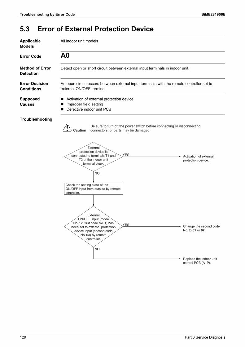
Troubleshooting by Error Code SiME281906E
5.3 Error of External Protection Device
Applicable Models
All indoor unit models
Error Code A0
Method of Error Detection
Detect open or short circuit between external input terminals in indoor unit.
Error Decision Conditions
An open circuit occurs between external input terminals with the remote controller set to external ON/OFF terminal.
Supposed Causes
Activation of external protection device Improper field setting Defective indoor unit PCB
Troubleshooting
Activation of external protection device.
External protection device is
connected to terminals T1 and T2 of the indoor unit
terminal block.
Replace the indoor unit control PCB (A1P).
YES
Change the second code No. to 01 or 02.
External ON/OFF input (mode
No. 12, first code No. 1) has been set to external protection
device input (second code No. 03) by remote
controller.
YES
NO
CautionBe sure to turn off the power switch before connecting or disconnecting connectors, or parts may be damaged.
Check the setting state of the ON/OFF input from outside by remote controller.
NO
129 Part 6 Service Diagnosis

SiME281906E Troubleshooting by Error Code
5.4 Indoor Unit PCB Abnormality
Applicable Models
All indoor unit models
Error code A1
Method of Error Detection
The system checks data from EEPROM.
Error Decision Conditions
The error is generated when the data from the EEPROM is not received correctly.
EEPROM (Electrically Erasable Programmable Read Only Memory): A memory chip that holds its content without power. It can be erased, either within the computer or externally and usually requires more voltage for erasure than the common +5 volts used in logic circuits. It functions like non-volatile RAM, but writing to EEPROM is slower than writing to RAM.
Supposed Causes
Defective indoor unit PCB External factor (Noise, etc.)
Troubleshooting
Replace the indoor unit PCB (A1P, A2P).
Normal reset? NO
Caution
Switch the power OFF and ON again to restart.
The error may be caused byan external factor, rather thandamaged parts.Locate the cause and correctthe situation.
YES
CautionBe sure to turn off the power switch before connecting or disconnecting connectors, or parts may be damaged.
Part 6 Service Diagnosis 130

Troubleshooting by Error Code SiME281906E
Note(s)
5.5 Drain Water Level System Abnormality
Applicable Models
All indoor unit models
Error code A3
Method of Error Detection
By float switch OFF detection
Error Decision Conditions
The error is generated when the water level reaches its upper limit and when the float switch turns OFF.
Supposed Causes
Defective drain pump Improper drain piping work Drain piping clogging Defective float switch Defective indoor unit PCB Defective short circuit connector X15A on PCB
Troubleshooting
1.
Is the drain water level abnormally high?
Does the drain pump work after restarting operation?
Is a drain pump connected to the indoor unit
PCB?
YES YES
YES
Is the float switch connected to the indoor unit PCB?
NO
NO
NO
NONO
YES
Error is displayed again.
YES
Within the rated voltage (∗1)?YES
NO
Set to emergency and check the voltage of the connector to which the drain pump is connected (X25A).
Connect the drain pump.
Drain system abnormality
Connect the float switch.
Replace the float switch.
Replace the indoor unit control PCB (A1P).
Replace the drain pump.
Replace the indoor unit control PCB (A1P).
Caution Be sure to turn off the power switch before connecting or disconnecting connectors, or parts may be damaged.
Remove the float switch from X15A and attach a jumper connector to X15A. Then restart operation.
Model Voltage of the connector
FDMF-A 13 VDC ±10%
131 Part 6 Service Diagnosis
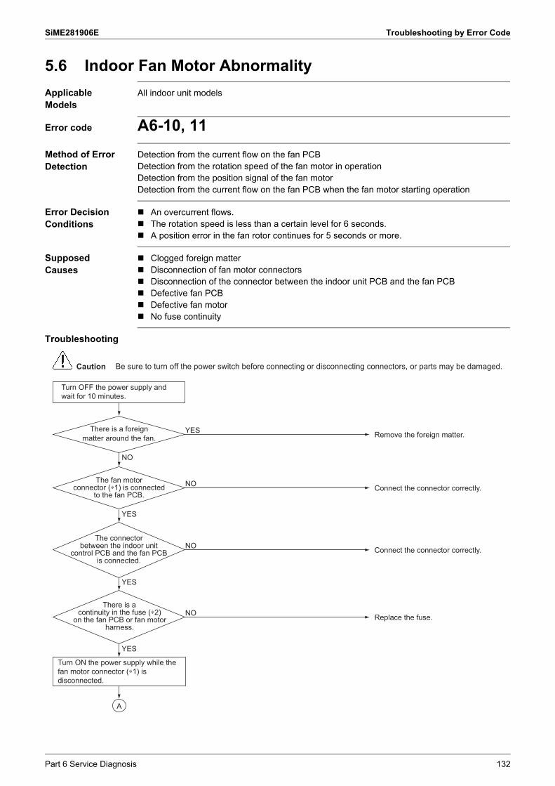
SiME281906E Troubleshooting by Error Code
5.6 Indoor Fan Motor Abnormality
Applicable Models
All indoor unit models
Error code A6-10, 11
Method of Error Detection
Detection from the current flow on the fan PCBDetection from the rotation speed of the fan motor in operationDetection from the position signal of the fan motorDetection from the current flow on the fan PCB when the fan motor starting operation
Error Decision Conditions
An overcurrent flows. The rotation speed is less than a certain level for 6 seconds. A position error in the fan rotor continues for 5 seconds or more.
Supposed Causes
Clogged foreign matter Disconnection of fan motor connectors Disconnection of the connector between the indoor unit PCB and the fan PCB Defective fan PCB Defective fan motor No fuse continuity
Troubleshooting
Connect the connector correctly.
Turn OFF the power supply and wait for 10 minutes.
NO
Turn ON the power supply while the fan motor connector (∗1) is disconnected.
YES
NO
Connect the connector correctly.NO
YES
YES
Replace the fuse. There is a
continuity in the fuse (∗2) on the fan PCB or fan motor
harness.
NO
The fan motor connector (∗1) is connected
to the fan PCB.
Remove the foreign matter.YESThere is a foreign matter around the fan.
The connector between the indoor unit
control PCB and the fan PCB is connected.
A
Caution Be sure to turn off the power switch before connecting or disconnecting connectors, or parts may be damaged.
Part 6 Service Diagnosis 132

Troubleshooting by Error Code SiME281906E
Note(s)
Reference CHECK 7 Refer to page 198.
Turn OFF the power supply and wait for 10 minutes.
Turn OFF the power supply and wait for 10 minutes.
NO
NO
Replace the fan motor.
Each resistance between the pins is equal to or
lower than 1 Ω.Replace the fan motor.Replace the fan PCB (A2P).
The HAP lamp on the indoor
unit control PCB is blinking while the HAP lamp on the fan
PCB is not blinking.
YES
YES
Check the fan motor connectors.CHECK 7
Replace the fan PCB (A2P). ↓When A6 abnormality still reoccurs, replace the fan motor.
A
Model 1 Fan motor connector 2 Fuse
FDMF-A X8A F2U
133 Part 6 Service Diagnosis

SiME281906E Troubleshooting by Error Code
5.7 Fan PCB Abnormality
Applicable Models
All indoor unit models
Error Code A8
Method of Error Detection
Microcomputer checks the voltage state of the fan PCB.
Error Decision Conditions
Overvoltage or voltage drop is detected on the fan PCB.
Supposed Causes
Defective connection of the power supply connector Defective indoor unit PCB Defective fan PCB External factor such as noise
Troubleshooting
Check for the indoor unit control PCB (A1P) and the fan PCB (A2P).
Connect the connector correctly.NO
YES
YES
YES
NO
NO
Is the connector X3A on the fan PCB connected
correctly?Connect the connector correctly.
NO
Is the connector X70A on the indoor unit control PCB connected correctly?
Replace the harness.YES
Is the harness connecting
X3A and X70A broken?
Remove the external factor.YESIs there any
external factor such as noise?
Normal.NOError is
displayed again.
Turn OFF the power supply and then turn it ON again.
↓Start operation with the remote controller.
CautionBe sure to turn off the power switch before connecting or disconnecting connectors, or parts may be damaged.
Part 6 Service Diagnosis 134

Troubleshooting by Error Code SiME281906E
5.8 Humidifier System Abnormality
Applicable Models
All indoor unit models
Error code AF
Method of Error Detection
Water leakage from the humidifier system is detected based on float switch ON/OFF operation while the compressor is in non-operation.
Error Decision Conditions
The float switch is activated while the compressor is OFF. Error code is displayed but the system operates continuously.
Supposed Causes
Defective humidifier water supply and drainage system Dust clogging in the solenoid valve of humidifier Error in the drain pipe installation Defective float switch Defective indoor unit PCB Defective connector connection Defective drain pump
Troubleshooting
Possible failure of float switch.Check to see if drain-upheight and horizontal pipelength exceed specifications.
A humidifier unit is installed on the indoor
unit.
Is humidifier water supply and drainage system
normal?Defective humidifier watersupply and drainage systemClogged drain waterdischarge systemClogged drain pumpDefective float switch
Replace the indoor unitcontrol PCB (A1P).Check to see if drain-upheight and horizontal pipelength exceed specifications.
NO
YES
YES
NO
CautionBe sure to turn off the power switch before connecting or disconnecting connectors, or parts may be damaged.
135 Part 6 Service Diagnosis

SiME281906E Troubleshooting by Error Code
Note(s)
5.9 Defective Capacity Setting
Applicable Models
All indoor unit models
Error code AJ
Method of Error Detection
Capacity is determined according to resistance of the capacity setting adaptor and the memory inside the IC memory on the indoor unit PCB, and whether the value is normal or abnormal is determined.
Error Decision Conditions
The capacity code is not saved to the PCB, and the capacity setting adaptor is not connected.A capacity that does not exist for that unit is set.
Supposed Causes
Defective capacity setting adaptor connection Defective indoor unit PCB
Troubleshooting
CautionBe sure to turn off the power switch before connecting or disconnecting connectors, or parts may be damaged.
Replace the indoor unit control PCB (A1P).
Replace the indoor unit control PCB (A1P).
NO
NO
YES
YES
Install a capacity setting adaptor.
The indoor unit PCB was replaced
with a spare PCB.
The capacity setting
adaptor was installed when replacing the PCB.
Type Model name Capacity setting adaptor
Middle and high staticpressure duct connection type
FDMF18AVMK J56
FDMF24AVMK J80
FDMF30AVMK J112
FDMF36AVMK J112
Part 6 Service Diagnosis 136

Troubleshooting by Error Code SiME281906E
5.10 Transmission Error (between Indoor Unit PCB and Fan PCB)
Applicable Models
All indoor unit models
Error Code C1-01
Method of Error Detection
Check the condition of transmission between the indoor unit control PCB and the fan PCB using microcomputer.
Error Decision Conditions
Error is decided when transmission between the indoor unit control PCB and the fan PCB has been lost for 15 seconds and the error code will be displayed on the remote controller 60 seconds later.
Supposed Causes
Defective connection of the transmission connector between the indoor unit PCB and the fan PCB
Defective indoor unit control PCB Defective fan PCB External factor such as noise
137 Part 6 Service Diagnosis

SiME281906E Troubleshooting by Error Code
Troubleshooting
Check for the indoor unit control PCB (A1P) and the fan PCB (A2P).
Connect the connector correctly.NO
YES
YES
Is the connector X70A on the indoor unit control PCB connected correctly?
Connect the connector correctly.NO
YES
Is the connector X3A on the fan
PCB connected correctly?
Connect the connector correctly.NOIs the
connector X10A on the fan PCB connected
correctly?
YES
NO
Replace the harness.YESIs the
harness broken?
NO
Remove the external factor.YESIs there any
external factor such as noise other than
failure?
Normal.NOError is
displayed again.
Turn OFF the power supply and then turn it ON again.
↓Put the unit into operation with the remote controller.
CautionBe sure to turn off the power switch before connecting or disconnecting connectors, or parts may be damaged.
Part 6 Service Diagnosis 138

Troubleshooting by Error Code SiME281906E
Note(s)
Reference
5.11 Thermistor Abnormality
Applicable Models
All indoor unit models
Error Code C4, C5, C9
Method of Error Detection
The error is detected by temperature detected by thermistor.
Error Decision Conditions
The thermistor becomes disconnected or shorted while the unit is running.
Supposed Causes
Defective connector connection Defective thermistor Defective indoor unit control PCB Broken or disconnected wire
Troubleshooting
Error code and thermistor
CHECK 1 Refer to page 192.
Normal.(Defective connector connection)
Does it function normally?
Replace the indoor unit control PCB (A1P).(Defective PCB)
YES
Disconnect the thermistor on the PCB and connect again.
Disconnect the thermistor on the PCB and measure the resistance with a multimeter.
NO
YES
Replace the thermistor.(Defective thermistor)Is it normal?
NOCHECK 1
CautionBe sure to turn off the power switch before connecting or disconnecting connectors, or parts may be damaged.
Error Code Thermistor Symbol
C4 Indoor heat exchanger liquid pipe thermistor R2T
C5 Indoor heat exchanger middle thermistor R3T
C9 Suction air thermistor R1T
139 Part 6 Service Diagnosis
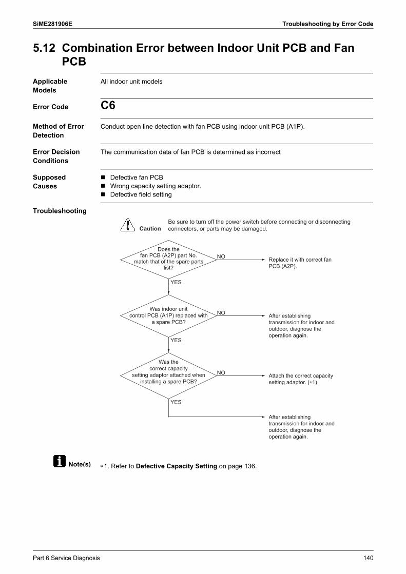
SiME281906E Troubleshooting by Error Code
Note(s)
5.12 Combination Error between Indoor Unit PCB and Fan PCB
Applicable Models
All indoor unit models
Error Code C6
Method of Error Detection
Conduct open line detection with fan PCB using indoor unit PCB (A1P).
Error Decision Conditions
The communication data of fan PCB is determined as incorrect
Supposed Causes
Defective fan PCB Wrong capacity setting adaptor. Defective field setting
Troubleshooting
1. Refer to Defective Capacity Setting on page 136.
CautionBe sure to turn off the power switch before connecting or disconnecting connectors, or parts may be damaged.
Replace it with correct fan PCB (A2P).
Does the fan PCB (A2P) part No.
match that of the spare parts list?
Attach the correct capacity setting adaptor. (∗1)
Was the correct capacity
setting adaptor attached when installing a spare PCB?
NO
Was indoor unit control PCB (A1P) replaced with
a spare PCB?
NO
After establishing transmission for indoor and outdoor, diagnose the operation again.
After establishing transmission for indoor and outdoor, diagnose the operation again.
NO
YES
YES
YES
Part 6 Service Diagnosis 140

Troubleshooting by Error Code SiME281906E
Note(s)
5.13 Remote Controller Thermistor Abnormality
Applicable Models
All indoor unit models
Error Code CJ
Method of Error Detection
Even the error is detected, the system is available for operation through the indoor suction temperature sensor.Error is detected on the temperature detected by the air temperature sensor of the remote controller.
Error Decision Conditions
The remote controller air temperature thermistor is disconnected or short-circuited in operation. The system continues operation while the error code is displayed.
Supposed Causes
Defective remote controller thermistor Defective remote controller PCB External factor such as noise
Troubleshooting
1. To delete the history, the Menu/Enter button of the remote controller must be pressed and held for 4 seconds in the error code display.
Replace the remote controller.Error is displayed again.
External factor such as noise is suspected.
YES
Delete the error code history of the remote controller (∗1).
NO
CautionBe sure to turn off the power switch before connecting or disconnecting connectors, or parts may be damaged.
141 Part 6 Service Diagnosis

SiME281906E Troubleshooting by Error Code
5.14 Outdoor Unit PCB Abnormality
Applicable Models
All outdoor unit models
Error code E1
Method of Error Detection
Microcomputer checks whether EEPROM is normal.
Error Decision Conditions
EEPROM error when turning the power supply ON.
Supposed Causes
Defective outdoor unit main PCB Defective fan motor External factor (Noise, etc.)
Troubleshooting
External factor (Noise, etc.)Does it return normally? YES
NO
Turn the power supply OFF once and then restart.
Replace the outdoor unit main PCB (A1P).
Error is displayed again.
Check the fan motor.
YES
NO
Turn OFF the power supply, remove the fan motor connector and then turn ON the power supply again.
CautionBe sure to turn off the power switch before connecting or disconnecting connectors, or parts may be damaged.
Part 6 Service Diagnosis 142

Troubleshooting by Error Code SiME281906E
5.15 High Pressure Abnormality
Applicable Models
All outdoor unit models
Error code E3
Method of Error Detection
Cooling: Detects errors by the outdoor heat exchanger thermistor. The protection device circuit checks continuity in the high pressure switch.
Error Decision Conditions
Cooling: When the outdoor heat exchanger thermistor detects the following pressure. 3.92 MPa or
more continuously for 1 minute (Ref.: Equivalent saturation temperature 62°C)
Error is detected when high pressure switch is activated.Operating pressure: 4.15 MPa
Supposed Causes
Dirty outdoor heat exchanger Defective outdoor fan motor Overcharge of refrigerant Stop valve is not opened. Defective outdoor unit main PCB
+ 0– 0.15
143 Part 6 Service Diagnosis

SiME281906E Troubleshooting by Error Code
Reference
Troubleshooting
CHECK 2 Refer to page 195.
CautionBe sure to turn off the power switch before connecting or disconnecting connectors, or parts may be damaged.
Correct the high pressure.Is high pressure abnormally high?
Replace the outdoor unit main PCB (A1P).
YES
NO
YES
Check the installation conditions.
Turn OFF the power supply. Wait for 10 minutes after compressor stops operating, then check the following.
Set the remote controller and turn ON again.
YES
YES
NO
CHECK 2
Replace the high pressure switch (S1PH).
YES
Is the stop valve open? Open the stop valve.NO
Are control and protection high
pressure switch connected to outdoor unit main
PCB?
Is there continuity in control and protection high pressure
switch?
Is the error code of H3 displayed?
Connect the connector correctly.
NO
Replace the high pressure switch with no continuity.
NO
Part 6 Service Diagnosis 144

Troubleshooting by Error Code SiME281906E
Reference
Reference
5.16 Low Pressure Abnormality
Applicable Models
All outdoor unit models
Error Code E4
Method of Error Detection
Cooling: Detect errors by the indoor heat exchanger middle thermistor (R3T).
Error Decision Conditions
When the detection pressure is the following value;0.12 MPa or less continues for 5 minutes(Ref.: Equivalent saturation temperature –35°C)
Supposed Causes
Stop valve is not opened. Disconnection of indoor heat exchanger middle thermistor Defective thermistors Defective outdoor unit main PCB Abnormal drop of low pressure
Troubleshooting
CHECK 1 Refer to page 192.
CHECK 3 Refer to page 195.
CautionBe sure to turn off the power switch before connecting or disconnecting connectors, or parts may be damaged.
Open the stop valve.Is the stop valve open? NO
Connect the connector properly.
NO
Replace the indoor heat exchanger middle thermistor.
NO
Replace the outdoor unit main PCB (A1P).
Is low pressure abnormally low?
Is it normal?
Correct the refrigerant system defect.
NO
YES
YES
YES
CHECK 3
Remove the thermistor from the indoor unit PCB and measure resistance.
YES
CHECK 1
Is the indoor heat exchanger
middle thermistor properly connected to the indoor unit
PCB?
145 Part 6 Service Diagnosis

SiME281906E Troubleshooting by Error Code
5.17 Compressor Motor Lock
Applicable Models
All outdoor unit models
Error code E5
Method of Error Detection
Detect the motor lock when the compressor is energized.
Error Decision Conditions
Motor rotor does not rotate when the compressor is energized.
Supposed Causes
Compressor lock High pressure (2.6 MPa or more) at starting Stop valve is not opened.
Troubleshooting
Is the stop valve open? NO
YES
Open the stop valve.
Is high pressure higher than 2.6 MPa at
starting?
Check and see whether compressor is
short-circuited or ground.
NO
YES Remedy the cause.
YES Replace the compressor.
Check the installation conditions.
Replace the compressor.
NO
CautionBe sure to turn off the power switch before connecting or disconnecting connectors, or parts may be damaged.
Part 6 Service Diagnosis 146

Troubleshooting by Error Code SiME281906E
5.18 Outdoor Fan Motor Abnormality
Applicable Models
All outdoor unit models
Error code E7
Method of Error Detection
Abnormality of fan motor system is detected according to the fan revolution detected by Hall IC when the fan motor runs.
Error Decision Conditions
When the fan runs with speed less than a specified one for 15 seconds or more when the fan motor running conditions are met.
When connector detecting fan revolution is disconnected. When the error is generated 4 times, the system shuts down.
Supposed Causes
Defective fan motor The harness connector between fan motor and PCB is left in disconnected, or defective
connector. Fan does not run due to foreign matter tangled. Defective outdoor unit main PCB Blowout of fuse External factor (Noise, etc.)
Troubleshooting RZF18/24AVMK
Is the fan motor connector
correctly connected to the outdoor unit main PCB?
(X106A)
YES
NO Properly connect the connector.
Turn OFF the power (and wait for 10 minutes).
A
Does the fuse F6U have continuity?
NO
YES
Replace the fuse.Use only specified fuse.
Is there any foreign matter around the fan?
NO
YESRemove the foreign matter.
Go to the next page
CautionBe sure to turn off the power switch before connecting or disconnecting connectors, or parts may be damaged.
147 Part 6 Service Diagnosis

SiME281906E Troubleshooting by Error Code
Reference CHECK 7 Refer to page 198.
Is the fan rotatable easily by hand?
Remove the fan motor connector. (X160A)
YES
NO Replace the fan motor.
CHECK 7
Are the resistance values between pins
less than 1 Ω?YES Replace the fan motor and the
outdoor unit main PCB (A1P).(The fan motor is broken by short circuit. Replace the outdoor unit main PCB (A1P) also as there is a possibility of failure.)If the E7 error recurs even so:The device is not at fault.The failure may be caused by external factors (such as noise).
Completed.(The outdoor unit main PCB (A1P) was defective.)If the E7 error recurs even so:The device is not at fault.The failure may be caused by external factors (such as noise).
Replace the fan motor.(The fan motor was broken by open circuit.)
A
Check the resistance value for the fan motor.
NO
Replace the outdoor unit main PCB (A1P).
Does the error recur? YES
NO
Part 6 Service Diagnosis 148

Troubleshooting by Error Code SiME281906E
Reference
Troubleshooting RZF30/36AVMK
CHECK 7 Refer to page 198.
Is the fan motor connector
correctly connected to the outdoor unit main PCB?
(X106A)
YES
NO Properly connect the connector.
Turn OFF the power (and wait for 10 minutes).
Does the fuse F6U have continuity?
NO
YES
Replace the fuse.Use only specified fuse.
Is there any foreign matter around the
fan?NO
YESRemove the foreign matter.
Is the fan rotatable easily by hand?
Remove the fan motor connector. (X106A)
YES
NOReplace the fan motor.
CHECK 7
Are the resistance values between pins
balanced within ±20%?YES Replace the outdoor unit main
PCB (A1P).(The fan motor is not defective.)If the E7 error recurs even so:The device is not at fault.The failure may be caused by external factors (such as noise).
Completed.(The fan motor was defective.)If the E7 error recurs even so:The device is not at fault.The failure may be caused by external factors (such as noise).
Replace the outdoor unit main PCB (A1P).(The fan motor and the outdoor unit main PCB (A1P) were defective.)
Check the resistance value for the fan motor.
NO
Replace the fan motor.
Does the error recur? YES
NO
CautionBe sure to turn off the power switch before connecting or disconnecting connectors, or parts may be damaged.
149 Part 6 Service Diagnosis

SiME281906E Troubleshooting by Error Code
5.19 Electronic Expansion Valve Abnormality
Applicable Models
All outdoor unit models
Error code E9
Method of Error Detection
Detect errors based on check of continuity of the electronic expansion valve. Detect errors by suction pipe superheating degree, discharge pipe superheating degree and
electronic expansion valve opening degree.
[Suction pipe superheating degree]Cooling: Suction pipe temperature – indoor heat exchanger temperature
[Discharge pipe superheating degree]Cooling: Discharge pipe temperature – heat exchanger middle temperature
Error Decision Conditions
No common power supply when the power is turned ON When the following conditions are all met;
Suction pipe superheating degree < 4°CDischarge pipe superheating degree < 5°CElectronic expansion valve opening degree is minimum.
Supposed Causes
Defective electronic expansion valve Broken harness of electronic expansion valve Defective connection of electronic expansion valve connector Defective each thermistor Defective each thermistor mounting Defective outdoor unit main PCB Wet operation
Part 6 Service Diagnosis 150

Troubleshooting by Error Code SiME281906E
Troubleshooting
CautionBe sure to turn off the power switch before connecting or disconnecting connectors, or parts may be damaged.
CHECK 8
Turn OFF the power supply once and then turn ON again.
Connect the connector properly.
YES
YES
Is the electronic expansion
valve connector properly connected to the outdoor
unit main PCB? (∗1)
NO
NO
YES
Replace the electronic expansion valve coil.
Is the coil resistance of the electronic expansion valve normal?
NO
A
Error is displayed again?
Mount the thermistor properly.
Is the thermistors
(suction pipe, discharge pipe, heat
exchanger middle, and outdoor heat exchanger
distributor pipe thermistors) mounted properly?
NO
YES
Go to the next page
151 Part 6 Service Diagnosis

SiME281906E Troubleshooting by Error Code
Note(s)
Reference
Reference
Reference
1. Connector and PCB
CHECK 1 Refer to page 192.
CHECK 8 Refer to page 199.
CHECK 9 Refer to page 200.
Actually, it is in wet operation.
Refer to to eliminate the causes of wet operation.
Restart the operation.
Replace the outdoor unit main PCB (A1P).
YESError is displayed again.
A
External factor (Noise, etc.)
NO
CHECK 1
CHECK 9
YES
Replace the defective thermistor.
Are the characteristics of each
thermistor normal? NO
Electronic expansion valve Connector for electronic expansion valve PCB
Y1E X21A A1P
Part 6 Service Diagnosis 152

Troubleshooting by Error Code SiME281906E
5.20 Discharge Pipe Temperature Abnormality
Applicable Models
All outdoor unit models
Error code F3
Method of Error Detection
The error is detected according to the temperature detected by the discharge pipe thermistor.
The error is detected if there is an abnormality in the self-operating thermal protector.
Error Decision Conditions
The discharge pipe temperature rises to an abnormally high level. The discharge pipe temperature rises suddenly. The discharge pipe temperature does not rise after operation start.
Supposed Causes
Defective discharge pipe thermistor Defective connection of discharge pipe thermistor connector Refrigerant shortage Defective compressor Disconnection of discharge pipe thermistor from discharge pipe Defective outdoor unit main PCB
153 Part 6 Service Diagnosis

SiME281906E Troubleshooting by Error Code
Reference
Troubleshooting
CHECK 1 Refer to page 192.
CautionBe sure to turn off the power switch before connecting or disconnecting connectors, or parts may be damaged.
Abnormality in refrigerant system such as refrigerant shortage, defective compressor, etc.Conduct inspection.
Is the discharge
pipe temperature higher than 110°C or the
compressor self-operating thermal protector
temperature higher than 120°C?
YES
Replace the discharge pipe thermistor.
Is the discharge pipe thermistor characteristic
normal?
Replace the outdoor unit main PCB (A1P).
NO
YES
NO
Connect the thermistor correctly.
Is the discharge pipe
thermistor correctly connected to outdoor unit main PCB?
NO
YES
Attach the thermistor properly.Is the discharge
pipe thermistor attached to the discharge pipe?
NO
YES
CHECK 1
Part 6 Service Diagnosis 154

Troubleshooting by Error Code SiME281906E
Note(s)
5.21 High Pressure Switch System Abnormality
Applicable Models
All outdoor unit models
Error code H3
Method of Error Detection
The protection device circuit checks continuity in the high pressure switch.
Error Decision Conditions
There is no continuity in the high pressure switch when the compressor stops operating.
Supposed Causes
Defective high pressure switch Defective connection of high pressure switch connector Defective outdoor unit main PCB Disconnected lead wire
Troubleshooting
1. Connector
CautionBe sure to turn off the power switch before connecting or disconnecting connectors, or parts may be damaged.
Connect the connector correctly.
Is high pressure switch
connector (∗1) correctly connected to outdoor unit
main PCB?
For 18/24 class :Proceed to H5 troubleshooting.For remaining outdoor units:Replace the outdoor unit main PCB (A1P).
NO
Wait for 10 minutes after the unit stops operating, then check the following.
YES
Replace the high pressure switch with no continuity.Resistance in normal operation: 10 Ω or less
Is there continuity in each high
pressure switch?NO
YES
Replace the lead wire.Is there continuity in lead wire?
NO
YES
High pressure switch Connector for high pressure switch Activation pressure
S1PH X32A 4.15 MPa
155 Part 6 Service Diagnosis

SiME281906E Troubleshooting by Error Code
5.22 Compressor Self-Operating Thermal Protector
Applicable Models
All outdoor unit models
Error Code H5
Method of Error Detection
The error is detected according to the continuity in the compressor self-operating thermal protector.
Error Decision Conditions
There is no continuity in the compressor self-operating thermal protector when the compressor starts operating.
Supposed Causes
Defective outdoor unit main PCB Defective compressor self-operating thermal protector
Troubleshooting
Properly connect thecompressor self-operatingthermal protector.
Replace the compressor self-operating thermal protector.
NO
Replace the outdoor unit mainPCB (A1P). If the error recurs,replace the compressor.
Is the compressor self-
operating thermal protector open (at normal temperature)?
NO
YES
YES
Is the compressor self-
operating thermal protector (X33A) on the outdoor unit main PCB (A1P) properly
connected?
CautionBe sure to turn off the power switch before connecting or disconnecting connectors, or parts may be damaged.
Part 6 Service Diagnosis 156

Troubleshooting by Error Code SiME281906E
Note(s)
Reference
5.23 Thermistor System Abnormality
Applicable Models
All outdoor unit models
Error code H9, J3, J5, J6, J7, J8
Method of Error Detection
The error is detected according to the temperature detected by each thermistor.
Error Decision Conditions
Thermistor is short-circuited or thermistor harness is broken during operation.
Supposed Causes
Defective thermistor Defective connection of connector Defective outdoor unit main PCB
Troubleshooting
1. Connector of thermistor
CHECK 1 Refer to page 192.
CautionBe sure to turn off the power switch before connecting or disconnecting connectors, or parts may be damaged.
Connect the connector correctly.
Is it normal?
Replace the outdoor unit main PCB (A1P).
NO
Remove thermistor from outdoor unit main PCB, then measure the resistance using a multimeter.
Check connectors for connection. (∗1)
YES
Replace the defective thermistor.Is it normal?
NO
YES
CHECK 1
Error Code Defective Thermistor
RZF18/24AVMK RZF30/36AVMK
Electric Symbol Connector Electric
Symbol Connector
H9 Outdoor air thermistor R1T X11A R1T X11A
J3 Discharge pipe thermistor R2T X12A R2T X12A
J5 Suction pipe thermistor R3T X12A R3T X12A
J6 Outdoor heat exchanger distributor pipe thermistor R4T X12A — —
J7 Outdoor heat exchanger middle thermistor R5T X12A R5T X12A
J8 Outdoor heat exchanger liquid pipe thermistor — — R4T X12A
157 Part 6 Service Diagnosis

SiME281906E Troubleshooting by Error Code
Note(s)
5.24 Outdoor Unit PCB Abnormality
Applicable Models
All outdoor unit models
Error code L1
Method of Error Detection
Detect error by current value during waveform output before compressor startup. Detect error by current sensor value during synchronized operation at the time of startup. Detect error using an PAM series capacitor overvoltage sensor.
Error Decision Conditions
Overcurrent is detected at the time of compressor starting. Current sensor error during synchronized operation Overvoltage occurs in PAM. IGBT (1) error EEPROM error
Supposed Causes
Defective outdoor unit main PCB IPM (2) failure Current sensor failure PAM circuit failure Defective IGBT or drive circuit Inverter EEPROM failure
Defective connection of compressor connector Compressor power supply open phase Defective outdoor fan motor Broken fuse External factor (Noise, etc.)
1. IGBT: IGBT is a power semiconductor device primarily used as an electronic switch.2. IPM: IPM is a semiconductor device for electric power incorporating the drive circuit and self-protection feature of the power device which controls electric power.
Part 6 Service Diagnosis 158

Troubleshooting by Error Code SiME281906E
Reference
Troubleshooting RZF18/24AVMK
CHECK 7 Refer to page 198.
CautionBe sure to turn off the power switch before connecting or disconnecting connectors, or parts may be damaged.
Request an improvement to make the power supply voltage fall within the standard range.
Is the power supply voltage within the
standard range?
Are the resistance values between
pins less than 1 Ω?
Does the fuse F6U have continuity?
External factor (Noise, etc.)
NO
Connect the lead wire tightly and correctly.
NO
Replace the fan motor and the outdoor unit main PCB (A1P).(The fan motor is broken by short circuit. Replace the outdoor unit main PCB (A1P) also as there is a possibility of failure.)
YES
Replace the fuse.Use only specified fuse.
NO
NO
Turn OFF the power supply.Disconnect the fan motor connector and restart operation.
Replace the outdoor unit main PCB (A1P).
YES
YES
Power ON again.
YES
Replace the fan motor.NO
YES
Check the resistance value for the fan motor.
YES
Error is displayed again.
Error is displayed again.
NO
CHECK 7
Is the compressor lead
wire securely connected to the PCB and compressor?
Is there open phase?
159 Part 6 Service Diagnosis

SiME281906E Troubleshooting by Error Code
Reference
Troubleshooting RZF30/36AVMK
CHECK 7 Refer to page 198.
CautionBe sure to turn off the power switch before connecting or disconnecting connectors, or parts may be damaged.
Request an improvement to make the power supply voltage fall within the standard range.
Is the power supply voltage within the
standard range?
Are the resistance values between
pins balanced within ±20%?
Does the fuse F6U have continuity?
External factor (Noise, etc.)
NO
Connect the lead wire tightly and correctly.
NO
NO
Replace the fuse.Use only specified fuse.
NO
NO
Turn OFF the power supply.Disconnect the fan motor connector and restart operation.
Replace the outdoor unit main PCB (A1P).
YES
YES
Power ON again.
Replace the fan motor.
YES
Replace the fan motor.NO
YES
Check the resistance value for the fan motor.
YES
Error is displayed again.
Error is displayed again.
YES
CHECK 7
Is the compressor lead
wire securely connected to the PCB and compressor?
Is there open phase?
Part 6 Service Diagnosis 160

Troubleshooting by Error Code SiME281906E
5.25 Radiation Fin Temperature Rise
Applicable Models
All outdoor unit models
Error code L4
Method of Error Detection
Radiation fin temperature is detected by the radiation fin thermistor.
Error Decision Conditions
The temperature of the inverter radiation fin rises abnormally due to defective heat dissipation.
Supposed Causes
Silicone grease is not properly adhered to the refrigerant piping and radiation fin. The refrigerant piping is not fixed to or contacting the radiation fin. U0 error (Refrigerant shortage) High outdoor air temperature Defective outdoor unit main PCB
Troubleshooting
CautionBe sure to turn off the power switch before connecting or disconnecting connectors, or parts may be damaged.
Correct the malfunction.Normal?
Continue operation.Local causes such as high outdoor air temperatures may have caused the radiation fin temperature to rise.
NO
Check the cooling status of the radiation fin for inverter cooling.(1) Is silicone grease properly
adhered to the refrigerant piping and radiation fin?
(2) Is the refrigerant piping fixed to and contacting the radiation fin with the cover and fixing screws?
(3) U0 error code appears in the error history.
YES
Replace the outdoor unit main PCB (A1P).
Does the error recur after turning
the power on and starting operation again?
YES
NO
Remove the power module thermistor connector (X111A) on the PCB (A1P) and mount correctly.
∗ RZF30/36AVMK only
161 Part 6 Service Diagnosis

SiME281906E Troubleshooting by Error Code
5.26 DC Output Overcurrent
Applicable Models
All outdoor unit models
Error code L5
Method of Error Detection
The error is detected by converting the current flowing to power transistor into voltage with DC current sensor.
Error Decision Conditions
Overcurrent has run to power transistor.(Actuated even by instantaneous overcurrent)
Supposed Causes
Defective compressor coil (disconnection, poor insulation) Compressor startup error (mechanical lock) Defective outdoor unit main PCB Defective compressor (scratched bearing) The stop valve is not opened. Momentary power failure Compressor noise, vibration Compressor power supply open phase
Troubleshooting
Connect tightly and correctly.Fix the open phase.
Is the compressor lead wire
securely connected to the PCB and compressor? Is there
open phase?
NO
Replace the compressor.Compressor is
grounded or short-circuited.YES
Check the installation conditions.
YES
NO
Open the stop valve.Is the stop valve open? NO
YES
A
YES
Replace the outdoor unit main PCB (A1P).
NOContinuity check in the power transistor (IGBT (∗1)).
Is the continuity normal?
CHECK 4
Go to the next page
CautionBe sure to turn off the power switch before connecting or disconnecting connectors, or parts may be damaged.
Part 6 Service Diagnosis 162

Troubleshooting by Error Code SiME281906E
Note(s)
Reference
1. IGBT: IGBT is a power semiconductor device primarily used as an electronic switch.2. In order to operate the compressor reliably, use the remote controller to set the test operation mode. The test operation mode lasts for 30 minutes, then automatically finishes and switches to normal mode. To continue in test operation mode, set the test operation mode once again.3. The unit must be run for at least 30 minutes to confirm the L5 error.
CHECK 4 Refer to page 196.
Inspect according to the diagnosis procedure for abnormal noise, vibration, operating status, etc. of the compressor.
Check the power supply voltage.
Turn on the power and operate in test operation mode (∗2).
YES
Correct the power supply.Is instantaneous
voltage drop generated?YES
Try another error diagnosis flow.Does error code L5 recur? (∗3)
Does normal operation continue?
NO NO
NO
Normal.
YES
A
163 Part 6 Service Diagnosis

SiME281906E Troubleshooting by Error Code
5.27 Compressor Overcurrent
Applicable Models
All outdoor unit models
Error code L8
Method of Error Detection
The error is detected by converting the current flowing to power transistor into voltage with DC current sensor.
Error Decision Conditions
Compressor overload (except for when startup) is detected.
Supposed Causes
Stop valve is not opened. High pressure is too high. Defective compressor wiring, compressor open phase Broken compressor coil Defective outdoor unit main PCB Defective compressor (scratched bearing)
Part 6 Service Diagnosis 164

Troubleshooting by Error Code SiME281906E
Note(s)
Reference
Reference
Reference
Troubleshooting
1. Inverter secondary current reference values:
2. IGBT: IGBT is a power semiconductor device primarily used as an electronic switch.
CHECK 2 Refer to page 195.
CHECK 4 Refer to page 196.
CHECK 12 Refer to page 203.
Open the stop valve.
Correct the malfunction.Check for refrigerant overcharge.
Is the secondary current of
the inverter higher than the reference values (∗1) for
each phase?
Is the stop valve open?
Compressor inspection.Inspect according to the diagnosis procedure for abnormal noises, vibration, operating status, etc. of the compressor.� Replacement of the outdoor unit
main PCB (A1P) is not necessary.
YES NO
YES
Caution Be sure to turn off the power switch before connecting or disconnecting connectors, or parts may be damaged.
Turn the main power supply OFF.
NO YES
Replace the outdoor unit main PCB (A1P).
NO
YES
Replace the outdoor unit main PCB (A1P).
NO
CHECK 4Continuity check in the
power transistor (IGBT (∗2)). Is the continuity
normal?
Secure the connection.Correct the open phase.
NO
YES
Is the compressor lead wire
securely connected to the PCB and compressor? Is there
open phase?
Pressure is high.CHECK 2
CHECK 12
Model Detection value
RZF18/24AVMK Cooling 17.7 A × 260 seconds
RZF30/36AVMK Cooling 22.1 A × 260 seconds
165 Part 6 Service Diagnosis

SiME281906E Troubleshooting by Error Code
5.28 Compressor Startup Abnormality
Applicable Models
All outdoor unit models
Error code L9
Method of Error Detection
The error is detected by converting the current flowing to power transistor into voltage with CT1 (DC current sensor).Outdoor unit main PCB detects the disorder of position signal.
Error Decision Conditions
When overload or load fluctuation is detected at compressor startup.
Supposed Causes
The stop valve is not opened. Defective wiring between compressor and inverter Defective compressor wiring, compressor open phase Pressure differential startup (0.9 MPa or more) Defective outdoor unit main PCB Defective compressor (lock)
Troubleshooting
CautionBe sure to turn off the power switch before connecting or disconnecting connectors, or parts may be damaged.
Open the stop valve.Is the stop valve open? NO
NO
YES
Mount the compressor lead wire.
Compressor lead wire is detached.
YES
NO
Check the installation conditions.
Insufficient pressure equalization.Check refrigerant system.
Is the difference between
high and low pressure before startup less than 0.2
MPa?
YES
A Go to the next page
Part 6 Service Diagnosis 166

Troubleshooting by Error Code SiME281906E
Note(s)
Reference
1. IGBT: IGBT is a power semiconductor device primarily used as an electronic switch.
CHECK 4 Refer to page 196.
Compressor inspection.Inspect according to the diagnosis procedure for abnormal noises, vibration, operating status, etc. of the compressor.
Replace the outdoor unit main PCB (A1P).
NO
NO
Replace the compressor.
Continuity check in the power transistor (IGBT (∗1)).
Is the continuity normal?
YES
Turn the main power supply OFF.
Disconnect the connection between the compressor and inverter.
YES
YES
The compressor is
grounded and short-circuited.
Connect tightly and correctly.Fix the open phase.
NO
Is the compressor lead
wire securely connected to the PCB and compressor?
Is there open phase?
CHECK 4
A
167 Part 6 Service Diagnosis

SiME281906E Troubleshooting by Error Code
5.29 Transmission Error between Microcomputers on Outdoor Unit Main PCB
Applicable Models
All outdoor unit models
Error code LC
Method of Error Detection
Check whether transmission between microcomputers on the outdoor unit main PCB is carried out normally.
Error Decision Conditions
The transmission is not carried out normally in a specified period of time.
Supposed Causes
Defective outdoor unit main PCB External factor (Noise, etc.) Defective outdoor fan motor Defective connection of fan motor connector
Troubleshooting
Connect the connector, and turn ON again.
Is the fan motor connector connected properly to
the outdoor unit main PCB?
NO
YES
Replace the outdoor unit main PCB (A1P).
Disconnect the fan motor connector, and turn ON again.
NO
Replace the fan motor.Inverter transmission error due to the error of fan motor.
Is the error code E7 displayed? (Is LC
not displayed?)
YES
CautionBe sure to turn off the power switch before connecting or disconnecting connectors, or parts may be damaged.
Part 6 Service Diagnosis 168

Troubleshooting by Error Code SiME281906E
5.30 PAM Circuit Error
Applicable Models
RZF18/24AVMK
Error code P1
Method of Error Detection
The error is detected according to the voltage waveform of main circuit capacitor built in inverter.
Error Decision Conditions
The above voltage waveform fluctuation increases.
Supposed Causes
Reactor connector detached Outdoor unit main PCB (A1P) malfunction (PAM circuit failure)
Troubleshooting
CautionBe sure to turn off the power switch before connecting or disconnecting connectors, or parts may be damaged.
Replace the outdoor unit main PCB (A1P).
Reinsert the connectors correctly.
Are the connectors for the reactor
L1R detached?YES
NO
169 Part 6 Service Diagnosis
SiME281906E Troubleshooting by Error Code
5.31 Open Phase or Power Supply Voltage Imbalance
Applicable Models
RZF30/36AVMK
Error code P1
Method of Error Detection
The error is detected according to the voltage waveform of main circuit capacitor built in inverter.
Error Decision Conditions
The above voltage waveform fluctuation increases.
Supposed Causes
Defective outdoor unit main PCB Defective main circuit capacitor Disconnection in diode module Defective magnetic relay Improper main circuit wiring
Troubleshooting
Replace the outdoor unit main PCB (A1P).
Caution Be sure to turn off the power switch before connecting or disconnecting connectors, or parts may be damaged.
Part 6 Service Diagnosis 170

Troubleshooting by Error Code SiME281906E
5.32 Power Module Thermistor Abnormality
Applicable Models
RZF30/36AVMK
Error code P4
Method of Error Detection
Detects open or short-circuit of the radiation fin thermistor while the compressor stops operating.
Error Decision Conditions
Open or short-circuit of the radiation fin thermistor is detected while the compressor stops operating.
Supposed Causes
Defective outdoor unit main PCB(Defective radiation fin thermistor)
External factor (Noise, etc.)
Troubleshooting
CautionBe sure to turn off the power switch before connecting or disconnecting connectors, or parts may be damaged.
Remove the power module thermistor connector (X111A) on the PCB (A1P) and mount correctly.
Replace the outdoor unit main PCB (A1P).
Continue operation.(Likely due to factors other than failure (noise, etc.))
Does error code P4 recur even when
the power is turned on again?
YES
NO
171 Part 6 Service Diagnosis

SiME281906E Troubleshooting by Error Code
Note(s)
5.33 Capacity Setting Abnormality
Applicable Models
All outdoor unit models
Error code PJ
Method of Error Detection
Judge whether the combination is correct through communication between the inverter and control microcomputers and the fan and control microcomputers.
Error Decision Conditions
If there is a mismatch in the signals sent between the inverter and control microcomputers, or between the fan and control microcomputers, the error is confirmed. (Error decision is made every time the power supply is turned ON.)
Supposed Causes
Outdoor unit main PCB model mistake EEPROM data is not written correctly or cannot be read.
Troubleshooting
1. Capacity setting adaptor is not connected at factory. (Capacity is written in EEPROM.) Capacity data for spare PCB is also written to the EEPROM, so a capacity setting adapter is not required.
Replace the outdoor unit main PCB (A1P) with the correct model.
Was the outdoor unit main PCB replaced?
Is the outdoor unit main PCB model correct?
YES NO
Caution Be sure to turn off the power switch before connecting or disconnecting connectors, or parts may be damaged.
NO YES
Restart operation after power reset.
Part 6 Service Diagnosis 172

Troubleshooting by Error Code SiME281906E
Reference
5.34 Refrigerant Shortage (Warning/Alarm)
Applicable Models
All outdoor unit models
Error code U0
Method of Error Detection
Judgment is based on the opening degree of electronic expansion valves as well as individual temperatures and pressures.
Error Decision Conditions
An error code is displayed but system operation continues.
Cooling Compressor frequency does not increase even though the electronic expansion valve is
opened to the fullest extent due to the heavy load. The temperature detected with the outdoor heat exchanger middle thermistor (R5T) does
not increase even when operation starts. The temperature detected with the indoor heat exchanger thermistor (R2T) does not
decrease even when operation starts.
Supposed Causes
Refrigerant shortage Defective compressor wiring, compressor open phase Stop valve is not opened. Clogged refrigerant piping system
Troubleshooting
CHECK 10 Refer to page 201.
CautionBe sure to turn off the power switch before connecting or disconnecting connectors, or parts may be damaged.
CHECK 10
Collect refrigerant and conduct vacuum drying, then recharge a proper amount of refrigerant.
Is the refrigerant level proper?
Check the refrigerant piping system for clogging.
NO
YES
YES
Is the compressor lead wire
securely connected to the PCB and compressor?
Connect tightly and correctly.Fix the open phase.
NO
173 Part 6 Service Diagnosis

SiME281906E Troubleshooting by Error Code
5.35 Refrigerant Shortage (Error)
Applicable Models
All outdoor unit models
Error code U0
Method of Error Detection
CoolingDetection based on difference in temperature between temperature preset by remote controllerand suction air temperature, electronic expansion valve opening degree, compressor frequencyand low pressure.
Error Decision Conditions
CoolingThe conditions below are obtained under a refrigerant shortage warning (1) The evaporation temperature remains far below the target evaporation temperature. The temperature detected with the outdoor heat exchanger middle thermistor (R5T) does
not increase even when operation starts. The temperature detected with the indoor heat exchanger thermistor (R2T) does not
decrease even when operation starts..1. In test operation mode, the conditions are obtained even without a refrigerant shortage warning.
Supposed Causes
Refrigerant shortage Defective compressor wiring, compressor open phase Stop valve is not opened. Clogged refrigerant piping system Mismatching of wiring and piping
Part 6 Service Diagnosis 174

Troubleshooting by Error Code SiME281906E
Reference
Reference
Troubleshooting
CHECK 10 Refer to page 201.
CHECK 11 Refer to page 202.
CautionBe sure to turn off the power switch before connecting or disconnecting connectors, or parts may be damaged.
CHECK 11
CHECK 10
Collect refrigerant and conduct vacuum drying, then recharge a proper amount of refrigerant.
Is the refrigerant level proper?
Check the refrigerant piping system for clogging.
NO
YES
Check for refrigerant shortage.
Check the transmission wiring and piping between the indoor and outdoor units.
YES
YES
Open the stop valve.Is the stop valve open?
NO
YES
Match wiring and piping connection.
Is wiring and piping connection matched?
NO
Is the compressor lead
wire securely connected to the PCB and compressor? Is
there open phase?Connect tightly and correctly.Fix the open phase.
NO
175 Part 6 Service Diagnosis

SiME281906E Troubleshooting by Error Code
5.36 Power Supply Voltage Abnormality
Applicable Models
All outdoor unit models
Error code U2
Method of Error Detection
The error is detected according to the voltage of main circuit capacitor built in inverter and the power supply voltage.
Error Decision Conditions
The voltage of main circuit capacitor built in inverter and the power supply voltage are detected to be abnormal.
Supposed Causes
Dropping power supply voltage Instantaneous power failure Defective outdoor fan motor Defective compressor wiring, compressor open phase Defective outdoor unit main PCB Voltage fluctuation due to an in-house generator
Troubleshooting RZF18/24AVMK
Correct the power supply voltage.Is the power
supply voltage within the normal range?
NO
Replace the fan motor and the outdoor unit main PCB (A1P).(The fan motor is broken by short circuit. Replace the outdoor unit main PCB (A1P) also as there is a possibility of failure.)
YES
Caution Be sure to turn off the power switch before connecting or disconnecting connectors, or parts may be damaged.
Are the resistance values between pins less
than 1 Ω?
YES
NO
Remove the fan motor connector from the PCB and start operation.
Replace the fan motor.Does error code U2 recur?
Is the fan motor operating normally?
(Refer to E7 troubleshooting flowchart)
NO NO
YESYES
CHECK 7
A Go to the next page
Part 6 Service Diagnosis 176

Troubleshooting by Error Code SiME281906E
Reference
Reference
CHECK 4 Refer to page 196.
CHECK 7 Refer to page 198.
Replace the outdoor unit main PCB (A1P).
NO
Monitor the voltage. (Instantaneous voltage drop)(Voltage fluctuation due to an in-house generator)
YESIs the
measured voltage 220 VDC or more?
While the compressor is running, measure the voltage between C+ and C– of power module.
Replace the outdoor unit main PCB (A1P).
Connect the fan motor and operate?
NO
YES
Connect the wires correctly.
Are the power supply and compressor connections correct? Is
there open phase?
NO
YES
A
CHECK 4
177 Part 6 Service Diagnosis

SiME281906E Troubleshooting by Error Code
Reference
Reference
Troubleshooting RZF30/36AVMK
CHECK 4 Refer to page 196.
CHECK 7 Refer to page 198.
Correct the power supply voltage.Is the power
supply voltage within the normal range?
NO
NO
Caution Be sure to turn off the power switch before connecting or disconnecting connectors, or parts may be damaged.
Are the resistance values between pins balanced
within ±20%?
YES
YES
Remove the fan motor connector from the PCB and start operation.
Replace the fan motor.Does error code U2 recur?Is the fan motor
operating normally? (Referto E7 troubleshooting
flowchart)
NO NO
YESYES
CHECK 7
Replace the outdoor unit main PCB (A1P).
NO
Monitor the voltage. (Instantaneous voltage drop)(Voltage fluctuation due to an in-house generator)
YESIs the
measured voltage 220 VDC or more?
While the compressor is running,measure the voltage between C+ and C– of power module.
Replace the outdoor unit main PCB (A1P).
Connect the fan motor and operate?
NO
YES
Connect the wires correctly.
Are the powersupply and compressor connections correct? Is
there open phase?
NO
YES
CHECK 4
Replace the fan motor.
Part 6 Service Diagnosis 178

Troubleshooting by Error Code SiME281906E
5.37 Transmission Error between Indoor Unit and Outdoor Unit, Outdoor Fan Motor Abnormality
Applicable Models
All indoor unit modelsAll outdoor unit models
Error code U4
Method of Error Detection
The microcomputer detects transmission error between the indoor and the outdoor unit.
Error Decision Conditions
The normal transmission is not conducted for a certain period of time.
Supposed Causes
Wiring indoor-outdoor transmission wire is incorrect. Optional device connection malfunction Defective indoor unit PCB Defective outdoor unit main PCB Defective outdoor fan motor External factor (Noise, etc.) Defective power supply
179 Part 6 Service Diagnosis
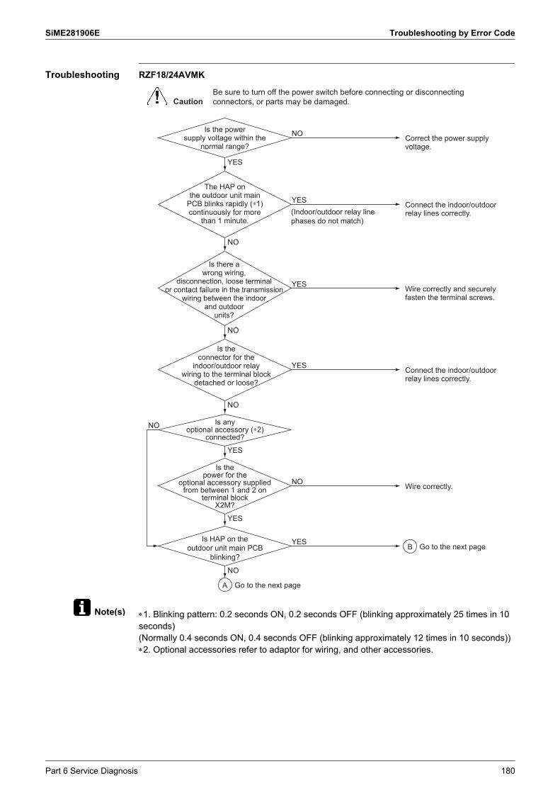
SiME281906E Troubleshooting by Error Code
Note(s)
Troubleshooting RZF18/24AVMK
1. Blinking pattern: 0.2 seconds ON, 0.2 seconds OFF (blinking approximately 25 times in 10 seconds)(Normally 0.4 seconds ON, 0.4 seconds OFF (blinking approximately 12 times in 10 seconds))2. Optional accessories refer to adaptor for wiring, and other accessories.
CautionBe sure to turn off the power switch before connecting or disconnecting connectors, or parts may be damaged.
Is the power supply voltage within the
normal range?Correct the power supply voltage.
NO
Is the connector for the
indoor/outdoor relay wiring to the terminal block
detached or loose?
Connect the indoor/outdoor relay lines correctly.
YES
The HAP on the outdoor unit main
PCB blinks rapidly (∗1) continuously for more
than 1 minute.
Connect the indoor/outdoor relay lines correctly.(Indoor/outdoor relay line
phases do not match)
YES
Is there a wrong wiring,
disconnection, loose terminal or contact failure in the transmission
wiring between the indoor and outdoor
units?
Is any optional accessory (∗2)
connected?
Is the power for the
optional accessory supplied from between 1 and 2 on
terminal block X2M?
Wire correctly and securely fasten the terminal screws.
YES
Wire correctly.NO
Is HAP on the outdoor unit main PCB
blinking?
YES
YES
NO
NO
YES
YES
NO
NO
NO
A
B Go to the next page
Go to the next page
Part 6 Service Diagnosis 180

Troubleshooting by Error Code SiME281906E
Reference CHECK 7 Refer to page 198.
Replace the fan motor and the outdoor unit main PCB (A1P).(The fan motor is broken by short circuit. Replace the outdoor unit main PCB (A1P) also as there is a possibility of failure.)
Are the resistance values between
pins less than 1 Ω?YES
NO
NO
Replace the indoor unit PCB.
External factor (Noise, etc.)
External factor (Noise, etc.)
Is the error code U4 displayed?
YES
Error is displayed again. NO
YES
After turning OFF the power supply, correctly insert the connector of the fan motor and then restore the power.
Replace the outdoor unit main PCB (A1P).
Check the resistance value of the outdoor fan motor.
A
B
CHECK 7
Is HAP on the outdoor unit main PCB
blinking?Replace the outdoor fan motor.
YES
NO
Turn OFF the power supply and disconnect the connector of the outdoor fan motor. Then power ON again.
181 Part 6 Service Diagnosis
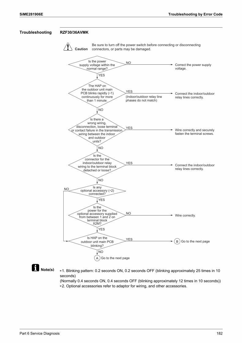
SiME281906E Troubleshooting by Error Code
Note(s)
Troubleshooting RZF30/36AVMK
1. Blinking pattern: 0.2 seconds ON, 0.2 seconds OFF (blinking approximately 25 times in 10 seconds)(Normally 0.4 seconds ON, 0.4 seconds OFF (blinking approximately 12 times in 10 seconds))2. Optional accessories refer to adaptor for wiring, and other accessories.
CautionBe sure to turn off the power switch before connecting or disconnecting connectors, or parts may be damaged.
Is the power supply voltage within the
normal range?Correct the power supply voltage.
NO
Is the connector for the
indoor/outdoor relay wiring to the terminal block
detached or loose?
Connect the indoor/outdoor relay lines correctly.
YES
The HAP on the outdoor unit main
PCB blinks rapidly (∗1) continuously for more
than 1 minute.
Connect the indoor/outdoor relay lines correctly.(Indoor/outdoor relay line
phases do not match)
YES
Is there a wrong wiring,
disconnection, loose terminal or contact failure in the transmission
wiring between the indoor and outdoor
units?
Is any optional accessory (∗2)
connected?
Is the power for the
optional accessory supplied from between 1 and 2 on
terminal block X2M?
Wire correctly and securely fasten the terminal screws.
YES
Wire correctly.NO
Is HAP on the outdoor unit main PCB
blinking?
YES
YES
NO
NO
YES
YES
NO
NO
NO
A
B Go to the next page
Go to the next page
Part 6 Service Diagnosis 182

Troubleshooting by Error Code SiME281906E
Reference CHECK 7 Refer to page 198.
Are the resistance values between
pins balanced within ±20%?
NO
YES
NO
Replace the indoor unit PCB.
External factor (Noise, etc.)
External factor (Noise, etc.)
Is the error code U4 displayed?
YES
Error is displayed again.NO
YES
After turning OFF the power supply, correctly insert the connector of the fan motor and then restore the power.
Replace the outdoor unit main PCB (A1P).
Check the resistance value of the outdoor fan motor.
A
B
CHECK 7
Is HAP on the outdoor unit main PCB
blinking?Replace the outdoor fan motor.
YES
NO
Turn OFF the power supply and disconnect the connector of the outdoor fan motor. Then power ON again.
Replace the outdoor fan motor.
183 Part 6 Service Diagnosis

SiME281906E Troubleshooting by Error Code
Reference
5.38 Transmission Error between Indoor Unit and Remote Controller
Applicable Models
All indoor unit models
Error code U5
Method of Error Detection
Microcomputer checks if transmission between indoor unit and remote controller is normal.
Error Decision Conditions
The transmission between the indoor unit and the remote controller is not normal over a certain amount of time.
Supposed Causes
Defective remote controller Defective indoor unit PCB External factor (Noise, etc.) Connection of 2 main remote controllers (when using 2 remote controllers).
Troubleshooting
Refer to Main/Sub setting on page 34.
Set one of the remote controllers to Sub, turn OFF the power supply temporarily, then restart operation.
Main/Sub setting of both remote
controllers is set to Main.
Control by 2 remote controllers
YES
NO
YES
NOReplace the indoor unit PCB.
Resets normally when power supply is turned OFF
temporarily.
All indoor unit PCB microcomputer normal
monitors blinking
The error could be produced by noise. Check the surrounding area and restart operation. (Ex.: Heavy-duty wireless equipment, etc.)
YES
Caution Be sure to turn off the power switch before connecting or disconnecting connectors, or parts may be damaged.
NO NO
NO
YES
Is operation normal? Normal.YES
NO
Is operation normal? Normal.YES
The error could be produced by noise. Check the surrounding area and restart operation.
Replace the remote controller and restart operation.
Replace the indoor unit PCB and restart operation.
Part 6 Service Diagnosis 184

Troubleshooting by Error Code SiME281906E
Reference
5.39 Transmission Error between Main Remote Controller and Sub Remote Controller
Applicable Models
All indoor unit models
Error code U8
Method of Error Detection
In case of controlling with 2 remote controllers, check the system using microcomputer if signal transmission between indoor unit and remote controller (main and sub) is normal.
Error Decision Conditions
The transmission between the indoor unit and the remote controllers (main and sub) is not normal over a certain amount of time.
Supposed Causes
Remote controller setting malfunction Remote controller wiring disconnection Transmission error between main remote controller and sub remote controller No main remote controller in the system Defective remote controller
Troubleshooting
Refer to Main/Sub setting on page 34.
Set the Main/Sub setting of one remote controller to Main.Turn OFF the power supply, and restart operation.
Main/Sub setting of one of the remote controllers is
set to Main.
Controlling with 2 remote controllers
NO
NO
NO
YES Turn OFF the power once and restart operation.Replace the remote controller PCB if any error is generated.
Is there continuity in remote
controller wiring?
Main/Sub setting on both remote
controllers are set to Sub.
Replace the remote controller wiring.
NO
Caution Be sure to turn off the power switch before connecting or disconnecting connectors, or parts may be damaged.
YES YES
Set the Main/Sub setting of one remote controller to Main.Turn OFF the power supply, and restart operation.
YES
185 Part 6 Service Diagnosis

SiME281906E Troubleshooting by Error Code
5.40 Field Setting Switch Abnormality
Applicable Models
All indoor unit models
Error Code UA
Error Decision Conditions
The indoor unit and outdoor unit combination is incorrect. Field settings are not correct.
Supposed Causes
Multiple remote controllers connected Defective indoor unit PCB Indoor-outdoor, indoor-indoor unit transmission wiring Optional device connection malfunction Power supply PCB connection malfunction Indoor unit power supply malfunction or miswiring Miswiring between units Defective remote controller wiring
Part 6 Service Diagnosis 186
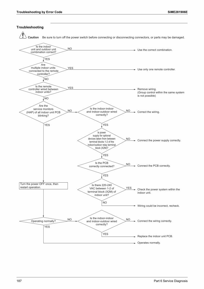
Troubleshooting by Error Code SiME281906E
Troubleshooting
Use the correct combination.Is the indoor
unit and outdoor unit combination correct?
NO
Use only one remote controller.YESAre
multiple indoor units connected to the remote
controller?
Caution Be sure to turn off the power switch before connecting or disconnecting connectors, or parts may be damaged.
YES
Remove wiring.(Group control within the same system is not possible)
Is the remote controller wired between
indoor units?
YES
NO
Operating normally?
NO
Correct the wiring.Is the indoor-indoor
and indoor-outdoor wired correctly?
Is there 220-240 VAC between 1-2 of
terminal block (X2M) of indoor unit?
Are the service monitors
(HAP) of all indoor unit PCB blinking?
NO NO
NO Connect the PCB correctly.
YES Check the power system within the indoor unit.
NONO Connect the wiring correctly.
Wiring could be incorrect, recheck.NO
Replace the indoor unit PCB.YES
YES
Is the PCB correctly connected?
Is the indoor-indoor and indoor-outdoor wired
correctly?
YES
NO Connect the power supply correctly.
Is power supply for optional
devices taken from between terminal blocks 1-2 of the
indoor/outdoor relay terminal block (X2M)?
YES
YES
Operates normally.
YES
Turn the power OFF once, then restart operation.
187 Part 6 Service Diagnosis

SiME281906E Troubleshooting by Error Code
5.41 Centralized Address Setting Error
Applicable Models
All indoor unit models
Error Code UC
Method of Error Detection
Indoor unit microcomputer detects and judges the centralized address signal according to the transmission between indoor units.
Error Decision Conditions
When the microcomputer judges that the centralized address signal is duplicated
An error code is displayed but system operation continues.
Supposed Causes
Defective centralized address setting Defective indoor unit PCB
Troubleshooting
Change the setting so that the centralized address is not duplicated.
Are devices relating to centralized control connected to
the indoor unit?
Replace the indoor unit PCB.
YES
NO
CautionBe sure to turn off the power switch before connecting or disconnecting connectors, or parts may be damaged.
Part 6 Service Diagnosis 188

Troubleshooting by Error Code SiME281906E
5.42 Transmission Error between Centralized Controller and Indoor Unit
Applicable Models
All indoor unit models Schedule timer Central remote controller
Error Code UE
Method of Error Detection
Microcomputer checks if transmission between indoor unit and centralized controller is normal.
Error Decision Conditions
Transmission is not carried out normally for a certain amount of time
Supposed Causes
Broken wire or wrong wiring Group No. address setting error Transmission error between optional controllers for centralized controller and indoor unit Defective PCB for central remote controller Defective indoor unit PCB
189 Part 6 Service Diagnosis

SiME281906E Troubleshooting by Error Code
Troubleshooting
Has the setting of central
control group No. been made with the indoor unit on
which the UE occurred?
Check the indoor
unit for which UE is displayed. Is the
transmission error UE caused on all indoor units?
Was the indoor unit
disconnected after connected or central
control group No. for indoor unit changed?
Is any broken wire or wrong wiring
found?
YES
Make correct setting of the central control group No.
Replace the indoor unit PCB.
NO
YES
YES
NONO
NO
YES
Reset the power supplies of every centralized controller.
Correct the wiring.
CautionBe sure to turn off the power switch before connecting or disconnecting connectors, or parts may be damaged.
Check the transmission wiring
between main centralized controller for any broken
wire or wrong wiring.
Replace the centralized controller.
Correct the wiring.NG
YES
Has the main centralized
controller setting connector been connected?
OK
Correct the connection of the connector.
NO
Part 6 Service Diagnosis 190

Troubleshooting by Error Code SiME281906E
5.43 Transmission Error between Indoor Unit and Outdoor Unit
Applicable Models
All outdoor unit models
Error code UF
Method of Error Detection
Checks the transmission between the indoor and outdoor units with a microcomputer when the power turned ON.
Error Decision Conditions
The transmission wiring between the indoor and outdoor units is incorrect.
Supposed Causes
This is not a failure of the outdoor unit main PCB. Defective transmission wiring between the indoor and outdoor units
Troubleshooting
CautionBe sure to turn off the power switch before connecting or disconnecting connectors, or parts may be damaged.
Correctly connect transmission wiring between the indoor and outdoor units.
The phase of transmission wiring between the indoor and outdoor units is incorrect.
191 Part 6 Service Diagnosis

SiME281906E Check
6. Check6.1 Thermistor Check
CHECK 1 If the cause of the problem is related to the thermistors, then the thermistors should be checked prior to changing the PCB.
Overview of ThermistorsThe table below contains an overview of the thermistors:Indoor
Outdoor
Checking To check the thermistors, proceed as follows:
Thermistor FDFM-A
R1T Suction air thermistor Type B
R2T Indoor heat exchanger liquid pipe thermistor Type A
R3T Indoor heat exchanger middle thermistor Type L
Thermistor RZF18/24AVMK RZF30/36AVMK
R1T Outdoor air thermistor Type M Type E
R2T Discharge pipe thermistor Type G Type G
R3T Suction pipe thermistor Type A Type A
R4T
Outdoor heat exchanger distributor pipe thermistor Type A —
Outdoor heat exchanger liquid pipe thermistor — Type A
R5T Outdoor heat exchanger middle thermistor Type A Type A
Step Action
1 Disconnect the thermistor from the PCB
2 Read the temperature and the resistance value.
3 Check if the measured values correspond with the values in the table on the next pages.
Part 6 Service Diagnosis 192

Check SiME281906E
Thermistor Resistance / Temperature Characteristics
This data is for reference purposes only.
Thermistor temperature
(°C)
Resistance (k)
Type A Type B Type E
30 363.8 361.7719 362.4862
25 266.8 265.4704 265.9943
20 197.8 196.9198 197.3083
15 148.2 147.5687 147.8597
10 112.0 111.6578 111.8780
5 85.52 85.2610 85.4291
0 65.84 65.6705 65.8000
5 51.05 50.9947 51.0954
10 39.91 39.9149 39.9938
15 31.44 31.4796 31.5417
20 24.95 25.0060 25.0554
25 19.94 20.0000 20.0395
30 16.04 16.1008 16.1326
35 12.99 13.0426 13.0683
40 10.58 10.6281 10.6490
45 8.669 8.7097 8.7269
50 7.143 7.1764 7.1905
55 5.918 5.9407 5.9524
60 4.928 4.9439 4.9536
65 4.123 4.1352 4.1434
70 3.467 3.4757 3.4825
75 – 2.9349 2.9407
80 – 2.4894 2.4943
85 – 2.1205 2.1247
90 – 1.8138 1.8173
95 – 1.5575 1.5605
100 – 1.3425 1.3451
105 – 1.1614 1.1636
Drawing No.
3SA480023SA480043SA480183P064103
(AD94A045)
3SA48001(AD87A001)
3PA50504 (AD87A001)
193 Part 6 Service Diagnosis

SiME281906E Check
This data is for reference purposes only.
Thermistor temperature
(°C)
Resistance (k)
Type G Type L Type M
30 4759 359.9 —
25 3454 265.1 —
20 2534 197.1 197.7
15 1877 147.7 148.2
10 1404 111.8 112.1
5 1059 85.39 85.60
0 806.5 65.80 65.93
5 618.9 51.13 51.14
10 478.8 40.04 39.99
15 373.1 31.60 31.52
20 292.9 25.11 25.02
25 231.4 20.09 20.00
30 184.1 16.19 16.10
35 147.4 13.12 13.04
40 118.7 10.70 10.62
45 96.13 8.783 8.707
50 78.29 7.248 7.176
55 64.10 6.013 5.947
60 52.76 5.014 4.953
65 43.63 4.202 4.146
70 36.26 3.538 3.487
75 30.27 2.993 2.946
80 25.38 2.542 2.499
85 21.37 2.167 2.130
90 18.06 1.855 1.822
95 15.33 1.595 1.565
100 13.06 1.376 1.349
105 11.17 1.192 —
110 9.585 1.037 —
115 8.254 0.9042 —
120 7.131 0.7914 —
125 6.181 0.6950 —
130 5.374 0.6121 —
135 4.686 0.5408 —
140 4.098 0.4791 —
145 3.594 0.4257 —
150 3.161 0.3792 —
Drawing No. 3SA48009 (AD970175)
3SA48014(AD100015)
4P275721 (AD030359)
Part 6 Service Diagnosis 194

Check SiME281906E
6.2 High Pressure Check
CHECK 2 Abnormally high pressure level is mostly caused by the condenser side. The following contents are provided by service engineer based on their field checks. Further, the number is listed in the order of degree of influence.
Cooling
6.3 Low Pressure Check
CHECK 3 Abnormally low pressure level is mostly caused by the evaporator side. The following contents are provided based on field checking of service engineer. Further, the number is listed in the order of degree of influence.
Cooling
No. Check items (Possible causes) Judgment
1 Does the outdoor fan run normally? Visual inspection
2 Is the outdoor heat exchanger clogged? Visual inspection
3
Is there clogging before or after the electronic expansion valve (capillary)?
Check if there is a temperature difference before and after electronic expansion valve (capillary).Check if the main valve unit of electronic expansion valve operates (by noise, vibration).
4 Is the high pressure switch normal? Check continuity by using a multimeter.
5 Is the outdoor unit installed under such conditions that short circuit easily occurs?
Visual inspection
6 Does air enter the refrigerant system? Conduct refrigerant collection and vacuum drying, and then recharge proper amount refrigerant.
7 Is the refrigerant overcharged? Conduct refrigerant collection and vacuum drying, and then recharge proper amount refrigerant.
No. Check items (Possible causes) Judgment
1 Does the indoor fan run normally? Visual inspection
2 Is the indoor unit filter clogged? Visual inspection
3
Is there clogging before or after the electronic expansion valve (capillary)?
Check if there is a temperature difference before and after electronic expansion valve (capillary).Check if the main valve unit of electronic expansion valve operates (by noise, vibration).
4 Is the indoor unit installed under such conditions that short circuit easily occurs?
Visual inspection
5 Is the refrigerant shortage? Conduct refrigerant collection and vacuum drying, and then recharge proper amount refrigerant.
195 Part 6 Service Diagnosis

SiME281906E Check
6.4 Power Transistor Check
CHECK 4 Use a multimeter to measure the resistance to determine if the power transistor is defective or not.1. Do not touch live parts (high voltage parts) within 10 minutes after turning off the power
supply.2. Touch the earth terminal with your hand to release static electricity. (This is to avoid
damaging the PCB.)3. Use a multimeter to measure the C+ and C- on the PCB to make sure that the residual
voltage of the power transistor is under 50 VDC.
4. After verifying the residual voltage, pull out the outdoor fan motor connector.If a strong wind causes the outdoor fan to rotate, the capacitor may store electricity.Therefore, make sure that the fan is still and then pull out the outdoor fan motor connector.
5. Disconnect the connection wire between the power transistor and the compressor.Remove the connection wire from the compressor.At this point, make sure that there is no deformation of the Faston terminal at the front end of the connection wire.
RZF18/24AVMK
E-box cover
Outdoor fan motor connector (X106A)
Earth terminal Multimeter
Front plate
Fan connectors
Earth terminal
RZF30/36AVMK
Part 6 Service Diagnosis 196

Check SiME281906E
6. Use a multimeter to measure the resistance listed in the table.Among the three phases listed in the table, if there is one phase with unbalanced resistance (with a value five times higher than the other values), then the power transistor is defective.When normal, all phases have the same resistance value.
Multimeter Resistance Multimeter Resistance
Red (+) Black (–) Red (+) Black (–)
C+ U C– U
C+ V C– V
C+ W C– W
U C+ U C–
V C+ V C–
W C+ W C–
红 BlueWhiteRed
Outdoor unit PCB
Compressor
197 Part 6 Service Diagnosis
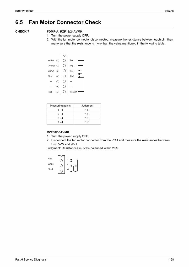
SiME281906E Check
6.5 Fan Motor Connector Check
CHECK 7 FDMF-A, RZF18/24AVMK1. Turn the power supply OFF.2. With the fan motor connector disconnected, measure the resistance between each pin, then
make sure that the resistance is more than the value mentioned in the following table.
RZF30/36AVMK1. Turn the power supply OFF.2. Disconnect the fan motor connector from the PCB and measure the resistances between
U-V, V-W and W-U.Judgment: Resistances must be balanced within 20%.
Measuring points Judgment
1 - 4 1
2 - 4 1
3 - 4 1
7 - 4 1
White
Orange
Brown
Blue
—
—
Red
FG
Vsp
Vcc
GND
—
—
Vdc/Vm
(1)
(2)
(3)
(4)
(5)
(6)
(7)
Red
White
Black
U
V
W
Part 6 Service Diagnosis 198

Check SiME281906E
Note(s)
6.6 Electronic Expansion Valve Check
CHECK 8 Outdoor unit
When the temperature is different, correct the resistance value referring to the graph below.
Measurement point Judgment
1 - 6
35-55 (at 20°C)
2 - 6
3 - 6
4 - 6
1 Orange
2 Red
3 Yellow
4 Black
5 —
6 Gray
1 White
2 Yellow
3 Orange
4 Blue
5 —
6 Red
Res
ista
nce
chan
ge r
ate
(%)
80%
85%
90%
95%
100%
105%
110%
115%
120%
125%
130%
135%
140%
–20 –10 0 10 20 30 40 50 60 70 80 90 100 110 120
Temperature (°C)
199 Part 6 Service Diagnosis

SiME281906E Check
Note(s)
Reference
6.7 Wet Operation Check
CHECK 9
Reference values for superheating degree to be used in the judgment of wet operation Discharge pipe superheating degree: 5°C or less(The values above must be used only for reference purposes. Even it is operated within the range above, operation may be normal in other conditions.)
CHECK 12 Refer to page 203.
Defective control
Dirty evaporator
Wet operation
Defective valve coil
Defective valve body
Defective suction pipe thermistor
Defective outdoor unit main PCB
Defective fan motor
Referring to the Fault Tree Analysis (FTA) shown below, identify the defective points.
Refer to .
Is the heat exchanger clogged?
Refrigerant dwelling
Excessive refrigerant charging
Defective superheating degree control
Decreased evaporation capacity
Frequent starts and stops of the compressor
Defective electronic expansion valve
Decreased fan airflow rate
Decreased fan output
Are the coil resistance and insulation normal?
Is the connector properly connected?Are the thermistor resistance characteristics normal?
Are the voltagecharacteristics normal?
Defective outdoor unit main PCB (including capacity setting)
CHECK 12
Can the fan motor be rotated with hands?Are the motor coil resistance and insulation normal?
Part 6 Service Diagnosis 200

Check SiME281906E
6.8 Clogged Points Check
CHECK 10 Temperature differences must occur before or after the clogged points.
(1)
(3)(3)
(5)(4)
Indoor unit Outdoor unit
(2)
COMPACC
Check points Check factor Causes Remedies
1 Around expansion mechanism
Temperature difference
DustChoked moistureReduced effective pipe diameter due to adherent contamination, etc.
Replace the electronic expansion valve.
2 Accumulator for compressor
Frosting Choked moisture Blow nitrogen gas, and then replace the refrigerant.
3 Distributor Temperature difference
DustChoked moistureReduced effective pipe diameter due to adherent contamination, etc.
Replace the heat exchanger or distributor.
4 Field piping Temperature difference
Collapsed pipe Replace the pipe.
5 Stop valve Temperature difference
The stop valve is not fully open. Open the stop valve fully.
201 Part 6 Service Diagnosis

SiME281906E Check
6.9 Refrigerant Shortage Check
CHECK 11 As criteria for judging whether refrigerant is shortage or not, refer to the following operating conditions.
Cooling1. As suction superheating degree increases due to refrigerant shortage, the electronic
expansion valve tends to open (opens fully) in order to avoid overheat operation.2. In response to decreased evaporator capacity caused by refrigerant shortage, capacity is
controlled in the inverter in order to maintain low pressure, which results in a decrease in frequency.
3. Because of items 1 and 2 above, the compressor frequency decreases despite a large difference (large load) between temperature set by the remote controller and indoor suction air temperature, resulting that cooling capacity becomes unavailable.
4. If refrigerant shortage worsens, the electronic expansion valve remains fully open and suction superheating degree further increases. In addition, because the compressor frequency drops to the level of the lowest frequency, low pressure cannot be maintained.
Cooling
Suction superheating degree
Compressor frequency
Electronic expansion valve
Adequate level
As compressor frequency decreases, high pressure decreases.
(Maintains a certain level of low pressure)
Actual high pressure
Control high pressure
When the refrigerant flow rate decrease, it is impossible to maintain a low pressure.
As the electronic expansion valve opening degree reaches the maximum, suction superheating degree increases.
Reaches the lowest frequency
Inadequate
In response to decreased evaporator capacity caused by refrigerant shortage, capacity is controlled in the inverter in order to maintain a low pressure, which resulting in a decrease in frequency.
The maximum opening degree of the electronic expansion valve (480 pulses)
Avoid overheat operation by changing SH target value
(Degree of inadequate refrigerant)
High pressure (Heat exchanger middle thermistor
(for outdoor unit thermistor))
Low pressure (Pressure sensor)
Refrigerant shortage warning
Abnormal refrigerant shortage
Part 6 Service Diagnosis 202

Check SiME281906E
6.10 Refrigerant Overcharge Check
CHECK 12 As criteria for judging whether refrigerant is excessively charged or not, refer to the following operating conditions.
1. Because high pressure rises due to excessive charging, overload control is carried out and capacity tends to run short.
2. Considering pressure load, compressor discharge pipe temperature is low.
Compressor frequency increases in order to maintain low pressure.
Cooling
Adequate level
Maximum frequency
Suction superheating degree is approx. 0 deg.
(Degree of excessive refrigerant charging)
As compressor frequency decreases, low pressure rises.
Compressor frequency decreases due to high pressure protection control
Minimum frequency
Electronic expansion valve opening degree decreases due to wet protection control
Minimum opening degree
Excessive charge
High pressure(Heat exchanger middle
thermistor)Low pressure
(Pressure sensor)
Compressor frequency
Electronic expansion valve
Suction superheating degree
Discharge superheating degree
203 Part 6 Service Diagnosis

SiME281906E
Part 7 Appendix 204
1. Wiring Diagrams..................................................................................2051.1 Indoor Unit............................................................................................2051.2 Outdoor Unit .........................................................................................206
Part 7 Appendix

Wiring Diagrams SiME281906E
1. Wiring Diagrams1.1 Indoor Unit
FDMF18/24/30/36AVMK
3D12
2556
A
205 Part 7 Appendix

SiME281906E Wiring Diagrams
1.2 Outdoor Unit
RZF18/24AVMK
3D12
2453
A
Part 7 Appendix 206

Wiring Diagrams SiME281906E
RZF30/36AVMK
3D12
2423
B
207 Part 7 Appendix

Warning
Cautions on product corrosion1. Air conditioners should not be installed in areas where corrosive gases, such as acid gas or alkaline gas, are produced.2. If the outdoor unit is to be installed close to the sea shore, direct exposure to the sea breeze should be avoided. If you need to install
the outdoor unit close to the sea shore, contact your local distributor.
Head Office:Umeda Center Bldg., 2-4-12, Nakazaki-Nishi, Kita-ku, Osaka, 530-8323 Japan
Tokyo Office:JR Shinagawa East Bldg., 2-18-1, Konan,Minato-ku, Tokyo, 108-0075 Japan
https://www.daikin.com/products/ac/
© All rights reserved
z Daikin products are manufactured for export to numerous countries throughout the world. Prior to purchase, please confirm with your local authorized importer, distributor and/or retailer whether this product conforms to the applicable standards, and is suitable for use, in the region where the product will be used. This statement does not purport to exclude, restrict or modify the application of any local legislation.
z Ask a qualified installer or contractor to install this product. Do not try to install the product yourself. Improper installation can result in water or refrigerant leakage, electrical shock, fire or explosion.
z Use only those parts and accessories supplied or specified by Daikin. Ask a qualified installer or contractor to install those parts and accessories. Use of unauthorized parts and accessories or improper installation of parts and accessories can result in water or refrigerant leakage, electrical shock, fire or explosion.
z Read the user's manual carefully before using this product. The user's manual provides important safety instructions and warnings. Be sure to follow these instructions and warnings.
If you have any inquiries, please contact your local importer, distributor and/or retailer.
zSpecifications, designs and other content appearing in this brochure are current as of October 2019 but subject to change without notice.SiME281906E 10/2019 AK.K