Installation and maintenance in- structions - Daikin
68
Installation and maintenance instructions Daikin Altherma integrated solar unit English Installation and maintenance in- structions Daikin Altherma integrated solar unit EHSX(B)04P30D EHSX(B)04P50D EHSH(B)04P30D EHSX(B)08P30D EHSX(B)08P50D EHSH(B)08P30D EHSH(B)08P50D 06/2018
-
Upload
khangminh22 -
Category
Documents
-
view
1 -
download
0
Transcript of Installation and maintenance in- structions - Daikin

Installation and maintenance instructionsDaikin Altherma integrated solar unit English
Installation andmaintenance in-
structions
Daikin Altherma integrated solar unit
EHSX(B)04P30DEHSX(B)04P50DEHSH(B)04P30D
EHSX(B)08P30DEHSX(B)08P50DEHSH(B)08P30DEHSH(B)08P50D
06/2018

List of contents
Installation and maintenance instructions
2Daikin Altherma EHS(X/H)
Daikin Altherma integrated solar unit008.1444099_00 – 06/2018 – EN
List of contents
1 General safety precautions 31.1 Particular safety instructions ..................................................... 3
1.1.1 Observing the instructions .......................................... 31.1.2 Meaning of warnings and symbols.............................. 4
1.2 Safety instructions for installation and operation....................... 41.2.1 General ....................................................................... 41.2.2 Intended use ............................................................... 51.2.3 Device installation room.............................................. 51.2.4 Electrical installation ................................................... 51.2.5 Requirements for the heating water............................ 51.2.6 Heating system and sanitary connection .................... 61.2.7 Operation .................................................................... 6
2 Handover to operator and warranty 72.1 Instruct the owner...................................................................... 72.2 Warranty conditions................................................................... 7
3 Product description 83.1 Design and components............................................................ 83.2 Function of the 3-way switch valves.......................................... 11
4 Set-up and installation 124.1 Dimensions and connection dimensions ................................... 124.2 Transport and delivery............................................................... 144.3 Installing the heat pump ............................................................ 14
4.3.1 Selecting the installation site....................................... 144.3.2 Installing the device .................................................... 15
4.4 Preparing the device for installation .......................................... 164.4.1 Remove the front screen............................................. 164.4.2 Remove the protective cover ...................................... 164.4.3 Moving the controller housing to the service position . 164.4.4 Open the controller housing........................................ 174.4.5 Removing the bottom thermal insulation..................... 174.4.6 Opening the vent valve ............................................... 184.4.7 Aligning the connections of the heating inflow and
return flow ................................................................... 184.4.8 Making the hood opening............................................ 194.4.9 Installing the rotary switch of the controller................. 20
4.5 Installing optional accessories................................................... 204.5.1 Installation of the electric backup heater..................... 204.5.2 Installation of the external heat generator connection
set ............................................................................... 204.5.3 Installation of the DB connection kit............................ 204.5.4 Installation of the P connection kit .............................. 21
4.6 Water connection ...................................................................... 214.6.1 Connecting hydraulic lines .......................................... 214.6.2 Connecting the drain................................................... 22
4.7 Electrical connection ................................................................. 234.7.1 Overall connection diagram ........................................ 244.7.2 Position of the printed circuit boards and terminal
strips ........................................................................... 254.7.3 Mains connection ........................................................ 254.7.4 General information on the electrical connection........ 254.7.5 Connecting the heat pump outdoor unit...................... 254.7.6 Connecting the outside temperature sensor
(optional) ..................................................................... 264.7.7 External switching contact .......................................... 264.7.8 EBA (external requirement request) ........................... 264.7.9 Connecting an external heat generator....................... 264.7.10 Connecting the room thermostat................................. 274.7.11 Connection of optional RoCon system components ... 284.7.12 Connecting the HP convector ..................................... 284.7.13 Connecting switching contacts (AUX outputs) ............ 294.7.14 Off-peak mains connection (HT/NT) ........................... 294.7.15 Connecting an intelligent controller (Smart Grid - SG) 30
4.8 Connection for refrigerant........................................................... 304.8.1 Laying refrigerant lines................................................. 304.8.2 Pressure test and filling the refrigerant circuit.............. 31
4.9 Filling the system........................................................................ 314.9.1 Checking the water quality and adjusting the
pressure gauge ............................................................ 314.9.2 Filling hot water heat exchangers ................................ 314.9.3 Filling the storage tank................................................. 314.9.4 Filling the heating system ............................................ 31
5 Start-up 325.1 Initial commissioning .................................................................. 32
5.1.1 Requirements............................................................... 325.1.2 Starting the unit and start-up........................................ 325.1.3 Bleeding the hydraulic system ..................................... 325.1.4 Checking the minimum flow ......................................... 335.1.5 Setting the screed program parameter (only as
required)....................................................................... 335.2 Re-commissioning...................................................................... 33
5.2.1 Requirements............................................................... 335.2.2 Start-up ........................................................................ 34
6 Hydraulic connection 356.1 Hydraulic system connection...................................................... 35
7 Inspection and maintenance 377.1 General overview of inspection and maintenance...................... 377.2 Inspection and maintenance tasks ............................................. 38
7.2.1 Filling, topping up the storage tank .............................. 387.2.2 Filling, topping up the heating system.......................... 39
8 Faults and malfunctions 418.1 Troubleshooting.......................................................................... 418.2 Overview of possible malfunctions ............................................. 418.3 Fault codes................................................................................. 448.4 Emergency operation ................................................................. 54
9 Taking out of operation 559.1 Temporary shutdown.................................................................. 55
9.1.1 Draining the storage tank............................................. 559.1.2 Draining the heating circuit and hot water circuit ......... 56
9.2 Final shutdown and disposal ...................................................... 56
10 Technical data 5810.1 Basic data................................................................................... 5810.2 Characteristic lines ..................................................................... 59
10.2.1 Sensor characteristic lines ........................................... 5910.2.2 Characteristic curves for pumps .................................. 60
10.3 Tightening torque ....................................................................... 6010.4 Minimum floor area and ventilation openings............................. 6010.5 Electrical connection diagram .................................................... 62
11 Notes 64
List of keywords 67

1 General safety precautions
Installation and maintenance instructions
3Daikin Altherma EHS(X/H)Daikin Altherma integrated solar unit008.1444099_00 – 06/2018 – EN
1 General safety precautions
1.1 Particular safety instructions
WARNINGDevices that have not been set up andinstalled correctly can impair the func-tion of the device and/or cause seriousor fatal injury to the user.▪ Work on the Daikin Altherma EHS(X/
H) (such as set-up, inspection, con-nection and initial commissioning)must only be carried out by personswho are authorised and who havesuccessfully completed qualifyingtechnical or vocational trainingand who have taken part in ad-vanced training sessions recognisedby the relevant authorities respons-ible for the specific activity. These in-clude, in particular, certified heatingengineers, qualified electriciansand HVAC specialists who, be-cause of their professional trainingand expert knowledge, have exper-ience in the professional installationand maintenance of heating, coolingand air conditioning systems as wellas hot water storage tanks.
WARNINGDisregarding the following safety in-structions may result in serious phys-ical injury or death.▪ This device must only be used by
children aged 8 and above and bypersons with restricted physical,sensory or mental capabilities or witha lack of experience and knowledge,if they are under supervision or ifthey have been instructed in the safeuse of the equipment and under-stand the dangers arising therefrom.Children must not play with thedevice. Cleaning and user mainten-ance must not be carried out bychildren without supervision.
▪ Make up the power supply in accord-ance with IEC 60335-1, via a separ-ator device which exhibits contactseparation in all poles with a contactopening distance that provide fulldisconnection in accordance withovervoltage category III.
▪ All the electrical work must only becarried out by electrically qualifiedexperts and with consideration of thelocal and national regulations, andthe instructions in this manual.Check that a suitable electrical cir-cuit is being used.Inadequate capacity of the power cir-cuit or improperly executed connec-tions can cause electrocution or fire.
▪ The customer must install a pressurerelief device with rated over-pressureless than 0.6 MPa (6 bar). The con-nected drain line must have a con-tinuous gradient and a free outlet ina frost-free environment (see Chap.4.3).
▪ Water may drip out of the drain lineof the pressure relief device. Thedrain opening must be left free to at-mosphere.
▪ The pressure relief device must beoperated regularly in order to re-move scale deposits and to makesure it is not blocked.
▪ The storage tank and hot water cir-cuit can be drained. The instructionsin chap. must be observed.
1.1.1 Observing the instructions▪ The original documentation is written in German. All other lan-
guages are translations.
▪ Please read this manual carefully and thoroughly before proceed-ing with the installation or modification of the heating system.
▪ The precautionary measures described in this document coververy important topics. Follow them meticulously.
▪ The installation of the system, and all activities described in thismanual and the applicable documents for the installer must becarried out by an approved installer.

1 General safety precautions
Installation and maintenance instructions
4Daikin Altherma EHS(X/H)
Daikin Altherma integrated solar unit008.1444099_00 – 06/2018 – EN
This manual provides all the necessary information for installation,start-up and maintenance, as well as basic information on operationand settings. Please see the attached documents for a detailed de-scription of operation and control.
All heating parameters needed for smooth operation are alreadyfactory-set. Please refer to other relevant documents for informationon setting the control.
Relevant documents▪ Daikin Altherma EHS(X/H):
▪ Installation instructions
▪ Start-up checklist
▪ Heat pump operating manual
▪ RoCon+ HP:
▪ Installation instructions
▪ Operating instructions
▪ Outdoor unit: Installation instructions
▪ Room station EHS157034 and mixer module EHS157068: Operat-ing instructions
▪ Other optional accessories and optional system components: As-sociated installation and operating instructions
The guides are included in the scope of supply for the individualdevices.
1.1.2 Meaning of warnings and symbolsWarnings in this manual are classified according into their severityand probability of occurrence.
DANGER
Indicates an immediate danger.
Disregarding this warning can lead to serious injury ordeath
WARNING
Indicates a potentially dangerous situation
Disregarding this warning may result in serious physical in-jury or death.
CAUTION
Indicates a situation which may cause possible damage
Disregarding this warning can cause damage to propertyand the environment, and result in minor injuries.
This symbol identifies user tips and particularly useful in-formation, but not warnings or hazards
Special warning signsSome types of danger are represented by special symbols:
Electric current
Danger of explosion
Risk of burning or scalding
Risk of poisoning
ValiditySome information in this manual has limited validity. The validity ishighlighted by a symbol.
Exterior heat pump unitERGA
Heat pump indoor unitDaikin Altherma EHS(X/H)
HP convector
Comply with the stipulated tightening torque (seechap. Chap. 10.3)
Only applies to devices with unpressurised solar systemconnection (DrainBack).
Only applies to devices with a bivalent solar system connec-tion (Biv).
Only valid for Daikin Altherma EHS(X/H) with cooling func-tion
Handling instructions1 Handling instructions are shown as a list. Actions for which the
sequential order must be maintained are numbered.è Results of actions are identified with an arrow.
1.2 Safety instructions for installationand operation
1.2.1 General
WARNING
Devices that have not been set up and installed correctlycan impair the function of the device and/or cause seriousor fatal injury to the user.
▪ Work on the Daikin Altherma EHS(X/H) (such as set-up,inspection, connection and initial commissioning) mustonly be carried out by persons who are authorised andwho have successfully completed qualifying technicalor vocational training and who have taken part in ad-vanced training sessions recognised by the relevant au-thorities responsible for the specific activity. These in-clude, in particular, certified heating engineers, quali-fied electricians and HVAC specialists who, becauseof their professional training and expert knowledge,have experience in the professional installation andmaintenance of heating, cooling and air conditioningsystems as well as hot water storage tanks.
▪ Switch off the external main switch before starting anywork on the Daikin Altherma EHS(X/H) and secure itagainst unintentional switch-on.
▪ Do not leave any tools or other objects below the hoodof the unit after finishing installation or maintenancework.
Avoiding dangerDaikin Altherma EHS(X/H) conforms to the state-of-the-art andmeets all recognised technical requirements. However, improper usemay result in serious physical injuries or death, as well as propertydamage. To prevent such risks, only install and operate the devices:
▪ as stipulated and in perfect condition,
▪ with an awareness of safety and the hazards involved.
This assumes knowledge and use of the contents of this manual, ofthe relevant accident prevention regulations as well as the recog-nised safety-related and occupational health rules.
Before working on the hydraulic system▪ Work on the system (such as installation, connection and initial
commissioning, for example) must only be carried out by personswho are authorised, who have successfully completed qualifyingtechnical or vocational training for the respective activity and whohave taken part in advanced training sessions recognised by therelevant responsible authority.
1 General safety precautions
Installation and maintenance instructions
5Daikin Altherma EHS(X/H)Daikin Altherma integrated solar unit008.1444099_00 – 06/2018 – EN
▪ When carrying out any work on the system, switch off the mainswitch and secure against being switched on inadvertently.
▪ Seals must not be damaged or removed.
▪ Make sure that the safety valves comply with the requirements ofEN 12828 when connecting on the heating side, and with the re-quirements of EN 12897 when connecting on the domestic waterside.
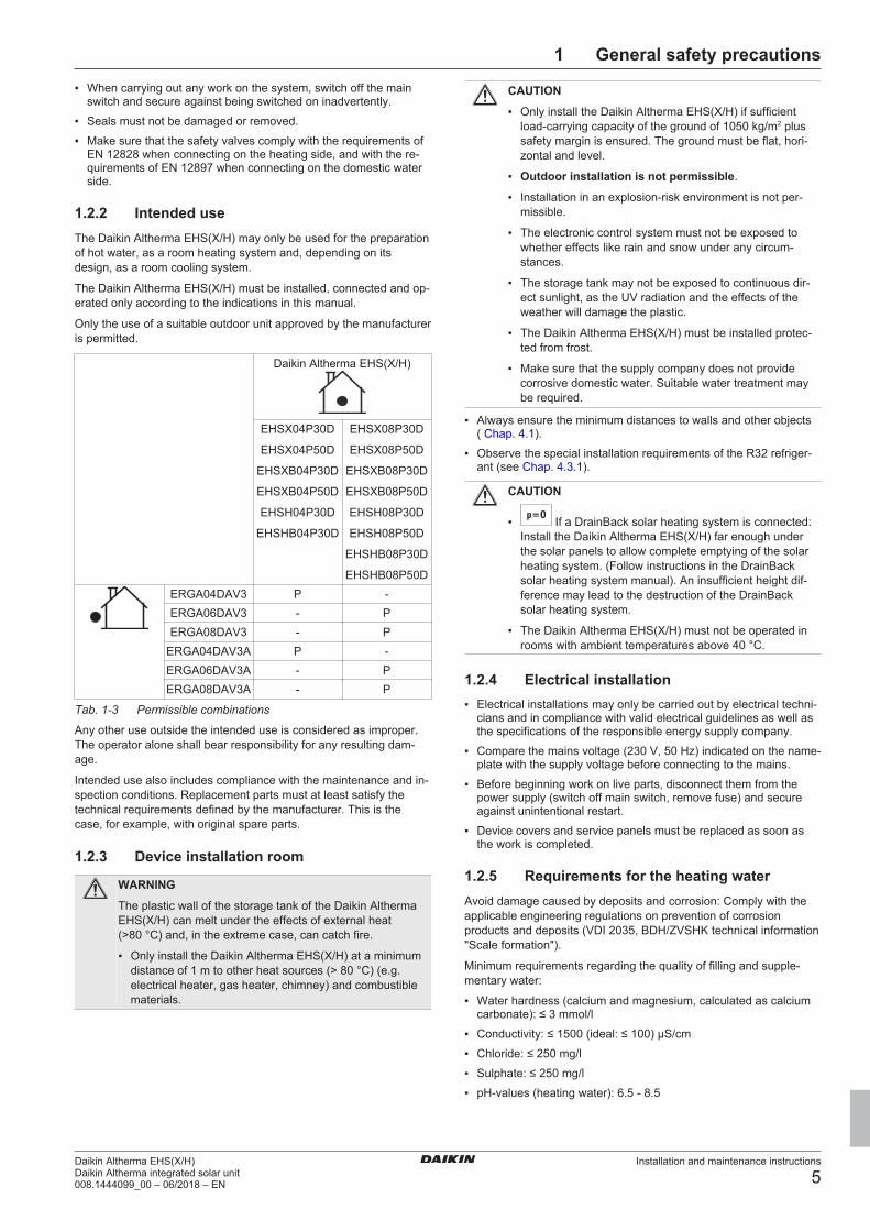
1.2.2 Intended useThe Daikin Altherma EHS(X/H) may only be used for the preparationof hot water, as a room heating system and, depending on itsdesign, as a room cooling system.
The Daikin Altherma EHS(X/H) must be installed, connected and op-erated only according to the indications in this manual.
Only the use of a suitable outdoor unit approved by the manufactureris permitted.
Daikin Altherma EHS(X/H)
EHSX04P30D
EHSX04P50D
EHSXB04P30D
EHSXB04P50D
EHSH04P30D
EHSHB04P30D
EHSX08P30D
EHSX08P50D
EHSXB08P30D
EHSXB08P50D
EHSH08P30D
EHSH08P50D
EHSHB08P30D
EHSHB08P50DERGA04DAV3 P -ERGA06DAV3 - PERGA08DAV3 - P
ERGA04DAV3A P -ERGA06DAV3A - PERGA08DAV3A - P
Tab. 1-3 Permissible combinations
Any other use outside the intended use is considered as improper.The operator alone shall bear responsibility for any resulting dam-age.
Intended use also includes compliance with the maintenance and in-spection conditions. Replacement parts must at least satisfy thetechnical requirements defined by the manufacturer. This is thecase, for example, with original spare parts.
1.2.3 Device installation room
WARNING
The plastic wall of the storage tank of the Daikin AlthermaEHS(X/H) can melt under the effects of external heat(>80 °C) and, in the extreme case, can catch fire.
▪ Only install the Daikin Altherma EHS(X/H) at a minimumdistance of 1 m to other heat sources (> 80 °C) (e.g.electrical heater, gas heater, chimney) and combustiblematerials.
CAUTION
▪ Only install the Daikin Altherma EHS(X/H) if sufficientload-carrying capacity of the ground of 1050 kg/m2 plussafety margin is ensured. The ground must be flat, hori-zontal and level.
▪ Outdoor installation is not permissible.
▪ Installation in an explosion-risk environment is not per-missible.
▪ The electronic control system must not be exposed towhether effects like rain and snow under any circum-stances.
▪ The storage tank may not be exposed to continuous dir-ect sunlight, as the UV radiation and the effects of theweather will damage the plastic.
▪ The Daikin Altherma EHS(X/H) must be installed protec-ted from frost.
▪ Make sure that the supply company does not providecorrosive domestic water. Suitable water treatment maybe required.
▪ Always ensure the minimum distances to walls and other objects( Chap. 4.1).
▪ Observe the special installation requirements of the R32 refriger-ant (see Chap. 4.3.1).
CAUTION
▪ If a DrainBack solar heating system is connected:Install the Daikin Altherma EHS(X/H) far enough underthe solar panels to allow complete emptying of the solarheating system. (Follow instructions in the DrainBacksolar heating system manual). An insufficient height dif-ference may lead to the destruction of the DrainBacksolar heating system.
▪ The Daikin Altherma EHS(X/H) must not be operated inrooms with ambient temperatures above 40 °C.
1.2.4 Electrical installation▪ Electrical installations may only be carried out by electrical techni-
cians and in compliance with valid electrical guidelines as well asthe specifications of the responsible energy supply company.
▪ Compare the mains voltage (230 V, 50 Hz) indicated on the name-plate with the supply voltage before connecting to the mains.
▪ Before beginning work on live parts, disconnect them from thepower supply (switch off main switch, remove fuse) and secureagainst unintentional restart.
▪ Device covers and service panels must be replaced as soon asthe work is completed.
1.2.5 Requirements for the heating waterAvoid damage caused by deposits and corrosion: Comply with theapplicable engineering regulations on prevention of corrosionproducts and deposits (VDI 2035, BDH/ZVSHK technical information"Scale formation").
Minimum requirements regarding the quality of filling and supple-mentary water:
▪ Water hardness (calcium and magnesium, calculated as calciumcarbonate): ≤ 3 mmol/l
▪ Conductivity: ≤ 1500 (ideal: ≤ 100) μS/cm
▪ Chloride: ≤ 250 mg/l
▪ Sulphate: ≤ 250 mg/l
▪ pH-values (heating water): 6.5 - 8.5

1 General safety precautions
Installation and maintenance instructions
6Daikin Altherma EHS(X/H)
Daikin Altherma integrated solar unit008.1444099_00 – 06/2018 – EN
Measures for desalination, softening or hardness stabilisation arenecessary if the filling and top-up water have a high total hardness(>3 mmol/l - total of the calcium and magnesium concentrations, cal-culated as calcium carbonate). We recommend the use of FernoxKSK limescale and corrosion protector. For other properties deviat-ing from the minimum requirements, suitable conditioning measuresare necessary to maintain the required water quality.
Using filling water and top-up water which does not meet the statedquality requirements can cause a considerably reduced service lifeof the device. The responsibility for this lies solely with the operator.
1.2.6 Heating system and sanitary connection▪ Create a heating system according to the safety requirements of
EN 12828.
▪ The plumbing connection must comply with the requirements ofEN 12897. The requirements of the following must also be ob-served:
▪ EN 1717 – Schutz des Trinkwassers vor Verunreinigungen inTrinkwasser-Installationen und allgemeine Anforderungen anSicherheitseinrichtungen zur Verhütung von Trinkwasserverun-reinigungen durch Rückfließen. Protection against pollution ofpotable water installations and general requirements of devicesto prevent pollution by backflow. Protection contre la pollutionde l'eau potable dans les réseaux intérieurs et exigencesgénérales des dispositifs de protection contre la pollution parretour
▪ EN 61770 – Elektrische Geräte zum Anschluss an dieWasserversorgungsanlage – Vermeidung von Rücksaugungund des Versagens von Schlauchsätzen. Electric appliancesconnected to the water mains – Avoidance of backsiphonageand failure of hose-sets. Appareils électriques raccordés auréseau d'alimentation en eau – Exigences pour éviter le retourd'eau par siphonnage et la défaillance des ensembles de rac-cordement
▪ EN 806 – Technische Regeln für Trinkwasserinstallationen(TRWI). Specifications for installations inside buildings convey-ing water for human consumption. Spécifications techniques re-latives aux installations pour l'eau destinée à la consummationhumaine à l'intérieur des bâtiments
▪ and, in addition, the country-specific legislation.
During operation of the Daikin Altherma EHS(X/H) with additionalheat source, the storage tank temperature may exceed 65 °C, aboveall when solar energy is used.
▪ For this reason, some form of scalding protection needs to be in-cluded when you install the system (hot water mixing device, e.g.VTA32).
If the Daikin Altherma EHS(X/H) is connected to a heating systemwith steel pipes, radiators or non-diffusion-proof floor heating pipes,sludge and chips can enter the hot water storage tank and causeblockages, local overheating or corrosion damage.
▪ To prevent possible damage, install a dirt filter or sludge separatorinto the heating return flow of the system (SAS 1 or SAS 2).
▪ The dirt filter must be cleaned at regular intervals.
1.2.7 OperationThe Daikin Altherma EHS(X/H):
▪ Do not operate until all installation and connection work is com-pleted.
▪ Only operate with a completely full storage tank (Level indicator)and heating circuit.
▪ Operate at a maximum pressure of 3 bar.
▪ Only connect with a pressure reducer on the external water supply(supply line).
▪ Only operate the with the specified quantity of coolant and thetype of coolant specified.
▪ only operate if the protective cover is installed.
The specified servicing intervals should be adhered to and inspec-tion work must be carried out.
2 Handover to operator and warranty
Installation and maintenance instructions
7Daikin Altherma EHS(X/H)Daikin Altherma integrated solar unit008.1444099_00 – 06/2018 – EN
2 Handover to operator andwarranty
2.1 Instruct the owner▪ Before you hand over the heating system, explain to the owner
how he/she can operate and check the heating system.
▪ Hand over the technical documentation (at least the operating in-structions and operating manual) to the operator and advise himthat these documents must be made available at all times and bestored in the immediate vicinity of the device.
▪ Document the handover by filling out the installation and instruc-tion forms together with the owner and sign them.
2.2 Warranty conditionsThe legal guarantee conditions fundamentally apply. Our more ex-tensive warranty conditions can be found in the Internet. Ask yoursuppliers if necessary.
There is only an entitlement to warranty services when it can be cer-tified that the annual maintenance work according to Chap. 7 hasbeen regularly completed.

3 Product description
Installation and maintenance instructions
8Daikin Altherma EHS(X/H)
Daikin Altherma integrated solar unit008.1444099_00 – 06/2018 – EN
3 Product description
3.1 Design and componentsOutside of the device
RoCon+ B1 33 26
24
10
25
Fig. 3-1 Design and components - Outside of the device (1)
Upper side of the device
A
A
6
30
5
(34)
4
(34)
3UV DHW 3UVB1
15
17
1 32 3UV DHWDS31 35 38 tV,BH
7
39 37
3UV DHW
2
FLS
8
tV,BH tR 3
tV
Fig. 3-2 Design and components - Top of the device (1)
(1) For legend, see Tab. 3-1

3 Product description
Installation and maintenance instructions
9Daikin Altherma EHS(X/H)Daikin Altherma integrated solar unit008.1444099_00 – 06/2018 – EN
Internal structure…04P30D/…08P30D
EKSRPS4
Fig. 3-3 Design and components – Internal struc-ture ...04P30D/...08P30D (1)
Internal structure …B04P30D / …B08P30D (Biv)
EKSRPS4
Fig. 3-4 Design and components - Internal struc-ture ...B04P30D / ...B08P30D (Biv) (1)
(1) For legend, see Tab. 3-1

3 Product description
Installation and maintenance instructions
10Daikin Altherma EHS(X/H)
Daikin Altherma integrated solar unit008.1444099_00 – 06/2018 – EN
Internal structure …04P50D / …08P50D
EKSRPS4
Fig. 3-5 Design and components - Internal struc-ture ...04P50D / ...08P50D (1)
Internal structure …B04P50D / …B08P50D (Biv)
EKSRPS4
Fig. 3-6 Design and components - Internal structure …B04P50D / …B08P50D (Biv) (1)
(1) For legend, see Tab. 3-1

3 Product description
Installation and maintenance instructions
11Daikin Altherma EHS(X/H)Daikin Altherma integrated solar unit008.1444099_00 – 06/2018 – EN
Item Designation Item Designation1 Solar inflow or connec-
tion for another heatsource (BIV only)
25 Type plate
2 Cold water connection 26 Protective cover3 Domestic hot water 27 Solar - return flow4 Heating inflow 28 Solar - inflow5 Heating return flow 29 Solar - return flow6 Circulation pump 30 Plate heat exchanger7 Pressure relief valve 31 Connection for refrigerant
fluid line7a Non-return valve (ac-
cessory)32 Connection for refrigerant
gas line8 Automatic vent valve 33 Status display9 Storage tank (polypropyl-
ene double walled jacketwith PUR hard foam heatinsulation)
34 Ball valve (heating cir-cuit)
10 Filling and draining con-nection or solar returnflow connection
35 Combined filling anddraining valve (heatingcircuit)
11 Mount for solar controlleror handle
37
tDHW1,tDHW2
Storage tank temperaturesensor
12 Heat exchanger (stain-less steel) for domestichot water heating
38 Connection for dia-phragm expansion vessel
13 Heat exchanger (stain-less steel) for storagetank charging or heatingsupport
39 Control system housing
14 Heat exchanger (stain-less steel) for pressur-ised solar system storagecharging
3UVB1
3-way switch valve (in-ternal heat generator cir-cuit)
15 Connection for optionalelectrical backup heaterEKBUxx
3UVDHW
3-way switch valve (hotwater/heating)
16 Solar - inflow layeringpipe
DS Pressure sensor
17 Fill level indicator (tankwater)
FLS FlowSensor
18 Optional: electric backupheater (EKBUxx)
tR Return flow temperaturesensor
19 Submersible sensorsleeve for storage tanktemperature sensor tDHW1
and tDHW2
tV Inflow temperaturesensor
20 Pressure-free storagetank water
tV, BH Backup heater inflowtemperature sensor
21 Solar zone RoCon+ B1
Controller control panel
22 Hot water zone EKS-RPS4
Optional: Solar controland pump unit
23 Safety overflow connec-tion
MAG Diaphragm expansionvessel
24 Mount for handle
Tab. 3-1 Legend for Fig. 3-1 to Fig. 3-6
3.2 Function of the 3-way switchvalves
Fig. 3-7 3-way switch valve function

4 Set-up and installation
Installation and maintenance instructions
12Daikin Altherma EHS(X/H)
Daikin Altherma integrated solar unit008.1444099_00 – 06/2018 – EN
4 Set-up and installationWARNING
Cooling systems (heating pumps), climate control systemsand heating devices that have been set up and installed in-correctly can both endanger human life and health and beimpaired in their function.
▪ Work on the Daikin Altherma EHS(X/H) (such as install-ation, repair, connection and initial commissioning, forexample) must only be carried out by persons who areauthorised, who have successfully completed qualifyingtechnical or vocational training for the respective activityand who have taken part in advanced training sessionsrecognised by the relevant responsible authority. Theseinclude, in particular, certified heating engineers, quali-fied electricians and HVAC specialists who, because oftheir professional training and expert knowledge, haveexperience in the professional installation and mainten-ance of heating, cooling and air conditioning systemsand heat pumps.
Incorrect set-up and installation would render the manufacturer'sguarantee void. If you have questions, please contact our TechnicalCustomer Service.
4.1 Dimensions and connectiondimensions
Dimensions …04P30D/…08P30D
0
B
45
161
0 183
334
490
1770
1380
1659
1565
642
0 0
1599
1905
Fig. 4-1 Dimensions, side view - …04P30D/…08P30D

4 Set-up and installation
Installation and maintenance instructions
13Daikin Altherma EHS(X/H)Daikin Altherma integrated solar unit008.1444099_00 – 06/2018 – EN
0 125
315
490
590
9 7 5 26
A
B
418 3
0
388
615
±595
97
184
205
Fig. 4-2 Dimensions, top of the device - Type …04P30D/…08P30D
Dimensions …04P50D/…08P50D
259
0 280
432
588
1651
1591
1555
B
1380
642
0 0
1762
1905
4576
Fig. 4-3 Dimensions, side view - Type …04P50D/…08P50D

4 Set-up and installation
Installation and maintenance instructions
14Daikin Altherma EHS(X/H)
Daikin Altherma integrated solar unit008.1444099_00 – 06/2018 – EN
587,5
0 432
412,5
147,5
9 8 21 453
A
B
6 7
785
0
249
332,5
452,5
162,5
147,5
Fig. 4-4 Dimensions, top of the device - Type …04P50D/…08P50D
Item Designation1 Solar - inflow2 Cold water3 Domestic hot water4 Heating inflow5 Heating return flow6 Connection for refrigerant gas line7 Connection for refrigerant fluid line8 Solar – inflow (…Biv type only)9 Solar – return flow (…Biv type only)A frontB rear
Tab. 4-1
4.2 Transport and deliveryWARNING
The Daikin Altherma EHS(X/H) is top-heavy in the unfilledstate and could tip over during transport. That could putpersons in danger or damage the unit.
▪ Secure the Daikin Altherma EHS(X/H) well, transportcarefully, use the handles.
The Daikin Altherma EHS(X/H) is delivered on a pallet. All industrialtrucks, such as lifting trucks and forklift trucks, are suitable for trans-porting it.
Scope of delivery▪ Daikin Altherma EHS(X/H) (preassembled),
▪ Bag of accessories (see Fig. 4-5),
▪ Document pack.
A (2x)
B (3x)
C (1x)
D (1x)
E (2x)
H (2x)
F (2x)
G (1x)
I (1x)
J (1x)K (1x)
L (1x)
Fig. 4-5 Contents of bag of accessories
Item Designation Item DesignationA Handles (only required
for transport)G O-ring
B cover panel H Cable tieC Hose connecting piece
for safety overflowI Plug bracket
D Assembly wrench J Venting hoseE Ball valve K Drain hose coverF Flat gasket L RoConPlus controller
rotary switch
Tab. 4-2
For further accessories for the Daikin Altherma EHS(X/H), see Pricelist.
4.3 Installing the heat pump
4.3.1 Selecting the installation site
CAUTION
If the total refrigerant charge in the system is ≥ 1.84 kg, it isessential to comply with additional requirements for min-imum footprint and minimum ventilation openings. Ob-serveChap. 10.4.
Information on the total refrigerant charge can be found onthe type plate of the outdoor unit. Please follow the installa-tion instructions.

4 Set-up and installation
Installation and maintenance instructions
15Daikin Altherma EHS(X/H)Daikin Altherma integrated solar unit008.1444099_00 – 06/2018 – EN
The installation site of the Daikin Altherma EHS(X/H) must meet theminimum requirements below (see also Chap. 1.2.3).
Installation area▪ The base must be level and smooth and have a sufficient ground
load-bearing capacity of 1050 kg/m² plus safety factor. Install apedestal if necessary.
▪ Observe the installation dimensions (see Chap. 4.1).
Minimum distance
DANGER: RISK OF BURNING
The plastic wall of the storage tank of the Daikin AlthermaEHS(X/H) can melt under the effects of external heat(>80 °C) and, in the extreme case, can catch fire.
▪ Only install the Daikin Altherma EHS(X/H) with a min-imum distance of 1 m to other heat sources (>80 °C)(e.g. electrical heater, oil heater, chimney) and the ma-terial to be combusted.
CAUTION
If the Daikin Altherma EHS(X/H) is not installed asufficient distance below the flat solar panels (the topedge of the storage tank is higher than the bottom edge ofthe solar panels), the unpressurised solar system in theoutdoor area will not be able to drain completely.
▪ When a solar connection is used, install the DaikinAltherma EHS(X/H) low enough at the flat solar panels(observe minimum gradient in the solar connectionlines).
Recommended minimum distances:To the wall: (back) ≥ 100 mm, (sides) ≥ 500 mmTo the ceiling: ≥ 1200 mm, at least 480 mm.
4.3.2 Installing the device
WARNING
The Daikin Altherma EHS(X/H) is top-heavy in the unfilledstate and could tip over during transport. That could putpersons in danger or damage the unit.
▪ Secure the Daikin Altherma EHS(X/H) well, transportcarefully, use handles.
Precondition▪ The installation site complies with applicable country-specific reg-
ulations and meets the minimum requirements described in Chap.4.3.1.
Installation
Fig. 4-6 Installing the handles
Item DesignationA HandleB cover panelF Threaded piece
Tab. 4-3
1 Remove packing and dispose of it in an environment-friendlymanner.
2 Pull off the cover screens from the storage tank (Fig. 4-6, item B)and unscrew the threaded fittings (Fig. 4-6, item F) from theopenings at which the handles are to be fitted.
3 Screw the handles (Fig. 4-6, item A) into the now uncoveredthreaded holes.
4 Carefully transport the Daikin Altherma EHS(X/H) to the installa-tion site, use the handles.

4 Set-up and installation
Installation and maintenance instructions
16Daikin Altherma EHS(X/H)
Daikin Altherma integrated solar unit008.1444099_00 – 06/2018 – EN
5 Installing the Daikin Altherma EHS(X/H) at the installation site.
▪ When setting up the unit in a cabinet, behind panels or in otherrestricted conditions, ensure sufficient ventilation (e.g. usingventilation gratings). If the total refrigerant charge in the systemis ≥ 1.84 kg, further requirements of the ventilation openingsmust be met (see Chap. 10.4).
4.4 Preparing the device forinstallation
4.4.1 Remove the front screen1 Undo the screws (1.).
2 Press the lateral holding burls upwards with your fingers (2.),stem from above with the thumbs.
3 Remove the front screen to the front (3.).
Fig. 4-7 Remove the front screen
4 After completing the installation: Place the front screenstraight directly above the rotary switch of the RoCon+ HP.Press on the top and bottom until the front screen is securely en-gaged again.
4.4.2 Remove the protective cover1 Undo the screws (1.).
2 Unhook the protective cover from the rearward facing holdingburls (2.), lift at the back (3.) and remove to the front (4.).
Fig. 4-8 Remove the protective cover
A
Fig. 4-9 Without protective cover
4.4.3 Moving the controller housing to theservice position
To facilitate work on the hydraulics of the Daikin Altherma EHS(X/H),the control box can be moved to the service position.
1 Loosen the screws (1) of the holder of the controller housing.

4 Set-up and installation
Installation and maintenance instructions
17Daikin Altherma EHS(X/H)Daikin Altherma integrated solar unit008.1444099_00 – 06/2018 – EN
1
1
Fig. 4-10 Moving the controller housing to the service position
2 Remove the controller housing from the front and insert it intothe bracket with the hooks on the rear brackets.
Fig. 4-11 Controller housing in the service position
4.4.4 Open the controller housingTo make the electrical connections, the controller housing itself mustbe opened. This can be done in both the normal and the service po-sition.
1 Loosen the front screw.
2 Push the cover upwards and pull it away to the front.
1
2
Fig. 4-12 Open the controller housing
3 Hook in the cover on the controller housing with the lateralhooks.
Fig. 4-13 Hooking in the cover
4.4.5 Removing the bottom thermal insulation
CAUTION
The thermal insulation (Fig. 4-9, item A) consists of pres-sure-sensitive EPP moulded parts that can be easily dam-aged if not handled correctly.
▪ Only remove the thermal insulation in the order statedbelow and in the stated directions.
▪ Do not use force.
▪ Do not use tools.
1 Remove the thermal insulation in the following order:
▪ Pull the side insulating element off horizontally (item A).
▪ Pull the rear insulating element off horizontally (item B).
▪ Pull the front insulating element off horizontally (item C).

4 Set-up and installation
Installation and maintenance instructions
18Daikin Altherma EHS(X/H)
Daikin Altherma integrated solar unit008.1444099_00 – 06/2018 – EN
AB
C
Fig. 4-14 Removing the top thermal insulation
2 As required: Remove the bottom thermal insulation in the fol-lowing order:
▪ Pull the side insulating element off vertically (item A).
▪ Pull the rear insulating element off vertically (item B).
A
B
Fig. 4-15 Removing the bottom thermal insulation
INFORMATION
The thermal insulation is installed in reverse order.
4.4.6 Opening the vent valve1 Removing the thermal insulation (see Chap. 4.4.5).
2 Open the vent valve on the pump by one turn.
Fig. 4-16 Opening the vent valve
4.4.7 Aligning the connections of the heatinginflow and return flow
CAUTION
When working on the hydraulics, pay attention to the in-stallation position of the O-rings to avoid damaging themand causing leaks.
▪ Always place O-rings on the part to be inserted after dis-assembly or before assembly (see Fig. 4-18).
▪ The heating lines must be connected free of tension viathe plug connectors. Establish a suitable strain relief es-pecially when connecting with flexible lines (not open todiffusion!) (see ).
CAUTION
If the plug brackets cannot be put on properly, the coup-lings can be detached from their mountings to ensure avery strong or continuous escape of liquid can occur.
▪ Before putting on a plug bracket, make sure that the stir-rup engages in the coupling groove. To do so, insert thecoupling far enough into the mounting that the groove isvisible through the plug bracket mounting.
▪ Insert the plug bracket up to the end stop.
The connections of the heating inflow and return flow can be direc-ted upwards or backwards in order to adapt it optimally to the struc-tural conditions of the installation site.
The device is supplied with upwards aligned connections as stand-ard. The following conversion steps are required in order to directthe connections to the rear out of the device:
1 Remove the protective cover and top thermal insulation(see Chap. 4.4.2).

4 Set-up and installation
Installation and maintenance instructions
19Daikin Altherma EHS(X/H)Daikin Altherma integrated solar unit008.1444099_00 – 06/2018 – EN
Fig. 4-17 Aligning the heating inflow and return flow upwards
2 Pull the two plug brackets off the connection couplings (Fig.4-17, item C).
3 Pull off the two connection couplings (Fig. 4-17, item B).
Fig. 4-18 Hydraulic system plug connectors
4 Remove the retaining plate (Fig. 4-17, item A).
5 Pull off the sealing plug bracket (Fig. 4-17, item D).
6 Pull out the sealing plug (Fig. 4-17, item E).
7 Turn the elbow (Fig. 4-17, item H) 90° to the rear.
8 Pull the plug bracket off the manifold (Fig. 4-17, item G).
9 Carefully pull the manifold (Fig. 4-17, item F) so far backwardsout of its horizontal mounting that the retaining plate (Fig. 4-19,item A) can be pushed vertically in between.
Fig. 4-19 Heating inflow and return flow connections aligned to therear
10 Slide the retaining plate between the manifold and its horizontalmounting and insert the manifold (Fig. 4-19, item F) back into itsmounting through the middle hole of the retaining plate.
11 Secure the manifold with plug bracket (Fig. 4-19, item G) in itsmounting again.
12 Insert the two connection couplings (Fig. 4-19, item B) into thelateral mountings through the retaining plate.
13 Secure the two connection couplings with plug bracket (Fig.4-19, item C) in their mountings.
14 Insert the sealing plug (Fig. 4-19, item E) into the upper mount-ing.
15 Secure the sealing plug with plug bracket (Fig. 4-19, item D).
16 Cut out side openings in the thermal insulation (Fig. 4-20,item A) using a suitable tool.
Fig. 4-20 Cut-out in thermal insulation
4.4.8 Making the hood opening1 With the heating inflow and return flow directed upwards: Cut the
hood along the perforation with a suitable tool.

4 Set-up and installation
Installation and maintenance instructions
20Daikin Altherma EHS(X/H)
Daikin Altherma integrated solar unit008.1444099_00 – 06/2018 – EN
Fig. 4-21 Making the hood opening
4.4.9 Installing the rotary switch of thecontroller
1 Place the rotary switch on the rotary switch holder of the RoCon+ HP and press it on.
Fig. 4-22 Putting on the rotary switch
4.5 Installing optional accessories
4.5.1 Installation of the electric backup heater(EKBUxx)
INFORMATION
If the ceiling height is low, the storage tank must be tilted toinstall the backup heater when empty. This must be donebefore any further installation steps.
The Daikin Altherma EHS(X/H) provides the option of installing anelectrical auxiliary heater (backup heater EKBUxx). For example, re-newable energy can be used as an additional heat source.
INFORMATION
A separate manual containing instructions about installa-tion and operation is included with this component.
4.5.2 Installation of the external heat generatorconnection set
The connection set for external heat generators must be installed tocontrol an electrical backup heater or another external heat gener-ator.
1 Open the housing by removing the screw.
2 Remove additional components from the housing (strain reliefclip, cable tie, grommet).
3 Attach the connection set to the controller housing of the DaikinAltherma EHS(X/H). To do this, insert the hooks (1) of the con-nection set into the slots of the controller housing (2); then pressthe connection set downwards.
1 2
Fig. 4-23 Fitting the connection set
4 Attach the grommet (3) to the bushing between the connectionset (A) and the controller housing (B). Make sure that the grom-met surrounds both plates.
3A B
3
Fig. 4-24 Cable gland
5 Guide the cable of the Ultra EHS printed circuit board throughthe cable grommet and connect it to the RoCon BM2C (see Fig.4-38).
6 After the installation and the electrical connections (see Chap.4.6or Chap. 4.7) have been completed, replace the cover andclose it with the screw.
4.5.3 Installation of the DB connection kitThe optional DB connection kit allows better access for connectingthe DrainBack pipe (solar inflow).
A
D
B
C
Fig. 4-25 DB connection kit
4 Set-up and installation
Installation and maintenance instructions
21Daikin Altherma EHS(X/H)Daikin Altherma integrated solar unit008.1444099_00 – 06/2018 – EN
Item DesignationA DB pipe connection (solar inflow)B FlowSensor (not part of the DB connection kit, but in-
cluded with EKSRPS4)C Flow rate limiter (FlowGuard)D
Solar - inflow connection on the storage tank
Tab. 4-4
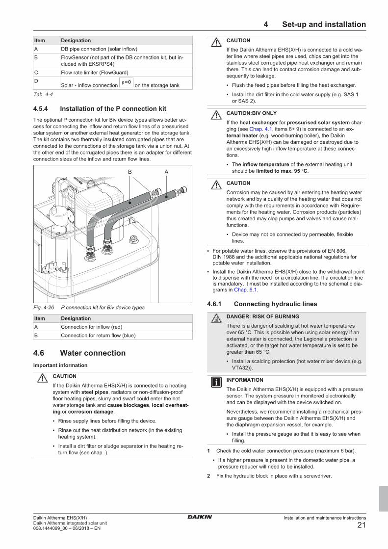
4.5.4 Installation of the P connection kitThe optional P connection kit for Biv device types allows better ac-cess for connecting the inflow and return flow lines of a pressurisedsolar system or another external heat generator on the storage tank.The kit contains two thermally insulated corrugated pipes that areconnected to the connections of the storage tank via a union nut. Atthe other end of the corrugated pipes there is an adapter for differentconnection sizes of the inflow and return flow lines.
AB
Fig. 4-26 P connection kit for Biv device types
Item DesignationA Connection for inflow (red)B Connection for return flow (blue)
4.6 Water connectionImportant information
CAUTION
If the Daikin Altherma EHS(X/H) is connected to a heatingsystem with steel pipes, radiators or non-diffusion-prooffloor heating pipes, slurry and swarf could enter the hotwater storage tank and cause blockages, local overheat-ing or corrosion damage.
▪ Rinse supply lines before filling the device.
▪ Rinse out the heat distribution network (in the existingheating system).
▪ Install a dirt filter or sludge separator in the heating re-turn flow (see chap. ).
CAUTION
If the Daikin Altherma EHS(X/H) is connected to a cold wa-ter line where steel pipes are used, chips can get into thestainless steel corrugated pipe heat exchanger and remainthere. This can lead to contact corrosion damage and sub-sequently to leakage.
▪ Flush the feed pipes before filling the heat exchanger.
▪ Install the dirt filter in the cold water supply (e.g. SAS 1or SAS 2).
CAUTION:BIV ONLY
If the heat exchanger for pressurised solar system char-ging (see Chap. 4.1, items 8+ 9) is connected to an ex-ternal heater (e.g. wood-burning boiler), the DaikinAltherma EHS(X/H) can be damaged or destroyed due toan excessively high inflow temperature at these connec-tions.
▪ The inflow temperature of the external heating unitshould be limited to max. 95 °C.
CAUTION
Corrosion may be caused by air entering the heating waternetwork and by a quality of the heating water that does notcomply with the requirements in accordance with Require-ments for the heating water. Corrosion products (particles)thus created may clog pumps and valves and cause mal-functions.
▪ Device may not be connected by permeable, flexiblelines.
▪ For potable water lines, observe the provisions of EN 806,DIN 1988 and the additional applicable national regulations forpotable water installation.
▪ Install the Daikin Altherma EHS(X/H) close to the withdrawal pointto dispense with the need for a circulation line. If a circulation lineis mandatory, it must be installed according to the schematic dia-grams in Chap. 6.1.
4.6.1 Connecting hydraulic lines
DANGER: RISK OF BURNING
There is a danger of scalding at hot water temperaturesover 65 °C. This is possible when using solar energy if anexternal heater is connected, the Legionella protection isactivated, or the target hot water temperature is set to begreater than 65 °C.
▪ Install a scalding protection (hot water mixer device (e.g.VTA32)).
INFORMATION
The Daikin Altherma EHS(X/H) is equipped with a pressuresensor. The system pressure in monitored electronicallyand can be displayed with the device switched on.
Nevertheless, we recommend installing a mechanical pres-sure gauge between the Daikin Altherma EHS(X/H) andthe diaphragm expansion vessel, for example.
▪ Install the pressure gauge so that it is easy to see whenfilling.
1 Check the cold water connection pressure (maximum 6 bar).
▪ If a higher pressure is present in the domestic water pipe, apressure reducer will need to be installed.
2 Fix the hydraulic block in place with a screwdriver.

4 Set-up and installation
Installation and maintenance instructions
22Daikin Altherma EHS(X/H)
Daikin Altherma integrated solar unit008.1444099_00 – 06/2018 – EN
Fig. 4-27 Fix the hydraulic block in place when connecting to thetop (left) or to the rear (right)
3 Establish hydraulic connections on the Daikin Altherma EHS(X/H).
▪ Refer to Chap. 4.1 for the position of the heater connections.
▪ Observe specified tightening torque (see Chap. 10.3)
▪ Install the line in such a way that the protective cover of theDaikin Altherma EHS(X/H) is simple to put on after assembly.
▪ Connect the water for filling or refilling the heating system asspecified by EN 1717/EN 61770 to avoid contamination ofdrinking water by return flow.
4 For rearward facing connections: Support hydraulic lines suit-ably according to the spatial conditions.
Fig. 4-28 Connection to the rear: Support hydraulic lines
5 Connect the blow-off line to the safety over-pressure valve anddiaphragm expansion vessel in accordance with EN 12828.
▪ Any steam or heating water which may escape must be drainedby a suitable blow-off line with constant gradient in a frost-pro-tected, safe and observable manner.
▪ Install the line in such a way that the protective cover of theDaikin Altherma EHS(X/H) is simple to put on after assembly.
▪ Check the seat of the drain hose on the safety pressure reliefvalve. If necessary, connect and install a separate hose.
6 Connecting a diaphragm expansion vessel.
▪ Connect a suitably dimensioned and preset diaphragm expan-sion vessel for the heating system. There may not be any hy-draulic blocking elements between the heat generator and thesafety valve.
▪ Position the diaphragm expansion vessel in an easily access-ible place (maintenance, parts replacement).
7 Carefully insulate pipework against heat loss and to avoid con-densation (insulation thickness at least 20 mm).– Water shortage protection: The pressure and temperature
monitoring of the controller shuts off and locks the DaikinAltherma EHS(X/H) safely if there is a shortage of water. Noadditional water shortage protection is needed in the con-struction.
– Avoid damage caused by deposits and corrosion: seeChap. 1.2.5
Fig. 4-29 Connecting a diaphragm expansion vessel
4.6.2 Connecting the drain1 Connect the drain hose to the hose connecting piece for the
safety overflow (Fig. 3-1, item 23).– Use transparent drain hose (draining water must be visible).– Connect the drain hose to an adequately dimensioned waste
water installation.– Drain should not be lockable.
Fig. 4-30 Connection of the overflow hose

4 Set-up and installation
Installation and maintenance instructions
23Daikin Altherma EHS(X/H)Daikin Altherma integrated solar unit008.1444099_00 – 06/2018 – EN
4.7 Electrical connectionDANGER: RISK OF ELECTROCUTION
Touching live parts can result in an electric shock andlead to potentially fatal injuries and burns.
▪ Before beginning work on live parts, disconnect all of thesystems circuits from the power supply (switch off ex-ternal main switch, disconnect fuse) and secure againstunintentional restart.
▪ Establishment of the electrical connection and work onelectrical components should only be performed by elec-trical technicians in compliance with valid standardsand guidelines as well as the specifications of the en-ergy supply company and the instructions in this manual.
▪ Never make constructional changes to connectors orother electrical equipment components.
▪ Device covers and service panels must be replacedas soon as the work is completed.
CAUTION
Increased temperatures may arise in the controller housingof the Daikin Altherma EHS(X/H) during operation. Thiscan result in currently-carrying wires from reaching highertemperatures during operation due to self-heating. For thisreason, these lines need to have a continuous use temper-ature of 90 °C.
▪ For the following connections, only use cables with along-term use temperature ≥ 90 °C: Heat pump outdoorunit and optional: Electric backup heater (EKBUxx)
CAUTION
If the mains cable of the Daikin Altherma EHS(X/H) is dam-aged, it must be replaced by the manufacturer or his cus-tomer service or a similarly qualified person to avoid haz-ards.
All Daikin Altherma EHS(X/H) control and safety devices are con-nected ready for use and tested. Modifications on the electrical in-stallation are dangerous and prohibited. The operator alone shallbear responsibility for any resulting damage.

4 Set-up and installation
Installation and maintenance instructions
24Daikin Altherma EHS(X/H)
Daikin Altherma integrated solar unit008.1444099_00 – 06/2018 – EN
4.7.1 Overall connection diagram
4-8
kW
J8
J13J3
CA
N-HA1
PE
PE
21
L
CA
N-LA
N
N3
N
CA
N-V
CC
A2
L
L1
PE
PE
CA
N-G
ND
XAG1
GN
D
GN
D
J8 J8
GN
D
GN
D
GN
D
GN
D
EB
A
Sm
art
Grid
EB
A
J8 J14
J16P
Z
EK
BU
xx 1
N ~
23
0V
EK
BU
xx 3
N ~
40
0V
EH
S1
57
03
4
EH
S1
57
06
8
AU
X
0,7
5 m
m²
/ sig
0,7
5 m
m²
/ sig
/ 2
30
VE
XT
HT
/NT
RT
0,7
5 m
m²
/ sig
0,7
5 m
m²
/ sig
0,7
5 -
1,5
mm
² / sig
SG
0,7
5 m
m²
/ sig
0,7
5 m
m²
/ sig
EX
T
2,5
mm
² / 2
30
V / <
30
m
1,5
mm
² / 2
30
V
NL CO
M
EV
U
RoCon BM2CRTX - EHS
L1 N
PE
BU
BU
L1
L2
L3 N
PE
BU
BU
BU
BU
X1 X1
2,5
mm
² / 2
30
V
2,5
mm
² / 4
00
V
NN
PE
PE
J6
V3
90
°C
90
°C
L1
L2
L3
Fu
se
16
A
RC
D (
FI)
L1
L2
L3
V3
1
N ~
23
0V
NP
EL
1L
2L
3
Po
we
r su
rge
ca
teg
ory
III
Po
we
r su
rge
ca
teg
ory
III
Po
we
r su
rge
ca
teg
ory
III
Fu
se
RC
D (
FI)
1,5
mm
² / 2
30
V
Po
we
r su
rge
ca
teg
ory
III
L1
Fu
se
16
A
RC
D (
FI)
1N
~ 2
30
V
L2
L3
NP
E
?
40
0V
23
0V
TA
1 m
m²
/ sig
XTA1
ER
GA
04
DA
V3
2
0 A
≥
2,5
ER
GA
06
DA
V3
2
0 A
≥
2,5
ER
GA
08
DA
V3
2
5 A
≥
4
ER
GA
04
DA
V3
A
16
A ≥
2,5
ER
GA
06
DA
V3
A
16
A ≥
2,5
ER
GA
08
DA
V3
A
16
A ≥
2,5
Typ
e
F
use
m
m²
Fu
se
1A
RC
D (
FI)
≤ 9
KW
1K
W -
3K
W
Fig. 4-31 Overall connection diagram - for the electrical connection during the device installation (for the legend and pin assignment of theprinted circuit board, see Chap. 10.5)

4 Set-up and installation
Installation and maintenance instructions
25Daikin Altherma EHS(X/H)Daikin Altherma integrated solar unit008.1444099_00 – 06/2018 – EN
4.7.2 Position of the printed circuit boards andterminal strips
X1
A1PRoCon BM2C
1
XTA1
XAG1
RoCon+ HP2
RTX-EHS
Fig. 4-32 Position of the printed circuit boards and terminal strips(for the legend, see Chap. 10.5)
4.7.3 Mains connectionA flexible cable for the mains connection is already connected insidethe device.
1 Check the supply voltage (~230 V, 50 Hz).
2 Disconnect the junction box of the domestic installation.
3 Connect the cable for connecting the Daikin Altherma EHS(X/H)to the mains to the domestic installation's junction box (isolatoraccording to EN 60335-1) via an all-pole separating main switchto be installed in the building. Ensure that the polarity is correct.
4.7.4 General information on the electricalconnection
1 Check the supply voltage.
2 Set the mains switch to "Off".
3 Switch off the circuit breaker in the junction box of the domesticpower supply.
4 Open the controller housing (see Chap. 4.4.4).
5 Insert the cable through one of the cable glands into the interiorof the controller housing. When cutting and laying cables to beconnected, make sure that the controller housing can be broughtinto the service position without any tension.
Fig. 4-33 Cable gland
6 Make electrical connections according to Chap. 4.7.1 and thefollowing sections
7 Effective strain relief in the controller housing by means of cableties must be ensured for all cables connected to the DaikinAltherma EHS(X/H) (steps 1 – 3, Fig. 4-34).
Fig. 4-34 Establishing and checking the strain relief
8 Check the holding force of the strain relief (step 4, Fig. 4-34).
9 After the installation is complete: Close the controller housingagain and, if necessary, move it to the normal position.
4.7.5 Connecting the heat pump outdoor unit
INFORMATION
A separate manual containing instructions about installa-tion and operation is included with this component.
1 Follow the installation steps in Chap. 4.7.4.
2 Connect the heat pump outdoor unit to terminal strip XAG1 (seeFig. 4-35).
X1M
L
N
COM
PE
1
2
3
PE
COM
32
N
1
L
Fig. 4-35 Connecting the heat pump outdoor unit
INFORMATION
If the heat pump outdoor unit is shut off via a circuit spe-cified by the utility company, the Daikin Altherma EHS(X/H)indoor unit is not shut off.

4 Set-up and installation
Installation and maintenance instructions
26Daikin Altherma EHS(X/H)
Daikin Altherma integrated solar unit008.1444099_00 – 06/2018 – EN
4.7.6 Connecting the outside temperaturesensor (optional)
The heat pump outdoor unit has an integrated outdoor temperaturesensor which is used for weather-compensated inflow temperaturecontrol with frost protection function. The weather-compensated in-flow temperature control can be further optimised with the optionaloutdoor temperature sensor.
▪ Choose a location at about one third of the building height (min-imum distance from floor: 2 m) at the coldest side of the building(North or North-East). Ensure that the location is not near to anyexternal heat sources (flues, air ducts), nor subject to direct solarradiation.
▪ Place external temperature sensors in such a way that the cableexit points face downwards (prevents humidity ingress).
CAUTION
Laying the sensor and mains lines in parallel in a wiringconduit can lead to major malfunctions during controlledoperation of the Daikin Altherma EHS(X/H).
▪ Always lay the sensor line separately.
1 Connect the exterior temperature sensor to a twin-core sensorline (minimum diameter 1 mm2).
2 Install the sensor line to the Daikin Altherma EHS(X/H).
3 Follow the installation steps in Chap. 4.7.4.
4 Connect the sensor line to the XTA1 terminal strip (see Chap.4.7.2).
5 On the RoCon+ HP controller, set the [External temperaturesensor] parameter to "On" [→ Main menu → Configuration→ Sensors].
4.7.7 External switching contactConnection of an external switching contact (Fig. 4-36) enableschangeover of the operating mode on the Daikin Altherma EHS(X/H).
The current operating mode is switched by a changing resistancevalue (Tab. 4-6). The changeover of the operating mode is only ef-fective for a long as the external switching contact is closed.
The operating mode has an effect on the direct circuit of the DaikinAltherma EHS(X/H) as well as all other heating circuits connected tothis device as an option.
When special functions (e.g. "48h Emergency Operation") are activ-ated, the input is not evaluated.
Fig. 4-36 EXT switching contact connection
Operating mode Resistance RV ToleranceStandby < 680 Ω ± 5%Heating 1200 Ω
Reducing 1800 ΩSummer 2700 Ω
Automatic 1 4700 ΩAutomatic 2 8200 Ω
Tab. 4-6 Resistance values for evaluating the EXT signal
INFORMATION
The input is not considered for resistance values greaterthan the value for "Automatic 2".
INFORMATION
The [Heating support (HZU)] function integrated in the Ro-Con+ HP controller (see the Controller operating instruc-tions) makes it unnecessary to connect the connection tothe burner blocking contact connection of the solar system.
4.7.8 EBA (external requirement request)By connecting the EBA switching contact to the Daikin AlthermaEHS(X/H) (Fig. 4-37) and corresponding parametrisation in its Ro-Con+ HP controller, an external switching contact can be used togenerate a heat request. If the switching contact is closed, the DaikinAltherma EHS(X/H) switches to heating mode. The inflow temperat-ure is controlled to the temperature set in the [Inflow temperatureheating operation] parameter [→ Main menu → Configuration→ Heating].
The EBA switching contact has priority over a request from the roomthermostat.
The switching contact is not evaluated in cooling mode, standby,manual or summer mode. The heating limits are also ignored.
Fig. 4-37 EBA switching contact connection
4.7.9 Connecting an external heat generator
INFORMATION
To connect an external heat generator, the connection setfor external heat generators must be installed. (see Chap.4.5).
For heating support or as an alternative to an electric backup heater,an external heat generator (e.g. gas- or oil-fired boiler) can be con-nected to the Daikin Altherma EHS(X/H). To connect an externalheat generator, the connection set for external heat generators mustbe installed (see Chap. 4.5).
The heat supplied by the external heat generator must be fed to theunpressurised storage tank water in the Daikin Altherma EHS(X/H)'s hot water storage tank.
▪ Implement the hydraulic connection according to one of the twofollowing options:

4 Set-up and installation
Installation and maintenance instructions
27Daikin Altherma EHS(X/H)Daikin Altherma integrated solar unit008.1444099_00 – 06/2018 – EN
▪ unpressurised via the connections (solar inflow and solarreturn flow) of the hot water storage tank
▪ for Daikin Altherma EHS(X/H) …Biv, device types, via theintegrated pressurised solar heat exchanger.
▪ Comply with the instructions on hydraulic connections(see Chap. 1.2)
▪ Examples of the hydraulic connection (see Chap. 6).
The external heat generator request is connected via a relay on prin-ted circuit board RTX-EHS (see Fig. 4-38). Electrical connection tothe Daikin Altherma EHS(X/H) is possible as follows;
▪ External heat generator has a potential-free switching contact con-nection for heat request:
▪ Connection to K3 if the external heat generator is responsiblefor the preparation of hot water and the heating support (settingof the [Config. of external heat source] parameter = "2" [→ Mainmenu → Settings→ Ext. Source])
or
▪ Connection to K1 and K3 if two external heat generators areused (setting of the [Config. of external heat source ] parameter= "3" [→ Main menu → Settings → Ext. Source]). In this case,K1 connects the external heat generator (e.g. gas-fired or oil-fired boiler) for heating support and K3 connects the externalheat generator (EKBUxx) for hot water preparation.
or
▪ Connection to AUX connection A (see Chap. 4.7.13)
▪ External heat generator can only be connected via mains voltage:Connection (~230 V, maximum load 3000 W) to K1 and K3.
CAUTION
Danger of voltage flash-overs.
▪ The connections of the RTX-EHS printed circuit boardmust not be used simultaneously for connecting mainsvoltage (~230 V) and SELV ("Safety Extra LowVoltage").
Fig. 4-38 Connection on the RTX-EHS printed circuit board
1 Refer to the external heat generator's respective installation in-structions for a suitable electrical connection.
2 Installing the connection set for external heat generators (seeChap. 4.5).
3 Make suitable connections on the RTX-EHS printed circuit boardof the connection set (see Fig. 4-38).
4 Fix cables that are fed into the connection set from the outsideusing the strain relief clips and cable ties included (see steps 7and 8 in Chap. 4.7.4).
4.7.10 Connecting the room thermostat
INFORMATION
A separate manual containing instructions about installa-tion and operation is included with this component.

4 Set-up and installation
Installation and maintenance instructions
28Daikin Altherma EHS(X/H)
Daikin Altherma integrated solar unit008.1444099_00 – 06/2018 – EN
Fig. 4-39 Connection with wired room thermostat (RT = DaikinEKRTW)
Fig. 4-40 Connection with radio-controlled room thermostat (RT-E= Daikin EKRTR)
4.7.11 Connection of optional RoCon systemcomponents
The optional RoCon devices must be connected to the DaikinAltherma EHS(X/H) via a 4-wire CAN bus line (connection J13).
For this, we recommend shielded lines with the following character-istics:
▪ Standardisation according to ISO 11898, UL/CSA type CMX (UL444)
▪ PVC outer sheath with flame retardancy according to IEC60332-1-2
▪ Up to 40 m, minimum cross-section 0.75 mm2. Larger conductorcross-section necessary with increasing length.
Commercially available junction boxes can be used to connect CANbus lines of several RoCon devices.
Ensure that mains, sensor and data bus lines are routed separately.Use only cable ducts with separators or separate cable ducts spacedat least 2 cm apart. Line crossings are permissible.
A maximum of 16 devices with a total line length of up to 800 m canbe connected in the entire RoCon system.
Room controller EHS157034A separate EHS157034 room controller can be connected for eachheating circuit to enable remote adjustment of operating modes andtarget room temperatures from another room.
INFORMATION
Separate installation instructions are included with thiscomponent. See the enclosed control system manual forinstructions on setting and operation.
EHS157068 mixer moduleThe EHS157068 mixer module can be connected to the DaikinAltherma EHS(X/H) (J13 circuit board connector) and is controlledby the electronic controller.
INFORMATION
Separate installation instructions are included with thiscomponent. See the enclosed control system manual forinstructions on setting and operation.
Internet gateway EHS157056The controller can be connected to the internet with the optionalEHS157056 gateway. This enables remote control of the DaikinAltherma EHS(X/H) by mobile phones (by app).
INFORMATION
Separate installation instructions are included with thiscomponent. See the enclosed control system manual forinstructions on setting and operation.
4.7.12 Connecting the HP convector
INFORMATION
A separate manual containing instructions about installa-tion and operation is included with this component.
▪ Electrical connection of the HP convector with the following ac-cessories according to Fig. 4-41 as a switchover contact (heating/cooling).
▪ If necessary, install and connect a 2-way valve (2UV) (HPC-RP 1420 13) in the HP convector. Set its controller so that the 2-wayvalve (2UV) closes when no request is available from this device.
INFORMATION
The operating mode (heating/cooling) can only be switchedon the Daikin Altherma EHS(X/H).

4 Set-up and installation
Installation and maintenance instructions
29Daikin Altherma EHS(X/H)Daikin Altherma integrated solar unit008.1444099_00 – 06/2018 – EN
Fig. 4-41 Connecting the HP convector (max. 2) to the DaikinAltherma EHS(X/H)
Fig. 4-42 Connecting the HP convector (min. 3) to the DaikinAltherma EHS(X/H)
4.7.13 Connecting switching contacts (AUXoutputs)
The switching contacts (AUX outputs) can be used for various para-metrisable functions.
The A-A1-A2 switchover contact switches under the conditions set inthe [AUX switching function] parameter [→ Main menu → Settings→ Inputs/Outputs] (see Controller operating instructions).
3J
3J
L
L
L / +
L / +
N / -
N / -
N
N
250V, max. 63 mA
250V, max. 63 mA
250V, max. 63 mA
250V, max. 63 mA
≤ 15 W
> 15 W
max.1A
max.1A
Fig. 4-43 Connection of switching contact (AUX output)
The relays user for variant 2 (switched output > 15 W) must be suit-able for a 100 % power-on time.
Connection terminals B+B1 are not occupied for these devices orare available for additional functions.
The relays user for variant 2 (switched output > 15 W) must be suit-able for a 100 % power-on time.
Switchover contact A-A1-A2 can be used e.g. to control the heatgenerators in bivalent heating systems consisting of a DaikinAltherma EHS(X/H) and an oil-or gas-fired boiler. Examples of theintegration of the hydraulic system are described in Chap. 6.
INFORMATION
When an A2 F or G-plus condensing boiler is connected,the [AUX switching function] and [AUX time] parametersmust be set according to the required function [→ Mainmenu → Settings → Inputs/Outputs].
See Controller operating instructions → chapter Parametersettings.
Precise information on the electrical connection and the re-quired parameter settings for such bivalent heating sys-tems are available on the Internet (www.daikin.com) orfrom your service partner.
4.7.14 Off-peak mains connection (HT/NT)If the outdoor unit is connected to an off-peak mains connection, theS2S potential-free switching contact of the receiver (which evaluatesthe low-tariff input signal output by the electricity supply company)must be connected to the J8 connector, EVU connection on the Ro-Con BM2C printed circuit board (see Fig. 4-44).
When setting the [HT/NT Function] parameter > 0 [→ Main menu→ Settings → Inputs/Outputs], certain system components areswitched off at peak tariff times (see Controller operating instruc-tions).
The following types of off-peak mains connection are common:
▪ Type 1: With this type of off-peak mains connection, the powersupply to the heat pump outdoor unit is not interrupted.
▪ Type 2: With this type of off-peak mains connection, the powersupply to the heat pump outdoor unit is interrupted after a certainperiod of time.
▪ Type 3: With this type of off-peak mains connection, the powersupply to the heat pump outdoor unit is interrupted immediately.
Potential-free switching contact S2S can be implemented as a nor-mally closed or normally open switching contact.

4 Set-up and installation
Installation and maintenance instructions
30Daikin Altherma EHS(X/H)
Daikin Altherma integrated solar unit008.1444099_00 – 06/2018 – EN
▪ For the NC contact version, the [HT/NT connection] parameter = 1must be set [→ Main menu → Settings → Inputs/Outputs]. Whenthe electricity supply company sends the off-peak signal, switchingcontact S2S is opened. The system switches to "Mandatory OFF".If the signal is sent again, potential-free switching contact S2Scloses and the system resumes operation.
▪ For the NO contact version, the [HT/NT connection] parameter = 0must be set [→ Main menu → Settings → Inputs/Outputs]. Whenthe electricity supply company sends the off-peak signal, switchingcontact S2S is closed. The system switches to "Mandatory OFF".If the signal is sent again, potential-free switching contact S2Sopens and the system resumes operation.
[HT/NT connection] = 1 [HT/NT connection] = 0
Fig. 4-44 Connection of the H/NT switch contact
Item Designation1 Mains connection box for off-peak mains connection2 Receiver for evaluating the HT/NT control signal3 Power supply of the heat pump outdoor unit (see re-
spective installation instructions for the heat pump out-door unit)
4 Potential-free switching contact for heat pump indoorunit
Tab. 4-8
4.7.15 Connecting an intelligent controller(Smart Grid - SG)
As soon as the function is activated through the [Smart Grid] para-meter = 1 [→ Main menu → Settings → Inputs/Outputs] (see Con-troller operating instructions), the heat pump is switched to stand-by,normal or a mode at higher temperatures depending on the utilitycompany signal.
For this purpose, the floating switching contacts SG1/SG2 of the in-telligent controller must be connected to connector J8, connectionsSmart Grid and EVU, on the RoCon BM2C printed circuit board (seeFig. 4-45).
As soon as the function is active, the HT/NT function is automaticallydeactivated. The heat pump is operated differently depending on thevalue of the [Modus Smart Grid] parameter [→ Main menu → Set-tings → Inputs/Outputs] (see Controller operating instructions).
Fig. 4-45 Connecting the Smart Grid
4.8 Connection for refrigerantINFORMATION
Follow the installation instructions for the outdoor unit.
4.8.1 Laying refrigerant lines
CAUTION
The use of refrigerant lines that have already been usedcan lead to damage to the unit.
▪ Do not reuse a refrigerant line that has been used withanother refrigerant. Replace or carefully clean the refri-gerant line.
▪ Check if an oil trap bend for the refrigerant line is necessary.
▪ Required if Daikin Altherma EHS(X/H) is not installed at groundlevel to the external heat pump unit (Fig. 4-46, HO ≥ 10 m).
▪ At least one oil trap bend must be installed for every 10 m ofheight difference (Fig. 4-46, H = distance from oil trap bend tooil trap bend).
▪ An oil trap bend is only required in the gas line.
▪ Install lines with bending unit and an adequate clearance to elec-trical lines.
▪ Only solder with light nitrogen flow (hard soldering only).
▪ Do not apply thermal insulation to connection points until afterstart-up (for purposes of leakage search).
▪ Make flared connections and connect to the devices (observetightening torque, see Chap. 10.3).

4 Set-up and installation
Installation and maintenance instructions
31Daikin Altherma EHS(X/H)Daikin Altherma integrated solar unit008.1444099_00 – 06/2018 – EN
Fig. 4-46 Oil trap bend for refrigerant line
Item DesignationA Heat pump outdoor unitB Daikin Altherma EHS(X/H)C Gas lineD Liquid lineE Oil trap bendH Height to 1st oil trap (max. 10 m)HO Height difference between heat pump outdoor unit and
heat pump indoor unit
Tab. 4-9 Legend for Fig. 4-46
4.8.2 Pressure test and filling the refrigerantcircuit
WARNING
The overall heat pump system contains refrigerants withfluorinated greenhouse gases that are harmful to the envir-onment when released.
Refrigerant type: R32
GWP* value: 675
*GWP = Global Warming Potential
▪ Enter the total filling quantity of refrigerant on the labelsupplied on the external heat pump unit (for notes, seeInstallation instructions for the heat pump outdoor unit).
▪ Never allow refrigerant to escape into the atmosphere -always extract and recycle with a suitable recyclingdevice.
1 Perform pressure test with nitrogen.
▪ Use nitrogen 4.0 or higher.
▪ Maximum 40 bar.
2 After the leak search is complete, completely drain.
3 Vacuum lines.
▪ Pressure to be reached: 1 mbar absolute.
▪ Time: Minimum 1 h
4 Check whether additional refrigerant is needed for primer filling;fill if necessary.
5 Open the stop valves on the exterior unit completely until thestop. Slightly tighten.
6 Reinstall the valve caps.
7 Check that the storage tank temperature sensors are inserted toa depth of tDHW1 80 cm and tDHW2 60 cm.
4.9 Filling the systemOnly fill the Daikin Altherma EHS(X/H) after completion of all installa-tion work in the order shown below.
4.9.1 Checking the water quality and adjustingthe pressure gauge
1 Comply with the instructions for the water connection (see Chap.4.6) and for the water quality.
2 Adjust the mechanical pressure gauge (mounted on site in ac-cordance with Chap. 4.6.1 or temporarily installed with fillinghose): Turn the pressure gauge glass so that the minimum pres-sure marking corresponds to the system height +2 m (1 m wa-ter column corresponds to 0.1 bar).
4.9.2 Filling hot water heat exchangers1 Open the shutoff valve for the cold water supply pipe.
2 Open the hot water tap connections so that the draw-off volumecan be set as high as possible.
3 Once water has been discharged from the tap connections, donot interrupt the cold water flow to ensure that the heat ex-changer will be fully vented and that any impurities or residuewill be discharged.
4.9.3 Filling the storage tanksee Chap. 7.2.1.
4.9.4 Filling the heating systemsee Chap. 7.2.2.

5 Start-up
Installation and maintenance instructions
32Daikin Altherma EHS(X/H)
Daikin Altherma integrated solar unit008.1444099_00 – 06/2018 – EN
5 Start-upWARNING
If a Daikin Altherma EHS(X/H) is not started up properly, itmay not operate properly and can endanger human lifeand health.
▪ Only heating engineers, authorised and trained by gasand energy supply companies, are allowed to start upthe Daikin Altherma EHS(X/H).
CAUTION
If the Daikin Altherma EHS(X/H) is not started up properly,it could lead to material or environmental damage.
▪ Observe the information concerning water quality in ac-cordance with Chap. 1.2.5.
▪ During operation of the system, the water must bechecked at regular intervals on the building-side mano-meter (green range) or by querying the controller (seeaccompanying controller manual). If necessary, correctthe pressure by topping up with water.
Incorrect start-up voids the manufacturer's guarantee for the device.If you have questions, please contact our Technical Customer Ser-vice.
5.1 Initial commissioningOnce the Daikin Altherma EHS(X/H) has been installed and com-pletely connected, it must be adapted once to the installation envir-onment by expert personnel (configuration).
After this configuration is complete, the installation is ready for oper-ation and the operator can make additional custom configurations onit.
The heating technician must instruct the user, draw up the start-uplog and complete the operating manual.
The settings of optional components such as a room thermostat orsolar system must be carried out on the respective components.
5.1.1 Requirements▪ The Daikin Altherma EHS(X/H) is fully connected.
▪ The refrigerant system is dehumidified and filled with the specifiedamount of refrigerant.
▪ The heating and hot water system has been filled and pressurisedto the correct pressure (see Chap. 7.2.2).
▪ The storage tank is filled up to the overflow (see Chap. 7.2.1).
▪ Optional accessories have been installed and connected up.
▪ The heating system's control valves are open.
5.1.2 Starting the unit and start-up
INFORMATION
Please observe the operating instructions of the RoCon+HP controller.
INFORMATION
If the storage tank temperature falls below specific min-imum values, the safety settings of the Daikin AlthermaEHS(X/H) prevent the heat pump from being operated atlow outside temperatures:
- Outside temperature < -2 °C, minimum storage tank tem-perature = 30 °C
- Outside temperature < 12 °C, minimum storage tank tem-perature = 23 °C
Without backup heater:
The storage tank water must be heated to the requiredminimum storage tank temperature with an external heaterbooster.
With backup heater (EKBUxx):
At an outside temperature of < 12 °C and a storage tanktemperature of < 35 °C, the backup heater (EKBUxx) isautomatically switched on to heat the storage tank water toat least 35 °C.
▪ To speed up the heating process with the backupheater, temporarily set the [Config. of external heatsource] parameter = "1" and [Ext. hot water power] para-meter to the maximum value of the backup heater[→ Main menu → Settings → Ext. Source].
▪ Select the [1x Hot Water] parameter in the "User" menuand switch it on. After the heating has completed, switchoff the parameter again [→ Main menu → User → 1xLoad].
5.1.3 Bleeding the hydraulic system▪ Make sure that the automatic vent valve cap is open (item A).
Fig. 5-1 Automatic vent valve
▪ Provide the manual vent valve (item B) with a hose and direct itaway from the unit. Open the valve until water emerges.
▪ Fit the second manual vent valve (item C) with a hose and open ituntil water emerges.
▪ Activate the air purge (see RoCon+ HP operating instructions).
By activating the air purge, the RoCon+ HP controller starts a per-manently defined sequence program with start/stop operation of theintegrated heating circulation pump and various settings of the 3-wayswitch valves integrated in the Daikin Altherma EHS(X/H).
Any air present can escape via the automatic vent valve during theair purge and the hydraulic circuit connected to the Daikin AlthermaEHS(X/H) is evacuated.

5 Start-up
Installation and maintenance instructions
33Daikin Altherma EHS(X/H)Daikin Altherma integrated solar unit008.1444099_00 – 06/2018 – EN
INFORMATION
The activation of this function does not replace correctventing of the heating circuit.
The heating circuit must be completely full before activat-ing this function.
▪ Check the water pressure and replenish water if necessary(see Chap. 7.2.2).
▪ Repeat the venting, checking and replenishing process until:
▪ it is completely vented.
▪ there is sufficient water pressure.
Fig. 5-2 Manual vent valves
5.1.4 Checking the minimum flowThe minimum flow must be checked with the heating circuit closed.
INFORMATION
If the minimum flow is too low, an error message may ap-pear and the heating system may shut down.
If the minimum flow rate is not sufficient, there may be airin the circulation pump or the valve drive of the 3-wayswitching valves (3UVB1 / 3UV DHW) is defective.
▪ Vent the circulation pump.
▪ Check the function of the valve drives; replace the valvedrive if necessary.
▪ Close the valves and adjuster drives of all connected heat distribu-tion circuits.
▪ Set the "Heating" operating mode on the Daikin Altherma EHS(X/H) controller [→ Main menu → Operating mode].
▪ Read the [Actual flow rate] information parameter [→ Main menu→ Info → Values].
▪ The flow rate must be at least 480 l/h (see Controller operatinginstructions).
INFORMATION
The Daikin Altherma EHS(X/H) controller constantly monit-ors the flow rate of the internal heat generator circuit. Dif-ferent minimum flow rate values are required depending onthe active operating mode:
"Heating" operating mode: 480 l/h
"Cooling" operating mode: 660 l/h
Automatic thawing function (Defrost) active: 780 l/h
If an error message regarding an inadequate minimum flowis displayed at a flow rate of more than 480 l/h, check theactual flow rate in the active operating mode and eliminatepossible fault causes.
5.1.5 Setting the screed program parameter(only as required)
In the screed program, the inflow temperature is controlled accordingto a pre-set temperature profile.
See the Controller operating instructions for further information onthe screed program, its activation and sequence.
After the screed program has ended, the RoCon+ HP control unitcontinues to work in the previously set operating mode. If not con-figured beforehand, the following finishing work is necessary.
1 On connection without room station EHS157034:– Set the heating characteristic curve or required inflow tem-
perature.
2 On connection with room station EHS157034:– Activate the room station.– Set the heating characteristic curve or required inflow tem-
perature. If necessary, set the [Room Influence] parameter[→ Main menu → Configuration → Heating] and set the tar-get room temperature.
5.2 Re-commissioning
5.2.1 Requirements
CAUTION
Start-up in frosty conditions can result in damage to the en-tire heating system.
▪ Start-up at temperatures below 0 °C only if a water tem-perature of at least 5 °C is guaranteed in the heatingsystem and the storage tank.
▪ We recommend not to operate the installation in ex-tremely frosty conditions.
▪ The Daikin Altherma EHS(X/H) is fully connected.
▪ The refrigerant system is dehumidified and filled with the specifiedamount of refrigerant.
▪ The heating and hot water system has been filled and pressurisedto the correct pressure (see Chap. 7.2.2).
▪ The storage tank is filled up to the overflow (see Chap. 7.2.1).

5 Start-up
Installation and maintenance instructions
34Daikin Altherma EHS(X/H)
Daikin Altherma integrated solar unit008.1444099_00 – 06/2018 – EN
5.2.2 Start-up
INFORMATION
If the storage tank temperature falls below specific min-imum values, the safety settings of the Daikin AlthermaEHS(X/H) prevent the heat pump from being operated atlow outside temperatures:
- Outside temperature < -2 °C, minimum storage tank tem-perature = 30 °C
- Outside temperature < 12 °C, minimum storage tank tem-perature = 23 °C
Without backup heater:
The storage tank water must be heated to the requiredminimum storage tank temperature with an external heaterbooster.
With backup heater (EKBUxx):
At an outside temperature of < 12 °C and a storage tanktemperature of < 35 °C, the backup heater (EKBUxx) isautomatically switched on to heat the storage tank water toat least 35 °C.
▪ To speed up the heating process with the backupheater, temporarily set the [Config. of external heatsource] parameter = "1" and [Ext. hot water power] para-meter to the maximum value of the backup heater[→ Main menu → Settings → Ext. Source].
▪ Select the [1x Hot Water] parameter in the "User" menuand switch it on. After the heating has completed, switchoff the parameter again [→ Main menu → User → 1xLoad].
1 Check the cold water connection and, where necessary, fill thepotable water heat exchanger.
2 Switch on the power supply to the Daikin Altherma EHS(X/H).
3 Wait for the start phase.
4 After the start phase in heating mode has completed, evacuatethe heating system, check the installation pressure and adjust ifnecessary (max. 3 bar, see Chap. 7.2.2).
5 Carry out a visual inspection for leaks on all connection pointsinternally. Seal any leaks that occur in a professional manner.
6 Set the controller to the required operating mode.
7 If a solar system is connected, commission it according to theenclosed instructions. After shutting off the solar system, againcheck the fill level in the buffer storage tank.

6 Hydraulic connection
Installation and maintenance instructions
35Daikin Altherma EHS(X/H)Daikin Altherma integrated solar unit008.1444099_00 – 06/2018 – EN
6 Hydraulic connectionDANGER: RISK OF BURNING
High temperatures can occur in the solar storage tank.Therefore, sufficient scalding protection must be includedwhen the hot water system is installed (automatic hot watermixing device).
To avoid heat losses due to gravity flows, the devices canbe optionally equipped with plastic non-return valves.These are suitable for maximum operating temperatures of95 °C and for installation in all heat exchanger connectionson the storage tank side (except heat exchangers for pres-surised solar system charging).
Suitable non-return valves must be installed in the buildingfor components connected to the heat exchanger for pres-surised solar system charging.
6.1 Hydraulic system connectionINFORMATION
The system diagram below is an example and is never asubstitute for careful system planning. Please visit ourwebsite for more diagrams.
Item Meaning1 Cold water distribution network2 Hot water distribution network3 Heating inflow4 Heating return flow5 Mixer circuit7 Check valve, return valve7a Non-return valves8 Solar circuit9 Gas line10 Liquid line3UV DHW 3-way distribution valve (hot water/heater)3UVB1 3-way mixer valve (heater/internal boiler circuit)EKBUxx Backup heaterBV Bypass valveC Refrigerant compressorCW Cold waterDHW Domestic hot waterDSR1
Pressurised solar system E Expansion valveH 1, H 2 … H m Heating circuitsMAG Diaphragm expansion vesselMIX 3-way mixer with drive motorMK1 Mixer group with high-efficiency pumpMK2 Mixer group with high-efficiency pump (PWM-regulated)P High-efficiency pumpP K Boiler circuit pumpP Mi Mixer circuit pumpP S Solar operating pump RDS2
Pressure station RoCon+ HP Control Daikin Altherma EHS(X/H)PWT Plate heat exchangerSAS1 Sludge and magnetic separatorSK Solar panel fieldSV Safety overpressure valvet AU External temperature sensort DHW Storage tank temperature sensort Mi Inflow temperature sensor, mixer circuittK Solaris trap temperature sensor

6 Hydraulic connection
Installation and maintenance instructions
36Daikin Altherma EHS(X/H)
Daikin Altherma integrated solar unit008.1444099_00 – 06/2018 – EN
Item MeaningtR Solaris return flow temperature sensorTS Solaris storage cylinder temp. sensorTV Solaris inflow temperature sensorV Fan (vaporiser)VS Scalding protection VTA32
Tab. 6-1
RoCon+ HP
Altherma EHS(X/H)
EKBUxx
EHS157068
Fig. 6-1 Hydraulic diagram (Biv types) with pressurised solar

7 Inspection and maintenance
Installation and maintenance instructions
37Daikin Altherma EHS(X/H)Daikin Altherma integrated solar unit008.1444099_00 – 06/2018 – EN
7 Inspection and maintenance
7.1 General overview of inspectionand maintenance
Regular inspection and maintenance of the Daikin Altherma EHS(X/H) reduces the energy consumption and ensures a long service lifeand trouble-free operation.
WARNING
The overall heat pump system contains refrigerants withfluorinated greenhouse gases that are harmful to the envir-onment when released.
Refrigerant type: R32
GWP* value: 675
*GWP = Global Warming Potential
▪ Enter the total filling quantity of refrigerant on the labelsupplied on the external heat pump unit (for notes, seeInstallation instructions for the heat pump outdoor unit).
▪ Never allow refrigerant to escape into the atmosphere -always extract and recycle with a suitable recyclingdevice.
INFORMATION
Have the inspection and maintenance carried out by au-thorised and trained heating engineers once a year and, ifpossible, before the heating period. This will avoid mal-functions during the heating period.
We recommend an inspection and maintenance contract toensure regular inspection and maintenance.
Legal requirementsAccording to F-Gases Directive (EC) No. 842/2006 Article 3, re-placed on 01/01/2015 by (EC) No. 517/2014 Articles 3 and 4, operat-ors (or owners) must regularly maintain their fixed refrigeration sys-tems, check for leaks and have any leaks rectified immediately.
All installation, maintenance and repair work on the refrigerant circuitmust be documented, e.g. in the operating manual.
The operator has the following obligations for our heat pump sys-tems:
INFORMATION
The European legal inspection period applies to heatpumps with a total filling quantity of the system with refri-gerant of 3 kg or from 01/01/2017 with a total filling quant-ity of 5 t CO2 equivalent.
However, we recommend concluding a maintenance con-tract including documentation of the work carried out in theoperating manual to safeguard warranty claims, even forsystems for which there is no legal obligation to check forleaks.
▪ With a total filling quantity of refrigerant of 3 kg - 30 kg or from6 kg in hermetic systems and from 01/01/2017 with a total fillingquantity of refrigerant of 5-50 t CO2 equivalent or from 10 t CO2equivalent in hermetic systems:
▪ Inspections by certified personnel at intervals of no more than12 months and documentation of the work carried out in accord-ance with the valid regulation. This documentation must be keptfor at least 5 years.
INFORMATION
Certified persons are those who have an expert certificatefor work on stationary cooling systems (heat pumps) andair-conditioning units in the European region in accordancewith the F-Gases Directive (EU) No. 303/2008.
▪ Up to 3 kg total filling quantity of refrigerant: Expert certi-ficate category II
▪ From 3 kg filling quantity of refrigerant: Expert certificatecategory I
Maintenance work to be carried out annually
WARNING
Work carried out improperly on the Daikin AlthermaEHS(X/H) and its optionally connected components canendanger human life and health and affect the function ofthese components.
▪ Work on the Daikin Altherma EHS(X/H) (such as main-tenance or servicing) must only be carried out by per-sons who are authorised and who have successfullycompleted qualifying technical or vocational training andwho have taken part in advanced training sessions re-cognised by the relevant authorities responsible for thespecific activity. These include, in particular, certifiedheating engineers, qualified electricians and HVAC spe-cialists who, because of their professional training andexpert knowledge, have experience in the professionalinstallation and maintenance of heating, cooling and airconditioning systems and heat pumps.
WARNING
The gaseous refrigerant is heavier than air. In pits or inbadly ventilated rooms, it can collect in high concentra-tions. Breathing in high concentrations of gaseous refriger-ant leads to feelings of faintness and suffocation. Toxicgases can be formed if gaseous refrigerants come intocontact with open fire or hot objects.
▪ When working on the refrigerant circuit, ensure that theworkplace is well vented.
▪ If necessary, before starting work, evacuate the refriger-ant system completely.
▪ Never carry out work on the refrigerant circuit in closedrooms or work pits.
▪ Do not let refrigerant come into contact with open fire,embers or hot objects.
▪ Never allow refrigerant to escape into the atmosphere(forms high concentrations).
▪ After removing the service pipes from the filling connec-tions, carry out a leakproof test on the refrigeration sys-tem. Refrigerant can escape through leaks.
WARNING
At normal atmospheric pressure and ambient temperat-ures, liquid refrigerant vaporises so suddenly that on con-tact with skin or eyes it can cause the tissue to freeze(danger of going blind).
▪ Always wear safety goggles and protective gloves.
▪ Never allow refrigerant to escape into the atmosphere(high pressure at the point of the leak).
▪ When removing the service pipes from the filling connec-tions, never hold the connections in the direction of yourbody. Residual refrigerant could escape.
7 Inspection and maintenance
Installation and maintenance instructions
38Daikin Altherma EHS(X/H)
Daikin Altherma integrated solar unit008.1444099_00 – 06/2018 – EN
WARNING
Temperatures of up to 90 °C can arise during operation un-der the cover of the Daikin Altherma EHS(X/H). During op-eration, hot water temperatures of > 60 °C occur.
▪ Touching components during or after operation leads toa risk of burns.
▪ Water discharged during maintenance and repair workcan cause scalding on contact with the skin.
▪ Before carrying out maintenance and inspection work,allow the Daikin Altherma EHS(X/H) to cool down suffi-ciently.
▪ Wear protective gloves.
WARNING
Touching live parts can result in an electric shock and leadto potentially fatal injuries and burns.
▪ Before beginning work on live parts, disconnect all cir-cuits of the system from the power supply (switch off ex-ternal main switch, disconnect fuse) and secure againstunintentional restart.
▪ The electrical connection and work on the electricalcomponents should only be performed by electrical en-gineers in compliance with valid standards andguidelines as well as the specifications of the energysupply company.
▪ Device covers and service panels must be replaced assoon as the work is complete.
1 Removing the cover and thermal insulation (see Chap. 4.4.2).
2 Check the function of the Daikin Altherma EHS(X/H) and all in-stalled accessory components (backup heater, solar system) bychecking the temperature display and switch states in the indi-vidual operating modes.
3 If a solar system of the DrainBack type is connected and in oper-ation, shut it off and empty the collectors.
4 If the Daikin Altherma EHS(X/H) is operated in a bivalent, altern-ative system, switch off all heat generators and deactivate the bi-valence controller.
5 Visual check of the general condition of the Daikin AlthermaEHS(X/H).
6 Visual check of the water storage tank level (filling level indic-ator).
▪ If necessary, replenish water (Chap. 7.2.1), determine and rem-edy the reason for the low water level.
7 Check the connection of the safety overflow, drain hose and liddrain for leaks, free drainage and gradient.
▪ If necessary, clean the safety overflow and drain hose and relayit; replace damaged parts.
INFORMATION
Thanks to its design, the Daikin Altherma EHS(X/H) re-quires very little maintenance. No corrosion protectionequipment is required (such as expendable anodes). Thismeans there is no need for maintenance work such aschanging the protective anodes or cleaning the inside ofthe storage tank.
8 Check the connection of the safety overflow and drain hose forleaks, free drainage and gradient.
▪ If necessary, clean the safety overflow and drain hose and relayit; replace damaged parts.
9 Check all electrical components, connections and cables.
▪ Repair damaged parts or replace them.
INFORMATION
If the connection cable of the optional backup heater isdamaged, the entire backup heater must be replaced.
The connection cable cannot be exchanged separately.
10 Check the water pressure of the cold water supply (< 6 bar)
▪ and, if necessary, the fitting or adjustment of the pressure redu-cer.
11 Check the system water pressure on the RoCon+ HP controllerfor the Daikin Altherma EHS(X/H).
▪ If necessary, top up the water in the heating system until thepressure display is in the permissible range (see Chap. 7.2.2).
12 Check and clean the filter/sludge separator.
13 Check the minimum flow (see Chap. 5.1.4).
14 Clean the plastic surface of the Daikin Altherma EHS(X/H) withsoft cloths and mild detergent. Do not use any cleaners with ag-gressive solvents (damage to the plastic surface may occur).
15 Re-install the cover (see Chap. 4.4.2).
16 Perform maintenance on the outdoor unit and other heatingcomponents connected to the Daikin Altherma EHS(X/H) ac-cording to the respective installation and operating instructions.
17 Complete the confirmation of maintenance in the supplied oper-ating manual of the Daikin Altherma EHS(X/H).
7.2 Inspection and maintenance tasksCleaning the protective cover and storage tank▪ The low-maintenance plastic only needs to be cleaned with soft
cloths and mild detergent.
▪ Do not use any cleaners with aggressive solvents (damage to theplastic surface may occur).
7.2.1 Filling, topping up the storage tank
CAUTION
Filling the storage tank with a too high water pressure ortoo high flow speed can cause damage to the DaikinAltherma EHS(X/H).
▪ Only fill with a water pressure <6 bar and a flow speed<15 l/min.

7 Inspection and maintenance
Installation and maintenance instructions
39Daikin Altherma EHS(X/H)Daikin Altherma integrated solar unit008.1444099_00 – 06/2018 – EN
INFORMATION
If the storage tank temperature falls below specific min-imum values, the safety settings of the Daikin AlthermaEHS(X/H) prevent the heat pump from being operated atlow outside temperatures:
- Outside temperature < -2 °C, minimum storage tank tem-perature = 30 °C
- Outside temperature < 12 °C, minimum storage tank tem-perature = 23 °C
Without backup heater:
The storage tank water must be heated to the requiredminimum storage tank temperature with an external heaterbooster.
With backup heater (EKBUxx):
At an outside temperature of < 12 °C and a storage tanktemperature of < 35 °C, the backup heater (EKBUxx) isautomatically switched on to heat the storage tank water toat least 35 °C.
▪ To speed up the heating process with the backupheater, temporarily set the [Config. of external heatsource] parameter = "1" and [Ext. hot water power] para-meter to the maximum value of the backup heater[→ Main menu → Settings → Ext. Source].
▪ Select the [1x Hot Water] parameter in the "User" menuand switch it on. After the heating has completed, switchoff the parameter again [→ Main menu → User → 1xLoad].
Without installed solar system1 Connect the filling hose with non-return valve (1/2") to the
"Solar - inflow" connection (Fig. 7-1, item 1).
2 Fill the storage tank of the Daikin Altherma EHS(X/H) until wa-ter escapes from the overflow connection (Fig. 7-1, item 23).
3 Remove the filling hose with non-return valve (1/2").
With installed solar system1 Install the filling connection with combined filling and draining
valve (accessory KFE BA) following the solar control and pumpunit (EKSRPS4).
2 Connect the filling hose with non-return valve (1/2") to the pre-viously installed combined filling and draining valve.
3 Fill the storage tank of the Daikin Altherma EHS(X/H) until wa-ter escapes from the overflow connection (Fig. 7-1, item 23).
4 Remove the filling hose with non-return valve (1/2").
Fig. 7-1 Filling the buffer tank - without connected DrainBacksolar system
Item Designation1
Solar - inflow23 Safety overflow
Tab. 7-1
7.2.2 Filling, topping up the heating system
DANGER: RISK OF ELECTROCUTION
During the filling process, water can escape from any leak-ing points and can cause an electric shock if it comes intocontact with live parts.
▪ Before the filling process, de-energise the DaikinAltherma EHS(X/H).
▪ After the first filling and before switching on the DaikinAltherma EHS(X/H) at the mains switch, check whetherall electric parts and connection points are dry.
WARNING
Polluted domestic water is hazardous to health.
▪ When filling the heating system, make sure that heatingwater cannot flow back into the domestic water pipe.
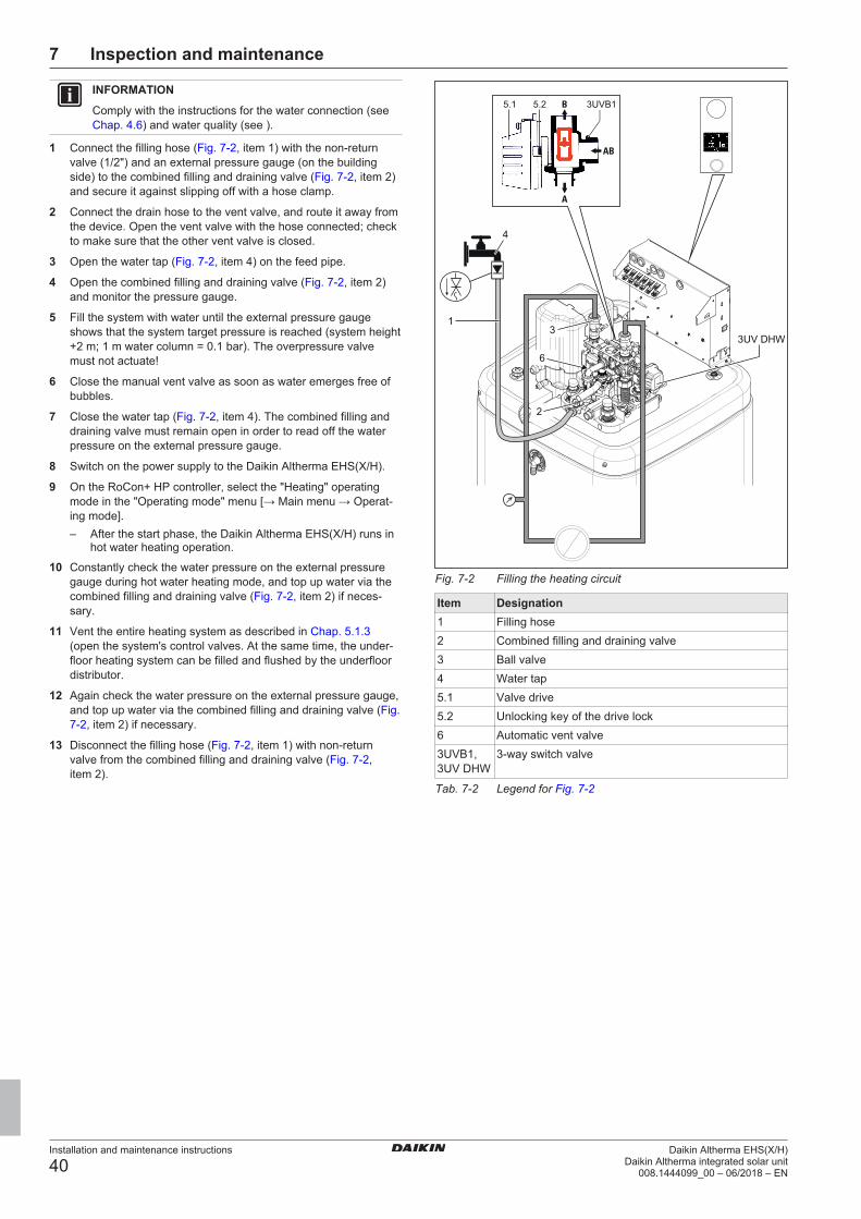
7 Inspection and maintenance
Installation and maintenance instructions
40Daikin Altherma EHS(X/H)
Daikin Altherma integrated solar unit008.1444099_00 – 06/2018 – EN
INFORMATION
Comply with the instructions for the water connection (seeChap. 4.6) and water quality (see ).
1 Connect the filling hose (Fig. 7-2, item 1) with the non-returnvalve (1/2") and an external pressure gauge (on the buildingside) to the combined filling and draining valve (Fig. 7-2, item 2)and secure it against slipping off with a hose clamp.
2 Connect the drain hose to the vent valve, and route it away fromthe device. Open the vent valve with the hose connected; checkto make sure that the other vent valve is closed.
3 Open the water tap (Fig. 7-2, item 4) on the feed pipe.
4 Open the combined filling and draining valve (Fig. 7-2, item 2)and monitor the pressure gauge.
5 Fill the system with water until the external pressure gaugeshows that the system target pressure is reached (system height+2 m; 1 m water column = 0.1 bar). The overpressure valvemust not actuate!
6 Close the manual vent valve as soon as water emerges free ofbubbles.
7 Close the water tap (Fig. 7-2, item 4). The combined filling anddraining valve must remain open in order to read off the waterpressure on the external pressure gauge.
8 Switch on the power supply to the Daikin Altherma EHS(X/H).
9 On the RoCon+ HP controller, select the "Heating" operatingmode in the "Operating mode" menu [→ Main menu → Operat-ing mode].– After the start phase, the Daikin Altherma EHS(X/H) runs in
hot water heating operation.
10 Constantly check the water pressure on the external pressuregauge during hot water heating mode, and top up water via thecombined filling and draining valve (Fig. 7-2, item 2) if neces-sary.
11 Vent the entire heating system as described in Chap. 5.1.3(open the system's control valves. At the same time, the under-floor heating system can be filled and flushed by the underfloordistributor.
12 Again check the water pressure on the external pressure gauge,and top up water via the combined filling and draining valve (Fig.7-2, item 2) if necessary.
13 Disconnect the filling hose (Fig. 7-2, item 1) with non-returnvalve from the combined filling and draining valve (Fig. 7-2,item 2).
Fig. 7-2 Filling the heating circuit
Item Designation1 Filling hose2 Combined filling and draining valve3 Ball valve4 Water tap5.1 Valve drive5.2 Unlocking key of the drive lock6 Automatic vent valve3UVB1,3UV DHW
3-way switch valve
Tab. 7-2 Legend for Fig. 7-2

8 Faults and malfunctions
Installation and maintenance instructions
41Daikin Altherma EHS(X/H)Daikin Altherma integrated solar unit008.1444099_00 – 06/2018 – EN
8 Faults and malfunctionsDANGER: RISK OF ELECTROCUTION
Electrostatic charges can lead to voltage arcing that candestroy the electronic components.
▪ Before touching the control panel PCB, ensure potentialequalisation.
8.1 TroubleshootingThe electronics of the Daikin Altherma EHS(X/H)
▪ signal a fault by status display illuminating in red and
▪ show a fault code on the display.
An integrated fault memory stores up to 15 fault messages that haveoccurred most recently.
Depending on the operating mode, messages are also forwarded toconnected room controllers or room thermostats.
Troubleshooting: Error code E90XX1 On the RoConPlus controller: Perform an error reset (see Con-
troller operating instructions).
2 Error will be displayed again shortly: Find and rectify the causeof the error.
Troubleshooting: Other error codes1 Find and rectify the cause of the error.
8.2 Overview of possible malfunctionsMalfunction Possible cause Possible solution
System not working(nothing on the display,operation LED on Ro-Con BM2C off)
No mains voltage ▪ Switch on the system's external main switch.
▪ Switch on system fuse(s).
▪ Replace system fuse(s).
Switching time pro-grams are not operatingor programmed switch-ing times are carriedout at the wrong time.
The date and time are not set correctly. ▪ Set the date.
▪ Set the time.
▪ Check the weekday to switching time assignment.Incorrect operating mode set. ▪ Set the "Automatic 1" or "Automatic 2" operating mode
During a switching time the user made a manual set-ting (e.g. changed the target temperature, changedthe operating mode)
1 Select the "Operating mode" menu [→ Main menu → Oper-ating mode].
2 Select the correct operating mode.The controller does notrespond to inputs
The controller's operating system has crashed. ▪ RESET the controller. To do this, disconnect the system fromthe power supply for at least 10 s and then switch on again.
Operating data are notupdated
The controller's operating system has crashed. ▪ RESET the controller. To do this, disconnect the system fromthe power supply for at least 10 s and then switch on again.
Heating does not warmup
Requirement heating mode shut off (e.g. switchingtime program is in the economy phase, outside tem-perature is too high, parameters for optional backupheater (EKBUxx) incorrectly set, requirement for hotwater active)
▪ Check the operating mode setting.
▪ Check the request parameters.
▪ Check the date, time and switching time program settings onthe controller.
Refrigerant compressor is not working. ▪ With backup heater (EKBUxx) installed:
▪ Check that the backup heater heats the return flow temperat-ure to at least 15 °C (at a low return flow temperature, theheat pump uses the backup heater first to achieve this min-imum return flow temperature).
▪ Check mains supply of the backup heater (EKBUxx).
▪ Thermal contactor (STB) on the backup heater (EKBUxx) hastriggered. Unlock.
The system is in the "Cooling" operating mode. ▪ Switch the operating mode to "Heating".
Settings for off-peak mains connection do not cor-respond to settings for electrical connections.
▪ HT/NT function is active and the [HT/NT connection] para-meter is set incorrectly.
▪ Other configurations are also possible. However, these mustmatch the type of off-peak mains connection.
▪ The [SMART GRID] parameter is active and the connectionsare incorrectly set.
The electricity company has sent the peak rate sig-nal.
▪ Wait for the repeat off-peak rate signal which reactivates thepower supply.

8 Faults and malfunctions
Installation and maintenance instructions
42Daikin Altherma EHS(X/H)
Daikin Altherma integrated solar unit008.1444099_00 – 06/2018 – EN
Malfunction Possible cause Possible solutionHeating does not warmup enough
Water flow too low. ▪ Check that all stop valves of the water circuit are fully open.
▪ Check that the water filter is dirty.
▪ Check if the expansion tank is defective.
▪ Completely vent the heating system and the internal circula-tion pump.
▪ On the controller ("Info" menu), check that sufficient waterpressure (> 0.5 bar) is available; if necessary, top up heatingwater.
▪ Check that the resistance in the water circuit is not too highfor the pump (see Chap. 10).
Target value range is too low. In [→ Main menu → Configuration → Heating]:
▪ Increase the [Heat-Slope ] parameter.
▪ Increase the [HZU max. temperature ] parameter.
▪ Increase the [Max. inflow temperature] parameter.Weather-dependent inflow temperature control act-ive.
▪ Check the [Heating operation limit], [Heat-Slope] parametersin [→ Main menu → Configuration → Heating].
Optional backup heater (EKBUxx) or alternativeheater booster not cut in.
▪ Check mains supply of the backup heater (EKBUxx).
▪ Thermal contactor (STB) on the backup heater (EKBUxx) hastriggered. Unlock.
▪ Check the [Config. of external heat source], [Ext. power level1] and [Ext. power level 2] parameters [→ Main menu → Set-tings → Ext. Source].
Water volume in heating system too low ▪ Check the admission pressure in the expansion tank and wa-ter pressure; if necessary, top up the heating water and adjustthe admission pressure (see Chap. 7.2.2).
Hot water supply is taking too much of the output ofthe heat pump.
▪ Check the settings of the [Config. of external heat source]parameter [→ Main menu → Settings → Ext. Source].
▪ Check the settings of the [Ext. hot water power] parameter[→ Main menu → Settings → Ext. Source].
Hot water does notwarm up
Hot water preparation shut off (e.g. switching timeprogram is in the economy phase, parameters forhot water preparation incorrectly set).
▪ Check the operating mode setting.
▪ Check the request parameters.
Storage tank charging temperature too low. ▪ Increase the target hot water temperature.
Draw-off rate too high. ▪ Reduce the draw-off rate, limit throughput.
Output of heat pump too low. ▪ Check the switching times for room heating and hot watersupply for overlaps.
Water volume in heating system too low. ▪ Check the admission pressure in the expansion tank and wa-ter pressure; if necessary, top up the heating water and adjustthe admission pressure.
Optional backup heater (EKBUxx) or alternativeheater booster not cut in.
▪ Check mains supply of the backup heater (EKBUxx).
▪ Thermal contactor (STB) on the backup heater (EKBUxx) hastriggered. Unlock.
▪ Check the [Config. of external heat source], [Ext. power level1] and [Ext. power level 2] parameters [→ Main menu → Set-tings → Ext. Source].

8 Faults and malfunctions
Installation and maintenance instructions
43Daikin Altherma EHS(X/H)Daikin Altherma integrated solar unit008.1444099_00 – 06/2018 – EN
Malfunction Possible cause Possible solutionRoom cooler does notcool
Water flow too low. ▪ Check that all stop valves of the water circuit are fully open.
▪ Check that the water filter is dirty.
▪ Check if the expansion tank is defective.
▪ Completely vent the heating system and the internal circula-tion pump.
▪ On the controller [→ Main menu → Info → Overview→ Psyst], check that sufficient water pressure (> 0.5 bar) isavailable; if necessary, top up heating water.
▪ Check that the resistance in the water circuit is not too highfor the pump (see Chap. 10).
"Cooling" switched off (e.g. room thermostat re-quests "Cooling", but switching time program is inthe economy phase, outside temperature too low).
▪ Check the operating mode setting.
▪ Check the request parameters.
▪ Check the date, time and switching time program settings onthe controller.
Refrigerant compressor is not working. ▪ With backup heater (EKBUxx) installed:
▪ Check that the backup heater heats the return flow temperat-ure to at least 15 °C (at a low return flow temperature, theheat pump uses the backup heater first to achieve this min-imum return flow temperature).
▪ Check mains supply of the backup heater (EKBUxx).
▪ Thermal contactor (STB) on the backup heater (EKBUxx) hastriggered. Unlock.
The system is in the "Heating" operating mode. ▪ Switch the operating mode to "Cooling".
Outside temperature < 4 °C ▪ The heat pump has automatically switched to the "Heating"operating mode in order to guarantee frost protection if theoutside temperature continues to fall. No room cooling pos-sible.
Cooling output for roomcooling too low
Water flow too low. ▪ Check that all stop valves of the water circuit are fully open.
▪ Check that the water filter is dirty.
▪ Check if the expansion tank is defective.
▪ Completely vent the heating system and the internal circula-tion pump.
▪ On the controller [→ Main menu → Info → Overview→ Psyst], check that sufficient water pressure (> 0.5 bar) isavailable; if necessary, top up heating water.
▪ Check that the resistance in the water circuit is not too highfor the pump.
Water volume in heating system too low. ▪ Check the admission pressure in the expansion tank and wa-ter pressure; if necessary, top up the heating water and adjustthe admission pressure.
Refrigerant quantity in the heating system too low ortoo high.
▪ Determine causes of too low or too high refrigerant quantity inthe refrigerant circuit.
▪ If the refrigerant quantity is too low, check the refrigerantcircuit for leaks, repair and add refrigerant.
▪ If the refrigerant quantity is too high, recycle the refrigerantand refill the system with the correct quantity.

8 Faults and malfunctions
Installation and maintenance instructions
44Daikin Altherma EHS(X/H)
Daikin Altherma integrated solar unit008.1444099_00 – 06/2018 – EN
Malfunction Possible cause Possible solutionInternal circulationpump generates ex-cessively high operat-ing noises
Air in the water circuit. ▪ Completely vent the heating system and the internal circula-tion pump.
Noises caused by vibrations. ▪ Check the Daikin Altherma EHS(X/H), its components andcovers to ensure they are fastened correctly.
Bearing damage in the internal circulation pump ▪ Replace the internal circulation pump.
Water pressure at pump inlet too low. ▪ On the controller [→ Main menu → Info → Overview], checkthat sufficient water pressure (> 0.5 bar) is available.
▪ Check that the pressure gauge is working correctly (connec-tion of an external pressure gauge).
▪ Check the admission pressure in the expansion tank and wa-ter pressure; if necessary, top up the heating water and adjustthe admission pressure.
Safety pressure reliefvalve is leaking or al-ways open.
Expansion tank is defective. ▪ Replace the expansion tank.
Water pressure in heating system is too high. ▪ On the controller [→ Main menu → Info → Overview], checkthat the water pressure is below the specified maximum pres-sure. If necessary, drain sufficient water until the pressure isin the middle of the permissible range.
Safety pressure relief valve is stuck. ▪ Check the safety pressure relief valve and if necessary, re-place it.
▪ Turn the red knob on the safety pressure relief valve anti-clockwise. If you can hear a rattling noise, the safety pres-sure relief valve needs replacing.
Tab. 8-1 Possible malfunctions
8.3 Fault codesCode Component/Designation Error Possible fault rectificationE75 Inflow temperature sensor
tV, BH
Inflow temperature sensor fault Inflow temperature sensor defective.
▪ Check, replace.E76 Storage tank temperature
sensor tDHW1
Storage tank temperature sensor fault Storage tank temperature sensor tDHW1 or connectingcable defective or not connected.
▪ Check, replace.
▪ Check the [Hot water sensor] setting.E81 RoCon BM2C printed circuit
boardCommunication fault Parameter storage in the EEPROM corrupted.
▪ Contact a service technician.E88 RoCon BM2C printed circuit
boardParameter storage in the external flash memory cor-rupted.
▪ Contact a service technician.E91 Connected CAN modules CAN module bus ID duplicated, set unique data bus
address.E128 Return flow temperature
sensor tR1
Return flow temperature sensor fault Return flow temperature sensor tR1 in FLS flowsensor connecting cable defective.
▪ Check, replace.E129 Pressure sensor DS Pressure sensor fault Pressure sensor DS defective.
▪ Check, replace.

8 Faults and malfunctions
Installation and maintenance instructions
45Daikin Altherma EHS(X/H)Daikin Altherma integrated solar unit008.1444099_00 – 06/2018 – EN
Code Component/Designation Error Possible fault rectificationE198 FLS flow sensor,
3-way switch valve 3UVB1
Flow measurement not plausible Error occurs when 3UVB1 3-way switch valve is inthe bypass position, the internal circulation pump isrunning but too low a volumetric flow is measured.
Required minimum water flow rate:
▪ "Heating" operating mode: 600 l/h
▪ "Cooling" operating mode: 840 l/h
▪ Automatic thawing function () active: 1020 l/h
▪ Air in heating system.
▪ Vent.
▪ Internal circulation pump is not running.
▪ Check electrical connection and controller set-tings. If the circulation pump is defective, re-place it.
▪ FLS flow sensor dirty, clogged.
▪ Check, clean.
▪ FLS flow sensor defective.
▪ 3UVB1 3-way switch valve drive defective.
▪ Check, replace.E200 Electrical components Communication fault Communication between the RoCon BM2C and
A1P printed circuit board lost.
▪ Wiring or connections, poor contact.
▪ Check, replaceE8005 Pressure sensor DS Water pressure in heating system too low Water pressure has fallen below permissible min-
imum value.
▪ Insufficient water in the heating system.
▪ Check the heating system for leaks, top up wa-ter.
▪ Pressure sensor DS defective.
▪ Check, replace.E8100 Electrical components Communication Initialisation after heat pump start failed.
Printed circuit board A1P defective.
▪ Check, replace.E9000 Temporary internal message Not relevant for proper system operation.E9001 Return flow temperature
sensor tR2
Return flow temperature sensor fault Sensor or connecting cable defective.
▪ Check, replace.E9002 Inflow temperature sensor
tV1 or tV, BH
Inflow temperature sensor fault Sensor or connecting cable defective.
▪ Check, replace.E9003 Frost protection function
faultPlate heat exchanger (PWT) Measured value tV1 < 0 °C
▪ Failure of the frost protection function for the plateheat exchanger because the water flow is too low.See fault code E9004 / 7H.
▪ Failure of the frost protection function for the plateheat exchanger because there is a lack of refri-gerant in the system. See fault code E9015 / E4.

8 Faults and malfunctions
Installation and maintenance instructions
46Daikin Altherma EHS(X/H)
Daikin Altherma integrated solar unit008.1444099_00 – 06/2018 – EN
Code Component/Designation Error Possible fault rectificationE9004 FLS flow sensor Flow fault Water flow is too low or non-existent.
Required minimum flow rate: see Chap. 5
Check the following items:
▪ All stop valves of the water circuit must be com-pletely open.
▪ Optional water filters must not be contaminated.
▪ Heating system must run within its operatingrange.
▪ Heating system and internal circulation pumpmust be completely vented.
▪ On the controller, check that sufficient water pres-sure (> 0.5 bar) is available. [→ Main menu →Info → Overview → Psyst]
▪ Check function of 3UVB1 3-way changeovervalve: Actual position of 3UVB1 with displayedposition [→ Main menu → Info → Overview→ BPV].
▪ Does this fault occur during defrosting in roomheating or hot water preparation operating mode?With optional backup heater: check its power sup-ply and fuses.
▪ Check the fuses (pump fuse (FU1) on the A1Pprinted circuit board and PCB fuse (F1) on theRoCon BM2C printed circuit board).
▪ Check the FLS flow sensor for soiling and func-tion; clean, replace if necessary.
▪ Frost damage on the plate heat exchanger (out-door unit)
E9005 Inflow temperature sensortV, BH
Inflow temperature tV, BH > 75 °C Inflow temperature of backup heater (tV, BH) is toohigh.
▪ Inflow temperature sensor delivers incorrect val-ues. Temperature sensor or connecting cable de-fective.
▪ Check, replace.
▪ Contact problem, A1P jumper on X3A.
E9006 Inflow temperature sensortV, BH
Inflow temperature tV, BH > 65 °C
E9007 Circuit board A1P IG circuit board defective Communication between the heat pump outdoorunit and heat pump indoor unit lost.
▪ Electromagnetic influences.
▪ Perform reset.
▪ Printed circuit board A1P defective.
▪ Replace A1P printed circuit board.E9008 Temperature sensor (refri-
gerant fluid side) tL2
Refrigerant temperature outside the valid range No heat consumption at the plate heat exchanger.
▪ Check the flow rate.
▪ If the flow rate is OK, replace the refrigerant tem-perature sensor.
E9009 Optional: STB backupheater (EKBUxx)
STB fault Thermal contactor (STB) in the backup heater (EK-BUxx) has triggered.
▪ Check and unlock the position of the STB.E9010 Jumper on A1P circuit
boardJumper missing on the "X21A" connection socket ofthe A1P circuit board.
▪ Install the jumper.E9011 FLS flow sensor Flow sensor fault FLS flow sensor defective.
▪ Replace the FLS flow sensor.E9012 Inflow temperature sensor
tV1 or tV, BH
Inflow temperature sensor fault Measured value outside the permissible valuerange. Sensor or connecting cable defective.
▪ Check, replace.E9013 Heat pump outdoor unit
main circuit boardAG circuit board defective ▪ Main circuit board in the heat pump outdoor unit
defective.
▪ Fan motor defective.
▪ Check, replace.

8 Faults and malfunctions
Installation and maintenance instructions
47Daikin Altherma EHS(X/H)Daikin Altherma integrated solar unit008.1444099_00 – 06/2018 – EN
Code Component/Designation Error Possible fault rectificationE9014 High-pressure switch S1PH
in the refrigerant systemPRefrigerant high Pressure in refrigerant system is too high.
▪ High-pressure switch S1PH or fan motor defect-ive.
▪ Check, replace.
▪ Poor wiring contact.
▪ Flow rate in the heating system too low.
▪ Filled refrigerant quantity too high.
▪ Check, replace.
▪ Service valves in the heat pump outdoor unit notopen.
▪ Open the service valves.E9015 Pressure sensor S1NPH in
the heat pump outdoor unitPrefrigerant low Pressure in refrigerant system too low.
▪ Refrigerant quantity too low.
▪ Check, eliminate cause, top up refrigerant.
▪ Pressure sensor S1NPH in the heat pump out-door unit defective.
▪ Temperature sensor of fin-cooled heat exchangerR4T in the heat pump outdoor unit defective.
▪ Solenoid valve in the heat pump outdoor unit notopening.
▪ Main circuit board in the heat pump outdoor unitdefective.
▪ Check, replace.E9016 Electronic overload protec-
tion in the refrigerant com-pressor
Compressor load protection Refrigerant compressor overload protection hastriggered. Pressure difference in the refrigerant cir-cuit between high and low pressure side too high(> 26 bar).
▪ Refrigerant compressor defective.
▪ Inverter circuit board in the heat pump outdoorunit defective.
▪ Refrigerant compressor/inverter circuit board wir-ing, poor contact.
▪ Filled refrigerant quantity too high.
▪ Check, replace.
▪ Service valves in the heat pump outdoor unit notopen.
▪ Open the service valves.E9017 Fan motor in the heat pump
outdoor unitVentilator blocked ▪ A fan in the heat pump outdoor unit is blocked.
▪ Check the fan for dirt or blockages; if neces-sary, clean and free up.
▪ Fan motor defective.
▪ Fan motor wiring, poor contact.
▪ Overvoltage at fan motor.
▪ Fuse in the heat pump outdoor unit defective.
▪ Inverter circuit board in the heat pump outdoorunit defective.
▪ Check, replace.E9018 Electronic expansion valve Expansion valve The electronic expansion valve in the heat pump
outdoor unit is defective, replace.E9019 Storage tank temperature
sensor tDHW2
Hot water temperature > 85 °C The storage tank temperature sensor tDHW2 deliversa temperature value > 85 °C.
Sensor or connecting cable defective.
▪ Check, replace.E9020 Outlet temperature sensor
(hot gas sensor) R2T onthe heat pump outdoor unitrefrigerant compressor toohigh
TEvaporator high ▪ Outlet temperature sensor R2T on the refrigerantcompressor or connecting cable defective.
▪ Refrigerant compressor defective.
▪ Check, replace.

8 Faults and malfunctions
Installation and maintenance instructions
48Daikin Altherma EHS(X/H)
Daikin Altherma integrated solar unit008.1444099_00 – 06/2018 – EN
Code Component/Designation Error Possible fault rectificationE9021 High-pressure switch S1PH
in the heat pump outdoorunit
HPS system ▪ High-pressure switch S1PH defective.
▪ Main circuit board in the heat pump outdoor unitdefective.
▪ Wiring, poor contact.
▪ Check, replace.E9022 Outside temperature sensor
R1T in the heat pump out-door unit
AT sensor fault Sensor or connecting cable defective.
▪ Check, replace.
E9023 Storage tank temperaturesensor tDHW1 or tDHW2
WW sensor fault
E9024 Pressure sensor S1NPH inthe heat pump outdoor unit
Pressure sensor
E9025 Outlet temperature sensorR2T in the heat pump out-door unit
Return flow temperature sensor fault
E9026 Intake temperature sensorR3T in the heat pump out-door unit
Intake pipe sensor fault
E9027 Temperature sensor of finheat exchanger R5T in theheat pump outdoor unit de-fective.
Aircoil sensor Defrost
E9028 Temperature sensor of finheat exchanger R4T in theheat pump outdoor unit de-fective.
(only in 1116 kW system)
Aircoil sensor Temp
E9029 Fluid side temperaturesensor R6T in the heatpump outdoor unit
AG cold sensor fault
8 Faults and malfunctions
Installation and maintenance instructions
49Daikin Altherma EHS(X/H)Daikin Altherma integrated solar unit008.1444099_00 – 06/2018 – EN
Code Component/Designation Error Possible fault rectificationE9030 Temperature sensor R10T
on inverter circuit board inthe heat pump outdoor unit
(only in 1116 kW system)
Electrically defective Overtemperature in the heat pump outdoor unit.
▪ Very high outdoor temperature.
▪ Insufficient cooling of the inverter board.
▪ Air intake dirty/blocked.
▪ Inverter circuit board in the heat pump outdoorunit defective.
▪ Temperature sensor on inverter circuit board de-fective, plug connection X111A not correct.
▪ Check, eliminate cause, replace.
▪ If necessary, contact a service technician.E9031 Electrical components over-
voltage faultIf the fault occurs <15x, the functional safety of theDaikin Altherma EHS(X/H) is still guaranteed.
▪ Sporadic message during continuous self-monit-oring by the device.
▪ No further measures are required.
If the fault occurs 15x, it is locked and may have thefollowing causes:
▪ Current mains overvoltage.
▪ Refrigerant compressor blocked or defective.
▪ Inverter circuit board in the heat pump outdoorunit defective.
▪ Wiring, poor contact.
▪ Service valves in the heat pump outdoor unit notopen.
▪ Check, eliminate cause, replace.
▪ If necessary, contact a service technician.E9032 Electrical components ▪ Refrigerant compressor defective.
▪ Inverter circuit board in the heat pump outdoorunit defective.
▪ Check, replace.
▪ If necessary, contact a service technician.E9033 ▪ Refrigerant compressor blocked or defective.
▪ Pressure difference between high and low pres-sure side too high before starting refrigerant com-pressor.
▪ Service valves in the heat pump outdoor unit notopen.
▪ Check, eliminate cause, replace.
▪ If necessary, contact a service technician.E9034 Communication error - internal communication in
the heat pump outdoor unit lost.
▪ Electromagnetic influences.
▪ Perform reset.
▪ Main circuit board in the heat pump outdoor unitdefective.
▪ Inverter circuit board in the heat pump outdoorunit defective.
▪ Fan motor defective.
▪ Wiring, poor contact.
▪ Check, eliminate cause, replace.
▪ If necessary, contact a service technician.E9035 Inverter circuit board in the
heat pump outdoor unitAG circuit board defective No supply voltage from the mains connection.
▪ Inverter circuit board in the heat pump outdoorunit defective.
▪ Check, eliminate cause, replace.
▪ If necessary, contact a service technician.

8 Faults and malfunctions
Installation and maintenance instructions
50Daikin Altherma EHS(X/H)
Daikin Altherma integrated solar unit008.1444099_00 – 06/2018 – EN
Code Component/Designation Error Possible fault rectificationE9036 Temperature sensor R10T
on inverter circuit board inthe heat pump outdoor unit
(only in 1116 kW system)
Electrically defective Overtemperature in the heat pump outdoor unit
▪ Inverter circuit board in the heat pump outdoorunit defective.
▪ Temperature sensor on inverter circuit board de-fective, plug connection X111A not correct.
▪ Check, eliminate cause, replace.
▪ If necessary, contact a service technician.E9037 Output setting Output setting for heat pump outdoor unit incorrect ▪ Contact a service technician.E9038 Sensors and parameter set-
tings in the heat pump out-door unit
Refrigerant leak Refrigerant loss.
▪ Refrigerant quantity too low. See fault codeE9015 / E4.
▪ Blockage or leak in refrigerant line.
▪ Check, eliminate cause, top up refrigerant.E9039 Undervoltage/overvoltage Mains voltage outside the permissible range
▪ Sporadic fault shortly after a power failure.
▪ No fault elimination necessary.
▪ Inverter circuit board in the heat pump outdoorunit defective.
▪ Check, replace.
▪ If necessary, contact a service technician.E9041 Transmission fault Electrical components Communication between the heat pump outdoor
unit and heat pump indoor unit lost.
▪ Wiring or connections, poor contact.
▪ No heat pump outdoor unit connected.
▪ Printed circuit board A1P defective.
▪ Main circuit board in the heat pump outdoor unitdefective.
▪ Check, replace.E9042 Communication between the A1P printed circuit
board and RoCon BM2C lost.
▪ See fault code E200.E9043 Communication between the main circuit board and
inverter circuit board in the heat pump outdoor unitlost.
▪ Main circuit board in the heat pump outdoor unitdefective.
▪ Inverter circuit board in the heat pump outdoorunit defective.
▪ Wiring, poor contact.
▪ Check, eliminate cause, replace.E9044 Configuration of the A1P printed circuit board does
not match the heat pump outdoor unit
▪ Replace A1P printed circuit board.
▪ If necessary, contact a service technician.E9045 Software WW heating time WW heating > 6 hours
▪ Check the heating element.
▪ Check that the power supply meets the regula-tions. Check for frequency fluctuations.
▪ Check the fuses on the printed circuit boards.
▪ Check WW consumption (poss. too high).
▪ Check the building's WW tap.
▪ Confirm that the software and EEPROM on thehydro printed circuit board match.

8 Faults and malfunctions
Installation and maintenance instructions
51Daikin Altherma EHS(X/H)Daikin Altherma integrated solar unit008.1444099_00 – 06/2018 – EN
Code Component/Designation Error Possible fault rectificationE9046 Software Compressor start-up System detects an abnormal electricity wave shape
16x in 5 min
▪ Check that the power supply meets the regula-tions. Check for frequency fluctuations.
▪ Check the compressor.
▪ Check the compressor's connection and wiring.
▪ Check the operation of the expansion valve (fluidreturn flow).
▪ Check the refrigerant filling capacity and check forleaks.
▪ After resetting the power supply, check if the erroroccurs when the compressor is not in operation:check the expansion valve.
E9047 Software Overvoltage System detects an overcurrent of > 20 A to the com-pressor for > 2.5 seconds 16x in 5 min
▪ Check the compressor.
▪ Check the compressor's connection and wiring.
▪ Check the operation of the expansion valve (fluidreturn flow).
▪ Check the refrigerant filling capacity and check forleaks.
▪ Check the power transistor.
▪ Check the outer inverter conductor plate.
▪ Check that the current flow LED flashes at regularintervals.
▪ Check that the correct replacement part has beeninstalled.
▪ Check that the outer main conductor plate is re-ceiving a power supply.
▪ Check that the power supply meets the regula-tions. Check for frequency fluctuations.
E9048 4-way valve 4-way valve The following condition occurs for 10 min after oper-ation for 5 min:
Heating: Temperature of the condenser negativeoutlet water temperature < -10 °C
▪ Check the thermistor for the outlet water in theheat exchanger.
▪ Check the thermistor for the refrigerant fluid side.
▪ Check that the current flow LED flashes at regularintervals.
▪ Check that the correct replacement part has beeninstalled.
▪ Check that the outer main conductor plate is re-ceiving a power supply.
▪ Check the 4-way valve coil/wiring harness.
▪ Check the 4-way valve body.
▪ Check for insufficient refrigerant. Perform a leaktest.
▪ Check the quality of the refrigerant.
▪ Check the shut-off valves.
▪ Check that the hydro printed circuit board is beingsupplied with voltage.
8 Faults and malfunctions
Installation and maintenance instructions
52Daikin Altherma EHS(X/H)
Daikin Altherma integrated solar unit008.1444099_00 – 06/2018 – EN
Code Component/Designation Error Possible fault rectificationE9049 Temperature sensor on the
evaporatorCooling high pressure The temperature measured by the temperature
sensor on the fin heat exchanger exceeds 60 °C
▪ Check that the installation room meets the regula-tions.
▪ Check the fan.
▪ Check the fan motor's connection and wiring.
▪ Check the expansion valve.
▪ Check the outer inverter conductor plate.
▪ Check that the current flow LED flashes at regularintervals.
▪ Check that the correct replacement part has beeninstalled.
▪ Check that the outer main conductor plate is re-ceiving a power supply.
▪ Check the shut-off valves.
▪ Check the heat exchanger.
▪ Check the temperature sensor on the fin heat ex-changer.
▪ Check the quality of the refrigerant.E9050 Software Voltage/current sensor Power supply condition malfunction detected before
or directly after the compressor starts up
▪ Check the compressor.
▪ Check the compressor's connection and wiring.
▪ Check the operation of the expansion valve (fluidreturn flow).
▪ Check the refrigerant filling capacity and check forleaks.
▪ Check the outer inverter conductor plate.
▪ Check that the current flow LED flashes at regularintervals.
▪ Check that the correct replacement part has beeninstalled.
▪ Check that the outer main conductor plate is re-ceiving a power supply.
E9052 Software Compressor system Compressor operating frequency below 55 Hz,voltage below 0.1 V and input current below 0.5 A
▪ Check the compressor.
▪ Check the compressor's connection and wiring.
▪ Check the operation of the expansion valve (fluidreturn flow).
▪ Check the refrigerant filling capacity and check forleaks.
▪ Check that the power supply meets the regula-tions. Check for frequency fluctuations.
▪ Check the outer inverter conductor plate.
▪ Check that the current flow LED flashes at regularintervals.
▪ Check that the correct replacement part has beeninstalled.
E9053 Pressure sensor Refrigerant pressure sensor Pressure sensor detects an abnormal value for3 minutes (> 4.5 MPa or < -0.05 MPa)
▪ Check the pressure sensor.
▪ Check that the current flow LED flashes at regularintervals.
▪ Check that the correct replacement part has beeninstalled.
▪ Check that the outer main conductor plate is re-ceiving a power supply.
E9054

8 Faults and malfunctions
Installation and maintenance instructions
53Daikin Altherma EHS(X/H)Daikin Altherma integrated solar unit008.1444099_00 – 06/2018 – EN
Code Component/Designation Error Possible fault rectificationE9055 Room temperature sensor
(optional)Room temperature sensor fault Sensor or connecting cable defective
▪ Check, replaceE9056 Outside temperature sensor
(optional)Room temperature sensor fault Sensor or connecting cable defective
▪ Check, replaceE9057 Overpressure in the refrigerant circuit; shutdown by
high-pressure switchPlease contact your service partner
E9058 Controller housing in theoutdoor unit
Temperature fault Please contact your service partner
E9059 Inverter in the outdoor unit Temperature fault Please contact your service partnerE9060 Software Screed program not ended correctly ▪ Check the screed program
▪ Restart the program if necessaryW8006 Pressure sensor DS Pressure loss warning Warning message: Maximum permissible pressure
drop exceeded.
Insufficient water in the heating system.
▪ Check the heating system for leaks, top up water.W8007 Water pressure in heating system too high Warning message: Water pressure has exceeded
permissible maximum value.
▪ Diaphragm expansion vessel defective or incor-rect admission pressure set.
▪ Check, replace.
▪ [Max Pressure] parameter setting too low.
▪ Set the parameter if necessary. If the setting iscorrect,
▪ drain water to reduce system pressure.
Tab. 8-2 Fault codes
INFORMATION
Observe maximum temperature sensor tightening torque(see Chap. 10.3).
Fig. 8-1 Components in the heat pump circuit
Item Designation Item Designationa Plate heat ex-
changer (con-denser)
N 4-way switchvalve (—>Heating, ····>Cooling)
b Fan motor O Inverter circuitboard
c Fin-cooled heatexchanger (va-poriser)
R1T External tem-perature sensor
Item Designation Item Designationd R2T Outlet temperat-
ure sensor (re-frigerant com-pressor)
e Filter R3T (2) Inlet temperat-ure sensor (re-frigerant com-pressor)
f Electronic ex-pansion valve
R4T (2) Temperaturesensor of fin-cooled heat ex-changer input
g Service valve(fluid line)
R5T Temperaturesensor of fin-cooled heat ex-changer middle
h Service valvewith mainten-ance connec-tion (gas line)
R6T (2) Fluid line tem-perature sensor(tL2)
i Accumulator R10T (2) Temperaturesensor on in-verter circuitboard
K Refrigerantcompressor
S1PH High-pressureswitch
Tab. 8-3
(2) Only for 11-16 kW heat pump outdoor units.

8 Faults and malfunctions
Installation and maintenance instructions
54Daikin Altherma EHS(X/H)
Daikin Altherma integrated solar unit008.1444099_00 – 06/2018 – EN
8.4 Emergency operationIf the electronic controller settings are incorrect, emergency heatingoperation can be maintained by activating the special "48h Emer-gency Operation" function on the controller [→ Main menu → Fault→ 48 h Operation] (see accompanying Controller operating instruc-tions).
When the 3-way valves are intact the Daikin Altherma EHS(X/H)switches to heating operation. The required inflow temperature canbe adjusted with the rotary switch.

9 Taking out of operation
Installation and maintenance instructions
55Daikin Altherma EHS(X/H)Daikin Altherma integrated solar unit008.1444099_00 – 06/2018 – EN
9 Taking out of operationDANGER: RISK OF BURNING
When opening the solar return flow connection and theheating and hot water connections, there is a danger ofscalding and flooding from escaping hot water.
▪ Only empty the storage tank or heating system when ithas cooled down sufficiently and if it is provided with asuitable device for safely draining off or collecting the es-caping water.
▪ Wear suitable protective clothing.
9.1 Temporary shutdownCAUTION
A heating system that is shut down can freeze in the eventof frost and may suffer damage.
▪ Drain the heating system that is shut down if there isdanger of frost.
▪ If the heating system is not drained, the power supplymust be ensured and the external main switch must re-main switched on if there is a danger of frost.
If the Daikin Altherma EHS(X/H) is not required for a lengthy period,it can be temporarily decommissioned.
However, we recommend not to disconnect the system from thepower supply but merely to switch it to "Standby mode" (see Control-ler operating instructions).
The system is then protected from frost. The pumps and valve pro-tection functions are active.
If it is not possible to guarantee the power supply when there isdanger of frost,
▪ completely discharge the Daikin Altherma EHS(X/H) on the waterside, or
▪ apply suitable antifreeze measures to the connected heating sys-tem and hot water storage tank (e.g. draining).
INFORMATION
If there is a danger of frost for only a few days with uncer-tainly in the gas and power supply, the Daikin AlthermaEHS(X/H) does not need to be drained because the heatinsulation is excellent as long as the storage tank temper-ature is observed regularly and does not fall below + 3 °C.
However, this provides no frost protection for the connec-ted heat distribution system.
9.1.1 Draining the storage tank1 Switch off the main switch and secure against restarting.
2 Connect the drain hose to the combined filling and drainingfilling connection (combined filling and draining BA ac-cessories) (Fig. 9-1, item A) and to a waste water drainagepoint which is at least at ground level.
INFORMATION
If no combined filling and draining filling connection isavailable, the connecting piece (Fig. 9-1, item C) can bedetached from the safety overflow (item B) and used.
This must be re-installed after the draining process beforethe heating system is put back into operation.
Fig. 9-1 Installing the drain hose; optional: Detaching the con-necting piece from the safety overflow
Item Designation Item DesignationA Combined filling
and drainingconnection(combined fillingand draining BAaccessory)
E Threaded piece
B Safety overflow F Sealing plugC Hose connect-
ing piece forsafety overflow
G Connectingbracket
D Clamping piece X Valve insert
Tab. 9-1 Legend for Fig. 9-1 to Fig. 9-6
Without solar system:1 Remove the cover panel on the filling and draining connection.
2 When using the combined filling and draining connection(combined filling and draining BA accessory):
Remove the cover panel on the handle and unscrew the threadedpiece (Fig. 9-2, item E) from the storage tank.
Fig. 9-2 Unscrewing the threaded piece
1 Insert the combined filling and draining filling connection in thethreaded piece (Fig. 9-3, item E) and secure with the clampingpiece (Fig. 9-3, item D).
2 Place a suitable collecting tray under the filling and draining con-nection.
3 Unscrew the threaded piece on the filling and draining connec-tion (Fig. 9-4, item E), remove the sealing plug (Fig. 9-4, item F)and immediately screw in the pre-installed threaded insert withcombined filling and draining filling connection into thefilling and draining connection (Fig. 9-4) again.
CAUTION
After removing the sealing plug, storage tank water surgesout.
There is no valve or check valve on the filling and drainingconnection.
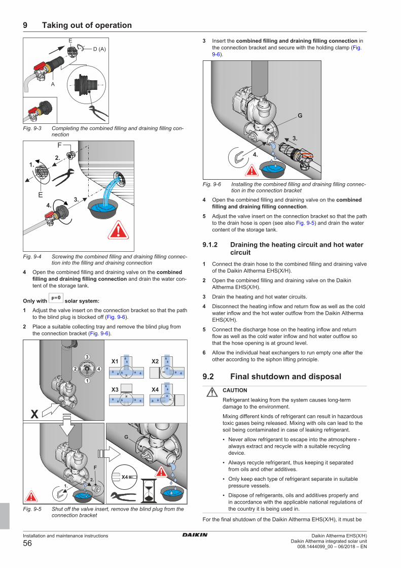
9 Taking out of operation
Installation and maintenance instructions
56Daikin Altherma EHS(X/H)
Daikin Altherma integrated solar unit008.1444099_00 – 06/2018 – EN
Fig. 9-3 Completing the combined filling and draining filling con-nection
Fig. 9-4 Screwing the combined filling and draining filling connec-tion into the filling and draining connection
4 Open the combined filling and draining valve on the combinedfilling and draining filling connection and drain the water con-tent of the storage tank.
Only with solar system:1 Adjust the valve insert on the connection bracket so that the path
to the blind plug is blocked off (Fig. 9-6).
2 Place a suitable collecting tray and remove the blind plug fromthe connection bracket (Fig. 9-6).
Fig. 9-5 Shut off the valve insert, remove the blind plug from theconnection bracket
3 Insert the combined filling and draining filling connection inthe connection bracket and secure with the holding clamp (Fig.9-6).
Fig. 9-6 Installing the combined filling and draining filling connec-tion in the connection bracket
4 Open the combined filling and draining valve on the combinedfilling and draining filling connection.
5 Adjust the valve insert on the connection bracket so that the pathto the drain hose is open (see also Fig. 9-5) and drain the watercontent of the storage tank.
9.1.2 Draining the heating circuit and hot watercircuit
1 Connect the drain hose to the combined filling and draining valveof the Daikin Altherma EHS(X/H).
2 Open the combined filling and draining valve on the DaikinAltherma EHS(X/H).
3 Drain the heating and hot water circuits.
4 Disconnect the heating inflow and return flow as well as the coldwater inflow and the hot water outflow from the Daikin AlthermaEHS(X/H).
5 Connect the discharge hose on the heating inflow and returnflow as well as the cold water inflow and hot water outflow sothat the hose opening is at ground level.
6 Allow the individual heat exchangers to run empty one after theother according to the siphon lifting principle.
9.2 Final shutdown and disposalCAUTION
Refrigerant leaking from the system causes long-termdamage to the environment.
Mixing different kinds of refrigerant can result in hazardoustoxic gases being released. Mixing with oils can lead to thesoil being contaminated in case of leaking refrigerant.
▪ Never allow refrigerant to escape into the atmosphere -always extract and recycle with a suitable recyclingdevice.
▪ Always recycle refrigerant, thus keeping it separatedfrom oils and other additives.
▪ Only keep each type of refrigerant separate in suitablepressure vessels.
▪ Dispose of refrigerants, oils and additives properly andin accordance with the applicable national regulations ofthe country it is being used in.
For the final shutdown of the Daikin Altherma EHS(X/H), it must be
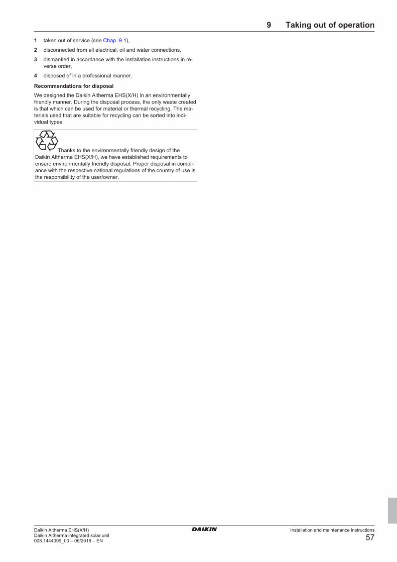
9 Taking out of operation
Installation and maintenance instructions
57Daikin Altherma EHS(X/H)Daikin Altherma integrated solar unit008.1444099_00 – 06/2018 – EN
1 taken out of service (see Chap. 9.1),
2 disconnected from all electrical, oil and water connections,
3 dismantled in accordance with the installation instructions in re-verse order,
4 disposed of in a professional manner.
Recommendations for disposalWe designed the Daikin Altherma EHS(X/H) in an environmentallyfriendly manner. During the disposal process, the only waste createdis that which can be used for material or thermal recycling. The ma-terials used that are suitable for recycling can be sorted into indi-vidual types.
Thanks to the environmentally friendly design of theDaikin Altherma EHS(X/H), we have established requirements toensure environmentally friendly disposal. Proper disposal in compli-ance with the respective national regulations of the country of use isthe responsibility of the user/owner.

10 Technical data
Installation and maintenance instructions
58Daikin Altherma EHS(X/H)
Daikin Altherma integrated solar unit008.1444099_00 – 06/2018 – EN
10 Technical data
10.1 Basic dataType EHSH04P30D
EHSH08P30D
EHSX04P30D
EHSX08P30D
EHSHB04P30D
EHSHB08P30D
EHSXB04P30D
EHSXB08P30D
EHSH08P50D
EHSX04P50D
EHSX08P50D
EHSHB08P50D
EHSXB04P50D
EHSXB08P50D
Parameters UnitDimensions (H x W x D) cm 189.1 x 59.5 x 61.5 189.6 x 79 x 79Empty weight kg 73 76 93 99
Water heating circulation pumpType — Grundfos UPM3K 25-75 CHBLSpeed rates — Continuous (PWM)Voltage V 230Frequency Hz 50Protection type — IP 44Nominal output, maximum W 58
Heat exchanger (water/coolant)Type — Stainless steel plate heat exchangerHeat insulation — EPP
Storage tankTotal storage capacity litres 294 477Maximum permissible storage water temperature °C 85Heat consumption at stand-by and at 60 °C kWh/24 h 1.5 1.7
Drinking water heat exchanger (stainless steel 1.4404)Water capacity heat exchanger litres 27,14 28.17 28.14Domestic water heat exchanger surface m2 5.6 5.8 5.9Max. operating pressure bar 6
Storage tank charging heat exchanger (stainless steel 1.4404)Water capacity heat exchanger litres 12.4 11.92 12.08Heat exchanger surface area m2 2.53 2.42 12.46
Pressurised solar heat exchanger (stainless steel 1.4404)Water capacity heat exchanger litres — 3.9 — 10.18Heat exchanger surface area m2 — 0.74 — 1.687
Pipe connectionsCold and hot water inches 1" outer threadHeating inflow and return flow inches 1" inner thread
Solar connection
inches 1" inner thread
Solar connection
inches — 3/4‘‘ IG + 1"AG
— 3/4‘‘ IG + 1"AG
Refrigerant circuitNumber of circuits — 1
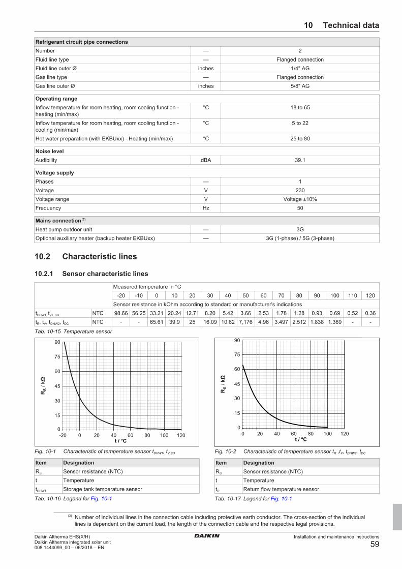
10 Technical data
Installation and maintenance instructions
59Daikin Altherma EHS(X/H)Daikin Altherma integrated solar unit008.1444099_00 – 06/2018 – EN
Refrigerant circuit pipe connectionsNumber — 2Fluid line type — Flanged connectionFluid line outer Ø inches 1/4" AGGas line type — Flanged connectionGas line outer Ø inches 5/8" AG
Operating rangeInflow temperature for room heating, room cooling function -heating (min/max)
°C 18 to 65
Inflow temperature for room heating, room cooling function -cooling (min/max)
°C 5 to 22
Hot water preparation (with EKBUxx) - Heating (min/max) °C 25 to 80
Noise levelAudibility dBA 39.1
Voltage supplyPhases — 1Voltage V 230Voltage range V Voltage ±10%Frequency Hz 50
Mains connection (3)
Heat pump outdoor unit — 3GOptional auxiliary heater (backup heater EKBUxx) — 3G (1-phase) / 5G (3-phase)
10.2 Characteristic lines
10.2.1 Sensor characteristic lines
Measured temperature in °C-20 -10 0 10 20 30 40 50 60 70 80 90 100 110 120
Sensor resistance in kOhm according to standard or manufacturer's indicationstDHW1, tV, BH NTC 98.66 56.25 33.21 20.24 12.71 8.20 5.42 3.66 2.53 1.78 1.28 0.93 0.69 0.52 0.36tR, tV, tDHW2, tDC NTC - - 65.61 39.9 25 16.09 10.62 7,176 4.96 3.497 2.512 1.838 1.369 - -
Tab. 10-15 Temperature sensor
Fig. 10-1 Characteristic of temperature sensor tDHW1, tV,BH
Item DesignationRS Sensor resistance (NTC)t TemperaturetDHW1 Storage tank temperature sensor
Tab. 10-16 Legend for Fig. 10-1
15
30
45
90
75
60
Fig. 10-2 Characteristic of temperature sensor tR ,tV, tDHW2, tDC
Item DesignationRS Sensor resistance (NTC)t TemperaturetR Return flow temperature sensor
Tab. 10-17 Legend for Fig. 10-1
(3) Number of individual lines in the connection cable including protective earth conductor. The cross-section of the individuallines is dependent on the current load, the length of the connection cable and the respective legal provisions.

10 Technical data
Installation and maintenance instructions
60Daikin Altherma EHS(X/H)
Daikin Altherma integrated solar unit008.1444099_00 – 06/2018 – EN
Fig. 10-3 Characteristic of the pressure sensor (DS)
Item DesignationP Water pressureU Voltage
Tab. 10-18 Legend for Fig. 10-3
10.2.2 Characteristic curves for pumps
0
100
200
300
400
500
600
700
800
0 200 400 600 800 1000 1200 1400 1600 1800 2000
∆p
/ m
ba
r
m / L/hH
R
100%
50%
75%
Fig. 10-4 Residual head of the internal heating circulation pumpwith heating support heat exchanger
Item DesignationΔPR Residual head of internal heating circulation pumpmH Flow rate of heating system
Tab. 10-19 Legend for Fig. 10-4
10.3 Tightening torque
Component Thread size Tighten-ing
torque inNm
Temperature sensor all Max. 10Hydraulic line connections (water) 1‘‘ 25 – 30Gas line connections (refrigerant) 5/8" 63 – 75Fluid line connections (refrigerant) 1/4" 15 – 17Fluid line connections (refrigerant) 3/8" 33 – 40Backup heater 1.5" Max. 10
(handtight)
Tab. 10-20 Tightening torque
10.4 Minimum floor area and ventilationopenings
CAUTION
The use of refrigerant lines that have already been usedcan lead to damage to the unit.
▪ Do not reuse a refrigerant line that has been used withanother refrigerant. Replace or carefully clean the refri-gerant line.
▪ If the total refrigerant charge in the system is < 1.84 kg, there areno further requirements.
▪ f the total refrigerant charge in the system is ≥ 1.84 kg, other min-imum floor space requirements must be met:
1 Compare the total refrigerant charge in the system (mc) with themaximum refrigerant filling (mmax) permitted for the installationroom (Aroom), (see ).
▪ If mc ≤ mmax: The device can be installed in this room withoutany further requirements.
▪ If mc > mmax: Proceed with the following steps.
2 Compare the minimum floor area (Amin) from with the floor areaof the installation room (Aroom) and the adjacent room (Aroom2).
▪ If Amin ≤ Aroom + Aroom2: Proceed with the following steps.
▪ If Amin > Aroom + Aroom2: Contact your local dealer.
3 Calculate coolant quantity (dm) exceeding mmax: dm = mc – mmax
4 Calculate the minimum opening range (VAmin) for natural ventila-tion between the installation room and the adjacent room (see ).
5 The device can be installed if:– 2 ventilation openings are provided between the installation
room and adjacent room (1 each at top and bottom)– Bottom opening: The bottom opening must meet the require-
ments for the minimum opening range (VAmin). It must be asclose to the ground as possible. If the ventilation openingstarts on the floor, the height ≥ must be 20 mm. The bottomof the opening must be ≤ 100 mm above the floor. At least50% of the required opening area must be < 200 mm fromthe floor. The entire area of the opening must be < 300 mmfrom the floor.
– Upper opening: The area of the upper opening must be lar-ger or the same size as the lower opening. The bottom ofthe upper opening must be at least 1.5 m above the topedge of the lower opening.
– Ventilation openings to the outside are not considered suit-able ventilation openings.
Aroom (m2) Maximum refrigerant filling permitted in aroom (mmax) (kg)
28 1,81429 1,84630 1,87731 1,909
Tab. 10-21 Maximum refrigerant filling permitted in a room
mc (kg) Minimum floor area Amin (m²)1.84 28.811.86 29.441.88 30.081.90 30.72
Tab. 10-22 Minimum floor area of indoor unit

10 Technical data
Installation and maintenance instructions
61Daikin Altherma EHS(X/H)Daikin Altherma integrated solar unit008.1444099_00 – 06/2018 – EN
mc mmax dm=mc–mmax (kg) Minimum area of the ventilationopening (cm2)
1.9 0.1 1.80 7291.9 0.3 1.60 6481.9 0.5 1.40 5671.9 0.7 1.20 4861.9 0.9 1.00 418
mc mmax dm=mc–mmax (kg) Minimum area of the ventilationopening (cm2)
1.9 1.1 0.80 3701.9 1.3 0.60 3011.9 1.5 0.40 2161.9 1.7 0.20 115
Tab. 10-23 Minimum area of the ventilation opening

10 Technical data
Installation and maintenance instructions
62Daikin Altherma EHS(X/H)
Daikin Altherma integrated solar unit008.1444099_00 – 06/2018 – EN
10.5 Electrical connection diagramV
3
1N
~ 2
30
V
L N RC
D (
FI)
Fu
se
1
6A
≤
Po
we
r su
rge
ca
teg
ory
RJ4
5
CA
N
J1
6J
8J
9J
13
J3
J1
2J
2J
14
J6
J11
J7
J5
PE
J4
P1
NL1NL1N L1
GND
VCC
11
11
11
11
1
F1
Ro
Co
n B
M2
C
Q1
J1
7
S3
on
12
34
off
S5
12
34
11
11
J1
0
J1
J1
5
1 1 1
AU
XH
T/N
T
25
0V
~
≤ 0
,06
3 A
SG
RT
PE
PE
N
L1
PE
N
L1
PE
N
PE
N
CAN-H
CAN-L
CAN-GNDCAN-VCC
A
A1
A2
GND
BSK
EBA
GND
GND
Smart GridGND
GND
GND
EVU
GND
GND
PZ
3UV
DH
W
AB
M
AB
3U
VB
1
AB
M
AB
EH
S1
57
03
4E
HS
15
70
68
EX
T
...
EB
A
21
24
18
t DH
W1
t V,B
H
TR
A1
X1
A
X2
6A
X7
AX
22
A
X1
8A
X3
1A
X2
1A
X3
A
X1
9A
X1
6A X6
0A
X2
5A
X4
A
X5
AX
8A
A1
P
N LPE
CO
M
4-8
kW
L N
PE
123
V3
1N
~ 2
30
V
NP
EL
1L
2L
3
Po
we
r surg
e c
ate
go
ry III
Fus
e se
eta
ble
RC
D (
FI)
t DH
W2
TA
1X
AG
1
XTA
1
P
LN
PW
M
(P)
12
Ro
Co
n+
Ph
yd
RT
X-E
HSX
3
X1
K3
K2
K1
L3
L2
L1
N N N PE
BU
BU
BU
BU
BU
BU
BU
L3 NRC
D (
FI)
Fu
se
16
A
L2
L1 N N
Power surge
category
V3
1N ~ 230V
W1
3N ~ 400V
T1
N T2
PE
N T3
N
XB
UH
1
EK
BU
HS
WB
Pre
f
FL
S (
V)
B
B1
cool
ing
outp
ut
21
24
18
t DC
t Vt R
P2P1
42
31
12
V=
≤ 1
A
PE
EK
BU
xx
Typ
eF
use
ER
GA
04
DA
V3
20
A
ER
GA
06
DA
V3
20
A
ER
GA
08
DA
V3
25
A
ER
GA
04
DA
V3
A1
6 A
ER
GA
06
DA
V3
A1
6 A
ER
GA
08
DA
V3
A1
6 A
Fig. 10-5 Electrical connection diagram

10 Technical data
Installation and maintenance instructions
63Daikin Altherma EHS(X/H)Daikin Altherma integrated solar unit008.1444099_00 – 06/2018 – EN
Item Designation Item DesignationHeat pump outdoor unit K1 Relay 1 for backup heater
Heat pump indoor unit K2 Relay 2 for backup heater
3UVB1 3-way switch valve (internal heat generator circuit) K3 Relay 3 for backup heater3UV DHW 3-way switch valve (hot water/heating) X1 Terminal strip for backup heater mains connectionA1P Printed circuit board (heat pump basic control) X3 Plug connection for internal wiring to J17 (RoCon BM2C)X26A Plug connection to TRA1 (230 V) FLS Flow sensorX31A Plug connection to TRA1 (12 V) HT/NT Switching contact for off-peak mains connectionX3A Plug connection for internal wiring (bridging plug) P Heating circulation pump (connected inside the device)X4A Plug connection for FLS flow sensor and tDHW2 PZ Circulation pumpX5A Plug connection for tV inflow temperature sensor PWM Pump connection (PWM signal)X6A Plug connection for tV, BH inflow temperature sensor RJ45 CAN Plug connection (RoCon BM2C) for internal wiring (for Ro-
Con+ B1)X7A Plug connection for temperature sensor (refrigerant fluid)
tDC
RoCon+B1
Controller control panel
X8A Plug connection for return flow temperature sensor tR RoConBM2C
Printed circuit board (basic controller module)
X16A Plug connection for heating circulation pump X16A Plug connection for heating circulation pump PX18A Plug connection to J11 of RoCon BM2C J2 Plug connection for 3UVB1X19A Plug connection to XAG1 + J10 of RoCon BM2C J3 Plug connection AUX switching contacts and cooling out-
put status outputX21A Plug connection for internal wiring (bridging plug) J5 Pressure sensor plug connectionAUX Switching contact outputs (A-A1-A2) + (B-B1) J6 Plug connection mains voltageEKBUxx Backup heater J8 Plug connection for EXTDS Pressure sensor Plug connection for EBAEBA Switching contact for external requirement request Plug connection for Smart Grid EVU switching contactsEXT Switching contact for external operating mode changeover Plug connection for external temperature sensor tV,BH
F1 Fuse 250 V T 2 A (RoCon BM2C) Plug connection for storage tank temperature sensor tDHW1
SG Switching contact for Smart Grid (intelligent mains con-nection)
Plug connection for HT/NT EVU switching contact
TRA1 Transformer J10 Plug connection for internal wiring to X19AtA External temperature sensor J11 Plug connection for internal wiring to X18A (A1P)tDHW1 Storage tank temperature sensor 1 (RoCon BM2C) J12 Plug connection for 3UV DHWtDHW2 Storage tank temperature sensor 2 (A1P) J13 System bus plug connection (e.g. room station)tR Return flow temperature sensor 2 (A1P) J14 Circulation pump PZ plug connectiontV1 Inflow temperature sensor 1 (A1P) J15 Plug connection for internal wiring (bridging plug)tV, BH Backup heater inflow temperature sensor J16 Room thermostat (EKRTR / EKRTW) plug connectionEHS157068
Mixer module HT/NT Switching contact for off-peak mains connection
EHS157034
Room station XAG1 Heat pump outdoor unit plug connection
coolingoutput
Status output for "Cooling" operating mode
(floor heating control connection cooling output)
XBUH1 Backup heater plug connection (EKBUxx)
RT Room thermostat (EKRTW) X2M6 HPc-VK-1 connection cable clampRT-E Receiver for wireless room thermostat (EKRTR) X2M7 HPc-VK-1 connection cable clampRTX-EHS Printed circuit board (backup heater) X11M Terminal strip in the HP convector
Tab. 10-24 Key names for connection and wiring diagrams
11 Notes
Installation and maintenance instructions
64Daikin Altherma EHS(X/H)
Daikin Altherma integrated solar unit008.1444099_00 – 06/2018 – EN
11 Notes

11 Notes
Installation and maintenance instructions
65Daikin Altherma EHS(X/H)Daikin Altherma integrated solar unit008.1444099_00 – 06/2018 – EN

11 Notes
Installation and maintenance instructions
66Daikin Altherma EHS(X/H)
Daikin Altherma integrated solar unit008.1444099_00 – 06/2018 – EN

List of keywords
Installation and maintenance instructions
67Daikin Altherma EHS(X/H)Daikin Altherma integrated solar unit008.1444099_00 – 06/2018 – EN
List of keywordsAAnnual maintenance work .................................................................................... 37
CCombined filling and draining filling connection ........................................ 55Connecting the mixer circuit ................................................................................ 28Controller:Connection............................................................................................. 23
DDesign and components .......................................................................................... 8Dirt filter ......................................................................................................................... 21Disposal......................................................................................................................... 57
EElectrical installation................................................................................................ 23Emergency operation ............................................................................................. 54
FFilling connection ...................................................................................................... 55Filling: Heating system........................................................................................... 31Filling: Storage tank................................................................................................. 31
HHeating system:Emptying..................................................................................... 55Hydraulic connection: Example connections .............................................. 35
IInstallation area ......................................................................................................... 15Installation site ........................................................................................................... 15Intended use .................................................................................................................. 5
LLegal requirements .................................................................................................. 37
MMaintenance................................................................................................................ 37Malfunctions ................................................................................................................ 44Minimum distance .................................................................................................... 15
PProtective cover......................................................................................................... 16
RRelevant documents .................................................................................................. 4Room controller ........................................................................................................ 28Room station............................................................................................................... 28
SScope of delivery ...................................................................................................... 14
TTightening torques ................................................................................................... 60Transport....................................................................................................................... 14
WWarranty .......................................................................................................................... 7

008.1444099_00 – 06/2018 – EN
Cop
yrig
ht ©
Dai
kin