Installation, Operating & Maintenance - Diverter Ball Valves ...
18
Diverter Ball Valves - D47/S47 Valves Series Installation, Operating & Maintenance Diverter Ball Valves D47/S47 Valves Series REV01-06/21 Item number: YP0005373
-
Upload
khangminh22 -
Category
Documents
-
view
1 -
download
0
Transcript of Installation, Operating & Maintenance - Diverter Ball Valves ...

Diverter Ball Valves - D47/S47 Valves Series
Installation, Operating & Maintenance Diverter Ball Valves D47/S47 Valves Series
REV01-06/21
Item number: YP0005373

Diverter Ball Valves - D47/S47 Valves Series
Diverter Ball Valves - D47/S47 Valves Series
1
Contents
1. General .............................................................................. 2
2. Sil ................................................................................... 2
3. Limitations ........................................................................ 3
4. Storage .......................................................................... 3
4.1. Long Term Storage ................................................ 4
5. Installation ........................................................................... 4
5.1. General ..................................................................... 4
5.2. Valve Marking and Labeling ................................. 5
5.3. Cryogneic Valves ......................................................... 6
5.4. Weld End Valves in-line - Extended Ends ................. 7
5.5. Weld End Valves not in-line ...................................... 7
5.6. Flanged Valves ......................................................... 8
5.7. Threaded End Valves .................................................. 8
6. Operating Instructions .................................................... 9
7. Maintenance ...................................................................... 11
8. Disassembly & Assembly Manual ................................ 12
Habonim cannot anticipate all of the situations user may encounter while installing and using Habonim valves. The user MUST know and follow all applicable industry specifications on the safe installation and use of these valves. Misapplication of the product may result in injuries or property damage. Refer to Habonim product catalogues, product brochures and installation, operating and maintenance manuals for additional product safety information or contact Habonim.
Keep hands and objects away from the valve ports at all times. Actuated valves could be accidentally operated, resulting in serious injury or valve damage. Before removing a valve from the line, always make sure the line has been depressurized and drained. Cycle the valve a few times to relieve any pressure that could be trapped in the body cavity. Utmost caution must be taken when handling a valve that has toxic, corrosive, flammable or a contaminant nature media flowing through its pipeline. The following safety precautions are recommended when dismantling valves with hazardous media:
Wear safety glasses, protective headgear, clothing, gloves and footwear. Have available running water. Have a suitable fire extinguisher when media is flammable.
Do not try to operate a valve that exhibits any sign of leakage. Isolate the valve and either repair or replace it.

Diverter Ball Valves - D47/S47 Valves Series
Diverter Ball Valves - D47/S47 Valves Series
2
1. General
This Installation, Operating & Maintenance manual represents the instructions required for safe use of Habonim ball valve. The manual relates to reduce and full bore valves. Before using any of these series valves, read the entire IOM carefully and make sure everything is clear. Where in doubt, please consult with Habonim engineering team.
2. Sil
Under severe operating conditions inspection should be more frequently; detected defects should be repaired promptly. Severe operating conditions can be defined as:
• Application temperature less or above than specified on the valve tag label • Flow velocity higher than 5 m/sec for liquids, and 200 m/sec for gaseous • Acidic media PH < 5 or alkaline media PH > 9
Habonim recommend a proof test interval of 12 months; in case of Fail to Open ESD system, a partial stroke is acceptable to confirm that the installation is functioning properly. For ESD systems with a Fail-To-Close demand, it is necessary to plan a system shut-down; de-energize the system and inspect the valve turning to its fully closed position. It is essential to log-in the following parameters on site QA records as a proof for preserving SIL capabilities: date, hour, name and signature of the responsible engineer, air pressure on site, time to close the valve, time to open the valve. The combined corrosion and erosion allowance for the valve body wall thickness is 1 mm. When this allowance has been eroded or corroded, mechanically removed or otherwise, the valve should no longer be used. Inspect the valve wall thickness every time the valve is maintained. The estimated mean time to repair (MTTR) a valve, i.e. time net (line draining or cooling down time excluded from the valve MTTR) of replacing old valve with a new one is 60 minutes. Maintenance team must read and understand the Habonim product IOM before starting the operation. In case of a doubt please consult the Habonim engineering team. When a valve has been repaired or any maintenance was performed, check the valve for proper function (proof testing). Any failures affecting functional safety should be reported to the Habonim factory. During the proof test operation, all soft inner parts to be examine and replaced in interval less than 5 years to claim the valve assembly "as-good-as-new“. Habonim recommend valve full maintenance operation every 500,000 cycles or 5 years, whichever comes first. Client should consult the Habonim factory in order to obtain the product assessment, FMEDA report, and other associated statistical data to satisfy SIL level.
The ambient temperature range for which these valves are suitable depends on the materials used intheir construction and the pressure at which they will be used. The maximum withstand temperature is included in the Pressure Equipment Directive (PED) marking. The lower ambient will be specified inthe documentation provided with each valve.

Diverter Ball Valves - D47/S47 Valves Series
Diverter Ball Valves - D47/S47 Valves Series
3
3. Limitations The correct selection of materials of construction, seats and seals, internal valve components and pressure/temperature ratings determines the safe use of the valves and the particular performance requirements for the application. This information can be found on the name plate welded to the valve body.
The combined corrosion and erosion allowance for the valve body wall thickness is 1(mm). When this allowance has gone, the valve should no longer be used. Inspect the valve wall thickness every time the valve is maintained.
Refer to Habonim Chemical Compatibility Chart to determine the corrosion rate for your application. As the variety of applications these valves can be used in is large, it is impossible to cover all installation and maintenance instructions for servicing the valves. Habonim's standard valves design is for relative humidity of 50% and SATP (Standard Ambient Temperature and Pressure) environment conditions. It is the owner’s responsibility to use the valves as recommended and in accordance with the pressure/temperature limits and chemical compatibility for both inner & outer parts as stated in this manual. Where in doubt, please consult with Habonim. Any unstable fluid or gas should be identified by its manufacturer and must not be used with Habonim valves.
CAUTION: The valves should be used in a well-designed, adequately protected system to ensure that external and internal pressure and temperature limits do not exceed the valve limits. The valve rating is defined as the lower rating of the seat and valve body. Valve surface temperature may become extremely hot or cold due to operating conditions. Prevent any type of direct contact with the valve that may cause harm or injury .Avoid direct contact with the valve by wearing protective gloves.
The valves are not designed to operate during or after earthquakes or under fatigue conditions. It is the responsibility of the owner to determine if fatigue conditions exist.
The process fluid temperature shall not exceed the ignition temperature of the dust. WARNING: USE OF THE VALVE IS APPLICATION SPECIFIC. BE SURE THAT THE VALVE IS SUITABLE FOR ITS INTENDED SERVICE. IF YOU HAVE ANY QUESTIONS CONCERNING THE USE, APPLICATION OR COMPATIBILITY OF THE VALVE WITH THE INTENDED SERVICE, CONTACT HABONIM FOR MORE INFORMATION.
DO NOT EXCEED THE VALVE PERFORMANCE LIMITATIONS! EXCEEDING THE PRESSURE OR TEMPERATURE LIMITATIONS MARKED ON THE VALVE LABEL PLATE MAY CAUSE DAMAGE AND LEAD TO UNCONTROLLED PRESSURE RELEASE. DAMAGE OR PERSONAL INJURY MAY RESULT.

Diverter Ball Valves - D47/S47 Valves Series
Diverter Ball Valves - D47/S47 Valves Series
4
4. Storage
Prior to storage, inspect the valve for shipping damage. Keep all protective packaging, flange covers and end caps attached to the valves during storage. It is recommended to keep the valves in a clean and dry environment until it is ready for use. Carbon Steel valves have a “black oxide” and oil dipped finish. This nontoxic process is performed to retard rusting during storage. It is not a substitute for paint or other means of protective coating to be applied to the valve once installed. Stainless steel valves have their natural finish and do not need any additional protection once installed.
4.1. Long Term Storage
4.1.1. It is advisable to store the valves in waterproof conditions. Ball valves should be protected to safeguard against humidity, Moisture, dust, dirt, sand, mud, salt spray, and sea water.
4.1.2. Manual ball valves must remain in the open position during the period of storage. 4.1.3. Actuated valves (fail to close position) remain in closed position during this time. 4.1.4. Valves may be stored as shipped, provided the above storage location and
equipment orientation instructions are followed 4.1.5. In order to prevent damage, protective covers on valve ends should
not be removed until immediately prior to installation. 4.1.6. Visual inspection should be performed on a semi-annual basis and results recorded.
5. Installation
The installation procedure for Habonim ball valves is critical to ensuring both long life and satisfying performance. Valves stored on site, awaiting installation, should be kept in their original packing, in dry conditions, where damage will not occur (See Para. 4). Before carrying out the installation, it is important to follow the basic procedures described below:
5.1. General
5.1.1. It is essential to flush the line prior to assembling any valve on the line. 5.1.2. Carefully unpack the valve and check valve nameplate for identification of materials. 5.1.3. Remove any special packing materials surrounding the valve. 5.1.4. Check the valve for the flow direction indication marks. Appropriate care must be
taken, to install the valve for proper flow orientation. 5.1.5. Inspect the valve interior through the end ports to determine it is clean and free
from foreign matter according to ASME G93-03E1. 5.1.6. Cycle the valve and inspect any functionally significant features. 5.1.7. Read all the literature and note any special warning tags or plates attached to the valve. 5.1.8. Before installation check to insure that the flow line balls are in the fully open
position in order to prevent possible damage to the balls and seats. The valve performance depends on its original conditions. At any stage do not leave the valve in the partially open position on either of the lines.

Diverter Ball Valves - D47/S47 Valves Series
Diverter Ball Valves - D47/S47 Valves Series
5
5.2. Valve Marking and Labeling
5.2.1. All valves marking is on a nameplate which is spot welded to the valve body. 5.2.2. Valves for the European market and above 1” carry the CE mark with the information
required by the PED. 5.2.3. The valve markings that are according to API-6D standard are presented in order to
provide the user full traceability and information regarding the valve. Unless otherwise requested, nameplates will be secured to the valve body and will be visible to user. The information on the nameplate is as described below: Standard Habonim Tag
Standard CE Tag
Standard ATEX Tag

Diverter Ball Valves - D47/S47 Valves Series
Diverter Ball Valves - D47/S47 Valves Series
6
Standard API-6D Tag
5.3. Cryogenic Valves
5.3.1. All Habonim cryogenic valves are unidirectional and must be installed for flow in one direction as indicated by the flow arrow welded on the body and bonnet pad. Usually the arrow points to the shutoff direction of the valve. In case of uncertainty related to direction. Relate to the arrow head as the low pressure side and the arrow tail as the high pressure side.
5.3.2. DO NOT Install Cryogenic valves with the extended bonnet tilted more than 45˚ from the upright vertical position for the 12”.
5.3.3. DO NOT Install Cryogenic valves with the extended bonnet tilted more than 15˚ from the upright vertical position for the 6”.
5.3.4. When the valve is in the closed position the ball relief hole will be seen in the upstream port of the valve as indicated by the arrow. The stem head has an engraved “T” mark identifying the ball port and the pressure relief cavity direction.

Diverter Ball Valves - D47/S47 Valves Series
Diverter Ball Valves - D47/S47 Valves Series
7
5.4. Weld End Valves in-line - Extended Ends
5.4.1. Welding of valves shall be performed by a qualified person according to the ASME Boiler Construction Code Section IX. For valves to be welded within the EEA, refer to the requirements of ESR 3.1.2 of the Pressure Equipment Directive 97/23/EC.
5.4.2. Valves that will be welded directly to the line must be in the fully open position to protect the ball and seats from excessive temperatures during the welding procedures.
5.4.3. It is recommended to remove the valve wrench during the welding procedure. Protect or remove actuators from weld splatter or arc strikes. Valves in the “Fail Close” position should be cycled to the open position.
5.4.4. Use a temperature stick and a wet cloth wrapped around the center section to prevent overheating.
WARNING: DO NOT heat the center section over 150°C (300°F).
5.4.5. Align valve to pipe line, ensuring proper fit to minimize pipe load. Tack weld only. 5.4.6. Complete welding in small segments. Allow enough time for cooling between each segment. 5.4.7. After completing the welds, wait for the valve to cool below 90°C (200°F). 5.4.8. Replace the wrench or actuator. It is recommended not to rotate the valve to the
closed position before flushing the line.
5.5. Weld End Valves not in-line
5.5.1. Welding instructions for not in-line valves are supplied in the valve package. For more information on recommended welding procedures or seat materials, please consult with Habonim.

Diverter Ball Valves - D47/S47 Valves Series
Diverter Ball Valves - D47/S47 Valves Series
8
5.6. Flanged Valves
5.6.1. Before installing the valves, make sure the flanges and the pipe are free from grit, dirt or burrs. 5.6.2. The flanges must be aligned and parallel with the correct distance to allow the
valve face-to-face dimension and gaskets to fit between. 5.6.3. Insert the valve between the flanges. If tilting or levering of the flanges is required,
avoid harming the sealing surfaces of the flanges. 5.6.4. Align the valve and the pipe counter flanges and insert at least 2 bolts at the lowest
side of the flange to support the gaskets. 5.6.5. Slide the gaskets between the flanges. Insert the remaining bolts and thread the nuts hand tight. 5.6.6. Before tightening the bolts, make sure the gaskets are aligned with the raised face of the flanges. 5.6.7. Tighten the flange bolts, with a torque values determined by the gasket manufacturer,
other variables like gasket type and material, bolt, flange and lubricant affect the tightening torque values.
IMPORTANT: the tightening torque selected must be high enough to ensure adequate strain (stretch) in the bolt, but not so high as to cause the material to be taken beyond yield into the plastic response region. If the initial bolt stress is too low the total amount of strain (stretch in the bolt) is low and under these circumstances any subsequent reduction in thickness of the gasket due to creep will quickly result in loss of bolt strain and subsequent leakage.
5.6.8. It is recommended to use ring spanners to tighten and support the bolts and nuts.
5.6.9. Note: bolts tightening must be uniform in order to create a parallel movement of the two flanges and uniform deformation of the gasket in between them.
5.6.10. Before flushing the line, be sure the valves are in the fully open position. Fail-to-close actuated valves should be operated to the open position for flushing.
5.6.11. Before pressure testing the valves, bring the valves to the half open position to ensure pressure reaches the stem seals and to avoid unnecessary loading of the seats. Fail-to-close actuated valves should be brought to the half-open position.
5.7. Threaded End Valves
5.7.1. Valves with threaded ends should be treated as a single unit and should not be dismantled when installing to pipeline.
5.7.2. Before installing the valves, make sure that the threads on the mating pipe are free from excessive grit, dirt or burrs.
5.7.3. When tightening the valve, apply a pipe wrench or spanner to the end connector closest to the pipe being worked, using standard piping practices.
5.7.4. Use appropriate joining sealants material in correct quantities. 5.7.5. If “back-welding” is required on threaded end valves, refer to the instructions for Weld
End valves or to the “Habonim Welding Instructions” bulletin.

Diverter Ball Valves - D47/S47 Valves Series
Diverter Ball Valves - D47/S47 Valves Series
9
6. Operating Instructions
Habonim Valves provide tight shut off when used under normal conditions and in accordance with Habonim’s published pressure/temperature chart. If these valves are used in a partially open (throttled) position, seat life may be reduced. Consult with Habonim for the proper seat material selection. On manual operated valves, the valve operation is done by turning the valve handle 90° clockwise to open (handle is parallel to flow line), and 90° counter clockwise to close (handle is perpendicular to flow line). For unidirectional designed valves; a flow arrow indicates the flow direction of the valve for proper installation. A silicone-based lubricant is applied to assist valve break in. The lubricant, if unacceptable, may be removed by a solvent wash. If a shut-off valve is installed for end of line service, it must be ensured that it is closed with a blind end connection and the valve is secured against being opened unintentionally.
WARNING: Never look into the valve bore while the valve is in a flow line. Pressure and fluids could escape from the valve causing harm or injury. To prevent leakage, malfunctions resulting from internal wear or seal degradation, the user must establish a preventive maintenance and inspection program. This program must include: 1. Inspection of parts to detect loss of wall thickness which may result in decreased
pressure capacity (see Para. 3 for acceptable reduction of wall thickness). 2. Routine replacement of seals and inspection for proper operation (See Para. 7 for
maintenance instructions). Valve operating torques, as published in the Habonim literature, are the normal expected maximum break-out torques. These torques have been confirmed by laboratory testing of each valve under controlled conditions. Highly viscous or abrasive media, frequency of operation and temperature fluctuations could cause an increase in valve torque.

Diverter Ball Valves - D47/S47 Valves Series
Diverter Ball Valves - D47/S47 Valves Series
10
Diverter valves series D47/S47 designed for the flow pattern as illustrated below. For any other flow pattern, please consult with Habonim.

Diverter Ball Valves - D47/S47 Valves Series
Diverter Ball Valves - D47/S47 Valves Series
11
7. Maintenance
HABONIM valves have a long and reliable life, and maintenance is seldom required. When maintenance is necessary, valves can be refurbished on site. To extend valve performance and reduce possible plant problems, the following procedures should be followed: 7.1. If leakage around the stem is noticed, check the stem nut torque according to value in Table 1 in the
Disassembly and assembly manual. If the leak continues, tighten the gland nut about a 1/6-turn as a routine maintenance procedure. This will compensate for any wear or settling of the gland packing.
Caution: Excessive tightening of the stem nut can result in accelerated seal wear and high valve operating torque.
7.2. If the valve is removed from the line and disassembled, replacement of all seats and seals is recommended using the appropriate Habonim Repair kit. Examine all metallic sealing surfaces such as ball, stem, and the surfaces on the end connectors that contact the seats for wear, corrosion or damage.
7.3. Only Habonim authorized spare parts should be used. Default repair kit parts from Habonim can be found at "components & materials" in Habonim catalog.
7.4. In addition to repair kits, other spare parts are available from Habonim, such as stem, glands, bolts, screws and nuts.
7.5. Should additional parts be required, it is recommended that the complete valve be replaced. When ordering repair kits, please provide the valve size and full figure number code and series, engraved on the valve ID tag.

Diverter Ball Valves - D47/S47 Valves Series
Diverter Ball Valves - D47/S47 Valves Series
12
Disassembly & Assembly Manual Diverter Ball Valves
Series included:
D47/S47 Series
Sizes included:
¼” - 6” (DN8 – DN150)

Diverter Ball Valves - D47/S47 Valves Series
Diverter Ball Valves - D47/S47 Valves Series
13
Contents
1. General .......................................................................... 14
2. Disassembly .................................................................. 14
3. Assembly ....................................................................... 15
Habonim cannot anticipate all of the situations user may encounter while installing and using Habonim valves. The user MUST know and follow all applicable industry specifications on the safe installation and use of these valves. Misapplication of the product may result in injuries or property damage. Refer to Habonim product catalogues, product brochures and installation, operating and maintenance manuals for additional product safety information or contact Habonim.
Keep hands and objects away from the valve ports at all times. Actuated valves could be accidentally operated, resulting in serious injury or valve damage. Before removing a valve from the line, always make sure the line has been depressurized and drained. Cycle the valve a few times to relieve any pressure that could be trapped in the body cavity. Utmost caution must be taken when handling a valve that has toxic, corrosive, flammable or a contaminant nature media flowing through its pipeline. The following safety precautions are recommended when dismantling valves with hazardous media:
Wear safety glasses, protective headgear, clothing, gloves and footwear. Have available running water. Have a suitable fire extinguisher when media is flammable.
Do not try to operate a valve that exhibits any sign of leakage. Isolate the valve and either repair or replace it.

Diverter Ball Valves - D47/S47 Valves Series
Diverter Ball Valves - D47/S47 Valves Series
14
1. General • It is strongly recommended to review both the disassembly and assembly chapters before getting
started • For any discrepancies please contact Habonim
2. Disassembly 2.1. Cycle the valve with the line pressure fully relieved before
attempting to remove the valve from the pipeline, to insure pressure has also been discharged from the valve cavity.
2.2. Set the valve to open position.
2.3. Remove the body bolts.
2.4. Carefully separate the ends from the valve body and pull the center section from the line.
2.5. Remove and discard the seats, body seals and all the valve parts.
2.6. Set the valve to close position
2.7. Support the ball to prevent it from falling out of the valve body and set the ball aside in a clean secure area for reuse.
2.8. Remove stem nut and all the stem assembly components. Place all the removed components, in a clean and secure area.
2.9. Push the stem down into the body and remove it. 2.10. Discard the stem thrust seals, care taken not to scratch or nick the stem bore area of the
body. 2.11. Clean the stem and the stem bore area.
Fig.1:

Diverter Ball Valves - D47/S47 Valves Series
Diverter Ball Valves - D47/S47 Valves Series
15
3. Assembly The following instructions are for valves of all sizes (both D47 and S47)
3.1. Lubricate the stem thrust seal(7) and the stem seal(9) with appropriate lubricant
3.2. Place the stem thrust seal (7) on the stem (4).
3.3. Insert the stem (4) horizontally into the center body (1) with the threaded side first and carefully guide it up through the stem bore.
Stem for valve sizes 1/4" to 2.5" (DN8 – DN65)
3.4. Holding the stem (4) up insert the stem seal (9) over the stem (4) and into the stem bore. Place the anti-abrasion ring (7A), follower (10), slide bearing (10A), two disc springs (11), and Thread the stem nut (12) onto the stem (4).
3.5. Add the tab lock washer (13) after tightening the stem nut
Stem for valve sizes 3” to 6” (DN80 - DN150) 3.6. Holding the stem (4) up insert the stem seal (9) over the stem and into the
stem bore. Place the anti- abrasion ring (7A), slide bearing, follower (10), two disc springs (11), location ring (13A), locking clip (13) and thread the stem nut onto the stem.
3.7. Bend the locking clip washer (13) across the stem nut after tightening it.
3.8. Tighten the stem nut onto the stem according to table 1 and lock the locking clip.
Valve Size Stem Size Stem Thread HERMETIX
N-m Lb-In
1/4”-3/4” 1/2” 3/8”-24UNF 6 53
1”-1 1⁄4” 1” 7/16”- 20 UNF 11 97
1 1⁄2 " − 2 " 1 1⁄2” 9/16”- 18 UNF 15 133
3”-4” 3” 1” - 14 UNS 60 530
6” 6” 1.5”- 12 UNF 120 1060
WARNING: For valves size 3" and above verify that the thrust seal chamfer faces down.
Detail A:
Detail B:
Table 1:

Diverter Ball Valves - D47/S47 Valves Series
Diverter Ball Valves - D47/S47 Valves Series
16
Handles for valve sizes 1/4" to 2.5" (DN8 – DN65)
3.9. Holding the stem (4) up insert the stem seal ( 9 ) over the stem
(4) and into the stem bore. Place the anti-abrasion ring (7A), follower (10), slide bearing (10A), two disc springs (11), and Thread the stem nut (12) onto the stem (4).
3.10. Tighten the stem nut onto the stem according to table 1
3.11. Add the tab lock washer (13).
3.12. Place the handle (14) on the top of the tab lock washer.
3.13. Place the serrated washer (15) and tighten the handle nut (12) onto the stem according to table 1
3.14. Thread the stop pin (8
Handles for valve sizes 3” to 6” (DN80 - DN150)
3.15. Holding the stem (4) up insert the stem seal (9) over the stem and into the stem bore. Place the anti-abrasion ring (7A), slide bearing (10A), follower (10), stop plate (14A), locking clip (13) and thread the stem nut onto the stem.
3.16. Tighten the stem nut onto the stem according to table 1
3.17. Bend the locking clip washer (13) across the stem nut.
3.18. Insert the handle (14) into the wrench head (14B).
3.19. Place the wrench head on the top of the stem and tighten the wrench bolt (16).
3.20. Place the stop pin washer (8A) and thread the stop pin (8).
Detail A:
Detail B:
Diverter Ball Valves - D47/S47 Valves Series
Diverter Ball Valves - D47/S47 Valves Series
17
The following instructions are for off-line assembly of valves all sizes (both D47 and S47)
3.21. Bring the valve to the close position and insert the ball (3).
3.22. Place the ball in the valve body (1) until the stem tongue is engaged, and turn the stem so the valve is at open position, to prevent the ball from falling out.
3.23. Place the support ring (6B)*, seats (5), primary body seals (6A) and secondary body seals (6) into the valve body (1).
3.24. To prevent galling of threads of the bolts or nuts, lubricate threads with an anti-galling compound.
3.25. Ease back the body assembly between end connectors (2), taking care not to score faces or damage seals, and reinstall body bolts (18).
3.26. Apply initial tightening of the body bolts according to tightening sequence as illustrated:
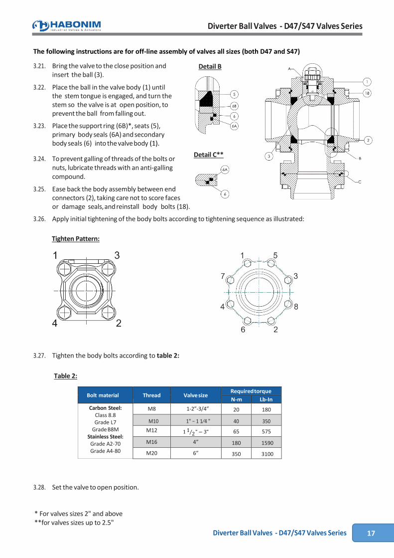
3.27. Tighten the body bolts according to table 2:
Bolt material Thread Valve size Required torque
N-m Lb-In
Carbon Steel: Class 8.8 Grade L7
Grade B8M Stainless Steel:
Grade A2-70 Grade A4-80
M8 1-2”-3/4” 20 180
M10 1" − 1 1⁄4 " 40 350
M12 1 1⁄2 " − 3" 65 575
M16 4” 180 1590
M20 6” 350 3100
3.28. Set the valve to open position.
Tighten Pattern:
Table 2:
Detail B
Detail C**
* For valves sizes 2" and above **for valves sizes up to 2.5"