Ball rail systems
241
www.boschrexroth.com Ball rail systems ball runner blocks, ball guide rails, accessories
-
Upload
khangminh22 -
Category
Documents
-
view
3 -
download
0
Transcript of Ball rail systems

www.boschrexroth.com
Ball rail systemsball runner blocks, ball guide rails, accessories
General product information 4New features at a glance 4Product description 6Notes 8Selection of a linear guide according to DIN 637 10Product overview ball runner blocks with load ratings and load moments 12Product overview ball guide rails with rail lengths 16General technical data and calculations 18Design and version 26System preload 30Accuracy classes 33Ball chain 35Seals 35Materials 36
Product description High-precision Ball Runner Block BSHP made of steel 38Product description 38Comparison 39Application examples 45
Standard ball runner block BSHP made of steel 46Overview 46Order example 47FNS – Flanged, normal, standard height 48FLS – Flanged, long, standard height 50FKS – flange, short, standard height 52SNS – Slimline, normal, standard height 54SLS – Slimline, long, standard height 56SKS – Slimline, short, standard height 58SNH – Slimline, normal, high 60SLH – Slimline, long, high 62FNN – flange, normal, low 64FKN – flange, short, low 66SNN – Slimline, normal, low 68SKN – Slimline, short, low 70
Heavy-duty ball runner block BSHP made of steel 72FNS 72FLS 74SNS 76SLS 78SNH 80SLH 82
High-speed ball runner block BSHP made of steel 84Product description 84FNS, FLS, SNS, SLS 85
Super ball runner block made of steel 86Product description 86FKS 88SKS 90
Aluminum ball runner block BSHP 92Product description 92FNS 94SNS 96
Ball runner block BSHP Resist NR 98Product description 98FNS, FLS, FKS, SNS, SLS, SKS 99
Ball runner block BSHP Resist NR II 100Product description 100FNS, FLS, FKS, SNS, SLS, SKS 102
Ball runner block BSHP Resist CR 104Product description 104FNS, FLS, SNS, SLS, SNH, SLH, FNN, FKN, SNN, SKN, FKS, SKS 106
Standard ball guide rails made of steel 108Product description 108Ordering guide rails in the recommended rail lengths 109SNS/SNO with cover strip and strip clamps 110SNS/SNO with cover strip and protective caps 112SNS/SNO with plastic mounting hole plugs 114SNS with mounting hole plugs made of steel 116SNS for mounting from below 118
Standard ball guide rails Resist NR II 120Product description 120
Standard ball guide rails Resist CR 122Product description 122
Standard ball guide rails with temperature control 124Product description 124
Table of contents2 Ball rail systems |
Bosch Rexroth AG, R999000485/2020-10

Wide ball rail systems BSHP made of steel and Resist CR 126Product description 126BNS – wide, normal, standard height 128CNS – compact, normal, standard height 132Product description 134Ordering guide rails in the recommended rail lengths 135
Accessories for ball runner blocks 140Product description 140Front seal 142FKM seal 143Seal kit 144Lubrication adapter 145Lubrication plate 146Lubrication plate G 1/8 147Transport lock 148Front lube units 150Bellows 154Lube nipple, lube fittings, extensions 158
Accessories for ball guide rails 162Product description 162Cover strip 163Mounting hole plugs 167Mounting runner block 168V-guide 170Cardboard box opener 171
Clamping and braking units 172Product description hydraulic clamping and braking units 172Hydraulic clamping and braking units, KBH, FLS 174Hydraulic clamping and braking units, KBH, SLS 175Hydraulic clamping units product description 176Technical data and calculations 177Hydraulic clamping units KWH, SLH 180Pneumatic clamping and braking units, product description 182Pneumatic clamping and braking units MBPS 184Pneumatic clamping and braking units UBPS 186Product description pneumatic clamping units 188Pneumatic clamping units MK 190Pneumatic clamping units MKS 192
Pneumatic clamping units LCP 194Pneumatic clamping units LCPS 196Manual clamping units, product description 198Manual clamping units HK 199Spacer plate 201Safety instructions clamping and braking units 202
Instructions for mounting 204General instruction for mounting 204Fastener 205Installation tolerances 215Composite ball guide rails 218
Lubrication 220Notes on lubrication 220Lubrication 222Maintenance 236
Further information 237
Table of contents | Ball rail systems 3
R999000485/2020-10, Bosch Rexroth AG
General product information
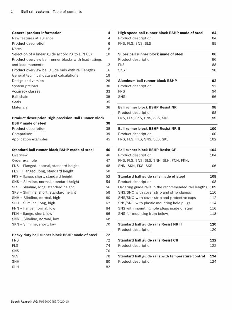
New features at a glanceRunner block and guide rail configurator
Link to the runner block configurator
Link to the ball guide rail configurator
With the new configurators, Bosch Rexroth accelerates the selection and configuration of ball runner blocks and ball guide rails. A built-in plausibility check monitors each decision in real time to ensure that the individual configuration can be implemented. Then the selected components can be ordered directly from the Bosch Rexroth eShop.
4 Ball rail systems |
Bosch Rexroth AG, R999000485/2020-10
Extension of relubrication intervals for grease lubrication
The latest investigations in the Bosch Rexroth testing prove that under certain operating conditions, significantly longer relubrication intervals are possible with grease lubrication. If small loads, normal ambient temperatures and medium to high travel speeds are present, up to 20,000 km can be realized without relubrication in ball rail systems. This enormous increase has been made possible by continuous improvements in the manufacturing processes for runner blocks and guide rails, which have resulted in better surfaces and higher geometrical dimensional accuracy of the running tracks.
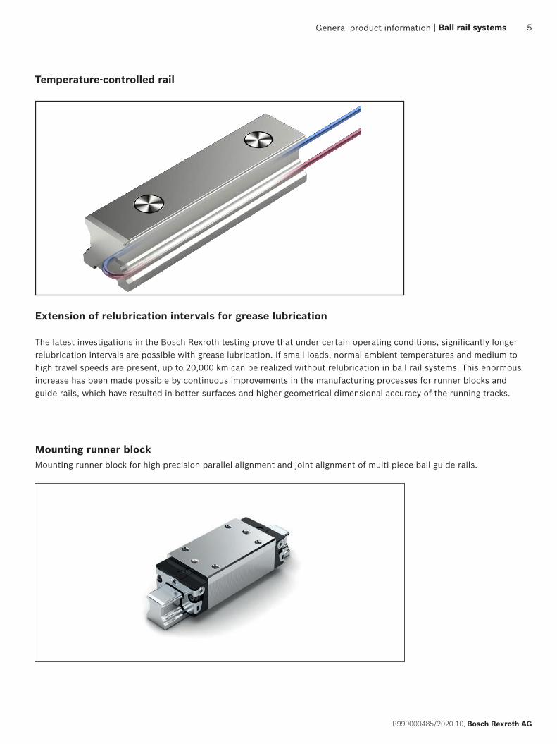
Mounting runner block
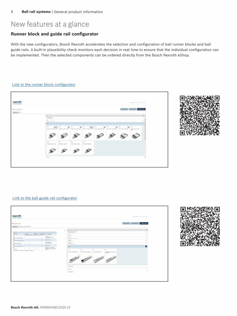
Temperature-controlled rail
General product information
Mounting runner block for high-precision parallel alignment and joint alignment of multi-piece ball guide rails.
| Ball rail systems 5
R999000485/2020-10, Bosch Rexroth AG

1) Type-dependent
Characteristic featuresComplete guide units can also be designed by combining interchangeable elements from stock...Rexroth manufactures ball guide rails and ball runner blocks especially for the ball raceway sector with such high precision that each individual component element is fully interchangeable. As a result, any combination is possible within each accuracy class. This enables globally unique, premium logistics. Each element can be individually planned and separately stocked. On ball guide rails, both sides can be used as reference edges.
Highlights ▶ The same high load ratings in all four main directions of loading ▶ Minimal noise level and optimum travel behavior ▶ Excellent dynamic characteristics:
Travel speed: vmax up to 10 m/s Acceleration: amax = 500 m/s2
▶ Long-term lubrication is possible over several years ▶ Minimum quantity lubrication system with integrated reservoir for oil lubrication1)
▶ Lube fittings with metal threads on all sides1)
▶ Limitless interchangeability as all ball guide rail versions can be combined at will with all ball runner block versions ▶ Maximum system rigidity due to preloaded O-arrangement ▶ Maximum installation error compensation with super ball runner blocks ▶ 60% less gravity with aluminum all runner blocks (compared to ball runner blocks made of steel)
Product description
Further highlights ▶ Interchangeability with roller rail system ▶ Optional integrated, inductive and wear-free measuring system ▶ Wide range of accessories ▶ Attachments on the ball runner block can be mounted from above and below1)
▶ Improved rigidity under lift-off and side loading conditions due to two additional mounting screw holes at the center of the ball runner block1)
▶ End-face fastening thread for all attachments ▶ High rigidity in all load directions – permits applications with just one runner block per rail ▶ Integrated all-round sealing ▶ High torque load capacity ▶ Optimized entry-zone geometry and high number of balls minimize variation in elastic deflection ▶ Quiet, smooth running thanks to optimally designed ball and ball chain return and guideway ▶ Different preload classes
Corrosion protection (optional)1)
▶ Resist NR: Ball runner block body made of corrosion resistant steel as per DIN EN 10088 ▶ Resist NR II: Ball runner block body and ball guide rail as well as all steel parts made of corrosion resistant steel in
accordance with DIN EN 10088 ▶ Resist CR: Ball runner block body or ball guide rail made of steel with corrosion resistant coating, matte-silver finish,
hard chrome plated
General product information6 Ball rail systems |
Bosch Rexroth AG, R999000485/2020-10

Proven cover strip for the ball guide rail mounting holes ▶ One cover for all bore holes saves time and costs ▶ Made of corrosion resistant spring steel DIN EN 10088 ▶ Easy and safe during mounting ▶ Clip on and secure
Ball chain (optional) ▶ Optimized noise level
General product information | Ball rail systems 7
R999000485/2020-10, Bosch Rexroth AG
Separate catalogs are available for other products in the field of ball rail systems:
Integrated measuring system IMS for ball and roller rail systems
IMScompact integrated measuring system for BSHP ball rail systems
Miniature ball guide rail systems
Cam roller guides
Ball rail systems NRFG for use in the packaging industry and food industry areas.

General notes ▶ Combinations of different accuracy classes
Combining ball guide rails and ball runner blocks of different accuracy classes results in different tolerances for the dimensions H and A3. See “Accuracy classes and their tolerances.”
Intended use ▶ The ball rail systems are linear guideways capable of absorbing forces from all transverse directions and moments
about all axes. The ball rail system is intended exclusively for guiding and positioning tasks when installed in a machine. ▶ The product is intended exclusively for professional use and not for private use. ▶ Use for the intended purpose also includes the requirement that users must have read and understood the related
documentation completely, in particular the “Safety instructions”.
MisuseUse of the product in any other way than as described under “Intended use” is considered to be misuse and is therefore not permitted. If unsuitable products are installed or used in safety-critical applications, this may lead to uncontrolled operating statuses in the application which can cause personal injury and/or damage to property. The product may only be used in safety-critical applications if this use has been expressly specified and permitted in the product documentation. Bosch Rexroth AG will not accept any liability for injury or damage caused by misuse of the product. The risks associated with any misuse of the product shall be borne by the user alone.Misuse of the product includes:
▶ The transport of persons
General safety instructions ▶ The safety rules and regulations of the country in which the product is used must be observed. ▶ All current and applicable accident prevention and environmental regulations must be adhered to. ▶ The product may only be used when it is in technically perfect condition. ▶ The technical data and environmental conditions stated in the product documentation must be complied with. ▶ The product must not be put into service until it has been verified that the final product (for example a machine or
system) into which the product has been installed complies with the country-specific requirements, safety regulations and standards for the application.
▶ Rexroth ball rail systems may not be used in zones with potentially explosive atmospheres as defined in ATEX directive 94/9/EC.
▶ Rexroth ball rail systems must never be altered or modified. The user may only perform the work described in the “Quick User Guide” or the “Mounting instructions for ball rail systems”.
▶ The product is never allowed to be disassembled. ▶ At high travel speeds a certain amount of noise is caused by the product. If necessary, appropriate measures should be
taken to protect hearing. ▶ The special safety requirements for specific sectors (e.g. crane construction, theaters, food technology) set forth in
laws, directives and standards must be complied with. ▶ In all cases, the provisions of the following standard should be noted and followed. DIN 637, Safety regulations for
dimensioning and operation of Profiled Rail Systems with recirculating rolling elements.
Notes
General product information8 Ball rail systems |
Bosch Rexroth AG, R999000485/2020-10

Directives and standardsRexroth ball rail systems BSHP are designed for reliability and high precision in dynamic, linear applications. The machine tool industry and other sectors must observe a series of standards and directives. These requirements can vary significantly worldwide. It is therefore essential to understand the legislation and standards that apply in each particular region.
DIN EN ISO 12100This standard describes the safety of machinery – general principles for design, risk assessment and risk reduction. It gives a general overview and contains a guide to the major developments governing machines and their intended use.
Directive 2006/42/ECThe European Machinery Directive describes the basic safety and health requirements for the design and manufacture of machinery. The manufacturer of a machine or his authorized representative has a duty to ensure that a risk assessment has been performed in order to determine the health and safety requirements which have to be fulfilled for that machine. The machine must be designed and built taking into account the results of the risk assessment.
Directive 2001/95/ECThis directive covers general safety requirements for any product placed on the market and intended for consumers, or likely to be used by consumers under reasonably foreseeable conditions, including products that are made available to consumers in the context of service provision for use by them
Directive 1999/34/ECThis directive concerns the liability for defective products and applies to industrially manufactured movable objects, irrespective of whether or not they have been incorporated into another movable or immovable object.
REGULATION (EC) No. 1907/2006 (REACH)This directive describes the restrictions on the marketing and use of certain dangerous substances and preparations. “Substances” means chemical elements and their compounds as they occur in the natural state or as produced by industry. “Preparations” means mixtures or solutions composed of two or more substances.
General product information | Ball rail systems 9
R999000485/2020-10, Bosch Rexroth AG
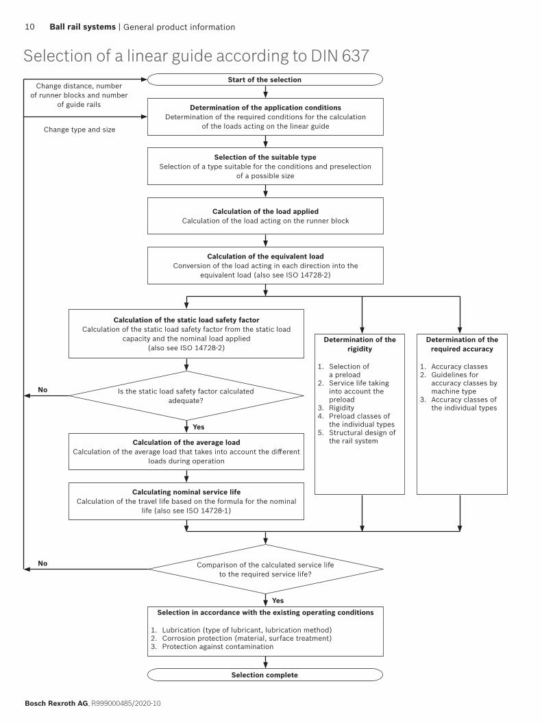
Selection of a linear guide according to DIN 637
Selection complete
Start of the selection
Is the static load safety factor calculated adequate?
Comparison of the calculated service life to the required service life?
Determination of the application conditionsDetermination of the required conditions for the calculation
of the loads acting on the linear guide
Change distance, number of runner blocks and number
of guide rails
No
Yes
Yes
No
Change type and size
Selection of the suitable typeSelection of a type suitable for the conditions and preselection
of a possible size
Calculation of the load appliedCalculation of the load acting on the runner block
Calculation of the equivalent loadConversion of the load acting in each direction into the
equivalent load (also see ISO 14728-2)
Selection in accordance with the existing operating conditions
1. Lubrication (type of lubricant, lubrication method)2. Corrosion protection (material, surface treatment) 3. Protection against contamination
Calculation of the average loadCalculation of the average load that takes into account the different
loads during operation
Calculation of the static load safety factorCalculation of the static load safety factor from the static load
capacity and the nominal load applied (also see ISO 14728-2)
Determination of the rigidity
1. Selection of a preload
2. Service life taking into account the preload
3. Rigidity4. Preload classes of
the individual types5. Structural design of
the rail system
Determination of the required accuracy
1. Accuracy classes2. Guidelines for
accuracy classes by machine type
3. Accuracy classes of the individual types
Calculating nominal service lifeCalculation of the travel life based on the formula for the nominal
life (also see ISO 14728-1)
General product information10 Ball rail systems |
Bosch Rexroth AG, R999000485/2020-10

General product information | Ball rail systems 11
R999000485/2020-10, Bosch Rexroth AG
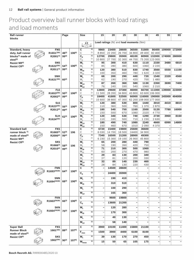
Product overview ball runner blocks with load ratings and load momentsBall runner blocks
Page Size 15 20 25 30 35 45 55 65
CC0C
C0
CC0
Load ratings (N) and load moments (Nm)
Standard, heavy duty, ball runner blocks7) made of steel3)
Resist NR4)
Resist CR6)
FNS R16513)6)
R20014)483)
994)1066)
C 1) 9860 23400 28600 36500 51800 86400 109000 172000C 2) 8 850 22 200 26 700 34 800 49 400 82 400 – –C0
1) 12700 29800 35900 48100 80900 132000 174000 280000C0
2) 10 800 27 700 32 300 44 700 75 200 123 000 – – SNS
R16223)6)
R20114)543)
994)
Mt1) 95 300 410 630 1110 2330 3480 6810
1066) Mt2) 85 280 380 600 1060 2 220 – –
Mt01) 120 380 510 830 1740 3560 5550 11100
Mt02) 100 350 460 780 1 620 3 320 – –
SNHR16213)6) 603)
ML1) 68 200 290 440 720 1540 2320 4560
ML2) 62 190 270 420 700 1 480 – –
ML01) 87 260 360 580 1130 2350 3690 7400
ML02) 76 240 330 540 1060 2 210 – –
FLSR16533)6)
R20024)503)
994)
563)
994)
623)
1066)
1066)
1066)
C 1) 12800 29600 37300 46000 66700 111000 139000 223000C 2) 11 500 28 200 34 800 43 800 63 600 106 000 – –C0
1) 18400 41800 52500 66900 116000 190000 245000 404000C0
2) 15 600 38 800 47 300 62 200 108 000 177 000 – –
SLSR16233)6)
R20124)
Mt1) 120 380 530 800 1440 3010 4410 8810
Mt2) 110 360 500 760 1 370 2 870 – –
Mt01) 180 540 750 1160 2500 5120 7780 16000
Mt02) 150 500 670 1080 2320 4 770 – –
SLHR16243)6)
ML1) 120 340 530 740 1290 2730 3960 8160
ML2) 110 330 500 710 1 230 2 630 – –
ML01) 180 490 740 1080 2240 4660 6990 14800
ML02) 150 460 670 1010 2 090 4 370 – –
Standard ball runner block 7) made of steel3)
Resist NR4)
Resist CR6)
FKS R16653)
R20004)523)
994)
583)
994)
106
106
C 1) 6720 15400 19800 25600 36600 – – –C 2) 6 030 14 700 18 500 24400 34 900 – – –C0
1) 7340 16500 21200 28900 49300 – – –C0
2) 6 230 15 300 19 100 26 900 45 800 – – – SKS
R16663)
R20104)
Mt1) 65 200 280 440 790 – – –
Mt2) 58 190 260 420 750 – – –
Mt01) 71 210 300 500 1060 – – –
Mt02) 60 200 270 470 980 – – –
ML1) 29 83 130 200 340 – – –
ML2) 27 81 120 200 330 – – –
ML01) 32 89 140 230 460 – – –
ML02) 28 84 130 220 430 – – –
FNNR16933)6)8) 643)
683)
1066)
1066)
C 1) – 14500 28600 – – – – –
C01) – 24400 35900 – – – – –
SNNR16943)6)8)
Mt1) – 190 410 – – – – –
Mt01) – 310 510 – – – – –
ML1) – 100 290 – – – – –
ML01) – 165 360 – – – – –
FKNR16633)6)8) 663)
703)
1066)
1066)
C 1) – 9600 19800 – – – – –
C01) – 13600 21200 – – – – –
SKNR16643)6)8)
Mt1) – 120 280 – – – – –
Mt01) – 170 300 – – – – –
ML1) – 40 130 – – – – –
ML01) – 58 140 – – – – –
Super Ball Runner Block made of steel3)
Resist CR6)
FKS16613)6) 883)
903)
1076)
1076)
C 1) 3900 10100 11400 15800 21100 – – –
Fmax1) 1500 3900 4400 6100 8100 – – –
SKS16623)6)
Mt1) 39 130 170 270 450 – – –
Mtmax1) 15 50 65 105 175 – – –
General product information12 Ball rail systems |
Bosch Rexroth AG, R999000485/2020-10
The determination of the dynamic load ratings and load moments is based on a 100,000 m stroke according to DIN ISO14728-1.However, the values are often based on only 50 000 m. For comparison: Multiply the values C, Mt and ML by 1.26 according to the table.1) Ball runner block without ball chain.2) Ball runner block with ball chain.3) Steel: All steel parts made of carbon steel.4) Resist NR size 15 – 35: Ball Runner Block body made of corrosion resistant steel as per DIN EN 10088.5) Resist NR II: All steel components are made from corrosion resistant steel in accordance with DIN EN 10088.6) Resist CR: Steel ball runner block body with corrosion resistant coating, matte-silver finish, hard chrome plated.7) BSHP ball runner block8) BSHP ball runner block size 25 only
For short product names of the design styles, see the product description
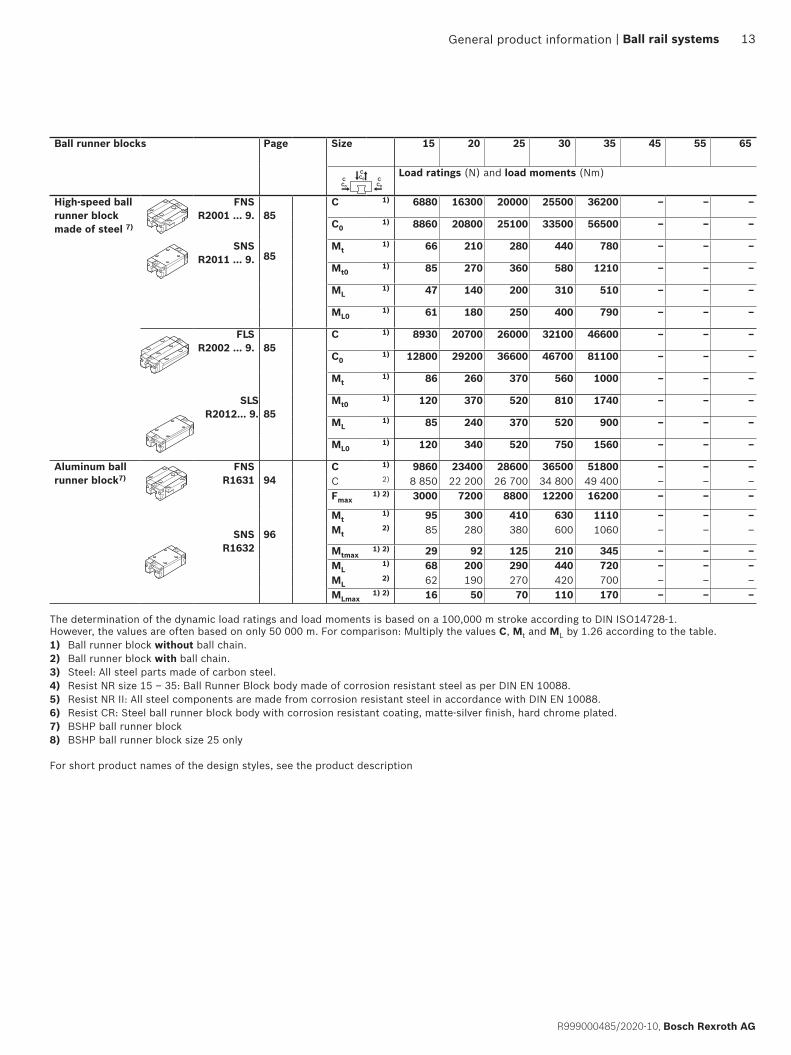
Ball runner blocks Page Size 15 20 25 30 35 45 55 65
CC0C
C0
CC0
Load ratings (N) and load moments (Nm)
High-speed ball runner block made of steel 7)
FNSR2001 ... 9. 85
85
C 1) 6880 16300 20000 25500 36200 – – –
C01) 8860 20800 25100 33500 56500 – – –
SNS R2011 ... 9.
Mt1) 66 210 280 440 780 – – –
Mt01) 85 270 360 580 1210 – – –
ML1) 47 140 200 310 510 – – –
ML01) 61 180 250 400 790 – – –
FLSR2002 ... 9. 85
C 1) 8930 20700 26000 32100 46600 – – –
C01) 12800 29200 36600 46700 81100 – – –
Mt1) 86 260 370 560 1000 – – –
SLSR2012... 9. 85
Mt01) 120 370 520 810 1740 – – –
ML1) 85 240 370 520 900 – – –
ML01) 120 340 520 750 1560 – – –
Aluminum ball runner block7)
FNSR1631
SNSR1632
94
96
C 1) 9860 23400 28600 36500 51800 – – –C 2) 8 850 22 200 26 700 34 800 49 400 – – –Fmax
1) 2) 3000 7200 8800 12200 16200 – – – Mt
1) 95 300 410 630 1110 – – –Mt
2) 85 280 380 600 1060 – – –
Mtmax1) 2) 29 92 125 210 345 – – –
ML1) 68 200 290 440 720 – – –
ML2) 62 190 270 420 700 – – –
MLmax1) 2) 16 50 70 110 170 – – –
General product information | Ball rail systems 13
R999000485/2020-10, Bosch Rexroth AG

The determination of the dynamic load ratings and load moments is based on a 100,000 m stroke according to DIN ISO14728-1. However, the values are often based on only 50 000 m. For comparison: Multiply the values C, Mt and ML by 1.26 according to the table.1) Ball runner block without ball chain.2) Ball runner block with ball chain.3) Steel: All steel parts made of carbon steel.4) Resist NR size 15 – 35: Ball Runner Block body made of corrosion resistant steel as per DIN EN 10088.5) Resist NR II: All steel components are made from corrosion resistant steel in accordance with DIN EN 10088.6) Resist CR: Steel ball runner block body with corrosion resistant coating, matte-silver finish, hard chrome plated.7) BSHP ball runner block8) BSHP ball runner block size 25 only
For short product names of the design styles, see the product description
Product overview ball runner blocks with load ratings and load momentsBall runner blocks
Page Size 15 2020/40
2525/70
30 3535/90
45 55 65
CC0C
C0
CC0
Load ratings (N) and load moments (Nm)
Ball runner blocks Resist NR II5)7)
FNS R2001 ... 0. 102
103
C 1) 5100 12300 15000 20800 27600 – – –C 2) 4 700 11400 14000 19300 27600 – – –C0
1) 9300 16900 21000 28700 37500 – – –C0
2) 8 400 15000 18 900 25 800 37500 – – – SNS
R2011 ... 0.Mt
1) 63 205 270 460 760 – – –Mt
2) 58 190 250 425 760 – – –Mt0
1) 90 215 295 500 805 – – –Mt0
2) 81 190 265 450 805 – – – ML
1) 34 110 150 245 375 – – –ML
2) 31 100 140 225 375 – – –ML0
1) 49 115 165 265 390 – – –ML0
2) 44 100 150 240 390 FLS
R2002 ... 0. 102
103
C 1) 8500 16000 20000 26300 36500 – – –C 2) 7 600 15 200 18 100 25 000 34 800 – – –C0
1) 14000 24400 31600 40100 56200 – – –C0
2) 12 100 22 500 27 400 37300 52500 – – –
SLSR2012 ... 0.
Mt1) 82 265 365 590 1025 – – –
Mt2) 73 250 330 560 975 – – –
Mt01) 132 310 450 695 1210 – – –
Mt02) 118 295 410 660 1 150 – – –
ML1) 64 190 290 420 710 – – –
ML2) 58 180 265 400 675 – – –
ML01) 104 230 350 495 840 – – –
ML02) 93 215 320 470 805
FKS R2000 ... 0. 102
103
C 1) 4500 8200 10500 14500 19300 – – –C 2) 3900 8200 9 200 14500 19300 – – –C0
1) 5600 9400 12600 17200 22400 – – –C0
2) 4 600 9400 10500 17200 22400 – – – SKS
R2010 ... 0.Mt
1) 44 125 195 320 545 – – –Mt
2) 37 125 175 320 545 – – –Mt0
1) 55 115 180 295 485 – – –Mt0
2) 48 115 160 295 485 – – –ML
1) 16 45 70 110 170 – – –ML
2) 13 45 60 110 170 – – –ML0
1) 19 40 65 105 150 – – –ML0
2) 16 40 55 105 150Wide ball runner blocks made ofsteel3)7)
Resist CR6)7)
BNSR16713)6) 1263) 1266)
C 1) – 14900 36200 – 70700 – – –C 2) – 13 700 33 700 – – – – –C0
1) – 20600 50200 – 126000 – – –C0
2) – 18 200 45 200 – – – – – CNS
R16723)6 1303) 1306)Mt
1) – 340 1350 – 3500 – – –Mt
2) – 310 1 260 – – – – –Mt0
1) – 470 1870 – 6240 – – –Mt0
2) – 410 1 680 – – – – – ML
1) – 140 490 – 1470 – – –ML
2) – 130 460 – – – – –ML0
1) – 190 680 – 2620 – – –ML0
2) – 170 620 – – – – –
General product information14 Ball rail systems |
Bosch Rexroth AG, R999000485/2020-10

General product information | Ball rail systems 15
R999000485/2020-10, Bosch Rexroth AG
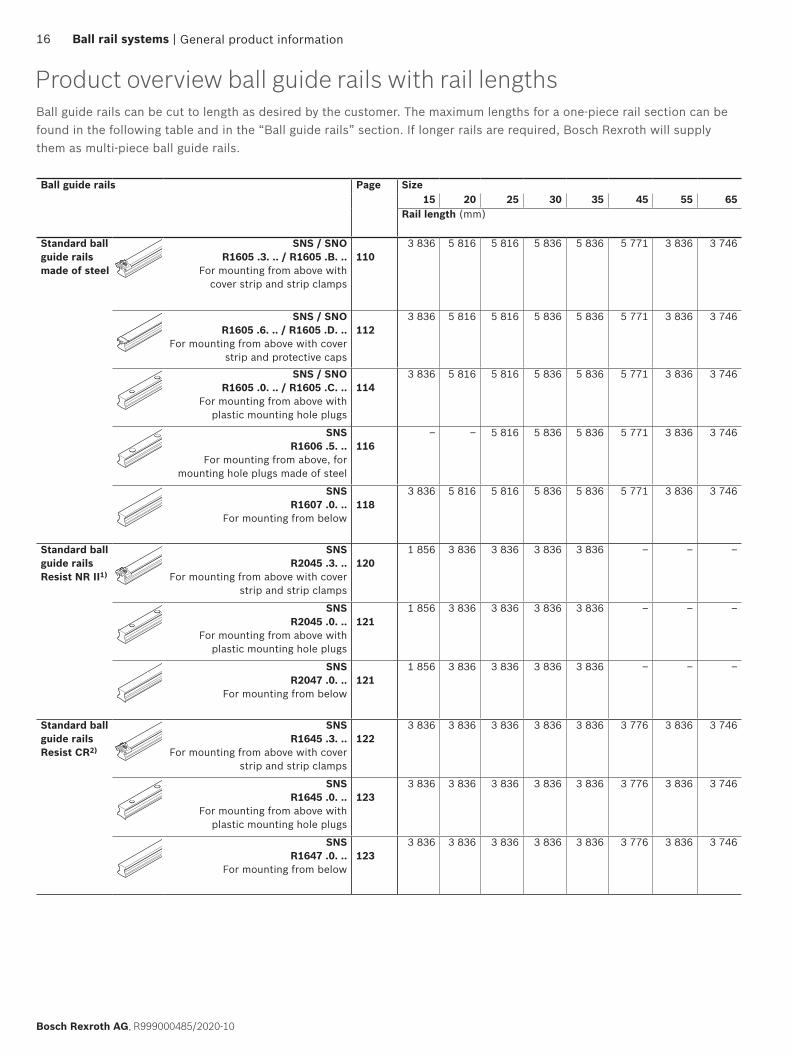
Product overview ball guide rails with rail lengths
Ball guide rails Page Size15 20 25 30 35 45 55 65
Rail length (mm)
Standard ball guide rails made of steel
SNS / SNO R1605 .3. .. / R1605 .B. ..
For mounting from above with cover strip and strip clamps
1103 836 5 816 5 816 5 836 5 836 5 771 3 836 3 746
SNS / SNO R1605 .6. .. / R1605 .D. ..
For mounting from above with cover strip and protective caps
1123 836 5 816 5 816 5 836 5 836 5 771 3 836 3 746
SNS / SNO R1605 .0. .. / R1605 .C. ..
For mounting from above with plastic mounting hole plugs
1143 836 5 816 5 816 5 836 5 836 5 771 3 836 3 746
SNS R1606 .5. ..
For mounting from above, for mounting hole plugs made of steel
116– – 5 816 5 836 5 836 5 771 3 836 3 746
SNS R1607 .0. ..
For mounting from below118
3 836 5 816 5 816 5 836 5 836 5 771 3 836 3 746
Standard ball guide rails Resist NR II1)
SNS R2045 .3. ..
For mounting from above with cover strip and strip clamps
1201 856 3 836 3 836 3 836 3 836 – – –
SNS R2045 .0. ..
For mounting from above with plastic mounting hole plugs
1211 856 3 836 3 836 3 836 3 836 – – –
SNS R2047 .0. ..
For mounting from below121
1 856 3 836 3 836 3 836 3 836 – – –
Standard ball guide rails Resist CR2)
SNS R1645 .3. ..
For mounting from above with cover strip and strip clamps
1223 836 3 836 3 836 3 836 3 836 3 776 3 836 3 746
SNS R1645 .0. ..
For mounting from above with plastic mounting hole plugs
1233 836 3 836 3 836 3 836 3 836 3 776 3 836 3 746
SNS R1647 .0. ..
For mounting from below123
3 836 3 836 3 836 3 836 3 836 3 776 3 836 3 746
General product information
Ball guide rails can be cut to length as desired by the customer. The maximum lengths for a one-piece rail section can be found in the following table and in the “Ball guide rails” section. If longer rails are required, Bosch Rexroth will supply them as multi-piece ball guide rails.
16 Ball rail systems |
Bosch Rexroth AG, R999000485/2020-10

Ball guide rails Page Size20/40 25/70 35/90
Rail length (mm)
Wide ball guide rails made of steel
BNS R1675 .0. ..
For mounting from above with plastic mounting hole plugs
1343 836 3 836 3 836
BNS R1676 .5. ..
For mounting from above, for mounting hole plugs made of
steel
136– 3 836 3 836
BNS R1677 .0. ..
For mounting from below137
3 836 3 836 3 836
Wide ball guide rails Resist CR2)
BNS R1673 .0. ..
For mounting from above with plastic mounting hole plugs
1343 836 3 836 3 836
1) Resist NR II: Ball guide rail made of corrosion resistant steel as per DIN EN 100882) Resist CR: Ball guide rail made of steel with corrosion resistant coating, matte-silver finish, hard chrome plated
For short product names of the design styles, see the product description
General product information | Ball rail systems 17
R999000485/2020-10, Bosch Rexroth AG

General technical data and calculations
Preload classes
Guide systems with parallel rails
Travel speed
Acceleration
Operating temperature range
General notes
Up to 100°C is permissible for a short time. For operation at negative temperatures, please consult us.For ball runner blocks without ball chain: Lower limit - 10 °C.
amax : 250–500 m/s2
vmax : 3–10 m/s
For exact values, see the individual ball runner blocks.(If Fcomb > 2.8 · Fpr : amax = 50 m/s2)If preload force Fpr is canceled, amax = 50 m/s2 applies
For exact values, see the individual ball runner blocks.
The general technical data and calculations apply to all ball rail systems i.e. to all ball runner blocks and ball guide rails. Specific technical data relating to the individual ball runner blocks and ball guide rails is given separately.
To cover the widest possible range of applications, Rexroth ball runner blocks are available in different preload classes.
The following preload classes are available: ▶ ball runner block without preload (preload class C0) ▶ ball runner blocks with moderate preload (preload class C1) ▶ ball runner blocks with average preload (preload class C2) ▶ ball runner blocks with high preload (preload class C3)
To prevent reductions to the service life, the preload should not exceed 1/3 of the load on bearing F.
In general, the rigidity of the ball runner block rises with increasing preload. If vibrations occur, select a correspondingly high preload (≥ preload class C2).
When choosing the preload class, also pay attention to the permissible parallelism offset of the rails (“Accuracy class selection criterion”). When assembling ball rail systems of accuracy class N, we recommend preload class C0 or C1 in order to avoid distortive stress due to the tolerances.
t : 0-80 °C
General product information18 Ball rail systems |
Bosch Rexroth AG, R999000485/2020-10
General product information
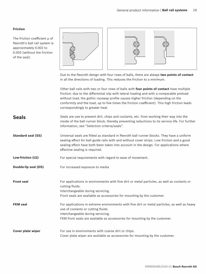
Friction
The friction coefficient µ of Rexroth's ball rail system is approximately 0.002 to 0.003 (without the friction of the seal).
Due to the Rexroth design with four rows of balls, there are always two points of contact in all the directions of loading. This reduces the friction to a minimum.
Other ball rails with two or four rows of balls with four points of contact have multiple friction: due to the differential slip with lateral loading and with a comparable preload without load, the gothic raceway profile causes higher friction (depending on the conformity and the load, up to five times the friction coefficient). This high friction leads correspondingly to greater heat.
Seals Seals are use to prevent dirt, chips and coolants, etc. from working their way into the inside of the ball runner block, thereby preventing reductions to its service life. For further information, see “Selection criteria/seals”.
Standard seal (SS) Universal seals are fitted as standard in Rexroth ball runner blocks. They have a uniform sealing effect for ball guide rails with and without cover strips. Low friction and a good sealing effect have both been taken into account in the design. For applications where effective sealing is required.
Front seal
FKM seal
Cover plate wiper For use in environments with coarse dirt or chips. Cover plate wiper are available as accessories for mounting by the customer.
For applications in environments with fine dirt or metal particles, as well as coolants or cutting fluids.Interchangeable during servicing.Front seals are available as accessories for mounting by the customer.
Low-friction (LS)
Double-lip seal (DS)
For special requirements with regard to ease of movement.
For increased exposure to media
For applications in extreme environments with fine dirt or metal particles, as well as heavy use of coolants or cutting fluids.Interchangeable during servicing.FKM front seals are available as accessories for mounting by the customer.
| Ball rail systems 19
R999000485/2020-10, Bosch Rexroth AG
xy
z
Mx
M z
My
Fz
Fy
CC0
CC0
CC0
Mt
Mt0
ML
ML0
ML
ML0
General technical data and calculations
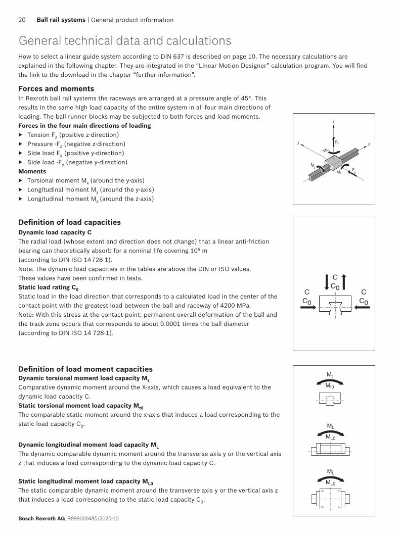
Definition of load capacitiesDynamic load capacity CThe radial load (whose extent and direction does not change) that a linear anti-friction bearing can theoretically absorb for a nominal life covering 105 m (according to DIN ISO 14 728-1). Note: The dynamic load capacities in the tables are above the DIN or ISO values. These values have been confirmed in tests.Static load rating C0Static load in the load direction that corresponds to a calculated load in the center of the contact point with the greatest load between the ball and raceway of 4200 MPa.Note: With this stress at the contact point, permanent overall deformation of the ball and the track zone occurs that corresponds to about 0.0001 times the ball diameter (according to DIN ISO 14 728-1).
Forces and momentsIn Rexroth ball rail systems the raceways are arranged at a pressure angle of 45°. This results in the same high load capacity of the entire system in all four main directions of loading. The ball runner blocks may be subjected to both forces and load moments.Forces in the four main directions of loading
▶ Tension Fz (positive z-direction) ▶ Pressure -Fz (negative z-direction) ▶ Side load Fy (positive y-direction) ▶ Side load -Fy (negative y-direction)
Moments ▶ Torsional moment Mx (around the y-axis) ▶ Longitudinal moment My (around the y-axis) ▶ Longitudinal moment Mz (around the z-axis)
Definition of load moment capacitiesDynamic torsional moment load capacity MtComparative dynamic moment around the X-axis, which causes a load equivalent to the dynamic load capacity C.Static torsional moment load capacity Mt0The comparable static moment around the x-axis that induces a load corresponding to the static load capacity C0.
Dynamic longitudinal moment load capacity MLThe dynamic comparable dynamic moment around the transverse axis y or the vertical axis z that induces a load corresponding to the dynamic load capacity C.
Static longitudinal moment load capacity ML0The static comparable dynamic moment around the transverse axis y or the vertical axis z that induces a load corresponding to the static load capacity C0.
General product information
How to select a linear guide system according to DIN 637 is described on page 10. The necessary calculations are explained in the following chapter. They are integrated in the “Linear Motion Designer” calculation program. You will find the link to the download in the chapter “further information”.
20 Ball rail systems |
Bosch Rexroth AG, R999000485/2020-10
General product information
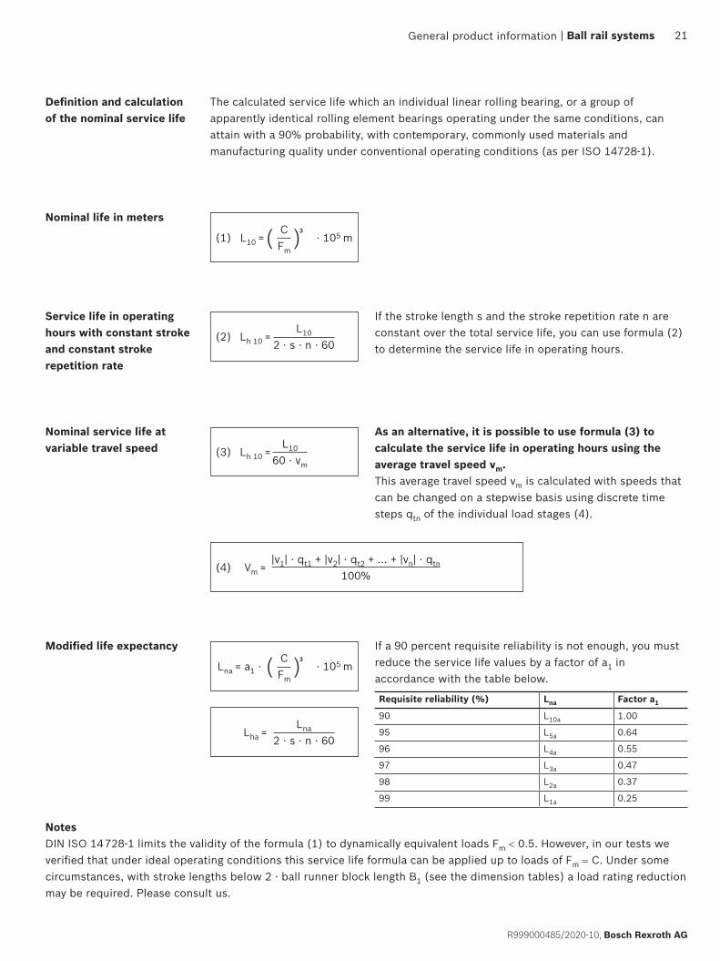
Definition and calculation of the nominal service life
The calculated service life which an individual linear rolling bearing, or a group of apparently identical rolling element bearings operating under the same conditions, can attain with a 90% probability, with contemporary, commonly used materials and manufacturing quality under conventional operating conditions (as per ISO 14728-1).
( )
( )
Nominal life in meters
Nominal service life at variable travel speed
Service life in operating hours with constant stroke and constant stroke repetition rate
Modified life expectancy
If the stroke length s and the stroke repetition rate n are constant over the total service life, you can use formula (2) to determine the service life in operating hours.
NotesDIN ISO 14 728-1 limits the validity of the formula (1) to dynamically equivalent loads Fm < 0.5. However, in our tests we verified that under ideal operating conditions this service life formula can be applied up to loads of Fm = C. Under some circumstances, with stroke lengths below 2 · ball runner block length B1 (see the dimension tables) a load rating reduction may be required. Please consult us.
As an alternative, it is possible to use formula (3) to calculate the service life in operating hours using the average travel speed vm. This average travel speed vm is calculated with speeds that can be changed on a stepwise basis using discrete time steps qtn of the individual load stages (4).
Requisite reliability (%) Lna Factor a1
90 L10a 1.00
95 L5a 0.64
96 L4a 0.55
97 L3a 0.47
98 L2a 0.37
99 L1a 0.25
If a 90 percent requisite reliability is not enough, you must reduce the service life values by a factor of a1 in accordance with the table below.
CFm
CFm
L10
2 · s · n · 60
Lna
2 · s · n · 60
L10
60 · vm
|v1| · qt1 + |v2| · qt2 + ... + |vn| · qtn
100%
(1)
(2)
(3)
(4)
L10 =
Lna = a1 ·
Lh 10 =
Lha =
Lh 10 =
Vm =
· 105 m
· 105 m
3
3
| Ball rail systems 21
R999000485/2020-10, Bosch Rexroth AG

Fcomb = |Fy| + |Fz|(5)
xy
z
Fz
Fy
xy
z
Mx
M z
My
Fz
Fy
Combined equivalent bearing loadIn the case of a combined vertical and horizontal external load, calculate the dynamic equivalent load Fcomb according to formula (5). NoteThe structure of the ball rail system permits this simplified calculation.
General technical data and calculations
General product information
NoteReduce an external load that affects the ball runner block at any angle with the correct sign to Fy and Fz and insert the amounts into formula (5) or (6).
22 Ball rail systems |
Bosch Rexroth AG, R999000485/2020-10
Load on bearing for calculating the service life
NoteIn general, both the static and dynamic load ratios should not be below the minimum value of 4.0. In the case of applications that place high demands on rigidity and/or the service life, a higher load ratio is required.With tensile loads, check the screw stability. See the chapter entitled “Instruction for mounting”.
CFm, max
C0
Feff, maxStatic load ratio
Dynamic load ratio
Combined equivalent load on bearing in conjunctionwith momentsUsing formula (6), you can combine all the partial loads that occur in a load case into one single comparison load. i.e. the combined equivalent load on bearing.
NotesIncluding moments as stated in formula (6) only applies to an individual ball guide rail with just one ball runner block. The formula is simpler for other combinations.
The forces and moments plotted in the coordinate system can also have an effect in the opposite direction. Reduce an external load that affects the ball runner block at any angle to Fy and Fz and insert the amounts into formula (6). The structural design of the ball runner blocks allows this simplified calculation.
Fcomb = |Fy| + |Fz| + C ⋅ + C ⋅ + C ⋅|Mx|Mt
(6)|My|ML
|Mz|ML
Fpr
F
F
2.8 · Fpr
2 ·
a
b
ba
General product information
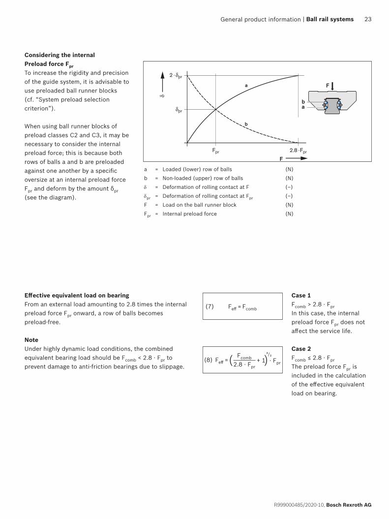
a = Loaded (lower) row of balls (N)
b = Non-loaded (upper) row of balls (N)
δ = Deformation of rolling contact at F (–)
δpr = Deformation of rolling contact at Fpr (–)
F = Load on the ball runner block (N)
Fpr = Internal preload force (N)
| Ball rail systems 23
R999000485/2020-10, Bosch Rexroth AG
Considering the internal Preload force FprTo increase the rigidity and precision of the guide system, it is advisable to use preloaded ball runner blocks (cf. “System preload selection criterion”).
When using ball runner blocks of preload classes C2 and C3, it may be necessary to consider the internal preload force; this is because both rows of balls a and b are preloaded against one another by a specific oversize at an internal preload force Fpr and deform by the amount δpr (see the diagram).
Effective equivalent load on bearingFrom an external load amounting to 2.8 times the internal preload force Fpr onward, a row of balls becomes preload-free.
NoteUnder highly dynamic load conditions, the combined equivalent bearing load should be Fcomb < 2.8 · Fpr to prevent damage to anti-friction bearings due to slippage.
Case 1Fcomb > 2.8 · Fpr In this case, the internal preload force Fpr does not affect the service life.
Case 2Fcomb ≤ 2.8 · Fpr The preload force Fpr is included in the calculation of the effective equivalent load on bearing.
Feff = Fcomb
Fcomb
2.8 · Fpr
(7)
(8) Feff = ( )+ 1³/₂· Fpr

Fm = (Feff 1) ·qs1
100 % 3 3
(Feff 2) · 3+ + ... +
qs2
100 %(Feff n) ·
qsn
100 % 3
(10) F0 comb = |F0y| + |F0z| + C0 · + C0 · + C0 ⋅ |M0x|Mt0
|M0y|ML0
|M0z|ML0
General technical data and calculations
General product information
Dynamic equivalent load on bearingThe determination of the dynamic equivalent load on bearing Fm for the calculation of the service life is implemented according to track ratios qm according to formula (9).
Equivalent static load on bearingWith a combined vertical and horizontal external static load in conjunction with a static torsional or longitudinal moment, calculate the static equivalent load on bearing F0 comb according to formula (10).
(9)
Fmax
C
F0 max
C0
Fmax
C0
Machine type/sector Application example C/Fmax C0/F0 max
Machine tools General 6 ... 9 > 4
Turning 6 ... 7 > 4
Milling 6 ... 7 > 4
Grinding 9 ... 10 > 4
Engraving 5 > 3
Rubber and plastics processing machinery Injection molding 8 > 2
Woodworking and wood processing machines Sawing, milling 5 > 3
Area of mounting/handling technology and industrial robots Handling 5 > 3
Oil hydraulics and pneumatics Lifting/lowering 6 > 4
Case 1: Static load F0 max > Fmax: Case 2: Static load F0 max < Fmax:
Dynamic ratio = Static ratio = Static ratio =
Definitions and calculation for dynamic and static load ratiosUsing the ratio of load rating to load of the ball runner blocks, you can make a preselection of the guideway. The dynamic loading ratio C/Fmax and the static loading ratio C0 /F0 max should be selected according to the application. The necessary load ratings are calculated from this. The load rating overview yields the corresponding dimensions and format.
Recommended values for load ratiosThe table below contains guideline values for the load ratios. The values are offered merely as a rough guide reflecting typical customer requirements (e.g. service life, accuracy, rigidity) by sector and application.
NotesThe static equivalent load on bearing F0 comb must not exceed the static load capacity C0. Formula (10) only applies when using a single ball guide rail. Reduce an external load that affects the ball runner block at any angle to F0y and F0z and insert the amounts into formula (10).
24 Ball rail systems |
Bosch Rexroth AG, R999000485/2020-10

S0 =C0
F0 max
General product information
Static load safety factor S0You must verify mathematically any structural design involving rolling contact with regard to the static load safety factor. The static load safety factor for a linear guide results from the following equation:
In this connection, F0 max represents the maximum load amplitude that can occur, which can affect the linear guide. It does not matter whether this load is exerted only for a short period. It may represent the peak amplitude of an overall dynamic loading. For dimensioning, the data shown in the table applies.
Static load safety factor S0 Conditions of useOverhead hanging arrangements or applications with serious potential risks ≥ 12
High dynamic load when at standstill, contamination. 8 – 12
Normal dimensioning of machinery and plant without full knowledge of the load parameters or connection details. 5 – 8
Full knowledge of all the load data. Vibration-free operation is ensured. 3 – 5
Key to formulasFormula Unit Designation
a1 — Life expectancy factor
C N Dynamic load capacity
C0 N Static load capacity
Fmax N Maximum dynamic load
F0 max N Maximum static load
Fcomb N Combined equivalent bearing load
F0 comb N Equivalent static load on bearing
Feff N Effective equivalent load on bearing
Feff 1 – n N Uniform effective individual loads
Fm N Dynamic equivalent load on bearing
Fpr N Preload force
Fy N External load due to a resulting force in the y-direction
F0y N External load due to a static force in the y-direction
Fz N External load due to a resulting force in the z-direction
F0z N External load due to a static force in the z-direction
Mt Nm Dynamic torsional moment load capacity1)
Mt0 Nm Static torsional moment load capacity1)
ML Nm Dynamic longitudinal moment load capacity1)
ML0 Nm Static longitudinal moment load capacity1)
Mx Nm Load due to the resultant moment around the x-axis
Formula Unit Designation
M0x Nm Load due to the static moment around the x-axis
My Nm Load due to the resultant moment around the y-axis
M0y Nm Load due to the static moment around the y-axis
Mz Nm Load due to the resultant moment around the z-axis
M0z Nm Load due to the static moment around the z-axis
L10 m Nominal life (travel range)
Lh 10 h Nominal life (time)
Lna m Modified life expectancy (travel range)
Lha h Modified life expectancy (time)
n min-1 Stroke repetition rate (full cycles)
s m Stroke length
S0 – Static load safety factor
vm m/min Average linear speed
v1 ... vn m/min Travel speeds of phases 1 ... n
qt1 ... qtn % Discrete time steps for v1 ... vn of phases 1 ... n
Refer to the table for the values
| Ball rail systems 25
R999000485/2020-10, Bosch Rexroth AG
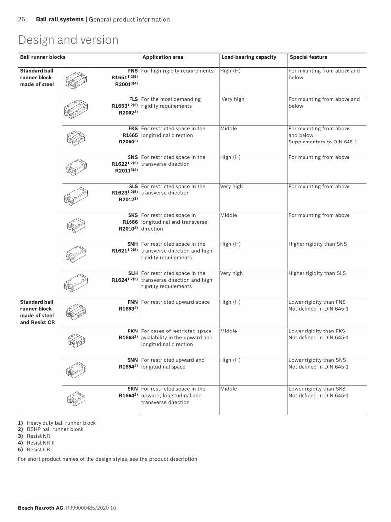
Ball runner blocks Application area Load-bearing capacity Special feature
Standard ball runner block made of steel
FNS R16511)2)5)
R20013)4)
For high rigidity requirements High (H) For mounting from above and below
FLS R16531)2)5)
R20023)
For the most demanding rigidity requirements
Very high For mounting from above and below
FKS R1665
R20003)
For restricted space in the longitudinal direction
Middle For mounting from above and belowSupplementary to DIN 645-1
SNS R16221)2)5)
R20113)4)
For restricted space in the transverse direction
High (H) For mounting from above
SLS R16231)2)5)
R20123)
For restricted space in the transverse direction
Very high For mounting from above
SKS R1666
R20103)
For restricted space in longitudinal and transverse direction
Middle For mounting from above
SNH R16211)2)5)
For restricted space in the transverse direction and high rigidity requirements
High (H) Higher rigidity than SNS
SLH R16241)2)5)
For restricted space in the transverse direction and high rigidity requirements
Very high Higher rigidity than SLS
Standard ball runner block made of steel and Resist CR
FNN R16932)
For restricted upward space High (H) Lower rigidity than FNSNot defined in DIN 645-1
FKN R16632)
For cases of restricted space avialability in the upward and longitudinal direction
Middle Lower rigidity than FKSNot defined in DIN 645-1
SNN R16942)
For restricted upward and longitudinal space
High (H) Lower rigidity than SNSNot defined in DIN 645-1
SKN R16642)
For restricted space in the upward, longitudinal and transverse direction
Middle Lower rigidity than SKSNot defined in DIN 645-1
For short product names of the design styles, see the product description
1) Heavy-duty ball runner block2) BSHP ball runner block3) Resist NR4) Resist NR II5) Resist CR
Design and version
General product information26 Ball rail systems |
Bosch Rexroth AG, R999000485/2020-10

Ball runner blocks Application area Load-bearing capacity Special feature
Super ball runner block made of steel and Resist CR
FKSR1661
For compensating large tolerances in the adjoining structure
Middle At least 2 ball runner blocks required per rail
SKS R1662
For compensating large tolerances in the adjoining structure
Middle At least 2 ball runner blocks required per rail
Aluminum ball runner block
FNS R16312)
For light-weight construction typefor compensating low tolerances with connected structures
High (H) For mounting from above and below
SNS R16322)
For light-weight construction typefor compensating low tolerances with connected structures
High (H) For mounting from above
High-speed ball runner block made of steel
FNS R2001 ... 9.2)
For maximum travel speeds (up to 10 m/s)
High (H) For mounting from above and below
SNS R2011 ... 9.2)
For maximum travel speeds (up to 10 m/s)
High (H) For mounting from above
Wide Ball Runner Block made of steel and Resist CR
BNS R16712)
For high torsional moments on rails
Very high For mounting from above and below
CNS R16722)
For high torsional moments on rails with restricted lateral space
Very high For mounting from above
General product information | Ball rail systems 27
R999000485/2020-10, Bosch Rexroth AG

Design and versionBall guide rails Application area Fastening type Special feature
Standard ball guide rail made of steel
SNS / SNOR1605 .3. .. R1605 .B. ..
R1645 .3. ..2) R2045 .3. ..1)
Standard version Very harsh environments Robust strip clamp
For mounting from above
With cover strip and strip clamp. A single cover for all holes. No end-face hole required for strip clamp.
SNS / SNO R1605 .6. ..R1605 .D. ..
Harsh environments Compact strip clamp
For mounting from above
With cover strip and protective cap. A single cover for all holes.
SNS / SNO R1605 .0. ..R1605 .C. ..
R1645 .0. ..2) R2045 .0. ..1)
Inexpensive For mounting from above
With plastic mounting hole plugs. No extra space required at rail ends.
SNS R1606 .5. ..
More resistant to mechanical influences (e.g. shocks)Very harsh environments
For mounting from above
With steel mounting hole plugs. No extra space required at rail ends.
SNS R1607 .0. ..
R1647 .0. ..2) R2047 .0. ..1)
Easy access to the mounting base underside, best sealing action of end seals
For mounting from below
Use of larger screws than for mounting from above. Greater side loads permitted. No extra space required at rail ends.
Wide ball guide rails made of steel
BNS R1675 .0. ..
R1673 .0. ..2)
High moment rigidity For mounting from above
With plastic mounting hole plugs. No extra space required at rail ends.
BNS R1676 .5. ..
More moment rigidity, more resistant to mechanical influences (e.g. shocks)Very harsh environments
For mounting from above
With steel mounting hole plugs. No extra space required at rail ends.
BNS R1677 .0. ..
High moment rigidity Best sealing action of end seals
For mounting from below
Use of larger screws than for mounting from above. Larger side loads are permitted than for the single-row series. No extra space required at rail ends.
1) Resist NR II2) Resist CR
General product information
For short product names of the design styles, see the product description
28 Ball rail systems |
Bosch Rexroth AG, R999000485/2020-10

AccessoriesConnection elements are available as options for the ball runner blocks
Application area
Cover plate wiper
The cover plate wiper is an additional element for wiping off coarse particles or dealing with contamination that has been deposited on the ball guide rail. When making your selection, please note whether the ball guide rail is used with or without cover strips.
Front sealTwo-piece
The front seal effectively prevents dirt, liquid or small particles from entering the ball runner block. This means that the sealing effect is improved even more. The two-part front seal can also be retrofitted via the ball guide rail.
FKM sealOne and two-piece
Better sealing effect than front seal but higher friction. Used for very heavy contamination, cooling lubricants or aggressive media.Chemical and temperature resistant.
Seal kit When using cover plate wiper and front seal simultaneously, the seal kit is recommended.
Lubrication adapter For oil and grease lubrication from above for SNH and SLH ball runner blocks (high versions).
Lubrication plate
Enables further variations for lubrication of ball runner blocks; Available for lube connection with metric thread or pipe thread.
Front lube unit For applications requiring very long relubrication intervals. They allow travel distances of up to 25,000 km without relubrication under normal loads. The function is only assured where there is no exposure to liquids and little contamination. The maximum operating temperature is 60 °C.
Bellows Bellows are available in various versions, with or without lubrication plate. Bellows in heat-resistant design are metalized on one side and are therefore not flammable, resistant to sparks, welding spatter or hot chips. Temperature stability briefly up to 200 °C and operating temperature of 80 °C possible.
Clamping and braking units
Clamping elements can be used to secure the ball rail system against displacement in the static state. With braking units, the ball rail system can be braked in the dynamic state and secured against displacement in the resting state. The following versions are available: Hydraulic, pneumatic and manual clamping units.
General product information
Accessories
| Ball rail systems 29
R999000485/2020-10, Bosch Rexroth AG

System preloadDefinition of preload
Code Preload Application areaC01) Without preload (clearance) For particularly smooth-running guide systems with the lowest possible friction for applications
with large installation tolerances. Clearance versions are available only in accuracy classes N and H.
C1 Moderate preload For precise guide systems with low external loads and high demands on overall rigidity.
C2 Medium preload For precise guide systems with both high external loading and high demands on overall rigidity; also recommended for single-rail systems. Above average moment loads can be absorbed without significant elastic deflection. Further improved overall rigidity with only medium moment loads.
C3 High preload For highly rigid guide systems, e.g. precision tooling machines etc. Above-average loads and moments are caught with the lowest possible elastic deformation. Ball runner blocks with preload C3 only available in accuracy classes UP, SP and XP, heavy duty ball runner blocks only available in UP, SP and P.
Selection criteria
Ball Runner Blocks can be preloaded to increase rigidity. The internal preload forces that occur in this connection must be considered in the life expectancy calculation. You can choose the preload class to match the area of application. Refer to the table for preload force Fpr .
Example ▶ Area of application: Precise guide systems with low external load and high
overall rigidity requirements. This results in preload class C1. ▶ Selected ball runner block FNS R1651 314 20 ▶ The selected ball runner block yields a preload force Fpr according to
the table. ▶ It is installed at 840 N internal preload force Fpr.
1) In the case of ball runner blocks without preload (preload class C0), there is a clearance between the ball runner block and the rail of 1 to 10 µm. When using two rails and more than one ball runner block per guide rail, this clearance is usually equalized by parallelism tolerances.
30 Ball rail systems |
Bosch Rexroth AG, R999000485/2020-10
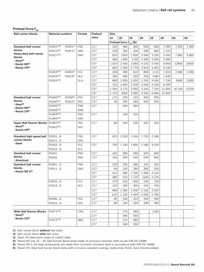
Ball runner blocks Material numbers Format Preload class
Size15 20 25 30 35 45 55 65Preload force Fpr (N)
Standard ball runner blocksHeavy-duty ball runner blocks- Steel3)
- Resist NR4)
- Resist CR6)
R16513)6) R20014) FNS C11) 160 380 460 630 840 1 360 1 960 2 460R16223)6) R20114) SNS C12) 150 350 430 590 840 1 270R16213)6) SNH C21) 620 1500 1 820 2 540 3 350 5 450 7 860 9 840
C22) 580 1390 1700 2 340 3 350 5 060C31) 1 010 2 440 2 960 4 120 5 450 8 850 12800 16000C32) 950 2 260 2 770 3 810 5 450 8 230
R16533)6) R20024) FLS C11) 200 490 610 800 1110 1 810 2 480 3 260R16233)6) R20124) SLS C12) 180 460 550 760 1060 1 640R16243)6) SLH C21) 800 1 950 2 430 3 200 4 450 7 230 9940 13000
C22) 720 1 850 2 200 3 040 4 240 6 550C31) 1 300 3 170 3 950 5 200 7 230 11 800 16 100 21200C32) 1 170 3000 3 580 4 940 6 890 10 600
Standard ball runner blocks- Steel3)
- Resist NR4)
- Resist CR6)
R16653)6) R20004) FKS C11) 110 250 320 440 590R16663)6) R20104) SKS C12) 90 250 280 440 590R16933)6) FNN C11) 290 460R16943)6) SNNR16633)6) FKN C11) 190 320R16643)6) SKN
Super Ball Runner Blocks - Steel3)
- Resist CR6)
R16613)6) FKS C11) 80 200 230 320 420R16623)6) SKS
Standard high speed ball runner blocks- Steel
R2001…9. FNS C21) 420 1 020 1 240 1 720 2 280R2011…9. SNSR2002…9. FLS C21) 700 1 330 1 660 2 180 3 020R2012…9. SLS
Standard ball runner blocks- Aluminum
R1631 FNS C11) 160 380 460 630 840R1632 SNS C12) 150 350 430 590 840
Standard ball runner blocks- Resist NR II5)
R2001…0. FNS C11) 100 250 300 420 550R2011…0. SNS C12) 90 230 280 390 550
C21) 410 980 1 200 1 660 2 210C22) 380 910 1 120 1540 2 210
R2002…0. FLS C11) 170 320 400 530 730R2012…0. SLS C12) 150 300 360 500 700
C21) 680 1 280 1 600 2 100 2 920C22) 610 1 220 1 450 2 000 2 780
R2000…0. FKS C11) 90 160 210 290 390R2010…0. SKS C12) 80 160 180 290 390
Wide Ball Runner Blocks - Steel3)
- Resist CR6)
R16713)6) CNS C11) 270 580 1160C12) 260 550
R16723)6) BNS C11) 270 580C12) 260 550
1) Ball runner block without ball chain.2) Ball runner block with ball chain.3) Steel: All steel parts made of carbon steel.4) Resist NR size 15 – 35: Ball Runner Block body made of corrosion resistant steel as per DIN EN 10088.5) Resist NR II: All steel components are made from corrosion resistant steel in accordance with DIN EN 10088.6) Resist CR: Steel ball runner block body with corrosion resistant coating, matte-silver finish, hard chrome plated.
Preload force Fpr
Selection criteria | Ball rail systems 31
R999000485/2020-10, Bosch Rexroth AG

10
20
30
40
0
50
60
5000 100000 15000 20000 25000
a
b
c
10
20
30
40
0
50
60
5000 100000 15000 20000 25000
abc
10
20
30
40
0
50
60
5000 100000 15000 20000 25000
a
b
c
10
20
30
40
0
50
60
5000 100000 15000 20000 25000
a
bc
Keyδel = Elastic deformation (µm)F = Load (N)
Rigidity of ball rail system with preloading
Example Ball runner blocks FNSFlanged, normal, standard heightSize 35:a) Ball runner blocks R1651 31. 20
for preload C1b) Ball runner blocks R1651 32. 20
for preload C2c) Ball runner blocks R1651 33. 20
for preload C3
ExampleBall runner blocks FLSFlanged, long, standard heightSize 35:a) Ball runner blocks R1653 31. 20
for preload C1b) Ball runner blocks R1653 32. 20
for preload C2c) Ball runner blocks R1653 33. 20
for preload C3
ExampleBall runner blocks SNSSlimline, normal, standard heightSize 35:a) Ball runner blocks R1622 31. 20
for preload C1b) Ball runner blocks R1622 32. 20
for preload C2c) Ball runner blocks R1622 33. 20
for preload C3
ExampleBall runner blocks SLSSlimline, long, standard heightSize 35:a) Ball runner blocks R1623 31. 20
for preload C1b) Ball runner blocks R1623 32. 20
for preload C2c) Ball runner blocks R1623 33.20
for preload C3
Rigidity ball runner block
Selection criteria
PreloadC1/C2/C3 = in accordance with table for
preload force Fpr
Due to the large number of variants only one type is listed. Further rigidity diagrams are available on request.
32 Ball rail systems |
Bosch Rexroth AG, R999000485/2020-10
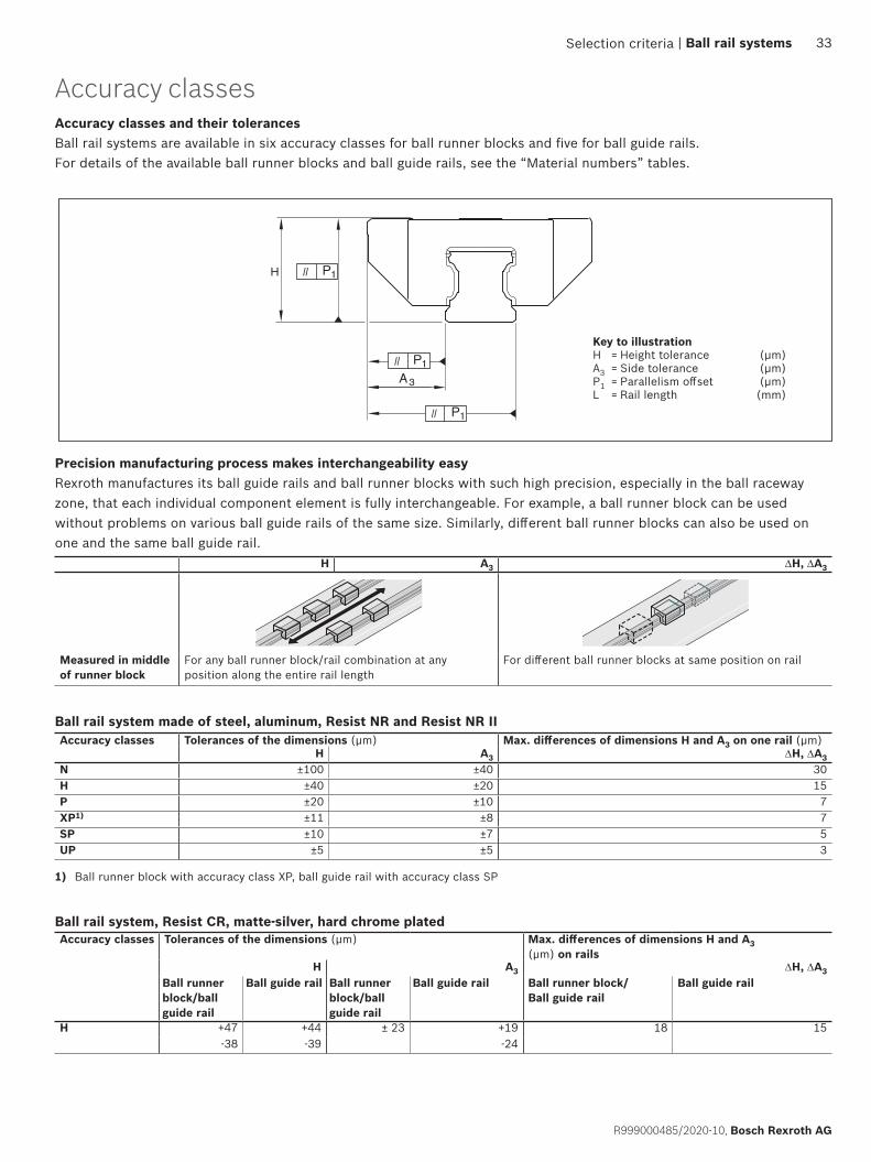
H P1
P1
P1
A3
Selection criteria
Accuracy classes and their tolerancesBall rail systems are available in six accuracy classes for ball runner blocks and five for ball guide rails. For details of the available ball runner blocks and ball guide rails, see the “Material numbers” tables.
Accuracy classes Tolerances of the dimensions (µm) Max. differences of dimensions H and A3 on one rail (µm)H A3 ∆H, ∆A3
N ±100 ±40 30H ±40 ±20 15P ±20 ±10 7XP1) ±11 ±8 7SP ±10 ±7 5UP ±5 ±5 3
H A3 ∆H, ∆A3
Measured in middle of runner block
For any ball runner block/rail combination at any position along the entire rail length
For different ball runner blocks at same position on rail
Accuracy classes
1) Ball runner block with accuracy class XP, ball guide rail with accuracy class SP
Precision manufacturing process makes interchangeability easyRexroth manufactures its ball guide rails and ball runner blocks with such high precision, especially in the ball raceway zone, that each individual component element is fully interchangeable. For example, a ball runner block can be used without problems on various ball guide rails of the same size. Similarly, different ball runner blocks can also be used on one and the same ball guide rail.
Ball rail system, Resist CR, matte-silver, hard chrome plated
Ball rail system made of steel, aluminum, Resist NR and Resist NR II
Key to illustrationH = Height tolerance (μm)A3 = Side tolerance (μm)P1 = Parallelism offset (μm)L = Rail length (mm)
Accuracy classes Tolerances of the dimensions (µm) Max. differences of dimensions H and A3 (µm) on rails
H A3 ∆H, ∆A3Ball runner block/ball guide rail
Ball guide rail Ball runner block/ball guide rail
Ball guide rail Ball runner block/ Ball guide rail
Ball guide rail
H +47 +44 ± 23 +19 18 15-38 -39 -24
| Ball rail systems 33
R999000485/2020-10, Bosch Rexroth AG
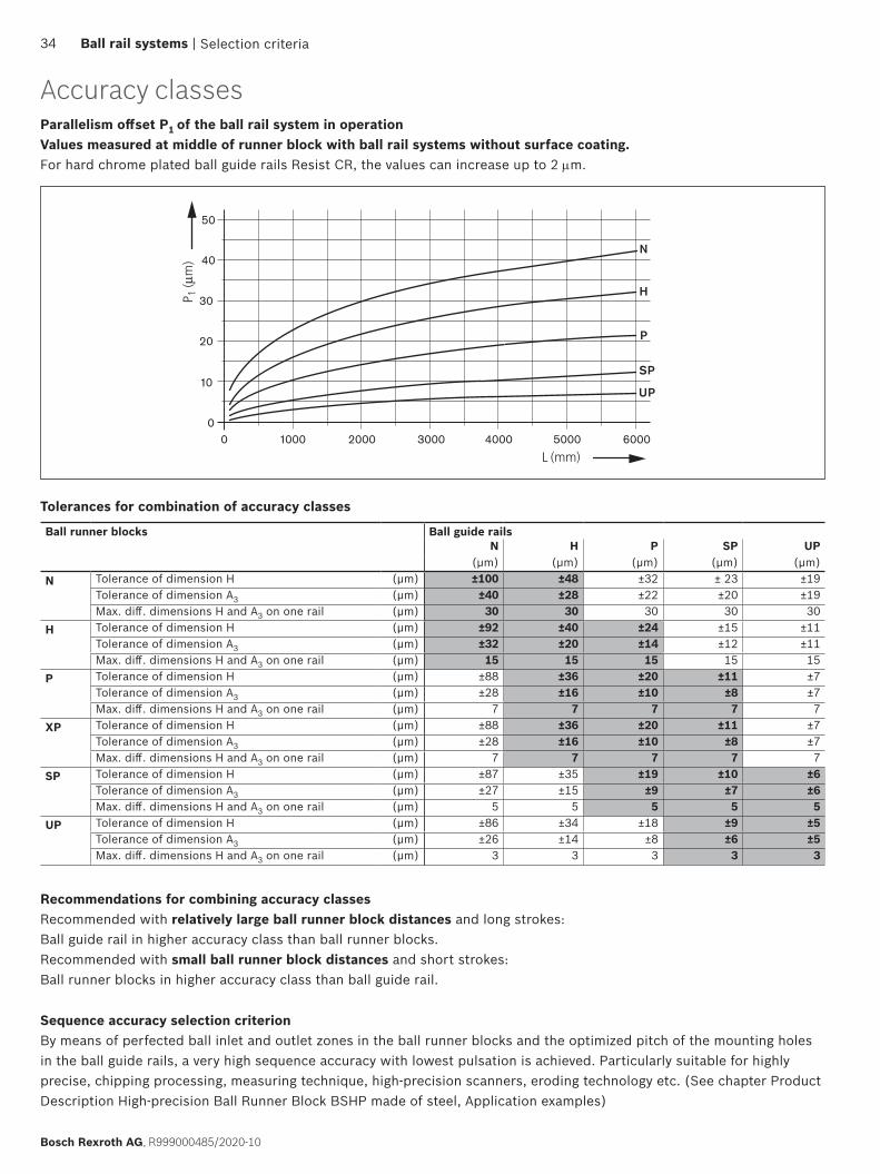
1000 2000 3000 4000 5000
10
20
30
0
40
0
50
6000
H
N
P
SP
UP
Selection criteria
Tolerances for combination of accuracy classes
Recommendations for combining accuracy classesRecommended with relatively large ball runner block distances and long strokes:Ball guide rail in higher accuracy class than ball runner blocks.Recommended with small ball runner block distances and short strokes:Ball runner blocks in higher accuracy class than ball guide rail.
Sequence accuracy selection criterionBy means of perfected ball inlet and outlet zones in the ball runner blocks and the optimized pitch of the mounting holes in the ball guide rails, a very high sequence accuracy with lowest pulsation is achieved. Particularly suitable for highly precise, chipping processing, measuring technique, high-precision scanners, eroding technology etc. (See chapter Product Description High-precision Ball Runner Block BSHP made of steel, Application examples)
Ball runner blocks Ball guide railsN H P SP UP
(μm) (μm) (μm) (μm) (μm)N Tolerance of dimension H (μm) ±100 ±48 ±32 ± 23 ±19
Tolerance of dimension A3 (μm) ±40 ±28 ±22 ±20 ±19Max. diff. dimensions H and A3 on one rail (μm) 30 30 30 30 30
H Tolerance of dimension H (μm) ±92 ±40 ±24 ±15 ±11Tolerance of dimension A3 (μm) ±32 ±20 ±14 ±12 ±11Max. diff. dimensions H and A3 on one rail (μm) 15 15 15 15 15
P Tolerance of dimension H (μm) ±88 ±36 ±20 ±11 ±7Tolerance of dimension A3 (μm) ±28 ±16 ±10 ±8 ±7Max. diff. dimensions H and A3 on one rail (μm) 7 7 7 7 7
XP Tolerance of dimension H (μm) ±88 ±36 ±20 ±11 ±7Tolerance of dimension A3 (μm) ±28 ±16 ±10 ±8 ±7Max. diff. dimensions H and A3 on one rail (μm) 7 7 7 7 7
SP Tolerance of dimension H (μm) ±87 ±35 ±19 ±10 ±6Tolerance of dimension A3 (μm) ±27 ±15 ±9 ±7 ±6Max. diff. dimensions H and A3 on one rail (μm) 5 5 5 5 5
UP Tolerance of dimension H (μm) ±86 ±34 ±18 ±9 ±5Tolerance of dimension A3 (μm) ±26 ±14 ±8 ±6 ±5Max. diff. dimensions H and A3 on one rail (μm) 3 3 3 3 3
Parallelism offset P1 of the ball rail system in operationValues measured at middle of runner block with ball rail systems without surface coating.For hard chrome plated ball guide rails Resist CR, the values can increase up to 2 µm.
Accuracy classes
34 Ball rail systems |
Bosch Rexroth AG, R999000485/2020-10

2
LS SS DS
1
SS
DS
LS
The sealing plate on the front side (2) protects the interior of the ball runner block against dirt, chips and fluids. Additionally, it prevents the discharge of lubricant. Due to the optimized form of the sealing lips, the occurring friction is reduced to a minimum. Sealing plates are optionally available with black standard seals (SS), beige low-friction seals (LS) or green double-lip seals (DS).Low-friction seal (LS) (seal with very low friction)For special requirements with regard to ease of movement and reduced lubricant application, the low-friction seal has been developed. It consists of an open-pored polyurethane foam and features only limited wiping action.Standard seal (SS) (universal sealing with good sealing effect)For most application cases, the standard seal is suitable. It comprises of a good wiping action but also enables long relubrication intervals.Double-lip seal (DS) (sealing with very good sealing effect)For applications in which the rail guide is heavily charged with chips, wood dust, cooling lubricants etc., Rexroth recommends the double-lip sealing. It comprises an excellent wiping action but a greater friction force and lower relubrication interval.Sealing effect and displacement resistanceThe displacement resistance can be impacted by the geometry and the material. The diagram shows the effects of different sealing versions on the sealing effect and the displacement resistance.
Seals
Less preload More preload
Ball chainRexroth recommends the ball chain especially for applications where a low noise level is required.
Ball runner blocks including ball chain (1) are available as an option. The ball chain prevents the balls from colliding with each other and helps to achieve a calmer and smoother running. A lower noise level is achieved. Due to the smaller number of load-bearing balls in the ball runner block with ball chain, lower load ratings and load moments can result (“Product overview with load ratings and load moments”).
Ball runner block including ball chain
Dis
plac
emen
t re
sist
ance
(N
)
Sealing effect
Selection criteria | Ball rail systems 35
R999000485/2020-10, Bosch Rexroth AG
MaterialsRexroth offers ball runner blocks made of different materials for the different requirements in the various applications.
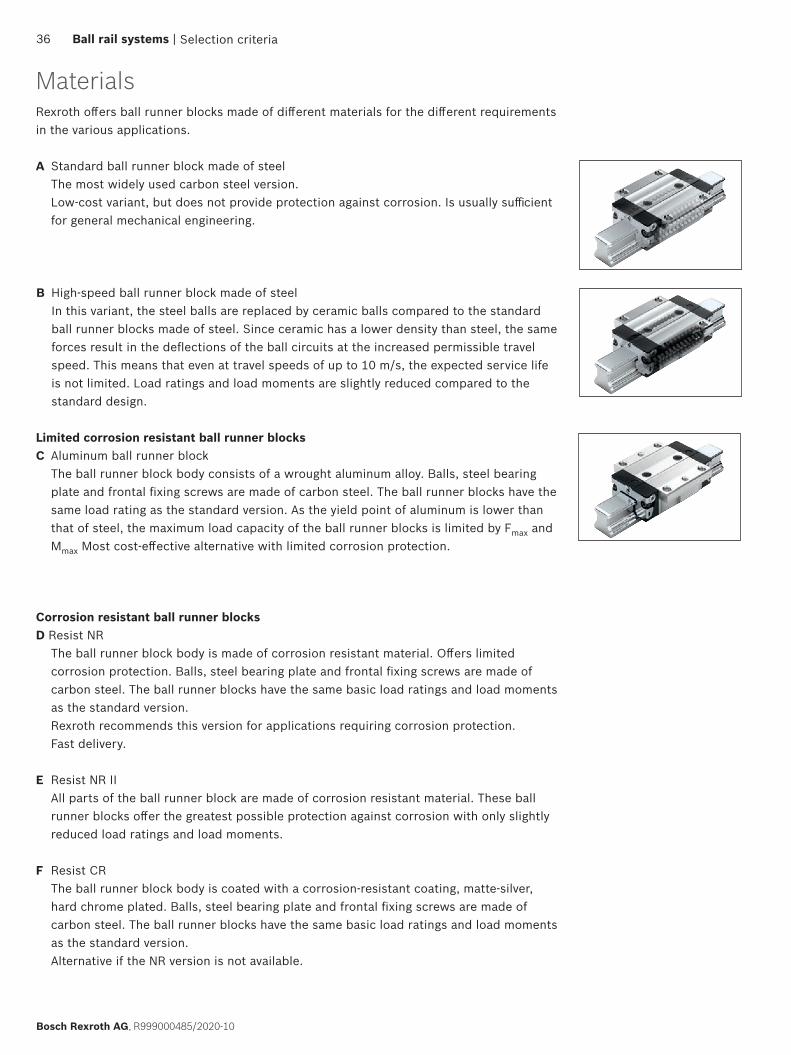
A Standard ball runner block made of steel The most widely used carbon steel version. Low-cost variant, but does not provide protection against corrosion. Is usually sufficient for general mechanical engineering.
Limited corrosion resistant ball runner blocksC Aluminum ball runner block
The ball runner block body consists of a wrought aluminum alloy. Balls, steel bearing plate and frontal fixing screws are made of carbon steel. The ball runner blocks have the same load rating as the standard version. As the yield point of aluminum is lower than that of steel, the maximum load capacity of the ball runner blocks is limited by Fmax and Mmax Most cost-effective alternative with limited corrosion protection.
B High-speed ball runner block made of steel In this variant, the steel balls are replaced by ceramic balls compared to the standard ball runner blocks made of steel. Since ceramic has a lower density than steel, the same forces result in the deflections of the ball circuits at the increased permissible travel speed. This means that even at travel speeds of up to 10 m/s, the expected service life is not limited. Load ratings and load moments are slightly reduced compared to the standard design.
Corrosion resistant ball runner blocksD Resist NR
The ball runner block body is made of corrosion resistant material. Offers limited corrosion protection. Balls, steel bearing plate and frontal fixing screws are made of carbon steel. The ball runner blocks have the same basic load ratings and load moments as the standard version. Rexroth recommends this version for applications requiring corrosion protection. Fast delivery.
E Resist NR II All parts of the ball runner block are made of corrosion resistant material. These ball runner blocks offer the greatest possible protection against corrosion with only slightly reduced load ratings and load moments.
F Resist CR The ball runner block body is coated with a corrosion-resistant coating, matte-silver, hard chrome plated. Balls, steel bearing plate and frontal fixing screws are made of carbon steel. The ball runner blocks have the same basic load ratings and load moments as the standard version. Alternative if the NR version is not available.
Selection criteria36 Ball rail systems |
Bosch Rexroth AG, R999000485/2020-10
1
2
5
4
6
7
8
9 3
1110
12
13
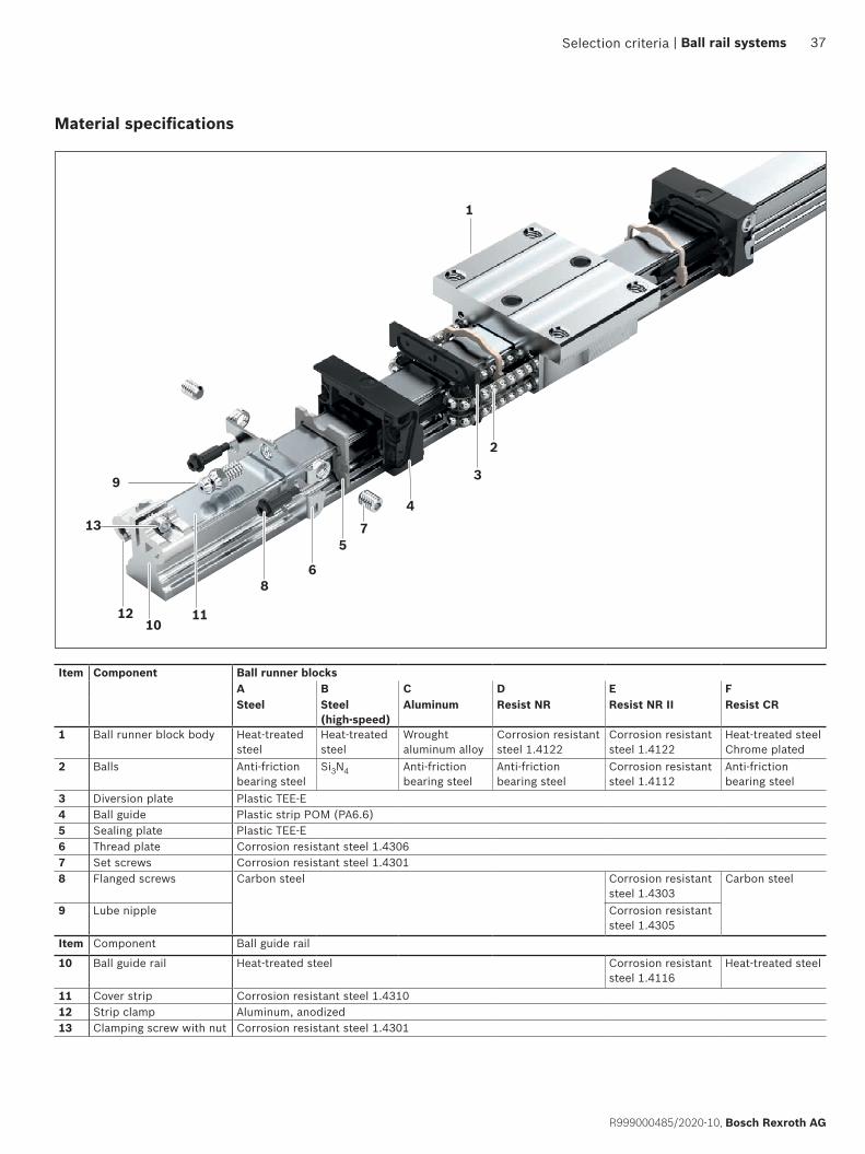
Material specifications
Item Component Ball runner blocksA B C D E FSteel Steel
(high-speed)Aluminum Resist NR Resist NR II Resist CR
1 Ball runner block body Heat-treated steel
Heat-treated steel
Wrought aluminum alloy
Corrosion resistant steel 1.4122
Corrosion resistant steel 1.4122
Heat-treated steel Chrome plated
2 Balls Anti-friction bearing steel
Si3N4 Anti-friction bearing steel
Anti-friction bearing steel
Corrosion resistant steel 1.4112
Anti-friction bearing steel
3 Diversion plate Plastic TEE-E4 Ball guide Plastic strip POM (PA6.6)5 Sealing plate Plastic TEE-E6 Thread plate Corrosion resistant steel 1.43067 Set screws Corrosion resistant steel 1.43018 Flanged screws Carbon steel Corrosion resistant
steel 1.4303Carbon steel
9 Lube nipple Corrosion resistant steel 1.4305
Item Component Ball guide rail
10 Ball guide rail Heat-treated steel Corrosion resistant steel 1.4116
Heat-treated steel
11 Cover strip Corrosion resistant steel 1.431012 Strip clamp Aluminum, anodized13 Clamping screw with nut Corrosion resistant steel 1.4301
Selection criteria | Ball rail systems 37
R999000485/2020-10, Bosch Rexroth AG

Characteristic features
▶ The same high load ratings in all four main directions of loading
▶ Low noise level and outstanding travel behavior ▶ Excellent dynamic characteristics:
Travel speed: vmax = 5 m/s Acceleration: amax = 500 m/s2
▶ Long-term lubrication is possible over several years ▶ Minimum quantity lubrication system with integrated
reservoir for oil lubrication1)
▶ Lube fittings with metal threads on all sides1)
▶ Limitless interchangeability as all ball guide rail systems can be combined at will with all ball runner block versions within each accuracy class.
▶ Maximum system rigidity due to preloaded O-arrangement
▶ Optional integrated, inductive and wear-free measuring system
▶ First-class logistics unique worldwide thanks to universal interchangeability of the components within any accuracy class
▶ Attachments on the ball runner block can be mounted from above and below1)
▶ Improved rigidity under lift-off and side loading conditions due to two additional mounting screw holes at the center of the ball runner block1)
▶ Wide range of accessories ▶ End-face fastening thread for all attachments
Further highlights
▶ High rigidity in all load directions – permits applications with just one runner block per rail
▶ Integrated all-round sealing ▶ High torque load capacity ▶ Optimized entry-zone geometry and high number of
balls minimize variation in elastic deflection ▶ Quiet, smooth running thanks to optimally designed
ball and ball chain return and guideway ▶ Different preload classes ▶ Ball runner block pre-lubricated at the factory1)
▶ Optionally available with ball chain1)
Corrosion protection (optional)1)
▶ Resist NR: Ball runner block body made of corrosion resistant steel as per DIN EN 10088
▶ Resist NR II: Ball runner block body and ball guide rail as well as all steel parts made of corrosion resistant steel in accordance with DIN EN 10088
▶ Resist CR: Ball runner block body or ball guide rail made of steel with corrosion resistant coating, matte-silver finish, hard chrome plated
Ball rail system with steel ball runner block FNS(components and assembly)
Product description High-precision Ball Runner Block BSHP made of steel
Product description
1) Type-dependent
38 Ball rail systems |
Bosch Rexroth AG, R999000485/2020-10
1
2
3
Comparison
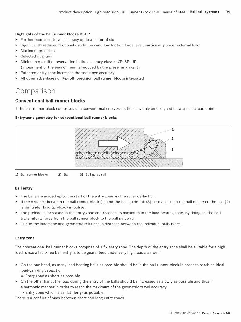
Ball entry
▶ The balls are guided up to the start of the entry zone via the roller deflection. ▶ If the distance between the ball runner block (1) and the ball guide rail (3) is smaller than the ball diameter, the ball (2)
is put under load (preload) in pulses. ▶ The preload is increased in the entry zone and reaches its maximum in the load bearing zone. By doing so, the ball
transmits its force from the ball runner block to the ball guide rail. ▶ Due to the kinematic and geometric relations, a distance between the individual balls is set.
Entry-zone geometry for conventional ball runner blocks
1) Ball runner blocks
Conventional ball runner blocksIf the ball runner block comprises of a conventional entry zone, this may only be designed for a specific load point.
Entry zone
The conventional ball runner blocks comprise of a fix entry zone. The depth of the entry zone shall be suitable for a high load, since a fault-free ball entry is to be guaranteed under very high loads, as well.
▶ On the one hand, as many load-bearing balls as possible should be in the ball runner block in order to reach an ideal load-carrying capacity. ⇒ Entry zone as short as possible
▶ On the other hand, the load during the entry of the balls should be increased as slowly as possible and thus in a harmonic manner in order to reach the maximum of the geometric travel accuracy. ⇒ Entry zone which is as flat (long) as possible
There is a conflict of aims between short and long entry zones.
Highlights of the ball runner blocks BSHP ▶ Further increased travel accuracy up to a factor of six ▶ Significantly reduced frictional oscillations and low friction force level, particularly under external load ▶ Maximum precision ▶ Selected qualities ▶ Minimum quantity preservation in the accuracy classes XP; SP; UP.
(Impairment of the environment is reduced by the preserving agent) ▶ Patented entry zone increases the sequence accuracy ▶ All other advantages of Rexroth precision ball runner blocks integrated
Product description High-precision Ball Runner Block BSHP made of steel
2) Ball 3) Ball guide rail
| Ball rail systems 39
R999000485/2020-10, Bosch Rexroth AG
2
3
1
567 4
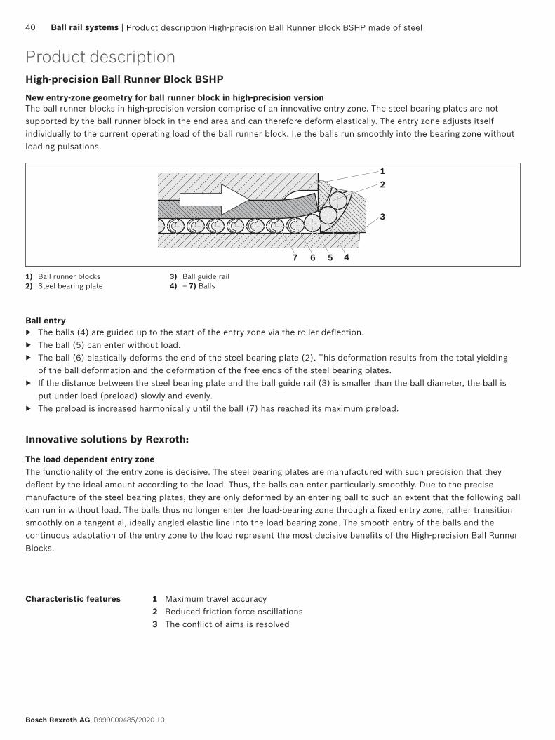
New entry-zone geometry for ball runner block in high-precision versionThe ball runner blocks in high-precision version comprise of an innovative entry zone. The steel bearing plates are not supported by the ball runner block in the end area and can therefore deform elastically. The entry zone adjusts itself individually to the current operating load of the ball runner block. I.e the balls run smoothly into the bearing zone without loading pulsations.
1) Ball runner blocks2) Steel bearing plate
Innovative solutions by Rexroth:
Characteristic features 1 Maximum travel accuracy2 Reduced friction force oscillations3 The conflict of aims is resolved
The load dependent entry zone The functionality of the entry zone is decisive. The steel bearing plates are manufactured with such precision that they deflect by the ideal amount according to the load. Thus, the balls can enter particularly smoothly. Due to the precise manufacture of the steel bearing plates, they are only deformed by an entering ball to such an extent that the following ball can run in without load. The balls thus no longer enter the load-bearing zone through a fixed entry zone, rather transition smoothly on a tangential, ideally angled elastic line into the load-bearing zone. The smooth entry of the balls and the continuous adaptation of the entry zone to the load represent the most decisive benefits of the High-precision Ball Runner Blocks.
3) Ball guide rail4) – 7) Balls
Ball entry ▶ The balls (4) are guided up to the start of the entry zone via the roller deflection. ▶ The ball (5) can enter without load. ▶ The ball (6) elastically deforms the end of the steel bearing plate (2). This deformation results from the total yielding
of the ball deformation and the deformation of the free ends of the steel bearing plates. ▶ If the distance between the steel bearing plate and the ball guide rail (3) is smaller than the ball diameter, the ball is
put under load (preload) slowly and evenly. ▶ The preload is increased harmonically until the ball (7) has reached its maximum preload.
High-precision Ball Runner Block BSHP
Product description High-precision Ball Runner Block BSHP made of steel
Product description
40 Ball rail systems |
Bosch Rexroth AG, R999000485/2020-10
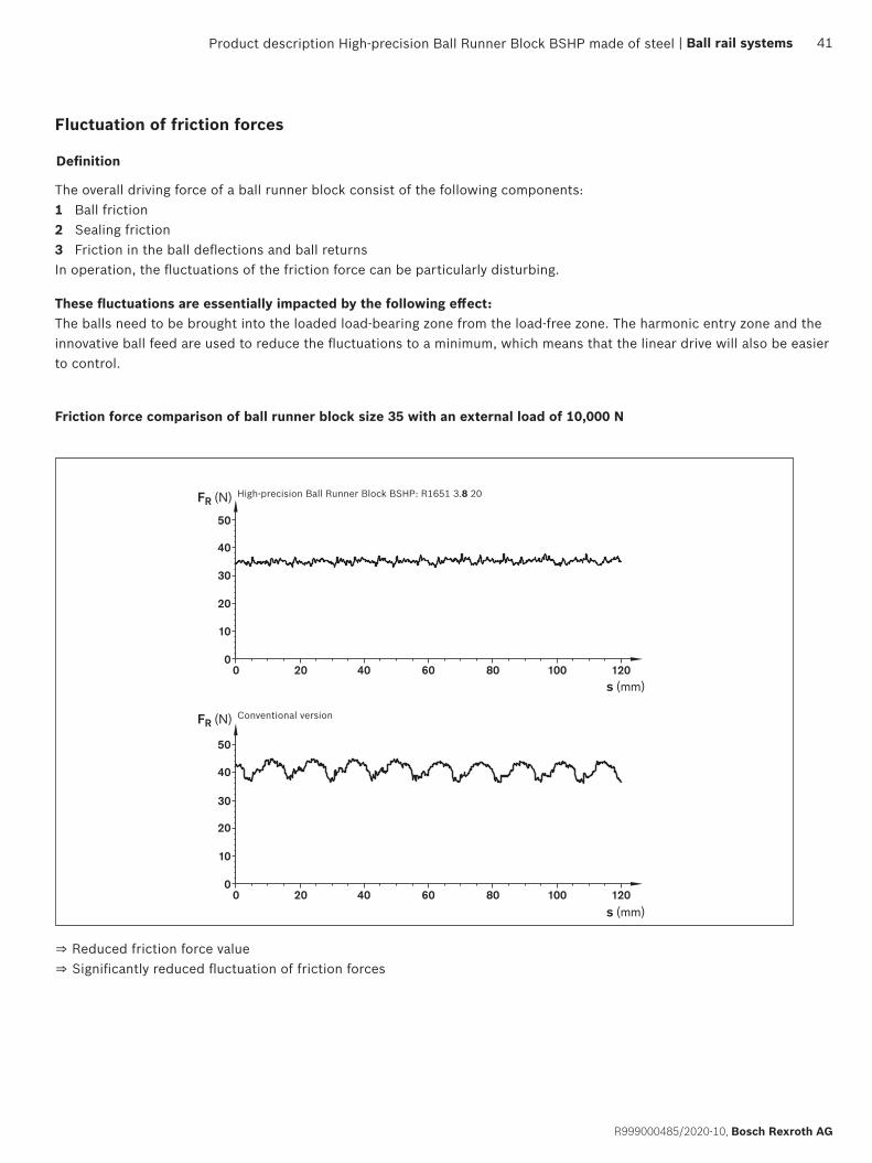
FR (N)
FR (N)
s (mm)
s (mm)
Fluctuation of friction forces
Definition
The overall driving force of a ball runner block consist of the following components:1 Ball friction2 Sealing friction3 Friction in the ball deflections and ball returnsIn operation, the fluctuations of the friction force can be particularly disturbing.
These fluctuations are essentially impacted by the following effect:The balls need to be brought into the loaded load-bearing zone from the load-free zone. The harmonic entry zone and the innovative ball feed are used to reduce the fluctuations to a minimum, which means that the linear drive will also be easier to control.
High-precision Ball Runner Block BSHP: R1651 3.8 20
Conventional version
Friction force comparison of ball runner block size 35 with an external load of 10,000 N
⇒ Reduced friction force value⇒ Significantly reduced fluctuation of friction forces
Product description High-precision Ball Runner Block BSHP made of steel | Ball rail systems 41
R999000485/2020-10, Bosch Rexroth AG

6
4
51Z
Y
X
2
3
Travel accuracy
Definition
In an ideal case, a ball runner block moves transitively in relation to the x-axis over the ball guide rail. In practice, however, deviations occur in all six degrees of freedom. The term travel accuracy describes the deviation from this ideal line.
Six different degrees of freedom1 Height deviation (linear deviation in Z)2 Yaw (rotary motion around Z)3 Side deviation (linear deviation in Y)4 Pitching (rotary motion around Y)5 Translation (linear movement in X)6 Rollers (rotary motion around x)
The Travel inaccuracy is impacted by the following points.1. Inaccurate mounting base on which the ball guide rail is mounted.2. Parallelism error between the contact areas of the ball guide rail and the running tracks.3. Elastic deformations of the ball guide rail by the mounting screws.4. Accuracy fluctuations caused by the balls entering and exiting.
With respect to 1: Contact surfaces of the ball guide rail should be produced as precisely as possible (outside of the scope of influence of Rexroth).With respect to 2: Any deviation should be equalized by the selection of the accuracy class of the ball guide rail.With respect to 3: Reduce the tightening torque. The tightening torque of the fastening screws has a proportional impact. A reduction of the tightening torque decreases the compressive strain of the rail material. ⇒ Lower geometric process fluctuations With respect to 4: The patented, innovative entry zone of Rexroth - High-precision Ball Runner Blocks reduces the speed fluctuations to a minimum.
Causes of travel inaccuracy
Potential for optimization
Further potential for improvement:
▶ Use of long ball runner blocks ▶ Installation of additional ball runner blocks per ball guide rail.
With this measure, the transferable forces and moments can be reduced.
Product description
Product description High-precision Ball Runner Block BSHP made of steel42 Ball rail systems |
Bosch Rexroth AG, R999000485/2020-10

Lever arm
Lever arm
The measured deviations have the following cause
A ball circulation contains a number n of supporting balls which are under load. If the ball runner block is moved into the direction of travel, via the entry zone, a new ball enters the load-bearing zone and n + 1 balls are supporting. This disturbs the internal balance of the four supporting rows of balls. The ball runner block enters a rotational movement since the balls can arbitrarily enter the supporting rows of balls. In order to restore the balance, the ball runner block is moving into a new balance position. If the ball runner block is moved further, a supporting ball exits the load-bearing zone at the ball exit. Thus, the internal balance of the four supporting rows of balls is disturbed again and the ball runner block enters a rotational movement. This effect can be clearly seen in the diagram on the next page.
As it has been verified in practical applications, the period of short-wave inaccuracies roughly corresponds to twice the ball diameter. The remaining long-wave deviation is caused by the described causes 1, 2 and 3 (inaccurate support, parallelism errors and elastic deformation of the ball guide rail due to the mounting screws).
Force distribution in the ball runner block
Product description High-precision Ball Runner Block BSHP made of steel | Ball rail systems 43
R999000485/2020-10, Bosch Rexroth AG
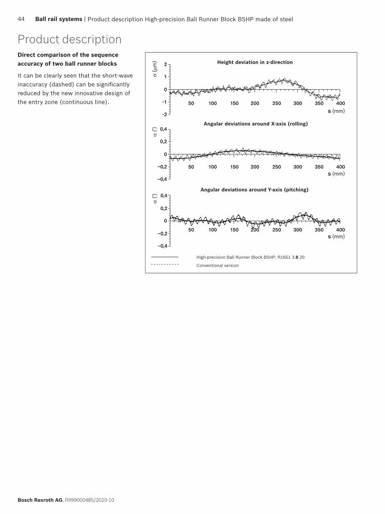
α (’
)σ
(µm
)α
(’)
s (mm)
s (mm)
s (mm)
Height deviation in z-direction
Angular deviations around X-axis (rolling)
Angular deviations around Y-axis (pitching)
High-precision Ball Runner Block BSHP: R1651 3.8 20
Conventional version
It can be clearly seen that the short-wave inaccuracy (dashed) can be significantly reduced by the new innovative design of the entry zone (continuous line).
Direct comparison of the sequence accuracy of two ball runner blocks
Product description
Product description High-precision Ball Runner Block BSHP made of steel44 Ball rail systems |
Bosch Rexroth AG, R999000485/2020-10

Rexroth high-precision ball runner blocks are particularly suited for the following applications:
Application examples
3D Coordinate Measuring Machine
Contour measurement
Internal cylindrical grinding
Wire electrical discharge machining
Grinding a fit bore
Electrical discharge machining of die plate
Hard milling
High-precision turning
Printed board mounting machine
Milling a mold insert
Turning optical lenses made from plastic
Equipping a printed board
Measuring
Grinding
Electrical discharge machining
Milling
Turning
Microelectronics
These are only a few examples. Naturally, other applications can be realized. Feel free to ask any questions that you may have. We have an appropriate solution.
Product description High-precision Ball Runner Block BSHP made of steel | Ball rail systems 45
R999000485/2020-10, Bosch Rexroth AG
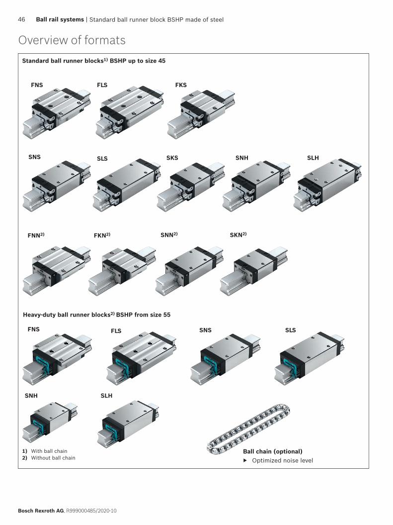
FNS SNS SLSFLS
SNH SLH
SNS SNH
FNS
SLH
FLS
SLS SKS
FKS
FNN2) SNN2)FKN2) SKN2)
Standard ball runner blocks1) BSHP up to size 45
Heavy-duty ball runner blocks2) BSHP from size 55
Ball chain (optional) ▶ Optimized noise level
1) With ball chain2) Without ball chain
Overview of formats
Standard ball runner block BSHP made of steel46 Ball rail systems |
Bosch Rexroth AG, R999000485/2020-10
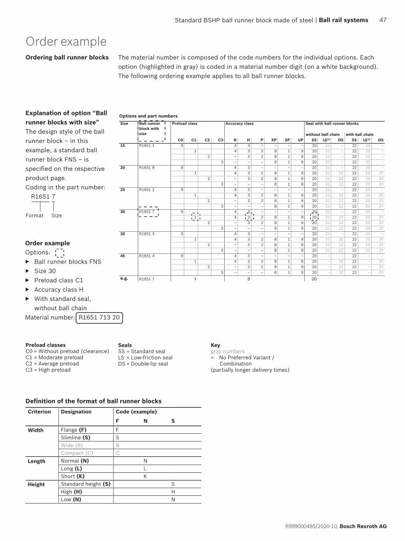
Standard steel ball runner blocks BSHP
Dynamic characteristicsTravel speed: vmax = 5 m/sAcceleration: amax = 500 m/s2
(If Fcomb 2.8 · Fpr : amax = 50 m/s2)
Note on lubrication ▶ Pre-lubricated
NoteFor all SNS/SNO ball guide rails.
Preload classesC0 = Without preload
(clearance)C1 = Moderate preloadC2 = Average preloadC3 = High preload
SealsSS = standard sealLS = low-friction sealDS = double-lipped seal
Size Ball runner block with size
skcolb rennur llab htiw laeSssalc ycaruccAssalc daolerP
without ball chain with ball chainC0 C1 C2 C3 N H P XP SP UP SS LS1) DS SS LS1) DS
15 R1651 1 9 4 3 – – – – 20 21 – 22 23 –1 4 3 2 8 1 9 20 21 – 22 23 –
2 – 3 2 8 1 9 20 21 – 22 23 –3 – – – 8 1 9 20 21 – 22 23 –
20 R1651 8 9 4 3 – – – – 20 21 – 22 23 –1 4 3 2 8 1 9 20 21 2Z 22 23 2Y
2 – 3 2 8 1 9 20 21 2Z 22 23 2Y3 – – – 8 1 9 20 21 2Z 22 23 2Y
25 R1651 2 9 4 3 – – – – 20 21 – 22 23 –1 4 3 2 8 1 9 20 21 2Z 22 23 2Y
2 – 3 2 8 1 9 20 21 2Z 22 23 2Y3 – – – 8 1 9 20 21 2Z 22 23 2Y
30 R1651 7 9 4 3 – – – – 20 21 – 22 23 –1 4 3 2 8 1 9 20 21 2Z 22 23 2Y
2 – 3 2 8 1 9 20 21 2Z 22 23 2Y3 – – – 8 1 9 20 21 2Z 22 23 2Y
35 R1651 3 9 4 3 – – – – 20 21 – 22 23 –1 4 3 2 8 1 9 20 21 2Z 22 23 2Y
2 – 3 2 8 1 9 20 21 2Z 22 23 2Y3 – – – 8 1 9 20 21 2Z 22 23 2Y
45 R1651 4 9 4 3 – – – – 20 – – 22 – –1 4 3 2 8 1 9 20 – 2Z 22 – 2Y
2 – 3 2 8 1 9 20 – 2Z 22 – 2Y3 – – – 8 1 9 20 – 2Z 22 – 2Y
e.g. R1651 7 0231
Order exampleOptions:
▶ FNS ball runner block ▶ Size 30 ▶ Preload class C1 ▶ Accuracy class H ▶ With standard seal,
without ball chainPart number: R1651 713 20
1) With accuracy classes N and H and XP in preload class C1 only.
KeyGray digits= No preferred variant/
combination(Some delivery times may be longer)
FNS – Flange, normal, standard height
Options and part numbers
R1651 ... 2.
48 Ball Rail Systems |
Bosch Rexroth AG, R999000485 (2014-12)
Order exampleOrdering ball runner blocks The material number is composed of the code numbers for the individual options. Each
option (highlighted in gray) is coded in a material number digit (on a white background).The following ordering example applies to all ball runner blocks.
Order exampleOptions:
▶ Ball runner blocks FNS ▶ Size 30 ▶ Preload class C1 ▶ Accuracy class H ▶ With standard seal,
without ball chainMaterial number: R1651 713 20
Explanation of option “Ball runner blocks with size”The design style of the ball runner block – in this example, a standard ball runner block FNS – is specified on the respective product page.Coding in the part number: R1651 7
Format Size
Standard BSHP ball runner block made of steel
Preload classesC0 = Without preload (clearance)C1 = Moderate preloadC2 = Average preloadC3 = High preload
SealsSS = Standard sealLS = Low-friction sealDS = Double-lip seal
Keygray numbers= No Preferred Variant /
Combination(partially longer delivery times)
| Ball rail systems 47
R999000485/2020-10, Bosch Rexroth AG
Definition of the format of ball runner blocksCriterion Designation Code (example)
F N S
Width Flange (F) FSlimline (S) SWide (B) BCompact (C) C
Length Normal (N) NLong (L) LShort (K) K
Height Standard height (S) SHigh (H) HLow (N) N
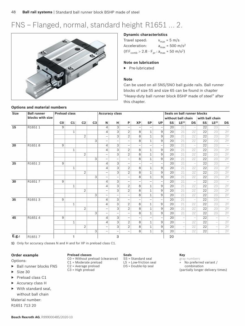
Standard ball runner block BSHP made of steel
Dynamic characteristicsTravel speed: vmax = 5 m/sAcceleration: amax = 500 m/s2
(If Fcomb > 2.8 · Fpr : amax = 50 m/s2)
Note on lubrication ▶ Pre-lubricated
NoteCan be used on all SNS/SNO ball guide rails. Ball runner blocks of size 55 and size 65 can be found in chapter “Heavy-duty ball runner block BSHP made of steel” after this chapter.
Preload classesC0 = Without preload (clearance)C1 = Moderate preloadC2 = Average preloadC3 = High preload
SealsSS = Standard sealLS = Low-friction sealDS = Double-lip seal
Size Ball runner blocks with size
Preload class Accuracy class Seals on ball runner blockswithout ball chain with ball chain
C0 C1 C2 C3 N H P XP SP UP SS LS1) DS SS LS1) DS15 R1651 1 9 4 3 – – – – 20 21 – 22 23 –
1 4 3 2 8 1 9 20 21 2Z 22 23 2Y2 – 3 2 8 1 9 20 21 2Z 22 23 2Y
3 – – – 8 1 9 20 21 2Z 22 23 2Y20 R1651 8 9 4 3 – – – – 20 21 – 22 23 –
1 4 3 2 8 1 9 20 21 2Z 22 23 2Y2 – 3 2 8 1 9 20 21 2Z 22 23 2Y
3 – – – 8 1 9 20 21 2Z 22 23 2Y25 R1651 2 9 4 3 – – – – 20 21 – 22 23 –
1 4 3 2 8 1 9 20 21 2Z 22 23 2Y2 – 3 2 8 1 9 20 21 2Z 22 23 2Y
3 – – – 8 1 9 20 21 2Z 22 23 2Y30 R1651 7 9 4 3 – – – – 20 21 – 22 23 –
1 4 3 2 8 1 9 20 21 2Z 22 23 2Y2 – 3 2 8 1 9 20 21 2Z 22 23 2Y
3 – – – 8 1 9 20 21 2Z 22 23 2Y35 R1651 3 9 4 3 – – – – 20 21 – 22 23 –
1 4 3 2 8 1 9 20 21 2Z 22 23 2Y2 – 3 2 8 1 9 20 21 2Z 22 23 2Y
3 – – – 8 1 9 20 21 2Z 22 23 2Y45 R1651 4 9 4 3 – – – – 20 – – 22 – –
1 4 3 2 8 1 9 20 – 2Z 22 – 2Y2 – 3 2 8 1 9 20 – 2Z 22 – 2Y
3 – – – 8 1 9 20 – 2Z 22 – 2YE.g.: R1651 7 1 3 20
Order exampleOptions:
▶ Ball runner blocks FNS ▶ Size 30 ▶ Preload class C1 ▶ Accuracy class H ▶ With standard seal,
without ball chainMaterial number: R1651 713 20
1) Only for accuracy classes N and H and for XP in preload class C1.
Keygray numbers= No preferred variant /
combination(partially longer delivery times)
FNS – Flanged, normal, standard height
Options and material numbers
R1651 ... 2.
48 Ball rail systems |
Bosch Rexroth AG, R999000485/2020-10

E4
B1 E2
K1
E3
E1
S2S2
AE8
A3 A2
A1
H1
V1 K4
E9
H
K2S9
S1S1K3N2
N1
ØS5
B2
B
H2 N6
T
b)
c)d)
a)
Standard ball runner block BSHP made of steel
Size Dimensions (mm)A A1 A2 A3 B+0.5 B1 E1 E2 E3 E8 E9 H H1 H2
1) H22) K1 K2 K3 K4
15 47 23.5 15 16.0 58.2 39.2 38 30 26 24.55 6.70 24 19.90 16.30 16.20 8.00 9.6 3.20 3.2020 63 31.5 20 21.5 75.0 49.6 53 40 35 32.50 7.30 30 25.35 20.75 20.55 11.80 11.8 3.35 3.3525 70 35.0 23 23.5 86.2 57.8 57 45 40 38.30 11.50 36 29.90 24.45 24.25 12.45 13.6 5.50 5.5030 90 45.0 28 31.0 97.7 67.4 72 52 44 48.40 14.60 42 35.35 28.55 28.35 14.00 15.7 6.05 6.0535 100 50.0 34 33.0 110.5 77.0 82 62 52 58.00 17.35 48 40.40 32.15 31.85 14.50 16.0 6.90 6.9045 120 60.0 45 37.5 137.6 97.0 100 80 60 69.80 20.90 60 50.30 40.15 39.85 17.30 19.3 8.20 8.20
1) Dimension H2 with cover strip2) Dimension H2 without cover strip3) Load ratings and load moments for ball runner block without ball chain. Load ratings and load moments for ball runner block with ball
chain 12 Determination of the dynamic load capacities and load moments is based on a stroke travel of 100,000 m according to DIN ISO 14728-1. Often only 50,000 m are actually stipulated. For comparison: Multiply the values C, Mt and ML by 1.26 according to the table.
Size Dimensions (mm) Mass (kg)
Load capacities3) (N)
Load moments3) (Nm)
N1 N2 N6±0.5 S1 S2 S5 S9 T V1 m C C0 Mt Mt0 ML ML0
15 5.2 4.40 10.3 4.3 M5 4.5 M2.5x3.5 60 5.0 0.20 9860 12700 95 120 68 8720 7.7 5.20 13.2 5.3 M6 6.0 M3x5 60 6.0 0.45 23400 29800 300 380 200 26025 9.3 7.00 15.2 6.7 M8 7.0 M3x5 60 7.5 0.65 28600 35900 410 510 290 36030 11.0 7.90 17.0 8.5 M10 9.0 M3x5 80 7.0 1.10 36500 48100 630 830 440 58035 12.0 10.15 20.5 8.5 M10 9.0 M3x5 80 8.0 1.60 51800 80900 1110 1740 720 113045 15.0 12.40 23.5 10.4 M12 14.0 M4x7 105 10.0 3.00 86400 132000 2330 3560 1540 2350
a) For O-ring Size 15: Ø 4 · 1.0 (mm) Size 20 - 45: Ø 5 · 1.0 (mm) Open lube port if necessary (see section entitled “Lubrication”).
b) Recommended position for pin holes (dimension E4 see chapter Mounting) Pre-drilled holes may be present at this position for manufacturing reasons. They are suitable for drilling out.
c) Lube nipple, size 15 – 20: Funnel-type lube nipple DIN 3405-A, M3x5, B2 = 1.6 mm When using different lube nipples, pay attention to the screw-in depth of 5 mm! Lube nipple, size 25 – 45: Hydraulic-type lube nipple DIN 71412-A M6x8, B2 = 9.5 mm When using different lube nipples, pay attention to the screw-in depth of 8 mm! The lube nipple is included in the scope of delivery (not installed). Connection is possible on all sides.
d) Sealing plugs may be present at this position for manufacturing reasons. Remove before mounting.
| Ball rail systems 49
R999000485/2020-10, Bosch Rexroth AG,

Standard ball runner block BSHP made of steel
Dynamic characteristicsTravel speed: vmax = 5 m/sAcceleration: amax = 500 m/s2
(If Fcomb > 2.8 · Fpr : amax = 50 m/s2)
Note on lubrication ▶ Pre-lubricated
NoteCan be used on all SNS/SNO ball guide rails. Ball runner blocks of size 55 and size 65 can be found in chapter “Heavy-duty ball runner block BSHP made of steel” after this chapter.
FLS – Flanged, long, standard height
1) Only for accuracy classes N and H and for XP in preload class C1.
Size Ball runner blocks with size
Preload class Accuracy class Seals on ball runner blockswithout ball chain with ball chain
C0 C1 C2 C3 N H P XP SP UP SS LS1) DS SS LS1) DS15 R1653 1 9 4 3 – – – – 20 21 – 22 23 –
1 4 3 2 8 1 9 20 21 2Z 22 23 2Y2 – 3 2 8 1 9 20 21 2Z 22 23 2Y
3 – – – 8 1 9 20 21 2Z 22 23 2Y20 R1653 8 9 4 3 – – – – 20 21 – 22 23 –
1 4 3 2 8 1 9 20 21 2Z 22 23 2Y2 – 3 2 8 1 9 20 21 2Z 22 23 2Y
3 – – – 8 1 9 20 21 2Z 22 23 2Y25 R1653 2 9 4 3 – – – – 20 21 – 22 23 –
1 4 3 2 8 1 9 20 21 2Z 22 23 2Y2 – 3 2 8 1 9 20 21 2Z 22 23 2Y
3 – – – 8 1 9 20 21 2Z 22 23 2Y30 R1653 7 9 4 3 – – – – 20 21 – 22 23 –
1 4 3 2 8 1 9 20 21 2Z 22 23 2Y2 – 3 2 8 1 9 20 21 2Z 22 23 2Y
3 – – – 8 1 9 20 21 2Z 22 23 2Y35 R1653 3 9 4 3 – – – – 20 21 – 22 23 –
1 4 3 2 8 1 9 20 21 2Z 22 23 2Y2 – 3 2 8 1 9 20 21 2Z 22 23 2Y
3 – – – 8 1 9 20 21 2Z 22 23 2Y45 R1653 4 9 4 3 – – – – 20 – – 22 – –
1 4 3 2 8 1 9 20 – 2Z 22 – 2Y2 – 3 2 8 1 9 20 – 2Z 22 – 2Y
3 – – – 8 1 9 20 – 2Z 22 – 2Y
E.g.: R1653 7 1 3 20
Options and material numbers
Order exampleOptions:
▶ Ball runner blocks FLS ▶ Size 30 ▶ Preload class C1 ▶ Accuracy class H ▶ With standard seal,
without ball chainMaterial number: R1653 713 20
Preload classesC0 = Without preload (clearance)C1 = Moderate preloadC2 = Average preloadC3 = High preload
SealsSS = Standard sealLS = Low-friction sealDS = Double-lip seal
Keygray numbers= No preferred variant /
combination(partially longer delivery times)
R1653 ... 2.
50 Ball rail systems |
Bosch Rexroth AG, R999000485/2020-10
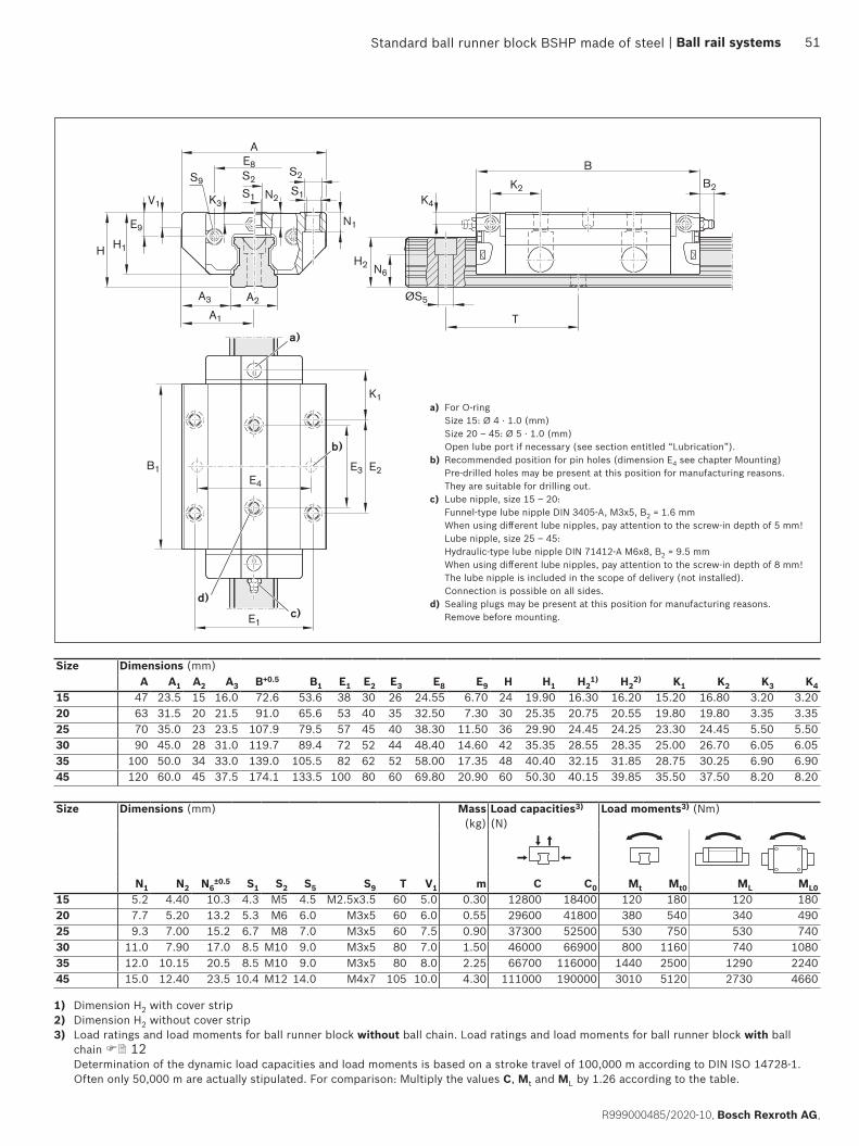
E4
B1 E2
K1
E3
E1
S2S2
AE8
A3 A2
A1
H1
V1 K4
E9
H
K2S9
S1S1K3N2
N1
B2
B
H2 N6
ØS5
T
b)
c)d)
a)
Standard ball runner block BSHP made of steel
Size Dimensions (mm)A A1 A2 A3 B+0.5 B1 E1 E2 E3 E8 E9 H H1 H2
1) H22) K1 K2 K3 K4
15 47 23.5 15 16.0 72.6 53.6 38 30 26 24.55 6.70 24 19.90 16.30 16.20 15.20 16.80 3.20 3.2020 63 31.5 20 21.5 91.0 65.6 53 40 35 32.50 7.30 30 25.35 20.75 20.55 19.80 19.80 3.35 3.3525 70 35.0 23 23.5 107.9 79.5 57 45 40 38.30 11.50 36 29.90 24.45 24.25 23.30 24.45 5.50 5.5030 90 45.0 28 31.0 119.7 89.4 72 52 44 48.40 14.60 42 35.35 28.55 28.35 25.00 26.70 6.05 6.0535 100 50.0 34 33.0 139.0 105.5 82 62 52 58.00 17.35 48 40.40 32.15 31.85 28.75 30.25 6.90 6.9045 120 60.0 45 37.5 174.1 133.5 100 80 60 69.80 20.90 60 50.30 40.15 39.85 35.50 37.50 8.20 8.20
Size Dimensions (mm) Mass (kg)
Load capacities3) (N)
Load moments3) (Nm)
N1 N2 N6±0.5 S1 S2 S5 S9 T V1 m C C0 Mt Mt0 ML ML0
15 5.2 4.40 10.3 4.3 M5 4.5 M2.5x3.5 60 5.0 0.30 12800 18400 120 180 120 18020 7.7 5.20 13.2 5.3 M6 6.0 M3x5 60 6.0 0.55 29600 41800 380 540 340 49025 9.3 7.00 15.2 6.7 M8 7.0 M3x5 60 7.5 0.90 37300 52500 530 750 530 74030 11.0 7.90 17.0 8.5 M10 9.0 M3x5 80 7.0 1.50 46000 66900 800 1160 740 108035 12.0 10.15 20.5 8.5 M10 9.0 M3x5 80 8.0 2.25 66700 116000 1440 2500 1290 224045 15.0 12.40 23.5 10.4 M12 14.0 M4x7 105 10.0 4.30 111000 190000 3010 5120 2730 4660
1) Dimension H2 with cover strip2) Dimension H2 without cover strip3) Load ratings and load moments for ball runner block without ball chain. Load ratings and load moments for ball runner block with ball
chain 12 Determination of the dynamic load capacities and load moments is based on a stroke travel of 100,000 m according to DIN ISO 14728-1. Often only 50,000 m are actually stipulated. For comparison: Multiply the values C, Mt and ML by 1.26 according to the table.
a) For O-ring Size 15: Ø 4 · 1.0 (mm) Size 20 – 45: Ø 5 · 1.0 (mm) Open lube port if necessary (see section entitled “Lubrication”).
b) Recommended position for pin holes (dimension E4 see chapter Mounting) Pre-drilled holes may be present at this position for manufacturing reasons. They are suitable for drilling out.
c) Lube nipple, size 15 – 20: Funnel-type lube nipple DIN 3405-A, M3x5, B2 = 1.6 mm When using different lube nipples, pay attention to the screw-in depth of 5 mm! Lube nipple, size 25 – 45: Hydraulic-type lube nipple DIN 71412-A M6x8, B2 = 9.5 mm When using different lube nipples, pay attention to the screw-in depth of 8 mm! The lube nipple is included in the scope of delivery (not installed). Connection is possible on all sides.
d) Sealing plugs may be present at this position for manufacturing reasons. Remove before mounting.
| Ball rail systems 51
R999000485/2020-10, Bosch Rexroth AG,

Standard ball runner block BSHP made of steel
FKS – flange, short, standard heightDynamic characteristicsTravel speed: vmax = 5 m/sAcceleration: amax = 500 m/s2
(If Fcomb > 2.8 · Fpr : amax = 50 m/s2)
Note on lubrication ▶ Pre-lubricated
NoteCan be used on all SNS/SNO ball guide rails.
Size Ball runner blocks with size
Preload class Accuracy class Seals on ball runner blockswithout ball chain with ball chain
C0 C1 N H SS LS DS SS LS DS15 R1665 1 9 4 3 20 21 – 22 23 –
1 4 3 20 21 2Z 22 23 2Y20 R1665 8 9 4 3 20 21 – 22 23 –
1 4 3 20 21 2Z 22 23 2Y25 R1665 2 9 4 3 20 21 – 22 23 –
1 4 3 20 21 2Z 22 23 2Y30 R1665 7 9 4 3 20 21 – 22 23 –
1 4 3 20 21 2Z 22 23 2Y35 R1665 3 9 4 3 20 21 – 22 23 –
1 4 3 20 21 2Z 22 23 2Y
E.g.: R1665 7 1 3 20
Options and material numbers
Order exampleOptions:
▶ Ball runner blocks FKS ▶ Size 30 ▶ Preload class C1 ▶ Accuracy class H ▶ With standard seal,
without ball chainMaterial number: R1665 713 20
Preload classesC0 = Without preload (clearance)C1 = Moderate preload
SealsSS = Standard sealLS = Low-friction sealDS = Double-lip seal
Keygray numbers= No preferred variant /
combination(partially longer delivery times)
R1665 ... 2.
52 Ball rail systems |
Bosch Rexroth AG, R999000485/2020-10

B1
K1
E1
S2
AE8
A3 A2
A1
H1
V1 K4
E9
H
K2S9
S1K3
N1
B2
B
H2 N6
ØS5
T
b)
a)
Standard ball runner block BSHP made of steel
Size Dimensions (mm)A A1 A2 A3 B+0.5 B1 E1 E8 E9 H H1 H2
1) H22) K1 K2 K3 K4
15 47 23.5 15 16.0 44.7 25.7 38 24.55 6.70 24 19.90 16.30 16.20 16.25 17.85 3.20 3.2020 63 31.5 20 21.5 57.3 31.9 53 32.50 7.30 30 25.35 20.75 20.55 22.95 22.95 3.35 3.3525 70 35.0 23 23.5 67.0 38.6 57 38.30 11.50 36 29.90 24.45 24.25 25.35 26.50 5.50 5.5030 90 45.0 28 31.0 75.3 45.0 72 48.40 14.60 42 35.35 28.55 28.35 28.80 30.50 6.05 6.0535 100 50.0 34 33.0 84.9 51.4 82 58.00 17.35 48 40.40 32.15 31.85 32.70 34.20 6.90 6.90
Size Dimensions (mm) Mass (kg)
Load capacities3) (N)
Load moments3) (Nm)
N1 N6±0.5 S1 S2 S5 S9 T V1 m C C0 Mt Mt0 ML ML0
15 5.2 10.3 4.3 M5 4.5 M2.5x3.5 60 5.0 0.15 6720 7340 65 71 29 3220 7.7 13.2 5.3 M6 6.0 M3x5 60 6.0 0.30 15400 16500 200 210 83 8925 9.3 15.2 6.7 M8 7.0 M3x5 60 7.5 0.50 19800 21200 280 300 130 14030 11.0 17.0 8.5 M10 9.0 M3x5 80 7.0 0.80 25600 28900 440 500 200 23035 12.0 20.5 8.5 M10 9.0 M3x5 80 8.0 1.20 36600 49300 790 1060 340 460
a) For O-ring Size 15: Ø 4 · 1.0 (mm) Size 20 – 35: Ø 5 · 1.0 (mm) Open lube port if necessary (see section entitled “Lubrication”).
b) Lube nipple, size 15 – 20: Funnel-type lube nipple DIN 3405-A, M3x5, B2 = 1.6 mm When using different lube nipples, pay attention to the screw-in depth of 5 mm! Lube nipple, size 25 – 35: Hydraulic-type lube nipple DIN 71412-A M6x8, B2 = 9.5 mm When using different lube nipples, pay attention to the screw-in depth of 8 mm! The lube nipple is included in the scope of delivery (not installed). Connection is possible on all sides.
1) Dimension H2 with cover strip2) Dimension H2 without cover strip3) Load ratings and load moments for ball runner block without ball chain. Load ratings and load moments for ball runner block with ball
chain 12 Determination of the dynamic load capacities and load moments is based on a stroke travel of 100,000 m according to DIN ISO 14728-1. Often only 50,000 m are actually stipulated. For comparison: Multiply the values C, Mt and ML by 1.26 according to the table.
| Ball rail systems 53
R999000485/2020-10, Bosch Rexroth AG,

Standard ball runner block BSHP made of steel
SNS – Slimline, normal, standard heightDynamic characteristicsTravel speed: vmax = 5 m/sAcceleration: amax = 500 m/s2
(If Fcomb > 2.8 · Fpr : amax = 50 m/s2)
Note on lubrication ▶ Pre-lubricated
NoteCan be used on all SNS/SNO ball guide rails. Ball runner blocks of size 55 and size 65 can be found in chapter “Heavy-duty ball runner block BSHP made of steel” after this chapter.
1) Only for accuracy classes N and H and for XP in preload class C1.
Size Ball runner blocks with size
Preload class Accuracy class Seals on ball runner blockswithout ball chain with ball chain
C0 C1 C2 C3 N H P XP SS LS1) DS SS LS1) DS15 R1622 1 9 4 3 – – 20 21 – 22 23 –
1 4 3 2 8 20 21 2Z 22 23 2Y2 – 3 2 8 20 21 2Z 22 23 2Y
3 – – – 8 20 21 2Z 22 23 2Y20 R1622 8 9 4 3 – – 20 21 – 22 23 –
1 4 3 2 8 20 21 2Z 22 23 2Y2 – 3 2 8 20 21 2Z 22 23 2Y
3 – – – 8 20 21 2Z 22 23 2Y25 R1622 2 9 4 3 – – 20 21 – 22 23 –
1 4 3 2 8 20 21 2Z 22 23 2Y2 – 3 2 8 20 21 2Z 22 23 2Y
3 – – – 8 20 21 2Z 22 23 2Y30 R1622 7 9 4 3 – – 20 21 – 22 23 –
1 4 3 2 8 20 21 2Z 22 23 2Y2 – 3 2 8 20 21 2Z 22 23 2Y
3 – – – 8 20 21 2Z 22 23 2Y35 R1622 3 9 4 3 – – 20 21 – 22 23 –
1 4 3 2 8 20 21 2Z 22 23 2Y2 – 3 2 8 20 21 2Z 22 23 2Y
3 – – – 8 20 21 2Z 22 23 2Y45 R1622 4 9 4 3 – – 20 – – 22 – –
1 4 3 2 8 20 – 2Z 22 – 2Y2 – 3 2 8 20 – 2Z 22 – 2Y
3 – – – 8 20 – 2Z 22 – 2Y
E.g.: R1622 7 1 3 20
Options and material numbers
Order exampleOptions:
▶ Ball runner blocks SNS ▶ Size 30 ▶ Preload class C1 ▶ Accuracy class H ▶ With standard seal,
without ball chainMaterial number: R1622 713 20
Preload classesC0 = Without preload (clearance)C1 = Moderate preloadC2 = Average preloadC3 = High preload
SealsSS = Standard sealLS = Low-friction sealDS = Double-lip seal
Keygray numbers= No preferred variant /
combination(partially longer delivery times)
R1622 ... 2.
54 Ball rail systems |
Bosch Rexroth AG, R999000485/2020-10

B1 E2
E1
AE8
A3 A2
A1
H1
V1
E9
H
S9S2
K3
N3
B2
B
H2 N6
K4
K2
K1
ØS5
T
a)
b)
Standard ball runner block BSHP made of steel
Size Dimensions (mm)A A1 A2 A3 B+0.5 B1 E1 E2 E8 E9 H H1 H2
1) H22) K1 K2 K3 K4
15 34 17 15 9.5 58.2 39.2 26 26 24.55 6.70 24 19.90 16.30 16.20 10.00 11.60 3.20 3.2020 44 22 20 12.0 75.0 49.6 32 36 32.50 7.30 30 25.35 20.75 20.55 13.80 13.80 3.35 3.3525 48 24 23 12.5 86.2 57.8 35 35 38.30 11.50 36 29.90 24.45 24.25 17.45 18.60 5.50 5.5030 60 30 28 16.0 97.7 67.4 40 40 48.40 14.60 42 35.35 28.55 28.35 20.00 21.70 6.05 6.0535 70 35 34 18.0 110.5 77.0 50 50 58.00 17.35 48 40.40 32.15 31.85 20.50 22.00 6.90 6.9045 86 43 45 20.5 137.6 97.0 60 60 69.80 20.90 60 50.30 40.15 39.85 27.30 29.30 8.20 8.20
Size Dimensions (mm) Mass (kg)
Load capacities3) (N)
Load moments3) (Nm)
N3 N6±0.5 S2 S5 S9 T V1 m C C0 Mt Mt0 ML ML0
15 6.0 10.3 M4 4.5 M2.5x3.5 60 5.0 0.15 9860 12700 95 120 68 8720 7.5 13.2 M5 6.0 M3x5 60 6.0 0.35 23400 29800 300 380 200 26025 9.0 15.2 M6 7.0 M3x5 60 7.5 0.50 28600 35900 410 510 290 36030 12.0 17.0 M8 9.0 M3x5 80 7.0 0.85 36500 48100 630 830 440 58035 13.0 20.5 M8 9.0 M3x5 80 8.0 1.25 51800 80900 1110 1740 720 113045 18.0 23.5 M10 14.0 M4x7 105 10.0 2.40 86400 132000 2330 3560 1540 2350
a) For O-ring Size 15: Ø 4 · 1.0 (mm) Size 20 – 45: Ø 5 · 1.0 (mm) Open lube port if necessary (see section entitled “Lubrication”).
b) Lube nipple, size 15 – 20: Funnel-type lube nipple DIN 3405-A, M3x5, B2 = 1.6 mm When using different lube nipples, pay attention to the screw-in depth of 5 mm! Lube nipple, size 25 – 45: Hydraulic-type lube nipple DIN 71412-A M6x8, B2 = 9.5 mm When using different lube nipples, pay attention to the screw-in depth of 8 mm! The lube nipple is included in the scope of delivery (not installed). Connection is possible on all sides.
1) Dimension H2 with cover strip2) Dimension H2 without cover strip3) Load ratings and load moments for ball runner block without ball chain. Load ratings and load moments for ball runner block with ball
chain 12 Determination of the dynamic load capacities and load moments is based on a stroke travel of 100,000 m according to DIN ISO 14728-1. Often only 50,000 m are actually stipulated. For comparison: Multiply the values C, Mt and ML by 1.26 according to the table.
| Ball rail systems 55
R999000485/2020-10, Bosch Rexroth AG,
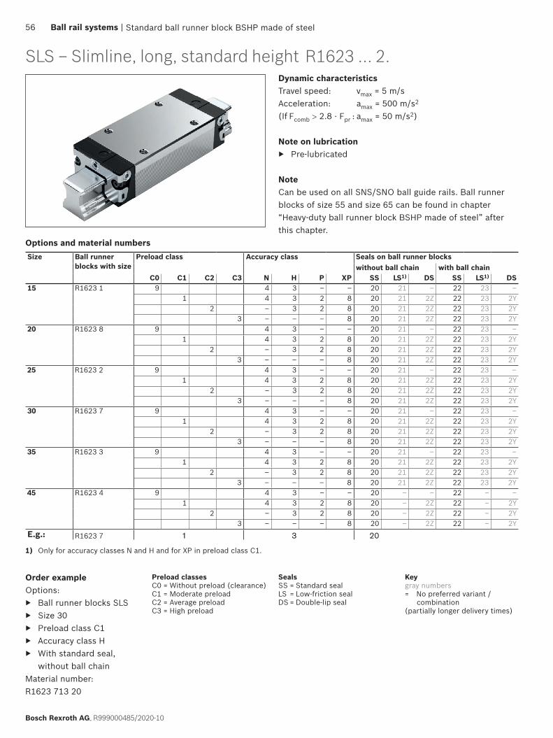
Standard ball runner block BSHP made of steel
SLS – Slimline, long, standard heightDynamic characteristicsTravel speed: vmax = 5 m/sAcceleration: amax = 500 m/s2
(If Fcomb > 2.8 · Fpr : amax = 50 m/s2)
Note on lubrication ▶ Pre-lubricated
NoteCan be used on all SNS/SNO ball guide rails. Ball runner blocks of size 55 and size 65 can be found in chapter “Heavy-duty ball runner block BSHP made of steel” after this chapter.
Order exampleOptions:
▶ Ball runner blocks SLS ▶ Size 30 ▶ Preload class C1 ▶ Accuracy class H ▶ With standard seal,
without ball chainMaterial number: R1623 713 20
1) Only for accuracy classes N and H and for XP in preload class C1.
Size Ball runner blocks with size
Preload class Accuracy class Seals on ball runner blockswithout ball chain with ball chain
C0 C1 C2 C3 N H P XP SS LS1) DS SS LS1) DS15 R1623 1 9 4 3 – – 20 21 – 22 23 –
1 4 3 2 8 20 21 2Z 22 23 2Y2 – 3 2 8 20 21 2Z 22 23 2Y
3 – – – 8 20 21 2Z 22 23 2Y20 R1623 8 9 4 3 – – 20 21 – 22 23 –
1 4 3 2 8 20 21 2Z 22 23 2Y2 – 3 2 8 20 21 2Z 22 23 2Y
3 – – – 8 20 21 2Z 22 23 2Y25 R1623 2 9 4 3 – – 20 21 – 22 23 –
1 4 3 2 8 20 21 2Z 22 23 2Y2 – 3 2 8 20 21 2Z 22 23 2Y
3 – – – 8 20 21 2Z 22 23 2Y30 R1623 7 9 4 3 – – 20 21 – 22 23 –
1 4 3 2 8 20 21 2Z 22 23 2Y2 – 3 2 8 20 21 2Z 22 23 2Y
3 – – – 8 20 21 2Z 22 23 2Y35 R1623 3 9 4 3 – – 20 21 – 22 23 –
1 4 3 2 8 20 21 2Z 22 23 2Y2 – 3 2 8 20 21 2Z 22 23 2Y
3 – – – 8 20 21 2Z 22 23 2Y45 R1623 4 9 4 3 – – 20 – – 22 – –
1 4 3 2 8 20 – 2Z 22 – 2Y2 – 3 2 8 20 – 2Z 22 – 2Y
3 – – – 8 20 – 2Z 22 – 2YE.g.: R1623 7 1 3 20
Options and material numbers
R1623 ... 2.
Preload classesC0 = Without preload (clearance)C1 = Moderate preloadC2 = Average preloadC3 = High preload
SealsSS = Standard sealLS = Low-friction sealDS = Double-lip seal
Keygray numbers= No preferred variant /
combination(partially longer delivery times)
56 Ball rail systems |
Bosch Rexroth AG, R999000485/2020-10
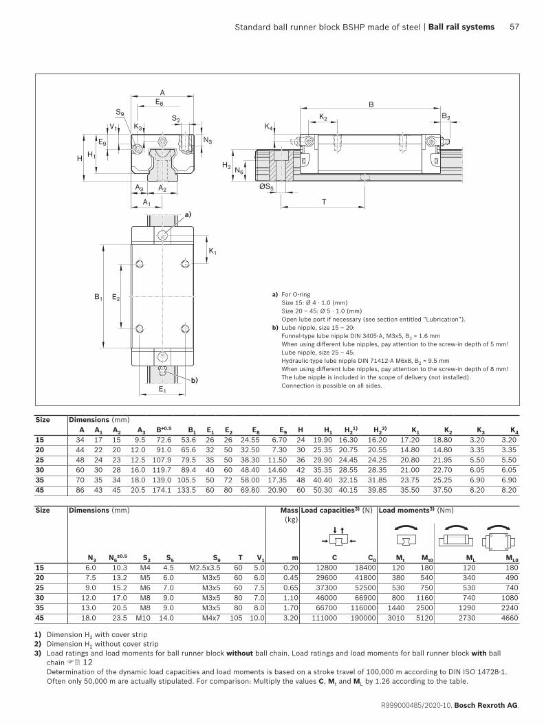
B1 E2
E1
ØS5
B2
B
H2 N6
K4
K2
K1
T
AE8
A3 A2
A1
H1
V1
E9
H
S9S2
K3
N3
a)
b)
Standard ball runner block BSHP made of steel
Size Dimensions (mm)A A1 A2 A3 B+0.5 B1 E1 E2 E8 E9 H H1 H2
1) H22) K1 K2 K3 K4
15 34 17 15 9.5 72.6 53.6 26 26 24.55 6.70 24 19.90 16.30 16.20 17.20 18.80 3.20 3.2020 44 22 20 12.0 91.0 65.6 32 50 32.50 7.30 30 25.35 20.75 20.55 14.80 14.80 3.35 3.3525 48 24 23 12.5 107.9 79.5 35 50 38.30 11.50 36 29.90 24.45 24.25 20.80 21.95 5.50 5.5030 60 30 28 16.0 119.7 89.4 40 60 48.40 14.60 42 35.35 28.55 28.35 21.00 22.70 6.05 6.0535 70 35 34 18.0 139.0 105.5 50 72 58.00 17.35 48 40.40 32.15 31.85 23.75 25.25 6.90 6.9045 86 43 45 20.5 174.1 133.5 60 80 69.80 20.90 60 50.30 40.15 39.85 35.50 37.50 8.20 8.20
Size Dimensions (mm) Mass (kg)
Load capacities3) (N) Load moments3) (Nm)
N3 N6±0.5 S2 S5 S9 T V1 m C C0 Mt Mt0 ML ML0
15 6.0 10.3 M4 4.5 M2.5x3.5 60 5.0 0.20 12800 18400 120 180 120 18020 7.5 13.2 M5 6.0 M3x5 60 6.0 0.45 29600 41800 380 540 340 49025 9.0 15.2 M6 7.0 M3x5 60 7.5 0.65 37300 52500 530 750 530 74030 12.0 17.0 M8 9.0 M3x5 80 7.0 1.10 46000 66900 800 1160 740 108035 13.0 20.5 M8 9.0 M3x5 80 8.0 1.70 66700 116000 1440 2500 1290 224045 18.0 23.5 M10 14.0 M4x7 105 10.0 3.20 111000 190000 3010 5120 2730 4660
a) For O-ring Size 15: Ø 4 · 1.0 (mm) Size 20 – 45: Ø 5 · 1.0 (mm) Open lube port if necessary (see section entitled “Lubrication”).
b) Lube nipple, size 15 – 20: Funnel-type lube nipple DIN 3405-A, M3x5, B2 = 1.6 mm When using different lube nipples, pay attention to the screw-in depth of 5 mm! Lube nipple, size 25 – 45: Hydraulic-type lube nipple DIN 71412-A M6x8, B2 = 9.5 mm When using different lube nipples, pay attention to the screw-in depth of 8 mm! The lube nipple is included in the scope of delivery (not installed). Connection is possible on all sides.
1) Dimension H2 with cover strip2) Dimension H2 without cover strip3) Load ratings and load moments for ball runner block without ball chain. Load ratings and load moments for ball runner block with ball
chain 12 Determination of the dynamic load capacities and load moments is based on a stroke travel of 100,000 m according to DIN ISO 14728-1. Often only 50,000 m are actually stipulated. For comparison: Multiply the values C, Mt and ML by 1.26 according to the table.
| Ball rail systems 57
R999000485/2020-10, Bosch Rexroth AG,
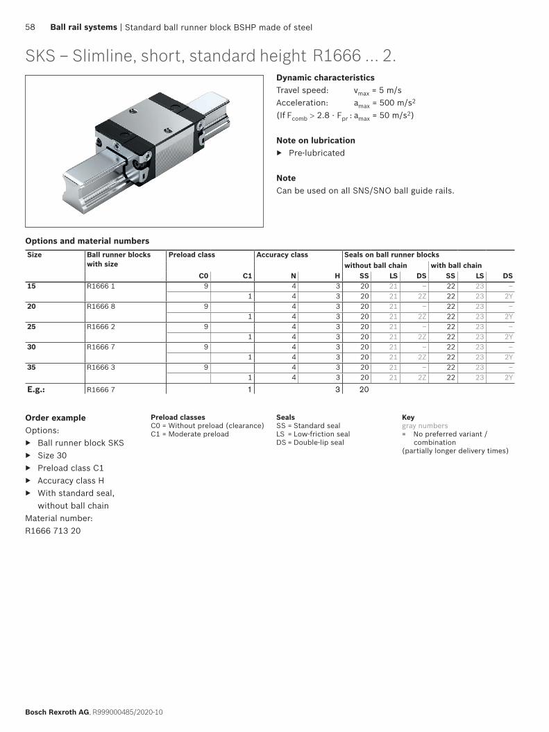
Standard ball runner block BSHP made of steel
SKS – Slimline, short, standard heightDynamic characteristicsTravel speed: vmax = 5 m/sAcceleration: amax = 500 m/s2
(If Fcomb > 2.8 · Fpr : amax = 50 m/s2)
Note on lubrication ▶ Pre-lubricated
NoteCan be used on all SNS/SNO ball guide rails.
Order exampleOptions:
▶ Ball runner block SKS ▶ Size 30 ▶ Preload class C1 ▶ Accuracy class H ▶ With standard seal,
without ball chainMaterial number: R1666 713 20
Size Ball runner blocks with size
Preload class Accuracy class Seals on ball runner blockswithout ball chain with ball chain
C0 C1 N H SS LS DS SS LS DS15 R1666 1 9 4 3 20 21 – 22 23 –
1 4 3 20 21 2Z 22 23 2Y20 R1666 8 9 4 3 20 21 – 22 23 –
1 4 3 20 21 2Z 22 23 2Y25 R1666 2 9 4 3 20 21 – 22 23 –
1 4 3 20 21 2Z 22 23 2Y30 R1666 7 9 4 3 20 21 – 22 23 –
1 4 3 20 21 2Z 22 23 2Y35 R1666 3 9 4 3 20 21 – 22 23 –
1 4 3 20 21 2Z 22 23 2Y
E.g.: R1666 7 1 3 20
Options and material numbers
R1666 ... 2.
Preload classesC0 = Without preload (clearance)C1 = Moderate preload
SealsSS = Standard sealLS = Low-friction sealDS = Double-lip seal
Keygray numbers= No preferred variant /
combination(partially longer delivery times)
58 Ball rail systems |
Bosch Rexroth AG, R999000485/2020-10

B1
E1
AE8
A3 A2
A1
H1
V1
E9
H
S9S2
K3
N3
B2
B
H2 N6
K4
K2
K1
ØS5
T
a)
b)
Standard ball runner block BSHP made of steel
Size Dimensions (mm)A A1 A2 A3 B+0.5 B1 E1 E8 E9 H H1 H2
1) H22) K1 K2 K3 K4
15 34 17 15 9.5 44.7 25.7 26 24.55 6.70 24 19.90 16.30 16.20 16.25 17.85 3.20 3.2020 44 22 20 12.0 57.3 31.9 32 32.50 7.30 30 25.35 20.75 20.55 22.95 22.95 3.35 3.3525 48 24 23 12.5 67.0 38.6 35 38.30 11.50 36 29.90 24.45 24.25 25.35 26.50 5.50 5.5030 60 30 28 16.0 75.3 45.0 40 48.40 14.60 42 35.35 28.55 28.35 28.80 30.50 6.05 6.0535 70 35 34 18.0 84.9 51.4 50 58.00 17.35 48 40.40 32.15 31.85 32.70 34.20 6.90 6.90
Size Dimensions (mm) Mass (kg)
Load capacities3) (N) Load moments3) (Nm)
N3 N6±0.5 S2 S5 S9 T V1 m C C0 Mt Mt0 ML ML0
15 6.0 10.3 M4 4.5 M2.5x3.5 60 5.0 0.10 6720 7340 65 71 29 3220 7.5 13.2 M5 6.0 M3x5 60 6.0 0.25 15400 16500 200 210 83 8925 9.0 15.2 M6 7.0 M3x5 60 7.5 0.35 19800 21200 280 300 130 14030 12.0 17.0 M8 9.0 M3x5 80 7.0 0.60 25600 28900 440 500 200 23035 13.0 20.5 M8 9.0 M3x5 80 8.0 0.90 36600 49300 790 1060 340 460
a) For O-ring Size 15: Ø 4 · 1.0 (mm) Size 20 – 35: Ø 5 · 1.0 (mm) Open lube port if necessary (see section entitled “Lubrication”).
b) Lube nipple, size 15 – 20: Funnel-type lube nipple DIN 3405-A, M3x5, B2 = 1.6 mm When using different lube nipples, pay attention to the screw-in depth of 5 mm! Lube nipple, size 25 – 35: Hydraulic-type lube nipple DIN 71412-A M6x8, B2 = 9.5 mm When using different lube nipples, pay attention to the screw-in depth of 8 mm! The lube nipple is included in the scope of delivery (not installed). Connection is possible on all sides.
1) Dimension H2 with cover strip2) Dimension H2 without cover strip3) Load ratings and load moments for ball runner block without ball chain. Load ratings and load moments for ball runner block with ball
chain 12 Determination of the dynamic load capacities and load moments is based on a stroke travel of 100,000 m according to DIN ISO 14728-1. Often only 50,000 m are actually stipulated. For comparison: Multiply the values C, Mt and ML by 1.26 according to the table.
| Ball rail systems 59
R999000485/2020-10, Bosch Rexroth AG,
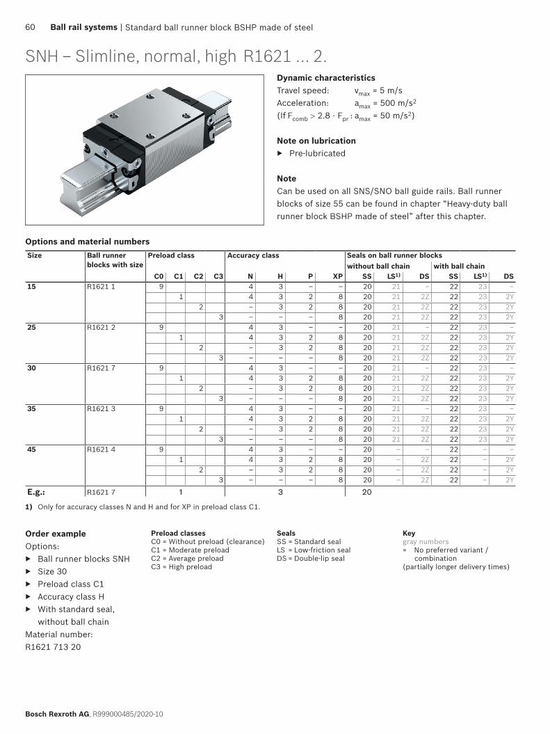
Standard ball runner block BSHP made of steel
SNH – Slimline, normal, highDynamic characteristicsTravel speed: vmax = 5 m/sAcceleration: amax = 500 m/s2
(If Fcomb > 2.8 · Fpr : amax = 50 m/s2)
Note on lubrication ▶ Pre-lubricated
NoteCan be used on all SNS/SNO ball guide rails. Ball runner blocks of size 55 can be found in chapter “Heavy-duty ball runner block BSHP made of steel” after this chapter.
1) Only for accuracy classes N and H and for XP in preload class C1.
Size Ball runner blocks with size
Preload class Accuracy class Seals on ball runner blockswithout ball chain with ball chain
C0 C1 C2 C3 N H P XP SS LS1) DS SS LS1) DS15 R1621 1 9 4 3 – – 20 21 – 22 23 –
1 4 3 2 8 20 21 2Z 22 23 2Y2 – 3 2 8 20 21 2Z 22 23 2Y
3 – – – 8 20 21 2Z 22 23 2Y25 R1621 2 9 4 3 – – 20 21 – 22 23 –
1 4 3 2 8 20 21 2Z 22 23 2Y2 – 3 2 8 20 21 2Z 22 23 2Y
3 – – – 8 20 21 2Z 22 23 2Y30 R1621 7 9 4 3 – – 20 21 – 22 23 –
1 4 3 2 8 20 21 2Z 22 23 2Y2 – 3 2 8 20 21 2Z 22 23 2Y
3 – – – 8 20 21 2Z 22 23 2Y35 R1621 3 9 4 3 – – 20 21 – 22 23 –
1 4 3 2 8 20 21 2Z 22 23 2Y2 – 3 2 8 20 21 2Z 22 23 2Y
3 – – – 8 20 21 2Z 22 23 2Y45 R1621 4 9 4 3 – – 20 – – 22 – –
1 4 3 2 8 20 – 2Z 22 – 2Y2 – 3 2 8 20 – 2Z 22 – 2Y
3 – – – 8 20 – 2Z 22 – 2Y
E.g.: R1621 7 1 3 20
Options and material numbers
Order exampleOptions:
▶ Ball runner blocks SNH ▶ Size 30 ▶ Preload class C1 ▶ Accuracy class H ▶ With standard seal,
without ball chainMaterial number: R1621 713 20
R1621 ... 2.
Preload classesC0 = Without preload (clearance)C1 = Moderate preloadC2 = Average preloadC3 = High preload
SealsSS = Standard sealLS = Low-friction sealDS = Double-lip seal
Keygray numbers= No preferred variant /
combination(partially longer delivery times)
60 Ball rail systems |
Bosch Rexroth AG, R999000485/2020-10
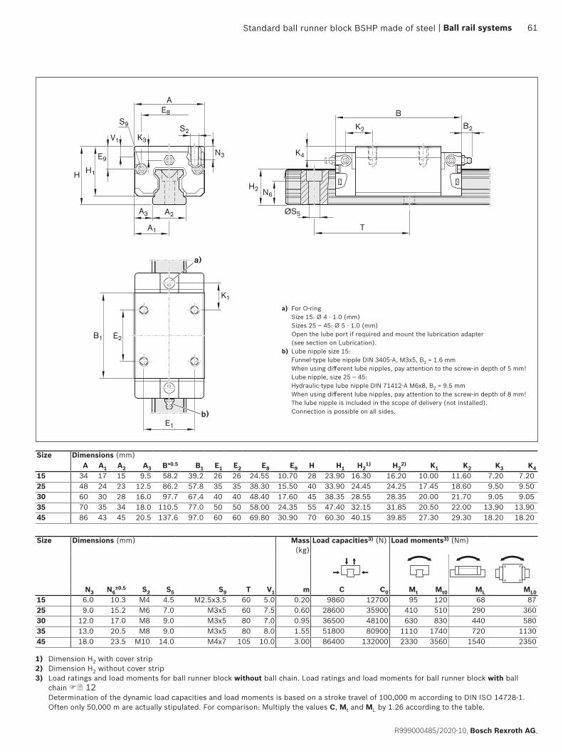
B1 E2
E1
AE8
A3 A2
A1
H1
V1
E9
H
S9S2
K3
N3
B2
B
H2 N6
K4
K2
K1
ØS5
T
a)
b)
Standard ball runner block BSHP made of steel
Size Dimensions (mm)A A1 A2 A3 B+0.5 B1 E1 E2 E8 E9 H H1 H2
1) H22) K1 K2 K3 K4
15 34 17 15 9.5 58.2 39.2 26 26 24.55 10.70 28 23.90 16.30 16.20 10.00 11.60 7.20 7.2025 48 24 23 12.5 86.2 57.8 35 35 38.30 15.50 40 33.90 24.45 24.25 17.45 18.60 9.50 9.5030 60 30 28 16.0 97.7 67.4 40 40 48.40 17.60 45 38.35 28.55 28.35 20.00 21.70 9.05 9.0535 70 35 34 18.0 110.5 77.0 50 50 58.00 24.35 55 47.40 32.15 31.85 20.50 22.00 13.90 13.9045 86 43 45 20.5 137.6 97.0 60 60 69.80 30.90 70 60.30 40.15 39.85 27.30 29.30 18.20 18.20
Size Dimensions (mm) Mass (kg)
Load capacities3) (N) Load moments3) (Nm)
N3 N6±0.5 S2 S5 S9 T V1 m C C0 Mt Mt0 ML ML0
15 6.0 10.3 M4 4.5 M2.5x3.5 60 5.0 0.20 9860 12700 95 120 68 8725 9.0 15.2 M6 7.0 M3x5 60 7.5 0.60 28600 35900 410 510 290 36030 12.0 17.0 M8 9.0 M3x5 80 7.0 0.95 36500 48100 630 830 440 58035 13.0 20.5 M8 9.0 M3x5 80 8.0 1.55 51800 80900 1110 1740 720 113045 18.0 23.5 M10 14.0 M4x7 105 10.0 3.00 86400 132000 2330 3560 1540 2350
a) For O-ring Size 15: Ø 4 · 1.0 (mm) Sizes 25 – 45: Ø 5 · 1.0 (mm) Open the lube port if required and mount the lubrication adapter (see section on Lubrication).
b) Lube nipple size 15: Funnel-type lube nipple DIN 3405-A, M3x5, B2 = 1.6 mm When using different lube nipples, pay attention to the screw-in depth of 5 mm! Lube nipple, size 25 – 45: Hydraulic-type lube nipple DIN 71412-A M6x8, B2 = 9.5 mm When using different lube nipples, pay attention to the screw-in depth of 8 mm! The lube nipple is included in the scope of delivery (not installed). Connection is possible on all sides.
1) Dimension H2 with cover strip2) Dimension H2 without cover strip3) Load ratings and load moments for ball runner block without ball chain. Load ratings and load moments for ball runner block with ball
chain 12 Determination of the dynamic load capacities and load moments is based on a stroke travel of 100,000 m according to DIN ISO 14728-1. Often only 50,000 m are actually stipulated. For comparison: Multiply the values C, Mt and ML by 1.26 according to the table.
| Ball rail systems 61
R999000485/2020-10, Bosch Rexroth AG,

Standard ball runner block BSHP made of steel
SLH – Slimline, long, highDynamic characteristicsTravel speed: vmax = 5 m/sAcceleration: amax = 500 m/s2
(If Fcomb > 2.8 · Fpr : amax = 50 m/s2)
Note on lubrication ▶ Pre-lubricated
NoteCan be used on all SNS/SNO ball guide rails. Ball runner blocks of size 55 can be found in chapter “Heavy-duty ball runner block BSHP made of steel” after this chapter.
Order exampleOptions:
▶ Ball runner blocks SLH ▶ Size 30 ▶ Preload class C1 ▶ Accuracy class H ▶ With standard seal,
without ball chainMaterial number: R1624 713 20
1) Only for accuracy classes N and H and for XP in preload class C1.
Size Ball runner blocks with size
Preload class Accuracy class Seals on ball runner blockswithout ball chain with ball chain
C0 C1 C2 C3 N H P XP SS LS1) DS SS LS1) DS25 R1624 2 9 4 3 – – 20 21 – 22 23 –
1 4 3 2 8 20 21 2Z 22 23 2Y2 – 3 2 8 20 21 2Z 22 23 2Y
3 – – – 8 20 21 2Z 22 23 2Y30 R1624 7 9 4 3 – – 20 21 – 22 23 –
1 4 3 2 8 20 21 2Z 22 23 2Y2 – 3 2 8 20 21 2Z 22 23 2Y
3 – – – 8 20 21 2Z 22 23 2Y35 R1624 3 9 4 3 – – 20 21 – 22 23 –
1 4 3 2 8 20 21 2Z 22 23 2Y2 – 3 2 8 20 21 2Z 22 23 2Y
3 – – – 8 20 21 2Z 22 23 2Y45 R1624 4 9 4 3 – – 20 – – 22 – –
1 4 3 2 8 20 – 2Z 22 – 2Y2 – 3 2 8 20 – 2Z 22 – 2Y
3 – – – 8 20 – 2Z 22 – 2Y
E.g.: R16247 1 3 20
Options and material numbers
R1624 ... 2.
Preload classesC0 = Without preload (clearance)C1 = Moderate preloadC2 = Average preloadC3 = High preload
SealsSS = Standard sealLS = Low-friction sealDS = Double-lip seal
Keygray numbers= No preferred variant /
combination(partially longer delivery times)
62 Ball rail systems |
Bosch Rexroth AG, R999000485/2020-10
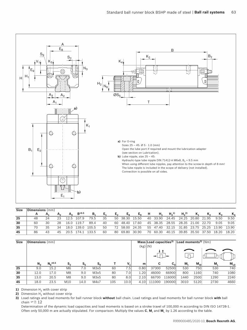
B1 E2
E1
AE8
A3 A2
A1
H1
V1
E9
H
S9S2
K3
N3
B2
B
H2 N6
K4
K2
K1
ØS5
T
a)
b)
Standard ball runner block BSHP made of steel
Size Dimensions (mm)A A1 A2 A3 B+0.5 B1 E1 E2 E8 E9 H H1 H2
1) H22) K1 K2 K3 K4
25 48 24 23 12.5 107.9 79.5 35 50 38.30 15.50 40 33.90 24.45 24.25 20.80 21.95 9.50 9.5030 60 30 28 16.0 119.7 89.4 40 60 48.40 17.60 45 38.35 28.55 28.35 21.00 22.70 9.05 9.0535 70 35 34 18.0 139.0 105.5 50 72 58.00 24.35 55 47.40 32.15 31.85 23.75 25.25 13.90 13.9045 86 43 45 20.5 174.1 133.5 60 80 69.80 30.90 70 60.30 40.15 39.85 35.50 37.50 18.20 18.20
Size Dimensions (mm) Mass (kg)
Load capacities3) (N)
Load moments3) (Nm)
N3 N6±0.5 S2 S5 S9 T V1 m C C0 Mt Mt0 ML ML0
25 9.0 15.2 M6 7.0 M3x5 60 7.5 0.80 37300 52500 530 750 530 74030 12.0 17.0 M8 9.0 M3x5 80 7.0 1.20 46000 66900 800 1160 740 108035 13.0 20.5 M8 9.0 M3x5 80 8.0 2.10 66700 116000 1440 2500 1290 224045 18.0 23.5 M10 14.0 M4x7 105 10.0 4.10 111000 190000 3010 5120 2730 4660
1) Dimension H2 with cover strip2) Dimension H2 without cover strip3) Load ratings and load moments for ball runner block without ball chain. Load ratings and load moments for ball runner block with ball
chain 12 Determination of the dynamic load capacities and load moments is based on a stroke travel of 100,000 m according to DIN ISO 14728-1. Often only 50,000 m are actually stipulated. For comparison: Multiply the values C, Mt and ML by 1.26 according to the table.
a) For O-ring Sizes 25 – 45: Ø 5 · 1.0 (mm) Open the lube port if required and mount the lubrication adapter (see section on Lubrication).
b) Lube nipple, size 25 – 45: Hydraulic-type lube nipple DIN 71412-A M6x8, B2 = 9.5 mm When using different lube nipples, pay attention to the screw-in depth of 8 mm! The lube nipple is included in the scope of delivery (not installed). Connection is possible on all sides.
| Ball rail systems 63
R999000485/2020-10, Bosch Rexroth AG,
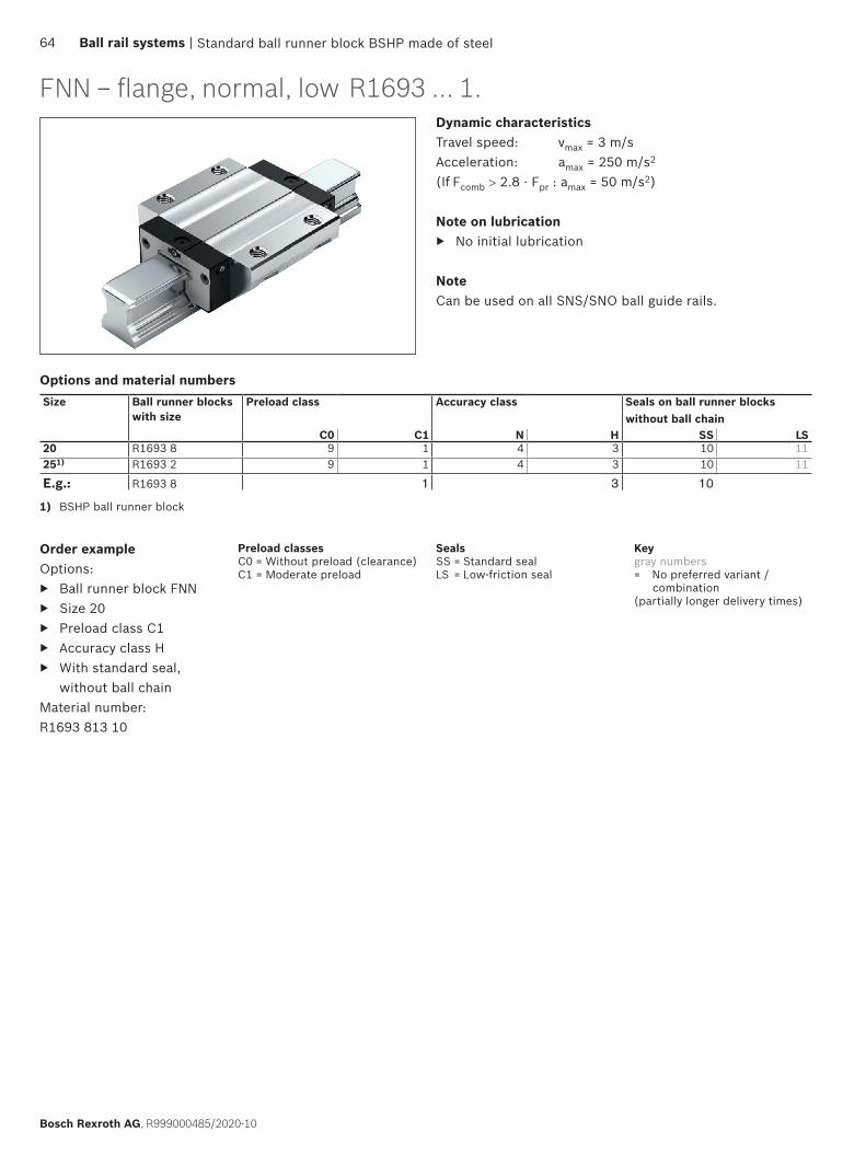
Standard ball runner block BSHP made of steel
FNN – flange, normal, lowDynamic characteristicsTravel speed: vmax = 3 m/sAcceleration: amax = 250 m/s2
(If Fcomb > 2.8 · Fpr : amax = 50 m/s2)
Note on lubrication ▶ No initial lubrication
NoteCan be used on all SNS/SNO ball guide rails.
Order exampleOptions:
▶ Ball runner block FNN ▶ Size 20 ▶ Preload class C1 ▶ Accuracy class H ▶ With standard seal,
without ball chainMaterial number: R1693 813 10
Size Ball runner blocks with size
Preload class Accuracy class Seals on ball runner blockswithout ball chain
C0 C1 N H SS LS20 R1693 8 9 1 4 3 10 11251) R1693 2 9 1 4 3 10 11
E.g.: R1693 8 1 3 10
1) BSHP ball runner block
Options and material numbers
R1693 ... 1.
Preload classesC0 = Without preload (clearance)C1 = Moderate preload
SealsSS = Standard sealLS = Low-friction seal
Keygray numbers= No preferred variant /
combination(partially longer delivery times)
64 Ball rail systems |
Bosch Rexroth AG, R999000485/2020-10

S9S2
S1
AE8
K3
H1
V1E9
H
N1
A3 A2
A1
H2 N6
B
B2K2
E1
B1
K1
E2
ØS5
T
K4
b)
a)
Standard ball runner block BSHP made of steel
a) For O-ring Size 20 – 25: Ø 5 · 1.0 (mm) Open lube port if necessary (see section entitled “Lubrication”).
b) Lube nipple, size 20 – 25: Funnel-type lube nipple DIN 3405-B, M3x5, B2 = 8 mm Lube connection with additional anti-twist feature. When using different lube nipples, pay attention to the screw-in depth of 5 mm! The lube nipple is included in the scope of delivery (not installed). Size 20: Connection is possible on end-face. Size 25: Connection is possible on all sides.
1) Dimension H2 with cover strip2) Dimension H2 without cover strip3) Load ratings and load moments for ball runner block without ball chain.
Determination of the dynamic load capacities and load moments is based on a stroke travel of 100,000 m according to DIN ISO 14728-1. Often only 50,000 m are actually stipulated. For comparison: Multiply the values C, Mt and ML by 1.26 according to the table.
Size Dimensions (mm) Mass (kg)
Load capacities3) (N)
Load moments3) (Nm)
N1 N6±0.5 S1 S2 S5 S9 T V1 m C C0 Mt Mt0 ML ML0
20 7.7 13.2 5.3 M6 6.0 M3x5 60 6.0 0.40 14500 24400 190 310 100 16525 9.3 15.2 6.7 M8 7.0 M3x5 60 7.5 0.60 28600 35900 410 510 290 360
Size Dimensions (mm)A A1 A2 A3 B+0.5 B1 E1 E2 E8 E9 H H1 H2
1) H22) K1 K2 K3 K4
20 59 29.5 20 19.5 72.5 49.6 49 32 30.5 5.6 28 23.0 20.75 20.55 13.0 – 3.6 –25 73 36.5 23 25.0 81.0 57.8 60 35 38.3 8.5 33 26.5 24.45 24.25 16.6 17.0 4.1 4.1
| Ball rail systems 65
R999000485/2020-10, Bosch Rexroth AG,
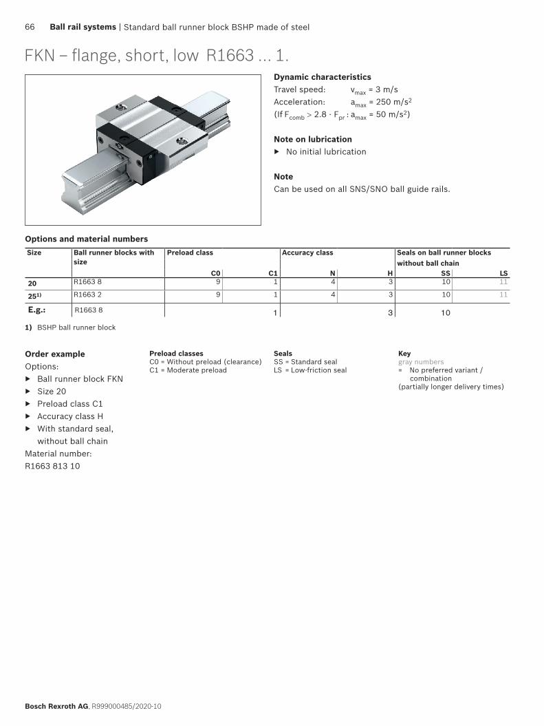
Standard ball runner block BSHP made of steel
FKN – flange, short, lowDynamic characteristicsTravel speed: vmax = 3 m/sAcceleration: amax = 250 m/s2
(If Fcomb > 2.8 · Fpr : amax = 50 m/s2)
Note on lubrication ▶ No initial lubrication
NoteCan be used on all SNS/SNO ball guide rails.
Order exampleOptions:
▶ Ball runner block FKN ▶ Size 20 ▶ Preload class C1 ▶ Accuracy class H ▶ With standard seal,
without ball chainMaterial number: R1663 813 10
Size Ball runner blocks with size
Preload class Accuracy class Seals on ball runner blockswithout ball chain
C0 C1 N H SS LS20 R1663 8 9 1 4 3 10 11
251) R1663 2 9 1 4 3 10 11
E.g.: R1663 8 1 3 10
1) BSHP ball runner block
Options and material numbers
R1663 ... 1.
Preload classesC0 = Without preload (clearance)C1 = Moderate preload
SealsSS = Standard sealLS = Low-friction seal
Keygray numbers= No preferred variant /
combination(partially longer delivery times)
66 Ball rail systems |
Bosch Rexroth AG, R999000485/2020-10

S9S2
S1
AE8
K3
H1
V1E9
H
N1
A3 A2
A1
H2 N6
B
B2
E1
B1
K1
K2
ØS5
T
K4
b)
a)
Standard ball runner block BSHP made of steel
1) Dimension H2 with cover strip2) Dimension H2 without cover strip3) Load ratings and load moments for ball runner block without ball chain.
Determination of the dynamic load capacities and load moments is based on a stroke travel of 100,000 m according to DIN ISO 14728-1. Often only 50,000 m are actually stipulated. For comparison: Multiply the values C, Mt and ML by 1.26 according to the table.
Size Dimensions (mm) Mass (kg)
m
Load capacities3) (N)
Load moments3) (Nm)
N1 N6±0.5 S1 S2 S5 S9 T V1 C C0 Mt Mt0 ML ML0
20 7.7 13.2 5.3 M6 6.0 M3x5 60 6.0 0.25 9600 13600 120 170 40 5825 9.3 15.2 6.7 M8 7.0 M3x5 60 7.5 0.45 19800 21200 280 300 130 140
Size Dimensions (mm)A A1 A2 A3 B+0.5 B1 E1 E8 E9 H H1 H2
1) H22) K1 K2 K3 K4
20 59 29.5 20 19.5 55 31.9 49 30.5 5.6 28 23.0 20.75 20.55 20.1 – 3.6 –25 73 36.5 23 25.0 62 38.6 60 38.3 8.5 33 26.5 24.45 24.25 24.5 25.0 4.1 4.1
a) For O-ring Size 20 – 25: Ø 5 · 1.0 (mm) Open lube port if necessary (see section entitled “Lubrication”).
b) Lube nipple, size 20 – 25: Funnel-type lube nipple DIN 3405-B, M3x5, B2 = 8 mm Lube connection with additional anti-twist feature. When using different lube nipples, pay attention to the screw-in depth of 5 mm! The lube nipple is included in the scope of delivery (not installed). Size 20: Connection is possible on end-face. Size 25: Connection is possible on all sides.
| Ball rail systems 67
R999000485/2020-10, Bosch Rexroth AG,

Standard ball runner block BSHP made of steel
SNN – Slimline, normal, lowDynamic characteristicsTravel speed: vmax = 3 m/sAcceleration: amax = 250 m/s2
(If Fcomb > 2.8 · Fpr : amax = 50 m/s2)
Note on lubrication ▶ No initial lubrication
NoteCan be used on all SNS/SNO ball guide rails.
Order exampleOptions:
▶ Ball runner block SNN ▶ Size 20 ▶ Preload class C1 ▶ Accuracy class H ▶ With standard seal,
without ball chainMaterial number: R1694 813 10
Size Ball runner blocks with size
Preload class Accuracy class Seals on ball runner blockswithout ball chain
C0 C1 N H SS LS20 R1694 8 9 1 4 3 10 11
251) R1694 2 9 1 4 3 10 11
E.g.: R1694 8 1 3 10
1) BSHP ball runner block
Options and material numbers
R1694 ... 1.
Preload classesC0 = Without preload (clearance)C1 = Moderate preload
SealsSS = Standard sealLS = Low-friction seal
Keygray numbers= No preferred variant /
combination(partially longer delivery times)
68 Ball rail systems |
Bosch Rexroth AG, R999000485/2020-10

V1
S9 S2
AE8
K3
H2 N6
B
B2
E1
B1 E2
H1
E9
H
A2
A1
N3
A3
K1
K2
K4
ØS5
T
b)
a)
Standard ball runner block BSHP made of steel
1) Dimension H2 with cover strip2) Dimension H2 without cover strip3) Load ratings and load moments for ball runner block without ball chain.
Determination of the dynamic load capacities and load moments is based on a stroke travel of 100,000 m according to DIN ISO 14728-1. Often only 50,000 m are actually stipulated. For comparison: Multiply the values C, Mt and ML by 1.26 according to the table.
Size Dimensions (mm) Mass (kg)
Load capacities3) (N)
Load moments3) (Nm)
N3 N6±0.5 S2 S5 S9 T V1 m C C0 Mt Mt0 ML ML0
20 6.3 13.2 M5 6.0 M3x5 60 6.0 0.30 14500 24400 190 310 100 16525 7.0 15.2 M6 7.0 M3x5 60 7.5 0.45 28600 35900 410 510 290 360
Size Dimensions (mm)A A1 A2 A3 B+0.5 B1 E1 E2 E8 E9 H H1 H2
1) H22) K1 K2 K3 K4
20 42 21 20 11.0 72.5 49.6 32 32 30.5 5.6 28 23.0 20.75 20.55 13.0 – 3.6 –25 48 24 23 12.5 81.0 57.8 35 35 38.3 8.5 33 26.5 24.45 24.25 16.6 17.0 4.1 4.1
a) For O-ring Size 20 – 25: Ø 5 · 1.0 (mm) Open lube port if necessary (see section entitled “Lubrication”).
b) Lube nipple, size 20 – 25: Funnel-type lube nipple DIN 3405-B, M3x5, B2 = 8 mm Lube connection with additional anti-twist feature. When using different lube nipples, pay attention to the screw-in depth of 5 mm! The lube nipple is included in the scope of delivery (not installed). Size 20: Connection is possible on end-face. Size 25: Connection is possible on all sides.
| Ball rail systems 69
R999000485/2020-10, Bosch Rexroth AG,
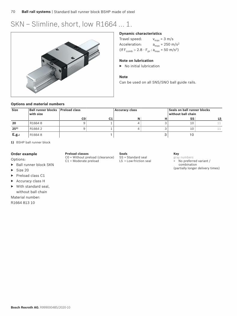
Standard ball runner block BSHP made of steel
SKN – Slimline, short, lowDynamic characteristicsTravel speed: vmax = 3 m/sAcceleration: amax = 250 m/s2
(If Fcomb > 2.8 · Fpr : amax = 50 m/s2)
Note on lubrication ▶ No initial lubrication
NoteCan be used on all SNS/SNO ball guide rails.
Order exampleOptions:
▶ Ball runner block SKN ▶ Size 20 ▶ Preload class C1 ▶ Accuracy class H ▶ With standard seal,
without ball chainMaterial number: R1664 813 10
Size Ball runner blocks with size
Preload class Accuracy class Seals on ball runner blocks without ball chain
C0 C1 N H SS LS20 R1664 8 9 1 4 3 10 11
251) R1664 2 9 1 4 3 10 11
E.g.: R1664 8 1 3 10
1) BSHP ball runner block
Options and material numbers
R1664 ... 1.
Preload classesC0 = Without preload (clearance)C1 = Moderate preload
SealsSS = Standard sealLS = Low-friction seal
Keygray numbers= No preferred variant /
combination(partially longer delivery times)
70 Ball rail systems |
Bosch Rexroth AG, R999000485/2020-10

H1
E9
H
A3 A2
A1
S9 S2
AE8
K3
E1
B1
K1
H2 N6
BB2K2
V1
N3
K4
ØS5
T
b)
a)
Standard ball runner block BSHP made of steel
1) Dimension H2 with cover strip2) Dimension H2 without cover strip3) Load ratings and load moments for ball runner block without ball chain.
Determination of the dynamic load capacities and load moments is based on a stroke travel of 100,000 m according to DIN ISO 14728-1. Of-ten only 50,000 m are actually stipulated. For comparison: Multiply the values C, Mt and ML by 1.26 according to the table.
Size Dimensions (mm) Mass (kg)
m
Load capacities3) (N) Load moments3) (Nm)
N3 N6±0.5 S2 S5 S9 T V1 C C0 Mt Mt0 ML ML0
20 6.3 13.2 M5 6.0 M3x5 60 6.0 0.20 9600 13600 120 170 40 5825 7.0 15.2 M6 7.0 M3x5 60 7.5 0.30 19800 21200 280 300 130 140
Size Dimensions (mm)A A1 A2 A3 B+0.5 B1 E1 E8 E9 H H1 H2
1) H22) K1 K2 K3 K4
20 42 21 20 11.0 55 31.9 32 30.5 5.6 28 23.0 20.75 20.55 20.1 – 3.6 –25 48 24 23 12.5 62 38.6 35 38.3 8.5 33 26.5 24.45 24.25 24.5 25.0 4.1 4.1
a) For O-ring Size 20 – 25: Ø 5 · 1.0 (mm) Open lube port if necessary (see section entitled “Lubrication”).
b) Lube nipple, size 20 – 25: Funnel-type lube nipple DIN 3405-B, M3x5, B2 = 8 mm Lube connection with additional anti-twist feature. When using different lube nipples, pay attention to the screw-in depth of 5 mm! The lube nipple is included in the scope of delivery (not installed). Size 20: Connection is possible on end-face. Size 25: Connection is possible on all sides.
| Ball rail systems 71
R999000485/2020-10, Bosch Rexroth AG,
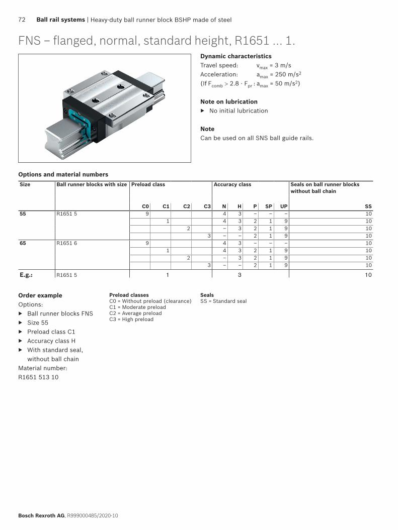
Dynamic characteristicsTravel speed: vmax = 3 m/sAcceleration: amax = 250 m/s2
(If Fcomb > 2.8 · Fpr : amax = 50 m/s2)
Note on lubrication ▶ No initial lubrication
NoteCan be used on all SNS ball guide rails.
Order exampleOptions:
▶ Ball runner blocks FNS ▶ Size 55 ▶ Preload class C1 ▶ Accuracy class H ▶ With standard seal,
without ball chainMaterial number: R1651 513 10
Size Ball runner blocks with size Preload class Accuracy class Seals on ball runner blocks without ball chain
C0 C1 C2 C3 N H P SP UP SS55 R1651 5 9 4 3 – – – 10
1 4 3 2 1 9 102 – 3 2 1 9 10
3 – – 2 1 9 1065 R1651 6 9 4 3 – – – 10
1 4 3 2 1 9 102 – 3 2 1 9 10
3 – – 2 1 9 10
E.g.: R1651 5 1 3 10
Options and material numbers
FNS – flanged, normal, standard height, R1651 ... 1.
Heavy-duty ball runner block BSHP made of steel
Preload classesC0 = Without preload (clearance)C1 = Moderate preloadC2 = Average preloadC3 = High preload
SealsSS = Standard seal
72 Ball rail systems |
Bosch Rexroth AG, R999000485/2020-10
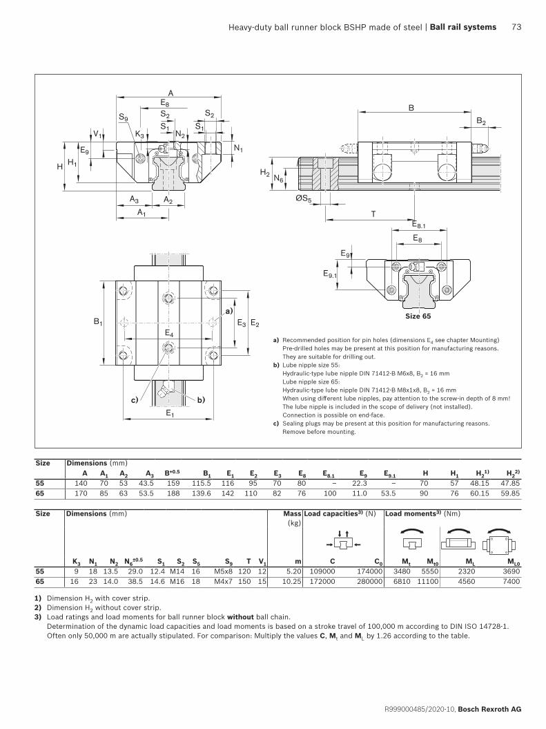
S9S2
B2S1
S2
S1
A
BE8
K3 N2
A3 A2
A1
N1
H1H2 N6
E9
H
E4
B1 E2E3
E1
V1
ØS5
T
a)
b)c)
E8.1
E8
E9
E9.1
a) Recommended position for pin holes (dimensions E4 see chapter Mounting) Pre-drilled holes may be present at this position for manufacturing reasons. They are suitable for drilling out.
b) Lube nipple size 55: Hydraulic-type lube nipple DIN 71412-B M6x8, B2 = 16 mm Lube nipple size 65: Hydraulic-type lube nipple DIN 71412-B M8x1x8, B2 = 16 mm When using different lube nipples, pay attention to the screw-in depth of 8 mm! The lube nipple is included in the scope of delivery (not installed). Connection is possible on end-face.
c) Sealing plugs may be present at this position for manufacturing reasons. Remove before mounting.
Size 65
1) Dimension H2 with cover strip.2) Dimension H2 without cover strip. 3) Load ratings and load moments for ball runner block without ball chain.
Determination of the dynamic load capacities and load moments is based on a stroke travel of 100,000 m according to DIN ISO 14728-1. Often only 50,000 m are actually stipulated. For comparison: Multiply the values C, Mt and ML by 1.26 according to the table.
Size Dimensions (mm)A A1 A2 A3 B+0.5 B1 E1 E2 E3 E8 E8.1 E9 E9.1 H H1 H2
1) H22)
55 140 70 53 43.5 159 115.5 116 95 70 80 – 22.3 – 70 57 48.15 47.8565 170 85 63 53.5 188 139.6 142 110 82 76 100 11.0 53.5 90 76 60.15 59.85
Size Dimensions (mm) Mass (kg)
Load capacities3) (N) Load moments3) (Nm)
K3 N1 N2 N6±0.5 S1 S2 S5 S9 T V1 m C C0 Mt Mt0 ML ML0
55 9 18 13.5 29.0 12.4 M14 16 M5x8 120 12 5.20 109000 174000 3480 5550 2320 369065 16 23 14.0 38.5 14.6 M16 18 M4x7 150 15 10.25 172000 280000 6810 11100 4560 7400
Heavy-duty ball runner block BSHP made of steel | Ball rail systems 73
R999000485/2020-10, Bosch Rexroth AG
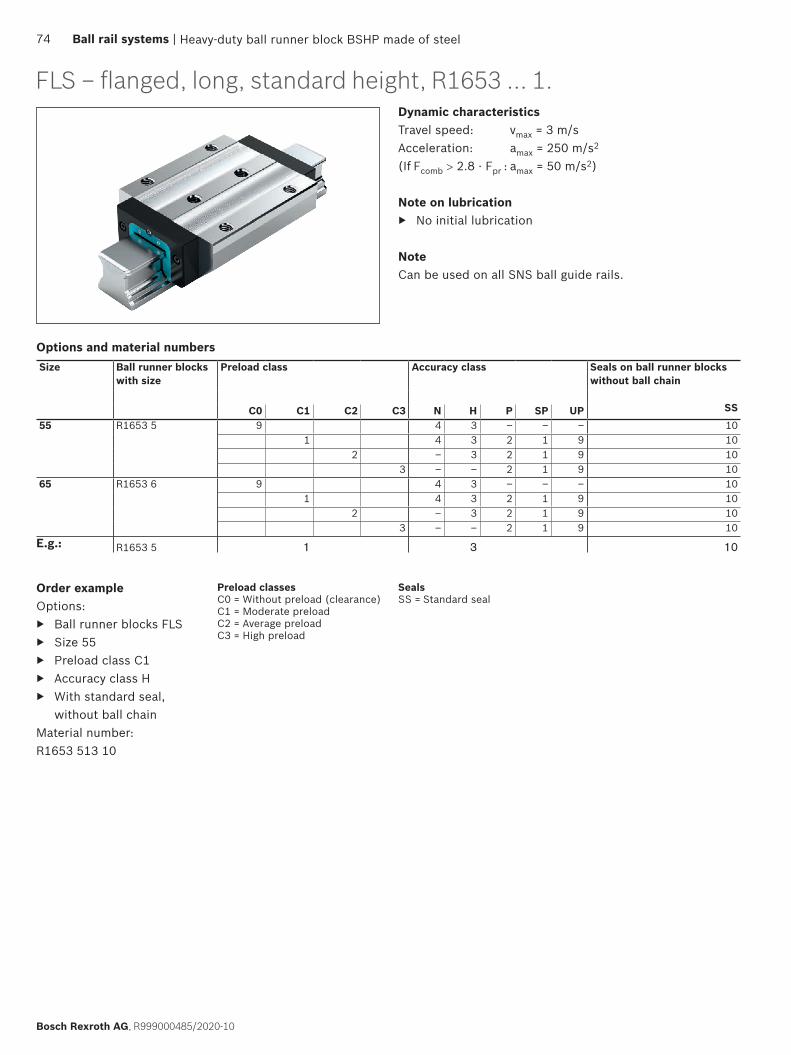
Dynamic characteristicsTravel speed: vmax = 3 m/sAcceleration: amax = 250 m/s2
(If Fcomb > 2.8 · Fpr : amax = 50 m/s2)
Note on lubrication ▶ No initial lubrication
NoteCan be used on all SNS ball guide rails.
FLS – flanged, long, standard height, R1653 ... 1.
Order exampleOptions:
▶ Ball runner blocks FLS ▶ Size 55 ▶ Preload class C1 ▶ Accuracy class H ▶ With standard seal,
without ball chainMaterial number: R1653 513 10
Size Ball runner blocks with size
Preload class Accuracy class Seals on ball runner blocks without ball chain
SSC0 C1 C2 C3 N H P SP UP55 R1653 5 9 4 3 – – – 10
1 4 3 2 1 9 102 – 3 2 1 9 10
3 – – 2 1 9 1065 R1653 6 9 4 3 – – – 10
1 4 3 2 1 9 102 – 3 2 1 9 10
3 – – 2 1 9 10E.g.: R1653 5 1 3 10
Heavy-duty ball runner block BSHP made of steel
Options and material numbers
Preload classesC0 = Without preload (clearance)C1 = Moderate preloadC2 = Average preloadC3 = High preload
SealsSS = Standard seal
74 Ball rail systems |
Bosch Rexroth AG, R999000485/2020-10

S9S2
S1
S2
S1
AE8
K3 N2
A3 A2
A1
N1
H2 N6
B
B2
H1
E9
H
E1
E4
B1 E2E3
V1
ØS5
T
a)
b)c)
E8.1
E8
E9
E9.1
Size Dimensions (mm)A A1 A2 A3 B+0.5 B1 E1 E2 E3 E8 E8.1 E9 E9.1 H H1 H2
1) H22)
55 140 70 53 43.5 199 155.5 116 95 70 80 – 22.3 – 70 57 48.15 47.8565 170 85 63 53.5 243 194.6 142 110 82 76 100 11.0 53.5 90 76 60.15 59.85
Size 65
1) Dimension H2 with cover strip2) Dimension H2 without cover strip3) Load ratings and load moments for ball runner block without ball chain.
Determination of the dynamic load capacities and load moments is based on a stroke travel of 100,000 m according to DIN ISO 14728-1. Often only 50,000 m are actually stipulated. For comparison: Multiply the values C, Mt and ML by 1.26 according to the table.
Size Dimensions (mm) Mass (kg)
Load capacities3) (N) Load moments3) (Nm)
K3 N1 N2 N6±0.5 S1 S2 S5 S9 T V1 m C C0 Mt Mt0 ML ML0
55 9 18 13.5 29.0 12.4 M14 16 M5x8 120 12 7.50 139000 245000 4410 7780 3960 699065 16 23 14.0 38.5 14.6 M16 18 M4x7 150 15 14.15 223000 404000 8810 16000 8160 14800
a) Recommended position for pin holes (dimensions E4 see chapter Mounting) Pre-drilled holes may be present at this position for manufacturing reasons. They are suitable for drilling out.
b) Lube nipple size 55: Hydraulic-type lube nipple DIN 71412-B M6x8, B2 = 16 mm Lube nipple size 65: Hydraulic-type lube nipple DIN 71412-B M8x1x8, B2 = 16 mm When using different lube nipples, pay attention to the screw-in depth of 8 mm! The lube nipple is included in the scope of delivery (not installed). Connection is possible on end-face.
c) Sealing plugs may be present at this position for manufacturing reasons. Remove before mounting.
Heavy-duty ball runner block BSHP made of steel | Ball rail systems 75
R999000485/2020-10, Bosch Rexroth AG

SNS – Slimline, normal, standard height, R1622...1.Dynamic characteristicsTravel speed: vmax = 3 m/sAcceleration: amax = 250 m/s2
(If Fcomb > 2.8 · Fpr : amax = 50 m/s2)
Note on lubrication ▶ No initial lubrication
NoteCan be used on all SNS ball guide rails.
Order exampleOptions:
▶ Ball runner blocks SNS ▶ Size 55 ▶ Preload class C1 ▶ Accuracy class H ▶ With standard seal,
without ball chainMaterial number: R1622 513 10
Size Ball runner blocks with size
Preload class Accuracy class Seals on ball runner blockswithout ball chain
C0 C1 C2 C3 N H P SS55 R1622 5 9 4 3 – 10
1 4 3 2 102 – 3 2 10
3 – – 2 1065 R1622 6 9 4 3 – 10
1 4 3 2 102 – 3 2 10
3 – – 2 10E.g.: R1622 5 1 3 10
Options and material numbers
Heavy-duty ball runner block BSHP made of steel
Preload classesC0 = Without preload (clearance)C1 = Moderate preloadC2 = Average preloadC3 = High preload
SealsSS = Standard seal
76 Ball rail systems |
Bosch Rexroth AG, R999000485/2020-10
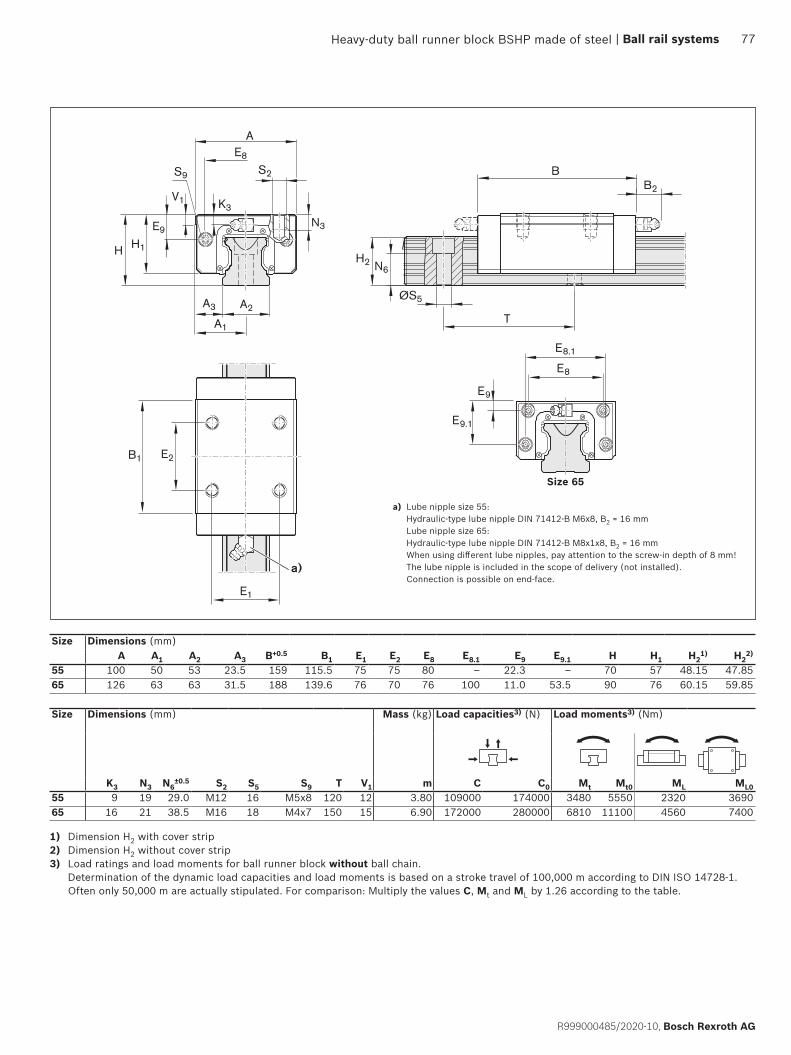
H2 N6
BB2
H1
E9
S2
A3 A2
A1
AE8
K3
N3
H
E1
E2B1
V1
S9
ØS5
T
a)
E8.1
E8
E9
E9.1
Size 65
Size Dimensions (mm)A A1 A2 A3 B+0.5 B1 E1 E2 E8 E8.1 E9 E9.1 H H1 H2
1) H22)
55 100 50 53 23.5 159 115.5 75 75 80 – 22.3 – 70 57 48.15 47.8565 126 63 63 31.5 188 139.6 76 70 76 100 11.0 53.5 90 76 60.15 59.85
Size Dimensions (mm) Mass (kg) Load capacities3) (N) Load moments3) (Nm)
K3 N3 N6±0.5 S2 S5 S9 T V1 m C C0 Mt Mt0 ML ML0
55 9 19 29.0 M12 16 M5x8 120 12 3.80 109000 174000 3480 5550 2320 369065 16 21 38.5 M16 18 M4x7 150 15 6.90 172000 280000 6810 11100 4560 7400
1) Dimension H2 with cover strip2) Dimension H2 without cover strip3) Load ratings and load moments for ball runner block without ball chain.
Determination of the dynamic load capacities and load moments is based on a stroke travel of 100,000 m according to DIN ISO 14728-1. Often only 50,000 m are actually stipulated. For comparison: Multiply the values C, Mt and ML by 1.26 according to the table.
a) Lube nipple size 55: Hydraulic-type lube nipple DIN 71412-B M6x8, B2 = 16 mm Lube nipple size 65: Hydraulic-type lube nipple DIN 71412-B M8x1x8, B2 = 16 mm When using different lube nipples, pay attention to the screw-in depth of 8 mm! The lube nipple is included in the scope of delivery (not installed). Connection is possible on end-face.
Heavy-duty ball runner block BSHP made of steel | Ball rail systems 77
R999000485/2020-10, Bosch Rexroth AG

SLS – Slimline, long, standard height, R1623...1.Dynamic characteristicsTravel speed: vmax = 3 m/sAcceleration: amax = 250 m/s2
(If Fcomb > 2.8 · Fpr : amax = 50 m/s2)
Note on lubrication ▶ No initial lubrication
NoteCan be used on all SNS ball guide rails.
Order exampleOptions:
▶ Ball runner blocks SLS ▶ Size 55 ▶ Preload class C1 ▶ Accuracy class H ▶ With standard seal,
without ball chainMaterial number: R1623 513 10
Size Ball runner blocks with size Preload class Accuracy class Seals on ball runner blockswithout ball chain
C0 C1 C2 C3 N H P SS55 R1623 5 9 4 3 – 10
1 4 3 2 102 – 3 2 10
3 – – 2 1065 R1623 6 9 4 3 – 10
1 4 3 2 102 – 3 2 10
3 – – 2 10E.g.: R1623 5 1 3 10
Options and material numbers
Heavy-duty ball runner block BSHP made of steel
Preload classesC0 = Without preload (clearance)C1 = Moderate preloadC2 = Average preloadC3 = High preload
SealsSS = Standard seal
78 Ball rail systems |
Bosch Rexroth AG, R999000485/2020-10
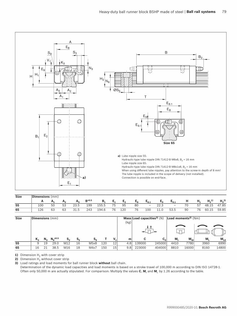
H1
E9
S9 S2
A3
A1
AE8
K3
HH2 N6
BB2
E1
E2B1
V1
N3
A2 ØS5
T
a)
E8.1
E8
E9
E9.1
Size 65
1) Dimension H2 with cover strip2) Dimension H2 without cover strip3) Load ratings and load moments for ball runner block without ball chain.
Determination of the dynamic load capacities and load moments is based on a stroke travel of 100,000 m according to DIN ISO 14728-1. Often only 50,000 m are actually stipulated. For comparison: Multiply the values C, Mt and ML by 1.26 according to the table.
Size Dimensions (mm)A A1 A2 A3 B+0.5 B1 E1 E2 E8 E8.1 E9 E9.1 H H1 H2
1) H22)
55 100 50 53 23.5 199 155.5 75 95 80 – 22.3 – 70 57 48.15 47.8565 126 63 63 31.5 243 194.6 76 120 76 100 11.0 53.5 90 76 60.15 59.85
Size Dimensions (mm) Mass (kg)
Load capacities3) (N) Load moments3) (Nm)
K3 N3 N6±0.5 S2 S5 S9 T V1 m C C0 Mt Mt0 ML ML0
55 9 19 29.0 M12 16 M5x8 120 12 4.8 139000 245000 4410 7780 3960 699065 16 21 38.5 M16 18 M4x7 150 15 9.8 223000 404000 8810 16000 8160 14800
a) Lube nipple size 55: Hydraulic-type lube nipple DIN 71412-B M6x8, B2 = 16 mm Lube nipple size 65: Hydraulic-type lube nipple DIN 71412-B M8x1x8, B2 = 16 mm When using different lube nipples, pay attention to the screw-in depth of 8 mm! The lube nipple is included in the scope of delivery (not installed). Connection is possible on end-face.
Heavy-duty ball runner block BSHP made of steel | Ball rail systems 79
R999000485/2020-10, Bosch Rexroth AG
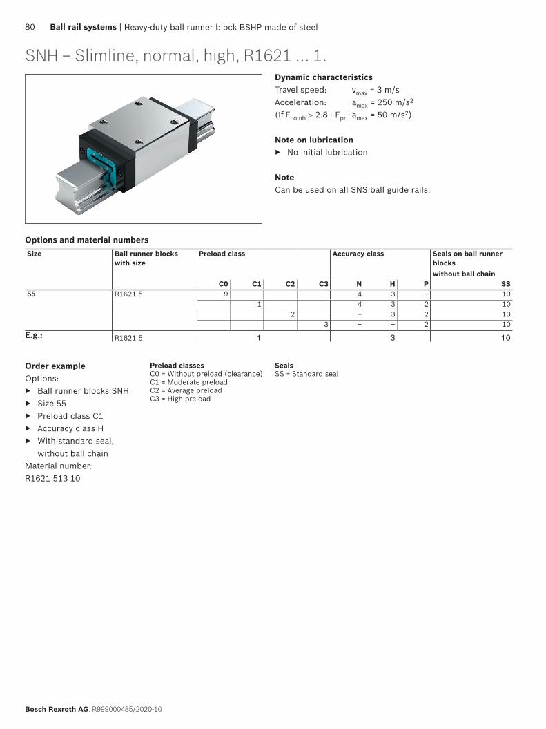
SNH – Slimline, normal, high, R1621 ... 1.Dynamic characteristicsTravel speed: vmax = 3 m/sAcceleration: amax = 250 m/s2
(If Fcomb > 2.8 · Fpr : amax = 50 m/s2)
Note on lubrication ▶ No initial lubrication
NoteCan be used on all SNS ball guide rails.
Order exampleOptions:
▶ Ball runner blocks SNH ▶ Size 55 ▶ Preload class C1 ▶ Accuracy class H ▶ With standard seal,
without ball chainMaterial number: R1621 513 10
Options and material numbersSize Ball runner blocks
with sizePreload class Accuracy class Seals on ball runner
blockswithout ball chain
C0 C1 C2 C3 N H P SS55 R1621 5 9 4 3 – 10
1 4 3 2 102 – 3 2 10
3 – – 2 10E.g.: R1621 5 1 3 10
Heavy-duty ball runner block BSHP made of steel
Preload classesC0 = Without preload (clearance)C1 = Moderate preloadC2 = Average preloadC3 = High preload
SealsSS = Standard seal
80 Ball rail systems |
Bosch Rexroth AG, R999000485/2020-10
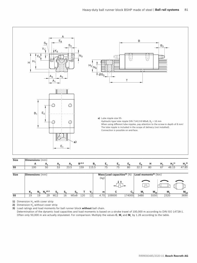
V1
S9 S2
AE8
K3
H1
E9
H
A3 A2
A1
N3
H2 N6
B
B2
B1 E2
E1
ØS5
T
a)
Size Dimensions (mm)A A1 A2 A3 B+0.5 B1 E1 E2 E8 E9 H H1 H2
1) H22)
55 100 50 53 23.5 159 115.5 75 75 80 32.3 80 67 48.15 47.85
Size Dimensions (mm) Mass (kg)
Load capacities3) (N) Load moments3) (Nm)
K3 N3 N6±0.5 S2 S5 S9 T V1 m C C0 Mt Mt0 ML ML0
55 19 19 29 M12 16 M5x8 120 12 4.70 109000 174000 3480 5550 2320 3690
1) Dimension H2 with cover strip2) Dimension H2 without cover strip3) Load ratings and load moments for ball runner block without ball chain.
Determination of the dynamic load capacities and load moments is based on a stroke travel of 100,000 m according to DIN ISO 14728-1. Often only 50,000 m are actually stipulated. For comparison: Multiply the values C, Mt and ML by 1.26 according to the table.
a) Lube nipple size 55: Hydraulic-type lube nipple DIN 71412-B M6x8, B2 = 16 mm When using different lube nipples, pay attention to the screw-in depth of 8 mm! The lube nipple is included in the scope of delivery (not installed). Connection is possible on end-face.
Heavy-duty ball runner block BSHP made of steel | Ball rail systems 81
R999000485/2020-10, Bosch Rexroth AG

SLH – Slimline, long, high, R1624 ... 1.Dynamic characteristicsTravel speed: vmax = 3 m/sAcceleration: amax = 250 m/s2
(If Fcomb > 2.8 · Fpr : amax = 50 m/s2)
Note on lubrication ▶ No initial lubrication
NoteCan be used on all SNS ball guide rails.
Order exampleOptions:
▶ Ball runner blocks SLH ▶ Size 55 ▶ Preload class C1 ▶ Accuracy class H ▶ With standard seal,
without ball chainMaterial number: R1624 513 10
Size Ball runner blocks with size
Preload class Accuracy class Seals on ball runner blockswithout ball chain
C0 C1 C2 C3 N H P SS55 R1624 5 9 4 3 – 10
1 4 3 2 102 – 3 2 10
3 – – 2 10E.g.: R1624 5 1 3 10
Options and material numbers
Heavy-duty ball runner block BSHP made of steel
Preload classesC0 = Without preload (clearance)C1 = Moderate preloadC2 = Average preloadC3 = High preload
SealsSS = Standard seal
82 Ball rail systems |
Bosch Rexroth AG, R999000485/2020-10

H1
E9
H
S9 S2
AE8
K3
A3 A2
A1
H2 N6
B
B2
E1
B1 E2
V1
N3
ØS5
T
a)
1) Dimension H2 with cover strip2) Dimension H2 without cover strip3) Load ratings and load moments for ball runner block without ball chain.
Determination of the dynamic load capacities and load moments is based on a stroke travel of 100,000 m according to DIN ISO 14728-1. Often only 50,000 m are actually stipulated. For comparison: Multiply the values C, Mt and ML by 1.26 according to the table.
Size Dimensions (mm)A A1 A2 A3 B+0.5 B1 E1 E2 E8 E9 H H1 H2
1) H22)
55 100 50 53 23.5 199 155.5 75 95 80 32.3 80 67 48.15 47.85
Size Dimensions (mm) Mass (kg)
Load capacities3) (N) Load moments3) (Nm)
K3 N3 N6±0.5 S2 S5 S9 T V1 m C C0 Mt Mt0 ML ML0
55 19 19 29 M12 16 M5x8 120 12 6.00 139000 245000 4410 7780 3960 6990
a) Lube nipple size 55: Hydraulic-type lube nipple DIN 71412-B M6x8, B2 = 16 mm When using different lube nipples, pay attention to the screw-in depth of 8 mm! The lube nipple is included in the scope of delivery (not installed). Connection is possible on end-face.
Heavy-duty ball runner block BSHP made of steel | Ball rail systems 83
R999000485/2020-10, Bosch Rexroth AG
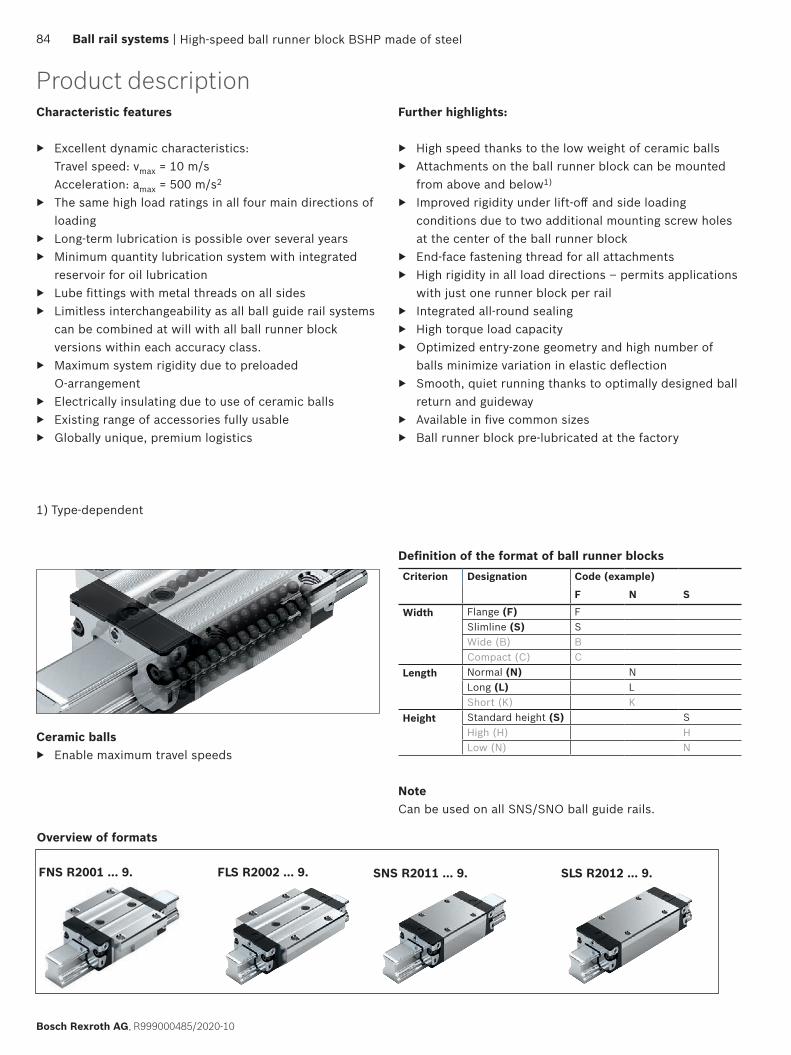
FLS R2002 ... 9. SLS R2012 ... 9.FNS R2001 ... 9. SNS R2011 ... 9.
Product descriptionFurther highlights:
▶ High speed thanks to the low weight of ceramic balls ▶ Attachments on the ball runner block can be mounted
from above and below1)
▶ Improved rigidity under lift-off and side loading conditions due to two additional mounting screw holes at the center of the ball runner block
▶ End-face fastening thread for all attachments ▶ High rigidity in all load directions – permits applications
with just one runner block per rail ▶ Integrated all-round sealing ▶ High torque load capacity ▶ Optimized entry-zone geometry and high number of
balls minimize variation in elastic deflection ▶ Smooth, quiet running thanks to optimally designed ball
return and guideway ▶ Available in five common sizes ▶ Ball runner block pre-lubricated at the factory
Characteristic features
▶ Excellent dynamic characteristics: Travel speed: vmax = 10 m/s Acceleration: amax = 500 m/s2
▶ The same high load ratings in all four main directions of loading
▶ Long-term lubrication is possible over several years ▶ Minimum quantity lubrication system with integrated
reservoir for oil lubrication ▶ Lube fittings with metal threads on all sides ▶ Limitless interchangeability as all ball guide rail systems
can be combined at will with all ball runner block versions within each accuracy class.
▶ Maximum system rigidity due to preloaded O-arrangement
▶ Electrically insulating due to use of ceramic balls ▶ Existing range of accessories fully usable ▶ Globally unique, premium logistics
Overview of formats
Ceramic balls ▶ Enable maximum travel speeds
NoteCan be used on all SNS/SNO ball guide rails.
High-speed ball runner block BSHP made of steel
1) Type-dependent
84 Ball rail systems |
Bosch Rexroth AG, R999000485/2020-10
Definition of the format of ball runner blocksCriterion Designation Code (example)
F N S
Width Flange (F) FSlimline (S) SWide (B) BCompact (C) C
Length Normal (N) NLong (L) LShort (K) K
Height Standard height (S) SHigh (H) HLow (N) N
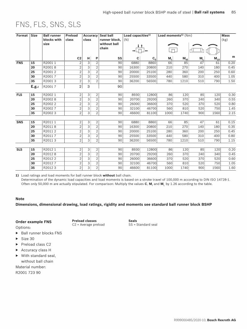
Format Size Ball runner blocks with size
Preload class
Accuracy class
Seal ball runner block, without ball chain
Load capacities1) (N)
Load moments1) (Nm) Mass (kg)
m
C2 H P SS C C0 Mt Mt0 ML ML0FNS 15 R2001 1 2 3 2 90 6880 8860 66 85 47 61 0.20
20 R2001 8 2 3 2 90 16300 20800 210 270 140 180 0.4525 R2001 2 2 3 2 90 20000 25100 280 360 200 250 0.6030 R2001 7 2 3 2 90 25500 33500 440 580 310 400 1.0535 R2001 3 2 3 2 90 36200 56500 780 1210 510 790 1.50
E.g.: R2001 7 2 3 90
FLS 15 R2002 1 2 3 2 90 8930 12800 86 120 85 120 0.3020 R2002 8 2 3 2 90 20700 29200 260 370 240 340 0.5525 R2002 2 2 3 2 90 26000 36600 370 520 370 520 0.8030 R2002 7 2 3 2 90 32100 46700 560 810 520 750 1.4535 R2002 3 2 3 2 90 46600 81100 1000 1740 900 1560 2.15
SNS 15 R2011 1 2 3 2 90 6880 8860 66 85 47 61 0.1520 R2011 8 2 3 2 90 16300 20800 210 270 140 180 0.3525 R2011 2 2 3 2 90 20000 25100 280 360 200 250 0.4530 R2011 7 2 3 2 90 25500 33500 440 580 310 400 0.8035 R2011 3 2 3 2 90 36200 56500 780 1210 510 790 1.15
SLS 15 R2012 1 2 3 2 90 8930 12800 86 120 85 120 0.2020 R2012 8 2 3 2 90 20700 29200 260 370 240 340 0.4525 R2012 2 2 3 2 90 26000 36600 370 520 370 520 0.6030 R2012 7 2 3 2 90 32100 46700 560 810 520 750 1.0535 R2012 3 2 3 2 90 46600 81100 1000 1740 900 1560 1.60
FNS, FLS, SNS, SLS
Order example FNSOptions:
▶ Ball runner blocks FNS ▶ Size 30 ▶ Preload class C2 ▶ Accuracy class H ▶ With standard seal,
without ball chainMaterial number: R2001 723 90
1) Load ratings and load moments for ball runner block without ball chain. Determination of the dynamic load capacities and load moments is based on a stroke travel of 100,000 m according to DIN ISO 14728-1. Often only 50,000 m are actually stipulated. For comparison: Multiply the values C, Mt and ML by 1.26 according to the table.
High-speed ball runner block BSHP made of steel
SealsSS = Standard seal
Preload classesC2 = Average preload
NoteDimensions, dimensional drawing, load ratings, rigidity and moments see standard ball runner block BSHP
| Ball rail systems 85
R999000485/2020-10, Bosch Rexroth AG
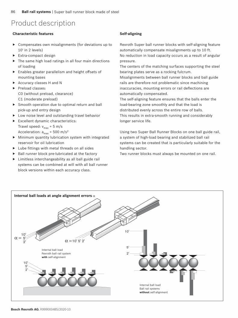
10' 5' 2'
10'5'2'
2'5'
10'
10'
5'
2'
Product descriptionCharacteristic features
▶ Compensates own misalignments (for deviations up to 10' in 2 levels)
▶ Extra-compact design ▶ The same high load ratings in all four main directions
of loading ▶ Enables greater parallelism and height offsets of
mounting bases ▶ Accuracy classes H and N ▶ Preload classes:
C0 (without preload, clearance) C1 (moderate preload)
▶ Smooth operation due to optimal return and ball pick-up and entry design
▶ Low noise level and outstanding travel behavior ▶ Excellent dynamic characteristics:
Travel speed: vmax = 5 m/s Acceleration: amax = 500 m/s2
▶ Minimum quantity lubrication system with integrated reservoir for oil lubrication
▶ Lube fittings with metal threads on all sides ▶ Ball runner block pre-lubricated at the factory ▶ Limitless interchangeability as all ball guide rail
systems can be combined at will with all ball runner block versions within each accuracy class.
Self-aligning
Rexroth Super ball runner blocks with self-aligning feature automatically compensate misalignments up to 10 ft. No reduction in load capacity occurs as a result of angular pressure. The centers of the matching surfaces supporting the steel bearing plates serve as a rocking fulcrum. Misalignments between ball runner blocks and ball guide rails are therefore not problematic since machining inaccuracies, mounting errors or rail deflections are automatically compensated.The self-aligning feature ensures that the balls enter the load-bearing zone smoothly and that the load is distributed evenly across the entire row of balls.This results in extra-smooth running and considerably longer service life.
Using two Super Ball Runner Blocks on one ball guide rail, a system of high-load bearing and stabilized ball rail systems can be created that is particularly suitable for the handling sector.Two runner blocks must always be mounted on one rail.
Internal ball loads at angle alignment errors α
Internal ball loadRexroth ball rail system with self-alignment
Internal ball loadBall rail systemswithout self-alignment
Super ball runner block made of steel86 Ball rail systems |
Bosch Rexroth AG, R999000485/2020-10
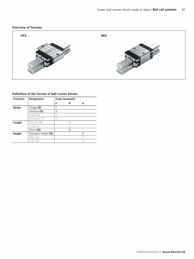
SKSFKS
Overview of formats
Super ball runner block made of steel | Ball rail systems 87
R999000485/2020-10, Bosch Rexroth AG
Definition of the format of ball runner blocksCriterion Designation Code (example)
F K S
Width Flange (F) FSlimline (S) SWide (B) BCompact (C) C
Length Normal (N) NLong (L) LShort (K) K
Height Standard height (S) SHigh (H) HLow (N) N
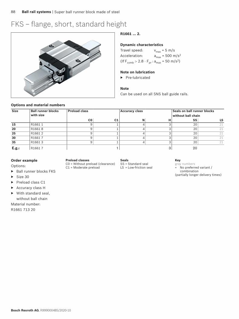
R1661 ... 2.
Dynamic characteristicsTravel speed: vmax = 5 m/sAcceleration: amax = 500 m/s2
(If Fcomb > 2.8 · Fpr : amax = 50 m/s2)
Note on lubrication ▶ Pre-lubricated
NoteCan be used on all SNS ball guide rails.
Size Ball runner blocks with size
Preload class Accuracy class Seals on ball runner blockswithout ball chain
C0 C1 N H SS LS15 R1661 1 9 1 4 3 20 2120 R1661 8 9 1 4 3 20 2125 R1661 2 9 1 4 3 20 2130 R1661 7 9 1 4 3 20 2135 R1661 3 9 1 4 3 20 21
E.g.: R1661 7 1 3 20
Order exampleOptions:
▶ Ball runner blocks FKS ▶ Size 30 ▶ Preload class C1 ▶ Accuracy class H ▶ With standard seal,
without ball chainMaterial number: R1661 713 20
Super ball runner block made of steel
Options and material numbers
FKS – flange, short, standard height
SealsSS = Standard sealLS = Low-friction seal
Keygray numbers= No preferred variant /
combination(partially longer delivery times)
Preload classesC0 = Without preload (clearance)C1 = Moderate preload
88 Ball rail systems |
Bosch Rexroth AG, R999000485/2020-10

B1
K1
E1
S2
AE8
A3 A2
A1
H1
V1 K4
E9
H
K2S9
S1K3
N1
B2
B
H2 N6
ØS5
T
10'
10'
10' 10'
b)
a)
Size Dimensions (mm) Weight (kg)
Load ratings3)
(N) Permissible
load (N)Load moments3) (Nm)
N1 N6±0.5 S1 S2 S5 S9 T V1 C Fmax Mt Mt max
15 5.2 10.3 4.3 M5 4.5 M2.5x3.5 60 5.0 0.15 3900 1500 39 1520 7.7 13.2 5.3 M6 6.0 M3x5 60 6.0 0.30 10100 3900 130 5025 9.3 15.2 6.7 M8 7.0 M3x5 60 7.5 0.50 11400 4400 170 6530 11.0 17.0 8.5 M10 9.0 M3x5 80 7.0 0.80 15800 6100 270 10535 12.0 20.5 8.5 M10 9.0 M3x5 80 8.0 1.20 21100 8100 450 175
1) Dimension H2 with cover strip2) Dimension H2 without cover strip3) Load ratings and load moments for ball runner block without ball chain.
Determination of the dynamic load capacities and load moments is based on a stroke travel of 100,000 m according to DIN ISO 14728-1. Often only 50,000 m are actually stipulated. For comparison: Multiply the values C and Mt by 1.26 according to the table.
a) For O-ring Size 15: Ø 4 · 1.0 (mm) Size 20 – 35: Ø 5 · 1.0 (mm) Open lube port if necessary (see section entitled “Lubrication”).
b) Lube nipple, size 15 – 20: Funnel-type lube nipple DIN 3405 – A, M3x5, B2 = 1.6 mm When using different lube nipples, pay attention to the screw-in depth of 5 mm! Lube nipple, size 25 – 35: Hydraulic-type lube nipple DIN 71412 – A M6x8, B2 = 9.5 mm When using different lube nipples, pay attention to the screw-in depth of 8 mm! The lube nipple is included in the scope of delivery (not installed). Connection is possible on all sides.
Size Dimensions (mm)A A1 A2 A3 B+0.5 B1 E1 E8 E9 H H1 H2
1) H22) K1 K2 K3 K4
15 47 23.5 15 16.0 44.7 25.7 38 24.55 6.70 24 19.90 16.30 16.20 16.25 17.85 3.20 3.2020 63 31.5 20 21.5 57.3 31.9 53 32.50 7.30 30 25.35 20.75 20.55 22.95 22.95 3.35 3.3525 70 35.0 23 23.5 67.0 38.6 57 38.30 11.50 36 29.90 24.45 24.25 25.35 26.50 5.50 5.5030 90 45.0 28 31.0 75.3 45.0 72 48.40 14.60 42 35.35 28.55 28.35 28.80 30.50 6.05 6.0535 100 50.0 34 33.0 84.9 51.4 82 58.00 17.35 48 40.40 32.15 31.85 32.70 34.20 6.90 6.90
Super ball runner block made of steel | Ball rail systems 89
R999000485/2020-10, Bosch Rexroth AG
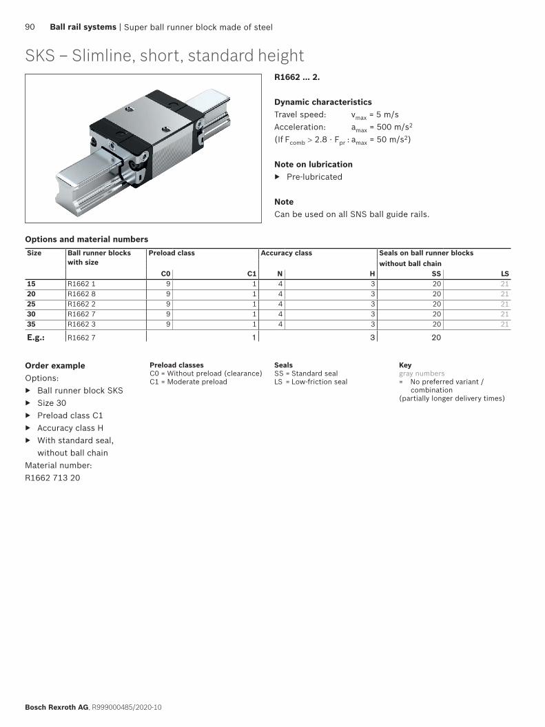
SKS – Slimline, short, standard heightR1662 ... 2.
Dynamic characteristicsTravel speed: vmax = 5 m/sAcceleration: amax = 500 m/s2
(If Fcomb > 2.8 · Fpr : amax = 50 m/s2)
Note on lubrication ▶ Pre-lubricated
NoteCan be used on all SNS ball guide rails.
Order exampleOptions:
▶ Ball runner block SKS ▶ Size 30 ▶ Preload class C1 ▶ Accuracy class H ▶ With standard seal,
without ball chainMaterial number: R1662 713 20
Size Ball runner blocks with size
Preload class Accuracy class Seals on ball runner blockswithout ball chain
C0 C1 N H SS LS15 R1662 1 9 1 4 3 20 2120 R1662 8 9 1 4 3 20 2125 R1662 2 9 1 4 3 20 2130 R1662 7 9 1 4 3 20 2135 R1662 3 9 1 4 3 20 21
E.g.: R1662 7 1 3 20
Super ball runner block made of steel
Options and material numbers
SealsSS = Standard sealLS = Low-friction seal
Keygray numbers= No preferred variant /
combination(partially longer delivery times)
Preload classesC0 = Without preload (clearance)C1 = Moderate preload
90 Ball rail systems |
Bosch Rexroth AG, R999000485/2020-10
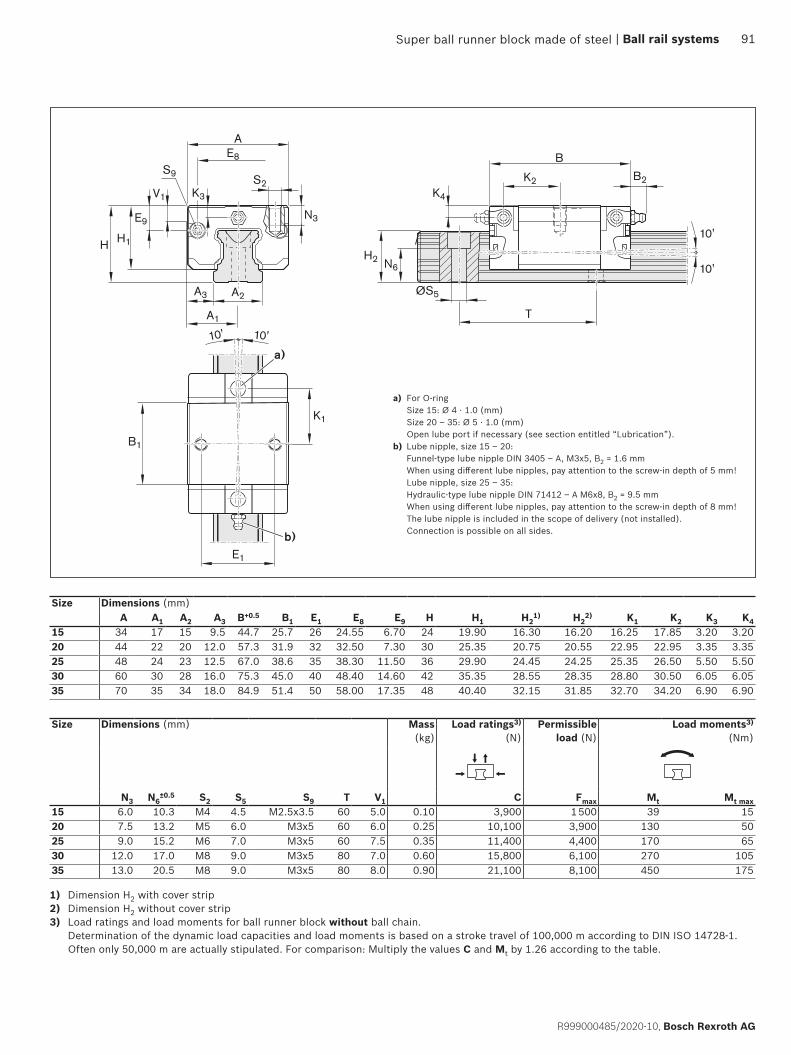
B1
E1
AE8
A3 A2
A1
H1
V1
E9
H
S9S2
K3
N3
B2
B
H2 N6
K4
K2
K1
ØS5
T
10' 10'
10'
10'
a)
b)
1) Dimension H2 with cover strip2) Dimension H2 without cover strip3) Load ratings and load moments for ball runner block without ball chain.
Determination of the dynamic load capacities and load moments is based on a stroke travel of 100,000 m according to DIN ISO 14728-1. Often only 50,000 m are actually stipulated. For comparison: Multiply the values C and Mt by 1.26 according to the table.
Size Dimensions (mm) Mass (kg)
Load ratings3)
(N) Permissible
load (N)Load moments3)
(Nm)
N3 N6±0.5 S2 S5 S9 T V1 C Fmax Mt Mt max
15 6.0 10.3 M4 4.5 M2.5x3.5 60 5.0 0.10 3,900 1 500 39 1520 7.5 13.2 M5 6.0 M3x5 60 6.0 0.25 10,100 3,900 130 5025 9.0 15.2 M6 7.0 M3x5 60 7.5 0.35 11,400 4,400 170 6530 12.0 17.0 M8 9.0 M3x5 80 7.0 0.60 15,800 6,100 270 10535 13.0 20.5 M8 9.0 M3x5 80 8.0 0.90 21,100 8,100 450 175
a) For O-ring Size 15: Ø 4 · 1.0 (mm) Size 20 – 35: Ø 5 · 1.0 (mm) Open lube port if necessary (see section entitled “Lubrication”).
b) Lube nipple, size 15 – 20: Funnel-type lube nipple DIN 3405 – A, M3x5, B2 = 1.6 mm When using different lube nipples, pay attention to the screw-in depth of 5 mm! Lube nipple, size 25 – 35: Hydraulic-type lube nipple DIN 71412 – A M6x8, B2 = 9.5 mm When using different lube nipples, pay attention to the screw-in depth of 8 mm! The lube nipple is included in the scope of delivery (not installed). Connection is possible on all sides.
Size Dimensions (mm)A A1 A2 A3 B+0.5 B1 E1 E8 E9 H H1 H2
1) H22) K1 K2 K3 K4
15 34 17 15 9.5 44.7 25.7 26 24.55 6.70 24 19.90 16.30 16.20 16.25 17.85 3.20 3.2020 44 22 20 12.0 57.3 31.9 32 32.50 7.30 30 25.35 20.75 20.55 22.95 22.95 3.35 3.3525 48 24 23 12.5 67.0 38.6 35 38.30 11.50 36 29.90 24.45 24.25 25.35 26.50 5.50 5.5030 60 30 28 16.0 75.3 45.0 40 48.40 14.60 42 35.35 28.55 28.35 28.80 30.50 6.05 6.0535 70 35 34 18.0 84.9 51.4 50 58.00 17.35 48 40.40 32.15 31.85 32.70 34.20 6.90 6.90
Super ball runner block made of steel | Ball rail systems 91
R999000485/2020-10, Bosch Rexroth AG

Product descriptionCharacteristic features
Rexroth ball rail systems with aluminum ball runner blocks have been developed specially for industrial robots and general machine building requiring compact, ball bearing-mounted longitudinal guides in various accuracy classes with very high load capacity and low gravity. The extremely small and lightweight guide units in five common sizes have the same high load ratings in all four main directions of loading.
Highlights
▶ High torque load capacity ▶ Optimized entry-zone geometry and high number of
balls minimize variation in elastic deflection ▶ Extra-compact lightweight design 60% less gravity due
to aluminum compared to the ball runner blocks made of steel
▶ Limitless interchangeability as all ball guide rail systems can be combined at will with all ball runner block versions within each accuracy class.
Further highlights
▶ Low noise level and outstanding travel behavior ▶ Excellent dynamic characteristics:
Travel speed: vmax = 5 m/s Acceleration: amax = 500 m/s2
▶ Long-term lubrication is possible over several years ▶ Minimum quantity lubrication with integrated reservoir
for oil lubrication ▶ Enables greater parallelism and height offsets of
mounting bases ▶ Accuracy classes H and N are combinable with all rails
in each accuracy class ▶ Lube connection with metal thread on all sides ▶ End-face fastening thread for all attachments ▶ Ball guide rails of accuracy class H are also available
with coated Resist CR (matt silver finish, hard chrome plated)
▶ Quiet, smooth running thanks to optimally designed ball and ball chain return and guideway
▶ Improved rigidity under lift-off and side loading conditions due to two additional mounting screw holes at the center of the ball runner block1)
▶ Attachments on the ball runner block can be mounted from above and below1)
▶ Predrilled holes on the ball runner block for pinned fitting
▶ Optionally available with ball chain ▶ Ball runner block pre-lubricated at the factory
1) Type-dependent
Aluminum ball runner block BSHP92 Ball rail systems |
Bosch Rexroth AG, R999000485/2020-10
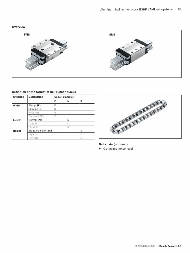
FNS SNS
Ball chain (optional) ▶ Optimized noise level
Overview
Aluminum ball runner block BSHP | Ball rail systems 93
R999000485/2020-10, Bosch Rexroth AG
Definition of the format of ball runner blocksCriterion Designation Code (example)
F N S
Width Flange (F) FSlimline (S) SWide (B) BCompact (C) C
Length Normal (N) NLong (L) LShort (K) K
Height Standard height (S) SHigh (H) HLow (N) N

FNS – flanged, normal, standard height, R1631 ... 2.
Size Load capacities1) (N)
Permissible load (N) Load moments1) (Nm)
C Fmax Mt Mt max ML ML max15 9860 3000 95 29 68 1620 23400 7200 300 92 200 5025 28600 8800 410 125 290 7030 36500 12200 630 210 440 11035 51800 16200 1110 345 720 170
R1631 ... 2.
Dynamic characteristicsTravel speed: vmax = 5 m/sAcceleration: amax = 500 m/s2
(If Fcomb > 2.8 · Fpr : amax = 50 m/s2)
Note on lubrication ▶ Pre-lubricated
NoteCan be used on all SNS ball guide rails.
Order exampleOptions:
▶ Ball runner blocks FNS ▶ Size 30 ▶ Preload class C1 ▶ Accuracy class H ▶ With standard seal,
without ball chainMaterial number: R1631 713 20
Size Ball runner blocks with size
Preload class Accuracy class Seals on ball runner blockswithout ball chain
with ball chain
C0 C1 N H SS LS SS LS15 R1631 1 9 1 4 3 20 21 22 2320 R1631 8 9 1 4 3 20 21 22 2325 R1631 2 9 1 4 3 20 21 22 2330 R1631 7 9 1 4 3 20 21 22 2335 R1631 3 9 1 4 3 20 21 22 23
E.g.: R1631 7 1 3 20
Options/material numbers/technical data
1) Load ratings and load moments for ball runner block without ball chain. Load ratings and load moments for ball runner block with ball chain 13 Determination of the dynamic load capacities and load moments is based on a stroke travel of 100,000 m according to DIN ISO 14728-1. Often only 50,000 m are actually stipulated. For comparison: Multiply the values C, Mt and ML by 1.26 according to the table.
Aluminum ball runner block BSHP
SealsSS = Standard sealLS = Low-friction seal
Keygray numbers= No preferred variant /
combination(partially longer delivery times)
Preload classesC0 = Without preload (clearance)C1 = Moderate preload
94 Ball rail systems |
Bosch Rexroth AG, R999000485/2020-10

E4
B1 E2
K1
E3
E1
S2
AE8
A3 A2
A1
H1
V1 K4
E9
H
K2S9
S1K3N2
B2
B
H2 N6
S11
S2
S1
N1 N4
ØS5
T
c)d)
a)
b)
1) Dimension H2 with cover strip2) Dimension H2 without cover strip
Size Dimensions (mm)A A1 A2 A3 B+0.5 B1 E1 E2 E3 E8 E9 H H1 H2
1) H22) K1 K2 K3 K4
15 47 23.5 15 16.0 58.2 39.2 38 30 26 24.55 6.70 24 19.90 16.30 16.20 8.00 9.6 3.20 3.2020 63 31.5 20 21.5 75.0 49.6 53 40 35 32.50 7.30 30 25.35 20.75 20.55 11.80 11.8 3.35 3.3525 70 35.0 23 23.5 86.2 57.8 57 45 40 38.30 11.50 36 29.90 24.45 24.25 12.45 13.6 5.50 5.5030 90 45.0 28 31.0 97.7 67.4 72 52 44 48.40 14.60 42 35.35 28.55 28.35 14.00 15.7 6.05 6.0535 100 50.0 34 33.0 110.5 77.0 82 62 52 58.00 17.35 48 40.40 32.15 31.85 14.50 16.0 6.90 6.90
Size Dimensions (mm) MassN1 N2 N4 N6
±0.5 S1 S2 S5 S9 S11 T V1 (kg)15 5.2 4.40 10.3 10.3 4.3 M5 4.5 M2.5x3.5 3.7 60 5.0 0.1020 7.7 5.20 13.5 13.2 5.3 M6 6.0 M3x5 4.7 60 6.0 0.2425 9.3 7.00 17.8 15.2 6.7 M8 7.0 M3x5 5.7 60 7.5 0.3030 11.0 7.90 20.5 17.0 8.5 M10 9.0 M3x5 7.7 80 7.0 0.5535 12.0 10.15 24.0 20.5 8.5 M10 9.0 M3x5 7.7 80 8.0 0.75
a) For O-ring Size 15: Ø 4 · 1.0 (mm) Size 20 – 35: Ø 5 · 1.0 (mm) Open lube port if necessary (see section entitled “Lubrication”).
b) Recommended position for pin holes (dimensions E4 see the chapter “Mounting”) Due to production-related issues, pre-drilled holes may be present at this position. They are suitable for drilling out.
c) Lube nipple, size 15 – 20: Funnel-type lube nipple DIN 3405-A, M3x5, B2 = 1.6 mm When using different lube nipples, pay attention to the screw-in depth of 5 mm! Lube nipple, size 25 – 35: Hydraulic-type lube nipple DIN 71412-A M6x8, B2 = 9.5 mm When using different lube nipples, pay attention to the screw-in depth of 8 mm! The lube nipple is included in the scope of delivery (not installed). Connection is possible on all sides.
d) Sealing plugs may be present at this position for manufacturing reasons. Remove before mounting.
Aluminum ball runner block BSHP | Ball rail systems 95
R999000485/2020-10, Bosch Rexroth AG

SNS – Slimline, normal, standard height, R1632 ... 2.R1632 ... 2.
Dynamic characteristicsTravel speed: vmax = 5 m/sAcceleration: amax = 500 m/s2
(If Fcomb > 2.8 · Fpr : amax = 50 m/s2)
Note on lubrication ▶ Pre-lubricated
NoteCan be used on all SNS ball guide rails.
Order exampleOptions:
▶ Ball runner blocks SNS ▶ Size 30 ▶ Preload class C1 ▶ Accuracy class H ▶ With standard seal,
without ball chainMaterial number: R1632 713 20
Size Ball runner blocks with size
Preload class Accuracy class Seals on ball runner blockswithout ball chain
with ball chain
C0 C1 N H SS LS SS LS15 R1632 1 9 1 4 3 20 21 22 2320 R1632 8 9 1 4 3 20 21 22 2325 R1632 2 9 1 4 3 20 21 22 2330 R1632 7 9 1 4 3 20 21 22 2335 R1632 3 9 1 4 3 20 21 22 23
E.g.: R1632 7 1 3 20
Size Load capacities1) (N) Permissible load (N) Load moments1) (Nm)
C Fmax Mt Mt max ML ML max15 9860 3000 95 29 68 1620 23400 7200 300 92 200 5025 28600 8800 410 125 290 7030 36500 12200 630 210 440 11035 51800 16200 1110 345 720 170
1) Load ratings and load moments for ball runner block without ball chain. Load ratings and load moments for ball runner block with ball chain 13 Determination of the dynamic load capacities and load moments is based on a stroke travel of 100,000 m according to DIN ISO 14728-1. Often only 50,000 m are actually stipulated. For comparison: Multiply the values C, Mt and ML by 1.26 according to the table.
Options/material numbers/technical data
Aluminum ball runner block BSHP
SealsSS = Standard sealLS = Low-friction seal
Keygray numbers= No preferred variant /
combination(partially longer delivery times)
Preload classesC0 = Without preload (clearance)C1 = Moderate preload
96 Ball rail systems |
Bosch Rexroth AG, R999000485/2020-10

c)
a)
b)
E5
B1 E2
K1
E1
AE8
A3 A2
A1
H1
V1 K4
E9
H
K2S9
K3
B2
B
H2 N6
S11
S2
N3
ØS5
T
1) Dimension H2 with cover strip2) Dimension H2 without cover strip
Size Dimensions (mm)A A1 A2 A3 B+0.5 B1 E1 E2 E8 E9 H H1 H2
1) H22) K1 K2 K3 K4
15 34 17 15 9.5 58.2 39.2 26 26 24.55 6.70 24 19.90 16.30 16.20 10.00 11.60 3.20 3.2020 44 22 20 12.0 75.0 49.6 32 36 32.50 7.30 30 25.35 20.75 20.55 13.80 13.80 3.35 3.3525 48 24 23 12.5 86.2 57.8 35 35 38.30 11.50 36 29.90 24.45 24.25 17.45 18.60 5.50 5.5030 60 30 28 16.0 97.7 67.4 40 40 48.40 14.60 42 35.35 28.55 28.35 20.00 21.70 6.05 6.0535 70 35 34 18.0 110.5 77.0 50 50 58.00 17.35 48 40.40 32.15 31.85 20.50 22.00 6.90 6.90
Size Dimensions (mm) Mass N3 N6
±0.5 S2 S5 S9 S11 T V1 (kg)15 6.0 10.3 M4 4.5 M2.5x3.5 3.7 60 5.0 0.1020 7.5 13.2 M5 6.0 M3x5 4.7 60 6.0 0.2025 9.0 15.2 M6 7.0 M3x5 5.7 60 7.5 0.3530 12.0 17.0 M8 9.0 M3x5 7.7 80 7.0 0.4535 13.0 20.5 M8 9.0 M3x5 7.7 80 8.0 0.65
a) For O-ring Size 15: Ø 4 · 1.0 (mm) Size 20 – 35: Ø 5 · 1.0 (mm) Open lube port if necessary (see section entitled “Lubrication”).
b) Recommended position for pin holes (dimensions E4 see the chapter “Mounting”) Due to production-related issues, pre-drilled holes may be present at this position. They are suitable for drilling out.
c) Lube nipple, size 15 – 20: Funnel-type lube nipple DIN 3405-A, M3x5, B2 = 1.6 mm When using different lube nipples, pay attention to the screw-in depth of 5 mm! Lube nipple, size 25 – 35: Hydraulic-type lube nipple DIN 71412-A M6x8, B2 = 9.5 mm When using different lube nipples, pay attention to the screw-in depth of 8 mm! The lube nipple is included in the scope of delivery (not installed). Connection is possible on all sides.
Aluminum ball runner block BSHP | Ball rail systems 97
R999000485/2020-10, Bosch Rexroth AG
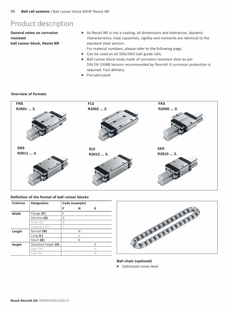
FNSR2001 ... 3.
FLSR2002 ... 3.
FKSR2000 ... 3.
SNSR2011 ... 3.
SLSR2012 ... 3.
SKSR2010 ... 3.
Overview of formats
Product descriptionGeneral notes on corrosion resistant ball runner block, Resist NR
▶ As Resist NR is not a coating, all dimensions and tolerances, dynamic characteristics, load capacities, rigidity and moments are identical to the standard steel version. For material numbers, please refer to the following page.
▶ Can be used on all SNS/SNO ball guide rails. ▶ Ball runner block body made of corrosion resistant steel as per
DIN EN 10088 Version recommended by Rexroth if corrosion protection is required. Fast delivery.
▶ Pre-lubricated
Ball runner block BSHP Resist NR
Ball chain (optional) ▶ Optimized noise level
98 Ball rail systems |
Bosch Rexroth AG, R999000485/2020-10
Definition of the format of ball runner blocksCriterion Designation Code (example)
F N S
Width Flange (F) FSlimline (S) SWide (B) BCompact (C) C
Length Normal (N) NLong (L) LShort (K) K
Height Standard height (S) SHigh (H) HLow (N) N

FNS, FLS, FKS, SNS, SLS, SKSFormat Size Ball runner
blocks with size
Preload class Accuracy class Seals on ball runner blockswithout ball chain with ball chain
C0 C1 H SS LS DS SS LS DSFNS 15 R2001 1 9 – 3 30 31 – 32 33 –
20 R2001 8 9 – 3 30 31 – 32 33 –25 R2001 2 9 – 3 30 31 – 32 33 –30 R2001 7 9 3 30 31 – 32 33 –
1 3 30 31 3Z 32 33 3Y35 R2001 3 9 3 30 31 – 32 33 –
1 3 30 31 3Z 32 33 3YE.g.: R2001 7 1 3 30
FLS 15 R2002 1 9 – 3 30 31 – 32 33 –20 R2002 8 9 – 3 30 31 – 32 33 –25 R2002 2 9 – 3 30 31 – 32 33 –30 R2002 7 9 3 30 31 – 32 33 –
1 3 30 31 3Z 32 33 3Y35 R2002 3 9 3 30 31 – 32 33 –
1 3 30 31 3Z 32 33 3Y
FKS 15 R2000 1 9 – 3 30 31 – 32 33 –20 R2000 8 9 – 3 30 31 – 32 33 –25 R2000 2 9 – 3 30 31 – 32 33 –30 R2000 7 9 3 30 31 – 32 33 –
1 3 30 31 3Z 32 33 3Y35 R2000 3 9 3 30 31 – 32 33 –
1 3 30 31 3Z 32 33 3Y
SNS 15 R2011 1 9 – 3 30 31 – 32 33 –20 R2011 8 9 – 3 30 31 – 32 33 –25 R2011 2 9 – 3 30 31 – 32 33 –30 R2011 7 9 3 30 31 – 32 33 –
1 3 30 31 3Z 32 33 3Y35 R2011 3 9 3 30 31 – 32 33 –
1 3 30 31 3Z 32 33 3Y
SLS 15 R2012 1 9 3 30 31 – 32 33 –20 R2012 8 9 3 30 31 – 32 33 –25 R2012 2 9 3 30 31 – 32 33 –30 R2012 7 9 3 30 31 – 32 33 –
1 3 30 31 3Z 32 33 3Y35 R2012 3 9 3 30 31 – 32 33 –
1 3 30 31 3Z 32 33 3Y
SKS 15 R2010 1 9 – 3 30 31 – 32 33 –20 R2010 8 9 – 3 30 31 – 32 33 –25 R2010 2 9 – 3 30 31 – 32 33 –30 R2010 7 9 3 30 31 – 32 33 –
1 3 30 31 3Z 32 33 3Y35 R2010 3 9 3 30 31 – 32 33 –
1 3 30 31 3Z 32 33 3Y
Keygray numbers= No preferred variant /
combination(partially longer delivery times)
Order example FNSOptions:
▶ Ball runner block BSHP Resist NR, FNS ▶ Size 30 ▶ Preload class C1 ▶ Accuracy class H ▶ With standard seal, without ball chain
Material number: R2001 713 30
Ball runner block BSHP Resist NR
SealsSS = Standard sealLS = Low-friction sealDS = Double-lip seal
NoteDimensions, dimensional drawing, load ratings, rigidity and moments see standard ball runner block BSHP
Preload classesC0 = Without preload (clearance)C1 = Moderate preload
| Ball rail systems 99
R999000485/2020-10, Bosch Rexroth AG
Characteristic features
Ball rail systems Resist NR II made of corrosion resistant steel1) are used specifically in conjunction with water-based media, heavily diluted acidic materials, alkali or saline solutions. These guideways are also ideally suitable for use at relative humidities above 70 % and temperatures exceeding 30 °C.Such conditions are found mainly in cleaning plants, electroplating and pickling lines, vapor degreasing plants and refrigeration systems.Since no additional corrosion protection is required, ball rail systems Resist NR II are ideally suited for use in clean rooms and general printed circuit board manufacturing. They are also suitable for other applications in the general packaging industry.
General notes on ball runner blocks Resist NR II ▶ Can be used on all SNS ball guide rails, not initially lubricated, not preserved ▶ For dimensions see corresponding ball runner blocks made of steel
Highlights
▶ All metal parts are made of corrosion resistant steel ▶ Available in five common sizes ▶ Excellent dynamic characteristics:
Travel speed: vmax = 5 m/s Acceleration: amax = 500 m/s2
▶ The same high load ratings in all four main directions of loading ▶ Available in accuracy classes N, H and P, up to preload class C2 ▶ Long-term lubrication is possible over several years ▶ Minimum quantity lubrication system with integrated reservoir for oil lubrication ▶ Lube fittings with metal threads on all sides ▶ Optionally available with ball chain
▶ Ball rail systems for sectors of the food industry, see the ball rail systems NRFG catalog R310DE2226 (2011.04). ▶ Combinations of different accuracy classes
Combining ball guide rails and ball runner blocks of different accuracy classes results in different tolerances for the dimensions H and A3. See “Accuracy classes and their tolerances.”
▶ Combinations of different materials Combining ball guide rails and ball runner blocks made of different materials will change the load ratings, permitted loads and load moments. The lower value must be used in each case.
General notes
Ball runner block BSHP Resist NR II
Product description
1) Resist NR II: Ball runner block body and ball guide rail as well as all steel parts made of corrosion resistant steel in accordance with DIN EN 10088
100 Ball rail systems |
Bosch Rexroth AG, R999000485/2020-10

FKS R2000 ... 0.
SKS R2010 ... 0.
FLS R2002 ... 0.
SLS R2012 ... 0.
FNS R2001 ... 0.
SNS R2011 ... 0.
Further highlights
▶ Limitless interchangeability as all ball guide rail systems can be combined at will with all ball runner block versions within each accuracy class (also made of steel, aluminum, Resist NR or Resist CR).
▶ Maximum system rigidity due to preloaded O-arrangement ▶ Existing range of accessories fully usable ▶ Attachments on the ball runner block can be mounted from above and below2)
▶ Improved rigidity under lift-off and side loading conditions due to two additional mounting screw holes at the center of the ball runner block2)
▶ End-face fastening thread for all attachments ▶ High rigidity in all load directions – permits applications with just one runner block per rail ▶ Integrated all-round sealing ▶ Optimized entry-zone geometry and high number of balls minimize variation in elastic deflection ▶ Quiet, smooth running thanks to optimally designed ball and ball chain return and guideway ▶ Ball guide rail Resist NR II, with or without cover strip, available for mounting from above and below ▶ Ball runner block also available with chrome-plated ball guide rails
Overview of formats
Ball runner block BSHP Resist NR II
2) Type-dependent
Ball chain (optional) ▶ Optimized noise level
| Ball rail systems 101
R999000485/2020-10, Bosch Rexroth AG
Definition of the format of ball runner blocksCriterion Designation Code (example)
F N S
Width Flange (F) FSlimline (S) SWide (B) BCompact (C) C
Length Normal (N) NLong (L) LShort (K) K
Height Standard height (S) SHigh (H) HLow (N) N

FNS, FLS, FKS, SNS, SLS, SKS
Order exampleOptions:
▶ Ball runner block BSHP Resist NR II, SKS ▶ Size 30 ▶ Preload class C1 ▶ Accuracy class H ▶ With standard seal, without ball chain
Material number: R2010 713 04
Size Ball runner blocks with size
Preload class
Accuracy class
Seals on ball runner blocks Mass (kg)
Load ratings2) (N)
Load moments2) (Nm)
without ball chain
with ball chain
C0 C1 C2 N H P SS LS1) DS SS LS1) DS m C C0 Mt Mt0 ML ML0
FNS15 R2001 1 9 4 3 – 04 05 – 06 07 – 0.20 5100 9300 63 90 34 49
1 4 3 2 04 05 0X 06 07 0W2 – 3 2 04 – 0X 06 – 0W
20 R2001 8 9 4 3 – 04 05 – 06 07 – 0.45 12300 16900 205 215 110 1151 4 3 2 04 05 0X 06 07 0W
2 – 3 2 04 – 0X 06 – 0W25 R2001 2 9 4 3 – 04 05 – 06 07 – 0.65 15000 21000 270 295 150 165
1 4 3 2 04 05 0X 06 07 0W2 – 3 2 04 – 0X 06 – 0W
30 R2001 7 9 4 3 – 04 05 – 06 07 – 1.10 20800 28700 460 500 245 2651 4 3 2 04 05 0X 06 07 0W
2 – 3 2 04 – 0X 06 – 0W35 R2001 3 9 4 3 – 04 05 – 06 07 – 1.60 27600 37500 760 805 375 390
1 4 3 2 04 05 0X 06 07 0W2 – 3 2 04 – 0X 06 – 0W
FLS15 R2002 1 9 4 3 – 04 05 – 06 07 – 0.30 8500 14000 82 132 64 104
1 4 3 2 04 05 0X 06 07 0W2 – 3 2 04 – 0X 06 – 0W
20 R2002 8 9 4 3 – 04 05 – 06 07 – 0.55 16000 24400 265 310 190 2301 4 3 2 04 05 0X 06 07 0W
2 – 3 2 04 – 0X 06 – 0W25 R2002 2 9 4 3 – 04 05 – 06 07 – 0.90 20000 31600 365 450 290 350
1 4 3 2 04 05 0X 06 07 0W2 – 3 2 04 – 0X 06 – 0W
30 R2002 7 9 4 3 – 04 05 – 06 07 – 1.50 26300 40100 590 695 420 4951 4 3 2 04 05 0X 06 07 0W
2 – 3 2 04 – 0X 06 – 0W35 R2002 3 9 4 3 – 04 05 – 06 07 – 2.25 36500 56200 1 025 1210 710 840
1 4 3 2 04 05 0X 06 07 0W2 – 3 2 04 – 0X 06 – 0W
FKS15 R2000 1 9 4 3 – 04 05 – 06 07 – 0.15 4500 5600 44 55 16 19
1 4 3 – 04 05 0X 06 07 0W– – – – – – – – – –
20 R2000 8 9 4 3 – 04 05 – 06 07 – 0.30 8200 9400 125 115 45 401 4 3 – 04 05 0X 06 07 0W
– – – – – – – – – –25 R2000 2 9 4 3 – 04 05 – 06 07 – 0.50 10500 12600 195 180 70 65
1 4 3 – 04 05 0X 06 07 0W– – – – – – – – – –
30 R2000 7 9 4 3 – 04 05 – 06 07 – 0.80 14500 17200 320 295 110 1051 4 3 – 04 05 0X 06 07 0W
– – – – – – – – – –35 R2000 3 9 4 3 – 04 05 – 06 07 – 1.20 19300 22400 545 485 170 150
1 4 3 – 04 05 0X 06 07 0W– – – – – – – – – –
Ball runner block BSHP Resist NR II
SealsSS = Standard sealLS = Low-friction sealDS = Double-lip seal
Keygray numbers= No preferred variant /
combination(partially longer delivery times)
Preload classesC0 = Without preload (clearance)C1 = Moderate preloadC2 = Average preload
102 Ball rail systems |
Bosch Rexroth AG, R999000485/2020-10

1) Only for accuracy classes N and H2) Load ratings and load moments for ball runner block without ball chain. Load ratings and load moments for ball runner block with ball
chain 14 Determination of the dynamic load capacities and load moments is based on a stroke travel of 100,000 m according to DIN ISO 14728-1. Often only 50,000 m are actually stipulated. For comparison: Multiply the values C, Mt and ML by 1.26 according to the table.
Size Ball runner blocks with size
Preload class
Accuracy class
Seals on ball runner blocks Mass (kg)
Load ratings2) (N)
Load moments2) (Nm)
without ball chain
with ball chain
C0 C1 C2 N H P SS LS1) DS SS LS1) DS m C C0 Mt Mt0 ML ML0
SNS15 R2011 1 9 4 3 – 04 05 – 06 07 – 0.15 5100 9300 63 90 34 49
1 4 3 2 04 05 0X 06 07 0W2 – 3 2 04 – 0X 06 – 0W
20 R2011 8 9 4 3 – 04 05 – 06 07 – 0.35 12300 16900 205 215 110 1151 4 3 2 04 05 0X 06 07 0W
2 – 3 2 04 – 0X 06 – 0W25 R2011 2 9 4 3 – 04 05 – 06 07 – 0.50 15000 21000 270 295 150 165
1 4 3 2 04 05 0X 06 07 0W2 – 3 2 04 – 0X 06 – 0W
30 R2011 7 9 4 3 – 04 05 – 06 07 – 0.85 20800 28700 460 500 245 2651 4 3 2 04 05 0X 06 07 0W
2 – 3 2 04 – 0X 06 – 0W35 R2011 3 9 4 3 – 04 05 – 06 07 – 1.25 27600 37500 760 805 375 390
1 4 3 2 04 05 0X 06 07 0W2 – 3 2 04 – 0X 06 – 0W
SLS15 R2012 1 9 4 3 – 04 05 – 06 07 – 0.20 8500 14000 82 132 64 104
1 4 3 2 04 05 0X 06 07 0W2 – 3 2 04 – 0X 06 – 0W
20 R2012 8 9 4 3 – 04 05 – 06 07 – 0.45 16000 24400 265 310 190 2301 4 3 2 04 05 0X 06 07 0W
2 – 3 2 04 – 0X 06 – 0W25 R2012 2 9 4 3 – 04 05 – 06 07 – 0.65 20000 31600 365 450 290 350
1 4 3 2 04 05 0X 06 07 0W2 – 3 2 04 – 0X 06 – 0W
30 R2012 7 9 4 3 – 04 05 – 06 07 – 1.10 26300 40100 590 695 420 4951 4 3 2 04 05 0X 06 07 0W
2 – 3 2 04 – 0X 06 – 0W35 R2012 3 9 4 3 – 04 05 – 06 07 – 1.70 36500 56200 1 025 1210 710 840
1 4 3 2 04 05 0X 06 07 0W2 – 3 2 04 – 0X 06 – 0W
SKS15 R2010 1 9 4 3 – 04 05 – 06 07 – 0.10 4500 5600 44 55 16 19
1 4 3 – 04 05 0X 06 07 0W– – – – – – – – – –
20 R2010 8 9 4 3 – 04 05 – 06 07 – 0.25 8200 9400 125 115 45 401 4 3 – 04 05 0X 06 07 0W
– – – – – – – – – –25 R2010 2 9 4 3 – 04 05 – 06 07 – 0.35 10500 12600 195 180 70 65
1 4 3 – 04 05 0X 06 07 0W– – – – – – – – – –
30 R2010 7 9 4 3 – 04 05 – 06 07 – 0.60 14500 17200 320 295 110 1051 4 3 – 04 05 0X 06 07 0W
– – – – – – – – – –35 R2010 3 9 4 3 – 04 05 – 06 07 – 0.90 19300 22400 545 485 170 150
1 4 3 – 04 05 0X 06 07 0W– – – – – – – – – –
E.g.: R2010 7 1 3 04
Ball runner block BSHP Resist NR II
NoteDimensions, dimensional drawing see standard ball runner block BSHP
| Ball rail systems 103
R999000485/2020-10, Bosch Rexroth AG
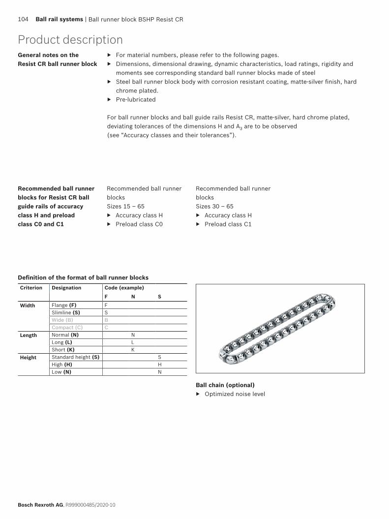
General notes on the Resist CR ball runner block
Recommended ball runner blocksSizes 15 – 65
▶ Accuracy class H ▶ Preload class C0
Recommended ball runner blocks for Resist CR ball guide rails of accuracy class H and preload class C0 and C1
▶ For material numbers, please refer to the following pages. ▶ Dimensions, dimensional drawing, dynamic characteristics, load ratings, rigidity and
moments see corresponding standard ball runner blocks made of steel ▶ Steel ball runner block body with corrosion resistant coating, matte-silver finish, hard
chrome plated. ▶ Pre-lubricated
For ball runner blocks and ball guide rails Resist CR, matte-silver, hard chrome plated, deviating tolerances of the dimensions H and A3 are to be observed (see “Accuracy classes and their tolerances”).
Ball runner block BSHP Resist CR
Product description
Recommended ball runner blocksSizes 30 – 65
▶ Accuracy class H ▶ Preload class C1
Ball chain (optional) ▶ Optimized noise level
104 Ball rail systems |
Bosch Rexroth AG, R999000485/2020-10
Definition of the format of ball runner blocksCriterion Designation Code (example)
F N S
Width Flange (F) FSlimline (S) SWide (B) BCompact (C) C
Length Normal (N) NLong (L) LShort (K) K
Height Standard height (S) SHigh (H) HLow (N) N
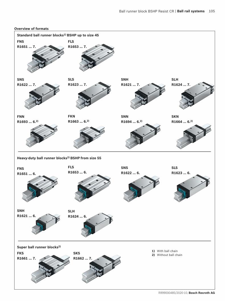
FNSR1651 ... 6.
SNSR1622 ... 6.
SLSR1623 ... 6.
FLSR1653 ... 6.
SNHR1621 ... 6.
SLHR1624 ... 6.
FKSR1661 ... 7.
SKSR1662 ... 7.
FNSR1651 ... 7.
FLSR1653 ... 7.
SNSR1622 ... 7.
SNHR1621 ... 7.
SLHR1624 ... 7.
SLSR1623 ... 7.
FNN R1693 ... 6.2)
SNNR1694 ... 6.2)
FKNR1663 ... 6.2)
SKNR1664 ... 6.2)
Heavy-duty ball runner blocks2) BSHP from size 55
Super ball runner blocks2)
1) With ball chain2) Without ball chain
Ball runner block BSHP Resist CR
Overview of formats
Standard ball runner blocks1) BSHP up to size 45
| Ball rail systems 105
R999000485/2020-10, Bosch Rexroth AG

Format Size Ball runner blocks with size
Preload class Accuracy class Seals on ball runner blocks
without ball chain with ball chainC0 C1 H SS LS DS SS LS DS
FNS 45 R1651 4 9 3 70 – – 72 – –1 3 70 – 7Z 72 – 7Y
E.g.: R1651 4 1 3 70
FLS 45 R1653 4 9 3 70 – – 72 – –1 3 70 – 7Z 72 – 7Y
SNS 45 R1622 4 9 3 70 – – 72 – –1 3 70 – 7Z 72 – 7Y
SLS 45 R1623 4 9 3 70 – – 72 – –1 3 70 – 7Z 72 – 7Y
SNH 15 R1621 1 9 – 3 70 71 – 72 73 –25 R1621 2 9 – 3 70 71 – 72 73 –30 R1621 7 9 3 70 71 – 72 73 –
1 70 71 7Z 72 73 7Y35 R1621 3 9 3 70 71 – 72 73 –
1 70 71 7Z 72 73 7Y45 R1621 4 9 3 70 – – 72 – –
1 70 – 7Z 72 – 7Y
SLH 25 R1624 2 9 – 3 70 71 – 72 73 –30 R1624 7 9 3 70 71 – 72 73 –
1 70 71 7Z 72 73 7Y35 R1624 3 9 3 70 71 – 72 73 –
1 70 71 7Z 72 73 7Y45 R1624 4 9 3 70 – – 72 – –
1 70 – 7Z 72 – 7Y
FNN 20 R1693 8 9 – 3 60 – – – – –25 R1693 2 9 – 3 60 – – – – –
FKN 20 R1663 8 9 – 3 60 – – – – –25 R1663 2 9 – 3 60 – – – – –
SNN 20 R1694 8 9 – 3 60 – – – – –25 R1694 2 9 – 3 60 – – – – –
SKN 20 R1664 8 9 – 3 60 – – – – –25 R1664 2 9 – 3 60 – – – – –
Standard ball runner blocks BSHP
Order exampleOptions:
▶ Ball runner block BSHP Resist CR, FNS ▶ Size 45 ▶ Preload class C1 ▶ Accuracy class H ▶ With standard seal, without ball chain
Material number: R1651 413 70
Ball runner block BSHP Resist CR
SealsSS = Standard sealLS = Low-friction sealDS = Double-lip seal
Keygray numbers= No preferred variant /
combination(partially longer delivery times)
FNS, FLS, SNS, SLS, SNH, SLH, FNN, FKN, SNN, SKN, FKS, SKS
Preload classesC0 = Without preload (clearance)C1 = Moderate preload
106 Ball rail systems |
Bosch Rexroth AG, R999000485/2020-10

Format Size Ball runner blocks with size Preload class Accuracy class Seals on ball runner blocks without ball chain
C0 C1 H SSFNS 55 R1651 5 9 1 3 60
65 R1651 6 9 1 3 60
FLS 55 R1653 5 9 1 3 6065 R1653 6 9 1 3 60
SNS 55 R1622 5 9 1 3 6065 R1622 6 9 1 3 60
SLS 55 R1623 5 9 1 3 6065 R1623 6 9 1 3 60
SNH 55 R1621 5 9 1 3 60
SLH 55 R1624 5 9 1 3 60
Heavy-duty BSHP ball runner blocks
Format Size Ball runner blocks with size Preload class Accuracy class Seals on ball runner blocks without ball chain
C0 C1 H SS LS DSFKS 15 R1661 1 9 – 3 70 71 –
20 R1661 8 9 – 3 70 71 –
25 R1661 2 9 – 3 70 71 –30 R1661 7 9 3 70 71 –
1 3 70 71 7Z35 R1661 3 9 3 70 71 –
1 3 70 71 7Z
SKS 15 R1662 1 9 – 3 70 71 –20 R1662 8 9 – 3 70 71 –25 R1662 2 9 – 3 70 71 –30 R1662 7 9 3 70 71 –
1 3 70 71 7Z35 R1662 3 9 3 70 71 –
1 3 70 71 7Z
Super ball runner blocks
Ball runner block BSHP Resist CR
NoteDimensions, dimensional drawing, load ratings, rigidity and moments see standard/heavy-duty ball runner block BSHP and super ball runner block.
| Ball rail systems 107
R999000485/2020-10, Bosch Rexroth AG

Standard ball guide rails made of steel
Proven cover strip for the ball guide rail mounting holes ▶ One cover for all bore holes saves time and costs ▶ Made of corrosion resistant spring steel as per
DIN EN 10088 ▶ Easy and safe during mounting ▶ Clip and secure
Ball guide rails with cover strip and screwed plastic protective caps
▶ With threaded holes at the end faces
Ball guide rails with cover strip and strip clamps made of aluminum
▶ Without end-face threaded holes (not required)
Ball guide rails with plastic mounting hole plugs
Ball guide rails with steel mounting hole plugs
Ball guide rails for mounting from below
Characteristic features
▶ Maximum rigidity in all load directions ▶ High torque load capacity
Product description
108 Ball rail systems |
Bosch Rexroth AG, R999000485/2020-10
Definition of the format of ball guide railsCriterion Designation Code (example)
S N SWidth Slimline (S) S
Wide (B) BLength Normal (N) NHeight Standard height (S) S
Without groove (O) O

T1
nT · T(T1)T
L± 1.5
T1
nT · T(T1)T
L± 1.5
L = · T – 4 LW T
*
L = nB · T – 4 mm
L = nT · T + 2 · T1S
L = · 80 mm – 4 mm
L = 21 · 80 mm – 4 mmL = 1676 mm
166080 mm( )
Ordering guide rails in the recommended rail lengthsOrdering ball guide rails in the recommended rail lengths
The procedure shown in the following ordering examples applies to all ball guide rails. Recommended rail lengths are more cost effective.
Excerpt from table with part numbers and recommended rail lengths for ordering example
L = Recommended rail length (mm)
LW = Desired rail length (mm)
T = Pitch (mm)
T1S = Preferred dimension (mm)
nB = Number of holes (–)
nT = Number of spaces (–)
Basis: Number of holes
Basis: Number of spaces
From the desired rail length to the recommended length
Calculation example
* Round up quotient LW/T to the nearest whole number!
R1605 .3. ../ R1605 .B. ..
For mounting from above, with cover strip made of corrosion-resistant spring steel per EN 10088 and strip clamps made of aluminum (without threaded mounting holes on end face)
Notes ▶ Secure the cover strip! ▶ Strip clamps are supplied. ▶ Follow the mounting instructions!
Send for the publications “Mounting Instructions for Ball Rail Systems” and “Mounting Instructions for the Cover Strip.”
▶ Composite guide rails also available.Further SNS/SNO ball guide rails and accessories are available.
▶ Cover strip, protective caps (see accessories for ball guide rails)
SNO R1605 .B. ball guide rails .. with fl at underside for mounting on components made of cast mineral materials
▶ In size 25 – 45 and accuracy class P and SP available on request.
SNS/SNO with cover strip and strip clamps
Size Ball guide rail with size
Accuracy class Number of sections, rail length L (mm), ....
Pitch T (mm)
Recommended rail length in accordance with formula L = nB · T – 4 mm
N H P SP UP One-piece Composite Maximum number of holes nB 15 4606.... ,.3.... ,139123431 5061R20 4606.... ,.3.... ,139123438 5061R25 4606.... ,.3.... ,139123432 5061R30 8408.... ,.3.... ,139123437 5061R35 8408.... ,.6.... ,169123433 5061R45 63501.... ,.6.... ,169123434 5061R55 23021.... ,.6.... ,169123435 5061R65 52051.... ,.6.... ,169123436 5061Re.g. R1605 73 3 31, 1676
Ordering example 1 (to Lmax)Options:
▶ Ball guide rail SNS ▶ Size 30 ▶ Accuracy class H ▶ One-piece ▶ Rail length
L = 1676 mmPart number: R1605 733 31, 1676 mm
Options and part numbers
Ordering example 2 (above Lmax)Options:
▶ Ball guide rail SNS ▶ Size 30 ▶ Accuracy class H ▶ 2 sections ▶ Rail length
L = 5116 mmPart number: R1605 733 32, 5116 mm
Ordering example 3 (to Lmax , with smooth base surface)Options:
▶ SNO ball guide rail ▶ Size 30 ▶ Accuracy class H ▶ One-piece ▶ Rail length
L = 1676 mmPart number: R1605 7B3 31, 1676 mm
Standard ball guide rails made of steel110 Ball Rail Systems |
Bosch Rexroth AG, R999000485 (2014-12)
Standard ball guide rails made of steel
Notes on ordering examplesIf preferred dimension T1S is not used, it is possible to choose between:
▶ Select end spacing T1 between T1S and T1 min
▶ As an alternative, it is possible to choose end spacings T1 to T1 max
Ordering example 1 (to Lmax) ▶ Ball guide rail SNS size 30 with
cover strip and strip clamps ▶ Accuracy class H ▶ Calculated rail length 1676 mm,
(20 · T, preferred dimension T1S = 38 mm; number of holes nB = 21)
Ordering dataPart number; rail length (mm) T1 / nT · T / T1 (mm)
R1605 733 31, 1676 mm 38 / 20 · 80 / 38 mm
Ordering example 2 (above Lmax) ▶ Ball guide rail SNS size 30 with
cover strip and strip clamps ▶ Accuracy class H ▶ Calculated rail length 5116 mm,
2 partial sections (63 · T, preferred dimension T1S = 38 mm; number of holes nB = 64)
Ordering dataMaterial number with number of partial sections, rail length (mm) T1 / nT · T / T1 (mm)
R1605 733 32, 5116 mm 38 / 63 · 80 / 38 mm
In the case of rail lengths above Lmax, partial sections approved by Rexroth are joined together.
| Ball rail systems 109
R999000485/2020-10, Bosch Rexroth AG

R1605 .3. ../ R1605 .B. ..
For mounting from above, with cover strip made of corrosion-resistant spring steel as per DIN EN 10088 and aluminium strip clamps (without threaded holes on end faces)
Notes ▶ Secure the cover strip! ▶ Strip clamps included in scope of delivery. ▶ Observe the instruction for mounting!
Please request the “Mounting instructions for ball rail systems” and “Mounting instructions for cover strip”.
▶ Composite ball guide rail also available.Further ball guide rails SNS/SNO and accessories available.
▶ Cover strip, protective caps (see accessories for ball guide rails)
Ball guide rails SNO R1605 .B. .. with smooth base area for mounting surfaces from cast mineral partsIn sizes 25-45 and available in accuracy class P and SP.
SNS/SNO with cover strip and strip clamps
Size Ball guide rail with size
Accuracy class Number of partial sections .,Rail length L (mm), ....
Spacing T (mm)
Recommended rail length in accordance with formula L = nB · T – 4 mm
N H P SP UP One-piece Composite Maximum number of holes nB 15 R1605 13 4 3 2 1 9 31, .... 3., .... 60 6420 R1605 83 4 3 2 1 9 31, .... 3., .... 60 6425 R1605 23 4 3 2 1 9 31, .... 3., .... 60 6430 R1605 73 4 3 2 1 9 31, .... 3., .... 80 4835 R1605 33 4 3 2 1 9 61, .... 6., .... 80 4845 R1605 43 4 3 2 1 9 61, .... 6., .... 105 3655 R1605 53 4 3 2 1 9 61, .... 6., .... 120 3265 R1605 63 4 3 2 1 9 61, .... 6., .... 150 25E.g.: R1605 73 3 31, 1676
Ordering example 1 (to Lmax)Options:
▶ Ball guide rail SNS ▶ Size 30 ▶ Accuracy class H ▶ One-piece ▶ Rail length
L = 1676 mmMaterial number: R1605 733 31, 1676 mm
Options and material numbers
Ordering example 2 (above Lmax)Options:
▶ Ball guide rail SNS ▶ Size 30 ▶ Accuracy class H ▶ 2 partial sections ▶ Rail length
L = 5116 mmMaterial number: R1605 733 32, 5116 mm
Ordering example 3 (up to Lmax , with smooth surface)Options:
▶ Ball guide rail SNO ▶ Size 30 ▶ Accuracy class H ▶ One-piece ▶ Rail length
L = 1676 mmMaterial number: R1605 7B3 31, 1676 mm
Standard ball guide rails made of steel110 Ball rail systems |
Bosch Rexroth AG, R999000485/2020-10
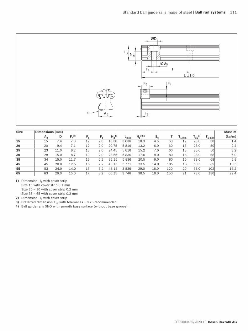
ØS5
T1 T
L ±1.5
F5 F4
H2 N 6
ØD
A2 F64)
1) Dimension H2 with cover strip Size 15 with cover strip 0.1 mm Size 20 – 30 with cover strip 0.2 mm Size 35 – 65 with cover strip 0.3 mm
2) Dimension H4 with cover strip3) Preferred dimension T1S with tolerances ± 0.75 recommended.4) Ball guide rails SNO with smooth base surface (without base groove).
Size Dimensions (mm) Mass mA2 D F4
2) F5 F6 H21) Lmax N6
±0.5 S5 T T1 min T1S
3) T1 max (kg/m)
15 15 7.4 7.3 12 2.0 16.30 3 836 10.3 4.5 60 12 28.0 50 1.420 20 9.4 7.1 12 2.0 20.75 5 816 13.2 6.0 60 13 28.0 50 2.425 23 11.0 8.2 13 2.0 24.45 5 816 15.2 7.0 60 13 28.0 50 3.230 28 15.0 8.7 13 2.0 28.55 5 836 17.0 9.0 80 16 38.0 68 5.035 34 15.0 11.7 16 2.2 32.15 5 836 20.5 9.0 80 16 38.0 68 6.845 45 20.0 12.5 18 2.2 40.15 5 771 23.5 14.0 105 18 50.5 89 10.555 53 24.0 14.0 17 3.2 48.15 3 836 29.0 16.0 120 20 58.0 102 16.265 63 26.0 15.0 17 3.2 60.15 3 746 38.5 18.0 150 21 73.0 130 22.4
Standard ball guide rails made of steel | Ball rail systems 111
R999000485/2020-10, Bosch Rexroth AG
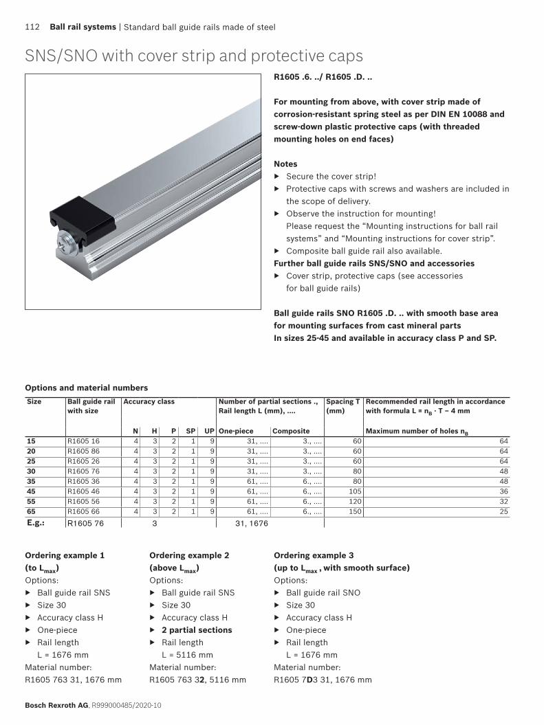
SNS/SNO with cover strip and protective capsR1605 .6. ../ R1605 .D. ..
For mounting from above, with cover strip made of corrosion-resistant spring steel as per DIN EN 10088 and screw-down plastic protective caps (with threaded mounting holes on end faces)
Notes ▶ Secure the cover strip! ▶ Protective caps with screws and washers are included in
the scope of delivery. ▶ Observe the instruction for mounting!
Please request the “Mounting instructions for ball rail systems” and “Mounting instructions for cover strip”.
▶ Composite ball guide rail also available.Further ball guide rails SNS/SNO and accessories
▶ Cover strip, protective caps (see accessories for ball guide rails)
Ball guide rails SNO R1605 .D. .. with smooth base area for mounting surfaces from cast mineral partsIn sizes 25-45 and available in accuracy class P and SP.
Ordering example 1 (to Lmax)Options:
▶ Ball guide rail SNS ▶ Size 30 ▶ Accuracy class H ▶ One-piece ▶ Rail length
L = 1676 mmMaterial number: R1605 763 31, 1676 mm
Options and material numbers
Ordering example 2 (above Lmax)Options:
▶ Ball guide rail SNS ▶ Size 30 ▶ Accuracy class H ▶ 2 partial sections ▶ Rail length
L = 5116 mmMaterial number: R1605 763 32, 5116 mm
Size Ball guide rail with size
Accuracy class Number of partial sections .,Rail length L (mm), ....
Spacing T (mm)
Recommended rail length in accordance with formula L = nB · T – 4 mm
N H P SP UP One-piece Composite Maximum number of holes nB 15 R1605 16 4 3 2 1 9 31, .... 3., .... 60 6420 R1605 86 4 3 2 1 9 31, .... 3., .... 60 6425 R1605 26 4 3 2 1 9 31, .... 3., .... 60 6430 R1605 76 4 3 2 1 9 31, .... 3., .... 80 4835 R1605 36 4 3 2 1 9 61, .... 6., .... 80 4845 R1605 46 4 3 2 1 9 61, .... 6., .... 105 3655 R1605 56 4 3 2 1 9 61, .... 6., .... 120 3265 R1605 66 4 3 2 1 9 61, .... 6., .... 150 25E.g.: R1605 76 3 31, 1676
Ordering example 3 (up to Lmax , with smooth surface)Options:
▶ Ball guide rail SNO ▶ Size 30 ▶ Accuracy class H ▶ One-piece ▶ Rail length
L = 1676 mmMaterial number: R1605 7D3 31, 1676 mm
Standard ball guide rails made of steel112 Ball rail systems |
Bosch Rexroth AG, R999000485/2020-10

H2
ØS5
N 6
T1 T
ØD
N11
M4 F5
F6A2
L ± 1.5
3)
Size Dimensions (mm) Mass m
A2 D F5 F6 H21) Lmax N6
±0.5 N11 S5 T T1 min
2) T1S4) T1
max (kg/m)
15 15 7.4 14.0 6.5 16.30 3 836 10.3 9.8 4.5 60 12 28.0 50 1.420 20 9.4 14.0 6.5 20.75 5 816 13.2 13.0 6.0 60 13 28.0 50 2.425 23 11.0 15.2 6.5 24.45 5 816 15.2 15.0 7.0 60 13 28.0 50 3.230 28 15.0 15.2 7.0 28.55 5 836 17.0 18.0 9.0 80 16 38.0 68 5.035 34 15.0 18.0 7.0 32.15 5 836 20.5 22.0 9.0 80 16 38.0 68 6.845 45 20.0 20.0 7.0 40.15 5 771 23.5 30.0 14.0 105 18 50.5 89 10.555 53 24.0 20.0 7.0 48.15 3 836 29.0 30.0 16.0 120 20 58.0 102 16.265 63 26.0 20.0 7.0 60.15 3 746 38.5 40.0 18.0 150 21 73.0 130 22.4
1) Dimension H2 with cover strip Size 15 with cover strip 0.1 mm Size 20 – 30 with cover strip 0.2 mm Size 35 – 65 with cover strip 0.3 mm
2) For end spaces below T1min, no threaded holes in end faces possible. Secure the cover strip. 3) Ball guide rails SNO with smooth base surface (without base groove).4) Preferred dimension T1S with tolerances ± 0.75 recommended.
Standard ball guide rails made of steel | Ball rail systems 113
R999000485/2020-10, Bosch Rexroth AG

SNS/SNO with plastic mounting hole plugsR1605 .0. ../ R1605 .C. ..
For mounting from above with plastic mounting hole plugs
Notes ▶ Plastic mounting hole plugs included in scope of supply. ▶ Observe the instruction for mounting!
Please request the “Mounting instructions for ball rail systems.”
▶ Composite ball guide rail also available.Further ball guide rails SNS and accessories
▶ Corrosion resistant ball guide rails Resist NR, Resist CR ▶ Mounting hole plugs made of plastic, see accessories
for ball guide rails Ball guide rails SNO R1605 .C. .. with smooth base area for mounting surfaces from cast mineral partsIn sizes 25-45 and available in accuracy class P and SP.
Ordering example 1 (to Lmax)Options:
▶ Ball guide rail SNS ▶ Size 30 ▶ Accuracy class H ▶ One-piece ▶ Rail length
L = 1676 mmMaterial number: R1605 703 31, 1676 mm
Options and material numbers
Ordering example 2 (above Lmax)Options:
▶ Ball guide rail SNS ▶ Size 30 ▶ Accuracy class H ▶ 2 partial sections ▶ Rail length
L = 5116 mmMaterial number: R1605 703 32, 5116 mm
Size Ball guide rail with size
Accuracy class Number of partial sections .,Rail length L (mm), ....
Spacing T (mm)
Recommended rail length in accordance with formula L = nB · T – 4 mm
N H P SP UP One-piece Composite Maximum number of holes nB 15 R1605 10 4 3 2 1 9 31, .... 3., .... 60 6420 R1605 80 4 3 2 1 9 31, .... 3., .... 60 6425 R1605 20 4 3 2 1 9 31, .... 3., .... 60 6430 R1605 70 4 3 2 1 9 31, .... 3., .... 80 4835 R1605 30 4 3 2 1 9 31, .... 3., .... 80 4845 R1605 40 4 3 2 1 9 31, .... 3., .... 105 3655 R1605 50 4 3 2 1 9 31, .... 3., .... 120 3265 R1605 60 4 3 2 1 9 31, .... 3., .... 150 25
E.g.: R1605 70 3 31, 1676
Ordering example 3 (up to Lmax , with smooth surface)Options:
▶ Ball guide rail SNO ▶ Size 30 ▶ Accuracy class H ▶ One-piece ▶ Rail length
L = 1676 mmMaterial number: R1605 7C3 31, 1676 mm
Standard ball guide rails made of steel114 Ball rail systems |
Bosch Rexroth AG, R999000485/2020-10
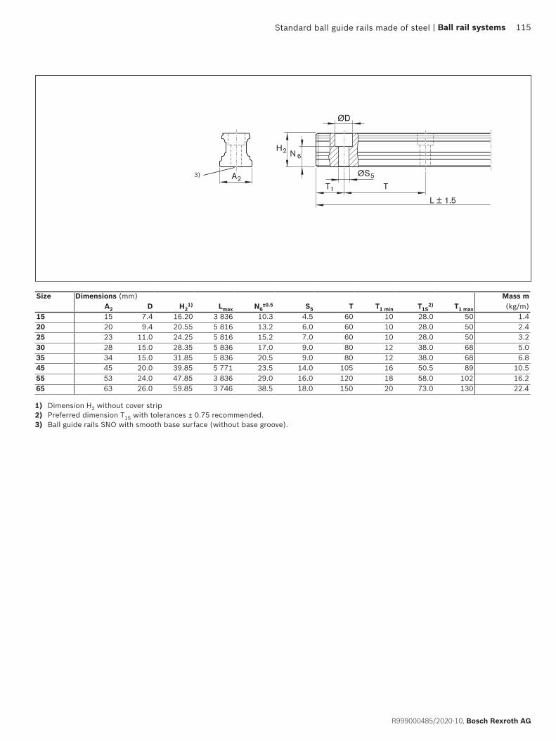
ØS5
T1 T
L ± 1.5
ØD
H2 N 6
A23)
Size Dimensions (mm) Mass mA2 D H2
1) Lmax N6±0.5 S5 T T1
min T1S
2) T1 max (kg/m)
15 15 7.4 16.20 3 836 10.3 4.5 60 10 28.0 50 1.420 20 9.4 20.55 5 816 13.2 6.0 60 10 28.0 50 2.425 23 11.0 24.25 5 816 15.2 7.0 60 10 28.0 50 3.230 28 15.0 28.35 5 836 17.0 9.0 80 12 38.0 68 5.035 34 15.0 31.85 5 836 20.5 9.0 80 12 38.0 68 6.845 45 20.0 39.85 5 771 23.5 14.0 105 16 50.5 89 10.555 53 24.0 47.85 3 836 29.0 16.0 120 18 58.0 102 16.265 63 26.0 59.85 3 746 38.5 18.0 150 20 73.0 130 22.4
1) Dimension H2 without cover strip2) Preferred dimension T1S with tolerances ± 0.75 recommended.3) Ball guide rails SNO with smooth base surface (without base groove).
Standard ball guide rails made of steel | Ball rail systems 115
R999000485/2020-10, Bosch Rexroth AG

SNS with mounting hole plugs made of steelR1606 .5. ..
For mounting from above, for mounting hole plugs made of steel
Notes ▶ Mounting hole plugs made of steel not included in scope
of delivery. ▶ Observe the instruction for mounting!
Please request the “Mounting instructions for ball rail systems.”
▶ Composite ball guide rail also available.Further ball guide rails SNS and accessories
▶ Mounting hole plugs made of steel, mounting device for mounting hole plugs made of steel see accessories for ball guide rails
Ordering example 1 (to Lmax)Options:
▶ Ball guide rail SNS ▶ Size 30 ▶ Accuracy class H ▶ One-piece ▶ Rail length
L = 1676 mmMaterial number: R1606 753 31, 1676 mm
Options and material numbers
Ordering example 2 (above Lmax)Options:
▶ Ball guide rail SNS ▶ Size 30 ▶ Accuracy class H ▶ 2 partial sections ▶ Rail length
L = 5116 mmMaterial number: R1606 753 32, 5116 mm
Size Ball guide rail with size
Accuracy class Number of partial sections .,Rail length L (mm), ....
Spacing T (mm)
Recommended rail length in accordance with formula L = nB · T – 4 mm
N H P SP One-piece Composite Maximum number of holes nB 25 R1606 25 4 3 2 1 31, .... 3., .... 60 6430 R1606 75 4 3 2 1 31, .... 3., .... 80 4835 R1606 35 4 3 2 1 31, .... 3., .... 80 4845 R1606 45 4 3 2 1 31, .... 3., .... 105 3655 R1606 55 4 3 2 1 31, .... 3., .... 120 3265 R1606 65 4 3 2 1 31, .... 3., .... 150 25
E.g.: R1606 75 3 31, 1676
Standard ball guide rails made of steel116 Ball rail systems |
Bosch Rexroth AG, R999000485/2020-10
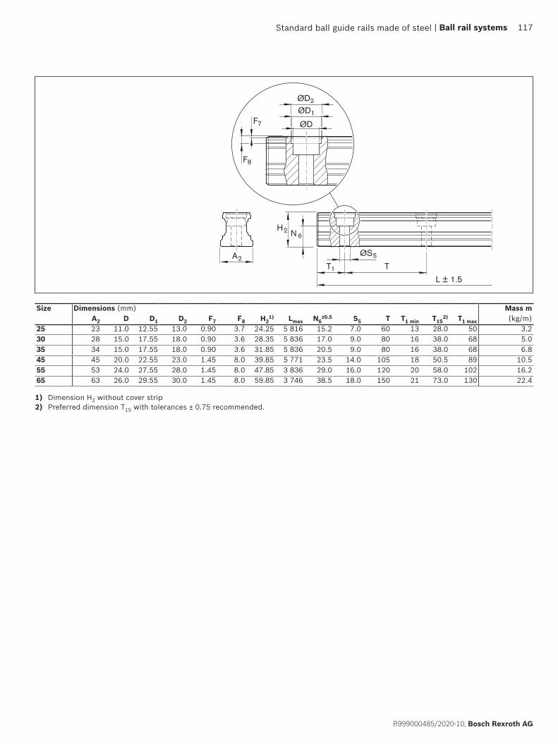
ØD
ØD1
ØD2
F7
F8
ØS5
T1 T
H2 N 6
A2
L ± 1.5
Size Dimensions (mm) Mass mA2 D D1 D2 F7 F8 H2
1) Lmax N6±0.5 S5 T T1 min T1S
2) T1 max (kg/m)
25 23 11.0 12.55 13.0 0.90 3.7 24.25 5 816 15.2 7.0 60 13 28.0 50 3.230 28 15.0 17.55 18.0 0.90 3.6 28.35 5 836 17.0 9.0 80 16 38.0 68 5.035 34 15.0 17.55 18.0 0.90 3.6 31.85 5 836 20.5 9.0 80 16 38.0 68 6.845 45 20.0 22.55 23.0 1.45 8.0 39.85 5 771 23.5 14.0 105 18 50.5 89 10.555 53 24.0 27.55 28.0 1.45 8.0 47.85 3 836 29.0 16.0 120 20 58.0 102 16.265 63 26.0 29.55 30.0 1.45 8.0 59.85 3 746 38.5 18.0 150 21 73.0 130 22.4
1) Dimension H2 without cover strip2) Preferred dimension T1S with tolerances ± 0.75 recommended.
Standard ball guide rails made of steel | Ball rail systems 117
R999000485/2020-10, Bosch Rexroth AG
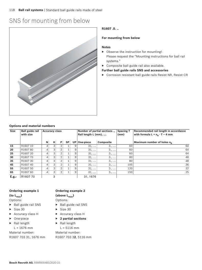
SNS for mounting from belowR1607 .0. ..
For mounting from below
Notes ▶ Observe the instruction for mounting!
Please request the “Mounting instructions for ball rail systems.”
▶ Composite ball guide rail also available.Further ball guide rails SNS and accessories
▶ Corrosion resistant ball guide rails Resist NR, Resist CR
Ordering example 1 (to Lmax)Options:
▶ Ball guide rail SNS ▶ Size 30 ▶ Accuracy class H ▶ One-piece ▶ Rail length
L = 1676 mmMaterial number: R1607 703 31, 1676 mm
Options and material numbers
Ordering example 2 (above Lmax)Options:
▶ Ball guide rail SNS ▶ Size 30 ▶ Accuracy class H ▶ 2 partial sections ▶ Rail length
L = 5116 mmMaterial number: R1607 703 32, 5116 mm
Size Ball guide rail with size
Accuracy class Number of partial sections .,Rail length L (mm), ....
Spacing T (mm)
Recommended rail length in accordance with formula L = nB · T – 4 mm
N H P SP UP One-piece Composite Maximum number of holes nB 15 R1607 10 4 3 2 1 9 31, .... 3., .... 60 6420 R1607 80 4 3 2 1 9 31, .... 3., .... 60 6425 R1607 20 4 3 2 1 9 31, .... 3., .... 60 6430 R1607 70 4 3 2 1 9 31, .... 3., .... 80 4835 R1607 30 4 3 2 1 9 31, .... 3., .... 80 4845 R1607 40 4 3 2 1 9 31, .... 3., .... 105 3655 R1607 50 4 3 2 1 9 31, .... 3., .... 120 3265 R1607 60 4 3 2 1 9 31, .... 3., .... 150 25
E.g.: R1607 70 3 31, 1676
Standard ball guide rails made of steel118 Ball rail systems |
Bosch Rexroth AG, R999000485/2020-10
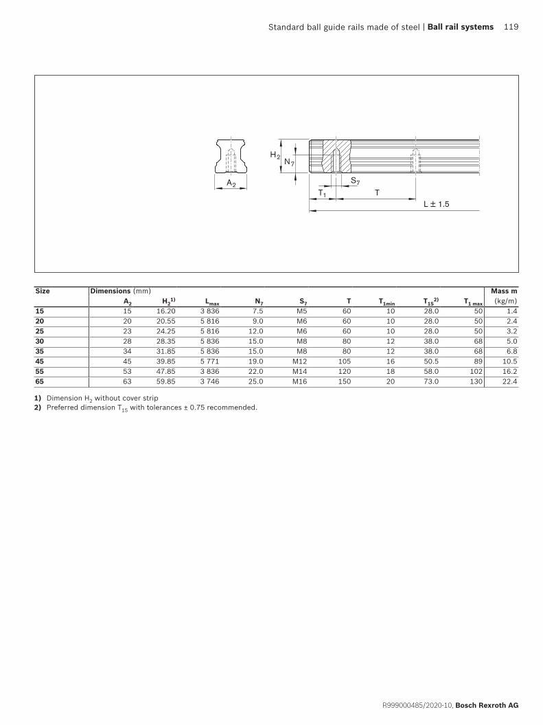
S7
T1 T
H2N7
A2
L ± 1.5
Size Dimensions (mm) Mass mA2 H2
1) Lmax N7 S7 T T1min T1S2) T1
max (kg/m)
15 15 16.20 3 836 7.5 M5 60 10 28.0 50 1.420 20 20.55 5 816 9.0 M6 60 10 28.0 50 2.425 23 24.25 5 816 12.0 M6 60 10 28.0 50 3.230 28 28.35 5 836 15.0 M8 80 12 38.0 68 5.035 34 31.85 5 836 15.0 M8 80 12 38.0 68 6.845 45 39.85 5 771 19.0 M12 105 16 50.5 89 10.555 53 47.85 3 836 22.0 M14 120 18 58.0 102 16.265 63 59.85 3 746 25.0 M16 150 20 73.0 130 22.4
1) Dimension H2 without cover strip2) Preferred dimension T1S with tolerances ± 0.75 recommended.
Standard ball guide rails made of steel | Ball rail systems 119
R999000485/2020-10, Bosch Rexroth AG
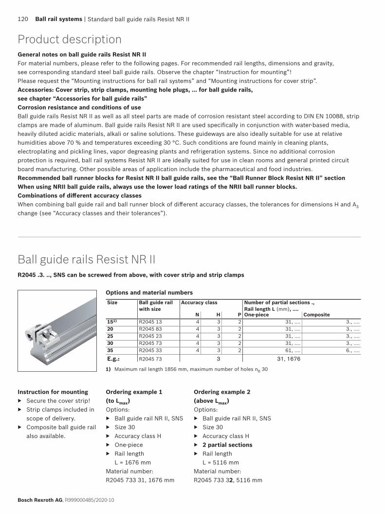
Ball guide rails Resist NR IIR2045 .3. .., SNS can be screwed from above, with cover strip and strip clamps
Options and material numbersSize Ball guide rail
with sizeAccuracy class Number of partial sections .,
Rail length L (mm), ....N H P One-piece Composite
151) R2045 13 4 3 2 31, .... 3., ....20 R2045 83 4 3 2 31, .... 3., ....25 R2045 23 4 3 2 31, .... 3., ....30 R2045 73 4 3 2 31, .... 3., ....35 R2045 33 4 3 2 61, .... 6., ....
E.g.: R2045 73 3 31, 1676
Ordering example 1 (to Lmax)Options:
▶ Ball guide rail NR II, SNS ▶ Size 30 ▶ Accuracy class H ▶ One-piece ▶ Rail length
L = 1676 mmMaterial number: R2045 733 31, 1676 mm
Ordering example 2 (above Lmax)Options:
▶ Ball guide rail NR II, SNS ▶ Size 30 ▶ Accuracy class H ▶ 2 partial sections ▶ Rail length
L = 5116 mmMaterial number: R2045 733 32, 5116 mm
Instruction for mounting ▶ Secure the cover strip! ▶ Strip clamps included in
scope of delivery. ▶ Composite ball guide rail
also available.
1) Maximum rail length 1856 mm, maximum number of holes nB 30
General notes on ball guide rails Resist NR IIFor material numbers, please refer to the following pages. For recommended rail lengths, dimensions and gravity, see corresponding standard steel ball guide rails. Observe the chapter “Instruction for mounting”!Please request the “Mounting instructions for ball rail systems” and “Mounting instructions for cover strip”.Accessories: Cover strip, strip clamps, mounting hole plugs, ... for ball guide rails, see chapter “Accessories for ball guide rails”Corrosion resistance and conditions of useBall guide rails Resist NR II as well as all steel parts are made of corrosion resistant steel according to DIN EN 10088, strip clamps are made of aluminum. Ball guide rails Resist NR II are used specifically in conjunction with water-based media, heavily diluted acidic materials, alkali or saline solutions. These guideways are also ideally suitable for use at relative humidities above 70 % and temperatures exceeding 30 °C. Such conditions are found mainly in cleaning plants, electroplating and pickling lines, vapor degreasing plants and refrigeration systems. Since no additional corrosion protection is required, ball rail systems Resist NR II are ideally suited for use in clean rooms and general printed circuit board manufacturing. Other possible areas of application include the pharmaceutical and food industries.Recommended ball runner blocks for Resist NR II ball guide rails, see the “Ball Runner Block Resist NR II” sectionWhen using NRII ball guide rails, always use the lower load ratings of the NRII ball runner blocks.Combinations of different accuracy classesWhen combining ball guide rail and ball runner block of different accuracy classes, the tolerances for dimensions H and A3 change (see “Accuracy classes and their tolerances”).
Standard ball guide rails Resist NR II
Product description
120 Ball rail systems |
Bosch Rexroth AG, R999000485/2020-10

R2045 .0. .., SNS can be screwed from above, with plastic mounting hole plugs
Options and material numbers
Ordering example 1 (to Lmax)Options:
▶ Ball guide rail NR II, SNS ▶ Size 30 ▶ Accuracy class H ▶ One-piece ▶ Rail length
L = 1676 mmMaterial number: R2045 703 31, 1676 mm
Ordering example 2 (above Lmax)Options:
▶ Ball guide rail NR II, SNS ▶ Size 30 ▶ Accuracy class H ▶ 2 partial sections ▶ Rail length
L = 5116 mmMaterial number: R2045 703 32, 5116 mm
Size Ball guide rail with size
Accuracy class Number of partial sections .,Rail length L (mm), ....
N H P One-piece Composite151) R2045 10 4 3 2 31, .... 3., ....20 R2045 80 4 3 2 31, .... 3., ....25 R2045 20 4 3 2 31, .... 3., ....30 R2045 70 4 3 2 31, .... 3., ....35 R2045 30 4 3 2 31, .... 3., ....
E.g.: R2045 70 3 31, 1676
Instruction for mounting ▶ Plastic mounting hole
plugs included in scope of supply.
▶ Composite ball guide rail also available.
R2047 .0. .., SNS, for mounting from below
Ordering example 1 (to Lmax)Options:
▶ Ball guide rail NR II, SNS ▶ Size 30 ▶ Accuracy class H ▶ One-piece ▶ Rail length
L = 1676 mmMaterial number: R2047 703 31, 1676 mm
Ordering example 2 (above Lmax)Options:
▶ Ball guide rail NR II, SNS ▶ Size 30 ▶ Accuracy class H ▶ 2 partial sections ▶ Rail length
L = 5116 mmMaterial number: R2047 703 32, 5116 mm
Options and material numbers
1) Maximum rail length 1856 mm, maximum number of holes nB 30
Size Ball guide rail with size
Accuracy class Number of partial sections .,Rail length L (mm), ....
N H P One-piece Composite151) R2047 10 4 3 2 31, .... 3., ....20 R2047 80 4 3 2 31, .... 3., ....25 R2047 20 4 3 2 31, .... 3., ....30 R2047 70 4 3 2 31, .... 3., ....35 R2047 30 4 3 2 31, .... 3., ....
E.g.: R2047 70 3 32, 5116
Ball guide rails Resist NR II
Instruction for mounting ▶ Composite ball guide rail
also available.
Standard ball guide rails Resist NR II
1) Maximum rail length 1856 mm, maximum number of holes nB 30
| Ball rail systems 121
R999000485/2020-10, Bosch Rexroth AG
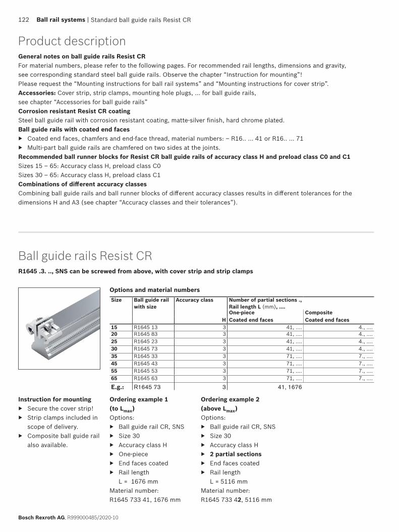
Ball guide rails Resist CRR1645 .3. .., SNS can be screwed from above, with cover strip and strip clamps
Options and material numbers
Ordering example 1 (to Lmax)Options:
▶ Ball guide rail CR, SNS ▶ Size 30 ▶ Accuracy class H ▶ One-piece ▶ End faces coated ▶ Rail length
L = 1676 mmMaterial number: R1645 733 41, 1676 mm
Instruction for mounting ▶ Secure the cover strip! ▶ Strip clamps included in
scope of delivery. ▶ Composite ball guide rail
also available.
Ordering example 2 (above Lmax)Options:
▶ Ball guide rail CR, SNS ▶ Size 30 ▶ Accuracy class H ▶ 2 partial sections ▶ End faces coated ▶ Rail length
L = 5116 mmMaterial number: R1645 733 42, 5116 mm
Size Ball guide rail with size
Accuracy class Number of partial sections .,Rail length L (mm), ....One-piece Composite
H Coated end faces Coated end faces15 R1645 13 3 41, .... 4., ....20 R1645 83 3 41, .... 4., ....25 R1645 23 3 41, .... 4., ....30 R1645 73 3 41, .... 4., ....35 R1645 33 3 71, .... 7., ....45 R1645 43 3 71, .... 7., ....55 R1645 53 3 71, .... 7., ....65 R1645 63 3 71, .... 7., ....
E.g.: R1645 73 3 41, 1676
General notes on ball guide rails Resist CRFor material numbers, please refer to the following pages. For recommended rail lengths, dimensions and gravity, see corresponding standard steel ball guide rails. Observe the chapter “Instruction for mounting”!Please request the “Mounting instructions for ball rail systems” and “Mounting instructions for cover strip”.Accessories: Cover strip, strip clamps, mounting hole plugs, ... for ball guide rails, see chapter “Accessories for ball guide rails”Corrosion resistant Resist CR coatingSteel ball guide rail with corrosion resistant coating, matte-silver finish, hard chrome plated.Ball guide rails with coated end faces
▶ Coated end faces, chamfers and end-face thread, material numbers: – R16.. ... 41 or R16.. ... 71 ▶ Multi-part ball guide rails are chamfered on two sides at the joints.
Recommended ball runner blocks for Resist CR ball guide rails of accuracy class H and preload class C0 and C1Sizes 15 – 65: Accuracy class H, preload class C0Sizes 30 – 65: Accuracy class H, preload class C1Combinations of different accuracy classesCombining ball guide rails and ball runner blocks of different accuracy classes results in different tolerances for the dimensions H and A3 (see chapter “Accuracy classes and their tolerances”).
Standard ball guide rails Resist CR
Product description
122 Ball rail systems |
Bosch Rexroth AG, R999000485/2020-10
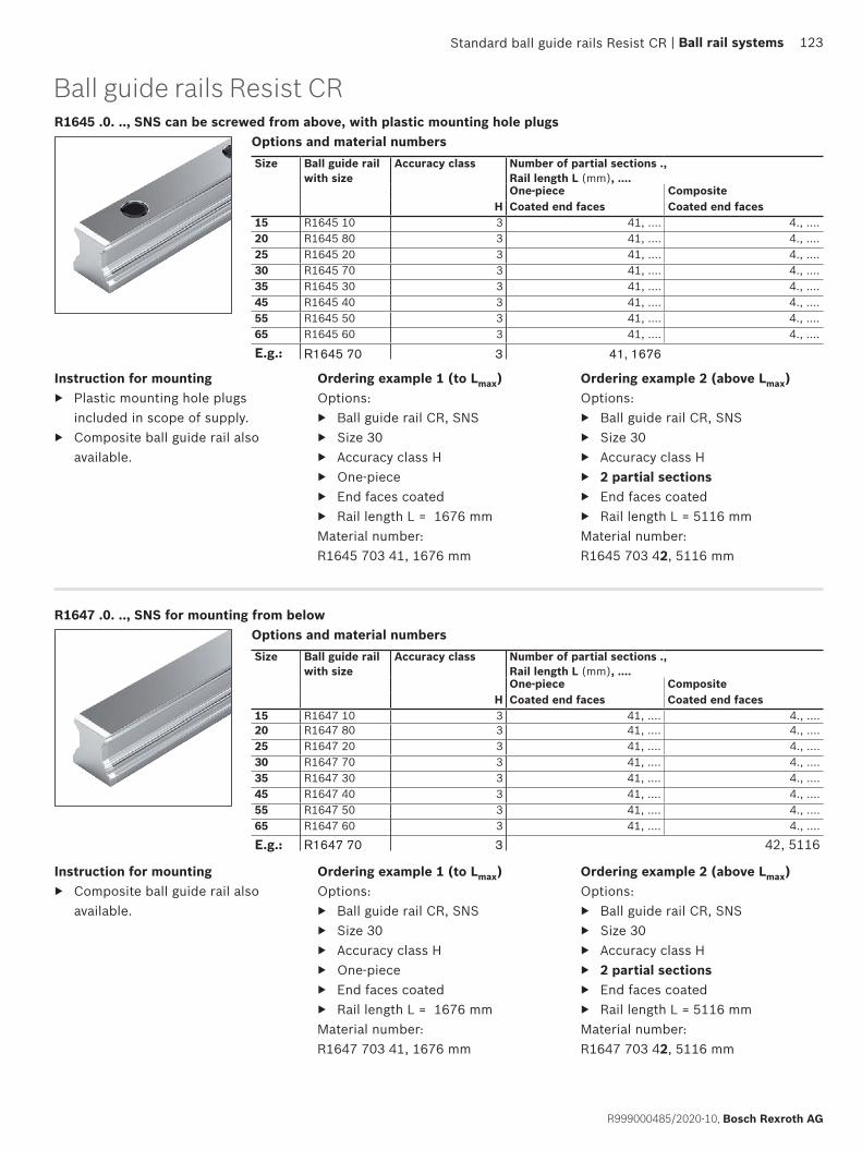
R1645 .0. .., SNS can be screwed from above, with plastic mounting hole plugsOptions and material numbers
Ordering example 1 (to Lmax)Options:
▶ Ball guide rail CR, SNS ▶ Size 30 ▶ Accuracy class H ▶ One-piece ▶ End faces coated ▶ Rail length L = 1676 mm
Material number: R1645 703 41, 1676 mm
Instruction for mounting ▶ Plastic mounting hole plugs
included in scope of supply. ▶ Composite ball guide rail also
available.
Ordering example 2 (above Lmax)Options:
▶ Ball guide rail CR, SNS ▶ Size 30 ▶ Accuracy class H ▶ 2 partial sections ▶ End faces coated ▶ Rail length L = 5116 mm
Material number: R1645 703 42, 5116 mm
Size Ball guide rail with size
Accuracy class Number of partial sections .,Rail length L (mm), ....One-piece Composite
H Coated end faces Coated end faces15 R1645 10 3 41, .... 4., ....20 R1645 80 3 41, .... 4., ....25 R1645 20 3 41, .... 4., ....30 R1645 70 3 41, .... 4., ....35 R1645 30 3 41, .... 4., ....45 R1645 40 3 41, .... 4., ....55 R1645 50 3 41, .... 4., ....65 R1645 60 3 41, .... 4., ....
E.g.: R1645 70 3 41, 1676
R1647 .0. .., SNS for mounting from below
Ball guide rails Resist CR
Options and material numbers
Ordering example 1 (to Lmax)Options:
▶ Ball guide rail CR, SNS ▶ Size 30 ▶ Accuracy class H ▶ One-piece ▶ End faces coated ▶ Rail length L = 1676 mm
Material number: R1647 703 41, 1676 mm
Ordering example 2 (above Lmax)Options:
▶ Ball guide rail CR, SNS ▶ Size 30 ▶ Accuracy class H ▶ 2 partial sections ▶ End faces coated ▶ Rail length L = 5116 mm
Material number: R1647 703 42, 5116 mm
Size Ball guide rail with size
Accuracy class Number of partial sections .,Rail length L (mm), ....One-piece Composite
H Coated end faces Coated end faces15 R1647 10 3 41, .... 4., ....20 R1647 80 3 41, .... 4., ....25 R1647 20 3 41, .... 4., ....30 R1647 70 3 41, .... 4., ....35 R1647 30 3 41, .... 4., ....45 R1647 40 3 41, .... 4., ....55 R1647 50 3 41, .... 4., ....65 R1647 60 3 41, .... 4., ....
E.g.: R1647 70 3 42, 5116
Instruction for mounting ▶ Composite ball guide rail also
available.
Standard ball guide rails Resist CR | Ball rail systems 123
R999000485/2020-10, Bosch Rexroth AG
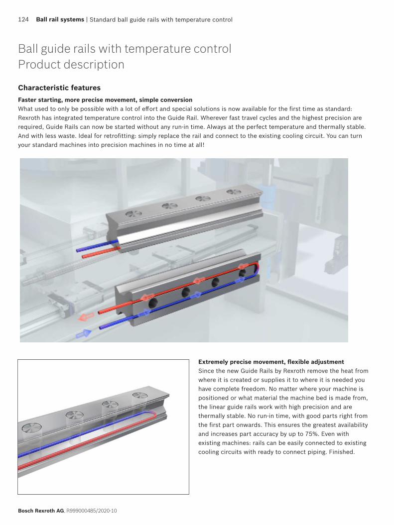
Standard ball guide rails with temperature control124 Ball rail systems |
Bosch Rexroth AG, R999000485/2020-10
Ball guide rails with temperature controlProduct description
Characteristic featuresFaster starting, more precise movement, simple conversionWhat used to only be possible with a lot of effort and special solutions is now available for the first time as standard: Rexroth has integrated temperature control into the Guide Rail. Wherever fast travel cycles and the highest precision are required, Guide Rails can now be started without any run-in time. Always at the perfect temperature and thermally stable. And with less waste. Ideal for retrofitting: simply replace the rail and connect to the existing cooling circuit. You can turn your standard machines into precision machines in no time at all!
Extremely precise movement, flexible adjustmentSince the new Guide Rails by Rexroth remove the heat from where it is created or supplies it to where it is needed you have complete freedom. No matter where your machine is positioned or what material the machine bed is made from, the linear guide rails work with high precision and are thermally stable. No run-in time, with good parts right from the first part onwards. This ensures the greatest availability and increases part accuracy by up to 75%. Even with existing machines: rails can be easily connected to existing cooling circuits with ready to connect piping. Finished.

35 45
Standard ball guide rails with temperature control
Ball guide rails with temperature control are available on request. The illustrations partly show the roller guide rail version
| Ball rail systems 125
R999000485/2020-10, Bosch Rexroth AG
Further highlights
▶ High precision: up to 75% higher part accuracy, regardless of environment
▶ Always available: no run-in to the operating temperature ▶ Flexible: can be adjusted to changes as required ▶ Can be retrofitted: compatible with existing systems ▶ Simple: pipes are ready to connect, uses existing cooling
circuits
Technical features
▶ Ball guide sizes: 35/45 ▶ Formats: R1605 ▶ Rail covers: Cover strip, plastic caps ▶ Series with groove ▶ Accuracy classes: P/SP ▶ Rail lengths: up to max. 4000 mm ▶ Redirecting temperature control: to the rails or universal ▶ Patent pending

Product description
1) Type-dependent
Size 20/40: New ball rail system with different ball diameters. Not interchangeable with the old 20/40 size!
Wide ball rail systems BSHP made of steel and Resist CR
Characteristic features ▶ Limitless interchangeability as all
ball guide rail systems can be combined at will with all ball runner block versions within each accuracy class. ▶ Very high torsional moment load capacity and very high torsion resistance – therefore primarily used as an
individual guide ▶ High torque load capacity ▶ The same high load ratings in all four main directions of loading ▶ Integrated all-round sealing ▶ Low noise level and optimum travel behavior ▶ Excellent dynamic characteristics:
Travel speed: vmax up to 5 m/s 1) Acceleration: amax up to 500 m/s2 1)
▶ Long-term lubrication is possible over several years ▶ Minimum quantity lubrication system with integrated reservoir for oil lubrication1)
▶ Lube fittings with metal threads on all sides1)
▶ Maximum system rigidity due to preloaded O-arrangement ▶ Wide range of accessories
Further highlights ▶ Optimized entry-zone geometry and high number of balls minimize variation in elastic deflection ▶ End-face fastening thread for all attachments ▶ Linear guideway with low clearance or moderate preload ▶ Quiet, smooth running thanks to optimally designed ball and ball chain return and guideway1)
▶ Attachments on the ball runner block can be mounted from above and below1)
▶ Improved rigidity under lift-off and side loading conditions due to two additional mounting screw holes at the center of the ball runner block
▶ Ball runner block pre-lubricated at the factory1)
▶ Optionally available with ball chain1)
▶ Can be used on all BNS ball guide rails.
Corrosion protection (optional) ▶ Resist CR:
Ball runner block body or ball guide rail made of steel with corrosion resistant coating, matte-silver finish, hard chrome plated
126 Ball rail systems |
Bosch Rexroth AG, R999000485/2020-10

BNS1) BNS
CNS1)
Sizes 20/40 and 25/70 ▶ With ball chain ▶ Pre-lubricated
Sizes 20/40 and 25/70 ▶ With ball chain ▶ Pre-lubricated
Overview of formats
Sizes 35/90
Wide ball rail systems made of steel and Resist CR
Ball chain (optional) ▶ Optimized noise level
| Ball rail systems 127
R999000485/2020-10, Bosch Rexroth AG
Definition of the format of ball runner blocksCriterion Designation Code (example)
B N S
Width Flange (F) FSlimline (S) SWide (B) BCompact (C) C
Length Normal (N) NLong (L) LShort (K) K
Height Standard height (S) SHigh (H) HLow (N) N

BNS – wide, normal, standard heightBall runner block made of steelR1671 ... 2.Dynamic characteristicsTravel speed: vmax = 5 m/sAcceleration: amax = 500 m/s2
(If Fcomb > 2.8 · Fpr : amax = 50 m/s2)Note on lubrication:
▶ Pre-lubricatedFurther ball runner blocks BNS
▶ Corrosion resistant ball runner blocks see below
Size Ball runner blocks with size
Preload class Accuracy class Seals on ball runner blocks
without ball chain
with ball chain
C0 C1 N H P SS DS SS DS20 /401) R1671 5 9 4 3 – 20 – 22 –
1 4 3 2 20 2Z 22 2Y25/70 R1671 2 9 4 3 – 20 – 22 –
1 4 3 2 20 2Z 22 2Y
E.g.: R1671 2 1 3 20
Options and material numbers
Size Ball runner blocks with size
Preload class Accuracy class Seals on ball runner blocks
without ball chain
with ball chain
C0 H SS DS SS DS20/401) R1671 5 9 3 70 7Z 72 7Y25/70 R1671 2 9 3 70 7Z 72 7Y
E.g.: R1671 2 9 3 70
1) Caution: Ball runner blocks, not combinable with ball guide rail R167. 8.. ..!
Options and material numbers
Ball runner block, Resist CR R1671 ... 7.
Note on lubrication: ▶ Pre-lubricated
Order exampleOptions:
▶ Ball runner blocks BNS ▶ Sizes 25/70 ▶ Preload class C0 ▶ Accuracy class H ▶ With standard seal,
without ball chainMaterial number: R1671 293 70
Wide ball rail systems made of steel and Resist CR
Order exampleOptions:
▶ Ball runner blocks BNS ▶ Sizes 25/70 ▶ Preload class C1 ▶ Accuracy class H ▶ With standard seal,
without ball chainMaterial number: R1671 213 20
Preload classesC0 = Without preload (clearance)C1 = Moderate preload
SealsSS = Standard sealDS = Double-lip seal
Keygray numbers= No preferred variant /
combination(partially longer delivery times)
128 Ball rail systems |
Bosch Rexroth AG, R999000485/2020-10
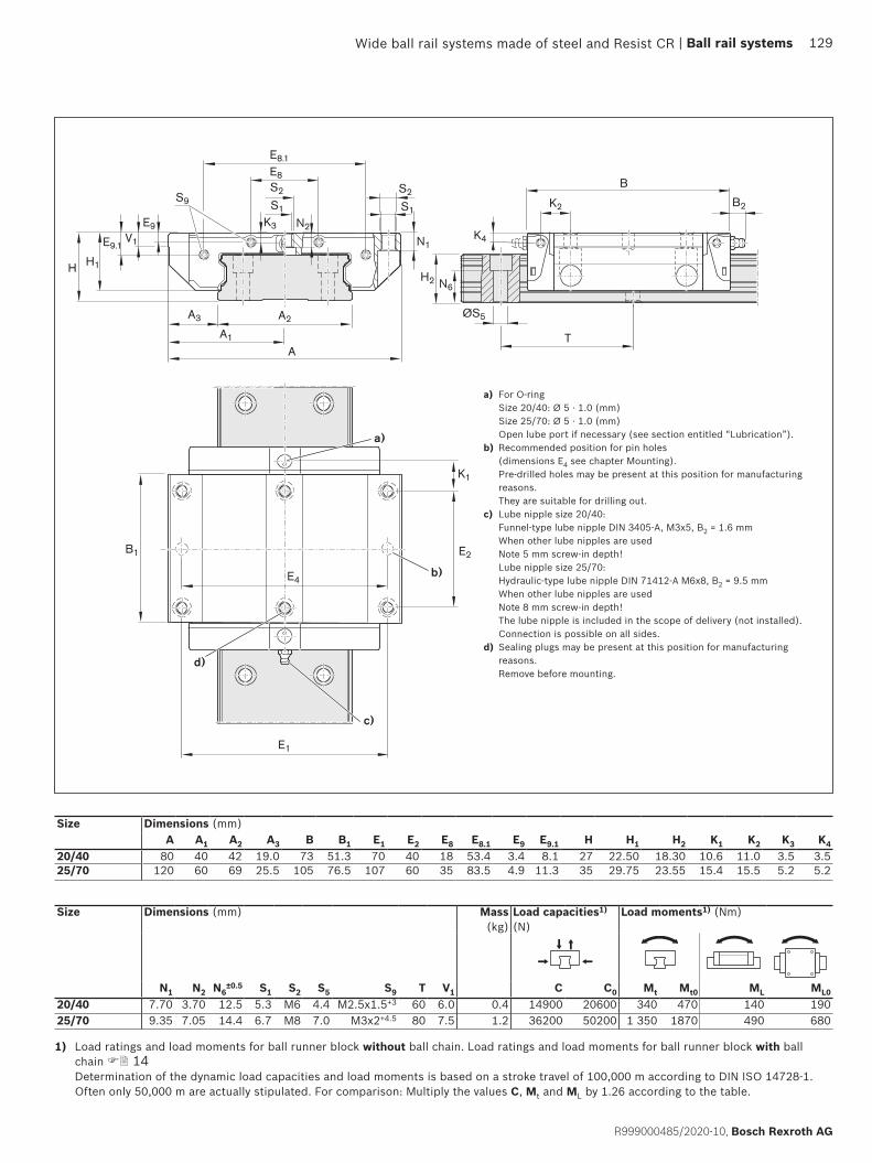
H1
V1E9.1
E9
H
A3 A2
A1
A
E1
N1
S2
S1S9
E8
E8.1
S2
S1
H2 N6
B
B1 E2
K1
K3 N2K4
B2K2
ØS5
T
E4b)
c)
d)
a)
a) For O-ring Size 20/40: Ø 5 · 1.0 (mm) Size 25/70: Ø 5 · 1.0 (mm) Open lube port if necessary (see section entitled “Lubrication”).
b) Recommended position for pin holes (dimensions E4 see chapter Mounting). Pre-drilled holes may be present at this position for manufacturing reasons. They are suitable for drilling out.
c) Lube nipple size 20/40: Funnel-type lube nipple DIN 3405-A, M3x5, B2 = 1.6 mm When other lube nipples are used Note 5 mm screw-in depth! Lube nipple size 25/70: Hydraulic-type lube nipple DIN 71412-A M6x8, B2 = 9.5 mm When other lube nipples are used Note 8 mm screw-in depth! The lube nipple is included in the scope of delivery (not installed). Connection is possible on all sides.
d) Sealing plugs may be present at this position for manufacturing reasons. Remove before mounting.
Size Dimensions (mm)A A1 A2 A3 B B1 E1 E2 E8 E8.1 E9 E9.1 H H1 H2 K1 K2 K3 K4
20/40 80 40 42 19.0 73 51.3 70 40 18 53.4 3.4 8.1 27 22.50 18.30 10.6 11.0 3.5 3.525/70 120 60 69 25.5 105 76.5 107 60 35 83.5 4.9 11.3 35 29.75 23.55 15.4 15.5 5.2 5.2
Size Dimensions (mm) Mass (kg)
Load capacities1) (N)
Load moments1) (Nm)
N1 N2 N6±0.5 S1 S2 S5 S9 T V1 C C0 Mt Mt0 ML ML0
20/40 7.70 3.70 12.5 5.3 M6 4.4 M2.5x1.5+3 60 6.0 0.4 14900 20600 340 470 140 19025/70 9.35 7.05 14.4 6.7 M8 7.0 M3x2+4.5 80 7.5 1.2 36200 50200 1 350 1870 490 680
1) Load ratings and load moments for ball runner block without ball chain. Load ratings and load moments for ball runner block with ball chain 14 Determination of the dynamic load capacities and load moments is based on a stroke travel of 100,000 m according to DIN ISO 14728-1. Often only 50,000 m are actually stipulated. For comparison: Multiply the values C, Mt and ML by 1.26 according to the table.
Wide ball rail systems made of steel and Resist CR | Ball rail systems 129
R999000485/2020-10, Bosch Rexroth AG
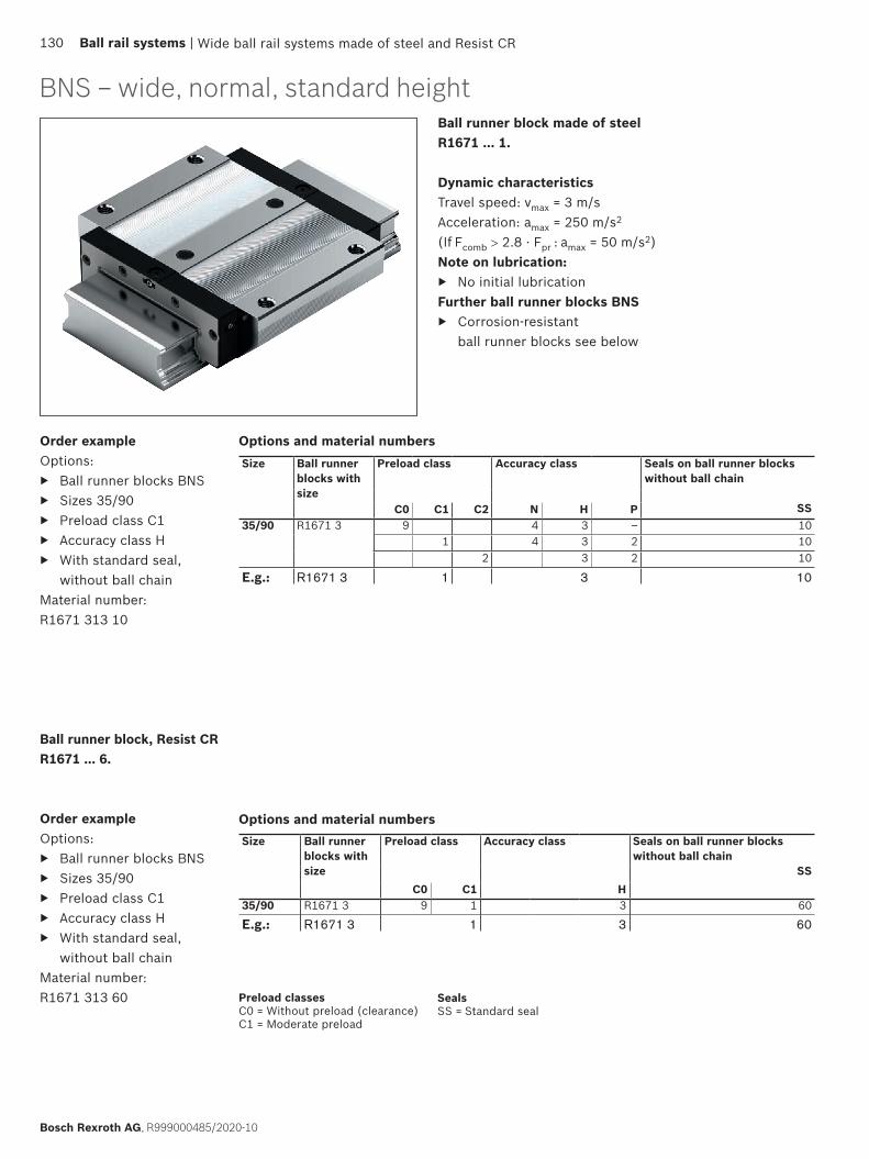
BNS – wide, normal, standard heightBall runner block made of steel R1671 ... 1.
Dynamic characteristicsTravel speed: vmax = 3 m/sAcceleration: amax = 250 m/s2
(If Fcomb > 2.8 · Fpr : amax = 50 m/s2)Note on lubrication:
▶ No initial lubricationFurther ball runner blocks BNS
▶ Corrosion-resistant ball runner blocks see below
Size Ball runner blocks with size
Preload class Accuracy class Seals on ball runner blocks without ball chain
SSC0 C1 C2 N H P35/90 R1671 3 9 4 3 – 10
1 4 3 2 102 3 2 10
E.g.: R1671 3 1 3 10
Options and material numbers
Ball runner block, Resist CR R1671 ... 6.
Order exampleOptions:
▶ Ball runner blocks BNS ▶ Sizes 35/90 ▶ Preload class C1 ▶ Accuracy class H ▶ With standard seal,
without ball chainMaterial number: R1671 313 60
Size Ball runner blocks with size
Preload class Accuracy class Seals on ball runner blocks without ball chain
SSC0 C1 H
35/90 R1671 3 9 1 3 60
E.g.: R1671 3 1 3 60
Options and material numbers
Order exampleOptions:
▶ Ball runner blocks BNS ▶ Sizes 35/90 ▶ Preload class C1 ▶ Accuracy class H ▶ With standard seal,
without ball chainMaterial number: R1671 313 10
Wide ball rail systems made of steel and Resist CR
Preload classesC0 = Without preload (clearance)C1 = Moderate preload
SealsSS = Standard seal
130 Ball rail systems |
Bosch Rexroth AG, R999000485/2020-10
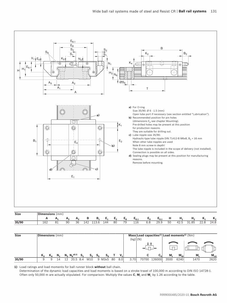
H1
V1
E9.1
E9
H
A3 A2
A1
A
N1
S2
S1S9
E8
E8.1
S2
S1
H2 N6
B
B1 E2
K1
K3 N2K4
B2K2
E4
ØS5
T
E1
b)
c)d)
a)
Size Dimensions (mm)A A1 A2 A3 B B1 E1 E2 E8 E8.1 E9 E9.1 H H1 H2 K1 K2
35/90 162 81 90 36 142 113.6 144 80 79 116 6.8 29.9 50 42.5 31.85 22.8 24.8
a) For O-ring Size 35/90: Ø 6 · 1.5 (mm) Open lube port if necessary (see section entitled “Lubrication”).
b) Recommended position for pin holes (dimensions E4 see chapter Mounting). Pre-drilled holes may be present at this position for production reasons. They are suitable for drilling out.
c) Lube nipple size 35/90: Hydraulic-type lube nipple DIN 71412-B M6x8, B2 = 16 mm When other lube nipples are used Note 8 mm screw-in depth! The lube nipple is included in the scope of delivery (not installed). Connection is possible on all sides.
d) Sealing plugs may be present at this position for manufacturing reasons. Remove before mounting.
Size Dimensions (mm) Mass (kg)
Load capacities1) (N)
Load moments1) (Nm)
K3 K4 N1 N2 N6±0.5 S1 S2 S5 S9 T V1 C C0 Mt Mt0 ML ML0
35/90 9 9 14 12 20.5 8.4 M10 9 M3x5 80 8.0 3.70 70700 126000 3500 6240 1470 2620
1) Load ratings and load moments for ball runner block without ball chain. Determination of the dynamic load capacities and load moments is based on a stroke travel of 100,000 m according to DIN ISO 14728-1. Often only 50,000 m are actually stipulated. For comparison: Multiply the values C, Mt and ML by 1.26 according to the table.
Wide ball rail systems made of steel and Resist CR | Ball rail systems 131
R999000485/2020-10, Bosch Rexroth AG

CNS – compact, normal, standard heightBall runner block made of steelR1672 ... 2.
Dynamic characteristicsTravel speed: vmax = 5 m/sAcceleration: amax = 500 m/s2
(If Fcomb > 2.8 · Fpr : amax = 50 m/s2)Note on lubrication:
▶ Pre-lubricatedFurther ball runner blocks CNS
▶ Corrosion-resistant ball runner blocks see below
Size Ball runner blocks with size
Preload class Accuracy class Seals on ball runner blocks
without ball chain
with ball chain
C0 C1 N H P SS DS SS DS20 /401) R1672 5 9 4 3 – 20 – 22 –
1 4 3 – 20 2Z 22 2Y25/70 R1672 2 9 4 3 – 20 – 22 –
1 4 3 – 20 2Z 22 2Y
E.g.: R1672 2 1 3 20
Options and material numbers
Size Ball runner blocks with size
Preload class Accuracy class Seals on ball runner blocks
without ball chain
with ball chain
C0 H SS DS SS DS20/401) R1672 5 9 3 70 7Z 72 7Y25/70 R1672 2 9 3 70 7Z 72 7Y
E.g.: R1672 2 9 3 70
1) Caution: Ball runner blocks, not combinable with ball guide rail R167. 8.. ..!
Options and material numbers
Ball runner block Resist CR2) R1672 ... 7.
Order exampleOptions:
▶ Ball runner blocks CNS ▶ Sizes 25/70 ▶ Preload class C0 ▶ Accuracy class H ▶ With standard seal,
without ball chainMaterial number: R1672 293 70
Order exampleOptions:
▶ Ball runner blocks CNS ▶ Sizes 25/70 ▶ Preload class C1 ▶ Accuracy class H ▶ With standard seal,
without ball chainMaterial number: R1672 213 20
Wide ball rail systems made of steel and Resist CR
Preload classesC0 = Without preload (clearance)C1 = Moderate preload
SealsSS = Standard sealDS = Double-lip seal
Keygray numbers= No preferred variant /
combination(partially longer delivery times)
132 Ball rail systems |
Bosch Rexroth AG, R999000485/2020-10

H1
V1E9 .1
E9
H
A3 A2
A1
A
E1
N3
S2S9
E8
E8.1
S2
S1
H2 N6
B
B1 E2
K1
K3K4
B2K2
ØS5
T
E5b)
c)
d)
a)
a) For O-ring Size 20/40: Ø 5 · 1.0 (mm) Size 25/70: Ø 5 · 1.0 (mm) Open lube port if necessary (see section entitled “Lubrication”).
b) Recommended position for pin holes (dimensions E5 see chapter Mounting). Pre-drilled holes may be present at this position for production reasons. They are suitable for drilling out.
c) Lube nipple size 20/40: Funnel-type lube nipple DIN 3405-A, M3x5, B2 = 1.6 mm When other lube nipples are used Note 5 mm screw-in depth! Lube nipple size 25/70: Hydraulic-type lube nipple DIN 71412-A M6x8, B2 = 9.5 mm When other lube nipples are used Note 8 mm screw-in depth! The lube nipple is included in the scope of delivery (not installed). Connection is possible on all sides.
d) Sealing plugs may be present at this position for manufacturing reasons. Remove before mounting.
Size Dimensions (mm)A A1 A2 A3 B B1 E1 E2 E8 E8.1 E9 E9.1 H H1 H2 K1 K2 K3 K4
20/40 62 31 42 10.0 73.0 51.3 46 32 18 53.4 3.4 8.1 27 22.50 18.30 14.6 15.00 3.5 3.525/70 100 50 69 15.5 104.7 76.5 76 50 35 83.5 4.9 11.3 35 29.75 23.55 19.4 20.45 5.2 5.2
Size Dimensions (mm) Mass (kg)
Load capacities1) (N)
Load moments1) (Nm)
N3 N6±0.5 S1 S2 S5 S9 T V1 C C0 Mt Mt0 ML ML0
20/40 6 12.5 5.3 M6 4.4 M2.5x1.5+3 60 6.0 0.3 14900 20600 340 470 140 19025/70 8 14.4 6.7 M8 7.0 M3x2+4.5 80 7.5 1.0 36200 50200 1 350 1870 490 680
1) Load ratings and load moments for ball runner block without ball chain. Load ratings and load moments for ball runner block with ball chain 14 Determination of the dynamic load capacities and load moments is based on a stroke travel of 100,000 m according to DIN ISO 14728-1. Often only 50,000 m are actually stipulated. For comparison: Multiply the values C, Mt and ML by 1.26 according to the table.
Wide ball rail systems made of steel and Resist CR | Ball rail systems 133
R999000485/2020-10, Bosch Rexroth AG
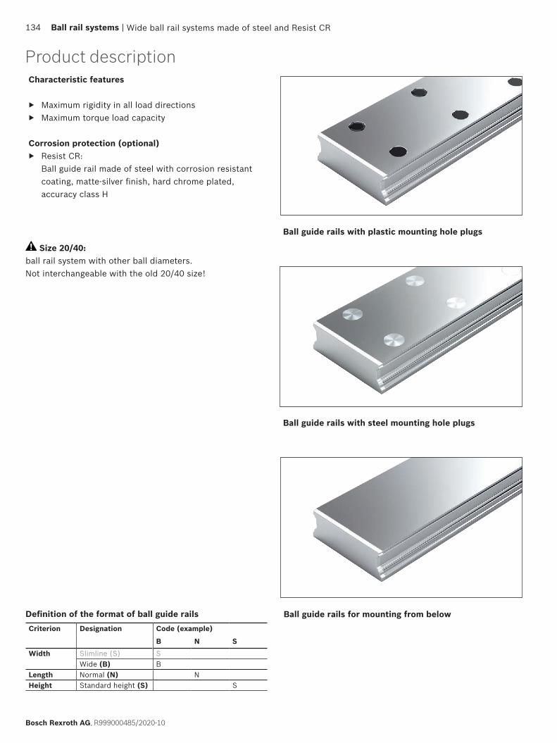
Product description Characteristic features
▶ Maximum rigidity in all load directions ▶ Maximum torque load capacity
Corrosion protection (optional) ▶ Resist CR:
Ball guide rail made of steel with corrosion resistant coating, matte-silver finish, hard chrome plated, accuracy class H
Ball guide rails with plastic mounting hole plugs
Ball guide rails with steel mounting hole plugs
Ball guide rails for mounting from below
Size 20/40: ball rail system with other ball diameters. Not interchangeable with the old 20/40 size!
Wide ball rail systems made of steel and Resist CR134 Ball rail systems |
Bosch Rexroth AG, R999000485/2020-10
Definition of the format of ball guide railsCriterion Designation Code (example)
B N SWidth Slimline (S) S
Wide (B) BLength Normal (N) NHeight Standard height (S) S

L = · T – 4 LW T
T1
nT · T(T1)T
L± 1.5
T1
nT · T(T1)T
L± 1.5
*
L = nT · T + 2 · T1S
L = nB · T – 4
L = · 80 mm – 4 mm
L = 21 · 80 mm – 4 mmL = 1676 mm
1660 mm 80 mm( )
From the desired rail length to the recommended length
Calculation example
* Round up quotient LW/T to the nearest whole number!
Ordering guide rails in the recommended rail lengthsOrdering ball guide rails in the recommended rail lengths
The procedure shown in the following ordering examples applies to all ball guide rails. Recommended rail lengths are more cost effective. Excerpt from table with part numbers and recommended rail lengths for ordering example
L = Recommended rail length (mm)
LW = Desired rail length (mm)
T = Pitch (mm)
T1S = Preferred dimension (mm)
nB = Number of holes per drill row (–)
nT = Number of spaces (–)
Basis: Number of holes per drill row
Basis: Number of spaces
BNS with plastic mounting hole plugsSteel ball guide railsR1675 .0. ..With two-row mounting hole pattern, for mounting from above, with plastic mounting hole plugsNotes
▶ Plastic mounting hole plugs included in scope of supply. ▶ Follow the mounting instructions!
Please ask for the “Mounting Instructions for Ball Rail Systems”.
▶ Composite guide rails also available.Further ball guide rails BNS and accessories
▶ See below for corrosion-resistant ball guide rails ▶ For caps, see the “Accessories for ball guide rails” chapter
Options and part numbers
Options and part numbers
Resist NR II ball guide railsR1673 .0. ..
Size Ball guide rail with size
Accuracy class
Number of sections, rail length L (mm), .... Hole spac-ing T(mm)
Recommended rail length in accor-dance with formula L = nB · T – 4
wor rep seloh fo rebmun mumixaMetisopmoCeceip-enOof holes nB N H P
20/401) 4606.... ,.3.... ,1323405 5761R25/70 8408.... ,.3.... ,1323402 5761R35/90 8408.... ,.3.... ,1323403 5761R
e.g. 6761 ,13303 5761R
Size Ball guide rail with size
Accuracy class
Number of sections, rail length L (mm), .... Hole spac-ing T(mm)
Recommended rail length in accor-dance with formula L = nB · T – 4
etisopmoCeceip-enOUncoated end faces
Coated end faces
Coated end faces
Maximum number of holes per row of holes nB H
20/401) 4606.... ,.4.... ,14.... ,13305 3761R25/70 8408.... ,.4.... ,14.... ,13302 3761R35/90 8408.... ,.4.... ,14.... ,13303 3761R
e.g. 6115 ,24303 3761R
Ordering example 1 (to Lmax)Options:
▶ Ball guide rail BNS ▶ Size 35/90 ▶ Accuracy class H ▶ One-piece ▶ Uncoated end faces ▶ Rail length L = 1676 mm
Part number: R1675 303 31, 1676 mm
Ordering example 2 (above Lmax)Options:
▶ Ball guide rail CR, BNS ▶ Size 35/90 ▶ Accuracy class H ▶ 2 sections ▶ Coated end faces ▶ Rail length L = 5116 mm
Part number: R1673 303 42, 5116 mm
1) Note: Ball guide rail cannot be combined with ball runner block R1671 8.. ..
Wide ball rail systems BSHP made of steel and Resist CR134 Ball Rail Systems |
Bosch Rexroth AG, R999000485 (2014-12)
Wide ball rail systems made of steel and Resist CR
Notes on ordering examplesIf preferred dimension T1S is not used, it is possible to choose between:
▶ Select end spacing T1 between T1S and T1 min
▶ As an alternative, it is possible to choose end spacings T1 to T1 max
Ordering example 1 (to Lmax) ▶ Ball guide rail BNS size 35/90 with
plastic mounting hole plugs ▶ Accuracy class H ▶ Calculated rail length 1676 mm,
(20 · T, preferred dimension T1S = 38 mm; Number of holes per drill row nB = 21)
Ordering dataPart number; rail length (mm) T1 / nT · T / T1 (mm)
R1675 303 31, 1676 mm 38 / 20 · 80 / 38 mm
Ordering example 2 (above Lmax) ▶ Ball guide rail BNS size 35/90 with
plastic mounting hole plugs ▶ Accuracy class H ▶ Calculated rail length
5116 mm, 2 sections (63 · T, preferred dimension T1S = 38 mm; Number of holes per drill row nB = 64)
Ordering dataMaterial number with number of partial sections, rail length (mm) T1 / nT · T / T1 (mm)
R1675 303 32, 5116 mm 38 / 63 · 80 / 38 mm
In the case of rail lengths above Lmax, factory-coordinated partial sections are joined together.
| Ball rail systems 135
R999000485/2020-10, Bosch Rexroth AG

BNS with plastic mounting hole plugsBall guide rails made of steel R1675 .0. ..With two-row hole pattern, for mounting from above with plastic mounting hole plugsNotes
▶ Plastic mounting hole plugs included in scope of supply. ▶ Observe the instruction for mounting!
Please request the “Mounting instructions for ball rail systems.”
▶ Composite ball guide rail also available.Further ball guide rails BNS and accessories
▶ Corrosion resistant ball guide rails see below ▶ Mounting hole plugs see chapter “Accessories for ball
guide rails”
Options and material numbers
Options and material numbers
Ball guide rails Resist CR R1673 .0. ..
Size Ball guide rail with size
Accuracy class
Number of partial sections .,Rail length L (mm), ....
Hole spacing T(mm)
Recommended rail length in accordance with formula L = nB · T – 4
One-piece Composite Maximum number of holes perdrill row nB N H P
20/401) R1675 50 4 3 2 31, .... 3., .... 60 6425/70 R1675 20 4 3 2 31, .... 3., .... 80 4835/90 R1675 30 4 3 2 31, .... 3., .... 80 48
E.g.: R1675 30 3 31, 1676
Size Ball guide rail with size
Accuracy class
Number of partial sections .,Rail length L (mm), ....
Hole spacing T(mm)
Recommended rail length in accordance with formula L = nB · T – 4
One-piece CompositeUncoated end faces
Coated end faces
Coated end faces
Maximum number of holes per drill row nB H
20/401) R1673 50 3 31, .... 41, .... 4., .... 60 64 25/70 R1673 20 3 31, .... 41, .... 4., .... 80 48 35/90 R1673 30 3 31, .... 41, .... 4., .... 80 48
E.g.: R1673 30 3 42, 5116
Ordering example 1 (to Lmax)Options:
▶ Ball guide rail BNS ▶ Sizes 35/90 ▶ Accuracy class H ▶ One-piece ▶ End faces uncoated ▶ Rail length L = 1676 mm
Material number: R1675 303 31, 1676 mm
Ordering example 2 (above Lmax)Options:
▶ Ball guide rail CR, BNS ▶ Sizes 35/90 ▶ Accuracy class H ▶ 2 partial sections ▶ End faces coated ▶ Rail length L = 5116 mm
Material number: R1673 303 42, 5116 mm
1) Caution: Ball guide rail cannot be combined with ball runner block R1671 8.. ..!
Wide ball rail systems made of steel and Resist CR136 Ball rail systems |
Bosch Rexroth AG, R999000485/2020-10
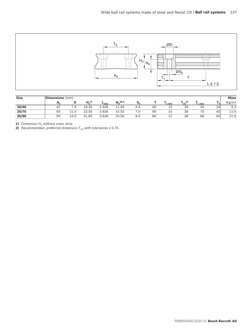
ØS5
T1 TA2
ØDT3
H2 N6
L ± 1.5
Size Dimensions (mm) MassA2 D H2
1) Lmax N6±0.5 S5 T T1 min T1S
2) T1 max T3 (kg/m)20/40 42 7.4 18.30 3 836 12.45 4.4 60 10 28 50 24 5.325/70 69 11.0 23.55 3 836 14.50 7.0 80 10 38 70 40 11.635/90 90 15.0 31.85 3 836 20.50 9.0 80 12 38 68 60 21.0
1) Dimension H2 without cover strip2) Recommended: preferred dimension T1S with tolerances ± 0.75.
Wide ball rail systems made of steel and Resist CR | Ball rail systems 137
R999000485/2020-10, Bosch Rexroth AG
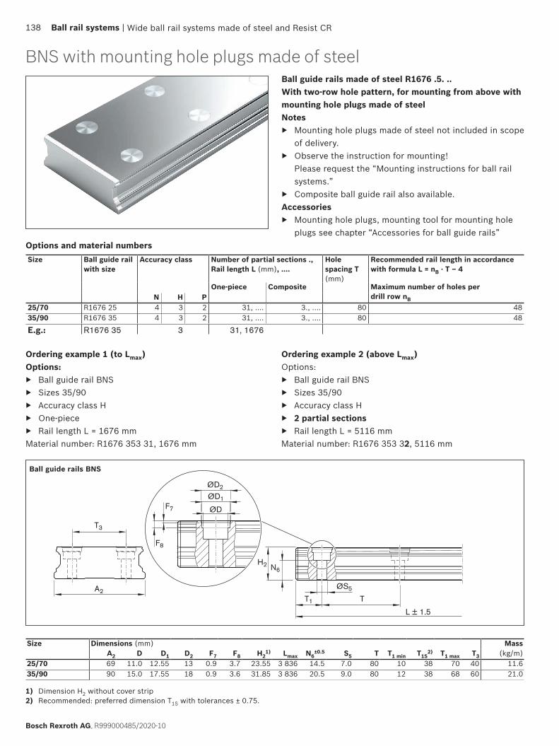
ØD
ØD1
ØD2
F7
F8
A2
T3
ØS5
T1 T
H2 N6
L ± 1.5
BNS with mounting hole plugs made of steelBall guide rails made of steel R1676 .5. ..With two-row hole pattern, for mounting from above with mounting hole plugs made of steelNotes
▶ Mounting hole plugs made of steel not included in scope of delivery.
▶ Observe the instruction for mounting! Please request the “Mounting instructions for ball rail systems.”
▶ Composite ball guide rail also available.Accessories
▶ Mounting hole plugs, mounting tool for mounting hole plugs see chapter “Accessories for ball guide rails”
Ball guide rails BNS
Size Dimensions (mm) MassA2 D D1 D2 F7 F8 H2
1) Lmax N6±0.5 S5 T T1 min T1S
2) T1 max T3 (kg/m)25/70 69 11.0 12.55 13 0.9 3.7 23.55 3 836 14.5 7.0 80 10 38 70 40 11.635/90 90 15.0 17.55 18 0.9 3.6 31.85 3 836 20.5 9.0 80 12 38 68 60 21.0
Options and material numbersSize Ball guide rail
with sizeAccuracy class Number of partial sections .,
Rail length L (mm), ....Hole spacing T(mm)
Recommended rail length in accordance with formula L = nB · T – 4
One-piece Composite Maximum number of holes perdrill row nB N H P
25/70 R1676 25 4 3 2 31, .... 3., .... 80 48 35/90 R1676 35 4 3 2 31, .... 3., .... 80 48
E.g.: R1676 35 3 31, 1676
Ordering example 1 (to Lmax)Options:
▶ Ball guide rail BNS ▶ Sizes 35/90 ▶ Accuracy class H ▶ One-piece ▶ Rail length L = 1676 mm
Material number: R1676 353 31, 1676 mm
Ordering example 2 (above Lmax)Options:
▶ Ball guide rail BNS ▶ Sizes 35/90 ▶ Accuracy class H ▶ 2 partial sections ▶ Rail length L = 5116 mm
Material number: R1676 353 32, 5116 mm
1) Dimension H2 without cover strip2) Recommended: preferred dimension T1S with tolerances ± 0.75.
Wide ball rail systems made of steel and Resist CR138 Ball rail systems |
Bosch Rexroth AG, R999000485/2020-10

A2
ØS7
T1 T
T3
H2 N7
L ± 1.5
Ball guide rails made of steel R1677 .0. ..With double-row mounting hole for mounting from below
Notes ▶ Observe the instruction for mounting!
Please request the “Mounting instructions for ball rail systems.”
▶ Composite ball guide rail also available.
Options and material numbersSize Ball guide rail
with sizeAccuracy class Number of partial sections .,
Rail length L (mm), ....Hole spacing T(mm)
Recommended rail length in accordance with formula L = nB · T – 4
One-piece Composite Maximum number of holes perdrill row nB N H P
20/401) R1677 50 4 3 2 31, .... 3., .... 60 64 25/70 R1677 20 4 3 2 31, .... 3., .... 80 48 35/90 R1677 30 4 3 2 31, .... 3., .... 80 48
E.g.: R1677 30 3 31, 1676
Ball guide rails BNS
1) Dimension H2 without cover strip2) Recommended: preferred dimension T1S with tolerances ± 0.75.
Size Dimensions (mm) MassA2 H2
1) Lmax N7 S7 T T1 min T1S2) T1 max T3 (kg/m)
20/40 42 18.30 3 836 7.5 M5 60 10 28 50 24 5.325/70 69 23.55 3 836 12.0 M6 80 10 38 70 40 11.635/90 90 31.85 3 836 15.0 M8 80 12 38 68 60 21.0
Ordering example 1 (to Lmax)Options:
▶ Ball guide rail BNS, ▶ Size 35/90, ▶ Accuracy class H, ▶ One-piece ▶ Rail length L = 1676 mm
Material number: R1677 303 31, 1676 mm
Ordering example 2 (above Lmax)Options:
▶ Ball guide rail BNS, ▶ Size 35/90, ▶ Accuracy class H, ▶ 2 partial sections ▶ Rail length L = 5116 mm
Material number: R1677 303 32, 5116 mm
1) Caution: Ball guide rail cannot be combined with ball runner block R1671 8.. ..!
BNS for mounting from below
Wide ball rail systems made of steel and Resist CR | Ball rail systems 139
R999000485/2020-10, Bosch Rexroth AG

Rexroth offers limitless interchangeability as all ball runner block versions can be combined at will with all accessories within each size. The entire range is ideally geared to enable a top performance and meet all special requirements. Accessories can also be supplied ready-mounted on request.
Overview of ball runner block accessoriesCover plate wiper
Seal kit1)
Two-piece front seal1) One and two-piece FKM seal1)
Lubrication plate1)Lubrication adapter only for existing systems with high ball runner blocks SNH or SLH1)
Front lube unit
Lube nipple
Bellows
▶ Reducers ▶ Extensions ▶ Connectors ▶ Swivel fittings ▶ Swivel screw joints for
plastic tubes
Plastic tube for lube connection
O-rings
Product description
1) For ball runner blocks F.N (flange ... low) and S.N. (slimline ... low) not available
Lube fittings
Accessories for ball runner blocks
Transport lock
140 Ball rail systems |
Bosch Rexroth AG, R999000485/2020-10
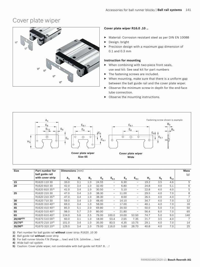
S12
E8
A4
E8.1
E8E9
S9
E9.1E9
H3
E8.1
E8E9
B3
B4
E9.1
Cover plate wiper R16.0 .10 ..
▶ Material: Corrosion resistant steel as per DIN EN 10088 ▶ Design: bright ▶ Precision design with a maximum gap dimension of
0.1 and 0.3 mm
Instruction for mounting ▶ When combining with two-piece front seals,
use seal kit: See seal kit for part numbers ▶ The fastening screws are included. ▶ When mounting, make sure that there is a uniform gap
between the ball guide rail and the cover plate wiper. ▶ Observe the minimum screw-in depth for the end-face
lube connection. ▶ Observe the mounting instructions.
1) Part number for ball guide rail without cover strip: R1620 .10 302) Ball guide rail without cover strip3) For ball runner blocks F.N (flange ... low) and S.N. (slimline ... low)4) Wide ball rail system5) Caution: Cover plate wiper, not combinable with ball guide rail R167. 8.. ..!
Cover plate wiper Size 65
Size Part number for ball guide rail with cover strip
Dimensions (mm) Mass
A4 B3 B4 E8 E8.1 E9 E9.1 H3 S9 S12
(g)
15 R1620 110 30 33.0 3.1 1.0 24.55 – 6.30 – 19.2 3.5 4.6 520 R1620 810 30 42.0 3.4 1.0 32.40 – 6.80 – 24.8 4.0 5.1 6
R1620 810 353) 41.0 3.4 1.0 30.50 – 5.10 – 22.8 4.0 4.0 525 R1620 210 30 47.0 3.4 1.0 38.30 – 11.00 – 29.5 4.0 7.0 8
R1620 210 353) 47.0 3.4 1.0 38.30 – 8.00 – 26.5 4.0 4.0 730 R1620 710 30 59.0 3.4 1.0 48.40 – 14.10 – 34.7 4.0 7.0 1235 R1620 310 401) 69.0 3.4 1.0 58.00 – 17.00 – 40.1 4.0 7.0 1645 R1620 410 401) 85.0 5.1 2.0 69.80 – 20.50 – 50.0 5.0 7.0 5055 R1620 510 401) 98.0 5.7 2.0 80.00 – 21.80 – 56.4 6.0 7.0 6565 R1620 610 401) 124.0 5.6 2.5 76.00 100.0 10.00 52.50 74.7 5.0 9.0 14020/404)5) R1670 510 002) 60.0 3.1 1.0 18.00 53.4 2.65 7.35 21.7 3.5 4.0 725/704) R1670 210 102) 101.0 3.4 1.0 35.00 83.5 4.35 10.75 29.1 4.0 7.0 1435/904) R1670 310 102) 129.0 3.4 1.0 79.00 116.0 5.60 28.70 40.8 4.0 7.0 25
Cover plate wiper Wide
Fastening screw shown is example
Accessories for ball runner blocks
Cover plate wiper
| Ball rail systems 141
R999000485/2020-10, Bosch Rexroth AG

B3
B4
B5
S12
H3
A4
E8
S9
E9
E8.1
E8E9
E9.1
Two-piece
▶ Material: Corrosion-resistant steel as per DIN EN 10088 with plastic seals
▶ Design: bright
Instruction for mounting ▶ The fastening screws are included. ▶ Observe the minimum screw-in depth for the end-face
lube connection. ▶ Observe the mounting instructions.
Size Material number Dimensions (mm) Mass(g)A4 B3 B4 B5 E8 E8.1 E9 E9.1 H3 S9 S12
15 R1619 121 20 32.0 4.3 2.2 3.0 24.55 – 6.30 – 19.0 3.5 4.3 6.0201) R1619 821 20 42.0 4.9 2.5 3.3 32.40 – 6.80 – 24.3 4.0 5.1 8.0251) R1619 221 30 47.0 4.9 2.5 3.3 38.30 – 11.00 – 29.0 4.0 7.0 10.030 R1619 721 30 59.0 5.7 3.3 4.5 48.40 – 14.10 – 34.5 4.0 7.0 18.035 R1619 321 30 69.0 5.7 3.3 4.5 58.00 – 17.00 – 39.5 4.0 7.0 25.045 R1619 421 30 85.0 7.1 4.0 5.5 69.80 – 20.50 – 49.5 5.0 7.0 55.055 R1619 521 30 98.0 7.7 4.0 5.5 80.00 – 21.50 – 56.0 6.0 7.0 65.020/402)3) R1619 522 20 60.0 4.6 2.5 3.3 18.00 53.4 2.65 7.35 21.7 3.5 4.0 7.525/702) R1619 222 20 99.0 4.9 2.5 3.3 35.00 83.5 4.30 10.70 28.6 4.0 7.3 14.535/902) R1619 322 20 128.6 5.7 3.3 4.5 79.00 116.0 5.80 28.90 41.0 4.0 7.0 40.0
Front seal Wide
1) Not for ball runner blocks F.N (flange ... low) and S.N. (slimline ... low)2) Wide ball rail system3) Caution: The new front seal is not combinable with existing ball guide rail R167. 8.. ..!
Fastening screw shown is example
Front seal
Accessories for ball runner blocks142 Ball rail systems |
Bosch Rexroth AG, R999000485/2020-10

B3
B4S12
H3
A4
E8
S9
E9
B5
A4
E 8
E8.1
E9
E9.1H3
S9S12
B3
B4
Two-piece
▶ Material: Corrosion-resistant steel as per DIN EN 10088 and seal made of FKM
▶ See Selection criteria/Seals for the area of application and resistance
Special featureSimple assembly/removal on fixed ball guide rail
Instruction for mounting ▶ The fastening screws are included. ▶ Observe the minimum screw-in depth for the end-face
lube connection. ▶ Observe the mounting instructions.
Size Material number Dimensions (mm) MassA4 B3 B4 B5 E8 E9 H3 S9 S12 (g)
35 R1619 320 30 69 8.4 4 6 58.0 17.0 39.5 4 7 39.045 R1619 420 30 85 9.1 4 6 69.8 20.5 49.5 5 7 61.055 R1619 520 30 98 9.7 4 6 80.0 21.8 56.4 6 7 80.5
Size Material number Dimensions (mm) MassA4 B3 B4 E8 E8.1 E9 E9.1 H3 S9 S12 (g)
65 R1619 620 30 124 9.6 6.5 76 100 10 52.5 74.7 5 9 146
One-piece
▶ Material: Corrosion-resistant steel as per DIN EN 10088 and seal made of FKM.
Instruction for mounting ▶ The fastening screws are included. ▶ Observe the minimum screw-in depth for the end-face
lube connection. ▶ Observe the mounting instructions.
FKM seal
Accessories for ball runner blocks | Ball rail systems 143
R999000485/2020-10, Bosch Rexroth AG

A4
E8
H3
E9
S9S12
B3
B4
12
3
1 Cover plate wiper2 Reinforcing plate3 Two-piece front seal
Instruction for mounting ▶ The seal kit is recommended when combining the cover
plate wiper with a two-piece front seal. ▶ The fastening screws are included. ▶ Observe the minimum screw-in depth for the end-face
lube connection. ▶ Observe the mounting instructions.
Size Part number for ball guide rail Dimensions (mm) Masswithout cover strip with cover strip A4 B3 B4 E8 E9 H3 S9 S12 (g)
15 R1619 120 50 R1619 120 50 32.0 6.3 4.2 24.55 6.30 19.0 3.5 4.3 16201) R1619 820 50 R1619 820 50 42.0 6.9 4.5 32.40 6.80 24.3 4.0 5.1 20251) R1619 220 50 R1619 220 50 47.0 6.9 4.5 38.30 11.00 29.0 4.0 7.0 2630 R1619 720 50 R1619 720 50 59.0 8.2 5.8 48.40 14.10 34.5 4.0 7.0 4235 R1619 320 40 R1619 320 50 69.0 8.2 5.8 58.00 17.00 39.5 4.0 7.0 5745 R1619 420 40 R1619 420 50 85.0 11.1 8.0 69.80 20.50 49.5 5.0 7.0 15555 R1619 520 40 R1619 520 50 98.0 11.7 8.0 80.00 21.50 56.0 6.0 7.0 195
1) Not for ball runner blocks F.N (flange ... low) and S.N. (slimline ... low)
Seal kit
Accessories for ball runner blocks144 Ball rail systems |
Bosch Rexroth AG, R999000485/2020-10

F1 F
D
F2
F3
D1
D2
For oil and grease lubrication from above, only for high ball runner blocks SNH R1621 or SLH R1624
▶ Material: Plastic ▶ Packaging unit: 1 unit
Instruction for mounting ▶ O-rings are provided. ▶ Before mounting, use a heated pointed metal tool to
open the lube hole on the ball runner block (but not a drill).
▶ For more details, see the “Lubrication and maintenance” chapter.
Size Material number Dimensions (mm) MassD D1 D2 F F1 F2 F3 (g)
15 R1621 100 05 12 6.2 3.4 3.7 3.1 0.5 3.20 0.525 R1621 200 05 15 7.2 4.4 3.8 3.2 0.5 5.85 0.930 R1621 700 05 16 7.2 4.4 2.8 2.2 0.5 6.10 0.735 R1621 300 05 18 7.2 4.4 6.8 6.2 0.5 6.80 2.245 R1621 400 05 20 7.2 4.4 9.8 9.2 0.5 8.30 4.1
Lubrication adapter
Accessories for ball runner blocks | Ball rail systems 145
R999000485/2020-10, Bosch Rexroth AG

A4
H3H
S12
S13
K3
B4
B3
K2
1
For standard lube nipples
▶ Material: Aluminum
Instruction for mounting ▶ The required mounting parts are included. ▶ Sizes 15 – 20:
A funnel-type lube nipple with a knock-in spigot is included.
▶ Sizes 25 – 65: The lube nipple of the ball runner block can be used.
▶ Observe the mounting instructions.
1) Not for ball runner blocks F.N (flange ... low) and S.N. (slimline ... low)2) Based on the mounting face of the ball runner block 3) For ball runner blocks S.H (slimline ... high)
Size Material number Dimensions (mm) MassA4 B3 B4 H H3
2) K2 K32) S12 S13 (g)
15 R1620 111 20 32 13.1 11 24283)
19.0 5.5 3.47.43)
M3 Ø3 15
201) R1620 811 20 42 15.0 12 30 24.8 6.0 3.5 M3 Ø3 25251) R1620 211 20 47 15.0 12 36
403)28.3 6.0 6.0
10.03)M6 M6 30
30 R1620 711 20 59 15.0 12 42453)
33.8 6.0 8.011.03)
M6 M6 45
35 R1620 311 20 69 15.0 12 48553)
39.1 6.0 8.015.03)
M6 M6 60
45 R1620 411 20 85 16.0 12 60703)
48.5 6.0 8.018.03)
M6 M6 85
55 R1620 511 20 98 17.0 12 70803)
56.0 6.0 9.019.03)
M6 M6 115
65 R1620 611 20 124 18.0 14 90 75.7 7.0 18.0 M8x1 M8x1 250
The enclosed lube pin (1) must be mounted between the lubrication plate and the ball runner block! (It contains a lubrication hole.)
Lubrication plate
Accessories for ball runner blocks146 Ball rail systems |
Bosch Rexroth AG, R999000485/2020-10

S12
S13 A4
H3H
K3
B4
B3
K2
S1210 23.5
A4
H3H
H3H
S12
A4
B4
B3
K2
S13
K3
For lube nipples G 1/8
▶ Material: Aluminum
Instruction for mounting ▶ The required mounting
parts are included. ▶ Ball runner block S..
(slimline ... ...) Size 25: Observe the side projection of the lubrication plate.
▶ Observe the mounting instructions.
1) Not for ball runner blocks F.N (flange ... low) and S.N. (slimline ... low)2) Based on the mounting face of the ball runner block 3) For ball runner blocks S.H (slimline ... high)4) Wide ball rail system
Lubrication plate for ball runner blocks S..Size 25
Size Material number Dimensions (mm) MassA4 B3 B4 H H3
2) K2 K32) S12 S13 (g)
251) R1620 211 30 57 19.0 16 36403)
28.3 8 7.011.03)
M6 G 1/8x8 40
30 R1620 711 30 59 19.0 16 42453)
33.8 8 7.010.03)
M6 G 1/8x8 59
35 R1620 311 30 69 19.0 16 48553)
39.1 8 8.015.03)
M6 G 1/8x8 79
45 R1620 411 30 85 20.0 16 60703)
48.5 8 8.018.03)
M6 G 1/8x8 112
55 R1620 511 30 98 21.0 16 70803)
56.0 8 9.019.03)
M6 G 1/8x8 152
65 R1620 611 30 124 20.0 16 90 75.7 8 18.0 M6 G 1/8x8 28525/704) R1670 211 40 99 19.0 16 35 29.6 8 8.4 M6 G 1/8x8 6535/904) R1670 311 30 129 19.0 16 50 42.0 8 9.5 M6 G 1/8x8 120
Lubrication plate, wide
Lubrication plate G 1/8
Accessories for ball runner blocks | Ball rail systems 147
R999000485/2020-10, Bosch Rexroth AG
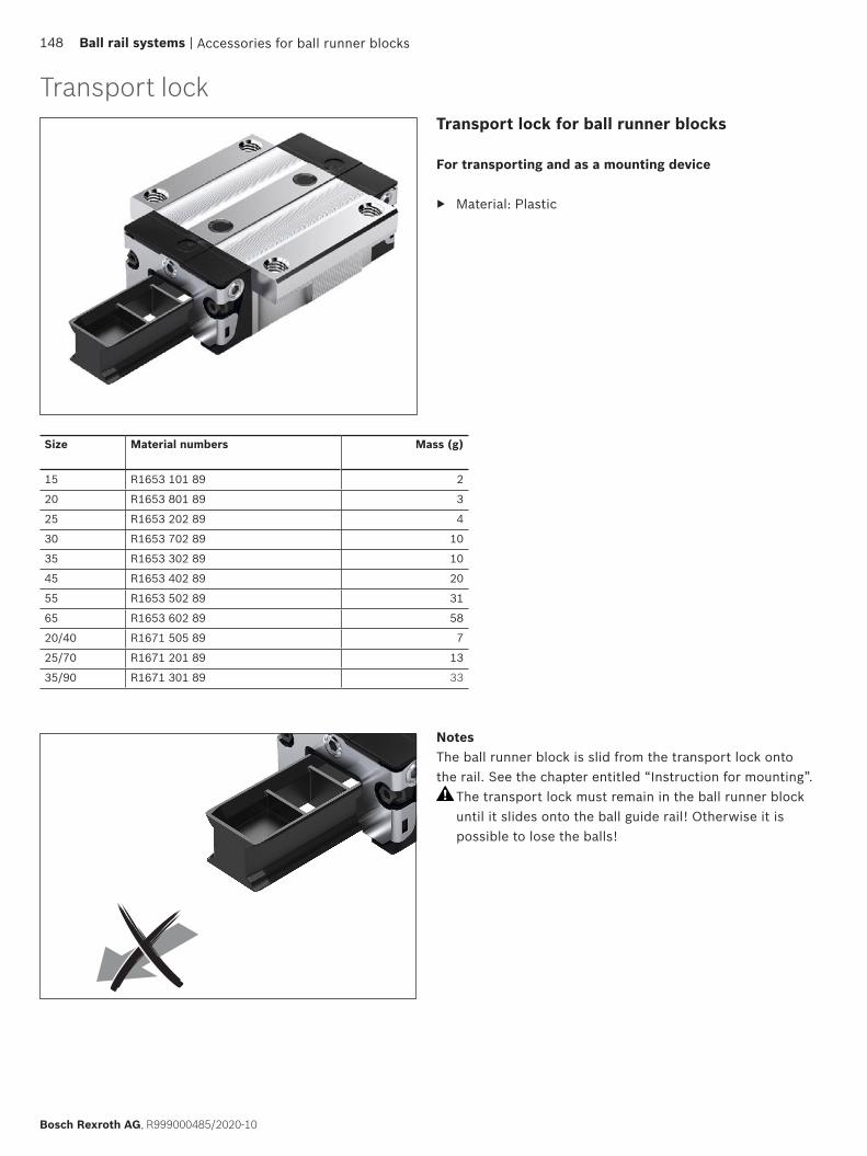
Accessories for ball runner blocks
Transport lockTransport lock for ball runner blocks
For transporting and as a mounting device
▶ Material: Plastic
Size Material numbers Mass (g)
15 R1653 101 89 2
20 R1653 801 89 3
25 R1653 202 89 4
30 R1653 702 89 10
35 R1653 302 89 10
45 R1653 402 89 20
55 R1653 502 89 31
65 R1653 602 89 58
20/40 R1671 505 89 7
25/70 R1671 201 89 13
35/90 R1671 301 89 33
NotesThe ball runner block is slid from the transport lock onto the rail. See the chapter entitled “Instruction for mounting”.
The transport lock must remain in the ball runner block until it slides onto the ball guide rail! Otherwise it is possible to lose the balls!
148 Ball rail systems |
Bosch Rexroth AG, R999000485/2020-10

Accessories for ball runner blocks | Ball rail systems 149
R999000485/2020-10, Bosch Rexroth AG
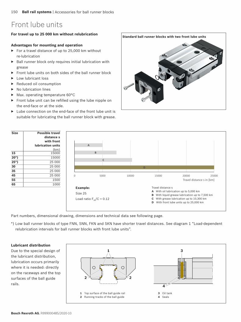
Standard ball runner blocks with two front lube unitsFor travel up to 25 000 km without relubrication
Advantages for mounting and operation ▶ For a travel distance of up to 25,000 km without
re-lubrication ▶ Ball runner block only requires initial lubrication with
grease ▶ Front lube units on both sides of the ball runner block ▶ Low lubricant loss ▶ Reduced oil consumption ▶ No lubrication lines ▶ Max. operating temperature 60°C ▶ Front lube unit can be refilled using the lube nipple on
the end-face or at the side. ▶ Lube connection on the end-face of the front lube unit is
suitable for lubricating the ball runner block with grease.
Travel distance sA With oil lubrication up to 5,000 kmB With liquid grease lubrication up to 7,500 kmC With grease lubrication up to 10,300 kmD With front lube units up to 25,000 km
Lubricant distributionDue to the special design of the lubricant distribution, lubrication occurs primarily where it is needed: directly on the raceways and the top surfaces of the ball guide rails.
1
22
3
4
1 Top surface of the ball guide rail2 Running tracks of the ball guide
3 Oil tank4 Seals
Size Possible travel distance s with front
lubrication units(km)
15 1500020*) 1500025*) 25 00030 25 00035 25 00045 25 00055 150065 1000
Part numbers, dimensional drawing, dimensions and technical data see following page.
Front lube units
Accessories for ball runner blocks
D
C
B
A
0 5000 10000 15000 20000 25000
Laufstrecke s in [km]
Example:
Size 25
Load ratio Fm/C = 0.12
*) Low ball runner blocks of type FNN, SNN, FKN and SKN have shorter travel distances. See diagram 1 “Load-dependent relubrication intervals for ball runner blocks with front lube units”.
Travel distance s in [km]
150 Ball rail systems |
Bosch Rexroth AG, R999000485/2020-10

K3
E8
S12S13
A4
E9K4
K2
H3H
B3
E8.1
E8
E9
E9.1
Front lube unit R1619 .2. 00 Material: special plastic
The front lube units R1619 .2. 00 are supplied ready-filled with oil (Mobil SHC 639) and can be mounted after basic lubrication of the ball runner blocks.
Size 65
Size Material number Dimensions (mm) Oil(cm3)
Mass(g)A4 B3 E8 E8.1 E9
2) E9.12) H H3
2) K2 K32)/K4
2) S12 S1315 R1619 125 00 31.8 11.5 24.55 – 6.70
10.703)– 24
283)19.40
23.403)5 3.35
7.353)M3 M3 1.00 15
20 R1619 825 00 43.0 12.5 32.50 – 7.30 – 30 24.90 5 3.70 M3 M3 2.20 20R1619 826 001) 41.0 12.5 30.50 – 5.60 – 28 22.90 – 3.10 – M3 1.80 20
25 R1619 225 00 47.0 13.0 38.30 – 11.5015.503)
– 36403)
29.3033.303)
5 5.509.503)
M6 M6 2.60 25
R1619 226 001) 47.0 13.0 38.30 – 8.50 – 33 26.30 5 4.10 M3 M3 2.50 2530 R1619 725 00 58.8 14.5 48.40 – 14.60
17.603)– 42
453)35.05
38.053)6 6.05
9.053)M6 M6 3.85 35
35 R1619 325 00 69.0 16.0 58.00 – 17.3524.353)
– 48553)
39.8546.853)
6 6.9013.903)
M6 M6 5.70 50
45 R1619 425 00 84.0 17.0 69.80 – 20.9030.903)
– 60703)
49.8059.803)
7 8.2018.203)
M6 M6 9.60 70
55 R1619 525 00 99.0 18.0 80.00 – 22.3032.303)
– 70803)
57.0567.053)
8 8.9018.903)
M6 M6 14.50 90
65 R1619 625 00 124.2 19.0 76.00 100 11.00 53.5 90 75.70 8 16.00 M8 M8 30.00 130
1) For ball runner blocks F.N (flange ... low) and S.N. (slimline ... low)2) Based on the mounting face of the ball runner block 3) For ball runner blocks S.H (slimline ... high)
Front lube unit R1619 .2. 10 Material: special plastic
The front lube units R1619 .2. 10 are not filled at the factory.
Recommended lubricant oil for initial filling:
▶ Mobil SHC 639 (viscosity 1000 mm2/s at 40 °C)
An initial lubrication of the ball runner blocks with grease lubricant is required before mounting the front lube units! See section “Lubrication”.
If other types of lubricant oil are used, please consider the compatibility of the lubricants and the travel distance!
Accessories for ball runner blocks | Ball rail systems 151
R999000485/2020-10, Bosch Rexroth AG
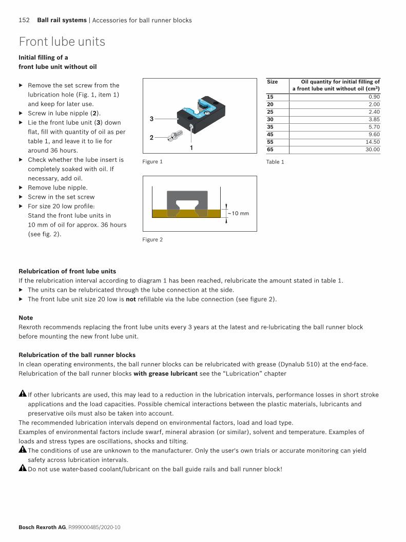
~10 mm
12
3
If other lubricants are used, this may lead to a reduction in the lubrication intervals, performance losses in short stroke applications and the load capacities. Possible chemical interactions between the plastic materials, lubricants and preservative oils must also be taken into account.
The recommended lubrication intervals depend on environmental factors, load and load type.Examples of environmental factors include swarf, mineral abrasion (or similar), solvent and temperature. Examples of loads and stress types are oscillations, shocks and tilting.
The conditions of use are unknown to the manufacturer. Only the user's own trials or accurate monitoring can yield safety across lubrication intervals. Do not use water-based coolant/lubricant on the ball guide rails and ball runner block!
Initial filling of a front lube unit without oil
▶ Remove the set screw from the lubrication hole (Fig. 1, item 1) and keep for later use.
▶ Screw in lube nipple (2). ▶ Lie the front lube unit (3) down
flat, fill with quantity of oil as per table 1, and leave it to lie for around 36 hours.
▶ Check whether the lube insert is completely soaked with oil. If necessary, add oil.
▶ Remove lube nipple. ▶ Screw in the set screw ▶ For size 20 low profile:
Stand the front lube units in 10 mm of oil for approx. 36 hours (see fig. 2).
Figure 1
Figure 2
Table 1
Size Oil quantity for initial filling of a front lube unit without oil (cm3)
15 0.9020 2.0025 2.4030 3.8535 5.7045 9.6055 14.5065 30.00
Relubrication of front lube unitsIf the relubrication interval according to diagram 1 has been reached, relubricate the amount stated in table 1.
▶ The units can be relubricated through the lube connection at the side. ▶ The front lube unit size 20 low is not refillable via the lube connection (see figure 2).
NoteRexroth recommends replacing the front lube units every 3 years at the latest and re-lubricating the ball runner block before mounting the new front lube unit.
Relubrication of the ball runner blocksIn clean operating environments, the ball runner blocks can be relubricated with grease (Dynalub 510) at the end-face. Relubrication of the ball runner blocks with grease lubricant see the “Lubrication” chapter
Front lube units
Accessories for ball runner blocks152 Ball rail systems |
Bosch Rexroth AG, R999000485/2020-10
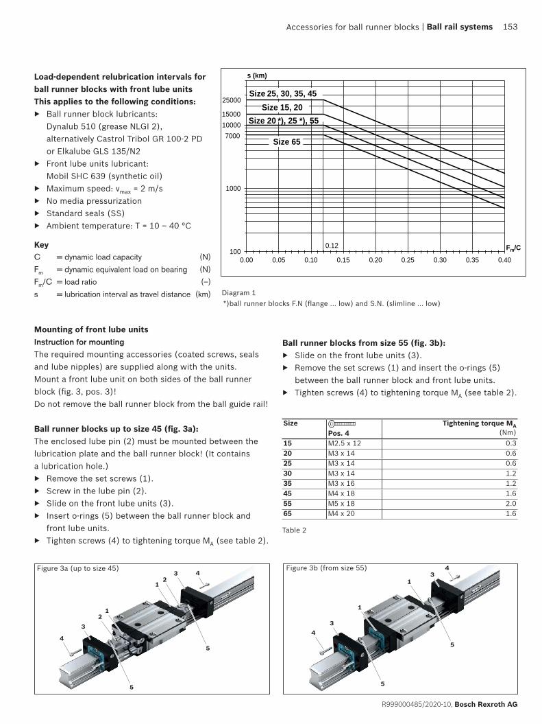
100
1000
10000
0.00 0.05 0.10 0.15 0.20 0.25 0.30 0.35 0.40
s (km)
Fm/C0.12
Size 25, 30, 35, 45Size 15, 20
7000Size 65
25000
15000Size 20 *), 25 *), 55
4
5
3
1
3
5
2
24
1
4
5
3
13
5
4
1
Mounting of front lube unitsInstruction for mountingThe required mounting accessories (coated screws, seals and lube nipples) are supplied along with the units.Mount a front lube unit on both sides of the ball runner block (fig. 3, pos. 3)!Do not remove the ball runner block from the ball guide rail!
Ball runner blocks up to size 45 (fig. 3a):The enclosed lube pin (2) must be mounted between the lubrication plate and the ball runner block! (It contains a lubrication hole.)
▶ Remove the set screws (1). ▶ Screw in the lube pin (2). ▶ Slide on the front lube units (3). ▶ Insert o-rings (5) between the ball runner block and
front lube units. ▶ Tighten screws (4) to tightening torque MA (see table 2).
Size
Pos. 4Tightening torque MA
(Nm)15 M2.5 x 12 0.320 M3 x 14 0.625 M3 x 14 0.630 M3 x 14 1.235 M3 x 16 1.245 M4 x 18 1.655 M5 x 18 2.065 M4 x 20 1.6
Table 2
Figure 3b (from size 55)
Load-dependent relubrication intervals for ball runner blocks with front lube unitsThis applies to the following conditions:
▶ Ball runner block lubricants: Dynalub 510 (grease NLGI 2), alternatively Castrol Tribol GR 100-2 PD or Elkalube GLS 135/N2
▶ Front lube units lubricant: Mobil SHC 639 (synthetic oil)
▶ Maximum speed: vmax = 2 m/s ▶ No media pressurization ▶ Standard seals (SS) ▶ Ambient temperature: T = 10 – 40 °C
Diagram 1
Figure 3a (up to size 45)
KeyC = dynamic load capacity (N)
Fm = dynamic equivalent load on bearing (N)
Fm/C = load ratio (–)
s = lubrication interval as travel distance (km)
Ball runner blocks from size 55 (fig. 3b): ▶ Slide on the front lube units (3). ▶ Remove the set screws (1) and insert the o-rings (5)
between the ball runner block and front lube units. ▶ Tighten screws (4) to tightening torque MA (see table 2).
Accessories for ball runner blocks
*)ball runner blocks F.N (flange ... low) and S.N. (slimline ... low)
| Ball rail systems 153
R999000485/2020-10, Bosch Rexroth AG

Size Part number, fold count
Type 1: with lubrication plate1) and end plateType 6: with VSE 2) and end plate
Type 2: with fastening frame and end plate
Type 3: with 2 lubrication plates1)
Type 7: with 2 VSE2)
Standard bellows15 R1620 10. 00, ... R1620 102 00, ... R1620 10. 00, ...20 R1620 80. 00, ... R1620 802 00, ... R1620 80. 00, ...25 R1620 20. 00, ... R1620 202 00, ... R1620 20. 00, ...30 R1620 70. 00, ... R1620 702 00, ... R1620 70. 00, ...35 R1620 30. 00, ... R1620 302 00, ... R1620 30. 00, ...45 R1620 40. 00, ... R1620 402 00, ... R1620 40. 00, ...55 R1620 50. 00, ... R1620 502 00, ... R1620 50. 00, ...65 R1620 60. 00, ... R1620 602 00, ... R1620 60. 00, ...20/403) – R1670 502 00, ... –25/703) – R1670 202 00, ... –35/903) – R1670 302 00, ... –
Heat-resistant bellows4)
25 R1620 25. 00, ... R1620 252 00, ... R1620 25. 00, ...30 R1620 75. 00, ... R1620 752 00, ... R1620 75. 00, ...35 R1620 35. 00, ... R1620 352 00, ... R1620 35. 00, ...45 R1620 45. 00, ... R1620 452 00, ... R1620 45. 00, ...55 R1620 55. 00, ... R1620 552 00, ... R1620 55. 00, ...65 R1620 65. 00, ... R1620 652 00, ... R1620 65. 00, ...
Bellowsstandard
Standard bellows R1620 .0. 00
▶ Material: Polyurethane-coated polyester fabric ▶ Aluminum lubrication plate
Heat-resistant bellows4)
R1620 .5. 00
▶ Material: Nomex fabric, metalizedTemperature stability
▶ Non combustible, non flammable ▶ Resistant to sparks, welding spatter and hot chips ▶ The protective metal coating can withstand peak
temperatures of up to 200 °C ▶ Operating temperature for the total bellows max. 80 °C
Bellowsheat-resistant4)
Bellows
Accessories for ball runner blocks154 Ball rail systems |
Bosch Rexroth AG, R999000485/2020-10
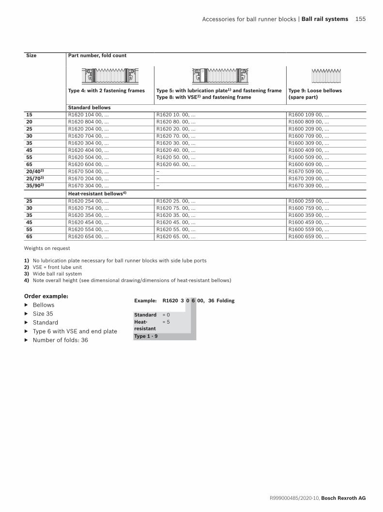
Order example: ▶ Bellows ▶ Size 35 ▶ Standard ▶ Type 6 with VSE and end plate ▶ Number of folds: 36
Size Part number, fold count
Type 4: with 2 fastening frames Type 5: with lubrication plate1) and fastening frameType 8: with VSE2) and fastening frame
Type 9: Loose bellows (spare part)
Standard bellows15 R1620 104 00, ... R1620 10. 00, ... R1600 109 00, ...20 R1620 804 00, ... R1620 80. 00, ... R1600 809 00, ...25 R1620 204 00, ... R1620 20. 00, ... R1600 209 00, ...30 R1620 704 00, ... R1620 70. 00, ... R1600 709 00, ...35 R1620 304 00, ... R1620 30. 00, ... R1600 309 00, ...45 R1620 404 00, ... R1620 40. 00, ... R1600 409 00, ...55 R1620 504 00, ... R1620 50. 00, ... R1600 509 00, ...65 R1620 604 00, ... R1620 60. 00, ... R1600 609 00, ...20/403) R1670 504 00, ... – R1670 509 00, ...25/703) R1670 204 00, ... – R1670 209 00, ...35/903) R1670 304 00, ... – R1670 309 00, ...
Heat-resistant bellows4)
25 R1620 254 00, ... R1620 25. 00, ... R1600 259 00, ...30 R1620 754 00, ... R1620 75. 00, ... R1600 759 00, ...35 R1620 354 00, ... R1620 35. 00, ... R1600 359 00, ...45 R1620 454 00, ... R1620 45. 00, ... R1600 459 00, ...55 R1620 554 00, ... R1620 55. 00, ... R1600 559 00, ...65 R1620 654 00, ... R1620 65. 00, ... R1600 659 00, ...
Example: R1620 3 0 6 00, 36 Folding
Standard = 0Heat-resistant
= 5
Type 1 - 9
1) No lubrication plate necessary for ball runner blocks with side lube ports2) VSE = front lube unit3) Wide ball rail system4) Note overall height (see dimensional drawing/dimensions of heat-resistant bellows)
Weights on request
Accessories for ball runner blocks | Ball rail systems 155
R999000485/2020-10, Bosch Rexroth AG

2
12
S13
B3 LmaxLmin
A4
N12
K3
H H3 H4
W
M4 a)
122Lmax
Lmin
H3 H4
A4
N12
N13
H
WM4 a)
H3 H4
Instruction for mounting ▶ The bellows are
pre-assembled.
▶ The fastening screws are included.
▶ Bellows with lubrication plate (type 1, 3 - 5) Sizes 15 – 20: A funnel-type lube nipple with a knock-in spigot is included. Sizes 25 – 65 and wide: The lube nipple of the ball runner block can be used.
▶ For type 1 and type 2, an M4x10 thread with 2 x 45° countersink must be placed in the end face of the ball guide rail SNS in each case. For ball guide rail BNS: Tap two threads at each end face.
▶ Observe the mounting instructions
Heat-resistant bellows2)
(Note the overall height)
Bellows, wide
a) Velcro fastener
Bellows
Illustrations not to scale
Accessories for ball runner blocks156 Ball rail systems |
Bosch Rexroth AG, R999000485/2020-10

Lmin LA Lmax
L
L = Lmin + Lmax + LA
Calculation
Ball guide rail length
Lmax = Bellows, elongated (mm)
Lmin = Bellows, contracted (mm)
Stroke = Stroke (mm)
U = Calculation factor (–)
W = Maximum bellows extraction (mm)
L = Ball guide rail length (mm)
LA = Ball runner block length with fastening frame (mm)
BellowsLmax = (stroke + 30) · U
Lmin = Lmax – stroke
Number of folds = + 2Lmax
W
Size Dimensions (mm) FactorA4 B3 H H3 H4 K3 N12 N13 S13 W U
15 45 11 24 26.5 31.5 3.4 11.0 – M3 19.9 1.1820 42 12 30 24.0 29.2 3.5 13.0 – M3 10.3 1.3325 45 12 36 28.5 35.0 6.0 15.0 – M3 12.9 1.3230 55 12 42 34.0 41.0 8.0 18.0 – M6 15.4 1.2535 64 12 48 39.0 47.0 8.0 22.0 – M6 19.9 1.1845 83 12 60 49.0 59.0 8.0 30.0 – M6 26.9 1.1355 96 12 70 56.0 69.0 9.0 30.0 – M6 29.9 1.1265 120 14 90 75.0 89.0 18.0 40.0 – M8x1 40.4 1.0820/401) 73 – 27 31.0 35.0 – 11.5 – – 19.9 1.1225/701) 101 – 35 29.0 35.0 – 14.0 26 – 12.9 1.2535/901) 128 – 50 42.0 49.0 – 21.5 40 – 19.9 1.18
Size Dimensions (mm) FactorA4 B3 H H3 H4 K3 N12 N13 S13 W U
25 62 12 36 39.0 44.5 6.0 15 – M6 25.9 1.2530 67 12 42 42.0 47.5 8.0 18 – M6 25.9 1.2535 74 12 48 47.0 54.0 8.0 22 – M6 29.9 1.2145 88 12 60 55.0 64.0 8.0 30 – M6 32.9 1.1855 102 12 70 63.0 75.0 9.0 30 – M6 37.9 1.1665 134 14 90 86.0 99.0 18.0 40 – M8x1 52.4 1.11
Heat-resistant bellows2)
Standard bellows
1) Wide ball rail system2) Observe the overall height (dimension H4 compared with dimension H)
Accessories for ball runner blocks | Ball rail systems 157
R999000485/2020-10, Bosch Rexroth AG
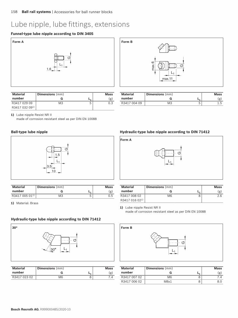
L1
G
30°
L1
G
max. 11
max
.6L1G
1.6
L1
G
1.5
3.510
L1
G
L1
G
Material number
Dimensions (mm) MassG L1 (g)
R3417 029 09 M3 5 0.3R3417 032 091)
Material number
Dimensions (mm) MassG L1 (g)
R3417 004 09 M3 5 1.5
Funnel-type lube nipple according to DIN 3405
Material number
Dimensions (mm) MassG L1 (g)
R3417 008 02 M6 8 2.6R3417 016 021)
Material number
Dimensions (mm) MassG L1 (g)
R3417 007 02 M6 8 7.4R3417 006 02 M8x1 8 8.0
Hydraulic-type lube nipple according to DIN 71412
Material number
Dimensions (mm) MassG L1 (g)
R3417 005 011) M3 5 0.5
Ball-type lube nipple
1) Lube nipple Resist NR II made of corrosion resistant steel as per DIN EN 10088
1) Lube nipple Resist NR II made of corrosion resistant steel as per DIN EN 10088
Form BForm A
Form B
Form A
1) Material: Brass
Hydraulic-type lube nipple according to DIN 71412
Material number
Dimensions (mm) MassG L1 (g)
R3417 023 02 M6 8 7.4
30°
Lube nipple, lube fittings, extensions
Accessories for ball runner blocks158 Ball rail systems |
Bosch Rexroth AG, R999000485/2020-10

d1
d2
L
R1/8"
Ø6Ø10
Plastic tube for lube connection
Plastic tube Ø 3 mm
O-rings
Material number Dimensions Mass External Ø(mm) Internal Ø (mm) Length (m) (kg)
R3499 287 00 3 1.7 50 0.4
Material number d1 x d2 Mass(mm)
R3411 130 01 4 x 1.0R3411 131 01 5 x 1.0R3411 003 01 6 x 1.5 0.03
Lube fittings
Material number Dimensions (mm)L
Mass(g)
R3455 030 44 200 158
Nozzle pipe
Accessories for ball runner blocks | Ball rail systems 159
R999000485/2020-10, Bosch Rexroth AG
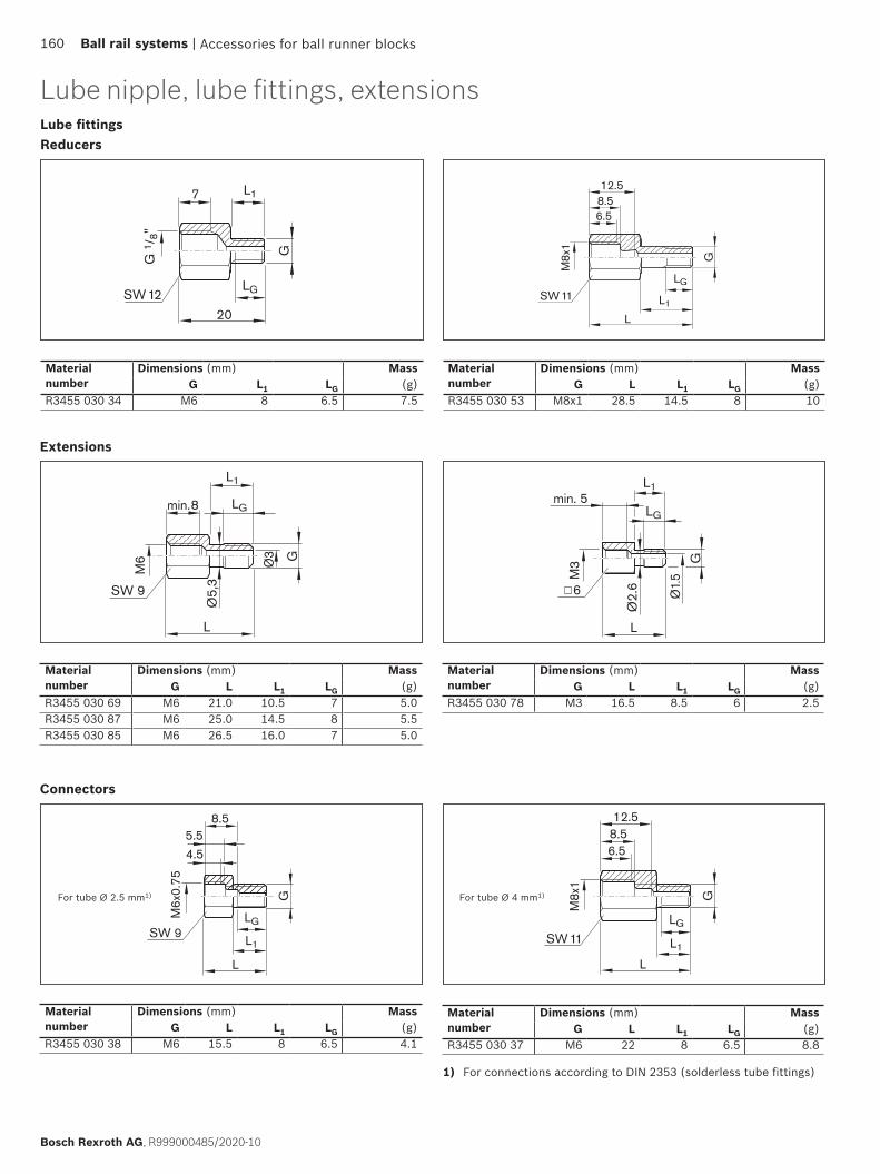
L
G
M6 Ø3
min. 8
L1
Ø5,
3
SW 9
LG
G
L1
LG
M3
Ø1.
5
min. 5
Ø2.
6L
6
L1
G
6.58.512.5
SW11
M8x
1
L
LG
L1
L
4.55.5
8.5
SW 9LG
M6x
0.75
G
20SW 12
G 1
/ 8"
7
LGG
L1
L1
G
6.58.512.5
SW11
M8x
1
L
LG
ReducersLube fittings
Material number
Dimensions (mm) MassG L1 LG (g)
R3455 030 34 M6 8 6.5 7.5
Extensions
Material number
Dimensions (mm) MassG L L1 LG (g)
R3455 030 69 M6 21.0 10.5 7 5.0R3455 030 87 M6 25.0 14.5 8 5.5R3455 030 85 M6 26.5 16.0 7 5.0
Material number
Dimensions (mm) MassG L L1 LG (g)
R3455 030 78 M3 16.5 8.5 6 2.5
For tube Ø 4 mm1)
Connectors
For tube Ø 2.5 mm1)
Material number
Dimensions (mm) MassG L L1 LG (g)
R3455 030 37 M6 22 8 6.5 8.8
Material number
Dimensions (mm) MassG L L1 LG (g)
R3455 030 38 M6 15.5 8 6.5 4.1
1) For connections according to DIN 2353 (solderless tube fittings)
Lube nipple, lube fittings, extensions
Material number
Dimensions (mm) MassG L L1 LG (g)
R3455 030 53 M8x1 28.5 14.5 8 10
Accessories for ball runner blocks160 Ball rail systems |
Bosch Rexroth AG, R999000485/2020-10

G
SW 917
M8x1SW 9
L1L
LGSW 10
L
G
d
LG
dAdA.1
SW
SW
L
G
d
L1
LG
dA
Swivel fittings
Material number Dimensions (mm) MassG L L1 LG (g)
R3417 018 09 M6 21.5 8 6.5 18.6
For tube Ø 4 mm1)
1) For connections according to DIN 2353 (solderless tube fittings)
Push-in fittings for plastic tubes and metal pipes
Not permitted for ball runner blocks with accessories on the end face
Straight connectors
Elbow plug-in connectionsturnable1)
1) Max. lubrication pressure: 30 bar (exerting slow pressure with manual grease gun) 2) Max. tightening torque MA = 0.5 Nm
Material number Dimensions (mm) MassdA dA.1 d±0.1 G L LG SW (g)
R3417 073 09 6.5 6.5 3 M3 16 5 1.51) 1.6R3417 074 09 6.5 8 3 M5 16 5 2 2.5R3417 075 09 9 9 4 M6 24.5 8 2.5 4.9R3417 076 09 11 11 6 M6 26 8 2.5 6.2
Material number Dimensions (mm) MassdA d±0.1 G L L1 LG SW (g)
R3417 077 09 6.5 3 M3 11.2 14.7 5 62) 3.8R3417 078 09 9 4 M6 18.1 18.1 8 9 10.8R3417 079 09 11 6 M6 20.8 18.1 8 9 12.9
1) Max. tightening torque MA = 0.5 Nm
Accessories for ball runner blocks | Ball rail systems 161
R999000485/2020-10, Bosch Rexroth AG
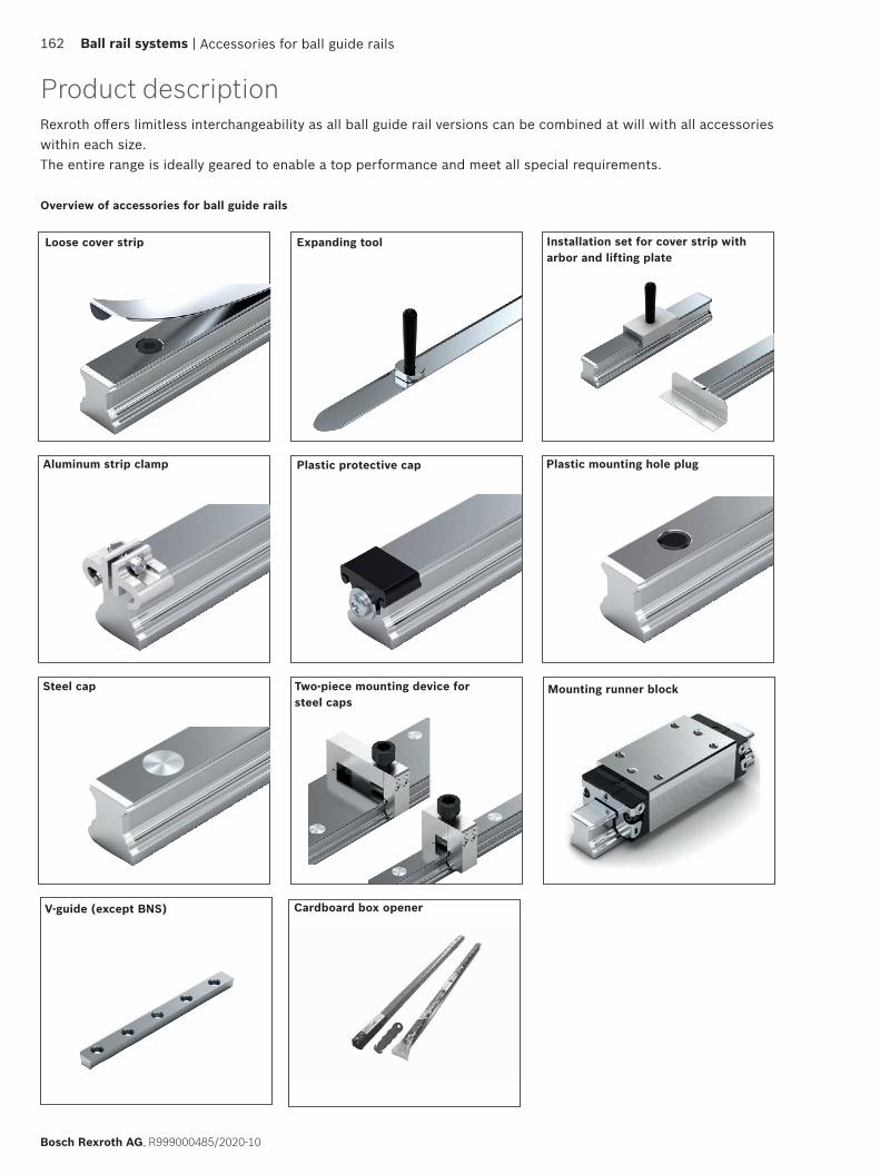
Cardboard box opener
Mounting runner block
Rexroth offers limitless interchangeability as all ball guide rail versions can be combined at will with all accessories within each size. The entire range is ideally geared to enable a top performance and meet all special requirements.
Overview of accessories for ball guide rails
Loose cover strip Expanding tool Installation set for cover strip with arbor and lifting plate
Aluminum strip clamp Plastic protective cap Plastic mounting hole plug
Steel cap Two-piece mounting device for steel caps
V-guide (except BNS)
Accessories for ball guide rails
Product description
162 Ball rail systems |
Bosch Rexroth AG, R999000485/2020-10
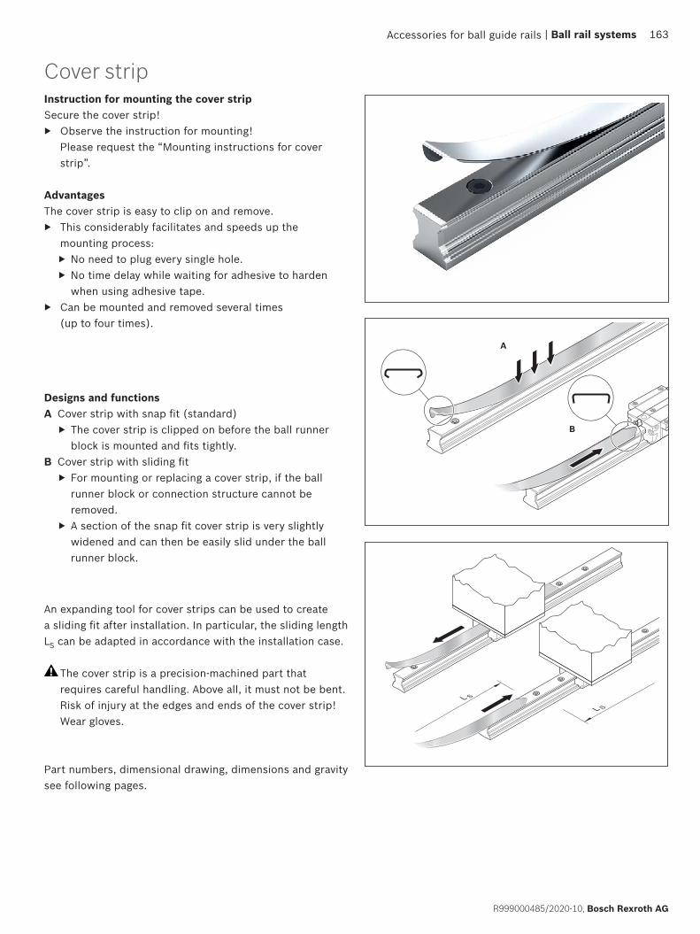
L SL S
A
B
Cover stripInstruction for mounting the cover stripSecure the cover strip!
▶ Observe the instruction for mounting! Please request the “Mounting instructions for cover strip”.
AdvantagesThe cover strip is easy to clip on and remove.
▶ This considerably facilitates and speeds up the mounting process: ▶ No need to plug every single hole. ▶ No time delay while waiting for adhesive to harden when using adhesive tape.
▶ Can be mounted and removed several times (up to four times).
Designs and functionsA Cover strip with snap fit (standard)
▶ The cover strip is clipped on before the ball runner block is mounted and fits tightly.
B Cover strip with sliding fit ▶ For mounting or replacing a cover strip, if the ball runner block or connection structure cannot be removed.
▶ A section of the snap fit cover strip is very slightly widened and can then be easily slid under the ball runner block.
An expanding tool for cover strips can be used to create a sliding fit after installation. In particular, the sliding length LS can be adapted in accordance with the installation case.
The cover strip is a precision-machined part that requires careful handling. Above all, it must not be bent. Risk of injury at the edges and ends of the cover strip! Wear gloves.
Part numbers, dimensional drawing, dimensions and gravity see following pages.
Accessories for ball guide rails | Ball rail systems 163
R999000485/2020-10, Bosch Rexroth AG

L
LS
L
min. 300 mm
Cover stripLoose cover strip
For initial installation, storage and replacement
NoteA suitable cover strip with snap fit or with sliding fit is available for each ball guide rail SNS.
Ordering example 1(standard cover strip with tight fit)
▶ Ball guide rail SNS ▶ Size 35 ▶ Rail length
L = 2696 mmMaterial number: R1619 330 20, 2696 mm
Standard loose cover strip with tight fit
Size Standard loose cover strip with tight fit MassPart number, rail length L (mm) (g/m)
15 R1619 130 00, .... 1020 R1619 830 00, .... 2925 R1619 230 00, .... 3230 R1619 730 00, .... 4035 R1619 330 20, .... 8045 R1619 430 20, .... 10055 R1619 530 20, .... 12065 R1619 630 20, .... 148
Cover strip with sliding fit section
LS = length of the sliding fits (mm)L = rail length (mm)
Ordering example 2(cover strip with sliding fit section)
▶ Ball guide rail SNS ▶ Size 35 ▶ Rail length
L = 2696 mm ▶ Length of sliding fit section
LS = 1200 mmMaterial number: R1619 330 30, 2696, 1200 mm
Size Cover strip with sliding fit section MassPart number, rail length L (mm), Length of sliding fit section LS (mm)
(g/m)
15 R1619 130 10, .... 1020 R1619 830 10, .... 2925 R1619 230 10, .... 3230 R1619 730 10, .... 4035 R1619 330 30, .... 8045 R1619 430 30, .... 10055 R1619 530 30, .... 12065 R1619 630 30, .... 148
Accessories for ball guide rails164 Ball rail systems |
Bosch Rexroth AG, R999000485/2020-10
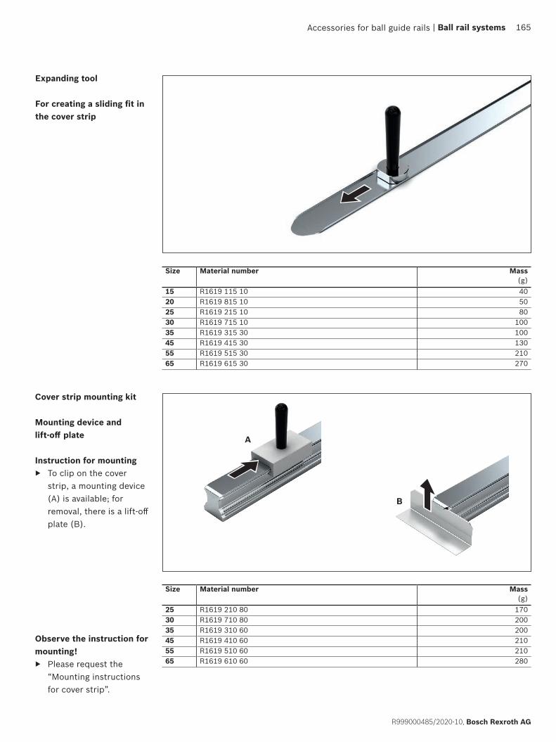
A
B
Cover strip mounting kit
Mounting device and lift-off plate
Instruction for mounting ▶ To clip on the cover
strip, a mounting device (A) is available; for removal, there is a lift-off plate (B).
Size Material number Mass(g)
25 R1619 210 80 17030 R1619 710 80 20035 R1619 310 60 20045 R1619 410 60 21055 R1619 510 60 21065 R1619 610 60 280
Size Material number Mass(g)
15 R1619 115 10 4020 R1619 815 10 5025 R1619 215 10 8030 R1619 715 10 10035 R1619 315 30 10045 R1619 415 30 13055 R1619 515 30 21065 R1619 615 30 270
Expanding tool
For creating a sliding fit in the cover strip
Observe the instruction for mounting!
▶ Please request the “Mounting instructions for cover strip”.
Accessories for ball guide rails | Ball rail systems 165
R999000485/2020-10, Bosch Rexroth AG
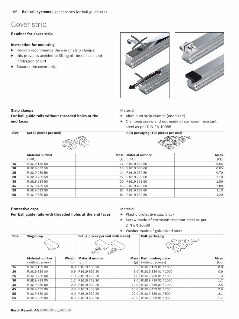
Retainer for cover strip
Instruction for mounting ▶ Rexroth recommends the use of strip clamps: ▶ this prevents accidental lifting of the rail seal and
infiltration of dirt ▶ Secures the cover strip
Size Single cap Set (2 pieces per unit with screw) Bulk packaging
Material number(without screw)
Weight (g)
Material number (unit)
Mass (g)
Part number/piece(without screws)
Mass (kg)
15 R1619 139 00 0.8 R1619 139 20 5.5 R1619 139 01 / 1000 0.820 R1619 839 00 0.9 R1619 839 20 6.0 R1619 839 01 / 1000 0.925 R1619 239 00 1.0 R1619 239 20 7.0 R1619 239 01 / 1000 1.330 R1619 739 00 1.7 R1619 739 20 9.0 R1619 739 01 / 1000 1.735 R1619 339 00 2.0 R1619 339 20 10.0 R1619 339 01 / 1000 2.545 R1619 439 00 4.0 R1619 439 20 13.0 R1619 439 01 / 700 2.655 R1619 539 00 4.0 R1619 539 20 20.0 R1619 539 01 / 500 2.165 R1619 639 00 6.0 R1619 639 20 20.0 R1619 639 01 / 300 1.7
Size Set (2 pieces per unit) Bulk packaging (100 pieces per unit)
Material number (unit)
Mass(g)
Material number (unit)
Mass(kg)
15 R1619 139 50 11 R1619 139 60 0.5520 R1619 839 50 13 R1619 839 60 0.6525 R1619 239 50 14 R1619 239 60 0.7030 R1619 739 50 22 R1619 739 60 1.1035 R1619 339 50 30 R1619 339 60 1.5045 R1619 439 50 56 R1619 439 60 2.8055 R1619 539 50 62 R1619 539 60 3.1065 R1619 639 50 84 R1619 639 60 4.20
Protective capsFor ball guide rails with threaded holes at the end faces
Strip clampsFor ball guide rails without threaded holes at the end faces
Material: ▶ Plastic protective cap, black ▶ Screw made of corrosion resistant steel as per
DIN EN 10088 ▶ Washer made of galvanized steel
Material: ▶ Aluminum strip clamps (anodized) ▶ Clamping screw and nut made of corrosion resistant
steel as per DIN EN 10088
Cover strip
Accessories for ball guide rails166 Ball rail systems |
Bosch Rexroth AG, R999000485/2020-10
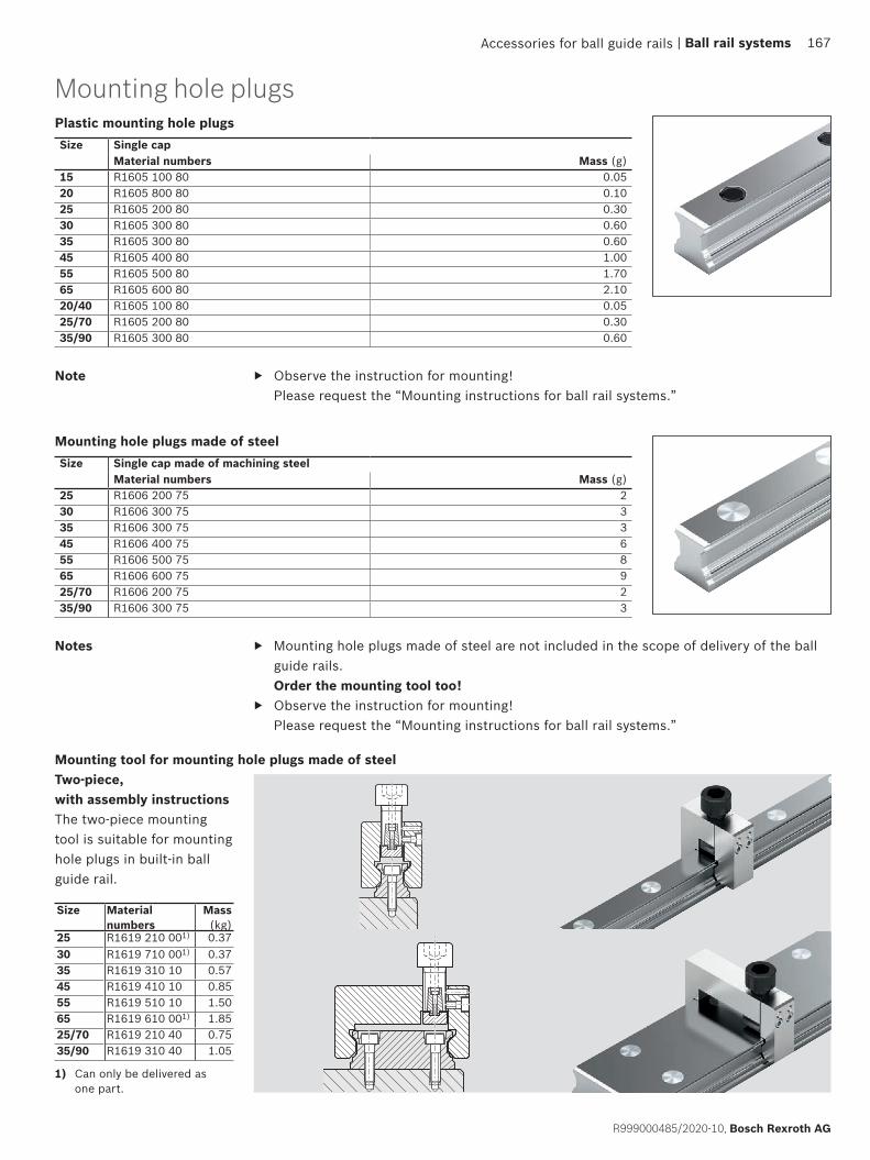
Mounting hole plugsPlastic mounting hole plugsSize Single cap
Material numbers Mass (g)15 R1605 100 80 0.0520 R1605 800 80 0.1025 R1605 200 80 0.3030 R1605 300 80 0.6035 R1605 300 80 0.6045 R1605 400 80 1.0055 R1605 500 80 1.7065 R1605 600 80 2.1020/40 R1605 100 80 0.0525/70 R1605 200 80 0.3035/90 R1605 300 80 0.60
Mounting hole plugs made of steelSize Single cap made of machining steel
Material numbers Mass (g)25 R1606 200 75 230 R1606 300 75 335 R1606 300 75 345 R1606 400 75 655 R1606 500 75 865 R1606 600 75 925/70 R1606 200 75 235/90 R1606 300 75 3
Notes ▶ Mounting hole plugs made of steel are not included in the scope of delivery of the ball guide rails. Order the mounting tool too!
▶ Observe the instruction for mounting! Please request the “Mounting instructions for ball rail systems.”
Note
Two-piece, with assembly instructionsThe two-piece mounting tool is suitable for mounting hole plugs in built-in ball guide rail.
Mounting tool for mounting hole plugs made of steel
1) Can only be delivered as one part.
Size Material numbers
Mass (kg)
25 R1619 210 001) 0.3730 R1619 710 001) 0.3735 R1619 310 10 0.5745 R1619 410 10 0.8555 R1619 510 10 1.5065 R1619 610 001) 1.8525/70 R1619 210 40 0.7535/90 R1619 310 40 1.05
▶ Observe the instruction for mounting! Please request the “Mounting instructions for ball rail systems.”
Accessories for ball guide rails | Ball rail systems 167
R999000485/2020-10, Bosch Rexroth AG

B T
A
D
Mounting runner block
Mounting runner block
▶ For highly accurate parallel alignment of ball rail systems (types SNS and SNO)
▶ For joint alignment of multi-piece ball guide rails (types SNS and SNO).
Size Material numbers Dimensions (mm) Mass
A B T D (kg)
15 R1629 121 90 34 72.6 43 6 0.2
20 R1629 821 90 44 91 55 6 0.5
25 R1629 221 90 48 107.9 60 8 0.8
30 R1629 721 90 60 119.7 75 10 1.1
35 R1629 321 90 70 139 80 10 2.2
45 R1629 421 90 86 174.1 105 15 4.1
55 R1629 521 90 100 199 120 18 6.0
65 R1629 621 90 126 243 150 20 9.8
Accessories for ball guide rails168 Ball rail systems |
Bosch Rexroth AG, R999000485/2020-10

Mounting with mounting runner block
Alignment of parallel rails
1 Align and mount the first ball guide rail using a graduated straightedge.2 Set up a mounting bridge with dial gauge between the ball runner blocks.3 Move both ball runner blocks in parallel until the holes D of the mounting runner block are exactly over two mounting
holes of the rail (provided that the drilling distances of the rail correspond to the spacing T).4 Align the ball guide rail manually until the dial gauge shows the correct dimension.5 Tighten the screws through the mounting runner block.
Mounting runner block R1629
Screwed down
Standard ball runner blocks
Screwed down
Accessories for ball guide rails
Alignment of the multi-piece rails
1 Slide the multi-piece rails together at the joint.2 Slide the mounting runner block over the center of the joint until both screw heads are visible. This is the case when
the hole center distance of the joint corresponds to hole spacing T. If this is not the case, continue with point 5. 3 The mounting runner block automatically aligns the rails at the joint.4 Tighten the screws through the mounting runner block.5 If the screw center distances of the guide rail at the joint are not equal to the spacing and deviate from the hole spacing
of the mounting runner block, each screw must be tightened individually and then moved to the next hole.
| Ball rail systems 169
R999000485/2020-10, Bosch Rexroth AG
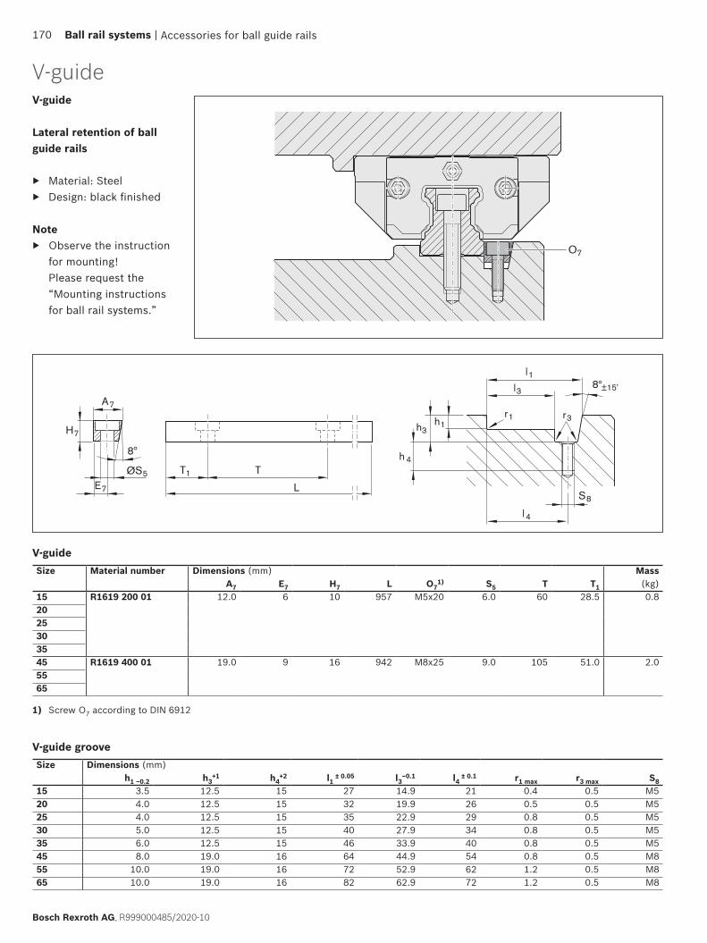
O7
T1 T
LE7
8
A7
H7
ØS5
l1l3 8 ±15'
h 4
h3h1
S8
l4
r1 r3
V-guide
Lateral retention of ball guide rails
▶ Material: Steel ▶ Design: black finished
Note ▶ Observe the instruction
for mounting! Please request the “Mounting instructions for ball rail systems.”
Size Material number Dimensions (mm) MassA7 E7 H7 L O7
1) S5 T T1 (kg)15 R1619 200 01 12.0 6 10 957 M5x20 6.0 60 28.5 0.82025303545 R1619 400 01 19.0 9 16 942 M8x25 9.0 105 51.0 2.05565
Size Dimensions (mm)h1 –0.2 h3
+1 h4+2 l1 ± 0.05 l3–0.1 l4 ± 0.1 r1 max r3 max S8
15 3.5 12.5 15 27 14.9 21 0.4 0.5 M520 4.0 12.5 15 32 19.9 26 0.5 0.5 M525 4.0 12.5 15 35 22.9 29 0.8 0.5 M530 5.0 12.5 15 40 27.9 34 0.8 0.5 M535 6.0 12.5 15 46 33.9 40 0.8 0.5 M545 8.0 19.0 16 64 44.9 54 0.8 0.5 M855 10.0 19.0 16 72 52.9 62 1.2 0.5 M865 10.0 19.0 16 82 62.9 72 1.2 0.5 M8
V-guide
V-guide groove
1) Screw O7 according to DIN 6912
V-guide
Accessories for ball guide rails170 Ball rail systems |
Bosch Rexroth AG, R999000485/2020-10

Cardboard box opener ▶ Tool for opening the guide rails packaging. ▶ Prevents risk of injury
Ordering dataMaterial number R320105175
Accessories for ball guide rails | Ball rail systems 171
R999000485/2020-10, Bosch Rexroth AG
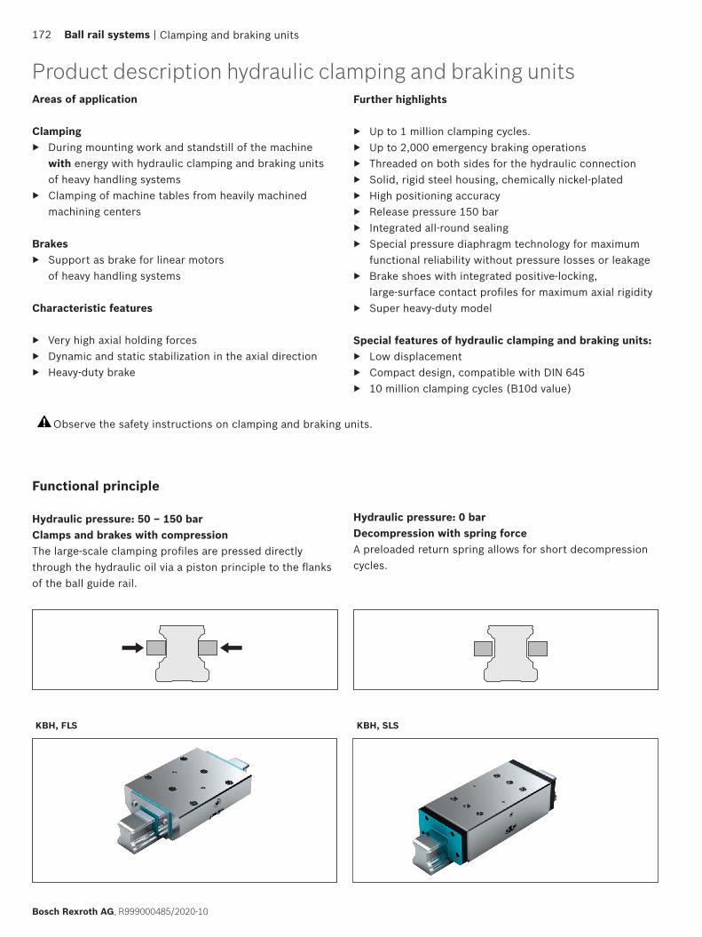
KBH, FLS KBH, SLS
Areas of application
Clamping ▶ During mounting work and standstill of the machine
with energy with hydraulic clamping and braking unitsof heavy handling systems
▶ Clamping of machine tables from heavily machined machining centers
Brakes ▶ Support as brake for linear motors
of heavy handling systems
Characteristic features
▶ Very high axial holding forces ▶ Dynamic and static stabilization in the axial direction ▶ Heavy-duty brake
Further highlights
▶ Up to 1 million clamping cycles. ▶ Up to 2,000 emergency braking operations ▶ Threaded on both sides for the hydraulic connection ▶ Solid, rigid steel housing, chemically nickel-plated ▶ High positioning accuracy ▶ Release pressure 150 bar ▶ Integrated all-round sealing ▶ Special pressure diaphragm technology for maximum
functional reliability without pressure losses or leakage ▶ Brake shoes with integrated positive-locking,
large-surface contact profiles for maximum axial rigidity ▶ Super heavy-duty model
Special features of hydraulic clamping and braking units: ▶ Low displacement ▶ Compact design, compatible with DIN 645 ▶ 10 million clamping cycles (B10d value)
Observe the safety instructions on clamping and braking units.
Clamping and braking units
Product description hydraulic clamping and braking units
172 Ball rail systems |
Bosch Rexroth AG, R999000485/2020-10
Functional principle
Hydraulic pressure: 50 – 150 barClamps and brakes with compressionThe large-scale clamping profiles are pressed directly through the hydraulic oil via a piston principle to the flanks of the ball guide rail.
Hydraulic pressure: 0 barDecompression with spring forceA preloaded return spring allows for short decompression cycles.
Hydraulic connections The hydraulic clamping units are pre-filled with HLP 46 at the factory. The hydraulic connection is attached on two sides. One connection is suitable for pressurization. Take care when venting fixed and flexible hydraulic lines because air ports can damage sealing elements.
Connection structure, mounting the clamping unitsTo prevent detrimental effects, e.g. permanent grinding on the linear guide, the connection structure must be rigid and in accordance with its load and requirements. If the clamping units tilt, this can result in contact, wear and therefore damage to the linear guide.
The setting at the factory is adapted for the linear guide and may not be altered when mounting. It is imperative to observe the mounting instructions for the clamping and braking units and the linear guides.Some spring-loaded accumulators are equipped with a transport lock between the contact profiles.This must be removed when mounting by pressurizing the unit. When pressure is removed, the transport lock or the associated linear guide must always lie between the contact profiles.The clamping units do not have any guiding function. A runner block can therefore not be replaced with a clamping unit. The ideal position of the clamping unit lies between two runner blocks.When using several clamping units, these should be distributed evenly on both guide railsin order to attain a maximum rigidity of the overall construction.
LubricationWhen using the prescribed pressurizing medium, lubrication is not required.
Surface protectionAll housings of the Clamping Units are chemically nickel-plated and therefore have limited rust protection. Aluminum subsections are chemically nickel-plated or hard-coated according to their requirement.
B10d valueThe B10d-value specifies the number of switching cycles until 10% of components fail dangerously.
Additional information
Clamping and braking units | Ball rail systems 173
R999000485/2020-10, Bosch Rexroth AG
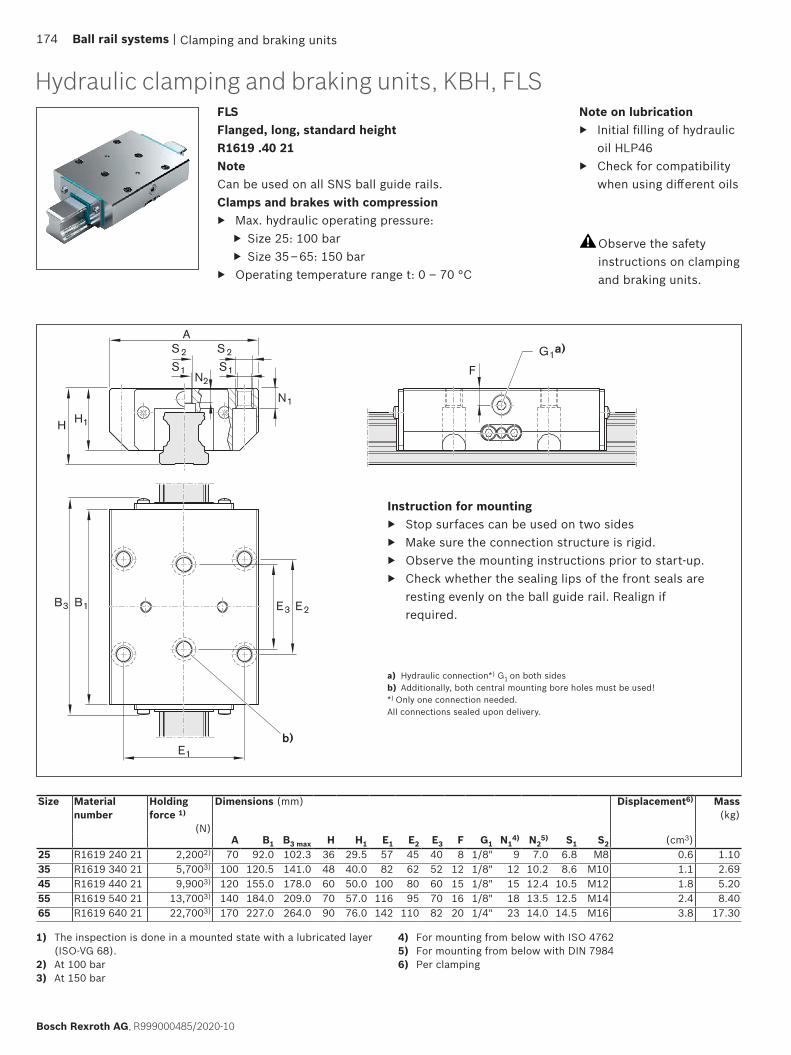
F
E1
B1B3 E2E3
S2
S1
S2
S1
A
N2
N1
H1H
G1a)
b)
Clamping and braking units
Hydraulic clamping and braking units, KBH, FLS
Size Material number
Holding force 1)
(N)
Dimensions (mm) Displacement6) Mass(kg)
A B1 B3 max H H1 E1 E2 E3 F G1 N14) N2
5) S1 S2 (cm3)25 R1619 240 21 2,2002) 70 92.0 102.3 36 29.5 57 45 40 8 1/8" 9 7.0 6.8 M8 0.6 1.1035 R1619 340 21 5,7003) 100 120.5 141.0 48 40.0 82 62 52 12 1/8" 12 10.2 8.6 M10 1.1 2.6945 R1619 440 21 9,9003) 120 155.0 178.0 60 50.0 100 80 60 15 1/8" 15 12.4 10.5 M12 1.8 5.2055 R1619 540 21 13,7003) 140 184.0 209.0 70 57.0 116 95 70 16 1/8" 18 13.5 12.5 M14 2.4 8.4065 R1619 640 21 22,7003) 170 227.0 264.0 90 76.0 142 110 82 20 1/4" 23 14.0 14.5 M16 3.8 17.30
FLS Flanged, long, standard heightR1619 .40 21NoteCan be used on all SNS ball guide rails.Clamps and brakes with compression
▶ Max. hydraulic operating pressure: ▶ Size 25: 100 bar ▶ Size 35 – 65: 150 bar
▶ Operating temperature range t: 0 – 70 °C
Observe the safety instructions on clamping and braking units.
Instruction for mounting ▶ Stop surfaces can be used on two sides ▶ Make sure the connection structure is rigid. ▶ Observe the mounting instructions prior to start-up. ▶ Check whether the sealing lips of the front seals are
resting evenly on the ball guide rail. Realign if required.
a) Hydraulic connection*) G1 on both sidesb) Additionally, both central mounting bore holes must be used!*) Only one connection needed.All connections sealed upon delivery.
1) The inspection is done in a mounted state with a lubricated layer (ISO-VG 68).
2) At 100 bar 3) At 150 bar
4) For mounting from below with ISO 47625) For mounting from below with DIN 79846) Per clamping
Note on lubrication ▶ Initial filling of hydraulic
oil HLP46 ▶ Check for compatibility
when using different oils
174 Ball rail systems |
Bosch Rexroth AG, R999000485/2020-10
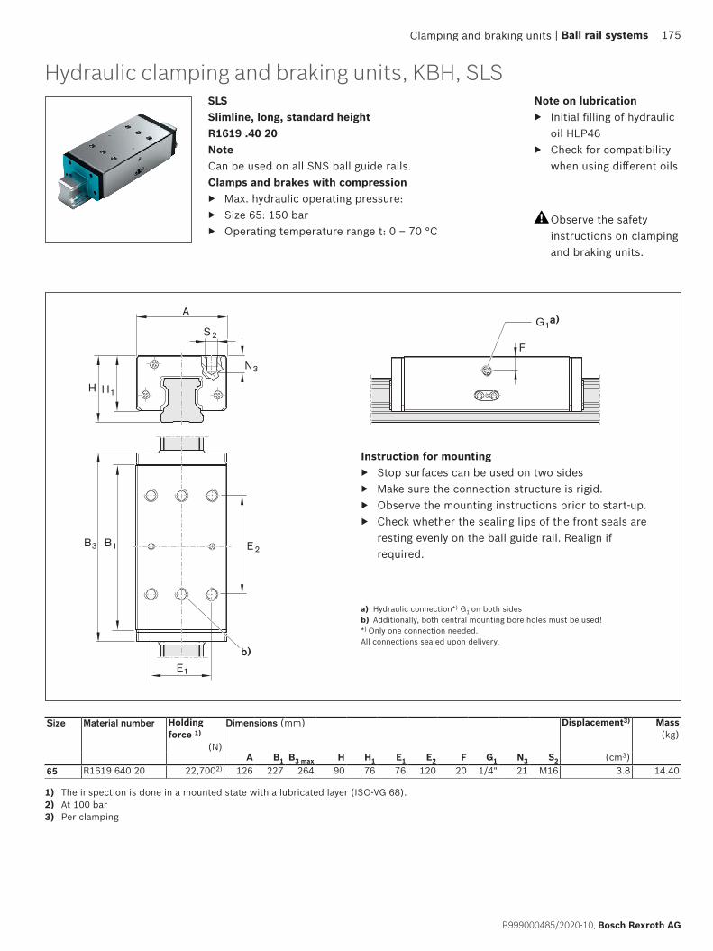
H1H
S2
A
N3
F
B1B3 E 2
E1
G1a)
b)
Clamping and braking units
Observe the safety instructions on clamping and braking units.
Instruction for mounting ▶ Stop surfaces can be used on two sides ▶ Make sure the connection structure is rigid. ▶ Observe the mounting instructions prior to start-up. ▶ Check whether the sealing lips of the front seals are
resting evenly on the ball guide rail. Realign if required.
a) Hydraulic connection*) G1 on both sidesb) Additionally, both central mounting bore holes must be used!*) Only one connection needed.All connections sealed upon delivery.
SLS Slimline, long, standard heightR1619 .40 20NoteCan be used on all SNS ball guide rails.Clamps and brakes with compression
▶ Max. hydraulic operating pressure: ▶ Size 65: 150 bar ▶ Operating temperature range t: 0 – 70 °C
Note on lubrication ▶ Initial filling of hydraulic
oil HLP46 ▶ Check for compatibility
when using different oils
Size Material number Holding force 1)
(N)
Dimensions (mm) Displacement3) Mass(kg)
A B1 B3 max H H1 E1 E2 F G1 N3 S2 (cm3)65 R1619 640 20 22,7002) 126 227 264 90 76 76 120 20 1/4" 21 M16 3.8 14.40
1) The inspection is done in a mounted state with a lubricated layer (ISO-VG 68).2) At 100 bar 3) Per clamping
Hydraulic clamping and braking units, KBH, SLS
| Ball rail systems 175
R999000485/2020-10, Bosch Rexroth AG
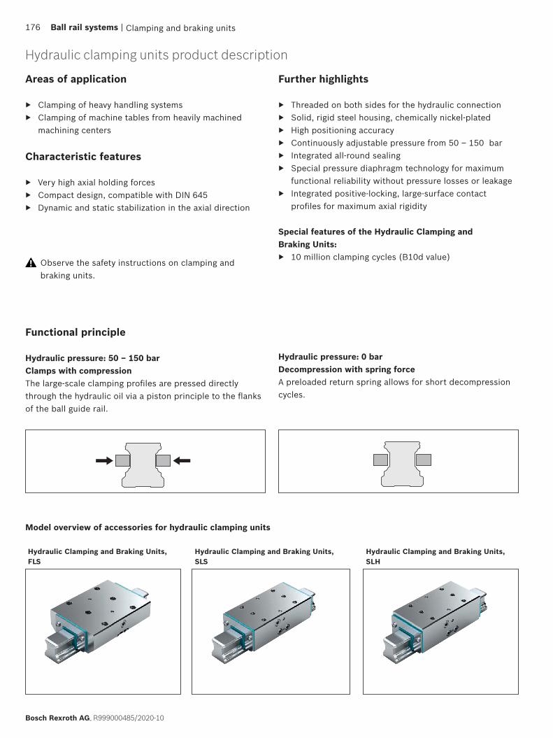
Hydraulic Clamping and Braking Units, FLS
Hydraulic Clamping and Braking Units, SLH
Hydraulic Clamping and Braking Units, SLS
Clamping and braking units
Hydraulic clamping units product description
Model overview of accessories for hydraulic clamping units
176 Ball rail systems |
Bosch Rexroth AG, R999000485/2020-10
Functional principle
Hydraulic pressure: 50 – 150 barClamps with compressionThe large-scale clamping profiles are pressed directly through the hydraulic oil via a piston principle to the flanks of the ball guide rail.
Hydraulic pressure: 0 barDecompression with spring forceA preloaded return spring allows for short decompression cycles.
Areas of application
▶ Clamping of heavy handling systems ▶ Clamping of machine tables from heavily machined
machining centers
Characteristic features
▶ Very high axial holding forces ▶ Compact design, compatible with DIN 645 ▶ Dynamic and static stabilization in the axial direction
Further highlights
▶ Threaded on both sides for the hydraulic connection ▶ Solid, rigid steel housing, chemically nickel-plated ▶ High positioning accuracy ▶ Continuously adjustable pressure from 50 – 150 bar ▶ Integrated all-round sealing ▶ Special pressure diaphragm technology for maximum
functional reliability without pressure losses or leakage ▶ Integrated positive-locking, large-surface contact
profiles for maximum axial rigidity
Special features of the Hydraulic Clamping and Braking Units:
▶ 10 million clamping cycles (B10d value) Observe the safety instructions on clamping and braking units.
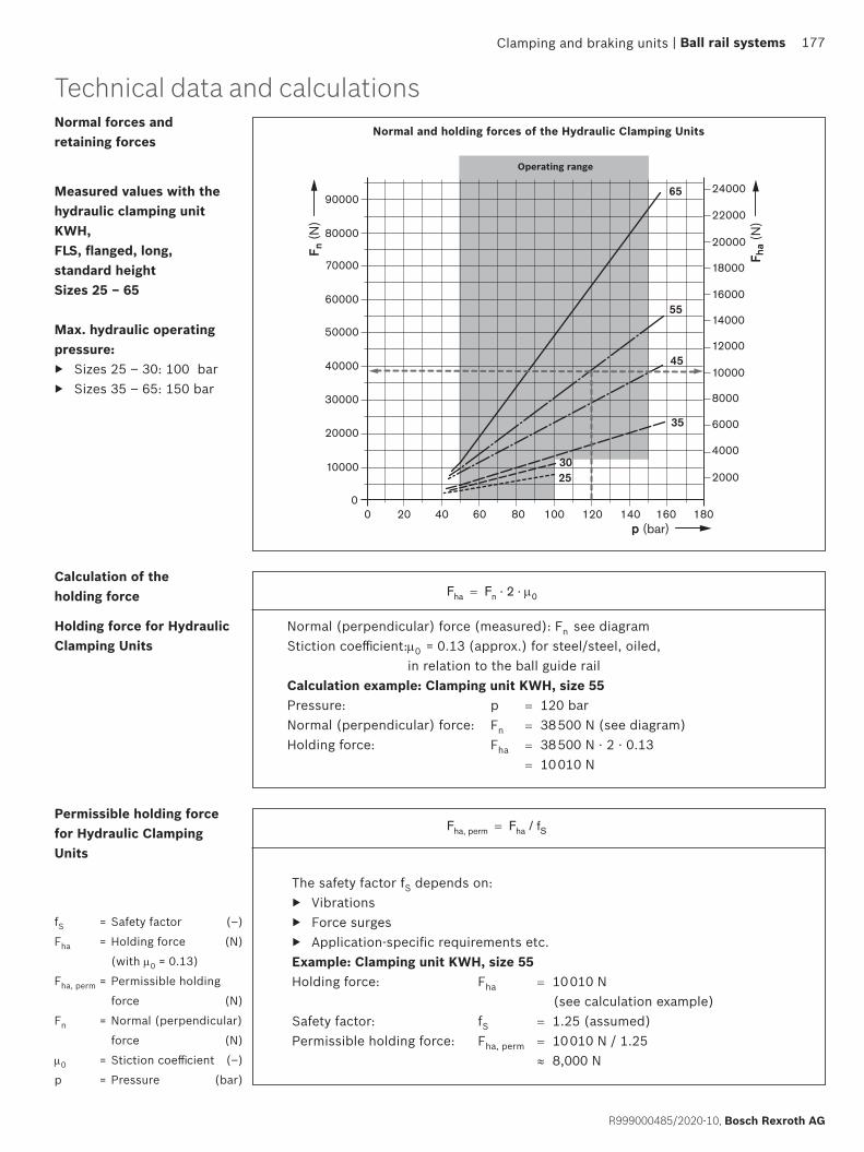
10000
20000
2000
4000
30000
40000
0
50000
20 40 60 80 100 120 1400
20000
22000
24000
18000
16000
14000
12000
10000
8000
6000
60000
70000
80000
90000
160 180
F n (N
)
F ha
(N)
p (bar)
35
2530
45
55
65
Clamping and braking units
Technical data and calculationsNormal forces and retaining forces
Measured values with the hydraulic clamping unit KWH, FLS, flanged, long, standard height Sizes 25 – 65
Max. hydraulic operating pressure:
▶ Sizes 25 – 30: 100 bar ▶ Sizes 35 – 65: 150 bar
fS = Safety factor (–)
Fha = Holding force (N)
(with µ0 = 0.13)
Fha, perm = Permissible holding
force (N)
Fn = Normal (perpendicular)
force (N)
µ0 = Stiction coefficient (–)
p = Pressure (bar)
Fha = Fn · 2 · µ0
Normal (perpendicular) force (measured): Fn see diagram Stiction coefficient: µ0 = 0.13 (approx.) for steel/steel, oiled,
in relation to the ball guide railCalculation example: Clamping unit KWH, size 55Pressure: p = 120 bar Normal (perpendicular) force: Fn = 38 500 N (see diagram) Holding force: Fha �= 38 500 N · 2 · 0.13
= 10 010 N
Fha, perm =� Fha / fS
The safety factor fS depends on: ▶ Vibrations ▶ Force surges ▶ Application-specific requirements etc.
Example: Clamping unit KWH, size 55Holding force: Fha = 10 010 N (see calculation example) Safety factor: fS = 1.25 (assumed) Permissible holding force: Fha, perm = 10 010 N / 1.25
≈ 8,000 N
Operating range
Normal and holding forces of the Hydraulic Clamping Units
Calculation of the holding force
Holding force for Hydraulic Clamping Units
Permissible holding force for Hydraulic Clamping Units
| Ball rail systems 177
R999000485/2020-10, Bosch Rexroth AG

F
E1
B1B3 E2E3
S2
S1
S2
S1
A
N2
N1
H1H
G1a)
b)
Clamping and braking units
Hydraulic clamping units KWH, FLS
Size Material number
Holding force1)
Dimensions (mm) Displacement6) Mass(kg)
(N) A B1 B3 max H H1 E1 E2 E3 F G1 N14) N2
5) S1 S2 (cm3)25 R1619 242 11 2,2002) 70 92.0 102.3 36 29.5 57 45 40 8.0 1/8" 9 7.0 6.8 M8 0.6 1.2230 R1619 742 11 3,0002) 90 103.5 115.4 42 35.0 72 52 44 10.5 1/8" 11 8.0 8.6 M10 0.7 2.0935 R1619 342 11 5,7003) 100 120.5 133.0 48 40.0 82 62 52 12.0 1/8" 12 10.2 8.6 M10 1.1 2.6945 R1619 442 11 9,9003) 120 155.0 170.0 60 50.0 100 80 60 15.0 1/8" 15 12.4 10.5 M12 1.8 5.3255 R1619 542 11 13,7003) 140 184.0 201.0 70 57.0 116 95 70 16.0 1/8" 18 13.5 12.5 M14 2.4 8.4065 R1619 642 11 22,7003) 170 227.0 256.0 90 76.0 142 110 82 20.0 1/4" 23 14.0 14.5 M16 3.8 17.30
FLS, flanged, long, standard height R1619 .42 11NoteCan be used on all SNS ball guide rails.Clamps with compression
▶ Max. hydraulic operating pressure: ▶ Sizes 25 – 30: 100 bar ▶ Sizes 35 – 65: 150 bar
▶ Operating temperature range t: 0 – 70 °C
Instruction for mounting ▶ Stop surfaces can be used on two sides ▶ Make sure the connection structure is rigid. ▶ Observe the mounting instructions prior to start-up. ▶ Check whether the sealing lips of the front seals are
resting evenly on the ball guide rail. Realign if required.
a) Hydraulic connection*) G1 on both sidesb) Additionally, both central mounting bore holes must be used!*) Only one connection needed.All connections sealed upon delivery.
1) The inspection is done in a mounted state with a lubricated layer (ISO-VG 68). Permissible holding force 173
2) At 100 bar 3) At 150 bar
4) For mounting from below with ISO 47625) For mounting from below with DIN 79846) Per clamping
Observe the safety instructions on clamping and braking units.
Note on lubrication ▶ Initial filling of hydraulic
oil HLP46 ▶ Check for compatibility
when using different oils
178 Ball rail systems |
Bosch Rexroth AG, R999000485/2020-10
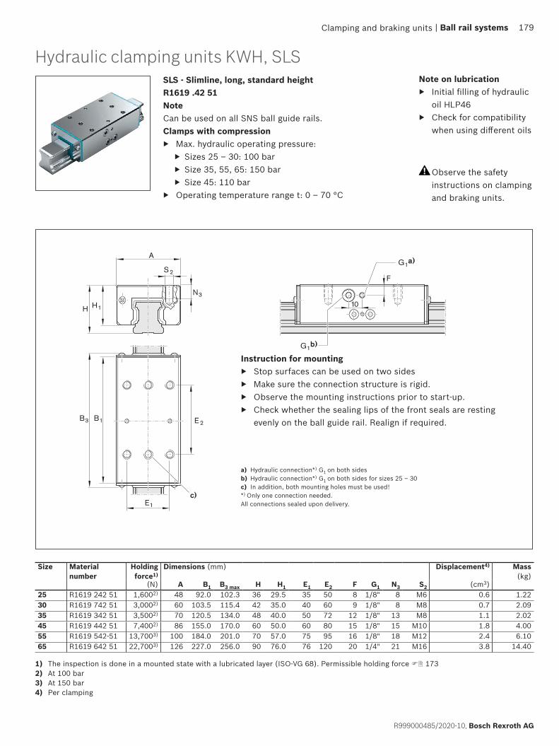
H1H
S2
A
F
10
B1B3 E 2
E1
N3
G1a)
G1b)
c)
Clamping and braking units
Size Material number
Holding force1)
Dimensions (mm) Displacement4) Mass(kg)
(N) A B1 B3 max H H1 E1 E2 F G1 N3 S2 (cm3)25 R1619 242 51 1,6002) 48 92.0 102.3 36 29.5 35 50 8 1/8" 8 M6 0.6 1.2230 R1619 742 51 3,0002) 60 103.5 115.4 42 35.0 40 60 9 1/8" 8 M8 0.7 2.0935 R1619 342 51 3,5002) 70 120.5 134.0 48 40.0 50 72 12 1/8" 13 M8 1.1 2.0245 R1619 442 51 7,4002) 86 155.0 170.0 60 50.0 60 80 15 1/8" 15 M10 1.8 4.0055 R1619 542-51 13,7003) 100 184.0 201.0 70 57.0 75 95 16 1/8" 18 M12 2.4 6.1065 R1619 642 51 22,7003) 126 227.0 256.0 90 76.0 76 120 20 1/4" 21 M16 3.8 14.40
SLS - Slimline, long, standard heightR1619 .42 51NoteCan be used on all SNS ball guide rails.Clamps with compression
▶ Max. hydraulic operating pressure: ▶ Sizes 25 – 30: 100 bar ▶ Size 35, 55, 65: 150 bar ▶ Size 45: 110 bar
▶ Operating temperature range t: 0 – 70 °C
Instruction for mounting ▶ Stop surfaces can be used on two sides ▶ Make sure the connection structure is rigid. ▶ Observe the mounting instructions prior to start-up. ▶ Check whether the sealing lips of the front seals are resting
evenly on the ball guide rail. Realign if required.
a) Hydraulic connection*) G1 on both sidesb) Hydraulic connection*) G1 on both sides for sizes 25 – 30c) In addition, both mounting holes must be used!*) Only one connection needed.All connections sealed upon delivery.
1) The inspection is done in a mounted state with a lubricated layer (ISO-VG 68). Permissible holding force 1732) At 100 bar 3) At 150 bar4) Per clamping
Hydraulic clamping units KWH, SLS
Observe the safety instructions on clamping and braking units.
Note on lubrication ▶ Initial filling of hydraulic
oil HLP46 ▶ Check for compatibility
when using different oils
| Ball rail systems 179
R999000485/2020-10, Bosch Rexroth AG
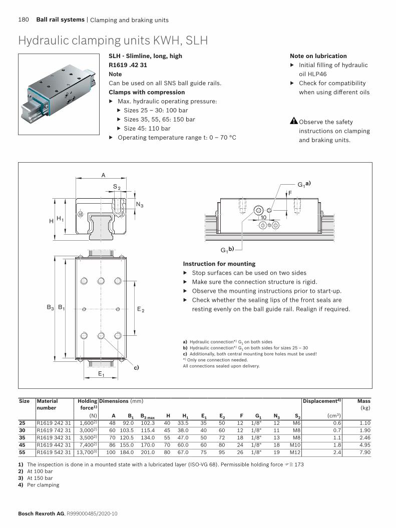
H1H
S2
A
N3
F
10
B1B3 E 2
E1
G1a)
G1b)
c)
Clamping and braking units
Size Material number
Holding force1)
Dimensions (mm) Displacement4) Mass(kg)
(N) A B1 B3 max H H1 E1 E2 F G1 N3 S2 (cm3)25 R1619 242 31 1,6002) 48 92.0 102.3 40 33.5 35 50 12 1/8" 12 M6 0.6 1.1030 R1619 742 31 3,0002) 60 103.5 115.4 45 38.0 40 60 12 1/8" 11 M8 0.7 1.9035 R1619 342 31 3,5002) 70 120.5 134.0 55 47.0 50 72 18 1/8" 13 M8 1.1 2.4645 R1619 442 31 7,4002) 86 155.0 170.0 70 60.0 60 80 24 1/8" 18 M10 1.8 4.9555 R1619 542 31 13,7003) 100 184.0 201.0 80 67.0 75 95 26 1/8" 19 M12 2.4 7.90
SLH - Slimline, long, highR1619 .42 31NoteCan be used on all SNS ball guide rails.Clamps with compression
▶ Max. hydraulic operating pressure: ▶ Sizes 25 – 30: 100 bar ▶ Sizes 35, 55, 65: 150 bar ▶ Size 45: 110 bar
▶ Operating temperature range t: 0 – 70 °C
Observe the safety instructions on clamping and braking units.
Instruction for mounting ▶ Stop surfaces can be used on two sides ▶ Make sure the connection structure is rigid. ▶ Observe the mounting instructions prior to start-up. ▶ Check whether the sealing lips of the front seals are
resting evenly on the ball guide rail. Realign if required.
a) Hydraulic connection*) G1 on both sidesb) Hydraulic connection*) G1 on both sides for sizes 25 – 30c) Additionally, both central mounting bore holes must be used!*) Only one connection needed.All connections sealed upon delivery.
1) The inspection is done in a mounted state with a lubricated layer (ISO-VG 68). Permissible holding force 1732) At 100 bar 3) At 150 bar4) Per clamping
Hydraulic clamping units KWH, SLHNote on lubrication
▶ Initial filling of hydraulic oil HLP46
▶ Check for compatibility when using different oils
180 Ball rail systems |
Bosch Rexroth AG, R999000485/2020-10

Clamping and braking units | Ball rail systems 181
R999000485/2020-10, Bosch Rexroth AG

Clamping and braking units
Areas of application
Clamping ▶ In the event of loss of pressure ▶ During assembly work and standstill of the machine
without energy ▶ of machine tables from machining centers ▶ of z-axis positioning in the resting position
Brakes ▶ In the event of energy failure ▶ In the event of a pressure drop ▶ Support of the emergency stop function ▶ Support as brake for linear motors
Pneumatic clamping and braking units, product description
Observe the safety instructions on clamping and braking units.
Characteristic features
▶ Clamps and brakes with spring energy accumulator ▶ Positive-locking integrated contact profiles ensure
maximum axial and horizontal rigidity, and thus an excellent braking effect
▶ Dynamic and static stability in axial direction
Special features MBPS/UBPS: ▶ 5 million clamping cycles (B10d value)
Functional principle
Air pressure: 0 barClamps and brakes with spring forceIn the event of a pressure drop, the clamping or braking effect is generated via a dual acting gate valve gear mechanism, each with one spring assembly (spring energy accumulator).An integrated quick-exhaust valve ensures short response times.
Air pressure: 4.5 – 8 bar (MBPS) 5.5 – 8 bar (UBPS)
Decompression with air pressureThe clamping profiles are held apart by the compressed air.
▶ Free movement is possible
182 Ball rail systems |
Bosch Rexroth AG, R999000485/2020-10
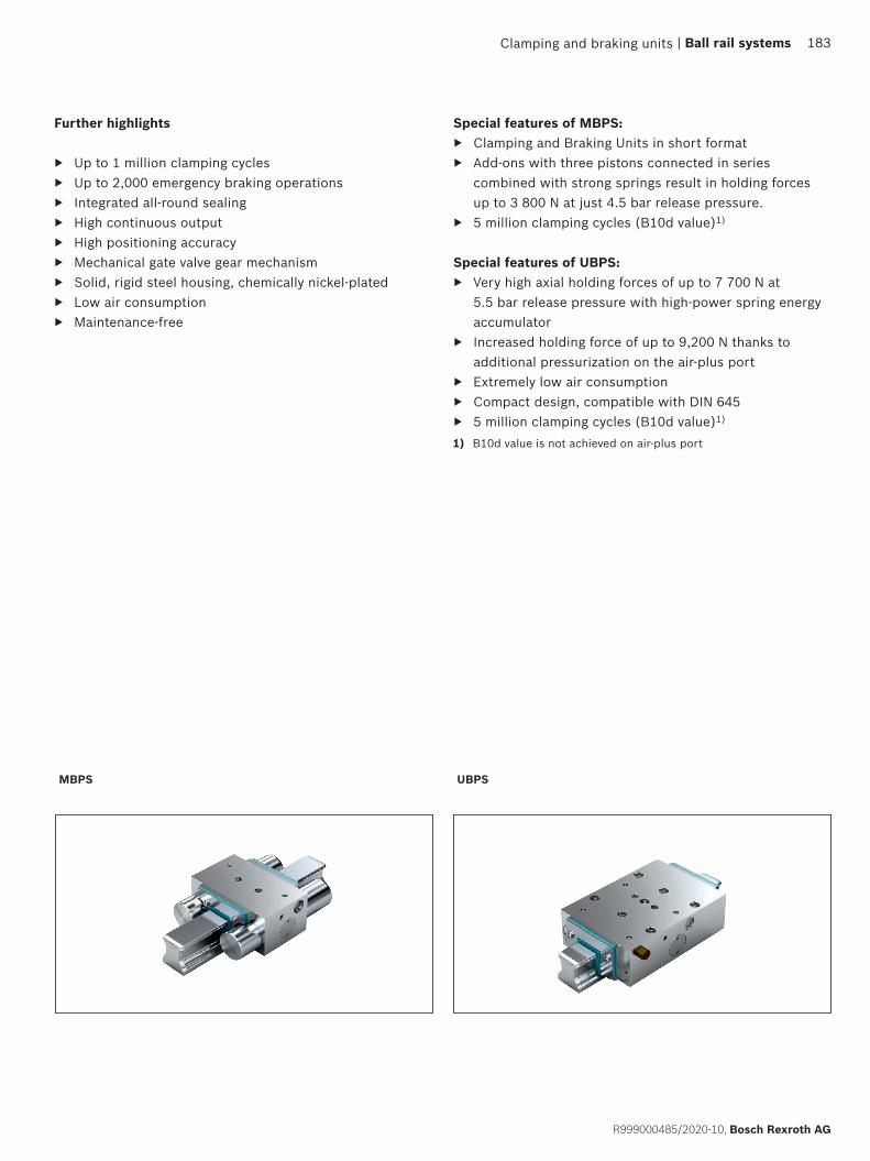
MBPS UBPS
Clamping and braking units
Special features of MBPS: ▶ Clamping and Braking Units in short format ▶ Add-ons with three pistons connected in series
combined with strong springs result in holding forces up to 3 800 N at just 4.5 bar release pressure.
▶ 5 million clamping cycles (B10d value)1)
Special features of UBPS: ▶ Very high axial holding forces of up to 7 700 N at
5.5 bar release pressure with high-power spring energy accumulator
▶ Increased holding force of up to 9,200 N thanks to additional pressurization on the air-plus port
▶ Extremely low air consumption ▶ Compact design, compatible with DIN 645 ▶ 5 million clamping cycles (B10d value)1)
Further highlights
▶ Up to 1 million clamping cycles ▶ Up to 2,000 emergency braking operations ▶ Integrated all-round sealing ▶ High continuous output ▶ High positioning accuracy ▶ Mechanical gate valve gear mechanism ▶ Solid, rigid steel housing, chemically nickel-plated ▶ Low air consumption ▶ Maintenance-free
1) B10d value is not achieved on air-plus port
| Ball rail systems 183
R999000485/2020-10, Bosch Rexroth AG
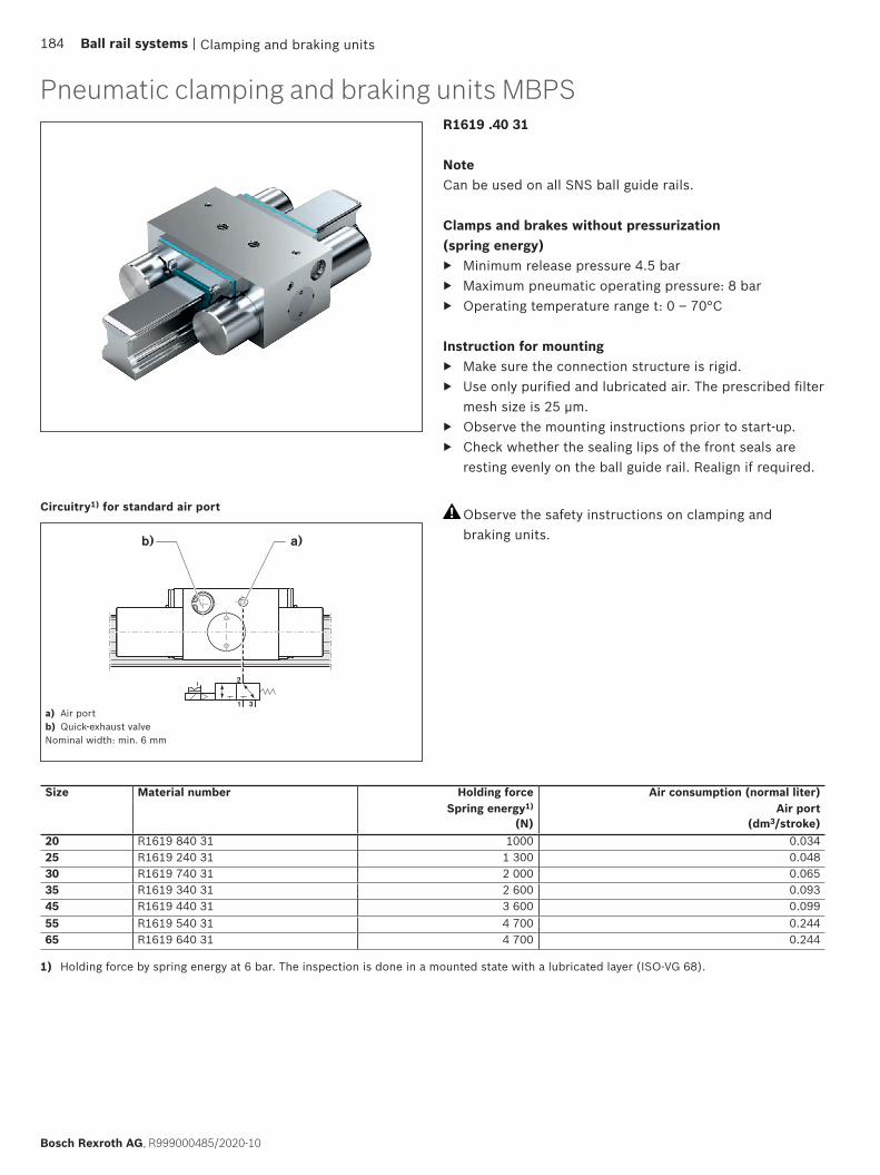
a)b)
1 3
2
Clamping and braking units
Pneumatic clamping and braking units MBPS
Circuitry1) for standard air port
a) Air portb) Quick-exhaust valveNominal width: min. 6 mm
1) Holding force by spring energy at 6 bar. The inspection is done in a mounted state with a lubricated layer (ISO-VG 68).
R1619 .40 31
NoteCan be used on all SNS ball guide rails.
Clamps and brakes without pressurization(spring energy)
▶ Minimum release pressure 4.5 bar ▶ Maximum pneumatic operating pressure: 8 bar ▶ Operating temperature range t: 0 – 70°C
Instruction for mounting ▶ Make sure the connection structure is rigid. ▶ Use only purified and lubricated air. The prescribed filter
mesh size is 25 µm. ▶ Observe the mounting instructions prior to start-up. ▶ Check whether the sealing lips of the front seals are
resting evenly on the ball guide rail. Realign if required.
Observe the safety instructions on clamping and braking units.
Size Material number Holding force Air consumption (normal liter)Spring energy1)
(N)Air port
(dm3/stroke)20 R1619 840 31 1000 0.03425 R1619 240 31 1 300 0.04830 R1619 740 31 2 000 0.06535 R1619 340 31 2 600 0.09345 R1619 440 31 3 600 0.09955 R1619 540 31 4 700 0.24465 R1619 640 31 4 700 0.244
184 Ball rail systems |
Bosch Rexroth AG, R999000485/2020-10
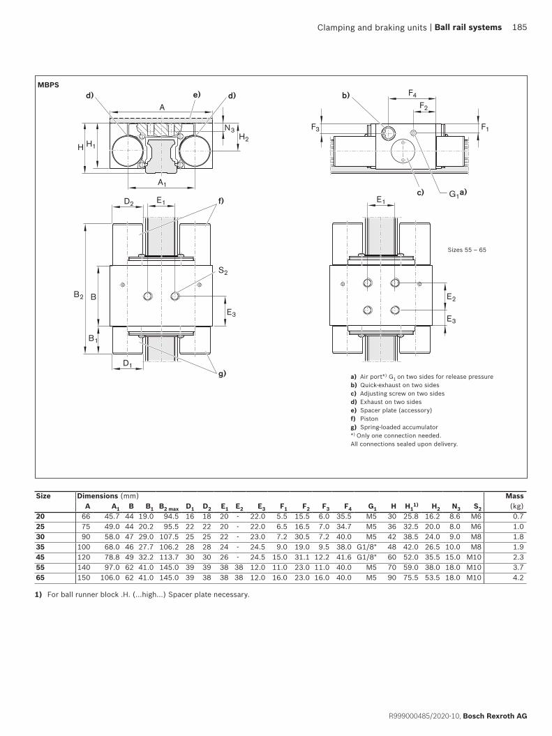
A
E1
E3
N3
H1H2
F3 F1
F4
B1
B2
D1
D2
B
A1
H
F2
E1
E2
E3
G1a)
b)d)
S2
f)
g)
e)d)
c)
Clamping and braking units
Size Dimensions (mm) MassA A1 B B1 B2 max D1 D2 E1 E2 E3 F1 F2 F3 F4 G1 H H1
1) H2 N3 S2 (kg)20 66 45.7 44 19.0 94.5 16 18 20 - 22.0 5.5 15.5 6.0 35.5 M5 30 25.8 16.2 8.6 M6 0.725 75 49.0 44 20.2 95.5 22 22 20 - 22.0 6.5 16.5 7.0 34.7 M5 36 32.5 20.0 8.0 M6 1.030 90 58.0 47 29.0 107.5 25 25 22 - 23.0 7.2 30.5 7.2 40.0 M5 42 38.5 24.0 9.0 M8 1.835 100 68.0 46 27.7 106.2 28 28 24 - 24.5 9.0 19.0 9.5 38.0 G1/8" 48 42.0 26.5 10.0 M8 1.945 120 78.8 49 32.2 113.7 30 30 26 - 24.5 15.0 31.1 12.2 41.6 G1/8" 60 52.0 35.5 15.0 M10 2.355 140 97.0 62 41.0 145.0 39 39 38 38 12.0 11.0 23.0 11.0 40.0 M5 70 59.0 38.0 18.0 M10 3.765 150 106.0 62 41.0 145.0 39 38 38 38 12.0 16.0 23.0 16.0 40.0 M5 90 75.5 53.5 18.0 M10 4.2
MBPS
a) Air port*) G1 on two sides for release pressureb) Quick-exhaust on two sidesc) Adjusting screw on two sides d) Exhaust on two sidese) Spacer plate (accessory)f) Pistong) Spring-loaded accumulator*) Only one connection needed.All connections sealed upon delivery.
1) For ball runner block .H. (...high...) Spacer plate necessary.
Sizes 55 – 65
| Ball rail systems 185
R999000485/2020-10, Bosch Rexroth AG
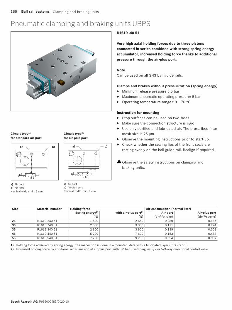
b)a)
5 1 3
4 2
b)a)
1 3
2
Clamping and braking units
Circuit type1) for standard air port
Circuit type2) for air-plus port
a) Air portb) Air filterNominal width: min. 6 mm
a) Air portb) Air-plus portNominal width: min. 6 mm
1) Holding force achieved by spring energy. The inspection is done in a mounted state with a lubricated layer (ISO-VG 68).2) Increased holding force by additional air admission at air-plus port with 6.0 bar. Switching via 5/2 or 5/3-way directional control valve.
Size Material number Holding force Air consumption (normal liter)Spring energy1)
(N)with air-plus port2)
(N)Air port
(dm3/stroke)Air-plus port(dm3/stroke)
25 R1619 240 51 1 500 2 650 0.080 0.16530 R1619 740 51 2 500 3 300 0.111 0.27435 R1619 340 51 2 800 3 800 0.139 0.30345 R1619 440 51 5 200 7 600 0.153 0.48355 R1619 540 51 7 700 9 200 0.554 0.952
Pneumatic clamping and braking units UBPSR1619 .40 51
Very high axial holding forces due to three pistons connected in series combined with strong spring energy accumulator; increased holding force thanks to additional pressure through the air-plus port.
NoteCan be used on all SNS ball guide rails.
Clamps and brakes without pressurization (spring energy) ▶ Minimum release pressure 5.5 bar ▶ Maximum pneumatic operating pressure: 8 bar ▶ Operating temperature range t:0 – 70 °C
Instruction for mounting ▶ Stop surfaces can be used on two sides. ▶ Make sure the connection structure is rigid. ▶ Use only purified and lubricated air. The prescribed filter
mesh size is 25 µm. ▶ Observe the mounting instructions prior to start-up. ▶ Check whether the sealing lips of the front seals are
resting evenly on the ball guide rail. Realign if required.
Observe the safety instructions on clamping and braking units.
186 Ball rail systems |
Bosch Rexroth AG, R999000485/2020-10

E1
E7
SW
XE6
E3
B3 B1 E2
A
N3
H1
N4
H
S2 S3
S2
F1
F3F2
F4
f)
g)g)
d)
G1a) G2b)c)e)
Clamping and braking units
Size Dimensions (mm)A B1 B3 max E1 E2 E3 E6 E7 F1 F2 F3 F4
25 70 99 115.1 57 45 20 20 49.5 6.5 11 34.3 59.030 90 109 128.7 72 52 22 22 54.5 6.5 11 40.8 66.535 100 109 131.0 82 62 26 24 54.5 8.0 11 40.8 66.545 120 197 220.1 100 80 30 - 98.5 12 32 167 106.555 140 197 221.6 116 95 35 - 98.5 13 32 165 103.5
Size Dimensions (mm) MassG1 G2 H H1
1) N3 N4 S2 S3 X SW (kg)25 M5 M5 36 31 7 7 M8 M6 5.5 Ø8, SW7 1.2030 M5 M5 42 37 8 8 M10 M8 5.5 Ø8, SW7 1.8035 G1/8" G1/8" 48 42 10 10 M10 M8 6.5 Ø15, SW13 2.2545 G1/8" G1/8" 60 52 - 12 M12 - 6.5 Ø15, SW13 6.2055 G1/8" G1/8" 70 60 - 14 M14 - 6.5 Ø15, SW13 9.40
UBPS
a) Air port*) G1 on two sides for release pressureb) Connection*) G2 on two sides for air-plus port or air filterc) Adjusting screw on two sidesd) Spacer plate (accessory) e) Exhaust on two sidesf) Air filter: Connection G2 (possible on both sides)g) At least two mounting holes at the center must be used!*) Only one connection needed.All connections sealed upon delivery.
1) For ball runner block .H. (...high...) Spacer plate necessary. Available on request.
| Ball rail systems 187
R999000485/2020-10, Bosch Rexroth AG

Clamping and braking units
Areas of application
▶ Pneumatic clamping of machine axes ▶ Table crossbars in the timber industry ▶ Positioning of lifting gear
Characteristic features
▶ High axial holding forces with short format ▶ Dynamic and static stability in axial direction ▶ Simple mechanical gripping principle in LCP and LCPS
with good price/performance ratio
Further highlights
▶ Easy mounting ▶ Chemically nickel-plated steel housing ▶ High axial and horizontal rigidity ▶ Precise positioning
Special features of MK: ▶ Clamps with compression (pneumatic) The clamping
profiles are pressed by compressed air onto the web surfaces of the ball guide rail via a dual acting gate valve gear mechanism.
▶ Continuously adjustable pressure from 4 – 8 bar ▶ Decompression with spring force. A preloaded return
spring allows for short decompression cycles. ▶ 5 million clamping cycles (B10d value)
Special features of MKS: ▶ Clamps without pressurization (spring energy). In the
event of a pressure drop, it clamps via the dual-action gate valve gear mechanism with two spring assemblies.
▶ An integrated quick-exhaust valve ensures short response times.
▶ Higher holding force due to the air-plus port ▶ Pneumatic decompression Release pressure 5.5 – 8 bar ▶ 5 million clamping cycles (B10d value) *)
Special features of LCP: ▶ Clamps with compression (pneumatic) by means of
mechanical gripping ▶ Continuously adjustable pressure from 5.5 – 8 bar ▶ Short decompression cycles ▶ Decompression with spring force. A preloaded return
spring allows for short decompression cycles.Special features of LCPS:
▶ Clamps without pressurization (with spring energy) by means of mechanical gripping with a spring assembly (spring energy accumulator)
▶ Release pressure 5.5 – 8 bar (pneumatic) ▶ Higher holding force due to the air-plus port ▶ Decompression with air pressure.
*) with the air-plus port, the B10d value cannot be achieved.
Product description pneumatic clamping units
Clamping with air pressure or spring force ▶ The clamping profiles are pressed to the web surfaces
of the ball guide rail.
Decompression with air pressure or spring force ▶ The clamping profiles are held apart. ▶ Free movement is possible
Functional principle
Observe the safety instructions on clamping and braking units.
188 Ball rail systems |
Bosch Rexroth AG, R999000485/2020-10

MK MKS
LCPSLCP
Clamping and braking units
Model overview of accessories for pneumatic clamping units
| Ball rail systems 189
R999000485/2020-10, Bosch Rexroth AG
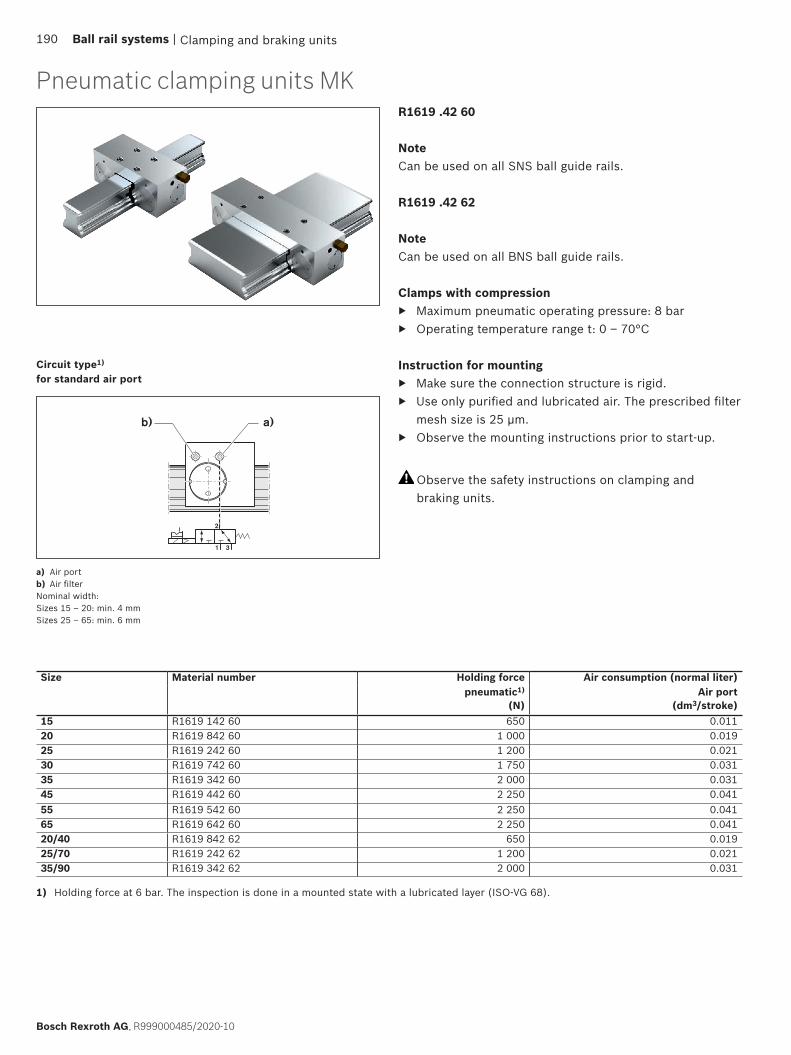
1 3
2
a)b)
Clamping and braking units
1) Holding force at 6 bar. The inspection is done in a mounted state with a lubricated layer (ISO-VG 68).
Circuit type1) for standard air port
a) Air portb) Air filterNominal width:Sizes 15 – 20: min. 4 mmSizes 25 – 65: min. 6 mm
Pneumatic clamping units MKR1619 .42 60
NoteCan be used on all SNS ball guide rails.
R1619 .42 62
NoteCan be used on all BNS ball guide rails.
Clamps with compression ▶ Maximum pneumatic operating pressure: 8 bar ▶ Operating temperature range t: 0 – 70°C
Instruction for mounting ▶ Make sure the connection structure is rigid. ▶ Use only purified and lubricated air. The prescribed filter
mesh size is 25 µm. ▶ Observe the mounting instructions prior to start-up.
Size Material number Holding force Air consumption (normal liter)pneumatic1)
(N)Air port
(dm3/stroke)15 R1619 142 60 650 0.01120 R1619 842 60 1 000 0.01925 R1619 242 60 1 200 0.02130 R1619 742 60 1 750 0.03135 R1619 342 60 2 000 0.03145 R1619 442 60 2 250 0.04155 R1619 542 60 2 250 0.04165 R1619 642 60 2 250 0.04120/40 R1619 842 62 650 0.01925/70 R1619 242 62 1 200 0.02135/90 R1619 342 62 2 000 0.031
Observe the safety instructions on clamping and braking units.
190 Ball rail systems |
Bosch Rexroth AG, R999000485/2020-10

E1
H1H
N3
A
E1
B
E3
E2
F3
H1H
N3
A
X
Ø8, SW7
F4
F2
F3
F4
F2
B
E3
E2
F1
F1
X
Ø8, SW7
S2
e)
e)
b)d)
c)
b)
c)
S2a)
a)
Clamping and braking units
a) Air port*) M5 on both sides for release pressureb) Connection*) M5 on both sides for air filterc) Adjusting screw on two sidesd) Spacer plate (accessory) for MKe) Air filter: Connection M5 (possible on two sides)*) Only one connection needed.All connections sealed upon delivery.
MK
Size Dimensions (mm) MassA B E1 E2 E3 F1 F2 F3 F4 H H1
1) N3 S2 X (kg)15 55 39 15 15 15.5 5.6 34.0 16.1 34.0 24 20.8 4.5 M4 6.5 0.2520 66 39 20 20 9.0 4.5 17.3 6.0 34.5 30 27.0 6.0 M6 5.5 0.3625 75 35 20 20 5.0 7.0 17.5 7.0 30.0 36 32.5 8.0 M6 5.5 0.4530 90 39 22 22 8.5 8.5 15.0 10.3 24.5 42 38.5 9.0 M8 5.5 0.7235 100 39 24 24 7.5 11.0 14.5 12.0 24.5 48 44.0 10.0 M8 5.5 0.8845 120 49 26 26 11.5 14.5 19.5 14.5 29.5 60 52.0 15.0 M10 5.5 1.7055 128 49 30 30 9.5 17.0 19.5 17.0 29.5 70 57.0 15.0 M10 5.5 1.9565 138 49 30 30 9.5 14.5 19.5 14.5 29.5 90 73.5 20.0 M10 5.5 2.6820/40 80 39 20 20 15.5 5.0 4.5 5.0 31.0 27 23.5 4.5 M4 5.5 0.3725/70 120 35 50 20 5.0 7.0 17.5 9.0 30.0 35 32.5 8.0 M6 5.5 0.6235/90 156 42 60 20 9.5 11.5 18.0 14.0 36.5 50 45.5 10.0 M10 5.5 0.88
1) For ball runner block .H. (...high...) Spacer plate necessary
MK wide
| Ball rail systems 191
R999000485/2020-10, Bosch Rexroth AG
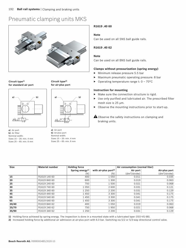
1 3
2
b)a) b)a)
5 1 3
4 2
Clamping and braking units
Circuit type1) for standard air port
Circuit type2) for air-plus port
a) Air portb) Air filterNominal width:Sizes 15 – 20: min. 4 mmSizes 25 – 65: min. 6 mm
a) Air portb) Air-plus portNominal width:Sizes 15 – 20: min. 4 mmSizes 25 – 65: min. 6 mm
1) Holding force achieved by spring energy. The inspection is done in a mounted state with a lubricated layer (ISO-VG 68).2) Increased holding force by additional air admission at air-plus port with 6.0 bar. Switching via 5/2 or 5/3-way directional control valve.
Pneumatic clamping units MKSR1619 .40 60
NoteCan be used on all SNS ball guide rails.
R1619 .40 62
NoteCan be used on all BNS ball guide rails.
Clamps without pressurization (spring energy) ▶ Minimum release pressure 5.5 bar ▶ Maximum pneumatic operating pressure: 8 bar ▶ Operating temperature range t: 0 – 70°C
Instruction for mounting ▶ Make sure the connection structure is rigid. ▶ Use only purified and lubricated air. The prescribed filter
mesh size is 25 µm. ▶ Observe the mounting instructions prior to start-up.
Size Material number Holding force Air consumption (normal liter)Spring energy1)
(N)with air-plus port2)
(N)Air port
(dm3/stroke)Air-plus port(dm3/stroke)
15 R1619 140 60 400 1 050 0.011 0.03520 R1619 840 60 600 1 300 0.019 0.06325 R1619 240 60 750 1 500 0.021 0.06830 R1619 740 60 1 050 2 600 0.031 0.12135 R1619 340 60 1 250 2 200 0.031 0.12945 R1619 440 60 1 450 3 300 0.041 0.17555 R1619 540 60 1 450 3 300 0.041 0.17565 R1619 640 60 1 450 3 300 0.041 0.17520/40 R1619 840 62 400 1 050 0.019 0.06325/70 R1619 240 62 750 1 950 0.021 0.06835/90 R1619 340 62 1 250 2 200 0.031 0.129
Observe the safety instructions on clamping and braking units.
192 Ball rail systems |
Bosch Rexroth AG, R999000485/2020-10
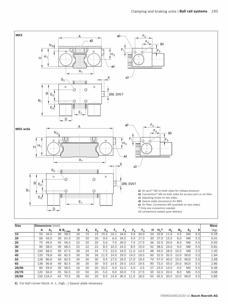
E1
B
B1
E3
E2
F1 F3
H1H2
H
N3
A
X
Ø8, SW7
A1
F2
F4
D
e)
b)
a)d)
c)S2
E1
H1H
N3
A
X
F1 F3
F2
F4
A1
Ø8, SW7 B
B1
E3
E2
H2
D
S2
e)
b)
a)
c)
Clamping and braking units
MKS
1) For ball runner block .H. (...high...) Spacer plate necessary
Size Dimensions (mm) MassA A1 B B1 max D E1 E2 E3 F1 F2 F3 F4 H H1
1) H2 N3 S2 X (kg)15 55 34.0 39 58.5 16 15 15 15.5 16.1 34.0 5.6 34.0 24 20.8 11.6 4.5 M4 6.5 0.2920 66 43.0 39 61.5 20 20 20 9.0 6.0 34.5 4.5 17.3 30 27.0 15.5 6.0 M6 5.5 0.4125 75 49.0 35 56.5 22 20 20 5.0 7.0 30.0 7.0 17.5 36 32.5 20.0 8.0 M6 5.5 0.5030 90 58.0 39 68.5 25 22 22 8.5 10.3 24.5 8.5 15.0 42 38.5 24.0 9.0 M8 5.5 0.8135 100 68.0 39 67.5 28 24 24 7.5 12.0 24.5 11.0 14.5 48 44.0 28.0 10.0 M8 5.5 1.0045 120 78.8 49 82.5 30 26 26 11.5 14.5 29.5 14.5 19.5 60 52.0 35.5 15.0 M10 5.5 1.8455 128 86.8 49 82.5 30 30 30 9.5 17.0 29.5 17.0 19.5 70 57.0 40.0 15.0 M10 5.5 2.0865 138 96.8 49 82.5 30 30 30 9.5 14.5 29.5 14.5 19.5 90 73.5 55.0 20.0 M10 5.5 2.8620/40 80 59.0 39 58.5 16 20 20 15.5 5.0 31.0 5.0 4.5 27 23.5 14.0 4.5 M4 5.5 0.3925/70 120 94.0 35 56.5 22 50 20 5.0 9.0 30.0 7.0 17.5 35 32.5 20.0 8.0 M6 5.5 0.6835/90 156 124.0 42 70.5 28 60 20 9.5 14.0 36.5 11.5 18.0 50 45.5 30.0 10.0 M10 5.5 0.89
MKS wide
a) Air port*) M5 on both sides for release pressureb) Connection*) M5 on both sides for air-plus port or air filterc) Adjusting screw on two sidesd) Spacer plate (accessory) for MKSe) Air filter: Connection M5 (possible on two sides)*) Only one connection needed.All connections sealed upon delivery.
| Ball rail systems 193
R999000485/2020-10, Bosch Rexroth AG
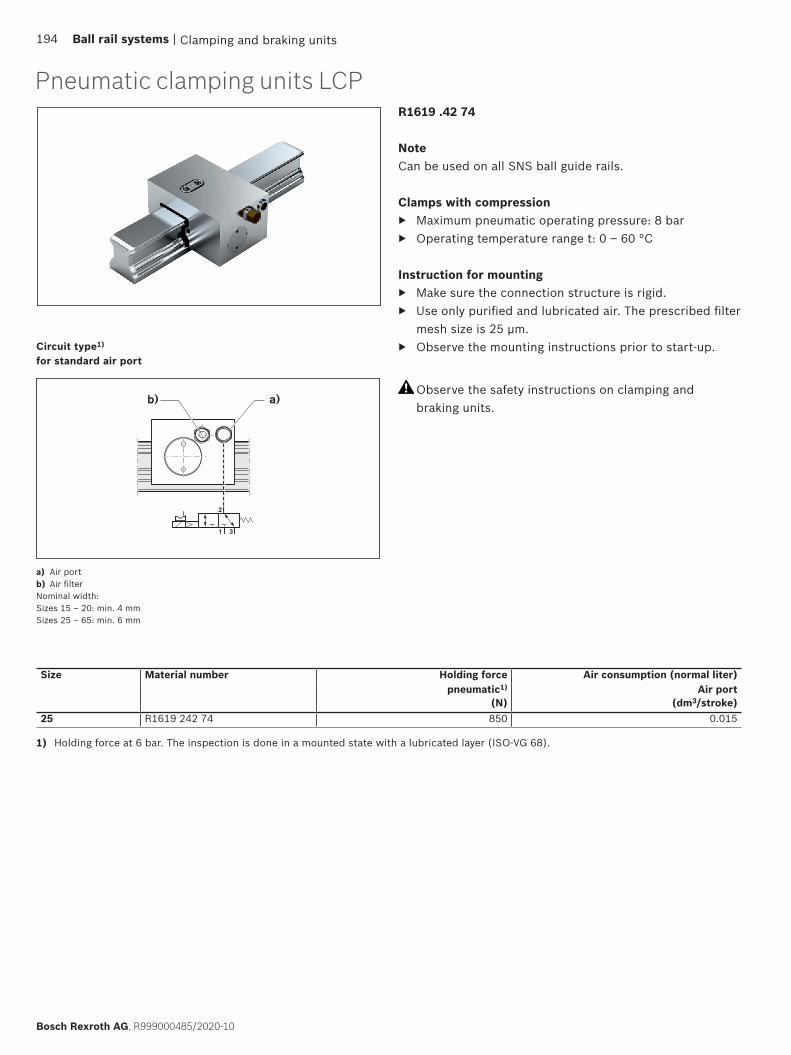
a)b)
1 3
2
Clamping and braking units
Pneumatic clamping units LCPR1619 .42 74
NoteCan be used on all SNS ball guide rails.
Clamps with compression ▶ Maximum pneumatic operating pressure: 8 bar ▶ Operating temperature range t: 0 – 60 °C
Instruction for mounting ▶ Make sure the connection structure is rigid. ▶ Use only purified and lubricated air. The prescribed filter
mesh size is 25 µm. ▶ Observe the mounting instructions prior to start-up.
Size Material number Holding force Air consumption (normal liter)pneumatic1)
(N)Air port
(dm3/stroke)25 R1619 242 74 850 0.015
1) Holding force at 6 bar. The inspection is done in a mounted state with a lubricated layer (ISO-VG 68).
Circuit type1) for standard air port
a) Air portb) Air filterNominal width:Sizes 15 – 20: min. 4 mmSizes 25 – 65: min. 6 mm
Observe the safety instructions on clamping and braking units.
194 Ball rail systems |
Bosch Rexroth AG, R999000485/2020-10
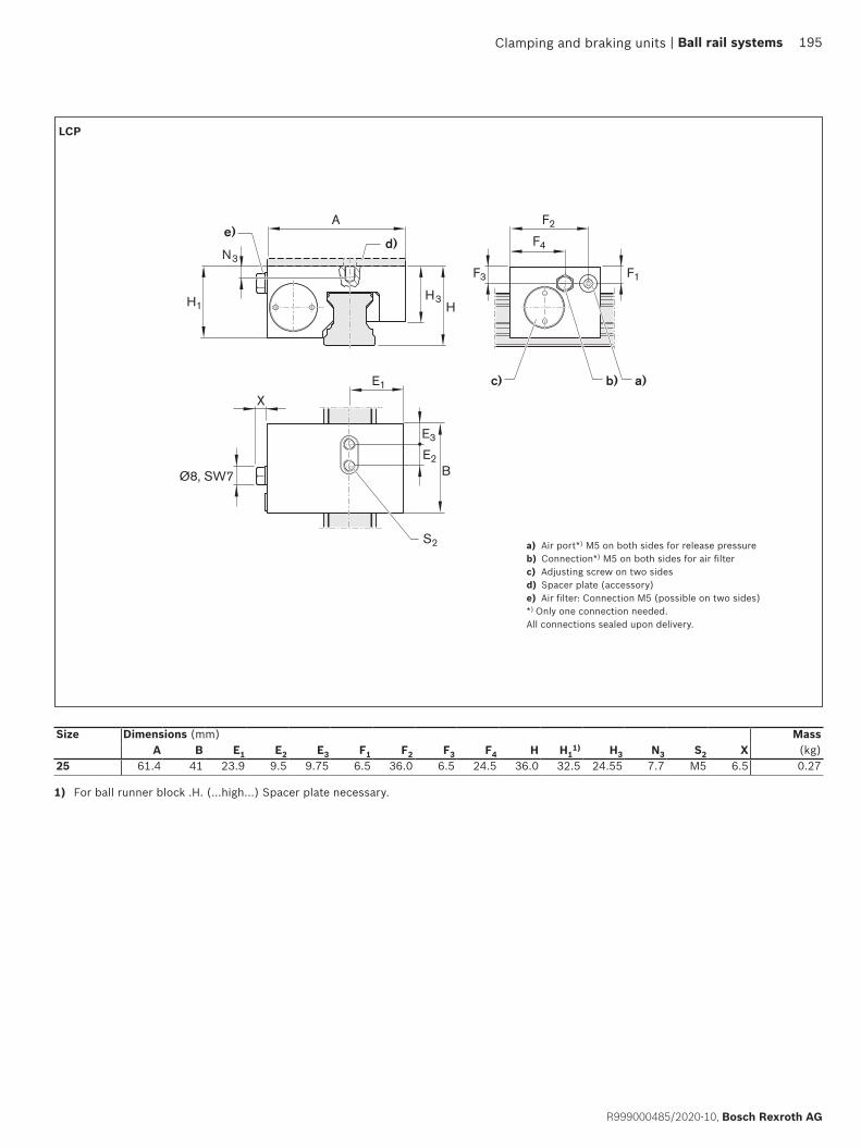
B
E3
E2
E1
H3HH1
X
F2A
F4
F3 F1
N3
Ø8, SW7
e)
c) a)b)
S2
d)
Clamping and braking units
LCP
1) For ball runner block .H. (...high...) Spacer plate necessary.
a) Air port*) M5 on both sides for release pressureb) Connection*) M5 on both sides for air filterc) Adjusting screw on two sidesd) Spacer plate (accessory)e) Air filter: Connection M5 (possible on two sides)*) Only one connection needed.All connections sealed upon delivery.
Size Dimensions (mm) MassA B E1 E2 E3 F1 F2 F3 F4 H H1
1) H3 N3 S2 X (kg)25 61.4 41 23.9 9.5 9.75 6.5 36.0 6.5 24.5 36.0 32.5 24.55 7.7 M5 6.5 0.27
| Ball rail systems 195
R999000485/2020-10, Bosch Rexroth AG
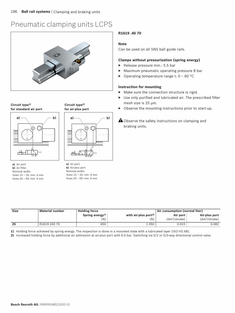
b)a)
1 3
2
b)a)
5 1 3
4 2
Clamping and braking units
Pneumatic clamping units LCPSR1619 .40 70
NoteCan be used on all SNS ball guide rails.
Clamps without pressurization (spring energy) ▶ Release pressure min.: 5.5 bar ▶ Maximum pneumatic operating pressure 8 bar ▶ Operating temperature range t: 0 – 60 °C
Instruction for mounting ▶ Make sure the connection structure is rigid. ▶ Use only purified and lubricated air. The prescribed filter
mesh size is 25 µm. ▶ Observe the mounting instructions prior to start-up.
Size Material number Holding force Air consumption (normal liter)Spring energy1)
(N)with air-plus port2)
(N)Air port
(dm3/stroke)Air-plus port(dm3/stroke)
25 R1619 240 70 650 1 050 0.015 0.082
Circuit type1) for standard air port
Circuit type2) for air-plus port
1) Holding force achieved by spring energy. The inspection is done in a mounted state with a lubricated layer (ISO-VG 68).2) Increased holding force by additional air admission at air-plus port with 6.0 bar. Switching via 5/2 or 5/3-way directional control valve.
a) Air portb) Air filterNominal width:Sizes 15 – 20: min. 4 mmSizes 25 – 65: min. 6 mm
a) Air portb) Air-plus portNominal width:Sizes 15 – 20: min. 4 mmSizes 25 – 65: min. 6 mm
Observe the safety instructions on clamping and braking units.
196 Ball rail systems |
Bosch Rexroth AG, R999000485/2020-10

B1
B
E3
E2
E1
H3 HH1
H2
A1
X
D
F4A
F2
F1 F3
N3
Ø8, SW7
e)
c) b)a)
S2
d)
Clamping and braking units
LCPS
1) For ball runner block .H. (...high...) Spacer plate necessary.
a) Air port*) M5 on both sides for release pressureb) Connection*) M5 on both sides for air-plus port or air filterc) Adjusting screw on two sidesd) Spacer plate (accessory)e) Air filter: Connection M5 (possible on two sides)*) Only one connection needed.All connections sealed upon delivery.
Size Dimensions (mm) MassA A1 B B1max D E1 E2 E3 F1 F2 F3 F4 H H1
1) H2 H3 N3 S2 X (kg)25 61.4 24.5 41 62.5 22 23.9 9.5 9.75 6.5 24.5 6.5 36.0 36 32.5 20.0 24.55 7.7 M5 6.5 0.35
| Ball rail systems 197
R999000485/2020-10, Bosch Rexroth AG

HK HK
Clamping and braking units
Areas of application ▶ Table crossbars and carriage ▶ Width adjustment ▶ Stops ▶ Positioning on optical devices and measuring tables
Characteristic features
▶ Simple and safe design in compact format ▶ Manually operated Clamping Unit without auxiliary
power
Further highlights ▶ Freely adjustable hand lever ▶ Symmetrical force application on ball guide rail via
floating contact profiles ▶ Precise positioning ▶ Holding forces up to 2,000 N
Spacer plate
Suitable for mounting with high ball runner blockSNH R1621 and SLH R1624.
Clamps with manual compressionThe clamping profiles are pressed to the web surfaces of the ball guide rail by the hand lever.
Hand lever disengaged
Manual clamping units, product description
Model overview of accessories for manual clamping units, spacer plate
Observe the safety instructions on clamping and braking units.
Spacer plate
For Clamping Units MK, MKS and HK
Compression via hand lever
198 Ball rail systems |
Bosch Rexroth AG, R999000485/2020-10
Special features of HK: ▶ 500,000 clamping cycles (B10d value)

HK
H1
A
H
L
C
N3 B
E3
E2
E1
L2
L1
X X
a)
S2
b)
Clamping and braking units
Size Material number Holding force1)
Tightening torque
(N) (Nm)15 R1619 142 82 1 200 420 R1619 842 82 1 200 525 R1619 242 82 1 200 730 R1619 742 82 2 000 1535 R1619 342 82 2 000 1545 R1619 442 82 2 000 1555 R1619 542 82 2 000 2265 R1619 642 82 2 000 22
Manual clamping units HK
Size Dimensions (mm) MassA B C E1 E2 E3 H H1
3) L L1 L22) N3 S2 (kg)
15 47 25 19.0 17 17 4.0 24 19 44 30.0 33.0 5 M4 0.1620 60 24 24.5 15 15 4.5 30 23 44 30.0 33.0 6 M5 0.2325 70 30 29.3 20 20 5.0 36 29 64 38.5 41.5 7 M6 0.4330 90 39 34.0 22 22 8.5 42 33 78 46.5 50.5 8 M6 0.8235 100 39 38.0 24 24 7.5 48 41 78 46.5 50.5 10 M8 1.0845 120 44 47.0 26 26 9.0 60 48 78 46.5 50.5 14 M10 1.6455 140 49 56.5 30 30 9.5 70 51 95 56.5 61.5 14 M14 1.7165 160 64 69.5 35 35 14.5 90 66 95 56.5 61.5 20 M16 2.84
R1619 .42 82
NoteCan be used on all SNS ball guide rails.
Manual Clamping Unit ▶ Operating temperature range t: 0 – 70°C
Instruction for mounting ▶ Make sure the connection structure is rigid. ▶ Observe the mounting instructions prior to start-up.
1) The inspection is done in a mounted state with a lubricated layer (ISO-VG 68).2) Hand lever disengaged3) For ball runner block .H. (...high...) Spacer plate necessary
a) Spacer plate (accessory)b) Position of the hand lever can be changed.
Observe the safety instructions on clamping and braking units.
| Ball rail systems 199
R999000485/2020-10, Bosch Rexroth AG
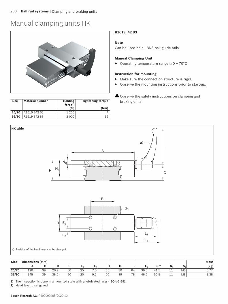
H1
A
H
L
C
N3
B
E3
E2
E1
L2
L1
a)
S2
Clamping and braking units
Size Material number Holding force1)
Tightening torque
(N) (Nm)25/70 R1619 242 83 1 200 735/90 R1619 342 83 2 000 15
Manual clamping units HK
Size Dimensions (mm) MassA B C E1 E2 E3 H H1 L L1 L2
2) N3 S2 (kg)25/70 120 39 28.2 50 25 7.0 35 30 64 38.5 41.5 11 M6 0.7735/90 145 39 38.0 60 20 9.5 50 39 78 46.5 50.5 11 M8 1.38
R1619 .42 83
NoteCan be used on all BNS ball guide rails.
Manual Clamping Unit ▶ Operating temperature range t: 0 – 70°C
Instruction for mounting ▶ Make sure the connection structure is rigid. ▶ Observe the mounting instructions prior to start-up.
1) The inspection is done in a mounted state with a lubricated layer (ISO-VG 68).2) Hand lever disengaged
a) Position of the hand lever can be changed.
HK wide
Observe the safety instructions on clamping and braking units.
200 Ball rail systems |
Bosch Rexroth AG, R999000485/2020-10

E2B
E1
A
D
Ø d
Clamping and braking units
Spacer platefor clamping units MK, MKS and HK
NoteSuitable for mounting with high ball runner blockSNH R1621 and SLH R1624.
Size Material number Dimensions (mm) MassA B D d E1 E2 (kg)
15 R1619 140 65 55 39 4 4.5 15 15 0.06525 R1619 240 65 75 35 4 6.5 20 20 0.07830 R1619 740 65 90 39 3 8.5 22 22 0.07735 R1619 340 65 100 39 7 8.5 24 24 0.20245 R1619 440 65 120 49 10 10.5 26 26 0.43455 R1619 540 65 128 49 10 10.5 30 30 0.465
Size Material number Dimensions (mm) Mass A B D d E1 E2 (kg)
15 R1619 142 85 47 25 4 4.5 17 17 0.03525 R1619 242 85 70 30 4 6.5 20 20 0.06230 R1619 742 85 90 39 3 6.5 22 22 0.08035 R1619 340 65 100 39 7 8.5 24 24 0.20245 R1619 442 85 120 44 10 10.5 26 26 0.38755 R1619 542 85 140 49 10 14.5 30 30 0.511
R1619 .40 65
Suitable for Clamping Units:
▶ R1619 .42 60 (MK) ▶ R1619 .40 60 (MKS)
R1619 .42 .5
Suitable for Clamping Units:
▶ R1619 .42 82 (HK)
Spacer plate
| Ball rail systems 201
R999000485/2020-10, Bosch Rexroth AG
Clamping and braking units
General safety instructions
During all work on the clamping units, the respective valid accident prevention regulations, as well as the VDE safety instructions and instruction for mounting are to be observed!
The clamping units do not have any guiding function. A runner block can therefore not be replaced with a clamping unit. The ideal position of the clamping unit lies between two runner blocks. When using several clamping elements, these should be distributed evenly on both guide rails in order to attain maximum rigidity for the overall construction.
For Hydraulic Clamping and Braking Units, the return pressure in the tank line must be lower than 1.5 bar!
Consider the response times of the Clamping and Braking Units!
The Clamping Unit is not intended for securing suspended loads!
Do not remove the cover of the safety clamping unit - spring under tension!
The transport lock may only be removed if: – The hydraulic port has been pressurized with the operating pressure according to instructions. – The air port has been pressurized with compressed air to at least 4.5 bar (MBPS) or 5.5 bar (UBPS, MKS) according to instructions.
The Clamping Unit may only be de-pressurized when the appropriate ball guide rail or transport lock is in position between the contact profiles!
The use of clamping and braking units is not permissible on ball guide rails with integrated measuring systems.
Additional notes for Clamping and Braking Units
The clamping and braking units are suitable for usage in safety-critical applications for braking and clamping. The safe function of the total system in which the Clamping and Braking Units are used is primarily defined by the controller for this system. The technical dimensioning of this system and the controller is to be undertaken by the manufacturer of the higher level system, assembly, plant or machine. During this process the safety-related requirements for functional safety are to be observed.
Additional notes for Clamping Units
The unit may not be used as a Braking Unit! For use only when the axis is at a standstill!
Pressure may only be applied when the unit is properly mounted on the ball guide rail!
Safety instructions clamping and braking units
202 Ball rail systems |
Bosch Rexroth AG, R999000485/2020-10

Clamping and braking units | Ball rail systems 203
R999000485/2020-10, Bosch Rexroth AG

1
4
2
1
3
2
Mounting with fixing of both ball guide railsand both ball runner blocks
Installation examples
Mounting with fixing of one ball guide railand one ball runner block
Ball guide railsEach ball guide rail has ground reference surfaces on both sides.
Possibilities for side fixing: 1 Reference edges2 Clamping strips3 V-guidesNote
▶ Ball guide rails without side fixing have to be aligned straight and parallel when mounting, preferably using a straightedge.
▶ For guide values for permissible lateral force without additional lateral retention, see corresponding ball runner blocks and instructions for mounting, page 206.
Ball runner blocksEach ball runner block has a ground reference edge on one side (see dimension V1 in the dimension drawings).
Possibilities for additional fixing:1 Reference edges2 Clamping strips4 Locating pins
Notes ▶ Before installing the components, clean and degrease all mounting surfaces. ▶ Please ask for the “Mounting Instructions for ball rail systems”. ▶ After mounting, it should be possible to move the ball runner block easily.
Instructions for mounting
General instruction for mountingThe following notes relating to mounting apply to all ball rail systems. However, different specifications exist with regard to the parallelism of the ball guide rails and to mounting the ball runner blocks with screws and locating pins. This information is provided separately alongside the descriptions of the individual types of ball rail systems.
In the case of overhead installation (hanging installation) or vertical installation, the ball runner block can release from the ball guide rail due to the balls being lost or broken. Secure the ball runner block from falling! Risk of death! We recommend protection against falling loads! Rexroth ball rail systems are high-quality products. Use with extreme care during transport and mounting. The same care must be taken with cover strips. All steel parts are protected with anti-corrosion oil. It is not necessary to remove this oil, provided that the recommended lubricants are used.
204 Ball rail systems |
Bosch Rexroth AG, R999000485/2020-10
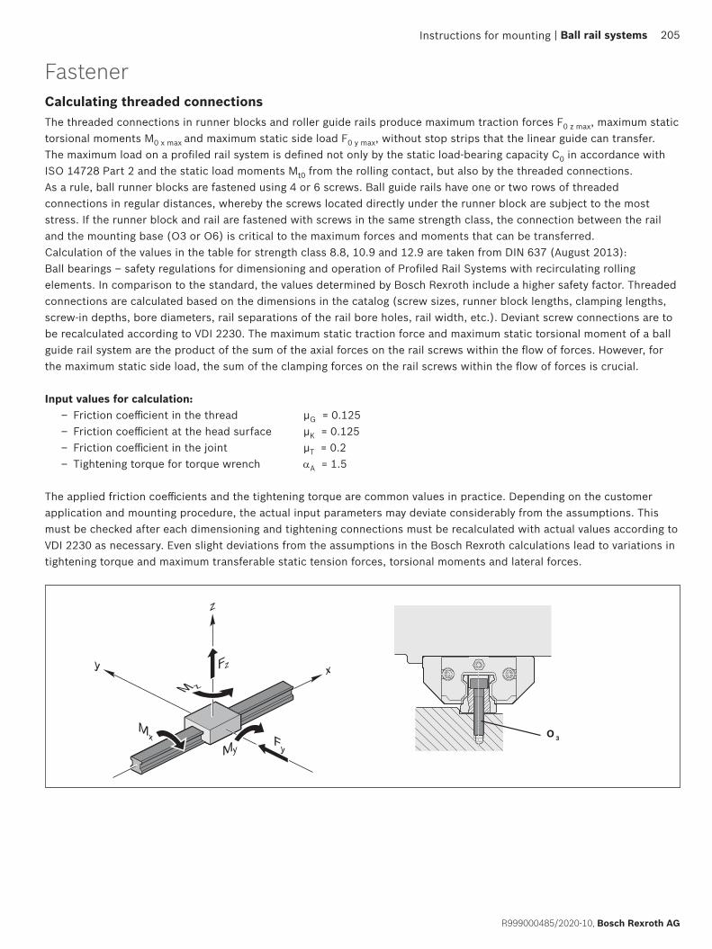
xy
z
Mx
M z
My
Fz
Fy
O 3
Instructions for mounting | Ball rail systems 205
R999000485/2020-10, Bosch Rexroth AG
FastenerCalculating threaded connectionsThe threaded connections in runner blocks and roller guide rails produce maximum traction forces F0 z max, maximum static torsional moments M0 x max and maximum static side load F0 y max, without stop strips that the linear guide can transfer. The maximum load on a profiled rail system is defined not only by the static load-bearing capacity C0 in accordance with ISO 14728 Part 2 and the static load moments Mt0 from the rolling contact, but also by the threaded connections.As a rule, ball runner blocks are fastened using 4 or 6 screws. Ball guide rails have one or two rows of threaded connections in regular distances, whereby the screws located directly under the runner block are subject to the most stress. If the runner block and rail are fastened with screws in the same strength class, the connection between the rail and the mounting base (O3 or O6) is critical to the maximum forces and moments that can be transferred.Calculation of the values in the table for strength class 8.8, 10.9 and 12.9 are taken from DIN 637 (August 2013): Ball bearings – safety regulations for dimensioning and operation of Profiled Rail Systems with recirculating rolling elements. In comparison to the standard, the values determined by Bosch Rexroth include a higher safety factor. Threaded connections are calculated based on the dimensions in the catalog (screw sizes, runner block lengths, clamping lengths, screw-in depths, bore diameters, rail separations of the rail bore holes, rail width, etc.). Deviant screw connections are to be recalculated according to VDI 2230. The maximum static traction force and maximum static torsional moment of a ball guide rail system are the product of the sum of the axial forces on the rail screws within the flow of forces. However, for the maximum static side load, the sum of the clamping forces on the rail screws within the flow of forces is crucial.
Input values for calculation: – Friction coefficient in the thread µG = 0.125 – Friction coefficient at the head surface µK = 0.125 – Friction coefficient in the joint µT = 0.2 – Tightening torque for torque wrench αA = 1.5
The applied friction coefficients and the tightening torque are common values in practice. Depending on the customer application and mounting procedure, the actual input parameters may deviate considerably from the assumptions. This must be checked after each dimensioning and tightening connections must be recalculated with actual values according to VDI 2230 as necessary. Even slight deviations from the assumptions in the Bosch Rexroth calculations lead to variations in tightening torque and maximum transferable static tension forces, torsional moments and lateral forces.
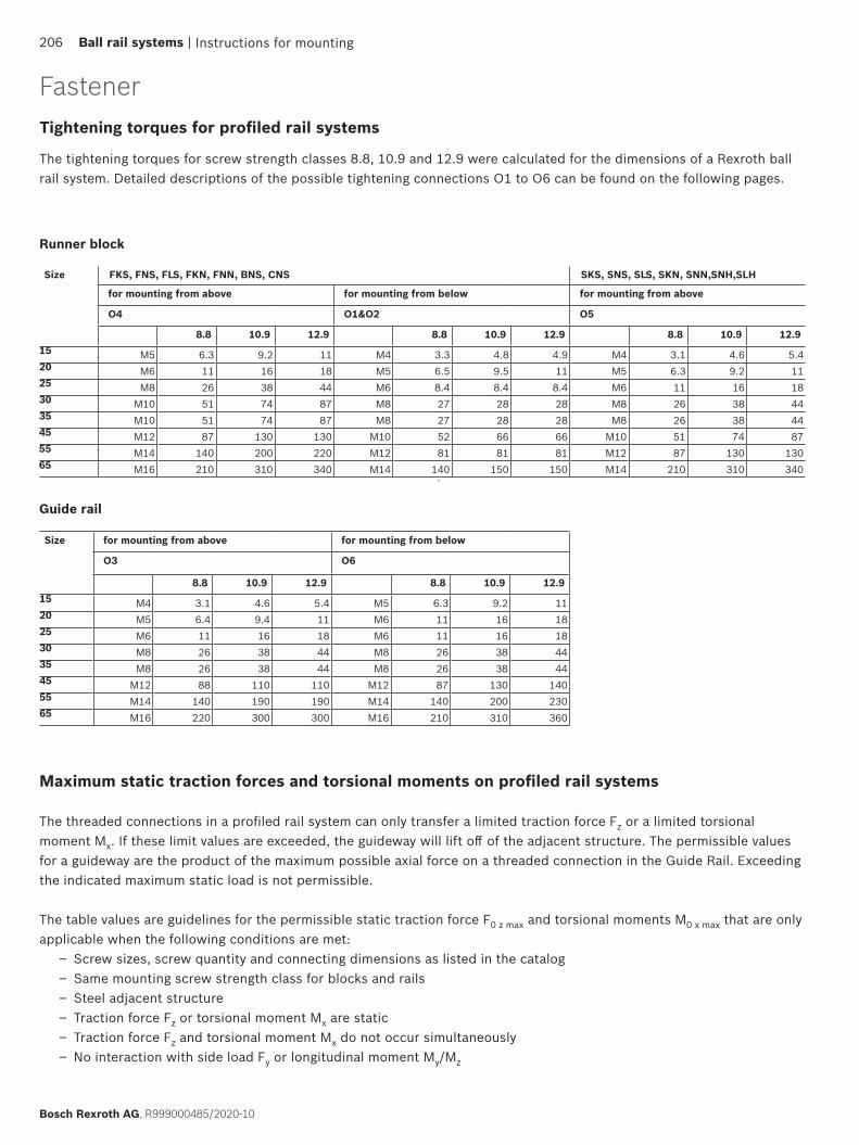
Instructions for mounting206 Ball rail systems |
Bosch Rexroth AG, R999000485/2020-10
Maximum static traction forces and torsional moments on profiled rail systems
The threaded connections in a profiled rail system can only transfer a limited traction force Fz or a limited torsional moment Mx. If these limit values are exceeded, the guideway will lift off of the adjacent structure. The permissible values for a guideway are the product of the maximum possible axial force on a threaded connection in the Guide Rail. Exceeding the indicated maximum static load is not permissible.
The table values are guidelines for the permissible static traction force F0 z max and torsional moments M0 x max that are only applicable when the following conditions are met:
– Screw sizes, screw quantity and connecting dimensions as listed in the catalog – Same mounting screw strength class for blocks and rails – Steel adjacent structure – Traction force Fz or torsional moment Mx are static – Traction force Fz and torsional moment Mx do not occur simultaneously – No interaction with side load Fy or longitudinal moment My/Mz
FastenerTightening torques for profiled rail systems
Size FKS, FNS, FLS, FKN, FNN, BNS, CNS SKS, SNS, SLS, SKN, SNN,SNH,SLH
for mounting from above for mounting from below for mounting from above
O4 O1&O2 O5
8.8 10.9 12.9 8.8 10.9 12.9 8.8 10.9 12.915 M5 6.3 9.2 11 M4 3.3 4.8 4.9 M4 3.1 4.6 5.420 M6 11 16 18 M5 6.5 9.5 11 M5 6.3 9.2 1125 M8 26 38 44 M6 8.4 8.4 8.4 M6 11 16 1830 M10 51 74 87 M8 27 28 28 M8 26 38 4435 M10 51 74 87 M8 27 28 28 M8 26 38 4445 M12 87 130 130 M10 52 66 66 M10 51 74 8755 M14 140 200 220 M12 81 81 81 M12 87 130 13065 M16 210 310 340 M14 140 150 150 M14 210 310 340
The tightening torques for screw strength classes 8.8, 10.9 and 12.9 were calculated for the dimensions of a Rexroth ball rail system. Detailed descriptions of the possible tightening connections O1 to O6 can be found on the following pages.
Runner block
Size for mounting from above for mounting from below
O3 O6
8.8 10.9 12.9 8.8 10.9 12.915 M4 3.1 4.6 5.4 M5 6.3 9.2 1120 M5 6.4 9.4 11 M6 11 16 1825 M6 11 16 18 M6 11 16 1830 M8 26 38 44 M8 26 38 4435 M8 26 38 44 M8 26 38 4445 M12 88 110 110 M12 87 130 14055 M14 140 190 190 M14 140 200 23065 M16 220 300 300 M16 210 310 360
Guide rail

Instructions for mounting | Ball rail systems 207
R999000485/2020-10, Bosch Rexroth AG
If these conditions are not met, recalculate the threaded connection in accordance with VDI 2230. If the applied loads are just below the limit values, Bosch Rexroth also recommends checking the threaded connections.
F0 z max
M0 x max
Size Maximum static tensile forces F0 z max in [N]
Short Normal length Long
xKx xNx xLx
8.8 10.9 12.9 8.8 10.9 12.9 8.8 10.9 12.915 2410 3900 4700 2410 3900 4700 2410 3900 470020 4220 6690 8010 4220 6690 8010 4600 7300 873025 5520 8740 10500 5520 8740 10500 7340 11600 1390030 10100 16000 19200 10100 16000 19200 11300 17900 2150035 10500 16400 19600 10500 16400 19600 13900 21700 2590045 25400 34900 34900 25400 34900 34900 32300 44300 4430055 36500 53700 53700 36500 53700 53700 47400 69800 6980065 50600 76400 77500 50600 76400 77500 65800 99400 101000
Tensile forces
Torsional moments
Size Maximum static torsional moments M0 x max in [Nm]
Short Normal length Long
xKx xNx xLx
8.8 10.9 12.9 8.8 10.9 12.9 8.8 10.9 12.915 16 26 31 16 26 31 16 26 3120 38 60 72 38 60 72 41 66 7925 58 92 110 58 92 110 77 120 15030 130 210 250 130 210 250 150 230 28035 170 260 310 170 260 310 220 350 41045 550 750 750 550 750 750 690 950 95055 910 1340 1340 910 1340 1340 1190 1740 174065 1490 2250 2290 1490 2250 2290 1940 2930 2970
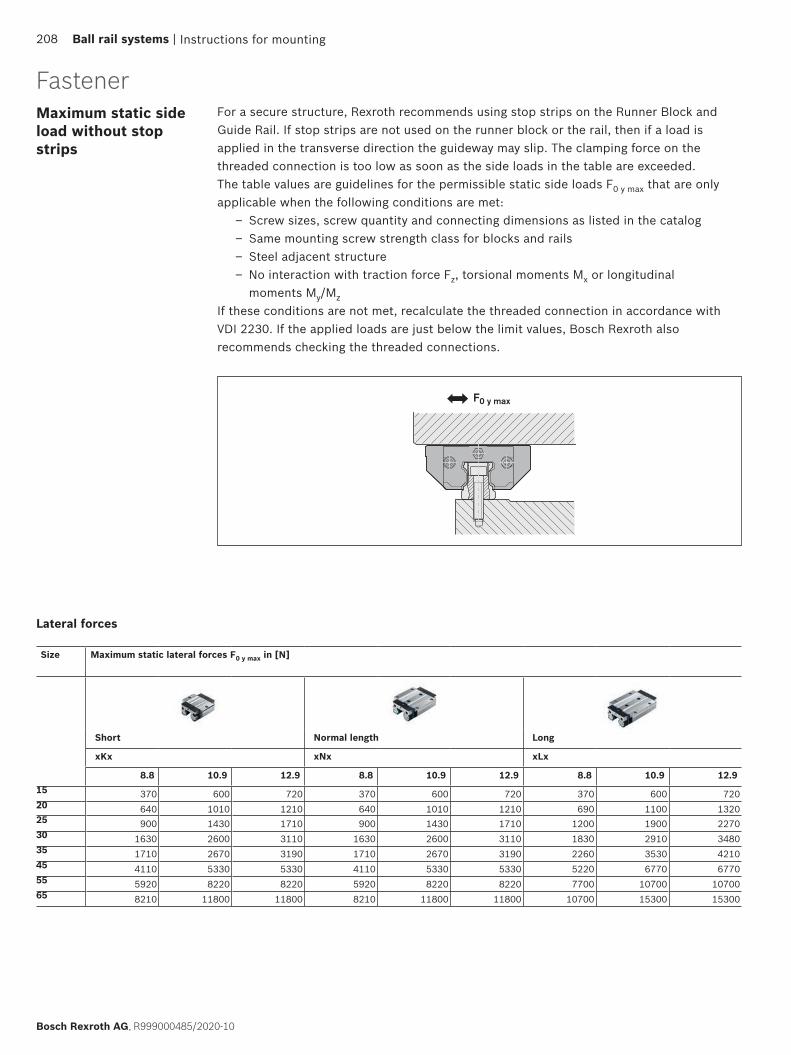
Instructions for mounting208 Ball rail systems |
Bosch Rexroth AG, R999000485/2020-10
1
2
F0 y max
For a secure structure, Rexroth recommends using stop strips on the Runner Block and Guide Rail. If stop strips are not used on the runner block or the rail, then if a load is applied in the transverse direction the guideway may slip. The clamping force on the threaded connection is too low as soon as the side loads in the table are exceeded. The table values are guidelines for the permissible static side loads F0 y max that are only applicable when the following conditions are met:
– Screw sizes, screw quantity and connecting dimensions as listed in the catalog – Same mounting screw strength class for blocks and rails – Steel adjacent structure – No interaction with traction force Fz, torsional moments Mx or longitudinal moments My/Mz
If these conditions are not met, recalculate the threaded connection in accordance with VDI 2230. If the applied loads are just below the limit values, Bosch Rexroth also recommends checking the threaded connections.
Maximum static side load without stop strips
Fastener
Size Maximum static lateral forces F0 y max in [N]
Short Normal length Long
xKx xNx xLx
8.8 10.9 12.9 8.8 10.9 12.9 8.8 10.9 12.915 370 600 720 370 600 720 370 600 72020 640 1010 1210 640 1010 1210 690 1100 132025 900 1430 1710 900 1430 1710 1200 1900 227030 1630 2600 3110 1630 2600 3110 1830 2910 348035 1710 2670 3190 1710 2670 3190 2260 3530 421045 4110 5330 5330 4110 5330 5330 5220 6770 677055 5920 8220 8220 5920 8220 8220 7700 10700 1070065 8210 11800 11800 8210 11800 11800 10700 15300 15300
Lateral forces
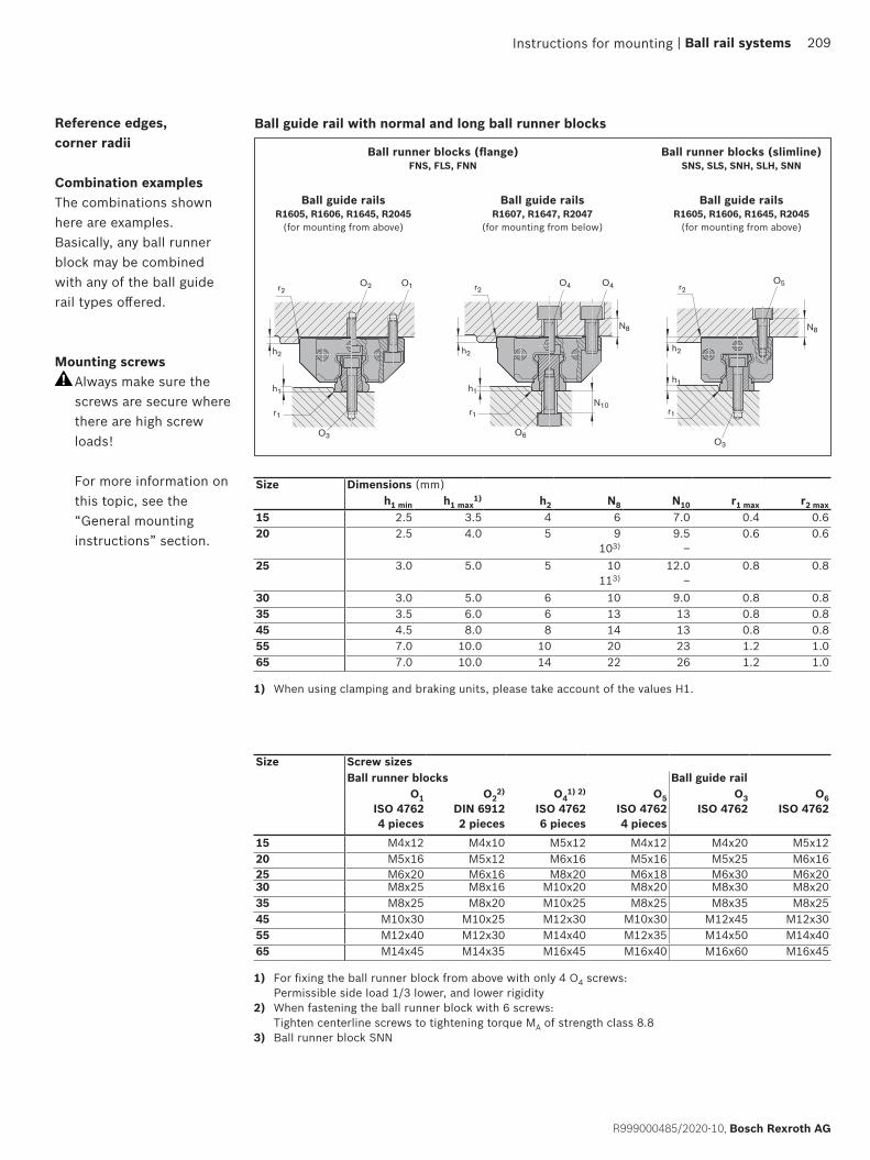
r2 r2O2 O1 O4O4
r1
h1
r1
h1
h2 h2
O3
N8
O6
N10
r2 r2O2 O1 O4O4
r1
h1
r1
h1
h2 h2
O3
N8
O6
N10r1
h1
h2
r2O5
N8
O3
Ball guide rail with normal and long ball runner blocksReference edges, corner radii
Combination examplesThe combinations shown here are examples. Basically, any ball runner block may be combined with any of the ball guide rail types offered. Mounting screws
Always make sure the screws are secure where there are high screw loads! For more information on this topic, see the “General mounting instructions” section.
Size Dimensions (mm)h1 min h1 max
1) h2 N8 N10 r1 max r2 max15 2.5 3.5 4 6 7.0 0.4 0.620 2.5 4.0 5 9
103)9.5
–0.6 0.6
25 3.0 5.0 5 10113)
12.0–
0.8 0.8
30 3.0 5.0 6 10 9.0 0.8 0.835 3.5 6.0 6 13 13 0.8 0.845 4.5 8.0 8 14 13 0.8 0.855 7.0 10.0 10 20 23 1.2 1.065 7.0 10.0 14 22 26 1.2 1.0
Ball runner blocks (flange)FNS, FLS, FNN
Ball guide railsR1607, R1647, R2047
(for mounting from below)
Ball guide railsR1605, R1606, R1645, R2045
(for mounting from above)
Ball runner blocks (slimline)SNS, SLS, SNH, SLH, SNN
Ball guide railsR1605, R1606, R1645, R2045
(for mounting from above)
1) For fixing the ball runner block from above with only 4 O4 screws: Permissible side load 1/3 lower, and lower rigidity
2) When fastening the ball runner block with 6 screws: Tighten centerline screws to tightening torque MA of strength class 8.8
3) Ball runner block SNN
Instructions for mounting
Size Screw sizesBall runner blocks Ball guide rail
O1ISO 47624 pieces
O22)
DIN 69122 pieces
O41) 2)
ISO 47626 pieces
O5ISO 47624 pieces
O3ISO 4762
O6ISO 4762
15 M4x12 M4x10 M5x12 M4x12 M4x20 M5x1220 M5x16 M5x12 M6x16 M5x16 M5x25 M6x1625 M6x20 M6x16 M8x20 M6x18 M6x30 M6x2030 M8x25 M8x16 M10x20 M8x20 M8x30 M8x2035 M8x25 M8x20 M10x25 M8x25 M8x35 M8x2545 M10x30 M10x25 M12x30 M10x30 M12x45 M12x3055 M12x40 M12x30 M14x40 M12x35 M14x50 M14x4065 M14x45 M14x35 M16x45 M16x40 M16x60 M16x45
1) When using clamping and braking units, please take account of the values H1.
| Ball rail systems 209
R999000485/2020-10, Bosch Rexroth AG
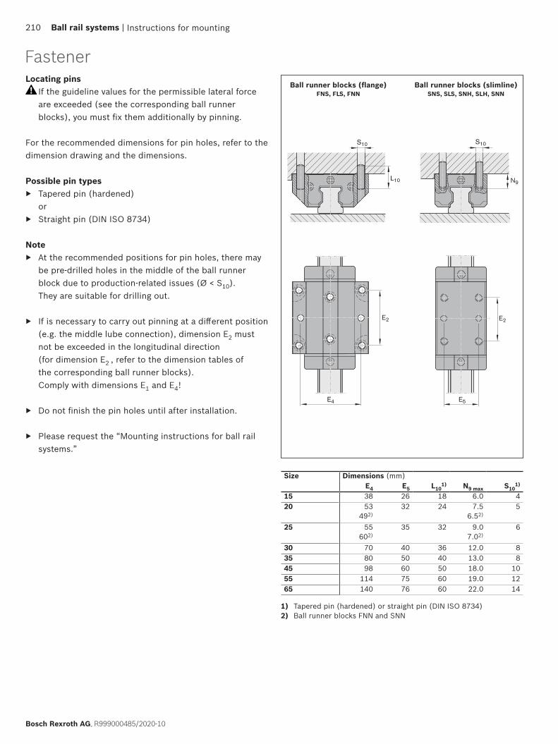
E2
L10
S10
E4
E2
E5
N9
S10
Locating pins If the guideline values for the permissible lateral force are exceeded (see the corresponding ball runner blocks), you must fix them additionally by pinning.
For the recommended dimensions for pin holes, refer to the dimension drawing and the dimensions.
Possible pin types ▶ Tapered pin (hardened)
or ▶ Straight pin (DIN ISO 8734)
Note ▶ At the recommended positions for pin holes, there may
be pre-drilled holes in the middle of the ball runner block due to production-related issues (Ø < S10). They are suitable for drilling out.
▶ If is necessary to carry out pinning at a different position (e.g. the middle lube connection), dimension E2 must not be exceeded in the longitudinal direction (for dimension E2 , refer to the dimension tables of the corresponding ball runner blocks). Comply with dimensions E1 and E4!
▶ Do not finish the pin holes until after installation.
▶ Please request the “Mounting instructions for ball rail systems.”
Ball runner blocks (flange)FNS, FLS, FNN
Ball runner blocks (slimline)SNS, SLS, SNH, SLH, SNN
Size Dimensions (mm)E4 E5 L10
1) N9 max S101)
15 38 26 18 6.0 420 53
492)32 24 7.5
6.52)5
25 55602)
35 32 9.07.02)
6
30 70 40 36 12.0 835 80 50 40 13.0 845 98 60 50 18.0 1055 114 75 60 19.0 1265 140 76 60 22.0 14
1) Tapered pin (hardened) or straight pin (DIN ISO 8734)2) Ball runner blocks FNN and SNN
Instructions for mounting210 Ball rail systems |
Bosch Rexroth AG, R999000485/2020-10
Fastener
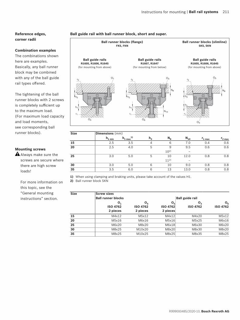
r2 r2O1 O4
r1
h1
r1
h1
h2 h2
O3
N8
N10
O6
r2 r2O1 O4
r1
h1
r1
h1
h2 h2
O3
N8
N10
O6
r1
h1
h2
r2O5
N8
O3
Reference edges, corner radii
Combination examplesThe combinations shown here are examples. Basically, any ball runner block may be combined with any of the ball guide rail types offered.
The tightening of the ball runner blocks with 2 screws is completely sufficient up to the maximum load. (For maximum load capacity and load moments, see corresponding ball runner blocks).
Mounting screws Always make sure the screws are secure where there are high screw loads! For more information on this topic, see the “General mounting instructions” section.
Size Dimensions (mm)h1 min h1 max
1) h2 N8 N10 r1 max r2 max
15 2.5 3.5 4 6 7.0 0.4 0.620 2.5 4.0 5 9 9.5 0.6 0.6
102) –25 3.0 5.0 5 10 12.0 0.8 0.8
112) –30 3.0 5.0 6 10 9.0 0.8 0.835 3.5 6.0 6 13 13.0 0.8 0.8
Ball runner blocks (flange)FKS, FKN
Ball guide railsR1607, R1647
(for mounting from below)
Ball guide railsR1605, R1606, R1645
(for mounting from above)
Ball runner blocks (slimline) SKS, SKN
Ball guide railsR1605, R1606, R1645
(for mounting from above)
Ball guide rail with ball runner block, short and super.
Instructions for mounting
Size Screw sizesBall runner blocks Ball guide rail
O1ISO 47622 pieces
O4ISO 47622 pieces
O5ISO 47622 pieces
O3ISO 4762
O6ISO 4762
15 M4x12 M5x12 M4x12 M4x20 M5x1220 M5x16 M6x16 M5x16 M5x25 M6x1625 M6x20 M8x20 M6x18 M6x30 M6x2030 M8x25 M10x20 M8x20 M8x30 M8x2035 M8x25 M10x25 M8x25 M8x35 M8x25
1) When using clamping and braking units, please take account of the values H1.2) Ball runner block SKN
| Ball rail systems 211
R999000485/2020-10, Bosch Rexroth AG
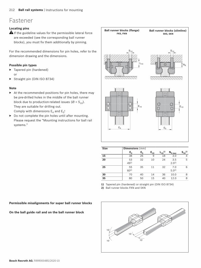
L10
S10
E10
E4 E5
E10
N9
S10
10´
10´
10´
10´
Instructions for mounting
Ball runner blocks (flange)FKS, FKN
Ball runner blocks (slimline) SKS, SKN
Size Dimensions (mm)E4 E5 E10 L10
1) N9 max S101)
15 38 26 9 18 3.0 420 53
492)32 10 24 3.5
2.02)5
25 55602)
35 11 32 7.05.02)
6
30 70 40 14 36 10.0 835 80 50 15 40 12.0 8
1) Tapered pin (hardened) or straight pin (DIN ISO 8734)2) Ball runner blocks FKN and SKN
Permissible misalignments for super ball runner blocks
On the ball guide rail and on the ball runner block
Locating pins If the guideline values for the permissible lateral force are exceeded (see the corresponding ball runner blocks), you must fix them additionally by pinning.
For the recommended dimensions for pin holes, refer to the dimension drawing and the dimensions.
Possible pin types ▶ Tapered pin (hardened)
or ▶ Straight pin (DIN ISO 8734)
Note ▶ At the recommended positions for pin holes, there may
be pre-drilled holes in the middle of the ball runner block due to production-related issues (Ø < S10). They are suitable for drilling out. Comply with dimensions E4 and E5!
▶ Do not complete the pin holes until after mounting. Please request the “Mounting instructions for ball rail systems.”
Fastener
212 Ball rail systems |
Bosch Rexroth AG, R999000485/2020-10
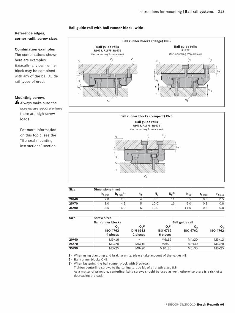
h2
h1
r1
O3
O1O2r2
h2
h1
N8
N10r1
O6
r2O4O4
h2
h1
N8
r1
O3
O4O4r2
Ball runner blocks (flange) BNS
Ball runner blocks (compact) CNS
Ball guide railsR1677
(for mounting from below)
Ball guide railsR1673, R1675, R1676
(for mounting from above)
Ball guide rails R1673, R1675, R1676
(for mounting from above)
Size Dimensions (mm)h1 min h1 max
1) h2 N8 N82) N10 r1 max r2 max
20/40 2.0 2.5 4 9.5 11 5.5 0.5 0.525/70 3.0 4.5 5 10.0 13 9.0 0.8 0.835/90 3.5 6.0 6 13.0 – 11.0 0.8 0.8
Ball guide rail with ball runner block, wideReference edges, corner radii, screw sizes
Combination examplesThe combinations shown here are examples. Basically, any ball runner block may be combined with any of the ball guide rail types offered.
Mounting screws Always make sure the screws are secure where there are high screw loads! For more information on this topic, see the “General mounting instructions” section.
Instructions for mounting
Size Screw sizesBall runner blocks Ball guide rail
O1ISO 47624 pieces
O23)
DIN 69122 pieces
O43)
ISO 47626 pieces
O3ISO 4762
O6ISO 4762
20/40 M5x16 – M6x16 M4x20 M5x1225/70 M6x20 M6x16 M8x20 M6x30 M6x2035/90 M8x25 M8x20 M10x25 M8x35 M8x25
1) When using clamping and braking units, please take account of the values H1.2) Ball runner blocks CNS3) When fastening the ball runner block with 6 screws:
Tighten centerline screws to tightening torque MA of strength class 8.8. As a matter of principle, centerline fixing screws should be used as well, otherwise there is a risk of a decreasing preload.
| Ball rail systems 213
R999000485/2020-10, Bosch Rexroth AG

E2
L10N9
S10
E4
E2
L10N9
S10
E5
Instructions for mounting
Ball runner blocks (flange)BNS
Ball runner block (compact)CNS
1) Tapered pin (hardened) or straight pin (DIN ISO 8734)
Size Dimensions (mm)E4 E5 L10
1) N9 max S101)
20/40 70 46 24 7 525/70 107 76 32 8 635/90 144 – 32 8 8
Locating pins If the guideline values for the permissible lateral force are exceeded (see the corresponding ball runner blocks), you must fix them additionally by pinning.
For the recommended dimensions for pin holes, refer to the dimension drawing and the dimensions.
Possible pin types ▶ Tapered pin (hardened)
or ▶ Straight pin
(DIN ISO 8734)
Note ▶ At the recommended positions for pin holes, there may
be pre-drilled holes in the middle of the ball runner block due to production-related issues (Ø < S10). They are suitable for drilling out.
▶ If is necessary to carry out pinning at a different position (e.g. the middle lube connection), dimension E2 must not be exceeded in the longitudinal direction (for dimension E2, refer to the dimension tables of the corresponding ball runner blocks). Comply with dimensions E4 and E5!
▶ Do not complete the pin holes until after mounting. ▶ Please request the “Mounting instructions for ball rail
systems.”
Fastener
214 Ball rail systems |
Bosch Rexroth AG, R999000485/2020-10
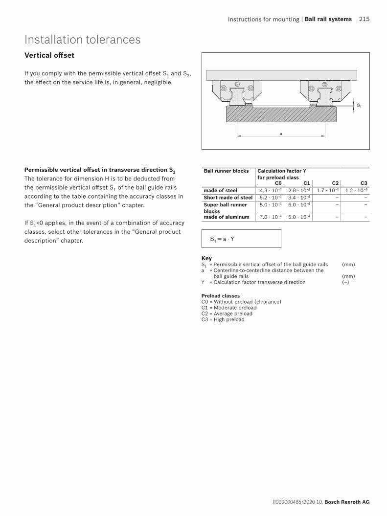
a
S1
S1 = a · Y
Installation tolerances
KeyS1 = Permissible vertical offset of the ball guide rails (mm)a = Centerline-to-centerline distance between the
ball guide rails (mm)Y = Calculation factor transverse direction (–)
Ball runner blocks Calculation factor Y for preload class
C0 C1 C2 C3made of steel 4.3 · 10 -4 2.8 · 10 -4 1.7 · 10 -4 1.2 · 10 -4
Short made of steel 5.2 · 10 -4 3.4 · 10 -4 – –Super ball runner blocks
8.0 · 10 -4 6.0 · 10 -4 – –
made of aluminum 7.0 · 10 -4 5.0 · 10 -4 – –
Instructions for mounting
Preload classesC0 = Without preload (clearance)C1 = Moderate preloadC2 = Average preloadC3 = High preload
| Ball rail systems 215
R999000485/2020-10, Bosch Rexroth AG
Vertical offset
If you comply with the permissible vertical offset S1 and S2, the effect on the service life is, in general, negligible.
Permissible vertical offset in transverse direction S1The tolerance for dimension H is to be deducted from the permissible vertical offset S1 of the ball guide rails according to the table containing the accuracy classes in the “General product description” chapter.
If S1<0 applies, in the event of a combination of accuracy classes, select other tolerances in the “General product description” chapter.
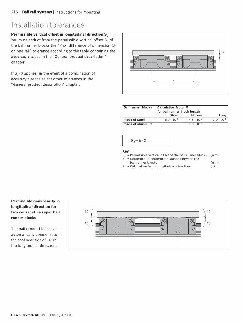
S2
b
10'
10'
10'
10'
S2 = b · X
Instructions for mounting
KeyS2 = Permissible vertical offset of the ball runner blocks (mm)b = Centerline-to-centerline distance between the
ball runner blocks (mm)X = Calculation factor longitudinal direction (–)
Ball runner blocks Calculation factor X for ball runner block length
Short Normal Longmade of steel 6.0 · 10 -5 4.3 · 10 -5 3.0 · 10 -5
made of aluminum – 6.0 · 10 -5 –
Permissible nonlinearity in longitudinal direction for two consecutive super ball runner blocks
The ball runner blocks can automatically compensate for nonlinearities of 10' in the longitudinal direction.
Installation tolerances
216 Ball rail systems |
Bosch Rexroth AG, R999000485/2020-10
Permissible vertical offset in longitudinal direction S2You must deduct from the permissible vertical offset S2 of the ball runner blocks the “Max. difference of dimension ∆H on one rail” tolerance according to the table containing the accuracy classes in the “General product description” chapter.
If S2<0 applies, in the event of a combination of accuracy classes select other tolerances in the “General product description” chapter.
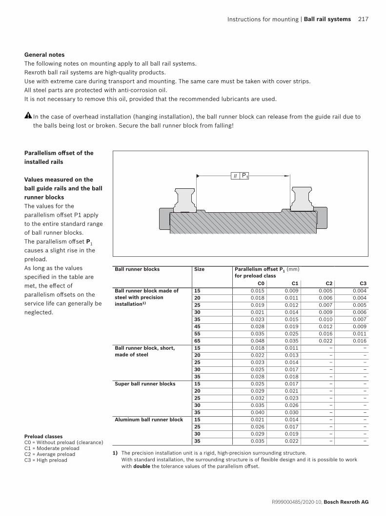
II P1
Ball runner blocks Size Parallelism offset P1 (mm) for preload class
C0 C1 C2 C3Ball runner block made of steel with precision installation1)
15 0.015 0.009 0.005 0.00420 0.018 0.011 0.006 0.00425 0.019 0.012 0.007 0.00530 0.021 0.014 0.009 0.00635 0.023 0.015 0.010 0.00745 0.028 0.019 0.012 0.00955 0.035 0.025 0.016 0.01165 0.048 0.035 0.022 0.016
Ball runner block, short, made of steel
15 0.018 0.011 – –20 0.022 0.013 – –25 0.023 0.014 – –30 0.025 0.017 – –35 0.028 0.018 – –
Super ball runner blocks 15 0.025 0.017 – –20 0.029 0.021 – –25 0.032 0.023 – –30 0.035 0.026 – –35 0.040 0.030 – –
Aluminum ball runner block 15 0.021 0.014 – –25 0.026 0.017 – –30 0.029 0.019 – –35 0.035 0.022 – –
1) The precision installation unit is a rigid, high-precision surrounding structure. With standard installation, the surrounding structure is of flexible design and it is possible to work with double the tolerance values of the parallelism offset.
Instructions for mounting
General notesThe following notes on mounting apply to all ball rail systems.Rexroth ball rail systems are high-quality products.Use with extreme care during transport and mounting. The same care must be taken with cover strips.All steel parts are protected with anti-corrosion oil.It is not necessary to remove this oil, provided that the recommended lubricants are used.
In the case of overhead installation (hanging installation), the ball runner block can release from the guide rail due to the balls being lost or broken. Secure the ball runner block from falling!
Parallelism offset of the installed rails
Values measured on the ball guide rails and the ball runner blocksThe values for the parallelism offset P1 apply to the entire standard range of ball runner blocks.The parallelism offset P1 causes a slight rise in the preload.As long as the values specified in the table are met, the effect of parallelism offsets on the service life can generally be neglected.
Preload classesC0 = Without preload (clearance)C1 = Moderate preloadC2 = Average preloadC3 = High preload
| Ball rail systems 217
R999000485/2020-10, Bosch Rexroth AG

002 002001 001
L ± 1.5
c)
b)a)
d)
b)a)
d)c)
001 001
L ± 1.5
c) c)d)
a)
Instructions for mounting
Composite ball guide railsNotes on ball guide rails
▶ Matching partial sections of a composite ball guide rail are identified as such by a label on the packaging. All partial sections of the same rail have the same serial rail number.
▶ The numbering is marked on the top of the ball guide rail.
Ball guide rail made up of three or more partial sections
L = rail length (mm)nB = number of holes (–)
a) Jointb) Rail numberc) Full rail identification on first and last sectionsd) Joint identification number
Ball guide rail made up of two partial sections
Note on cover strip ▶ For composite ball guide rails, a one-piece cover strip to cover the total length L is supplied separately. ▶ Secure the cover strip!
Note on adjacent structuresPermissible mounting hole tolerances for adjacent structures
Size Hole position tolerance (mm)
15 – 35 Ø 0.2
45 – 65 Ø 0.3
For composite ball guide rails, the actual tolerances of the individual sections may sum up. In such case, the fastening bore holes in the connecting structure may lie outside of the tolerances and a rework of the connecting structure may be required.
218 Ball rail systems |
Bosch Rexroth AG, R999000485/2020-10

| Ball rail systems 219
R999000485/2020-10, Bosch Rexroth AG
Lubrication
Notes on lubrication ▶ All specifications on lubrication are based on experimental values and field experience are recommendations by
Bosch Rexroth. ▶ The service life of the ball rail system crucially depends on the lubrication. For this purpose, the documentation,
especially the chapter on lubrication, must be read and understood completely. ▶ The operator is responsible for the selection and supply of the ball rail system with sufficient and suitable lubricant.
These notes do not exempt the operator from the individual examination of the conformity and suitability of the lubricant for its application.
▶ For recommended lubricants, see the chapter “Notes on Dynalub”.
To safeguard the supply of lubricant the lube fittings from the chapter “Accessories” must be used. When using other lube fittings it must be ensured that they are identical to Rexroth lube fittings.If using a progressive lubrication system, with grease lubrication, please pay attention to the minimum dosing amount for relubrication stated in table 9. We recommend carrying out initial lubrication separately using a grease gun before connecting to the central lubrication system. If using a central lubrication system, you must make sure that all the pipes and elements are filled with lubricant and do not contain any air pockets until they are connected to the consumer (ball runner block). The number of pulses results from the partial amounts and the piston distributor size.
▶ With fluid grease lubrication according to table 9 ▶ With oil lubrication according to table 14
The seals on the ball runner block must be oiled or greased with the respective lubricant before mounting.
If using different lubricants than the ones specified, relubrication intervals may be shorter and performance may decrease with short stroke and load ratio; in addition, chemical interactions can take place between the plastics, lubricants and preservative agents. Single-line central lubrication systems also need to be able to pump these lubricants.
Lubricant reservoirs should contain an agitator to ensure the lubricant can flow (avoids hardening in the reservoir).
Do not use lubricants with solid particles (e.g. graphite or MoS2).
With basic lubrication at the factory, both grease and oil lubrication is possible. In the case of relubrication, it is not possible to change from grease to oil lubrication, as the lubrication channels are already filled with grease and are therefore impermeable to oil.
Ball runner blocks without factory basic lubrication must be lubricated before commissioning.
When applying metalworking fluids at the start or after a relatively long standstill, carry out 2 to 5 lubrication pulses in succession. When the system is in operation, 3 to 4 pulses per hour are recommended, irrespective of the distance traveled. If possible, carry out lubrication in one lubricating stroke. Carry out cleaning cycles (see “Maintenance”).
An unfavorable selection of coolant/lubricant may lead to damage to the ball rail system. We recommend getting in touch with the manufacturer of the coolant/lubricant. Bosch Rexroth accepts no liability. Lubricant and metalworking fluids must be coordinated.
If environmental factors such as contamination, vibrations, impact loads, etc. are present, we recommend shorter lubrication intervals. Even under normal operating conditions, relubrication is required every 2 years due to grease aging.
220 Ball rail systems |
Bosch Rexroth AG, R999000485/2020-10
Lubrication
Dynalub 510Grease lubricantFeatures:
▶ Lithium-based, high-performance grease of NLGI grade 2 according to DIN 51818 (KP2K-20 according to DIN 51825)
▶ Good water resistance ▶ Corrosion protection ▶ Temperature range: -20 to +80 °C
Material numbers for Dynalub 510: ▶ R3416 037 00 (cartridge 400 g) ▶ R3416 035 00 (hobbock 25 kg)
Alternative greases: ▶ Castrol Tribol GR 100-2 PD*) or Elkalub GLS 135/N2*).
Notes on Dynalub(Approved for EU countries only; not approved outside of the EU)
Pay attention to the assignment of the ball rail system.
Under conventional environmental conditions, this short-fibred, homogeneous grease is ideally suited for the lubrication of linear elements:
▶ With loads up to 50 % C ▶ With short-stroke applications > 1 mm ▶ For the permissible travel speed range of ball rail systems
The product and safety data sheets can be found on our website at: www.boschrexroth.com.
Dynalub 520Liquid greaseFeatures:
▶ Lithium-based, high-performance grease of NLGI grade 00 according to DIN 51818 (GP00K-20 according to DIN 51826)
▶ Good water resistance ▶ Corrosion protection ▶ Temperature range: -20 to +80 °C
Material numbers for Dynalub 520: ▶ R3416 043 00 (cartridge 400 g) ▶ R3416 042 00 (bucket 5 kg)
Alternative greases: ▶ Castrol Tribol GR 100-00 PD*) or Elkalub GLS 135/N00*)
Notes on lubricant oil
We recommend Shell Tonna S3 M 220 *) or similar products with the following properties: ▶ Special demulsifying oil CLP or CGLP as per DIN 51517-3 for machine bed tracks and tool guides ▶ A blend of highly refined mineral oils and additives. Can be used even when mixed with significant quantities of
metalworking fluids
*) No liability is accepted for changes to the product properties of these lubricants.
▶ If your application involves more demanding environmental requirements (such as clean room, vacuum, food industry applications, increased exposure to fluids or aggressive media, extreme temperatures), please consult us. Each application must be considered on its own merits in order to chose the most appropriate lubricant. Special requirements call for special seals and wipers (see chapter “Ball runner block accessories”). Be sure to have all the information concerning your application at hand when contacting us. Pay attention to the chapter “Maintenance”.
▶ Rexroth recommends piston distributors by SKF. These should be installed as close as possible to the lube fittings of the ball runner blocks. Long lines and small line diameters should be avoided, and the lines should be laid on an upward slant. Install the lines at a gradient.
▶ Refer to the chapter entitled “Ball runner block accessories” for a selection of possible lube ports (in this connection, contact the manufacturer of your lubrication system too).
▶ If other consumers are connected to the single-line lubrication system, the weakest link in this chain determines the lubrication cycle.
| Ball rail systems 221
R999000485/2020-10, Bosch Rexroth AG

Lubrication
LubricationGrease lubrication with grease guns or progressive lubrication systems
Table 1
Size Initial lubrication (normal stroke) Part numbers (not exhaustive)(no initial lubrication) (with initial lubrication)R16.. ... 10 R20.. ... 04/0Z R16.. ... 20/2Z R20.. ... 30/3Z R16.. ... 70/7ZR16.. ... 11 R20.. ... 05 R16.. ... 21 R20.. ... 31 R16.. ... 71R16.. ... 60 R20.. ... 06/0Y R16.. ... 22/2Y R20.. ... 32/3Y R16.. ... 72/7Y
R20.. ... 07 R16.. ... 23 R20.. ... 33 R20.. ... 90
R16.. ... 73
Partial quantity (cm3)15 0.4 (3x)
Initial lubrication in the factory with Dynalub 510
20 0.7 (3x)25 1.4 (3x)30 2.2 (3x)35 2.2 (3x)45 –55 9.4 (3x)
–65 15.4 (3x)20/40
– Initial lubrication in the factory with Dynalub 51025/70
35/90 2.7 (3x) –
Stroke < 2 · ball runner block length B1 (short stroke)
▶ Two lube connections per ball runner block, attach one connection on the left and right ball guide and lubricate!
The initial lubrication is done three times for each connection with the partial quantities according to table 2:1. Lubricate the ball runner block for each
connection with an initial partial quantity according to table 2 by slowly applying pressure to the grease gun.
2. Move ball runner blocks with three double strokes of 3 · ball runner block length B1.
3. Repeat steps 1 and 2 twice.4. Check whether a film of grease is visible
on the ball guide rail.
Initial lubrication of the ball runner blocks (basic lubrication)Stroke ≥ 2 · ball runner block length B1 (normal stroke)
▶ One lube connection per ball runner block, attach optionally on the left or right ball guide and lubricate!
The initial lubrication is done three times with the partial quantities according to table 1:1. Pre-lubricate the ball runner block with
an initial partial amount according to table 1 by slowly applying pressure to the grease gun.
2. Move ball runner blocks with three double strokes of 3 · ball runner block length B1.
3. Repeat steps 1 and 2 twice.4. Check whether a film of grease is visible
on the ball guide rail.
Table 2
Size Initial lubrication (short stroke) Part numbers (not exhaustive)(no initial lubrication) (with initial lubrication)R16.. ... 10 R20.. ... 04/0Z R16.. ... 20/2Z R20.. ... 30/3Z R16.. ... 70/7ZR16.. ... 11 R20.. ... 05 R16.. ... 21 R20.. ... 31 R16.. ... 71R16.. ... 60 R20.. ... 06/0Y R16.. ... 22/2Y R20.. ... 32/3Y R16.. ... 72/7Y
R20.. ... 07 R16.. ... 23 R20.. ... 33 R20.. ... 90
R16.. ... 73
left right15 0.4 (3x) 0.4 (3x)
Initial lubrication in the factory with Dynalub 510
20 0.7 (3x) 0.7 (3x)25 1.4 (3x) 1.4 (3x)30 2.2 (3x) 2.2 (3x)35 2.2 (3x) 2.2 (3x)45 –55 9.4 (3x) 9.4 (3x)
–65 15.4 (3x) 15.4 (3x)20/40
– Initial lubrication in the factory with Dynalub 51025/70
35/90 2.7 (3x) 2.7 (3x) –
Never put ball runner blocks into operation without basic lubrication. No initial lubrication is required if pre-lubricated at the factory. Rexroth ball rail systems are supplied with preservation.
Observe chapter “Note on lubrication” Grease lubricant: We recommend using Dynalub 510. For further information, please refer to chapter “Note on lubrication”.
222 Ball rail systems |
Bosch Rexroth AG, R999000485/2020-10
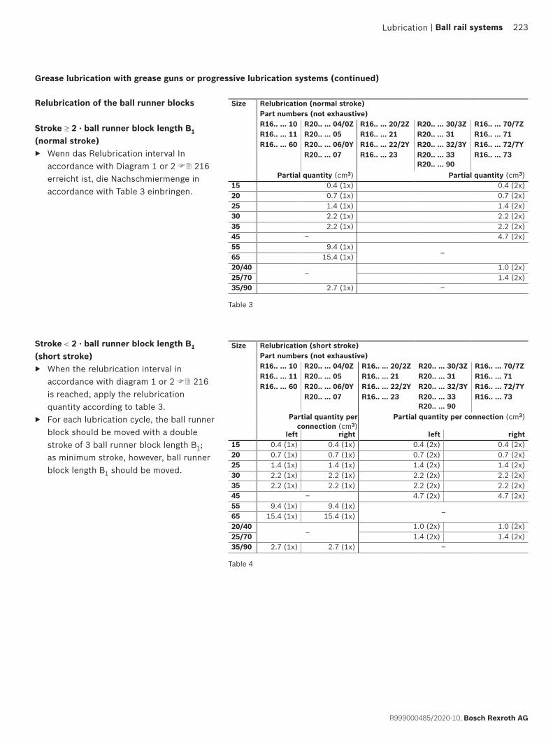
Grease lubrication with grease guns or progressive lubrication systems (continued)
Stroke < 2 · ball runner block length B1 (short stroke)
▶ When the relubrication interval in accordance with diagram 1 or 2 216 is reached, apply the relubrication quantity according to table 3.
▶ For each lubrication cycle, the ball runner block should be moved with a double stroke of 3 ball runner block length B1; as minimum stroke, however, ball runner block length B1 should be moved.
Relubrication of the ball runner blocks
Stroke ≥ 2 · ball runner block length B1 (normal stroke)
▶ Wenn das Relubrication interval In accordance with Diagram 1 or 2 216 erreicht ist, die Nachschmiermenge in accordance with Table 3 einbringen.
Table 3
Size Relubrication (normal stroke)Part numbers (not exhaustive)R16.. ... 10 R20.. ... 04/0Z R16.. ... 20/2Z R20.. ... 30/3Z R16.. ... 70/7ZR16.. ... 11 R20.. ... 05 R16.. ... 21 R20.. ... 31 R16.. ... 71R16.. ... 60 R20.. ... 06/0Y R16.. ... 22/2Y R20.. ... 32/3Y R16.. ... 72/7Y
R20.. ... 07 R16.. ... 23 R20.. ... 33 R20.. ... 90
R16.. ... 73
Partial quantity (cm3) Partial quantity (cm3)15 0.4 (1x) 0.4 (2x)20 0.7 (1x) 0.7 (2x)25 1.4 (1x) 1.4 (2x)30 2.2 (1x) 2.2 (2x)35 2.2 (1x) 2.2 (2x)45 – 4.7 (2x)55 9.4 (1x)
–65 15.4 (1x)20/40
–1.0 (2x)
25/70 1.4 (2x)35/90 2.7 (1x) –
Table 4
Size Relubrication (short stroke)Part numbers (not exhaustive)R16.. ... 10 R20.. ... 04/0Z R16.. ... 20/2Z R20.. ... 30/3Z R16.. ... 70/7ZR16.. ... 11 R20.. ... 05 R16.. ... 21 R20.. ... 31 R16.. ... 71R16.. ... 60 R20.. ... 06/0Y R16.. ... 22/2Y R20.. ... 32/3Y R16.. ... 72/7Y
R20.. ... 07 R16.. ... 23 R20.. ... 33 R20.. ... 90
R16.. ... 73
Partial quantity per connection (cm3)
Partial quantity per connection (cm3)
left right left right0.4 (2x) 0.4 (2x)0.7 (2x) 0.7 (2x)1.4 (2x) 1.4 (2x)2.2 (2x) 2.2 (2x)2.2 (2x) 2.2 (2x)4.7 (2x) 4.7 (2x)
–
1.0 (2x) 1.0 (2x)1.4 (2x) 1.4 (2x)
–
15 0.4 (1x) 0.4 (1x)20 0.7 (1x) 0.7 (1x)25 1.4 (1x) 1.4 (1x)30 2.2 (1x) 2.2 (1x)35 2.2 (1x) 2.2 (1x)45 –55 9.4 (1x) 9.4 (1x)65 15.4 (1x) 15.4 (1x)20/40
–25/7035/90 2.7 (1x) 2.7 (1x)
Lubrication | Ball rail systems 223
R999000485/2020-10, Bosch Rexroth AG

10
100
1000
10000
0.00 0.05 0.10 0.15 0.20 0.25 0.30 0.35 0.40
Size 20, 25
Size 35/90
s (km)
Fm/C
6000
500
Size 55
Size 65
0.12
4000
100
1000
10000
0.00 0.05 0.10 0.15 0.20 0.25 0.30 0.35 0.40
Size 25, 30, 35, 45
Size 15, 20, 20/40, 25/70
s (km)
Fm/C
20000
Lubrication
Lubrication
Load-dependent relubrication intervals This applies to the following conditions:
▶ dynalub 510 grease or Castrol Tribol GR 100-2 PD or Elkalube GLS 135/N2
▶ no media pressurization ▶ standard seals (SS) ▶ ambient temperature:
T = 10 – 40 °C
Pay attention to the notes on lubrication!
For relubrication intervals, please consult us:
▶ in case of exposure to cooling lubricants ▶ in case of exposure to dust
(wood, paper,...) ▶ with use of a double-lip seal (DS) ▶ with standard seal (SS) in combination
with front seal or FKM seal or seal kit
▶ at low mean travel speed vm
▶ at a raised ambient temperature ▶ at high loads Fm/C > 0.4
Diagram 1
Material numberR20.. ... 04 R16.. ... 20 R20.. ... 30 R16.. ... 70 R20.. ... 90R20.. ... 05 R16.. ... 21 R20.. ... 31 R16.. ... 71R20.. ... 06 R16.. ... 22 R20.. ... 32 R16.. ... 72R20.. ... 07 R16.. ... 23 R20.. ... 33 R16.. ... 73
Material numberR16.. ... 10 R16.. ... 11 R16.. ... 60
Diagram 2
KeyC = Dynamic load capacity (N)
Fm = Dynamically equivalent
Load on bearing (N)
Fm/C = Load ratio (–)
s = Relubrication interval
as travel distance (km)
Grease lubrication with grease guns or progressive lubrication systems (continued)
224 Ball rail systems |
Bosch Rexroth AG, R999000485/2020-10

Liquid grease lubrication with single-line piston distributor systems
Stroke < 2 · ball runner block length B1 (short stroke)
▶ Two lube connections per ball runner block, attach one connection on the left and right ball guide and lubricate!
The initial lubrication is done three times for each connection with the partial quantities according to table 6:1. Lubricate the ball runner block for each
connection with an initial partial quantity according to table 6 by slowly applying pressure to the grease gun.
2. Move ball runner blocks with three double strokes of 3 · ball runner block length B1.
3. Repeat steps 1 and 2 twice.4. Check whether a film of grease is visible
on the ball guide rail.
Initial lubrication of the ball runner blocks (basic lubrication)Stroke ≥ 2 · ball runner block length B1 (normal stroke)
▶ One lube connection per ball runner block, attach optionally on the left or right ball guide and lubricate!
The initial lubrication is done three times with the partial quantities according to table 5:1. Lubricate the ball runner block with
an initial partial amount according to table 5 by slowly applying pressure to the grease gun.
2. Move ball runner blocks with three double strokes of 3 · ball runner block length B1.
3. Repeat steps 1 and 2 twice.4. Check whether a film of grease is visible
on the ball guide rail.
Table 5
Size Initial lubrication (normal stroke)Part numbers (not exhaustive)(no initial lubrication) (with initial lubrication)R16.. ... 10 R20.. ... 04/0Z R16.. ... 20/2Z R20.. ... 30/3Z R16.. ... 70/7ZR16.. ... 11 R20.. ... 05 R16.. ... 21 R20.. ... 31 R16.. ... 71R16.. ... 60 R20.. ... 06/0Y R16.. ... 22/2Y R20.. ... 32/3Y R16.. ... 72/7Y
R20.. ... 07 R16.. ... 23 R20.. ... 33 R20.. ... 90
R16.. ... 73
Partial quantity (cm3)15 0.4 (3x)
Initial lubrication in the factory with Dynalub 510
20 0.7 (3x)25 1.4 (3x)30 2.2 (3x)35 2.2 (3x)45 –55 9.4 (3x)
–65 15.4 (3x)20/40
– Initial lubrication in the factory with Dynalub 51025/70
35/90 2.7 (3x) –
Table 6
Size Initial lubrication (short stroke)Part numbers (not exhaustive)(no initial lubrication) (with initial lubrication)R16.. ... 10 R20.. ... 04/0Z R16.. ... 20/2Z R20.. ... 30/3Z R16.. ... 70/7ZR16.. ... 11 R20.. ... 05 R16.. ... 21 R20.. ... 31 R16.. ... 71R16.. ... 60 R20.. ... 06/0Y R16.. ... 22/2Y R20.. ... 32/3Y R16.. ... 72/7Y
R20.. ... 07 R16.. ... 23 R20.. ... 33 R20.. ... 90
R16.. ... 73
Partial quantity per connection (cm3)
left right15 0.4 (3x) 0.4 (3x)
Initial lubrication in the factory with Dynalub 510
20 0.7 (3x) 0.7 (3x)25 1.4 (3x) 1.4 (3x)30 2.2 (3x) 2.2 (3x)35 2.2 (3x) 2.2 (3x)45 –55 9.4 (3x) 9.4 (3x)
–65 15.4 (3x) 15.4 (3x)20/40
– Initial lubrication in the factory with Dynalub 51025/70
35/90 2.7 (3x) 2.7 (3x) –
Never put ball runner blocks into operation without basic lubrication. No initial lubrication is required if pre-lubricated at the factory. Rexroth ball rail systems are supplied with preservation.
Lubrication
Observe chapter “Note on lubrication” Grease lubricant: We recommend using Dynalub 520. For further information, please refer to chapter “Note on lubrication”.
| Ball rail systems 225
R999000485/2020-10, Bosch Rexroth AG
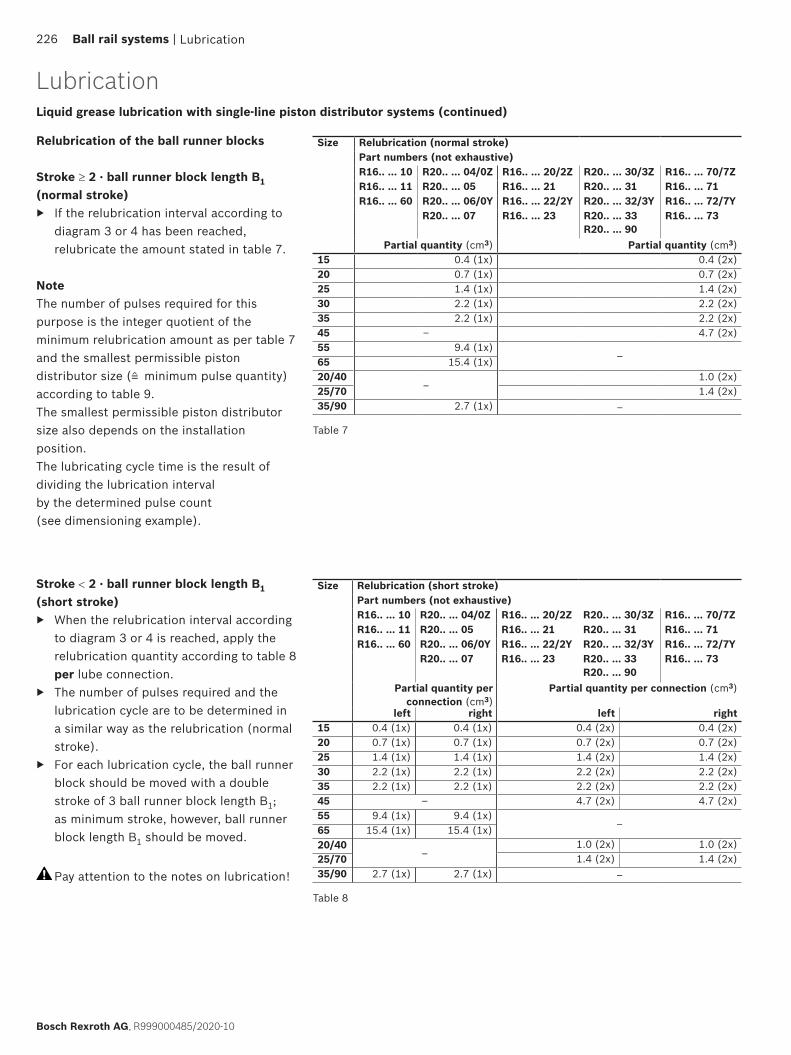
Stroke < 2 · ball runner block length B1 (short stroke)
▶ When the relubrication interval according to diagram 3 or 4 is reached, apply the relubrication quantity according to table 8 per lube connection.
▶ The number of pulses required and the lubrication cycle are to be determined in a similar way as the relubrication (normal stroke).
▶ For each lubrication cycle, the ball runner block should be moved with a double stroke of 3 ball runner block length B1; as minimum stroke, however, ball runner block length B1 should be moved.
Pay attention to the notes on lubrication!
Relubrication of the ball runner blocks
Stroke ≥ 2 · ball runner block length B1 (normal stroke)
▶ If the relubrication interval according to diagram 3 or 4 has been reached, relubricate the amount stated in table 7.
NoteThe number of pulses required for this purpose is the integer quotient of the minimum relubrication amount as per table 7 and the smallest permissible piston distributor size (≠ minimum pulse quantity) according to table 9. The smallest permissible piston distributor size also depends on the installation position. The lubricating cycle time is the result of dividing the lubrication intervalby the determined pulse count (see dimensioning example).
Table 7
Size Relubrication (normal stroke)Part numbers (not exhaustive)R16.. ... 10 R20.. ... 04/0Z R16.. ... 20/2Z R20.. ... 30/3Z R16.. ... 70/7ZR16.. ... 11 R20.. ... 05 R16.. ... 21 R20.. ... 31 R16.. ... 71R16.. ... 60 R20.. ... 06/0Y R16.. ... 22/2Y R20.. ... 32/3Y R16.. ... 72/7Y
R20.. ... 07 R16.. ... 23 R20.. ... 33 R20.. ... 90
R16.. ... 73
Partial quantity (cm3) Partial quantity (cm3)15 0.4 (1x) 0.4 (2x)20 0.7 (1x) 0.7 (2x)25 1.4 (1x) 1.4 (2x)30 2.2 (1x) 2.2 (2x)35 2.2 (1x) 2.2 (2x)45 – 4.7 (2x)55 9.4 (1x)
–65 15.4 (1x)20/40
–1.0 (2x)
25/70 1.4 (2x)35/90 2.7 (1x) –
Table 8
Size Relubrication (short stroke)Part numbers (not exhaustive)R16.. ... 10 R20.. ... 04/0Z R16.. ... 20/2Z R20.. ... 30/3Z R16.. ... 70/7ZR16.. ... 11 R20.. ... 05 R16.. ... 21 R20.. ... 31 R16.. ... 71R16.. ... 60 R20.. ... 06/0Y R16.. ... 22/2Y R20.. ... 32/3Y R16.. ... 72/7Y
R20.. ... 07 R16.. ... 23 R20.. ... 33 R20.. ... 90
R16.. ... 73
Partial quantity per connection (cm3)
Partial quantity per connection (cm3)
left right left right0.4 (2x) 0.4 (2x)0.7 (2x) 0.7 (2x)1.4 (2x) 1.4 (2x)2.2 (2x) 2.2 (2x)2.2 (2x) 2.2 (2x)4.7 (2x) 4.7 (2x)
–
1.0 (2x) 1.0 (2x)1.4 (2x) 1.4 (2x)
–
15 0.4 (1x) 0.4 (1x)20 0.7 (1x) 0.7 (1x)25 1.4 (1x) 1.4 (1x)30 2.2 (1x) 2.2 (1x)35 2.2 (1x) 2.2 (1x)45 –55 9.4 (1x) 9.4 (1x)65 15.4 (1x) 15.4 (1x)20/40
–25/7035/90 2.7 (1x) 2.7 (1x)
Lubrication
LubricationLiquid grease lubrication with single-line piston distributor systems (continued)
226 Ball rail systems |
Bosch Rexroth AG, R999000485/2020-10
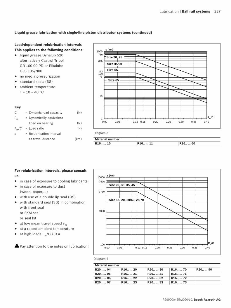
1
10
100
1000
0.00 0.05 0.15 0.20 0.25 0.30 0.35 0.400.12
Size 20, 25
Size 35/90
s (km)
Fm/C
112
750
Size 55
Size 65
375
75
100
1000
10000
0.00 0.05 0.15 0.20 0.25 0.30 0.35 0.400.12
Size 25, 30, 35, 45
s (km)
Fm/C
7500
3750
Size 15, 20, 20/40, 25/70
Load-dependent relubrication intervals This applies to the following conditions:
▶ liquid grease Dynalub 520 alternatively Castrol Tribol GR 100-00 PD or Elkalube GLS 135/N00
▶ no media pressurization ▶ standard seals (SS) ▶ ambient temperature:
T = 10 – 40 °C
Liquid grease lubrication with single-line piston distributor systems (continued)
Diagram 3
Material numberR20.. ... 04 R16.. ... 20 R20.. ... 30 R16.. ... 70 R20.. ... 90R20.. ... 05 R16.. ... 21 R20.. ... 31 R16.. ... 71R20.. ... 06 R16.. ... 22 R20.. ... 32 R16.. ... 72R20.. ... 07 R16.. ... 23 R20.. ... 33 R16.. ... 73
Material numberR16.. ... 10 R16.. ... 11 R16.. ... 60
Diagram 4
For relubrication intervals, please consult us:
▶ in case of exposure to cooling lubricants ▶ in case of exposure to dust
(wood, paper,...) ▶ with use of a double-lip seal (DS) ▶ with standard seal (SS) in combination
with front seal or FKM seal or seal kit
▶ at low mean travel speed vm
▶ at a raised ambient temperature ▶ at high loads Fm/C > 0.4
Pay attention to the notes on lubrication!
KeyC = Dynamic load capacity (N)
Fm = Dynamically equivalent
Load on bearing (N)
Fm/C = Load ratio (–)
s = Relubrication interval
as travel distance (km)
Lubrication | Ball rail systems 227
R999000485/2020-10, Bosch Rexroth AG

Liquid grease lubrication with single-line piston distributor systems (continued)
Ball runner blocks Smallest permissible piston distributor size (≠ minimum impulse quantity) for each connection (cm3) with liquid grease of NLGI grade 00Size
Material number Installation positions
15 20 25 30 35 45 55 65 20/40 25/70 35/90
R16.. ... 10R16.. ... 11R16.. ... 60
Horizontal I, IV– 0.30 0.30 – – – 0.30 0.30 – – 0.30Vertical II, V
Wall mounting III, VI
R20.. ... 04R20.. ... 0ZR20.. ... 05R20.. ... 06R20.. ... 0YR20.. ... 07
R16.. ... 20R16.. ... 2ZR16.. ... 21R16.. ... 22R16.. ... 2YR16.. ... 23
R20.. ... 30R20.. ... 3ZR20.. ... 31R20.. ... 32R20.. ... 3YR20.. ... 33 R20.. ... 90
R16.. ... 70R16.. ... 7ZR16.. ... 71R16.. ... 72R16.. ... 7YR16.. ... 73
Horizontal I, IV
0.03
0.03 0.03 0.06 0.10 0.10
–
0.03 0.03
–
Vertical II, V
Wall mounting III, VI 0.06 0.06 0.10 0.20 0.20 0.06 0.06
Smallest permissible piston distributor size for liquid grease lubrication via single-line piston distributor1)
Horizontal1 lube connection, either on the left or on the right ball guide
Installation position I – Normal stroke Installation position II – Normal stroke Installation position III – Normal stroke
Installation position IV – short stroke Installation position V – short stroke Installation position VI – short stroke
Horizontal over headSame connection
Horizontal2 lube connections, 1 connection each on the left and right ball guide
Horizontal over headSame connections
Vertical to inclined horizontal2 lube connections, 1 connection each on the top and bottom ball guide
Vertical to inclined horizontal1 lube connection at the upper ball guide
Vertical to inclined over headSame connection
Wall mounting2 lube connections, 1 connection each on the left and right ball guide
Wall mounting1 lube connection, either on the left or on the right ball guide
Vertical to inclined over headSame connections
Table 91) This applies to the following conditions:
– Liquid grease Dynalub 520 (alternatively Castrol Tribol GR 100-00 PD or Elkalube GLS 135/N00) and piston distributors by SKF. – Lubrication channels must be filled – Ambient temperature T = 10 – 40 °C
0° up to max. ±90°
0° up to max. ±90°
0° up to max. ±90°
0° up to max. ±90°
Same connections
Same connection
Lubrication
Lubrication
228 Ball rail systems |
Bosch Rexroth AG, R999000485/2020-10

Oil lubrication with single-line piston distributor systems
Stroke < 2 · ball runner block length B1 (short stroke)
▶ Two lube connections per ball runner block, attach one connection on the left and right ball guide and lubricate!
The initial lubrication is done two times for each connection with the partial quantities according to table 11:1. Oil the ball runner block for each
connection with the initial partial quantity according to table 11.
2. Move ball runner blocks with three double strokes of 3 · ball runner block length B1.
3. Repeat steps 1 and 2 once.4. Check whether a film of grease is visible
on the ball guide rail.
Initial lubrication of the ball runner blocks (basic lubrication)Stroke ≥ 2 · ball runner block length B1 (normal stroke)
▶ One lube connection per ball runner block, attach optionally on the left or right ball guide and lubricate!
The initial lubrication is done two times with the partial quantity according to table 10:1. Oil the ball runner block with the initial
partial quantity according to table 10.2. Move ball runner blocks with three double
strokes of 3 · ball runner block length B1.3. Repeat steps 1 and 2 once.4. Check whether a film of grease is visible
on the ball guide rail.Table 10
Size Initial lubrication (normal stroke)Part numbers (not exhaustive)(no initial lubrication) (with initial lubrication)R16.. ... 10 R20.. ... 04/0Z R16.. ... 20/2Z R20.. ... 30/3Z R16.. ... 70/7ZR16.. ... 11 R20.. ... 05 R16.. ... 21 R20.. ... 31 R16.. ... 71R16.. ... 60 R20.. ... 06/0Y R16.. ... 22/2Y R20.. ... 32/3Y R16.. ... 72/7Y
R20.. ... 07 R16.. ... 23 R20.. ... 33 R20.. ... 90
R16.. ... 73
Partial quantity (cm3)15 0.4 (2x)
Initial lubrication in the factory with Dynalub 510
20 0.7 (2x)25 1.0 (2x)30 1.1 (2x)35 1.2 (2x)45 –55 3.6 (2x)
–65 6.0 (2x)20/40
– Initial lubrication in the factory with Dynalub 51025/70
35/90 1.8 (2x) –
Table 11
Size Initial lubrication (short stroke)Part numbers (not exhaustive)(no initial lubrication) (with initial lubrication)R16.. ... 10 R20.. ... 04/0Z R16.. ... 20/2Z R20.. ... 30/3Z R16.. ... 70/7ZR16.. ... 11 R20.. ... 05 R16.. ... 21 R20.. ... 31 R16.. ... 71R16.. ... 60 R20.. ... 06/0Y R16.. ... 22/2Y R20.. ... 32/3Y R16.. ... 72/7Y
R20.. ... 07 R16.. ... 23 R20.. ... 33 R20.. ... 90
R16.. ... 73
Partial quantity per connection (cm3)
left right15 0.4 (2x) 0.4 (2x)
Initial lubrication in the factory with Dynalub 510
20 0.7 (2x) 0.7 (2x)25 1.0 (2x) 1.0 (2x)30 1.1 (2x) 1.1 (2x)35 1.2 (2x) 1.2 (2x)45 –55 3.6 (2x) 3.6 (2x)
–65 6.0 (2x) 6.0 (2x)20/40
– Initial lubrication in the factory with Dynalub 51025/70
35/90 1.8 (2x) 1.8 (2x) –
Lubrication
Never put ball runner blocks into operation without basic lubrication. No initial lubrication is required if pre-lubricated at the factory. Rexroth ball rail systems are supplied with preservation.
Observe chapter “Note on lubrication” Lubricant oil: We recommend Shell Tonna S3 M220. For further information, please refer to chapter “Note on lubrication”.
| Ball rail systems 229
R999000485/2020-10, Bosch Rexroth AG
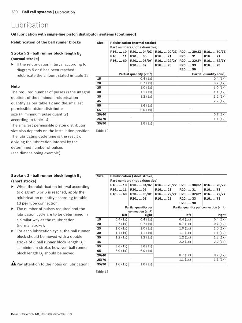
Stroke < 2 · ball runner block length B1 (short stroke)
▶ When the relubrication interval according to diagram 5 or 6 is reached, apply the relubrication quantity according to table 13 per lube connection.
▶ The number of pulses required and the lubrication cycle are to be determined in a similar way as the relubrication (normal stroke).
▶ For each lubrication cycle, the ball runner block should be moved with a double stroke of 3 ball runner block length B1; as minimum stroke, however, ball runner block length B1 should be moved.
Pay attention to the notes on lubrication!
Relubrication of the ball runner blocks
Stroke ≥ 2 · ball runner block length B1 (normal stroke)
▶ If the relubrication interval according to diagram 5 or 6 has been reached, relubricate the amount stated in table 12.
NoteThe required number of pulses is the integralquotient of the minimum relubrication quantity as per table 12 and the smallest permissible piston distributor size (≠ minimum pulse quantity) according to table 14.The smallest permissible piston distributor size also depends on the installation position. The lubricating cycle time is the result of dividing the lubrication interval by the determined number of pulses (see dimensioning example).
Table 12
Size Relubrication (normal stroke)Part numbers (not exhaustive)R16.. ... 10 R20.. ... 04/0Z R16.. ... 20/2Z R20.. ... 30/3Z R16.. ... 70/7ZR16.. ... 11 R20.. ... 05 R16.. ... 21 R20.. ... 31 R16.. ... 71R16.. ... 60 R20.. ... 06/0Y R16.. ... 22/2Y R20.. ... 32/3Y R16.. ... 72/7Y
R20.. ... 07 R16.. ... 23 R20.. ... 33 R20.. ... 90
R16.. ... 73
Partial quantity (cm3) Partial quantity (cm3)15 0.4 (1x) 0.4 (1x) 20 0.7 (1x) 0.7 (1x)25 1.0 (1x) 1.0 (1x)30 1.1 (1x) 1.1 (1x) 35 1.2 (1x) 1.2 (1x) 45 – 2.2 (1x)55 3.6 (1x)
–65 6.0 (1x)20/40
–0.7 (1x)
25/70 1.1 (1x) 35/90 1.8 (1x) –
Table 13
Size Relubrication (short stroke)Part numbers (not exhaustive)R16.. ... 10 R20.. ... 04/0Z R16.. ... 20/2Z R20.. ... 30/3Z R16.. ... 70/7ZR16.. ... 11 R20.. ... 05 R16.. ... 21 R20.. ... 31 R16.. ... 71R16.. ... 60 R20.. ... 06/0Y R16.. ... 22/2Y R20.. ... 32/3Y R16.. ... 72/7Y
R20.. ... 07 R16.. ... 23 R20.. ... 33 R16.. ... 73R20.. ... 90
Partial quantity per connection (cm3)
Partial quantity per connection (cm3)
left right left right0.4 (1x) 0.4 (1x) 0.7 (1x) 0.7 (1x)1.0 (1x) 1.0 (1x) 1.1 (1x) 1.1 (1x)1.2 (1x) 1.2 (1x)2.2 (1x) 2.2 (1x)
–
0.7 (1x) 0.7 (1x)1.1 (1x) 1.1 (1x)
–
15 0.4 (1x) 0.4 (1x) 20 0.7 (1x) 0.7 (1x) 25 1.0 (1x) 1.0 (1x)30 1.1 (1x) 1.1 (1x) 35 1.2 (1x) 1.2 (1x) 45 –55 3.6 (1x) 3.6 (1x) 65 6.0 (1x) 6.0 (1x) 20/40
–25/7035/90 1.8 (1x) 1.8 (1x)
Lubrication
LubricationOil lubrication with single-line piston distributor systems (continued)
230 Ball rail systems |
Bosch Rexroth AG, R999000485/2020-10

s (km)
1
10
100
1000
0.00 0.05 0.15 0.20 0.25 0.30 0.35 0.400.12
Size 20, 25
Size 35/90
Fm/C
50
500
Size 55
Size 65
250
75
s (km)
100
1000
10000
0.00 0.05 0.15 0.20 0.25 0.30 0.35 0.400.12
Size 25, 30, 35, 45
s (km)
Fm/C
5000
2500
Size 15, 20, 20/40, 25/70
Load-dependent relubrication intervals for oil lubrication via single-line piston distributor systems (“dry axes”)
This applies to the following conditions: ▶ lubricant oil Shell Tonna S3 M220 ▶ no media pressurization ▶ standard seals (SS) ▶ ambient temperature:
T = 10 – 40 °C
Oil lubrication with single-line piston distributor systems (continued)
Material numberR16.. ... 10 R16.. ... 11 R16.. ... 60
Diagram 5
Diagram 6
Material numberR20.. ... 04 R16.. ... 20 R20.. ... 30 R16.. ... 70 R20.. ... 90R20.. ... 05 R16.. ... 21 R20.. ... 31 R16.. ... 71R20.. ... 06 R16.. ... 22 R20.. ... 32 R16.. ... 72R20.. ... 07 R16.. ... 23 R20.. ... 33 R16.. ... 73
For relubrication intervals, please consult us:
▶ in case of exposure to cooling lubricants ▶ in case of exposure to dust
(wood, paper,...) ▶ with use of a double-lip seal (DS) ▶ with standard seal (SS) in combination
with front seal or FKM seal or seal kit
▶ at low mean travel speed vm
▶ at a raised ambient temperature ▶ at high loads Fm/C > 0.4
Pay attention to the notes on lubrication!
KeyC = Dynamic load capacity (N)
Fm = Dynamically equivalent
Load on bearing (N)
Fm/C = load ratio (–)
s = Relubrication interval
as travel distance (km)
Lubrication | Ball rail systems 231
R999000485/2020-10, Bosch Rexroth AG
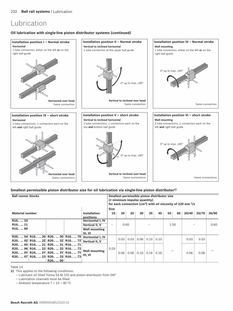
Smallest permissible piston distributor size for oil lubrication via single-line piston distributor1)
Installation position I – Normal stroke Installation position II – Normal stroke Installation position III – Normal stroke
Installation position IV – short stroke Installation position V – short stroke Installation position VI – short stroke
Horizontal over headSame connection
Horizontal over headSame connections
Vertical to inclined over headSame connection
Vertical to inclined over headSame connections
0° up to max. ±90°
0° up to max. ±90°
0° up to max. ±90°
0° up to max. ±90°
Same connections
Same connection
Ball runner blocks Smallest permissible piston distributor size (≠ minimum impulse quantity) for each connection (cm3) with oil viscosity of 220 mm 2/sSize
Material number Installation positions
15 20 25 30 35 45 55 65 20/40 25/70 35/90
R16.. ... 10R16.. ... 11R16.. ... 60
Horizontal I, IV– 0.60 – 1.50 – 0.60Vertical II, V
Wall mounting III, VI
R20.. ... 04R20.. ... 0ZR20.. ... 05R20.. ... 06R20.. ... 0YR20.. ... 07
R16.. ... 20R16.. ... 2ZR16.. ... 21R16.. ... 22R16.. ... 2YR16.. ... 23
R20.. ... 30R20.. ... 3ZR20.. ... 31R20.. ... 32R20.. ... 3YR20.. ... 33 R20.. ... 90
R16.. ... 70R16.. ... 7ZR16.. ... 71R16.. ... 72R16.. ... 7YR16.. ... 73
Horizontal I, IV
0.03
0.03 0.03 0.06 0.10 0.10
–
0.03 0.03
–
Vertical II, V
Wall mounting III, VI 0.06 0.06 0.10 0.16 0.16 0.06 0.06
Table 141) This applies to the following conditions:
– Lubricant oil Shell Tonna S3 M 220 and piston distributor from SKF – Lubrication channels must be filled – Ambient temperature T = 10 – 40 °C
Lubrication
Lubrication
Horizontal1 lube connection, either on the left or on the right ball guide
Horizontal2 lube connections, 1 connection each on the left and right ball guide
Vertical to inclined horizontal2 lube connections, 1 connection each on the top and bottom ball guide
Vertical to inclined horizontal1 lube connection at the upper ball guide
Wall mounting2 lube connections, 1 connection each on the left and right ball guide
Wall mounting1 lube connection, either on the left or on the right ball guide
Oil lubrication with single-line piston distributor systems (continued)
232 Ball rail systems |
Bosch Rexroth AG, R999000485/2020-10
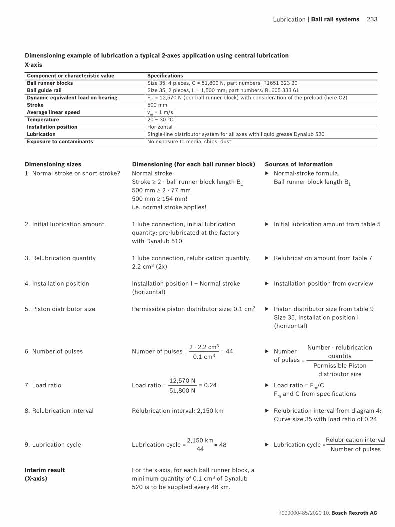
Normal stroke: Stroke ≥ 2 · ball runner block length B1 500 mm ≥ 2 · 77 mm 500 mm ≥ 154 mm! i.e. normal stroke applies!
1 lube connection, initial lubrication quantity: pre-lubricated at the factory with Dynalub 510
1 lube connection, relubrication quantity: 2.2 cm3 (2x)
Installation position I – Normal stroke (horizontal)
Permissible piston distributor size: 0.1 cm3 Number of pulses =
Load ratio =
Relubrication interval: 2,150 km
Lubrication cycle =
For the x-axis, for each ball runner block, a minimum quantity of 0.1 cm3 of Dynalub 520 is to be supplied every 48 km.
▶ Normal-stroke formula, Ball runner block length B1
▶ Initial lubrication amount from table 5
▶ Relubrication amount from table 7
▶ Installation position from overview
▶ Piston distributor size from table 9 Size 35, installation position I (horizontal)
▶ Number of pulses
▶ Load ratio = Fm/C Fm and C from specifications
▶ Relubrication interval from diagram 4: Curve size 35 with load ratio of 0.24
▶ Lubrication cycle =
X-axisDimensioning example of lubrication a typical 2-axes application using central lubrication
1. Normal stroke or short stroke?
2. Initial lubrication amount
3. Relubrication quantity
4. Installation position
5. Piston distributor size
6. Number of pulses
7. Load ratio
8. Relubrication interval
9. Lubrication cycle
Interim result (X-axis)
Dimensioning (for each ball runner block)
2 · 2.2 cm3
0.1 cm3= 44
12,570 N51,800 N
= 0.24
Relubrication intervalNumber of pulses
2,150 km44 = 48
Component or characteristic value SpecificationsBall runner blocks Size 35, 4 pieces, C = 51,800 N, part numbers: R1651 323 20Ball guide rail Size 35, 2 pieces, L = 1,500 mm; part numbers: R1605 333 61Dynamic equivalent load on bearing Fm = 12,570 N (per ball runner block) with consideration of the preload (here C2)Stroke 500 mmAverage linear speed vm = 1 m/sTemperature 20 – 30 °CInstallation position HorizontalLubrication Single-line distributor system for all axes with liquid grease Dynalub 520Exposure to contaminants No exposure to media, chips, dust
Dimensioning sizes Sources of information
Number · relubrication quantity
Permissible Piston distributor size
=
Lubrication | Ball rail systems 233
R999000485/2020-10, Bosch Rexroth AG
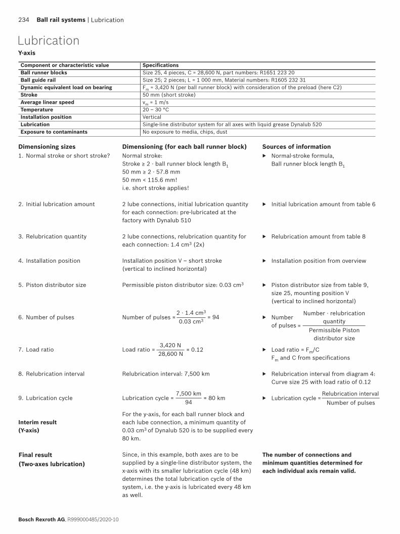
▶ Normal-stroke formula, Ball runner block length B1
▶ Initial lubrication amount from table 6
▶ Relubrication amount from table 8
▶ Installation position from overview
▶ Piston distributor size from table 9, size 25, mounting position V (vertical to inclined horizontal)
▶ Number of pulses
▶ Load ratio = Fm/C Fm and C from specifications
▶ Relubrication interval from diagram 4: Curve size 25 with load ratio of 0.12
▶ Lubrication cycle =
Normal stroke: Stroke ≥ 2 · ball runner block length B1 50 mm ≥ 2 · 57.8 mm 50 mm < 115.6 mm! i.e. short stroke applies!
2 lube connections, initial lubrication quantity for each connection: pre-lubricated at the factory with Dynalub 510
2 lube connections, relubrication quantity for each connection: 1.4 cm3 (2x)
Installation position V – short stroke (vertical to inclined horizontal)
Permissible piston distributor size: 0.03 cm3
Number of pulses =
Load ratio =
Relubrication interval: 7,500 km
Lubrication cycle =
For the y-axis, for each ball runner block and each lube connection, a minimum quantity of 0.03 cm3 of Dynalub 520 is to be supplied every 80 km.
Since, in this example, both axes are to be supplied by a single-line distributor system, the x-axis with its smaller lubrication cycle (48 km) determines the total lubrication cycle of the system, i.e. the y-axis is lubricated every 48 km as well.
1. Normal stroke or short stroke?
2. Initial lubrication amount
3. Relubrication quantity
4. Installation position
5. Piston distributor size
6. Number of pulses
7. Load ratio
8. Relubrication interval
9. Lubrication cycle
Interim result (Y-axis)
Y-axis
Component or characteristic value SpecificationsBall runner blocks Size 25, 4 pieces, C = 28,600 N, part numbers: R1651 223 20Ball guide rail Size 25; 2 pieces; L = 1 000 mm, Material numbers: R1605 232 31Dynamic equivalent load on bearing Fm = 3,420 N (per ball runner block) with consideration of the preload (here C2)Stroke 50 mm (short stroke)Average linear speed vm = 1 m/sTemperature 20 – 30 °CInstallation position VerticalLubrication Single-line distributor system for all axes with liquid grease Dynalub 520Exposure to contaminants No exposure to media, chips, dust
Final result (Two-axes lubrication)
Dimensioning (for each ball runner block)
2 · 1.4 cm3
0.03 cm3 = 94
3,420 N28,600 N
= 0.12
7,500 km94
= 80 km
Dimensioning sizes Sources of information
Relubrication intervalNumber of pulses
Number · relubrication quantity
Permissible Piston distributor size
=
Lubrication
The number of connections and minimum quantities determined for each individual axis remain valid.
Lubrication
234 Ball rail systems |
Bosch Rexroth AG, R999000485/2020-10

ø 0,8
0,5
Tmax
1
32
1
4
1
3
6
5
Size Lubrication opening, top: Maximum permissible depth for piercing Tmax (mm)
Ball runner block standard
height/high
Ball runner block low
15 3.6 –20 3.9 4.425 3.3 4.930 6.6 –35 7.5 –45 8.8 –20/40 4.0 –25/70 2.1 –35/90 7.9 –
Lubrication from abovewithout lubrication adapterFor all ball runner blocks with preparation for lubrication from above.(Exceptions: High ball runner block SNH R1621 and SLH R1624)In the groove for the O-ring, another small groove (1) is pre-fitted. Do not open this with a drill.Risk of contamination!
1. Heat up a metal tip (2) with a diameter of 0.8 mm.
2. Carefully open and pierce the groove (1) with the metal tip. Observe the maximum permissible depth Tmax according to the table!
3. Insert the o-ring (3) into the groove (the o-ring is not included in the scope of delivery of the ball runner block. Ball runner block accessories)
with lubrication adapter(Ball runner block accessories)A lubrication adapter is necessary for high ball runner blocks if lubrication is to be carried out from the carriage.In the groove for the O-ring, another small groove (1) is pre-fitted. Do not open this with a drill.Risk of contamination!
1. Heat up a metal tip (2) with a diameter of 0.8 mm.
2. Carefully open and pierce the groove (1) with the metal tip. Observe the maximum permissible depth Tmax according to the table!
3. Insert the o-ring (3) into the groove (the o-ring is not included in the scope of delivery of the lubrication adapter).
4. Insert the lubrication adapter at a slant into the groove and press the straight side (4) against the steel part (5). Use grease to fix the adapter in place.
5. Insert the o-ring (6) into the lubrication adapter (the o-ring is not included in the scope of delivery of the lubrication adapter).
FNS R1651 (example)
SNH R1621 (example)
Lubrication | Ball rail systems 235
R999000485/2020-10, Bosch Rexroth AG
MaintenanceCleaning cycle Dirt can settle and encrust on ball guide rails, especially when these are not enclosed.
To ensure that seals and cover strips retain their functionality, this dirt must be removed at regular intervals.It is advisable to perform at least one full cleaning cycle over the entire stroke at least twice a day or every 8 hours at the latest.Before shutting down the machine, always perform a cleaning cycle.Shorter maintenance intervals in case of exposure to cooling lubricants.
Maintenance of accessories
All accessories used for scraping the ball guide rail shall be subject to regular maintenance.
In environments with heavy contamination, it is advisable to replace all the parts directly exposed to such contamination.
We recommend annual maintenance.
Maintenance236 Ball rail systems |
Bosch Rexroth AG, R999000485/2020-10

Further information | Ball rail systems 237
R999000485/2020-10, Bosch Rexroth AG
Bosch Rexroth Linear Motion Technology homepage
Configurators and tools
https://www.boschrexroth.com/en/xc/products/product-groups/linear-motion-technology/index
https://www.boschrexroth.com/en/xc/products/engineering/econfigurators-and-tools/econfigurators
Further information
Further information238 Ball rail systems |
Bosch Rexroth AG, R999000485/2020-10
GoTo Europe
How-to: Linear Motion Technology
http://www.boschrexroth.com/goto
https://www.youtube.com/playlist?list=PLRO3LeFQeLyMF6evW4E7kR93JHzpJlV4r

Further information | Ball rail systems 239
R999000485/2020-10, Bosch Rexroth AG
Service
https://www.boschrexroth.com/en/xc/products/product-groups/linear-motion-technology/service-linear-motion-technology
Training
https://www.boschrexroth.com/en/xc/training/training

Notes240 Ball rail systems |
Bosch Rexroth AG, R999000485/2020-10

R999000485/2020-10replaces R999000485 (2014-12)© Bosch Rexroth AG 2020Subject to modifications!
The data specified above only serves to describe the product.No statements concerning a certain condition or suitability for a certain application can be derived from our information. The information given does not release the user from the obligation of their own judgment and verification. It should be noted that our products are subject to a natural process of aging and wear.
Bosch Rexroth AGErnst-Sachs-Straße 10097424 Schweinfurt, GermanyTel. +49 9721 937-0 Fax +49 9721 937-275www.boschrexroth.com
Find your local contact person here:www.boschrexroth.com/contact