Chennai Metro Rail Limited
1606
Chennai Metro Rail Ltd, – Contract No. Part (A) – Qualification Criteria 1 CHENNAI METRO RAIL LIMITED (A JOINT VENTURE OF GOVERNMENT OF INDIA AND GOVERNMENT OF TAMILNADU) TECHNO COMMERCIAL TENDER TWO COVER SYSTEM CONSTRUCTION OF METRO HEAD QUARTERS BUILDING AND OTHER METRO RAIL AMENITIES AT ANNA SALAI, NANDANAM, CHENNAI 600 035 Cover – A – TECHNICAL PART PART - A: QUALIFICATION CRITERIA DATE OF SUBMISSION OF TENDER – 13-04-2016 at 15.00 Hours DATE OF OPENING OF TENDER - 13-04-2016 2016 at 15.30 Hours TO BE SUBMITTED TO: The Chief General Manager(EC) Chennai Metro Rail Limited Admin. Building, CMRL Depot Poonnamallee High Road , Koyambedu, Chennai - 600107 TENDER SUBMITTED BY: M/s._________________________ Address_____________________ ____________________________
-
Upload
khangminh22 -
Category
Documents
-
view
0 -
download
0
Transcript of Chennai Metro Rail Limited

Chennai Metro Rail Ltd, – Contract No. Part (A) – Qualification Criteria
1
CHENNAI METRO RAIL LIMITED (A JOINT VENTURE OF GOVERNMENT OF INDIA AND GOVERNMENT OF TAMILNADU)
TECHNO COMMERCIAL TENDER TWO COVER SYSTEM
CONSTRUCTION OF METRO HEAD QUARTERS BUILDING AND OTHER METRO RAIL AMENITIES AT ANNA SALAI, NANDANAM,
CHENNAI 600 035
Cover – A – TECHNICAL PART
PART - A: QUALIFICATION CRITERIA
DATE OF SUBMISSION OF TENDER – 13-04-2016 at 15.00 Hours
DATE OF OPENING OF TENDER - 13-04-2016 2016 at 15.30 Hours TO BE SUBMITTED TO:
The Chief General Manager(EC) Chennai Metro Rail Limited Admin. Building, CMRL Depot Poonnamallee High Road , Koyambedu, Chennai - 600107
TENDER SUBMITTED BY:
M/s._________________________
Address_____________________
____________________________
Chennai Metro Rail Ltd, – Contract No. Part (A) – Qualification Criteria
2
CHENNAI METRO RAIL LIMITED
(A JOINT VENTURE OF GOVERNMENT OF INDIA AND GOVERNMENT OF TAMILNADU)
TECHNO COMMERCIAL TENDER
(TWO COVER SYSTEM)
CONSTRUCTION OF METRO HEADQUARTERS BUILDING AND OTHER METRO RAIL AMENITIES
AT ANNA SALAI, NANDANAM, CHENNAI, TAMIL NADU, INDIA
CONTENTS Notice inviting Tenders
Information and Instructions to Tenderer
1. General 2. Brief Description of Project 3. Summary of Important Conditions of Contract 4. Eligible TENDERER for applying. 5. Qualifying Criteria for the contractor 6. Site Visit 7. Submission of TENDER documents 8. Particular Attention 9. Final Decision Making Authority
10. Qualification Information
10.1. Appendix A : Letter of Transmittal
10.2. Qualification requirements
Format – A : Structure and Organization of TENDERER Format – B : Key Personnel to be deployed Format – C : Financial Information Format – D : Details of Completed works Format – E : Details of Ongoing works Format – F : Plant, machinery & Equipment Format – G : Details of Termination of contract in the past, if any Format – H : Status of Current litigations, if any
11. Annexure A : Certificates

Chennai Metro Rail Ltd, – Contract No. Part (A) – Qualification Criteria
3
CHENNAI METRO RAIL LIMITED CONSTRUCTION OF METRO HEADQUARTERS BUILDING AND OTHER METRO
RAIL AMENITIES AT ANNA SALAI, NANDANAM, CHENNAI, TAMIL NADU, INDIA
NOTICE INVITING TENDER
Tender Notice No: CMRL/CON/RT01/ ACHQ -2 /2016 Dated 23rd Feb 2016
Name of Work: Construction of Metro Headquarters Building and other Metro Rail Amenities at Nandanam, Chennai, Tamilnadu under the two cover system from the Contractors who meet the following criteria: The TENDERER to be eligible for Qualification, should fulfill the following qualifying criteria:
1. Tenderer should have satisfactorily completed the works as mentioned below during the last Seven years ending last day of the month 31st March 2015. The works completed upto previous day of last date of submission of tenders shall also be considered
Three similar works each costing not less than Rs 56,00,00,000/- (Fifty six Crore only)
Or Two similar works, costing not less Rs 84,00,00,000/- (Eighty Four Crore only)
Or One similar work, costing not less than Rs 112,00,00,000/- (One hundred twelve crore only)
2. Tenderer should have satisfactorily completed at least one building of not less than 30 Metre height multi storied housing / Commercial Project as a Principle Contractor along with MEP scope in the same name and style for the Central Government Department/ State Government Department/ Central Autonomous Body/ State Autonomous Body/ Central Public Sector Undertaking/ State Public Sector Undertaking/City Development Authority/ Municipal Corporation of City formed under any Act by Central/ State Government and published in Central/State Gazette. The experience certificate testifying satisfactory completion is to be obtained from the Engineers not below the rank of Chief Engineer concerned / Director or equivalent and the Notarized copy should be enclosed. Reputed contractors who have completed Multi Storied buildings for Private companies is acceptable subject to producing authenticated completion certificate or TDS certificates from the respective clients or Final Bill Certificates of Architect / PMC of the Project etc . In case of Private firms, CMRL has the right to scrutinize the original bill certificate, Payment made in the name of concern firm etc.
3. The TENDERER should have an average annual turnover of Rs.140 Crores (Rupees One
Hundred fourty Crores only) in the field of Construction of Building and its associated works during the past three consecutive financial years, ending on 31st March, 2015. (At the time of submission of tender contractor may upload Affidavit/ Certificate from CA mentioning Financial Turnover of last 3 years or for the period as specified in the bid document and further details if required may be asked from the contractor after opening of technical bids.)
4. Should not have incurred any loss in the last two years ending 31st March 2015 and the same
should be certified by Chartered Accounts.
Chennai Metro Rail Ltd, – Contract No. Part (A) – Qualification Criteria
4
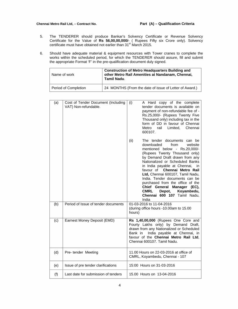
5. The TENDERER should produce Bankar’s Solvency Certificate or Revenue Solvency
Certificate for the Value of Rs 56,00,00,000/- ( Rupees Fifty six Crore only). Solvency certificate must have obtained not earlier than 31st March 2015.
6. Should have adequate material & equipment resources with Tower cranes to complete the
works within the scheduled period, for which the TENDERER should assure, fill and submit the appropriate Format ‘F’ in the pre-qualification document duly signed.
Name of work
Construction of Metro Headquarters Building and other Metro Rail Amenities at Nandanam, Chennai, Tamil Nadu.
Period of Completion 24 MONTHS (From the date of issue of Letter of Award.)
(a) Cost of Tender Document (Including VAT) Non-refundable.
(i) A Hard copy of the complete tender documents is available on payment of non-refundable fee of - Rs.25,000/- (Rupees Twenty Five Thousand only) including tax in the form of DD in favour of Chennai Metro rail Limited, Chennai 600107.
(ii) The tender documents can be
downloaded from website mentioned below - Rs.20,000/- (Rupees Twenty Thousand only) by Demand Draft drawn from any Nationalized or Scheduled Banks in India payable at Chennai, in favour of Chennai Metro Rail Ltd, Chennai 600107, Tamil Nadu, India. Tender documents can be purchased from the office of the Chief General Manager (EC), CMRL Depot, Koyambedu, Chennai 600 107 Tamil Nadu, India
(b) Period of Issue of tender documents 01-03-2016 to 11-04-2016 (during office hours -10.00am to 15.00 hours)
(c) Earnest Money Deposit (EMD) Rs 1,40,00,000 (Rupees One Core and Fourty Lakhs only) by Demand Draft, drawn from any Nationalized or Scheduled Bank in India payable at Chennai, in favour of the Chennai Metro Rail Ltd, Chennai 600107. Tamil Nadu.
(d) Pre- tender Meeting 11.00 Hours on 22-03-2016 at office of CMRL, Koyambedu, Chennai - 107
(e) Issue of pre tender clarifications 15:00 Hours on 31-03-2016
(f) Last date for submission of tenders 15.00 Hours on 13-04-2016
Chennai Metro Rail Ltd, – Contract No. Part (A) – Qualification Criteria
5
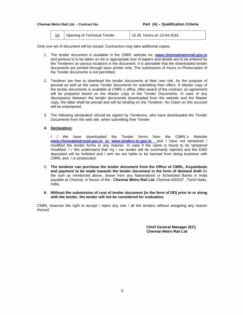
(g) Opening of Technical Tender 15.30 Hours on 13-04-2016
Only one set of document will be issued. Contractors may take additional copies.
1. The tender document is available in the CMRL website viz. www.chennaimetrorail.gov.in and printout is to be taken on A4 or appropriate size of papers and details are to be entered by the Tenderers at various locations in the document. It is advisable that the downloaded tender documents are printed through laser printer only. The submission of Xerox or Photocopies of the Tender documents is not permitted.
2. Tenderer are free to download the tender documents at their own risk, for the purpose of perusal as well as the same Tender documents for submitting their offers. A Master copy of the tender documents is available at CMRL‘s office. After award of the contract, an agreement will be prepared based on the Master copy of the Tender Documents. In case of any discrepancy between the tender documents downloaded from the website and the Master copy, the latter shall be prevail and will be binding on the Tenderer. No Claim on this account will be entertained.
3. The following declaration should be signed by Tenderers, who have downloaded the Tender Documents from the web site, when submitting their Tender:
4. Declaration: I / We have downloaded the Tender forms from the CMRL’s Website www.chennaimetrorail.gov.in or www.tenders.tn,gov.in and I have not tampered / modified the tender forms in any manner. In case if the same is found to be tampered /modified. I / We understand that my / our tender will be summarily rejected and the EMD deposited will be forfeited and I am/ we are liable to be banned from doing business with CMRL and / or prosecuted.
5. The tenderer can purchase the tender document from the Office of CMRL, Koyambedu and payment to be made towards the tender document in the form of demand draft for the sum as mentioned above, drawn from any Nationalized or Scheduled Banks in India payable at Chennai, in favour of the - Chennai Metro Rail Ltd, Chennai 600107 , Tamil Nadu, India,
6. Without the submission of cost of tender document (in the form of DD) prior to or along with the tender, the tender will not be considered for evaluation.
CMRL reserves the right to accept / reject any one / all the tenders without assigning any reason thereof.
Chief General Manager (EC) Chennai Metro Rail Ltd
Chennai Metro Rail Ltd, – Contract No. Part (A) – Qualification Criteria
6
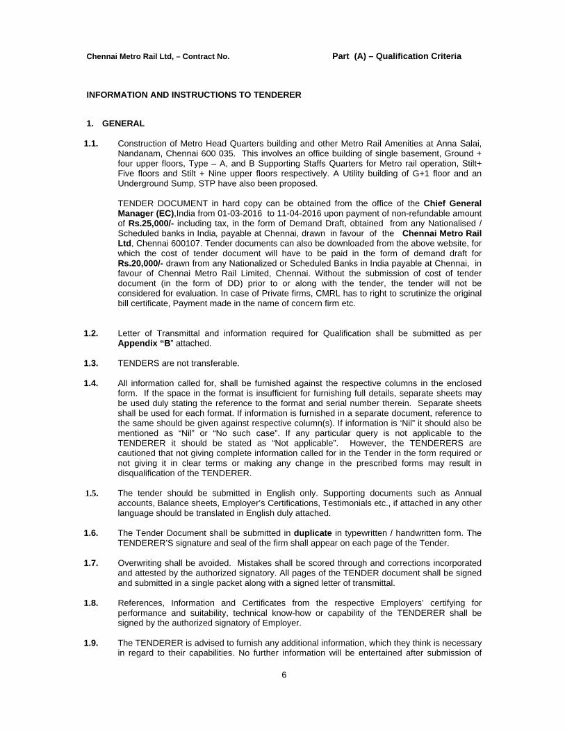
INFORMATION AND INSTRUCTIONS TO TENDERER
1. GENERAL
1.1. Construction of Metro Head Quarters building and other Metro Rail Amenities at Anna Salai, Nandanam, Chennai 600 035. This involves an office building of single basement, Ground + four upper floors, Type – A, and B Supporting Staffs Quarters for Metro rail operation, Stilt+ Five floors and Stilt + Nine upper floors respectively. A Utility building of G+1 floor and an Underground Sump, STP have also been proposed.
TENDER DOCUMENT in hard copy can be obtained from the office of the Chief General Manager (EC),India from 01-03-2016 to 11-04-2016 upon payment of non-refundable amount of Rs.25,000/- including tax, in the form of Demand Draft, obtained from any Nationalised / Scheduled banks in India, payable at Chennai, drawn in favour of the Chennai Metro Rail Ltd, Chennai 600107. Tender documents can also be downloaded from the above website, for which the cost of tender document will have to be paid in the form of demand draft for Rs.20,000/- drawn from any Nationalized or Scheduled Banks in India payable at Chennai, in favour of Chennai Metro Rail Limited, Chennai. Without the submission of cost of tender document (in the form of DD) prior to or along with the tender, the tender will not be considered for evaluation. In case of Private firms, CMRL has to right to scrutinize the original bill certificate, Payment made in the name of concern firm etc.
1.2. Letter of Transmittal and information required for Qualification shall be submitted as per Appendix “B” attached.
1.3. TENDERS are not transferable.
1.4. All information called for, shall be furnished against the respective columns in the enclosed
form. If the space in the format is insufficient for furnishing full details, separate sheets may be used duly stating the reference to the format and serial number therein. Separate sheets shall be used for each format. If information is furnished in a separate document, reference to the same should be given against respective column(s). If information is ‘Nil” it should also be mentioned as “Nil” or “No such case”. If any particular query is not applicable to the TENDERER it should be stated as “Not applicable”. However, the TENDERERS are cautioned that not giving complete information called for in the Tender in the form required or not giving it in clear terms or making any change in the prescribed forms may result in disqualification of the TENDERER.
1.5. The tender should be submitted in English only. Supporting documents such as Annual
accounts, Balance sheets, Employer’s Certifications, Testimonials etc., if attached in any other language should be translated in English duly attached.
1.6. The Tender Document shall be submitted in duplicate in typewritten / handwritten form. The
TENDERER’S signature and seal of the firm shall appear on each page of the Tender.
1.7. Overwriting shall be avoided. Mistakes shall be scored through and corrections incorporated and attested by the authorized signatory. All pages of the TENDER document shall be signed and submitted in a single packet along with a signed letter of transmittal.
1.8. References, Information and Certificates from the respective Employers’ certifying for
performance and suitability, technical know-how or capability of the TENDERER shall be signed by the authorized signatory of Employer.
1.9. The TENDERER is advised to furnish any additional information, which they think is necessary
in regard to their capabilities. No further information will be entertained after submission of

Chennai Metro Rail Ltd, – Contract No. Part (A) – Qualification Criteria
7
TENDER document, unless it is called for by the Employer.
1.10. Tender Document details and enclosures shall be submitted in sealed envelopes and addressed to The Chief General Manager (EC), Chennai Metro Rail Limited, Admin Building, CMRL Depot, Poonnamallee Road, Koyambedu, Chennai - 600107, Tamil Nadu, India as detailed above. Tender submitted late will not be opened. All times and dates mentioned in this Tender Notice and application are Indian Standard Time (IST) only. The same will be followed for communication and other purposes.
1.11. Documents submitted in connection with the Tender, will be treated as CONFIDENTIAL and
will not be returned.
1.12. The cost incurred by TENDERERS in preparing their Tender, in collecting information, in providing clarifications or attending discussions, conferences or in making presentations, site visit etc. in connection with this TENDER will not be reimbursed by the Employer under any circumstances
1.13. Any clarification given by the Employer on his own will be forwarded to all those who have
purchased TENDER documents / attended the pre Tender meeting.
1.14. The Employer reserves the right to reject any or all TENDERS, without assigning any reasons whatsoever and without incurring any liability to whomsoever.
1.15. Canvassing or influencing in any form will entail disqualification.
1.16. The Employer reserves the right to approach individuals, employers, companies and
corporations to verify TENDERER’S competency and general reputation.
1.17. Tenderers who’s work got terminated in CMRL will not be considered.
2. BRIEF DESCRIPTION OF PROJECT :
2.1. The Project consists of office building of single basement, Ground + four upper floors, Type – A, and B Type – A, and B Supporting Staffs Quarters for Metro rail operation, Stilt + Five floors and Stilt + Nine upper floors respectively. The building will house a comprehensive fire protection system in line with the requirement of TNFRS. Stilt floor will house parking (two and four wheelers), electrical room, Lobby and Common amenities. UG sump and Fire sump with Pump room are planned underground. Plumbing and electrical works for the units are also included in the scope of works. .
2.2. The scope of this tender includes for
a) Civil works including RCC framed structure, masonry works, plastering and all related finishing works like Tiling, Painting etc,
b) Supply and installation of UPVC windows and Joinery, Fire and Flush doors along with hardware, etc
c) Electrical Works including electrical fittings in common area.
d) Fire Protection and detection systems including pumps, smoke detectors, etc
e) Plumbing and sanitation works including supply and installation of all sanitary ware and CP fittings.
2.3. The period of completion of the work will be 24 months from the date of signing the
agreement.

Chennai Metro Rail Ltd, – Contract No. Part (A) – Qualification Criteria
8
2.4. All construction documents, prepared by the Contractor shall be reviewed and approved by the Employer / Employer’s representative before commencement of procurement and construction. All works shall have to be carried out, in compliance with Bill of Quantities, Conditions of Contract, Technical Specification, Preamble and tender Drawings, relevant Indian standard (IS) Codes, International Codes and local bye-laws.
3. SUMMARY OF CONDITIONS OF CONTRACT:
3.1. The Contract shall be item rate contract with unit rates, to be quoted in Indian Rupees only.
3.2. Since the project is to be implemented strictly on the time schedule, the employer may extend the deadline for submission of tenders by issuing an amendment in which case, all rights and obligations of the Employer and Tenderer previously ensured in the original deadline, will then be shifted to the new deadline. The Employer will lay high emphasis on the capacity of the selected contractor to deploy high-tech and speedy construction techniques, high degree of planning, good procurement and quality check procedures, quality assurance Plan, Environment and Safety Plan to meet the appropriate standards, execution and co-ordination, ability to prepare PERT network and adhering to it meticulously.
3.3. Therefore the TENDERERS are required to demonstrate with firm examples of deployment of above techniques in their previously completed project.
4. ELIGIBLE TENDERERS :
4.1. The firms applying for eligibility should have extensive experience and proven track record in Civil Construction and associated works.
4.2. The Tender made by a partnership firm, shall be signed by all the partners of the firms above
their full typewritten / handwritten names and current addresses, or alternatively by a partner holding Power of Attorney for the firm, in which case, a certified copy of the Power of Attorney shall accompany the Tender. A certified copy of the deed, full names and current addresses of all the partners of the firm shall also accompany the Tender. (*)
4.3. The Tender made by a firm shall be signed by Authorized signatory but appropriate evidence
should be enclosed for authorizing the signing person in the tender document. (*)
4.4. The financial Tenders of only those Tenderer, who fulfill the eligibility criteria mentioned in the Notice Inviting Tender and mentioned in Clause No.5 below, will be only opened.
4.5. Any change in the legal status of a TENDERER subsequent to submission of Tender will be
subject to approval of the Employer
4.6. TENDERERs under joint Venture arrangements are not permitted. Note: (*) denotes requirement of enclosure(s) along with Tender.
5. QUALIFYING CRITERIA FOR THE CONTRACTOR
5.1. Tenderer should have satisfactorily completed the works as mentioned below during the last
Seven years ending last day of the month 31st March 2015. The works completed upto previous day of last date of submission of tenders shall also be considered
Three similar works each costing not less than Rs 56,00,00,000/- (Fifty six Crore only)
Or Two similar works, costing not less Rs 84,00,00,000/- (Eighty Four Crore only)

Chennai Metro Rail Ltd, – Contract No. Part (A) – Qualification Criteria
9
Or One similar work, costing not less than Rs 112,00,00,000/- (One hundred twelve crore only)
7. Tenderer should have satisfactorily completed at least one building of not less than 30 Metre height multi storied housing / Commercial Project as a Principle Contractor along with MEP scope in the same name and style for the Central Government Department/ State Government Department/ Central Autonomous Body/ State Autonomous Body/ Central Public Sector Undertaking/ State Public Sector Undertaking/City Development Authority/ Municipal Corporation of City formed under any Act by Central/ State Government and published in Central/State Gazette. The experience certificate testifying satisfactory completion is to be obtained from the Engineers not below the rank of Chief Engineer concerned / Director or equivalent and the Notarized copy should be enclosed. Reputed contractors who have completed Multi Storied buildings for Private companies is acceptable subject to producing authenticated completion certificate or TDS certificates from the respective clients or Final Bill Certificates of Architect / PMC of the Project etc . In case of Private firms, CMRL has the right to scrutinize the original bill certificate, Payment made in the name of concern firm etc.
5.2. The TENDERER should have an average annual turnover of Rs.140 Crore (Rupees One
Hundred and fourty Crores only) in the field of Construction of Building and its associated works during the past three consecutive financial years, ending on 31st March, 2015. (At the time of submission of tender contractor may upload Affidavit/ Certificate from CA mentioning Financial Turnover of last 3 years or for the period as specified in the bid document and further details if required may be asked from the contractor after opening of technical bids.)
5.3. Should not have incurred any loss in the last two years ending 31st March 2015 and the same
should be certified by Chartered Accounts.
5.4. The TENDERER should produce Bankar’s Solvency Certificate or Revenue Solvency Certificate for the Value of Rs 56,00,00,000/- ( Rupees Fifty Six Crore only). Solvency certificate must have obtained not earlier than 31st March 2015.
5.5. Should have adequate material & equipment resources with Tower cranes to complete the works within the scheduled period, for which the TENDERER should assure, fill and submit the appropriate Format ‘F’ in the pre-qualification document duly signed.
5.6. The TENDERER should further furnish evidence for the following.
i) that they have the required minimum tools, plant and equipment as detailed below, but not limited to, with adequate labour force for the proposed work. The list of equipment shall be furnished in Format ‘F’.
Sl.No. Description Qty. ( Minimum Requirement)
1 Concrete Pumps 5 Nos.
2 Weigh Batcher 3 Nos.
3 Vibrators 20 Nos.
4 Dewatering pumps with suitable capacity 4 Nos.
5 Tower Crane having adequate size and capacity
1 No.
6 125 KVA DG Set 1No.
7 Steel Centering Materials 7000 M2
8 Minimum Lab equipments As needed
Chennai Metro Rail Ltd, – Contract No. Part (A) – Qualification Criteria
10
9 Lorry/tipper/Water tank 6 Nos.
10 Material Hoist Min 1 No
11 Passenger Hoist Min 1 No for 8 passengers
12 Debris Chute Min 4 No
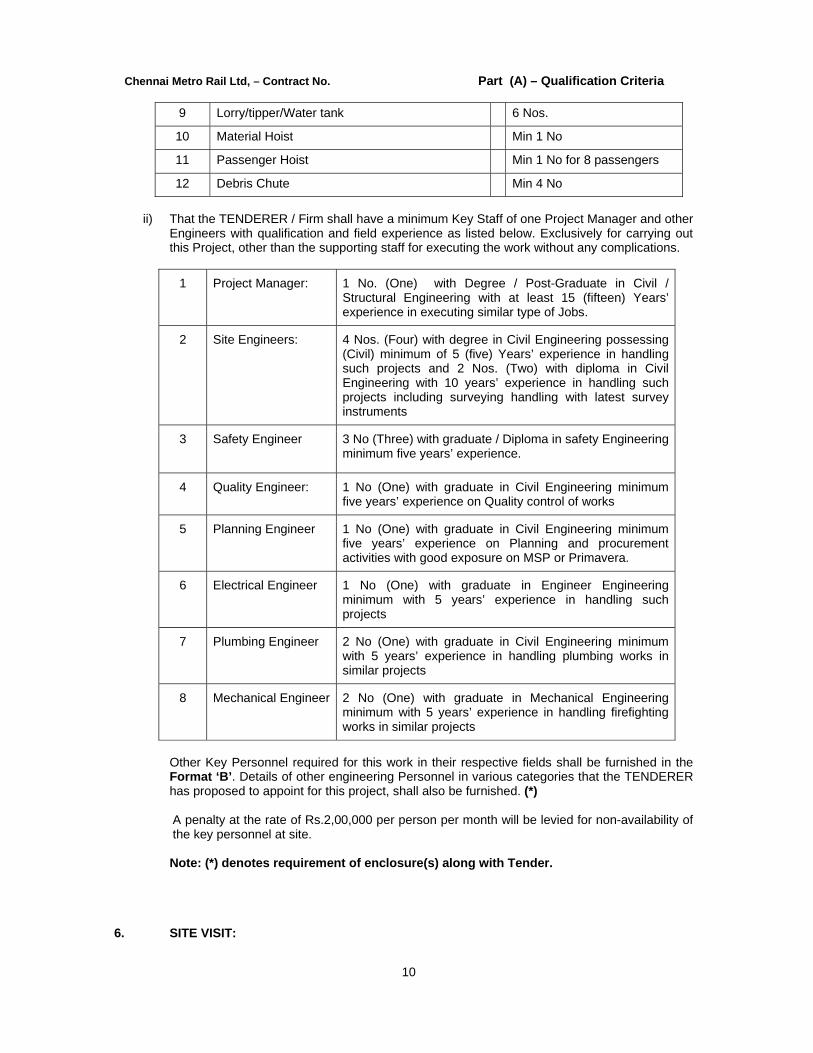
ii) That the TENDERER / Firm shall have a minimum Key Staff of one Project Manager and other Engineers with qualification and field experience as listed below. Exclusively for carrying out this Project, other than the supporting staff for executing the work without any complications.
1 Project Manager: 1 No. (One) with Degree / Post-Graduate in Civil / Structural Engineering with at least 15 (fifteen) Years’ experience in executing similar type of Jobs.
2 Site Engineers: 4 Nos. (Four) with degree in Civil Engineering possessing (Civil) minimum of 5 (five) Years’ experience in handling such projects and 2 Nos. (Two) with diploma in Civil Engineering with 10 years’ experience in handling such projects including surveying handling with latest survey instruments
3 Safety Engineer 3 No (Three) with graduate / Diploma in safety Engineering minimum five years’ experience.
4 Quality Engineer: 1 No (One) with graduate in Civil Engineering minimum five years’ experience on Quality control of works
5 Planning Engineer 1 No (One) with graduate in Civil Engineering minimum five years’ experience on Planning and procurement activities with good exposure on MSP or Primavera.
6 Electrical Engineer 1 No (One) with graduate in Engineer Engineering minimum with 5 years’ experience in handling such projects
7 Plumbing Engineer 2 No (One) with graduate in Civil Engineering minimum with 5 years’ experience in handling plumbing works in similar projects
8 Mechanical Engineer 2 No (One) with graduate in Mechanical Engineering minimum with 5 years’ experience in handling firefighting works in similar projects
Other Key Personnel required for this work in their respective fields shall be furnished in the Format ‘B’. Details of other engineering Personnel in various categories that the TENDERER has proposed to appoint for this project, shall also be furnished. (*) A penalty at the rate of Rs.2,00,000 per person per month will be levied for non-availability of the key personnel at site. Note: (*) denotes requirement of enclosure(s) along with Tender.
6. SITE VISIT:
Chennai Metro Rail Ltd, – Contract No. Part (A) – Qualification Criteria
11
The TENDERER shall, prior to submission of the tender for the work at his own responsibility and risk, visit and examine the site of work & its surroundings with prior intimation to the Employer for proper assessment of the prospective assignment. The TENDERER should refer to the enclosed drawings also. The Tenderer Should make himself familiar with the works already executed / being executed at site and plan for suitable measures for transition of works.
7. SUBMISSION OF TENDER DOCUMENTS : 7.1 Sealed Tenders should be addressed to the Chief General Manager (EC) Chennai Metro Rail
limited, Admin Building, CMRL Depot, Poonnamallee High Road, Koyambedu, Chennai 600 107, and superscripting the name of the Tender on the top left hand corner of the cover and the name of the TENDERER on the bottom left hand corner of the cover and sent so as to reach him not later than 15-00 hours on 13-04-2016.
7.2 The Tender shall be two cover system / Two part tender system, Cover - A the Technical
and Qualification Tender along with EMD and Tender document fee if downloaded and Cover - B Price Tender. Both the Parts, each in separate sealed Covers - A & B have to be submitted together put in a common sealed cover.
7.3 All Tenderer who fulfill the eligibility condition will be eligible for opening for their financial
proposals. The Employer shall notify all technically qualified tenderers to attend the opening of the financial proposal. The financial proposal will then be opened in presence of all tenderers.
7.4 Cover - A (Technical and Pre-Qualification document ), of the Tender document consists of
Part - A,B&C pertaining to Qualification criteria (A), Conditions of Contract (B) and Technical Specification (C) and Cover - B Price Tender of Tender document, pertaining to Bill of Quantities shall be submitted in duplicate i.e. one original and one copy. All the other enclosures that the TENDERERs wish to submit shall also be in duplicate. (Note: Part - C Technical Specification: Duplicate copy need not be submitted.)
7.5 All Tender Drawings duly signed and affixed with the seal of the TENDERER shall be
returned in a separate cover (only one set). 7.6 The Tender document shall be submitted in duplicate. The original Tender document issued to
the TENDERER shall be marked ‘Original’ and copy marked `Duplicate’. Should there be any discrepancy/is, in filling / write-up among the original and the copy of the Tender documents, the ‘Original’ shall be given effect and the duplicate copy is subject to be amended as per ‘Original’.
7.7 A Tender which is not accompanied by EMD and tender document fee if downloaded in the
approved form in a separate envelope attached to the sealed cover will be rejected. 7.8 The duly sealed Tenders shall be submitted to the Employer after superscribing the name of
work, Tender Part No., and name of TENDERER, so as to reach him not later than the due date and time specified above.
7.9 No indication of Tender value or any financial aspect of Tender shall be made in any manner in any of the enclosures, covering letter etc. in Cover- A containing Part- A,B & C (Technical and Qualification Tender). If so, such Tender will be rejected.
7.10 Documents submitted in connection with the Tender will not be returned.
In addition to the identification required above, the inner envelopes shall include the name and addresses of the TENDERER to enable the Tender to be returned as unopened, in case it is
Chennai Metro Rail Ltd, – Contract No. Part (A) – Qualification Criteria
12
declared late.
7.11 If the outer envelope is not sealed and marked as above, the employer will assume no responsibility for misplacement or premature opening of the tender and the tender will be treated on the grounds of not substantially responsive.
7.12 To be eligible for Qualification, TENDERERS shall provide, evidence to the suitability of their meeting the Criteria indicated in Clause – 5.0 above and furnish details giving their full bio-data, organization, technical experience, plant and equipments etc. to establish their capacity and competence, and possession of adequate resources to carry out the contracts effectively and for this, the TENDERS submitted shall include the following:
7.13 Letter of transmittal; as in Appendix - B. (*)
i. Copies of original documents defining the legal status of the TENDERER, its structure and
organisation, place of registration and principal place of business of the TENDERER in the Format – A. (*)
ii. The qualification and experience of key personnel proposed for the administration and
execution of the contract, both on and off site in the format prescribed in Format – B. (*)
iii. Details of Financial Information in Format – C. (*)
iv. Details of completed works of similar nature in Format – D as at date of Tender. (*)
v. Details of on-going works of similar nature in Format – E as at date of Tender. (*)
vi. Details of Plant, machinery & equipment in Format – F. (*)
vii. Details of termination of contract by Employer, if any, in Format – G. (*) viii. Details of Status of current litigations, if any in Format – H as at date of Tender. (*)
ix. Certificates in support of suitability, technical know-how and capability for having successfully
completed the works during the last five years under Annexure ‘A’. (*)
x. A detailed description on the approach methodology to the construction technology proposed, schedule and type of equipment to be used, names and responsibilities and detailed qualifications of the proposed sub-contractors, if any , etc. (*)
xi. A detailed description of any method of approach specially devised by the Contractor to speed
up the work. (*)
xii. Details of cases of having been barred or black listed from the Tendering process, if any. Black-listed Agencies’ Tender is liable to be rejected. (*)
xiii. The TENDERERS are required to make a presentation on their organisation, infrastructure,
project-scheduling, performance, capabilities etc., upon request from the Employer .
xiv. The TENDERERS for qualification shall provide all facilities to the Employer for verification of the information / details furnished by them and also for inspection of their works carried out / in progress, if requested.
Note: (*) denotes requirement of enclosure(s) along with Tender.
8. PARTICULAR ATTENTION :
The EMPLOYER reserves his rights to disqualify any TENDERER if:

Chennai Metro Rail Ltd, – Contract No. Part (A) – Qualification Criteria
13
a) The TENDERERS have made untrue or false representation in the forms, statements and
attachments submitted in proof of the qualification and requirements ;
b) The TENDERER’s track record of poor performance such as abandoning the work, not properly completing the Contract, inordinate delays in completion or financial failures etc.
c) The TENDERERS have suits lodged / admitted / pending against it in a Court of Law for
proceedings for declaration of Bankruptcy, etc or any suit, which challenges the basic existence of the TENDERER and substantially influences its capacity to implement the Works satisfactorily. Information on the legal matters is to be submitted as per FORMAT – H. (*)
Note: (*) denotes requirement of enclosure(s) along with Tender.
9. FINAL DECISION MAKING AUTHORITY:
9.1. After opening the outer envelope containing the Tender, its contents shall be examined for compliance in pursuant to clause 5.0, in the presence of the TENDERERs or their authorized representatives, who choose to be present, at 15.30 hours on the Last Date of receipt of Tender Documents. Tenders found not complying are liable to be rejected without further examination. The contents of envelope titled “Technical Tender” will be opened first and its contents shall be scrutinized as per requirements of Tender documents. Only for the TENDERERs, whose contents of technical tender have been found in order and evaluated as substantially responsive, the envelope titled “Financial Tender” shall be opened, at the same address in the presence of TENDERERs or their authorized representatives, who choose to be present at the time and date of opening of the tender. This intimation will be sent to those TENDERERs whose technical tenders are found to be in order and evaluated as substantially responsive.
9.2. Tenders determined to be substantially responsive will be checked by the Employer for any
arithmetic errors. Errors will be corrected by the Employer. Where there is discrepancy between the unit rates in figures and in words, the rates in words only, will govern. The amount stated in the tender will be adjusted by the Employer in accordance with the above procedure for the correction of errors.
9.3. The Employer reserves the right, to accept or reject any Tender or to reduce the scope /
cancel the exercise without having to incur any cost or to assign any reason for its decision to any party whatsoever, and the Employer’s decision on qualifying contractors will be final and binding on all the contractors.
Date of Submission Authorized Signature of TENDERER with Official seal

Chennai Metro Rail Ltd, – Contract No. Part (A) – Qualification Criteria
14
Appendix - A
LETTER OF TRANSMITTAL
Date:
To The Chief General Manager (EC) Chennai Metro Rail Limited Admin Building, CMRL Depot, Poonnamallee High road, Koyambedu, Chennai 600 107. Sir, Sub: Submission of Techno Commercial Tender for the Construction of Metro Head Quarters
building and other Metro Rail Amenities at Anna Salai, Nandanam, Chennai 600 035.
a) I / We ……………………………………….., having examined the details given in the Invitation to TENDERERS, we hereby submit the following information and relevant documents.
b) I / We hereby certify that all the statements, information and data provided in the enclosed formats A to G. and accompanying statements are true and correct to the best of my / our knowledge.
c) I / We .…………………………. have read the instructions appended with the qualification document
and I / We understand that any contract made between ourselves and the Employer on the basis of the information given by me / us, is liable to be cancelled , if any false information is detected at a later date.
d) I / We ……………………………..have also no objection, if enquiries are made on all the projects and works listed by me / us, in the accompanying sheets or any other enquiry, on the information furnished herewith in the accompanying sheets.
e) I / We have furnished all information and details as asked for and have no further pertinent information
to provide.
f) I / We also authorise the Employer, to approach individuals, employers, companies, and corporation to verify my / our competency and general reputation.
g) I / We submit in Annexure ‘A’ the certificates in support of my / our suitability, technical know-how and
capability for having successfully completed the works during the last five years.
h) I / We also agree that the decision of the Employer, in the Qualification and selection of Contractors will be final and binding upon me / us.
i) I / We agree that the Employer reserves the right to qualify any contractor or to cancel the exercise without assigning any reason for doing so or to incur any liability to any party whatsoever.
j) I / We agree not to withdraw from the contract after issue of LOA and before signing the agreement. If so, we attendee by the condition that liquidated damages shall be claimed against us by the Employer

Chennai Metro Rail Ltd, – Contract No. Part (A) – Qualification Criteria
15
k) The following are enclosed as enclosures to the letter of transmittal :
1. Certificate of Incorporation from Registrar of Companies
2. Memorandum of Association
3. Annual Report / Audited Balance Sheet & Profit and Loss Statement for the past 4 years
4. Registration with Govt. Departments or Public Bodies.
5. Solvency Certificate from Bankers for the value of Rs 56,00,00,000/- dt not earlier than 31st
March 2015. 6 Sales Tax / Works Contract Tax / VAT / PAN Registration certificate.
10. PERT Charts and quality Formats used at site such as pour card for Concrete etc, referred in
Formats ‘D’ & ‘E’ 11. Testimonials from Employers / Consultants for completion of works included in Format - D 12. LOI / Work Order issued by the Employers for ongoing works included in Format - E 13. Organization Chart of Company showing the Officer in-Charge who will have direct link with
and control of, site organization. 14. Organization Chart and Curriculum Vitae of Key staffs. 15. Method Statement: Programming & Planning and Progress monitoring plan, weekly and
monthly ; Management of Direct Sub-Contractors from selection through execution of work; Coordination with Specialist contractors ,if any, etc. ;Quality control & quality Assurance at site; Safety Plan
16. Formats ‘A ‘ to ‘H ‘ with complete details., and any certificates other than that listed above.
I / we hereby agree to abide by the decisions of the Employer in all matters, relating to this Qualification. Place :
Authorized Signature of the TENDERER
Date :
Common seal of the Company

Chennai Metro Rail Ltd, – Contract No. Part (A) – Qualification Criteria
16
QUALIFICATION REQUIREMENTS
1. Do you satisfy requirement of Clause 5.01. a Yes / No
2. Do you satisfy requirement of Clause 5.01. b Yes / No
3. Do you satisfy requirement of Clause 5.01. c Yes / No
4. Do you satisfy requirement of Clause 5.01. d Yes / No
5. Do you satisfy requirement of Clause 5.02 (i) Yes / No
6. Do you satisfy requirement of Clause 5.02 (ii) Yes / No
7. Have you enclosed necessary Documentary evidence for all items Sl.No.1 to 7 above
Yes / No
Place :
Authorized Signature of the TENDERER
Date :
Common seal of the Company

Chennai Metro Rail Ltd, – Contract No. Part (A) – Qualification Criteria
17
FORMAT – A
STRUCTURE AND ORGANISATION OF TENDERER
S.No. Details required To be filled by the
Building Construction Company
1 Name of the TENDERER's Company
2 Nationality of TENDERER
3 Establishment of the Company
i) Year
ii) Location
4. The TENDERER is a company (Please enclose attested copy of registration / incorporation under appropriate laws of the TENDERER’s country)
Yes / No
Enclosed
5 Address of the TENDERER :
i) Registered Office Address
Telephone Number
Fax Number
E-mail Address
Web site
ii) Local office address in India , if any:
Telephone Number
Fax Number
E-mail Address
iii) Office address through which this work will be handled and name of officer in-charge.
Telephone Number
Fax Number
E-mail Address
6 Enclose Company's Organisation Chart showing the structure of the organisation including the names of the Directors / Chief Executive Officer and position of Officers.
7 Number of years of experience and other Details.

Chennai Metro Rail Ltd, – Contract No. Part (A) – Qualification Criteria
18
a. As a Principal Contractor (Contractor shouldering major responsibility)
Yes / No
i. In own country Yes / No No. of Years :
ii. Other countries (If yes, pl. specify country) Yes / No No. of Years :
Country :
8(a) Average number of permanent employees in the last 12 months.
i) Managerial Nos.
ii) Technical Nos.
iii) Administration Nos.
iv) Financial Nos.
v) Quality Control and Quality Assurance Engineer Nos.
vi) Safety Officer Nos.
vii) Industrial Relations Officer Nos.
viii) Supervisors Nos.
ix) Foreman Nos.
x) Skilled Labours Nos.
xi) Un Skilled Labours Nos.
xiii) Others ( to specify) 1. Nos. 2. Nos. 3. Nos.
9(b) xii) Apprentices / Trainees Nos.
10 Whether registered with any Government / Public Sector Undertaking / Local bodies like CPWD / MES / PWD or equivalent applicable in the TENDERER's country. If yes, please furnish details class and type of Registration.
Yes / No. 1. 2. 3.
11 Registration Details :
i) Sales Tax Registration No or equivalent applicable in the TENDERER's country & Valid upto
ii) PF Registration No or equivalent applicable in the TENDERER's country & Valid upto
iii) ESI Registration No or equivalent applicable in the TENDERER's country & Valid upto
iv) Service Tax registration No or equivalent applicable in the TENDERER's country & Valid upto

Chennai Metro Rail Ltd, – Contract No. Part (A) – Qualification Criteria
19
12 Whether adequate and satisfactory evidence to indicate financial capacity of the organisation to undertake the said construction work is enclosed.
Yes / No
13 Do you have experience in Modern technology of manufacture and execute large span steel roof structure / concrete structure / Cast in situ or precast structure/Flat slab/If yes, please furnish the details.
Yes / No. 1. 2. 3.
14 Do you have Latest Survey instruments and Equipment to set out levels at any heights and all type of Special structures?
Yes / No If yes mention the name of equipment and the quantity
possessed
15 Do you have your own Ready mix concrete facility? If yes, pl. give details of location and its production capability in terms of quantity per day.
Yes / No. Location : Production : Cum/Day
16 i) Do you have and adopt Quality Control and Quality Assurance Manual?
Yes / No Enclose QA Plan
ii) Is your company an ISO certified Company?If yes, please furnish the ISO certification no.
Yes / No
iii) Do you follow Quality Assurance System as per the appropriate ISO series of standards?
Yes / No
17 i) Do you have and follow Safety Manual? If yes, please give details of health and safety facilities available with you.
Yes / No Enclose Environmental Health and Safety Plan.
ii) Was there any major, fatal accident occurred at any of your Sites during execution in the last five years? If yes, furnish Details.
Yes / No
iii) Whether corrective action taken immediately and first-aid facilities provided in the site?
Yes / No
18 Were there any terminations of Contracts by the Employer?If yes, please furnish the details.
Yes / No. 1. Name of Project : Reasons 2. Name of Project : Reasons
19 Details of the Banker
Name of the Banker
Chennai Metro Rail Ltd, – Contract No. Part (A) – Qualification Criteria
20
Contact person
Office Address
Telephone Number
Fax Number
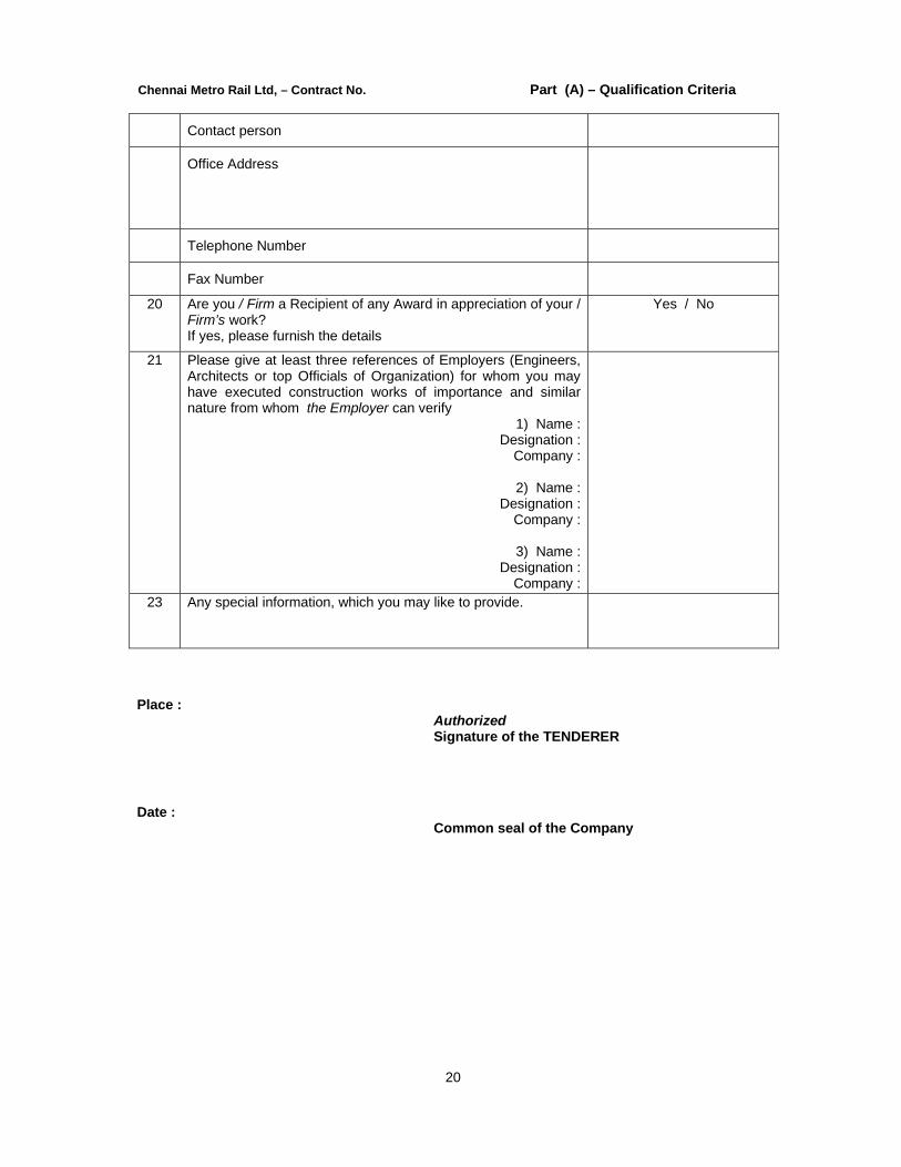
20 Are you / Firm a Recipient of any Award in appreciation of your / Firm’s work? If yes, please furnish the details
Yes / No
21 Please give at least three references of Employers (Engineers, Architects or top Officials of Organization) for whom you may have executed construction works of importance and similar nature from whom the Employer can verify
1) Name : Designation :
Company :
2) Name : Designation :
Company :
3) Name : Designation :
Company :
23 Any special information, which you may like to provide.
Place :
Authorized Signature of the TENDERER
Date :
Common seal of the Company

Chennai Metro Rail Ltd, – Contract No. Part (A) – Qualification Criteria
21
Format - B
KEY PERSONNEL TO BE DEPLOYED FOR THE PROJECT S.No. Details required To be filled by
TENDERER A Managerial Level - General
1 Individual’s Name
2 Age
3 Qualification
4 Present position
5 Professional experience in the similar nature of works.
6 Years with the TENDERER
7 Language known
8 Name two recent works and nature of involvement of the person
B Managerial Level - Technical
1 Individual’s Name
2 Age
3 Qualification
4 Present position
5 Professional experience in the similar nature of works.
6 Years with the TENDERER
7 Language known
8 Name two recent works and nature of involvement of the person
C Managerial Level - Administration & Finance
1 Individual’s Name
2 Age
3 Qualification
4 Present position

Chennai Metro Rail Ltd, – Contract No. Part (A) – Qualification Criteria
22
5 Professional experience in the similar nature of works.
6 Years with the TENDERER
7 Language known
8 Name two recent works and nature of involvement of the person
D Managerial Level - Quality Control and Quality Assurance
1 Individual’s Name
2 Age
3 Qualification
4 Present position
5 Professional experience in the similar nature of works.
6 Years with the TENDERER
7 Language known
8 Name two recent works and nature of involvement of the person
E Managerial Level - Safety Officer & Industrial Relation Officer
1 Individual’s Name
2 Age
3 Qualification
4 Present position
5 Professional experience in the similar nature of works.
6 Years with the TENDERER
7 Language known
8 Name two recent works and nature of involvement of the person
Chennai Metro Rail Ltd, – Contract No. Part (A) – Qualification Criteria
23
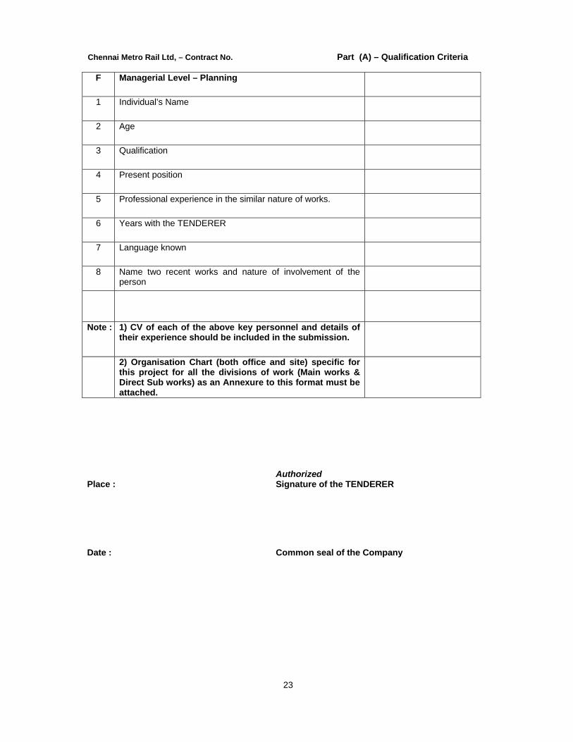
F Managerial Level – Planning
1 Individual’s Name
2 Age
3 Qualification
4 Present position
5 Professional experience in the similar nature of works.
6 Years with the TENDERER
7 Language known
8 Name two recent works and nature of involvement of the person
Note : 1) CV of each of the above key personnel and details of their experience should be included in the submission.
2) Organisation Chart (both office and site) specific for this project for all the divisions of work (Main works & Direct Sub works) as an Annexure to this format must be attached.
Place :
Authorized Signature of the TENDERER
Date :
Common seal of the Company

Chennai Metro Rail Ltd, – Contract No. Part (A) – Qualification Criteria
24
Format - C
FINANCIAL INFORMATION
Sl.No Description Details to be filled in by TENDERER
A Annual Turnover in the last five financial years (In INR )
1 Year : 01st April 2010- 31st March 2011
2
Year : 01st April 2011- 31st March 2012
3 Year : 01st April 2012 - 31st March 2013
4 Year : 01st April 2013 - 31st March 2014
5 Year : 01st April 2014 - 31st March 2015
B Financial Information (In INR)
1 Year : 01st April 2010 - 31st March 2011
a. Total assets
b. Current assets
c. Total Liabilities
d. Current Liabilities
e. Profits before taxes
f. Profits after taxes
g. Net worth
h. Working Capital
2 Year : 01st April 2011 - 31st March 2012
a. Total assets
b. Current assets
c. Total Liabilities
d. Current Liabilities
e. Profits before taxes
f. Profits after taxes
g. Net worth
h. Working Capital
3 Year : 01st April 2012 - 31st March 2013
a. Total assets b. Current assets c. Total Liabilities d. Current Liabilities

Chennai Metro Rail Ltd, – Contract No. Part (A) – Qualification Criteria
25
e. Profits before taxes f. Profits after taxes g. Net worth h. Working Capital
4 Year : 01st April 2013 - 31st March 2014 a. Total assets b. Current assets c. Total Liabilities d. Current Liabilities e. Profits before taxes f. Profits after taxes g. Net worth h. Working Capital
5 Year : 01st April 2014 - 31st March 2015 a. Total assets b. Current assets c. Total Liabilities d. Current Liabilities e. Profits before taxes f. Profits after taxes g. Net worth h. Working Capital D Credit facilities available to TENDERER – Fund
and non-fund based such as Cash Credit, Working capital term loans, LCs and Bank Guarantees - Banker's or Bankers' Letter must be produced - (In INR)
a. Name of Banker with address
b. Date of Letter of Support
c. Amount
E TENDERER's Financial resources for this project
a. Own resources b. Banker's or Bankers' credits
F a. Approximate total value of on-going works

Chennai Metro Rail Ltd, – Contract No. Part (A) – Qualification Criteria
26
b. Total Value of works to be completed as 30.04.2015 Note: 1) The TENDERER should furnish the value of work to be completed as of now along with break-up details of each work in the Proforma enclosed with this Format - C. 2) The TENDERER has to ensure that the list of works covered in this Proforma should be same as the ones listed in Format - E (List & details of Ongoing works) with Proforma of each work.
G Anticipated total value of new works for the next financial year i.e.
Place : Authorized Signature of the TENDERER Date: Common seal of the Company
Chennai Metro Rail Ltd, – Contract No. Part (A) – Qualification Criteria
27
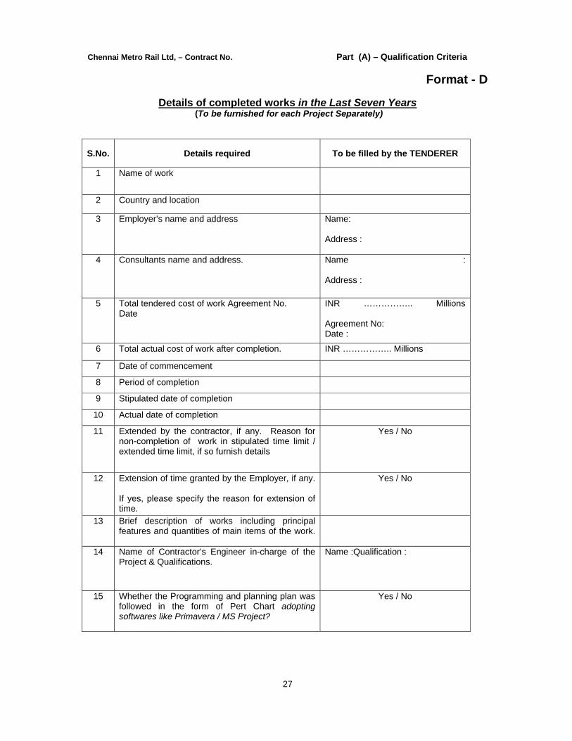
Format - D
Details of completed works in the Last Seven Years (To be furnished for each Project Separately)
S.No. Details required To be filled by the TENDERER
1 Name of work
2 Country and location
3 Employer’s name and address Name: Address :
4 Consultants name and address. Name : Address :
5 Total tendered cost of work Agreement No. Date
INR …………….. Millions Agreement No: Date :
6 Total actual cost of work after completion. INR …………….. Millions
7 Date of commencement
8 Period of completion
9 Stipulated date of completion
10 Actual date of completion
11 Extended by the contractor, if any. Reason for non-completion of work in stipulated time limit / extended time limit, if so furnish details
Yes / No
12 Extension of time granted by the Employer, if any. If yes, please specify the reason for extension of time.
Yes / No
13 Brief description of works including principal features and quantities of main items of the work.
14 Name of Contractor’s Engineer in-charge of the Project & Qualifications.
Name :Qualification :
15 Whether the Programming and planning plan was followed in the form of Pert Chart adopting softwares like Primavera / MS Project?
Yes / No

Chennai Metro Rail Ltd, – Contract No. Part (A) – Qualification Criteria
28
16 Whether the Quality Control and Quality Assurance function was carried out?If yes, Please give details and copies of quality formats used in anyone project
Yes / No
17 Whether the safety measures were followed?If yes, Please give details.
Yes / No
18 Attach Employer’s certificate, as may be available (Not below the rank of Director or equivalent)
Yes / No
Place :
Authorized Signature of the TENDERER
Date :
Common seal of the Company

Chennai Metro Rail Ltd, – Contract No. Part (A) – Qualification Criteria
29
Format - E
Details of On-Going works (To be furnished for each Project Separately)
S.No. Details required To Be filled by the TENDERER
1 Name of work
2 Country and location
3 Employer's name and address Name : Address :
4 Consultants name and address. Name : Address :
5 Total tendered cost of work (Agreement No. and Date) INR …………………. Millions
6 (a) Brief description of works including principal features and quantities of main items of the work.
7 i) Percentage of physical completion
ii) Amount billed for the work completed.
iii) Cost of work remaining to be executed as on the date of submission.
iv) Stipulated date of completion
v) Anticipated date of completion
8 Name of Contractor’s Engineer in-charge of the Project & Qualifications.
Name : Qualification :
9 Details of specialized works under this Contract

Chennai Metro Rail Ltd, – Contract No. Part (A) – Qualification Criteria
30
10 Specialised works being executed by their own divisions
11 Attach Employer's certificate, as may be available (Not below the rank of Director or equivalent)
Yes / No
Place :
Authorized Signature of the TENDERER
Date :
Common seal of the Company

Chennai Metro Rail Ltd, – Contract No. Part (A) – Qualification Criteria
31
Format - F
PLANT, MACHINERY & EQUIPMENT
S. No.
Name of Equip- ment*
Qty Total requirement
Equipment in Hand Equipment to be Procured
No. of units for the Work
Kind and
Make Capacity
No. of
each
Year of Manufacture &
Present Condition
Num ber
Capacity
Through Purchase /
Lease **
1
2
3
4
5
6
* Attach list of additional and essential equipment for the works for which qualification has been asked. This will include special requirements, if any, of executing Agency, as stipulated by them ** If leased / hired, indicate the date , when the current / lease expires,
Place :
Authorized Signature of the TENDERER
Date :
Common seal of the Company

Chennai Metro Rail Ltd, – Contract No. Part (A) – Qualification Criteria
32
Format - G
Details of Termination of contract by previous Employers in the past, if any
(To be furnished for each Project separately, if more than one)
S.No. Particulars To Be filled by the TENDERER
1 Name of works
2 Name of the Employer
3 Value of Contract in INR
4 Period of Contract
5 Terminated at what stage
6 Reasons / grounds for termination
7 Approx. value of work completed at the time of termination in INR
8 Approx. value of balance work not completed in INR
9 Remarks
Place :
Authorized Signature of the TENDERER
Date :
Common seal of the Company

Chennai Metro Rail Ltd, – Contract No. Part (A) – Qualification Criteria
33
I. Nature of Submissions :
1. The submissions from the TENDERER in response to the above question under Clause-IV shall be in the form of a statement signed by the authorized signatory on behalf of the TENDERER, who shall hold the Power of Attorney to sign such documents. The Power of Attorney documents shall also be attached.
2. The statement submitted and signed by the Power of Attorney holder shall also be countersigned by the Company Secretary of the Company with official seal.
Note : 1) The Employer or his authorized representatives reserves the right to verify any part of
the information furnished by the TENDERER in the above statements, without any prejudice to the terms and conditions of the Contract. The TENDERER is deemed to have given his consent, for the right of verification by the Employer, or his authorised representative, when the TENDERER submits the above statements.
2) If it comes to the notice of the Employer, that the TENDERER has suppressed any
information, or furnished misleading, or inaccurate information, or in case whether any litigation currently in progress at the time of submission of TENDERS, lead to the decree by the Court of Law, against the TENDERER, the Employer reserves the right, to nullify the Qualification, and to disqualify the TENDERER. If such information becomes available to the Employer, prior to issue of Letter of Intent, the TENDERER will be disqualified, and will not be considered for award of work. If such information comes to the knowledge of the Employer, after the award of work, the Employer reserves the right, to terminate the Contract unilaterally, at the total cost and risk of the TENDERER and such action would include but not limited to forfeiture of all deposits, guarantees etc. furnished in any form. The Employer will also reserve the right, to recover any Retention Money, Mobilization Advance, paid by invoking of Bank Guarantees submitted, including invoking of the Performance Bond.
The entire work executed upto the stage of such termination including materials procured and delivered at site, will be taken over by the Employer, and adjusted towards any payment due, as per Contract conditions. The Employer can thereafter arrange for a tendering process, for completion of the balance works, for which any additional financial burden to be met by the Employer, will also be recovered, from the Contractor, who has been terminated, without prejudice to the other rights, of the Employer, under the Contract
Place :
Authorized Signature of the TENDERER
Date : Common seal of the Company
Chennai Metro Rail Ltd, – Contract No. Part (A) – Qualification Criteria
34
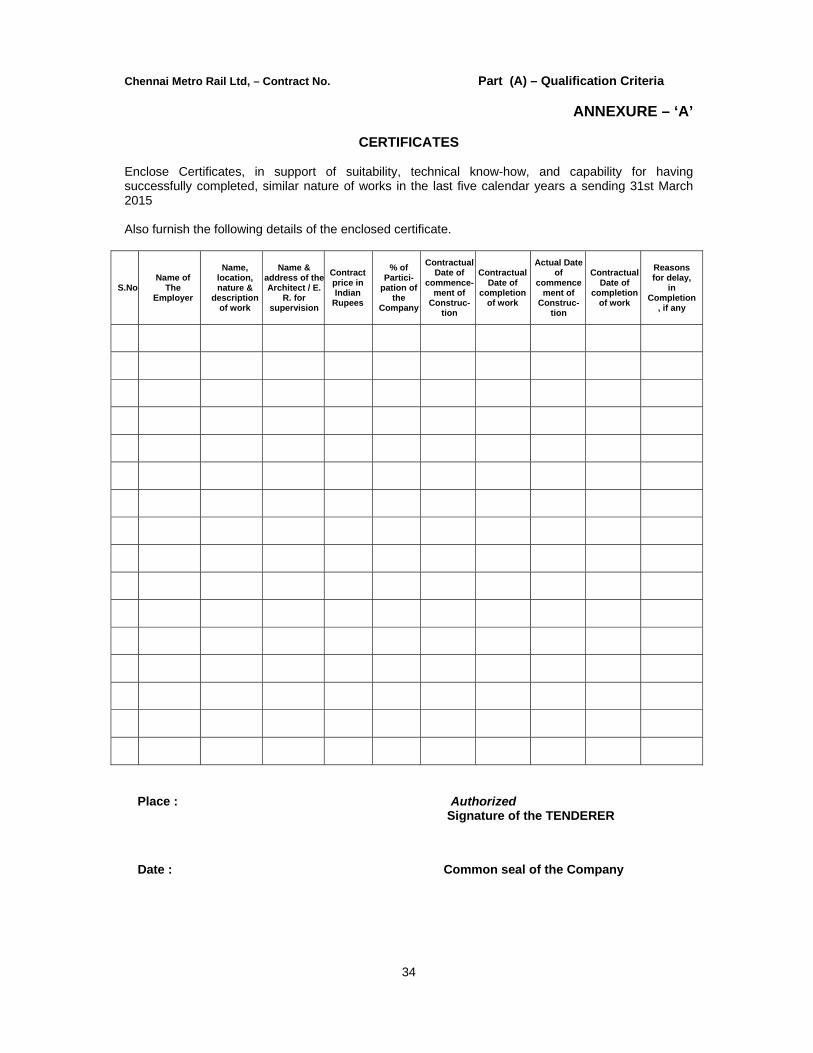
ANNEXURE – ‘A’
CERTIFICATES Enclose Certificates, in support of suitability, technical know-how, and capability for having successfully completed, similar nature of works in the last five calendar years a sending 31st March 2015 Also furnish the following details of the enclosed certificate.
S.No Name of
The Employer
Name, location, nature &
description of work
Name & address of theArchitect / E.
R. for supervision
Contract price in Indian
Rupees
% of Partici-
pation of the
Company
Contractual Date of
commence-ment of
Construc- tion
Contractual Date of
completion of work
Actual Date of
commencement of
Construc-tion
Contractual Date of
completion of work
Reasons for delay,
in Completion
, if any
Place :
Authorized Signature of the TENDERER
Date : Common seal of the Company
CHENNAI METRO RAIL LIMITED
(A JOINT VENTURE OF GOVERNMENT OF INDIA AND GOVERNMENT OF TAMIL NADU) TECHNO COMMERCIAL TENDER
TWO COVER SYSTEM
CONSTRUCTION OF METRO HEAD QUARTERS BUILDING AND OTHER METRO RAIL AMENITIES AT ANNA SALAI, NANDANAM,
CHENNAI 600 035
COVER - A - TECHNICAL BID
PART B – NOTICE INVITING TENDER AND
GENERAL CONDITIONS OF CONTRACT
DATE OF SUBMISSION OF TENDER - 13-04-2016 at 15.00 Hours
DATE OF OPENING OF TENDER - 13-04-2016 at 15.30 Hours
TO BE SUBMITTED TO:
The Chief General Manager(EC) Chennai Metro Rail Limited Admin. Building, CMRL Depot Poonnamallee High Road , Koyambedu, Chennai - 600107
TENDER SUBMITTED BY:
M/s._________________________ Address_____________________ ____________________________
Chennai Metro Rail Limited, Chennai NIT & Condition of Contract (Part 1B)
1
CHENNAI METRO RAIL LIMITED
(A JOINT VENTURE OF GOVERNMENT OF INDIA AND GOVERNMENT OF TAMILNADU)
TECHNO COMMERCIAL TENDER (TWO COVER SYSTEM)
CONSTRUCTION OF METRO HEAD QUARTERS BUILDING AND OTHER METRO
RAIL AMENITIES AT ANNA SALAI, NANDANAM, CHENNAI 600 035
TECHNICAL TENDER - PART 1 (B) NIT & CONDITIONS OF CONTRACT
CONTENTS Page No
1.0 CONTRACT DATA 8
2.0 TENDER FORM 9
3.0 INTRODUCTIONS 12
4.0 INSTRUCTIONS TO TENDERERS 12 5.0 DEFINITIONS AND INTERPRETATIONS 15 6.0 Headings and Marginal Notes and Interpretations 17
6.1. Headings and Marginal Notes 6.2. Interpretations
7.0 Singular and Plural and Gender
ENGINEER AND ENGINEER’S REPRESENTATIVE 17 8.0 ENGINEER AND ENGINEER’S REPRESENTATIVE
8.1. Duties and Authority of Engineer 8.2. Duties and Authority of Engineer’s Representative 8.3. Assistants to Engineer And Engineer’s Representative 8.4. Instructions in writing
CONTRACT SUM, ASSIGNMENT AND SUBCONTRACTING 19 9.0 ASSIGNMENT AND SUBCONTRACTING
9.1. Item rate Contract 9.2. Contract sum 9.3. Assignment contract 9.4. Sub contract 9.5. Assignment of Sub-contractor's obligation
Chennai Metro Rail Limited, Chennai NIT & Condition of Contract (Part 1B)
2
9.6. Selection of Subcontractor 9.7. Special Qualifying Criteria
CONTRACT DOCUMENTS 10.0 EXPLANATION ON SUBCONTRACTING 20
10.1. No change in responsibility of contractor 10.2. Sub-Contractor/Vendor Warranty 10.3. Joint and several liability
11.0 COMMUNICATIONS AND LANGUAGE OF CONTRACT 25 11.1. Communications to be in writing 11.2. Language of Contract
12.0 LAWS GOVERNING THE CONTRACT AND CO-RELATION OF DOCUMENTS 25 12.1. Laws governing the Contract 12.2. Co-relation of documents 12.3. Ambiguities or discrepancies
GENERAL OBLIGATIONS 26
13.0 SPECIFICATION AND DRAWINGS 13.1. Ownership 13.2. Adherence to Specifications and Drawings 13.3. Meaning and Intent of specification drawings 13.4. Compliance with contractor's request for details
14.0 COMPLIANCE WITH REGULATIONS AND BYLAWS 27 15.0 OCCUPATION AND USE OF LAND 27 16.0 REPRESENTATION OF WORK 27 17.0 RELICS AND TREASURES 27 18.0 EXCAVATED MATERIALS 28 19.0 INDEMNITY BY CONTRACTOR 28
19.1. Indemnity against all actions of contractor 19.2. Indemnity against all claims of patent rights and royalties 19.3. Contactors warranty
20.0 PERFORMANCE GUARANTEE 29 20.1. Amount of performance guarantee 20.2. Release of performance guarantee
21.0 INSPECTION OF SITE 30 22.0 CONTRACTOR'S UNDERSTANDING 30 23.0 GENERAL RESPONSIBILITY OF THE CONTRACTOR 30

Chennai Metro Rail Limited, Chennai NIT & Condition of Contract (Part 1B)
3
24.0 PROVISION OF EFFICIENT AND COMPETENT STAFF 31 25.0 OPPORTUNITY FOR OTHER CONTRACTORS 31 26.0 WORKS DURING NIGHT 31 27.0 DAMAGE TO EMPLOYER'S PROPERTY,PRIVATE PROPERTY AND LIFE 32 28.0 INSURANCE 32
28.1. Requirements 28.2. Policy in joint names of contractor and employer
29.0 SITE OFFICE 33 30.0 SHEDS, STORES, YARDS 34 31.0 EMPLOYERS MATERIAL 34 32.0 TOOLS PLANTS AND EQUIPMENTS SUPPLIED BY THE EMPLOYER 35 33.0 ROADS AND WATER COURSES, ACCESS TO PREMISES AND SAFETY 35 34.0 USE OF EXPLOSIVES 36 35.0 INDEMNITY BY EMPLOYER 36 36.0 CARE OF WORK 36 37.0 EXTRAORDINARY TRAFFIC 37
37.1. Avoidance of damage to roads 37.2. Special loads 37.3. Settlement of extraordinary traffic claims
38.0 CONTRACTOR TO KEEP SITE CLEAR 38 39.0 EMPLOYER NOT TO PROVIDE QUARTERS FOR CONTRACTOR 40.0 LABOUR CAMP 38 41.0 SAFETY PROVISIONS 39
41.1. Safety of Labour 41.2. Safety of Works and Public 41.3. Recovery of cost from the Contractor
42.0 RATES FOR ITEMS OF WORK TO BE ALL INCLUSIVE 40 43.0 SUPPLY OF WATER AND ELECTRICAL POWER 40 44.0 URGENT REPAIRS 41 45.0 SETTING OUT 41 46.0 BOREHOLES AND EXPLORATORY EXCAVATION 41 47.0 ILLEGAL GRATIFICATION 42
47.1. Bribe, commission, gift or advantage 47.2. Settlement of dispute as to commission of such offence 47.3. Compensation to Contractor on rescission of Contract under this clause
48.0 DISCLOSURE OF RELATIONSHIP 42 49.0 CLEARANCE OF SITE ON COMPLETION 42

Chennai Metro Rail Limited, Chennai NIT & Condition of Contract (Part 1B)
4
50.0 ENGAGEMENT OF LABOUR 43 50.1. Contractor to Provide Labour: 50.2. Employment of labour below the age of 18
51.0 WAGES TO LABOUR 43 52.0 REPORT OF ACCIDENTS TO LABOUR 44 53.0 MATERIALS AND WORKMANSHIP 44 54.0 REMOVAL OF IMPROPER MATERIALS AND WORKS 45 55.0 COVERING UP OF WORK 45
55.1. Examination of work before covering up 55.2. Cost of uncovering the work already covered up
56.0 SUSPENSION OF WORK 46 56.1. Protection during suspension of work 56.2. Cost Incidental to suspension of work 56.3. Extension of time on account of suspension 56.4. Compensation for idle labour / plant due to extension of time 56.5. Contractor’s option to ask for closure of Contract
57.0 COMMENCEMENT OF WORK 47 58.0 PROGRAMME OF WORK 47 59.0 POSSESSION OF SITE 48 60.0 WAYLEAVES 48 61.0 ACCESS TO SITE OF WORK 48
61.1. Access for Engineer 61.2. Access Road
62.0 DELAY AND EXTENSION OF CONTRACT PERIOD 48 62.1. Time to be essence and extension of time 62.2. Extension due to modifications 62.3. Delays not due to Employer/Contractor 62.4. Delays due to Employer/Engineer 62.5. Delays due to Contractor 62.6. Time to continue to be the essence of Contract 62.7. Engineer’s decision on compensation payable being final
TERMINATION OF CONTRACT 63.0 FORECLOSURE OR TERMINATION OF CONTRACT 50
63.1. Payment to Contractor on fore-closure or termination of Contract: 63.2. Default of Employer
64.0 RESCISSION OF CONTRACT DUE TO DEATH OF CONTRACTOR/PARTNER 52

Chennai Metro Rail Limited, Chennai NIT & Condition of Contract (Part 1B)
5
65.0 DETERMINATION OF CONTRACT DUE TO CONTRACTOR’S DEFAULT 52 65.1. Conditions leading to determination of Contract 65.2. Entitlement of Employer 65.3. Non-exercise of power not to constitute waiver
ALTERATIONS, ADDITIONS AND OMISSIONS 66.0 MODIFICATIONS TO WORK 54
66.1. Authority to order modifications 66.2. Modification not to affect the Contract 66.3. Decision of Engineer to be final
67.0 EXTRA ITEMS NOT IN THE BILL OF QUANTITIES 55 67.1. Operation of extra items of work 67.2. Derivation of rates for extra items of work 67.3. Notice by Contractor 67.4. Provisional payment for extra item 67.5. Payment of extra items of work on the basis of actual expenditure 67.6. Decision of Engineer to be final and binding
68.0 MODIFICATIONS TO CONTRACT TO BE IN WRITING 56 CHANGES IN COST 69.0 PRICE ADJUSTMENT 56
69.1. Accepted rate applicable till the completion of work 69.2. Price variation formula
70.0 PRICE VARIATION DURING EXTENDED PERIOD OF CONTRACT 58 PROCEDURE FOR CLAIMS 71.0 CLAIMS 59 72.0 LIEN IN RESPECT OF CLAIMS IN OTHER CONTRACT 59 73.0 PLANT AND MATERIALS SUPPLIED BY THE CONTRACTOR 59
73.1. Contractor’s plants / material at site to be exclusive to the work 73.2. Removal of construction plants/materials from site 73.3. Loss and damage to construction plants/materials 73.4. Assistance to Contract for re-export of plants 73.5. Assistance to Contractor for customs clearance 73.6. Rejection of any material/workmanship found defective at site
74.0 TEMPORARY WORKS 60
Chennai Metro Rail Limited, Chennai NIT & Condition of Contract (Part 1B)
6
75.0 MEASUREMENTS AND PAYMENTS 60 75.1. Quantity in Bill of Quantity only estimated quantity 75.2. Payment on actual measurements 75.3. Measurement of work at regular intervals 75.4. Measurement of works as per records and drawings
76.0 INTERIM PAYMENTS 61 76.1. Payment for works 76.2. Final Bill 76.3. Final Bill Payment 76.4. Deduction in Final Bill
77.0 DELAYED PAYMENT 62 78.0 PAYMENT OF RETENTION MONEY: 62
78.1. Payment on account and retention: 78.2. Retention amount
79.0 SECURED ADVANCE ON MATERIAL AT SITE 62 80.0 FINAL MEASUREMENTS AND PAYMENTS 62 81.0 ROUND OFF 63 82.0 PAYMENT, TAX DEDUCTION AT SOURCE AND SALES TAX 63
ON WORKS CONTRACTS 82.1. Payment by NEFT / RTG 82.2. Tax Deduction at Source 82.3. Sales Tax on Works Contracts
83.0 COMPLETION CERTIFICATE 63 83.1. Time of completion 83.2. Notice by Contractor regarding completion of work 83.3. Completion Certificate not to absolve
84.0 POST PAYMENT AUDIT 63 85.0 MAINTENANCE CERTIFICATE 63
85.1. Maintenance Certificate 85.2. Definition of “Period of maintenance” 85.3. Maintenance Certificate 85.4. Final approval by Maintenance Certificate 85.5. Cessation of Employer’s liability 85.6. Unfulfilled obligations
86.0 PRODUCTION OF VOUCHERS 65 87.0 WITHHOLDING AND LIEN FOR SUMS CLAIMED 65 88.0 SIGNATURE ON RECEIPTS FOR PAYMENTS 66

Chennai Metro Rail Limited, Chennai NIT & Condition of Contract (Part 1B)
7
89.0 FORCE MAJEURE 66
SETTLEMENT OF DISPUTES 90.0 SETTLEMENT OF DISPUTES AND ARBITRATION 67
90.1. Dispute to be referred to and settled by Engineer at the first place 90.2. Referring of dispute for arbitration 90.3. Dispute due for arbitration 90.4. Settlement of disputes 90.5. Nomination of Arbitrators/Sole Arbitrator 90.6. Award to be binding on all parties 90.7. Rules governing the arbitration proceedings 90.8. Limitation of time
91.0 NOTICES 69 91.1. Notices to Contractor 91.2. Notices to Employer and Engineer 91.3. Change of address 91.4. Change in constitution of firm
92.0 APPENDIX APPENDIX-1 Proforma of Bank Guarantee for Earnest Money Deposit 70 APPENDIX-2 Articles of Agreement 71 APPENDIX-3 Form of Performance Guarantee 74 APPENDIX-4 Affidavit 76 APPENDIX-5 Proforma of BG for Mobilisation Advance Payment 77 APPENDIX 6 Special Conditions – Green Building Concept 79
APPENDIX 7 Special Conditions on Safety 87
APPENDIX 8 Form of Tender / Clauses at a Glance 91 APPENDIX 9 Soil Investigation Report 93

Chennai Metro Rail Limited, Chennai NIT & Condition of Contract (Part 1B)
8
NOTICE INVITING TENDER
1.0 CONTRACT DATA
Period of Sale of Tender Document
01.03.2016 to 11.04.2016 (During office hours – from 10.00 hours to 15.00 hours)
Date of submission of tenders
15.00 Hours on 13.04. 2016
Validity of tender 150 days from last date of submission of tender
Time and Date of Pre-bid meeting
15.00 Hours on 22.03.2016 at the office of Chief General Manager (EC), CMRL, Koyambedu, Chennai 600 107.
Issue of Pre tender Clarifications
On or before 15:00 Hours, 31.03.2016
Earnest Money Deposit Rs 1,40,00,000/- (Rupees One Crore Fourty Lakhs Only) by Demand Draft, drawn from any Nationalized or Scheduled Bank in India payable at Chennai, in favour of Chennai Metro Rail Ltd, Chennai-107, Tamil Nadu, India (OR) by Bank Guarantee on any Nationalized or Scheduled Bankers in India, valid up to 12-09-2016.
Tender Documents to be submitted to
Chief General Manager (EC)Chennai Metro Rail Limited Admin. Building, CMRL Depot Poonnamallee High Road , Koyambedu, Chennai - 600107
Place of Opening of Tender
Office of Chief General Manager (EC) Chennai Metro Rail Limited Admin. Building, CMRL Depot Poonnamallee High Road , Koyambedu, Chennai - 600107
Period of completion of work 24 (Twenty Four) Months
TENDER SUBMITTED BY

Chennai Metro Rail Limited, Chennai NIT & Condition of Contract (Part 1B)
9
2.0 TENDER FORM To Chief General Manager (EC) Chennai Metro Rail Limited Admin. Building, CMRL Depot Poonamallee High Road , Koyambedu, Chennai - 600107 Dear Sir,
1. Having examined the drawings, specification, designs and Bill of Quantities, relating to the works specified in the memorandum hereinafter set out, and having visited and examined the site of the works specified in the said tender, and having acquired the requisite information relating thereto as affecting the Tender, I / we, hereby offer to execute the works specified in the said tender within the time specified in the said memorandum at the rates mentioned in the attached Bill of Quantities and in accordance in all respects with the specification, designs, drawings, and instructions in writing referred to in the Conditions of Tender, the Articles of Agreement, Special Conditions, Bill of Quantities, and Conditions of Contract, and with such materials as are provided for by and in all other respects in accordance with such conditions so far as they may be applicable.
MEMORANDUM
a. Description of works
Construction of Metro Head Quarters building and other Metro Rail Amenities at Anna Salai, Nandanam, Chennai 600 035.
b. Earnest Money Deposit Rs 1,40,00,000./- (Rupees One Crore and Fourty lakhs Only) by Demand Draft, drawn from any Nationalized or Scheduled Bank in India payable at Chennai, in favour of the Chennai Metro Rail Ltd, Chennai-600 107, Tamil Nadu, India (OR) by Bank Guarantee on any Nationalized or Scheduled Bankers in India, valid up to 13-09-2016
c. Percentage to be deducted from bills towards retention money
10% of the value of the work done will be deducted by the Employer from each payment to be made to the Contractor until the retention money amounts to a maximum of 5% of the contract sum of the work. Upon the Engineer’s certificate of completion of the works, 50% of the retention money would be refunded and the balance after due completion of all obligations under the contract agreement and defects liability period. The amounts retained by the Employer shall not bear interest.
d. Date of Commencement
10 days from the date of issue of Letter of Award

Chennai Metro Rail Limited, Chennai NIT & Condition of Contract (Part 1B)
10
e. Time allowed from the date commencement for completion of the work
24 (Twenty Four) Months
2. Should this Tender be accepted, I / we hereby agree to abide by and fulfill the terms and
provisions of the said Conditions of Contract annexed hereto or in default thereof to forfeit and pay to Chennai Metro Rail Limited, Chennai-600 107 the amount mentioned in the said Contract.
3. We agree to execute the proposed project works with complete cooperation and coordination with
the independent other contractors, if any, to achieve sequential, unhindered and harmonious progress with the objective of completion of the Entire Project within the stipulated time for the entire project works for the Employer’s beneficial use of the Project.
4. I / We have enclosed herewith the Earnest Money Deposit for INR 1,40,00,000/-(Rupees One
Crore and Fourty Lakhs only) in the form of Demand draft which amount is not to bear any interest. Should I / we, fail to execute the contract when called upon to do so I / we do hereby agree that this sum shall be forfeited by me / us, to the Chennai Metro Rail Limited, Chennai - 600 107.
5. If this Tender is accepted we agree to provide a Bank Guarantee from a Nationalized / Scheduled
Bank in India as Performance Bond for a sum equivalent to Five percent of the Contract value for the due performance of the Contract under the terms of the conditions of Contract within time.
6. We agree to abide by this Tender for the period of 150 days (one hundred and fifty days) from
the last date of submission of tender and it shall remain binding upon us and may be accepted at any time before the expiration of that period, without any additional cost.
7. Unless and until, a formal agreement is prepared and executed this Tender together with your
written acceptance thereof shall constitute a binding contract between us.
8. The lists showing the particulars of large works carried out and the names of manufacturers of specialized items as required, are enclosed.
9. Our bankers are : (Please state name, address, and phone No.)
i)………………………………………….. ii)………………………………………….
The names of Partners of our Firm / Directors, of our company are : (Please state name, address, and Phone No.) i) ………………………………………… ii) …………………………………………

Chennai Metro Rail Limited, Chennai NIT & Condition of Contract (Part 1B)
11
The name of the Partner, of the Firm / Director of our company, authorised to sign :
Yours faithfully,
Authorized Signature of Tenderer (Should be signed by the authorised signatory. Board Resolution in the case of Company or a letter signed by all partners in the case of Firm to be enclosed.)
WITNESSES : i) Signature: Occupation: Address: ii) Signature: Occupation: Address:

Chennai Metro Rail Limited, Chennai NIT & Condition of Contract (Part 1B)
12
3.0 INTRODUCTION
3.1. Brief Description of Project: The Project consists of Construction of Multi-Storied framed structure of single Basement, Ground + Four upper floors, Residential buildings of Type – A, and B, Stilt + Five floors and Stilt + Nine upper floors respectively. A utility block of Ground and first floor and an Underground Sump and STP have also been proposed. The building will house a comprehensive fire protection system in line with the requirement of TNFRS. Plumbing and electrical works for the units are also included in the scope of works.
3.2. Time is the essence of project and the entire scope of work is to be completed within 24 (Twenty four) months, with responsibility to co-operate and coordinate with Employer / Employer’s Representative if any to execute certain special nature of works and undertake responsibility to complete all the works concurrently within the time frame of the Project Completion Period and ensure sequential, unhindered and harmonious progress of work.
3.3. Project Outline and Summary: The scope of this tender includes for
3.3.i. Civil works including excavation, framed structure, masonry works, plastering and all related finishing works like Tiling, Painting etc, and Structural Glazing works
3.3.ii. Supply and installation of UPVC windows and Joinery, Fire and Flush doors along with hardware, etc
3.3.iii. Electrical Works including electrical fittings in common area and DG works.
3.3.iv. Fire Protection and detection systems including pumps, smoke detectors, hose reel, sprinklers, etc
3.3.v. Plumbing and sanitation works including supply and installation of all sanitary ware and CP fittings.
3.3.vi. Air conditioning and Mechanical Ventilation system.
3.3.vii. Integrated Building Management systems,
3.3.viii. IT & Networking
4.0 INSTRUCTIONS TO TENDERERS
4.1. Before submission, the Tenderer shall visit the site and familiarize himself with the site
conditions including access to site, condition of existing structures, space for stacking of material and auxiliary construction activity, availability of required construction materials locally etc. and also carefully examine the conditions of contract, technical specifications (including drawing and other specifications referred to therein), the schedules and the bill of quantities and if there should be or appear to be any ambiguity in or discrepancy between any of these documents or between figured and measured dimensions upon the

Chennai Metro Rail Limited, Chennai NIT & Condition of Contract (Part 1B)
13
drawings, he should immediately refer the matter for clarifications. 4.2. The Tenderer shall investigate the following items during the site inspection referred
above and to provide in his Tender rates for assuming full responsibility for services and amenities therefor, which will not be payable separately by the Employer.
● Availability of power for construction ● Availability of water for construction. ● Means of disposal of storm water from the site. ● Means of disposal of water due to de-watering at the site ● Suitability of soil stratum at foundation base. ● A copy of Soil Investigation Report on the investigation done on the site by
the Employer is furnished under Appendix 6 for information.
4.3. The Employer discourages stipulation of additional conditions by the Tenders, as they are expected to accept the various provisions and conditions in the Tender documents. No conditional offer will be accepted.
4.4. Timely completion of the works is the essence of this contract and the period specified for the completion of the works from the date of Letter of Acceptance must be adhered to as indicated. Any deviation proposed shall be clearly mentioned. Commitment on early completion of work will be given due weightage while deciding on the tender.
4.5. The Tenderer shall complete the required documentation and fill in the rates and amounts in the bill of quantities. He shall sign and date the Tender documents in the spaces provided for the purpose. The Tenderer shall initial each page of the Tender Documents.
4.6. The tender shall be signed by person or persons duly authorised by the Tenderer with signature duly witnessed. In the case of proprietary firm the Tender shall be signed by the proprietor. In case of a partnership firm the Tender shall be signed by partner duly authorised under partnership deed. In the case of a limited company the Tender shall be signed by a person holding Power of Attorney. In the case of consortium authorised signatory of each member of consortium.
4.7. The Tender shall contain an address for serving notices required to be served to the Tenderer in connection with the Tender.
4.8. The Tender form and the documents attached to it shall not be detached one from the other, and no alteration or mutilation (other than filling in all the blank spaces) shall be made in any of the documents attached hereto. Any modification proposed to the entries in the attached documents shall be pointed out in the covering letter; otherwise it shall not be entertained.
4.9. The rates quoted by the Tenderer shall not be subject to any adjustment with variations in wage rates, taxes, levies, prices of material or any other costs except where specific provisions have been made in this document.
4.10. The Tender shall be accompanied by the following information, schedules and drawings: 4.10.i. Construction programme showing the Tenderer’s proposed sequence of
operations together with the estimated time for each activity, including preparation of Shop drawings and designs for approval of the Employer / the Engineer / Employer’s personnel manufacture, delivery, erection, commissioning and total completion of the work, etc. The tenderer shall submit a bar chart for fabrication and construction activities for the building.
4.10.ii. The tenderer’s proposals for supervising the work, including the numbers and experience of the various grades of supervisory personnel/officers for each month of the construction period and name of the person proposed to act as site

Chennai Metro Rail Limited, Chennai NIT & Condition of Contract (Part 1B)
14
in charge with brief details of his qualification and experience. 4.10.iii. Schedule of labour requirements showing the total estimated labour force, for
each month of construction period. 4.10.iv. Schedule of proposed subcontractors / associates. 4.10.v. Schedule of monthly electric power consumption including peak power
requirement where applicable. 4.10.vi. List of machinery & equipment to be deployed for the project. 4.10.vii. The Tenderer should carefully go through the safety & quality norms required for
the project. The Tenderer has to strictly adhere to the quality & safety requirements stated there in the Conditions of contract.
4.10.viii. The Employer reserves the right to adjust arithmetical or other errors in the tender in accordance with the following general rules. In the event of discrepancy between words and figures quoted, the description in words shall prevail. Similarly in the event of an error in the amount column arising as a result of wrong extension, the unit or item rates shall be regarded as firm and extensions amended accordingly.
4.10.ix. Collection of Information for Tender: The Tenderer must obtain for himself on his own responsibility and at his own expense all the information which may be necessary for the purpose of making a Tender and for entering into a contract and must examine the Drawings and must inspect the site of the work and acquaint himself with all local and site conditions, means of access to the work, nature of the work, nature of soil conditions, availability of any infrastructure and all matters appertaining thereto. Ignorance of the site conditions shall not be accepted by the Employer as a basis for any claim for compensation.
4.10.x. The EMD will be forfeited if the tenderer withdraws / modifies their offer / refuse to accept the LOA
Chennai Metro Rail Limited, Chennai NIT & Condition of Contract (Part 1B)
15
GENERAL CONDITIONS OF THE CONTRACT 5.0 DEFINITIONS AND INTERPRETATIONS
In the Contract, as hereinafter defined the following words and expressions shall have the meanings hereby assigned to them, except where the context requires otherwise.
5.1. “Employer” means the Board of the Chennai Metro Rail Limited (CMRL), Chennai, a body corporate established by Companies Act 1956, acting through its Managing Director or any other officer so nominated by the Managing Director and shall include their legal successors and permitted assignees.
5.2. “Engineer / Employer’s Representative” means such persons, or firm, as may be appointed from time to time by the Employer, and notified in writing to the Contractor to act as Engineer for the purposes of the Contract, or any nominated officer of CMRL.
5.3. Engineer’ Representative” means any Assistant of the Engineer, or any clerk of works, appointed from time to time by the Engineer under Sub-clause 5.2.
5.4. “Contractor” means the individual, firm, company, corporation, Joint Venture, or consortium whether incorporated or not, who enters into the Contract with the Employer and shall include his heirs, his executors, administrators, successors, legal representatives, as the case may be “Contractor’s Agent” shall mean the person or persons authorised under power of attorney duly empowered to take all actions relating to the work, as could be taken by the Contractor himself.
5.5. “Contractor’s Representative” shall mean a person in supervisory capacity who shall be so declared by the Contractor and who shall be authorised under a duly executed power of attorney to comply the instructions and to receive materials issued by the Engineer to the Contractor for works. He shall be capable of taking responsibility for proper execution of works.
5.6. “Sub-Contractor” means the individual, Firm Company, Corporation, Joint Venture or Consortium, having direct contract with the Contractor and to whom any part of the Work has been sublet by the Contractor, with prior permission of the Engineer or Employer and shall include his heirs, his executors, administrators, successors, legal representatives, as the case may be.
5.7. “Other Contractor” or “Others” means the individual, firm, Company, Corporation, Joint Venture or Consortium, employed by or having a contract directly or indirectly with the Employer otherwise than through the Contractor.
5.8. Tenderer or Bidder” means the individual, firm, Company, Corporation, Joint Venture or Consortium submitting a bid / tender.
5.9. “Scheduled Bank” means a bank included in the second schedule to the Reserve Bank of India Act, 1934, or modifications thereto.

Chennai Metro Rail Limited, Chennai NIT & Condition of Contract (Part 1B)
16
5.10. “Contract” means the Contract Agreement with all documents mentioned in “Instruction to Tenderers”.
5.11. “Tender or Bid” means the offer made by individual, Firm, Company, Corporation, for the execution of the works.
5.12. “Specification” means the specification referred to in the Contract and any modification thereof or addition thereto, as may from time to time be furnished or approved in writing by the Engineer.
5.13. “Drawings” means maps, drawings, plans, tracings or prints thereof, calculations and technical information of a like nature provided by the Engineer to the Contractor or annexed to the Contract, and any modifications of such drawings and further drawings that may be issued by the Engineer from time to time or approved by the Engineer in writing. It includes such other drawings as are made from time to time and furnished by the Contractor and approved by the Engineer.
5.14. “Bill of Quantities “means the priced and completed Bill of Quantities forming part of the Tender.
5.15. “Contract Price” or “Contract Value” means the sum stated in the Letter of Acceptance, subject to such additions thereto or deductions there from as may be made under the provisions of the Contract.
5.16. “Works” means the work to be executed in accordance with the Contract and shall include both Permanent Works and Temporary Works.
5.17. “Permanent Works” means the permanent works to be executed, completed and maintained in accordance with the Contract.
5.18. “Temporary Works” means all temporary and enabling works of every kind required for the execution and completion of the permanent works and the remedying of any defects therein.
5.19. “Construction Plant” means all machinery, appliances or things of whatsoever nature, required for the execution, completion or maintenance of the works, but does not include material or other things, intended to form or forming part of the permanent works.
5.20. “Site” means the land and / or other places on, under, in or through which the Works are to be carried out, and any other lands or places provided by the Employer for the purpose of the Contract.
5.21. “Materials” means all equipment, components, fittings and other materials including raw materials required to execute and complete the work.
5.22. “Test” means such tests as are prescribed in the specifications or by the Engineer or Engineer’s Representative, whether performed by the Contractor or by the Engineer or his Representative or any agency acting under the direction of the Engineer.
5.23. “Approval or Approved” means approval in writing including subsequent written confirmation of previous verbal approval.

Chennai Metro Rail Limited, Chennai NIT & Condition of Contract (Part 1B)
17
5.24. “Period of Maintenance” means the specified period of maintenance from the date of completion of the work as certified by the Engineer and specified in the Contract. This period is also termed as “Defects Liability Period”.
5.25. “Letter of Acceptance” means the letter from the Employer or the Engineer, or a person nominated by them on their behalf for this purpose, to the Contractor, conveying acceptance of the Tender, subject to any modifications agreed to between the parties and includes advance acceptance of the tender.
5.26. “Month” means calendar month.
5.27. “Day” means calendar day.
5.28. “Terms and expressions not herein defined” shall have the meanings assigned to them in the “Indian General Clauses Act,1897” or the Indian Contract Act or the Indian Sale of Goods Act or any other applicable Indian Law, as the case may be.
6.0 HEADINGS AND
6.1. Headings and Marginal Notes: The top headings and marginal notes given in the Tender or Contract documents are solely for the purpose of facilitating reference and shall not be deemed to be part thereof and shall not be taken into consideration in the interpretation or construction thereof or of the Contract.
6.2. Interpretation: Words importing persons or parties shall include firms, corporations and any organization having legal entity.
7.0 SINGULAR, PLURAL AND GENDER
7.1. Words importing the singular only also include the plural and vice versa where the context requires. Similarly words importing masculine gender also include the feminine gender.
8.0 ENGINEER AND ENGINEER’S REPRESENTATIVE
8.1. Duties and Authority of Engineer: The Engineer shall carry out the duties specified or implied in the Contract including issue of instructions, decisions, certificates and orders, as are specified in the Contract, or necessary for the observance / administration of the Contract and expeditious and timely completion of the Work. Should the Engineer exercise any specific authority for which, as per the terms of his appointment, he has to obtain the approval of the Employer, the Contractor shall deem such approval to have been given by the Employer.
8.2. Duties and Authority of Engineer’s Representative: The Engineer’s Representative shall be responsible to the Engineer. His duties are to watch and supervise the Works and to test and examine any materials to be used or workmanship employed in connection with the Works. He shall have no authority to relieve the Contractor of any of his duties or obligations under the Contract, nor, except as expressly provided hereunder or elsewhere in the Contract, to order any Work involving extra time or any extra payment by the Employer, nor to make any variation of or in the Works.

Chennai Metro Rail Limited, Chennai NIT & Condition of Contract (Part 1B)
18
8.3. The Engineer may, from time to time, in writing delegate to the Engineer’s Representative, any of the powers and authorities vested in the Engineer, and shall furnish to the Contractor and to the Employer, a copy of all such written delegations of powers and authorities. Only written instruction, decision or approval given by the Engineer’s Representative to the Contractor within the terms of such delegation, but not otherwise, shall bind the Contractor and the Employer, as though it had been given by the Engineer. Provided always as follows:
8.4. Failure of the Engineer’s Representative or his assistants, to reject any work or materials shall not prejudice the authority of the Engineer or Employer thereafter, to reject such work or materials or plant and order the pulling down, removal or breaking up thereof. The Engineer’s Representative shall have similar authority to reject any work or material or plant passed by his Assistants, appointed in terms of provision of herein.
8.5. If the Contractor shall be dissatisfied by reason of any instruction or decision of the Engineer’s Representative, he shall be entitled to refer the matter to the Engineer, who shall thereupon confirm, reverse or vary such decision. The Engineer’s Representative shall have similar authority to confirm, vary, or, reverse any instructions and decisions issued by his Assistants, appointed in terms of herein.
8.6. Assistants to Engineer and Engineer’s Representative: The Engineer or the Engineer’s Representative may appoint any number of assistants to assist them. Their names, duties and scope of authority shall be notified to the Contractor, and they shall have the authority to issue instructions / give decisions to the extent of duties assigned and powers delegated to them.
8.7. Instructions in writing: Instructions given by the Engineer shall be in writing, provided that if for any reason the Engineer considers it necessary to give any such instruction orally, the Contractor shall comply with such instructions. Confirmation in writing of such oral instruction given by the Engineer, whether before or during or after carrying out of the instruction, shall be deemed to be an instruction within the meaning of this Sub-clause.
9.0 CONTRACT SUM, ASSIGNMENT AND SUBCONTRACTING
9.1. Item Rate Contract
9.1.i. The Contract shall be an item rate contract. The Contractor shall be paid for the actual quantity of work permanently installed and in accordance with the contract documents, at the rates quoted by him in the Contract Bills. Measurement shall be carried out as indicated in the tender specification and as per schedule of quantities and prices.
9.1.ii. The schedule of Quantities given in Contract Bill is provisional and is meant to indicate the scope of the work and to provide a uniform basis for Tendering. The Owner reserves the right to increase or decrease any of the quantities or to totally omit any item of work and the Contractor shall not claim any extras or damages on these grounds.
9.1.iii. Quantity variation will have no ceiling limit in respect of individual items and individual quantities can vary to any extent except skewed items. Such variations shall not warrant any claims for modifications to already quoted and

Chennai Metro Rail Limited, Chennai NIT & Condition of Contract (Part 1B)
19
accepted rates. However variation to the value of total contract sum can vary to the extent up to Plus (+) or minus (-) 30% without warranting change of rates. In case the total value of contract varies in excess of the above limit, rates of only the variation items and extra items will be re-considered based on actual impact.
9.1.iv. Tax - The rates shall also be firm and shall not be subject to variations in costs of any or all inputs, such as but not limited to, materials, labour, exchange variations, labour conditions, fluctuations in railway freights, or any conditions whatsoever. Tenderers must include in their rates / various tax / Duty / Freight charges, excise duty, entry, octroi or other tax, duty or, and any other tax and duty or other levy levied by the Central Government or any State Government or local authority except Service tax and cess, as applicable including any variation during the Contract period and any agreed extension thereto. No claim in respect of any variation or introduction taxes or duties or levies as existing or future, shall be entertained by the Employer.
9.1.v. This project is exempted from Service Tax and Cess as per CMRL Mega notification No: 25 of 2012 hence Tenderer to quote the price without services Taxes and Cess.
9.1.vi. Moreover the tenderer to mention the % of VAT / Amount considered while computing over cost of the all items in the Summary of Bill of quantities.
9.2. The Contract Sum
9.2.i. The Contract Sum shall be agreed or determined and be subject to adjustments in accordance with the Contract;
9.2.ii. The Contractor shall pay all taxes, duties and fees required to be paid by him under the Contract, and the Contract Sum shall not be adjusted for any of these costs
9.2.iii. Any quantities which may be set out in the Bill of Quantities or other Schedule are estimated quantities and are not to be taken as the actual and correct quantities of the Works which the Contractor is required to execute.
9.2.iv. Mobilisation Advance: 10% of tendered amount at 13% simple interest shall be paid as Mobilisation advance (recoverable) payment in five equal instalments against Bank Guarantee from a Nationalised / Scheduled Bank in India valid till the completion of work. Payment will be made after the receipt of Performance Bank Guarantee from the Contractor.
9.2.v. The first instalment of Mobilisation Advance shall be paid within 21 days from the date of issue of letter of Award of work subject to furnishing required Bank guarantee valid till the completion of work and also Performance Bank Guarantee. The second instalment shall be paid against required Bank Guarantee, on full mobilisation by the Contractor at site to the satisfaction of the Employer / Engineer / Employer’s representative.
9.2.vi. The value of the Bank Guarantee for Mobilisation Advance shall be 110% of the Mobilisation Advance.
9.2.vii. The recovery shall be commenced after 10% of work is complete and the entire
Chennai Metro Rail Limited, Chennai NIT & Condition of Contract (Part 1B)
20
amount together with interest shall be recovered in five equal instalments in subsequent running bills.
9.3. Assignment of Contract: The Contractor shall not, without the prior consent of the Employer (which consent shall be at the sole discretion of the Employer), assign the Contract or any part thereof, or any benefit or interest therein or thereunder, otherwise than by:
9.3.i. A charge in favour of the Contractor’s bankers of any money due or to become due under the Contract, or
9.3.ii. Assignment to the Contractor’s insurers (in cases where the insurers have discharged the Contractor’s loss or liability) of the Contractor’s right to obtain relief against any other party liable.
9.4. Subcontracting: The Contractor shall not subcontract the whole of the Works. Except where otherwise provided by the Contract, the Contractor shall not subcontract any part of the Works without the prior consent of the Engineer. Any such consent shall not relieve the Contractor from any liability or obligation under the Contract and he shall be responsible for the acts, defaults and defects of any Subcontractor, his agents, servants or workmen as fully as if they were the acts, defaults or defects of the Contractor, his agents, servants or workmen.
9.4.i. Provided that the Contractor shall not be required to obtain such consent for:
9.4.i.1. The provision of labour, or
9.4.i.2. The purchase of materials which are in accordance with the standards specified in the Contract, or the subcontracting of any part of the Works for which the Subcontractor is named in the Contract.
9.5. Assignment of Subcontractor’s Obligation: In the event of a Subcontractor having undertaken towards the Contract in respect of the work executed, or the goods, materials, plant or services supplied by such Subcontractor, any continuing obligation extending for a period exceeding that of the Defects Liability Period or Maintenance Period under the Contract, the Contractor shall at any time, after the expiration of such period, assign to the Employer, at the Employer’s request and cost, the benefit of such obligation for the unexpired duration thereof.
9.6. Selection of Subcontractor : Specialist works such as sanitary & plumbing works, water proofing, structural glazing, and metal cladding, aluminium doors, windows and partitions, suspended false ceiling, granite and stone cladding, special floor finishes, special wall finishes etc., covered in the Main Contract work and any other areas of work identified by the Employer / Employer’s Personnel / The Engineer shall be undertaken by specialist agencies engaged by the Contractor as Subcontractor on approval of the Employer after adopting the procedures given below.
9.6.i. Names of at least three and up to a maximum of five specialised sub-agencies for each work shall be proposed at the time of submission of Tender itself along with the details of scope, experience, financial standing etc. Such sub-agencies shall be called Subcontractors.. The Employer / Employer’s personnel

Chennai Metro Rail Limited, Chennai NIT & Condition of Contract (Part 1B)
21
/ The Engineer will have the right to call for additional information as may be required to assess the capability of Subcontractors or even to inspect their previous works for fully satisfying themselves on the performance of the Subcontractors. The Employer, thereafter will convey their approval to the Contractor for selection of Subcontractor, minimum being one number per trade or in the event of a special need for engaging more than one such specialist, upto a maximum of three in each trade. The successful Tenderer shall engage only such approved Subcontractor. If The Employer/ Employer’s personnel / The Engineer is not satisfied with the capacity and experience of the Subcontractor proposed by the Contractor, the Employer / Employer’s personnel / The Engineer shall have the right to nominate an agency / agencies (called as Nominated Sub-contractors) of their choice whom the Contractor shall be bound to engage forthwith. The decision of the Employer / Employer’s Personnel / The Engineer in identifying and selection of Subcontractor shall be final and Tendering on the Contractor. If during execution, the performance of any such Subcontractor / Nominated Subcontractor is found to be unsatisfactory, the Employer shall reserve the right to order termination of such Subcontractor / Nominated Subcontractor and nominate alternative agency to continue the works. The Contractor shall comply with such instructions promptly and effectively.
9.6.ii. The Contractor shall propose Subcontractors for each discipline of specialist works who meet the required minimum qualifications:
Minimum Qualification Criteria for Sub - Contractors to be appointed by the Main Contractor S.No Specialist
Works Experience of having successfully
completed works during the last 7 years upto previous day of last date of
submission of tenders shall also be considered
Turnover(Minimum
Average annual financial
turnover on construction works during the immediate
last 3 consecutive
financial year)
Solvency( Minimum
Solvency of the amount in
Crores)
One similar completed
work of aggregate cost not less than
(In Crores)
Two similar completed
works, costing not less than
(In Crores)
Three similar completed works costing not less than
(In Crores)
1 Electrical 11.0 8.0 5.5 13.5 5.5
2 Diesel Generator
3.0 2.0 1.5 3.5 1.5
3 HVAC 6.5 5.0 3.0 8.5 3.5
4 Plumbing 1.5 1.0 0.5 2.0 0.5
5 Fire Fighting
2.5 2.0 1.5 3.5 1.5
6 BMS 3.5 2.5 1.5 4.5 1.5

Chennai Metro Rail Limited, Chennai NIT & Condition of Contract (Part 1B)
22
7 External Facade and Associated Works
7.5 5.5 4.0 9.5 4.0
8 Interior 35.5 26.0 17.5 45.0 18.0
Note:
The Subcontractor should not have incurred any loss in more than two years during the last five years ending 31st March 2015
Evaluation of the performance of Subcontractors proposed by the Main contractor for eligibility shall be done by CMRL's approving authority or a Committee constituted by CMRL. If required, the works executed by the bidders who otherwise qualify may be got inspected by a Committee or any other authority as decided by CMRL's approving authority.
9.7. Special Qualifying Criteria:
9.7.i. HVAC Sub Contractor: Experience of having successfully completed atleast one
work of minimum of 800 TR of water cooled Chillers works during the last 3 years upto previous day of last date of submission of tenders shall also be considered
9.7.ii. Electrical Sub Contractor: Experience of having successfully completed atleast one work of minimum of all types of HT & LT installations in Multi storied commercial & Residential building during the last 3 years upto previous day of last date of submission of tenders shall also be considered
9.7.iii. PHE Sub Contractor: Experience of having successfully completed at least one work of minimum of all types of Internal & External pluming & Sanitary works in Multi storied commercial & Residential building during the last 3 years upto previous day of last date of submission of tenders shall also be considered
9.7.iv. IBMS Sub Contractor: Experience of having successfully completed atleast one work of all associated Building Maintenance systems such as Access Control system, CCTV, Public address System, Fire alarm system etc. During the last 3 years upto previous day of last date of submission of tenders shall also be considered
9.7.v. External Facade and Associated Works Sub Contractor: Experience of having successfully completed atleast one work of minimum of glazing area 3500 Sqm and ACP area 3500 sqm during the last 3 years upto previous day of last date of submission of tenders shall also be considered. In addition, the Fabricator should have established factory for Glazing equipped with Double headed CNC machine, AC space for Sealing by 2 part Sealant and Vertical saw cutting machine for ACP fabrication as minimum facility, Adequate storage racks for curing the Glazed panel.
9.7.vi. Interior Works Sub Contractor: Experience of having successfully completed atleast one work of minimum of tiling works of 1,00,000 Sqft and Marble flooring works of 30,000 Sqft works during the last 3 years upto previous day of last date of submission of tenders shall also be considered

Chennai Metro Rail Limited, Chennai NIT & Condition of Contract (Part 1B)
23
9.7.vii. FPS Sub contractor: Experience of having successfully completed at least one work of high rise building above 30 mts during the last 3 years upto previous day of last date of submission of tenders shall also be considered
9.8. All the terms and conditions under this Contract shall be equally enforceable on the Subcontractor / Nominated Subcontractor for each trade and accordingly the Contractor shall have a tie up with each of the Subcontractor / Nominated Subcontractors.
Both Nominated Subcontractor and Subcontractor shall further be governed as under :
9.8.i. That the Subcontractor / Nominated Subcontractors shall carry out and complete the sub-contract works in every respect to the reasonable satisfaction of the Contractor and of the Employer’s Personnel / The Engineer.
9.8.ii. That the Subcontractor shall observe, perform and comply with all the provisions of this Contract on the part of the Contractor to be observed, performed and complied with so far as they relate and apply to the Subcontract works or to any portion of the same.
9.8.iii. That the Contractor shall indemnify the Employer against the same liabilities in respect of the Subcontract work as those for which the Contractor is liable to indemnify the Employer under this Contract and the Employer will not be liable for any claims made by the Subcontractors against the Contractor.
9.8.iv. That the Contractor shall indemnify the Employer against claims in respect of any negligence, omission or default of such Subcontractor, his servants or agents or any misuse by him or them of any scaffolding or other plant, and shall insure himself against any such claims and produce the policy, or policies and premium and premium receipts as and when required by the Contractor or Employer’s Personnel/ The Engineer.
9.8.v. That the Employer’s Personnel / The Engineer and his representative shall have right of access to the workshops and other places of the Subcontractor associated with project.
9.8.vi. That the Subcontract work shall be completed within the period or (where they are to be completed in sections) periods therein specified, that the Contractor shall not without the written consent of the Employer’s Personnel / The Engineer grant any extension of time for the completion of Subcontract work or any section thereof, and that the Contractor shall inform the Employer’s Personnel / The Engineer of any representations made by the Subcontractor as to the cause of any delays in the progress of completion of the Subcontract work or of any section thereof.
9.8.vii. Before issuing any bill or certificate the Employer’s Personnel / The Engineer may request the Contractor to furnish to him reasonable proof that all amounts included in the calculation of the amount stated as due on previous certificates in respect of the total value of work materials or goods executed or supplied by any Subcontractor have been duly discharged and if the Contractor fails to comply with any such request the Employer’s Personnel / The Engineer shall issue a certificate to that effect and thereupon the Employer may himself pay
Chennai Metro Rail Limited, Chennai NIT & Condition of Contract (Part 1B)
24
such amounts to any Subcontractor concerned and deduct the same from any sums due or to become due to the Contractor.
9.8.viii. The Contractor shall not grant to any Subcontractor any extension of the period within which the Subcontract work or (where the Subcontract works are to be completed in sections) any section thereof is to be completed without the written consent of the Employer’s Personnel / The Engineer Provided always that the Contractor shall inform the Employer’s Personnel / The Engineer of any representation made by the Nominated Direct Subcontract work or any section thereof and that the consent of the Employer’s Personnel / The Engineer shall not be unreasonably withheld.
9.8.ix. If any Subcontractor fails to complete the Sub Contract work or (where the Subcontract works are to be completed in sections) any section thereof within the period specified in the Contract or within the extended time granted by the Contractor with the written consent of the Employer’s Personnel / The Engineer then if the same ought reasonably so to have been completed the Employer’s Personnel / The Engineer shall certify in writing accordingly. Any such certificates shall be issued to the Contractor and immediately upon issue the Engineer’s Personnel / The Engineer shall send a duplicate copy thereof to the Subcontractor.
9.8.x. If the Employer’s Personnel / The Engineer desires to secure final payment to any Subcontractor before final payment is due to the Contractor, and if such Subcontractor has satisfactorily indemnified the Contractor against any latent defects then the Employer’s Personnel / The Engineer may in an Interim Certificate include an amount to cover the said final payment and thereupon the Contractor shall pay such Subcontractor the amount so certified. Upon such final payment the amount named in the Form of Tender to these conditions as limit of retention fund shall be reduced by the sum which bears the same ratio to the said amount as does such Subcontractor’s price to the Contract Sum, and save for latent defects the Contractor shall be discharged from all liability for the work materials or goods executed or supplied by such Subcontractor under the Subcontract to which the payment relates.
9.8.xi. Neither the existence nor the exercise of the foregoing powers nor anything else contained in these conditions shall render the Employer in any way liable to any Subcontractor.
9.8.xii. It shall be a condition of any Tender accepted under this paragraph that clause 13.1 of these conditions shall apply in respect of the Item Work included in the Tender as if for the reference therein to the Contract Drawings and the Contract Bills there were references to the equivalent documents included or referred in the Tender.
9.8.xiii. The Contractor shall for general attendance upon Subcontractors including free use of plant scaffolding and is to allow them the use of sanitary conveniences, storage facilities for storing materials, other amenities and affording them all

Chennai Metro Rail Limited, Chennai NIT & Condition of Contract (Part 1B)
25
reasonable facilities for carrying out their Contracts.
9.9. Compensation for Breach: Any breach of the conditions above shall entitle the Employer to rescind the contract of these conditions and also render the Contractor liable to the Employer for compensation, in respect of loss or damage arising out of our ensuing from such cancellation.
10.0 Explanation on Subcontracting: Provided always that execution of the details of the works by petty contracts, or on piece work basis, under the personal supervision of the Contractor or his agent, shall not be deemed to be subcontracting under this clause.
10.1. No Change in The Responsibility of Contractor: Permission to assign, transfer or subcontract the work by the Contractor, shall not establish any contractual relationship between the assignee, transferee or the subcontractor and the Employer and shall not relieve the Contractor of any responsibility under the Contract.
10.2. Sub-Contractor/Vendor Warranty: In the event that a sub-contractor/vendor provides to the Contractor or any other sub-contractor a warranty in respect of Plant, Equipment, Materials or services supplied in connection with the Works, or undertakes a continuing obligation of any nature whatsoever in relation to such Plant, Equipment, Materials or services (including without limitation an obligation to maintain stocks of spare parts) extending for a period exceeding that of the Defects Liability Period, and if the Employer's Representative so directs in writing within 21 days of the expiry of the Defects Liability Period the Contractor shall immediately assign or obtain the assignment of the benefit of such warranty or obligation to the Employer.
If a sub-contractor/vendor has undertaken a continuing and assignable obligation to the Contractor for the work designed or executed, or Plant, Equipment, Materials, services supplied, by such sub-contractor/vendor, and if such obligation extends beyond the expiry of the Contract Period, the Contractor shall, upon the expiry of the Contract Period, assign the benefit of such obligation to the Employer for its unexpired duration.
10.3. Joint and Several Liability: Joint venture, consortium, or other incorporated grouping of two or more persons will not be qualified to participate in this tender.
11.0 COMMUNICATIONS AND LANGUAGE OF CONTRACT
11.1. Communications to be in writing: All notices, communications, references and complaints by either party to the Contract shall be in writing and no notice, communication, reference or complaint not in writing, shall be recognized or be binding.
11.2. Language of Contract: The Contract document shall be drawn up in English. Supporting documents or literature may be in any other language, but an appropriate English translation duly authenticated thereof shall be provided. In case of inconsistency between the two, the English translation shall prevail.
12.0 LAWS GOVERNING THE CONTRACT AND CO-RELATION OF DOCUMENTS
12.1. Laws governing the Contract: The Contract shall be governed by the laws for the time being in force in India.

Chennai Metro Rail Limited, Chennai NIT & Condition of Contract (Part 1B)
26
12.2. Co-relation of documents: The contract documents are complementary and what is called for by any one of them shall be as binding as if called for by all of them.
12.3. Ambiguities or discrepancies: The documents forming the Contract are to be taken as mutually explanatory of one another. For the purposes of interpretation, the priority of the documents shall be in accordance with the following sequence:
12.3.i. The letter of Acceptance.
12.3.ii. Articles of Agreement
12.3.iii. Pre Bid Queries
12.3.iv. Preamble & Bill of Quantities
12.3.v. Technical Specification
12.3.vi. Conditions of Contract
12.3.vii. Tender Drawings
12.3.viii. IS Code
12.3.ix. Other Codes
12.4. If an ambiguity or discrepancy is found in the documents or conflicts between description in 2 documents, then the following priority shall govern:
12.4.i. Contract Agreement
12.4.ii. Letter of Acceptance
12.4.iii. Preamble & Bill of Quantities
12.4.iv. Technical Specifications
12.4.v. Conditions of Contract
12.4.vi. Tender Drawings
12.4.vii. IS Code
12.4.viii. Other codes
13.0 SPECIFICATIONS AND DRAWINGS
13.1. Ownership: The Contractor shall keep at site in good order one copy of latest approved Specifications and Drawings and also such other contract documents as may be necessary and make them available to the Engineer or his Representative. All specifications and drawings shall remain the property of the Employer and shall not be used on other works and shall be returned by the Contractor to the Employer on completion of the works or on termination of the Contract.

Chennai Metro Rail Limited, Chennai NIT & Condition of Contract (Part 1B)
27
13.2. Adherence to Specifications and Drawings: The works shall be executed in perfect conformity with the specifications and drawings of the Contract issued to the Contractor by the Engineer from time to time. If the Contractor does any work or part of work in a manner contrary to the specifications or drawings without the approval of the Engineer, he shall bear all the costs arising there from including dismantling and reconstruction strictly in accordance with the specifications and drawings and shall be responsible for all loss to the Employer. The Engineer shall have full power and authority to supply to the Contractor from time to time such further drawings as may be needed for the proper and adequate execution and maintenance of the work. The term “Drawings” in this Sub-clause includes the drawings prepared by the Contractor and approved by the Engineer, as specified in the Contract.
13.3. Meaning and Intent of Specifications and Drawings: If any ambiguity arises as to the meaning and intent of any portion of the specifications and drawings or as to execution or quality of any work or material or as to the measurement of the Works, the decision of the Engineer there shall be final and binding.
13.4. Compliance with Contractor’s Request for Details: The Contractor shall give notice in writing to the Engineer whenever progress of the Works is likely to be delayed or disrupted
14.0 COMPLIANCE WITH REGULATIONS AND BYLAWS
14.1. The Contractor shall comply with the provisions of any statute relating to the works, regulations and bylaws of any local authority and undertaking, including those controlling the utilities such as water supply, sewerage, telephones, power supply, etc., in whose area / jurisdiction the work is to be executed. The Contractor shall be bound to give all notices required by statute, regulations or by-laws, as aforesaid and to pay all fees and invoices payable to any authority or undertaking in respect thereof.
14.2. It will be the responsibility of the Contractor to arrange for necessary clearances and approvals from such authorities and undertakings before the work is taken up.
15.0 OCCUPATION AND USE OF LAND
15.1. No land belonging to or in the possession of the Employer shall be occupied by the Contractor without the permission of the Engineer or the Employer. The Contractor shall not use, or allow the site to be used for any purpose other than that of executing the Works
16.0 REPRESENTATION ON WORKS
16.1. The Contractor, shall, when he is not in a position to be present at the site of work place keep responsible agent(s) there, during all working hours, who shall, on receiving reasonable notice, present himself / themselves to the Engineer, Engineer’s Representative or their Assistants. The instructions and orders given by them to the Contractor’s Agent (s) shall be deemed to have the same force, as if they had been given to the Contractor. Before absenting himself, the Contractor should furnish the name and
Chennai Metro Rail Limited, Chennai NIT & Condition of Contract (Part 1B)
28
address of his agent (s), for the purpose of this clause. Failure on part of the Contractor to comply with these provisions shall constitute a breach of Contract leading to action.
17.0 RELICS AND TREASURES
17.1. All gold, silver, coins, oil and other minerals of any description, and all precious stones of all kinds, treasures, antiques, fossils and other similar things, which shall be found in or at site, shall be the property of the Employer, and the Contractor shall duly preserve the same to the satisfaction of the Employer, and shall from time to time deliver the same to such person or persons, as the Employer may appoint to receive the same.
18.0 EXCAVATED MATERIALS
18.1. The Contractor shall not sell or otherwise dispose off, or remove, except for the purpose of this Contract, sand, stone, clay, ballast, earth, rock or any other substance or materials, which may be obtained from any excavation made for the purpose of the Works, or any building or produce existing at the site at the time of delivery of possession thereof. All such substances, materials, buildings and produce, shall be the property of the Employer; provided that the Contractor may with the permission of the Engineer use the same for the purpose of Works either free of cost or on payment of cost, as provided for under the Special Conditions of the Contract or in the absence of such conditions, as per mutually accepted terms and conditions.
19.0 INDEMNITY BY CONTRACTOR
19.1. Indemnity against All Actions of Contractor: The Contractor shall hold and save harmless and indemnify the Employer, from and against all actions, suits, proceedings, loss, costs, damages, charges, claims and demands of every nature and description brought or recovered against the Employer, by reason of any act or omissions of the Contractor, his agent or his employees, in the execution of the Works or in the guarding of the same. All sums payable by way of compensation under any of these conditions, shall be considered as reasonable compensation payable to the Employer, without reference to the actual loss or damage sustained, and whether or not any damage shall have been sustained.
19.2. Indemnity against All Claims of Patent Rights and Royalties: The Contractor shall hold and save harmless and indemnify the Employer, his officers, agents, servants and employees from and against all claims and proceedings, for or on account of infringement by the Contractor of copyright, any patent rights, design trademark or name, secret process, patented or unpatented invention, articles or appliances manufactured or used for or in connection with the Works and from and against all claims, proceedings, damages, costs, charges and expenses whatsoever in respect thereof or in relation thereto. Except where otherwise stated, the Contractor shall pay all royalties, rent and other payments or compensation, if any, for getting stone, sand, gravel, clay or other materials required for the Works.

Chennai Metro Rail Limited, Chennai NIT & Condition of Contract (Part 1B)
29
19.3. Contractor’s Warranty:
The Contractor warrants to the Employer that:
19.3.i. the Works will, when completed, comply in all respects with the Employer's Requirements, and the intended use of the Works;
19.3.ii. the Electrical and Mechanical Works have been manufactured, installed and otherwise constructed to the highest standards available using proven up-to-date good practice;
19.3.iii. the Works will, when completed, comply with enactments and regulations relevant to the Works;
19.3.iv. materials generally known to be deleterious or not in accordance with good engineering practice have been neither selected nor incorporated in the Works, by the Contractor.
19.3.v. the transfer to the Employer of any warranty received from a sub-contractor/vendor for the Works shall be effected to the Employer at the time of Issue of the Performance Certificate.
20.0 PERFORMANCE GUARANTEE
20.1. Amount of Performance Guarantee: Within 30 days of receipt of the Letter of Acceptance from the Employer, the successful tenderer shall furnish to the Employer a security in the form of a bank guarantee for an amount of ten per cent of the Contract value. The approved form provided in the “Instructions to Tenderers” documents shall be used for Bank Guarantee. The Bank Guarantee shall be valid for a period of 90 days beyond the “Maintenance Period” as specified in Clause no.85
20.2. Failure of the successful tenderer to furnish the required Performance Guarantee shall be a ground for the annulment of the award of Contract and forfeiture of the tender security.
20.3. Release of Performance Guarantee: The whole of the Performance Guarantee amount, shall be liable to be forfeited to the Employer at the discretion of the Employer, in the event of any breach of contract on the part of the Contractor or if the Contractor fails to perform or observe any of the conditions of Contract. On due and faithful completion of the entire work, one half of the Performance Guarantee amount shall be refunded to the Contractor, subject to the issue of Completion Certificate by the Engineer, in accordance with conditions for issue of completion certificate of these conditions. This shall not relieve the Contractor from his obligations and liabilities, to make good any failures, defects, imperfections, shrinkages or faults that may be detected during the period of maintenance specified in the Special Conditions of Contract. The balance of the Performance Guarantee amount, shall become due and shall be paid to the Contractor, after the expiry of the period of maintenance specified in the Contract, reckoned from the date on which the Engineer shall have issued the Certificate of Completion comprising the whole of the Works, and after all failures, defects, imperfections, shrinkages and faults have been rectified by the Contractor, to the satisfaction of the Engineer. Where different maintenance periods are applicable to

Chennai Metro Rail Limited, Chennai NIT & Condition of Contract (Part 1B)
30
different parts of the Works, the expression, “expiration of the period of maintenance”, shall for the purpose of this clause, be deemed to mean the expiry of last of such periods.
20.4. Provided always that, no Performance Guarantee amount shall become due nor payable to the Contractor, unless all the stipulations of the Contract have been fulfilled by the Contractor and all claims and demands made by the Employer for and in respect of damage or loss by, from or in consequence of the Works, but excluding the claims made by the Contractor on the Employer, have been finally satisfied.
21.0 INSPECTION OF SITE
21.1. The Employer shall have made available to the Contractor with the Tender documents such data on hydrological and sub-surface conditions as may have been obtained by or on behalf of the Employer from investigations undertaken relevant to the Works and the Tender shall be deemed to have been based on such data, but the Contractor shall be responsible for interpretation thereof.
21.2. The Contractor shall also be deemed to have inspected and examined the Site and its surroundings and information available in connection therewith and to have satisfied himself, so far as is practicable, before submitting his Tender, as to the form and nature thereof, including the sub-surface conditions, the hydrological and climatic conditions, the extent and nature of work and materials necessary for the completion of the Works, the means of access to the Site and the accommodation he may require and, in general, shall be deemed to have obtained all necessary information, subject as above mentioned, as to risks, contingencies and all other circumstances which may influence or affect his Tender or execution of work.
22.0 CONTRACTOR’S UNDERSTANDING
22.1. The Contractor shall be deemed to have satisfied himself, before tendering, as to the correctness and sufficiency of his Tender for the Works and of the rates and prices stated in the priced Bill of Quantities and the Schedule of Rates and Prices, if any, all of which shall, except insofar as it is otherwise provided in the Contract, cover all his obligations under the Contract and all matters and things necessary for the proper execution and maintenance of the Works. If, however, during the execution of the Works, the Contractor shall encounter physical conditions, other than climatic conditions on the site, or conditions or obstructions could, in his opinion, not have been reasonably foreseen by an experienced Contractor, the Contractor shall forthwith give written notice thereof to the Engineer’s Representative and if, in the opinion of the Engineer, such conditions could not have been reasonably foreseen by an experienced Contractor, then the Engineer shall certify and the Employer shall pay reasonable additional cost to which the Contractor could have incurred by reason of such conditions in the following cases :
22.1.i. for complying with any instruction which the Engineer may issue to the Contractor in connection therewith, and
22.1.ii. for any proper and reasonable measures approved by the Engineer which the Contractor may take in the absence of specific instructions from the Engineer, as a result of such conditions or obstructions being encountered.

Chennai Metro Rail Limited, Chennai NIT & Condition of Contract (Part 1B)
31
22.2. The decision of the Employer as to the additional cost shall be final and binding.
23.0 GENERAL RESPONSIBILITY OF THE CONTRACTOR
The Contractor shall comply with the provisions of the contract and with due care and diligence execute and maintain the works and provide all labour there for, and be responsible for supervision of all works, structural Plans and other things whether of temporary or permanent nature required for such execution and maintenance in so far as necessary for providing these, as is specified or as could be reasonably inferred from the Contract. The Contractor shall take full responsibility for the adequacy, stability and safety at site of all works, materials and methods of construction, provided, however, that the Contractor shall not be responsible except as may be expressly provided for in the tender or the General or Special Conditions of Contract for the design or specifications of permanent works or of any temporary works prepared and approved by the Engineer.
24.0 PROVISION OF EFFICIENT AND COMPETENT STAFF
The Contractor shall employ and keep on the works at all times efficient and competent staff to give necessary directives to his workers to see that they execute works in a safe and proper manner. The Contractor shall employ only such supervisors and workmen as are capable, careful, skilled in their trade and calling. The Engineer shall be at liberty to object to and require the Contractor to remove forthwith from the works, any person employed by the Contractor in or for the execution of works or maintenance of works, who, in the opinion of the Engineer, misconducts himself or is incompetent or negligent in the proper performance of his duties or whose employment is otherwise considered by the Engineer to be undesirable and such person shall not be employed again in the works without the written permission of the Engineer. Any person so removed from the works shall be replaced by a competent substitute immediately.
25.0 OPPORTUNITY FOR OTHER CONTRACTORS
25.1. Reasonable opportunity: The Contractor shall, in accordance with the requirements of the Engineer, cooperate with and afford all reasonable opportunities for carrying out their work to any other Contractors employed by the Employer and their workmen and to the workmen of the Employer, who may be employed in the execution on or near the Site, of any work not included in the Contract or of any contract which the Employer may enter into in connection with or ancillary to the Works.
25.2. The Contractor shall, on the written request of the Engineer or the Engineer’s Representative, make available to any such Contractor, or to the Employer or any such authority, any roads or ways for the maintenance of which the Contractor is responsible, for which no additional payment shall be made by the Employer. The Contractor shall also permit the use by any such of the Contractor’s scaffolding or other plant on the Site, or provide any other service of whatsoever nature at the request of the Employer. The Employer shall pay to the Contractor in respect of such use or service such sum or sums as shall, in the opinion of the Engineer, be reasonable. The decision of the Engineer as to the sum payable shall be final and binding.
25.3. Inspection of work of other Contractors: If any part of the Contractor’s work depends upon the work of another contractor, he shall inspect and promptly report to the Engineer any defects in such work that may render it unsuitable for proper execution. The

Chennai Metro Rail Limited, Chennai NIT & Condition of Contract (Part 1B)
32
Contractor’s failure to so inspect and report shall amount to acceptance of the other Contractor’s work as fit and proper
26.0 WORKS DURING NIGHT
26.1. Works are generally carried out in day hours. The Contractor shall not carry out any work in night subject to restriction imposed by local authorities /police. If Situation warrants to undertake the works at night hours , the contractor has to apply in writing to Employer / Employer’s representative for permitting them to work for the specific period and upon approval by Employer / Employer’s representative the work can be executed at night Hours.
27.0 DAMAGE TO EMPLOYER’S PROPERTY, PRIVATE PROPERTY AND LIFE
27.1. The Contractor shall be responsible for all risks to the works and for trespass and shall make good, at his own expense, all loss or damage to the works themselves or to any other property of the Employer or the lives, persons and property of others from whatsoever cause in connection with works until they are taken over by the Employer; in case the Employer is called upon to make good any such costs, loss or damages, or to pay compensation (including that payable under the provisions of Workmen’s Compensation Act or any statutory amendments thereof) to any person or persons sustaining damage as aforesaid by reason of any act, omission or negligence on the part of the Contractor the amount of any costs or charges (including costs and charges in connection with legal proceedings), which the Employer may incur in reference thereto, shall be charged to the Contractor. The Employer shall have the authority to pay or to defend or compromise any claim or threatened legal proceeding or in anticipation of legal proceedings being instituted consequent on the action or default of the Contractor, to take such steps as may be considered necessary or desirable to ward off or mitigate the effect of such proceedings, as aforesaid. Any sum or sums of money which may be paid and any expenses whether for reinstatement or otherwise which may be incurred and the propriety of any such payment, defence or compromise, and the incurring of any such expenses shall not be called in question by the Contractor.
28.0 INSURANCE
28.1. Requirements: Before commencing execution of Works, unless stated otherwise in the Special Conditions of Contract, it shall be obligatory for the Contractor to obtain at his own cost stipulated insurance cover under the following requirements:
28.1.i. Contractor’s All Risk and Third Party Cover.
28.1.ii. Liability under the Workmen’s compensation Act, 1923, Minimum Wages Act, 1948 and Contract Labour (Regulation and Abolition) Act, 1970.
28.1.iii. Accidents to staff, Engineers, Supervisors and others who are not governed by Workmen’s Compensation) Act.
28.1.iv. Damage to material, machinery and works due to fire, theft etc.
28.1.v. Any other risk to be covered by Insurance as may be specified by the Employer in the Special Conditions of Contract.

Chennai Metro Rail Limited, Chennai NIT & Condition of Contract (Part 1B)
33
28.2. Policy in joint names of Contractor and Employer
28.3. The policy referred to under Contractor’s All Risk and Third Party Cover above shall be obtained in the joint names of the Contractor and the Employer and shall inter-alia provide coverage against the following, arising out of or in connection with execution of Works, their maintenance and performance of the Contract.
28.3.i. Loss of life or injury involving public, employee of the Contractor, or that of Employer and Engineer, labour etc.
28.3.ii. Injury, loss or damages to the Works or property belonging to public, Government bodies, local authorities, utility organisations, contractors, Employer or others.
28.4. Currency of Policy: The policies shall remain in force throughout the period of execution of the Works and till the expiry of the maintenance period. The Contractor shall whenever called upon, produce to the Engineer or his representative the various insurance policies taken by him as also the rates of premia and the premia paid by him to ensure that the policies indeed continue to be in force. If the Contractor fails to effect or keep in force or provide adequate cover in the Insurance policies mentioned in the tender or any other insurance he might be required to effect under the Contract, then in such cases, the Employer may effect and keep in force any such insurance or further insurance and the cost and expenses incurred by him in this regard shall be deductible from payments due to the Contractor or from the Contractor’s Performance Guarantee.
29.0 SITE OFFICE:
The Contractor shall, within the quoted rates provide for fully furnished and air-conditioned Site Office Accommodation for the representatives of Employer’s Personnel /The Employer / The Engineer. Such accommodation shall consist of :
29.1. An air-conditioned meeting hall to seat 20 persons with necessary facilities for write-on board, soft boards for display etc.
29.2. The Employer representative’s air conditioned office space to seat about 8 persons with a minimum of 1.5 mts x 0.6 mts work surface with necessary facilities for storage of drawings and records.
29.3. The Employer / The Engineer / Employer’s Personnel representative’s air conditioned office to seat about 8 persons with a minimum of 1.5 mts x 0.6 mts work surface with necessary facilities for storage of drawings and records.
29.4. Toilet facilities for men & women (All western) 29.5. Pantry equipped with a RO drinking water facility / Branded bubble top water dispensers,
fridge, sink, microwave and drain board and storage space. 29.6. A room for keeping samples, approved materials etc 29.7. Facilities such as Pantry including preparation of Coffee / Tea, dining space for 10
persons, required office boys and maintenance for entire contract period shall be provided.
29.8. Provide and Maintain for the exclusive use of the Employer / Employer’s Personnel / The Engineer representative and Consultants 30 safety helmets, 30 fluorescent jacket and 30 pairs of safety boots of assorted sizes as required.
29.9. Provide when required, for the use of the Employer / The Engineer / Employer’s

Chennai Metro Rail Limited, Chennai NIT & Condition of Contract (Part 1B)
34
Personnel representative a theodolite, level and other instruments together with surveying assistance.
29.10. The layout of the site office shall be submitted to the Employer / The Engineer / Employer’s Personnel for approval prior to erecting / constructing.
29.11. All the above rooms shall be provided with adequate lighting, air conditioners and plug points suitable for operating computers, copiers etc. By furnishing, it is meant that all tables, chairs, side units, cupboards etc., shall be provided by the Tenderer. All rooms shall benefit from natural lighting and cross ventilation. Windows and ventilators shall be provided with security grilles and shall also be provided with insect proof mesh.
29.12. All the above areas shall be built to avoid water logging around the office accommodation with clear access. The structure shall be weather tight. The Tenderer shall include in his rates the charges for day-to-day cleaning and maintenance as well as housekeeping of the entire Site Office Accommodation. The charges towards electricity consumed in the Site Office and all maintenance and upkeep shall be absorbed within the quoted rates.
29.13. At the time of the successful handing over of the project to the Employer or at any time earlier, as directed by the Employer, the Contractor shall arrange to dismantle the entire structure and remove the accommodation including debris
30.0 SHEDS, STORES, YARDS
30.1. The Contractor shall at his own expense provide sheds, store-houses and yards in such situations and in such numbers as in the opinion of the Engineer are necessary for carrying on the works and the Contractor shall keep at each of such sheds, store-houses and yards sufficient quantity of materials and plant in stock as not delay the execution of the Works with due expedition. The Engineer and the Engineer’s representatives shall have free access to the said sheds, store-houses and yards at any time for the purpose of inspecting the stock of materials and plant so kept in hand. Any materials or plant which the Engineer may object to shall not be brought upon or used in the Works, but shall forthwith be removed from the sheds, store-houses or yards by the Contractor. The Contractor shall at his own expense provide and maintain any other land, space, plant or equipment necessary for execution of works.
31.0 EMPLOYER’S MATERIAL
31.1. Materials to be supplied by the Employer: Except for any specific items mentioned in the Special Conditions of Contract, the Contractor is required to supply all materials for the Works. Soon after the acceptance of tender, the Contractor shall give in writing to the Engineer a phased requirement of materials to be supplied by the Employer according to the programme of execution of Works.
31.2. Phased Requirements: For the materials that are required to be supplied by the Employer to the Contractor, the latter shall give reasonable notice in writing of his phased requirements to the Engineer in accordance with the approved programme for the completion of the Works. Such materials shall be supplied for the purpose of Contract only and against a Bank Guarantee for the value of materials so supplied at the rate specified in the aforesaid Schedule. The value of Bank Guarantee shall be set off or deducted, as and when materials are consumed in items of work for which payment, is being made to the Contractor, from any sums then due or which may thereafter

Chennai Metro Rail Limited, Chennai NIT & Condition of Contract (Part 1B)
35
become due to the Contractor, under the Contract. At the time of submission of bills, the Contractor shall certify that balance of materials supplied is available at Site.
31.3. Cost to be Borne by Contractor: The materials shall be issued to the Contractor at the Employer’s nominated depots / goods sheds. The Contractor shall bear the cost of loading, transporting to site, unloading, storing under cover as required, assembling and joining the several parts together as may be necessary and incorporating and fixing materials in the Works including all preparatory work of whatever description as may be required, and of closing, preparing, loading and returning empty cases or containers to the place of issue, if so required in the Contract.
31.4. Return of Surplus Materials: All materials issued to the Contractor by the Employer for use, incorporation or fixing in the Works (including preparatory works) shall, on completion of or before closure of Works, be returned by the Contractor at his expense, at the place of issue, after making due allowances for actual consumption and permissible wastage. However, material considered unserviceable by the Employer will not be taken back. If the Contractor is required to deliver such materials at a place other than the place of issue as specified in this tender, he shall do so and transportation charges from the site to such place less transportation costs which would have been incurred by the Contractor had such materials been delivered at the place of issue shall be borne by the Employer.
31.5. Credit for Returned Materials: Surplus materials returned by the Contractor shall be credited to him by the Engineer at rates not exceeding those at which those were originally issued to him after taking into consideration any deterioration or damage which may have been caused to the said materials whilst in the custody of the Contractor.
31.6. Remedy for Failure to Return Materials: If, on completion of works, the Contractor fails to return surplus materials out of those supplied by the Employer, then, in addition to any other liability which the Contractor would incur, the Engineer may, by a written notice to the Contractor require him to pay, within a fortnight of receipt of the notice, for such unreturned surplus materials, at market rates as assessed by the Engineer, plus 14% of the market rates.
32.0 TOOLS, PLANTS AND EQUIPMENT SUPPLIED BY THE EMPLOYER
32.1. Except for any specific item mentioned in the Special Conditions of Contract, the Contractor is expected to supply all tools, plants and equipment for the Works. In respect of such exceptional tools, plants or equipment committed to his charge by the Employer under terms and conditions specified in the Special Conditions of Contract, the Contractor shall take all reasonable care and shall be responsible for all damages or loss caused by him, his agents, permitted sub-contractors or his workmen or others while they are in his charge. The Contractor shall sign accountable receipts for tools, plants and equipment made over to him by the Employer and on completion of the Works, shall hand over the unused balance of the same to the Employer in good order and repair, fair wear and tear excepted, and shall be responsible for any failure to account for the same or any damage done thereto. The decision of the Engineer as to the amount recoverable from the Contractor on this account shall be final and binding.

Chennai Metro Rail Limited, Chennai NIT & Condition of Contract (Part 1B)
36
33.0 ROADS AND WATER COURSES, ACCESS TO PREMISES AND SAFETY OF PUBLIC
33.1. Existing road or water courses shall not be blocked, cut through, altered, diverted or obstructed in anyway by the Contractor, except with the permission of the Engineer. All compensation claimed for any unauthorised closure, cutting through, alteration, diversion or obstruction to such roads or water courses by the Contractor or his agent or his staff shall be recoverable from the Contractor by deduction from any sums which may become payable to him in terms of the Contract, or otherwise according to law.
33.2. During progress of work in any street or thoroughfare, the Contractor shall make adequate provision for the passage of traffic, for securing safe access to all premises - approached from such street or thoroughfare and for any drainage, water supply or means of lighting which may be interrupted by reason of execution of works and shall erect and maintain at his own cost barriers, lights and other safeguards as prescribed by the Engineer for the regulation of traffic, and provide watchman necessary to prevent accidents. The Works shall in such cases be executed day and night if so ordered by the Engineer and with such vigour that the traffic is impeded for as short a time as possible.
33.3. The Contractor shall be responsible for taking all precautions to ensure safety of the public, whether on public or Employer’s property and shall post such look-out men as may, in the opinion of the Engineer, be necessary to comply with the regulations appertaining to the work and to ensure safety.
34.0 USE OF EXPLOSIVES
34.1. Explosives shall not be used on the Works or on the Site by the Contractor without the permission of the Engineer and only in the manner and to the extent such permission is given. When explosives are required for Works, they shall be stored in a special magazine, to be provided by and at the cost of the Contractor, in accordance with the provisions of law on Explosives. The Contractor shall take all precautions in using the explosives and prevent damage to nearby structures and utilities. The Contractor shall also obtain necessary licence for the storage and the use of explosives. All operations in which or for which explosives are employed shall be at the sole risk and responsibility of the Contractor and the Contractor shall indemnify the Employer in respect thereof.
35.0 INDEMNITY BY EMPLOYER
35.1. The Employer shall indemnify the Contractor against all claims, proceedings, damages, costs, charges and expenses in respect of :
35.1.i. the permanent use or occupation of land by the Works or part thereof.
35.1.ii. injuries or damages to persons or property resulting from any act of omission or neglect of the Employer, his agents, servants or other Contractors not being employed by the Contractor, or for or in respect of any claims, proceedings, damages, costs, charges and expenses in respect thereof or in relation thereto. Where the injury or damage is contributed partially by the other Contractor or his servants or agents, the proportion in which the liability will be borne by each party shall be decided by the Engineer and his decision shall be final.

Chennai Metro Rail Limited, Chennai NIT & Condition of Contract (Part 1B)
37
36.0 CARE OF WORK
36.1. From the commencement of the Works until the date stated in the Certificate of Completion for the whole of the Works pursuant to issue of maintenance certificate, the Contractor shall take full responsibility for the care thereof. Provided that if the Engineer shall issue a Certificate of Completion in respect of any part of the Permanent Works for which a separate date of completion is stipulated as provided for in Sub Clause 84.2, the Contractor shall cease to be liable for the care of that part of the Permanent Works from the date stated in the Certificate of Completion in respect of that part and responsibility for the care of that part shall pass to the Employer. Provided further that the Contractor shall take full responsibility for the care of any outstanding work, which he shall have undertaken to finish during the Period of Maintenance. In case any damage, loss or injury shall happen to the Works, or to any part thereof, from any cause whatsoever, save and except the “Excepted risks” as defined in this tender hereof, while the Contractor shall be responsible for the care thereof, the Contractor shall, at his own cost, repair and make good the same, so that on completion, the Permanent Works shall be in good order and condition and in conformity in every respect with the requirements of the Contract and the Engineer’s instructions. In the event of any such damage, loss or injury happening from any of the “Excepted risks”, the Contractor shall if and to the extent required by the Engineer and subject always to the provision of Clause 90.0, repair and make good the same as aforesaid at the cost of the Employer. The Contractor shall also be liable for any damage to the Works occasioned by him in the course of any operations carried out by him for the purpose of completing any outstanding work or complying with his obligation to clear site on completion or clause 86.0 hereof.
37.0 EXTRAORDINARY TRAFFIC
37.1. Avoidance of Damage to Roads: The Contractor shall use every reasonable means to prevent any of the highways or bridges communicating with or on the routes to the Site from being damaged or injured by any traffic of the Contractor or any of his agents or sub-contractors and, in particular, shall select routes, choose and use vehicles and restrict and distribute loads so that any such extraordinary traffic as will inevitably arise from the moving of plant and material from and to the Site shall be limited, as far as reasonably possible, and so that no unnecessary damage or injury may be occasioned to such highways and bridges. Should any such damage or injury occur, the cost of rectification or reconstruction thereof shall be borne by the Contractor and he shall indemnify the Employer fully against any claim on this account.
37.2. Special Loads: Save insofar as the Contract otherwise provides, the Contractor shall be responsible for and shall pay the cost of strengthening any bridges or altering or improving any road communicating with or on the routes to the Site to facilitate the movement of Contractor’s plant or materials or execution of Temporary Works and the Contractor shall indemnify and keep indemnified the Employer against all claims for damage to any such road or bridge caused by such movement, including such claims as may be made directly against the Employer, and shall negotiate and pay all claims arising solely out of such damage.
37.3. Settlement of Extraordinary Traffic Claims:If, notwithstanding any damage occurs to any bridge or road communicating with or on the routes to the Site arising from the transport of materials or Plant, the Contractor shall notify the Engineer with a copy to the

Chennai Metro Rail Limited, Chennai NIT & Condition of Contract (Part 1B)
38
Employer, as soon as he becomes aware of such damage or as soon as he receives any claim from the authority entitled to make such claim. Where under any law or regulation the haulier of such materials or Plant is required to indemnify the road authority against damage, the Employer shall not be liable for any costs, charges or expenses in respect thereof or in relation thereto. In other cases the Employer shall negotiate the settlement and pay all sums due in respect of such claim and shall indemnify the Contractor in respect thereof and in respect of all claims, proceedings, damages, costs, charges and expenses in relation thereto. Provided that if and so far as any such claim or part thereof is, in the opinion of the Engineer, due to any failure on the part of the Contractor to observe and perform his obligations under this tender then the amount, determined by the Engineer, after due consultation with the Employer and the Contractor, to be due to such failure shall be recoverable from the Contractor by the Employer and may be deducted by the Employer from any monies due or to become due to the Contractor and the Engineer shall notify the Contractor whenever a settlement is to be negotiated and, where any amount may be due from the Contractor, the Employer shall consult with the Contractor, before such settlement is agreed.
38.0 CONTRACTOR TO KEEP SITE CLEAR
During the progress of Works, the Contractor shall keep the Site free from obstructions and shall store neatly any construction plant and surplus materials and clear away and remove from site any rubbish or temporary works no longer required. On completion of the works, the Contractor shall clear away and remove from site all constructional plant, surplus material and temporary works. He should leave the whole of the site and Works in a clean, tidy and workman like condition to the satisfaction of the Engineer.
39.0 EMPLOYER NOT TO PROVIDE QUARTERS FOR CONTRACTOR
No quarters shall be provided by the Employer for the accommodation of Contractor or any of his staff employed on Works. Where accommodation is provided to the Contractor at the Employer’s discretion, recoveries shall be made at such rates, as may be fixed by the Employer, for full rent of the building, equipment therein as well as charges for electric current, water supply and conservancy.
40.0 LABOUR CAMP 40.1. Provision of Labour Camp: The Contractor shall make his own arrangements for
engagement of all labour, local or otherwise, and save in so far as the Contract otherwise provides for the transport, housing (not at the Employer’s site), feeding and payment thereof. No labour camp is permitted inside the project site Premises.
40.2. Compliance with Rules for Employment of Labour: The Contractor shall comply with all laws, bylaws, rules and regulations, for the time being in force, pertaining to the employment of local or imported labour, and shall take all necessary precautions to ensure and preserve the health and safety of all staff, employed on the Works directly or through petty contractors or sub-contractor.
40.3. Preservation of Peace: The Contractor shall take requisite precautions, and use his best endeavours to prevent any riotous or unlawful behaviour by or amongst his workmen, and others, employed on Works directly or through petty contractors or assignees or sub-contractors and for preservation of peace and protection of the inhabitants and security of property in the neighbourhood of Works. In the event of the Employer requiring the maintenance of a Special Police Force at or in the vicinity of the

Chennai Metro Rail Limited, Chennai NIT & Condition of Contract (Part 1B)
39
Site during the tenure of Works, the expenses thereof shall be borne by the Contractor and if paid by the Employer, shall be recoverable from the Contractor.
40.4. Sanitary Arrangements: The Contractor shall obey all sanitary rules, and carry out at his cost all sanitary measures that may from time to time be prescribed by the Local Medical Authority, and permit inspection of all sanitary arrangements at all times by the Engineer, the Engineer’s Representative or the Medical staff of the Employer and the staff of the local municipal or other authorities concerned. Should the Contractor fail to make adequate sanitary arrangements, these will be provided by the Employer, and the cost thereof recovered from the Contractor.
40.5. Outbreak of Infectious Diseases:
40.5.i. The Contractor shall maintain the Labour Camp in a sanitary condition taking all necessary precautions to protect the staff and labour from outbreak of infectious diseases. He shall provide them with suitable prophylactics for the prevention of malaria, gastroenteritis, typhoid and other water-borne diseases.
40.5.ii. The Contractor shall remove from his camp such labour and their families, who refuse protective inoculation and vaccination, when called upon to do so by the Engineer or the Engineer’s Representative on the advice of Medical Authority. Should Cholera, Plague or any other epidemic, contagious or infectious disease break out, the Contractor shall on his own burn the huts beddings, clothes and other belongings of or used by the infected persons, and promptly erect new huts on healthy sites as required by the Engineer, within the time specified in the Engineer’s requisition, failing which the same may be done by the Employer and cost thereof recovered from the Contractor.
40.6. Medical Facilities at Site:
40.6.i. The Contractor shall, at his own cost, provide First Aid and medical facilities, at the Site as may be prescribed by the Engineer, on advice of Medical Authority in relation to the strength of the Contractor’s staff and workmen employed on the Works, directly or through petty contractors or sub-contractors.
40.7. Use of Intoxicants: The sale of intoxicating drugs or beverages upon the Works, or in any of the buildings encampments or tenements owned or occupied, by or within the control of the Contractor or any of his employees employed on the Works directly or through petty contractors or sub-contractors shall be forbidden, and the Contractor shall exercise his influence and authority to secure strict compliance with this condition. The Contractor shall also ensure that no labour or employee is permitted to work at the Site in an intoxicated state or under the influence of drugs.
41.0 SAFETY PROVISIONS
41.1. Safety of Labour: The Contractor shall, at his own expense, arrange for the safety provisions as required by any Law for time being in force, in respect of labour employed directly or indirectly for performance of the Works, and shall provide all facilities in connection therewith. Safety precautions shall be as warranted by the particular
Chennai Metro Rail Limited, Chennai NIT & Condition of Contract (Part 1B)
40
type of work or those directed by the Engineer. Also, mere observance of these precautions shall not absolve the Contractor of his liability in case of loss or damage to property, or injury to or death of any person, including Contractor’s labour, Employer’s officers, agents or servants or any member of the public.
41.2. Safety of Works and Public: The Contractor shall provide and maintain at his own cost, all lights, guards, signages, signalmen, fencing and watching arrangements when and where necessary, or as required by the Engineer for the protection of the Works or for safety and convenience of those employed on Works or of the public.
41.3. Recovery of cost from the Contractor: Should the Contractor fail to make provision as required in the preceding sub clauses, the Employer may provide necessary arrangements, the cost of which shall be recoverable from the Contractor.
42.0 RATES FOR ITEMS OF WORK TO BE ALL INCLUSIVE
42.1. The rates entered in the accepted Bill of Quantities of the Contract, shall be all inclusive and provide for Works duly and properly completed in accordance with these Conditions of Contract, Special Conditions of Contract and the Specifications and Drawings, together with such enlargement, extension, diminution, reduction, alteration or addition, as may be ordered in terms of conditions of Contract, and without prejudice to the generality thereof, shall inter-alia be deemed to include and cover all charges relating to labour and superintendence thereof, supply including all cost and freight of materials, stores, equipments, profiles, moulds, cuttings, centerings, scaffoldings, shuttering, machinery, derricks, tackles, ropes, pegs, posts, tools and all apparatus and plants, required at / for the work, and contingencies, except such items as may be specified in the Special Conditions of Contract to be supplied to the Contractor by the Employer. The rates quoted shall also include:
42.1.i.1. Erection, maintenance and removal of all temporary works and buildings.
42.1.i.2. All watching, lighting, pumping and draining unless otherwise provided for.
42.1.i.3. All barriers and arrangements for safety of the property, utilities, public or of employees / workers during the execution of Works.
42.1.i.4. All sanitary and medical arrangements for labour camps as may be prescribed. - The setting out of all works of construction, repair and upkeep of all centre lines, benches, brackets, etc.
42.1.i.5. Site clearance.
42.1.i.6. All taxes, royalties, duties, cess, octroi and other levies payable to various authorities.
42.1.i.7. Nothing extra shall be payable over the quoted rates, notwithstanding any provision to the contrary in any law for the time being in force, save and except what is specifically provided in General or Special Conditions of Contract.
Chennai Metro Rail Limited, Chennai NIT & Condition of Contract (Part 1B)
41
42.1.i.8. The Employer will make efforts to get some or all of taxes, royalties, duties, cess, octroi and other levies payable to various authorities, waived fully or partially. The Contractor shall maintain complete records on the amounts paid on these accounts and advise the Employer the details every month. In case the waiver becomes effective, the Contractor will be advised for getting the refund from the concerned authority. He will arrange for the same and remit the amount to the Employer. In case of failure by the Contractor to remit such amounts, the same will be recovered from the pending dues of the Contractor.
43.0 SUPPLY OF WATER AND ELECTRICAL POWER
Unless otherwise provided for in Special Conditions of Contract, the Contractor shall be responsible for arrangements to obtain supply of water, or electrical power, necessary for the Works. In the event the Employer is in a position to supply water or electrical power, or both, required for Works, such supply will be given only at one point near the Site. The cost of making necessary connections to the Employer’s distribution system and laying of necessary pipe line, specials, valves, meter for water supply or the laying of underground / overground conductor, circuit protection, electric power meters and transmission structures in case of electric power, shall be borne by the Contractor. The Contractor shall bear the cost of water and power supplied, the rates for which shall be determined and notified by the Engineer. The decision of the Engineer on such cost shall be final. Any increase in Water / Power tariff by supply agency with either prospective or retrospective effect shall be borne by the Contractor.
44.0 URGENT REPAIRS
If, by reason of any accident, or failure, or other event occurring to or in connection with the Works, or any part thereof or proximity thereof, either during the execution of the Works, or during the Period of Maintenance, any remedial or other work or repair shall, in the opinion of the Engineer or the Engineer’s Representative, be urgently necessary for the safety of the Works, adjoining property, traffic, utility or public and the Contractor is unable or unwilling to do such work or repair at once, the Employer or the Engineer on behalf of the Employer may employ and pay other persons to carry out such work or repair, as the Engineer or the Engineer’s Representative may consider necessary. If the work or repair so got done by the Employer is work which, in the opinion of the Engineer, the Contractor was liable to do at his own expense under the Contract, all expenses properly incurred by the Employer in so doing, shall be recoverable from the Contractor by the Employer, or may be deducted by the Employer from any monies due or which may become due to the Contractor Provided always that the Engineer or the Engineer’s Representative, as the case may be, shall, as soon after the occurrence of any such emergency as may be reasonably practicable, notify the Contractor thereof in writing.
45.0 SETTING OUT
The Contractor shall be responsible for the true and proper setting out of the Works, in relation to the original points, lines and levels of reference given by the Engineer in writing and for the correctness, subject as above mentioned, of the positions, levels, dimensions and alignment of all parts or the works, and for the provision of all necessary instruments, appliances and labour, in connection therewith. If any time during the progress of Works, any error appears or arises in
Chennai Metro Rail Limited, Chennai NIT & Condition of Contract (Part 1B)
42
any part of the work, the Contractor, on being required so to do by the Engineer shall at once rectify such error, to the satisfaction of the Engineer or his representatives. The checking of any setting out, or of any line or level by the Engineer or his representative, shall not in any way relieve the Contractor of his responsibility for the correctness thereof, and the Contractor shall carefully protect and preserve all bench marks, sight rails, pegs and other things used in setting out the Works.
46.0 BOREHOLES AND EXPLORATORY EXCAVATION
Where the works are to be executed by the Contractor as per his own Designs, it will the responsibility of Contractor to make bore holes or to carry out exploratory excavation at his cost. If at any time during the execution of the works, the Engineer shall require the Contractor to make out additional bore holes or to carryout additional exploratory excavation, the Contractor shall comply with the same and no extra amount will be payable on this account
47.0 ILLEGAL GRATIFICATION
47.1. Bribe, commission, gift or advantage: Any bribe, commission, gift or advantage given or offered by the Contractor directly or through his partner, agent or servant to any officer or employee of the Engineer or Employer, or to any person on their behalf, in relation to obtaining or the execution of this or any other Contract with the Engineer or the Employer, shall in addition to any criminal liability which he may incur, subject the Contractor to rescission of the Contract and all other Contracts with the Employer, and liability for payment of any loss or damage to the Employer, resulting from such rescission. The Employer shall be entitled to deduct the amounts so payable from any money / moneys due to the Contractor alone, or jointly under the Contract or any other contract with the Employer. The Contractor shall not be due, nor shall be paid any compensation whatsoever for any loss, alleged or actual, suffered by him when the Contract is so rescinded. Contract and all other Contracts with the Employer. The Contractor shall be liable to pay compensation for any loss or damage to the Employer resulting from such rescission and the Employer shall be entitled to deduct the amounts so payable from the money (s) due to the Contractor.
47.2. Settlement of dispute as to commission of such offence: If any question or dispute as to the commission of any such offence arises under Sub clauses 47.1, the same shall be settled by the Engineer, in such manner as he shall consider fit and proper, and his decision shall be final and binding.
47.3. Compensation to Contractor on rescission of Contract under this clause: In the event of rescission of Contract under Sub-clause 47.1 the Contractor shall not be entitled to any compensation whatsoever, except for the work done up to the date of rescission.
48.0 DISCLOSURE OF RELATIONSHIP: If the Contractor or any partner of the Contractor or Director of the Contractor’s company is closely related to any of the Officers of the Employer or the Engineer, or alternatively, if any close relative of an officer of the Employer or the Engineer has financial interest / stake in the Contractor’s firm, the same shall be disclosed by the Contractor at the time of filing his tender. Any failure to disclose the interest involved, shall entitle the Employer to rescind the Contract, without payment of any compensation to the Contractor.

Chennai Metro Rail Limited, Chennai NIT & Condition of Contract (Part 1B)
43
49.0 CLEARANCE OF SITE ON COMPLETION
On completion of Works, the Contractor shall clear away and remove from site all constructional plant, surplus materials, rubbish and temporary works of every kind, and leave the whole of the site of work clean, tidy and in a workmanlike conditions to the satisfaction of the Engineer. No final payment in settlement of the accounts for Works shall be made or held to be due to the Contractor, till, in addition to any other condition necessary for such final payment, site clearance shall have been effected by him. Such clearance may be made by the Engineer through any other agency at the expense of the Contractor in the event of the Contractor’s failure to comply with this provision within 7 days after receiving notice to that effect from the Engineer. Should it become necessary for the Engineer to have the site cleared at the expense of the Contractor, the Employer and / or the Engineer shall not be held liable, for any loss or damage to Contractor’s property on the site due to such removal therefrom. Removal may be effected by means of public sale of such plant, materials and property or in such a manner as may be deemed fit and proper by the Engineer. All expenses on such removal / clearance shall be debitable to the Contractor as loans due from the Contractor to the Employer, and the Employer shall be competent to recover the same from Contractor’s on-account or final bills, or from Performance Guarantee amount or from any other amount payable to the Contractor.
50.0 ENGAGEMENT OF LABOUR
50.1. Contractor to Provide Labour: The Contractor shall make his own arrangements for the engagement of all labour, except as provided otherwise in the Contract, and shall provide for their transport, housing and payment.
50.2. Employment of Labour Below the Age of 18:The Contractor shall not employ children below the age of 18 or the age prescribed in any labour legislation, whichever is higher, as labourers, directly or through petty contractors or sub-contractors, for execution of the Work.
51.0 WAGES TO LABOUR
51.1. In dealing with labour and employees, the Contractor and his sub-contractors (including piece rate and petty Contractors) shall comply fully with all laws and statutory regulations such as the Payment of Wages Act, 1936, the Minimum Wages Act, 1948, Workman’s Compensation Act, 1923, The Contract Labour (Regulations and Abolition) Act, 1970, Employer’s Liability Act, 1938, Industrial Disputes Act, 1947, Maternity Benefits Act, 1961, Employees Provident Funds and Miscellaneous Provisions Act, 1952, Employees State Insurance Act, 1948, Equal Remuneration Act, 1976, Payment of Gratuity Act, 1972, Apprentices Act, 1965, Mines Act, 1952, and other laws or regulations framed by competent legislative authorities from time to time, as may be applicable. In accordance with the various Acts and regulations with all upto date amendments, the Contractor shall ensure that he and his subcontractors (including petty and piece rate contractors) observe strictly inter- alia the following:
51.1.i. Wages paid are not less than those prescribed;
51.1.ii. Wages and other dues are paid regularly and in time;
51.1.iii. Liens / Licenses are obtained as required under any of the Acts or regulations;

Chennai Metro Rail Limited, Chennai NIT & Condition of Contract (Part 1B)
44
51.1.iv. Maintain prescribed records, submit necessary statements to authorities concerned and display required notices; and
51.1.v. Take prompt action on any instructions/directions from the authorities under various labour laws.
51.2. Supply of Labour by the Contractor: If, the Contractor directly or through petty contractors or sub-contractors supplies any labour to be used wholly or partly under the direct orders and control of the Engineer or the Employer, whether in connection with any work being executed by the Contractor or otherwise for the purposes of the Employer, such labour shall, for the purpose of this clause, be deemed to be persons employed by the Contractor,
51.3. Claim on account of violation of Labour laws: If any moneys shall, as a result of any instructions, directions or decisions from the Authorities or claim or application made under any of the labour laws or regulations, be directed to be paid by the Employer, such moneys shall be deemed to be moneys payable to the Employer by the Contractor and on failure of the Contractor to repay the Employer any moneys paid or to be paid by it as aforesaid within seven days after the same shall have been demanded, the Employer shall be entitled to recover the amount from any moneys due or accruing to the Contractor under this or any other Contract with the Employer. The Employer shall not be bound to contest any such claim or demand unless the Contractor makes a written request for it, the Contractor’s reasons for contesting are considered reasonable by the Engineer and the Contractor deposits the full cost that the Employer may have to incur in contesting the case.
52.0 REPORT OF ACCIDENTS TO LABOUR
The Contractor shall be responsible for safety of all employees, employed by him on Works, directly or through petty contractors or sub-contractors, and shall report accidents to any of them, however, and wherever occurring on Works, to the Engineer or the Engineer’s Representative, and shall make every arrangement to render all possible assistance and to provide prompt and proper medical attention. The compensation for affected Workers or their relatives shall be paid by the Contractor in such cases immediately in accordance with the Workmen’s Compensation Act.
53.0 MATERIALS AND WORKMANSHIP
53.1. Material and workmanship as per specification: All materials and workmanship shall be of the respective kinds described in the Contract and in accordance with the Engineer’s instructions and shall be subjected from time to time to such tests as the Engineer may direct at the place of manufacture or fabrication, or on the Site or at such other place or places as may be specified in the Contract, or at all or any of such places. The Contractor shall provide such assistance, instruments, machines, labour and materials as are normally required for examining, measuring and testing any work and the quality, weight or quantity of any material used and shall supply samples of materials before incorporation in the Works for testing as may be selected and required by the Engineer.
Chennai Metro Rail Limited, Chennai NIT & Condition of Contract (Part 1B)
45
53.2. Sources of materials being supplied shall be intimated to the Engineer and are subject to his approval. Materials that are not specified in the Contract document shall conform to the relevant Indian Standards or International standards as specified in the contract.
53.3. Supply of sample: All samples shall be supplied by the Contractor at his own cost as specified in the contract.
53.4. Cost of test provided in Contract: The cost of making any test shall be borne by the Contractor if such test is clearly intended by or provided for in the Contract.
53.5. Cost of test not provided in Contract: If any test is ordered by the Engineer which is either:
53.5.i. Not so intended by or provided for in the Contract, or is not so particularised in the Contract, or
53.5.ii. Though so intended or provided for is ordered by the Engineer to be carried out by an independent person at any place other than the Site or the place of manufacture or fabrication of the materials tested.
Then the cost of such test shall be borne by the Employer. If, however, the test shows the workmanship or materials not to be in accordance with the provisions of the Contract or the Engineer’s instructions, then the cost of such test will be charged to the Contractor.
54.0 REMOVAL OF IMPROPER MATERIALS AND WORKS
54.1. The Engineer shall have the authority to order in writing from time to time :
54.1.i. The removal from site within such time, as the Engineer may specify, any material, which in his opinion, is not in accordance with the Specifications and Conditions of the Contract.
54.1.ii. The substitution of defective material by proper and suitable material; and
54.1.iii. The removal and proper re-execution, notwithstanding any previous decision or interim payment thereof, of any work which in respect of materials or workmanship is not, in the opinion of the Engineer, in accordance with the Contract.
54.2. In case of default on the part of the Contractor in carrying out such order, the Employer shall be entitled to employ and pay other parties, to carry out the same, and all expenses consequent thereof or incidental thereto, shall be recoverable from the Contractor or may be deducted by the Employer from any money which may be due to the Contractor.
55.0 COVERING UP OF WORK
55.1. Examination of work before covering up: No work or part of work shall be covered up or put out of view, without the prior approval of the Engineer or the Engineer’s Representative, and the Contractor shall afford full opportunity for the Engineer or the Engineer’s Representative, to examine and measure any work, which is to be covered up, and to examine foundations before the permanent work is placed thereon. The

Chennai Metro Rail Limited, Chennai NIT & Condition of Contract (Part 1B)
46
Contractor shall give due notice to the Engineer’s Representative, whenever any such work or foundation is ready for examination, and the Engineer’s representative shall without delay, attend for the purpose of examining and measuring such work or for the purpose of examining such foundations.
55.2. Cost of uncovering the work already covered up: The Contractor shall uncover any part or parts of the Works, or make openings in or through the same, as the Engineer may from time to time direct, and shall reinstate and make good such part or parts, to the satisfaction of the Engineer. If any such part or parts have been covered up, or put out of view after compliance with the requirement of Sub-clause 56.1 and the Works are found to be executed in accordance with the Contract, the expenses of uncovering, making openings in or through, reinstating and making good the same, shall be borne by the Employer, but if the Works are found to be defective, all such costs shall be borne by the Contractor.
56.0 SUSPENSION OF WORKS:
56.1. Protection during suspension of work: The Contractor shall, on the order of the Engineer, suspend the Works or any part thereof, for such time, and in such manner, as the Engineer may consider necessary, and shall during such suspension, properly protect and secure the Works so far as it is necessary in the opinion of the Engineer.
56.2. Cost Incidental to suspension of work: If such suspension is
56.2.i. Provided for in the Contract, or
56.2.ii. Necessary for proper execution of Works or by reasons of weather condition or by some default on the part of the Contractor, or
56.2.iii. Necessary for the safety of Works or any part thereof or
56.2.iv. Necessary for the safety of adjoining public or other property or safety of the public or workmen or those who have to be at the site or
56.2.v. To ensure safety and to avoid disruption of traffic and utilities, as also to permit fast repairs and restoration of any damaged utilities, the Contractor shall not be entitled to extra cost (if any), incurred by him, during the period of suspension of Work.
56.3. Extension of time on account of suspension: If suspension is ordered by the Engineer for reasons other than those mentioned in sub-clause 56.2, and when each such period of suspension exceeds 14 days but does not exceed 30 days, at any one time, the Contractor shall not be entitled to extra costs, if any, incurred by him during the period of suspension of work, but the Contractor shall be entitled to such extension of time for completion of the work, as the Engineer may consider proper, having regard to the period of such suspensions. For any such suspension of work not exceeding 14 days at any one time, the Contractor will not be entitled to any extension of time for completion of the work except where specifically agreed to by the Engineer.
56.4. Compensation for idle labour / plant due to extension of time: If the suspension referred to in Sub-clause 56.3 exceeds 30 days, at any one time, the Contractor shall be
Chennai Metro Rail Limited, Chennai NIT & Condition of Contract (Part 1B)
47
entitled to extension of time for completion of the Works, as the Engineer may consider reasonable having regard to the periods of such suspension. He shall also be entitled to compensation on account of any idle labour / employees and idle plant / machinery, which could not be diverted for use elsewhere during the period of suspension. Every effort shall, however, be made by the Contractor, to direct these resources for use elsewhere. The compensation so payable, shall be calculated at the actual daily rate of wages payable to the employees / labour rendered idle, and 70% of the rate for hire charges for plant and machinery as assessed by the Engineer, (excluding cost of fuel and lubricants) plus an additional 15% above all these items, to cover overhead costs. The Contractor shall furnish documentary proof to the satisfaction of the Engineer on the numbers of employees/labour rendered idle, the period for which rendered idle and the daily rates of wages payable to them. Similarly he will also furnish details of the number of different types of Plant/Machinery rendered idle, the period for which rendered idle and the hire charges for the same. The decision of the Engineer shall be final on the amount of compensation payable on account of any idle labour/employees and idle plant/machinery. Recovery of instalments towards all advances shall remain suspended during the period the suspension of work lasts, and no interest on advance shall be charged for the said period of suspension. However, if only a portion of the Works has been suspended, Engineer shall permit postponement of advance recovery and waiver of interest charges, only on the portion of advances as considered reasonable by him.
56.5. Contractor’s option to ask for closure of Contract: If the suspension of the whole of the Works, or any part or group of the Works exceeds 90 days, the Contractor shall have the option to ask for closure of the Contract, or deletion from the Contract of that part of Works which has been suspended. In that event, the Contractor shall not be entitled to any compensation for damage or loss, alleged or actual and for loss of any profits anticipated.
57.0 COMMENCEMENT OF WORK
The Contractor shall commence the Works as soon as is reasonably possible after the receipt by him of a notice to this effect from the Engineer, within the time limit as specified in the “Instructions to Tenderers”. Thereafter, the Contractor shall proceed with the Works with due expedition and without delay.
58.0 PROGRAMME OF WORK
The Contractor shall, on receipt of letter of award of his tender, or as soon as thereafter as possible, but not later than 30 days from the date of receipt of letter of award, submit to the Engineer for his approval, a detailed programme, showing the order and procedure in which he proposes to carry out the work so as to complete the whole of the Works within the “Time for Completion” stipulated in “Instruction to Tenderers”. Any requirement for completion of any part or parts of the Works before completion of the whole of the Works should be reflected in the programme. The Contractor shall, whenever required by the Engineer or the Engineer’s Representative, also provide in writing for their information, a general description of the arrangements and method of deployment of labour and machinery which the Contractor proposes to adopt for the execution of the Works. If at any time it should appear to the Engineer that the actual progress of work does not conform to the approved programme, referred to above,
Chennai Metro Rail Limited, Chennai NIT & Condition of Contract (Part 1B)
48
the Contractor shall produce at the request of the Engineer, a revised programme showing modifications to the approved programme, necessary to ensure completion of the work within the time for completion stipulated in the Contract. The submission to and approval by the Engineer or Engineer’s representative of such programme or the furnishing of such particulars shall not relieve the Contractor of any of his duties or responsibilities or obligations under the Contract. The Engineer shall have full power and authority during progress of work, to issue such instructions as may be necessary for the proper and adequate execution and maintenance of the Work. The Contractor shall carry out and be bound by the same. The programme finally approved by the Engineer shall supersede the one submitted earlier with the Tender as per “Instruction to Tenderers”.
59.0 POSSESSION OF SITE Save insofar as the Contract may prescribe, the extent of portion of the Site of which the Contractor is to be given possession from time to time, and the order in which such portions shall be made available to him and, subject to any requirement in the Contract as to the order in which the Works shall be executed, the Employer will, on the Engineer’s written order to commence the Works, give to the Contractor, possession of so much of the Site, as may be required to enable the Contractor to commence and proceed with the execution of the Works in accordance with the programme referred in contract if any, and otherwise in accordance with such reasonable proposals of the Contractor as he shall, by written notice to the Engineer, make. The Employer will, from time to time as the Works proceed, give to the Contractor possession of such further portions of the Site as may be required to enable the Contractor to proceed with the execution of the Works with due despatch in accordance with the said programme or proposals, as the case may be. If the Contractor suffers delay or incur extra cost as a result of failure on the part of the Employer to give possession of site in accordance with the terms of this Clause, the Engineer may on Contractor’s request, grant extension of time for the completion of the Works and / or certify such sum, as in his opinion, shall be fair to cover the extra cost incurred, which sum shall be paid by the Employer to the Contractor provided further that if the Employer is unable to give possession of the site for a small portion of the Works, the Employer, or the Engineer on his behalf, may delete the work at that site from the scope of the Contract and ask the Contractor to complete the rest of the work. The Contractor shall complete the same within the time frame stipulated in the Contract without any extra payment. The decision of the Engineer as to extra cost as referred to above in this clause shall be final.
60.0 WAYLEAVES The Contractor shall bear all costs and charges, for special or temporary wayleaves required by him, in connection with access to the Site. The Contractor shall also provide at his own cost, any additional accommodation outside the Site required by him for the purposes of the Works.
61.0 ACCESS TO SITE OF WORK
61.1. Access for Engineer: The Employer or the Employer’s representative, shall, at all times have access to the Works and to all workshops and places, where work is being performed from where materials, manufactured articles or machinery are being obtained for the Works, and the Contractor shall afford every facility and every assistance in obtaining the right to such access.
61.2. Access Road: The Contractor shall provide necessary access roads to the site of work, from the nearest public thoroughfare / right of way, at his cost, unless otherwise provided for in the Contract.
Chennai Metro Rail Limited, Chennai NIT & Condition of Contract (Part 1B)
49
62.0 DELAY AND EXTENSION OF CONTRACT PERIOD
62.1. Time to be essence and Extension of Time: The time allowed for execution and completion of the Works or part of the Works as specified in the Contract, in accordance with these conditions, shall be the essence of the Contract on the part of the Contractor. Subject to any requirement in the Contract as to completion of any portion or portions of the works before completion of the whole, the Contractor shall fully and finally complete the whole of the Works comprised in the Contract (with such modifications as may be decided by the Engineer in terms of Clause 62.2) by the date stipulated in the Contract or extended date in accordance with the Contract. In case of delay on the part of the Contractor, the Contractor shall pay as compensation an amount as provided herein. This is without prejudice to the right of the Employer to rescind the Contract in terms of Clause 65.0.
As soon as it becomes apparent to the Contractor, that the Works and / or portions thereof (required to be completed earlier) cannot be completed within the period (stipulated in the Contract, or the extended periods granted, he shall forthwith inform the Engineer and advise him of the reason(s) for the delay, as also the extra time required to complete the works and / or portions of work, together with justification thereof. In all such cases, whether the delay is attributable to the Contractor or not, the Contractor shall be bound to apply for extension in the period of completion of the whole works and / or portions thereof. This application shall reach the Engineer, at least 30 days before the stipulated or extended date of completion of the whole works or the stage completion date of any portion of the work. In case the Contractor fails to apply for the extension of Contract or fails to apply in time, the Engineer, shall, in the case of any subsequent delay in the completion of the whole and / or portion of works, be justified to hold that such delay is due only to Contractor’s failure or fault and shall take further action accordingly in terms of the Contract. Any reasons or circumstances resulting in delay in the completion of the work s) even if they are not the result of the Contractor’s failure or fault, shall not invalidate or vitiate the Contract.
62.2. Extension due to Modifications: If any modifications ordered by the Engineer or site condition actually encountered are such, that in the opinion of the Engineer the magnitude of the work has increased materially, then such extension of the stipulated date of completion may be granted, as shall appear to the Engineer to be reasonable.
62.3. Delays not due to Employer / Contractor: If the completion of the whole works (or part thereof which as per the Contract is required to be completed earlier), is likely to be delayed on account of:
62.3.i. Any force majeure event referred to in Clause 89.0.
62.3.ii. Delay on the part of other Contractors or other parties engaged directly by the Employer on whose progress the performance of the Contractor necessarily depends.
62.3.iii. Any order of Court.
62.3.iv. Any other event or occurrence which, according to the Engineer is not due to the Contractor’s failure or fault, and is beyond his control; the Engineer may grant such extension in period of completion of the work(s), as in his opinion is

Chennai Metro Rail Limited, Chennai NIT & Condition of Contract (Part 1B)
50
reasonable.
62.4. Delay due to Employer or Engineer: In the event of any failure or delay by the Employer or the Engineer, to hand over to the Contractor the possession of site necessary for execution of Works, or any part of the Works if different dates for handing over the site for different Works have been indicated in the Contract, or to give necessary notice to commence the Works, or to provide necessary Drawings or instructions or clarifications or to supply any material, plant or machinery, which under the Contract, is the responsibility of the Employer, then such failure or delay, shall in no way affect or vitiate the Contract or alter the character thereof; or entitle the Contractor to damages or compensation thereof but in any such case, the Engineer shall grant such extension or extensions of time to complete the work, as in his opinion is / are reasonable.
62.5. Delays due to Contractor: If the delay in the completion of the whole Works or a portion of the Works, for which an earlier completion period is stipulated, is due to the Contractor’s failure or fault, and the Engineer feels that the remaining Works or the portions of Works can be completed by the Contractor in a reasonable and acceptable short time, then, the Engineer may allow the Contractor extension or further extension of time, for completion, as he may decide, subject to the following:
62.5.i. Without prejudice to any other right or remedy available to the Employer on that behalf, by way of ascertained and liquidated damages, recover a sum equivalent to one half of one percent of the Contract Value of the works, for each week or part of a week the Contractor is in default.
62.5.ii. If the delay relates only to a portion of the Works with a separate and earlier completion period, the Contract Value shall be restricted to the cost of that portion of the works only.
62.5.iii. The total recovery on account of compensation shall be limited to 10% of the Contract Value of the Works, or the portion of the Works, as the case may be.
62.6. Time to continue to be the essence of Contract in spite of extension of time. It is an agreed term of the contract that notwithstanding grant of extension of time under any of the sub-clauses mentioned herein, time shall continue to be the essence of contract on the part of the Contractor.
62.7. Engineer’s decision on compensation payable being final. The decision of the Engineer as to the compensation payable by the Contractor under this Clause shall be final and binding.
63.0 FORE-CLOSURE OR TERMINATION OF CONTRACT
63.1. Payment to Contractor on fore-closure or termination of Contract:
63.1.i. The Employer shall be entitled to foreclose and terminate the Contract, at any time, should, in the Employer’s opinion, the cessation of works becomes necessary, owing to paucity of funds or due to court orders or from any other cause whatsoever. Notice in writing from the Employer, of such termination and reasons therefor, shall be conclusive evidence thereof and be binding on the

Chennai Metro Rail Limited, Chennai NIT & Condition of Contract (Part 1B)
51
Contractor. In such a case, the value of approved materials actually brought to the site and reasonably required to execute the Works during next three months, as per approved programme, and of Work done up-to-date by the Contractor, shall be paid for in full by the Employer, at rates specified in the Contract. If rates for any materials or items of work are not available in the Contract, these shall be fixed by the Engineer by taking into account market rates or by adopting the procedure set forth in sub-clause 69. In addition, a sum not exceeding 2% (two percent) of the value of the work remaining incomplete on the date of closure (i.e. total stipulated value of Contract less the value of works actually done in terms of Contract and paid for and less the cost of materials at site taken over by the Employer and paid for as aforesaid), shall be payable to the Contractor, to allow for expenditure incurred on preliminary site work, not fully covered by payments effected and for transportation of Contractor’s tools, plants and materials, scaffolding and shuttering, etc. as also labour and other personnel back to his depot, notwithstanding whether the sum actually spent by the Contractor on all these items is more or less than the amount paid under this Clause. If any materials supplied by the Employer to the Contractor which was charged to the Contractor are rendered surplus, the same shall be returned by the Contractor to the Employer’s depot at Contractor’s cost and full credit at rates initially charged to the Contractor, shall be allowed for such materials. Similarly, any plant, equipment or tool issued by the Employer to the Contractor free of cost or on lease terms shall be returned by the Contractor to Employer’s depot at his own cost. The Employer shall be entitled to recover the cost of unreturned material, plant, equipment and tools from the Contractor where such materials have been supplied free of cost and plant, equipment and tools free of cost or on lease basis to the Contractor as stipulated in the Special Conditions of Contract. In case of such unreturned materials, recovery to be effected from the Contractor will be as indicated in Sub-cause 31.6. In case of such unreturned plant, equipment and tools, the amount to be recovered from the Contractor shall be decided by the Engineer and this shall be final and binding as indicated in Clause 32.0. The Contractor shall have to pay back unrecovered portion of advances made to him, together with accrued interest thereon. In case the Contractor defaults, the Employer shall be entitled to recover the amounts from any payment due to the Contractor, or from the Performance Guarantee amount or by encashing the Bank Guarantees given by the Contractor for securing the advances. This is without prejudice to other remedies available to the Employer.
63.1.ii. Provided further, that any reduction of quantities against individual items of the Contract, merely as a variation when the work is executed, shall not constitute foreclosure of Contract in terms of this clause, and no compensation whatsoever as per this clause will be due or payable to the Contractor on that account.
63.2. Default of Employer:
63.2.i. In the event of the Employer:
63.2.i.1. Failing to pay to the Contractor the amount due under any certificate of the Engineer, within ninety days after the same shall have become due under the terms of the Contract, subject to any deduction that the
Chennai Metro Rail Limited, Chennai NIT & Condition of Contract (Part 1B)
52
Employer is entitled to make under the Contract, or
63.2.i.2. Becoming bankrupt or
63.2.i.3. Being a company, going into liquidation or
63.2.i.4. The Contractor shall then be entitled to issue a notice to the Engineer, with a copy to the Employer, stating that he shall be terminating the Contract after 30 days of receipt of the notice by the Engineer, for reasons stated in the notice. If within the said period of 30 days, the Engineer notifies the Contractor with a copy to the Employer, that the reasons stated in the notice of the Contractor are not valid or that the alleged reasons of default of the Employer have been remedied and no longer exist, then the Contractor shall not be entitled to terminate the Contract.
63.2.i.5. Subject to the Engineer not raising any objection to the notice of termination of the contract by the Contractor, upon expiry of 30 days notice as per para (i) of this Sub-clause, the Contract shall stand terminated and the Contractor shall remove from site all balance material and constructional plant and equipment brought by him thereon, with all reasonable despatch.
63.2.i.6. In the event of termination of Contract under this Clause, the Employer shall be under the same obligations to the Contractor in regard to payment, as if the Contract had been terminated under the provisions of Sub-clause 63.1.i hereof, but, in addition to the payments specified in Sub-clause 63.1.i hereof, the Employer shall pay to the Contractor, an amount for actual loss or damage to Contractor arising out of or in connection with or as a result of such termination. The Engineer’s decision on the amount payable on this account shall be final and binding.
64.0 RESCISSION OF CONTRACT DUE TO DEATH OF CONTRACTOR/PARTNER
If the Contractor is an individual or a sole proprietary concern, and the individual or the sole proprietor dies, or if the Contractor is a partnership concern and one of the partners dies, in that case unless the Employer is satisfied that the legal representative of the individual Contractor or of the sole proprietor, as the case may be, or in the case of a partnership firm, all surviving partners, are capable of carrying out and completing the Contract, the Employer shall be entitled to rescind the Contract as to its incomplete part. In that event, the Employer shall not be liable to pay any compensation to the legal heirs of the deceased Contractor and / or to the surviving partners of the Contractor’s firm, on account of such cancellation of Contract. The Engineer’s decision as to whether the legal representatives of the deceased Contractor or surviving partners of the Contractor firm can or cannot carry out and complete the Contract, shall be final and binding on the parties. Provided further that the legal representatives of the Deceased Contractor the surviving partners shall also not be liable to pay any damages actually suffered by the Employer, in respect of incomplete part of the Contract. Any liability incurred by the deceased Contractor, or by the deceased partner of the contracting firm, before his death,
Chennai Metro Rail Limited, Chennai NIT & Condition of Contract (Part 1B)
53
shall be recovered from the legal representatives of the deceased Contractor or from the surviving partners of the said contract firm as the case may be.
65.0 DETERMINATION OF CONTRACT DUE TO CONTRACTOR’S DEFAULT
65.1. Conditions leading to determination of Contract:
65.1.i. If the Contractor,
65.1.i.1. Becomes bankrupt or insolvent or
65.1.i.2. Makes arrangements with or assignment in favour of his creditor, or agrees to carry out the Contract under a committee of inspection of his creditors or
65.1.i.3. Being a Company or Corporation goes into liquidation by a resolution passed by the Board of Directors / General body of the share holders or as a result of Court order (other than voluntary liquidation for the purpose of amalgamation or reconstruction); or
65.1.i.4. Has received execution order by Court levied on his goods or property on the Works, or
65.1.i.5. Assigns or sublets the Contract or any part thereof otherwise than as provided for under conditions of this Contract, or
65.1.i.6. Abandons the Contract, or
65.1.i.7. Persistently disregards instructions of the Engineer or contravenes any provisions of the Contract, or
65.1.i.8. Fails to adhere to the agreed programme of work or fails to complete the works or parts of the Works within the stipulated or extended period of completion, or is unlikely to complete the whole Work or part thereof within time because of poor record of progress; or
65.1.i.9. Fails to remove materials from the Site, or pull down and replace work, after receiving notice from the Engineer to the effect that the said materials or Works have been condemned or rejected, or
65.1.i.10. Fails to take steps to employ competent and/or additional staff and labour, or
65.1.i.11. Fails to afford the Engineer or his representative
65.1.i.12. Proper facilities for inspecting the Works or any part thereof, or
65.1.i.13. Suppresses or gives misleading information while submitting the tender, then, and in any such case, the Engineer or the Employer shall be entitled, after giving 7 days’ notice in writing, under his hand or under the hand of the Engineer, to rescind the Contract, as a whole or in part or parts (as may be specified in such notice).
Chennai Metro Rail Limited, Chennai NIT & Condition of Contract (Part 1B)
54
65.1.ii. In such a case of rescission, the Employer may adopt either or both of the following courses:
65.1.ii.1. Take possession of the site and any materials, constructional plants, implements, stores, etc. thereof, and carry out the whole or part of the Work from which the Contractor has been removed by the employment of the required labour and materials, the cost of which shall include lead, lift, freight, supervision and / or incidental charges.
65.1.ii.2. Measure up whole or part of the Work from which the Contractor has been removed, and get it completed by another Contractor; and the manner and method in which such work is to be completed, shall be entirely in the discretion of the Engineer whose decision shall be final.
65.1.ii.3. In case of sub para (g) 65.1.I.7, the Engineer at its sole discretion may terminate only part of the Contract also by taking out some part of the total scope of work and may complete or arrange for any other entity through the process of open/ limited / single tender or by calling quotations, to do so at the risk and cost of the Contractor.
65.2. Entitlement of Employer: In both cases described in sub-clause 65.1.ii above, the Employer shall be entitled to:
65.2.i. Forfeit the whole or such portion of the Performance Guarantee amount, as he may consider fit, and
65.2.ii. Recover from the Contractor the cost of carrying out the balance work in excess of the sum which he would have been paid according to the certificate of the Engineer, if the works had been carried out and completed by the Contractor under the terms of contract. Such certificate shall be final and binding upon the Contractor. The amount to be recovered may be deducted by the Employer from any monies then due or which, at any time thereafter, may become due to the Contractor alone or jointly under this or any other Contract or otherwise.
65.3. Non-exercise of power not to constitute waiver: Provided always that in case any of the powers conferred upon the Employer by Sub-clause 65.2 above, shall have become exercisable, and the same may not have been exercised, the non-exercise thereof shall not constitute waiver of any of the conditions thereof. Any such powers shall, notwithstanding, be exercisable in the event of any future case of default by the Contractor for which his liability in the past or future shall remain unaffected.
66.0 MODIFICATIONS TO WORK
66.1. Authority to order modifications: The Engineer acting on behalf of the Employer, shall be competent by an order in writing to enlarge or extend, diminish or reduce the Works or make any alterations in their design, character, position, site, quantities, dimensions or in the method of execution or in the combination or use of materials for the execution thereof and to order any additional works to be done or any work not to be done and save as provided under Sub-clause 67.2 the Contractor will not

Chennai Metro Rail Limited, Chennai NIT & Condition of Contract (Part 1B)
55
be entitled to any compensation for any reduction, but will be paid only for the actual amount of work done and for approved materials supplied at site up to the date of intimation of such reduction, diminution or alteration.
66.2. Modification not to affect the Contract: The enlargement, extension, diminution, reduction, alterations or additions, referred to in Sub-clause 67.1 of this clause shall in no degree affect the validity of the Contract, but shall be performed by the Contractor as provided therein and be subject to the same conditions, stipulations, obligations and rates as if they had been originally and expressly included and provided for in the schedules, specifications and drawings, and the amount to be paid therefor shall be calculated in accordance with accepted schedule of rates and other extra items of works at the rates, determined under Clauses 67.0 of these conditions. Provided that if the nature or amount of any variation relative to the nature or amount of the whole of the works shall be such that in the opinion of the Engineer, the rate for any item in the accepted Bill of Quantities is by reason of such variation rendered unreasonable or in applicable, the Engineer shall fix such other rate or extra payments (plus or minus), as in the circumstances, he shall consider reasonable and proper.
66.3. Decision of Engineer to be final: The decision of the Engineer under this clause shall be final.
67.0 EXTRA ITEMS NOT IN THE BILL OF QUANTITIES
67.1. Operation of extra items of work: If any items of work not provided for in the accepted Bill of Quantities is to be operated, the Contractor on receipt of instructions from the Engineer, shall be bound to carry out such works at the rates to be decided as per Sub-clause 67.2
67.2. Derivation of rates for extra items of work: The rate of such items shall be derived, wherever possible, from rate for similar items available in the Bill of Quantities of the accepted tender. The Rate shall also be referred from latest DSR. In case this is not possible, the rate may be decided on the following basis:
67.2.i. Cost of materials at current market rates, as actually utilised in the final finished permanent work, including a reasonable percentage for wastage and transportation.
67.2.ii. Cost of enabling works if any (unless provided for separately) worked out on the above basis but with less stringent quality specifications minus salvage value of serviceable material released after completion of work and cost of material released as scrap..
67.2.iii. Cost of labour actually used at the site of work at rates under Payment of Minimum Wages Act for the area of work for each category of worker, further enhanced by a percentage of 30% of the aforesaid rates to account for labour not directly utilised at Site and other ancillary and incidental expenses on labour.
67.2.iv. Hire charges for Plant & Machinery, scaffolding, shuttering, forms, etc., required to be used at the site of the work. The tools used by various trades shall not be counted as Plant & Machinery for this purpose.

Chennai Metro Rail Limited, Chennai NIT & Condition of Contract (Part 1B)
56
67.2.v. An amount of 15 % of items (a), (b), (c) and (d) above to allow for Contractor’s overheads, taxes, and profits. This percentage shall also apply to estimated cost of materials supplied free to the Contractor.
67.3. Notice by Contractor: In all cases where extra items of work are involved, for which there are no rates in the accepted Bill of Quantities, the Contractor shall give a notice to the Engineer, of at least 7 days before the need for their execution arises.Such a notice shall not, however, be necessary if the Engineer has already instructed in writing to take up such an item of work. To decide the rate, the Engineer may ask the Contractor to furnish detailed analysis of the new rates on the lines mentioned in Sub-clause 67.2 above and / or attend a meeting with him to settle the rate. The Contractor shall be bound to furnish the requisite details and / or attend the meeting.
67.4. Provisional payment for extra item: In case the Contractor fails to so notify the Engineer in advance, wherever required, or having notified fails to attend the meeting after due notice for settlement of rates, or if mutually agreeable settlement of rates is not arrived at between the Engineer and the Contractor, the Contractor shall be bound to carry out the works at rates to be decided by the Engineer. In the absence of a finalised rate for a new item, the Engineer shall be free to certify a payment to the Contractor based on a provisional rate for the work done under the new item. This shall be subject to upward or downward adjustment after the rate is finalised by him for that item. Normally, no price variation clause shall be applicable to new rates not originally included in the Bill of Quantities.
67.5. Payment for extra items of work on the basis of actual expenditure: The Engineer may, however, alternatively decide to allow payment on the basis of actual expenditure incurred on day-work basis. In such a case, the Contractor shall furnish to the Engineer, vouchers to prove the expenditure incurred. Before ordering material or hiring any plant etc., the Contractor shall get the quotations and rates accepted by the Engineer, if the same is not already provided in the Day work schedule of agreement. The Contractor shall furnish to the Engineer or his representative, a daily list (with name, occupation and shift time) of all workmen deployed on the work, in duplicate for checking and approval. The Contractor shall submit to the Engineer a priced statement of labour, material, plant, etc., actually used on the work, together with the output of work at the end of each calendar month and / or as soon as the work is completed. The payment for the new item of work will be certified by the Engineer based on this submission, duly providing for Contractor's overheads, taxes and profit as indicated in Sub-clause 64.2.
67.6. Decision of Engineer to be final and binding: The decision of the Engineer under this clause shall be final and binding.
68.0 MODIFICATIONS TO CONTRACT TO BE IN WRITING
In the event of any provisions of the Contract requiring to be modified after the agreement has been signed, the modifications shall be made in writing and signed by the Employer or the Employer’s authorised representative and the Contractor or his authorised representative. Such modifications shall not be effective until the same have been signed by both the Parties. Any verbal or written arrangements for abandoning, modifying, extending, reducing or supplementing the Contract, or any of the terms therefor, shall be deemed to be provisional and shall not be binding on the Employer unless and until the same are incorporated in a formal

Chennai Metro Rail Limited, Chennai NIT & Condition of Contract (Part 1B)
57
instrument and signed by the Employer or his authorised representative and the Contractor or his authorised representative.
69.0 PRICE ADJUSTMENT Price adjustment clause is applicable for this project.
PRICE ADJUSTMENT CLAUSE
Price Adjustment Clause is eligible for this work subject to the following.
69.1. Full Price Adjustment on all the Components including cement, steel and bitumen shall be applicable, if the Contract period is above 12 Months as per specified formula.
69.2. Price Adjustment on Cement, Steel, and Bitumen shall not be applicable, if the contract period is 12 Months and below
69.3. Price Adjustment clause will be applicable for all works where value of work put to tender costing Rs.100 lakhs and above. However, No Price Adjustment will be applicable for maintenance and repair works.
69.4. Price Adjustment will apply only when the indices exceed or decrease by 3% (RBI Index Price).
69.5. The Price Adjustment shall be calculated only on the departmental estimated cost of the work.
69.6. In respect of Bitumen it may be considered on ‘Pass Through’ basis with payment of actual rates / price at the rates charged by Indian Oil Corporation.
69.7. All works for which price escalation / variation is contemplated must have milestone fixed in physical terms and have a prefixed time-line for use of inputs – clearly indicating the nature and quantum of eligible inputs to be used for the work for the relevant period between two mile stones. Price variation / escalation will be applicable for those quantities ‘actually’ used by the contractor including additional quantities, if any, used or achieved ahead of the time-line. However, if the contractor does a certain quantity of the work in the third quarter which ought have been done in earlier quarter, price variation / escalation will still be applicable on that quantity at the rates applicable in the relevant quarter as per time-line or period of actual use which ever is less.
69.8. Liquidated damages will be imposed on the contractor for the lapses / shortfall in achieving the rates of progress as per existing schedule.
69.9. The Price Adjustment mechanism will cease to operate for value of work executed beyond the agreement period. But agreement period shall include the “actual period” for which the work was “suspended officially” and extension of time permitted under employer's account.
69.10. Price Variation will be calculated once in a quarter (i) in respect of cement and steel for the works with contractor period upto 12 months and (ii) in respect of all components except bitumen for the works with contract period of more than 12 months, as per the specified formula from the last date of submission of bid upto the end of agreement period provided, if the agreement is signed within the minimum specified time, failing

Chennai Metro Rail Limited, Chennai NIT & Condition of Contract (Part 1B)
58
which, the price variation will be applicable from the date of agreement only, based on the wholesale price indexes of RBI. The quarter would be reckoned with reference to the quarter of the calendar year in which the last date on bid submission is fixed. In case of delayed agreement, the quarter in which the agreement is signed will be reckoned for the purpose of calculation of price adjustments.
69.11. The formula for adjustment of prices are
I. Adjustment of cement component.
Price adjustment for increase or decrease in the cost of cement procured by the contractor shall be paid in accordance with the following formula if this component is involved in the work executed during the quarter under consideration.
Vc = ( 0.85 X Pc / 100 ) X R X ( ( C1 – C0) / C0)
V = Increase or decrease in the cost of work during the quarter under consideration due to changes in the rates of cement.
Co = The RBI index for cement for the quarter during the date of opening of tenders.
C1 = The RBI index for cement for the quarter under consideration.
Pc = Percentage for the cement component of the work.
R = Total value of work done during the specified period
II. Adjustment of Steel Component:
Price adjustment for increase or decrease in the cost of steel procured by the contractor shall be paid in accordance with the following formula if this component is involved in the work executed during the quarter under consideration.
Vs = ( 0.85 X Ps / 100 ) X R X ((S1 – S0) / S0)
Vs = Increase or decrease in the cost of work during the quarter under consideration due to changes in the rates of Steel Rods & Structural steel.
So = The RBI index for steel Rods & Structural steel for the quarter during the date of opening of tenders.
S1 = The RBI index for Steel Rods & Structural steel for the quarter under consideration.
Ps = Percentage for the Steel Rods & Structural steel component of the work.
R = Total value of work done during the specified period
III) Adjustment of Bitumen component
(iv) Price adjustment for increase or decrease in the cost of bitumen shall be paid in accordance with the following formula:
Vb = (0.85 x Pb/100) x R x ((Bi - Bo)/Bo )
Vb = Increase or decrease in the cost of work during the quarter under consideration due to changes in the rate for bitumen.

Chennai Metro Rail Limited, Chennai NIT & Condition of Contract (Part 1B)
59
Bo = The average official retail price of bitumen at the IOC depot on the day 30 days prior to the date of opening of Bids.
Bi = The average official retail price of bitumen at IOC depot for the 15th day of the middle calendar month of the quarter under consideration.
Pb = Percentage of bitumen component of the work.
R = Total value of work done during the specified period
70.0 PRICE VARIATION DURING EXTENDED PERIOD OF CONTRACT
Price adjustment applicable during the extended period of Contract will be regulated depending on whether the extension has been granted due to Contractor’s account or otherwise.
71.0 CLAIMS
The Contractor shall send to the Engineer’s Representative once in every three months an account giving particulars, along with full details and justification, of all claims for any additional payment to which the Contractor may consider himself entitled and of all extra or additional work ordered by the Engineer which he has executed during the preceding three months. No final or interim claim for payment for any such work or expense will be considered which has not been included in such particulars. Provided always that the Engineer shall be entitled to authorise payment to be made for any such work or expense, notwithstanding the Contractor’s failure to comply with this condition, if the Contractor has, at the earliest practicable opportunity, notified the Engineer in writing that he intends to make a claim for such work.
72.0 LIEN IN RESPECT OF CLAIMS IN OTHER CONTRACTS
Any money due to the Contractor either alone or jointly with others, including the Performance Guarantee amount returnable to him, may be withheld or retained by exercise of lien by the Employer, against any claim of the Employer or of any other branch, office, department or subsidiary of the Employer in respect of payment of a sum of money arising out of or under any Contract other than the present Contract made by the Contractor, alone or jointly with the Employer or any other branch, office, department or subsidiary of the Employer. It is an agreed term of Contract that the sums of money so withheld or retained under this clause by the Employer, shall be kept withheld or retained till the claims arising out of or under the other Contract, are either mutually settled or determined by the Arbitrator, or by the competent Court, as the case may be, and that the Contractor shall have no claim for interest or damages whatsoever on this account, or any other account, in respect of any sums of money withheld or retained, under this clause and duly notified to the Contractor.
73.0 PLANT AND MATERIALS SUPPLIED BY THE CONTRACTOR
73.1. Contractor’s plants / material at site to be exclusive to the work:All Constructional Plant and materials provided by the Contractor shall, when brought on to the Site, be deemed to be exclusively intended for the execution of the Works and the Contractor shall not remove the same or any part thereof, except for the purpose of moving it from one part of the Site to another with the consent in writing of the Engineer.
73.2. Removal of construction plants / materials from site Upon completion of the Works the Contractor shall remove from the Site all the said Constructional Plant remaining thereon

Chennai Metro Rail Limited, Chennai NIT & Condition of Contract (Part 1B)
60
and any unused materials belonging/ paid for to the Contractor.
73.3. Loss or damage to construction plants / materials: The Employer shall not at any time be liable for the loss or damage to any of the said Constructional Plant, Temporary Works or materials save as mentioned in Clauses 31.0 and 32.0.
73.4. Assistance to Contractor for re-export of plant: In respect of any Constructional Plant which the Contractor shall have imported for the purpose of the Works, the Employer may assist the Contractor, where required, in procuring any necessary Government consent for re-export of such Constructional Plant by the Contractor after the completion of the Works.
73.5. Assistance to Contractor for Customs clearance: The Employer may assist the Contractor, where required, in obtaining clearance through the Customs of Constructional Plant, materials and other things required for the Works. This shall not in any way dilute the Contractor’s obligations and responsibilities under the Contract.
73.6. Rejection of any material / workmanship found defective at site:The operation of Clauses 54.0 and 75.0 hereof shall not be deemed to imply any approval by the Engineer of the materials or other matters referred to therein nor shall it prevent the rejection of any such materials or workmanship at any time by the Engineer if the same is found to be defective and / or not conforming to the Contract and Specification
74.0 TEMPORARY WORKS
All temporary works necessary for the proper execution of the works shall be got done and maintained by the Contractor at his cost and subject to the consent of the Engineer shall be removed by him at his expense when they are no longer required and in such manner as the Engineer shall direct. In the event of failure on the part of the Contractor to remove the temporary works, the Engineer will cause them to be removed and cost as incurred for removal, supervision, and other incidental charges shall be recovered from the Contractor. No temporary huts or any other form of accommodation can be provided by the Contractor on the Employer’s land for labour engaged by him for the execution of the works. The Contractor shall arrange for such accommodation by himself.
75.0 MEASUREMENTS OF WORK AND PAYMENTS
75.1. Quantity in Bill of Quantity only estimated quantity: The quantities set out in the accepted Bill of Quantities, are the estimated quantities of the Works, and they shall not be taken as the actual and correct quantities of the work to be executed by the Contractor, in fulfilment of his obligations under the Contract.
75.2. Payment on actual measurements: The Contractor shall be paid for the Works, at rates in the accepted Bill of Quantities of the Contract, and for additional and extra items of work at rates determined under Clause 67.0 of these conditions, on the measurements taken by the Contractor or his Agent in the presence of the Engineer or Engineer’s representative.
75.3. Measurement of work at regular intervals: Such measurements shall be taken of the
Chennai Metro Rail Limited, Chennai NIT & Condition of Contract (Part 1B)
61
work in progress from time to time, and at such intervals, as in the opinion of the Engineer, shall be proper, having regard to the progress of the work. On an agreed date and time, the Contractor or his authorised agent shall take the on-account or final measurements in the presence of Engineer or Engineer’s representative, in the Measurement Books to be supplied by the Engineer. The Contractor or his authorised agent shall sign the result of the measurements, which shall also be signed by the Engineer or the Engineer’s representative as an acknowledgement and acceptance of the accuracy thereof.
75.4. Measurement of works as per records and drawings: For the purpose of measuring such permanent works, as are to be measured by records and drawings, the Contractor shall prepare records and drawings month by month of such work, and submit the same to the Engineer or Engineer’s Representative for his agreement on such records and drawings. The Engineer or the Engineer’s Representative shall have the right to delete or correct any measurement if it is found at a later stage that the work is incomplete, defective and / or not conforming to the specifications.
76.0 INTERIM PAYMENTS :
76.1. Payment for works:
76.1.i. Progressive payment shall be made on monthly running account bills. 76.1.ii. Engineer shall certify the running account bills within 21 days from the date of
submission of bills in complete shape by the Contractor with all required enclosures, attachments etc.
76.1.iii. The Employer shall make payment within 21 days from the date of certification of bills by the Engineer .
76.1.iv. Mobilization Advance will be recovered equally in five instalments with the interest as applicable in this contract.
76.1.v. Any other applicable deductions as per Conditions of Contract 76.1.vi. Other applicable deductions.
76.2. Final Bill:
The Contractor shall submit his final bill for the works within three months of completion of works. The bill shall be based only on works as measured and at accepted agreement rates, including rates for any additional or extra work, which might have been sanctioned by the Employer. All deductions due under the Contract shall be made.
76.3. FINAL BILL PAYMENT:
76.3.i. Final bill shall be submitted by the Contractor, within three months from the date
of completion of all the works.
76.3.ii. The Employer shall certify the final bill within two months of submission in complete shape with all the required documents, subject to finalisation of extra claims, if any.
Chennai Metro Rail Limited, Chennai NIT & Condition of Contract (Part 1B)
62
76.3.iii. The Employer shall make payment for the final bill within two months from the date of certification of final bill by the Employer.
76.4. DEDUCTION IN FINAL BILL :
76.4.i. Applicable deductions as per Conditions of Contract.
76.4.ii. Any money recoverable from the Contractor.
76.4.iii. All interim payments effected.
77.0 DELAYED PAYMENT:
No interest is payable on Delayed Payments.
78.0 PAYMENT OF RETENTION MONEY:
78.1. PAYMENT ON ACCOUNT AND RETENTION:
The Contractor may, at intervals specified in the Tender, submit claims for payment of advances on account of work done and materials delivered at the Site in accordance with the Contract. Such claims which shall be for a net amount not less than the minimum named in the tender shall be computed as under
78.2. RETENTION AMOUNT:
In addition to the Performance Bond/Performance Guarantee in the form of Bank Guarantee as required under Clause No.20 above, as a further security for the due fulfilment of the contract by the Contractor, 10% of the value of the work done will be deducted by the Employer from each payment to be made to the Contractor until the retention money amounts to a maximum of 5% of the contract sum of the work.
Upon the Engineer’s certificate of completion of the works, 50% of the retention money would be refunded and the balance after due completion of all obligations under the contract agreement and defects liability period. The amounts retained by the Employer shall not bear interest.
79.0 SECURED ADVANCE ON MATERIAL AT SITE:
Secured Advance against material delivered at site is not payable.
80.0 FINAL MEASUREMENTS AND PAYMENTS
80.1. Soon after the issue of the Completion Certificate, as per Clause 83 and 85 the Engineer shall have the final measurements taken, recorded and signed, as in the case of interim measurements referred to in Clause 76.0. A joint account of any plant, equipment and materials issued by the Employer to the Contractor, shall also be prepared and signed jointly. Based on the final measurements and joint material and plant, equipment account statements, the Contractor shall submit a draft Final bill with supporting documentation in the Proforma prescribed by the Engineer. Within four months of receipt of the draft Final bill and of all information reasonably required for its

Chennai Metro Rail Limited, Chennai NIT & Condition of Contract (Part 1B)
63
verification, the Engineer shall determine the value of all matters to which the Contractor is entitled under the Contract, and issue his draft Final bill account to the Employer and the Contractor. The Contractor shall sign the Engineer’s copy of the draft Final Bill Account in token of acknowledgement of the full and final value of the Works performed under the Contract, and based on that, submit promptly the Final Bill duly signed by him in the format desired by the Engineer, together with a “No Claim” certificate or a list of any unsettled claims in accordance with Clause 71.0. On receipt of the Final Bills, the Engineer shall promptly prepare and issue to the Employer the Certificate of Final Payment, confirming the amount due to the Contractor under the Contract. The Employer, shall, on receipt of the Certificate, arrange to make payment, subject always to any deductions under these presents, due to the Contractor, within a period of 60 days failing and after which the Employer shall be liable to pay interest at 10% per annum which shall be compounded every 3 months. Provided always, that, no interest shall be payable on any amount disallowed or disputed by the Engineer or the Employer, even if such amount is later on determined to be payable to the Contractor, as a result of any process resorted to for the settlement of the dispute as per Conditions of Contract.
80.2. In respect of both on-account Bills and final Bill, purely as a matter of convenience and to help expedite the work, the Engineer may ask the Contractor to furnish the details in a computer disc also, prepared using a mutually agreed software package, and the Contractor shall supply the same. The computer disc shall not replace the written and signed bills and other documents to be submitted by the Contractor.
81.0 ROUND OFF
In calculating the amount each item due to the Contractor, in every certificate prepared for payment, sums of less than fifty paise shall be omitted and sums of fifty paise and more up to one rupee shall be reckoned as one rupee.
82.0 PAYMENT, TAX DEDUCTION AT SOURCE AND SALES TAX ON WORKS CONTRACTS
82.1. Payment by NEFT / RTG: Unless otherwise specified all payments to the Contractor shall be made by NEFT / RTG / Cheque, but no Cheque will be issued for an amount less than Rs.1000/-. This stipulation, however, shall not apply to Final Invoices.
82.2. Tax Deduction at Source: Where there is a statutory requirement for Tax deduction at source, such deduction towards Income Tax and other Taxes as applicable will be made from the invoices payable to the Contractor at rates as notified from time to time.
82.3. Sales Tax on Works Contracts: Sales Tax on works contract shall be borne by the Contractor and will be deemed to have been built by him in the Contract Price. It will not be reimbursed by the Employer.
83.0 COMPLETION CERTIFICATE
83.1. Time of Completion: Subject to any provision in the Contract as to completion of any section of the Works before completion of the whole, the whole of the Works shall be completed in accordance with Clause 58.0 hereof, within the time limit stated in the “Instructions to Tenderers” or such extended time as may be allowed under Clause 57.0

Chennai Metro Rail Limited, Chennai NIT & Condition of Contract (Part 1B)
64
hereof.
83.2. Notice by Contractor regarding completion of work: As soon as the work is completed, the Contractor shall give notice of such completion, whether of the whole of the Works, or of any part of the work, for which a separate date of completion is stipulated in the Contract, to the Engineer, and the Engineer, within 30 days of receipt of such notice, shall inspect the work and also arrange for carrying out of such tests as may be prescribed under the Contract. If the Engineer notices any incomplete item of work or any defect which is to be rectified by the Contractor, or if any part of or whole of the work fails to pass the specified tests, the Engineer shall furnish to the Contractor, the list of all such incomplete items of work, deficiencies, defects failure to pass tests, etc., and may refuse to issue a Certificate of Completion to the Contractor. Provided, however, that such certificate shall not be refused only on grounds of any minor defect in the work, required to be rectified by the Contractor in respect of Contracts wherein a specific defect liability period (maintenance period) is provided for. If in the opinion of the Engineer, the work shall have been satisfactorily completed and shall have satisfactorily passed final test or tests that may be prescribed, the Engineer shall issue a Certificate of Completion, showing the date of completion in respect of Work and the defect liability period if any (i.e. the maintenance period), shall commence from the date of such certificate provided that the Engineer may issue such a certificate with respect to any part of the Works, before the completion of the whole of the Works or with respect to any specific substantial part of the work which has been so completed and / or used by the Employer. When any such certificate is given in respect of a part of the work, such part shall be considered as completed and the defect liability period (Maintenance period) of such part, shall commence from the date of such certificate.
83.3. Completion Certificate not to Absolve: The Certificate of Completion of works referred to in Sub-clause 85.2 above, shall not absolve the Contractor from his liability to make good defects, imperfections and shrinkages or faults, which may appear during the defect liability period (period of maintenance) specified in the Contract, arising in the opinion of the Engineer from materials or workmanship being not in accordance with Drawings or Specifications or instructions of the Engineer. These shall be amended and made good by the Contractor at his own cost. In case of default on the part of the Contractor, to so make good the defects or deficiencies, the Engineer may employ labour, plant and machinery and materials or appoint another agency or Contractor, to amend and make good such defects, imperfections, shrinkages and faults, and all expenses consequent thereto and incidental thereto, shall be borne by the Contractor and shall be recoverable from any moneys due to the Contractor under the Contract including the Performance Guarantee amount or from any moneys payable to the Contractor by the Employer, under any other Contract, or as a debt due.
84.0 POST PAYMENT AUDIT
It is an agreed term of the Contract, that the Employer reserves to himself the right to carry out a post payment audit and / or technical examination of the Works, and the Final bill including all supporting vouchers, abstracts, etc., and to make a claim on the Contractor for the refund of any excess amount paid to him, if as a result of such examination, any over-payment to him is noticed to have been made in respect of any work done or claimed to have been done by the Contractor,

Chennai Metro Rail Limited, Chennai NIT & Condition of Contract (Part 1B)
65
under the contract. If any under-payment is noticed, the same shall be paid by the Employer to the Contractor. Such payments or recoveries, however, shall not carry any interest.
85.0 MAINTENANCE CERTIFICATE
85.1. Definition of ‘Period of Maintenance’: In the Contract, the expression “Maintenance Period” or “Period of Maintenance”, shall mean the period of maintenance calculated from the date of completion of the Works, as certified by the Engineer in accordance with Clause 66.0 hereof, or, in the event of more than one certificate having been issued by the Engineer under the said Clause, from the respective dates so certified and in relation to the Period of Maintenance the expression “the Works” shall be construed accordingly.
85.2. Completion Certificate: The Contract shall not be considered as completed, until a Completion Certificate shall have been signed by the Engineer stating that the Works have been completed and maintained to his satisfaction. Maintenance Certificate shall be issued by the Engineer, upon expiration of Maintenance Period (Period of Maintenance), or as soon thereafter as any works ordered during such period pursuant to Clause 66.0 of these conditions, shall have been completed to the satisfaction of the Engineer and full effect shall be given to this clause, notwithstanding the taking possession of or using the Works or any part thereof by the Employer.
85.3. Final Approval by Maintenance Certificate: No certificate other than ‘Maintenance Certificate’ referred to in Sub-clause 85.2 of these conditions, shall be deemed to constitute final approval of any work or other matter, in respect of which it is issued, or shall be taken as an admission of due performance of the Contract or any part thereto, or of the accuracy of any claim or demand made by the Contractor, or of additional or waived work having been ordered by the Engineer, nor shall any other certificate concluded or prejudice any of the powers of the Engineer or the Employer.
85.4. Cessation of Employer’s Liability: The Employer shall not be liable to the Contractor for any matter, arising out of or in connection with the Contract, or the execution of the Works, unless the Contractor shall have made a claim in writing in respect thereof within 60 days from the date of completion of the Works.
85.5. Unfulfilled obligations: Notwithstanding the issue of Maintenance Certificate, the Contractor and the Employer, shall remain liable for the fulfillment of any obligation incurred under the provision of the Contract, prior to the issue of the Maintenance Certificate, which remain unperformed at the time such certificate is issued, and for the purpose of determination of the nature and extent of any such obligation, the Contract shall be deemed to remain in force between the parties hereto.
86.0 PRODUCTION OF VOUCHERS
86.1. The Contractor shall, whenever required by the Engineer, produce or cause to be produced for examination by the Engineer, any quotation, invoice, cost or other account books, vouchers, receipts, letters, memoranda or any copy of or extract from any such documents and also furnish information and returns, as may be required, relating to the execution of this Contract or relevant for verifying or ascertaining the cost of execution of this Contract or ascertaining the materials supplied by the Contractor are in accordance with the specifications laid down in the Contract. The Engineer’s decision on the question of relevancy of any documents, information or returns shall be final and binding

Chennai Metro Rail Limited, Chennai NIT & Condition of Contract (Part 1B)
66
on the parties.
86.2. If any part or item of the work is allowed to be carried out by a sub-contractor, assignee or any subsidiary or allied firm, the Engineer shall have power to secure the books of such sub-contractor, assignee or any subsidiary or allied firm through the Contractor, and shall have power to examine and inspect the same. The above obligations are without prejudice to the obligations of the Contractor under any statute, rules or orders.
87.0 WITHHOLDING AND LIEN FOR SUMS CLAIMED
87.1. The Employer shall have lien over all or any moneys that may become due and payable to the Contractor under these presents, and / or over the deposit of Performance Guarantee or other amount or amounts made under the Contract and which may become payable to the Contractor, under the condition in that behalf herein contained, in respect of any debt or sum that may become due and payable to the Employer by the Contractor, either alone or joint with others, either under this or under any other Contract or transaction of any nature whatsoever between the Employer and the Contractor.
87.2. And further, unless the Contractor pays and clears immediately on demand anyclaim of the Employer, the Employer shall at all times be entitled to deduct the amount of the said claim from the moneys, securities and / or deposits which may have become or will become payable to the Contractor under these presents, or under any other Contract or transaction whatsoever between the Employer and the Contractor even if the matter stands referred to Arbitration. Provided further that if the Contractor does not accept any such claim, the amount deducted shall be treated as having been withheld only till the claim is mutually settled or determined by the Arbitrator or by the competent court of law. The Contractor shall have no claim for any interest or damages whatsoever in respect of any amounts withheld or treated as withheld under the lien referred to above and duly notified as such to the Contractor.
88.0 SIGNATURE ON RECEIPTS FOR PAYMENTS Every receipt of payment which may become payable, or for any Performance Guarantee amount which may become returnable to the Contractor, under this Contract, shall, if signed in the partnership name by anyone of the partners of a Contractor firm, or by a person holding a power of attorney, if the Contractor is a limited (private / public) company, be a good and sufficient discharge to the Employer in respect of moneys or security amount purported to be acknowledged thereby. In the event of death of any of the Contractor’s partners during the currency of the Contract, it is hereby expressly agreed that every receipt by any one of surviving Contractor’s partners, shall, if so signed as aforesaid, be a good and sufficient discharge as aforesaid, provided that nothing in this Clause shall be deemed to prejudice or affect any claim, which the Employer may hereafter have against the legal representatives of any Contractor’s partner so dying, for or in respect of breach of any of the conditions of the Contract. Provided also that nothing contained in this clause shall be deemed to prejudice or affect the respective rights and obligations of the Contractor’s partners, or of the legal heirs/representatives of any deceased contractor/partner interests.
Chennai Metro Rail Limited, Chennai NIT & Condition of Contract (Part 1B)
67
89.0 FORCE MAJEURE
If, at any time during the currency of the Contract, the performance in whole or in part by either party of any obligation under this Contract shall be prevented or delayed by reasons of any war, hostilities, invasion, acts of public or foreign enemies, rebellion, revolution, insurrection, civil commotion, sabotage, large scale arson, floods once in 50 year cycle, earthquake, large scale epidemics, nuclear accidents, any other catastrophic unforeseeable circumstances, quarantine restrictions, any statutory rules, regulations, orders or requisitions issued by a Government department or competent authority or acts of God (hereinafter referred to as “event”) then, provided notice of the happening of such an event as given by either party to the other within 21 days of the occurrence thereof.
89.1. Neither party shall be reason of such event be entitled to terminate the Contact or have claim for damages against the other in respect of such non-performance or delay in performance.
89.2. The obligation under the Contract shall be resumed as soon as practicable after the event has come to an end or ceased to exist.
89.3. If the performance in whole or part of any obligation under the Contract is prevented or delayed by reason of the event beyond a period mutually agreed to if any, or 90 days, whichever is more, either party may at its option terminate the Contract.
89.4. In case of doubt or dispute, whether a particular occurrence should be considered an “event” as defined under this clause, the decision of the Engineer shall be final and binding.
89.5. Works that have already been measured shall be paid for by the Employer even if the same is subsequently destroyed or damaged as a result of the event. The cost of rebuilding or replacing any work that has been measured, shall be borne by the Employer.
89.6. If the Contract is terminated under this Clause, the Contractor shall be paid fully for the work done under the Contract, but not for any defective work or work done which has been destroyed or damaged before its measurement. The Employer shall have the option to take over any plant and material lying at site, at rates provided for in the Contract, failing that, as per rates which are determined to be fair and reasonable by the Engineer.
89.7. If neither party issues notice regarding the event within 21 days of its occurrence, the said event shall be deemed not have occurred and the Contract will continue to have effect as such.
90.0 SETTLEMENT OF DISPUTES AND ARBITRATION
90.1. Dispute to be referred to and settled by Engineer at the first place: Should any dispute or difference of any kind whatsoever arise between the Employer and the Contractor, touching, in connection with, or arising out of the Contract, or subject matter thereof, or the execution of Works, whether, during the progress of Works or after their completion and whether before or after termination, abandonment or breach of Contract, it should, in the first place, be referred to and settled by the serving CMRL officer, not

Chennai Metro Rail Limited, Chennai NIT & Condition of Contract (Part 1B)
68
below the rank of General Manager who will be appointed by the Managing Director and who has not dealt with the case and who shall, within a period of sixty days after being requested in writing by either party to do so, give written notice of his decision to the Employer and the Contractor. The Engineer while considering the matters of dispute referred to him, shall be competent to call for any records, vouchers, information and enforce the attendance of the parties either in person or through authorised representatives, to sort out or clarify any issue, resolve the differences and to assist him to decide the matters referred to him. Subject to arbitration, as hereinafter provided, such decision in respect of every matter so referred shall be final and binding upon the Employer and the Contractor and shall forthwith be given effect to by the Employer and by the Contractor, who shall proceed with the execution of Works with all due diligence irrespective of whether any of the parties goes in or desires to go in for arbitration. If the Engineer has given written notice of his decision to the Employer and the Contractor and no intimation of reference of any claim to arbitration has been sent to him by either the Employer or the Contractor within a period of sixty days from receipt of such notice, the said decision of the Engineer shall remain final and binding upon the Employer and the Contractor and the same shall be deemed to have been accepted by them. The Employer or the Contractor shall not seek any arbitration thereafter.
90.2. Referring of dispute for arbitration: If the Engineer shall fail to give notice of his decision, as aforesaid, within a period of sixty days after being requested as aforesaid or if either the Employer or the Contractor be dissatisfied with any such decision of the Engineer, only then shall the matter in dispute be referred to arbitration as herein provided.
90.3. Dispute due for arbitration: Disputes or differences shall be due for arbitration only if all the conditions in Sub clause 90.1 is fulfilled.
90.4. Settlement of disputes: Except where otherwise provided in the Contract, all disputes or differences, whatsoever arising between the parties, arising out of contract or relating to construction, operation or effect of the Contract or the breach thereof, shall be settled by arbitration as detailed in Sub Clause 90.5.
90.5. Nomination of Arbitrators/Sole Arbitrator: Matters to be arbitrated upon shall be referred to a sole Arbitrator where the total value of claims does not exceed Rs.2.5 millions. Beyond the claim limit of Rs.2.5 million, there shall be three arbitrators. For this purpose the Employer will make out a panel of Engineers with the requisite qualifications and professional experience relevant to the field to which the Contract relates. This panel will be from serving or retired Engineers of Government departments or of Public sector. In case of a single arbitrator, the Panel will be of three Engineers, out of which the Contractor will choose one. In case three arbitrators are to be appointed, the Employer will make out a panel of five. The Contractor and the Employer will choose one arbitrator each and the two so chosen will choose the third arbitrator. Neither party shall be limited in the proceedings before such arbitrator/s to the evidence or arguments put before the Engineer for the purpose of obtaining his decision. No decision given by the Engineer in accordance with the foregoing provisions shall disqualify him from being called as a witness and giving evidence before the arbitrator/s on any matter, whatsoever, relevant to dispute or difference referred to arbitrator/s. The arbitration proceedings shall be held in Chennai only. The language of proceedings, that

Chennai Metro Rail Limited, Chennai NIT & Condition of Contract (Part 1B)
69
of documents and communication shall be English and the awards shall be made in writing. The arbitrators shall always give item-wise and reasoned awards in all cases where the value of total claims exceeds Rs.1.00 million. Where three arbitrators have been appointed, the award by the majority will prevail.
The reference to arbitration shall proceed notwithstanding that Works shall not then be or be claimed to be complete, provided always that the obligations of the Employer, the Engineer and the Contractor shall not be altered by reasons of arbitration being conducted during the progress of Works. Neither party shall be entitled to suspend the work to which the dispute relates on account of arbitration and payments to the Contractor shall continue to be made in terms of the Contract.
90.6. Award to be binding on all parties: The award of the sole arbitrator or a bench of three arbitrators shall be binding on all parties.
90.7. Rules governing the arbitration proceedings: The arbitration proceedings shall be governed by Indian Arbitration and Conciliation Act, 1996, as amended from time to time including provisions in force at the time the reference is made.
90.8. Limitation of time: No dispute or difference shall be referred to Arbitration after expiry of 60 days from the date of decision by the Engineer, if notified, or from the date when the Engineer ought to have given his decision in terms of provisions under Sub-clause 90.1 in case of failure on the part of the Engineer to give notice of decision.
90.8.i. Payment of Interest
Where the arbitral award is for payment of money, no interest shall be payable on whole or any part of the money for any period till the date on which the award is made.
90.8.ii. Cost of Arbitration
The cost of arbitration shall be shared by both the parties equally. Members of the Arbitration tribunal shall be paid Rs 25,000/- ( Rupees Twenty Five thousand only) per day or part there of.
91.0 NOTICES
91.1. Notice to Contractor: All certificates, notices, written orders or letters, to be given by the Employer or the Engineer to the Contractor, shall be deemed to have been served, if the same are delivered to the Contractor or his authorised agent, or delivered or left at or posted to the given address of the Contractor or Contractor’s agent or Contractor’s Registered Office or principal place of business. Such documents shall be deemed to have been received on the day they are left or delivered, or in the case of postal transmission, on the day they would ordinarily have reached but not exceeding 7 days from the date of posting inclusive of day of posting, in any case. The Contractor shall, on award of the Contract, furnish to the Engineer, the name, designation, address and telephone, telex and telefax numbers of his agent referred to in Clause 11.0.
91.2. Notice to Employer and Engineer: All notices to be given to the Employer or to the Engineer, under the terms of the Contract, shall be served by sending by post or telex

Chennai Metro Rail Limited, Chennai NIT & Condition of Contract (Part 1B)
70
or telefax, or by delivering the same, to the respective addressees nominated for this purpose.
91.3. Change of Address: Either party may change the nominated address by prior written notice to the other party, and the Engineer may do so by prior written notice to both the parties, viz. The Employer and the Contractor.
91.4. Change in Constitution of Firm: In case the Contractor is a partnership firm, any change in the constitution of the firm shall forthwith be notified by the Contractor to the Engineer as also to the Employer.

Chennai Metro Rail Limited, Chennai NIT & Condition of Contract (Part 1B)
71
APPENDIX - 1
Proforma of Bank Guarantee for Earnest Money Deposit
Whereas, ………………………………………………………… (hereinafter called “the Tenderer”) has
submitted its tender dated, ------------------------- for the “CONSTRUCTION OF METRO HEADQUARTERS
BUILDING , TYPE A & B STAFF QUARTERS AND OTHER WORKS FOR CMRL AT NANDANAM,
CHENNAI, TAMILNADU” hereinafter called “the tender”.
KNOW ALL MEN, by these presents, that we, …………………………………………. , having our
registered office at, . . . . . . . (hereinafter called “the Bank”), are bound unto, the Chief General Manager
(EC), Chennai Metro Rail Ltd, Admin Building, CMRL Depot, Poonamallee high Road, Koyambedu -
Chennai - 600107 (hereinafter called the “Employer”), in the sum of INR…………. ( Indian
Rupees………………………………………………… only), for which, payment, well and truly to be made,
to the said “Employer, the Bank binds itself, its successors, and assigns by these presents.
Sealed with common seal of the said Bank, this ……………… day of …………. 2015.
The Conditions of the obligation are :
a) if the Tenderer , withdraws his tender, during the period of tender validity.
b) If the Tenderer fails to accept the corrections of his errors in the tender documents as
determined by the “Employer”
c) If the Tenderer having been notified of the acceptance of his tender by the “Employer” during the period of validity of tender :
i) Fails or refuses to execute the Form of Agreement.
ii) Fails or refuses or neglects to furnish the Performance Bank Guarantee.
We undertake to pay to the “Employer”, the above amount, upon receipt of his, first written demand, without the “Employer, having to substantiate his demand, provided that in his demand the “Employer“, will note, that the amount claimed by him, is due to him, owing to the occurrence of any of the above conditions, specifying the occurred condition or conditions.
Signature of the Bank
Signature of Witness
Name of Witness
Address

Chennai Metro Rail Limited, Chennai NIT & Condition of Contract (Part 1B)
72
APPENDIX - 2
CONTRACT AGREEMENT
This Contract Agreement is made at Chennai on the ………………………….
Between
Chennai Metro Rail Limited, a company incorporated under the laws of India and having its principal
place of business at Chennai Metro Rail Limited, Admin building, Depot, Poonamallee High Road,
Koyambedu, Chennai, Tamil Nadu India, hereinafter called “the Employer” on one part
And …………………………………………………………………………………………………………………………
…of the other part whose Registered office is situated at …………………………………………………. hereinafter called as “the Contractor” on the other part, each of which is jointly and severally liable to the
Employer for all the contractor’s obligations under this contract Whereas the Employer is desirous that the Works should be executed, viz.,Construction of Metro Headquarters, Type “A” & “B” staff Quarters and ancillary Buildings, hereinafter called “the Works”
and has accepted a Tender by the Contractor for the execution and completion of such works (as well as
a Guarantee of such works) and the remedying of defects therein. NOW TIS AGREEMENT WITNESSED as follows: 1. In this Agreement words and expression shall have the same meanings as are respectively
assigned to them in the Conditions of Contract Parts I and II hereinafter referred to. 2. The following documents shall be deemed to form and be read and construed as part of this
Agreement and the order of priority is as follows: (a) Contract Agreement. (b) Letter of Acceptance and minutes of the Pre-Contract Negotiation meetings. (c) Letters of Clarification on the submitted tender (LoC)

Chennai Metro Rail Limited, Chennai NIT & Condition of Contract (Part 1B)
73
(d) Addenda to the Tender document (e) Contract Documents i. Notice of Invitation to Tender (NIT) ii. Instructions to Tenderers (ITT) Including Annexure iii. Conditions of Contract iv. Employer’s Requirements. v Outline Design Specifications. vi. Outline Construction Specifications. vii. Occupational Health, Safety & Environmental Management Plan viii. Quality Assurance Requirements ix. Tender Drawings and subsequent minor modifications issued. x. Pricing Document including Form of Tender, Appendix FT-1, FT-2 & Annexure 10 B xi. Environmental Impact Assessment (EIA) Report xii. Geotechnical Report xiii. Guarantee for the system xiv. Contractor’s Proposal xv. Any other items as applicable 3. In consideration of the payment to be made by the Employer to the Contractor as hereinafter
mentioned, the Contractor hereby covenants with the Employer to execute and complete the works by 24
Months from the Commencement Date to achieve issuance of Taking-Over Certificate to achieve
issuance of Performance Certificate and remedy any defects therein in conformity in all respects with the
provisions of the Contract.
4. The Employer hereby covenants to pay the Contractor in consideration of the execution and
completion of the works and the remedying of defects therein, for a Total Contract Price of INR …………………………………………………………………………………………………..including all taxes,
duties (taxes and duties subject to ceiling as stated in the pricing document and proof of payment) and
deviations as per tender conditions being the sum stated in the letter of acceptance subject to such
additions thereto or deductions there from as may be made under the provisions of the Contract at the
times and in the manner prescribed by the contract. This project is exempted from service tax and the
quoted price by the “Contractor” is excluding the Service tax.
5. OBLIGATIONS OF THE CONTRACTOR The contractor shall ensure full compliance with tax laws of India with regard to this Contract and shall be
solely responsible for the same. The Contractor shall submit copies of acknowledgements evidencing
filing of returns every year and shall keep the Employer fully indemnified against liability of tax, interest,

Chennai Metro Rail Limited, Chennai NIT & Condition of Contract (Part 1B)
74
penalty etc., of the Contractor in respect thereof, which may arise. 6. JURISDICTION OF COURT For settlement of disputes, the Courts at Chennai shall have the jurisdiction to try all disputes arising out
of this agreement between the parties, as noted in CPA Clause 42 – Claims, Disputes and Arbitration.
IN WITNESS WHEREOF the parties hereto have caused their respective Common Seals to be hereunto
affixed the day and year first above written.
For and on behalf of the Employer For and on behalf of the Contractor
Signature of the authorized official Signature of the authorized official

Chennai Metro Rail Limited, Chennai NIT & Condition of Contract (Part 1B)
75
APPENDIX- 3
FORM OF PERFORMANCE GUARANTEE
1.In consideration of the Chennai Metro Rail Ltd, Admin Building, CMRL Depot, Poonamallee high Road,
Koyambedu - Chennai - 600107 Tamil Nadu, India,. (hereinafter, called “Employer” having agreed to
allow M/s. ……………………….. (hereinafter called, “the said Contractor(s)”) from the demand under the
terms and conditions of an Agreement No. . . . . . . . . . . . . ., for the work of “CONSTRUCTION OF
METRO HEADQUARTERS BUILDING , TYPE A & B STAFF QUARTERS AND OTHER WORKS FOR
CMRL AT NANDANAM, CHENNAI, TAMILNADU TAMILNADU”, (hereinafter called “the said Agreement”
for furnishing Performance Bond for the due fulfillment, by the said Contractor(s) of the terms and
conditions in the said Agreement, by production of a BANK GUARANTEE for INR.. . . . . . . . ( Indian
Rupees.. . . . . . . . . . . only). We, the . . . . . . . . . . . . . (Name of the Bank) having our Head Office at ,. . .
. . . . . . . . and having branch at,. . . . . . . . . . referred to as “the Bank” at the request of M/s. ….. . . . . . . .
Contractor(S), do hereby undertake to pay to the Employer an amount not exceeding INR.... . . . . . ., on
demand by the Employer. 2. We, . . . . . . . . . . . . . . . . . . . . (Name of the Bank) . . . . . . . . Branch, do hereby undertake to pay the
amounts due, and payable under this guarantee without any demur, merely on a demand from the
Employer, stating that the amount claimed is required to meet the recoveries due or likely to be due, from
the said Contractor(s). Any such demand made on the Bank shall be conclusive as regards the amount
due, and payable by the Bank under this guarantee. However, our liability under this guarantee shall be
restricted to an amount not exceeding, INR... . . . . . . . ( Indian Rupees.. . . . . . . . only). 3.We undertake to pay to the Employer the amount due under this Guarantee so demanded,
notwithstanding any dispute or disputes raised by the Contractor(s), in any suit or proceeding pending
before any Court, or Tribunal, relating thereto, our liability under this present being absolute and
unequivocal. The payment so made by us under this bond shall be a valid discharge of our liability for payment there-
under. 4.We , . . . . . . . . . . . . (Name of the Bank) . . . . . . . . .. , Branch, further agree, that the guarantee herein
contained shall remain in full force and effect during the period, that would be taken for the performance
of the said agreement, and that it shall continue, to be enforceable till the dues of under or by virtue of,
the said agreement have been fully paid and its claims satisfied or discharged ,or till the Engineer in
charge on behalf of the Employer certifies that the terms and conditions of the said Agreement have
Chennai Metro Rail Limited, Chennai NIT & Condition of Contract (Part 1B)
76
been fully and properly carried out by the said Contractor(s) accordingly discharges this guarantee. 5.We, . . . . . . . . . . (Name of the Bank) . . . . . . . . ,Branch, further agree with the Employer, that the Employer, shall have the fullest liberty, without our consent and without affecting in any manner ,our
obligations hereunder, to vary any of the terms, and conditions, of the said Agreement ,or to extend time
of performance, by the said Contractor(s), from time to time, or to postpone, for any time, or from time to
time, any of the powers exercisable, by the Employer ,against the said Contractor(s), and to forbear or
enforce, any of the terms and conditions, relating to the said agreement, and we shall not be relieved,
from our liability, by reason of any such variation or extension of time being granted to the said
Contractor(s), or for any forbearance act or omission, on the part of Employer or any indulgence by the
Employer to the said Contractor(s), or by any such matter or thing whatsoever which under the law
relating to sureties would, but for this provision have effect of so relieving us. 6.This guarantee will not be discharged, due to the change in the constitution of the Bank or the
Contractor(s). 7. We hereby waive the necessity of your demanding, the Contractor, before presenting us, with the
demand. 8.We, . . . . . . . . . . . . (Name of the Bank) . . . . . . Branch , lastly undertake not to revoke this guarantee
except with the previous consent, of the Employer in writing.
9.This guarantee shall be valid upto . . . . . . . . . . . . , not –withstanding, anything contained hereinbefore ,
our liability against this guarantee, is restricted to INR. . . . . . . ( Indian Rupees.….. …. . only) ,and it will
remain in force till . . . . . ………..) ,unless, a claim or demand in writing is made against us under this
guarantee before the aforesaid date that is before . . . . . . . of . . . . ……….. …. ( . . ………………..) ,all
your rights under the said guarantee shall be forfeited and, we shall be relieved and discharged from all
liability hereunder.
Dated the day of ……… for (Name of the Bank) Branch.
Chennai Metro Rail Limited, Chennai NIT & Condition of Contract (Part 1B)
77
APPENDIX - 4 (In a Stamp Paper of ………../-)
AFFIDAVIT
We have submitted Bank Guarantee, for the work of . . . . . . . . . . . . . . . . . . . . . . . . . . . Agreement No. ---------------- from ------------(Name of the Bank) ------------------ Branch, to Chennai Metro
Rail Ltd, Admin Building, CMRL Depot, Poonamallee high Road, Koyambedu - Chennai - 600107, Tamil Nadu, with a view to furnish Performance Bond. This Bank Guarantee expires on .. . . …….. We
undertake, to keep the validity, of the Bank Guarantee in force by getting it, extended from time to time, at
our own initiative, up to a further period of six months or as directed by the Chennai Metro Rail Ltd,
Chennai -107 . We also indemnify, CMRL,, against any losses arising out of non-encashment of the Bank
Guarantee, if any.
Notary Public Signature Authorised Signature of the Contractor

Chennai Metro Rail Limited, Chennai NIT & Condition of Contract (Part 1B)
78
APPENDIX - 5
PROFORMA OF BANK GUARANTEE FOR MOBILISATION ADVANCE PAYMENT
In consideration of Chennai Metro Rail Ltd, Admin Building, CMRL Depot, Poonamallee high Road, Koyambedu - Chennai - 600107 , Tamil Nadu, India (hereinafter called the “Employer “, having agreed to pay mobilisation advance, under the terms and conditions of letter of acceptance, No............................... dated ……..........., made between M/s. ……………................................………………………………………………………………. ,a company having its registered office, at .............................................................................. ,in .......................................................... in the state of .................... , (hereinafter called "the said CONTRACTOR", which expression, shall unless, the context required otherwise, include its successors and assigns), for the WORK “CONSTRUCTION OF METRO HEADQUARTERS BUILDING , TYPE A & B STAFF QUARTERS AND OTHER WORKS FOR CMRL AT NANDANAM, CHENNAI, TAMILNADU TAMILNADU by "the said CONTRACTOR", on production of a Bank Guarantee, for INR. ............................. (Indian Rupees ........................................................only). We, ............................................................ (hereinafter referred to "as the Bank" at the request of M/s..................................................... , do hereby undertake to pay to the Employer an amount not exceeding INR................... (Indian Rupees..............................…………………………………... ................................................................. only). We, ................................................ do hereby undertake. to pay the amounts due. and payable under this guarantee. without any demur, merely on a demand from the Employer, stating that the amount claimed is required to meet the recoveries due or likely to be due from the said CONTRACTOR. Any such demand made on the Bank shall be conclusive as regards the amount due and payable by the Bank under this guarantee. However, our liability, under this guarantee shall be restricted to an amount not exceeding INR. ........................... (Indian Rupees .................................. ............................................................... only). We undertake to pay to the Employer any money so demanded ,not withstanding any dispute or disputes raised by the CONTRACTOR in any suit or proceeding pending before any Court or Tribunal relating thereto, our liability under this present being absolute and unequivocal. The payment so made, by us under this guarantee shall be a valid discharge of our liability or payment there-under and the CONTRACTOR shall have no claim against us for making such payment. This Guarantee shall remain in force and effect so long as the said advance or any part thereof,, remaining outstanding ,and shall expire and become ineffectual only after the recovery of the entire sum of INR..________________________ covered by the Guarantee. The Guarantee shall come into force from the date the CONTRACTOR receives from the Employer the said advance. This Guarantee will not be discharged due to change in the constitution of the bank or the

Chennai Metro Rail Limited, Chennai NIT & Condition of Contract (Part 1B)
79
CONTRACTOR. We, .................................................... ,lastly undertake not to revoke this guarantee except with the previous consent of the Employer in writing. This Guarantee shall be valid upto ................................, unless extended on demand by the Employer. Notwithstanding anything mentioned above, our liability against this guarantee is restricted to INR............................. (Indian Rupees ........................................………. ................................... only). Witness: For and on behalf of the Bank : Designation

Chennai Metro Rail Limited, Chennai NIT & Condition of Contract (Part 1B)
80
APPENDIX 6 -SPECIAL CONDITIONS - GREEN BUILDING CONCEPT
1. Special Conditions and Guidelines to Contractor for maintaining a Sustainable Site during construction
The contractor shall to prevent erosion, plan for sedimentation collection systems, drainage systems, and runoff diversion systems shall be in place before the commencement of construction activity. A soil erosion and sedimentation control plan should be prepared prior to construction and should be applied effectively.
It is strongly recommended to design for Sedimentation basin of desired capacities for rainwater catchments from the site during construction.
2. Confine construction activity to pre-designated areas:
Barricade the areas where construction activities will be carried out so as to protect the remainder of the site from harm/ damage. Proper construction planning should be carried out to ensure minimum disruption to site. Pre designated areas for storage of materials, vehicle access, etc., should be planned.
It is also recommended to demarcate areas on the site plan to which the site activities would be limited during construction by the contractor. The demarcated area should be separated from the rest of the site through a physical barrier.
3. Proper implementation of staging and spill prevention plan:
Staging areas:
Staging is dividing a construction area into two or more areas to minimize the area of soil that will be exposed at any given time. Staging should be done to separate undisturbed land from land disturbed by construction activity and material storage. Measures shall be followed for collecting drainage water runoff from construction areas and material storage sites; diverting water flow away from such polluted areas, so that pollutants do not mix with storm water runoff from undisturbed areas. Temporary drainage channels, perimeter dike/swale, etc. shall be constructed to carry the pollutant-laden water directly to the treatment device or facility (municipal sewer line). The plan shall indicate how the above is accomplished on-site, well in advance of the commencing of the construction activity.
4. Spill prevention and control:
Spill prevention and control plans should be made, clearly stating measures to stop the source of the spill, to contain the spill, to dispose the contaminated material and hazardous wastes, and stating designation of personnel trained to prevent and control spills. Hazardous wastes include pesticides, paints, cleaners, and petroleum products.
Chennai Metro Rail Limited, Chennai NIT & Condition of Contract (Part 1B)
81
5. General instructions for handling & disposal of hazardous waste
● Labelling all Hazardous products and waste as ‘Hazardous materials’ in local and other preferred
languages should be incorporated as a general practice. ● Locations should be identified on the construction site to store the used/scrap wastes and the
items should be segregated and stored in the bins accordingly. The waste should be then handed over to the authorized agencies for safe disposal.
● In addition to the hazardous materials, following items used for application of hazardous chemicals should also be properly disposed
○ Cotton Hosiery gloves/ Criss cross gloves ○ Arm Guards ○ Corrugated /Thermocol Scrap ○ Plastic and glassware. ○ Effective soil erosion and sedimentation control plan:
There are two types of soil erosion control. ○ Temporary controls – provide cover to the soil for a short period of time, till the
permanent measures are adopted. These are usually applicable during construction. ○ Permanent controls – These measures are incorporated on soil, when activities that
disturb the soil are over. These measures could be applicable post construction in the proposed landscape plan.
Temporary control measures ● Temporary seeding:
This is carried out to reduce erosion and sedimentation from disturbed areas that will not be stabilised for long period and where permanent plant growth is not appropriate. Temporary seeding means growing vegetative cover for a short period of time on disturbed site areas that are prone to soil erosion. Fast growing grasses are used in this system whose root systems hold the soil together so that they are not carried away by storm water run off and wind. Temporary seeding also helps in reducing the problem of dust from bare soil due to construction. Temporary seeding should be performed on areas which have been disturbed during construction and which are likely to be disturbed after a few weeks. For this time gap the top soil should be preserved from erosion through temporary measures like temporary seeding.
● Earth dikes and contour trenching
An earth dike is a ridge and channel arrangement constructed parallel to the contours along the face of the slope at regular intervals on the lengths and slopes greater than 10% (1:10). They are used to protect the work areas from upslope runoff and to divert the sediment – laden water to sediment traps. The dike can be made of compacted soil and stone or vegetation to stabilise the channel.
● Mulching
Mulch is simply a protective layer of a material that is spread on the top of the soil. Mulching is a temporary soil stabilization technique. Mulches can either be organic, such as grass, hay, straw, wood chips, and similar materials, or inorganic, such as stones and brick chips. Mulching should be used with seedlings and plantings in steep slope areas (slopes>33%). Steep slopes are prone
Chennai Metro Rail Limited, Chennai NIT & Condition of Contract (Part 1B)
82
to heavy erosion. Netting or anchoring should be used to hold it in place. Other surface runoff control measures like contour terracing to break up concentrated flows shall be installed prior to seeding and mulching.
● Geotextiles
Geotextiles are porous fabrics which are manufactured by weaving or bonding fibres made from synthetic materials. Geotextiles like nets when combined with mulch act as stronger mulch. Nets are made from jute or other wood fibres and can be used to stabilise soil while plants are growing. Geotextiles could also be used to stabilise the flow on channels and swales. It could also be used to protect seedlings until they become established.
● Sediment trap
A sediment trap can be constructed by excavating a pond across a low-lying area on the site. The trap should retain the run off enough to allow the sediment to settle before they are released. The outlet is constructed using large stones and aggregate to slow down the release of run off. This system is appropriate for small drainage areas not more than 10 acres (Source: EPA, Chapter 3 – Sediment and Erosion Control). The volume of the storage required depends upon the surface type and rainfall intensity.
Application:
A temporary sediment trap could be used in conjunction with swales, contour trenches, earth dikes, diversion channels. Sediment traps are suitable for small drainage areas, less than 10 acres. The traps should be maintained till the site area is permanently stabilised through vegetation and or when permanent structures are in place.
Preservation & protection of existing vegetation:
It is required to preserve and protect existing vegetation by non-disturbance or damage to specified site areas during construction. The project site has many trees – details of which have been shared by the Landscape consultants. It is recommended to preserve and/or transplant the mature trees as much as possible. Following measures shall be followed to protect the retained tree during construction process:
● Damage to roots should be prevented during trenching, placing backfill, driving or parking heavy equipment, dumping of trash, oil, paint, and other materials detrimental to plant health. These activities should be restricted to the areas outside of the canopy of the tree.
● The tree should not be used for support; its trunk should not be damaged by cutting and carving or by nailing posters, advertisements, or in any other way.
● Lighting of fires or carrying out heat or gas emitting construction activity within the ground covered by canopy of the tree shall not be permitted.
● Existing drainage patterns shall not be modified unless specifically directed by the landscape Consultant/Consultant/ engineer-in-charge.
● Maintenance activities shall be performed as needed to ensure that the vegetation remains healthy.
● The preserved vegetated area shall be inspected by the landscape Employer’s Representative/ Employer’s Representative/ Employer at regular intervals so that it remains undisturbed. The date of inspection during construction activity and, type of maintenance or restorative action followed shall be recorded in the logbook.
Chennai Metro Rail Limited, Chennai NIT & Condition of Contract (Part 1B)
83
Compensate the loss of trees due to the construction activity by compensatory plantation. Replant the same number of mature or fully-grown trees as eliminated during the construction. Replant the same native and/or non-invasive species, which existed on the site before elimination, in the proportion of 1:3.
Plant in excess of 25% to the minimum requirement (in addition to the above requirement) within the site premises (plantation to follow same criteria as above).
Provide minimum level of sanitation / safety facilities for construction workers ● Follow the various guidelines laid down in the National Building Code 2005 for construction safety
for construction workers. ● Follow the various guidelines laid down in the National Building Code 2005 for health and
sanitation facilities for workers residing on site. ● Ensure regular maintenance and repair of heavy machinery, lifts, hoists, lift equipment and other
equipment. Maintain them in good working condition. ● Provide warning and safety signs as appropriate across the site. ● Ensure the safety nets and harnesses are provided for construction workers working on higher
floors. Ensure that the walking boards and formwork are stable. ● Provide safety equipment like safety helmets, jackets, boots, gloves, etc. ● Provide fire extinguishers on site. ● Provide sufficient light for workers to work safely at night. ● The construction company should develop safety policies and ensure their implementation.
NBC good practices recommendations: ● Provide a minimum illumination level of 100 lux for work on site during night. ● Provide overhead protection against falling materials. ● Helmets, conforming to accepted standards, should be worn properly at all times. ● Safety goggles should be worn during activities which are hazardous to eyes like drilling, cutting,
welding, etc. ● Welders and gas cutters should have the required safety equipment like gloves, safety boots,
hand shields, etc. ● Cordon off areas during construction in order to prevent people from hitting the structural
components and getting hurt. ● Display warning signs wherever required like ‘NO SMOKING‘, ‘MEN AT WORK’, ‘440 VOLTS’,
etc. (preferably in a local language or signages) ● All electrically operated hand tools must be provided double earthing to make it safe for the
workers. ● Safety belts should always be available on site for use as and when required. The rope used for
the belts just be treated to be free of dew and rotting. ● All fire extinguishers should be maintained in serviceable condition. ● All construction waste on site should be collected daily and disposed of safely. ● Workers should not be permitted to wear clothes which enhance their getting involved in an
accident. No loose clothes should be permitted. ● Workers working at heights should have sufficient provisions provided to them like safety belts,
harnesses, sturdy scaffolding, etc.
Reduction air pollution during construction
Site preparation
Chennai Metro Rail Limited, Chennai NIT & Condition of Contract (Part 1B)
84
● Stage construction on site and clear vegetation only from those areas where work has to begin right away.
● Provide at least a three metre high hoarding around the perimeter of the site, next to the road or public area.
● Provide dust screens, sheeting or netting along the perimeter of the building. ● Vegetate/mulch all areas where vehicles do not ply. In case mulching or vegetating is not
possible, apply gravel or landscaping rocks to the areas. Vegetate/mulch all loose soil and exposed earth.
● Identify areas on site where vehicles have to ply. Limit movement of vehicles only to designated areas on site. Limit vehicle speed on site to a maximum of 10 km/hour.
● Ensure that the vehicle circulation paths and parking areas are hard paved or covered with gravel, etc.
● All stationary vehicles on site should not have their engines idling and should be turned off. Ensure constant monitoring on site to ensure various measures are being implemented properly. Put a dust and air pollution control plan in place during construction.
Water spraying
Use water as a dust suppressant. Spray water over areas where demolition work is being carried out. Spray water to suppress dust on any unpaved road or pathway. Regularly wash the wheels of vehicles plying in and out of the site to prevent any dust from travelling outside.
Dust problems due to vehicles can also be reduced by having a trough of water or metal grills on the roads right at the entrance of the site. This would ensure that the dust in the wheels of the vehicles is either washed in the trough of water or shaken off by travelling over the metal grill. Ensure that all vehicles and gensets use cleaner fossil fuels like Ultra Low Sulphur Diesel, etc.
Cover and enclosure ● Cover all loose stored material with geotextile or any impervious fabric or covering. ● Cover all dusty loads on vehicles with impervious sheeting before they enter or exit the site. ● Store loose materials in enclosed spaces. Provide wind barriers or fences or wind breakers
around the area where loose soil, sand, etc., are stored. ● Store materials on site in an area away from sensitive areas surrounding the site like schools,
hospitals, etc.
All gensets should be maintained properly. The gensets used on site should meet the recommended pollution norms. Minimum stack height should be provided for all gensets based on height of the building and capacity of the gensets.
Toxicants, contaminants on a building construction site and guidelines for their handling and disposal
1. Asbestos products – insulation, tiles etc
To effectively handle asbestos products several elements need to be considered. Site Engineers and building Employers must:
● Keep an up-to-date inventory of all asbestos-containing materials on the site/building ● Ensure that all asbestos-containing materials are clearly identified. ● Conduct a risk assessment of the potential for exposure to any of the asbestos-containing
materials.

Chennai Metro Rail Limited, Chennai NIT & Condition of Contract (Part 1B)
85
● Develop safe work procedures, including the correct use of personal protective equipment, for workers who may work near asbestos-containing materials
● Instruct all workers who could be exposed in all aspects of the asbestos handling precautions. ● Prepare written work procedures specific to each job site and make them available to all workers
required to follow the procedures. ● Ensure that work is carried out under the supervision of experienced and qualified supervisors
along with the uses of appropriate safety equipments. ● Handling and disposal of the asbestos products should be as per instructions and procedures
marked in the manufacturers manual. ● Any asbestos containing building component should be clearly identified and information should
be given to the building residents/manager. ● All asbestos products for disposal should be kept in a separate marked covered bin and given to
authorized agency for disposal.
2. Centering oil, formwork oil prevention of oil spillage at the time of oiling of machinery or
metal works on construction site. ● All vessels used for oil collection/ storage should be appropriately secured to avoid spillage. ● Vessels should be kept under the equipments for collection of leaked oil during maintenance of
equipments or during time of greasing of metal works during construction. ● Any spilled oil is to be covered with sand immediately. ● In case of fire/spillage the Fire & safety department should be informed. ● In case of heavy leakage of oil the Security department should be notified. ● It is the primary responsibility of the site engineer to ensure that these procedures are adhered to.
Mop cloths or other materials used for cleaning up or wiping during oil and diesel works should be disposed off.
3. Tar and Tar products (bitumen, felt, water proofing compounds etc.) ● Wear personal protective equipment & clothes (hardhat, gloves, goggles, earmuffs, etc.), as
appropriate. ● · Avoid any kind of contacts with the materials. ● Wear respiratory protection and gloves while working. ● Wear the chemical goggles when using, applying or handling chemical liquids or powders from
containers labeled "Caustic" or "Corrosive." ● When handling hot tar, wear clothing made of cotton or non-synthetic fibers. Wear long sleeve
shirts, long pants and gloves. ● Do not smoke or eat while performing tar work. ● Prevent spillage on the ground and other surfaces. ● Disposal – All tar and tar products for disposal should be kept in a separate marked covered bin
and give to authorized agency for disposal.
4. Chemical admixtures, sealants, adhesives solvents etc. ● Wear safety shoes with non-skid soles. ● Wear long-sleeve shirts and protect hands with protective gloves and appropriate eye protection.

Chennai Metro Rail Limited, Chennai NIT & Condition of Contract (Part 1B)
86
● Every worker should use respiratory protective equipment during working with chemical admixture products, sealants, adhesives, solvents etc.
● Avoid any kind of skin contact with the chemicals used. ● Wash well with soap and warm water or use special cleansers, especially after direct contact with
chemicals, and before drinking and eating. ● Do not inhale or smell the chemicals when the cans are opened. ● Disposal of containers of chemical products, materials applied with chemical products etc should
be done by segregating and collecting these separately as hazardous waste. These should then be given to an authorized agency for disposal.
● These materials should never be burnt.
5. Paints, pigments, dyes and primers ● Wear safety shoes with non-skid soles. ● Wear long-sleeve shirts and protect hands with protective gloves and appropriate eye protection. ● Every worker should use respiratory protective equipment during working with chemical
admixture products, sealants, adhesives, solvents etc. ● Avoid any kind of skin contact with the chemicals used. ● Lead-based paint should be avoided completely. ● Wash well with soap and warm water or use special cleansers, especially after direct contact with
paints, pigments, etc., and before drinking and eating. ● Do not inhale or smell the chemicals when the cans are opened. ● Disposal of containers of paints, pigments, dyes and primers, other products used for its
application, or any other products applied with these products should be done by segregating and collecting these separately as hazardous waste. These should then be given to an authorized agency for disposal.
6. Product packaging (cement bags, cartons, containers, plastic covers etc.) ● Collect all product-packaging material at a designated area. ● Reuse & recycle to the extent possible the product packaging material. ● Handover the packaging material to proper recycling agents or Municipal authority for recycling or
proper disposal.
7. Fluorescent Lamps Intact and Crushed, Halogen Lamps, Arc Lamps, UV Lamps, High
Pressure Sodium Lamps, Neon Lamps, Incandescent Lamps ● Collect all the above-mentioned materials separately in properly marked bins. ● Handover the material to proper recycling agents or Municipal authority.
8. Mercury Containing Lamps and Tubes, Mercury Vapor Lamps, Mercury Containing
Devices – Mercury switches, relays, regulators, thermostats, thermometers, manometers and debris containing mercury
● First, builder should be encouraged to buy products that do not contain mercury. There are now several products on the market that can be used as substitutes to mercury.

Chennai Metro Rail Limited, Chennai NIT & Condition of Contract (Part 1B)
87
● Make sure personnel are familiar with the proper cleanup procedures for handling a spill involving mercury.
● Do not place mercury-containing materials in waste receptacles for bio-hazardous waste because mercury will be released to the atmosphere when the bio-hazardous waste is incinerated.
● Collect all the mercury containing materials separately in properly marked bins. ● Handover the material to proper recycling agents or Municipal authority.
9. All types of batteries ● Always wear goggles or a visor when working on batteries. ● Wherever possible, always use a properly designated, well-ventilated area for charging. ● Remove any metallic items from hands, wrists and neck (rings, chains etc) before working on a
battery. ● Used Battery to be disposed of to the Authorized Battery Dealer
10. Electronic Ballasts, PCBs, Transformers, capacitors, switchgear, Lead Cable, Oil filled / gel
filled cables ● Collect all the above-mentioned materials separately in properly marked bins as per
manufacturer’s instructions. ● Handover the material to proper recycling agents or Municipal authority.
11. Electronic Waste– computer products, circuit boards, CRTs, electronic parts, solder dross,
weld waste ● Collect all the above-mentioned materials separately in properly marked bins as per
manufacturer’s instructions. ● Store them properly and prevent rusting of the components, so as to maintain its recycling value. ● Handover the material to proper recycling agents or local authority.
Authorized Signature of the Tenderer having perused as instructed above.

Chennai Metro Rail Limited, Chennai NIT & Condition of Contract (Part 1B)
88
APPENDIX 6 - SPECIAL CONDITIONS ON SAFETY
Additional Special Conditions on safety in handling equipment and materials during execution of work 1. Contractor to provide required supervisor for every Building
2. All Employees of the Contractor shall wear badge showing name, profession, date of training, work
order no., work description, valid from and to dates, name of the Contractor, name of supervisor. 3. Welding transformer, if any brought to the site, shall have a valid test certificate 4. Contractor should provide detailed plan of material handling during time of contract. Material -
manual handling shall conform to State Regulations. 5. Pre-commissioning test report shall be provided for all electrical systems. Including cables, wire,
motors, transformers, voltage stabilizers. 6. All rotating and moving parts with a nip must be guarded, such that even a little finger cannot come in
contact with any moving part. 7. Section 32 of the Factory Act regarding ladders, platforms/stairs and scaffolding to be followed
strictly. (For e.g. Ladders should have uniform step height of not over 300mm. All fixed ladders to have railings at a height of 910-1050mm. Ladders over 3m height to be roped.)
8. All portable ladders shall be of Aluminum with rubber shoes and flat treads as per IS3696 part 2
(1991) except where these could come in contact with live electrical. In such situations, only carbon fiber or insulated ladders to be used. Wooden and Bamboo ladders are not to be used. Portable ladders to be stored in a place where it is easily accessible.
9. All platforms, walkways to have toe-boards of 100 to 150mm and hand rails at a height of 910mm to
1150mm. A spring return bar gate to be provided at every access to the ladder. 10. All scaffolds to be of metallic construction and conform to IS2750-1964. Safe access by means of
stairway to be provided if the height is more than 4m. Working platform with handrails at a height of 910mm to 1150mm and toe boards of 100-150mm to be provided.
11. Methods statement to be produced for all high risk activities (including risk assessment of critical
activities). Approximate PPE usage for all critical activities to be compiled with. 12. Lifting gears, tools and tackles and equipment like cranes shall conform to requirements of section 28
and 29 of the Factory Act. 13. Noise level at 1 Mtr. distance from the equipment should not exceed the level indicated elsewhere in
the specification.

Chennai Metro Rail Limited, Chennai NIT & Condition of Contract (Part 1B)
89
Any further clarification on Environment, Health and Safety guidelines can be sought from unit, Environment Health and Safety Manager and Employer’s guidelines on EHS.
14 Safety Code and Safety Rules:
First aid appliances, including adequate supply of sterilized dressings, and cotton wool, shall be maintained in a readily accessible place.
An injured person shall be taken to a Public Hospital, without loss of time, in cases, where the injury necessitates hospitalization.
Suitable and strong scaffolds should be provided for workmen for all works that cannot safely be done from ground.
No portable single ladder shall be over 8 meters in length. The width between the side rails, shall not be, less than 30 cm. (clear) and the distance between two adjacent rungs shall not be more than 30cm. When a ladder is used, an extra mazdoor shall be engaged for holding the ladder.
The excavation material shall not be placed within 1.5 meters of the edge of the trench or half of the depth of trench, whichever is more. All trenches and excavations shall be provided with necessary fencing and lighting.
Every opening in the floor of a building or in a working platform be provided with suitable means to prevent the fall of persons or materials by providing suitable fencing or railing, whose minimum height shall be one metre.
No floor, roof or other part of the structure shall be so overloaded with debris or materials, as to render it unsafe.
Workers employed on mixing and handling material, such as asphalt, cement mortar or concrete,
and lime mortar, shall be provided with protective foot wear and rubber hand-gloves. Those engaged in welding works, should be provided with welder's protective eye-shields and
gloves. All persons at site shall wear shoes and protective safety helmets approved for construction sites.
No paint containing lead or lead products shall be used except in the form of paste or readymade
paint. Suitable facemasks should be supplied for use by the workers when the paint is applied in the form
of spray or when the surface having lead paint is dry rubbed and scrapped. Overalls shall be supplied by the Contractor to the painters and adequate facilities shall be provided
to enable the working painters to wash during the period of cessation of work.

Chennai Metro Rail Limited, Chennai NIT & Condition of Contract (Part 1B)
90
Hoisting machines and tackle used in the works including their attachments, anchorage and supports, shall be in perfect condition.
The ropes used in hoisting or lowering material or as a means of suspension, shall be of durable
quality and adequate strength and free from defects. 15 SAFETY RULES TO BE FOLLOWED BY THE CONTRACTOR DURING EXECUTION OF
WORK: 1. All the staff working at site will wear helmets. 2. All electrical equipment used by the Contractor will have double earthling, and will be connected
through an ELCB. 3. No temporary electrical connections with loose wire will be permitted. For all electrical connections
proper sockets and plugs will be used and wiring / cabling clamped. 4. Electrical hand tools, like drilling machine will be of 220 volts type. 5. ELCB's will be used, wherever power & electrical connections are taken by the Contract. 6. Fire fighting portable extinguishers will be used and located at appropriate locations. 7. All staff working at heights will use safety belts and standard platforms, with one metre height
railing. 8. All the staff working in the site shall wear shoes. 9. All electricians will have wiremen's license. 10. Standard ladders only will have to be used, and non-standard ladders will not be permitted. 11. Inflammable materials like Petrol, Kerosene, Wax etc., will not be allowed to be stored at site stores.
Special storage space with fire protection arrangements, will have to be provided to store such materials.
12. Each Contractor will keep a well furnished FIRST AID box, with easy accessibility. Respiratory
protective equipment should be available with the Contractor. 13. Welding mechanics and electricians will wear rubber gloves. 14. Personal protecting equipment like Ear Muffler, Goggles, Gloves, Safety Belt, Safety Helmet,
Rubber Shoes, etc., should be used, wherever necessary, and available in Contractor's stores. 15. Use of asbestos shall be prohibited. 16. If correct manual handling is not used, it can result in back injuries. Therefore all workers should be
trained in safe manual handling. Special objects require special handling.

Chennai Metro Rail Limited, Chennai NIT & Condition of Contract (Part 1B)
91
17. All scaffolding will be of steel and double stage. 18. The Contractor has to ensure, that all equipment and tools, brought on to the premises, will be in a
safe condition, which should have recently been checked, and that all personnel using the equipment and tools have been trained in their safe use.
19. The Contractor has to ensure that whilst on site premises, he will comply with all health and safety
regulations, as required by the Employer. 20. All the platforms, scaffolding and catwalks should have railings of 1 Mt. height and 100 mm toe
board. All the catwalks should be minimum 450 mm wide and of grill type. All ladders should have hand rails.
21. HAND BOOK ON HEALTH AND SAFETY AT WORK : The Contractor while carrying out the Project shall follow the guide lines given in the hand book
on health and safety at work appended herewith Technical Specification during execution.

Chennai Metro Rail Limited, Chennai NIT & Condition of Contract (Part 1B)
92
FORM OF TENDER – APPENDIX - 8
GENERAL CONTRACT CONDTIIONS
Sl. No.
Item GCOC Sub-Clause
Description
1. Employer’s name and address Part 1 (B) 5.1 Chennai Metro Rail Limited Admin. Building, CMRL Depot Poonnamallee High Road , Koyambedu, Chennai – 600107 Phone:+91 44 23792145
2. Contractor’s name and address
Part 1 (B) 5.4
3. Name and address of the Employer’s Representative
Part 1 (B) 5.3 C R Narayana Rao ( Consultants) Private Limited, No 10, Karpagambal Nagar, Mylapore, Chennai – 600 004 Phone; +91 44 43441100
4. Time for notice to commence Part 1 (B) 2.0 10 days from the date of issue of Letter of Award
5. Time for Completion of the Works
Part 1 (B) 1.0 24 (Twenty Four) Months
6. Law of the Contract Part 1 (B) 12.0 Laws for the time being in force in India
7. Ruling language Part 1 (B) 11.2 English
8. Language for communications Part 1 (B) 11.1 English
9. Electronic transmission systems
Part 1 (B) 11 Electronic Mail followed by Hand Delivery / Airmail/ Courier. Speed Post, unless agreed otherwise by the Employer
10. Confidential details Part 1 (B) 48 Details which are not related to the contract and also required by the Tender documents (or) Contract Documents
11. Time for access to the Site Part 1 (B) 62 The Employer or the Employer’s representative, shall, at all times have access to the Works and to all workshops and places.
12. Amount of Performance Security in the form of BG
Part 1 (B) 78.2 5% of the contract sum of the work

Chennai Metro Rail Limited, Chennai NIT & Condition of Contract (Part 1B)
93
13. Time for submission of programme
Part 1 (B) 58 After receipt of Letter of Award but not later than 30 days from the date of receipt of LOA.
14. Normal working hours Part 1 (B) 26.1 Day hours. Work at night hours subject to approval of Employer.
15. Liquidated damages for the Works
Part 1 (B) 62.5.i Liquidated damages will recover a sum equivalent to one half of one percent of the Contract Value of the works, for each week or part of a week the Contractor is in default.
16. Limit of liquidated damages for delay
Part 1 (B) 62.5.iii 10% of the Contract Value of the Works
17. Total amount of advance payments
a) Mobilization advance Part 1 (B) 9.2.iv 10% of tendered Amount at 13% Simple Interest.
18. Number and timing of instalments
Part 1 (B)
a) Mobilization advance Part 1 (B) 9.2vii Shall be recovered in five equal instalments in subsequent running bills
19. Start repayment of advance payment
Part 1 (B) 9.2.vii The recovery shall be commenced after 10% of work is complete
20. Percentage of retention Part 1 (B) 78.2 Maximum of 5% of the contract sum of the work.
21. Limit of Retention Money Part 1 (B) 78.2 50% of the retention money would be refunded and the balance after due completion of all obligations under the contract agreement and defects liability period
22. Arbitration rules Part 1 (B) 90.7 The arbitration proceedings shall be governed by Indian Arbitration and Conciliation Act, 1996, as amended from time to time
23. Number of arbitrators Part 1 (B) 90.6 The award of the sole arbitrator or a bench of three arbitrators shall be binding on all parties
24. Language of arbitration Part 1 (B) 90.5 English
25. Fees for arbitration Part 1 (B) 90.8.ii Members of the Arbitration tribunal shall be paid Rs 25,000/- (Rupees Twenty five thousand only) per day and part there of.
26. Place of arbitration Part 1 (B) 90.5 Chennai, India
27. Price Variation Formula Part 1 (B) 69.0 Please refer General Condition of Contract.
Chennai Metro Rail Limited Technical Specifications (Part 1B)
1
CHENNAI METRO RAIL LIMITED (A JOINT VENTURE OF GOVERNMENT OF INDIA AND GOVERNMENT OF TAMILNADU)
TECHNO COMMERCIAL TENDER TWO COVER SYSTEM
CONSTRUCTION OF METRO HEAD QUARTERS BUILDING AND OTHER METRO RAIL AMENITIES AT ANNA SALAI, NANDANAM,
CHENNAI 600 035 Cover – A
Technical Bid
PART - 1B: TECHNICAL SPECIFICATION
DATE OF SUBMISSION OF TENDER : 13-04-2016 at 15.00 Hours
DATE OF OPENING OF TENDER : 13-04-2016 at 15.30 Hours TO BE SUBMITTED TO:
The Chief General Manager(EC) Chennai Metro Rail Limited Admin. Building, CMRL Depot Poonnamallee High Road , Koyambedu, Chennai - 600107
TENDER SUBMITTED BY:
M/s._________________________
Address_____________________
____________________________

Chennai Metro Rail Limited Technical Specifications (Part 1B)
2
SECTION – 1
PARTICULAR SPECIFICATION
TABLE OF CONTENTS
1.0 GENERAL
2.0 THE SITE 2.0 THE WORKS

Chennai Metro Rail Limited Technical Specifications (Part 1B)
3
SECTION – 1
PARTICULAR SPECIFICATION
1.0 GENERAL
1.1.1 Scope and Applicability This Particular Specification gives the project specific special requirements for the Construction of Metro Headquarters Building and Other Metro Rail Amenities at Nandanam, Chennai herein after referred to as the Works, except where otherwise modified or amended within the Contract. Reference must be made to the General Specification for general requirements and to the appropriate Technical Specification for the corresponding technical requirements of all work.
1.1.2 The Specifications listed in paragraph 1.1.3 (below) have been added for guidance
of the Employer / Employer’s Representative responsible for carrying out the Works who shall however ensure that all aspects of the construction of the Works shall comply with Local Standards, Laws and Regulations and accepted good practice in India.
The Indian Standards referred to shall be subject to its relevance as appropriate currency and British Standards that are referred herein shall correspond to equivalent Indian Standards (IS) that apply.
1.1.3 The following specifications shall be applicable to the work in addition to the Technical
Specification provided for other sub-heads to the masonry, floor etc. pertains to civil and structural works in general.
a) Particular specification
b) General specification
c) Technical specification for instrumentation and monitoring
1.2 Statutory Bodies The requirement of statutory bodies connected with the project work shall be complied with
by taking timely action without causing any hold up in completion of work as per time schedule.
1.3 Contractor’s Responsibility Apart from carrying out necessary surveying and setting out of the buildings and equipment
foundations wherever required collecting all materials, equipment, plant, labour, consumables, tools and services necessary for proper execution, fabrication, ensuring quality control by conducting required tests at the appropriate time and intervals during the execution, disposal of excavated material as instructed, carrying out all associated works like removal, disposal of the debris, getting out, remove temporary facilities on completion of the works, clearance from local bodies / authorities for commissioning of all installation / equipment of the project work shall be obtained and furnished before taking over of the completed work, all within the quoted rates only. Machinery operators, drivers should have valid license.
Child labours are strictly prohibited.
Top most attention shall be paid to the Health, safety of workers and Environment and the same shall be monitored on daily basis by a qualified and experienced personnel in HSE. A LMV (PASSENGER VEHICLE) shall be kept available round the clock as ambulance with
drivers on shift basis.
Chennai Metro Rail Limited Technical Specifications (Part 1B)
4
2.0 THE SITE 2.1 Description of the site
2.1.1 The site is located at Nandanam, Chennai 2.1.2 The site covers an area of 9.40 acres 2.1.3 The full report of the site investigation may be examined during office hours and by
prior appointment at the Emplouer / Consultant. 2.2 Site Conditions
2.2.1 The Contractor shall forthwith notify the Employer / Employer’s Representative in writing should conditions encountered on the site be significantly different from those generally described in the Contract Documents.
2.3 Monitoring
2.3.1 The Contractor shall allow for providing and maintaining the check points and settlement monitoring points as directed, at the site, the constructed works and adjacent structures / retaining walls and for monitoring them at the frequencies shown. Reference shall be made to the Technical Specification for Instrumentation and Monitoring. Results shall be reported in MS Project and graphical format weekly.
2.3.2 Should the monitoring points mentioned in 2.3.1 (above) be existing and
serviceable, the Contractor shall conduct an initial conditional and full monitoring survey on site possession and shall thereafter maintain and survey those points as specified.
2.3.3 All adjacent roads, structures and utilities that may be affected by the works shall be
surveyed and monitored prior to the commencement of the works to provide a baseline set of readings. In particular, monitoring points shall be installed on and adjacent to the railway and hospital mentioned in 2.4.1 (below).
2.4 Interfaces – Adjacent Sites, Ground, Roads and Structures
2.4.1 Adjacent to the site there is on western side.The works, including all associated temporary works, shall be designed and constructed to minimise the effect on all adjacent roads, structures and utilities and the Contractor shall take all necessary precautions in this respect.
2.5 Supervision
The supervision requirements in terms of grades and numbers of Employer / Employer’s Representative etc. shall be as provided in the Conditions of Contract.
3.0 THE WORKS 3.1 Description
The project is for the Construction of Metro Headquarters Building and Other Metro Rail Amenities at Nandanam, Chennai including all facilities

Chennai Metro Rail Limited Technical Specifications (Part 1B)
5
Key Elements
3.2.1 Ground Water
As per soil investigation report, the area explored has got top soil of 0.20 to 1.0 M is non uniform and fill. The underlaying layers comprise of sand, clayey stilt,silty sand followed by expansive silty clay extending to 16.52 to 24.0 M followed by cemented sand / cemented stilt / silty sand with coreble rock as appreing at 25 to 28 m below ground level.
3.3 Interfaces – Co-ordination and Management
The Contractors role and responsibility in Interface Management in terms of management and “team-leading” of Sub-contractors particularly with regard to shared access, work sequencing, information requirements and forward planning etc. Long lead-in and procurement times for imported items to be identified to the Contractor to assist his forward planning shall be as provided in the Conditions of Contract.
3.4 Specialist Trades
Full method statements on a trade-by-trade basis for all trades not covered in the accompanying TS shall be as provided in the Technical Specification of respective trade should include any requirements in excess of those specified in the Technical Specification.
3.5 Samples
3.6.1 The Contractor shall provide all samples required by the Specification for the approval
of the Employer / Employer’s Representative and provide safe storage including racks for the display, reference and inspection of approved samples.
3.6.2 Quality samples.
3.6.3 The Contractor shall prepare samples for quality control purposes, of all major work
to be constructed using his proposed methods and by his proposed personnel, for approval by the Client / Consultant. Such samples shall include, without limitation, the civil and structural samples scheduled in Table – 1 below. Until an acceptable standard of finish and quality of work is obtained in the sample no work represented by the sample is to be constructed for the works.
Sample Description Quality items
Pavement on grade
1.2 m x 1.2 m slab including
Scratched (brushed) non-slip surface tamped (herringbone) ribbed surface Construction joint (CJ) Movement joint (MJ) Isolation joint (IJ) including filler and sealant Saw-cut control joint Expansion joint (EJ) including dowel bars, filler and sealant
Water Tank 1.2 m x 1.2 m slab and 1.2 m (H) kicker including
Concrete CJ Reinforcement and cover blocks Render Fairfaced finish Embedded pipe with puddle flange
3.7 Guarantees

Chennai Metro Rail Limited Technical Specifications (Part 1B)
6
3.7.1 The Contractor shall provide in a format acceptable to the Employer / Employer’s
Representative the following specific item guarantees : 3.7.1.1 Caulking materials, sealant, hydrophilic strips.
Chennai Metro Rail Limited Technical Specifications (Part 1B)
7
SECTION - 2
GENERAL SPECIFICATION
TABLE OF CONTENTS
1.0 GENERAL
2.0 SCOPE OF WORK
3.0 CONTRACT DRAWINGS
4.0 SITE INFORMATION
5.0 SETTING OUT
6.0 MATERIALS
7.0 STORAGE OF MATERIALS
8.0 WORKMANSHIP
9.0 PLANT
10.0 POLLUTION & ENVIRONMENTAL PARTICULARS
11.0 METHODOLOGY AND SEQUENCE OF WORK
12.0 TESTING OF WORK AND MATERIALS
13.0 FIELD LABORATORY
14.0 PROTECTION
15.0 CLEARING OF SITE
16.0 PREPARATION OF BUILDING FOR OCCUPATION
17.0 RATES
SECTION – 2
Chennai Metro Rail Limited Technical Specifications (Part 1B)
8
GENERAL SPECIFICATION
1.00 GENERAL
These specifications are intended for general description of quality and workmanship of materials and finished work. They are not intended to cover minute details. The work shall be executed in accordance with best modern practices.
These specifications shall have precedence in case anything contrary to this is stated
anywhere in this document. The Architect’s decision shall be final on any issues arising out of such discrepancies.
This specification shall be read in conjunction with the particular specifications for various
items of work the relevant drawings, construction logic, schedule of quantities and instructions to the Contractors to ascertain in detail the type and amount of work covered under this scope. The Contractor shall carefully acquaint himself with the general specifications, coordinate the same with any other specifications forming a part of the contract document and determine his contractual obligations or the execution of various items of work in accordance with good Construction Management practice.
All works shall be carried out as per this specification, the respective work specifications and
the latest Indian Standards, Acts, Codes and best practices. All standards, specifications, code of practice referred to are applicable and shall be
considered to be a part of this specification. In case of variation and discrepancy in condition mentioned here, and in particular specifications, the Employer’s representative interpretation and discretion shall govern.
All applicable standards, specifications etc. and codes of practice mentioned in respective
work specifications shall generally be the latest editions, including all applicable official amendments and revisions. A complete set of all these documents shall generally be available at site, with the Contractor.
2.00 SCOPE OF WORK The work to be carried out under the Contract shall consist of the various items as generally
described in the Tender Documents as well as in the Bill of Quantities furnished in the Tender Documents.
The works to be performed shall also include all general works preparatory to the
construction of civil, structural, architectural, finishing works, water supply and sanitary works, roads, drains, site development, underground sump, substation building, STP/ETP structures special sporting surfaces and all other related service works. The work shall include work of any kind necessary for the due and satisfactory construction, completion and maintenance of the works to the intent and meaning of the drawings and these specifications and further drawings and orders that may be issued by the Employer’s representative from time to time. The scope of work shall include compliance by the Contractor with all general conditions of contract, whether specifically mentioned or not in the various clauses of these specifications, all materials, apparatus, plant, equipment, tools, fuel, water, strutting, timbering, transport, offices, stores, workshop, staff, labour and the provision of proper and sufficient protective works, diversions, temporary fencing lighting. It shall also include safety of workers, first-aid equipment, suitable accommodation for the staff and workmen, with adequate sanitary arrangements, the effecting on maintenance of all insurance, the payment of all wages, salaries, fees, royalties, duties or other charges arising out of the erection of works and the regular clearance of rubbish, reinstatement and clearing up of the site as may be required completion of works safety of the public and protection of the works and adjoining land, structures properties etc.
Chennai Metro Rail Limited Technical Specifications (Part 1B)
9
The contractor shall ensure that all actions are taken to build in quality assurance in the planning and execution of works. The quality assurance shall cover all stages of work such as setting out, selection of materials, selection of construction methods, selection of equipment and plant, deployment of personnel and supervisory staff, quality control testing, etc. The work of building in quality assurance shall be deemed to be covered in the scope of the work.
The Contractor shall furnish, at least 15 days in advance, his programme of commencement
of item of work, the method of working he intends to adopt for various items of work. He shall provide information regarding the details of the method of working, and equipment he proposes to employ and satisfy the Architect about the adequacy and safety of the same. The sole responsibility for the safety and adequacy of the method adopted by the Contractor will, however, rest on the Contractor, irrespective of any approval given by the Architect.
The Contractor shall strictly follow, at all stages of work, the stipulations contained in the Indian Standard Safety Code and the provisions of the safety code and the provision of the safety rules as specified in the General Conditions of the Contract for ensuring safety of men and materials.
Any approval, instructions, permission, checking, review, etc. whatsoever by the Architect, shall not relieve the Contractor of his responsibility and obligation regarding adequacy, correctness, completeness, safety, strength, quality, workmanship, etc.
3.00 CONTRACT DRAWINGS The Contract Drawings provided for tendering purposes shall be as contained in the Tender
Documents and shall be used as a reference and for guidance only. The Contractor should visualise the nature and type of work contemplated and ensure that the rates and prices quoted by him in the Bill of Quantities have due consideration of the qualitative and quantitative variations, as may be found at the site and complexities of work involved during actual execution/construction.
The Contract drawings will also include any other drawings which the Architect may issue
from time to time during the currency of the contract. “Issued for Construction” drawings will be issued to the Contractor during the progress of
the work and as further data becomes available to supplement the tender drawings. “Issued for Construction” drawings will be revised and fresh revised copies issued to the
Contractor from time to time by the Architect to adopt the work to the final designs and to suit the physical conditions encountered during the progress of the work. “Issued for Construction” drawings as issued by the Architect shall form part of this specification. Unless otherwise specified, the plans and specifications are intended to include everything obviously requisite and necessary for the proper and entire completion of the work and accordingly the work shall be carried out in completeness as required whether each item is mentioned herein or not.
It shall be understood that drawings furnished to the Contractor shall be interpreted by the
use of given dimensions, and nomenclature only, and that the drawing shall not be scaled. Figured dimensions on drawings are in all cases to be accepted in preference to scaled sizes and drawings to a large scale shall take precedence over those to a smaller scale drawings. In case of discrepancy the Contractor shall ask for clarification before proceeding with the work. All dimensions shall be checked on site prior to execution.
In case of difference between drawings and specifications, the specifications shall govern.
Any thing mentioned in the specifications, and not shown on the drawings, or shown on the drawings and not mentioned in specifications, shall be of like effect as if shown or mentioned in both.
Shop drawings consisting of such detailed drawings as are not included in the contract
drawings or larger scale details of certain parts of the work indicated on the contract drawings, shall be complete and shall contain all required detailed information as may be reasonably required for satisfactory execution of the work. Prior to submittal for approval,
Chennai Metro Rail Limited Technical Specifications (Part 1B)
10
the Contractor shall be responsible for thoroughly checking all drawings whether prepared by him or by his sub-contractors to ensure that they comply with the intent and the requirements of the contract specifications, and that they fit in with the overall building layout.
Examination and/or approval by the Architect of any drawing or other drawings or other
documents submitted by the Contractor shall not relieve the Contractor of his responsibilities or liabilities under the contract.
The approval of the drawings by the Architect shall not be construed as a complete
dimensional check, but will indicate only that the general method of construction and detailing is satisfactory. Approval of such drawings will not relieve the Contractor of the responsibility for any errors or compliance with requirements of the contract plans and specifications not will any discrepancy between shop drawings and contract plans, and specifications constitute a basis for deviation from the requirements of the contract plans, and specifications. The Contractor shall be responsible for the dimensions and design of adequate connections, supports details and satisfactory construction of the work, any fabrication, erection setting or other work done in advance of the receipt of approved drawings shall be done entirely at the Contractor’s risk. Approval of the shop drawings shall not be construed as authorising additional work or increased costs to the Owner. Adjustment in the bid price or any extension of time to cover required changes in the shop drawings to comply with the requirements of the contract specifications shall not be permitted.
The tendered rates/prices for the work shall be deemed to include the cost of preparation,
supply and delivery of all necessary drawings, prints, tracings and negatives which the contractor is required to provide in accordance with the contract.
4.00 SITE INFORMATION The Contractor shall visit the construction site and examine himself thoroughly the site
condition and satisfy himself as to the nature of the existing roads or other means of communications, the character of the soil and the excavations, the extent and magnitude of the work and facilities for obtaining materials and shall obtain generally his own information on all matters affecting the execution of the work. No extra charges made in consequence of any misunderstanding or incorrect information on any of these points or on the grounds of insufficient description will be allowed. All expenses incurred by the Contractor in connection with obtaining information for submitting this tender including his visits to the site or efforts in compiling the tender shall be borne by the tenderer and no claims for reimbursement thereof shall be entertained.
5.00 SETTING OUT The Contractor shall set out the works. Client will provide one permanent mark in the
vicinity of the plant for reference. All further laying out work, temporary bench-mark, grid pillars etc. shall be carried out accurately by the Contractor and maintained till the end of the job.
The work of setting out construction of permanent / temporary pillars etc. shall be deemed to
be a part of general works preparatory to the execution of work and no separate payment shall be made for the same.
6.00 MATERIALS The relevant standards for materials, as well as the testing procedures, have been indicated
at appropriate places in the Specifications.
Materials shall be of approved quality and the best of their kind available and shall generally conform to I. S. Specifications. The Contractor shall order all the materials required for the execution of work as early as necessary and ensure that such materials are on site well ahead of requirement for use in the work.

Chennai Metro Rail Limited Technical Specifications (Part 1B)
11
All material brought on the site of work by Contractor meant to be used in the same, shall be as per the specification and to the approval of the Architect.
The Contractor shall obtain the Architect’s approval for samples of all materials to be used
in the works and shall deposit these samples with him before placing an order for the materials with suppliers. The materials brought on the works, shall conform in every respect to their approved samples, fresh samples shall be deposited with Architect whenever type or source of any material changes.
The Contractor shall check each fresh consignment of materials as it is brought to the site of
works to see that they conform in all respects to the specifications of the samples approved by the Architect.
The Architect will have the option to have any of the materials tested to find out whether
they are in accordance with the specification and the Contractor will bear all expenses for such testing.
Any materials that have not been found to conform to the specification will be rejected
forthwith and shall be removed from the site by the Contractor at his own cost. The Architect shall have power to cause the Contractor to purchase and use such materials
from any particular source, as may in his opinion be necessary for the proper execution of the work.
7.00 STORAGE OF MATERIALS The Contractor shall store cement on site in a weatherproof and leak proof shed and the
shed shall hold atleast 3 months requirement. The Contractor shall store all the other materials in a proper manner to avoid contamination and deterioration, at places at site approved by the Architect and protect from sun, wind, rain or other natural causes. Should the place where the Contractor stores material be required by the Client for any other purpose, the Contractor shall forthwith remove the material from that place at his own cost and clear the place for the use of the Owner.
The Contractor shall make his own arrangement for storing water, if necessary, in U.G.Sumps or tanks or cisterns, to the approval of the Architect. Care shall be exercised to see that water is not contaminated in any way.
8.00 WORKMANSHIP The work-involved calls for high standard of workmanship combined with speed and to the
entire satisfaction of the Architect. All works shall be true to level, plumb and square and the corners, edges and arises in all
cases shall be unbroken and neat. Any work not to the satisfaction of the Architect or his representative will be rejected and the
same shall be rectified, or removed and replaced with work of the required standard of workmanship at no extra cost.
Child Labour is strictly prohibited. 9.00 PLANT The Contractor will be required to provide and maintain in working order the power driven
equipments required during the construction work. In addition to the general conditions indicated in the Contract Documents, the following
conditions regarding use of equipment in works shall be satisfied:
a) The Contractor shall be required to give a trial run of the equipment for establishing their capability to achieve the laid down Specifications and tolerances to the satisfaction of the Architect before commencement of the work ;

Chennai Metro Rail Limited Technical Specifications (Part 1B)
12
b) All equipment provided shall be of proven efficiency and shall be operated and
maintained at all times in a manner acceptable to the Architect ;
c) All the plant/equipment to be deployed on the works shall be got approved from the Architect for ensuring their fitness and efficiency before commencement of work /equipment, operators, drivers should have valid license.
d) Any material or equipment not meeting the approval of the Architect shall be removed
from the site forthwith ;
e) No equipment will be removed from site without permission of the Architect ; and
f) The Contractor shall also make available the equipment for site quality control work as directed by the Architect.
g) One passenger vehicle with well experienced drivers should be kept at site on 24 x 7
basis as ambulance.
10.00 POLLUTION AND ENVIRONMENTAL PROTECTION The Contractor shall take all precautions for safeguarding the environment during the
course of the construction of the works. He shall abide by all laws, rules and regulations in force governing pollution and environmental protection that are applicable in the area where the works are situated.
The Contractor must take all reasonable steps to minimise dust nuisance during the
construction of the works. 11.00 METHODOLOGY AND SEQUENCE OF WORK Prior to start of the construction activities at site, the Contractor shall submit to the Architect
for approval, the detailed construction methodology including mechanical equipment proposed to be used, sequence of various activities and schedule from start to end of the project.
12.00 TESTING OF WORK AND MATERIALS The Contractor shall, if required by the Architect, arrange to test materials and / or portions
of the works at his own cost in order to prove their soundness and efficiency. If after any such test the work or portion of works is found in the opinion of the Architect to be defective or unsound, the Contractor shall pull down and redo the same at his own cost. Defective materials shall immediately be removed from the site.
13.00 FIELD LABORATORY An adequately equipped field laboratory as required for site control on the quality of
materials and the works shall be provided and maintained by the Contractor till the completion of works. The rates quoted for all the items of work shall include for the provision and maintenance of field laboratory.

Chennai Metro Rail Limited Technical Specifications (Part 1B)
13
Description The Contractor shall provide fully furnished and adequately equipped field laboratory
constructed as shown in drawings or as directed. The field laboratory shall preferably be located adjacent to the site office of the Architect / PM and provided with amenities like water supply, electric supply etc.
The floor space requirement for the field laboratory shall be as indicated in the drawing or as
directed. It shall include one room for use of staff of Owner, one room for Contractor staff and a store for the storage of samples. The remaining space shall be provided for the installation of equipment, laboratory tables and cupboards, working space for carrying out various laboratory tests, besides a wash basin, toilet facility and a curing tank for the curing of samples, around 4 m x 2 m x 1 m in size and a fume chamber.
Required furniture and furnishing shall be provided in the laboratory. The Contractor shall maintain the field laboratory in a satisfactory manner till the completion
of work. There shall be no separate payment for the facility as it is required for site control on quality
of materials and the works. The Contractor shall include in his rates for all the facilities. Laboratory Equipment The following items of laboratory equipment shall be provided in the field laboratory. General
(i) Oven - Electrically operated, thermostatically controlled, range upto 200oC sensitivity 1oC
1 No.
(ii) Platform balance 300 Kg. capacity 1 No.
(iii) Balance 20 Kg. capacity-self indicating type 1 No.
(iv) Electronic Balance 5 Kg. capacity accuracy 0.5 gm
2 Nos.
(v) Water bath-electrically operated and thermostatically controlled with adjustable shelves, sensitivity 1oC
1 No.
(vi) Thermometers :
Mercury-in-glass thermometer range
0o to 250oC
Mercury-in-steel thermometer with 30 cm stem, range upto 300oC
4 Nos
(vii) Kerosene or gas stove or electric hot plate 1 No.
(viii) Glasswares, spatulas, wire gauzes, steel scales, measuring tape, casseroles, Kara his, enameled trays of assorted sizes, pestle-mortar, porcelain dishes, gunny bags, plastic bags, chemicals, digging tools like pickaxes, shovels etc.
As required
(ix) Set of IS sieves with lid and pan : 450 mm diameter :
1 Set
63 mm, 53 mm, 37.5 mm, 26.5 mm, 13.2 mm,

Chennai Metro Rail Limited Technical Specifications (Part 1B)
14
9.5 mm 6.7 mm and 4.75 mm size
200 mm diameter :
2.36 mm, 2.0 mm, 1.18 mm, 600 micron, 425 micron, 300 micron, 150 micron and 75 micron
2 Sets
(x) Water testing kit 1 Set
(xi) First aid box 1 Set
For soils and aggregates :
(i) Riffle Box 1 No.
(ii) Atterberg Limits (liquid and plastic limits) determination apparatus
1 Set
(iii) Compaction Test Equipment both 2.5 Kg and 4.5 Kg rammers (Light and Heavy comp active efforts)
1 Set
(iv) Dry Bulk Density Test apparatus (sand pouring cylinder, tray can etc.) complete
1 Set
(v) Speedy Moisture Meter complete with chemicals 1 Set
(vi) Post-hole Auger with extensions 1 Set
(vii) Core cutter apparatus 10 cm dia. 10/15 cm height, complete with dolly, rammer etc.
1 Set
(viii) Aggregate Impact Value Test apparatus / Los Angles Abrasion Test apparatus
1 Set
(ix) Flakiness and Elongation Test Gauges 1 Set
(x) Standard measures of 30, 15 and 3 litres capacity along with standard tamping rod.
1 Set
(xi) California Bearing Ratio test apparatus 1 Set
(xii) Unconfirmed compression test apparatus 1 Set
For bitumen and bituminous mixes :
(i) Penetrometer with standard needles 1 Set
(ii) Riffle box - small size 1 No.
(iii) Centrifuge type bitumen extractor, hand operated, complete with petrol/commercial benzenes
1 Set
(iv) Marshall stability test apparatus, complete with all accessories
1 Set
(v) Field density bottle along with cutting tray, chisel, hammer and standard sand
2 Nos.
(vi) 3 m straight edge 1 No. (vii) Camber board 1 No (viii) Core cutting machine with 10 cm dia. diamond
cutting edge
1 Set (ix) Vacuum pump and 3 specific gravity bottles 1 Set For cement and cement concrete : (i) Vicat apparatus for testing setting times 1 Set (ii) Slump testing apparatus 4 Sets (iii) Compression and Flexural strength testing 1 No.

Chennai Metro Rail Limited Technical Specifications (Part 1B)
15
machine of 200 tonne capacity with additional dial for flexural testing
(iv) Needle Vibrator 2 Nos. (v) Air Meter 1 No. (vi) Vibrating hammer for vibrating dry mix as for Dry
Lean Cement concrete sub-base
1 No.
Note : The items and their numbers listed above in this Clause shall be decided by the Architect as per requirements of the Project and modified accordingly.
14.00 PROTECTION The Contractor shall properly cover up and protect all work throughout the duration of work
until completion, particularly masonry, arrises, mouldings, steps, terrazzo or special floor finishes, staircases and balustrades, doors and window frames, plaster angles / corners lighting and sanitary fittings, glass, paint work and all finishing.
15.00 CLEARING OF SITE The Contractor shall after completion of the work clear the site of all debris and left over
materials at his own expense to the entire satisfaction of the Architect and Municipal or other public authorities.
16.00 PREPARATION OF BUILDING FOR OCCUPATION
The whole of the work shall be thoroughly inspected by the Contractor and all deficiencies and defects put right. On completion of such inspection, the Contractor shall inform the Architect in writing that he has finished the work and it is ready for the Architect inspection.
On completion, the Contractor shall clean all windows and doors and all glass panes,
including cleaning of all floors, staircases and every part of the building including oiling of all hardware. He will leave the entire building neat and clean and ready for immediate occupation and to the satisfaction of the Architect.
17.00 RATES The quoted rate shall be for finished work covering all labour, materials, wastage, temporary
work, plant, equipment, overhead charges and profit as well as the general liabilities, obligations, insurance and risks arising out of General Conditions of Contract.
The items rates quoted by the Contractor shall, unless otherwise specified, also include
compliance with / supply of the following:
a) General works such as setting out, clearance of site before setting out and clearance of works after completion.
b) A detailed programme for the construction and completion of the works (using
CPM/PERT techniques) giving, in addition to construction activities, detailed network activities for the submission and approval of materials, procurement of critical materials and equipment, fabrication of special products / equipment and their installation and testing, and for all activities of the Client that are likely to affect the progress of work, etc. including updating of all such activities on the basis of the decisions taken at the periodic site review meetings or as directed by the Architect .
c) Samples of various materials proposed to be used on the work for conducting tests
thereon as required as per the provisions of the contract. d) Design of concrete mixes as per the relevant clauses of the specifications giving
proportions of ingredients, sources of aggregates along with accompanying trial mixes as per the relevant clauses of these specifications to be submitted to the Architect for his approval before use on the works ;

Chennai Metro Rail Limited Technical Specifications (Part 1B)
16
e) Detailed design calculations and drawings for all Temporary works (such as form
work, staging, centering, specialised constructional handling and launching equipment and the like) to be submitted to architect for approval.
f) Detailed drawings for templates, bar bending and cutting schedules for
reinforcement, material lists for fabrication of structural steel etc ; g) Mill test reports for all mild and high tensile steel and cast steel as per relevant
provisions of the specifications; h) Testing of various finished items and materials including bitumen, cement, concrete
as required under these specifications and furnishing test reports / certificates ; i) Inspection Reports in respect of formwork, staging, reinforcement and other items of
work as per the relevant Specifications ; j) Any other data which may be required as per these specifications or the conditions
of contract or any other annexures / schedules forming part of the contract; k) Any other item of work which is not specifically provided in the Bill of Quantities but
which is necessary for complying with the provisions of the contract l) All temporary works, form work and false work; scaffolding etc.
m) Establishing and running a laboratory with facilities for testing for various items of
works as specified
n) Cost of in-built provisions for quality Assurance o) Cost of safeguarding the environment p) Cost of providing “as-built drawings” in original and two sets of prints and q) Cost of other facilities and requirements connected with the work All expenses incurred by the Contractor in connection with obtaining information for submitting this tender including his visits to the site or efforts in compiling the tender shall be borne by the tenderer and no claims for reimbursement thereof shall be entertained.
*********
SECTION - 3
EARTHWORK EXCAVATION

Chennai Metro Rail Limited Technical Specifications (Part 1B)
17
TABLE OF CONTENTS 1.0 GENERAL 2.0 Definition & Classification 3.0 Excavation 4.0 Earthwork 5.0 Filling 6.0 Testing 7.0 Precautions for Heavy Rainfall 8.0 Mode of Measurement

Chennai Metro Rail Limited Technical Specifications (Part 1B)
18
SECTION - 3
EARTH WORK EXCAVATION GENERAL 1.1 Scope
1.1.1 The technical specification for all excavation and earthworks (including filling), referred herein shall apply to the works, expect where otherwise modified or amended within the contract.
1.2.1 All excavation and earthworks shall comply with the requirements of The Indian
Building (Construction) Regulations and the latest version of Indian Standards (IS), except where more stringent requirements are specified herein.
1.2.2 Some of the relevant Indian standards, Acts and Codes are referred to here below:
IS:383 : Specification for coarse and fine aggregate from
natural sources for concrete.
IS:2720 (Part-II, IV to : Methods of tests for soils determination XIV, XXI, VIII, XXIII, XXIV, XXVII of water content etc. to XXIX & XL.
IS:3764 : Safety code for excavation work
IS:4081 : Safety code for blasting and related drilling
operations
IS:4701 : Code of Practice for earth work in canals
IS:9758 : Guide lines for Dewatering during construction.
IS:10379 : Code of practice for field control of moisture and compaction of soils for embankment and sub-grade.
Indian Explosives Act 1940: as undated.
1.3 Contractor’s Submission
1.3.1 The Contractor shall submit to the Architect, for his approval, the following information well before the commencement of the work.
1.3.1.1 Schedule of construction plant and haulage vehicles 1.3.1.2 Proposed sources of supply and uses of imported material 1.3.1.3 Method statement for the excavation and filling 1.3.1.4 Method statement for stock piling and disposal methods 1.3.1.5 Method statement for controlling the moisture content of fills material 1.3.1.6 Method statement for controlling ground and surface water and
prevention of water damage 1.3.1.7 Method statement for monitoring ground water levels and adjacent
ground and structure

Chennai Metro Rail Limited Technical Specifications (Part 1B)
19
1.3.2 The Contractor shall prepare a shoring and excavation plan and submit to the Architect for approval prior to commencement of work well in advance. The Contractor shall be deemed to have allowed for all time and costs associated with the preparation of the Plan to the required standard, its approval process and any subsequent amendments deemed necessary to satisfy the Specification or the reasonable requirements of the Architect.
2.0 DEFINITION AND CLASSIFICATION
2.1 Definitions
2.1.1 “Top soil” shall mean soil that is capable of supporting vegetation. 2.1.2 “Approved material” shall comprise all that which is acceptable in accordance
with the Contract for use in the Works, and which is capable of being compacted in the manner specified in paragraph 5.7 (below) to form a stable fill.
2.1.3 “Unsuitable material” shall mean other than approved material and shall
include :
a) Material from swamps
b) Peat, logs, stumps and perishable materials
c) Material susceptible to spontaneous combustion
d) Soil of liquid limit exceeding 65% and / or plasticity index exceeding 35%
e) Material having an in-situ moisture content greater than the
maximum permitted for such material in the Contract, unless otherwise permitted by the Architect.
2.1.4 “Hard Rock” is where both the 90 class machine and D 50 class dozers (or
equivalent) are unable to function. 2.1.5 “Type A” rock fill is a well graded and durable material with a maximum
particle size of 2m. 2.1.6 “Type B” rock fill is similar, but with max. particle size of 300mm and
isolated boulders of < 2m. 2.1.7 “Special filling material” shall mean “approved material” but capable also of
passing a 75mm IS sieve. The fraction passing a 75mm IS sieve shall have the following characteristics:
a) Liquid limit not exceeding 45%
b) Plasticity index not exceeding 20%
c) Co-efficient of uniformity shall be greater than 50
d) The percentage passing a 63 µm IS sieve shall be less than 45%
by weight.
2.1.8 “Cohesive soil” includes clay with up to 20% of gravel and having a moisture content not less than the value of the plastic limit minus 4.
2.1.9 “Well-graded granular and dry cohesive soils” includes clays containing
more than 20% of gravel and / or having a moisture content less than the
Chennai Metro Rail Limited Technical Specifications (Part 1B)
20
value of plastic limit minus 4, well-graded sands and gravels with a uniformity coefficient exceeding 10.
2.1.10 “Uniformly-graded material” includes sands and gravels with a uniformity
coefficient of 10 or less, and all silts. Any soil containing 80% or more of material particle size range 60 to 2 mm will be regarded as silt for this purpose.
3.0 EXCAVATION
3.1 General
3.1.1 The Contractor shall be fully responsible for proper setting out of works, profiling in excavation, stacking etc. taking adequate safety measures etc. The contractor shall submit the methodology of excavation to the Client / Consultantfor approval.
3.1.2 The Contractor shall furnish all skilled and unskilled labour, plant, tools,
tackles, equipment, men, materials required for complete execution of the work in accordance with the drawings and as described herein and / or as directed by the Architect.
3.1.3 Excavation shall be carried out to the dimensions, lines, levels, and slopes as
indicated on the drawings. If the Contractor excavates deeper than the depths shown on the drawings or as instructed by the Architect then he shall, at his own expense, fill in such excessive depths with CC 1:4:8 with 40 mm down size HDG metal to the satisfaction of the Architect.
3.1.4 The bottoms of all excavations shall be kept free from mud and water,
trimmed clean, protected from the effects of weather and thoroughly compacted and consolidated in an approved manner and means, subject to the requirements as stipulated under paragraph 5.7 (below).
3.1.5 All soft or defective portions of soil below formation level shall be cut out
and filled in with approved material well consolidated in layers of approved thickness.
3.1.6 Unless otherwise specified no excavated approved material other than
surplus to the requirements of the Contract shall be removed from the Site except on the direction or with the permission of the Architect/Owner. Should the Contractor be permitted to remove approved material from the Site to suit his operation procedures, then he shall make good at his own expense any consequent deficit of filling arising there from with approved material.
3.1.7 Where the excavation reveals a combination of approved and unsuitable
materials the Contractor shall, unless otherwise agreed by the Architect, carry out the excavation in such a manner that the approved materials are excavated separately for use in the Works without contamination by the unsuitable materials.
3.1.8 All materials obtained from excavation shall remain Owner’s property. All
salvaged materials of archeological importance or of value (in the opinion of the Architect) shall be segregated from the other materials and both stacked separately and in regular manner at locations indicated by the Architect.
3.1.9 The Contractor shall erect during progress of work caution sign boards,
adequate lighting and protective barricades.
3.2 Approval of Excavation
Chennai Metro Rail Limited Technical Specifications (Part 1B)
21
3.2.1 The Contractor shall report to the Client / Consultantwhen secure bottoms have been obtained to the excavations and are ready to receive the concrete. Any concrete or other work put in before the excavations have been inspected and approved by the Architect shall, if so directed, be removed and new work substituted in accordance with the Specification after the excavations have been approved, all at the Contractor’s own expense.
3.3 Cuttings :
3.3.1 Unless otherwise specified or shown on the drawings, the top edges of cutting
shall be neatly rounded to the dimensions shown on the drawings or as directed by the Architect. Such work shall be deemed to be included in the Contractor's rate for cutting work.
3.3.2 Trenches cut into the toe of a slope can undermine a slopes stability and shall
not be permitted.
3.3.3 Trenches excavated may provide a location where infiltration of water into the hillside could cause slope instability. Trenches loosely backfilled with soil can permit almost as much infiltration from the surface as an open trench and will permit lateral flow of water along the trench through the backfilled material. The Contractor shall not normally open up such service (or other) trenches in or above slopes during the rainy season.
3.3.4 Where such trench excavations are permitted by the Architect, the Contractor
shall: (a) protect the trench against ingress or egress of water by means of sand bags,
concrete kerbs or compacted earth fill bunds along each side of the trench (b) provide pumps at all low points to maintain the trench bottom in a dry state (c) supervise the functioning and maintenance of the pumps continuously (24 hours
per day) even when work is not proceeding and (d) on completion of the work, the Contractor shall backfill the trench in layers not
greater than 150mm deep compacted to not less than 95% MDD
3.4 Excavation of foundation pits and trenches
3.4.1 Where required by the nature of the materials to be excavated, the Contractor shall provide all necessary planking, strutting and shoring required upholding the face of the excavation and any necessary staging. The Contractor is responsible for the design, supply, fixing and removal of all planking and strutting required resisting all anticipated loading and to ensure safety and prevent damage to any adjoining property. The Architect may direct that such supports be left in position.
3.4.2 The Contractor may suitably batter faces of excavations subject to the
Architect’s prior approval. 3.4.3 The bottoms of all excavations shall be leveled carefully and stepped or
benched horizontally as shown on the drawings. Any pockets of soft material or loose rock in the bottom of pits and trenches shall be removed and the resulting cavities and any large fissures filled with 1:4:8 mix concrete. After the placing of any blinding concrete required by the Contract, no trimming of the side faces shall be carried out for 24 hours.
3.4.4 The Contractor shall obtain the Architects approval to all foundation
excavations prior to the placing of any blinding layer or fixing of reinforcement. The Contractor shall also take photographic records of all such excavations and shall provide an as-built level survey of all such

Chennai Metro Rail Limited Technical Specifications (Part 1B)
22
excavations, prepared by an independent registered surveyor. 3.4.5 Trenches and pits shall not be wider than is necessary for the efficient laying
and jointing of pipes or for other works to be carried out. 3.4.6 No greater length of trench shall be opened at any one time than has been
approved by the Architect. All surplus spoil shall be removed immediately on excavation. Unless otherwise specified sacked spoil for filling shall be kept tidy at all times.
3.4.7 The Contractor shall make good with approved material or plain cement concrete 1:4:8 using 40 mm metal and down size blue granite aggregate as directed by the Architect, the following:
3.4.7.1 Any excavation greater than the net volume required for the works
as described in the Contract.
3.4.7.2 Any additional excavation at or below the bottom of foundations to remove material which the Contractor allows to become unsuitable.
3.5 Trial Holes
3.5.1 The Contractor shall be deemed to have satisfied himself as to conditions affecting execution of the Works by visiting and inspecting the site of the proposed works. He may be permitted to inspect the trial holes that have been made and any open excavations in connection with other works should such be in progress, and also to study any available drawings which might be of assistance. The Contractor must clearly understand that all information is given expressly without guarantee and he shall obtain his own information regarding the notices of the excavation, conditions peculiar to the Site, and all other matters affecting the proposed works, and he shall make provision in his rates to cover for the types of materials to be excavated.
3.6 Proving of Bearing Stratum
3.6.1 Where strip, pad, raft or similar foundations are used, the bearing stratum shall be proven by the Contractor and the results of all such proving tests shall be submitted to the Architect for information along with the records mentioned in 3.4.4 (above) prior to the construction of any such foundation. The Contractor shall be deemed to have allowed for all time and costs associated with such proving and reporting of results.
3.6.2 Where foundations as mentioned in 3.6.1 (above) are to be founded on rock,
proving tests shall be carried out at each isolated pad footing or at 10m (or other) centres and shall include core drilling to a depth of 5m below the founding stratum and “star-drilling” or other appropriate method to detect weathered seams, voids and the like wherever directed.
3.6.3 Where foundations as mentioned in 3.6.1 (above) are to be founded on
material other than rock, proving tests shall be carried out at each isolated pad footing or at 10m (or other) centres and shall include plate loading tests or other appropriate method as directed by the Architect.
3.7 Excavation in hard rock
3.7.1 Rock which is in solid beds, which can only be removed either by air compressed jack hammer, by wedging or chiseling by using hydraulic rock breaker / chiseling or by using chemical compound approved make and application as per Manufacturer’s Specification shall be treated as hard rock.

Chennai Metro Rail Limited Technical Specifications (Part 1B)
23
A boulder or detached rock measuring one cubic metre or more, and existing R.CC STRUCTURES shall also be treated as hard rock if the same cannot be removed without, wedging or chiseling. No blasting will be permitted.
3.7.2 Since blasting is not practicable and is prohibited, excavation shall be done
by air compressed jack hammer, by wedging or chiseling by using hydraulic rock breaker / chiseling or by using chemical compound approved make and application as per Manufacturer’s specification and it shall be restricted to the quantity required to enable the necessary foundation etc. to be put in. In case, the dimension of trenches exceed those shown in drawings the excess quantity shall not be paid for.
3.7.3 Benching on rocky strata shall be done wherever required or as directed for
foundation beds and drilling of holes at specified spacing for embedment of dowel bars as provided in the work or as shown in the drawing.
Excavation in Soft Rock :
This shall include all materials which are rock or hard conglomerate, all decomposed weathered rock, highly fissured rock, old masonry, boulders bigger than 0.03 cum, in volume but not bigger than 0.5 cum. and other varieties of soft rock which can be removed only with pick axes, crow bars, wedges and hammers with some difficulty. The mere fact that the contractor resorts to blasting and / or wedging and chiseling of reasons of his own, shall not mean the rock is classifiable as hard rock.
All types of Soils, Murrum, Boulders:
This includes earth, murrum, top deposits of agricultural soil, reclaimed soil, clay, sand or any combination thereof and soft and hard murrum, shingle etc. which is loose enough to be removed with spades, shovel and pick axes. Boulders not more than 0.03 cum. in volume found during the course of excavation shall also fall under this classification.
4.0 EARTHWORKS 4.1 General
4.1.1 The Contractor shall carry out all earthworks in such a manner as to prevent
erosion or slips, shall limit working faces to safe slopes and height, and shall ensure that all surfaces have at all times sufficient gradients to enable them to shed water without causing erosion. He shall also take all other relevant precautions and as noted on the drawings.
4.1.2 At the end of each day, all surfaces shall be left with no area that can retain
water. If necessary, the Contractor shall provide and maintain temporary and approved surface or sub-surface drainage system to ensure minimum delay in working progress due to wet weather. Alternatively, adequate means, such as covering all surfaces with polythene, shall be provided and maintained.
4.1.3 The Contractor shall provide and maintain all necessary temporary access
roads and shall divert and reinstate permanent drainage system. All temporary roads shall be provided with drainage ditches over full length.
4.2 Surplus Earth
4.2.1 The Contractor shall remove, deposit, spread and level surplus excavated materials after

Chennai Metro Rail Limited Technical Specifications (Part 1B)
24
filling where directed within the confines of the site. Rate of excavation shall inclusive of backfilling with the available excavated earth and multiple handling if required.
4.2.2 The Contractor shall take all necessary precautions to prevent any spillages
or soiling of the Public Roads during the earth removal operation.
4.2.3 The contractor shall remove all surplus and unusable excavated earth from the site and dispose to places approved by the local authority at the quoted price.
4.3 Existing Services
4.3.1 The Contractor shall notify the Client / Consultantof any mains, pipes or
conduits met with during the excavation and where any excavation is carried out adjacent to or under any existing cable, and the like the Contractor shall prevent damage by subsidence, as the Client / Consultantmay direct, whether such work is shown on the drawings or not.
4.3.2 In the event that damage is done to the public services due the Contractor’s
work or otherwise, all expenditure for such necessary repairs, etc. shall be borne by the Contractor. Should these repairs be carried out by the relevant Authorities, the Contractor shall reimburse the Authorities for the cost of carrying out the repairs, failing which the Client / Consultantreserves the right to pay the Authorities directly and deduct same from any monies due or becoming due to the Contractor.
4.4 Dealing with Water
4.4.1 The Contractor shall keep the excavations well drained and dry at all times and shall take all precautions to prevent surface water from entering the excavations. He shall maintain on the site, at all times, pumps of sufficient capacity to deal with any surface or subterranean water, which may arise from the excavations. The Contractor shall also provide all pumps, hoses and other equipment necessary for the drainage and de-watering.
4.4.2 The Contractor shall allow for the construction of all necessary temporary
earth drains, 300 mm half round drains and pipe culverts and the maintenance and temporary diversion or damming of any existing drains. If required, any drains or water course so diverted shall be reconstructed in original position upon completion of the works.
4.4.3 The Contractor shall provide a network of temporary drains to adequately
drain the site. The drainage system should comply with the requirements of the appropriate local authorities. The Contractor shall obtain the necessary approvals and pay all costs and expenses in this respect.
4.4.4 The drains shall be sufficiently large so that no mud or water will spill onto the
roads or pavements. The Contractor shall also keep the main Authorities drains in the immediate and surrounding areas free from silting up owing to the effluent from the site. If the water is muddy, it will be necessary to place strutted and supported boarding near the exposed surface. The space in between the boarding and the surface shall be filled in with graded stone chippings and coarse sand which will act as a filter to prevent the loss of soil.
4.5 Well point and deep well pumps
4.5.1 The Contractor shall, when using well points or deep well points for de-watering the site, comply with the following requirements:
4.5.2 The Contractor shall provide full details of the proposed well point or deep-
well pump system duly taking into consideration the soil profile and the grain
Chennai Metro Rail Limited Technical Specifications (Part 1B)
25
size analysis curve as to permeability characteristics of different layers based on bore hole data for deciding the spacing and size of Steiner pipes.
4.5.3 The Contractor shall conduct preliminary site trials to determine the final
layout of the system and verify its effectiveness and shall determine the spacing and depth of the points and the number of stages required based upon these trials. Two stages of de-watering shall however be a minimum.
4.5.3.1 Withdrawal of stages shall be done as decided by the Client /
Consultantat site, while removal of lowest stage, which is mandatory, shall be only after completion of roof of the lowest basement.
4.5.4 The manner of installation of the well points shall not cause weakening or
subsidence of either the surrounding area or any slips in nearby slopes.
4.5.4.1 The jetting operation during installation of Steiner shall not cause disturbance to sub-soil stratification.
4.5.5 The Contractor shall install measuring device to determine water head and
flow rate for purposes of control. The system shall provide for sufficient valves in leaders and pipes to maintain control over separate sections of the system.
4.5.5.1 The water table shall be lowered by not less than 10 metre and
maintain the level to ensure that the bottom of excavation is reasonably dry till the basement work is completed.
4.5.6 Where auxiliary sand drains are installed, they shall be considered an integral
part of the system. 4.5.7 The arrangement of the system shall go well with excavation operation and
shall have adequate stand by pumps etc.
4.5.8 The contract sum shall be deemed to include for the provisions of paragraphs 4.5.1 to 4.5.7 above.
4.6 Planking and Strutting
4.6.1 The Contractor shall be responsible for the design, supply, fixing and removal of all planking and strutting, shoring, etc. required by the Works or as otherwise deemed appropriate by the Architect.
4.6.2 All such shoring etc. shall be sufficiently strong to resist earth pressure,
insure the safety of the workpeople and the works and to prevent damage to any adjoining property. The Contractor at his own expense shall clear any falls of earth into the excavations. The Contractor at his own cost shall similarly carry out any consequential back filling or reinstatement.

Chennai Metro Rail Limited Technical Specifications (Part 1B)
26
4.7 Steel Sheet Piling
4.7.1 Necessity
The sides of excavation in foundations whether of shallow or deep, depending on site conditions, shall be protected and taken care of by the Contractor. Steel sheet piles used for protection of sides of excavation shall be driven adequately below excavation levels to give stability. The sheet piles shall be supported at several points, by soldier beams, wales and struts. Wherever the excavation width is more inclined bracing or rakes shall be provided to support the sheet pile.
4.7.2 Contractors Responsibilities The Contractor shall submit his plans on sheet piling for the pits and
trenches, shoring and strutting system along with the tender. The Contractor shall responsible for the design of the shoring which shall be
strong enough to resist side thrust and prevent slips / blows and damage to adjacent works and property. It shall be capable of safe removal when all the items of work for which it is required are completed, without causing damage to adjacent property or the foundations already completed.
Adequate protective measures shall be taken to see that the foundation
excavation does not affect or damage adjoining structures and sides of foundations. The Contractor shall take all measures required for ensuring stability of the excavation and safety of the property and people in the vicinity.
4.7.3 Shapes of Sheet Piling
Steel piling comprises a row of piles engaging with or interlocked with one another so as to form a continuous wall, which may be a temporary retaining wall to protect the sides of vertical cut for deep foundations or shallow foundation depending on specific site condition. Steel sheet piling shall have suitable joints, which do not deform during driving and shall form a continuous protection wall. The pile length can be increased either by welding or bolting. The shapes of steel sheet piles shall be of either straight sheet piling, shallow arch-web piling, arch-web piles and or Z- piles. The deep arch-web and Z-piles shall be used in cases where the large bending moments are to be resisted. Where the bending moments are less, the shallow arch piles with corresponding smaller section module shall be used. Straight-web sheet piles shall be used where the web will be subjected to tension.
4.7.4 Driving steel sheet piles
Steel sheeting shall be driven by a pile frame with hammers or by an automatic double acting hammer suspended from a derrick. The pile shall be guided to an interlock system. A drop hammer or a double acting hammer shall be used for clay and non-cohesive soils such as coarse sand and gravel respectively for non-cohesive soils. Alignment of the piling shall be maintained. Double acting hammers shall be operated either by steam or by compressed air. The operation of a double acting hammer shall be in such a manner that the whole weight of the hammer always rest on the head of the pile. The hammer shall hit directly on the pile or on a suitable head fixed on the pile. Steel sheet piles shall be interlocked in pairs with helmets. Steel sheet piles

Chennai Metro Rail Limited Technical Specifications (Part 1B)
27
with web section shall be reinforced by steel strips bolted or welded on to minimise skin friction on the pile driven in stiff cohesive soil.
4.7.5 Extraction of sheet piles The driven steel sheet piles shall be withdrawn on completion of foundation,
carefully without disturbing / damaging the newly laid foundation or the adjoining area using either double acting hammers fitted with an extracting attachment or an extractor suspended from a derrick.
5.0 FILLING
5.1 Filling Generally
5.1.1. End tipping of fill shall not be permitted except in special circumstances and then only with the approval of the Architect. Such approval shall not exempt the Contractor from compacting of the end-tipped material to the requirements as specified in paragraph 5.7 (below).
5.1.2 When the state of the weather is such that in the opinion of the Architect, it
would adversely affect the placing of specially compacted fill, all such shall be stopped.
5.1.3 All filling material, whether placed and / or compacted or awaiting placing and
/ or compaction which, in the opinion of the Architect, does not comply with the Specification, or has been damaged by weather or in any other way, shall be removed and replaced at the Contractor’s expense.
5.1.4 The Contractor shall also observe all requirements of section 4 (above).
5.2 Ground Preparation for Roads and Ground slabs
5.2.1 All unsuitable material evident on the surface shall be removed. The cleared site shall then be scarified to a minimum depth of 300mm. Any areas where visual examination reveals the presence of unsuitable material shall be excavated as necessary to remove such material. Any soft spots indicating underlying pockets of unsuitable material shall also be excavated.
5.2.2 The Contractor shall undertake thorough compaction of all perimeter and
entrance areas where non-suspended ground slab has been specified. Similarly, all areas for internal roads construction shall be thoroughly compacted as specified herein.
5.2.3 At all times during ground preparation / earthworks the surface shall be gently
sloped to temporary ditches to enable surface water to run off. Any ponding evident after rain shall immediately be pumped dry and the area filled and compacted with suitable material.
5.3 Filling of Foundation pits and trenches and removal of supports
5.3.1 Unless otherwise shown on the drawings, or directed by the Architect, all
filling for this purpose shall consist of approved material, deposited and compacted by approved plan in accordance with paragraph 5.7 (below). Timber sheeting and other excavation supports shall be carefully removed as the filling proceeds except where such are required by the Contract to be left in position, but the removal of such supports will not relieve the Contractor of his responsibilities for the stability of the works.
5.3.2 Fill adjacent to pipes shall be free of stones, concrete, etc. and shall be hand placed and compacted uniformly on both sides of the pipe and where practicable upto a minimum depth of 300 mm over the top of pipes. While
Chennai Metro Rail Limited Technical Specifications (Part 1B)
28
tamping around the pipes, care should be taken to avoid unequal pressure. 5.4 Embankments
5.4.1 Embankment construction (founding on fill) shall include the preparation and
compaction to the degree as specified under paragraph 5.7 (below) of the areas upon which embankments are to be placed, the placing and compacting of approved material within areas from which unsuitable material has been removed as specified, and the placing and compacting of embankment material in holes, pits and other depressions within the foundation area.
5.4.2 Unless otherwise specified, the natural ground over which filling is to be
placed shall be cleared of all loose boulders, grass, top soil, bushes, trees, roots and other vegetation. If the Architect considers that any under lying material is unstable or unsuitable, he may direct it to be removed and replaced with approved material.
5.4.3 The Contractor is to provide all necessary de-watering measures for the
completion of the works.
5.4.4 The construction of any section of fill shall not be commenced until the Architect has approved that section.
5.5 Placing Fill
5.5.1 Fill shall be placed in even horizontal layers over the full width laid in
thickness appropriate to the compaction plant used and compacted to satisfy the requirement as specified in paragraph 5.7 (below). At all times the embankments shall be maintained with a sufficient camber and a surface sufficiently even to enable the surface water to drain readily from them.
5.5.2 If the material deposited as fill subsequently reaches a condition such that it
cannot be compacted in accordance with the requirements of the Contract, the Contractor shall at his own expense either.
5.5.2.1 Make good by removing the material off the fill either to tip or
elsewhere until it is in a suitable physical condition for re-use, and replacing it with suitable materials or
5.5.2.2 Make good the material by mechanical or chemical means to
improve its stability or
5.5.2.3 Cease work on the material until its physical condition is again such that it can be compacted as described in the contract.
5.5.3 Rock material shall be broken down to dimensions not exceeding the compacted
thickness of the layer in which it is placed. Rock material shall be well distributed in layers extending the full width of the fill, and sufficient fine material shall be placed around the larger material as it is deposited to fill the voids and produced a dense compacted fill. Where insufficient fine material is present to fill the voids, additional fine material shall be obtained from other sources of Contractor’s expense.
5.6 In-situ Ground Compaction
5.6.1 Following ground preparation, the Contractor shall thoroughly compact the whole using a vibrating roller of approximately 5000 kg. Dead weight, e.g.

Chennai Metro Rail Limited Technical Specifications (Part 1B)
29
Dynapac CA25 or Ingersoll-Rand DA30 roller as specified herein. 5.6.2 Where small deep areas have to be compacted following local excavation of
unsuitable material, the Contractor shall place fill in layers not exceeding 200mm loose, compaction shall be carried out using approved vibratory tampers or as specified in to be included
5.7 Compaction of Fill
5.7.1 All material shall be compacted in layers as soon as practicable after
deposition. The thickness of each layer shall be compatible with the compaction plant used and shall be agreed with the Architect. Earth moving plant shall not be accepted as compaction equipment under this clause.
5.7.2 Each class of material to be compacted shall be tested, prior to compaction,
by approved agencies, to determine its maximum dry density and optimum moisture content for compaction.
5.7.3 The moisture content of the in-situ material during compaction shall be
maintained as close to the optimum moisture content as possible. If necessary, this shall be adjusted by wetting or drying on site to establish required in-situ field densities of the fill material to be obtained consistently.
5.7.4 Other than site formation compaction specified under paragraph 5.6.1
(above) and small localised compaction specified under paragraph 5.6.2 (above), shall be used as a guide for the Contractor in establishing general compaction arrangements. However, site trials shall be carried out to ensure that the density requirement is achieved.
5.8 Definitions and Requirements (Associated with Table 2)
5.8.1 The depth of compacted layer is the height by which an embankment is
raised by each successive compacted layer.
5.8.2 For items marked the rollers shall be towed by track laying tractors. Self propelled rollers are unsuitable.
5.8.3 Where combinations of different types of categories of plant are used, the
compaction requirements shall be : 5.8.3.1 The depth of layer shall be that for the type of plant requiring the
least depth of layer; and 5.8.3.2 The number of passes shall be that for the type of plant requiring
the greatest number of passes 5.8.4 However, where the Contractor uses a lighter type of plant to provide some
preliminary compaction only to assist the use of heavier plant, this shall be disregarded in assessing the above requirements.

Chennai Metro Rail Limited Technical Specifications (Part 1B)
30
Table 2 : Compaction Requirement
Type of
compaction plant
Category Cohesive Soil Well-graded Granular and Dry
Cohesive soils
Uniformly graded materials
Max. depth of compac
ted layer (mm)
Min. no. of
passes
Max. depth of compac
ted layer (mm)
Min. no. of
passes
Max. depth of
compacted layer (mm)
Min. no. of passe
s
Smooth wheeled roller
Force per 100mm width
2.1 – 2.6 kN
2.61 – 5.5 kN
> 5.2 kN
125
125
150
8
6
4
125
125
150
10
8
8
125
125
Unsuitable
10*
8*
Unsuitable
Grid Roller Force per 100mm width
2.6 – 5.2 kN
5.3 – 7.8 kN
> 7.8 kN
150
150
150
10
8
4
Unsuitable
125
150
Unsuitable
12
12
150
Unsuitable
Unsuitable
10
Unsuitable
Unsuitable
Pneumatic Tyred Roller
Wheel Load
1 – 1.5 ton
1.5 – 2 ton
2 – 2.5 ton
2.5 – 4 ton
4 – 6 ton
6 – 8 ton
8 – 12 ton
> 12 ton
125
150
175
225
300
350
400
450
6
5
4
4
4
4
4
4
Unsuitable
Unsuitable
125
125
125
159
175
175
Unsuitable
Unsuitable
12
10
10
8
8
6
150
Unsuitable
Unsuitable
Unsuitable
Unsuitable
Unsuitable
Unsuitable
Unsuitable
10*
Unsuitable
Unsuitable
Unsuitable
Unsuitable
Unsuitable
Unsuitable
Unsuitable
Vibratory Roller
Force per 100mm width
0.25 – 0.45 kN
0.46 – 0.70 kN
0.71 – 1.25 kn
1.26 – 1.75 kN
1.76 – 2.30 kN
Unsuitable
Unsuitable
100
125
150
Unsuitable
Unsuitable
12
8
4
75
75
125
150
150
16
12
12
8
4
150
150
150
200
225
16
12
6
10*
12*

Chennai Metro Rail Limited Technical Specifications (Part 1B)
31
2.31 – 2.80 kN
2.81 – 3.50 kN
3.51 – 4.20 kN
4.21 – 4.90 kN
175
200
225
250
4
4
4
4
175
200
225
250
4
4
4
4
250
275
300
300
10*
8*
8*
8*
Vibratory Compactor
Static pressure under base plate 8.6 – 10.3 kN/m 10.3 – 12.1 kN/m 12.1 – 13.8 kN/m 13.8 – 17.2 kN/m 17.2 – 20.7 kN/m > 20.7 kN/m
Unsuitable
Unsuitable
Unsuitable
100 150 200
Unsuitable
Unsuitable
Unsuitable 6 6 6
Unsuitable 75 75 125 150 200
Unsuitable 10 6 6 5 5
75 100 150 150 200 250
6 6 4 4 4 4
Vibro Tamper
Mass Kilogram 50 – 65 65 – 75 > 75
100 125 200
3 3 3
100 125 150
3 3 3
150 200 225
3 3 3
Power Rammer
Mass Kilogram 100 > 100
150 275
4 8
150 275
6
12
Unsuitable Unsuitable
Unsuitable
Unsuitable
5.9 Settlement
5.9.1 The Contractor shall be responsible for making good to the satisfaction of the
Architect all settlement in filling and back filling which may occur up to the end of the Defects Liability Period.
5.10 Hardcore
5.10.1 Hardcore where noted, shall be well graded hard, dry stone, brick, concrete,
block or other sound hard material to the Architect’s approval broken to a maximum gauge of 50 mm thick well consolidated in layers not exceeding 150 mm thick. The surface shall be dense and well watered prior to placing concrete.
6.0 TESTING 6.1 General
6.1.1 Following the compaction process, in-situ density test, moisture content test, maximum dry density test and optimum moisture content test shall be carried as specified by the Architect. Each layer shall be tested in the field QC lab and approved by the Architect prior to the placing of the next layer where filling is required for construction of roads or non-suspended ground slabs. The Architect may require additional in-situ density tests by an external agency.

Chennai Metro Rail Limited Technical Specifications (Part 1B)
32
6.1.2 Field density tests shall form the basis for acceptance of the compaction.
These tests shall be carried out at the surface and at depths 1.0m and 3.0m below the surface. Each layer of fill shall be well compacted and have obtained the required density before subsequent layer can be laid. The Architect shall approve Field density tests procedure. The Contractor shall undertake density and moisture control tests as and wherever directed by the Architect.
6.1.3 As a measure of quality control the Contractor shall undertake field density
tests at 10m centres as a minimum requirement around the areas of non-suspended ground slabs and at 10m centres along all roads.
6.2 Reports
6.2.1 All tests shall be reported in a format acceptable to the Architect and shall be
submitted for his approval. Daily records of field tests shall be kept available at the site for the Architect’s inspection. All sampling and testing shall be undertaken by a laboratory to be approved by the Architect. The Contractor shall propose the names of at least 3 laboratories for approval and shall allow for all costs to comply with this specification and tests.
6.3 Acceptance Criteria
6.3.1 The following in-situ field densities of compacted materials given as percentages of the maximum dry density (MDD) shall be obtained :
6.3.1.1 Within 500mm of formation level (subgrade or foundation) – 95%
MDD 6.3.1.2 From 500mm to 1500mm below formation level – 95% MDD.
6.3.1.3 More than 1500mm below formation level – 90% MDD.
6.3.1.4 Face zone of any embankment 95% MDD.
6.3.2 The Contractor may chose to establish by site trials the relationship among
the in-situ material for compaction, compaction plant used, thickness of each layer, and compacting effort in terms of number of passes. If so established and agreed by the Architect, the Contractor shall follow the same compaction. However, the Client / Consultantmay at any time carry out in-situ field density tests to determine whether the degree of compaction has satisfied the requirement in paragraph 5.7 (above).
6.3.3 The agreed compaction arrangement as mentioned in paragraph 5.7 (above)
shall be adjusted to the satisfaction of the Architect when the compaction is found inadequate.
7.0 PRECAUTIONS FOR HEAVY RAINFALL
7.1 During Rainy Season
7.1.1 The Contractor shall intercept and conduct from the site to an indicated safe discharge point, all surface water flowing into the site. At each intersection and abrupt change in direction of surface drainage channels, an accessible catch pit shall be provided within the quoted rate. All drainage works shall be kept clear of debris at all times.
7.1.2 Where partially completed permanent drainage works discharge within the site, the
Contractor shall provide a temporary conduit to the approved discharge point at no extra cost

Chennai Metro Rail Limited Technical Specifications (Part 1B)
33
7.1.3 The Contractor shall grade all earthworks to ensure run-off and to avoid ponding. 7.1.4 The Contractor shall adopt a method of working in which the minimum of bare soil is
exposed at any time. The Contractor shall provide a channel or bund wall at the head of basement excavation and an adequate number of sump pits at the base. The sump pits shall be lined with chunam and contain operational submersible pumps to pump water to approved discharge points.
7.1.5 Where slope faces are to be temporarily exposed for more than two weeks temporary hard surfacing such as chunam shall be provided and temporary drains shall be installed.
7.2 When heavy rainfall is imminent, or as and when determined by the Architect or
the Architect
7.2.1 Excavations shall not be left open on or adjacent to a slope. 7.2.2 In trenches on or adjacent to slopes are to be excavated, this shall be done
with extreme care and in short sections. The Contractor shall take precautions to prevent water entering and collecting in the trench.
7.2.3 The Contractor shall seal bare earth slope faces with a suitable hard
surfacing or by sheeting well secured against the wind.
7.2.4 The Contractor shall seal earthworks to the satisfaction of the Architect.
8.0 MODE OF MEASUREMENT Unless noted otherwise in the bills of quantities, the method of measurement for various items shall be generally in accordance with IS 1200….subject to the following.
8.1 EXCAVATION
8.1.1 Raft slab and Base slab: Depth of Excavation for Raft slab / base slab requires
mass / open excavation, mechanically or manually shall be measured from average natural ground level (as decided by Architect) upto bottom of raft slab / base slab and size equal to size of slabs. If a levelling course is ordered, its shall be measured upto the bottom of levelling course. Any additional excavation taken for working space, providing shoring, strutting and for any kind of works including water proof treatment on the side walls shall not be measured and paid for.
8.1.2 Column Footings: Depth of Excavation for footing requires mass / open excavation shall be measured from average natural ground level (as decided by Architect) upto bottom of footing and size equal to size of footing. If a levelling course is ordered, it shall be measured upto the bottom of levelling course. Any additional excavation taken for working space, providing shoring, strutting and for any kind of works including water proof treatment on the side walls shall not be measured and paid for.
8.1.3 Plinth Beams : Depth of excavation for plinth beam shall be measured from ground
level upto bottom of beam and width equal to width of beam. If a levelling course is ordered, it shall be measured upto the bottom of the levelling course.
8.1.4 Where excavation is made in trenches, measurements for cutting shall be taken by
means of tape and staff and the width of concrete or rubble packing as shown on the drawing shall be considered as width of excavation.
8.1.5 Where excavation is made for levelling the site, levels shall be taken before start and
after completion of work and total quantity of excavation computed from these levels in manner approved by the Architect.
8.1.6 Where soil including soft rock and hard rock and mixed, hard rock after excavation
shall be stacked separately. Measurement of the entire excavation shall be taken as

Chennai Metro Rail Limited Technical Specifications (Part 1B)
34
indicated above. Excavation of hard rock shall be measured from stacks of excavated hard rock and reduced by 40% for bulkage and voids. The quantity so arrived at shall be paid for under hard rock. The difference between the quantity of entire excavation and quantity payable under hard rock shall be paid as soil including soft rock.
8.1.7 Steel sheet piling : The length / breadth of foundation and the depth from top of sheet pile to bottom of foundation as shown in the drawing or as directed only shall be measured for payment irrespective of depth of driving of pile, extra excavation done for the system and for working space for any kind of work etc. horizontal or inclined bracing struts etc. and other means to keep the sheets in place shall be deemed to be included in the rate of sheet pile and will not be measured separately.
8.1.8 PILE CAP: Depth of excavation for pile caps should be measured from average natural ground level ( as decided by Architect) upto bottom of pile cap. If any levelling course is in order, the size and depth of the same only can be allowed for measurement. Any additional excavation done for working space, providing shoring, strutting and for any kind of work including waterproofing treatment if any on side walls, shall not be measured and paid for.
8.2 In open spaces : Filling shall be measured from cross sections of embankments, levels
of which are recorded by means of levels before start of work and after completion of work. When it is not possible to measure filling from cross sections, it may be measured from loose stacks or lorry measurements with previous written permission from the Architect and 20% deduction shall be made from the measured quantity to arrive at the net quantity payable.

Chennai Metro Rail Limited Technical Specifications (Part 1B)
35
SECTION - 4
ANTI-TERMITE TREATMENT
TABLE OF CONTENTS 1.0 Scope 2.0 General Requirements 3.0 Codes and Standards 4.0 Materials 5.0 Applications 6.0 Guarantee 7.0 Mode of Measurement 8.0 Proforma of Guarantee Certificate

Chennai Metro Rail Limited Technical Specifications (Part 1B)
36
SECTION - 4
ANTI-TERMITE TREATMENT 1.00 SCOPE
1.01 This specification covers the general requirements for pre-constructional anti-termite treatment to the buildings to protect against attack by sub-terranean termites by suitable chemical treatment measures.
2.00 GENERAL REQUIREMENTS
2.01 The building shall be adequately protected against attack by subterranean termites by suitable chemical treatment measures. The work shall be carried out by a specialist pest control agency approved by the Client / Consultant. The work to be carried out by the specialist firm shall carry a guarantee for the satisfactory performance of the treatment for a minimum period of 10 years. Material Safety Data Sheets shall be furnished for the material to be used for anti termite treatment.
2.02 The Contractor shall submit manufacturer’s literature, specifications and application
instructions for insecticide materials for the reference of Client / Consultant. 2.03 The treatment shall be carried out generally in accordance with the stipulations laid
down by IS 6313 - Part II, Latest (code of practice for anti-termite measures in buildings- Part II - pre-constructional chemical treatment measures) subject to the minimum requirements given in this specification.
2.04 The earth filling immediately under the stone soling (under floors) bottom and
side fills of all foundations (excepting foundations) and soil along external perimeter of all buildings shall be chemically treated against termites.
2.05 The Contractor shall furnish all skilled and unskilled labour, plant, tools, tackle,
equipment, men, materials, chemicals required for complete execution of the work in accordance with the specification as described herein and / or as directed by the Client / Consultant.
2.06 The Contractor shall strictly follow, at all stages of work, the stipulations contained in
the Indian Standard Safety Code and the provisions of the Safety Rules as specified in the General Conditions of the Contract for ensuring safety of men and materials.
3.0 CODES AND STANDARDS The applicable Indian Standard and Code is given below :
IS : 6313 Part II : Code of practice for anti-termite measure in buildings - (Latest edition) pre-constructional chemical treatment measures.
4.00 MATERIALS

Chennai Metro Rail Limited Technical Specifications (Part 1B)
37
4.01 The chemical to be used as insecticide for the treatment shall be Biflex Tc, TC stands for Termiticide Concentrate for Termite Control (Bifenthrin) and the application shall be diluted 1 part of chemical Biflex Tc with 49 parts of water to get 0.05% emulsion and strictly in accordance with the manufacturer’s specification.
5.00 APPLICATION
5.01 Latest IS 6313 (Part-II) shall be followed as general guidance for preparation and application of chemicals. The chemical solution shall be prepared by mixing the chemical with the appropriate quantity of water to obtain a chemical emulsion of the correct concentration as stipulated in IS : 6313 (Part - II).
The application shall be as follows : Dilute 1 part of chemical Biflex Tc with 49 parts of water to get 0.05% emulsion. The
prepared emulsion shall be applied by trained operators strictly in accordance with the Manufacturer’s Specifications / directions. Health and safety precautions recommended by manufacturer shall be observed during the treatment. The Contractor shall protect surfaces not intended to have treatment.
To facilitate proper penetration of the chemical into the soil, a pressure pump of
adequate capacity and sprayers shall be employed to apply the solution. 5.02 Foundations and basement The treatment is applied essentially to masonry foundations in trenches/ Raft
foundation/ Foundation in basements where there are voids in the joints through which termites may move above to seek entry into buildings. Hence the masonry foundations in trenches / Raft foundation/ Foundation in basements and the areas as specified in the bills of materials are required to be completely enveloped by a chemical barrier.
The treatment shall start at a depth of 500mm below the ground level in the case of
masonry foundation and the treatment shall start at a depth of 500mm below the horizontal excavated surface at the raft slab level in case of foundation in basements except when such ground level is raised or lowered by filling or cutting after the foundations have been cast. In such cases, the depth of 500mm shall be determined from the new soil level resulting from the filling or cutting mentioned above and in soil in immediate contact with the Horizontal / vertical surfaces of foundations shall be treated at the rate of 7.5 litres per sq.metre.
5.03 Top Surface of Plinth Filling The top surface of the consolidated earth within plinth walls shall be treated with
chemical emulsion at the rate of 5 liters per sqm of the surface before the stone bed or sand bed is laid. If the filled earth has been well consolidated and the surface does not permit the emulsion to seep through, holes up to 50 to 75 mm deep at 150 mm centres both ways may be made with 12 mm dia. mild steel rod on the surfaces to facilitate saturation of the soil with the chemical emulsion.
5.04 External Perimeter Of Building After the building is complete, the earth along the external perimeter of the building
should be roded at intervals of 150 mm and to a depth of 300 mm. The rods should be moved backward and forward parallel to the wall to breakup the earth and chemical emulsion poured along the wall at the rate of 7.5 litres per square metre of vertical surfaces. After the treatment, the earth should be tamped back into place. Should the earth outside the building be graded on completion of building, this treatment should be carried out on completion of such grading.
5.05 Soil Surrounding Pipes

Chennai Metro Rail Limited Technical Specifications (Part 1B)
38
Wherever any service pipes enter the soil inside the area of the foundation of any
building, the soil surrounding the point of entry of each pipe at the foundation, floor etc. shall be fully soaked with the chemical solution for a distance of atleast one meter from the point of such entry.
5.06 Expansion Joints Soil beneath expansion joints at ground floor level shall be specially treated as
directed. The joint itself shall also be treated as directed by the Client’s Client / Consultant.
5.07 Treatment Under Apron The soil below the concrete for stone aprons to be provided around the perimeter
walls of all buildings shall also be treated with the chemical solution. 5.08 Treatment Over DPC Top of concrete damp proof course in external and internal walls shall be given a
liberal coat of chemical solution when the concrete is still green. 6.00 GUARANTEE The Contractor shall provide a written guarantee in the format given in the next page that the
building covered in this contract will be protected from termites for a period of ten years from the date of substantial completion of work covered under this contract.
The Guarantee shall be in legal paper in an acceptable form. 7.00 MODE OF MEASUREMENT The measurement shall be in square metre for the plinth area of the building /area of raft slab
in the case basement floor treated.

Chennai Metro Rail Limited Technical Specifications (Part 1B)
39
PROFORMA OF GUARANTEE CERTIFICATE
Name of the Firm/Company and its address. Dear Sirs, Pest Control Pre-Construction Anti-termite Treatment Guarantee regarding. We hereby certify that the foundation(s) and Structure(s) of the premises of the ....................................... described in the schedule below, have been pre-treated by us against subterranean termite infestation in accordance with our procedure for pre- treatment set out in our letter(s) dated ......... and in accordance with the terms and conditions under which the said work has been awarded to us. We hereby guarantee that the foundation(s) and structure(s) of the said premises of the ....................................... shall be safe against subterranean termite attack or infestation for a period of TEN YEARS from ………............................................. to. ..................................... In the event of the said structure(s) and foundation(s) of the premises of the ......................................... being or becoming subject to subterranean termite attack or infestation at any time during the guaranteed period of Ten years, we agree to carryout as often as it becomes necessary, at our cost and expense, all and every treatment that may be necessary to render the said foundations and structures free from such subterranean termite attack or infestation. The question whether the foundation(s) and structure(s) of the premises are or become subject to subterranean termite attack or infestation and whether any anti-termite treatment is or has become necessary shall be decided by the .................................. ....... and we agree that their decision in this regard shall be final and binding on us.
Yours faithfully Signature : Name of the Company : Address : Seal :
*****
Chennai Metro Rail Limited Technical Specifications (Part 1B)
40
SECTION – 5
CONCRETE WORKS
TABLE OF CONTENTS 1.0 General 2.0 Materials 3.0 Concrete – Workmanship 4.0 Mode of measurement
Chennai Metro Rail Limited Technical Specifications (Part 1B)
41
SECTION - 5
CONCRETE WORKS 1.0 CONCRETE - GENERAL 1.1 Scope
1.1.1 This section gives the technical requirements for all structural concrete in building and civil Construction Management works except where otherwise modified or amended within the Contract. All general requirements are given in this specification and in the Bill of quantities covering, but not limited to; definitions; Contractor’s responsibilities; site conditions; site safety; construction programme; quality control; materials; testing; site transportation and accommodation; temporary works; maintenance and as-built drawings.
1.2 Building Regulations and Authoritative Standards and Codes of Practice
1.2.1 Where the structural concrete is to be used in any building works in the concrete shall comply with the requirements of the latest version of Indian Standards (IS), except where more stringent requirements are specified herein. A complete set of all these documents shall generally be available at site with the Contractor.
1.2.2 List of certain important Indian Standards and Codes applicable to this work is given
below. However, the applicable standards and codes shall be as per, but not limited to the list given below :
IS : 383 : Coarse and fine aggregates from natural sources for concrete.
IS : 432 : Specification for mild steel, medium tensile steel
bars and hard drawn steel wire for concrete reinforcement.
IS : 455 : Portland slag cement
IS : 456 : Code of practice for plain and reinforced concrete IS : 457 : Code of practice for general construction of plain &
Reinforced concrete for dams & other massive structures.
IS : 516 : Method of test for strength of concrete IS : 650 : Standard sand for testing of cement IS :1199 : Methods of sampling and analysis of concrete
IS :1200 : Methods of measurement of building and civil Architect
/ Engineering works
IS :1489 : Portland-pozzolana cement, Fly ash based & Calcined clay based IS :1566 : Hard drawn steel wire fabric for Concrete reinforcement. IS :1786 : Specification for cold-worked steel high strength deformed
bars for concrete reinforcement. IS : 1791 : Batch type concrete mixers.
Chennai Metro Rail Limited Technical Specifications (Part 1B)
42
IS : 1834 : Hot applied sealing compound for joint in concrete IS : 1838 : Preformed fillers for expansion joint in concrete
pavements and structures IS : 2062 : Steel for general structural purposes. IS : 2074 : Ready mixed paint, air drying, red oxide -Zinc, chrome priming. IS : 2204 : Code of practice for construction of reinforced concrete shell roof. IS : 2210 : Criteria for the design of reinforced concrete shell structures and folded plates. IS : 2386 : Methods of test of aggregates for concrete IS : 2430 : Methods of sampling of aggregates for concrete. IS : 2438 : Roller pan mixer IS : 2502 : Code of practice for bending and fixing of bars for concrete reinforcement. IS : 2505 : Concrete vibrators - immersion type
IS : 2506 : General requirements for screed board concrete vibrators IS : 2514 : Concrete vibrating tables
IS : 2571 : Code of practice for laying in-situ cement concrete flooring IS : 2722 : Portable swing weigh batchers for concrete (Single
and double bucket type). IS : 3025 : Methods of sampling and test ([physical and chemical)
for water and waste water. IS : 3067 : Code of practice for general design details and
preparatory work for damp proofing & water proofing of buildings.
IS : 3370 : Code of practice for concrete structures for the stroage
of liquids. IS : 3414 : Code of practice for design and installation of joints
in buildings. IS : 3558 : Code of practice for use of immersion vibrators for
consolidating concrete. IS : 4031 : Methods for physical tests for hydraulic cement IS : 4082 : Recommendation on stacking and storage of construction
materials at site. IS : 4326 : Code of practice for earthquake resistant design and
construction of buildings.
Chennai Metro Rail Limited Technical Specifications (Part 1B)
43
IS : 4656 : Form vibrators for concrete. IS : 4671 : Expanded polystyrene for thermal insulation purposes. IS : 4925 : Batching and mixing plant. IS : 4995 : Criteria for design of reinforced concrete bins for the
storage of granular and powdery materials
IS : 4998 : Criteria for design of reinforced concrete chimneys
IS : 5256 : Code of practice for sealing expansion joints in
concrete lining on canals.
IS : 5816 : Method of test for splitting tensile strength of concrete
cylinders. IS : 6452 : Specification for high alumina cement for structural use. IS : 64 61 : Glossary of terms relating to cement concrete IS : 6494 : Code of practice for water proofing and underground
water reservoirs and swimming pools. IS : 6509 : Code of practice for installation of joints in concrete
pavements. IS : 6909 : Specification for supersulphated cement. IS : 7293 : Safety code for working with Construction machinery. IS : 7861 : Code of practice for extreme weather Concreting IS : 8041 : Specification for rapid hardening Portland cement (first revision) IS : 8042 : Specification for white Portland cement
(first revision) IS : 8043 : Specification for hydrophobic Portland Cement (first revision) IS : 8112 : 43 Grade ordinary Portland cement IS : 9012 : Recommended practice for shotcreting. IS : 9013 : Method of making, curing and determining compressive
strength of accelerated cured concrete test specimens.
IS : 9103 : Admixtures for concrete. IS : 10262 : Recommended guidelines for concrete mix design. IS : 11384 : Code of practice for composite construction in structural
steel and concrete. IS : 12118 : Two part polysulphide based sealant.
Chennai Metro Rail Limited Technical Specifications (Part 1B)
44
IS :1220 : Code of practice for prosvision of water Stops at transverse contraction joints in masonry and concrete dams.
IS :12269 : 53 Grade ordinary Portland cement. IS :12600 : Low heats Portland cement. SP : 23 : Handbook of concrete mixes SP : 24 : Explanatory Hand book on Indian Standard code for plain and reinforced concrete(IS:456-1978)
1.2.3 The Contractor must understand thoroughly any such requirements stated by the
foregoing Codes and Regulations before tendering. He shall also construct the work in strict accordance with this Specification, working drawings and written instructions issued by the Client / Consultant.
1.2.4 If the Contractor wishes to substitute any other authoritative standard or code of
practice for any listed above he shall submit details of any such together with two complete copies to the Employer / Employer’s Representative for approval. Approval for such substitution shall be at the discretion of the Employer / Employer’s Representative and will not be given unless the Employer / Employer’s Representative considers the proposed standard or code of practice will give a quality of finished work equal to or better than the specified standard.
1.2.5 The Employer / Employer’s Representative reserves the right to check the work
constructed by the Contractor, and his setting out at such times as he may deem fit. There is however no duty on his part to make such checks and any omission by him to observe errors shall not relieve the Contractor of his responsibilities in these respects.
1.3 Preliminary Information from Contractor
1.3.1 The Contractor shall submit the following information on his proposals for the approval of the Employer / Employer’s Representative before work is commenced.
a) Source of supply of all aggregates / concrete / bricks / solid & hollow blocks b) Source of supply of cement c) Source of supply of water d) Grading curves for coarse and fine aggregate e) Certificate of soundness of cement f) Results of tests for organic and inorganic impurities of aggregates and
water g) Results of tests drying shrinkage of aggregates h) Source of supply of reinforcing steel i) Test certificates for reinforcing steel j) Types of water bars k) Types of joint fillers and sealant l) Positions of all construction joints m) Types of form work
1.4 Bar bending Schedules
1.4.1 Reinforcement bar bending schedules shall be prepared by the Contractor and submitted to the Employer / Employer’s Representative on this project as and when directed.
1.5 Use of Concrete
Chennai Metro Rail Limited Technical Specifications (Part 1B)
45
1.5.1 No concrete of any particular mix proportions shall be incorporated into the Works until all the requirements of this specification have been met in respect of those mix proportions and have been approved by the Client / Consultant.
1.6 Approvals
1.6.1 A minimum of 14 working days before construction commences the Contractor shall supply to the Employer / Employer’s Representative for his approval details of his proposed layouts of concrete plant and on site workshop, details of form work systems and construction devices, eg. Cranes, chutes, scaffolding, which he proposes to use for structural concrete. The information is to be sufficiently detailed to enable the Employer / Employer’s Representative to approve or otherwise.
1.6.2 Where the Contractor proposed to use climbing tower cranes or any type of plant
which places any load on the reinforced concrete structure, he must furnish full details of such plant to the Employer / Employer’s Representative for approval a minimum 14 days before the work is commenced. If approved by the Employer / Employer’s Representative, the structure will be strengthened to carry such loads and the Contractor shall be responsible for any resulting additional design and construction costs or time incurred. Loads from such plant or equipment shall only be imposed on such completed storey of the structure where the loaded concrete has already attained the minimum specified 28 days compressive strength.
1.6.3 The Contractor should note that further approvals are required by the Specification
before construction starts. The Contractor is wholly responsible for obtaining these approvals and no claim for delays or additional payments will be entertained due to the Contractors failure to obtain such approvals in adequate time.
1.6.4 Any approval, instructions, permission, checking, review etc. whatsoever by the
Employer / Employer’s Representative , shall not relieve the Contractor of his responsibility and obligation regarding adequacy, correctness, completeness, safety, strength, quality, workmanship etc.
1.7 Contractors Responsibility and Defects
1.7.1 The Contractor shall furnish all skilled and unskilled labour, plant, equipment, scaffolding, all materials etc. required for complete execution of the work in accordance with the drawings and as described herein and / or as directed by the Client / Consultant.
1.7.2 The fact that the Contractor has used materials, etc. to the approval of the Employer /
Employer’s Representative shall in no way relieve the Contractor of his responsibilities of producing a concrete of the required minimum strength, workability, shrinkage characteristics etc. for the purpose to which it is put.
1.7.3 Any defects due to materials and workmanship not being in accordance with this
specification shall be made good to the satisfaction of the Employer / Employer’s Representative by the Contractor at the Contractor’s own expense.
1.7.4 The Contractor shall be responsible for making good to the satisfaction of the
Employer / Employer’s Representative any damage to the permanent structure which may be caused by his plant.
1.7.5 If the Contractor desires to leave any permanently embedded supports for his
shuttering, etc. in the concrete, he must furnish in writing exact details of his proposals and approval must be obtained from the Employer / Employer’s Representative
1.8 Source of Supply
1.8.1 The Contractor shall not alter the source of supply of any material from that initially approved by the Employer / Employer’s Representative without the prior written

Chennai Metro Rail Limited Technical Specifications (Part 1B)
46
permission of the Employer / Employer’s Representative . 1.9 Supervision
1.9.1 The Contractor shall employ competent personnel whose first duty will be the supervision of all stages of mixing, placing and site testing of all concrete and for the supervising of the preparation of cubes for testing.
1.10 Safety and Site Conditions
1.10.1 The Contractor shall strictly follow, at all stages of work, the stipulations contained in the Indian Standard Safety Code and the provisions of the safety code and the provision of the safety rules as specified in the General Conditions of the Contract for ensuring safety of men and materials and in the event of an accident shall hold the Employer blameless.
1.11 Quality Control
1.11.1 Reference shall be made to the accompanying General Specification for Quality Control Requirements
1.11.2 The Contractor shall submit to the Employer / Employer’s Representative , within 14
days of award, a Quality Manual in accordance with ISO 9001. The Quality Manual shall outline the Quality Control measures that the Contractor shall put in place to carry out the Works and shall include the Quality Control of the Sub-contractors. The Quality Manual shall include a Project Quality Plan. The Quality Manual shall be reviewed by the Employer / Employer’s Representative and, upon acceptance, shall be implemented by the Contractor.
1.11.3 The Contractor shall submit to the Employer / Employer’s Representative , within 14
days of award, a list of the Quality Control Personnel proposed for the Works and shall outline roles and responsibilities. Staff listed shall include the Project Manager, Quality Control Superintendent and Project Foreman. If, for some reason, a person so listed is unable to fulfill their role in this Works, then the Contractor shall find an equivalently qualified person to fill that vacancy. Details of the proposed replacement shall be submitted to the Client / Consultants before.
1.11.4 The Contractor shall establish, document and maintain an inspection and testing
system capable of producing objective evidence that the Works conform to the Specification, whether carried out by the Contractor or his sub-contractors, or procured from vendors. A summary of this system shall be included in the Quality Manual.
2.0 MATERIALS 2.1 General
2.1.1 All materials shall conform to the requirements laid down in this section the Indian Construction Regulations and the relevant current Indian Standards, and also subject to the satisfaction and approval of the Employer / Employer’s Representative . The Contractor shall maintain a current copy of all such regulations and standards on site for the use of the Employer / Employer’s Representative .
2.1.2 After specific materials have been accepted, the source of supply of such materials
shall not be changed without prior approval of the Employer / Employer’s Representative .
2.1.3 Any material considered being sub-standard, or not upto satisfaction of the
Employer / Employer’s Representative shall not be used by the Contractor and shall be removed from the site immediately.
Chennai Metro Rail Limited Technical Specifications (Part 1B)
47
2.1.4 Representative samples shall be procured by the Contractor and submitted to the Employer / Employer’s Representative for approval before bulk procurement. The approved representative samples shall be retained by the Employer / Employer’s Representative for future comparison and reference.
2.1.5 The Employer / Employer’s Representative shall have the right to inspect the
sources of materials, method of procurement and storage of materials, quality control procedures, etc.
2.1.6 Generally, all materials shall be stacked and stored by the Contractor as described
in IS: 4082 unless otherwise mentioned and in a manner affording convenient access for identification and inspection at all times. The storage area and arrangements shall be subject to the approval of the Employer / Employer’s Representative. Any material rendered unserviceable during the Contractor’s custody, shall be replaced or repaired by the Contractor as determined by the Employer / Employer’s Representative.
2.1.7 All materials shall be as stored as to prevent deterioration or intrusion of foreign
matter and to ensure the preservation of their quality and fitness for the work. Any material which has deteriorated or has been damaged or is otherwise considered defective by the Employer / Employer’s Representative, shall not be used and shall be removed immediately and the cost thereof, shall be realized from the Contractor’s dues. The Contractor shall maintain up to date accounts of receipts, issue and balance (stock wise) of all materials.
2.2 Cement
2.2.1 Type of Cement
2.2.1.1 The cement used shall be any of the following with prior approval of the
Client / Consultant.
I. High strength ordinary Portland cement (Grade 43) conforming to IS: 8112.
II. Portland Pozzolana cements conforming IS: 1489. III. Portland slag cements conforming to IS: 455.
2.2.1.2 Unless otherwise specified ordinary Portland cement of 43 grade
conforming to latest IS - 8112 shall be used for all concrete works. 2.2.1.3 Ordinary Portland cement (53 Grade) conforming to IS : 12269 shall be
used for important concrete works and wherever higher grade of concrete is specified.
2.2.1.4 White or coloured Portland cement shall comply with physical
requirements of IS 8112 and pigments shall be inorganic oxide pigments, either natural or synthetic in origin complying with the requirements of BS : 1014 Pigments whether added just before mixing or by the cement manufacturer shall only be incorporated in the proportions approved.
2.2.1.5 Supersulphate and high alumina cement shall not be used in any part of
the works unless specified.
2.2.2 Certification and Testing of Cement
2.2.2.1 The Contractor shall obtain a manufacturer’s certificate of test in accordance with the appropriate standard for each consignment of cement delivered to the site and shall immediately forward these certificates to the Employer / Employer’s Representative for his retention.

Chennai Metro Rail Limited Technical Specifications (Part 1B)
48
2.2.2.2 Not withstanding the manufacturer’s certificate the Employer / Employer’s Representative may require that any cement delivered to the site, or elsewhere for use in the works, shall be sampled and tested. Any batch of cement so tested which fails to comply with this specification will be rejected. The cost of any such testing shall be borne by the Contractor.
2.2.3 Delivery and Storage of Cement
2.2.3.1 Cement of different types and manufacture shall not be mixed one with
another. Cement shall be transported to site in covered vehicles adequately protected against water. All cement shall be delivered to the Site or elsewhere for use in the Works in the original sealed bags of the manufacturer or in approved bulk containers.
2.2.3.2 The Contractor shall make his own arrangements for the storage of
adequate quantity of cement and all cement shall at all times be protected from deterioration. Cement, unless delivered in bulk, shall be stored and neatly stacked in piles not exceeding 10 bags high in weather proof closed sheds well away from walls, the floor of which shall be with raised wooden plank flooring to prevent deterioration by dampness or intrusion of foreign matter, Storage under tarpaulins shall not be permitted. Cement delivered in bulk shall be stored in a weather proof silo.
2.2.3.3 Each consignment of cement shall be clearly identified, stored separately
with clear identifiable stack number and used in chronological order of receipt ie. the first received being first used.
2.2.3.4 Daily record of cement received and consumed shall be maintained by the
Contractor in an approved form and a copy submitted to the Employer / Employer’s Representative once a week.
2.2.4 Inspection of Cement
2.2.4.1 Any cement which, upon inspection, is considered by the Employer / Employer’s Representative to have deteriorated in any way will be rejected.
2.2.4.2 Any type and grade of cement more than 3 months old shall invariably be
tested to ascertain that it satisfies the acceptability requirements. 2.2.4.3 All cement rejected for any cause shall be removed from the site i immediately. 2.2.4.4 Bulk cement shall be used only if the Client / Consultant’s approval in writing
has been obtained. Bulk cement shall conform in all respects to the relevant clauses above. Automatic weighing equipment shall be used for weighing the cement to be added to each batch.
2.2.5 Cement for use in all concrete floor slabs and beams shall be obtained from a single
source to maintain uniformity of colour. 2.3 Aggregates for Concrete
2.3.1 Type of Aggregates
2.3.1.1 Aggregates mean both coarse and fine inert materials used in the preparation of concrete. Aggregates shall consist of natural sands, crushed stone and gravel from a source known to produce satisfactory aggregate for concrete complying with IS: 383 and shall be chemically inert, clean, hard,

Chennai Metro Rail Limited Technical Specifications (Part 1B)
49
strong, durable against weathering of limited porosity and free from such quantities of deleterious materials as may cause corrosion of reinforcement or may impair the strength and / or durability of the concrete. Additionally, the flakiness index when determined by the sieve method described in IS 2386 shall not exceed 35 for any size of concrete aggregate. Total percentage of all deleterious materials, including coal, lignite, clay lumps, materials finer than 75 microns, soft fragments and shale but excluding mica shall not exceed 5%. However, for crushed fine aggregate, total percentage of coal and lignite and clay lumps, shall be limited to 2%.
2.3.1.2 Aggregates shall not contain water soluble sulphur trioxide in excess of
0.1% 2.3.1.3 The chloride ion content of the fine and coarse aggregate shall not exceed
0.06% and 0.02% respectively by mass of dry aggregate. If either aggregate exceeds these limits the material may still be considered acceptable by the Employer / Employer’s Representative provided that the total chloride ion concentration derived from the aggregates is not greater than 0.35% by mass of the cement in the mix.
2.3.1.4 All aggregates shall comply with IS – 2386 and IS 383 in respect of impurities
and additionally with the following
a) Absorption 6% maximum by weight for ordinary construction 2% maximum for water proof construction
b) Salt 1% maximum (equivalent anhydrous calcium percentage by weight
of cement).
c) Shell
8% maximum by weight
d) Carbonates
10% maximum by weight
2.3.1.5 The drying shrinkage of the aggregates measured in accordance with IS : 2386 shall not exceed.
a) 0.06% for general purpose concrete b) 0.04% for pre-cast concrete, concrete for special purposes and water
proof concrete.
2.3.1.6 For reinforced concrete work, aggregates conforming to IS:383 & IS:2386 having a maximum size of 20 mm shall be used. For certain reinforced concrete works, aggregates having a maximum size other than 20 mm size shall also be used as called for in the drawings. However, for lean concrete provided as mud mat below structural concrete, maximum size upto 40 mm shall be used.
2.3.1.7 Aggregates (coarse or fine) with a specific gravity below 2.6 shall not
be used without special permission of the Client / Consultant. Sand and crushed rock shall be prepared for use by such screening or washing, or both, as necessary to remove all objectionable foreign matter at contractors cost.
2.3.1.8 Fine Aggregate: Fine aggregate shall mean aggregate which pass
through IS Sieve 4.75 mm (3/16 B.S.) test sieve to IS: 2430, leaving a
Chennai Metro Rail Limited Technical Specifications (Part 1B)
50
residue not more than 5% and shall conform to IS : 383. It shall be sand from a natural source approved by the Client / Consultant. Machine-made sand will be acceptable provided the constituent (rock/gravel) is sound, hard, dense and is acceptable to the Client / Consultant. Sand containing any trace of salt shall be rejected. The fine aggregate for concrete shall be graded within limits as specified in Table – 1 of IS : 383 -1970 and the fineness modules shall range between 2.60 to 3.20.
Table – 1
IS Sieve Percentage Passing Designation Grading
Zone I Grading Zone II
Grading Zone III
Grading Zone IV
10 mm 100 100 100 100
4.75 mm 90 - 100 90 - 100 90 - 100 95 - 100
2.36 mm 60 - 95 75 - 100 85 - 100 95 - 100
1.18 mm 30 - 70 55 - 90 75 - 100 90 - 100
600 Micron 15 - 34 35 - 59 60 - 79 80 - 100
300 Micron 5 - 20 8 - 30 12 - 40 15 - 50
150 Micron 0 - 10 0 - 10 0 - 10 0 - 15
2.3.1.9 Coarse Aggregate : Coarse aggregate shall mean aggregate of which not less than 95% by weight is retained on a 4.75 mm mesh IS test sieve to IS : 2430 and shall conform to Table – 2 of IS : 383 – 1970 It shall be obtained from crushed granite, trap, basalt or similar approved stones from approved quarry. Coarse aggregate shall be chemically inert when mixed with cement and shall be angular in shape and free from soft friable thin porous laminated or flaky pieces. It shall be free from dust and other foreign matter. Unless otherwise specifically stated, for all RCC works the size of coarse aggregate shall be 20 mm and down size.

Chennai Metro Rail Limited Technical Specifications (Part 1B)
51
Table – 2
IS Sieve A B
Desig-nation % Passing for single sized aggregate of nominal size
% Passing of graded aggregate of nominal size
63 mm 40 mm
20 mm
16 mm
12.5 mm
10 mm
40 mm
20 mm
16 mm
12.5 mm
80 mm 100 - - - - - 100 - - -
63 mm 85 - 100 100 - - - - - - - -
40 mm 0 - 30 85 - 100
100 - - - 95 - 100
100 - -
20 mm 0 - 5 0-20 85 - 100
100 - - 30 - 70
95 - 100
100 100
16 mm - - - 85 - 100
100 - - - 90 - 100
-
12.5 mm - - - - 85 - 100
100 - - - 90 - 100
10 mm 0-5 0-5 0-20 0-30 0-45 85 - 100
10-35
25-55
30-70
40-85
4.75 mm - - 0-5 0-5 0-10 0-20 0-5 0-10 0-10 0-10
2.36 mm - - - - - 0-5 - - - -
2.3.1.10 Between the limits specified for coarse and fine aggregates the grading shall be such as to produce dense concrete of a consistency, which will work into position without segregation, and without the use of excess water content.
2.3.1.11 Aggregates for water proof concrete shall be non-porous not subject
to internal movement, change in volume, shape or structure and suitable in every respect for use in water proof concrete.
2.3.1.12 Lightweight aggregate shall be 5mm exfoliated vermiculite or similar
material approved by the Client / Consultant
2.3.2 Approval of Aggregate
2.3.2.1 A minimum of 14 working days before the commencement of any concrete work, the Contractor shall forward to the Employer / Employer’s Representative for approval, details of his proposed source of supply of aggregates giving the aggregate group classification and typical physical properties as required by IS : 383.
2.3.2.2 The Employer / Employer’s Representative shall be given advance notice of
any alteration in the source of supply of aggregate.
2.3.3 Certification of Aggregates
2.3.3.1 The Contractor shall provide the Employer / Employer’s
Chennai Metro Rail Limited Technical Specifications (Part 1B)
52
Representative with a certificate for his retention at such regular intervals as the Employer / Employer’s Representative may prescribe from time to time showing that all aggregates have been re-tested since the date of the last such certificate and showing that they continue to comply with the requirements of this specification.
2.3.3.2 Samples of aggregates of different sizes or types shall be sent to an
approved laboratory for testing prior to the commencement of any concrete works. The cost of such testing shall be borne by the Contractor.
2.3.3.3 Not withstanding any certificate of compliance the Employer /
Employer’s Representative may at any time require that any aggregate delivered to the site, or elsewhere for use in the works be sampled and tested. Any aggregate so tested which fails to comply with this specification will be rejected.
2.3.4 Delivery and Storage of Aggregates
2.3.4.1 No deliveries in bulk shall be commenced until the Contractor has demonstrated to the satisfaction of the Employer / Employer’s Representative that the samples comply with this specification.
2.3.4.2 The samples approved by the Employer / Employer’s Representative shall
be representative of the grading and general quality of the aggregate delivered during the course of the work.
2.3.4.3 Graded aggregate as recommended / shown in Table 2 in the document,
only shall be used for all R.C.C. Works.
2.3.4.4 Any aggregate, which in the opinion of the Client / Consultant, has become contaminated or does not conform to the foregoing requirements may be rejected by the Client / Consultant.
2.3.5 Testing of Aggregates
2.3.5.1 Tests shall be carried out on samples obtained from the delivered aggregates
taken at intervals required by the Employer / Employer’s Representative in accordance with IS : 2386. Tests shall be carried out in the presence of the Employer / Employer’s Representative and to the expense of the Contractor.
2.3.5.2 Should a sample fail to comply with any of the tests the Employer /
Employer’s Representative may, at his discretion, either reject the batch from which the sample was taken, order it to be washed and / or screened, or permit it to be used with variations in the proportions or the concrete mixes specified. Any batch of aggregate rejected by the Employer / Employer’s Representative shall be removed from site forthwith.
2.3.6 Grading Aggregate
2.3.6.1 Aggregates will be subjected to sieve analysis to IS: 2386, and the limits of
acceptance are as shown in Table 1 and 2 in the document. The Employer / Employer’s Representative may require further analysis to be made if there is any alteration in the type of aggregate. The cost of any such analysis is to be borne by the Contractor.
2.3.6.2 The Contractor is to provide a set of IS sieves and weighing equipment with
accuracy to 0.5% of the mass of test sample and carry out sieve analysis to IS : 2386 on site as required by the Employer / Employer’s Representative at the expense of the Contractor.
Chennai Metro Rail Limited Technical Specifications (Part 1B)
53
2.3.6.3 The Contractor shall carry out sieve analysis for coarse and fine aggregates at the minimum of one per week at each stockpile. At the start of the contract, sieve analysis should be taken twice per week at each stockpile until the consistency of grading is evident and agreed by the Client / Consultant.
2.4 Water and Ice for Concrete
2.4.1 Water for use in mixing and curing concrete shall be clean, fresh and free from injurious amounts of oils, acids, alkalis, sugar, organic materials or other substances that may be deleterious to concrete or steel. Potable water is generally considered satisfactory for mixing concrete. The maximum permissible values of impurities shall be as given in clause no. 5.4 of IS: 456 - 2000. Water storage tanks shall be covered to the satisfaction of the Employer / Employer’s Representative to prevent contamination.
2.4.2 In case of doubt regarding development of strength, the suitability of water for making concrete shall be ascertained by the compressive strength and initial setting time tests specified in IS:456.
2.4.3 The Employer / Employer’s Representative may require that any water be sampled
and tested at the expense of the Contractor by the method given in IS: 3025. Water failing the criteria given in the appendix to IS: 3025 will be rejected.
2.4.4 The Contractor shall produce test results of water proposed to be used on the job for approval by the Employer / Employer’s Representative before using for concrete works.
2.4.5 Water for use in mixing with cement shall neither be hotter than 25oC nor colder than 5oC at the time of mixing.
2.4.6 Wherever temperature controlled concrete is specified, the Contractor may establish
an ice making plant of required capacity at site.
2.5 Measures for Controlling Alkali – Aggregate Reaction
2.5.1 Measures to control the occurrence of alkali-aggregate reaction (AAR) in concrete shall be submitted to the Employer / Employer’s Representative for approval. In the absence of alternative proposals, such control shall be achieved by limiting the reactive alkali content of the concrete as described in clauses 2.5.2 to 2.5.4 below unless in the opinion of the Employer / Employer’s Representative the concrete element will not be subjected to moisture ingress throughout its design life.
2.5.2 The reactive alkali of concrete expressed as the equivalent sodium oxide per cubic
metre of concrete shall not exceed 3.0 kg.
2.5.3 The equivalent sodium oxide (Na2O) content of the concrete shall be determined in accordance with the following steps :
The equivalent Na2O shall be calculated by the expression : Equivalent Na2O = A + B + C Where; A is the sum of the acid-soluble alkalis (expressed as equivalent Na2O) of
cement, admixture and water B is equal to 1/6 the total alkalis of pulverised fuel ash (PFA) (expressed as
Chennai Metro Rail Limited Technical Specifications (Part 1B)
54
equivalent Na2O) and C is equal to 0.76 times the chloride ion (Cl) of the aggregate 2.5.3.2 The acid-soluble alkali content of the cement shall be determined in
accordance with IS : 4032 and shall be taken as the average of the latest 25 daily determination of equivalent sodium oxide plus twice the standard deviation of the results.
2.5.3.3 The acid soluble alkali content of admixtures shall be determined in
accordance with IS : 4032.
2.5.3.4 The acid-soluble alkali content of water shall be determined in accordance with American Public health Association (APHA) 17 ed. 1989) Sections 3500-K and 3500-Na.
2.5.3.5 The total alkali content of the PFA shall be determined in accordance with
IS : 4032 and shall be taken as the average of 25 weekly determination plus twice the standard deviation of the results.
2.5.3.6 The equivalent sodium oxide content of the coarse and fine aggregates
shall be calculated from the quantity of chloride ion present measured in accordance with IS : 2386.
2.5.4 Test Certificates and Calculations
2.5.4.1 The following particulars of the concrete mix should be submitted by the concrete supplier to the Client / Consultant.
a) Calculation of the reactive alkali of the proposed mix.
2.6 Admixtures
2.6.1 No admixtures of cements containing additive shall be used in concrete unless specified or approved by the Client / Consultant. Such approval will not be given unless in the Client / Consultant’s opinion specific benefit to the density or quality of the concrete will result. Additives so approved shall be used strictly in accordance with the manufacturer’s recommendations and written instructions. Admixtures should not have detrimental effect on reinforcement.
2.6.2 The Contractor shall obtain the written approval of the Employer / Employer’s
Representative for use of additives if they differ from those specified by the Client / Consultant, and their use is proposed by the Contractor but not specified by the Client / Consultant.
2.6.3 The Contractor shall submit the following details of any admixtures or cement
containing additives for approval before using : Brand name and manufacturer’s literature
Proposed dosage and detrimental effects, if any, of under dosage and/or over dosage
Method of adding to the concrete mix and
Details of the Chloride content
2.6.4 The chloride ion content of admixtures for concrete containing embedded metal or for concrete containing sulphate resisting Portland cement shall not exceed 2% by mass of admixture or 0.03% by mass of the cementitious content, whichever is the less.
2.6.5 Calcium chloride as accelerating admixture is not permitted to be used other than in
mass concrete works.
Chennai Metro Rail Limited Technical Specifications (Part 1B)
55
2.6.6 Where the use of admixtures is specified or approved they shall comply with the
requirements of IS: 9103 and shall be of proven make and from a reputed manufacturer.
2.6.7 The Contractor shall produce latest test results carried out at approved Government
Test Houses for the approval of the Client / Consultant, before use. 2.6.8 Approved admixtures shall be stored in water tight weatherproof containers clearly
marked to show the contents. 2.7 Steel bar Reinforcement
2.7.1 Refer separate specification given elsewhere.
2.8 Joint Fillers and Sealants
2.8.1 Joint fillers shall be preformed and of a proprietary brand in accordance with the drawings or similar approved by the Client / Consultantand shall be placed in accordance with the manufacturer’s recommendations and written instructions.
2.8.2 Joint sealants shall be as described in the drawings, or similar approved by the Client
/ Consultantand shall be used strictly in accordance with the manufacturer’s recommendations and written instructions.
2.8.3 Poured joint sealing compound shall be a hot poured rubber bitumen compound
complying with the requirements of IS: 1580 or BS: 2499 unless otherwise specified. 2.9 Water Stops
2.9.1 Water stops shall be either metallic like copper or non-metallic like PVC.
2.9.2 Water stops shall be preformed and of a proprietary brand in accordance with the drawings, or similar approved by the Client / Consultant.
2.9.3 Water stops shall be used at all construction joints in Water Tanks or other structures designated water proof concrete.
2.10 Curing Compounds
2.10.1 Concrete curing compound for structures shall be a liquid resin or wax-resin base
membrane curing compound of an approved proprietary brand. It shall have a minimum curing efficiency of 75% and shall contain a fugitive dye.
2.10.2 Aluminised curing compound shall, when applied at the rate of approximately 0.25 litres / m2 by a mechanical sprayer with low pressure fine spray, become stable and impervious to evaporation of water from the concrete surface within 60 minutes after application.
2.10.3 The curing compound shall contain sufficient flake aluminium in finely divided dispersion to produce a complete coverage of the sprayed surface with a metallic finish. The curing compound shall not react chemically with the concrete to be cured and shall not crack, peel or disintegrate within three weeks after application.
2.10.4 Concrete curing compound for carriage ways shall be a non-pigmented liquid resin or
wax-resin base membrane curing compound of a proprietary brand. It shall achieve a 96% efficiency index and shall be available both with and without a fugitive dye.
2.10.5 The Contractor shall supply test certificates, prepared by an approved testing

Chennai Metro Rail Limited Technical Specifications (Part 1B)
56
laboratory, to show that the compound will provide the required curing efficiency. 2.10.6 Curing compounds shall not be detrimental to the applied finish and surface
treatments specified on the drawings. 2.11 Damp-proof Membranes
2.11.1 Damp-proof Membranes (DPM) generally for use below non-suspended ground floor
slabs, shall be 1200 gauge (0.3mm) polythene sheet complying with Packaging and Industrial Film Association Standard 6/83 and shall be laid and jointed in strict accordance with the manufacturers printed instructions.
3.0 CONCRETE - WORKMANSHIP 3.1 Steel Reinforcement
3.1.1 Refer separate specification given elsewhere.
3.2 Form work and False work
3.2.1 Type of Form work
3.2.1.1 Form work shall include all temporary or permanent forming for the concrete, together with all temporary construction required for its support.
3.2.1.2 False work shall include any temporary structure used to support a
permanent structure during its erection and until it becomes self-supporting. 3.2.1.2 The Contractor shall be responsible for the design, stability, supply, fixing,
alignment and safe removal of all form work, false work and supports in accordance with BS: 5975 or corresponding IS code. Strutting shall be so arranged that it can be removed without undue shock to the concrete. The Contractor shall submit the design of false work and form work to the Client / Consultantfor approval before construction. In the case of folded plates and shell roofs the Contractor should take approval for the pattern of centering and shuttering along with programme for de-shuttering.
3.2.1.4 The Contractor shall construct form work and false work to support safely the
worst combined effects of all loads as given below so that the final concrete structure is within the limits of acceptable dimensional tolerances and without causing bulging or deflection:
a) Total weight of form work, reinforcement and wet concrete
b) Construction loads, including dynamic effects of placing, compacting
and construction traffic and
c) Wind loads
3.2.1.5 All form work shall be watertight and so constructed that there shall be no loss of material from the concrete. After the concrete has hardened and the form work has been removed, the concrete shall be in the position and of the shape, dimensions, and surface finish described in this specification or on the drawings.
3.2.1.6 The form work shall so designed and positioned that can be removed without
damage to concrete. In the case of beams, slabs or like members the form work shall be so arranged that the sides or edges may be removed without disturbance to the soffit or propping system.

Chennai Metro Rail Limited Technical Specifications (Part 1B)
57
3.2.1.7 Form work shall compose of steel, best quality wood or non-absorbent type plywood. Timber shall be free from significant knots and shall be of medium grain as far as possible and hard woods shall be used as caps and wedges under or over posts. Timber shall be well seasoned, free from sap, shakes, worm holes, warps or other surface defects and shall have smooth finish.
3.2.1.8 Staging, unless specified otherwise, shall generally be of mild steel tubes,
steel beams and channels etc. 3.2.1.9 Plywood shall be used in exposed surfaces (fair faced finish specified) as
shown on drawings or as directed by the Client / Consultantwhere a specially fair faced finish is required. Such surfaces shall be formed using approved brand of heavy quality water resistant plywood to produce a perfectly levelled, uniform and smooth surface.
3.2.1.10 Form work for Architectural shapes for columns, ring beams, circular or
spherical walls, shell roofs or bottoms in the case of water reservoirs or any other structure shall be made from approved plywood or steel plates and frames.
3.2.1.11 Form work composed of steel and or approved good quality (seasoned)
wood may be used in places where ordinary surface finish in required, plywood shuttering can also be used by the Contractor.
3.2.1.12 The staging shall be true and rigid and thoroughly braced in both
directions as well as cross braced, strutted and propped such that it will not deform unduly under weight of concrete and other loads due to men, equipment, etc. Vertical member or props should not be supported on an un-propped lower suspended floor or beam unless it is ensured by the Contractor that the lower floor or beam can safely carry the loads. No propping shall take place until the Client / Consultant’s approval has been given to the Contractor’s scheme submitted along with supporting calculations.
3.2.1.13 To achieve the desired rigidity, ample studs, braces, bolts, spacer blocks,
wires, clamps, ties, straps, shores, etc. shall be used to hold the form in proper position without undue distortion.
3.2.1.14 Temporary openings for cleaning, inspection and for pouring concrete
shall be provided at the base of vertical forms and at other places, where these are necessary and as may be directed by the Client / Consultant. The temporary openings shall be so formed that they can be conveniently closed rigidly when required and must not leave any mark on the concrete.
3.2.1.15 Provision shall be made for traffic on form work not to bear directly on
reinforcing steel. 3.2.1.16 The mould used for manufacturing precast components normally consist
of two parts, (a) bottom mould and (b) side moulds. The bottom mould can be made out of timber, masonry, concrete, steel FRP, plastic or any other material acceptable to the Client / Consultant. The side moulds similarly can be of timber, steel FRP, or plastic. When using masonry or concrete moulds, the top surface shall be finished to the required accuracy and made smooth.
3.2.1.17 In case of masonry moulds, the use of chicken mesh or fibre
reinforcements in the top surfaces will help in making the mould last longer for higher efficiency.
Chennai Metro Rail Limited Technical Specifications (Part 1B)
58
3.2.1.18 In the case of cored units can be created either by an extrusion process, by inflated tubes, Mild steel tubes, timber, cardboard / hard paper or any other materials.
3.2.2 Pre-cambering of Form work
3.2.2.1 In general, and unless otherwise shown or specified in the contract, all form work for beams and slabs shall be set with an upward camber at mid span of 2 mm per 1.0m of span for all spans in excess of 5.0 m. Cantilevers shall be set with an upward camber at end of span of 4mm per 1.0m. Pre-camber of 40 mm at mid span of flat slab shall be provided.
3.2.3 Joints in Form work
3.2.3.1 All joints in form work shall be either horizontal or vertical, end form work being square across the mass of concrete. The design of the form work shall permit it to be struck and removed without injury to the concrete. The joints shall be sufficiently tight to prevent any leakage of mortar.
3.2.3.2 The Contractor shall use grout checks at all horizontal construction joints and
shall adopt such other approved expedients, eg. foam rubber sealing strips, polyester crack filler in joints, or taping of joints, as may be necessary to obtain satisfactory results at joints in form work.
3.2.4 Internal Metal Ties for Form work
3.2.4.1 Where internal metal ties are permitted they or their removable parts shall be
extracted without damage to the concrete and the remaining holes shall be carefully pressure grouted using epoxy grout. No permanently embedded metal part shall have less cover than that indicated for adjacent steel reinforcement.
3.2.4.2 Internal metal ties in fair faced concrete work shall be arranged in an
approved neat, regular, consistent pattern throughout the work. 3.2.4.3 Details of internal metal ties shall be submitted to the Client / Consultantfor
approval well in advance prior to their use in the works. 3.2.4.4 The Client / Consultantmay at his discretion allow the Contractor to use tie-
bolts running through the concrete and the Contractor shall decide the location and size of such tie-bolts in consultation with the Client / Consultant. Holes left in the concrete by these tie-bolts shall be filled as specified by the Client / Consultantat no extra cost. No through tie will be permitted in all liquid / earth retaining walls / slabs, basement walls etc.
3.2.5 Holes in Form Work
3.2.5.1 When holes are to be provided in form work for pipes, weep holes and the like they shall be neatly trimmed to fir the pipe and caulked with an approved material to form a grout-tight joint.
3.2.6 Sloping Form Work
3.2.6.1 When concrete is to be deposited to a steeper slope than 15o from the
horizontal top forms shall be used to enable the concrete to be properly compacted.
3.2.7 Cast in Pipes / Sleeves
Chennai Metro Rail Limited Technical Specifications (Part 1B)
59
3.2.7.1 Where required in external walls, retaining walls and like structural elements,
cast in pipes and sleeves shall be fixed securely in place and shall be provided with puddle flanges and hydrophilic caulking compounds as specified on the drawings.
3.2.7.2 The Contractor shall fix pipe sleeves and inserts or box out to form holes and
chases to specified size and incorrect positions before placing concrete. Hardened concrete shall not be cut to provide holes or chases without prior approval. Where reinforcement passes through form work, the form work shall be designed and constructed to maintain the reinforcement in it correct position and to minimise leakage of concrete or grout.
3.2.8 Approval of Form Work
3.2.8.1 For each concrete pour requiring form work propping, the Contractor shall
submit to the Client / Consultant, well in advance prior to commencement of form work and propping, details and / or calculations of all proposed form work and props, along with a detailed programme of the work. Such approval, if given, shall in no way relieve the Contractor of his responsibility for the safety or adequacy of such form work for its purposes.
3.2.9 Coating of Form Work
3.2.9.1 The inside surface of forms, except for permanent form work, or unless
otherwise agreed by the Client / Consultant, shall be coated with an approved material to prevent adhesion of the concrete.
3.2.9.2 Surface retarders or release agents shall not be used without prior
approval. Release agents shall not be used where surface treatments require bonding adhesives to be applied.
3.2.9.3 Mould oils or release agents shall be of a type, which will have no adverse
effect to concrete and on any finishes to be applied to the concrete or on the appearance of fair faced concrete. Release agents shall be applied strictly in accordance with the manufacturer’s instructions and shall not come into contact with reinforcement or pre-stressing tendons. Different release agents shall not be used in form work to concrete, which will be visible in the finished works.
3.2.9.4 Care should be taken that mould oils or release agents do not accumulate
at the bottom of form work. If the form work is not used within 24 hours, a further coat of mould oil or release agent shall be applied before casting the concrete.
3.2.10 Cleaning of Form Work 3.2.10.1 All rubbish, particularly chippings, shavings and sawdust, shall be removed
from the interior of all form work immediately before concrete is placed. In the case of deep sections an opening shall be left at the base to enable such cleaning to be adequately completed.
3.2.10.2 The Contractor shall provide compressed air jet and / or a water jet free from
any oil or other contamination for the cleaning of form work. 3.2.11 Inspection of Form work
3.2.11.1 Concreting shall not commence until the Client / Consultanthas had an
opportunity to inspect the form work and any enclosed reinforcement and
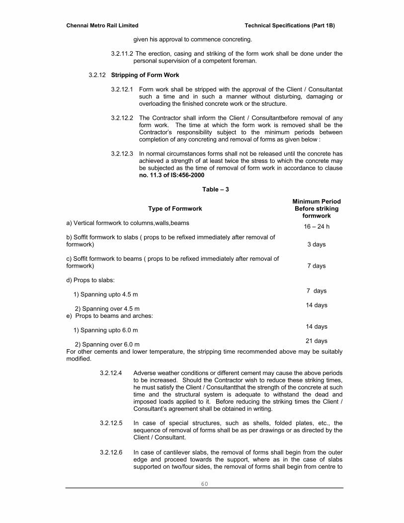
Chennai Metro Rail Limited Technical Specifications (Part 1B)
60
given his approval to commence concreting. 3.2.11.2 The erection, casing and striking of the form work shall be done under the
personal supervision of a competent foreman. 3.2.12 Stripping of Form Work
3.2.12.1 Form work shall be stripped with the approval of the Client / Consultantat
such a time and in such a manner without disturbing, damaging or overloading the finished concrete work or the structure.
3.2.12.2 The Contractor shall inform the Client / Consultantbefore removal of any
form work. The time at which the form work is removed shall be the Contractor’s responsibility subject to the minimum periods between completion of any concreting and removal of forms as given below :
3.2.12.3 In normal circumstances forms shall not be released until the concrete has
achieved a strength of at least twice the stress to which the concrete may be subjected as the time of removal of form work in accordance to clause no. 11.3 of IS:456-2000
Table – 3
For other cements and lower temperature, the stripping time recommended above may be suitably modified.
3.2.12.4 Adverse weather conditions or different cement may cause the above periods
to be increased. Should the Contractor wish to reduce these striking times, he must satisfy the Client / Consultantthat the strength of the concrete at such time and the structural system is adequate to withstand the dead and imposed loads applied to it. Before reducing the striking times the Client / Consultant’s agreement shall be obtained in writing.
3.2.12.5 In case of special structures, such as shells, folded plates, etc., the
sequence of removal of forms shall be as per drawings or as directed by the Client / Consultant.
3.2.12.6 In case of cantilever slabs, the removal of forms shall begin from the outer
edge and proceed towards the support, where as in the case of slabs supported on two/four sides, the removal of forms shall begin from centre to
Type of Formwork Minimum Period Before striking
formwork a) Vertical formwork to columns,walls,beams 16 – 24 h
b) Soffit formwork to slabs ( props to be refixed immediately after removal of formwork)
3 days
c) Soffit formwork to beams ( props to be refixed immediately after removal of formwork)
7 days
d) Props to slabs: 1) Spanning upto 4.5 m 2) Spanning over 4.5 m
7 days
14 days
e) Props to beams and arches: 1) Spanning upto 6.0 m 2) Spanning over 6.0 m
14 days
21 days

Chennai Metro Rail Limited Technical Specifications (Part 1B)
61
supports. Form work to cantilevers shall be removed only with the approval of the Client / Consultant.
3.2.12.7 Form work props shall be positioned between permanent supports such that
the members are supported at maximum 3m centres in both directions. 3.2.12.8 When, in the opinion of the Client / Consultant, the striking of form work
should be detrimental to or may prejudice the safety of the structure, the form work shall be left in.
3.2.12.9 The Contractor shall be responsible for the demolition and re-concreting of
any damaged or defective work howsoever caused at his own expense. The use of epoxy for bonding fresh concrete shall be carried out as directed by the Client / Consultantat no extra cost.
3.2.12.10 If the props are to be left in place whilst the soffit forms to slabs and beams
are to be removed, the props shall be so designed as to remain in position throughout the striking process without having to be temporarily removed. The use of props designed so that a few can be taken away at a time and replaced immediately shall be subject to the Client / Consultant’s prior approval.
3.2.12.11 No construction loads shall be supported from any un-shored portion of the structure under construction. The number of floors requiring propping shall be as instructed by the Client / Consultantaccording to the design loads of such floors.
3.2.13 Reuse of Forms
3.2.13.1 The Contractor shall obtain permission for reusing of forms. Before
reuse, all forms shall be thoroughly scraped, cleaned, all nails and adhering substances removed, holes and leaks satisfactorily plugged, joints examined and wherever necessary repaired and inside surfaces treated as specified herein before.
3.2.13.2 Form work materials shall be cleaned after use and maintained in good
condition. Any timber which has shrunk, warped or split and any forms which are damaged to such an extent as to weaken the form or to affect the quality or appearance of the concrete shall be replaced or repaired. If the strength and composition of the form work has so far deteriorated due to repeated uses that in the opinion of the Client / Consultantit will not longer adequately perform its function, then it shall not be used again and is to be removed from site.
3.2.14 Nominal Cover to Reinforcement
3.2.14.1 Nominal Cover Nominal cover is the design depth of concrete cover to all steel reinforcement, including links. It is the dimension used in design and indicated in the drawings. It shall be not less than the diameter of the bar. 3.2.14.2 Nominal cover to meet durability requirement. Minimum values for the nominal cover of normal-weight aggregate concrete which should be provided to all reinforcement, including links depending on the condition of exposure described given in Table 16 of IS 456 – 2000
Table – 4

Chennai Metro Rail Limited Technical Specifications (Part 1B)
62
Table 16 of IS 456 – 2000 Nominal Cover to Meet Durability Requirements. Exposure Nominal Concrete Cover in mm
not less than Mild 20
Moderate 30 Severe 45
Very Severe 50 Extreme 75
3.3 FORMED FINISHES FOR CONCRETE
3.3.1 General 3.3.1.1 Where a sawn form work finish is specified or in all cases where no
alternative finish is specified, the surface of the concrete shall be not worse than that obtained by the use of properly designed moulds of close jointed swan boards. Small surface blemishes caused by entrapped air will be permitted but the surface should be free of voids, honey combing or other defects.
3.3.1.2 Should any concrete in the works, in the opinion of the Client / Consultant,
fail to match the standard sample in surface finish then the Client / Consultantmay for this sole reason order the removal of all such –substandard concrete which shall be replaced with acceptable concrete all at the Contractor’s expense.
3.3.2 Samples of Finishes
3.3.2.1 For all specified finishes apart from sawn form work the Contractor shall provide a sample panel at least 2.4m x 1.2m in vertical surface area including a typical horizontal and vertical joint in the form work and the construction techniques that the Contractor proposes for the actual works. The sample when approved shall form the standard for the entire works. All unsuccessful samples shall be removed from the site.
3.3.3 Fair Faced Finish (F1)
3.3.3.1 Where fair faced finish (F1) is specified the irregularities of the finish shall be no greater than those obtained from the use of wrought thickness square edged boards. The boards shall be arranged in a uniform patter as specified or approved.
3.3.3.2 The concrete surface shall be smooth, free from fins, lippings, board marks
or other irregularities and shall be even with sharp true arises. Only very minor blemishes or voids shall occur and there shall be no staining and no dis-colouration. The finish is intended to be left as struck and the only treatment generally permitted is light manual abrasion with a carborandum stone to remove minor marks. Patching of any description will not normally be permitted.
3.3.3.3 Isolated blow holes not exceeding 10mm diameter will be permitted, but
otherwise surface is to be free from voids, honey combing or other large defects. Small defects shall be made good and blow holes filled with mortar specially mixed to match the colour and texture of the concrete.
3.3.3.4 Abrupt irregularities shall not exceed 2mm.
3.3.4 Rough Board Finish (F0)
3.3.4.1 Where rough board finish (F0) is specified it shall be produced using form work or form work linings of approved rough textured seasoned wood

Chennai Metro Rail Limited Technical Specifications (Part 1B)
63
boards with moisture content of between 10% and 20%. These boards to be of varying textures and to be arranged to give uniform overall effect. Boards shall be assembled to prevent penetration or loss of grout between them. Gaps greater than 5mm shall be filled. Form work shall be soaked with water before erecting, and shall be kept damp until concrete is placed. Cover spacers and bolts shall be positioned to the satisfaction of the Client / Consultant.
3.3.4.2 The number of uses of form work linings will be limited to their ability to
provide the required finish. 3.3.4.3 The finish shall be left as struck. Any blemishes shall not be made good
until inspected by the Client / Consultant. After inspection minor voids and irregularities on surfaces shall be filled with a matching mortar to the Client / Consultant’s approval, using a sponge rubber faced float Discolouration will not be permitted.
3.3.5 Worked Surface Finish
3.3.5.1 The surface of concrete after casting shall be generally be finished level or to falls as specified with one of the following surface finishes as indicated on the drawings.
3.3.5.2 Type U1 : The concrete shall be uniformly levelled and screeded to
produce a plain surface. No further work shall be carried out to the surface unless it is to be used as a first stage for a type U2 or U3 finish.
3.3.5.3 Type U2: After the concrete has stiffened sufficiently, the type U1 finish
shall be floated by hand or machine sufficiently just to produce a uniform surface free from screed marks.
3.3.5.4 Type U3 : When the surface moisture has diappeared and the concrete
stiffened sufficiently to prevent laitance from being worked to the surface, a Type U1 finish shall be steel trowelled under firm pressure to produce a dense, smooth uniform surface free from trowel marks.
3.3.5.5 The following methods may also be specified in conjunction with the above
to provided specific qualities of finish.
a) Wood float to give an even textured surface b) Steel trowel or power float to give a smooth un-textured surface c) Scratch with a stiff brush to give a slightly roughened even texture
d) Tamp with the edge of a board to give an even texture of parallel ribs
e) Other finishes as specified and executed in an approved manner.
3.3.5.6 The Contractor shall not wet the concrete surface to assist working and shall
not add cement to produce the specified finish without the prior approval of the Client / Consultant.
3.4 Construction, Contraction and Expansion Joints
3.4.1 The Contractor shall be responsible for the position and detail of construction joints not specified in the Contract subject to the Indicative acceptable spacing given in Table 3 (below). Such joints shall be arranged so as to minimise the possibility of the occurrence of shrinkage cracks.
Table 5 - Indicative Acceptable Spacing of Construction Joints

Chennai Metro Rail Limited Technical Specifications (Part 1B)
64
Element Maximum Area (m2)
Minimum Dimension (m)
Waterproof concrete walls 25 5
Waterproof concrete slabs 100 10
Slabs with major restraint at both ends 100 13
Slabs with major restraint at one end only
250 20
Slabs with little restraint in any direction 500 30
Walls (other than above) 40 10
3.4.2 Vertical construction joints shall be properly made to form a vertical grout tight joint. Where reinforcement passes through the face of the joint the stopping off board shall be drilled so that the bars pass through, or the board shall be made in sections with half round indentations in the joint faces for each bar.
3.4.3 Where the Contractor’s proposed construction joints result in alterations to the reinforcement, he shall provide full revised details for the Client / Consultants approval a minimum 14 working days prior to commencement of the works.
3.4.4 The Contractor shall furnish the upper surface of lifts of concrete walls and columns
horizontal and clean the form work of adhering concrete before the next lift is placed.
3.4.6 At all construction joints, both horizontal and vertical, the surface of the previously placed concrete shall be suitably treated to remove laitance and to expose the coarse aggregate thus forming an irregular surface key for adjacent concrete. This work shall be carried out to the satisfaction of the Client / Consultantby the following or other approved methods (in either case the surface shall thoroughly washed and cleaned after roughening). a) After the initial set has taken place but before final set (a minimum period of 4
hours after casting) the coarse aggregate shall be exposed by the use of water jet and stiff brushing or an air-and-water jet.
b) After final set has taken place (a minimum period of 4 hours after casting) the
laitance shall be removed and coarse aggregate shall be exposed by bush hammering taking care not to loosen the aggregate in the face of the concrete matrix.
3.4.7 The Contractor shall ensure the surface of the construction joint is coated with
approved polymer bonding agent prior to concreting afresh immediately. 3.4.8 At least 72 hours shall be left between completion of concreting one bay and the
start of concreting any adjacent bay. 3.4.9 Panels of walls and slabs shall be cast in such a sequence as to minimise and
control the effect of shrinkage at construction joints. 3.4.10 Form work to construction joints shall be rigid and shall accommodate projecting
reinforcement without bending or displacement. 3.4.11 Where kickers are cast at base of walls and columns, these shall be cast
monolithically with the base slab. 3.4.12 if placing of concrete has to be unexpectedly stopped, the Contractor shall form
construction joints as directed by the Client / Consultant.

Chennai Metro Rail Limited Technical Specifications (Part 1B)
65
3.4.13 Contraction joints and Expansion joints shall be formed as detailed where shown on the Drawings.
3.4.14 Concrete shall not be placed on both sides of Contraction or Expansion joint at the
same time. 3.4.15 Water stops shall be provided at all construction joints in water retaining structures.
The details of all such joints shall be approved by the Client / Consultant.
3.5 Concrete Mixes
3.5.1 General
3.5.1.1 Reference shall be made to concrete mixes as Nominal mix concrete or Designed Mix concrete. Nominal mix concrete is denoted by proportions of cement, fine aggregate and coarse aggregate such as 1:5:10, 1:4:8, 1:3:6 or 1:2:4. The proportion referred to is by weight (mass). Designed mix concrete is denoted by grade such as M-20,M-25,M-30,M-35 etc. where M refers to mix and the number to the characteristic strength of concrete in N/mm2 to be established by 28 days of 15 cm works cube tests. The particular mix to be used shall be as described in the Contract or on the Drawings.
3.5.1.2 The characteristic strength of Designed Mix concrete with any type of
cement shall be the 28 days cube strength below which not more than 5% of the test results are expected to fall.
3.5.1.3 The quality and strength of concrete shall be determined by test on
samples taken on Site from the member during concreting and tested at an approved Laboratory as directed by the Client / Consultant.
3.5.1.4 The maximum size of aggregate for structural work shall generally be 20
mm. For thin sections and where reinforcement is congested, 10 mm aggregate may be approved or required. For large sections where the reinforcement is widely spaced and for mass concrete, 40 mm aggregate may be approved.
3.5.1.5 The free water / cement ratio will generally be chosen to suit strength and
workability requirements but may be limited by the considerations of durability given in Table 6 (below).
3.5.1.6 The cement content not including fly ash and blast furnace slag in excess
of 450 kg/m3 should not be used unless special consideration has been given in design to the increased risk of cracking due to drying shrinkage in thin sections, or to early thermal cracking and to the increased risk of damage due to alkali silica reactions.
Table – 6
Table 5 of IS 456 – 2000 Minimum Cement Content, Maximum Water- Cement Ratio and minimum Grade of Concrete for Different Exposures with Normal Weight Aggregate of 20mm
and Nominal Maximum size
S.No Exposure Plain Concrete Reinforced Concrete Minimum
Cement Content Kg/m3
Maximum Free water
Cement Ratio
Minimum Grade of concrete
Minimum Cement Content Kg/m3
Maximum Free water
Cement Ratio
Minimum Grade of concrete

Chennai Metro Rail Limited Technical Specifications (Part 1B)
66
i) Mild 220 0.60 - 300 0.55 M20 ii) Moderate 240 0.60 M 15 300 0.50 M25 iii) Severe 250 0.50 M 20 320 0.45 M 30 iv) Very
Severe 260 0.45 M 20 340 0.45 M 35
v) Extreme 280 0.40 M 25 360 0.40 M 40
3.5.2 Nominal Mix Concrete
3.5.2.1 Nominal mix concrete shall normally be used only for plain cement concrete works and less important reinforced concrete works where shown on drawings or specifically allowed by the Client / Consultant. Such concrete shall not require preparation of trial mixes and all such concrete shall be mixed in a mechanical mixer. Proportions for nominal mix concrete shall be according to Table-9 of IS: 456-2000. In addition, standard proportion by volume shall be used wherever specified.
3.5.2.2 In proportioning concrete, the cement shall be measured by weight (mass).
The quantities of fine and coarse aggregates may be determined by volume (for corresponding weight) but preferably by weight. If fine aggregates are moist, the amount of surface water shall be determined. Also an allowance shall be made for bulking in case of volume batching, in accordance with IS:2386 (Part-III). The weight of aggregate shall be measured when the aggregates are dry. Due allowance shall be made for the water content of moist aggregates. All the above data shall be maintained properly, to the satisfaction of the Client / Consultant.
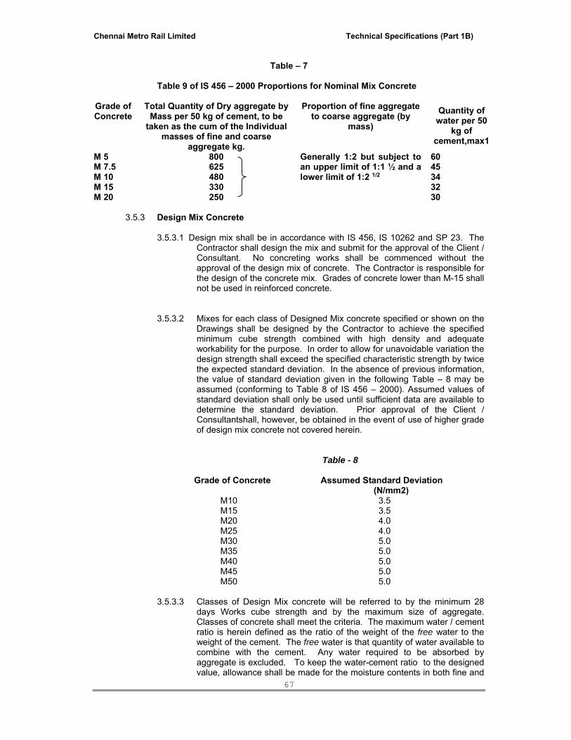
Chennai Metro Rail Limited Technical Specifications (Part 1B)
67
Table – 7
Table 9 of IS 456 – 2000 Proportions for Nominal Mix Concrete
Grade of Concrete
Total Quantity of Dry aggregate by Mass per 50 kg of cement, to be
taken as the cum of the Individual masses of fine and coarse
aggregate kg.
Proportion of fine aggregate to coarse aggregate (by
mass)
Quantity of water per 50
kg of cement,max1
M 5 800 Generally 1:2 but subject to an upper limit of 1:1 ½ and a lower limit of 1:2 1/2
60 M 7.5 625 45 M 10 480 34 M 15 330 32 M 20 250 30
3.5.3 Design Mix Concrete
3.5.3.1 Design mix shall be in accordance with IS 456, IS 10262 and SP 23. The Contractor shall design the mix and submit for the approval of the Client / Consultant. No concreting works shall be commenced without the approval of the design mix of concrete. The Contractor is responsible for the design of the concrete mix. Grades of concrete lower than M-15 shall not be used in reinforced concrete.
3.5.3.2 Mixes for each class of Designed Mix concrete specified or shown on the
Drawings shall be designed by the Contractor to achieve the specified minimum cube strength combined with high density and adequate workability for the purpose. In order to allow for unavoidable variation the design strength shall exceed the specified characteristic strength by twice the expected standard deviation. In the absence of previous information, the value of standard deviation given in the following Table – 8 may be assumed (conforming to Table 8 of IS 456 – 2000). Assumed values of standard deviation shall only be used until sufficient data are available to determine the standard deviation. Prior approval of the Client / Consultantshall, however, be obtained in the event of use of higher grade of design mix concrete not covered herein.
Table - 8
Grade of Concrete Assumed Standard Deviation (N/mm2)
M10 3.5 M15 3.5 M20 4.0 M25 4.0 M30 5.0 M35 5.0 M40 5.0 M45 5.0 M50 5.0
3.5.3.3 Classes of Design Mix concrete will be referred to by the minimum 28 days Works cube strength and by the maximum size of aggregate. Classes of concrete shall meet the criteria. The maximum water / cement ratio is herein defined as the ratio of the weight of the free water to the weight of the cement. The free water is that quantity of water available to combine with the cement. Any water required to be absorbed by aggregate is excluded. To keep the water-cement ratio to the designed value, allowance shall be made for the moisture contents in both fine and

Chennai Metro Rail Limited Technical Specifications (Part 1B)
68
coarse aggregates and determination of the same in accordance with IS:2386 shall be made as frequently as directed by the Client / Consultant.
3.5.3.4 Details of any proposed mix design shall be forwarded to the Employer /
Employer’s Representative for his approval in principle well in advance before that class of concrete is required to be used on the works. The details shall include at least the following information :
(a) Source, nature and grading of coarse and fine aggregates (b) Source of cement (c) Nominal maximum size of aggregate (d) Cement content (e) Aggregate / cement ratio (f) Water / cement ratio (g) Design density (h) Design slump or compacting factor (i) Design strength (j) Proposed admixtures (k) Nominal grading details (tabular & graphical) of the combined
aggregate together with details of the proportions in which the fine and coarse aggregates are combined.
(l) Type of plant to be used and location if ready-mixed off site.
3.5.3.5 The cement content of concrete shall be not less than the appropriate
amount given in Table 5 of IS 456 – 2000. For water retaining structures, the minimum cement content shall be 320 kg/m3.Minimum cement contents, from durability consideration, or different exposures and sulphate attack shall be as given in Table-4 of IS:456 – 2000 . In case, higher value is obtained from trial mix from strength consideration, same shall be considered.
3.5.3.6. Where a Designed mix is to be used, the Contractor shall carry out trial mixes to determine the suitability of the proposed mix proportions for production of concrete of the required quality, workability and computability for the location specified. The Contractor shall prepare trial mixes on receipt of the Client / Consultant’s provisional approval of the mix design and complete well before commencement of concreting. Failure on the part of the Contractor to do so and the consequent delay in the completion of the works will not entitle him for any compensation whatsoever, either financially or by way of extension of time.
3.5.3.7 The proportions, once decided for different grades of concrete, shall be
adhered to, during all concreting operations as long as the quality of the materials does not change.
3.5.3.8 Each batch of concrete shall be sampled and the following prepared.

Chennai Metro Rail Limited Technical Specifications (Part 1B)
69
(a) six 150 mm cubes – three for test at 7 days, and three
for test at 28 days (b) three slump tests (for design slump greater than 25
mm) or (c) three compacting factor tests (for design slump less
than 25mm).
3.5.3.9 Variations in the proportions and sources of materials or in the type, size and grading of aggregates for approved mixes shall not be made without the consent of the Client / Consultant.
3.6 Mixing and Transporting Concrete:
3.6.1 All materials for concrete shall be measured as per approved design mix by weight in approved weight batching equipment of adequate capacity. Such equipment shall be checked at weekly intervals at the Contractor’s expense and shall be accurate to within 2%. Certificates of accuracy shall be submitted immediately to the Client / Consultant.
3.6.2 Mixing
Concrete shall be mixed in a mechanical mixer. The mixer should comply with IS
1791 and IS 12119. The mixers shall be fitted with water measuring (metering) devices. The mixing shall be continued until there is a uniform distribution of the materials and the mass in uniform in colour and consistency. If there is segregation after unloading from the mixer, the concrete should be remixed.
3.6.3 A water / cement ratio shall be maintained to produce concrete of adequate
workability. The workability of fresh concrete shall be at the discretion of the Contractor but subject to approval by the Employer / Employer’s Representative and shall be the minimum consistent with producing a dense, well compacted mass. Due regard shall be paid to the size and shape of the section together with any congestion of reinforcement. A guide to the degree of workability required for various types of work is shown in Table 10 (below).
3.6.4 The slump for concrete as determined by slump tests as per IS: 1199 shall not
exceed the maximum slumps indicated in Table 9 below for each type of construction using high frequency vibration unless otherwise approved or directed by the Client / Consultant. The Contractor shall not place concrete having a slump outside the limits specified without the approval of the Client / Consultant. At least one slump test shall be made for every compressive strength test carried out. More frequent tests shall be made if there is a distinct change in job conditions, or if required by the Client / Consultant.

Chennai Metro Rail Limited Technical Specifications (Part 1B)
70
Table – 9
Nature of Concrete
Workability
Slump in mm
Type of Construction
Min. Max.
Conventional Medium 50 100 All RCC works
Pumpable High 100 150 All RCC works.
3.6.5 All materials shall be thoroughly mixed dry before water is added and the mixing of
each batch shall continue for a period of not less than two minutes after the water is added or such longer period as recommended by the manufacturer of the mixer. The mixture shall be of uniform colour and distribution on discharge and the entire contents of the mixer shall be discharged without segregation before recharging. The volume of mixed material shall not exceed the rated capacity of the mixer.
3.6.6 Prior to the first mix each day being agitated in the mixer a rich cement / sand mix
shall be used to coat the inside of the drum, the surplus material being emptied away and not used in the works. Each time if the work stops for more than 30 minutes, the mixer shall be thoroughly cleaned and when the next mixing commences the first batch shall have 10% additional cement.
3.6.7 Volume batching of materials and hand mixing of concrete will be allowed only at
the discretion of the Client / Consultant. Where approved, hand mixing of concrete shall be done on a clean close boarded platform. The materials shall be turned over not less than three times dry, water shall then be sprayed on through a hose and the materials again turned over not less than three times in a set condition and worked together until a mixture of uniform consistency is obtained.
3.6.8 For hand mixed or volume batched concrete the specified quantities of cement shall be increased by 10 per cent and not more than 0.5 cubic metre shall be mixed at one time. The Contractor shall not be entitled to any additional payment in respect of any extra cost of hand mixing by reason of the additional cement or otherwise. However, the extra cement shall be considered for reconciliation purposes.
3.6.9 Workability of Concrete The concrete mix proportions chosen should be such that the concrete is of adequate workability for the placing conditions of he concrete and can properly be compacted with the means available. Suggested ranges of workability f concrete measured in accordance with IS 1199 are given below.
Placing Conditions Degree of Workability Slump(mm) Blinding concrete, Shallow sections, pavements using pavers
Very low a)Refer IS 1199
Mass Concrete Lightly reinforced sections in labs, beams, walls, columns, floors, Hand placed pavements, Canal lining, Strip footings.
Low 25-75

Chennai Metro Rail Limited Technical Specifications (Part 1B)
71
Heavily reinforced sections in slabs,beams,walls,columns,
Medium 50-100
Slip form work, pumped concrete Medium 75-100
Trench fill-In-situ piling High 100-150 Termite concrete Very High b)Refer IS 9103
3.6.9 The moisture content of the coarse and fine aggregates shall be checked by the Contractor at frequent intervals and the amount of water added to the mix shall be adjusted to maintain the design workability. For the determination of moisture content in the aggregates IS: 2386 shall be referred to.
3.6.10 Concrete shall be discharged from the mixer directly into the works or onto a clean,
level, water tight platform or into a clean water tight container. It shall be transported as rapidly as practicable in a manner which ensures that it is of the correct quality and consistency at the point of deposition. Normally, not more than 30 minutes shall laps between mixing and consolidation in position. All platforms and containers shall be cleaned of the old concrete before the fresh concrete is discharged onto them.
3.6.11 Conveying equipment for concrete shall be mortar tight, well maintained and
thoroughly cleaned before commencement of concrete mixing. Concrete shall be transported by transit mixers.
3.6.12 Concrete shall not be dropped from a height, thrown or otherwise treated so that
segregation, un-desirable finishes, or defective structural quality results. The maximum drop shall be 2.1m unless otherwise approved by the Client / Consultant.
3.6.13 No extra water shall be added to the concrete mix after it has left the batching plant. 3.6.14 The Contractor shall take adequate precautions to protect concrete in transit from
the effects of the weather. 3.6.15 Pumping of concrete, which will require a special Design Mix, will only be permitted
with the approval of the Client / Consultant. The Employer / Employer’s Representative shall also review the entire scheme for which comprehensive details shall be furnished by the Contractor.
3.6.15.1 Pumping operation whenever commenced shall proceed continuously
so as to prevent "cold" joints between placed sections.
3.6.15.2 The delivery line of the pump shall be of 100 mm diameter or greater and the pump shall be capable of pumping concrete containing a 20 mm nom. Size aggregate.
3.6.15.3 The pump shall have a receiving hopper and pumping chamber capable
of displacing at least 15 cu. Metres of concrete per hour against a horizontal delivery head of at least 90 metres and/or a vertical delivery head of 20 metres.
3.6.15.4 Pumping lines shall be of approved metallic type laid to avoid bends.
3.6.15.5 The Joints in pumping lines shall be sealed tight to prevent leakages.
3.6.15.6 Pulsating lines shall be isolated from the structure and shall be
supported from the deck on stands.
3.6.15.7 The feet of such stands shall be placed on timbers or similar material to prevent movement of the line and stand scuffing the deck. Timbers

Chennai Metro Rail Limited Technical Specifications (Part 1B)
72
shall not be embedded in finished work. Stands shall be kept clear of reinforcement.
3.6.15.8 All equipment, pump chamber, hoppers, lines and rubber hoses shall
be kept clean at all times. Any build-up in the lines of material from previous operations shall be cleaned out preparatory to pumping.
3.6.15.9 In the event of a breakdown in the equipment causing delay not
exceeding twenty (20) minutes, during which time concrete cannot be placed, the following procedures shall be carried out:-
3.6.15.9.1 With the approval of the Client / Consultantat site the concrete already
in place shall have the "wet edges" maintained by depositing small quantities of hand mixed concrete placed by hand against the "wet edge" and vibrated into the mass.
3.6.15.10 Where atmospheric temperature exceeds 30 degrees C, the receiving
hopper and lines shall be cleaned out and the concrete contained therein discarded and immediately removed from the site.
3.6.15.11 The concrete shall be discarded if initial setting of the concrete has
begun in the hopper or discharge lines.
3.6.15.12 All lines shall be cleaned free of concrete prior to resumption of pumping after each breakdown
3.6.15.13 Concrete in the lines shall be pumped at approximately eight (8) minute
intervals to ensure the concrete in the line is live, whenever delivery of concrete to the pump is delayed.
3.6.15.13.1 This pumping interval shall be reduced to five (5) minutes during extra
hot weather conditions.
3.6.15.14 Delivery lines where exposed to hot sun, shall be protected by covering with bags, wet Hessian or other approved means.
3.6.16 Should the concreting be stopped due to mechanical malfunction, accident, or other
similar cause then the Contractor shall inform the Employer / Employer’s Representative immediately so that necessary measures and precautions can be taken. The cost of any additional work caused by these stoppages shall be the responsibility of the Contractor.
3.6.17 No concreting shall be commenced until the form work and reinforcement and all
other preparations for the pour have been inspected by the Employer / Employer’s Representative who shall be given a minimum 24 hours notice.
3.7 Placing and Compacting Concrete
3.7.1 Concrete shall be transported and placed by an approved method which ensures that there shall be no contamination, segregation or loss of the constituent materials.
3.7.2 If concrete is placed by pumping, the consistency shall be the minimum necessary
for such conveyance of concrete. Before commencement of regular pumping, the pipeline shall be lubricated by cement mortar (1:2), and once pumping commences, stoppages shall be avoided.
3.7.3 All areas where concrete is to be placed shall be clean and rendered free from
standing water immediately before the placing of concrete, except for concrete placed under water.
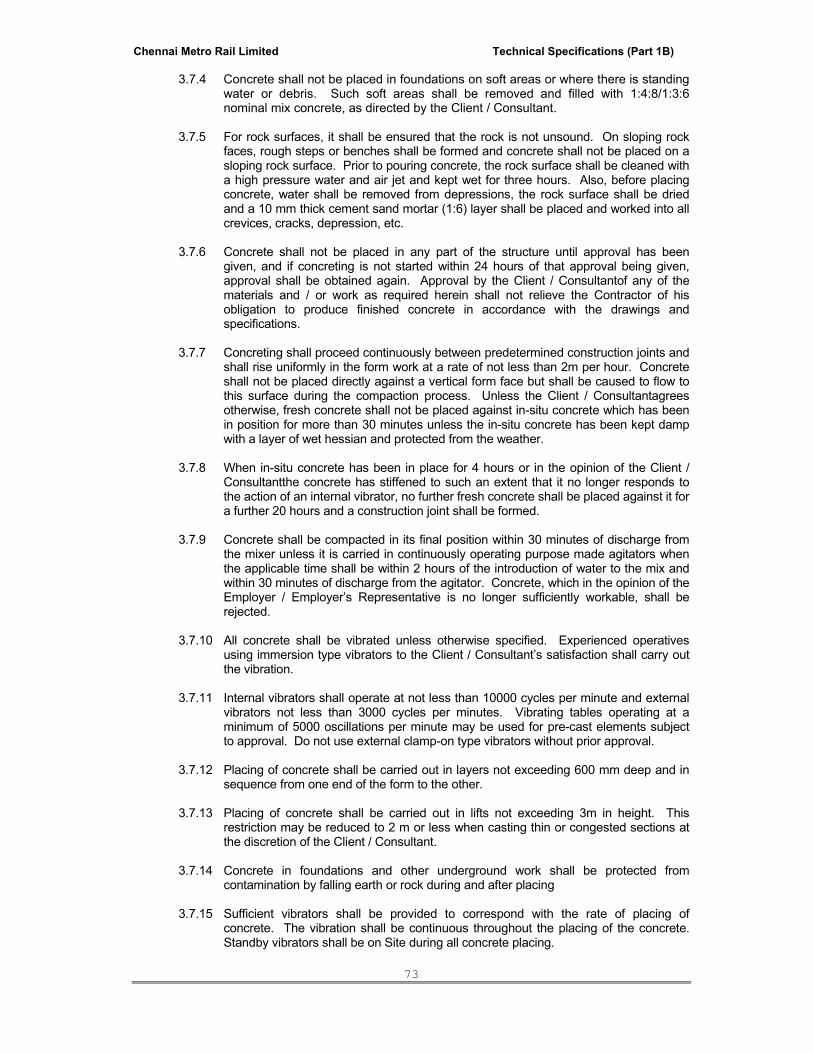
Chennai Metro Rail Limited Technical Specifications (Part 1B)
73
3.7.4 Concrete shall not be placed in foundations on soft areas or where there is standing water or debris. Such soft areas shall be removed and filled with 1:4:8/1:3:6 nominal mix concrete, as directed by the Client / Consultant.
3.7.5 For rock surfaces, it shall be ensured that the rock is not unsound. On sloping rock
faces, rough steps or benches shall be formed and concrete shall not be placed on a sloping rock surface. Prior to pouring concrete, the rock surface shall be cleaned with a high pressure water and air jet and kept wet for three hours. Also, before placing concrete, water shall be removed from depressions, the rock surface shall be dried and a 10 mm thick cement sand mortar (1:6) layer shall be placed and worked into all crevices, cracks, depression, etc.
3.7.6 Concrete shall not be placed in any part of the structure until approval has been
given, and if concreting is not started within 24 hours of that approval being given, approval shall be obtained again. Approval by the Client / Consultantof any of the materials and / or work as required herein shall not relieve the Contractor of his obligation to produce finished concrete in accordance with the drawings and specifications.
3.7.7 Concreting shall proceed continuously between predetermined construction joints and
shall rise uniformly in the form work at a rate of not less than 2m per hour. Concrete shall not be placed directly against a vertical form face but shall be caused to flow to this surface during the compaction process. Unless the Client / Consultantagrees otherwise, fresh concrete shall not be placed against in-situ concrete which has been in position for more than 30 minutes unless the in-situ concrete has been kept damp with a layer of wet hessian and protected from the weather.
3.7.8 When in-situ concrete has been in place for 4 hours or in the opinion of the Client /
Consultantthe concrete has stiffened to such an extent that it no longer responds to the action of an internal vibrator, no further fresh concrete shall be placed against it for a further 20 hours and a construction joint shall be formed.
3.7.9 Concrete shall be compacted in its final position within 30 minutes of discharge from the mixer unless it is carried in continuously operating purpose made agitators when the applicable time shall be within 2 hours of the introduction of water to the mix and within 30 minutes of discharge from the agitator. Concrete, which in the opinion of the Employer / Employer’s Representative is no longer sufficiently workable, shall be rejected.
3.7.10 All concrete shall be vibrated unless otherwise specified. Experienced operatives using immersion type vibrators to the Client / Consultant’s satisfaction shall carry out the vibration.
3.7.11 Internal vibrators shall operate at not less than 10000 cycles per minute and external vibrators not less than 3000 cycles per minutes. Vibrating tables operating at a minimum of 5000 oscillations per minute may be used for pre-cast elements subject to approval. Do not use external clamp-on type vibrators without prior approval.
3.7.12 Placing of concrete shall be carried out in layers not exceeding 600 mm deep and in
sequence from one end of the form to the other. 3.7.13 Placing of concrete shall be carried out in lifts not exceeding 3m in height. This
restriction may be reduced to 2 m or less when casting thin or congested sections at the discretion of the Client / Consultant.
3.7.14 Concrete in foundations and other underground work shall be protected from contamination by falling earth or rock during and after placing
3.7.15 Sufficient vibrators shall be provided to correspond with the rate of placing of concrete. The vibration shall be continuous throughout the placing of the concrete. Standby vibrators shall be on Site during all concrete placing.
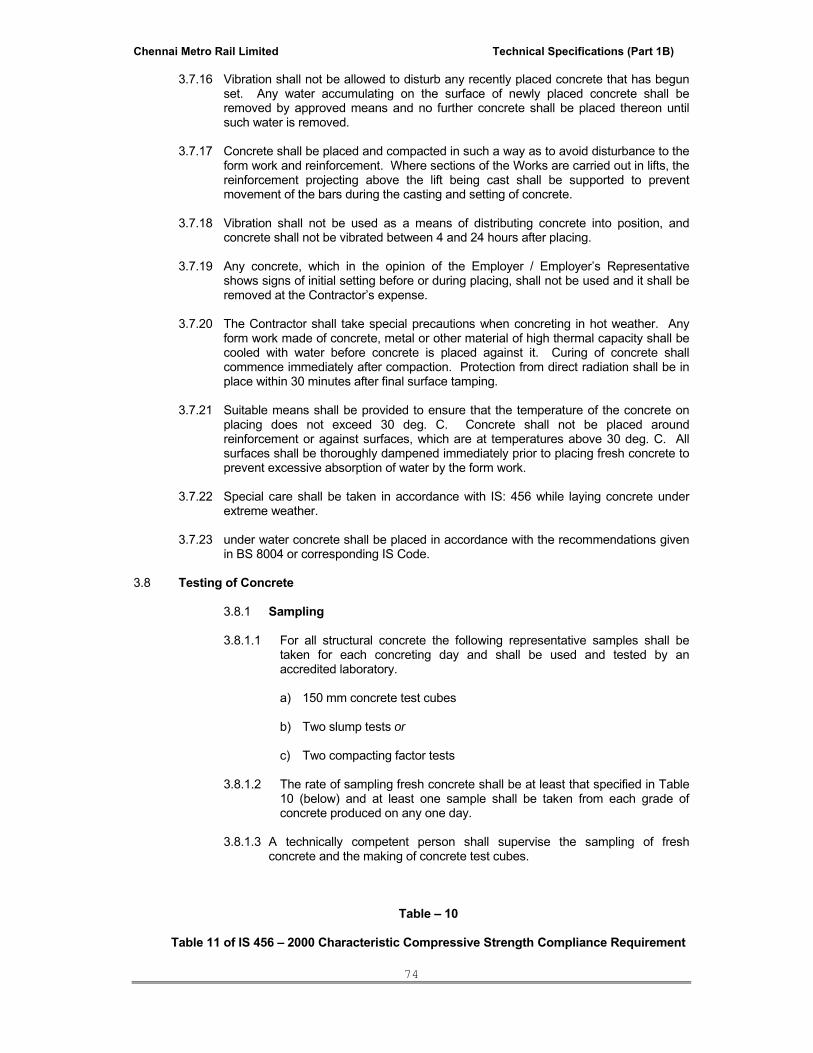
Chennai Metro Rail Limited Technical Specifications (Part 1B)
74
3.7.16 Vibration shall not be allowed to disturb any recently placed concrete that has begun set. Any water accumulating on the surface of newly placed concrete shall be removed by approved means and no further concrete shall be placed thereon until such water is removed.
3.7.17 Concrete shall be placed and compacted in such a way as to avoid disturbance to the form work and reinforcement. Where sections of the Works are carried out in lifts, the reinforcement projecting above the lift being cast shall be supported to prevent movement of the bars during the casting and setting of concrete.
3.7.18 Vibration shall not be used as a means of distributing concrete into position, and concrete shall not be vibrated between 4 and 24 hours after placing.
3.7.19 Any concrete, which in the opinion of the Employer / Employer’s Representative shows signs of initial setting before or during placing, shall not be used and it shall be removed at the Contractor’s expense.
3.7.20 The Contractor shall take special precautions when concreting in hot weather. Any form work made of concrete, metal or other material of high thermal capacity shall be cooled with water before concrete is placed against it. Curing of concrete shall commence immediately after compaction. Protection from direct radiation shall be in place within 30 minutes after final surface tamping.
3.7.21 Suitable means shall be provided to ensure that the temperature of the concrete on
placing does not exceed 30 deg. C. Concrete shall not be placed around reinforcement or against surfaces, which are at temperatures above 30 deg. C. All surfaces shall be thoroughly dampened immediately prior to placing fresh concrete to prevent excessive absorption of water by the form work.
3.7.22 Special care shall be taken in accordance with IS: 456 while laying concrete under extreme weather.
3.7.23 under water concrete shall be placed in accordance with the recommendations given in BS 8004 or corresponding IS Code.
3.8 Testing of Concrete
3.8.1 Sampling
3.8.1.1 For all structural concrete the following representative samples shall be
taken for each concreting day and shall be used and tested by an accredited laboratory.
a) 150 mm concrete test cubes
b) Two slump tests or c) Two compacting factor tests
3.8.1.2 The rate of sampling fresh concrete shall be at least that specified in Table
10 (below) and at least one sample shall be taken from each grade of concrete produced on any one day.
3.8.1.3 A technically competent person shall supervise the sampling of fresh
concrete and the making of concrete test cubes.
Table – 10
Table 11 of IS 456 – 2000 Characteristic Compressive Strength Compliance Requirement

Chennai Metro Rail Limited Technical Specifications (Part 1B)
75
Specified Grade Mean of the Group of 4Non-overlapping consecutive Test results in N/mm2
Individual Test results in N/mm2
M 15 > f ck + 0.825 x established standard deviation (rounded off to nearest 0.5 N/mm2)
or f ck + 3 N/mm2 whichever is greater
> f ck - 3 N/mm2
M 20 or above > f ck + 0.825 x established standard deviation (rounded off to nearest 0.5 N/mm2)
or f ck + 3 N/mm2 whichever is greater
> f ck - 3 N/mm2
3.8.1.4 The names and qualifications of the supervisory personnel representing the
Employer / Employer’s Representative and the Contractor respectively shall be entered into an inspection log book. All inspections shall be clearly recorded with date, time and location of inspections, structural members’ references, names or personnel present and details of site activities. The logbook shall be provided by the Contractor and kept on site by the Client / Consultant.
3.8.1.5 The supervisory personnel shall mark and sign on the concrete test cubes
a unique reference number and sufficient to allow the testing laboratory to identify clearly the date and time of casting and the position in which the batch of concrete (from which the cube was made) was placed.
3.8.2 Concrete Test Cubes
3.8.2.1 Make six cubes from a single sample taken from a batch of concrete selected at random. Taken the sample at the point of discharge from the mixer, or elsewhere as directed by the Client / Consultant. On completion of curing one set of three cubes is tested for 7 days strength and the remaining tested for 28 days strength. The average of the three results shall be taken as the test result.
3.8.2.2 The strength requirement shall be as per clause no 15.2.2, 15.4 & 16.1 of IS-
456 – 2000 latest version
3.8.2.3 Acceptance criteria shall be based on test results on 28 days strength only subject to clause 16.1 of IS-456 – 2000 latest version
3.8.2.4 The variation between the lowest and highest shall not be more than 15% of
the mean of the three. 3.8.2.5 In addition to the water tank curing method specified in IS-516, cubes may
be cured on Site or in the laboratory in approved mist rooms. Where mist rooms are used, they shall comply with ASTM C511-75 except that the temperature shall be maintained at 27 ºC + 3 ºC.
3.8.2.6 If concrete represented by test cubes in any concreting day fails to meet
the standard of acceptance specified in accordance with the IS codes, the Employer / Employer’s Representative may order the taking of core samples from finished concrete work in same concreting day for test at the Contractor’s expense. The locations of these cores to be taken shall be

Chennai Metro Rail Limited Technical Specifications (Part 1B)
76
decided by the Client / Consultant. These cores shall be treated as in 3.8.3 below.
3.8.3. Concrete Test Cores : (Non-destructive testing on concrete will be carried out at the
discretion of the Employer / Employer’s Representative based on the cube test results and review of concrete executed).
3.8.3.1 Concrete core samples, from the finished concrete work, shall be taken in the
locations directed by the Client / Consultant. 3.8.3.2 The diameter of the concrete cores should be 150 mm for 40 mm aggregate
concrete, 100 mm for 20 mm (or smaller) aggregate concrete and must not be less than 75 mm. The length of the test sample cut from the concrete core shall be at least 95% of the diameter.
3.8.3.3 All coring shall be completed within 7 working days of the date the instruction
is given by the Client / Consultant. 3.8.3.4 All cores shall be drilled and tested by an accredited laboratory. 3.8.3.5 Cored holes shall be made good to the approval of the Employer / Employer’s
Representative with cement mortar or concrete of similar strength to that of the parent concrete.
3.8.3.6 Results of the cores for the same concreting day will be examined
individually.
3.8.3.7 In assessing the results of compressive tests on cores the concrete represented by the core shall be deemed not to comply with the specification if the strength of the core when adjusted for length / diameter ratio and converted to estimated cube strength as follows:
a) The average result of the cores is less than 85% of the specified
grade strength or b) An individual result is less than 75% of the specified grade strength
3.8.3.8 Concrete cores should not show evidence of segregation of constituent
materials 3.8.3.9 There should be no honeycombing in the cores and the extent of the voids in
the cores should not be more than “few”. 3.8.3.10 Cores shall not be tested for strength at ages less than 28 days and no
adjustment shall be made to the measured strength in respect of the age of the core when tested.

Chennai Metro Rail Limited Technical Specifications (Part 1B)
77
3.8.4 Testing and Test Record
3.8.4.1 The concrete cubes tested at 7 days are intended to be indicative only and the target works strengths at 7 days are not mandatory. It should be noted however that it is unlikely that cubes failing the 7 days target will subsequently pass the 28 days cube strength.
3.8.4.2 The concrete cubes tested at 28 days shall be taken to represent the
concrete placed in the works. The standard of acceptance for cube strength tests shall be calculated from the maximum load sustained by the cube at failure.
3.8.4.3 The appropriate compressive strength compliance requirement as given in
Table 11 of IS 456 – 2000 shall be considered to be satisfied if the test results comply with the acceptance criteria.
3.8.5 Workability
3.8.5.1 The standard of acceptance for the slump test during the production of
concrete shall be the design slump + 10 mm. 3.8.5.2 The standard of acceptance for the compacting factor test during the
production of concrete shall be the design compacting factor (as specified in Table 10) + 0.03.
3.8.6 Testing
3.8.6.1 The standard of acceptance of any preliminary tests will be similar to the standard for normal works cubes, cores, slump or compacting factor, except that the minimum cube strengths required shall be those given under minimum Preliminary Cube Strength at 28 days in Table 2 of IS 456 -2000.
3.8.6.2 The Employer / Employer’s Representative shall, during the progress of the
work, have the power to order tests, other than cube tests, including slump tests as far as practicable due to local conditions.
3.8.6.3 If the strength requirement is not satisfied the Employer / Employer’s
Representative may order such further testing, including chemical analysis of samples of hardened concrete in the structure, as he considers necessary.
3.8.6.4 Any concrete which fails to meet the above standards of acceptance shall
he be either further tested, or rejected at the discretion of the Client / Consultant. The costs of any such tests or of the removal of rejected concrete and its replacement and associated costs shall be borne by the Contractor.
3.8.6.5 If the strengths required are not attained or maintained throughout the
contract, the Employer / Employer’s Representative may instruct the Contractor to take any one of the following steps or a combination thereof as the Employer / Employer’s Representative considers appropriate.:-
a) Adjust the mix proportion and carry out further trial mixes until a new
mix proportion satisfying the requirements of the foregoing test is obtained and approved.
b) Improve the standard of quality control c) Carryout, at the Contractor’s expense, other tests as directed by the
Client / Consultant.

Chennai Metro Rail Limited Technical Specifications (Part 1B)
78
d) Replace any site concrete condemned as a result of failing to comply
with the standards of acceptance specified and meet all costs arising from such replacement. Submit for approval the method statement for replacing the condemned concrete before the replacement is carried out. In certain cases, the Employer / Employer’s Representative may require the method statement to be prepared and the remedial work to be supervised by a qualified Employer / Employer Representative.
3.9 Curing and Protecting Concrete
3.9.1 All freshly placed concrete surfaces shall be protected from damages by workmen equipment or any other cause.
3.9.2 Newly placed concrete shall be protected by approved means from harmful effects of weather including rain, sun and wind. Concrete placed below ground level, shall be protected from falling earth, during and after placing. Concrete placed in ground containing any deleterious substances, shall be kept free from contact with such ground or with water draining from such ground, during placing of concrete and for a period of at least three days or as otherwise instructed by the Client / Consultant.
3.9.3 Steps, as approved by the Client / Consultant, shall be taken to protect immature concrete from damage by debris, excessive loading, vibration, abrasion, mixing with earth or other deleterious materials, etc. that may impair the strength and durability of the concrete.
3.9.4 Immediately after compaction and for 7 days thereafter concrete shall be prevented from drying out too rapidly and protected against harmful effects of weather including rain, rapid temperature changes, and wind. This period may be extended, at the discretion of the Client / Consultant, up to 14 days. The methods of protection used shall be subject to the approval of the Client / Consultant. The method of curing used shall prevent loss of moisture from the concrete.
3.9.5 During the curing period horizontal surfaces shall be protected by one or more of the following or other approved means.
a) Covering with damp hessian canvas sacks or similar absorbent materials
kept constantly damp and wholly covering the exposed concrete surface.
b) Covering with impermeable materials raised approximately 50 mm over the surface so as to prevent loss of moisture.
c) an approved sprayed membrane curing compound
d) Flooding with water (potable water free from sediments of any kinds shall be
used).
3.9.6 During the curing period other surfaces shall be provided by the following or other approved means :
a) Form work in close contact with the concrete b) covering as in 3.9.5 above
3.9.7 All concrete faces or edges, particularly those, which are exposed without rendering in
the final structure, shall be adequately protected from damage and discoloration at all times.
3.9.8 Concrete structures shall not be loaded until the concrete is at least 21 days in the case of cantilevers. With the prior approval of the Client / Consultantthe structure may be loaded after this time but in no case will loading greater than the final design loading be permitted.

Chennai Metro Rail Limited Technical Specifications (Part 1B)
79
3.10 Cleaning and Finishing of Concrete
3.10.1 All concrete surfaces shall have an even and clean finish free from honeycombs, air bubbles, fins or other blemishes unmarred, reasonable smooth. The form work joint marks on concrete work exposed to view shall be rubbed with carborandum stone and defects patched up with paste of cement sand mortar (1:1) and cured. The finish shall be made to the satisfaction of the Client / Consultant. Concrete surfaces to be subsequently plastered or where brick work is to be built against them, shall be adequately hacked as soon as the form is stripped off so that proper bond can develop.
3.10.2 Immediately after removal of forms, the concrete shall be inspected and defective
areas as pointed out by the Client / Consultantshall be removed partially or entirely as directed. Holes, left by form bolts, etc. shall be filled-up and made good with cement sand mortar of approved mix. All superficial defects such as honeycombing, rough patches, etc. shall be similarly made good. If the defective area is at a vulnerable location, e.g. at the ends of beams & columns etc. then it may be necessary to cut out the member completely or in part and reconstruct as directed by the Client / Consultant. If epoxies have to be used, the same shall be subject to the approval of the Client / Consultant. Poured concrete affected by faulty form work shall be removed totally and replaced. If so directed, the Contractor shall have to resort to grouting / shotcreting.
3.10.3 A smooth finish shall be obtained with the use of forms having smooth and even
surfaces and edges. Panels and form linings shall be of uniform size and be as large as practicable and installed with closed joints. Upon removal of forms, the joint marks shall be smoothened off and all blemishes, projections etc. removed leaving the surfaces reasonably smooth and unmarred.
3.10.4 Where integral cement concrete finish is called for, the surface shall be compacted
and then floated and treated with a straight edge and any high and low spots eliminated. The work shall be carried out as per IS:2571.
3.11 Tolerances
3.11.1 All other cast in place concrete work shall be dimensionally accurate to within the tolerances given in Table 11 (below), unless closer tolerances are further specified or shown on the drawings
3.11.2 Closer tolerances will generally be specified for:
a) Pre-cast concrete
b) Measuring flume contours
c) Filter bed and drying bed floors
d) Machinery bases

Chennai Metro Rail Limited Technical Specifications (Part 1B)
80
Table – 11
Item Tolerance
1 Variations from the plumb
1a) In the lines and surfaces of columns, piers, walls and arises
In 3m 5 mm
In any storey or 6 m maximum 10 mm
In 12 mm or more 20 mm
1b) For exposed corner columns, control-joint grooves and other conspicuous lines
In any storey or 6 m maximum 5 mm
In 12 mm or more 10 mm
2. Variation from the level, or from the grades indicated on the drawings **
At any point (from true elevation)
+ 10 mm
but not more than 5 mm variation between two points within 6 m in a horizontal plane.
3. Variation of the linear building lines from established position in plan and related position of columns, walls and partitions.
In any bay or 6 m maximum 10 mm
IN 12 m or more 25 mm
No tolerance that would result in encroachment on adjoining properties is permissible
4. Variation in the sizes and locations of sleeves, floor openings and wall openings
5 mm
5. Cross sections of columns and beams, thickness of walls, slabs and other parts of the building
Upto 0.5 m +5/-3mm
Over 0.5 m +/-5 mm
6. Footings
6a. Variation in dimensions in plan +25 mm#/-10mm
6b. Misplacement or eccentricity 2%
of the footing width in the direction of misplacement but nor more than +25 mm#
6c. Reduction in thickness 50 mm of specified thickness
7. Variation in steps
7a. IN a flight of stairs
Rise 3 mm

Chennai Metro Rail Limited Technical Specifications (Part 1B)
81
Item Tolerance
Tread 5 mm
7b. In consecutive steps
Rise 2 mm
Tread 3 mm
** Variation in floor level are to be measured before removal of supporting shores
# Applies to concrete only, not to reinforcing bars or dowels Except otherwise shown on drawings, these are maximum allowable tolerances.
3.12 Miscellaneous
3.12.1 Holes, chases, indentations and the like shall be provided where indicated on the drawings. All such shall be formed in the concrete and not cut after the concrete has hardened. Should the Contractor or any subcontractor require additional case-in items, holes or the like these requirements shall be submitted to the Client / Consultantfor his approval a minimum of 14 working days prior to concreting. Pipes, conduits, fixing bolts and other such cast-in items shall be provided where indicated on the drawings.
3.13 Concrete (Non-Structural)
3.13.1 Lightweight aggregate concrete shall be proportioned, mixed and placed as required by the Client / Consultant. Unless otherwise shown, the mixes shall be one of the following, the type to be directed by the Client / Consultant.
a) Breeze Concrete
1 Part cement to 6 Parts of coke breeze aggregate by volume.
b) Polystyrene aggregate concrete
i) 1:2:4 mix (913 kg.m3): 45 kg. Cement and 0.056m3 sand to 2.25 kg. Expanded polystyrene particles.
ii) 1:3:6 mix (800 kg.m3): 45 kg. Cement and 0.084m3 sand to 3.06 kg.
Expanded polystyrene particles.
iii) 1:1:4 mix (640 kg.m3): 45 kg. Cement and 0.028m3 sand to 2.155 kg. Expanded polystyrene particles.
c) Vermiculite aggregate concrete
1 Part cement to 6 Part vermiculite by volume
3.13.2 Lightweight “air entrained” concrete to be proportioned and mixed according to the manufacturer’s instructions and placed as required by the Client / Consultant.
3.14 Water proofness of non-structural – External walls
3.14.1 Non structural walls shall be constructed from block work, brick work, non – structural reinforced concrete etc. as described on the Architectural drawings and in the

Chennai Metro Rail Limited Technical Specifications (Part 1B)
82
specification.
3.14.2 The Contractor shall be completed and solely responsible for the water proofness of the nonstructural external walls and shall satisfy himself that the materials, details and construction sequences are such as to provide a water proof external facade.
3.14.3 Any water leakage, dripping or dampness is unacceptable and shall be repaired to the
satisfaction of the Client / Consultantat no extra cost. 3.14.4 The Contractor shall review the drawings and specification and shall propose
whatever changes he considers necessary, at no extra cost to the contract, including reviewing construction sequence, pour lengths, movement joint locations and water proofing details, caulking materials, shrinkage reinforcement, etc. and supervision of the work to ensure the agreed construction meets the requirements of clause 3.14.3 above.
3.14.5 Prior to applying finishes the contractor shall make a detailed inspection and repair
any defects which could impair the water proofness of such non-structural external walls. Remedial proposals for such repair shall be submitted to the Client / Consultantfor his agreement.
3.14.6 Any remedial works shall be carried out and all caulking / water proofing materials and
details shall be applied to the supplier / manufacturers recommendations. The Contractor shall submit the relevant manufacturers guarantees and test results to the Client / Consultantfor his agreement.
3.15 Cantilevered Canopies
3.15.1 Construction joints for cantilevered canopy slabs must not be located along the external edge of the supporting beams or walls. Cantilevered canopy slabs shall be cast monolithically with supporting beams and walls.
3.15.2 Adequate bar spacers shall be provided to maintain the position and alignment of the steel bar reinforcement.
3.15.3 Effective water proofing should be provided on the top of the canopy slab.
3.15.4 Upon the completion of the canopy structure, the Contractor shall submit a report including the following to the Client / Consultantfor his approval and / or retention :
a) An as-built plan showing
i. Locations and dimensions of members
ii. Direction and gradient of falls
iii. Location of drainage outlets / down pipes
iv. The thickness of screeding and finishes
v. Locations and details of any construction joints for the canopy Structure
vi. Grades of concrete and steel
vii. Diameter and spacing of steel reinforcement in the canopy slab
viii. Date on which the concrete was cast
ix. Concrete cover to steel reinforcement at critical positions of the canopy slab as measured by cover meter and
b) Record photographs showing clearly and in detail.

Chennai Metro Rail Limited Technical Specifications (Part 1B)
83
i) Conditions and arrangement of the fabricated steel reinforcement in the canopy slab and all the supporting members prior to concreting and
ii) Condition of the canopy slab and the supporting members after concreting but
before laying of the finishes and water proofing materials.
3.15.5 A statement confirming that the Contractor has inspected and supervised the construction of the canopy structure and that it has been constructed in accordance with the approved plans.
4.0 Mode of measurement
Unless noted otherwise in the bills of quantities, the method of measurement for various items shall be generally in accordance with IS 1200
*****
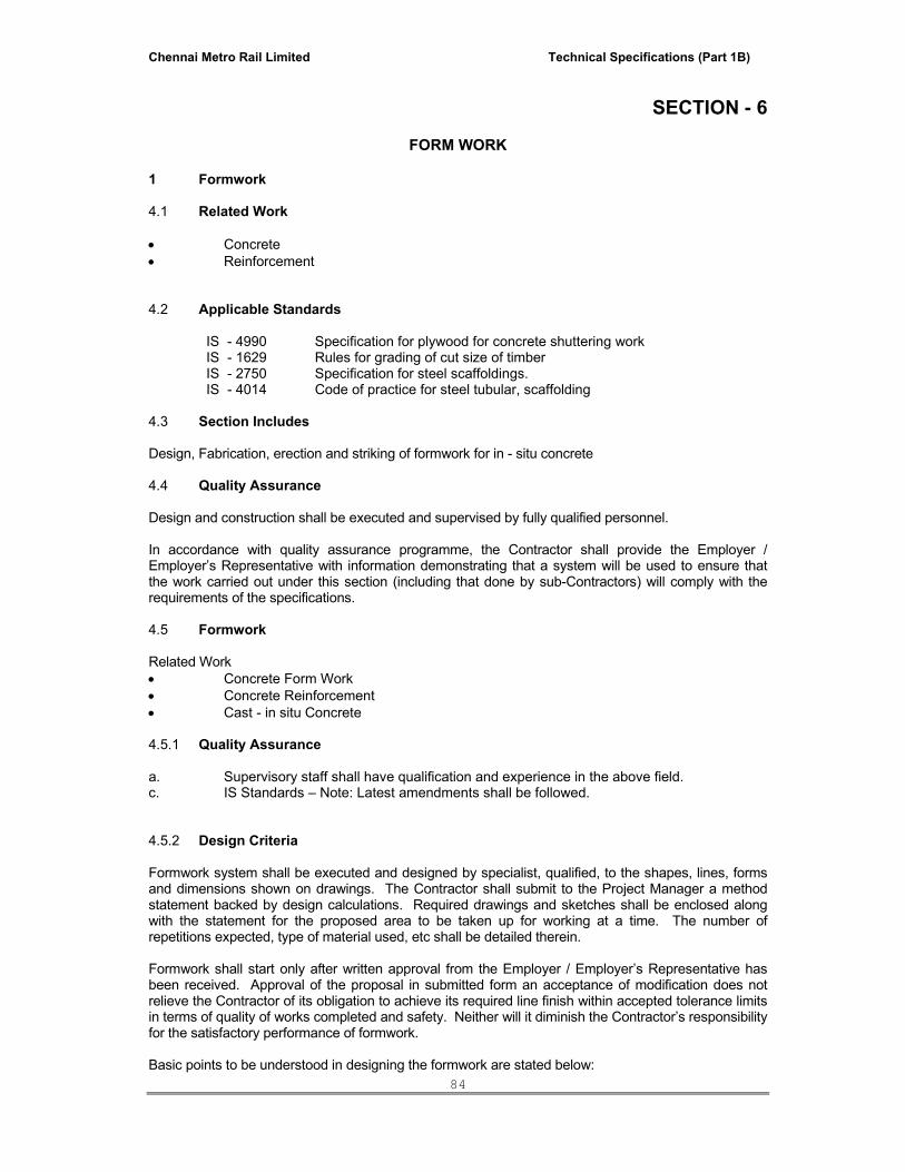
Chennai Metro Rail Limited Technical Specifications (Part 1B)
84
SECTION - 6
FORM WORK
1 Formwork 4.1 Related Work • Concrete • Reinforcement 4.2 Applicable Standards
IS - 4990
Specification for plywood for concrete shuttering work
IS - 1629 Rules for grading of cut size of timber IS - 2750 Specification for steel scaffoldings. IS - 4014 Code of practice for steel tubular, scaffolding
4.3 Section Includes Design, Fabrication, erection and striking of formwork for in - situ concrete 4.4 Quality Assurance Design and construction shall be executed and supervised by fully qualified personnel. In accordance with quality assurance programme, the Contractor shall provide the Employer / Employer’s Representative with information demonstrating that a system will be used to ensure that the work carried out under this section (including that done by sub-Contractors) will comply with the requirements of the specifications. 4.5 Formwork Related Work • Concrete Form Work • Concrete Reinforcement • Cast - in situ Concrete 4.5.1 Quality Assurance a. Supervisory staff shall have qualification and experience in the above field. c. IS Standards – Note: Latest amendments shall be followed. 4.5.2 Design Criteria Formwork system shall be executed and designed by specialist, qualified, to the shapes, lines, forms and dimensions shown on drawings. The Contractor shall submit to the Project Manager a method statement backed by design calculations. Required drawings and sketches shall be enclosed along with the statement for the proposed area to be taken up for working at a time. The number of repetitions expected, type of material used, etc shall be detailed therein. Formwork shall start only after written approval from the Employer / Employer’s Representative has been received. Approval of the proposal in submitted form an acceptance of modification does not relieve the Contractor of its obligation to achieve its required line finish within accepted tolerance limits in terms of quality of works completed and safety. Neither will it diminish the Contractor’s responsibility for the satisfactory performance of formwork. Basic points to be understood in designing the formwork are stated below:

Chennai Metro Rail Limited Technical Specifications (Part 1B)
85
a) Erected Form work shall be watertight, shall conform to shape, lines, dimensions, verticality,
rigid during placing, vibrating and configuring the concrete b) Formwork system shall be of steel or timber or 12mm thick water resistant Ply board, and
shall be continuous, straight and without any warping. c) Design of formwork shall take into account:
• Height of pour • Thickness of member • Rate of pour • Concrete slump • Texture of finish • Placing temperature • Concrete density • Construction joints • Wind load • Method of Discharge
d) Form work design shall have
• Dimensional tolerance • De mountable without shock, disturbance or damage to concrete
e) All construction joints in beams and slabs shall be provided as shown in drawings. f) Ties shall be provided where required g) Cambers shall be provided where shown. h) Props / supports of extra ceiling height shall be specially designed. 4.6 Form Work Material Construction formwork with smooth faced plywood, steel or timber to produce smooth straight level and sharp profiles shall be used for the works. Panels to be of design of optimum size to reduce the number of joints. a) Form material shall have strength adequate to withstand pressure of newly placed concrete
without excessive and adjustable bow or deflection. b) Factory fabricated, adjustable length removable or snap of metal form ties, design to
prevent from deflection and to prevent spilling concrete surfaces on removal. c) Ties shall be such that
• A portion remaining within the concrete shall be at least 38mm from the outer
concrete surface. • That will not leave a hole larger than 25mm dia meter on the concrete surface.
d) Form coating compound that will not bond with, stain, not adversely effect concrete for
required bond or adhesion not hamper the wetting of surface to be covered with water or curing compound.
All propping and centering shall be of adjustable steel supports (built-up sections of rolled steel) and tubular props to full height without joints, and with sufficient bracing to take into account the construction loads, namely full load of concrete with any live load and impact load likely to occur during concreting.

Chennai Metro Rail Limited Technical Specifications (Part 1B)
86
Steel shuttering used for concreting shall be sufficiently stiffened. The steel shuttering shall also be properly repaired before sue and properly cleaned to avoid stains and defects in concreting. 4.7 Workmanship Formwork shall be classified based on the ultimate finishes required of the concrete surface as:
• Textured or decorative finish • Fair-faced finish • Rough finish
4.7.1 The Contractor shall account for all material and labour to achieve the above finishes to the
satisfaction of the Project Manager in his quoted price.
4.7.2 Guidelines for Good Workmanship Following are a few points as guidelines for good workmanship in formwork and shall be
accounted for in his quoted price. • Erection of formwork may be from pre-moulded, pre-fabricated, pre-assembled plates or form
reasonable enough to transport and erect at site to correct lines and levels as set at site. • Supports shall be firm and maintained in position by nails, cross bracing, tie-rods, locking
bolts, nuts, etc. It shall be rigid and stiff so as to retain its shape during and after concreting. • Joints shall be water-tight and no cement slurry shall be allowed to get through • Pre-fabricated or site forms shall be assembled so as to de-shutter without any jerk to the
green concrete. For this double wedges shall be used. The wedges shall be nailed. The heads left with, allowing easy removal while de-shuttering.
• Pre-fabricated or site formwork shall be sufficient thickness with supporting spans in both directions. These shall be standardised in size for easy replacement and universal use at site
• Props shall be of steel only. Its spacing shall be as per design. It shall be vertical and plumbed. Base shall be of proper steel plate or timber plank for equal distribution of load
• Contractor’s shall remove the tag provided by the plywood manufactures present on plywood board while using he same.
• In case of multi-storied buildings, any upper floor shall be suitably supported on at least one floor below the same, or as approved by the Project Manager.
• Props shall be adequately cross-braced horizontally • At the design and erection stage following additional points shall be considered and be
incorporated into the setting • Opening of cleaning prior to the start of concreting • Pouring points shall avoid high drops and provide easy access to vibrating needles • Surfaces shall be treated with suitable releasing oil or emulsion prior to the reinforcement
laying. Such releasing oil shall be got approved from the Project Manager. • Ensure that forms and adjacent surfaces are thoroughly cleaned to receive concrete and
debris. • Locate construction joints in a manner so as not to impair strength and appearance of
structure. Following points shall be observed very carefully: • Joints of formwork shall be watertight. It is easy to check from the bottom and make sure no
light is visible • Props shall be on solid base, plumbed, in straight line, braced horizontally and cross • Tie-bars, bracing and spacers in beams, walls and columns shall be at correct place/location
and fully tight • Wedges shall be fully secured and nailed with heads left out for easy removal • All saw dust, dirt, shavings and any other unwanted material shall be cleaned and hosed out • Provision shall be made for watching formwork while concreting and any other platform
needed for movement of workers without any disturbance to the reinforcement • Provision is made for traffic on formwork : not to bear directly on reinforcing steel.

Chennai Metro Rail Limited Technical Specifications (Part 1B)
87
• Number of reuses shall be decided by the Project Manager on examining the condition of formwork after each use. If during concreting any weakness develops or formwork shows any distress, the work shall be stopped and remedial action taken.
4.7.3 Finishing Formed Surfaces The Contractor shall:
- Repair and patch defective areas with fins and other projections completely removed or smoothed.
- To smooth concrete where fins and other projections have formed moisten concrete surface within a day after forms have been removed and rub with carborundum stone until surface is a uniform colour and texture within the projection limits.
- Not apply cement ground other than that produced by the rubbing process. - Remove and replace concrete having defective surfaces if defects cannot be repaired to the
satisfaction of the superintendent. Surface defects shall include colour and texture irregularities, cracks, spills, air bubbles, honeycombs, rock pockets, fins and other projection on the surface, stain and form tie holes. The Contractor shall: - Undercut voids larger than 25mm diameter and fill with fresh concrete after thoroughly wetting
concrete surfaces. - Fill small holes and irregularities using 2:1 (Portland cement to fine sand by volume) grout
mixed with approved bonding admixture according to manufacturer’s specification. - Blend standard Portland cement with white Portland cement if necessary so that final colour
of dry grout will match adjacent surfaces. - After applying grout to repair area, wipe with Hessian cloth to match adjacent texture and
within the specified surface tolerances. - Keep concrete patch damp with fog *spray for at least 36 hours. 4.8 Measurements Formwork shall be measured as the area (in square meters) of shuttering in contact with the concrete including covers, angles, splays, mitres, bevels, etc. for which no special rate shall be allowed. • It shall be measured to the nearest centimeter and the area worked out correct to two decimal
places • No deduction shall be made for openings up to 0.4 square meter in plan • Area of voids shall deducted from the face area of shuttering. • No deductions shall be made from formwork of main beams where a secondary beam
intersects it. Formwork for secondary beams shall be measured up to sides of the main beams.
• No deduction shall be made from the formwork to column casings at intersection of beams. • Lapping of formwork with previously laid out concrete will not be measured and will not be
paid for. • The quoted rate shall be applicable for all working conditions and at all heights and depths or
lifts specified in the drawings. The rate shall include the cost of materials and labour for various operations involved including, but not limited to the following:
• Provision of formwork, its erection and treatment of the concrete surface immediately after removal of the formwork
• Holes to be made in the formwork for inserting electrical conduits, piping for plumbing works, etc
• Centering, bracing, tightening with bolts and nuts, staging, etc. • Splayed edges, notchings, allowance for overlaps, centering, shuttering, strutting, bolting,
nailing, welding, casing striking and removal. • Filling to form stop chamfered edges or splayed external angles to footings, beams, columns
and the like. • Temporary openings in the forms for pouring concrete and removing rubbish. • Dressing with oil/approved emulsion to prevent adhesion of concrete with shuttering. • Raking or cutting.
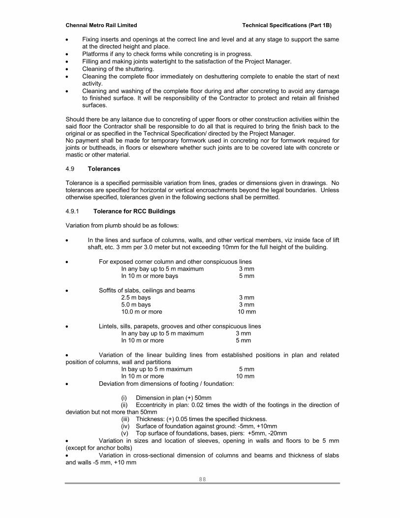
Chennai Metro Rail Limited Technical Specifications (Part 1B)
88
• Fixing inserts and openings at the correct line and level and at any stage to support the same at the directed height and place.
• Platforms if any to check forms while concreting is in progress. • Filling and making joints watertight to the satisfaction of the Project Manager. • Cleaning of the shuttering. • Cleaning the complete floor immediately on deshuttering complete to enable the start of next
activity. • Cleaning and washing of the complete floor during and after concreting to avoid any damage
to finished surface. It will be responsibility of the Contractor to protect and retain all finished surfaces.
Should there be any laitance due to concreting of upper floors or other construction activities within the said floor the Contractor shall be responsible to do all that is required to bring the finish back to the original or as specified in the Technical Specification/ directed by the Project Manager. No payment shall be made for temporary formwork used in concreting nor for formwork required for joints or buttheads, in floors or elsewhere whether such joints are to be covered late with concrete or mastic or other material. 4.9 Tolerances Tolerance is a specified permissible variation from lines, grades or dimensions given in drawings. No tolerances are specified for horizontal or vertical encroachments beyond the legal boundaries. Unless otherwise specified, tolerances given in the following sections shall be permitted. 4.9.1 Tolerance for RCC Buildings Variation from plumb should be as follows: • In the lines and surface of columns, walls, and other vertical members, viz inside face of lift
shaft, etc. 3 mm per 3.0 meter but not exceeding 10mm for the full height of the building. • For exposed corner column and other conspicuous lines In any bay up to 5 m maximum 3 mm In 10 m or more bays 5 mm • Soffits of slabs, ceilings and beams 2.5 m bays 3 mm 5.0 m bays 3 mm 10.0 m or more 10 mm • Lintels, sills, parapets, grooves and other conspicuous lines In any bay up to 5 m maximum 3 mm In 10 m or more 5 mm • Variation of the linear building lines from established positions in plan and related position of columns, wall and partitions In bay up to 5 m maximum 5 mm In 10 m or more 10 mm • Deviation from dimensions of footing / foundation: (i) Dimension in plan (+) 50mm (ii) Eccentricity in plan: 0.02 times the width of the footings in the direction of deviation but not more than 50mm (iii) Thickness: (+) 0.05 times the specified thickness. (iv) Surface of foundation against ground: -5mm, +10mm (v) Top surface of foundations, bases, piers: +5mm, -20mm • Variation in sizes and location of sleeves, opening in walls and floors to be 5 mm (except for anchor bolts) • Variation in cross-sectional dimension of columns and beams and thickness of slabs and walls -5 mm, +10 mm

Chennai Metro Rail Limited Technical Specifications (Part 1B)
89
• Variation in steps In a flight of stairs Risers Treads In flight of stairs 3 mm 5 mm In consecutive steps 1.5 mm 3 mm All the tolerances mentioned above shall apply to concrete dimensions only, and not to positioning of vertical steel or dowels. 4.10 Removal of Formwork: Formwork shall not be struck until the concrete has reached a strength at least twice the stress to which the concrete may be subjected at the time of removal of formwork. • Formwork shall be removed carefully without jarring the concrete and curing of the concrete shall commence immediately. Sudden shocks / vibrations during removal of wedges shall be avoided. Where finished edges have re-entrant angles, remove formwork as early as possible to avoid shrinkage cracks. • Concrete surfaces to be exposed shall where required by the Project Manager, be rubbed with carborandum stone to give a smooth and even finish. • Where concrete requires plastering or other finish later, the concrete surface shall be hacked as directed. • No extra charge will be allowed to the Contractor for such work. 4.10.1 Minimum time Requirements For other cements the stripping time shall be suitably modified in consultation with the Project Manager. For precast moulds the stripping time shall be 24 hours. Striking time shall be as follows: Type of Formwork Minimum period before striking
(excluding the day of casting) i. Walls, columns 12 hrs ii. Vertical faces 12 hrs iii Removal of formwork with props fully left under spanning over 6m 7 days iv Between ribs not more than 1 to 2 m 7 days v. Ribs, joists, beams, soffits - Up 3m clear span - Beams 7 days - Between 3m to 6m - Beams 14 days - Above 6m clear span beams 21 days vi. One way floor slabs - up to 3m 7 days vii. One way floor slabs - between 3m to 6m 10 days viii One way floor slabs - over 6m 14 days ix Beams and Girder Sides 12 days x. Removal of props below slabs spanning over 6m 21 days Striking of Formwork within the time limits listed above is subject to successful crushing of cubes compressive strength results. However re-shuttering and re-propping can be done if the required strength is attained as per the instructions of Client / Consultant 4.11 Cleaning and Oiling of Forms The contactor shall ensure that the surface of the forms that will touch the concrete shall be free from encrustations of mortar, grout, or other foreign material. Temporary openings shall be left at the bottom of formwork to enable sawdust, shavings, wire off-cuts and other foreign material to be removed from the interior of the forms before the concrete is placed. Compressed air shall be used to clean the complete formwork and remove all traces of duct and debris before pouring concrete the temporary holes shall then be closed. The surface of the forms to be in contact with the concrete shall be coated with a reliable coating that

Chennai Metro Rail Limited Technical Specifications (Part 1B)
90
will effectively prevent the adherence of concrete and will not stain the concrete surfaces. After each use, the surfaces of forms which have been in contact with concrete shall be cleaned of mortar and any other material sticking to them, then well wetted and treated with form oil approved by the Project Manager. The Contractor shall provide commercial form release agent that will not bond with, stain or adversely affect concrete surfaces and will not impair subsequent treatment of concrete surfaces. 4.12 Openings / Inserts Contractor shall provide all required openings, pockets, inserts as detailed in drawings. The Contractor shall provide required material and labour for fixing and supporting during concreting. In its quoted price, it is imperative to consider that all openings and pockets shall be de-shuttered with care and all corners of openings shall be preserved, ie shall be in correct line and level. After concreting the openings shall be secured against any accident by proper covering and guard rail, warning notice, lighting, etc for which no extra cost is payable to the Contractor.

Chennai Metro Rail Limited Technical Specifications (Part 1B)
91
SECTION - 7
STEEL REINFORCEMENT 1.1 Related Works A. Concrete Formwork B. Cast in-situ Concrete 1.1.a Applicable Standards IS - 432
Specification for Mild steel and medium tensile bars and hard drawn steel wire.
IS - 1139
Specification for hot rolled mild steel, medium tensile steel and high yield strength steel deformed bars for concrete reinforcement.
IS - 1566
Specification for plain hard drawn steel wire fabric for concrete reinforcement
IS - 1785
Specification for plain hard drawn steel wire for prestressed concrete.
IS - 1786
Specification for cold twisted steel high strength deformed bars for concrete reinforcement.
IS - 2080
Specification for high tensile steel bars used in prestressed concrete
IS - 2751
Code of practice for welding of mild steel structures are folded plates
IS - 2502
Code of practice for bending and fixing of bars for concrete reinforcement
1.2 Steel Grades Reinforcements for concrete may be from any of the “grades” of steel indicated below, conforming to the relevant Indian Standards and their latest amendments mentioned against each:
Grade Description Conforming to
Fe 250 Mild Steel IS 432 (Part I)
Fe 490 Hard drawn steel wire IS 432 (Part II)
Fe 415 High strength deformed/ ribbed steel IS 1786
Fe 500 High strength deformed / ribbed steel IS 1786
Fe 550 High strength deformed / ribbed steel IS 1786
Reinforcing steel may be any of the following types: Type I Plain round bars (PR) Type II Welded wire Fabrics (WWF) Type III Cold Twisted Deformed Bars / Corrosion resistant bars. (CTD-CR) Type IV Thermo-Mechanically Treated Ribbed bars (TMT) Type V Thermo-Mechanically Treated Ribbed Corrosion Resistant bars (Copper) Bearing (TMT-CR)

Chennai Metro Rail Limited Technical Specifications (Part 1B)
92
1.3 BIS Certification Material received at the Site shall have BIS Certification mark. Such bundle or coil containing the bars shall be suitably marked with BIS Certification mark. Bars shall also be marked to identify categories. This shall be done as per IS: 1387. In case bars are without BIS Certification mark, the manufacturer shall give a certificate stating the process of manufacture, chemical composition and mechanical properties. Each certificate shall indicate the number or identification mark of the cart to which it applies, corresponding to the number or identification mark to be found on the material. All reinforcements shall be free from loose mill scale, excessive rust, loose rust, pitting, oil, grease, paint, mud or any other foreign deleterious material present on the surface. Cleaning should be done to the satisfaction of the Client / Consultant. Each batch of steel brought to the Site shall be tested prior to use. Cost of all tests shall be borne by the Contractor. Material acceptable as per IS Specifications will be allowed into the Project. All rejected material shall be removed from the Site by the Contractor within 30 days of its rejection. If the same is not done, the Project Manager can get work done by third party at the Contractor’s risk and cost shall impose a penalty of Rs 500 (Rupees Five Hundred only) per metric ton per day. This will be without any appeal and shall not be subjected to arbitration. 1.4 Storage Reinforcement bars received at the Site shall be stored on hard, concreted platform and clear of the ground to a minimum of 200 mm with the use of timber sleepers or any other means. Reinforcements shall be kept covered by tarpaulins or plastic to avoid excessive corrosion or any other contamination. It is advised to follow storage methods as described in IS: 4082. Reinforcement steel shall be stored in such a manner as to avoid distortion and to prevent deterioration and corrosion. Prior to assembly of reinforcement no account any oily substance shall be used for removing the rust. 1.5 Quality Assurance a. Supervisory staff shall have qualification and experience in the above field. b. Welders qualified and having approved certificates for welding shall be employed. 1.6 Handling a. Bend / rebend test requirements shall conform to the following and shall be based on 1800
bends of full size bars around pins.
Bar diameter (mm) Pin diameter for test bend 10, 12,16 3.5 x bar dia 20, 22, 25 5.0 x bar dia 28, 30, 32 7.0 x bar dia
b. Spacers of same dia shall be used with any of the following:
i. Wire ii. Precast concrete iii. Moulded plastic
Spacer material shall be of durable quality and shall not lead to corrosion of reinforcement or spilling of concrete.

Chennai Metro Rail Limited Technical Specifications (Part 1B)
93
Precast concrete spacers shall be of the same mix as that of surrounding concrete. c. Tying wire shall be of 18 G black annealed mild steel wire or other approved type double
fold to tie the reinforcements. d. Cover blocks shall be non-corrosive material such as plastic, but not wooden or broken
bricks or stone. Specially made concrete blocks shall be used. Such cover blocks shall be cast from concrete and not from cement mortar; strength of these blocks shall be equal to the concrete in use.
e. Binding wire for fixing reinforcement shall be either no.16 gauge soft Galvanised annealed iron wire, or no.18 gauge stainless steel wires.
1.7 Unit Weights:
Unit weights payable per meter shall be as follows:
6 mm ∅ 0.22 kg/ rm 8 mm ∅ 0.39 kg/ rm 10 mm ∅ 0.62 kg/ rm 12 mm ∅ 0.89 kg/ rm 14 mm ∅ 1.21 kg/ rm 16 mm ∅ 1.58 kg/ rm 18 mm ∅ 2.00 kg/ rm 20 mm ∅ 2.47 kg/ rm 22 mm ∅ 2.98 kg/ rm 25 mm ∅ 3.85 kg/ rm 28 mm ∅ 4.83 kg/ rm 32 mm ∅ 6.31 kg/ rm 36 mm ∅ 7.99 kg/ rm 40 mm ∅ 9.86 kg/ rm
1.8 Execution 1.8.1 Cutting and Bending a. Flame cut and hot bending is absolutely forbidden. b. Cut and bend reinforcement to approved shop drawings and details shall be used. c. Bars to be cold-bend, either mechanically or by hand, but to correct radius using proper
tools, machine and platform and confirming to IS 2502-1963. d. Do not rebend without approval. In case of re bending, care shall be taken that the rating of
bend is not less than 4 x bar dia at construction joints for plain steel bars and 6 x bar dia for high strength bars.
e. Reinforcement projecting from concrete shall not be bent without approval.
Bar bending schedule to be submitted for approval of the Structural Consultant to the Project Manager prior to commencement of any cutting, bending and binding of steel at site.
f. Cracked end of bars shall not be used on this Project. g. Bars should be inspected for visible defects such as cracks, brittleness, excessive rust,
loose mills scale, etc. 1.8.2 Welding

Chennai Metro Rail Limited Technical Specifications (Part 1B)
94
a. Do not weld reinforcement unless authorized by the Employer / Employer’s Representative
and recommended by the manufacturers. b. Site welding shall be done with suitable safeguards and techniques. c. Welding, if approved, may be used for: i. Lapping reinforcement in position ii. Fixing reinforcement to other steel members. d. The length of run deposited in a single pass shall not exceed 5 x bar diameters. If a longer
welded length is required divide into sections with the space between runs not less than 5 x bar diameters.
e. Welded joints:
i. Shall not be made at bends in reinforcement. ii. Stagger joints in parallel bars of principal reinforcement unless otherwise approved. iii. The distance between staggered joints shall not be less than the end anchorage length joints.
1.8.3 Mechanical Splicing a. To comply with ISI 456-2000. ACI 318-1983 and ACI 439-3R-83 b. Use as indicated in structural drawings. c. Consultant has to approve mechanical splices before using it at site. Inspection a. Ensure that the reinforcement placing is checked by Client / Consultant. b. Ensure that the Formwork to receive the reinforcement is clean and free from debris. c. Cracked end of bars to be cut out. 1.8.4 Anchoring Anchoring of bars and stirrups shall be provided exactly as detailed in the structural drawings or as directed by Client / Consultant. In case of reinforcement steel in tension, deformed bars may be used without end anchorage provided the development length requirement is satisfied. Hocks shall normally be provided for plain bars in tension. Development length of the bars shall be determined as per relevant clauses of IS: 456 - 2000. The anchorage length of straight bar in compression shall be equal to the Development length of the bars in compression as specified in relevant clause of IS: 456 - 2000. 1.8.5 Lapping of Bars Laps shall be strictly as per the structural drawing or as directed by the Development Manager/Structural Consultant. For general guidance the following principles shall be followed as given in IS: 456 - 2000 • As far as possible bars of the maximum length available shall be used.
• Laps shown on drawings or otherwise specified by the Structural Consultant will be based
on the Contractor using bars of maximum length. • In case Contractor wishes to use bars of shorter length, laps shall be provided at the
Contractor’s expense in the manner and the locations approved by the Structural Consultant.

Chennai Metro Rail Limited Technical Specifications (Part 1B)
95
• Splices shall be provided as far as possible away from the sections of maximum stress and be staggered.
• Not more than half of the bars shall be spliced at a section
• If more than half of the bars shall be spliced at a section, special case shall be ensured such
as increasing length of lap or closer spacing of stirrups around the length of splice. • Lap splice shall not be used for bars having diameter larger than 36 mm. For larger
diameters bars it may be welded. Lap length including anchorage value of hooks in flexural tension shall be La (as defined in Article 25.2.1 of IS: 456-2000) or 30 times the diameter of the bar whichever is greater and for direct tension 2La or 30 times the diameter of the bar whichever is greater. The straight length of lap shall not be greater than 15D or 20 cm, whereas D is the diameter of the bar.
• Lap length in compression shall be equal to the development length in compression
calculated as described in relevant clause of IS: 456-2000 or as specified in the structural drawing but not less than 24 times the diameter of the bar.
• Overlapping bars shall not touch each other and these shall be kept apart with concrete
between them by 25mm or 1.25 times the maximum size of the coarse aggregate, whichever is greater.
• When above is not possible, the overlapping bars shall be bound together at intervals not
exceeding twice the diameter of such bars with two strands of annealed binding wire of 0.90mm to 1.6mm diameter twisted together tightly.
• As and when necessary welded laps shall be proved as specified by the Structural
Consultant. 1.8.6 Securing Reinforcement a. Adequately secure with tying wire or approved steel clips. b. Bend the tying wires well back clear of forms. 1.8.7 Concrete Cover a. Shall be in accordance with ISI: 456-2000 and as per the instructions in structural drawings. i. Footings, retaining walls and Similar members in contact with earth but not cast against earth - 50 mm ii. Slabs - 20 mm iii. Walls, ribs - 20 mm iv. Beams: For main bars - Min.25 mm or dia. of the bar For stirrups - 15 mm v. Columns - 40 mm Columns less than 20 cms - 25 mm vi. Water tanks: In contact with water - 40 mm In contact with air - 20 mm vii Walls in contact with water / Earth - 40mm 1.8.8 Spacers Chairs and Other Supports a. Provide necessary supports to maintain reinforcement in its correct position.

Chennai Metro Rail Limited Technical Specifications (Part 1B)
96
b. Provide spacer bars of same diameter as longitudinal bars but not less than 25mm diameter between two layers at 1.5 mm centers except where bundled bars are detailed.
1.8.9 Precautionary Measures a. Do not insert bars into placed concrete. b. Do not damage forms and form linings, if any when fixing reinforcement. 1.8.10 Adjustment and Cleaning a. Check reinforcement prior to and during placing concrete with particular attention to the top
reinforcement in Cantilever sections. b. Ensure that reinforcement is clean and free from corrosive pitting, loose rust, loose mill scale,
oil and other substances, which may adversely affect reinforcement concrete or the bond between the two.
c. Protect the projecting reinforcement from weather where the rust staining of exposed
concrete surfaces may occur. 1.9 Measurements Reinforcement shall be measured as follows:
• Length of different diameters of bars actually placed in position including laps shall be
measured nearest to a centimeter and their weights calculated as shown on the drawings or as instructed by the Structural Consultant
• Weights per meter shall be as mentioned in Clause 3 / 2.3.7 • Rolling margin to be considered in quoted rates. • The Contractor shall account for all these in its quoted rate.
• Rate build-up shall include, in addition to cost of material (ie will not be measured and paid
for separately):
- Cover blocks (PVC or concrete) of required thickness for keeping reinforcement bars in position
- Unauthorised overlaps (allowed for Contractor’s convenience), spacer bars, chairs and ties.
- Cutting, bending, placing and fixing in position in any size and shape and placing in position as per detailed drawings
- Binding wire as approved (will not be measured and hence not paid separately) - Wastage - Cleaning of bare reinforcement - Welding where required as shown in drawings and specifications

Chennai Metro Rail Limited Technical Specifications (Part 1B)
97
SECTION - 8
MASONRY WORKS
TABLE OF CONTENTS 1.0 Scope 2.0 General Requirements 3.0 Codes and Standards 4.0 Materials 5.0 Scaffolding 6.0 Mortar 7.0 Brick Masonry 8.0 Hollow / Solid Block Masonry 9.0 Stone Masonry 10.0 Mode of Measurement
Chennai Metro Rail Limited Technical Specifications (Part 1B)
98
SECTION - 8 MASONRY WORKS
1.00 SCOPE
1.01 This specification covers the general requirements for brick masonry, stone masonry and concrete hollow / solid block masonry and allied works.
2.00 GENERAL REQUIREMENTS
2.01 The Contractor shall furnish all skilled and unskilled labour, plant, equipment, scaffolding, materials, etc. required for complete execution of the work in accordance with the drawings and as described herein and/or as directed by the Architect.
2.02 All workmanship shall be in accordance with the latest standards and best possible
practice. Masonry work shall be true to line & level as shown on drawings. All such masonry shall be tightly built against structural members and bonded with dowels, anchors, inserts, etc, as shown on the drawings.
2.03 The Contractor shall strictly follow, at all stages of work, the stipulations contained
in the Indian Standard Safety Code and the provisions of the Safety Rules as specified in the General Conditions of the Contract for ensuring safety of men and materials.
2.03 Any approval, instructions, permission, checking, review, etc. whatsoever by the
Architect shall not relieve the Contractor of his responsibility and obligation regarding adequacy, correctness, completeness, safety, strength, quality, workmanship, etc.
3.00 CODES AND STANDARDS
3.01 All applicable standards, acts and codes of practice referred to shall be the latest editions including all applicable official amendments and revisions. A complete set of all these documents shall generally be available at site, with the Contractor.
3.02 List of certain important Indian Standards, Acts and Codes applicable to this work is
given below. However, the applicable standards and codes shall be as per but not limited to the list given below :
IS : 383 Coarse and fine aggregate from natural sources for concrete IS : 455 Portland slag cement
IS : 456 Code of practice for plain and reinforced concrete IS : 712 Building lines IS : 1077 Common burnt clay building bricks
IS : 1124 Method of test for determination of water obsorption apparent specific gravity and porosity of natural building stones
IS : 1127 Recommendations for dimensions and workmanship of natural
building stones for masonry work. IS : 1489 Portland Pozzolana cement IS : 1597 Code of practice for construction of stone masonry.

Chennai Metro Rail Limited Technical Specifications (Part 1B)
99
IS : 1905 Code of practice for structural use of un-reinforced masonry. IS : 2116 Sand for masonry mortars. IS : 2185 Concrete masonry units - hollow and solid concrete blocks. IS : 2212 Code of practice for brickwork. IS : 2250 Code of practice for preparation and use of masonry mortars. IS : 2386 Methods of test for aggregates for concrete IS : 2572 Code of practice for construction of hollow concrete block masonry IS : 2691 Burnt clay facing bricks
IS : 3414 Code of practice for design and installation of joints in buildings.
IS : 3696 Safety code for scaffolds and ladders. IS : 4326 Code of practice for earthquake resistant design and construction of
buildings IS : 8112 43 grade ordinary Portland cement IS : 12894 Fly ash lime bricks.
SP : 20 Handbook on masonry design and construction. 4.00 MATERIALS
4.01 Bricks Burnt clay bricks, for general masonry work, shall conform to IS:1077 and for face
brick work, shall conform to IS:2691. Fly ash lime bricks shall conform to IS:12894. First class table moulded chamber burnt bricks of nominal size 8-3/4” x 4-1/2” x 2-
3/4” shall be used for general masonry work Bricks shall generally conform to IS 1077-1992. In any case minimum crushing
strength shall not be less than 35 kg/sq.cm and water absorption shall not be more than 25% by weight. The PMC shall have the right to reject bricks obtained from any field where the soils have an appreciable quantity of sulphates and chlorides. The specifications for cement, sand and water shall be same as described herein before under cement concrete. Bricks shall be thoroughly soaked in water before using till the bubbles ceases to come up. No half or quarter brick shall be used except as closer. The closers shall be cut to required size and used near the end of the walls. The walls shall be raised truly to plumb. The type of bond to be adopted shall be decided by the PMC, but vertical joints shall be laid staggered.
Bricks shall be stacked on dry firm ground in regular tiers even as they are
unloaded to minimize breakage and defacement of bricks. Bricks of different class, selected for various categories of use in the work, shall be stacked separately. Each stack shall contain equal number of bricks, preferably not more than 3000.
Representative samples of bricks shall be submitted to the Architect for approval
Chennai Metro Rail Limited Technical Specifications (Part 1B)
100
before supply to site and the approved samples shall remain with the Architect. All bricks proposed to be used shall conform to the approved samples in all respects.
Bricks picked up at random from the stacks shall be tested as to ascertain to satisfy
the acceptability requirements as and when desired by the Architect at the Contractor’s cost.
4.02 Stones The stone shall be of the type specified, such as granite, sand stone, quartzite and
/or best locally available stone which shall be subject to approval of the Architect. All stones shall be from approved quarries. These shall be hard, tough, durable, compact grained, uniform the texture and colour and free from decay, flaws, veins, cracks and sand holes. The surface of a freshly broken stone shall be bright, clean and sharp and shall show uniformity of texture, without loose grains and free from any dull, chalky or earthy appearance. Stone with round surface shall not be used.
Stones showing mottled colours shall not be used for face work. A stone shall not
absorb more than 5% of its weight of water after 24 hours immersion. The type of stone shall be as specified or shown on drawings and/or as instructed by the Architect. Stones used for masonry work shall conform to IS:1597 (part-I) No soft stone shall be used for masonry or for filling purpose. The minimum crushing strength of stone shall be 200 kg/sq cm unless otherwise specified.
Normally, stones used should be small enough to be lifted and placed by hand. the
length of stone, shall not exceed three times the height and the breadth on base shall not be greater than three fourth of the thickness of wall not less than 15 cm. The height of stone may be upto 30 cm.
Any stone not found upto the satisfaction of Architect shall be removed immediately
from site by the Contractor. Dressed stone for all facing, paving etc. shall be stored with special care to avoid
defacement of faces and edges or damp and rust stains.
4.03 Hollow / Solid Concrete Blocks Manufacture
Mix
The Concrete mix used for blocks shall not be leaner than one part by volume of cement to 6 parts of combined fine and coarse aggregate unless otherwise specified, the concrete shall be of CC 1:2:4 by using 12 mm and down size aggregate. Mixing
The concrete shall normally be mixed in a mechanical mixer. Mixing shall be
continued until there is a uniform distribution of the materials, and the mass is uniform in colour and consistency.
Placing And Compaction

Chennai Metro Rail Limited Technical Specifications (Part 1B)
101
The mould shall be filled upto a height of above the mould appropriate to the machine used, vibrated or mechanically tamped and struck off level.
Immediately the block is made, it shall be released from the mould and removed
with the pallet to a covered shed, to protect it against sun and strong winds. The blocks shall be stored in the shed until they are sufficiently hardened to permit handling without damage but in no case shall this period be less than 12 hours.
Curing
The blocks hardened as above shall then removed from the pallets and placed in a curing water tank or taken to the curing yard, where these shall be kept continuously moist for atleast 21 days. When the blocks are cured in an immersion tank, the water of the tank shall be changed atleast every 4 days.
The curing yard is a paved yard, which are provided with water fountains in the centre. The blocks are stacked on the platform around the fountains, which work continuously. The foundation tank are connected to an elevated water, storage tank, if directed by the Architect. Steam curing of blocks may be adopted instead of normal curing by pressure or no pressure steam curing as directed by the Architects, for non pressure steam curing, the blocks shall be subjected to the action of thoroughly saturated steam at a temperature of 38 to 54C for a period of not less than 24 hours or when necessary, for such additional time as may be necessary to meet the physical requirements.
Drying After curing the blocks shall be dried under shade for a period of 4 weeks before
being used on the work. They shall be stacked with voids horizontal to facilitate through passage of air. The blocks shall be allowed to complete their initial shrinkage before they are laid in a wall.
Surface Texture and Finish
Concrete masonry units shall be given surface textures ranging from a very fine close texture to a course open texture by proper selection, grading and proportioning of the aggregate at the time of manufacture and as directed by the Client / Consultant. Colour may be introduced by incorporating non-bading mineral pigments in the facing concrete, or by applying a coloured portland cement grout or paint to the face of the units soon after they are removed from the moulds, all as directed by the Architect. Physical Requirements
All units shall be sound and free of cracks or other defects which interfare with the proper placing of the unit or impair the strength or performance of the construction.
Compressive Strength
The minimum compressive strength, being the average of eight units, and the minimum compressive strength of individual units, when tested in the manner described shall be as prescribed below :
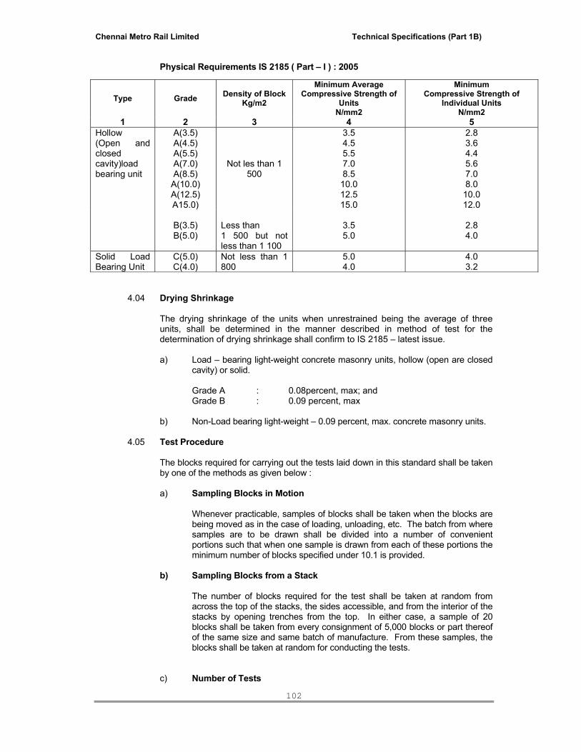
Chennai Metro Rail Limited Technical Specifications (Part 1B)
102
Physical Requirements IS 2185 ( Part – I ) : 2005
4.04 Drying Shrinkage
The drying shrinkage of the units when unrestrained being the average of three units, shall be determined in the manner described in method of test for the determination of drying shrinkage shall confirm to IS 2185 – latest issue.
a) Load – bearing light-weight concrete masonry units, hollow (open are closed
cavity) or solid.
Grade A : 0.08percent, max; and Grade B : 0.09 percent, max
b) Non-Load bearing light-weight – 0.09 percent, max. concrete masonry units.
4.05 Test Procedure
The blocks required for carrying out the tests laid down in this standard shall be taken by one of the methods as given below :
a) Sampling Blocks in Motion
Whenever practicable, samples of blocks shall be taken when the blocks are being moved as in the case of loading, unloading, etc. The batch from where samples are to be drawn shall be divided into a number of convenient portions such that when one sample is drawn from each of these portions the minimum number of blocks specified under 10.1 is provided.
b) Sampling Blocks from a Stack The number of blocks required for the test shall be taken at random from across the top of the stacks, the sides accessible, and from the interior of the stacks by opening trenches from the top. In either case, a sample of 20 blocks shall be taken from every consignment of 5,000 blocks or part thereof of the same size and same batch of manufacture. From these samples, the blocks shall be taken at random for conducting the tests.
c) Number of Tests
Type Grade Density of Block Kg/m2
Minimum Average Compressive Strength of
Units N/mm2
Minimum Compressive Strength of
Individual Units N/mm2
1 2 3 4 5Hollow (Open and closed cavity)load bearing unit
A(3.5) A(4.5) A(5.5) A(7.0) A(8.5)
A(10.0) A(12.5) A15.0)
Not les than 1 500
3.5 4.5 5.5 7.0 8.5 10.0 12.5 15.0
2.8 3.6 4.4 5.6 7.0 8.0 10.0 12.0
B(3.5) B(5.0)
Less than 1 500 but not less than 1 100
3.5 5.0
2.8 4.0
Solid Load Bearing Unit
C(5.0) C(4.0)
Not less than 1 800
5.0 4.0
4.0 3.2
Chennai Metro Rail Limited Technical Specifications (Part 1B)
103
All the 20 blocks shall be checked for dimensions and inspected for visual
defects. Out of the 20 blocks, 3 blocks shall be subjected to the test for blocks density,
8 blocks to the test for compressive strength, 3 blocks to the test for water absorption and 3 blocks to the test for drying shrinkage and later to the test for moisture movement. The remaining 3 blocks shall be reserved for retest for drying shrinkage and moisture movement if a need arises. The above tests shall be carried out in accordance with IS : 2185 (Part – II) latest issue and no extra payment will be paid for conducting the above tests.
4.06 Cement The cement used shall be the Ordinary Portland cement conforming to and IS :
8112. Unless otherwise specified ordinary Portland cement of 43 grade conforming to latest IS - 8112 shall be used for all masonry and concrete works.
The Contractor shall make his own arrangements for the storage of adequate
quantity of cement.
Cement shall be stored in closed weather proof sheds with raised wooden plank flooring to prevent deterioration by damages or intrusion of foreign matter away from walls.
4.07 Sand Sand shall conform to IS : 383 and IS : 2116. Sand shall have fineness modulus
between 2.1 and 2.5. Sand shall be hard, durable, clear and free from dirt clay organic materials or other impurities. Silt content of sand shall not exceed 5% by volume. Sand containing any trace of salt shall be rejected.
4.08 Water Water used for mortar and curing shall be clean and free from injurious amounts of
deleterious matter such as oils, acids, alkalis, sugar, organic materials etc. Potable water is generally considered satisfactory for mixing mortar and curing.
4.09 Lime Lime shall be stone lime and it shall conform to IS:712. Hydrated lime shall be
mixed with water to form a putty. This shall be stored with reasonable care to prevent evaporation of water for atleast 24 hours before use. Quick lime shall be slaked with enough water to make a cream and then stored with reasonable care to
prevent evaporation of water for atleast seven days before use.
5.00 SCAFFOLDING : Unless otherwise instructed by the Architect, double scaffolding having two sets of vertical
supports shall be provided for all building work. The supports shall be sound, strong and tied together with horizontal pieces over which scaffolding planks shall be fixed. The contractor shall be responsible for providing and maintaining sufficiently strong scaffolding so as to with stand all loads likely to come upon it.
6.00 MORTAR
6.01 IS : 2250 shall be followed as general guidance for preparation and use of mortar. Mixing of mortar shall be done in a mechanical mixer. Cement and sand shall be mixed dry in specified proportions thoroughly and then water shall be added gradually. Wet mixing shall be continued till mortar of the consistency of a stiff

Chennai Metro Rail Limited Technical Specifications (Part 1B)
104
paste and uniform colour is obtained. Only the quantity of mortar which can be used within thirty minutes of its mixing shall be prepared at a time. Hand mixing may be allowed by the Architect on clean approved platform in special cases only.
6.02 Mortar shall be used as soon as possible after mixing and before it has begun to set
and in any case within thirty minutes after the water is added to the dry mixture. Mortar left unused for more than thirty minutes after mixing shall be rejected and removed from the site of work.
6.03 Surplus mortar droppings while laying masonry, if received on a surface free from
dirt, may be mixed with fresh mortar if permitted by the Architect, where directed for addition of extra cement and this shall be implemented.
7.00 BRICK MASONRY :
7.01 Only cement-sand mortar shall be used. Lime shall be added for composite mortar with specific approval of the Architect.
Unless otherwise specified, mortar for brickwork having one or more brick thickness
shall be as specified in BOQ . Mortar for half-brick thick walls shall be 1 part cement and 4 parts sand by volume. Richer mix proportion shall be used, whenever specified or as per design requirement. Mortar shall meet the compressive strength requirement as per IS:2250 and IS:1905.
7.02 Laying IS:2212 shall be followed as general guidance for construction of brick masonry.
Bricks shall be soaked in water before use for a period generally not less than 6 hours so that the water just penetrates the whole depth of the bricks.
Bricks shall be laid in English Bond unless otherwise specified. Half or cut bricks
shall not be used except where necessary to complete the bond. Closer in such cases shall be cut to the required size and used near the ends of the walls, next to quoin headers.
Bricks shall be laid generally with frogs upwards. A layer of mortar shall be spread
on the full width and over a suitable length of the lower course. Each brick shall be properly bedded and set home (in position) by gently tapping with the trowel handle or with a wooden mallet. Its inside face shall be buttered with mortar before the next brick is laid and pressed against it. On completion of a course, all vertical joints shall be fully filled from the top with mortar. The thickness of joints shall be kept uniform and shall not exceed 10 mm. Bricks shall be so laid that all joints are full of mortar.
All face joints shall be raked to a minimum depth of 15 mm by raking tools during the progress of brickwork, when the mortar is still green, so as to provide proper key for the plaster or pointing to be done. When plastering or pointing is not required to be done, the joints shall be struck flush and finished at the time of laying.
Brickwork in walls shall be taken up truly plumb. All courses shall normally be laid
truly horizontal unless indicated to be laid on slope and all vertical joints shall be truly vertical. Vertical joints in alternate courses shall come directly one over the other. Brick wall shall be construed with atleast one plain face with proper alignment.
All connected brickwork shall be carried up simultaneously and no portion of work
shall be left more than one metre below the rest of the work. Where this is not possible, in the opinion of the Architect, the work shall be raked back according to bond (and not toothed) at an angle not steeper than 45 deg. The work done per day should not be more than one metre height

Chennai Metro Rail Limited Technical Specifications (Part 1B)
105
All iron fixtures, pipes, water outlets, hold fasts for doors and windows, etc. which are required to be built into the brickwork shall be embedded in their correct position in mortar or cement concrete as the work proceeds as per directions of the Architect.
All brickwork shall be built tightly against columns, floor slabs or other structural
parts and around door and window frames with proper distance to permit caulked joint. Where drawings indicate that structural steel columns and spandrel beams are to be partly or wholly covered with brickwork, the bricks shall be laid closely against all flanges and webs with all spaces between the steel and brickwork filled solid with mortar not less than 10mm in thickness.
The top courses of all plinth, parapet, steps and top wall shall be laid with brick on
edge unless otherwise specified. Care shall be taken that the bricks forming the top courses and ends of walls are properly radiated and keyed into position as shown on the drawings.
Scaffolding shall be strong enough to withstand all the dead, live and impact loads
which are likely to come upon it. It shall also be so designed as to ensure the safety of the workmen using them.
In case of joining old brickwork with new brick work, the old work shall be toothed to
the full width of the new wall and to the depth of quarter of a brick in alternate courses. It shall be cleaned of all dust, loose mortar, etc., and thoroughly wetted before starting new brick work. Thickness of each course of new work shall be made equal to the thickness of the corresponding course of the old work by adjusting thickness of horizontal mortar joints.
The face of the brickwork shall be cleaned on the same day on which brickwork is
laid and all mortar dropping removed promptly. Template (bed-block) of plain or reinforced cement concrete shall generally be
provided to support ends of RCC beams. Top surface of the wall shall be suitably treated as per direction of the Architect so as to minimise the friction to movement of the concrete slab over the
bearing. Brickwork shall be protected from rain by suitable covering when the mortar is
green. Masonry work shall be cured by keeping it constantly moist on all faces for a minimum period of seven days. Brickwork carried out during the day shall be suitably marked indicating the date on which the work is done so as to keep a watch on the curing period.
7.03 Half brick masonry The work shall be done in the same manner, as mentioned in 7.02 except that all
courses shall be laid with stretchers. Unless otherwise specified the walls will be provided with RCC (1:2:4) binders reinforced with 2 nos. of 8 mm tor steel bars and 6 mm MS tie bars at 230 intervals. The cost of half brick work shall include the cost of reinforcement and form work for binders. RCC band shall be of size 115 mm wide x 80 mm high and shall be continuous, unless where broken by openings in walls, and the R.C.binders should be provided at 1m intervals regularly.
7.04 Exposed brickwork Exposed brickwork i.e brickwork in superstructure which is not covered by plaster
shall be as shown on the drawings and shall be done by specially skilled masons. All courses shall be laid truly horizontal and all vertical joints shall be truly vertical. Vertical joints in alternate courses shall come directly one over the other. Thickness of brick courses shall be kept uniform and for this purpose wooden straight edge
Chennai Metro Rail Limited Technical Specifications (Part 1B)
106
with graduations indicating thickness of each course including joint shall be used. The height of window sills, bottom of lintels and other such important points in the height of the wall shall be marked on the graduated straight edge. Masons must check workmanship frequently with plumb, spirit level, rule and string.
For all exposed brick work, double scaffolding having two sets of vertical supports
shall be provided. The supports shall be sound and strong, tied together with horizontal pieces over which scaffolding planks shall be fixed.
If face bricks are specified on the drawings, the brickwork shall be in composite
work with face bricks on the exposed face and balance in standard bricks, but maintaining the bond fully. Where face bricks are not specified, bricks for the exposed face shall be specially selected from available stack of bricks. All exposed brickwork on completion of work shall be rubbed down, washed clean and pointed as specified. Where face bricks are used, carborandum stone shall be used for rubbing down.
7.05 Reinforcing Anchorage For external walls, the anchorage in the form of flats or rods from spandrel beams
and columns and any other anchoring and reinforcement as shown on the drawing shall be adequately embedded in the masonry.
8.00 HOLLOW / SOLID BLOCK MASONRY
8.01 Laying
All Hollow / Solid block masonry work should be carried out as shown on the drawings with set blocks, projections. Cuttings, toothings etc., wherever the projection of cement mortar for pointing in the proportion of 1:5 shall be used. Mortar shall consists of cement and clean, sharp coarse sand. The mortar mixed with high sulphate resistance cement shall be used upto ground floor level and above Portland cement shall be used confirming to IS 269 – Latest issue. Sand shall be clean, not too fine, not to coarse and shall fall with in the grading bones I to IV given in Table – III of IS 383 – latest issue. The silt content of sand shall not exceed 5% by volume. Water used for mixing mortar shall be in accordance with Clause 4.3 of IS : 456 – Latest issue. Unless otherwise specified, the size of blocks shall be as follows: i. Main walls: Length = 400 mm, Width = 300/200 mm and Depth 100 mm. ii. Partition Walls : Length = 400 mm, Width = 100 mm and Depth 100 mm. iii. Half length blocks shall be of 200mm length
iv. and it shall be used for obtaining the bond and where absolutely necessary
as directed by the Architect. The blocks shall be bedded and jointed with mortar in such a manner as not to leave voids. Each block shall be correctly bedded into position by topping with the handle of the trowel, grouting of mortar slurry will not be allowed except where necessary for special reasons and in such cases, prior permission of the Architect shall be obtained. Care shall be taken that each coarse of block masonry work is truly horizontal and perfect in bond and the face of the wall is straight, plumb and even. The mortar joints shall be 12 mm thickness, except where extra thickness is required for the purpose of bringing the block to the required height or level. All junctions of main walls, partition walls and cross walls shall be carefully bonded into the main walls. The rate of laying masonry will be upto a height of 100 cm per

Chennai Metro Rail Limited Technical Specifications (Part 1B)
107
day if cement mortar is used. Greater heights may be built only if permitted by the Architect. During rains, the work shall be carefully covered to prevent mortar from being washed away, should any mortar or cement be washed away, the work shall be removed and rebuilt at the contractor’s expense. Unless otherwise specified the Hollow / Solid block walls will be provided with RCC 1:2:4 binders 75 mm thick, reinforced with 2 nos. of 8 mm dia. mild steel bars with 6 mm dia. mild steel tie bars at 230 mm centres at every 1 metre interval from floor level. The cost of Hollow / Solid block work shall include the cost of reinforcement and form work for binders.
9.00 STONE MASONRY
9.01 IS : 1597 shall be followed as general guidance for construction of stone masonry. 9.02 Mortar Unless otherwise specified, mortar for stone masonry shall be 1 part of and 6 parts
sand by volume. Properties, preparation and use of mortar shall be same as specified under clause 6.00.
9.03 Dressing of Stone The dressing of stone shall be as specified below for individual types of masonry
work and it shall also conform to the general requirements for stone covered in IS:1129.
a) For Random Rubble Stone Masonry, stone shall be hammered the face, the sides
and the beds to enable it to come into close with the neighbouring stone. the bushing on the face shall be 4 cm on an exposed face.
b) For coursed Rubble Masonry (First sort) Face stones, shall dressed on all beds,
and joints, so as to give them approx. angular shape. 9.04 Laying i. Random Rubble Masonry
All stones shall be wetted before use. The wall shall be carried up truly plumb or to the specified batter. Every stone shall be carefully fitted to the adjacent stones, so as to form neat and close joints. Stones may be brought to level courses at plinth, window sills and roof level. Levelling up shall be done with concrete comprising of one part of mortar (used for the masonry) and two parts of graded stone aggregate of 20 mm nominal size. The bond shall be obtained by fitting in closely, the adjacent stones and by using bond stones.
The stones shall be roughly chisel dressed to ensure equal size on face as far as
possible. They shall be of uniform colour and they shall be carefully laid and solidly bedded in mortar.
Face stones shall extend and bond well into the backing. These shall be arranged
to break joints as much as possible, and to avoid long vertical lines of joints, the hearting or interior filling of the wall shall consist of rubble stones which may be of any shape but shall not pass through a circular ring of 15 cm inner diameter. Thickness of these stones in any direction shall not be less than 10 cm. These shall be carefully laid, hammered down with a wooden mallet into the position and solidly bedded in mortar. Clips and spells of stone shall be used where necessary to avoid thick mortar beds or joints and at the same time ensuring that no hollow spaces are left any where in the masonry. The hearting shall be laid nearly level with facing and backing except that at about one metre intervals, vertical ‘plumb’ projecting about

Chennai Metro Rail Limited Technical Specifications (Part 1B)
108
15 cm to 20 cm shall be firmly embedded to form a bond between successive courses. The chips shall not be used below the hearting stone to bring these upto the level of face-stones. The use of chips shall be restricted to the fillings of interstices between the adjacent stones in hearting and these shall not exceed 20% of the quantity of stone masonry. The masonry in a structure shall be carried regularly. Where the masonry of one part has to be delayed, the work shall be raked back at an angle not steeper than 45 deg. Toothing in masonry shall not be permitted.
Bond or through stones running right through the thickness of walls shall be
provided in walls upto 60 cm thick and in case of walls above 60 cm thickness, a set of two or more bond stones overlapping each other by atleast 15 cm shall be provided in a line from back to back.
Where bond stones of suitable length are not available, cement concrete block of mix 1:3:6 (with 20mm nominal size graded stone aggregate) shall be used. Atleast one bond stone or a set of bond stones shall be provided for every 0.5 sqm of the wall surface. All bond stones in stone masonry shall be marked suitably as directed by the Architect.
The quoins shall be selected stones, neatly dressed with the hammer or chisel to
form the required angle, and laid header and stretcher in the alternate layers. Volume of these stones shall not be less than 0.03 cu m.
Stones shall be so laid that all joints are fully packed with mortar and chips. Face
joints shall not be more that 20mm thick. When plastering or pointing is not required to be done, the joints shall be struck flush and finished at the time of laying. Otherwise the joints shall be raked to a minimum depth of 20 mm by raking tool during the progress of work, when the mortar is still green.
Single scaffolding having one set of vertical support shall be allowed. Masonry work
shall be kept constantly moist on all faces for a minimum period of seven days. Green work shall be protected from damage, mortar dropping and rain during construction.
ii. Coursed Rubble Masonry (First Sort)
All stones shall be wetted before use. The walls shall be built up truly plumb or to
specified batter. All courses shall be laid truly horizontal and all vertical joints shall be truly vertical. The height of each course shall not be less than 150 mm nor more than 300 mm. Every stone shall be carefully fitted to the adjacent stones, so as to form neat and close joints. Face stones shall be laid in alternate header and stretcher fashion. No face stone shall be less in breadth than its height and at least one third of the stones shall tail into the work for length not less than twice their height. These shall be so arranged as to break joints by 7 atleast 75 mm. Each face stone shall be of the same height in any given course. The bond shall be obtained by fitting in closely the adjacent stones and by using bond stones.
Stones shall be laid with grains horizontal so that the load is transmitted along the
direction of the maximum crushing strength.
The hearting or the interior filling of the wall shall consist of stones carefully laid on their proper beds in mortar; chips and spalls of stone being used where necessary to avoid thick beds or joints of mortar and at the same time ensuring that no hollow spaces are left anywhere in the masonry. The chips shall not be used below the hearting stone to bring these upto the level of face stones. The use of chips shall be restricted to the filling of interstices between the adjacent stones in hearting and these shall not exceed 10% of the total volume of stone masonry. All bed joints shall be horizontal and all side joints vertical. All joints shall be fully packed with mortar. Face joints shall not be more than 10 mm thick. When plastering or pointing is not required to be done, the joints shall be struck flush and finished at the time of laying.

Chennai Metro Rail Limited Technical Specifications (Part 1B)
109
Otherwise, the joints shall be raked to a minimum depth of 20mm by raking tool during the progress of work, when the mortar is still green.
Stone may be brought to level courses at plinth, window sills and roof level.
Levelling up at plinth level, window sills and roof level shall be done with concrete comprising of one part of the mortar (use for the masonry) and two parts of graded stone aggregate of 20mm nominal size.
The masonry in a structure shall be raised up uniformly and regularly but where
breaks are unavoidable, the work shall be raked back at angle not steeper than 45 deg. Toothing shall not be allowed. Masonry on any day should not be raised by more than 1 metre in height.
Bond or through stones running right through the thickness of walls shall be
provided in walls upto 600 mm thick and in case of walls above 600 mm thickness, a set of two or more bond stones overlapping each other by atleast 150mm shall be provided in a line from face to back.
In case of highly absorbent types of stones (porous limestone and sand stone etc.)
the bond stone shall extend about two-third into the wall. Through stones in such cases may give rise to damp penetration. Therefore, for all the thickness of such walls, a set of two or more bond stones overlapping each other by atleast 150mm shall be provided.
Where bond stones of suitable lengths are not available, cement concrete blocks of
1;3:6 mix (1cement : 3 sand : 6 graded stone aggregate 20mm nominal size) shall be used.
A bond stone or a set of bond stones shall be inserted 1.5 to 1.8 metres apart, in
every course. All bond stones shall be suitably marked during construction for subsequent verification and shall be staggered in subsequent layers. The quoins shall be of selected stones, neatly dressed with the hammer or chisel to form the required angle. These shall be of the same height in which these occur. These shall be atleast 450 mm long and shall be laid stretchers and headers alternately. These shall be laid square on the beds, which shall be rough chisel dressed to a depth of atleast 100 mm. In case of exposed work, these stones shall have a minimum 25mm wide chisel drafts at four edges, all the edges being in the same plane. Single scaffolding having one set of vertical support shall be allowed. The supports shall be sound and strong, tied together by horizontal scaffolding member may rest in a hole provided in the masonry. Such holes, however, shall not be allowed in pillars under one metre in width. The holes left in masonry work for supporting scaffolding shall be filled and made good with cement concrete 1:3:6 (1 cement : 3 sand : 6 stone aggregate 20 mm nominal size)
Masonry work shall be kept constantly moist on all faces for a minimum period of
seven days. Green work shall be protected from rain by suitable covering. The work shall also be suitably protected from damage, mortar dropping and rain during construction.
iii. Coursed Rubble Masonry (second sort)
Laying of this type of masonry shall be in the same manner as First Sort masonry described above except for the following :
The use of chips for filling of interstices of adjacent stones in hearting shall not
exceed 15% of the total volume of stone masonry, and stone in each course need not be of the same height, but more than two stones shall not be used in the height of a course. Face joints shall not be more than 20mm thick.
10.0 MODE OF MEASUREMENT

Chennai Metro Rail Limited Technical Specifications (Part 1B)
110
Unless noted otherwise in the bills of quantities, the method of measurement for various items shall be generally in accordance with IS 1200….subject to the following. Except where otherwise described, stone work and stone walling generally shall be given in cubic metres and fascia work in square metres. When measuring walls, the thickness shall be measured to the nearest one centimetre. Deductions shall made as described in IS : 1200.
*****

Chennai Metro Rail Limited Technical Specifications (Part 1B)
111
SECTION - 9
STRUCTURAL STEEL WORKS & ANTI-CORROSIVE TREATMENT
TABLE OF CONTENTS 1.0 Scope 2.0 General Requirements 3.0 Codes & Standards 4.0 Materials 5.0 Fabrication Drawing 6.0 Fabrication 7.0 Shop Inspection and approval 8.0 Painting and Delivery 9.0 Field Erection 10.0 Final acceptance and handling over of structure 11.0 Miscellaneous steel works 12.0 Tolerances allowed in the erection of plant building without cranes 13.0 Common Weld Defects for filler welds in Structural Steel Fabrication 14.0 Extent of Inspection and Testing. 15.0 Mode of measurement 16.0 Proforma of Guarantee Certificate.

Chennai Metro Rail Limited Technical Specifications (Part 1B)
112
SECTION - 9 STRUCTURAL STEEL WORK
1.00 Scope : The Fabrication and Erection of the Steelwork consist of accomplishing of all Works herein
enumerated including providing all labour, tools and plants, all materials and consumables such as welding electrodes, bolts and nuts, oxygen and acetylene gases, oils for cleaning, etc. of approved quality as per relevant Indian Standards. The work shall be executed in a workman like manner to the complete satisfaction of Architect.
2.00 General requirements : 2.01 This Specification covers the Supply, Fabrication, Painting, Transportation to site and
Erection on prepared Foundations, Structural Steelwork consisting of Columns, Beams, Lattice girders, trusses, purlins, bracing, built-up sections, sag rods, girts, etc.
2.02 Fabrication, Erection and approval of Steel Structures shall be in compliance with :
- These General Specifications, IS : 800 and other relevant Indian Standards as listed in clause 12.
- Drawings and supplementary drawings to be supplied to the Contractor by during
execution of the work.
2.03 In case of conflict between the clauses mentioned here and the Indian Standards, those expressed in this Specification shall govern.
3.00 CODES AND STANDARDS The applicable Indian Standard and code is given below: IS 123 : RED OXIDE PRIMER IS 277 : GALVANIZED STEEL SHEETS (PLAIN & CORRUGATED) IS 459 : CORRUGATED & SEMI-CORRUGATED A.C. SHEETS IS 730 : HOOK BOLTS FOR CORRUGATED SHEET ROOFING IS 800 : COP FOR GENERAL CONSTRUCTION IN STEEL IS 806 : COP FOR USE OF STEEL TUBES IN GENERAL
BUILDING CONSTRUCTION IS 808 : DIMENSIONS OF HR STEEL BEAMS, CHANNELS & ANGLES IS 811 : COLD FORMED LIGHT GAUGE STRUCTURAL STEEL SECTIONS IS 812 : GLOSSARY OF TERMS RELATING TO WELDING & CUTTING IS 813 : SCHEME OF SYMBOLS FOR WELDING

Chennai Metro Rail Limited Technical Specifications (Part 1B)
113
IS 814 (P 1 & 2) : COVERED ELECTRODES FOR METAL ARC WELDING OF STRUCTURAL STEELS IS 815 : CLASSIFICATION CODING OF COVERED ELECTRODES FOR METAL ARC WELDING OF STRUCTURAL STEELS IS 816 : COP FOR METAL ARC WELDING FOR GENERAL CONSTRUCTION IN MS IS 817 : COP FOR TRAINING & TESTING OF METAL ARC WELDERS IS 822 : COP FOR INSPECTION OF WELDS IS 875(P 1 TO 5) : COP FOR DESIGN LOADS FOR BUILDINGS & STRUCTURES IS 961 : HIGH TENSILE STRUCTURAL STEELS IS 1079 : HR CARBON STEEL SHEET & STRIP IS 1161 : STEEL TUBES FOR STRUCTURAL PURPOSES IS 1200 (P 8) : METHOD OF MEASUREMENT OF STEEL WORK & IRON WORK IS 1200 (P 9) : METHOD OF MEASUREMENT OF ROOF COVERING &CLADDING IS 1200 (P 14) : METHOD OF MEASUREMENT OF GLAZING IS 1200 (P 15) : METHOD OF MEASUREMENT OF PAINTING IS 1239 (P 1 & 2) : MS TUBES & TUBULARS IS 1254 : CORRUGATED ALUMINIUM SHEETS IS 1363(P 1 TO 3) : HEXAGON HEAD FASTENERS OF PRODUCT GRADE ‘C’ IS 1364(P 1 TO 5) : HEXAGON HEAD FASTENERS OF PRODUCT GRADE A & B IS 1367 : TECHNICAL SUPPLY CONDITIONS FOR THREADED (P1 TO 18) : STEEL FASTENERS IS 1477 (P 1 & 2) : COP FOR PAINTING OF FERROUS METALS IN BUILDINGS IS 1626 (P 2 & 3) : A.C. GUTTERS, PIPES & ROOFING ACCESSORIES IS 1852 : ROLLING & CUTTING TOLERANCES FOR HR STEEL PRODUCTS IS 1977 : STRUCTURAL STEEL - ORDINARY QUALITY IS 2016 : PLAIN WASHERS IS 2062 : WELDABLE STRUCTURAL STEEL IS 2074 : RED OXIDE ZINC CHROME PRIMER IS 2339 : ALUMINIUM PAINT IS 2527 : COP FOR FIXING GUTTERS & RAIN WATER PIPE FOR ROOF DRAINAGE IS 2932 : SYNTHETIC ENAMEL PAINTS

Chennai Metro Rail Limited Technical Specifications (Part 1B)
114
IS 3007 (P 1 &2) : COP FOR LAYING A.C. SHEETS IS 3444 : CRANE RAIL SECTIONS IS 3502 : STEEL CHEQUERED PLATES IS 3548 : COP FOR GLAZING IN BUILDING IS 4000 : COP FOR ASSEMBLY OF STRUCTURAL JOINTS
USING HSFG FASTENERS IS 4923 : HOLLOW STEEL SECTIONS FOR STRUCTURAL USE IS 5372 : TAPER WASHERS FOR CHANNELS IS 5374 : TAPER WASHERS FOR BEAMS IS 5624 : FOUNDATION BOLTS IS 6639 : HEXAGONAL BOLTS FOR STEEL STRUCTURES IS 7205 : SAFETY CODE FOR ERECTION OF STRUCTURAL STEELWORK IS 7215 : TOLERANCES FOR FABRICATON IS 8869 : WASHERS FOR CORRUGATED SHEET ROOFING IS 12093 : COP FOR LAYING & FIXING SLOPED ROOF COVERINGS USING PLAIN & CORRUGATED GALVANISED STEEL SHEETS IS 12843 : TOLERANCES FOR ERECTION OF STEEL STRUCTURES COP : Code of Practice 4.00 MATERIALS : 4.01 Rolled Sections The following grades of steel shall be used for steel structures. 4.1.01 Structural steel shall conform to IS 2062 Gr. ‘A’ (for thickness upto 20 mm) & IS 2062 Gr. ‘B’
(for thickness above 20 mm). 4.1.02 For purlins and girts cold rolled Z sections of TI Metal sections Ltd. or equivalent shall be
used. Z sections shall be manufactured from tested HR coils to IS : 10748 and the sections shall
conform to IS : 801 and IS : 811. The size and sectional properties shall be as follows :
Span Size Thickness Zx Zx Zy (mm) (top) (bottom)
cm3 cm3 cm3 4 M 150230 2.3 31.14 29.92 8.56 5 M 165255 2.55 36.40 35.55 8.26

Chennai Metro Rail Limited Technical Specifications (Part 1B)
115
Z purlin shall be supplied with sleeves duly drilled / punched, sag rods and fasteners. 4.02 WELDING MATERIALS : 4.2.01 Welding Electrodes shall conform to IS : 814 & AWS E 6013 | For thickness
upto 20mm | For thickness
| above20mm-AWS | E7018
4.2.02 Approval of welding procedures shall be as per IS : 816 4.03 BOLTS, NUTS AND WASHERS : Bolts and nuts shall be as per IS 1363 & IS 1367 class 8.8. Washers shall be as per IS :
2016, IS : 5372 & IS : 5374. 4.04 All materials shall conform to their respective specifications. The use of Equivalent or
higher grade or alternate materials will be considered only in very special cases subject to the approval of the Architect in writing.
Any defective material used, pointed out at any stage of work, shall be replaced by
Contractor at his own expenses. Care shall be taken to prevent any damage to the other portion of work during removal.
4.05 Receipt and Storing of Materials : 4.5.01 Each rolled section must be marked for identification and each lot should be accompanied
by Manufacturer’s quality certificate, confirming chemical analysis and mechanical characteristics.
4.5.02 All steel parts furnished by Supplier shall be checked, sorted out, straightened and arranged
by grades and qualities in stores. 4.5.03 Structurals with surface defects such as pitting, cracks, laminations etc. shall be rejected if
the defects exceed the allowable tolerances specified in relevant Standards. 4.5.04 Welding electrodes shall be stored separately by qualities and lots inside a dry and
enclosed room, in compliance with IS : 816 and as per instructions given by Architect. Electrodes shall be perfectly dry and drawn from an Electrode oven, if required.
4.5.05 Checking of quality of bolts of any kind as well as storage of same shall be made
conforming to relevant standards. 4.5.06 Each lot of electrodes, bolts, nuts etc. shall be accompanied by Manufacturer’s test
certificates. 4.5.07 The Contractor may use alternative materials as compared to Design Specifications only
with the written approval of Architect. 4.06 Material Tests : 4.6.01 Contractor shall be required to produce Manufacturer’s quality certificate for the material or
wherever quality certificates are missing or incomplete or when material quality differs from standard Specifications the Contractor shall conduct all appropriate tests as directed by the Architect, at no extra cost, in approved test houses.
4.6.02 Materials for which Test Certificates are not available or for which test results do not tally
with relevant standard Specification, shall not be used.

Chennai Metro Rail Limited Technical Specifications (Part 1B)
116
5.00 Fabrication Drawings : 5.01 Fabrication and erection drawings shall be prepared by the Contractor on the basis of
Design drawings supplied to him and submit the same to Architect (EIC) for review in triplicate. Architect may review at his option some, all or none of the Fabrication drawings. Wherever such reviews are carried out, the same shall be restricted to the following :
- Structural layout, orientation and elevation of Structures and Members.
- Sizes of members - Adequacy of critical connections and joints for required strength. - Shop / Field welding details from view point of erection. 5.02 In those cases where EIC carries out either full, or partial review, one copy of drawing
submitted by the Contractor shall be returned to him and Contractor shall incorporate the amendments and submit further three copies of amended drawings for final review. In those cases where EIC does not review the drawings, he shall return 1 copy of drawings, stamped “Not reviewed proceed at Contractor’s responsibility”, to the Contractor for further action.
5.03 Fabrication drawings shall include the following : - Structural layout and Elevations - Sizes of Structural Members - Adequacy of Connections and joints
- Design and detailing of structural joints for required strength and erection - Type and dimension of welds and bolts - Shapes and sizes of edge preparation for welding - Details of shop and field joints included in the Assembly - Bill of Materials
- Quality of Structural steel, welding electrodes, bolts, nuts and washers to be used
- Erection assemblies identifying all transportable parts and sub-assemblies associated with special erection instructions, if required.
- Non Destructive Testing (NDT)
Crane Girders - 20% Dye Penetrant Examination (DPE) of rootruns. - 10% radiography of all butt welds Others - 10% DPE 5.04 Review by EIC fully/partially or non-review of Fabrication drawings submitted by Contractors
shall not absolve the Contractor of his responsibility and he shall modify /rectify the structures at any stage of work when pointed out by Architect that such work is not in conformity with specification and/or standard practice.
5.05 Connections, splices etc. other details not specifically detailed in Design drawings shall be
suitably given on Fabrication drawings considering normal detailing practices and developing full member strengths. Where asked for calculations for the same, these shall also be submitted for approval.
5.06 Any alternate design or change in section is allowed only when approved in writing by the
Architect.

Chennai Metro Rail Limited Technical Specifications (Part 1B)
117
5.07 However if any variation in the scheme is found necessary later, the Contractor shall incorporate these changes in his Shop Drawings, at no extra cost and resubmit for review.
5.08 The contractor shall supply six prints each of the final reviewed drawings to Architect within
a week from the date of final review, at no extra cost, for reference and record of OWNER. 5.09 The Architect will verify the correct interpretation of his requirements. 5.10 If any modification is made in the Design drawing during the course of execution of the
work, revised Design drawings will be issued to the Contractor. Further changes arising out of these shall be incorporated by the Contractor in the Fabrication drawings already prepared at no extra cost and the revised Fabrication drawings shall be duly got reviewed as per the above clauses.
6.00 Fabrication : 6.01 Fabrication shall be in accordance with IS : 800 Section - V in addition to the following : Fabrication shall be done as per approved Fabrication drawings adhering strictly to work
points and work lines on the same. The connections shall be welded or bolted as per Design drawings. Work shall also include fabricating built up sections. (Fabrication of basic rolled sections equivalent from plates is not included).
All the fabricated and delivered items shall be suitably packed to be protected from any
damage during transportation and handling. Any damage caused at any time shall be made good by the Contractor at his cost.
Any faulty fabrication pointed out at any stage of work shall be made good by the Contractor
at his cost. 6.02 Preparation of Materials : 6.2.01 Prior to release for fabrication, all rolled sections warped beyond allowable limits shall be
pressed or rolled straight and free from twists, taking care that uniform pressure is applied. 6.2.02 Minor warpings, corrugations etc. in rolled sections shall be rectified by cold working. 6.2.03 The sections shall be straightened by hot working where the Architect so directs and shall
be cooled slowly after straightening. 6.2.04 Warped members like plates and flats may be used as such only if wave like deformation
does not exceed L/1000 but limited to 3 mm (L = Length). 6.2.05 Surfaces of Members that are to be joined by lap or fillet welding or bolting shall be even so
that there is no gap between overlapping surfaces. 6.03 Marking : 6.3.01 Marking of Members shall be made on horizontal pads, or on appropriate racks or supports
in order to ensure horizontal and straight placement of such Members. 6.3.02 Marking accuracy shall be within ± 1 mm. 6.04 Cutting : 6.4.01 Members shall be cut mechanically (by saw or shear) or by oxyacetylene flame. 6.4.02 All sharp, rough, or broken edges, and all edges of joints which are subjected to tensile or
alternating stresses, shall be ground. 6.4.03 No electric metal arc cutting shall be allowed.

Chennai Metro Rail Limited Technical Specifications (Part 1B)
118
6.4.04 All edges cut by oxyacetylene process shall be cleaned of impurities and slag prior to
assembly. 6.4.05 Cutting tolerances shall be as follows :
a) For members connected at both ends ± 1 mm b) Elsewhere ± 3 mm.
6.4.06 The edge preparation for welding of members more than 12 mm thick shall be done by
flame cutting and grinding. Cut faces shall not have cracks or be rough. 6.4.07 Edge preparation shall be as per IS : 816 6.05 Drilling : 6.5.01 Bolt holes shall be drilled. Materials of thickness upto 16 mm, may be punched. 6.5.02 Drilling shall be made to the diameter specified in drawings. 6.5.03 No enlarging of holes by filing, mandrilling or oxyacetelene flame shall be allowed. 6.5.04 Allowable variations for holes (out of roundness, eccentrictly, plumb-line deviation) shall be
as per IS : 800.
- Maximum deviation for spacing of two holes on the same axis shall be ± 1 mm.
- Two perpendicular diameters of any oval hole shall not differ by more than 1 mm.
6.5.05 Drilling faults in holes may be rectified by reaming holes to the next upper diameter,
provided that spacing of new hole centres and distance of hole centres to the edges of members are not less than allowed and that the increase of hole diameter does not impair the structural strength. Hole reaming shall be allowed if the number of faulty holes does not exceed 15% of the total number of holes for one joint.
6.5.06 Unless otherwise noted in the drawing - Pitch of holes - 3D Edge distance-Shear and edge - 1.5 D Rolled edge - 1.25 D 6.06 Bending : 6.6.01 Bending of plates, flats and sections shall be carried out on bending rolls or in presses. 6.6.02 Cold bending may be accepted when bending radius is equal or more than ; - 25 times member thickness for plates and flats
- 25h or 25b for rolled steel beams and channels according to bending plane - 45b for angle Where h = section height and b = flange width. 6.6.03 When bending radius is less than that indicated in 5.6.2, bending shall be done by heating
the member up to 850 - 900oC (light red radiance). Cooling shall be done slowly as directed by Architect.
6.6.04 Bending shall be discontinued when temperature drops below 500oC.

Chennai Metro Rail Limited Technical Specifications (Part 1B)
119
6.6.05 Accuracy of bending operations shall be checked by means of Templates and the clearance between member and template shall not be more than 1 mm.
6.6.06 Bent members shall not have cracks or deep indentations from bending equipment. 6.07 Preparation of Members for Welding : 6.7.01 Assembly of structural Members shall be made with proper jigs and fixtures to ensure
correct positioning of members (angles, axes, nodes, etc.) 6.7.02 Sharp edges, rust of cut edges, notches, irregularities and fissures due to faulty cutting shall
be chipped or ground or filled over the length of the affected area, deep enough to remove faults completely.
6.7.03 Edge preparation for welding shall be carefully and accurately made so as to facilitate a
good joint. 6.7.04 Generally no special edge preparation shall be required for members under 8 mm thick. 6.7.05 Edge preparation (bevelling) denotes cutting so as to result in V,X,K or U seam shapes as
per IS : 816. Unless otherwise noted in the drawing : < 6 mm - Square butt 8 - 11 mm - Single V > 12 mm - Double V 6.7.06 The members to be assembled shall be clean and dry on the welding edges. Under no
circumstances shall wet, greasy, rust or dirt covered parts be assembled. Joints shall be kept free from any foreign matter, likely to get into the gaps between members to be welded.
6.7.07 Before assembly the edges to be welded as well as adjacent areas extending for atleast 20
mm shall be cleaned (until metallic polish is achieved). 6.7.08 When assembling members, proper care shall be taken of welding shrinkage and
distortions, as the drawing dimensions cover finished dimensions of the Structure. 6.7.09 The elements shall be got checked and approved by the Architect or his authorised
representative before assembly. 6.7.10 The permissible Tolerances for assembly of members preparatory to welding shall be as per
IS : 816. 6.7.11 After the assembly has been checked, temporary tack welding in position shall be done by
electric welding, keeping in view finished dimensions of the Structure. 6.7.12 Preheating of members to be joined to be carried out as per standards wherever necessary. 6.08 Welding Procedures : 6.8.01 Welding shall be carried out only by fully trained and experienced welders as tested and
approved by the Architect or his representative or the Inspectors. The cost involved for such tests shall be borne by the Contractor himself.
6.8.02 Qualification tests for Welders as well as tests for approval of electrodes will be carried out
as per IS : 816. The nature of test for performance qualification of welders shall commensurate with quality of welding required on this work as judged by the Architect.
Unless otherwise noted in the drawing : < 20 mm - Electrodes to AWS E 6013 > 20 mm - Electrodes to AWS E 7018 6.8.03 The Steel structures shall be automatically, semi-automatically or manually welded.

Chennai Metro Rail Limited Technical Specifications (Part 1B)
120
6.8.04 Welding shall begin only after the checks shown under 5.7 have been carried out. 6.8.05 Welding precedures and Tests for Welders skill shall be conducted as per IS : 816 and
approved by the Architect. 6.8.06 The welder shall mark his Identification mark on each element welded by him. 6.8.07 When welding is carried out in open air, steps shall be taken to protect the place of welding
against wind or rain. The electrodes, wires and parts being welded shall be dry. 6.8.08 Before beginning the welding operation, each joint shall be checked to ensure that the parts
to be welded are clean and root gaps provided as per IS : 816. 6.8.09 For continuing the welding of seams discontinued due to some reason, the end of the
discontinued seam shall be melted in order to obtain a good continuity. Before resuming the welding operation, the groove as well as the adjacent parts shall be well cleaned for a length of approximately 50 mm.
6.8.10 For single butt welds (in V,1/2V or U) and double butt welds (in K, double U, etc) the
rewelding of the root butt is mandatory but only after the metal deposition on the root has been cleaned by back gouging or chipping.
6.8.11 The welding seams shall be left to cool slowly. The Contractor shall not be allowed to cool
the welds quickly by any method. 6.8.12 For multi-layer welding, before welding the following layer, the formerly welded layer shall
be cleaned by light chipping and wire brushing. Backing strips shall not be allowed. 6.8.13 The order and method of welding shall be so that : - no unacceptable deformation appears in the welded parts
- due margin is provided to compensate for contraction due to welding in order to avoid any high permanent stresses.
6.8.14 The defects in welds must be rectified according to IS : 816 and as per instruction of
Architect. 6.09 Weld Inspection : 6.9.01 The weld seams shall satisfy the following : - shall correspond to Design shapes and dimensions
- shall not have any defects such as cracks, incomplete penetration and fusion, under-cuts, rough surfaces, burns, blow holes and porosity etc. beyond permissible limits (See Annexure-I).
6.9.02 During the welding operation and approval of finished elements, inspections and tests shall
be made as shown in Annexure - II. 6.9.03 The mechanical characteristics of the welded joints shall be as in IS : 816. 6.10 Preparation of Members for Bolting : 6.10.01 The Members shall be assembled for bolting with proper jigs and fixtures to sustain the
assemblies without deformation and bending. 6.10.02 Before assembly, all sharp edges, shaving, rust, dirt etc. shall be removed.
Chennai Metro Rail Limited Technical Specifications (Part 1B)
121
6.10.03 Before assembly, the contacting surfaces of the members shall be cleaned and given a coat of red oxide primer.
6.10.04 The members which are bolt assembled shall be set according to drawings and temporarily
fastended with erection bolts (minimum 4 pieces) to check the coaxiality of the holes. 6.10.05 The members shall be finally bolted after the deviations have been corrected, after which
there shall not be gaps. 6.10.06 Before assembly, the member shall be checked and got approved by the Architect. 6.10.07 The difference in thickness of the Sections that are butt assembled shall not be more than
3% or maximum 0.8 mm whichever is less. If the difference is large, it shall be corrected by grinding or filling.
6.10.08 Reaming of holes to final diameter or cleaning of these, shall be done only after the parts
have been check assembled. 6.10.09 As each hole is finished to final dimensions (reamed if necessary) it shall be set and bolted
up. Erection bolts shall not be removed before other bolts are set. 6.11 Bolting Up : 6.11.01 Final bolting of the members shall be done after the defects have been rectified and
approval of joints obtained. 6.11.02 The bolts shall be tightened starting from the centre of the joint towards the edge. 6.12 Holes for Field Joints : 6.12.01 Holes for field joints shall be drilled in the shop to final diameters and tested in the shop,
with trial assemblies. Gas cutting of holes shall not be permitted. 6.12.02 When three-dimensional assembly is not possible in the shop, the holes for field joints may
be drilled in shop and reamed on site after Erection, on approval by the Architect. 6.12.03 For bolted steel structures, trial assembly in shop is mandatory. 6.12.04 The tolerance for spacing of holes shall be ± 1 mm. 6.13 Tolerances : 6.13.01 All tolerances regarding dimensions, geometrical shapes and sections of Steel Sections,
shall be as per IS 808 & IS 1852, if not specified in the drawing. 6.14 Marking for Identification : 6.14.01 All elements and members prior to despatch for Erection shall be shop marked. 6.14.02 The members shall be visibly marked with a weather proof light coloured paint. The size
and thickness of the numbers shall be so chosen as to facilitate the identification of members.
6.14.03 For the small members that are delivered in bundles or crates, the required marking shall be
done on small metal tags securely tied to the bundle, while the crates shall be marked directly.
6.14.04 Each bundle or crate shall be packed with members for one and the same assembly in the
same bundle or crate, general utility members such as bolts, gussets, etc. may be packed. 6.14.05 All bill of materials showing weight, quality and dimension of contents shall be placed in the
crates.
Chennai Metro Rail Limited Technical Specifications (Part 1B)
122
6.14.06 The members shall be marked with a durable paint, in a visible location, preferably at one
end of the member so that these may be easily checked during storage and erection. 6.14.07 The members shall be marked in the shop before inspection and acceptance. 6.14.08 When the member is being painted, the marking area shall not be painted but bordered with
white paint. 6.14.09 The marking and job symbol shall be registered in all shop delivery documents
(transportation, for erection etc.) 6.15 Shop Test Pre-assembly : 6.15.01 For Steel Structures that have the same type of welding the shop test pre-assembly shall be
performed on one out of every 10 members minimum. 6.15.02 In case one member does not meet the limiting deviations specified in the general
specification in pre-assembly shop test, all members shall be shop tested. 6.15.03 For bolted Steel Structures, shop test pre-assembly is mandatory for all elements as well as
for the entire structure in conformity with clause 5.12. 7.00 Shop Inspection and Approval : 7.01 General : The Architect or his representative shall have free access at all reasonable times to the
Contractor’s Fabrication Shop and shall be afforded all reasonable facilities for satisfying himself that the Fabrication is being undertaken in accordance with Drawings and Specifications.
7.1.01 Technical approval of the Steel Structure in the shop by the Architect is mandatory. 7.1.02 The Contractor shall not limit the number and kinds of Tests, final as well as intermediate
ones, or extra tests requested by the Architect. 7.1.03 The Contractor shall furnish necessary tools gauges, instrument etc. and technical and non-
technical personnel for shop tests required by Architect, free of cost. 7.02 Shop Acceptance : The Architect shall inspect and approve at the following stages. 7.2.01 The following approvals may be given in shop : - Intermediate approvals of work that cannot be inspected later. - Partial approvals. - Final approvals. 7.2.02 Intermediate approvals of work shall be given when a part of the work is performed later - Inspection would be difficult to perform and results not be satisfactory. - Cannot be inspected later 7.2.03 Partial approval in the shop is given on members and assemblies of Steel Structures before
the primer coat is applied and includes : - Approval of material

Chennai Metro Rail Limited Technical Specifications (Part 1B)
123
- Approval of field joints - Approval of part with planed surface - Test Erection - Approval of members - Approval of markings
- Inspection and approvals of special features, like rollers, loading platform mechanism etc.
7.2.04 During the partial approval, intermediate approvals as well as former approvals shall be
taken into consideration. 7.03 Final Approval in the Shop : 7.3.01 The final approval refers to all elements and assemblies of the Steel Structures with shop
primer coat, ready for delivery from shop, to be loaded for transportaion or stored. 7.3.02 The final approval comprises : - Partial approvals. - Approvals for shop primer coat - Approval of mode of loading and transport - Approval of storage (for materials stored) 7.3.03 Inspection by EIC shall be only at random and on critical factors and shall not absolve the
contractor of the responsibility to fabricate the structures as per the specified standards & specifications.
8.00 Painting and Delivery : 8.01 Preparation of Parts for Shop Painting and Site Painting : 8.1.01 Painting shall consist of providing one coat of zinc chromate primer and one coat of
anticorrosive enamel paint of approved make and colour to steel members before despatch from shop.
Site Painting : After providing one coats of primer and one finish coat at shop as mentioned above, at site
after erection one more coat of anticorrsive enamel paint shall be provided. Touching up shall be done wherever required and on site welded surfaces and as directed.
8.1.02 Primer coat shall not be applied unless : - Surfaces have been sandblasted to clean, dust, oil, rust, etc.
- Erection gaps between members spots that cannot be painted or where moisture or other aggressive agents may penetrate have been filled with an approved type of oil and putty.
Chennai Metro Rail Limited Technical Specifications (Part 1B)
124
- The surfaces to be painted are completely dry. - Members and parts have been inspected and accepted. - Welds have been accepted.
8.1.03 The following are not to be painted or protected by any coating. - Surfaces which are in the vicinity of joints to be welded at SITE. - Surfaces bearing markings. - Other surfaces indicated in the Design. 8.1.04 The following shall be given a coat of hot oil or any approved resistant lubricant only: - Planed surfaces. - Holes for links. 8.1.05 The surfaces that are to be embedded or in contact with the concrete, shall not be painted. 8.1.06 The other surfaces shall be given a primer coating. 8.1.07 Special attention shall be given to locations not accessible, where water can collect and
which after assembly and erection cannot be inspected, painted and maintained. Holes shall be provided for water drainage and inaccessible box type sections shall be hermatically sealed by welds.
8.02 Packing, Transportation, Delivery : 8.2.01 After final shop acceptance and marking, the item shall be packed and loaded for
transportation. 8.2.02 Packing must be adequate to protect items against warping during loading and unloading. 8.2.03 Proper lifting devices shall be used for loading, in order to protect items against warping. 8.2.04 Slender projecting parts shall be braced with additional steel bars before loading for
protection against warping during transportation. 8.2.05 Loading and transportation shall be done in compliance with transportation rules. 8.2.06 If certain parts cannot be transported in the lengths stipulated in the Design, the position
and type of additional splice joints shall be approved by Architect. 8.2.07 Items must be carefully loaded on platforms for transportation with adequate means to
prevent warping, bending or falling during transportation. 8.2.08 The small parts such as fish plates, gussets etc. shall be securely tied with wire to their
respective parts. 8.2.09 Bolts, nuts and washers shall be packed and transported in crates or bags. 8.2.10 The parts shall be delivered in the order stipulated by the Architect and shall be
accompanied by documents showing: - Quality and quantity of structure of members - Position of member in the structure - Particulars of structure
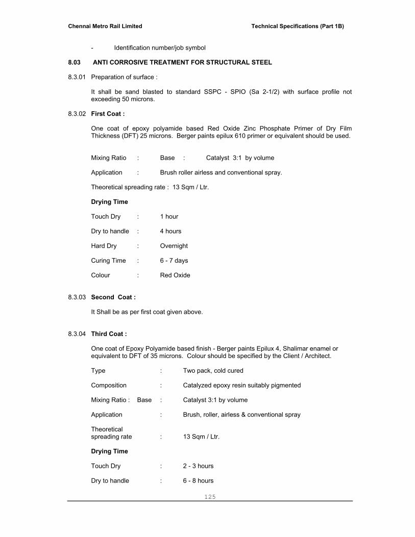
Chennai Metro Rail Limited Technical Specifications (Part 1B)
125
- Identification number/job symbol 8.03 ANTI CORROSIVE TREATMENT FOR STRUCTURAL STEEL 8.3.01 Preparation of surface :
It shall be sand blasted to standard SSPC - SPIO (Sa 2-1/2) with surface profile not exceeding 50 microns.
8.3.02 First Coat : One coat of epoxy polyamide based Red Oxide Zinc Phosphate Primer of Dry Film
Thickness (DFT) 25 microns. Berger paints epilux 610 primer or equivalent should be used. Mixing Ratio : Base : Catalyst 3:1 by volume Application : Brush roller airless and conventional spray. Theoretical spreading rate : 13 Sqm / Ltr. Drying Time Touch Dry : 1 hour Dry to handle : 4 hours Hard Dry : Overnight Curing Time : 6 - 7 days Colour : Red Oxide 8.3.03 Second Coat : It Shall be as per first coat given above. 8.3.04 Third Coat : One coat of Epoxy Polyamide based finish - Berger paints Epilux 4, Shalimar enamel or
equivalent to DFT of 35 microns. Colour should be specified by the Client / Architect. Type : Two pack, cold cured Composition : Catalyzed epoxy resin suitably pigmented Mixing Ratio : Base : Catalyst 3:1 by volume Application : Brush, roller, airless & conventional spray Theoretical spreading rate : 13 Sqm / Ltr. Drying Time Touch Dry : 2 - 3 hours Dry to handle : 6 - 8 hours
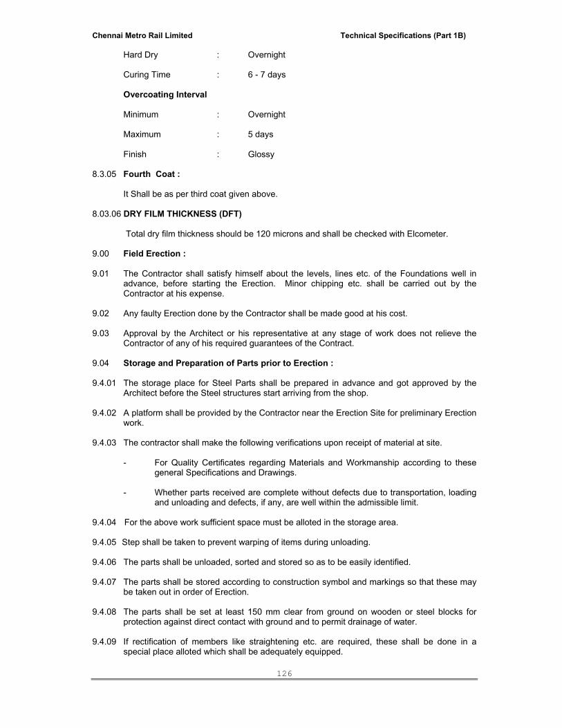
Chennai Metro Rail Limited Technical Specifications (Part 1B)
126
Hard Dry : Overnight Curing Time : 6 - 7 days Overcoating Interval Minimum : Overnight Maximum : 5 days Finish : Glossy 8.3.05 Fourth Coat : It Shall be as per third coat given above. 8.03.06 DRY FILM THICKNESS (DFT) Total dry film thickness should be 120 microns and shall be checked with Elcometer. 9.00 Field Erection : 9.01 The Contractor shall satisfy himself about the levels, lines etc. of the Foundations well in
advance, before starting the Erection. Minor chipping etc. shall be carried out by the Contractor at his expense.
9.02 Any faulty Erection done by the Contractor shall be made good at his cost. 9.03 Approval by the Architect or his representative at any stage of work does not relieve the
Contractor of any of his required guarantees of the Contract. 9.04 Storage and Preparation of Parts prior to Erection : 9.4.01 The storage place for Steel Parts shall be prepared in advance and got approved by the
Architect before the Steel structures start arriving from the shop. 9.4.02 A platform shall be provided by the Contractor near the Erection Site for preliminary Erection
work. 9.4.03 The contractor shall make the following verifications upon receipt of material at site.
- For Quality Certificates regarding Materials and Workmanship according to these general Specifications and Drawings.
- Whether parts received are complete without defects due to transportation, loading
and unloading and defects, if any, are well within the admissible limit. 9.4.04 For the above work sufficient space must be alloted in the storage area. 9.4.05 Step shall be taken to prevent warping of items during unloading. 9.4.06 The parts shall be unloaded, sorted and stored so as to be easily identified. 9.4.07 The parts shall be stored according to construction symbol and markings so that these may
be taken out in order of Erection. 9.4.08 The parts shall be set at least 150 mm clear from ground on wooden or steel blocks for
protection against direct contact with ground and to permit drainage of water. 9.4.09 If rectification of members like straightening etc. are required, these shall be done in a
special place alloted which shall be adequately equipped.
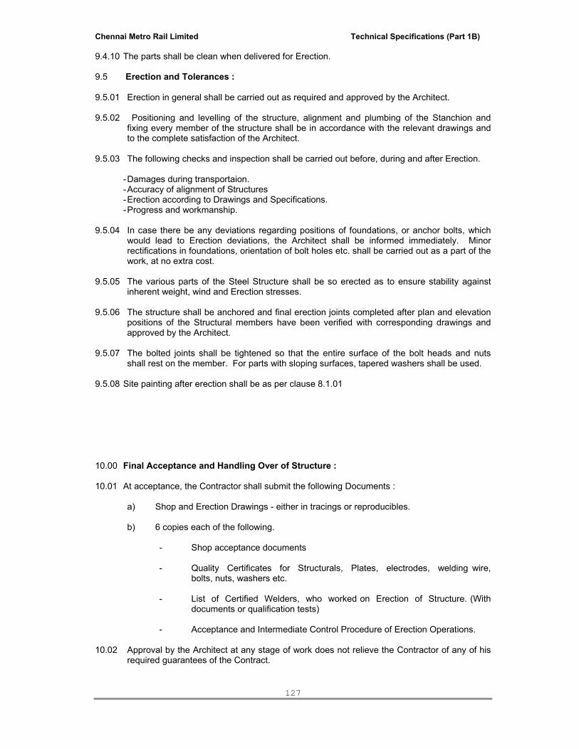
Chennai Metro Rail Limited Technical Specifications (Part 1B)
127
9.4.10 The parts shall be clean when delivered for Erection. 9.5 Erection and Tolerances : 9.5.01 Erection in general shall be carried out as required and approved by the Architect. 9.5.02 Positioning and levelling of the structure, alignment and plumbing of the Stanchion and
fixing every member of the structure shall be in accordance with the relevant drawings and to the complete satisfaction of the Architect.
9.5.03 The following checks and inspection shall be carried out before, during and after Erection. - Damages during transportaion. - Accuracy of alignment of Structures - Erection according to Drawings and Specifications. - Progress and workmanship. 9.5.04 In case there be any deviations regarding positions of foundations, or anchor bolts, which
would lead to Erection deviations, the Architect shall be informed immediately. Minor rectifications in foundations, orientation of bolt holes etc. shall be carried out as a part of the work, at no extra cost.
9.5.05 The various parts of the Steel Structure shall be so erected as to ensure stability against
inherent weight, wind and Erection stresses. 9.5.06 The structure shall be anchored and final erection joints completed after plan and elevation
positions of the Structural members have been verified with corresponding drawings and approved by the Architect.
9.5.07 The bolted joints shall be tightened so that the entire surface of the bolt heads and nuts
shall rest on the member. For parts with sloping surfaces, tapered washers shall be used. 9.5.08 Site painting after erection shall be as per clause 8.1.01 10.00 Final Acceptance and Handling Over of Structure : 10.01 At acceptance, the Contractor shall submit the following Documents :
a) Shop and Erection Drawings - either in tracings or reproducibles. b) 6 copies each of the following.
- Shop acceptance documents - Quality Certificates for Structurals, Plates, electrodes, welding wire,
bolts, nuts, washers etc. - List of Certified Welders, who worked on Erection of Structure. (With
documents or qualification tests) - Acceptance and Intermediate Control Procedure of Erection Operations.
10.02 Approval by the Architect at any stage of work does not relieve the Contractor of any of his
required guarantees of the Contract.

Chennai Metro Rail Limited Technical Specifications (Part 1B)
128
11.00 Miscellaneous Steelwork : 11.01 Anchor Bolts : All materials supplied by the Contractor shall be of tested quality as per Specifications below
and Test Certificates of raw materials shall be provided by the Contractor. Fabrication of Anchor Bolts shall be in compliance with the Specifications. Complete
Anchor Bolt assembly shall be as per drawings, and will include the cost of sleeve pipes, bottom plates, and other fixtures including all welding work if involved.
a) Bolts shall be turned from M.S rounds conforming to IS 2062 Gr ‘A’ b) Nuts shall be Hexagonal type conforming to IS 1363. c) Plain washers shall be of mild steel conforming to IS 2016/IS 2062 Grade ‘A’ d) Threads shall be of coarse type conforming to IS 1367 & IS 4218.
The surface not to be covered with concrete shall be greased and protected from damage
by wrapping and tying jute cloth/polythene. 12.00 Tolerances allowed in the Erection of Plant Building without Cranes : The maximum tolerances for line and level of the Steelwork shall be ± 3.0 mm on any part of
the Structure. The Structure shall not be out of plumb more than 5.0 mm on each 10 M section of height and not more than 8.0 mm per 30 M section.
These tolerances shall apply to all parts of the Structure unless the Drawings issued for
Erection purposes state otherwise.
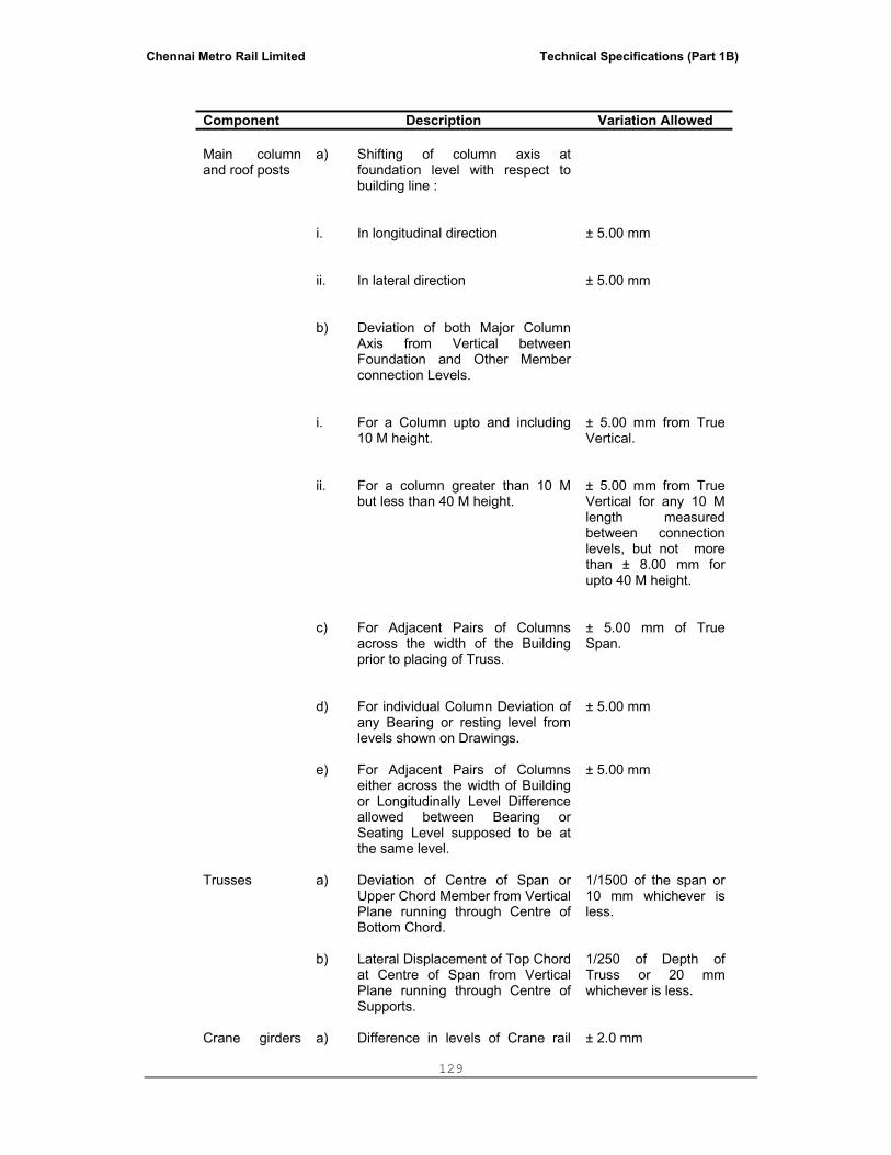
Chennai Metro Rail Limited Technical Specifications (Part 1B)
129
Component Description Variation Allowed Main column and roof posts
a)
Shifting of column axis at foundation level with respect to building line :
i.
In longitudinal direction
± 5.00 mm
ii. In lateral direction
± 5.00 mm
b) Deviation of both Major Column Axis from Vertical between Foundation and Other Member connection Levels.
i.
For a Column upto and including 10 M height.
± 5.00 mm from True Vertical.
ii. For a column greater than 10 M but less than 40 M height.
± 5.00 mm from True Vertical for any 10 M length measured between connection levels, but not more than ± 8.00 mm for upto 40 M height.
c)
For Adjacent Pairs of Columns across the width of the Building prior to placing of Truss.
± 5.00 mm of True Span.
d)
For individual Column Deviation of any Bearing or resting level from levels shown on Drawings.
± 5.00 mm
e)
For Adjacent Pairs of Columns either across the width of Building or Longitudinally Level Difference allowed between Bearing or Seating Level supposed to be at the same level.
± 5.00 mm
Trusses
a)
Deviation of Centre of Span or Upper Chord Member from Vertical Plane running through Centre of Bottom Chord.
1/1500 of the span or 10 mm whichever is less.
b)
Lateral Displacement of Top Chord at Centre of Span from Vertical Plane running through Centre of Supports.
1/250 of Depth of Truss or 20 mm whichever is less.
Crane girders
a)
Difference in levels of Crane rail
± 2.0 mm

Chennai Metro Rail Limited Technical Specifications (Part 1B)
130
Component Description Variation Allowed and tracks measured between Adjacent
columns.
b)
Deviation to Crane rail gauge
± 3.0 mm
c)
Relative Shifting of Ends of Adjacent Crane Rail in Plan and Elevation after Thermit Welding.
± 2.0 mm
d)
Deviation of Crane Rail Axis from Centre Line of Web.
± 3.5 mm
Setting of Expansion Gaps
At the time of setting of the Expansion Gaps, due regard shall be taken of the Ambient Temperature above or below 30oC. The co-efficient of Expansion or Contraction shall be taken as 0.000012 per unit Length per degree celsius.
13.00 COMMON WELD DEFECTS FOR FILLER WELDS IN STRUCTURAL STEEL
FABRICATION 13.01 Incomplete Fusion :
It is defined as the failure to fuse together adjacent layers of weld metal or weld metal and base metal. Causes :
i) Failure to raise the temperature of base metal (or previously deposited weld metal)
to the melting point.
ii) Improper cleaning of the oxides or other foreign material present on the surface to which the deposited metal must fuse.
iii) In-experienced welders.
13.02 Inadequate Penetration :
It is defined as the failure of the filler metal and base metal to fuse integrally at the root of the weld. Causes :
Heat transfer conditions such as,
i) Use of too large an electrode.
ii) An abnormally high rate of travel.
iii) Use of insufficient welding current, is a frequent source of this defect. 13.03. Cracks :
Chennai Metro Rail Limited Technical Specifications (Part 1B)
131
Cracks is defined as in multilayer welds, cracking mostly occurs in the first layer of the weld and unless repaired, will continue through other layers as they are deposited. Cracks may be longitudinal, transverse or crater cracks. Causes : i) Improper electrode manipulation or electrical conditions.
ii) Higher speed of travel resulting in lesser thickness of the deposit.
iii) Higher base metal thickness (which may require pre-heating.)
iv) Wrong type of electrode.
13.04. Under cut :
It is defined as the melting away of the sidewall of a joint at the edge of a layer or bead thus forming a sharp recess in the sidewell.
Causes :
i) Too high a current
ii) Too long an arc.
iii) Magnetic arc below.
13.05 Slag inclusion :
It is defined as oxides and non-metallic solids that are entrapped in weld metal or between weld metal and base metal.
Causes : i) High viscosity of the weld metal.
ii) Rapid solidfication of weld metal.
iii) Too low a welding temperature.
iv) Improper cleaning between passes.
v) Improper electrode manipulation.
13.06 Porosity :
It is defined as gas pockets or voids, free of any solid material, that are frequently found in welds. It may be present as uniformly scattered porosity, cluster porosity or linear porosity.
Causes :
i) Excessive Current.
ii) Excessive arc length.
iii) Wet/unclean joint surfaces.
iv) Eccentric burning of electrode.
v) Frequent interruptions.
13.07.01 Incorrect Weld Profiles.
Causes :

Chennai Metro Rail Limited Technical Specifications (Part 1B)
132
i) Desirable weld profile.
ii) Acceptable fillet weld profile.
iii) Insufficient lag.
13.07.02 Insufficient throat. 13.07.03 Excessive convexity. 13.08. Overlap :
It is defined that the condition in which weld metal protrudes beyond the bond lines at the toe of a weld.
Causes :
i) Incorrect welding technique.
ii) Improper electrical conditions i.e. excessive current or arc length.
14.0 EXTENT OF INSPECTION AND TESTING S.No. Inspection of Test Coverage Procedure Evaluation Findings
and remedy of defect 1. Inspection of weld seam
appearance. All Welds Naked eye or
lens. All faulty welds shall be rectified.
2. Checking of sizes. Atleast one for each weld seam.
Ordinary measuring instruments
Should faulty weld be found, all welds shall be (rule checked and all templates) defect shall be rectified.
3. Mechanical Test for welding procedures performance and Electrodes.
--- As per IS 816 As per IS 816
15.0 Mode of measurement:
Unless noted otherwise in the bills of quantities, the method of measurement for various items shall be generally in accordance with IS 1200.
Chennai Metro Rail Limited Technical Specifications (Part 1B)
133
16. PROFORMA OF GUARANTEE CERTIFICATE FOR ANTI-CORROSIVE TREATMENT TO STRUCTURAL STEEL TO BE TYPED IN STAMP PAPER
Name of the Firm / Company and its address Dear Sirs Anti-corrosive treatment with specialised painting to structural steel work for the work of ……………………………………………………………… Agreement No…………… dated…………. We hereby certify that the work of providing anti-corrosive treatment with specialised painting to structural steel for the work of…………………………………………………
has been executed and completed by us as per specification and in accordance with terms and conditions of contract.
We hereby guarantee that the structural steel of…………………………………………… Treated by us for anti-corrosion shall be safe against attack of corrosion and peeling off for a period of 5 (Five) years from the date of virtual completion of whole work from……to……… In the event of the said treated structural steel of………………………………………… Being or becoming subject to corrosion at any time or times during the guaranteed period of 5 (Five) years, we agree to carryout as often as it becomes necessary, at our cost and expense, all and every treatment that may be necessary to render the said treated structural steel free from corrosion attack or peeling off. The question of whether there is any corrosion, any defect, substandard painting or the treatment has failed away after the date of virtual completion of whole work i.e from……… to…….. shall be decided by the Architect and the decision of the Architect in this regard shall be final and binding on us. We shall carryout the rectification works to the satisfaction of the Architect by bringing new materials at no extra cost to the Architect. Yours faithfully Signature : Name of Company : Address : Seal :
Chennai Metro Rail Limited Technical Specifications (Part 1B)
134
SECTION - 10
ROLLING SHUTTERS
TABLE OF CONTENTS 1.0 Scope 2.0 General Requirements 3.0 Codes and Standards 4.0 Shop Drawings 5.0 Samples 6.0 Mild Steel Plain / Grille Rolling Shutters 7.0 Aluminium Grill Rolling Shutters 8.0 Painting 9.0 Acceptance Criteria 10.0 Mode of Measurements
Chennai Metro Rail Limited Technical Specifications (Part 1B)
135
SECTION – 10 ROLLING SHUTTERS
1.00 SCOPE This specification covers the general requirements for mild steel plain / grille rolling shutter
and aluminium grille rolling shutter with motor drives and/or manual operation and/or Gear operation including design, supply, fabrication and installation in accordance with the drawings and specifications.
2.00 GENERAL REQUIREMENTS
2.01 The Contractor shall furnish all materials, labour, operations, equipment, tools & plant, scaffolding and incidentals necessary and required for the completion of all metal work in connection with steel rolling shutters as called for in the drawings, specifications and bill of quantities which cover the major requirements only. Anything called for in the tender documents shall be considered as applicable to the items of work concerned. The supply and installation of additional fastenings, accessory features and other items not specifically mentioned, but which are necessary to make a complete functioning installation shall form a part of this contract.
2.02 All metal work shall be free from defects, impairing strength, durability and
appearance and shall be of the best quality for purposes specified made with structural properties to withstand safely strains, stresses to which they shall normally be subjected to.
2.03 All fittings shall be of high quality and as specified and as per approval of Architect.
2.04 All electrical work shall be in strict accordance with the latest Indian Electricity
Rules. 2.05 The Contractor shall strictly follow, at all stages of work, the stipulations contained in
the Indian Standard Safety Code and the provisions of the Safety Rules as specified in the General Conditions of the Contract for ensuring safety of men and materials.
2.06 Any approval, instructions, permission, checking, review etc. whatsoever by the
Architect shall not relieve the Contractor of his responsibility and obligation regarding adequacy, correctness, completeness, safety, strength, workmanship etc.
3.00 CODES AND STANDARDS 3.01 All standards, specifications, acts, and codes of practice referred to herein shall be the latest
editions including all applicable official amendments and revisions. 3.02 List of certain important Indian Standards, Acts and Codes applicable to this work is
given below. However, the applicable standards and codes shall be as per but not limited to the list given below :
IS : 2074 Ready mixed paint, air drying, red oxide - zinc chrome, priming
IS : 2108 Blackheart malleable iron castings IS : 6248 Specification for metal rolling shutters and rolling grills.
4.00 SHOP DRAWINGS
4.01 The Contractor shall submit shop drawings and / or samples of each type of roller doors and other items of metal work called for to the Architect for his approval ahead of their use at site and to conform to the C.P.M. Chart. The shop drawings shall show full size sections of doors and other components, thickness of metal,

Chennai Metro Rail Limited Technical Specifications (Part 1B)
136
details of construction, hardware as well as connection of doors and other metal work to adjacent work / supports. Samples of all joints and methods of fastening and joining shall be submitted to the Architect for approval well in advance before commencing the work.
5.00 SAMPLES
5.01 Samples of all typical mild steel plain / grille rolling shutter and aluminium rolling shutter as called for shall be fabricated, assembled and erected or submitted to the Architect as directed by him, for his Approval well in advance of their use at site.
6.00 MILD STEEL PLAIN / GRILLE/ PERFORATED ROLLING SHUTTER
6.01 Components & Fabrication a) Curtain
i) For Plain Shutter / Perforated Shutter
Lath sections or slats for rolling shutter curtain shall be fabricated from 18 gauge tested bright, cold rolled annealed steel strips and machine rolled at 75 mm rolling centres with effective bridge depth of 12 mm interlocked with each other and ends locked with heavy type malleable MS/CI clips conforming to IS : 2108. The profile shall be such as to prevent excessive deflection at specified wind load. In case of peforated shutter lath section shall have 3mm perforation at 3mm clear gap.
Bottom lock plate of curtain shall be made of 3.15 mm thick (10 gauge) MS
plate and 95 mm wide reinforced with suitable angle section at the bottom. The lock plate shall be interlocked with bottom most lath section of curtain so as to provide contact against the sill, when closed. When shown on drawings, a flexible weather strip shall be applied to make tight contact with the floor. The lock plate shall be provided with pulling handles and locking arrangements on both sides as shown on the drawings or as specified and / or as directed by the Architect.
ii) For Grill Shutter
Grille curtains shall be made of 16 gauge MS links of 150 mm long with 75
mm rolling centre with the link openings of 115 x 45 mm. This link shall be assembled with 3/8” dia. hard drawn seamless tubes and the connecting sides (ie. end of tubes) should be sealed with MS clips.
Bottom lock plate of curtain shall be the same as per the Plain shutter. b) Guide Channels The guide channels shall be of mild steel deep channel section and of rolled,
pressed or built-up (fabricated) construction of 75 mm deep, 25 mm wide, and 3.5 mm thick (minimum) with required number of fixing cleats or supports for attachment to the walls or columns by means of anchor fastner/coach screws. The guide shall be of such depth as to retain the shutter under specified wind pressure.
c) Bracket plate The bracket plate shall be fabricated out of mild steel of 3.15 mm thickness
(minimum), thicker plates may be used depending upon the height of shutter. The bracket plate shall have fitted at the centre a U shaped cast iron or mild steel clamp riveted or welded to it. Since the bracket plate carries the full load of the shutter, it should have sufficient cross-sectional area to resist the shear force and it shall be held in position rigidly by means of suitable foundation bolts.
d) Roller
Chennai Metro Rail Limited Technical Specifications (Part 1B)
137
The suspension shaft of the roller shall be made of steel pipe conforming to heavy duty of latest IS : 1161 and of sufficient diameter so as to resist deflection due to the weight of the rolling shutter. The deflection shall not exceed 5 mm per metre width.
The pipes of the suspension shaft which are clamped to the bracket shall be fitted
with rotatable cast iron pulleys to which the curtain is attached. The pulleys and the pipe shaft shall be connected by means of pretension helical springs of suitable gauge conforming to grade 2 of IS : 4454 to counterbalance the weight of the curtain and to keep the shutter in equilibrium in any partly opened position. Grease packed ball bearings or bushings of approved make shall be provided for smooth, trouble free operation. For large size rolling shutter the roller shall be provided with double row, self-aligning ball bearings. For wide openings, the roller shall be of fabricated cage type, the roller assembly shall be designed so as to be capable of producing sufficient torque to ensure easy operation of the rolling shutter in any position. The spring tension shall be adjusted by means of suitable adjustment holes on the rim of the pulleys.
e) Hood The hood cover shall be made of 20 gauge galvanised sheets, suitably reinforced
with stiffener to prevent sag. f) Gears, Worms, etc. All gears, worms, etc. used in the assembly of the rolling shutters shall be machine-
cut. Worm gear wheels shall be of high grade cast iron or mild steel or phosphor bronze. The worms shall be of mild steel or gun-metal or phosphor bronze.
6.02 Manually Operating Shutters
Manually operated shutters shall be easily operable by one person. The speed of operation shall be about 0.3 metres per second.
In general, manually operated shutters shall be push-pull types for small
openings. Larger shutters shall be either chain and gear operated or crank and gear operated. The crank handle shall be removable. All shutters shall be lockable from one or both sides as desired by the Architect.
6.03 Power Operating Shutters
Power unit shall be suitable for 3 phase, 50 cycle, 400 volt AC power supply and
shall be either floor or wall mounted unit. The motors shall be of sufficient capacity to move the shutter in either direction at a speed of 0.3 metres per second. In addition to the Gear motor, each standard power unit shall include a magnetic brake, reversing starter with built-in overload protection, a geared limit switch and one push button station located inside the building unless otherwise stated.
It is desirable that the bottom bar of motor operated doors shall be provided with a
sensitive edge, electrically connected to stop the travel of the door on meeting an obstruction.
Operating chains shall be of tested quality, heavily galvanised and with all ends
rounded to assure smooth operation and hand protection. Reduction gears shall be of high strength grey cast iron, machine moulded from
machine cut patterns. These shall be operable from a push button station conveniently located beside the
door or as shown on drawings. One emergency hand chain/crank operation shall also be provided for use in case of failure of the electrical system.

Chennai Metro Rail Limited Technical Specifications (Part 1B)
138
6.04 Shop Coat Shutters shall be painted with one coat of red oxide or zinc chromate primer paint of
approved make conforming to IS : 2074, latest edition. All surfaces shall be thoroughly cleaned of rust, grease, loose mill sealed etc. before painting shop coat. Portions which will be inaccessible after assembly of units shall be given an extra coat of paint before assembly. Where specified, doors shall be galvanized and subsequently painted with one coat of zinc chromate for adhesion of field coat.
6.05 Storage The fabricated shutter shall be stacked in a careful manner and supported evenly.
All precautions shall be taken to ensure that the shutters are not damaged or distorted in any manner.
6.06 Installation
Brackets shall be rigidly fixed to the lintel, wall or at any position as required to take
the full load of the shutter. The shaft along with springs shall be fixed to the brackets. The shutter shall be laid on ground and the guide channels shall be bound with it, with ties. The shutter shall then be placed in position and the top fixed with suspension shaft. The side guides channels and cover frame shall then be fixed to the wall. Pockets shall be cut to fix the brackets, clamps, guide channels, etc. and shall be grouted with cement concrete, proportion 1:2:4, or these shall be fixed by any other method as directed by the Architect or as specified by the Manufacturer, at the Contractor’s own cost. Fixing shall be done true to plumb and level such that the operation of the shutter is easy and smooth.
6.07 Scaffolding is the responsibility of the Contractor and shall be done without causing
any damage to the structure and the finishes therein.
6.08 Painting Door shutter shall be enamel painted to approved finish. All painting, shall be
carried out as specified under “PAINTING” or as specified in the drawings or as specified in bill of quantities.
7.00 ALUMINIUM GRILL ROLLING SHUTTER
7.01 Components & Fabrication
a) Curtain
Lath sections of aluminium curtain shall be made out of 20 gauge aluminium alloy links. The links shall be 150 mm long with 75 mm rolling centre and the link openings shall be 115 x 45 mm. They are linked together with 16 gauge MS plated small links with 3/8” dia. hard drawn seamless tubes and the end sealed with mild steel clips.
Bottom lock plate shall be as per MS Rolling shutter. b) Guide Channels As per MS Rolling shutter given above. c) Bracket plate As per MS Rolling shutter given above d) Roller As per MS Rolling shutter given above e) Hood As per MS Rolling shutter given above

Chennai Metro Rail Limited Technical Specifications (Part 1B)
139
f) Gears, Worms, etc. As per MS Rolling shutter given above 7.02 Manually Operating Shutters
As per MS Rolling shutter given above
7.03 Power Operating Shutters As per MS Rolling shutter given above 7.04 Shop Coat As per MS Rolling shutter given above 7.05 Storage As per MS Rolling shutter given above
7.06 Installation As per MS Rolling shutter given above 7.07 Scaffolding is the responsibility of the Contractor and shall be done without causing
any damage to the structure and the finishes therein. 8.00 Painting
8.01 Door shutters, shall be anodised to approved colour with anodic film thickness not less than 20 microns or powder coated with approved colour to approved finish. All painting shall be carried out as specified under “PAINTING” or as specified in the drawings or as specified in the Bill of Quantities
9.00 ACCEPTANCE CRITERIA 9.01 Shop Inspection After completion the manufacture of different components of the rolling shutter, an
arrangement for shop inspection by the Architect shall be made to check the conformity with approved shop drawings.
9.02 Field Inspection After installing the shutters, the Contractor shall test the performance of the shutter
in the presence of the Architect. The doors shall be smoothly operable under all ambient conditions. All control and locking devices shall give fault-free performance.
10.00 MODE OF MEASUREMENT
10.01 Unless noted otherwise in the bills of quantities , the method of measurement for various items shall be generally in accordance with IS 1200 subject to the following:
Clear width between sides Jambs and clear height between floor and bottom of lintel / beam shall be measured. Hood shall not be measured separately. The rate should be inclusive of the cost of hood.

Chennai Metro Rail Limited Technical Specifications (Part 1B)
140
SECTION - 11
ALUMINIUM WORKS
TABLE OF CONTENTS
1.0 Scope 2.0 General 3.0 Aluminium Windows, Fixed Windows, Ventilators and Doors 4.0 System Details 5.0 Design Criteria 6.0 Material Specification 7.0 Responsibility for Design and Suitability 8.0 Design 9.0 Ordering and Delivery 10.0 Samples 11.0 Sources 12.0 Tests 13.0 Shop Drawings 14.0 Fabrication 15.0 Installation 16.0 Rejection 17.0 Examination of Work before Covering up 18.0 Removal of Improper Work, Materials 19.0 Cleaning 20.0 As Built Drawings & Maintenance Manual 21.0 Guarantee 22.0 Mode of Measurement
Chennai Metro Rail Limited Technical Specifications (Part 1B)
141
SECTION - 11
ALUMINIUM WORKS
1.00 SCOPE 1.01 This specification covers the general requirements of ALUMINIUM, WINDOWS, FIXED
WINDOWS, & VENTILATORS etc., including supplying, installing, testing and maintaining, etc.
2.00 GENERAL 2.01 Preliminary works such as making layout. 2.02 The work under this section includes all labour, materials, equipment and services as
required for the complete design, Architect, testing, fabrication, assembly, delivery, anchorage, installation and water tight of the Aluminium Windows, Fixed Windows and, Ventilators, Doors etc. all in accordance with the true intent and meaning of the specification and drawings taken together, regardless of whether the same may or may not be particularly shown on the drawings or described in the specification provided that the same can be reasonably inferred from there. Anchorage includes all primary and secondary anchor assemblies and supportive structural framing as required to secure the Windows, Fixed Windows, Ventilators and Doors to the building structure.
2.03 The Windows, Fixed Windows and Ventilators shall be designed, fabricated at works
from extruded Aluminium alloy sections of standard sizes and designs, supplied, delivered and installed in accordance with the shop drawings and samples of materials approved by the Architect and shall be constructed to meet the required performance and standards.
2.04 The supply, fabrication and erection will include all parts such as but not restricted to
frames, tracks, guides, mullions, styles, rails, couplers, transoms, plates, glazing bars, weather bars, glass, hinges, handles, peg stays, bolts, locks, latches, locking arrangements, spring catches, cord and pulley arrangements, door closers, floor springs etc., required for the whole work whether the parts/items are individually and specifically referred to in the schedule/specifications/drawings or not, provided that the supply and installation of such parts can be inferred therefrom and are necessary to make the work complete, unless separate provision is made in the bills for quantities for supply to such parts / items.
2.05 In general, the system should be designed to suit the aesthetics and performance
requirements, taking into consideration the necessary factors to suit fabrication and the site conditions for erection.
2.06 The Contractor shall strictly follow, at all stages of work, the stipulations contained in
the Indian Standard Safety Code and the provisions of the Safety Rules as specified in the General Conditions of the Contract for ensuring safety of men and materials.
2.07 Any approval, instructions, permission, checking, review, etc. whatsoever by the
Architect shall not relieve the Contractor of his responsibility and obligation regarding adequacy, correctness, completeness, safety, strength, quality, workmanship, etc.
3.00 ALUMINIUM WINDOWS, FIXED WINDOWS, VENTILATORS AND DOORS 3.01 It shall be designed to accommodate thermal movement of the aluminium
components resulting from the exterior skin temperature from 15o C to 82o C and interior temperature of 15o C to 30o C.
3.02 All windows, ventilators and doors should be made with all necessary frame work and
should be water-tight.

Chennai Metro Rail Limited Technical Specifications (Part 1B)
142
3.03 All Aluminium Work to Architect detail to building. 3.04 Double glazed Sliding / Openable Windows, Fixed Windows and Ventilators as indi-
cated. 3.05 Double Swing Single / Double leaf Shutters for Doors with or without fan light and side
light as indicated. 3.06 Iron monger and accessories to aluminium fixed windows & ventilators, windows and
doors to meet the requirement of necessary loading condition. 4.00 SYSTEM DETAILS 4.01 The Aluminium Windows, Fixed Windows, Ventilators and Doors described hereafter
shall include but will not necessarily be limited to the following:- 4.1.01 Frames, Glass & Glazing and complete finish with hardware. 4.1.02 Copings, soffit trimmers and external ceiling panels for Aluminium Works. 4.1.03 Access panels and inspection of lightening protection and test clamps. 4.1.04 Inserts in concrete for the anchorage of all work under this section. 4.1.05 All steel structural framing and beam supports, anchors and attachments
required for the complete installation of the whole system. 4.1.06 All caulking, sealing and flashing including sealing at junction with roof
waterproofing at exterior wall, flashing at doorway and raised kerbs, where called for.
4.1.07 Sealant within and around the perimeter of all work (ie. at all junctions of
dissimilar materials or similar material) under this section. 4.1.08 Separators, Neoprene gaskets, trims, cap nets etc. 4.1.09 Inner liner trays to conceal the steel structural supports to the Aluminium
windows, ventilation & Door frames for the protection against heat and humidity.
4.1.10 Isolation of dissimilar metals and moving parts. 4.1.11 Architecting proposals, drawings and data. 4.1.12 Shop drawings, Construction Managing data and structural calculations of
the framing, fasteners and claddings. 4.1.13 Scheduling and monitoring of the work. 4.1.14 All samples, mock ups and test units. 4.1.15 Coordination with work of other trades. 4.1.16 All final exterior and interior cleaning of the all Aluminium Works. 4.1.17 Cost of all hoisting, staging and temporary services. 4.1.18 Cost of full performance test, inclusive of necessary reports at a laboratory
approved by the Architect. 4.6.19 Guarantees.

Chennai Metro Rail Limited Technical Specifications (Part 1B)
143
4.1.20 Maintenance manuals and As-Built drawings.
4.1.21 Recommended provision for interfacing with exterior eleaning equipment.
5.00 DESIGN CRITERIA 5.01 All individual components and complete works shall be designed and erected to
comply with the required performance standards.
5.02 The system is to be designed to withstand wind pressure of 200 Kg/M2 in accordance with requirements of the performance specifications, confirm to IS 875. The structural performance shall be able to withstand at least 1.5 times the designed wind pressure without evidence of Aluminium structural failure.
5.03 Allowable deflections of metal framing members at design load are limited to L/240 or
19mm maximum whichever is less. No failures, glass breakage not permanent set in excess of 1/1000 allowed and deflections are not normally measured.
5.04 Air infiltration and static water penetration shall meet the minimum performance level
under the performance specifications. Air leakage shall not exceed 1.0 L/S/M at static test pressure of 100 Pascals or 10 Kg/m2.
5.05 There shall be no water penetration when subjected to static test pressure of 600
Pascals for 10 minutes and water flow rate of 2 L/S/M2 and at 60% of positive design wind pressure for 5 minutes.
5.06 Static and Dynamic water filtration test shall confirm to AAMA 501.1. Differential set
pressure shall be 0.5 KPA. 5.07 The necessary anchorage system shall be designed to accommodate building
construction tolerance of +/-25mm. 5.08 Design Parameters for Building / Structure. a) All loading condition including Wind load as per IS 875 b) Earthquake resistant design as per IS – 1893 c) Lateral Building movement (EQ Governs) is 1 in every 950.
d) The Structure is designed as per IS 456
6.00 MATERIAL SPECIFICATION 6.01 Aluminium Extrusion for Windows, Fixed Windows and Ventilators & Doors : - 6.01.01 Aluminium extrusion shall be of 6063 Alloy or BS H9 conforming to IS 63400. The
extrusion shall be clean, straight with sharply defined lined and free from distortion and defects impairing appearance, strength and durability. The extrusion shall be of suitable wall thickness and profile for rigidity and strength in respect to tensile, shear, bending and bearing stresses, capable of providing local and lateral stability, maximum resistance to wear and tear.
6.01.02 The Aluminium extrusions shall be Indal, Jindal or Indal Hydro extrusions. The
proposed designed sections should be specifically mentioned in the shop drawing for prior approval of the Architect. IS specification shall be strictly adhered to.
6.01.03 The following indicative sections shall be used for the fabrication of doors, windows
and ventilators etc. subject to prior approval and confirming the design parameters set out in the Technical specifications and Bill of Quantities.
INDAL/JINDAL Section No. Minimum Weight - Kg/RM

Chennai Metro Rail Limited Technical Specifications (Part 1B)
144
9200 1.974 9201 1.299 9202 1.202 9203 1.319 9807 1.757 4420 0.136 9771 1.054 8650 0.485 8732 1.055 8758 0.659 8765 0.558 8766 0.424 6358 0.617 6410 0.885 6.02 Finish 6.02.01 The extruded aluminium section shall be mechanically finished to remove all
scratches, extrusion marks etc and subsequently thoroughly cleaned in an alkali bath prior to anodising.
6.02.02The extrusion shall be finished in electrolytic Colour anodising of approved shade and
colour with an anodic coating not less than 20 microns and conform to IS 1868. 6.02.03 The anodising shall be in natural or colour finish by electro chemical process as per IS
Specification 7088 Film thickness test for anodic coating shall be done in authorised test house and test results shall be submitted for approval.
6.02.04 The anodised material shall be sealed properly and it should be wrapped in
gummed tape before fabrication to avoid scratches during fabrication and erection and shall be kept protected till handing over.
6.03 Glass for Aluminium doors, windows & Ventilators 6.03.01 Glazing shall be done with flawless sheet glass of best approved quality without
waviness, distortion, coloration/discoloration, of specified thickness, in sizes as shown in the drawings, fixed as required with special glazing clips, putty, neoprene/PVC gaskets. The gasket shall be extruded EPDM synthetic rubber wrap around U channel type with beveled edges to run continuously around the perimeter of the glass. All glass shall be cleaned thoroughly before they are fixed in position.
6.03.02 In general Glass shall be toughened as specified in the Bill of Quantities under the respective items.
6.03.03 Unless noted otherwise in the bill of quantities specified the following thickness of
toughened glass shall be used for the items given below:
Chennai Metro Rail Limited Technical Specifications (Part 1B)
145
i) Door with Style - 6mm thick ii) Stiless door - 12mm thick iii) Windows - 5mm thick iv) Ventilators. - 5mm thick v) Fixed glazing panel. - 5mm thick
Glass shall be fixed with the methodology specified in IS. 6..03.04 Glass Specified elsewhere shall be clear float glass, frosted glass, tinted glass,
reflective glass with reflective coating on clear glass, reflective glass with coating on tinted glass.
6.04 Anchorage System All aluminium works should be fixed to the main building structure using components
of alloy steel or other materials appropriate and conforming to statutory requirements and codes of practices. In general, Galvanized steel bracket shall be used as the anchoring system. The type and size of the bracket is to be selected in accordance with Engineering calculations to withstand the designed wind and Dead load. Mullions and frames are to be mounted to the brackets of desired thickness and size. All fastenings shall be of stainless steel bolts and nuts with spring washers.
The anchorage system should be designed to accommodate to building tolerance of
+/- 25mm. 6.04 Hardware Fittings 6.04.01 All screws, lugs, nuts or other fastening devices shall be of galvanised steel, stainless
steel or other materials that will not result in the corrosion with the installation. 6.04.02 Hinges for the openable windows and top hung windows in structural glazing shall be
stainless steel friction hinges/stays selected to meet the required wind and dead load or designed as a extruded hinge forming part of the window sash members. Stainless steel restrictor arm shall be used where restricted opening is desired.
6.04.03 Door Closing devices should be of the ‘DORMA’ or equivalent make as per IS
specification and as specified. 6.04.04 Hardwares such as hinges, flush bolts, locks, latches, latching arrangements,
pegstays, pirots, etc. shall be provided on prior approval of the Architect.
6.04.05 Unless otherwise specified the handles shall be aluminium anodised and to be fixed flush with Frame/shutter. Pegstays shall be aluminium anodised.
6.05 Sealant 6.05.01 Sealant for weather seals or other use shall be Dow Corning or equivalent make and
shall be applied in accordance with manufacturer's specification. 6.05.02 Sealant shall be applied using gun to ensure air and water seal between the window
and the surrounding construction. 6.06 Weather Stripping Weather stripping shall be extruded Neoprene/EPDM or equivalent and of the
required size. 6.07 Protection 6.07.01 Providing a protective thick layer of clear transparent lacquer based on
methaorylates or cellulose butyrate, for protection of surfaces of various units

Chennai Metro Rail Limited Technical Specifications (Part 1B)
146
during transportation and installation and removal of the same after installation is complete.
6.07.02 The finished surface should be protected with a self-adhesive peel-off foil with two
layers of white and black, tested to withstand at least 6 months exposure to local weather condition, without losing the original peel- off characteristic or causing stains or other damages.
6.07.03 All fabricated items shall be packed and carted properly before despatch to site to
prevent damage in transit. On receipt at site they shall be carefully stacked in protected storage to avoid distortion/damage. Such items shall also be in the safe custody of the contractor.
7.00 RESPONSIBILITY FOR DESIGN AND SUITABILITY 7.01 The Contractor shall be responsible for the design of the Aluminium Works and shall
ensure and undertake that the work will be suitable for their purposes. 7.02 The Contractor shall be responsible to provide joint details pertain to aluminium
windows, doors and ventilators. The joint details shall consists of the details between the members and Concrete / Masonry Wall / Granite Cladding,
7.03 The Contractor shall be responsible to ensure that the shop drawings include such
junctions details confirming to design criteria. 7.04 The Contractor shall ensure that such junctions are watertight and satisfy all other
requirements stipulated as per design. The Contractor shall be responsible for all sealant, vapour barriers, Neoprane / EPDM Gaskets, fixing and anchorage proposed by the respective specialists.
7.05 The contractor shall responsible for sealing the junction of windows or glazing frame
with openings and / or wooden base lining around the opening with approved non-hardening single part sealant gun applied to make the junction Air and water tight.
7.06 The Contractor shall indicate in his programme the following information relating to
Aluminium Work. - Design and Approval - Shop drawing along with sample pertains to the relevant work for approval - Laboratory test on materials. - Materials co-ordination, ordering and delivery - Fabrication - Installation - Inspection, remedial measures 8.00 DESIGN 8.01 Preliminary Design Drawings for junctions of Aluminium members and concrete
structure and granite or other finishes and shall fully describe the materials, profiles, relevant sections, thickness, methods of glazing and sealing, detail of fixing methods and anchorage system to walls or structure, Details for provision for thermal movement, details of fire stops, expansion joints, condensation gutters, mullions, jointing, etc. and all other pertinent information.
8.02 Structural Calculation for the Aluminium works shall be certified by a professional
Engineer to substantiate that the works offered are capable to withstand the loads specified in this specification and Architect shall approve the same.
9.00 ORDERING AND DELIVERY 9.01 Before the commencement of any fabrication or ordering of any materials, goods or
works, contractor shall be required to submit for approval, shop drawings, samples,

Chennai Metro Rail Limited Technical Specifications (Part 1B)
147
etc. of all relevant details as to materials, sizes, construction and all other details and information as required.
9.02 Any item of work that is any way damaged either upon its arrival on site or while being
carried, fixed or placed thereon will be removed forthwith by him and replacement of identical specification provided without delay.
10.00 SAMPLES All samples shall be supplied by the Contractor at his own cost. Samples shall be submitted
for approval well in advance of the date, the particular work involving the use of materials for which samples are submitted is scheduled to begin.
The work shall be in accordance with the approved samples. 11.00 SOURCES 13.1 The Contractor shall submit the name of the suppliers for the following item along with
the shop drawings and samples. ♦ Aluminium Extrusions ♦ Anodising/Paint finish ♦ Sealant ♦ Glass
12.00 TESTS : 12.01 The contractor has to arrange all testing required with regard to this work at his own cost, at
such test laboratories as approved by the Architect. 12.02 Test in Materials: Tests of aluminium extrusions shall be conducted in accordance with IS code and test
certificates should be produced for approval. 12.03 The Following field test shall be conducted on prior approval.
i) Air Infiltration. ii) Water Infiltration under static and dynamic pressure.
iii) Test sealant in place for adhesion, using methods recommended by sealant
manufacturing. 12.04 Correct defects revealed by tests including retest on corrected work to dermine effectiveness of
remedial measure at no extra cost. Replace any sealant that does not adhere or fails to cure.

Chennai Metro Rail Limited Technical Specifications (Part 1B)
148
13.00 SHOP DRAWINGS 13.01 The Contractor shall submit shop drawings clearly indicates the relationship of
Aluminium works to the structure, mechanical and electrical system, floor slabs and other related work. They shall show the arrangement of components, the sequence and details of fabrication, assembly and installation of components. They shall include the following :
13.1.01 Jointing techniques, show relative position of all adjacent walls, beams,
columns, and slabs, all correctly dimensioned. 13.1.02 Dimension position of glass edge / faces relative to metal and similarly
provide dimensions and edge details as applicable. 13.1.03 Full size details including isometric drawing of sealing, flashing and jointing
methods. 13.1.04 Materials, type, size, location and spacing of all screws, bolts, welds,
anchoring devices and accessories. 13.02 The Contractor shall submit a fully detailed programme for the presentation of shop
drawings to the Architect for approval, and in no case shall the Contractor proceed with any position of these works without approved shop drawings.
13.03 The shop drawings shall include instructions and explanatory details for the sequence
of fabrication, assembly, erection and installation of all materials including the Glass. 13.04 The Contractor shall review and submit all shop drawings in a sequence consistent
with sequence of erection, installation or assembly of the various elements of the work. He shall be deemed to have determined and verified all materials, site measurements and construction criteria related thereto and to have checked the shop drawings for complete dimensional accuracy.
13.05 Any approval by the Architect of the Contractor shop drawings shall not relieve the
Contractor of his responsibility for any deviation from the requirements of the Contract unless he has specifically informed the Architect in writing of such deviation at the time of submission and Architect has given written approval to the specific deviation.
13.06 The Contractor shall be required to submit to the Architect three sets of prints of all
shop drawings Further four sets of approved shop drawings shall be submitted to the Architect for reference and record.
14.00 FABRICATION 14.01 Aluminium windows, fixed windows, ventilators, doors and other aluminium
works shall be fabricated at works in accordance with the approved shop drawings and samples.
14.02 Fabrication shall be done true to the drawings to correspond to the finished
openings at the site, the sections cut to lengths to suit, mitred at the corners, to true right angles with joints made neatly to hair lines, with concealed fasteners, wherever possible joints shall be made in concealed locations.

Chennai Metro Rail Limited Technical Specifications (Part 1B)
149
15.00 Installation 15.01 The units shall be factory built to precision, alignment, dimensional accuracy and strength. 15.02 The outer frame shall be inter-fitted together by mechanical means of best fabrication
technique. 15.03 The interlocking members shall be accurately manufactured to close tolerances to ensure tight
fit of the mating interlock profiles. 15.04 There shall be minimum gap between shutter and frame to facilitate easy and smooth
movement of the shutter. 15.05 Field connections may be made with concealed screws, self tapping or other approved
fasteners or may be made with weld due precautions being taken to avoid altogether distortion / discoloration of the finish.
15.06 Faces / Parts coming into contact with masonry in the construction shall before shipment to
the site be given a heavy coat of an alkali resistance bitumen paint. Aluminium coming in contact with other incompatible metals shall be given similarly a thick coat of Zinc Chromate primer.
15.07 The sliding shutters are to be fixed with nylon rollers with stainless steel ball bearings and
stainless steel pin. 15.08 Scaffolding, working platform, form work shall be provided at Contractor’s cost. Type and
method of scaffolding he intends to use, incorporating therein shall be provided for approval by Architect.
16.00 REJECTION If, at the time and place agreed in accordance with sub-clause (Removal of improper work,
Materials) the materials are not ready for inspection or testing or if, as a result of the inspection or testing referred to in this clause, the Architect determines that the materials are defective or otherwise not in accordance with the Contract, he may reject the materials and shall notify the Contractor thereof immediately. The Contractor shall then promptly make good the defect or ensure that rejected materials comply with the Contract. If the Architect so requests, the tests, of rejected materials shall be made or repeated under the same terms and conditions. All costs incurred by the Architect by the repetition of the tests shall be recoverable from the contractor by the Architect and may be deducted from any monies due or to become due to the contractors.
17.00 EXAMINATION OF WORK BEFORE COVERING UP No part of the works shall be installed, without the approval of the Architect and the contractor
shall afford full opportunity for the Architect to examine and and to examine. The Contractor shall give reasonable notice to the Architect, whenever any such part of the works or is or are ready or about or be ready for examination and the Architect shall, without unreasonable delay, unless he considers if unnecessary and advises the contractor accordingly, attend for the purpose of examining and measuring such part of the works. Where the works involve more that one stage / process, the Contractor shall give notice when each stage / process is ready to enable inspection by the Architect.

Chennai Metro Rail Limited Technical Specifications (Part 1B)
150
18.00 REMOVAL OF IMPROPER WORK, MATERIALS 18.01.01 Any materials and / or works which, in the opinion of the Architect, are not in accordance
with the specification, shop drawings and instructions shall be removed from the site immediately.
18.01.02 Correct defects in materials revealed by test including retest on corrected works to
determine effectiveness of remedial measures. 19.00 CLEANING On virtual completion and on receiving instructions from the Architect, the Contractor shall
remove all protective coverings and thoroughly clean the internal and external glazing areas and members. The Contractor will be responsible for the safe properties of the cleaning agents and products to be used by him with concurrence of the Architect but such concurrence from the Architect shall not relieve the Contractor from the responsibility to make good any damage to finishes or harm done by such products at his own cost.
20.00 AS BUILT DRAWINGS & MAINTENANCE MANUAL The Contractor shall prepare as built drawing and maintenance manual in accordance with
International Standards. Three copies of maintenance manual and As-Built drawings must be handed over to the Architect within four weeks from virtual completion of work.
21.00 GUARANTEE : The contractor shall furnish performance guarantee for aluminium extrusions and related
materials against defects in materials and workmanship for a period of 1 year from the date of installation. Also Guarantee for glass & sealant shall be provided for the period specified by manufacturers from the date of installation against effects in materials, installation and workmanship.
22.0 Mode of Measurement:
Unless noted otherwise in the bills of quantities, the method of measurement for various items shall be generally in accordance with IS 1200 subject to the following:
22.01 Measurements shall be in square metre of net areas fixed.

Chennai Metro Rail Limited Technical Specifications (Part 1B)
151
SECTION - 12
WOOD WORK
TABLE OF CONTENTS 1.0 Scope 2.0 General Requirements 3.0 Codes and Standards 4.0 Samples and Shop Drawings 5.0 Materials 6.0 Doors, Windows and Ventilators 7.0 Panelling for Wall Lining and Partition 8.0 Installation 9.0 Hardware Fittings 10.0 Preservative Treatment 11.0 Mode of Measurements 12.0 List of approved brand / manufacturer of Materials

Chennai Metro Rail Limited Technical Specifications (Part 1B)
152
SECTION - 12
WOOD WORK 1.00 SCOPE This specification covers the general requirements for wood work. 2.00 GENERAL REQUIREMENTS 2.01 The contractor shall furnish all materials, labour, operations, equipment, tools and plants,
scaffolding and incidental necessary and required for the completion of all carpentry and joinery work as called for in the drawings and Bill of Quantities. 2.02 The carpentry and joinery work shall include the provision of fixing of fastening
devices and hardware in accordance with the drawings and attached hardware schedule. Hardware and other materials will be supplied by the contractor after obtaining prior approval of the Architect of samples for each item of hardware.
2.03 The Contractor shall strictly follow, at all stages of work, the stipulations contained
in the Indian Standard Safety Code and the provisions of the Safety Rules as specified in the General Conditions of the Contract for ensuring safety of men and materials.
2.04 Any approval, instructions, permission, checking, review etc. whatsoever by the
Architect shall not relieve the Contractor of his responsibility and obligation regarding adequacy, correctness, completeness, safety, strength, workmanship etc.
3.00 CODES AND STANDARDS 3.01 All standards, specifications, acts, and codes of practice referred to herein shall be the latest
editions including all applicable official amendments and revisions. 3.02 List of certain important Indian Standards, Acts and Codes applicable to this work is
given below. However, the applicable standards and codes shall be as per but not limited to the list given below :
IS : 205 Non-ferrous metal butt hinges IS : 281 Mild steel sliding door bolts for use with pad locks
IS : 287 Permissible moisture content for timber used for different purposes IS : 303 Plywood for general purposes IS : 848 Synthetic resin adhesives for plywood.
IS : 883 Code of practice for design of structural timber in building IS : 1003 Timber panelled and glazed shutters IS : 1141 Seasoning of timber - Code of practice IS : 1328 Veneered decorative plywood. IS : 1659 Block boards. IS : 2202 Wooden flush door shutters IS : 2835 Flat transparent sheet glass.
Chennai Metro Rail Limited Technical Specifications (Part 1B)
153
IS : 3087 Wooden particle boards (medium density) for general purposes IS : 3097 Veneered particle boards. IS : 3809 Fire resistant test for structures IS : 4021 Timber door, window and ventilator frames 4.00 SAMPLES AND SHOP DRAWINGS The contractor shall, before proceeding with the work, submit to the Architect for his approval
complete samples of the various materials including hardware and fastening devices and shop drawings and large scale details covering all joinery works.
5.00 MATERIALS
5.01 Timber : Timber used shall be of type as stated in the Schedule and of best quality. All timber shall be of natural growth and uniform in texture and shall be well and properly seasoned. It shall be free from large, loose, dead, or cluster of knots, waves, injurious open shakes, borer holes, rot, decay, knots, discolouration, soft or spongy spots, hollow pockets with or centre heart and all other defects and blemishes. Timber shall conform to IS 883.
The seasoning of timber shall be as laid down in IS : 1141. 5.02 Teak wood : Teak should be from the forests of Dandeli and Mysore in
Karnataka, Malabar in Kerala, Ballarshah in MP, Bulsar in Gujarat. It shall have uniform colour reasonably straight grains and shall be free from large loose dead knots cracks, shakes, warp, twists, bends bore holes, sap wood. For first class no individual hard and sound knot shall be more than 1 Sq.cm and the aggregate area of all knots shall not exceed 1/2% the area of piece and for second class 1.5 Sq.cm and 2% respectively. It shall be close grained and there shall not be less than 2 growth rings per cm width.
The wood shall be well seasoned. It shall be considered well seasoned if its
moisture content does not exceed the limits as per IS 287. The moisture content shall be determined as per IS 287. Unless otherwise specified tolerance for door and window frames and shutters should not exceed provisions in IS 4021 & IS 1003 (part I & II).
a) Frames 14% b) Planking, shutters etc. 12%
5.03 Country wood & Malaysian Sal : Country wood and Malaysian Sal are
wood that are not classified as teak wood, honey wood, nandi and mathi wood. It shall have uniform colour, reasonably straight grains and shall be generally free from large loose dead knots, cracks, shakes, warp, twists, bends, bore holes, sap wood. No individual hard and sound knot shall be more than 1.5 Sq.cm and the aggregate area of all knots shall not exceed 2% of the area of piece. It shall be close grained and there shall not be less than 2 rings per cm width.
The wood shall be well seasoned. It shall be considered well seasoned if its
moisture content does not exceed the limits as per IS 287. The moisture content shall be determined as per IS 287. Unless otherwise specified tolerance for door and window frames and shutters should not exceed provisions in IS 4021 & 1003 - Part I & II.
5.04 Laminated Particles Board: Laminated particles board of approved shade
bonded with phenol formaldehyde with all cut edges provided with teak lipping 12 mm thick with moisture proof coating with aluminium paint and chlorinated rubber paint along edges. The particle board shall conform to IS 3087.

Chennai Metro Rail Limited Technical Specifications (Part 1B)
154
5.05 Veneered Particle Board : Particle board bonded with Phenol Formaldehyde resin shall comply with the specification as per IS 3087 and shall have veneering on both sides with teak veneer faces. The exposed surface of veneered boards on both sides shall be polished fully.
5.06 Glass: All glass shall be of superior quality from approved manufacturer like Pilkington, Ashahi, St.Gobain, or approved equivalent, having uniform refractive index and free from flaws, speaks and bubbles. Sheet glass for glazing and framing purposes shall conform to IS : 2835 latest edition. The glass shall be brought to site in the original packing from the manufacturer and cut to size at site. The cut edges shall be straight and free from chips, spalls or any other damages. Wherever clear sheet glass is specified, it shall be flat drawn sheet glass and shall be atleast 4 mm thick or as specified. Where wire glass is mentioned, it shall be thick rolled glass with centrally embedded wire mesh or Georgian type. Where obscure glass is mentioned it shall have a cast surface on one side. The Contractor shall submit samples of glass for prior approval of the Architect.
5.07 Putty : In general, the putty shall conform to IS : 420 latest edition. The putty shall be
of best quality from approved manufacturer. It shall be brought to site in the manufacturer’s original packing. Quick setting putty shall be used for windows and sashes except when glare reducing glass is used where it shall be of non-setting type.
6.00 DOORS, WINDOWS AND VENTILATORS
6.01 Doors, windows and ventilators etc. shall be in accordance with the drawing in every detail and all joiner's work shall be accurately set out, framed and finished in a proper workman like manner. Frames of doors, windows and ventilators, shutter styles and rails shall be of best solid wood of quality specified in the schedule of quantities. The scantlings shall be accurately planed smooth. Rebates, roundings and mouldings shall be made as shown on the drawings. Patching or plugging of any kind shall not be allowed.
Joints shall be simple, neat and strong. Framed joints shall be coated with suitable
adhesive like glue or synthetic resin before the frames are put together. All mortice and tenon joints shall fit in fully and accurately without wedging or filling. The joints shall be pinned with hard wood or bamboo pins of 10 mm to 12 mm dia. or rust resisting star shaped metal pins of 8 mm diameter. All portions of timber abutting against or embedded in masonry or concrete shall be treated against termites by giving a coat of an approved wood preservative, for which no extra cost will be paid. Putty shall not be used to cover any defects. Unless otherwise specified, all door frames shall have six holdfasts. Holdfasts shall be provided to the ventilators if directed. Size of holdfasts shall be 400 mm x 40 mm x 5 mm M.S. flat bent to shape with fish tail and shall be fixed to frame with sufficient number of screws as directed. When door/window frames are to be fixed to RCC column or RCC wall, holdfasts shall be substituted by suitable arrangements such as coach screws, rawl bolts/grip bolts etc. to secure frames to RCC column or RCC wall as directed by the Architect. The frame shall be fixed only after getting the approval of the Architect.
6.02 Fire Resistence Door : The fire resistance door one hour / two hours fire rated
or as specified shall be provided. The fire rating to doors shall conform to PS 47648 and IS 3809 and as approved by the Architect.
6.03 Toilet Doors
a) External Doors : Laminate shall be provided on inner face and decorative veneer or as per specification/ BOQ shall be provided on outer face of door shutters unless otherwise specified in the Bill of Quantities and all as per manufacturer specifications including necessary finishing and fittings etc.
b) Internal doors : Laminate shall be provided on inner face and on outer face of
door shutters unless otherwise specified in the Bill of Quantities and all as per manufacturer specifications including necessary finishing and fittings etc.

Chennai Metro Rail Limited Technical Specifications (Part 1B)
155
6.04 Frames : These shall be cut and planed from first class timber of respective kind and
of sizes as stated in the Schedule of Quantities or as detailed on the drawings, in the case of main frames as well as sub-frames.
6.05 Architraves : Architraves shall be cut and planed from best quality seasoned
timber to sizes as shown in the drawings and fixed to the door or window frames with wood screws. Screw heads shall be sunk into frames. The side abutting the frame shall be finished with a coat of wood primer.
6.06 Interior door shutters
a) Flush shutters : Interior wood door shutters, unless otherwise noted or specified, shall be 38 / 32 mm thick phenol formal-dehyde synthetic resin thermo pressed flush shutters, teak veneered face on both faces as specified The shutters shall conform to IS:2202 (Part-I). Shutter make shall be approved by the Architect.
The solid core shall be wood laminate prepared from battens of well
seasoned and treated good quality wood having straight grains. The battens shall be of uniform size of about 2.5 cm width. These shall be properly glued and machine pressed together , with grains of each piece reversed from that of adjoining one. The Longitudinal joints of the battens shall be staggered and no piece shall be less than 50 cm. in length. Alternatively, the core shall be of solid teak particle board. Edges of the core shall be lipped internally with first class teak wood battens of 4 cm. minimum depth, glued and machine pressed along with the core.
The core surface shall then have two or three veneers firmly glued on
each face. The first veneer (called cross band) shall be laid with its grains at right angles to those of the core and the second and the third veneers with their grains parallel to those of the core. The under veneers shall be of good quality, durable and well seasoned wood. The face veneers shall be of minimum 1 mm thickness and of well matched and seasoned first class teak, laid along with grains of the core battens. The combined thickness of all the veneers on each face shall not be less than 4 mm. Thermosetting synthetic resin conforming to I.S. 303 or moisture-proof plywood grade M.P.F.I. shall be used in manufacture. All doors shall have external lipping alround 6 to 10 mm thick in addition to internal lipping.
Block boards and ply for various items of work called for shall be of
approved make. Unless otherwise shown all block boards and ply shall be teak veneered faced on both faces.
Samples of flush doors, block boards, etc., shall be submitted to the
Architect for his approval and all shutters, etc., to be used in the work shall conform to the approved sample in all respects.
b) Panelled Shutters : i) The thickness of the panels shall be 15 mm for 25 mm shutters and 20mm
for shutters of larger thickness. The edges of the panels shall be tapered symmetrically on all the sides for insertion into the styles and rails. The depth of rebate in frames for housing the shutters shall in all cases be 1.25 cm and the rebate in shutters, for closing, in double leaf shutter doors, and indows shall not be less than 2 cm. The edges of styles and rails all round the panels shall be moulded, rounded or chamfered on both faces of the shutter as directed by the Architect.
ii) Factory made, kiln seasoned and chemically treated panelled shutters - The
thickness and quality of wood of the shutters shall be as indicated in the item. Styles and rails of teak wood and panels made of 12 mm thick teak

Chennai Metro Rail Limited Technical Specifications (Part 1B)
156
veneered particle board or similar material bonded with phenol formaldehyde synthetic resin adhesive conforming to IS : 3097 shall be used.
7.00 PANELLING FOR WALL LINING AND PARTITION
The boarding for wall lining shall be of commercial plywood, black board, plywood with teak veneer, laminate or any other materials as directed; fixed on to the frame. The boarding shall be of sizes shown in the drawing or as directed. In case of partitions, the facing materials like plywood with approved teak veneers, or formica, or any other material as directed shall be fixed.
8.00 INSTALLATION All timber for joinery work or wrought form work shall be of best Indian Teakwood unless
otherwise specified and or specified quality, carefully selected free from sap and subject to inspection and approved before delivery. All teakwood to be used in this work shall be seasoned in an approved manner.
All workmanship pertaining to wood work shall be of best standard and all joinery work shall fit
freely and without wedging or filling and of the kind directed by the Architect. Wood work in frames shall be wrought and all frames joints shall be put together with white lead and pinned with hard wood pins. All exposed faces of joinery shall be thoroughly planed. Jointing shall be by means of mortice and tenon, dovetailed joints or as directed by the Architect.
The joiner work shall be framed and put together immediately but not to be wedged up until
required for fixing. The approval of the Architect shall be obtained before any primer coat is applied.
The whole of joinery to be finished to the dimensions and sizes indicated in the drawings
are subject to a tolerance to 1.50 mm of each planed face, but no allowance shall be given to flush doors, shutters, ply and other manufactured board etc.
All black boards etc. shall correspond to respective IS specifications. Flush doors shall
correspond to relevant IS specifications. Samples of all black board, plywood, flush doors, etc. shall be got approved by the Architect before placing order. All such items shall be of standard manufacture of reputed quality. Unless otherwise specified, all flush shutters shall be teak veneered on both sides. All flush shutters shall be of solid core and shall be provided with teakwood external lipping.
If after execution any shrinkage or bad workmanship is found, the Contractor shall forthwith
replace or refix the same at his own cost, all as directed by the Architect. Rate quoted shall include for all framing, usual waste and cuttings and no extra rates or
claims will be entertained on this account. The rate for wood work shall include the cost of all sawing, planing, jointing, framing, labour
and materials for raising and fixing and all workmanship and fixing and supplying of all strips, bolts, nails, trenails, spikes, keys, wedges, pins, screws etc. necessary for the framing as per specification and drawings. Edges of the beams, joists, posts, frames etc. shall be rounded, moulded or chamfered as directed without extra charges.
The Contractors shall be responsible to deliver all items at site of work. The Contractor will
submit a programme of work in such a way that requirements for each floor commencing from ground floor is completed before the requirement of the next floor and arrange to have them fixed in position as the General Builders work progresses.
Timber in contact with masonry or concrete shall be treated with solignum paint or any
approved anti-termite treatment before fixing. The Contractor will be making necessary holes in concrete and masonry for fixing in
position and grouting. The Contractor will be responsible for the proper fixing of partitions

Chennai Metro Rail Limited Technical Specifications (Part 1B)
157
true to plumb and alignment until completion and grouting pockets with cement concrete and make good affected portions without claim to any extra.
The iron monger fittings shall be of heavy type cast brass oxidised and of approved
manufacture. Samples of all iron monger items shall be got approved by the Architect prior to procurement.
9.00 HARDWARE FITTINGS All hardware fittings and fixtures shall be made with structural properties to sustain safety and
withstand strains and stresses to which they are normally subjected to such as opening and closing, wind pressure etc. The fittings shall generally conform to relevant specifications.
They shall be made true, clean, straight, with sharply defined profiles and unless otherwise
shown or specified, with true smooth surfaces and edges, free from defects, screw holes shall be counter sunk to suit the head of wood screws.
The metal shall be treated with finish as specified in the Bill of Quantities.
9.01 Butt Hinges These shall be treated with finish as specified in the Bill of Quantities. M.S. Butt Hinges shall conform generally to the latest version of I.S.205. M.S Butt hinges shall be manufactured from M.S sheets of approved gauges. Hinges
shall be finished as specified in the respective items. The size of butt hinges shall be taken as length of the hinge.
9.02 Aldrops These shall be of anodised aluminium or as specified and shall be capable of smooth
sliding action. Aldrops shall be finished as specified and shall conform generally to the latest version of I.S.281.
In case of single leaf door, hole of suitable size shall be made in the door frame and a
plate cut to shape shall be fixed at the face of the hole. The size of aldrop shall be taken as the length of the rod.
9.03 Sliding bolts/Latches These shall be of S.S.Brass or as specified and shall be capable of smooth sliding
action. These shall be finished as specified. The size of latch shall be taken as the length of the bolt catch.
9.04 Tower Bolts These shall be as specified viz., anodised aluminium tower bolts from external
section. In the case of brass and aluminium tower bolts, steel spring and ball shall be provided
between the sheet and the barrel. The size of tower bolts shall be taken as the length of barrel without top socket. The
bolt shall be finished as specified.
9.05 Handles: These shall be as described in the Bill of Quantities and finished as specified. 10.00 PRESERVATIVE TREATMENT All wood work in contact with masonry shall be painted with approved sphalt or bitumen
paint before placing. Care shall be taken to keep exposed faces clear from tar, etc. Tarfelt

Chennai Metro Rail Limited Technical Specifications (Part 1B)
158
shall be used to isolate wood from masonry wherever practically possible. All concealed wood members in ceiling, partitions, cabinet work, etc., shall be treated fully and liberally with solignum before placing in position.
11.00 MODE OF MEASUREMENT
Unless noted otherwise in the bills of quantities, the method of measurement for various items shall be generally in accordance with IS 1200 subject to the following:
1) All work shall be measured net as fixed. No extra measurement will be given for shape,
joints, splayed, meeting stiles of doors and windows and shall be measured in unit of square metre. Door frames shall be in cubic metre, if measured separately.
2) Area over one face inclusive of exposed frame thickness (excluding width of cover
mould) shall be measured in case of doors, windows and ventilators when frames are included in the item. Portions embedded in masonry or flooring shall not be measured.
Chennai Metro Rail Limited Technical Specifications (Part 1B)
159
SECTION - 13
FLOORING AND DADOING WORKS
TABLE OF CONTENTS 1.0 Scope 2.0 General Requirements 3.0 Codes & Standards 4.0 Materials 5.0 Storage Materials 6.0 Base Concrete 7.0 Workmanship 8.0 Preparation of the Base Surface 9.0 Granolithic Flooring 10.0 Ceramic Tiles 11.0 Cement based Colour and patterned Tiles 12.0 Shahabad, Tandur, Kotah and Cuddapah Flooring 13.0 Granite flooring / Dadoing 14.0 Marble Flooring / Dadoing 15.0 Vinyl Flooring 16.0 Acceptance Criteria 17.0 Mode of Measurement

Chennai Metro Rail Limited Technical Specifications (Part 1B)
160
SECTION - 13
FLOORING AND DADOING WORKS 1.00 SCOPE
1.01 This specification covers the general requirements for flooring and dadoing of
various types of finishes including supplying, installation, finishing, curing, testing, protecting, maintaining until handing over.
2.00 GENERAL REQUIREMENTS
2.01 The Contractor shall furnish all skilled and unskilled labour, plant, equipment, scaffolding, materials etc., required for complete execution of the work in accordance with the drawings and as described herein and / or as directed by the Engineer.
2.02 The Contractor shall follow all safety requirements / rules during execution of the work.
2.03 The Contractor should have adequate experience in execution of such works.
Alternatively, he should engage specialised agency for executing the work after obtaining approval from the Engineer.
2.04 All works shall be carried out as per relevant Indian Standard Specifications, as per
the instructions of manufacturer and as directed by Engineer. The Contractor shall carryout all works including preparation of base, chipping extra concrete, roughening of surface and skin removing, cleaning, screeding, levelling, curing, protecting the slab / tile by using pop over plastic sheet etc.
2.05 The commencement, scheduling and sequence of the finishing works shall be
planned in details and must be specifically approved by the Engineer, keeping in view the activities of other agencies working in the area. However, the Contractor shall remain fully responsible for all normal precautions and vigilance to prevent and damage whatsoever till handing over to the Client.
2.06 Only approved make, colour, size of tiles / slabs to form any pattern in combination
of any specified colour shall be used. 3.00 CODES AND STANDARDS
3.01 IS Codes
Some of the important applicable Indian Codes for this section are listed below. Latest editions of these codes shall be followed:
IS : 1237 - Cement concrete flooring tiles
IS : 4457 - Ceramic unglazed vitreous acid resisting tiles
IS : 5491 - Code of practice for laying of in-situ Granolithic concrete flooring topping
IS : 13753 - Dust pressed ceramic tiles with water absorption of E 10%.
IS : 13755 - Dust pressed ceramic tiles with water absorption 3% of E 6% (Group B II.a)

Chennai Metro Rail Limited Technical Specifications (Part 1B)
161
4.00 MATERIALS
4.01 Cement : Ordinary Portland cement of 43 Grade conforming to IS : 8112 and as specified under concrete work of Technical Specification.
4.02 Coarse Aggregate As specified under concrete works and conforming to
IS: 383.
4.03 Fine Aggregates: As specified under concrete works and conforming to IS : 383.
4.04 Water : As specified under concrete works generally potable water
4.05 Special Materials
Materials required for individual finishing items are specified under respective
items. In general, all such materials shall be in accordance with the relevant IS Codes where applicable. In all cases these materials shall be of the best indigenous quality unless specified otherwise.
The materials for finishing items must be procured from well-reputed approved
specialised manufactures and on the basis of approval of samples by the Engineer. The materials shall be ordered, procured and stored well in advance to avoid possible delays to the construction programme.
5.0 STORAGE OF MATERIALS
Storage of cement, aggregates and water shall be as specified under concrete works. 6.0 BASE CONCRETE
6.01 The base concrete may be deposited as per specification and as directed. Before
placing the concrete the sub-base shall be properly wetted and well rammed. The concrete shall then be deposited between the forms where necessary, thoroughly compacted and the surface finished level with the top edges of the forms. The surface of base concrete shall be left rough to provide adequate bond for the topping. Two or three hours after the concrete has been laid in position, the surface shall be brushed with a hard brush to remove any scum or laitance and swept clean so that coarse aggregate is exposed.
7.00 WORKMANSHIP
7.01 Workers specially experienced in particular items of finishing work shall carry out the work. Where such workers are not readily available, experienced supervisors recommended by the manufacturer shall be engaged with the prior permission and based on approval of the Engineer. In particular cases, Engineer may desire the installation of finishing items by the manufacturer. This arrangement shall be made by the Contractor.

Chennai Metro Rail Limited Technical Specifications (Part 1B)
162
8.00 PREPARATION OF THE BASE SURFACE
8.01 For all types of flooring, skirting, dado, the base (base concrete / structural slab /
masonry wall / concrete wall etc.) to receive the finish shall be adequately roughened, joints raked, thoroughly cleaned of all dirt, grease, loose particle, caked mortar droppings, and laitance, if any by scrubbing with coir or steel wire brush before the operation of laying the topping is started. Where the concrete is hardened so much that roughening the surface by wire brush is not possible, the entire surface shall be roughened by chipping or hacking and the skin removed. The surface shall be thoroughly cleaned and soaked with water, atleast for twelve hours and the surplus water shall be removed by mopping immediately before the topping is laid in position. The prepared surface has to be approved by the Engineer before commencing the finishing work.
9.00 GRANOLITHIC FLOORING
9.01 General The work shall be carried out in accordance with Indian Standard Specification 5491
latest. The flooring shall be of specified thickness and shall consist of CC 1:1.5:3
granolithic flooring. Floor finish shall be divided into suitable panels so as to reduce and avoid the risk of cracking. The granolithic flooring shall be laid with the specified strips in panels not exceeding 20 Sqm in plan. The screed strips shall be fixed on the base concrete dividing it into suitable panels not exceeding 20 Sqm in plan. The intermediate panels shall be filled in after one or two days. If glass or aluminium or other metal strips are provided for effective separation of panels, the topping may be laid in all the panels simultaneously or as specified.
9.02 Laying
a. Before the operation of laying the topping is started, the surface of base
concrete shall be prepared as described earlier, screed strips shall be fixed over the base as divided.
b. The flooring concrete shall be of using 6 to 10 mm graded crushed granite
stone. The ingredients shall be thoroughly mixed with sufficient water to obtain the required plasticity. The free water on the surface of the base shall be removed and a coat of cement slurry of the consistency of thick cream shall be brushed on the surface.
c. The prepared concrete shall be laid immediately after mixing on the fresh
grouted base. The concrete shall be spread evenly and levelled carefully and compacted. Then the surface shall be tested with the straight edge and mason’s spirit level to detect any inequalities in the surface. Low places shall be filled, humps removed and the whole surface again levelled. The layer shall be thoroughly compacted to the finished thickness by ramming and power trowelled and allowed to set. Just sufficient trowelling shall be made to give a level surface. The surface should not be over trowelled as excessive trowelling will bring the cement to the surface which shall be strictly avoided. When the initial set takes place further compaction by power trowelling shall be done and final trowelling shall be done well before the topping becomes too hard.
d. The surface shall be trowelled three times at intervals so as to produce a
uniform, hard and smooth surface. No mortar or cement will be allowed to be added in this process.
Chennai Metro Rail Limited Technical Specifications (Part 1B)
163
The screed strips should be removed the next day after the concrete has been deposited in the panels and the edges of panels shall be examined for any honeycombing or undulation which, if found, shall be repaired straight and smooth by cement mortar; if the intermediate panels are not to be filled the next day, the screed strips shall then be cleared and put back against the edge of panels till the concrete in the alternate panels is to be deposited. When the concrete is being deposited in the alternate panels the screed strips shall be removed. When the concrete is being compacted in new panels, care shall be taken to avoid damage to the panels already laid. When desired by the Engineer, the surface while still ‘green’ shall be intended by pressing strings. The markings and forming a groove shall be of even size and depth, in straight lines and the panels shall be of uniform and symmetrical patterns.
9.03 Curing - As soon as the surface is hard enough, it shall be covered with sacking or
sand and kept continuously wet for a period of atleast one week.
9.04 Protection - The surface shall be protected with a layer of pop to a required thickness over a plastic sheet.
10.0 CERAMIC TILES
10.01 Types of Ceramic Tile a) Glazed Ceramic Tiles Glazed ceramic tiles shall be highly pressed, single fired, red body, top glazed
white or coloured, plain or with designs.
The body of glazed ceramic tiles should consist of high grade clay and minerals and well pressed in hydraulic presses and glaze should be a combination of different minerals. Varied combination of the body materials, glaze coating and the firing temperature will give tiles of varied strength, abrasion resistance, surface hardness, antiskid properties. The top surface shall be glazed with stable gloss / semi gloss / matt finish of uniform colour and texture and free from flaws, cracks, chips, craze, specks, crawling or other imperfections. These shall be sound, true to shape with true and straight edges, non-absorbing and non-fading. A fractured section shall appear fine grained in texture, dense and homogenous. The edges and the underside of the tiles shall be completely free from glaze so that these may adhere properly to the surface below.
The under side of tiles shall have ribs or indentations for better anchorage with the base mortar / adhesive specified
The group and quality of tiles specified in the bill of quantities and as shown on the drawings shall be used as directed by the Engineer, even though the group of tiles specified below :
i) Floor Tiles These tiles should have high strength, good resistance to wear and tear, low water absorption and sufficient antiskid properties and shall conform to IS : 13755 and BLLA EN177 (European Standard). Based on the properties of the glaze and their hardness, floor tiles are categorized abrasion resistance wise as Group – II to V / V+. According to the intensity of foot traffic, the tile group shall be selected and used as given below.
Group II tiles shall be used for areas destined to medium foot traffic, to be trod on with leather or rubber footwear.
Group III tiles shall be used for areas destined to frequent foot traffic with medium abrasion.
Group IV tiles shall be used for areas destined to a strong passage and intensive foot traffic with heavy abrasion.
Chennai Metro Rail Limited Technical Specifications (Part 1B)
164
Group V – Floor tiles having very high Abrasive Resistance shall be used for areas destined to high intensive foot traffic with heavy abrasion.
ii) Wall tiles Ceramic wall tiles shall be single fast fired tiles having medium water absorption and high strength characteristics. These tiles should have high glaze and better adhesion to wall and shall conform to IS : 13753 and EN 159 standards. Wall tiles shall be glossy / semi glossy / matt glaze finish, white or coloured, plain or printed, special printed and premium printed. These tiles shall be sound, uniform colour, true to shape with true and straight edges and non-fading.
b) Vitrified (Unglazed) Ceramic Unpolished / Polished Tiles
These tiles are of different shades having monolithic body which is pressed in very high tonnage press and fired to high temperature. The tiles shall be homogeneous and compact through out the entire body with very high strength, low porosity and extreme surface hardness, high resistance to abrasion resistant to chemicals etc. and shall conform to IS : 4457 and EN 98 standards. The tiles shall be sound, non-absorbing flat and true to shape with straight edges. The tiles shall be with smooth surface or textured anti-skid finish surface. The tiles should be free from any warping, deformation any chipping and any scratches. The tiles shall be in absolute level. The under side of tiles shall have ribs or indentations for better anchorage with the base mortar / adhesive as specified.
Polished vitrified ceramic floor tiles shall be homogeneous heavy and tough with highly reflective polished surface but non-slippery. The tiles shall be in different shades and shall have uniform colour, size and thickness.
10.05 Samples
Samples of each type / design / finish / print / size / colours of tiles shall be submitted well in advance to the Engineer for approval at Contractor cost.
Approved sample tiles will be retained by the Engineer. All tiles procured should be exactly as per approved samples. Tiles shall be procured from a single approved source / manufacturers who can provide products of consistent quality and physical properties. The manufacturer of tiles should be an approved company specializing in ceramic tiles.
Tiles of approved make, colour, design, finish, size etc. as stipulated in item description and /or as shown in the drawings only should be procured and used on the works.
10.03 Storage of Materials The delivery of tiles shall be in original containers with seals unbroken. Adequate precaution shall be taken to prevent accidental damage to tiles while unloading and these shall be stored under cover in a manner approved by the Engineer. Adhesives shall be stored as per the manufacturers instructions.

Chennai Metro Rail Limited Technical Specifications (Part 1B)
165
10.04 Laying and Finishing of Floor tiles Preparation of base shall be as specified under head “Preparation of Base Surface”. The under bed for flooring shall be of 20 mm average thick cement mortar 1:4 (1 part cement and 4 parts sand) or as specified in item specification. The bedding shall be laid evenly over the surface, tamped and corrected to desired levels and allowed to harden enough to offer a fairly rigid cushion to tiles. Before fixing the tiles, the bed mortar shall be roughened by scratching diagonal lines at closed intervals and grey cement slurry of honey like consistency shall be applied over the bedding. Tiles shall be well soaked in water washed clean and fixed in cement grout one after the other, each tile being gently tapped in its position with a wooden mallet till it is properly bedded and in level with the adjoining tiles. The joints shall be kept as thin as possible and in straight lines or to suit the required pattern. Where the full tiles cannot be fixed these shall be cut (sawn) to the required size and their edges rubbed smooth to ensure straight and true joints. When grouting the tiles special care shall be taken to prevent scratch. After the tiles have been laid, surplus cement grout shall be cleaned off. The joints shall be cleaned off the grey cement grout with a wire brush or trowel to a depth of 5 mm and all dust and loose mortar removed. Joints shall then be flush pointed with grout of white cement mixed with “Roff Rainbow Tile Mate” or approved equivalent, to match the colour of tiles as per Manufacturer’s specification. The floor shall then be kept wet for 7 days. After curing, the surface shall be washed with mild hydrochloric acid and clean water. The finished floor shall not sound hollow when tapped with a wooden mallet.
10.05 Laying and Finishing of Wall Tiles
Preparation of wall surface shall be as specified under head “Preparation of Base Surface”
A 12 mm thick plaster of cement mortar 1:3 mix or as specified in item shall be applied and allowed to harden. The plaster shall be roughened with wire brushes or by scratching diagonal at closed intervals and cured properly.
The tiles should be washed clean and a coat of cement slurry applied liberally at the back of tiles and set in the bedding mortar and for pointing the tiles.
If specified in the item, chemical adhesive of approved make shall be used for setting the tiles in the bedding mortar.
For maintaining uniform gap and alignment plastic spacer should be used.
The tiles shall be tamped and corrected to proper plan and lines. The tiles shall be set in the required pattern and jointed true to plumb. The joints shall be as fine as possible. Top of skirting or dado shall be truly horizontal and joints truly vertical except where otherwise indicated or as directed by Engineer.
Skirting / dado shall rest on the top of the flooring where full size tiles cannot be fixed these shall be cut (swan) to the required size and height as specified and their edges rubbed smooth.
The joints shall be cleaned off with wire / coir brush or trowel and all dust and loose mortar removed. Joints than shall be flush pointed with grout of white cement mixed with “Roff Rainbow Tile Mate” or approved equivalent to match the colour of tiles as per manufacturer specification. The work shall then be kept wet for 7 days.
After curing, the surface shall be washed with mild hydrochloric acid and clean water. The finished work shall not sound hollow when tapped with a wooden mallet.
10.06 The finished surface shall be protected with a layer of pop to a required thickness

Chennai Metro Rail Limited Technical Specifications (Part 1B)
166
over a plastic sheet.
11.0 CEMENT BASED COLOUR AND PATTERNED TILES
11.01 Cement tile to be used for external and internal applications shall be manufactured using very high quality raw materials, high strength cement, colour pigments etc. to withstand all conditions of sever intensity in terms of temperature, vagaries of the nature, traffic, extreme heat and cold etc. and shall conform to IS 1237.
The tiles shall be heavy, dense, homogeneous in texture with high strength and surface hardness, high resistance to abrasion and low porosity. Thickness of floor tiles shall be 22 mm and wall tiles shall be 12 mm.
Tiles of approved make, colour, design, plain chequered or grooved pattern etc. as shown on the drawings, as specified in the Bill of Quantities shall be used in the works as directed by the Engineer. Laying of tiles in any pattern in combination of any colour tiles desired by the Engineer shall be carried out without any extra cost.
11.02 Samples - Samples of each type / design / finish / print / size / colours of tiles shall be submitted well in advance to the Engineer for approval at Contractor cost.
Approved sample tiles will be retained by the Engineer. All tiles procured should be exactly as per approved samples. Tiles shall be procured from a single approved source
Tiles of approved make, colour, design, finish, size etc. as stipulated in item description and / or as shown in the drawings only should be procured and used on the works.
11.03 Storage - Tiles shall be stacked and stored as per instructions of the manufacturer.
11.04 Laying And Finishing Of Floor Tiles
A bedding of 20 mm thick with cement mortar 1:4 (one part of cement and four parts of coarse sand) or as specified shall be laid over the prepared base after setting the levels for the floor.
Neat cement slurry of honey like consistency shall be spread over the levelled base mortar.
The tiles after wetting the reverse side, shall be fixed in the cement grout one after the other, each tile being gently tapped with a wooden mallet to obtain perfect levels.
The laid surface shall be cleaned with water immediately with wet sponge.
It shall be ensured that the cement grout which squeezes through joints does not settle on the tile.
The joints, after cleaning, shall be pointed with white cement mixed with colour pigment of tile finish like “Roff Rainbow Tile make or approved equivalent. The surface shall be cured for 7 days.
The surface shall be maintained by cleaning the tiles regularly with water and detergent.
11.05 Laying and finishing of wall tiles - Laying of wall tiles shall be in the same manner as described above for floor tiles.
12.0 SHAHABAD, TANDUR, KOTAH AND CUDDAPAH FLOORING
Chennai Metro Rail Limited Technical Specifications (Part 1B)
167
The slabs shall be of selected quality, hard sound, dense, homogenous in texture, free from cracks, decay, weathering and flaws and of thickness as specified. The top exposed faces should have been roughly polished before bringing it to site. Unless otherwise specified the slabs should be cut to the required shape and size, by machine cut as specified. All pieces should be of uniform colour.
A bed of cement mortar 1:4 shall be laid and properly levelled to an average thickness of
20 mm and the surface should be kept slightly rough to form a satisfactory key for the tiles. Neat cement paste of honey like consistency shall be spread over mortar bed over such an area so that the paste will not harden before laying tiles. Slabs shall be soaked in water for 15 minutes and allowed to dry. The slabs shall then be fixed as per approved pattern with thin coat of cement paste on back of each slab. They will be tapped with a wooden mallet till it is properly bedded in level with adjoining slabs. Joints shall be kept as thin as possible and in straight lines or to suit the required pattern. The surplus cement grout that may have come out of the joints has to be wiped off gently and joints cleaned. The joints shall be filled up with grey or white cement with an admixture of pigments to match the shade of the slab. The flooring shall be cured for 14 days.
Protection - The surface shall be protected with a layer of pop to a required thickness over a
plastic sheet. 13.00 GRANITE FLOORING / DADOING The slabs must be of uniform thickness as specified the variation in the thickness not
exceeding 2 mm and must be from the same source. They shall be of uniform texture and colour free of any veins and streaks. All the edge shall be chiseled true to line, square and shape. The brushes in the joints are not more than specified thickness.
13.01 Rough Finish
The surface should be rough dressed/one line dressed/two lines dressed/three line dressed finish using palmane tools as specified.
a) Rough dressing : The stone surface to be chisel dressed to one plane by removing
all bushings so that the maximum depression is not more than 6 mm.
b) One line dressing - This is done after the rough dressing is completed by point chiselling so that the variations are not more than 4 mm. Work includes rough dressing also.
c) Two line dressing : This is done after one line dressing is done by chiselling so that
variations are not more than 2.5 mm. Work includes rough and one line dressing also.
d) Three lines dressing : This is done after two lines dressing is over by chiselling so that the variations are not more than 1.5 mm. Work includes rough, one line & two line dressing also.
e) Palmane dressing : After the three line dressing is over the surface is
smoothened by using a special palmane tool to further even out the 3 line dressed surface so that the maximum variation in surface evenness is not more than 1.0 mm. Work includes rough, one line, two line & three line dressing also unless otherwise stated.
13.02 Mirror Finish
The surface will be polished by grinding using manual or mechanical process to give a smooth, even, perfect plane surface or as may be directed. The polished surface should reflect light like a mirror free from scratches and depressions.
13.04 Protection

Chennai Metro Rail Limited Technical Specifications (Part 1B)
168
Granite slabs in flooring shall be protected with layer of pop to a required thickness over a plastic sheet. The pop and plastic sheet shall be removed and one coat of polishing to be carried out if required before handing over.
14.00 MARBLE FLOORING / DADOING Marble slabs of approved shade, variety, size and thickness as specified in the item shall be
used. They shall be of selected quality, dense, uniform and homogeneous in texture and free from cracks or other structural defects. The exposed face shall have no veins or unsightly stains and defects. They shall have uniform milky white or coloured shade or patterns of colours approved by Engineer. Samples shall be got approved by the Engineer before ordering the slabs. The surface shall be fine polished and sides machine cut, true to square.
Marble shall be hard, sound, dense and homogeneous in texture with crystalline and
course grains. It shall be free from stains, cracks, decay and weathering. The place of quarrying, colour and quality and thickness should be as specified. Every stone must be machine cut to a specified size in any direction and shape chisel dressed on all sides so as to be free from waviness and to give truly vertical, horizontal, radial and circular joints as required. Chisel dressing shall also be done on exposed faces to remove any waviness. The sides and top surfaces of marble slabs shall be machine rubbed with coarse sand before using. Marble slabs in borders, joints and soffits of entrances, openings and skirting shall be in full width. Marble slabs in treads and risers of steps shall be in single pieces with rounded edges or angular edges as may be described. All the exposed edges of these are to be machine cut and polished smooth along with exposed faces. In all cases samples shall be got approved.
14.01 Flooring slabs will be set in cement mortar 1:4 proportion 20 mm thick and white
cement slurry under marble stone slab. In other places slabs will be set in CM 1:3 - 12 mm thick .Polishing will be rough, medium, nice, acid wash and tin- oxide as per Industry manufacture's specification and as approved by the Engineer including fixing with brass \ copper clamps 12 mm diameter and 100 mm long caulked into slab, let into the brick masonry walls and cement grouted.
14.02 When a single course of marble slab is to be fixed as in dado etc., the slab shall be
fixed as described below. Mortar pads of 1 : 2 C. M. of uniform width shall be struck on to the wall at close
intervals and the marble slabs shall be pressed on to them firmly. The remaining cavities if any, shall then be filled with thin grout of cement mortar of the same proportion. The sound coming, on gently tapping of the slab will indicate if there are hollows. When the hollow cannot be filled with grout and the finished slab continues to give a hollow sound on tapping, the slab shall be removed and reset.
14.03 For fascia work where more than one course is required, the marble slabs shall be
fixed in the same way as described above except that at horizontal joints of the slab, adjacent slabs shall be held together by a wrought iron/copper pin passing through a hole drilled into the slabs. In addition, wrought iron/copper hold fasts/dowels shall be provided to anchor the slabs to the wall. The hold fasts shall be counter-sunk into the joints of the slab and it shall be located at a specified intervals subject to a minimum of two for each slab for each horizontal joint.
14.04 The facing shall be fixed truly in plumb and in perfect line or curves as shown on the
plans. The courses and joints shall be as directed by Engineer. The surface shall be protected from sun and rain and cured for ten days and shall be finally polished.
Chennai Metro Rail Limited Technical Specifications (Part 1B)
169
14.05 Protection
Marble slabs in flooring shall be protected with layer of pop to a required thickness
over a plastic sheet. The pop and plastic sheet shall be removed and one coat of polishing to be carried out if required before handing over.
15.0 VINYL FLOORING
PVC based vinyl Tiles and Rolls set with adhesive on to a concrete or masonry base shall conform to latest IS : 3462. 15.01 Materials
a) Tiles The tiles should be calendered laminated solid resilient unbreakable and homogeneous flexible quartz reinforced PVC Vinyl tiles composed of 100% vinyl from face to back with alkaline resisting colour pigments and other plastic compounds in different shades and designs and in different sizes and thickness and shall conform to IS : 3462. Unless otherwise mentioned the tiles shall be squares of approved dimensions. Tiles shall have properties of a high wear resistance and resilience, designed to withstand high traffic and abrasion. The face of these tiles shall be free from porosity, blisters, cracks, embedded foreign matter, or other physical defects, which affect the appearance or impair the service ability of the tiles. All edges shall be cut true and square. The colour shall be non-fading and uniform in appearance, insoluble in water and resistant to alkalies cleaning agents and usual floor polishes.
Cove base shall be extruded PVC (100% putty) with moulded top set cove
colour and the height of the base shall be as indicated on the drawings, scheduling and / or as approved by Engineer.
Samples of tile and cove base shall be submitted to the Engineer along with test
certificate for approval. b) Rolls
It should be calandered laminated solid resilient unbreakable and homogeneous quartz reinforced flexible PVC Vinyl Flooring in different shades and designs and in different width and thickness with inherent characteristics of wear resistance, dimensional stability, elegance etc and shall conform to IS : 3462.
Each packet of tile or roll shall be legibly and indelibly marked with the manufacturer’s trade mark, thickness, size batch number and date of manufacture.
Tiles shall be delivered securely packed and store in clean, dry, well ventilated places.
b) Adhesive
Synthetic rubber based adhesive to be used for fixing tiles shall be Dunlop S-758 or Fevicol SR-998 or equivalent or as recommended by the manufacturer. The adhesive shall have a short drying time and long life. Each container shall show the self life, date of manufacture and over age container shall be immediately removed from the site.
d) Sub-floor

Chennai Metro Rail Limited Technical Specifications (Part 1B)
170
The surface of sub-floor to receive this finish shall be firm, hard, smooth even textured, without undulations and other deficiencies.
The surface shall be thoroughly cleaned. All loose dust particles shall be
removed. Oil grit and grease, if any shall be removed completely by the use of detergent and sub-floor should be carefully dried prior to laying.
e) Laying
The tiles shall be stored in the room to be tiled for at least 24 hours to bring them to the same temperature as the room. In air conditioning spaces, the air conditioning shall be fully operational before the tiling is laid.
The adhesive shall be applied uniformly at the rate recommended by the
Manufacturer to the fully dry surface in the desired thickness. The adhesive shall also be applied to the backs and edges of the tiles and surface shall be allowed to “touch dry” before fixing. The tiles shall then be placed neatly on the surface exactly to the approved pattern and set firmly with a suitable tool. After it has adhered, vinyl tiles shall be rolled in two directions with a roller weighing 45 Kg. or more. If the edges tend to curl up, weights are to be applied to keep the edges down. Special care shall be taken to avoid the formation of air pockets under the tiles. The joints shall be very fine. Any adhesive squeezed out through the joints shall be removed and cleaned immediately.
Rolls are to be stacked on the sub-floor following the grain directions of the
rolls.
Joint welding can be provided where ever the PVC Rolls are installed in order to avoid dust accumulation leakage of water and prevention from wear and tear in joints. In this, a PVC cord is put into the joint after making grooves with machine and is welded with hot thermo welding machine.
Adhesives and other materials used must have resistance against the corrosive
chemicals. Any defective surface must be capable of easy replacement. Joints shall be finished smooth and will not be a source of accumulation of dust, pool of liquid etc.
Tile shall be fitted to and around all permanent fixtures. Borders shall be fitted
accurately. Exposed edges or tile at door sills etc. shall be protected with metal moulding.
Cove base shall be firmly cemented to the walls and accurately scribed to trim and plinth.
f) Finishing
Any adhesive marks on the surface shall be removed by wiping with a soft cloth
soaked in solvent. The surface shall be cleaned with soft soap, dried and then polished with approved type of acrylic base emulsion polish using a soft cloth. A time interval of atleast 60 minutes must be given between the application of each coat of polish. After the polishing is done a duration of eight hours must be provided for the adhesive and polish to set before the area is put into regular use.
Protection – The surface shall be protected by covering with a plastic sheet
over which, Gypsum powder / POP shall be provided. The same shall be removed before handing over the area for use of work.

Chennai Metro Rail Limited Technical Specifications (Part 1B)
171
16.00 ACCEPTANCE CRITERIA
The finish shall be checked specially for :
a) Level, slope, plumb as the case may be (The surface of the finish shall be smooth and within +/-5 mm of the specified level or position. Local irregularities shall be within +/-3 mm when measured against a 3 metre straight edge. Abrupt changes of alignment shall not exceed 2 mm).
b) Pattern and symmetry
c) Alignment of joints, dividing strips, etc.
d) Colour, texture
e) Surface finish
f) Thickness of joints
g) Details of edges, junctions, etc.
h) Performance
i) Precautions specified for durability 17.00 MODE OF MEASUREMENT
The method of measurement for various items shall be generally in accordance with the IS : 1200 subject to the following :
i) Floor
Flooring shall be measured from skirting to skirting and where the wall surfaces are plastered or provided with dado it shall be measured from plaster to plaster or dado to dado. The measurements shall be in square metre. ii) Skirting: The measurement for skirting shall be in running metre. The height of skirting shall be specified in bill of quantities. iii) Dado: Dadoing shall be measured from finished floor level to specified height in the Bill of Materials. The measurements shall be in square metre.

Chennai Metro Rail Limited Technical Specifications (Part 1B)
172
SECTION - 14
INTERNAL & EXTERNAL FINISH (PLASTERING WORKS)
TABLE OF CONTENTS 1.0 Scope 2.0 General Requirements 3.0 Codes and Standards 4.0 Materials 5.0 Mortar 6.0 Samples 7.0 Chasings and Cuttings 8.0 Preparation of Surface 9.0 Application of Plaster 10.0 Pointing 11.0 Mode of Measurements
Chennai Metro Rail Limited Technical Specifications (Part 1B)
173
SECTION - 14
INTERNAL AND EXTERNAL FINISH (PLASTERING WORKS)
1.00 SCOPE
1.01 This specification covers the general requirements for plastering and allied works on all types of masonry and concrete surfaces and pointing works.
2.00 GENERAL REQUIREMENTS
2.01 The Contractor shall furnish all skilled and unskilled labour, plant, equipment, scaffolding, materials, etc. required for complete execution of the work in accordance with the drawings and as described herein and/or as directed by the Architect.
2.02 IS : 1661 shall be followed as a general guidance for plastering work. All plaster
work and other wall finishes shall be executed by skilled workmen in a workmanlike manner and shall be of the best workmanship and in strict accordance with the dimensions on drawings subject to the approval of the Architect.
2.03 The primary requirement of plaster work shall be to provide absolutely water tight
enclosure, dense, smooth and hard and devoid of any cracks on the interior and/or exterior. The contractor shall do all that is necessary to ensure that this objective is achieved. All plastering shall be finished to true plane, without any imperfections and shall be square with adjoining work and form proper foundation for finishing materials such as paint etc.
2.04 Masonry and concrete surfaces which call for applications of plaster shall be clean,
free from efflorescence, damp and sufficiently rough and keyed to ensure proper bond, subject to the approval of the Architect.
2.05 Wherever directed by the Architect, all joints between concrete frames and masonry
in filling shall be expressed by a groove cut in the plaster. The said groove shall coincide with the joints beneath as directed. Where grooves are not called for, the joints between concrete members and masonry in filling shall be covered by 24 gauge galvanised chicken mesh strips 400 mm wide or as called for on drawings / documents which shall be in position before plastering.
2.05 The Contractor shall strictly follow, at all stages of work, the stipulations contained
in the Indian Standard Safety Code and the provisions of the Safety Rules as specified in the General Conditions of the Contract for ensuring safety of men and materials.
2.07 Any approval, instructions, permission, checking, review etc. whatsoever by the
Architect shall not relieve the Contractor of his responsibility and obligation regarding adequacy, correctness, completeness, safety, strength, workmanship etc.
3.00 CODES AND STANDARDS 3.01 All applicable standards, acts and codes of practice referred to shall be the latest editions
including all applicable official amendments and revisions. A complete set of all these documents shall generally be available at site with the Contractor.
3.02 List of certain important Indian Standards, Acts and Codes applicable to this work is
given below. However, the applicable standards and codes shall be as per but not limited to the list given below :

Chennai Metro Rail Limited Technical Specifications (Part 1B)
174
IS : 383 Coarse and fine aggregates from natural sources for
concrete.
IS : 712 Building limes. IS : 1542 Sand for plaster.
IS : 1635 Code of practice for field slaking of building lime and preparation of putty.
IS : 1661 Code of practice for application of cement and cement-lime
plaster finishes
IS : 2250 Code of practice for preparation and use of masonry mortars.
IS : 2547 Gypsum building plaster.
IS : 3150 Hexagonal wire netting for general purposes. 4.00 MATERIALS
4.01 Cement
The cement used shall be Ordinary Portland cement conforming to IS:269 or IS :
8112. Unless otherwise specified Ordinary Portland cement of 43 grade conforming to latest IS - 8112 shall be used for all plastering works.
The Contractor shall make his own arrangements for the storage of adequate
quantity of cement.
Cement shall be a stored in closed weather proof shed on raised wooden plank flooring away from wall to prevent deterioration by dampness or intrusion of foreign matter etc.
4.02 Sand
Sand shall conform to IS : 1542, IS : 383 and IS : 2116. It shall be from a natural source or crushed stone sand. The sand shall be hard, durable, clean and free from adherent coatings and organic matter, and shall not contain any appreciable amount of clay balls or pellets. The sand shall not contain any harmful impurities. The sand shall be properly graded and of medium size with a fineness modules of 2.0 to 2.2. Sand containing any trace of salt shall be rejected. Sand shall be washed if required by the Architect.
4.03 Coarse aggregate shall conform to IS : 383. Coarse aggregate of size 6 to 12 mm
shall be used for rough cast plaster in finishing coat. 4.04 Water
Water used for mortar and curing shall be clean and free from injurious amounts of
oils, acids, alkalis, sugar, organic materials etc. Potable water is generally considered satisfactory for mixing mortar and curing.
4.05 Lime
Lime shall be stone lime and it shall conform to IS:712. Hydrated lime shall be
mixed with water to form a putty. This shall be stored with reasonable care to prevent evaporation of water for atleast 24 hours before use. Quick lime shall be

Chennai Metro Rail Limited Technical Specifications (Part 1B)
175
slaked with enough water to make a cream and then stored with reasonable care to prevent evaporation of water for atleast seven days before use.
4.06 Water Proofing Compound
CICO No.1 or equivalent approved quality shall be used.
5.00 MORTAR
5.01 Unless otherwise specified cement-sand mortar shall be used. Cement mortar shall be of proportion specified for each type of work. Cement mortar shall be prepared by mixing cement and sand in specified proportions by volume. Sand shall be measured on the basis of its dry volume using gauge boxes. Suitable allowance in quantity shall be made to cater for the bulkage. Cement shall preferably be measured by weight. For the purpose of determining the corresponding volume, one cubic metre of cement shall be taken to weigh 1440 Kg.
5.02 Cement mortar mix is specified as 1:2, 1:3, 1:4, 1:5 etc. The first figure will mean
one part of Portland cement by volume, the second figure will mean so many parts of sand by volume. For example, cement mortar 1:4 would mean one part of cement and four parts of sand.
5.03 The mixing of mortars shall be done in mechanical mixer. However.
depending on nature, magnitude and location of the work, the Architect may relax the condition of use of mechanical mixer and allow hand mixing.
Cement and sand in the specified proportions shall be fed into the mixer and mixed
dry thoroughly in the mixer. Water shall then be added gradually and the wet mixing continued for atleast 3 minutes. If hand mixing is allowed it shall be carried out on a clean, water tight platform. The accurately gauged materials shall be put on platform, and thoroughly mixed dry. Water shall then be added and the whole mixed thoroughly until the mix is homogeneous and of uniform colour. Only that quantity of mortar, which can be used within 30 minutes of its mixing shall generally be prepared at a time. Care shall be taken, not to add more water than required. IS:2250 and IS:1661 shall be referred for ascertaining the quantity of water.
Cement mortar shall be used as soon as possible after mixing and before it begins
to set, preferably within half an hour from the time water is added to cement during mixing. Any mortar for plaster partially set shall be rejected and removed from the site.
Sweep mortar shall not be used.
6.00 SAMPLES Samples of each type of plaster and other wall finish shall be prepared well in advance of
undertaking the work for approval by the Architect. 7.00 CHASINGS AND CUTTINGS All chasings, installations of conduits, inserts, boxes, etc. shall be completed and finished
with cement mortar with galvanised chicken mesh before any plastering or other wall finish is commenced on a surface. No chasing or cutting of plaster or other finish on a surface shall be permitted. Broken corners shall be cut back not less than 150 mm on both sides and patched with plaster of paris as directed.
8.00 PREPARATION OF SURFACE

Chennai Metro Rail Limited Technical Specifications (Part 1B)
176
The surface shall be cleaned of all dust, loose mortar droppings, traces of algae, efflorescence and other foreign matter by water or by brushing. Smooth surfaces shall be roughened by wire brushing, if it is not hard and by heckling when it is hard. In case of concrete surface, if a chemical retarder has been applied to the framework, the surface shall be roughened by wire brushing and all the resulting dust and loose particles cleaned off and care shall be taken that none of the retarders is left on the surface.
Galvanised chicken mesh (24 gauge, 12 mm size) shall be provided at junctions of brick
masonry and concrete members, to be plastered and other locations 150 mm on either sides of the junction in double fold or as called for, properly stretched and nailed, ensuring equal thickness of plaster on both sides of the mesh. The rate includes in the plaster works.
Trimming of projections, wherever necessary shall be done to achieve an even surface.
The joints in all walls shall be raked out to a depth of at least 10 mm, brush cleaned with wire brushes, dusted and thoroughly wetted before plastering work.
For ceiling plaster, the concrete surface shall be pock marked with a pointed tool to ensure
a proper key for the plaster. The wall shall be dampened evenly and not soaked before application of plaster. If the
surface becomes dry in spots, such areas shall be moistened again. 9.00 APPLICATION OF PLASTER
9.01 Plaster application shall be commenced only after the preparatory work is approved by the Architect. To ensure even thickness and a true surface, plaster about 10 cm to 15 cm square shall be first applied horizontally and vertically, at not more than 2m intervals over the entire surface to serve as gauges. The surfaces of those gauged areas shall be truly in the plane of the finished plastered surface and finished as approved by the Architect to give a smooth, true and even surface.
Plastering of cornices, decorative features etc. shall be completed before the finishing coat is applied.
In all plaster work, mortar shall be firmly applied with some what more than the required thickness and spread evenly well pressed in to the joint and on the surface and rubbed, levelled and smoothened with straight edge, wooden float and trowel to the required thickness and finished as approved by the Architect to give a smooth true and even surface. Plaster when more than 15 mm thick, shall be applied in two coats a base coat followed by the finishing coat. Thickness of the base coat shall be just sufficient to fill up all unevenness in the surface, no single coat, however shall exceed 12 mm in thickness. The lower coat shall be thicker than the upper coat. The overall thickness of the coats shall not be less than the minimum thickness shown on the drawings. The undercoat shall be allowed to dry and shrink before applying the second coat of plaster. After a suitable time interval (Preferably not more than 5 days) the second coat may be applied. The under coat shall be scratched or roughened before it is fully hardened to form a mechanical key.
The finished wall surface shall be true to plumb, and the Contractor shall, without any extra cost, make up any irregularity in the masonry and concrete work with plaster. All vertical edges of brick pillars door jambs etc. shall be chamfered or rounded off as directed by the Architect. All corners must be finished to their true angles or rounded. Any plastering that is damaged shall be repaired and left in good condition at the completion of the job.
9.02 Grooves in Plaster Where specified in drawings, rectangular grooves 12 to 20 mm wide and 8 to 10
mm deep at the quoted rate shall be provided in external plaster by means of timber
Chennai Metro Rail Limited Technical Specifications (Part 1B)
177
battens or metal strips, fixed on plaster when plaster is still green. Battens or strips shall be carefully removed after initial set of plaster and broken edges and corners made good. All grooves shall be uniform in width and depth and shall be truly plumb and correctly aligned.
9.03 Drip Course
Drip course wherever indicated in the drawings shall be provided at the time of
plastering to prevent travelling of water drops from the projections. Unless otherwise, specified, projected strip form drip course shall be provided with the quoted rate.
9.04 Thickness of plaster shall be as specified. Any extra thickness of plaster required to
be plastered in the case of brick masonry or extra thickness required due to raking of the joints or filling up depressions formed in concrete surface during the course of roughening or due to bad casting or centering shall not be paid separately, but shall be covered by the general rate for plastering.
9.05 The rate for plastering shall include the cost of scaffolding, platform, swing etc.
needed for carrying out the plaster work and shall cover the extra labour for plastering the joints, sills and soffits of openings. No extra payment shall be made for roughening the surface to obtain key for plastering work.
9.06 Finishes
The interior plaster shall generally be finished to a smooth surface. Wherever punning is indicated, the interior plaster shall be finished rough. The exterior surface, shall generally be finished with a wooden float. Wherever any +/*-+special treatment to the plastered surface is indicated, the work shall be done exactly as shown on the drawings, to the entire satisfaction of the Architect regarding the texture, colour and finish.
Ceiling Plaster – Plaster to ceilings, soffits or stairs flight slabs and similar locations,
where called for, shall be as specified in the Schedule of Quantities. 9.07 Rough Cast Finish
The plaster shall be laid in two coats. The first coat shall consist of one part of
cement and four parts of clean sharp sand or as specified. The thickness of the first coat shall be just sufficient to fillup all unevenness in the surface under treatment but shall not exceed 12 mm. The plaster shall be laid by throwing the mortar by using a strong whipping motion on the prepared surface with a trowel in a uniform layer and pressed to form a good bond. The surface shall not be smoothened. The second coat shall consist of one part of cement, one part of specially selected and graded sand, one parts of gravel / crushed stone of size 6 to 12 mm or as approved by the Architect.
The thickness of this coat shall be 7 mm to 8 mm. The cement and aggregates
shall be mixed dry in the proportion by volume as specified. Water shall be added to form a plastic mix easily workable. The second coat shall be applied while the first coat is still soft and plastic. The plastic mix shall be flung upon the first coat with large trowel to form an even and decorative coat.
Chennai Metro Rail Limited Technical Specifications (Part 1B)
178
9.08 Rough cast plaster with colour finish
This finish shall be similar to “Rough Cast Finish” above except a high grade mineral pigment of approved shade shall be mixed with white cement instead of ordinary grey cement while preparing the mortar for finishing coat.
9.09 Sand Faced Finish The plaster shall be applied in two coats consisting of an undercoat of cement
mortar (1:4), 12 mm thick and a finishing coat with cement mortar (1:3), 6 mm thick. The sand used in the finishing coat shall pass through 4.75 mm sieve and be retained on 2.36 mm sieve. Key should be formed on the uniformly levelled surface of base coat by thoroughly combing it in many horizontal lines about 12 mm apart and 3 mm deep when the mortar is still plastic. The finishing coat shall be applied a day or two after. The surfaces of the finishing coat shall be tapped and treated to obtain a uniform fine grained texture with the help of sponges, felt pads, etc. Care shall be taken to see that the cement used is of the same shade throughout the work.
9.10 Pebble Dash Finish Mortar of required thickness consisting of one part cement and four parts sand by
volume or as specified shall be applied to form a base coat in the usual manner as described under plastering. While the mortar is still plastic, small pebbles or crushed stone of size generally from 10 mm to 20 mm as approved by the Architect shall be thrown to the plastered surface. The aggregate shall be lightly tapped into the mortar with a wooden unit float or the flat end of a trowel, in order to ensure satisfactory bond between the dashing and the mortar.
9.11 Curing
Finished plaster shall be kept wet for atleast 7 days after completion. In hot
weather, walls exposed to such shall be screened with matting kept constantly wet or by any other approved means.
10.00 POINTING 10.01 The materials, preparation of mortar etc. shall be same as specified for cement
plaster works. The mix proportion shall not be leaner than 1:3, unless otherwise specified. For all exposed brickwork or stone masonry work, self supporting double scaffolding, having two sets of vertical supports shall be provided so as to avoid openings in the wall.
10.02 Preparation of surface The joints shall be raked out properly to such a depth that the minimum depth of the
new mortar measured from either the sunk surface of the finished pointing or from the edge of the brick shall not be less than 10 mm. Dust and loose mortar shall be brushed out. Efflorescence, if any shall be removed by brushing and scraping. The surface shall then be thoroughly washed with water, cleaned and kept wet before commencement of pointing.
10.03 Application of mortar and Finishing The mortar shall be pressed into the raked out joints, with a pointing trowel, flush,
sunk or raked, according to the type of pointing required. The mortar shall not spread over the corner, edges or surface of the masonry. The pointing shall then be finished with the proper tool according to the type of pointing required.
10.04 Type of Pointing
Chennai Metro Rail Limited Technical Specifications (Part 1B)
179
a) Ruled pointing Unless otherwise specified ruled pointing shall be adopted for all exposed
brick/block masonry work. However, for rubble masonry works, recessed pointing shall be adopted.
The mortar shall be pressed into the raked out joints and shall be finished
off flush and then while the mortar is still green, a groove of shape and size as shown in drawings shall be formed by running a forming tool straight along the centre line of joints. This operation shall be continued till a smooth and hard surface is obtained. The vertical joints shall also be finished in a similar way. The vertical joints shall make true right angles at their junctions with the horizontal lines and shall not project beyond the same. For recessed pointing in rubble masonry recess shall be provided along the centre line of the joint profile.
b) Flush pointing The mortar shall be pressed into the joints and shall be finished off flush
and level with the edges of the brick, tiles or stones so as to give a smooth appearance. The edges shall be neatly trimmed with a trowel and straight edge. Unless otherwise specified, flush pointing shall be adopted for drains and brick on edge paving.
c) Raised and cut pointing Raised and cut pointing shall project from the wall facing with its edges cut
parallel so as to have a uniformly raised band about 6 mm raised and width 10 mm or more as directed. The superfluous mortar shall be cut off from the edges of the lines and the surface of the masonry shall also be cleaned off all mortar. Unless otherwise specified, raised and cut pointing shall be adopted for stone masonry pointing, and shall be provided along the Centre line of the joint profile.
10.05 Curing The pointing shall be kept wet for 7 days. 11.00 MODE OF MEASUREMENT
Unless noted otherwise in the bills of quantities, the method of measurement for various items shall be generally in accordance with IS 1200 subject to the following:
All plastering work shall be measured in square metres unless otherwise described. Net area of surface plastered shall be measured. No deductions will be made for ends of
joists, beams, posts, etc. and openings not exceeding 0.5 sqm. each and no addition shall be made for reveals, jambs, soffits, sills, etc. of these openings.

Chennai Metro Rail Limited Technical Specifications (Part 1B)
180
SECTION - 15
INTERNAL & EXTERNAL FINISH (PAINTING WORKS)
TABLE OF CONTENTS
1.0 Scope 2.0 General Requirements 3.0 Codes and Standards 4.0 Materials 5.0 Storage 6.0 Preparation of Surface 7.0 Application 8.0 Protection 9.0 Cleaning up 10.0 Acceptance Criteria 11.0 Mode of Measurements

Chennai Metro Rail Limited Technical Specifications (Part 1B)
181
SECTION - 15
INTERNAL & EXTERNAL FINISH (PAINTING WORKS) 1.00 SCOPE
This specification covers the general requirements for painting, white washing, etc. of both interior and exterior surfaces of masonry, concrete, plaster and all carpentry works, structural and miscellaneous steel works. This also includes furnishing of all materials, labour, scaffolding, tools and appliances etc.
2.00 GENERAL REQUIREMENTS
2.01 Before commencing painting, the Contractor shall obtain the approval of the Architect in writing regarding the scheduling of work to minimise damage, disfiguration or staining by other trades. He shall also undertake necessary precautions to prevent damage, disfiguration or staining of other trades or other installations.
2.02 Contractor shall protect not only his own work at all times but also all the adjacent
work and materials by suitable covering, protection or other methods acceptable to the Architect during progress of painting. It is the responsibility of the contractor upon completion of painting work to remove all paint and varnish spots from floors, walls, glass panes and other surfaces and restore them to the original conditions. The work generally to be touched up shall be attended to after all other workmen have left. All accumulated material, rubbish etc. have to be cleared and the premises left in clean, orderly and acceptable conditions.
2.03 Contractor shall provide scaffolding wherever necessary erected on double
supports tied together by horizontals, no ballies, bamboos or planks shall rest on or touch the surface which is being painted. Contractor is deemed to have considered the following while tendering and no extra claim on account of these will be entertained.
a) Supplying the paint and other materials required of approved colour and brand. b) Preparing the surface to be painted c) Providing and erecting scaffolding and removing the same after completion of
the work. d) Lifting of materials to any height and painting at all levels. e) Application of paint as per the specification and to Manufacturer’s instructions. f) Curing, protecting the painted surface, adjacent work and thoroughly cleaning of
the premises.
2.04 The Contractor shall furnish all skilled and unskilled labour, plant, equipment, scaffolding, all materials etc. required for complete execution of the work in accordance with the drawings and as described herein and / or as directed by the Architect.
2.05 The Contractor shall strictly follow, at all stages of work, the stipulations contained
in the Indian Standard Safety Code and the provisions of the Safety Rules as specified in the General Conditions of the Contract for ensuring safety of men and materials.
2.06 Any approval, instructions, permission, checking, review etc. whatsoever by the
Architect shall not relieve the Contractor of his responsibility and obligation regarding adequacy, correctness, completeness, safety, strength, workmanship etc.

Chennai Metro Rail Limited Technical Specifications (Part 1B)
182
3.00 CODES AND STANDARDS 3.01 All standards, specifications, acts, and codes of practice referred to herein shall be the latest
editions including all applicable official amendments and revisions. 3.02 List of certain important Indian Standards, Acts and Codes applicable to this work is
given below. However, the applicable standards and codes shall be as per but not limited to the list given below :
IS : 157 : Chemical resistant paint. IS : 161 : Oil resistant paint IS : 162 : Ready mixed paint, brushing, fire esisting, silicate type for
use on wood, colour as required IS : 348 : French Polish IS : 423 : Plastic wood for joiners filter
IS : 427 : Distemper, dry, colour as required
IS : 428 : Distemper, oil emulsion, colour as required IS : 712 : Building limes
IS : 1200 : Method of measurement of building and civil Engineering works.
IS : 1477 : Code of practice for painting of ferrous metal and buildings
IS : 2074 : Ready mixed paint, air drying, red oxide – zinc chrome priming.
IS : 2922 : Specification for wooden tent mallets
IS : 2932 : Enamel, synthetic, exterior (a) undercoating, (b) finishing IS : 2933 : Enamel exterior (a) undercoating, (b) finishing IS : 5410 : Cement paint 4.00 MATERIALS
4.01 General Paint shall be ready mixed and of first quality of the approved brand and
manufacturer. The paint shall generally conform to the chemical composition and other characteristics laid down in the relevant Indian standard specification. Mixing of paint by the Contractor at site will not be allowed. However, in the case of selection of special shades and colours (not available standard shades) theContractor shall mix different shades of ready mixed paints as per Manufacturer’s instructions and as directed by the Architect.
Materials shall be the highest grade products of well known approved
manufacturers and shall be delivered to the site in original sealed containers, bearing brand name, manufacturer’s name and colour shade, with labels intact and seals unbroken. All materials shall be subject to inspection and approval by the Architect. It is desired that materials of one manufacturer only shall be used as far as possible and paint of one shade be obtained from the same manufacturing

Chennai Metro Rail Limited Technical Specifications (Part 1B)
183
batch. All paints shall be subjected to analysis from random samples taken at site from the painter’s bucket, if so desired by the Architect.
All unspecified materials shall be of the highest quality available and shall conform
to the latest IS standards. All such materials shall be made by reputable recognised manufacturers and shall be approved by the Architect.
Any materials found not conforming to the relevant specification shall have to be removed by the Contractor from the site at his own expenses.
All colours shall be as per the painting schedule and tinting and matching shall be
done to the satisfaction of the Architect. In such cases, where samples are required, they shall be executed in advance with the specified materials for the approval of the Architect.
All primer coats shall be compatible to the material of the surface to be finished as
well as to the finishing coats to be applied. 4.02 Synthetic Enamel Paint Shall be made from synthetic resins and drying oil with rutile titanium dioxide and
other selected pigments to give a smooth, hard, durable and glossy finish to all exterior and interior surfaces. White and pastel shades shall resist yellowing and darkening with ageing, The paint shall conform to IS:2932 and IS:2933.
4.03 Waterproof Cement Paint Shall be made from best quality white cement and lime resistant colours with
accelerators, waterproofing agents and fungicides. The paint shall conform to IS:5410.
4.04 Dry Distemper Dry distemper of required colour conforming to IS:427 and of approved brand and
manufacturer shall be used. The primer where used shall be cement primer or distemper primer. These shall be of same manufacturer as that of distemper.
4.05 Lime for White Washing Lime for white washing shall be pure shell lime or fat lime, or a mixture of both and
shall conform to IS:712 (latest edition) Samples of lime shall be submitted to the Architect for approval and lime as per the approved samples shall be brought to site in an unslaked condition.
4.06 Lime and Mineral for Colour Wash Shall be done with mineral colours not affected by lime added to white wash. No
colour wash shall be done until a sample of the colour wash to the required tint or shade has been approved by the Architect. The colour shall be of even tint or shade over the whole surface. If it is blotchy or otherwise badly applied, it shall be redone by the Contractor at his own cost.
4.07 Acrylic Emulsion Paint : Shall be water based acrylic copolymer emulsion
with rutile titanium dioxide and other selected pigment and fungicide. It shall exhibit excellent adhesion to plaster and cement surface and shall resist deterioration by alkali salts. The paint film shall allow the moisture in wall to escape without pelling or blistering the paint. After it is dried, the paint should be able to withstand washing with mild soap and water without any deterioration in colour or without showing flaking, blistering or peeling.
4.08 Oil Bound Distemper ; Oil bound distemper (IS:428-1969) of approved
brand and manufacture shall be used. The primer where used be cement primer or

Chennai Metro Rail Limited Technical Specifications (Part 1B)
184
distemper primer. These Shall be of same manufacturer as that of distemper. The distemper shall be diluted with prescribed thinner in a manner recommended by the manufacturer. Only sufficient quality of distemper required for a day’s work shall be prepared.
4.09 Chemical Resistant Paint : Chemical resistant paint as per IS:157 of approved
brand and manufacture shall be used. Primer coat to be used shall be as per manufacturer’s specifications.
4.10 Fire Resistant Paint : Fire resisting paint (silicate type) shall be as per IS:162 and
of approved brand and manufacture. Primer to be used shall be as per manufacturer’s specifications.
4.11 Oil Resistant Paint : Oil resistant paint shall be as per IS:161 and of approved
brand and manufacturer. Primer coat shall be as per manufacturer’s specifications. 4.12 French Polish : French polish shall be an approved make conforming to IS : 348.
5.00 STORAGE
The Contractor shall arrange for safe and proper storage of all materials and tools. Paints shall be kept covered at all times and mixing shall be done in suitable containers. All necessary precautions shall be taken by the Contractor to prevent fire.
6.00 PREPARATION OF SURFACE
6.01 Wood Work : Pretruding timber fibre shall be removed and all holes shall be filled with teakwood batten. the nail marks shall be covered with putty. The work shall then be sanded first with G/80 sand paper followed by G/120 or G/150 sand paper. Sanding should be taken up only when it can be followed immediately by painting.
6.02 Steel work : The surface shall be thoroughly cleaned sand prepared and / or
rubbed with emery cloth if necessary to remove grease, mortar or any other foreign materials. In case of rusted surface, it shall be first cleaned with steel wire brushes till the corroded crust is removed. The cleaned surface shall be shiny and free from brush marks, patches, blisters and other irregularities. The surface thus finished shall be got approved before painting.
6.03 Masonry, concrete and plastered surface : Concrete / masonry surface and
cement plastered surfaces shall be thoroughly cleaned of mortar droppings and other stickings. All loose scales and flakes shall be removed by rubbing with hessian cloth or sand papering. All holes shall be filled and the surface rubbed smooth to get evenness of the existing surface. The surface shall be free from all oil, grease, efflorescence, mildew, loose paint or other foreign and loose materials. Masonry cracks shall be cleaned out and patch filled with mortar similar to the original surface and uniformly textured. Where this type of resurfacing may lead to the finishing paint being different in shade from the original surfaces, the resurfaced area shall be treated with a minimum of one coat of cement primer and should be continued to the surrounding area for a distance of atleast 100mm.
Surfaces with mildew or efflorescence shall be treated as below : (a) MildewN : All mildewed surfaces shall be treated with an approved
fungicide such as ammonia wash consisting of 7 gm. of copper carbonate dissolved in 80 ml liquor and diluted to 1 liter with water or 2.5 percent magnesium silica fluoride solution and allowed to dry thoroughly before paint is applied.
(b) Efflorescence : All efflorescence shall be removed by scrubbing the
affected surface with a solution of mariatic acid and in water (1:6 to 1:8) and then washed fully with clear water and allowed to dry thoroughly.
Chennai Metro Rail Limited Technical Specifications (Part 1B)
185
Area to be distempered shall be applied with one coat of white chalk solution mixed with required quantity of glue or plaster of paris and shall be sand papered before distempering. The area to be cement painted shall be wetted by sprinkling of water with fine spray. The surface shall be sprayed several times with a few minutes intervals between each spraying to allow the moisture to seek into the surface.
6.04 Iron and Steel Surface
Surface of steel work to be painted shall be thoroughly cleaned of all grease, oil dirt, rust, foreign matter like cement splashings, etc. by suitable solvent and mild rubbing with abrasive paper / hand scrapping to the full satisfaction of the Architect. Clearing with solvents / scraping shall be limited to the affected areas only. All galvanised iron surfaces shall be pretreated with a compatible primer according to the manufacturer’s direction. Any abrasion in shop coat shall be touched up with the same quality of paint as the original coat.
6.05 Before starting the work, the Contractor shall obtain the approval of the Architect
regarding the soundness and readiness of the surface to be painted on. 7.00 APPLICATION
7.01 General
Before the commencement of the work the Contractor shall provide sample panels of painting at his own cost for the approval of the Architect to enable him to keep an accurate check on the materials supplied and final shade to be painted. It is however the express responsibility of the Contractor to provide any deviations and defects shall have to be rectified by the Contractor at his own cost.
The method of application shall be as recommended by the manufacturer. In case
of selection of a special shade and colour (not available in standard shades) the Contractor shall prepare test panels in different shades of minimum size 1 metre square as instructed by the Architect and obtain his approval prior to applications of the finishing paints.
Proper tools and implements shall be used. Scaffolding if used shall be independent
of the surface to be painted to avoid shade differences of the freshly repaired anchor holes. Painting shall be done by skilled labour in a workman like manner. All materials shall be evenly applied, so as to be free of sags, runs, crawls or other defects. All coats shall be of proper consistency. In case of application by brush, no brush marks shall be visible. The brushes shall be clean and in good condition before application of the paint.
All priming undercoats for painting shall be applied by brush only. Roller and spray
equipment, etc., shall not be used. The cleaned surface shall be dusted and a primer shall be applied. One shop coat of red oxide or zinc chromate primer or as specified shall be given to
all iron surfaces. Painting work on steel and iron surface shall conform to IS : 1477 (Part I and II).
All primer coats shall be compatible to the material of the surface to be finished as
well as to the finishing coat to be applied. No work shall be done under conditions that are unsuitable for the production of
good results. No painting shall be done when plastering is in progress or is drying. Paint which seals the surfaces to moisture shall be applied only after the moisture on and below the surface has dried out.
All coats shall be thoroughly dry before being sand papered or before the
succeeding coat is applied. Coats of painting as specified are intended to cover

Chennai Metro Rail Limited Technical Specifications (Part 1B)
186
surfaces perfectly. In case the surface is not covered properly by applying the specified number of coats, further coats shall be applied by the Contractor when so directed by the Architect at no extra cost.
All primers and under coats shall be tinted to approximate the colour of the finishing
coats. Finished coats shall be of exact colour and shade as approved samples and all finish shall be uniform in colour and texture. All parts of mouldings and ornaments shall be left clean and true to finish.
Stopping and filling carpentry work should be done when the primer is just dry. For
deep scratches, holes etc. stopping shall be done with putty of plastic wood (IS 423). Putty can be white lead with linseed oil base or synthetic metal putty.
For all minor scratches and rough surfaces, like flush door’s faces filling made out of
one part of white lead, two parts of whiting (powdered chalk) mixed and kneaded in double boiled linseed oil shall be evenly applied and rubbed down with G/220 or G/240 sand paper after allowing it to dry overnight.
Painting shall be done by skilled labourers in a workmanlike manner. All materials
shall be evenly applied so as to be free from sags, runs, crawls, or other defects. All coats shall be of proper consistency and shall be well brushed out, so that no brush marks are visible, except varnish and enamels which shall be uniformly flowed on. The brushes shall be clean and in good condition before application of paint. No work shall be done under conditions that are unsuitable for production of good results.
The undercoating should be nearest to the specified colour of the finishing coat.
Ready mixed synthetic enamel paint or fill paint may be used for the undercoat. The undercoat shall be uniform and free of all brush marks.
Undercoats should be completely dry before finishing coat is taken up. For
synthetic enamels overnight and for oil paints, a whole day shall be left between undercoat and finishing coat. The undercoat shall then be rubbed with G/240 sand paper and dusted clean. The finishing coat of approved paint shall then be applied. If the surface is not satisfactory additional finish coats shall be applied at no extra cost. The paints shall be applied with bristle brushes and not horse hair ones.
7.02 Oil / Enamel / Aluminium Paint Ready mixed oil paint, synthetic enamel paint, Aluminium paint, etc. shall be brought
in original containers and in sealed tins. If for any reason thinner is necessary the brand and quantity of thinner recommended by the manufacturer or as instructed by the Architect shall be used.
After allowing 24 hours for drying of primer coat specified quality paint shall be
applied evenly and smoothly. If required a filler putty coating may be given to give smooth finish. A filler putty coating has to be given after primer coat in the case of wooden surfaces. The putty shall be made from pure whiting mixed to the proper consisting with new linseed oil. A little white lead being mixed to help hardening of putty. On no account putty is to be used before primary coat. Each coat shall be allowed to dry out thoroughly and then lightly rubbed down with sand paper and cleaned of dust before the next coat is applied. Number of coats shall be as specified in the item and if however the finish of the surface is not uniform additional coats as required shall be applied to get good and uniform finish at no extra cost. After completion no hair marks from the brush or clogging of paint puddles in the corners of panel angles of mouldings shall be left on the work. The glass panes floor etc., shall be cleaned of stains.
When the final coat is applied, if directed, the surface shall be rolled with a roller
or if directed it shall be stipplied with a stippling brush. 7.03 Cement Paint

Chennai Metro Rail Limited Technical Specifications (Part 1B)
187
The number of coats shall be indicated in the bill of quantities. The surface to be
cement painted shall be prepared as described above. The cement paint shall be prepared in exact conformity and workable consistency as
per specifications of the manufacturer. Approval of the Architect shall be obtained in regard to the exact shade and colour before applying the cement paint. Cement paint shall be applied with good quality flat brush horizontally or vertically to ensure perfect covering. The first coat should be well brushed into the surface to form a good film appearance. The second or subsequent coats shall be applied carefully to give a good final satisfactory finish and may be applied by brushing or spraying. Each cement paint application should be wetted at the end of the day with a fine water spray. Twenty four hours after the first coat has been applied, saturate the surface with water and second or subsequent coats can be applied when the surface is damp to touch. Rewater the surface with ample water after 24 hours to ensure perfect setting of the paint film.
7.04 Dry Distemper New plastered surface shall be allowed to dry for atleast two months. New lime or
lime plastered surface shall be washed with a solution of 1 part of vinegar to 12 parts water or 1:50 sulphuric acid solution and left for 24 hours after which the wall shall be thoroughly washed with clean water. For cement plastered surface, the surface shall be washed with a solution of 100 gms of zinc sulphate to 1 litre of water and then allowed to dry.
Dry distempering shall be done as per manufacturer’s instruction. In applying the
distempers, the brush should first be applied horizontally and immediately crossed off perpendicularly. Brushing shall not be continued too long as otherwise brush marks may result.
7.05 White washing walls and ceilings White wash shall be prepared from fat lime or shell lime slaked onsite mixed with
just enough water to make a thick paste and allowed to remain for atleast 7 days before use. At the time of using, the paste shall be diluted with just sufficient water and stirred through clean and coarse cloth. Four kgs. of gum dissolved in hot water shall be added to each cu. metre of the lime used. Ultra marine blue shall be added to give required whiteness. The number of coats shall be specified in the bill of quantities and shall be applied by using flat brushes or spray pumps, on surface prepared. The wash shall be applied with brush with alternate coats of horizontals and verticals. When a coat is being given it shall be ensured that the previous one has dried up completely. Two or more coats of wash (as specified in the schedule of quantities) shall be applied to give uniform finished surface without any patches or cracks and brush marks. It should not come off when rubbed hard with hand. One coat of white wash shall consist of one stroke from top downwards, another from bottom upward over the first stroke, and another from left to right before the previous one dries up. The final coat shall be perfectly uniform in appearance and free from brush marks.
Chennai Metro Rail Limited Technical Specifications (Part 1B)
188
7.06 Colour Wash Colour wash shall be prepared by adding mineral colours or approved pigments not
affected by lime or light to the lime solution prepared for white wash. Colour wash shall be applied as specified under “white wash”. Approval of the Architect shall be obtained in regard to exact shade before applying colour wash.
7.07 Acrylic Emulsion Paint Acrylic emulsion paint, shall be brought in original containers and in sealed tins. After allowing 24 hours for drying of primer coat specified approved quality paint
shall be applied evenly and smoothly. If required a filler putty coating may be given to give smooth finish. Each coat shall be allowed to dry out thoroughly and then lightly rubbed down with sand paper and cleaned of dust before the next coat is applied. Number of coats shall be as specified in the item and if however the finish of the surface is not uniform additional coats as required shall be applied to get good and uniform finish at no extra cost. After completion no hair marks from the brush or clogging of paint puddles in the corners of panel angles of mouldings shall be left on the work.
When the final coat is applied, if directed, the surface shall be rolled with a roller
or if directed it shall be stipplied with a stippling brush. Lime gauged cement plastered surfaces shall not be painted for at least one month
after plastering. All sample patch shall be painted to check alkali reaction if so desired by the Architect. Painting shall be strictly as per manufacturer’s specification.
7.08 Oil Bound Distemper Any unevenness in surface shall be made good by applying putty. The patched
surface shall be allowed to dry thoroughly before the coat of distemper is applied. One coat of distemper properly diluted with thinner as specified by the manufacturer shall be applied by brush in horizontal strokes followed immediately by vertical ones which together will constitute one coat. Two or more coats of distemper as found necessary shall be applied to obtain even shade.
7.09 Chemical Resistant, Fire Resistant and Oil Resistant Paints In general, method of application of these paints shall be strictly as per
manufacturer’s specification. 7.10 Polishing and Varnishing
a) Colourless Lacquer Polish
Polish Nitro cellulose lacquer polish of approved brand manufacture and finish
shall be used.
Preparation of Surface The surface shall be cleaned and all unevenness shall be rubbed down
smooth with suitable grade sand paper and well dusted. Knots if visible shall be made good as per the direction of the architects. Holes and indentation on the surface shall be stopped with glaziers putty. The surface then shall be given a coat of ready made ragging wood filler and allowed to dry for maximum 4 hours. The surface again shall be rubbed down perfectly smooth with suitable emery paper and wiped clean. There after a finishing touch up with ragging wood filler is to be given and allowed to dry. To receive the polishing the surface is again rubbed down smooth.
Chennai Metro Rail Limited Technical Specifications (Part 1B)
189
Application Nitro cellulose sealer coat of approved manufacturer shall be applied strictly as per the manufacturers specification. The polish shall be applied with a sprayer at suitable pressure and viscocity as recommended by the manufacturer, and allowed to dry for 4 to 6 hours and rubbed down with suitable grade emery. The surface shall be again sprayed with 3 coats of NC lacquer (3 wet on wet coat). Finally the surface shall be given wax polishing by using rubbing compound.
b) Melamine Polish
Glossy / Matt Apcolite Natural Wood finish clear glossy / matt is a premium quality
melaminised coating specially formulated as a protective and decorative finishing clear coating for wood.
Technical Data
Method of application : Brushing at 25-30 seconds by Ford Cup B4 at 30 degree C.
Spraying at 20-25 seconds by Ford Cup at 30 degree C
Thinner recommended : Brushing-Thinner 106
Spraying - Thinner 124 Thinner intake : 20-25% by volume Mixing ratio : Base to hardener in 10:1 by volume Drying Time : 8 hours
Surface dry - less than 30 minutes Hard dry 16-20 hours Recoating period - Overnight
Finish : 25 microns film thickness smooth and glossy / matt
Flash point : Above 14 degree C (57o F)
Sand the surface along the grains with Emery Paper No.180 or with a suitable grade sand
paper. Brush the surface free of loose dust. Fill the wood using Apcolite Wood Filler. Remove excess filler immediately after applications. Allow 2-3 hours of drying, before sanding with Emery Paper No.240 or 280. If desired, apply Apcolite Natural Wood Finish upto 20% by volume and apply by spraying after Sealer Coat. In application by ragging allow a drying time of 5-10 minutes in between coats and 30-60 minutes before over coating with finish coats. Apply a coat of Apcolite Natural Wood Finish Clear Sealer. After overnight drying, smooth sand with Emery Paper No.320 and wipe the surface free of loose dust. Apply Apcolite Natural Wood Finish Clear Glossy / Matt as follows. Ensure that the surface to be coated is free from loose matter. Apcolite Natural Wood Finish Clear Glossy / Matt is a two component system consisting of base and hardener. These should be mixed in the recommended ratio. The two components should be mixed in a glass, plastic or enamelled container. Allow the mixture to stand for 30 minutes and then apply by brushing or spraying using the recommended thinner for consistency adjustment. The mixture of base and hardener should be used within 8 hours.
c) French Polishing

Chennai Metro Rail Limited Technical Specifications (Part 1B)
190
French spirit polish shall be an approved make conforming to IS 348. If it has to be prepared on site,the polish shall be made by dissolving 0.7 Kg of best shellac in 4.5 litres of methylated spirit without heating. To obtain required shade, pigment may be added and mixed.
Surface shall be cleaned. All unevenness shall be rubbed down smooth with sand paper and well dusted. Knots if visible shall be covered with a preparation of red lead and blue. Resinous or loose knots and gaps filled with seasoned timber pieces made level with reset of the surface. Holes and indentations on surface shall be filled with putty made of whiting and linsed oil. Surface shall be given a coat of filler made of 2.25 kg. of whiting in 1.5 litre of methylated spirit. When it dries surface shall again be rubbed down perfectly smooth with sand paper and wiped clean.
Piece of clean fine cotton cloth and cotton wool made into shape of pad
shall be used to apply polish. The pad shall be moistures with polish and rubbed hard on the surface applying the polish sparingly but uniformly and completely over the entire surface. It shall be allowed to dry and another coat applied in the same way. To give finishing coat, the pad shall be covered with a fresh piece of clean fine cotton cloth, slightly damped with mythylated spirit and rubbed lightly and quickly with a circular motion, till the finished surface attains uniform texture and high gloss.
d) Wax Polishing
Wax polish shall either be prepared on site or obtained ready made from
market. Polish made on the site shall be prepared from a mixture of pure bees wax, linseed oil, turpentine oil and varnish in the ration of 2: 1 1/2 : 1 1/2 by weight. The bees wax and the boiled linseed oil shall be heated over a slow fire when the wax is completely dissolved the mixture shall be cooled till it is just warm, and turpentine oil and varnish added to it in the required proportions and the entire mixture is well stirred.
Surface shall be prepared as described under French Spirit Polish except
that the final rubbing shall be done with sand paper which has been slightly moistures with linseed oil.
Mixture of polish shall be applied evenly with a clean cloth pad in such a way that no blank patches are left and rubbed continuously for half an hour. When the surface is quite dry a second coat shall be applied in the same manner and rubbed continuously for half an hour or until the surface is dry. Final coat shall then be applied and rubbed for 2 hours or more if necessary, until the surface has assumed an uniform Gloss and is quite dry showing no sign of stickiness when touched. Gloss of the polish depends on the amount of rubbing, therefore rubbing must be continuous and with uniform pressure and frequent change in direction.
e) Varnishing
Surface shall be prepared as described above. After preparation of surface,
two coats of clean boiled linseed oil shall be applied at sufficient interval of time. After the linseed oil has dried two coats of varnish obtained from approved manufacturer shall be applied at sufficient interval of time. If the surface fails to produce the required gloss an additional coat shall be applied without any extra cost.
8.00 PROTECTION
Contractor shall provide and use sufficient number of drop clothes, covers, tarpaulins and other screens to protect adjacent surfaces and shall remove all splatter and stains from such surfaces. The contractor shall also protect his own work.

Chennai Metro Rail Limited Technical Specifications (Part 1B)
191
Furniture and other movable objects, equipment, fittings and accessories shall be moved,
protected and replaced upon completion of the painting work. All stationary items of equipment shall be well covered so that no paint can fall on them. Work finished by other agencies shall be well protected. All protection shall be as per instruction of the Architect.
9.00 CLEANING UP The Contractor shall upon completion of painting etc. remove all marks and make good
surfaces, where paint has spilled, splashed or splattered, including all equipment, fixtures, glass furniture, fittings, etc. to the satisfaction of the Architect.
10.00 ACCEPTANCE CRITERIA 10.01 All painted surfaces shall be uniform and pleasing the appearance.
10.02 The colour, texture etc. shall match exactly with approved samples. 10.03 All stains, splashes and splatters of paint shall be removed from surrounding
surfaces. 11.00 MODE OF MEASUREMENT
Unless noted otherwise in the bills of quantities, the method of measurement for various items shall be generally in accordance with IS 1200 subject to the following:
The following multiplying factors for obtaining equivalent areas shall be adopted.
S.No. Description of work How Measured Multiplying Factor
(1) (2) (3) 1. Panelled, or framed Measured flat (not 1.30 (for
and braced or girthed),including each side) ledged and battened CHOWKAT or frame. and braced joinery Edges, chocks, cleats, etc., shall be deemed to be included in the item.
2. Flush joinery Measured flat (not 1.20 (for girthed) including each side) CHOWKAT or Frame. Edges, chocks, cleats, etc., shall be deemed to be included in the item.
3. Fully glazed or Measured flat (not 0.80 (for gauzed joinery girthed), including each side) CHOWKAT or frame. Edges, chocks, cleats, etc., shall be deemed to be included in the item.
4. Partly Panelled Measured flat (not 1.00 (for
and Partly glazed girthed), including each side)

Chennai Metro Rail Limited Technical Specifications (Part 1B)
192
or gauzed joinery CHOWKAT or frame. Edges, chocks, cleats, etc., shall be deemed to be included in the item.
5. Fully venetioned Measured flat (not 1.80 (for or louvred joinery girthed), including each side) or gauzed joinery CHOWKAT or frame. Edges, chocks, cleats, etc., shall be deemed to be included in the item.
6. Weather boarding Measured flat (not 1.20 (for girthed), support- each side) ing framework shall not be measured separately.
7. Wood shingle Measured flat (not 1.10 (for roofing girthed) each side)
8. Boarding with cover Measured flat (not 1.05 (for fillets and match girthed) each side) boarding.
9. Tile and slate Measured flat (not 0.80 (for
battening. all) no deduction painting shall be made for all over) open spaces.
10. Trellis (or JAFRI Measured flat over 2.00 (for
work) one-way or all; no deduction painting two-way. shall be made for all over) open spaces; supporting members shall not be measured separately.
11. Guard bars, Measured flat over 1.00 (for balustrades, gates, all; no deduction painting gratings, grills shall be made for all over) expanded metal and open spaces; railings. supporting members shall not be measured separately.
12. Gates, and open Measured flat over 1.00 (for palisade fencing, all; no deduction painting including standards, shall be made for all over) braces, rails, open spaces; stays, etc. supporting members shall not be measured separately.

Chennai Metro Rail Limited Technical Specifications (Part 1B)
193
13. Carved or enriched Measured flat 2.00
14. Steel roller Measured flat (size 1.10 (for
shutters of opening) Overall each side) Jamb guides, bottom rails and locking arrangement, etc. shall be included in the item (top cover shall be measured separately).
15. Plain sheet steel Measured flat (not 1.10 (for doors and windows. girthed) including each side) frame, edges, etc.
16. Fully glazed or Measured flat (not 0.50 (for gauzed steel doors girthed) including each side) and windows. frame, edges, etc.
17. Partly Panelled and Measured flat (not 0.80 (for Partly glazed or girthed) including each side) gauzed steel doors. frame, edges, etc.
18. Collapsible gate. Measured Flat (size 1.50 (for of opening) painting all over
NOTE :
The height shall be taken from the bottom of the lowest rail, if the palisades do not go below it (or from the lower end of palisades, if they project below the lowest rail) upto the top of palisades, but not upto the top of the standards, if they are higher than the palisades. Similarly for gates depth of roller shall not be considered while measuring the height.
******

Chennai Metro Rail Limited Technical Specifications (Part 1B)
194
SECTION – 16
WATERPROOFING TREATMENT
TABLE OF CONTENTS 1.0 Scope 2.0 General Requirements 3.0 Codes and Standards 4.0 Materials 5.0 Surface Preparation 6.0 Different Stages Treatment to Underground Structures 7.0 Treatment to Roof slab 8.0 Treatment to Sunken Slab 9.0 Guarantee 10.0 Mode of Measurements 11.0 Proforma of Guarantee Certificate

Chennai Metro Rail Limited Technical Specifications (Part 1B)
195
WATERPROOFING TREATMENT
1.00 SCOPE 1.01 This specification covers the general requirements for water proofing to the underground
structure, machinery foundation, pits, trenches, lift pits, pile and pile cap, roof slab, toilet sunken slab etc.
2.00 GENERAL REQUIREMENTS
2.01 Waterproofing treatment shall be done with waterproofing materials of approved reputed manufacturers and applied by specialist firms with long experience in the particular trade and proven track record.
2.02 The Contractor shall furnish all skilled and unskilled labour, plant, tools, tackle,
equipment, men, materials required for complete execution of the work in accordance with the drawings and as described herein and/or as directed by the Architect.
2.03 The Contractor shall strictly follow, at all stages of work, the stipulations contained
in the Indian Standard Safety Code and the provisions of the Safety Rules as specified in the General Conditions of the Contract for ensuring safety of men and materials.
2.04 Any approval, instructions, permission, checking, review etc. whatsoever by the
Architect shall not relieve the Contractor of his responsibility and obligation regarding adequacy, correctness, completeness, safety, strength, workmanship etc.
2.05 The treatment shall include both external and internal type at different stages of
execution involving various operations of preparation, application and induction of chemicals as water proof barrier in order of sequence.
2.06 The treatment shall be done as per the specifications and instructions of
manufacturers including cost of all materials all leads and lifts, cleaning, scaffolding, curing, conducting, leakage test etc.
3.00 CODES AND STANDARDS The applicable Indian Standard and Code is given below : IS : 2645 : Integral cement water proofing compounds. IS : 9103 : Admixtures for Concrete 4.00 MATERIALS Cement : Ordinary Portland cement of 43 Grade conforming to IS : 8112 shall be used. Coarse Aggregate : Coarse aggregate shall conform to IS:383
Sand : Sand shall conform to IS : 383, IS 1542 and IS : 2116 Water : Water shall conform to IS : 456.
Water Proofing Compound : Water proofing compound shall conform to IS 2645.

Chennai Metro Rail Limited Technical Specifications (Part 1B)
196
5.00 SURFACE PREPARATION
The surface to receive the waterproofing shall be cleaned of all dust, dirt, loose material, debris, mortar droppings, laitance, oil, grease or any other form of foreign matter which might affect adhesion and left in a saturated, surface dried condition and approval of Architect taken before starting the work. The surface to be treated in underground structures shall be kept dry by continuous pumping of water.
The surface preparation shall be done as per specification and instructions of the
manufacturer. 6.00 DIFFERENT STAGES OF TREATMENT TO UNDERGROUND STRUCTURES
6.01 Treatment on PCC levelling course : Treatment on the top surface of PCC levelling course before casting of base slab :
a) After laying of PCC to proper level and line, the surface shall be cured for the
required period. b) The PCC surface shall be prepared as described above and kept dry by
continuous pumping of water. c) 20 mm thick Cement concrete slurry 1:2:4 – using 6 mm and down size
aggregate admixed with approved normal setting integral cement water proofing compound like CICO No.1 – (Normal Setting Integral Waterproofing Compound) Conforming to IS : 2645 @ 2% by weight of cement, or approved equivalent at the rate specified by the manufacturer shall be laid on top of the PCC surface as per specifications and instructions of the manufacturer. The plaster shall be finished smooth with a steel trowel and cured for 1day.
d) The plastered surface shall then be coated with two (2) coats of TAPECRETE –
Acrylic Polymer modified cementitous coating, or approved equivalent as per manufacturer's specification and instructions. The coating shall be cured with water for 1 day.
e) The surface shall then be covered with another 20 mm thick Cement concrete
slurry 1:2:4 – using 6 mm and down size aggregate as described under clause (c) above. The treated surface shall be cured for 5 days.
f) Base slab concrete admixed with CICO No.1 (Normal Setting Integral
Waterproofing Compound) Conforming to IS : 2645 or CICO SUPAPLAST Super Plasticiser-cum-High Range Water Reducing Admixture-Cum-Waterproofer conforming to IS : 9103 as Plasticiser and IS : 2645 as Integral Waterproofer as per recommended dosage or approved equivalent shall be laid over this treated surface. This item no. (a) shall be operated if so specifically ordered in the bills of quantities.
Note : Applicable to PCC levelling course below base slab of under ground sump, under
ground structure, lift pit, pile and pile cap, machinery foundations, trenches etc.
In the case of waterproofing for pile cap specified in the B.O.Q.the junctions of treatment for pile and pile cap shall provide the following ;G.I.Nozzles 19mm dia projecting out to the required height and to be inclined form the natural Ground level so as to facilitate grouting the junctions of pile and pile cap through the nozzles by waterproofing agency.

Chennai Metro Rail Limited Technical Specifications (Part 1B)
197
6.02 Chemical injection treatment to base slab : Chemical injection treatment in the form of pressure grouting to the concrete
mass of base slab : The treatment shall be as per manufacturers specification adopting following general
operation details :
a) After casting of base slab and side wall, the surface shall be cured as per the standard practice.
b) 18 mm dia. holes shall be drilled on top of base slab to required depth using
pneumatic hammer drill in grid pattern at a spacing not exceeding 1 M centre to centre. Particular care should be taken to drill holes and fix GI nozzles along the construction joint line wherever it occurs and on other vulnerable areas.
c) The depth of GI nozzles shall be adequate to push the grout at all depth. GI
nozzles shall be fixed in the holes drilled using single component rapid setting mortar like CICO No.3, or approved equivalent.
d) Cement slurry mixed with grout admixture like CICO Non-Shrink Polymer
Waterproof Grouting Compound at 2% by weight of cement or approved equivalent as per specification and instruction of the manufacturer shall be prepared to the required consistency.
e) The prepared slurry shall be injected through the prefixed nozzles under pressure
using grout pump to fill all possible pores and gaps left within the concrete mass. When the flow of the grout stops the grout mains shall be disconnected.
f) The GI nozzles shall be sealed off with single component rapid setting mortar like
CICO NO. 3, or approved equivalent after the injection operation is over. g) The grout holes shall then be finished after cutting the projected nozzles.
Note : Applicable to base slab of underground sump, underground structure, pile and
pipe cap, lift pit, trenches etc. 6.03 Treatment to side wall Treatment to side wall from exterior surface
a. Casting of RCC walls shall be done with specified grade of concrete admixed with CICO No.1 (Normal Setting Integral Waterproofing Compound) Conforming to IS : 2645 or CICO SUPAPLAST Super Plasticiser-cum-High Range Water Reducing Admixture-Cum-Waterproofer conforming to IS : 9103 as Plasticiser and IS : 2645 as Integral Waterproofer as per recommended dosage or approved equivalent, shall be laid over this treated surface. This item no. (a) shall be operated if so specifically ordered in the bills of quantities.
b) After casting of side wall to the required height, the surface shall be cured as per
the standard practice.
c) Chemical injection treatment in the form of pressure grouting shall be done as given below :
i. 18 mm dia. holes shall be drilled on exterior surface of wall to required depth
using pneumatic hammer drill in grid pattern at a spacing not exceeding 1 M centre to centre. Particular care should be taken to drill holes and fix GI nozzles along the construction joint line wherever it occurs and on other vulnerable areas.

Chennai Metro Rail Limited Technical Specifications (Part 1B)
198
ii. The depth of GI nozzles shall be adequate to push the grout at all depth. GI nozzles shall be fixed in the holes drilled using single component rapid setting mortar like CICO No.3, or approved equivalent.
iii. Cement slurry mixed with grout admixture like CICO Non-Shrink Polymer
Waterproof Grouting Compound at 2% by weight of cement or approved equivalent as per specification and instruction of the manufacturer shall be prepared to the required consistency.
iv. The prepared slurry shall be injected through the prefixed nozzles under pressure using grout pump to fill all possible pores and gaps left within the concrete mass. When the flow of the grout stops the grout mains shall be disconnected.
v. The GI nozzles shall be sealed off with single component rapid setting mortar
like CICO NO. 3, or approved equivalent after the injection operation is over. vi. The grout holes shall then be finished after cutting the projected nozzles.
d) The outside surface of wall shall be prepared as described under head "Surface
Preparation" after the chemical injection treatment is over. e) The prepared exterior surface shall be coated (2 coats) with TAPECRETE –
Acrylic Polymer modified cementitous coating, or approved equivalent as per Manufacturer's Specification and instructions. The surface shall be cured with water for 1 day.
f) On top of the coating a 15 mm thick plaster with cement sand mortar (1:4)
admixed with CICO NO. 1 – Normal Setting Integral Waterproofing Compound conforming to IS : 2645, or approved equivalent at the rate specified by the manufacturer shall be applied as per specifications and instructions of the manufacturer. The plaster shall be finished smooth with a steel trowel and cured for 5 days.
g) In case of nil accessibility owing to constructional hazards, etc. the interior surface
of wall may be treated as mentioned above to produce same effect. Note : Applicable to side walls of underground sump, underground structure, lift pit,
trenches and retaining wall. In the case of underground sump interior surface of walls shall be treated.
6.04 Treatment to cover slab :
a) After casting of cover slab with specified grade of concrete admixed with CICO No.1 (Normal Setting Integral Waterproofing Compound) Conforming to IS : 2645 or CICO SUPAPLAST Super Plasticiser-cum-High Range Water Reducing Admixture-Cum-Waterproofer conforming to IS : 9103 as Plasticiser and IS : 2645 as Integral Waterproofer as per recommended dosage or approved equivalent, the surface shall be cured for the required period. This item no. (a) shall be operated if so specifically ordered in the bills of quantities
b) Treatment - to side walls including chemical injection treatment as described
above shall be adopted for cover slab also. Note : Applicable to cover slab of under ground structure, under ground sump etc.
7.00 TREATMENT TO ROOF SLABS
7.01 Method - I

Chennai Metro Rail Limited Technical Specifications (Part 1B)
199
a) After casting of roof slab with specified grade of concrete admixed with CICO
No.1 (Normal Setting Integral Waterproofing Compound) Conforming to IS : 2645 or CICO SUPAPLAST Super Plasticiser-cum-High Range Water Reducing Admixture-Cum-Waterproofer conforming to IS : 9103 as Plasticiser and IS : 2645 as Integral Waterproofer as per recommended dosage or approved equivalent, the surface shall be cured for the required period. This item no. (a) shall be operated if so specifically ordered in the bills of quantities
b) Parapet wall shall be constructed and plastered. c) The surface shall then be prepared as described above under head "Surface
preparation". d) Two coats of TAPECRETE – Acrylic Polymer modified cementitous slurry
coat shall be applied over the RCC morter roof slab surface and to be taken to the vertical parapet walls and turned down the exterior surface of the parapet walls.
e) A layer of fibre glass water proofing cloth ( MGI - 207 - T2 ) is laid over the first
coat of cement slurry coat as specified under point (d) above. Fibre Glass Cloth shall be laid over the TAPECRETE applied surface when the coating is still green.
f) A layer of 20 mm thick cement mortar 1:4 admixed with CICO NO - 1 (normal
setting integral water proofing compound) or other approved equivalent make compound shall be spread over the operation specified in point (e) above.
g) On the layer of ccement mortar water proofing cloths specified under point (f)
above, screed concrete 1:2:4 mix using 20mm and down size Course greaded blue granite Aggregate to an average minimum thickness of 125 mm (i.e. minimum 75 mm thickness at lower end/near rainwater outlet and 175 mm thickness at higher end/at the ridge). An additional layer of Screed concrete shall be laid over the existing concrete surface if required to get the required gradient for adequate drainage giving a slope of approximately 1 in 100,which will be measured separately under relevant item. Screed concrete shall be laid with one layer of IRC mesh no 65 and concrete shall be mixed with Fibermesh Harbourite or equivalent100% virgin fine fibrillated polypropylene fibers containing no reprocessed olefin materials to ISO 1873 - PP -H, FN 28-02-045 and the fibres shall be mixed at the rate of 0.90 Kg/Cum.and curing shall be carried out for minimum three days. Fibers shall confirm to ASTM C -1116 & ACI 524 R - 93.
h) On the spread mortar (specified under point (g) above) provide and lay a layer
of fibre glass water proofing cloth ( MGI - 207 - T6)
i) A final layer of cement mortar 1:4 admixed with water proofing compound like CICO NO:1 or approved equivalent make shall be laid to a thickness of 20 mm over the treatment specified in point (h) above.
j) Making machine cut grooves of size 4 x 4mm on a grid of 5 x 5 M (Plan area not
exceeding 25 Sqm) and the grooves shall be filled with Polysulphite sealent -" VULKEM - 202 PU" from supreme or approved equivalent make and finish the surface neatly and the surface shall be cured for 15 days as per manufacturer's specification.This treatment shall be carried out in the openings provided in the terrace for rain water down take pipes.
Leakage test shall be conducted by storing water on the terrace for about 25 mm depth continuously for a period of for a period of 7days.
7.02 Method - II

Chennai Metro Rail Limited Technical Specifications (Part 1B)
200
a) After casting of roof slab with specified grade of concrete admixed with CICO
No.1 (Normal Setting Integral Waterproofing Compound) Conforming to IS : 2645 or CICO SUPAPLAST Super Plasticiser-cum-High Range Water Reducing Admixture-Cum-Waterproofer conforming to IS : 9103 as Plasticiser and IS : 2645 as Integral Waterproofer as per recommended dosage or approved equivalent, the surface shall be cured for the required period. This item no. (a) shall be operated if so specifically ordered in the bills of quantities
b) The surface shall then be prepared as described above under head "Surface
preparation".
c) Two coats of TAPECRETE Acrylic Polymer Cementitous coating shall be applied over the prepared surface of roof slab.
d) A layer of 20 mm thick cement mortar 1:4 admixed with water proofing compound
like CICO No.1 – Normal Setting Integral Waterproofing Compound conforming to IS : 2645, or approved equivalent shall be laid over the TAPECRETE applied surface.
e) On this surface well burnt best quality brick bats shall be laid to required gradient
for easy drainage giving a slope of approximately 1 in 100. The gap between brick bats shall be filled with cement mortar 1:4 admixed with water proofing compound like CICO No.1 – Normal Setting Integral Waterproofing Compound conforming to IS : 2645, or approved equivalent and the surface shall be cured for 2 days.
f) A final layer of 20 mm thick cement mortar 1:3 admixed with water proofing
compound like CICO No.1 – Normal Setting Integral Waterproofing Compound conforming to IS : 2645, or approved equivalent shall be laid on the brick bats and top neatly finished with false square of size 300 x 300 mm and cured for 15 days.
Treatment of Parapet wall
a) The parapet wall shall be thoroughly cleaned to remove all dust particles. b) A layer of 15 mm thick cement mortar 1:4 admixed with water proofing compound
like CICO No.1 – Normal Setting Integral Waterproofing Compound conforming to IS : 2645, or approved equivalent shall be applied on the parapet wall.
c) A vatta (gola) is then prepared with brick bats using cement mortar 1:4 admixed
with water compound like CICO No.1 – Normal Setting Integral Waterproofing Compound conforming to IS : 2645, or approved equivalent at the junction between the slab and wall.
d) The vatta is further plastered with 20 mm thick cement mortar 1:3 mixed with
water proofing compound like CICO No.1 – Normal Setting Integral Waterproofing Compound conforming to IS : 2645, or approved equivalent.
Leakage test shall be conducted by storing water on the terrace for about 25 mm depth continuously for a period of 7 days.
Note : The above work shall be got executed by an approved applicator. In case the Contractor proposed to execute the work by other specialised equivalent firm, the firm should be got approved by the Architect.
8.00 TREATMENT TO SUNKEN SLAB
Chennai Metro Rail Limited Technical Specifications (Part 1B)
201
a) After casting the sunken slab, the surface shall be cured for required period. b) The inner surface shall be prepared as described above under head "Surface
Preparation". c) The prepared surface shall be plastered with cement mortar 1:4 – 15 mm thick admixed
with CICO No.1 – Normal Setting Integral Waterproofing Compound conforming to IS : 2645, or approved equivalent at 2% by weight of cement.
d) Two coats of TAPECRETE – Acrylic Polymer Modified Cementitous Slurry Coating
shall be applied over the plastered surface.
e) The surface shall then be covered with another 15 mm thick plaster as described under clause ( c ) above.
f) Well burnt best quality brick bats shall be laid in sunken area with C.M 1:4 admixed with
CICO No.1 – Normal Setting Integral Waterproofing Compound conforming to IS : 2645, or approved equivalent at 2% by weight of cement.
g) The top shall be finished with 15 mm thick plaster as described under clause ( c) above. h) Tiles shall be laid over this treated surface with base mortar by the main contractor.
9.00 GUARANTEE
Guarantee for watertight performance of the structure for a minimum period of 10 years from the date of completion shall be given in the prescribed form given below. This guarantee shall be in legal paper in an acceptable form. The guarantee shall be enforceable by the Client. If, during the guarantee period, water leaks are noticed in the structure from the portions treated by the Contractor, the same shall be rectified when called upon immediately, all at no extra cost to the entire satisfaction of the Client.
10.00 MODE OF MEASUREMENT
10.01 Base Slab On PCC levelling course : Measurements shall be in square metre for the areas
actually treated. Injection Treatment : Measurements shall be in square metre for the plan areas
actually treated for all thickness / depths. 10.02 Side Walls Injection Treatment : Measurements shall be in square metre for the area actually
treated for all thickness.
Surface treatment shall be measured in square metre for the areas actually treated. 10.03 Cover Slab Injection Treatment : Measurements shall be in square metre for the plan area
actually treated for all thickness. Surface Treatment : Measurements shall be in square metre for the areas actually
treated. 10.04 Roof Slab, Terraces : Measurements shall be in square metre for the plan area
actually treated. Parapet shall be measured in squaremetre.

Chennai Metro Rail Limited Technical Specifications (Part 1B)
202
10.05 Toilet Sunken Slab : Bottom : The actual area treated in square metre. Sides : The actual area treated in square metre above the treated bottom. Top : The actual area treated in square metre.

Chennai Metro Rail Limited Technical Specifications (Part 1B)
203
11.0 PROFORMA OF GUARANTEE CERTIFICATE FOR WATERPROOF WORK.
Name of the Firm/Company at its address Dear Sirs
Water proofing work to ...................................... - Free maintenance guarantee for 10 (Ten) years - Reg.
Agreement No. ...........……. dated ..........………….. We hereby certify that the work of water proofing to ..................................... has been executed and completed by us as per specification and in accordance with terms and conditions of contract. We hereby guarantee that the water proofing treatment given by us to .......................... shall be safe against any leakage, forming wet patches, dampness etc. for a period of 10 (ten) years from the date of virtual completion of whole work, from ………........ to ..............………. If at any time or times during the guaranteed period of 10 (Ten) years the underground structure lift pit, trenches, roofs, moris, toilets, water tanks and other portion thus treated by us starts leaking or in any way give way to the influence of water including forming wet patches, dampness etc. due to the inadequacy of the work carried out or due to any other reason whatsoever relating to the specification, workmanship etc. including the responsibility for any surface treatment and plumbing etc, we agree to carry out necessary remedial measures to such extent and so often as may be necessary to free the said premises from leakage etc without any extra cost to the Client or to the occupants. The question of whether there is any leakage or the treatment has given way to water or moisture after the date of virtual completion of whole work ie. from ………............ to ………........... shall be decided by the Client and the decision of the Client in this regard shall be final and binding on us. We shall reinstate the surface to its original condition after carrying out the rectification work, if necessary by bringing new materials at no extra cost to the Client. Signature of Contractor : Name of Company : Address : Seal :
******
Chennai Metro Rail Limited Technical Specifications (Part 1B)
204
SECTION - 17
STEEL DOORS
TABLE OF CONTENTS
1.0 Scope 2.0 General Requirements 3.0 Codes and Standards 4.0 Hollow Metal Fire Door with Honey Comb Core 5.0 Hollow General purpose Doors with Honey Comb Core 6.0 Field Inspection 7.0 Mode of Measurements

Chennai Metro Rail Limited Technical Specifications (Part 1B)
205
SECTION - 17 STEEL DOORS
1.00 SCOPE 1.01 This specification covers the design, supply of materials, fabrication and installation of
factory made special type of approved make steel fire doors and general purpose doors with all accessories and including supply and installation of hardwares.
2.00 GENERAL REQUIREMENTS 2.01 The Contractor shall furnish all materials, labour, operations, equipment, tools & plant,
scaffolding and incidentals necessary and required for the completion of all metal work in connection with steel doors, as called for in the drawings, specifications and bill of quantities which cover the major requirements only. Anything called for in the tender documents shall be considered as applicable to the items of work concerned. The supply and installation of additional fastenings, accessory features and other items not specifically mentioned, but which are necessary to make a complete functioning installation shall form a part of this contract.
2.02 All metal work shall be free from defects, impairing strength, durability and appearance and
shall be of the best quality for purposes specified made with structural properties to withstand safely strains, stresses to which they shall normally be subjected to.
2.03 All fittings shall be of high quality and as specified and as per approval of Architect. 2.04 The Contractor shall strictly follow, at all stages of work, the stipulations contained in the
Indian Standard Safety Code and the provisions of the safety code and the provision of the safety rules as specified in the General Conditions of the Contract for ensuring safety of men and materials.
2.05 Any approval, instructions, permission, checking, review, etc. whatsoever by the Architect,
shall not relieve the Contractor of his responsibility and obligation regarding adequacy, correctness, completeness, safety, strength, quality, workmanship, etc.
3.00 CODES AND STANDARDS 3.01 All standards, specifications, acts, and codes of practice referred to herein shall be the latest
editions including all applicable official amendments and revisions. 3.02 List of certain important Indian Standards, Acts and Codes applicable to this work is given
below. However, the applicable standards and codes shall be as per but not limited to the list given below :
IS : 277 Galvanised steel sheet (plain and corrugated) IS : 3614 Metallic and non-metallic fire check doors - Resistance test
and Part – 2 performance criteria. 4.00 HOLLOW METAL FIRE DOOR WITH HONEY COMB CORE 4.01 Fire door shall be 2 hour fire rated and door quality shall be approved by TAC/CBRI and
tested conformed to IS : 3614. The door should meet the requirements of Tariff Advisory Committee (TAC).
Unless otherwise specified, maximum size of door in this type : Single shutter door : 1150 mm x 3000 mm Double shutter door : 2000 mm x 3000 mm. For doors of size 3000 mm height, the options shall be :

Chennai Metro Rail Limited Technical Specifications (Part 1B)
206
a) A man operation door of size above 2400 mm height shall be provided with a
removable panel / fixed panel on top with glazing or without glazing as required. b) The construction of above panel shall be designed similar to that of a shutter in case
of flush panel to match the exteriors. In the case of glazing a 6 mm thick toughened glass with clipping arrangement on top shall be provided which shall be mounted on a transom of approved design.
4.02 Frame
a) Material - Frame to be manufactured from 1.60 mm (16 gauge) galvanized steel sheets complying with latest IS 277 coating class zinc coating mill phosphatized.
b) Profile - Door frame profile to be double rebated of dimensions 143 mm x 57
mm (+/- 0.3) with bending radius of 1.4 mm. c) Fabrication - Frame to be fabricated from 1.60 mm thick galvanised steel sheet to
the specified profile and dimensions. Frames fabricated at factory shall be in knock down form with butt joints for bolted assembly at site.
d) Door frame preparations - Frames to be provided with a 3 mm thick back plates
on all jambs with provision for anchor bolt fixing to wall openings. All frames to have reinforcement pads for fixing of door closer, at appropriate location as per manufacturer’s details.
e) Frames to have factory finish-pre-punched cut outs to receive specific hardware and
iron mongery. f) Frames to be provided with hinge plates 3 mm thick pre-drilled to receive hinges for
screw mounted fixing. All cut outs including hinge plates, strike plates to have mortar guard covers from inside to prevent cement, dust ingress into cut outs at the time of grouting.
g) Frames to have rubber shutter silencer on strike jambs for single shutter frames and
on the head jambs for double shutter frames. h) Finish: Door frames to be suitably cleaned with solvents and etch primered for receiving
primer and top coats. Door frames to be primered in zinc phosphate stoving primer (35 microns
DFT). Door frames to be finished in thermo setting paint (35 microns DFT) of approved
colour and make as specified by Architect.
4.03 Fire door shutter a) Material - Fire door shutter to be manufactured from 1.25 mm (18 gauge)
galvanized sheets conforming to latest IS : 277 coating class zinc coating, mill phosphatized.
b) Fabrication - Shutters to be press formed to 46 mm thick double skin hollow door
with lock seam joints at stile edges. Shutters to have no visible screws or fasteners on either face. Internal reinforcement to be provided at top, bottom and stile edges for desired fire rating.
c) Door shutter cores - Shutters to be provided with honeycomb paper core to be
bounded to the inner faces of the shutter.

Chennai Metro Rail Limited Technical Specifications (Part 1B)
207
d) Door shutter preparations - Shutters to be factory prepared with pre-punched
cutouts and reinforcements to receive iron mongery as per final finish hardware schedule. The shutter should have an interlocking arrangement at this stile edges for flat surface on either side.
Shutters to have pre-drilled hinge plates with hinge guard covers. Shutters with
locks to have concealed lock box with lock fixing brackets with pre-tapped holes. e) For shutter with door closer reinforcement pads to be provided at appropriate
location as per manufacturer’s design. All iron mongery preparation to have adequate reinforcement for flushes fixing at
site. f) Vision panel for Fire rated door : Vision panel to be provided with
Boroslicate clear float glass of the thickness 6 mm for upto two hours fire rating. Glass to be fixed with clip on frames for square and rectangular vision panels and with spin turned rings for circular vision panels. Unless otherwise specified, standard sizes are 200 mm x 200 mm, and 380 mm diameter.
g) Finish: Shutters to be suitably cleaned with solvents and etch primered for
receiving primer and top coats. Shutters to be primered in zinc phosphate stoving primer (35 microns DFT). Shutters to be finished in thermo setting paint (35 microns DFT) of approved colour
and make as specified by Architect.
4.04 PACKING
a) Frame: Individual frames members to be wrapped in polyethene sheets and placed in individual card board boxes. Individual boxes to be sealed. Frames to be assembled at site with aid of roofing bolts. b) Shutters: Shutters to be wrapped in polyethene sheets and further packed in card
board and duly strapped. All frames and shutters duly marked as per door schedule for easy identification at site.
4.05 STORAGE
All knocked down frames shall be stacked flat and shutters vertically on wooden runners
and suitably covered as per the instructions of manufacturer to prevent rust and damage. 4.06 INSTALLATION i. Door frame fixing : The door frames should be assembled adjacent to the place of
installation as the frames are not designed for transporting in an assembled condition. After assembly it is to be ensured that all threaded preparations are covered from the back of the frame using 15 x 10 self adhesive sponge strip to prevent penetration of mortar back- fill into screw threads. The head member of assembled frame shall be positioned against jambs ensuring correct alignment and secured using M8 x 20 long plated bolts together with nuts spring and flat washers.
The assembled frame shall be kept in position within the opening by means of bracing. In
order to correctly position the frame against finished floor level or equalise on adjustable floor anchors where specified, shim shall be used under jambs. The frame shall be checked for squareness, alignment, twist etc. with carpenters bevel and plumb.
A tie rod shall be fixed to the frame during installation to ensure the correct
dimensions between the frame rebates and the same may be removed after installation.

Chennai Metro Rail Limited Technical Specifications (Part 1B)
208
Where a 2nd fix application is required a shim detail is suggested to take up gap
between frame and existing opening.
Existing masonry wall openings - Metal expansion shields
a) Brace, position, level etc. b) Mark all positions of fixings on wall. c) Remove frame and drill wall to appropriate specified size. d) Fit rod anchor shells metal expansion bolts into the wall. e) Fit jamb spacer bracket into back of frame profile. f) Reposition frame back into opening and realign.
g) Lightly screw CSK HD machine screws into shells, shim behind frame.
h) Slowly tighten screws continually checking plumb, square etc. Finally ensure frames are not deformed as tightened.
i) After fixing the frame shall be grouted with cement mortar 1:3
or Plaster of Paris or Gypsum powder as approved. Gap between frame and wall to be closed by cement pointing using cement mortar 1:3.
j) Back fill the frame through holes provided and insert nylon plugs.
ii) Door shutter fixing: Fix all the hardware to the door shutter like hinges, flush bolts, bolts, mortice locks, door closer, door stoppers, handles etc. with the appropriate screws and bolts supplied. The shutter is to be then fixed to the frame which is already installed. Align the
shutter to match the hardware to the cutouts in the frame. Tighten the hinge screws.
iii) Application of ‘FLAT’ seal (for smoke check if specifically required)
Clean door jamb rebate surfaces of all dust, oil etc. Affix self-adhesive ‘FLAT’ seal
on the door frame rebates as indicated by the manufacturer on hinge jambs, strike jambs, head member and sill.
4.07 FIRE DOOR - HARDWARE SCHEDULE
a) Where locking / latching provision is required
: Mortice sashlock 50/60 mm backset. Double action deadbolt brass / nickel finish of Dorset make. 5 pin tumbler brass cylinder 70 mm length. One side key one side knob operation and Brass/Nickel lever handles with independent escutcheon of Dorset make.
b)
Where latching provision is required
:
Mortice latch 50 mm backset field reversible latch, brass/nickel finish of Dorset make.
Chennai Metro Rail Limited Technical Specifications (Part 1B)
209
And Brass lever handles of Dorset make.
c)
Hinges
:
Stainless steel double bearing butt hinges 102 x 89 x 3 mm thick. Hinge holes template drilled as per ANSI of approved make.
d)
Door closer
:
Hydraulic door closer double speed pressure die cast body with steel rack and pinion of Dorma make.
e)
Flush bolts (Double doors)
:
Concealed steel flush bolts for fixing on inactive shutter 300 mm length of Superbright / Ryobi make.
f)
Smoke seal
:
Self adhesive EPDM smoke seal ‘FLAT’ type (Polyethylene cross linked foam of size 2 mm thick and 12.5 mm width) of Monarch Make.
g)
Stainless Steel “D” handle :
Stainless steel “D” handle 19 mm x 300 mm length. Through bolt fixing with estruction in satin finish of Dorma or D-line make.
h)
Panic Emergency exist device
:
Rim latch of advance design for single door with or without locking arrangements of Dorma or Briton make.
Note : If the locking arrangement is required the above devices shall be married with Dorset lock.
5.00 HOLLOW GENERAL PURPOSE DOORS WITH HONEYCOMB CORE 5.01 Unless otherwise specified, maximum size of door in this type : Single shutter door : 1150 mm x 3000 mm Double shutter door : 2000 mm x 3000 mm
For doors of size 3000 mm height, the options shall be :
a) A man operation door of size above 2049 mm height shall be provided with a removable panel / fixed panel on top with glazing or without glazing as required.
b) The construction of above panel shall be designed similar to that of a shutter in case
of flush panel to match the exteriors. In the case of glazing a 6 mm thick toughened glass with clipping arrangement on top shall be provided which shall be mounted on a transom of approved design.
5.02 FRAME
a) Material - Frame to be manufactured from 1.25 mm (18 gauge) galvanised steel sheets complying with latest IS 277 coating class zinc coating mill phosphatized.

Chennai Metro Rail Limited Technical Specifications (Part 1B)
210
b) Profile - Door frame profile to be single rebated of dimensions 100 mm x 57 mm (+/- 0.3) with bending radius of 1.2 mm.
c) Fabrication - Frame to be fabricated from 1.25 mm thick galvanised steel sheet to
the specified profile and dimensions. Frames fabricated at factory shall be in knock down form with butt joints for bolted assembly at site.
d) Door frame preparations - Frames to be provided with a 3 mm thick back plates
on all jambs with provision for anchor bolt fixing to wall openings. All frames to have reinforcement pads for fixing of door closer at appropriate location as per manufacturer’s details.
e) Frames to have factory finish - prepunched cut outs to receive specific hardware
and iron mongery. f) Frames to be provided with hinge plates 3 mm thick pre-drilled to receive hinges for
screw mounted fixing. All cut outs including hinge plates, strike plates to have mortar guard covers to prevent cement, dust ingress into cut outs.
g) Frames to have rubber shutter silencer on strike jambs for single shutter frames and
on the head jambs for double shutter frames. h) Finish - Door frames to be suitably cleaned with solvents and etch primered for
receiving primer and top coats. Door frames to be primered in zinc phosphate stoving primer (35 mircons
DFT). Door frames to be finished in thermo setting paint (35 microns DFT) of approved
colour and make as specified by Architect.
5.03 GENERAL PURPOSE DOOR SHUTTER a) Material : General purpose door shutter to be manufactured from 0.80 mm (22
gauge) galvanised sheets conforming to latest IS : 277 coating class zinc coating, mill phosphatized.
b) Fabrication: Shutters to be press formed to 46 mm thick double skin hollow door
with lock seam joints at stile edges. Shutters to have no visible screws or fasteners on either face.
c) Door shutter core : Shutters to be provided with honeycomb paper core to be
bounded to the inner faces of the shutter. d) Door shutter preparations: Shutters to be factory prepared with pre-punched
cutouts and reinforcements to receive iron mongery as per final finish hardware schedule. The shutter should have an interlocking arrangement at this stile edges for flat surface on either side.
Shutters to have pre-drilled hinge plates with hinge guard covers. Shutters with
locks to have concealed lock box with lock fixing brackets with pre-tapped holes. All iron mongery preparation to have adequate reinforcement for flush fixing at site. e) For shutter with door closer reinforcement pads to be provided at appropriate
location as per manufacturer’s design. f) Vision panel: Vision panel to be provided with toughened float glass of the
thickness 6 mm. Glass to be fixed with clip on frames for square and rectangular vision panels and with spin turned rings for circular vision panels. Unless otherwise specified, standard sizes are 130 mm x 270 mm, 200 mm x 300 mm, 450 mm x 750 mm and 360 mm diameter.

Chennai Metro Rail Limited Technical Specifications (Part 1B)
211
g) Finish: Shutters to be suitably cleaned with solvents and etch primered for
receiving primer and top coats. Shutters to be primered in zinc phosphate stoving primer (35 microns DFT). Shutters to be finished in thermo setting polyurethane aliphtic grade paint (35
microns DFT) of approved colour and make as specified by Architect.
5.04 PACKING
a) Frame; Individual frames members to be wrapped in polyethene sheets and placed in individual card board boxes. Individual boxes to be sealed. Frames to be assembled at site with aid of roofing bolts. b) Shutters: Shutters to be wrapped in polyethene sheets and further packed in card
board and duly strapped. All frames and shutters duly marked as per door schedule for easy identification at site.
5.05 STORAGE Storage shall be the same as specified in clause 4.05 for fire door. 5.06 INSTALLATION Installation shall be the same as specified in clause 4.06 for fire door. 5.07 GENERAL PURPOSE DOOR - HARDWARE SCHEDULE
a) Where locking / latching provision is required
: Mortice sashlock 50/60 mm backset. Double action deadbolt brass / nickel finish of Dorset make. 5 pin tumbler brass cylinder 70 mm length. One side key one side knob operation and Nickel / Brass lever handles with independent escutcheon of Dorset make.
b)
Where latching provision is required
:
Mortice latch 50 mm backset field reversible latch, brass/nickel finish of Dorset make. And Nickel / Brass lever handles of Dorset make.
c)
Where locking provision required
:
Mortice dead bolt double action 50 mm backset saw resistance bolt - brass / nickel finish of Dorset make.
d)
Cylindrical knob Lock set
:
One side key one side push button stainless steel satin finish of ACME or Brass / Satin finish Godrej.
e)
Hinges
:
Stainless steel double bearing butt hinges 102 x 89 x 3 mm thick hinge holes template drilled as per ANSI of approved make.
f)
Door Closer
:
Hydraulic heavy duty double speed pressure die cast body with steel rack and pinion door closer of Dorma make.
g)
Flush bolts (Double doors)
:
Concealed flush bolts 300 mm length

Chennai Metro Rail Limited Technical Specifications (Part 1B)
212
with steel bolt of approved make. h)
Stainless Steel “D” handle
:
Stainless steel “D” handles 19 mm x 300 mm length. Through bolt fixing with estruction in satin finish of Dorma or d-line make.
i)
Stainless steel push plate
:
Stainless steel push plate of size surface fixed size 300 x 75 x 1.6 mm. Of Dorma make.
j)
Stainless Steel “D/SS” push plate
:
Where only one side handle is required and one side Push Plate shall be as detailed below. • 300 mm x 19 mm dia. SS “D”
handle with inside bolt fixing. • 300 x 75 x 1.6 mm SS push
plate fixed with surface mounted Philips head screw.
k) Smoke seal
: Self adhesive EPDM Smoke Seal
‘FLAT’ type (Polyethylene cross linked foam of size 2 mm thick and 12.5 mm width) of Monarch make.
6.00 FIELD INSPECTION After installing the door, the Contractor shall test the performance of the shutter in the
presence of the Architect. The doors shall be smoothly operable under all ambient conditions. All control and locking devices shall give fault free performance.
7.00 MODE OF MEASUREMENT Measurement shall be in square metre for clear area over one face inclusive of exposed
frame. Portions embedded in masonry / concrete / flooring shall not be measured.
*****

Chennai Metro Rail Limited Technical Specifications (Part 1B)
213
ROAD WORKS
1.00 Introduction : 1.01 These specifications shall apply to all such road works as are required to be executed under
the Contract or otherwise directed by the Employer / Employer’s Representative (hereinafter referred to as the Engineer). In every case, the work shall be carried out in accordance with the latest edition of “ Specification for Road and Bridge Works “ of Indian Road Congress to the satisfaction of the Engineer and conform to the location, dimensions, lines, grades and cross-sections shown on the drawings or as indicated by the Engineer. The quality of materials, processing of materials as may be needed at the site, salient features of the construction work and quality of finished work shall comply with requirements set forth in succeeding sections. Where the drawings and Specifications describe a portion of the work in only general terms, and not in complete detail, it shall be understood that only the best general practice is to prevail, materials and workmanship of the best quality are to be employed and the instructions of the Engineer are to be fully complied with.
2.00 Definitions : 2.01 The words like Contract, Contractor, Engineer (synonymous with Engineer-in-Charge)
Drawings, Government, Works, Work site used in these Specifications shall be considered to have the meaning as understood from the definitions of these terms given in the General Conditions of Contract.
2.02 The following abbreviations shall have the meaning as set forth below : AASHTO : American Association of State Highway and Transportation Officials ASTM : American Society for Testing and Materials. BS : British Standard published by the British Standards Institution CBR : California Bearing Ratio IRC : Indian Roads Congress IS : Indian Standard published by the Bureau of Indian Standards 3.00 Materials and Test Standards: The relevant standards for materials, as well as the testing procedures, have been indicated
at appropriate places in the Specifications. 4.00 SCOPE OF WORK : The work to be carried out under the Contract shall consist of the various items as generally
described in the Tender Documents as well as in the Bill of Quantities furnished in the Tender Documents.
The works to be performed shall also include all general works preparatory to the
construction of roads and all other related works. The work shall include work of any kind necessary for the due and satisfactory construction, completion and maintenance of the

Chennai Metro Rail Limited Technical Specifications (Part 1B)
214
works to the intent and meaning of the drawings and these specifications and further drawings and orders that may be issued by the Engineer from time to time. The scope of work shall include compliance by the Contractor with all general conditions of contract, whether specifically mentioned or not in the various the clauses of these specifications, all materials, apparatus, plant, equipment, tools, fuel, water, strutting, timbering, transport, offices, stores, workshop, staff, labour and the provision of proper and sufficient protective works, diversions, temporary fencing lighting. It shall also include safety of workers, first-aid equipment, suitable accommodation for the staff and workmen, with adequate sanitary arrangements, the effecting on maintenance of all insurances, the payment of all wages, salaries, fees, royalties, duties or other charges arising out of the erection of works and the regular clearance of rubbish, reinstatement and clearing up of the site as may be required on completion of works safety of the public and protection of the works and adjoining land.
The contractor shall ensure that all actions are taken to build in quality assurance in the
planning and execution of works. The quality assurance shall cover all stages of work such as setting out, selection of materials, selection of construction methods, selection of equipment and plant, deployment of personnel and supervisory staff, quality control testing, etc. The work of building in quality assurance shall be deemed to be covered in the scope of the work.
The Contractor shall furnish at least 15 days in advance his programme of commencement
of item of work, the method of working he intends to adopt for various items of work. He shall provide information regarding the details of the method of working, and equipment he proposes to employ and satisfy the Engineer about the adequacy and safety of the same. The sole responsibility for the safety and adequacy of the method adopted by the Contractor will, however, rest on the Contractor, irrespective of any approval given by the Engineer.
5.00 Construction Equipment : In addition to the general conditions indicated in the Contract Documents, the following
conditions regarding use of equipment in works shall be satisfied :
a) The Contractor shall be required to give a trial run of the equipment for establishing their capability to achieve the laid down Specifications and tolerances to the satisfaction of the Engineer before commencement of the work ;
b) All equipment provided shall be of proven efficiency and shall be operated and
maintained at all times in a manner acceptable to the Engineer ; c) All the plant/equipment to be deployed on the works shall be got approved from the
Engineer for ensuring their fitness and efficiency before commencement of work ; d) Any material or equipment not meeting the approval of the Engineer shall be removed
from the site forthwith ; e) No equipment will be removed from site without permission of the Engineer ; and f) The Contractor shall also make available the equipment for site quality control work as
directed by the Engineer.
6.00 CONTRACT DRAWINGS : The Contract Drawings provided for tendering purposes shall be as contained in the Tender
Documents and shall be used as a reference only. The Contractor should visualise the nature and type of work contemplated and to ensure that the rates and prices quoted by him in the Bill of Quantities have due consideration of the qualitative and quantitative variations, as may be found at the site and complexities of work involved during actual execution/construction.

Chennai Metro Rail Limited Technical Specifications (Part 1B)
215
The tendered rates/prices for the work shall be deemed to include the cost of preparation, supply and delivery of all necessary drawings, prints, tracings and negatives which the contractor is required to provide in accordance with the contract.
The Contract drawings will also include any other drawings which the Engineer may issue
from time to time during the currency of the contract. Examination and/or approval by the Engineer of any drawing or other drawings or other
documents submitted by the Contractor shall not relieve the Contractor of his responsibilities or liabilities under the contract.
7.00 SITE INFORMATION : The information about the site of work and site conditions in the Tender Documents is given
in good faith for guidance only but the Contractor shall satisfy himself regarding all aspects of site conditions.
The location of the works and the general site particulars are as generally shown on the Site
plan / Index plan enclosed with the Tender Documents. Whereas the right-of-way to the road works shall be provided to the Contractor by the
Engineer,the Contractor shall have to make his own arrangement for the land required by him for site offices, labour camps, stores, etc.
It is assumed that the Contractor has inspected the quarries, borrow areas etc. before
quoting his rates for the work to assess the availability of construction materials in required quantity and quality.
8.00 Setting out : The Contractor shall establish working Bench Marks tied with the Reference Bench Mark in
the area soon after taking possession of the site. The Reference Bench Mark for the area shall be as indicated in the Contract Documents and the values of the same shall be obtained by the Contractor from the Engineer. The working Bench Marks shall be at the rate of four per km and also at or near all drainage structures, over-bridges and underpasses. The working Bench Marks/levels should be got approved from the Engineer. Checks must be made on these Bench Marks once every month and adjustments, if any, got agreed with the Engineer and recorded. An up-to-date record of all Bench Marks including approved adjustments, if any, shall be maintained by the Contractor and also a copy supplied to the Engineer for his record.
The lines and levels of formation, side slopes, drainage works, carriageways and shoulders
shall be carefully set out and frequently checked, care being taken to ensure that correct gradients and cross-sections are obtained everywhere.
In order to facilitate the setting out of the works, the centre line of the carriageway or
highway must be accurately established by the Contractor and approved by the Engineer. It must then be accurately referenced in a manner satisfactory to the Engineer, every 50 m intervals in plain and rolling terrains and 20 m intervals in hilly terrain and in all curve points as directed by the Engineer, with marker pegs and chainage boards set in or near the fence line, and a schedule of reference dimensions shall be prepared and supplied by the Contractor to the Engineer. These markers shall be maintained until the works reach finished formation level and are accepted by the Engineer.
On construction reaching the formation level stage, the centre line shall again be set out by
the Contractor and when approved by the Engineer, shall be accurately referenced in a manner satisfactory to the Engineer by marker pegs set at the outer limits of the formation.
Chennai Metro Rail Limited Technical Specifications (Part 1B)
216
No reference peg or marker shall be moved or withdrawn without the approval of the Engineer and no earthwork or structural work shall be commenced until the centre line has been referenced.
The Contractor will be the sole responsible party for safeguarding all survey monuments,
bench marks, beacons etc. The Engineer will provide the Contractor with the data necessary for setting out of the centre line. All dimensions and levels shown on the drawings or mentioned in documents forming part of or issued under the Contract shall be verified by the Contractor on the site and he shall immediately inform the Engineer of any apparent errors or discrepancies in such dimensions or levels. The Contractor shall, in connection with the staking out of the centre line, survey the terrain along the road and shall submit to the Engineer for his approval, a profile along the road centre line and cross-sections at intervals as required by the Engineer.
After obtaining approval of the Engineer, work on earthwork can commence and the profile
and cross-sections shall form the basis for measurements and payment. The Contractor shall be responsible for ensuring that all the basic traverse points are in place at the commencement of the contract and if any are missing, or appear to have been disturbed, the Contractor shall make arrangements to re-establish these points. A “Survey File” containing the necessary data will be made available for this purpose. If in the opinion of the Engineer, design modifications of the centre line or grade are advisible, the Engineer will issue detailed instructions to the Contractor and the Contractor shall perform the modifications in the field, as required, and modify the ground levels on the cross-sections accordingly as many times as required. There will be no separate payment for any survey work performed by the Contractor. The cost of these services shall be considered as being included in the cost of the items of work in the Bill of Quantities.
The work of setting out shall be deemed to be a part of general works preparatory to the
execution of work and no separate payment shall be made for the same. Precision automatic levels, having a standard deviation of ±2 mm per km, and fitted with
micrometer attachment shall be used for all double run levelling work. Setting out of the road alignment and measurement of angles shall be done by using theodolite with traversing target, having an accuracy of one second. Measurement of distances shall be done preferably using precision instruments like Distomat.
9.00 Public Utilities : Drawings scheduling the affected services like water pipes, sewers, oil pipelines, cables,
gas ducts etc. owned by various authorities including Public Undertakings and Local Authorities included in the Contract Documents shall be verified by the Contractor for the accuracy of the information prior to the commencement of any work.
Notwithstanding the fact that the information on affected services may not be exhaustive,
the final position of these services within the works shall be supposed to have been indicated based on the information furnished by different bodies and to the extent the bodies are familiar with the final proposals. The intermediate stages of the works are, however, unknown at the design stage, these being dictated by the Contractor’s methods of working. Accordingly, the Contractor’s programme must take into account the period of notice and duration of diversionary works of each body as given on the Drawings and the Contractor must also allow for any effect of these services and alterations upon the Works and for arranging regular meetings with the various bodies at the commencement of the Contract and throughout the period of the Works in order to maintain the required co-ordination. During the period of the Works, the Contractor shall have no objection if the public utility bodies vary their decisions in the execution of their proposals in terms of programme and construction, provided that, in the opinion of the Engineer, the Contractor has received reasonable notice thereof before the relevant alterations are put in hand.
No clearance or alterations to the utility shall be carried out unless specially ordered by the
Engineer.

Chennai Metro Rail Limited Technical Specifications (Part 1B)
217
Any services affected by the Works must be temporarily supported by the Contractor who
must also take all measures reasonably required by the various bodies to protect their services and property during the progress of the Works.
The Contractor may be required to carry out certain works for and on behalf of the various
bodies and he shall also provide, with the prior approval of the Engineer, such assistance to the various bodies as may be authorized by the Engineer.
The work of temporarily supporting and protecting the public utility services during execution
of the Works shall be deemed to be part of the Contract and no extra payment shall be made for the same.
The Contractor may be required to carry out the removal or shifting of certain
services/utilities on specific orders from the Engineer for which payment shall be made to him. Such works shall be taken up by the Contractor only after obtaining clearance from the Engineer and ensuring adequate safety measures.
10.00 PRECAUTIONS FOR SAFEGUARDING THE ENVIRONMENT 10.01 General : The Contractor shall take all precautions for safeguarding the environment during the
course of the construction of the works. He shall abide by all laws, rules and regulations in force governing pollution and environmental protection that are applicable in the area where the works are situated.
10.02 Borrowpits for Embankment Construction : Borrowpits shall not be dug in the right-way of the road. The stipulations in Clause 305 of
MOST Specifications shall govern. 10.03 Quarry Operations : The Contractor shall obtain materials from quarries only after the consent of the Forest
Department or other concerned authorities is obtained. The quarry operations shall be undertaken within the purview of the rules and regulations in force.
10.04 Control of Soil Erosion, Sedimentation and Water Pollution : The Contractor shall carry out the works in such a manner that soil erosion is fully
controlled, and sedimentation and pollution of natural water courses, ponds, tanks and reservoirs is avoided. The stipulations in Clause 306 of MOST Specifications shall govern.
10.05 Pollution from Hot-Mix Plants and Batching Plants : Bituminous hot-mix plants and concrete batching plants shall be located sufficiently away
from habitation, agricultural operations or industrial establishments. The Contractor shall take every precaution to reduce the levels of noise, vibration, dust and emissions from his plant and shall be fully responsible for any claims for damages caused to the owners of property, fields and residences in the vicinity.

Chennai Metro Rail Limited Technical Specifications (Part 1B)
218
10.06 Substances Hazardous to Health : The Contractor shall not use or generate any materials in the works which are hazardous to
the health of persons, animals or vegetation. Where it is necessary to use some substances which can cause injury to the health of workers, the Contractor shall provide protective clothing or appliances to his workers.
10.07 Use of Nuclear Gauges: Nuclear gauges shall be used only where permitted by the Engineer. The Contractor shall
provide the Engineer with a copy of the regulations governing the safe use of nuclear gauges he intends to employ and shall abide by such regulations.
10.08 The Contractor must take all reasonable steps to minimize dust nuisance during the
construction of the works. 10.09 All existing highways and roads used by vehicle of the Contractor or any of his sub-
contractors or suppliers of materials or plant, and similarly any new roads which are part of the works and which are being used by traffic, shall be kept clean and clear of all dust / mud or other extraneous materials dropped by the said vehicles or their tyres. Similarly, all dist/mud or other extraneous materials from the works spreading on these highways shall be immediately cleared by the Contractor.
10.10 Clearance shall be effected immediately by manual sweeping and removal of debris, or, if
so directed by the Engineer, by mechanical sweeping and clearing equipment, and all dust, mud and other debris shall be removed entirely from the road surface. Additionally, if so directed by the Engineer, the road surface shall be hosed or watered using suitable equipment.
10.11 Any structural damage caused to the existing roads by the Contractor’s construction
equipment shall be made good without any extra cost. 10.12 Compliance with the foregoing will not relieve the Contractor of any responsibility for
complying with the requirements of any Highway Authority in respect of the roads used by him.
11.00 Traffic Safety and Control : The contractor shall take all necessary measures for the safety of traffic during construction
and provide, erect and maintain such barricades, including signs, markings, flags, lights and flagmen as may be required by the Engineer for the information and protection of traffic approaching or passing through the section of the highway under improvement. Before taking up any construction, an agreed phased programme for the diversion of traffic on the highway shall be drawn up in consultation with the Engineer.
The barricades erected on either side of the carriageway/portion of the carriageway closed
to traffic, shall be of strong design to resist violation, and painted with alternate black and white stripes. Red lanterns or warning lights of similar type shall be mounted on the barricades at night and kept lit throughout from sunset to sunrise.
At the points wheel traffic is to deviate from its normal path (whether on temporary diversion
or part width of the carriageway) the channel for traffic shall be clearly marked with the aid of pavement markings, painted drums or a similar device to the directions of the Engineer. At night the passage shall be delineated with lanterns or other suitable light source.
One-way traffic operation shall be established whenever the traffic is to be passed over part of the carriageway inadequate for two-lane traffic. This shall be done with the help of temporary traffic signals or flagmen kept positioned on opposite sides during all hours. For regulation of traffic, the flagmen shall be equipped with red and green flags and lanterns/lights.

Chennai Metro Rail Limited Technical Specifications (Part 1B)
219
On both sides, suitable regulatory/warning signs as approved by the Engineer shall be installed for the guidance of road users. On each approach at least two signs shall be put up, one close to the point where transition of carriageway begins and the other 120 metres away. The signs shall be of approved design and of reflectory type if so directed by the Engineer.
12.00 Methodology and Sequence of work : Prior to start of the construction activities at site, the Contractor shall submit to the Engineer
for approval, the detailed construction methodology including mechanical equipment proposed to be used, sequence of various activities and schedule from start to end of the project. Programme relating to pavement and shoulder construction shall be an integrated activity to be done simultaneously in a coordinated manner. The methodology and the sequence shall be so planned as to provide proper safety, drainage and free flow of traffic.
13.00 Approval of materials : Approval of all sources of material for work shall be obtained in writing from the Engineer
before their use on the project. 14.00 Supply of Quarry Samples : Raw and processed samples of the mineral aggregates from the approved quarry shall be
submitted by the Contractor at no extra cost. 15.00 Use of Surfaces by Construction Traffic : Ordinarily, no construction traffic shall be allowed on pavement under construction unless
authorized by the Engineer. Even in that case the load and intensity of construction traffic should be so regulated that no damage is caused to the subgrade or pavement layers already constructed. Where necessary, service roads shall be constructed for this purpose and the same shall be considered as incidental to the work.
The wheels or tracks of plant moving over the various pavement courses shall be kept free
of deleterious materials. Bituminous base course shall be kept clean and uncontaminated as long as the same
remains uncovered by a wearing course or surface treatment. The only traffic permitted access to the base course shall be that engaged in laying and compacting the wearing course or that engaged on such surface treatment where the base-course is to be blinded and / or surface dressed should the base course or tack coat on the base course become contaminated, the Contractor shall make good by clearing it to the satisfaction of the Engineer, and if this is impracticable, by removing the layer and replacing it to Specification without any extra cost.
16.00 FIELD LABORATORY 16.01 An adequately equipped field laboratory as required for site control on the quality of
materials and the works shall be provided and maintained by the Contractor till the completion of works. The rates quoted for all the items of work shall include for the provision and maintenance of field laboratory.
16.02 Description : The Contractor shall arrange to provide fully furnished and adequately equipped field
laboratory constructed as shown in drawings. The field laboratory shall preferably be located adjacent to the site office of the Engineer and provided with amenities like water supply, electric supply etc.
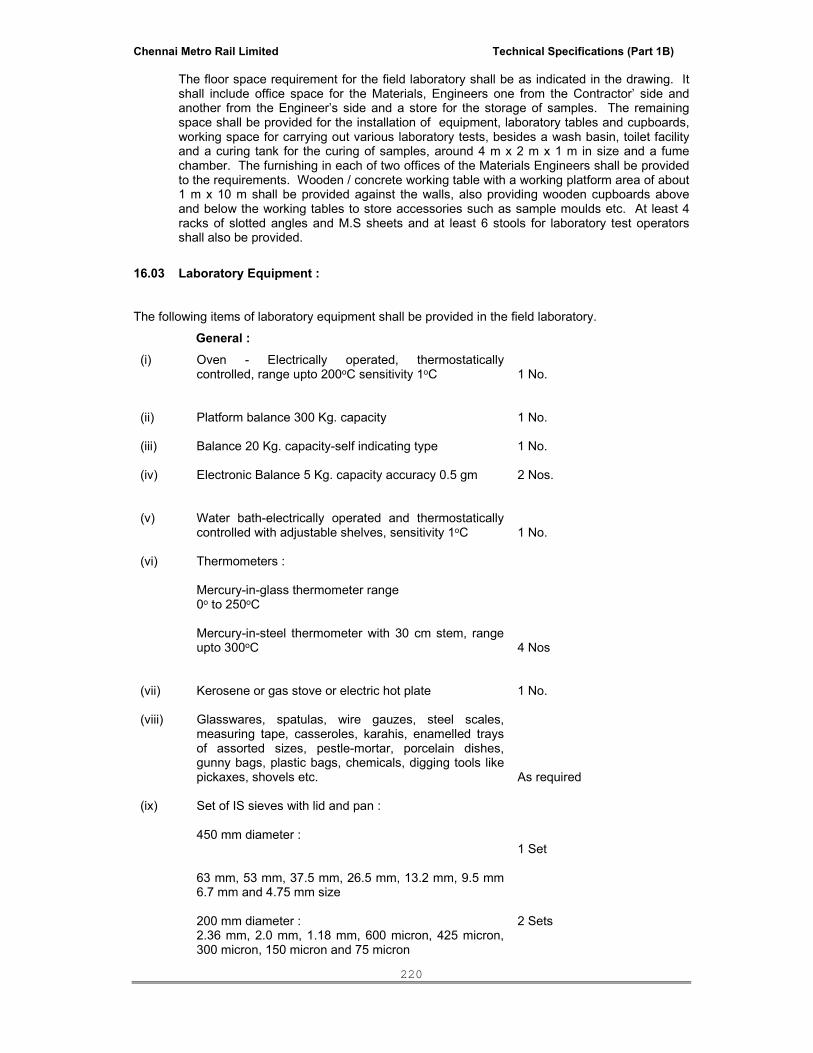
Chennai Metro Rail Limited Technical Specifications (Part 1B)
220
The floor space requirement for the field laboratory shall be as indicated in the drawing. It shall include office space for the Materials, Engineers one from the Contractor’ side and another from the Engineer’s side and a store for the storage of samples. The remaining space shall be provided for the installation of equipment, laboratory tables and cupboards, working space for carrying out various laboratory tests, besides a wash basin, toilet facility and a curing tank for the curing of samples, around 4 m x 2 m x 1 m in size and a fume chamber. The furnishing in each of two offices of the Materials Engineers shall be provided to the requirements. Wooden / concrete working table with a working platform area of about 1 m x 10 m shall be provided against the walls, also providing wooden cupboards above and below the working tables to store accessories such as sample moulds etc. At least 4 racks of slotted angles and M.S sheets and at least 6 stools for laboratory test operators shall also be provided.
16.03 Laboratory Equipment :
The following items of laboratory equipment shall be provided in the field laboratory.
General : (i) Oven - Electrically operated, thermostatically
controlled, range upto 200oC sensitivity 1oC 1 No.
(ii)
Platform balance 300 Kg. capacity
1 No.
(iii) Balance 20 Kg. capacity-self indicating type 1 No.
(iv) Electronic Balance 5 Kg. capacity accuracy 0.5 gm 2 Nos.
(v)
Water bath-electrically operated and thermostatically controlled with adjustable shelves, sensitivity 1oC
1 No.
(vi) Thermometers : Mercury-in-glass thermometer range 0o to 250oC Mercury-in-steel thermometer with 30 cm stem, range upto 300oC
4 Nos
(vii) Kerosene or gas stove or electric hot plate 1 No.
(viii) Glasswares, spatulas, wire gauzes, steel scales, measuring tape, casseroles, karahis, enamelled trays of assorted sizes, pestle-mortar, porcelain dishes, gunny bags, plastic bags, chemicals, digging tools like pickaxes, shovels etc.
As required
(ix) Set of IS sieves with lid and pan : 450 mm diameter :
1 Set
63 mm, 53 mm, 37.5 mm, 26.5 mm, 13.2 mm, 9.5 mm 6.7 mm and 4.75 mm size 200 mm diameter : 2.36 mm, 2.0 mm, 1.18 mm, 600 micron, 425 micron, 300 micron, 150 micron and 75 micron
2 Sets
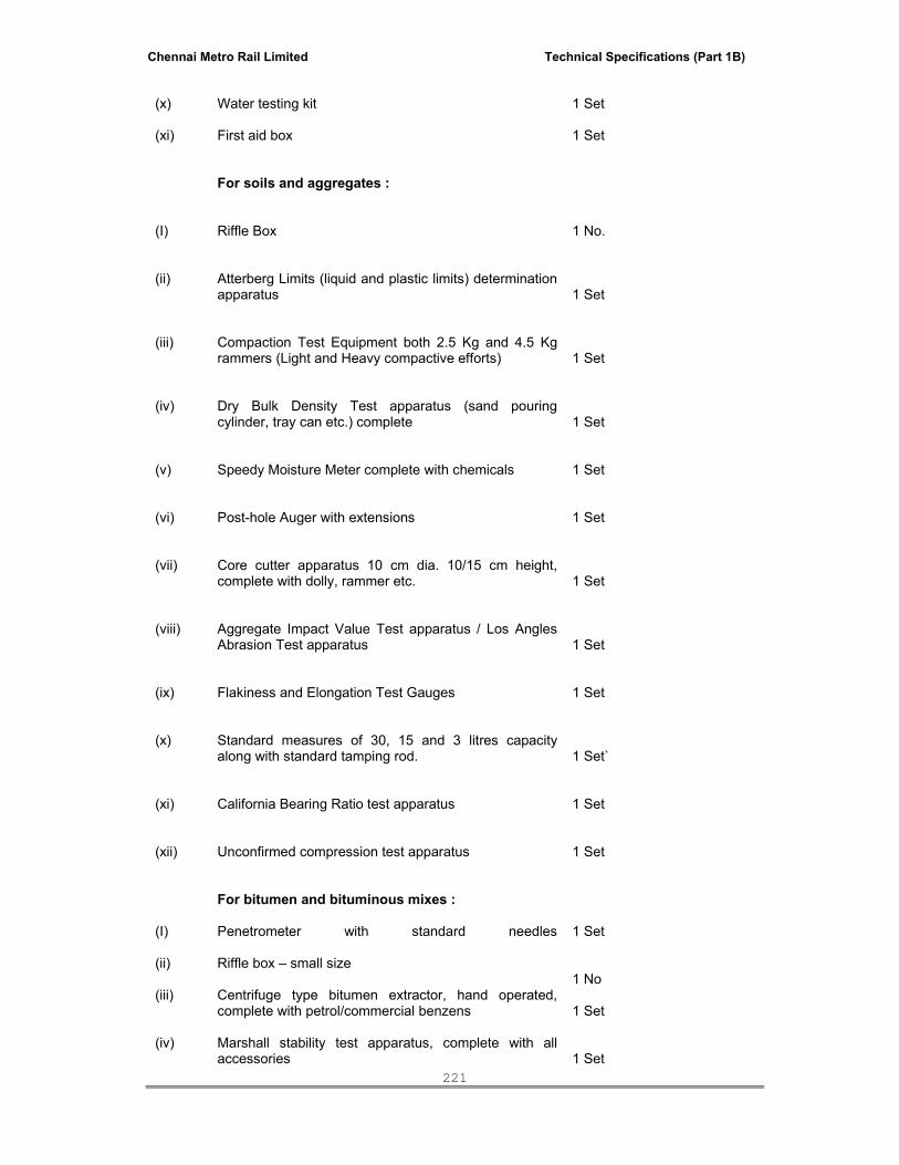
Chennai Metro Rail Limited Technical Specifications (Part 1B)
221
(x)
Water testing kit
1 Set
(xi)
First aid box
1 Set
For soils and aggregates :
(I)
Riffle Box
1 No.
(ii)
Atterberg Limits (liquid and plastic limits) determination apparatus
1 Set
(iii) Compaction Test Equipment both 2.5 Kg and 4.5 Kg rammers (Light and Heavy compactive efforts)
1 Set
(iv)
Dry Bulk Density Test apparatus (sand pouring cylinder, tray can etc.) complete
1 Set
(v)
Speedy Moisture Meter complete with chemicals
1 Set
(vi)
Post-hole Auger with extensions
1 Set
(vii)
Core cutter apparatus 10 cm dia. 10/15 cm height, complete with dolly, rammer etc.
1 Set
(viii) Aggregate Impact Value Test apparatus / Los Angles Abrasion Test apparatus
1 Set
(ix)
Flakiness and Elongation Test Gauges
1 Set
(x)
Standard measures of 30, 15 and 3 litres capacity along with standard tamping rod.
1 Set`
(xi)
California Bearing Ratio test apparatus
1 Set
(xii)
Unconfirmed compression test apparatus
1 Set
For bitumen and bituminous mixes :
(I) Penetrometer with standard needles
1 Set
(ii) Riffle box – small size 1 No
(iii) Centrifuge type bitumen extractor, hand operated, complete with petrol/commercial benzens
1 Set
(iv) Marshall stability test apparatus, complete with all accessories
1 Set

Chennai Metro Rail Limited Technical Specifications (Part 1B)
222
(v)
Field density bottle along with cutting tray, chisel, hammer and standard sand
2 Nos.
(vi)
3 m straight edge
1 No.
(vii)
Camber board
1 No
(viii)
Core cutting machine with 10 cm dia. diamond cutting edge
1 Set
(ix)
Vacuum pump and 3 specific gravity bottles
1 Set
For cement and cement concrete :
(I)
Vicat apparatus for testing setting times
1 Set
(ii)
Slump testing apparatus
4 Sets
(iii)
Compression and Flexural strength testing machine of 200 tonne capacity with additional dial for flexural testing
1 No.
(iv)
Needle Vibrator
2 Nos.
(v)
Air Meter
1 No.
(vi)
Vibrating hammer for vibrating dry mix as for Dry Lean Cement concrete sub-base
1 No.
Note : The items and their numbers listed above in this Clause shall be decided by the Engineer as per requirements of the Project and modified accordingly.
16.04 Maintenance : The Contractor shall arrange to maintain the field laboratory in a satisfactory manner until
the issue of Taking Over Certificate for the complete work.
*****

Chennai Metro Rail Limited Technical Specifications (Part 1B)
223
EARTHWORK EXCAVATION FOR ROADS
SPECIFICATIONS
1.00 Scope : Roadway and drain excavation shall consist of excavation, removal and satisfactory
disposal of all materials necessary for the construction of roadway, side drains, and waterways, in accordance with the requirements of these Specifications and the lines, grades and cross sections shown in the drawings or as indicated by the Engineer. This work shall include the hauling and stacking of or hauling to sites of embankment and subgrade construction, of suitable cut materials as required, as also the disposal of unsuitable cut materials in specified manner and the trimming and finishing of the road to specified dimensions or as directed by the Engineer.
2.00 Construction Operations : 2.01 Setting Out : After the site has been cleared the limits of excavation shall be set out true to lines, curves,
slopes, grades and sections as shown on the drawings or as directed by the Engineer. The Contractor shall provide all labour, survey instruments and materials such as strings, pegs, nails, bamboos, stones, lime, mortar, concrete etc., required in connection with the setting out of works and the establishment of bench marks. The Contractor shall be responsible for the maintenance of bench marks and other marks and stakes as long as in the opinion of the Engineer they are required for the work.
2.02 Stripping and storing top soil : When so directed by the Engineer, the top soil existing over the sites of excavation shall be
stripped to specified depths constituting horizon ‘A’ and stock piled at designated locations for re-use in covering embankment slopes, cut slopes, berms and other disturbed areas where re-vegetation is desired. Prior to stripping the topsoil, all trees, shrubs, etc. shall be removed along with their roots, with approval of the Engineer.
2.03 Excavation - General : All excavations shall be carried out in conformity with the directions laid herein under and in
a manner approved by the Engineer. The work shall be so done that the suitable materials available from excavation are satisfactorily utilized as decided upon beforehand.
While planning or executing excavations, the Contractor shall take all adequate precautions
against soil erosion, water pollution etc. The excavations shall conform to the lines, grades, side slopes and levels shown on the
drawings or directed by the Engineer. The Contractor shall not excavate outside the slopes or below the established grades or loosen any material outside the limits of excavation. Subject to the permitted tolerances, any excess depth excavated below the specified levels on the road shall be made good at the cost of the Contractor with suitable materials of similar characteristics to that removed and compacted to the requirements.
All debris and loose material on the slopes of cuttings shall be removed. No backfilling shall
be allowed to obtain required slopes excepting that when boulders or soft materials are encountered in cut slopes. These shall be excavated to approved depth on instructions of the Engineer and the resulting cavities filled with suitable material and thoroughly compacted in an approved manner.
2.04 Methods, tools and equipment :
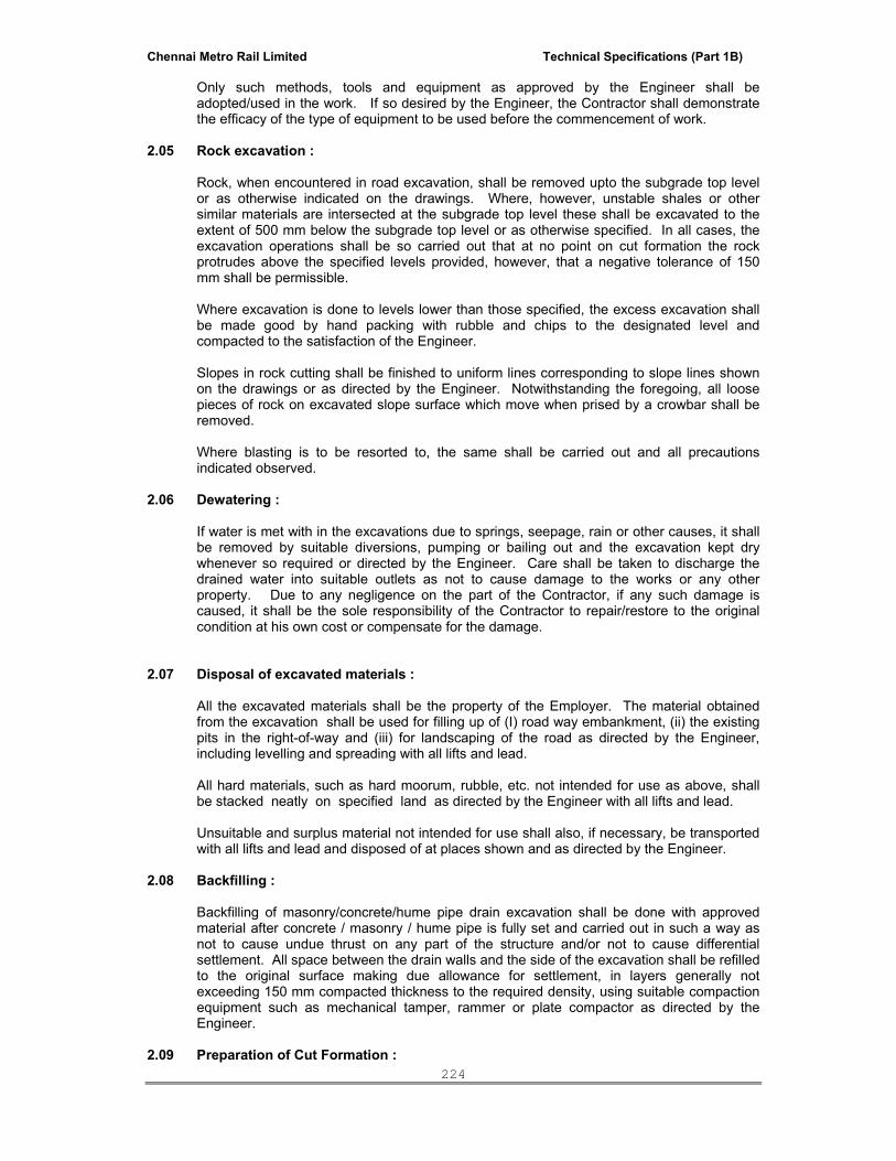
Chennai Metro Rail Limited Technical Specifications (Part 1B)
224
Only such methods, tools and equipment as approved by the Engineer shall be adopted/used in the work. If so desired by the Engineer, the Contractor shall demonstrate the efficacy of the type of equipment to be used before the commencement of work.
2.05 Rock excavation : Rock, when encountered in road excavation, shall be removed upto the subgrade top level
or as otherwise indicated on the drawings. Where, however, unstable shales or other similar materials are intersected at the subgrade top level these shall be excavated to the extent of 500 mm below the subgrade top level or as otherwise specified. In all cases, the excavation operations shall be so carried out that at no point on cut formation the rock protrudes above the specified levels provided, however, that a negative tolerance of 150 mm shall be permissible.
Where excavation is done to levels lower than those specified, the excess excavation shall
be made good by hand packing with rubble and chips to the designated level and compacted to the satisfaction of the Engineer.
Slopes in rock cutting shall be finished to uniform lines corresponding to slope lines shown
on the drawings or as directed by the Engineer. Notwithstanding the foregoing, all loose pieces of rock on excavated slope surface which move when prised by a crowbar shall be removed.
Where blasting is to be resorted to, the same shall be carried out and all precautions
indicated observed. 2.06 Dewatering : If water is met with in the excavations due to springs, seepage, rain or other causes, it shall
be removed by suitable diversions, pumping or bailing out and the excavation kept dry whenever so required or directed by the Engineer. Care shall be taken to discharge the drained water into suitable outlets as not to cause damage to the works or any other property. Due to any negligence on the part of the Contractor, if any such damage is caused, it shall be the sole responsibility of the Contractor to repair/restore to the original condition at his own cost or compensate for the damage.
2.07 Disposal of excavated materials : All the excavated materials shall be the property of the Employer. The material obtained
from the excavation shall be used for filling up of (I) road way embankment, (ii) the existing pits in the right-of-way and (iii) for landscaping of the road as directed by the Engineer, including levelling and spreading with all lifts and lead.
All hard materials, such as hard moorum, rubble, etc. not intended for use as above, shall
be stacked neatly on specified land as directed by the Engineer with all lifts and lead. Unsuitable and surplus material not intended for use shall also, if necessary, be transported
with all lifts and lead and disposed of at places shown and as directed by the Engineer. 2.08 Backfilling : Backfilling of masonry/concrete/hume pipe drain excavation shall be done with approved
material after concrete / masonry / hume pipe is fully set and carried out in such a way as not to cause undue thrust on any part of the structure and/or not to cause differential settlement. All space between the drain walls and the side of the excavation shall be refilled to the original surface making due allowance for settlement, in layers generally not exceeding 150 mm compacted thickness to the required density, using suitable compaction equipment such as mechanical tamper, rammer or plate compactor as directed by the Engineer.
2.09 Preparation of Cut Formation :

Chennai Metro Rail Limited Technical Specifications (Part 1B)
225
The cut formation which serves as a subgrade, shall be prepared to receive the sub-base /
base course as directed by the Engineer. Where the material in the subgrade (that is within 500 mm from the lowest level of the
pavement) has a density less than the specified, the same shall be loosened to a depth of 500 mm and compacted in layers in accordance with the requirements. Any unsuitable material encountered in the subgrade shall be removed as directed by the Engineer to a depth indicated by the Engineer and replaced with suitable material compacted in accordance with IRC specification.
In rocky formations, the surface irregularities shall be corrected and the levels brought up to
the specified elevation with granular base or base material as directed by the Engineer, laid and compacted in accordance with the respective specifications for these materials.
3.00 Measurements for Payment : Excavation for roadway shall be measured by taking cross sections at suitable intervals in
the original position before the work starts and after its completion and computing the volumes in cubic metres by the method of average end areas for each class of material encountered. Where it is not feasible to compute volumes by this method because of erratic location of isolated deposits, the volumes shall be computed by other accepted methods.
At the option of the Engineer, the Contractor shall leave depth indicators during excavations
of such shape and size and in such positions as directed so as to indicate the original ground level as accurately as possible. The Contractor shall see that these remain intact till the final measurements are taken.
For rock excavation, the overburden shall be removed first so that necessary cross sections
could be taken for measurement. Where cross sectional measurements could not be taken due to irregular configuration or where the rock is admixed with other classes of materials, the volumes shall be computed on the basis of stacks of excavated rubble after making 35 per cent deduction therefrom. When volumes are calculated in this manner for excavated material other than rock, deductions made will be to the extent of 16 per cent of stacked volumes.
*****
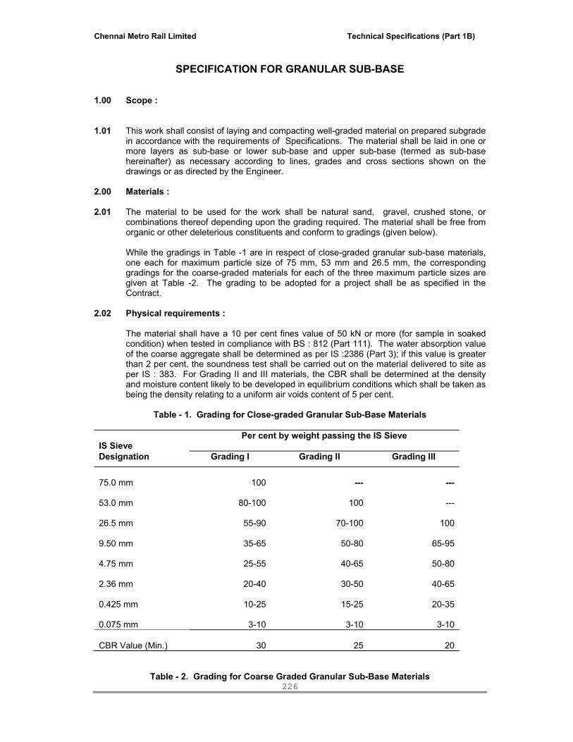
Chennai Metro Rail Limited Technical Specifications (Part 1B)
226
SPECIFICATION FOR GRANULAR SUB-BASE
1.00 Scope : 1.01 This work shall consist of laying and compacting well-graded material on prepared subgrade
in accordance with the requirements of Specifications. The material shall be laid in one or more layers as sub-base or lower sub-base and upper sub-base (termed as sub-base hereinafter) as necessary according to lines, grades and cross sections shown on the drawings or as directed by the Engineer.
2.00 Materials : 2.01 The material to be used for the work shall be natural sand, gravel, crushed stone, or
combinations thereof depending upon the grading required. The material shall be free from organic or other deleterious constituents and conform to gradings (given below).
While the gradings in Table -1 are in respect of close-graded granular sub-base materials,
one each for maximum particle size of 75 mm, 53 mm and 26.5 mm, the corresponding gradings for the coarse-graded materials for each of the three maximum particle sizes are given at Table -2. The grading to be adopted for a project shall be as specified in the Contract.
2.02 Physical requirements : The material shall have a 10 per cent fines value of 50 kN or more (for sample in soaked
condition) when tested in compliance with BS : 812 (Part 111). The water absorption value of the coarse aggregate shall be determined as per IS :2386 (Part 3); if this value is greater than 2 per cent, the soundness test shall be carried out on the material delivered to site as per IS : 383. For Grading II and III materials, the CBR shall be determined at the density and moisture content likely to be developed in equilibrium conditions which shall be taken as being the density relating to a uniform air voids content of 5 per cent.
Table - 1. Grading for Close-graded Granular Sub-Base Materials
IS Sieve
Per cent by weight passing the IS Sieve
Designation Grading I Grading II Grading III
75.0 mm 100 ---
---
53.0 mm
80-100
100
---
26.5 mm
55-90
70-100
100
9.50 mm
35-65
50-80
65-95
4.75 mm
25-55
40-65
50-80
2.36 mm
20-40
30-50
40-65
0.425 mm
10-25
15-25
20-35
0.075 mm
3-10
3-10
3-10
CBR Value (Min.)
30
25
20
Table - 2. Grading for Coarse Graded Granular Sub-Base Materials

Chennai Metro Rail Limited Technical Specifications (Part 1B)
227
IS Sieve
Per cent by weight passing the IS Sieve
Designation Grading I Grading II Grading III
75.0 mm 100 ---
---
53.0 mm
---
100
---
26.5 mm
55-75
50-80
100
9.50 mm
---
---
---
4.75 mm
10-30
15-35
25-45
2.36 mm
---
---
---
0.425 mm
---
---
---
0.075 mm
<10
<10
<10
CBR Value (Min.) 30 25 20
Note : The material passing 425 micron (0.425 mm) sieve for all the three gradings when
tested according to IS : 2720 (Part - 5) shall have liquid limit and plasticity index not more than 25 per cent and 6 per cent respectively.
3.00 Strength of Sub-base : 3.01 It shall be ensured prior to actual execution that the material to be used in the sub-base
satisfies the requirements of CBR and other physical requirements when compacted and finished.
3.02 When directed by the Engineer, this shall be verified by performing CBR tests in the
laboratory as required on specimens re-moulded at field dry density and moisture content and any other tests for the “quality” of materials, as may be necessary.
4.00 Construction Operations : 4.01 Preparation of subgrade : Immediately prior to the laying of sub-base, the subgrade already finished as applicable
shall be prepared by removing all vegetation and other extraneous matter, lightly sprinkled with water if necessary and rolled with two passes of 8 - 10 Ton smooth wheeled roller.
4.02 Spreading and compacting : The sub-base material of grading specified in the Contract shall be spread on the prepared
subgrade with the help of a motor grader of adequate capacity, its blade having hydraulic controls suitable for initial adjustment and for maintaining the required slope and grade during the operation or other means as approved by the Engineer.
When the sub-base material consists of combination of materials mentioned above, mixing
shall be done mechanically by the mix-in-place method. Manual mixing shall be permitted only where the width of laying is not adequate for
mechanical operations. The equipment used for mix-in-place construction shall be a rotavator or similar approved equipment capable of mixing the material to the desired degree. If so desired by the Engineer, trial runs with the equipment shall be carried out to establish its suitability for the work.

Chennai Metro Rail Limited Technical Specifications (Part 1B)
228
Moisture content of the loose material shall be checked in accordance with IS : 2720 (Part -
II) and suitably adjusted by sprinkling additional water from a truck mounted or trailer mounted water tank and suitable for applying water uniformly and at controlled quantities to variable widths of surface or other means approved by the Engineer so that, at the time of compaction it is from 1 per cent above to 2 per cent below the optimum moisture content corresponding to IS : 2720 (Part VIII). While adding water, due allowance shall be made for evaporation losses. After water, has been added, the material shall be processed by mechanical or other approved means like disc harrows, rotavators until the layer is uniformly wet.
Immediately thereafter, rolling shall start. If the thickness of the compacted layer does not
exceed 100 mm, a smooth wheeled roller of 8 to 10 Ton weight may be used. For a compacted single layer upto 225 mm the compaction shall be done with the help of a vibratory roller of minimum 8 to 10 Ton static weight with plain drum or pad foot drum or heavy pneumatic tyred roller of minimum 200 to 300 kN weight having a minimum tyre pressure of 0.7 MN/m2 or equivalent capacity roller capable of achieving the required compaction. Rolling shall commence at the lower edge and proceed towards the upper edge longitudinally for portions having unidirectional crossfall and super elevation and shall commence at the edges and progress towards the centre for portions having crossfall on the both sides.
Each pass of the roller shall uniformly overlap not less than one third of the track made in
the preceding pass. During rolling, the grade and camber shall be checked and any high spots or depressions which become apparent corrected by removing or adding fresh material. The speed of the roller shall not exceed 5 km per hour.
Rolling shall be continued till the density achieved is at least 98% of the maximum dry
density for the material determined as per IS: 2720 (Part 7). The surface of any layer of material on completion of compaction shall be well closed, free from movement under compaction equipment and from compaction planes, ridges, cracks or loose material. All loose, segregated or otherwise defective areas shall be made good to the full thickness of layer and re-compacted.
4.03 Surface Finish and quality Control of Work: The surface finish of construction shall conform to the requirements. 5.00 Mode of Measurements: Granular sub-base shall be measured as finished work in position in cubic metres. The protection of edges of granular sub-base extended over the full formation as shown in
the drawing shall be considered incidental to the work providing granular sub-base and as such no extra payment shall be made for the same.
*****

Chennai Metro Rail Limited Technical Specifications (Part 1B)
229
WET MIX MACADAM SUB – BASE / BASE
1.0 Scope
This work shall consist of laying and compacting clean, crushed, graded aggregate and granular material, premixed with water, to a dense mass on a prepared sub grade/ sub- base / base or existing pavement as the case may be in accordance with the requirements of these specifications. The material shall be laid in one or more layers as necessary to lines, grades and cross-sections shown on the approved drawings or as directed by the Engineer.
The thickness of a single compacted Wet Mix Macadam layer shall not be less than 75 mm and should be done in two layers. When vibrating or other approved types of compacting equipment are used, the compacted depth of a single layer of the sub-base course may be increased to 200 mm upon approval of the Engineer.
2.00 Materials : 2.01 Coarse aggregates : Coarse aggregates shall be either crushed or broken stone. Materials other than crushed or
broken stone shall be used in sub-base courses only. Not less than 90 per cent by weight of the gravel pieces retained on 4.75 mm sieve shall have at least two fractured faces. The aggregates shall conform to the physical requirements set forth in Table - 1 (given below). The type and size range of the aggregate shall be specified in the Contract or shall be as specified by the Engineer. If the water absorption value of the coarse aggregate is greater than 2 per cent, the soundness test shall be carried out on the material delivered to site as per IS : 2386 (Part 5).
a. Crushed or broken stone : The crushed or broken stone shall be hard, durable and free from excess flat, elongated,
soft and disintegrated particles, dirt and other deleterious material.
Table-1: Physical Requirements of Coarse Aggregates for Wet mix Macadam
for Sub-base/Base Courses
S.No Test Test method Requirements
1
* Los Angeles Abrasion Value Or
Aggregate Impact
Value
IS : 2386 (Part IV) IS : 2386 (Part IV) or IS : 5640**
40 Per cent max. 30 per cent max.
2.
Combined Flakiness and Elongation Indices (Total) ***
IS : 2386 (Part I)
30 per cent max.
* Aggregates may satisfy requirements of either of the two tests.

Chennai Metro Rail Limited Technical Specifications (Part 1B)
230
** The requirements of Flakiness Index and elongation index shall be enforced only in the case
of crushed broken stone and crushed slag.
B . Grading requirements: The aggregates shall conform to the grading given in Table 2.
TABLE 2. GRADING REQUIREMENTS OF AGGREGATES FOR WET MIX MACADAM
IS Seive Designation Per cent by weight passing the IS sieve
53.00 mm 100
45.00 mm 95-100
26.50 mm --
22.40 mm 60-80
11.20 mm 40-60
4.75 mm 25-40
2.36 mm 15-30
600.00 micron 8-22
75.00 micron 0-8
Materials finer than 425 micron shall have Plasticity Index (PI) not exceeding 6.
The final gradation approved within these limits shall be well graded from coarse to fine and shall not vary from the low limit on one sieve to the high limit on the adjacent sieve or vice versa.
3. Construction Operations
3.1 Preparation of base: 3.2. Provision of lateral confinement of aggregates: While constructing wet mix macadam,
arrangement shall be made for the lateral confinement of we mix. This shall be done by laying materials in adjoining shoulders along with that of wet macadam layer and following the sequence of operations
3.3 Preparation of mix:Wet Mix Macadam shall be prepared in a approved mixing lant of
suitable capacity having provision for controlled addition of water and forced / positive mixing arrangement like pug mill or pan type mixer of concrete batching plant. For small quantity of wet mix work, the Engineer may permit the mixing to be done in concrete mixers.
Optimum moisture for mixing shall be determined in accordance with IS: 2720 (Part -8)
after replacing the aggregate fraction retained on 22.4 mm sieve with material of 4.75 mm to 22.4 mm size. While adding water, due allowance should be made for evaporation losses. However, at the time of compaction, water in the wet mix should not vary from the optimum value by more than agreed limits. The mixed material should be uniformly wet and no segregation should be permitted.

Chennai Metro Rail Limited Technical Specifications (Part 1B)
231
3.4 Spreading of mix: Immediately after mixing, the aggregates shall be spread uniformly and evenly upon the prepared sub grade /sub-base /base in required quantities. In no case should these be dumped in heaps directly on the area where these are to be laid nor shall their hauling over a partly completed stretch
be permitted.
The mix may be spread either by a paver finisher or motor grader. For portions where mechanical means cannot be used, manual means as approved by the Engineer shall be used. The motor grader shall be capable of spreading the material uniformly all over the surface. Its blade shall have hydraulic control suitable for initial adjustments and maintaining the same so as to achieve the specified slope and grade. The paver finisher shall be self –propelled, having the following features: (i) Loading hoppers and suitable distribution mechanism (ii) The screed shall have tamping and vibrating arrangement for initial compaction to
the layer as it is spread without rutting or otherwise marring the surface profile. (iii) The paver shall be equipped with necessary control mechanism so as to ensure that
the finished surface is free from surface blemishes.
The surface of the aggregate shall be carefully checked with templates and all high or low spots remedied by removing or adding aggregate as may be required. The layer may be tested by depth blocks during construction. No segregation of larger and fine particles should be allowed. The aggregates as spread should be of uniform gradation with no pockets of fine materials.
3.5. Compaction: After the mix has been laid to the required thickness, grade and cross
fall/camber the same shall be uniformly compacted, to the full depth with suitable roller. If the thickness of single compacted layer does not exceed 100mm, a smooth wheel roller of 80 to 100 kN weight may be used. For a compacted single layer upto 200mm, the compaction shall be done with the help of vibratory roller of minimum static weight of 80 to 100 kN or equivalent capacity roller. The speed of the roller shall not exceed 5 km/h.
In portions having unidirectional cross fall / super elevation, rolling shall commence from the lower edge and progress gradually towards the upper edge. Thereafter, roller should progress parallel to the centre line of the road, uniformly over-lapping each preceding track by at least one third width until the entire surface has been rolled. Alternate trips of the roller shall be terminated in stops at least 1m away from any preceding stop. In portions in camber, rolling should begin at the edge with the roller running forward and backward until the edges have been firmly compacted. The roller shall then progress gradually towards the centre parallel to the centre line of the road uniformly overlapping each of the preceding track by at least one-third width until the entire surface has been rolled. Any displacement occurring as a result of reversing of the direction of a roller or from any other cause shall be corrected at once as specified and/or removed and made good. Along forms, kerbs, walls or other places not accessible to the roller, the mixture shall be thoroughly compacted with mechanical tampers or a plate compactor. Skin patching of an area without scarifying the surface to permit proper bonding of the added material shall not be permitted. Rolling should not be done when the subgrade is soft or yielding or when it causes a wave-like motion in the sub-base/base course or subgrade. If irregularities develop during rolling which exceed 12mm when tested with a 3 metre straight edge, the surface should be loosened and premixed material added or removed as required before rolling again so as to achieve a uniform surface conforming to the desired grade and cross fall. In no case should the use of unmixed material be permitted to make up the depressions. Rolling shall be continued till the density achieved is at least 98 percent of the maximum dry density for the material as determined by the method outlined in IS: 2720 (Part-8).

Chennai Metro Rail Limited Technical Specifications (Part 1B)
232
After completion, the surface of any finished layer shall be well-closed, free from movement under compaction equipment or any compaction planes, ridges, cracks and loose material. All loose, segregated or otherwise defective areas shall be made good to the full thickness of the layer and recompacted.
3.6. Setting and drying: After final compaction of wet mix macadam course, the road shall be allowed to dry for 24 hours.
4. Opening to Traffic: Preferably no vehicular traffic of any kind should be allowed on the finished wet mix macadam surface till it has dried and the wearing course laid.
5. Surface Finish and Quality Control of work
5.1. Surface eveness: The surface finish of construction shall conform to the requirements. 5.2 Quality control : Control on the quality of materials and works shall be exercised by the Engineer.
6. Rectification of Surface Irregularity Where the surface irregularity of the wet mix macadam course exceeds the permissible tolerances or where the course is otherwise defective due to subgrade soil getting mixed with the aggregates, the full thickness of the layer shall be scarified over the affected area, reshaped with added premixed material or removed and replaced with fresh premixed material as applicable and recompacted. The area treated in the aforesaid manner shall not be less than 5m long and 2m wide. In no case shall depressions be filled up with unmixed and ungraded material or fines.
7.00 Mode of Measurements : Wet mix macadam shall be measured as finished work in position in square metres
*****

Chennai Metro Rail Limited Technical Specifications (Part 1B)
233
SPECIFICATION FOR TACK COAT / PRIME COAT
1.00 Scope :
Providing and laying Prime Coat as per MORTH specification and after allowing for twenty four hours and a tack coat over the following previously prepared surface with Rapid setting bituminous emulsion using mechanical sprayer including preparing the surface for laying the priming coat and tack coat, applying the required quantity of bituminous emulsion including cost and conveyance of all materials, all labour charges, hire and fuel charges for all tools and plants employed and all other incidental charges etc. all complete as per IS Code and MORTH Specifications 502 & 503.
2.00 Materials : The binder used for tack coat shall be bituminous emulsion or cutback as specified in the
Contract. 3.00 Construction Operation: 3.01 Preparation of base : The surface on which the tack coat or prime coat is to be applied shall be cleaned of dust
and any extraneous material before the application of the binder, by using a mechanical broom or any other approved equipment/method as specified by the Engineer.
4.00 Application of Prime coat / Tack Coat : Priming coat over wet mix macadam surface using SLOW SETTING emulsion complying to
IS: 8887 grade at the rate of 9 Kg per 10 sqm area Tack coat over bituminous surface using Rapid setting bituminous emulsion complying to IS:
8887 at the rate of 4.0 Kg per 10 sqm area Tack coat over first layer of dense bituminous macadam surface using Rapid setting
emulsion complying to IS: 8887 at the rate of 3.0 Kg per 10 sqm area Tack coat over second layer of dense bituminous macadam surface using Rapid setting
emulsion complying to IS: 8887 at the rate of 3.0 Kg per 10 sqm area 5.00 Mode of Measurement : Tack coat shall be measured in terms of surface area of application in square metres.
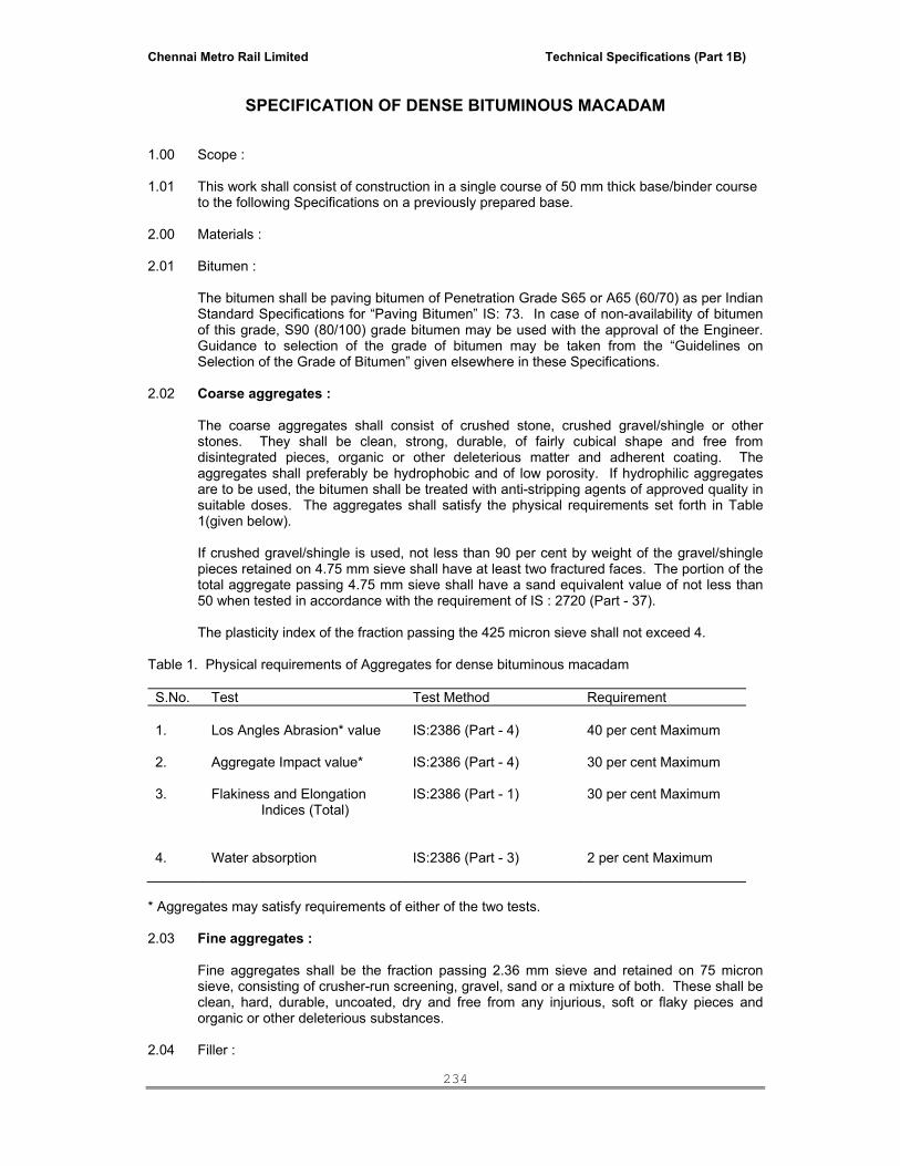
Chennai Metro Rail Limited Technical Specifications (Part 1B)
234
SPECIFICATION OF DENSE BITUMINOUS MACADAM
1.00 Scope : 1.01 This work shall consist of construction in a single course of 50 mm thick base/binder course
to the following Specifications on a previously prepared base. 2.00 Materials : 2.01 Bitumen : The bitumen shall be paving bitumen of Penetration Grade S65 or A65 (60/70) as per Indian
Standard Specifications for “Paving Bitumen” IS: 73. In case of non-availability of bitumen of this grade, S90 (80/100) grade bitumen may be used with the approval of the Engineer. Guidance to selection of the grade of bitumen may be taken from the “Guidelines on Selection of the Grade of Bitumen” given elsewhere in these Specifications.
2.02 Coarse aggregates : The coarse aggregates shall consist of crushed stone, crushed gravel/shingle or other
stones. They shall be clean, strong, durable, of fairly cubical shape and free from disintegrated pieces, organic or other deleterious matter and adherent coating. The aggregates shall preferably be hydrophobic and of low porosity. If hydrophilic aggregates are to be used, the bitumen shall be treated with anti-stripping agents of approved quality in suitable doses. The aggregates shall satisfy the physical requirements set forth in Table 1(given below).
If crushed gravel/shingle is used, not less than 90 per cent by weight of the gravel/shingle
pieces retained on 4.75 mm sieve shall have at least two fractured faces. The portion of the total aggregate passing 4.75 mm sieve shall have a sand equivalent value of not less than 50 when tested in accordance with the requirement of IS : 2720 (Part - 37).
The plasticity index of the fraction passing the 425 micron sieve shall not exceed 4. Table 1. Physical requirements of Aggregates for dense bituminous macadam S.No. Test Test Method Requirement 1.
Los Angles Abrasion* value
IS:2386 (Part - 4)
40 per cent Maximum
2.
Aggregate Impact value*
IS:2386 (Part - 4)
30 per cent Maximum
3.
Flakiness and Elongation
Indices (Total)
IS:2386 (Part - 1)
30 per cent Maximum
4.
Water absorption
IS:2386 (Part - 3)
2 per cent Maximum
* Aggregates may satisfy requirements of either of the two tests. 2.03 Fine aggregates : Fine aggregates shall be the fraction passing 2.36 mm sieve and retained on 75 micron
sieve, consisting of crusher-run screening, gravel, sand or a mixture of both. These shall be clean, hard, durable, uncoated, dry and free from any injurious, soft or flaky pieces and organic or other deleterious substances.
2.04 Filler :

Chennai Metro Rail Limited Technical Specifications (Part 1B)
235
Filler shall consist of finely divided mineral matter such as rock dust, hydrated lime or
cement as approved by the Engineer. The filler shall be graded within the following limits:
IS Sieve Per cent passing by weight
600 micron 300 micron 75 micron
100 95-100 85-100
The filler shall be free from organic impurities and have a Plasticity Index not greater than 4.
The Plasticity Index requirement shall not apply if filler is cement or lime. When the coarse aggregate is gravel, 2 per cent by mass of total aggregate of Portland cement or hydrated lime shall be added and the percentage of fine aggregate reduced accordingly. Cement or hydrated lime is not required when the gravel is limestone.
2.05 Aggregate gradation: The combined and fine aggregates and filler (when used) shall produce a mixture to
conform to the grading set forth in Table 2 (given below). Table 2. Aggregate Gradation for Dense Bituminous Macadam
Sieve Designation Percentage passing the sieve by weight
37.5 mm 26.5 mm 13.2 mm 4.75 mm 2.36 mm 300 micron 75 micron
100 90-100 56-80 29-59 19-45 5-17 1-7
The aggregate mix, as used in work, shall not vary from the low limit on one sieve to the high limit on the adjacent sieve but shall be well graded. 3.00 Mix Design : 3.01 Requirement of mix : Apart from conformity with grading and quality requirements of individual ingredients, the
mix shall meet the requirements set out in Table 3 (given below). Table 3. Requirements of Dense Bituminous Macadam Mix S.N
Description
Requirements
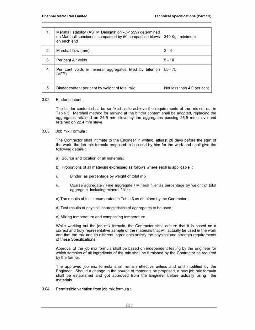
Chennai Metro Rail Limited Technical Specifications (Part 1B)
236
1. Marshall stability (ASTM Designation -D-1559) determined on Marshall specimens compacted by 50 compaction blows on each end
340 Kg minimum
2. Marshall flow (mm) 2 - 4
3. Per cent Air voids 5 - 10
4. Per cent voids in mineral aggregates filled by bitumen (VFB)
55 - 75
5. Binder content per cent by weight of total mix Not less than 4.0 per cent
3.02 Binder content : The binder content shall be so fixed as to achieve the requirements of the mix set out in
Table 3. Marshall method for arriving at the binder content shall be adopted, replacing the aggregates retained on 26.5 mm sieve by the aggregates passing 26.5 mm sieve and retained on 22.4 mm sieve.
3.03 Job mix Formula : The Contractor shall intimate to the Engineer in writing, atleast 20 days before the start of
the work, the job mix formula proposed to be used by him for the work and shall give the following details :
a) Source and location of all materials; b) Proportions of all materials expressed as follows where each is applicable : i. Binder, as percentage by weight of total mix ;
ii. Coarse aggregate / Fine aggregate / Mineral filler as percentage by weight of total aggregate including mineral filler :
c) The results of tests enumerated in Table 3 as obtained by the Contractor ;
d) Test results of physical characteristics of aggregates to be used ; e) Mixing temperature and compacting temperature. While working out the job mix formula, the Contractor shall ensure that it is based on a
correct and truly representative sample of the materials that will actually be used in the work and that the mix and its different ingredients satisfy the physical and strength requirements of these Specifications.
Approval of the job mix formula shall be based on independent testing by the Engineer for
which samples of all ingredients of the mix shall be furnished by the Contractor as required by the former.
The approved job mix formula shall remain effective unless and until modified by the
Engineer. Should a change in the source of materials be proposed, a new job mix formula shall be established and got approved from the Engineer before actually using the materials.
3.04 Permissible variation from job mix formula :
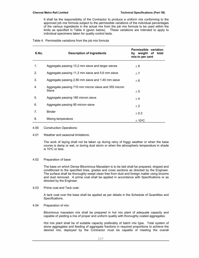
Chennai Metro Rail Limited Technical Specifications (Part 1B)
237
It shall be the responsibility of the Contractor to produce a uniform mix conforming to the approved job mix formula subject to the permissible variations of the individual percentages of the various ingredients in the actual mix from the job mix formula to be used within the limits as specified in Table 4 (given below). These variations are intended to apply to individual specimens taken for quality control tests.
Table 4. Permissible variations from the job mix formula
S.No. Description of Ingredients Permissible variation by weight of total mix-in per cent
1. 2. 3. 4. 5. 6. 7. 8.
Aggregate passing 13.2 mm sieve and larger sieves Aggregate passing 11.2 mm sieve and 5.6 mm sieve Aggregate passing 2.80 mm sieve and 1.40 mm sieve Aggregate passing 710 mm micron sieve and 355 micron Sieve Aggregate passing 180 micron sieve Aggregate passing 90 micron sieve Binder Mixing temperature
± 8 ± 7 ± 6 ± 5 ± 4 ± 2 ± 0.3 ± 10oC
4.00 Construction Operations: 4.01 Weather and seasonal limitations: The work of laying shall not be taken up during rainy of foggy weather or when the base
course is damp or wet, or during dust storm or when the atmospheric temperature in shade is 10oC or less.
4.02 Preparation of base: The base on which Dense Bituminous Macadam is to be laid shall be prepared, shaped and
conditioned to the specified lines, grades and cross sections as directed by the Engineer. The surface shall be thoroughly swept clean free from dust and foreign matter using brooms and dust removed. A prime coat shall be applied in accordance with Specifications or as directed by the Engineer.
4.03 Prime coat and Tack coat: A tack coat over the base shall be applied as per details in the Schedule of Quantities and
Specifications. 4.04 Preparation of mix: Bituminous macadam mix shall be prepared in hot mix plant of adequate capacity and
capable of yielding a mix of proper and uniform quality with thoroughly coated aggregates. Hot mix plant shall be of suitable capacity preferably of batch mix type. Total system of
stone aggregates and feeding of aggregate fractions in required proportions to achieve the desired mix, deployed by the Contractor must be capable of meeting the overall
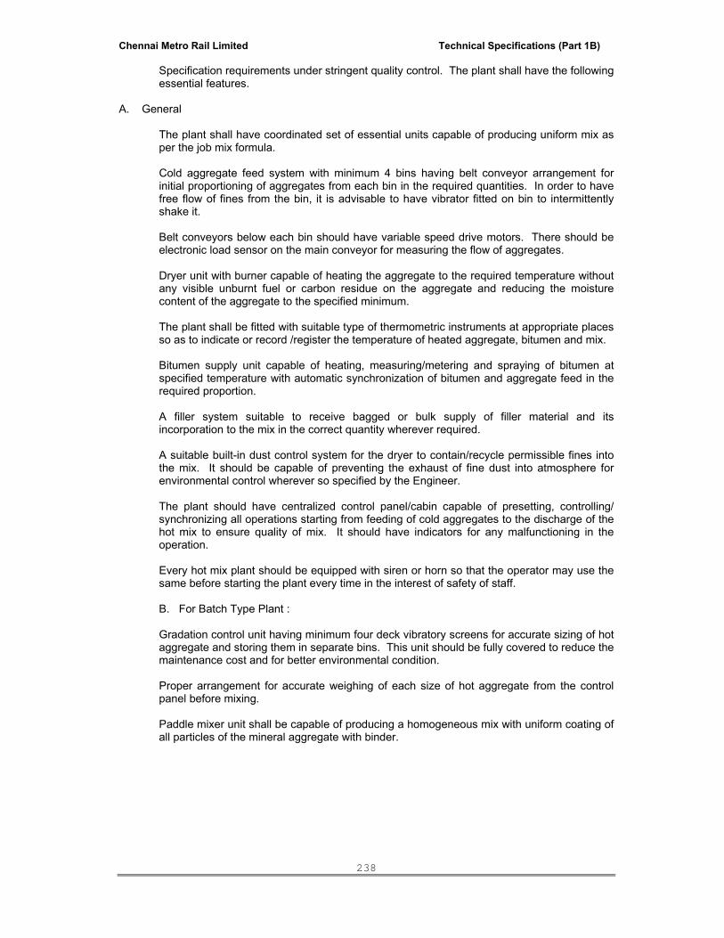
Chennai Metro Rail Limited Technical Specifications (Part 1B)
238
Specification requirements under stringent quality control. The plant shall have the following essential features.
A. General The plant shall have coordinated set of essential units capable of producing uniform mix as
per the job mix formula. Cold aggregate feed system with minimum 4 bins having belt conveyor arrangement for
initial proportioning of aggregates from each bin in the required quantities. In order to have free flow of fines from the bin, it is advisable to have vibrator fitted on bin to intermittently shake it.
Belt conveyors below each bin should have variable speed drive motors. There should be electronic load sensor on the main conveyor for measuring the flow of aggregates.
Dryer unit with burner capable of heating the aggregate to the required temperature without any visible unburnt fuel or carbon residue on the aggregate and reducing the moisture content of the aggregate to the specified minimum.
The plant shall be fitted with suitable type of thermometric instruments at appropriate places so as to indicate or record /register the temperature of heated aggregate, bitumen and mix.
Bitumen supply unit capable of heating, measuring/metering and spraying of bitumen at specified temperature with automatic synchronization of bitumen and aggregate feed in the required proportion.
A filler system suitable to receive bagged or bulk supply of filler material and its incorporation to the mix in the correct quantity wherever required.
A suitable built-in dust control system for the dryer to contain/recycle permissible fines into the mix. It should be capable of preventing the exhaust of fine dust into atmosphere for environmental control wherever so specified by the Engineer.
The plant should have centralized control panel/cabin capable of presetting, controlling/
synchronizing all operations starting from feeding of cold aggregates to the discharge of the hot mix to ensure quality of mix. It should have indicators for any malfunctioning in the operation.
Every hot mix plant should be equipped with siren or horn so that the operator may use the
same before starting the plant every time in the interest of safety of staff. B. For Batch Type Plant :
Gradation control unit having minimum four deck vibratory screens for accurate sizing of hot aggregate and storing them in separate bins. This unit should be fully covered to reduce the maintenance cost and for better environmental condition.
Proper arrangement for accurate weighing of each size of hot aggregate from the control panel before mixing.
Paddle mixer unit shall be capable of producing a homogeneous mix with uniform coating of all particles of the mineral aggregate with binder.
Chennai Metro Rail Limited Technical Specifications (Part 1B)
239
C. For Continuous Type Plant :
Gradation control unit having vibratory screens for accurate sizing of hot aggregate and storing them in separate bins. This unit should be fully covered to reduce the maintenance cost and for better environmental condition.
There should be appropriate arrangement for regulating and volumetric control of the flow of hot aggregate from each bin to achieve the required proportioning.
Paddle mixer unit shall be capable of producing a homogeneous mix with uniform coating of all particles of the mineral aggregate with binder.
D. For Drum Mix Plant :
It is a prerequisite that only properly screened and graded materials are fed fo the bins. If required, a vibratory screening unit shall be installed at the plant site to ensure the same.
A primary 4-deck vibratory screening unit shall be installed before the multiple bind cold feed system for screening the aggregates and grading the same.
Belt conveyers below each bin should have variable speed drive motors. There should be electronic load sensor on the main conveyor for measuring the flow of aggregate.
The temperature of binder at the time of mixing shall be in the range of 150oC to 163oC and
that of the aggregate in the range of 155oC - 163oC provided that the difference in temperature between the binder and aggregate at no time exceeds 14oC.
Mixing shall be thorough to ensure that a homogeneous mixture is obtained in which all
particles of the aggregates are coated uniformly, and the discharge temperature of mix shall be between 130oC to 160oC.
The mixture shall be transported from the mixing plant to the point of use in suitable tipper
vehicles. The vehicles employed for transport shall be clean and be covered in transit if so directed by the Engineer. Any tipper causing excessive segregation of materials by its spring suspension or other contributing factors or that which shows undue delay shall be removed from the work until such conditions are corrected.
4.05 Spreading : The mix transported from the hot mix plant to the site shall be spread by means of a self-
propelled paver with suitable screeds capable of spreading, tamping and finishing the mix to specified grade, lines and cross-section. Paver Finisher shall have the following essential features.
Loading hoppers and suitable distributing mechanism.
All drives having hydrostatic drive/control.
The screed shall have tamping and vibrating arrangement for initial compaction to the layer as it is spread without rutting or otherwise marring the surface.
The paver shall be equipped with necessary control mechanism so as to ensure that the finished surface is free from surface blemishes.
The screed shall have the internal heating arrangement
The paver shall be capable of laying either 2.5 to 4.0 m width.
Chennai Metro Rail Limited Technical Specifications (Part 1B)
240
The paver shall be so designed as to eliminate skidding/silppage of the tyres during operations.
However, in restricted locations and in narrow widths where the available equipment cannot
be operated in the opinion of the Engineer, he may permit manual laying of the mix. Similarly for smaller jobs, mechanical paver may be used with the approval of the Engineer.
The temperature of mix at the time of laying shall be in the range of 120oC - 160oC. Mixes with a temperature of less than 120oC shall not be put into paver spreader.
Longitudinal joints and edges shall be constructed true to the delineating lines parallel to the centre line of the road. Longitudinal and transverse joints shall be offset by atleast 250 mm from those in the lower courses and the joint on the top most layer shall not be allowed to fall within the wheel path. All transverse joints shall be cut vertically to the full thickness of the previously laid mix with asphalt cutter and the surface painted with hot bitumen before placing fresh material. Longitudinal joints shall be preferably hot joints. Cold longitudinal joints shall be properly heated with joint heater to attain a suitable temperature of about 80oC before laying of adjacent material.
4.06 Rolling : After spreading the mix by paver, it shall be thoroughly compacted by rolling with a set of
rollers moving at a speed not more than 5 km/h, immediately following close to the paver. Generally the initial or breakdown rolling shall be done with 8 - 10 Ton static weight smooth-wheeled roller. The intermediate rolling shall be done with 8 - 10 Ton static weight vibratory roller or with a pneumatic tyred roller of 150 - 250 kN weight having a tyre pressure of at least 0.7 Mpa. All the compaction operations, ie. breakdown rolling and intermediate rolling can be accomplished by using vibratory tandem roller of 8 - 10 Ton static weight. During initial breakdown rolling and finish rolling, no vibratory compaction shall be resorted to. The exact pattern of rolling shall be established after trial compaction as approved by the Engineer. Any displacement occuring as a result of reversing of the direction of a roller or from any other cause shall be corrected at once as specified and / or removed and made good. The rollers shall not be permitted to stand on pavement which has not been fully compacted and where temperature is still more than 70oC. Necessary precautions shall be taken to prevent dropping of oil, grease, pertol or other foreign matter on the pavement either when the rollers are operating or standing.
The wheels of roller shall be kept moist to prevent the mix from adhering to them. But in no
case shall fuel/lubricating oil be used for this purpose nor excessive water poured on the wheels. Rolling shall commence longitudinally from edges and proceed towards the centre, except that on superelevated and unidirectional cambered portions, it shall progress from the lower or upper edge parallel to the centre line of the pavement. The roller shall proceed on the fresh material with rear or fixed wheel leading so as to minimise the pushing of the mix and each pass of the roller shall overlap the preceding one by half the width of the rear wheel.
Rolling shall be continued till all roller marks are eliminated. Skin patching of an area that
has been rolled will not be permitted. Rolling operations shall be completed in all respects before the temperature of the mix falls below 100oC.

Chennai Metro Rail Limited Technical Specifications (Part 1B)
241
5.00 Surface Finish and Quality Control of Work : The surface finish of construction shall conform to the requirements. 6.00 Mode of Measurements : Dense Bituminous Macadam shall be measured as finished work in square metres as
specified in the Schedule of Quantities.
*****
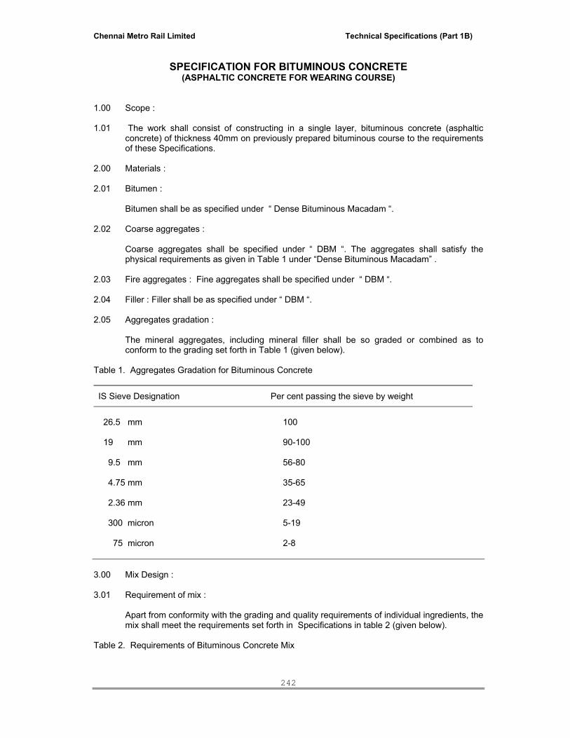
Chennai Metro Rail Limited Technical Specifications (Part 1B)
242
SPECIFICATION FOR BITUMINOUS CONCRETE
(ASPHALTIC CONCRETE FOR WEARING COURSE) 1.00 Scope : 1.01 The work shall consist of constructing in a single layer, bituminous concrete (asphaltic
concrete) of thickness 40mm on previously prepared bituminous course to the requirements of these Specifications.
2.00 Materials : 2.01 Bitumen : Bitumen shall be as specified under “ Dense Bituminous Macadam “. 2.02 Coarse aggregates : Coarse aggregates shall be specified under “ DBM “. The aggregates shall satisfy the
physical requirements as given in Table 1 under “Dense Bituminous Macadam” . 2.03 Fire aggregates : Fine aggregates shall be specified under “ DBM “. 2.04 Filler : Filler shall be as specified under “ DBM “. 2.05 Aggregates gradation : The mineral aggregates, including mineral filler shall be so graded or combined as to
conform to the grading set forth in Table 1 (given below). Table 1. Aggregates Gradation for Bituminous Concrete
IS Sieve Designation Per cent passing the sieve by weight
26.5 mm 19 mm 9.5 mm 4.75 mm 2.36 mm 300 micron 75 micron
100 90-100 56-80 35-65 23-49 5-19 2-8
3.00 Mix Design : 3.01 Requirement of mix : Apart from conformity with the grading and quality requirements of individual ingredients, the
mix shall meet the requirements set forth in Specifications in table 2 (given below). Table 2. Requirements of Bituminous Concrete Mix

Chennai Metro Rail Limited Technical Specifications (Part 1B)
243
S.No. Description Requirements
1.
Marshall stability (ASTM Designation : D-1559) determined on Marshall specimens compacted by 50 compaction blows on each end
340 kg (1800 lb) Minimum
2.
Marshall flow (mm)
Minimum 2 - 4
3. Per cent air voids in mix 5 - 10
4. Per cent voids in mineral aggregates filled by bitumen (VFB)
55 - 75
6.
Binder content, per cent by weight of total mix
Minimum 5 - 6
3.02 Binder content : The binder content shall be so fixed as to achieve the requirements of the mix set forth in
Table 2. Marshall method for arriving at the binder content shall be adopted. 3.03 Job mix formula : Specification described under “ Dense Bituminous Macadam “ shall apply except that the
requirement of Bituminous Concrete mix shall be as per Table 2. 3.04 Permissible variations from the job mix formula : The Contractor shall have the responsibility of ensuring proper proportioning of materials in
accordance with the approved job mix formula and producing a uniform mix. The permissible variations of individual percentages of various ingredients in the actual mix from the job mix formula may be within the limits as specified in Table given under “Dense Bituminous Macadam”. These variations are intended to apply to individual specimens taken for quality control tests.
4.00 Construction Operations : Weather and seasonal limitations : The work of laying shall not be taken up during rainy or foggy weather or when the base
course is damp or wet, or during dust storm or when the atmospheric temperature in shade in 10oC or less.
Preparation of base : The base on which bituminous concrete is to be laid shall be prepared, shaped and
conditioned to the specified levels, grade and crossfall (camber) as directed by the Engineer.
The surface shall be thoroughly swept clean free from dust and foreign matter using
mechanical broom and dust removed by mechanical means or blown off by compressed air. In portions where mechanical means cannot reach, other approved method shall be used.
Tack coat : A tack coat complying with Specifications shall be applied over the base. Preparation of mix : Specification described under “ Dense Bituminous Macadam” . Spreading : Clause for “ Dense Bituminous Macadam “ shall apply.

Chennai Metro Rail Limited Technical Specifications (Part 1B)
244
Rolling : Clause for “ Dense Bituminous Macadam” shall apply.
Opening to Traffic : Traffic may be allowed immediately after completion of the final rolling when the mix has
cooled down to the surrounding temperature. Surface Finish and Quality Control of Work : The surface finish of construction shall conform to the requirements of the Engineer. Measurements for Payment : Bituminous concrete shall be measured as finished work in square metres as specified in
the Schedule of Quantities. GUIDELINES ON SELECTION OF THE GRADE OF BITUMEN (Source: Bituminous Road Construction Handbook, Indian Oil Corporation and Central Road
Research Institute) A. For bituminous premix carpet, choice is governed by climatic conditions and intensity of
traffic. a) Grade 60/70 for areas where difference between maximum and minimum atmospheric
temperatures is less than 25oC and traffic intensity is greater than 1500 commercial vehicles per day. For traffic intensity less than 1500 commercial vehicles per day, Grade 80/100 is preferred.
b) Where the difference between maximum atmospheric temperature is more than 25oC and
traffic intensity is greater than 1500 commercial vehicles per day, Grade 50/60 may be used. For traffic intensity of less than 1500 commercial vehicles per day, Grade 80/100 may be used. For roads with very heavy traffic greater than 4500 commercial vehicles per day, such as metropolitan city roads, Grade 60/70 is preferred.
c) Grade 80/100 may be used in high altitude and snow-bound regions, irrespective of traffic
intensity consideration. B. For bituminous macadam and penetration macadam as also built-up spray grout, Grade
30/40 (for hot climates) and 60/70 or 80/100 for other climates are suggested. C. For a dense-graded bituminous concrete, a more viscous grade like 60/70 can withstand
stresses of heavier wheel loads better than a less viscous grade of 80/100. Similarly paving bitumen grade 60/70 is more advantageous for roads with large number of repetitions of wheel loads like expressways, urban roads, factory roads etc. High stability requirement cannot be met effectively by less viscous bitumen.
D. A more viscous grade of bitumen is advantageous in reducing stripping of bitumen film from
aggregates in the presence of water. E. With rounded river shingles, a more viscous grade of bitumen compensates to some extent
for poor mechanical interlock. QUALITY CONTROL FOR ROAD WORKS 1.00 General :
Chennai Metro Rail Limited Technical Specifications (Part 1B)
245
All materials to be used, all methods adopted and all works performed shall be strictly in accordance with the requirements of IRC Specifications. The Contractor shall set up a field laboratory at locations approved by the Engineer and equip the same with adequate equipment and personnel in order to carry out all required tests and Quality Control Work as per Specifications and / or as directed by the Engineer. The internal layout of the laboratory shall be as
indicated in the drawing and / or as directed by the Engineer. The list of equipment and the facilities to be provided shall be got approved from the Engineer in advance.
The Contractor’s laboratory should be manned by a qualified Materials Engineer / Civil
Engineer assisted by experienced technicians, and the set-up should be got approved by the Engineer.
The Contractor shall carry out quality control tests on the materials and work to the
frequency stipulated in subsequent paragraphs. In the absence of clear indications about method and or frequency of tests for any item, the instructions of the Engineer shall be followed.
For satisfying himself about the quality of the materials and work, quality control tests will
also be conducted by the Engineer (by himself, by his Quality Control Units or by any agencies deemed fit by him), generally to the frequency set forth hereinunder. Additional tests may also be conducted where, in the opinion of the Engineer, need for such tests exists.
The Contractor shall provide necessary co-operation and assistance in obtaining the
samples for tests and carrying out the field tests as required by the Engineer from time to time. This may include provision of labour, attendants, assistance in packing and dispatching and any other assistance considered necessary in connection with the tests.
For the work of embankment, subgrade and pavement, construction of subsequent layer of
same or other material over the finished layer shall be done after obtaining permission from the Engineer. Similar permission from the Engineer shall be obtained in respect of all other items of works prior to proceeding with the next stage of construction.
The Contractor shall carry out modifications in the procedure of work, if found necessary, as
directed by the Engineer during inspection. Works failing short of quality shall be rectified / redone by the Contractor at his own cost, and defective work shall also be removed from the site of works by the Contractor at his own cost.
The cost of laboratory building including services, essential supplies like water, electricity,
sanitary services and their maintenance and cost of all equipment, tools, materials, labour and incidentals to perform tests and other operations of quality control according to the Specification requirements shall be deemed to be incidental to the work and no extra payment shall be made for the same.
For testing of samples of soils/soil mixes, granular materials, and mixes, bituminous materials and mixes, aggregates, cores etc., samples in the required quantity and form shall be supplied to the Engineer by the Contractor at his own cost.
For cement, bitumen, mild steel, and similar other materials where essential tests are to be
carried out at the Manufacturer’s plants or at laboratories other than the site laboratory, the cost of samples, sampling, testing and furnishing of test certificates shall be borne by the Contractor. He shall also furnish the test certificates to the Engineer.
For testing of cement concrete at site during construction, arrangements for supply of
samples, sampling, testing and supply of test results shall be made by the Contractor as per the frequency and number of tests specified in the Handbook of Quality Control for Construction of Roads and Runways (IRC : SP : 11) and relevant IS Codes or relevant clauses of these Specifications, the cost of which shall be borne by the Contractor.
The method of sampling and testing of materials shall be as required by the “Handbook of
Quality Control for Construction of Roads and Runways” (IRC : SP : 11), and these

Chennai Metro Rail Limited Technical Specifications (Part 1B)
246
Specifications. Where they are contradicting, the provision in these Specifications shall be followed. Where they are silent, sound engineering practices shall be adopted. The sampling and testing procedure to be used shall be approved by the Engineer and his decision shall be final and binding on the Contractor.
The materials for embankment construction shall be got approved from the Engineer. The
responsibility for arranging and obtaining the land for borrowing or exploitation in any other way shall rest with the Contractor who shall ensure smooth and uninterrupted supply of materials in the required quantity during the construction period.
Similarly, the supply of aggregates for construction of road pavement shall be from quarries
approved by the Engineer. Responsibility for arranging uniterrupted supply of materials from the source shall be that of the Contractor.
2.00 Defective Materials : All materials which the Engineer/his representative has determined as not conforming to the
requirements of the Contract shall be rejected whether in place or not; they shall be removed immediately from the site as directed. Materials, which have been subsequently corrected, shall not be used in the work unless approval is accorded in writing by the Engineer. Upon failure of the Contractor to comply with any order of the Engineer/his representative, given under this Clause, the Engineer / his representative shall have authority to cause the removal of rejected material and to deduct the removal cost thereof from any payments due to the Contractor.
3.00 Imported Materials : At the time of submission of tenders, the Contractor shall furnish a list of materials/finished
products manufactured, produced or fabricated outside India which he proposes to use in the work. The Contractor shall not be entitled to extension of time for acts or events occuring outside India and it shall be the Contractor’s responsibility to make timely delivery to the job site of all such materials obtained from outside India.
The materials imported from outside India shall conform to the relevant Specifications of the
Contract. In case where materials/finished products are not covered by the Specifications in the Contract, the details of Specifications proposed to be followed and the testing procedure as well as laboratories/establishments where tests are to be carried out shall be specifically brought out and agreed to in the Contract.
The Contractor shall furnish to the Engineer a certificate of compliance of the tests carried
out. In addition, certified mill test reports clearly identified to the lot of materials shall be furnished at the Contractor’s cost.
4.00 CONTROL OF ALIGNMENT, LEVEL AND SURFACE REGULARITY 4.01 General : All works performed shall conform to the lines, grades, cross sections and dimensions
shown on the drawings or as directed by the Engineer, subject to the permitted tolerances described herein-after.

Chennai Metro Rail Limited Technical Specifications (Part 1B)
247
4.02 Horizontal Alignment : Horizontal alignments shall be reckoned with respect to the centre line of the carriageway as
shown on the drawings. The edges of the carriageway as constructed shall be correct within a tolerance of ± 10 mm therefrom. The corresponding tolerance for edges of the roadway and lower layers of pavement shall be ± 25 mm.
4.03 Surface Levels : The levels of the subgrade and different pavement courses as constructed, shall not vary
from those calculated with reference to the longitudional and cross-profile of the road shown on the drawings or as directed by the Engineer beyond the tolerances mentioned in Table 1.
Table 900-1. Tolerances in Surface levels
1. Subgrade + 20 mm - 25 mm
2. Sub-base + 10 mm a) Flexible pavement b) Concrete pavement (Dry lean concrete or Rolled concrete)
- 20 mm + 6 mm - 10 mm
3.
Base-course for flexible pavement a) Bituminous course b) Other than bituminous I) Machine laid ii) Manually laid
+ 6 mm - 6 mm + 10 mm - 10 mm + 15 mm - 15 mm
4. Wearing course for flexible pavement a) Machine laid b) Manually laid
+ 6 mm - 6 mm + 10 mm - 10 mm
5.
Cement concrete pavement
+ 5 mm - 6 mm*
* This may not exceed - 8 mm at 0 - 30 cm from the edges.
Provided, however, that the negative tolerance for wearing course shall not be permitted in conjunction with the positive tolerance for base course, if the thickness of the former is thereby reduced by more than 6 mm for flexible pavements and 5 mm for concrete pavements.
For checking compliance with the above requirement for subgrade, sub-base and base courses, measurements of the surface levels shall be taken on a grid of points placed at 6.25 m longitudinally and 3.5 m transversely. For any 10 consecutive measurements taken longitudinally or transversely, not more than one measurement shall be permitted to exceed the tolerance as above, this one measurement being not in excess of 5 mm above the permitted tolerance.
For checking the compliance with the above requirement for bituminous wearing courses and concrete pavements, measurements of the surface levels shall be taken on a grid of points speced at 6.25 m along the length and at 0.5 m from the edges and at the centre of the pavement. In any length of pavement, compliance shall be deemed to be met for the final road surface, only if the tolerance given above is satisfied for any point on the surface.
4.04 Surface Regularity of Pavement Courses :

Chennai Metro Rail Limited Technical Specifications (Part 1B)
248
The longitudinal profile shall be checked with a 3 metre long straight edge/moving straight-
edge as desired by the Engineer at the middle of each traffic lane along a line parallel to the centre line of the road.
The maximum permitted number of surface irregularities shall be as per Table 2 (MOST). Table 2. Maximum Permitted Number of Surface Irregularities
Surface of Carriageways and paved shoulders
Surface of laybys, service areas and all bituminous base courses
Irregularity 4 mm 7 mm 4 mm 7 mm Lengh(m)
300
75
300
75
300
75
300
75
National Highways/Expressways*
20
9
2
1
40
18
4
2
Roads of lower category*
40
18
4
2
60
27
6
3
* Category of each section of road as described in the Contract. The maximum allowable difference between the road surface and underside of a 3 m straight-edge when placed parallel with, or at right angles to the centre line of the road at points decided by the Engineer shall be ; for pavement surface (bituminous and cement concrete) 3 mm for bituminous base courses 6 mm for granular sub-base/base course 8 mm for sub-bases under concrete pavements 10 mm 5.00 Rectification : Where the surface regularity of subgrade and the various pavement courses fall outside the
specified tolerances, the Contractor shall be liable to rectify these in the manner described below and to the satisfaction of the Engineer.
a) Subgrade : Where the surface is high, it shall be trimmed and suitably compacted.
Where the same is low, the deficiency shall be corrected by scarifying the lower layer and adding fresh material and recompacting to the required density. The degree of compaction and the type of material to be used shall conform to the requirements of Clause 305.
b) Granular Sub-base : Same as at (I) above, except that the degree of compaction and
the type of material to be used shall conform to the requirements of Clause 401. c) Lime/Cement Stabilized Soil Sub-base : For lime/cement treated materials where the
surface is high, the same shall be suitably trimmed while taking care that the material below is not disturbed due to this operation. However, where the surface is low, the same shall be corrected as described herein below.
For cement treated material, when the time elapsed between detection of irregularity and the time of mixing of the material is less than 2 hours, the surface shall be scarified to a depth of 50 mm supplemented with freshly mixed materials as necessary and recompacted to the relevant specification. When this time is more than 2 hours, the full depth of the layer shall be removed from the pavement and replaced with fresh material to Specification. This shall also apply to lime treated material except that the time criterion shall be 3 hours instead of 2 hours.

Chennai Metro Rail Limited Technical Specifications (Part 1B)
249
d) Wet Mix Macadam Sub-base/Base : Where the surface is high or low, the top 75 mm shall be scarified, reshaped with added material as necessary and re-compacted to Clause 404 (MOST). This shall also apply to wet mix macadam to Clause 406 (MOST).
e) Bituminous Construction: For bituminous construction other than wearing course, where the surface is low, the deficiency shall be corrected by adding fresh material over a suitable tack coat if needed and re-compacting to specifications. Where the surface is high, the full depth of the layer shall be removed and replaced with fresh material and compacted to specifications.
For wearing course, where the surface is high or low, the full depth of the layer shall be removed and replaced with fresh material and compacted to specifications. In all cases where the removal and replacement of a bituminous layer is involved, the area treated shall not be less than 5 m in length and not less than 3.5 m width.
f) Dry Lean Concrete Sub-base/Rolled Cement Concrete: The defective length of the
course shall be removed to full depth and replaced with material conforming to Clauses 601 and 603, as applicable. The area treated shall be at least 3 m long, not less than 1 lane wide and extend to the full depth. Before relaying the course, the disturbed subgrade or layer below shall be corrected by levelling, watering and compacting.
g) Cement concrete pavement: The defective areas having surface irregularity
exceeding 3 mm but not greater than 6 mm may be rectified by bump cutting or scrabbling or grinding using approved equipment. When required by the Engineer, areas which have been reduced in level by the above operation(s) shall be retextured in an approved manner either by cutting grooves (5 mm deep) or roughening the surface by hacking the surface. If high areas in excess 6 mm to low areas in excess of 3 mm occur, exceeding the permitted numbers and if the Contractor cannot rectify, the slab shall be demolished and reconstructed at the Contractor’s expense and in no case the area removed shall be less than the full width of the lane in which the irregularity occurs and full length of the slab.
If deemed necessary by the Engineer, any section of the slab which deviates from the
specified levels and tolerances shall be demolished and reconstructed at the Contractor’s expense.
6.00 QUALITY CONTROL TESTS DURING CONSTRUCTION
6.01 General : The materials supplied and the works carried out by the Contractor shall conform to the
specifications prescribed in the preceding Clauses. For ensuring the requisite quality of construction, the materials and works shall be subjected
to quality control tests, as described hereinafter. The testing frequencies set forth are the desirable minimum and the Engineer shall have the full authority to carry out additional tests as frequently as he may deem necessary, to satisfy himself that the materials and works comply with the appropriate specifications. However, the number of tests recommended in Tables 3 and Table 4 may be reduced at the discretion of the Engineer if is felt that consistency in the quality of materials can still be maintained with the reduced number of tests.
Test procedures for the various quality control tests are indicated in the respective Sections
of these Specifications or for certain tests within this Section. Where no specific testing procedure is mentioned, the tests shall be carried out as per the prevalent accepted engineering practice to the directions of the Engineer.
6.02 Tests on Earthwork for Embankment, Subgrade Construction and Cut Formation: (i) Borrow Material :

Chennai Metro Rail Limited Technical Specifications (Part 1B)
250
Grid the borrow area at 25 m c/c (or closer, if the variability is high) to full depth of proposed
working. These pits should be logged and plotted for proper identification of suitable sources of material. The following tests on representative samples shall be carried out :
a) Sand Content (IS:2720 - Part 4) : 2 tests per 3000 cubic metres of soil. b) Plasticity Test (IS:2720 - Part 5) : Each type to be tested, 2 tests per 3000 cub. metres
of soil c) Density Test (IS : 2720 - Part 8) : Each soil type to be tested, 2 tests per 3000 cub.
metres of soil. d) Deleterious Content Test (IS : 2720 - Part 27) : As and when required by the
Engineer. e) Moisture Content Test (IS : 2720 - Part 2) : One test for every 250 cubic metres of
soil. f) CBR Test on materials to be incorporated in the subgrade on soaked/unsoaked
samples (IS : 2720 - Part 16): One CBR test for every 3000 cum., at least or closer as and when required by the Engineer.
(ii) Compaction Control : Control shall be exercised on each layer by taking at least one measurement of density for
each 1000 square metres of compacted area, or closer as required to yield the minimum number of test results for evaluating a day’s work on statistical basis. The determination of density shall be in accordance with IS : 2720 (Part - 28). Test locations shall be chosen only through random sampling techniques. Control shall not be based on the result of any one test but on the mean value of a set of 5 - 10 density determinations. The number of tests in one set of measurements shall be 6 (if non-destructive tests are carried out, the number of tests shall be doubled) as long as it is felt that sufficient control over borrow material and the method of compaction is being exercised. If considerable variations are observed between individual density results, the minimum number of tests in one set of measurement shall be increased to 10. The acceptance criteria shall be subject to the condition that the mean density is not less than the specified density plus :
1.65 1.65 - ------------------------ times the standard deviation. (No.of samples)0.5
However, for earthwork in shoulders (earthen) and in the subgrade, atleast one density measurement shall be taken for every 500 square metres for the compacted area provided further that the number of tests in each set of measurements shall be atleast 10. In other respects, the control shall be similar to that described earlier.
(iii) Cut Formation : Tests for the density requirements of cut formation shall be carried out as per specification
or as specified in the Schedule of Quantities. 6.03 Tests on Sub-bases and Bases (excluding bitumen bound bases) :
(I) The tests and their frequencies for the different types of bases and sub-bases shall be as given in Table 3. The evaluation of density results and acceptance criteria for compaction control shall be on lines similar to those set out in IRC Specification or as specified.
(ii) Acceptance Criteria :

Chennai Metro Rail Limited Technical Specifications (Part 1B)
251
The acceptance criteria for tests on the strength of cement/lime stabilised soil and
distribution of stabiliser content shall be subject to the condition that the mean value is not less than the specified value plus :
1.65 1.65 - --------------------------- times the standard diviation. (No. of samples) 0.5
Table 3. Control tests and their minimum frequency for sub-bases and bases
(excluding bitumen bound bases)
S.No. Type of
Construction
Test Frequency (min.)
1. Granular I) Gradation One test per 200 M3
ii) Atterberg limits One test per 200 M3
iii) Moisture content prior to
Compaction
One test per 200 M2
iv) Density of compacted layer
One test per 200 M2
v) Deleterious constituents As required
vi) C.B.R As required
2. LIme/Cement Stabilized Soi Sub-base
I) Quality of lime/cement One test for each consignment subject to a minimum of one test per 5 tonnes.
ii) Lime/Cement content Regularly, through procedural checks
iii) Degree of pulverisation Periodically as considered necessary
iv) CBR or Unconfined Compressive Strength test on a set of 3 specimens
As required
v) Moisture content prior to compaction
One test per 250 Sq.m
vi) Density of compacted layer
One test per 500 Sq.m.
vii) Deleterious constituents As required
3. Wet mix Macadam I) Aggregate Impact Value One test per 200 Cu.m of aggregate
ii) Grading One test per 100 Cu.m
iii) Flakiness Index and Elongation Index
One test per 200 Cu.m. of aggregate

Chennai Metro Rail Limited Technical Specifications (Part 1B)
252
S.No. Type of
Construction
Test Frequency (min.)
iv) Atterberg limits of binding material
One test per 25 Cu.m of binding material
v) Atterberg limits of portion of aggregate passing 425 micron sieve
One test per 100 cubic metre of aggregate
4. Wet Mix Macadam I) Aggregate Impact Value One test per 200 Cu.m. of aggregate
ii) Grading One test per 100 Cu.m of aggregate.
iii) Flakiness and Elongation Index
One test per 100 Cu.m. of aggregate
iv) Atterberg limits of portion of aggregate passing 425 micron sieve
One test per 100 Cu.m of aggregate
v) Density of compacted layer
One test per 500 Cu.m
ATRIUM ROOFING Atrium roof with Structure load shall be made of hollow tube structure tubes of mild steel confirming to Latest relevant IS codes. Structure shall be analysed and designed for primary loads i.e. Dead Load, Live Load & Wind Load and their combinations specified as per Latest relevant IS codes : 875 Part - I, II & III .Structure shall be checked for Structural stability and critical stresses confirming to Latest IS:800, & IS:806 . Welded Structural joints shall confirm to Latest IS:816 and the electrodes for welding shall confirm to Latest IS:814 (Part I & II).Bolted Structural joints shall confirm to Latest IS:1367 (Part - III) & IS:3757. Structure shall be treated with suitable sand blasted and suitable polyurethene paint over a coat of primer.
Technical Properties Tensile Fabric Standards Yarn PES HT 1670 Dtex/2200 Dtex TERSUISSES Weight 1500 g / sqm – 44 oz/ sqyd EN ISO 2286-2 Width 178 cm ( -1mm / +1mm) Tensile Strength ( warp/weft) 100/800 daN / 5 cm 1020/810 Lbs EN ISO1421
ASTM D 751-00 cut strip method
Tear Resistance ( warp/weft) 160/140 daN 235/165 Lbs
DIN 53,363 ASTM D 751-00 Trapezoid Tear method
Adhesion 15 daN / 5 cm EN ISO 2411 Flame Retardancy B1/DIN 4102 – 1
Test 2 / NFPA 701 BS 7837 CSFM T 19 SIS 650082(SITAC / SINTEF/ETA)
Surface Treatment Fluotop T 2 ( High concentration PVDF) Back side Treatment Weldable PVDF ( for a better resistance to
pollution of the back side of the fabric)
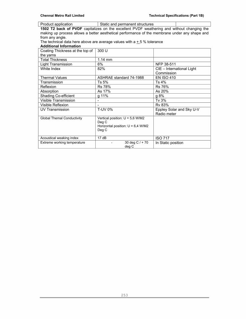
Chennai Metro Rail Limited Technical Specifications (Part 1B)
253
Product application Static and permanent structures 1502 T2 back of PVDF capitalizes on the excellent PVDF weathering and without changing the making up process allows a better aesthetical performance of the membrane under any shape and from any angle. The technical data here above are average values with a + 5 % tolerance Additional Information Coating Thickness at the top of the yarns
300 U
Total Thickness 1.14 mm Light Transmission 6% NFP 38-511 White Index 82% CIE – International Light
Commission Thermal Values ASHRAE standard 74-1988 EN ISO 410 Transmission Ts 5% Ts 4% Reflexion Rs 78% Rs 76% Absorption As 17% As 20% Shading Co-efficient g 11% g 8% Visible Transmission - Tv 3% Visible Reflexion - Rv 83% UV Transmission T-UV 0% Eppley Solar and Sky U-V
Radio meter Global Themal Conductivity Vertical position: U = 5,6 W/M2
Deg C Horizontal position: U = 6,4 W/M2 Deg C
Acoustical weaking index 17 dB ISO 717 Extreme working temperature - 30 deg C / + 70
deg C In Static position
Chennai Metro Rail Limited Technical Specifications (Part 1B)
254
PLUMBING AND SANITATION WORKS
TECHNICAL SPECIFICATIONS
SECTION-01 :: BASIS OF DESIGN 1. BASIS OF DESIGN
The Plumbing, Sanitary & Drainage System for the project is designed keeping in view the following:
1.1 The objective of this report is to give an overview of Plumbing service for the entire project
(CMRL), Chennai. 1.2 Local Codes and Relevent Indian and International standard. 1.3 Requirement of adequate and equal pressure of hot and cold water in bathrooms, toilets,
kitchen and other designated areas 1.4 Adequate storage of water in under ground raw + treated domestic water tanks, preferably
for 1.5 days consumption. 1.5 Levels of roads / pavements and other services in the area. 1.6 Landscape layout.
The execution of works and materials used shall be as per the latest relevant I.S. specifications. The extension of work shall in strict compliance to the Enviromental Clearance granted by MoEF, Govt. of India. Wherever reference has been made to Indian Standard or any other specifications, the same shall mean to refer to the latest specification irrespective of any particular edition of such specification being mentioned in the specifications below or Schedule of Quantities.
2. CONCEPT OF THE SYSTEM
The following services are envisaged for the entire Project : Water treatment plant (WTP) to ensure that the chemical and bacteriological parameters of water supply in the Entire Project are in accordance with World Health Organization (WHO) standards. Since, water from municipal/tanker has to be treated by UV treatment plant. However, WTP system design shall be verified for suitability prior to installation in accordance to latest water analysis report.
Domestic water supply provided through Gravity system with water available at minimal residual pressure of 1.5 to 2.1 kg/cm2 based on operator’s guidelines.
Sewage and sullage collection & conveyance system based on ASPE standard and applicable guidelines by NBC.
Storm / rain water drainage system from the roof terrace and various levels of the building including balcony drains, planter drains and fountain drains by means of draining, and surface run-off water to rain water recharge pits.
3. WATER STORAGE & DISTRIBUTION SYSTEM

Chennai Metro Rail Limited Technical Specifications (Part 1B)
255
3.1 Water Requirement
The water requirement for the project is proposed to be based on the provisions of IS: 1172 and prevalent practice. The estimated requirement of water per day for the Entire Project based on the number of users and other services shall be 165 KL / day.
3.2 Source of Water
It is expected that the daily potable domestic water requirement for the Entire Project shall be met through municipal water authority, Tanker supply & Bore Well,
3.3 Water Storage
The total water storage in raw & domestic water tanks is of 165 KL / day capacity. 3.4 Water Quality
Water treatment plant shall be provided in accordance with the various requirements of use. The various type/quality of water and their water treatment plant are as follows: Domestic Water: Water sourced from the municipal water authority & Tanker supply shall be passed through basic water treatment plant comprising of multi grade filters and pH correction units. Provision of UV treatment unit shall be made for water treatment. Further specialized treatment, may be provided based on the source water analysis report. Water shall be used for domestic usage in bath room (shower and wash basin), Kitchen and other areas, where direct human contact / use are envisaged. Flushing Water: Flushing water for the Entire Project shall be sourced from the in-house sewage treatment plant (STP). The treated effluent for flushing shall be obtained after tertiary treatment at STP. The tertiary treatment shall comprise of multi-grade filters and activated carbon filters. In addition to that UV treatment also. The treated effluent shall be colour-less, odourless and shall be in acceptable chemical / bacteriological parameters as per local pollution control board laws. Drinking Water: Drinking water shall be provided at kitchen sinks of each flat.
3.5 Water Distribution
The water distribution for hot and cold water supply for the Entire Project shall be designed on principle of zoning to ensure availability of adequate residual head at user outlet. Provision of pressure reducing station and non-return valve shall be made for effective and efficient water distribution in the Entire Project. Design is such that the hot and cold water pressure and flow shall be fairly equal to avoid reversal of flow from one service to another. Variable speed hydropematic system shall be provided fully equipped with pre-charged, non-toxic food grade bladder. Separate direct connection from header shall be taken for water requirement of Kitchen etc., and for hot water mixing tank connection. Zoning of cold and hot water supply for floors at lower and higher levels shall be provided. The Flush water store at STP plant it self, from where the flush water shall be pumped to the each block terrace OHT.
3.6 Appurtenant Following components shall be included in the water supply system for efficient functioning:
i. Isolation valves at strategic points.
ii. Non Return valves for backflow prevention. iii. Automatic air vent at each of the high point.

Chennai Metro Rail Limited Technical Specifications (Part 1B)
256
iv. Drain valve at each of the low point. v. Strainer.
vi. Cross connection. vii. Pressure Reducing valve where abnormally high pressure is to be reduced. viii. Water Hammer Arrestors (as required). ix. Air Vessel to confront Surge pressure. x. Flow meter. xi. Pressure Gauge. xii. Anchor block / thrust block.
4. SEWAGE, SULLAGE AND STORM WATER The soil and waste shall be carried down in separate independently vented pipes. Two pipe
drainage systems shall be adopted as per NBC (Part-IX). Provision of ASP vertical vent shall also be made for hygiene, safety consideration and to avoid foul smell entering through trapped gully in WC and Urinal trap.. Provision of grease trap shall be made for waste water from Kitchen.
4.1. Design Limitations The system is designed considering the following: a. High thrust developed at soil & Waste pipe connections.
b. Termination of vent cowl at terrace level. c. Provision of adequate slope for horizontal header pipes for achieving self- cleansing velocity in
the pipes. d. Provision of cleanout plug and Rodding eye. e. Minimum diameter of Soil pipe as 100 mm and Waste pipe as 80mm.
5. WORKMANSHIP The workmanship shall be best of its kind and shall conform to the specifications, as below
or Indian Standard Specifications in every respect or latest trade practices and shall be subject to approval of the Owner’s Site Representative. All materials and/or Workmanship which in the opinion of the Owner’s Site Representative / Architect / Consultant is defective or unsuitable shall be removed immediately from the site and shall be substituted with proper materials and/or workmanship forthwith.
6. MATERIALS All materials shall be best of their kind and shall conform to the latest Indian Standards. All materials shall be of approved quality as per samples and origins approved by the
Owner’s Site Representative / Architect / Consultants. As and when required by the Owner’s Site Representative / Consultant, the contractor shall
arrange to test the materials and/or portions of works at his own cost to prove their soundness and efficiency. If after tests any materials, work or portions or work are found defective or unsound by the Owner’s Site Representative / Consultant, the contractor shall remove the defective material from the site, pull down and re-execute the works at his own cost to the satisfaction of the Owner’s Site Representative / Consultant. To prove that the

Chennai Metro Rail Limited Technical Specifications (Part 1B)
257
materials used are as specified the contractor shall furnish the Owner’s Site Representative with original vouchers on demand.
SECTION-02 :: SANITARY FIXTURES & CHROMIUM PLATED FITTINGS 1. SCOPE
The scope of this section consists of but is not necessarily limited to supply, installation, testing and commissioning of following items:
a. Sanitary appliances and fixtures for toilets. b. Chromium plated brass fittings c. Stainless steel sinks d. Accessories e.g. towel rods, toilet paper holders, soap dish, liquid soap dispensers,
towel rails, coat hooks etc. e. Hand driers, drinking water fountains etc.
Whether specifically mentioned or not the Contractor shall provide for all appliances and fixtures all fixing devices, nuts, bolts, screws, hangers as required.
All exposed pipes within toilets and near appliances/fixtures shall be of chromium plated brass or copper unless otherwise specified.
2 GENERAL REQUIREMENT
Sanitary appliances and fixtures for toilets, chromium plated brass fittings, stainless steel sinks, bathroom accessories like towel rods, toilet paper holders, soap dish, liquid soap dispensers, towel rails coat hooks etc and mirrors, hand driers, drinking water fountains etc as listed in the relevant items in the Schedule of Quantities shall be supplied by the contractor scope. The rates shall be inclusive of accessories (in such case) required for installation. All sanitary fixtures and fittings to be stored under covered roof and handled carefully to prevent any damage by the Contractor. All appliances, fixtures and fittings shall be provided with all such accessories as are required to complete the item in working condition whether specifically mentioned or not in the Schedule of Quantities, specifications, and drawings. Accessories shall include proper fixing arrangements, brackets, nuts, bolts, washers, screws and required connection pieces. The sanitary fixtures and fittings shall be installed at the correct assigned position as shown on the drawings and as directed by the Architect / Owner’s Site Representative and shall fully meet with the aesthetic and symmetrical requirements as demanded by the Architect / Interior Designer All fixtures and accessories shall be fixed in accordance with a set pattern matching the tiles or interior finish as per Architect requirements. Wherever necessary, the fittings shall be centered to dimensions and pattern as called for. Fixing screws shall be half round head chromium plated (CP) brass screws, with CP brass washers unless otherwise specified. Fixtures shall be installed by skilled workman with appropriate tools according to the best trade practice. All appliances, fittings and fixtures shall be fixed in a neat workmanlike manner true to level and to heights shown on the drawings and in accordance with the manufacturer’s recommendations. Care shall be taken to fix all inlet and outlet pipes at correct positions. Faulty locations shall be made good and any damage to the finished floor, tiling, plaster, paint, insulation or terrace shall be made good by the Contractor at his own cost. Fixtures shall be mounted rigid, plumb and true to alignment.

Chennai Metro Rail Limited Technical Specifications (Part 1B)
258
All materials shall be rust proofed ; materials in direct or indirect contact shall be compatible to prevent electrolytic or chemical (bimetallic) corrosion. Wall flanges shall be provided on all walls, floors, columns etc. wherever supply and disposal pipes pierce through them. These wall caps shall be or chromium plated brass fittings and the receiving pipes and shall be large enough to cover the punctures properly. Sanitary appliances, subject to the type of appliance and specific requirements, shall be fixed in accordance with the relevant standards and the following : i. Contractor shall, during the entire period of installation and afterwards protect the
appliances by providing suitable cover or any other protection so as to absolutely prevent any damage to the appliances until handing over (The original protective wrapping shall be left in position for as long as possible)
ii. The appliances shall be placed in correct position or marked out in order that pipe
work can be fixed or partially fixed first. iii. The appliance shall be fixed in a manner such that it will facilitate subsequent
removal if necessary. iv. The appliance shall be securely fixed. Manufacturer's brackets and fixing methods
shall be used wherever possible. Compatible rust-proofed fixings shall be used. Fixing shall be done in a manner that minimize noise transmission.
v. Appliances shall not be bedded (e.g. WC pans, pedestal units) in thick strong
mortar that could crack the unit (e.g. ceramic unit) vi. Pipe connections shall be made with demountable unions. Pipe work shall not be
fixed in a manner that it supports or partially supports and appliance. vii. Appliances shall be fixed true to level firmly fixed to anchor or supports provided by
the manufacturer and additional anchors or supports where necessary. Sizes of sanitary fixtures given in the Specifications or in the Schedule of Quantities are for identification with reference to the catalogues of make considered. The contractor shall fix all plumbing fittings such as water faucets, shower fittings, mixing valves etc. in accordance with manufacturer’s instructions and connect to piping system. The contractor shall supply all fixing materials such as screws, rawl plugs, unions, collars, compression fittings etc., as required. Joints / gaps between all sanitary appliances / fixtures and the floor / walls shall be caulked with an approved mildew resistant sealant, having antifungal properties, of colour and shade to match that of the appliances / fixture and the floor / wall to the extent possible.
2.1 Water Closet Water Closet shall be wash down or symphonic wash down type floor or wall mounted set,
as shown in the drawings, designed for low volume flushing from 3-6 litres of water, flushed by means of a concealed type flushing cistern. Flush pipe / bend shall be connected to the WC by means of a suitable rubber adaptor. Wall hung WC shall be supported by rock bolt mounted shall be fixed approved by the Owners Site Representative.
Each WC set shall be provided with approved quality of seat, rubber buffers and chromium
plated hinges. Seat shall be so fixed that it remains absolutely stationary in vertical position without falling down on the WC.
Each WC shall be provided with 110 mm dia (OD) PVC Pan Connector connecting the
ceramic outlet of WC to PVC pipe.
Orissa W.C
Chennai Metro Rail Limited Technical Specifications (Part 1B)
259
Orissa W.C shall be in glazed vitreous chinaware white or colour of size specified. The W.C shall be provided with a 100 mm white vitreous chinaware P or S trap with or without vents as required.
Each W.C shall be provided with an exposed flushing cistern of approved material and make.
Each WC shall be provided with 110 mm dia (OD) PVC Pan connector connecting the
ceramic outlet of WC to CI pipe. 2.2 Urinals Urinals shall be lipped type half stall with glazed vitreous China of size as called for in the
Bill of Quantities. Half stall urinals shall be provided with 15mm dia CP spreader, 32mm dia CP domical
waste and CP cast brass bottle trap with pipe and wall flange and shall be fixed to wall by CI brackets, CI wall clips and CP brass screws as recommended by manufacturer complete as directed by the Owner’s Site Representative.
Flushing for urinals shall be by means of no hand operation, infrared electric flush valve
with complete kit of plumbing, electrical and electronic items, infrared photo cells, solenoid valve transformer and electrical connection. The automatic flush sensor plate shall be flush and press fitted and be of high quality mirror polish finish. Each urinal shall be provided with one flush valve unit.
Flush pipes shall be GI pipes concealed in wall chase but with chromium plated bends at
inlet and outlet. 2.3 Bath Tub Bath tub shall be white enameled cast iron, pressed steel, acrylic, built-up marble
(polymarble) or of any other material as specified in the Schedule of Quantities. Each bath tub shall be provided with 40 mm dia (lever operated pop-up brass waste if
required) waste with 32 mm CP overflows assembly with brass P trap with cleaning eye. Bath tubs shall be fixed true to level firmly fixed to anchor or supports provided by the
manufacturer. Edges touching the walls shall be thoroughly sealed. The fixing shall be perfectly done with hold fasts or bathtubs with PCC and plaster done so that the wall behind does not tend to get damp or patchy.
Contractor shall during the entire period of installation and afterwards protect the bath tub by
providing suitable cover over the entire bath tub by providing suitable sheet protection to prevent any damage to the bath tub until completion of the works.
2.4 Wash Basin Wash basins shall be white glazed vitreous china of size, shape and type specified in the
Schedule of Quantities. Each basin shall be provided with painted MS angle or CI brackets and clips and the basin
securely fixed to wall/counter slab. Placing of basins over the brackets without secure fixing shall not be accepted. The MS angle shall be provided with two coats of red oxide primer and two coats of synthetic enamel paint of make , brand and colour as approved by the Owner’s Site Representative. The cost of fixing the basin shall be inclusive of supply and installation of brackets as described above.
Each basin shall be provided with 32mm dia CP waste with overflow, pop-up waste or
rubber plug and CP brass chain as specified in the Schedule of Quantities.

Chennai Metro Rail Limited Technical Specifications (Part 1B)
260
Each basin shall be provided with hot and cold water mixing fitting or as specified in the Schedule of Quantities.
2.5 Sinks Sinks shall be stainless steel or any other material as specified in the Schedule of
Quantities. Each sink shall be provided with painted MS or CI brackets and clips and securely fixed.
Counter top sinks shall be fixed with suitable painted angle iron brackets or clips as recommended by the manufacturer. Each sink shall be provided with 40mm dia CP waste and rubber plug with CP brass chain as given in the Schedule of Quantities. The MS angle shall be provided with two coats of red oxide primer and two coats of synthetic enamel paint of make, brand and colour as approved by the Owner’s site representative.
Sanitary fittings for sinks shall be deck mounted or wall mounted CP swivel faucets with or without hot and cold water mixing fittings as specified in the Schedule of Quantities. Installation of fittings shall be measured and paid for separately.
2.6 Shower Set Shower shall be stainless steel or any other material as specified in the Schedule of
Quantities. Shower set shall comprise of two CP brass concealed stop cocks, single lever diverter, adjustable type over-head shower with CP shower arm , all with CP wall flanges of approved quality all as specified in the Schedule of Quantities. Bath spout, hand showers and pop up wastes shall also be provided wherever, specified. Wall flanges shall be kept clear off the finished wall. Wall flanges embedded in the finishing shall not be accepted.
2.7 Flow Control Device
Approved / rated flow control fitment in brass body, chrome outer cover, rated for flow / discharge of the fixture.
2.8 Toilet Paper Holder Toilet paper holder shall be white glazed vitreous china or chrome plated of size, shape and
type specified in the Schedule of Quantities. Porcelain toilet paper holder shall be fixed in walls and set in cement mortar 1:2 (1 cement :
2 coarse sand) and fixed in relation to the tiling work. The latter (chrome) shall be fixed by means of screws/capping having finish similar to the
toilet paper holder in wall/temper partitions with raw l plugs or nylon sleeves. When fixed on timber partition, it shall be fixed on a solid wooden base member provided by the Owner’s Site Representative.
2.9 Towel Rail Towel rail shall be chromium plated brass or of stainless steel or powder coated brass of
size, shape and type specified in the Schedule of Quantities. Towel rail shall be fixed with screws/capping having finish similar to the towel rail in wall with
rawl plugs or nylon sleeves and shall include cutting and making good as required or directed by the Owner’s Site Representative.
2.10 Janitor's Sink
Chennai Metro Rail Limited Technical Specifications (Part 1B)
261
Janitor's sink shall be stainless steel, single bowl type of size as called for in the Schedule of
Quantities , provided with painted R.S. or CI brackets and clips and securely fixed. Each sink shall be provided with 40mm dia CP waste. Fixing shall be as directed by the Owner’s Site Representative.
The supply fittings for Janitor's sink shall be wall mounted type of size as mentioned in
Schedule of Quantities. 2.11 Drinking Water Fountain
Drinking water fountain shall be well mounting type made of vitreous china, stainless steel or any other material as given in the Schedule of Quantities. The drinking water fountain shall be with anti-squirt bubble less, self closing valve type with automatic volume regulator. The drinking water fountain shall be provided with an anti-splash back and integral strainer with 32mm or 40mm cast brass trap.
2.13 Liquid Soap Dispenser Liquid Soap Dispenser shall be wall/counter mounted suitable for dispensing liquid soaps, lotions, detergents. The cover shall lock to body with concealed locking arrangement, opened only be key provided. Liquid soap dispenser body and shank shall be of high impact resistance material. The piston and spout shall be stainless steel with 1 litre capacity polyethylene container. The valve shall operate with less than 2.27 Kg (5 lbs) of force.
2.14 Hand Drier
The hand drier shall be no touch operating type with solid state time delay to allow user to keep hand in any position. The hand drier shall be fully hygienic, rated for continuous repeat use (CRU). The rating of hand drier shall be such that time required to dry a pair of hands up to wrists is approximately 30 seconds. The hand drier shall be of wall mounting type suitable for 230 V, single phase, 50 Hz, AC power supply.
3. TOILETS FOR THE DISABLED Where specified, in washroom facilities designed to accommodate physically disabled,
accessories shall be provided as directed by the Owner’s Site Representative. Stainless steel garb brass of required size suitable for concealed or exposed mounting and
opened non-slip gripping surface shall be provided in all washroom. The flushing cistern/valve shall be provided with chromium plated long handles.
4. MOCKUP AND TRIAL ASSEMBLY The installation of the Sanitary fixtures and fittings shall be as per the shop drawings
approved by the Architect/Consultant. The contractor shall have to assemble at least one set of each type of sanitary fixtures and
fittings in order to determine precisely the required supply and disposal connections. Relevant instructions from manufacturers shall be followed as applicable. This trial assembly shall be developed to determine the location of puncture holes, holding devices
Chennai Metro Rail Limited Technical Specifications (Part 1B)
262
etc. which will be required for final installation of all sanitary fixtures and fittings. The above assembly shall be subject to final approval by the Architect / Interior Designer.
The fixtures in the trial assembly can be re-used for final installation without any additional
payments for fixing or dismantling of the fixtures. 5. SUPPORTING AND FIXING DEVICES The contractor shall provide all the necessary supporting and fixing devices to install the
sanitary fixtures and fittings securely in position. The fixing devices shall be rigidly anchored into the building structure. The devices shall be rust resistant and shall be so fixed that they do not present an unsightly appearance in the final assembly SS:304 Nut Bolts & screw. Where the location demands, the Architect may instruct the contractor to provide chromium plated or other similarly finished fixing devices. In such circumstances the contractor shall arrange to supply the fixing devices and shall be installed complete with appropriate vibration isolating pads, washers and gaskets.
6. FINAL INSTALLATION The contractor shall install all sanitary fixtures and fittings in their final position in
accordance with approved trial assemblies and as shown on drawings. The installation shall be complete with all supply and waste connections. The connection between building and piping system and the sanitary fixtures shall be through proper unions and flanges to facilitate removal/replacement of sanitary fixtures without disturbing the built in piping system. All unions and flanges shall match in appearance with other exposed fittings.
Fixtures shall be mounted rigid, plumb and to alignment. The outlets of water closet pans
and similar appliances shall be examined to ensure that outlet ends are butting on the receiving pipes before making the joints. It shall be ensured that the receiving pipes are clear of obstruction. When fixtures are being mounted, attention shall be paid to the possibility of movement and settlement by other causes. Overflows shall be made to ensure that necessary anchoring devices have been provided for supporting water closets, wash basins, sinks and other appliances.
7. PROTECTION AGAINST DAMAGE The contractor shall take every precaution to protect all sanitary fixtures against damage,
misuse, cracking, staining, breakage and pilferage by providing proper wrapping and locking arrangement till the completion of the installation. At the time of handing over, the contractor shall clean, disinfect and polish all the fixtures and fittings. Any fixtures and fittings found damaged, cracked chipped stained or scratched shall be removed and new fixtures and fittings free from defects shall be installed at his own cost to complete the work.
8. MEASUREMENT 8.1. Rate for Supply & fixing only of sanitary fixtures accessories, CP fittings shall etc. include all
items, and operations stated in the respective specifications and bill of quantities and nothing extra is payable.
8.2 Rates for all items under specifications para above shall be inclusive of cutting holes and chases and making good the same, CP screws, nuts, bolts and any fixing arrangements required and recommended by manufacturers, testing and commissioning and making good to the satisfaction of the Owner’s Site Representative.
9. TESTING AND ACCEPTANCE
All appliances, fixtures and fittings shall be tested before and after installation. Water seals of all appliances shall be tested. The contractor shall block the ends of waste and ventilation pipes and shall conduct an air test.
9.1 The sanitary fixtures form the final terminal units of the water supply and drainage system
and shall meet the performance needs as a terminal unit. Each fixture shall be inspected for scratches or chippings and alignment before acceptance.

Chennai Metro Rail Limited Technical Specifications (Part 1B)
263
SECTION-03 :: WATER SUPPLY (COLD & HOT)
1. SCOPE The scope of this section comprises the supply, installation, testing and commissioning of
piping network for water supply for internal & external services as follows:
a Municipal / Tanker Water supply. b. Drinking Water Supply. c. Flushing Water Supply f. Connection to various mechanical equipments to be supplied and installed by the
other specialist contractors. The Contractor shall make all necessary application and arrangements for his work to be
inspected by the Local Authorities. The Contractor shall be solely responsible for obtaining the Authorities approval of his works
prior to the handing over of the complete water supply / distribution installation to the Owner. 2. PIPING MATERIALS
The piping system shall consist of: CPVC SDR 11.0 piping from 15 mm to 50 mm & Schedule 40 from 65 mm to 150 mm for cold water supply & schedule 80 from 65 mm to 150 mm for hot water supply. The sizes are specified in the Schedule of Quantities and the makes are specified in Special Conditions of Contract.
Heavy class galvanized iron pipes and fittings conforming to IS:1239. The sizes are specified in the Schedule of Quantities and the makes are specified in Special Conditions of Contract. Unplasticised Polyvinyl Chloride pipes and Specials conforming to IS:4985. The sizes are specified in the Schedule of Quantities and the makes are specified in Special Conditions of Contract. For any internal works, the CPVC pipes / UPVC pipes and fittings shall be embedded in the wall chase or run on the floor/ceiling unless otherwise specified. No unsightly exposed runs shall be permitted. The sizes are specified in the Schedule of Quantities and the makes are specified in Special conditions of contract.
A. CPVC Pipes & Fittings The pipes shall be CPVC (Chlorinated Poly Vinyl Chloride) material for hot & cold water
supply piping system with pipes as per CTs SDR -11 at a working pressure of 320 PSI at 23 deg C and 80 PSI at 82 deg.C, using solvent welded CPVC fittings i.e. Tees, Elbows, Couples, Unions, Reducers, Brushing etc. including transition fittings (connection between CPVC & Metal pipes / GI) i.e. Brass adapters (both Male & Female threaded and all conforming to ASTM D-2846 with only CPVC solvent cement conforming to ASTM F-493, with clamps / structural metal supports as required /directed at site including cutting chases & fitting the same with cement concrete / cement mortar as required, including painting of the exposed pipes with one coat of desired shade of enamel paint. All termination points for installation of faucets shall have brass termination fittings. Installation shall be to the satisfaction of manufacturer & Project Manager. Pipes from 65 mm to 150 mm dia shall be Schedule 40 for CWC & Schedule 80 for HWS / HWR.
TECHNICAL DETAILS
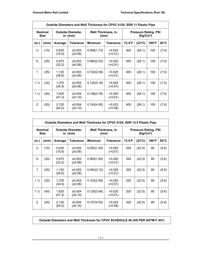
Chennai Metro Rail Limited Technical Specifications (Part 1B)
264
Outside Diameters and Wall Thickness for CPVC 4120, SDR 11 Plastic Pipe
Nominal Size
Outside Diameter, in. (mm)
Wall Thickness, in. (mm)
Pressure Rating. PSI (Kg/Cm2)
(in.) (mm) Average Tolerance Minimum Tolerance 73.4°F (23°C) 180°F 82°C
½ (15) 0.625 (15.9)
±0.003 (±0.08)
0.068(1.73) +0.020 (+0.51)
400 (28.1) 100 (7.0)
¾ (20) 0.875 (22.2)
±0.003 (±0.08)
0.080(2.03) +0.020 (+0.51)
400 (28.1) 100 (7.0)
1 (25) 1.125 (28.6)
±0.003 (±0.08)
0.102(2.59) +0.020 (+0.51)
400 (28.1) 100 (7.0)
1 ¼ (32) 1.375 (34.9)
±0.003 (±0.08)
0.125(3.18) +0.020 (+0.51)
400 (28.1) 100 (7.0)
1 ½ (40) 1.625 (41.3)
±0.004 (±0.10)
0.148(3.76) +0.020 (+0.51)
400 (28.1) 100 (7.0)
2 (50) 2.125 (54.0)
±0.004 (±0.10)
0.193(4.90) +0.023 (+0.58)
400 (28.1) 100 (7.0)
Outside Diameters and Wall Thickness for CPVC 4120, SDR 13.5 Plastic Pipe
Nominal Size
Outside Diameter, in. (mm)
Wall Thickness, in. (mm)
Pressure Rating. PSI (Kg/Cm2)
(in.) (mm) Average Tolerance Minimum Tolerance 73.4°F (23°C) 180°F 82°C
½ (15) 0.625 (15.9)
±0.003 (±0.08)
0.055(1.40) +0.020 (+0.51)
320 (22.5) 80 (5.6)
¾ (20) 0.875 (22.2)
±0.003 (±0.08)
0.065(1.65) +0.020 (+0.51)
320 (22.5) 80 (5.6)
1 (25) 1.125 (28.6)
±0.003 (±0.08)
0.083(2.12) +0.020 (+0.51)
320 (22.5) 80 (5.6)
1 ¼ (32) 1.375 (34.9)
±0.003 (±0.08)
0.102(2.59) +0.020 (+0.51)
320 (22.5) 80 (5.6)
1 ½ (40) 1.625 (41.3)
±0.004 (±0.10)
0.120(3.06) +0.020 (+0.51)
320 (22.5) 80 (5.6)
2 (50) 2.125 (54.0)
±0.004 (±0.10)
0.157(4.00) +0.023 (+0.58)
320 (22.5) 80 (5.6)
Outside Diameters and Wall Thickness for CPVC SCHEDULE 40 (AS PER ASTM F 441)
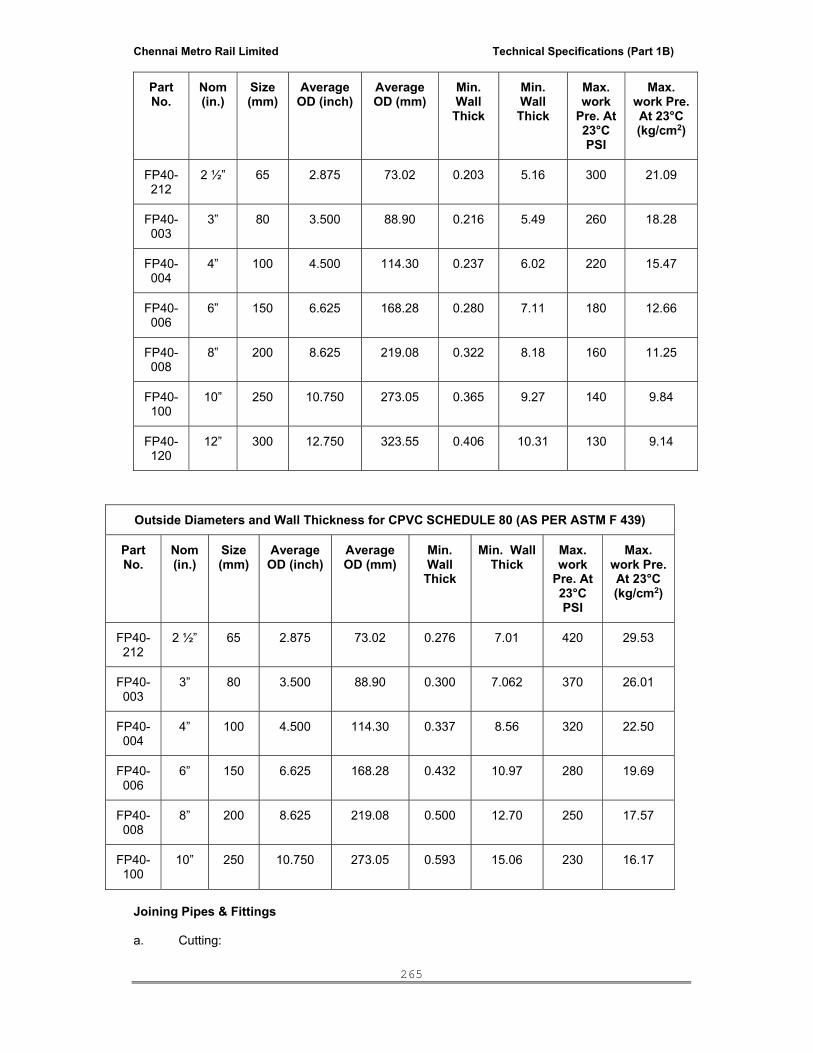
Chennai Metro Rail Limited Technical Specifications (Part 1B)
265
Part No.
Nom (in.)
Size (mm)
Average OD (inch)
Average OD (mm)
Min. Wall Thick
Min. Wall Thick
Max. work
Pre. At 23°C PSI
Max. work Pre. At 23°C (kg/cm2)
FP40-212
2 ½” 65 2.875 73.02 0.203 5.16 300 21.09
FP40-003
3” 80 3.500 88.90 0.216 5.49 260 18.28
FP40-004
4” 100 4.500 114.30 0.237 6.02 220 15.47
FP40-006
6” 150 6.625 168.28 0.280 7.11 180 12.66
FP40-008
8” 200 8.625 219.08 0.322 8.18 160 11.25
FP40-100
10” 250 10.750 273.05 0.365 9.27 140 9.84
FP40-120
12” 300 12.750 323.55 0.406 10.31 130 9.14
Joining Pipes & Fittings a. Cutting:
Outside Diameters and Wall Thickness for CPVC SCHEDULE 80 (AS PER ASTM F 439)
Part No.
Nom (in.)
Size (mm)
Average OD (inch)
Average OD (mm)
Min. Wall
Thick
Min. Wall Thick
Max. work
Pre. At 23°C PSI
Max. work Pre. At 23°C (kg/cm2)
FP40-212
2 ½” 65 2.875 73.02 0.276 7.01 420 29.53
FP40-003
3” 80 3.500 88.90 0.300 7.062 370 26.01
FP40-004
4” 100 4.500 114.30 0.337 8.56 320 22.50
FP40-006
6” 150 6.625 168.28 0.432 10.97 280 19.69
FP40-008
8” 200 8.625 219.08 0.500 12.70 250 17.57
FP40-100
10” 250 10.750 273.05 0.593 15.06 230 16.17

Chennai Metro Rail Limited Technical Specifications (Part 1B)
266
Pipes shall be cut either with a wheel type plastic pipe cutting or hacksaw blade and care shall be taken to make a square cut which provides optimal bonding area within a joint.
b. Deburring / Beveling:
Burrs and fittings should be removed from the outside and inside of pipe with a pocket knife or file otherwise burrs and fittings may prevent proper contact between pipe and fittings during assembly.
c. Fitting preparation:
A clean dry rag/cloth should be used to wipe dirt and moisture from the fitting sockets and tubing end. The tubing should make contact with the socket wall 1/3 or 2/3 of the way into the fitting socket.
d. Solvent Cement Application:
Only CPVC solvent cement confirming to ASTM-F493 should be used for joining pipe with fittings. An even coat of solvent cement should be applied on the pipe end and a thin coat inside the fitting socket, otherwise too much of cement solvent can cause clogged water ways.
e. Assembly:
After applying the solvent cement on both pipe and fitting socket, pipe should be inserted into the fitting socket within 30 seconds, and rotating the pipe ¼ to ½ turn while inserting so as to ensure even distribution of solvent cement with the joint. The assembled system should be held for 10 seconds ( approximately) in order to allow the joint to set up. An even bead of cement should be evident around the joint and if this bead is not continues remake the joint to avoid potential leaks.
Set & Cure times: Solvent cement set and cure times shall be strictly adhered to as per the below mentioned
table. Minimum Core prior to pressure testing at 150 PSI
Ambient Temperature during Core period
Pipe Size½ " - 1" 1.¼" - 2"
Above 15 deg. C 1 Hr 2 Hrs 4-15 deg.C 2 Hrs 4 Hrs Below 4 deg C 4 Hrs 8 Hrs
Special care shall be exercised when assembling flow guard systems in extremely low temperature ( below 4°C) or extremely high temperature (above 45°C) In extremely hot temperatures, make sure that both surfaces to be joined are till wet with cement solvent when putting them together.
f. Testing Once an installation is completed and cored as per above mentioned recommendations, the
system should be hydrostatically pressure tested at 150 psi (10 Bar) for one hour. During pressure testing, the system should be fitted with water and if a leak is found, the joint should be cut out and replacing the same with new one by using couplers.
i. Transition of Flow guard CPVC to Metals
When making a transition connection to metal threads, special Brass / plastic transition fitting (Male and female adapters) should be used. Plastic threaded connections should not be over torqued Hard tight puts one half turn should be adequate.

Chennai Metro Rail Limited Technical Specifications (Part 1B)
267
ii. Threaded Sealants
Teflon tape shall be used to make threaded connections leak proof. iii. Solvent Cement
Only CPVC solvent cement conforming to ASTMF 493 should be used for joining pipe with fittings and valves. Flow guard CPVC cement solvent have a minimum shelf life of 1 year. Aged cement solvent will often change colour or being to thicken and become gelatinous or jelly like and when this happens, the cement should not be used. The cement solvent should be used within 30 days after opening the company’s seal and tightly close the seal after using in order to avoid its freezing. The freezed cement solvent should be discarded immediately and fresh one should be used. The CPVC solvent cement usage should be adhered to as given in table below
Diameter of pipe in inch
( flow guard) ½” ¾” 1” ¼” 1½” 2”
Approx. nos. of joints which can be mode per litre of solvent cement.
200 Nos
180 Nos
150 Nos
130 Nos
100 Nos
70 Nos
iv. Hangers and supports
For Horizontal runs, support should be given at 3 foot ( 90 cm) intervals for diameters of one inch and below and at 4 foot (1.2m) intervals for larger sizes.
Hangers should not have rough or sharp edges which come in contact with the tubing.
Supports should be as per the below mentioned table:
Size of Pipe 21°C 49°C 71°C 82°C Inch Ft. Ft. Ft. Ft. ½” 5.5 4.5 3.0 2.5 ¾” 5.5 5.0 3.0 2.5 1” 6.0 5.5 3.5 3.0 1¼” 6.5 6.0 3.5 3.5 1½” 7.0 6.0 3.5 3.5 2” 7.0 6.5 4.0 3.5
SCHEDULE - 40 Recommended Support spacing (in feet) Nom. Pipe Size Temperature oC (In) (mm) 23 38 49 60 71 82 2 ½ 65 7 ½ 7 7 6 ½ 6 3 ½ 3 80 8 7 7 7 6 3 ½ 4 100 8 ½ 7 ½ 7 ½ 7 6 ½ 4 6 150 9 ½ 8 8 7 ½ 7 4 ½ 8 200 9 ½ 8 8 7 ½ 7 5
SCHEDULE - 80 Recommended Support spacing (in feet) Nom. Pipe Size Temperature oC (In) (mm) 23 38 49 60 71 82 2 ½ 65 8 7 ½ 7 ½ 6 ½ 4 ½ 4 3 80 8 8 7 ½ 7 4 ½ 4

Chennai Metro Rail Limited Technical Specifications (Part 1B)
268
4 100 9 9 8 ½ 7 ½ 5 4 ½ 6 150 10 9 ½ 9 8 5 ½ 5
B. Galvanised Iron Pipes & Fittings
The pipes shall be galvanised mild steel welded (ERW) 7 screwed and socketed conforming to the requirements of IS:1239. The pipes under this standard are designated by their nominal bore and are further classified as Light, Medium and Heavy depending upon their wall thickness and shall be used as per required suitabile pressure. Sockets of these pipes are designated by respective nominal bore of the pipe. Joints: The threads of all screwed and socket pipes shall conform to IS:554. The minimum length of thread in Light pipes shall be 80 percent of that specified in IS:554. Each pipe shall be supplied with one socket Manufacturing Process : Tubes are made from tested quality of steel manufactured by any approved by any approved process (a) Hot Finished Seamless (HFS), (b) Electric Resistance Welded (HFIW), and (d) Hot Finished Welded (HFW). Tubes manufactured by manual welding are not covered by this standard. Light, Medium and Heavy tubes, and sockets shall be either welded or seamless. Medium and heavy tubes shall be manufactured from mild steel by the open hearth, electric or basic oxygen process. All electric welded tubes and sockets (Medium and Heavy) class shall be normalised. Tensile Strength : The tensile strength of strips cut from selected tubes shall be at least 320 MPa. Chemical Composition: The ladle analysis of steel for tubes and sockets used for steam services shall not show sulphur and phosphorus in amount exceeding 0.050 percent each. When pipes are used for water and gas purpose these contents shall not exceed 0.060 percent each. Tolerance : The manufacturing tolerance to the following extent is permissible on pipes and sockets: Butt Welded : Light tubes: - 8 percent + not limited. Medium and Heavy tubes: - 10 percent + not limited. Seamless tubes: -12.5 percent + not limited. Weights: (1) Single tube Light – 8 percent + 10 per cent (2) Single tube Medium & heavy – 8 percent + 10 percent (3) For quantities per Load of 10 tonnes Min. (Light Series) + 5 percent (4) For quantities per load of 10 tonnes Min. (Medium & Heavy series) + 7.5 percent. Note: For the purpose of minimum weighment of 10 tonnes lot, the weighment may be done in convenient lots at the option of the manufacturer. Manufacturing Process : Tubes are made from tested quality of steel manufactured by any approved by any approved process (a) Hot Finished Seamless (HFS), (b) Electric Resistance Welded (HFIW), and (d) Hot Finished Welded (HFW). Tubes manufactured by manual welding are not covered by this standard.

Chennai Metro Rail Limited Technical Specifications (Part 1B)
269
Light, Medium and Heavy tubes, and sockets shall be either welded or seamless. Medium and heavy tubes shall be manufactured from mild steel by the open hearth, electric or basic oxygen process. All electric welded tubes and sockets (Medium and Heavy) class shall be normalised. Tensile Strength : The tensile strength of strips cut from selected tubes shall be at least 320 MPa. Chemical Composition: The ladle analysis of steel for tubes and sockets used for steam services shall not show sulphur and phosphorus in amount exceeding 0.050 percent each. When pipes are used for water and gas purpose these contents shall not exceed 0.060 percent each. Tolerance : The manufacturing tolerance to the following extent is permissible on pipes and sockets: Butt Welded : Light tubes: - 8 percent + not limited. Medium and Heavy tubes: - 10 percent + not limited. Seamless tubes: -12.5 percent + not limited. Weights: (1) Single tube Light – 8 percent + 10 per cent (2) Single tube Medium & heavy – 8 percent + 10 percent (3) For quantities per Load of 10 tonnes Min. (Light Series) + 5 percent (4) For quantities per load of 10 tonnes Min. (Medium & Heavy series) + 7.5 percent.
(5) Note: For the purpose of minimum weighment of 10 tonnes lot, the weighment may be done in convenient lots at the option of the manufacturer. Joints : The threads of all screwed and socket pipes shall conform to IS-554. The minimum length of thread in ‘Light’ pipe shall be 80 percent of specified in IS-554. Each tube shall be supplied with one socket. Length : The tubes shall be supplied in random lengths of 4 to 7 m. Galvanising : When tubes are required to be galvanized, the Zinc coating shall conform to IS 4736. (Hot dip zinc coatings on steel tubes). The Galvanising shall conform to IS:4736, the hot dip zinc coating shall be uniform, adherent reasonably smooth and free from such imperfections as flux, ash and drop inclusions, bare patches, black spots, pimples, lumpiness, runs, rust strains, bulky white deposits and blisters. The pipes and sockets shall be cleanly finished, well galvanised in and out and free from cracks, surface flaws laminations and other defects. All screw threads shall be clean and well cut. The ends shall be cut cleanly, and square with the axis of the pipe. The fittings shall be malleable iron and comply with all the requirements of the pipes. The sizes of pipes and fitting is specified in the schedule of quantities. Hydraulic test: Each pipe shall be hydraulically tested at manufacturer’s work to withstand a test of Pressure of 5 Mpa. Marking: The different classes of pipes shall have 75mm colour bands when arrived on site. The following colour bands shall be provided. Light : Yellow

Chennai Metro Rail Limited Technical Specifications (Part 1B)
270
Medium : Blue Heavy : Red Fittings: The fittings shall be malleable iron screwed fittings and shall conform to IS:1879. The fittings are classified as Light, Medium and Heavy. The sizes of pipes and fitting is specified in the schedule of quantities. Hydraulic Test : Each tube shall be hydraulically tested at manufacturer’s works to withstand a test pressure of 5 Mpa. Bend Test on Finished Tubes and Sockets Upto 50 mm dia : The finished welded tubes shall be bent with the weld at 90o without showing any sign of fracture or failure. Ungalvanised shall be capable of being bent cold, without cracking, through 180o round a former having a radius at the bottom of the groove, in plane of bending, equal of 6 times the outside diameter of tube. Marking : The different classes of tubes shall have 75 mm colour bands before leaving the manufacture’s works. Light tube : Yellow Medium tube : Blue Heavy tune : Red
Table 125 Dimension and Nominal Weights of Black Steel Tubes (LIGHT) IS-1239
N.B mm
Outside dia Thickness
mm
Weight of Black Tube Calculated nominal Wt. of Galvanised Tubes
Max mm
Min mm
Plain end Kg/m
Screwed and
socketed Kg/m
Plain end Kg/m
Screwed and
socketed Kg/m
15 21.4 21.0 2.00 0.952 0.961 1.02 1.03 20 26.9 26.4 2.35 1.41 1.42 1.49 1.50 25 33.8 33.2 2.65 2.01 2.03 2.11 2.13 32 42.5 41.9 2.65 2.58 2.61 2.71 2.74 40 48.4 47.0 2.90 3.25 3.29 3.39 3.43 50 60.2 59.6 2.90 4.11 4.18 4.29 4.36 65 76.0 75.2 3.25 5.80 5.90 6.04 6.11 80 88.7 87.9 3.25 6.81 6.98 7.06 7.29 100 113.90 113.0 3.65 9.89 10.20 10.21 10.51
Notes: 1. For seamless tubes, maximum outside dia of 100 mm tube shall be 114.9 mm and weight 9.94 Kg/m for plain end. 2. Columns of calculated nominal weights of galvanized Tubes in table 125 to 127 have been based on Brochure of Bharat Steel Tubes Ltd. Table 126 Dimensions And Nominal Weights of Black Steel Tubes (MDEIUM) (IS 1239)
N.B mm
1
Outside dia Thickness
mm 4
Weight of Black Tube Calculated nominal Wt. of Galvanised Tubes
Max mm
2
Min mm
3
Plain end Kg/m
5
Screwed and
socketed Kg/m
6
Plain end Kg/m
7
Screwed and socketed
Kg/m 8
15 21.8 21.0 2.65 1.22 1.23 1.28 1.29 20 27.3 26.5 2.65 1.58 1.59 1.66 1.67 25 34.2 33.3 3.25 2.44 2.46 2.54 2.56 32 42.9 42.0 3.45 3.14 3.17 3.26 3.29 40 48.8 47.9 3.25 3.61 3.65 3.75 3.79 50 60.8 59.7 3.65 5.10 5.17 5.28 5.35
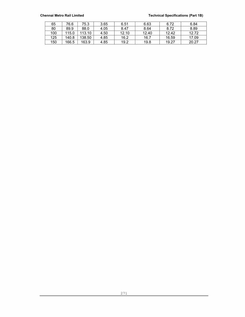
Chennai Metro Rail Limited Technical Specifications (Part 1B)
271
65 76.6 75.3 3.65 6.51 6.63 6.72 6.84 80 89.9 88.0 4.05 8.47 8.64 8.72 8.89
100 115.0 113.10 4.50 12.10 12.40 12.42 12.72 125 140.8 138.50 4.85 16.2 16.7 16.59 17.09 150 166.5 163.9 4.85 19.2 19.8 19.27 20.27

Chennai Metro Rail Limited Technical Specifications (Part 1B)
272
Table 127 Dimensions And Nominal Weight of Black Steel Tubes (HEAVY) (IS 1239)
15 21.8 21.0 3.25 1.45 1.46 1.51 1.52 20 27.3 26.5 3.25 1.90 1.91 1.98 1.99 25 34.2 33.3 4.05 2.97 2.99 3.07 3.09 32 42.9 42.0 4.05 3.84 3.87 3.96 3.99 40 48.8 47.9 4.05 4.43 4.47 4.59 4.63 50 60.8 59.7 4.50 6.17 6.26 6.35 6.42 65 76.6 75.3 4.50 7.90 8.02 8.11 8.23 80 89.9 88.0 4.85 10.10 10.30 10.34 10.51
100 115.0 113.10 5.4 14.4 14.7 14.72 15.02 125 140.8 138.50 5.4 17.8 18.3 18.19 18.69 150 166.5 163.9 5.4 21.2 21.8 21.67 22.27
Permissible Working Pressure for Mild Steel Tubes
N.B. of pipe mm
Working Pressure Light Medium Heavy
Ibs/sq.in Kg.cm2 Ibs/sq.in Kg.cm2 Lbs/sq.in Kg.cm2
15 150 10.55 300 21.09 350 24.61 20 150 10.55 300 21.09 350 24.61 25 150 10.55 300 21.09 350 24.61 32 125 8.80 250 17.58 300 21.09 40 125 8.80 250 17.58 300 21.09 50 100 7.03 200 14.06 250 17.58 65 100 7.03 200 14.06 250 17.58 80 100 7.03 200 14.06 250 17.58
100 100 7.03 171 12.02 228 16.03 125 - - 171 12.02 213 14.79 150 - - 142 9.98 171 12.02
Pipe Flanges Pipe Flanges shall conform to British Standards 10 (Specification for flanges and bolting for pipes, valves and fittings). Following table gives specification of Pipe Flanges and Sleeves.
SCHEDULE OF SLEEVES
SR. N
O
M S SLEEVE M. S. FLANGE BOLTING M.S. PUDDLE
SLEE
VE N
OS
N.B
. OF
PIPE
THIC
KNE
SS O
F PI
PE
DIA
MET
ER
THIC
KN
ESS
PCD
DIA
OF
BO
LT
NO
. OF
BO
LT
INSI
DE
OUT
SID
E
SIZE
THIC
KN
ESS
mm mm mm mm mm
1 S1 15 DIA 3.25 mm 100 10 70 15 4 -- -- 50 x 50 6
2 S2 20 DIA 3.25 mm 100 10 75 15 4 -- -- 50 x 50 6
3 S3 25 DIA 4.05 mm 120 10 90 15 4 -- -- 50 x 50 6
4 S4 32 DIA 4.05 mm 135 10 100 15 4 -- -- 100x 00 6

Chennai Metro Rail Limited Technical Specifications (Part 1B)
273
5 S5 40 DIA 4.05 mm 140 15 125 15 4 -- -- 100x 00 6
6 S6 50 DIA 4.05 mm 165 15 105 15 4 -- -- 150x 50 6
7 S7 65 DIA 4.05 mm 185 15 150 15 8 -- -- 150x 50 6
8 S8 80 DIA 4.85 mm 200 15 165 15 8 -- -- 200x 00 6
9 S9 100 DIA 5.4 mm 225 20 200 15 8 -- -- 200x 00 6
10 S10 150 DIA 5.4 mm 300 25 260 20 12 -- -- 300x 00 6
11 S11 200 DIA 6.0 mm 370 25 325 20 12 -- -- 350x350 6
12 S12 250 DIA 6.0 mm 435 32 380 25 12 -- -- 400x 00 6
13 S13 300 DIA 6.0 mm 500 32 450 25 16 -- -- 400x 00 6
14 S14 350 DIA 6.0 mm 550 40 500 25 16 -- -- 500x 00 6
Laying And Jointing Of GI Pipes The galvanised pipes and fittings shall run in wall chase or ceiling or as specified. The fixing shall be done by means of standard pattern holder bat clamps keeping the pipes about 1.5 cm clear of the wall where to be laid on surface. Where it is specified to conceal the pipes, chasing may be adopted for pipes fixed in the shafts, ducts etc. there should be sufficient space to work on the pipes with the usual tools. As far as possible, pipes may be buried for short distances provided adequate protection is given against damage and where so required special care to be taken at joints. Where directed by the Owner’s Site Representative, pipe sleeves shall be fixed at a place the pipe is passing through a wall or floor for reception of the pipe and allow freedom for expansion and contraction and other movements. In case of pipe is embedded in walls or floors it shall be painted with anticorrosive bitumastic paints of approved quality. Under the floors the pipes shall be laid in layer of sand filling. Galvanised iron pipes shall be jointed with threaded and socket joints, using threaded fittings. Care shall be taken to remove any burr from the end of the pipes after threading. Teflon tape, White lead or an equivalent jointing compound of proprietary make shall be used, according to the manufacturer’s instructions, with a grommet of a few strands of fine yarn while tightening. Compounds containing red lead shall not be used because of the danger of contamination of water. Any threads exposed after jointing shall be painted with bituminous paint to prevent corrosion. Electric Welded steel pipes conforming to IS:3589 for 150mm to 2000mm Nominal Diameter: The pipes shall be made from Steel plates or strips by butt welding longitudinally or spirally. The pipes shall be butt welded by employing any of the methods such as a) Electric Resistance Welding and b) Electric Fusion Arc welding. Minimum specified thickness of pipes as per IS:3589: Nominal diameter Minimum specified thickness of pipes
(mm) 150 to 300 4.0 Above 300 to 500 5.0 Above 500 to 600 6.0Above 600 to 850 7.0 Above 850 to 1200 8.0 Above 1200 to 2000 10.0
Joints: The Joints shall be a) Plain or bevelled ends for field butt welding and b) Joints with sleeve joints or swelled and plain ends for welding.

Chennai Metro Rail Limited Technical Specifications (Part 1B)
274
3 SPECIFICATIONS OF VARIOUS TYPES OF PIPES, SPECIALS AND THEIR LAYING AND
JOINTING SYSTEM PLASTIC PIPES Conformance of Plastic Pipes: (1) Indian Standard – 3076/1985 Low density polyethylene (LDPE) pipes for potable water supply. (2) Indian Standard – 4984/1987 High density polyethylene (HDPE) pipes for potable water supply, Sewage and Industrial Effluents. (3) Indian Standard – 4985, Unplasticised Polyvinylchloride (PVC) pipes for potable water supply. The Plastic pipes shall conform to the following properties: Table 231 Properties of Plastic Pipes
Property & Unit Low Density
(LDPE) IS-3076
High Density(HDPE) IS-4984
Polyvinyl Chloride (PVC) IS-4985
Softening point. C0 Ultimate tensile strength at 230 , Kg/cm2 Recommended temperature range for pressure pipe C0 Flammability. Weathering characteristics Effect of low temperature Chemical resistance Safe working stresses at 20C kg/cm2
Pressure Rating. Kg/cm2 Abraison resistance Flexibility. Common jointing Method Available sizes mm Application
80-100 115-170 -40 to +38 Slow Flairs Good low temp. Properties, un-affected by large number of freezing thaw cycles Good alround chemical resistance 32 2.5, 4.6, 10 Low Highly flexible, can be coiled. Heat welding and be compression fittings. 12 to 140 Internal plumbing of building,s water supply distribution lines.
110-130 265-280 -18 to +38 Slow Fair Same as For low density Good alround chemical resistance 50 2.5, 4, 6, 10 Fair Same as for low density -do- 100 to 400 Underground W.S. lines. Also for Plumbing in buildings with special precautions.
75-80 445-600 -1 to +60 Self extinguish Excellent Tendency to become brittle at low temperature. Repeated freezing and thawing reduces working pressures. Good chemical resistance 100 2.5, 4, 6, 10 Good Relatively rigid Only small bore pipe may be coiled. Solvent welding and by rubber gaskets. 16 to 311 Substitute for Conventional pipes for plumbing of buildings except for hot water, also substitute for conventional pipes in distribution systems.

Chennai Metro Rail Limited Technical Specifications (Part 1B)
275
Testing: After pressurizing the test pressure continues to fall for about 12 hours before establishing. About 1 to 2 percent of the total volume of test water in the pipe will be needed as make up water due to the expansion of pipe in the initial phase. It is recommended that the plastic pipes shall be tested only upto 1.5 times the rated working pressure for a duration of 1 to 2 hours without any leakage and thus drop in pressure being within the limit as mentioned above. The maximum allowable leakage should not exceed 0.365/1000 m length of pipe/cm dia of nominal bore/Kg of test pressure. Plastic pipes shall conform to the following as per various Indian Standards. Unplasticised Polyvinyly Chloride (PVC) Pipes for Potable Water Supply Table 237 PVC Pipes (IS-4985 / 1981)
Outside Dia mm
Maximum working
pressure Kg/cm2
Wall Thickness, mm
Remarks Min Max. Working pressure feet
of water
16 10 1.1 1.5 340
20 10 1.1 1.5 340
25 10 1.4 1.8 340
32 10 1.8 2.2 340
40 10 2.2 2.7 340 Class Working
40 6 1.4 1.8 200 Of pipe Pressure
50 6 1.7 2.1 200 At 270 C
50 4 1.2 1.6 140
63 6 2.2 2.7 200 Class 1 0.25 MPa
63 4 1.5 1.9 140 Class 2 0.40 MPa
75 6 2.6 3.1 200 Class 3 0.6 MPa
75 4 1.8 2.2 140 Class 4 1.0 MPa
90 6 3.1 3.7 200
90 4 2.1 2.6 140 (1 MPa = 10.1972
110 6 3.7 4.3 200 Kg/cm2)
110 4 2.5 3.0 140 Pipes are supplied
125 6 4.3 5.0 200 in straight lengths of
125 4 2.9 3.4 140 4,5 and 6 m with a
140 4 3.2 3.8 140 Tolerance of + 10
140 6 4.8 5.5 200
160 4 3.7 4.3 140
160 6 5.4 6.2 200
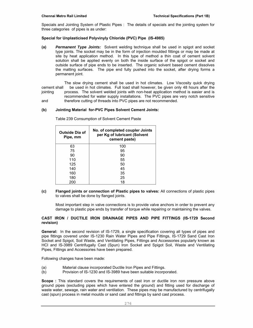
Chennai Metro Rail Limited Technical Specifications (Part 1B)
276
Specials and Jointing System of Plastic Pipes : The details of specials and the jointing system for three categories of pipes is as under: Special for Unplasticised Polyvinyly Chloride (PVC) Pipe (IS-4985) (a) Permanent Type Joints: Solvent welding technique shall be used in spigot and socket
type joints. The socket may be in the form of injection moulded fittings or may be made at site by heat application method. In this type of method a thin coat of cement solvent solution shall be applied evenly on both the inside surface of the spigot or socket and outside surface of pipe ends to be inserted. The organic solvent based cement dissolves the matting surfaces. The pipe end fully pushed into the socket, after drying forms a permanent joint.
The slow drying cement shall be used in hot climates. Low Viscosity quick drying cement shall be used in hot climates. Full load shall however, be given only 48 hours after the jointing process. The solvent welded joints with non-heat application method is easier and is recommended for water supply installations. The PVC pipes are very notch sensitive and therefore cutting of threads into PVC pipes are not recommended. (b) Jointing Material for-PVC Pipes Solvent Cement Joints: Table 239 Consumption of Solvent Cement Paste
Outside Dia of Pipe, mm
No. of completed coupler Joints per Kg of lubricant (Solvent
cement paste)
63 75 90 110 125 140 160 180 200
100 95 90 55 50 45 35 25 18
(c) Flanged joints or connection of Plastic pipes to valves: All connections of plastic pipes
to valves shall be done by flanged joints. Most important step in valve connections is to provide valve anchors in order to prevent any damage to plastic pipe ends by transfer of torque while repairing or maintaining the valves. CAST IRON / DUCTILE IRON DRAINAGE PIPES AND PIPE FITTINGS (IS-1729 Second revision) General: In the second revision of IS-1729, a single specification covering all types of pipes and pipe fittings covered under IS-1230 Rain Water Pipes and Pipe Fittings, IS-1729 Sand Cast Iron Socket and Spigot, Soil Waste, and Ventilating Pipes, Fittings and Accessories popularly known as HCI and IS-3989 Centrifugally Cast (Spun) Iron Socket and Spigot Soil, Waste and Ventilating Pipes, Fittings and Accessories have been prepared. Following changes have been made: (a) Material clause incorporated Ductile Iron Pipes and Fittings. (b) Provision of IS-1230 and IS-3989 have been suitable incorporated. Scope : This standard covers the requirements of cast iron or ductile iron non pressure above ground pipes (excluding pipes which have entered the ground) and fitting used for discharge of waste water, sewage, rain water and ventilation. These pipes may be manufactured by centrifugally cast (spun) process in metal moulds or sand cast and fittings by sand cast process.
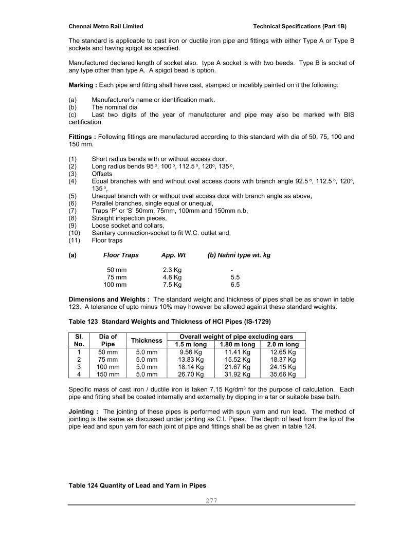
Chennai Metro Rail Limited Technical Specifications (Part 1B)
277
The standard is applicable to cast iron or ductile iron pipe and fittings with either Type A or Type B sockets and having spigot as specified. Manufactured declared length of socket also. type A socket is with two beeds. Type B is socket of any type other than type A. A spigot bead is option. Marking : Each pipe and fitting shall have cast, stamped or indelibly painted on it the following: (a) Manufacturer’s name or identification mark. (b) The nominal dia (c) Last two digits of the year of manufacturer and pipe may also be marked with BIS certification. Fittings : Following fittings are manufactured according to this standard with dia of 50, 75, 100 and 150 mm. (1) Short radius bends with or without access door, (2) Long radius bends 95 o, 100 o, 112.5 o, 120o, 135 o, (3) Offsets (4) Equal branches with and without oval access doors with branch angle 92.5 o, 112.5 o, 120o,
135 o, (5) Unequal branch with or without oval access door with branch angle as above, (6) Parallel branches, single equal or unequal, (7) Traps ‘P’ or ‘S’ 50mm, 75mm, 100mm and 150mm n.b, (8) Straight inspection pieces, (9) Loose socket and collars, (10) Sanitary connection-socket to fit W.C. outlet and, (11) Floor traps (a) Floor Traps App. Wt (b) Nahni type wt. kg 50 mm 2.3 Kg - 75 mm 4.8 Kg 5.5 100 mm 7.5 Kg 6.5 Dimensions and Weights : The standard weight and thickness of pipes shall be as shown in table 123. A tolerance of upto minus 10% may however be allowed against these standard weights. Table 123 Standard Weights and Thickness of HCI Pipes (IS-1729)
Sl. No.
Dia of Pipe Thickness Overall weight of pipe excluding ears
1.5 m long 1.80 m long 2.0 m long 1 50 mm 5.0 mm 9.56 Kg 11.41 Kg 12.65 Kg 2 75 mm 5.0 mm 13.83 Kg 15.52 Kg 18.37 Kg 3 100 mm 5.0 mm 18.14 Kg 21.67 Kg 24.15 Kg 4 150 mm 5.0 mm 26.70 Kg 31.92 Kg 35.66 Kg
Specific mass of cast iron / ductile iron is taken 7.15 Kg/dm3 for the purpose of calculation. Each pipe and fitting shall be coated internally and externally by dipping in a tar or suitable base bath. Jointing : The jointing of these pipes is performed with spun yarn and run lead. The method of jointing is the same as discussed under jointing as C.I. Pipes. The depth of lead from the lip of the pipe lead and spun yarn for each joint of pipe and fittings shall be as given in table 124. Table 124 Quantity of Lead and Yarn in Pipes
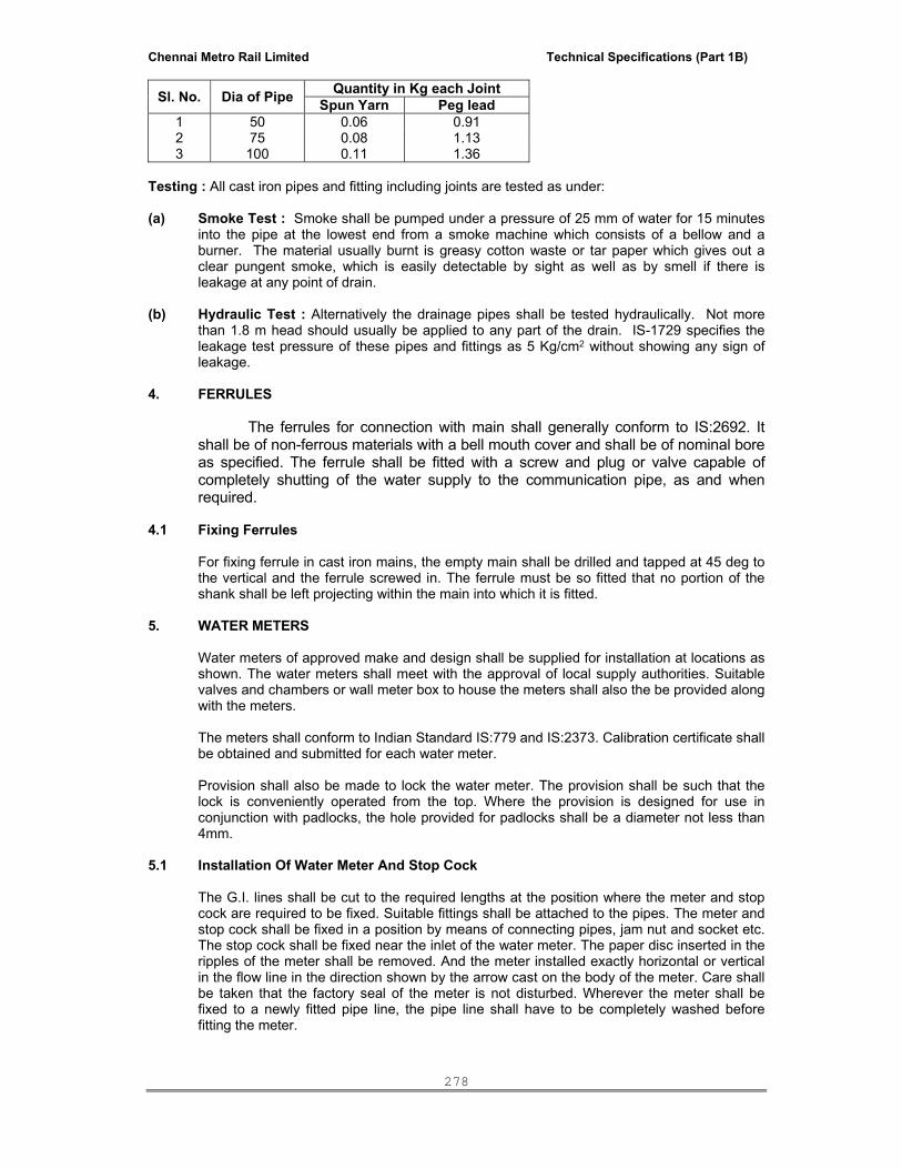
Chennai Metro Rail Limited Technical Specifications (Part 1B)
278
Sl. No. Dia of Pipe Quantity in Kg each JointSpun Yarn Peg lead
1 50 0.06 0.91 2 75 0.08 1.13 3 100 0.11 1.36
Testing : All cast iron pipes and fitting including joints are tested as under: (a) Smoke Test : Smoke shall be pumped under a pressure of 25 mm of water for 15 minutes
into the pipe at the lowest end from a smoke machine which consists of a bellow and a burner. The material usually burnt is greasy cotton waste or tar paper which gives out a clear pungent smoke, which is easily detectable by sight as well as by smell if there is leakage at any point of drain.
(b) Hydraulic Test : Alternatively the drainage pipes shall be tested hydraulically. Not more
than 1.8 m head should usually be applied to any part of the drain. IS-1729 specifies the leakage test pressure of these pipes and fittings as 5 Kg/cm2 without showing any sign of leakage.
4. FERRULES
The ferrules for connection with main shall generally conform to IS:2692. It shall be of non-ferrous materials with a bell mouth cover and shall be of nominal bore as specified. The ferrule shall be fitted with a screw and plug or valve capable of completely shutting of the water supply to the communication pipe, as and when required.
4.1 Fixing Ferrules For fixing ferrule in cast iron mains, the empty main shall be drilled and tapped at 45 deg to
the vertical and the ferrule screwed in. The ferrule must be so fitted that no portion of the shank shall be left projecting within the main into which it is fitted.
5. WATER METERS Water meters of approved make and design shall be supplied for installation at locations as
shown. The water meters shall meet with the approval of local supply authorities. Suitable valves and chambers or wall meter box to house the meters shall also the be provided along with the meters.
The meters shall conform to Indian Standard IS:779 and IS:2373. Calibration certificate shall
be obtained and submitted for each water meter. Provision shall also be made to lock the water meter. The provision shall be such that the
lock is conveniently operated from the top. Where the provision is designed for use in conjunction with padlocks, the hole provided for padlocks shall be a diameter not less than 4mm.
5.1 Installation Of Water Meter And Stop Cock The G.I. lines shall be cut to the required lengths at the position where the meter and stop
cock are required to be fixed. Suitable fittings shall be attached to the pipes. The meter and stop cock shall be fixed in a position by means of connecting pipes, jam nut and socket etc. The stop cock shall be fixed near the inlet of the water meter. The paper disc inserted in the ripples of the meter shall be removed. And the meter installed exactly horizontal or vertical in the flow line in the direction shown by the arrow cast on the body of the meter. Care shall be taken that the factory seal of the meter is not disturbed. Wherever the meter shall be fixed to a newly fitted pipe line, the pipe line shall have to be completely washed before fitting the meter.

Chennai Metro Rail Limited Technical Specifications (Part 1B)
279
6. TESTING The Contractor shall notify the Architect three days in advance of any test so that the
Architect can witness the tests if he so wishes. All water supply system shall be tested to hydrostatic pressure test of at least one and a half (1.5) times the maximum pressure but not less than 10Kg/Sq.cm for a period of not less than 8 hours. All leaks and defects in joints revealed during the testing shall be rectified and got approved at site by retest. Piping required subsequent to the above pressure test shall be retested in the same manner. System may be tested in sections and such sections shall be entirely retested on completion. The Contractor shall make sure that proper noiseless circulation of fluid is achieved through the entire piping network of the system concerned. In case of improper circulation, the contractor shall rectify the defective connections. He shall bear all expenses for carrying out the above rectifications including the tearing up and refinishing of floors and walls as required. In addition to the sectional testing carried out during the construction, contractor shall test the entire installation after connections to the overhead tanks or pumping system or mains. He shall rectify all leakages and shall replace all defective materials in the system. Any damage done due to carelessness, open or burst pipes or failure of fittings, to the building, furniture and fixtures shall be made good by the contractor during the defects liability period without any cost. After commissioning of the water supply system, contractor shall test each valve by closing and opening it a number of times to observe if it is working efficiently. Valves which do not effectively operate shall be replaced by new ones at no extra cost and the same shall be tested as above. A test register shall be maintained and all entries shall be signed and dated by Contractor(s) and Owner’s site representative.
7. DISINFECTION OF PIPING SYSTEM AND STORAGE TANKS
Before commissioning the water supply system, the contractor shall arrange to disinfect the entire system as described in the succeeding paragraph.
The water storage tanks and pipes shall first be filled with water and thoroughly flushed out. The storage tanks shall then be filled with water again and disinfecting chemical containing chlorine added gradually while tanks are being filled to ensure thorough mixing. Sufficient chemical shall be used to give water a dose of 50 parts of chlorine to one million parts of water. If ordinary bleaching powder is used, the proportions will be 150 gm of power to 1000 liters of water. The power shall be mixed with water in the storage tank. If a proprietary brand of chemical is used, the proportions shall be specified by the manufacturer. When the storage tanks is full, the supply shall be stopped and all the taps on the distributing pipes are opened successively working progressively away from the storage tank. Each tap shall be closed when the water discharged begins to smell of chlorine. The storage tank shall then be filled up with water from supply pipe and added with more disinfecting chemical in the recommended proportions. The storage tank and pipe shall then remain charged at least for three hours. Finally the tank and pipes shall be thoroughly flushed out before any water is used for domestic purpose. The pipe work shall be thoroughly flushed before supply is restored.
8. STERILIZATION OF MAIN After the pipe work has been tested and approved, but before it is coupled, it shall be
sterilized with a solution of chloride of lime.

Chennai Metro Rail Limited Technical Specifications (Part 1B)
280
9. CUTTING CHASES IN MASONARY WALLS Cold water distribution pipes to fixtures and equipment exposed to view in the bathrooms,
kitchens, and sanitary compartments shall be chased into walls or floors or placed in wall cavities. The Contractor shall be responsible for cutting all notches, chases, and recesses in walls and floors and only a diamond cutter shall be used. The maximum size of conduit or pipe permitted to be concealed in floor slabs shall be 32 mm diameter unless otherwise approved by the Architect.
The chases upto 7.5 x 7.5 cm shall be made in the walls for housing GI pipes etc. These shall be provided in correct positions as shown in the drawings or directed by the Architects. Chases shall be made by chiselling out the masonry to proper line and depth. After the pipes etc are fixed in chases, the chases shall be filled with cement mortar 1:2:4 or as may be specified, and made flush with the masonry surface. The concrete surface shall be roughened with wire brush to provide a key for plastering.
Where pipes pass through beams or structural walls, subject to the approval of the
Structural Consulting Engineer, the Contractor shall ensure that sizes and locations of openings required are formed in when the relevant beams or walls are cast.
VALVE CHAMBERS
Provision of suitable brick masonry chambers in cement mortar 1:5 (1 cement : 5 coarse sand)
on cement concrete foundations 150 mm thick 1:5:10 mix (1 cement:5 fine sand : 10 graded stone aggregate 20 mm nominal size ) with 15 mm thick cement plaster inside and outside finished with a plaster inside and outside finished with a floated coat of neat cement inside with cast iron surface box approved by fire brigade including excavation, back-filling complete shall be made.
10. VALVES All valves (gate, globe, check, safety) shall be of gun metal suitable for the particular service
as specified. All valves shall be of the particular duty and design as specified. Valves shall either be of screwed type or flanged type, as specified, with suitable flanges and non-corrosive bolts and gaskets. Tail pieces as required shall be supplied along with valves. Gate, globe and check valves shall conform to Indian Standard IS:776 and non-return valves and swing check type reflux to IS:5312.
10.1 Sluice valves Sluice valves, where specified shall be flanged sluice valves of cast iron body. The spindle,
valve seat and wedge nuts shall be gunmetal. They shall generally have non-rising spindle and shall be of the particular duty and design as specified. The valves shall be supplied with suitable flanges, non-corrosive bolts and asbestos fibre gaskets. Sluice valves shall conform to Indian standard IS:780 and IS:2906.
10.2 Butterfly valve The butterfly valve shall be suitable for waterworks and rated Pressure requirement as
mentioned in the Schedule of quantities. The body shall be of cast iron to IS:210 in circular shape and of high strength to take the water
pressure. The disc shall be heavy duty cast iron with anti corrosive epoxy or nickel coating. The valve seat shall be of high grade elastomer or nitrile rubber. The valve is closed position
shall have complete contact between the seat and the disc throughout the perimeter. The elastomer rubber shall have a long life and shall not give away on continuous applied water pressure. The shaft shall be EN 8 grade carbon steel.
The valve shall be fitted between two flanges on either side of pipe flanges. The valve edge
rubber shall be projected outside such that they are wedged within the pipe flanges to prevent leakages.

Chennai Metro Rail Limited Technical Specifications (Part 1B)
281
10.3 Ball valve The ball valve shall be made forged brass and suitable for test pressure of pipe line. The
valve shall be internally threaded to receive pipe connections. The ball shall be made from brass and machined to perfect round shape and subsequently
chrome plated. The seat of the valve body-bonnet gasket and gland packing shall be of Teflon. The handle shall be provided with PVC jacket. The handle shall also indicate the direction of
‘open’ and ‘closed’ situations. The gap between the ball and the teflon packing shall be sealed to prevent water seeping.
The handle shall also be provided with a lug to keep the movement of the ball valve within 90°.
The lever shall be operated smoothly and without application of any unnecessary force. 10.4 Ball float valve Ball valves with floats to be fixed in storage tanks shall consist of cast brass lever arm
having copper balls (26 SWG) screwed to the arm integrally. The copper ball shall have bronze welded seams. The closing/opening mechanism incorporating the piston and cylinder shall be non-corrosive metal and include washers. The size and construction of ball valves and float shall be suitable for desired working pressure operating the supply system. Where called for brass valves shall be supplied with brass hexagonal back nuts to secure them to the tanks and a socket to connect to supply pipe.
Globe valves on Hot-water line shall be union bonnet with stem/disc and body seat ring of
SS. Suitable for temperature upto 80° C. S.No Type of Valve Size Construction Ends a. Isolating Valve 15 mm to 50 mm
65 mm and above Gun Metal Gun Metal
Screwed Flanged
b. Sluice Valve & Butterfly Valve 65 mm and above Cast Iron Flanged
c. G.M. non return valve 15 mm to 50 mm 65 mm above
Gun Metal Gun Metal
Screwed Flanged
d. Flap Type – Non return valve 65 mm and above Cast Iron Flanged
All valves shall be suitable for the working pressure involved. 10.5 Gun metal valve Gun metal Valves shall be used for smaller dia pipes, and for threaded connections. The
Valves shall bear certification as per IS : 778. The body and bonnet shall be of gun metal to IS : 318. The stem gland and gland nut shall be
of forged brass to IS : 6912. The hand wheel shall be of cast iron to IS : 210. The Hand wheel shall be of high quality finish to avoid hand abrasions. Movement shall also be
easy. The spindle shall be non rising type. 10.6 Non-return valve Non-Return valves shall be cast iron double flanged with cast iron body and gunmetal internal
parts conforming to IS : 5312. 10.7 Pressure Reducing Valve Set

Chennai Metro Rail Limited Technical Specifications (Part 1B)
282
Each pressure reducing valve set shall be complete with pressure reducing or pressure regulating valve, isolating valves, pressure gauges (fix with symphonic check) on inlet and outlet, pressure relief valve on outlet and filter on inlet.
Each pressure reducing valve shall contain loading neoprene diaphragm and a full floating,
self aligning, ignition resistant seat and shall be of the single stage, pressure reduction type with provision for manually adjusting the delivery pressure. The valve shall fail safe to the low pressure.
Valves shall be capable of operating at the maintaining automatically the respective delivery
pressure and flow rates as indicated and shall not be liable to creep. Valves shall also be capable of maintaining the pre-set down stream pressure under static condition.
The filter on each inlet to a pressure reducing valve shall be of replaceable porous sintered
metal type. 10.8 Pressure Relief Valves Each pressure relief valve shall be of the fully enclosed type and fitted with hand easing
gear. Each pressure relief valve in a pressure reducing station shall have a flow capacity equal to
that of the pressure reducing valve. Pressure relief valves in locations other than reducing stations shall have flow capacities
equal to that of the associated equipment. 10.9 Pressure Gauge The pressure gauge shall be constructed of die cast aluminium and stove enamelled. It shall
be weather proof with an IP 55 enclosure. It shall be a stainless steel Bourden tube type pressure gauge with a scale range from 0 to 16 Kg / cm square and shall be constructed as per IS:3524. Each pressure gauge shall have a siphon tube connection. The shut off arrangement shall be by Ball Valve.
Calibration certificate shall be obtained and submitted for each pressure gauge. 11. WATER FITTINGS
Unless otherwise specified all Gunmetal fittings such as gate, globe, check & safety valves shall be fitted in pipe line in workman like manner. Necessary unions shall be provided on both ends of the valves for easy replacement. The joints between fittings and pipes shall be leak-proof when tested to desired pressure rating. The defective fittings and joints shall be replaced or redone.
12. PAINT: Used paints and coatings that comply with the following limits for VOC content and the
following chemical restrictions: Non-Flat Paints and Coatings: VOC not more than 150 g/L. Anti-Corrosive Coatings VOC not more than 250 g/L.
Aromatic Compounds: Paints and coatings shall not contain more than 1.0 percent by weight total aromatic compounds (hydrocarbon compounds containing one or more benzene rings).
Paints and coatings shall not contain any of the following: Acrolien Acrylontrile
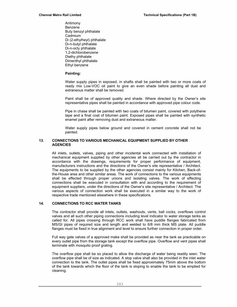
Chennai Metro Rail Limited Technical Specifications (Part 1B)
283
Antimony Benzene Buty benzyl phthalate Cadmium Di (2-ethylheyl) phthalate Di-n-butyl phthalate Di-n-octy phthalate 1,2-dichlorobenzene Diethy phthalate Dimenthyl phthalate Ethyl benzene
Painting:
Water supply pipes in exposed, in shafts shall be painted with two or more coats of ready mix Low-VOC oil paint to give an even shade before painting all dust and extraneous matter shall be removed.
Paint shall be of approved quality and shade. Where directed by the Owner’s site
representative pipes shall be painted in accordance with approved pipe colour code. Pipe in chase shall be painted with two coats of bitumen paint, covered with polythene
tape and a final coat of bitumen paint. Exposed pipes shall be painted with synthetic enamel paint after removing dust and extraneous matter.
Water supply pipes below ground and covered in cement concrete shall not be
painted.
13. CONNECTIONS TO VARIOUS MECHANICAL EQUIPMENT SUPPLIED BY OTHER AGENCIES
All inlets, outlets, valves, piping and other incidental work connected with installation of
mechanical equipment supplied by other agencies all be carried out by the contractor in accordance with the drawings, requirements for proper performance of equipment, manufacturers instructions and the directions of the Owner’s site representative / Architect. The equipments to be supplied by the other agencies consist mainly for Kitchen, Back-of-the-House area and other similar areas. The work of connections to the various equipments shall be effected through proper unions and isolating valves. The work of effecting connections shall be executed in consultation with and according to the requirement of equipment suppliers, under the directions of the Owner’s site representative / Architect. The various aspects of connection work shall be executed in a similar way to the work of respective trade mentioned elsewhere in these specifications.
14. CONNECTIONS TO RCC WATER TANKS
The contractor shall provide all inlets, outlets, washouts, vents, ball cocks, overflows control valves and all such other piping connections including level indicator to water storage tanks as called for. All pipes crossing through RCC work shall have puddle flanges fabricated from MS/GI pipes of required size and length and welded to 6/8 mm thick MS plate. All puddle flanges must be fixed in true alignment and level to ensure further connection in proper order.
Full way gate valves of a approved make shall be provided as near the tank as practicable on every outlet pipe from the storage tank except the overflow pipe. Overflow and vent pipes shall terminate with mosquito proof grating.
The overflow pipe shall be so placed to allow the discharge of water being readily seen. The overflow pipe shall be of size as indicated. A stop valve shall also be provided in the inlet water connection to the tank. The outlet pipes shall be fixed approximately 75mm above the bottom of the tank towards which the floor of the tank is sloping to enable the tank to be emptied for cleaning.

Chennai Metro Rail Limited Technical Specifications (Part 1B)
284
The floor and the walls of the tank shall be tiled with glazed tiles upto the overflow level. Alternatively food grade epoxy to be applied. Tiling of Walls The floor and the walls of the tanks shall be tiled with glazed tiles up to the overflow level. Alternatively food grade epoxy to be applied to the floor and the walls of the tanks.
15. MEASUREMENTS The length above ground shall be measured in running meter correct to a cm for the finished
work, which shall include pipe and fittings such as coupling , bends, tees, elbows, reducers, crosses, plugs, sockets, nipples and nuts, unions. Deductions for length of valves shall be made. Rate quoted shall be inclusive of all fittings, clamps, cutting holes chased and making good the same and all items mentioned in the specifications and Bill of Quantities.
All pipes below ground shall be measured per linear meters (to the nearest cm) and shall be
inclusive of all fittings e.g. coupling, tees, bends, elbows, unions, deduction for valves shall be made rate quoted shall be inclusive of all fittings, excavation, back filling and disposal of surplus earth, cutting holes and chase and making good all item mentioned in Bill of Quantities.
16. LAWN HYDRANTS
Lawn hydrants shall be of 25mm size unless otherwise indicated. All hydrants shall be provided with gate valves and threaded nipple to receive hose pipes. Lawn hydrant valves shall be of approved make and design. Where called for lawn hydrants shall be located in masonry chambers of appropriate size.
17. PIPE PROTECTION (FOR COLD WATER PIPES BURIED IN TRENCHES / GROUND /
EARTH)
All buried pipes shall be cleaned with zinc chromate primer and bitumen paint, wrapped with three layers of fiber glass tissue, each layer laid in bitumen and placed on concrete blocks with PUF saddles dipped in bitumen at every 2 meters. The pipes where laid under floor shall be encased with 100 mm thick good quality, river sand all around in addition to protective coating as described above. Alternatively pypcoat / coatek insulation for protection of pipe would also be acceptable as per final approval of project engineer / consultant.
18. THRUST BLOCKS In case of bigger pipes (80 mm dia and above), thrust blocks of cement concrete 1:2:4 (1
cement: 2 coarse sand : 4 graded stone aggregate of 20 mm nominal size) shall be constructed on all bends as directed by the Owner’s site representative.
19. MASONRY CHAMBER
i. All masonry chambers for stop cocks, sluice valves and meter etc. shall be built as per supplied drawings.
ii. The excavation for chambers shall be done true to dimension and level indicated on
plans or as directed by the Owner’s site representative. iii. Concrete shall be of cement concrete 1:3:6 (1 cement : 3 coarse sand : 6 graded
stone aggregate 40 mm nominal size. iv. Brick shall be of class designation 75 in cement mortar 1:5 (1 cement : 5 fine sand) v. Inside Plastering not less than 12 mm thick shall be done in cement mortar 1:3 (1
cement : 3 fine sand) finished with a floating coat of neat cement.

Chennai Metro Rail Limited Technical Specifications (Part 1B)
285
20. SHIFTING OF EXCAVATED SURPLUS MATERIAL Contractor shall make his own arrangement to shift the surplus excavated material within the site limits as directed by Owner’s site representative at free of cost within time limit.
21. HOT WATER PIPING INSULATION MATERIAL Insulation material for Pipe insulation shall be Closed Cell Elastomeric Nitrile Rubber or closed cell cross linked
polyethylene foam. Thermal conductivity of elastomeric nitrile rubber shall not exceed 0.038 W/moK or 0.0313 Kcal / Mhr oC or 0.212 BTU / (Hr-ft2-oF/inch) at an average temperature of 40oC. The product shall have temperature range of –40 oC to 105oC. Density of material shall not be less than 0.06 gm/cm3. The insulation shall have fire performance such that it passes minimum CLASS 1 as per BS476 part 7 for surface spread of flame. Water vapour permeability shall not exceed 0.024 perm inch (3 x 10-14 Kgs / m.sec.Pa). The material shall have approval from the Chief Fire Officer.
Thickness of the insulation shall be as specified for the individual application. Each lot of insulation material
delivered at site shall be accompanied with manufacturer test certificate for thermal conductivity values. Samples of insulation material from each lot delivered at site may be selected by Owner’s site representative and gotten tested for
thermal conductivity and density at Contractor’s cost All joints shall be sealed properly with adhesive, which shall provide similar vapour barrier as the original insulating material.
All hot water piping shall be insulated in the manner specified herein. Before applying
insulation, all pipe shall be brushed and cleaned. Thermal insulation shall be applied as follows or as specified in drawings or schedule of quantity:
----------------------------------------------------------------------------------------------------------------- Pipe size (mm) Thickness of Nitrile rubber insulation ----------------------------------------------------------------------------------------------------------------- 15 mm to 25 mm 9 mm 32 mm to 50 mm 13 mm 65 mm and above 19 mm ----------------------------------------------------------------------------------------------------------------- Insulation for pipes in wall chase and for pipes in shaft / plant room. Insulating material in tube form shall be sleeved on the pipes. On existing piping, slit opened
tube from insulating material shall be placed over the pipe and adhesive (as recommended by the manufacturer) shall be applied as suggested by the manufacturer. Adhesive must be allowed to tack dry and then press surface firmly together starting from butt end and working towards centre.
Wherever flat sheets shall be used it shall be cut out in correct dimension. All longitudinal
and transverse joints shall be sealed as per manufacturer recommendations. The insulation shall be continuous over the entire run of piping, fittings and valves. All valves, fittings, joints, strainers etc. in hot water piping shall be insulated to the same thickness as specified for the main run of piping and application shall be same as above. Valves bonnet, yokes and spindles shall be insulated in such a manner as not to cause damage to insulation when the valve is used or serviced.
All insulation work shall be carried out by skilled workmen specially trained in this kind of work. All insulated pipes shall be labeled (HWS / HWR / HWRR) and provided with 300 mm wide band of paint along circumference at every 1200 mm for colour coding. Direction of fluid shall also be marked. All painting shall be as per relevant BIS codes.
Flexible Pre-Insulate Pipe System (Our buried external piping)
Providing and fixing Pre-insulated (pre-fabricated) pipe systems in accordance with manufacture “Quality Assurance” or another equivalent external monitoring system. It should allow a radius of curvature of 0.40 to 1.25 meter up to DN 100, from DN 100 to DN 200 a radius of 16 to 20 meter. It should be corrosion-resistant and maintenance-free; shutdown (outside the season) can be performed without special measures. No compensators or compensation tube bends should be used during laying as the pipe system
Chennai Metro Rail Limited Technical Specifications (Part 1B)
286
should itself compensates for linear expansion on its own. System should consist exclusively of the components belonging to a system.
The pre-fabricated thermal insulation consists of flexible, closed-cell flexible polyolefin foam that is bonded to the casing pipe, having density of 30 – 40 kg/ m3, capable of operating for the temperature range of – 80 to + 95oC, the thermal conductivity: of the pre-fabricated (pre-insulated) system should be 0.301 W/mK at 50oC. The casing pipe should be of HDPE and should be water tight while being bonded with insulation.
Protective Coating Over Insulation To provide mechanical strength and protection from damage all exposed pipe insulated with
nitrile rubber as indicated in BOQ shall be covered with fibreglass fabric. The fibreglass fabric shall be applied with one coat of fire proof epoxy or acrylic compound (resin & hardner). The coat shall be allowed to cure to non stick state. Subsequently second coat of compound shall be applied to give a tough and smooth finish to the insulated surface.
Measurement of Insulation Unless otherwise specified measurement for pipe insulation for the project shall be on the basis of centre line
measurements described herewith Pipe Insulation shall be measured in units of length along the centre line of the installed
pipe, strictly on the same basis as the piping measurements. The linear measurements shall be taken before the application of the insulation. It may be noted that for piping measurement, all valves, orifice plates and strainers shall not be separately measurable by their number and size. It is to be clearly understood that for the insulation measurements, all these accessories including valves, orifice plates and strainers etc. shall be considered strictly by linear measurements along the centre line of pipes and no special rate shall be applicable for insulation of any accessories, fixtures or fittings whatsoever.
SECTION-04::INTERNAL DRAINAGE (SOIL, WASTE, VENT & RAIN WATER PIPES)
1. SCOPE The scope of this section comprises the supply, installation, testing and commissioning of
internal drainage services. Work under this section shall consist of furnishing all labour, materials, equipments and
appliances necessary and required to completely install all soil, waste, vent and rainwater pipes and fittings as required by the drawings, and given in the schedule of quantities.
2. BASIC PIPING SYSTEM Soil, waste and vent pipes in shafts, ducts and in concealed areas i.e. false ceilings etc. shall
consist of cast iron pipes & fittings as called for. In general wastes and vents smaller than and upto 50mm dia shall be of heavy class GI.
The soil pipes shall be circular with a minimum diameter of 100mm. Pipes shall be fixed by
means of stout GI clamps in two sections, bolted together, built into the walls, wedged and neatly jointed as directed and approved by the Owner’s site representative / Architect. All bends, branches, swan neck and other parts shall conform to the requirement and standards as described for the pipes. Pipes shall be rested against the walls on suitable wooden cradles. Local authority regulations applicable to the installations shall be strictly followed.
Where indicated, the soil pipes shall be continued upwards without any diminution in its
diameter, without any bend or angle to the height shown in the drawings. Joints throughout shall be made with molten lead as described under jointing of cast iron pipes. Soil pipes shall be painted as provided under `painting'. The soil pipes shall be covered on top with cast iron terminal outlets as directed and approved. All vertical soil pipes shall be firmly fixed to the walls with properly fixed clamps, and shall as far as possible be kept 50mm clear of wall. Waste pipes and fittings shall be of cast iron or galvanised mild steel pipes. Pipes shall be fixed, jointed and painted as described in installation of soil, waste & vent pipes.

Chennai Metro Rail Limited Technical Specifications (Part 1B)
287
Every waste pipe shall discharge above the grating of properly trapped gully. The contractor
will ensure that this requirement is adequately met with. Wherever floor traps are provided, it shall be ensured that atleast one wash is connected to such floor traps to avoid drying of water seal in the trap. Ventilating pipes shall be of cast iron or galvanised mild steel pipes, conforming to the requirements laid down earlier. Anti-syphon vent pipes/relief vent pipes where called for on the drawings shall be of cast iron or galvanised mild steel pipes as specified. The pipes shall be of the diameter shown on the drawings.
All traps on branch soil and waste pipes shall also be ventilated at a point not less than 75mm
or more than 300mm from their highest part and on the side nearest to the soil pipe or waste pipes.
Access doors for fittings and clean outs shall be so located that they are easily accessible for
repair and maintenance. Any access panel required in the civil structure, false ceiling or marble cladding etc. shall be clearly reported to the Owner in the form of shop drawings so that other agencies are instructed to provide the same.
All the fittings used for connections between soil, waste and ventilation pipes and branch pipes
shall be made by using pipe fittings with inspection doors for cleaning. The doors shall be provided with 3mm thick rubber insertion packing and when closed and bolted shall be air and water tight.
Where soil, waste and ventilating pipes are accommodated in shafts ducts, adequate access to
cleaning eyes shall be provided. Head (starting point) of drains and sewage / waste water sumps (as and where applicable)
having a length of greater than 4 m upto it connection to the main drain or manhole shall be provided with a 80 / 100 mm vent pipe.
3. PIPING MATERIALS 3.1 Cast Iron Pipes Cast iron pipes and fittings shall be of good and tough quality and dark grey on fracture. The
pipes and fittings shall be true to shape, smooth and cylindrical, their inner and outer surface being as nearly as practicable concentric. They shall be sound and nicely cast, shall be free from cracks, taps, pinholes and other manufacturing defects.
The pipes and fittings shall conform to IS:3989 / IS:1729 as called for. Fittings shall be of
required degree with or without access door. All access doors shall be made up with 3mm thick insertion rubber gasket of white lead and tightly bolted to make the fittings air and water tight. The fittings shall be of the same manufacture as the pipes used for soil and waste.
All CI pipes and fittings shall bear the manufacturer's name and ISI specification to which it
conforms. All pipes and fittings shall be coated internally and externally with the same material at the
factory, the fittings being preheated prior to total immersion in a bath containing a uniformly heated composition having a tar/other suitable base. The coating material shall have good adherence and shall not scale off. The coating shall be smooth and tenacious and hard enough not to flow when exposed to a temperature of 77 degree C but not so brittle at a temperature of '0' degree C as to chip off when scratched lightly with a pen knife.
All pipes and fittings before installation at site shall be tested hydrostatically to a pressure of
0.45 Kg/sq. cm without showing any sign of leakage, sweating or other defects of any kind. The pressure shall be applied internally and shall be maintained for not less than 15 minutes. All these tests shall be carried out in the presence of the representative of the Project Manager. Alternatively a test certificate from manufacturers be obtained before dispatch of material to site.
Cast Iron Specialities

Chennai Metro Rail Limited Technical Specifications (Part 1B)
288
If required, Cast iron speciality items such as deep seal floor traps, urinal traps, trap integral pieces with integral inlet/outlet connections, manhole cover with frame, chamber cover etc. shall be fabricated to suit individual location requirements. The contractor shall arrange the fabrication of these items from an approved source.
Lead Caulked joints with pig lead: The approximate depth and weights of pig lead for various diameters of CI pipes and specials shall be as follows:
Nominal size of Pipe (mm Lead per Joint (Kg) Depth of Lead Joint (mm)
50 0.77 25 80 0.88 25 100 0.99 25 150 1.5 38
Pipe Joint Sealant:
Pipe joint sealant shall be used for joining various diameters of C.I. pipes and specials. This sealant replaces the standard lead caulked joints. The application is by Homogenously mixing the two pack system in cold condition. Application Procedure: Clean the pipe joints thoroughly to ensure it is free from any traces of oil, dirt or any other foreign body. Mix two parts of Drip Seal thoroughly with an iron flat to get a homogenous compound. * Place Spun yarn in the pipe joint as a filler and then take the required quantity of the compound and push it in the joint with a caulking tool, MS flat / damp finger uniformly all over to obtain a smooth and uniform joint. Dip the fingers in water every often to ensure the compound does not stick to the hands of the workmen, but this will ensure perfect sealing and the smooth surface for the joint cement. (* The compound prepared from the two mixtures is to be used within 30 minutes) Precaution to be taken to wash hands thoroughly with soap before and after use. Preferably use disposable gloves for hand application.
Following varieties of Cast Iron Pipes are available and shall be used as specified in the Schedule of Quantities:
Vertically Cast or Pit Cast Pipes Vertical Cast Pipes shall conform to IS 1537. These Pipes are not recommended for pressure applications and shall be suitable only for small projects and for temporary works.
The process of manufacturing these pipes is by casting the metal into vertical moulds which is the usual foundry method of casting in fixed sand moulds. These are called vertically cast or pit cast pipes. Spun iron pipes are more compact, free from blow holes and other imperfections and when compared weight for weight with vertically cast pipes, these are appreciably stronger. Spun Pipes have smooth inner surface. Spun iron pipes have therefore practically suspended vertically cast iron pipes. Indian standard 1537 ‘Vertically cast iron pressure pipes for water,gas and sewage’ provides the following dimensional and other details:
Nominal dia. (DN) mm
D MM
a MM
b MM
s MM Remark
80 200 40 21 13
Note: Thickness ’e’ is equal to the thickness of pipe or fitting comprising the
flange. Not to exceed `s’ value.
100 220 42 22 13.5 125 250 44.5 22.5 14.5 150 285 47 23 15 200 340 52 24.5 16.5 250 395 57 26 18 300 445 61 27.5 19.5

Chennai Metro Rail Limited Technical Specifications (Part 1B)
289
350 505 66 29 21 400 565 71 30 22.5 450 615 76 31.5 24 500 670 81 33 25.5 600 780 90 36 28.5 700 895 100 38.5 31.5 750 960 105 40 33 800 1015 110 41.5 34.5 900 1115 120 44 37.5
1000 1230 130 47 40.5
TABLE Dimensions of Flanges of pipes and Fittings ( IS 1537)
Nominal Dia. (DN)
Barrel Wt. of Pipe & Flange Working Length (L) DE
MM e MM Wt. of one meter pipe (approx) kg
Wt. of one flange (approx) kg
80 98 7.9 16 3.7 1 to 3 100 118 8.3 20.5 4.2 1 to 4 125 144 8.7 26.4 5.3 1 to 4 150 170 9.2 33.2 6.7 1 to 4 200 222 10.1 48.1 9.3 1 to 4 250 274 11.0 65.0 12.0 1 to 4 300 326 11.9 84.0 14.8 1 to 4 350 378 12.8 105.0 19.0 1 to 4 400 429 13.8 128.7 23.4 1 to 4450 480 14.7 156.0 26.5 1 to 4 500 532 15.6 181.0 32.1 1 to 4 600 635 17.4 241.4 44.0 1 to 4 700 738 19.3 311.6 59.0 1 to 4 750 790 20.2 348.9 69.8 1 to 4 800 842 21.1 389.1 80.8 1 to 4900 945 22.9 474.3 94.6 1 to 4
1000 1048 24.8 570.0 120.0 1 to 4
TABLE Flanged Pipes Vertically Cast/Sand Cast Class A (IS – 1537)
Nominal Dia. (DN) mm
Barrel Wt. of Pipe and Flange Working Length (L)
m DE MM e MM Wt. of one meter
pipe (approx) kg Wt. of one flange
(approx) kg 80 98 7.9 16 3.7 1 to 3 100 118 9.0 22 4.2 1 to 4 125 144 9.5 28.7 5.3 1 to 4 150 170 10.0 35.9 6.7 1 to 4 200 222 11.0 52.1 9.3 1 to 4 250 274 12.0 70.6 12.0 1 to 4 300 326 13.0 91.4 14.8 1 to 4 350 378 14.0 114.5 19.0 1 to 4 400 429 15.0 139.5 23.4 1 to 4 450 480 16.0 169.0 26.5 1 to 4 500 532 17.0 181.0 32.1 1 to 4 600 635 19.0 241.4 44.0 1 to 4 700 738 21.0 311.6 59.0 1 to 4 750 790 22.0 348.9 69.8 1 to 4 800 842 23.0 389.1 80.8 1 to 4 900 945 25.0 474.3 94.6 1 to 4
1000 1048 27.0 570.0 120.0 1 to 4 TABLE Flanged Pipes Vertically Cast/Sand Cast Class B (IS – 1537)
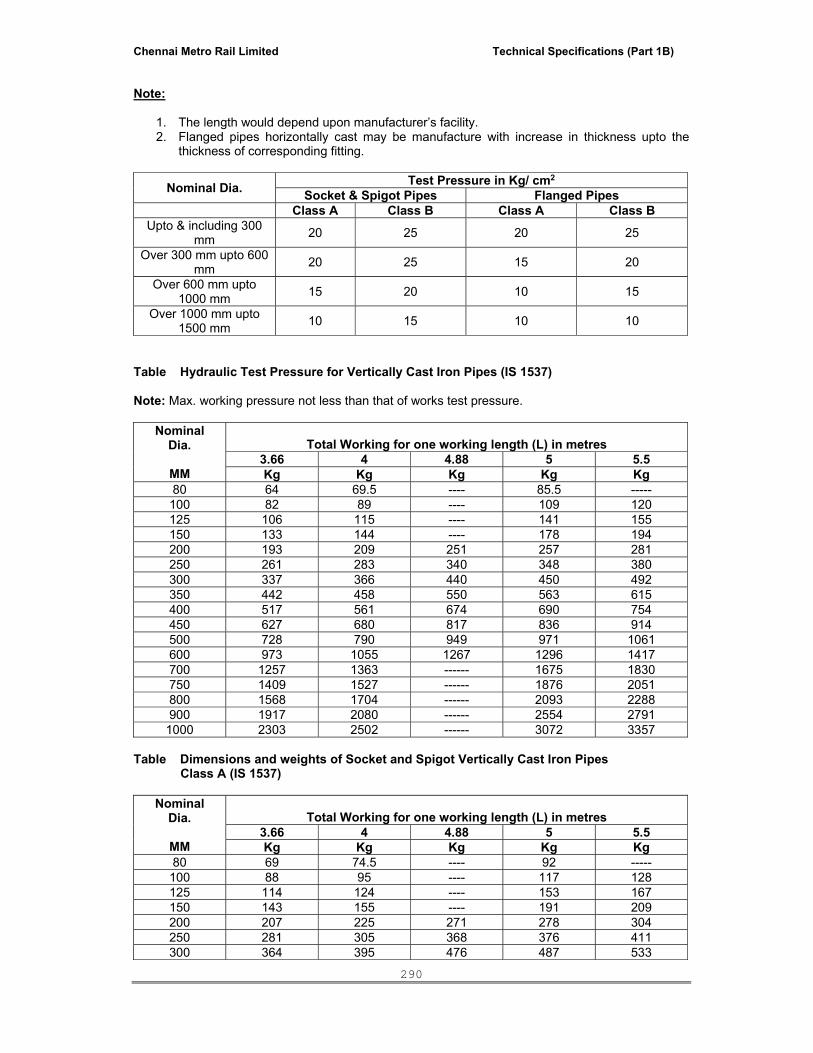
Chennai Metro Rail Limited Technical Specifications (Part 1B)
290
Note:
1. The length would depend upon manufacturer’s facility. 2. Flanged pipes horizontally cast may be manufacture with increase in thickness upto the
thickness of corresponding fitting.
Nominal Dia. Test Pressure in Kg/ cm2
Socket & Spigot Pipes Flanged Pipes Class A Class B Class A Class B
Upto & including 300 mm 20 25 20 25
Over 300 mm upto 600 mm 20 25 15 20
Over 600 mm upto 1000 mm 15 20 10 15
Over 1000 mm upto 1500 mm 10 15 10 10
Table Hydraulic Test Pressure for Vertically Cast Iron Pipes (IS 1537)
Note: Max. working pressure not less than that of works test pressure.
Nominal
Dia.
MM
Total Working for one working length (L) in metres 3.66 4 4.88 5 5.5 Kg Kg Kg Kg Kg
80 64 69.5 ---- 85.5 ----- 100 82 89 ---- 109 120 125 106 115 ---- 141 155 150 133 144 ---- 178 194 200 193 209 251 257 281 250 261 283 340 348 380 300 337 366 440 450 492 350 442 458 550 563 615 400 517 561 674 690 754 450 627 680 817 836 914 500 728 790 949 971 1061 600 973 1055 1267 1296 1417 700 1257 1363 ------ 1675 1830 750 1409 1527 ------ 1876 2051 800 1568 1704 ------ 2093 2288 900 1917 2080 ------ 2554 2791
1000 2303 2502 ------ 3072 3357 Table Dimensions and weights of Socket and Spigot Vertically Cast Iron Pipes
Class A (IS 1537) Nominal
Dia.
MM
Total Working for one working length (L) in metres 3.66 4 4.88 5 5.5 Kg Kg Kg Kg Kg
80 69 74.5 ---- 92 ----- 100 88 95 ---- 117 128 125 114 124 ---- 153 167 150 143 155 ---- 191 209 200 207 225 271 278 304 250 281 305 368 376 411 300 364 395 476 487 533

Chennai Metro Rail Limited Technical Specifications (Part 1B)
291
350 457 495 596 610 667 400 557 604 727 714 814 450 675 732 881 901 986 500 786 853 1026 1049 1148 600 1052 1145 1372 1404 1535 700 1355 1470 ------ 1808 1977 750 1525 1644 ------ 2035 2225 800 1696 1840 ------ 2263 2475 900 2073 2249 ------ 2766 3024
1000 2489 2699 ------ 3318 3628 Table Dimensions and weights of Socket and Spigot Vertically Cast Iron Pipes Class B (IS 1537) 3.2 Galvanised Iron Pipes
Waste pipes of 50mm dia and below and where called for shall be galvanised iron pipes
screwed and socketed conforming to the requirements of IS:1239 of heavy grade. The pipes and sockets shall be cleanly finished, well galvanised in and out and free from cracks, surface flaws, laminations and other defects. All screw thread shall be clean and well cut. All pipes and fittings shall bear manufacturer's trade mark and conform to the IS as specified.
3.3 UPVC Pipes and Fittings The pipes shall be round and shall be supplied in straight lengths with socketed ends. The
internal and external surfaces of pipes shall be smooth, clean, free from groovings and other defects. The ends shall be cleanly cut and square with the axis of the pipe. The pipes shall be designed by external diameter and shall conform to IS:4985-1981 or IS:13592. The pipes shall be of Class-III; 6 Kg/sq.cm pressure rating.or type B.
Fittings Fittings shall be of the same make as that of pipes, injection moulded and shall conform to
IS:14735. Laying and Jointing The pipes shall be laid and clamped to wooden plugs fixed above the surface of the wall.
Alternatively plastic clamps of suitable designs shall be preferred. Provision shall be made for the effect of thermal movement by not gripping or disturbing the pipe at supports between the anchors for suspended pipes. The supports shall allow the repeated movements to take place without abrasion.
Jointing for UPVC pipes shall be made by means of solvent cement for horizontal lines and ‘O’
rubber ring for vertical line. The type of joint shall be used as per site conditions / direction of the Owner’s site representative. Where UPVC pipes are to be used for rain water pipes, the pipe shall be finished with GI adopter for insertion in the RCC slab for a water proof joint complete as directed by Owner’s site representative.
Supports UPVC pipes require supports at close intervals. Recommended support spacing for
unplasticised PVC pipes is 1400 mm for pipes 50 mm dia and above. Pipes shall be aligned properly before fixing them on the wooden plugs with clamps. Even if the wooden plugs are fixed using a plumb line, pipe shall also be checked for its alignment before clamping, piping shall be properly supported on, or suspended from clamps, hangers as specified and as required. The Contractor shall adequately design all the brackets, saddles, anchors, clamps and hangers and be responsible for their structural sufficiency. Pipe supports shall be primer coated with rust preventive paint.

Chennai Metro Rail Limited Technical Specifications (Part 1B)
292
Repairs While temporary or emergency repairs may be made to the damaged pipes, permanent repairs
shall be made by replacement of the damaged section. If any split or chip out occur in the wall of the pipe, a short piece of pipe of sufficient length to cover the damaged portion of the pipe is cut. The sleeve is cut longitudinally and heated sufficiently to soften it so that it may be slipped over the damaged hard pipe.
4. PIPES HANGERS, SUPPORTS, CLAMPS ETC. All vertical pipes shall be fixed by galvanized clamps and galvanized angle brackets truly
vertical. Branch pipes shall be connected to the stack at the same angle as that of the fittings. No collars shall be used on vertical stacks. Each stack shall be terminated at top with a cowl (terminal guard).
Horizontal pipes running along ceiling shall be fixed on galvanized structural adjustable clamps
of special design shown on the drawings or as directed. Horizontal pipes shall be laid to uniform slope and the clamps adjusted to the proper levels so that the pipes fully reset on them.
Contractor shall provide all sleeves, openings, hangers, inserts during the construction. He
shall provide all necessary information to the building contractor for making such provisions in the structure as necessary. All damages shall be made good to restore the surfaces.
All pipes clamps, supports and hangers shall be galvanized. Factory made prefabricated
clamps shall be preferred. Contractor may fabricate the clamps of special nature and galvanize them after fabrication but before installation. All nuts, bolts, washers and other fasteners shall be factory galvanized.
Clamps shall be of approved design and fabricated from MS flats (which shall be galvanized
after fabrication) of thickness and sizes as per drawings or contractor’s shop drawings. Clamps shall be fixed in accordance to manufacturer’s details/shop drawings to be submitted by the contractors.
When required to be fixed on RCC columns, walls or beam they shall be fixed with approved
type of galvanized expansion anchor fasteners (Dash fasteners) of approved design and size according to load.
Structural clamps e.g.. trapeze or cluster hangers shall be fabricated by electro-welding from
MS structural members e.g. rods, angles, channels flats as per contractors shop drawings shall be galvanized after fabrication. All nuts, bolts and washers shall be galvanized.
Galvanized slotted angle/channel of approved sizes supports on walls shall be provided
wherever shown on shop drawings. Angles/channels shall be fixed to brick walls with bolts embedded in cement concrete blocks and to RCC walls with anchor fasteners mentioned above. The spacing of support bolts on support members fixed horizontally shall not exceed 1 m.
5. INSTALLATION OF SOIL, WASTE & VENT PIPES Soil, waste & vent pipes in shafts under the floors / suspended below slab shall consist of cast
iron pipes as described earlier. Waste pipes from bottle trap to floor/urinal traps for wash basin, urinal and sink shall be GI pipes and fittings.
All Horizontal pipes running below the slab and along the ceiling, shall be fixed on structural
adjustable clamps, sturdy hangers of the design as called for in the drawings. The pipes shall be laid in uniform slope and proper levels. All vertical pipes shall be truly vertical fixed by means of stout clamps in two sections, bolted together, built into the walls, wedged and neatly jointed. The branch pipes shall be connected to the stack at the same angle as that of fittings. All connections between soil, waste and ventilating pipes and branch pipes shall be made by using pipe fittings with inspection doors for cleaning. Pipes shall be fixed in a manner as to

Chennai Metro Rail Limited Technical Specifications (Part 1B)
293
provide easy accessibility for repair and maintenance and shall not cause obstruction in shafts. Where the horizontal run off the pipe is long or where the pipes cross over building expansion joints etc. suitable allowance shall be provided for any movements in the pipes by means of expansion joint etc. such that any such movement does not damage the installation in any way.
All cast iron pipes and fittings shall be jointed with drip seal / Best Quality pig lead free from
impurities confirming to IS 27. Before jointing, the interior of the socket and exterior of the spigots shall be thoroughly cleaned
and dried. The spigot end shall be inserted into the socket right up to the back of the socket and carefully centered by two or three laps of threaded spun yarn, twisted into ropes of uniform thickness, well caulked into the back of the socket. No piece of yarn shall be shorter than the circumference of the pipe. The jointed pipe line shall be at required levels and alignment. The reminder of the socket is left for the lead caulking. Where the gasket has been tightly held, a jointing ring shall be placed round the barrel against the face of the socket. Molten Lead shall be poured to the remainder of the socket.
The depth of the lead joints for the cast iron pipes shall be 45mm for the pipes upto 100mm dia
and 50mm for the pipes beyond 100mm dia respectively. The joint shall not be covered till the pipe line has been tested under pressure. Rest of pipe line
shall be covered so as to prevent the expansion and contraction due to variation in temperature.
Rainwater Pipes All open terraces shall be drained by rain water down takes. Rainwater down takes are separate and independent of the soil and waste system and will
discharge into the underground storm water drainage system of the entire Project. Rainwater in open courtyards shall be collected in catch basins and connected to the Storm
Water Drains. Any dry weather flow from waste appliances, e.g. AHU’s pump rooms, waste water sumps
shall connected to sewers after traps and not in the storm water drainage systems. Balcony / Planter drainage Wherever required, all balconies, terraces, planters and other frontal landscape areas will be
drained by vertical down takes or other type of drainage system shown on the drawings and directed by the Project Manager.
6. TRAPS 6.1 Floor Traps Floor traps where specified shall be siphon type full before P or S type cast iron having a
minimum 50 mm deep seal. The trap and waste pipes when buried below ground shall be set and encased in cement concrete blocks firmly supported on firm ground or when installed on a sunken RCC structural slab. The blocks shall be in 1:2:4 mix (1 cement : 2 coarse sand : 4 stone aggregate 20 mm nominal size).
Contractor shall provide all necessary shuttering and centering for the blocks. Size of the block shall be 30 x 30 cms of the required depth.
6.2 Floor Trap Inlet /Hopper
Bath room traps and connection shall ensure free and silent flow of discharging water. Where specified, contractor shall provide a special type of floor inlet fitting fabricated from GI pipe, with one, two or three inlet sockets welded on side to connect the waste pipe. All joint between waste hopper and CI inlet socket shall be drip seal/Lead Caulked. Inlet shall be connected to a

Chennai Metro Rail Limited Technical Specifications (Part 1B)
294
CI “P” trap. Floor trap inlet and the traps shall be set in cement concrete blocks where burried in floors without extra charge. Floor trap for the shower cubicle shall suit site and as per the approval of Owner’s site representative. All fabricated hopper shall be hot dip galvanized.
6.3 Floor Trap Grating
Floor and urinal traps shall be provided with 100 – 150 mm square or round stainless steel gratings, with frame and rim of approved design and shape or as specified in the schedule of quantities approved by the Owner’s site representative.
6.4 Cleanout Plugs Floor Clean Out Plug Clean out plug for soil, waste or rain water pipes laid under floors shall be provided near pipe
junctions bends, tees, “Y” and on straight runs at such intervals as required as per site conditions. Cleanout plugs shall terminate flush with the floor level. They shall be threaded and provided with key holes for opening. Cleanout plugs shall be cast brass suitable for the pipe dia. With screwed to a GI socket. The socket shall be drip seal joined/ Lead Caulked to the drain pipes.
Cleanout on Drainage Pipes Cleanout plugs shall be provided on head of each drain and in between at locations indicated
on plans or directed by Owner’s site representative. Cleanout plugs shall be of size matching the full bore of the pipe but no exceeding 150 mm dia CO plugs on drains of greater diameters shall be 150 mm dia. Fixed with a suitable reducing adapter.
Floor cleanout plugs shall be cast brass. Cleanouts provided at ceiling level pipe shall be fixed to a CI flanged tail piece. The cleanout
doors shall be specially fabricated from light weight galvanized sheets and angles with hinged type doors with fly nuts, gasket etc. as per drawing.
7. PIPE SLEEVES Pipe sleeves, next larger diameter than pipes shall be provided wherever pipes pass through
walls & slabs and annular space filled with fiberglass & finished with retainer rings. All pipes shall be accurately cut to the required sizes in accordance with relevant BIS codes and burrs removed before laying. Open ends of the pipe shall be closed as the pipe is installed to avoid entrance of foreign matter.
8. PIPE PROTECTION Cast iron soil and waste pipes under floor in sunken slabs and in wall chases (when cut
specially for the pipe) shall be encased in cement concrete 1:2:4 mix (1 cement : 2 coarse sand : 4 stone aggregate of 12 mm size) 10 cm bed and around. When pipes are running well above the structural slabs, the encased pipes shall be supported with suitable cement concrete pillars of required height and size at intervals directed by the Project Manager.
9. CUTTING AND MAKING GOOD Pipes shall be fixed and tested as building proceeds. The contractor shall provide all necessary
holes, cutouts and chases in structural members as building work proceeds. Wherever holes are cut or left originally they shall be made good with cement concrete 1:2:4 (1 cement: 2 coarse sand : 4 stone aggregate 20 mm nominal size) or cement mortar 1:2 (1 cement : 2 coarse sand). Cured and the surface restored to original condition.
10. PAINTING Used paint and coatings that comply with the following limits for VOC content and the
following chemical restrictions:

Chennai Metro Rail Limited Technical Specifications (Part 1B)
295
Non-Flat Paints and Coatings: VOC not more than 150 g/L. Anti-Corrosive Coatings VOC not more than 250 g/L.
Aromatic Compounds: Paints and coatings shall not contain more than 1.0 percent by weight total aromatic compounds (hydrocarbon compounds containing one or more benzene rings).
Paints and coatings shall not contain any of the following: Acrolien Acrylontrile Antimony Benzene Buty benzyl phthalate Cadmium Di (2-ethylheyl) phthalate Di-n-butyl phthalate Di-n-octy phthalate 1,2-dichlorobenzene Diethy phthalate Dimenthyl phthalate Ethyl benzene Soil, waste, vent and rain water pipes in exposed location, in shafts shall be painted with two
or more coats of ready mix Low – VOC oil paint to give an even shade. Before painting all dust and extraneous matter shall be removed.
Paint shall be of approved quality and shade. Where directed by the Owner’s site
representative pipes shall be painted in accordance with approved pipe colour code. Pipe in chase shall be painted with two coats of bitumen paint, covered with polythene tape
and a final coat of bitumen paint. Exposed pipes shall be painted with synthetic enamel paint after removing dust and extraneous matter.
C.I. Soil and waste pipes below ground and covered in cement concrete shall not be
painted. 11. TESTING Testing shall be done in accordance with IS:1172 and IS:5329 except as may be modified
herein under. Entire drainage system shall be tested for water tightness and smoke tightness during and
after completion of the installation. No portion of the system shall remain untested. Contractor must have adequate number of expandable rubber bellow plugs, manometers, smoke testing machines, pipe and fitting work tests,
All materials obtained and used on site must have manufacturer’s hydraulic test certificate
for each batch of materials used on the site.
Before use at site all CI pipes shall be tested by filling up with water for at least 30 minutes. After filling, pipes shall be struck with a hammer and inspected for blow holes and cracks. All defective pipes shall be rejected and removed from the site within 48 hours. Pipes with minor sweating may be accepted at the discretion of the Project Manager. Soil and waste pipes shall be tested in sections after installation, by filling up the stack with water. All openings and connections shall be suitably plugged as approved by the Project Manager. The total head in the stack shall be 4.5 m at the highest point of the section under test. The period of test shall be minimum for 30 minutes or as directed by the Project

Chennai Metro Rail Limited Technical Specifications (Part 1B)
296
Manager. If any leakage is visible, the defective part of the work shall be cut out and made good.
On completion of the work the entire installation shall be tested by smoke testing machine. The test shall be conducted after the plumbing fixtures are installed and all traps have water seal or by plugging the outlets with bellow plugs. Apply dense smoke keeping the top of stack open and observe for leakages. Rectify or replace defective sections.
After the installation is fully complete, it should be tested by flushing the toilets, running
atleast 20% of all taps simultaneously and ensuring that the entire system is self draining, has no leakages, blockages etc. rectify and replace where required.
A test register shall be maintained and all entries shall be signed and dated by the
Contractor and the Project Manager or his representative. All pipes in wall chase or meant to be encased or burried shall be hydro tested before the
chase in plastered or the pipe encased or burried.
SECTION-05:: EXTERNAL DRAINAGE (SEWAGE & STORM WATER DISPOSAL) 1. SCOPE The scope of this section comprises the supply, installation, testing and commissioning of
external drainage & sewage disposal services. 1.1 General Scheme The contractor shall install a drainage system to effectively collect, drain and dispose all soil
and waste water from various parts of the buildings, appurtenances and equipment. The piping system shall finally terminate and discharge into the STP. The piping work mainly consists of laying of Salt glazed stoneware pipes, reinforced cement concrete pipes and cast iron soil pipes as called for on the drawings. All piping shall be installed at depth greater than 80 cm below finished ground level. The disposal system shall include construction of gully traps, manholes, intercepting chambers as indicated. The piping system shall be vented suitably at the starting point of all branch drains, main drains, the highest/lowest point of drain and at intervals as shown. All ventilating arrangements shall be unobstructive and concealed. The work shall be executed strictly in accordance with IS: 1742. The sewage system shall be subject to smoke test for its soundness as directed by the Project Manager. Wherever the sewerage pipes run above water supply lines, same shall be completely encased in cement concrete 1:2:4 all round with the prior approval of the Project Manager.
Without restricting to the generality of the foregoing, the drainage system shall inter-alia
include:
a. Sewer lines including earth work for excavation, disposal, back filling and compaction, pipe lines, manholes, drop connections and connections to the municipal or existing sewer.
b. Storm water drainage, earth works for excavation, disposal, backfilling and
compaction, pipe lines, manholes, catch basins and connections to the existing municipal storm water drain or connected as indicated by the Project Manager.
General Requirements All materials shall be new and of quality conforming to specifications and subject to the approval of the Owner’s site representative. Wherever particular makes are mentioned, the choice of selection shall remain with the Architect / Consultant / Owner’s site representative. Drainage lines and open drains shall be laid to the required gradients and profiles. All drainage work shall be done in accordance with the local municipal bye-laws.

Chennai Metro Rail Limited Technical Specifications (Part 1B)
297
Contractor shall obtain necessary approval and permission for the drainage system from the municipal or any other competent authority. Location of all manholes, etc shall be got confirmed by the Project Manager before the actual execution of work at site. As far as possible, no drains or sewers shall be laid in the middle of road unless otherwise specifically shown on the drawings or directed by the Project Manager in writing. All materials shall be rust proofed; materials in direct or indirect contact shall be compatible to prevent electrolytic or chemical (bimetallic) corrosion.
2. TRENCHING FOR PIPES AND DRAINS 2.1 General All the material shall be new of best quality conforming to specifications and subject to the
approval of the Architects. Drainage lines shall be laid to the required gradients and profiles. All drainage work shall be done in accordance with the local municipal by-laws.
Contractor shall obtain necessary approval and permission for the drainage system from the
municipal or any other competent authority. Location of all manholes, catch basins etc. shall be finalized and shown in approved shop drawings before the actual execution of work at site. All work shall be executed as directed by the Project Manager.
2.2 Alignment & Grade The sewer and storm water drainage pipes shall be carefully laid to levels and gradients
shown in the plans and sections but subject to modifications as shall be ordered by the Architects from time to time to meet the requirements of the works. Great care shall be taken to prevent sand etc. from entering the pipes. The pipes between two manholes shall be laid truly in straight lines without vertical or horizontal undulations. The body of the pipes shall rest on an even bed in the trench for its length and places shall be excavated to receive collar for the purpose of jointing. No deviations from the lines, depths of cuttings or gradients as called for on the drawings shall be permitted without the written approval of the Architect. All pipes shall be laid at least 60cms below the finished ground level or as called for on the drawings.
2.3 Setting out Trenches The contractor shall set out all trenches, manholes, chambers and such other works to true
grades and alignments as called for. He shall provide the necessary instruments for setting out and verification for the same. All trenches shall be laid to true grade and in straight lines and as shown on the drawings. The trenches shall be laid to proper levels by the assistance of boning rods and sight rails which shall be fixed at intervals not exceeding 10 meters or as directed by the Project Manager.
2.4 Trench Excavation The trenches for the pipes shall be excavated with bottoms formed to level and gradients as
shown on the drawings or as directed by the Project Manager. In soft and filled in ground, the Project Manager may require the trenches to be excavated to a greater depth than the shown on the drawings and to fill up such additional excavation with concrete (1:4:8) consolidated to bring the excavation to the required levels as shown on the drawings.
All excavations shall be properly protected where necessary by suitable timbering, piling and
sheeting as approved by the Project Manager. All timbering and sheeting when withdrawn shall be done gradually to avoid falls. All cavities be adequately filled and consolidated. No blasting shall be allowed without prior approval in writing from the Architect. It shall be carried out under thorough and competent supervision, with the written permission of the appropriate authorities taking full precautions connected with the blasting operations. All excavated earth shall be kept clear of the trenches to a distance equal to 75 cms.

Chennai Metro Rail Limited Technical Specifications (Part 1B)
298
2.5 Timbering of Sewer and Trenches The Contractor shall at all times support efficiently and effectively the sides of all the
trenches and other excavations by suitable timbering, piling and sheeting and they shall be close timbered in loose or sandy starta and below the surface of the sub soil water level.
All timbering, sheeting and piling with their wallings and supports shall be of adequate
dimensions and strength and fully braced and strutted so that no risk of collapse or subsidence of the walls of the trench shall take place.
The Contractor shall be held responsible and shall be accountable for the sufficiency of all
timbering, bracings, sheeting and piling used and also for, all damage to persons and property resulting from improper quality strength placing, maintaining or removing of the same.
2.6 Shoring of Buildings The Contractor shall shore up all buildings, walls and other structures, the stability of which
is liable to be endangered by the execution of the work and shall be fully responsible for all damages to persons or property resulting from any accident.
2.7 Obstruction Road The contractor shall not occupy or obstruct by his operation more than one half of the width
of any road or street and sufficient space shall then be left for public and private transit. He shall remove the materials excavated and bring them back again when the trench is required to be refilled. The contractor shall obtain the consent of the Project Manager in writing before closing any road to vehicular traffic and the foot walks must be clear at all times.
2.8 Protection of Pipes etc. All pipes, water mains, cables etc. met in the course of excavation shall be carefully
protected and supported. Care shall be taken not to disturb the cables, the removal of which shall be arranged by the contractor with the written consent from the Project Manager.
2.9 Trench Back Filling Refilling of the trenches shall not be commenced until the length of pipes therein has been
tested and approved. All timbering which may be withdrawn safely shall be removed as filling proceeds. Where the pipes are unprotected by concrete hunching, selected fine material shall be carefully hand-packed around the lower half of the pipes so as to buttress them to the sides of the trench.
The refilling shall then be continued to 150mm over the top of the pipe using selected fine
hand packed material, watered and rammed on both sides of the pipes with a wooden hammer. The process of filling and tamping shall proceed evenly in layers not exceeding 150mm thickness, each layer being watered and consolidated so as to maintain an equal pressure on both sides of the pipe line. In gardens and fields the top solid and turf if any, shall be carefully replaced.
2.10 Contractor to restore settlement and Damages The contractor shall at his own costs and expenses, make good promptly during the whole
period for the works in hand if any settlement occurs in the surfaces of roads, beams, footpaths, gardens, open spaces etc. in the public or private areas caused by his trenches or by his other excavations and he shall be liable for any accident caused thereby. He shall also, at his own expense and charges, repair (and make good) any damage done to building and other property. If in the opinion of the Project Manager he fails to make good such works with all practicable dispatch, the Project Manager shall be at his liberty to get the work done by other means and the expenses thereof shall be paid by the contractor or deducted from any money that may be or become due to him or recovered from him by any other manner according to the laws of land.
Chennai Metro Rail Limited Technical Specifications (Part 1B)
299
The contractor shall at his own costs and charges provide places for disposal of all surplus materials not required to be used on the works. As each trench is refilled, surplus soil shall be immediately removed, the surface shall be properly restored and roadways and sides shall be left clear.
2.11 Removal of Water from Sewer, Trench etc. The contractor shall at all times during the progress of work keep the excavations free from
water which shall be disposed by him in a manner as will neither cause injury to the public health nor to the public or private property nor to the work completed or in progress nor to the surface of any road or streets, nor cause any interference with the use of the same by the public.
If any excavation is carried out at any point or points to a greater width of the specified cross
section of the sewer with its cover, the full width of the trench shall be filled with concrete by the contractor at his own expense and charges to the requirements of the Project Manager.
2.12 Removal of Filth
All night soil, filth or any other offensive mater met with during the execution of the works, shall not be deposited on the surface of any street or where it is likely to be a nuisance or passed into any sewer or drain but shall be immediately, after it is taken out of any trench, sewer or cess pool, put into the carts and removed to a suitable place to be provided by the Contractor.
2.13 Width of Trench
The Project Manager shall have power by giving an order in writing to the Contractor to increase the maximum width/depth for excavation and backfilling in trenches for various classes of sewer, manholes and other works in certain length to be specifically laid down by him, where on account of bad ground on other unusual conditions, he considers that such increased width/depths are necessary in view of the site conditions.
3. PIPING MATERIAL 3.1 RCC pipes All pipes shall be centrifugally spun RCC pipes NP2. Pipes shall be true and straight with
uniform bore throughout. Cracked, warped pipes shall not be used on the work. All pipes shall be tested by the manufacturer and the Contractor shall produce, prior to use on site, a certificate to that effect from the manufacturer.
The pipes shall be with or without reinforcement as required and of the class as specified.
These shall conform to IS:458-1971. All pipes shall be true to shape, straight, perfectly sound and free from cracks and flaws.
The external and internal surface of the pipes shall be smooth and hard. The pipes shall be free from defects resulting from imperfect grading of the aggregate mixing or moulding.
Laying RCC spun pipes shall be laid on cement concrete bed of cradles as specified and shown on
the detailed drawings. The cradles may be precast and sufficiently cured to prevent cracks and breakage in handling. The invert of the cradles shall be left 12 mm below the invert level of the pipe and properly placed on the soil to prevent any disturbance. The pipe shall then be placed on `the bed concrete or cradles and set for the line and gradient by means of sight
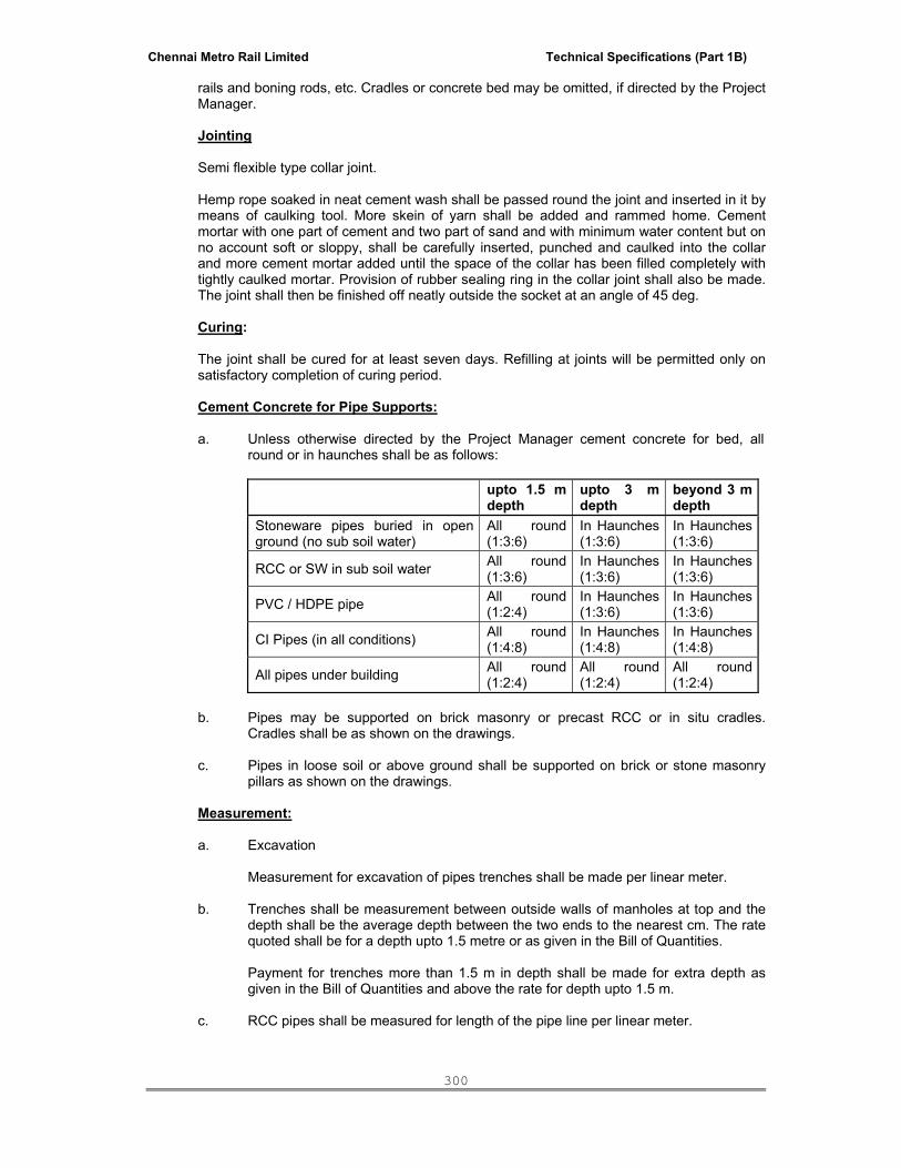
Chennai Metro Rail Limited Technical Specifications (Part 1B)
300
rails and boning rods, etc. Cradles or concrete bed may be omitted, if directed by the Project Manager.
Jointing Semi flexible type collar joint. Hemp rope soaked in neat cement wash shall be passed round the joint and inserted in it by
means of caulking tool. More skein of yarn shall be added and rammed home. Cement mortar with one part of cement and two part of sand and with minimum water content but on no account soft or sloppy, shall be carefully inserted, punched and caulked into the collar and more cement mortar added until the space of the collar has been filled completely with tightly caulked mortar. Provision of rubber sealing ring in the collar joint shall also be made. The joint shall then be finished off neatly outside the socket at an angle of 45 deg.
Curing: The joint shall be cured for at least seven days. Refilling at joints will be permitted only on
satisfactory completion of curing period. Cement Concrete for Pipe Supports:
a. Unless otherwise directed by the Project Manager cement concrete for bed, all round or in haunches shall be as follows:
upto 1.5 m depth
upto 3 m depth
beyond 3 m depth
Stoneware pipes buried in open ground (no sub soil water)
All round (1:3:6)
In Haunches (1:3:6)
In Haunches (1:3:6)
RCC or SW in sub soil water All round (1:3:6)
In Haunches (1:3:6)
In Haunches (1:3:6)
PVC / HDPE pipe All round (1:2:4)
In Haunches (1:3:6)
In Haunches (1:3:6)
CI Pipes (in all conditions) All round (1:4:8)
In Haunches (1:4:8)
In Haunches (1:4:8)
All pipes under building All round (1:2:4)
All round (1:2:4)
All round (1:2:4)
b. Pipes may be supported on brick masonry or precast RCC or in situ cradles.
Cradles shall be as shown on the drawings.
c. Pipes in loose soil or above ground shall be supported on brick or stone masonry pillars as shown on the drawings.
Measurement: a. Excavation
Measurement for excavation of pipes trenches shall be made per linear meter. b. Trenches shall be measurement between outside walls of manholes at top and the
depth shall be the average depth between the two ends to the nearest cm. The rate quoted shall be for a depth upto 1.5 metre or as given in the Bill of Quantities.
Payment for trenches more than 1.5 m in depth shall be made for extra depth as
given in the Bill of Quantities and above the rate for depth upto 1.5 m. c. RCC pipes shall be measured for length of the pipe line per linear meter.

Chennai Metro Rail Limited Technical Specifications (Part 1B)
301
i. Length between manholes shall be recorded from inside of one manhole or inside of other manhole.
ii. Length between gully trap and manhole shall be recorded between socket of pipe near gully trap and inside of manhole.
3.2 UPVC Pipes and Fittings The pipes shall be round and shall be supplied in straight lengths with socketed ends. The
internal and external surfaces of pipes shall be smooth, clean, free from groovings and other defects. The ends shall be cleanly cut and square with the axis of the pipe. The pipes shall be designed by external diameter.
Fittings
Fittings shall be of the same make as that of pipes, injection moulded and shall conform to Indian Standard.
Laying in Trenches UPVC pipes shall be laid on cement concrete bed of width 300mm over the outside diameter
of pipe, and 100 mm thickness. Fine sand shall be carefully filled around the lower half of the pipes so as to buttress them to the sides of the trench.
The filling shall then be continued to 150mm over the top of the pipe using fine sand,
watered and rammed on both sides of the pipes. The process of filling and ramming with fine hand picked material shall proceed evenly in layers not exceeding 150mm thickness, each layer being watered and consolidated so as to maintain an equal pressure on both sides of the pipe line.
4. CONSTRUCTION OF MANHOLE
Where manholes are to be constructed, the excavation, filling back and ramming, disposal of surplus earth, preparation of bottom and sides etc. shall be carried out as described earlier under trench excavation. Manhole shall be sized and depths as called for in the drawings and Bill of Quantities.
The manhole shall be built on a base concrete 1:3:6 of 150mm thickness for manholes upto
1500mm depth and 250mm thickness for manholes from 1500 to 2500mm depth and 300mm thickness manholes of depth greater than 2500mm. Reinforcement as shown shall be provided in the base slabs.
The walls shall be of brick work of thickness as shown in drawings built in cement mortar
1:5. The joints of brick work shall be raked and plastered internally in cement mortar 1:3 (at least 12 mm thick) and finish with a coat of neat cement, external plaster shall be rough plaster in 1:3, PCC benching & semi circular channels of the same diameter as the pipes shall be provided and finished with neat cement coating.
Above the horizontal diameter, the sides of channel shall be extended vertically to the same
level as the crown of the outgoing pipe and the top edge shall be suitably rounded off. The branch channels shall also be similarly constructed with respect to the benching but at their junction with the main channel an appropriate fall suitably rounded off in the direction of flow in the main channel shall be given. All manholes / sumps shall be provided with poly propylene coated steel reinforced foot rest. The polypropylene shall confirm to ASTM D-4101 specification, injection moulded around 12 mm dia IS-1786 grade FE-415 steel reinforcing bar. These rungs shall be set at 30cms interval in two vertical runs at 380mm apart horizontally. The top rung shall be 450mm below the manhole cover. Unless otherwise mentioned, manholes shall be constructed to the requirements of Indian Standard IS:4111 (Part I). All manholes shall be constructed so as to be water tight under test. All angles shall be rounded to a 75mm radius with cement plaster 20mm thick. The benching at the side shall be carried out in such a manner so as to provide no lodgment for any splashing in case of accidental flooding. Manhole cover with frame shall be of cast iron of an approved make. The covers and frame shall generally be double seal as specified in the Bill of Quantities.
Chennai Metro Rail Limited Technical Specifications (Part 1B)
302
4.1 Measurements
Manhole shall be measured in numbers as indicated in the Bill of Quantity. The depth of manhole shall be measured from invert of channel to the top of manhole cover. Manhole with depth greater than specified under the main item shall be paid for under `Extra Depth’ and shall include all items as given for manholes depth will be measured to the nearest cm. Depth of the manholes shall be measured from top of the manhole cover to bottom of channel. The following are inclusive in the cost of manhole viz; i. Bed concrete ii. Brick work. iii. Plastering (inside & outside) iv. R C C top slab, benching and channeling including drop connections.
v. Supply and fix foot rests. vi. Keeping holes and embedding pipes for all the connections.
vii. Excavation, refilling, necessary de-watering and disposing off surplus soil to a places as directed by Project Manager.
viii. Curing. ix Cost of angle frame and embedding the frame in concrete bed. x Testing.
xi De-watering of chambers. 4.2. Drop Connection Drop connection shall be provided between branch sewer and main sewer in the main sewer
itself in steep ground when the difference in invert level of two exceeds 60 cms of the required sizes. Drop connections from gully traps to main sewer in rectangular shall be made inside the manholes and shall have CI special types door bend on to top and heel rest bend at bottom connected by a CI pipe. The pipe shall be supported by holder bat clamps at 180 cms intervals with atleast one clamp for each drop connection. All joints shall be lead caulked joints 25mm deep.
Drop connections from branch sewer to main sewer shall be made outside the manhole wall
with CI / CI class LA pipe, connection, vertical pipe and bend at the bottoms. The top of the tee shall be finished upto the surface level and provided with a CI hinges type frame and cover 30cms x 30cms. The connection and tee upto the surface chamber of the tee.
Drop connection made from vertical stacks directly into manholes shall not be considered as
drop connections.
Road Gully chambers The chamber shall be of brick masonry with Bricks of class designation 75 in cement mortar 1:5 (1 cement : 5 coarse sand) and shall have a PCC/SFRC/D.I gully grating with frame fixed in 150mm thick cement concrete 1: 2 :4 (1 cement : 2 coarse sand : 4 hard stone ballast 20mm nominal size) on top. The size of the chamber shall be taken as the clear internal dimension as specified in the schedule of quantities . The brick walls on the top of the bed concrete 1:4:8 (1 cement : 4 coarse sand :8 hard stone ballast 40 mm and down gauge) of the chamber shall be plastered with 12mm thick cement plaster 1:3 (1 cement : 3 coarse sand) internally and externally and finished with a floating coat of neat cement . The excavation shall be done true to dimension and level shown in the drawing.
Masonry Drains Brick masonry drains shall be of a minimum width of 30cms for depth upto 45cm and a maximum width of drains shall be 45cms for depths beyond 45cms. However, in special cases where the depth is very high, the width of drain shall be in proportion of 1:5 with the

Chennai Metro Rail Limited Technical Specifications (Part 1B)
303
depth. Brick masonry drains shall be constructed in brick masonry in cement mortar 1:5 in cement concrete foundations as specified in the schedule of quantities. Whereever specified, masonry drains shall be plastered with cement mortar inside. The outer surface shall be flush pointed without additional charge.
All brick masonry covered drains shall be provided with Cast Iron perforated cover with frame or cast in situ or precast RCC slabs as specified in drawings. All drains shall be plastered with cement mortar 1:4, 12mm thick with a coat of neat cement. All finished work shall afford specified gradient to ensure free and efficient discharge.
Payment for masonry drains shall be made under individual items of masonry, cement concrete and plaster by volume of area as given in the drawings and schedule of quantities.
4.3 Making Connections Contractor shall connect the new sewer line to the existing manhole by cutting the walls
benching and restoring them to the original condition. A new channel shall be cut in the benching of the existing manhole for the new connection. Contractor shall remove all sewage and water if encountered in making the connection without additional cost.
5. GREASE TRAP 5.1 Size of Grease Trap The size given in Bill of Quantities and drawings shall be internal size of chamber. The work
shall be done strictly as per standard drawing and following specifications. 5.2 Bed Concrete Shall be in 1:4:8 cement concrete 150 mm thick. 5.3 Brick work Brick work shall be with best quality bricks in I:5 CEMENT MORTAR.
Baffle walls shall be of R.C.C and of size as mentioned in Bill of Quantities. Brick partition constructed of best quality table moulded bricks in cement mortar 1:5 shall be provided for the entire height of chamber.
5.4 Plaster The walls of chamber shall be plastered from inside with 12 mm thick cement plaster 1:3 and
finished smooth with a floating coat of neat cement & rough plaster on outside in cement mortar 1:3.
5.5 Chamber Covers Covers shall be of size and duty as mentioned in Bill of Quantities. Covers shall be of cast iron
as per the details given in the drawing and shall be fixed on frame embedded in concrete. C. I steps shall be provided at two corners of the chamber. All Cast Iron and MS items shall be painted with two coats of bitumastic paint. 5.6. Technical Specification
1) Polymer Concrete Channel for External Drainage System:
The Channel shall be of specification EN 1433 for External Application. It shall be Pre casted of V Shape cross section, the material of construction is Polymer Concrete and it has integrated edge rail and safety groove. It should provide water
Chennai Metro Rail Limited Technical Specifications (Part 1B)
304
tight laying, the grating will have a locking system so that it can fit on safety groove. The Gratings are as per load class A15, B125, C250, D400 and E600 of materials C.I. or S.S. or G.I. depending on the application. The Channels shall have tongue & groove facility for the Interlocking for uniformity of a line.
2) S.S GULLIES AND CHANNELS FOR WET AREA:
Gully and Channel are made up of S.S. 304 or 316 for Corrosion resistance. It shall be with Removable F.A.T. (Foul Air Trap), the Water drainage capacity shall be upto 1.2 l/s. The product should have Horizontal or Vertical Spigot Outlet with Water Seal of 30mm-50mm. The Products shall be with Pickle passivated to prevent Corrosion at joints.
3) RECESSED ACCESS COVERS:
The Recess Access Covers shall be of specification EN 124. The material of Construction is Aluminium, Galvanise Steel or S.S. depending on the Applications (Indoor or Outdoor). Load Bearing Capacity of A 15, B 125, C 250 AND D400 depending on the Application. The Covers shall be Gasket Seal and Locking Screw Fixed Type. The Covers shall be Triple Seal (Air Tight, Water Tight and Dustproof). The Recess Cover shall have provision for infill (50mm-110mm) to match the surface finish.
4) GREASE SEPARATORS
The Product shall be of specification EN 1825. The separators shall be Prefabricated in PE (Polyethylene) or S.S. depending on the applications and requirements. Product availability for all site conditions like Above the Ground applications, Under the Ground Application & Below Sink Applications (At source).The Product can be upgraded in Retrofit applications also. The opening of All Grease Separators shall be Air and Water Tight.
5) KERB DRAIN -KERBSTONE WITH THE DRAIN
The Product shall be of specification EN1433. The material for the KERBDRAIN should be made of Polymer Concrete. The Product shall take a Load Class of D400. It shall have Chemical Resistance to Salt and Zero percent Water Absorption.
5.6 Cast iron Manhole cover and Frame The Cast Iron Manhole Cover and Frame shall conform to IS:1726 and the grade and types
have been specified in the Bill of Quantities. The cover and frames shall be cleanly cast and they shall be free from air and sand holes and from cold shuts. They shall be neatly dressed and carefully trimmed. All castings shall be free from voids whether due to shrinkage, gas inclusion or other causes. Covers shall have a raised checkered design on the top surface to provide an adequate non-slip grip.
The sizes of covers specified shall be taken as the clear internal dimensions of the frame. The covers and frames shall be coated with a black bituminous composition. The coating shall
be smooth and tenacious. It shall not flow when exposed to a temperature of 63° C and shall not brittle as to chip off at a temperature of 0° C.
6. TESTING All rights of the sewer and drain shall be carefully tested for water tightness by means of
water pressure maintained for not less than 30 minutes. Testing shall be carried out from manhole to manhole. All pipes shall be subject to a test pressure of 1.5 meter head of water. The test pressure will however, not exceed 6 meters head at any point. The pipes shall be plugged preferably with standard design plugs or with rubber plugs on both sides, the upper

Chennai Metro Rail Limited Technical Specifications (Part 1B)
305
end shall, however, be connected to a pipe for filling with water and getting the required head poured at one time.
Sewer lines shall be tested for straightness by :
i. Inserting a smooth ball 12 mm less than the internal diameter of the pipe. In the absence of obstructions such as yarn or mortar projecting at the joints the ball shall roll down the invert of the pipe and emerge at the lower end.
ii. means of a mirror at one end a lamp at the other end. If the pipe is straight the full
circle of light will be seen otherwise obstructions or deviations will be apparent. iii. The contractor shall give a smoke test to the drain and sewer at his own expense
and charges, if directed by the Owner’s site representative. iv. A test register shall be maintained which shall be signed and dated by contractor
and Owner’s site representative.

Chennai Metro Rail Limited Technical Specifications (Part 1B)
306
SECTION-06 :: HYDROPNEUMATIC SYSTEM & PUMPING MAINS 1. SCOPE
This section of the contract involves the design, supply, installation, testing and commissioning of the complete Hydropneumatic pumping system and other pumping systems complete with all controls and electrical work for domestic water supply, water supply for flushing. All submersible water re-circulation, drainage and ejector pumps for the project are also included in this contract. It also involves testing and commissioning of the pumping system with the domestic water, flushing water and RO water supply & distribution. This specification described the particulars of the contract, designs and systems chosen, and mode of operation. All installation work shall comply with the latest rules and regulations. The work embraced by this specifications covers the design, submission to authorities, supply, delivery on site, installation, testing, commissioning and maintenance of the Hydropneumatic pumping system, other pumping system installation of the building in accordance with this specification and associated drawings. The scope of work shall include the following (list is indicative and not exhaustive) : - Variable speed pumping units domestic water flushing water and RO water supply &
distribution. - Suitably sized food grade quality, non-toxic diaphragm type pressure vessels
complete with necessary interconnections and controls. - Control panel for pump control complete with variable speed drives, circuit breakers,
fusses, pressure transmitters etc. complete with all interconnections to pumps and electrical supply panels.
- Pump control units complete with pre-programmed micro-processor chip. - Pump monitoring units to monitor operation of pumps. - Each Hydropneumatic Pumping unit shall be supplied as a complete set including
variable speed pumps, pressure vessels suction and discharge common manifolds, non-return valves, isolating valves, pressure transmitters on the discharge side and level electrode at the suction tank. Each unit shall be provided with electronic microprocessors for unit control and all necessary electrical work for the unit.
- Submersible water re-circulation pump for water fountain, drainage pumps for plant
room drainage complete with electrical panels and necessary accessories with automation for pump operation.
- All the pipework etc. shown in the system drawings is meant for information only
and shall be carried out by others. The Hydropneumatic system supplier shall provide the pumping units in the designated pump rooms as complete units included all necessary piping within plant such that only discharge connections are required to be connected into the unit’s discharge manifolds just inside the plant room, by the Plumbing contractor. The Hydropneumatic system contractor shall guarantee specified pump performance at various pump speeds and Hydropneumatic pumps must be able to supply at least 2 bar pressure at the highest/farthest fitting.
- Electrical equipment and installation work including the PLC in Control panel. - Painting and labelling of pipe work and equipment;

Chennai Metro Rail Limited Technical Specifications (Part 1B)
307
- Provision of all hold down bolts, spigots struts and the like required to be built in during construction; - Provision of dry contacts to BMS indicating the status of the pumps and pressure vessel in form of hardware interfacing panels inside each pump room and control panels of all pumps. - Provision of all level switches, flow switches and other sensing devices for status indication. - All interfacing work with other trades. - Testing & commissioning and balancing of the Hydropneumatic & Pumping system; - Provision of twenty four (24) months operational maintenance and breakdown services; - Provisions of operating instructions and maintenance manuals; - Provision of spare parts; - Training of the employer's staff for proper operation of the entire systems; - Liaison with Local Authorities to obtain all necessary certificates and approvals, including the completion of all submission drawings, forms and payment of any fees and charges. All the costs for all the tests required by Local Authorities shall be included. To attend to any Authorities inspection regardless of whether this inspection is carried out after the defect liability period; - Provisions of the necessary installation which include pumping works, pipe work within the pumping unit up to suction and discharge manifolds, conduit and control wiring, etc. to form a workable system required; - All other works and systems as specified in the Contract document and or shown on the drawings. - All cutting, patching, framing up, furring in, chasing and making good associated with the building construction for the passage of pipes, conduits and the like including providing GI pipes sleeves of required size corresponding to pipe dia, wherever pipes crossing fire rated walls and floors and sealing with glass wool in between and fire sealant compound on either end. Details on shop drawings shall also be provided.
2. GENERAL
Equipment offered for supply and installation shall include the following: All minor items and incidental work, equipment accessories and materials may not be
specifically mentioned but are required for the proper completion of the installations in accordance with the true intent and meaning of this Specification.
All necessary safety devices for the protection of personnel against injury and the protection
of plant and equipment against damage including relief valves, belt guards, fan inlet and/or discharge guards, safety railing, effective earthing of electrical components, electrical interlocks, warning lights and alarms.
Readily accessible, dust-proof lubricating facilities on all moving parts and equipment
including provision for cleaning all lubricating lines and bearings and charging same with the correct lubricants after installation but prior to testing and commissioning.
Clearly visible and robust manufacturer's name-plates permanently fitted each and every
item of equipment and showing the manufacturer's name, type and/or model number, serial number, and all essential operating data such as speed, capacity, voltage, current draw, etc.

Chennai Metro Rail Limited Technical Specifications (Part 1B)
308
The Contractor also shall allow provision for the inspection of all plant and equipment by the
manufacturer or his licensed representative, at least twice during the course of the installation.
3. PIPING The pipes and fittings in the domestic Water Treatment plant room shall be GI class `C'
(heavy class) conforming to IS: 1239 ( Part-I) for pipes and IS:1879 (Part 1 to 10) for malleable cast iron galvanized fittings.
All drainage / burried piping shall be cast iron pipes (CI Class LA) as per IS:1536 and fittings
with ty-ton joints complete with required accessories (Fittings shall be of lead joints). 4. PUMPS FOR HYDROPNEUMATIC & DRAINAGE SYSTEM 4.1 PUMPS Pumps shall be vertical, centrifugal, multistage directly coupled to motor. Provision of pump
with pump head & base of cast iron and other parts in SS 304 shall be made for pumps required in Hydropneumatic System and water fountain re-circulation system. Impeller shall be hydraulically balanced and keyed to shaft. Pump shall be mounted on a concrete foundation, projecting at least 15 CM above finished floor level. The pumps base shall be set on a vibration elimination pad. The pump shall be lubricated in strict accordance with the manufacturer’s instructions and shall be factory aligned prior to shipment. All motors and bases shall be painted with approved finish shop coat of paint. The pump shall be selected for the lowest operating noise level and shall be complete with flexible connections, valves, and pressure gauges. The pumps shall include cost of foundation channel complete.
The Contractor shall supply and install pumps of the type and performance as shown on the
drawings. All duties of pumps given in the Tender Drawings shall be checked and where necessary corrected before ordering. All the parts of the pumps that are in contact with water e.g. shaft, impeller etc. shall be of stainless steel construction.
Pumps shall be so selected that the design duty point is within 5% of the maximum
efficiency point. The pump casing so selected shall have ample space to take an impeller one size larger than that capable of performing the design duty.
The pump shall have a speed of not more than 1500 rpm. However pumps of 2900 rpm with
high efficiency and low noise motor can be selected and noise data submitted for approval. All pumps and motors shall be of minimum vibration and noise level during operation. Vibration isolators shall be provided for all pump sets.
Facilities shall be provided to prevent starting of pumps when the water tank is at low water
level. An indicator for this low water level alarm shall be provided. Facilities to select which pump to be duty pump and standby pump shall be provided and be
interchangeable. Leakage from pump gland shall be drained to the nearest floor waste. Pump curves for all pumps offered shall be submitted. All curve indicating excessive shut-off
head will not be approved. Each pump shall be provided with a gate valve at suction and discharge, approved check
valve at discharge, approved strainer at suction, flexible connections at pump suction and discharge, eccentric reducer at suction, concentric reducer at discharge, pressure gauges at suction and discharge, circulation relief valve and automatic air relief valve.
Appropriate neoprene vibration isolation mountings shall be provided for each pump sets.

Chennai Metro Rail Limited Technical Specifications (Part 1B)
309
Vertical Multi-Stage Pumps Multi-stage pumps shall be of centrifugal type and arranged with shafts vertically installed.
The impellers shall be of stainless steel mechanically balanced and keyed to shaft. Renewable guide rings are to be provided in the casting, keyed to prevent rotation.
Pumps shall be driven by elevated in-line TEFC squirrel cage motors via extended vertical
shafted complete with universal couplings. The shafts shall be stainless steel. Stainless steel sleeves shall be provided to protect the
shaft in the water space and through the sealing glands. The sleeves shall be keyed to prevent rotation and secured against axial movement.
The bearings shall be of ball or roller type protected against ingress of water, dirt and other
matter. Vertical multistage pumps shall have universal flanges. Intermediate bearing, support
bearing shall be provided in the pump. The shaft seal shall be easily serviceable and shall allow for correct adjustment and loading
of the seal.. Pump motors above 7.5 kW shall be equipped with a spacer coupling which allows changing of shaft seals without removing the motor. The pump motors shall be of Class “F” insulation and IP55 rating and shall be provided with built-in thermistors for protection against over heating.
4.2 VARIABLE SPEED HYDROPNEUMATIC PUMPING SYSTEM
Variable speed Hydropneumatic pumping units shall be provided for supply of domestic water, flushing water and RO water supply for the project. The units shall be selected so as to provide at minimum of 2 bar pressure at the highest/farthest fitting in each plumbing system, the unit serves. The hdyropnematic pumping units shall have the following features;
4.2.1 System Description
The system shall be supplied as complete sets including suction and discharge common manifolds, non-return valves, isolating valves, pressure transmitter on the discharge side and electrode at the suction tank.
The system operation will be such that the initial small water demand shall be met by the charged diaphragm pressure vessel. Should the water demand continue the system pressure will dip to a preset pump cut-in point when the lead pump starts to operate at reduced speed through the variable speed drive. However, should the system pressure be still below the preset value, the controller continuously increases pump speed to meet the system demand. When the lead pump is not able to meet the system pressure at full speed, the second pump also starts to operate.
At peak demand all the pumps operate, similarly, if there is a drop in water demand the duty pump speed starts to reduce, then standby pumps cuts-off, followed by stopping of the duty pump.
The closed diaphragm pressure vessel shall be of polyethylene material with a pressure gauge and isolating valve. The interior shall be of non-toxic lining suitable for use with potable water. The vessel shall be manufactured to conform to ASME pressure vessel code/standards.
The system shall be under the control of an electronic microprocessor unit (EMU).
A pressure transmitter shall detect the pressure at the delivery manifold and feedback to the microprocessor control panel via control circuit.

Chennai Metro Rail Limited Technical Specifications (Part 1B)
310
The system shall incorporate a frequency converter or frequency converter motors on the pumps and the pressure transmitter shall register the actual pressure on the discharge side.
The variable speed drive pumping system shall maintain a constant pressure regardless of the system demand. If there is a drop in pressure outside the preset point, the Variable Speed Drive (VSD) pump shall start to run until the pressure increases to the preset limit, or it will continue to increase the pump speeds to the upper limit of the frequency. If the water system demand still cannot be met, the second pump shall be called in to run, the VSD will then alter the pump speed to meet the preset pressure point. If the set point is still unable to be met, the third pump is then activated to run (in case of 3 pumps units).
This shall be achieved by continuously varying the motor speed of the duty pump according to the demand up to a maximum designed capacity.
Under decreasing hydraulic demand the reverse sequence to the above description shall apply.
The EMU shall ensure alternation of all the duty and standby pumps for even running hours for all the pumps.
The frequency converter shall be linked to the motor of the duty pump for continuous speed adjustment and ultimately the water delivery shall be maintained at constant pressure at the preset value.
4.2.2 Local Motor Control Panel
The motor control panel shall be equipped with all the necessary electrical components including a microprocessor control unit and a frequency drive. The control panel and the microprocessor shall cover the followings functions :
- Flexibility and simplicity in allowing the necessary re-adjustment of the
pumping system pre-set delivery pressure to operate the pumps within the specified maximum and minimum delivery ranges.
- Built-in frictional loss compensation factor which will automatically increase
the delivery pressure setting, in collaboration with the increase in flow demand. This shall be able to minimise the system pressure differences and provide a more constant pressure along the supply line and also to save the energy consumption of the motor when running at low speed.
- Automatic changeover of the pumps to be controlled by the microprocessor
which dictates the duty and standby pumps to run at variable speed. - Built-in clock functions with weekly programming and with switch on system
to operate at least 10 different pre-set pressure points as required. - When the system has not been operated for more than 24 hours, it shall
automatically start the pumps for a few seconds/day to ensure the pumps readiness at all times. The standby pumps shall be activated upon failure of duty pump(s). In event of control failure, the pumps shall be able to be start/stopped manually at the local panel by means of pressure switches.
- The microprocessor control panel shall be able to cut-off the pumping
system when excess pressure is registered in the discharge common manifold.
- The system shall have the capability of receiving input signal concerning
reduced water level in suction tanks and shall have control mechanisms to prevent the pumps form running dry.

Chennai Metro Rail Limited Technical Specifications (Part 1B)
311
- Automatically starting the pumps when the water level is back to normal. - In case of pump failure due to motor overload, the standby pump is
switched on automatically. Alarm signal is displayed on the LCD Display unit and alarm lights are activated.
- Functions to limit the no. of start/stop of pumps per hour. - The system control panel shall incorporate at least the following
components :
a. LCD Display b. Pumps selections for up to 4 pumps so that system controller can
control up to 6 pumps c. Pump status button to display duty pump speed and system
capacity d. Zone status button to display operating parameters for different
pumping units e. Setting button to input preset pressure, system start/stop time etc. f. ±1 button to key in numeric data such as pressure set point, etc. g. Enter button for confirmation of input into the system h. Alarm button to show location of fault - self diagnostic function
display i. Hour Run measurement for each supplied pumpset j. Buttons for scrolling to select the actual display reading for system
configuration, i.e. up and down scroll concept. k. Necessary devices for programming, supervising and monitoring
operation data/system, status shall be incorporating into the control panel.
4.2.3 Operations
Local control panel shall perform as follows:
Auto mode
The desired delivery pressure within the range specified, shall be set at the duty local control panel. The pressure transmitter shall detect the delivery pressure continuously within 1 second and feedback to the microprocessor which will control the variable speed drive frequency converter for speed control of the duty pump. When demand increases, the subsequent pumps in the system will be activated to boost up the pressure. Ultimately the duty pumpset shall be operated fully automatically to maintain the delivery pressure constantly at the desired set value.
Manual Mode
The on/off function of the pumps shall be manually adjusted at the microprocessor located at the local control panel.
Frequency Control By-pass Mode

Chennai Metro Rail Limited Technical Specifications (Part 1B)
312
All the pumpsets shall be started / stopped automatically with the pump output at fixed maximum rotational speed. All the control and protection functions shall remain active. The cut in/cut out pressure shall be internally calculated by the microprocessor for each pump.
4.2.4 System Features
The required performance features of each Hydropneumatic pumping unit shall be as follows :
System Configuration
Variable speed pumps with pressure vessels.
Control panel consisting of the following components :
- Pump Functional Unit (PFU) - control unit c/w pre-programmed
microprocessor chip. This unit shall control all pumping unit operations through electronic controller.
- Pumping Monitoring Unit (PMU) - monitor the operation of the pumpsets.
This unit shall allow for monitoring and setting of all control parameter. - Variable Speed Drive - Circuit Breakers - Fusses - Pressure Transmitter
Set Point
Ten separate pressure “set points” shall be able to be programmed into the PMU, and switching between set points is timed by a real time clock when a lower pressure is acceptable during certain periods, for instance after hours or weekends, the set point shall be lowered to minimise power consumption.
An external input shall also be used to switch between set points, or manually adjust a set point at any time.
Friction Loss Compensation
It shall be possible to allow for the friction loss component of the system, calculated at full flow and set as a percentage of the set point which will reduce the working pressure of the pump set depending on the actual no. of pumps in operation. A linear approximation of system resistance curve can therefore be allowed for, and pressure will automatically increase as system flow and subsequent frictional losses increase. As such power consumption shall reduce which is required for the pumping system.
Displays
Through the PMU keypad all variable parameters shall be adjustable, current status of settings and measured values shall be able to display on the 2 line x 24 character liquid crystal display.
Individual menus shall be available for monitoring individual pumps, zones, settings, alarms and ON/OFF functions.
Pump Status

Chennai Metro Rail Limited Technical Specifications (Part 1B)
313
Running hours of each pump Actual pump status (running, not available, standby, allocated to zone, fault) Maximum head of pump at zero flow.
Zone Status
This menu shall be the main operating menu where at the setting and operating parameters can be viewed,
• Current operating set point • Measured values in the system • Operating capacity in terms of total output • Mode of operation for the zone • Clock programs (relating to set point pressures) • Standby pumps • Pump change over time • Zone configuration • Pressure transducer scaling • Friction loss compensation • Pump priority • Inlet pressure measuring (if required) • System response times • Allowable number of starts per hour for the pumps • Minimum limit (loss of water, burst mains protection)
Setting Menu (Set)
In this menu all parameters for the operation of the pump set shall be able to be adjusted as required.
a Set points (up to 10) b. On/Off function (used to prevent unnecessary cycling at low demands) c. Displayed pressure units (Bar, PSI, mBar, kPa) d. Real time clock programming for any time of the day, week, or weekend e. Zone configuration f. Friction loss compensation
Alarm
The alarm menu shall display all faults that occur during operation, logging the time and date of when the fault occurred and when it was corrected, or whether it is still an actual fault, up to 10 faults can be maintained as history in the controller. The following type of faults shall be diagnosed by the controller.
a. Mains failure b. Frequency converter fault c. Analogue input (pressure transducer) fault d. High discharge pressure fault e. Low discharge pressure fault f. Motor thermal overload fault
Variable Frequency Drive
Variable frequency drive shall be of a reputable make acceptable to Project Manager and shall be complete with RFI filter and harmonic dampers.
Enclosure
An IP 54 powder coated steel enclosure shall house all the electrical components.

Chennai Metro Rail Limited Technical Specifications (Part 1B)
314
The enclosure can be supplied loose for remote mounting, or mounted on a common base with the pumps, it shall be adequately ventilated for use in conditions up to a maximum ambient temperature of 45 degrees Celsius.
Electrical Component
All circuit breakers, thermal overloads and contactors shall be of reputable make acceptable to the architect. Electrical supply to the pump controller shall be protected using an isolating circuit breaker.
Method of Starting
The panel shall be built to start the pumps in suitable starting modes, i.e. D.O.L., Star/Delta, or using Soft Starters.
Quality and Testing
Manufacture of the pumps, plus design and assembly of the complete packaged Hydropneumatic pumping system shall be factory assembled and the pump station shall be fully tested hydraulically and electrically prior to dispatch to site. Test reports etc. shall be submitted for review before dispatch.
4.2.5 Pump Pressure Vessel
Diaphragm type pressure vessels shall be provided as shown on the drawings. They shall be incorporated into the system so that during normal operation the pump shall not need to be start within 30 seconds of it switching off in order to prevent the pump hunting.
The pressure vessel shall be of adequate capacity to accommodate a considerable fluctuation in water demand by the system with minimum start/ stop cycles of the pumps. The vessel shall be constructed of steel plate built to ASME Standards for Unfired Pressure Vessel. A rubber diaphragm shall be provided in the vessel for separating the water and pre-charge nitrogen. The pre-charge pressure shall be adjustable and charging port with non-return device shall be provided. The adjustable cut-in and cut-off pressure unit for the pumps shall be built-in at the vessel to suit the system.
4.3 FLOATLESS TYPE LEVEL SWITCH IN WATER TANKS
The Contractor shall supply and install float less type switch probes in the water tanks as indicated below and shown on the drawings.
Raw Water Tanks · High level alarm (over-flow); · Low level alarm; · Low level cut-out for raw water pumps; · Earthing probe. RO water Tanks · High level alarm (over-flow); · Low level alarm; · Low level cut-out for cooling tower makeup water supply pumps; · Earthing probe. Potable Water Tank · High level alarm (over-flow); . Low level alarm; . Low water level cut-out for the domestic hydropneumatic pumps; · Earthing probe.
Chennai Metro Rail Limited Technical Specifications (Part 1B)
315
Each probe shall be of the correct length for the particular application and tank location. Electrodes shall be of polished stainless steel 20 mm OD. Electrode holders shall be weatherproof in all respect.
The earthing probes shall be connected and wired to the building earth systems of the building.
Each set of electrodes shall be installed inside a 230 mm diameter PVC pipe acting as a wave barrier. The level switch set shall operate with a stepped down voltage at 24V maximum. Stepped down transformers shall be provided for each set of control probes and shall be installed inside centralised control cubicles inside pump room. Mechanical steel stuffing boxes shall be used.
Control of Duty / Standby Pumps
Operation of the duty and standby pumps shall be carried out by the following method:
a Automatically by means of pressure sensor (i.e. pressure switches); b Manually by means of a local start/stop push buttons on pump local motor control
panel and emergency stop switch.
The pressure switch shall be installed next to the manual release valve. When the pressure drops to the pre-determined level, a signal will be sent to the pump local motor control panel to start the pump.
Automatic controls shall be operated by electronic, float less type level switches.
Pump Indicator
The following audible and visible indication shall be provided at the pump local control panels as applicable: a Red "overflow level" indicator with buzzer for the associated water tanks; b Amber "extra high water level" indicator for the associated water tank; c Amber "high water level" indicator; d Amber "low water level" indicator; e Red "pump trip" indicator for each pump; f Green "pump on" indicator for each pump; g "Pump electrical supply healthy" indicator for each pump; h Amber "remote/local" status indicator.
CI MH covers for Water Tanks Manhole covers and frame for Water Tanks shall be of Cast Iron. These shall be embedded in cement concrete slabs / brick works as shown on drawings. These shall be of medium duty, the weight of the same shall be as mentioned in schedule of quantities.
PVC Foot rests for Water Tanks
Providing and fixing safely foot rest of required shape of minimum 6 mm thick plastic encapsulated as per IS 10910 on 12mm dia steel bar as per IS 1786 having minimum cross section as 23mm x 25mm overall minimum length 263 mm nad width as 165 mm with minimum 112 mm space between protruded legs having 2mm tread on top surface by ribbing besides necessary and adequate anchoring projection on tail length of 138 mm and

Chennai Metro Rail Limited Technical Specifications (Part 1B)
316
suitable to withstand and bend test and chemical resistance test as per manufacturer specification. Preferably footrest shall be fixed before concreting of walls for UG tank or fixed cement concrete 1:2:4 mix with proper anchoring.
4.4 SUMP PUMP 4.4.1 Submersible
These shall be fully submersible with a fully submersible motor. The pumps shall be provided with an automatic level controller and all interconnecting power and control cabling which shall cause the pumps to operate when the water level in the sump rises to a preset level and stop when the preset low level is reached.
Pumps for drainage shall be single stage, single entry.
Pump shall be C.I. casing and C.I. two vane open type with a dynamically balanced impeller connected to a common shaft of the motor. The vane for sewage pump will be open type, while for drainage pump, etc. it will be of semi open type. The MOC of the sump shall be in accordance to schedule of quantity.
Stuffing box shall be provided with mechanical seals.
Each pump shall be provided with a suitably rated induction motor suitable for 415 volts, 3 phase, 50 Hz A.C. power supply.
Each pump shall be provided with in built liquid level controller for operating the pump between predetermined levels.
The pumping set shall be for stationary application and shall be provided with pump connector unit. The delivery pipe shall be joined to the pump through a rubber diaphragm, and bend and guide pipe for easy installation.
Pump shall be provided with all accessories and devices necessary and required for the pump to make it a complete working system.
Sump pump shall be complete with level controllers, power and control switch gear, Auto/off/Manual switches, pumps priority selections and control and power cabling upto motor and controller/probes etc. (Including earthing). Level control shall be such that one pump starts on required level, 2nd pump cuts in at high level and alarms is given at extra high level. All level controllers shall be provided with remote level indications.

Chennai Metro Rail Limited Technical Specifications (Part 1B)
317
4.4.2 Motor Design
The pump motor shall be a squirrel cage induction, housed in air filled water-tight enclosure. Oil filled motors are not acceptable. The stator windings shall be Class "F" insulation (155 degree C or 311 degree F) for general usage and class `H' insulation (180 degree C or 317-8 grade 2) for submersible type. The stator shall be heat shrunk fitted into the enclosure and shall not use bolts, pins or other fasteners that penetrate through the stator enclosure. The starter shall be equipped with a thermal switch embedded in series in the coils of the stator windings to protect the stator from wheel. The motors shall be designed for continuous running duty type at 415 volts, 3 phase, 50 Hz power supply and capable of sustaining a minimum of 20 starts/stops per hour. Between stator housing and pump, a tandem seal arrangement will be provided with an oil barrier. Both seals run in oil, allowing dry running without seal damage. Both seals shall be of the rubber bellows or metallic bellow type with positive drive between shaft and rotating seal face.
SECTION-07 :: ELECTRICAL INSTALLATION
1. SCOPE The scope of this section comprises of fabrication, supply, erection, testing and
commissioning of Motor Control Centre (MCC), wiring and earthing of all Plumbing, sanitary and drainage system equipment, components and accessories.
2. GENERAL Work shall be carried out in accordance with the accompanying specifications and shall
comply with the latest relevant Indian Standards and Electricity Rules and Regulations. The configuration of the MCC shall be designed to suit the requirements of the process”.
The necessary Single Line diagrams/ Schematic drawings shall be furnished for approval by Consultant/ Owner.
All motor control centres shall be CPRI approved and shall be suitable for operation on 3
phase/single phase 415/230 volts, 50 cycles power supply system. 3. CONSTRUCTIONAL FEATURES
The Motor Control Centre (MCC) electrical panels shall be sheet steel cabinet for indoor installation, dead front, floor mounting/wall mounting type and shall be 3b construction. The control panel shall be totally enclosed, completely dust and vermin proof and shall be with hinged doors with Neoprene gasket. Control panel shall be suitable for the climatic conditions as specified in Specifications. Steel sheets used in the construction of Control panel shall be 2 mm thick and shall be folded and braced as necessary to provide a rigid support for all components. Joints of any kind in sheet metal shall be seam welded, all welding, slag shall be rounded off and welding pits wiped smooth with plumber metal. The general construction shall confirm to relevant BIS Codes.
All panels and covers shall be properly fitted and square with the frame, and holes in the panel correctly positioned. Fixing screws shall enter into holes tapped into an adequate thickness of metal or provided with wing nuts. Self threading screws shall not be used in the construction of Control panels. A base channel of 75 mm x 40 mm x 5 mm thick shall be provided at the bottom for floor mounted panels. Minimum clearance of 275 mm shall be provided between the floor of control panel and the lowest unit.
The control panel shall be of adequate size with a provision of 25% spare space to accommodate possible future breakers. Breakers shall be arranged in multi-tier. Knockout

Chennai Metro Rail Limited Technical Specifications (Part 1B)
318
holes of appropriate size and number shall be provided in the Motor Control Centre in conformity with the location of cable/conduit connections. Removable sheet steel plates shall be provided at the top to make holes for additional cable entry at site if required. Every cabinet shall be provided with Trifoliate or engraved metal name plates. All panels shall be provided with circuit diagram mounted on inside of door shutter protected with Hylam sheet. All live accessible connections shall be shrouded and shall be finger touch proof and minimum clearance between phase and earth shall be 20 mm and phase to phase shall be 25 mm. Panels with ACB shall necessarily have front and rear access as per requirement whereas panels with all MCCB breaker shall be provided with front access with sufficient clearance. Dual sources of incoming power supply is required.
4. WIRING SYSTEM All control wiring shall be carried out by using PVC insulated copper conductor LSZH wires
in conduits. Minimum size of control wiring shall be 1.5 sq mm. Minimum size of conductor for power wiring shall be 4 sq. mm 1100 volts grade PVC insulated copper conductor wires in conduits.
5. CIRCUIT COMPARTMENT Each circuit breaker, contactor and relay shall be housed in a separate compartment and
shall have steel sheets on top and bottom of compartment. Sheet steel hinged lockable door shall be duly interlocked with the breaker in the “ON” position. Safety interlocks shall be provided to prevent the breaker from being drawn-out when the breaker is in ‘ON’ position. The door shall not form an integral part of the draw-out portion of the panel. Sheet steel barriers shall be provided between the tiers in a vertical section.
6. INSTRUMENT ACCOMMODATION
Adequate space shall be provided for accommodating instruments, indicating lamps, control contactors and control MCBs. These shall be accessible for testing and maintenance without any danger of accidental contact with live parts of the circuit breaker and bus bar `ON’ lamps shall be provided on all outgoing feeders.
7. BUS BAR CONNECTIONS
Bus bar and interconnections shall be of high conductivity electrolytic aluminium complying with requirement of grade E91E of IS:5082-1981 and shall be of rectangular cross section suitable for carrying the rated full load current and short circuit current without overheating of phase and neutral bus bar and shall be extendable on either side. Bus bar and interconnections shall be insulated with heat shrinkable sleeve and shall be colour coded and shall be supported on glass fiber reinforced thermosetting plastic insulated supports at regular intervals to withstand the force arising from in case of short circuit in the system. All bus bar shall be provided in a separate chamber and all connections shall be done by bolting. Additional cross sectional area shall be added to the bus bar to compensate for the holes. All connections between bus bar and breaker shall be through solid aluminium strips of proper size to carry full rated current as per approved for construction shop drawing and insulated with insulating sleeves. Bus bar shall be rated for current density of 1.0 amps/mm2 cross section area.
8. TEMPERATURE - RISE LIMIT
Unless otherwise specified, in the case of external surface of enclosures of bus bar trunking system which shall be accessible but do not need to be touched during normal operation, an increase in the temperature up to 85° C shall be permissible for metal surface as per relevant IS Codes.

Chennai Metro Rail Limited Technical Specifications (Part 1B)
319
9. CABLE COMPARTMENTS
Cable compartment of adequate size shall be provided in the control panel for easy clamping of all incoming and outgoing cables entering from the top/bottom. Adequate supports shall be provided in cable compartment to support cables as per approved for construction shop drawing.
10. MOULDED CASE CIRCUIT BREAKER (MCCB) All MCCB’s shall be motor duty and Current Limiting type, and comprise of Quick Make -
break switching mechanism, preferably Double Break Contact system, arc extinguishing device and the tripping unit shall be contained in a compact, high strength, heat resistant, flame retardant, insulating moulded case with high withstand capability against thermal and mechanical stresses. All MCCB’s shall be capable of defined Variable overload adjustment. All MCCB’s rated 200 Amps and above shall have adjustable Magnetic short circuit pick up.
The trip command shall override all other commands. MCCB shall employ maintenance free
double break contact system to minimise the let thru’ energies and capable of achieving discrimination upto full short circuit capacity of downstream MCCB. The manufacturer shall provide both discrimination tables and let thru energy curves.
The breaking capacity of MCCB’s shall be asked for in the schedule of quantities. The
breaking capacities specified will be ICU=ICS i.e type-2. Co-ordination as per relevant IS and IEC Codes.
The MCCB’s shall be provided with rotary handle operating mechanism. The handle position
shall give positive indication of ‘ON’, ‘OFF’ or ‘Tripped’ thus qualifying to Disconnection as per the IS/IEC indicating the true position of all the contacts. In case of 4 pole MCCB the neutral shall be defined and capable of offering protection.
11. MINIATURE CIRCUIT BREAKER (MCB) Miniature Circuit Breaker shall comply with relevant IS Codes and shall be quick make and
break type for 230/415 VAC 50 Hz application with magnetic thermal release for over current and short circuit protection. The breaking capacity shall not be less than 10 KA at 415 VAC. MCBs shall be DIN mounted. The MCB shall be Current Limiting type (Class-3). MCBs shall be classified (B,C,D ref IS standard) as per their Tripping Characteristic curves defined by the manufacturer. The MCB shall have the minimum power loss (Watts) per pole defined as per the IS/IEC and the manufacturer shall publish the values.
The housing shall be heat resistant and having a high impact strength. The terminals shall
be protected against finger contact to IP20 Degree of protection. All DP, TP and TPN miniature circuit breakers shall have a common trip bar independent to the external operating handle.
12. PAINTING
All sheet steel work shall undergo a process of degreasing, pickling in acid, cold rinsing, phosphating, passivating (seven tank processing) and then painted with electrostatic paint (Powder coating). The shade of colour of panel inside/outside shall be as specified in the datasheet as per relevant BIS code.
13. LABELS
Engraved PVC labels shall be provided on all incoming and outgoing feeder. Circuit diagram showing the arrangements of the circuit inside the control panel shall be pasted on inside of the panel door and covered with transparent plastic sheet.
14. METERS
i. All voltmeters and indicating lamps shall be through MCB’s.

Chennai Metro Rail Limited Technical Specifications (Part 1B)
320
ii. Meters and indicating instruments shall be plug type. iii. All CT’s connection for meters shall be through Test Terminal Block (TTB). iv. CT ratio and burdens shall be as specified on the Single line diagram.
15. CURRENT TRANSFORMERS
Current transformers shall be provided for Control panels carrying current in excess of 60 amps. All phase shall be provided with current transformers of suitable VA burden with 5 amps secondaries for operation of associated metering. The CTs shall confirm to relevant Indian Standards. The design and construction shall be dry type, epoxy resin cast robust to withstand thermal and dynamic stresses during short circuits. Secondary terminals of CTs shall be brought out suitable to a terminal block which shall be easily accessible for testing and terminal connections. The protection CTs shall be of accuracy class 5P20 and measurement CTs shall be of accuracy class I.
16. SELECTOR SWITCH Where called for, selector switches of rated capacity shall be provided in control panels, to
give the choice of operating equipment in selective mode. 17. STARTERS Each motor shall be provided with a starter of suitable rating. contractor shall select suitable
rating and type of starter for the motors as per directions and approval from relevant authorities. Starters shall be in accordance with relevant IS Codes.
The following capacity contactors and overload relays shall be provided for different capacity motors or as per Type 2 Coordination chart published by manufacturer whichever is suitable as per selected make.
------------------------------------------------------------------------------------------------------- TYPE OF CONTACTOR OVERLOAD STARTER CURRENT RELAY
CAPACITY RANGE ------------------------------------------------------------------------------------------------------- 5 HP Motors D O L 16 amps 6-10 amps 7.5 HP motors D O L 16 amps 9-15 amps 10 HP Motors D O L 25 amps 9-15 amps 12.5 HP Motors D O L 16 amps 9-15 amps 15 HP Motors Star Delta 25 amps 9-15 amps 20 HP Motors Star Delta 32 amps 14-23 amps 25 HP Motors Star Delta 32 amps 14-23 amps 200 HP Motors DOL 325 amps CT Operated relay Two speed motors when specified, shall be provided with DOL starter irrespective of it
rating. 18. CONTACTOR
Contractor shall be built into a high strength thermoplastic body and shall be provided with an arc shield for quick arc extinguishing. Silver alloy tips shall be provided to ensure a high degree of reliability and endurance under continuous operation. The magnet system shall consist of laminated yoke and armature to ensure clean operation without hum or chatter.
Starters contactors shall have 3 main and 2 Nos. NO / NC auxiliary contacts and shall be air
break type suitable for making and breaking contact at minimum power factor of 0.35. For design consideration of contactors the starting current of connected motor shall be assumed to be 6 times the full load current of the motor in case of direct-on-line starters and 3 times the full load current of the motor in case of Star Delta and Reduced Voltage Starters. The insulation for contactor coils shall be of Class “E”.
Coil shall be tape wound vacuum impregnated and shall be housed in a thermostatic
Chennai Metro Rail Limited Technical Specifications (Part 1B)
321
bobbin, suitable for tropical conditions and shall withstand voltage fluctuations. Coil shall be suitable for 220/415±10% volts AC, 50 cycles AC supply.
19. THERMAL OVERLOAD RELAY
Thermal over load relay shall have built in phase failure sensitive tripping mechanism to prevent against single phasing as well as on overloading. The relay shall operate on the differential system of protection to safeguard against three phase overload, single phasing and unbalanced voltage conditions.
Auto-manual conversion facility shall be provided to convert from auto-reset mode to manual-reset mode and vice-versa at site. Ambient temperature compensation shall be provided for variation in ambient temperature from -5° C to +55°C.
All overload relays shall be of three element, positive acting ambient temperature compensated time lagged thermal over load relays with adjustable setting. Relays shall be directly connected for motors up to 35 HP capacity. C.T. operated relays shall be provided for motors above 35 HP capacity. Heater circuit contactors may not be provided with overload relays.
20. TIME DELAY RELAYS Time delay relays shall be adjustable type with time delay adjustment from 0-180 seconds
and shall have one set of auxiliary contacts for indicating lamp connection. 21. INDICATING LAMP AND METERING All meters and indicating lamps shall be in accordance with IS:1248 and IS-1258. The
meters shall be flush mounted type. The indicating lamp shall be of low wattage . Each MCC and control panel shall be provided with voltmeter 0-500 volts with three way and off selector switch, CT operated ammeter of suitable range with three nos. CTS of suitable ratio with three way and off selector switch, phase indicating lamps, and other indicating lamps as called for. All phase indicating lamp shall be backed up with MCB.
22. TOGGLE SWITCH Toggle switches, where called for in Schedule of Quantities, shall be in conformity with
relevant IS Codes and shall be of 5 amps rating. 23. PUSH BUTTON STATIONS
Push button stations shall be provided for manual starting and stopping of motors / equipment Green and Red colour push buttons shall be provided for ‘Starting’ and ‘Stopping’ operations. ‘Start’ or ‘Stop’ indicating flaps shall be provided for push buttons. Push Buttons shall be suitable for panel mounting and accessible from front without opening door, Lock lever shall be provided for ‘Stop’ push buttons. The push button contacts shall be suitable for 6 amps current capacity.
24. CONDUITS
Conduits and Accessories shall conform to relevant Indian Standards. Wall thickness shall be 16 gauge up to 32 mm dia and 14 gauge above 32 mm dia conduit. Screwed G.I. Conduits shall be used. Joints between conduits and accessories shall be securely made, to ensure earth continuity. All conduit accessories shall be threaded type only. All raw metal shall be painted with bitumastic paint.
Only approved make of conduits and accessories shall be used.
Conduits shall be delivered to the site of construction in original bundles and each length of conduit shall bear the label of the manufacturer.

Chennai Metro Rail Limited Technical Specifications (Part 1B)
322
Maximum permissible number of 650/1100 volt grade PVC insulated wires that may be drawn into rigid non metallic or GI Conduits are given below :
Size of wires Nominal Cross Maximum number of wires within conduit size(mm)
section Area (Sq. mm.) 20 25 32 40 50 1.5 5 10 14 -- -- 2.5 5 8 12 -- -- 4 3 7 10 -- -- 6 2 5 8 -- -- 10 -- 3 5 6 -- 16 -- 2 3 -- 6 25 -- -- 2 4 6 35 -- -- -- 3 5
25. CABLES & CABLE SIZES
1100V grade Cables of sizes 25 sq. mm. and above shall be XLPE FRLS insulated aluminium conductor armoured type and PVC insulated Copper conductor armoured cables for sizes 16 sq. mm. and below. All cables shall be conforming to IS Codes. Cables shall be suitable for laying in trenches, ducts, and on cable trays as required. Cables shall be termite resistant. Cable glands shall be heavy duty double compression brass glands. Control cables and indicating panel cables shall be multi core PVC insulated copper conductor and armoured cables.
1100V grade Cables shall be with FRLS grade outer sheath PVC insulation and armoured
conforming to IS Codes. Cables shall be suitable for laying in trenches, ducts, and on cable trays as required. 1100V grade Cables shall be termite resistant. Cable glands shall be double compression glands. Control cables and indicating panel cables shall be multi core PVC insulated copper conductor and armoured cables.
The equipment inside plant room shall be connected to the control panel by means of
suitable cables of adequate size. An isolator shall be provided near each motor/equipment (mounted within 10 ~ 15 mtr distance on nearest wall or self supported on floor) wherever the motor/equipment is separated from the supply panel through a partition barrier or through ceiling construction. PVC insulated copper conductor wires shall be used inside the control panel for connecting different components and all the wires inside the control panel shall be neatly dressed and plastic beads shall be provided at both the ends for easy identification of control wiring.
Contractor shall select suitable rating and type of starter for the motors as per directions and approval from relevant authorities. Power cabling shall be suitable for selected rating and type of starter selected. Power cabling shall be of the following sizes: Power wiring, cabling shall be of the following sizes:
i. Up to 5 HP motors/ 5 KW heaters 1no. 3C x 4 sq. mm Copper conductor, ( DOL Starter ) PVC insulated armoured cable on motor
side and same size cable but of 4C on supply side till starter panel.
ii. From 6 HP to 12.5 HP motors 1no.3C x 6 sq. mm Copper conductor

Chennai Metro Rail Limited Technical Specifications (Part 1B)
323
6 KW to 7.5 KW heaters ( DOL Starter ) PVC insulated armoured cable on motor side and same size cable but of 4C on supply side till starter panel.
. iv. From 15 HP to 25 HP motors 1 No. 4C x 10 sq. mm Copper
(Star-Delta Starter) conductor, PVC insulated armoured cables on supply side and 2 nos. 3C x 4 sq. mm Copper conductor, PVC insulated armoured cables on motor side.
v. From 30 HP to 35 HP motors 1 no. 4C x 16 sq.mm Copper Conductor
(Star-Delta Starter) PVC insulated, armoured cable on supply side and 2 nos. 3C x 6 sq. mm Copper conductor, PVC insulated armoured cables on motor side.
vi. From 40 HP to 50 HP motors 1 No. 3.5C x 35 sq.mm aluminium (Star-Delta Starter) conductor, XLPE insulated, armoured
Cable on supply side and 2 nos. 3C x 10 sq. mm Copper conductor, PVC insulated armoured cables on motor side.
vii. From 60 HP to 75 HP motors 1 No. 3.5C x 70 sq. mm aluminium (Star-Delta Starter) conductor, XLPE insulated, armoured
Cable on supply side and 2 nos. 3C x 35 sq. mm Aluminium conductor, XLPE insulated armoured cables on motor side.
viii. 100 HP motors 1 No. 3.5C x 95sq. mm. aluminium,
(Star-Delta Starter) conductor, XLPE insulated, armoured cable on supply side and 2 nos. 3C x 50 sq. mm Aluminium conductor, XLPE insulated armoured cables on motor side.
ix. 125 HP motors 1 No. 3.5C x 150 sq. mm. aluminium,
(Star-Delta Starter) conductor, XLPE insulated, armoured cable on supply side and 2 nos. 3C x 70 sq. mm Aluminium conductor, XLPE insulated armoured cables on motor side.
x. 150 HP motors 1 No. 3.5C x 185 sq. mm. aluminium,
(Star-Delta Starter) conductor, XLPE insulated, armoured cable on supply side and 2 nos. 3C x 95 sq. mm Aluminium conductor, XLPE insulated armoured cables on motor side.
xi. 200 HP motors 1 No. 3.5C x 240 sq. mm. aluminium,
(Star-Delta Starter) conductor , XLPE insulated, armoured cable supply side and 2 nos. 3C x 120 sq. mm Aluminium conductor, XLPE insulated armoured cables on motor side.
26. CABLE LAYING
Cable shall be laid in accordance with IS code of Practice. Cables shall be laid on 14 gage factory fabricated perforated Hot Dip galvanized sheet steel cable trays, and cable drops / risers shall be fixed to ladder type cable trays factory fabricated out of galvanized steel angle. Access to all cables shall be provided to allow cable withdrawal / replacement in the

Chennai Metro Rail Limited Technical Specifications (Part 1B)
324
future. Where more than one cable is running on a cable tray, one dia spacing shall be provided between cables to minimise the loss in current carrying capacity. Cables shall be suitably supported with Galvanized saddles when run on walls / trays. When buried, they shall be laid in 350 mm wide and 750 mm deep trench and shall be covered with 250 mm thick layer of soft sifted sand & protected with bricks/tiles. Special care shall be taken to ensure that the cables are not damaged at bends. The radius of bend of the cables when installed shall not be less than 12 times the diameter of cable.
27. EARTHING
Earthing shall be provided in accordance with relevant BIS Codes and shall be copper strips /wires .The main panel shall be connected to main earthing system of the power supply. All single phase metal clad switches and control panels be earthed with minimum 3 mm diameter copper conductor wire. All 3 phase motors and equipment shall be earthed with 2 numbers distinct and independent copper wires / GI tapes of minimum sizes as follows:
i. Motor upto and including 2 Nos. 3 mm dia copper 10 HP rating. wires. ii. Motor 12.5 HP to 40 HP capacity 2 Nos. 4 mm dia copper wires iii. Motor 50 to 75 HP capacity. 2 Nos. 6 mm dia copper iv. Motor above 75 HP. 2 Nos. 25 mm x 3 mm copper tapes.
Above sizes are the minimum sizes to be provided. The contractor shall do a check for expected fault current at the motor end and shall provide a higher size conductor if necessary in order to withstand the fault current for 1sec.
All switches shall be earthed with two numbers distinct and independent copper wires’ tapes
as follows:
i. 3 phase switches 2 Nos. 3 mm dia copper and control panels upto wires. 60 amps rating. ii. 3 phase switches, and 2 Nos. 4 mm dia copper control panels 63 amps to wires. 100 amps rating. iii. 3 phase switches and control 2 Nos. 6 mm dia copper panels 125 amps to wires. 200 amps rating. iv. 3 phase switches, control 2 Nos. 3 mm x 25 mm panels, bus ducts, above copper tapes. 200 amps rating.
The earthing connections shall be tapped off from the main earthing of electrical installation. The overlapping in earthing strips at joints where required shall be minimum 75 mm. These straight joints shall be riveted with brass rivets & brazed in approved manner. Sweated lugs of adequate capacity and size shall be used for all termination of wires. Lugs shall be bolted to the equipment body to be earthed after the metal body is cleaned of paint and other oily substance, and properly tinned. 28. DRAWINGS
Shop drawings for control panels and for wiring of equipment showing the route of conduit & cable shall be submitted by the contractor for approval of Project Manager/Consultant before starting the fabrication of panel and starting the work. On completion, four sets of complete “As-installed” drawings incorporating all details like, conduits routes, number of
Chennai Metro Rail Limited Technical Specifications (Part 1B)
325
wires in conduit, location of panels, switches, junction/pull boxes and cables route etc. shall be furnished by the contractor.
29. TESTING
Before commissioning of the equipment, the entire electrical installation shall be tested in accordance with relevant BIS codes and test report furnished by a qualified and authorised person. The entire electrical installation shall be gotten approved by Electrical Inspector and a certificate from Electrical Inspector shall be submitted. All tests shall be carried out in the presence of Project Manager. Testing of the panels shall be as per relevant BIS Codes :
30. PAINTING
All sheet steel work shall undergo a process of degreasing, thorough cleaning, and painting with a high corrosion resistant primer. All panels shall then be baked in an oven. The finishing treatment shall be by application of powder coating of approved shade.
31. MEASUREMENT OF ELECTRICAL CONTROL PANELS
Each panels shall be counted as one unit. Quoted rates shall include as lumpsum (NOT measurable lengths) for all internal wiring, power wiring and earthing connections from the control panel to the starter and to the motor, control wiring for interlocking, power and control wiring for automatic and safety controls, and control wiring for remote start/stop as well as indication as per the specifications. Cables shall be separate item (1 lot) in BOQ. Similarly earthing shall be separate item (1 lot) in BOQ. The quoted rate of panel shall also include all accessories, switchgear, contactors, indicating meters and lights as per the Specifications and Schedule of Quantities.
32. RUBBER MAT
Rubber mat shall be provided in front to cover the full length of all panels. Where back space is provided for working from the rear of the panel, rubber mat shall also be provided to cover the full length of panel on the rear also.
33. PROGRAMMABLE LOGICAL CONTROLLER
An electronic dedicated pump logic controller (Multi Pump Controller). The controller shall operate the pumps to maintain the required system pressure while using minimum energy and alternating between pumps to maintain relatively equal pump operating hours.
As flow demand begins, one of the pumps will start at low speed. As demand increases, the pump will speed up until it reaches full RPM. At this point the second pump will start in full speed. The speed of the first pumps will vary until it builds up required system pressure. This sequence will continue for additional working pumps, if demand is not met.
Pumps shall changeover automatically to maintain the system pressure depending on demand, time, and fault.
Electronic controller should perform a flow estimation every 2 minutes so as to minimize or utilize the number of duty pumps and stop all pumps in an event of no demand, thereby the performance and energy consumption of the system is optimized. If the system includes an optional standby pump, the controller shall exercise the standby pump as a part of the system and equally run the pump as other pumps in the system.
The controller shall accept a low-suction pressure or other suction fault input to shut down the system.
The controller shall have a keypad and a graphical user interface display with Installation wizard for easy commissioning of the system.
SECTION- 8 :: COMMISSIONING & GUARANTEE

Chennai Metro Rail Limited Technical Specifications (Part 1B)
326
1. SCOPE OF WORK
Work under this section shall be executed without any additional cost. The rates quoted in this tender shall be inclusive of the works given in this section. Contractor shall provide all tools, equipment, metering and testing devices required for the purpose. On award of work, Contractor shall submit a detailed proposal giving methods of testing and gauging the performance of the equipment to be supplied and installed under this contract. All tests shall be made in the presence of the Architect or his representative or any inspecting authority. At least five working days notice in writing shall be given to the inspecting parties before performing any test. Water flow rates of all equipment and in pipe lines through valves shall be adjusted to design conditions. Complete results of adjustments shall be recorded and submitted. Contractor shall ensure proper balancing of the hydraulic system and for the pipes / valves installed in his scope of work by regulating the flow rates in the pipe line by valve operation. The contractor shall also provide permanent Tee connection (with plug) in water supply lines for ease of installing pressure gauge, temperature gauge & rota meters. Contractor shall also supply all required pressure gauge, temperature gauge & rotameter for system commissioning and balancing. The balancing shall be to the satisfaction of Consultant / Project Manager.
Three copies of all test results shall be submitted to the Engineer in A4 size sheet paper within two weeks after completion of the tests.
2. PRECOMMISSIONNIG
On completion of the installation of all pumps, piping, valves, pipe connections, insulation etc. the Contractor shall proceed as follows: a. Prior to start-up and hydraulic testing, the Contractor shall clean the entire
installation including all fitments and pipe work and the like after installation and keep them in a new condition. All pumping systems shall be flushed and drained at least once through to get rid of contaminating materials. All pipes shall be rodded to ensure clearance of debris, cleaning and flushing shall be carried out in sections as the installation becomes completed.
b. All strainers shall be inspected and cleaned out or replaced. c. When the entire systems are reasonably clean, a pre-treatment chemical shall be
introduced and circulated for at least 8 hours. Warning signs shall be provided at all outlets during pre-treatment. The pre-treatment chemical shall:
· Remove oil, grease and foreign residue from the pipe work and fittings;
· Pre-condition the metal surfaces to resist reaction with water or air.
· Establish an initial protective film;
· After pre-treatment, the system shall be drained and refilled with fresh water and left until the system is put into operation.
· Details and procedures of the pre-treatment shall be submitted to the
Architect for approval. d. Check all clamps, supports and hangers provided for the pipes.

Chennai Metro Rail Limited Technical Specifications (Part 1B)
327
e. Check all the equipment, piping and valves coming under hot water system and operate each and every valve on the system to see if the valves are functioning properly. Thereafter conduct & hydro test of the system as for (b) above.
f
.
Fill up pipes with water and apply hydrostatic pressure to the system as given in the relevant section of the specification. If any leakage is found, rectify the same and retest the pipes.
8. PIPE COLOUR CODE: Note: All colours and code refer to Synthetic Enamel colours. The painting shall be with synthetic enamel paint unless otherwise specified.
S.No Services/Equipments Ground Colour
First Colour Band
Second Colour Band
Band
Width (mm) Spacing (mm)
A. WATER
2. Municipal Raw water Sea Green - - - -
3. Treated Domestic water Sea Green Light Orange - 25 1500
4. Drinking water Sea Green French blue Signal Red 25 1500
5. Cold water downtakes from Overhead storage tanks
Sea Green French blue Canary Yellow 25 1500
6. Domestic Hot water from localised heaters Sea Green Light Grey - 25 1500
7. Centralised heating below 600C Sea Green Canary
Yellow - 25 1500
9. Recycled treated water for Flushing Sea Green Light Brown - 25 1500
B. DRAINAGE
1. Soil Black - - - -
2. Waste Black White - 25 1500
3. Vent Black White - 25 1500
4. Rain water Black - - 25 1500
D. Equipments and others
1. Pumps and Motors Canary Yellow - - - -
2. Pipe supports Black or as directed - - - -
3. Electric panels Steel Grey - - - -

Chennai Metro Rail Limited Technical Specifications (Part 1B)
328
8.1 IDENTIFICATION The system of colour coding shall consist of a ground colour and colour bands superimposed on it.
8.1.1 Ground Colours
The ground colour shall identifies the basic nature of the fluid carried (see Fig.1) and also distinguishes one fluid from another. The various ground colours are indicated in Table above.
8.1.2 Ground colour shall be applied throughout the entire length for un-insulated pipes,
for insulated pipes, on the metal cladding or on the pipes of material such as non-ferrous metals, austenitic stainless steel, plastic, etc., ground colour coating of minimum 2m length or of adequate length, not to be mistaken as colour band, shall be applied.
8.2 Colour Bands Colour bands shall be superimposed on the ground colour. Wherever the ground colour is not applied throughout the entire length, it shall be applied
near valves, junctions, joints, service appliances, bulkheads, walls, etc. (see Fig. 3) They shall be superimposed on ground colour at the following location:
a) At battery limit points; b) Intersection points and change of direction points in piping ways; c) Other points such as midway of each piping way, near valves, junction joints of service
appliances, walls, on either side of pipe culverts; d) For long stretch yard piping at 50m interval; and e) At start and terminating points.
The relative proportional widths of the first colour band to the subsequent bands shall be 4:1
Minimum width of colour band shall confirm to the following Table;
Nominal Pipe Size
Width L (mm)
80 NB and below 25 Over 100 NB upto 150 NB 50 Over 200 NB upto 300 NB 75 Over 350 NB 100
For insulated pipes nominal pipe size means the outside diameter of insulation. Valves shall be painted with the same colour as the main pipelines except when the pipeline
has been provided with the safety colour, the valves shall be painted red, for fire fighting; yellow, with black diagonal stripes, for warning of danger; and french blue in conjunction with the green basic colour, to denote pipes carrying fresh water, either potable or non-potable.
9 CHECKLIST FOR COMMISSIONING.
Water Supply, Drainage and Water Treatment Equipment
1) Operate each and every valve on the system to see if the valves are functioning
properly.
2) Check all clamps, support and hangers provided for the pipes.
3) Check rotation of each motor and correct the same if required.
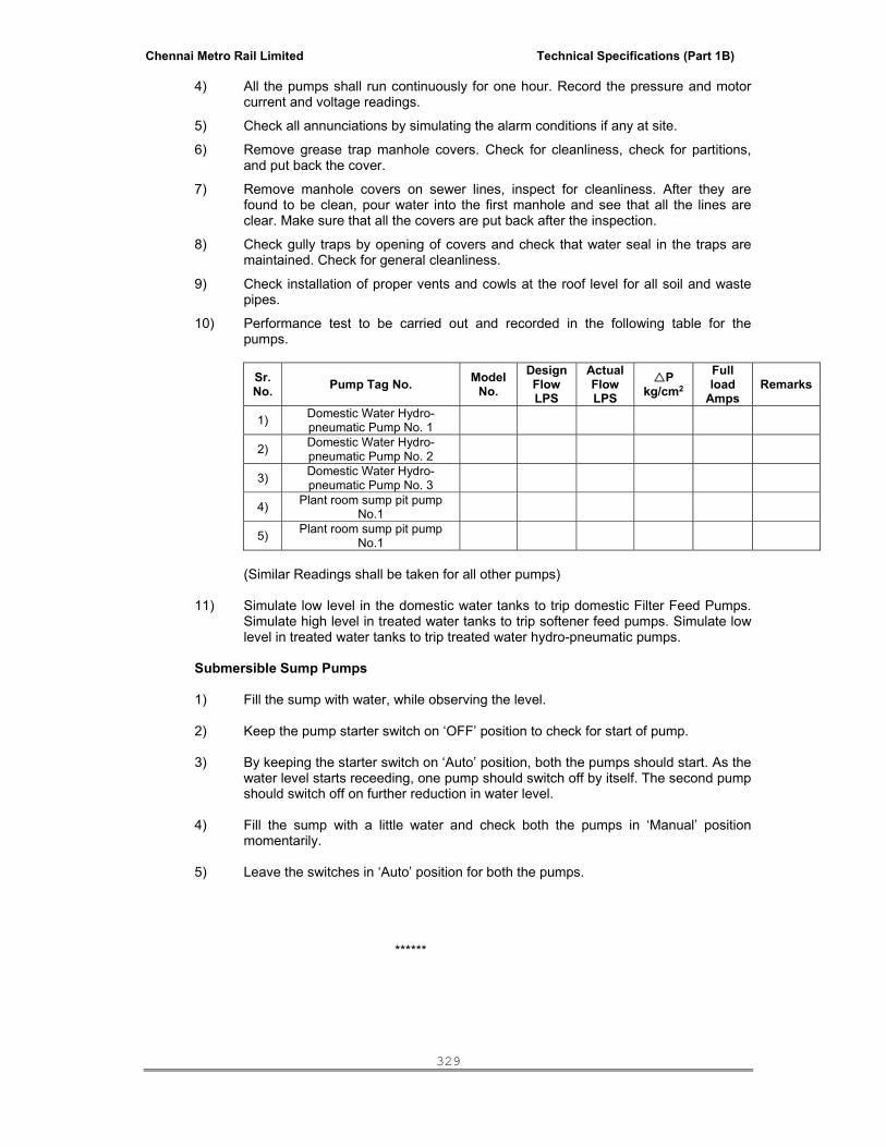
Chennai Metro Rail Limited Technical Specifications (Part 1B)
329
4) All the pumps shall run continuously for one hour. Record the pressure and motor current and voltage readings.
5) Check all annunciations by simulating the alarm conditions if any at site.
6) Remove grease trap manhole covers. Check for cleanliness, check for partitions, and put back the cover.
7) Remove manhole covers on sewer lines, inspect for cleanliness. After they are found to be clean, pour water into the first manhole and see that all the lines are clear. Make sure that all the covers are put back after the inspection.
8) Check gully traps by opening of covers and check that water seal in the traps are maintained. Check for general cleanliness.
9) Check installation of proper vents and cowls at the roof level for all soil and waste pipes.
10) Performance test to be carried out and recorded in the following table for the pumps.
Sr.No. Pump Tag No. Model
No. Design Flow LPS
Actual Flow LPS
P kg/cm2
Full load
Amps Remarks
1) Domestic Water Hydro-pneumatic Pump No. 1
2) Domestic Water Hydro-pneumatic Pump No. 2
3) Domestic Water Hydro-pneumatic Pump No. 3
4) Plant room sump pit pump No.1
5) Plant room sump pit pump No.1
(Similar Readings shall be taken for all other pumps)
11) Simulate low level in the domestic water tanks to trip domestic Filter Feed Pumps.
Simulate high level in treated water tanks to trip softener feed pumps. Simulate low level in treated water tanks to trip treated water hydro-pneumatic pumps.
Submersible Sump Pumps
1) Fill the sump with water, while observing the level. 2) Keep the pump starter switch on ‘OFF’ position to check for start of pump. 3) By keeping the starter switch on ‘Auto’ position, both the pumps should start. As the
water level starts receeding, one pump should switch off by itself. The second pump should switch off on further reduction in water level.
4) Fill the sump with a little water and check both the pumps in ‘Manual’ position
momentarily. 5) Leave the switches in ‘Auto’ position for both the pumps.
******

Chennai Metro Rail Limited Technical Specifications (Part 1B)
330
INTERIOR WORKS
TECHNICAL SPECIFICATIONS
TECHNICAL SPECIFICATION FOR WOOD WORKS 1.00 SCOPE This specification covers the general requirements for woodworks. 2.00 GENERAL REQUIREMENTS 2.01 The contractor shall furnish all materials, labour, operations, equipment, tools and plants,
scaffolding and incidental necessary and required for the completion of all carpentry and joinery work as called for in the drawings and Bills of Quantities.
2.02 The Contractor shall strictly follow, at all stages of work, the stipulations contained in the
Indian Standard Safety Code and the provisions of the Safety Rules as specified in the General Conditions of the Contract for ensuring safety of men and materials.
2.03 The Carpentry and joinery work shall include the provision of fixing of fastening devices and
hardware in accordance with the drawings and attached hardware schedule. Hardware and other materials will be supplied by the contractor after obtaining prior approval of the Architect of samples for each item of hardware.
2.04 Any approval, instructions, permission, checking, review etc. whatsoever by the Architect
shall not relieve the Contractor of his responsibility and obligation regarding adequacy, correctness, completeness, safety, strength, workmanship etc.
3.00 CODES AND STANDARDS 3.01 All standards, specifications, acts, and codes of practice referred to herein
shall be the latest editions including all applicable official amendments and revisions.
3.02 List of certain important Indian Standards, Acts and Codes applicable to this work is given below. However, the applicable standards and 0codes shall be as per but not limited to the list given below:
IS : 205 Non-ferrous metal butt hinges IS : 281 Mild steel sliding door bolts for use with pad locks
IS : 287 Permissible moisture content for timber used for different purposes
IS : 303 Plywood for general purposes IS : 848 Synthetic resin adhesives for plywood.
IS : 883 Code of practice for design of structural timber in building
IS : 1003 Timber paneled and glazed shutters IS : 1141 Seasoning of timber - Code of practice IS : 1328 Veneered decorative plywood. IS : 1659 Block boards.

Chennai Metro Rail Limited Technical Specifications (Part 1B)
331
IS : 2202 Wooden flush door shutters IS : 2835 Flat transparent sheet glass.
IS : 3087 Wooden particle boards (medium density) for general purposes
IS : 3097 Veneered particle boards. IS : 3809 Fire resistant test for structures IS : 4021 Timber door, window and ventilator frames 4.00 SAMPLES AND SHOP DRAWINGS The contractor shall, before proceeding with the work, submit to the Architect for his approval
complete samples of the various materials including hardware and fastening devices and shop drawings and large scale details covering all joinery works.
5.00 MATERIALS 5.01 Timber
Timber used shall be of type as stated in the Schedule and of best quality. All timber shall be of natural growth and uniform in texture and shall be well and properly seasoned. It shall be free from large, loose, dead, or cluster of knots, waves, injurious open shakes, borer holes, rot, decay, knots, discolouration, soft or spongy spots, hollow pockets with or centre heart and all other defects and blemishes. Timber shall conform to IS 883. The seasoning of timber shall be as laid down in IS : 1141.
5.02 Teak wood
Teak should be from the forests of Dandeli and Mysore in Karnataka, Malabar in Kerala, Ballarshah in MP, Bulsar in Gujarat. It shall have uniform colour reasonably straight grains and shall be free from large loose dead knots cracks, shakes, warp, twists, bends bore holes, sap wood. For first class no individual hard and sound knot shall be more than 1 Sq.cm and the aggregate area of all knots shall not exceed 1/2% the area of piece and for second class 1.5 Sq.cm and 2% respectively. It shall be close grained and there shall not be less than 2 growth rings per cm width. The wood shall be well seasoned. It shall be considered well seasoned if its moisture content does not exceed the limits as per IS 287. The moisture content shall be determined as per IS 287. Unless otherwise specified tolerance for door and window frames and shutters should not exceed provisions in IS 4021 & IS 1003 (part I & II).
a) Frames 14% b) Planking, shutters etc. 12%
5.03 Malaysian Sal
Malaysian Sal are wood that are not classified as teak wood, honey wood, nandi and mathi
wood. It shall have uniform colour, reasonably straight grains and shall be generally free from large loose deadknots, cracks, shakes, warp, twists, bends, bore holes, sap wood. No individual hard and sound knot shall be more than 1.5 Sq.cm and the aggregate area of all knots shall not exceed 2% of the area of piece. It shall be close grained and there shall not be less than 2 rings per cm width. The wood shall be well seasoned. It shall be considered well seasoned if its moisture content does not exceed the limits as per IS 287. The moisture content shall be determined as per IS

Chennai Metro Rail Limited Technical Specifications (Part 1B)
332
287. Unless otherwise specified tolerance for door and window frames and shutters should not exceed provisions in IS 4021 & 1003 - Part I & II.
5.04 Glass
All glass shall be of superior quality from approved manufacturers like Saint Gobain, Guardian, Pilkington or approved equivalent, having uniform refractive index and free from flaws, speaks and bubbles. Sheet glass for glazing and framing purposes shall conform to IS : 2835 latest edition. The glass shall be brought to site in the original packing from the manufacturer and cut to size at site. The cut edges shall be straight and free from chips, spalls or any other damages. Wherever clear sheet glass is specified, it shall be flat drawn sheet glass and shall be atleast 4 mm thick or as specified. Where wire glass is mentioned, it shall be thick rolled glass with centrally embedded wire mesh or Georgian type. Where obscure glass is mentioned it shall have a cast surface on one side. The Contractor shall submit samples of glass for prior approval of the Architect.
5.05 Putty In general, the putty shall conform to IS : 420 latest edition. The putty shall be of best quality from approved manufacturer. It shall be brought to site in the manufacturer’s original packing. Quick setting putty shall be used for windows and sashes except when glare reducing glass is used where it shall be of non-setting type.
6.00 DOORS, WINDOWS AND VENTILATORS 6.01 Doors, windows and ventilators etc. shall be in accordance with the drawing in every detail and
all joiner’s work shall be accurately set out, framed and finished in a proper workman like manner. Frames of doors, windows and ventilators, shutter styles and rails shall be of best solid wood of quality specified in the schedule of quantities. The scantlings shall be accurately planed smooth. Rebates, roundings and mouldings shall be made as shown on the drawings. Patching or plugging of any kind shall not be allowed.
Joints shall be simple, neat and strong. Framed joints shall be coated with suitable adhesive like glue or synthetic resin before the frames are put together. All mortice and tenon joints shall fit in fully and accurately without wedging or filling. The joints shall be pinned with hard wood or bamboo pins of 10 mm to 12 mm dia. or rust resisting star shaped metal pins of 8 mm diameter. All portions of timber abutting against or embedded in masonry or concrete shall be treated against termites by giving a coat of an approved wood preservative, for which no extra cost will be paid. Putty shall not be used to cover any defects. Unless otherwise specified, all door frames shall have six holdfasts. Holdfasts shall be provided to the ventilators if directed. Size of holdfasts shall be 400 mm x 40 mm x 5 mm M.S. flat bent to shape with fish tail and shall be fixed to frame with sufficient number of screws as directed. When door/window frames are to be fixed to RCC column or RCC wall, holdfasts shall be substituted by suitable arrangements such as coach screws, rawl bolts/grip bolts etc. to secure frames to RCC column or RCC wall as directed by the Architect. The frame shall be fixed only after getting the approval of the Architect.
6.02 Fire Resistance Door
The fire resistance door one hour fire rated or as specified shall be provided. The fire rating to doors shall conform to PS 47648 and IS 3809 and as approved by the Architect.

Chennai Metro Rail Limited Technical Specifications (Part 1B)
333
6.03 Toilet Doors
a) External Doors
Laminate shall be provided on inner face and decorative veneer shall be provided on outer face of door shutters unless otherwise specified in the Bill of Quantities and all as per manufacturer specifications including necessary finishing and fittings etc.
b) Internal doors
Laminate shall be provided on inner face and on outer face of door shutters unless otherwise specified in the Bill of Quantities and all as per manufacturer specifications including necessary finishing and fittings etc.
6.04 Frames These shall be cut and planed from first class timber of respective kind and of sizes as stated in the Schedule of Quantities or as detailed on the drawings, in the case of main frames as well as sub-frames.
6.05 Architraves
Architraves shall be cut and planed from best quality seasoned timber to sizes as shown in the drawings and fixed to the door or window frames with wood screws. Screw heads shall be sunk into frames. The side abutting the frame shall be finished with a coat of wood primer.
6.06 Interior door shutters
a) Flush shutters
Interior wood door shutters, unless otherwise noted or specified, shall of thickness as in drawings and made of phenol formal-dehyde synthetic resin thermo pressed flush shutters, teak veneered face on both faces. The shutters shall conform to IS:2202 (Part-I). Shutter make shall be approved by the Architect.
The solid core shall be wood laminate prepared from battens of well seasoned and
treated good quality wood having straight grains. The battens shall be of uniform size of about 2.5 cm width. These shall be properly glued and machine pressed together , with grains of each piece reversed from that of adjoining one. The Longitudinal joints of the battens shall be staggered and no piece shall be less than 50 cm. in length. Alternatively, the core shall be of solid teak particle board. Edges of the core shall be lipped internally with first class teak wood battens of 4 cm. minimum depth, glued and machine pressed along with the core.
The core surface shall then have two or three veneers firmly glued on each face. The
first veneer (called cross band) shall be laid with its grains at right angles to those of the core and the second and the third veneers with their grains parallel to those of the core. The under veneers shall be of good quality, durable and well seasoned wood. The face veneers shall be of minimum 1 mm thickness and of well matched and seasoned first class teak, laid along with grains of the core battens. The combined thickness of all the veneers on each face shall not be less than 4 mm. Thermosetting synthetic resin conforming to I.S. 303 or moisture-proof plywood grade M.P.F.I. shall be used in manufacture. All doors shall have external lipping alround 6 0 to 10 mm thick in addition to internal lipping.
Block boards and ply for various items of work called for shall be of approved make.
Unless otherwise shown all block boards and ply shall be teak veneered faced on both faces.

Chennai Metro Rail Limited Technical Specifications (Part 1B)
334
Samples of flush doors, block boards, etc., shall be submitted to the Architect for his approval and all shutters, etc., to be used in the work shall conform to the approved sample in all respects.
(b) Panelled Shutters
i) The thickness of the panels shall be 15 mm for 25 mm shutters and 20 mm
for shutters of larger thickness. The edges of the panels shall be tapered symmetrically on all the sides for insertion into the styles and rails. The depth of rebate in frames for housing the shutters shall in all cases be 1.25 cm and the rebate in shutters, for closing, in double leaf shutter doors, and windows shall not be less than 2 cm. The edges of styles and rails all round the panels shall be moulded, rounded or chamfered on both faces of the shutter as directed by the Architect.
iii) Factory made, kiln seasoned and chemically treated panelled shutters - The
thickness and quality of wood of the shutters 0shall be as indicated in the item. Styles and rails of teak wood and panels made of 12 mm thick teak veneered particle board or similar material bonded with phenol formaldehyde synthetic resin adhesive conforming to IS : 3097 shall be used.
6.07 Steel Doors:
Hollow metal fire door fully flush type of 46 mm thick Pressed Galvanized steel Double leaf of specified size & shape (General (GD) series) confirming to IS 3614 / equivalent BS consists of frame, shutter, infill and finish as detailed below and conforming to IS 277 or equivalent BS.
Door frame shall be single rebate profile of size 100 x 57 mm with bending radius of 1.00 mm having 1.25mm thick galvanized steel sheet (18 gauge ) with steel door shutter of 46 mm thick fully flush, double skin door shall manufactured from 0.80 mm thick galvanized steel sheet (22 gauge). The infill material shall be resin bonded honey comb paper with thermal insulation. Door frames and shutter shall be finished with etched primer coating, stoved zinc phosphate primer and thermosetting polyurethane aliphatic grade paint (35 micron DFT) of approved colour. The following allied works shall be part of steel door specifications:
a. Grouting the frame with cement slurry including providing necessary Hilti /
equivalent make Elastic fire stop Sealant - code no CP 601 & 601S at the Joints between Wall & Frame to the required thickness and to be applied by using Dispenser tool CS 201 P1.as per manufacture's specification etc complete and as directed.
b. Base plates of 3mm thick for all joints of frames with provision of anchor bolt fixing
to wall / RC surface, reinforcement pad for fixing of door closers, factory finish pre-punched cut outs to receive hardwares and iron mongery.
c. All necessary door hardware provisions such as hinges, lock, handle etc. shall be
considered and door shall be manufactured accordingly. 7.00 PANELLING FOR WALL LINING AND PARTITION
The boarding for wall lining shall be of commercial plywood, black board, plywood with teak veneer, laminate or any other materials as directed; fixed on to the frame. The boarding shall be of sizes shown in the drawing or as directed. In case of partitions, the facing materials like plywood with approved teak veneers, or formica, or any other material as directed shall be fixed.
8.00 INSTALLATION

Chennai Metro Rail Limited Technical Specifications (Part 1B)
335
All timber for joinery work or wrought form work shall be of best Indian Teakwood unless otherwise specified and or specified quality, carefully selected free from sap and subject to inspection and approved before delivery. All teakwood to be used in this work shall be seasoned in an approved manner.
All workmanship pertaining to wood work shall be of best standard and all joinery work shall fit freely and without wedging or filling and of the kind directed by the Architect. Wood work in frames shall be wrought and all frames joints shall be put together with white lead and pinned with hard wood pins. All exposed faces of joinery shall be thoroughly planed. Jointing shall be by means of mortice and tenon, dovetailed joints or as directed by the Architect.
The joinery work shall be framed and put together immediately but not to be wedged up until
required for fixing. The approval of the Architect shall be obtained before any primer coat is applied.
The whole of joinery to be finished to the dimensions and sizes indicated in the drawings are
subject to a tolerance to 1.50 mm of each planed face, but no allowance shall be given to flush doors, shutters, ply and other manufactured board etc.
All block boards etc. shall correspond to respective IS specifications. Flush doors shall
correspond to relevant IS specifications. Samples of all black board, plywood, flush doors, etc. Shall be got approved by the Architect before placing order. All such items shall be of standard manufacture of reputed quality. Unless otherwise specified, all flush shutters shall be teak veneered on both sides. All flush shutters shall be of solid core and shall be provided with teakwood external lipping.
If after execution any shrinkage or bad workmanship is found, the Contractor shall forthwith
replace or refix the same at his own cost, all as directed by the Architect. Rate quoted shall include for all framing, usual waste and cuttings and no extra rates or claims
will be entertained on this account. The rate for wood work shall include the cost of all sawing, planning, jointing, framing, labour
and materials for raising and fixing and all workmanship and fixing and supplying of all strips, bolts, nails, trenails, spikes, keys, wedges, pins, screws etc. necessary for the framing as per specification and drawings. Edges of the beams, joists, posts, frames etc. shall be rounded, moulded or chamfered as directed without extra charges.
The Contractors shall be responsible to deliver all items at site of work. The Contractor will
submit a programme of work in such a way that requirements for each floor commencing from ground floor is completed before the requirement of the next floor and arrange to have them fixed in position as the General Builders work progresses.
Timber in contact with masonry or concrete shall be treated with solignum paint or any
approved anti-termite treatment before fixing. The Contractor will be making necessary holes in concrete and masonry for fixing in position
and grouting. The Contractor will be responsible for the proper fixing of partitions true to plumb and alignment until completion and grouting pockets with cement concrete and make good affected portions without claim to any extra.
The iron monger fittings shall be of heavy type cast brass oxidised and of approved
manufacture. Samples of all ironmongery items shall be got approved by the Architect prior to procurement.
9.00 HARDWARE FITTINGS All hardware fittings and fixtures shall be made with structural properties to sustain safety and
withstand strains and stresses to which they are normally subjected to such as opening and closing, wind pressure etc. The fittings shall generally conform to relevant specifications.
They shall be made true, clean, straight, with sharply defined profiles and unless otherwise
shown or specified, with true smooth surfaces and edges, free from defects, screw holes shall be counter sunk to suit the head of wood screws.

Chennai Metro Rail Limited Technical Specifications (Part 1B)
336
The metal shall be treated with finish as specified in the Bill of Quantities. 9.01 Mortice Lock for Euro Profile Cylinder, S S Ball Bearing Hinges :
These shall be treated with finish as specified in the Bill of Quantities. S.S Butt hinges shall be manufactured from S.S sheets (304 grade) of approved gauges.
Hinges shall be finished as specified in the respective items. The size of butt hinges shall be taken as length of the hinge.
9.02 Sliding bolts/Latches
These shall be of Stainless Steel or as specified and shall be capable of smooth sliding action.
These shall be finished as specified. The size of latch shall be taken as the length of the bolt catch.
9.03 SS Lever Handles. These shall be as described in the Bill of Quantities and finished as specified.
10.00 PRESERVATIVE TREATMENT All wood work in contact with masonry shall be painted with approved asphalt or bitumen paint
before placing. Care shall be taken to keep exposed faces clear from tar, etc. Tarfelt shall be used to isolate wood from masonry wherever practically possible. All concealed wood members in ceiling, partitions, cabinet work, etc., shall be treated fully and liberally with solignum before placing in position.
11.00 MODE OF MEASUREMENT The method of measurement for various items in the tender shall be generally in accordance
with the IS : 1200 subject to the following:
1) All work shall be measured net as fixed. No extra measurement will be given for shape, joints, splayed, meeting stiles of doors and windows and shall be measured in unit of square metre. Door frames shall be in cubic metre, if measured separately.
2) Area over one face inclusive of exposed frame thickness (excluding width of cover
mould) shall be measured in case of doors, windows and ventilators when frames are included in the item. Portions embedded in masonry or flooring shall not be measured.
12.0 PRE-LAMINATED PARTICLE BOARD (PLPB)
Particle Board is a panel product. It is manufactured by gluing particles of wood. Particles are flakes, shavings and splinters produced by cutting or breaking. Made from recycled agricultural fibre, it is coloured with non-toxic, water based dyes. The texture you see or feel comes from the fibre content, not found in other similar products. For the production of particle boards a well planned manufacturing process and quality inspection is needed.
Prelaminated melamine faced 3-layered particle board. The plain particle boards are made from plantation hardwood timber agro waste. The same are laminated with melamine impregnated high grammage imported paper on either side. Green lamiboard is an eco-friendly alternative to conventional timber, plywood and block board. Apart from IS:12823 Grade II. It also conforms to internal standards.

Chennai Metro Rail Limited Technical Specifications (Part 1B)
337
Technical Specifications:
SL. No. Properties Unit
Specified Values as per IS:12823-
1990 1 Density Kg/M3 500 – 900
2 Moisture Content % >5,<15
3 Water Absorption
a) 2 hrs.
b) 24 hrs.
%
%
15 (Max.)
30 (Max.)
4 Thickness swelling in two hours % 8 (Max.)
5 Modulus of Rupture N/mm2 11 (Min.)
6 Tensile Strength perpendicular to surface
N/mm2 0.3 (min.)
7 Screw withdrawal strength
a) Face
b) Edge
N
N
1250 (Min.)
750 (Min.)
8 Resistance to steam Should pass test
9 Resistance to Cracking Should pass test
10 Resistance to cigarette burns Should pass test
11 Resistance to stain Should pass test
12 Abrasion resistance Rev 450 (Min.)
13.00 Prelaminated Medium Density Fibre Board (MDFB) MDF is a type of fibreboard made from wood or lignocellulosic material refined into fibres and reconstituted with a resin binder (glue) carrying elevated temperatures. MDF has a homogenous structure with uniform texture and properties throughout. It is easier to machine than natural wood and can be laminated and shaped very evenly and smoothly.
Pre laminated MDF Boards is melamine faced medium density fibre board having a dense, compact and homogenous construction. Imported base papers impregnated in Melamine Resin are laminated on either side of the medium density fibre board. The product conforms to IS: 14587-1998
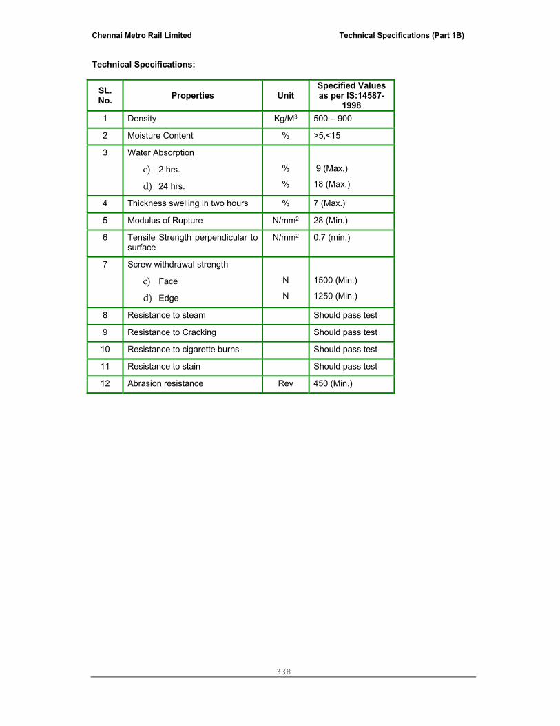
Chennai Metro Rail Limited Technical Specifications (Part 1B)
338
Technical Specifications:
SL. No. Properties Unit
Specified Values as per IS:14587-
1998 1 Density Kg/M3 500 – 900
2 Moisture Content % >5,<15
3 Water Absorption
c) 2 hrs.
d) 24 hrs.
%
%
9 (Max.)
18 (Max.)
4 Thickness swelling in two hours % 7 (Max.)
5 Modulus of Rupture N/mm2 28 (Min.)
6 Tensile Strength perpendicular to surface
N/mm2 0.7 (min.)
7 Screw withdrawal strength
c) Face
d) Edge
N
N
1500 (Min.)
1250 (Min.)
8 Resistance to steam Should pass test
9 Resistance to Cracking Should pass test
10 Resistance to cigarette burns Should pass test
11 Resistance to stain Should pass test
12 Abrasion resistance Rev 450 (Min.)

Chennai Metro Rail Limited Technical Specifications (Part 1B)
339
TECHNICAL SPECIFICATION FOR PAINTING WORKS
TABLE OF CONTENTS 1.0 Scope 2.0 General Requirements 3.0 Codes and Standards 4.0 Materials 5.0 Storage 6.0 Preparation of Surface 7.0 Application 8.0 Protection 9.0 Cleaning up 10.0 Acceptance Criteria 11.0 Mode of Measurements

Chennai Metro Rail Limited Technical Specifications (Part 1B)
340
1.00 SCOPE
This specification covers the general requirements for painting, white washing, etc. of both interior and exterior surfaces of masonry, concrete, plaster and all carpentry works, structural and miscellaneous steel works. This also includes furnishing of all materials, labour, scaffolding, tools and appliances etc.
2.00 GENERAL REQUIREMENTS 2.01 Before commencing painting, the Contractor shall obtain the approval of the Architect in
writing regarding the scheduling of work to minimize damage, disfiguration or staining by other trades. He shall also undertake necessary precautions to prevent damage, disfiguration or staining of other trades or other installations.
2.02 Contractor shall protect not only his own work at all times but also all the adjacent work and materials by suitable covering, protection or other methods acceptable to the Architect during progress of painting. It is the responsibility of the contractor upon completion of painting work to remove all paint and varnish spots from floors, walls, glass panes and other surfaces and restore them to the original conditions. The work generally to be touched up shall be attended to after all other workmen have left. All accumulated material, rubbish etc. have to be cleared and the premises left in clean, orderly and acceptable conditions.
2.03 Contractor shall provide scaffolding wherever necessary erected on double supports tied together by horizontals, no ballies, bamboos or planks shall rest on or touch the surface which is being painted. Contractor is deemed to have considered the following while tendering and no extra claim on account of these will be entertained.
g) Supplying the paint and other materials required of approved colour and brand.
h) Preparing the surface to be painted i) Providing and erecting scaffolding and removing the same after completion of the
work. j) Lifting of materials to any height and painting at all levels.
k) Application of paint as per the specification and to Manufacturer’s instructions.
l) Curing, protecting the painted surface, adjacent work and thoroughly cleaning of the
premises. 2.04 The Contractor shall furnish all skilled and unskilled labour, plant, equipment, scaffolding, all
materials etc. required for complete execution of the work in accordance with the drawings and as described herein and / or as directed by the Architect. 2.05 The Contractor shall strictly follow, at all stages of work, the stipulations contained
in the Indian Standard Safety Code and the provisions of the Safety Rules as specified in the General Conditions of the Contract for ensuring safety of men and materials.
2.06 Any approval, instructions, permission, checking, review etc. whatsoever by the
Architect shall not relieve the Contractor of his responsibility and obligation regarding adequacy, correctness, completeness, safety, strength, workmanship etc.
3.00 CODES AND STANDARDS 3.01 All standards, specifications, acts, and codes of practice referred to herein shall be the latest
editions including all applicable official amendments and revisions.
Chennai Metro Rail Limited Technical Specifications (Part 1B)
341
3.02 List of certain important Indian Standards, Acts and Codes applicable to this work is given below. However, the applicable standards and codes shall be as per but not limited to the list given below:
IS : 157 : Chemical resistant paint. IS : 161 : Oil resistant paint IS : 162 : Ready mixed paint, brushing, fire resisting, silicate type for
use on wood, colour as required IS : 348 : French Polish IS : 423 : Plastic wood for joiners filter
IS : 427 : Distemper, dry, colour as required
IS : 428 : Distemper, oil emulsion, colour as required.
IS : 712 : Building limes
IS : 1200 : Method of measurement of building and civil Engineering works.
IS : 1477 : Code of practice for painting of ferrous metals and buildings
IS : 2074 : Ready mixed paint, air drying, red oxide – zinc chrome
priming. IS : 2922 : Specification for wooden tent mallets
IS : 2932 : Enamel, synthetic, exterior (a) undercoating (b) finishing
IS : 2933 : Enamel exterior (a) undercoating, (b) finishing IS : 5410 : Cement paint 4.00 MATERIALS
4.02 General Paint shall be ready mixed and of first quality of the approved brand and
manufacturer. The paint shall generally conform to the chemical composition and other characteristics laid down in the relevant Indian standard specification. Mixing of paint by the Contractor at site will not be allowed. However, in the case of selection of special shades and colours (not available standard shades) the Contractor shall mix different shades of ready mixed paints as per Manufacturer’s instructions and as directed by the Architect.
Materials shall be the highest grade products of well known approved
manufacturers and shall be delivered to the site in original sealed containers, bearing brand name, manufacturer’s name and colour shade, with labels intact and seals unbroken. All materials shall be subject to inspection and approval by the Architect. It is desired that materials of one manufacturer only shall be used as far as possible and paint of one shade be obtained from the same manufacturing batch. All paints shall be subjected to analysis from random samples taken at site from the painter’s bucket, if so desired by the Architect.

Chennai Metro Rail Limited Technical Specifications (Part 1B)
342
All unspecified materials shall be of the highest quality available and shall conform to the latest IS standards. All such materials shall be made by reputable recognized manufacturers and shall be approved by the Architect.
Any materials found not conforming to the relevant specification shall have to be
removed by the Contractor from the site at his own expenses. All colours shall be as per the painting schedule and tinting and matching shall be
done to the satisfaction of the Architect. In such cases, where samples are required, they shall be executed in advance with the specified materials for the approval of the Architect.
All primer coats shall be compatible to the material of the surface to be finished as
well as to the finishing coats to be applied. 4.02 Dry Distemper Dry distemper of required colour conforming to IS:427 and of approved brand and
manufacturer shall be used. The primer where used shall be cement primer or distemper primer. These shall be of same manufacturer as that of distemper.
4.03 Acrylic Emulsion Paint Shall be water based acrylic copolymer emulsion with rutile titanium dioxide and
other selected pigment and fungicide. It shall exhibit excellent adhesion to plaster and cement surface and shall resist deterioration by alkali salts. The paint film shall allow the moisture in wall to escape without pelling or blistering the paint. After it is dried, the paint should be able to withstand washing with mild soap and water without any deterioration in colour or without showing flaking, blistering or peeling.
4.04 SOFT SHEEN ENAMEL PAINT Soft sheen enamel paint - Satin Finish to walls of approved colour over a coat of
primer (cement Primer 34-200) including preparation of surface by thorough cleaning and free from grime, dust, grease, loose or flaking particles, hair cracks shall be filled, smoothen out the surface by using suitable emery paper of 320 grade followed by a coat of water based cement primer - ( 32-168 ) fully to give an even shade before painting.
5.00 STORAGE
The Contractor shall arrange for safe and proper storage of all materials and tools. Paints shall be kept covered at all times and mixing shall be done in suitable containers. All necessary precautions shall be taken by the Contractor to prevent fire.
6.00 PREPARATION OF SURFACE
6.01 Wood Work Pretruding timber fibre shall be removed and all holes shall be filled with teakwood
batten. the nail marks shall be covered with putty. The work shall then be sanded first with G/80 sand paper followed by G/120 or G/150 sand paper. Sanding should be taken up only when it can be followed immediately by painting.
6.02 Steel work
Chennai Metro Rail Limited Technical Specifications (Part 1B)
343
The surface shall be thoroughly cleaned sand prepared and / or rubbed with emery cloth if necessary to remove grease, mortar or any other foreign materials. In case of rusted surface, it shall be first cleaned with steel wire brushes till the corroded crust is removed. The cleaned surface shall be shiny and free from brush marks, patches, blisters and other irregularities. The surface thus finished shall be got approved before painting.
6.03 Masonry, concrete and plastered surface Concrete / masonry surface and cement plastered surfaces shall be thoroughly
cleaned of mortar droppings and other stickings. All loose scales and flakes shall be removed by rubbing with hessian cloth or sand papering. All holes shall be filled and the surface rubbed smooth to get evenness of the existing surface. The surface shall be free from all oil, grease, efflorescence, mildew, loose paint or other foreign and loose materials. Masonry cracks shall be cleaned out and patch filled with mortar similar to the original surface and uniformly textured. Where this type of resurfacing may lead to the finishing paint being different in shade from the original surfaces, the resurfaced area shall be treated with a minimum of one coat of cement primer and should be continued to the surrounding area for a distance of atleast 100mm.
Surfaces with mildew or efflorescence shall be treated as below: (a) Mildew All mildewed surfaces shall be treated with an approved fungicide such as
ammonia wash consisting of 7 gm. of copper carbonate dissolved in 80 ml liquor and diluted to 1 liter with water or 2.5 percent magnesium silica fluoride solution and allowed to dry thoroughly before paint is applied.
(b) Efflorescence All efflorescence shall be removed by scrubbing the affected surface with a
solution of mariatic acid and in water (1:6 to 1:8) and then washed fully with clear water and allowed to dry thoroughly.
Area to be distempered shall be applied with one coat of white chalk solution mixed with required quantity of glue or plaster of paris and shall be sand papered before distempering. The area to be cement painted shall be wetted by sprinkling of water with fine spray. The surface shall be sprayed several times with a few minutes intervals between each spraying to allow the moisture to seek into the surface.
6.04 Iron and Steel Surface
Surface of steel work to be painted shall be thoroughly cleaned of all grease, oil dirt, rust, foreign matter like cement splashings, etc. by suitable solvent and mild rubbing with abrasive paper / hand scrapping to the full satisfaction of the Architect. Clearing with solvents / scraping shall be limited to the affected areas only. All galvanized iron surfaces shall be pretreated with a compatible primer according to the manufacturer’s direction. Any abrasion in shop coat shall be touched up with the same quality of paint as the original coat.
6.05 Before starting the work, the Contractor shall obtain the approval of the Architect
regarding the soundness and readiness of the surface to be painted on.

Chennai Metro Rail Limited Technical Specifications (Part 1B)
344
7.00 APPLICATION
7.01 General Before the commencement of the work the Contractor shall provide sample panels of painting at his own cost for the approval of the Architect to enable him to keep an accurate check on the materials supplied and final shade to be painted. It is however the express responsibility of the Contractor to provide any deviations and defects shall have to be rectified by the Contractor at his own cost. The method of application shall be as recommended by the manufacturer. In case of selection of a special shade and colour (not available in standard shades) the Contractor shall prepare test panels in different shades of minimum size 1 metre square as instructed by the Architect and obtain his approval prior to applications of the finishing paints. Proper tools and implements shall be used. Scaffolding if used shall be independent of the surface to be painted to avoid shade differences of the freshly repaired anchor holes. Painting shall be done by skilled labour in a workman like manner. All materials shall be evenly applied, so as to be free of sags, runs, crawls or other defects. All coats shall be of proper consistency. In case of application by brush, no brush marks shall be visible. The brushes shall be clean and in good condition before application of the paint.
All priming undercoats for painting shall be applied by brush only. Roller and spray equipment, etc., shall not be used.
The cleaned surface shall be dusted and a primer shall be applied.
One shop coat of red oxide or zinc chromate primer or as specified shall be given to all iron surfaces. Painting work on steel and iron surface shall conform to IS : 1477 (Part I and II).
All primer coats shall be compatible to the material of the surface to be finished as well as to the finishing coat to be applied.
No work shall be done under conditions that are unsuitable for the production of good
results. No painting shall be done when plastering is in progress or is drying. Paint which seals the surfaces to moisture shall be applied only after the moisture on and below the surface has dried out.
All coats shall be thoroughly dry before being sand papered or before the succeeding coat is applied. Coats of painting as specified are intended to cover surfaces perfectly. In case the surface is not covered properly by applying the specified number of coats, further coats shall be applied by the Contractor when so directed by the Architect at no extra cost. All primers and under coats shall be tinted to approximate the colour of the finishing coats. Finished coats shall be of exact colour and shade as approved samples and all finish shall be uniform in colour and texture. All parts of mouldings and ornaments shall be left clean and true to finish.
Stopping and filling carpentry work should be done when the primer is just dry. For deep scratches, holes etc. stopping shall be done with putty of plastic wood (IS 423). Putty can be white lead with linseed oil base or synthetic metal putty.
For all minor scratches and rough surfaces, like flush door’s faces filling made out of one part of white lead, two parts of whiting (powdered chalk) mixed and kneaded in double boiled linseed oil shall be evenly applied and rubbed down with G/220 or G/240 sand paper after allowing it to dry overnight.
Painting shall be done by skilled labourers in a workmanlike manner. All materials shall be evenly applied so as to be free from sags, runs, crawls, or other defects. All coats shall be of proper consistency and shall be well brushed out, so that no brush marks are visible,

Chennai Metro Rail Limited Technical Specifications (Part 1B)
345
except varnish and enamels which shall be uniformly flowed on. The brushes shall be clean and in good condition before application of paint. No work shall be done under conditions that are unsuitable for production of good results.
The undercoating should be nearest to the specified colour of the finishing coat. Ready
mixed synthetic enamel paint or fill paint may be used for the undercoat. The undercoat shall be uniform and free of all brush marks.
Undercoats should be completely dry before finishing coat is taken up. For synthetic
enamels overnight and for oil paints, a whole day shall be left between undercoat and finishing coat. The undercoat shall then be rubbed with G/240 sand paper and dusted clean. The finishing coat of approved paint shall then be applied. If the surface is not satisfactory additional finish coats shall be applied at no extra cost. The paints shall be applied with bristle brushes and not horse hair ones all be stipplied with a stippling brush.
7.02 Dry Distemper
New plastered surface shall be allowed to dry for atleast two months. New lime or lime plastered surface shall be washed with a solution of 1 part of vinegar to 12 parts water or 1:50 sulphuric acid solution and left for 24 hours after which the wall shall be thoroughly washed with clean water. For cement plastered surface, the surface shall be washed with a solution of 100 gms of zinc sulphate to 1 litre of water and then allowed to dry.
Dry distempering shall be done as per manufacturer’s instruction. In applying the distempers, the brush should first be applied horizontally and immediately crossed off perpendicularly. Brushing shall not be continued too long as otherwise brush marks may result.
7.03 Acrylic Emulsion Paint
Acrylic emulsion paint, shall be brought in original containers and in sealed tins.
After allowing 24 hours for drying of primer coat specified approved quality paint shall be applied evenly and smoothly. If required a filler putty coating may be given to give smooth finish. Each coat shall be allowed to dry out thoroughly and then lightly rubbed down with sand paper and cleaned of dust before the next coat is applied. Number of coats shall be as specified in the item and if however the finish of the surface is not uniform additional coats as required shall be applied to get good and uniform finish at no extra cost. After completion no hair marks from the brush or clogging of paint puddles in the corners of panel angles of mouldings shall be left on the work.
When the final coat is applied, if directed, the surface shall be rolled with a roller or if directed it shall be stipplied with a stippling brush.
Lime gauged cement plastered surfaces shall not be painted for at least one month after plastering. All sample patch shall be painted to check alkali reaction if so desired by the Architect. Painting shall be strictly as per manufacturer’s specification.
8.00 PROTECTION
Contractor shall provide and use sufficient number of drop clothes, covers, tarpaulins and other screens to protect adjacent surfaces and shall remove all splatter and stains from such surfaces. The contractor shall also protect his own work.

Chennai Metro Rail Limited Technical Specifications (Part 1B)
346
Furniture and other movable objects, equipment, fittings and accessories shall be moved,
protected and replaced upon completion of the painting work. All stationary items of equipment shall be well covered so that no paint can fall on them. Work finished by other agencies shall be well protected. All protection shall be as per instruction of the Architect.
9.00 CLEANING UP The Contractor shall upon completion of painting etc. remove all marks and make good
surfaces, where paint has spilled, splashed or splattered, including all equipment, fixtures, glass furniture, fittings, etc. to the satisfaction of the Architect.
10.00 ACCEPTANCE CRITERIA 10.01 All painted surfaces shall be uniform and pleasing the appearance.
10.02 The colour, texture etc. shall match exactly with approved samples. 10.03 All stains, splashes and splatters of paint shall be removed from surrounding
surfaces. 11.00 MODE OF MEASUREMENT
Unless noted otherwise in the bills of quantities, the method of measurement for various items shall be generally in accordance with IS 1200.
*****

Chennai Metro Rail Limited Technical Specifications (Part 1B)
347
TECHNICAL SPECIFICATION FOR
FLOORING AND DADOING WORKS 1.00 SCOPE
1.01 This specification covers the general requirements for flooring and dadoing of various types of finishes including supplying, installation, finishing, curing, testing, protecting, maintaining until handing over.
2.00 GENERAL REQUIREMENTS
2.01 The Contractor shall furnish all skilled and unskilled labour, plant, equipment, scaffolding, materials etc., required for complete execution of the work in accordance with the drawings and as described herein and / or as directed by the Engineer.
2.02 The Contractor shall follow all safety requirements / rules during execution of the work.
2.03 The Contractor should have adequate experience in execution of such works.
Alternatively, he should engage specialized agency for executing the work after obtaining approval from the Engineer.
2.04 All works shall be carried out as per relevant Indian Standard Specifications, as per
the instructions of manufacturer and as directed by Engineer. The Contractor shall carryout all works including preparation of base, chipping extra concrete, roughening of surface and skin removing, cleaning, screeding, levelling, curing, protecting the slab / tile by using pop over plastic sheet etc.
2.05 The commencement, scheduling and sequence of the finishing works shall be
planned in details and must be specifically approved by the Engineer, keeping in view the activities of other agencies working in the area. However, the Contractor shall remain fully responsible for all normal precautions and vigilance to prevent and damage whatsoever till handing over to the Owner.
2.06 Only approved make, colour, size of tiles / slabs to form any pattern in combination
of any specified colour shall be used. 3.00 CODES AND STANDARDS
3.01 IS Codes
Some of the important applicable Indian Codes for this section are listed below. Latest editions of these codes shall be followed:
IS : 1237 - Cement concrete flooring tiles
IS : 4457 - Ceramic unglazed vitreous acid resisting tiles
IS : 5491 - Code of practice for laying of in-situ Granolithic concrete flooring topping
IS : 13753 - Dust pressed ceramic tiles with water absorption of E 10%

Chennai Metro Rail Limited Technical Specifications (Part 1B)
348
IS : 13755 - Dust pressed ceramic tiles with water absorption 3% of E 6% (Group B II.a)
4.00 MATERIALS
4.01 Cement : Ordinary Portland cement of 43 Grade conforming to IS:8112 and as specified under concrete work to Technical Specification.
4.02 Coarse Aggregate : As specified under concrete works and conforming to
IS:383 4.03 Fine Aggregates : As specified under concrete works and conforming to
IS:383
4.04 Water : As specified under concrete works
4.05 Special Materials Materials required for individual finishing items are specified under respective
items. In general, all such materials shall be in accordance with the relevant IS Codes where applicable. In all cases these materials shall be of the best indigenous quality unless specified otherwise.
The materials for finishing items must be procured from well-reputed approved
specialized manufactures and on the basis of approval of samples by the Engineer. The materials shall be ordered, procured and stored well in advance to avoid possible delays to the construction programme.
6.0 STORAGE OF MATERIALS
Storage of cement, aggregates and water shall be as specified under concrete works. 6.0 BASE CONCRETE
6.01 The base concrete may be deposited as per specification and as directed. Before
placing the concrete the sub-base shall be properly wetted and well rammed. The concrete shall then be deposited between the forms where necessary, thoroughly compacted and the surface finished level with the top edges of the forms. The surface of base concrete shall be left rough to provide adequate bond for the topping. Two or three hours after the concrete has been laid in position, the surface shall be brushed with a hard brush to remove any scum or laitance and swept clean so that coarse aggregate is exposed.
7.00 WORKMANSHIP
7.01 Workers specially experienced in particular items of finishing work shall carry out the work. Where such workers are not readily available, experienced supervisors recommended by the manufacturer shall be engaged with the prior permission and based on approval of the Engineer. In particular cases, Engineer may desire the installation of finishing items by the manufacturer. This arrangement shall be made by the Contractor.
8.00 PREPARATION OF THE BASE SURFACE
8.02 For all types of flooring, skirting, dado, the base (base concrete / structural slab / masonry wall / concrete wall etc.) to receive the finish shall be adequately roughened, joints raked, thoroughly cleaned of all dirt, grease, loose particle, caked mortar droppings, and laitance, if any by scrubbing with coir or steel wire brush before the operation of laying the topping is started. Where the concrete is hardened so much that roughening the surface by wire brush is not possible, the entire surface shall be roughened by chipping or hacking and the skin removed.

Chennai Metro Rail Limited Technical Specifications (Part 1B)
349
The surface shall be thoroughly cleaned and soaked with water, atleast for twelve hours and the surplus water shall be removed by mopping immediately before the topping is laid in position.
The prepared surface has to be approved by the Engineer before commencing the finishing work.
9.00 GRANOLITHIC FLOORING
9.01 General
The work shall be carried out in accordance with Indian Standard Specification 5491 latest.
The flooring shall be of specified thickness and shall consist of CC 1:1.5:3
granolithic flooring. Floor finish shall be divided into suitable panels so as to reduce and avoid the risk of cracking. The granolithic flooring shall be laid with the specified strips in panels not exceeding 20 Sqm in plan. The screed strips shall be fixed on the base concrete dividing it into suitable panels not exceeding 20 Sqm in plan. The intermediate panels shall be filled in after one or two days. If glass or aluminium or other metal strips are provided for effective separation of panels, the topping may be laid in all the panels simultaneously or as specified.
9.02 Laying
e. Before the operation of laying the topping is started, the surface of base
concrete shall be prepared as described earlier, screed strips shall be fixed over the base as divided.
f. The flooring concrete shall be of using 6 to 10 mm graded crushed granite
stone. The ingredients shall be thoroughly mixed with sufficient water to obtain the required plasticity. The free water on the surface of the base shall be removed and a coat of cement slurry of the consistency of thick cream shall be brushed on the surface.
g. The prepared concrete shall be laid immediately after mixing on the fresh
grouted base. The concrete shall be spread evenly and levelled carefully and compacted. Then the surface shall be tested with the straight edge and mason’s spirit level to detect any inequalities in the surface. Low places shall be filled, humps removed and the whole surface again levelled. The layer shall be thoroughly compacted to the finished thickness by ramming and power trowelled and allowed to set. Just sufficient trowelling shall be made to give a level surface. The surface should not be over trowelled as excessive trowelling will bring the cement to the surface which shall be strictly avoided. When the initial set takes place further compaction by power trowelling shall be done and final trowelling shall be done well before the topping becomes too hard.
h. The surface shall be trowelled three times at intervals so as to produce a
uniform, hard and smooth surface. No mortar or cement will be allowed to be added in this process.
The screed strips should be removed the next day after the concrete has been deposited in the panels and the edges of panels shall be examined for any honeycombing or undulation which, if found, shall be repaired straight and smooth by cement mortar; if the intermediate panels are not to be filled the next day, the screed strips shall then be cleared and put back against the edge of panels till the concrete in the alternate panels is to be deposited. When the concrete is being deposited in the alternate panels the screed strips shall be removed. When the concrete is being compacted in new panels, care shall be taken to avoid damage to the panels already laid. When desired by the Engineer, the surface while still ‘green’ shall be intended by pressing strings.

Chennai Metro Rail Limited Technical Specifications (Part 1B)
350
The markings and forming a groove shall be of even size and depth, in straight lines and the panels shall be of uniform and symmetrical patterns.
9.03 Curing - As soon as the surface is hard enough, it shall be covered with sacking or
sand and kept continuously wet for a period of atleast one week.
9.05 Protection - The surface shall be protected with a layer of pop to a required thickness over a plastic sheet.
11.0 CERAMIC TILES
10.01 Types of Ceramic Tile
c) Glazed Ceramic Tiles
Glazed ceramic tiles shall be highly pressed, single fired, red body, top glazed white or coloured, plain or with designs.
The body of glazed ceramic tiles should consist of high grade clay and minerals and well pressed in hydraulic presses and glaze should be a combination of different minerals. Varied combination of the body materials, glaze coating and the firing temperature will give tiles of varied strength, abrasion resistance, surface hardness, antiskid properties. The top surface shall be glazed with stable gloss / semi gloss / matt finish of uniform colour and texture and free from flaws, cracks, chips, craze, specks, crawling or other imperfections. These shall be sound, true to shape with true and straight edges, non-absorbing and non-fading. A fractured section shall appear fine grained in texture, dense and homogenous. The edges and the underside of the tiles shall be completely free from glaze so that these may adhere properly to the surface below.
The under side of tiles shall have ribs or indentations for better anchorage with the base mortar / adhesive specified
The group and quality of tiles specified in the bill of quantities and as shown on the drawings shall be used as directed by the Engineer, even though the group of tiles specified below:
i) Floor Tiles These tiles should have high strength, good resistance to wear and tear, low water absorption and sufficient antiskid properties and shall conform to IS : 13755 and BLLA EN177 (European Standard). Based on the properties of the glaze and their hardness, floor tiles are categorized abrasion resistance wise as Group – II to V / V+. According to the intensity of foot traffic, the tile group shall be selected and used as given below.
Group II tiles shall be used for areas destined to medium foot traffic, to be trod on with leather or rubber footwear.
Group III tiles shall be used for areas destined to frequent foot traffic with medium abrasion.
Group IV tiles shall be used for areas destined to a strong passage and intensive foot traffic with heavy abrasion.
Group V – Floor tiles having very high Abrasive Resistance shall be used for areas destined to high intensive foot traffic with heavy abrasion.
ii) Wall tiles
Chennai Metro Rail Limited Technical Specifications (Part 1B)
351
Ceramic wall tiles shall be single fast fired tiles having medium water absorption and high strength characteristics. These tiles should have high glaze and better adhesion to wall and shall conform to IS : 13753 and EN 159 standards. Wall tiles shall be glossy / semi glossy / matt glaze finish, white or coloured, plain or printed, special printed and premium printed. These tiles shall be sound, uniform colour, true to shape with true and straight edges and non-fading.
b) Vitrified Tiles Polished
These tiles are of different shades having monolithic body which is pressed in very high tonnage press and fired to high temperature. The tiles shall be homogeneous and compact through out the entire body with very high strength, low porosity and extreme surface hardness, high resistance to abrasion resistant to chemicals etc. and shall conform to IS : 4457 and EN 98 standards. The tiles shall be sound, non-absorbing flat and true to shape with straight edges. The tiles shall be with smooth surface or textured anti-skid finish surface. The tiles should be free from any warping, deformation any chipping and any scratches. The tiles shall be in absolute level. The under side of tiles shall have ribs or indentations for better anchorage with the base mortar / adhesive as specified.
Polished vitrified ceramic floor tiles shall be homogeneous heavy and tough with highly reflective polished surface but non-slippery. The tiles shall be in different shades and shall have uniform colour, size and thickness.
10.02 Samples
Samples of each type / design / finish / print / size / colours of tiles shall be submitted well in advance to the Engineer for approval at Contractor cost.
Approved sample tiles will be retained by the Engineer. All tiles procured should be exactly as per approved samples. Tiles shall be procured from a single approved source / manufacturers who can provide products of consistent quality and physical properties. The manufacturer of tiles should be an approved company specializing in ceramic tiles.
Tiles of approved make, colour, design, finish, size etc. as stipulated in item description and /or as shown in the drawings only should be procured and used on the works.
10.04 Storage of Materials
The delivery of tiles shall be in original containers with seals unbroken. Adequate precaution shall be taken to prevent accidental damage to tiles while unloading and these shall be stored under cover in a manner approved by the Engineer. Adhesives shall be stored as per the manufacturers instructions.
10.04 Laying and Finishing of Floor tiles
Preparation of base shall be as specified under head “Preparation of Base Surface”. The under bed for flooring shall be of 9 mm thick Laticrete adhesive L 290 or 20 mm average thick cement mortar 1:4 (1 part cement and 4 parts sand) or as specified in item specification. The bedding shall be laid evenly over the surface, tamped and corrected to desired levels and allowed to harden enough to offer a fairly rigid cushion to tiles. Before fixing the tiles, the bed mortar shall be roughened by scratching diagonal lines at closed intervals and grey cement slurry of honey like consistency shall be applied over the bedding. Tiles shall be well soaked in water washed clean and fixed in cement grout one after the other, each tile being gently tapped in its position with a wooden mallet till it is properly bedded and in level with the adjoining tiles. The joints shall be kept as thin as possible and in straight lines or to suit the required pattern. Where the full tiles cannot be fixed these shall be cut

Chennai Metro Rail Limited Technical Specifications (Part 1B)
352
(sawn) to the required size and their edges rubbed smooth to ensure straight and true joints. When grouting the granite slab / ceramic tiles special care shall be taken to prevent scratch. After the granite slab / ceramic tiles have been laid, surplus adhesives / unsanded cementitious grout shall be cleaned off. The joints shall be cleaned off with a wire brush to a depth of 5 mm and all dust and surplus adhesives removed. Joints shall then be flush pointed with adhesives / unsanded cementitious grout with colour pigments of Laticrete or approved equivalent, to match the Granite slab / Ceramic tiles as per Manufacturer’s specification. The floor shall then be kept wet for 7 days. After curing, the surface shall be washed with clean water. The finished floor shall not sound hollow when tapped with a wooden mallet.
10.05 Laying and Finishing of Wall Tiles.
Preparation of wall surface shall be as specified under head “Preparation of Base Surface”
A 9mm thick adhesive of Laticrete or equivalent shall be applied for fixing the wall tiles. The tile joints shall be pointed with matching Latapoxy adhesive / unsanded cementitious grout.
As specified in the item, adhesive of approved make shall be used for setting the tiles in the bedding mortar.
The tiles shall be tamped and corrected to proper plan and lines. The tiles shall be set in the required pattern and jointed true to plumb. The joints shall be as fine as possible. Top of skirting or dado shall be truly horizontal and joints truly vertical except where otherwise indicated or as directed by Engineer.
Skirting / dado shall rest on the top of the flooring where full size tiles cannot be fixed these shall be cut (swan) to the required size and height as specified and their edges rubbed smooth.
The joints shall be cleaned off with wire brush and all dust and unsanded cementitious grout removed. Joints than shall be flush pointed with adhesive / unsanded cementitious grout of Laticerete or approved equivalent to match the colour of tiles as per manufacturer specification. The work shall then be kept wet for 7 days.
After curing, the surface shall be washed with clean water. The finished work shall not sound hollow when tapped with a wooden mallet.
10.07 The surface shall be protected with a layer of pop to a required thickness over a plastic sheet.
12.0 CEMENT BASED COLOUR AND PATTERNED TILES
11.02 Cement tile to be used for external and internal applications shall be manufactured using very high quality raw materials, high strength cement, colour pigments etc. to withstand all conditions of sever intensity in terms of temperature, vagaries of the nature, traffic, extreme heat and cold etc. and shall conform to IS 1237.
The tiles shall be heavy, dense, homogeneous in texture with high strength and surface hardness, high resistance to abrasion and low porosity. Thickness of floor tiles shall be 22 mm and wall tiles shall be 12 mm.
Tiles of approved make, colour, design, plain chequered or grooved pattern etc. as shown on the drawings, as specified in the Bill of Quantities shall be used in the works as directed by the Engineer. Laying of tiles in any pattern in combination of any colour tiles desired by the Engineer shall be carry out without any extra cost.
Chennai Metro Rail Limited Technical Specifications (Part 1B)
353
11.02 Samples - Samples of each type / design / finish / print / size / colours of tiles shall be submitted well in advance to the Engineer for approval at Contractor cost.
Approved sample tiles will be retained by the Engineer. All tiles procured should be exactly as per approved samples. Tiles shall be procured from a single approved source
Tiles of approved make, colour, design, finish, size etc. as stipulated in item description and / or as shown in the drawings only should be procured and used on the works.
11.04 Storage - Tiles shall be stacked and stored as per instructions of the manufacturer.
11.04 The surface shall be protected with a layer of pop to a required thickness over a plastic sheet.
12.0 KOTAH FLOORING: The slabs shall be of selected quality, hard sound, dense, homogenous in texture, free from
cracks, decay, weathering and flaws and of thickness as specified. The top exposed faces should have been roughly polished before bringing it to site. Unless otherwise specified the slabs should be cut to the required shape and size, by machine cut as specified. All pieces should be of uniform colour.
A bed of cement mortar 1:4 shall be laid and properly levelled to an average thickness of
20 mm and the surface should be kept slightly rough to form a satisfactory key for the tiles. Neat cement paste of honey like consistency shall be spread over mortar bed over such an area so that the paste will not harden before laying tiles. Slabs shall be soaked in water for 15 minutes and allowed to dry. The slabs shall then be fixed as per approved pattern with thin coat of cement paste on back of each slab. They will be tapped with a wooden mallet till it is properly bedded in level with adjoining slabs. Joints shall be kept as thin as possible and in straight lines or to suit the required pattern. The surplus cement grout that may have come out of the joints has to be wiped off gently and joints cleaned. The joints shall be filled up with grey or white cement with an admixture of pigments to match the shade of the slab. The flooring shall be cured for 14 days.
Protection - The surface shall be protected with a layer of pop to a required thickness over a
plastic sheet. 13.00 GRANITE FLOORING / DADOING The slabs must be of uniform thickness as specified the variation in the thickness not
exceeding 2 mm and must be from the same source. They shall be of uniform texture and colour free of any veins and streaks. All the edge shall be chiseled true to line, square and shape. The brushes in the joints are not more than specified thickness.
13.03 Rough Finish
The surface should be rough dressed/one line dressed/two lines dressed/three line dressed finish using palmane tools as specified.

Chennai Metro Rail Limited Technical Specifications (Part 1B)
354
a) Rough dressing The stone surface to be chisel dressed to one plane by removing all bushings so
that the maximum depression is not more than 6 mm. b) One line dressing - This is done after the rough dressing is completed by
point chiselling so that the variations are not more than 4 mm. Work includes rough dressing also.
c) Two line dressing This is done after one line dressing is done by chiselling so that variations are not
more than 2.5 mm. Work includes rough and one line dressing also. d) Three lines dressing This is done after two lines dressing is over by chiselling so that the
variations are not more than 1.5 mm. Work includes rough, one line & two line dressing also.
d) Palmane dressing: After the three line dressing is over the surface is smoothened by using a
special palmane tool to further even out the 3 line dressed surface so that the maximum variation in surface evenness is not more than 1.0 mm. Work includes rough, one line, two line & three line dressing also unless otherwise stated.
13.04 Mirror Finish
The surface will be polished by grinding using manual or mechanical process to give a smooth, even, perfect plane surface or as may be directed. The polished surface should reflect light like a mirror free from scratches and depressions.
13.04 Protection Granite slabs in flooring shall be protected with layer of pop to a required thickness
over a plastic sheet. The pop and plastic sheet shall be removed and one coat of polishing to be carried out if required before handing over.
16.0 ANTI STATIC VINYL FLOORING
PVC based Synthetic Homogenous Vinyl Tiles and Rolls set with adhesive on to a concrete or masonry base shall conform to latest EN 649. 14.01 Materials
a) Tiles
The tiles should be calendered laminated solid resilient unbreakable and homogeneous flexible quartz reinforced PVC Vinyl tiles composed of 100% vinyl from face to back with alkaline resisting colour pigments and other plastic compounds in different shades and designs and in different sizes and thickness and shall conform to ES428. Unless otherwise mentioned the tiles shall be squares of approved dimensions. Tiles shall have properties of a high wear resistance and resilience, designed to withstand high traffic and abrasion. The face of these tiles shall be free from porosity, blisters, cracks, embedded foreign matter, or other physical defects, which affect the appearance or impair the service ability of the tiles. All edges shall be cut true and square. The colour shall be non-fading and uniform in appearance, insoluble in water and resistant to alkalies cleaning agents and usual floor polishes.

Chennai Metro Rail Limited Technical Specifications (Part 1B)
355
Cove base shall be extruded PVC (100% putty) with moulded top set cove
colour and the height of the base shall be as indicated on the drawings, scheduling and / or as approved by Engineer.
Samples of tile and cove base shall be submitted to the Engineer along with test certificate for approval.
b) Rolls
It should be calandered laminated solid resilient unbreakable and homogeneous quartz reinforced flexible PVC Vinyl Flooring in different shades and designs and in different width and thickness with inherent characteristics of wear resistance, dimensional stability, elegance etc and shall conform to EN 649.
Each packet of tile or roll shall be legibly and indelibly marked with the manufacturer’s trade mark, thickness, size batch number and date of manufacture.
Tiles shall be delivered securely packed and store in clean, dry, well ventilated places.
d) Adhesive
Synthetic rubber based adhesive to be used for fixing tiles shall be Dunlop S-758 or Fevicol SR-998 or equivalent or as recommended by the manufacturer. The adhesive shall have a short drying time and long life. Each container shall show the self life, date of manufacture and over age container shall be immediately removed from the site.
d) Sub-floor
The surface of sub-floor to receive this finish shall be firm, hard, smooth even textured, without undulations and other deficiencies.
The surface shall be thoroughly cleaned. All loose dust particles shall be
removed. Oil grit and grease, if any shall be removed completely by the use of detergent and sub-floor should be carefully dried prior to laying.
e) Laying
The tiles shall be stored in the room to be tiled for at least 24 hours to bring them to the same temperature as the room. In air conditioning spaces, the air conditioning shall be fully operational before the tiling is laid.
The adhesive shall be applied uniformly at the rate recommended by the Manufacturer to the fully dry surface in the desired thickness. The adhesive shall also be applied to the backs and edges of the tiles and surface shall be allowed to “touch dry” before fixing. The tiles shall then be placed neatly on the surface exactly to the approved pattern and set firmly with a suitable tool. After it has adhered, vinyl tiles shall be rolled in two directions with a roller weighing 45 Kg. or more. If the edges tend to curl up, weights are to be applied to keep the edges down. Special care shall be taken to avoid the formation of air pockets under the tiles. The joints shall be very fine. Any adhesive squeezed out through the joints shall be removed and cleaned immediately.

Chennai Metro Rail Limited Technical Specifications (Part 1B)
356
Rolls are to be stacked on the sub-floor following the grain directions of the
rolls.
Joint welding can be provided where ever the PVC Rolls are installed in order to avoid dust accumulation leakage of water and prevention from wear and tear in joints. In this, a PVC cord is put into the joint after making grooves with machine and is welded with hot thermo welding machine.
Adhesives and other materials used must have resistance against the corrosive
chemicals. Any defective surface must be capable of easy replacement. Joints shall be finished smooth and will not be a source of accumulation of dust, pool of liquid etc.
Tile shall be fitted to and around all permanent fixtures. Borders shall be fitted
accurately. Exposed edges or tile at door sills etc. shall be protected with metal moulding.
Cove base shall be firmly cemented to the walls and accurately scribed to trim and plinth.
f) Finishing
Any adhesive marks on the surface shall be removed by wiping with a soft cloth soaked in solvent. The surface shall be cleaned with soft soap, dried and then polished with approved type of acrylic base emulsion polish using a soft cloth. A time interval of atleast 60 minutes must be given between the applications of each coat of polish. After the polishing is done a duration of eight hours must be provided for the adhesive and polish to set before the area is put into regular use.
Protection – The surface shall be protected by covering with a plastic sheet
over which, Gypsum powder / POP shall be provided. The same shall be removed before handing over the area for use of work.
15.00 ACCEPTANCE CRITERIA
The finish shall be checked specially for:
a) Level, slope, plumb as the case may be (The surface of the finish shall be smooth and within +/-5 mm of the specified level or position. Local irregularities shall be within +/-3 mm when measured against a 3 metre straight edge. Abrupt changes of alignment shall not exceed 2 mm).
b) Pattern and symmetry
c) Alignment of joints, dividing strips, etc.
d) Colour, texture
e) Surface finish
f) Thickness of joints
g) Details of edges, junctions, etc.
h) Performance
ii) Precautions specified for durability

Chennai Metro Rail Limited Technical Specifications (Part 1B)
357
16.00 MODE OF MEASUREMENT
The method of measurement for various items shall be generally in accordance with the IS : 1200 subject to the following:
i) Floor
Flooring shall be measured from skirting to skirting and where the wall surfaces are plastered or provided with dado it shall be measured from plaster to plaster or dado to dado. The measurements shall be in square metre.
ii) Skirting:
The measurement for skirting shall be in running metre. The height of skirting shall be specified in bill of quantities.
iii) Dado:
Dadoing shall be measured from finished floor level to specified height in the Bill of Materials. The measurements shall be in square metre.
*******

Chennai Metro Rail Limited Technical Specifications (Part 1B)
358
TECHNICAL SPECIFICATIONS FOR FALSE CEILING
Properties ACOUSTIC
MINERAL FIBRE TILE GRID CEILING
ALUMINIUM COIL COATED TILE GRID
CEILING PLAIN GYPSUM BOARD CEILING
Thickness 19mm 0.5 mm 12.5mm
Noise Reduction Coefficient 0.70 or better
0.60 with ‘Soundtex’ backer 0.10 with no
infill 0.1
Ceiling Attenuation Class 35 NA 35
Relative Humidity 95%(min.) NA 60%
Light Reflectance 83% (min.) 95% NA
Light Transmission NA NA NA
Fire Rating Class A Class A Class A
Weight 4.5 Kg/ sqm(min.) 1.44 kg/sqm (min.) 10.5 kg/sqm (approx.)
Method of production Cast NA NA
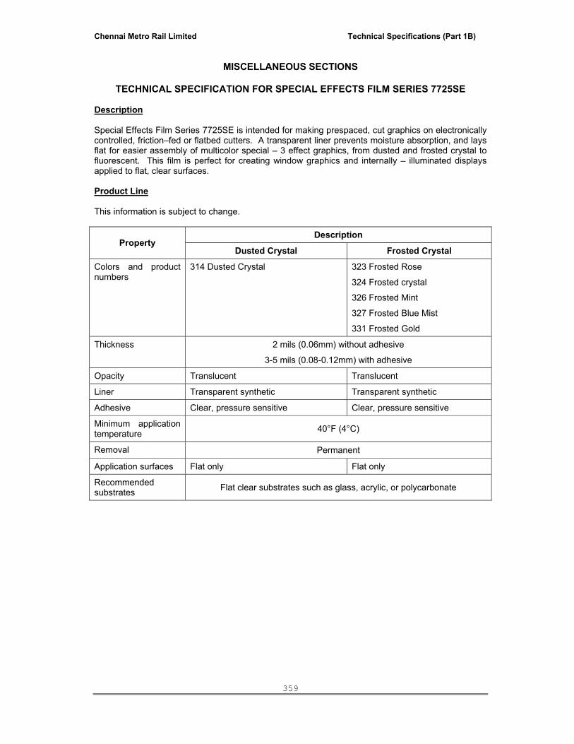
Chennai Metro Rail Limited Technical Specifications (Part 1B)
359
MISCELLANEOUS SECTIONS
TECHNICAL SPECIFICATION FOR SPECIAL EFFECTS FILM SERIES 7725SE
Description Special Effects Film Series 7725SE is intended for making prespaced, cut graphics on electronically controlled, friction–fed or flatbed cutters. A transparent liner prevents moisture absorption, and lays flat for easier assembly of multicolor special – 3 effect graphics, from dusted and frosted crystal to fluorescent. This film is perfect for creating window graphics and internally – illuminated displays applied to flat, clear surfaces. Product Line This information is subject to change.
Property Description
Dusted Crystal Frosted Crystal
Colors and product numbers
314 Dusted Crystal 323 Frosted Rose
324 Frosted crystal
326 Frosted Mint
327 Frosted Blue Mist
331 Frosted Gold
Thickness 2 mils (0.06mm) without adhesive
3-5 mils (0.08-0.12mm) with adhesive
Opacity Translucent Translucent
Liner Transparent synthetic Transparent synthetic
Adhesive Clear, pressure sensitive Clear, pressure sensitive
Minimum application temperature 40°F (4°C)
Removal Permanent
Application surfaces Flat only Flat only
Recommended substrates Flat clear substrates such as glass, acrylic, or polycarbonate

Chennai Metro Rail Limited Technical Specifications (Part 1B)
360
STEEL LOCKERS & SLOTTED ANGLES RACKS:
TECHNICAL SPECIFICATIONS
A) PERSONAL LOCKER UNIT(PLU):
Multi Bend Construction fastener free, Knock Down Construction. Aesthetic punched design door for Better Ventilation. Ergonomically Designed Plastic Handles. Label Holder for Easy Identification. Stands to Facilitate Cleaning of Work Area. Aesthetic Leveling Screws for alignment.10 Lever cam lock. Anti Corrosion Treated Components and Oven Baked Powder Coating Process. B) PLU :-
2 DOOR PLU:- DIMENSION OUTER – 1830 x 457 x 380 mm a) Top, bottom, LH & RH sides, Door and back material thickness = 0.8mm (0.63 for Export)
b) Door with 10 lever cam lock.( HAPSE OPTIONS ALSO AVAILBLE)
c) I Nos Hanging Rod
C) RAW MATERIAL ( MILD STEEL)
1) Mild Steel: - Cold Rolled close Annealed Steel used for thickness 0.6 to 1.2 mm range as per IS-513 1994 ( Reaffirmed In 1998). Grade ‘D’ or ‘DD’ Quality.
Chemical Composition, Tensile Properties, Bend Test, Surface, Flatness, Hardness as Per IS-513 1994.
2) Mild Steel:- Hot Rolled Steel used for Thickness 2.0 To 3.15 mm range. As per Is- 1079
.1994 ‘D’ Quality Or IS-10748. 1995 Grade II. Chemical Composition, Tensile Properties, Bend Test, Surface, Flatness, Hardness as per IS-1079 1994. Surface free from Lamination, Surface Flaws, Roll Mark, Dent, And Lines etc.
D) Assembly
a. Use of Co2 Welding & Spot Welding to give Spatter less Welding. Assembly using Standard Fixtures to give Dimensional Accuracy. Assembly of Product using Cell Type Concepts. All Welding Process are Qualified as per Code for Welding Process.
E) Spray Phosphating
a) Eight Stage Spray Phosphating Line, followed by Drying In Oven. No Material Handling take place. Better Cleaning & Coating Uniformity by means of Direct Spray, Faster Treatment Speed. To Increase the Corrosion Resistance of the Powder Coated Products.
b) Iron Phosphate Deposit on Components Is 0.3 Gm / M2 Minimum. As per IS-3618 1966 Reaffirmed in 1991 And IS- 6005 1998.

Chennai Metro Rail Limited Technical Specifications (Part 1B)
361
F) Powder Coating
1) Epoxy-Polyster Powder are Specially Formulated to Provide Excellent Finish,
Outstanding Hardness and High Resistance to Chemical, Thermal and Mechanical Stress.
2) To pass Following Test as per Standards.
Characteristic Specification Method Used Standards References
DFT (DRY FILM THICKNESS 50-60 MICRON ELCOMETER OR
DFT METER ASTM-D 1186-93, IS13871:1993, IS 101
GLOSS AT 600 70 ±5 UNITS GLOSS METER
ASTM-D 523-89 REAPPROVED (1994)
ISO 2813
DIN-67530, IS 13871:1993, IS 101
SCRATCH HARDNESS 3 Kgs
SCRATCH HARDNESS TESTER
BS-3900PART E2 1970
IS 101 (PART-5 /SEC-2)1988, IS 13871:1993
IMPACT RESISTANCE 275 Kg.cm IMPACT TESTER
ASTM-D2794-93
BS-3900 PART E3 1979, IS 101
JISK 5400-1979., IS 13871:1993
CROSS CUT ADHESION
1x1 mm or GT=0
-------------
DIN 53151
ISO 2409
ASTM 3002
ASTM 3359
JISK 5400 1979., IS 13871:1993
FLEXIBILITY 3.25 mm
CYLINDERICAL MANDREL BENDING TESTERS
DIN-53152, ISO1519
ASTM D522
BS 3900 PART E1, IS 101 (PART-5 SEC-2 ) 1988
ERICHSEN CUPPING 8 mm
ERICHSEN CUPPING TESTER
JISK-5400-1990
IS 101 (PART5 SEC2) 1988, IS 13871:1993
SALT SPRAY 1000 HOURS SALT SPRAY CHAMBER
IS 101 (PART 6SEC1)1988
ASTM B117-95, IS 13871:1993

Chennai Metro Rail Limited Technical Specifications (Part 1B)
362
TENDER FOR EXTERNAL FAÇADE AND ASSOCIATED WORKS
TECHNICAL SPECIFICATION
TABLE OF CONTENTS
S.No Description
A. Section - 1 – Technical Specification 1. Scope
2. General
3. Quality Assurance
4. Quality Control
5. Codes and Standards
6. Façade Contractor’s Qualification
7. Design Responsibility
8. Performance Requirements
9. Specification of Materials
10. Tests on Materials and Assembly
11. Submittals
12. Samples
13. Product Handling
14. Fabrication
15. Inspection
16. Erection
17. Protection
18. Cleaning
19. Maintenance Requirements
20. Spares
21. Mode of Measurement
B Section – 2 - Particular specification
C Section – 3 - Special Instructions to the Bidders
D Section – 5 - Technical Questionnaire - To be filled by the Bidder
E Annexure – A – Form of Performance Guarantee of System
F Annexure – B – Form of Performance Back to Back Guarantee of materials.

Chennai Metro Rail Limited Technical Specifications (Part 1B)
363
SECTION – 1 - TECHNICAL SPECIFICATION
1.0 SCOPE
Design, Supply, Fabrication, Erection, Installation and testing of work at all levels and heights, hand over the complete External Façade and Associated works involving the following scope of work:
• Semi Unitized system with Structurally Glazed panel / Structurally Glazed Punched and Strip window,
• Frame less glazing with Spiders / Articulated bolts and Fin glass / Tensile cable with
laminated DGU / laminated toughened heat soak tested glass to satisfy the structural criteria,
• Doors of Sliding (Automatic) or Swing Type with Double Glazed Unit (DGU) /
Laminated / Monolithic Glass with the specified Hardwares and frames to satisfy the structural criteria.
• Fixed cum Openable / Sliding window with aluminum extruded or specially extruded
frame with anodized finish of varying size and fixed either on the Glazing system or on the Windows and Ventilators as specified.
• Cladding the wall to any shape and profile with laminated sandwiched composite
panel comprising 100% virgin LDPE sandwiched between aluminium skins and fixed to satisfy the structural criteria either
a. As part of the Glazing system maintaining the same glazing plane.
b. On the opaque wall with specified framing method.
• Providing canopy and any other type of projections either with laminated
sandwiched composite panel comprising 100% virgin LDPE sandwiched between aluminium skin or laminated glass with supporting system as per structural criteria.
• Providing Anodic coated aluminum extruded Louvers with “Z” profile, Aerofoil profile
and other specially extruded Louver made out of extruded aluminium with anodized finish of varying size and fixed either on the Glazing system or on the Windows and Ventilators as specified.
• Providing shading Device with specially profiled Louvers using extruded aluminium
sections to any shape / profile of specialized manufacturer product with complete accessories and fixed on the necessary specialized hot dip galvanized bracket support system.
• Cladding the wall with Natural stone like Granite / Sand stone or any other stone
Materials and fixed to satisfy the structural criteria either
a. As part of the Glazing system maintaining the same plane of Glazing / Cladding system.
b. On the opaque wall with specified dry type fixing method with SS brackets of
size as specified.
c. Wet fixing method on the appropriate base materials specified,
• Providing and installing the façade associated works like Insulation on the Spandrel / Opaque wall as specified, fixing of cement based particle board, flashing and Cold Bituminous coating on the Opaque wall etc.

Chennai Metro Rail Limited Technical Specifications (Part 1B)
364
System shall be fabricated according to the type of glazing and cladding system called for in the specification using Anodic coated aluminum Extruded Members with specified type of Glass, laminated sandwiched composite panel (ACP) with PVDF coating, Gaskets with EPDM or Silicon, Silicon Sealants (Structural / weather) etc and the system shall be erected using the Hot dip Galvanized Brackets for glazing and Aluminium brackets for Metal cladding with necessary fastening system with Stainless steel fasteners, bolts, nuts and screws etc complete.
Protection of the system and materials including glass, metal panels and all other materials involved in the system is sole responsibility of the façade Contractor until the completed works are taken over by the Employer. Glazed panels supplied at site must have a cork buttons at appropriate locations on the exposed glass surface in order to avoid scratches and breakage of glass, while the panels are stocked. Entire frames involved in the Glazing & cladding system shall be protected with self adhesive removable PVC wrapper in order to protect the surface finish. Erected panels shall be protected with appropriate protection methodology in order to protect the erected panels free from damage at construction site.
Protection of the supplied and installed façade panels is sole responsibility of the Façade Contractor until the complete works are taken over by the Employer. As part of tender scope, Façade contractor shall adopt appropriate safety & security measures at site of works by means of implementing proper methodology and arrangements made by the Façade contractor and such methodology is strictly complied by his site team until the completed works are taken over by the Employer. Glazing and Cladding system shall be neatly maintained by the Façade Contractor to ensure that the complete system is free from all defects and damages in terms of Materials and workmanship including the replacement of broken glass, if any during the construction stage, etc until the completed works are taken over by the Employer.
Work shall be executed by coordinating with the Vendors engaged for various types of works including Façade access system agency as and when is required. In particular, Facade Contractor shall coordinate with Façade access agency by making the provision / cut outs on the cladding works to install the façade cleaning system and equipments including finishing the cladding work neatly to the acceptable level after installation of Façade cleaning equipment as part of tender scope.
Work site shall be maintained with neat and clean housekeeping by way of clearing the unwanted materials like broken glass if any, Metal panel scrap, broken stones, packing Materials, damaged fastener, bolts, nuts, screws any other debris regularly and the premises shall be kept clean at all times. Providing the Guarantee for the entire External Façade and associated system to the specified period in an approved format attached with the specification supported by the back to back guarantee from the specialized Material supplier like Extrusions, Glass, Metal panels like Aluminium composite panel, Extrusion coating, Gasket, Sealant, all type of Hardware including Spider, Articulated bolts and patch fitting door etc.
Conduct periodical checking of the system including the materials involved in the system during Defects liability period to ensure that the performance of the system and the materials involved in the Glazing and cladding system are free from any defects and damages during the defects liability period.

Chennai Metro Rail Limited Technical Specifications (Part 1B)
365
In general, the detailed scope of works is as outlined hereunder, but will not necessarily be limited to:
• Complete Facade cladding for the building comprises the following:
Complete exterior walling for the building comprises the following elements:
Factory fabricated Semi Unitized structural Glazing (4 sided Glazing) consisting of
color anodic coated to the specified thickness of approved colour aluminium specially extruded sections with Insulated / Laminated / Monolithic Heat treated glass of approved shade & make with Top hung open able panels (part), Silicone sealant both structural and weather, weather stripping gaskets (EPDM/Silicon), setting blocks, support and anchorage system, Protection, Cleaning, Guarantee of the system etc.
Frameless glazing with Laminated DGU / Laminated / Monolithic Heat treated and
heat soak tested glass of approved shade & make with the specified supporting system like Spiders or articulated fittings supported with the help base framing of Hot dip galvanized structures or glass fin wherever is indicated.
Frameless fixed glazed panel including Sliding (Automatic) and Swing door with
DGU / Laminated / Monolithic Heat treated glass of approved shade & make with the specified supporting system comprising patch fittings or anodic coated aluminium twin rails (top & bottom) wherever is indicated.
Cladding with laminated sandwiched composite panel sandwiched with non
combustible and non toxic Mineral core / polyethylene between two aluminium skins on the opaque walls to the architectural features and detail to building including roof, canopy and other type of projections wherever is indicated.
Cladding with approved shade of Natural stone like Granite as specified.
Fixing of Ironmongery, Hardware and accessories involved in the Glazing system,
Doors, windows and ventilators.
Fixing the Aluminum extruded Louvers like “Z” type, and specialized manufacturer Louvered like Aerofoil on the Glazing or Opaque wall and window system as part of Glazing and cladding works.
Ironmongery and accessories to all windows and doors.
Façade Cladding works comprising Semi Unitized structural Glazing system, Point fixed glazing with Spider/Articulated bolt with fin glass, Frameless fixed glazed panel with Doors (Sliding / Swing type), Louvers with extruded special shape profiles, Cladding with laminated sandwiched composite panel sandwiched with non combustible and non toxic Mineral core / polyethylene / LDPE between aluminium skins, Cladding the Canopies and any other type of projections with Composite panel / Glass, and cladding with Natural stones like Granite (by dry type / wet fixing method) etc as described hereafter shall include but will not necessarily be limited to the following:-
Frames, glass and glazing, spandrel panels, Aluminum / Frameless / Point fixed
with fixed panel and Glazed doors, windows and ventilators, Louvers, Vents, finish hardware and fire stop between storey floor slabs, sill level and gap between Mullion and columns. Doors and windows where indicated, inclusive of all accessories, ironmongeries etc
Copings, Soffit trimmers and External ceiling panels for both metal wall claddings
and curtain walling system.

Chennai Metro Rail Limited Technical Specifications (Part 1B)
366
Access panels and test clamps. Pull out test for Masonry Blocks, where the clamps are mounted.
Inserts in concrete for the anchorage of all work under this section.
All steel structural framing and beam supports, anchors and attachments required
for the complete installation of the whole system.
All caulking, sealing and flashing including sealing at junction with roof waterproofing and exterior wall, flashing at door way and raised kerbs. All sealing / Flashing shall have minimum overlap of 100 to 125mm and the joints shall be sealed with weather silicon sealant.
Sealants within and around the perimeter of all work under this section.
Separators, neoprene gaskets, trim etc.
Inner liner trays to conceal the steel structural supports to the wall claddings,
granite cladding and for the protection against heat and humidity.
Isolation of dissimilar metals and moving parts.
Finishing and coating of the metal wall cladding system.
Engineering proposals, drawings and data.
Shop drawings, engineering data and structural calculations of the framing, fasteners and claddings stamped by a professional structural engineer approved by the Employer.
Scheduling and monitoring of the work.
All samples, Mock ups and test units.
Coordination with work of Principle or main Civil Contractor and other
agencies/contractors of Employer.
All final exterior and interior cleaning of the glazing systems, wall cladding system and aluminium doors/louvers etc and conducting field test.
Cost of all hoisting, staging and temporary services.
Cost of full performance test, inclusive of necessary reports at a laboratory
approved by the Employer.(As called for in the Bills of quantities)
Guarantees and Maintenance manuals.
Provision for interfacing with exterior window cleaning equipment. 2.0 GENERAL
Structural design and engineering, fabrication and erection of Semi Unitized Structural Glazing / Structurally Glazed punched / Strip Window system, Point fixed Glazing with Laminated DGU / laminated / Monolithic heat treated and heat soak tested glass with Articulated bolts, M.S PU painted framing system or with glass fin, Fixed cum Openable / Sliding window with DGU / Monolithic with Aluminium extruded framing system, Cladding with Aluminium Composite panel on the Glazing system maintaining the Glazing plane and on the Opaque wall with dry wall system, Cladding the Canopy and any other type of projections with Composite metal panel / Laminated Glass, providing Aluminum extruded Louvers with “Z” profile, Aerofoil, cladding with Natural stone like Granite with dry type fixing method / wet type fixing

Chennai Metro Rail Limited Technical Specifications (Part 1B)
367
to all size and at all level shall form part of the external façade works, which inclusive the submission of the following particulars and details but will not necessarily limited to: A. Pre-award Stage: (Submissions along with Bid for review)
• Submission of Project proposal details. • Submission of Schematic drawings including extruded member details. • Submission of Typical details of the supporting arrangements of the system. • Submission of Typical Structural design calculations for main & sub members. • Submission of Typical Jointing / connection details of the system. • Submission of Report on Material proposal confirming to the Tender specification. B. Post-award Stage: (Submissions by successful bidder for review and approval) • Execute Site survey / Building survey prior to submission of shop drawing. • Execute preliminary works such as marking layout and bracket location at site, to verify
the site condition prior to preparation of Shop Drawing. • Submission of Shop drawings, engineering data and structural computations of all
systems including aluminum framing members, all required glass, paneling materials, Point fixed glazing with spiders / Articulated bolts, Automatic sliding or Open able doors, Canopy works, fasteners, and other accessories.
• Submission of details for the system with Top hung open able panel/Entrance doors with or without side panels (Open able/Automatic sliding Door), and other connected works.
• Submission of details for a continuous gutter system at each floor level ensuring that the water drained out at lowest floor level collectively.
• Submission of details for laminated sandwiched composite panel cladding and its appropriate supporting extruded member details including fastening and sealing the groove.
• Submission of details for Granite cladding and its supporting structure and fastening. • Submission details for Frame less glazing (Point fixed Glazing) with spiders or articulated
bolts with fixed glazing system with glass fin / M.S PU painted support including necessary structural supports and its entire fastening.
• Submission details for Aluminum extruded louvers with necessary Structural supports and its entire fastening.
• Submission of details for all types of Glass including Insulated , Monolithic, Insulated laminated glass with Heat soak testing details and Glazing materials, all separators, EPDM, Gaskets, spacer rods, backer rods, trims and Sealant on the Glazing system.
• Submission of Joint details for external facade glazing system. • Submission of Joint details for Aluminum composite panel/Granite cladding on the
Structurally Glazed frame work. • Granite on the Dry wall with SS Clamps with structural supports and adjoining work if any
with dissimilar Material. • Submission of details for all anchors, clips, fasteners, and brackets involved in the entire
external cladding work covering make and its structural properties. • Submission of details for all interior trim covers and closures including extruded furring
panels to receive dry wall. • Submission of details for all perimeters flashing and counter flashing contiguous to
Structurally Glazed panel / window and the overlap of 100 to 125mm shall be considered between the flashing.
• Submission of details for Fire stops/smoke seals, flashing using color anodized extruded sections and sealing of all interfaces with the building Structural members / finishing works internally & externally.
• Submission details of smoke seal to close the gap between sill wall and Transom member to cover the gap.
• Submission details of Aluminum flashing to close the gap between column face and aluminum member vertically from floor to floor and its fastening with suitable sealant.
• Provide hoisting, staging, scaffolding and temporary services as required to execute the entire external façade works.

Chennai Metro Rail Limited Technical Specifications (Part 1B)
368
• Submission of details on the proposed Glass processor and their credentials establishing their infrastructure facility / capabilities to process all type of glasses.
• Submission of Methodology for glass processing detail including details on cutting, edge grinding / polishing, heat treatment process, processing of Insulated glazing unit.
• Provide full scale visual mock up at site based on the approved shop drawing covering minimum 2 floors and with 3 bays, which includes one open able panel and any Architectural special elements and Features shown in the elevation.
• Pay all costs and obtain statutory approvals and permits related to the External cladding works like Structural Glazing and ACP works, if any. Water test shall be carried out to ensure that the system has no air and water leakage.
• Execute Full scale off site proto type tests, if specified and called for in the Bills of Quantities.
• Execute Field Tests – Hose reel Test at minimum 4 locations as approved. • Submission of all Maintenance manuals and Guarantees. • Window washing stage including cleaning the entire façade prior to taking over the work
by the Client. • Provide Guarantees of the entire façade System including system design & Performance
of the Materials involved in the entire system to the specified period else where in the document in an approved format attached as Annexure – A & B.
3.0. QUALITY ASSURANCE
• Unless otherwise specified wind loads factors & calculation, structural design & parameters shall strictly comply with the relevant National Building Code and Indian / International Standard Code. Requirements of regulatory agencies shall comply with all the applicable local codes and Regulations.
• Products used in the work shall be produced by manufacturers regularly engaged in manufacturing of similar items and with a history of successful production acceptable to the Employer / Employer’s Representative .
• Submission of certificate establishing that the Glass thickness and heat treatment
process with desired strength have been selected and specified to the Glass processor to provide the strength is meeting the specified Structural and thermal performance criteria.
• Submission of substrate test report for each exterior use of both Structural and weather
sealant compatible with Glazing and cladding system Member finish, all types of Glass, Metal panels, Natural stone and Louvers etc prior to procurement of sealant.
4.0 QUALITY CONTROL
• Each bidder shall maintain the approved shop Drawings, details and typical Design calculation as per the items listed above at site office & elsewhere for review of PMC/Architect during inspection of work.
• Shop and field materials and workmanship activities shall be subject to inspection by the
Employer / Employer’s Representative and their representative at all times. Such inspections do not relieve the Contractor from obligations to provide materials conforming to all requirements of the Contract Documents and Industry standards for material quality and finish.
5.0 CODES AND STANDARDS:

Chennai Metro Rail Limited Technical Specifications (Part 1B)
369
All Materials & Workmanship shall comply with the following standards as minimum:
Code No Particulars
IS 875 Design Loads for Buildings and Structures.
IS 1893 Criteria for Earthquake resistant design of Structures.
BS 1474 Design Loads & Properties of Metals & Alloys.
IS 8147 Specification for use of Aluminium Alloys on Structures.
AS 2047 Specification for use of Aluminium Alloys on Structures.
BS 6262 Specification for Safety Glazing in Buildings.
AS 2208 Safety Glazing Materials for use in Buildings.
CPSC 16 CFR 1201 Specification for Safety Glass use in Buildings.
AS E 1288 Selection & Installation of Glass in Buildings.
AS E 1300 Determining Load resistance & Deflection in Glass.
ASTM C 1036 Specification for Float / Flat Glass.
ASTM C 1048 Specification for Heat Treated Glass.
ANSI Z 97.1 Specification for Tempered Glass - Safety Glazing
ASTM C 1172 Specification for Laminated Glass.
ASTM C 1376 Specification for coated Glass products.
ASTM C 509 Specifications for Sealing Materials.
ASTM E 773 Specification for Seal Durability of Insulted Glazing Unit.
ASTM E 774 Specification for Sealed Insulted Glazing Unit.
ASTM C 864 Specification for Compression sealed Gaskets.
ASTM C 1115 Specification for Silicone Rubber Gaskets.
ASTM C 1135 Specification for Properties of Sealants.
ASTM C 1184 Specification for Structural Silicone sealants.
ASTM C 920 Specifications for Joint Sealants.
AS 1580 Specification for Test Methods of Material finish.
ASTM C 794 Specification for Test Method of Elastomeric joint sealants.
ASTM C 1087 Test methods for determining compatibility with accessories.
AAMA 501.2 Test methods for Field Test - Hose reel & pressure Box test. 6.0 EXTERNAL CLADDING CONTRACTOR’S QUALIFICATION:

Chennai Metro Rail Limited Technical Specifications (Part 1B)
370
• All the work shall be executed only by pre-qualified specialized contractor under single point responsibility, who is having experience in the engineering, fabrication, finishing and installation of Semi Unitized Structural Glazed panel / window including glazing and sealing of glass, Aluminum composite panel cladding, Framed / Patch fitting door and fixed panel and connected works of similar nature of this project.
• Subcontracting any part of work by specialized Structural Glazing agency is specifically prohibited, except for that which may be approved by Employer / Employer’s Representative in writing prior to award of the Contract. If approval is granted to subcontract installation and/or glazing, approval is contingent upon the supervision of his subcontractor(s) by the same full time supervisor who co-ordinates and supervises full scale mock-up work at the testing laboratory and installation at the project.
7.0 DESIGN RESPONSIBILITY:
• Contract documents define design intent and performance requirements of the Employer/ PMC/Architect. Details shown in Architect’s tender specification and drawings for items covered in the entire bid package are Indicative but preferred profiles and System. External Cladding contractor is charged with total responsibility for design and structural calculations, submission of details at project proposal stage, site survey and shop drawing based on approved project proposal detail, fabrication, installation, warranties, certifications and related documentation.
• External Cladding contractor shall be solely responsible for the design, fabrication and
erection of the systems, and all work covered in the bid package and to perform entirely by their own staff. No sub contract at any stage is acceptable.
• Design metal framing members to accommodate expansion and contraction of
components without buckling, creating stress on glass, structural components and fasteners, joint seals or other damaging effects when subject to a surface temperature range of 50C to1000C.
• Design Structural glazing system (or) Point fixed glazing system with spider / articulated
bolts including fixed panel with Sliding or side hung open able door if any must accommodate the applicable wind loads and Lateral force and be capable of sustaining its own weight. The glass restraints must be designed to satisfy the applicable loads. Computations defining the loads and stresses developed must be provided. All friction grip connections must be substantiated by computations.
• Design extruded louver windows/ventilators at various levels in the Buildings and its
Structural supports and fastening. Computations defining the loads and stresses developed must be provided.
• Glass for frameless point fixed glazing system shall be designed to satisfy the
requirements of AS 1288. Heat treatment process such as Heat strengthened/Toughened Laminated glass either with clear or tinted glass with required thickness. Lamination inter layer in between 2 skin glass shall be PVB layer of sentry glas (R) of DuPont make or approved equivalent make.
• Drainage system with pressure equalization concept / system must be incorporated into the
structural frame proposed for Glazing and Cladding with Metal panels like laminated sandwiched composite panel.
• Water and air leakage and condensation if any on the system shall be drained or
discharged to the exterior surface of the façade at each floor level / at lowest floor level. All interior spaces must be effectively sealed to ensure that the pressure equalization system will operate adequately even under the most severe rain periods and also during severe wind effect expected in the area.

Chennai Metro Rail Limited Technical Specifications (Part 1B)
371
• Water movement must be controlled and necessary built in arrangement shall be provided in the system to drain out the water from the system at each floor level / at lowest floor level in such a way to prevent any water being retained within the system.
• Drainage system shall be sealed off at every floor to prevent infiltrated water from leaking
into lower floors as well as prevent water entering into the inside of the Building from the in built drainage system by way of in built Barrier System.
8.00 PERFORMANCE REQUIREMENTS 8.01 System Design Criteria:
a. General:
Performance design shall comply with the current edition of the relevant standards.
The building envelop systems including canopy under the façade scope of the works shall be watertight and weatherproof (Air, Water, Humidity infiltration), able to support all dead loads, seismic loads, live loads and other loads imposed on the building façade envelope and any projection including Canopy system accommodate all movements due to base structure movements and deflections and thermal expansion and contraction and generally retain its appearance for the service life of the system without failure or breakdown of individual materials and components.
8.02 Dimensional stability:
All works carried out by the Façade contractor shall have adequate dimensional stability to function properly and prevent damage to adjacent or applied work by other contractors.
Design shall allow for the following:
1. Expansion and contraction. 2. Building movement. 3. Dimensional changes due to weather change.
8.03 Design Pressures:
• Wind Pressure and Seismic load used for design shall satisfy the relevant code but the wind pressure shall not be less than the minimum wind pressure of 200 Kg/Sqm under Service load (Design Load) condition as specified and seismic forces shall be as derived by adopting the relevant code. The wind pressure specified here has been calculated based on IS 875 with the defined wind speed, zone and terrain condition as service load and as minimum requirement subject to verification of the Facade Contractor. However, maximum wind pressure shall only be considered for system design.
• Design calculation for wind pressure considered that the wind speed design basis of 50
m/s and the same shall be considered by External Façade contractor also for verification of wind pressure specified. Design load for seismic condition shall be considered by the Bidders in accordance with IS 1893.
Chennai Metro Rail Limited Technical Specifications (Part 1B)
372
8.03 Proof load:
• Proof load for testing purpose shall be considered as 1.5 times of the Service load, which will be considered for acceptance criteria of the system design and the materials involved. Minimum drift for seismic load condition test shall be considered as 8 mm (Minimum) subject to verification by the Façade Contractor at an appropriate time which will be considered as acceptance criteria for Seismic Load testing at laboratory.
• Minimum design pressures inward and outward and acting perpendicular to glass
Installed to any profile & shape of Glass, laminated sandwiched composite panel sandwiched with 100% virgin non combustible and non toxic Mineral / polyethylene core between aluminium skins, and Natural stone like Granite slab etc (including return surfaces) shall be as per the requirements of the code of practice for design load other than earth quake for buildings and structures - IS 875 and Lateral forces as per IS 1893. Latest revision of Code shall only be referred.
8.04 Corner Effect:
Determine the maximum service load, design wind pressure and lateral forces applicable for that particular building to satisfy the corner effects of the façade system including glass and other façade materials. Negative pressures if determined considering the service load, wind pressure and Lateral forces using the respective codes will make allowances for corner effects as described in the code.
8.05 Performance Criteria for Materials:
A. Metal members Metal members supporting glass, laminated sandwiched composite panel and granite slab shall be as follows:
• Perpendicular to the plane of the wall, net deflection of framing members shall not
exceed 1/175 times span, or 19mm, whichever is less. Span is defined as the distance between anchor centre lines in the case of Mullions. Where a sealant joint occurs between a framing member and a relatively stiff building element, framing member deflection shall not exceed ½ of the nominal joint width, or less if required by sealant manufacturer. Where a framing member runs continuously past a deflecting support, the support deflection shall be added to the member deflections. Span is defined for transom occurs between the Mullions. Depth of Mullion and transom shall be maintained uniform.
• In the plane of the wall, deflection of framing members shall not reduce the glass bite below 75% of the design dimension, and shall not reduce the glass edge clearance below 25% of the design dimension or 3 mm, whichever is greater. Restrict deflection further if required for assembly and fit of components.
• Stresses shall not exceed the allowable values established by the Specification listed
under “Standard References”. In no case shall allowable values exceed the yield stress. Where permitted by code, a 1/3 increase in allowable stress for wind or seismic load is generally acceptable, but not in combination with any reductions to combined loads.
• Performance criteria at test pressure and loads (1.5 times design pressure and loads)
for metal members supporting glass and aluminium composite panels shall be as follows:
Net permanent deflection of framing member shall not exceed 1/1000 times span.

Chennai Metro Rail Limited Technical Specifications (Part 1B)
373
There shall be no failure or gross permanent distortion of framing members, anchors or connections.
At connection points of framing members to anchors, combined movement of anchor shall not exceed 4.5 mm in any direction, nor 3mm set after load is removed.
B. Glass:
• Provide glazing assemblies to withstand normal conditions, without failure, loss of weather tightness or Deterioration includes the following:
i. Coated Glass:
Development of any visible defects in coating. ii. Heat Treated Glass:
Allowable surface Compression shall range from 27 Mpa to 48 Mpa based on the type of heat treatment proposed in the tender.
When Strengthening process results in essentially parallel ripples or waves the
deviation from flatness at any peak shall not exceed 0.230 mm within the 265 mm of a leading or trailing edge or 0.076 mm peak to valley with in the Main body or size of the sheet.
Direction of the ripples shall be consistent and in conformance with Design intent.
Heat strengthened and Tempered Glass should be horizontally processed with the
Automatic glass cutting fabrication completed before Heat treatment. Heat strengthened glass shall have surface compression of 5500 PSI plus or minus 1500 psi predetermined as project requirement. Tempering glass shall have a surface compression of 10000 Psi.
iii. Insulated Glass:
Moisture or Dirt between panes.
Development of condensation between panes.
Damage to Internal coating, if any.
Development of other indication of seal failure.
iv. Laminated Glass:
Bubbling or visible delaminating of the Interlayer Material.
Color change indicating deterioration of the Laminate.
Bubbling or delaminating of the film.
• Quoted rate of Structural Glazing item of Bills of quantities shall include for arranging inspection of glass at manufacturing / Processor place either in India or overseas by the representatives of Employer, PMC and Architect's (one from each as minimum) during the time of glass processing.
• For the purpose of glass Design and selection, design wind pressure as specified in the
Bills of Quantities and seismic load as per code shall be assumed to have 60 second duration.

Chennai Metro Rail Limited Technical Specifications (Part 1B)
374
• Upon first application of design wind load and live load pressures, statistical probability of breakage shall not exceed 8 per 1000 at 60 second load in vertical application.
• Probability of breakage due to anticipated thermal stress in glass shall not exceed 8 per
1000 at 60 second load in vertical application. Exposure classification shall be in accordance with Exposure D ANSI A 58.1.
• 1 pane per 1000 for lites set over 15 degrees off vertical under design wind pressure as
specified in the Bills of Quantities and seismic load as per code. • Glass proposed for the mock-up shall be identical (including strength) to the glass being
provided for the corresponding zone on the actual building. Mock-up glass, which breaks, shall be replaced with the same type glass, and the tests continued. Repeated glass breakage shall constitute a failure.
• Glass deflection shall not exceed 1/ 90 times span (span defines only shortest span of
the panel glazed in the system).
• Glass design shall accommodate Thermal movements resulting from the range of 120 F and Material temperature range of 180 F.
• Glass thickness for exterior pane shall not be less than 6 mm and safety glazing
requirements supercede the strength requirement specified.
• Allowable maximum stress shall be as follows;
Heat strengthened glass - 18 to 25 Mpa Tempered / Toughened glass - 27 to 48 Mpa Laminated Tempered glass - 35 to 48 MPa
• Submit the wind pressure and thermal analysis indicating that the specified maximum
deflections and probabilities of breakage not exceeding the prescribed minimum.
• Use the Material including glass from one Manufacturer. Cut Glass to size and shape and drill holes prior to heat treatment process. Manual edge grinding shall be prohibited. Use only Automatic machine for edge grinding and chamfering.
• For Insulating Glass use desiccants either molecular sieve or silica gel of blend of both.
• Spacer construction shall be as per manufacturer’s specification. Continuous Bent
spacer of black color shall be used. Sealing system of Insulated panel shall dual seal system.
• Fabricate Glass with bite and edge clearance dimensions including tolerances as
recommended. Provide venting of internal airspace if the units are transported through higher elevation and subsequently seal the vent.
C. laminated sandwiched composite panel. • For the purpose of selection of laminated sandwiched panels, the design wind pressure
as specified in the Particular specification shall be assumed to have 3 second duration. • The allowable design stress for all Metals Panels shall not exceed the recommendations
made by the supplier. Refer relevant section herein for additional details on structural performance characteristics.
• No cladding element shall sustain permanent deformation or failure under a loading
equivalent of test pressure (1.5 times the design wind pressure).

Chennai Metro Rail Limited Technical Specifications (Part 1B)
375
• The cladding shall be so fabricated and installed to accommodate all the likely expansion and contraction of all components.
• Panel deflection shall not exceed 1/60 times span (Span defines only shortest span of
the panel proposed in the system for fixing). • There should be no colour variation in the installed panels as a result of polarized
lighting on the aluminium panels. D. Sealant:
• Weather Sealants shall withstand movements up to the limits prescribed by the
manufacturer. Exposed sealant surface either (structural or weather) sealant shall not crack or bubble. Non-staining / Non-bleeding weather sealant shall be used for exposed weather sealant.
• Authorized trained personal and recommended type of nozzle depends on the nature of
application only to be employed by the fabricator in the glazing work. (Either shop / Factory or site glazing) to ensure the proper adhesion and also to avoid air entrapment in the sealant applied area.
E. Visual Requirements: • Profiles: The Façade contractor shall design building façade envelop components so
that sizes, profiles, dimensions and style satisfy the performance specification. The drawings included in the tender are to be used as a guideline. Indicative variations on the shop drawings. The Façade contractor shall not commence production of extruded aluminium sections until all profiles have been accepted and endorsed.
• Applied finishes: The design of the components, selection and application of finishes
and installation procedures shall ensure a high standard of applied finish protection during construction. The Façade contractor shall develop and implement procedures to eliminate scratches, marks and blemishes to finished surface during construction. Indicative procedures in the installation procedures.
• Flatness and alignment: The design of the components, fabrication and installation
procedures shall ensure a high standard of flatness, joint and edge straightness and alignments of mating surfaces of joinery. Close attention shall be given to cutting and cut edge treatment procedures, stiffening and the tightening of fixing and fastenings which may cause distortion or warping.
• Service life of the building envelope shall not be less than 50 to 60 years (Indicative).
F. General:
• Provide moveable joints to accommodate the full range of manufacturing tolerance, construction tolerance, field tolerance, thermal movement, floor sag, beam sag, and column settlement and concrete creep. Joints shall accommodate the worst possible combination of effects so as to prevent internal stress, failure, deterioration or failure of weather seals. It is the responsibility of external cladding contractor to verify the deflection of the structural members and structural movement tolerance etc. with Architect/Structural Engineer.
• Thermal components of joint movement shall be based upon a minimum material
temperature increase of 500 C and decrease of 500 C relative to the time of installation. Design for these assumed temperature changes regardless of surface areas exposed to the exterior and interior. Assume the entire cross section has uniform temperature. For thermal design other than joint movement, design the winter surface temperature shall

Chennai Metro Rail Limited Technical Specifications (Part 1B)
376
be the 99% design dry bulb winter temperature from the ASHRAE handbook; the design summer surface temperature shall be at least 1000 C.
• All components including adhesives and sealants shall be capable of withstanding,
without failure, design winter temperature to design summer temperature with simultaneous specified loads.
• Joint widths (Open Groove system) shown on the Drawings are for design profile only.
It is the responsibility of the external cladding contractor to establish the joint width, and to verify the seismic displacement requirements with the Architect / Structural Engineer.
• Design for dead load in combination with other specified pressures and loads shall be
the responsibility of the external cladding contractor. • The general method of water leakage control shall be internal gutters which are drained
to the exterior and utilizing the Pressure Equalization System. Vertical walls, which consist solely of glazed openings, shall have an isolated gutter cavity at each glass perimeter, so that any leakage is confined to and wiped from the leakage origin. All exterior wall joints shall be backed up by a gutter system at each level.
• All thermal insulation and metal support frames shall be held away from face of wall to
provide a 25mm (minimum) cavity for water leakage control Seal and tape all insulated joints.
• Glazing details shall permit glass replacement after initial construction is completed and
during maintenance period, if any breakages to the glass take place in such a way both Vision glass and spandrel glass shall be replaced from the exterior. However, the glass replacement vertically in the installed structural glazed system will not be permitted under any circumstances, during construction /execution stage.
• Performance requirements for resistance to air leakage, resistance to water leakage,
seismic racking and thermal performance are specified below elsewhere under Test on Material and Assembly test.
• In general, performance requirements specified for test mock-ups and samples also
apply to actual building, and vice versa. Variations in criteria over the surface of the building, such as wind pressure and Lateral force are taken into account in testing of mock-ups and samples. Where certain performance is required for specific test conditions of mock-up and samples, that same performance is also required for the actual building, for natural conditions equivalent to or less severe than the test conditions.
9.0 SPECIFICATION OF MATERIALS
9.01 ALUMINIUM
A. Extrusions:
• Alloy for Aluminium extrusions shall be of aluminium alloy 6063-T6 Conforming to BS 1474 or - 63400 (H9) grade conforming to IS 8147, provided with minimum wall thickness as required for structural members. Standard commercial tolerances as listed in ‘Aluminium Standards and Data shall apply to finished, fabricated and assembled materials. Strict tolerance shall apply where required assuring proper functions of glass and glazing materials. Use only 6063 - Structural grade alloy for support Brackets. All aluminum brackets to have serration.
B. Finishes:

Chennai Metro Rail Limited Technical Specifications (Part 1B)
377
• All exposed surfaces shall be free of scratches and other serious blemishes. • Aluminum sections shall be extruded sections shall be finished with AC25 grade
Architectural quality electrolytic color anodic coating of approved color Field cutting of anodized components shall not be permitted.
9.02 GLASS:
A. General:
Annealed / Flat glass. Heat Treated Glass – Heat strengthened and Tempered glass.
B. Type of Glass:
Monolithic Glass. Insulating Glass. Laminated Glass (Safety Glass)
C. Type of work Involved Glass:
Vision Panel. Spandrel Panel. Sloped or Curved Vision / Spandrel panel. Façade Panels - Point fixed Glazing with spiders or articulated bolts. Sky Light Panels.
D. Spectral Properties and Characteristics of Glass Covers:
Thickness of Glass. Type and Source of Substrate Glass. Type of coating. Position of coating. Light Transmittance in percentage – % of visible day light Transmitted. Light Reflectance in percentage – % of visible day light Reflected. UV Transmittance in percentage. Solar Energy Transmittance in percentage. Solar Energy Reflectance in percentage. Solar Energy Absorption in percentage. Solar factor in percentage. Shading Coefficient - Fraction of total solar energy transmitted when compared to
that transmitted by clear glass – 3 mm thick. U -Value - BTU per Hr / Sq.ft per Deg. F Difference or Watt per Hr/Deg. Luminous Efficacy. Relative Heat Gain.
E. Selection of Glass:
Glass selection for the project is generally based on the specific requirement mentioned under vertical fenestration in Energy Conservation Building code published on 2007.
The following parameters are governed for the selection of Glass based on WWR
(Window wall ratio of the Vertical Fenestration) :
Minimum Visual Light Transmission “U’ Factor of the Glass including Frame. Solar Heat Gain coefficient of the Glass.
F. Glass Description:

Chennai Metro Rail Limited Technical Specifications (Part 1B)
378
• All Safety Glass shall conform to the requirements of AS 2208 or CPSC 16 CFR 1201. • Provide Heat strengthened or Tempered or Toughened glass as required to withstand
thermal stresses and to meet the design wind pressure as specified in Particular specification or as per IS 875, whichever is higher.
• Provide Tempered or Toughened glass heat soak processed for the Point fixed glazing
using spider / Articulated bolt / patch including sliding / side hung door to withstand thermal stresses and to meet the design wind pressure as specified in Particular specification or as per IS 875, whichever is higher.
• It is the responsibility of the contractor to determine the maximum service load, design
wind pressure and lateral forces applicable for that particular building to satisfy the corner effects of the façade system including glass and other façade materials. Negative pressures if determined considering the service load, wind pressure and Lateral forces using the respective codes will make allowances for corner effects as described in the code.
• Heat strengthened and Tempered / Toughened glass shall be examined by the glass
manufacturer to detect and discard any lights, which exceed the following tolerances:
Where the strengthening process results in essentially parallel ripples or waves, the deviation from flatness at any peak shall not exceed 0.230 mm with in the 265 mm of a leading or trailing edge and the difference between adjacent peaks shall not exceed 0.076mm with in the main body or size of the sheet.
Where bow tolerance and wave tolerance differ, the stricter requirement shall
govern. Direction of ripples shall be consistent and in conformance with Architectural design intent. The specification defines nickel sulphide stones as a glass material defect.
It is recommended that an inspection procedure be used to eliminate the
incidence of Nickel Sulphide (NiS) inclusions in all Heat strengthened / Tempered glass. Alternatively, heat soak procedure shall be followed to minimize the incidence of NiS induced failures if specified in any particular item of work like Point fixed glazing with spider / Articulated / Patch fittings including the sliding / side hung open able doors on prior approval by Employer / Employer’s Representative .
• Insulated glass shall have double edge seals. The primary seal between spacer and
glass shall be a continuous butyl tape with no skips or voids. The preferred primary seal shall be poly isobutylene (Pib). The spacer shall be of Black colour and the same shall be bent to shape of glazed unit profile and the bent black spacer shall be filled with desiccant drying agent of Molecular sieve or silica gel or blend of both. The secondary seal shall be Structural Sealant of Dow corning or GE Bayer silicones Single / Two part silicon sealant – DC 983 or DC 995 of Dow corning or ultra glaze SSG 4000/4400 of GE Bayer silicones or approved equivalent.
The secondary seal shall completely cover the spacer with no voids or gaps,
and shall be continuously bonded on both plates of glass.
The required thickness of the secondary seal shall be determined by calculation and verified by testing of samples as specified.
The Glass panel shall be separated by a de-hydrated air space specified.
Edge seal construction of the insulated until shall be able to withstand at least
three times the stress caused by the design wind pressures specified in the Bills of Quantities. Insulated Glazing unit fabricator / processor shall be used only approved sealant / product with the prior approval of the PMC/Architect.

Chennai Metro Rail Limited Technical Specifications (Part 1B)
379
Edge seal construction of the insulated unit will be tooled to a smooth clean surface between the interior and exterior glass edges. Samples shall be submitted to Employer / Employer’s Representative for approval. The approved sample shall be retained at the job site and Structural Glazing Panel / Window manufacturer’s assembly facility for ready reference.
In compliance with the warranty policy of Glass Manufacturer’s for insulated and
reflective glass, written confirmation approving the glass installation procedures for this project shall be provided.
The secondary seal of Insulated Glazed unit shall completely cover by the
silicon Gaskets as part of glazing system and shall be continuously bonded on both plates of the Insulated glass.
G. Glass Accessories:
• Sealant backers within glazing pockets and continuous glass spacer pads at glass butt
joints shall be black heat cured silicone rubbers (type one where sealant adhesion is to be prevented and type two where adhesion is desired).
• Properties falling within the range listed below are accepted provided that adequate
glass support and weather seals are achieved.
S.No Properties Minimum Maximum 1 Durometer + or – 5, shore A 60 70 2 Tensile strength in KPa 138 138 3 Elongation in % 200 200 4 Tear, die B, kPa min. 13 15 5 Compression set 6 Maximum % 22 hrs. at 100 deg.C 20 25 7 Maximum % 22 hrs. at 175 deg.C 40 50 8 Heat age for 70 hrs at 100 deg.C 40 50 9 Durometer A, change pts. Max + 3 + 3 10 Tensile, change % max - 10 - 10 11 Elongation, change max % - 20 - 20
• Setting Blocks Setting Blocks shall the black solid extruded silicone rubber with a hardness of 70 +/- 5
Durometer Shore “A” with a minimum length of 50 mm and a minimum width correspond to the glass thickness. Locate the setting blocks at quarter points.
• Side Blocks Located side blocks within the upper half of each jamb for each light. Blocks shall be 55
+/- 5 Durometer Shore “A” solid EPDM or Silicone. Install blocks with 3 mm clearance between block and the bearing surfaces.
Side blocks are not required where an individual glass lite is continuously sealed with
silicone at 2 or more edges. Resistant plating or non-condensation shall be used, if it is in a non-wetting location. All stainless steel bolted connections shall include lock washers, lock nuts or other locking device.
9.03 LAMINATED SANDWICHED COMPOSITE PANEL. (ACP)
Chennai Metro Rail Limited Technical Specifications (Part 1B)
380
i. GENERAL • laminated sandwiched composite panel - Skin Aluminum shall be of aluminium alloy
5000 series - H14 / H25 conforming to BS 1475. • All composite aluminium panels shall have a minimum total thickness of 4 mm as
specified in the Particular specification. • If specified, the composite aluminium panel shall be installed using the rain screen
principle, with provision for natural ventilation of the space between the cladding panels and the structural wall.
• The composite cladding panels shall be of the cassette type, framed with an extruded
aluminium profile. • All fasteners shall be concealed within the panel joints. All fixing and joint details shall
be designed to provide for the expected thermal expansion and contraction. The fixing of these panels shall accommodate the expected structural movements in the building.
• With a gloss of 30% according to Gardner Scale, the installed composite panel surface
shall not have irregularities such as oil canning, waves, buckles, and other irregularities when viewed at any position not less than 15 degrees to the true plane of the panel.
• All brackets and similar attachments used for the fixing and erection of these panels
shall be of hot dip galvanized steel. • All fasteners and anchors including nuts, washers etc. for brackets and similar
attachments for fixing and erection of the system shall be of non-magnetic stainless steel of 300 series - 316 Grade.
ii. PRODUCT COMPOSITION:
Laminated sandwiched composite panel sandwiched between two aluminium skins used for opaque wall cladding shall have 0.50 mm thick aluminium solid sheets of Alloy 5000 - H14/H25 and composed with 3 mm thermoplastic core of 100% virgin core of Mineral core / polyethylene.
• Total thickness of laminated sandwiched composite panel shall not be less than
4 mm. • Total weight of panels shall be in the range 5.3 to 5.5 KG/Sqm.
• Composition.
Skin Material : Aluminium Alloy sheet of 0.5 mm thick and of Aluminium
grade of 5000 - H14 conforming to BS 1475.
Core Material : 100% virgin core of Mineral core / polyethylene and it shall be Anti-toxic after burning to become water (H2O) and carbon dioxide (CO2).
• Skin aluminum sheet of laminated sandwiched composite panel shall be
manufactured by the aluminium coil manufacturers using Direct-casting line, ensuring that the specified compressive strength of the skin aluminium is achieved.
• Aluminium coil shall be procured from the approved source only. Methodology
describing the sandwiching of the aluminium skin with Mineral core / polyethylene core satisfying the fire grade shall be submitted for review.

Chennai Metro Rail Limited Technical Specifications (Part 1B)
381
Sandwiching the panel with skin aluminium by adopting Glue technology shall only be accepted & Self adhesive panel protected with PVC film and sandwiched with core by removing the PVC sheet, which is called as film technology is not accepted. Bidder shall verify the type of sandwiching the panel and make sure that the panels are fabricated complying with the specified requirement.
iii. Colour and coating:
• Exposed surface of the panel shall be coated with Poly vinylidene Fluoride
coating (PVDF) complying the “specification for coated coil for exterior building applications” issued by ECCA (European Coil Coating Association) or AAMA (American Aluminium Manufacturers Association) and to achieve the quality level of each Association.
• Exposed Surface (Top Side) of the laminated sandwiched Composite metal
Panel shall finish with Poly vinylidene Fluoride coating (PVDF) containing 70% Kynar 500 based Lumiflon fluorocarbon coating and 30% resin. The coating shall be on top side as described below :
Solid Color - Total dry film thickness on the topside shall be in the range of
23 to 25-µ minimum.
Metallic Color - Total dry film thickness on the topside shall be in the range of 30 to 35 µ minimum.
• Un Exposed (Reverse side) surface of the laminated sandwiched Composite
metal Panel ie. facing the wall surface shall finish with Polyester based wash coating or mill finish to a thickness ranging from 300 to 350 Microns as per Manufacturer’s specification. Wash coat on the reverse side of the panel is to protect the panel against the possible corrosion problems and hence Bidder to verify the compliance of the coating requirement on the panel.
• Colour variation of PVDF coating – Metallic finish on the exposed surface (Top
side) of the laminated sandwiched composite panel with aluminium skins is not acceptable under any circumstances. Also, they should be no colour variation in the laminated sandwiched composite panel with aluminium skins on the installed condition as a result of polarized lighting on the laminated sandwiched composite panel. The colour variation due to the orientation of the flacks of PVDF coating in the dry film (Referred as “Flop”) and due to metallic finish is not an isotropic, as referred by the manufacturer is not acceptable and hence the fabricator is full responsible to procured entire quantity in one consignment and make sure that the manufacturer has coated the coil as single batch for the entire quantity. Also, the fabricator shall ensure that the panels are installed on the project by following the directional arrow marks provided by the manufacturer both on the surface of the protective film and on the back side of all metallic finished panels. If the colour variation is still noticed at the time of supply of panels or after the erection of the panel at site, Façade Contractor is sole responsible to replace such panels with new one maintaining the uniform shade and colour of the facade at no cost to the Employer.
• Virgin core of Mineral core / polyethylene used for sandwiching the aluminium
skins shall be 100% virgin core and no recycled virgin core shall be used. Bidder to verify the compliance of the use of 100% virgin & the manufacturer certificate shall be produced ensuring that the laminated composite panels are sandwiched with 100% virgin core and the panels are sandwiched by using Glue Technology, Compatible with virgin core of LDPE / Mineral core and PVDF coating on the skin.
• Finished surface shall be protected with a self adhesive peel off foil with two
layers of white and black, tested to withstand at least six month exposure to

Chennai Metro Rail Limited Technical Specifications (Part 1B)
382
local weather condition, UV resistance properties without losing the original peel off characteristic or causing stains or other damages on the coated surface of the laminated sandwiched composite metal Panel. If the stain or any damage noticed after peel off, such panel shall be replaced with new one of the same shade and colour by the façade Contractor.
• Minimal properties of coating and colour of panels:
1. Pre – Treatment : Polyvinylidene Fluoride (PVDF) coating consists
of 70% Kynar - 500 based Lumiflon based fluro carbon coating and 30% resin.
2. Top Side Solid Colour : Two Bake System with total dry film thickness on the top side of the panel in the range of 23 to 25-µ minimum and the coating consist of a conversion coating, an inhibitive primer and Lumiflon-based fluorocarbon coating. Metallic Colour: Three coats - Three Bake System or Two coats – Two Bake System adding with Metal pigments or Natural Pearl pigments with total dry film thickness on the topside in the range of 30 to 35 µ minimum and consist of conversion coating, an inhibitive primer and Lumiflon-based fluorocarbon coating added with Natural Pearl pigments.
3. Reverse side Polyester based wash coating or mill finish to a thickness not less than 300 to 350 Microns.
4. Coating Standard European Coil Coating Association - ECCA American Aluminium Manufacturers Association – AMMA.
5. Colors – Gloss 30 to 80% as per ASTM D 525 - 89 6. Hardness H - F – H / 2 H 7. Hardness - Pencil 2 H as per NCCA 11 – 5. 8. Formability (T Bend) No Cracks at 1 or 2 Tas per NCCA 11 -19 and
ASTM 01737 – 62.
9. Reverse Impact Cross Hatch No pick off under 62 as per NCCA 11 – 5.
10. Hardness HB - H
Chennai Metro Rail Limited Technical Specifications (Part 1B)
383
iii. Minimal properties of skin Aluminium skin – 0.50 mm thick:
S.No Description Mechanical Properties
1 Yield Strength 15.5 Kg / Sq.mm Grade of 5000 - H14 as per ASTM E-8.
2 Modules of elasticity 7000 Kg / Sq.mm as per ASTM C393.
3 Bond integrity (Vertical pull) 120 Kg / Sq.Cm as per ASTM C-297
4 Deflection temperature 115 Deg as per ASTM D 648
5 Sound transmission loss 26 STC as per ASTM E413
6 Manufacturing Process of Coil
Direct continuous Casting line ensuring that the specified Compressive strength is achieved.
7 Manufacturers of Coil Alcan or Alcoa iv. Minimal Mechanical & Physical properties of Aluminium Composite panel – 4 mm thick:
S.No Description Mechanical Properties 1 Tensile Strength 4.9 Kg / Sq.mm as per ASTM – E 8
2 Yield Strength 4.5 Kg / Sq.mm as per ASTM – E 8
3 Elongation 14 % as per ASTM – E 8
4 Flexural Elasticity 4060 Kg / Sq.mm as per ASTM – C 393
5 Thermal Expansion 1.20 mm per M per 50 Deg.C
S.No Description Physical Properties
1. Weight in Kg / Sqm Ranging from 5.3 to 5.5 Kg/ Sqm
2. Specific Gravity 1.38
3. Thermal Expansion 1.2 mm / M / 50oC as per ASTM D 696 4. Thermal Conductivity 0.39 K cal m. h.0C as per ASTM C 976
5. Thermal Resistance 0.19 m2 Ci Kcal as per ASTM D 976 v. Minimal Test Properties of Aluminium Composite Panel – 4 mm thick:
S.No Description Test Properties
A. Chemical Resistance :
1. HCL No Change after 5 units as per ASTM D 1308.
2. H2SO4 No Change after 5 units as per ASTM D 1308
3. Mortar No Change after 5 units as per ASTM D 605.2
4. Detergent No Change after 5 units as per ASTM D 2248.
B. Weather ability :
Chennai Metro Rail Limited Technical Specifications (Part 1B)
384
1. Colour Retention Maximum 5 units after 4000 Hours as per ASTM D – 2244.
2. Gloss Retention Maximum 70% after 4000 Hours as per ASTM D – 523.
3. Chalking Maximum 8 units after 4000 Hours as per ASTM D – 4214.
4. Salt Spray resistance Aluminium Blisters - 10 - Scribe - 8 after 3000 Hours and under Salt Fog 35 Deg.C as per ASTM D – B 117.
5. Humidity Resistance No Change after 3000 Hours at 100 % RH x 35 Deg.C according to ASTM D - 2247.
6. Humidity-Thermal Scribe - 8 at 35 Deg. C as per ASTM D - 2244. No Blister at 10 cycles at 24 Hours x 100% RH. No Crack at 37.8 Deg.c after 2 Hours x 18 Deg.C and after 4 Hours x 24 Deg.c - No crack.
7. Condensing Humidity / Water Immersion Resistance
None to Vary few H 8 blisters at 100% RH x 54.4 deg.C after 2500 hours as per ASTM D 4585.
C. Adhesion :
1. Dry No change as per Method 8 of ASTM D-3359.
2. Wet No Change at 37.8oC after 24 Hrs.
3. Boiling Water No change at 100oC under 20 mm depth.
4. Abrasion Resistance 20 Litres as the criterio specified in AAMA standard and 70 Litres / mil as per ASTM D-968 under Falling sand.
D. Fire Safety :
1. Spread of surface flame (BS / ASTM)
2. Ignitability class " P "
3. Heat Evolved class " 0 "
4. Smoke Developed class " 0 "
5. Fire Propagation class " 0 0 "
6. Flame Retardancy Normal
Note: Laminated sandwiched composite panel (ACP) shall be tested by the
manufacturer to meet the above test criteria and Manufacturer test certificate shall be produced by the Façade Contractor.
9.04 STAINLESS STEEL
• Spiders, articulated bolts, splice plate, brackets and fixtures used in point fixed
glazing system and Patch fittings or extruded twin style door used in Frameless

Chennai Metro Rail Limited Technical Specifications (Part 1B)
385
glazing system shall be made of Non magnetic stainless steel of 300 series - 316 Grade and the surface shall have 300 Mill finish. Fiber gaskets and shear bolts used in Point fixed and Frameless fittings glazing system shall be of approved make and Non magnetic stainless steel 300 series of 316 Grade with surface finish of 300 Mill.
• Bidders to make sure that there is no contact between metal and glass or any
other dissimilar material under any circumstances 9.05 STRUCTURAL STEEL:
Fabrication, Erection and approval of Steel Structures shall be in compliance with IS: 800 and other relevant Indian Standards for general construction and design. All Structural steel shall conform to IS 2062 Gr. ‘A’ (for thickness up to 20 mm) & IS 2062 Gr. ‘B’ (for thickness above 20 mm). Structural steel grade shall be fy 250 or YST 240 conforming to the relevant IS codes.
• All structural steel works shall be painted (both priming and finish coat) according to the classification in conformance with IS 12944.
• Provide minimum dry film thickness of 225 Microns Single or Multiple coats with
primer coat of minimum 75 microns as desired by the manufacturer for the concealed surfaces and 250 Microns Single or Multiple coats with primer coat of minimum 75 microns as desired by the manufacturer for the exposed surfaces. Only Low VOC paint satisfying IGBC criteria shall be used (Either Epoxy or Polyurethane).
• Hot dip Galvanizing on steel shall be carried out in accordance with IS specification
conforming to IS 2629 (recommended practice for Hot dip galvanizing of Iron and steel) and 4759 (Hot dip Zinc coatings on structural steel and other allied products).Mass of Zinc coating shall be as per clause no 6.1 (Table No 1) and thickness of coating shall be calculated as per clause no 9.2.1(b).If the steel fabricated articles thickness is 5 mm thick and over, mass of Zinc coating shall be as minimum (or) average 610 gm/ Sqm and covert the mass of Zinc coating in to thickness, the coating shall be minimum of 86 Microns. Test procedure shall be in accordance with IS 2633.
NOTE: Where finishes one not specified or noted on the drawings, all such metal shall be
finished in a manner consistent with similar work and necessary to conform to the design intent.
Welding Electrodes shall conform to IS: 814 & AWS E 6013 for thickness up to 20mm and AWS E7018 for thickness above 20mm. The mechanical characteristics of the welded joints and welding procedures shall be as per IS: 816 Welding joints in the structural steel frame works shall be tested randomly on 10% of the joint in overall welded joints. The testing on welding shall be done by any one of the methods as follows as per Employer / Employer’s Representative approval.
• Radiography • Ultrasonic • Liquid penetrant • Magnetic particle • Radiography film interpretation
9.06 FASTENING & OTHER MATERIALS:

Chennai Metro Rail Limited Technical Specifications (Part 1B)
386
• All screens, bolts, nuts, washers and rivets in wetting locations shall be 300 series non-magnetic stainless steel of AISI 316 grade. Fasteners in non-wetting locations can be cadmium plated or an approved equal.
• Fasteners in non-wetting locations can be cadmium plated or an approved equal.
All fasteners 12mm diameter or less can be non-magnetic stainless steel of AISI 316 Grade of 300 series.
• Provide lock washer or other locking device at all bolted connections.
Weep hole filters shall be 45 pores per 25mm open cell plastic coated
urethane foam, compressed 30 to 50 percent.
Slip Pads: Provide non-flammable eel slip, nylatron, high impact polystyrene or approved equal slip pads between moving parts at all expansion connections. Provide minimum thickness of 1.5mm for nylatron and polystyrene, and a 3 mm for eel slip. Do not use nylatron or polystyrene in close proximity to a field weld.
9.07 SEALANTS:
i. General Requirement:
• Locate and identify all sealants by product name on Shop Drawings. In general, sealants for the following locations :
Structurally Glazed Panel, Window Joints & Glazing Systems Joints.
Exterior perimeter joints between Structurally Glazed Panel, Window
systems and adjacent, contiguous surfaces.
Internal seals, splices and beds that may be either shop or field installed during fabrication or erection of units or modules of the project Structural Glazing Panel / Window systems.
• All sealant shall be tooled as a separate operation after application. • Sealant back-up material – double adhesive tape for Glazing shall be open cell
dense Polyurethane foam of product code no.V-2100 / V 2200 of Norton Grind well – Saint Gobain make conforming to ASTM C 509 and as per Sealant manufacturer specification.
• In using specified sealants or approved alternates, strictly observe the printed
instructions of the sealant manufacturer regarding joining size limitations, mixing, priming, and application. Where printed instructions are indefinite on the use of a primer, a primer shall be used. Unless printed instructions advice to the contrary, do not apply sealants when substrates are wet or when the temperature is below 40deg.C.
• All structural silicone glazing should be conducted in the shop or in a controlled
environment (clean room) and under controlled temperature set-up at the job site.
• Single source sealant responsibility is mandatory. Hence, use only the products from single manufacturer on the entire project. Exceptions will not be tolerated. Unspecified sealants will be required to be removed from the project and the proper products reinstalled at the applicators expense.
• Unless otherwise specified, use only the Sealants whose manufacturer will provide
a qualified representative to:

Chennai Metro Rail Limited Technical Specifications (Part 1B)
387
Visit the shop / site of fabrication and the project site prior to initiation of work to ensure proper installation of his materials.
Review all applications as a function of the submittals process.
Provide testing for adhesion compatibility and non-staining and return the
results and recommendations in a timely fashion.
Arrange for submittals in co-ordination with the fabricator.
• Do not use sealants provided by any manufacturer who will not review project details approved and perform testing as required in the drawing and specification. Do not use Elastomer sealants produced by any manufacturer who will not agree to send a qualified technical representative to the project site when requested, for the purpose of rendering advice concerning the proper installation of his materials.
• If more than one of the manufacturer’s products complies with the requirements for
any item specified herein, use the specific product recommended by the manufacturer for the particular application or condition of use in each case.
• Provide the manufacturer’s standard color of sealant for fully concealed joints, which has the best overall performance characteristics for the application shown. For exposed joints provide colors as selected by the Architect from either manufacturer’s standard colors or custom formulated to match adjacent finished surfaces.
• Select shape and size of joint filler in consultation with the manufacturer for proper
performance in the specific condition of use in each case. • Sealant Standards and properties shall confirm to ASTM 1184 and ASTM 920.
Structural silicon sealant shall comply with ASTMC1184 and weather or Joint sealant shall comply with ASTM C920.
• Test method of sealant and determining compatibility of the sealant with
accessories shall comply with ASTM C794 & C1087. • Execute adhesion testing on shop / field on installed structural and weather seals
of the glazing as described below in section elsewhere.
ii. Application:
• Silicone Sealant proposed for the project shall be either one-part or two part of Structural grade capable of sustaining dynamic movements.
• Weather sealant shall be proposed as neutral cure system, non staining, non
bleeding with high performance and properties of sealant complying with ASTM C920, Type-S, Grade NS, Class-25, capable of sustaining dynamic movements.
• Single part silicon sealant for Structurally Glazed Panel and Window applications
at shop and site glazing shall be DC 995 of Dow corning or approved equivalent.
• Two part silicon sealant for Structurally Glazed Panel and Window applications at shop glazing shall be DC 983 of Dow corning or approved equivalent.
• Weather sealant for Structurally Glazed Panel and Window applications fabrication
of either at shop glazing or site glazing shall be DC 991 HP of Dow corning or approved equivalent.

Chennai Metro Rail Limited Technical Specifications (Part 1B)
388
• Weather sealant for Laminated sandwiched Composite Metal panel, corrugated solid sheet and Natural stone cladding with Granite and for any other sealing applications to improve aesthetics shall be DC 991 HP of Dow corning or approved equivalent.
• Sealants used for structural and weather sealing applications, all joints which are
to be sealed in the field as part of the assembly and installation procedure shall be capable of taking movement capability of ± 50%.
• Sealant proposed for the project shall govern the following.
Alternate sealant materials will be considered if technical data sheets and cured and uncured samples are submitted, but not preferred to use.
Polybutene, oleo-resinous, asphaltic, butyl and poly isobutylene sealants and
other oil base sealants are not acceptable for shop and factory use and for field use.
The properties and test performance of the sealant shall comply with the
technical data sheet specified below.
iii. Accessory Materials:
• Joint Cleaner : Provide non staining, chemical cleaners of type which are recommended by and acceptable to manufacturers of sealants and sealant backing materials, which are not harmful to substrate and/or adjacent materials, and which do not leave oily residues or otherwise have a detrimental effect of sealant on sealant adhesion or in-service performance.
• Joint Primer: Product recommended by, and as verified through adhesion testing,
the manufacturer of the sealant for the specific joint surface and condition shall be part of the system and shall be provided.
• Tape Type Bond Breaker: Pressure sensitive polyethylene tape, or other plastic
tape, as recommended and tested by the sealant manufacturer to prevent bond of the sealant in the heel of the joint.
• Weep and Vent Tubes: Silicone tubing minimum 6 mm inside diameter. • Masking Tape: Use masking tape that utilizes adhesive systems, which will not
discolor, or mar the finish of, the substrate to which it will be applied. All masking tape shall be removed within one day of installation. Approved make and compatible with other material shall only be used.
iv. Minimal properties of sealant:
S.No Properties Structural Sealant Weather Sealant
1. System of the Sealant Single Part Two Part Single Part
2. Colour Black Black Black / Grey
Black / Grey
3. Cure System Neutral cure system 4. Hardness - Shore A 37 43 20 27
5. Tensile Strength at Break in M Pa 2.1 2.1 1.6 1.6
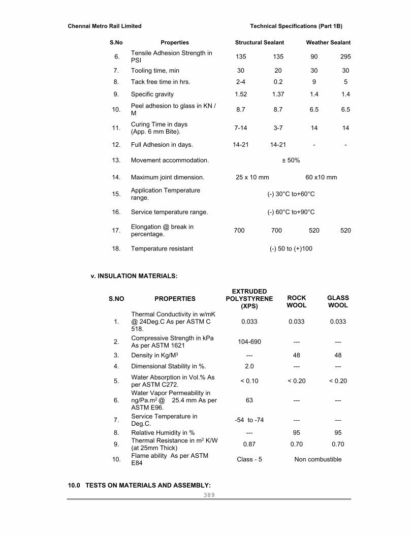
Chennai Metro Rail Limited Technical Specifications (Part 1B)
389
S.No Properties Structural Sealant Weather Sealant
6. Tensile Adhesion Strength in PSI 135 135 90 295
7. Tooling time, min 30 20 30 30
8. Tack free time in hrs. 2-4 0.2 9 5
9. Specific gravity 1.52 1.37 1.4 1.4
10. Peel adhesion to glass in KN / M 8.7 8.7 6.5 6.5
11. Curing Time in days (App. 6 mm Bite). 7-14 3-7 14 14
12. Full Adhesion in days. 14-21 14-21 - -
13. Movement accommodation. ± 50%
14. Maximum joint dimension. 25 x 10 mm 60 x10 mm
15. Application Temperature range. (-) 30°C to+60°C
16. Service temperature range. (-) 60°C to+90°C
17. Elongation @ break in percentage. 700 700 520 520
18. Temperature resistant (-) 50 to (+)100
v. INSULATION MATERIALS:
S.NO PROPERTIES EXTRUDED
POLYSTYRENE (XPS)
ROCK WOOL
GLASS WOOL
1. Thermal Conductivity in w/mK @ 24Deg.C As per ASTM C 518.
0.033 0.033 0.033
2. Compressive Strength in kPa As per ASTM 1621 104-690 --- ---
3. Density in Kg/M3 --- 48 48
4. Dimensional Stability in %. 2.0 --- ---
5. Water Absorption in Vol.% As per ASTM C272. < 0.10 < 0.20 < 0.20
6. Water Vapor Permeability in ng/Pa.m2 @ 25.4 mm As per ASTM E96.
63 --- ---
7. Service Temperature in Deg.C. -54 to -74 --- ---
8. Relative Humidity in % --- 95 95
9. Thermal Resistance in m2 K/W (at 25mm Thick) 0.87 0.70 0.70
10. Flame ability As per ASTM E84 Class - 5 Non combustible
10.0 TESTS ON MATERIALS AND ASSEMBLY:

Chennai Metro Rail Limited Technical Specifications (Part 1B)
390
A. Laboratory tests on full-scale off site proto type test (If called for in the Tender BOQ).
• Unless specified, default test sequence shall be as follows:
Pre load at 50% of inward design pressure.
Air infiltration - Air leakage test – ASTM E 283.
Water infiltration under static pressure (or) static water resistance - ASTM E
331.
Water infiltration under dynamic pressure (or) dynamic water Resistance – AAMA 501.1
Structural test at 50% and 100% of inward design pressure (or) Structural
performance @ 50% and 100% inward design wind pressure as per ASTM E 330.
Structural test at 50% and 100% of outward design pressure (or) Structural
performance @ 50% and 100% outward design wind pressure as per ASTM E 330.
Air infiltration – Air leakage test only after 100% of inward and outward
design pressure test as per ASTM E 283.
Water infiltration under static pressure (or) static water resistance only after 100% of inward and outward design pressure test as per ASTM E 331.
Water infiltration under dynamic pressure (or) dynamic water Resistance
only after 100% of inward and outward design pressure test – AAMA 501.1
Seismic rack test – two directions Design pressure at design movement (or) Seismic movement @ design displacement at two directions (Drift by 8 mm) as per AAMA 501-47.
Structural test at 150% of inward design pressure as proof load (or)
Structural performance @ 1.5 x Design wind pressure at two directions – ASTM E 330.
Structural test at 150% of outward design pressure as proof load (or)
Structural performance @ 1.5 x Design wind pressure at two directions – ASTM E 330.
Structural outward design load to 200% of design load (or) Structural
performance @ 2.0 x Design wind pressure. This load may be treated as failure load and this test is applicable only for structural glazing application.
Note: To determine the drift causing glass fall out (i.e fall out) – Refer AAMA 501.6-
01
• Unless specified in the Bill of Materials or elsewhere, Design wind pressure for the mock-up shall be considered as per IS 875. Part 1, 3 & 5 or as specified in the Bills of quantities whichever is maximum and lateral force shall be as per IS 1893 latest code.
• Air infiltration test shall conform to ASTM E 283. Differential static test pressure
shall be 300 Pascal. Chamber leakage shall be accurately determined, not estimated. Air leakage of test specimen shall not exceed 1.098 cum/Hr.Sqm on fixed and 2.784 cum/hr.m of crack length of vent on the open able window.
Chennai Metro Rail Limited Technical Specifications (Part 1B)
391
• The occurrence of condensation during water infiltration tests is acceptable. Other water leakage is acceptable only if all of the following conditions are satisfied:
The water is contained and drained to the exterior.
There is no wetting of surface that would be visible to building occupants.
There would be no staining or other damage to any part of the completed
building or its furnishings. This definition of water leakage shall govern over other definitions that may appear in referenced documents. State criteria of temperature and humidity.
• Where the test sequence or test failures requires successive water infiltration
tests, the only means used to drain water form internal cavities shall be gravity drainage through the weep system (pressure equalization system) for a minimum of 10 minutes. Air pressure, removal of parts or other means of draining water shall not be used.
• Static water infiltration test shall conform to AAMA 501.1, except as otherwise
specified herein. Differential test pressure shall be 500 Pascal. (1.92” H2O). There shall be no unacceptable water leakage as defined herein.
• Dynamic water infiltration test shall conform to AAMA 501.1, except as
otherwise specified herein. Differential test pressure shall be 500 Pa (1.92” H20). There shall be no unacceptable water leakage as defined herein.
• Structural test shall conform to ASTM E 330. Deflection gauges shall be set to
zero prior to each application of pressure at 50% and 100% of design pressures.
• Deflection gauge readings shall be recorded after each application of pressure
at 50% and 100%. Deflection measurements are not required for the 150% design pressure.
Structural loads (ASTM E 330-70) held for ten seconds each as follows.
50% of positive pressure - design load (To remove the slack). 100% of positive pressure - design load. 50% negative pressure - design load (To remove the slack). 100% of negative pressure - design load.
Typical deflections at the above loads will be measured with micrometer
dial indicators. Allowable deflections of metal framing members at design load are limited to 1/175 of the span or 19 mm max. whichever less is.
Supplementary loads (ASTM E 330-70) if any held for ten seconds as
follows:
50% Positive design pressure (to remove slack) 150% Positive Design Pressure (1.5 x design load) 50% Suction Design Load (to remove slack) 150% Suction Design Load (1.5 design load)
Deflections are not normally measured for supplementary load conditions
specified above.
No failures, in glass breakage nor permanent set in Aluminium Composite panel in excess of 1/1000 allowed.
Chennai Metro Rail Limited Technical Specifications (Part 1B)
392
Perform test of each operable unit to five cycles of opening, closing and locking at the neither stage prior to testing, after air leakage test, after static and dynamic test, at every stage, after completion of every stage of structural performance test confirming to respective ASTM standards.
• Perform concentrated load test on track tie back if directed as follows:
Apply 300 kgf outward for at least 10 seconds.
Apply 125 kgf side loads in either direction for at least ten seconds.
There shall be no failure or gross permanent distortion of the track / tieback or any part of the exterior wall.
• Off site proto type test sequence specified above shall be carried out on prior
approval of the Employer / Employer’s Representative as per the item specified in the Schedule of quantities on prior approval of Employer / PMC / Architect. Off site proto type test drawings and methodology for testing shall be submitted to the Employer / PMC / Architect for review and approval.
• A successful bidder shall arrange a Off site proto type test for one Typical
Module covering the minimum of 3 panels and for 2 floors as proposed by the Employer / PMC / Architect at the approved independent accredited laboratory and conduct the test with in the quoted rate of the respective item of Schedule of quantities & ensure that the system includes Glass, open able vent & Aluminum composite panel and all other relevant materials including special architectural features if any & the test shall comply the set out criteria.
• Credentials of the Laboratory shall be produced for review and approval of
Employer / PMC / Architect prior to fixing the Laboratory for testing. Conduct Off site proto type test at an approved laboratory including necessary arrangements to conduct the test in the presence of the Employer / PMC / Architect’s representative.
• Quoted rate under respective item of Schedule of quantities shall include for
making necessary arrangements and facility to attend / witness the test by the representatives of Client, PMC and Architect (One representative from each as minimum).
• If off site proto type test fails, correct the defects revealed till the satisfaction of
the performance data as setout in the Technical Specification.
• Provide a Test report for the tested system in an acceptable format in a stamped paper prior to commencement of the ordering and procurement of the Materials.
• Unless directed in the Particular specifications or the Employer disowning for
carrying out off-site proto type test, the previous off-site proto type test data of the similar nature of the system/work will be recorded in the project documents as a substitution, provided the successful Bidder or specialized External Facade fabricator has tested the same or similar system, to standards equal to, or exceeding, those specified, the test date with drawings.
• In this case of previous off site proto type test data is recorded as substitute, the
successful Bidder or specialized External facade fabricator should be carried out the test at an approved laboratory with the same or similar system, to standards equal to, or exceeding, those specified above, in the presence of the Employer / Employer’s Representative representative.
B. Field test on actual building – Hose Test:
Chennai Metro Rail Limited Technical Specifications (Part 1B)
393
• Hose test for water leakage shall be carried out conforming to AAMA 501.2.
There shall be no water leakage. Provide a Test report for the tested system for review and record.
• Begin testing as early as possible during erection so that approved corrections
can be incorporated into the remaining work. Correct defects revealed by tests. Retest corrected work to determine effectiveness of remedial measures.
• Provide power scaffolding, hose, water supply and manpower to perform at
least two successful tests at the specified four different locations. The test areas shall be as selected by Employer / PMC / Architect.
• Employer / PMC / Architect will select typical areas to be tested, each
equivalent or not less than to three bays wide and two Stories high and at minimum 4 locations.
• Corrective measure shall meet standards of quality, represented by successfully
tested mock-ups, filed tests and are subject to Employer / PMC / Architect.
• If site test fails, correct the defects revealed till the satisfaction of the performance data as setout in the Technical Specification. Test sealants in place for adhesion, using methods recommended by sealant manufacturer. Promptly replace any sealant that does not adhere or fails to cure.
C. Manufacturers tests of sealants.
• Provide to sealant manufacturer samples of all relevant substrates, including
finished aluminium, coated glass, and gaskets, setting blocks and brackets. Label and identify samples for this project.
• Sealant manufacturer shall perform tests to verify adhesion, staining and
chemical compatibility. Use sealants and substrates only in combinations for which favorable addition and compatibility results have been obtained.
• Separate for record only, sealant manufacturers written test reports, and
recommendations regarding cleaning and priming.
• Specific Test for sealants as per sealant manufactures recommendation:
Test results confirming compatibility and adhesion are mandatory for all concealed and exposed sealant materials used in the Structural Glazing panel / Window systems.
All testing shall be either complete or in progress prior to the initiation
of full size mock-up testing.
In the event sealant testing has not been completed prior to the initiation of specimens for mock-up testing such mock-up testing may precede contingent on the full battery of preliminary adhesion test results, except that no final fabrication or installation will be permitted until all sealant testing is complete.
Schedule sufficient time for testing and analysis of results to prevent delay
in the progress of the work. Fabricator shall consult with sealant manufacturer regarding timing.
Investigate materials that fail compatibility and adhesion testing and obtain
sealant manufacturer’s written recommendations for corrective measure, including use of primer, cleaners, cleaning measures, curing time,

Chennai Metro Rail Limited Technical Specifications (Part 1B)
394
temperature limitations (surface and air), humidity conditions, moisture content of substrate, etc.
Definitions:
Compatibility: The capability of the sealant materials and substrates
to be placed in direct contact with each other and maintain their required physical, chemical and visual qualities with the absence of softening, staining, oil exudation, discoloration or other detrimental, deleterious or degradative effects caused by chemical interactions.
Adhesion: The mechanical or chemical ability of the sealant
materials and substrates to adhere or bond together at their interface.
Staining: Aesthetically unacceptable visual effects caused by sealant materials onto the surrounding surfaces to which the sealants are adhered.
Specimen Sizes and Shapes: As required by the manufacturers testing
laboratory for the tests listed, unless specified.
Adhesion in Peel Testing Method: Comply with ASTM C794, modified to include project specific substrates and to report cohesive failure mode. All specimens shall be tested, primed and unprimed and be subjected to water immersion. Seven days immersion is required for Structural Glazing panel/window Sealants, and one-day immersion is required for weather seals.
Compatibility Testing: This test method describes an accelerated laboratory
procedure to determine if the proposed sealant materials and substrates are chemically compatible. Comply with ASTM C1087 modified as appropriate for the project. UV light exposure should be from UVA 340 bulbs.
Stain Testing: This test method describes an accelerated laboratory
procedure to predict the migration of plasticizers from the sealant into porous substrates such as granite, marble, sandstone, and masonry. Comply with ASTM C1248 modified to test in heat exposure for 14 days at 70 Deg C after 21 days of room temperature sealant cure. Compress the sealant 50% regardless of the rated movement capability. Room Temperature controls and QUV samples are not required.
Record and submit: Any colour change of substrate or sealant, bubbles, or
sealant softening as appropriate for approval.
Chennai Metro Rail Limited Technical Specifications (Part 1B)
395
D. Pre Construction Field testing on sealants:
Prior to installation of field applied sealants, field-test their adhesion to joint substrates as follows:
• Conduct field tests for each exposed exterior wall sealant and substrate.
• Sealant application and tests shall take place with Employer / Employer’s
Representative, Sealant installer and sealant manufacturer’s representative present.
• Test joint sealants by hand pull method using the procedure described below:
Install sealant in 1500mm joint lengths using the same materials and methods for joint preparation and sealant installation in accordance with manufacturer’s final laboratory testing recommendations. Allow sealants to cure a minimum of seven days.
With a knife, completely cut through the sealant bead at 90 degrees perpendicular to the direction of the joint. Make 2 cuts on either side of the joint as close to the substrate as possible, without damaging the substrate, to an approximate length of 75mm.
Use fingers to grasp 75mm piece of sealant, pull firmly down at a 180 Degree angle parallel to the joint. Pull sealant out of joint to the distance recommended by sealant manufacturer for testing adhesion. Record the result ie. Pass or fail. Repair joint as recommended by sealant manufacturer.
• Provide & submit written summary of each test, whether it was performed in the Laboratory, shop or site. This shall include all adhesion, compatibility and deglazing tests.
11.0 SUBMITTALS
A. Shop Drawings:
• Prepare and submit Shop Drawings for all the items covered in the entire external façade system to PMC/Architect’s for Review, including at project proposal stage.
• Prepare Shop Drawings incorporating all allowances for construction and
fabrication tolerances and in line with the project proposal drawings and details prior to preparation of final shop drawing for execution.
• Submit preliminary schematic shop drawings along with Bid to understand the
proposal of the system. Drawings shall show all major Structural Glazing Panel/window System components. No Tender will be considered without preliminary Drawings.
• Employer / Employer’s Representative ’s review will be conformance to the design
concept and for the general arrangement only. And such review shall not relieve the contractor of any responsibilities as stated herein or any other applicable items herein or any other applicable items herein specified.
• Submit shop drawings for all work of this section, based on approved project
proposal stage system details for review and approval including shop drawings for mock-up test along with Methodology of Off site proto type test and Credentials of the independent Laboratory for testing and review and approval.
• Shop drawing should include the following, but not limited to :

Chennai Metro Rail Limited Technical Specifications (Part 1B)
396
Show joinery techniques. Provisions for horizontal and vertical expansion. Glass and Metal thickness, framing and anchor member profiles. Identify all materials, including metal alloys, glass types, and fasteners and
glazing materials. Identify all shop and field sealants by product name and locate on drawings. Show relative layout of all adjacent walls, beams, columns, and slabs, with all
dimensions to each other and grid lines. Dimension position of glass edge relative to metal daylight. Anchorage details to the building structure and coping details at the parapet
are also to be submitted.
• Submit die drawings for all gaskets, weather strips and Aluminium extrusions for record only, not for review.
• Shop Drawings shall be signed and sealed by an Independent Qualified Consultant
with specific experience in Structural Glazing work construction & design and submit the same for review and approval of PMC / Architect.
B. Structural Calculations:
• Submit for review structural computations, of all the critical elements that constitute the Structural Glazing panel/window elements, include mock-up Test proposal. Comply with current design rules of the relevant aluminum code. Include analysis for wind, dead loads, and if appropriate seismic loads on framing members and anchors.
• Show section property computations for framing members and full size die
drawings.
Existing test reports shall not be an acceptable substitute for computations. In no case shall glass be considered as a lateral brace for the framing
members.
• Submit structural calculations for the structural silicone joint size as required. Aluminium profiles, silicone gaskets and glass bite must accommodate the silicone joint size required.
• Submit structural calculations for the glass stiffeners required for spider / point
fixed glazing. • Calculations shall be signed and sealed by a registered independent Structural
Engineer experienced in the field of Structural Glazing/Structural Glazing Window design and submit the same for review and approval of PMC / Architect.
C. Submittal Procedure:
• Submit preliminary shop drawings and shop drawing at project proposal stage with bid by the successful bidder to Employer / Employer’s Representative review.
• Incorporate Employer / Employer’s Representative Review comments related to
the preliminary shop drawings including the comments if any based on the Off site proto type test report.
• After receiving Employer / Employer’s Representative ’s approvals, submit
drawings and calculations to the City Council for approval if required. • Pay appropriate statutory fees to the city and secure relevant permits.

Chennai Metro Rail Limited Technical Specifications (Part 1B)
397
• Return one stamped copy from the statutory bodies to Employer / Employer’s Representative ’s for the record.
• Submit glass Analysis for record, only glass manufacturer’s wind pressure analysis
and thermal analysis showing that the specified maximum deflections and probabilities of breakage are not exceeded.
• Submit Suitability for Structural Silicone Glazing for record, only glass
manufacturer’s written statement that any insulated glass, reflective glass and spandrel glass is supported by structural silicone is suitable for such application.
• Submit Structural Silicone Substrate Tests for review the results of the structural
silicone substrate tests as specified above in relevant article. • Submit Silicone Adhesive Tests for records, only sealant manufacturer’s test report
for weather seal silicone adhesive to all relevant substrate. • Test must include a seven-day water immersion after which silicone must have
excellent adhesion to substrates. Report the results on adhesion strength in terms of shear stress and tensile stress. Test samples shall approximate sealant joint sizes and configurations intended for production materials.
• Submit for the record, the laminated sandwiched composite panel (Aluminium
composite panel) Plain and Corrugated supplier’s analysis of the stresses in the panels when subjected to lateral pressures.
• Submit a letter of certification from the sealant manufacturer stating that the
sealant has been tested for adhesion and compatibility on production samples of metals, glass, and other glazing components, and that all sealant details and application procedures shown on the reviewed Shop Drawings are acceptable for use. If required specifically the following submittals shall be provided by the contractor.
Provide and review of shop drawings noting support required, tolerances,
materials used, placement of setting blocks, thermal performance and specification on flatness from the Insulated glazing manufacturer. See Glass & Glazing. Use no acid cure silicones on or near Insulating Glass Units.
Sealant Manufacturer review of the Mockup Drawings prior to the mockup.
Test results for all jobs specific concealed and exposed sealant conditions
confirming compatibility and adhesion are mandatory for all materials prior to mock-up and testing. Preliminary results in advance of final reports will be acceptable contingent on adhesive values tested and reported equal to or in excess of the minimums specified.
Complete instructions for handling, storage, priming, installation, curing and
protection of each type of sealant, joint filler and accessory.
Manufacturer’s Data sheets, clearly indicating shelf life of sealant to be supplied.
Manufacturer review of the final drawings after mockup, clearly indicating that
each product to be furnished complies with this specification, is recommended for the application shown, and is compatible with each other material in the joint system.
Quality assurance sample logs for the silicone Structural Glazing
panel/Window system before fabrication. Submit weekly Quality Assurance Documentation on all Structural Glazing panel / Window production.

Chennai Metro Rail Limited Technical Specifications (Part 1B)
398
• Chart of Required Submittals pertain to sealant :
Completion Pre mockup
Post mockup
During fabrication
Site survey and report X
Sealant Manufacturer Print Review X
Sealant Material Data Sheets X
Manufacturers Instructions X
Adhesion Testing Report X
Compatibility Testing Report X
Final Shop Drawing Review X
Off site proto type Test Report X
Off site proto type Deglaze Report X
QA Sample Logs X
Pre-construction Field Test X
Shop QA Logs X
Deglaze Tests X
Field Adhesion Tests X
Field Tests Report on the System X
System Guarantee X
Anodizing Performance Warranty X
Glass & ACP Performance Warranty X
Insulated Glass Warranty X
Gasket Properties Warranty X
Sealant Performance Warranty X
Deglazing reports on deglazing of structural silicone on Structural Glazing panel/Window frames.
Deglaze using the following schedule for fabrication.
a. A full report on a mock up deglaze
b. 1 in the first 10 of production 1 in the next 40 of production 1 in the next 50 of production 1 in the next 100 thereafter (or) 1 at every 25 panel glazed irrespective of total quantum of panels.
Field Adhesion testing summary of results and location and Manufacturers
warranty at job completion.

Chennai Metro Rail Limited Technical Specifications (Part 1B)
399
12.0 SAMPLES:
• Submit for review three (3) sets of labeled samples of each required type and colour of metal finish, on 300mm long sections of aluminium extrusion shapes. Samples must show extremes of colour and texture variation. Architect will review samples for colour and texture only. Compliance with other requirements is the responsibility of the Contractor. Colour and texture range of production material shall match approved samples.
• Submit 300 mm square labeled samples of each type of glass to Architect for review.
Reflective glass samples shall show extremes of colour range. • Submit for review, 3 sets of sample sealant backers, anchor components, anchor
assemblies and epoxies. • Submit for approval, current (within six months of submittal date) test reports by
independent laboratories for granite properties and anchors as specified in relevant section. Submit written certification that samples tested are representative of production material. Reports will be reviewed for completeness and clarity only. Accuracy of report is the exclusive responsibility of the Contractor.
13.0 PRODUCT HANDLING
• Package and store materials in a manner that will prevent surface damage or contamination, distortion, breakage or structural weakening.
• All composite aluminum panels shall be packaged vertically, face to face or back to
back, with adequate protection to prevent scratching.
• The factory applied protective peel – off foil shall only be removed after the panels have been installed on site.
• Replace any material damaged during manufacture, shipping, storage, or erection. • Protect materials in place from contamination and damage. • Protect factory-applied finishes from staining and scratches. • Field cutting of anodized / powder coated components shall not be permitted. • Deliver Sealants to project site in manufacturer’s original unopened containers, with
manufacturer’s name, product name, and color fully indicated thereon. Store the sealants in accordance with manufacturer’s instructions. Counterfeit products found on site will be required to be removed and proper product reinstalled at the expense of the applicator/fabricator. Any damage caused by counterfeit products will be repaired at the expense of the applicator/fabricator, without causing delay to the project. This includes replacement of stained substrates.
14.0 FABRICATION:
• Competent workmen who are thoroughly skilled in their trade shall do work. Assemblies shall be neat and free of defects that impairs strength, function or appearance.
• The work shall be accomplished in compliance with the specified criteria without
buckling, opening or joints, undue stress on fasteners, sealants and gaskets, opening of welds, cracking of glass, leakage, noises and other harmful effects. As far as practicable, fitting and assembly of the work shall be done in the factory.

Chennai Metro Rail Limited Technical Specifications (Part 1B)
400
• All exposed work shall be carefully matched to produce continuity of line and design. All joints in exposed metal work, unless otherwise shown or specified, shall be accurately fitted and rigidly secured with joint sizes conforming to industry standards.
• Except where otherwise shown, specified or directed the method of assembly and
joining shall be the Contractor’s option provided the results are satisfactory. The manufacturer’s proven methods that will produce the required standards of workmanship shall be used subject to approval.
• Fabricate and fasten metal work so that the work will not be distorted nor the
fasteners overstressed from the expansion and contraction of the metal. • All welding shall be in accordance with the appropriate recommendations of the
American Welding society and shall be done with electrodes and/or by methods recommended by the manufacturer of the alloys being welded. All welds behind finished surfaces shall be done as to minimize distortion and/or discoloration on the finished side. All weld spatter and welding oxides on finished surfaces shall be removed by decaling and/or grinding.
• Unless shown or specified, all weld beads or exposed surfaces shall be ground
and finished to match and blend with finish on adjacent parent metal. Grinding and polishing of nonferrous metal shall be done only with clean wheels and compounds free from iron and iron compounds. No soldering and/or brazing shall be allowed.
• Conceal fasteners where visible in the finished work. • Fabricate aluminum components before finishing. Components cut in the field will
not be acceptable. • All Composite aluminum panels shall be factory fabricated and assembled in
compliance with the manufacturer’s Data sheets. All panels shall be cut and routed using equipment and tools recommended and approved by the panel manufacturer. After folding into cassettes, an extruded aluminium profile shall be fixed to the minimum 25 mm deep return bend using 5 mm blind rivets. The aluminium flat of size 25 x 2mm shall be provided as a stiffener to ACP in the corner bends to the total height of the panel.
15.0 INSPECTION
• All shop and field materials and workmanship shall be subject to review by Employer / Employer’s Representative at all times. Such reviews shall not relieve the Contractor from the obligation to provide materials conforming to all requirements of the Contractor Documents, and matching approved samples. The Contractor shall promptly correct any deficiencies reported and carry out his own control measurements for all materials, whether reviewed or not.
• Verify that surfaces and conditions are suitable to receive the work of this Section
at site, and that conditions will not adversely affect the installation and performance of the installed work.
• Correct all unsatisfactory conditions prior to beginning erection of specified work.

Chennai Metro Rail Limited Technical Specifications (Part 1B)
401
16.0 ERECTION
• Erect Structural Glazing panel / Window and aluminium drain system in accordance with the approved Shop Drawings.
Provide labor, material, booms, accessories, and supervision necessary to
erect the complete material.
Coordinate erection with the requirements of the hoist man lift, including tie back and kicker connections tot he floors, and door openings at the various floors.
Do not install components, which are defective in any way, including
warped, bowed, dented, abraded, and broken members and glass with edge or surface damage. Remove and replace all damaged components to PMC/Architect’s satisfaction.
• Set walls plum, square and level and fasten securely in correct vertical and
horizontal alignment. Seal joints within wall and between adjacent constructions. • Install components level, plum, true to line, and with uniform joints and reveal.
Attach to structure with non-staining and non-corrosive anchors, fasteners, spacers, and fillers as required.
• Do not cut, trim or weld components during erection in any manner, which would
damage the finish, decrease strength, or result in a visual imperfection, or failure of such components. Return components that require alteration to the shop for re-fabrication, or for the replacement with new parts or components.
• Tolerances.
Tolerances for building frame and other work are specified in other
Sections. Make provisions for these tolerances, including a ± 25mm concrete slab tolerance.
All parts of the work when completed shall be within the following
tolerances:
Deviation from plumb, level or dimensioned angle shall not exceed 3 mm per 3.2m of length of any member, or 5mm in any total run in any line.
Deviation from theoretical position in plan or elevation, including
deviation from plum, level or dimensioned angle, shall not exceed 10 mm total at any location. Change in deviation shall not exceed 3mm for any 3.2 m in any direction.
Maximum offset from true alignment between two consecutive
members placed end to end shall not exceed 1.5mm.
Maximum offset between glass framing members at corners of glazing pocket shall not exceed 1mm.
Provide accurate bench marks for use in wall erection at all floors. Promptly
correct any errors or inconsistencies.
Chennai Metro Rail Limited Technical Specifications (Part 1B)
402
• Assembly and Anchorage:
Anchor component parts securely in place by bolting, welding or other
permanent, mechanical attachment system, which will comply with performance requirements and permit movements, which are intended or necessary. Install slip pads between moving parts.
Provide a separator at contact surface of dissimilar material wherever there
is a possibility of corrosive or electrolytic action.
Remove weld slag and apply prime paint over welds. Also paint exposed portions of inserts. Touch up shop applied paint that is damaged by welding or other causes.
• Glazing:
Preparation: Clean all surfaces, which will abut glass immediately prior to
glazing. Remove all dirt, oil and other bond reducing film. Use cleaning material only as recommended by the Structural Glazing panel/ Window contractor.
All glass shall be new. Mock-up glass shall not be used on the building. Glass shall be of the specified types and quality, with seamed edges and corners. Inspect all lights of glass before installation. Do not install defective glass.
Before setting glass, inspect frame for proper dimensions and square.
Adjust frame and/or glass size as required to meet specified requirements.
Unless otherwise specified, comply with FGMA Glazing Manual. Provide a minimum nominal glass bite of 12mm. Where glass bite will be reduced by frame thermal movement, increase nominal glass bite to provide 12mm bite when splice joints are fully opened. For Structural Glazing Panel/Window, glass bite shall be adequate to provide the surface contact area required for the structural silicone and silicone gaskets.
Unify the appearance of each series of lights by setting each piece to match
others as closely as possible. Inspect each light, and set with pattern, draw, and bow oriented in the same direction.
Thoroughly clean glazing pocket before setting glass. Solvents shall be
compatible with aluminium, glass and glazing materials. Place setting blocks at quarter points. Place side blocks in the upper half of each jamb light. Side blocks shall be positively retained in position.
Remove and replace stops and apply sealants as required for a complete
glass installation. Details of installation shall permit replacement of glass after the construction period.
Defer glazing of openings which is obstructed during construction. Glaze
such openings when obstructions are removed. Replace any glass, which breaks or sustains edge damage, surface damage or damage to reflective coating as defined above.
• Sealant Application:
Apply sealant materials in accordance with sealant manufacturer’s
recommendations.
Apply sealant using a continuous bead of sealant.
Chennai Metro Rail Limited Technical Specifications (Part 1B)
403
Apply a continuous sealant bead between flashing and adjacent construction.
Before application of sealant, examine the substrates, adjoining
construction and the conditions under which the work is to be installed. Do not proceed with the work until unsatisfactory conditions have been corrected. In no instance shall the installer install sealant in conditions which conflict with this specification without approval.
Clean bonding joint surfaces to remove deleterious substances, this might
interfere with bond or otherwise impair the work.
Do not apply electrometric sealants to joint surfaces previously painted or treated with sealer, curing compound, or other coatings, unless a laboratory adhesion and peel test in accordance with ASTM C 920 and ASTM C794 has been performed and successfully demonstrated that bond will be durable.
Unless shown or specified and documented, Install materials in accordance
with the manufacturer’s printed instructions.
Confine sealants and primers to joints using masking tapes or other precautions where required to prevent contact of sealant or primer with adjoining surfaces which otherwise would be permanently stained or damaged by such contact or by cleaning methods required to remove sealant smears. Remove tape immediately after tooling without disturbing sealant.
Primers: Prime all substrates recommended by the manufacturer based
upon adhesion testing. Comply with the instructions of the sealant manufacturer. Avoid migration of primer onto adjoining surfaces and remove any spillage promptly. Unless specifically recommended by the manufacturer as noted in the above submittals prime before installation of backer materials.
Where joint filler is used as backup for sealant, install filler continuously
without voids or interruptions to depth and shape specified by sealant manufacturer for proper application and performance of products. Trim for tight fit around obstructions or elements penetrating the joint.
Install bond breaker in joints as shown and wherever recommended by the
sealant manufacturer to prevent bond of the sealant to surfaces and where such bond might impair the performance of the sealant. Do not puncture surface or skin of expanded Polyethylene joint filler backer rods.
Apply joint fillers accurately according to the joint profile shown in the
drawings after joint cleaning and priming. Provide watertight and airtight corners and joints in a manner recommended by the manufacturer.
Apply sealants in continuous beads filling joint from the bottom without
openings, voids or air pockets so as to provide a watertight and airtight seal for the entire joint length. Apply sealants in concealed bedding joints accurately so that excess sealant will not exude from the joint.
Apply sealants in the depth shown or, if none is shown, apply in accordance
with the manufacturer’s recommendations. Apply electrometric sealants, in field joints not subject to traffic or other abrasion, to a depth equal to 50% of the joint width, but not less than 6mm and not more than 12mm.

Chennai Metro Rail Limited Technical Specifications (Part 1B)
404
Immediately after sealant application and prior to time skinning or curing begins, tool sealants to form smooth, uniform beads of configuration indicated, to eliminate air pockets and to ensure contact and adhesion of sealant with sides of joint. Remove excess sealant from surfaces adjacent to joint. Do not use tooling agents which discolor sealants or adjacent surfaces or are not approved by sealant manufacturer. Tool exposed surfaces of sealants to the profile shown or if none is shown, tool slightly concave to match the configuration as in ASTM C1193.
Provide a slight slope on horizontal joints where horizontal and vertical
surfaces meet.
Remove excess sealant promptly as the work progresses and clean the adjoining surfaces as may be necessary to eliminate any evidence of spillage.
Do not proceed with installation of field sealants during inclement weather.
Do not proceed with installation of elastomeric sealants when extreme temperatures or heavy wind loads are forecast during the period required for initial or nominal cure of elastomeric sealants. Whenever possible, schedule the installation and cure of elastomeric sealants during periods of mean temperatures (nominal joint width shown) so that subsequent stresses upon the cured sealants will be minimized. Install field sealants in accordance with manufacturer recommendation to reduce sealant wrinkling from movement during cure. Do not install sealants into joint widths that are less than specified without approval of the Employer / Employer’s Representative .
17.0 PROTECTION
• Take all necessary means to prevent any damage (scratches, dents, nicked edges etc.) to components during handling and erection. Replace components beyond acceptable field repair at no additional cost to the Employer / Employer’s Representative .
• Protect glass from breakage immediately upon installation by attachment of crossed
streamers to framing held away from the glass. Do not apply markers of any kind to glass surfaces. Remove and replace glass which is broken, chipped, cracked, abraded or damaged in any manner as a result of construction activities, natural causes, accidents or vandalism. Replace with new materials at no additional cost to the Employer / Employer’s Representative .
• Maintain glass in a clean condition at all times, including during construction, to
prevent glass damage from corrosive action from the elements, and contributing side-effects (by wash-off) to other components and other work.
• Cure sealants in accordance with the manufacturer’s instructions, to obtain
maximum bond to surfaces, cohesive strength and durability at the earliest possible date.
• Protect sealant during the remainder of the construction period, so that they will not
be subjected to damage before the time of acceptance by the Employer / Employer’s Representative . Do not proceed with a mockup until representative size sealant joints are fabricated and documented as cured.
18.0 CLEANING
• Clean surfaces as required to remove corrosive substances. At the conclusion of construction, clean all surfaces to the satisfaction of PMC/Architect.

Chennai Metro Rail Limited Technical Specifications (Part 1B)
405
• Provide written verification those cleaning agents are compatible with aluminium, glass, glazing materials and sealants.
• Periodically removes from the site debris, excess materials and unused tools and
equipment resulting from this work. At the conclusion of construction, leave the premises in a clean condition acceptable to PMC/Architect. Surfaces as required to remove corrosive substances.
• Upon Completion of construction and prior to taking over the work by the Employer,
it is the responsible of the Successful bidder to clean all surfaces to the satisfaction of Employer/PMC /Architect.
19.0 MAINTENANCE REQUIREMENTS:
• General: Provide design of the building envelope systems to allow for all BMU / Cherry picker load which may occur.
• Retaining pins for the BMU are to be provided by the BMU contractor to the Glazing
assembly factory and are to be fixed to the glazing system by the Façade contractor.
• Damage: Horizontal or near horizontal surfaces, which form part of the building
envelope system such as copings, beam encasements, ledges, or the like, shall be designed to carry human live loads from maintenance personal.
• Self cleaning: the design of all components for the contracts works shall be such
that their configuration shall facilitate the self cleaning of the various systems. Inclined drainage surfaces and flashings properly designed drip grooves and self cleaning joint design are examples of this requirement.
• Panel replacement method: the Façade contractor shall design and install the
building envelop systems to allow for the future replacement of any individual panel. The Façade contractor shall submit details and procedures for replacing individual damaged items as part of the shop drawings.
20.0 SPARES:
• The contractor shall supply an adequate number of spare glass panel’s specification wise to be held in storage by the Employer as spares in the event of accidental breakage or some other failures that might occur in the future at the mutually agreed quoted rates.
• It is the contractor's responsibility to advise the Employer as to the number of
spares required for this project. In general, the attic stock of the total glass shall be considered as given in the Schedule of quantities covering all the size of the different glass panel used in the project at the agreed Quoted rate.
21.0 MODE OF MEASUREMENT:
• Unless noted otherwise in the Description matrix and Schedule of quantities, items will be measured generally in accordance with IS 1200.
Chennai Metro Rail Limited Technical Specifications (Part 1B)
406
SECTION – 2 - PARTICULAR SPECIFICATION
S.No Ref.
Description of Items BOQ item No Description
General Note: This Particular specification (Description Matrix) shall be read along with Schedule of quantities while quoting the rate for the respective items. The quoted rate under this schedule shall be deemed to have considered Technical specification. 22.01 1.01 to
1.05 Semi
unitized Glazing
Semi unitized Structural Glazing System
Scope: Designing the Semi unitized structural glazing system as per design intent and as per approved drawings, preparation of shop drawings, supply, fabricate the panel with the specified glass on the child frame at factory, erect the system on erected extruded main frame & Transom fixed on supporting system at site as per approved shop drawings at all floor levels and for all heights. Designing, providing and fixing frame supporting system, the framing system (i.e. Main & Child frame) to support Vision panels (Insulated Glass) / Spandrel panels either with Monolithic Glass or Laminated sandwiched composite panel (ACP),/openable Top hung window panels/ punched strip windows/ decorative capping to any shape & profile, smoke seal, flashing including gaskets, sealants necessary accessories, as part of the system on a continuous framing supported between floors as detailed below and as per the specification for external facade system.
Design the split framing semi unitized glazing system in case of Punched windows with vision panel proposed with either Insulated/Monolithic Glass as specified maintaining groove width shall not be more than 16 mm both in horizontal and vertical. Conducting the test for the materials involved in the system, field test on the erected system at site as per the test criteria set out in the specification of External Facade system. Submission of methodology for the Materials and assembly (Mock up & field test) supported by the copy of relevant codes & Standards and the same shall be got approved by the Employer / PMC / Architect prior to testing. Protection of the System and Materials till handing over to the Employer / PMC / Architect, removal of the unwanted materials, broken glass, Screws, bolts, Nuts, Packing Materials, debris etc, regularly and keeping the premises neat and clean at all times. Coordinate the details of the façade cleaning system during the preparation of shop drawing and incorporate such details in the shop drawing submitted for approval of Employer / PMC / Architect. Maintaining the system by means of periodical inspection at site (bi-monthly) and checking the system and Materials involved in the system during Defects liability period (this will not relieve the contractor from the condition laid down in the contract under defects liability period) to ensure that the system and all materials are free from any defects during this period. Providing the Guarantee for the entire External Façade system to the specified period in an approved format supported with Back to back guarantee from the specialized Material supplier like Glass, Aluminium composite panel, Gasket, Sealant, Hardware etc. complete as directed by Employer / PMC / Architect. I.DESIGN: a. Design: Design pre-assembled aluminium Semi unitized Structurally

Chennai Metro Rail Limited Technical Specifications (Part 1B)
407
S.No Ref.
Description of Items BOQ item No Description
glazed Panel with continuous framed panels / Strip window / Punched window system with split mullion to any shape and profile to satisfy the structural design criteria specified in the technical specification (Test pressure shall be 1.5 times of the design wind pressure) and fixed at horizontally / vertically / sloped / curved position etc as shown in the approved drawings by using Aluminium extrusions, Glass, Spacer tape, Gasket, Sealant etc. as specified. Contractor shall be responsible to determine the maximum design wind pressure and lateral forces, moments, stresses etc. applicable for the system. Negative / suction pressures if determined as per IS 875 and Lateral forces as per code IS 1893 shall make allowances as described in the code for corner effects on the system. System shall be designed with Air Pressure equalization chamber and concealed continuous gutter vertically and horizontally at all levels as self drainage barrier to achieve water tightness besides providing EPDM Gaskets on the frame and EPDM Gasket / Sealant on the external groove as air and water barrier.
b. System: System shall be designed to satisfy the structural design criteria specified in the technical specification with self-bearing modular elements supported between floors (Supporting span of minimum 3.50 meter) in the case of structural glazing and split mullion supported between sill & lintel/beam in the case of punched windows, EPDM Gaskets on the frame and Gasket/sealant on the groove to prevent the system from Air & water penetration ,double adhesive spacer tape, backer rod, sealant, supporting brackets (Resistance to design wind pressure), Separator Gaskets for Bi-Metallic Corrosion, Pressure equalization chamber in the system, built-in continuous internal drainage gutter for collection and facility at lowest floor level to drain out penetrated water, in built adjustability to accommodate thermal expansion, thermal movement and movement due to any other forces etc. System shall be designed with Gasket/Sealant on the external groove with colour anodized aluminium holder alround the panel to the required width and thickness as per design as Dead load support to the Glass panel. Non Staining sealant between glass & aluminium holder alround the panel shall be provided. Glazing the panel with child frame shall be done only at factory at the controlled atmosphere to erect the panel on erected extruded aluminium main member and transom with supporting system at site fixed on the RC surface. The Mullion and sill / head Transom flush on inside of the facade. Intermediate transoms shall be provided keeping 2 to 3mm recessed from the inner face of the mullion. Joints between mullion and transom shall be filled with weather sealant on the inside. All transoms shall have uniform in depth on the inner face of the system. Vertical in-situ glazing shall not be carried out during construction/erection stage. System shall be designed in such a way that the outer surface of insulated glass unit, monolithic glass unit and Aluminium Composite Panel shall be in the same plane or as per approved drawing. Aluminium shim shall be used for level adjustment of bracket but more than 20 mm is not acceptable. If more than 20 mm bracket shall be designed according to site condition. c. Movement: System shall be designed to accommodate movement due to any force including the movement resulting from the exterior skin temperature ranging from 15 to 85 deg Celsius, Interior skin temperature ranging from 15 to 30 deg Celsius, and also to accommodate the horizontal building movement of 10 mm per panel & vertical movement of 20 mm between floors on the aluminium framing system with support

Chennai Metro Rail Limited Technical Specifications (Part 1B)
408
S.No Ref.
Description of Items BOQ item No Description
brackets, glass, gaskets and fastening devices. System shall be designed to accommodate the size and shape of the glass panels as per the approved drawings including approved modifications as may be required during execution as well as all other incidental forces and stresses likely to be experienced under service conditions, i.e. Lateral force, Dead weight and Thermal expansion due to building movement both vertical and horizontal etc. The supporting system shall consists of Brackets / Clamps, fastening straps, nuts, bolts, rivets, washers and other fastening materials etc. Extruded sections shall be designed to accommodate Insulated Glass Unit (IGU) / Monolithic (Single) Glass and Aluminium composite panel as per the approved shop drawings. Extruded aluminium sections shall be 63400 (H9) grade conforming to IS 8147, finished with AC25 grade Architectural quality electrolytic colour anodic coating of approved colour conforming to IS 1868.
d. Glass: Fixing the Insulated Glass (IGU) with laminated / Monolithic (single) Glass as per specification for both vision and spandrel panel conforming to the minimum spectral parameters as specified. Spacer for Insulated glazing unit shall be aluminium extruded profile and finished with AC 25 grade electrolytic colour anodic coating of black colour conforming to IS 1868 and filled with dry desiccant. Primary sealant shall be Poly-isobutylene (PIB) and Secondary seal shall be structural silicon sealant of DC 995 (one part) or DC 983 (two parts) of Dow corning or approved equivalent. Make and thickness of Inner pane glass shall be the same make as outer pane glass of IGU / DGU. Refer the separate item in Schedule of Quantities for the supply of Insulated / Monolithic glass.
e. Gaskets: Providing and fixing weather barrier to ensure the air & water tightness at minimum 3 stages and to ensure that the system is thermally broken systems. The first barrier exposed to weather condition shall be Elastomer silicon synthetic rubber manufacture by oven process at different stages conforming to BS or equivalent IS. The properties of Elastomer silicon synthetic rubber such as hardness, tensile strength elongation compression test & ozone resistance shall be in accordance with BS 903 & BS 903A minimum hardness (shore A) of Elastomer silicon synthetic rubber shall be 65 to 75 Deg and the weather strip with in the system for unexposed shall be Elastomer EPDM (Ethylene Propylene Dinine Monomer) synthetic rubber and its properties like hardness, expanded density (Specific gravity) compressive set, water absorption, skin surface, cell structure, ozone resistance, low temperature includes work shall be in accordance with ASTM D – 1056 and minimum hardness ( Shore A ) shall be 61/71 Grade. In general, EPDM gaskets / silicon synthetic rubber shall be as per pre approved make. Contractor shall submit the Manufacturer test certificate conforming that the properties of the Gasket supplied is meeting the specification, codes & standards and copy of such codes shall be produced by the Contractor for verification of Employer / Employer’s Representative . Contractor shall arrange to carry out the test to check the properties of EPDM / silicon rubber gasket on the random sample selected by Employer / Employer’s Representative (Min. 3 Nos of each type to a required length) and the contractor shall make sure that the properties are meeting the codes and standards and specifications. f. Sealing: Design bite and thickness of structural sealant to withstand 3 times of the stress caused by the design wind pressure specified above

Chennai Metro Rail Limited Technical Specifications (Part 1B)
409
S.No Ref.
Description of Items BOQ item No Description
and to ensure the same, the design calculation of sealant manufacturer shall be submitted along with shop drawing. Necessary materials as proposed in the shop drawing such as Extruded member with finish, glass and any other material required by the Sealant manufacturer shall be supplied to them to carryout the test as per relevant codes & standards in order to validate the bite and thickness designed by them. Contractor shall obtain the test certificate from Sealant manufacturer and submit the same along with shop drawing and supported by the copy of relevant codes and standards. Contractor shall ensure that the bite and thickness of sealant as designed & determined by calculation, verified and tested by Manufacture's is followed in the shop drawing and the same shall be adopted for the glazing at factory after the approval of shop drawing. Field test shall be conducted for adhesion of sealant with in the quoted rate. Supplying and fixing the Sealant as per specification and Double Adhesive spacer tapes for glazing the panel at factory. Spacer tape shall be open cell polyethylene of code no. Nortan V-2100 of Nortan Grind well make or approved equivalent, Jointing / Sealing of the glazed panel at factory shall be done with Non structural (weather) sealant / Non staining sealant of DC 991 HP of Dow corning make or approved equivalent with Polyurethane baker rods of Supreme make or approved equivalent. Acetoxy sealant shall not be used for Structural Glazing application. In general, providing and fixing the Structural and non Structural (weather) sealant shall be as follows: Shop / Factory Sealants:
i) Structural sealant shall be DC 995 (one part) or DC 983 (Two part) of Dow corning make or SSG 4000 (one part) or SSG 4400 (Two part) of GE Bayer Silicone make or approved equivalent.
ii) Non-Structural (weather) sealant shall be DC 991 HP of Dow corning make or approved equivalent.
Field Sealants:
i) Structural Sealant shall be DC 995 (one part) of Dow corning make or SSG 4000 (one part) of GE Bayer Silicon make or approved equivalent.
ii) Non-Structural (weather) sealant shall be DC 991 HP of Dow corning make or approved equivalent.
g. System Supports : Providing and fixing the supporting system with Brackets / Clamps including fastening straps, nuts, bolts, rivets, washers etc. as per design requirement and as per approved shop drawing. Brackets / Clamps shall be of hot dip galvanized steel and fastening materials shall be Non - magnetic Stainless steel 300 series - 316 grade of Hilti make or approved equivalent. Galvanizing thickness shall be in accordance with IS 2629 and 4759. Providing and fixing serrated plates or serrated washer wherever required as per the system requirement and as shown in the approved shop drawing. Shim thickness beyond 20mm is not permitted. Shims shall be similar material, preferably with aluminium, not more than 20mm thick and if the variation is beyond 20 mm, the bracket shall be designed accordingly with fastener.
h. Smoke seal: Providing and fixing Smoke seal / Fire stop using extruded aluminium channel with cap for continuous structurally glazed framing system with required thickness as per site and in general the thickness of channel and cap shall be 2 mm and to a width as required between transom and sill finish material and it shall be 63400 (H9) grade
Chennai Metro Rail Limited Technical Specifications (Part 1B)
410
S.No Ref.
Description of Items BOQ item No Description
conforming to IS 8147, finished with AC25 grade Architectural quality electrolytic colour anodic coating conforming to IS 1868 of approved colour. Aluminium colour anodized extruded Channel shall be supported with the help of Aluminium bracket as designed and this bracket to be fixed on the wall / RCC surface with necessary SS anchor bolt and fastener of Hilti make or approved equivalent. This channel with cap shall be provided between Sill finish Material (Civil scope)) and structural glazing member at sill level and between RCC member face and structural glazing member at soffit level / false ceiling and etc complete. All the Joints between the capping channel and any other finish material at both sill and soffit level shall be sealed with intumescent sealant of Lurint or Hilti make.
The channel with cap shall be provided between Sill finish Material (Sill finish material shall be paid separately) and structural glazing member at sill level and between RCC member face and structural glazing member at soffit level / false ceiling and etc complete. All the Joints between the capped channel and any other finish material at both sill and soffit level shall be sealed with Intumescent sealant of 3 M make or approved equivalent. Also, close the gap on the vertical surface between the face of column/wall/partition and structural glazed frame/glass by using extruded aluminium channel with cap with anodized finish aluminium bracket supported on the coloum/wall/partition and in general the thickness of channel and cap shall be 2 mm and to a width as per drawing and it shall be 63400 (H9) grade conforming to IS 8147, finished with AC25 grade Architectural quality electrolytic colour anodic coating conforming to IS 1868 of approved matching colour to the Mullion & transom. g. Flashing: In addition to the Channel specified above, providing and fixing flashing at all floor levels as part of the system (applicable only for continuous structural glazing portion) made to profile as shown in the approved drawings and the profile shall be made out of hot dip galvanized sheet 1.2 mm thick and galvanizing coating thickness shall be in accordance with IS 2629 & 4759. In general, the flashing shall be provided to the entire length of structural glazing portion horizontally at all floor levels and at terrace level with a overlap of 100 to 125 mm in plan and the joints shall be sealed with weather silicon sealant and with recessing anchoring system soaked and SS fastening devices in sealant of Hilti make or approved equivalent. Also, the flashing shall be provided at parapet top below the coping to drain the water during any seepage through the sealant joints with overlap of 100 to 125 mm in plan with sealant at joints to make sure that no water leakage through coping / flashing joints. h. Insulation on spandrel panel: Providing and fixing Rock wool - 50 mm thick - 64 Kg / cum and having ‘K’ value of 0.023 w / M deg k of approved make conforming to IS - 8183 / BS 3958 / ASTM C 612 on the spandrel panel area i.e, behind the ACP / glass and for smoke seal at sill level. These wool should be covered with Black tissue factory pressed - 0.50 mm thick (Nominal Mass - 60 Kg/cum) to conform Non combustibility Class - fire rating to BS 476 - part 7 & IS 3808 and fixed by using Aluminium Angle / channel of required size as base and the wool shall be tied with Aluminium flat into Aluminium angle / Channel to the structure and shall be covered with Anodized aluminium sheet tray of 1.0 mm thick. Rock wool should be fixed to the main aluminium frame work between mullion & transom on each side with the gap of 25 to 30 mm from the inner surface of the glass (i.e behind the spandrel panel glass area). The measurement shall be made only between mullion & transom on each

Chennai Metro Rail Limited Technical Specifications (Part 1B)
411
S.No Ref.
Description of Items BOQ item No Description
side of the inner surface of system. k. Top hung Openable window Hardwares: Providing and fixing the hardwares for the shutter with heavy duty self balancing stainless steel friction hinges, corner transmission, detachable restrictor stay assembly and Multi point locking with heavy duty mechanism (minimum 9 points including corner locking point), handle with key at centre of the transom having a ceremony. Handle / cremony shall be made out of aluminium die cast with powder coat finish - 65 microns, matching to the transom profile colour. Rate shall include the shutter frame as designed to accommodate the Hinge, stay arm and multi point lock, EPDM gaskets, fastening materials including all other necessary materials etc. Hinge shall have thermoplastic asymmetric end cap to ensure weather tight sealing at the ends. Rate shall exclude cost of Glass and main frame, but include cost of sub frame for shutter and the frame to be designed to fix all the hardwares specified like heavy duty self balancing stainless steel friction hinges of Model no SPT 26, Corner Transmission Model no 9312, corner locking point model no 9313 and restrictor stay arm assembly model no SRD 8 with release key of model no R 7437 of Securestyle (UK) make or pre approved equivalent make and Multi point lock (minimum 9 point) and handle / cremone size of 110 x 27mm with key of Model no 610 K of Alualpha make or pre approved equivalent make. Shutter will have a provision for hold open option and to restrict the opening not more than 200 mm and to keep the vent weather tight while closing the shutter. Gaskets shall be designed to ensure the air and water tight including noise control while the shutter is closed in position and the gasket shall be silicon synthetic rubber of required strength. Rate shall include for providing master key - 3 sets (floor wise) & Grand master key - 3 sets (building wise) for openable with necessary coding engraved on the keys etc, complete.. i. Provision: System design in total, shall have the provision to fix the Sliding / Openable door integrating with glazing system with necessary structural supports cladded with specified materials and necessary hardwares etc complete and fixing the doors shall be form part of the over all system. Note: Door item shall be operated as specified in Bills of quantities. l. Visual mock up: Providing and fixing full scale visual mock-up with minimum 3 bays with openable window, ACP cladding, smoke seal and other special architectural features etc, to establish the actual system design prior to proceeding with full scale production of the materials involved in the system. Conduct a water test on the installed visual mock up system, (only water using hose real to the specified pressure in the technical specification) and submit the test result of the system for review. Rate shall include for any improvements required on the system based on the test result by the Glazing contractor. m. Off-Site proto type Test: Provide shop drawings and design calculation to carry out the full Scale off site proto type at an approved accredited Laboratory based on the Design Criteria set out in the Technical specification and confirming to ASTM E 330. Methodology along with shop drawing shall be submitted for the approval of Employer / Employer’s Representative . Supply the test specimen to the approved laboratory and the test specimen shall be provided for minimum 3 bays and for 2 floor heights with the combination of vision, spandrel and

Chennai Metro Rail Limited Technical Specifications (Part 1B)
412
S.No Ref.
Description of Items BOQ item No Description
openable window with Glass/ACP and any other special features on the system as proposed to be installed and the specimen to be tested to the specified loading parameters and design wind pressure (Testing pressure shall be 1.5 times of the design wind pressure) conforming to IS 875 and the lateral displacement as specified above. Rate shall include erecting the specimen as per approved shop drawing on the test rig to conduct the off-site proto type test. Conduct test as per design criteria set out in the Technical specification and confirming to the standards as per ASTM E 330. Necessary clearance from the Laboratory to inspect the test by the contractor and he shall arrange for the inspection of the representatives of the Employer, PMC and Architect (one representative from each) to witness the test during the test is in progress and the contractor shall include the expenses incurred for the Inspection of the team. If off-site proto type test fails, correct the defects revealed to the satisfaction of the performance data as set out in the Technical Specification with prior approval of Employer / Employer’s Representative on defects rectification Methodology. Upon approval of methodology retesting shall be done at laboratory to the satisfaction of the performance data as set out in the Technical Specification with prior approval of Employer / Employer’s Representative . Any charges on account of rectification of test specimen and test rig due to failure of the test shall not be paid for. System design shall be considered as final only after the satisfactory completion of the test and submission of test report to Employer / PMC / Architect. n. Field Test: Conduct Field test at site on the installed glazing system as per the criteria set out in the specification of the external facade system and as per the Methodology described in ASTM 501-2. Test shall be carried out in the presence of Employer / Employer’s Representative . Methodology for carrying out the test shall be submitted to Architect for approval prior to testing. The results shall be recorded and the reports shall be submitted to the Engineer in charge for approval. If Field test fails, contractor shall submit the rectification methodology to correct the defects as per the performance data set out in the Specification of external facade system and as per the methodology described in the relevant code for the approval of PMC/Architect .Defects, if any noticed shall be rectified to the satisfaction of Employer / PMC / Architect. o. General : System design in total, including Aluminium extruded frames, type & thickness of Glass pane, Aluminium sleeves at connections, inserts, EPDM Gaskets / Silicon rubber, Adhesive tapes, Sealant, Supporting system / bracket including fastening and anchoring system & Materials specified in the schedule and the system details as shown in the tender drawing are only tentative and is meant to set out a general outline of the Proprietary system and minimum requirements/ properties of the system and component parts. The general guidelines governing the system design and performance parameters as set out in the Specification relating to External Façade System and the contents therein. Since the External Façade system in terms of Design, materials, all fixing details, methodology of execution are proprietary in nature, the onus of the design and Performance requirements, shop drawing, execution etc satisfying the design intent and specification of external facade system including conducting the site survey prior to and after preparation of shop drawing and accommodating the site conditions in the system at appropriate levels etc lies solely with the Contractor.

Chennai Metro Rail Limited Technical Specifications (Part 1B)
413
S.No Ref.
Description of Items BOQ item No Description
p. Mode of Measurement: Length and breadth of the superficial area of the finished work shall be measured centre to centre of the grooves on the external surface viewed externally correct to a centimeter under the respective items. Areas shall be calculated in a square meter correct to two places of decimal. q. Rate. Quoted rate shall include the cost of all materials and labour involved in all the operations as specified above, specified in the external facade system, to execute the work as per approved drawings / shop drawings including, scaffolding, infrastructure facility, tools and plants etc. necessary for execution of the respective item for all height and for all floor levels, Item measurable in sqm. Rate shall exclude cost of Insulation on spandrel and supply of hardware for top hung window, but includes the cost for supplying and fixing of glass, off site proto type test, field test and visual mock up and fixing of window hardware. Supply of hardware for top hung window and Insulation tray on spandrel shall be measured separately and paid under respective item given in the tender.
22.02 2.00 Point Fixed
Glazing
Frameless Glazing (Point fixed) with Glass fin / Tensile Cable net / truss frame work and Spider/Articulated bolt system:
Scope: Designing the Frameless glazing system with or without sliding / openable doors as per design intent and as per approved drawings, preparation of shop drawings, supply, fabricate the panel with the specified glass on the Glass fin / Tensile Cable net / truss frame work with custom designed brackets and articulated blots, erect the system on the erected supporting system at site made out of RCC / MS PU painted / Epoxy painted tubular structure as per approved shop drawings at all floor levels and for all heights. Designing, providing and fixing Glass fin and bracket with articulated bolt supporting system, the framing system to support Face Glass panel to any shape & profile, smoke seal, flashing including gaskets, sealants necessary accessories, as part of the system on a continuous framing supported between floors and soffit as detailed below. Design the frameless glazing system with laminated glass panel proposed and as specified by maintaining a groove width shall not be more than 10 mm both in horizontal and vertical. Conducting the test for the materials involved in the system, field test on the erected system at site as per the test criteria set out in the specification of External Facade system. Submission of methodology for the Materials and assembly - field test supported by the copy of relevant codes & Standards and the same shall be got approved by the Employer / PMC / Architect prior to testing. Protection of the System and Materials till handing over to the Employer / PMC / Architect , removal of the unwanted materials, broken glass, Screws, bolts, nuts, Packing Materials, debris etc, regularly and keeping the premises neat and clean at all times. Coordinate the details of the façade cleaning system during the preparation of shop drawing and incorporate such details in the shop drawing submitted for approval of Employer / Employer’s Representative . Maintaining the system by means of periodical inspection at site (bi-monthly) and checking the system and Materials involved in the system during Defects liability period (this will not relieve the contractor from the condition laid down in the contract under defects liability period) to ensure that the system and all materials are free from any defects during this period. Providing the Guarantee for the entire External Façade system to the specified period in an approved format supported with Back to back

Chennai Metro Rail Limited Technical Specifications (Part 1B)
414
S.No Ref.
Description of Items BOQ item No Description
guarantee from the specialized Material supplier like SS Bracket, Laminated glass for fin and facade, Gasket, Sealant, Hardware etc. complete as directed by the Employer / PMC / Architect. I.DESIGN: a. Basis: Design, supply and install frameless glazing system at all levels using custom designed SS Brackets to support the Glass fin / Tensile cable net / truss frame work system using stainless steel double / single stand pre tensioned cable tied to the building structure by means of turn buckles and fork – ends required for the fixing and tensioning satisfying the design criteria to ensure that the cable truss to move independently under the structural load maintaining the integrity and stability of the glazed panels and the entire system shall be designed to satisfy the structural design criteria specified in the technical specification. The design shall accommodate Facade glass panel of specified thick laminated glass and its dead load. The suspended glazing system shall be of Stainless steel Articulated bolts with specially fabricated SS brackets of grade 316 and Bolts are from Lisus / Kin long make or approved equivalent make, supported on stainless steel brackets and toughened, heat soak tested Monolithic / laminated glass fin of specified thick. Glass fin / Tensile cable net / truss frame work shall have lateral support at every grid division and up to finished floor level. Design shall accommodate floor movement of 15 mm at the floor bottom and top level and the Glass fin shall be suspended from ceiling with the help of SS channel and the fin shall be rest on SS channel at bottom. SS Channel shall be fixed in to the structure by using SS fasteners and anchor bolts of 316 grade of Hilti or approved make. Structural sealant of Dow Corning DC 983 (grey colour) or approved make of Grey colour shall be used between the Glass fin and facade panel and between the Facade panels. Also Teflon / nylon bushes & separators to prevent bi-metallic contacts shall be provided and all in complete required performing as per specification and drawing in conjunction with Particular specifications & Schedule of quantities. Quote rate shall include all design, engineering & shop drawing approval from Employer / PMC / Architect. b. Movement: System shall be designed to accommodate movement due to any force including the movement resulting from the exterior skin temperature ranging from 15 to 85 deg.celsius, Interior skin temperature ranging from 15 to 30 deg.celsius, and also to accommodate the lateral/dynamic pressure movement, horizontal & vertical building movement to minimum 10 mm between panels and on the framing system with support brackets, gaskets and fastening devices. System shall be designed to accommodate the size and shape of the glass panels as per the approved drawings including approved modifications as may be required during execution as well as all other incidental forces and stresses likely to be experienced under service conditions, i.e. Lateral force, Dead weight and Thermal expansion due to building movement both vertical and horizontal etc. II. MATERIALS: a. Frames: Providing and fixing pre - assembled SS Bracket and frame work designed to with stand design wind pressure and movements as specified as continuous framing system for Point fixing the glazed panel system. Brackets shall be made out of specially designed SS sections and shall be fixed at all levels and heights as per approved shop drawing on the erected main member and supporting system erected on RCC

Chennai Metro Rail Limited Technical Specifications (Part 1B)
415
S.No Ref.
Description of Items BOQ item No Description
surface at site. The supporting system shall consists of Brackets / Clamps, fastening straps, nuts, bolts, rivets, washers and other fastening materials etc. b. Facade Glass: Fixing Laminated Glass Unit as per specification conforming to the minimum spectral parameters as specified. Make of Inner pane glass shall be the same as outer pane glass of Laminated Glazing unit. Both panes of laminated glass proposed for Facade glass shall be 100% heat soak tested and provide a 100% heat soak program for fully toughened glass for the specified thickness that is consistent with the EN 14179-1standard (550°F +/- 18°F for a dwell time of two hours). Necessary certificate shall be produced for all the glasses to ensure that all the glasses are tested. Methodology for submitting the test report shall be desired at the appropriate time by the Engineering Consultant. c. Fin Glass: Providing and fixing Monolithic / Laminated Glass Unit of specified thick the laminated glass shall having outer pane and inner pane interlayed PVB of DuPont make. Make and thickness of outer and Inner pane glass shall be the same and both the panes extra clear glass of approved make both panes of laminated glass proposed for fins shall be 100% heat soak tested and provide a 100% heat soak program for fully toughened glass for the specified thickness that is consistent with the EN 14179-1standard (550°F +/- 18°F for a dwell time of two hours). Necessary certificate shall be produced for all the glasses to ensure that all the glasses are tested. Methodology for submitting the test report shall be desired at the appropriate time by the Engineering Consultant. d. Rubber pads between brackets: Providing and Fixing Ethylene Propylene Dinine Monomer (EPDM) rubber pad as weather strip and barrier and shall have Hardness (5 second) shore A with a typical value not less than 70, ultimate tensile strength of 70 (+/- 10%) Kg/Sq.cm and ultimate elongation of 250% (+/- 10%). The rubber pad shall be of approved make as per list of approved make given as part of tender. Contractor shall submit the Manufacturer test certificate conforming that the properties of the rubber pad supplied is meeting the specification, codes & standards and copy of such codes shall be produced by the Contractor for verification of Employer / Employer’s Representative . Contractor shall arrange to carry out the test to check the properties of EPDM rubber pad on the random sample selected by Employer / Employer’s Representative (Min. 3 Nos of each type to a required length) at India and the contractor shall make sure that the properties are meeting the codes and standards and copy of such codes shall be produced by the Contractor for verification of Employer / PMC / Architect. e. Sealing between Facade Glass Panels: Design bite and thickness of structural sealant to withstand 3 times of the stress caused by the design wind pressure specified above and to ensure the same, the design calculation of sealant manufacturer shall be submitted along with shop drawing. Necessary materials as proposed in the shop drawing such as member, glass and any other material required by the Sealant manufacturer shall be supplied to them to carryout the test as per relevant codes & standards in order to validate the bite and thickness designed by them. Contractor shall obtain the test certificate from Sealant manufacturer and submit the same along with shop drawing and supported by the copy of relevant codes and standards. Contractor shall ensure that the bite and thickness of sealant as designed & determined by calculation, verified and tested by Manufacture's is followed in the shop drawing and the same shall be adopted for the glazing at factory
Chennai Metro Rail Limited Technical Specifications (Part 1B)
416
S.No Ref.
Description of Items BOQ item No Description
after the approval of shop drawing. Acetoxy sealant shall not be used for Structural Glazing application. In general, providing and fixing the Structural and non Structural (weather) sealant shall be as follows: i) Structural sealant shall be DC 995 (one part) or DC 983 (Two part) of Dow corning make or SSG 4000 (one part) or SSG 4400 (Two part) of GE Bayer Silicone make or approved equivalent. ii) Non-Structural (weather) sealant shall be DC 991 HP of Dow corning make or approved equivalent. f. System Supports : Providing and fixing the supporting system with Brackets / Clamps including fastening straps, nuts, bolts, rivets, washers etc. as per design requirement and as per approved shop drawing. Brackets in to the structures shall be of hot dip galvanized steel and Fastening materials shall be Non - magnetic Stainless steel 300 series - 316 grade of Hilti make or approved equivalent. Galvanizing thickness shall be in accordance with IS 2629 and 4759. Providing and fixing Serrated plates or Serrated washer wherever required as per the system requirement and as shown in the approved shop drawing. g. Smoke seal (If necessitated as per drawing): Providing and fixing Smoke seal / Fire stop using SS cap at sill level between sill finish material and Glass as well as at soffit level and in general it shall be supported with the help of chromotised finish aluminium bracket as designed and this bracket to be fixed on the wall / RCC surface with necessary SS anchor bolt and fastener of Hilti make or approved equivalent. All the Joints between the capped channel and any other finish material at both sill and soffit level shall be sealed with Intumeasant sealant of Lurint make or approved equivalent. Also, close the gap on the vertical surface between the face of column / wall / partition and structural glazed frame / glass by using extruded aluminium channel with cap with chromotised finish aluminium bracket supported on the column / wall / partition and in general the thickness of channel and cap shall be as per the design criteria. h. Off-Site proto type Test: Provide shop drawings and design calculation to carry out the full Scale off site proto type at an approved accredited Laboratory based on the Design Criteria set out in the Technical specification and confirming to ASTM E 330. Methodology along with shop drawing shall be submitted for the approval of Employer / Employer’s Representative . Supply the test specimen to the approved laboratory and the test specimen shall be provided for minimum 3 bays and for 2 floor heights with specified glazed panel with any other special features on the system as proposed to be installed and the specimen to be tested to the specified loading parameters and design wind pressure (Testing pressure shall be 1.5 times of the design wind pressure) conforming to IS 875 and the lateral displacement as specified above. Rate shall include erecting the specimen as per approved shop drawing on the test rig to conduct the off-site proto type test. Conduct test as per design criteria set out in the Technical specification and confirming to the standards as per ASTM E 330. Necessary clearance from the Laboratory to inspect the test by the contractor and he shall arrange for the inspection of the representatives of the Employer, PMC and Architect (one representative from each) to witness the test during the test is in progress and the contractor shall include the expenses incurred for the Inspection of the team. If off-site
Chennai Metro Rail Limited Technical Specifications (Part 1B)
417
S.No Ref.
Description of Items BOQ item No Description
proto type test fails, correct the defects revealed to the satisfaction of the performance data as set out in the Technical Specification with prior approval of Employer / Employer’s Representative on defects rectification Methodology. Upon approval of methodology retesting shall be done at laboratory to the satisfaction of the performance data as set out in the Technical Specification with prior approval of Employer / Employer’s Representative . Any charges on account of rectification of test specimen and test rig due to failure of the test shall not be paid for. System design shall be considered as final only after the satisfactory completion of the test and submission of test report to Employer / PMC / Architect. h. Field Test: Conduct Field test at site on the installed glazing system as per the criteria set out in the specification of the external facade system and as per the Methodology described in ASTM 501-2. Test shall be carried out in the presence of Employer / Employer’s Representative . Methodology for carrying out the test shall be submitted to Architect for approval prior to testing. The results shall be recorded and the reports shall be submitted to the Employer / Employer’s Representative for approval. If Field test fails, contractor shall submit the rectification methodology to correct the defects as per the performance data set out in the Specification of external facade system and as per the methodology described in the relevant code for the approval of Employer / Employer’s Representative . Defects, if any noticed shall be rectified to the satisfaction of Employer / Employer’s Representative . i. Provision: System design in total, shall have the provision to fix the Sliding / Openable door integrating with frameless glazing system with necessary structural supports cladded with specified materials and necessary hardwares etc complete and fixing the doors shall be form part of the over all system. j. General Guideline: System design in total, including framing system, type & thickness of Glass pane, sleeves at connections, inserts, EPDM Gaskets, Adhesive tapes, Sealant, Supporting system / bracket including fastening and anchoring system & Materials specified in the schedule and the system details as shown in the tender drawing are only tentative and is meant to set out a general outline of the Proprietary system and minimum requirements / properties of the system and component parts. The method of fixing is subject to the approval of Employer / PMC / Architect. The general guidelines governing the system design and performance parameters as set out in the Specification relating to external Façade System and the contents therein. Since the external Façade system in terms of Design, materials, all fixing details, methodology of execution are proprietary in nature, the onus of the design and Performance requirements, shop drawing, execution etc satisfying the design intent and specification of external facade system including conducting the site survey prior to and after preparation of shop drawing and accommodating the site conditions in the system at appropriate levels etc lies solely with the Contractor. k. Mode of Measurement: Length and breadth (Sqm Items) of the superficial area of the finished work shall be measured centre to centre of the grooves on the external surface viewed externally correct to a centimeter under the respective items. Areas shall be calculated in a square meter correct to two places of decimal. Glass area including groove (i.e centre to centre of groove line both horizontal and vertical) on

Chennai Metro Rail Limited Technical Specifications (Part 1B)
418
S.No Ref.
Description of Items BOQ item No Description
the external surface only will be measured under respective item and paid for. Quoted rate shall be deemed to have considered the above stipulation. l. Rate. Quoted rate shall include the cost of all materials and labour involved in all the operations as specified above, specified in the external facade system, to execute the work as per approved drawings / shop drawings including, scaffolding, infrastructure facility, tools and plants etc. necessary for execution of the respective item for all height and for all floor levels. Item measurable in Sqm. Rate shall include cost of supplying and fixing of face glass, glass fin / Tensile cable net / truss, Off site proto type test and field test etc. Rate shall exclude supply of Doors and shall be measured separately and paid under respective items.
22.03 3.00 Automatic Sliding Door: Providing and fixing the sliding door operator as per specified type and make given in BOQ With specified size and model as per drawing, with the required structural support of load bearing system of Dorma / Gaze / Kin long make or approved equivalent make. The sliding door operator shall be fixed with required number of sensors to ensure that the maximum sensing range in the entrance portion is covered. The operator shall be fixed with satin finish SS plate of 6 mm thick to a required depth on the glazed partition itself in such a way the operator is housed neatly or house the sliding operator on the Facade glass panel. All structural supports shall be housed neatly with ACP enclosure and with vent for Maintenance of the operator. Method of fixing is subject to the approval of Employer / Employer’s Representative . Rate shall include providing SS strip on the edges to protect the laminated exposed face, Guide rail, supplying and fixing of Glass as per the specification given in Schedule of quantities. Mode of measurement shall be considered the Length and breadth of the door including fixed panel viewed externally correct to a centimeter under the respective items. Areas shall be calculated in a square meter correct to two places of decimal. Note: the following requirements shall be considering for Automatic Sliding door:
a. Weight of each sliding panel is in the range of 110 to 130kg. b. Maximum width of opening is 3000mm. c. Maximum width of opening is 3000mm. d. Thickness of glass in the range of 12 to 15mm.
22.04 4.00 Swing / Openable door:
Providing and fixing colour anodized aluminium Pivoted Double leaf / Single leaf door with openable side hung shutter and fabricated as per drawing and fixed at all levels, elevations and heights. The door system shall be designed to satisfy the structural design criteria specified in the technical specification. All aluminium sections shall be 63400 (H9) grade conforming to IS 8147, finished with AC25 grade Architectural quality electrolytic colour anodic coating conforming to IS 1868 of approved colour and weight ratio joints mitered adjoined with heavy duty aluminium pressure die cast cleats with fins to match the sections of frames. The section unit weight per running meter is subjected to tolerance on the wall thickness as per IS 6977/ Equivalent BS. The sizes and dimensions also are subject to slight variations and for which no extra payment will be

Chennai Metro Rail Limited Technical Specifications (Part 1B)
419
S.No Ref.
Description of Items BOQ item No Description
paid. Door shutter shall be provided with 24 mm (6mm + 12mm + 6mm) thick Double glazed unit as per the specification given in the BOQ and as per design for all panels and with snap fit aluminium colour anodized beading with special water proof cascades, Neoprene etc. complete. Door shall be provided with necessary approved hardwares such as Floor pivot hinge XZ01 (Hold / Non Hold open), Door axial pivot both top and bottom – Model No XP12, Mortise dead Lock - XS21 without handle (both side key operation) SS forend and SS strike plate (Suitable for both single / double leaf shutter) of Satin finish - Grade SS 316, SS handle – Model No LS 41304F 457 mm long, SS Door stoppers floor mounted, Door buffers etc. complete and as directed. All hardwares shall be Kin long make or equivalent Dorma or approved equivalent make. Quote rate shall include all materials and labour involved and supplying & fixing of glass and supply & fixing of hardwares like floor hinge, door axial pivot, lock and SS Handle etc with necessary accessories as per drawing. Mode of measurement shall be considered the Length and breadth of the clear opening of door viewed externally correct to a centimeter under the respective items. Areas shall be calculated in a square meter correct to two places of decimal.
22.05 5.00 Swing / Openable door: TP/TA Designing, providing and fixing Aluminium Twin Style Double leaf / Single leaf door with openable side hung shutter with Top & Bottom rails with (colour code - 107) similar satin stainless steel finish on the aluminium rail with fixed panel on both sides and fabricated as per drg and fixed at all levels, elevations and heights to withstand the structural design criteria. The door shall have laminated Toughened glass or Monolithic glass with specified thickness given the BOQ. The door shall be supported with top pivot compatible with TP/TA rail. The top and bottom of the doors shall be supported with TP/TA Door Rails 76.5mm high, comprising of top rail (Art no.04.012), bottom rail with floor lock (Art no.04.011) and EPC, Strike plate of Dorma make or Gaze make as given in Details of Hardwares With Particular Type & Make in Section – 5 below. The sizes and dimensions also are subject to slight variations and for which no extra payment will be paid. All panels shall be with snap fit with special water proof cascades, Neoprene etc. complete. Rate shall include all materials and labour involved and supplying & fixing of glass, supply & fixing of hardwares like, top & bottom rail, Hold open Heavy duty floor spring BTS - 80 V, SS Handle TGDI - H 450 with 25 mm dia with necessary accessories etc of Dorma / Gaze make or approved equivalent make. Mode of measurement shall be considered the Length and breadth of the clear opening of door viewed externally correct to a centimeter under the respective items. Areas shall be calculated in a square meter correct to two places of decimal.
22.06 6.00 Aluminium fixed cum Openable windows
Providing and fixing Aluminium Fixed cum openable windows fabricated as per drawing and fixed at all levels, elevations and heights having a main frame work of vertical and horizontals, out of specially designed approved extruded sections shall be satisfied the structural design criteria specified in the technical specification. All aluminium sections shall be 63400 (H9) grade conforming to IS 8147, finished with AC25 grade Architectural quality electrolytic colour anodic coating conforming to IS

Chennai Metro Rail Limited Technical Specifications (Part 1B)
420
S.No Ref.
Description of Items BOQ item No Description
1868 of approved colour. Rate shall include fixing the main frames into masonry wall / RC concrete surface with colour anodized aluminium extruded Sub frame of the section size of 14 mm x 62 mm, clamps, fastening straps, nuts, bolts, rivets, washers and other fastening materials shall be in stainless steel. The section unit weight per running meter is subjected to tolerance on the wall thickness as per IS 6977/ Equivalent BS. The sizes and dimensions are subject to slight variations and for which no extra payment will be paid. Glass for Window shutter / Fixed panel shall be provided as specified in the Bills of quantities and as per design for all panels and with snap fit aluminium colour anodized beading with special water proof cascades, Neoprene etc. complete, as directed. Necessary weather silicon sealant of Dow corning or approved equivalent make shall be provided at the junctions between wall and main frames. Rate shall include all the materials involved in this item and stainless steel safety clips to be provided on each corner of glass as an additional safety to avoid breakage of corner of the glass and also to be provided with EPDM / Neoprene triple barrier, extruded Reddiprone weather strip to ensure water and air tightness and shall include providing necessary approved hardwares, concealed locks, Hinges and Handle etc. complete all as directed. Mode of Measurement: Overall Length and breadth (Outer to outer) of the superficial area of the finished window shall be measured on the external surface viewed externally correct to a centimeter under the respective items. Areas shall be calculated in a square meter correct to two places of decimal. Applicable for item in Schedule of quantities.
22.07 7.00 Aluminium fixed cum
sliding windows
Providing and fixing aluminium fixed cum sliding windows fabricated as per drawing and fixed at all levels, elevations and heights having a main frame work of vertical and horizontals, out of specially designed approved extruded sections shall be satisfied the structural design criteria specified in the technical specification. All aluminium sections shall be 63400 (H9) grade conforming to IS 8147, finished with AC25 grade Architectural quality electrolytic colour anodic coating conforming to IS 1868 of approved colour. Rate shall include fixing the main frames into masonry wall / RC concrete surface with colour anodized aluminium extruded Sub frame of the section size of 14 mm x 62 mm and necessary clamps, fastening straps, nuts, bolts, rivets, washers and other fastening materials shall be in stainless steel or aluminium. The section unit weight per running meter is subjected to tolerance on the wall thickness as per IS 6977/ Equivalent BS. The sizes and dimensions are subject to slight variations and for which no extra payment will be paid. Glass for Window shutter / Fixed panel shall be provided as specified in the Bills of quantities and as per design for all panels and with snap fit aluminium colour anodized beading with special water proof cascades, Neoprene etc. complete, as directed. Necessary weather silicon sealant of Dow corning or approved equivalent make shall be provided at the junctions between wall and main frames. Rate shall include stainless steel safety clips to be provided on each corner of glass as an additional safety to avoid breakage of corner of the glass and also to be provided with EPDM / Neoprene triple barrier, extruded Reddiprone weather strip to ensure water and air tightness and shall include providing necessary approved hardwares, concealed locks and Handle etc. complete all as directed.

Chennai Metro Rail Limited Technical Specifications (Part 1B)
421
S.No Ref.
Description of Items BOQ item No Description
Mode of Measurement: Overall Length and breadth (Outer to outer) of the superficial area of the finished window shall be measured on the external surface viewed externally correct to a centimeter under the respective items. Areas shall be calculated in a square meter correct to two places of decimal. Applicable for item in Schedule of quantities.
22.08 1.01, 1.03,
2.01a, 2.02a, 4.01,
6.00 & 7.00
Supply of Glass for Structural glazing.
(IGU/DGU/ Monolithic)
Glass for Structural Glazing system:a. General: Supply of glass either Insulated glass, Double or Monolithic glass as per the options given in Schedule of quantities to the respective place to fix the glass on the system. Fixing the glass shall form part of the system cost quoted under respective items. Refer Annexure - I for the glass performance, processing, thickness and coating of glass and other parameters. Spacer for Insulated glazing unit shall be aluminium extruded profile and finished with AC 25 grade electrolytic colour anodic coating of black colour conforming to IS 1868 and filled with dry desiccant. Primary sealant shall be Poly-isobutylene (PIB) and Secondary seal shall be structural silicon sealant of DC 995 (one part) or DC 983 (two parts) of Dow corning or approved equivalent. Make and thickness of Inner pane glass shall be the same make as outer pane glass of IGU/DGU. Refer the separate item in Schedule of Quantities for the supply of Insulated / Monolithic glass. However all the glass panes are shall be heat strengthened and the protection of glass as specified shall be responsible of the Bidder/Processor. b. Processing of Glass: Details of the processor and their facilities should be submitted to the Employer / Employer’s Representative for approval. Insulated glazing unit shall be processed only by the approved Processor. All glass panes used in the glazing shall be heat strengthened conforming to ASTM C 1048. No tong marks shall be allowed in the processed glass. Necessary test certificate shall be produced by the processor to confirm the adherence of the parameters set out in the codes and standards. New substrate glass shall only be used for coating and to ensure the same, a certificate shall be produced by the contractor. Making necessary arrangement to inspect the Glass processor by the representative of Employer, PMC and Architect (one representative from each as minimum) during the progress of glass processing. Glass Manufacturer shall ensure that only new substrate glass is used for coating and necessary inspection procedure shall be adopted to eliminate the incidence of Nickel sulphate (NIS) inclusion on the float glass used for coating and to ensure the same, a certificate from glass Manufacturer shall be obtained by the contractor and submit the same to Engineer-in-charge. Contractor shall arrange for obtaining necessary clearance from the processor for the inspections of the glass processing plant during the progress of glass processing and to carry out the random test (Minimum 3 nos) at the glass processor lab by Engineer-in-Charge. It shall be the responsibility of the contractor to make sure that the glass shall be processed as per specification and it shall be conforming to the criteria of the respective codes and standards. The contractor shall have to submit certificate from the glass processor that the glass processing has been done as per specification and codal provisions has been observed and such copy of codes shall be made available for verification of Employer / PMC / Architect. Processor shall provide removable Safety clips on each corner of glass and provide self adhesive plastic sheet to the required thickness on the external surface of the glass as a safety measure prior to packing to avoid breakage of glass in the corners during transit, free from scratches and

Chennai Metro Rail Limited Technical Specifications (Part 1B)
422
S.No Ref.
Description of Items BOQ item No Description
this safety clip shall be retained till the glass is taken for Glazing in to the frame at factory and plastic sheet shall be retained till handing over the project. Glazed panel with broken or Chipped off glass at the edges and with any scratch on the surface of the glass shall not be allowed to use in the Facade and found any such damages in the glazed panel even after glazing / erected in place shall be rejected and shall be replaced with new one after the approval of installation methodology by Employer / PMC / Architect c. Mode of Measurement: Length and breadth of the superficial area of the finished work shall be measured centre to centre of the grooves on the external surface viewed externally correct to a centimeter under the respective items. Areas shall be calculated in a square meter correct to two places of decimal. d. Attic stock Glass: Actual size of the glass shall be measured correct to a centimeter. Areas shall be calculated in a square meter correct to two places of decimal.
22.09 2.01a & b 2.02a & b
3.00, 5.00
Supply of Glass for
Point fixed glazing
etc. (Laminated /Monolithic)
a. General: Supply of glass laminated glass as given in Schedule of quantities to the respective place to fix the glass on the system. Fixing the glass shall form part of the system cost quoted under respective items. Refer Technical specification for the glass performance, processing, thickness and coating of glass and other parameters. However all the panes of laminated glass proposed for Facade glass shall be 100% heat soak tested and provide a 100% heat soak program for fully toughened glass for the specified thickness that is consistent with the EN 14179-1standard (550°F +/- 18°F for a dwell time of two hours). Necessary certificate shall be produced for all the glasses to ensure that all the glasses are tested. Methodology for submitting the test report shall be desired at the appropriate time by the Engineering Consultant. Make of Inner pane glass shall be the same make of outer pane glass of Laminated Glazing unit. However all the glass panes are shall be toughened and heat soak tested and the protection of glass as specified shall be responsible of the Bidder/Processor. b. Processing of Glass: Details of the processor and their facilities should be submitted to the Employer / Employer’s Representative for approval. Insulated glazing unit shall be processed only by the approved Processor. All glass panes used in the glazing shall be heat strengthened conforming to ASTM C 1048. No tong marks shall be allowed in the processed glass. Necessary test certificate shall be produced by the processor to confirm the adherence of the parameters set out in the codes and standards. New substrate glass shall only be used for coating and to ensure the same, a certificate shall be produced by the contractor. Making necessary arrangement to inspect the Glass processor by the representative of Employer, PMC and Architect (one representative from each as minimum) during the progress of glass processing. Glass Manufacturer shall ensure that only new substrate glass is used for coating and necessary inspection procedure shall be adopted to eliminate the incidence of Nickel sulphate (NIS) inclusion on the float glass used for coating and to ensure the same, a certificate from glass Manufacturer shall be obtained by the contractor and submit the same to Engineer-in-charge. Contractor shall arrange for obtaining necessary clearance from the processor for the inspections of the glass processing plant during the progress of glass processing and to carry out the random test (Minimum 3 nos) at the glass processor lab by Engineer-in-Charge. It shall be the responsibility of the contractor to make sure that the glass shall be processed as per specification and it shall be conforming to the criteria of

Chennai Metro Rail Limited Technical Specifications (Part 1B)
423
S.No Ref.
Description of Items BOQ item No Description
the respective codes and standards. The contractor shall have to submit certificate from the glass processor that the glass processing has been done as per specification and codal provisions has been observed and such copy of codes shall be made available for verification of Employer / PMC / Architect. Processor shall provide removable Safety clips on each corner of glass and provide self adhesive plastic sheet to the required thickness on the external surface of the glass as a safety measure prior to packing to avoid breakage of glass in the corners during transit, free from scratches and this safety clip shall be retained till the glass is taken for Glazing in to the frame at factory and plastic sheet shall be retained till handing over the project. Glazed panel with broken or Chipped off glass at the edges and with any scratch on the surface of the glass shall not be allowed to use in the Facade and found any such damages in the glazed panel even after glazing / erected in place shall be rejected and shall be replaced with new one after the approval of installation methodology by Employer / PMC / Architect. c. Mode of Measurement: Length and breadth of the superficial area of the finished work shall be measured centre to centre of the grooves on the external surface viewed externally correct to a centimeter under the respective items. Areas shall be calculated in a square meter correct to two places of decimal.
22.10 8.00 ACP Cladding
Laminated sandwiched composite panel cladding system and Associated works
Scope: Designing the cladding system with Laminated sandwiched composite panel (Aluminium composite panel) as per design intent, preparation of shop drawings for approval, supply, fabricate, erect as per approved shop drawings at all floor levels and at all floor heights and the cladding shall be provided matching the plane of glazing system as shown in the approved drawings, wherever required. Design the framing system with the gap as per drawing between wall/column/steel structures/any supporting system & cladding. Frame to support Laminated sandwiched composite panel and Decorative capping to any shape & profile and shall be supported between the aluminium angle brackets anodized finish. Brackets shall be fixed on to the Masonry wall with Solid block (Compressive strength not less than 5.5 N/mm2) / RCC / steel structures/any other supporting structures like brackets, Angles and the brackets shall be fixed with Polyamide expansion SS anchors of suitable dia and length with the strength as per design criteria. In order to decide the actual strength of expansion bolts to be achieved as per design, a pull out test on bolts shall be conduct at site on the block wall/RCC member at minimum 3 locations on each. Pull out test results will decide the type of anchors (PMC/Architect. All fasteners and expansion bolts shall be Hilti make or approved equivalent. Groove width in the system both in horizontal and vertical shall not be more than 18 mm and the groove width shall be maintained uniform for both structural glazing and cladding system. Groove shall be sealed with non structural and non-staining sealant. A.DESIGN Design : Design the cladding system with Laminated sandwiched composite panel for the external surface like column, wall, jambs, sills, projected area, ceiling, decorative cladding on any surface to any profile and shape at horizontally / vertically / sloped / curved / circular etc with approved make of Laminated sandwiched composite panel (ACP) - 4 mm

Chennai Metro Rail Limited Technical Specifications (Part 1B)
424
S.No Ref.
Description of Items BOQ item No Description
thick (0.5 mm thick aluminium sheet on top & bottom sandwiched with 3 mm thick core material confirming to BS 1467 in combination with approved Solid and Metallic colour panels Laminated sandwiched composite panel. The complete system to be designed to satisfy the structural design criteria specified in the technical specification. Necessary pull out test of anchor fastener shall be carried out on the masonry wall /RCC structure to check the load carrying capacity of the bolt designed under suction pressure for designing the supporting and anchoring system. Movement: System shall be designed to accommodate movement due to any force including the movement resulting from the exterior skin temperature ranging from 15 to 85 deg.celsius and also to accommodate the horizontal building movement of 10 mm per panel & vertical movement of 20 mm between floors on the aluminium framing system with support brackets, glass, gaskets and fastening devices. System shall be designed to accommodate the size and shape of the Laminated sandwiched composite panel as per the approved drawings including approved modifications as may be required during execution as well as all other incidental forces and stresses likely to be experienced under service conditions, i.e. Lateral force, Dead weight and Thermal expansion due to building movement both vertical and horizontal etc. Grooves shall be designed in such a way to accommodate weather sealant - Non staining sealant of approved make. B.MATERIALS a. Frames: Providing and fixing Aluminium extruded members (Box Tube) designed to with stand design wind pressure and movement as specified as continuous member for cladding the aluminium Composite panel. Aluminium member shall be fixed into masonry wall / RCC member /steel structures with Brackets / Clamps and it shall be of chromotised finish aluminium. All fastening straps, nuts & bolts, rivets, washers/other fastening materials shall be of non magnetic Stainless steel and aluminium brackets shall be considered for ACP cladding with standard dimension and after the site survey if any undulation is observed in tern that doesn't allow to fix the aluminium bracket only in these areas the additional support with locally fabricated Hot dip galvanized bracket can be considered. The bidder shall include the provision for these brackets also with in the quoted rate for ACP cladding works. Aluminium shim shall be used for level adjustment of bracket but more than 20 mm is not acceptable. If more than 20 mm bracket shall be designed according to site condition. Aluminium brackets / clamps shall be fixed with chemical injection technique threaded anchor rods of Hilti make or approved equivalent to the base structure in the case of masonry wall / RCC members and SS anchor bolts in the case of steel structure. Extruded member shall be designed to accommodate Laminated sandwiched composite panel as per the approved shop drawings and extruded aluminium member shall be 6063 T6 or 63400 (H9) grade conforming to BS 1467 or IS 8147, finished with transparent electrolytic colour anodic coating AC15 grade conforming to IS 1868. b. Composite Panel: Laminated sandwiched composite panel of approved make as specified in BOQ in combination with solid and Metallic colors and it shall consist of 3 mm thermoplastic 100% virgin core of Mineral core / polyethylene sandwiched between 2 skins of 0.5mm thick Aluminium sheet (alloy designation 5000 series - H14 / H25 conforming to
Chennai Metro Rail Limited Technical Specifications (Part 1B)
425
S.No Ref.
Description of Items BOQ item No Description
BS 1475) making a consolidated panel thickness of 4 mm and weight not less than 5.45 kg/sqm and to be fixed on the framing system described above. Laminated sandwiched composite panel finished with PVDF (Polyvinylidenfluorid) coating containing minimum 70% kynar 500 and 30% resin or Lumiflon based coating on the topside / top surface and the dry film thickness shall not be less than 23 microns for solid colour and 33 microns for Metallic colour with natural pearl pigment. The reverse side coated with polyester based wash coat and top surface shall be protected with a self-adhesive peel-off foil. Lamination process of Aluminium panel shall only be Glue Technology and the source of complete composite panel shall only be accepted. Providing and fixing Laminated sandwiched composite panel suitably stiffened internally on the back side for preventing deformation due to design wind pressure beyond permissible limits and to maintain panel flatness using the same ACP Panel. Aluminium flat of size 25 mm wide and 3 mm thick shall be provided to a length 100 mm bent to shape, wherever the Inner skin is cut to bend the ACP at the corners and as per approved shop drawing. Methodology of fixing the stiffener/Flat in the corner panel shall be established in the drawing or to be glued to ACP on the backside of the panel in such a way the fixing mechanism of stiffener / Flat shall not be visible on the elevation of the panel / outside. d. Sealing: Providing and applying the sealant for Jointing / Sealing and it shall be done with Non structural (weather) sealant / Non staining sealant of DC 991 HP of Dow corning make or approved equivalent with Polyurethane baker rods of Supreme make or approved equivalent. Acetoxy sealant shall not be used for Structural Glazing application. Sealing shall be carried out with Non structural (weather) sealant / Non staining sealant with Polyurethane baker rods, wherever the system is interfacing with glazing, cladding groove and any other groove. In addition to the sealant provided in the Cladding joints, all horizontal Cladding joints shall be covered with 3M (Code No: 4412N Translucent white) Tape of approved type and pattern with minimum 50 mm wide in addition to the Sealant. 3M Tape and Sealant shall be provided as per manufacturer requirement and methodology. e. Flashing: providing and fixing flashing at terrace level as part of the system made to profile as shown in the approved shop drawings and the profile shall be made out of hot dip galvanized sheet 1.2 mm thick and galvanizing coating thickness shall be in accordance with IS 2629 & 4759. In general, the flashing shall be provided to the entire length of cladding horizontally at terrace level with necessary anchoring system with SS fastening devices of Hilti make or approved equivalent. Also, the flashing shall be provided at parapet top below the coping to drain the water during any seepage through the sealant joints with overlap of 100 to 125 mm in plan with sealant at joints to make sure that no water leakage through coping / flashing joints. f. Field Test: Conduct Field test at site on the installed system as per the criteria set out in the particular specification in the presence of Engineer in charge. Methodology for carrying out the test shall be submitted to Employer / Employer’s Representative for approval prior to testing. Record the results and submit the report to the Employer/ PMC/ Architect for approval. If Field test fails, correct the defects revealed to the satisfaction of the performance data as setout in the Technical Specification with the prior approval of Employer / Employer’s Representative on defects rectification Methodology.

Chennai Metro Rail Limited Technical Specifications (Part 1B)
426
S.No Ref.
Description of Items BOQ item No Description
g. General Guideline: System design in total, including Aluminium extruded member, type & thickness of Aluminium composite panel, Aluminium sleeves at connections, inserts, Sealant, Supporting system/bracket including fastening and anchoring system & Materials specified in the schedule and the system details as shown in the tender drawing are only tentative and is meant to set out a general outline of the Proprietary system. Since the cladding system in terms of Design, materials, all fixing details, methodology of execution are proprietary in nature, the onus of the design and Performance requirements, shop drawing, execution etc satisfying the design intent, particular specification and site conditions lies solely with the Contractor. h. Mode of Measurement: Length and width of the superficial area of the finished work shall be measured centre to centre of the grooves on the external surface viewed externally correct to a centimeter under the respective items. Areas shall be calculated in a square meter correct to two places of decimal. i. Rate. Quoted rate shall include the cost of all materials and labour involved in the item for all operation described above and any other stipulations in the particular specification and agreement. Also, include the cost of scaffolding, infrastructure facility and all other consumables to execute the work as specified above. Rate shall exclude the cost of 3M tape 4412N Translucent white, which will measured separately under respective item in the Schedule of quantities.
22.11 9.00 Bituminous coating
Providing and applying Cold Bituminous coating on the External wall behind Composite panel cladding area by using Multi-purpose anti-corrosive black cold bituminous of `Shalikote' of STP Ltd or Lloyds - L4 of Lloyds Insulation make at the rate of application as specified by the manufacturers. Rate shall include for all Materials, Labour and consumables such as brush, gloves, labour charges for handling, surface preparation, scaffolding etc, to execute the work described above all complete as directed by Employer / Employer’s Representative .
22.12 10.00 Structural steel
Providing and fixing in position Hot rolled structural steel Members / Sections at all levels and to any shape & profile, if specifically ordered as & when required by the Employer / Employer’s Representative and to be executed on prior approval (In general the structural Supports called for as part of the Schedule of quantities item elsewhere in the Schedule of quantities will not be considered in this item) and the structural support may be called for in a special case for cladding on the ceiling / soffit etc. In general, Structural steel consists of MS joists, channels, angles, purlins, runners, pipes (hollow / solid – square / rectangular / circular) insert plates, flats and sag rods with necessary sleeves, bolts and nuts, gratings including cutting, straightening, welding as per standards for connections including consumables, anchoring the structural members in to the RCC/Masonry wall with suitable anchor fastener of Hilti or approved equivalent make etc complete. Rate shall include preparation of surface, applying Zinc Phosphate primer before and after erection with minimum 75 microns (DFT) with top coat with Low VOC Epoxy or Polyurethane paint with minimum 225 microns (DFT) of Akzo Noble make of approved colour for all structural steel members with in the quoted rate. Note: In general the structural steel members called for as part of the Schedule of quantities item elsewhere in the Schedule of quantities will not be considered in this item.
22.13 11.00 Extruded louver
Providing and fixing aluminium extruded louver "Z" type / Aerofoil 100 as described below and to be designed to satisfy the structural design criteria specified in the technical specification. and the louvered system shall be made out of heavy duty aluminium anodized storm Louver /

Chennai Metro Rail Limited Technical Specifications (Part 1B)
427
S.No Ref.
Description of Items BOQ item No Description
Aerofoil 100 Profile extruded as Baruka Extrusions or approved equivalent and anodized extruded louver blades having 2 mm thick and to profile and shape as per drawing. The blades shall be fixed at 45 deg angle with a pitch as specified in Schedule of quantities and the louver blades to be set in aluminium box frame plate of size 95.6 x 10.97 x 2.20 mm - section no. 3849 - weight not less than 0.726 Kg/sqm and this plate shall be fixed in to the outer box frame alround of size 100 x 45 mm - 2.20mm - section no. 0074 and weight not less than 1.365 Kg/m. The louver shall be fixed on to the aluminium box frame as per approved drawings including fixing the Box frame into wall/RC surface using colour anodized aluminium extruded Sub frame of the section size of 14 mm x 62 mm, SS anchor fasteners of Hilti make or approved equivalent. All aluminium sections shall be 63400 (H9) grade conforming to IS 8147, finished with AC25 grade Architectural quality electrolytic colour anodic coating conforming to IS 1868 of approved colour. The louver should be fitted into the aluminium box using SS screws including necessary accessories etc complete as per direction of the Engineer in charge. Rate shall include for providing and fixing Aluminium anodized angle of size 25 x 25 mm alround frame to protect the system from rain water entry through the sides, materials and labour involved to execute the work as described. If any sub structural support is necessitated to fix the louver system/assembly, the contractor shall provide on prior approval of the Employer / Employer’s Representative and it shall be measured under respective item. Rate shall include for providing GI Flashing - 2mm thick bent to profile and to be provided around the openings and between the gap of frame and wall. Mode of Measurement: Length and breadth of the superficial area of the finished Louver area with in the Frames shall be measured on the external surface viewed externally correct to a centimeter under the respective items. Areas shall be calculated in a square meter correct to two places of decimal.
22.14 12.00 84R louver Providing and fixing Plain Panel louver of Luxalon with Specified product in the BOQ with approved colour consisting of panel 84 mm wide x 16mm deep x 0.6mm thick with round edges panel with coil coated on a continuous paint line double baked and roll formed from enameled corrosion Resistance Aluminium Alloy AA3005 (Al.Mg.) for higher strength and good Roll forming characteristics. Panels shall be clipped to Aluminium Stringer as given in the BOQ made out of double baked enameled Aluminium Alloy AA5050 (Al.Mg.) white/black to hold the panel in a module. Stringer shall be fixed at 150 mm from panel ends and at a distance of not more than 900mm center to center across the panel span. The louver system shall be satisfying the structural design criteria specified in the technical specification. The carrier shall be fixed on RC / Steel structure by using SS 316 grade screws, bolts and anchor fastener etc. All properties and specifications shall comply with ECCA directives and more specifically with CEN standard EN 1396:1996. Panel shall be finished with special three layered coating system like Luxacote (consisting of first a conversion layer of thickness 800-2000mg/sq mtr, a polyurethane basecoat of 16-20 microns, and a special top coat of polyamide particles of 8-12 microns thick in a continuous coil coating process of the approved colour on the exposed side and the reverse side with epoxy coat. Rate shall include louver Panel, Carrier, Carrier Splice, Panel Splice, SS anchors, bolts and accessories etc

Chennai Metro Rail Limited Technical Specifications (Part 1B)
428
S.No Ref.
Description of Items BOQ item No Description
Mode of Measurement: Length and breadth of the superficial area of the finished Louver area shall be measured on the external surface viewed externally correct to a centimeter under the respective items. Areas shall be calculated in a square meter correct to two places of decimal.
22.15 13.00 Aluminium Grille
Providing and fixing of Aluminium Grille / Louvers of Fameline make shall be fixed on the system by using aluminium box section 50mm X100mm with minimum 2.20mm thick as a main frame. Grille / Louver panel shall be fixed on the aluminium main framing system with suitable size and thick brackets shall be fixed on the RC / MS surface with vertically to the spacing not more than 1500mm and horizontally not more than 1500mm by using SS 316 grade anchors and bolts and the complete system shall be satisfy the structural design criteria specified in the technical specification. In addition to the aluminium main frame, aluminium clip on vertical support of 2.0mm thick & covering profile of 0.7mm thick to fix the aluminium Grille shall be fixed at every vertical aluminium main frame as per manufacturer specification with specified product code in the bills of quantities with not less than 0.80 mm thick shall be fixed as per drawing with pitch as specified in the BOQ using SS 316 grade bolt and nut arrangement. The aluminium grille and all aluminium frames shall be finished with PVDF coating with approved colour. All aluminium sections shall be 6063-T6 Conforming to BS 1474 / 63400 (H9) grade conforming to IS 8147. Rate shall include the supplying and fixing of aluminum main frame, sub frames to receive the grille, aluminium brackets / clamps with necessary SS 316 grade anchor fastener, nuts, bolts, rivets, aluminium end caps on the terminations and washers of approved make and all materials involved in the work. Mode of Measurement: Length and breadth of the superficial area of the finished Louver area shall be measured on the external surface viewed externally correct to a centimeter under the respective items. Areas shall be calculated in a square meter correct to two places of decimal.
22.16 14.00 Granite Cladding
Providing and fixing Granite slab - Dry type fixing using approved colour granite slab (Basic cost of Granite as specified in Schedule of Quantities) thickness as specified in Schedule of Quantities and size as per drawing subject to the size of slab is not less than 600x600 mm to the maximum extent. Rate shall include providing smaller size of granite if necessitated to form a Patten or at corners and no extra cost is payable, if any additional cutting, polishing is involved. Each granite slab is to be individually supported using 4 Nos.of stainless steel clamps of size 75 x 50 x 5 mm two each at top and bottom with necessary SS screws & bolts and all SS shall be 300 series - 316 Grade. Each SS clamp will be fixed to the wall using two numbers of MS oxidized non-corrosive expansion anchor fasteners of size 10 mm head, 6 mm dia. and 100 mm length for masonry work , 10 mm head, 6 mm dia. and 75 mm length for RCC areas. SS clamps with the lipping of 12 mm height shall be fixed into the Granite at the top & bottom in the cut groove on the granite with groove cut is being 20mm long, 8mm wide. Any corner or junction slab which may be of smaller size should also be supported similarly. Each slab will also have similar 2 clamps at the top, balance gaps in the grooves after placing the Clamps in the granite shall be filled with suitable adhesive of approved make to ensure that the clamps are fixed stable and not loosened. There will be no gaps seen between the granite slabs in elevation or provide 3 mm Gap between the Granite slabs as directed. All the edges of the Granite slab shall have "V"

Chennai Metro Rail Limited Technical Specifications (Part 1B)
429
S.No Ref.
Description of Items BOQ item No Description
cut or Half / Full round chamfered finish both horizontal and vertical joints. It has to be ensured that the slabs are perfectly vertical and in plumb. Gaps between the granite slabs are to be filled with clear silicone non staining sealant of approved make and all as per manufacturer specifications. Rate shall include providing the Granite slab matching the groove / elevation lines to close the gaps on the top and sides to prevent water or any insects coming through the gap between wall and Dry fixing Granite. Rate shall include for using the water cut Granite slab (Kerosine cut not permitted either at factory or at site), procuring the Granite from well recognized approved quarry / supplier’s with control over quarry and mixing of quarry / supplier’s for same shade shall not be permitted under no circumstances and also to be ensured that the shade of Granite procured from single source will be uniform and no colour or pattern variation and charges for groove cutting in granite to fix SS clamps, Chamfering, edge polishing, fabrication and fixing of SS clamps, anchor fasteners, double scaffolding to the required heights, wastages, work at all levels and heights, cleaning the surface, protection of the Granite slab from any damage till taken over by the Employer including designing the entire system shall be designed to satisfy the structural design criteria specified in the technical specification etc complete.
22.17 16.00 Roofing Poly carbonate sheet roofing Design, Supply, Fabrication, Installation in position the polycarbonate
sheet roofing by using Aluminium anodized extruded box sections for Sky light Roofing system shall be designed to satisfy the structural design criteria specified in the technical specification etc complete with 16mm thick multi wall insulated polycarbonate sheet with necessary Anodized aluminium extruded sections, EPDM Gaskets, backer rod, Silicon sealant of Dow corning or equivalent make based on the following specifications: Quoted rate shall include the following : i. System: Designing, providing and fixing in position aluminium anodized extruded box sections at all levels and to any shape & profile and to be executed on prior approval. In general, anchoring the Aluminium members in to the M.S support / RCC / Masonry wall with suitable anchor fastener of Hilti or approved equivalent make etc complete. ii. Cladding: Supplying and fixing 16mm thick Multi wall insulated polycarbonate sheet roof cladding at all levels as per pattern for sky Light Roof including single skin - 10mm thick insulated poly carbonate sheet capping & specials with necessary anodized aluminium extrusion, cutting, fabricating, erection at all levels with authorized, providing openings, painting, all fixtures and fixing accessories such as self drilling, self tapping fasteners, butyl or acrylic sealant, profiled foam / neoprene fillers etc. including cost of all materials, scaffolding, tools, tackles, equipment, preparation of shop drawings etc. all complete as per specifications and as directed. Mechanical lifting equipment, temporary scaffolding for all elevations, levels and heights including aligning, leveling, fixing bolts, nuts, washers and welding the members and anchorages wherever required at all levels, elevations & heights and all labour, tools, tackles and plants deployed, consumables etc. complete and as directed. Note: Payment for assembling and erection shall be done on Sqm basis. Horizontal surface area at the top level of roofing will be measured for
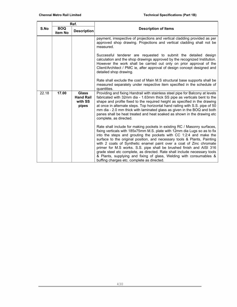
Chennai Metro Rail Limited Technical Specifications (Part 1B)
430
S.No Ref.
Description of Items BOQ item No Description
payment, irrespective of projections and vertical cladding provided as per approved shop drawing. Projections and vertical cladding shall not be measured. Successful tenderer are requested to submit the detailed design calculation and the shop drawings approved by the recognized Institution. However the work shall be carried out only on prior approval of the Client/Architect / PMC ie, after approval of design concept designed and detailed shop drawing. Rate shall exclude the cost of Main M.S structural base supports shall be measured separately under respective item specified in the schedule of quantities.
22.18 17.00 Glass Hand Rail with SS pipes
Providing and fixing Handrail with stainless steel pipe for Balcony at levels fabricated with 32mm dia - 1.63mm thick SS pipe as verticals bent to the shape and profile fixed to the required height as specified in the drawing at once in alternate steps. Top horizontal hand railing with S.S. pipe of 50 mm dia - 2.0 mm thick with laminated glass as given in the BOQ and both panes shall be heat treated and heat soaked as shown in the drawing etc complete, as directed. Rate shall include for making pockets in existing RC / Masonry surfaces, fixing verticals with 185x75mm M.S. plate with 12mm dia Lugs so as to fix into the steps and grouting the pockets with CC 1:2:4 and make the surface to the original position, and necessary tools & Plants, Painting with 2 coats of Synthetic enamel paint over a coat of Zinc chromate primer for M.S works. S.S. pipe shall be brushed finish and AISI 316 grade steel etc complete, as directed. Rate shall include necessary tools & Plants, supplying and fixing of glass, Welding with consumables & buffing charges etc. complete as directed.
Chennai Metro Rail Limited Technical Specifications (Part 1B)
431
SECTION – 3 - SPECIAL INSTRUCTIONS TO THE TENDERERS 23.0 SPECIAL INSTRUCTIONS TO THE BIDDERS TO BE GOVERENED WHILE QUOTING
THE RATE FOR THE TENDERED ITEMS UNDER BILLS OF QUANTITITIES: 23.01 General:
The particular specification and schedule of quantities must be read with the drawings, conditions of contract and the specifications and the bidder shall be deemed to have examined the drawings, specifications, conditions of contract and to have acquainted himself the works to be done in the way in which they are to be carried out. This Special instructions is shall form part of the contract. In case of any inconsistency between the BOQ (Schedule of quantities, Particular Specification), Technical Specifications and Tender Drawings and incase of conflict amongst different sections/heads, precedence shall be given in the following order of descending priority
• Schedule of quantities, Particular Specification. • Technical Specifications. • Tender Drawings.
23.02 Unless otherwise specified in BOQ (Schedule of Quantities, Particular Specification) and
Tender Drawings, rate quoted for External Facade and Associated works shall include the following:-
• Cost of all materials, labour, equipment, tools & plants required, conveyance,
infrastructure facilities, single / double - Scaffolding, staging, formwork, working platform, suspension platforms, davits, hoisting equipment, protective materials etc. as required at any stage of execution / maintenance.
• Work at all levels, heights & elevation and location.
• Items should strictly comply with the Technical specification, Particular specifications and
Schedule of Quantities. Specifications and Drawings furnished herewith will only be the governing factor for the bidders to choose the system and Materials as per design Intent.
• Entire structural Glazing system including type & thickness of Glass, extruded frames,
sleeves, inserts, Gasket, adhesive tapes, Sealant, Supporting arrangements including fastening and anchoring system envisaged in the Particular specifications & Schedule of Quantities is only indicative and is meant to set out a general outline of the Proprietary system as commonly understood. Since the Structural Glazing system, both in terms of Design, materials, details, methodology of execution are proprietary in nature, the onus of the design, drawings, specifications and execution satisfying design intent, performance requirements and site conditions lies solely on the bidder.
• Bidder shall be responsible to design the system as per the sizes and shapes of the glass
panels shown in the drawings including any modifications as may be required during execution and the designed system should withstand the wind pressure specified in the Documents as well as all other incidental forces and stresses likely to be experienced under service conditions, i.e. Lateral force, Dead weight and Thermal expansion due to building movement both vertical and horizontal etc.
• Bidder shall also be responsible to design the entire aluminium framing system, type &
thickness of Glass considering the minimal spectral and physical parameters of the glass set out in the technical specifications and Schedule of quantities, sealant including Bite

Chennai Metro Rail Limited Technical Specifications (Part 1B)
432
thickness, supporting arrangements including fastening device size & material, prepare and submit shop drawing in two stages namely project proposal stage and execution stage, obtain approval prior to execution, fabrication, supply, erection of the system and testing the system as envisaged in the Technical specification, Particular specifications and Schedule of quantities ie. for both Mock-up & Field test.
• Bidder shall be responsible to design the framing system to support both Vision &
Spandrel panel on a continuous framing system, irrespective of spandrel panel proposed with Glass or laminated sandwiched composite panel (Aluminium Composite Panel) or Granite or a combination thereof.
• Bidders to note that the eventual requirement is performance oriented with in the profile,
to achieve total structural Glazing system (either Unitized or Semi-unitized system specified in the Schedule of quantities) expected from the design that is adopted. ie. Resistance to design wind pressure, Prevention of Air & water penetration, continuous Pressure Equalization system, built-in continuous internal drainage for condensation & penetration & built-in adjustability for thermal movement, thermal barrier, separator Gaskets for Bi-Metallic Corrosion, smoke seals wherever essential etc.. Designing and providing the continuous internal drainage system in such a way that the system is built in over all system with the drain point at bottom most level and it shall be the responsibility of the bidder.
• Bidder shall be responsible for incorporating the air pressure equalization principal with
concealed continuous gutter at all levels and at all Floors for self drainage to achieve water tightness besides providing air & water barrier with Gaskets. Barrier should be provided at minimum three stages either unitized & or semi-unitized system. Entire system shall be designed to accommodate thermal movement of the aluminium components and glass resulting from the exterior skin temperature from 15 to 85 deg celsius & interior skin temperature from 15 to 30 deg celsius and to accommodate horizontal building movement of maximum 10mm per bay and vertical movement of maximum 20 mm between floors. Irrespective of system either Unitized or Semi-unitized system specified in the Schedule of quantities, Bidder shall be responsible for providing the Structural Glazing system conforming that no aluminum members and Sealant is visible or seen on the Exterior/Elevation.
• Bidder shall be responsible to design the system as per the sizes and shapes of the
laminated sandwiched composite panels (ACP) / Granite / Sand stone slab shown in the drawing and the designed system should withstand the wind pressure specified in the Documents. Bidder shall also be responsible to design the entire extruded aluminium framing system proposed to erect on the Main Structure, type & thickness of laminated sandwiched composite panels (ACP) or Granite slab / Sand stone considering the minimal technical criteria of the panel set out in the technical specifications, particular specifications and schedule of quantities. Gaskets, baker rod, sealant including Bite thickness, supporting arrangements including fastening device size & material, preparation of shop drawing, fabrication, supply, erection of the system and testing the system as envisaged in the Technical specification, Particular specifications and Schedule of Quantities ie. both Full scale off site proto type (if specifically called for in the Schedule of Quantities) & Field test (Methodology should be described for both hose & pressure box test along with submission, in line with Technical specification).
• Bidder shall be responsible to design the system for Granite cladding covers supporting
structure, Aluminium member, laminated sandwiched composite panels (ACP) and all type of Louvers, Glass details and size as per specification, Granite / Sand stone thickness and size, EPDM, Sleeve details in the system for expansion, drainage system, details of drain point, sealant, etc.
• Irrespective of the system either Unitized or Semi-unitized system proposed by the
bidder, the following factors shall be considered while quoting their rates and thereafter to be complied:

Chennai Metro Rail Limited Technical Specifications (Part 1B)
433
Structural framework to be pre-assembled self bearing modular elements of floor to floor height i.e. split mullion grid unitized construction system with Sealant free surface Glazing panels to be fixed without the use of restraining screws.
No screws / rivets / fasteners are visible after complete system is installed.
Open groove constructions with out aluminium member and Sealant on the surface since aluminium member and Sealant on the surface are not permitted to use.
• Bidder shall be responsible to provide a full scale off site proto type at site for atleast 3
bay (Vision and Spandral panel) and for 2 storied prior to commencement of fabrication based on project proposal approval in such a way, the system provides aluminum member, glass, laminated sandwiched composite panels (ACP), EPDM, Sleeve details in the system for expansion, pressure equalization concept and in-built drainage system, details of drain point, sealant details, etc. Field test shall be conducted on the site mock up prior to commencement of full scale work. As a result of test, if any rectification is required shall be carried over by the cladding contractor at free of cost. Quoted rate under respective item of Schedule of quantities shall include for making necessary arrangements and facility to attend / witness the test by the representatives of the Employer, PMC and Architect (Minimum one from each firm).
• Bidders to note that the quoted rate for the items covered under External Facade and
Associated works shall be comprehensive and appropriate and shall include all the applicable items envisaged in the system, whether or not they have been specifically described in the documents / information supplied, including change in sizes & thicknesses of members as appropriate.
• Bidders to note that the minimum spectral Values of Glass specified under various
options, Technical characteristics of laminated sandwiched composite panels (ACP)l and Technical properties of the sealant as given over and above to Schedule of quantities, Particular specifications and technical specifications shall be strictly complied with. Fabricator shall design the system suitable for installing the glass from the exterior surface after handing over and during maintenance by the Employer. However, the vertical in situ glazing in the system shall not be allowed during construction / Erection stage under any circumstances.
• Bidder shall produce design parameters for the following items including the various
components involved in the system in 2 stages namely, project proposal stage along with bid submission and Prepare shop drawing based on the approved system by the successful bidder, but will not necessarily limited to,.
Aluminium Extrusions for all kinds of framing and structural support for all types of
the system.
Glass for various applications.
Laminated sandwiched composite panels (ACP) including all types of Aluminium Extruded Louvers / Projection Louvers with special profile.
Structural system and ACP wrapping Details for Canopies / Parasol with
Supporting Details.
Structural system and Glass fixing Details for Glass Canopies with Supporting Details.
Point fixed Glazing using Spiders or Articulated bolts with supporting member.
System with supporting Details for Aluminium Doors with Patch Fittings,
Windows, Ventilators, etc.
Gaskets and Baker rod.
Chennai Metro Rail Limited Technical Specifications (Part 1B)
434
Sealant - both structural and weather sealant.
Details of Anchoring and Fastening Devices, brackets, cleats, separators,
interlocking sleeves. • Bidder shall be responsible to design the system in such a way that the sealants shall
withstand movement’s upto 50% or to the limitation of manufacturer's specification. Exposed sealant surface shall not crack or bubble. No acetoxy sealant shall be used. Elastomeric sealant shall not be allowed to use, unless otherwise the manufacture render the service on product back-up and guarantee. Intumeasent Sealant shall be used between fire stops/Flashing and structural aluminium members.
• Aluminium extrusions shall be of aluminium alloy 6063 - T6 conforming to BS 1474 or
63900 HP confirming to IS 8147.Any marks, lines, roller marks on the extruded sections prior or after anodizing is not acceptable.
• Aluminium extrusions shall be anodized to an approved colour and shall conform
architectural Class I colour anodic coating or AC 25 conforming to IS. Field cutting of anodized components shall not be permitted.
• In general, the proposed glass shall be of approved make and as specified in the
document. Inner pane of the glass proposed to use in Insulated Glazing unit shall be the same make of outer pane glass. The Insulated glazing unit shall be supplied by the same manufacturer, or pre-approved processor on prior approval. If the Insulated glazing unit processed and supplied by the manufacturer or specialized processor a single point guarantee for Insulated glazing unit shall be provided by the fabricator and sole responsibility lies on the fabricator.
• New substrate glass shall only be used for coating and to ensure the same, the
manufacturer shall produce the certificate. There should be no tong marks in the glass. The glasses with broken/chipped off at the edges shall not be allowed to use in the system under any circumstances and if any such glass is noticed with any kind of damage, the glass in the panel shall be replaced with new one before erection.
• Float glass shall conform to ASTM C 1036. • Heat strengthened and tempered glass shall conform to ASTM C 1048. • Tempered glass shall conform to ANSI Z 97. • Glass shall be designed to satisfy the requirement of AS 1288 & 1300. • All safety glass shall conform to the requirements of AS2208 or CPSE 16 & CFR 1201. • The glass for Spider/Point fixing/Frameless/patch fittings system shall be Heat soak
tested confirming to the relevant AS or ISTM Standards. • In general, the glass products shall conform the following International standards :
BS 952 - Part I ASTM C 1036 – 91 EN 572 - 1 & EN 572 – 2 NBN S 23 – 002 NF P 78 – 302 DIN 1249 TEIL 3 NEN 3264
• Top Hung openable windows shall be provided with Multi point locking with Handle with
key / cremones of Alualpha or pre approved equivalent make with self balancing stainless steel friction hinges with thermoplastic asymmetric end cap to ensure weather

Chennai Metro Rail Limited Technical Specifications (Part 1B)
435
tight sealing including all connected hardwares. Multi point locking handle shall be manufactured from die cast material and to be powder coated of approved colour and shade and all other accessories / components shall be manufactured from stainless steel - 316 grade. Hinges and Detachable handle to conform 500 hr neutral salt spray test - BS 7479:
• Laminated sandwiched composite panels (ACP) shall be of aluminium alloy 5000 - H 14 /
H25 conforming to BS 1475 and the thickness of panel shall be 4mm., (skin aluminium on both sides should not be less than 0.5mm) suitably stiffened internally on the back side (Methodology of fixing the stiffener to be described by the Bidder for approval) for preventing deformation due to design wind pressure beyond permissible limits. Skin aluminium supplied by Aluminium coil manufacturer shall be manufactured on Direct casting line to the International standards to ensure that the skin aluminium shall withstand the specified compressive strength.
• Aluminum composite panels shall be factory fabricated and assembled in compliance
with the manufacturer’s Data sheets. All panels shall be cut and routed using equipment and tools recommended and approved by the panel manufacturer. After folding into cassettes, an extruded aluminium profile shall be fixed to the minimum 25 mm deep return bend using 5 mm blind rivets. The aluminium flat of size 25 x 2mm shall be provided as a stiffener to ACP in the corner bends to the total height of the panel either to be gloved or with 3 M sticker.
• Provide factory fabricated Composite aluminum panels for Canopies including all the
Structural steel support and any additional steel support required to extend the canopy etc complete. All structural members shall be Hot dip Galvanized to the specified coating thickness and to be painted with two coats of Zinc chromate/Phosphate primer before and after erection with minimum 75 microns (DFT) with top coat with Low VOC Epoxy or Polyurethene paint with minimum 150 to 175 microns (DFT) of approved make.
• Provide the Joints with clear non staining silicon sealant or approved colour and
approved make and all as per Manufacturer's Specification, if called for in the Particular specifications and Schedule of quantities.
• Weather stripping / Gaskets shall be Elastomer - EPDM of approved make with shore
61 & 71 EP / TN. • Baker rods shall be polyurethene foam of "supreme or approved equivalent make".
Spacer tape (Adhesive tape) shall be of open cell polyethylene foam of `Nortan' make. • Secondary sealant, primary sealant, spacer, PVC non-adhesive tape, setting blocks
made out of solid extruded silicon rubber with a hardness of 85 Durometer - Shore A shall be provided.
• Under any circumstances, sealants within 30 days of expiry date marked / labeled on
the container / cartridges shall not be allowed to use in the work. • All support brackets for aluminium members in the structural glazing shall be 6061- T6 -
Structural grade and the brackets to have serrations. • All supporting system, such as brackets and similar attachments used for fixing &
erection of the aluminium members, laminated sandwiched composite panels (ACP), aluminium extruded louvers, ACP cladded canopies shall be of hot dip galvanized steel to the coating thickness as per IS 2629 & IS 4759. Anchors, fasteners with nuts & washers and all other fastening materials shall be non-magnetic stainless steel of 300 series -316 grade steel.
• All Flashings / smoke seals / fire stops shall be provided with extruded colour anodized
aluminium profiles at all floor levels, sills and top of parapet at terrace and sides of vertical surfaces where necessary.

Chennai Metro Rail Limited Technical Specifications (Part 1B)
436
• All bolted connections shall include lock washers, lock nuts or other locking device and
conceal the fasteners where visible in the finished work. Fasteners in non-wetting locations shall be cadmium plated, if directed.
• All steel plates and shapes shall be primer painted in conformation with Fed.
Specification TT-P-6445. • All hot dip galvanized steel shall conform ASTM A 123 and coating shall conform IS
2629 and IS 4759. • All electro galvanized steel shall conform ASTM A 164 or FS-Q-Z-325b (2). • All stainless steel shall be 316 grade, brush finish and 300 series non-magnetic steel. • Wherever finishes are not specified, all such metals shall be finished in a manner
consistent with similar work and necessary to confirm with the design intent. Such items shall be identified by the successful bidder well in advance to the Employer / Employer’s Representative and the work shall be executed on prior approval from Employer / Employer’s Representative .
• Shop drawing for full scale Mock-up as well as for entire external cladding system based
on approved Design Parameters shall be provided for approval at appropriate stages.
• Structural test shall confirm to ASTM E 330. • Making provision for inspection of glass at manufacturing / Processor place including
their facility by the representatives of Employer, PMC and Architect.(one representative from each firm as minimum shall be considered).
• Conducting periodical test for sealant in place for adhesion and extent of fill, using the
recommended practice of the manufacturer. Replace any sealant that does not adhere or fails to cure. Trial deglazing shall be done both during factory processing stage and at site, if so directed by the Employer / Employer’s Representative s.
• Off site proto test - full scale (if specifically called for in the Schedule of Quantities) and
Field test - Hose test shall be carried out in accordance with Technical specification including all materials required for Off site proto type test and Field test. This shall includes submission of shop drawings of test unit, test bed, test chamber, preparing and supplying the materials for specimen etc.
• Conducting Off site proto type test including necessary arrangements at an approved
laboratory with the specified design wind pressure and Lateral force including making necessary arrangements and facility to attend / witness the test by the representatives of one from Employer, one from PMC and one from Architect. If off site proto type test fails, correct the defects revealed till the satisfaction of the performance data as setout in the Technical Specification.
• Air infiltration test / Air permeability, Static water infiltration test, dynamic water
infiltration test and wind pressure tightness shall be pretested in internationally recognized laboratory and confirm to ASTM E 283 / AAMA 501.1 / ASTM E 330 respectively or its equivalent British standards or its equivalent UNI standards.
• Aluminium Extrusions, Glass, laminated sandwiched composite panels (ACP),
Aluminium extruded Louvers (Storm proof type and specialized profile and shape), Gasket, sealant, supporting system including fastening Devices provided at site of work shall be as approved in the off site proto type test and shall be identical.
• Conducting Field test - Hose test including necessary arrangements, scaffolding, hose,
water & manpower with in the quoted rate. If field test fails, correct the defects revealed till the satisfaction of the performance data.

Chennai Metro Rail Limited Technical Specifications (Part 1B)
437
• Provide accurate benchmarks for use in wall erection at all floors and if there are any
errors or inconsistencies rectify at no extra cost. • Tolerances for building frame and other works shall be strictly adhered to. • Provide non-flammable eel-slip, nylatron, high impact polystyrene or approved
equivalent slippads between moving parts at all expansion connections. • Seal the joints within the wall and between adjacent constructions using the approved
intumeasent sealant. • Remove and replace all damaged or disfigured components to the satisfaction of the
Employer at no extra cost. • Provide a separator at contact surface of dissimilar material wherever there is a
possibility of corrosive or electrolytic action. • Maintain housekeeping during the tenure of the field work by way of cleaning and
removing the unwanted materials, broken glass, ACP wastage, packing Materials, debris regularly and on a periodical basis and keep the work place and premises neat and clean. Protect all components and materials from damage or disfiguration of any kind of at all stages of work until handing over.
• Clean glazing pocket before setting the glass. • Clean entire structural glazing, laminated sandwiched composite panels (ACP) & other
components prior to handing over. • Cleaning agents which are compatible with aluminium, glass, glazing materials &
sealants shall only be used and the same shall get it approved before use on work. • Necessary provision shall be considered on the Structural glazing system to facilitate
Façade Cleaning agency to clean the entire facade system including Canopy areas. An additional identified built in support shall be provided on ACP cladding on the top of canopy camouflaging with cladding in such a way the facade cleaning agency to walk over the support and clean the top surface of the Cladding with out damaging the cladding. Details and methodology shall submit for Employer / Employer’s Representative 's approval. Also, include necessary provision to facilitate Facade cleaning agent to clean the structural glazing and associated works by providing their own system and equipment.
• Quantities furnished in the Schedule of Quantities are indicative / tentative and are
subject to reconciliation on award of work between successful bidder and Employer / Employer’s Representative , if there is any discrepancy at the shop drawing stage.
• Supply an adequate number of glass panels as spares so as to replace broken glass
panels in the event of accidental breakage in the future for maintenance, which will be paid separately under respective item. Number of spares required shall be decided by the Employer, based on the sucessesful bidder proposal on the sizes and numbers, tentatively attic stock will be 2% (Two percent) covering all the different type and sizes of panel.
• Submittals should be provided as mentioned in the Technical specification for approval. Tenderer submissions should include a statement showing the conformity for each component with technical specification or otherwise tenderer should specify/highlight the Material or component proposed, which does not comply with Technical specification.
• All the drawings and samples submitted along with tender document shall form part of the contract. Bidders are requested to submit the tender drawings and the samples of materials required along with tender submission duly signed & stamped, failing which

Chennai Metro Rail Limited Technical Specifications (Part 1B)
438
the tender is liable for rejection. Samples of all components such as Aluminium Extrusions (Main member, supporting member, sleeve member etc.), Glass, Gaskets, Sealants, laminated sandwiched composite panels (ACP), aluminium extruded Louvers and granite / sand stone etc. shall be submitted along with tender for approval. Atleast 300mm square size samples labeled for Glass, ACP and Gaskets shall be produced by the bidder along with tender for scrutiny. Based on approval, all the samples required shall be reproduced by the successful bidder for final approval of the Employer / PMC / Architect and all the approved samples of Materials shall be stored by the successful bidder at site and to be produced as and when required for verification.
• Entire facade and associated works including all the components involved in these items shall be guaranteed by the external cladding agency as General and system Guarantee for a period of 10 (Ten) years including special guaranty for glass, reflective coating of the Glass, laminated sandwiched composite panels (ACP) including coating and Sealant by the Manufacturer / Supplier for the period specified in the Technical Specification in an approved Performa acceptable to the Employer on a stamp paper. The Guarantees from Specialist applicators such as for sealants, Double Glazed unit fabrication/Processor, Glass processing & Coating, DG unit manufacturer / processor, laminated sandwiched composite panels (ACP) including Skin Material from the Coil Manufacturer and processor etc, shall also be submitted from the respective Manufacturer / sub - vendor, counter signed by the Specialist Structural Glazing and External cladding agency.
• Specialist Structural Glazing and External Facade agency shall also provide a certificate
for compliance of the conditions provided by the sealant manufacturer in their Warranty in the form of Affidavit, which shall also form part of system guarantee.
SECTION – 5 - TECHNICAL INFORMATION TO BE FILLED BY THE TENDERERS:
1. Typical Detailed calculation and drawings shall be submitted for approval along with the data sheet as part of tender submission for evaluation.
2. Method statement for technical proposal shall be included wherever required while
filling the following statement. 3. Minimum standards for the below technical data sheet should be as per details and
specifications, conditions as given in the Tender shall be followed. No deviations for the same will be permitted.
4. Deviations to establish special features of the Bidder's system if any to be highlighted
separately for evaluation.
5. The information’s from the Bidders as called for is required to evaluate their offer and hence filling the below table is compulsory.
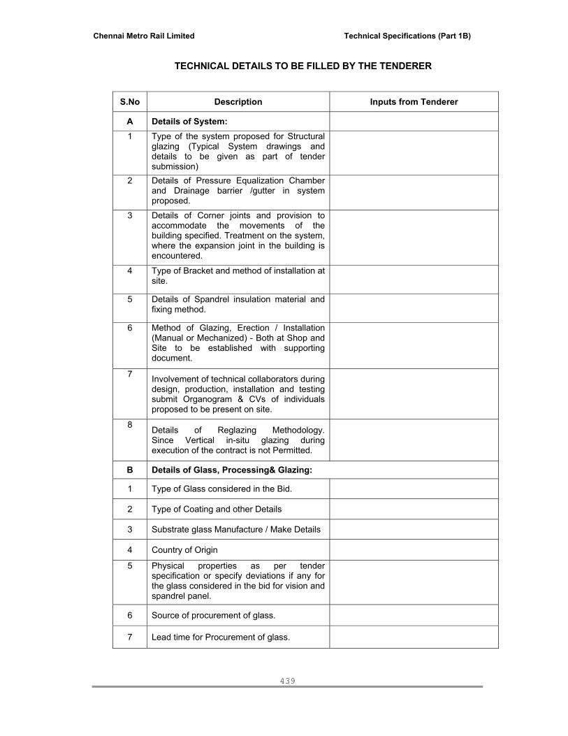
Chennai Metro Rail Limited Technical Specifications (Part 1B)
439
TECHNICAL DETAILS TO BE FILLED BY THE TENDERER
S.No Description Inputs from Tenderer
A Details of System: 1 Type of the system proposed for Structural
glazing (Typical System drawings and details to be given as part of tender submission)
2 Details of Pressure Equalization Chamber and Drainage barrier /gutter in system proposed.
3 Details of Corner joints and provision to accommodate the movements of the building specified. Treatment on the system, where the expansion joint in the building is encountered.
4 Type of Bracket and method of installation at site.
5 Details of Spandrel insulation material and fixing method.
6 Method of Glazing, Erection / Installation (Manual or Mechanized) - Both at Shop and Site to be established with supporting document.
7 Involvement of technical collaborators during design, production, installation and testing submit Organogram & CVs of individuals proposed to be present on site.
8 Details of Reglazing Methodology. Since Vertical in-situ glazing during execution of the contract is not Permitted.
B Details of Glass, Processing& Glazing:
1 Type of Glass considered in the Bid.
2 Type of Coating and other Details
3 Substrate glass Manufacture / Make Details
4 Country of Origin
5 Physical properties as per tender specification or specify deviations if any for the glass considered in the bid for vision and spandrel panel.
6 Source of procurement of glass.
7 Lead time for Procurement of glass.

Chennai Metro Rail Limited Technical Specifications (Part 1B)
440
S.No Description Inputs from Tenderer 8 Sourcing of Insulated glazing
(Specify warranty levels and names of undertakers)
9 Location of Processing Plant and Details.(Please attach the Credentials of the Processor)
10 Spacer Details of insulated glazing unit including make of infill material.
11 Type and make of Adhesive tape used for glazing and others.
12 Structural bonding of glass and type of sealant (2 part or 1 part)
13 Quality control measures (Give details of Quality plan)
14 Give details of the test certificates and type of tests.
15 Specify the Hardwares considered in the bid including Locking system for open able panels.
C Details of Aluminium Extrusions: 1 Specify Extruder details and description of
Alloy ie. Make, Grade & Temper, Source of Aluminium substrate and the Standards followed by Extruder.
2 Specify Coating details and description of coating, Standards followed by coater.
3 Type of testing to ensure the thickness of coating and details of other tests required as per standards.
4 Type of Protective coating to Aluminium extrusions.
D Details of laminated sandwiched Composite Panel (ACP):
1 Type and make laminated sandwiched Composite Panel.
2 Make, Thickness, Weight and Grade of core used in ACP.
3 Details of Fire rating, coating etc
4 Specify the Quality control test of ACP skin material.
5 Typical fixing details and specification of Fixing Material.
F Details of Frameless Glazing:
1 Type and make of Frameless Glazing - Spider / Articulated bolts.
2 Type and Make of Patch fittings
3 Manufacturer Details

Chennai Metro Rail Limited Technical Specifications (Part 1B)
441
S.No Description Inputs from Tenderer 4 Country of Origin
G Details of Fixing and Fabrication: 1 Type of Bracket including Material and
coating Description including Nut and bolts.
2 Type of Material proposed as Separators and details.
3 General Type and Make of Anchors and fasteners / Specify if they are chemical anchors or if any.
H Details of Sealing : 1 Type and make of Gasket proposed (EPDM
or Neoprene)
2 Make and Grade, Components for both Structural and Weather sealant.
3 Fire stop and Smoke Seal Details with Material and rating. Please provide the typical drawing and details.
4 Flashing Details with Material and rating. Please provide the typical drawing and details.
I Details of Miscellaneous Items : 1 Type and make of Hardwares and
accessories for doors, windows such as lock, floor spring and door closer etc
2 Preventive Maintenance offered - spare
J Details of Performance Test: 1 Details and location of off site proto type
Test laboratory
2 Methodology of Test and Credentials of the Laboratory.
3 Details of Field test viz. Type, Equipments used, methodology etc.
Chennai Metro Rail Limited Technical Specifications (Part 1B)
442
ANNEXURE - A
FORMAT OF PERFORMANCE GUARANTEE OF SYSTEM Submit Performance Bank Guarantee for an amount equal to 5% of the Final bill value for both the period of Defects liability period as per the respective clause of the Conditions of Contract under tender documents and for the Guarantee period of 10 (Ten) years from the mutually agreed date of final acceptance of completion of defects liability period agreeing to repair or replace the defective materials and workmanship and as per the details given below. Note: DRAFT FORM OF WARRANTY IN THE FORM OF PERFORMANCE BANK GUARNTEE TO BE ISSUED BY THE SUCCESSFUL BIDDER TO THE EMPLOYER IN CONSIDERATION OF AWARD OF CONTRACT IS GIVEN BELOW: To Client / Employer Name: ……………………. (Hereinafter referred to as the Owner) Whereas ………………………………. having its registered office at ……………………………………. (Hereinafter called “The Contractor”) has undertaken, in pursuance of Contract No. …………………………….. Dated …………………. for the work of ………………………………………………………at ………………………. (hereinafter called “The contract”). AND WHEREAS it has been stipulated by you in the said Contract that the Contractor shall furnish you with a Bank Guarantee by a recognized bank for the sum specified therein i.e. for an amount of Rs…………………….. (Rupees ………………………………… only) as security for the External Façade Glazing and Associated works undertaken by them, agreeing to: 1. Nothing in our agreement with the Employer shall operate to exclude or limit our liability for
breach of the warranties set out herein. 2. During Guarantee Period, we will be agreeing to repair or replace defective materials and
workmanship including during the Defects liability period. Defective materials and workmanship include but not limited to the following:
• Abnormal deterioration, • Aging or weathering of the work, • Water leakage, • Air exceeding specified limits, • Structural failure of components resulting from exposure to pressures and forces up to
specified limits, • Failure of operating parts to function normally, • Deterioration or discoloration of any finishes in excess of normal weathering and aging, • Glass breakage, secondary glass damage or breakage due to falling glass fragments,
deterioration of glass reflective coating, • Cracking, staining, chipping and discoloration of granite, • Scratching, denting other type of surface damage to the composite aluminum panels,

Chennai Metro Rail Limited Technical Specifications (Part 1B)
443
• Adhesive or cohesive failure of silicone sealant and failure of the work to fulfill other specified performance requirements.
• Anodized finish on aluminum works and Galvanized finish for brackets • Materials and fastening devices used in the system. • Corrosion in any of the brackets made out of stainless steel. 3. The Performance Bank Guarantee shall include failure of the work to fulfill other specified
performance requirements and also replacement if any or all members and components involved in the executed systems by the Contractor in case if any deficiency or failure in performance of the work as per the design requirement during the defect liability period and guarantee period (Note: Period shall be as specified in the contract condition under volume I – Part - A. The contractor has to undertake responsibility for safety with respect to set out of glass with or without member with which it is held in position during the Guarantee period.
4. The Performance Bank Guarantee does not include damage caused by vandalism, or
natural condition exceeding the performance requirements. 5. This Performance Bank Guarantee offers free replacement and rectification free of cost if
the defects are attributable to faulty manufacture of panels, all extruded members / fixtures used in the system, substandard finish and defective workmanship if noticed.
6. This Performance Bank Guarantee and its enforcement shall not deprive the Employer of
other action, right or remedy available to him. 7. Performance Bank Guarantee for the systems and for the performance of the materials
used in the system shall be include the following special guarantee also :
• The unconditional Guarantee for peeling or deterioration of glass reflective / reflective Low E coating & any other modified coating by the Glass Manufacturer and for material obstruction of Facade vision glass as a result of dust or film formation on the internal glass surfaces.
• The unconditional guarantee period of Aluminum extrusion, Aluminum Composite
panel, Gaskets and Sealant. We ………………………………..Bank incorporated in ……………………..having its Registered /Head office at …………………………………… (hereinafter referred to as “the said Bank”), do hereby irrevocably and unconditionally guarantee that in the event of the Contractor failing to fulfill or comply with all the terms and conditions as set out in points under para 2 of this Guarantee properly, faithfully and punctually, we shall pay to the Owner or their successors in the title without any protest or demur upon Demand in writing made by the Owner any sum not exceeding the sum of Rs………………. (Rupees ……………………………. only) as may be claimed by the Owner to be the loss sustained by reason of any breach by the Contractor of any of the terms and conditions of the Contract. THEREFORE we hereby affirm that we are Guarantors and responsible to you, on behalf of the Contractor, upto a total of Rs…………………….. (Rupees ……………………………… only), and we undertake to pay you, upon your first written demand declaring the Contractor to be in default under the Contract and without cavil or argument, any sum or sums within the limit of Rs………………………………./- (Rupees …………………………………………. only), as aforesaid, without your needing to prove or to show grounds or reasons for your demand or the sum specified therein. This Performance guarantee is valid until ……………………….. Notwithstanding anything contained hereinabove:- 1. Our liability under this Bank Guarantee shall not exceed Rs…………………. (Rupees ………………………………. only).

Chennai Metro Rail Limited Technical Specifications (Part 1B)
444
2. This Bank Guarantee shall be valid upto ………………………….. where after it ceases to be in effect in all respect whether or not the original Bank Guarantee is retuned to us and; 3. Our liability under this Bank Guarantee will arise only if we receive a notice in writing from …………………………., on or before ………………… advising us of ……………………………. failure leading to our liability hereunder. SIGNED & SEALED by the SIGNED & SEALED by the Facade Glazing Contractor Bank Date: Date: Place: Place:

Chennai Metro Rail Limited Technical Specifications (Part 1B)
445
ANNEXURE - B
FORMAT OF BACK TO BACK GUARANTEE OF MATERIALS
DRAFT FORMAT BACK TO BACK TO BACK WARRENTY FROM THE GLASS MANUFACTURER FOR INSULATED / MONOLITHIC GLAZED UNIT BY USING THE
REFLECTIVE COATED HI PERFORMANCE GLASS AS OUTER PANE & CLEAR GLASS AS INNER PANE HEAT STRENGTHENED & HEAT SOAK TESTED.
The ………………………..(Herein after called the Glass Manufacturer and the Processor) warrants its Laminated glass for a period of ten (10) years from date of manufacture against defective materials or workmanship which result in material obstruction of vision caused by dust collection or film formation on internal glass surfaces due to failure of the Laminated glass seal.
1. In the event that a Insulated glass unit is found and verified by the Glass Manufacture to be defective, the Glass Manufacturer will provide replacement unit at no extra charge including transport to the place of installation) refund the purchase price of the glass. If the Glass Manufacturer elects to replace the defective glass, the Glass Manufacturer will not be liable for any other expenses including removal of the defective unit, installation of replacement units, any labor, materials, and /or any other damages including incidental, indirect, special, or consequential damages.
2. The Glass Manufacturer expressly assumes for and this warranty does not include the following:
• Glass breakage, product failure due to improper usage; • Product failure due to improper handling, loading, unloading or storage. • Incompatibility whether glazing or installation materials, including, coatings,
sealants, gaskets, setting blocks, lubricants, insulation or any other materials; • Fault in glazing, building construction; • Damage caused by water and use in sloped glazing installations; • Failure to adhere the Glass Manufacturer’s instructions regarding installation and /
or Maintenance of the unit, including written proof of routine maintenance. • Scratches or abrasions to the product; • Abnormal weather conditions; or damage caused / solvents, alkalis or any other
chemicals used on or around the products.
3. Subject to the provisions of this warranty, …………….………………(Herein after called the Glass Manufacturer and the Processor) warrants that the Product will be for a period of 10 (Ten) years from the date of supply, free of :
• Edge separation or de-lamination other than that which occurs within 6mm of the
original glass edges, if the reflective Low E coated is specified.

Chennai Metro Rail Limited Technical Specifications (Part 1B)
446
• Visible or visual defects, inclusions or faults that can be seen from a distance of at least 3 meters from the outside surface and 1 m from the inside surface and which are not within the acceptable limits set out in the performance specifications of the tender issued and in accordance with the technical specifications..
• All architectural Insulated Glass conforms to the applicable Australian Standards
AS2208 and AS2080.
• This Warranty specifically includes any consequence of glass breakage due to lesser thickness of glass panes than required as per Design Criteria.
4. Warranty Coverage: In the event of any breach of this warranty (Herein after called the
Glass Manufacturer and the Processor) shall replace the Product inclusive of all costs of transportation and installation.
5. To the greatest extent permitted by law …………….………… (Herein after called the Glass
Manufacturer and the Processor) will not be liable for any personal injury, loss, claim, property damage or labour, material or other costs (whether special or consequential or otherwise) suffered by or arising as a result of any breach of this Warranty regardless of how such loss or damage is caused and whether such loss or damage is direct or indirect.
6. The Warranty is further subject to the following conditions:
The Warranty applies only to Product in the size, shape and form supplied by ………………………………….………… (Hereinafter called the Glass Manufacturer and the Processor). Any further cutting, edge-working or processing of the Product as supplied shall render the Warranty void:
using the Product in such a manner that it comes into contact with wet cement, hard foreign objects, metals and material will likely give rise to abrasive damage, and will render the Warranty void; The use, installation and maintenance of the Product should be entirely in accordance with Manufacturer recommendations as published in the Manufacturer literature and any specific correspondence pertaining to this installation. Failure to comply with these procedures will render the Warranty void;
The Product shall be installed in a manner that prevents prolonged contact with moisture at the glass edge, or risk voiding the Warranty;
The Product should not be exposed to chemical fumes or gases other than those present in normal clear atmospheric air nor subjected to prolonged exposure to water or moisture which may cause rainbow type staining, nor exposed to radiation of any type other than normal sunlight, to prevent voiding of the Warranty;
The Product should not be subject to, or likely to be subjected to stresses from any cause in excess of the stresses advised as acceptable in design standards, to prevent voiding of the Warranty;
7. Warranty of Replacement Product: Any replacement Product supplied pursuant to this
Warranty will be warranted, according to the terms herein, only until the expiration of the Warranty period as from the original supply of Product.
SIGNED, SEALED AND DELIVERED by the Glass Manufacturer and Processor in the presence of Façade Glazing Contractor and:- (Note 1 :………………………………..witness)
OR THE COMMON SEAL of the Glass Manufacturer and Processor was hereunto affixed in the presence of Façade Glazing Contractor and of:- (Note 2 …………………………….. Witness)
OR

Chennai Metro Rail Limited Technical Specifications (Part 1B)
447
SIGNED, SEALED AND DELIVERED for and on behalf of and as lawful attorney of the Glass Manufacturer and Processor and under Power of Attorney dated ……………………by ……………in the presence of Façade Glazing Contractor and of:- (Note 1)………………………………witness)
OR
THE COMMON SEAL of the Glass Manufacturer and Processor was hereunto affixed in the presence of Façade Glazing Contractor and of :- (Note 2 : ……………….. ……………… witness) Name of witness in Block letters: ------------------------------------------------- Address: ……………………………………………………………
Note: The External façade contractor shall undertake the responsibility for safety with respect to set out of glass with or without member with which it is held in position during the guarantee period.

Chennai Metro Rail Limited Technical Specifications (Part 1B)
448
TECHNICAL SPECIFICATION FOR
FACADE ACCESS SYSTEM
FACADE ACCESS SYSTEM - TECHNICAL SPECIFICATIONS
TABLE OF CONTENTS 1.0 Scope 2.0 General 3.0 Codes and Standards 4.0 Design Criteria 5.0 Design Parameters 6.0 Responsibility for Design and Suitability 7.0 Systems Proposed and Material specification 8.0 Ordering and Delivery 9.0 Samples 10.0 Sources 11.0 Tests 12.0 Shop Drawing 13.0 Fabrication 14.0 Installation 15.0 Rejection 16.0 Examination of Work before Covering up 17.0 Removal of Improper Work, Materials 18.0 Cleaning 19.0 As Built Drawings & Maintenance Manual 20.0 Guarantee 21.0 Mode of Measurement

Chennai Metro Rail Limited Technical Specifications (Part 1B)
449
FACADE ACCESS SYSTEM - TECHNICAL SPECIFICATIONS
1.0 SCOPE
Supply and installation of Facade Access system covering external façade area, to enable easy access to all parts of the elevation area to facilitate cleaning and maintenance of the proposed state of art, multi-storied high rise building located at Chennai. Also, the scope of work covers import, supply, deliver at site and erect the complete system including design, manufacture, testing, commissioning, and train Employer’s personnel (4 persons) and undertaking of operating and Maintenance operations.
The system generally comprises the following: A. Operating System :
• Manual Jib Trolley mounted with Swivel on specialized rollers and fitted to the steel track. The trolley must be made of Hot dip galvanized MS frame work and boom of Aluminium alloy sections and must be capable of achieving variable length of outreach with arm length as required and as specified in the BOQ and as per drawing. The ISMB track and supporting brackets must be designed to be mounted on the RC Parapet wall / Roof at terrace level with M16 SS 316 bolts hardened to A4-70 grade.
B. Accessible System :
• Cradle Standard Cradle with all accessories – 2000 mm long (2 persons) which are locally fabricated with imported, winches, ropes, safety brakes and motors. The winches, safety brakes and motors must comply with EN1808 regulations. The controls and ropes must be of approved make. Cradle shall be constructed with Powder coated Aluminium alloy box section, the flooring shall aluminum tread plate and fitted with necessary accessories, PVC covered foam buffer and soft rubber rollers. Cradle shall be cladded with Aluminium or Stainless Steel perforated sheet to a suitable thickness and to the profile with necessary stiffeners and the cradle shall have slewing castors.
• Portable articulated Lifting equipment (Aerial working platform) fully imported with tilting assembly and its accessories with required working height as specified in Bills of Quantities.
• Portable Electro hydraulic Imported Vertical platform fully imported with complete system and the working height as specified in Bills of Quantity.
In general, the specification given above are indicative and it is the responsibility of the Tenderers to evaluate the Elevation and its features and providing the façade access system with all accessories with safety systems for accessing entire façade area including projecting surfaces. List of items covered in the Quote shall be attached with tender.

Chennai Metro Rail Limited Technical Specifications (Part 1B)
450
2.0 GENERAL 2.1 BUILDING DESCRIPTION
Building Complex of Office Complex and Residential Flats at Chennai comprises construction of official activities. This Building envisages the following: Building is having Semi Unitized Structural Glazing, ACP cladding and Point fixed glazing façade, Windows and Automatic sliding door at the Entrance. Also, the Building is proposed to clad with Granite from ground level to first floor level.
2.2 EXTERNAL FINISHES AND ITS AREA APPROXIMATELY.
a. Structural Glazing with Double / Single Glass / ACP – 2600 Sqm. b. Aluminium windows with Double / Single Glass – 2255 Sqm.
c. Spider Glazing with fin assembly and support system - 585 Sqm
d. Aluminium composite panels Cladding on the Dry wall as well as on the Structurally
Glazed frame work on the Spandrel Panel and Canopy – 7950 Sqm.
e. Aluminium shading Louvers on the Structural Glazing - 2000 Sqm and other associated works etc.
Total Façade Area approximately – 15390 Sqm.
2.2 DRAWINGS
Drawings showing the terrace floor plans at various levels and indicative details of the systems provided in the Bills of Quantities are enclosed herewith as Tender drawing.
2.3 PROVISIONS
• Successful tenderer shall make own arrangement for water and power from the pre-determined point during the execution of their part of work.
• Tenderer should clearly indicate the construction power requirement in their offer.
Water and power utilized by the successful Façade access system agency will be charged on the basis of tariff fixed by the local authority.
• Facilities such as office, storage etc for their respective works shall be arranged by
the respective successful tenderer themselves in co-ordination with the PMC.
• Civil works in connection with the installation of the system as part of External façade access system vendor scope.
• However, the Tenderer should clearly indicate the requirement of Minor builder’s work
and Electrical point / circuit details to erect the system well in advance that has to be carried out by the Civil & Electrical Contractor in coordination with successful façade access agency.
2.4 SCOPE OF WORK INCLUDED THE FOLLOWING:

Chennai Metro Rail Limited Technical Specifications (Part 1B)
451
• Complete design and Engineering - Three sets of drawings with loads, Structural
calculations to satisfying the design criteria, wind speed etc, and certified by independent agency shall be submitted by the successful Tenderer without which tenderer shall not be allowed for installation of the system.
• List the Imported equipment and sources and Complete list of local equipment with
source of supply and Schedule of Transport of materials.
• Installation methodology and system.
• Training scheme including training period and number of personnel to be trained, for the owner’s personnel in the operation of the system and in cleaning practices. The successful tenderer have to train employees or designate agencies in the operation and maintenance of the complete system including but not restrict to the Operation of Trolleys / Aluminium Davit / permanent runways, Erection of complete system, Rigging of cradle, Maintenance of motors and other equipment, cleaning operators etc. The training will have to be held at site and tenderer to take responsibility for procuring of Insurance and other safeguards for the designated number of trainees, during the training period.
• All relevant manuals and technical details must be submitted as part of the bid document.
• Inherent safety features in the respective systems and cleaning period, timings and methodology for this building.
3.0 CODES AND STANDARDS
Equipments proposed for supply & Installation should comply with British and European Standards (Latest Issues) and it should generally comply with European Standards EN 1808 or equivalent British standards with regard to safety requirements on Suspended Access Equipment, Design Calculations, Stability Criteria, Construction and Tests criteria. The list of codes given below is indicative in nature and is not an exhaustive list, and is given as guidance only.
The tenderer shall indicate the list of codes to conform, which the equipments proposed to be supplied and installed by them.
EN 292-1 and 2 Safety of machinery - Basic concepts general principles for design, Basic terminology, Technical principles & specifications and methodology.
EN 294 Safety of machinery - Safety distances to prevent danger zones being reached by the upper limbs.
EN 418 Emergency stop equipment, functional aspect. Principles for design.
EN 614 / BS 6037 Safety of machinery - Ergonomic design principles - Terminology and general principles.
EN 954 / BS 6037 Safety of machinery - Safety related parts of control systems - General principles for design.
EN 982 / EN 1808 Safety requirements for fluid power system and their components - Hydraulics.
EN 983 Safety requirements for fluid power systems and their components – Pneumatics
EN 60204-1 Safety of machinery - electrical equipment of machine - General requirements.

Chennai Metro Rail Limited Technical Specifications (Part 1B)
452
EN / IEC 60529 Degrees of protection provided by enclosures.
EN 60947-5-1 Low- voltage switchgear and control gear. Control circuit devices and switching elements. Electro mechanical control circuit devices & elements.
EN 280 Mobile elevating work platform - Design calculations, Stability criteria, Construction - Safety, Examinations and Tests.
EN 1050 Safety of machinery - Risk assessments.
CP 118 Structural use of Aluminium.
EN 795 Protection of falls from height.
BS 302/BS 449 Steel for wire rope/Use of Structural steel in system.
4.0 DESIGN CRITERIA
3. All individual components and complete works shall be designed and erected to comply with the required performance standards.
4. The Building and External cladding system are designed to withstand wind pressure of 200 Kg/Sqm in accordance with requirements of the performance specifications, conforming to IS 875 or its Equivalent British Standard. The proposed façade access and cleaning systems and Equipments are to be designed to with stand the same wind pressure of 200 Kg/Sqm conforming to relevant IS or it’s Equivalent British Standard during operation.
5. Allowable deflections of metal framing members at design load are limited to the standards.
6. Necessary anchorage system shall be designed to accommodate building construction tolerance of +/-25mm.
7. All loading condition including wind load as per IS-875 or its Equivalent British Standard.
8. Earthquake resistant design as per IS-1893 or its Equivalent British Standard. 5.0 DESIGN PARAMETRES
9. Cradle shall be designed to park only at floor and hence provide floor mounted cradle only. If the roof mounted cradle is being proposed, the design should be such that the ropes do not trail over parapet edges and top and also on the top of ACP cladding. However, this is not the preferred option.
10. The design should be such that the two or one operators in the Cradle are able to carry out cleaning operation without any additional operator either at the roof level or on the ground floor level to operate the cradle. Ie. Providing and considering the control only at cradle platform.
11. All metallic material shall be isolated where the joint positions could lead to electrolytic action or other corrosive deterioration.
12. The tenderers should also note that the equipment proposed is to be portable and it shall be easy for transportation of the same at terrace level. The complete design shall be to suit the building requirements for cleaning and maintenance.
Chennai Metro Rail Limited Technical Specifications (Part 1B)
453
13. The tenderers should also note that the design should be such that the equipment(s) has / have minimum life of 10 years being a permanent access.
14. Periodic inspection / certification as required in the scope of the tenderer, during the warranty period of 12 (Twelve) Months and comprehensive maintenance period of 2 (Two) years after defects liability period of 12 months from virtual completion of work should be the responsibility of the successful tenderer.
15. The permanent runways shall be provided at the face level of the building as proposed in the façade Drawing/Elevation. Cleaning of the façade areas above the louvers / projections if any shall be carried out by using the trolley / Aluminium Davit / jib and cradle platforms using suitable mechanism.
6.0 RESPONSIBILITY FOR DESIGN AND SUITABILITY
16. The tenderer shall be responsible for the design of the entire façade access system and shall ensure and undertake that the work will be suitable for their purposes.
17. The tenderer shall be responsible to provide fixing and anchoring details pertaining to aluminium davit brackets, horizontal rails and their brackets & other accessories. Pull out test for anchoring of bolts at minimum 2 locations shall be carried out prior to installation of the brackets. Necessary report shall be submitted for review and approval.
18. The tenderer shall be responsible to ensure that the shop drawings include all details pertaining to supply and installation of the system confirming to design criteria.
19. The tenderer shall indicate in his program the following information relating to the Work.
Design and Approval Shop drawing along with sample pertains to the finishes of the material for
approval. Post construction site survey and verify with shop drawing approval. Revision of shop drawing if any based on the results of site survey. Laboratory test on materials, if any Materials co-ordination, ordering and delivery Fabrication Installation Inspection, remedial measures Testing & Commissioning. Operation & Maintenance.

Chennai Metro Rail Limited Technical Specifications (Part 1B)
454
7.0 SYSTEMS PROPOSED AND MATERIAL SPECIFICATION: 7.1 SYSTEMS PROPOSED:
In general the proposed equipments for this project are: A. Operating System: 1. Aluminium permanent Swivel trolley system Parapet mounted.
B. Accessible system:
1. Standard Cradle platform 2 M long.
2. Portable Aerial work platform. 3. Electro Hydraulic vertical platform.
Note: The Cradles shall be parked either on terrace of the building or on the Ground level of the Building and shall have to be rigged from the terrace level / Ground level as appropriate. Providing the Gondola at ground floor level is preferred.
7.2. MATERIAL SPECIFICATION.
A. Operating System: 1. Manual traversing Jib Trolley running on ISMB Track - Permanent:
Model : Traverse Trolley / Jib – Swivel type with Head & pin
Material : Hot Dip Galvanized MS Sections and Aluminium Alloy sections
Source : Locally fabricated.
Finish : Aluminium – Silver anodized Finish.
Base & Frame : Hot Dip Galvanized MS Sections.
Boom : Aluminium Alloy sections
Type : Permanent type
Horizontal Traverse : Manual on Specialized rollers fitted to the Track.
Length of Cantilever : As per drawing.
Length of out reach : As per drawing.
Height of Trolley : Please indicate the height considered in the bid. Minimum clearance from parapet top shall be 700 to 900 mm.
Support system : Hot Dip Galvanized Bracket with ISMB of required size to operate manual trolley track at top and bottom.
Anchoring system : SS 316 grade Anchor fastener or Chemical Fastener to suitable Dia and size of Hilti or approved equivalent make. The fasteners must be hardened to A2-70 grade.
Cradle and Safe working load.
: Weight of Cradle (2M) – Articulated model to carry 2 persons plus 50 Kg additional loads – Total load approximately would be 1000 Kg and confirming to EN 1808 standards. Weight of cradle shall be provided by the bidder in the bid.
Components : Pivoting Safety stops and Safety Harness Anchoring point.
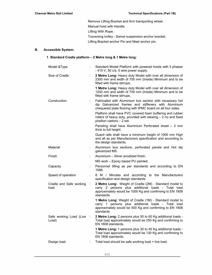
Chennai Metro Rail Limited Technical Specifications (Part 1B)
455
Remove Lifting Bracket and Arm transporting wheel. Manual hoist with Handle. Lifting With Rope. Traversing trolley - Swivel suspension anchor bracket. Lifting Bracket anchor Pin and Mast anchor pin.
B. Accessible System:
1. Standard Cradle platform – 2 Metre long & 1 Metre long: Model &Type : Standard Model Platform with powered hoists with 3 phases
- 415 V, 50 c/s, 5 wire power supply. Size of Cradle : 2 Metre Long: Heavy duty Model with over all dimension of
2300 mm and width of 700 mm (Inside) Minimum and to be fitted with frame stirrups. 1 Metre Long: Heavy duty Model with over all dimension of 1200 mm and width of 700 mm (Inside) Minimum and to be fitted with frame stirrups.
Construction : Fabricated with Aluminium box section with necessary hot dip Galvanized frames and stiffeners with Aluminium chequered plate flooring with tPMC board on all four sides. Platform shall have PVC covered foam buffering and rubber rollers of heavy duty, provided with slewing – 2 no and fixed position castors – 2 set. Paneling shall have Aluminium Perforated sheet – 2 mm thick to full height. Guard rails shall have a minimum height of 1000 mm High and all as per Manufacturers specification and according to the design standards.
Material : Aluminium box sections, perforated panels and Hot dip galvanized MS.
Finish : Aluminium – Silver anodized finish. MS work – Epoxy based PU painted.
Capacity : Personnel lifting as per standards and according to EN 1088.
Speed of operation : 8 M / Minutes and according to the Manufacturers specification and design standards.
Cradle and Safe working load.
: 2 Metre Long: Weight of Cradle (2M) - Standard model to carry 2 persons plus additional loads - Total load approximately would be 1000 Kg and confirming to EN 1808 standards. 1 Metre Long: Weight of Cradle (1M) - Standard model to carry 1 persons plus additional loads - Total load approximately would be 500 Kg and confirming to EN 1808 standards.
Safe working Load (Live Load)
: 2 Metre Long: 2 persons plus 50 to 60 Kg additional loads - Total load approximately would be 250 Kg and confirming to EN 1808 standards. 1 Metre Long: 1 persons plus 30 to 40 Kg additional loads - Total load approximately would be 130 Kg and confirming to EN 1808 standards.
Design load : Total load should be safe working load + live load.

Chennai Metro Rail Limited Technical Specifications (Part 1B)
456
Power Supply & Cable : Metal clad plug and socket out let 5 pin – 415 V, 3 phase, 50 HZ, 20 Amps. (Builder Scope) PVC copper flexible cable 6 core x 2.5 Sq mm as per required length (Façade Access system vendor scope).
Traction Hoist / winch : Imported power winches of Power Climber make or approved equivalent make and capacity not less than 500 kg each. 2 nos for 2 metre platform and 1 no for 1 Metre platform.
Location of wire rope and winch
: To be housed in the Cradle.
Motors for winch : 2 Metre Long: Winched are fitted with Imported motors of capacity not less than 1500 or 3000 RPM and all according to design parameters, to lift 500 Kg minimum on each winch - Powered Heavy Model with 3 Phase - 415 V, 50 HZ supply and to satisfy IP 55 construction.
Wire Rope : Imported make wire ropes according to the design standards and shall be provided with: Main Suspension ropes - 2 Nos of required capacity. Secondary, suspension rope - 2 Nos of required capacity. Factor of safety – 1/ 8 according to EN 1088.
Type : Suitable for 8.3 mm dia, 6x19 mm/0.260 Kg/M ropes - Indicative
Material : Corrosion protected Galvanized. Finish : IP 55 protection. Accessories : Thermal overload protection for motors. Interlocked over
speed device. Rope Reeling (Slack Free)
: Provide torque limiters for Rope winding / unwinding on to power reelers fitted below the winches for both, main suspension and secondary safety wire for slack free reeling.
Controls : Central control in the cradle for traction hoists with IP 55 protection, Main Switch, Phase Protection & Push Buttons and according to EN 1088.
Components and Safety device
: Fail-safe primary brake positively locked with power switch in off position. Emergency descent at controlled speed in case of power failure by operating primary brake lever. Automatic trip device (fitted underside of cradle) to operate in case of cradle meeting obstructions during descent. Block stop Anti-fall safety device. Upper limit switch’s to halt the ascent at predetermined height. Cradle fitted with safety harness anchorages. Bottom Trip Bar with limit switches. Power Winch with Motors. Galvanized wire ropes Castors and Anti - collision Bars Central control Box and Motorized wire rope reelers. Over load Devices. Upper and final limit switch. Guide Rollers. Electrical cable to the required length.
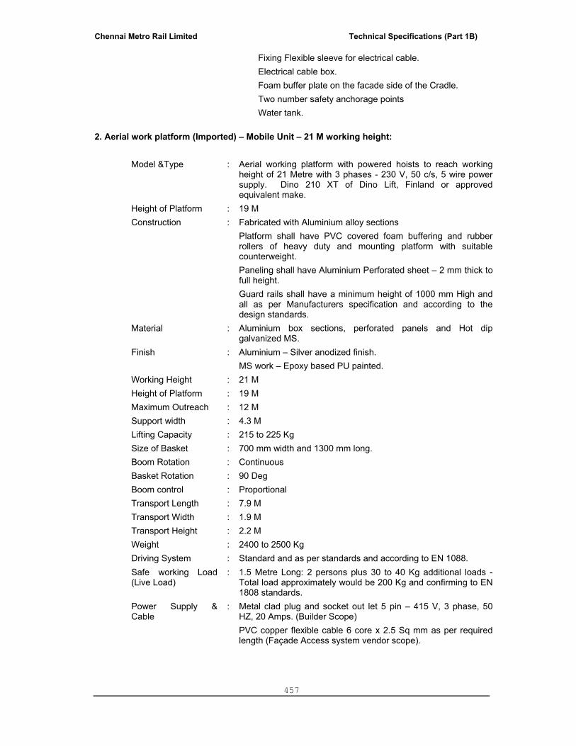
Chennai Metro Rail Limited Technical Specifications (Part 1B)
457
Fixing Flexible sleeve for electrical cable. Electrical cable box. Foam buffer plate on the facade side of the Cradle. Two number safety anchorage points Water tank.
2. Aerial work platform (Imported) – Mobile Unit – 21 M working height:
Model &Type : Aerial working platform with powered hoists to reach working height of 21 Metre with 3 phases - 230 V, 50 c/s, 5 wire power supply. Dino 210 XT of Dino Lift, Finland or approved equivalent make.
Height of Platform : 19 M Construction : Fabricated with Aluminium alloy sections
Platform shall have PVC covered foam buffering and rubber rollers of heavy duty and mounting platform with suitable counterweight. Paneling shall have Aluminium Perforated sheet – 2 mm thick to full height. Guard rails shall have a minimum height of 1000 mm High and all as per Manufacturers specification and according to the design standards.
Material : Aluminium box sections, perforated panels and Hot dip galvanized MS.
Finish : Aluminium – Silver anodized finish. MS work – Epoxy based PU painted.
Working Height : 21 M Height of Platform : 19 M Maximum Outreach : 12 M Support width : 4.3 M Lifting Capacity : 215 to 225 Kg Size of Basket : 700 mm width and 1300 mm long. Boom Rotation : Continuous Basket Rotation : 90 Deg Boom control : Proportional Transport Length : 7.9 M Transport Width : 1.9 M Transport Height : 2.2 M Weight : 2400 to 2500 Kg Driving System : Standard and as per standards and according to EN 1088. Safe working Load (Live Load)
: 1.5 Metre Long: 2 persons plus 30 to 40 Kg additional loads - Total load approximately would be 200 Kg and confirming to EN 1808 standards.
Power Supply & Cable
: Metal clad plug and socket out let 5 pin – 415 V, 3 phase, 50 HZ, 20 Amps. (Builder Scope) PVC copper flexible cable 6 core x 2.5 Sq mm as per required length (Façade Access system vendor scope).

Chennai Metro Rail Limited Technical Specifications (Part 1B)
458
Controls :
Central control in the platform for traction hoists with IP 55 protection, Main Switch, Phase Protection & Push Buttons and according to EN 1088.
Components and Safety device
: Emergency descent at controlled speed in case of power failure by operating primary brake lever. Automatic trip device (fitted underside of cradle) to operate in case of cradle meeting obstructions during descent. Block stop Anti-fall safety device. Upper limit switch’s to halt the ascent at predetermined height. Cradle fitted with safety harness anchorages. Bottom Trip Bar with limit switches. Castors and Anti - collision Bars Central control Box. Over load Devices. Upper and final limit switch. Electrical cable to the required length. Fixing Flexible sleeve for electrical cable. Electrical cable box. Two number safety anchorage points
3. Electro hydraulic vertical platform – 16 M working height:
Model &Type : Electro hydraulic vertical working platform with working height of 16 Metre with runs on 1.5 KW 220 V power supply of approved make.
Working Height : 16 M
Height of Platform : 14 M
Closed Height 3 M Lifting Capacity : 215 to 225 Kg Cage size : 110 x 1600 x 780 Cm. Base area for single operator
: 106cm x 66cm
Driving System : Standard and as per standards and according to EN 1088.
Safe working Load (Live Load)
: 1.5 Metre Long: 2 persons plus 30 to 40 Kg additional loads - Total load approximately would be 200 Kg and confirming to EN 1808 standards.
Power Supply & Cable
: Metal clad plug and socket out let 5 pin – 415 V, 3 phase, 50 HZ, 20 Amps (Façade Access system vendor scope) PVC copper flexible cable 6 core x 2.5 Sq mm as per required length (Façade Access system vendor scope)
Controls :
Central control in the platform for traction hoists with IP 55 protection, Main Switch, Phase Protection & Push Buttons and according to EN 1088.

Chennai Metro Rail Limited Technical Specifications (Part 1B)
459
Components and Safety device
: Vibration Reduction System Chain Control System Inserted Control System Mobile 24V power kit including 2 batteries 1 battery charger
8.0 ORDERING AND DELIVERY.
• Before the commencement of any fabrication or ordering of any materials, goods or works, tenderer shall be required to submit for approval, shop drawings, samples, etc. of all relevant details as to materials, sizes, construction and all other details and information as required.
• Any item of work that is any way damaged either upon its arrival on site or while being carried, fixed or placed thereon will be removed forthwith by the successful tenderer and replacement of identical specification provided without delay.
9.0 SAMPLES
• All samples shall be supplied by the tenderer with in the quoted rates. Samples shall be submitted for approval well in advance of the date, the particular work involving the use of materials for which samples are submitted is scheduled to begin.
• The work shall be in accordance with the approved samples and according to the bills of materials.
10.0 SOURCES
• The Tenderer shall submit the name of the suppliers for the following item along with the shop drawings and samples, if required.
11.0 TESTS
• The tenderer has to arrange all testing required with regard to this work with in the quoted rates, at such test laboratories as approved by the Architect.
• Tests of aluminium / Hot Dip Galvanised materials shall be conducted in accordance with International codes and test certificates should be produced for approval. Correct defects revealed by tests including retest on corrected work to determine effectiveness of remedial measure at no extra cost.
12.0 SHOP DRAWING
The Tenderer shall submit shop drawings clearly indicate the relationship of the system to the structure, mechanical and electrical system. Contractor shall show the arrangement of components, the sequence and details of fabrication, assembly and installation of components.
Shop drawings shall include the following:
• Jointing techniques show relative position of all adjacent walls, beams, columns,
and slabs, all correctly dimensioned.
• Full size details including isometric drawing of the system and jointing methods. Materials, type, size, location and spacing of all screws, bolts, weld, anchoring devices and accessories.

Chennai Metro Rail Limited Technical Specifications (Part 1B)
460
• The Tenderer shall submit a fully detailed program for the presentation of shop drawings to the Employer/Architect/PMC for approval, and in no case shall the Tenderer proceed with any position of these works without approved shop drawings. The shop drawings shall include instructions and explanatory details for the sequence of fabrication, assembly, erection and installation of all materials.
• The Tenderer shall review and submit all shop drawings in a sequence consistent with sequence of erection, installation or assembly of the various elements of the work. He shall be deemed to have determined and verified all materials, site measurements and construction criteria related thereto and to have checked the shop drawings for complete dimensional accuracy.
• Any approval by the Employer/Architect/PMC of the Tenderer shop drawings shall not relieve the Tenderer of his responsibility for any deviation from the requirements of the Contract unless successful tenderer has specifically informed the Employer/Architect/PMC in writing of such deviation at the time of submission and Employer/Architect/PMC has given written approval to the specific deviation.
• The Tenderer shall be required to submit to the Employer/Architect/PMC three sets of prints of all shop drawings. Further four sets of approved shop drawings shall be submitted to the Employer/Architect/PMC for reference and record.
13.0 FABRICATION
• Entire system / Works shall be fabricated at works in accordance with the approved shop drawings and samples.
• Fabrication shall be done true to the drawings to correspond to the finished openings at the site, the sections cut to lengths to suit, mired at the corners, to true right angles with joints made neatly to hair lines, with concealed fasteners, wherever possible joints shall be made in concealed locations.
14.0 INSTALLATION
• The units shall be factory built to precision, alignment, dimensional accuracy and strength.
• The interlocking members shall be accurately manufactured to close tolerances to ensure tight fit of the mating interlock profiles.
• Field connections may be made with concealed screws, self tapping or other approved fasteners or may be made with weld due precautions being taken to avoid altogether distortion / discoloration of the finish.
• Faces / Parts coming into contact with masonry in the construction shall before shipment to the site be given a heavy coat of alkali resistance bitumen paint. Aluminium coming in contact with other incompatible metals shall be given similarly a thick coat of Zinc Chromate primer.
• Scaffolding, working platform, formwork shall be provided by the tenderer within the quoted rates. Type and method of scaffolding he intends to use; incorporating therein shall be provided for approved by Employer/Architect/PMC.
15.0 REJECTION
If, at the time and place agreed in accordance with sub-clause (Removal of improper work, Materials) the materials are not ready for inspection or testing or if, as a result of the

Chennai Metro Rail Limited Technical Specifications (Part 1B)
461
inspection or testing referred to in this clause, the Employer/Architect/PMC determines that the materials are defective or otherwise not in accordance with the Contract, he may reject the materials and shall notify the Tenderer thereof immediately. The Tenderer shall then promptly make good the defect or ensure that rejected materials comply with the Contract. If the Employer/Architect/PMC requests, the tests, of rejected materials shall be made or repeated under the same terms and conditions. All costs incurred by the Employer/Architect/PMC by the repetition of the tests shall be recoverable from the tenderer by the Employer/Architect/PMC and may be deducted from any monies due or to become due to the tenderers.
16.0 EXAMINATION OF WORK BEFORE COVERING UP
No part of the works shall be installed, covered up or put out of view without the approval of the Employer/Architect/PMC and the tenderer shall afford full opportunity for the Employer/Architect/PMC to examine and measure any such part of the works which is about to be covered unto or put out of view and to examine foundations before any part of the works is placed thereon. The Tenderer shall give reasonable notice to the Employer/Architect/PMC, whenever any such part of the works are ready or about or be ready for examination and the Employer/Architect/PMC shall, without unreasonable delay, unless he considers if unnecessary and advises the tenderer accordingly, attend for the purpose of examining and measuring such part of the works or of examining such foundations. Where the works involve more that one stage / process, the Tenderer shall give notice when each stage / process is ready to enable inspection by the Employer/Architect/PMC.
17.0 REMOVAL OF IMPROPER WORK, MATERIALS
Any materials and / or works that, in the opinion of the Employer/Architect/PMC, are not in accordance with the specification, shop drawings and instructions shall be removed from the site immediately. Correct defects in materials revealed by test including retest on corrected works to determine effectiveness of remedial measures.
18.0 CLEANING
On virtual completion and on receiving instructions from the Employer/PMC, the Tenderer shall remove all protective coverings, if any.
19.0 AS BUILT DRAWINGS & MAINTENANCE MANUAL The tenderer shall prepare as built drawing and maintenance manual in accordance with
International Standards. Three copies of maintenance manual and as-Built drawings must be handed over to the Employer/Architect/PMC within four weeks from virtual completion of work.
20.0 GUARANTEE
The tenderers should also note that the design should be such that the equipment(s) has / have minimum life of 10 years being a permanent access. The tenderer shall furnish performance guarantee for the entire system and related materials against defects in materials and workmanship for a period of 1 year from the date of virtual completion.
21.0 MODE OF MEASUREMENTS
Unless noted otherwise in the bills of materials, the method of measurements shall be generally in accordance with IS 1200 or its Equivalent British standard.

Chennai Metro Rail Limited Technical Specifications (Part 1B)
462
Place: Signature of the Tenderer Date:
ELECTRICAL & INSTALLATION WORKS (HT & LT)
SL.NO. DESCRIPTION PAGE NO.
I GENERAL
II TECHNICAL SPECIFICATION FOR 11KV RING MAIN SWITCHGEAR
III TECHNICAL SPECIFICATION FOR 11KV HT OUTDOOR VCB SINGLE PANEL
IV TECHNICAL SPECIFICATION FOR 11KV HT INDOOR VCB FOUR PANEL
V TECHNICAL SPECIFICATION FOR BATTERY, BATTERY CHARGER
VI TECHNICAL SPECIFICATION FOR 11KV/433V 2000KVA OIL COOLED, ONAN TYPE OUTDOOR TRANSFORMER
VII TECHNICAL SPECIFICATION FOR L. T. SWITCH BOARDS
VIII TECHNICAL SPECIFICATION FOR AUTOMATIC POWER FACTOR CORRECTION PANELS (WITH DETUNED SERIES REACTOR)
IX TECHNICAL SPECIFICATION FOR RELAYS
X TECHNICAL SPECIFICATION FOR DISTRIBUTION BOARD
XI TECHNICAL SPECIFICATION FOR SANDWICH BUSBAR TRUNKING SYSTEM
XII TECHNICAL SPECIFICATIONS FOR 11KV HT CABLE
XIII TECHNICAL SPECIFICATION FOR CROSS LINKED POLYETHYLENE (XLPE)/ PVC INSULATED/ FIRE RESISTANT (FS) LT POWER AND CONTROL CABLES
XIV TECHNICAL SPECIFICATION FOR CABLE TRAY
XV TECHNICAL SPECIFICATIONS FOR WIRING
XVI TECHNICAL SPECIFICATIONS FOR UPS SYSTEMS
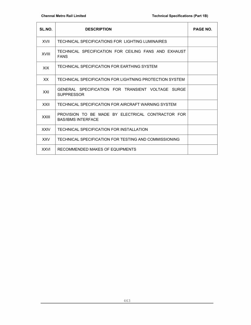
Chennai Metro Rail Limited Technical Specifications (Part 1B)
463
SL.NO. DESCRIPTION PAGE NO.
XVII TECHNICAL SPECIFICATIONS FOR LIGHTING LUMINAIRES
XVIII TECHNICAL SPECIFICATION FOR CEILING FANS AND EXHAUST FANS
XIX TECHNICAL SPECIFICATION FOR EARTHING SYSTEM
XX TECHNICAL SPECIFICATION FOR LIGHTNING PROTECTION SYSTEM
XXI GENERAL SPECIFICATION FOR TRANSIENT VOLTAGE SURGE SUPPRESSOR
XXII TECHNICAL SPECIFICATION FOR AIRCRAFT WARNING SYSTEM
XXIII PROVISION TO BE MADE BY ELECTRICAL CONTRACTOR FOR BAS/IBMS INTERFACE
XXIV TECHNICAL SPECIFICATION FOR INSTALLATION
XXV TECHNICAL SPECIFICATION FOR TESTING AND COMMISSIONING
XXVI RECOMMENDED MAKES OF EQUIPMENTS

Chennai Metro Rail Limited Technical Specifications (Part 1B)
464
I. GENERAL 1.0 INTRODUCTION This tender comprises of Technical requirements for complete electrification like 11KV Substation, Power Distribution, Lighting, Earthing required for the Proposed Office & Residential building of M/s. Chennai Metro Rail Limited at Nandanam, Chennai. 2.0 ELECTRICAL SYSTEM DETAILS
Incoming Voltage - 11KV, 3Ph, 50Hz A.C Supply Earthed System Operating Voltage for Power - 415V, 3 Phases, 4 Wire Operating Voltage for Lighting - 230V, 1 Phase, AC
3.0 SCOPE OF WORK
The scope of work covered by this Tender shall include Supply, Installation, Testing and Commissioning of the following: The Scope of Work shall also include transportation of all material to site, unloading safe keeping, storage and leading to site for installation. It is the contractor’s sole responsibilities to obtain all permits and statutory approvals from Governments. 4.0 BRIEF DESCRIPTION OF SCOPE OF WORK: Design, Supply, Installation, Testing, Commissioning, Operation and Maintenance of the following: 1. RMG to receive 11KV power supply from TNEB. 2. 11KV XLPE, FRLS HT Cable from Client’s outdoor VCB panel to Indoor HT 3 Panel and
installing 2 Nos. 2000KVA, 11KV/433V Transformers. 3. Single Front, Cubicle, Floor mounting type with form 4B construction and Single Busbar
arrangement Main Power Control Center with PLC controls at sub-station building.
4. All LT cables shall be – XLPE (FRLS) armoured cable/ PVC armoured (FRLS) cable (As per SLD) from MPCC to Various Panel boards like, AC Equipments, power and lighting rising mains, From Panel boards to Power and lighting Distribution Boards, Equipments etc., and fire resistant (FS) cables / wires to be provided for all critical loads like fire Hydrants / Sprinkler MCC, Fire pumps, UPS incoming & outgoings and emergency lighting etc.
5. In MHQ building all wiring (like lighting and raw power) shall be with FRLS wires in GI conduit and in residential building all wires shall be with FRLS wires in PVC pipe (MMS).
6. Cable trays of various sizes for cable laying suitably fixed to ceiling / wall inside the premises.
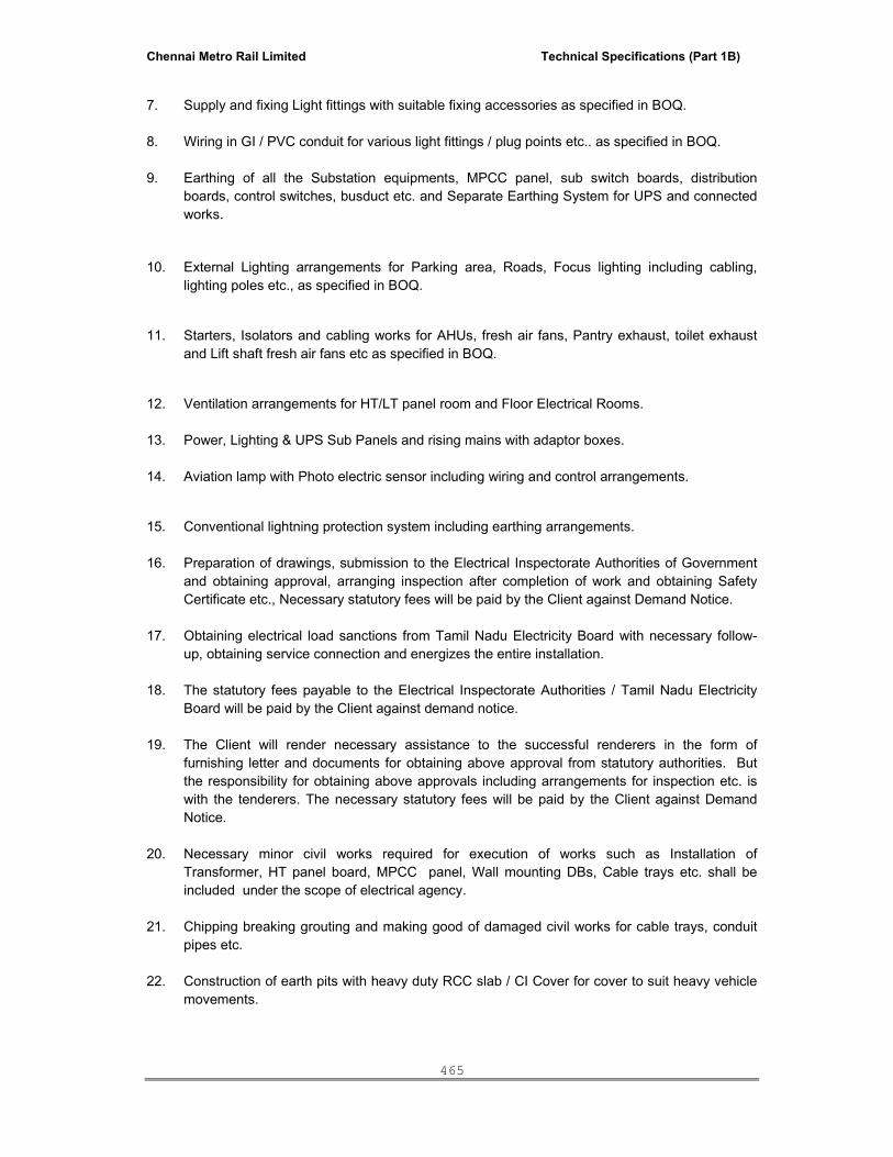
Chennai Metro Rail Limited Technical Specifications (Part 1B)
465
7. Supply and fixing Light fittings with suitable fixing accessories as specified in BOQ. 8. Wiring in GI / PVC conduit for various light fittings / plug points etc.. as specified in BOQ. 9. Earthing of all the Substation equipments, MPCC panel, sub switch boards, distribution
boards, control switches, busduct etc. and Separate Earthing System for UPS and connected works.
10. External Lighting arrangements for Parking area, Roads, Focus lighting including cabling, lighting poles etc., as specified in BOQ.
11. Starters, Isolators and cabling works for AHUs, fresh air fans, Pantry exhaust, toilet exhaust and Lift shaft fresh air fans etc as specified in BOQ.
12. Ventilation arrangements for HT/LT panel room and Floor Electrical Rooms. 13. Power, Lighting & UPS Sub Panels and rising mains with adaptor boxes. 14. Aviation lamp with Photo electric sensor including wiring and control arrangements.
15. Conventional lightning protection system including earthing arrangements. 16. Preparation of drawings, submission to the Electrical Inspectorate Authorities of Government
and obtaining approval, arranging inspection after completion of work and obtaining Safety Certificate etc., Necessary statutory fees will be paid by the Client against Demand Notice.
17. Obtaining electrical load sanctions from Tamil Nadu Electricity Board with necessary follow-
up, obtaining service connection and energizes the entire installation. 18. The statutory fees payable to the Electrical Inspectorate Authorities / Tamil Nadu Electricity
Board will be paid by the Client against demand notice. 19. The Client will render necessary assistance to the successful renderers in the form of
furnishing letter and documents for obtaining above approval from statutory authorities. But the responsibility for obtaining above approvals including arrangements for inspection etc. is with the tenderers. The necessary statutory fees will be paid by the Client against Demand Notice.
20. Necessary minor civil works required for execution of works such as Installation of
Transformer, HT panel board, MPCC panel, Wall mounting DBs, Cable trays etc. shall be included under the scope of electrical agency.
21. Chipping breaking grouting and making good of damaged civil works for cable trays, conduit
pipes etc. 22. Construction of earth pits with heavy duty RCC slab / CI Cover for cover to suit heavy vehicle
movements.

Chennai Metro Rail Limited Technical Specifications (Part 1B)
466
23. 433V LT Bus ducts from Outdoor 2000KVA Transformer (Secondary side) to Main Power Control Centre (MPCC), DG Set Auto Load sharing /synchronizing Control Panel to MPCC and MPCC panel to APFC panel.
24. Automatic Power Factor Correction Control Capacitor Panels with LT Bus ducts from MPCC
to APFCC capacitor Panel 25. DOL and Star-Delta Starters for Electrical equipments as specified in the BOQ. 26. Push Button stations and Control cabling. 27. Termination of cables at equipment end for equipments supplied by others. 28. Providing UPS power for all critical loads like server, EPABX, computers, emergency lighting,
fire alarm etc. 29. Aviation lamp with Photo electric sensor including wiring and control arrangements. 30. Earth mat provision thro’ antistatic flooring if required
31. Rubber mats to be provided in front of all electrical panels.
32. SLD’s of each panel and Main SLD’s in HT Room &MPCC Rooms to be displayed as required.
33. First aid boxes to be fixed and First aid charts in English & Local Language Tamil to be displayed as required.
34. All the Displays shall be of laminated card boards suitable for wall mounted type.
35. The contractor should follow the below colour codings for every 1mtr interval in conduits, cable trays, wire ways and termination boxes etc. (a) Raw Power : Orange (b) Essential Power : Yellow (c) Control system : Blue (d) Network system : Grey (e) Signalling : Pink (f) Telecom : Purple (g) AFC : Green (h) PST : Red
5.0 SPECIFIC INCLUSIONS
- Hot dipped GI Cable tray, bends, couplers, down road supports, provision of Anchor
fasteners, wherever required.
- Epoxy painted steel angles and channel support for cable trays with proper earthing at equal
intervals – will be paid in separate line item.
- Steel support channels for panels / DBs.
- Excavation of pits for earth electrode, Construction of earth pits including masonry and
covers as per IS 3043 standards

Chennai Metro Rail Limited Technical Specifications (Part 1B)
467
- Provision of pipe sleeves for cables and earth bus
- Chipping, Breaking and making good the damaged portion of civil works
- Calibration & Testing of all protective relays, meters & other measuring and Protective
devices as specified in testing requirements
- Co-operation / Co-ordination for testing and commissioning with other suppliers
- Obtain drawing approval from necessary authorities, arrange inspection and obtain safety
certificate for entire installation.
- Submission of 6 (six) copies of As Built Drawings, Documents and maintenance manuals
- Epoxy / Zinc rich painting, wherever required
- Preparation of working drawings, drawings for CEIG submission
- Power Supply during installation.
- Inspection charges for Transformer, HT panel and critical equipments
6.0 CHIEF ELECTRICAL INSPECTOR TO GOVT’S APPROVAL
The preliminary physical layout and schematic drawings and site plan will be furnished by the Architects. It is the responsibility of the contractor to prepare all detailed working drawings required for erection and by Chief Electrical Inspector and obtain his approval. The contractor has to arrange for site inspection and get safety certificate to commission the installation for the entire scope of work carried out by him.
The inspection fee and drawing approval fee payable to the Electrical Inspector’s office will be paid by the Contractor whose rates shall be inclusive of all such expenses. 7.0 ALTERATION OF WORK
If during inspection by Electrical Inspector, any defects are pointed out either on equipment supplied by the contractor or on the workmanship, the Contractor shall replace / repair the equipment and redo the work as per Electrical Inspector's requirements without any extra cost.
8.0 STATUTORY REGULATION
Contractors License The contractor shall hold valid contractor’s license issued by competent authority of Government for carrying out the work covered in this tender. Special condition to the contractors: Shop Drawings / Co-ordination Drawings The Contractor shall arrange for detailed shop drawings / fabrication drawings and material specifications for specialized works including detailed design calculation and submit required copies each of the same for Client / Architect’s prior approval. All shop drawings shall reflect the design intent as provided in the execution drawings and shall not be deviated without prior permission. The shop drawings shall be based on the actual site conditions and shall take into account all coordination as may be required in order to avoid any clash or interference with other service lines or any other building features. The shop drawings shall be fully supported by necessary design

Chennai Metro Rail Limited Technical Specifications (Part 1B)
468
calculations wherever applicable or as directed by the Architect to the Contractors. Such design calculations shall be carried out by a competent agency and shall also comply with relevant Indian / International standards as applicable. Wherever so required, the Client reserves the right to demand a certificate as to the correctness of the design to be issued after verification by an independent proof checking agency that the Client may either approve or nominate. All charges for preparing the shop drawings, coordination drawings, preparation of design, getting the same proof checked including carrying out any other modifications as necessary shall be fully covered in the quoted rates and no extra shall be payable for adherence of the above requirement.
As executed drawing shall be submitted within one month of completion of entire work. Copies of each of such built in drawings shall be submitted to the Client / Architects. The final version thereof submitted in hard copy format in triplicate as well as electronic format in AutoCAD latest Release as on date ( not less than 2007)
II. TECHNICAL SPECIFICATION FOR RING MAIN SWITCH GEAR
OUTDOOR FLOOR MOUNTING TYPE FREE STANDING METAL CLAD RING MAIN
SWTICHGEAR COMPRISING 11kV LOAD BREAK SWITCHES, VACUUM CIRCUIT BREAKER CONSTRUCTIONS FEATURES: Ring main switchgears shall be constructed of MS sheet steel not less than of 2mm for side sheets,
doors covers and screens etc., and 2.5mm for load bearing members. The ring main switchgear
shall be provided with a separate for main busbar, Load break switch/VCB/CT/PT/metering/relay
chambers and cable termination. The ring main gear shall be of built assembly to high quality
standard and shall comply with IS 3247. Panel shall be provided with pressure relief flap at top.
Each panel shall have minimum 2 Nos. of lifting hooks at top for easy transportation. Panel shall be
provided with gland plate at the rear with adequate clearance between the cable terminations. Each
panel shall be fully segregated with a sheet steel and busbars through seal of bushing to avoid
transfer of oxidation and carbonize during fire accident, if any. The Ring Main Switchgear shall be
suitable for degree of protection IP55 as per IS2147. Ring Main Switchgear shall be finished with
Light Grey to shade 631 of IS5, after undergoing a pre-treatment at 7-tank process.
BUSBARS:
Electrolytic grade tinned COPPER Busbar shall be used as Main Busbar and interconnections.
Busbar shall have uniform cross section throughout the Ring Main Switchgear. Busbar is provided
with a heat shrinkable PVC sleeve. Colour coding as per IS shall be made at regular intervals. The
busbar should be designed based on the temperature rise limit.
LOADBREAK SWITCHES: Load break Switches are Air-break type and suitable for panel mounting. Load break switches shall
comply with as per IS 9920. Load break switches shall be suitable to withstand a rated short circuit
current and also suitable for short circuit making (50kA peak) and rated breaking current as per the
test duties of IS 9920. Earth switch shall be provided with LBS in such a way that any one switch
can be operated at a time. Suitable mechanical interlocks shall be provided between Earth Switch
and Load Break Switch.
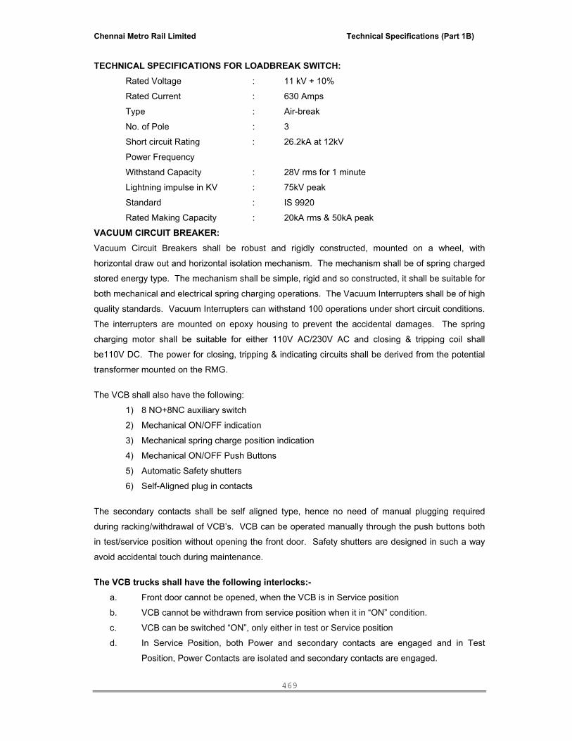
Chennai Metro Rail Limited Technical Specifications (Part 1B)
469
TECHNICAL SPECIFICATIONS FOR LOADBREAK SWITCH: Rated Voltage : 11 kV + 10%
Rated Current : 630 Amps
Type : Air-break
No. of Pole : 3
Short circuit Rating : 26.2kA at 12kV
Power Frequency
Withstand Capacity : 28V rms for 1 minute
Lightning impulse in KV : 75kV peak
Standard : IS 9920
Rated Making Capacity : 20kA rms & 50kA peak
VACUUM CIRCUIT BREAKER: Vacuum Circuit Breakers shall be robust and rigidly constructed, mounted on a wheel, with
horizontal draw out and horizontal isolation mechanism. The mechanism shall be of spring charged
stored energy type. The mechanism shall be simple, rigid and so constructed, it shall be suitable for
both mechanical and electrical spring charging operations. The Vacuum Interrupters shall be of high
quality standards. Vacuum Interrupters can withstand 100 operations under short circuit conditions.
The interrupters are mounted on epoxy housing to prevent the accidental damages. The spring
charging motor shall be suitable for either 110V AC/230V AC and closing & tripping coil shall
be110V DC. The power for closing, tripping & indicating circuits shall be derived from the potential
transformer mounted on the RMG.
The VCB shall also have the following:
1) 8 NO+8NC auxiliary switch
2) Mechanical ON/OFF indication
3) Mechanical spring charge position indication
4) Mechanical ON/OFF Push Buttons
5) Automatic Safety shutters
6) Self-Aligned plug in contacts
The secondary contacts shall be self aligned type, hence no need of manual plugging required
during racking/withdrawal of VCB’s. VCB can be operated manually through the push buttons both
in test/service position without opening the front door. Safety shutters are designed in such a way
avoid accidental touch during maintenance.
The VCB trucks shall have the following interlocks:-
a. Front door cannot be opened, when the VCB is in Service position
b. VCB cannot be withdrawn from service position when it in “ON” condition.
c. VCB can be switched “ON”, only either in test or Service position
d. In Service Position, both Power and secondary contacts are engaged and in Test
Position, Power Contacts are isolated and secondary contacts are engaged.

Chennai Metro Rail Limited Technical Specifications (Part 1B)
470
TECHNICAL SPECIFICATION FOR VCB:- Rated Voltage : 11KV + 10%
Rated Current : 630Amps
No. of Pole : 3
Breaking capacity : 26.2KA
Making capacity : 63KA Peak
Short circuit withstanding capacity : 26.2KA for 3 sec. At 12KV
Operating duty : O-3MIN-CO-3Min-CO
Insulation level
a) Power frequency
:
28KV rms for 1 Min.
b) Impulse : 75KV peak.
Standards : IS 13118/IEC56
CURRENT TRANSFORMERS: Current Transformers are Epoxy Resin cast, dual core dual ratio type and shall comply as per IS
2705.
POTENTIAL TRANSFORMERS: Potential Transformers are Epoxy Resin cast Draw-out type and shall comply as per IS 3516.
PROTECTION RELAYS: Relays are of Flush Mounted Draw-out type pattern fully Comply as per IS
3231.All other Instruments/Switches and Wires & Cables shall comply to the latest IS.
BILL OF MATERIALS INDOOR FLOOR MOUNTING, FREE STANDING, DUST & VERMIN PROOF METAL CLAD TYPE 11KV 630A, 500 MVA RING MAIN GEAR SHALL CONSIST OF:
INCOMER (2 SOURCES): 2 Nos. SYSAIR TYPE 11kV 630A, 500 MVA LOADBREAK SWITCH INCOMING PANEL EACH COMPRISING OF:
1 No. 11KV, 630A, 500 MVA Load Break Switch (Air Break) consists of:-
• 1 No. Manual spring charging mechanism.
• 1 No. Mechanically interlocked earth switch.
• 1 No. 2NO+2NC Aux. Switch
• 1 set Mechanical On/Off indication.
• 1 No. On/Off indication lamps
• 1 set Power terminals without cable termination kit.
OUTGOING:- 1 No. 11KV 630A, 500 MVA VCB OUTGOING PANEL COMPRISING OF:-
1 No. 11KV, 630A, 500 MVA Horizontal draw out / Horizontal isolation Vacuum Circuit Breaker
consists of:
• 3 Nos. 630A Vacuum Interrupters

Chennai Metro Rail Limited Technical Specifications (Part 1B)
471
• Manual Motor operated spring charging mechanism (Motor rated for 230V AC)
• Closing coil suitable for 110V DC.
• Tripping coil suitable for 110V DC.
• 8NO+8NC Auxiliary Switch
• Mechanical On/Off indication.
• Mechanical spring closing indication.
• Mechanical On/Off Push button
• Breaker Position indicator
• Mechanical operating counter.
• Automatic safety shutters.
• Secondary self-aligned plug in contacts.
• Anti-pumping feature.
• 1 No. 11KV Epoxy resin cast draw out type 3 limb 3 phase potential transformer of ratio
11KV/110/ class0.5 with 200VA burden.
• 3 Nos. 11KV Epoxy Resin Cast Dual Core current transformer suitable ratio with class 0.5
metering and class 5p10 for protection with 15VA burden AS REQUIRED BY EB
AUTHORITY.
• Mater Trip Relay.
• 1 No. Non-directional IDMT relay with 3 O/C and 1 E/F relay with high set element type.
• 1 set 144sq.mm Misc Ammeter with selector switch
• 1 set 144sq.mm Misc Voltmeter with selector switch
• 1 No. Provision for Tri-vector meter.
• 1 No. TNC Switch
• 1 set. Damper proof R/Y/B Phase indication lamps
• 1 set. On/Off/Trip indication lamps.
• 1 No. Trip circuit healthy indicating lamp with push button.
• 1 No. Motor spring charging mechanism indicating lamp.
• 1 No. Emergency Off Push Button.
• 1 No. Power pack suitable for 230-110V AC/110V DC with continuous and stored energy.
• 1 No. Test terminal block.
• 1 set. Power terminals suitable to receive XLPE cables without termination kit.
Note: 1. The panel shall be manufactured as required by the electrical authorities and
approval shall be obtained including commissioning. 2. Any additional features required by the authorities shall be carried out at no extra
cost.
III. TECHNICAL SPECIFICATION FOR 11KV, HT OUTDOOR SINGLE PANEL VCB
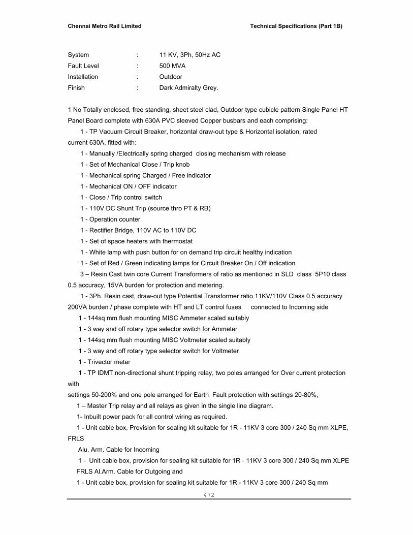
Chennai Metro Rail Limited Technical Specifications (Part 1B)
472
System : 11 KV, 3Ph, 50Hz AC
Fault Level : 500 MVA
Installation : Outdoor
Finish : Dark Admiralty Grey.
1 No Totally enclosed, free standing, sheet steel clad, Outdoor type cubicle pattern Single Panel HT
Panel Board complete with 630A PVC sleeved Copper busbars and each comprising:
1 - TP Vacuum Circuit Breaker, horizontal draw-out type & Horizontal isolation, rated
current 630A, fitted with:
1 - Manually /Electrically spring charged closing mechanism with release
1 - Set of Mechanical Close / Trip knob
1 - Mechanical spring Charged / Free indicator
1 - Mechanical ON / OFF indicator
1 - Close / Trip control switch
1 - 110V DC Shunt Trip (source thro PT & RB)
1 - Operation counter
1 - Rectifier Bridge, 110V AC to 110V DC
1 - Set of space heaters with thermostat
1 - White lamp with push button for on demand trip circuit healthy indication
1 - Set of Red / Green indicating lamps for Circuit Breaker On / Off indication
3 – Resin Cast twin core Current Transformers of ratio as mentioned in SLD class 5P10 class
0.5 accuracy, 15VA burden for protection and metering.
1 - 3Ph. Resin cast, draw-out type Potential Transformer ratio 11KV/110V Class 0.5 accuracy
200VA burden / phase complete with HT and LT control fuses connected to Incoming side
1 - 144sq mm flush mounting MISC Ammeter scaled suitably
1 - 3 way and off rotary type selector switch for Ammeter
1 - 144sq mm flush mounting MISC Voltmeter scaled suitably
1 - 3 way and off rotary type selector switch for Voltmeter
1 - Trivector meter
1 - TP IDMT non-directional shunt tripping relay, two poles arranged for Over current protection
with
settings 50-200% and one pole arranged for Earth Fault protection with settings 20-80%,
1 – Master Trip relay and all relays as given in the single line diagram.
1- Inbuilt power pack for all control wiring as required.
1 - Unit cable box, Provision for sealing kit suitable for 1R - 11KV 3 core 300 / 240 Sq mm XLPE,
FRLS
Alu. Arm. Cable for Incoming
1 - Unit cable box, provision for sealing kit suitable for 1R - 11KV 3 core 300 / 240 Sq mm XLPE
FRLS Al.Arm. Cable for Outgoing and
1 - Unit cable box, provision for sealing kit suitable for 1R - 11KV 3 core 300 / 240 Sq mm

Chennai Metro Rail Limited Technical Specifications (Part 1B)
473
XLPE, FRLS Alu. Arm. Cable for stand by cable
IV. TECHNICAL SPECIFICATION FOR 11KV HT 4 VCB PANEL (INDOOR) WITH EXTENSIBLE FACILITY FOR FUTURE 11KV SWITCHGEAR
1.0 Scope: This specification covers the design, manufacture, testing, packing and supply of MV Indoor Air Insulated draw-out type switchgear panels (Switchboards) upto 15 KV, incorporating Vacuum Circuit Breaker including extensible for future HT Panel complete with all accessories for efficient and trouble free operation. The switchboard shall be new which will be specifically manufactured against the enclosed detailed specification and the Single Line Diagram enclosed herewith. The equipment offered under this specification shall be of proven design by way of commercial operation for 3 years. 2.0 Codes and Standards: The switchgear shall be manufactured and tested in line with the latest revisions of the following Indian as well as International Standards: The equipment covered by this specification shall unless otherwise stated, be designed, constructed and tested in accordance with the latest revisions Amendments of relevant Standards and conform to the following: IEC56 International Standard :- High voltage alternating current Circuit Breakers. IEC298 International Standard :- AC Metal enclosed Switchgear and Control gear for rated voltages above 11KV and upto & including 52KV. IEC694 International Standard:- Common specification for High Voltage Switchgear and Control gear standards. IS2516 International Standard:- Specification for Alternating Current Circuit Breakers. Voltages above 1000V up to and including 11000V. IS 12729 : General requirements for Switchgear and Control gear for voltages exceeding 1000V. IS 13118 : General requirements for Circuit Breakers for voltages above 1000V. IS 3427 : Metal enclosed Switchgear and Control gear for voltages above 1000V but not exceeding 11000V. IS 5082 : Material for data for copper busbars. IS 9920 : Switches and Switch Isolators for voltages above 1000V. IS 2705 : Current Transformers. IS 3156 : Voltage Transformers. IS 1248 : Electrical indicating instruments. IS 3231 : Electrical Relays for power system protection.

Chennai Metro Rail Limited Technical Specifications (Part 1B)
474
IS 6875 : Control switches and push buttons. IS 694 : PVC insulated cables for working voltages upto and including 1100V. IS 375 : Marking and arrangement for switchgear busbar main connections and auxiliary wiring. IS 722 : AC Electricity Meters.
IEC 129: AC Isolators & Earthing Switches IEC 470: HV AC Contactors In case of conflict between the above standards and this specification, the requirements of this specification will prevail. 3.0 GENERAL REQUIREMENTS The circuit breaker shall be vaccum. Switchgear shall be Indoor, floor mounting, and metal clad draw out type, incorporating enclosures for the circuit breaker unit, bus bar chamber, current transformers, potential transformers, with necessary meters, relays switches and auxiliary wiring etc. The Circuit Breaker shall be mounted on trolley, which shall be movable in all directions. The Switchgear shall be of robust construction designed for maximum reliability of service in the tropical climate specified. Each circuit breaker panel shall be extensible in both directions so that individual units may be joined together in any order to form a composite flush fronted switchboard. For this purpose the busbar chamber shall have a removable cover. Enclosures shall be manufactured from folded and welded cold rolled sheet steel of minimum 2.0 mm thick CRGO. Cable sealing boxes shall have a removable gland plate. They shall be amply sized for the cable and shall be positioned to give adequate ground clearance to facilitate cable termination. All retaining catches, screws and bolts for doors and covers shall be Nickel plated. (Minimum 10 Microns average, 15 microns thick) The Brass Screws and bolts shall be Nickel plated for 15 Microns. They shall be corrosion proof for Ten years. Gasketting shall be done at suitable locations to achieve IP-42 degree of protection. Equipments to be mounted on the face of the cubicle shall be flush mounted. Panel shall be fabricated in suitable transport sections. All hardware for the complete equipment including foundation bolts, lifting lugs etc., shall be supplied along with the panel. The switch gear assembly shall form a continuous dead front line up of free standing vertical cubicles. Each cubicle shall have a lockable front hinged door and a removable bolted back cover. All covers and doors shall be provided with neoprene gaskets. Suitable arrangement for lifting of each cubicle shall be provided.

Chennai Metro Rail Limited Technical Specifications (Part 1B)
475
Circuit breaker shall be provided with three distinct positions, namely, service, test and withdrawn. It should be possible to close fully the front access door with breaker in test position. All relays, switches, lamps, etc. comprising the control, indication and protective devices shall be located in a separate compartment on the front of the cubicle. Bus bars shall be made of high strength, high conductivity copper alloy with maximum temperature rise limited to thermal limits of connected equipment, viz. cables, etc. Bus bar chamber shall be provided with inter panel barriers with epoxy cast seal off bushings. Circuit breakers of identical rating shall be completely interchangeable. Vacuum circuit breakers shall be provided with suitable surge protection devices to restrict rate of rise of restriking voltage. Breakers shall be provided with motor wound spring charged trip free mechanism with anti pumping feature and shunt trip. In addition facility for manual charging of spring shall also be available. One open - close - open operation of the breaker shall possible after loss of supply to the motor. Each breaker shall be provided with a shrouded manual emergency trip push button, ON / OFF indication, operation counter and spring charged /discharged indicator . The following minimum interlocks shall be provided for: i). breaker cannot be racked from one position to the other in closed position. ii). breaker cannot be operated in any intermediate position. iii). breaker cannot be opened or closed with compartment front door open. iv). With selector switch in “local” position breaker can only be operated in “test” position. For
operation in “service” position, control must be from “remote”. The following minimum indication lamps shall be provided for in the front of the cubicle. - Breaker Open / Closed / Tripped, Vacuum pressure low, Spring charged, trip circuit healthy and Control supply healthy. - Lamps shall be clustered LED type and trip circuit supervision scheme shall be of continuous supervision type. After meeting all necessary control and indication requirements 4 nos. NO and 4 nos. NC auxiliary contacts of the breaker shall be made available for the purchaser, wired upto terminal block. Meters and indicating instruments shall be of accuracy class and size specified where necessary motor ammeters shall have suppressed scale. Energy meters shall be provided with test terminal blocks. All spare contacts of breaker, relays, switches etc shall be wired up to terminal blocks. Wiring shall be done with flexible, 1100 volts grade, PVC insulated FRLS cables, minimum size 1.5sqmm for all circuits and 2.5sqmm for CT circuits. Each wire shall be identified at both ends with permanently marked ferrules. All wire termination's shall be made with crimped connectors having insulating sleeves. Not more than 2 wires shall be connected to any terminal. Spare terminals equal to at least 20% of active terminals shall be provided in each terminal block. Terminals will also need to be segregated circuit wise and voltage wise.

Chennai Metro Rail Limited Technical Specifications (Part 1B)
476
Switch gear shall be suitable for cable entry from bottom as specified. Power and control cabling shall be completely segregated. Suitable space for termination / maintenance shall be provided in the cable compartment. Suitable working space between gland plate and power cable box shall be provided for and also for mounting core balance CTs if required. Gland plates shall be of non magnetic material for single core cables. A ground bus rated for same short circuit level as the system shall be provided along the full length of the switch gear. Ground bus shall be of copper and bolted studs should be provided at each end of the switch gear to permit connection of flat / cable. All instrument transformer neutrals shall be connected to the ground bus through removable links. All removable / hinged doors and covers shall be grounded by flexible stranded connectors. Each cubicle shall be provided with a space heater with thermostat control, one CFL / LED light fitting with suitable lamp & switch and 3 pin 5 amps plug socket. The following power supplies shall be made available to each switch gear.
a.) A.C Supply; Single feeder. b.) D.C Supply; Double feeder.
MCB shall be provided on incomer to each cubicle and D.C. supply shall have an selector switch (Source I & Source II). A.C load from control supply shall be so distributed so as to ensure proper balancing of three phase supply. 3.1 Labels Labels shall be provided to describe the duty of or otherwise identify every instrument, or other item of equipment mounted internally and externally. Switch portions shall be fully identified, wording shall be clear, concise and unambiguous. Each label shall be permanently secured to the panel surface below the item to which it refers. The labels shall be engraved / anodised aluminium with white letters on black background or non-removable stickers. The nameplates shall not be screwed on. In additions to component labels, each cubicle door shall bear a large identification label and the board shall include a large, prominent overall identification Label. 3.2 Painting Care shall be taken in workmanship and selection of materials to prevent the occurrence of any form of damage or corrosion due to damp or humid conditions. The Board shall be prepared, primed, filled and painted to the highest standards. All items shall be cleaned and deburred, after fabrication and welding is completed. External surfaces shall be filled and rubbed down as necessary to obtain a perfectly flat smooth surface, free from blemishes and imperfections. Paint shade shall be inside white. Outside colour shall shade 631 as per IS : 5 for Outdoor type panel and shade RAL 7032 as per IS : 5 for Indoor type panel both inside and outside The painting process shall be pre approved by the Consultant / Owner. 4.0 CLEARANCE Minimum insulator lengths and clearances in air shall be not less than those specified for class A switchgear in IS: 3427.

Chennai Metro Rail Limited Technical Specifications (Part 1B)
477
5.0 TEMPERATURE RISE The design ambient shall be 45 deg. C. The limits of temperature rise determined in accordance with the relevant standard, shall be reduced such that the final temperature obtained at site does not exceed the final temperature computed by the addition of the design ambient temperature to the permissible temperature rise of 40 deg. C. The maximum busbar temperature rise shall not exceed 85 Degree C. All other electrical / insulated items shall have temperature rise as per the relevant Indian Standard. Temperature rise & SC tests The busbars shall be supported adequately on non-hygroscopic insulators. For indoor application epoxy insulators have been found adequate. Porcelain insulators are brittle and need careful handling and hence better avoided. The temperature rise limit of the busbars shall be as per the limits of IEC-694 and with respect to ambient temperature as per IS 9676. To maintain the temperature within the limits particularly for higher currents, additional ventilation openings may be necessary. Manufacturers shall provide adequate ventilation arrangements. The degree of protection of enclosure shall be coordinated in such cases. It is impracticable in certain cases to achieve required temperatures limits without ventilation fans 6.0 CURRENT RATINGS Every current carrying part of the equipment, including circuit breakers, current transformers, isolating switches, busbars, connectors and joints shall be capable of carrying its rated current continuously and in no part shall the permissible temperature rise be exceeded. In addition, all parts of the switchgear, including current transformers, shall be capable of withstanding, without thermal or mechanical damage, the instantaneous peak and the three second short time currents corresponding to the rated making and breaking capacity of the circuit breaker. 7.0 MAKING AND BREAKING CAPACITIES Each circuit breaker shall be capable of making and breaking short circuit faults at 3 phase symmetrical fault and asymmetrical faults. The supplier shall submit for approval certified test certificates of making and breaking tests carried out on similar equipment by approved independent testing authorities. Opening time around 60ms, closing time around 80ms or faster.
8.0 CIRCUIT BREAKER TYPE All circuit breakers shall be of same make and type and shall be interchangeable. 9.0 OPERATING MECHANISM Spring charging motor shall be 110V Universal / DC motor. Control supply of the entire HT Panels shall be 110V DC Tripping shall be effected by means of a D.C. shunt trip coil. Each breaker shall be provided with a visual, mechanised, indicating device for `Open' and `Closed' position of the breaker. It shall be operative when the circuit breaker is in the `Service', `Test' and
Chennai Metro Rail Limited Technical Specifications (Part 1B)
478
`Isolated/Earthed' position. Operation counters shall be provided on each mechanism to count the number of trips and cannot be reset. Means shall be provided for coupling the secondary, circuits on the fixed portion to those on the movable portion when the circuit breaker is in `Test' position in order to permit closing, tripping and interlock circuits to be checked for operation test purposes. It shall not be possible, without the use of tools, to gain access to the tripping toggle or any part of the mechanism which would permit defeat of the locking of the mechanical tripping feature or closing feature, casually or carelessly. The door shall not be openable unless the breaker is tripped. Operating mechanism shall not hunt if a closing command and an opening command are simultaneously given. It shall first “Close” and then “Open” or first “Open” and then “Close”. It shall not be possible to render the electrical tripping feature in-operative by any mechanical locking device. Adequate contacts shall be provided to open and close the breaker from remote. Status of breakers, alarm and trip signals shall be available in the form of Potential free contacts for indicated in the Building Automation System. 9.0 CONTACTS All contact parts shall be readily and quickly replaceable. Where contact parts are, by design, not intended to be dismantled the complete contact shall be easily replaceable with the minimum of special tools. 10.0 CIRCUIT BREAKER ISOLATING FEATURES The circuit breaker shall have the positions, `Service', `Test' and `isolated', with the cubicle door closed. Each circuit breaker shall be connected to the busbars and feeder circuit through plug in type isolating devices. Plug and socket arrangement shall be provided for connection of secondary circuit. 11.0 INTERLOCKS All mechanical interlocks shall be of the preventive type and shall be arranged to prevent mal operation as close as possible to the point at which mechanical force is applied, in order to prevent defeat of the interlocks by distortion of linkages. Electrical interlocks shall also function so as to prevent the closing of the circuit breaker. Undetachable mechanical interlocks shall be provided which are designed to prevent: a. A closed circuit breaker from withdrawn or inserted into the isolating contacts. b. Tripping by attempted isolation. c. The closing of a circuit breaker except when correctly located in service, and test position. d. A circuit breaker being closed in the service position when the secondary circuits between
the fixed and moving portions are not completed. e. It shall not be possible to defeat the inter locks manually by the operating personnel. f. Withdraw of a closed Circuit Breaker from the ‘Service’ Position.
Chennai Metro Rail Limited Technical Specifications (Part 1B)
479
11.1 SPACE HEATER A space heater of 230 Volts, AC supply has to be provided to prevent condensation during humid atmospheric condition. 12.0 SAFETY SHUTTER DEVICES A set of metallic shutters shall be provided to cover stationery isolating contacts. The shutters shall open automatically by a positive drive initiated by the movement of the circuit breaker. The closing operation shall also be automatic. When padlocked/closed, the shutters shall completely shroud the stationary contacts, and it shall not be possible to force the shutters or part of the shutters, to gain access to the stationary contacts. To facilitate testing, means other than locking shall be provided for securing the shutters in the open position. However, such means shall be automatically cancelled and the automatic operation of the shutters restored upon reconnection of the circuit breaker to the fixed isolating contacts. Busbar shutters shall be painted signal red, and shall be clearly and indelibly labeled `BUSBARS' in large white letters. Circuit shutters shall be painted yellow, but shall not be lettered, except that on incoming feeders the circuit shutters shall be clearly and indelibly labeled `DANGER LIVE CABLES' in large red letters. Durable phase colour identification shall be provided in a prominent position. Provision or access shall be made for lubricating the mechanical linkages. All shutters shall be effectively earthed. Shutters shall not operate towards the fixed isolating contacts. Shutters shall not have less than 20 mm gap from the moving isolating contacts of the circuit breaker throughout the movement of the truck. 13.0 BUSBARS AND CONNECTIONS Busbars and connections shall comply with applicable clauses of IS:1897. The busbar should be designed based on the temperature rise limit. The temperature rise limit of the busbars shall be as per the limits of IEC-694 and with respect to ambient temperature as per IS 9676.. The busbars shall be amply sized to carry the rated continuous current under the specified ambient temperature without exceeding the total temperature of 85 deg C. The busbars and their connections shall be capable of withstanding, without damage, the thermal and mechanical effects of a through fault current equivalent to the short time rating of the switchgear. Busbars shall be of uniform cross sectional area throughout their length with connections as short and straight as possible. The resistance of any length shall not be greater than an equal length of similar section conductor, without a joint. Busbars shall be contained in a separate compartment within the general casing of the switchgear. Access to busbars and the connections directly thereto shall be gained only by the removal of covers secured by bolts or screws. Busbars shall be extensible at both ends, such extension shall entail the minimum possible disturbance to the busbar chambers. Compound filled busbar chambers are not acceptable. Phase colours shall be red-yellow-blue and colour sleeves shall be provided at regular intervals.
Chennai Metro Rail Limited Technical Specifications (Part 1B)
480
All live parts should be shrouded by FRP transparent polycarbonate sheet of 2mm thick
14.0 EARTHING All metal parts, other than those forming part of an electrical circuit, shall be connected to a hard-drawn, high conductivity, 25x3 mm copper earth conductor on each unit. CU Earth bar should be run throughout the length of the switch gear. Should have short circuit with stand time same as phase bus bars. It shall be bolted to the main frame and shall be located so as to provide convenient facilities for earthing cable sheaths and for use with earthing devices. Earth bars of adjacent unit shall form a continuous earth bar. Particular care should be taken to ensure the following: The truck of draw-out circuit breakers shall be connected to the earth bar through a plug type contact and the plug shall be long enough to allow the busbar and feeder shutters to close before breaking contact. Current transformer and voltage transformer secondary circuits shall be earthed at one point only. Earthing facilities shall be provided in the incomer and outgoing circuit for discharging of busbar and power cable through earth trucks. The panel shall be provided with two earthing stud terminals with suitable nuts, washers etc., for connection to ground bus. 15.0 INSULATORS Insulators of moulded or resin bonded material shall have a durable, non-hygroscopic surface finish having a high anti-tracking index. Provisions shall be made to accommodate expansion and contraction of the connection, to take care the temperature rise likely to be attained during fault conditions. 16.0 CONTROL SWITCHES Control switches shall be of `Spring return to neutral' type and selector switches shall be of stay put type. The contacts of all switches shall be shrouded to minimise ingress of dust and accidental contact. 17.0 AUXILIARY SWITCHES Each circuit breaker shall be provided with auxiliary switches to interrupt the supply to the closing mechanism and to complete the trip circuit, when the circuit breaker is in the `Closed' position, and to cover all the necessary indication, interlocking and control facilities. All secondary connections between the fixed and moving portions of circuit breaker equipment shall be by means of plug and socket connections, arranged so as to eliminate, positively any false indication when the moving portion is racked into the service location. Each circuit breaker shall be provided with 4 NO + 4 NC auxiliary contacts as spare in addition to the other functional requirements. 18.0 CURRENT TRANSFORMERS The current transformers shall have synthetic resin insulation and be of the single-phase type, with separate core for metering and separate core for protection.
Chennai Metro Rail Limited Technical Specifications (Part 1B)
481
The primary and secondary connections shall be clearly labelled. The cores for measuring purposes shall be as per the drawing and specification. All current transformers shall be dimensioned to carry continuously a current of 120% of the rated current. The rated secondary winding current shall be 1A. 19.0 VOLTAGE TRANSFORMERS The voltage transformers shall be of synthetic resin insulation and be of the single phase draw out type. Rated secondary voltage shall be 110 V / √3. Line VTs shall be mounted in Incomer Panel. All primary and secondary connections shall be clearly marked. The secondary windings shall have accuracy Class 0.5 The burden of all windings shall be as specified. 20.0 INSTRUMENTS, RELAYS AND INDICATION LAMPS The instruments shall be 144mm square flush type with (at least) 90 deg. pointer deflection. The instrument shall be of Analog / Digital type. The relays shall be Microprocessor based alphanumeric type. Indicating lamps shall be of LED Cluster type. The lamp shall be adequately ventilated and arranged so that they can be changed from the front of the panel by manual means. All meters shall be provided as indicated in the drawing The demand controller should control the demand in such a way that to trip the circuit breaker while its reached the set value. The demand controller and multifunction meters should have the parameters of V, U, I, KVA, KVAR, KW, Kwh, KVARH, PF, Freq, Max, Avg Values, 3Phase Individual Current Bargraph, THD V&I, Individual Harmonics upto 25th order, 21.0 PANEL WIRING The switchboard shall be completely factory wired and ready for external connections. The wiring shall be carried out with flexible stranded 1.1 KV grade PVC insulated, FRLS copper conductor cable / wire of not less than 2.5 sq.mm. size for C.T / current carrying connections. For other control circuits 1.5 Sq. mm wires shall be used. Colour coding to be followed. All wiring shall be marked by numbered ferrules for easy identification. The supplier shall provide single line diagram and control wiring diagrams for the switchboards inside the compartment/ panel. 22.0 TESTS 22.1 Factory Tests Complete test shall be made at the manufacturer’s works to determine the performance and operating characteristics of the assembled circuit breakers, and their respective accessories and to determine whether or not the guarantees have been met. The bidder shall give a complete description of the proposed test methods. All routine tests shall be witnessed by Client/Architect. Unless otherwise specified, all tests shall be carried out in accordance with IS: 13118. 21.0 TESTS:

Chennai Metro Rail Limited Technical Specifications (Part 1B)
482
The panel shall be completely assembled, wired, adjusted and tested for operation under simulated conditions to ensure accuracy of wiring, correctness of control scheme and proper functioning of all equipment. 21.1 Type Tests:
• Breaking and making capacity tests • Short-time current tests • Temperature rise tests • Lightning impulse voltage test • Mechanical operation test
The Bidder shall furnish the (2) sets of type test certificates for all the above tests, conducted on similar panel. 21.2 Routine Tests (All Units)
• Mechanical operation tests • Power frequency voltage test • Tests on auxiliary & control circuits • Measurement of IR of the main circuit
All routine tests shall be witnessed by the Purchaser / Consultant 23.0 DRAWINGS AND MANUALS Following drawings and manuals shall be submitted in four sets, for approval. General arrangement of circuit breaker showing. Overall dimensions Terminal location and dimensional data Total weight Operating mechanism Bill of materials Terminal pad details Single line diagram for metering and protection. Typical scheme drawing for each type of feeder. Quality plan Details of bushings and insulators including electrical and mechanical characteristics. General arrangement of supporting structure Schematic and wiring diagram for control Manufacturing schedule and test schedule Instruction manual of each equipment and all the components supplied Calibration certificates of all the measuring equipments 24.0 SPARES 24.1 Commissioning Spares The quoted price shall be inclusive of all necessary Commissioning Tools & Spares.
24.2 List of recommended Essential spare for trouble free operation of 2 yrs shall be furnished with detailed list under the price quoted separately.
PECIFICATION AND SCHEDULE OF 11KV INDOOR HT VACUUM CIRCUIT BREAKER

Chennai Metro Rail Limited Technical Specifications (Part 1B)
483
PANEL (Each) INCOMING OUTGOINGS Quantity 1 No. 3 Nos Rating - KV 11KV 11KV - KA 26.2 KA 26.2KA - MVA 500 500 - AMPS 630A 630A Insulation level KV 70 KV Peak 70 KV Peak Bus bars Copper Copper Painting type 631 of IS 5 631 of IS 5
BREAKER
Quantity 1 No. 3Nos. Type Vacuum Vacuum Mechanism Manually and Electrically Manually and Electrically Motor voltage 230V / 110 V AC 230V / 110 V AC Shunt Trip Coil 110V DC 110V DC Aux. Contacts 8 NO + 8 NC 8 NO + 8 NC per breaker Miniature circuit breakers Suitable Nos Provide Suitable Nos Provide Anti-pumping Contactor Provide Provide CURRENT TRANSFORMER
Quantity 6 Nos. x 1Ph. 6 Nos. x 1Ph. per breaker Ratio 200-100/ 1-1A 100-50/ 1-1A Class 5P 10 for protection 0.5 for metering 5P 10 for protection 0.5 for meteringBurden 15 VA or higher as required 15 VA or higher as required Short time rating 26.2 KA for 3 Sec. 26.2 KA for 3 Sec. POTENTIAL TRANSFORMER
Quantity 3 Nos. x 1Ph. 3 Nos. x 1Ph.
Ratio 11KV / √3 / 110 V / √3 11KV / √3 / 110 V / √3
Class CL0.5 CL0.5
Burden 200VA or higher as required 200VA or higher as required
ACCESSORIES
T-N-C Switch (Trip-Neutral-Close)
Provide provide
Local remote switch Provide
Indication lamp 6 nos 6 nos / breaker
Alarm Scheme Hooter 1 no / breaker
Space heater with ON/OFF Switch
Provide Provide
Power Pack Provide Provide

Chennai Metro Rail Limited Technical Specifications (Part 1B)
484
Demand controller 1no. -
Multi function meter / Load Manager
- 1 no / breaker
Auxiliary Relay provide provide
PROTECTION RELAYS Microprocessor based alphanumeric type 3 O/C with site selectable IDMTL / DMTL characteristics and high set, and 1 E/F with selectable IDMTL / DMTL characteristics and high set. The relay shall be provided with circuit breaker failure protection (51&51N), Master trip relay(86), Trip circuit supervising relay (95), DC supply supervising relay(80), Under voltage relay (27), Over voltage relay (59), frequency relay (81) and Phase reverse relay (PRR)/Phase failure relay (PFR)
Master trip relay(86), 3 nos of Phase over current time delay relay (51), Ground over current time delay relay (51N), Stand by earth fault relay (51S) and transformers auxiliary relays (74-1,2,3,4,5,6,7,8, 9,). for each out goings.
CABLE TERMINATION Suitable for 1R - 11 KV 3C 300 Sq.mm XLPE Aluminium Armoured Conductor for Incoming and 1R - 11 KV 3C 240 Sq.mm XLPE Aluminium Armoured Conductor for Outgoing. The panel shall be provided with suitable removable busbar plate for future extension.
Meters : The incoming feeder of 4VCB panel should have Maximum demand controller (which will trip the circuit breaker when it is reached the preset value) with RS 485 and all outgoing feeders in 4VCB panel should have digital type MULTI FUNTION meter with RS485for measuring V, U, I, KVA, KVAR, KW, Kwh, KVARH, PF, Freq, Max, Avg Values, 3Phase Individual Current Bargraph, THD V&I,Individual Harmonics upto 25th order and as specified in the single line diagram. The surge protection device should be provided in incoming and all outgoing feeders of 4 VCB panel and the same should be connected to main earth grid directly. All demand controller and multifunction meter should have RS485 port for BMS monitoring / control. Note :
• Panel shall be painted to shade RAL 7032 (siemens Grey shade) both inside and outside for Indoor type and shade 631 as per IS : 5
• Vacuum circuit breaker shall be horizontal draw out and shall be horizontal isolation type • Phase to Phase clearance for panel shall be min. 250 mm. • Phase to Earth clearance for panel shall be min.250 mm. • All routine tests shall be carried as per IS 13118. • Shunt trip and closing coil shall be rated for 110 V. • Breaker-operated auxiliary switch with 4 NO and 4 NC spare contacts shall be provided.
• The panel should have the 20% of spare MCBs, auxiliary contacts. And all necessary switches.
GUARANTEED TECHNICAL PARTICULARS FOR HT PANELS
(TO BE FILLED IN BY THE BIDDERS)
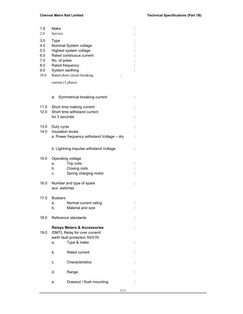
Chennai Metro Rail Limited Technical Specifications (Part 1B)
485
1.0 Make : 2.0 Service :
3.0 Type : 4.0 Nominal System voltage : 5.0 Highest system voltage : 6.0 Rated continuous current : 7.0 No. of poles : 8.0 Rated frequency : 9.0 System earthing : 10.0 Rated short circuit breaking :
current (3 phase)
a. Symmetrical breaking current : 11.0 Short time making current : 12.0 Short time withstand current for 3 seconds : 13.0 Duty cycle : 14.0 Insulation levels a. Power frequency withstand Voltage – dry :
b. Lightning impulse withstand Voltage : 15.0 Operating voltage a. Trip coils : b. Closing coils : c. Spring charging motor : 16.0 Number and type of spare : aux. switches 17.0 Busbars a. Normal current rating : b. Material and size : 18.0 Reference standards : Relays Meters & Accessories : 19.0 IDMTL Relay for over current/ earth fault protection 50/51N a. Type & make : b. Rated current : c. Characteristics : d. Range : e. Drawout / flush mounting :

Chennai Metro Rail Limited Technical Specifications (Part 1B)
486
f. Test Facility : g. Reference standard : 20.0 Auxiliary Relay a. Type & make : b. Rated voltage : c. Operating voltage range : d. No. of contacts : 21.0 Control switches a. Type & make : b. Type of handle : c. Contact development : 22.0 Test terminal block a. Type & make : b. System : 23.0 Wiring & Accessories a. Auxiliary wiring minimum cross section of wire for control circuits : VT Circuits :
V. TECHNICAL SPECIFICATION FOR BATTERY AND BATTERY CHARGER 1.0 SCOPE: This specification covers the design, manufacture, list and Works, Supply, installation, Testing and commissioning of Battery, Battery Charger and DC Distribution Board, with all accessories for efficient & trouble free operation. 2.0 STANDARDS: The equipment covered by this specification shall unless, otherwise stated, be designed, constructed and tested in accordance with the latest revisions of relevant Indian standards and shall confirm to the regulations of Local Statutory authorities. 3.0 GENERAL: Battery, Battery charger and DC DB shall be housed in a metal enclosed, free standing compartmentalised, sheet steel Panel. The Batteries shall be housed in the Bottom compartment with the Battery Charger in the middle and the DC DB housed in the Top compartment. The Panel shall be fabricated out of adequate thickness mild steel of not less than 2.0 mm thickness. All retaining catches, screws and bolts shall be cadmium plated.

Chennai Metro Rail Limited Technical Specifications (Part 1B)
487
4.0 BATTERY: The Battery shall be maintenance free, sealed Lead Acid VRLA type. Battery Voltage shall be 110V DC with the minimum capacity of 100AH. The Cell containers shall be heat resistant, shock absorbing. The complete batteries shall include the cells inter cell connectors, terminal lugs, etc. 5.0 PARTICULARS OF THE BATTERIES: The batteries shall have an adequate capacity to supply power to steady state loads for ten (10) hours. At the end of the three (3) hours, the voltage shall not have fallen under 95% of the rated voltage. The discharge capacity shall be so determined that at the end of the discharge period of the eight (8) hours the voltage is not less than that nominal discharge voltage of 1.75V 6.0 CONNECTION: All connections except inter-cell connections shall be made with copper rod supported on insulators of approved type. The copper rod, as well as the cable connections, shall be protected from corrosion by painting with two coats of anti-sulphuric enamel or other approved means. Inter cell connections shall be of low resistance and shall be in a clean condition when bolted and shall be protected by petroleum jelly. Alternatively, inter cell connections may be soldered. 7.0 BATTERY CHARGER: The charger shall be SMPS type suitable for 110V (DC), battery with provision for float charge and Boost charge the battery.
The charger shall be provided with input/output MCBs.
The following meters shall be provided. - Input AC Voltmeter moving coil type - Output DC Voltmeter / Ammeter moving coil type - DC Ammeter (Charging) with fuse Indications lamps for Power ‘ON’, Float / Boost charging shall be provided with accept / reset / Lamp Test Push Buttons, Alarm Annunciation shall be provided for the following. - Rectifier Failure - Low output DC Voltage - High Output DC Voltage - Earth fault
- Mains failure - AC Input fuse fail - DC Output fuse fail - AC under voltage - Battery MCCB trip - Capacitor fuse fail - Load on Battery - Reverse polarity
The battery charger shall be designed to operate with the battery and shall be of sufficient capacity. The charger shall have characteristic "IU" and shall be suitable for stand-by paralleling. It shall be automatic type with manual control for equalizing charge. It should be without fans or moving parts

Chennai Metro Rail Limited Technical Specifications (Part 1B)
488
and should be capable of charging a completely discharged battery to full charge in a maximum of ten hours while simultaneously supplying the station demand. The charger shall be of the self-adjusting type which will automatically adjust the charging rate from 0.1 A to full charger capacity to maintain desired battery cell voltage. The transformer shall be provided with taps to maintain desired output voltage with plus or minus 10 percent variations in nominal input voltage. At any tap setting, the voltage regulator shall regulate the voltage within plus and minus 1 percent of the regulator setting with an A.C. supply voltage variation as stated in the required main data. Double wound (isolating transformer) shall be provided at the input side of the chargers to prevent galvanic connection between the D.C. and A.C. system. Boost charger should recharge a fully discharged battery in 10 hours, voltage 2.65- 2.75VPC, constant current during boost charging, stabilized within 2%, shall be maintained by current controller. Type of Charger : Float cum boost charger (with 1 x 100 % battery and 2nos. Float cum boost chargers)
Battery shall be designed to take care the black start. Operational & back-up requirements as envisaged for the complete load package on the duty cycle as well as to take care of future load growth of 20%.
8.0 DC DISTRIBUTION PANEL: The D.C. distribution panel shall consist of 1 No. 40 Amps double pole main miniature circuit breaker as incomer with ample interrupting capacity and 7 Nos. of 20 Amps two-pole circuit breaker for each feeder circuit. Miniature circuit breakers shall have a quick-make and quick-break toggle mechanism with inverse time trip characteristics. In addition, an instantaneous trip device shall be furnished for heavy short circuit current. 9.0 EARTHING: Battery charger, D.C. Distribution board shall be suitably earthed. 10.0 TESTS: Test shall be carried out to verify at least the following: - rated capacity of the batteries - Accuracy of output voltage of charges with different - Loads and input voltages - Automatic current limitation by the charges
- Power frequency voltage withstands 2 KV rms. - Ampere Hour & Watt Hour efficiency test for batteries. - Endurance test for Batteries. - Test for voltage during discharge - Wiring/Functional checks for Battery Charger - Ripple measurement - Demonstration of guaranteed efficiency and power factor - IR Test - Heat Run Test
11.0 PARTICULAR SPECIFICATION: The battery shall be conforming to the following technical particulars:
a. Type : Re-chargeable lead acid stationary VRLA type battery.
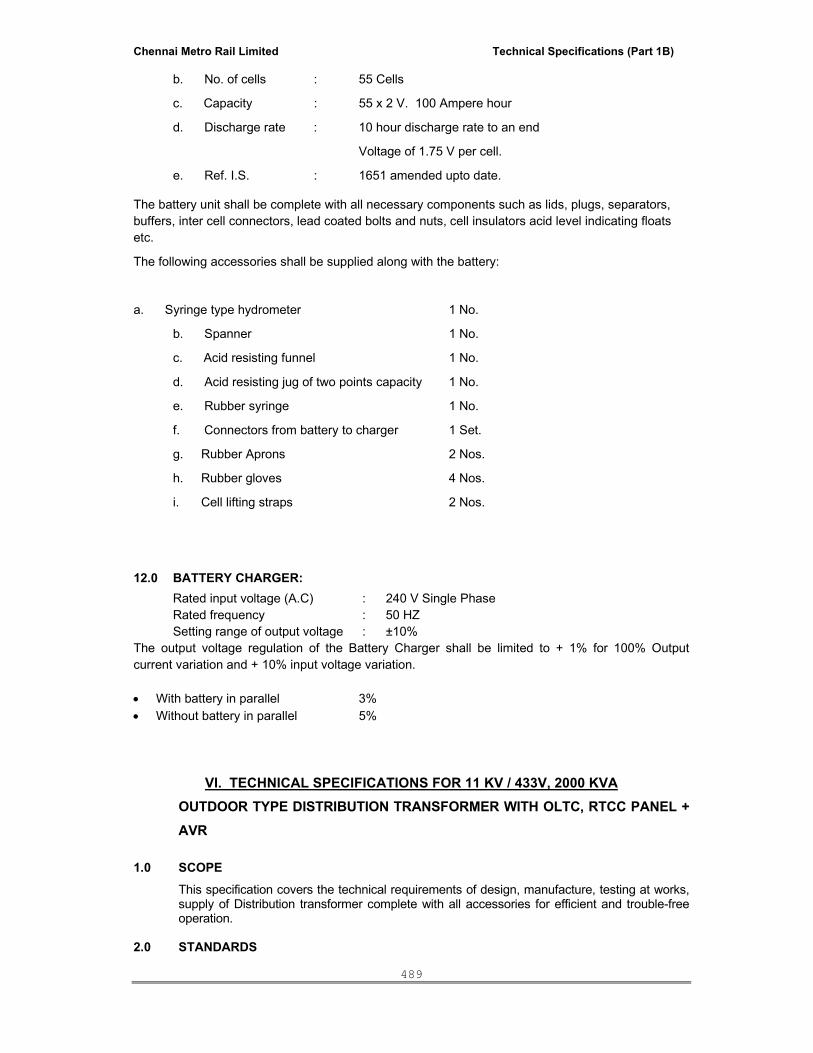
Chennai Metro Rail Limited Technical Specifications (Part 1B)
489
b. No. of cells : 55 Cells
c. Capacity : 55 x 2 V. 100 Ampere hour
d. Discharge rate : 10 hour discharge rate to an end
Voltage of 1.75 V per cell.
e. Ref. I.S. : 1651 amended upto date.
The battery unit shall be complete with all necessary components such as lids, plugs, separators, buffers, inter cell connectors, lead coated bolts and nuts, cell insulators acid level indicating floats etc.
The following accessories shall be supplied along with the battery:
a. Syringe type hydrometer 1 No.
b. Spanner 1 No.
c. Acid resisting funnel 1 No.
d. Acid resisting jug of two points capacity 1 No.
e. Rubber syringe 1 No.
f. Connectors from battery to charger 1 Set.
g. Rubber Aprons 2 Nos.
h. Rubber gloves 4 Nos.
i. Cell lifting straps 2 Nos.
12.0 BATTERY CHARGER: Rated input voltage (A.C) : 240 V Single Phase Rated frequency : 50 HZ Setting range of output voltage : ±10% The output voltage regulation of the Battery Charger shall be limited to + 1% for 100% Output current variation and + 10% input voltage variation. • With battery in parallel 3% • Without battery in parallel 5%
VI. TECHNICAL SPECIFICATIONS FOR 11 KV / 433V, 2000 KVA OUTDOOR TYPE DISTRIBUTION TRANSFORMER WITH OLTC, RTCC PANEL + AVR
1.0 SCOPE This specification covers the technical requirements of design, manufacture, testing at works,
supply of Distribution transformer complete with all accessories for efficient and trouble-free operation.
2.0 STANDARDS

Chennai Metro Rail Limited Technical Specifications (Part 1B)
490
The equipment covered by this specification shall, unless otherwise stated, be designed,
constructed and tested in accordance with latest revisions of relevant Indian Standards and
shall conform to the Regulations of local Statutory Authorities.
IS : 2026 Power transformers
IS : 10028 Code of practice for selection, installation and maintenance of transformers.
IS : 2099 Bushing for alternating voltage above 1000V.
IS : 3637 Gas operated relays.
IS : 4527 Porcelain bushing for transformers.
IS : 335 New insulating oils.
IS : 6600 Guide for loading of oil transformer.
3.0 GENERAL REQUIREMENTS
The distribution transformer shall be of core type, 2 winding, 3 phase oil immersed having a
rating by oil and natural air cooling and shall be suitable for OUT-DOOR installation.
3.1 Voltage and Frequency Variations:
Transformer shall operate without injurious heating on any Tap under the following
conditions provided increase in voltage is not accompanied by reduction in frequency.
i) At rated MVA at any voltage within ±10% of the rated voltage.
ii) At rated current at a voltage equal to 105% of the rated voltage.
iii) To deliver rated current under 10% continuous over fluxing.
3.2 Overloads
It shall be possible to operate the transformer satisfactorily upto overloads of 150% of the
rated value in conformation with the loading guide specified in IS:6600. There shall be no
limitation imposed by bushings, tap changers, auxiliary equipments to meet this
requirement.
3.3 Rated Power and Temperature Rise
The transformer shall be capable of operating at rated power specified in the technical
schedule on a continuous basis and with the cooling classification given at the most onerous
simultaneous climatic conditions specified.
The temperature rise specified shall not be exceeded when the transformer is operated continuously at the rated power at the design ambient temperature of 50° C.
3.4 Rated Voltage and Tapping
The principal tapping rated voltage shall be as specified. The tappings shall provide a
variation in the transformation ratio without producing phase displacement. All tappings
shall be full power tappings.
3.5 Impedance Voltage and Short Circuit Impedance
The impedance voltage at principal tapping shall be as specified.
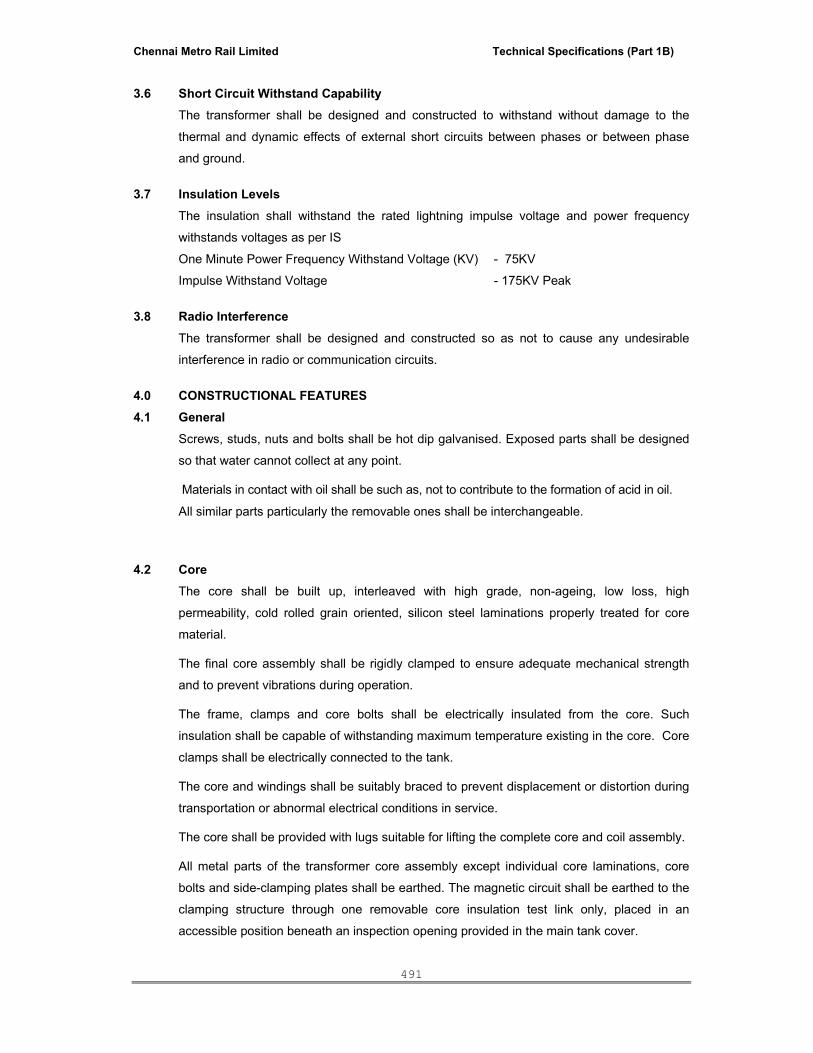
Chennai Metro Rail Limited Technical Specifications (Part 1B)
491
3.6 Short Circuit Withstand Capability
The transformer shall be designed and constructed to withstand without damage to the
thermal and dynamic effects of external short circuits between phases or between phase
and ground.
3.7 Insulation Levels
The insulation shall withstand the rated lightning impulse voltage and power frequency
withstands voltages as per IS
One Minute Power Frequency Withstand Voltage (KV) - 75KV
Impulse Withstand Voltage - 175KV Peak
3.8 Radio Interference
The transformer shall be designed and constructed so as not to cause any undesirable
interference in radio or communication circuits.
4.0 CONSTRUCTIONAL FEATURES
4.1 General Screws, studs, nuts and bolts shall be hot dip galvanised. Exposed parts shall be designed
so that water cannot collect at any point.
Materials in contact with oil shall be such as, not to contribute to the formation of acid in oil.
All similar parts particularly the removable ones shall be interchangeable.
4.2 Core
The core shall be built up, interleaved with high grade, non-ageing, low loss, high
permeability, cold rolled grain oriented, silicon steel laminations properly treated for core
material.
The final core assembly shall be rigidly clamped to ensure adequate mechanical strength
and to prevent vibrations during operation.
The frame, clamps and core bolts shall be electrically insulated from the core. Such
insulation shall be capable of withstanding maximum temperature existing in the core. Core
clamps shall be electrically connected to the tank.
The core and windings shall be suitably braced to prevent displacement or distortion during
transportation or abnormal electrical conditions in service.
The core shall be provided with lugs suitable for lifting the complete core and coil assembly.
All metal parts of the transformer core assembly except individual core laminations, core
bolts and side-clamping plates shall be earthed. The magnetic circuit shall be earthed to the
clamping structure through one removable core insulation test link only, placed in an
accessible position beneath an inspection opening provided in the main tank cover.

Chennai Metro Rail Limited Technical Specifications (Part 1B)
492
Following are the mandatory requirements:-
1. Transformer shall be of BOLTLESS core design.
2. Core should be procured from one of the following manufacturers
– Posco / Nippon/ Novex/ Ak Steels.
3. Mill’s test certificates to be provided for the transformer core.
4. The insulation structure for the core to bolts and core to clamp plates shall be such as to
withstand a voltage of 2000V for one minute.
4.3 Windings The coils shall be of high conductivity electrolytic copper conductor, properly insulated and
stacked. Coil assembly shall be suitably supported between adjacent sections by insulating
spacers and barriers, which shall be permanently secured in place.
Windings shall not contain sharp bends, which might damage the insulation or produce high
dielectric stresses.
Coils shall be so insulated that the effects of impulse and power frequency voltage stresses
are minimum.
The transformer winding shall be connected in group of vector symbols specified. All
terminal and tapping markings shall be in accordance with IS:2026.
5.0 CONSTRUCTIONAL FEATURES 5.1 Tank
Tank shall be of all welded construction and fabricated from good commercial grade low carbon steel of adequate thickness. All seams shall be properly welded.
The tanks shall have sufficient strength to withstand the following without any deformation.
i) The tank together with core and oil can be lifted and transported without damage or
loss of oil tightness.
ii) Mechanical shock during transportation. The tank cover shall be bolted onto the tank
with weatherproof hot oil resistant, resilient gasket in between for complete oil
tightness. Bushings, turrets, holes and other devices shall be designed to prevent
any leakage of water into the tank or oil from the tank.
Tank cover shall not distort when lifted. Each tank shall be fitted with inspection covers of
ample size to give any access to internal connections of the bushings, current transformers,
winding connections and earth link for testing.
The design shall be such that the cover does not support the weight of the core and
windings.
Tank cover shall be fitted with pockets for oil temperature indicator, which shall be located in
the position of maximum oil temperature at maximum continuous rating.
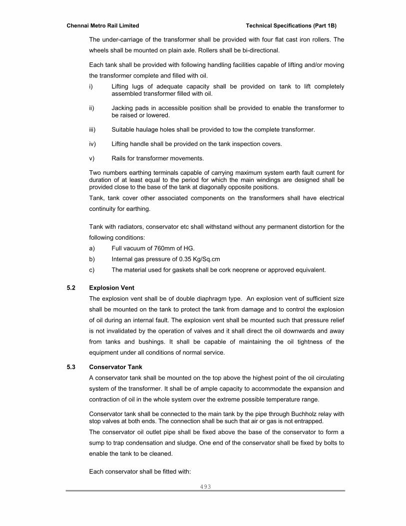
Chennai Metro Rail Limited Technical Specifications (Part 1B)
493
The under-carriage of the transformer shall be provided with four flat cast iron rollers. The
wheels shall be mounted on plain axle. Rollers shall be bi-directional.
Each tank shall be provided with following handling facilities capable of lifting and/or moving
the transformer complete and filled with oil.
i) Lifting lugs of adequate capacity shall be provided on tank to lift completely assembled transformer filled with oil.
ii) Jacking pads in accessible position shall be provided to enable the transformer to
be raised or lowered.
iii) Suitable haulage holes shall be provided to tow the complete transformer.
iv) Lifting handle shall be provided on the tank inspection covers.
v) Rails for transformer movements. Two numbers earthing terminals capable of carrying maximum system earth fault current for
duration of at least equal to the period for which the main windings are designed shall be provided close to the base of the tank at diagonally opposite positions.
Tank, tank cover other associated components on the transformers shall have electrical
continuity for earthing.
Tank with radiators, conservator etc shall withstand without any permanent distortion for the
following conditions:
a) Full vacuum of 760mm of HG.
b) Internal gas pressure of 0.35 Kg/Sq.cm
c) The material used for gaskets shall be cork neoprene or approved equivalent.
5.2 Explosion Vent The explosion vent shall be of double diaphragm type. An explosion vent of sufficient size
shall be mounted on the tank to protect the tank from damage and to control the explosion
of oil during an internal fault. The explosion vent shall be mounted such that pressure relief
is not invalidated by the operation of valves and it shall direct the oil downwards and away
from tanks and bushings. It shall be capable of maintaining the oil tightness of the
equipment under all conditions of normal service.
5.3 Conservator Tank
A conservator tank shall be mounted on the top above the highest point of the oil circulating
system of the transformer. It shall be of ample capacity to accommodate the expansion and
contraction of oil in the whole system over the extreme possible temperature range.
Conservator tank shall be connected to the main tank by the pipe through Buchholz relay with stop valves at both ends. The connection shall be such that air or gas is not entrapped.
The conservator oil outlet pipe shall be fixed above the base of the conservator to form a
sump to trap condensation and sludge. One end of the conservator shall be fixed by bolts to
enable the tank to be cleaned.
Each conservator shall be fitted with:

Chennai Metro Rail Limited Technical Specifications (Part 1B)
494
i) At least one oil level indicator of direct reading prismatic glass type visible from
ground level, provided with alarm contacts for minimum oil level.
ii) Oil filling hole with cover.
iii) The conservator tank shall be vented to atmosphere through a weather proof
dehydrating breather with activated silica gel as dehydrating agent.
5.4 Cooling Units
The cooling unit shall consist of detachable type of radiators made of pressed sheet steel of
thickness not less than 1.2mm. Radiators shall be designed so that all painted surfaces can
be thoroughly cleaned by hand and subsequently painted inside by suitable brushes. They
shall be also so designed to avoid pockets in which moisture, dust or sand may collect.
Radiators shall withstand the pressure tests appropriate to the main tank. They shall be also
capable of withstanding without damage the full vacuum associated with oil treatment. The
radiators shall be provided with the following accessories.
i) Bolted gasketed flanges connection at each point of connection to the main tank.
ii) Top and bottom shut off valves on each radiator.
iii) Air release plug, on top.
iv) Oil drain plug at bottom at convenient level.
v) Lifting lugs.
5.5 Transformer Oil Insulating oil shall be Non-PCB oil and conform to IS 335 and shall be suitable in all
respects for operating the transformer at the ratings and under conditions laid down in the
specification. 10 % extra oil in a non returnable drum to be supplied along with main equipment.
5.6 Gas and Oil Actuated Relays
The Buchholz relay shall be as per the latest revision of IS 3637. The relay shall be fitted in
the expansion pipe connecting the transformer tank to the conservator.
The pipe work shall be so arranged that all gas arising from the transformer shall pass into
the relay. Sharp bends in the pipe work shall be avoided.
The design of the relay mounting arrangement and associated pipe work shall be such that
the relay will not sustain damage during transport or service, or mal operate due to
vibrations under service conditions.
The relay shall be provided with drain cock, air vent and facility for testing with air injection
by hand pump. The device shall be provided with two independent floats and electrical
contacts, one for alarm on gas accumulation and the other for tripping on sudden rise of
pressure due to abnormal conditions. The relay shall be provided with a window through
which a scale indication can be seen in order that the quantity of gas collected within the

Chennai Metro Rail Limited Technical Specifications (Part 1B)
495
relay housing can be determined. The oil circuit through the relay shall not form a delivery
path in parallel with any circulating oil pipe.
5.7 Winding Temperature Indicator Winding temperature indicator shall be fitted locally in a weather proof box so as to be
readable at a standing height from ground level. The device shall be provided with two sets
of electrical contacts, one for alarm and one for trip.
5.8 Oil Temperature Indicator Thermometer pocket and sensing element with dial type thermometer calibrated in degree
celsius, with a hand reset pointer to register the highest temperature attained, shall be
provided for indicating temperature of the top layer oil in tank.
Two sets of electrical contacts, one for alarm and one for trip, shall be provided. The cover
of Marshalling Box shall be equipped with a viewing aperture of adequate size fitted with
clear glass.
5.9 Breather The conservator of the transformer shall be provided with a silica gel breather complete with
oil seal and oil level indication window. Visual indication of the extent to which the silicagel
has absorbed moisture shall be provided. The unit must allow simple cleaning and
replacement of the desiccant and sealing oil without the use of tools, by using wing nuts or
similar forms of corrosion resistant hand - tightening devices.
The breather shall be mounted at appropriate height from ground level and connecting pipe,
fitted to the main tank by means of brackets. The breather should be placed at appropriate
height of the supervisor at site.
5.10 Valves
The transformer shall be fitted with the following valves:
i) One valve at the top and one valve at the bottom of the tank mounted diagonally
opposite to each other, for connection to oil circulating and filtering equipments. The
lower valve shall also function as drain valve. These valves shall be fitted with blank
flanges.
ii) Oil sampling valve at top and bottom of the tank.
iii) Valves between radiator and tank.
iv) 1 No. Air Release Plug.
v) Shut off valves for Buchholz relay on both sides.
5.11 Cable Box and Disconnecting Chamber a. The cable box shall be of outdoor type sheet steel construction, self supporting,
with all standard facilities including the body earth terminal.
b. Cable box shall be provided with undrilled gland plate.
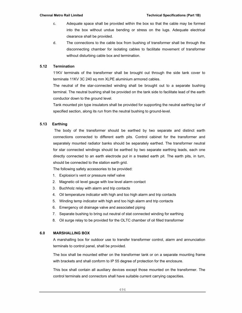
Chennai Metro Rail Limited Technical Specifications (Part 1B)
496
c. Adequate space shall be provided within the box so that the cable may be formed
into the box without undue bending or stress on the lugs. Adequate electrical
clearance shall be provided.
d. The connections to the cable box from bushing of transformer shall be through the
disconnecting chamber for isolating cables to facilitate movement of transformer
without disturbing cable box and termination.
5.12 Termination
11KV terminals of the transformer shall be brought out through the side tank cover to
terminate 11KV 3C 240 sq mm XLPE aluminium armored cables.
The neutral of the star-connected winding shall be brought out to a separate bushing
terminal. The neutral bushing shall be provided on the tank side to facilitate lead of the earth
conductor down to the ground level.
Tank mounted pin type insulators shall be provided for supporting the neutral earthing bar of
specified section, along its run from the neutral bushing to ground-level.
5.13 Earthing The body of the transformer should be earthed by two separate and distinct earth
connections connected to different earth pits. Control cabinet for the transformer and
separately mounted radiator banks should be separately earthed. The transformer neutral
for star connected windings should be earthed by two separate earthing leads, each one
directly connected to an earth electrode put in a treated earth pit. The earth pits, in turn,
should be connected to the station earth grid.
The following safety accessories to be provided:
1. Explosion’s vent or pressure relief valve
2. Magnetic oil level gauge with low level alarm contact
3. Buchholz relay with alarm and trip contacts
4. Oil temperature indicator with high and too high alarm and trip contacts
5. Winding temp indicator with high and too high alarm and trip contacts
6. Emergency oil drainage valve and associated piping
7. Separate bushing to bring out neutral of stat connected winding for earthing
8. Oil surge relay to be provided for the OLTC chamber of oil filled transformer
6.0 MARSHALLING BOX
A marshalling box for outdoor use to transfer transformer control, alarm and annunciation
terminals to control panel, shall be provided.
The box shall be mounted either on the transformer tank or on a separate mounting frame
with brackets and shall conform to IP 55 degree of protection for the enclosure.
This box shall contain all auxiliary devices except those mounted on the transformer. The
control terminals and connectors shall have suitable current carrying capacities.

Chennai Metro Rail Limited Technical Specifications (Part 1B)
497
A removable bottom gland plate shall be provided for cable entry. Cables between
transformer and marshalling box shall also be provided.
7.0 TAP CHANGER 7.1 On Load Tap Changing Gear The on-load tap changing gear shall comply with IS:8468. The tap changer shall be
mounted in a separate tank or compartment in accessible position in/on the transformer
tank. The operation of the transformer at any of the taps provided shall not produce phase
displacement. All the tap changing switches shall be rated for full Uni-directional power
flow.
Oil surge relay shall be fitted between the tap changer compartment and the
conservator.
OLTC shall be provided with the following modes of operation.
Local : Manual Control and Electrically Operated
Remote : Manual Control and Electrically Operated with RTCC & AVR
Both local and remote operation shall be possible with RTCC Panel. OLTC should comply to
the following:
a) The OLTC gear shall be designed to complete successfully tap changes for the maximum
current to which transformer can be loaded i.e. 150% of the rated current. Devices shall be
incorporated to prevent tap change when the through current is in excess of the safe current
that the tap changer can handle. The OLTC gear shall withstand through fault currents
without injury.
b) When a tap change has been initiated it should be completely independent of the operation
of the control relays and switches. Necessary safeguard should be provided to allow for
failure of auxiliary power supply or any other contingency which may result in the tap
changer movement not being completed once it is commenced.
c) Oil in compartments which contain the making and breaking contacts of the OLTC shall not
mix with oil in other compartments of the OLTC or with transformer oil. Gases released from
these compartments shall be conveyed by a pipe to a separate oil conservator or to a
segregated compartment within the main transformer conservator. An Oil surge relay shall
be installed in the above pipe. The conservator shall be provided with a prismatic oil level
gauge.
d) Oil, in compartments of OLTC which do not contain the make and break contacts, shall be
maintained under conservator head by valve pipe connections. Any gas leaving these
compartments shall pass through the Buchholz relay before entering the conservator.

Chennai Metro Rail Limited Technical Specifications (Part 1B)
498
e) Oil filled compartments shall be provided with filling plug, drain valve with plug, air release
vent, oil sampling device, inspection opening with gasket and bolted cover with lifting
handles.
f) OLTC driving mechanism and its associated control equipment (local) shall be mounted in an
outdoor, weatherproof cabinet with IP 55 protection which shall Include :-
• Driving motor (415V, 3-phase, 50 Hz. AC squirrel cage).
• Motor starting contactor with Motor Protection Circuit Breaker, isolating switch and MCBs.
• Control switch: Raise/off/lower (spring return to normal type).
• Remote/local selector switch (maintained contact type).
• Mechanical tap position indicator showing rated tap voltage against each position and
resettable maximum and minimum indicators.
• Limit switches to prevent motor over-travel in either direction and final mechanical stops.
• Brake or clutch to permit only one tap change at a time on manual operation.
• Emergency manual operating device (hand crank or hand wheel).
• A five digit operation counter.
• Electrically interlocked reversing contactors (mechanical interlock preferred).
• 240V, 50 Hz. AC space heater with switch and MCBs.
• Interior lighting fixture with lamp door switch and MCBs.
• Gasketed and hinged door with locking arrangement.
• Terminal blocks, internal wiring, earthing terminals and cable glands for power and control cables.
• Necessary relays, contactors, current transformers etc.
g) Control requirements for OLTC : The following electrical control features shall be provided:
• Positive completion of load current transfer, once a tap change has been initiated, without
stopping on any intermediate position, even in case of failure of external power supply.
• Only one tap change from each tap change impulse even if the control switches or push
button is maintained in the operated position.
• Cut-off of electrical control when manual control is resorted to. Cut-off of a counter impulse
for a reverse tap change until the mechanism comes to rest and resets the circuits for a
fresh operation.
• Cut-off of electrical control when it tends to operate the tap beyond its extreme position.
h) Automatic Control of OLTC : Automatic OLTC control shall include the following items:
• Voltage setting device.
• Voltage sensing and voltage regulating devices.

Chennai Metro Rail Limited Technical Specifications (Part 1B)
499
• Line drop compensator with adjustable R and X elements.
• Timer 5-25 seconds for delaying the operation of the tap changer in the first step for every
tap change operation.
• Adjustable dead band for voltage variation. 7. 2 Mechanical Control
The cranking device for operation of the OLTC gear shall be removable and located at a
height not exceeding 1500 mm above ground level for easy operation. The
mechanism shall be complete with normal accessories including atleast the following.
- Tap position indicator.
- Mechanical operation counter
- Mechanical stops to prevent over cranking the mechanism beyond extreme tap
positions.
7.3 Electrical Control Control circuit shall incorporate the following.
- Local - electrical operation
- Device to ensure a positive and full completion of tap change once it is initiated
even if the control supply fails.
7.4 Internal Earthing The framework and clamping arrangement of core and coil shall be securely earthed inside the tank
by copper strap connection to the tank.
8.0 NOISE AND VIBRATION
Care shall be taken to ensure in the design and manufacture so as to reduce noise and vibration to the level of that obtained in good modern practice. It should be in conformance to NEMA Standards
9.0 PAINTING
All accessories and transformer tank shall be sand blasted and grounded to produce a
smooth, clean surface, free from scale, grease and rust.
After cleaning, the surfaces shall be given a phosphate coating followed by two coats of
Epoxy primer.
The transformer shall be finished with two coats of Epoxy paint to shade 631 of IS 5. 10.0 PERFORMANCE GUARANTEE
The performance figures which will be indicated by the vendor shall be guaranteed subject
to tolerances specified as per IS:2026.
Vendor shall also furnish guarantee for the design, manufacture, material, safe and
trouble free operation of the equipment and its accessories for a period of twenty four (18)
months from the date of commissioning or twelve (24) months from the date of supply which
ever later.

Chennai Metro Rail Limited Technical Specifications (Part 1B)
500
11.0 TESTS 11.1 Factory Tests
Complete test shall be made at the manufacturer’s plant to determine the performance and operating characteristics of the assembled transformer, and accessories to determine whether or not the guarantees have been met. Unless otherwise specified, all tests shall be carried out in accordance with IS : 2026, and shall include the following.
11.2 Routine Tests
a. Resistance measurement of all windings on the rated voltage connection and on all taps.
b. Ratio tests on the rated voltage connection and on all taps.
c. Polarity and phase rotation tests.
d. Impedance and load loss at rated current on the rated voltage connection and on all
the taps.
e. No-load loss and current at rated voltage on the rated voltage connection and at
95,110 and 115% of rated voltage.
f. Power frequencies withstand test.
g. Insulation resistance tests on winding, auxiliary devices core and tank.
h. Mechanical operation test on Tap changer.
i. Induced over voltage test
j. Magnetic Balance test
k. Magnetising Current Test
l. Vector Group Check test
m. Short circuit test
n. 2KV With stand test for all wiring
o. zero phase sequence impedence test
p. Impulse test on any one phase of the HT winding of any one transformer
All routine tests shall be witnessed by the Purchaser’s Engineer / Consultant.
12.0 DRAWINGS AND MANUAL The following drawings and manual shall be submitted for the Engineer's approval:
a. General arrangement and dimensional Drawing showing Constructional features
and Disposition of various fittings and Accessories. (Drawings shall be to scale).
b. General Arrangement Drawing of Marshalling Box.
c. Wiring Diagram of Marshalling Box.
d. Name plated drawing with Terminal Marking and connection Diagrams.
e. Drawings of other major components.
f. Technical Leaflets on All Components.
g. Manufacturing Schedule in the form of Bar Chart/Net work.
h. Manufacturing and supply record.
i. Technical Particular Data-sheet duly completed and fill-in.
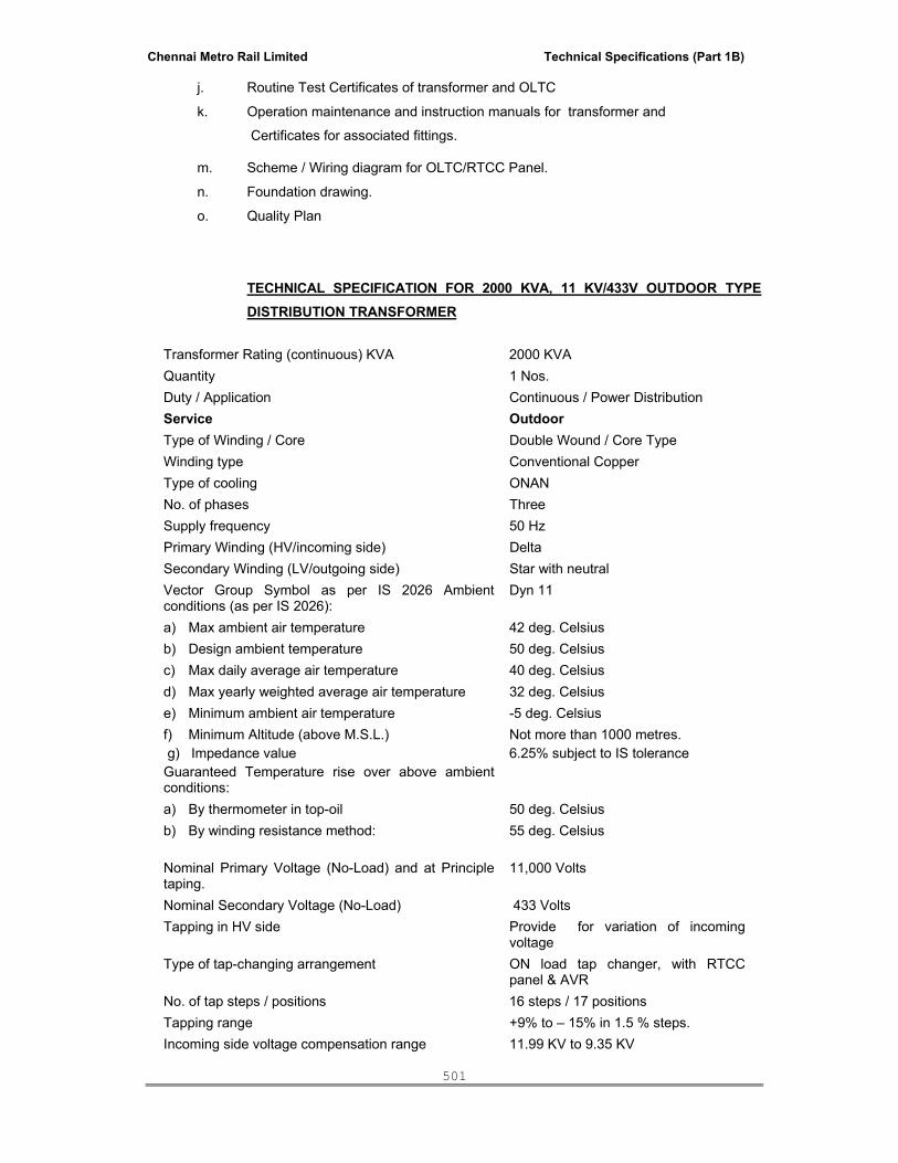
Chennai Metro Rail Limited Technical Specifications (Part 1B)
501
j. Routine Test Certificates of transformer and OLTC
k. Operation maintenance and instruction manuals for transformer and
Certificates for associated fittings.
m. Scheme / Wiring diagram for OLTC/RTCC Panel.
n. Foundation drawing.
o. Quality Plan
TECHNICAL SPECIFICATION FOR 2000 KVA, 11 KV/433V OUTDOOR TYPE DISTRIBUTION TRANSFORMER
Transformer Rating (continuous) KVA 2000 KVA Quantity 1 Nos. Duty / Application Continuous / Power Distribution Service Outdoor Type of Winding / Core Double Wound / Core Type Winding type Conventional Copper Type of cooling ONAN No. of phases Three Supply frequency 50 Hz Primary Winding (HV/incoming side) Delta Secondary Winding (LV/outgoing side) Star with neutral Vector Group Symbol as per IS 2026 Ambient conditions (as per IS 2026):
Dyn 11
a) Max ambient air temperature 42 deg. Celsius b) Design ambient temperature 50 deg. Celsius c) Max daily average air temperature 40 deg. Celsius d) Max yearly weighted average air temperature 32 deg. Celsius e) Minimum ambient air temperature -5 deg. Celsius f) Minimum Altitude (above M.S.L.) Not more than 1000 metres. g) Impedance value 6.25% subject to IS tolerance Guaranteed Temperature rise over above ambient conditions:
a) By thermometer in top-oil 50 deg. Celsius b) By winding resistance method: 55 deg. Celsius Nominal Primary Voltage (No-Load) and at Principle taping.
11,000 Volts
Nominal Secondary Voltage (No-Load) 433 Volts Tapping in HV side Provide for variation of incoming
voltage Type of tap-changing arrangement ON load tap changer, with RTCC
panel & AVR No. of tap steps / positions 16 steps / 17 positions Tapping range +9% to – 15% in 1.5 % steps. Incoming side voltage compensation range 11.99 KV to 9.35 KV

Chennai Metro Rail Limited Technical Specifications (Part 1B)
502
Power loss As per the ECBC guidelines
The transformer(s) shall be supplied with first filling of mineral oil, as per IS 335 and with all standard accessories and fittings as per I.S 2026, as listed in below.
The transformer(s) shall conform to I.S 2026 (Parts – I-IV) and CBIP Manual on Power Transformers, and Standard manufacturing practice. LIST OF FITTINGS AND ACCESSORIES BEING SUPPLIED ALONG WITH THE DISTRIBUTION TRANSFORMER.
The transformer(s) shall be equipped with the following standard fittings and accessories:
1 No. oil-conservator with oil filing hole and cap and drain plug.
1 No. prismatic plain oil level gauge mounted on conservator wall, with max./min level indication.
1 No. silica-gel dehydrating breather with oil-seal and with first fill of charge.
1 No. double-diaphragm type Explosion-vent for pressure relief purposes.
Adequate Nos. of Thermometer pockets, including one no for accommodating bulb type thermometer.
1 No. top oil filter valve.
1 No. bottom oil filter cum drain valve.
1 Set of Rating, Diagram and Terminal Marketing plates.
2 Nos. earthing terminals, located on diagonally opposite sides of transformer tank-base .
1 Set of lifting lugs
1 Set of jacking pads
1 No. inspection cover on transformer-tank.
Under-carriage with 4 Nos. flat plain bi-directional rollers.
1 No. air release plug on main transformer tank.
Adequate Nos. of detachable type cooling radiators with top and bottom isolating valves.
The following additional fittings / accessories shall be provided for the transformer(s):
1. 1 No. double float Buchholz relay, with alarm and trip contacts, with two Nos. isolating valves
on both sides.
2. Relays of transformer protection with alarm and trip contacts for Winding temperature, Oil
temperature, OLTC surge and Pressure release valve.
3. 1 No. 6 inch (150 mm) Dial type Oil Temperature Indicator (OTI), with MRP/RSD, with two
pairs of alarm and top contacts.
4. 1 No. 6 inch (150 mm) Dial type Winding Temperature Indicator (WTI), CT-activated type, with
MRP/RSD, with two pairs of alarm and trip contacts.
5. 1 No. outdoor, weatherproof type Marshalling box for housing the OTI and WTI.
6. 1 No magnetic oil-level gauge (MOG) mounted on conservator tank wall, for main-oil level
indication, equipped with one pair of low Alarm contact.
The following spares are to be supplied along with the transformer ( Bidder to recommend if any required other than the following)
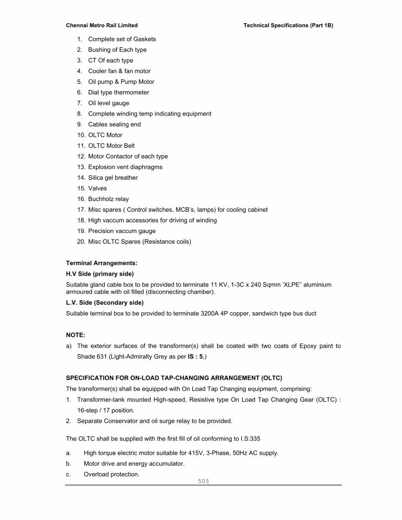
Chennai Metro Rail Limited Technical Specifications (Part 1B)
503
1. Complete set of Gaskets
2. Bushing of Each type
3. CT Of each type
4. Cooler fan & fan motor
5. Oil pump & Pump Motor
6. Dial type thermometer
7. Oil level gauge
8. Complete winding temp indicating equipment
9. Cables sealing end
10. OLTC Motor
11. OLTC Motor Belt
12. Motor Contactor of each type
13. Explosion vent diaphragms
14. Silica gel breather
15. Valves
16. Buchholz relay
17. Misc spares ( Control switches, MCB’s, lamps) for cooling cabinet
18. High vaccum accessories for driving of winding
19. Precision vaccum gauge
20. Misc OLTC Spares (Resistance coils)
Terminal Arrangements: H.V Side (primary side) Suitable gland cable box to be provided to terminate 11 KV, 1-3C x 240 Sqmm ‘XLPE” aluminium armoured cable with oil filled (disconnecting chamber).
L.V. Side (Secondary side) Suitable terminal box to be provided to terminate 3200A 4P copper, sandwich type bus duct
NOTE: a) The exterior surfaces of the transformer(s) shall be coated with two coats of Epoxy paint to
Shade 631 (Light-Admiralty Grey as per IS : 5.) SPECIFICATION FOR ON-LOAD TAP-CHANGING ARRANGEMENT (OLTC) The transformer(s) shall be equipped with On Load Tap Changing equipment, comprising:
1. Transformer-tank mounted High-speed, Resistive type On Load Tap Changing Gear (OLTC) :
16-step / 17 position.
2. Separate Conservator and oil surge relay to be provided.
The OLTC shall be supplied with the first fill of oil conforming to I.S:335 a. High torque electric motor suitable for 415V, 3-Phase, 50Hz AC supply.
b. Motor drive and energy accumulator.
c. Overload protection.

Chennai Metro Rail Limited Technical Specifications (Part 1B)
504
d. Contactors for forward and reverse operation of motor.
e. ‘Raise/Lower’ control selector switch.
f. ‘Local/Remote’ control selector switch.
g. ‘Raise/Lower’ limit switches.
h. Retainer Push button.
i. Auxiliary transformer.
j. Anti-condensation heater with switch.
k. Interlock between manual and electrical operation.
l. Mains isolating switch/MCB.
m. A set of MCB.
n. Insulated terminal board (with connectors for transformer tap leads).
o. Mechanical (local) tap position indicator.
p. Handle for manual operation.
q. Tap changing operation counter.
r. Mechanical stops to prevent over cranking of the mechanism beyond extreme positions.
s. Rating plate.
t. Driving mechanism chamber locking arrangement.
u. Undrilled gland plate for Cable entry
v. Terminal strips
w. Lubrication chart
3. Indoor floor mounted type, Remote Tap Changing Control Cubicle (RTCC) panel, fitted with
Automatic Voltage-regulating Relay (AVR).
4. The paint shade of RTCC panel is RAL7032 – Siemens gray
An indoor floor mounted remote control cubicle (RTCC) with rear access door with wiring and
with the following components:
a. Remote tap position indicating digital meter
b. Tap changer in progress signal lamp
c. Raise/lower push buttons for remote operation
d. Cubicle illuminating lamp with door switch with MCB control
e. Terminal strips
f. Supply ON signal lamp
g. Undrilled gland plate for cable entry
i) RTCC Panel: The RTCC remote control equipment shall be suitable for 30V DC supply and shall be housed in an
indoor sheet cubicle to be located in a remote control room. The OLTC control panel shall comprise
of rigid welded structural frames made of structural steel section or of pressed and formed cold
rolled steel and frame enclosures, doors and partitions shall be of cold rolled steel of thickness 2
mm. Stiffeners shall be provided wherever necessary. All doors, removable covers and plate shall
be gasketed all around with neoprene gaskets. Panel shall be dust, weather and vermin proof

Chennai Metro Rail Limited Technical Specifications (Part 1B)
505
providing degree of protection of IP54, colour of finish shade for interior and exterior shall be
Powder Coated RAL7032 respectively. Earthing bus shall be of 25 x 6 mm copper.
Control switch : Raise/Off/Lower
(spring return to normal type)
Auto/manual selector switch :
(Maintained contact type)
Tap position indicator :
1) Facia type alarm annunciator with “accept” and “lamp test” facilities. The following
features should be included:
a) A.C. supply failure
b) Drive motor auto tripped
c) Tap change delayed
d) Selector switch auto/non-auto operation
e) Voltage Transformer for RTCC
2) Necessary auxiliary relays 3) Lamp indications for:
a. Tap change in progress
b. Lower limit reached
c. Upper Limit reached 4) Cable glands for power and control cables
5) 240 V rated panel space heater with ON-OFF switch
6) Fluorescent type interior lighting fixture with lamp and door switch
7) MCBs
8) Terminal blocks
9) Internal wiring
10) Earthing terminal
11) Supply ON Indication Lamp.
12) Labels for Accessories.
13) Automatic Voltage Regulating Relay.
14) Heater Switch (Rotary Type)
15) Control Supply Switch (Rotary Type)
16) Hooter for Facia annunciator (230V AC)
17) Time Delay Relay for ‘Tap Change Delayed’ (110V AC)
18) H.V. Voltmeter (Digital Type)
19) H.V. Voltmeter Selector Switch (Rotary Type)
20) L.V. Voltmeter (Digital Type)
21) L.V. Voltmeter Selector Switch (Rotary Type)
22) PT for AVR.

Chennai Metro Rail Limited Technical Specifications (Part 1B)
506
23) Tap changer Counter for registering No of times the Tap is changed for voltage correction The following indicating lamps to be provided in the RTCC Panel:
a. Tap Changer – “Supply on”
b. Tap Changer – “in progress”
c. Upper limit reached
d. Lower limit reached
5. Oil surge relay with one pair of trip contacts.
The On Load Tap Changing equipment shall be suitable for the following tap-change operations:
a) Local-manual tap change operation, with cranking handle.
b) Local-electrical tap change operation, with Raise/Lower switches / push buttons on OLTC.
c) Remote/electrical, independent tap change’ operation, with Raise / Lower switches / push
buttons on RTCC panel.
d) Remote-electrical, automatic tap change operations through AVR
GUARANTEED TECHNICAL PARTICULARS FOR TRANSFORMER (TO BE FILLED IN BY THE
TENDERER)
S.No Description Units To be filled by the Bidders
1. Name of Manufacturer & Type of
Transformer
2. Service (Outdoor/indoor)
3. Rating
a) ONAN KVA
4. Rated Frequency Hz
5. Number of phases
6. Rated Voltage
a) HV winding
b) LV winding
KV
KV
7. Vector group symbol
8. Type of cooling (ONAN/ONAF)
9. Tapping :
a) Range

Chennai Metro Rail Limited Technical Specifications (Part 1B)
507
S.No Description Units To be filled by the Bidders
b) Number of steps
c) Tapping provided on HV side
10. Losses at 75°C and principal tapping)
Subject to IS Tol.
a) No load loss at rated voltage and
frequency
b) Load loss at rated current (ONAN)
c) Total losses
11. Impedance voltage at 75° C
a) At principal tapping
b) At maximum tapping
c) At minimum tapping
%
%
Order
12. Reactance at rated current and frequency %
13. Resistance at rated current and at 75°
C
a) HV
b) LV
Ohms/phase
Ohms/phase
order
14. Zero sequence impedance %
15. Max Temperature rise above 50° C
ambient
a) Top of oil by thermometer
b) Winding by resistance for
16. Hottest spot temperature in winding limit to
– over an maximum yearly weighted
average ambient temperature of 32° C
17. Efficiency at 75°C
a) At full load (ONAN/ONAF) %
b) At 75% load (ONAN/ONAF) %
c) At 50% load (ONAN/ONAF) %
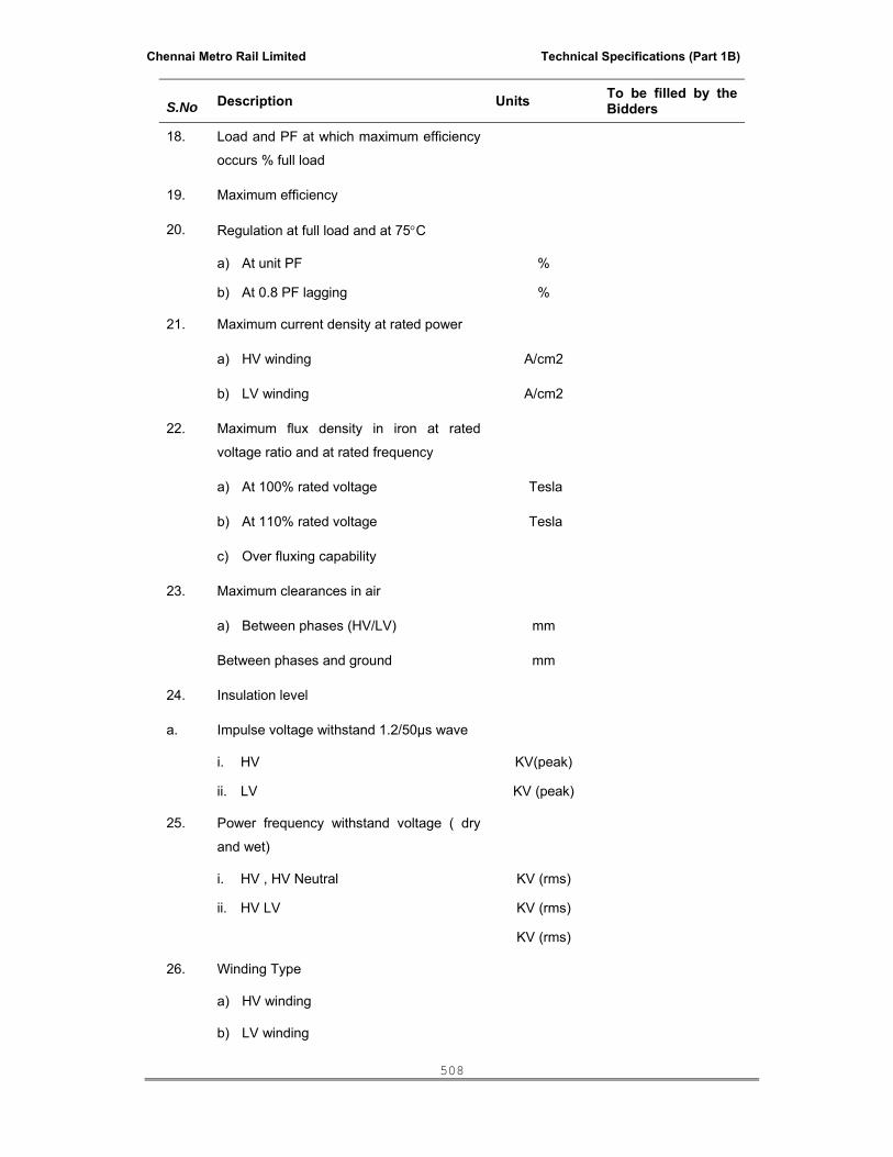
Chennai Metro Rail Limited Technical Specifications (Part 1B)
508
S.No Description Units To be filled by the Bidders
18. Load and PF at which maximum efficiency
occurs % full load
19. Maximum efficiency
20. Regulation at full load and at 75°C
a) At unit PF %
b) At 0.8 PF lagging %
21. Maximum current density at rated power
a) HV winding A/cm2
b) LV winding A/cm2
22. Maximum flux density in iron at rated
voltage ratio and at rated frequency
a) At 100% rated voltage Tesla
b) At 110% rated voltage
c) Over fluxing capability
Tesla
23. Maximum clearances in air
a) Between phases (HV/LV) mm
Between phases and ground mm
24. Insulation level
a. Impulse voltage withstand 1.2/50µs wave
i. HV
ii. LV
KV(peak)
KV (peak)
25. Power frequency withstand voltage ( dry
and wet)
i. HV , HV Neutral
ii. HV LV
KV (rms)
KV (rms)
KV (rms)
26. Winding Type
a) HV winding
b) LV winding
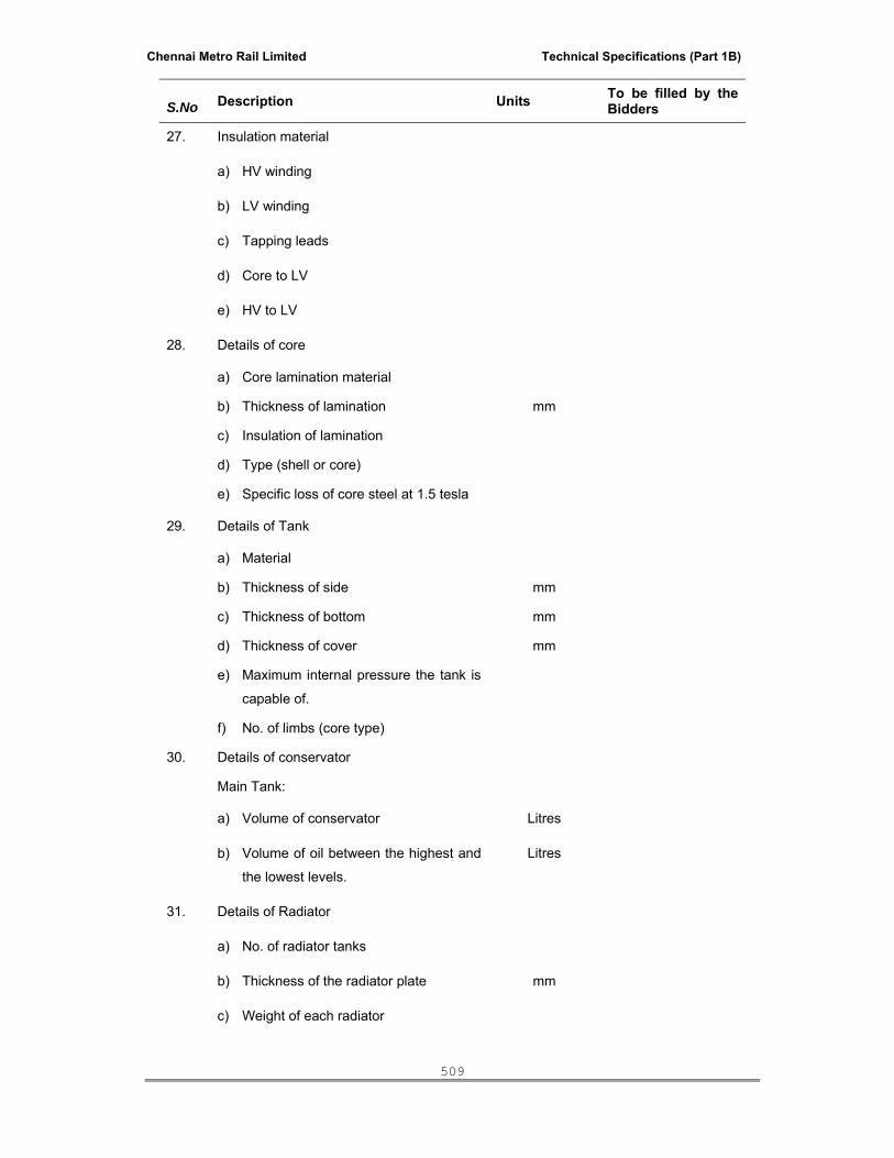
Chennai Metro Rail Limited Technical Specifications (Part 1B)
509
S.No Description Units To be filled by the Bidders
27. Insulation material
a) HV winding
b) LV winding
c) Tapping leads
d) Core to LV
e) HV to LV
28. Details of core
a) Core lamination material
b) Thickness of lamination mm
c) Insulation of lamination
d) Type (shell or core)
e) Specific loss of core steel at 1.5 tesla
29. Details of Tank
a) Material
b) Thickness of side mm
c) Thickness of bottom mm
d) Thickness of cover mm
e) Maximum internal pressure the tank is
capable of.
f) No. of limbs (core type)
30. Details of conservator
Main Tank:
a) Volume of conservator Litres
b) Volume of oil between the highest and
the lowest levels.
Litres
31. Details of Radiator
a) No. of radiator tanks
b) Thickness of the radiator plate mm
c) Weight of each radiator
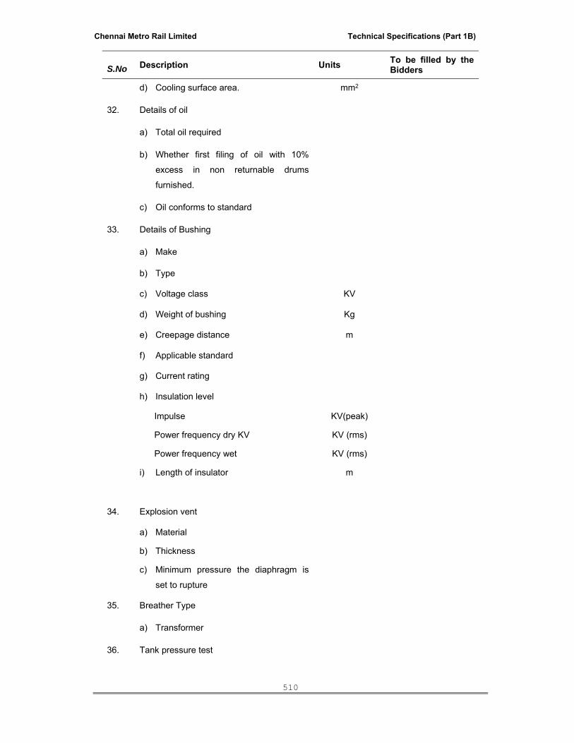
Chennai Metro Rail Limited Technical Specifications (Part 1B)
510
S.No Description Units To be filled by the Bidders
d) Cooling surface area. mm2
32. Details of oil
a) Total oil required
b) Whether first filing of oil with 10%
excess in non returnable drums
furnished.
c) Oil conforms to standard
33. Details of Bushing
a) Make
b) Type
c) Voltage class KV
d) Weight of bushing Kg
e) Creepage distance m
f) Applicable standard
g) Current rating
h) Insulation level
Impulse KV(peak)
Power frequency dry KV KV (rms)
Power frequency wet KV (rms)
i) Length of insulator m
34. Explosion vent
a) Material
b) Thickness
c) Minimum pressure the diaphragm is
set to rupture
35. Breather Type
a) Transformer
36. Tank pressure test

Chennai Metro Rail Limited Technical Specifications (Part 1B)
511
S.No Description Units To be filled by the Bidders
a) Pressure Kg/m2
b) Duration Hours
37. Tank Vacuum test
a) Vacuum
b) Duration Hours
38. Maximum Noise level dB
39. Approximate overall dimensions including
coolers and fittings
a) Height mm
b) Breadth mm
c) Length mm
d) Crane lift for un-tanking core and coil
assembly (including sling)
mm
40. Shipping Dimensions
a) Height mm
b) Breadth mm
c) Length mm
41. Weight
a) Core and windings (approx.) Kg
b) Tank and fittings Kg
c) Oil Kg
d) Total weight including radiators, tap
changer, fittings and oil
Kg
e) Shipping weight
Kg
42. Free space required at top for removal
43. Reference standards

Chennai Metro Rail Limited Technical Specifications (Part 1B)
512
S.No Description Units To be filled by the Bidders
44. Guaranteed no load current
a. When excited from LV Side at
100% rated voltage
b. When excited from LV Side at
110% rated Voltage
45. Vaccum withstand capability
a. Main tank ( mm of Hg)
b. Radiators and accessories(mm of
Hg)
46. Onload tap changer
a. Make
b. Type of designation
c. Suitable for auto/manual operation
d. Rated voltage
e. Rated current
f. Number of steps
g. Step voltage
h. Rated voltage of drive motor
i. Rated voltage of control circuit
j. Time to complete tap changing
operation from any one step to next
higher or lower step
1. On auto operation
2. On Manual operation i.e through
push button
k. List of routine tests to be carried out
as per IS
Amps
Amps

Chennai Metro Rail Limited Technical Specifications (Part 1B)
513
VII. TECHNICAL SPECIFICATION FOR LT SWITCH BOARDS
1.0 SCOPE: This specification covers the technical requirements of design, manufacture, test, supply of 415V L.T Switch Boards complete with all accessories for efficient and trouble free operation. 2.0 STANDARDS: The equipment covered by this specification shall, unless otherwise stated, be designed, constructed and tested in accordance with the latest revisions of relevant Indian Standards and shall conform to the regulations of local statutory Authorities. Panel should be compliant with IEC 61439 -1 & 2.
IS-722 A.C. electricity meters IS -732 Code of practice for Electrical wiring installation.
IS -375 marking and arrangement for switchgear busbar main connections and auxiliary wiring.
IS -1248 Direct acting electrical indicating instruments. IS -13947 LV Switchgear and Control Gear. IS -2705 Current Transformers. IS -3231 Electrical relays for power system protection.
IS -8623/13947 Specifications for factory Built assemblies for Voltages upto1000V A.C. and 1200V D.C.
IS 2147 - 1962 Degrees of protection provided by enclosures for low voltage switchgear and control gear. IS 5578 - 1984 Guide for marking of insulated conductors. IS11353 - 1985 Guide for uniform system of marking and identification of conductors and
apparatus terminals. IS 8828 - 1996 Electrical accessories, Circuit breakers for over current protection for
household and similar installations. The panel supplied shall satisfy all the requirements of Local statutory authorities and modification if any required at site shall be carried out by the supplier at his own cost. 3.0 CONSTRUCTION: The panel shall be metal-enclosed, free-standing compartmentalised, modular type with form 4B-type6 construction, licensee type tested (TTA) panel from OEM as per IEC 61439-1&2 and suitable for indoor / outdoor installation as specified in the BOQ. The panel shall be dust and vermin proof and the enclosure shall provide a degree of protection of not less than IP-54 (Except APFC panel & DG sync. Panel – IP42). The panel shall be of uniform height not exceeding 2300 mm. The board shall be fabricated out of adequate thickness mild steel structural sections. The frames shall be enclosed with steel of not less than 2.0 mm thickness Sheet Steel - CRCA Base frame - 3mm Gland Plate - 2mm Structure - 2mm Mounting Plate - 2mm Front door - 2mm Rear door - 1.6mm Barrier - 1.6mm The panel shall be extensible on either side by the addition of a module. It shall be possible to extend the switch board irrespective of the type of end panel.
Chennai Metro Rail Limited Technical Specifications (Part 1B)
514
Each of the outgoing feeders in the switch board, terminal are brought out to the cable chamber to form convenient connection of the outgoing cables. Incomers and outgoing feeders shall be provided with their own separate modules having separate doors, isolating switch of each units shall be mechanically interlocked with its respective doors. Each cable chamber shall have cable entry from bottom / Top and suitable removable gland plates shall be provided for this purpose. The cable chamber shall be provided with suitable supporting arrangement between the gland plate and terminals, in the middle. The cable chamber shall have a minimum width of 300 mm depending upon the outgoing cables. All retaining catches, screws and bolts for doors and covers shall be cadmium plated. Screws and bolts shall be captive. All covers, doors and joints shall be gasketted. Equipment to be mounted outside cubicles shall be flush mounted on cubicle door. No externally mounted equipment shall be mounted above 1.8m or below 0.3m above floor level. The panel shall be fabricated in suitable transport sections and assembled on rolled steel channel box frame. The switchboard shall be made from CRCA sheet steel 14/16 SWG thick and shall be folded and braced as necessary to provide a rigid support for all components. Joints of any king in sheet shall be seam welded, all welding slag grounded off and welding pit wiped smooth with plumber metal. All panels and covers shall be properly fitted and square with the frames and holes in the panel correctly positioned. Fixing screws shall enter into holes tapped into an adequate thickness of metal or provided with shrunk nuts. Self-threading screws shall not be used in the construction of switchboards. The board shall be of totally enclosed design, completely dust tight and vermin proof. Gaskets between all adjacent and beneath all covers shall be used to render the joint effectively dust tight. Soft compressible gasket shall be used between all metal joints, doors and covers to prevent ingress of dust. All similar materials and removable parts of the switchboard shall be interchangeable. The switchboards shall be filled with the same family of switches for various ratings with a view to ensure uniformly of design, maintenance and replacements. A horizontal wire way with screwed cover shall be provided at the top/bottom to take inter-connecting control wiring between different vertical sections. Separate and adequate compartments shall be provided for accommodating instruments, indicating lamps, control contractors and control fuses etc. These shall be accessible for testing and maintenance without any danger of accidental contact with live parts of the circuit breaker bus bar connections. Switchgear type and construction data of switchgear The indoor air insulated switchgear is basically a metal enclosed switchgear with an external metal enclosure intended to be earthed and complete except for external connections. The switchgear should be consists of 3 separate compartments. One each for the main switching devices and components connected one side of the main switching device, for ex. feeder circuit, and components connected to other side of the main switching device, for ex. Busbar. In addition, a separate compartment for low voltage equipment also is provided depending upon the need. The enclosure is normally designed so that normal services, inspection, maintenance operations can be carried out safely.
The enclosure is designed to take care of the normal stress as well as the abnormal electromechanical stress due to short circuit conditions.
All the covers and doors provided shall offer adequate safety to the operating persons and the enclosures shall also offer the degree of protection as per IEC 298.
Chennai Metro Rail Limited Technical Specifications (Part 1B)
515
Ventilating opening and vent outlets shall be arranged such that the same degree of protection, as specified, for the enclosure is obtained and also opening and outlets shall be arranged in such a way that the gas of vapours escaping under pressure, does not endanger an operator.
Suitable pressure relief devices are to be provided to minimise the danger to an operator during the internal fault conditions.
Details of main compartments Switching device Compartment The switching device compartment shall be designed to house the main switching device such as circuit breaker or contactor or load break switch.
The operating conditions of the switching device shall be clearly defined by the manufacturer and shall be mentioned in the operation and maintenance manual.
The interlocking shall be as per the logic conditions defined by IEC 298 or as specifically agreed between the manufacturer and buyer.
Busbar compartment The busbar compartment shall house the main horizontal busbars to supply power to the entire switchboard. The busbars shall be supported adequately to withstand the electromechanical and thermal forces due to short circuit currents.
The busbar material shall be electrolytic copper as per requirement. The cross section shall be uniform through the length of the switchboard and adequate to withstand and thermal and electromechanical forces.
The strength of busbars and busbar supports to withstand the thermal and electromechanical forces shall be proved by the manufacturer either by the calculations or by performing the recommended tests.
Cable compartment The cable compartment shall be provided to terminate the user’s cables. The size and type of cable shall be specified by the user at the time of enquiry. Manufacturer shall make suitable provision for the termination of these cables. If required, additional cable compartment may be used by the manufacturer to accommodate larger number of cables. However, such additional compartments shall satisfy all the requirements as those for the main structure. The instrument current transformers may also be housed in this compartment.
Low Voltage compartment This separate compartment shall be provided to house all indicating and recording meters, protection relays, operating devices and the like. GENERAL REQUIREMENTS FOR PANELS:
• The bus bars in all panels shall be electrolytic grade Copper, suitable for Short Circuit rating as indicated in SLDs & shall confirm to IS 5082. Earth bus of the same rating shall be provided with facility to connect to purchaser’s earthing conductor at both ends where ever indicated in SLDs enclosed with the specification. Calculations for bus bar sizing shall be furnished by vendor.
• The main bus bars (horizontal) shall have uniform current ratings throughout their length. • Bus bars shall be provided with color coded heat shrunk PVC sleeves. • FRP shrouds shall be provided at joints and tap offs. • Control transformer of 415V / 110V secondary centrally earthed shall be used to achieve the
same where ever indicated in enclosed SLDs. • All ACB/MCCB incomers and Outgoing feeders Multi function meters shall be

Chennai Metro Rail Limited Technical Specifications (Part 1B)
516
communicable type over RS485. • All ACB feeders shall be draw out type and MCCB feeders shall be fixed type. • All Air Circuit Breakers will be considered with built-in microprocessor releases with
adjustable O/C, S/C and E/F.
• All incoming and outgoing breakers of MPCC panel should be provided with built-in microprocessor release with adjustable O/C, S/C and E/F.
• All panels incoming breaker should have over current, Time adjustable short circuit and earth fault releases.
• All sub panels (except MPCC panel) outgoing breaker should have over current and Time adjustable short circuit.
• Feeders rated above 630 Amps shall be with ACBs. All ACBs shall be EDO type. • Breakers rated above 250Amps shall be microprocessor based release and 250Amps &
below rated breaker shall be thermal magnetic released. • For ACB’s Icu = Ics= Icw shall be 100%.For MCCB’s Icu = Ics.
For ACB’s The front panel of the circuit breaker truck shall have the following features :
1. Mechanical push buttons for breaker close/open. 2. Mechanical indications for spring charge/discharge. 3. Mechanical indications for breaker test/service position. 4. Mechanical indication for breaker ON/OFF. 5. Breaker Position indication
MCCB’s shall be provided with Rotary type lockable handles with Lock out Tag out (LOTO) application.
MCCB feeders shall also be provided with door operating handle with pad lock arrangement & door interlock facility
Switchgear shall be provided with undrilled detachable gland plates of adequate sizes.
Switchgear shall be epoxy painted having color shade interior as glossy white and exterior Light Grey (Shade 631 of IS 5) / Siemens Gray (shade No. RAL.7032).
All the Panels shall be fuse less type.
All the Panels shall have thermal monitoring system.
The following equipment shall be providing for all the panels as required.
• LV compartment illumination lamp (Retrofit type CFL)
• 16A, switch socket with MCB./RCCB (30mA sensitivity)
• Space heater with adjustable thermostat, MCB & interlocked with breaker.
• Terminal blocks suitable for given current rating.
• 20% spare terminals shall be provided in the terminal blocks.
Additional shrouding shall be provided with Polycarbonate/ acrylic sheet inside the panel wherever there are exposed live terminals, contacts, bus bars and at the rear / side of panel to be accessed
Chennai Metro Rail Limited Technical Specifications (Part 1B)
517
during maintenance, such as to provide secondary barrier/protection.
All the unused auxiliary contacts of circuit breakers, protection, auxiliary, control relay etc. shall be wired up to the terminals.
Terminal blocks shall be located at suitable place for easy access. CT shorting, isolating terminals shall be provided for CT and isolating drop link type terminals shall be provided for PT connections.
In Cable chamber necessary supporting arrangements shall be provided for cable / cable termination.
The cable chamber shall be suitably sized for the required no. of cables.
The terminals to be suitable for Copper / aluminium FRLS, XLPE power cables and shall be such that easy termination of cables shall be possible without overcrowding.
Control cables shall be 1100 V grade PVC insulated, extruded PVC inner sheathed, steel wire armored, extruded FRLS PVC outer sheathed, multi stranded copper conductor as per IS : 1554 ( part 1) 1988. The control cable shall be of 1.5/2.5 sq. mm size.
All panels shall be provided with removable type lifting hooks. Lifting hooks shall be provided on blind holes (The removal of lifting hooks shall not result in opening in the equipment enclosure).
All panels shall have uniform panel height.
Operating height of all accessories shall be restricted between 250 mm to 1800mm from finished floor level.
All the panels shall be provided with top Cable entry as indicated in respective SLDs.
4.0 BUSBARS: The busbars shall be air insulated and made up of high conductivity, Copper. The busbar should be designed based on the temperature rise limit. The temperature rise limit of the busbars shall be as per the limits of IEC-694 and with respect to ambient temperature as per IS 9676.. The busbars shall be amply sized to carry the rated continuous current under the specified ambient temperature without exceeding the temperature limit as per IEC. To maintain the temperature within the limits particularly for higher currents, additional ventilation openings may be necessary. Manufacturers shall provide adequate ventilation arrangements with considering the said degree of protection. It shall have a fault withstand capacity as mentioned in the BOQ & SLDs. All busbars shall be fully screened by means of PVC sleeves in their own compartment running throughout the length of the panel and also suitable allowance shall be made for bus expansion. Suitable segregation shall be provided in between busbar chamber and adjoining compartments.

Chennai Metro Rail Limited Technical Specifications (Part 1B)
518
The busbars shall be 4pole, the section of the neutral bus shall be 100% size of the phase busbar as referred / specified in the BOQ The busbar shall be PVC sleeved with colour strips of red, yellow, blue and black and the same shall be arranged in accordance with IS-375. The busbar shall be properly segregated, suitably braced with insulated supports (DMC/FRP/SMC) placed at appropriate intervals to withstand the electromagnetic stresses during short circuit. Minimum electrical clearances shall be maintained between phase, neutral and body as per standards. Phase to Phase clearance - 25mm Phase to Neutral clearance - 25mm Phase to Earth clearance - 25mm Neutral to Earth clearance - 20mm 5.0 INTERCONNECTION: The interconnections of all the phases between the busbars and the incoming side of the switch control shall be inaccessible when the doors of the controls are opened for removal of fuses etc. For each and every tapping from the busbars, separate connections shall be made.
No direct tappings from the busbar shall be made for any feeder without control and protection. The incoming and outgoing cable shall be properly identified and also the circuit to which it is connected on each outlet. 6.0 AIR CIRCUIT BREAKERS: 6.1 General: Air circuit breakers shall be of TP/FP as per BOQ / drawing and shall have over load, short Circuit and Earth Fault protections. They shall be complete in all respects having the following minimum requirements. • The Air Circuit Breakers shall be rated Service voltage of 690V AC and Insulation Voltage of
1000VAC. The Air circuit Breaker shall be 3/4 Pole Motorised Draw out type capable of handling rated current up to in ambient temperature of 45 deg Celsius. The vendor shall furnish derating chart in the submittals.
• The Air Circuit Breaker shall comply with latest international standards IEC60947-2. • Should be suitable for Isolation as per standard. • Shall have the Isolation between power circuit and Control circuit. • Shall have Micro Processor trip-release with EMC compatibility. • Facility to change setting in on condition. • Breaker Capacity should be Ics value only. • The breaker should be comply with Ics=Icu=Icw • All ACBs shall be with Icu=100%Ics=Icw(1Sec) • The ACB shall have front face with Insulation Class II ia for safety as per IEC 60947-2
allowing class II installations with breaker control from outside. • Should have short time withstand capacity of 0.5, 1 & 3 Sec. • Should have facility of local fault identification (O/C, SC, E/F) • The Breaking capacity shall be as indicated in the BOQ. • The ACB shall have 100% neutral pole in case of 4 Pole breakers Circuit breakers shall be provided with following accessories.

Chennai Metro Rail Limited Technical Specifications (Part 1B)
519
• Mechanically operated targets to show 'Open', 'Closed', 'Service' and 'Test' positions of the circuit breaker.
• Mechanically operated, red ‘trip’ push button, shrouded to prevent accidental operation. • Locking facilities in the 'Service', 'Test', and 'Isolated', positions. • In test position the breaker will be tested without energizing the power circuits. The breaker
shall remain fully housed inside the compartment in the test position. • Minimum 6 NO and 6 NC potential free auxiliary contacts, rated 10 A at 240V A.C. and 1A
(inductive breaking at 220 V D.C.) • 'Red', 'green' and 'amber' indicating lamps to show 'Closed' 'Open', and ‘trip’ status. • 'Auto-trip' conditions of the circuit breaker when breaker operation is controlled by a control
switch. • Closing and trip coil shall operate satisfactorily under the following conditions of supply
voltage variation : • Closing coils - 85% to 110% of rated voltage. Trip coils - 70% to 110% of rated voltage. • When series trip circuit breakers are specified the following releases with adjustable settings
shall be provided : (Oil dash-pot type release is not acceptable): • Overload • Short circuit • Under voltage
• In addition to the adjustable current setting range specified in the Data, short circuit releases shall be provided with at least four adjustable time delay settings, If it is not possible to provide the specified adjustable current setting range for the short circuit releases, shunt trip circuit breakers together with necessary protective relays
• Facilities shall be provided for blocking the under-voltage release, if so required at Site. • Each of the foregoing releases shall be provided with a single pole, double throw, and
potential free alarm contact rated for 0.5A, 220V D.C.
SPRING OPERATED MECHANISM • The operating mechanism shall be manually operated spring charging stored energy type
or with motor, opening and closing springs, limit switches for automatic charging and all necessary accessories. Facility for manual charging of the closing spring shall be provided. The operating mechanism shall be trip- free and non-pumping electrically. An antidumping relay to achieve electrical anti-pumping feature even if the breaker has provision for anti-pumping by mechanical arrangement.
• Power operated mechanism shall be: • Provided with facilities for remote panel closing and opening operations as per breaker
module designation and respective enclosed control scheme drawing. 6.2 Construction: • Shall have facility for rating interlocking. • Motor wound spring closing mechanism wherever specified. • Full draw-out type with indication for service, test and isolated positions. • Trip free mechanism. • Mechanical open, closed and spring charges indicator. • Main contacts made up of copper. • Magnetic blow out arc control device. • Facilities for pad locking. • Circuit breakers shall be sheet metal enclosed flush front, draw out type provided with trip free manual operating mechanisms with mechanical "ON"-"OFF" indicators. Shunt trips and closing coils suitable for 110V / 240 AC as per the specifications shall be provided. Circuit breakers shall be for continuous rating and suitable for specified fault levels at 415 volts or as specified in SLD

Chennai Metro Rail Limited Technical Specifications (Part 1B)
520
The circuit breaker shall be fully draw out type. Suitable guides shall be provided to facilitate easy withdrawal of the trolley. All identical feeder compartments shall be inter-changeable.
ACB shall have Safety Shutter as standard with provision for locking for safety. ACB shall conform to stringent environmental directives i.e. ROHS & WEEE norms. • • All current carrying contacts of the breaker shall be silver plated. Contacts subjected to arcing shall be tipped with suitable arc resisting material. • Shall have facility of O/C Pre-Trip alarm at set current. The contacts shall be self-aligning, plug-in type, designed to ensure adequate contact pressure on the main busbars and requiring minimum maintenance.
- ACB shall have Line and Load Reversibility. - Should have the Anti-pumping feature. All accessories like Shunt trip/ Under voltage/ Closing Coils shall be common for all Breakers. Shunt trip shall be continuous rated coil. ACB shall be provided with Arc Chute Cover and stainless steel filters to absorb all gases which are released in the event of Short circuit which ensures better safety All ACBs shall be provided with Ready to Close Contacts as standard feature to check in the event of Closing under the following conditions:
a. ACB is in OFF position b. Spring Mechanism is Charged c. Opening order is not present d. device not completely racked in
6.3 Operating Mechanism: The operating mechanism shall be trip-free. Failure of spring, vibrations or shocks shall not cause unintended operation of breaker or prevent intended tripping operation. Closing of breakers shall be prevented unless the spring is fully charged. 6.4 Interlocks: - Should be suitably of Isolation as per standard. The breaker shall be provided with all necessary interlocks to prevent inadvertent operations and to ensure safety of operating personnel and also the equipment. It shall not be possible to push in a drawn out breaker in closed condition or withdraw a breaker in closed condition. Compartment doors shall be interlocked against opening when breaker is in ‘Closed’ condition. It shall not be possible to operate the breaker in intermediate position while inserting or withdrawing a circuit breaker. There shall be 3 distinct and separate positions of Test/Isolated/Service on circuit breakers on cradles which are self lockable at each position: 6.5 Microprocessor Control Unit: All ACBs shall have segregated LED fault indications and Mp fault indication.
a. All ACBs shall be set for different protection settings using Rotary Dial potentiometer and navigation keys. b. The Control unit shall be suitable to provide Overload, Short Circuit and Earth Fault

Chennai Metro Rail Limited Technical Specifications (Part 1B)
521
protection The Control Unit shall not be a peak sensing device and shall measure the true
RMS values to make the measurement free from the influence of harmonics. It shall have
thermal memory. c. ACB shall be provided with Energy Release(Only for incoming & buscoupler breakers of
MPCC panel and wherever specified) and will measure the following: • Current –Phase and Neutral • Voltage – Phase to Phase and Phase to Neutral • Power- KW,KVAR,KVAH • Energy- KWH • Power Factor
The above parameters along with the status of breaker shall be displayed on front door of the panel. Also trip unit shall provide last 10 trip histories which include date and time stampings. It shall be possible to upgrade the breakers with Communication feature at Site. With RS485 -2 way communication and further upgradable to Ethernet connectivity. Zone Selective Interlocking shall be provided in the Breakers for logic discrimination which reduces the thermal / electro dynamic stresses in the event of Short Circuit and earth fault. 7.0 MOULDED CASE CIRCUIT BREAKERS: The MCCB up to 630A shall be current limiting category A and shall comply with the requirement of IEC 60947-2 / IS13947-2:test sequence I, II, III. MCCBs shall have Class II Front Fascia. No live parts shall be accessible inside the frame where accessories are fitted in the breaker to ensure safety of the operators. Cross Bolt Termination facility shall be provided to avoid loose termination. The breaker shall be Double Break type to reduce the let through energy in the event of short circuits. MCCBs shall be designed according to Eco-design complying with ISO 14062 Especially MCCB’s materials shall be of hallogen free type. They shall be supplied in recyclable packing complying with European Directives. The manufacturer shall implement non polluting production processes that do not make use of chlorofluorocarbons, chlorinated hydrocarbons, ink for cardboard markings, etc - Should be suitable for isolation as per standard. - Above 250A rated MCCBs should be provided with Microprocessor based release and
250A & below the rated MCCBs should be provided with thermal magnetic release.
- Micro processor / electronic releases should be EMC compatibility, thermal memory and true rms sensing
- The breaking capacity shall be Ics values as per the Schedule of Quantities.
- The breaker should be comply with Ics=100% Icu - Should have the facility to change the setting in on condition. - Shall have the Isolation between power circuit and Control circuit. - Shall have with front door handles
Chennai Metro Rail Limited Technical Specifications (Part 1B)
522
- MCCB shall have minimum 15000 cycles electrical life upto 160A The MCCB shall comprise of switching mechanism, contact system, arc extinguishing device and the tripping unit all mounted inside a moulded case. The MCCB shall be provided with field settable over load protection and S/C protection. MCCB shall employ quick make and quick break switching mechanism independent of the speed of operation of the operating handle. The operating mechanism also is trip free. The operating handle shall indicate the position of the MCCB in ON / OFF / TRIP. The operating handle shall have provision for padlocking. Door interlocking shall be provided in the drawing and specification. MCCBs shall be rated as specified in the BOQ. All the MCCBs should be supplied with Front operating handle.
1. MCCBs should be electrically and mechanically interlocked wherever specified in the BOQ.
2. Electrical interlock should be done with timer and control contactor logic 3. Mechanical interlock should be done with MCCB has to be fitted in the
mechanical frame with interlock lever. 4. MCCB’s shall be provided with Rotary type lockable handles with Lock out Tag
out (LOTO) application. 5. Frame should be fitted in either direction ( vertical or horizontal )
INCOMING BREAKER OF MPCC: • Electrical draw out (EDO), Air Circuit Breaker with microprocessor based IDMT over current,
Time delay adjustable short circuit and earth fault releases and also complete anti pumping feature, closing coil, tripping coil, with manual spring charging facility, castle key and 6NO + 6NC (min.) auxiliary contacts and shall be communicable type with RS485 -2 way communication and further upgradable to Ethernet connectivity.
• Closing, tripping coils shall be suitable for 240V AC, spring charging motor, space heater supply and panel illumination lamp shall be suitable for 240V AC supply.
• The following equipment shall be mounted on panel door / inside LT compartment. • Clustered LED indicating lamps for breaker ON, OFF, Trip, Breaker in service, test ,spring
charged position & Trip circuit healthy suitable for • 1 No. Auto/manual selector switch. • Power monitor cum Demand controller (multi-function load manager ) displaying all electrical
parameters like current, voltage, frequency, kW, kWH, kVAR, PF etc. along with test terminal block and also it can be control the demand by trip the ACB.
• Digital Ammeter suitable for 5 A CT secondary, Digital Voltmeter suitable for connecting to 240V AC supply.
• One no. Emergency trip push button and one no. trip circuit Healthy check push button with hinged acrylic covers.
• CT Requirements: 6 Nos. 1 phase, 1 core, Cl. 1.0, 15 VA cast resin CT’s with ratio as indicated in single line diagram for metering.
• And all other relays, meters, necessary surge protection device, ON, OFF, TRIP & RYB phase indication lamps with control MCB/MPCB/ELCB/RCBOs with necessary CTs, PTs etc. as indicated in the SLD and BOQ.
OUTGOING MCCB FEEDERS: • All MCCB out goings shall be 415V range and all other ratings as given in the BOQ and SLD,

Chennai Metro Rail Limited Technical Specifications (Part 1B)
523
Fixed type with 3NO+3NC auxiliary contacts. • All the controls & indications for various feeders shall be as indicated in SLD.
Outgoing Motor Starter Feeders • All feeders with motor starter shall be Type-II coordinated as per IS 13947 with MCCB/MPCB +
overload relay + contactor (AC3) rating as applicable for KW ratings as indicated in enclosed Single Line Diagram except for high inertia load like fans, blowers etc.
• Overload relay shall have adjustable tripping characteristics (i.e. class10, 20 & 30). • All Motors of rating <7.5 kW shall be provided with Direct-On-Line starter and wherever specified. • All Motors of rating >7.5 kW shall be provided with Star-delta starter. • Sensitive Earth Fault Relay (with CBCT) shall be provided for motors 30kW & above & for
critical motors as indicated in enclosed SLDs. • All Motors of rating <=15 kW shall be provided with MPCB+ Contactor + over load relay. • All Motors of rating >15 kW and <= 90 KW shall be provided with MCCB+ Contactor + Overload relay. • All Motors of rating above 90 KW shall be provided with MCCB/ACB + Motor protection Relay. • Red, Green and Amber clustered LED indicating lamps for breaker ON, OFF, Trip suitable 240V
AC shall be considered.
• 1no. Emergency trip push button with hinged acrylic covers and reset facility.
• Motor shall have Local/remote control facility where ever indicated in SLD.
• In local mode -Local control station for all pump-motors located in field shall have START push
button and mushroom head stay put type STOP push button for start & stop operation of the
motor. In remote mode – motor shall be controlled by IBMS
• In addition, loads indicated with "LOTO" shall be provided with local on load dis-connector
switch of the same rating as the up-stream MCCB with 2 NO + 2 NC. contacts
• For motors >= 30 kW Multi function meter shall be provided, All Motors of rating 30 kW and
above shall be provided with Space heater
8.0 CONTACTORS: Contactor shall be of electromagnetic type rated for uninterrupted duty as defined in IS-13947-4-1 unless otherwise specified and also suitable for capacitor duty. The main contacts shall be of silver or silver alloy. The insulation class for the coil shall be class E or better.
Each contactor shall be provided with 2 N/O and N/C aux. contacts. Contactor coil rating shall be minimum pick up of 85% of rated voltage and minimum drop out of 75% rated voltage. 9.0 PUSH BUTTONS: Push buttons shall be generally shrouded. Each push button shall be provided with 1 N/O and 1 N/C aux. contacts. "Stop" push button shall have, 'stay-put' feature. Colour code shall be as per IS-6875. 10.0 INDICATION LAMPS: 10.1 LED Indication lamps shall be provided in each feeder with indicate ON, OFF & Trip. 10.2 Potential free contact shall be provided for monitory ON, OFF and Trip status in all feeders
for automations and each cable shall be brought to panel for interfacing with IBMS.

Chennai Metro Rail Limited Technical Specifications (Part 1B)
524
10.3 Fire alarm trip contacts and lamp, hooter with test button circuit shall be provided in the incomers 11.0 CONTROL TRANSFORMER: Control transformer shall be double wound, dry type and Secondary output 110V AC (55V-0-55V ) with centrally earthed transformer shall have good regulation (5% or less) to cope with inrush current of contactor coils with sufficient rating of ELCB with 30mA for primary and secondary. Transformers for Control, Space Heating and Annunciator Supplies Adequately rated single phase, two winding, dry type transformers shall be provided for providing supply to the switchgear control and alarm circuits, space heaters provided in plant equipment and space heaters in the switchgear and motor winding heating circuits. As specified in the enclosed module control wiring drawing/bill of material either duplicate common transformer with one as stand by shall be provided in each switchgear or a separate control transformer shall be provided in each module to cater for that particular module. Common control transformer rating shall be adequate to cater for all the control equipment connected across it. For control transformers in each module, the minimum rating shall be as follows :- All transformers of 500 VA and above shall be controlled by MCBs/switches on the primary and secondary side. Common control transformer shall have MCB on all line leads of each winding and control transformer in individual module shall have fuse in the line lead of only secondary winding. The MCBs shall be of proper rating to protect the control transformers against over loads and short circuits. The neutral or the earth lead shall have earth link instead of MCBs.
12.0 SPACE HEATERS: Anti condensation space heaters, with thermostat suitable for 230V, 1 Ph supply along with a control MCB shall be provided in each panel. 13.0 CONTROL SWITCHES: A general purpose control switch shall be provided for selection of "Auto" & "Manual". The switch shall be provided with engraving plate in the front with "Auto", Manual" & "Off" inscription. This switch shall be normally of the fixed-control bar type heavy duty unit. 14.0 MEASURING INSTRUMENTS: Ammeters and Voltmeters shall be of digital type. They shall be industrial grade and shall have means of zero adjustment from the front without dismantling them. They shall be capable of carrying the normal full load current (via CTS) and shall not be damaged by effects of rated fault current. The instruments shall have an accuracy class of 1.0 as per IS - 1248. 15.0 CONTROL WIRING: Panel shall be supplied with all internal wiring comprising of PVC insulated 1.1 KV grade, multistranded flexible copper conductor of 2.5 Sq.mm cross section. Wiring associated with a particular phase shall be the colour of that phase viz. Red / Yellow, or Blue, wiring associated with earthing shall be with green colour insulation and for neutral it shall be with black colour insulation. Wiring shall be neatly laid and run on insulated cleats of limited compression type insulated straps. All cables shall have crimped terminations and shall be identified by means of glossy plastic ferrules at both ends, showing the wire number as indicated in the schematic diagrams. The ferrules shall be indelibly marked.
Chennai Metro Rail Limited Technical Specifications (Part 1B)
525
Wiring to items mounted on hinged doors or wiring that is subject to movement, shall run in helical binding. The binding shall be securely anchored at both ends and sufficient slack provided to prevent any strain being imposed on wiring. 16.0 EARTHING: All the metal parts of all equipment supplied within the panel (including doors and gland plates) other than those forming part of all electric circuit, shall be connected by means of two independent earth conductors to continuous copper earth bar running along the full length of the panel with minimum size of 40 x 6mm copper conductor or higher as required. The panel shall be provided with two brass earthing stud terminals, with suitable nuts, washers etc. for connection to ground bus. 17.0 TERMINAL BLOCK: Terminal blocks shall preferably be grouped according to circuit functions and each terminal block group shall have at least 20% spare terminals. Terminal blocks for control circuit shall be of 1100V grade with contact ratings not less than 10A and stud/clamp type. Not more than two wires shall be connected to any terminal block. Terminal blocks for CTs and VTs shall be provided with test links and isolating facilities and CT terminals shall have short circuiting and earthling facility. All spare contacts and terminals of cubicle mounted equipment and devices shall be wired to terminal blocks. 18.0 LABELS: Labels shall be provided to describe the duty of or otherwise identify every Instrument, or other item of equipment mounted internally and externally. Switch positions shall be fully identified. Wording shall be clear, concise and unambiguous. Each label shall be permanently secured to the panel surface below the item to which it refers. The labels shall be engraved plastic (4 mm THICK) with white letters in black background. In addition to component labels, each cubicle door shall bear a large identification labels and the panel shall include large, prominent overall identification label. 19.0 PAINTING: Care shall be taken in workmanship and selection of materials to prevent the occurrence of any form of damage or corrosion due to damp or highly humidity conditions. The panel shall be prepared, primed, filled and painted to the highest standards.
All items shall be cleaned and deburred after fabrication and welding is complete. External surfaces shall be filled and rubbed down as necessary to obtain a perfectly flat smooth surface free from blemishes and imperfections and the whole shall be Powder Coated with Epoxy paint and the shade shall be indicated later. The panels shall be fabricated at such work shops where the following facilities are available. a) Sand blasting
b) Pre-treatment (Seven tank process)
c) Spray booth
d) Heating oven for all sizes of panels.
e) Heat shrinking of PVC sleeves.

Chennai Metro Rail Limited Technical Specifications (Part 1B)
526
20.0 TESTS: The panel shall be completely assembled, wired, adjusted and tested for operation under simulated conditions to ensure accuracy of wiring, correctness of control scheme and proper functioning of all equipment. All Panels should be compliant with IEC 61439 – 1&2. 20.1 Type Tests: The Bidder shall furnish the (2) sets of type test certificates for all the tests, conducted on similar panel.
1 . Strength of materials and parts of the assembly. 2 . Degrees of protection provided enclosures 3 . Clearance 4 . Creepage distances 5 . Short circuit with stand strength. 6 . Protection against electric shock and continuity of PE circuits 7 . Internal electric circuits and terminals 8 . Terminal connections for external conductors 9 . Dielectric properties 1 0 . Temperature rise limit test 1 1 . Short-circuit resistance 1 2 . Electro magnetic compatibility (EMC) 1 3 . Mechanical function 1 4 . One minute power frequency voltage withstand test. 1 5 . Corrosion, insulating material, lifting.
20.2 Routine Tests: (To be witnessed by Client / Consultant)
A) Verification of Construction:- i. degree of protection of enclosures ii. Clearances and creepage distances iii. Protection against electric shock and integrity of protective circuits iv. Incorporation of switching devices and of components v. Internal electrical circuits and connections vi. Terminals for external conductors vii.Mechanical operation
B) Verification of Performance: i. Dielectric properties (power-frequency withstand voltage at 50 Hz and impulse withstand voltage) ii. Wiring, operational performance and function.
21.0 DRAWINGS AND DOCUMENTS: The following drawings and documents shall be furnished. a. General Arrangement drawing of the panel showing. i. Overall Dimensions
ii Terminal locations
iii. Total weight
iv Foundation details
Chennai Metro Rail Limited Technical Specifications (Part 1B)
527
v. Sectional view
vi. Bill of materials
b. Single line diagram and wiring diagram.
c. Technical details for ACBs, Switchgear, lamps, meters etc.
d. Manufacturing schedule and test schedule.
e. Calculation for sizing of busbars.
f. Quality Plan
g. O & M manual The bidder shall furnish a tentative drawing showing the overall dimensions of the panel, along with the bid. 22.0 TOOLS AND TACKLES: All tools, normal as well as special tools if any, required for the repairs or maintenance of panel shall be recommended and supplied along with the panel without extra cost. 23.0 SPARES: A list of recommended spares shall be indicated and the price is quoted separately.
VIII. TECHNICAL SPECIFICATION FOR AUTOMATIC POWER FACTOR CORRECTION PANEL
1.0 SCOPE:
The scope of work under this section includes design, manufacture, assembly, testing at manufacturer's works, inspection, packing for transportation, delivery at site, installation, connection, testing and commissioning of Thyristor controlled Automatic Power Factor Correction Panel. Panel shall include all the specified Capacitor banks, Switchgears, Control Gears, Bus bars, meters, earthing, interconnections etc as specified in the data sheets / BOQ / Schematics. 2.0 STANDARDS:
All equipment, material and components shall comply with the requirements of the latest editions of Indian Standards and Electricity Rules with updated amendments. Standards and Regulations applicable in the area where equipment is to be installed shall also be followed. The equipment offered complying with other standards; shall be equal to or superior to those specified below: IS 13340 -1993 &13341-1992 Capacitors for power system IEC 60831-1+2 Capacitors for power system IS 13947 Low Voltage Switchgear and Control Gears Specifications IS 8623 Low Voltage Switchgear and Control gear assemblies IS 4237 General requirements for switchgear & control gear for voltage not exceeding 1000V. IS 2147 Degree of protection for enclosures for low voltage switchgear and control gear. IS 5082 Electrolytic Copper / Aluminum IS 2705 Current Transformers IS 3156 Voltage Transformers IS 14697 AC Electric Meters

Chennai Metro Rail Limited Technical Specifications (Part 1B)
528
IS 3231 Electrical Relays for Power System Protection IS 3043 Earthing IS 2551 Danger Notice Plates IS 2516 Circuit Breakers, voltages up to 1000 Volts IS 4064 Air Break Switches, Air Break Disconnectors, for voltages not exceeding 1000V AC or 1200V DC. IS 8828 Miniature Circuit Breakers for voltages not exceeding 1000V AC IS 2959 Contactors for voltages not exceeding 1000 Volt A.C or 1200 Volts D.C IS 12640 Residual Current operated Circuit Breakers IS 375 Marking & Arrangement for Switchgear, Bus Bars, main connections and auxiliary wiring 3.0 CONSTRUCTION:
The panels shall be floor mounting, fixed type, single front, self standing, totally enclosed to make it dust and vermin proof.
The Panels shall be fabricated with 14/16 SWG cold rolled sheet metal. The Panels shall be fully compartmentalized with all doors in front only. The number of steps and the KVAR rating of the Panels shall be as per the BOQ Adequate lifting facilities shall be provided and the lifting eye bolts are removable.
The panel consists of 3 nos. of bus-bars for Phases and 1 no. for neutral. The bus-bars are of high conductivity copper and are of sufficient cross section to carry fault current without any damage. The bus-bars shall be supported on epoxy resin impregnated insulators and covered by heat shrinkable PVC tapes. The main bus bars shall be adequately supported to withstand stresses developed due to short circuit current. Tapping points shall be treated against oxidation. Appropriate identification markings/labels shall be provided on the bus-bars and trappings for distinguishing the various phase and neutral.
The cable alleys shall be provided with hinged doors for easy access to cables inside. The cable alley door shall be provided with bolts, which can be opened with special keys by authorized persons. The compartment doors shall open away from the cable alley and shall be provided with special locks, which will ensure tight closing of doors making the compartment effectively dust proof. The fabricated panel shall undergo a treatment of degreasing, picking and 2 coats of primer, before inside and outside powder coating. The equipment inside the compartment shall be arranged in a logical manner for ease of reference at site. Undrilled gland plates shall be provided at top and bottom of the panel and shall be removable type with nuts and bolts for proper fixing. The control supply shall be tapped after the mains incomer ACB / MCCB. Control circuit shall have protection MCBs. Indicating lamps shall be provided on each rack. Capacitors “ON” & “OFF” indications shall be provided on APFC relay.
Chennai Metro Rail Limited Technical Specifications (Part 1B)
529
Panels shall be provided with sufficient cooling through cooling fans for containing the excessive temperature with suitable mesh doors for natural ventilation as required by the Local Electrical Inspectorate. 4.0 PUSH BUTTONS: Push buttons shall be generally shrouded. Each push button shall be provided with 1 N/O and 1 N/C auxiliary contacts. “Stop” push button shall have, ‘stay-put’ feature. Colour code shall be as per IS-6875. 5.0 INDICATING LAMPS: 2 Nos. indicating lamps (LED Type) shall be provided in each capacitor feeder with red and green colour to indicate ‘ON’ or ‘OFF’ 6.0 CURRENT TRANSFORMERS: Current transformer shall be double wound, dry type and shall have good regulation (5% or less) to cope with inrush current of contactor coils with sufficient rating of HRC fuses for primary and secondary. 7.0 SPACE HEATERS: Anti-condensation space heaters, with thermostat suitable for 230 V, 1 Ph supply along with a switch fuse/MCB shall be provided in each panel. 8.0 CONTROL SWITCHES: A general purpose control switch shall be provided for selection of “Auto” & “Manual”. The switch shall be provided with engraving plate in the front with “Auto”, “Manual” & “Off” inscription. This switch shall be normally of the fixed control bar type heavy duty unit. 9.0 APFC RELAY: The Panels shall be provided with APFC relay having 8/10/12/14 steps with facility for setting target P.F. range in the form of high and low, step indication, low current indication, and auto manual selection. A 7 segment LED display is provided to indicate existing power factor. The relay also provides over voltage protection upto 10% of rated voltage. Lead power factors are completely eliminated and the switching takes place on FIFO arrangement. 10.0 CAPACITORS: Metal polypropylene capacitors shall be used 11.0 INCOMER CIRCUIT BREAKERS: ACB/MCCB as specified in the Schedule of quantities. 12.0 EARTHING: The panel should have (50x6mm or higher as required) copper earth bus for full length of the panel. The Panels shall be provided with 2 earthing terminals of minimum M8 size on both sides of the Panel. 13.0 TESTS AND INSPECTION:
The panel shall be completely assembled, wired and tested as per IS-8623 at the factory in the presence of the Consultant/Purchaser’s Engineer at no extra cost. The test shall include wiring continuity tests, insulation resistance tests, high voltage tests (2.5 KV AC for 1 min) and functional tests to ensure operation of control scheme and individual equipment. Manufacturer’s Test Certificates in respect of all meters, contactors, switch fuse, capacitors, ACB etc shall be forwarded to Owner prior to inspection, by Bidder.
Chennai Metro Rail Limited Technical Specifications (Part 1B)
530
Panels to be type tested as per IEC 61439 as explained above in LT Panels requirement
All the Panels routine tests to be witnessed in Factory before dispatch 14.0 DRAWING AND INSTRUCTION MANUAL:
Along with the offer, the Bidder shall submit the following documents: a. General arrangement drawings of the Automatic Power Factor Capacitor Panel. b. Single line diagram. c. Technical leaflets on meters, semiconductor fuses, switches, lamps, capacitors, power factor
controller and its technical review etc. d. Type test reports conducted on similar equipment. After award of the order, the manufacturer shall submit the following documents for approval. a. Arrangement of compartments, capacitor tray etc. b. Single line diagram. c. Control schematic diagram & power wiring. d. Complete technical particulars of all the equipment, meter etc. e. Commissioning & maintenance instructions for all equipments supplied. f. Set of reproducible for all the above drawings. g. 6 sets of “AS-BUILT” drawings along with tracings should be handed over to the Owner after
commissioning. SPECIFICATION FOR LOW VOLTAGE CAPACITORS 1.0 STANDARDS:
The capacitors shall conform to IS: IS 13340-1993, IS 13341-1992, IEC 60831-1+2 MPP capacitors for power system. 2.0 CONSTRUCTION:
The MPP type capacitors shall be suitable for operation on 440V, 3 Phase, 3 wire, 50 Hz solidly earthed AC supply system. The capacitor element shall comprise of aluminium foils as conducting layers (electrodes) separated by 2 layers of electrical grade hazy die-electric polypropylene film with both side roughness for better impregnation. The unit should be impregnated in the vacuum environment with Non-PCB Oil as the impregnate. Several such elements shall be assembled into packs, connected to the terminals and enclosed in a metallic container. Each element shall be protected by fuse/PSD (Pressure Sensitive Dis-connector). In the event of a localised fault, only the faulty element shall be isolated by its fuse from the rest of the elements without any appreciable change in the performance or output of the capacitor. The capacitor unit rating shall be of 25 KVAR, 440 volt, 3 phases. The air in the container and the moisture absorbed by the PP shall be removed under high vacuum, at an elevated temperature and filled by high permeability, high dielectric strength and flame resistant oil. After evacuation and impregnation, all voids shall be completely filled with the impregnate and the container shall be hermetically sealed to prevent ingress of air, dust and moisture. The capacitor shall be suitable for a rated voltage of 440 volts and shall be of continuously operating at a maximum over-voltage of 10% above the rated voltage.
Chennai Metro Rail Limited Technical Specifications (Part 1B)
531
The Dielectric loss (operating loss) of the material should be restricted to <0.2 watts/kvar. Total losses of the capacitor unit (including discharge resistor) should be restricted to <0.45 watts/kvar. The rated frequency is, 50 Hz. The capacitor shall however, be suitable for continuous operation with a frequency variation of + 5% from the rated frequency. The capacitor shall be suitable for operation in temperature category 50 Deg.C. As per table 1 of IS: 13585-1994. The capacitor shall also be capable of carrying without injury an increase in current loading upto 70% of the rated current which may arise due to increase in voltage, increase in frequency, presence of non-sinusoidal voltage supply or other causes. The maximum continuous reactive output of the capacitor shall not exceed 70% over the rated reactive output. All capacitors shall be suitably tropicalised and rated for the service conditions on site. The capacitors shall be liberally designed and manufactured from best materials for satisfactory operation under onerous service conditions without causing any permanent injury or shortening of the life. The capacitors shall be suitable for mounting in the rack modules of panels. Due to pressure of non sinusoidal wave capacitor should be supplied with 7% detuned reactor. 3.0 DISCHARGE DEVICES: Each capacitor bank shall be internally fitted with a low loss continuously rated effective discharge device. It shall be designed to discharge the entire capacitor from the peak A.C voltage to a voltage not exceeding 50 volts measured at the terminals of the capacitor within a maximum period of 1 minute of disconnection from supply. HARMONIC FILTERS:
Each outgoing feeder should provided with suitable Harmonic filters to avoid de-rating/over heating the equipments.
Each and every step should be accompanied by a 7% detuned harmonic reactor to prevent amplification of harmonics and improve life of the capacitors in harmonic rich environment.
Rated voltage of the reactors should be 440/415V.
The reactors shall be designed for the operating temperature of 0 deg.C to 55 deg.C at an altitude of <1000 m.
The reactor insulation should comply to Class H. The reactor shall be Dry type, Aluminum wound, double impregnated. It shall follow IP00 protection class.
Reactors shall be designed & tested as per IEC 60076-6.
IX. TECHNICAL SPECIFICATION FOR RELAYS
SENSITIVE EARTH FAULT RELAY
The sensitive earth fault protection provided shall be in two stages. The first shall be with selectable definite or inverse time characteristic. The inverse time characteristic shall be selectable between

Chennai Metro Rail Limited Technical Specifications (Part 1B)
532
normal inverse, very inverse or extremely inverse as per BS 142/IEC 255-4. The reset setting of inverse time characteristic shall be selectable. The pick-up current shall be adjustable from 0.01 to 2.1 times In in steps of 0.001; 0.002; 0.005 x In in case of Isolated systems and 0.1 to 20% of In in steps of 0.01; 0.02; 0.05 % of In in case of Compensated systems. The time multiplier setting shall be variable from 0.06 to 10 in steps of 0.01. For definite time characteristics, the time delay setting shall be continuously from 0.04 to 260s. The 2nd earth fault stage shall have a definite time or instantaneous characteristic. The pick-up current shall be adjustable from 0.01 to 15 times In in steps of 0.001; 0.002; 0.005 x In for Isolated systems. For compensated system, it shall be variable from 0.1 to 150% In in steps of 0.01; 0.02; 0.05% In. The time delay setting shall be adjustable from 0.04 to 2.0s in steps of 0.01s; 0.025; 0.05s. The minimum operating time of the relay shall be 30ms. The transient overreach at instantaneous operation shall be less than 5%. The drop off to pickup ratio shall be greater than 97%. VOLTAGE CONTROLLED OVER CURRENT RELAY This relay is to protect the alternator against faults occurring close to the terminals in which case the sustained fault current maybe less than normal operating current. It shall have in addition to the basic over-current relay an under voltage supervision element which on energisation shall switch over to a lower response value so as to give a faster tripping. A two stage three phase over current protection shall be provided. The first stage shall be selectable between definite time characteristic or inverse time characteristic. Inverse time characteristic shall be selectable between NINV, VINV & EINV. The pickup over current value during normal/under voltage operation shall be variable from 0.5 to 2 times In in steps of 0.05; 0.1 x In. The TMS shall be variable from 0.05 to 1.6 in steps of 0.01; 0.02. Selectable reset setting shall be provided for inverse time characteristic. For definite time characteristic the time delay setting shall be continuously adjustable from 0.03 to 165s. The 2nd over current stage shall be with definite time characteristic, pickup value shall be adjustable from 2 to 40 x In in steps of 0.1; 0.2; 0.5; 1.0 x In. Time delay shall be continuously adjustable from 0.03 to 2.0s The under voltage setting shall be in the range of 10V to 110V in steps of 5V for UN of 110V. The minimum operating time of the relay shall be 30ms. The transient overreach at instantaneous operation shall be less than 5%. The drop off to pickup ratio shall be greater than 97%. MASTER-TRIP RELAY The lock-out relay shall be hand reset type with a tripping time less than 10ms. Provision shall be made for selecting mode of resetting – hand reset type. The relay shall have a total of 8 C/O contacts. The making capacity shall not be less than 7500 VA/30A AC and DC for 3 sec. Breaking capacity DC shall not be less than as specified below: Ohmic : 110V/0.35A Inductive (L/R < 40ms) : 110V/0.2A. Numeric relay settings shall be provided as per site conditions.
X. TECHNICAL SPECIFICATION FOR DISTRIBUTION BOARDS 1.0 SCOPE:
Chennai Metro Rail Limited Technical Specifications (Part 1B)
533
This specification covers the design, manufacture, assembly, testing at works and supply of Distribution Boards. Complete with all accessories for efficient and trouble free operation. 2.0 CONSTRUCTION:
The distribution boards shall be fabricated out of 1.6mm thick sheet steel and shall be totally enclosed, dust and vermin proof, dead front, with hinged door type of bolted / welded construction suitable for wall mounting. Each DB shall have individual hinged/bolted gasketed doors with can lock. Removable conduit entry plates shall be provided at top and bottom of the DB to facilitate drilling the conduit holes at site to suit individual requirements or knockout shall be provided. Protective insulated cover plate shall be provided inside the panel to shroud all the live parts. Only the operating handle of the switch and the operating knobs of the miniature circuit breakers shall be projecting outside the cover plate. The unused outgoing gap of DB shall be suitably blanked with PVC plate at no extra cost. The incoming switch terminals should be suitably shrouded to avoid accidental contact. Each phase or way shall also be suitably shrouded with DMC/SMC/FRP. The boards shall be factory wired and assembled. Circuit identification cables shall be provided on the cover. All Lighting/Power/UPS Distribution Boards shall be provided with Double Door arrangements with Phase segregation Type.
All components in the Distribution boards shall be same make.
3.0 BUSBARS:
The busbars shall be air insulated and made of high conductivity high strength Electrolytic tinned copper busbars liberally sized with high safety factor for the required rating (both short circuit and continuous currents). The neutral busbar shall have adequate number of terminals for all outgoing single phase circuits. A copper earth bus of suitable size shall be provided in each DB for earthing of the power, lighting circuits and earthing of DB. 4.0 MINIATURE CIRCUIT BREAKERS:
The Miniature Circuit Breakers (MCBs) shall be heat resistant, moulded type, designed, manufactured and tested as per IS 8828. The MCBs shall have inverse-time tripping characteristic against over loads and instantaneous trip against short circuits. The MCBs shall be of fault current limiting type also. The MCBs shall be slip on type to the busbar. The ON and OFF machines of the switch handle shall be clearly marked. The MCBs shall be suitable for operating in ambient of 45 deg.C without derating. The incoming and outgoing of the MCBs shall be accessible only after opening the front door of the DB. The MCBs shall be suitable for 415V, 3 phases, 4 wires, 50 Hz system with the fault level of 10 KA RMS symmetrical. The terminals of MCBs shall be suitable for use with eye lugs. The 4 pole, 3 pole and 2 pole MCB knobs shall be trunked with adequate strength tandem pin. The MCB value of the instantaneous tripping current, they are categorized into 3 types, namely, B,C and D. Type B is for resistive or slightly inductive loads such as heating and lighting, Type C for Inductive loads such as motors or transformers and Type D for loads such as UPS,VFDs and high discharge illumination. 5.0 EARTH LEAKAGE CIRCUIT BREAKERS:
Chennai Metro Rail Limited Technical Specifications (Part 1B)
534
Incomer of the DB shall be provided with current operated Earth leakage circuit breakers with a sensitivity of 30mA/100mA/300mA as specified in the BOQ. The ELCB shall have Trip free mechanism and shall operate even on neutral failure. The ELCB shall be provided with a Test Push Button to stimulate leakage and test the ELCB. The ELCB shall operate and switch off the circuit within milliseconds in case of a fault. The enclosures of the ELCB shall be moulded from High quality insulating materials, which shall be fire retardant, anti-tracking, non-hygroscopic, and impact resistant and shall withstand high temperatures. ELCB (HI/SI/Hpi Version) used for UPS application shall have enhanced high immunity against transient current and voltage and hence reduce unwanted tripping of the circuit in environments with disturbances and defects faults with DC components 6.0 GROUNDING:
The DBs shall be provided with two Nos brass earthing stud terminals with suitable nuts, washers etc for connection to earth bus outside the DB.
7.0 PAINTING:
Care shall be taken in workmanship and selection of materials to prevent the occurrence of any form of damage or corrosion due to damp or highly humid conditions. The DB shall be prepared, primed, filled and painted to the highest standards. All items shall be cleaned and deburred after fabrication and welding is complete. External surfaces shall be filled and rubbed down as necessary to obtain a perfectly flat smooth surface free from blemishes and imperfections and the whole shall be powder coated with epoxy paint and the shade shall be indicated later. 8.0 TEST:
All necessary routine tests shall be performed on the equipment to demonstrate satisfactory performance to owner / consultant at works without any extra cost. Equipment shall not be despatched without obtaining approval of test certificates for type, routine and acceptance tests. 9.0 DRAWINGS AND INSTRUCTION MANUALS:
Along with the offer, the bidder shall submit the following documents, in Triplicate. a. General arrangement of DB b. Technical leaflets on DB, MCB, isolator etc. c. Type test reports as per IS 8828 d. Tripping characteristic curves for MCB. After award of the order, the contractor shall submit the following documents for approval, in six copies.
a. General arrangement drawing showing the constructional features, dimensions, installation details etc. b. Complete technical particulars of Distribution boards, miniature circuit breakers, isolators etc. c. Tripping characteristic curves for MCB.

Chennai Metro Rail Limited Technical Specifications (Part 1B)
535
Before taking up manufacturing of the equipment the Bidder shall have to take the approval of for design and drawing. Any manufacturing done prior to approval shall be rectified by the bidder at his own cost and the equipment shall also be supplied within the stipulated period.
XI. TECHNICAL SPECIFICATION FOR THE BUSBAR TRUNKING SYSTEM
— SANDWICH TYPE
Scope This specification covers Sandwich type busduct / rising main for use as Distribution Busbar for
interconnection between separate electrical equipment/ load centers’, and for use as Plug in busbar
risers.
System details: The busbar system shall be 4 pole suitable for operation in a 1000 V system with frequency of either
50 Hz or 60Hz. System can be either earthed or unearthed. Insulation Voltage should be 1 KV.
Standards: The busbar shall be designed and manufactured in accordance with the following international
standards for rising main.
IS 8623/ 1993 Part 1 & 2: Particular requirements of busbar trunking System
IEC 61439 Part 1,2 & 6: Particular requirements of busbar trunking System
IEC- 60529: Degree of protection
TESTING: The busbars shall be type tested as per IEC 61439-6 at a reputable national / international test
laboratory (like CPRI) for short circuit withstand. The test shall be for a minimum duration of one
second. Degree of ingress protection (IP rating) shall also be tested at any reputed independent
laboratory. This test shall be for IP 54 for indoor application. Short circuit withstands and Degree of
protection type test reports will be submitted for verification. Temp. Rise test as per IEC 61439 - 6
on the specified rating will be conducted in house at manufacturer’s premises (after the finalization
of order) and the same test reports will be submitted before delivery of material.
MANUFACTURERS: The manufacturer must have an established track record in design and manufacture of Sandwich
rising main. The manufacturer must have ISO 9001 certification for design, manufacture and testing
of rising main systems. A Past Record of at least 50 installations is a must.
Design & Construction requirements – Sandwich Design. General The busbars shall be of Sandwich construction design. It shall be possible to mount the busbar
system in any orientation, without affecting the current rating. The length of each section will be
Chennai Metro Rail Limited Technical Specifications (Part 1B)
536
limited to max. 3 meters. PVC insulation on the busbars wherever required should be provided on
the busbars.
Busbars: The busbars shall be of high conductivity Copper of 99.99% purity, where as earth conductor is
required, it shall be separate external earth conductor of high conductivity Copper. Cross section of
Earth Conductor shall be as per IEC 61439. The insulation material used on the busbar shall be
Class ‘F’
Phase cross over box should have busbars crossing over each other not cables.
The maximum hot spot temperature rise at any point in the bus at continuous full load shall not
exceed 55 C above the maximum ambient of 45deg C.
Housing: The housing shall be made of 1.6 mm electrogalvanised sheet steel, with an epoxy powder coated
paint finish of RAL 7032 grade. The housings shall be profiled, to provide higher strength and
efficient heat dissipation. The width of the housings shall be same for all ratings of busbars, in order
to provide interchangeability of tap off boxes. The busway housing shall be totally enclosed non-
ventilated for protection against mechanical damage and dust accumulation.
FIRM SHOULD PROVIDE CERTIFICATE OF FIRE RESISTANCE OF RISING MAINS BY FIRE
BARRIER SYSTEM (UL94 V – 0). FURTHER THE FIRE BARRIER PROVISION WITH F&T
RATING FOR 2 HOURS SHOULD BEPROVIDED.
Busbar Support Insulator: Flame retardant, non-hygroscopic and class ‘F’ insulators should be provided to support busbars.
Brackets: Rising Mains will be fixed to the supporting structure on wall through brackets (2 nos per floor)
whose position can be shifted as required at site.
Joints: The joints between sections shall be made so as to provide flexibility during installation and
expansion / contraction of busbar during operation. The joints shall be of the Uniblock Joint. The
joint construction must have the following features.
a) Shear off nut: To ensure tightness of joint at desired torque.
b) Tamper proof cap over shear off nut to prevent opening of nut after achieving desired torque.
c) Heat expansion of atleast 3 mm per joint.
d) The joint insulation must be of one piece moulded design and not have any cut edges which
can absorb moisture.
e) Joint assembly shall be removable as separate sub-assembly so that it can be inserted or
removed without disturbing the adjacent sections.
Chennai Metro Rail Limited Technical Specifications (Part 1B)
537
f) The joint system must be designed in a way that the installer cannot insert the bus duct length
too far and damage the bolt insulator.
g) The busbars ends shall not have any holes or slots at the joints – the electrical continuity shall
be through pressure plates, achieving a high area of joint cross section and expansion
capability.
Tap of Units: a) Plug in boxes will be draw out type, contacts shall be silver plated and spring loaded.
b) The front operating handle will be interlocked with the plug-in boxes cover so that MCCB can be
operated only with suitable cover in close position.
c) The door shall be provided with the door knobs.
e) Busbar Interlocking i.e. when the MCCB is in ‘ON’’ position, even with the door knobs unlocked,
the operator should not be able to remove the Plug in box.
f) During insertion, the earth conductor shall make contact first before the phase conductors. This
should follow the sequence of first in last out concept.
g) When the box is open the live conductors shall be safe guarded but does not allow touching of
the live conductors.
h) The tap off unit arrangement must achieve IP 54 without requiring any additional sealing at site.
i) The tap off boxes will be suitable for accommodating MCCBs or other accessories, as required.
The tap off units should allow the flexibility of accommodating different, reputed MCCB makes, to be
mutually agreed depending on the tender requirements.
Accessories: A full range of accessories like bends, end flanges, end feed units, End cover and support brackets
etc shall be available with the manufacturer for all kind of application / flexi routing to suit any kind of
customized project requirement.
Testing: Routine test: The following tests shall be conducted by manufacturer & reports for the same to be submitted. 1. Physical & Dimension
2. Insulation Resistance
3. HV Test
Type Test: Test Reports for the following tests to be furnished.
Chennai Metro Rail Limited Technical Specifications (Part 1B)
538
1. Short Circuit withstand capacity for 1 sec
2. Temperature Rise Test
3. IP Test
Short Circuit Capacity The lengths, qty/nos of the feeder busways, Plug-in busways & Plug-in units with MCCBs shall be
as per the Scheme/BOQ.
The whole busbar trunking system shall be capable of withstanding the short circuit capacity of the
electrical installation without damaging the electrical, mechanical and thermal stress under fault
condition Short circuit certification from an ASTA / CPRI approved test laboratory should be provided
Temperature Rise Test The maximum hot-spot temperature rise at any point in the busbar at continuous rated load shall not
exceed limits defined by IEC above the maximum ambient temperature of 45o C in any position,
when operating at rated load current.
Technical Particulars: (To be filled by the Bidder)
1.0 BUSDUCT
1.1 TYPE OF BUSDUCT & COOLING
1.2 INSTALLATION INDOOR/OUTDOOR
1.3 NOMINAL VOLTAGE
1.4 CURRENT RATING UNDER SITE CONDITIONS (Amps)
1.5 RATED VOLTAGE CLASS
1.6 ONE MINUTE POWER FREQUENCY WITHSTAND VOLTAGE
1.7 MOMENTARY CURRENT RATING
1.8 SHORT CIRCUIT CURRENT RATING FOR 1 SEC
1.10 MAX TEMP (HOT SPOT) OF BUSBARS AT RATED CURRENT - °C
1.11 MAX TEMP (HOT SPOT) OF ENCLOSURE AT RATED CURRENT - °C
1.12 BUS MATERIAL
1.13 BUSBAR SECTION

Chennai Metro Rail Limited Technical Specifications (Part 1B)
539
1.14 BUS ENCLOSURE MATERIAL, SHAPE OF ENCLOSURE
1.15 SIZE OF NEUTRAL BUSBAR
1.16 MAKE OF BUSDUCT
2.0 CLEARANCES
2.1 A) PHASE TO PHASE
2.2 B) PHASE TO EARTH
3.0 HEAT LOSS IN THE BUSDUCT AT FULL LOAD
4.0 WEIGHT OF 3-PHASE DUCT
5.0 QUANTITY / STRAIGHT LENGTH
5.1 SIZE OF ENCLOSURE (WxH) in mm
5.2 STANDARD STRAIGHT LENGTH
5.3 SIZE OF HORIZONTAL BEND
5.4 SIZE OF VERTICAL BEND
5.5 MIN. BEND TO BEND DISTANCE
5.6 BUSDUCT FLANGE AT PANEL END -COMPLETE WITH CU FLEXIBLES & ALL NECESSARY ACCESSORIES
5.7 BUSDUCT FLANGE AT TRAFO END -COMPLETE WITH CU FLEXIBLES & ALL NECESSARY ACCESSORIES
5.8 WALL FRAME ASSEMBLY FOR CLOSING FIRE WALL OPENNING OF THE BUSDUCT
6.0 INSULATORS AND SEAL OFF BUSHINGS
6.1 RATED VOLTAGE
6.2 ONE MINUTE POWER FREQUENCY WITHSTAND
6.3 MINIMUM CREEPAGE DISTANCE
6.4 INSULATORS
6.4.1 MANUFACTURER
6.4.2 MATERIAL

Chennai Metro Rail Limited Technical Specifications (Part 1B)
540
6.5 SEAL OFF BUSHING
6.5.1 MANUFACTURER
6.5.2 MATERIAL
TABULATED/EVALUATED BY: SCR
7.0 EARTHING CONDUCTOR
7.1 MATERIAL
2.2 SIZE
9.0 FINISH OF BUS ENCLOSURE
9.1 EXTERIOR
9.2 INTERIOR
10.0 RAIN HOOD REQUIRED
11.0 MINIMUM CLEARENCES REQUIRED FROM
A) TO STRUCTURAL STEEL WORK PARALLEL TO BUS DUCT
B) TO STRUCTURAL STEEL WORK PERPENDICULAR TO BUS DUCT
12.0 PHASE CROSS-OVER ASSEMBLY PROVIDED
13.0 TESTS
13.1 ROUTINE TEST
13.2 TYPE TESTS
13.3
TESTS ON COMPONENTS SUCH AS INSULATORS, SEAL-OFF BUSHINGS, BOLTED AND FLEXIBLE JOINTS, BUSBARS, ENCLOSURE MATERIAL, GALVANISING OF SUPPORTING STRUCTURES, CTS AND FUSES
14.0 STANDARDS

Chennai Metro Rail Limited Technical Specifications (Part 1B)
541
15.0 IF ANY DEVIATION IN TECHNICAL SPECIFIC REQUIREMENTS, IT IS BROUGHT OUT SEPARATELY IN DEVIATION SCHEDULE
16.0 LIST OF MAINTENANCE TOOLS AND TACKLES
17.0 LIST OFRECOMMENDED & ESSENTIAL SPARES FOR 2 YEARS SUCCESSFUL OPERATION
XII. TECHNICAL SPECIFICATIONS FOR 11KV HT CABLE
Sl.No
Description Application
1. Type : 11KV (E) , 3C XLPE, FRLS compacted circular shaped cables consisting of H2/H4 grade stranded aluminium conductors, screened with extruded semi-conducting compound XLPE insulated, insulation screened with extruded semi-conducting compound in combination with a layer of non-magnetic copper tape. The inner sheath in between metallic screening and armouring and the outer sheath over armour shall be of extruded PVC compound. Armouring shall be of non-magnetic material. The cables shall conform to IS 7098/Part –2/1985 with amendments upto date and with ISI marking.
2.0 Voltage : 11KV(E)
2.1 Purpose : For use in H.T network (earthed system). Cables to be laid in ground.
2.2 Conductor Size & Material : Size shall be as per BOQ & H2/H4 Grade Aluminium conductor.
2.3 Formation of Conductor : Compacted circular
2.4 Number of Strands per core : Shall comply with class 2 of IS:8130-1984
3.0 Cable lengths : Cable shall be supplied in continuous drum length of 500 metres with a tolerance of plus or minus 3%.
3.1 A quantity of cable not exceeding 5% of the ordered quantity will be allowed to be supplied in non-stranded length, but none of which shall be less than 50% of the standard length mentioned.

Chennai Metro Rail Limited Technical Specifications (Part 1B)
542
Sl.No
Description Application
4. The following details / words may be indented, printed or embossed on the outer sheath of the cable at intervals of two metres approximately.
i. Trade mark
ii. Manufactrurers identification.
5. Packing : The cables should be securely packed in non-returnable wooden drums so as to withstand rough handling during transport by Rail, Road etc. and subsequent storage. The diameter of the barrel of the drums should not be less than 20 times of overall diameter of the cable.
6. The following information shall be stenciled on drums in bold letters :
: a. Reference to the Indian standard specification. b. Manufacturer’s name, brand name or trade
mark. c. Type of cable and voltage grade. d. Number of cores. e. Nominal Cross sectional area of the conductor. f. Cable code. g. Length of the cable in metres. h. Number of the lengths in the drum. i. Direction of rotation of the drum. j. Approximate gross weight. k. Year of manufacture. l. The drum may also be marked with ISI
certification mark.
6.1 The location of the outer end of the cable shall be indicated by an arrow mark in the drum.
7.0 Cable end Sealing : The ends of the cables shall be capped and sealed at both ends with end caps suitably to avoid entry of moisture.
8.0 Conductor Screening : Conductor screening over the conductor shall be provided by applying non-metallic extruded semi-conducting compound as per Clause – 10 of IS 7098/Part – 2/1985.
9.0 Insulation : The conductor shall be provided with cross linked polyethylene insulation as per Clause – 11 of IS 7098/Part – 2/1985 with its amendments upto date.
10.0 Insulation Screening : Cables shall be provided with insulation screening as per Clause – 12 of IS 7098/Part-2/1985 with its amendments upto date. Non-metallic part by

Chennai Metro Rail Limited Technical Specifications (Part 1B)
543
Sl.No
Description Application
extruded semi-conducting compound. Metallic part shall consist of non-magnetic copper tape.
11.0 Outer Sheath : The outer sheath shall be applied by extrusion as per Clause-17 of IS 7098/Part-2/1985 with its amendments upto date. The colour of the outer sheath shall be black.
12.0 Armouring : Armouring applied over the non-metallic part of insulation screening shall be of non-magnetic material only, and as per Clause –16 of IS 7098/Part-2/1985 with its amendments upto date.
The armour wires/strips shall be applied as closely as practicable
13.0 Test Certificates : Type, routine and acceptance test and other special tests as per IS 7098 / Part – 2 / 1985 with its amendments up to date shall be conducted and test results shall be furnished.
XIII. TECHNICAL SPECIFICATION FOR CROSS LINKED POLYETHYLENE [XLPE] / PVC INSULATED / FIRE REISITANT (FS) POWER AND CONTROL CABLES
1.0 SCOPE:
This specification covers the design, manufacture, testing at works, inspection and delivery at site of XLPE / PVC insulated and fire resistant (FS) power and Control cables. 2.0 STANDARDS:
The cables covered by this specification shall, unless otherwise stated, be designed manufactured and tested in accordance with the latest revisions of relevant Indian standards. IS-694 : PVC insulated cables for working voltages up to and
including 1100 volts.
IS-1554 : PVC insulated heavy duty cables for working voltages upto and including 1100 volts.
IS-3961 : Recommended current ratings for PVC insulating and PVC sheathed heavy-duty cables.

Chennai Metro Rail Limited Technical Specifications (Part 1B)
544
IS-8130 : Conductors for insulated electric cables and flexible cords.
IS-5831 : PVC insulation and sheath of Electric cables.
IS-3975 : Mild steel wires, strips and tapes for armouring of cables.
IS-7098 : Cross linked polyethylene insulated PVC sheathed cables.
IS-6130 : Conductors for insulated electric cables and flexible cords
3.0 CONDUCTOR: The conductor shall be Copper / aluminium as specified in the Schedule of Quantities. It shall be smooth, uniform in quality and free from scale and other defects. The stranded conductor shall be clean and reasonably uniform in size and shape. The conductor shall be either circular or shaped. 4.0 CONDUCTOR SHIELD:
Conductor shield shall be extruded in the same operation as the insulation. The semi-conductor polymer shall be cross linked. 5.0 INSULATION:
a) Insulation shall be cross linked polyethylene and it shall preferably be gas-cured for XLPE cable b) Insulation shall be PVC for PVC cable as specified in the Schedule of quantities. 5.1 OUTER SHEATH: All cables specified in the Schedule of Quantities shall have Outer sheath with Fire retardant low smoke PVC (FRLS) to reduce the Fire hazard.
a. Oxygen Index - 29 when tested at 27 + 2°C. b. Temperature Index - Minimum 250°C at Oxygen Index 21. c. Flammability - As per IS 10810 Part 53 – 61 & 62. d. Smoke Generator - Smoke density rating shall not be more than 60%. e. Acid gas generation - Less than 20% by weight. 6.0 INSULATION SHIELD: This shall preferably be of the strippable, triple-extruded thermoset type. 7.0 ARMOUR: The armour may be of galvanised steel wires or galvanised steel strips 8.0 SERVING: The cable serving shall protect the cable sheath and armour from electrolysis caused by stray currents, and from galvanic action. It shall also protect the cable from mechanical damage and corrosion. 9.0 GENERAL: The cable shall withstand all mechanical and thermal stresses under steady state and transient operating conditions.
Chennai Metro Rail Limited Technical Specifications (Part 1B)
545
10.0 TEMPERATURE RISE: The maximum conductor temperature shall not exceed 90 degree C during continuous operation at full rated current. The temperature after short circuit for 1.0 second shall not exceed 250 degree C with initial conductor temperature of 90 degree C. Bidder shall give the following information in the Bid for each conductor cross section specified. a. Rated continuous current b. Rated 1.0 second short circuit / short time current Rating factor shall be given by the Bidder for the following: a. Variation in ground temperature b. Variation in soil thermal resistivity c. Variation of Ambient Temperature d. For the cables laid side by side, at ID spacing and in Tier formation. The Bidder shall also indicate the percentage overload that the cable can carry and its duration, when operating initially at a conductor temperature of 90 degree C, with peak conductor temperature of 130 degree C. 11.0 CABLE DRUMS: Cables shall be supplied in non-returnable drums of sturdy construction. All ferrous and other metal parts of drum shall be treated with a suitable rust preventive finish or coating to avoid rusting during transit or storage. Type of dust preventive finish and coating adopted may be mentioned. The length of cable on each drum shall be determined by manufacturer considering the transport limitations from manufacturer’s works to the site. 12.0 TESTS: 12.1 Routine Tests: (To be performed on each drum length) All tests as per relevant IS shall be conducted and shall be witnessed by the Client. 12.2 Type Tests: The Bidder shall furnish two (2) copies of type test certificates conducted on similar cables along with the Bid. a. Partial discharge test b. Bending test followed by partial discharge test c. Dielectric power factor as function of voltage d. Dielectric power factor as function of temperature e. Heating cycle test followed by dielectric power factor as a function of voltage and
partial discharge tests. f. Impulse withstand test g. High voltage test. 13.0 SPECIFICATION FOR PVC ARMOURED CABLE: All codes and standards mean the latest. Where not specified otherwise the installation shall generally follow the Indian Standard codes of practice or the British Standard Codes of practice where Indian standards are not available. 13.1 Cables: All cables shall be 1100 Volt grade PVC insulated, sheathed with or without steel armouring as specified and with an outer PVC protective sheath. Cables shall have high conductivity stranded copper conductors and cores shall be colour coded to the Indian Standards.
Chennai Metro Rail Limited Technical Specifications (Part 1B)
546
All cables shall be new without any kinds or visible damage. The manufacturers name, insulating material, conductor size and voltage class shall be marked on the surface of the cable at every 600 mm centres. 14.0 SPECIFICATION FOR FIRE RESISTANT (FS) CABLE: All codes and standards mean the latest. Where not specified otherwise the installation shall generally follow the Indian Standard codes of practice or the British Standard Codes of practice where Indian standards are not available. The cable shall be 1100 Volt, Stranded (Class 2) Compacted Sector Shaped Annealed Plain Copper / aluminium Conductor and cores shall be colour coded to the Indian Standards Heat barrier Glass Mica tape over the conductor, Extruded XLPE Insulated, Cores laid up, Extruded Low Smoke Zero Halogen Compound (LSZH) Inner sheathed, Galvanised Steel Round Wire / Flat Strip Armoured and Overall Extruded Low Smoke Zero Halogen (LSZH) Outer sheathed Power Cables generally Conforming to IEC-60502-1. All cables shall be new without any kinds or visible damage. The manufacturers name, insulating material, conductor size and voltage class shall be marked on the surface of the cable at every 600 mm centres. 15.0 INSTALLATION: Cables shall be laid in the routes marked in the drawings. Where the route is not marked, the contractor shall mark it out on the drawings and also on the site and obtain the approval of the Architect / Client before laying the cable. Procurement of cables shall be on the basis of actual site measurements and the quantities shown on the schedule of work shall be regarded as a guide. Cables rising indoors shall be laid on walls, ceiling, inside shafts, or trenches. Single cables laid shall be fixed directly to walls or ceiling. All supports shall be at not more than 500 mm. Where numbers of cables are run, necessary cable trays shall be provided wherever shown. Cables laid in built-up trenches shall be on steel supports. Aluminium identification tags shall be provided at every 20 m. Cables shall be bent to a radius not less than 12 times the overall diameter of the cable, or in accordance with the manufacturer's recommendations whichever is higher. In case of direct buried cables, the cable route shall be parallel or perpendicular to roadways, walls, etc., Cables shall be laid in an excavated, graded trench, over a sand cushion to provide protection against abrasion. Width of excavated trenches shall be as per drawings. Backfill over the cables shall be sifted earth 90% compacted cables shall be buried with a minimum earth cover of 600 mm. The cables shall be provided with cable markers at every 20 metres. The general arrangement of cable laying is shown on drawings. All cables shall be full runs from panel to panel without any joints or splices. Cables shall be identified at end terminations indicating the feeder number and the Panel / Distribution Board from where it is being laid. All cable terminations for conductors’ upto 4sq.mm may be insertion type and all higher sizes shall have tinned copper compression lugs. Cables terminations shall have necessary brass glands. The end-terminations shall be insulated with a minimum of six- half-lapped layers of PVC tape. Cable armouring shall be earthed at both ends. 16.0 TESTING: MV cables shall be tested upon installation with a 500 V Megger and the following readings established. 1) Continuity on all phases 2) Insulation Resistance (a) between conductors
Chennai Metro Rail Limited Technical Specifications (Part 1B)
547
(b) All conductors and ground All test readings shall be recorded in the separate book and the same to be handed over to the Client/Architects. SPECIFICATION FOR CABLE LAYING 1. GENERAL: All cables shall be laid in ground, trenches & or on walls, trays as may be specified and as per schematic diagram. Cables shall be laid in the routes marked in the drawings. Where the route is not marked, the contractor shall mark it out on the drawings and also on the site and obtain the approval of the Engineer-in-charge before laying the cable. All cables shall be clamped properly when laid along the wall /ceiling /cable tray. Cables laid in built -up trenches shall be on steel supports. Aluminium identification tags shall be provided at every 20 m. Cables shall be bent to a radius not less than 12 times the overall diameter of the cable, or in accordance with the manufacturer's recommendations whichever is higher. Cables shall be identified at end terminations indicating the feeder number and size and no. of runs and the Panel / Distribution Board from where it is being laid. For Cables laid in soil, the cable route shall be parallel or perpendicular to roadways, walls, etc, Cables shall be laid in an excavated, graded trench, over sand cushion to provide protection against abrasion. Width of excavated trenches shall be as per drawings/ department specifications. Width of trench Height of trench sand cushioning
i. For MV cable 600mm 750mm 250mm
ii. For HT cable 600mm 1200mm 250mm
The cables laid in the excavated trenches shall be protected with bricks over the cable. The bricks should be laid laterally to the trench. The cables laid in buried underground trench shall be provided with cable markers at every 10 metres. All cable terminations for conductors’ upto 4 sq.mm may be insertion type and all higher sizes shall have compression lugs. Cable terminations shall have necessary brass glands. Wherever cables pass through floor or through wall openings, it shall be taken through HDPE PVC/GI sleeves. The open ends of the sleeves shall be sealed by cold setting compound after cables are pulled through them to prevent entry of vermin and ingress of water. In making connection on switches and other terminals no strand of conductor shall be cut to facilitate termination. Cable armouring shall be earthed at both ends
Chennai Metro Rail Limited Technical Specifications (Part 1B)
548
The cable shall be as per the relevant IS amended from time to time, Test certificate should be submitted by the contractor for the cables supplied by him. The contractor at his own cost and risk shall arrange all necessary tools & plants. The contractor will be held responsible for any damage to the building or equipment at the time execution of work. 2. TESTING: Testing of complete cable installation shall be done as provided in general Specification for electrical works (Part 2 External) 1994/1995 amended upto date. MV cables shall be tested after installation with a 500 V Megger and the following readings established. 1) Continuity on all phases 2) Insulation Resistance (a) between conductors (b) All conductors and ground All test readings shall be recorded in the separate book and the same to be handed over to the Engineer-in-charge.
XIV. TECHNICAL SPECIFICATION FOR CABLE TRAY
General Requirement:- Cable Tray and Cable Ladder systems are intended for the support and accommodation of cables and possibly other Electrical equipment in Electrical/ Instrumentation/ Communication systems. Design and Fabrication of Cable Trays / Ladders:- The cable trays / ladders shall be fabricated according to the design specified by IEC 61537 (or) as per standard specification and should be tested for Safe Working Load (SWL). The relevant details of SWL and the load chart with respect to SWL, supporting distance and the deflection should be according to the following chart.
Safe Working Load (SWL) with a span length up to 3 meters
Description Side
Height (in mm)
Width (in mm)
Span length (in meters)
1.5m 2m 2.5m 3m
Permitted Load (in kg/meter)
Perforated Cable Tray
35 50 - 300 125 90 50 - 60 50 - 600 150 100 50 - 85 100 - 600 175 110 50 -
110 100 - 550 185 130 75 60

Chennai Metro Rail Limited Technical Specifications (Part 1B)
549
Cable Ladder 45 200 - 600 180 140 100 55
60 200 - 600 - 225 150 100
110 200 - 600 - 310 200 140
Safe Working Load (SWL) with a span length up to 10 meters
Description Side
Height (in mm)
Width (in mm)
Span length (in meters)
4m 5m 6m 7m 8m 9m 10m
Permitted Load (in kg/meter)
Perforated Cable Tray for long span distance
110 200 - 300 160 110 75 - 20 - - 400 - 600 200 150 100 - 40 - -
160 200 - 300 230 180 140 100 70 - - 400 - 600 250 200 160 130 100 - -
Cable Ladder for long span distance
110 200 - 300 160 110 80 40 - - -
400 - 600 210 150 100 70 - - -
160 200 - 300 230 180 140 100 70 - -
400 - 600 250 200 160 130 100 - -
200 200 - 600 - - 300 250 200 140 100 Fabrication of Tray / Ladder and accessories at site and welding is not permitted. In unavoidable circumstances, If any cut or holes are made in the trays/Ladder/accessories, zinc spray need to be applied over the surface. The metal edge has to be protected by edge protection sleeves to avoid cable damage. Edge of the supports has to be protected with plastic END caps. Screwed connections and internal fixing Devices should not create any damage to the cable when correctly fixed. Sudden or jerky motions shall not be used to tighten reusable screw connections. Cables shall run in cable tray / ladder mounted horizontally or vertically on cable tray support system which in turn shall be supported from floor, ceiling, overhead structures, trestles, pipe racks, trenches or other building structures using mounting accessories Cable Tray:- The cable tray and all accessories shall be fabricated from sheet steel and has to be hot dip galvanized against corrosion confirming to ISO 1461-1999 for installations in both indoor and outdoor applications & should have a Base Perforation Class B according to IEC 61537. The cable trays shall be supplied in standard lengths of 3000mm and the width of the tray shall be as follows. Width: 50, 100, 150, 200, 300, 400, 500, 600 & 750 mm. All the cable tray accessories like Bend’s, TEES’s, Cross over’s etc should be designed in accordance with IEC 61537 (or) as per standard specification and shall be factory fabricated. The accessories shall be from the same material as of the tray and modular type, it should be connected with the trays by using fasteners. Typical details of trays, fittings and accessories.etc are shown in the enclosed drawings. For Cable trays designed, tested and confirming to IEC 61537 (or) as per standard specification, thickness of cable tray should be according to the manufacturers catalogue. For locally fabricated and non tested tray, thickness should be 2 mm up to span length of 1.5 meter, 2.5 mm for span length between 2 to 3 meter and 3 to 4 mm for span length between 4 and 10 meter

Chennai Metro Rail Limited Technical Specifications (Part 1B)
550
Cable ladder:- The cable Ladder and all accessories shall be fabricated from sheet steel and has to be hot dip galvanized against corrosion confirming to ISO 1461-1999 for installations in both indoor and outdoor applications & should have a Free Base Area classification Y according to IEC61537 (or) as per standard specification. The cable ladders shall be supplied in standard lengths of 3000/6000 mm and the width of the tray shall be as follows. Width: 200 to 1200 mm in multiples of 100 mm Maximum rung spacing in the ladder shall be 300mm. The rung’s should be made of C profiles suitable to fix cables by special metal clamps according to the drawing. The ladder shall be of riveted and foldable type for easy transportation and to avoid damage during transportation and storage. All the ladder accessories like Bend’s, TEES’s, Cross over’s etc should be designed in accordance with IEC 61537 (or) as per standard specification and shall be factory fabricated. The accessories shall be made from the same material as of the ladder and modular type, it should be connected with the ladder by using fasteners. The details of ladders, fittings and accessories .etc are shown in the enclosed drawing. For Cable Ladders designed, tested and confirming to IEC 61537 (or) any standard specification, thickness of cable Ladder should be according to the manufacturer’s catalogue. For locally fabricated and non tested Ladder, thickness should be 2.5 mm up to span length of 1.5 to 2 meter, 3 mm for span length between 2.5 to 4 meter and 3 to 4 mm for span length between 5 and 10 meter Cover for Cable Trays / Ladders:- Cover for trays/ladders to protect the cable insulation from falling objects, water droplets, harmful effects of ultraviolet rays and accumulation of dust. The cover shall be made either from Hot Dip Galvanized sheet steel or superior quality Double Dip Galvanized Sheets. For Outdoor application, Double dip Galvanized material shall be used. The covers should be fitted properly to the Ladder / Tray by using pre fixed and tested locks which ensure that covers are fitted rigidly to Tray / Ladder. For outdoor application in high wind areas, additional cross over beadings to be used for fixing the cover on tray / ladder of width more than 500 mm. Mounting Accessories (supports and Brackets):- The mounting accessories shall be fabricated from steel and has to be hot dip galvanized against corrosion confirming to ISO 1461-1999 for installations in both indoor and outdoor applications and should be of completely modular type. All supports and Brackets should be factory made, hot dip galvanized after completing welding, cutting, drilling, other machining operations and tested according to IEC 61537 according to the arrangements in the enclosed drawing. The system shall be designed such that it allows easy assembly at site by using Bolts and Nuts. The main support and brackets shall be fixed at site using necessary brackets, clamps, fittings, bolts, nuts and other hard ware etc to form various arrangements required to support the cable trays. Welding of the components at the site shall not be allowed. Corrosion Protection:- The cable tray / ladder/accessories shall be of HOT DIP Galvanized (ISO 1461-1999) for installations in corrosive atmospheres both indoor and outdoor application. Sample tray / ladder /

Chennai Metro Rail Limited Technical Specifications (Part 1B)
551
accessories / mounting accessories and supports should be salt spray tested according to ISO 9227 for > 500 hours. (*550 hours according to class 6 for Hot dip Galvanized surface as per ISO) Testing and Certification:- Cable tray / Ladder, bend, T Bend, cross, and all supports are to be tested for Safe Working Load (SWL), deflections, Impact resistance, Salt Spray & Electrical continuity test according to IEC 61537 (or) as per standard specification. The cable tray/ladder should not deflect more than 1/100th of the span length at SWL in Mid span and the transverse deflection of all mounting accessories at SWL shall not exceed 1/20th of the length. The cable tray / cable ladder should be tested up to 1.7 times SWL at minimum and maximum room temperature. The temperature classification of cable tray system should be - 5 to + 150°C. Marking, Documentation, Compliance and Inspection:- Each system component shall be durably and legibly marked with: -the manufacturer’s or responsible vendor’s name or trade mark or identification mark; -a product identification mark which may be, for example, a catalogue number, a symbol, or the like. When system components other than cable tray lengths and cable ladder lengths are supplied in a package, the product identification mark may be, as an alternative, marked on the smallest package unit. Marking shall be applied, by moulding, pressing, engraving, printing, adhesive labels, or water slide transfers. Compliance is checked by inspection and, for marking on the product, by rubbing by hand for 15 s with a piece of cotton cloth soaked with water and again for 15 s with a piece of cotton cloth soaked with petroleum spirit. Marking made by moulding, pressing, or engraving is not subjected to the rubbing test. After the test, the marking shall be legible. If a system component is stored and transported at a temperature outside the declared minimum and maximum temperatures, the manufacturer or responsible vendor shall declare the precautions and the alternative temperature limits. Compliance is checked by inspection. The manufacturer or responsible vendor shall provide in his literature all information necessary for the proper and safe installation and use of the cable tray system and cable ladder system. The SWL and impact resistance is valid for the whole temperature classification declared. The information shall include a. Instructions for the assembly and installation of system components and for the precautions
required to avoid excessive transverse deflection, which could cause damage to the cables. b. Thermal Expansion properties and precautions to be taken, if necessary, c. Material, Surface Treatment and Salt Spray Test certificate d. Relative humidity if it affects the material and Surface Treatment e. Information on holes or devices provided for equipotential bonding or to run Earth Bonding Bar f. Precautions for transport and storage outside the declared temperature classification, where
applicable g. Product dimensions h. Torque setting in Nm for screwed connections and internal fixing Devices. These devices
should not create any damage to the cable when correctly fixed. Sudden or jerky motions shall not be used to tighten reusable screw connections. To test the screwed connections, it shall be tightened and removed.
i. End Span Distance j. Position and type of coupling along the span
Chennai Metro Rail Limited Technical Specifications (Part 1B)
552
k. SWL in kg/m for the fittings when not directly supported l. Fixing method for installing cable tray or cable ladder to the supports m. SWL in kg/m for the cable tray lengths or the cable ladder lengths including joints for various
Span Distances. SWL information can be given in the form of a diagram, table or similar. Compliance is checked by inspection
n. SWL in kg for cantilever brackets o. SWL for pendants as a bending moment in kg and /or as a force in N p. The appropriate material specification and environmental conditions, chemical environments
or aggressive agents for which the product is suitable
FIRE RATED CABLE TRAY WITH SUPPORTING ACCESSORIES 1.0 General Requirement:- Cable tray systems shall be support minimum 90 Mts in fire condtions Integrity as per DIN 4102-12 shall be required only for Red color Cable tray with cable (including fixings, anchors, cables, etc) supporting fire and life safety systems (90 Minutes-Fire rated Test) Following cables
1. Emergency lighting cable, 2. Safety system DB incoming cable 3. UPS incoming cables 4. Fire fighting cable
2.0 Design And Fabrication Of Cable Ladders/ Trays:- The cable ladders /Tray shall be fabricated according to the design specified by IEC 61537 and should be tested for Safe Working Load (SWL). The relevant details of SWL and the load chart with respect to SWL, supporting distance and the deflection should be according to the following chart. Fabrication of Tray/Ladder and accessories at site and welding is not permitted. In unavoidable circumstances, If any cut or holes are made in the Ladder/accessories, zinc spray need to be applied over the surface. The metal edge has to be protected by edge protection sleeves to avoid cable damage. Edge of the supports has to be protected with plastic END caps. Screwed connections and internal fixing Devices should not create any damage to the cable when correctly fixed. Sudden or jerky motions shall not be used to tighten reusable screw connections. Cables shall run in cable tray/ ladder mounted horizontally or vertically on cable tray support system which in turn shall be supported from floor, ceiling, overhead structures, trestles, pipe racks, trenches or other building structures using mounting accessories 3.0 Cable Trays Our cable trays are tested for E90 according to DIN 4102-12. The application of E90 is for routing the emergency function maintenance cables means in case of fire the cables should function till 90 minutes and the cables trays also should support the cables during this period. ( The cables used for this application will be very less in weight and the no of cables will also be less ). The No of cables and the cable load on the cable tray should be maintained as per the manufacturer’s recommendation. The cable tray and all accessories shall be fabricated from steel and has to be galvanized against corrosion protection requirements ,an economically viable rounting variant. The cable trays shall be supplied in standard lengths of 3000 mm and the width of the ladder shall be as follows.

Chennai Metro Rail Limited Technical Specifications (Part 1B)
553
Width: 100 to 400 mm in multiples of 100 mm Side height :60 mm height for all trays. 4.0 Cable ladders
Our cable ladders are tested for E90 according to DIN 4102-12. The application of E90 is for routing the emergency function maintenance cables means in case of fire the cables should function till 90 minutes and the cables ladders also should support the cables during this period. In this case normal SWL is not applicable the loading factor will be less. ( The cables used for this application will be very less in weight and the no of cables will also be less ). The No of cables and the cable load on the cable ladder should be maintained as per the manufacturer’s recommendation. The cable Ladder and all accessories shall be fabricated from sheet steel and has to be galvanized against corrosion confirming to EN10346 for installations in indoor and outdoor applications respectively. The cable ladders shall be supplied in standard lengths of 6000 mm and the width of the ladder shall be as follows. Width: 200 to 400 mm in multiples of 100 mm Side height :60 mm height for all trays. Maximum rung spacing in the ladder shall be 300mm. The rung’s should be made of C profiles suitable to fix cables by special metal clamps according to the drawing. All the ladder accessories like Bend’s , TEES’s, Cross over’s etc should be designed in accordance with IEC 61537 and shall be factory fabricated . The accessories shall be made from the same material as of the ladder and modular type, it should be connected with the ladder by using fasteners. The details of ladders, fittings and accessories..etc. are shown in the enclosed drawing. 5.0 Mounting Accessories (supports and Brackets):- The mounting accessories shall be fabricated from steel and has to be hot dip galvanized against corrosion confirming to ISO 1461-1999 for installations in both indoor and outdoor applications and should be of completely modular type. All supports and Brackets should be factory made, hot dip galvanized after completing welding, cutting, drilling, other machining operations and tested according to IEC 61537 according to the arrangements in the enclosed drawing. The system shall be designed such that it allows easy assembly at site by using Bolts and Nuts. The main support and brackets shall be fixed at site using necessary brackets, clamps, fittings, bolts, nuts and other hard ware etc to form various arrangements required to support the cable trays/ladder. Welding of the components at the site shall not be allowed. 6.0 Corrosion Protection:- The cable ladder/tray accessories shall be Galvanized according to EN10346 / ISO 1461-1999 for installations indoor and corrosive outdoor applications respectively. Sample tray / ladder / accessories / mounting accessories and supports should be salt spray tested according to ISO 9227 for > 150 hours & 500 hours. (*155 hours according to class 3 for pre-galvanized surface and 550 hours according to class 6 for Hot dip Galvanized surface as per ISO) 7.0 Testing and Certification:-

Chennai Metro Rail Limited Technical Specifications (Part 1B)
554
Cable tray /Ladder, bend, T Bend, cross, and all supports are to be tested for Safe Working Load (SWL), deflections, Impact resistance, Salt Spray & Electrical continuity test according to IEC 61537. The cable tray/ladder should not deflect more than 1/100th of the span length at SWL in Mid span and the transverse deflection of all mounting accessories at SWL shall not exceed 1/20th of the length. The cable tray/ladder should be tested up to 1.7 times SWL at minimum and maximum room temperature. The temperature classification of cable tray system should be - 5 to + 150°C. 8.0 Marking, Documentation, Compliance and Inspection:- Each system component shall be durably and legibly marked with: -the manufacturer’s or responsible vendor’s name or trade mark or identification mark; -a product identification mark which may be, for example, a catalogue number, a symbol, or the like. When system components other than cable tray lengths and cable ladder lengths are supplied in a package, the product identification mark may be, as an alternative, marked on the smallest package unit. Marking shall be applied, by moulding, pressing, engraving, printing, adhesive labels, or water slide transfers. Compliance is checked by inspection and, for marking on the product, by rubbing by hand for 15 s with a piece of cotton cloth soaked with water and again for 15 s with a piece of cotton cloth soaked with petroleum spirit. Marking made by moulding, pressing, or engraving is not subjected to the rubbing test. After the test, the marking shall be legible. If a system component is stored and transported at a temperature outside the declared minimum and maximum temperatures, the manufacturer or responsible vendor shall declare the precautions and the alternative temperature limits. Compliance is checked by inspection. The manufacturer or responsible vendor shall provide in his literature all information necessary for the proper and safe installation and use of the cable tray system and cable ladder system. The SWL and impact resistance is valid for the whole temperature classification declared. The information shall include
a. Instructions for the assembly and installation of system components and for the precautions required to avoid excessive transverse deflection, which could cause damage to the cables.
b. Thermal Expansion properties and precautions to be taken, if necessary, c. Material, Surface Treatment and Salt Spray Test certificate d. Relative humidity if it affects the material and Surface Treatment e. Information on holes or devices provided for equipotential bonding or to run Earth Bonding
Bar f. Precautions for transport and storage outside the declared temperature classification, where
applicable g. Product dimensions h. Torque setting in Nm for screwed connections and internal fixing Devices. These devices
should not create any damage to the cable when correctly fixed. Sudden or jerky motions shall not be used to tighten reusable screw connections. To test the screwed connections, it shall be tightened and removed.
i. End Span Distance j. Position and type of coupling along the span k. SWL in kg/m for the fittings when not directly supported l. Fixing method for installing cable tray or cable ladder to the supports m. SWL in kg/m for the cable tray lengths or the cable ladder lengths including joints for various
Span Distances. SWL information can be given in the form of a diagram, table or similar. Compliance is checked by inspection
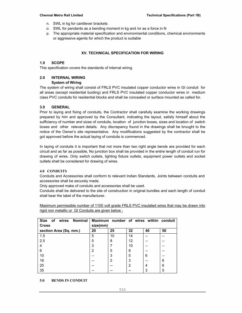
Chennai Metro Rail Limited Technical Specifications (Part 1B)
555
n. SWL in kg for cantilever brackets o. SWL for pendants as a bending moment in kg and /or as a force in N p. The appropriate material specification and environmental conditions, chemical environments
or aggressive agents for which the product is suitable
XV. TECHNICAL SPECIFICATION FOR WIRING
1.0 SCOPE This specification covers the standards of internal wiring. 2.0 INTERNAL WIRING System of Wiring The system of wiring shall consist of FRLS PVC insulated copper conductor wires in GI conduit for all areas (except residential buiding) and FRLS PVC insulated copper conductor wires in medium class PVC conduits for residential blocks and shall be concealed or surface mounted as called for. 3.0 GENERAL Prior to laying and fixing of conduits, the Contractor shall carefully examine the working drawings prepared by him and approved by the Consultant, indicating the layout, satisfy himself about the sufficiency of number and sizes of conduits, location of junction boxes, sizes and location of switch boxes and other relevant details. Any discrepancy found in the drawings shall be brought to the notice of the Owner’s site representative. Any modifications suggested by the contractor shall be got approved before the actual laying of conduits is commenced. In laying of conduits it is important that not more than two right angle bends are provided for each circuit and as far as possible, No junction box shall be provided in the entire length of conduit run for drawing of wires. Only switch outlets, lighting fixture outlets, equipment power outlets and socket outlets shall be considered for drawing of wires. 4.0 CONDUITS Conduits and Accessories shall conform to relevant Indian Standards. Joints between conduits and accessories shall be securely made. Only approved make of conduits and accessories shall be used. Conduits shall be delivered to the site of construction in original bundles and each length of conduit shall bear the label of the manufacturer. Maximum permissible number of 1100 volt grade FRLS PVC insulated wires that may be drawn into rigid non metallic or GI Conduits are given below : Size of wires Nominal Cross
Maximum number of wires within conduit size(mm)
section Area (Sq. mm.) 20 25 32 40 501.5 5 10 14 -- -- 2.5 5 8 12 -- -- 4 3 7 10 -- -- 6 2 5 8 -- -- 10 -- 3 5 6 -- 16 -- 2 3 -- 6 25 -- -- 2 4 6 35 -- -- -- 3 5 5.0 BENDS IN CONDUIT

Chennai Metro Rail Limited Technical Specifications (Part 1B)
556
Where necessary, bends or diversions may be achieved by means of bends and / or circular inspection boxes with adequate and suitable inlet and outlet joints. In case of recessed system each junction box shall be provided with a cover properly secured and flush with the finished wall surface. No bends shall have radius less than 4.5 cms or three times the outside diameter of the conduits. 6.0 FIXING OF CONDUITS All conduits shall be installed so as to avoid steam and hot water pipes. After the conduits, junction boxes, outlet boxes and switch boxes are installed in position, their outlets shall be properly plugged or covered so that water, mortar, insects or another foreign matter does not enter into the conduit system. Recessed conduiting shall be done by making chase in the masonry by chase cutter, the conduit shall be fixed in the chase by means of GI hooks not more than 600 mm apart. After fixing of conduit the chase shall be filled with cement mortar after fixing of chicken mesh and brought to the original finish level of the surface. 7.0 SWITCH OUTLETS AND JUNCTION BOXES All outlet boxes for switches, sockets and other receptacles shall be rust proof and shall be of 2 mm thick mild steel sheets with HOT dipped galvanizing (or as specified in BOQ), having smooth external and internal surfaces to true finish. All outlet boxes for receiving plug sockets and switches shall be fabricated to approved sizes. All boxes shall have adequate number of knock out holes of required diameter and earthing terminal screws. Outlet boxes shall be of a minimum depth of 65 mm. 8.0 INSPECTION BOXES 50 mm dia inspection boxes of cast iron shall have smooth external and internal finish to facilitate removal and replacement of wires, where required. 9.0 CONDUCTORS All FRLS PVC insulated copper conductor wires shall conform in all respects to Indian Standards. 10.0 BUNCHING OF WIRES Wires carrying current shall be so bunched that the outgoing and return wires are drawn into the same conduit. For lighting wires originating from two different phases shall not run in the same conduit. All wires shall have ferrules for identification. Lighting and power circuits shall be separate. 11.0 DRAWING CONDUCTORS The drawing and jointing of FRLS PVC insulated copper conductor wires shall be executed with due regard to the following precautions. While drawing wires through conduits, care shall be taken to avoid scratches and kinks which may cause breakage of conductors. There shall be no sharp bends. Wire reel stands to be used for pulling of wires to avoid kinks. Insulation shall be removed by insulation stripper only. Strands of wires shall not be cut for connecting terminals. The terminals shall have sufficient cross sectional area to take all strands and connecting brass screws shall have flats ends. All looped joints shall be connected through terminal block/connectors. The pressure applied to tighten terminal screws shall be just adequate, neither too much nor too less. All light points shall be terminated through a connector. All light points will terminated through a connector. Conductors having nominal cross sectional areas exceeding 10 sq.mm shall always be provided with cable sockets. At all bolted terminals brass flat washer of large area and approved steel spring washer shall be used. Brass nuts and bolts shall be used for all connections.

Chennai Metro Rail Limited Technical Specifications (Part 1B)
557
Only licensed wiremen (Before doing the work or before appointing him on site contractor has to submit his wiring licence to Client) and cable jointers shall be employed to do jointing work. All wires and cables shall bear the manufacturer’s label and shall be brought to site in original packing. For all internal wiring FRLS PVC insulated copper conductor 1100V grade wires shall be used for all buildings. The sub-circuit wiring for point shall be carried out in loop system and no joints shall be allowed in the length of the conductors. No wire shall be drawn into any conduit until all work of any nature that may cause injury to wire is completed. Care shall be taken while pulling out the wires so that no damage occurs to conduits/wire itself, the conduits shall be thoroughly cleaned of moisture, dust, dirt or any other obstruction. The minimum size of FRLS PVC insulated copper conductor wires for all sub-circuit wiring for light points shall be minimum 1.5 sq.mm copper Separate neutral to be pulled for each circuit. 12.0 JOINTS All joints shall be made at main switches, distribution boards, socket outlets, lighting outlets and switches boxes only. No joints shall be made in conduits and in junction boxes. Conductors shall be continuous from outlet to inlet. 13.0 COLOUR CODE OF CONDUCTORS Colour code shall be maintained as indicated by the Consultant for the entire wiring installations. Red, yellow, blue shall be for three phases, black for neutral and green with yellow band shall be for earthing.
XVI. TECHNICAL SPECIFICATION FOR UPS SYSTEM
These specifications describe requirements for a Micro Processor Controlled Uninterruptible Power System (UPS) consisting of UPS connected ( Scalability should be possible by adding UPS in future without warranting extra hardware other than similar UPS system) in parallel. The UPS shall automatically maintain AC power within specified tolerances to the critical load, without interruption, during failure or deterioration of the mains power supply. The manufacturer shall design and furnish all materials and equipment to be fully Compatible with electrical, environmental, and space conditions at the site. It shall include all equipment to properly interface the AC power source to the intended load and be designed for unattended operation. STANDARDS The UPS and all associated equipment and components shall be manufactured in accordance with the following applicable standards: Construction & safety : IEC 62040-1-2/IEC 60950 IEC 60146 : Semiconductor Converters – General requirement and line commutated converters –
Part 1-1: Specification of basic requirements. Performance & topology : IEC 62040-3/ EN 62040-3 EMC : IEC 61000-4-2 / EN 62040-2 level 4(electrostatic discharge : 15KV air 8 KV contact IEC 61000-4-3 / EN 62040-3 level 3(radiated electromagnetic fields:1 0V/m

Chennai Metro Rail Limited Technical Specifications (Part 1B)
558
IEC 61000-4-4 / EN 62040-2 level 4 (fast transient : 4kV on mains cable IEC 61000-4-5 / EN 62040-2 level 4 ( high -energy surges : 2KV couling b/w lines IEC 61000-4-5 / EN 62040-2 level 4 ( high -energy surges : 2KV couling b/w lines IEC 61000-4-6 / EN 62040-2 level 3 ( conducted immunity : 10V rms on mains cable) IEC 61000-4-8 / EN 55024 level 4 (radiated immunity : 30 A/m) Emission: IEC 62040-2 : C3 monitoried distribution is std / C2 class A is optional Harmonics : IEC 61003 -2 / IEC 61003-4 The Quality System for the engineering and manufacturing facility shall be certificated to conform to Quality System Standard ISO 9001 for the design and manufacture of power protection systems for computers and other sensitive electronics.
SYSTEM DESCRIPTION UPS System Load voltage and bypass line voltage will be 415V AC, three phase and Neutral. Input voltage will be 415V AC, three phases. The battery system shall have a capacity to withstand full load for 30 minutes & 2 hours per system for office area UPS power (160KVA) & safety system UPS (20KVA) respectively. The battery will be installed in a closed Cabinet. Modes of Operation The UPS system shall operate as a true on-line system in the following modes: Normal: The critical AC load is continuously powered by the UPS inverters. The rectifier/chargers derives power from the mains AC power supply source converting this to DC power to supply the inverters, while simultaneously float charging the battery system. Power supplied by the UPS inverters is, to within close tolerances, at rated voltage and frequency. Emergency: Upon failure of the mains AC power supply source, the critical AC load is powered by the inverters which, without any switching, obtain power from the battery system. There shall be no interruption in power to the critical load upon failure or restoration of the mains AC power supply source. Recharge: Upon restoration of the mains AC power supply source, power to the rectifier/chargers initially is restricted by a gradual power walk-in. Following this relatively short power walk-in period, the rectifier/chargers power the inverters and simultaneously recharge the battery. This shall be an automatic function Bypass: If the UPS system must be taken out of service for maintenance or repair, the static bypass switch shall transfer the load to the bypass source. The transfer process shall cause no interruption to the critical load. Off-Battery: If the battery system only is taken out of service for maintenance, it is disconnected from the rectifier/charger and inverters by means of external disconnect breaker. The UPS shall continue to function and meet all of the specified steady-state performance criteria, except for the power outage back-up time capability. UPS AC Input

Chennai Metro Rail Limited Technical Specifications (Part 1B)
559
Voltage Range: 415 +15% @ full load & 415+15%-35% @ 70% load up to 160KVA UPS & 415V+/-15% @ full load & 415+15%-35% @ 35% load >160KVA Vendor to specify the input voltage range at different load levels. Frequency Range: 50 Hz ±10% In-rush Current Limiting: 20% to 100% of full rated current over 10 seconds. Power Factor: >0.99 @ Full Load. 2-Step Input Current Limit: Maximum of 120% normal full load input current. (100% for generator operation.) Temperature Compensated Charging: Above 25ºC the battery charge voltage should be reduced by 2mV per cell per ºC in order to optimise on the battery lifetime. Current Distortion: <3 % THD at full load current. Surge protection : The ups input shall have inbuilt protection against surges. UPS Output Load Rating: 100% continuous load rating at 40ºC for any combination of linear and non-linear loads . Voltage Regulation: 1% steady state for balanced load, 2% for 100% unbalanced load. Frequency Regulation: ± 4Hz synchronized mode (settable) with bypass source, ± 0.01Hz free running or on battery operation. Frequency Slew Rate: 0.1Hz per second. Efficiency: Defined as output kW / input kW at a load power factor of 0.9 lagging: greater than 93 % at full rated load when operating as a true on-line configuration with harmonic reduction options Phase Imbalance: 120º ±1º el. for balanced loads. 120º ±2º el. for 100% unbalanced loads Voltage Transients: ± 3% for 100% output load step. Transient Recovery Time: To within 1% of steady state output voltage within 20ms Voltage Distortion (at 100% rated load with crest factor 3:1): ~1% typical ≤3% Ph/Ph voltage total harmonic distortion (vTHD) for non-linear loads < 3% Ph/N voltage total harmonic distortion (vTHD) Overload Capability at Rated Output Voltage: 110% of rated load for 30 minutes. 125% of rated load for 10 minutes. 150% of full load for a minimum of 60 seconds up to 160KVA UPS System Bypass

Chennai Metro Rail Limited Technical Specifications (Part 1B)
560
Voltage Range: 380V to 415V (380 / 400 / 415V) Frequency Range: 50Hz ± 10Hz. Fault HandlingCapability: 25.0 times rated current up to 20ms Neutral Conductor Sizing: 1.5 times rated current. Earthing The AC output neutral shall be electrically isolated from the UPS chassis. The UPS chassis shall have an equipment earth terminal. Provisions for local bonding are to be provided. ENVIRONMENTAL CONDITIONS Operating Ambient Temperature UPS: 0ºC to 40ºC without derating. Battery: 25ºC for optimum battery performance. Storage/Transport Ambient Temperature UPS: -20ºC to 70ºC. Battery: 20ºC for optimum battery storage. Relative Humidity 0 to 95%, non-condensing. Altitude Operating: To 1000 m above sea level without derating. UPS Delivery Submittals The specified UPS shall be supplied with 2 user manuals to include details of Functional description of the equipment with block diagrams. Detailed installation drawings, including all terminal locations for power and control connections for both the UPS and battery system. Safety precautions. Step-by-step operating procedures General maintenance guidelines The UPS shall be supplied with a record of pre-shipment final factory test report. QUALITY ASSURANCE Manufacturer Qualifications A minimum of twenty-five years experience in the design, manufacture and testing of solid-state UPS systems is required. The manufacturer shall be certified to ISO 9001. & ISO 14001. Factory Testing Before shipment, the system shall be fully and completely tested to ensure compliance with the specification. PRODUCT Materials All materials of the UPS shall be new, of current manufacture, high grade and shall not have been in prior service except as required during factory testing. All active electronic devices shall be solid-

Chennai Metro Rail Limited Technical Specifications (Part 1B)
561
state. Control logic and fuses shall be physically isolated from power train components to ensure operator safety and protection from heat. All electronic components shall be accessible from the front without removing sub-assemblies for service access. Wiring Wiring practices, materials and coding shall be in accordance with the requirements of EN. All electrical power connections shall be torqued to the required value and marked with a visual indicator. Provision shall be made in the cabinets to permit installation of input, output, and external control cabling. Provision shall be made for either top or bottom access, allowing for adequate cable bend radius, to the input and output connections. Construction The UPS shall be housed in an IP20 enclosure, designed for floor mounting. The UPS shall be structurally adequate and have provisions for hoisting, jacking, and forklift handling. Maximum cabinet height shall be 1.9 meters. The UPS panel shall be fabricated with Cold Rolled MS sheet of thickness not less 1.8 mm. with proper supporting member. Cooling Adequate ventilation shall be provided to ensure that all components are operated well within temperature ratings. UPS System The UPS system shall consist of relevant UPS rating modules, battery disconnect breakers and battery systems.
UPS system should be True ON Line double conversion type with Micro Processor/DSP Controller. Each Unit shall consist of an IGBT rectifier/charger and three-phase inverter, static transfer switch, protective devices, and accessories as specified. External Isolation Transformer at the output of the UPS systems.
Configurations The UPS system should be compatible for one or more (up to a maximum of four) units of the same kVA rating operating in parallel. All units shall operate simultaneously and share the load. The system shall be redundant as stated elsewhere in this specification. Redundant system: The UPS system shall have one or more module(s) than required to supply the full rated load. The malfunction of one of the modules shall cause that module to be disconnected automatically from the critical load and the remaining module(s) shall continue to carry the load. Any malfunctioning of the UPS system shall be indicated with Audio/Visual alarm. Upon repair of the module, it shall be reconnected to the critical load to resume redundant operation. Any module from the system can be removed from the critical load manually for maintenance without disturbing the critical load bus. Module redundancy level shall be a predefined number of modules that are required to supply the full rated load. With the number of connected modules equal to this value, a malfunction of another module shall cause the load to be transferred automatically and uninterrupted to the bypass line by the use of the static mains bypass switch. System Protection The UPS shall have built-in protection against: surges, sags, and over-current from the AC source, over voltage and voltage surges from output terminals of paralleled sources, and load switching and circuit breaker operation in the distribution system. The UPS shall be protected against sudden changes in output load and short circuits at the output terminals. The UPS shall have built-in protection against permanent damage to itself and the connected load for all predictable types of malfunctions. Fast-acting current limiting devices shall be used to protect against cascading failure of solid-state devices. Internal UPS malfunctions shall cause the module to trip off-line with minimum

Chennai Metro Rail Limited Technical Specifications (Part 1B)
562
damage to the module and provide maximum information to maintenance personnel regarding the reason for tripping off line. The load shall be automatically transferred to the bypass line uninterrupted, should the connected critical load exceed the capacity of the available on-line modules. The status of protective devices shall be indicated on a graphic display screen on the front of the unit. 2.9.0 COMPONENTS Rectifier/Charger The term rectifier/charger shall denote the solid-state equipment and controls necessary to convert AC to regulated DC for input to the inverter and for charging the battery. Input Current Total Harmonic Distortion: The input current THD shall be < 3% at full load current. The input power factor shall be > 0.99 on full load. AC Input Current Limiting: The rectifier/charger shall include a circuit to limit AC input current to 120% of the full input current rating. An optional secondary circuit shall provide limiting to 100% on receipt of an external low voltage signal, i.e. during generator operation. Battery Charge Current Limiting: The rectifier/charger shall include a circuit to limit the battery charging current to 20% of maximum battery discharge current. An optional secondary circuit shall reduce the charging current to 0% on receipt of an external low voltage signal, i.e. during generator operation. Battery Charge Compensation: The rectifier/charger shall automatically adjust the battery float charging voltage by ±2mV per cell per ºC when used in conjunction with an optional remote temperature sensor. Input Power Walk-in: The rectifier/charger shall provide a feature that limits the total initial power requirements to 20% of rated load, and gradually increases power to 100% of full rating over a 10 second time interval. Input Breaker: The rectifier/charger shall have an input breaker and shall be fuse protected. The isolator shall be of the frame size to supply full rated load and recharge the battery at the same time. Fuse Protection: Each AC phase shall be individually fused with fast acting fuses so that loss of any semiconductor shall not cause cascading failures. DC Filter: The rectifier/charger shall have an output filter to minimize ripple current in to the battery. The AC ripple voltage of the rectifier DC output shall not exceed 1% rms of the float voltage. The filter shall be adequate to ensure that the DC output of the rectifier/charger will meet the input requirements of the inverter without the battery connected. Battery Recharge: In addition to supplying power to the load, the rectifier/charger shall be capable of producing battery charging current sufficient to replace 95% of the battery discharge power within ten (10) times the discharge time. After the battery is recharged, the rectifier/charger shall maintain the battery at full charge until the next emergency operation. Battery Breaker should have the facility to set the short circuit current depends on the battery connected. Surge protection : The ups input shall have inbuilt protection against surges Inverter

Chennai Metro Rail Limited Technical Specifications (Part 1B)
563
The term inverter shall denote the equipment and controls to convert DC from the rectifier/charger or battery to provide AC power to the load. The inverter shall be solid-state, capable of providing rated output power. For increased performance, the inverter shall be a pulse width modulated (PWM) design and utilize insulated gate bipolar transistors (IGBTs), switching at high frequency in order to minimize output voltage distortion. Overload Capability: The inverter shall be able to sustain an overload across its output terminals up to 150% with ±1% output voltage regulation. The inverter shall be capable of supplying at least 150% current for short circuit conditions. Output Frequency: The inverter shall track the bypass mains supply continuously providing the bypass source maintains the rated frequency (of either 50 or 60Hz) ±2Hz. However, the range can be set. The inverter will change its frequency at 0.1Hz per second (adjustable 0.1 to 1.0Hz per second) to maintain synchronous operation with the bypass. This shall allow make-before-break manual or automatic transfers of the load between the inverter and the bypass mains supply. If the bypass mains supply frequency falls outside of these limits, the inverter shall revert to an internal oscillator which shall be temperature compensated and hold the inverter output frequency to within ±0.01Hz of the rated frequency for steady state and transient conditions Phase-to-Phase Balance: System logic shall provide individual phase voltage compensation to obtain phase balance ±1% under all conditions including up to 100% load unbalance Fault Sensing and Isolation: Fault sensing shall be provided to isolate a malfunctioning inverter from the critical load bus to prevent disturbance of the critical load voltage beyond the specified limits. The inverter output static switch shall be switched off to isolate a malfunctioning module from the critical load. Battery Protection: The inverter shall be provided with monitoring and control circuits to protect the battery system from damage due to excessive discharge. Shutdown of the inverter shall be initiated when the battery has reached the end of discharge (EOD) voltage. The battery EOD voltage shall be calculated and automatically adjusted for reduced load conditions to allow for extended autonomy periods without damage to the battery. Automatic shutdown control shall not be a function of discharge time. Bypass Static Switches: Static bypass switches should be provided in each UPS. Vendors who can not parallel static bypass lines of individual UPS system should be quoting for centralized bypass switch with control panel. Manual Load Transfers: A manual load transfer between the inverter output and the alternate AC source shall be initiated from the control panel. A means to perform manual transfers remotely shall be made available as an optional extra. Automatic Load Transfers: An automatic load transfer between the inverter output and the alternate AC source shall be initiated if an overload or short circuit condition is sustained for a period in excess of the inverter output capability or due to a malfunction that would affect the output voltage. Transfers caused by overloads shall initiate an automatic retransfer of the load back to the inverter only after the load has returned to a level within the rating of the inverter source Maintenance Bypass A fully rated bypass circuit shall be fitted in each UPS to provide an alternative path for power flow from the alternate AC supply to the critical load for the purpose of maintaining all the UPS modules while they are completely powered down.

Chennai Metro Rail Limited Technical Specifications (Part 1B)
564
Display and Controls UPS Display and Control Panel: Each UPS shall be equipped with a alphanumeric LCD display. This shall automatically provide all information relating to the current status of the UPS or the system, respectively, as well as being capable of displaying metered values. The display shall be menu-driven, permitting the user to easily navigate through operator screens. Metered Values: A microprocessor shall control the display functions of the monitoring system. All three-phase parameters shall be displayed simultaneously. All voltage and current parameters shall be monitored using true RMS measurements for accurate (±1%) representation of non-sinusoidal waveforms typical of computers and other sensitive loads. Power Flow Mimic: Each UPS shall be equipped with a mimic to indicate power flow to the critical load along with an indication of the availability of the rectifier mains supply, battery supply and the alternate AC mains bypass supply. Under normal operation, the UPS mimic shall also display the amount of charge stored in the battery system. During mains failure, the battery charge indication will alternate to identify the remaining battery autonomy time; as well as indicating low battery voltage conditions. Alarms and Status Information: Alarm and status conditions shall be reported at UPS system. Each alarm shall be visually displayed in text form and an audible alarm will sound for each alarm displayed. Communications SNMP/HTTP Network Interface Card: The UPS shall have internally fitted, network interface card to provide all alarm status information as SNMPv1 traps for connection to a 10-baseT Ethernet connection. In addition the same card will also transmit the same status information and all measured parameters for display at a web browser in LAN/WAN. BATTERY BANK The battery bank shall at least consist of the following:-
(1) Set of 2V batteries, in split banks to facilitate maintenance.ie. each UPS with Individual battery bank
(2) Battery racks, which shall be coated by acid resistant material from the factory. (3) Associated equipment of the battery, panel board and isolators. (4) Grounding system (5) Battery manager to have interoperability of the battery banks.
BATTERY
(1) The battery shall be Valve Regulated Sealed Lead Acid (VRLA) type (SMF) and each unit shall be enclosed in battery cabinet equipped with appropriate insulation.
(2) The battery shall have capability to deliver the output power rating as specified on the drawings at the output terminal of the UPS for at least in the event of input power to the UPS failure.
(3) The maximum and minimum voltage of the battery shall be matched with the operating input voltage of the inverter. The minimum final discharge voltage of the battery shall be limited at 1.75 or at the recommendation value from the manufacturer.
(4) Low Battery Voltage Protection: To prevent total discharge or damage to the battery, the UPS shall transfer to standby operation when the battery voltage reaches a set minimum voltage level (programmable). If AC input source has not returned within 10 minutes after “low battery” shutdown, the UPS shall electronically disconnect DC Power from the battery to avoid deep discharge.

Chennai Metro Rail Limited Technical Specifications (Part 1B)
565
(5) Battery Monitor: Battery function monitor shall be capable of monitoring and defining battery bank capacity. It shall be possible to program the unit to perform an automatic battery test every 90 days to test the condition of the battery.
(6) The inter connection between batteries shall be carried with appropriate size of copper cables.
(7) Battery shall be design as per ups rated power and battery calculation shall be submitted with considering nitrogen gas release.
Associated Equipment of the Battery (1) The battery cell inter-connectors shall be copper bar and fully insulated. All bolts and nuts
shall be of the acid resistant type. (2) All battery terminal posts shall be covered with soft rubber pole caps to prevent external short
circuit.
UPS SYSTEM - TECHNICAL DATA SHEET S. No DESCRIPTION TENDER SPECIFICATION VENDOR TO CONFIM
A. UNINTERRUPTIBLE POWER
SUPPLY 1 Brand and Model Country of Origin
2 Manufacturer
3 Manufacturer compliance to ISO9001
4 UPS Performance and Test Method Compliance to IEC 146
5 Local Agent
6 UPS capacity Tenderer to specify
7 System Input: i) Input Voltage/Phase/Frequency 400V/3phase/50hz ii) Voltage Tolerance 400V+/-15% @ full load iii) Frequency Tolerance 50Hz+/-10% iv) Power walk-in Progessive for 5 to 30sec
v) Input power at 100% load on inverter with battery at full charged
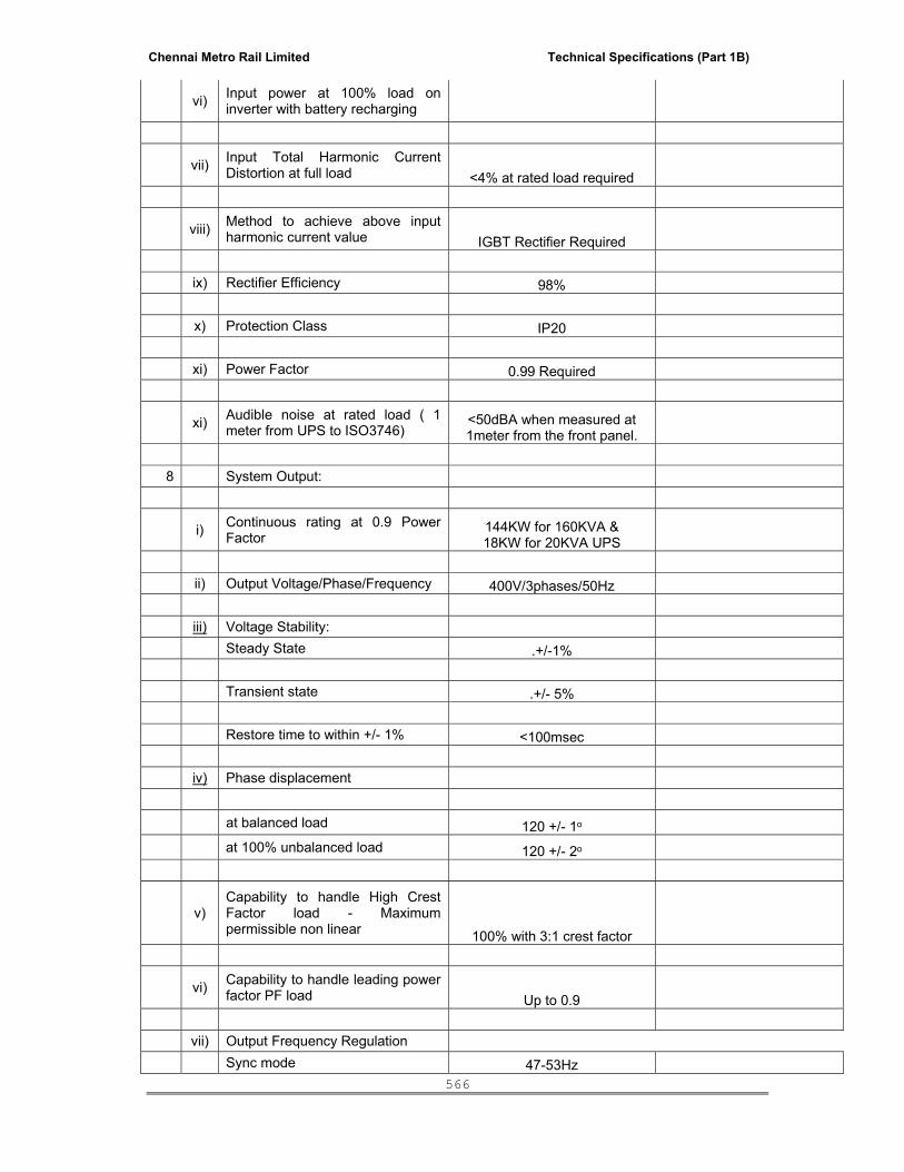
Chennai Metro Rail Limited Technical Specifications (Part 1B)
566
vi) Input power at 100% load on inverter with battery recharging
vii) Input Total Harmonic Current Distortion at full load <4% at rated load required
viii) Method to achieve above input harmonic current value IGBT Rectifier Required
ix) Rectifier Efficiency 98% x) Protection Class IP20 xi) Power Factor 0.99 Required
xi) Audible noise at rated load ( 1 meter from UPS to ISO3746)
<50dBA when measured at 1meter from the front panel.
8 System Output:
i) Continuous rating at 0.9 Power Factor
144KW for 160KVA & 18KW for 20KVA UPS
ii) Output Voltage/Phase/Frequency 400V/3phases/50Hz iii) Voltage Stability: Steady State .+/-1% Transient state .+/- 5% Restore time to within +/- 1% <100msec iv) Phase displacement at balanced load 120 +/- 1o at 100% unbalanced load 120 +/- 2o
v) Capability to handle High Crest Factor load - Maximum permissible non linear 100% with 3:1 crest factor
vi) Capability to handle leading power factor PF load Up to 0.9
vii) Output Frequency Regulation Sync mode 47-53Hz

Chennai Metro Rail Limited Technical Specifications (Part 1B)
567
Free running +/- 0.01Hz
viii) Maximum output voltage distortion with:
Linear Load max. 2%
100% non-linear load (3:1 crest factor) max. 3%
Overload ability at 0.8 p.f. 110% for > 60minutes,
125% for > 10minutes & 150% for > 1minute.
x) Inverter power required at rated load Tenderer to specify
xi) Inverter DC current at minimum DC voltage Tenderer to specify
xii) Inverter switching / regulation technology Pulse Width Modulation
xiii) Inverter switching power component
Insulated Gate Bi-Polar Transistor (IGBT)
9 D.C. Characteristics D.C. Voltage Range 400-600Vdc Battery Charging Voltage Range Tenderer to specify Voltage Stability of the Rectifier +/- 1% D.C. Ripple <1% Nominal Float Charge Voltage 2.25Vdc Operation without Battery Yes
10 Parelleling kit / panels requried for parelleling and On-line adding new UPS to system in future To be included / mandatory
11 Battery
Make Tender to specify
Type Maintenance Free Sealed Lead Acid
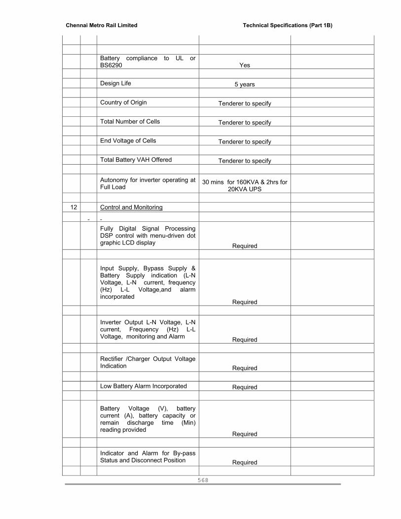
Chennai Metro Rail Limited Technical Specifications (Part 1B)
568
Battery compliance to UL or BS6290 Yes
Design Life 5 years Country of Origin Tenderer to specify Total Number of Cells Tenderer to specify End Voltage of Cells Tenderer to specify Total Battery VAH Offered Tenderer to specify
Autonomy for inverter operating at Full Load
30 mins for 160KVA & 2hrs for 20KVA UPS
12 Control and Monitoring
Fully Digital Signal Processing DSP control with menu-driven dot graphic LCD display Required
Input Supply, Bypass Supply & Battery Supply indication (L-N Voltage, L-N current, frequency (Hz) L-L Voltage,and alarm incorporated
Required
Inverter Output L-N Voltage, L-N current, Frequency (Hz) L-L Voltage, monitoring and Alarm Required
Rectifier /Charger Output Voltage Indication Required
Low Battery Alarm Incorporated Required
Battery Voltage (V), battery current (A), battery capacity or remain discharge time (Min) reading provided
Required
Indicator and Alarm for By-pass Status and Disconnect Position Required
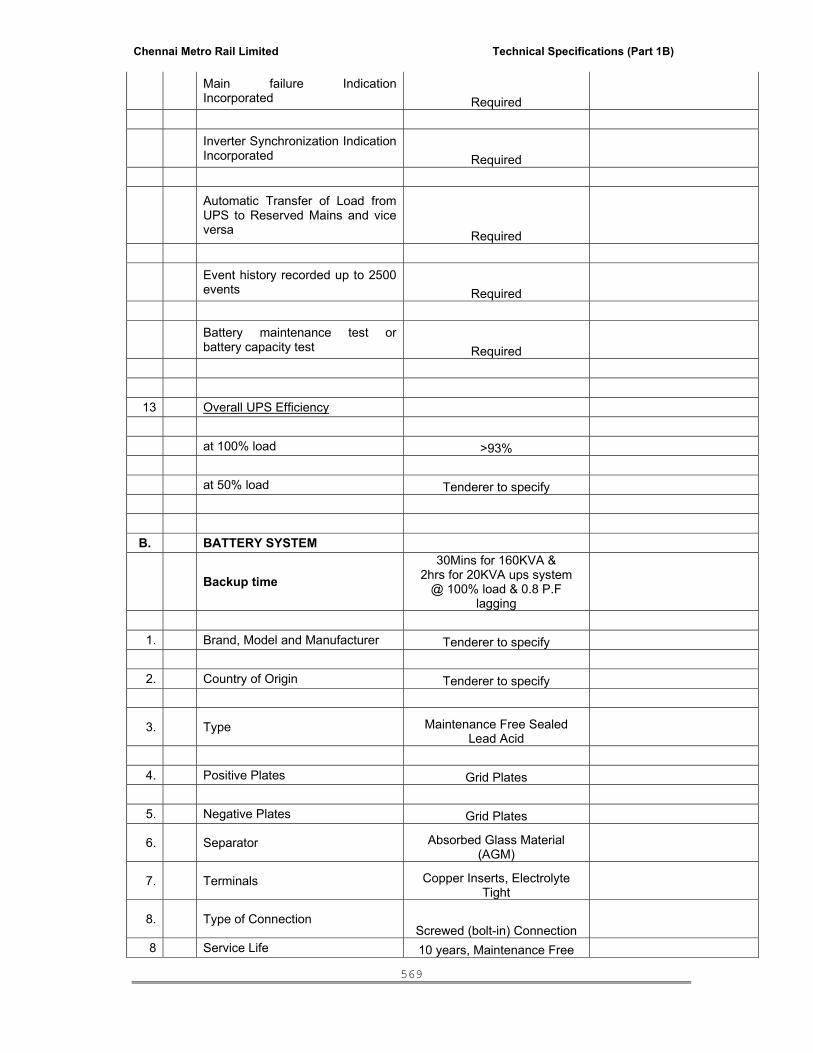
Chennai Metro Rail Limited Technical Specifications (Part 1B)
569
Main failure Indication Incorporated Required
Inverter Synchronization Indication Incorporated Required
Automatic Transfer of Load from UPS to Reserved Mains and vice versa Required
Event history recorded up to 2500 events Required
Battery maintenance test or battery capacity test Required
13 Overall UPS Efficiency at 100% load >93% at 50% load Tenderer to specify
B. BATTERY SYSTEM
Backup time 30Mins for 160KVA &
2hrs for 20KVA ups system @ 100% load & 0.8 P.F
lagging 1. Brand, Model and Manufacturer Tenderer to specify
2. Country of Origin Tenderer to specify
3.
Type Maintenance Free Sealed Lead Acid
4. Positive Plates Grid Plates
5. Negative Plates Grid Plates
6.
Separator Absorbed Glass Material (AGM)
7.
Terminals Copper Inserts, Electrolyte Tight
8.
Type of Connection Screwed (bolt-in) Connection
8 Service Life 10 years, Maintenance Free
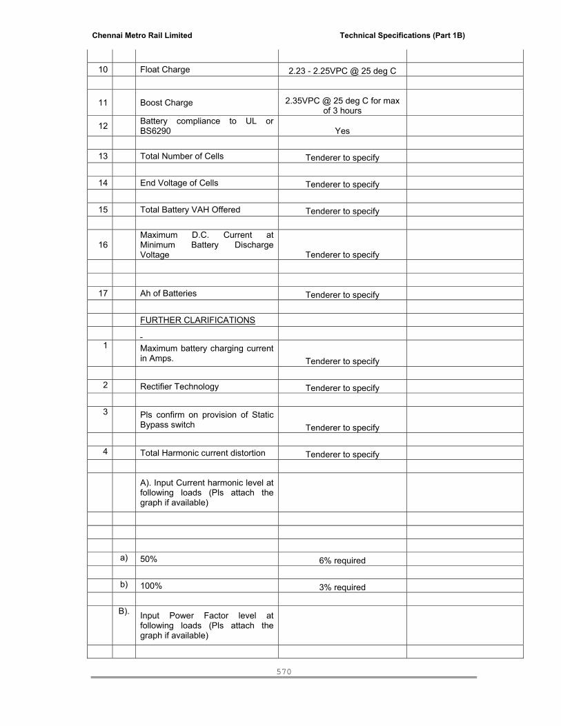
Chennai Metro Rail Limited Technical Specifications (Part 1B)
570
10 Float Charge 2.23 - 2.25VPC @ 25 deg C
11
Boost Charge 2.35VPC @ 25 deg C for max of 3 hours
12 Battery compliance to UL or BS6290 Yes
13 Total Number of Cells Tenderer to specify
14 End Voltage of Cells Tenderer to specify
15 Total Battery VAH Offered Tenderer to specify
16
Maximum D.C. Current at Minimum Battery Discharge Voltage Tenderer to specify
17 Ah of Batteries Tenderer to specify
FURTHER CLARIFICATIONS 1
Maximum battery charging current in Amps. Tenderer to specify
2 Rectifier Technology Tenderer to specify
3 Pls confirm on provision of Static
Bypass switch Tenderer to specify
4 Total Harmonic current distortion Tenderer to specify
A). Input Current harmonic level at following loads (Pls attach the graph if available)
a) 50% 6% required b) 100% 3% required
B). Input Power Factor level at following loads (Pls attach the graph if available)

Chennai Metro Rail Limited Technical Specifications (Part 1B)
571
a) 25% Tenderer to specify b) 50% Tenderer to specify c) 75% Tenderer to specify d) 100% Tenderer to specify B). Output Voltage harmonic level at
following loads (Pls attach the graph if available)
a) 25% Tenderer to specify b) 50% Tenderer to specify c) 75% Tenderer to specify d) 100% Tenderer to specify
5
Do you have the following parameters for monitoring (Answer Yes / No)
a) Input voltage (phase wise) Tenderer to specify b) Input current (phase wise) Tenderer to specify c) Output power KW/KVA Tenderer to specify d) Input frequency Tenderer to specify e) Input rectifier voltage Tenderer to specify f) Battery charging /Discharging
Current Tenderer to specify g) Output current (phase wise) Tenderer to specify i) Output frequency Tenderer to specify j) Output rectifier voltage Tenderer to specify k) Bypass Status Tenderer to specify l) Battrer Breaker Status Tenderer to specify m) Bypass input voltage Tenderer to specify n) Invertors Output power factor Tenderer to specify o) Input breaker condition Tenderer to specify p) Sink temp. Tenderer to specify q) Surrounding Temperature Tenderer to specify r) Event logging Tenderer to specify

Chennai Metro Rail Limited Technical Specifications (Part 1B)
572
s) Please list all/ any other parameters that your product offers in a separate file Tenderer to specify
6 operational temperature of UPS Tenderer to specify
7
What is the UPS uptime you will be offering (Considering there is no problem in input power and Surrounding Temp)
Tenderer to specify
8 a) No of battery bank with each UPS Tenderer to specify b) No Battery in each bank Tenderer to specify c) Provide details of the rating of the
battery ( Ah, V) Tenderer to specify d) AH of each Battery Tenderer to specify e) Confirmation of the battery
enclosure and size of the same Tenderer to specify
XVII. TECHNICAL SPECIFICATION FOR THE LIGHTING LUMINARIES 1.0 SCOPEThis specification covers the design, material specification, manufacture, testing at works, inspection and delivery at site of light fittings and their associated accessories.
2.0 STANDARDSThe light fittings and their associated accessories such as lamps / tubes, reflector, housings, ballasts etc. shall comply with the latest applicable standards.All luminaries, lamps and accessories shall be of same make.
3.0 GENERAL REQUIREMENTSFittings shall be designed for continuous trouble-free operation under hot humid atmospheric conditions, at the specified ambient temperature, without reduction in lamp life or without deterioration of materials and internal wiring. Outdoor fittings shall be weather proof and rain proof type.
The fittings shall be designed so as to facilitate easy maintenance, including cleaning, replacement of lamps / starters etc.
Connections between different components shall be made in such a way that they will not work loose by small vibration.
For each type of light fitting the Contractor shall supply the utilisation factor to indicate the proportion of the light emitted by the bare lamp which falls on the working plane.

Chennai Metro Rail Limited Technical Specifications (Part 1B)
573
The fittings shall be supplied complete with lamps.
The fittings and accessories shall be designed to have low temperature rise. The temperature rise above the ambient temperature shall be as indicated in the relevant standards.
All Discharge Lamp fittings shall be complete with accessories like lamps. ballasts, power factor improvement capacitors, starters / igniters wherever applicable, etc. These shall be mounted as far as possible in the fitting assembly only.
Outdoor type fittings shall be provided with Weather Proof control gear box. The fittings shall be power factor corrected to 0.99 lagging (Maximum).
Each fitting shall have a terminal block suitable for loop-in, loop-out and T-Off connection. The internal wiring shall be completed by the Manufacturer by means of stranded copper wire and terminated on the terminal block.
All hardware used in the luminaries shall be cadmium plated /zinc passivated.
4.0 EARTHING Each light fitting shall be provided with an earthing terminal suitable for connection to the earthing conductor.
All metal or metal enclosed parts of the housing shall be bonded to the earthing terminal so as to ensure satisfactory earth continuity throughout the fixture.
5.0 PAINTING / FINISHAll surfaces of the fittings shall be thoroughly cleaned and degreased. The fittings shall be free from scale, rust, sharp edges and burrs.
The housing shall be stove-enamelled / epoxy stove-enamelled / vitreous enamelled or anodised as indicated under various types of fitting.The finish of the fitting shall be such that no bright spots are produced either by direct light source or by reflection.
6.0 LED FITTING For LED light fittings, the complete luminaire should have a warranty for 5 years which includes the housing + LED + Driver Conformance Standards for LED lamps:
1. LM80 compliance certificate to be adhered by the LED manufacturer. LED data sheet should comprise of lumen output, junction temperature, pad temperature, thermal resistance, and LED drive current.
2. The luminaire shall conform to IEC 60598 or equivalent standard and the driver should comply with IEC 61347-2-13, IEC 61547, CISPR-15, IEC 62124 and IEC 62384.
3. Luminaire should be tested as per BIS 10322 standards and following Test Reports should be submitted: Heat Resistance Test, Thermal Test, Ingress Protection Test, Drop Test, Vibration Test, Electrical / Insulation Resistance Test, Endurance Test, Humidity Test, Photometry Test (LM 79 Report), Electronics Test.
Technical Specifications of Galvanised Octagonal Poles (Street light)

Chennai Metro Rail Limited Technical Specifications (Part 1B)
574
Design The poles shall be designed to withstand the maximum wind speed of 180 km / hr. The top loading i.e. the weight and the area of top luminaires are to be considered to calculate maximum deflection of the pole and the same shall meet the requirement of BS: 5649 Part VI 1982. For the Design of Octagonal Poles, the Structural Calculation Details, confirming the suitability as per standards, shall be produced by the Supplier.
Pole Shaft The pole shaft shall have Octagonal cross section and shall be continuously tapered with single longitudinal welding. There shall not be any circumferential welding. The welding of pole shaft shall be done by Submerged Arc Welding (SAW) process.
The Octagonal pole shafts shall be provided with the rigid flange plate of suitable thickness with provision for fixing 4 foundation bolts. This base plate shall be fillet welded to the pole shaft at two locations i.e. from inside and outside. The welding shall be done as per qualified MMAW process approved by Third Party Inspection Agency.
Door opening The pole shall have door of approximate 500 mm length at the elevation of 500 mm from the Base plate. The door shall be vandal resistance and shall be weather proof to ensure safety of inside connections. The door shall be flush with the exterior surface and shall have suitable locking arrangement. There shall also be suitable arrangement for the purpose of earthing.
The pole shall be adequately strengthened at the location of the door to compensate for the loss in section.
Material Octagonal Poles Conforming to Gr. S355JO as per BSEN 10025 With
Yield Strength = 355 N/ Sq.mm
Tensile Strength = 490 – 630 N/ Sq.mm
Base Plate Fe 410 conforming to IS 226/ IS 2062
Foundation Bolts 6.8 Gr. As per IS 1367
Test Certificates from the Steel Manufacturer for the above to be produced by the supplier.
Welding The welding shall be carried out confirming to approved procedures duly qualified by third party inspection agency. The welders shall also be qualified for welding the octagonal pole shafts.
Pole sections The Octagonal Poles up to the length of 6 meters shall be in single piece with single longitudinal welding joint. There shall not be any circumferential weld joint.
Galvanization The poles shall be hot dip galvanised as per IS 2629/ IS 2633/ IS 4759 standards with average coating thickness of 65 micron. The galvanizing shall be done in single dipping. Galvanising Test Reports as per standards shall be produced by the manufacturer of Poles. The supplier should show the average galvanizing coating thickness of 65 microns on the poles during supply before the erection.

Chennai Metro Rail Limited Technical Specifications (Part 1B)
575
Fixing Type The Octagonal Poles shall be bolted on a pre-cast foundation with a set of four foundation bolts for greater rigidity. The Test Certificate for Foundation Bolts shall be produced by the supplier.
Top Mountings Galvanized fixture mounting bracket shall be supplied along with the poles for installation of 1 No.( for Single Sided Arrangement) or 2 nos.( for Centre verge Arrangement) 37W LED Street Light Fittings.
S.No. DESCRIPTION IMAGE
1
(Similar to PHILIPS - DN191B LED6S-6500 PSU WH) Recess mounted 10W LED downlighter made of a high quality diffuser with a die cast heat sink and a polycarbonate diffuser. CCT shall be of 6500K. The luminaire shall have integrated constant current driver and a power factor of 0.9. The Burning Hours of the LED downlighter shall be > 40,000 hours at L70. VOLTAGE: 240V. System POWER Consumption: 10W. System Lumen Output: 600 lm. CRI: >70. System Efficacy: >60lm/W. The luminaire shall be supplied with suitable accessories from ceiling fixed with false ceiling.
2
(Similar to PHILIPS - DN192B LED9S-6500 PSU WH)Recess mounted 15W LED downlighter made of a high quality diffuser with a die cast heat sink and a polycarbonate diffuser. CCT shall be of 6500K. The luminaire shall have integrated constant current driver and a power factor of 0.9. The Burning Hours of the LED downlighter shall be > 40,000 hours at L70. VOLTAGE: 240V. System POWER Consumption: 15W. System Lumen Output: 900 lm. CRI: >70. System Efficacy: >60lm/W. The luminaire shall be supplied with suitable accessories from ceiling fixed with false ceiling.
3
(Similar to PHILIPS - DN194B LED15S-6500 PSU WH)Recess mounted 24W LED downlighter made of a high quality diffuser with a die cast heat sink and a polycarbonate diffuser. CCT shall be of 6500K. The luminaire shall have integrated constant current driver and a power factor of 0.9. The Burning Hours of the LED downlighter shall be > 40,000 hours at L70. VOLTAGE: 240V. System POWER Consumption: 24W. System Lumen Output: 1500 lm. CRI: >70. System Efficacy: >60lm/W. The luminaire shall be supplied with suitable accessories from ceiling fixed with false ceiling.
4
(Similar to PHILIPS - RC240B LED37-5000 PSE-OD WH)Recess mounted LED luminaire with system wattage of 40W delivering system lumen of 3700 lumens with system efficiacy of > 95 lm/W. The luminaire shall have an inbuilt electronic driver with PF > 0.9, THD < 10% and complying safety, performance and EMI standards. The housing of the luminaire shall be of CRCA white powder coated and diffuser of high efficiency opal type. The LEDs used in the luminaire Mid flux LED module. The CRI shall be > 80. The CCT shall be of 5000K.
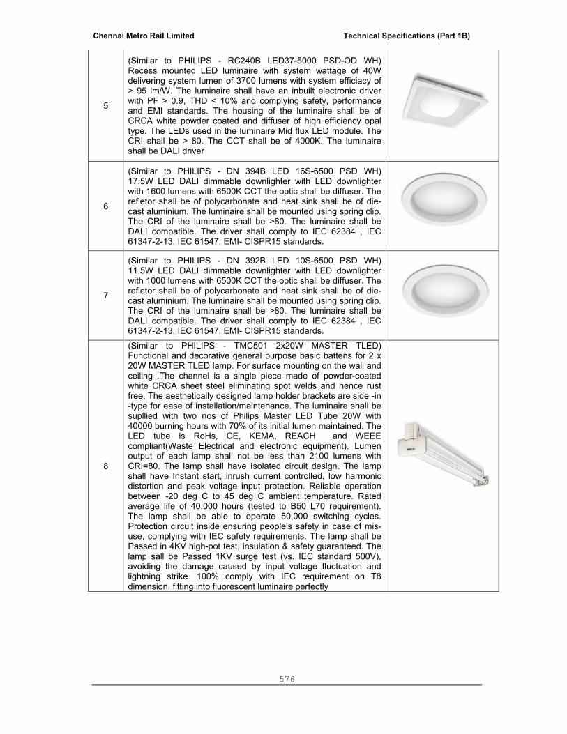
Chennai Metro Rail Limited Technical Specifications (Part 1B)
576
5
(Similar to PHILIPS - RC240B LED37-5000 PSD-OD WH)Recess mounted LED luminaire with system wattage of 40W delivering system lumen of 3700 lumens with system efficiacy of > 95 lm/W. The luminaire shall have an inbuilt electronic driver with PF > 0.9, THD < 10% and complying safety, performance and EMI standards. The housing of the luminaire shall be of CRCA white powder coated and diffuser of high efficiency opal type. The LEDs used in the luminaire Mid flux LED module. The CRI shall be > 80. The CCT shall be of 4000K. The luminaire shall be DALI driver
6
(Similar to PHILIPS - DN 394B LED 16S-6500 PSD WH)17.5W LED DALI dimmable downlighter with LED downlighter with 1600 lumens with 6500K CCT the optic shall be diffuser. The refletor shall be of polycarbonate and heat sink shall be of die-cast aluminium. The luminaire shall be mounted using spring clip. The CRI of the luminaire shall be >80. The luminaire shall be DALI compatible. The driver shall comply to IEC 62384 , IEC 61347-2-13, IEC 61547, EMI- CISPR15 standards.
7
(Similar to PHILIPS - DN 392B LED 10S-6500 PSD WH)11.5W LED DALI dimmable downlighter with LED downlighter with 1000 lumens with 6500K CCT the optic shall be diffuser. The refletor shall be of polycarbonate and heat sink shall be of die-cast aluminium. The luminaire shall be mounted using spring clip. The CRI of the luminaire shall be >80. The luminaire shall be DALI compatible. The driver shall comply to IEC 62384 , IEC 61347-2-13, IEC 61547, EMI- CISPR15 standards.
8
(Similar to PHILIPS - TMC501 2x20W MASTER TLED)Functional and decorative general purpose basic battens for 2 x 20W MASTER TLED lamp. For surface mounting on the wall and ceiling .The channel is a single piece made of powder-coated white CRCA sheet steel eliminating spot welds and hence rust free. The aesthetically designed lamp holder brackets are side -in -type for ease of installation/maintenance. The luminaire shall be supllied with two nos of Philips Master LED Tube 20W with 40000 burning hours with 70% of its initial lumen maintained. The LED tube is RoHs, CE, KEMA, REACH and WEEE compliant(Waste Electrical and electronic equipment). Lumen output of each lamp shall not be less than 2100 lumens with CRI=80. The lamp shall have Isolated circuit design. The lamp shall have Instant start, inrush current controlled, low harmonic distortion and peak voltage input protection. Reliable operation between -20 deg C to 45 deg C ambient temperature. Rated average life of 40,000 hours (tested to B50 L70 requirement). The lamp shall be able to operate 50,000 switching cycles. Protection circuit inside ensuring people's safety in case of mis-use, complying with IEC safety requirements. The lamp shall be Passed in 4KV high-pot test, insulation & safety guaranteed. The lamp sall be Passed 1KV surge test (vs. IEC standard 500V), avoiding the damage caused by input voltage fluctuation and lightning strike. 100% comply with IEC requirement on T8 dimension, fitting into fluorescent luminaire perfectly

Chennai Metro Rail Limited Technical Specifications (Part 1B)
577
9
(Similar to PHILIPS - TMC501 1x20W MASTER TLED)Functional and decorative general purpose basic battens for 1 x 20W MASTER TLED lamp. For surface mounting on the wall and ceiling .The channel is a single piece made of powder-coated white CRCA sheet steel eliminating spot welds and hence rust free. The aesthetically designed lamp holder brackets are side -in -type for ease of installation/maintenance. The luminaire shall be supllied with two nos of Philips Master LED Tube 20W with 40000 burning hours with 70% of its initial lumen maintained. The LED tube is RoHs, CE, KEMA, REACH and WEEE compliant(Waste Electrical and electronic equipment). Lumen output of each lamp shall not be less than 2100 lumens with CRI=80. The lamp shall have Isolated circuit design. The lamp shall have Instant start, inrush current controlled, low harmonic distortion and peak voltage input protection. Reliable operation between -20 deg C to 45 deg C ambient temperature. Rated average life of 40,000 hours (tested to B50 L70 requirement). The lamp shall be able to operate 50,000 switching cycles. Protection circuit inside ensuring people's safety in case of mis-use, complying with IEC safety requirements. The lamp shall be Passed in 4KV high-pot test, insulation & safety guaranteed. The lamp sall be Passed 1KV surge test (vs. IEC standard 500V), avoiding the damage caused by input voltage fluctuation and lightning strike. 100% comply with IEC requirement on T8 dimension, fitting into fluorescent luminaire perfectly
10
(Similar to PHILIPS - SM518C LED9S 6500 PSU OD)15W Surface mounted square LED luminaire with housing in Die-Cast Aluminum constructions. LED Driver is compliant to IEC Standards. Die-cast Housing & Heat Sink CRI > 70. The luminaire shall deliver > 900 lumens.
11
(Similar to PHILIPS - BWS150 LED200/WW PSU 220-240V 7043) 8W Philips LED wall mount offers a high level of durability with high impact resistant, and ingrees protection with comfortable soft lighting. Low-power white-light LED light source, available in a choice of warm white. Choice of colors for housing (dark grey RAL7043, light grey RAL9006). Long lifetime of 25,000 hours (70% lumen maintenance). IP65 protection and IK08 impact resistance. The system output shall not be less than 500 lumens
12
(Similar to PHILIPS - WT550W)42W LED IP 65 luminaire made of virgin polycarbonate body. The diffuser shall be of virgin polycarbonate diffuser. The luminaire shall be able to deliver a system lumen of 3500 lumens. The CCT shall be 6500K, CRI shall be > 80. The gasket shall be of silicone. THD<10%, PF > 0.95. Surge protection: Differential mode and common mode - 3kV

Chennai Metro Rail Limited Technical Specifications (Part 1B)
578
13
(Similar to PHILIPS - SM365C LED-34-5000 PSE-OD GR)Surface mounted LED luminaire with Mid flux LED using efficient optics , System lumen efficacy > 80Lumen/Watt , System Luminous flux of 3200 lumens, System Wattage =40W with 50,000 hours burning life. Color rendering index > 70 and Color temperature 5000K. CRCA housing with high efficieny opal diffuser. Luminarie sealed from bottom. Inbuilt gear . Zero maintenance, Zero mercury. Driver Surge protection > 1.5kV. Electronic In-Built PF > 0.9 , THD < 10% , IEC Compliant for Safety , Performance & EMI.
14
(Similar to PHILIPS - QWG305 with MASTER LED13-75W E27 2700K 230V A67 DIM)13W LED decorative Wall Light with Premium sand blasted glass, steel suitable for dimmable LED lamp with E27 base. Nickel finish for the rims. The lamp shall be with 310 degree beam angle. The lamp lumen output shall not be less than 1050 lumens. The CCT shall be 2700K. The life of LED lamp shall be 25000 hours. Working Voltage range of 120 – 240V.
15
(Similar to PHILIPS - BN150W LED 20S-6500 PSE OD WH)4' - 28W LED batten with 2000 lumens. The luminaire shall be with 6500K CCT. The life of luminaire shall not be less than 40,000 hours. The luminaire shall be of Extruded Aluminium housing, Extruded PC diffuser, Powder Coated CRCA back plate and End To End Electrical Contact ( LILO). The luminaire shall be able to operate for a voltage range 160v -270v AC. The driver efficiency shall be >80%. Power Factor : 0.9. THD : < 33%. Protection : High voltage cut off @ 270V
16
(Similar to PHILIPS - BN150W LED 13S-6500 PSE OD WH)2' - 15W LED batten with 1300 lumens. The luminaire shall be with 6500K CCT. The life of luminaire shall not be less than 40,000 hours. The luminaire shall be of Extruded Aluminium housing, Extruded PC diffuser, Powder Coated CRCA back plate and End To End Electrical Contact ( LILO). The luminaire shall be able to operate for a voltage range 160v -270v AC. The driver efficiency shall be >80%. Power Factor : 0.9. THD : < 33%. Protection : High voltage cut off @ 270V
17
Similar to PHILIPS - QWZ802 - 2 x MASTER LED 4W 2700K 230V B35 CL DIM)Decorative wall light with Chrome finish. Water resistant IP44 rating, Double wire entry Handmade 3 layered glass. Designed for 2 x LED Candle light. The luminaire shall be with 2 nos 4W LED candle with E14 base. Each lamp shall deliver a lumen output of 250 lumens. The CCT shall be 2700K. The life of LED lamp shall be 20000 hours. The LED lamp shall be dimmable.

Chennai Metro Rail Limited Technical Specifications (Part 1B)
579
18
(Similar to PHILIPS - WT202W LED 6S CW PSU SI PC)An inovative and reliable LED solution that fits seamlessly in a variety of applications and serves as a simple energy eficient alternative to CFL bulkhead luminaries. 10W LED multi purpose luminaire suitable for wall and ceiling mounting with 600 lumens. The CCT shall be 6500K. CRI shall be typical 70. The operating THD shall be <20%. The opertaing PF shall be > 0.9. The protection shall be IP 66 with IK09. The housing shall be made of die-cast aluminium. The front cover shall be polycarbonate diffuser.
19
140W LED Highbay luminaire with housing in High Pressure Die Cast Aluminum. The total system wattage shall not exceed 140W with system lumens shall not be less than 14000 lumens. The system efficacy of the luminaire shall be >100 lumens / W. The luminaire shall be with Wide beam optics delivering 6500K CCT with CRI > 80. The luminaire shll be with IP65 protection ensured by Silicone gasket material and Tempered Glass cover. Hook / Threaded Rod shall be used for mounting the same. The luminaire shall use Philips Xitanium driver with DALI compatible and the driver shall be with <20% THD and PF >0.95. The operating voltage of the luminaire shall vary from 120V - 277V AC. The life of the system shall be 50K hours @L70. The luminaire shall have an in-built surge protection for 2kV. The luminaire shall be in circular fashion. The dia of luminaire shall not exceed 470mm, width shall not exceed 470mm and depth / height of luminaire shall not exceed 158mm. The net weight shall not be more than 7.2kg. Philips: BY415P LED140S CW WB FG
XVIII. TECHNICAL SPECIFICATION FOR CEILING FANS AND EXHAUST FANS 1. HEAVY DUTY EXHAUST FANS: • The exhaust fan shall be capacitor start and run type, continuously rated motor. • Double ball bearing with Class A and E insulation. • Dynamically balanced propeller type impeller. • Silence motor that lasts longer and delivers the maximum output at lower operating cost. • Low sound level. 2. CEILING FANS Ceiling fans shall be complete with fan suspension – stem canopies and regulators (Electronic type). Required length of suspension –stem shall be provided at site. The stem shall be heavy duty galvanised steel tubes to I.S 1239 – 1958. Fans shall be mounted on a pre-embedded hook with hard rubber isolator. Regulators shall be non-stop type mounted in the switch box. The fan shall be made out of following accessories.

Chennai Metro Rail Limited Technical Specifications (Part 1B)
580
• Double ball bearing. • Blades are aerodynamically designed and made of heavy gauge aluminium sheets. • Motor is made of superior grade copper wire and low-loss silicon steel stampings. • Coated with special anticorrosive enamel paint in Brown or White colour. • Fans shall be confirming to ISI specification. • Suitable rating of capacitor.
XIX. TECHNICAL SPECIFICATION FOR EARTHING SYSTEM 1.0 EARTHING: 1.1 Scope: This specification covers the supply, installation testing and commissioning of earthing system. 1.2 Standards: IS 3043 : Code of Practice for earthing Indian Electricity Rules : 1956 Indian Electricity Act : 1910 And Local Electrical Inspectorate Regulations. 1.3 General Requirements: The plant shall be provided with complete earthing system comprising earth electrodes in conjunction with earth grid. Design criterion: Earthing system should be TNS (i.e. separate neutral and protective conductor) type and shall be run throughout the palnt. The plant should have a single reference earth. The system to be as per IS 3043 Earth Grid: A composite earthing grid to cover all plant area, indoor switchgear and transformer rooms, outdoor switchyard and transformer yard should be provided. The outdoor earthing grid should comprise earthing strips, earth electrodes driven into ground and earthpits where earth electrodes are put in to treated pits The buried earthing strips should be put around the perimeter of the plant buildings as per earthing drawings The indoor and outdoor earthing strips and all earthing electrodes should be interconnected to form a composite earth grid The resistance of the earth grid to earth should be less than 1 ohm, to achieve this additional external buried earthed conductors and earth electrodes should be provide as per earthing drawing Main Earth grid conductor: Galvanized steed flats which should be able to carry the system earth faults current for 1 sec Wherever the earthing conductor crosses or runs at less than 300mm distance along metallic structures Such as gas, water and steam, conduits, pipes etc., and steel reinforcements in concretes , it should be bonded to the same Junction boxes, field switches, cable end boxes, glands, fittings and fixtures should be double earthed Flexible earthing connectors should be provided where flexible conduits are connected to rigid conduits to ensure continuity. 1.4 Details of Earthing System:

Chennai Metro Rail Limited Technical Specifications (Part 1B)
581
Unless otherwise specified main earthing shall not be less than 50x6mm GI. flat. The minimum size of earthing conductor of various equipment shall be as follows: a. 2000KVA Transformer Neutral - 75 x 12 mm copper flat b. Transformer body & HT Panel body - 50 x 6 mm copper flat c. MPCC Panel body - 65 x 10 mm GI flat d. LT Switch boards body - 50 x 6 mm GI flat e. Distribution Panels - 25 x 3 mm GI flat 1.5 Earth Electrode: Earth electrodes shall be erected 1.5 Mtrs away from the building edge and minimum spacing between the electrodes 3 Mtrs shall be maintained as per IS: 3043 1.6 Earthing Layout: Earthing conductors in outdoor areas shall be buried at least 600mm below finished grade level unless stated otherwise. Wherever earthing conductors cross cable trenches, underground service ducts, pipes, tunnels, etc. it shall be laid minimum 300 mm below and shall be re-routed in case it fouls with equipment structure foundations. Tap-connections from the earthing grid to the equipment/structure to be earthed shall be terminated on earthing terminals of the equipment/structure, if the equipment is available at the time of laying the grid, otherwise,” earth riser" shall be provided near the equipment foundation/ pedestal for future connections to the equipment earthing terminals. Earthing conductors along their run on cable trench ladder columns, beams, walls, etc shall be supported by suitable cleating at intervals of 750 mm. Earthing conductors along cable trenches shall be cleated to the wall nearer to the equipment. Cable trays and supports shall be connected to the earth mat at every 10 meters interval. Wherever it passes through walls, floors, etc GI sleeves shall be provided for the passage of the conductor. Earthing conductor around the building shall be buried in earth at a minimum distance of 1500 mm from the outer boundary of the building. 1.7 Equipment Earthing: All electrical power items shall be earthed by two separate and distinct earth connections from main earth bus. Earthing pads shall be provided by the supplier of the apparatus/equipment at accessible position. The connection between earthing pads and the earthing grid shall be made by short and direct earthing lead free from links and splices. Electrical continuity shall be ensured by bonding the different sections of hand-rails and metallic stairs. Metallic pipes, and cable tray sections for cable installation shall be bonded to ensure electrical continuity and connected to earthing conductors at regular interval. Apart from intermediate connections, beginning points shall also be connected to earthing system. Metallic conduits shall not be used as earth continuity conductor. Wherever earthing conductor crosses or runs along metallic structures such as gas, water, steam, conduits, pipes etc. and steel reinforcement in concrete, it shall be bonded to the same.
Chennai Metro Rail Limited Technical Specifications (Part 1B)
582
Cable end boxes, glands, etc. shall be connected to the earthing conductor running along with the supply cable which, in turn, shall be connected to earthing grid conductor at minimum two points. The metallic screens of the single core cable shall be connected to earth at one end only. 1.8 Jointing: Earthing connections with equipment earthing pads shall be bolted type. Contact surface shall be free from scale, paint enamel, grease, rust or dirt. Earthing connections to equipment earthing terminals should be of the bolted type with GI bolts and nuts, two bolts should be provide for making each connection. Equipment bolted connections should be painted with an anti corrosive paint/compound. Resistance of the joint shall not be more than the resistance of the equivalent length of the conductor. Connection between equipment earthing lead and main earthing conductors and between main earthing conductors should be of the welded type Steel to copper connection should be of the brazed type Bonding and Earthing for static electricity: All electrical equipment,structure,plants,metallic bodies as well as all joins in pipe lines,valves,storage tanks etc. should be made electrically continuous by bonding and earthing Some of the statutory provisions for earthing are as follows. 1.All medium voltage ( i.e. which does not exceed 650V under normal conditions of supply ) equipment shall be earthed by means of two separate and distinct connections with earth. 2.As far as possible all earth connections will be visible for inspection. 3.No cut out, link or switch other than a linked switch arranged to operate simultaneously on the earthed or earthed neutral conductor and live conductors shall be inserted on any supply system. The basic system of earthing shall be TNS wherein separate neutral and protective conductors are provided throughout the system. This ensures that a metallic path is available for earth fault currents to flow from the installation to the earthed points of the source. A bi-colour combination using green and yellow shall be used for identifying the protective conductor and no other purpose. This is the only colour permissible as per IS 3043. 1.9 General: Excavation and refilling of earth necessary for laying of under ground earth bus and earth pipes shall be the responsibility of the Contractor. All earth electrodes shall be tested for earth resistance by means of standard earth resistance tester. Earthing resistance of the main bus shall be measured after connecting all the electrodes to the bus and the resistance shall not exceed one (1) ohm. The exact location of Earth Bus/conductor, earth electrodes and earthing points on the equipment shall be determined at site in consultation with owner. Any change of methods, routing, and size of conductor shall be subject to approval by Owner.

Chennai Metro Rail Limited Technical Specifications (Part 1B)
583
XX. TECHNICAL SPECIFICATION FOR LIGHTNING PROTECTION
General Lightning Protection System shall be in accordance with IEC 62305-3, IS:2309 & IS 3043 Zone of Protection The zone of protection of a lightning conductor defines the space within which Air Terminal provides protection against a direct lightning strike with probability of protection as per LPL. LPL (Lightning Protection Level) LPL is a number associated with a set of lightning current parameters relevant to the probability that the associated minimum & maximum values do not exceed the normally occurring lightning. LPL can be determined by Risk analysis as explained in IEC 62305-2. LPL levels and probability of protection: Lightning protection Lightning current Lightning current Interception
Class peak value MINIMUM peak value MAXIMUM probability LPL 3: 10 kA 100 kA 88%
Components of External LPS 1.) Air terminal (as per rolling sphere or mesh or protective angle method or any combination thereof.) 2.) Down conductor 3.) Earthing 1) Air termination system: No drilling or welding is allowed in the terrace for fixing the air terminal. Values of Rolling sphere radius, Mesh size and protection angle as per Class of LPL/LPS.
Class of LPL/LPS Rolling sphere radius(m) Mesh size (m) Protection angle3 45 15*15 Refer figure 1
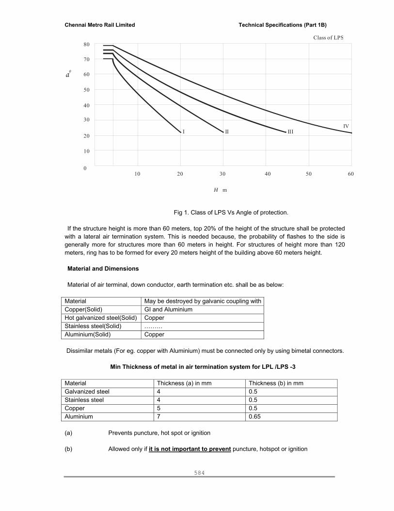
Chennai Metro Rail Limited Technical Specifications (Part 1B)
584
80
70
60
50
40
30
20
10
0605040302010
I II IIIIV
Class of LPS
H m
a0
Fig 1. Class of LPS Vs Angle of protection. If the structure height is more than 60 meters, top 20% of the height of the structure shall be protected with a lateral air termination system. This is needed because, the probability of flashes to the side is generally more for structures more than 60 meters in height. For structures of height more than 120 meters, ring has to be formed for every 20 meters height of the building above 60 meters height. Material and Dimensions Material of air terminal, down conductor, earth termination etc. shall be as below: Material May be destroyed by galvanic coupling with Copper(Solid) GI and Aluminium Hot galvanized steel(Solid) Copper Stainless steel(Solid) ……… Aluminium(Solid) Copper Dissimilar metals (For eg. copper with Aluminium) must be connected only by using bimetal connectors. Min Thickness of metal in air termination system for LPL /LPS -3 Material Thickness (a) in mm Thickness (b) in mm Galvanized steel 4 0.5 Stainless steel 4 0.5 Copper 5 0.5 Aluminium 7 0.65 (a) Prevents puncture, hot spot or ignition (b) Allowed only if it is not important to prevent puncture, hotspot or ignition

Chennai Metro Rail Limited Technical Specifications (Part 1B)
585
Material configuration and Min cross sectional area of air terminal and down conductors
Material Type Min cross sectiarea Remarks
Copper Solid tape 50 sq mm 2mm min thickness
Copper Solid round 50 sq mm 8mm dia
Aluminum Solid tape 70 sq mm 3 mm min thickness
Aluminium Solid round 50 sq mm 8 mm dia
GI Solid tape 50 sq mm 2.5 mm min thickness
Stainless steel Solid tape 50 sq mm 2 mm min thickness
Air terminal holder Conductors shall be securely fixed on the terrace by means of air terminal holder which is fixed on the roof by adhesive of good quality taking care of varying weather conditions. Air conductor holder is an insulator & should be of minimum 50 mm height so that even small amount of water logging on terrace is below the level of conductor holder. Air terminal holder shall not be more than 0.5 m apart for a flat conductor & 1m for round conductor of atleast 8mm diameter & 1.0 meter apart for vertical run Recommended distance between air terminal holders.
Arrangement Recommendeddistance for SOLID TAPE
Recommended distancefor ROUND conductors
Horizontal conductor on horizontal surface. 500 mm 1000 mm Horizontal conductor on vertical surface 500 mm 1000 mm Vertical conductor from Ground to 20m height 1000 mm 1000 mm Vertical conductor above 20m height 500 mm 1000 mm
If antenna, air cooler or any other electrical equipment is present above terrace level, the same have to be protected by using vertical air terminal after calculating the safety or separation distance. The vertical air terminal has to have suitable supports to hold it. Vertical air terminal must be connected to horizontal air terminal by using suitable connectors. At the crossings of the horizontal air terminals, suitable T or Cross connector has to be used for secure connection. Safety or Separation distance. It is must to calculate safety or separation distance in order to avoid flash over to the electrical equipment when the lightning current is passing through the vertical air terminal. Safety/Separation distance (S) in m = ( ki * kc*L) / km Coefficient ki depends on class of LPL/LPS. ki = 0.08 for LPL1, ki = 0.06 for LPL 2, ki = 0.04 for LPL3 and 4.

Chennai Metro Rail Limited Technical Specifications (Part 1B)
586
Coefficient kc depends on no of down conductors: kc = 0.66 for 2 down conductors kc = 0.44 for 3 or more down conductors Value of coefficient km = 1 Value of L is the total distance between the equipment to be protected ( for e.g. Antenna) to the equi-potential bonding bar situated just above the ground. Need for Expansion piece In order to take care the expansion of the metal in summer and contraction of the metal in winter, expansion piece with suitable connectors have to be used at every 20m distance of horizontal air terminal. Joints and Bonds The lightning protective system shall have as few joints. As far as possible, air terminal & down conductor have to be straight. Where it is not possible, it should NOT be bent at 90 degree (right angles) & should have a curved path of 45 degree.. 2.) Down conductor system In order to reduce the probability of damage to electronic/electrical equipment, the down conductors shall be arranged in such a way that from the point of strike to earth, several parallel current paths should exist & length of the current path should be minimum .Down conductors can be installed separately or more wisely it can be part of natural components of the building Examples are steel reinforcement in RCC columns, metal facades, profile rails, metal doors & windows. Down conductors should be installed at each exposed corner of the structure. Value of distance between down conductors as per Class of LPL / LPS. Class of LPL/LPS Typical distance (m)3 15 Test joints: At the connection of the earth terminal, a test joint should be fitted on each down conductor, except in the case of natural down conductors combined with foundation earth electrode. The purpose of test joint is to measure the earth resistance value. Earth Terminations Earth mat is most preferable. Where earth mat is not possible, ring earthing is the next best method. Ring earthing must be 1 meter away from the building and 0.5m below the ground level. The resistance of earthing system shall not exceed 10 ohm as per IEC 62305. Lower earth resistance is still better. For earth termination system, 2 basic types of earth electrode arrangements are applicable. Type A & Type B arrangement. Type A arrangement: comprises of horizontal or vertical earth electrode installed outside the structure to be protected connected to each down conductor. In type A arrangement, the total number of earth electrodes shall not be less than two. Type A arrangement is suitable in places where electronic equipments are not located. Type B arrangement: This type of arrangement comprises either a ring conductor external to the structure to be protected, in contact with the soil for atleast 80% of its total length or a foundation

Chennai Metro Rail Limited Technical Specifications (Part 1B)
587
earth electrode. Such earth electrodes can also be meshed. For structures with extensive electronic systems or with high risk of fire, type B earthing is most preferable method. Corrosion proofing band has to be used wherever down conductor is connected to earth termination system. Bitumen has to be applied at the point of inter-connection. In potentially corrosive areas, Stainless steel must always be used.
References:
IEC62305 – PROTECTION AGAINST LIGHTNING: Part 1: General Principles Part 2: Risk Management Part 3: Protection of structures Part 4: Protection of Electrical & Electronic equipments within structure IS 2309: 1989: Code of practice -Protection of Buildings & allied structures against lightning. IS3043: 1987 : Code of practice for earthing. XXI. GENERAL SPECIFICATION FOR TRANSIENT VOLTAGE SURGE SUPPRESSOR
Part 1 General: 1.1 Description: a. This section describes the materials and installation requirements for Transient Voltage Surge Suppressors (TVSSs, also known as Surge Protective Devices, SPDs) as shown on the drawings and herein specified. 1.2 Related Sections: A. General Electrical Requirements. B. Basic Electrical Materials and Methods. C. Building Wire and Cable. D. Switchboards. E. Panel boards. 1.3 References: A. ANSI/IEEE C62.41-1991 and C62.45-1992. B. National Electrical Manufacturers Association (NEMA LS1). C. National Fire Protection Association (NFPA 70). D. Underwriters' Laboratories (UL 1449 and 1283). 1.4 Submittals: A. For each TVSS device indicated: 1. Product Data Sheets in NEMA LS-1 format - Publication for Low Voltage Surge Protection
Devices (SPDs). 2. Installation and Operating Instructions. 3. UL 1449 Edition 2 Listing Certificate. 4. Let-through voltage test results to ANSI IEEE C62.41 Cat B3 and C3 Combination waves (at
180 deg or without superimposed nominal AC voltage). 5. Independent test report showing product meets manufacturer’s claimed single shot surge rating.

Chennai Metro Rail Limited Technical Specifications (Part 1B)
588
1.5 Warranty: A. The manufacturer shall warrant the TVSS against defects in material and workmanship for
period of 5 years. B. “Acts of Nature” or similar statements typically exclude warranty claims resulting from lightning damage. Since the TVSSs shall be exposed to such threats, any product with such warranties shall not be accepted. Only products with warranties that include replacement due to abnormal over-voltage, excess surge or lightning current and product aging (due to excessive transient activity) shall be accepted.
Part 2 Products: 2.1 General Requirements: A. TVSS shall be listed to UL 1449 Edition 2, CUL and UL 1283. B. TVSS shall protect all modes via L-N, L-G and N-G modes of protection. For Delta power systems L-L and L-G protection modes shall be provided, with the ability to configure L-G to L-L for ungrounded systems. C. Independent certification shall be provided proving that the TVSS meets the required 8/20µs per phase single shot surge rating, without failure of any fusing, disconnects or surge module. Bypassing of any fusing/disconnects for purpose of this test is not acceptable. D. Each mode of the TVSS shall be rated to exceed the life cycle testing of ANSI/IEEE C62.45 by withstand of at least 200 operations at 3kA 8/20µs without failure. E. TVSS shall be listed for application on systems with short circuit fault currents of up to 65 kA IC. Default UL 1449, 10kA IC compliance is not acceptable. F. TVSS shall be capable of withstanding multiple temporary over-voltages per UL 1449 Ed 2 Section 36 “Over voltage Test”, & 37 “Abnormal Over voltage Tests” without failure or need to reset or replace modules/fuses. G. Multiple MOVs per mode shall be used, each with individual thermal disconnect devices bonded directly to the MOV substrate for rapid and automatic disconnection of any MOV exhibiting excessive temperature. The following are not acceptable: 1. TVSSs without thermal fuses/disconnects.
2. TVSSs with shared thermal devices that disconnect more than one MOV.
H. For safety, TVSS shall have a maximum continuous operating voltage (MCOV) of at least:
Power System MCOV (L-N) Single phase (2W+G) 220-240V 310V Three phase (4W+G) 277/480 WYE 310V
I. Enclosure shall: 1. Feature all metal NEMA 4 enclosure suitable for outdoor usage. 2. TVSS depth shall be less than 3.5” to allow mounting within wall cavity with optional flush mount kit. 3. TVSS width shall be less than 5” to enable installation between adjacent electrical enclosures. 2.2 TVSS shall be installed at distribution panels and/or as shown on drawings A. TVSS shall incorporate 100kA 8/20µs MOV protection per phase.

Chennai Metro Rail Limited Technical Specifications (Part 1B)
589
B. The status of the each individual mode of protection shall be separately monitored and displayed via status LED. A reduction in capacity below the manufacturer’s predetermined level shall operate a Form C alarm contact (dry contact) and Audible Alarm. C. The following clamping voltages (L-N) shall not be exceeded by the TVSS:
Impulse standard Voltage rating (no AC applied) 120/240V
120/208V 220/380V 277/480V 347/600V
D. At least 25db @ 100 kHz EMI/RFI shall be provided L-N (L-L for Delta power systems). To avoid unsafe ground leakage current, no filtering shall connect to ground.
Part 3 Executions: 3.1 Installation: A. At locations indicated on drawing(s), install TVSS in full accordance with manufacturer’s written instructions and comply with all applicable codes. B. Units shall be installed with minimal connection lead length to dedicated 30A breakers.
XXII. TECHNICAL SPECIFICATION FOR AIRCRAFT WARNING SYSTEM The aircraft warning system shall consists of dual-head non-flickering aircraft warning lights (neon type) located at the highest point of the building. The warning lights shall be of cast aluminium body with twin lamp head, red prismatio glass dome with smooth exterior, weather-proof construction necessary gasket & cable entry arrangement.
The lamp shall be wired with PVC insulated and sheathed armoured copper cable with copper earth wire.
The output lumens of the each Aviation lamp shall be minimum 1600 cd in flashing Red as required by the INTERNATIONAL CIVIL AVIATION ORGANISATION (ICAO).
Testing The entire installation shall be tested in accordance with the Indian Standard Code and the following ground resistance values shall be recorded.
i) Earthing Terminal (each) ii) Earthing system (as a whole) The wiring for each aircraft warning lights shall be measured as one point for payment and shall include:
i) Cost of 3C 2.5 mm armoured copper cable laid from nearest lift machine room, and necessary fixing accessories

Chennai Metro Rail Limited Technical Specifications (Part 1B)
590
ii) Weather proof Junction box with cover, painting control switch iii) Photo cell controller with necessary connected accessories and interconnections. XXIII. PROVISION TO BE MADE BY ELECTRICAL CONTRACTOR FOR BAS/IBMS INTERFACE
The following shall be incorporated in the electrical contractors scope for interfacing with BAS / IBMS :
1. All the microprocessor based system (System for measuring Electrical Quantities) should have a mod bus port for exchanging data with the IBMS with RS 485. 2. All MPCC Incomers shall have RS 485 OUTPUT for control the breaker and MEASURING ALL Electrical parameters like Current, Frequency, Power. Also the breakers shall be provided with ON/OFF/TRIP status through Micro-Processor RS 485 output.
3. All the incomer and outgoing breakers shall have ON / OFF / TRIP potential free contact IBMS integration. All the wiring to be connected and terminated in the cable alley of Main Panel
4. All the meters shall have RS 485 MODBUS communication port for IBMS integration. All meters are linked and terminated in cable alley for BMS integration
5. DG PLC should communicate the status & parameter of each DG set by MODBUS or backnet protocol
SPECIAL CONDITIONS TO THE CONTRACTOR
For Serial communication links between microprocessor based instruments/ microprocessor controlled equipment and the IBMS, the contractor supplying the instrument/ equipment is to provide all instrument/ equipment end hardware/ software. The contractor supplying the equipment is also to release the protocols (ModBus RTU shall be used) . The IBMS contractor provides the IBMS end hardware software to implement the serial communication using the ModBus RTU protocol. The necessary cabling between the instrument/ equipment and the IBMS shall be performed by the IBMS contractor. The IBMS contractor shall build the software and graphic displays to make this data available at the IBMS operator station. Implementation of the serial link shall be a joint responsibility between the IBMS and instrument/ equipment contractor and hence these contractor’s shall work in co-ordination and co-operation to implement the serial communication.”
All major equipments forming part of the Electrical Agency services shall be duly tested at the place of manufacture / assembly before despatch. The manufacturer shall have stringent quality control for the pre-delivery installation schedules and the product, when it leaves the manufacturing /
Chennai Metro Rail Limited Technical Specifications (Part 1B)
591
assembly plant, be proved to be capable of performing to the specified criteria. The Client / Architects reserve the right to be present at the time of testing of such major equipment at the manufacturer’s factory / assembly shops. For this purpose, the successful agency shall submit a detailed schedule of manufacturing and testing of equipment giving details of the expected dates of testing, location, duration of testing as well as nature of testing for the concurrence of the Client / Architects. The tenderers shall note that they should include in the quoted rates the cost of travel and accommodation for a maximum of three persons representing Client / Architects for being present at the place of testing.
All micro processor based MCCB/ACB shall have RS 485 modbus output for monitoring on/off /trip status and current consumption status.
XXIV. TECHNICAL SPECIFICATION FOR INSTALLATION 1.0 GENERAL: The electrical installation shall be complete in all respects and any item not included in the specification but essential for proper installation and functioning of the electrical system shall deemed to be included in the scope of the specification whether specifically mentioned or not. All equipment shall be shifted from the place of storage to erection site by the Contractor and shall be thoroughly cleaned of packing materials, scales, rust, oil, grease etc prior to commencement of the installation work. All equipments shall be checked physically for the completeness of all devices before taking up installation. After installation all unused cable/conduit entries shall be efficiently sealed. All equipments and accessories shall be installed strictly in accordance with the manufacturer's instructions/ drawings. Equipments supplied in sections or dismantled condition shall be reassembled at site with all associated accessories as per the manufacturer’s instructions. All accessories required like hardware, junction box glands, transparent polycarbonate sheets etc. shall be supplied by Contractor. A Model installation shall be made for approval by the Client, before proceeding with the final installation. The system under the scope of work shall conform to the latest codes and standards as amended in the respective technical specification and schedule of works. Nothing in the specification shall be construed to relieved the successful tenderer’s from the responsibilities where specifically mentioned in the tender or not. The following standards as amended shall also to be covered. Installation: All electrical works shall comply with following standards: Indian Electricity Rules – 1956. Andra Pradesh State Code of Practice for Installation. Local Electrical Inspectorate Guidelines on electrical installation. IS 10028 Code of Practice for installation of transformers IS 732 Code of Practice for electrical wiring installation. IS 5216 Guide for safety procedures & practices in electrical work. IS 10118 Code of practice for section, installation and maintenance of LT Switch, switch gears & control gears.

Chennai Metro Rail Limited Technical Specifications (Part 1B)
592
IS:12063 : Degree of Protection provided by enclosures IS:8623 : Specification for Factory Built Assemblies for Voltages upto 1000V AC &1200V DC IS:1646 : Code of Practice for Fire Safety of Buildings (General) Electrical Installation IS:3043 : Code of Practice for Earthing Workmanship shall be highest standard and /quality. EQUIPMENT AND MATERIALS All equipment and materials supplied by the Contractor shall be suitable in all respects, for the type of environment specified. All equipment and materials supplied shall be to the approval of the Contractor regarding Quality, Conformity to the specification and standards and suitability for the specified site conditions. STORAGE AND CARE PRIOR TO ERECTION The Contractor shall be fully responsible for the safe storage and care of equipment and materials. The Contractor shall be responsible for care and maintenance of all the Electrical equipments, whether supplied /erected by him, after the installation is completed and until the final certificate of acceptance of Electrical Installation is signed. Equipments: All equipments shall be installed strictly in accordance with manufacturer’s instructions / drawings. All HT and LT panels shall be erected on suitable base frame. Distribution boards shall be erected on wall such that height of top of board will be at 1800 mm. Switch boards / MCCs shall be erected with a front clearance of not less than 1000 mm and a clearance of not less than 750 mm at the rear clearance of there are cable entries or with a rear clearance of less than 200 mm in case there are no cable entries or attachments at the rear. TRANSFORMER Transformer shall be handled and erected as per relevant code of practice and as per manufacturer’s drawings and instructions. After erection of the transformer on the plinth, suitable wheel stopper shall be fixed. MV PANEL MV Panels shall be erected as per relevant code of practice for Installation. After erection of all the panels, necessary inter panel wiring shall be done. All panel fixing bolts and busbar bolts shall be tightened using torque wrench. Necessary front / rear / side clearance shall be maintained as per statutory regulations. All unused holes shall be blocked. LV PANELS All busbar joints shall be tightened using torque wrench and all shipping sections shall be properly bolted together.

Chennai Metro Rail Limited Technical Specifications (Part 1B)
593
After completion of cable terminations, all unused cable entry holes are to be covered to make the panel vermin proof. CABLES: Cable shall be taken on trays fixed on ceiling / wall. All cable shall be provided with punched aluminium identification tags at every 100 m interval at both ends. EARTHING: Earthing shall be as per IS 3043. All electrical power items shall be earthed by two separate and distinct earth connections from main earth bus. General grounding shall be done to achieve earth resistance of less than 1 Ohms. Special grounding shall be done to achieve earth resistance of less than 0.5 Ohms. Earth electrodes shall be erected 1500 mm away from the building edge and minimum spacing between the electrodes shall be 3000 mm. Earth electrodes – 38 mm Dia GI pipe 3 m long with 600 x 600 x 3mm Copper (or) 600 x 600 x 6mm GI plate earthing. TYPE OF WIRING: Substation building, electrical rooms : Open wiring using GI conduit General office & Toilet areas : Open conduit wiring Using GI conduit above false Ceiling
& Medium class PVC conduit for concealed wiring below false ceiling / slab
LIGHTNING PROTECTION: Lightning protection shall be as per IS 2309. Size of lightning shall be as per IS 2309. MCB DISTRIBUTION BOARDS: All DBs shall be phase segregated type as required by the Electrical Inspectorate. All DBs shall be powder coated, double door type. All MCB breaking capacity shall be 10 KA. DISTRIBUTION BOARDS: Distribution boards shall be erected on wall with concealed system inside the premises areas and open system in all electrical rooms. Erection cost shall be inclusive of all fixing brackets, hardware etc. Necessary clearance shall be maintained in front of the Distribution Boards for operation and maintenance LIGHT FITTINGS: All equipment shall be thoroughly cleaned of packing materials, scales, rust, oil, grease etc prior to commencement of the installation work. All equipments shall be checked physically for the completeness of all devices before taking up installation. All equipments and accessories shall be installed strictly in accordance with the manufacturer's instructions/ drawings. Equipments supplied in sections or dismantled condition shall be reassembled at site with all associated accessories as per the manufacture’s instructions. All accessories required like hardware, junction box glands, hylum sheets etc to be supplied by contractor. 3.0 LIGHTING: The Installation charges shall include all fixing accessories like screws, anchor fasteners, clamps,

Chennai Metro Rail Limited Technical Specifications (Part 1B)
594
cleats, down rods, ball socket, earthing, cabling and wiring works etc. The AC lighting shall operate at 230V, 1 Phase, the supply being taken from the lighting DB. 3.1 Indoor Lighting: Open conduit system using GI conduits above false ceiling and concealed conduit system below false ceiling, shall be adopted, as required. In all Service building, Electrical room, AHU room, open conduit wiring using GI conduit shall be adopted and in all Staircase area concealed conduit wiring using medium class PVC conduit shall be adopted and general office area & Toilet area open conduit wiring using GI conduit shall be adopted above the false ceiling area & concealed conduit wiring using medium class PVC conduit shall be adopted below the false ceiling. Conduit pipes, whenever necessary, shall be fixed by 16 SWG saddles with spacers, in an approved manner at intervals of every 600mm or minimum as required. Saddles shall be fixed on either side of couplers, bends or similar fittings at a distance of 300mm from the centre of such fittings. The cost of saddles, clamp etc., shall be deemed to have been included in the installation charges. Switches of lighting circuits shall be mounted at 1200mm above finished floor level. Where fittings are suspended, ball and socket type suspension units shall be used. Earth continuity shall be maintained throughout the entire installation. 4.0 CABLING: No cable shall be laid along side a water main. Spacing equal to the diameter of the cable shall be maintained between adjacent power cables. Selection of cable drums for each run shall be so planned as to minimise straight through joints. In each cable run, extra length shall be kept at a suitable point to enable one straight through joint to be made, should the cable develop a fault at a later date. All due care shall be taken during unreeling, laying and termination of cable, to avoid damage due to twist, kink and sharp bends, etc. Wherever cables pass through floor or through wall openings, it shall be taken through Al. pipe sleeves. The open ends of the sleeves shall be sealed by cold setting compound after cables are pulled through them to prevent entry of vermin and ingress of water. While laying cable, cable rollers shall be used at an interval of 2.0 Mts. The cables shall be pushed over the rollers by a gang of people positioned between rollers. The cable shall not be pulled from the end without intermediate pushing arrangement. The bending radius shall not be less than that specified by the manufacturer. Each cable shall be provided with an identification tags at entrance and exit from any equipment. The tag shall be of aluminium, with the number punched on it and securely attached to the cable by not less than two turns of GI wire. Single core cables shall be laid in trefoil formation and clamped with trefoil clamps at every 600mm intervals. All multi core cables shall be secured to the cable tray by clamps at every 600mm intervals.

Chennai Metro Rail Limited Technical Specifications (Part 1B)
595
Cables from overhead cable trays to the equipment shall be taken in prefabricated GI cable tray with cover/GI Pipe sleeves. 4.1 Direct In Ground: Power and control cables laid directly in ground shall be laid generally conforming to the requirements of code of practice IS: 1255. Generally cables shall be taken at a depth of 750mm from finished ground level and shall be provided at least 150mm sand cushioning both at top and bottom and brick protection. Control cables shall be laid touching each other without any horizontal spacing. However the distance of the control cable from the nearest power cables shall be 150mm. Power and control cables shall be laid separately in groups. Wherever power or control cables crosses fire hydrant or any other pipelines of earth flat the cable shall be taken 300mm below the pipeline. After laying of cables, the trench shall be back filled with good excavated soil and well rammed in successive layer not less than 300 mm depth. The width of the trench shall be in accordance with the number of cables to be laid and in no case shall be less than 300 mm. Cast Iron cable route markers (Cast Iron) shall be provided at every 100M intervals and at bends. 4.2 Laid On Cable Tray: The cables inside the plant buildings shall be taken on trays fixed on the ceiling. Cable trays shall be of prefabricated GI with necessary accessories like Tees/Bends etc. and shall be supplied along with fasteners. Cable trays shall be hot dip galvanised as per IS: 2629. The top tray shall be provided with cover if required. Galvanised angle supports for trays shall be welded to insert plates. The support shall be spaced at 1500 mm centres. Cables inside the premises shall be taken on cable trays running on ceiling. Vertical spacing between cable racks/trays shall be minimum 300 mm. Different voltage grade cables shall be laid in separate trays when trays are arranged in tiers. Contractor shall include in their scope of supply all Insert plates, Anchor fasteners, etc. required for the laying of cable trays. Fastening on walls/RCC columns shall be by Anchor Fasteners only. 4.3 Cable Termination: Termination and jointing of LT XLPE /PVC armoured cables shall be by means of compression method using double compression type glands and compression type lugs. Control cables are to be terminated by means of terminal lugs; the same shall be of tinned copper compression type. Whenever aluminium cables are to be terminated on copper busbar or vice versa, necessary bimetallic washers shall be provided. All control cables shall be terminated using pin type lugs. Cable tails shall be sufficiently long to run all cores to the farther most terminal and then back to the appropriate point of connection.
Chennai Metro Rail Limited Technical Specifications (Part 1B)
596
All cable glands shall be properly earthed using suitable earthing clips and connected to main earth bus. Wherever required, extension boxes shall be provided. Cable tails shall be sufficiently long to run all cores to the farther most terminal and then back to the appropriate point of connection. HT cables shall be terminated / jointed by means of cold setting epoxy based cast resin jointing kits
as heat shrinkable type or cold setting kit. 5.0 EQUIPMENT ERECTION: Circuit breakers, power transformers, and switch boards shall be handled and erected as per the relevant codes of practice and manufacturer's drawings and instruction manuals. HT & LT Panels shall be erected on suitable base frame. The details of foundation pockets required for grouting the frame shall be furnished by the Electrical Contractor. For power transformer drying out and oil filling as required, after checking and testing the dielectric strength shall be carried out by the contractor. Oil filtration shall be carried out by the contractor. 6.0 EARTHING: The overall earth resistance of the system shall not be greater than one (1) ohm. All panels, Distribution boards shall be provided with two (2) independent earth connections of adequate capacity to discharge the max. Earth fault current. The size of Earth bus and earth electrode shall be as per specification and as per schedule. Minimum spacing between earth electrodes shall be provided as per IS: 3043. Water stops shall be provided wherever earthing conductor enters the building from outside, below grade level. 7.0 INSPECTION: After completion of erection/installation, each piece of equipment shall be thoroughly inspected in the presence of Contractor for correctness and completion of erection and operation. 8.0 MISCELLANEOUS ITEMS: The contractor shall supply and install the safety devices as required by the statutory authorities but not limited to the following, for each Substations a) Danger boards for HT and LT Panels & Transformers b) Rubber mats for switchgear panels, power distribution boards etc.

Chennai Metro Rail Limited Technical Specifications (Part 1B)
597
c) Rubber gloves, first aid charts, first aid box etc. d) Fire extinguishers and Fire Buckets e) Discharge rods.
XXV. TECHNICAL SPECIFICATION FOR TESTING AND COMMISSIONING 1.0 GENERAL: The testing and commissioning for all electrical equipment at site shall be according to the procedures laid down below: All electrical equipment shall be Installed, tested and commissioned in accordance with the latest relevant Standards and Codes of Practices published by Indian Standards Institution wherever applicable and stipulations made in relevant general specifications. The testing of all electrical equipment as well as the system as a whole shall be carried out to ensure that the equipment and its components are in satisfactory condition and will successfully perform its functional operation. The inspection of the equipment shall be carried out to ensure that all materials, workmanship and installation conform to the accepted design, engineering and construction standards, as well as accepted codes of practice and stipulations made in the relevant general specifications. All tests shall be carried out by the Contractor using his own instruments, testing equipment as well as qualified testing personnel. The results of all tests shall be conforming to the specification requirements as well as any specific performance data guaranteed during finalisation of the contract. 2.0 PREPARATION OF THE ELECTRICAL SYSTEM FOR COMMISSIONING: After completion of the installation at site and for the preparation of Electrical system commissioning, the contractor shall carry out check and testing of all equipment and installation in accordance with the agreed standards, codes of Practice of Indian Standards Institution and specific instruction furnished by the particular equipment suppliers. Checking required to be made on all equipment and installations at site shall comprise, but not be limited, to the following: The following checks shall be made on all equipment and installations at site: I. Physical inspection for removal of any foreign bodies, external defects, such as damaged
insulators, loose connecting bolts, loose foundation bolts etc. ii. Check for grease, insulating/lubricating oil leakage and its proper quantity. iii. Check for the free movement of mechanism for the circuit breakers, rotating part of the
rotating machines and devices. iv. Check for tightness of all-cable, busbars at termination/ joints ends as well as earth
connections in the main earthing network. v. Check for clearance of live busbars and connectors from the metal enclosure. vi. Check for proper alignment of all draw out device like draw out type circuit-breakers.

Chennai Metro Rail Limited Technical Specifications (Part 1B)
598
vii. Continuity check in case of power cables. viii. Checking of all mechanical and electrical interlocks including tripping of breakers using
manual operation of relay. ix. Checking of alarm and annunciation circuits by manual actuation of relevant relays. x. Check and calibrate devices requiring field adjustment/ calibration like adjustment of relay
settings etc. xi. Check proper connection to earth network of all noncurrent carrying parts of the equipment
and installation. xii. Test reports for all meters are to be furnished. The tests that shall be carried out on the equipment shall include but not be limited to the above. 2.1 HT Breaker: The following tests shall be carried out in accordance with IS: 13118. I. Mechanical operation tests. ii. Power frequency HV test. iii. Insulation resistance test. iv. Functional tests on control circuits. v. Relay operation tests by primary, secondary injection method. vi. Checking of settings of all relays/releases as per single line diagram/specification. 2.2 Power Transformers: The following tests shall be carried out in accordance with IS: 2026. I. Measurement of winding resistance at all taps. ii. Measurement of voltage ratio on all taps. iii. Vector group check. iv. Measurement of impedance voltage / Short Circuit impedance (At principal tapping and load
loss). v. Measurement of no load loss and current. vi. Measurement of insulation resistance. vii. Power frequency withstand test. viii. Operational tests to know the correct functioning of all devices associated with the transformer. 2.3 Low Voltage Switchgear (upto 1000V AC or 1200V DC): I. Insulation resistance test with 1000V megger for main circuits. The minimum value of
insulation resistance shall be 1 Meg ohm. ii. Insulation resistance test with 500V megger for control, metering and relaying circuits. The
minimum value of insulation resistance shall be one Meg ohm. iii. Relay operation test by primary & secondary injection method. iv. Functional tests of control circuit. v. Checking of settings of all relay/releases as per single line diagram/specification. vi. ON/OFF operation of breakers both manually and electrically in "Test" as well as "Service"
positions. 2.4 Cables: I. Insulation resistance test with 2,500 V megger for high voltage power cables rated above 1.1
KV grade and 1,000 V megger for cables rated up to 1.1 KV grade. ii. All cables of 1.1 KV and all H.V. cables shall be subjected to high voltage test after joining
and terminating but before commissioning as per relevant standards. iii. In each test, the metallic sheath/screen/armour should be connected to earth. iv. Continuity of all the cores, correctness of all connections as per wiring diagram, correctness
of polarity and phasing of power cables and proper earth connection of cable glands, cable boxes, armour and metallic sheath, shall be checked.

Chennai Metro Rail Limited Technical Specifications (Part 1B)
599
2.5 Earthing System: I. Tests to ensure continuity of all earth connections. ii. Tests to obtain earth resistance of the complete network by using earth tester. The test
values obtained shall be within the limits. All documents / records regarding test data, oscillographs and other measured values of important parameters finalised after site adjustment shall be handed over to the Owner in the form of test
NAME OF WORK: SUPPLY, INSTALLATION, TESTING AND
COMMISIONING OF 1 Nos 1500KVA & 1 No 750 DG SET WITH CONNECTED WORKS
INDEX
Sl.No Description Page No.
I. Technical Specification for Diesel Generator Sets
II. Technical Specification for Battery charger
III. Acoustic Enclosure
IV. Automatic Mains Failure Control Panel & Auto Synchronizing And Load Sharing Panel
V. Technical Specification For Relays
VI. Specification For Cable Laying
Chennai Metro Rail Limited Technical Specifications (Part 1B)
600
VII. Technical Specification For Earthing
VIII. Technical Specification For Installation
IX. Technical Specification For Aviation Warning Lamp.
X. Provision To Be Made By DG Contractor For BAS/IBMS Interface
XI. Technical Specification For Testing And Commissioning
XII. Technical Data Sheet for DG Set
XIII. Special conditions / instruction
I) TECHNICAL SPECIFICATIONS FOR DIESEL GENERATOR SETS .1.0 Scope of Work: 1.1.1 The Engine alternator shall be suitable to generate rated KVA at the site conditions. 1.1.2 The Engine and the alternator shall be mounted on a common base frame through a suitable
direct flexible coupling. 1.1.3 Site conditions: Generating sets to be installed will be required to operate under the following climatic
conditions: a. Altitude – Less than 100 mtrs. From MSL b. Max. temp. - 50 deg C c. Max RH - 95 % 1.1.4 Scope of Work and Exclusions :
The scope of the work shall include but not be limited to the supply, installation, testing and commissioning the following items.

Chennai Metro Rail Limited Technical Specifications (Part 1B)
601
1.1.5 The supplier shall study the requirements stipulated in the specifications and also to suit the site conditions and offer a complete system with guaranteed performance under the severest operating conditions specified.
1.1.6 2 Nos. Diesel Generator sets of 1500 KVA & 1 No. of 750KVA capacity of continuous rating at
0.8 PF lag at site conditions developing 415 V, 50 Hz, three phase and 4 wire AC supply, along with AMF control, Auto-Synchronising with load sharing panel, Fault monitoring devices, heavy duty batteries including cabling along with all accessories and components.
1.1.7 Exhaust pipes and Silencers with thermal insulation, as required. 1.1.8 Exhaust pipe shall conform to the statutory regulations by Environment Authorities. 1.1.9 The height of the exhaust pipe shall be 30 Mtrs. The exhaust pipe shall be supported by stack
and shall include necessary holding down bolt arrangements. 1.1.10 Heavy duty anti-vibration spring type mounts (AVM) suitable for the DG sets as per
manufacturers’ recommendations. 1.1.11 Fuel pipe lines from day tank/reserve tank with necessary pumps, valves etc. Day tank /
Reserve fuel tank of 4 nos. each having a capacity of 990 Litres shall be installed on a suitable raised pedestal. The tank also supplied with secondary containment tank.
1.1.12 Necessary Bus ducting work between i) DG set to control panel and ii) Control panel to Auto
Synchronising/Load Sharing panel
1.1.13 Acoustic enclosure: 1.1.14 Minor building work including cutting and making good, including clamps, supports, grouting
etc. 1.1.15 The installation shall conform to norms of CPCB and other statutory bodies.
1.1.16 Design and Preparation of related schematic and GA drawings for DG installation, Exhaust piping & Fuel piping, acoustic enclosure etc. obtaining approval, from Engineer- in Charge.
1.1.17 Testing and commissioning of the installation are including arranging for Inspection and
obtaining clearance from Acceptance testing authorities of Engineer- in Charge. Consumables and artificial load for testing shall be in the scope of the Contractor.
1.1.18 Water line with necessary coupling valves, taps etc. for engine driven radiator cooling. Coolant
inhibitor shall be provided to prevent corrosion of radiator tubes. 1.1.19 The foundations for fuel transfer pump, day and reserve tanks and DG sets with acoustic
enclosure shall be carried out by the Principal civil contractor. However, detailed design drawings shall be prepared and submitted by the DG contractor based on which the foundations will be constructed by the civil contractor after approval by Electrical & Civil Engineer- In Charge.
1.1.20 The DG contractor shall however supply necessary bolts, insert plates, connectors etc., as
may be required in–time and co-ordinate with the civil contractor during construction.

Chennai Metro Rail Limited Technical Specifications (Part 1B)
602
1.1.21 In the attached site plan and building drawings, space allocation has been shown for the D.G sets as well as all accessories. The contractor shall ensure that all equipments are accommodated within the space earmarked.
1.1.22 The installation shall conform to emission limits and noise limits as laid down in the
environment (protection) Rules 1986 amended up to date. 1.1.23 The type approval and certificate of conformity of production for the DG set model with
enclosure which will be supplied shall be obtained in the current year from authorised agencies for certification as per Environment (protection) rules 1986 amended upto date.
1.1.24 The supplier of the DG set shall affix a conformance label on the DG set with the following
information .The label shall be durable and legible and shall be affixed on a part necessary for normal operation and not requiring replacement during DG sets life
a. Name & address of the supplier. b. Statement “ this product conforms to Environment ( protection ) rules 1986 “ c. Noise limit viz 75dB (A) at 1m. d. Type approval certificate number (both emission and noise) e. Date of manufacture of DG set. 1.2.0 Diesel Engine 1.2.1 Codes and Standards for Diesel Engine The Diesel Generator Set with all its components shall comply with BS: 5514 or ISO 3046 standard 1.2.2 The diesel engine shall be VEE type or in line type single acting direct injection type with turbo
charged and after cooled. 1.2.3 The speed of the diesel engine shall not exceed 1500 RPM. 1.2.4 The engine offered shall be a four (4) stroke engine designed for operating on high sulphur
diesel. 1.2.5 The engine shall be capable of withstanding without any damage, a 10% over load for a
period of one hour in every twelve hours of operation. 1.2.6 The diesel engine shall consist of the following: a. Air Inlet System i. Air intake filters (dry type) with service indicators. ii. Turbo charger iii. After cooler b. Exhaust System i. Exhaust elbow dry ii. Exhaust manifold dry

Chennai Metro Rail Limited Technical Specifications (Part 1B)
603
iii. Stainless steel Exhaust flexible fittings iv. Silencers – Residential c. Flywheel Housing i. Flywheel ii. Flexible coupling/Flex plate iii. Coupling guard iv. Flywheel housing d. Cooling System i. Engine driven water pump of centrifugal type ii. Engine driven radiator with hoses, fan, fan drive and fan guard iii. Engine Thermostats iv. Coolant inhibitor e. Fuel System i. Injectors ii. Fuel lines iii. Fuel filter iv. Fuel oil pump (engine driven) v. 990 litres day tank & reserve spare tank with level indicator, lid, fuel inlet and outlet, air vent,
drain plug, inlet arrangement for direct filling, fuel hoses of adequate length.
vi. The 990 ltr Day Tank and Reserve Tank (Size 900mm Width x 900mm Depth x 1500mm Height) shall be made of 3mm thick M.S Sheet enclosure with necessary painting etc., with Outdoor weather proof arrangement for day / reserve tank and necessary fixing arrangements with Fuel pipe lines from day/reserve tank.
f. Lube oil System Lube oil cooler Oil filling point with dipstick Oil pump gear type Oil pan Crankcase breather Lube oil filters Lube oil priming pump (if required) g. Electrical starting and charging system Heavy duty batteries (4Nos, 12V, DC with minimum capacity of 200AH with 27 plate and leads and terminals) for 1500 KVA & 750KVA Starting motor Charging alternator Electronic Engine control panel h. Engine control panel (vendor to furnish details of DG instrument – controller provided
by them for 1500 kVA sets & 750 set, which shall cover the following & more)

Chennai Metro Rail Limited Technical Specifications (Part 1B)
604
Start and stop switch Emergency stop Oil pressure indication Water temperature indication Battery voltage indication Hour meter RPM indicator i. Governing System Digital governing – for 1500 kVA & 750KVA j. Safety system Safety control against a) low lube oil pressure b) High water temperature c) Over speed etc… k. Others Anti vibration mounting as per manufacturer’s recommendation for the DG set l. General The engine control panel should give indication for faults related to engine. m. Factory tests:
The Contractor shall submit certificates of factory tests conducted on ENGINE of same capacity.
1.3. A.C. Generator 1.3.1 The equipment offered shall conform to the relevant codes/standards as amended upto date
and relevant local bye-laws. 1.3.2 The generator shall be of Brushless type rated for a continuous output of 1500KVA and
750KVA at 0.8 PF (lag) at site conditions at 415 volts, 3 phase, 50 Hz suitable for 4 wire system exclusive of power requirement of auxiliaries.
1.3.3 The Generator shall be of Double or single bearing type. The degree of protection shall be IP-
23. 1.3.4 The alternator stator windings shall be of class ‘H’ insulation. The windings and overhangs
shall be braced to withstand the temperature and short-circuit forces. 1.3.5 The field windings shall have Class ‘H’ insulation.
Chennai Metro Rail Limited Technical Specifications (Part 1B)
605
1.3.6 The alternator shall be provided with necessary lifting hooks. 1.3.7 Overload
The alternator shall also be capable of withstanding without any damage a 10% overload for a period of one hour after twelve hours of operation.
1.3.8 Space Heaters
Suitably rated anti-condensation space heaters shall be installed within the generator.
Location and maximum surface temperature of the heaters shall be such that no damage is caused to the insulation.
1.3.9 The leads of the space heater should be brought to a separate terminal box. Heaters shall be
suitable for single phase 240 V AC. 50 Hz with thermostat and Auto Cut off feature. 1.3.10 The heaters shall be ON only when the set is OFF. 1.3.11 Winding temperature sensors Suitable No. of RTD shall be provided in each phase for temperature monitoring. 1.3.12 Bearing temperature sensors: BTD (Bearing Temperature Detector) shall be provided for each bearing for monitoring the
temperature (1 no. BTD per bearing). 1.3.13 Excitation System The generator shall be provided with a PMG excitation system capable of supplying the
excitation current of the generator for any change in output between no load and full load at any power factor between 0.5 and unity, lead and lag for an engine speed variation of 4%.
1.3.14 Automatic Voltage Regulator (AVR) The automatic solid state voltage regulator shall be provided with the following features as
minimum a. -Under frequency protection b. -Short-circuit protection c. -Over voltage protection d. -Over excitation protection 1.3.15 Terminal Box: Terminal box shall be fabricated of cold rolled sheet steel and shall be complete with
accessible cover. 1.3.16 The bus bar material used in the terminal shall be electrolytic copper sleeved with flame-
retardant insulating material. 1.3.17 Terminal bus bars shall be supported on fibreglass insulators at regular intervals to withstand
short-circuit forces arising out of specified fault level. 1.3.18 Rating Plate A rating plate shall be fixed on the generator frame and shall give the following information: a. Manufacturer’s Name b. Serial Number, Type and frame reference. c. Rated output in KVA/MVA and KW/MW.

Chennai Metro Rail Limited Technical Specifications (Part 1B)
606
d. Rated power factor e. Rated frequency f. Rated voltage g. Current in amperes at rated output h. Rated speed in Rev/Min i. Class of insulation 1.3.19 TESTS on Alternator and assembled DG Set The Contractor shall submit certificates of Type tests conducted on generator of same
capacity 1.3.20 The following routine tests shall be carried out on one of the assembled DG sets at the
manufacturers’ works as per relevant IS (amended upto date) in the presence of Engineer- In Charge.
a. Measurement of resistance. b. Insulation resistance test. c. Phase sequence test. d. Regulation test. e. 50% load test for 30 minutes. f 75% load test for 30 minutes. g 100% load test for 30 minutes. h 110% load test for 30 minutes. 1.3.21 Tools
Standard tools shall be supplied for field inspection and maintenance of the generator. 1.4.0 AMF CONTROL PANELS 1.4.1 GENERAL Free standing floor mounting indoor type cubicle D.G. control panel, fabricated out of steel
sheet with hinged doors in the front and bolted type doors on the rear side, dust and vermin proof totally enclosed.
1.4.2 STANDARDS The equipment covered by this specification shall, unless otherwise stated, be designed,
constructed and tested in accordance with the requirements of the latest revision of Indian standards.
1.4.3 CONSTRUCTION The control Panel shall be fabricated out of sheet steel and shall be compartmentalised,
modular type, and suitable for Indoor installation. 1.4.4 The control Panel shall be dust and vermin proof and the enclosure shall provide a degree
of protection of not less than IP54. 1.4.5 Control Panel shall be fabricated out of structural sections. 1.4.6 The frames shall be enclosed with steel sheet of not less than 14 swg where load bearing
like instrument fixing, breaker fixing etc… are required and 16 swg for rest of the sections as minimum thickness with rubber gaskets at all joints.
1.4.7 All bolts, nuts and other fasteners shall be cadmium plated only.

Chennai Metro Rail Limited Technical Specifications (Part 1B)
607
1.4.8 The draw out module shall consist of `plug in' contacts for power connection and sliding contacts for secondary control connection. The power contact shall be spring loaded silver- plated electrolytic copper.
1.4.9 Each draw out module shall have three positions viz. service, test and isolated position with
necessary position interlocks. 1.4.10 All bolted joints shall be provided with toothed/spring washers to ensure good continuity. 1.4.11 The maximum operating height of the devices on the panel shall not exceed 1800 mm and
minimum-operating height shall not be less than 300 mm. 1.4.12 Control Panel shall be supplied along with base channel fabricated out of 3.25 mm thick
steel sheet, painted black. 1.4.13 Space heaters, with thermostat suitable for 230 V, 1 Ph supply along with a switch / fuse
shall be provided in each panel. 1.4.14 A general purpose control switch shall be provided for selection of "Auto" & "Manual".
The switch shall be provided with engraving plate in the front with "Auto", Manual" & "Off" inscription.
1.4.15 Digital type meter shall be provided for measuring the parameters like current, voltage,
kilowatts, KVA, KWH,PF, frequency etc. 1.4.16 The instruments shall have an accuracy class of 1.0. 1.4.17 Panel shall be supplied with all internal wiring comprising of PVC insulated 1.1 KV grade,
multi-stranded flexible copper conductor of 1.5 Sq.mm cross section. 1.4.18 Wiring associated with a particular phase shall be the colour of that phase viz. Red, Yellow
or Blue. Wiring associated with earthing shall be with green colour insulation and for neutral with black colour insulation.
1.4.19 Wiring shall be neatly laid and run on insulated cleats of limited compression type insulated
straps. 1.4.20 All cables shall have crimped terminations and shall be identified by means of glossy plastic
ferrules at both ends, showing the wire number as indicated in the schematic diagrams. The ferrules shall be indelibly marked.
1.4.21 Wiring to items mounted on hinged doors or wiring that is subject to movement, shall run in
helical binding. The binding shall be securely anchored at both ends and sufficient slack provided to prevent any strain being imposed on wiring.
1.4.22 All the metal parts of all equipment supplied with in the panel (including doors and gland
plates) other than those forming part of all electric circuit, shall be connected by means of two independent earth conductors to continuous copper earth bar of size 40 x 6 mm (minimum) running along the full length of the panel.
1.4.23 The panel shall be provided with two brass earthing stud terminals, with suitable nuts,
washers etc. for connection to ground bus.

Chennai Metro Rail Limited Technical Specifications (Part 1B)
608
1.4.24 Terminal blocks shall preferably be grouped according to circuit functions and each terminal block group shall have atleast 10% spare terminals. Terminal blocks for control circuit shall be of 650V grade with contact ratings not less than 10A and stud/clamp type.
1.4.25 Not more than two wires shall be connected to any terminal. 1.4.26 Labels shall be provided to describe the duty of or otherwise. 1.4.27 Identify every Instrument, or other item of equipment mounted internally and externally.
Switch positions shall be fully identified. Wording shall be clear, concise and unambiguous.
1.4.28 Each label shall be permanently secured to the panel surface below the item to which it
refers. 1.4.29 In addition to component labels, each cubicle door shall bear a large identification labels
and the panel shall include large, prominent overall identification label. 1.4.30 Care shall be taken in workmanship and selection of materials to prevent the occurrence of
any form of damage or corrosion due to damp or highly humid conditions. 1.4.31 The panel shall be prepared, primed, filled and painted to the highest standards. a. All items shall be cleaned and deburred after fabrication and welding.
b. External surfaces shall be filled and rubbed down as necessary to obtain a perfectly flat
smooth surface, free from blemishes and imperfections and the whole shall be Powder Coated with Epoxy paint and the shade shall be approved by Engineer-in-charge.
1.4.32 The panel shall be completely assembled, wired, adjusted and tested for operation under
simulated conditions to ensure accuracy of wiring, correctness of control scheme and proper functioning of all equipment and internal routine test certificate shall be furnished to Engineer- In Charge.
1.4.33 PARTICULAR REQUIREMENTS
a. Service - Indoor
b. Type - Cubicle, Metal enclosed, free standing
c. Degree of Protection - IP 54
d. Rated voltage - 415 V
e. Bus bars - Copper
i. Number phase/wires - 3 Ph, 4 wire
ii. Continuous current - As per particular requirement
iii. Frequency - 50 HZ
iv. Fault level - 50KA

Chennai Metro Rail Limited Technical Specifications (Part 1B)
609
v. Material - Copper
f. Insulation level
i. Power frequency with stand voltage dry- 2.5 KV RMS
g. Bus bar support insulator Material - FRP / DMC / SMC
h. Design Ambient Temperature - 45 Deg.C
i. Painting - Powder coating
j. Earthing
i. Material - Copper
ii. Size - 40 x 6 mm (minimum)

Chennai Metro Rail Limited Technical Specifications (Part 1B)
610
II) TECHNICAL SPECIFICATION FOR BATTERY CHARGER
2.1.0 GENERAL 2.1.1 This specification covers the design, manufacture, Supply, installation, Testing and
commissioning of Battery Charger & Batteries, and DC Distribution Board, with all accessories for efficient & trouble free operation.
2.1.2 Battery charger shall be housed in a metallic enclosed, free standing compartmentalised,
sheet steel Panel or as part of breaker panel supplied. 2.1.3 The Batteries shall be housed over the insulating pad. 2.1.4 The Panel shall be fabricated out of adequate thickness mild steel of not less than 1.6 mm
thickness. All retaining catches, screws and bolts shall be cadmium plated.
2.1.5 A base channel of 75mm x 40 mm fabricated out of 3.25 mm thick hot rolled sheet steel
painted black shall be provided to prevent corrosion of the sheet steel cubicles and facilitate cleaning of floors
2.2.0 STANDARDS The equipment covered by this specification shall unless, otherwise stated, be designed,
constructed and tested in accordance with the latest revisions of relevant Indian standards and shall confirm to the regulations of Local Statutory authorities.
2.3.0 CONNECTION 2.3.1 All inter-cell connections shall be made with copper rod supported on suitable insulators.
The copper rod, as well as the cable connections, shall be protected from corrosion by painting with two coats of anti-sulphuric enamel or other approved means.
2.3.2 Intercell connections shall be of low resistance and shall be in a clean condition when bolted
and shall be protected by petroleum jelly. Alternatively, intercell connections may be soldered.
2.4.0 BATTERY CHARGER 2.4.1 The charger shall be SMPS type suitable for float charge and Boost charge. The charger shall be provided with input/output HRC fuses/MCBs.
2.4.2 The following meters shall be provided. a. Input AC Voltmeter iron type b. Output DC Voltmeter / Ammeter c. DC Ammeter (Charging) with fuse 2.4.3 Indication lamps for Power ‘ON’, Float / Boost charging shall be provided. 2.5.0 EARTHING 2.5.1 Battery charger body shall be suitably earthed.
2.6.0 Battery Charger

Chennai Metro Rail Limited Technical Specifications (Part 1B)
611
a. Rated input voltage (a.c.) : 240 V Single Phase
b. Rated frequency : 50 HZ
c. Setting range of input voltage : ±10%
The output voltage regulation of the Battery Charger shall be limited to + 1% for 100% Output current variation and +10% or -10% input voltage variation.
III) ACOUSTIC ENCLOSURE
3.1.0 SCOPE OF SUPPLY:
3.1.1 Supply of containerised type ACOUSTIC ENCLOSURE suitable for 1500KVA and 750KVA with engine driven radiator cooled diesel engine including Design and Preparation of the drawings, submission and obtaining approval.
5.1.2 As per Environment (protection) rules 1986 amended up to date, the DG set shall be supplied with acoustic enclosure.
5.1.3 The maximum permissible sound pressure level under free field shall be 75dB (A) at 1 metre from the enclosure surface for 1500 kVA and 750KVA as measured average of readings taken at 8 various points as prescribed by guide lines @ 80% load factor.
5.1.4 The manufacturer of DG set shall obtain valid certificates of Type approval and also valid certificates of conformity of production from the authorised agencies for certification in the current year for the DG model which will be supplied to Engineer- In Charge.
5.1.5 The DG Agency shall comply the pollution control board norms and any deviation, shortfall in the parameters notified by the CPCB shall be carried out at no extra cost.
5.2.0 CONSTRUCTIONAL FEATURES : 5.2.1 The acoustic enclosure shall be of free standing, floor mounting type integral with the DG
set. 5.2.2 The construction and design of the Acoustic enclosure shall be very rugged, durable and
shall be virtually maintenance free. 5.2.3 The enclosure shall be provided with rugged heavy-duty structural steel base frame. 5.2.4 The enclosure shall be prefabricated factory-built and modular in construction, so that it can
be easily assembled at site around the DG set. 5.2.5 The enclosure shall consist of acoustically treated panels housed in rugged steel frames,
which shall be bolted together to form the body of the enclosure. 5.2.6 The acoustic panels shall be filled with a special grade high-density mineral wool retained
on the inside by perforated GI sheets specially designed for optimum sound attenuation. 5.2.7 The outer surface of the Acoustic Panels shall be fabricated of performed 1.6mm corrugated
CRCA sheet steel. All sheet steel frames shall be of 1.6mm CRCA sheets. 5.2.8 All structural members such as angles / channels used in the construction of the enclosure
frame shall be of TISCO / SAIL make only. 5.2.9 The sheet steel treatment shall consist of degreasing, de-rusting and phosphating followed
by powder coating 5.2.10 Hinged doors shall be provided, on either side, which shall also be acoustically treated,
thereby providing easy access to the DG set while minimizing the operating space requirements.
5.2.11 The construction of the acoustic enclosure shall be such that with both the acoustic doors open on the either side, full access is available to the engine and alternator.
5.2.12 For fresh air inlet into the system a parallel baffle air inlet silencer shall be provided.

Chennai Metro Rail Limited Technical Specifications (Part 1B)
612
5.2.13 For hot air discharge, an acoustic discharge plenum shall be provided in front of the engine, the engine driven radiator shall be located at the top of the DG set enclosure, for discharge of hot air into the surroundings through a parallel baffle air outlet silencer.
5.2.14 It shall be ensured that at least 800mm (min.) clear space is available all around the Acoustic Enclosure to ensure free air flow for the Genset as required and to facilitate accessibility for generator operation and routine maintenance.
5.2.15 The enclosure shall be provided with suction fans to ensure that the adequate cooling and combustion air is made available to the engine and the temperature within the enclosure is limited to 5 deg. C above ambient.
5.2.16 The fan shall be designed with sufficient static to draw the requisite quantity of air from the duct provided for this purpose. Calculations shall be furnished to prove the adequacy of the ventilation system offered.
5.2.17 The suction fan shall be of the axial flow type designed to handle the static pressure estimated based on the inlet air duct size and length.
5.2.18 Two light points controlled by a switch complete with 28W, T-5 fluorescent / LED Luminaire and lamps shall be provided. Provision shall also be made for fixing a heat detector inside the acoustic enclosure which will be connected to the central fire alarm panel.
5.2.19 Necessary openings shall be made for the entry of power cable and control cables, fuel piping, exhaust piping, air inlet pipe etc.
3.3.0 PERFORMANCE: 3.3.1 With the above Enclosure, the sound pressure levels when measured at a distance of 1
meter outside the Acoustic Enclosure shall be around 83 dbA or 75 dB (A) under free field conditions average taken at 8 points, as the case may be.
5.3.2 With the installation of the acoustic enclosure, there shall not be any de-rating of the DG set. The DG set shall give rated output continuously.
5.3.3 The maximum temperature of oil and water shall not exceed the limits prescribed by the manufacturer of the engine.
IV) AUTOMATIC MAINS FAILURE CONTROL PANEL
AND AUTO SYNCHRONIZING PANEL 4.1.0 OBJECTIVE: 4.1.1 The system will normally operate from the local EB power supply. Once the EB supply fails,
the system has to be run from the DG sets as follows. a) The change over from EB power to DG power and DG power to EB power should be totally
automatic without any manual intervention. b) When the System is on DG, the load of the system should be equally distributed on all DGs
to ensure proper hunt free operation of DGs to avoid System black out. 4.2.0 SCOPE OF WORK ENVISAGED IN THE SCHEME ARE:
EB supply failure detection Sequential starting of all DGs after EB supply failure. Auto synchronization of generators to the bus. (Auto/Manual) Auto Load sharing of generators after synchronization of DGs. Maintaining the operation of required DGs for the system load. Interlocks required for safe operation of the system. Protection of generators.
4.2.1 EB supply failure detection:
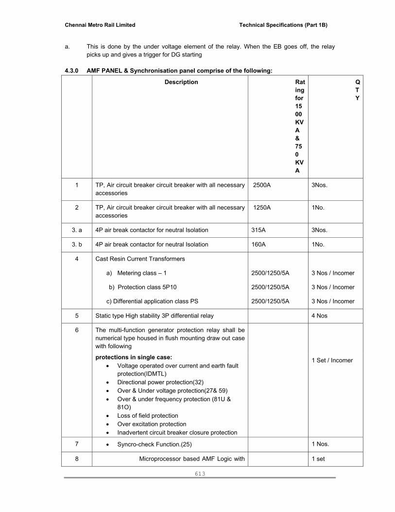
Chennai Metro Rail Limited Technical Specifications (Part 1B)
613
a. This is done by the under voltage element of the relay. When the EB goes off, the relay
picks up and gives a trigger for DG starting
4.3.0 AMF PANEL & Synchronisation panel comprise of the following:
Description Rating for 1500 KVA & 750 KVA
QTY
1 TP, Air circuit breaker circuit breaker with all necessary accessories
2500A 3Nos.
2 TP, Air circuit breaker circuit breaker with all necessary accessories
1250A 1No.
3. a 4P air break contactor for neutral Isolation 315A 3Nos.
3. b 4P air break contactor for neutral Isolation 160A 1No.
4 Cast Resin Current Transformers
a) Metering class – 1
b) Protection class 5P10
c) Differential application class PS
2500/1250/5A
2500/1250/5A
2500/1250/5A
3 Nos / Incomer
3 Nos / Incomer
3 Nos / Incomer
5 Static type High stability 3P differential relay 4 Nos
6 The multi-function generator protection relay shall be numerical type housed in flush mounting draw out case with following
protections in single case: • Voltage operated over current and earth fault
protection(IDMTL) • Directional power protection(32) • Over & Under voltage protection(27& 59) • Over & under frequency protection (81U &
81O) • Loss of field protection • Over excitation protection • Inadvertent circuit breaker closure protection
1 Set / Incomer
7 • Syncro-check Function.(25) 1 Nos.
8 Microprocessor based AMF Logic with 1 set
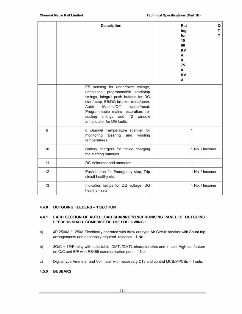
Chennai Metro Rail Limited Technical Specifications (Part 1B)
614
Description Rating for 1500 KVA & 750 KVA
QTY
EB sensing for under/over voltage, unbalance, programmable start/stop timings, integral push buttons for DG start/ stop, EB/DG breaker close/open, Auto/ Manual/Off accept/reset. Programmable mains restoration, re-cooling timings and 12 window annunciator for DG faults.
9 8 channel Temperature scanner for monitoring Bearing and winding temperatures.
1
10 Battery chargers for trickle charging the starting batteries
1 No. / Incomer
11 DC Voltmeter and ammeter 1
12 Push button for Emergency stop, Trip circuit healthy etc.
1 No. / Incomer
13 Indication lamps for DG voltage, DG healthy - sets
1 No. / Incomer
4.4.0 OUTGOING FEEDERS – 1 SECTION 4.4.1 EACH SECTION OF AUTO LOAD SHARING/SYNCHRONISING PANEL OF OUTGOING
FEEDERS SHALL COMPRISE OF THE FOLLOWING : a) 4P 2500A / 1250A Electrically operated with draw out type Air Circuit breaker with Shunt trip
arrangements and necessary required releases –1 No. b) 3O/C + 1E/F relay with selectable IDMTL/DMTL characteristics and in built High set feature
on O/C and E/F with RS485 communication port – 1 No. c) Digital type Ammeter and Voltmeter with necessary CTs and control MCB/MPCBs – 1 sets. 4.5.0 BUSBARS

Chennai Metro Rail Limited Technical Specifications (Part 1B)
615
a) The synchronising panel busbar shall be extendable on both sides of the panel. The busbar shall be of electrolytic Copper with the main busbar rated for 6300A.
b) The temperature rise shall be restricted to 45° over an ambient of 45°. C c) The switch board shall designed for conventional bus ducts entry and exit.
NOTE : A minimum of 20% spare terminal shall be provided apart from the terminals required for interfacing the temperature scanner, AVR, and Synchronising panel.
5.0 AUTO SYNCHRONIZING AND LOAD SHARING PANEL 5.1.0 OBJECTIVE: 5.1.1 The system will normally operate from the local EB power supply. Once the EB supply fails,
the system has to be run from the DG sets as follows. a) The change over from EB power to DG power and DG power to EB power should be totally
automatic without any manual intervention. b) When the System is on DG, the load of the system should be equally distributed on all DGs
to ensure proper hunt free operation of DGs to avoid System black out. 5.2.0 SCOPE OF WORK ENVISAGED IN THE SCHEME ARE: 6.2.1 EB supply failure detection 8.2.2 Sequential starting of all DGs after EB supply failure. 8.2.3 Auto synchronization of generators to the bus. 8.2.4 Auto Load sharing of generators after synchronization of DGs. 8.2.5 Maintaining the operation of required DGs for the system load. 8.2.6 Interlocks required for safe operation of the system. 8.2.7 Protection of generators. 5.2.1 EB supply failure detection: a. This is done by the under voltage element of the relay. When the EB goes off, the relay
picks up and gives a trigger for DG starting. 5.2.2 Sequential starting of Diesel engines after EB supply failure: a) When the EB supply fails, the required numbers of DGs are started and will get
synchronized and feed the system loads. b) The neutral contactors of the master DG will be connected in the system and slave DGs
neutral contactors are isolated. c) During starting, if the master engine does not start after EB supply failure, the next engine in
line will start after the engine fail alarm. 5.2.3 Auto synchronization of generators to the bus: a) DGs are auto synchronized to the bus by auto synchronizing relay. It controls the governor
and exciter of DG and gives a breaker closing command in synchronizing condition. If

Chennai Metro Rail Limited Technical Specifications (Part 1B)
616
individual controllers are used as per the design of the manufacturers, the same is acceptable and required operational requirements shall be met.
b) As soon as the EB power supply fails, the auto synchronizing relay will act in AMF logic and
the first DG will get connected to the dead bus only after its voltage and frequency are of nominal values.
c) After the first DG is connected to the bus, auto synchronizing relay is automatically
connected to the second DG’s PT. The relay will again start controlling the governor and exciter of next DG controls for synchronizing. After matching the DG voltage, frequency and phase angle to the bus, the relay gives the breaker close command to close the second DG.
d) Similarly remaining DGs will be synchronized with the bus. e) When DGs are in operation, logics required for PT switching of DGs for auto
synchronization and running the desired DGs according to the system load is performed by PLC.
5.2.4 Auto Load sharing of generators after synchronization: a) After the DGs are connected to the bus, the auto load sharing scheme is enabled. b) The set of load sharing relays monitor the total load on the bus and accordingly adjust the
voltage and frequency levels of the DGs by increase and decrease of pulses to ensure that the load is equally shared by each of the DGs.
c) The Load sharing system will ensure that the power delivered by each DG is restricted to
the same percentage level of its rated capacity. d) This process is online and continuous without any manual intervention. 5.2.5 Interlocks required for safe operation of the system has following interlocks built in a) The DGs are started only when EB power supply has failed and the incomer is open. b) If the engine has not started in three attempts, further start impulses are locked out and the
next engine is started. c) Auto synchronizing relay is enabled for synchronizing only after receiving the start ok signal
from the engine. d) At any time only one operation will be on - either synchronization or load sharing operation.
Both will never be on simultaneous. e) Provision is made for operating all the DGs individually when both the bus couplers are
open.
VI) TECHNICAL SPECIFICATION FOR RELAYS 6.1.0 HIGHLY STABILIZED DIFFERENTIAL CURRENT RELAY

Chennai Metro Rail Limited Technical Specifications (Part 1B)
617
9.1.1 This relay shall be with low input burden and is to function as a highly stabilised differential current relay.
9.1.2 It shall have a three-phase differential current supervision with pickup value adjustable from 5% to 82.5% of rated current with a grading of 2.5%.
9.1.3 The minimum operating time of the relay shall be 30ms. 6.2.0 SENSITIVE EARTH FAULT RELAY a) The sensitive earth fault protection provided shall be in two stages. b) The first shall be with selectable definite or inverse time characteristic. The inverse time
characteristic shall be selectable between normal inverse, very inverse or extremely inverse. 6.3.0 VOLTAGE CONTROLLED OVERCURRENT RELAY a) This relay is to protect the alternator against faults occurring close to the terminals in which
case the sustained fault current maybe less than normal operating current. b) It shall have in addition to the basic over-current relay an under voltage supervision element
which on energisation shall switch over to a lower response value so as to give a faster tripping.
c) A two stage three phase over current protection shall be provided.
6.4.0 VOLTAGE SUPERVISION RELAY a) The voltage supervision relay protects the alternator against over or under voltages in case
of defective voltage regulators. b) The relay shall be of numeric design with an alphanumeric display and menu driven
parameter settings. c) The system measured values, setting values and memorized fault data shall be numerically
displayed. 6.5.0 FREQUENCY RELAY a) The relay shall have four elements for under or over frequency protection with independent
separately adjustable timers. b) The over / under frequency setting shall be in steps of 0.1, 0.01Hz. 6.6.0 MASTER – TRIP RELAY a) The lock-out relay shall be hand reset type with a tripping time less than 10ms. b) The relay shall have a total of 8 No. Changeover contacts.
VII) SPECIFICATION FOR CABLE LAYING
7.1 The work shall be carried out strictly in accordance with National Electric code, general CPWD specifications for electrical works {Part 2 External) 1994 amended upto date.
7.2 All cables shall be laid in ground, trenches & or on walls, trays as may be specified and as per schematic diagram.
7.3 Cables shall be laid in the routes marked in the drawings. Where the route is not marked, the contractor shall mark it out on the drawings and also on the site and obtain the approval of the Engineer-in-charge before laying the cable.
7.4 All cables shall be clamped properly when laid along the wall /ceiling /cable tray. Cables laid in built-up trenches shall be on steel supports. Aluminium identification tags shall be provided at every 20 m.
7.5 Cables shall be bent to a radius not less than 12 times the overall diameter of the cable, or in accordance with the manufacturer's recommendations whichever is higher.
7.6 Cables shall be identified at end terminations indicating the feeder number and the Panel / Distribution Board from where it is being laid.
Chennai Metro Rail Limited Technical Specifications (Part 1B)
618
7.7 a. For Cables laid in soil, the cable route shall be parallel or perpendicular to roadways, walls, etc.,
7.8 b. Cables shall be laid in an excavated, graded trench, over sand cushion to provide protection against abrasion.
c. Width of excavated trenches shall be as per drawings/ department specifications. d. The cables laid in the excavated trenches shall be protected with bricks over the
cable. The bricks should be laid laterally to the trench. 7.9 The cables shall be provided with cable markers at every 10 metres. 7.10 All cable terminations for conductors’ upto 4 sq.mm may be insertion type and all higher sizes
shall have tinned copper compression lugs. 7.11 Cable terminations shall have necessary brass glands. The end-terminations shall be
insulated with a minimum of six- half-lapped layers of PVC tape. 7.12 Wherever cables pass through floor or through wall openings, it shall be taken through HDPE
PVC/GI sleeves. The open ends of the sleeves shall be sealed by cold setting compound after cables are pulled through them to prevent entry of vermin and ingress of water.
7.13 In making connection on switches and other terminals no strand of conductor shall be cut to facilitate termination.
7.14 Cable armouring shall be earthed at both ends. 7.15 The cable shall be as per the relevant IS amended from time to time, Test certificate should be
submitted by the contractor for the cables supplied by him. 7.16 The whole work shall be guaranteed for the period of one year from the date of completion . 7.17 The cable should be tested on load after laying the same. 7.18 The contractor shall submit completion plan of cable route diagram to scale in triplicate after
completion of work. 7.19 The contractor at his own cost and risk shall arrange all necessary tools & plants. The
contractor will be held responsible for any damage to the building or equipment at the time execution of work.
TESTING: 7.20 Testing of complete cable installation shall be done as provided in general specification for
electrical works (Part 2 External) 1994 amended upto date.
7.21 MV cables shall be tested upon installation with a 500 V Megger and the following readings established. 1) Continuity on all phases 2) Insulation Resistance (a) between conductors
(b) all conductors and ground All test readings shall be recorded in the separate book and the same to be handed over to the Engineer-in-charge.
VIII) TECHNICAL SPECIFICATION FOR EARTHING 8.1.1 SCOPE This specification covers the supply, installation testing and commissioning of Earthing system. 8.1.2 STANDARDS IS 3043 : Code of Practice for earthing

Chennai Metro Rail Limited Technical Specifications (Part 1B)
619
Indian Electricity Rules : 1956 8.1.3 GENERAL REQUIREMENTS The plant shall be provided with complete earthing system comprising earth electrodes in
conjunction with earth grid. 8.1.4 DETAILS OF EARTHING SYSTEM a. Unless otherwise specified main earthing shall not be less than 25x3mm Cu. flat. b. The minimum size of earthing conductor of various equipment shall be as follows: i) 1500KVA Generator Neutral - 75 x 10 mm copper flat ii) 1500KVA Generator body - 40 x 6 mm copper flat iii) 750KVA Generator Neutral - 40 x 10 mm copper flat iv) 750KVA Generator body - 25 x 6 mm copper flat v) Earth Bus station - 40 x 10 mm copper flat 8.1.5 EARTH ELECTRODE
Earth electrodes shall be erected 1.5 Mtrs away from the building edge and 3.0 Mtrs spacing between the electrodes shall be maintained as per IS: 3043
8.1.6 EARTHING LAYOUT a. Earthing conductors in outdoor areas shall be buried at least 600mm below finished grade
level unless stated otherwise. b. Wherever earthing conductors cross cable trenches, underground service ducts, pipes,
tunnels, etc. it shall be laid minimum 300 mm below and shall be re-routed in case it fouls with equipment structure foundations.
c. Tap-connections from the earthing grid to the equipment/structure to be earthed shall
be terminated on earthing terminals of the equipment/structure, if the equipment is available at the time of laying the grid, otherwise, “earth riser" shall be provided near the equipment foundation/ pedestal for future connections to the equipment earthing terminals.
d. Earthing conductors along their run on cable trench ladder columns, beams, walls, etc.
shall be supported by suitable cleating at intervals of 750 mm. e. Earthing conductors along cable trenches shall be cleated to the wall nearer to the
equipment. f. Cable trays and supports shall be connected to the earth mat at every 10 meters interval. g. Wherever it passes through walls, floors, etc. GI sleeves shall be provided for the passage
of the conductor. h. Earthing conductor around the building shall be buried in earth at a minimum distance of
1500 mm from the outer boundary of the building. 8.1.7 EQUIPMENT EARTHING

Chennai Metro Rail Limited Technical Specifications (Part 1B)
620
a) All electrical power items shall be earthed by two separate and distinct earth connections from main earth bus.
b) Earthing pads shall be provided by the supplier of the apparatus/equipment at accessible
position. The connection between earthing pads and the earthing grid shall be made by short and direct earthing lead free from links and splices.
c) Electrical continuity shall be ensured by bonding the different sections of hand-rails and
metallic stairs. d) Metallic pipes, and cable tray sections for cable installation shall be bonded to ensure
electrical continuity and connected to earthing conductors at regular interval. e) Apart from intermediate connections, beginning points shall also be connected to earthing
system. f) Metallic conduits shall not be used as earth continuity conductor. g) Wherever earthing conductor crosses or runs along metallic structures such as gas, water,
steam, conduits, pipes etc. and steel reinforcement in concrete, it shall be bonded to the same.
h) Cable end boxes, glands, etc. shall be connected to the earthing conductor running
along with the supply cable which, in turn, shall be connected to earthing grid conductor at minimum two points.
i) The metallic screens of the single core cable shall be connected to earth at one end only. 8.1.8 JOINTING a. Earthing connections with equipment earthing pads shall be bolted type. b. Contact surface shall be free from scale, paint enamel, grease, rust or dirt. c. Two bolts shall be provided for making each connections . Bolted connections, after
being checked and tested shall be taped with PVC tape. d. Resistance of the joint shall not be more than the resistance of the equivalent length of the
conductor. 8.1.9 GENERAL a. Excavation and refilling of earth necessary for laying of under ground earth bus and earth
pipes shall be the responsibility of the Contractor. b. All earth electrodes shall be tested for earth resistance by means of standard earth
resistance tester. c. Earthing resistance of the main bus shall be measured after connecting all the electrodes to
the bus and the resistance shall not exceed two (2) ohms. d. The exact location of Earth Bus/conductor, earth electrodes and earthing points on the
equipment shall be determined at site in consultation with Engineer-in-charge/consultants. e. Any change of methods, routing, and size of conductor shall be subject to approval by
Engineer- In Charge.
IX). TECHNICAL SPECIFICATION FOR INSTALLATION 9.1.0 GENERAL

Chennai Metro Rail Limited Technical Specifications (Part 1B)
621
a) The electrical installation shall be complete in all respects and any item not included in the specification but essential for proper installation and functioning of the electrical system shall deemed to be included in the scope of the specification whether specifically mentioned or not.
b) The system under the scope of work shall conform to the latest codes and standards as amended in the respective technical specification and schedule of works.
c) Nothing in the specification shall be construed to relieved the successful tenderers from the responsibilities where specifically mentioned in the tender or not.
9.1.1 Equipments i. All equipments shall be installed strictly in accordance with manufacturers instructions /
drawings. ii. All LT panels shall be erected on suitable base frame. iii. Distribution boards shall be erected on wall such that height of top of board will be at 1800
mm. iv. Switch boards / MCC’s shall be erected with a front clearance of not less than 1000 mm and a
clearance of not less than 750 mm at the rear side if there are cable entries or with a rear clearance of less than 200 mm in case there are no cable entries or attachments at the rear.
9.1.2 LIGHTING a. The AC lighting shall operate at 230V, 1 Phase, the supply being taken from the lighting DB
(MCB type) to be provided in the canopy by the DG set contractor. b. Supply to the above DB shall be provided by the EI contractor. c. Open conduit wiring using MS conduit shall be adopted. d. Conduit pipes, whenever necessary, shall be fixed by 16 SWG saddles with spacers, in an
approved manner at intervals of every 300mm. e. Saddles shall be fixed on either side of couplers, bends or similar fittings at a distance of
300mm from the centre of such fittings. f. The cost of providing lighting in the above manner i/e. providing DB shall be deemed to have
been included in the canopy charges. g. Switches of lighting circuits shall be mounted at 1300mm above finished floor level. h. Earth continuity shall be maintained throughout the entire installation.
9.1.3 Cable Termination a. Termination and jointing of XLPE (FRLS) /PVC armoured cables shall be by means of
compression method using double compression type glands and compression type lugs. b. Control cables are to be terminated by means of terminal lugs; the same shall be of tinned
copper compression type. c. Cable tails shall be sufficiently long to run all cores to the farther most terminal and then
back to the appropriate point of connection. 9.1.4 EQUIPMENT ERECTION a. Circuit breakers and switch boards shall be handled and erected as per the relevant codes
of practice and manufacturer's drawings and instruction manuals. b. LT Panels shall be erected on suitable base frame.
9.1.5 INSPECTION After completion of erection/installation, each piece of equipment shall be thoroughly
inspected in the presence of Engineering-in-charge or his authorised representatives.
Chennai Metro Rail Limited Technical Specifications (Part 1B)
622
9.1.6 MISCELLANEOUS ITEMS The contractor shall supply and install the safety devices as required by the statutory
authorities but not limited to the following. a) Danger boards for LT Panels & Generators b) Rubber mats for switchgear panels, power distribution boards etc. c) First aid charts, first aid box etc. d) Fire extinguishers and Fire Buckets 9.1.7 STATUTORY REQUIREMENTS / APPROVAL FROM STATUTORY AUTHORITIES a. Work for electrical installation shall be carried out in accordance with this specification
and complying with the relevant statutory requirements and national standards. b. It shall be the responsibility of the contractor to obtain approvals of competent Central
Electricity /Local Electrical Inspectorate authorities/CPCB and satisfy them regarding the compliance with relevant regulations for this scope of work.
c. The work should be carried out only under the supervision of licensed supervisors.
The licences possessed by the Contractor’s supervisor shall be made available to the Engineer-in-charge for scrutiny before commencement.
d. Test certificate for installation shall be prepared in the form required by the Engineer-in-
charge / other relevant Authorities. e. Any rework on account of remarks by Engineer-in-charge/other relevant Authorities shall
have to be carried out by the DG set contractor at no extra cost.
X) TECHNICAL SPECIFICATION FOR AVIATION WARNING LAMP 1) The aircraft warning system shall consists of dual-head non-flickering aircraft warning lights
(LED type) located at the highest point of the exhaust pipe/ stack. 2) The warning lights shall be of cast aluminium body with twin lamp head, red prismatic glass
dome with smooth exterior, weather-proof construction necessary gasket & cable entry arrangement.
3) The lamp shall be wired with PVC insulated and sheathed armoured aluminium/copper cable with copper earth wire.
4) The out put lumens of the each Aviation lamp shall be minimum 1600 cd in flashing Red as required by the INTERNATIONAL CIVIL ORGANISATION (ICAO).
Testing
The entire installation shall be tested in accordance with the Indian Standard Code and the following ground resistance values shall be recorded.
a) Earthing Terminal (each) b) Earthing system (as a whole)

Chennai Metro Rail Limited Technical Specifications (Part 1B)
623
10.1.1 The wiring for each aircraft warning lights shall include:
a) Cost of 3C 1.5 mm armoured copper cable laid with necessary fixing accessories b) Weather proof Junction box with cover, painting control switch c) Photo cell controller with necessary connected accessories and interconnections.
10.1.2 The cost of the air craft warning system to be provided as above shall be included in the cost of Stack.
XI) PROVISION TO BE MADE BY DG CONTRACTOR FOR BAS/IBMS INTERFACE 11.1.1 The following shall be incorporated in the DG contractor’s scope for interfacing with BAS /
IBMS:
a) All the Status monitoring point (DGs, Breakers (incomer, outgoing, and bus-coupler),
Interlocks, Fuel systems, Alarms, Trip) shall be provided with potential free contact to interface with BAS/IBMS.
b) All the control outputs. c) A potential free contact output of Auto/Manual status shall be provided by the DG contractor.
d) All the microprocessor-based system (System for measuring Electrical Quantities and protection) should have compatibility port for exchanging data with the IBMS.
XII) TECHNICAL SPECIFICATION FOR TESTING AND COMMISSIONING 1. Checking required to be made on all equipment and installations at site shall comprise, but
not be limited, to the following: 2. The following checks shall be made on all equipment and installations at site by contractor
and the report to be submitted to the Engineer-in-charge. i. Physical inspection for removal of any foreign bodies, external defects, such as damaged
insulators, loose connecting bolts, loose foundation bolts etc. ii. Check for grease, insulating/lubricating oil leakage and its proper quantity. iii. Check for the free movement of mechanism for the circuit breakers, rotating part of the
rotating machines and devices. iv. Check for tightness of all-cable, bus bars at termination/ joints ends as well as earth
connections in the main earthing network. v. Check for clearance of live bus bars and connectors from the metal enclosure.

Chennai Metro Rail Limited Technical Specifications (Part 1B)
624
vi. Check for proper alignment of all draw out device like draw out type circuit-breakers. vii. Continuity check in case of power cables. viii. Checking of all mechanical and electrical interlocks including tripping of breakers using
manual operation of relay. ix. Checking of alarm and annunciation circuits by manual actuation of relevant relays. x. Check and calibrate devices requiring field adjustment/ calibration like adjustment of relay
settings etc. xi. Check proper connection to earth network of all non-current carrying parts of the equipment
and installation. xii. Test reports for all meters are to be furnished. 12.1.1 Low Voltage Switchgear 440V AC i. Insulation resistance test with 1000V megger for main circuits. The minimum value of
insulation resistance shall be 1 meg.ohm. ii. Insulation resistance test with 500V megger for control, metering and relaying circuits. The
minimum value of insulation resistance shall be one meg.ohm. iii. Relay operation test by primary & Secondary injection method. iv. Functional tests of control circuit. v. Checking of settings of all relay/releases as per single line diagram/specification. vi. ON/OFF operation of breakers both manually and electrically in "Test" as well as "Service"
positions. 12.1.1 Cables i. Insulation resistance test with 1,000 V megger for cables rated up to 1.1 KV grade. ii. All cables of 1.1 KV shall be subjected to high voltage test after joining and terminating but
before commissioning as per relevant standards. iii. In each test, the metallic sheath/screen/armour should be connected to earth. iv. Continuity of all the cores, correctness of all connections as per wiring diagram, correctness
of polarity and phasing of power cables and proper earth connection of cable glands, cable boxes, armour and metallic sheath, shall be checked.
12.2.1 Earthing System i. Tests to ensure continuity of all earth connections. ii. Tests to obtain earth resistance of the complete network by using earth tester. The test
values obtained shall be within the limits. iii. All documents / records regarding test data and other measured values of important
parameters finalised after site adjustment shall be handed over to the Engineer-in-charge in the form of test reports for their future use and reference.
12.3.1 Training
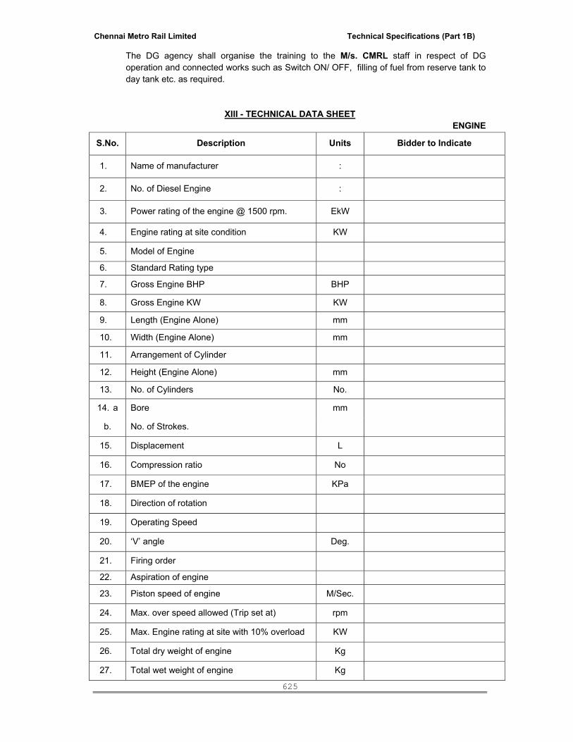
Chennai Metro Rail Limited Technical Specifications (Part 1B)
625
The DG agency shall organise the training to the M/s. CMRL staff in respect of DG operation and connected works such as Switch ON/ OFF, filling of fuel from reserve tank to day tank etc. as required.
XIII - TECHNICAL DATA SHEET ENGINE
S.No. Description Units Bidder to Indicate
1. Name of manufacturer :
2. No. of Diesel Engine :
3. Power rating of the engine @ 1500 rpm. EkW
4. Engine rating at site condition KW
5. Model of Engine
6. Standard Rating type
7. Gross Engine BHP BHP
8. Gross Engine KW KW
9. Length (Engine Alone) mm
10. Width (Engine Alone) mm
11. Arrangement of Cylinder
12. Height (Engine Alone) mm
13. No. of Cylinders No.
14. a Bore mm
b. No. of Strokes.
15. Displacement L
16. Compression ratio No
17. BMEP of the engine KPa
18. Direction of rotation
19. Operating Speed
20. ‘V’ angle Deg.
21. Firing order
22. Aspiration of engine
23. Piston speed of engine M/Sec.
24. Max. over speed allowed (Trip set at) rpm
25. Max. Engine rating at site with 10% overload KW
26. Total dry weight of engine Kg
27. Total wet weight of engine Kg

Chennai Metro Rail Limited Technical Specifications (Part 1B)
626
S.No. Description Units Bidder to Indicate
28. horse power consumed by engine driven accessories KW/HP
29. Mechanical efficiency of the engine %
30. Thermal efficiency of the engine %
31. Ref. standards for these engines
32. Height of base rail used for the engine Mm
Exhaust System
1. Exhaust system back pressure permitted (max.)
KPa
2. Diameter of engine exhaust outlet (inside) mm
3. No. of exhaust outlets required No.
4. No. of silencers supplied with each engine No.
5. Noise reduction provided by the silencers DB(A)
6. Restriction offered by silencers In.H20
7. Exhaust gas flow rate CPM
8. Exhaust gas flow rate M3/Min
9. Exhaust gas temp (stack) Deg. C
10. Exhaust silencer type Residential
11. Height of each Exhaust pipe M
Position of Center of Gravity(Approx.)
1. Forward from rear face of the block mm
2. Above crank shaft centerline mm
3. Right of crankshaft centerline mm
Specific Fuel Consumption
1. Specific Fuel Consumption @ 100% load g/bkW-Hr
2. Specific Fuel Consumption @ 75% load g/bkW-Hr
4. Specific Fuel Consumption @ 50% load g/bkW-Hr
5. Tolerance g/bkW-Hr
Fuel Consumption in Liters
1. Fuel Consumption in Liters @ 100% load L/Hr
3. Fuel Consumption in Liters @ 75% load L/Hr
4. Fuel Consumption in Liters @ 50% load L/Hr

Chennai Metro Rail Limited Technical Specifications (Part 1B)
627
S.No. Description Units Bidder to Indicate
5. Tolerance considered
6. Density of fuel considered Kg/L
7. Alternator Efficiency considered %
Lube oil Consumption of the Engine
1. Lube oil Consumption @ 100% load L/Hr
2. Lube oil Consumption @ 75% load L/Hr
3. Lube oil Consumption @ 50% load L/Hr
5. Recommended lube oil
6. Lube Oil change period Hrs.
7. Minimum acceptable lube oil temperature at start up
°C
8. Lube oil priming pump Yes/No
9. Lube oil priming pump Engine Driven / AC motor driven / DC motor driven
10. AC motor driven stand by pump if any Included / excluded
11. DC motor driven stand by pump if any Included / excluded
Heat Rejection Details
1. Heat Rejection to coolant kW
2. Heat Rejection to exhaust kW
3. Heat Rejection to atmosphere kW
6. Heat that can be recovered from exhaust kW
Deration Details
1. Deration of the engine – Altitude(normal temp) M
2. Deration of the engine – Altitude ( @ 50 deg C)
M
3. Deration of the engine – Temperature Deg. C
4. Deration of the engine – Humidity
5. Inlet air temperature %
6. Overall de-rating factor %
Air Intake System
1. Intake filter type
2. Air intake restriction – with clean element kPa

Chennai Metro Rail Limited Technical Specifications (Part 1B)
628
S.No. Description Units Bidder to Indicate
3. Air intake restriction – with dirty element kPa
4. Filtration capacity in microns Microns
5. Intake manifold pressure kPa
6. Max. intake manifold temperature Deg. C
7. Combustion air inlet flow rate CFM
8. Combustion air inlet flow rate M3/Min
Fuel System
1. Fuel System type
2. Filter type & No.
3. Filtration capacity (particle size) Microns
4. Full oil suction filters
Fuel Oil System
1. Day tank size Litres
2. Fuel Oil suction filters
Type and Number
Engine Construction Future
1. Turbo charger / Super charger Included / excluded
2. Name of the manufacture
3. Number
4. Speed RPM
5. After cooler Included / excluded
6. Inter cooler Included / excluded
Lube Oil System
1. Engine lube oil capacity L
2. Refill volume with filter L
3. Sump capacity – low mark level L
4. Sump capacity – high mark level L
5. Oil temp. – max. Deg. C
6. Oil pressure – normal range kPa
7. Oil pressure – low oil kPa

Chennai Metro Rail Limited Technical Specifications (Part 1B)
629
S.No. Description Units Bidder to Indicate
8. Filter type & No.
9. Filtration capacity in microns Microns
Starting System
1. System voltage VDC
2. No. motors provided & rating of motors No.
3. Battery charging alternator capacity Amps.
4. Min. Recommended Battery Capacity
Radiator Details
1. Coolant capacity of radiator Litres
2. Ambient capacity of the radiator Deg C.
3.
4. Size of Radiator (Height x Width x Length) mm
5. Diameter of radiator fan mm
6. Power of radiator fan kw
7.
8. Weight of radiator (Dry) kg
9. Weight of radiator (Wet) kg
Noise Level Details
Mechanical noise (all loads)
1. @ 1 Meter dB(A)
2. @ 7 Meters dB(A)
Exhaust noise @ 1.5 Meters
3. @ 100% load dB(A)
4. @ 90% load dB(A)
5. @ 80% load dB(A)
6. @ 75% load dB(A)
7. @ 70% load dB(A)
8. @ 50% load dB(A)
9. @ 25% load dB(A)
Exhaust noise @ 7 Meters
10. @ 100% load dB(A)
11. @ 90% load dB(A)
12. @ 80% load dB(A)

Chennai Metro Rail Limited Technical Specifications (Part 1B)
630
S.No. Description Units Bidder to Indicate
13. @ 75% load dB(A)
14. @ 70% load dB(A)
15. @ 50% load dB(A)
16. @ 25% load dB(A)
Emission Details @ 100% Load
1. NOX level as NO2 gm/hr
2. CO gm/hr
3. Total HC gm/hr
4. Sox as SO2 gm/hr
5. Particulate matter gm/hr
6. Oxygen dry %
7. Smoke Opacity %
8. Bosch smoke No.
MOUNTING SYSTEM
1. SAE No. of the flywheel housing
2. Fly wheel dimension
- Diameter mm
- Width mm
- No. of teeth No.
3. Type of coupling (for 2 bearing)
4. Whether comes with a base frame
GOVERNING SYSTEM
1. Type of governor (Digital –PCC)
Make
Model
2. Class of Governor
3. Steady state band of regulation %
4. Droop range %
5. Recovery time
6. Temporary variation
7. Permanent variation 2ALTERNATOR Description Units Bidder to Indicate

Chennai Metro Rail Limited Technical Specifications (Part 1B)
631
Description Units Bidder to Indicate
Name of manufacturer
Type
Design Rating (Maximum) KVA
KW Continuous output rating KW
Power Factor PU (Lag)
No. of Phase / Current
Frequency HZ
Speed RPM
Rated Voltage (RV) V
Voltage Variation %RV
Rated FLC AMP
Enclosure as per IS:4691
Cooling as per IS:6362
Mounting as per IS:2253
Altitude MSL
Ambient DEG C
Insulation Class
a. Stator
b. Rotor
Temp. Rise (Deg. C)
IS:12802
Above 40 Deg. C AMB
a. Stator °C
b. Rotor °C
c. Core °C
Governing Standards
Description Units Bidder to Indicate
AVR Type / DVR Type
Burden of AVR / DVR on CT’s & PT’s
Voltage Regulation
Wave Form Distortion THF
Synchronous Reactance XD
Transient Reactance XD’
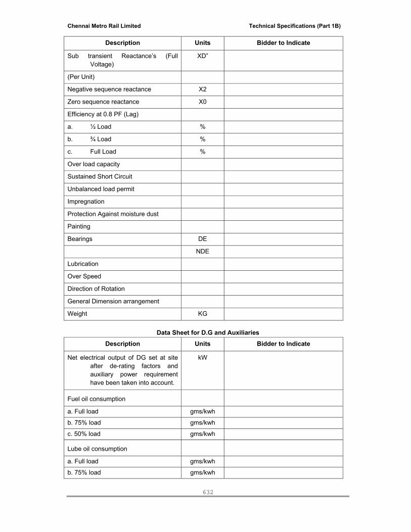
Chennai Metro Rail Limited Technical Specifications (Part 1B)
632
Description Units Bidder to Indicate
Sub transient Reactance’s (Full Voltage)
XD”
(Per Unit)
Negative sequence reactance X2
Zero sequence reactance X0
Efficiency at 0.8 PF (Lag)
a. ½ Load %
b. ¾ Load %
c. Full Load %
Over load capacity
Sustained Short Circuit
Unbalanced load permit
Impregnation
Protection Against moisture dust
Painting
Bearings DE
NDE
Lubrication
Over Speed
Direction of Rotation
General Dimension arrangement
Weight KG
Data Sheet for D.G and Auxiliaries Description Units Bidder to Indicate
Net electrical output of DG set at site after de-rating factors and auxiliary power requirement have been taken into account.
kW
Fuel oil consumption
a. Full load gms/kwh
b. 75% load gms/kwh
c. 50% load gms/kwh
Lube oil consumption
a. Full load gms/kwh
b. 75% load gms/kwh
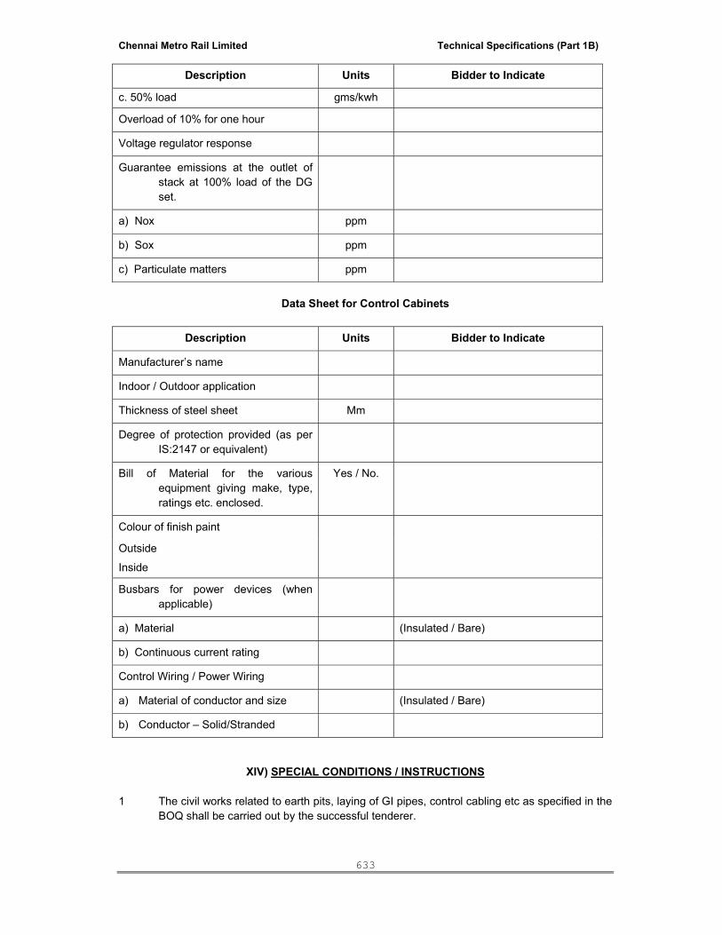
Chennai Metro Rail Limited Technical Specifications (Part 1B)
633
Description Units Bidder to Indicate
c. 50% load gms/kwh
Overload of 10% for one hour
Voltage regulator response
Guarantee emissions at the outlet of stack at 100% load of the DG set.
a) Nox ppm
b) Sox ppm
c) Particulate matters ppm
Data Sheet for Control Cabinets
Description Units Bidder to Indicate
Manufacturer’s name
Indoor / Outdoor application
Thickness of steel sheet Mm
Degree of protection provided (as per IS:2147 or equivalent)
Bill of Material for the various equipment giving make, type, ratings etc. enclosed.
Yes / No.
Colour of finish paint
Outside
Inside
Busbars for power devices (when applicable)
a) Material (Insulated / Bare)
b) Continuous current rating
Control Wiring / Power Wiring
a) Material of conductor and size (Insulated / Bare)
b) Conductor – Solid/Stranded
XIV) SPECIAL CONDITIONS / INSTRUCTIONS 1 The civil works related to earth pits, laying of GI pipes, control cabling etc as specified in the
BOQ shall be carried out by the successful tenderer.

Chennai Metro Rail Limited Technical Specifications (Part 1B)
634
2. The drawings furnished along with this tender is only tentative. The successful tenderer shall furnish the detailed drawings for approval.
3. Necessary approvals from statutory bodies such as explosive department, fire service
department shall be obtained. However the necessary statutory fees will be paid by the client against demand notice.
4. Guarantee of the performance of DG set and the accessories will be from the date of
handing over of DG set to the satisfaction of the client after entire commissioning works gets completed after attending snag.
5. The successful tenderer to design the exhaust pipe height along with required stack
including supporting frame work for exhaust stack and submit the detailed design calculation to project manager/client along with the foundation reaction to design the foundation structures and also to get approval.
6. Details of acoustic insulation is indicative only. The successful tenderer to carry out the
detailed engineering for the acoustic insulation for execution purposes. The bid shall take into account that the requirement of the noise reduction to the levels specified by statutory authority.
7. The successful tenderer to coordinate with other agencies like Civil, BAS, IBMS, Electrical
and other related works and the coordination cost should be included in this tender. The successful tenderer to arrange on his own the stocking yard and necessary infrastructure works.
NOTE: 1. The Successful tenderer shall submit test reports for all the
materials/equipments. 2. If any make is not in accordance with the tender specification it will not be
accepted even if the make is indicated in the above List. 3. The client /Architect have reserve to select any of the make specified above.
*****

Chennai Metro Rail Limited Technical Specifications (Part 1B)
635
FIRE PROTECTION SYSTEM
CONTENTS
SL.NO DESCRIPTION
1 SCOPE OF WORK
2 TECHNICAL SPECIFICATION
3 PUMPS
4 PIPES, FITTINGS AND VALVES
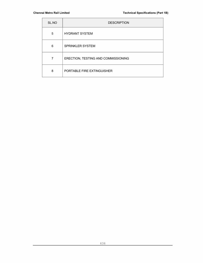
Chennai Metro Rail Limited Technical Specifications (Part 1B)
636
SL.NO DESCRIPTION
5 HYDRANT SYSTEM
6 SPRINKLER SYSTEM
7 ERECTION, TESTING AND COMMISSIONING
8 PORTABLE FIRE EXTINGUISHER
Chennai Metro Rail Limited Technical Specifications (Part 1B)
637
SCOPE OF WORK
The scope of work includes design, supply, installation, testing and commissioning of
Fire protection system with all necessary accessories as per the requirements of NBC
/ Local Fire Authorities. It should also include getting the necessary approvals / NOC
from the Fire Department. The Fire Protection System shall comprise of following:
Fire Pumps – Electrical driven, Diesel Pump, Jockey Pump and Booster Pump
Yard Hydrant systems
Internal Hydrant systems
Automatic Sprinkler systems
Fire Extinguishers
Control wiring between flow switch to Annunciation panel & interlocking.
Balancing, testing & commissioning of the entire Fire protection system.
Training of Owner’s staff
DRAWINGS AND DESIGN CALCULATIONS
The drawings enclosed herewith are for the general guidance to the Bidder. The
contractor shall upon the award of the work, furnish detailed working drawings to
carryout the work at site with detail design calculation. These shall be submitted to the
consultant for the approval and the work shall be commenced only after the approval
of drawing by the Consultant.
INSPECTION AND APPROVAL
The successful vendor shall obtain approval to the installation from the State Fire &
Rescue Services, and responsible for preparation of documents / applications /
drawings & hydraulic calculations and flow up action at all stages, (Drawing /
completion) arranging inspections, revisions / modifications for obtaining approval
from State Fire & Rescue Services within the overall completion period stipulated in
the Tender. The Contractor shall also make payment of all statutory payments like
payment for State Fire & Rescue Services approval etc. The quoted rates shall take
care of such contingencies. The contractor shall guarantee both the material and
workmanship of first class quality corresponding to standard engineering practice. Any
defective materials/workmanship shall be rejected, the contractor has to rectify/
replace at his own cost. Guarantee certificate of the materials supplied shall be
handed over to the clients.
DOCUMENTS TO BE SUBMITTED AFTER AWARD OF CONTRACT
List of data/document/drawings to be submitted after the award of contract shall be
indicated. The list shall essentially contain the following:

Chennai Metro Rail Limited Technical Specifications (Part 1B)
638
Design and operation philosophy of the complete fire system.
Shop drawings
Technical Data sheets of all the equipment/valves etc.
Detailed Hydraulic calculation
Bar chart/network schedule covering all milestone activities.
INSTRUCTION MANUAL/COMPLETION DRAWING/TRAINING
The contractor shall be responsible for training of the Employer's personnel in the
period of commissioning/handing over the system. The rates quoted shall inclusive of
submitting 4 sets of the following documents (HARD COPIES) along with CDs (Soft
copy) and the following,
Manufacture’s maintenance and operating instructions manuals
Set of as built drawings
Approved test readings of all equipment and installations
Inspection certificates
Certificates of approval from statutory or Local Authorities for the operation and maintenance
of the installations, wherever such approval or certification is required. This shall include
Application filed along with enclosures and receipts of fees paid and deposits made.
Warranty / guaranty certificate for all equipments
List of recommended spares together with list of suppliers and their contact details.
Vendor and Supplier’s Contact details
Submission of the above documentation shall form a precondition for final acceptance
of the plant and installation and final payments.

Chennai Metro Rail Limited Technical Specifications (Part 1B)
639
TECHNICAL SPECIFICATION
FIRE PUMPSETS SCOPE Work under this section shall consist of furnishing all materials, equipment ,labours and appliances
necessary and required to completely install electrically operated and diesel driven pumps and as
required by drawings and specified hereinafter or given in the schedule of rates.
• Electrically operated pumps with motors and diesel engine driven pumps with diesel
engine, common base plates, coupling, coupling guard and accessories.
• Automatic starting system with all accessories, wiring and connections and pressure
switches.
• Motor control centre.
• Annunciation system with all accessories wiring and connections.
GENERAL REQUIREMENTS Pumps shall be installed true to the levels on suitable concrete foundations as per the supplier’s
recommendation. Base plate shall be firmly fixed by properly grouted foundation bolts. Pumps and
motors shall be truly aligned with suitably instruments by pump supplier. Record of such alignment
shall be furnished to the Project Manager. All pump connections shall be standard flanged type with
number of bolts as per relevant standard requirement for the working pressure. Companion flanges
shall be provided with the pumps. Manufacturers’ instructions regarding installation, connections and
commissioning shall be strictly followed. Contractor shall provide necessary test certificates, type
test certificates, performance curves and NPSH curves of the pumps from the manufacturer when
called for. The contractor shall provide facilities to the Project Manager & Consultant for inspection
of equipment during manufacturing and also to witness various tests at the manufacturer’s works
without any cost to the Project Manager or Consultant. Seismic isolation and clamping for each
pump and flexible connection on the suction as well as the discharge side shall be provided. The
contractor shall submit with this tender a list of recommended spare parts for three years of normal
operation and quote the prices for the same as a separate submittal / annexure.
ELECTRIC FIRE PUMP GENERAL The electric fire pump shall be suitable for automatic operation complete with necessary electric
motor and automatic starting gear, suitable for operation on 415 volts, 3 phase, 50 Hz. A.C. system.
Both the motor and the pump shall be assembled on a common base plate, fabricated M.S. channel
type or cast iron type.
DRIVE

Chennai Metro Rail Limited Technical Specifications (Part 1B)
640
The pump shall be direct driven by means of a flexible coupling. Coupling guard shall also be
provided.
FIRE PUMP The fire pump shall be horizontally mounted end suction centrifugal type. It shall have a capacity to
deliver the requirements as specified in the Bill of quantities, and developing adequate head so as to
ensure a minimum pressure of 3.5 Kg/Sq.cm at the highest and the farthest outlet. The pump shall
be capable of giving a discharge of not less than 150 per cent of the rated discharge, at a head of not less than 65 per cent of the rated head and the motor Kw shall be selected for 150 %
discharge flow. The shut off head shall be within 120 per cent of the rated head. The pump casing
shall be of cast iron to grade FG 200 to IS: 210 and parts like impeller, shaft sleeve, wearing ring
etc. shall be of non-corrosive metal like bronze. The shaft shall be of stainless steel. Provision of
mechanical seal shall also be made. Bearings of the pump shall be effectively sealed to prevent loss
of lubricant or entry of dust or water. The pump shall be provided with a plate indicating the suction
lift, delivery head, discharge, speed and number of stages. The pump shall be designed to withstand
1.5 times the working pressure.
The jockey pump shall be end suction centrifugal pump and of detail as in schedule of quantity.
Contractor shall verify that the capacity of the Jockey pump shall not be less than 3% (Minimum 180
LPM) and not more than 10% of the installed pump capacity.
MOTOR The motor shall be squirrel cage A.C. induction type suitable for operation on 415 volts 3 phase 50
Hz. system. The motor shall be totally enclosed fan cooled type conforming to protection clause IP
55. The class of insulation shall be F. The motor shall be rated for continuous duty and shall have a
horse power rating necessary to drive the pump at 150 per cent of its rated discharge with at least
65 per cent rated head. The motor shall conform to I.S.325-1978.
MOTOR STARTER The motor starter shall be as per detail in MCC. The unit shall include suitable current transformer
and ammeter of suitable range on one line to indicate the current. The starter shall not incorporate
under voltage, no voltage trip overload or SPP. The starter assembly shall be suitably integrated in
the power and control panel for the wet riser system & sprinkler system. The panel should have
single phase preventer, start and stop push buttons, auto manual switch, ancillary contactors for
interlocking/sequence of operations and all necessary gauges, fittings required to complete the
system. The bus bar should be copper and appropriate thickness.
CONTROL PANEL FOR ELECTRICAL MOTOR DRIVEN PUMPSET The starting switch gear for the motor driven pump set shall be suitable for direct on line starting.
The control circuit for the electrical driven fire fighting pump set shall be designed for automatic
operation i.e., whenever the pressure reduces in the system, the pumps shall automatically starts.
The stopping of the pumps is ‘Manual’. The control circuit for the Jockey pump set and booster
pump set shall be designed that whenever pressure reduces the pump shall start automatically and

Chennai Metro Rail Limited Technical Specifications (Part 1B)
641
when pressure reaches, rated system pressure then it should automatically switched OFF.
Auto/Manual switch shall be provided for the electrical driven fire fighting pump set, Jockey pump
set and booster pump set so that the pump sets can be started / stopped manually also.
DIESEL FIRE PUMP GENERAL The diesel pump set shall be suitable for automatic operation complete with necessary automatic
starting gear, for starting on wet battery system and shall be complete with all accessories. Both
engine and pump shall be assembled on a common base plate. Pump specification is same as the
spec of electrical driven pump.
DRIVE The pump shall be only direct driven by means of a flexible coupling. Coupling guard shall also be
provided.
DIESEL ENGINE Engine Rating - The engine shall be cold starting type without the necessity of preliminary heating of
the engine cylinders or combustion chamber (for example, by wicks, cartridge, heater, plugs etc.).
The engine shall be multi cylinder/vertical 4 stroke cycle, water cooled, diesel engine, developing
suitable HP at the operating speed specified to drive the fire pump. Continuous capacity available
for the load shall be exclusive of the power requirement of auxiliaries of the diesel engine, and the
after correction for altitude, ambient temperature and humidity for the specified environmental
conditions. This shall be at least 20% greater than the maximum HP required to drive the pump at its
duty point. It shall also be capable of driving the pump at 150% of the rated discharge at 65% of
rated head. The engine shall be capable of continuous non-stop operation for 8 hours and major
overhaul shall not be required before 3000 hours of operation. The engine shall have 10% overload
capacity for one hour in any period of 12 hours continuous run. The engine shall accept full load
within 15 seconds from the receipt of signal to start. The diesel engine shall conform to BS 649/IS
1601/IS 10002, all amended up to date. Sufficient clearance is required in front of engine for
exhaust.
a. Engine Accessories - The engine shall be complete with the following accessories:-
• Fly wheel dynamically balanced.
• Direct coupling for pump and coupling guard.
• Corrosion Resistor.
• Air cleaner.
• Fuel service tank support and fuel oil filter with necessary pipe work.
• Elect. Starting battery (2X24 v).
• Exhaust silencer with necessary pipe work.

Chennai Metro Rail Limited Technical Specifications (Part 1B)
642
• Governor.
• Instrument panel housing all the gauges, including Tachometer, hour meter
and starting switch with key (for manual starting).
• Necessary safety controls.
b. Fuel System - The fuel shall be gravity fed from the engine fuel tank to the engine
driven fuel pump. The engine fuel tank shall be mounted either over or adjacent to the
engine. The fuel filter shall be suitably located to permit easy servicing. All fuel tubing
to the engine shall be with copper, with flexible hose connections where required.
Plastic tubing shall not be permitted. The fuel tank shall be of welded steel construction
(6 mm. thick) and of capacity sufficient to allow the engine to run on full load. The tank
shall be complete with necessary wall mounted supports, level indicator (protected
against mechanical injury) inlet, outlet, overflow connections and drain plug and piping
to the engine fuel tank. The outlet shall be so located as to avoid entry of any
sediments into the fuel line to the engine. The engine fuel oil shall be of quality and
grade specified by engine manufacturers. Where there is more than one compression
ignition engine driven pump set there shall be a separate fuel tank and fuel feed pipe
for each engine
c. Lubricating Oil System- Forced feed Lub. Oil system shall be employed for positive
lubrication. Necessary Lub. Oil filters shall be provided, located suitably for convenient
servicing.
i) A sludge and sediment trap
ii) A fuel level gauge
iii) An inspection and cleaning hole.
iv) A filter between the fuel tank and fuel pump mounted in an accessible
position for cleaning.
d. Starting System- The starting system shall comprise necessary batteries (2x24v), 24
volts starter motor of adequate capacity and axle type gear to match with the toothed
ring on the fly wheel. Bi metallic relay protection to protect starting motor from
excessively long cranking runs suitably integrated with engine protection system shall
be included within the scope of the work. The capacity of the battery shall be suitable
for meeting the needs of the starting system. The battery capacity shall be adequate
for 10 consecutive starts without recharging with cold engine under full compression.
The scope shall cover all cabling, terminals, initial charging etc.
e. Exhaust System - The exhaust system shall be complete with silencer suitable for
outdoor installation and silencer piping including bends and accessories needed for a
run of 15 metre from the engine manifold. The total back pressure shall not exceed the
engine manufacture's recommendation. The exhaust piping shall be suitably
supported.
f. Engine shut down mechanism- This shall be auto/ manually operated and shall
return automatically to the starting position after use.

Chennai Metro Rail Limited Technical Specifications (Part 1B)
643
g. Governing System- The engine shall be provided with an adjustable governor to
control the engine speed within 5% of its rated speed under all conditions of load up to
full load. The governor shall be set to maintain rated pump speed at maximum pump
load.
h. Engine Instrumentation- Engine instrumentation shall include the following:-
i) Lub. oil pressure gauge.
ii) Lub. oil temperature gauge.
iii) Water pressure gauge.
iv) Water temperature gauge.
v) Tachometer.
vi) Hour meter.
The instrumentation panel shall be suitably resident mounted on the engine.
Engine Protection Devices- Following engine protection and automatic shut down
facilities shall be provided:-
i) Low lub.oil pressure.
ii) High cooling water temp.
iii) High lub.oil temperature.
iv) Over speed shut down.
i. Pipe Work - All pipe lines with fittings and accessories required shall be provided for
fuel oil, lub.oil and exhaust systems, copper piping of adequate sizes, shall be used for
Lub.oil and fuel oil. M.S. piping will be permitted for exhaust.
j. Anti Vibration Mounting- Suitable vibration mounting duly approved by Project
Manager shall be employed for mounting the unit so as to minimise transmission of
vibration to the structure. The isolation efficiency achievable shall be clearly indicated.
k. Battery Charger-Necessary float and boost charger shall be incorporated in the
control section of the power and control panel, to keep the battery in trim condition.
Voltmeter to indicate the state of charge of the batteries shall be provided.
l. Air filteration - The air intake shall be fitted with a filter of adequate to prevent foreign
matter entering the engine.
m. Tools - A standard tools kit shall be provided with engine and kept at handy place.
n. Spare Parts - The following spare parts shall be supplied with the engine and kept
at handy places.
• Two sets of fuel filters, elements and seals.
• Two sets of lubricating oil filters elements and seals.
• One complete set of engine joints, gaskets and hoses.
• Two injector nozzles.
• One complete set of piston rings for each cylinder.
• One inlet valve and one exhaust valve.

Chennai Metro Rail Limited Technical Specifications (Part 1B)
644
AUTO START CONTROL PANEL FOR DIESEL ENGINE: The Auto-start control panel shall have the following:
• Auto/Manual selector switch for pump set.
• Manual start/stop push button.
• Indicating lamps showing power is on and run/stop.
• Voltmeter/Ammeter in battery charging circuit.
PUMP SETS ASSEMBLY On the main fire sprinkler and hydrant headers near pump sets a 150 mm dia by-pass valve located
in an accessible location shall be provided along with a rate of flow rota meter calibrated in 1 pm and
able to read 200% of the rated pump capacity. The delivery shall be connected to the fire tank. Each
and every pump set assembly shall be provided with suction valve (only for positive suction head),
discharge valve, non-return valve and 150 mm dia Bourdon type pressure gauge with isolation
valve.
ANNUNCIATION PANEL One solid state electronic annunciation panel fully wired with visual display and audible alarm unit
shall be provided to indicate:
a. Flow condition in any flow switch indicating the area of distress and fire alarm.
b. Starting, trip and auto mode fail status of each hydrant pump.
c. Starting, trip and auto mode fail status of each Main pump.
d. Starting, trip and auto mode fail status of each Jockey pump.
e. Starting, trip and auto mode fail status of each Booster pump.
f. High level in fire water storage tank compartment.
g. Low level in fire water storage tank compartment.
h. Low level in HSD day tank of the fire pump
i. Starting status for Diesel engine
j. Oil pressure low status for Diesel engine
k. High water temperature for Diesel engine
l. Fails to start status for Diesel engine
m. Auto mode fails status for Diesel engine
n. Flow switch status for Diesel engine
The panel shall be factory fabricated, wired and tested. All details shall be submitted with the tender.
The annunciation panel shall be located in the security office / reception on the ground floor or as
instructed by the Project Manager. The panel shall have the provision for interconnection with Fire
alarm system panel and IBMS.

Chennai Metro Rail Limited Technical Specifications (Part 1B)
645
PIPES, FITTINGS AND VALVES
The use of Pipes in the execution shall be as follows:
DUCTILE IRON (DI) PIPING GENERAL: The item includes the provision of supplying water quality Ductile Iron pipes and specials of
specified diameter including cutting, laying, fixing, and painting the pipe line.
MATERIAL: The pipes shall be centrifugally cast (spun) Pressure pipe conforming to IS: 8329 (latest revision/
amendments) and shall be of class "K9". These shall be spigot Jointed. All the pipes shall be
cylindrical and all dimensions shall be within the tolerance as per IS: 8329. The outer surface shall
be smooth / textured, sound, free from pin holes, cracks and other imperfections. Outer diameter of
pipe shall be metallic zinc coated. Mass of zinc coating shall not be less than 200g/m2. Above zinc
coating bitumen coating shall be applied. Pipe shall be centrifugally cement mortar lined as per IS:
8329. The table showing the dimensions of different diameter of pipes is given below:
CENTRIFUGALLY CAST (SPUN) DUCTILE IRON 'WATER QUALITY' PIPES
Dimensions of Sockets and Spigot Pipes Nominal Diameter
External Diameter
Barrel Wall Thickness (e)
-ve Tolerance
DN DE K7 K9 Thickness(e) DE 80 98 5.0 6.0 -1.38 -2.2 100 118 5.0 6.0 -1.40 -2.8 125 144 5.0 6.0 -1.43 -2.8 150 170 6.0 6.0 -1.45 -2.9 200 212 5.0 6.3 -1.50 -3.0 250 274 5.3 6.8 -1.55 -3.1 300 326 5.6 7.2 -1.60 -3.3 350 378 6.0 7.7 -1.65 -3.4 400 429 6.3 8.1 -1.70 -3.5 450 480 6.6 8.6 -1.75 -3.6 500 532 7.0 9.0 -1.80 -3.8 600 635 7.7 9.9 -1.90 -4.0 700 738 9.0 10.8 -2.00 -4.3 750 790 9.7 11.3 -2.05 -4.4 300 842 10.4 11.7 -1.60 -4.5 900 945 11.2 12.6 -2.20 -4.8 1000 1048 12.0 13.5 -2.30 -5.0 The tolerance given is subjected to minimum thickness 5mm for K7

Chennai Metro Rail Limited Technical Specifications (Part 1B)
646
a) Tolerances on External Diameter: External Diameter +1 and negative tolerance as per table
b) Tolerance on Length:
Tolerance on length of pipes shall be as follows
Type of Casting
Tolerance
mm 1. Socket and spigot and plain ended pipes ± 100 2. Flanged pipes ± 10
CLEANING:
The pipes shall be thoroughly cleaned with brush and washed if necessary to remove any
accumulated stone, soil or dirt inside and inside of socket and outside of the spigot shall also be
cleaned in similar way.
EXAMINATION:
Before pipe is laid it shall be first examined for damage and cracks. No cracked or damaged pipe
shall be used. The pipe shall be tested with a hammer to prove its soundness
DAMAGED MATERIAL:
If any material found damaged or cracked, the same shall not be used in the work. The contractor
has to replace the same at his own cost and charges.
MATERIALS:
The specials for Cast Iron, M.S, D.I water quality pipes shall be conforming to IS 1538, 13382 &
9523 as the case may be with socket and spigot or monolithic double flanged or suitable for
mechanical flexible Joint/Push on Joint. All the fittings shall be cylindrical, reasonably true with inner
and outer surfaces and nearly concentric as practicable. The outer surface shall be smooth, sound
and free from pin holes, cracks and other imperfections. M.S. specials shall be made out of M.S.
plate of thickness of 6 mm for pipes up to 100mm and 8 mm thick for pipes above 100 mm to 300.
10 mm thick for pipe above 300 mm. M.S. specials shall be treated with Anticorrosive coating of
Bituminous based coro coat.
CLEANING:
The specials and fittings shall be thoroughly cleaned with brush and washed if necessary to remove
any accumulated stone, soil or dirt inside the socket and outside of the spigot.
EXAMINING:
Before special is laid, it shall be first examined for damage and cracks. No cracked or damaged
pipe shall be used. The pipe shall be tested with a hammer to prove its soundness.

Chennai Metro Rail Limited Technical Specifications (Part 1B)
647
DAMAGED MATERIAL:
If any material found damaged or cracked, the same shall not be used in the work. The contractor
has to replace the same at his own cost and charges.
TRENCHES:
The depth of the trenches shall not be less than 1000 mm measured from the top of the pipe to the
surface of the ground under roads and not less than 750 mm elsewhere. The width of the trench
shall be the nominal diameter of the pipeline plus 400mm, but it shall not less than 550 mm in case
of all kind of soil, excluding rock and not less than 1000 mm in case of rock.
Trench shall be so deep that the pipes may be laid to the required alignment and at required depth.
The width of trench at bottom between face of sheeting shall be such as to provide not less than 200
mm clearance on either side of the pipe. Trenches shall be of such extra width, when required as
will permit the convenient placing of timber supports strutting and planking handling of specials etc.
The bed of trench, in soft or made up earth, shall be well watered and rammed before laying the
pipes and depression, if any, shall be properly filled with earth and consolidated in 20 cm layers.
If the trench bottom is extremely hard or rocky or loose stony soil, the trench shall be excavated
150mm below the trench grade. Rocks, stones or other hard substances from the bottom of the
trench shall be removed & trench brought back to the required grade by filling with selected fine
earth or sand or fine murrum & compact so as to provide smooth bedding for pipe. After the
excavation of the trench is completed, hollows shall be cut at the required position to receive the
socket of the pipe. The barrels of the pipes shall rest through their entire length on the solid ground
that sufficient space left for jointing the underside of the pipe joints. These socket holes shall be
refilled with sand after jointing the pipe.
The trench shall be kept free from water shoring and timbering shall be provided wherever required.
Excavation below water table shall be done after dewatering the trenches.
The road crossing shall be excavated half at a time and where the pipe line/drain crosses on
existing road after the pipe have been laid in the first half and the trench refilled. Care shall be taken
not to disturb the electrical 85 communication cable net with during the course of excavation.
LOWERING:
The pipe shall then be placed in trenches by means of proper sheer legs, chains and other tacts and
shall be properly driven home. In no case pipe shall be rolled or dropped into the trench. One end of
rope may be tied to a wooden or steel Pag or driven into ground and other end hold by men which
when slowly released till lower the pipe into trench The specials shall then be placed in trenches by
means of proper sheer legs, chains and other tacts and shall be properly driven home.
LAYING:

Chennai Metro Rail Limited Technical Specifications (Part 1B)
648
A) Laying below Ground - The pipes shall be carefully laid straight to correct alignment in raising or
falling gradients. The socket end of the pipe shall face uphill. All the pipes shall be used in standard
length as far as possible. Cut length may be used only where it is necessary to make up exact
length. While jointing the spigot it should be neatly placed into the socket for full length and properly
supported. The pipe shall be carefully packed underneath so that they shall bear loads arising from
traffic evenly throughout their whole length. The entire length of pipe shall be supported on bed of
the trench evenly throughout. Care shall be taken to prevent any sand, earth or other materials from
entering into the pipes during laying. At the end of the day's work the open end shall be suitably
plugged.
No pipe shall be laid until the trench has been excavated to its required depth for a distance of about
5 M in front of the pipe to be laid. No pipe shall be covered until it has been passed by the Engineer-
in-charge.
In unstable soils, such as soft soil and dry lumpy soil it shall be checked whether the soil can
support the pipe and if required, suitable special foundation shall be provided.
Where the soils are drastically affected by extremes of saturation and dryness, those soils are
subjected to extraordinary shrinkage which from wide and deep cracks in the earth surface may
result in damage to underground pipe because of tight gripping bond between pipe and clay,
subjecting to it excessive stresses as the clay shrinks. In such case envelop of minimum 100 mm of
tamped sand shall be made around the pipe line to avoid any bonding.
In places where rock is encountered, cushion of fine earth or sand shall be provided for a depth of
150mm by excavating extra depth of the trench where the gradient of the bed slopes is more than
30°, it may necessary to bind pipe against sliding downwards.
With Flanged Pipes - The recommended maximum unsupported span is 8 m. The supports shall be
located at the centre of every second pipe. The supports of all flanges pipe work spans should be
stable and unyielding due to movements in the pipeline. The straps should prevent any lateral
movement or lifting of the pipelines but not restrict expansions and constructions caused by
temperature fluctuations.
CUTTING OF PIPES:
The cutting of pipe for inserting valves, fittings etc., shall be done in a neat and workman like
manner without damage to the pipe or lining so as to leave a smooth end at right angles to the axis
of the pipe. Methods of cutting ductile iron pipes are given below:
a) By Hacksaw - Hand or power operated hacksaw should be used with blades having teeth at a
pitch of 1mm.
b) By Manually Operated Wheel Cutter - The type of cutting wheel used for cast iron is not suitable
for ductile iron pipe. Special wheels are used for cutting steel pipes, shall be used and cut ends are
trimmed with a file.
c) By Pipe Cutting Machine - Machines with cutter heads or abrasive wheels shall be used. Cutter
head should have a front rake angle 7° as used for steel pipes.

Chennai Metro Rail Limited Technical Specifications (Part 1B)
649
End Preparation of Cut Pipes for Jointing - The burr left after cutting should be trimmed off by light
grinding or by filing.
FIXING:
The contractor shall first get the layout for pipe line approved by the Engineer-in-charge as may be
required by the bye-laws. The pipe line shall be so fixed / laid as not to expose to the heat or subject
to any injury or risk to the pipe. The socket end of the pipe shall be facing up. All the pipes shall be
used in standard length as far as possible. Cut length may be used only where it is necessary to
make up exact length. DI pipe shall be jointed with push on joint using EPDM ring of approved and
tested quality. The specials shall be fixed by means of push on joint with EPDM ring on DI pipe line
as shown in the drawing or as directed by the Engineer- in Charge.
THRUST BLOCK:
Thrust blocks are required to transfer the resulting hydraulic thrust from the fittings of pipe on to a
larger load bearing soil section. Thrust blocks shall be installed wherever there is a change in the
direction/size of the pipe line or the pressure line diagram, or the pipe line ends at a dead end. If
necessary, thrust blocks may be constructed at valves also. Thrust block shall be constructed taking
into account the pipe size, water pressure, type of filling, gravity component when laid on slopes and
the type of soil. In case of pipe line laid in soft soil, joints/couplings are to be anchored on each side
by providing side thrust blocks without restricting the coupling.
Pipes on slopes need be anchored only when there is a possibility of the backfill around the pipe
sloping down the hill and carrying the pipe with it. Generally for slopes upto 30°, good well drained
soil carefully damped in layers of 100mm under and over the pipe, right up to the top of trench will
not require anchoring.
For steeper slopes, one out of every three pipes shall be held by straps fastened to vertical supports
anchored in concrete.
BACK FILLING:
Back filling shall follow the pipe installation as closely as possible to protect pipe from falling
boulders, eliminating possibility of lifting of the pipe due to flooding of open trench and shifting pipe
out of line by caved in soil.
The soil under the pipe and coupling shall be solidly tamped. The initial back fill material shall be
free of large stones and dry lumps.
In bags and Monshers gravel or crushed stone may be used for this purpose. The initial back fill
shall be placed evenly in a layer of 100 mm thick and consolidated up to a cushion of at least 300
mm cover over the pipe. Joints shall be taken care to resist the movement of the pipe due to
pressure while testing.
TESTING:
After a new pipe has been laid, jointed and back filled (or any valved section thereof), it shall be
subjected to the following two tests:

Chennai Metro Rail Limited Technical Specifications (Part 1B)
650
a) Pressure test at a pressure of at least double the maximum working pressure-pipe and joints shall
be absolutely water tight under the test.
b) Leakage test (to be conducted after the satisfactory completion of the pressure test) at a pressure
to be specified by the authority for duration of two hours
HYDROSTATIC TESTS:
Portions of the line shall be tested by subjecting to pressure test as the laying progresses before the
entire line is completed. In this way any error of workmanship will be found immediately and can be
corrected at a minimum cost. Usually the length of the section to be tested shall not exceed 500 m.
Where any section of a main is provided with concrete thrust blocks or anchorages, test shall not be
made until at least two days have elapsed.
Prior to testing, enough back fill as described in previous section shall be placed over the pipe line to
resist upward thrust. All thrust blocks forming part of the finished line shall have been sufficiently
cured and no temporary bracing shall be used.
The open end of the section shall be sealed temporarily with an end cap having an outlet which can
serve as an air relief vent or for filling the line, as may be required. The blind face of the end cap
shall be properly braced during testing by screw jacks and wooden planks or steel plate.
The section of the line to be tested shall be filled with water manually or by a low pressure pump. Air
shall be vented from all high spots in the pipe line before making the pressure strength test because
entrapped air gets compressed and causes difficulty in raising the required pressure for the pressure
strength test.
The test pressure shall be gradually raised at the rate of approximately one
kg/sqcm/min. The duration of the test period if not specified shall be sufficient to make a careful
check on the pipe line section.
PROCEDURE FOR PRESSURE TEST:
Each valve section of the pipe shall be slowly filled with water and all air shall be expelled from the
pipe through hydrants and blow offs. If these are not available at high places, necessary tapping
may be made at points of highest elevation before the test is made and plugs inserted after the tests
have been completed.
If the trench has been partially back-filled the specified pressure based on the elevation of the
lowest point of the line or section under test and corrected to the elevation of the test gauge, shall be
applied by means of a pump connected to the pipe in a manner satisfactory to the Engineer-in-
Charge. The duration of the test shall not be less than 5 minutes.
EXAMINTION UNDER PRESSURE:
All exposed pipes, fittings, valves, hydrants and joints should be carefully examined during the open-
trench test. Any cracked or defective pipes, fittings, valves or hydrants discovered in consequence
of this pressure test shall be removed and replaced by sound material and the test shall be repeated
until satisfactory to the Engineer-in-Charge.
Chennai Metro Rail Limited Technical Specifications (Part 1B)
651
If the trench has been back-filled to the top, the section shall be first subjected to water pressure
normal to the area and the exposed parts shall be carefully examined. If any defects are found, they
shall be repaired and the pressure test repeated until no defects are found. The duration of the final
pressure tests shall be at least one hour.
PROCEDURE FOR LEAKAGE TEST:
Leakage is defined as the quantity of water to be supplied into the newly laid pipe, or any valved
section thereof, necessary to maintain the specified leakage test pressure after the pipe has been
filled with water and the air expelled.
No pipe installation shall be accepted until the leakage is less than the number of cm3/h determined
by the formula:
Ql = (ND √ P) / 3.3
Where, Ql = the allowable leakage in cm3/h.
N = number of joints in the length of the pipe line.
D = diameter in mm, and
P = the average test pressure during the leakage testing
kg/cm2.
Variation from Permissible Leakage: Should any test of pipe laid in position discloses leakage
greater than that specified in above para, the defective joints shall be repaired until the leakage is
within the specified allowance.
GI PIPES All pipes inside the building and where specified, outside the building shall be GI. pipes Heavy up to
150mm dia shall be conforming to IS: 1239 and fittings for pipes shall be as per IS: 1239, Part II
(heavy grade).
GI pipes 200 mm dia. and above shall be as per IS: 3589 & fittings shall be fabricated from pipes
confirming to IS 3589.
All pipe clamps and supports shall be fabricated from MS steel sections and shall be factory
galvanized before use at site. Welding of galvanised clamps and supports shall not be permitted.
Pipes shall be hung by means of expandable anchor fastener of approved make and design. The
hangers and clamps shall be fastened by means of galvanised nuts and bolts. The size/diameter of
the anchor fastener and the clamps shall be suitable to carry the weight of water filled pipe and dead
load normally encountered. The selection of rod size with details shall be submitted along with shop
drawing
The piping system shall be tested for leakages at 14kg/cm2 or 2 times from the operating pressure,
which ever is higher including testing for water hammer effects.

Chennai Metro Rail Limited Technical Specifications (Part 1B)
652
Flanged joints shall be used for connections for vessels, equipment, flanged valves and also on two
straight lengths of pipelines of strategic points to facilitate erection and subsequent maintenance
work.
For pipes under ground installation the pipes shall be buried at least one meter below ground level
and shall have 230 mm x 230 mm masonry or concrete supports with water proofing at 3m intervals
and shall be laid at least 1.5 meter away from the building. Masonry work to have plain cement
concrete foundation (1 cement: 4 coarse sand: 8 stone aggregate) of size 380x380x75 thick resting
on firm soil.
Minimum thickness of steel pipes IS: 3589 shall be as follows: ------------------------------------------------------------------------------------
Pipe Size NB (mm) 200 250 300 350 400 ------------------------------------------------------------------------------------
Minimum wall thickness (mm) 6.35 6.35 7.1 8 8 ------------------------------------------------------------------------------------ PIPE FITTINGS Pipe fittings mean tees, elbows, couplings, unions, flanges, reducers etc and all such connecting
devices that are needed to complete the piping work in its totality.
Forged steel socket welded type fitting shall be used for pipes of 50 mm dia & below. Fabricated
fittings shall not be permitted for pipes diameters 50mm and below.
Fabricated fittings used on pipe size 65 mm & above shall be fabricated, welded in workshops. They
shall be inspected by Project Manager before dispatch from the workshop. The welding procedures
of the workshop should have been approved by the rules for sprinkler system and applicable to
hydrant and sprinkler system. For “T” connection, pipes shall be drilled and reamed. Cutting by gas
or electrical welding shall not be permitted.
GROOVED FITTINGS: Grooved Piping System for Fire Protection Service
1.01 General:
A. Section Includes:
1. General
2. Materials:
a. Pipe
b. Couplings
c. Fittings
3. Execution
B. Submittals:

Chennai Metro Rail Limited Technical Specifications (Part 1B)
653
Fire Protection products shall be shown on drawings and product submittals and shall be specifically
identified with the applicable mechanical coupling and fitting.
References: American Society for Testing Materials (ASTM)
ASTM A53 – Pipe, Steel, Black and Hot-Dipped, Zinc Coated, Welded, and Seamless.
ASTM A126-B – Gray Iron Castings for Valves, Flanges, and Pipe Fittings.
ASTM A153 – Zinc Coating (Hot-Dip) on Iron and Steel Hardware.
ASTM A183 – Carbon Steel Track Bolts and Nuts
ASTM A449 – Quenched and Tempered Steel Bolts and Nuts
ASTM A536 – Ductile Iron Castings
ASTM B16 – Free-Cutting brass rod , Bar and Shapes for Use in Screw Machines
ASTM B62 – Composition Bronze or Ounce Metal Castings.
ASTM B124 – Copper and Copper Alloy Forging Rod, Bar, and Shapes.
ASTM B584 – Copper Alloy Sand Castings for General Applications
ASTM D-2000 – Standard Specification System for Rubber Products in Automotive Applications.
American Water Works Association:
AWWA C606 – Grooved and Shouldered Joints
National Fire Protection Association:
a. NFPA-13 – Installation of Sprinkler Systems
Quality Assurance
All Fire Protection components (including couplings, fittings, valves and accessories) to be supplied
by one manufacturer and shall be UL listed and/or FM Global approved. Grooving tools shall be of
the manufacturer as the grooved components.
Materials
A. Pipe: (Standard/Light wall): Carbon Steel, A-53B/A-106B - Roll or cut grooved-ends as
appropriate to pipe material, wall thickness, pressures, size and method of joining. Pipe ends to be
grooved conforming to ANSI/AWWA C-606.
B. Mechanical Couplings for Joining Carbon Steel Pipe
1. Mechanical Couplings: Manufactured in two segments of cast ductile iron, conforming to
ASTM A-536, Grade 65-45-12. Gaskets shall be pressure-responsive synthetic rubber, grade to suit
the intended service, conforming to ASTM D-2000. Mechanical Coupling bolts shall be zinc plated

Chennai Metro Rail Limited Technical Specifications (Part 1B)
654
(ASTM B-633) heat treated carbon steel track head conforming to ASTM A-449 and A-183,
minimum tensile strength 110,000 psi (758450 kPa).
Rigid Type:
“Installation Ready” rigid joints in sizes 1-1/4”(DN32) through 4”(DN100), which shall be designed for
direct “stab” installation onto grooved pipe without prior disassembly of the coupling. Housings shall
be cast with offsetting, angle-pattern bolt pads.
Housings shall be cast with offsetting, angle-pattern bolt pads to provide system rigidity and support
and hanging in accordance with NFPA 13.
Rigid couplings shall require visual pad-to-pad verification of complete installation. Tongue and
recess type couplings which require the use of a torque wrench to achieve the exact required gap
between housings are not permitted.
Mechanical Coupling Gaskets: Pressure-responsive, synthetic rubber listed for use with the
housings.
Fire Protection Service Temperature Range Gasket Recommendation
Dry Systems Ambient Grade EPDM, Type A
Freezer Applications -30°F to 0°F
(-34°C to -17°C)
Grade L, Silicone
Water/Wet Systems Ambient Grade EPDM, Type A
3. Flange Adapters: For use with grooved end pipe and fittings, for mating to ANSI Class 125 /
150 flanges. For mating to ANSI Class 300 flanges.
C. Grooved End Fittings: Fittings shall be cast of ductile iron conforming to ASTM A-536,
Grade 65-45-12, forged steel conforming to ASTM A-234, Grade WPB 0.375" wall (9,53 mm wall),
or fabricated from Std. Wt. Carbon Steel pipe conforming to ASTM A-53, Type F, E or S, Grade B.
Fittings provided with an alkyd enamel finish or hot dip galvanized to ASTM A-153. Zinc
electroplated fittings and couplings conform to ASTM B633.
1. Hole-Cut Branch Outlets:
Bolted Branch Outlet: Branch reductions on 2"(DN50) through 8"(DN200) header piping. Bolted
branch outlets shall be manufactured from ductile iron conforming to ASTM ASTM A-536, Grade 65-
45-12, with synthetic rubber gasket, and heat treated carbon steel zinc plated bolts and nuts
conforming to physical properties of ASTM A-183.
b. Strapless Outlet: 1/2"(DN15) or 3/4"(DN20) NPT outlet on 4" (DN100) and larger
header sizes rated for 300 PSI (2065 kPa).

Chennai Metro Rail Limited Technical Specifications (Part 1B)
655
c. Strapless Thermometer Outlet: To accommodate industrial glass bulb thermometers with
standard 1-1/4"-18 NEF 2B extra fine thread and 6" (152mm) nominal bulb length on 4" (DN100)
and larger header sizes rated for 300 PSI (2065 kPa).
E. Grooved End Valves:
a. Wall Type Indicator Post: ASTM A-126-B cast iron wall type indicator post, with ASTM B-62
bronze operating stem and carbon steel operating rod.
b. Adjustable Indicator Post Vertical Type: ASTM A-126-B cast iron adjustable indicator post
vertical type with ASTM A-126-B cast iron extension sleeve, ASTM B-62 bronze operating stem and
carbon steel extension rod.
2-1/2"(DN65) through 3"(DN75) Sizes Spring Assisted: PPS coated ductile iron body, ASTM A-536,
Grade 65-45-12, aluminum bronze non-slam tilting disc, stainless steel spring and shaft, rubber seat
suitable for intended service, 300 psi (2065 kPa).
4”(DN100) through 12”(DN300) Sizes Spring Assisted: Black enamel coated ductile iron body,
ASTM A-536, Grade 65-45-12, elastomer encapsulated ductile iron disc suitable for intended
service, stainless steel spring and shaft, welded-in nickel seat, 300 psi (2065 kPa).
3.01 Execution:
A. Installation:
1. Pipe ends shall be clean and free from indentations, projections and roll marks in the area
from pipe end to groove.
2. The gasket style and elastomeric material (grade) shall be verified as suitable for the
intended service as specified.
3. Installation shall be as per manufacturer’s recommendations and guidelines.
B. Training:
1. Factory trained field representative shall provide on-site training for contractor’s field
personnel in the use of grooving tools, application of groove, and product installation.
C. Application:
Manufacturer’s representative shall periodically visit the job site and review installation. Contractor
shall remove and replace any improperly installed products.
Grooved mechanical pipe couplings, fittings, valves and other grooved components may be used as
an option to welding, threading or flanged methods.

Chennai Metro Rail Limited Technical Specifications (Part 1B)
656
All grooved components shall be FM approved.
Grooved end product manufacturer to be ISO-9001 certified.
COATING AND WRAPPING:
Steel pipelines to be laid underground buried in the soil shall be protected against corrosion by
means of coating & wrapping as per IS: 10221.
• Surface Preparation - The pipe surface shall be cleaned by a wire brush.
• Application of Primer - Pypkote / Coatek primer is to be applied on pipes immediately after
cleaning. This is to prevent any further accumulation of rust on the pipe. This is a cold
applied primer and is applied by brush.
• Application of Pypkote / Coatek 4 mm Tape - After the cold bitumen is applied on the pipe, it
is allowed to dry for about 30 min. till it becomes touch dry. Before adhering, the tape to the
pipe, it is advisable to gently heat coat by a torch. Remove the bottom polyethylene from the
tape & then heat bottom surface of the tape by torch or any heat source & start wrapping the
tape to the pipe by heating the primer coated pipe & by removing the bottom polyethylene
from the tape before wrapping better adhesion between the tape & pipe is obtained.
Overlaps are maintained.
• Tape coating of weld joints - The tape is applied over the weld joints after the necessary
welding & testing methods of the joints is completed. The procedure for application of tape
shall be the same as bare pipe procedure. Overlaps on each side of the weld joints shall be
50 mm.
VALVES: All valves shall be selected suitable to design and test pressure of the system. Vendor to submit the valve technical parameters prior to procurement SLUICE VALVE Sluice valve shall be as per IS: 778 and pressure rating shall be PN20. Sluice valves shall be of
non-rising bronze spindle type.
The sluice valves shall be provided with hand wheel, position indicator and locking facility.
Sluice valves shall be provided with back seating bush to facilitate gland renewal during full open
condition. Sluice Valves shall be with IS mark
BUTTERFLY VALVE
The butterfly valve shall be suitable for waterworks and rated for 300 P.S.I. The body shall be of cast
iron to IS: 210, GR: 260 in circular shape and of high strength to take the water pressure. The disc
shall be GR: 260heavy duty cast iron with anti corrosive epoxy or nickel coating. The valve seat
shall be of high grade EBDM rubber. The valve is closed position shall have complete contact
Chennai Metro Rail Limited Technical Specifications (Part 1B)
657
between the seat and the disc throughout the perimeter. The elastomer rubber shall have a long life
and shall not give away on continuous applied water pressure. The shaft shall be SS 304. The valve
shall be fitted between two flanges on either side of pipe flanges. The valve edge rubber shall be
projected outside such that they are wedged within the pipe flanges to prevent leakages. It shall be
selected for outdoor type application with anti corrosive coating.
BALL VALVE The ball valve shall be made forged brass and suitable for pipe (PN 20) test pressure. The valve
shall be internally threaded to receive pipe connections. The ball shall be made from brass and
machined to perfect round shape and subsequently chrome plated. The seat of the valve body-
bonnet gasket and gland packing shall be of Teflon. The handle shall be provided with PVC jacket.
The handle shall also indicate the direction of ‘open’ and ‘closed’ situations. The gap between the
ball and the Teflon packing shall be sealed to prevent water seeping. The handle shall also be
provided with a lug to keep the movement of the ball valve within 90°. The lever shall be operated
smoothly and without application of any unnecessary force.
GUN METAL VALVES
Gun metal Valves shall be used for smaller dia pipes, and for threaded connections. The Valves
shall bear certification as per IS: 778. The body and bonnet shall be of gun metal to IS: 318. The
stem gland and gland nut shall be of forged brass to IS: 6912. The hand wheel shall be of cast iron
to IS: 210. The Hand wheel shall be of high quality finish to avoid hand abrasions. Movement shall
also be easy. The spindle shall be non rising type.
NON - RETURN VALVES:
Non-Return valves shall be cast iron (PN20) double flanged with cast iron body and gunmetal body
and disc seat conforming to IS: 5312. The NRV shall be dual swing check valve
PRESSURE GAUGE
FM Approved Pressure gauge shall be provided near all individual connections of the hydrant
system with isolation valves and near each flow switch assembly of the sprinkler system. Pressure
gauge shall be 150 mm dia gunmetal bourdon type &siphon tube with gunmetal isolation ball valve,
tapping and connecting pipe and nipple. The gauge shall be installed at appropriate height for easy
readability.
FLOW SWITCH Flow switches shall be mounted in the branch taken from the yard hydrant to detect the flow of
water. It shall be mounted in a horizontal section of pipe where there is a straight horizontal line of
at least 10 pipe diameters on upstream side and 5 pipe diameter on down stream side of the flow
switch. Flow switch shall accommodate a micro switch with at least 2 NO and 2 NC contacts and
the same shall be actuated by metallic bellows sealed pivoted paddle. The instrument shall be
Chennai Metro Rail Limited Technical Specifications (Part 1B)
658
weather proof with IP55 when the cover and suitable cable gland are properly fixed. The flow switch
shall be suitable for mounted on 150/100 mm dia pipe line. The flow switches shall be provided for
sprinkler system. Out of 2 NO/NC contacts, one will be used for connecting to annunciator panel
and other will be used for connecting to BMS.
PAINTING All Hydrant and Sprinkler pipes shall be post office red color paint. All M S pipes shall first be
cleaned thoroughly before application of primer coat. After application of two coats of zinc primer
enamel paint shall be applied. Each coat shall be given minimum 24 hours drying time. No thinners
shall be used. Wherever required all pipe headers shall be worded indicating the direction of the
pipe and its purpose such as "TO RISER NO.1" etc. Painting shall be expertly applied; the paint
shall not over run on surfaces not requiring painting such as walls, surfaces etc.
EXCAVATION Excavation for pipe lines shall be in underground to levels and grades shown on the drawings or as
required at site. Pipe lines shall be buried with a minimum of 1 meter or as shown on drawings.
Wherever required, Contractor shall support all pipes with regular intervals. On completion of testing
in the presence of the Project Manager and pipe protection, it shall be backfilled with river sand and
consolidated. Contractor shall dispose off all surplus earth as directed by the Project Manager.
ANCHOR / THRUST BLOCK Contractor shall provide suitably designed anchor blocks in cement concrete/steel support to cater
to the excess thrust due to work hammer and high pressure. Exact location, design, size and mix of
the concrete blocks/steel support shall be as shown on the drawings or as directed by the
Consultant/Owner
HYDRANT SYSTEM EXTERNAL HYDRANTS
• The hydrants shall be controlled by a cast iron sluice valve. Hydrants shall have
instantaneous type 63mm dia outlets. The hydrants shall be double outlet conforming to
IS: 908 with CI duck foot bend and flanged riser or required height to bring the hydrant
to correct level above ground.
• Each external hydrant hose cabinet shall be provided with a drain in the bottom plate.
• Each external hydrant hose cabinet containing items as above shall also be provided
with a nozzle spanner and a Fireman’s Axe. This shall be measured and paid for
separately.
• Each hose cabinet shall be conspicuously painted with the letters “FIRE HOSE”.
INTERNAL HYDRANTS:
Chennai Metro Rail Limited Technical Specifications (Part 1B)
659
• Landing valve shall be provided at each floor landing area and other locations as shown
on the drawings. Landing valve shall be double headed gunmetal construction with 100
mm dia inlet as per IS: 5290, with shut off valves having cast iron wheels. Landing valve
shall have flanged inlet and instantaneous type outlets
• Instantaneous outlets for fire hydrants shall be standard pattern and suitable for fire
hoses.
• Fire hose reels of 25mm dia high pressure rubber hose 36 m long with gunmetal nozzle,
all mounted on a circular hose reel of heavy duty mild steel construction having cast iron
brackets. Hose reel shall be connected directly to the wet riser with an isolating valve.
Hose reel shall conform to IS: 884 and shall be mounted vertically.
• Each internal hydrant hose cabinet shall be provided with a drain in the bottom plate.
The drain point shall be lead away to the nearest general drain.
• Each internal hydrant hose cabinet containing items as above shall also be provided
with a nozzle spanner and a Fireman’s Axe. The cabinet shall be recessed in the wall as
directed. This shall be measured and paid for separately.
• Each hose cabinet shall be conspicuously painted with the letters “FIRE HOSE”.
BRANCH PIPE, NOZZLE: Branch pipes shall be of gun metal with loaded tin bronze ring at the discharge and to receive the
nozzle and provided at the other with a leaded tin bronze ring to fit into the instantaneous coupling.
Nozzle shall be of spray type of diameter of not less than 16 mm and not more than 25 mm. Nozzle
shall be of loaded tin bronze branch pipe and nozzle shall be of instantaneous pattern conforming to
Indian Standard – 903
HOSES: The hoses shall be 63 NB with heavy quality gunmetal coupling confirming to IS: 903 with ISI mark.
Hoses shall be RRL type with IS: 636 type 100% polyester, resistance to fungus formation. Hoses
shall be externally coated with red synthetic elastomeric compound, which provides resistance to
moisture mildew fungus and protection against heat and abrasion. Hoses shall be of 15 M long and
each hose shall be provided with a male and female coupling, gunmetal, 63 mm (2 1/2") size, heavy
quality bearing conforming to IS:903 with IS mark.
HOSE REEL:
• Hose reel shall be of type ‘A’ wall mount type, swinging complete with 19 mm bore, high
pressure braided rubber hose 36 M. long, 6.5 mm bore shut off nozzle and 25 mm dia inlet
valve, confirming to IS: 884.
• The material of construction for various components shall be as per IS: 884.
HOSE BOXES: Hose box for yard hydrants shall be fabricated from 16 G MS sheet materials with glass panel, lock
& key. The size of the hose box shall be 750 mm x 600 mm x 250 mm and capable of
Chennai Metro Rail Limited Technical Specifications (Part 1B)
660
accommodating 2 Nos. of 15 Mtr. Hoses and 2 No. branch pipe with nozzles. The hose box shall be
provided with double door with 4 mm thick glass, lock, 2 keys and a break glass, recess for keys.
The hose box shall be painted with red. Thickness of the glass shall be 4 mm.
INTERNAL HOSE CABINET
Hose cabinet shall be of glass fronted with hinged door & lock. The cabinet shall be made of 16
gauge thick MS sheet and spray painted to shade No. 536 of IS:5. The hose cabinet shall be of size
to accommodate the following:
• Landing Valves (Single/double headed)
• Hose pipe
• Hose reel (2 length of 15 m)
• Branch pipes, nozzles
• Fire man's axe and hand appliances
EXTERNAL HOSE CABINET
The hose cabinet shall be of size to accommodate the following:
• Single/Double headed yard hydrant valve
• Hose pipe (2 length of 15 m)
• Branch pipes, nozzles
• Fire man's axe
HOSE TRAY WITH FRONT DOOR
In each floor, in each riser, tapping will be taken and in this tapping, a double headed hydrant valve
and hose reel is connected. Also, the tray is made out of MS sheet and in this tray, required hoses
and the branch pipe will be kept. The entire arrangement will be inside the duct. For covering the
duct, a door shall be provided with anodized Aluminum frames and glass panel.
FIRE BRIGADE CONNECTION
Fire Brigade Inlet connection shall be given for all the wet risers. The fire brigade inlet connection shall
be of four way type incorporating non-return valves. The inside portion of the box shall be painted with
one coat of zinc rich primer and two coats of white enamel paint. The outside shall be painted with one
coat of zinc rich primer and two coats of red enamel paint. The box shall be also provided with lock
and key. Fire Brigade connection shall confirm to IS: 5131. All the hydrant components i.e. hydrant
valve, Hoses with coupling, branch pipe shall have ISI approval.
SPRINKLER SYSTEM

Chennai Metro Rail Limited Technical Specifications (Part 1B)
661
GENERAL SPECIFICATION
The scope of work shall include supply, commissioning, testing of the system as a whole. The sprinkler
heads are to be fixed into heavy quality GI pipes, conforming to IS 1239 or any other approved
specification. The size of pipe will vary from 20 mm to 150mm to suit the hydraulics of the system. All
piping shall be done by means of welding, screwed & flanged jointing as per codes.
Due care shall be taken that sprinklers are not applied with paint at the time of applying paint to piping
and fittings. All control, drain, test and alarm valves shall be provided with signs to identify their
purposes, functions, direction of flow the satisfaction of the Consultants/Owner.
SPRINKLER INSTALLATION
Sprinkler heads shall be located in positions shown on the drawings. While slight relocation may result
from building construction features or interference from other services, the maximum spacing between
sprinkler heads and coverage area shall not exceed those stipulated in the NFPA 13 Rules.
Allowance shall be made for such relocations within a radius of 1500 mm of the indicated positions
without additional cost. The Fire Protection Services Trade shall co-ordinate with the ceiling Trade to
set out the sprinkler locations to suit the site location of the unit grid. In general, all sprinklers shall be
located at the centre of the ceiling unit and a provision of about 10% more sprinklers and pipe work
than required in NFPA Rules shall be included in this sub-contract
INSTALLATION CONTROL VALVES
Each installation shall be provided with a set of installation control valves comprising:-
Sprinkler alarm gong is a hydraulically driven mechanical built. It shall sound continuously when the
sprinkler system operates. The impeller and drives of shall be energy efficient, made from light weight
non-metallic material and does not require any external lubrication. The above gong shall be mounted
outside the building in corrosion resistance housing. The waste water coming out of the gong shall be
drained properly. The gong shall be capable of making a alarm at a minimum pressure of 3.5 kg.per
sq.cm. Also, strainer shall be provided at the inlet side of the wall to prevent clogging. The alarm valve
shall be FM approved
• An Alarm Valve.
• A Water Motor Alarm & Gong.
• Retard Chamber
• Installation valves shall be installed on the sprinkler circuits as shown on the drawings.
• Contractor shall submit detailed shop drawings showing the exact location, details of
installation of the valves/alarm in all respects.
• Installation valve shall comprise of a cast iron body with gunmetal trim, and double seated
clapper check valves, pressure gauges, test valve and orifice assembly and drain valve
with pressure gauges, turbine water gong including all accessories necessary and required
and as supplied by original equipment manufacturer and required for full and satisfactory

Chennai Metro Rail Limited Technical Specifications (Part 1B)
662
performance of the system. A cast iron isolation valve with lock and chain at the inlet of the
installation valve shall be provided.
PIPES FOR DRAINAGE:
Sprinkler pipes shall be so installed that the system can be thoroughly drained. As far as possible all
pipes shall be arranged to drain to the installation drain valve as shown in the drawing
In the case of basement & other areas where sprinkler pipe-work is below the installation drain valve &
in other trapped points in the system, auxiliary valves of the following sizes shall be provided.
-25 mm valves for 80mm dia pipe.
-50 mm valves for pipes larger than 80mm dia.
VALVE CHAMBER:
The internal dimensions of the valve chamber shall be 1m x 1m x 1.8 m depth.
Adequate PCC’s shall be provided and then valve chamber shall be constructed with
brick work of 230mm thick and plastering on both sides. The cover slab shall be of
RCC with CI cover of heavy duty. Adequate rungs shall be provided for getting down
into the valve chamber
ERECTION, TESTING AND COMMISSIONING
PIPING: GENERAL:
• For Steel pipelines, welded construction shall be adopted unless specified otherwise
• Hangers and supports shall be capable of carrying the sum of all concurrently acting loads.
They shall be designed to provide the required supporting effects and allow pipelines
movements as necessary. Approval to the type of hangers and components for all piping
selected by contractor shall be obtained from the Employer/Architect before commencement
of work.
• All piping system shall be capable of withstanding the maximum pressure arising from any
condition of testing (as stipulated) and operation, including water hammer effects.
• While erecting field run pipes, the contractor shall check the accessibility of valves,
instrument tapping points, and maintain minimum head room requirement and other
necessary clearance from the adjoining work areas.
• Modification of pre-fabricated pipes, if any, shall have to be carried out by the contractor at
no extra charge to the Purchase/Employer.
• All pipelines shall be given proper slope towards the drain point.

Chennai Metro Rail Limited Technical Specifications (Part 1B)
663
• External and internal attachment to piping shall be designed so as not to cause flattening of
pipes of excessive localized stresses.
• All pipe lines shall be identified by means of colour bands and direction arrows in
consultation with the Architect.
END PREPARATION:
• For steel pipes, end preparation for butt welding shall be done by machining / flame cutting.
• Socket weld end preparation shall be sewing / machining.
• For tees, laterals, mitre bends and other irregular details cutting templates shall be used for
accuracy.
PIPE JOINTS:
• In general, pipes having sizes 65 mm and over shall be joined by butt welding, pipes having
50 mm size of less shall be joined by socket weldable fittings as per IS.
• Flanged joints shall be used for connection to vessels, equipment, flanged valves and
also on straight lengths of pipeline at strategic points to facilitate erection and subsequent
maintenance work.
OVER GROUND PIPING:
Piping to be laid over ground shall be supported on regular interval by RCC pedestal with MS
channel and U clamp. Support details shall have to be approved by the Employer/Consultant.
PAINTING:
Above ground pipes shall be coated with one coat of zinc rich primer and 2 (two) coats of synthetic
enamel of `Fire Red’ colour. The pipe line surfaces shall be manually cleaned of rust / millscales
by wire brush, carborandum tips etc., Use of Whipping hammer, emery paper shall be done to
clean pitted areas.
WELDING:
• Before welding, the ends shall be cleaned by wire brushing, filing or grinding. Each weld-run
shall be cleaned of slag before the next run is welded.
• Welding at any joint shall be completed uninterrupted. If this cannot be followed for some
reason, the weld shall be insulated for slow and uniform cooling.
• Welding shall be done by manual oxy-acetylene or manual shielded metal arc process.
• As far as possible welding shall be carried out in flat position. If not possible, welding shall
be done in a position as close to flat position as possible.
• The root of butt joints shall be such as to achieve full penetration with the complete fusion or
root edges. The weld projection shall not exceed 3 mm inside the pipe.
• On completion of each run crater, weld irregularities, slag etc., shall be removed by grinding
or chipping.

Chennai Metro Rail Limited Technical Specifications (Part 1B)
664
• During the process of welding, all movements, shocks, vibration or stresses shall be
carefully avoided in order to prevent weld cracks.
TEST AT SITE PIPING: After the entire pipe line is erected, the pipe line shall be subjected to a hydrostatic test at 1 1/2
times the working pressure for a period of 24 hours. The test should be made in the presence of and
to the satisfaction of the Employer's / Project Manager. Defects noticed in the test should be
repaired or if necessary defective work should be replaced with new work. Tests shall be repeated
until work is done satisfactorily.
10% of the total welding joints shall be tested for ‘Radiographic’ and the test results / films shall be
submitted for approval. Any defects under welding have to be rectified by the Contractor free of
cost.
PRECOMMISSIONNIG
On completion of the installation of all pumps, piping, valves, pipe connections, insulation etc. the
Contractor shall proceed as follows:
• Prior to start-up and hydraulic testing, the Contractor shall clean the entire installation
including all fitments and pipe work and the like after installation and keep them in a new
condition. All pumping systems shall be flushed and drained at least once through to get rid
of contaminating materials. All pipes shall be rodded to ensure clearance of debris, cleaning
and flushing shall be carried out in sections as the installation becomes completed.
• All strainers shall be inspected and cleaned out or replaced.
o Remove oil, grease and foreign residue from the pipe work and fittings;
o Pre-condition the metal surfaces to resist reaction with water or air.
o Establish an initial protective film;
o After pre-treatment, the system shall be drained and refilled with fresh water and left
until the system is put into operation.
o Details & procedures of pre-treatment shall be submitted to Architect for approval.
• Check all clamps, supports and hangers provided for the pipes.
• Check all the equipment, piping and valves coming under hot water system and operate
each and every valve on the system to see if the valves are functioning properly. Thereafter
conduct & hydro test of the system as for (b) above.
• Fill up pipes with water & apply hydrostatic pressure to the system as given in the relevant
section of the specification. If any leakage is found, rectify the same and retest the pipes.
Fire Protection System
• Check all hydrant valves by opening and closing: any valve found to be open shall be
closed.
• Check all the piping under hydro test.

Chennai Metro Rail Limited Technical Specifications (Part 1B)
665
• Check that all suction and delivery connections are properly made for all pump sets.
• Check rotation of each motor after decoupling and correct the same if required.
STATUTORY AUTHORITIES' TESTS AND INSPECTIONS As and when notified in writing or instructed by the Architect, the Contractor shall submit shop
drawing and attend all tests and inspections carried out by Local Fire Authorities, Water Authority
and other Statutory Authorities, and shall forthwith execute free of charge any rectification work
ordered by the Architect as a result of such tests and inspections where these indicate non-
compliance with Statutory Regulations. Some of these tests may take place after the issue of
Practical Completion of the Main Contract and the Contractor shall make all allowances in this
respect.
The Contractor shall be responsible for the submission of all necessary forms and shop drawings to
the Statutory Authorities which shall conform in layout to the latest architectural plans submitted to
and kept by these Authorities.
The submission shall comply with the requirements set forth in the current Codes of Practice and
circular letters of the Statutory Authorities. The shop drawings to be submitted shall be forwarded to
the Architect for checking before submission.
The Contractor shall notify the Architect at least seven days in advance of his application for local
Authority tests and inspections. On receipt of a confirmed date for test and inspection the Contractor
shall inform the Architect without delay.
FINAL ACCEPTANCE TESTS Following commissioning and inspection of the entire installation, and prior to issue of the
Completion Certificate, the Contractor shall carry out final acceptance tests in accordance with a
Programme to be agreed with the Architect. Should the results of the acceptance tests show that
plant, systems and/or equipment fail to perform to the efficiencies or other performance figures as
given in this Specification, the Contractor shall adjust, modify and if necessary replace the
equipment without further payment in order that the required performance is obtained. Where
acceptance tests are required by the relevant Authorities having jurisdiction, these tests shall be
carried out by the Contractor prior to the issue of Completion Certificate to the acceptance of the
Authorities.
REJECTION OF INSTALLATION / PLANT Any item of plant or system or component which fails to comply with the requirements of this
Specification in any respect whatsoever at any stage of manufacture, test, erection or on completion
at site may be rejected by the Employer/Consultant either in whole or in part as he considers

Chennai Metro Rail Limited Technical Specifications (Part 1B)
666
necessary/appropriate. Adjustment and/or modification work as required by the Architect so as to
comply with the Authority's requirements and the intent of the Specification shall be carried out by
the Contractor at his own expense and to the satisfaction of the Authority/Employer/Consultant. After
works have been accepted, the Contractor may be required to carry out assist in carrying out
additional performance tests as reasonably required by the Consultant/Employer.
WARRANTY AND HANDOVER
The Contractor shall warrant that all plant, materials and equipment supplied and all workmanship
performed by him to be free from defects of whatsoever nature before handover to the Owner.
CHECK LIST FOR COMMISSIONING Fire Protection System
• Check all hydrant & other valves by opening and closing. Any valve found to be open shall
be closed.
• Check all clamps, supports and hangers provided for the pipes.
• Fire Hydrant System - Pressurize the fire hydrant system by running the jockey pump and
after it attains the shutoff pressure of the pump, then
• Open bypass valve and allow the pressure to drop in the system. Check that the jockey
pump cuts-in and cuts-out at the preset pressure. If necessary adjust the pressure switch for
the jockey pump. Close by-pass valve.
• Open hydrant valve and allow the water to flow into the fire water tank in order to avoid
wastage of water. The main fire pump shall cut-in at the preset pressure and shall not cutout
automatically on reaching the normal line pressure. The main fire pump shall stop only by
manual push button. However the jockey pump shall cut-out as soon as the main pump
starts.
• Check each landing valve, male and female couplings and branch pipes, for compatibility
with each other. Any fitting which is found to be incompatible and do not fit into the other
properly shall be replaced by the Contractor. Each landing valve shall also be checked by
opening and closing under pressure.
FIRE PROTECTION SYSTEM CONTRACTOR SHALL COORDINATE AND OBTAIN LOCAL FIRE AUTHORITY’S APPROVAL BEFORE AND AFTER INSTALLATION OF THE SYSTEM.
PORTABLE FIRE EXTINGUISHER

Chennai Metro Rail Limited Technical Specifications (Part 1B)
667
SCOPE
Work under this section shall consist of furnishing all labour, materials, appliances and equipment
necessary and required to install fire extinguishing hand appliances as per relevant specification of
various authorities. Without restricting to the generality of the forgoing, the work shall consist of
supply and Installation of fully charged and tested fire extinguishing hand appliances as required
and specified in the drawings and schedule of quantities.
GENERAL REQUIREMENTS
• Hand appliances shall be installed in easily accessible locations with the brackets fixed to the
wall by suitable anchor fasteners.
• Each appliance shall be provided with an inspection card indicating the date of inspection,
testing change of charge and other relevant data.
• All appliances shall be fixed in a true workmanlike manner truly vertical and at correct locations.
• Distribution / installation of fire extinguisher to be in accordance to IS: 2190.
MEASUREMENT Fire extinguishers shall be counted in numbers and include installation of all necessary items
required as given in the specifications.
ABC TYPE DRY POWDER EXTINGUISHER The Extinguisher shall be filled with ABC grade 40 Mono Ammonium Phosphate 40% from any
approved manufacturer.
The capacity of the extinguisher when filled with Dry Chemical Powder (First filling) as per IS:4308
Part II, shall be 5kg +/ 3%.
The distribution of fire extinguishers to be as per IS: 2190-1992
It shall be operated upright, with a squeeze grip valve to control discharge. The plunger neck shall
have a safety clip, fitted with a pin, to prevent accidental discharge. It shall be pressurized with Dry
nitrogen as expellant. The Nitrogen to be charged at a pressure of 15 Kg/cm2.
Body shall be of mild steel conforming to relevant Is Standards. The neck ring shall be also mild
steel and welded to the body. The discharge valve body shall be forged brass or leaded bronze,
while the spindle, spring and siphon tube shall be of brass. The nozzle shall be of brass, while the
hose shall be braided nylon. The body shall be cylindrical in shape, with the dish and dome welded
to it. Sufficient space for Nitrogen gas shall be provided inside the body, above the powder filling.

Chennai Metro Rail Limited Technical Specifications (Part 1B)
668
The Neck Ring shall be externally threaded – the threading portion being 1.6cm. The filler opening in
the neck ring shall not less than 50mm Discharge nozzles shall be screwed to the hose. The design
of the nozzle shall meet the performance requirement so as to discharge at least 85% of contents
upto a throw of 4 mtrs, continuously, at least for 15 seconds. The hose, forming part of discharge
nozzle, shall be 500 mm long, with 10mm dia internally for 5 Kg capacity and 12mm for 10Kg
capacity. It shall have a pressure gauge fitted to the valve assembly or the cylinder to indicate
pressure available inside. The extinguisher shall be treated with anti-corrosive paint and it shall be
labelled with words ABC 2.5cm long, within a triangle of 5cm on each face. The extinguisher body
and valve assembly shall withstand internal pressure of 30 Kg/cm2 for a minimum period of 2
minutes. The pressure gauge shall be imported and suited for the purpose.
CARBON DIOXIDE EXTINGUISHER The Carbon Dioxide Extinguisher shall be as per IS: 2878
The body shall be constructed of seamless tube conforming to IS: 7285 and having a convex dome
and flat base. Its dia shall be maximum 140mm, and the overall height shall not exceed 720mm.
The discharge mechanism shall be through a control valve conforming to IS:3224. The internal
siphon tube shall be of copper aluminum conforming to relevant specifications.
Hose pipe shall be high pressure braided Rubber hose with a minimum burst pressure of 140 Kg/
cm2 and shall be approximately 1.0 meter in length having internal dia of mm. The discharge horn
shall be of high quality unbreakable plastic with gradually expanding shape, to convert liquid carbon
dioxide into gas form. The hand grip of Discharge horn shall be insulated with Rubber of appropriate
thickness.
The gas shall be conforming to IS:307 and shall be stored at about 85 Kg/ cm2 and shall be
approximately 1.0 meter in length having internal dia of 10mm. The discharge horn shall be of high
quality unbreakable plastic with gradually expanding shape, to convert liquid carbon dioxide into gas
form. The hand grip of Discharge horn shall be insulated with Rubber of appropriate thickness.
The gas shall be conforming to IS: 307 and shall be stored at about 85 Kg/ cm2. The expansion ratio
between stored liquid carbon dioxide to expanded gas shall be 1:9 times and the total discharge
time (effective) shall be minimum 10 sec and maximum 25 sec.
The extinguisher shall fulfill the following test pressures:
Cylinder: 236 Kg/ cm2
Control Valve: 125Kg/ cm2
Burst Pressure of Hose: 140 Kg/ cm2 minimum

Chennai Metro Rail Limited Technical Specifications (Part 1B)
669
It shall be an Upright type. The cylinder, including the control valve and high pressure Discharge
hose must comply with relevant Statutory Regulations and be approved by chief Controller of
Explosives, Nagpur and also bear IS marking.
The Extinguisher including components shall be IS marked.
*******
TECHNICAL SPECIFICATIONS – HVAC SYSTEM
TABLE OF CONTENTS
SECTION NO. DESCRIPTION
2 TECHNICAL SPECIFICATIONS
A WATER COOLED CENTRIGUGAL MAGNETIC CHILLERS
B CENTRIFUGAL PUMPS
C COOLING TOWERS
D AIR HANDLING UNITS
E ENERGY RECOVERY WHEELS
F TREATED FRESH AIR UNIT
G VARIABLE FREQUENCY DRIVES FOR HVAC SYSTEM
H VENTILATION FANS
Chennai Metro Rail Limited Technical Specifications (Part 1B)
670
I VARIABLE REFRIGERANT FLOW (VRF) SYSTEM
J PRECISION AIR CONDITIONING UNITS
K PIPES AND FITTINGS
L AIR DISTRIBUTION SYSTEM
M INSULATION
N VARIABLE AIR VOLUME BOXES
O MODE OF MEASUREMENT
P TESTING AND COMMISSIONING
Q TESTING, ADJUSTING AND BALANCING
R DATA SHEETS
SECTION-A WATER COOLED MAGNETIC CENTRIFUGAL CHILLERS SCOPE The scope of this consists of but is not necessarily limited to the following:
• Manufacture and supply of BMS compatible magnetic centrifugal chillers with associated motors and accessories.
• All associated items herein to be supplied delivered, installed, tested and commissioned. • Assembly of chiller components including connection of coolers, condensers, motors,
compressors, purge system for low pressure machine etc.. • Provide manufacturer’s factory representative’s services, including coordination, start-up
and testing supervision. • Testing (factory and field), start-up supervision, training and providing necessary
documentation for operation. • Factory Witness testing as per AHRI Standard 550/590 (I-P) and AHRI Standard 551/591
(SI) • The contractor shall submit the undertaking letter from the OEM confirming the availability of
spares at least for ten years for the Equipment supplied. • Country of origin shall be from Europe or USA • Evaporator and condenser vessels shall be manufactured and tested as per ASME and stamped on the vessels. • Carry out performance test run at site. • The data sheets of the chiller performance shall be selected in discussion and with the
presence of Client and Consultant. • Chiller shall be AHRI certified
Chennai Metro Rail Limited Technical Specifications (Part 1B)
671
TYPE & CAPACITY The chiller shall be Water cooled magnetic centrifugal chiller with Single /multiple compressors and the actual refrigeration capacity of chilling machine shall be as indicated in drawings and Bill of Quantities. COMPRESSOR The compressor shall be a single / multi-stage centrifugal type powered by a high speed electric motor. A cast aluminum, fully shrouded impeller shall be mounted directly to the motor shaft. The impeller shall be designed for balanced thrust, dynamically balanced and over speed tested for smooth, vibration free operation. Compressor castings shall be designed for 235 psig working pressure and hydrostatically pressure tested at 355 psig for HFC R-134A units. Capacity control shall be achieved by the use of variable speed drives to provide fully modulating control from maximum to minimum load while maintaining constant chiller leaving water temperature. The drive should be field serviceable. MOTOR The compressor motor shall be a semi hermetic, oil free, permanent magnet type directly coupled to the compressor. The motor will be bolted to a cast iron adapter plate mounted on the compressor to provide factory alignment of the shaft. The motor shaft shall be supported on active magnetic radial and thrust bearings. Magnetic bearing control shall be equipped with auto vibration reduction and balancing systems. During a power failure event, the magnetic bearings shall remain active throughout the compressor coast down. Rolling element bearings shall be provided as a backup to the magnetic bearings designed for emergency touch down situations. Motor stator and rotor shall be equipped with a pressure driven refrigerant cooling loop to maintain acceptable operating temperatures. VARIABLE SPEED DRIVE A variable speed drive shall be factory installed on the chiller. It will vary the compressor motor speed by controlling the frequency and voltage of the electrical power to the motor. The capacity control logic shall automatically adjust motor speed and compressor diffuser geometry for maximum part-load efficiency by analyzing information fed to it by sensors located throughout the chiller. All VSD components must be designed to last the life of the chiller. Chiller manufacturer must provide capacitor replacement free of charge for the life of chiller. Drive shall be utilizing IGBT’s with a fundamental power factor of 0.97 or better at all loads and speeds. Manufacturer must supply active harmonic filters to restrict TDD < 5% at source (equipment level). The variable speed drive shall be unit mounted in a NEMA 1 enclosure with all power and control wiring between the drive and chiller factory installed. Field power wiring shall be a single point connection and electrical lugs for incoming power wiring will be provided. The following features will be provided:
a. Door interlocked circuit breaker capable of being padlocked. b. Ground fault protection. c. Over voltage and under voltage protection. d. 3-phase sensing motor over current protection. e. 3-phase sensing input over current protection. f. Single phase protection. g. Insensitive to phase rotation. h. Over temperature protection. i. Digital readout at the chiller unit control panel of output frequency, output voltage, 3-phase
output current, input Kilowatts and Kilowatt-hours, self-diagnostic service parameters. Separate meters for this information will not be acceptable.
j. KW Meter - The unit’s input power consumption will be measured and displayed digitally via the unit’s control panel. The KW meter accuracy is typically +/- 3% of reading.

Chennai Metro Rail Limited Technical Specifications (Part 1B)
672
k. KWh Meter – The unit’s cumulative input power consumption is measured and displayed digitally via the unit’s control panel. The KWh meter is resetable and it’s accuracy is typically +/- 3% of reading.
l. Ammeter – Simultaneous three-phase true RMS digital readout via the unit control panel. Three current transformers provide isolated sensing. The ammeter accuracy is typically +/- 3% of readming.
m.Voltmeter – Simultaneous three-phase true RMS digital readout via the unit control panel. The voltmeter accuracy is typically +/- 3% of reading.
n.Elapsed Time Meter – Digital readout of the unit’s elapsed running time (0 – 876,600 hours, resetable) is displayed via the unit control panel.
The chiller shall be provided with the following connections and accessories
• Grooved coupling at inlet and outlet connections of condenser and evaporator. • Drain and vent connections with stop valves. • Descaling valves.
EVAPORATORS Evaporator shall be a shell-and-tube, flooded / hybrid falling film type designed for 235 psig working pressure on the refrigerant side. Shell shall be fabricated from rolled carbon steel plate with fusion welded seams; have carbon steel tube sheets, drilled and reamed to accommodate the tubes; and intermediate tube supports spaced no more than four feet apart. The refrigerant side shall be designed, tested and stamped in accordance with ASME Boiler and Pressure Vessel Code, Section VIII- Division 1. Tubes shall be high-efficiency, internally and externally enhanced type having plain copper lands at all intermediate tube supports to provide maximum tube wall thickness at the support area. Each tube shall be roller expanded into the tube sheets providing a leak-proof seal, and be individually replaceable. Water pressure drop shall not be more than 20 ft H2O. A liquid level sight glass will be located on the side of the shell to aid in determining proper refrigerant charge. A suction baffle eliminator will be located above the tube bundle to prevent liquid refrigerant carryover to the compressor. The evaporator shall have a refrigerant relief device sized to meet the requirements of ASHRAE 15 Safety Code for Mechanical Refrigeration. Water boxes shall be removable to permit tube cleaning and replacement. Stub out water connections having victaulic grooves will be provided. Water boxes shall be designed for 150psi (10.3 bar) design working pressure and tested at 225 psig (15.5 bar). Vent and drain connections with plugs will be provided on each water box. Low flow protection shall be provided by a thermal-type flow sensor, factory mounted in the water nozzle connection and wired to the chiller control center. Cooler shall be with nitrile rubber insulation as per manufacturer’s recommendation. The insulation shall The insulation should prevent sweating in environments with relative humidity up to 88% and dry bult temperatures ranging from 42 deg F to 90 °F. The insulation shall be set with compound recommended by the insulation manufacturer and shall be applied sealing at the joints. The insulation shall be applied in such a manner that water boxes and covers shall be removable without damaging the insulation. 24 g aluminum cladding shall be done over the insulation to avoid physical damages. CONDENSERS Condenser shall be of the shell-and-tube type, designed for 235 psig working pressure on the refrigerant side. Shell shall be fabricated from rolled carbon steel plate with fusion welded seams; have carbon steel tube sheets, drilled and reamed to accommodate the tubes; and intermediate tube supports spaced no more than four feet apart. The refrigerant side shall be designed, tested and stamped in accordance with ASME Boiler and Pressure Vessel Code, Section VIII- Division 1. Tubes
Chennai Metro Rail Limited Technical Specifications (Part 1B)
673
shall be high-efficiency, internally and externally enhanced type having plain copper lands at all intermediate tube supports to provide maximum tube wall thickness at the support area. Each tube shall be roller expanded into the tube sheets providing a leak-proof seal, and be individually replaceable. Water pressure drop through the tubes shall not be more than 16 ft H2O.. Water boxes shall be removable to permit tube cleaning and replacement. Stub out water connections having ANSI/AWWA C-606 grooves will be provided. Water boxes shall be designed for 150 psi (10.3 bar) design working pressure and tested at 225 psig (15.5 bar). Vent and drain connections with plugs will be provided on each water box. Marine water boxes with hinges shall be provided in the condenser. REFRIGERANT FLOW CONTROL Refrigerant flow to the evaporator shall be controlled by a Electronic expansion valve / variable orifice for improving unloading capabilities. The control device shall automatically adjust to maintain proper refrigerant level in the condenser and evaporator. This shall be controlled by monitoring refrigerant liquid level in the condenser, assuring optimal sub cooler performance. CASING The casing and structure of the machine shall be of robust construction. The panels shall be of heavy gauge, hot dip galvanized steel and they shall be assembled with folded joints. Where and if ferrous materials are used, whether for supporting structure or for any other system or for components, such materials / components / sections shall be given one coat of epoxy primer and two coats of epoxy paint of approved color.

Chennai Metro Rail Limited Technical Specifications (Part 1B)
674
INTEGRAL CONTROL PANEL & CONTROLS The control panel shall be provided in accordance with Electrical and Controls Requirements for Packaged Equipment. The unit control panel shall be equipped with the following:
• Electronic display to indicate evaporator, condenser pressures. • Automatic positioning of inlet guide vanes to control outlet water temperature, limit
evaporator refrigerant low temperature, and cut down high condenser refrigerant pressures. Inlet vane manual position control for service requirements.
• Local current/Motor current draw limit selector switch or key pad input for determining percent of full load current allowed, adjustable between 40 and 100 percent.
• One contact shall be provided for an all-inclusive failure alarm of the chiller. This remote alarm-annunciation contact shall be of fail-safe design (a normally open contact maintained closed in non-alarm conditions) so as to alarm upon the loss of control power or upon any other failures to the chiller. The dry contact is to be rated at 10 amps 120 Vac.
• A chiller operating control mode selector at the chiller control panel for off, local, and remote control mode selections. When in the remote run position, the chiller shall accept two 24 V DC signals, one to start and one to stop the chiller.
• When the chiller is commanded to run (either locally or remotely), the chiller will command the condenser water isolation valves to open and evaporator pumps to run via a dry contact closure (rated 10 amps, 120 V AC) located in the chiller cabinet. Pump control power will be provided from the individual MCC control circuits (24 V DC).
• Safety controls and interlocks for unloaded start, time between starts, refrigerant pressure and temperature, condenser water, and evaporator water flows, pressure switches and proof of status switches, oil pressure and temperature, surge protection, phase unbalance, phase reversal, electrical distribution protection, high current limit, and high motor temperature. Provide ride-through capability of 6 cycles at 30 percent voltage sag.
• Temperature sensors for the chilled water and condenser water inlet/outlet lines shall be furnished, installed, and pre-wired with the chiller package.
• Operating hours and number of starts meters. This function may also be provided through the Integral Control Panel software.
• Field interface terminal strip for all field wiring. • Chiller operating mode, chiller outlet water temperature and set point, current limit set point,
and system diagnostic information displays.
The control system shall provide the following chiller control functions: • Sequencing • Lead / Lag • Failure Recovery • Diagnostics • Operator Interface • System Optimization • Protection against single phasing and under voltage.
It shall be able to perform and program the running time for a minimum 3 months. It shall be capable of equalizing the total running hours of all the compressors housed in the unit. All safety and cycle shutdowns shall be annunciated through the alpha-numeric display and consist of day, time, cause of shut-down and type of re-start required. Safety shutdowns shall include:-

Chennai Metro Rail Limited Technical Specifications (Part 1B)
675
.evaporator – low pressure evaporator – transducer or leaving liquid probe . evaporator – transducer or temperature sensor . condenser – high pressure contacts open . condenser – high pressure . condenser – pressure transducer out of range . auxiliary safety – contacts closed . discharge – high temperature . discharge – low temperature . control panel – power failure . watchdog – software reboot . MBC – Internal Fault . MBC – High Bearing Temperature . MBC – Cable Fault . MBC – Speed Signal Fault . MBC – Overspeed Fault . MBC – Communication . MBC – High Bearing Current . MBC – Rotor Elongation . MBC – Oscillator Fault . MBC – Power Supply Fault . MBC – Unauthorized Rotation . MBC – No Rotation . VSD Shutdown – Requesting Fault Data . VSD – Stop contacts Open . VSD – DC Bus Preregulation Lockout . VSD – Logic Board Plug . VSD – Ground Fault . VSD – Phase __ Input DCCT (A,B,C) . VSD – Phase __ Motor DCCT (A,B,C) . VSD – Input Current Overload . VSD – 105% Motor Current Overload . VSD – High Phase __ Input Baseplate Temperature (A,B,C) . VSD – High Phase __ Motor Baseplate Temperature (A,B,C) . VSD – Motor or Stator Current Imbalance . VSD – Motor Current THD Fault . VSD – Motor Synchronization Fault . VSD – Rectifier Program Fault mm. VSD – Inverter Program Fault
.Cycling shutdowns enunciated through the display and the status bar, and consists of system status, system details, day, time, cause of shutdown, and type of restart required. Cycling shutdowns shall include:
• multiunit cycling – contacts open • system cycling - contacts open • control panel - power failure • leaving chilled liquid - low temperature • leaving chilled liquid - flow switch open • condenser – flow switch open • motor controller – contacts open • motor controller – loss of current • MBC – Position • MBC – Low Frequency Displacement • MBC – Vibration • MBC – High Amplifier Temperature • MBC – High DC/DC Temperature • MBC – No Levitation • MBC – Serial Communications Fault • Power Fault • Control Panel – Schedule

Chennai Metro Rail Limited Technical Specifications (Part 1B)
676
• VSD Precharge – Low DC Bus Voltage • VSD – DC Bus Preregulation • VSD – Logic Board Power Supply • VSD – High DC Bus Voltage • VSD – High Phase __ Input Current (A,B,C) • VSD – High Phase __ Motor Current (A,B,C) • VSD – Phase __ Input Gate Driver (A,B,C) • VSD – Phase __ Motor Gate Driver (A,B,C • VSD – Single Phase Input Power • VSD – DC Bus Under Voltage • VSD – Low Phase __ Input Baseplate Temperature (A,B,C) • VSD – Low Phase __ Motor Baseplate Temperature (A,B,C ) • VSD – High Internal Ambient Temperature • VSD – Serial Communications • VSD – Logic Board Processor • VSD – Run Signal • VSD Shutdown – Requesting Fault Data • VSD – Stop Contacts Open • VSD – Initialization Failed
Chiller package status like Start-up sequence status & Shut-down and operation status
• Number of compressor starts • Total hours of operation • Hours since last start • Time of last start and time of last stop • Compressor motor current • Fault history
Security access shall be provided to prevent unauthorized change of set points and to allow authorized local or remote control of chilling package. A fused connection through a transformer in the compressor motor starter to provide individual over-current protected power for all controls. The Control panel shall include machine protection shutdown with automatic reset when the condition is corrected for:
• Momentary power loss. • Under/over voltage • Loss of evaporator or condenser water flow
Over 100 diagnostic checks shall be made and displayed when a fault is detected. The display shall indicate the fault, the type of reset required, the fault, the time and date the diagnostic occurred, the mode in which the machine was operating at the time of the diagnostic and a help message. A diagnostic history shall display the last 20 diagnostics with the time and date of their occurrence. Clear language Display Panel: Factory mounted to the door of the control panel, the operator interface shall have a touchpad for operator input and a display screen. A chiller report, refrigerant report, compressor report, an operator configurable custom report, operator settings, service settings, service tests, and diagnostics may thus be accessed. All diagnostics and messages shall be displayed in “clear language.” The data contained in the chiller report, refrigerant report, and compressor report shall include:
• All water temperatures and set points

Chennai Metro Rail Limited Technical Specifications (Part 1B)
677
• Current chiller operating mode • Diagnostic history • Control Source (ie., local panel, external source, remote BAS) • Current Limit set points • Outdoor air temperature • Saturated refrigerant temperatures and pressures • Compressor starts and hours running • Line currents • Line Voltage • Approach temperatures.
All necessary settings and set points shall be programmed into the microprocessor controller via touchpad of the operator interface. The controller shall be capable of receiving signals from a variety of control sources (which shall not be mutually exclusive – i.e., any combination of control sources can coexist simultaneously) and shall be capable of programming at the keypad as to which control source has priority. Control sources can be:
• The local operator interface (standard) • A 4-20 mA or 2-10 VDC signal from an external source.
INTERFACE WITH HVAC BUILDING AUTOMATION SYSTEM All necessary hardwares / softwares to integrate the chiller panel to BAS system shall be provided free of cost by chiller manufacturer / supplier. For the integration of Microprocessor Panel of the chilling machine with the Building Automation System, an Interface Control Document shall be developed by BAS Contractor. It shall be responsibility of Chiller supplier to provide following to BAS Contractor for preparing the interface.
• Hardware Protocol of Chiller Microprocessor panel. • Software Protocol of Chiller Microprocessor panel. • Communication structure relating to collection of message / event information. • Description of the formatted packets / blocks of data which construct controller commands /
responses. • Written permission to BAS contractor to develop the interface without any financial
implication. ELECTRIC MOTOR Motor shall be energy efficient and suitable for 415±10% volts, 3phase, 50cycles AC supply. Hermetic / semi hermetic motors shall be suction gas cooled, two pole, squirrel cage induction types. In case of open compressor type motors shall be screen protected drip proof squirrel cage induction type. Motor shall be designed and guaranteed for continuous operation. Insulation of motors shall be `F’ class. Temperature rise of motor under rated service conditions shall not exceed 80 Deg C (by resistance method of measurement) over an ambient of 42 Deg C. the motor shall be provided with a combination of ball and roller bearing. Factory assembled Terminal box of sturdy construction shall provide enough space for terminating, connecting and earthing of copper cable. All terminal boxes shall be located at the same side of the motor and have terminal and cable glands suitable for the specified cables. The total efficiency shall include losses of the auxiliaries such as independent excitation, motor-driven fans, lube-oil pumps etc. Over voltage surge protection shall be provided to protect motor. INSTALLATION
Chennai Metro Rail Limited Technical Specifications (Part 1B)
678
The chilling machine shall be installed over a platform and shall be adequately isolated as per manufacturers’ recommendations against transmission of vibrations to the building structure. PAINTING Magnetic centrifugal water chilling machine shall be finished with durable enamel paint. Shop coats of paint that have become marred during shipment or erection, shall be cleaned off with mineral spirits, wire brushed and spot primed over the affected areas, then coated with enamel paint to match the finish over the adjoining shop-painted surfaces. PERFORMANCE RATING The unit shall be selected for the lowest operating noise level Capacity ratings, and power consumption with operating points clearly indicated, shall be submitted and verified at the time of testing and commissioning of the installation. Capacity shall be ascertained by measurements of chilled water flow rate and temperature of chilled water in and out of the chilling unit. Power consumption shall be computed from measurements of incoming voltage & input current to the chilling machine. DETAILED DESIGN SUBMITTALS On the Award of Contract, the HVAC Contractor / manufacturer shall submit the following for approval.
• Shop drawing on each piece of equipment provided in accordance with the specification. – Dimensional data sheet, wiring diagram, foundation detailed drawings etc.
• Computer selections print out for the chilling unit offered and certified performance chart. • Brief description of the system/equipment offered. • Installation, Operation and Maintenance data sheet/manuals. • Compliance statement with Tender requirements.
WITNESS TEST Prior to shipment, chilling machines shall be subjected to inspection and witness of performance tests by Client / Architect / Consultant’s representative to verify various performance parameters as confirmed by vendor earlier at the time of award of contract. Performance test shall be carried out as per procedure laid down by AHRI and as per consultant specified parameter, at two points. All the expenses towards Visit for witnessing performance test at manufacturers facility for 4 representatives from Client / Consultant/PMC side should be considered in the Vendors Offer. The chiller should not be despatched from the factory unless these have been witnessed and accepted by the Client / Consultant/ Project Management on the performance. CODES & STANDARDS The design, materials, construction, inspection, testing and performance of Magnetic centrifugal liquid chilling package shall comply with all currently applicable statues, regulations, codes and standards in the locality where the equipment is to be installed. Nothing in this specification shall be construed to relieve the CONTRACTOR of this responsibility. In particular, the Magnetic centrifugal liquid chilling package shall conform to the latest edition of following standards:
Chennai Metro Rail Limited Technical Specifications (Part 1B)
679
ASHRAE 15 Safety Code for Mechanical Refrigeration ASHRAE 23 Method of testing for rating positive displacement refrigerant compressors and condensing units. ASHRAE 30 Methods of testing liquid chilling packages. ASME SEC VIII DIV 1 Boilers and pressure vessel code ANSI B 31.5 Code for Refrigeration piping. ARI 550 / 590 Water Chilling packages using the Vapour compression cycle. ARI 575 Standard for method of measuring machinery sound within an equipment space. TEMA Standards of the Tubular exchanger manufacturers association. CHILLER PLANT MANAGER GENERAL A Chiller Plant Manager (CPM) system will be included with the chillers to provide coordinated chiller plant operation, optimize energy efficiency, equipment protection with alarms, and all other requirements of a central chiller plant. The CPM will also serve as an essential chiller management tool for owner personnel. This specification details specific features and functional requirements of the CPM System. In addition and priced separately, the CPM System shall be capable of controlling all central plant equipment, if so specified. SUPPLIER RESPONSIBILITIES The chiller manufacturer will be responsible for CPM System hardware, sensors, installation, programming, wiring, start-up, submittal, project documentation, warranty, and all other provisions of this specification. The chiller manufacturer will comply with the provisions of this specification as a requirement to be an acceptable supplier of the chillers and the CPM System. BID SUBMITTAL The following Bid Submittals are required for an acceptable proposal of the CPM System:
• CPM Equipment Dimensions • Chiller Plant Sequence of Operation • CPM software description and operation • CPM Equipment Data Sheets • Monitoring and Control Points List (indication of equipment to be installed by others) • RS-232C Compatibility Specification and Instructions • Installation List, with at least 30 installed systems • Exceptions and deviations from specification
CPM HARDWARE The CPM System must be a microprocessor based programmable controller with the capability of specific chiller plant control, chiller interface, and operator use. The CPM will be designed to operate in a NEMA-1 standard equipment room environment and must be U.L. approved.
• Inputs - The CPM will have inputs for accepting signals from temperature sensors, pressures sensors, flow meters, chiller power use, equipment status, etc. The CPM must be capable of using analog inputs 0 to 10 volts DC, 4 to 20mA, digital switch closure, and pulse

Chennai Metro Rail Limited Technical Specifications (Part 1B)
680
width signals. The chiller manufacturer will be responsible for selecting the appropriate method of system inputs and monitoring. Input quantity shall all be a minimum of four (4) inputs on up to 48 inputs according to the controller specified.
• Outputs - The CPM will control the chiller plant using Direct Digital Control (DDC). The CPM outputs must be capable of modulating/positioning valves, chiller control vanes, pump speed, fan speed, and other devices. The CPM must be capable of both analog control 0 to 10 volts, digital switch closure rating of 24VAC, and pulse width modulation. The chiller manufacturer will be responsible for selecting the appropriate method of control. Output quantity to be minimum of nine (9) and a maximum of twenty-four (24) in a specified controller.
• HOA – Hand/Off/Auto Switch - All CPM outputs must have Hand-Off-Auto (HOA) switch for manual override of the system and indicating light(s) for output status.
• Communication Data Port - The CPM must have an RS-232 data port for communication to a printer, terminal, or PC. The data port must use standard industry ASCII communication protocol, selectable 300 to 9600 baud synchronous communication speed. RS-485 must be used for the LAN (Local Area Network) communication port.
• Communications to Other Building Automation Systems - The CPM will have a translator capability included that will transfer all inputs, alarm conditions, safety/cycling information to the BMS. The translator shall broadcast in 0 to 10VDC signals. These signals are to be generic and not require special protocols.
• The supplier of the BMS shall be responsible for the connections to the CPM Translator. Any special signal conditions needed by the BMS supplier are to be provided in their portion of these specifications.
• The translator shall be capable of receiving commands from the BMS to request information on each device controlled by the CPM and to change setpoints, alarm points, on-status of the chillers, maximum demand of each chiller, and parameters as recommended by the chiller manufacturer. In no case shall the translator accept an improper command that will make the chillers operate at poor efficiencies or be subject to possible damage.
• RS-232 Translator - The CPM will have an RS-232 Translator for equipment control interface to third party BMS via RS-232 ASCII protocol communication.
• Communications to remote Service/Control Stations - The CPM will have the ability to communicate via a modem to a remote station. The remote station shall not require a terminal or computer to receive information. However, such terminals shall also be capable of being used if desired by the owner and included in this specification.
OPERATOR DISPLAY AND INTERFACE The CPM must have a display panel for human interface, on-site access to chiller plant operating data, enunciation of system alarms and messages, and changes in chiller plant control. The operator display shall be built-in. The CPM System must have the following features:
• Keypad - Must have twenty (20) keys allowing access to all functions of the system; access of all chiller system temperatures, pressures, flows, calculated values, and equipment status. Also, change of chiller setpoint, chiller lead/lag selection, pull-down demand limit, chiller plant operating schedule, and other parameters as recommended by the chiller manufacturer for optimize chiller plant operation.
• Display - The CPM System display shall be a built-in display with a two line digital display of forty (40) characters per line and must be capable of displaying system temperatures, pressures, flows, calculated values, equipment status, valve position, system alarms, and messages.
Chennai Metro Rail Limited Technical Specifications (Part 1B)
681
• Other Features - The CPM System must have an audible means to enunciate system alarms by use of a beeper or horn in conjunction with the flashing alarm indication on the display screen.
SENSORS AND INTERFACE DEVICES The chiller manufacturer shall provide all sensors and interface devices for the CPM System. All sensors and devices shall be of the highest quality and reliability while meeting the following accuracy and specifications for proper chiller plant operation.
• Temperature Sensors - Temperature sensors shall be platinum or nickel RTD or thermistor also must be mounted in a separable well. Temperature sensor accuracy must be less than 1% over application range and at least +/–1/4°F accuracy. Differential temperature sensors for chilled water temperature and load calculations must be 1°F accuracy.
• Other Sensors and Devices - Water pressure sensors, chiller kW/amp sensors, and refrigerant pressure sensors shall be 1% accuracy over the application range. All sensor mounts and fittings will be supplied by the chiller manufacturer and installed in the factory. System input sensors that are mounted in the field shall have piping installed by others. Water valves and operators will be supplied by others unless otherwise noted which then will be electric or pneumatic and interfaced with the CPM System. The chiller manufacturer will approve valve operator vendors per specification. The mechanical contractor will install all valves in the piping as shown on drawings.
• Auxiliary Panels - The chiller manufacturer will provide any auxiliary panels for interface devices, where needed.
• Chiller Control Panel Compatibility - The CPM System and interface devices shall tie into the chiller control panel without override to its operating control and safety integrity and shall be installed by the chiller manufacturer unless otherwise noted. In the event of CPM panel failure, the microprocessor on the chiller unit shall provide English read-out and shall be completely capable of controlling itself at the last command setpoint issued by the CPM System.
CPM SOFTWARE The CPM System must have operating system software with specific features, capabilities for proper chiller plant control and future customer requirements. The CPM software will be preprogrammed with provisions for customer programmability plus custom control features to match all requirements. Canned programs without total flexibility for customer needs are not acceptable.
• Control Algorithms - The CPM must be capable of P, PI, and PID (Proportional-Integral-Derivative) control for chilled water temperature control, and condenser by-pass valve control, cooling tower fan control, chiller loading/unloading control, pump control, and other control algorithms. Set point, offsets, and rate factors must be adjustable for fine-tuning and chiller plant control stability.
• Decision Logic - The CPM must be able to make logic control decisions for intelligent chiller plant control decisions based on various operating conditions. The software must be able to perform comparisons, if then, greater than, less than, equal to, and similar logic decisions.
• Equation Processor - The CPM software must incorporate a means to do mathematical equations for calculating chiller plant variables and chiller operator information. Totalizing the date is also an essential requirement.
• Clock/Calendar - The CPM software and control algorithms must incorporate an uninterruptable real time clock capable of time of day, month, year, and day of week.

Chennai Metro Rail Limited Technical Specifications (Part 1B)
682
• English Commands and Messages - The CPM software must use English commands for system programming and operator commands. The software must also be capable of displaying/printing messages, alarms based on chiller plant operating conditions, and operator input in English.
• Security Access - The CPM software must have at least three (3) levels of password security to allow access to information only, limited chiller plant control changes, and CPM reprogramming respectively.
• Historical Data - The CPM software must be capable of accumulating historical data and equipment logs. The CPM must have sufficient memory to store at least 48 hours of chiller logs and weekly chiller plant management reports.
• Other Software Features - The CPM must be capable of interfacing to a smart modem, be capable of auto-answer, and auto-dial for remote access, and shall have voice communication capabilities on-board the unit.
• Graphing - The CPM must be capable of graphing the relationship of 3 inputs. This capability must be provided and demonstrated at start-up and at acceptance of the system.
• Translation of Information - The CPM must be capable of including the software necessary to perform the functions of the translator described in this specification.
SEQUENCE OF OPERATION The CPM System will be programmed for specific sequences of operation to provide chiller plant operating efficiency by the use of automatic equipment operation, equipment protection, translation of data, and alarms. The chiller manufacturer will provide appropriate control application for customer chilled water plant and must include the following:
• Adaptive Start/Stop - The CPM will minimize equipment energy use and automatically adjust chiller-pump-tower start/stop schedule(s) by zone space temperature, chilled water temperature, and historical cooling load inertia/reaction time. chilled water pumps, condenser pumps, tower, and chillers will be controlled separately for optimum start time and stop time. The CPM will determine if water temperature can be reduced from a level reached during idle times before starting chiller compressor. The CPM will determine if water temperature is suitable for shutdown of chiller compressor in advance of actual unoccupancy time. In no case will a single contactor be allowed to shut everything down simultaneously.
• Chiller Sequencing/Selection - Lead/Lag chiller selection will be determined and can be rearranged upon customer selection. The CPM will automatically forecast cooling load requirement/trend and automatically select optimum equipment combination based on historical energy efficiency, load requirements, chiller-pump-tower kW, and chiller-ready-to-run. The customer may alternatively select optimize/equal chiller run time. chilled water and condenser water valve(s) will be opened/closed based on chiller selection. The CPM shall be capable of controlling any chiller configuration. Owner shall be able to start chillers at one location or shall be able to select automatic start. Any chiller commanded to start but not doing so will be a designated alarm. Operator will be alerted to start the next most optimum chiller by chiller number location.
• Optimum Chiller Load Distribution - CPM will automatically load individual chillers based on energy efficiency and optimum equipment combination. The CPM will also reset leaving chilled water temperatures on individual chiller(s) to optimize chiller load distribution while maintaining chilled water supply/return setpoint mode. Any parallel chiller that is in circulation but does not have water circulating, the evaporator will be in alarm.
• chilled water Reset/Condenser Water Reset - The chiller(s) leaving chilled water will be automatically reset/adjusted based on one of the following (customer selectable) methods:

Chennai Metro Rail Limited Technical Specifications (Part 1B)
683
(1) constant chilled water supply temperature for individual chiller or common supply; (2) constant return water temperature control; and, (3) chilled water reset based on outdoor temperature or outdoor humidity. Minimum and maximum reset limits are customer defined. The condenser water supplied to the chiller shall be lowered as much as to the leaving temperature to reduce lift and provide maximum savings.
• Low Load Control - An individual chiller will not be allowed to operate below a selectable operating point (i.e. 30% load) unless only one chiller is required for the cooling load. For cooling load below 25%, the CPM will select to cycle the chiller to maximize energy efficiency or select continuous operation based on cooling load inertia/reaction time and historical data.
• Auto Start after Power Failure - In the event of a power failure, all equipment will remain off for a select period. Equipment will then be sequentially started to minimize kW peak demand.
• Auto Start of Standby Chiller - If a chiller or its auxiliary equipment fails to start or shuts down on safety failure, a standby chiller and its associated auxiliaries will be started.
• Failure Alarms - The CPM shall recognize and enunciate chiller, pump, and fan failure by means of positive proof feedback and/or safety failure circuit. An alarm message will be displayed and beeper/horn sounded.
• Pull-Down Demand Limiting - Upon start-up, the chiller is gradually loaded to a selectable kW limit for a selectable period of time prior to allowing full loading.
• Cooling Tower Control (where applicable) - Cooling tower by-pass valve is modulated to maintain minimum condenser water supply temperature. This temperature is adjusted in accordance with outside conditions. Cooling tower fans are automatically cycled based on chiller operation. For optimize energy efficiency, cooling tower fan ON/OFF and fan speed is automatically selected based on fan kW rating and incremental chiller kW change.
• Pump Sequencing and Control - Pumps are started prior to chiller start-up and are sequenced based on chiller operation and cooling load requirement. Pump shut-down is based on same. Pump speed is controlled by pump pressure on secondary pumps equipped with variable speed control.
• Total Chiller Plant Optimization - The CPM sums cooling tower fan’s kW, pump’s kW, chiller’s kW, and automatically selects and operates equipment for maximum energy efficiency based on load forecast, historical efficiency, and optimum equipment combination.
ALARMS AND MESSAGES The CPM System must be capable of displaying chiller plant alarms and messages. Minimum requirements include chiller failure alarms, pump failure alarms, tower fan failure alarms, high/low temperature alarms, high/low alarms for all inputs, high/low alarms for all calculated variables (i.e. chiller efficiency), and CPM System diagnostics. REPORTS AND CHILLER LOGS The system must be capable of accumulating and displaying chiller plant data, historical chiller logs, and reports. Minimum report requirements include chiller historical kWh use, heating/cooling degree-days, chiller run times, lead/lag selection, historical cooling load, BTUH/Ton-hrs, number of chiller failures, most recent chiller alarm, cooling tower run times, pump run times, free cooling run times, and total chiller plant (est.) power use. Minimum chiller log requirements include all chiller plant operating temperatures, pressures, chiller kW, pump, tower and chiller operating status, and total system (est.) energy use. All logs must be available for a previous 48 hours, in 2-hour increments. BMS COMPATIBILITY

Chennai Metro Rail Limited Technical Specifications (Part 1B)
684
The CPM must be capable of interface with a third party Building Management System (BMS) through Translator or communication link. The chiller manufacturer will provide interface instructions prior to bid so that all work by others can be identified. PC COMPATIBILITY The CPM must be capable of ASCII communication to a PC through an RS-232 direct connection or telephone line. The chiller supplier must submit interface instructions and a list of PC software (proprietary or third party) capable of interface of chiller, communication, display of chiller data, reports, and alarms. WIRING AND PNEUMATICS
• Wiring - The HVAC Vendor shall provide all labor, material, and install all control wiring for all sensors, control devices, equipment interfaces, and electrical power to the CPM System. All wiring will be in accord with local and national Electrical Codes which also must be properly labeled. All wiring must be installed in EMT conduit.
• Pneumatics - Where pneumatic control is required, the chiller manufacturer will provide all material and labor used to install pneumatic piping, interface devices to the CPM System, and equipment/devices that are to be installed. Pneumatic air compressor and air source supplied by others.
PROJECT DRAWING AND DOCUMENTATION Project drawings must be submitted after installation and completion of the CPM System. The chiller manufacturer will provide three (3) copies of the following:
• As-built wiring diagrams • As-built pneumatic diagrams • Installed Bill of Material • Sequence of Operation • CPM System Operation’s Manual
CUSTOMER TRAINING The chiller manufacturer will provide one (1) day of on-site operator instruction to designated customer personnel. Training will include routine operation, use of optimize chiller plant operation, controller maintenance, and use of chiller energy management features. Also, Cpm training shall be given by the chiller manufactured SYSTEM WARRANTY After project completion, the chiller manufacturer will provide one (1) year (or as specified under GENERAL CONDITIONS OF CONTRACT) of CPM service with total responsibility for warranty including hardware, sensors, wiring, labor, and software. The chiller manufacturer will provide a minimum of two (4) routine inspections by a qualified Service Technician who will inspect, adjust, and verify proper CPM System operation / chiller plant. The chiller manufacturer will provide software support, including a back-up copy of software programming and will provide minor software changes as deemed necessary by the chiller manufacturer to assure proper system operation. SYSTEM FUTURE

Chennai Metro Rail Limited Technical Specifications (Part 1B)
685
The CPM System shall be expandable into a Building Management System. Although not a requirement of this section of the specification, supplier must demonstrate that the system is fully expandable from the central plant up to a building wide system using standard components manufactured by the chiller supplier. The components are to be fully distributive and totally stand-alone modules as previously described. SECTION-B CENTRIFUGAL PUMPS SCOPE The scope of this section comprises the supply, erection, testing and commissioning of horizontal end suction centrifugal pumps conforming to these Specifications and in accordance with requirements of Bill of Quantities.
TYPE & CAPACITY The type and capacity of pumps for air conditioning applications shall be in accordance with requirement of Drawings and Bill of Quantities. CASING
The casing shall be of heavy close-grained cast iron as per ASTM159A, to withstand high tensile strength with smooth waterways and fitted with bronze wear ring. It shall be of vertically split design with streamlined volute and integral-cast pedestal support feet in order to transmit pipe load to the base and foundation. Casing shall have tapped openings for priming, vent, drain and gauge connections. Suitable standard operations at 225° F and 175 PSIG working pressure or optional operations at up to 250° F and 250 PSIG working pressures. Working pressures shall not be de-rated at temperatures up to 250F. The pump internals shall be capable of being services without disturbing piping connections, electrical motor connections. The pumps shall be composed of three separable components a motor, bearing assembly, and pump end (wet end). The motor shaft shall be connected to the pump shaft via a replaceable flexible coupler. IMPELLERS
Impeller shall be lead free cast bronze, enclosed type, hydraulically balanced and passages smooth-finished for minimum friction and maximum efficiency. The impeller shall be secured to the shaft by impeller lock nut. The shaft shall be SS316. Pump shut of head and flow shall be designed at 25 % greater and impeller dia to be not greater than 90% of the design. WEARING RINGS
A renewable type bronze wearing ring shall be provided in the pump casing to maintain close running clearance and to minimize leakage and recirculation losses. SHAFT

Chennai Metro Rail Limited Technical Specifications (Part 1B)
686
Shaft shall be stainless steels (SS 316),ground and polished to final dimension and be adequately sized to with stand all stresses, hydraulic loads, vibrations and torques coming in during operation. Shaft shall be designed in such a way that first critical speed will be at least 25% away from the maximum rotating speed. Shaft run-out shall be limited as the seal face and at the impeller to 0.05 mm. Shaft shall be provided with Mechanical seal as default fitment to provide the leak free operation. COUPLING: Pumps shall be provided with flexible type, center drop-out (Spacer) design coupler, capable of absorbing torsional vibration, shall be employed between the pump and motor. Coupling guard shall be bolted to the base plate shall be furnished for all coupled pumps and it shall be rigid and free of vibration. BEARINGS
The bearings shall be precision ball bearings. The bearings shall be located and positioned on to shaft by means of lock nut. The outdoor bearing shall be double row bearings, to take the radial and thrust loads. The inboard bearing shall be single row bearing taking the shaft radial load and shall be free to move axially in the bearing housing to compensate for shaft expansion due to temperature changes. MECHANICAL SEAL The liquid cavity shall be sealed off at the pump shaft by an internally-flushed mechanical seal with carbon versus Silicon carbide /tungsten carbide/ceramic carbon mating faces, suitable for continuous operation at 284 Deg F (140 Deg C). The mechanical shaft seal has dimensions according to EN 12756. BASEPLATE Base plate shall be hot dip galvanized steel and securely welded cross members. Grouting area shall be fully open. The combined pump and motor base plate shall be sufficiently stiff as to limit the susceptibility of vibration. The base plate should be provided with lifting lugs. DRIVE MOTOR
Motor shall be energy efficient, totally enclosed, fan-cooled, Class-F insulation. Motor shall be specially designed for quiet operation and its speed shall not exceed 1450 rpm. The motor rating shall be such as to ensure non overloading of the motor throughout its capacity range. Motor shall be suitable for 415±10% volts, 3 phase, 50 cycles AC, power supply. The motor type shall be IE3. The secondary pump motor shall be suitable for VFD operation. The motor and pump shall be designed suitable for operating at 115% of design capacity. Soft starter for motors 11 and more than 11 kw shall be considered. Safety margin shall be considered according to ISO 5199 ALIGNMENT The pump and motor shall be aligned by the pump manufacturer. The pump manufacturer shall provide certification to the effect that the pump and motor coupling has been carried out by them and checked by them. On completion of the installation, grouting and connection of all piping, the pump and motor shall be rechecked for alignment by means of accepted methods, by the pump manufacturer/sole agent. Noise and vibration shall be tested as per Hydraulic Institute standards.

Chennai Metro Rail Limited Technical Specifications (Part 1B)
687
INSTALLATION The pumps shall be installed on inertia bases as per the manufacturer recommendations. Competent personnel on a floating foundation shall install the pump sets with suitable vibration isolators. The Contractor shall make the concrete foundations in accordance with manufacturer’s drawings & recommendations. The Contractor shall supply isolation pads & stainless steel or hot dip galvanized foundation bolts along with the concrete foundation. The bedplate levels and alignment shall be shown to the Consultant representative / Project managers before bolting and grouting the pumps to the foundation.
REGULATORY REQUIREMENTS
• Conform to Health/Life Safety Code for Public Schools • Conform to International Mechanical Code • Conform to BOCA National Building Code • Conform to BOCA National Fire Protection Code • Conform to State of Illinois Plumbing Code • Conform to National Electric Code NFPA 70 • Conform to Illinois Accessibility Code • Conform to applicable ANSI/HI standards • Products: Listed and classified by Underwriters Laboratories, Inc. as suitable for the
purpose specified and indicated. DELIVERY, STORAGE & HANDLING
• Deliver materials to the site in such a matter as to protect the materials from shipping and handling damage. Provide materials on factory provided shipping skids and lifting lugs if required for handling. Materials damaged by the elements should be packaged in such a matter that they could withstand short-term exposure to the elements during transportation.
• Store materials in clean, dry place and protect from weather and construction traffic. Handle carefully to avoid damage.
PERFORMANCE TESTS The Contractor shall arrange for 3 persons to visit the factory and witness the performance test confirming to the specifications. The all expenses toward the factory witness test shall be considwer3ed by the contractor. Also, after installation carry out commissioning tests and ensure that the specified flow rate and head are achieved, by means of Direct Reading Flow meter. The following tests shall be conducted at the rated RPM of the pump in the presence of Client / Consultant’s representative for performance as per relevant IS Standards.
- Discharge Vs Head
- Discharge Vs Efficiency
- Discharge Vs BHP
- Hydraulic tests for casing at 1.5 times of the design pressure
Performance test shall be conducted at the following operating points.
- Shut Off
- Rated duty point
- 120% rated capacity.
The Contractor shall submit detailed performance curves for the pumps supplied along with the
tender.
Chennai Metro Rail Limited Technical Specifications (Part 1B)
688
COMPONENTS OF VARIABLE SPEED PUMPING SYSTEM Pump Logic Controller (should be fully compatible to hook up to Chiller Plant Manager / BAS)
• The Multi pump controller factory assembled • The Equipment should be able to hook up to chiller plant management system (BMS) via
software integration either in BacNet / RTU Modbus Protocol. Necessary hardware / software for integration should be part of scope.
• The controller shall be specifically designed for variable speed pumping applications. • The controller shall function to proven program that safeguards against damaging hydraulic
conditions including: o Pump flow surges o Hunting o End of curve o System over pressure
• Multi pump controller shall be capable of receiving multiple discrete analog inputs from zone sensor / transmitter as indicated on the plans. It will then select he analogue signal that has deviated the greatest amount from its set point. This selected signal will used as the command feedback input for a hydraulic stabilization function to minimize hunting.
• Multi pump controller shall be capable of controlling up to Six pumps in parallel. • The Multi pump controller shall be capable of accepting an additional analog input for a flow
sensor. This input shall serve as the criteria for the end of curve protection algorithm. • The Multi pump controller shall be self-prompting. All messages shall be displayed in plain
English. The operator interface shall have the following features: o Multi-fault memory and recall last 24 faults with time stampins. o Red fault light, yellow warning light and Green power on light with graphical
representation of fault. o Soft-touch membrane keypad switches.
• Multi pump controller shall have a display size of minimum 320 pixels X 240 pixels VGA display with backlight .Current status of settings and measured values are to be displayed in the default screen.
• Controller shall be capable of performing the following pressure booster functions: o Low suction pressure cutout to protect the pumps against operating with insufficient
suction pressure. o High system pressure cutout to protect the piping system against high-pressure
conditions. o No flow shutdown to turn the pumps off automatically when system demand is low
enough to be supplied by hydro pneumatic tank. No flow shutdown shall require any external flow meters, flow switches, nor does pressure switch to determine when a No Flow conditions exist.
• The following communication features shall be provided to BAS:
o Remote system start / stop non-powered digital input. o Failure of any system component. Output closes to indicate alarm condition. o One 4-20 mA output with output of
i) Frequency ii) Process variable iii) Output current iv) Output Power
• The following communication features shall be provided to the Chiller Plant Management System (Building Automation system) via an RS-485 port suitable to hookup either in

Chennai Metro Rail Limited Technical Specifications (Part 1B)
689
BacNet / RTU Modbus protocol. Necessary hardware / software required for integration should be part of scope.
o Individual Analog Input. o Individual Zone Set points. o Individual Pump / VFD on/off status o System percent speed o System start/stop command o System operation mode o Individual kW signals o System flow, when optional flow sensor is provided.
• The Multi pump controller shall be of a high end type i.e. all the parameters available on the
logic control panel should be able to monitor / controlled from the remote location and should be housed in a NEMA 1 Enclosure.
SENSOR / TRANSMITTERS
Provide field mounted differential pressure sensor transmitters as indicated in the BOQ & also in the drawings. Unit shall transmit an isolated 4-20 mA dc signal indicative of process variable to the pump logic controller via three wire 24 DC system. Unit shall have stainless steel wetted parts with two 7/16” process connections. It shall be protected against radio frequency interference and shall have water tight, IP 41 electrical enclosure. Sensor should be capable of withstanding a burst pressure of 25 bar. Accuracy shall be within 2.5% BFSL (Best Fit Straight Line).
SEQUENCE OF OPERATION
• The system shall consist of Multi pump controller, multiple pump / VFD sets, with manual and automatic alternation and pump staging.
• The pumping system shall start upon the closure of customer’s contact when Multi pump controller mode of operation selector switch is in the REMOTE position.
• When the Multi pump controller selector switch is in the LOCAL position, and start command on controller is given via operator interface, the pumping system shall operate automatically.
• Sensor / transmitter shall send a 4-20 mA signal to the Multi pump controller, indicative of process variable condition.
• The Multi pump controller shall compare each DPT signal against common engineer defined setpoint and consider the most deviated signal for controlling the speed of VFD/Pumps.
• When all set points are satisfied by the process variable, the pump speed shall remain constant at the optimum energy consumption level.
• The Multi pump controller shall continuously scan and compare each process variable to the common set point and control to the latest satisfied zone.
• If the set point cannot be satisfied by the designated lead pump, the Multi pump controller shall initiate a timed sequence of operation to stage a lag pump.
• The lag pump shall accelerate resulting in the lead pumps decelerating until they equalize in speed.
• Further change in process variable shall cause the pumps to change speed together. • When the set point criteria can be safely satisfied with fewer pumps, the Multi pump
controller shall initiate a timed sequence and continue variable speed operation • As the worst-case zone deviates from set point, the Multi pump controller shall send the
appropriate analog signal to the VFD to speed up or slow down the pump/motor.
Chennai Metro Rail Limited Technical Specifications (Part 1B)
690
• In the event of a VFD fault, the Multi pump controller automatically initiates a times sequence of events to start the redundant pump/VFD set in the variable speed mode. The redundant variable speed system shall be started through the pump logic controller.
• Upon VFD faults, the pump controller shall display an alarm condition through a plain English message.
• VFD fault indication shall be continuously displayed on the operator interface of the pump until the fault has been corrected and the controller has been manually reset.
• In the event of the failure of a zone sensor/transmitter, its process variable signal shall be removed from the scan/compare program. Alternative zone sensor/transmitters, if available, shall remain in the scan/compare program for control.
• Upon sensor failure a plain English warning message shall be displayed on the operator interface of the pump logic controller.
• In the event of failure to receive all zone process variable signals, a user selectable number of VFDs shall maintain a user adjustable speed; reset shall be automatic upon correction of the zone failure.
Inertia Base frame: Concrete inertia bases shall be formed within a structural steel beam or channel frame reinforced as required preventing flexing, misalignment of the drive and driven units or transferrable of stresses into equipment. The base shall be complete- with .height saving brackets, concrete reinforcement and equipment bolting down provisions. In general the thickness of concrete inertia bases shall be a minimum of 1/12th of the longest dimension of the base but never less than 100mm. The base depth need not exceed 350mm unless specifically required. As an indication of the standards required, minimum thickness of the inertia base shall generally comply to the following table or be 1/12th of the longest dimension of the base, whichever is the larger: Motor Size (kW) Minimum Thickness
3.7-11 KW 100 /150mm 15-37 KW 200mm
Base forms shall include minimum concrete reinforcement consisting of 12mm bars or angles welded in place on 150mm centers running both ways in a layer 40mm above the bottom, or additional steel as is required by the structural conditions. Unless otherwise specified, concrete inertia bases shall weigh from 1.5 to 2 times the combined weight of the equipment/plant to be installed thereon. Height saving brackets shall be provided in all mounting locations to maintain a base clearance of 50mm. Detailed design calculations of the base and its anti-vibration arrangement plus shop Definitive Design Drawings for each base shall be provided for approval of the Contractor before manufacturing. PLC controller & with VFD with accessories mounted on the specified enclosure should be supplied by the pump manufacturer. SECTION-C COOLING TOWER SCOPE

Chennai Metro Rail Limited Technical Specifications (Part 1B)
691
The scope of this section comprises the supply, erection, testing and commissioning of cooling towers in accordance with requirements of Drawings and of the Bill of Quantities. The tower selection shall be based on the monsoon wet bulb temperature specified in the specification. TYPE & CAPACITY Cooling Towers type and capacity shall be in accordance with requirement of Drawings and Bill of Quantities. Cooling Tower shall be CTI standard STD - 201 COMPONENTS OF COOLING TOWER The basic components of cooling tower are: Frame and casing, single cell, fill, cold water basin, drift eliminators, air inlet, louvers, nozzles and fans with VFD.
FRAME AND CASING Cooling towers shall have structural frames that support the exterior enclosures (casings), motors, fans, and other components. The cooling tower shall have single-cell construction. This shall be made out of FRP construction with smooth surface on both sides for minimum resistance to air flow. It shall have sufficient structural strength to adequately withstand high wind velocities and vibration. The casing may be installed in the reinforced cement concrete basin if so identified in drawings, or in Bill of Quantities. The tower supporting structure shall be made out of hot dipped galvanized tubular frame. Air intake shall be all along the sides so that tower can be installed quite independent of prevailing wind direction. Anodized aluminium or PVC louvers integrated with fill and backed up by galvanized bird screen shall be provided at air intake. Sufficient clearance between casing and adjoining structures shall be provided to enable servicing and periodic cleaning. The fan guard shall be designed to prevent contact between fan and human finger. The tower structure and the components shall be designed to withstand a wind load of 146.5 kg/m2,psf as well 0.3 g seismic load. The fan deck and hot water basin covers shall be designed for 2.4 kpa live load or 90 kg concentrated load . The thickness of the casing shall be 3.0mm minimum. FILL Fillings shall be made of corrosion proof and rigid PVC film in honey comb design and arranged in square / rectangular form to facilitate heat transfer by maximizing water and air contact. Fill sheets shall be suspended from H.D.G steel structural tubing supported from the lower structure & shall be elevated above the floor of the cold water basin to facilitate cleaning and easy replacement. They shall be arranged in such a manner to ensure negligible resistance to air flow and to eliminate back water spots and prevent fouling through scales that may form. In order to reduce carry-over losses through entrainment of moisture drops in air stream, PVC drift eliminator shall be installed.
COLD WATER BASIN: The cold water basin shall be located at or near the bottom of the tower, to receive the cooled water that flows down through the tower and fill. The basin usually has a sump or low point for the cold water discharge connection. Cold water basin shall be a made of FRP supported by a Z600 heavy mill galvanized. The thickness of the basin shall be 4.0mm .Outlet connections shall be equipment with debris screens. The basin base shall slope towards the drain to allow complete flush out of debris. The basin shall be accessible and maintainable while circulating the water. Brass float operated make-up valve and side outlet sump complete with replaceable stainless steel section screen and anti-cavitations device shall be provided.
Chennai Metro Rail Limited Technical Specifications (Part 1B)
692
Basin fittings shall include the following :
• Bottom outlet & Screened suction assembly. • Drain connected to the side / underside of basin. • Quick fill & Overflow connected to the side of basin. • Built-in bleed off attached to inlet header discharging through polyethylene tube into
overflow pipe. • Ball type automatic make up water valve. • Float Valve • Equalizing connection and balancing valve for multiple CTs.
DRIFT ELIMINATORS Drift eliminators capture water droplets entrapped in the air stream that otherwise would be lost to the atmosphere. Drift eliminators shall be efficient enough to effectively limit drift loss to no more than 0.005% of the designed flow rate. AIR INLET This is the point of entry for the air entering a tower. The inlet may take up an entire side of a tower for cross flow design or be located low on the side or the bottom for counter flow designs. LOUVERS The purpose of louvers is to equalize air flow into the fill and retain the water within the tower. The cross-flow towers have inlet louvers and counter flow tower designs do not require louvers. NOZZLES
These provide the water sprays to wet the fill. Uniform water distribution at the top of the fill is essential to achieve proper wetting of the entire fill surface. Nozzles can either be fixed in place and have either round or square spray patterns or can be part of a rotating assembly as found in some circular cross-section towers. FAN & MOTOR The fan shall be axial-flow type, belt driven, multi aerofoil blades with variable pitch. The fan blades shall be made of aluminium alloy and galvanized hubs housed within a fan cylinder, design for smooth unobstructed air entry. The fan shall be factory balanced both statically and dynamically prior to shipment. A fan having non-automatic adjustable pitch blades permits the same fan to be used over a wide range of kW with the fan adjusted to deliver the desired air flow at the lowest power consumption. Automatic variable pitch blades can vary air flow in response to changing load conditions. Direct driven fan speed shall not exceed 700 RPM. The fan motor shall be totally enclosed fan-cooled, weather proof type. It shall be connected through a set of easily adjustable and low maintenance. Fan shall be driven by 415±10% volts, 3 phase, 50 cycles, AC supply, energy efficient motor, totally enclosed air over (TEAO), fan-cooled, weather-proof construction (IP55), Class F, designed and selected to operate in humid air stream. Fan shall be protected by a fan guard and bird screen of galvanized steel construction to prevent birds from nesting during idling period & shall be easily accessible for inspection and maintenance. G.S.S canopy shall be provided over the fan motor for

Chennai Metro Rail Limited Technical Specifications (Part 1B)
693
protection against rain water. Motor terminal box shall be made water tight. The motor and cooling tower shall be designed suitable for operating at 115% of design capacity The cooling tower fan motor shall be suitable for operating with Variable Frequency Drive as specified in the BOQ. Hot dip galvanized screen shall be provided to avoid bird’s entry into the cooling tower. HANDRAIL & LADDER Hot Dipped Galvanized made Ladder & Handrail should to access to the top of the cooling tower should also be part of scope. It shall be capable of withstanding an 890N concentrated live load in any direction and it shall be designed with OSHA guidelines. CONTROL SYSTEMS It should be possible to hook up to BMS. All necessary hardware & software should be part of the scope VIBRATION ISOLATORS Vibration Isolators of spring open type designed to minimize any vibration from transmitting to other structures to be included in the scope of supply. LOW NOISE TYPE Cooling tower supplied should be of low noise & sound pressure level at 1.5mtr distance vertically from the fan discharge tower should not be more than 75 dBA. Please attach computer selection noise transmission data for obtaining approval from acoustic consultants. The sound data in accordance with ATC - 128 DISTRIBUTION SYSTEM
Hot water distribution system shall comprise of header and branch arms system with flow balancing system or open pan gravity flow system. No overflow or splash of water shall be allowed at design flow rates. SUBMITTALS Provide the following in addition to the standard requirements with the Bid:
• Structural steel support including dimensions, sizes, and locations for mounting bolt holes, Include weight distribution drawings showing point loadings.
• Total fan BHP (driver output) • Drift loss (percent of circulating flow) • Evaporation loss (at design) • Tower cells (to be provided). • Thermostat and heater wiring drawings and catalog cut information. • Control / Operational Logic for CT Fan’s VFD • The cooling tower submittal shall include performance curves in accordance with Section 11
of ATC-105. A manufacturer’s guarantee, performance bond, or test by the manufacturer will not be accepted as an alternative to CTI certification or an independent field test.
Chennai Metro Rail Limited Technical Specifications (Part 1B)
694
PERFORMANCE DATA Complete performance ratings and power consumption at varying loads and outdoor wet bulb temperatures, shall be submitted and verified at the time of testing and commissioning of the installation.
TESTING
Capacity of the cooling tower shall be computed from the measurements of water flow, incoming/outgoing water temperatures and ambient air wet bulb temperature using accurately calibrated mercury-in-glass thermometers. Computed ratings shall conform to the specified capacities and quoted ratings. Power consumption for cooling towers shall be computed from measurements of incoming voltage and input current.

Chennai Metro Rail Limited Technical Specifications (Part 1B)
695
SECTION-D AIR HANDLING UNITS SCOPE The scope of this section comprises of supply, erection, testing and commissioning of Sectionalized Double skin air handling unit conforming of these specification and in accordance with the requirement of drawing and of the Bill of Quantities. TYPE & CAPACITY The air handling units type, capacity, motor HP, cooling capacity, static pressure etc., shall be as shown in the drawing and in the Bill of Quantities (BOQ) UNIT COMPOSITION The AHU shall be of the cabinet type Horizontal / Vertical configuration and shall be of metal construction using best quality galvanized sheet steel treated for rust prevention. They shall be constructed in sections such as fan section, coil section, damper section and filter section suitable for floor installation or ceiling suspension. The unit shall be fitted with unit mounted volume control damper. CASING: The casing for air handling unit shall be of double wall construction with Thermo break 45±5 mm thick for floor mounted horizontal / vertical type AHU and 25±2 mm thick for ceiling suspended type AHU filled with polyurethane foam or equivalent fire retardant insulation (CFC and HCFC free) sandwiched between the panels. The density of the insulation material shall be 40±2kg/m3 and the thermal conductivity does not exceed 0.02 W/m2°C. The inner walls of AHU shall be of 0.8mm plain galvanized sheet steel with coating 120GSM. The outer walls of AHU shall be of 0.8mm pre-coated galvanized sheet steel. Section frames shall be of hollow anodized extruded Aluminium internally insulated and mechanically joined. Units shall be with necessary air tight access doors with adjustable locking device for fan and filter. Sections shall be bolted together with special cast Aluminium fittings at the joints with rubber gaskets for air tight operation. The AHU base frame shall be 2.0mm thick and 125 mm height heavy duty GI section. FAN SECTION: The fan shall be of backward curved blades direct driven plug or plenum fans of no overloading characteristics for floor mounted AHU. Fan shall be AMCA certified for Air & Sound performance. Fan & motor combined. efficiency shall be more than 70%. The wheel and housing shall be fabricated from heavy gauge galvanized steel. Computerized AHU selection, plug fan selection and noise data to be furnished along with the specific frequency for each AHU capacity. The fan assembly shall be statically & dynamically balanced. The fan & fan motor shall be assembled on a common frame, which shall be mounted on the floor of the casing with spring vibration isolators. The fan outlet shall be connected to the casing with fire retardant fabric acting as a flexile connection to avoid any vibration from the unit on to the ducts. The fan shall be selected for a noise level less than 65 dBA at 1.5m distance. The motor and fan shall be designed suitable for operating at 110% of design capacity The static pressure given in the AHU schedule is minimum required for the system. Actual static pressure shall be calculated and confirmed by the vendor at the time of bidding. The static pressure calculation based on the approved shop drawing shall be submitted by the vendor and upgrade the
Chennai Metro Rail Limited Technical Specifications (Part 1B)
696
fan & motor to the requirement, without any extra cost to the Client. Follow fan specification in the ventilation fans section. MOTOR & DRIVE The motor shall be as per IS: 325 and with class "F" insulation, totally enclosed fan cooled. Fan motors shall be suitable for 415 volts, 50 cycles, 3-phase, IE3, totally enclosed fan cooled with IP-55 protection. Fan motor shall be suitable for variable speed by variable frequency drive application. The motor shall be capable of handling the required starting torque of the AHUs. Speed of motor shall be compatible with the speed of the fan. The cooling fans shall be directly driven from motor shaft. Motor situated outdoors or exposed to the weather shall be weather protected. Motors shall be enclosed type and shall have dust tight construction with suitable means of breathing and of drainage to prevent accumulation of water from condensation. Drain holes shall exclude bodies greater than 6mm diameter. All components shall be of adequate mechanical strength and robustness and shall be constructed of metal unless otherwise approved. All motors shall be dynamically balanced. The enclosure shall be designed to provide an effective sealing between the primary and secondary air circuits. Motor winding shall be vacuum impregnated with heat and moisture resistant varnish glass fiber insulated. Two independent earthing points shall be provided in accordance with IS:3043 on opposite sides of the motor for bolted connection. The cable boxes and termination shall be designed to enable easy disconnection and replacement of cables. Motor should be part of scope with AHU manufacturer & should not be supplied separately by HVAC Contractor. Soft starters shall be considered for 11 and more than 11.0 kw motor . If HVAC vendor proposed any AHU with number of fan/motors more than the tender specification, the vendor should account the additional cost towards the increase in fans, motors, VFDs, internal power and control wiring, starter panel modification, etc. in their quoted rate. CHW COIL SECTION & MOISTURE ELIMINATOR The coil section of the AHU shall be of the cartridge type, removable from the side of the casing and supported over the entire length of the coil. The Cooling coil section shall have 12.5 mm to 15 mm dia, minimum 27G wall thickness copper tubes with 0.178mm thick sine wave Aluminium fins firmly bonded to copper tubes assembled in zinc coated steel frame. The coil header shall be copper with MS Adopter and the coil fins shall be supplied with Anticorrosive hydrophilic coating. Face and surface area shall be such as to ensure rated capacity from each unit and such that air velocity across each coil shall not exceed 2.4 m/sec. Where required, eliminator shall be provided down stream of the cooling coil to arrest entrained free moisture from the air stream. An appropriate panel of the Coil Section shall incorporate factory made openings for coil inlet & outlet connections. The coils shall be mounted over an adequately sized condensate drain pan. Particular, care shall be taken to ensure that condensate is drained totally without leaving any stagnant pools any where in the unit. Each coil shall be factory tested under water. Tube shall be hydraulically expanded for minimum thermal contact resistance with fins. Fin spacing shall be 11 to 13 fins per inch. The Coil shall be mounted on castors to facilitate removal for cleaning. Flanges of resilient isolation material shall be provided both at the inlet and outlet connections of all cooling coils with necessary bushes of similar material to minimize transmission of vibration to connected piping. Coil shall have automatic air vents, the vent outlets beings piped to the drain pan with a copper pipe. Coil performance shall be rated in accordance with ARI Standard 410. Each coil shall be leak tested at 17 bars.

Chennai Metro Rail Limited Technical Specifications (Part 1B)
697
THERMAL BREAK PROFILE
AHU’s such as TFA units, AHU with mixing box having return air ducted shall be provided with thermal break profile as indicated in Bill of quantities. FILTER SECTION Each unit shall be provided with factory assembled filter sections containing filter having anodized aluminum frame and it shall be 1.2 mm thick. Filter bank shall be easily accessible and designed for easy withdrawal and renewal of filter cells. Filter framework shall be fully sealed and constructed from aluminium alloy. The filter type shall be specified in the Bill of quantities. The filtration efficiency shall be as per ASHRAE 52.2 standards. Necessary access door shall be provided for accessing the filter sections. The Pre filters shall have an efficiency of 90% down to 10 microns by Gravimetric Test (G3 or better) as per BS EN 779. The filter Pressure drop shall not exceed 6 mm wg when clean and 10 mm wg when fully loaded. Similarly Bag filters shall have an efficiency of 99% @ 3 microns, 85% @ 1 Micron & 55% 0.3 Micron by Gravimetric Test (F 7 or better). The filter pressure drop shall not exceed 9 mm of wg when clean and 13 mm when fully loaded.
DRAIN PAN / DRAIN PACKAGE: Extended drain pans for the AHUs shall be double wall construction with minimum 19mm thick nitrile rubber insulation over panel of 18G SS 316. Condensate drain piping shall be insulated with Nitrile rubber insulation. Drain pan connection shall be provided on both right and left hand sides. External drain piping shall be connected to both sides with suitable air seal trap. Each individual coil in an AHU shall have its own ancillary drain pan. This is to ensure that the condensate of one coil does not drip on to the other. SAFETY FEAUTRES Each Air Handling unit shall have safety features as described below, but not limited to those listed below:
• The fan access door shall be equipped with micro-switch inter locked with fan motor to enable switching off the fan motor automatically in the event of door opening. The access door shall be further having wire mesh screen as an added safety feature bolted on to the unit frame.
• Fan and motor base shall be properly earthen from the factory. • All screws used for panel fixing, projecting inside the unit shall be covered with PVC caps to
avoid human injury. • Air handling units shall be selected for the lowest operating noise level of the equipment.
Fan performance rating and power consumption data, with operating points clearly indicating shall be submitted and verified at the time of testing & commissioning of the installation.
• Fans shall have AMCA certification. Fan Section including wheels and housing shall be fabricated for heavy gauge steel. Fan and motor shall be internally housed and mounted on a common steel base of channel section, epoxy coated with vibration isolation mountings for absolute silent and vibration free operation.
• Fan shaft shall be grounded C-4.0 carbon steel and supported in self-aligning plummer block grease lubricated bearings. Particular attention shall be paid to ensure reasonably low and acceptable noise level.

Chennai Metro Rail Limited Technical Specifications (Part 1B)
698
ACCESSORIES All the accessories shown in the drawings as indicated shall be included. Each air-handling unit shall be provided with manual air vent at high point in the cooling coil and drain plug at the bottom of the coil.
• Inspection Window • Bulkhead lightning.
The AHU shall be provided with suitable space provision for the field equipments of BAS to monitor the parameters across the AHU elements like filters, coil, heater, ERW, fan, etc LIGHTING INSIDE THE AIR HANDLER Revision elements for fan- and filter components must be equipped with interior lighting. Interior lighting must be wet room execution, with a CFL lamp, terminal box and switch mounted on the unit’s outside, wired and ready for operation. INSTALLATION: The AHU shall be mounted on vibration isolation serrated rubber pads Note: The air conditioning contractor shall supply either horizontal design or vertical design air handling units in order to take care of the space constraints prevails at site without any extra cost. For ceiling suspended AHU, the height shall be restricted within 750mm PERFORMANCE TEST: The Contractor shall arrange for 3 persons to visit the Manufacturer’s facility for witness the performance test confirming to the specifications. The all expenses toward the factory witness test shall be considwer3ed by the contractor. CERTIFICATION & APPROVALS: AHUs shall be certified in accordance to EN-1886-1998 Certifications.
Mechanical Strength – Class 2A Casing Air Leakage – Class B Filter Bypass Leakage-Class F9 Thermal Bridging –Class TB2
COILS:
All Coils are AHRI certified as per test standard ARI-410. All coils are UL certified for safety.
FANS:
AMCA Certification for fans: The contractor shall provide AMCA certificate signed by Manufacturer certifying the compliance with requirements specified in AMCA Sound and Air performance.
AMCA Compliance: The fans shall comply with performance requirements and shall be licensed to use the

Chennai Metro Rail Limited Technical Specifications (Part 1B)
699
AMCA-Certified Ratings Seal for Sound and Air performance
Air Handling units at site shall be assembled by the Manufacturer only CODES & STANDARDS The design, materials, manufacture, inspection, testing and performance of the AHU’s shall comply with all currently applicable statutes, regulations, codes and standards in the locality where the equipment is to be installed. Nothing in this specification shall be construed to relieve the CONTRACTOR of this responsibility. In particular, the AHU’s shall confirm to the latest edition of the following standards:
IS 7613 Methods of Testing panel type Air Filters for Air-Conditioning and Ventilation purposes.
ASHRAE 33 Methods of testing – Forced Circulation Air Cooling and Air Heating Coils ARI 410 Forced circulation air –air cooling and air heating coils. ARI 430 Central-station air handling units. AMCA 210 Laboratory methods of testing fans for ratings. NFPA 90 A Installation of Air-Conditioning and Ventilation Systems. FACTORY VIBRATION BALANCE REPORT:
• Certificate of compliance papers shall be attached to each fan at shipment, and signed by the fan manufacturer’s quality control inspector. An additional copy shall be sent to Client.
• All factory balancing test results shall be furnished to certify the fan vibration does not exceed 50 mils per second rms for belt-driven units. Measurements shall be taken in a direction parallel to the shaft in a horizontal plane and in a direction perpendicular to the shaft in both the horizontal and the vertical planes.
• During balancing tests, the fan shall be operating at rated volume flow against the design external static pressure.
WITNESS TEST Prior to shipment, AHU machines shall be subjected to inspection and witness of performance tests by Client / Architect / Consultant’s representative to verify various performance parameters as confirmed by vendor earlier at the time of award of contract. Performance test shall be carried out as per procedure laid down by AHRI and as per consultant specified parameter. The cost towards the travel and accommodation shall be included in the bidder scope. The AHUs should not be despatched from the factory unless these have been witnessed and accepted by the Client / Project Manager / Consultant on the performance. PERFORMANCE DATA Air handling units shall be selected for the lowest operating noise level of the equipment. Fan performance rating and power consumption data, with operating points clearly indicating shall be submitted and verified at the time of commissioning of the equipment.

Chennai Metro Rail Limited Technical Specifications (Part 1B)
700
SECTION-E ENERGY RECOVERY WHEEL SCOPE The scope comprises the supply of energy recovery make-up air units, conforming of the specifications given below: ENERGY RECOVERY WHEEL The wheel matrix shall be of pure aluminum coated with non-corrosive foil so as to allow.
• Quick and efficient uptake of sensible and latent energy • Sufficient desiccant mass for optimum energy transfer • Maximum energy recovery at a relatively low rotational speed of 20 to 25 rpm. • The desiccant coating on the wheel shall be 3 angstrom molecular sieve. • The rotor shall be made of alternate flat and corrugated aluminium foil of uniform width. • The rotor honeycomb matrix foil should be so wound and adhered as to make a structurally
very strong and rigid media, which shall not get cracked or deformed etc. due to change of temperature of humidity.
• The rotor shall have spokes to reinforce the matrix and the option of a special wing structure, to prevent the rotors from wobbling or deforming due to the successive pressure differentials.
• The surface of the wheel / rotor shall be highly polished to ensure that the vertical run out does not exceed + 1 mm for every 1 meter diameter, thereby ensuring, negligible leakage, if labyrinth non contact seals are provided, and minimal drag, if contact wiper seals are provided.
• The radial run out also shall not exceed + 1 mm for every 1 meter diameter, thereby minimizing the leakage / drag on the radial seals, and minimize the fluctuation in the tension of the drive belt.
• The number of wraps (of alternative corrugated and flat foil) for every inch of rotor radii shall be very consistent so as to ensure uniform airflow and performance over the entire face in the air stream. Flute height and pitch will be consistent to a very tight tolerance to ensure uniform pressure drop and uniform airflow across the rotor face.
• The rotor shall be a non-clogging aluminium media, having a multitude of narrow aluminium foil channels, thus ensuring a laminar flow, and will allow particles upto 800 microns to pass through it.
• The wheel shall be arranged in such way that cross contamination should be less than 0.04%
• The media shall be cleanable with compressed air, without degrading the latent recovery. • Minimum sensible & latent effectiveness of energy recovery wheel shall be 75%
CASSETTE / CASING The recovery wheel cassette / casing shall be manufactured from tubular structure to provide a self supporting rigid structure, complete with access panels, purge sector, rotor, bearings, seals, drive mechanism complete with belt. The rotor / wheel should have a field adjustable purge mechanism to provide definite separation of airflow minimizing the carryover of bacteria, dust and other pollutants, from the exhaust air to the supply air. It shall be possible, with proper adjustment, to limit cross contamination to less than

Chennai Metro Rail Limited Technical Specifications (Part 1B)
701
0.04% of that of the exhaust air concentration. The purge air quantity shall be considered additionally to the required supply air quantity. The face and radial seals shall be brush seal or four (4) pass non-contact labyrinth seals for effective sealing between the two air streams, and also for a minimum wear and tear ensuring infinite life of the seals. TESTING Cooling capacity of various air handling unit models be computed from the measurements of air flow and dry and wet bulb temperatures of air entering and leaving the coil. Flow measurements shall be by an anemometer and temperature measurements by accurately calibrated mercury-in-glass thermometers. Computed results shall conform to the specified capacities and quoted ratings. Power consumption shall be computed from measurements of incoming voltage and input current. The Thermal Wheel shall be tested in accordance with the parameters fixed as below.
• Supply Air Capacity - FDB/FWB. • Exhaust Air Capacity - FDB / FWB. • Fresh Air Capacity - FDB / FWB.
CERTIFICATIONS
• The wheel has to be certified as per DIN EN ISO 846 with 0% fungal and bacterial growth at 95% Relative humidity
• NFPA - 90A certification with 0% for Flame spread classification should be confirmed by manufacturer.
• Heat Recovery wheel shall be AHRI certified

Chennai Metro Rail Limited Technical Specifications (Part 1B)
702
SECTION-F TREATED FRESH AIR UNITS
1.0 SCOPE The scope of this section comprises of the supply of double-skin “Treated Fresh Air Units conforming to the following specifications .The manufacturer or their principals shall have at least 10 years of designing and manufacturing experience directly in the product i.e. energy recovery devices, with a two tier, two air stream unit design in India. The heat recovery wheel and box should be from the same manufacturer. The manufacturer of the wheel should have manufacturing units in India.
2.0 TYPE The Treated Fresh Air units shall be two stream units in double skin construction, comprising of supply air section, return air section and Heat Recovery Section. The supply air section shall include the following sections if defined in the Bill Of Quantities:
3.0 CAPACITY The Treated Fresh Air units shall be of such capacities and static pressures as mentioned in the Bill of Quantities. 4.0 CASING The units shall be made of extruded Aluminum hollow profile frames. The profile box size shall be of minimum 30 mm, such that it provides the required mechanical strength and rigidity. The unit should be devoid of any welded construction and should be of cabinet type. All the frames should be assembled using glass fibre reinforced nylon joints/corners to make a self-supporting frame. The Casing leakage shall be in accordance with relevant EUROVENT standard that is CLASS B. The panels shall be of double skin construction with both inner and outer steel sheets being minimum 0.8mm thick. Outside sheet shall be pre coated & plasticized and inner sheet will be galvanized with 25 mm thick fire retardant, fibre glass insulation shall be sandwiched between the sheets. The fibre glass density shall be 48 kg/m3. The Inspection and access panels shall be hinged type . The hinges shall be casted, powder coated Zinc alloy. Flushed Locks and Handles shall be of glass fibre reinforced polyamide. Other panels will be screws on to the frame with sealant and soft rubber gasket thus making the joints air tight. All screws used for panel fixing shall be covered with PVC caps. Special hollow gaskets and seals shall be used on inspection doors and to create separation between the airstreams to ensure negligible air leakage and mixing The entire casing shall be mounted on galvanized channel frame work of 125mm Height and 2.0mm thick . Unit should be supplied with Inclined Canopy for outdoor application & Bird screen wire mesh at the inlet & exhaust air side.

Chennai Metro Rail Limited Technical Specifications (Part 1B)
703
SUPPLY AIR SECTION
The supply air section shall comprise of the following: 5.1 FAN SECTION The fan shall be centrifugal forward curved or backward curved, double inlet double width type. The impeller and the fan casing shall be made of hot galvanized sheet steel. The impeller shall be mounted on a solid shaft supported to housing with angle iron frame and pillow block heavy duty ball bearing . The impeller shall be statically and dynamically balanced . The fan shall be selected such that unit noise level is less than 85 db. Fan housing and motor shall be mounted on a common galvanized steel or aluminium block base which can be drawn out from side for ease of maintenance. A quarter pin lock arrangement between the slide and guide pin lock arrangement between Fan and TFA outlet should be provided.
5.2 MOTOR AND DRIVE Fan motor shall be energy efficient and suitable for 415 10% volts, 50 cycles, 3 phase squirrel cage, totally enclosed fan cooled with IP – 55 protections. Motor shall be designed for for quiet operation . Drive shall be provided through belt – drive arrangement. Belts will be of oil resistant type. 5.3. FILTER SECTION The filter section shall be normally designed for deep folded disposable synthetic prefilters ( BAG Type ) for Class G4.The filter elements shall be mounted on rails and shall be easily pulled out for replacement. The rails shall be provided with efficient gaskets to minimize the risk of leakage .If mentioned in the Bill Of Quantities the section shall be designed to include filters upto class F8 . 5.5 DAMPER SECTION Damper section shall contain a built in damper of aluminum profile 3v type with leakage of class I . The damper blades shall be connected with Nylon gear wheels with a gasket of silicon rubber to produce tightness between the blades. Also the damper shall be AMCA certified.
PERFORMANCE TEST: The Contractor shall arrange for 3 persons to visit the Manufacturer’s facility for witness the performance test confirming to the specifications. The all expenses toward the factory witness test shall be considwer3ed by the contractor.
SECTION-G VARIABLE FREQUENCY DRIVES FOR HVAC SYSTEMS GENERAL REQUIREMENTS
• This specification covers complete variable frequency drives (VFD’s) • The frequency converter shall not be a general purpose product, but a dedicated HVAC
engineered product • The VFD and its options shall be factory mounted and tested as a single unit under full load
before dispatch. • The VFD shall be tested to UL 508C. The appropriate UL label shall be applied. • The VFD shall be CE marked and conform to the European Union Electro Magnetic
Compatibility directive • The VFD shall be UL listed for a short circuit current rating of 100 kA and labelled with this
rating. • The VFD shall have factory assembled C1 filter and harmonic filter • The VFD shall be IP-55 for indoor application and IP-66 for outdoor application with bypass
starter.
Chennai Metro Rail Limited Technical Specifications (Part 1B)
704
• IEE519 standard shall be complied for VFD for Harmonics TECHNICAL REQUIREMENTS
• The VFD shall convert incoming fixed frequency three-phase AC power into an adjustable frequency and voltage for controlling the speed of three-phase AC motors. The motor current shall closely approximate a sine wave. Motor voltage shall be varied with frequency to maintain desired motor magnetization current suitable for the driven load and to eliminate the need for motor derating. When properly sized, the VFD shall allow the motor to produce full rated power at rated motor voltage, current, and speed without using the motor's service factor. VFD’s utilizing sine weighted/coded modulation (with or without 3rd harmonic injection) must provide data verifying that the motors will not draw more than full load current during full load and full speed operation
• The VFD shall include an input full-wave bridge rectifier and maintain a fundamental (displacement) power factor near unity regardless of speed or load.
• The VFD shall have a dual 5% impedance DC link reactor (harmonic filters) on the positive and negative rails of the DC bus to minimize power line harmonics and protect the VFD from power line transients. The chokes shall be non-saturating. Swinging chokes that do not provide full harmonic filtering throughout the entire load range are not acceptable.
• VFD’s with saturating (non-linear) DC link reactors shall require an additional 3% AC line reactor to provide acceptable harmonic performance at full load, where harmonic performance is most critical. IEEE519, 1992 recommendations shall be used for the basis of calculation of total harmonic distortion (THD) at the point of common coupling (PCC). On request VFD manufacturer shall provide THD figures for the total connected load. The contractor shall provide details of supply transformer rating, impedance, short circuit current, short circuit impedance etc to allow this calculation to be made.
• All VFD’s shall contain integral EMC Filters to attenuate Radio Frequency Interference conducted to the AC power line. The VFD’s shall comply with the emission and immunity requirements of IEC 61800-3: 2004, Category C1 with 50m motor cable (unrestricted distribution). The suppliers of VFD’s shall include additional EMC filters if required to meet compliance to this requirement.
• The VFD s full load output current rating shall meet or exceed the normal rated currents of standard IEC induction motors. The VFD shall be able to provide full rated output current continuously, 110% of rated current for 60 seconds and 120% of rated torque for up to 0.5 second while starting.
• The VFD shall provide full motor torque at any selected frequency from 20 Hz to base speed while providing a variable torque V/Hz output at reduced speed. This is to allow driving direct drive fans without high speed derating or low speed excessive magnetization, as would occur if a constant torque V/Hz curve was used at reduced speeds. Breakaway current of 160% shall be available.
• A programmable automatic energy optimization selection feature shall be provided as standard in the VFD. This feature shall automatically and continuously monitor the motor s speed and load to adjust the applied voltage to maximize energy savings – AEO is part of VFD
• The VFD must be able to produce full torque at low speed to operate direct driven fans • Output power circuit switching shall be able to be accomplished without interlocks or
damage to the VFD. • An Automatic Motor Adaptation algorithm shall measure motor stator resistance and
reactance to optimize performance and efficiency. It shall not be necessary to run the motor or de-couple the motor from the load to perform the test – AMA is part of VFD

Chennai Metro Rail Limited Technical Specifications (Part 1B)
705
• Galvanic isolation shall be provided between the VFD s power circuitry and control circuitry to ensure operator safety and to protect connected electronic control equipment from damage caused by voltage spikes, current surges, and ground loop currents. VFD’s not including either galvanic or optical isolation on both analog I/O and discrete digital I/O shall include Additional isolation modules
• VFD shall minimize the audible motor noise through the used of an adjustable carrier frequency. The carrier frequency shall be automatically adjusted to optimize motor and VFD operation while reducing motor noise. VFD’s with fixed carrier frequency are not acceptable
• The VFD shall allow up to at least 100 meters of SWA (Single Wire Armour) cable to be used between the FC and the motor and allow the use of MICS (Mineral Insulated Copper Sheath) cable in the motor circuit for fire locations
PROTECTIVE FEATURES
• A minimum of Class 20 I2t electronic motor overload protection for single motor applications shall be provided. Overload protection shall automatically compensate for changes in motor speed
• Protection against input transients, loss of AC line phase, output short circuit, output ground fault, over voltage, under voltage, VFD over temperature and motor over temperature. The VFD shall display all faults in plain language. Codes are not acceptable
• Protect VFD from input phase loss. The VFD should be able to protect itself from damage and indicate the phase loss condition. During an input phase loss condition, the VFD shall be able to be programmed to either trip off while displaying an alarm, issue a warning while running at reduced output capacity, or issue a warning while running at full commanded speed. This function is independent of which input power phase is lost
• Protect from under voltage. The VFD shall provide full rated output with an input voltage as low as 90% of the nominal. The VFD will continue to operate with reduced output, without faulting, with an input voltage as low as 70% of the nominal voltage
• VFD shall include current sensors on all three output phases to accurately measure motor current, protect the VFD from output short circuits, output ground faults, and act as a motor overload. If an output phase loss is detected, the VFD will trip off and identify which of the output phases is low or lost
• If the temperature of the VFD s heat sink rises to 80 C, the VFD shall automatically reduce its carrier frequency to reduce the heat sink temperature. It shall also be possible to program the VFD so that it reduces its output current limit value if the VFD s temperature becomes too high
• In order to ensure operation during periods of overload, it must be possible to program the VFD to automatically reduce its output current to a programmed value during periods of excessive load. This allows the VFD to continue to run the load without tripping
• The VFD shall have temperature controlled cooling fan(s) for quiet operation, minimized losses, and increased fan life. At low loads or low ambient temperatures, the fan(s) may be off even when the VFD is running
• Protect from output switching: The VFD shall be fully protected from switching a contactor / isolator at the output with out causing tripping e.g.: for switching on/off the isolators of the AHU / ventilation fans / pumps near the motor with VFD in ON mode
• When used with a pumping system, the VFD shall be able to detect no-flow situations, dry pump conditions, and operation off the end of the pump curve. It shall be programmable to take appropriate protective action when one of the above situations is detected
INTERFACE FEATURES

Chennai Metro Rail Limited Technical Specifications (Part 1B)
706
• Hand, Off and Auto keys shall be provided on the control panel to start and stop the VFD and determine the source of the speed reference. It shall be possible to either disable these keys or password protect them from undesired operation –
• There shall be an Info key on the keypad. The Info key shall include online context sensitive assistance for programming and trouble shooting.
• The VFD shall be programmable to provide a digital output signal to indicate whether the VFD is in Hand or Auto mode. This is to alert the Building Automation System whether the VFD is being controlled locally or by the Building Automation System
• Password protected keypad with alphanumeric, graphical, backlit display can be remotely mounted. Two levels of password protection shall be provided to guard against unauthorized parameter changes.
• All VFD’s shall have the same customer interface. The keypad and display shall be identical and interchangeable for all sizes of VFD
• To set up multiple VFD’s, it shall be possible to upload all setup parameters to the VFD’s keypad, place that keypad on all other VFD’s in turn and download the setup parameters to each VFD. To facilitate setting up VFD’s of various sizes, it shall be possible to download from the keypad only size independent parameters. Keypad shall provide visual indication of copy Status
• Display shall be programmable to communicate in multiple languages including English, Chinese, Korean, Japanese, Thai and Indonesian
• A red FAULT light, a yellow WARNING light and a green POWER-ON light shall be provided. These indications shall be visible both on the keypad and on the VFD when the keypad is removed
• A quick setup menu with factory preset typical HVAC parameters shall be provided on the VFD. The VFD shall also have individual Fan, Pump, and Compressor menus specifically designed to facilitate start-up of these applications
• A three-feedback PID controller to control the speed of the VFD shall be standard – • This controller shall accept up to three feedback signals. It shall be programmable to
compare the feedback signals to a common set point or to individual set points and to automatically select either the maximum or minimum deviating signal as the controlling signal. It shall also be possible to calculate the controlling feedback signal as the average of all feedback signals or the difference between a pair of feedback signals
• The VFD shall be able to apply individual scaling to each feedback signal • For fan flow tracking applications, the VFD shall be able to calculate the square root of any
or all individual feedback signals so that a pressure sensor can be used to measure air flow • The VFD s PID controller shall be able to actively adjust its set point based on flow. This
allows the VFD to compensate for a pressure feedback sensor which is located near the output of the pump rather than out in the controlled system
• The VFD shall have three additional PID controllers which can be used to control damper and valve positioners in the system and to provide set point reset.
• Floating point control interface shall be provided to increase/decrease speed in response to contact closures
• Five simultaneous meter displays shall be available. They shall be selectable from (at a minimum), frequency, motor current, motor voltage, VFD output power, VFD output energy, VFD temperature in degrees, feedback signals in their own units, among others
• Programmable Sleep Mode shall be able to stop the VFD. When its output frequency drops below set sleep level for a specified time, when an external contact commands that the VFD go into Sleep Mode, or when the VFD detects a no-flow situation, the VFD may be programmed to stop. When the VFD s speed is being controlled by its PID controller, it shall be possible to program a wake-up feedback value that will cause the VFD to start. To avoid excessive starting and stopping of the driven equipment, it shall be possible to program a

Chennai Metro Rail Limited Technical Specifications (Part 1B)
707
minimum run time before sleep mode can be initiated and a minimum sleep time for the VFD
• A run permissive circuit shall be provided to accept a system ready signal to ensure that the VFD does not start until dampers or other auxiliary equipment are in the proper state for VFD operation. The run permissive circuit shall also be capable of initiating an output run request signal to indicate to the external equipment that the VFD has received a request to run
• VFD shall be programmable to display feedback signals in appropriate units, such as inches of water column (in-wg), pressure per square inch (psi) or temperature (°F). Examples can be room temperature in 0C, return air temperature in 0C, supply air temperature in 0C, CO2 concentration in ppm, pressure in bar, differential pressure in PSI etc
• VFD shall be programmable to sense the loss of load. The VFD shall be programmable to signal this condition via a keypad warning, relay output and/or over the serial communications bus. To ensure against nuisance indications, this feature must be based on motor torque, not current, and must include a proof timer to keep brief periods of no load from falsely triggering this indication
• Standard Control and Monitoring Inputs and Outputs • Four dedicated, programmable digital inputs shall be provided for interfacing with the
systems control and safety interlock circuitry • Two terminals shall be programmable to act as either as digital outputs or additional
digital inputs. • Two programmable relay outputs, Form C 240 V AC, 2 A, shall be provided for remote
indication of VFD status. • Each relay shall have an adjustable on delay / off delay time. • Two programmable analogue inputs shall be provided that can be either direct-or-
reverse acting. • Each shall be independently selectable to be used with either an analog voltage or
current signal. • The maximum and minimum range of each shall be able to be independently scalable
from 0 to 10 V dc and 0 to 20 mA. • A programmable low-pass filter for either or both of the analog inputs must be included
to compensate for noise. • The VFD shall provide front panel meter displays programmable to show the value of
each analog input signal for system set-up and trouble shooting, • One programmable analog current output (0/4 to 20 mA) shall be provided for indication
of VFD status. This output shall be programmable to show the reference or feedback signal supplied to the VFD and for VFD output frequency, current and power. It shall be possible to scale the minimum and maximum values of this output. xi. It shall be possible to read the status of all analog and digital inputs of the VFD through serial bus communications
• It shall be possible to command all digital and analog output through the serial communication bus
• Optional Control and Monitoring Inputs and Outputs • It shall be possible to add optional modules to the VFD in the field to expand its analog
and digital inputs and outputs. • These modules shall use rigid connectors to plug into the VFD s control card. • The VFD shall automatically recognize the option module after it is powered up. There
shall be no need to manually configure the module. • Modules may include such items as:
Additional digital outputs, including relay outputs Additional digital inputs

Chennai Metro Rail Limited Technical Specifications (Part 1B)
708
Additional analog outputs Additional analog inputs, including Ni or Pt temperature sensor inputs
• It shall be possible through serial bus communications to control the status of all optional analog and digital outputs of the VFD.
• Standard programmable fire-fighter s override mode allows a digital input to control the VFD and override all other local or remote commands. It shall be possible to program the VFD so that it will ignore most normal VFD safety circuits including motor overload. The VFD shall display FIREMODE whenever in fire-fighters s override mode. Fire mode shall allow selection of forward or reverse operation and the selection of a speed source or preset speed, as required to accommodate local fire codes, standards and conditions.
• A real-time clock shall be an integral part of the VFD. • It shall be possible to use this to display the current date and time on the VFD s display • Ten programmable time periods, with individually selectable ON and OFF functions
shall be available. The clock shall also be programmable to control start/stop functions, constant speeds, PID parameter set points and output relays. Is shall be possible to program unique events that occur only during normal work days, others that occur only on non-work days, and others that occur on specific days or dates. The manufacturer shall provide free PC based software to set up the calendar for this schedule
• All VFD faults shall be time stamped to aid troubleshooting • It shall be possible to program maintenance reminders based on date and time, VFD
running hours, or VFD operating hours. • The real-time clock shall be able to time and date stamp all faults recorded in the VFD
fault log • The VFD shall be able to store load profile data to assist in analyzing the system
demand and energy consumption over time. • The VFD shall include a sequential logic controller to provide advanced control interface
capabilities. This shall include: • Comparators for comparing VFD analog values to programmed trigger values • Logic operators to combine up to three logic expressions using Boolean algebra • Delay timers • A 20-step programmable structure • The VFD shall include a Cascade Controller which allows the VFD to Operate in closed
loop set point (PID) control mode one motor at a controlled speed and control the operation of 3 additional constant speed motor starters
SERIAL COMMUNICATIONS The VFD shall include a standard EIA-485 communications port and capabilities to be connected to the following serial communication protocols at no additional cost and without a need to install any additional hardware or software in the VFD: Metasys N2 Modbus RTU VFD shall have standard USB port for direct connection of Personal Computer (PC) to the VFD. The manufacturer shall provide no-charge PC software to allow complete setup and access of the VFD and logs of VFD operation through the USB port. It shall be possible to communicate to the VFD through this USB port without interrupting VFD communications to the building management system The VFD shall have provisions for an optional 24 V DC back-up power interface to power the VFD s control card. This is to allow the VFD to continue to communicate to the building automation system even if power to the VFD is lost

Chennai Metro Rail Limited Technical Specifications (Part 1B)
709
ADJUSTMENTS The VFD shall have a manually adjustable carrier frequency that can be adjusted in 0.5 kHz increments to allow the user to select the desired operating characteristics. The VFD shall also be programmable to automatically reduce its carrier frequency to avoid tripping due to thermal loading. Four independent setups shall be provided. Four preset speeds per setup shall be provided for a total of 16. Each setup shall have two programmable ramp up and ramp down times. Acceleration and deceleration ramp times shall be adjustable over the range from 1 to 3,600 seconds. Each setup shall be programmable for a unique current limit value. If the output current from the VFD reaches this value, any further attempt to increase the current produced by the VFD will cause the VFD to reduce its output frequency to reduce the load on the VFD. If desired, it shall be possible to program a timer which will cause the VFD to trip off after a programmed time period. If the VFD trips on one of the following conditions, the VFD shall be programmable for automatic or manual reset: external interlock, under-voltage, over-voltage, current limit, over temperature, and VFD overload. The number of restart attempts shall be selectable from 0 through 20 or infinitely and the time between attempts shall be adjustable from 0 through 600 seconds. An automatic start delay may be selected from 0 to 120 seconds. During this delay time, the VFD shall be programmable to either apply no voltage to the motor or apply a DC braking current if desired. Four programmable critical frequency lockout ranges to prevent the VFD from operating the load at a speed that causes vibration in the driven equipment shall be provided. Semi-automatic setting of lockout ranges shall simplify the set-up. OPTIONAL FEATURES All optional features shall be built and mounted by VFD manufacturer as an inbuilt factory solution. All optional features shall be UL listed by the VFD manufacturer as a complete assembly and carry a UL label. SERVICE CONDITIONS -
• Ambient temperature at full speed, full load operation with continuous drive rated output current:
• 10 to 45°C for ratings up to 90 kW without derating • 10 to 40°C for ratings 110 kW and higher without derating • Relative Humidity: 0 to 95%, non-condensing. • Elevation: Up to 3,300 feet without derating. • AC line voltage variation: + 10% of nominal with full output. • Side Clearances: No side clearance shall be required for cooling. • All power and control wiring shall be done from the bottom. • All VFD’s shall be plenum rated.
QUALITY ASSURANCE
• To ensure quality, the complete VFD shall be tested by the manufacturer. The VFD shall drive a motor connected to a dynamometer at full load and speed and shall be cycled during the automated test procedure.
• All optional features shall be functionally tested at the factory for proper operation. VFD CONFIGURATION SOFTWARE

Chennai Metro Rail Limited Technical Specifications (Part 1B)
710
The VFD manufacturer shall provide PC based software configuration for the VFD. This software shall allow Client employees to setup, configure, document and diagnose the VFD, in order to enhance the VFDs functionality and to minimize Client’s dependence on outside sources for both setup and maintenance. The software shall be a Windows based program for computers with Windows based operating systems. Communication: The software shall be capable of communicating with the VFD and the factory automation system by means of acceptable digital communications protocols. Communication link between the VFD Control Panel and the BMS shall be provided to make all the status / parameters in the Logic Control Panel of VFD. For this purpose, the HVAC Contractor shall provide all necessary hardware and software at the VFD control panel end to make available the data in any one of BacNet, Lon or ModBus protocols. The HVAC Contractor shall provide all engineering data such as address and data list, type of connection, baud rates, handshake, parity, etc. to the BMS Contractor. The HVAC Contractor shall also provide the looping / interlinking of the Pumps microprocessor based panels. The BMS Contractor shall provide all necessary hardware and software at the BMS end and also the interconnecting cable between the VFD panel and the BMS. In case of multiple makes / models of the pump panels, as many links as required for each make / model shall be provided by the BMS Contractor and the HVAC Contractor shall loop each make / model’s panels. The BMS Contractor shall use the engineering data provided by the HVAC Contractor to implement the communication link. The BMS supplier shall perform all engineering including and up to generation of graphic pages, reports, alarms, etc. to display the status / parameters. CODES & STANDARDS The design, materials, construction, manufacture, inspection, testing and performance of AC Drives shall comply with all currently applicable statutes, regulations and safety codes in the locality where the equipment will be installed. The equipment shall also confirm to the latest applicable standards. Nothing in this specification shall be construed to relieve the VENDOR of this responsibility. DATA TO BE SUBMITTED BY VENDOR
• Following data shall be submitted within the period specified in technical specifications, after placing the order, for the PURCHASER’s approval.
• General arrangement drawings showing outline dimensions, cable entry openings, fixing / foundations details, weights and door openings.
• Front & Cross sectional views showing arrangement details of equipment and terminal and with a Bill of Material for all equipment.
• Schematic diagram indicating terminal number for external connections. • Manufacturers technical literature on various equipments supplied. • Wiring diagram of complete invertor. This shall be based on approved schematic diagram.
The correctness of this drawing shall be the responsibility of the VENDOR. • Test certificates for the cabinet and all individual equipment and performance load tests shall
be submitted at least 2 weeks before dispatch of equipment. • Operational and maintenance manuals shall be furnished with the equipment. • Detailed drawing of convertor showing layout of power semiconductors, fuses, heat sinks,
cooling systems etc., • Schematic diagram with detailed block diagram of gating circuits and control systems. • General arrangement drawing. • Operational and maintenance manual for the convertor.

Chennai Metro Rail Limited Technical Specifications (Part 1B)
711
• Details of testing procedure for power semiconductors and power converters as per Standards / Code of Practice for approval.
• Shipping details of the equipment.
SECTION-H VENTILATION FANS SCOPE
The scope of this section comprises the supply, erection, testing and commissioning of centrifugal,
in-line and propeller type fans conforming to these Specifications and in accordance with the
requirement of Drawings and Bill of Quantities.
TYPE & CAPACITY
Centrifugal, in-line, Vane Axial and propeller fans shall be of the type and capacity as indicated on
Drawings and identified in Bill of Quantities.
CENTRIFUGAL FAN
Centrifugal fan shall be DIDW / SISW type complete with access door, squirrel-cage induction
motor, V-belt drive, belt guard and vibration isolators, direction of discharge / rotation, and motor
position shall be as per the Approved-for-Construction shop drawings. Fan contained within the
cabinet shall be licensed to bear the AMCA Air and Sound Certified rating seal.
• Fans housing shall be of an appropriate thickness to prevent vibration and drumming. The
fan scroll shall be attached to the side plate by means permalock construction. The wheel
and inlet cone shall be aerodynamically designed and constructed to provide maximum
performance and efficiency as published by the manufacturer.
• 18 gauge galvanized wire mesh inlet guards of 5 cm sieves shall be provided on both inlets
if there is no cabinet. Housing shall be provided with standard cleanout door with handles.
Rotation arrow shall be clearly marked on the housing.
• All fans shall be dynamically trim-balanced to ISO1940 and AMCA 204/3 - G2.5 quality
grade after assembly. A computer printout with vibration spectrum analysis shall be
attached to the fans.
• Fan should be of G.S.S. , the Steel sheet should be JFE Galvazinc (Base metal cold rolled),
JIS G3302, SGCC with Z22 (minimum coating weight on both sides @ 270g / m2)
(minimum) zinc coating & Zero Spangle, skinpassed, chromated and dry.
• Fan Wheel shall be backward-curved non-over loading type. Fan wheel and housing shall
be statically and dynamically balanced. For AHU application fans upto 450 mm dia, fan
outlet velocity shall not exceed 550 meter/minute (1800 fpm) and maximum fan speed shall
not exceed 1450 rpm. For fans above 450 mm dia, the outlet velocity shall be within 670

Chennai Metro Rail Limited Technical Specifications (Part 1B)
712
meter/minute (2200 fpm) and maximum fan speed shall not exceed 1000 RPM. High static
pressure fan speed shall be as per manufacturer
• Fans must be physically capable of operating safely at every point of rating at or below the
“minimum performance” limit for that class as defined in AMCA standard 99-2408-69
“Performance Class of Operating Limits for Centrifugal Fans”. Fan’s shall be class II AMCA
certified.
• Shafts sizes shall be carefully calculated and designed such that the maximum operating
speed (RPM) shall not exceed 75% of the first critical speed. For any application that is not
a standard product from catalogue of the fan manufacturer detailed calculation of critical
speed characteristic shall be submitted for approval.
• Shafts shall be made of carbon steel (C45) machined and polished to tolerance of standard
ISO 286-2 - grade g6. Protective coat of anti-rusting shall be applied to all bare surfaces of
the shafts at the factory.
• Bearings shall be of self-alignment (concentric) type with adaptor sleeve bearing. Bearings
of eccentric locking collar with grub screw type are not acceptable. Bearing shall be
maintenance free with permanently lubricated sealed ball bearing type. Bearing life shall be
at least 75,000 hours based on basic rating life, L10 of ISO 281 standard. Calculation sheet
of Bearing Life shall be submitted for approval.
• Motor: Fan motor shall be energy efficient IE3 and suitable for 415±10% volts, 50 cycles, 3
phase AC power supply, squirrel-cage, totally enclosed, fan-cooled motor, provided with
class F insulation, and of approved make. Motor name plate horsepower shall exceed brake
horsepower by a minimum of 10%. Motor shall be designed especially for quiet operation
and motor speed shall not exceed 1440 rpm. The fan and motor combination selected for
the particular required performance shall be of the most efficient (smallest horse power), so
that sound level is lowest.
• Belts and pulleys shall be sized for a minimum 150% of the installed motor horsepower. The
belt speed shall not exceed 30m/s. The pulley shall be of Taper Lock SPZ, SPA, SPB or
SPC type. Conventional type of pulley is not acceptable. Both fan and motor pulley shall be
balanced to the quality grade G.2.5.
• All ventilation fans also must meet minimum energy performance requirements and the fan
power for all mechanical ventilation fans must not exceed 0.0006 bhp/cfm. NOISE AND VIBRATION
Noise level produced by any rotating equipment individually or collectively shall not exceed 70 dB
(A) measured at a distance of 1.5 meters from the source in any direction. The overall vibration level
Chennai Metro Rail Limited Technical Specifications (Part 1B)
713
shall be as per zones A and B of ISO 10816-1. Balance quality requirement shall be G 2.5
conforming to ISO 1940/1 and AMCA 204/3.
PROPELLER FAN
Propeller fan shall be direct-driven, three or four blade type, mounted on a steel mounting plate with
orifice ring.
• Mounting Plate shall be of steel construction, square with streamlined venturi inlet (reversed for
supply applications) coated with baked enamel paint. Mounting plate shall be of standard size,
constructed of 12 to 16 gauge sheet steel depending upon the fan size. Orifice ring shall be
correctly formed by spinning or stamping to provide easy passage of air without turbulence and
to direct the air stream.
• Fan Blades shall be constructed of aluminum or steel. Fan hub shall be of heavy welded steel
construction with blades bolted to the hub. Fan blades and hub assembly shall be statically and
dynamically balanced at the manufacturer’s works.
• Shaft shall be of steel, accurately ground and shall be of ample size for the load transmitted and
shall not pass through first critical speed thru the full range of specified fan speeds.
• Motor shall be standard (easily replaceable) permanent split capacitor or shaded pole for small
sizes, totally enclosed with pre-lubricated sleeve or ball bearings, designed for quiet operation
with a maximum speed of 1000 rpm for fans 60 cm dia or larger and 1440 rpm for fans less than
60 cm dia. Motors for larger fans shall be suitable for 415±6% volts, 50 cycles 3 phase
power supply, and for smaller fans shall be suitable for 220 ± 6% volts, 50 cycles single phase
power supply. Motors shall be suitable for either horizontal or vertical service as indicated
on Drawings and in Bill of Quantities.
• Accessories : The following accessories shall be provided with propeller fans :
• Wire guard on inlet side and bird screen & rain protection cowl at the outlet.
• Fixed or gravity louvers built into a steel frame at the outlet.
• Regulator for controlling fan speed for single phase fan motor.
• Single phase preventors for 3 phase fans.
IN LINE CENTRIFUGAL DUCT FAN: • Fan shall be of SISW / DIDW, forward or backward curved centrifugal, direct driven type
• Casing shall be of Galvanized steel with Oven-baked pure polyester powder coating. Impeller
material shall be either Galvanized Steel or Glass Reinforced Polypropylene.
• Fan should be of G.S.S. , the Steel sheet should be JFE Galva zinc (Base metal cold rolled),
JIS G3302, SGCC with minimum coating weight on both sides @ 220 g/m2 zinc coating & Zero
Spangle, skin passed, chromated and dry.
• Motor shall be external power supply 220~240V/50Hz/Single Phase. CEILING MOUNT TYPE DUCT FAN:

Chennai Metro Rail Limited Technical Specifications (Part 1B)
714
• Fan body shall be made of high impact ABS plastic, Round spigot opening for easy connection
to flexible hose at outlet, Modern discreet designed cover at inlet, spring clip on front cover
easily removable for cleaning. Fan shall be suitable for mounting on false ceiling.
• Non return flap shall be provided to prevent back flow • Motor shall be external power supply 220~240V/50Hz/Single Phase and capacitor operated
motor with thermal switch
VANE AXIAL FLOW FANS ( DIRECT DRIVE)
• Fans shall be licensed to bear the AMCA Air and Sound Certified Ratings Seal. The test
standard used shall be ANSI/AMCA 210-85, ANSI/ASHRAE Standard 51-1985 “Laboratory
Method of Testing Fans for Rating” and AMCA 300 “Reverberant Room Method for Sound
Testing of fans”.
• To achieve the minimum and equal clearance between the blade tips and casing, tube casing
shall maintain its roundness by means of using one piece of sheet metal with 90 edge flanging
up.
• Fan manufacturer shall mention the fan hub, number of blades, pitch & motor rpm mandatorily. Also fan manufacturers shall submit the Certificate received from AMCA to substantiate the claim.
• Integral Vane section of the fans shall be of rust free Aluminium/GSS.
• combined fan and motor shall be selected with minimum Total efficiency of 70%
• Fan manufacturers to submit the tip speed of the fan in their submittal.
• The fans impeller shall be made out of Aluminum Alloy with Aerofoil section throughout the
entire series of fans. Manufacturer shall refrain from supplying impeller of any other material
• High temperature fans shall be certified for 300 deg C for 2 hours shall be certified for EN12101-
3:2002. Manufacturer shall submit the high temperature certificate along with the fan submittal.
• The motor mounting plates shall be precisely cut using NC machines.
• Fans supplied shall be complete with factory fabricated mounting bracket (ceiling or foot
mounted) and suction/discharge matching flanges as accessories.
• Impellers shall be secured to the drive shaft by a key and keyway. Axial location shall be
provided by a collar or shoulder on the drive shaft together with a retaining washer and screw
fitted into a tapped hole at the end of the shaft and locked in position. Blades shall be secured in
place to the angle setting by scrtews, locking nuts or setting pins.
• Fan motor shall be totally enclosed and external terminal box of at least IP55 shall be provided.
Motor manufacturers shall be limited to Marathon Electric/ Siemens/ ABB.
• Motor Efficiency for Normal operation & high temperature shall be of IE3
• All fans after assembly shall be dynamically trim-balanced to ISO1940 and AMCA 204/3 - G2.5
or BV3 quality grade. A computer printout with vibration spectrum analysis shall be attached to
the fans.
• Fan should be of G.S.S. with Z22 (minimum coating weight on both sides @ 275 g/m2) zinc
coating & Zero Spangle, skinpassed, chromated and dry.
Chennai Metro Rail Limited Technical Specifications (Part 1B)
715
TUBE AXIAL FLOW FANS ( DIRECT DRIVE) • Fans shall be licensed to bear the AMCA Air and Sound Certified Ratings Seal. The test
standard used shall be ANSI/AMCA 210-85, ANSI/ASHRAE Standard 51-1985 “Laboratory
Method of Testing Fans for Rating” and AMCA 300 “Reverberant Room Method for Sound
Testing of fans”.
• To achieve the minimum and equal clearance between the blade tips and casing, tube casing
shall maintain its roundness by means of using one piece of sheet metal with 90 edge flanging
up.
• Fan manufacturer shall mention the fan hub, number of blades, pitch & motor rpm mandatorily. Also fan manufacturers shall submit the Certificate received from AMCA to substantiate the claim.
• The combined fan & motor shall be selected with minimum Total efficiency of 70%
• Fan manufacturers to submit the tip speed of the fan in their submittal.
• The fans impeller shall be made out of Aluminium Alloy with Aerofoil section throughout the
entire series of fans. Manufacturer shall refrain from supplying impeller of any other material
• High temperature fans shall be certified for 300 deg C for 2 hours shall be crtified for EN12101-
3:2002. Manufacturer shall submit the high temperature certificate along with the fan submittal.
• The motor mounting plates shall be precisely cut using NC machines.
• Fans supplied shall be complete with factory fabricated mounting bracket (ceiling or foot
mounted) and suction/discharge matching flanges as accessories.
• Impellers shall be secured to the drive shaft by a key and keyway. Axial location shall be
provided by a collar or shoulder on the drive shaft together with a retaining washer and screws
fitted into a tapped hole at the end of the shaft and locked in position. Blades shall be secured in
place to the angle setting by set screws locking nuts or setting pins.
• Fan motor shall be totally enclosed and external terminal box of at least IP55 shall be provided.
Motor manufacturers shall be limited to Marathon Electric/ Siemens/ ABB.
• Motor Efficiency for Normal operation & high temperature shall be of IE3
• All fans after assembly shall be dynamically trim-balanced to ISO1940 and AMCA 204/3 - G2.5
or BV3 quality grade. A computer printout with vibration spectrum analysis shall be attached to
the fans.
• Fan should be of G.S.S. with Z22 (minimum coating weight on both sides @ 275 g/m2) zinc
coating & Zero Spangle, skinpassed, chromated and dry.
.
PERFORMANCE DATA
• All fans shall be selected for the lowest operating noise level. Capacity ratings, power
consumption, with operating points clearly indicated, shall be submitted and verified at the time
of testing and commissioning of the installation.
TESTING

Chennai Metro Rail Limited Technical Specifications (Part 1B)
716
Capacity of all fans shall be measured by an anemometer. Measured air flow capacities shall conform to the specified capacities and quoted ratings. Power consumption shall be computed from measurements of incoming voltage and input current. BASEMENT FLOOR VENTILATION SYSTEM SCOPE Supply, installation, testing & commissioning of jet fan ventilation system for stilt floor parking as indicated on the drawings. The scope shall include submission of CFD analysis of the design concept, supply and installation of jet fans, supply of carbon monoxide sensor, installation and control wiring of all fans and control of fans based on demand (i.e demand control ventilation), control panel (PLC based and shall be able to hook up with BMS system).
INDUCED JET FAN: Axial Type Application: Car Park/Basement ventilation
Fans shall be tested & certified by AMCA (Air Movement & Control Association) for Sound & Air performance. Manufacturer shall submit the certificate provided by AMCA to substantiate their claim.
High temperature fans shall be certified for 300 deg C for 2 hours shall be crtified for EN12101-3:2002 & shall be certified by Applus Laboratory, Spain. Manufacturer shall submit the high temperature certificate along with the fan submittal.
FANS:
• Fans shall be licensed to bear the AMCA Air and Sound Certified Ratings Seal. The test
standard used shall be ANSI/AMCA 210-85, ANSI/ASHRAE Standard 51-1985 “Laboratory
Method of Testing Fans for Rating” and AMCA 300 “Reverberant Room Method for Sound
Testing of fans”.
• To achieve the minimum and equal clearance between the blade tips and casing, tube casing
shall maintain its roundness by means of using one piece of sheet metal with 90 edge flanging
up.
• Fan manufacturer shall mention the fan hub, number of blades, pitch & motor rpm mandatorily. Also fan manufacturers shall submit the Certificate received from AMCA to substantiate the claim.
• Integral Vane section of the fans shall be of rust free Aluminium.
• The combined fan & motor shall be selected with minimum Total efficiency of 70%
• Fan manufacturers to submit the tip speed of the fan in their submittal.
• The fans impeller shall be made out of Aluminium Alloy with Aerofoil section throughout the
entire series of fans. Manufacturer shall refrain from supplying impeller of any other material
• High temperature fans shall be certified for 300 deg C for 2 hours shall be crtified for EN12101-
3:2002 & shall be certified by Applus Laboratory, Spain. Manufacturer shall submit the high
temperature certificate along with the fan submittal.

Chennai Metro Rail Limited Technical Specifications (Part 1B)
717
• The motor mounting plates shall be precisely cut using NC machines.
• Fans supplied shall be complete with factory fabricated mounting bracket (ceiling or foot
mounted) and suction/discharge matching flanges as accessories.
• Impellers shall be secured to the drive shaft by a key and keyway. Axial location shall be
provided by a collar or shoulder on the drive shaft together with a retaining washer and screws
fitted into a tapped hole at the end of the shaft and locked in position. Blades shall be secured in
place to the angle setting by set screws locking nuts or setting pins.
• Fan motor shall be totally enclosed and external terminal box of at least IP55 shall be provided.
Motor manufacturers shall be limited to Marathon Electric/ Siemens/ ABB.
• Motor Efficiency for Normal operation & high temperature shall be of IE3
• All fans after assembly shall be dynamically trim-balanced to ISO1940 and AMCA 204/3 - G2.5
or BV3 quality grade. A computer printout with vibration spectrum analysis shall be attached to
the fans.
• Fan should be of G.S.S. with Z22 (minimum coating weight on both sides @ 275 g/m2) zinc
coating & Zero Spangle, skinpassed, chromated and dry.
MOTOR: Fan motor shall be class H insulation Smoke Venting special rated Motor for 300 Deg.C @ 2 hrs. Motor Manufacturer should certify for its Temp. Rating. Motor shall be of Single/Dual Speed (for
smoke exhaust application) Fan motor base support shall be properly secured (locked and sealed) to the fan housing and be of adjustable type to have precise control of motor shaft central position as well as running clearance between blade tips and casing. SILENCER
• Outer Casing Shall be made of Galvanized steel sheet and Inner casing shall be made of Galvanized steel perforated sheet with Z22 ( 220 GSM) grade.
• Silencer should have Rounded nose to smooth airflow and a tapered tail to reduce the air turbulence and pressure drop.
• Silencer should be with Glass fiber as absorption filler material to achieve excellent acoustic performance.
• Each Jet fan model should be available with 2D type silencer as standard length. • The complete assembly shall provided with inlet & outlet painted protection net for
protection against foreign particle. QUALITY ASSURANCE:
• The Aerofoil fans shall be licensed to bear the AMCA seal based on tests and procedures performed in accordance with AMCA Publication 211 and comply with the requirements of the AMCA Certified Ratings Program. Quality Assurance for design and manufacturing should be Register to BS EN ISO 9001.94, the manufacturer should own laboratory which is British Standard and AMCA accredited for aerodynamic performance are identified by the AMCA Seal on the appropriate characteristic curves(s)
• The jet fans should be fitted with IP 55 motors as a standard and should come with 2 years ex-works warranty. All JET fans shall be supplied for a one off emergency operation at
Chennai Metro Rail Limited Technical Specifications (Part 1B)
718
temperatures up to 200 Deg C for 2 hours (H.T.Category 200/2) and 300 Deg C for one hour.
• This facility should be independently certified by the Loss Prevention Certification, Board (LPCB), Certificate number 386a Issue
CO SENSORS The CO Sensor shall be microprocessor based device. The CO detector shall sense the level of carbon monoxide particle in the air of parking area and shall transmit the proportional signal to PLC controller for the control of ventilation / exhaust equipment and shall provide early warning of hazardous concentration of Carbon monoxide. The detector shall cover minimum range of 0 - 250 PPM for solid state. The detector shall have LCD displaying PPM level. The detector shall operate in the temperature range of 0 - 50 Deg.C and humidity range of 95 %. COMPUTATIONAL FLUID DYNAMICS (CFD) The optimum location of Jetfans would be determined at the time of equipment supply and would require a CFD (Computational Fluid Dynamics) analysis of the system. This process involves constructing a 3D model of the car park. Air inlets and supply points would then be added and modelled for pollution to identify any 'dead spots'. Car park Jetfans would then be introduced into the model and the model would be re-evaluated until all 'dead spots' has been removed. SPECIFICATION OF PLC CONTROL PANEL FOR BASEMENT VENTILATION SYSTEM:- CONTROL PANEL WILL BE CONSISTING OF FOLLOWING ELECTRICAL ITEMS:-
• PROGRAMMABLE LOGIC CONTROLLER (PLC) • MCCB • MCB • CONTACTORS • OVERLOAD RELAYS OLR • RELAY CARDS • BUS BARS • CURRENT TRANSFORMER • AMMETER • VOLTMETER • R,Y,B, PHASE INDICATION LAMPS • COOLING FAN • TUBE LIGHT WITH DOOR INTERLOCK • WIRES • TERMINALS • SMPS
PROGRAMMABLE LOGIC CONTROLLER (PLC):-
• PLC ALWAYS WILL RUN IN “AUTO” MODE. • PLC WILL HAVE ONE BMS PROTOCOL TO INTEGRATE WITH THIRD PARTY. • PLC WILL HAVE DIGITAL INPUTS AND DIGITAL OUTPUTS AND ANALOG INPUTS. • PLC DIGITAL INPUT WILL SENSE ON/OFF STATUS OF RUNNING FANS IN ZONES. • PLC DIGITAL OUTPUT WILL GIVE START/STOP COMMAND TO PARTICULAR ZONE
AS PER LOGIC. • PLC ANALOG INPUT WILL SENSE THE CO LEVEL OF ALL ZONES THROUGH CO
SENSORS.

Chennai Metro Rail Limited Technical Specifications (Part 1B)
719
MCCB ( MOULDED CASE CIRCUIT BREAKERS) :-
• OPERATOR CAN ISOLATE THE CONTROL PANEL FROM MAIN SUPPLY BY MCCB. • MCCB WILL HAVE THE DOOR INTERLOCKED OPERATING HANDLE FOR SAFETY
HANDELING. • MCCB WILL HAVE BREAKING CAPACITY OF 30KA AT 415V 50Hz.
MCB (MINIATUTE CIRCUIT BREAKERS) :-
• EACH FAN WILL HAVE INDIVISUAL 3 POLE MCB. • IN ANY ABNORMAL CONDITION OPERATOR CAN ISOLATE EACH FAN WITH THE
HELP OF MCB. • MCB WILL HAVE BREAKING CAPACITY OF 6KA AT 415V 50Hz.
CONTACTORS:-
• EACH FAN REQUIRES THREE CONTACTORS. 1 FOR LOW SPEED AND 2 FOR HIGH SPEED.
• EACH CONTACTORS WILL HAVE POTENTIAL FREE AUXILLARY ‘NO + NC’ BLOCKS. • COIL VOLTAGE OF THE CONTACTORS WILL BE 220V-240V.
OVERLOAD RELAY (OLR) :-
• EACH FAN WILL HAVE 2 OVERLOAD RELAYS, 1 FOR LOW SPEED AND 1 FOR HIGH SPEED.
• OLR WILL HAVE SPP (SINGLE PHASE PROTECTION).
RELAY CARDS:-
• PLC WILL SEND 24VDC THROUGH DIGITAL OUTPUT TO PRIMARY SIDE OF REALY CARD, AND SECONDARY SIDE OF RELAY WILL SWITCH ON RESPECTIVE CONTACTORS.
CURRENT TRANSFORMER, AMMETER, VOLTMETER:-
• AMMETER AND VOLTMETER WILL HAVE SELECTOR SWITCHES. • AMMETER AND VOLTMETER WILL BE ANALOG TYPE.
LOGIC OF JET FAN CONTROL PANEL:- THERE ARE THREE MODES IN THE PLC
• CO LEVEL MODE:- IF CO LEVEL IN PARTICULAR ZONE GOES ABOVE 25PPM THEN AUTOMATICALLY ALL JET FANS IN THAT ZONE WILL START WITH LOW SPEED.AND ALL JET FANS WILL STOP WHEN CO LEVEL GOES BELOW 20 PPM. IN THIS MODE PLC WILL GIVE SIGNAL ONLY TO SUPPLY FANS NOT TO EXHAUST FANS.
• FIRE MODE:-IF PLC RECEIVES THE FIRE SIGNAL FROM FIRE PANEL THE ALL JET FANS WILL START WITH HIGH SPEED. AND ALL JET FAN WILL STOP WHEN FIRE SIGNAL GET OFF. IN THIS MODE PLC WILL GIVE SIGNAL TO SUPPLY FAN AND EXHAUST FAN TOO.
• NORMAL MODE:-IF THERE IS NO SIGNAL FROM CO SENSOR AS WELL AS
FROM FIRE PANEL FOR 2 HOURS THEN PLC WILL START ALL THE JET FANS

Chennai Metro Rail Limited Technical Specifications (Part 1B)
720
IN LOW SPEED WITH TIME DELAY TO VENTILATE AIR FROM BASEMENT. AFTER 20 MINUTES ALL FANS WILL STOP RUNNING.
•
PERFORMANCE TEST: The Contractor shall arrange for 3 persons to visit the Manufacturer’s facility for witness the performance test confirming to the specifications. The all expenses toward the factory witness test shall be considwer3ed by the contractor. SECTION –I VARIABLE REFRIGERANT FLOW (VRF) SYSTEM SCOPE The scope of this section comprises the supply, erection, testing and commissioning of Variable
Refrigerant Flow (VRF) System conforming to these specifications and in accordance with the
requirements of Drawing and Schedule of Quantities. The successful vendor shall provide, required
documents to meet IGBC certification.
TYPE The air-conditioning system shall exhibit ‘Capacity Control’ operating features providing very efficient
energy and maximum comfort to the users. The system shall be air-cooled, variable refrigerant
system consisting of modular outdoor units and multiple indoor units, each having capability to cool
independently and serving the different requirements of the rooms and users.
• The system shall be equipped with variable refrigerant volume controller, enable it to reduce
to minimum load without the aid of hot gas by-pass system.
• The air-conditioning system of a particular zone shall automatically adapt to the number of
indoor units turned on by the room tenants. The system shall allow user-driven operating
environment to be established where users can directly request their own choice of
temperature, on / off, etc.
• Any oil traps shall not be required for the refrigerant piping system.
• The equipment shall be suitable for operating on 230 (220 ― 240) Volts / 50 Hz / 1 phase
for indoor units and 400 (380 ― 415) Volts / 50 Hz /3 phase for the outdoor unit.
• The refrigerant piping between indoor units and outdoor unit shall be extended up to 190 m
with maximum 90m level difference without any oil traps.
• Both indoor units and outdoor units shall be factory assembled, tested and outdoor units
filled with first charge of refrigerant before delivering at site.
OUTDOOR UNIT

Chennai Metro Rail Limited Technical Specifications (Part 1B)
721
The outdoor unit shall be factory assembled, weather proof casing, constructed from heavy gauge
mild steel panels and coated with baked enamel finish. The unit should be completely factory wired
tested with all necessary controls and switch gears:
• The EER of VRF COP of system to be minimum 3.7 @ 1005 load. COP of system to be
greater than 5.5 @ 50% load.
• The Compressors of all the outdoor units compressor shall be of inverter type.
• In case of outdoor units above 16HP (MULTI MODULAR), the outdoor unit shall have at
least 2-inverter compressor so that the operation is not disrupted with failure of any
compressor.
• It should also be provided with duty cycling for automatic switching, starting sequence of
multiple outdoor units/compressors.
• The noise level shall not be more than 60-65 dB (A) at normal operation measured
horizontally 1m away and 1.5m above ground level.
• The unit shall be provided with its own microprocessor control panel.
• The outdoor unit should be fitted with low noise, aero spiral design fan with large airflow and
should be designed to operate on compressor-linking technology. The outdoor unit fan
should also be capable to deliver 55 Pa external static pressure to meet long exhaust duct
connection requirement.
• Panel shall be easily removable to provide access for servicing. The condensing unit shall
be fitted with its own electrical compartment with all necessary electrical and control
components.
• The condensing unit shall be designed to operate safely when connected to multiple fan coil
units, which have a combined operating nominal capacity up to 130 % of indoor units.
• The condenser shall have special pre coated anti corrosive fins for long durability
COMPRESSOR The compressor shall be highly efficient scroll / DC twin type, rotary dual with all inverter type
operating on R410A environmental friendly refrigerant (HFC-R410A) and capable of inverter control.
It shall change the speed in accordance to the variation in cooling load requirement:
• The inverter shall be IGBT type for efficient and quiet operation.
• All outdoor units shall be designed for automatic capacity control to meet load fluctuation
and indoor unit individual control. All parts of compressor shall be sufficiently lubricated
stock. Forced lubrication may also be employed.
• Oil heater shall be provided in the compressor casing.
• IGBT represents Insulated Gate Bipolar Transistor.
It shall be equipped with Intelligent Power Drive Unit together with Electronic Expansion Valve in the
refrigerant circuit to precisely control the refrigerant volume and maintain comfort level in
accordance to the room load requirement.

Chennai Metro Rail Limited Technical Specifications (Part 1B)
722
The compressor shall be mounted on the sliding tray to facilitate servicing. It shall be mounted on
the springs and shock absorbing rubber to reduce the vibration transmitted onto the casing.
HEAT EXCHANGER The e-Pass heat exchanger shall be constructed with copper tubes mechanically bonded to
aluminum fins to form a cross fin coil.
• The aluminum fins shall be provided with special anti-corrosive coating.
• The unit shall be provided with necessary number of direct driven low noise level propeller
type aero spiral fans with DC motor arranged for vertical discharge. Each fan shall have an
Aero-fitting grille resulting in reduced pressure loss.
Condenser Coil: The condenser coil shall be constructed with copper tubes mechanically bonded to aluminum fins.
The condenser shall have large face area to minimize noise give a high EER for heat transfer. The
condensing unit shall be provided with chemically coated anti-corrosion fins.
Condenser Fan and Motor: The Condenser fan shall be of multi-blade low speed low noise level type, balanced dynamically and
statically for minimum noise and vibration. The condenser fan shall be directly coupled and driven by
drip proof permanently lubricated motor. The condenser fan and motor shall be able to vary the
speed corresponding to the heat load changes by stepping up or down according to the load
requirements. The fan shall be inverter type.
The Condenser Fan motor shall have the capability to rotate in reverse direction for dust removal
process.
REFRIGERANT CIRCUIT The refrigerant circuit shall include an accumulator, liquid, and gas shut off valves, solenoid valves
and an electronic expansion valve. All necessary safety devices should be provided to ensure the
safe operation of the system.
Accumulator: The cylindrical accumulator shall be constructed from mild steel plates pressed into shape. The
accumulator shall have sufficient capacity to prevent any liquid refrigerant from flowing back into the
compressor suction.
SAFETY DEVICES All necessary safety devices shall be provided to ensure safe operation of the system. The following safety devices shall be part of the condensing unit:
• High and Low pressure switches

Chennai Metro Rail Limited Technical Specifications (Part 1B)
723
• Fuses
• Crankcase heater
• Fusible plug
• Over current relay for the compressor
• Thermal protectors for compressor and fan motor
• Recycling guard timer
• Oil Recovery system
• Over-current sensor
• Compressor suction and discharge temperature sensor
• Compressor suction and discharge pressure sensor
OIL RECOVERY SYSTEM Unit shall be equipped with an oil recovery system to ensure stable operation with long refrigerant
pipes.
ENVIRONMENTALLY AWARE R410A is a new mixed refrigerant that exhibits superior safety characteristics. Even with zero
coefficient of ozone layer depletion, R410A offers a better performance to the conventional R22.
Further lead free PC Boards making its use even more environmentally conscious. Gal barium, a
material that requires no coating, is used for the bottom plate for easy recycling.
INDOOR UNIT This section deals with supply, installation, testing, commissioning of various type of indoor units
confirming to general specification and suitable for the duty selected. The type, capacity and size of
indoor units shall be as specified in detailed Bill of Quantities
GENERAL Indoor units shall be either ceiling mounted cassette type, or ceiling mounted ductable type or floor
standing type or wall mounted type or other as specified in BOQ. These units shall have electronic
control valve to control refrigerant flow rate respond to lead variations of the room.
• The indoor units shall function uninterrupted incase of any failure (due to electrical /
mechanical reasons) of one or more of the indoor units which are connected in the same
circuit
• The address of the indoor unit shall be set automatically in case of individual and group
control
• In case of centralized control, it shall be set by liquid crystal remote controller
• The fan shall be dual suction, aerodynamically designed turbo, multi blade type, statically &
dynamically balanced to ensure low noise and vibration free operation of the system. The
fan shall be direct driven type, mounted directly on motor shaft having supported from
housing.

Chennai Metro Rail Limited Technical Specifications (Part 1B)
724
• The cooling coil shall be made out of seamless copper tubes and have continuous
aluminum fins. The fins shall be spaced by collars forming an integral part. The tubes shall
be staggered in the direction of airflow. The tubes shall be hydraulically / mechanically
expanded for minimum thermal contact resistance with fins. Each coil shall be factory tested
at 21kg/sqm air pressure under water.
• Unit shall have cleanable type filter fixed to an integrally moulded plastic frame. The filter
shall be slide away type and neatly inserted.
• Each indoor unit shall have computerized PID control for maintaining design room
temperature. Each unit shall be provided with electronic expansion valve & should have
microprocessor thermostat for cooling.
• Each unit shall be with wired LCD type remote controller. The remote controller shall
memorize the latest malfunction code for easy maintenance. The controller shall have self-
diagnostic features for easy and quick maintenance and service. The controller shall be able
to change fan speed and angle of swing flat individually as per requirement.
• Each fan coil unit shall be equipped with a self-diagnosis remote controller and having the
features of setting of the room temperature (with digital indicator of room temperature), timer
and air discharge direction (for cassette units.)
COOLING COIL The coil shall be constructed from strong clean copper tubes bonded to aluminum fins suitably
spaced to ensure maximum heat transfer. The inlet of the coil shall be exceptional low to ensure
quiet operation.
ELECTRONIC REFRIGERATING CONTROL VALVE
An electronic expansion valve shall be factory brazed to the inlet of the coil. It shall modulate the
refrigerant volume continuously in respond to load variations of the room. Thus, maintain a precise
constant temperature of +/-0.5 C.
EVAPORATOR FAN The evaporator fan shall be of the multi-blade type with its performance designed to match the coil
performance. The fan shall be statically and dynamically balanced to ensure low noise and vibration
free operations. It shall be driven by a permanently lubricated mother and shall operate on 220 to
240 volts single phase 50 cycles. The selection of the VRF Indoor units should be such the fan
power of the ductable indoor units does not exceed 0.0006 bhp/cfm and cassette units does not
exceed 0.0004 bhp/cfm. Selection of VRF units must be done keeping in mind these requirements
and submit the documents on the same.
CONTROL
• The system shall be microprocessor controlled to achieve precise room temperature control
and minimum power consumption. The controls system shall employ proportional-integral-
differential temperature control and shall have an accuracy of +/-0.5 C.

Chennai Metro Rail Limited Technical Specifications (Part 1B)
725
• The control wiring is done by using 2-core cable, with non-polarity multiplex transmission
system (outdoor to outdoor, outdoor to indoor, indoor to indoor).
• In addition, the checking function for connection error of wiring and piping must come
standard with the system.
• Computerized control shall be used to maintain a correct room temperature with minimum
power consumption. Unit shall be equipped with automatic fan sped and its own 3 speed fan
controller, thermostat, LCD indicators.
• It is also to be equipped with a self- diagnosis circuit for easy and quick maintenance and
service. It shall also be able to indicate malfunction code displays.
SOFT START
• All condensing units shall be soft-start at to ensure low starting current.
• The compressor shall be to start at the minimum load and increased to the required power
(refrigerant volume) according to the actual load requirement.
• A recycling guard timer shall be provided to prevent the compressor to restart again
immediately after it was stopped.
AIR FILTER Resin net (washable) type air filter shall be provided for under ceiling type, hi-wall type and floor
standing type fan coil units. Long life type air filter shall be provided for fan coil unit. The return air
filter shall be of approved low velocity cleanable type with the material having the following
characteristics:
• Odourless
• Temperature resistant up to a continuous of 85 degree C
• Humidity resistant up to a continuous RH of 95 %
The filter shall be supported in a resin filter frame. The thickness of the filter shall be such that it
possess as an efficiency rating of 15 % (AFI) as measured by the atmospheric dust spot test in
accordance with JIS B9908. The air filter shall have a minimum effective life of 2500 hours.
CENTRALIZED TYPE REMOTE (TOUCH SCREEN TYPE) CONTROLLER (Option if specified in BOQ) A multifunctional compact centralized controller shall be provided with the system.
The Graphic Controller must act as an advanced air-conditioning management system to give
complete control of VRV air-conditioning Equipment, It should have ease of use for the user through
its touch screen, icon display and color LCD display.
It shall be able to control up to 64 groups of indoor units with the following functions:
• Starting / stopping of Air-conditioner as a zone or group or individual unit.
Chennai Metro Rail Limited Technical Specifications (Part 1B)
726
• Temperature settling for each indoor unit or zone.
• Switching between temperature control modes, switching of fan speed and direction of
airflow, enabling/disabling of individual remote controller operation.
• Monitoring of operation status such as operation mode & temperature setting of individual
indoor units, maintenance information, and troubleshooting information.
• Display of air conditioner operation history.
• Daily management automation through yearly schedule function with possibility of various
schedules.
The controller shall have wide screen user-friendly color LCD display and can be wired by a non-
polar 2-wire transmission cable to a distance of 1 km. away from indoor unit.
UNIFIED ON/OFF CONTROLLER (OPTION IF SPECIFIED IN BOQ) Unified ON/OFF controller shall be supplied as optional accessory. The controller shall be able to
control minimum 15 groups (each group containing maximum 16 indoor units) or 128 nos. of indoor
units with the following functions:
• On/Off as a zone or individual unit.
• Indication of operation condition of each group.
• Select one of 4 operation modes.
SCHEDULE TIMER (OPTION IF SPECIFIED IN BOQ) A schedule timer shall be supplied as an optional accessory.
• The timer shall be able to set operation schedule for all indoors units.
• The timer shall be able to set 8 pattern of schedule combined with centralized controller.
Wall mounted split units
• Wall mounting type evaporator-fan components: Factory fabricated, wall mounted type, non-
ducted type, Variable Refrigerant Flow Indoor Unit consisting of removable plastic
panel Cabinet, Hi- Static dynamically balanced centrifugal blowers, fan motors, Direct
Expansion type cooling coil, drain tray with 9-mm thick nitrile rubber insulation, Pre filters
90% efficiency down to 10microns, Electronic Refrigerant Flow Control valve, Refrigerant
inlet & outlet temperature detectors, Refrigerant inlet & outlet pressure sensors, Room
temperature sensor & Corded remote controller, Control module self-diagnostic features,
necessary supports etc
•
• Cabinet: Removable Plastic panels on front and ends in standard color, bottom discharge,
Return air inlet section with filters and drain pans with drain connection.
•
• Refrigerant Coil: Copper tube, with mechanically bonded aluminum fins with capillary-
expansion device.

Chennai Metro Rail Limited Technical Specifications (Part 1B)
727
•
• Fan: Direct drive, centrifugal fan, low noise with 3-speed motor (low, medium & high)
•
• Filters: Permanent, cleanable, removable through front panel.
DUCTABLE UNIT
• Ceiling Suspended Ductable Unit: Factory fabricated, Ceiling Suspended, ducted type,
Variable Refrigerant Flow Indoor Unit consisting of Galvanized sheet Cabinet, Hi-
Static dynamically balanced centrifugal blowers, fan motors, Direct Expansion type cooling
coil, drain tray with 9-mm thick nitrile rubber insulation, Pre filters 90% efficiency down to
10microns, Electronic Refrigerant Flow Control valve, Refrigerant inlet & outlet
temperature detectors, Refrigerant inlet & outlet pressure sensors, Room temperature
sensor & Corded remote controller, Control module self- diagnostic features, necessary
supports, Flexible connection in the mouth outlet
• Cabinet: Galvanized sheet cabinet with removable panels.
• Refrigerant Coil: Copper tube material, with mechanically bonded aluminum fins.
• Electronic Expansion Valve: High efficiency electronic expansion valve to control the
refrigerant flow through evaporator.
• Fan: Direct drive, centrifugal fan, hi-static (12-mm W.C external static pressure minimum).
• Filters: Permanent, cleanable, with 90% efficiency down to 10microns.
CEILING MOUNTING TYPE CASSETTE UNITS
o Ceiling mounting type Cassette Unit: Factory fabricated, Ceiling Suspended,
Cassette, Variable Refrigerant Flow Indoor Unit consisting of Galvanized sheet Cabinet, Removable plastic panels, Condensate Drain pump with controls, Hi-Static dynamically balanced centrifugal blowers, fan motors, Direct Expansion type cooling coil, drain tray with 6-mm thick nitrile rubber insulation,
o Pre filters 90% efficiency down to 10microns, Electronic Refrigerant Flow Control valve, Refrigerant inlet & outlet temperature detectors, Refrigerant inlet & outlet pressure sensors, Room temperature sensor & Corded remote controller, Control module self-diagnostic features, necessary supports, Flexible connection in the mouth outlet
o Cabinet: Galvanized sheet cabinet with removable plastic panels.
o Refrigerant Coil: Copper tube material, with mechanically bonded aluminum fins.

Chennai Metro Rail Limited Technical Specifications (Part 1B)
728
o Electronic Expansion Valve: High efficiency electronic expansion valve to control the refrigerant flow through evaporator.
o Condensate Drain pump: High efficiency drain pump suitable for 24 x 7 x 300 days operation with necessary piping, electrical and control connections.
o Fan: Direct drive, centrifugal fan, hi-static (12-mm W.C external static pressure minimum).
o Filters: Permanent, cleanable, with 90% efficiency down to 10microns.
FACTORY ACCEPTANCE TEST
Factory Acceptance Test: The contractor shall perform factory acceptance test before shipping, according to latest applicable AHRI standards..
The contractor shall perform the Test as specified in latest AHRI standards including but
not limited to
1. Visual and Dimensional inspection 2. Mechanical Run test of PCs to check the integrity of the rotating parts, noise &
vibration.& Touch Eck of COP / EER.
PERFORMANCE TEST: The Contractor shall arrange for 3 persons to visit the Manufacturer’s facility for witness the performance test confirming to the specifications. The all expenses toward the factory witness test shall be considwer3ed by the contractor.
SITE ACCEPTANCE TEST
Site Acceptance Test: The contractor shall test the ACs at site conditions under exactly identical conditions as indicated in the Tender specification. The following measurements/tests shall be carried out to establish the base data and also to assess the performance of the AC unit at site.
1. Coil face velocity measurement 2. Air flow measurement 3. Coil inlet and outlet air temperature and humidity measurement 4. Vibration and sound pressure level measurement 5. Safety controls
Acceptance Criteria: AC Capacity in TR (Tons of Refrigeration) shall be
computed from temperature readings, Air flow measurements at specified temperature and flows. For acceptance, the capacity of AC is to be tested as per latest ARI standards.
REFRIGERANT PIPING

Chennai Metro Rail Limited Technical Specifications (Part 1B)
729
SCOPE STANDARD : Seamless copper tube according to ASTM – B-280-standard specification for
seamless Cu.tube for A/c & refrigeration field service
The scope of this section comprises the supply and laying of pipes, pipe fittings, testing and
balancing of refrigerant piping required for the complete installation as shown on the Drawings. All
piping inclusive of fittings and valves shall follow the applicable Indian Standards.
REFRIGERANT PIPING To Select thickness of copper pipe in Soft & Hard categories having maximum thickness All refrigerant piping for the air conditioning system (hi wall split/cassette units)shall be constructed
from soft seamless upto 19.1mm and hard drawn copper refrigerant pipes for above 19.1mm with
copper fittings and silver-soldered joints. The refrigerant piping arrangements shall be in accordance
with good practice within the air conditioning industry, and are to include charging connections,
suction line insulation and all other items normally forming part of proper refrigerant circuits.
All joints in copper piping shall be sweat joints using low temperature brazing and or silver solder.
Before joining any copper pipe or fittings, its interiors shall be thoroughly cleaned by passing a clean
cloth via wire or cable through its entire length. The piping shall be continuously kept clean of dirt
etc. while constructing the joints through nitrogen bleeding at 1.0kg/sqcm and subsequently; it shall
be thoroughly blown out using nitrogen.
After the refrigerant piping installation has been completed, the refrigerant piping system shall be
pressure tested using nitrogen at pressure of 30Kg per sqcm. Pressure shall be maintained in the
system for 24 hours. The system shall then be evacuated to minimum vacuum if 700mm hg.
The air-conditioning system supplier shall be design sizes and erect proper interconnections of the
complete refrigerant circuit. 1.2-mm thick Hard-drawn-copper tubes between indoor and outdoor
suction and discharge connections. The suction and discharge piping shall be insulated separately
with aluminum foil faced nitrile rubber insulation
Supports for outdoor exposed piping: Use factory fabricated Zinc coated MS support angles (40 x 40
x 3- mm) for clamping the copper pipes. The support clamps shall be made out of factory fabricated
GI Clamps (25 x 3-mm thick flat) bolted with GI bolt & nuts. Provide factory made rubber sleeve
between Piping and clamps. The GI support angles shall be grouted to the wall and roof structure
using Anchor fasteners. The maximum spacing between the supports shall not exceed 1200-mm.
The copper Piping shall be completely covered with factory fabricated 1.6-mm thick GI tray on
top.

Chennai Metro Rail Limited Technical Specifications (Part 1B)
730
Supports for shaft piping: Use factory fabricated Zinc coated MS support angles (40 x 40 x 3-mm)
for clamping the copper pipes. The support clamps shall be made out of factory fabricated GI
clamps (25x3-mm thick flat) bolted with GI bolt & nuts. Provide factory made rubber sleeve
between piping and clamps The GI support angles shall be grouted to the wall and roof structure
using Anchor fasteners. The maximum spacing between the supports shall not exceed 1200-mm
The suction line pipe size and the liquid line pipe size shall be selected according to the
manufacturers specified outside diameter. All refrigerant pipes shall be properly supported and
anchored to the building structure using steel hangers, anchors, brackets and supports which shall
be fixed to the building structure by means of inserts or expansion shields of adequate size and
number to support the load imposed thereon.
Provide PVC drain pipes (6kg/cm²) from indoor unit to nearest drain point shown in the drawing. The
drain pipe shall be completely insulated with 6mm thick aluminum foil faced nitrile rubber tubular
insulation.
CONTROL CABLING:
Provide necessary control cabling between the Indoor Unit (IDU) and the Outdoor Unit (ODU) shall
be laid with GI conduits & accessories. The size of the cable shall be as per manufacturer
recommendation.
SECTION –J PRECISION AIR CONDITIONING UNITS
SCOPE
The system shall be designed to maintain temperature and humidity conditions in the data centre / UPS room containing critical equipment. The manufacturer shall design and furnish all equipment to be fully compatible with heat dissipation requirements of the room. DESIGN REQUIREMENTS
The precision environmental control systems shall be a self-contained factory assembled unit with down flow air delivery. The inside condition to be maintained is 21 ± 1 deg C and RH is 55 ± 5% for the server room and 23 ± 1 deg C and RH is 60 ± 5% for the UPS room. The unit is to be supplied with 415 volt, 3 Ph, and 50 Hz electrical service. The cooling capacity, dehumidified air and unit configuration shall be as per Bill of quantities / Tender drawings PRODUCT Cabinet Construction
It shall be sandwich panels with steel sheet facing and incombustible (Class 0, ISO 1182.2) insulating core material. The insulation shall be mineral fiber 30 kg/m3 density, 13 mm thick or more. The internal & external facing shall be 0.6mm thick & 0.8mm thick steel sheet respectively. The cabinet shall be powder coated and have a textured finish. The structure framework shall be of 14 gauge steel sheet. The hinged front panels shall be removable and include captive ¼ turn fasteners. The cabinet shall be assembled with pop rivets providing ease of disassembly. The access to the

Chennai Metro Rail Limited Technical Specifications (Part 1B)
731
unit shall be made easy by removing the front panel. The panel to base frame sealing shall be made of adhesive rubber.
Filtration
The filter chamber shall be an integral part of the system and withdraw able from the front of the unit. Filtration shall be provided by Washable type synthetic fabric media pre-filters with filtration efficiency of 95% down to 10 micron efficiency and shall be replaceable from the top of the unit. The filters shall be self extinguishing type with resistance to fire Class-1 as per DIN standards. They shall be easily removable, cleanable/ washable type with air/water.
Fans
Units should be offered with EC Direct Drive Fan, High efficiency, external rotor electronically commutated (EC) motor with integrated electronics, True soft start characteristics (inrush current lower than operating current), Backward curve, corrosion resistant aluminum fan wheel, Maintenance free design and construction. The fan section shall be designed for higher air flow.The unit shall be fitted with one (two, three) direct-driven, high efficiency, single inlet, backward curved; The fan motors shall be Electronically Commutated (EC), IP54, with internal protection and speed regulation via controller signal. They shall be statically and dynamically balanced.
Humidifier
The humidifier shall be of the infrared type or boiler type. The infrared type humidifier consisting of high intensity quartz lamps mounted above and out of the water supply. The humidifier pan shall be stainless steel and arranged to be removable without disconnecting high voltage electrical connections. In case of boiler type humidifier, Humidification shall be provided by boiling water in a high temperature polypropylene steam generator. Electric steam humidifier shall be equipped with replaceable polypropylene steam cylinder, immersed electrodes, water inlet and outlet valves and flood level sensor. The steam shall be distributed evenly into the bypass air stream of the environmental control system by means of suitable distributor to ensure full integration of the water vapour into the supply air without condensation. The complete humidifier section shall be pre-piped, ready for field connection to water supply. The humidifier shall be equipped with an automatic water supply system and shall have an adjustable water-overfeed to prevent mineral precipitation. A high-water detector shall shut down the humidifier to prevent overflowing. The humidifier shall have an efficiency of not less than 1.3 kg per kW and be fitted with an auto flush cycle activated on demand from the unit‘s control system. The humidity production shall be controlled by the AC unit microprocessor. Fresh water supply to the humidifier should interlock with water leakage detection system. Electrical Heating
The electric heating elements shall have a capacity of min 6.0 kW and shall operate at a heat density level not exceeding 60 W/m2. The low watt density elements shall be of finned tubular steel construction finished in high temperature paint. Electric heating shall be provided in a multi stage. The elements shall be low watt density, 304 stainless steel fin tubular construction, protected by thermal safety switches. The heating system shall include dual safety protection through loss of air and manual reset high temperature controls in accordance with AS/NZS 3102.2002 Cl 7.3.
Evaporator Coil
Chennai Metro Rail Limited Technical Specifications (Part 1B)
732
The evaporator coil shall be A / V Frame coil (for down flow) incorporating draw-through air design for uniform air distribution. The Chilled water cooling coil shall be of large face area to provide a Sensible Heat Ratio (SHR) over 0.95 at 22°C and 50% RH room conditions. The coil shall be constructed of rifled bore copper tubes and louvered Aluminium fins, with the frame and drip tray fabricated from heavy gauge Aluminium. All metal parts in contact with condensate shall be the same material to prevent electrolytic corrosion. The drip trays shall ensure the collection of condensate and be accessible for cleaning. The cooling coil shall be minimum 3 row and maximum 6 rows deep and 12-14 fins per inch and the face velocity shall not be more than 2.4 m/s. Dehumidification
Unique dual chilled water valve design provides superior SHR, dehumidification and part load control compared to traditional single valve systems. Control valve design employs 40 bar (580 psig) (PN40) static pressure rated ball valves. High close-off pressure rating of 13.8 bar (200psig) should be supplied for the PAHU provides tight shutoff compared to globe valve systems Compressor
The compressor shall be of the high efficiency Scroll design, with an E.E.R. (energy efficiency ratio) of not less than 11.1 BTUH/watt (C.O.P. of not less than 3.25) at ARI rating conditions. The compressor shall be charged with mineral oil and designed for operation on R410. Each compressor shall have internal motor protection and be mounted on vibration isolators. Compressor should be provided with Crank Case Heater. Air Cooled Condenser
The Air-cooled condenser shall be the low profile, weatherproof type incorporating high efficiency, direct drive, external rotor motors with axial blade fans. The condenser shall balance the heat rejection of the compressor at 40°C ambient. The condenser shall be constructed from heavy duty aluminum and corrosion resistant through special anti corrosive epoxy coatings for any specific polluted areas. Heavy duty mounting legs and all assembly hardware shall be included. Condensers shall be suitable for 24 hours operation and be capable of providing vertical or horizontal discharge. The condenser shall be fully factory wired and require a 230 volt, single phase, 50 Hz electrical service.
The high performance heat exchanger shall include mechanically expanded cross-hatched copper tubes and louvered aluminum fins for maximum heat transfer. The condenser fan shall be selected for quiet operation and should be directly driven by an energy efficient motor of speed not exceeding 1000 R.P.M and constructed from sheet and cast aluminum. The entire assembly should be supported by a corrosion treated frame. Condenser Power consumption should not exceed 0.5 Kw per fan. Refrigerant Circuit
The refrigeration system shall be of the dual fluid type and each unit must incorporate hermetic scroll compressors having independent evaporator coil circuit. Compressors shall be complete with isolating valves, crankcase heaters. The system shall include a manual reset HP control and an auto reset LP switch, filter drier and charging port. A thermostatic expansion valve, sight glass and filter drier shall be provided in each circuit as per standards. The system shall include muffler, refrigerant controls such as thermostatic expansion valves, and system components such as liquid strainers,

Chennai Metro Rail Limited Technical Specifications (Part 1B)
733
liquid moisture indicators, purge, relief and charging valves. Unit should come with Inbuilt Liquid Receiver. Micro Processor Controller
Each Air-conditioner should have single microprocessor with following controls. The controllers shall be microprocessor based, PID based Programmable. All units shall be with network able controller and controller shall be with RS 485 communication port & necessary interface card with an output of Modbus RTU Open Comm or Backnet as required for longer distances communication on BMS for Monitoring / operating. The complete necessary Software & Hard ware to export the unit data on to BMS controller shall be part of Microprocessor
Display
In normal operating mode the screen should display, temperature and relative humidity set points and actual, operating status. The Micro processor shall constitute Menu driven user friendly cursor keys with pass word protection to scroll the data on indoor unit screen. Same time Micro processor shall be capable of exporting data to BMS controller The controller shall have separate indication of operating modes (cooling, heating, humidifying and dehumidifying), alarm conditions with mute option (temperature high, compressor HP & LP, wet floor, no air flow and), Graphical display of set temperature and achieved temperature with 48 hrs graph status on temperature and humidity, Date, time Unit identification number display, Battery back up charge level status display, Maintenance schedules status and alarm display. The display and indication shall be visible on the front without removing any external panels. Local and remote alarms will be triggered if an alarm condition is reached. Alarms
The microprocessor shall activate an audible, visual and general alarm in the event of any of the
following conditions:
• High Temperature • Low Temperature • High Humidity • Low Humidity • Loss of Air • High Pressure • Low Pressure • Humidifier Low Water • Water leak Under Floor • Spare Alarm 1 and 2 (customized text)
These alarms shall have selectable control action-enabled, disabled or off. The microprocessor shall
activate a visual alarm only in the event of any of the following conditions:
• Service Intervals (cool, filter and humidifier)

Chennai Metro Rail Limited Technical Specifications (Part 1B)
734
• Water Flow Fail • Low Battery • Loss of Power (history only) • Unit off (history) All alarm occurrences shall be time and date stamped.
Safety Interlocks The microprocessor shall take care of the following safety interlocks:
a) Provision should also be made to operate the evaporator fan b) Operation of heaters & humidifiers shall be possible only when blower fan is in operation. c) Fire detection signal from fire detector system shall be able to switch off the package unit
operation in event of fire in conditioned space.
PERFORMANCE RATING
The unit shall be selected for the lowest operating noise level. Capacity rating and power consumption with operating points clearly indicated shall be submitted with the tenders and verified at the time of testing and commissioning of the installation. SECTION –K PIPES AND FITTINGS SCOPE
The scope of this section comprises the supply and laying of pipes, pipe fittings and valves, testing and balancing of chilled water piping required for the complete installation as shown on the Drawings. All piping inclusive of fittings and valves shall follow the Indian Standards.
PIPE SIZES Pipe sizes shall be as required for the individual fluid flows. Various pipe sizes have been indicated on the Drawings, these are for Tenderer’s guidance only and shall not relieve tenderer of responsibility for providing smooth noiseless balanced circulation of fluids. PIPING
• The pipes and all fittings shall be Mild Steel (MS -Heavy Class) conforming to relevant BIS-
1239 Code. Factory rolled pipes between 200mm and 250mm diameter shall have min 6.4 mm wall thickness. Factory rolled pipes above 250mm diameter shall have min 8.0mm wall thickness. All jointing in the pipe system shall generally be by welding, unless otherwise mentioned, or directed at site. All welding shall be done by qualified welders and shall strictly conform to BIS Code of practice for manual metal arc, welding of Mild Steel.
• All welded joints (except pipe welded end-to-end) shall be made by use of forged one-piece welding flanges, caps, nozzles, elbows, branch outlets and tees of approved make. For pipes upto 200mm diameter, readymade pipe fittings shall be used. Fabricated fitting shall not be used for pipes upto 200mm. Cut samples shall be submitted for approval, if directed. All such fittings etc. shall be of a type which maintain full wall-thickness at all points, simple radius and fillets, and proper bevels or shoulders at ends. All job welding shall be done by the electric arc welding process in accordance with the following :
• All joints shall have 45 degree bevel type, pipe mill-bevelled or machine-bevelled • All scale & oxide shall be removed with hammer, chisel/file & bevel left smooth and clean. • Pipe lengths shall line up straight with abutting pipe ends concentric.

Chennai Metro Rail Limited Technical Specifications (Part 1B)
735
• Both conductors from the welding machine shall be extended to locations at which welding work is being done. The leads from welding machine to location of welding work shall be held together with tape or other approved means so as to prevent induced current in structural steel, in piping or in other metals within the building. The ground lead shall be connected to length of pipe through joints in pipe, structural steel of building or steel pipe supports.
• All pipes and their steel supports shall be thoroughly cleaned and given one primary coat of red oxide paint before being installed. For vibration isolators pre-moulded polyurethane pipe sections of 160 Kg/m3 density with adhesive shall be fixed between pipe and MS support. 10 mm thick MS ‘U’ clamp shall be fixed on the pipe so that the pipe is kept in position. All welded piping shall be subject to the approval at site.
• Fittings shall be malleable casting of pressure rating suitable for the piping system. Fittings used on welded piping shall be of the weldable type. These shall form part of piping and are not separately identified in Bill of Quantities.
• Tee-off connections shall be through equal or reducing tees, otherwise ferrules welded to main pipe shall be used. Drilling and tapping of the walls of the main pipe shall not be resorted to.
PRE INSULATED PIPES The pipes and all fittings shall be Mild Steel (MS Heavy Class) conforming to relevant IS-1239 & 3589 Code. All pipes shall be brand new, flawless and free from any rust, corrosion and deterioration. The pipe shall be properly identified with the manufacturer‘s material test certificate. The pipes shall be blasted and painted with 100 microns polyamide epoxy prior to insulation. Factory rolled pipes between 200mm and 250mm diameter shall have min 6.35 mm wall thickness. Factory rolled pipes above 250mm diameter shall have min 8.0mm wall thickness. The pre-insulated pipe shall be covered with 24 Gauge aluminium spiral casing for exposed application and HDPE barrier cladding for underground.. End caps shall be provided on the ends of the pipes to prevent entering of debris during shipping and outdoor storage. Barrier Pipe The barrier pipe shall be UV resistant HDPE confirming to IS – 4984:1995.The wall thickness of HDPE jacket shall be 7 mm for injection process shall be as per material grade PE 80, table 4 PN 2.5 pressure rating and wall thickness of HDPE clad for spray insulation shall be minimum 6 mm for all sizes. Insulation The insulation shall be applied by injecting the PUF annulus between the pipe and pre extracted HDPE / Aluminum spiral casing accordance to the below standards. The insulation shall be Rigid Polyurethane foam having density of 40 Kg/M3 and Thermal Conductivity less than 0.020 W/mK @ 25 deg.C. The insulation shall be free from voids and completely fill the annular space between the chw pipe and HDPE/Aluminum spiral casing shall be bonded both. Minimum of 150 mm both sides of the chw water pipes shall be left without factory insulation to carry out field insulation at site. End seals shall be provided at the ends for the barrier pipe after PUF injection in order to prevent ingress of moisture.
Pipe Dia Insulation thickness (mm) Upto 50mm dia 30mm
65mm to 350mm dia 50mm 400mm dia & above 75mm

Chennai Metro Rail Limited Technical Specifications (Part 1B)
736
Codes and Standards IS 1239 : MS ERW Heavy Class [upto 150 mm dia] IS 3589 : MS ERW [above 150 mm] ASTM A53 Gr.B : Carbon steel pipes BS 5422 : PUF insulation by injection method ASTM C 1029 : PUF insulation by spray method ASTM C 518 : Insulation thermal conductivity, ‘K’ factor ASTM D 1621 : Compressive Strength of insulating foam ASTM D 1622 : Density of insulating foam Joint insulation Joint insulation shall be carried out by the same supplier who supplies the pre insulated pipe to maintain the uniformity and stand guarantee for the performance of the pre insulated pipes. Note : Pre insulated pipe shall be delivered at site after the pre dispatch inspection at factory BUTTERFLY VALVES Butterfly valves shall be of slim seal, short wafer type with standard finish. The valves shall be suitable for mounting between flanges drilled to ANSI 125. The valve body shall be ductile iron and the disc shall be of Aluminium bronze with Teflon coatings. The disc shall consist of disc pivot and driving stem. The disc shall move in bearings on both ends with ‘O’ Ring to prevent leakage. The seat shall be moulded EPDM. The valves shall be suitable for a working pressure of 16.5 kg/scm and shall be complete with flow control lever and notches, factory machined companion flanges, bolts & nuts. Valves above 150 mm dia & above shall be gear driven. Shall be SS 316.
FLOW CONTROL VALVES - Pressure Independent Balancing and Control Valve Pressure Controller Device should maintain the Pressure irrespective of Fluctuation with the help of Diaphragm self-adjusting type.The Valve with Integrated in a single Body with Globe Type in Construction. Balancing should be accomplished by the Diaphragm and Control should be taken care by Actuator receiving signals from Room Thermostats/BMS. The valve shall be BMS compatible. Pressure Drop across the valve shall be minimum and it should not exceed more than 30 Kpa. Each Valve should have a step less adjustable maximum flow limitation as per the designed flow rate of the AHU coils. All PIBCV shall be of one manufacturer and conform to the above specification.
Valve Actuator - Valve actuator housing shall be rated to IP54. Actuator shall be driven by 24 VAC
motor and shall accept 0-10 V/4-20mA. Actuator shall be capable of providing 4-20mA / 2-10V feedback signal to control system. FCU valves shall be provided with spring return actuators to operate the valve to either open or close from any position in case of power failure
Manufacturer shall verify the flow based on the signal receiving from BMS output from the valve
with help of flow measuring device.
BALL VALVES
The ball valve shall be made forged brass and suitable for test pressure of pipe line. The valve shall be internally threaded to receive pipe connections upto 40NB dia. The ball shall be made from brass and machined to perfect round shape and subsequently chrome plated. The ball and the shaft shall be of brass / stainless steel. The handle shall also indicate the direction of ‘open’ and ‘closed’ situations. The gap between the ball and the teflon packing shall be sealed to prevent water seeping. The handle shall also be provided with a lug to keep the movement of the ball valve within

Chennai Metro Rail Limited Technical Specifications (Part 1B)
737
90°. The lever shall be operated smoothly and without application of any unnecessary force. Valve handle in stainless steel confirming to SS 304.
BALANCING VALVES
balancing valves body shall be provided with cast iron and working pressure of PN 16 Built in locking devicefor tamper proof positioning with Flanged ends. These valves shall have connection with isolation device to measure pressure-drop measuring facility with integrate seals to compute flow rate across the valve. The test cocks shall be long enough to protrude out of pipe insulation.
• To balance the HVAC installation and calculate the necessary valve settings, based on
system measurements. • To log measured values from a valve (differential pressure, flow rate or temperature). • To print out saved data in computerized measurement protocol (CMP) consisting of :
- Name and size of Balancing Valve (BV) - Presetting position of BV - ΔP at BV - Flow at BV - Design Flow
CHECK VALVES (NRV)
Pre insulated Check Valve shall be of High Grade Cast Iron epoxy coated, suitable for PN 16 bar service as specified. The valve shall be of dual plate wafer design suitable to mount between the flanges. The disc shall be of stainless steel grade SS 304. The spring shall be of Stainless Steel. The Seal shall be of EPDM elastomer.
STRAINERS
Pre insulated Strainers shall be of cast iron body. Strainers shall incorporate a removable SS-316 screen with 3mm perforations and a permanent magnet. Strainers shall be provided with matching flanges at both ends for connecting with chilled water pipes. They shall be designed to enable blowing out the accumulated dirt and facilitate removal / replacement of screen without disconnecting the main pipe. The types of the strainers are as specified in the BOQ.
SUCTION GUIDE Pre insulated suction guide shall be cast iron and the strainer mesh shall be stainless steel. The cover shall be ductile iron. The strainer shall have a free area of 250% of pipe sectional area. The suction guide same dia of pump suction but also connect to inlet piping one dia larger than the pump suction. The suction guide shall be including built in flow straightener for stabilizing the outlet flow of the suction guide. The suction guide shall be bolted directly to the pump. The suction guide can be preferably bought from the same pump manufacturers complete with turns the piping 90º replacing the elbow. The suction guide shall be suitable for 150% of working pressure
Chennai Metro Rail Limited Technical Specifications (Part 1B)
738
PRE-INSULATED VALVE
The construction and materials of all pre-insulated valves shall be similar to the standard valve’s specification given in this section. The insulation shall be of rigid polyurethane of 70kg/m3 density min. which avoids any cladding requirements, insulation which aligns exactly in shape of valve to aesthetically appear in shape of valves only, with pressure rating of PN 16 along with pre-insulated flanged tail piece set of matching diameters consisting of two nos for convenient connectivity and having arrangement of bare portion of min. length for welding purpose at the ends. The approval of the colour share of the valves shall be obtained from the Client / Architect prior to procurement.
FLANGES & UNIONS
Sufficient number of flanges and unions shall be provided as required to facilitate the maintenance work after the piping is installed. Mild steel ANSI 125 flanges shall be used for pipes of 65mm dia and above. Flanges shall be of approved make. The supply of flanges shall form part of piping (not separately identified in Bill of Quantities) and shall also include supply of bolts, nuts, washers to be galvanized ( Make: TUS,UNBRAKO, Guest Keen Williams) suitable asbestos fibre / rubber insertion gaskets (min 3 mm thick). PRESSURE GAGES AND THERMOMETERS
• Both pressure gauge and Thermometer shall be made of stainless steel body and stem. The
gauges shall be weather proof and water proof. The valve shall have the accuracy of +/- 1% of the reading
• Pressure gauges shall be not less than 150 mm dia. They shall be selected for appropriate range and shall be complete with syphon and ball valve, etc. Pressure gages as specified shall be provided at chilled water supply and return at each air handling units shown on the Drawings and included in Bill of Quantities. Care shall be taken to protect pressure gages during testing. Pressure gage sockets on insulated pipes and accessories shall be extended up to insulation to avoid damage of insulation for replacement of gages.
• Thermometers as specified shall be provided at chilled water supply and return at each air handling unit, at each chiller and condenser, and as shown on Drawings and included in Bill of Quantities. Thermometers on CHW lines shall be with long stem. Thermometer socket shall be extended up to insulation thickness so that the thermometer shall be removable without damaging the insulation.
OPEN EXPANSION TANK
• The expansion tank will be of Heavy Duty HDPE construction. The expansion tank shall be complete with safety relief valve, pressure reducing valve, float valve, level indicator, locable door cover top, overflow arrangement, drain valve and pressure gauge. The quoted price shall be inclusive of structural support for the tank.
• For chilled water application, it will be insulated as per BOQ. CLOSED EXPANSION TANK
• The closed expansion tank will be of Mild Steel construction with interchangeable EPDM-BUTYL rubber membrane. The expansion tank shall be complete with safety relief valve, pressure reducing valve and pressure gauge. The quoted price shall be inclusive of structural support for the tank.
Chennai Metro Rail Limited Technical Specifications (Part 1B)
739
• The tank will be of pressure rating to suit the system pressure and will be sized to adequately compensate for water expansion due to operating temperature variations. The tank shall be fabricated as per IS 2825 for “non-fired pressure vessels” and the flanges shall be as per IS 6392.
• For chilled water application, it will be insulated as per BOQ • The expansion tank shall be supplied along with pressurization unit. The pressurization unit
shall consist of two nos. (1 working + 1 stand-by) high pressure pumps of suitable pressure rating mounted on M.S. frame, complete with interconnecting piping, isolation valves, NRV, Y-strainer, pressure gauge, pressure transmitter, auto-logic panel (IP 55) with dry-run protection, electrical MCB and interconnecting wiring. The unit shall be housed in powder-painted canopy suitable for external installation, if required.
AUTOMATIC AIR VENTS
The float shall be of synthetic material and shall keep the venting valve closed under normal condition. When air is collected inside the float chamber, the water level inside the auto air vent shall decrease and the venting valve shall be opened. The collected air then shall escape through the venting valve and the water level inside the float chamber shall increase again, closing the venting valve. This process shall continue as long as air is collected in the float chamber. There shall be a check valve at the bottom to seal the system when the auto air vent is removed for servicing.
COLD WATER AND DRAIN PIPING
• All pipes to be used for cold water (makeup), drain, condensate drain and fittings shall be galvanized steel Medium class conforming to relevant BIS Codes.
• All jointing in the pipe system shall be by screws/flanges using 3 mm 3 ply rubber insertion gaskets. Pipe threads and flanges shall be as per relevant BIS Codes.
• All pipes supports shall be mild steel, thoroughly cleaned and given one primary coat of red oxide paint before being installed.
• Fittings shall be galvanized steel `medium class’ malleable casting of pressure rating suitable for the piping system. Flanges shall be of approved make. Supply of flanges shall include bolts, nuts, and gaskets as required. Sufficient number of flanges and unions shall be provided for future cleaning and servicing of piping. Tee-off connection shall be through equal or reducing tees. All equipment and valve connections or connections to any other mating pipes shall be through flanges required for the mating connections. Fittings & flanges shall form part of piping and are not separately identified in Bill of Quantities.
• Gate valves, globe valves, check valves and strainers shall be similar to those specified for chilled and condensing piping.
• For proper drainage of AHU Condensate, ‘U’ trap shall be provided in the drain piping. • All condensate drain piping shall be insulated and painted as per the section “Insulation” as
indicated in Bill of Quantities. PIPING INSTALLATION
• Design Drawings indicate schematically the size and location of pipes. The Tenderer, on
award of the work, shall prepare detailed shop drawings, showing the cross-section, longitudinal sections, details of fittings, locations of isolating and control valves, drain and air valves, and all pipe supports. He must keep in view the specific openings in the building through which pipes are designed to pass.

Chennai Metro Rail Limited Technical Specifications (Part 1B)
740
• Piping shall be properly supported on, or suspended from, stands, clamps, and hangers as specified and as required. The Tenderer shall adequately design all the brackets, saddles, anchors, clamps and hangers and be responsible for their structural sufficiency.
• All pipes in HVAC plant room shall be supported with pipes and channels from floor only with necessary PUF pipe supports and isolation of vibration.
• Pipe supports shall be of steel, adjustable for height and primer coated with rust preventive paint and finish coated black. Where pipe and clamps are of dissimilar materials, a gasket shall be provided in between. Spacing of pipe supports shall not exceed the following :
_____________________________________________________________________ Pipe size Spacing between supports Rod Size
_____________________________________________________________________ 15 to 25 mm 2.0 meter 8 mm 30 to 125 mm 2.0 meter 10 mm 150 mm & above 3.0 meter MS Channel
• Vertical pipes passing through floors shall be plumb and parallel to wall. Pipes shall be
supported on alternate floor. MS cleats shall be wleded on pipes and rest on MS channel placed on the floor with 15 mm thick vibration isolation pads between the cleat and channel. U clamps with vibration isolation sheet shall be provided to keep the pipe in position.
• Bull heading in water/refrigerant piping shall be avoided. • Pipe sleeves atleast 3 mm thick, 50 mm / 100 mm larger in diameter than chilled water
pipes respectively shall be provided wherever pipes pass through retaining wall and slab. Annular space shall be filled with fibreglass and finished with retainer rings welded on the ends of the sleeve.
• Wherever pipes pass through the brick or masonry / slab openings, the gaps shall be sealed with fire barrier caulks.
• Insulated piping shall be supported in such a manner as not to put undue pressure on the insulation. 20G metal sheet shall be provided between the insulation and the clamp, saddle or roller, extending atleast 15cm on both sides of the clamp, saddles / roller.
• All piping work shall be carried out in a workman like manner, causing minimum disturbance to the existing services, buildings and structure. The entire piping work shall be organized, in consultation with other agencies work, so that laying of pipes, supports, and pressure testing for each area shall be carried out in one stretch.
• Cut-outs in the floor slabs for installing the various pipes are indicated in the Drawings. Tenderer shall carefully examine the cut-outs provided and clearly point out where the cut-outs shown in the Drawings do not meet with the requirements.
• The Tenderer shall make sure that the clamps, brackets, clamp saddles and hangers provided for pipe supports are adequate. Piping layout shall take due care for expansion and contraction in pipes and include expansion joints where required.
• All pipes shall be accurately cut to the required size in accordance with relevant BIS Codes, edges bevelled and burrs removed before laying. Open ends of the piping shall be closed as the pipe is installed to avoid entrance of foreign matter. Where reducers are to be made in horizontal runs, eccentric reducers shall be used for the piping to drain freely. In other locations, concentric reducers may be used.
• Flanged inspection pieces 1.5 meters long, with bolted flanges on both ends, shall be provided no more than 30 meters centres, or where-ever shown in Approved-for-Construction shop drawings, to facilitate future cleaning of all welded pipes.
• All buried pipes shall be cleaned and coated with zinc chromate primer and bitumen paint, and placed on concrete blocks with PUF saddles dipped in bitumen at every 2 meters and wrapped with three layers of fibre glass tissue, each layer laid in bitumen.

Chennai Metro Rail Limited Technical Specifications (Part 1B)
741
• Insulated buried pipes shall be cleaned, derusted, then coated with rust-resistant primer and placed on concrete blocks with PUF saddles dipped in bitumen at every 2 meters. Insulation shall be applied as per the section “Insulation”, wrapped with GI wire and covered with polyethylene sheet. Two coats (each 6 mm thick) of cement plaster shall be applied over chicken wire mesh lath. All buried insulated pipes shall be water-proofed using coat of Shalibond, or approved adhesive, over the plastered surface; wrapping one layer of fibre glass RP tissue and one layer of roofing tarfelt with sufficient overlaps, set and sealed with the adhesive, held in position by 16 gage G.I wire tied at 15 cm intervals.
• Auto purge valves shall be provided at all highest points in the piping system for venting air. Air valves shall be 15 mm pipe size with screw joints
• Discharge from the air valves shall be piped through an equal sized mild steel or galvanized steel pipe to the nearest drain or sump. These pipes shall be pitched towards drain points.
• All piping and fittings shall be pressure tested, painted and then insulated as described under the section “Insulation”.
• All pipes supports shall have vibration isolation arrangement. • Necessary sockets and nipples with suitable brass thermo well for mounting sensors /
transmitters on pipe line to interface the BMS system.
TESTING
• During construction, the tenderer shall properly cap all lines, so as to prevent the entrance of sand, dirt, etc. Each system of piping shall be flushed thoroughly after completion (for the purpose of removing dirt, grit, sand etc. from the piping and fittings) for as long a time as is required to thoroughly clean the system.
• All piping shall be tested to hydrostatic test pressure of atleast two and half times the maximum operating pressure, but not less than 10 kg/sq.cm gage for a period of not less than 48 hours. All leaks and defects in joints revealed during the testing shall be rectified, retested and gotten approved.
• Piping repaired subsequent to the above pressure test shall be re-tested in the same manner.
• Piping may be tested in sections and such sections shall be securely capped, then re-tested for the entire system.
• The Tenderer shall give sufficient notice to all other agencies at site, of his intention to test a section or sections of piping and all testing shall be witnessed and recorded by Client / Consultant’s site representative.
• The tenderers shall provide temporary pipe connections to initially by-pass condenser / chiller and circulate water through condenser/chilled water pipe lines for minimum 8 hours. Water should be drained out from the lowest point. The temporary lines shall be removed and blanked with dead flanges. Pot strainers and Y strainers shall be cleaned and fresh water filled in the circuits.
• The Tenderer shall make sure that proper noiseless circulation of fluid is achieved through all coils and other heat exchange equipment in the system concerned. If proper circulation is not achieved due to air bound connection, the Tenderer shall rectify the defective connections. He shall bear all expenses for carrying out the above rectifications including the tearing up and re-finishing of floors and walls if required.
• After the piping has been installed, tested and run for atleast three days of eight hours each, all insulated exposed piping in plant room shall be given two finish coats, 3 mils each of approved colour, conforming to relevant BIS Codes. The direction of flow of fluid in the pipes shall be visibly marked with identifying arrows. For painting of insulated and clad pipes refer to Insulation section.

Chennai Metro Rail Limited Technical Specifications (Part 1B)
742
• After testing, all systems shall be chemically cleaned. After cleaning, the pipe work should be rinsed multiples times until the system is neutral.
• Before handover Client / Architect / Consultant’s representative shall be provided with certificate of cleaning of pipe systems, signed by the Tenderer.
• The Tenderer shall provide all materials, tools, equipment, instruments, services and labour required to perform the test and to remove water resulting from cleaning and after testing.
BALANCING
• After completion of the installation, all water system shall be adjusted and balanced to
deliver the water quantities as specified, quoted, or as directed. • All balancing valves, Automatic control valves and two-way diverting valves shall be set for
full flow condition during balancing procedure. Each water circuit shall be adjusted thru balancing valves provided for this purpose; these shall be permanently marked after balancing is completed, so that they can be restored to their correct positions, if disturbed.
• Complete certified balancing report shall be submitted for evaluation and approval by Client / Consultant’s site representative. Upon approval, four copies of the balancing report shall be submitted with the as-installed drawings and completion documents.
VALVE IDENTIFICATION
Provide 30 mm dia brass valve tag, with embossed letters and number for each valve and attach the tag to valve handle by “S” hook or by suitable means. Tenderer shall provide valve tag schedule and valve chart for each piping system, consisting of schematic drawing of piping layout, along with a valve list, showing and identifying each valve by number, service and location and describing its function. The tenderer shall frame under glass in the air-conditioning plant room or as directed by Client / Architect / Consultant’s representative two copies of valve chart. Two additional uncounted copies shall be supplied to the Client / Consultant’s site representative. Tags shall correspond with the valve schedule and record drawings. In back of house areas, where ceilings are installed and the valve or valve tag is not visible, a self adhering tag with the valve number shall be installed on the wall or directly under the ceiling. For public area ceiling valves, these tags are to be installed in the service corridor, leading to the public areas. SECTION –L AIR DISTRIBUTION SYSTEM SCOPE Supply, Fabrication, Installation, Testing and Commissioning of Sheet Metal Ducts, Supply, Installation, Testing and Balancing of Grilles and Diffusers, in accordance with these specifications and the General Arrangement shown on the Tender Drawings. The air distribution system shall be designed to convey correct quantities of conditioned air to provide the design air flow rate and environmental condition, while maintaining suitable area pressurization requirement within the conditioned space DUCT MATERIALS & SIZES
All ducts shall be fabricated with zinc coating and Lock Forming Quality prime material along with mill test certificates. GI sheet metal shall conform to IS:277 with a zinc coating grade of 120GSM (both side inclusive) and aluminum sheets conforming to IS:737, Grade 31000. All fasteners shall be

Chennai Metro Rail Limited Technical Specifications (Part 1B)
743
galvanized. The duct construction shall conform to IS 655 and the sheet metal thickness to be used for various duct dimensions shall be as under:
Longest Side (mm)
Min. Sheet Thickness (mm)
G.I AL.
Upto 750 0.60 0.80
751 to 1500 0.80 1.00
1501 to 2250 1.00 1.50
2251 and above 1.2 1.80
Supporting of Ducting shall be provided by the Air Conditioning Contractor, it shall be generally supported from Roof Slab, Beams, Bottom Members of Truss and OR Additional MS Structural frame work as per the site conditions. MS Angles and threaded rods shall be utilized for supports. Further, anchor grip bolts shall be utilized wherever the supports are to be taken from concrete members. The support MS Structures should be duly painted with two coats on zinc chromate primer and two coats of black enamel paint. The spacing of hangers shall be as IS:655 DUCT CONSTRUCTION The duct shall be designed as per “equal friction method” as far as possible. All ducts shall be fabricated and installed in workmanlike manner, conforming to relevant SMACNA codes. Ducts so identified on the Drawings shall be acoustically lined and insulated from outside as described in the section “Insulation” and as indicated in Bill of Quantities. Duct dimensions shown on drawings, are overall sheet metal dimensions inclusive of the acoustic lining where required and indicated in Bill of quantities. The fabricated duct dimensions should be as per approved drawings and care should be taken to ensure that all connecting sections are dimensionally matched to avoid any gaps. Ducts shall be straight and smooth on the inside with longitudinal seams shall be airtight and at corners only which shall be either Pittsburgh or snap button as per SMACNA practice, to ensure air tightness. Changes in dimensions and shape of ducts shall be gradual (between 1:4 and 1:7). Air-turns (vanes) shall be installed in all bends and duct collars designed to permit the air to make the turn without appreciable turbulence. Ducts shall be fabricated as per details shown on Drawings. All ducts shall be rigid and shall be adequately supported and braced where required with standing seams, tees, or angles, of ample size to keep the ducts true to shape and to prevent buckling, vibration or breathing. All sheet metal connection, partitions and plenums, required to confine the flow of air to and through the filters and fans, shall be constructed of 18 gauge GSS / 16gauge aluminum, thoroughly stiffened with 25mm x 25mm x 3mm galvanized steel angle braces and fitted with all necessary inspection doors as required, to give access to all parts of the apparatus. Access doors shall be not less than 45cm x 45cm in size. Plenums shall be shop/factory fabricated panel type and assembled at site. Fixing of galvanized angle flanges on duct pieces shall be with rivets heads inside i.e. towards GS sheet and riveting shall be done from outside.
Chennai Metro Rail Limited Technical Specifications (Part 1B)
744
Self adhesive Neoprene rubber / UV resistant PVC foam lining 4mm nominal thickness instead of felt shall be used between duct flanges and between duct supports in all ducting installation. All ducts shall be installed generally as per tender Drawings, and in strict accordance with approved shop drawings to be prepared by the Contractor. The contractor shall also carryout the feasibility study at site, coordination with other services and interior drawings before fabrication of duct. Any fabricated duct rejected due to these reasons shall not be paid and only final measured and installed duct shall be certified for payment. The Contractor shall provide and neatly erect all sheet metal work as may be required to carry out the intent of these Specifications and Drawings. The work shall meet with the approval of Client / Consultant ’s site representative in all its parts and details. All necessary allowances and provisions shall be made by the Contractor for beams, pipes, or other obstructions in the building, whether or not the same are shown on the Drawings. Where necessary to avoid beams or other structural work, plumbing or other pipes, and conduits, the ducts shall be transformed, divided or curved to one side (the required area being maintained) all as per the site requirements. If a duct cannot be run as shown on the Drawings, the Contractor shall install the duct between the required points by any path available, in accordance with other services and as per approval of Client / Consultant’s site representative. All duct work shall be independently supported from building construction. All horizontal ducts shall be rigidly and securely supported, in an approved manner, with trapeze hangers formed of galvanized steel rods and galvanized steel angle/channel under ducts at no greater than 2 meter centre. All vertical duct work shall be supported by structural members on each floor slab. Galvanized steel cleat with a hole for passing the hanger rods shall be welded to the plates. Trapeze hanger formed of galvanized steel rods and angles/ channels shall be hung through these cleats. Duct support shall be through dash /anchor fastener driven into the concrete slab by electrically operated gun. Hanger rods shall then hang through the cleats. Ducting over furred ceiling shall be supported from the slab above, or from beams, after obtaining approval of Client / Consultant’s site representative. In no case shall any duct be supported from false ceiling hangers or be permitted to rest on false ceiling. All metal work in dead or furred down spaces shall be erected in time to occasion no delay to other Contractor’s work in the building. All supports of ducts shall be taken from structural slab/wall by means of fastener. Where ducts pass through masonry walls openings , it shall be provided with 25 mm thick TF quality expanded polystyrene around the duct and totally covered with mortar for complete sealing. Contractor shall ensure that contact between metal duct and mortar is avoided. All ducts shall be totally free from vibration under all conditions of operation. Whenever duct work is connected to fans, air handling units or blower coil units that may cause vibration in the ducts, ducts shall be provided with a fire resistant double flexible canvass connection, located at the unit discharge. Flexible connections shall be constructed of fire retarding flexible heavy canvas sleeve at least 15 cm long securely bonded and bolted on both sides. Sleeve shall be made smooth and the connecting duct work rigidly held by independent supports on both sides of the flexible connection. The flexible connection shall be suitable for pressure at the point of installation. Duct shall not rest on false ceiling and all the supports shall be provided from slab only Suitable arrangement shall be provided in duct for fixing of duct smoke sensor (supplied by other vendor). Toilet exhaust duct shall be provided with goose necking as shown in design drawings and exhaust shall continue operation in case of fire. PVC washers shall be provided at two different metallic joints to avoid bi-metallic corrosion DAMPERS All Volume Control dampers shall be AMCA certified for Air Performance (Pressure Drop)

Chennai Metro Rail Limited Technical Specifications (Part 1B)
745
All duct dampers shall be opposed blade louver dampers of robust 16G/ 1.5 mm GSS construction and tight fitting. The design, method of handling and control shall be suitable for the location and service required. Dampers shall be provided with suitable links levers and quadrants as required for their proper operation. Control or setting device shall be made robust, easily operable and accessible through suitable access door in the duct. Every damper shall have an indicating device clearly showing the damper position at all times. Dampers shall be placed in ducts at every branch supply or return air duct connection, whether or not indicated on the Drawings, for the proper volume control and balancing of the air distribution system. Damper supplier’s data sheets shall certify all air performance pressure drop data is licensed with AMCA certified program. Testing and rating shall be accordance with AMCA standard 500- D The blade shall be aerofoil type construction and with variable symmetrical blade arrangement SUPPLY AND RETURN AIR DIFFUSERS Supply and return air diffusers shall be as shown on the Drawings and indicated in Bill of Quantities. The diffusers shall be powder coated & made from extruded aluminium section as specified in Bill of quantities. Supply air diffusers/grills with volume control dampers shall be provided for all air-conditioned areas. Return air diffusers/grills of air conditioned areas shall be without VCD. Diffuser neck velocities shall be restricted below 2 m/s. Rectangular Diffusers shall be steel / extruded aluminium construction, square & rectangular diffusers with flush fixed pattern for different spaces as per BOQ these shall be selected in consultation with the Client / Architect / Consultant’s representative. These shall be procured only after obtaining written approval from Client / Architect / Consultant’s representative for each type of diffuser. Supply air diffusers shall be equipped with fixed air distribution grids, removable key-operated volume control dampers, and anti-smudge rings as required in specific applications, and as per requirements of Bill of quantities. All extruded aluminium diffusers shall be provided with removable central core and concealed key operation for volume control damper. Linear Diffuser shall be extruded aluminium construction with removable core, one or two way blow type. Supply air diffusers shall be provided with volume control / balancing dampers within the supply air collar. Diffusers for different spaces shall be selected in consultation with the Client / Architect / Consultant’s representative, and provided as per requirements of Bill of quantities. All diffusers shall have volume control dampers of extruded aluminium construction anodized in mat black shade. Slot Diffuser shall be extruded aluminium construction multislot type with air pattern controller provided in each slot. Supply air diffusers shall be provided with Hit & Miss volume control dampers in each slot of the supply air diffusers. Diffusers for different spaces shall be selected in consultation with the Client / Architect / Consultant’s representative and provided as per requirement of Bill of Quantities. All the supply air diffusers shall be provided with acoustically insulated plenum box. The insulation material for the supply air diffuser plenum box shall be 10 mm thick open cell Nitrile rubber. Design of all diffusers and grills shall be matching with the lighting fixture, false ceiling and other fittings. Prior approval of Purchaser shall be obtained for the location, type & colour code of diffusers/ grills. FIRE & SMOKE DAMPERS All supply and return air ducts crossing fire rated walls, and floor crossings shall be provided with Motor operated Fire & smoke damper of atleast 90 minutes rating as per UL555&555S. These shall be of multi-leaf type and provided with Spring Return electrical actuator having its own thermal trip for ambient air temperature outside the duct and air temperature inside the duct. Actuator shall have

Chennai Metro Rail Limited Technical Specifications (Part 1B)
746
Form fit type of mounting, metal enclosure and guaranteed long life span. The damper shall shut automatically in case of power failure. Each damper/Actuator shall have aUL555s @temperature rating of 121 deg C minimum and shall be operational & dynamic rated to operate at maximum design air flow at its installed location. Damper shall be supplied with an appropriate actuator installed by the damper manufacturer at the time of damper fabrication. Actuator shall be electric type for 230 Volt operation. Fire damper blades and outer frames shall be of 16G galvanized steel construction fitted with 18 gage extended sleeves on both sides. The damper blade shall be pivoted on both ends using chrome plated spindles in self lubricated bronze bushes. Stop seals shall be provided on top and bottom of the damper housing made of 16G galvanized sheets steel. For preventing smoke leakage metallic compression seals will be provided. Actuators shall be mounted on the sleeve by the damper supplier in his shop and shall furnish test certificate for satisfactory operation of each Motor Operated Damper in conjuction with it’s control panel. Control panel shall be wall mounted type and located in AHU room or nearest electrical room. Damper shall be supplied with a 74 deg c RRL. It shall be HVAC Contractor’s responsibility to co-ordinate with the Fire Alarm System Contractor for correctly hooking up the Motor Operated Damper to Fire Detection / Fire Management System. All necessary materials for hooking up shall be supplied and installed by HVAC Contractor under close co-ordination with the fire protection system contractor. HVAC Contractor shall demonstrate the testing of all Dampers and its control panel after necessary hook up with the fire protection / fire management system is carried out by energising all the smoke detectors with the help of smoke. HVAC Contractor shall provide Fire retardant cables (FRLS) for satisfactory operation and control of the Damper. HVAC Contractor shall strictly follow the instructions of the Damper Supplier or avail his services at site before carrying out testing at site. Installation of damper shall be as per manufacturer recommendation or as per CLIENT Instructions. Damper shall be provided with GI sleeves extending on either side of wall up to 3 inches to 6 inches. The damper shall be supported with structural wall by providing 32 mm x 32 mm angle frame on all sides of sleeve. Damper shall be supported with structure using a fastener. Installation details in form of sketch shall be submitted prior to execution and gotten approved from Client / Architect / Consultant’s representative. Fire/smoke damper shall be provided with factory fitted sleeves; however, access doors shall be provided in the ducts in accordance with the manufacturer’s recommendations. The location of actuator shall not foul with the fire rated wall. However, damper shall be placed on the fire rated wall. Filling-up the annular gap between wall and duct / smoke damper with fibre glass and applying fire sealant COMBINATION FIRE & SMOKE DAMPERS MOTOR ACTUATOR Damper blade and outer frames shall be of 16 G/ miminum 1.5 mm thickness construction Dampers shall meet the requirements of NFPA 80,90 A & 101 and further shall be tested, rated & labeled in accordance with latest edition of UL 555S. And shall have a fire rating of 90 minutes Each damper shall have equipped with factory installed heat responsive device/ fusible link, rated to close the damper when temperature at the damper reaches 74 deg C. It shall be provided with factory fitted integral sleeve with length of 300 mm. Sleeve shall be of same thickness of the damper. Combined Fire Smoke Dampers: Dampers shall meet the requirements of NFPA 80,90 A & 101 and further shall be tested, rated & labeled in accordance with latest edition of UL 555 & UL555S and have rated for 90 minutes. The dampers shall be equipped with factory fitted 230V Honeywell/ Belimo Actuator. The dampers shall be provided with Class 1 leakage with 3V blades.
Chennai Metro Rail Limited Technical Specifications (Part 1B)
747
Dampers shall be equipped with thermocouple which trips the actuator. The damper Actuator shall be provided with an auxiliary switch to provide blade position to BMS. Dampers shall be provided with 300mm /400mm integral sleeve. The thickness of the sleeve shall be same of the damper. FLEXIBLE DUCTING The flexible ducts used to tap supply air shall be of high quality thermally insulated duct. The insulation material shall be fiberglass and thickness of the insulation shall be minimum 25 mm thick. The density of the insulation shall be not less than of 16 kg / cum with a minimum R Value of 4.2. All thermal performance (R-Values) shall be certified by Underwriters Laboratories in accordance with ADC Flexible Duct Performance and Installation Standard (1991) using ASTM C-518 (1991), at installed wall thickness, on flat insulation only. Flexible duct shall also comply to the following standards and third party certification UL 181, NFPA 90A & 90B The inner core of the products shall be air-tight and designed for low-to-medium operating pressures in HVAC systems. A double lamination of tough polyester shall encapsulate a steel wire helix to form the air-tight inner core. The double-layer core of each product shall be wrapped in multiple thicknesses of fibreglass insulation. The product shall be sheathed in a rugged and durable tri-directionally reinforced, metalized polyester jacket. Flexible ducts shall be cut to the required size to ensure a curved connection between the main duct and the air terminal plenum. The contractor shall not join any small flexible pieces by any foreign materials before installation. The minimum length of the flexile duct shall not be less than 750 mm in length. A groove of 2 mm shall be made on the round collars to ensure that the spiral wire inside the flexible duct shall be fitted ahead of the groove. Stainless steel metal clamps, which are made out of 8-mm wide band with lifted edges, shall be used to tighten the connection of the flexible ducts on the round collars of the plenums. On the flexible ducts, the clamp is fitted with a flip up and quick locks tightening ahead of ease of fixing. The contractor shall ensure that all the flexile ducts wherever installed shall follow the above procedure. The contractor has to obtain the approval from the CLIENT managers before starting the actual installation. The flexible duct should not be rested on false ceiling frame / tiles / boards. The flexible ducts shall be hanged from the roof slab. TESTING AND BALANCING After the installation of the entire air distribution system is completed in all respects, all ducts shall be tested for air leaks by visual inspection. The entire air distribution system shall be balanced using an anemometer. Measured air quantities at fan discharge, at various outlets and return air shall be identical to or less/excess than 5 percent in excess of those specified and quoted. Branch duct adjustments shall be permanently marked after air balancing is completed so that these can be restored to their correct position if disturbed at any time. Complete air balance report shall be submitted for scrutiny and approval, and four copies of the approved balance report shall be provided with completion documents.

Chennai Metro Rail Limited Technical Specifications (Part 1B)
748
SECTION – M INSULATION SCOPE
The scope of this section covers the supply and application of insulation of various type insulation materials with various types of application as specified in the drawings and BOQ for sheet metal ducting - acoustic lining and thermal, refrigerant and drain pipes, etc., GENERAL All materials shall be new and fresh, incombustible, fire retardant, CFC/HCFC free, rot-proof, non-hygroscopic, vermin proof, fungus proof, non-injurious to health, chemically inert, non-corrosive to steel and aluminium (even if soaked in water for extended periods) and shall be guaranteed to withstand continuously and without deterioration the minimum and maximum temperatures to which these shall be subjected to under the specified applications. The insulation materials and any component of the finished insulation job shall not react chemically, singly or in combination, with water or moisture to form substances that are more actively corrosive to applied surface than water or moisture alone. In order to protect the workers from the hazards of insulation materials, suitable protective gadgets shall be provided. Required safety precautions shall be taken during handling and application of insulation. The insulation material shall be kept dry at all times during transport, storage and installation. Decking and covering tarpaulins alone are not adequate for any length of time and shall not be allowed except in extreme emergencies and only for short period. Stacking of insulation material directly on ground shall not be done. No wet insulation shall be installed. If wet insulation is present, it shall be removed and replace with new dry insulation. The insulation may be protected with plastic film but shall be vented to prevent sweating. INSULATION MATERIAL Electron Beam (physically) crosslinked polyolefin foam insulation with factory laminated reinforced aluminium foil facing. Thickness of the insulation material should be in conjunction with manufacturer’s recommendation/ as per BOQ. The density of the foam should be not less than 25kg/m3 and the maximum thermal conductivity K should be 0.032W/mK@ 23 Deg C. The water vapour permeability should be better than 0.8gm/m2 /24hrs(90%RH,38 Deg C). The minimum fire rating property of the insulation material when tested to BS476 part6 & 7 should be Class 0. The insulation material should pass through the smoke toxicity test as per BS6853 and ISO 5659 standards. Material should be ASTM E84 and NFPA 90A &90B compliant. Material shall comply to green building standards by using formaldehyde free compound or adhesives with low VOC content and also comply to ASTM G21 standard for mould growth. Foam Insulation must be installed in accordance with manufacturer’s instruction. All joints should be butted firmly against each other, seal all joints with 75mm wide reinforced aluminium tape. Insulate each duct separately, flanges should be insulated with a 120mm wide strip of insulation material, ensuring joints are sealed with 75mm reinforced aluminium foil tape. All supporting hangers should be lined with the same insulation material to avoid excess compression of insulation.(refer manufacturer’s instruction).Ensure no air pockets during the installation of the insulation to the duct. Any minor surface cuts should be covered with aluminium foil tape. NITRILE RUBBER INSULATION
The duct insulation shall have self adhesive backing with a peal-off cover for easy installation at site. Thermal conductivity of elastomeric nitrile rubber shall not exceed 0.035 W/moK at an average temperature of 20°C. The product shall have temperature range of –40°C to 105°C. The insulation
Chennai Metro Rail Limited Technical Specifications (Part 1B)
749
shall have fire performance such that it passes Class 1 as per BS476 Part 7 for surface spread of flame as per BS 476 and also pass Fire Propagation requirement as per BS476 Part 6 to meet the Class ‘O’ Fire category as per 1991 Building Regulations (England & Wales) and the Building Standards (Scotland) Regulations 1990. Water vapour permeability shall not exceed 1.74 x 10⁻¹⁴
Kg/m.s.Pa, i.e. Moisture Diffusion Resistance Factor or ‘µ’ value should be minimum 10,000 according to EN 12086 The material should be dust and fibre free. The density shall be within 140-180 Kg/m3. Insulation material for Duct thermal lining shall be processed closed cell Nitrile Rubber foam having anti-microbial protection. The density shall be within 45-60 Kg/m3. Ducts so identified and marked on Drawings and included in Bill of Quantities shall be provided with acoustic lining for a distance of minimum 5 meters. The inside surface for the ducts shall be covered with adhesive recommended by the manufacturer. Cut Foamed sheets into required sizes apply adhesive on the foam and stick it to the duct surface EBDM - Ethylene Propylene Diene Monomer Thermal insulation material for Duct & Pipe insulation shall be closed cell Elastomeric EPDM Rubber. The Thermal conductivity of the insulation material shall not exceed 0.038 W/moK at an average temperature of 32oC. Density of the EPDM rubber shall be 40-60 Kg/m3. The product shall have temperature range of –57 oC to 125oC. The insulation material shall be fire rated for Class V 0 as per UL 94.The flammability and smoke density shall be 25/50 as per ASTM E 84, Non flammable as per JIS K 6911, Australian standard 1530 and class 5.3 as per EMPA. Water vapour diffusion resistance factor(µ) ≥ 7000.The water absorption (weight%)shall not exceed 5 as per ASTM D 1056. The insulation material should be free from Nitrosamine contents as per US FDA norms. It should be CFC free. It should not be corrosive to copper and stainless when tested as per DIN 1988.The material should not develop crack when tested for ozone resistance as per ASTM 1149. The % shrinkage (Heat Stability) should not exceed 6 when tested as per ASTM C 534( 93oC, 7 days). No cracks should develop when exposed to UV (accelerated weathering resistance test cycle UVB-313 at 60 oC/8h, CON at 50 oC/4h) as per ASTM G 154-04. The resistance to microbiological growth should be in accordance to UL 181 – and meet the acceptance criteria of resistance to fungal contamination as per ASTM G21. It should meet the acceptance criteria of resistance to bacterial contamination as per ASTM 2180. Thickness of the insulation shall be as specified for the Specification.Insulation material delivered at site shall be accompanied with manufacturer’s test certificate for thermal conductivity values, density, water vapour resistance factor, Nitrosamine content, Heat stability and fire properties. Samples of insulation material from each lot delivered at site may be selected by Owner’s site representative and gotten tested for thermal conductivity and density at Contractor’s cost. Adhesive used for sealing the insulation shall be modified neoprene contact adhesive with minimum bond strength of 1.25 kg/m2. It should have high water vapour resistance, good weathering properties and self extinguishing once dried strictly as per manufacturer’s recommendations. Refrigerant piping shall be insulated in the manner specified herein. Before applying insulation, all pipe shall be brushed and cleaned. Insulating material in tube form shall be sleeved on the pipes. On piping, slit opened tube from insulating material shall be placed over the pipe and adhesive shall be applied as suggested by the manufacturer. Adhesive must be allowed to tack dry and then press surface firmly together starting from butt end and working towards centre.

Chennai Metro Rail Limited Technical Specifications (Part 1B)
750
Alternatively factory manufactured pre-slit tubes with self adhesive pressure sensitive tape applied along the slit surface and covered with 25mm - 50mm wide 0.6mm thick self adhesive EPDM protective tape overlap longitudinally along the slit should be used. For insulation tubes having OD ≥ 50mm, the protective EPDM tape of 50mm width is recommended. INSULATION - APPLICATION Duct surfaces shall be cleaned to remove all grease, oil, dirt, etc. prior to carrying out insulation work. Measurement of surface dimensions shall be taken properly to cut the insulation sheets to size with sufficient allowance in dimension. Material shall be fitted under compression and no stretching of material shall be permitted. A thin film of adhesive shall be applied on the back of the insulating material sheet and then on to the metal surface. When adhesive is tack dry, insulating material sheet shall be placed in position and pressed firmly to achieve a good bond. All longitudinal and transverse joints shall be sealed as per manufacturer recommendations. The adhesive shall be strictly as recommended by the manufacturer. Each lot of insulation material delivered at site shall be accompanied with manufacturer test certificate for thermal conductivity values and density. Samples of insulation material from each lot delivered at site may be selected by Client / Consultant’s site representative and gotten tested for thermal conductivity and density at Contractor’s cost. All joints shall be sealed properly with adhesive, which shall provide similar vapour barrier as the original insulating material. PIPING INSULATION
Chilled water piping inside the AHU rooms, all refrigerant and condensate drain pipe shall be insulated with insulation in the manner specified herein. Before applying insulation, all pipes shall be brushed and cleaned. All Pipe surfaces shall be free from dirt, dust, mortar, grease, oil, etc. The insulation shall be applied as follows:
Insulating material in tube form shall be sleeved on the pipes.
• On existing piping, pre-slited insulating material shall be placed over the pipe and adhesive shall be applied as suggested by the manufacturer.
• Adhesive must be allowed to tack dry and then press surface firmly together starting from butt ends and working towards centre.
• Wherever flat sheets shall be used it shall be cut out in correct dimension. All longitudinal and transverse joints shall be sealed as per manufacturer recommendations.
• The insulation shall be continuous over the entire run of piping, fittings and valves. • All valves, fittings, joints, strainers, etc. in chilled water piping shall be insulated to the same
thickness as specified for the main run of piping and application shall be same as above. Valves bonnet, yokes and spindles shall be insulated in such a manner as not to cause damage to insulation when the valve is used or serviced.
• The covering should be cut to size according the circumference of the insulated pipe –allow an additional 50mm for the overlap of the covering material. The Overlap shall be securely fixed using recommended Adhesive.
• Spread thin film of recommended on the 50mm overlap and close the seam. When covering fittings, please consult the manufacturer’s Application Manual. All fittings have to be covered to the same standards as the covering of the pipe work.
Aluminium Foil :

Chennai Metro Rail Limited Technical Specifications (Part 1B)
751
Aluminum foil shall be factory laminated along with insulation and it shall be 18 microns RECOMMENDED ADHESIVE: In all cases, the manufacturer’s recommended Adhesive should be used for the specified purpose. The adhesive shall have low VOC and shall confirm with LEED/IGBC guidelines. PUMP INSULATION chilled water pump shall be insulated to the same thickness as the pipe to which they are connected and application shall be same as above. Care shall be taken to apply insulation in a manner as to allow the dismantling of pumps without damaging the insulation. SHELL INSULATION The chiller shells shall be factory insulated with minimum 19mm thick insulation in accordance with the manufacturer’s standards. EXPANSION TANK INSULATION
chilled water expansion tank shall be insulated with minimum 19mm thick insulation as per manufacturer’s standard. PROTECTIVE COATING OVER INSULATION
To provide mechanical strength and protection from damage & UV rays all exposed duct insulation as indicated in BOQ shall be covered with woven glass fabric cloth. The glass fabric shall be applied with one coat of fire proof epoxy or acrylic compound. The coat shall be allowed to cure to non stick state. Subsequently second coat of compound shall be applied to give a tough and smooth finish to the insulated surface. ACOUSTIC LINING OF MECHANICAL ROOMS The walls of the air conditioning plant room and air handling unit rooms may be provided with acoustic lining of fiberglass as per Bill of Quantities and as shown on the Drawings. The surface shall be cleaned and frame work of 22 gauge GI fabricated Channels 25 mm x 50 mm screws back to back at 60 cm centres shall be provided vertically and horizontally so that 60 x 60 cm squares are formed. The gaps between frames shall be filled with 48kg/cum density, 50 mm thick about 60 cm x 60 cm cut panels of polyester fibre wool. The entire surface shall then be covered with Tisse paper and then 24 gauge perforated aluminium sheet, 60 cm or 120 cm wide having atleast 40 percent perforations with 3mm dia holes, fixed with sheet metal screws. Over-lapping of sheets shall be covered with Aluminium beading. Acoustic lining of walls shall be terminated approximately 15 cm above the finished floor to prevent damage to insulation due to accidental water-logging in plant/AHU rooms. The walls of the air conditioning plant room and air handling unit rooms may be provided with acoustic lining of fibre-glass as per Bill of Quantities and as shown on the Drawings. Modular removal type wall acoustic paneling system with 0.8 mm thick 600mm x 600 mm Aluminium hydraulic pressed panels by Clip on type method and insulated with 48 Kg. /m3 density, 50 mm thick Fiberglass wool including Clips and consumables complete Material specification:

Chennai Metro Rail Limited Technical Specifications (Part 1B)
752
Panels dimension: 600 mm x 600 mm - GI 0.8 mm thick Panels Carrier: 0.6 mm thick x 12 ft. length Insulation material: Fiberglass wool 48 Kg./m3 density, 50 mm thick Clamps for holding runner: 0.6 mm thick GI End Wall Angle: 0.8 mm GI - size 50 mm x 25 mm Size of Perforation: 3.00 mm Installation Procedure:
• Fix “U” Clamp on to the wall /ceiling, made out of 1.0 mm thick GI with the help of fasteners/Rawl plugs
• Fix pre-fabricated compressed G.I. Carriers having a thickness of 0.6 mm and fixed in to the “U” Clamp by friction fit method horizontally over Wall/Ceiling at an interval of 600 mm to receive pre fabricated panels.
• Fix Fiberglass wool having density of 48 Kg./m3, 50 mm thickness along with Fiberglass tissue on to the wall / ceiling.
• Fix pre-fabricated Aluminium panels of 0.6 mm thickness perforated modular type wall acoustic removal type panels with a dimension of 600 mm x 600 mm with clip on lock arrangements on the compressed clip already fixed on wall / Ceiling
• The sides of the panels are raised suitably to lock in to the clips by friction fit method.
Chennai Metro Rail Limited Technical Specifications (Part 1B)
753
SECTION-N VARIABLE AIR VOLUME UNITS SCOPE This Section comprises the design, supply, erection, testing and commissioning of Variable Air Volume Boxes (VAV) confirming to these specifications and as specified in the drawings and BOQ. The VAV shall be of factory assembled and factory calibrated. All the components of the VAV shall be supplied the VAV manufacturer. VAV boxes shall be provided for Demand Control Ventilation system serving multiple AHU that require outside air monitor and control. CONSTRUCTION: Variable Air Volume (VAV) box shall be designed and engineered to accomplish the accurate regulation and proportional control of conditioned air. Variable air volume box housing shall be constructed from high quality heavy gauge galvanized steel of 22Gauge internally with 25mm thick fibre glass insulation with double sided aluminium foil. Robust single blade damper shall be housed within a circular galvanized steel chamber. Damper rotation shall be via a steel shaft revolving in a self-lubricating bearing to provide a low friction damper operation. The damper interface within the chamber shall be sealed with a flexible gasket mounted on damper blade. The VAV box shall be of pressure independent type with full shut off capability combine with velocity probes. The differential pressure transducer is connected to the mutli-points velocity sensor at the inlet of the VAV box. One end of the velocity sensor shall be taken from the centre point of the sensor. Actuators and controls shall be supplied, installed at the VAV box manufacturer’s works and tested before dispatch of the VAV box to site. The VAV boxes shall be electrically operated and controlled by BMS. Boxes shall be of variable air volume at the inlet and variable at outlet and shall be fitted with air volume regulator of the fully proportional type. Maximum allowable static pressure to the boxes for its satisfactory operation shall not exceed 0.20” WG Boxes shall be able to reset any airflow between zero and the maximum air quantity that the boxes can handle without changing orifices or other parts. Air quantity limiters will not be accepted. The capacity of VAV boxes shall be such that it is able to provide airflow to the space between the range of 20% -120% of its design capacity. A suitable device shall be provided for the field adjustment of minimum air flow. All boxes shall be initially factory set at minimum air quantity of 15% of the design requirements. Under shut-off conditions, all boxes shall not have air leakage more than 15% of the maximum air quantity. VAV Unit shall be ceiling suspended with hanger brackets & vibration isolators. VAV Units shall be complete with following accessories: The VAV box shall be suitable for Demand control ventilation system. The VAV shall regulate the air flow based on the CO2 level in the return air stream. The CO2 sensor shall be provided at the outdoor air inlet stream of TFA unit and return air stream of each AHU. The look of the sensor should be rectangular in shape as shown in our schedule drawings showing VAV box quantities. Projection of the sensor should not exceed 27 mm. Accuracy : ± 0.5% Housing Material : ABS (Flame retardant) Ambient Range : 0 to 50 Deg C Connections : screws Terminals Protection : IP 55

Chennai Metro Rail Limited Technical Specifications (Part 1B)
754
Microprocessor Controller: Unit shall be suitable for transferring data & operating through master controller and BAS System. Necessary Hardware & Software (BCU) should be part of scope. Damper Actuator 24 Volts Control Transformer Hanger Bracket Disconnecting Switch Cable with Plug top to connect VAV unit to single phase raw power to the nearest plug point Necessary Hardware / Software to Transfer the following 4 points from each VAV to the Third Party BMS System should be considered:-
• Position of the Damper Actuator • CO2 levels • Air Flow • Air Velocity.
SECTION – O MODE OF MEASUREMENT For variable items like sheet metal ducting, insulation, piping works, cabling etc., the following measurement procedure shall be adopted for billing purposes. DUCTING Unless otherwise specified, measurements for ducting for the project shall be on the basis of centre-line measurements described herewith:
• Duct Work shall be measured on the basis of external surface area of ducts. Duct measurements shall be taken before application of the insulation. The external surface area shall be calculated by measuring the perimeter comprising overall width and depth, including the corner joints, in the centre of each duct section, multiplying with the overall length from flange face to flange face of each duct section and adding up areas of all duct sections. Plenums shall also be measured in similar manner.
• For tapered rectangular ducts, the average width and depth shall be considered for perimeter, whereas for tapered circular ducts, the diameter of the section midway between large and small diameter shall be adopted, the length of tapered duct section shall be the centre line distance between the flanges of the duct section.
• For special pieces like bends, tees, reducers, branches and collars, mode of measurement shall be identical to that described above using the length along the centre line.
• The quoted unit rate for external surface of ducts shall include all wastage allowances, flanges and gaskets for joints, nuts and bolts, hangers and angles with double nuts for supports, rubber strip 4 mm thick between duct and support, vibration isolator suspension where specified or required, inspection chamber / access panel, splitter damper with quadrant and lever for position indication, turning vanes, straightening vanes, and all other accessories required to complete the duct installation as per the Specifications. These accessories shall NOT be separately measured nor paid for.
• Special Items for Air Distribution shall be measured by the cross-section area perpendicular to air flow, as identified herewith:
• Grilles and registers - width multiplied by height, excluding flanges. Volume control dampers shall form part of the unit rate for registers and shall not be separately accounted.

Chennai Metro Rail Limited Technical Specifications (Part 1B)
755
• Diffusers - cross section area for air flow at discharge area, excluding flanges. Volume control dampers shall form part of unit rate for supply air diffusers and shall not be separately accounted.
• Linear diffusers - shall be measured by cross-sectional areas and shall exclude flanges for mounting of linear diffusers. The supply air plenum for linear diffusers shall be measured with ducting as described earlier.
DUCT INSULATION The measurements for insulation of ducts shall be made in actual square metres of bare uninsulated duct surface through all dampers, flanges and fittings. In case of bends the area shall be worked out by taking an average of inner and outer lengths of the bends. Measurements for the dampers, flanges, fittings shall be measured for the surface dimension. The overlapping of insulation shall not be measured separately for billing purpose. In case of acoustic lining of air ducts, measurements of the bare inside duct surface in square meters, shall be final for billing purposes. The acoustic insulation of plenum boxes shall not measured separately as it is part of plenum box supply as specified in Spec / BOQ. The insulation/acoustic panels shall include cost of battens, supports, adhesives, vapour proofing, finished tiles/boards sheets as well as additional labour and material required for completing the work. CHLLED WATER PIPING
Unless specified otherwise, measurement for piping for the project shall be on the basis of centre line measurements described herewith.
Piping shall be measured in units of length along the centre line of installed pipes including all pipe fittings, flanges (with gaskets, nuts, and bolts for jointing), unions, bends, elbows, tees, concentric and / or eccentric reducers, inspection pieces, expansion loops etc. The above accessories shall be measured as part of piping length along the centre line of installed pipes, and no special multiples of pipe lengths for accessories shall be permitted. The quoted rates for centre line linear measurements of piping shall include all wastage allowances, pipe supports including hangers, PUF supports, nuts, check nuts, vibration isolator suspension where specified or required, and any other item required to complete the piping installation as per the Specifications. None of these items will be separately measured nor paid for. However, all valves (gate / globe / check / balancing / purge / butterfly / drain etc), strainers, thermometers, pressure gages shall be separately counted and paid as per their individual unit rates, which shall also include their insulation as per Specifications / BOQ description. All the extra CI & CM flanged valves shall be measured according to the nominal size in mm and shall be measured by number. Such valves shall not be counted as part of pipe length hence deduction in pipe length will be made wherever valves occur. All valves shall include two Nos. of flanges and two numbers 150mm long MS nipples, with one side threaded matching one of the valves, and other welded to the M.S. slip-on-flange. Rate shall also include the necessary number of bolts, nuts and washers, 3 mm thick insertion gasket of required temp. grade and all items specified in the specifications. The rates quoted shall be inclusive of making connections to the equipment, tanks, pumps etc. and the connection made with an installed pipe line shall be included in the rates as per the B.O.Q. Tenderer shall get pressure testing of pipes / measurements etc verified by the Client / Architect / Consultant’s representative at site.

Chennai Metro Rail Limited Technical Specifications (Part 1B)
756
REFRIGERANT PIPE MEASUREMENTS The pipe lengths specified in the BOQ shall deemed to be inclusive of all fittings like Bends, Elbows, Reducers, Pipe supports, clamps, etc. These will not be measured separately and paid for. The pipes shall be in unit length rounded off to the nearest centimeter and measured along the centre line of the pipe and fittings. The quoted unit rate for all pipes shall inclusive of all wastage allowances and also inclusive of necessary painting as per the standard color code. PIPE INSULATION
Unless otherwise specified measurement for duct and pipe insulation for the project shall be on the basis of centre line measurements described herewith. Pipe Insulation shall be measured in units of length along the centre line of the installed pipe, strictly on the same basis as the piping measurements described earlier. The linear measurements shall be taken before the application of the insulation. It may be noted that for piping measurement, all valves, orifice plates and strainers are separately measurable by their number and size. It is to be clearly understood that for the insulation measurements, all these accessories including cladding, valves, orifice plates and strainers shall be considered strictly by linear measurements along the centre line of pipes and no special rate shall be applicable for insulation of any accessories, fixtures or fittings whatsoever. ACCESSORIES INSULATION The insulation for accessories such as expansion tank, pumps, chillers, valves, etc. shall be considered in the respective items and hence shall not be measured separately. CABLING Payment for Cabling works shall be effected on the basis of linear measurement measure from gland to gland. Any looping provided in cables near to the terminations shall also be measured and paid for. However, such looping shall not exceed 2 RMT per termination. No payment shall be made for left out and installed cut cable pieces. The rates quoted for underground cable laying shall include excavation charges, sand cushioning, standard burned brick protection, refilling, consolidating etc., The rates for cable termination works shall include the costs of copper / aluminium termination sockets of suitable type, brass single compression cable glands, copper earth clamps for glands, taping, crimping, yellow pasting, all labour charges etc., The payment for cable trays shall be effected based on the linear measurement of the cable trays of different sizes. The cost shall be inclusive of basic cable tray, suspenders and labour for tray fitting, fabrication and erection. STRUCTURAL SUPPORTS Structural supports like rods, clamps, bolts & nuts, etc for pipes and ducts shall be considered as part of pipe and ducts hence no separate payment will be made. Rates shall be inclusive of hoisting, cutting, jointing, welding, cutting of holes and chases in walls, slabs or floors, painting supports and other items as described in specifications, drawings and bill of quantities or as required at site by Engineer in Charge. The MS supports like plate, channels, angles, etc shall be measured separately as described in BOQ
Chennai Metro Rail Limited Technical Specifications (Part 1B)
757
SECTION-P TESTING AND COMMISSIONING SCOPE The following quality assurance, inspection, testing and commissioning procedures shall be required to be carried out upon award of work.
• Provide quality assurance program (QAP), works quality assurance program (WQAP), field quality assurance program (FQAP) and quality plan.
• Tests at manufacturer’s works. • Perform site tests and commissioning.
SUBMITTALS
• After award of work following information shall be submitted. o Quality Assurance Program (QAP) o Works Quality Assurance programme (WQAP) o Field Quality Assurance Programme (FQAP)
• For inspection and testing, submit inspection and testing procedures, programme, and record sheets applicable at each hold point.
• After completion of testing, submit test records, packaging, transportation and storage instructions and methods.
• For site installation and commissioning, submit installation methods or procedures, notification and procedures for pre-commissioning and commissioning.
• After commissioning, submit site test records, as-built drawings, manufacturer’s operation maintenance manuals and list of recommended spares and tools.
QUALITY ASSURANCE CONCEPT AND CONTROL
• Minimum requirements for establishing and implementing a quality assurance programme shall be applied to all aspects of the work necessary for carrying out the contract. Quality assurance shall extend to material parts, components, systems and services as a means of obtaining and sustaining the reliability of critical items, operating performance, maintenance and safety.
• Acceptance of the Tenderer’s quality assurance programme does not relieve the Tenderer’s obligation to comply with the requirement of the contract document. If the programme is found to be ineffective, then the Client / Consultant’s site representative reserves the right to request for necessary revisions of the programme.
• The Tenderer is required to produce readily identifiable documentary evidence covering the extent and details of both his own and his sub tenderer’s quality assurances system as follows :
o Quality Assurance Program (QAP) o Works Quality Assurance programme (WQAP) o Field Quality Assurance Programme (FQAP) o Quality Plan.
• These documents shall be prepared separately and submitted to the Client / Consultant ’s site representative at the time of starting the work.
• Quality Plan and Manual shall be prepared by the Tenderer for all items and services to be supplied, after the contract has been placed, but before commencement of fabrication, and shall be subject to evaluation and acceptance by the Client / Consultant’s site representative before start of work.

Chennai Metro Rail Limited Technical Specifications (Part 1B)
758
QUALITY ASSURANCE MANUAL (QAM)
• The QAM shall be a general comprehensive document outlining the Tenderer’s basic organization, policies and procedures. The information to be given in the QAM shall include but not limited to :
o Quality Policy. o Quality Assurance Programme o Organisation Structure showing inter relationships. o Functional responsibilities and levels of authority. o Lines of communication. o Customer relations. o Laboratory Facilities.
WORKS QUALITY ASSURANCE PROGRAMME (WQAP)
• The WQAP shall identify the Tenderer’s Quality Assurance Programme at works applicable throughout all phases of Contract performance, including design, procurement, manufacture, inspection and testing. It shall identify each of the programme elements to be designed, developed, executed and maintained by the Tenderer for the purpose of ensuring that all supplies and services comply with these specifications.
• The information to be given under this programme shall include but not limited to : o Organisation and Responsibility. o Contract Review. o Design and Document Control. o Procurement Control. o Production Control. o Control on Sub-tenderers. o In-process Quality Control and Traceability. o Inspection and Testing. o Control of Non-conformances. o Corrective Action. o Control of Inspection, Measuring and Test Equipment. o Handling, Storage, Packaging and Delivery. o Records. o Quality Audits. o After - Sales Servicing.
FIELD QUALITY ASSURANCE PROGRAMME (FQAP)
• This programme shall identify the Tenderer’s Quality Assurance Programme at site applicable throughout site construction, erection and commissioning. It is the underlying philosophy that the quality built into the product at works shall be maintained throughout the construction and commissioning stages.
• While, in principle, the FQAP shall include the items discussed in WQAP, it shall, however, be approached differently to take into account site conditions.
• The FQAP shall include, but not limited to the following information :

Chennai Metro Rail Limited Technical Specifications (Part 1B)
759
o Organisation and responsibility. o Control of Drawings and Documentation. o Product Checklist. o Control and Traceability of Purchased materials and services. o Receipt Inspection of materials at site. o Material Storage Control. o Inspection and Examination Procedures. o Control of Painting and Insulation Works. o Pre-commissioning. o Commissioning. o Control of Non-conformances. o Corrective Action. o Control of Inspection, Measuring and Test Equipment. o Records. o Completion Documents. o List of recommended spares and tools. o Personal Training. o Servicing during Defects Liability Period.
QUALITY PLAN
• The tenderer shall be required to prepare manufacturing and construction/erection quality plans for all equipment items and services. The quality plan shall also define the involvement of Client / Consultant’s site representative in the inspection and test programmes.
• The Quality Plan shall incorporate as appropriate : o Charts indicating flow of materials, parts and components through manufacturing
quality control inspection and test to delivery and erection. o The charts shall indicate the location of hold points for quality control, inspection
and test beyond which manufacture shall not continue until the action required by the hold point is met, and the documentation required is generated.
o The control documents associated with each hold point, i.e. drawings, material, specification, Works Process Schedule (WPS), Process Quality Records (PQR), quality control methods and procedures and acceptance standards.
SITE QUALITY CONTROL SECTION
• The Tenderer’s Quality Control (Q.C.) section shall be headed by an experienced Quality
Control Engineer. He shall be assisted by other supervisors. The section shall be an independent one, reporting to the tenderer’s Site Manager only on administrative matters, but otherwise under full control by the Tenderer’s Corporate Quality System Management.
• The Tenderer’s Q.C. Section shall liasise closely with the Client / Consultant’s site representative in charge of Quality Assurance/Quality Control, and to whom it shall give fullest cooperation. It is the underlying principle of this contract document that while the Tenderer’s Q.C. Engineer implements the Tenderer’s Quality Programme, the adequacy and effectiveness of that implementation shall be audited by the Client / Consultant ’s site representative whose recommendations on improving or maintaining quality shall be acted upon promptly by the Tenderer’s Q.C. Section.

Chennai Metro Rail Limited Technical Specifications (Part 1B)
760
INSPECTION AND TESTING The contractor shall carry out all performance / acceptance tests to the satisfaction of Client / Project Manager / Consultant’s representative at factory as well as on site. All such performance tests carried out shall be recorded and submitted for approval to the Client / Project Manager / Consultant’s representative The tests at site shall be performed to indicate freedom from vibration, unbalance, leakage and to establish the designed performance of the equipment. The contractor shall submit the producer for site tests to Client / Project Manager / Consultant’s representative for approval. After the complete installation of Air-conditioning System with ductwork, pipe-work, insulation etc. is completed, these shall be tested as per the applicable codes (unless otherwise specified), to check, and assess the functional performance. These tests to be conducted at site in the presence of Client / Project Manager / Consultant’s representative, shall include, but not limited to the following equipments in summer, monsoon and in winter seasons respectively.
Magnetic centrifugal chiller factory inspection and test as per AHRI & relevant standards.
• Visual inspection. • Designed Pressure test:- Refrigerant circuit and water circuit of chiller. • Designed Pressure test:- Condenser • Refrigerant suction pressure, Refrigerant Discharge pressure and Oil Pressure. • chilled water inlet outlet design temperatures. • Condenser Water inlet outlet design temperatures. • Electrical Motor (Compressor motor) insulation test, RPM, voltage, current, full load and
part load. • Vibration and Noise level • Chiller capacity test. • Condenser capacity test. • chilled water and Condenser Water flow rates • Chiller part loads and full loads test. • Chiller starting current and full load current test.
Water Pumps factory inspection and test as per IS, BS & relevant standards.
• Visual inspection. • Pump MOC inspection and testing. • Designed capacity test (discharge and head). • Motor insulation test. • R.P.M. of Pumps. • Vibration and Noise level • Starting current and running current test.
Pipes and valves factory inspection and test as per IS, BS & relevant standards.
• Visual inspection. • MOC inspection and testing. • Designed Pressure tests.
Thermal and acoustic Insulations factory inspection and test as per IS, BS & relevant standards.
• Visual inspection. • MOC inspection and testing.

Chennai Metro Rail Limited Technical Specifications (Part 1B)
761
• Designed thermal resistivity.
TESTS AT MANUFACTURER’S WORKS
• All tests to be performed during manufacture, fabrication and inspection shall be agreed with the Client / Consultant ’s site representative prior to commencement of the work. The Tenderer shall prepare the details of the schedule and submit these to the Client / Consultant’s site representative for approval. It must be ensured that adequate relevant information on the design code/standard employed, the manufacture /fabrication/assembly procedure and the attendant quality control steps proposed are made available to the Client / Consultant ’s site representative who will mark in the appropriate spaces his intention to attend or waive the invited tests, or inspections. Tenderer shall arrange inspection and factory witness test for Magnetic centrifugal chiller.
• A minimum of twenty-one days’ notice of the readiness of equipment for test or inspection shall be provided to the Client / Consultant’s site representative by the Tenderer (whether the tests be held at the Tenderer’s of Sub-tenderer’s works). The subject items should remain available for Client / Consultant’s site representative inspection and test up to a minimum 10 days beyond the agreed date of witnessing the test. Every facility in respect of access, drawings, instruments and manpower shall be provided by the Tenderer and sub-tenderer to enable the Client / Consultant’s site representative to carry out the necessary inspection and testing of the Plant.
• No plant shall be packed, prepared for shipment, or dismantled for the purpose of packing for shipment, unless it has been satisfactorily inspected, all tests called for have been successfully carried out in the presence of the Client / Consultant ’s site representative or approved for shipment, or alternatively inspection has been waived.
• Functional electrical, mechanical and hydraulic tests shall be carried out on completed assemblies in the works. The extent of these tests and method of recording the results shall be submitted to, and agreed by, the Client / Consultant ’s site representative in sufficient time to enable the tests to be satisfactorily witnesses, or if necessary for any changes required to the proposed programme of tests to be agreed.
• The Client / Consultant’s site representative reserves the right to visit the Manufacturer’s works at any reasonable time during fabrication of equipment and to familiarize himself with the progress made and the quantity of the work to date.
• Within 30 days of completion of any tests, triplicate sets of all principal test records, test certificates and correction and performance curves shall be supplied to the Client / Consultant’s site representative.
• These test records, certificates and performance curves shall be supplied for all tests, whether or not they have been witnessed by the Client / Consultant ’s site representative or not. The information given on such test certificates and curves shall be sufficient to identify the material or equipment to which the certificate refers and should also bear the Contract reference title.
• When all equipment has been tested, the test certificates from all works and site tests shall be compiled by the Tenderer into volumes and bound in an approved from complete with index and four copies of each volume shall be supplied to Client / Consultant ’s T site representative.
• Stage wise inspection of equipment in factory in waived.
Chennai Metro Rail Limited Technical Specifications (Part 1B)
762
PERFORMANCE TESTS AT MANUFACTURER’S WOKS
• All equipment may be subjected to routine performance tests at the Manufacturer’s Works in accordance with the relevant ANSI, ASME, ASTM, BIS standard including operating tests of complete assemblies to ensure correct operation of apparatus and components.
• Pumps, fans, compressor, and other rotating equipment shall be given full load tests, and run to 15% overspeed for 5 min to check vibration. Main and auxiliary gear boxes shall be subjected to shock load tests and a six-hour endurance run at rated speed and maximum torque.
• The Tenderer shall submit single line diagrams including the layout of the Plant together with the location of test instrumentation and the principal dimensions of the layout. All calculations to derive performance data shall be made strictly in accordance with format given in the approved standards. Any alterations or deviations from the approved standard test layout or formulae shall be subjected to the prior approval of the Client / Consultant’s site Representative.
• The performance test shall be conducted over the full operating range of the pump to a closed valve condition and a minimum of five measurement points covering the full range shall be taken. Curves indicating Quality vs. Head, Quantity vs. Power absorbed, and Quantity vs. Pump efficiency shall be provided. In addition a curve of the NPSH required vs. Quantity shall be provided except when the suction conditions do not require this test. Any proposal for the omission of this test shall be to the approval of the Client / Consultant’s site representative.
• On completion of the tests the Tenderer shall submit a report showing the test results obtained together with the curves corrected to the site operating conditions.
SECTION-Q TESTING, ADJUSTING AND BALANCING
SCOPE
• Testing, adjusting and balancing of heating, ventilating and air-conditioning systems at site. • Testing, adjusting and balancing of HVAC Hydronic system at site. • Testing, adjusting and balancing of exhaust system at site.
Comply with current editions of all applicable practices, codes, methods of standards prepared by technical societies and associations including: NEBB : National Environmental Balancing Bureau ASHRAE : HVAC Application. SMACNA : Manual for the Balancing and Adjustment of air distribution system. PERFORMANCE
• Verify design conformity. • Establish fluid flow rates, volumes and operating pressures. • Take electrical power readings for each motor. • Establish operating sound and vibration levels. • Adjust and balance to design parameters. • Record and report results as per the formats specified.

Chennai Metro Rail Limited Technical Specifications (Part 1B)
763
DEFINITIONS
• Test : To determine quantitative performance of equipment. • Adjust : To regulate for specified fluid flow rates and air patterns at
terminal equipment (e.g. reduce fan speed, throttling etc.) • Balance : To proportion within distribution system (sub mains, branches
and terminals) in accordance with design quantities. TESTING, ADJUSTING AND BALANCING (TAB) PROCEDURES The following procedures shall be directly followed in TAB of the total system. Before commencement of each one of the TAB procedure explained hereunder, the contractor shall intimate the Client / Consultant’s site representative about his readiness to conduct the TAB procedures in the format given in these specifications. DESCRIPTION OF SYSTEM AND REQUIREMENTS Adjust and balance the following system to provide most energy efficient operation compatible with selected operating conditions.
• All supply, return and outside air systems. • All exhaust air systems. • All chilled water systems. • All cooling tower (condenser) water systems. • Emergency purge systems.
AIR SYSTEMS Air Handlers Performance The TAB procedure shall establish the right selection and performance of the AHUs with the following results:
• Air-IN DB and WB temperature. • Air-OUT DB and WB temperature. • Dew point air leaving. • Sensible heat flow. • Latent heat flow. • Sensible heat factor. • Fan air volume. • Fan air outlet velocity. • Fan static pressure. • Fan power consumption. • Fan speed.
Air distribution Both supply and return air distribution for each AHU and for areas served by the AHU shall be determined and adjusted as necessary to provide design air quantities. It shall cover balancing of air through main and branch ducts utilizing telescoping probes of Electronic Rotating Vane Anemometers (Air Flow Hood with type)

Chennai Metro Rail Limited Technical Specifications (Part 1B)
764
The Preparatory Work
To conduct the above test, following preparatory works are required to be carried out including the availability of approved for construction shop drawings and submittals:
• All outside air intake return air and exhaust air dampers are in proper position. • All system volume dampers and fire dampers are in full open position. • All access doors are installed & are air tight. • Grilles are installed & dampers are fully open. • Provision and accessibility of usage of TAB instruments for traverse measurements are
available. • All windows, doors are in position. • Duct system is of proper construction and is equipped with turning vanes and joints are
sealed. HYDRONIC SYSTEM BALANCING
• The Hydronic system shall involve the checking and balancing of all water pumps, piping network (main & branches), the heat exchange equipment like cooling and heating coils, condensers and chillers and cooling towers in order to provide design water flows.
• The essential preparation work, must be done by the HVAC contractor prior to actual testing, adjusting and balancing of HVAC system and ensure following :
o Availability of co-ordinated drawings and approved submittals and system sketch with design water flows specified thereon.
o Hydronic system is free of leaks, is hydrostatically tested and is thoroughly cleaned, flushed and refilled.
o Hydronic system is vented. • The contractor or his nominated TAB (Testing, Adjusting & Balancing) agency shall confirm
completion of the basic procedures and prepare check lists for readiness of system balance. • Check pumps operation for proper rotation and motor current drawn etc. • Confirm that provisions for TAB measurements (Temperature, pressure and flow
measurements) have been made. • Open all shut-off valves and automatic control valves to provide full flow through coils. Set
all balancing valves in the preset position, if these values are known. If not, shut all riser balancing valves except the one intended to be balanced first.
Balancing work for both chilled water System and Condenser Water System shall be carried out in a professional manner and test reports in the specified format shall be prepared and presented to the Client / Consultant’s site representative for approval. READINESS FOR COMMENCEMENT OF TAB Before starting of any of the tests, the readiness to do so should be recorded as per the prescribed check list.
TAB INSTRUMENTS

Chennai Metro Rail Limited Technical Specifications (Part 1B)
765
Air Measuring Instruments For measuring DB and WB temperature, RH and dew point, microprocessor based
TSI USA make VelociCalc Plus Meter, Model 8386, or equivalent shall be used. This instrument shall be capable of calculating the sensible, latent total heat flows, sensible heat factor and give printouts at site and have data logging/downloading facility.
For measuring Air velocity, DB temperature and Air volume, TSI USA make VelociCalc meter model 8345 or equivalent shall be used. It shall be able to provide instant print out of recorded Air volume readings.
Pitot tube. Electronic Rotary Vane Anemometer TSI make or equivalent. Accubalance Flow Measuring Hood TSI make or equivalent. [All above instruments shall have NIST testification (US Institute of Science and
Technology) Calibration Certificate] • Hydronic Measuring Instruments - For measurement of water flow, differential pressure and
temperature, CBI Measuring instrument (Tour & Anderson AB Sweden or equivalent) shall be used. The instrument shall have a built-in microcomputer capable of giving readings for pressure differential, flow rate and temperature.
• Rotation Measuring Instrument - Electronic Digital Tachometer. • Temperature & RH Measuring Instrument - TSI VelociCalc model 8386 and VelociCalc
model 8345 or equivalent. • Electrical Measuring Devices - Clamp on Volt ammeter & Continuity Meter. • Vibration and Noise Levels
Vibration and alignment field measurements shall be taken for each circulating water pump, water chilling unit, air handling unit and fan driven by a motor over 10 HP. Readings shall include shaft alignment, equipment vibration, bearing housing vibration, and other test as directed by the Client / Consultant’s site representative. Sound level readings shall be taken at ten (10) locations in the building as selected by the Client / Consultant’s site representative. The readings shall be taken on an Octave Band nalyzer in a manner acceptable to him. The contractor shall submit test equipment data and reporting forms for review. In order to reduce the ambient noise level the readings shall be taken at night. All tests shall be performed in the presence of Client / Consultant’s site representative Essential tips for good evacuation Before evacuating a system, it is essential to check for any potential leaks. Such leaks may be discovered at brazed or flared joints. Evacuation can only start once the system has been properly pressure tested and found to be completely leak proof. Leak Testing in 3 steps Step 1 3.0 bar (N2) - Test for a minimum of 3 minutes Step 2 15.0 bar (N2) - Test for a minimum of 3 minutes Step 3 33.3 bar (N2) - Test for a minimum of 24 hours (if using R410A) Triple evacuation in 6 steps Step 1 Evacuate the system to 10 ‘Torr’ from both service valves. To measure the vacuum a ‘Torr gauge’ must be used at all times - do not use a system manifold gauge Step 2 Break the vacuum with OFN to 1 bar Step 3 Evacuate to 5 ‘Torr’ Step 4 Repeat Steps 2 Step 5 Evacuate to the lowest pressure that the pump will achieve (2 ‘Torr’ for 1 hour minimum) Step 6 The rise test must then be carried out for a minimum of 30 minutes
Chennai Metro Rail Limited Technical Specifications (Part 1B)
766
When using copper pipe work
• Use only copper pipes with the correct wall thickness -please refer to your usual copper pipe supplier for detail.
• Make sure you cut the copper pipe with a proper pipe cutter only. • Remove any burrs with the utmost care. • Make sure that no swarf or other impurities get into the piping. • When brazing make sure that Nitrogen (OFN) is used at all times. • Brazed joints must be bare and clean.

Chennai Metro Rail Limited Technical Specifications (Part 1B)
767
SECTION-R DATA SHEETS DATA TO BE FURNISHED BY TENDERER ALONG WITH OFFER FOR WATER COOLED MAGNETIC CENTRIFUGAL CHILLING MACHINES
DESCRIPTION VENDOR SPECIFICATION
GENERAL:
Make & Model
Country of Origin
Refrigerant Used
Capacity - TR @ Chiller : 270 TR Chiller in/out: 12 degC / 7 degC CDW in/out: 32 degC / 36 degC Fouling factor: Chiller side: 0.0005 FPS units Condenser side: 0.001 FPS units
COP and kW / TR
No. of Compressors / Machine
Overall dimensions (mm x mm x mm)
Operating Weight - Kg
Shipping Weight - Kg Part Load Characteristics
100% Load
75% Load
50% Load
25% Load
Cooling Capacity and ikW / TR at following condenser water inlet conditions
31.0 degC
30.0 degC
29.0 degC
28.0 degC
27.0 degC
26.0 degC
25.0 degC
Minimum clearance required from adjacent Structures
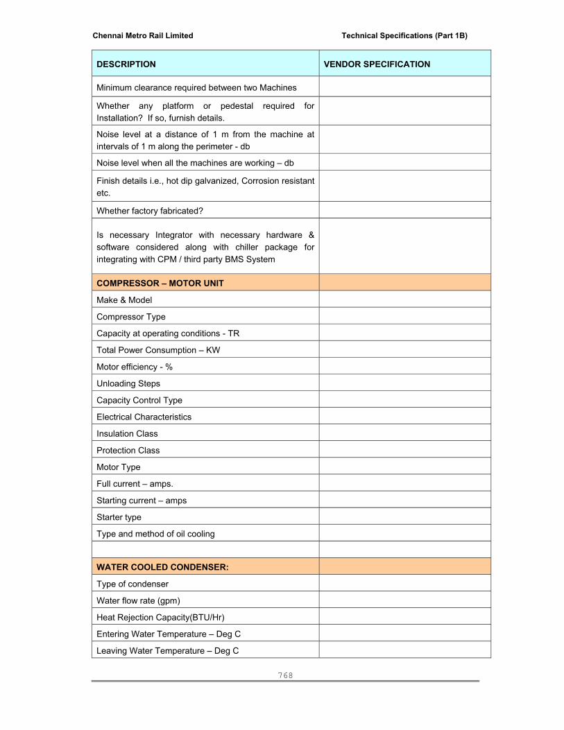
Chennai Metro Rail Limited Technical Specifications (Part 1B)
768
DESCRIPTION VENDOR SPECIFICATION
Minimum clearance required between two Machines
Whether any platform or pedestal required for Installation? If so, furnish details.
Noise level at a distance of 1 m from the machine at intervals of 1 m along the perimeter - db
Noise level when all the machines are working – db
Finish details i.e., hot dip galvanized, Corrosion resistant etc.
Whether factory fabricated?
Is necessary Integrator with necessary hardware & software considered along with chiller package for integrating with CPM / third party BMS System
COMPRESSOR – MOTOR UNIT
Make & Model
Compressor Type
Capacity at operating conditions - TR
Total Power Consumption – KW
Motor efficiency - %
Unloading Steps
Capacity Control Type
Electrical Characteristics
Insulation Class
Protection Class
Motor Type
Full current – amps.
Starting current – amps
Starter type
Type and method of oil cooling
WATER COOLED CONDENSER:
Type of condenser
Water flow rate (gpm)
Heat Rejection Capacity(BTU/Hr)
Entering Water Temperature – Deg C
Leaving Water Temperature – Deg C

Chennai Metro Rail Limited Technical Specifications (Part 1B)
769
DESCRIPTION VENDOR SPECIFICATION
Fouling Factor
Pressure Drop
Material of Tube
Tube OD - mm
No of Passes
Material of fin
Test pressure – Kg/Cm2
CHILLER:
Type of chiller (DX or Flooded)
Shell OD – mm
Overall length – mm
Number of tubes
Tube OD – mm
Nature of tubes (whether integrally finned or Whether tubes carry inserts)
Length of tube between tube sheets
Material of tube
Material of shell
Water side surface area - sqm
Refrigerant side surface area - sqm
Minimum operating charge of refrigerant – Kg
Water Flow rate – gpm
Leaving water temperature - deg C
Entering Water temperature - deg C
Refrigerant temperature - deg C
Leaving temperature difference - deg C
No. of passes
Tube velocity - mps
Pressure drop – Kg/sqcm
CONTROL PANEL
How Many Chillers can it Handle?
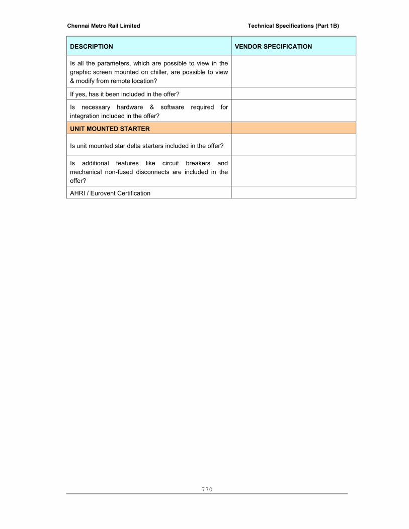
Chennai Metro Rail Limited Technical Specifications (Part 1B)
770
DESCRIPTION VENDOR SPECIFICATION
Is all the parameters, which are possible to view in the graphic screen mounted on chiller, are possible to view & modify from remote location?
If yes, has it been included in the offer?
Is necessary hardware & software required for integration included in the offer?
UNIT MOUNTED STARTER
Is unit mounted star delta starters included in the offer?
Is additional features like circuit breakers and mechanical non-fused disconnects are included in the offer?
AHRI / Eurovent Certification
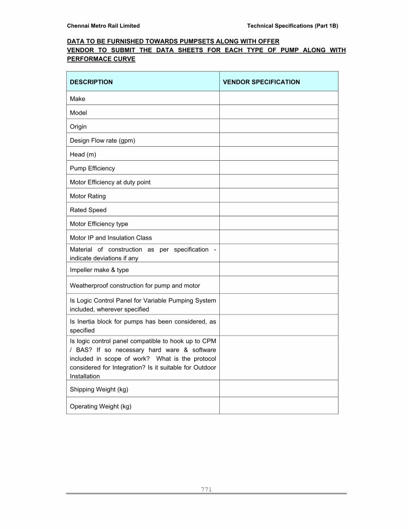
Chennai Metro Rail Limited Technical Specifications (Part 1B)
771
DATA TO BE FURNISHED TOWARDS PUMPSETS ALONG WITH OFFER VENDOR TO SUBMIT THE DATA SHEETS FOR EACH TYPE OF PUMP ALONG WITH PERFORMACE CURVE
DESCRIPTION VENDOR SPECIFICATION
Make
Model
Origin
Design Flow rate (gpm)
Head (m)
Pump Efficiency
Motor Efficiency at duty point
Motor Rating
Rated Speed
Motor Efficiency type
Motor IP and Insulation Class
Material of construction as per specification - indicate deviations if any
Impeller make & type
Weatherproof construction for pump and motor
Is Logic Control Panel for Variable Pumping System included, wherever specified
Is Inertia block for pumps has been considered, as specified
Is logic control panel compatible to hook up to CPM / BAS? If so necessary hard ware & software included in scope of work? What is the protocol considered for Integration? Is it suitable for Outdoor Installation
Shipping Weight (kg)
Operating Weight (kg)

Chennai Metro Rail Limited Technical Specifications (Part 1B)
772
DATA TO BE FURNISHED TOWARDS INDUCED DRAFT COOLING TOWERS ALONG WITH OFFER DESCRIPTION VENDOR SPECIFICATION
Type of the Cooling Tower
PERFORMANCE
Nominal Refrigeration tons Offered
Circulating Flow Rate Considered
Range (deg F)
Approach (deg F)
Hot Water Temperature Considered
Cold Water Temperature Considered
Ambient Wet-Bulb Considered
Drift Loss - % of flow
Evaporation Loss - % of flow
Overall Water Loss - % of flow
MATERIAL OF CONSTURCTION
Casing
Hot Water Basin
Cold Water Basin
Fan Cylinder
Frame Work
Fan
Fills
Louvers
Drift Eliminators
Nozzles
MOTOR & FAN
Type of Fan
Number of Fans
Number of Blades
Fan RPM
Drive System
Fan Motor type and rating
Motor efficiency
Variable Frequency Drive – Is it Considered along with the Offer
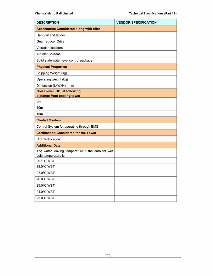
Chennai Metro Rail Limited Technical Specifications (Part 1B)
773
DESCRIPTION VENDOR SPECIFICATION
Accessories Considered along with offer
Handrail and ladder
Gear reducer Drive
Vibration Isolators
Air Inlet Screens
Solid state water level control package
Physical Properties
Shipping Weight (kg)
Operating weight (kg)
Dimension (LxWxH) - mm Noise level (DB) at following distance from cooling tower
5m
10m
15m
Control System
Control System for operating through BMS
Certification Considered for the Tower
CTI Certification
Additional Data The water leaving temperature if the ambient wet bulb temperature is
29.1⁰C WBT 28.0⁰C WBT 27.0⁰C WBT 26.0⁰C WBT 25.0⁰C WBT 24.0⁰C WBT 23.0⁰C WBT
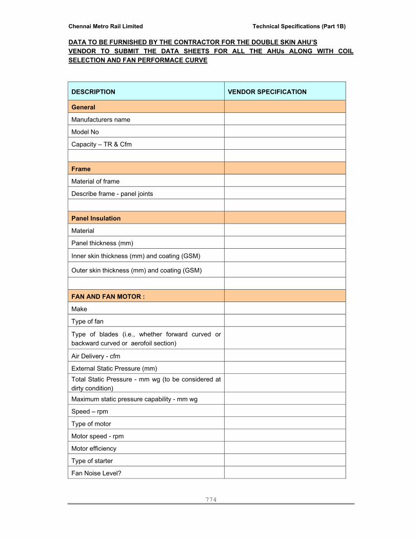
Chennai Metro Rail Limited Technical Specifications (Part 1B)
774
DATA TO BE FURNISHED BY THE CONTRACTOR FOR THE DOUBLE SKIN AHU’S VENDOR TO SUBMIT THE DATA SHEETS FOR ALL THE AHUs ALONG WITH COIL SELECTION AND FAN PERFORMACE CURVE
DESCRIPTION VENDOR SPECIFICATION
General
Manufacturers name
Model No
Capacity – TR & Cfm
Frame
Material of frame
Describe frame - panel joints
Panel Insulation
Material
Panel thickness (mm)
Inner skin thickness (mm) and coating (GSM)
Outer skin thickness (mm) and coating (GSM)
FAN AND FAN MOTOR :
Make
Type of fan
Type of blades (i.e., whether forward curved or backward curved or aerofoil section)
Air Delivery - cfm
External Static Pressure (mm) Total Static Pressure - mm wg (to be considered at dirty condition)
Maximum static pressure capability - mm wg
Speed – rpm
Type of motor
Motor speed - rpm
Motor efficiency
Type of starter
Fan Noise Level?

Chennai Metro Rail Limited Technical Specifications (Part 1B)
775
DESCRIPTION VENDOR SPECIFICATION
Whether impellor and shaft dynamically (and statically) balanced?
Vibration level
FILTER SECTION :
Overall dimensions - mm x mm x mm
Type of filters
Media used
Efficiency of filter (State the test method)
Manufacturer's name
Resistance of filter when clean-mm wg
Maximum resistance of filter - mm wg
Dust Holding Capacity ( Per & Fine Filter ) – gms
Is the media cleanable?
Is one set of commissioning filters considered in the Quote?
COOLING COIL
Please specify the type of Coils considered in the scope?
Material of Construction for Coil / Tubes
Material of Construction for Fins
Is special quoting specified in the Specs for Fins considered in the Scope
Is Moisture eliminator considered after coil section?
What is the material of construction for moisture eliminator
No of Rows
Bypass Factor
ENERGY RECOVERY WHEEL (wherever applicable)
Make & Type
Sensible recovery efficiency (%)
Latent recovery efficiency (%)
Purge Section details

Chennai Metro Rail Limited Technical Specifications (Part 1B)
776
DESCRIPTION VENDOR SPECIFICATION
Wheel Motor rating
Air leak losses make up details
SAFETY FEATURES Is safety switch (fan limit switch) considered in AHU?
Physical properties
Overall dimensions - mm x mm x mm
Overall weight (kg)
Is AHU suitable for Outdoor Installation? If so Weather Proof Canopy is Considered (Please refer where ever it is called)?
OTHERS
Is Mixing boxes considered in the scope
Is SA / RA damper included in the scope
Is Canvass connection at outlet included
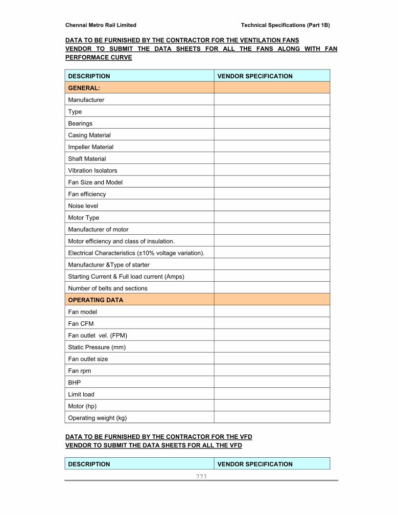
Chennai Metro Rail Limited Technical Specifications (Part 1B)
777
DATA TO BE FURNISHED BY THE CONTRACTOR FOR THE VENTILATION FANS VENDOR TO SUBMIT THE DATA SHEETS FOR ALL THE FANS ALONG WITH FAN PERFORMACE CURVE DESCRIPTION VENDOR SPECIFICATION
GENERAL:
Manufacturer
Type
Bearings
Casing Material
Impeller Material
Shaft Material
Vibration Isolators
Fan Size and Model
Fan efficiency
Noise level
Motor Type
Manufacturer of motor
Motor efficiency and class of insulation.
Electrical Characteristics (±10% voltage variation).
Manufacturer &Type of starter
Starting Current & Full load current (Amps)
Number of belts and sections
OPERATING DATA
Fan model
Fan CFM
Fan outlet vel. (FPM)
Static Pressure (mm)
Fan outlet size
Fan rpm
BHP
Limit load
Motor (hp)
Operating weight (kg) DATA TO BE FURNISHED BY THE CONTRACTOR FOR THE VFD VENDOR TO SUBMIT THE DATA SHEETS FOR ALL THE VFD DESCRIPTION VENDOR SPECIFICATION

Chennai Metro Rail Limited Technical Specifications (Part 1B)
778
DESCRIPTION VENDOR SPECIFICATION
Manufacturer
Model No
VFD Power rating (kW)
Input Power characteristics
Frequency control range
Harmonic current control
VFD enclosure protection
In-built Protective functions
Display type
Auto – Manual operation
Speed control feedback signals
Sequential logic controller
In built I/O points
Optional max I/O points
Microprocessor based logic controller
Compatibility to BMS integration
In built Communication Port
Other optional Protocol
Certification
Dimensions – mm ( L x B x H)
Weight (kg) ********
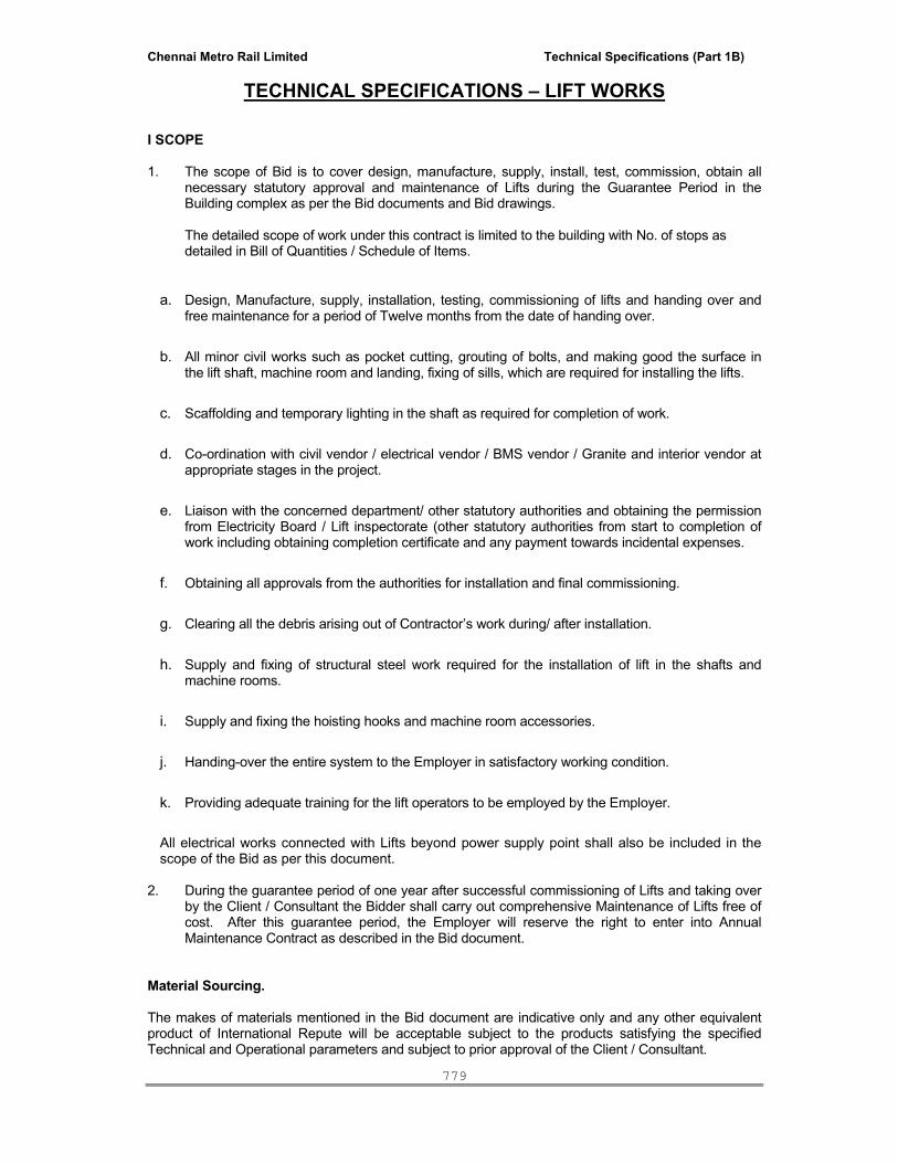
Chennai Metro Rail Limited Technical Specifications (Part 1B)
779
TECHNICAL SPECIFICATIONS – LIFT WORKS
I SCOPE 1. The scope of Bid is to cover design, manufacture, supply, install, test, commission, obtain all
necessary statutory approval and maintenance of Lifts during the Guarantee Period in the Building complex as per the Bid documents and Bid drawings.
The detailed scope of work under this contract is limited to the building with No. of stops as detailed in Bill of Quantities / Schedule of Items.
a. Design, Manufacture, supply, installation, testing, commissioning of lifts and handing over and free maintenance for a period of Twelve months from the date of handing over.
b. All minor civil works such as pocket cutting, grouting of bolts, and making good the surface in the lift shaft, machine room and landing, fixing of sills, which are required for installing the lifts.
c. Scaffolding and temporary lighting in the shaft as required for completion of work.
d. Co-ordination with civil vendor / electrical vendor / BMS vendor / Granite and interior vendor at appropriate stages in the project.
e. Liaison with the concerned department/ other statutory authorities and obtaining the permission from Electricity Board / Lift inspectorate (other statutory authorities from start to completion of work including obtaining completion certificate and any payment towards incidental expenses.
f. Obtaining all approvals from the authorities for installation and final commissioning.
g. Clearing all the debris arising out of Contractor’s work during/ after installation.
h. Supply and fixing of structural steel work required for the installation of lift in the shafts and machine rooms.
i. Supply and fixing the hoisting hooks and machine room accessories.
j. Handing-over the entire system to the Employer in satisfactory working condition.
k. Providing adequate training for the lift operators to be employed by the Employer.
All electrical works connected with Lifts beyond power supply point shall also be included in the scope of the Bid as per this document.
2. During the guarantee period of one year after successful commissioning of Lifts and taking over
by the Client / Consultant the Bidder shall carry out comprehensive Maintenance of Lifts free of cost. After this guarantee period, the Employer will reserve the right to enter into Annual Maintenance Contract as described in the Bid document.
Material Sourcing.
The makes of materials mentioned in the Bid document are indicative only and any other equivalent product of International Repute will be acceptable subject to the products satisfying the specified Technical and Operational parameters and subject to prior approval of the Client / Consultant.

Chennai Metro Rail Limited Technical Specifications (Part 1B)
780
Employer reserves the right to select different agencies for the above works and award the work either
directly or through the Main Contractor by nomination as specified elsewhere in the Bid. 3. The equipment supplied and erected shall be in accordance to updated version of IS- 14665
pertaining to lift provision. Fire protection requirement as per IS and as per National Building Code shall be complied with.
4. The Bidder shall note the following in the Lift Service particulars covered herein.
a. Capacity & Numbers, a. Travel height, number of stops and openings b. Type of Drive, c. Type of Safety Gear, door safety d. Type of Control and operation e. Interface leads to be left for Building Management / Automation System. f. Amenities and finishes in Lift Car.
5. The Bidder shall furnish any other details relevant to the work and not covered in the tender with
financial bearing if any explicitly.
6. As the Tender documents shall form part of the Agreement, the provisions covered therein should be noted carefully and any deviation felt necessary there from shall be highlighted at the time of tendering only and not after. For this a statement of deviation, if any shall be prepared by Bidder and shall be enclosed in the first envelope superscripted “Technical Bid”. If no deviation is proposed, still this form shall be submitted with an entry “No deviation proposed”. No deviation in commercial conditions is acceptable.
7. The Bidder shall give rates for all items given in the schedule of quantities. 8. No extra payment shall be considered either due to escalation or amendments / modifications to
statutory Act / Rules issued during the contract period. 9. The Bidder/ Contractor shall be responsible to obtain necessary License from Electrical / Lift
Authority, Local Competent Electrical Authority. 10. Terminal points: The terminal point (s) Viz. Civil work and other services shall be as follows: Civil works: The Lift shaft, pit shaft to the required dimensions including Plastering and Painting shall be completed by the civil agency. Hoist way / openings and the Machine room of required sizes shall be made available by the civil agency for erection of equipments well before its receipt at site. The Main Contractor shall be responsible for water proofing of the lift pit. Lift machine room with lockable doors and windows shall also be completed in all respects including lighting by the electrical agency. All other civil activities for Lift installation shall be within the scope of the Lift Contractor and shall fall within the Lift Contractor’s responsibility. All minor civil works under Lift Contractor’s responsibility include Cutting, Chasing and making good of the same at all levels, conceal the conduits and boxes for Panels etc. The minor Civil work shall also include items connected with fixing of Sill plate / Sill slab projection, fixing of buffer springs in the lift, fixing and mounting beams, bearing plate etc. at the Lift Machine room. Electrical Works: Power supply – 3 Phases, 415 Volts 50 Hz Power supply will be provided at Lift machine room above terrace level by the Electrical agency by terminating the incoming supply cable along with earthing at a lift panel board with one incoming and sufficient number of outgoing feeders, each controlled by an

Chennai Metro Rail Limited Technical Specifications (Part 1B)
781
isolator of suitable capacity, depending on the number of lift machines in each machine room. All power wiring for the Lift machine room will fall under the Lift Contractor’s scope commencing from the isolator.
The Lift Contractor scope however does not include providing M.S. Conduits in the Lift shaft for permanent lighting purposes including wiring, fixing of holders etc. which will be done by the Electrical agency. Likewise 5/15 Amps sockets at various levels in the lift shaft will also be provided by the electrical agency.
INTERFACE: The signals from the Fire mode services of the Lifts shall be integrated into the over all fire alarm system, forming part of the Building Management System. For this purpose, sufficient potential free leads shall be left by the Lift Contractor at appropriate locations preferably in machine room from which the Building Management system Contractor will connect the interface to BMS / BAS system.
II - PARTICULARS OF SERVICE REQUIREMENT
LIFTS - TECHNICAL AND PERFORMANCE CRITERIA
General Note: The bidders to note that in respect to the finish of the car interior, the final specification shall be as per the Client requirement and approval. At the time of Pre-bid meeting, the bidders are requested to come prepared with possible options of car interior finishes. Mirror finish / mirror polish finish is not to be provided. SL.
Description Capsule Lift Service Lift Passenger Lift Passenger Lift
No
Machine room less Elevator
(MHQ)
Machine room less Elevator
(MHQ)
Machine room less Elevator
(Type- A)
Machine room less Elevator
(Type- B) 1 Lift Type Gearless Elevator
without Machine room
Gearless Elevator without Machine room
Gearless Elevator without Machine room
Gearless Elevator without Machine room
2 Capacity 3 Number of Lifts 3 No’s 1 No 2 No 2 No 4 Speed 0.50 to 1.0 meters
per second. (Minimum)
0.50 to 1.0 meters per second. (Minimum)
0.50 to 1.0 meter per second. (Minimum)
0.50 to 1.0 meter per second. (Minimum)
5 Machine & Drive Micro processor based Variable Voltage Variable Frequency drive system
Micro processor based Variable Voltage Variable Frequency drive system
Micro processor based Variable Voltage Variable Frequency drive system
Micro processor based Variable Voltage Variable Frequency drive system
6 Travel 28.50 M (B+G+4 Upper floors)
28.50 M (B+G+4 Upper floors)
19.75 M (Stilt +5 Upper floors)
34.215M(Stilt + 9 Upper floors)
7 Servicing, no. of stops served
Basement+ Ground + Four upper floors, servicing 6 stops and 6 landings.
Basement+ Ground + Four upper floors, servicing 6 stops and 6 landings.
Stilt + 5 upper floors, servicing 6 stops and 6 landings.
Stilt + 9 upper floors, servicing 10 stops and 10 landings.

Chennai Metro Rail Limited Technical Specifications (Part 1B)
782
SL. Description
Capsule Lift Service Lift Passenger Lift Passenger Lift
No
Machine room less Elevator
(MHQ)
Machine room less Elevator
(MHQ)
Machine room less Elevator
(Type- A)
Machine room less Elevator
(Type- B) 8 Control & Operation Micro processor
based simplex selective collective control with or without attendant.
Micro processor based simplex selective collective control with or without attendant.
Micro processor based simplex selective collective control with or without attendant.
Micro processor based simplex selective collective control with or without attendant.
9 Potential free contacts
Monitoring the ON / OFF / status (position ,direction, emergency alarm, inspection drive, Fire Input) of all Lifts from the Building Management System shall be through potential free contacts and a separate terminal block within the lift control panel which shall be provided by the Lift Contractor including wiring. The wiring from the lift controller to BMS shall however be done by the Contractor for BMS.
Monitoring the ON / OFF / status (position ,direction, emergency alarm, inspection drive, Fire Input) of all Lifts from the Building Management System shall be through potential free contacts and a separate terminal block within the lift control panel which shall be provided by the Lift Contractor including wiring. The wiring from the lift controller to BMS shall however be done by the Contractor for BMS.
Monitoring the ON / OFF / status (position ,direction, emergency alarm, inspection drive, Fire Input) of Lift from the Building Management System shall be through potential free contacts and a separate terminal block within the lift control panel which shall be provided by the Lift Contractor including wiring. The wiring from the lift controller to BMS shall however be done by the Contractor for BMS.
Monitoring the ON / OFF / status (position ,direction, emergency alarm, inspection drive, Fire Input) of Lift from the Building Management System shall be through potential free contacts and a separate terminal block within the lift control panel which shall be provided by the Lift Contractor including wiring. The wiring from the lift controller to BMS shall however be done by the Contractor for BMS.
10 Position of Machine Room
Machine room less Machine room less
Machine room less
Machine room less
11 Shaft Size W X D 3250x3600 mm 2950x2650 mm 2500x2060 mm 2500x2060 mm 12 Lift pit depth 2000 mm 2000 mm 2000 mm 2000 mm 13 Overhead
(Head room height) NIL
NIL NIL
NIL
14 Lift Machine Room Size
The layout of the machinery, panels and room sizes will be in the scope of the lift supplier and will take care of the stops and scheduling requirements and shall be as per IS standard
The layout of the machinery, panels and room sizes will be in the scope of the lift supplier and will take care of the stops and scheduling requirements and shall be as per IS standard
The layout of the machinery, panels and room sizes will be in the scope of the lift supplier and will take care of the stops and scheduling requirements and shall be as per IS standard.
The layout of the machinery, panels and room sizes will be in the scope of the lift supplier and will take care of the stops and scheduling requirements and shall be as per IS standard.
15 Position of Counterweight
Filler weight at the back of the car
Filler weight at the back of the car
Filler weight at the back of the car
Filler weight at the back of the car

Chennai Metro Rail Limited Technical Specifications (Part 1B)
783
SL. Description
Capsule Lift Service Lift Passenger Lift Passenger Lift
No
Machine room less Elevator
(MHQ)
Machine room less Elevator
(MHQ)
Machine room less Elevator
(Type- A)
Machine room less Elevator
(Type- B) B CAR INTERIORS
16
Size of Lift car W x D x H (clear inside size)
1800 X 3000 X 2800mm
1800 X 3000 X 2800mm
2000 X 3000 X 2800mm
2000 X 3000 X 2800mm
17 No. of Entrance 1 No. 1 No. 1 No. 1 No. 18 Door Size 1800 mm x
2400mm 1800 mm x 2400mm
1800mm x 2400mm
1800mm x 2400mm
19 Car enclosure, Ceiling & Door
Shall be of MS powder coated/ painted / factory enameled finish on all four sides, MS painted Guard Rails on 3 sides at 2 levels surface of Car door shall be side opening telescopic of MS powder coated/ painted / factory enameled finish with two hours fire rated for the landing doors. Kick Plate False Ceiling shall be MS powder coated / painted / factory enameled finish. Vendor to submit samples.
Shall be of MS powder coated/ painted / factory enameled finish on all four sides, MS painted Guard Rails on 3 sides at 2 levels surface of Car door shall be side opening telescopic of MS powder coated/ painted / factory enameled finish with two hours fire rated for the landing doors. Kick Plate False Ceiling shall be MS powder coated / painted / factory enameled finish. Vendor to submit samples.
Shall be of MS powder coated/ painted / factory enameled finish on all four sides, MS painted Guard Rails on 3 sides at 2 levels surface of Car door shall be side opening telescopic of MS powder coated/ painted / factory enameled finish with two hours fire rated for the landing doors. .Kick Plate False Ceiling shall be MS powder coated / painted / factory enameled finish. Vendor to submit samples.
Shall be of MS powder coated/ painted / factory enameled finish on all four sides, MS painted Guard Rails on 3 sides at 2 levels surface of Car door shall be side opening telescopic of MS powder coated/ painted / factory enameled finish with two hours fire rated for the landing doors. .Kick Plate False Ceiling shall be MS powder coated / painted / factory enameled finish. Vendor to submit samples.
20 Pressure Sensor Pressure sensor operated doors safety system to be provided.
Pressure sensor operated doors safety system to be provided.
Pressure sensor operated doors safety system to be provided.
Pressure sensor operated doors safety system to be provided.
Passenger Safety : Full length infra red safety
Full length infra red light curtain:
Full length infra red light curtain:
Full length infra red light curtain:
Full length infra red light curtain:
The Light Curtain to consist of infra - red light beams (154 criss cross beams) passing between Car Door Entrances and one side of the Entrance the light source is sent and on the opposite side, sensors are sensing the light source. If an object cuts the light beams the receivers will sense and give door
The Light Curtain to consist of infra - red light beams (154 criss cross beams) passing between Car Door Entrances and one side of the Entrance the light source is sent and on the opposite side, sensors are sensing the light source. If an object cuts the light beams the receivers will
The Light Curtain to consist of infra - red light beams (154 criss cross beams) passing between Car Door Entrances and one side of the Entrance the light source is sent and on the opposite side, sensors are sensing the light source. If an object cuts the light beams the
The Light Curtain to consist of infra - red light beams (154 criss cross beams) passing between Car Door Entrances and one side of the Entrance the light source is sent and on the opposite side, sensors are sensing the light source. If an object cuts the light beams the receivers will
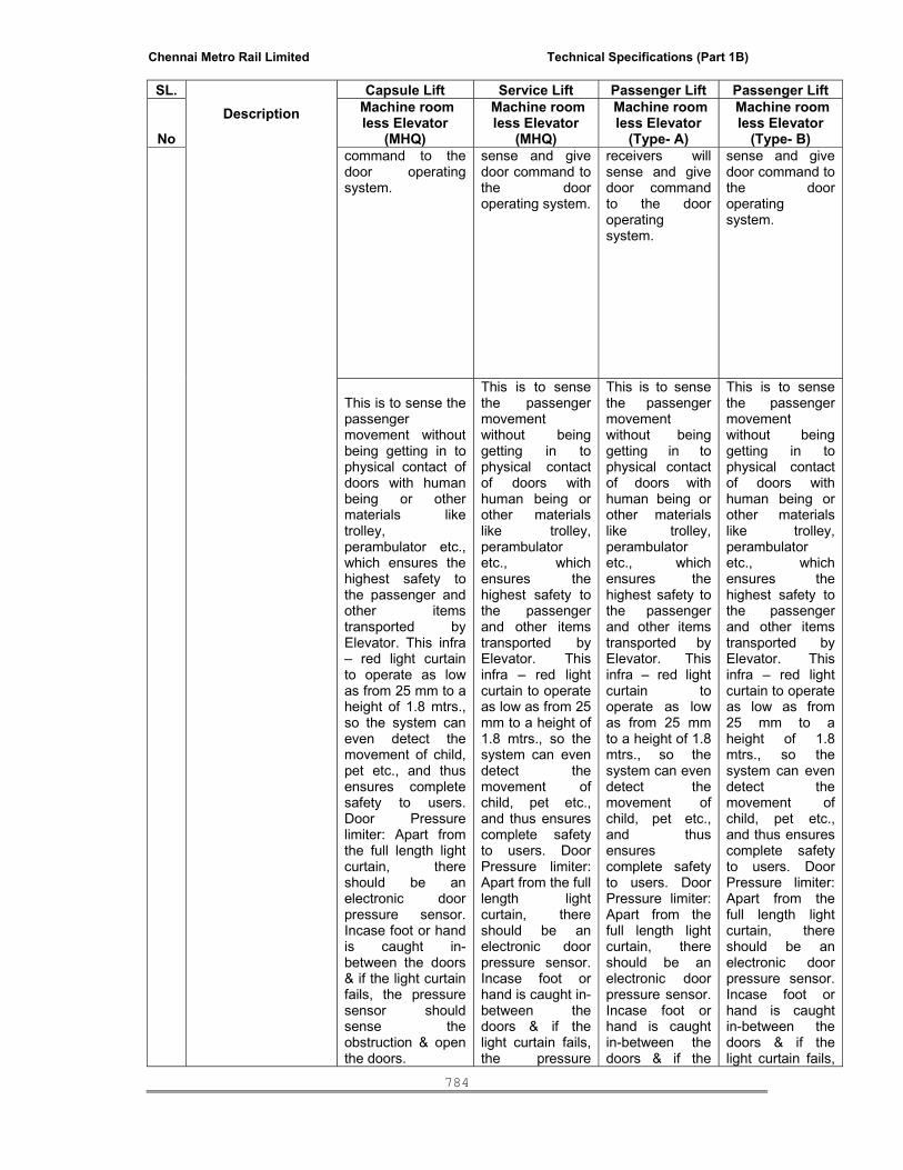
Chennai Metro Rail Limited Technical Specifications (Part 1B)
784
SL. Description
Capsule Lift Service Lift Passenger Lift Passenger Lift
No
Machine room less Elevator
(MHQ)
Machine room less Elevator
(MHQ)
Machine room less Elevator
(Type- A)
Machine room less Elevator
(Type- B) command to the door operating system.
sense and give door command to the door operating system.
receivers will sense and give door command to the door operating system.
sense and give door command to the door operating system.
This is to sense the passenger movement without being getting in to physical contact of doors with human being or other materials like trolley, perambulator etc., which ensures the highest safety to the passenger and other items transported by Elevator. This infra – red light curtain to operate as low as from 25 mm to a height of 1.8 mtrs., so the system can even detect the movement of child, pet etc., and thus ensures complete safety to users. Door Pressure limiter: Apart from the full length light curtain, there should be an electronic door pressure sensor. Incase foot or hand is caught in-between the doors & if the light curtain fails, the pressure sensor should sense the obstruction & open the doors.
This is to sense the passenger movement without being getting in to physical contact of doors with human being or other materials like trolley, perambulator etc., which ensures the highest safety to the passenger and other items transported by Elevator. This infra – red light curtain to operate as low as from 25 mm to a height of 1.8 mtrs., so the system can even detect the movement of child, pet etc., and thus ensures complete safety to users. Door Pressure limiter: Apart from the full length light curtain, there should be an electronic door pressure sensor. Incase foot or hand is caught in-between the doors & if the light curtain fails, the pressure
This is to sense the passenger movement without being getting in to physical contact of doors with human being or other materials like trolley, perambulator etc., which ensures the highest safety to the passenger and other items transported by Elevator. This infra – red light curtain to operate as low as from 25 mm to a height of 1.8 mtrs., so the system can even detect the movement of child, pet etc., and thus ensures complete safety to users. Door Pressure limiter: Apart from the full length light curtain, there should be an electronic door pressure sensor. Incase foot or hand is caught in-between the doors & if the
This is to sense the passenger movement without being getting in to physical contact of doors with human being or other materials like trolley, perambulator etc., which ensures the highest safety to the passenger and other items transported by Elevator. This infra – red light curtain to operate as low as from 25 mm to a height of 1.8 mtrs., so the system can even detect the movement of child, pet etc., and thus ensures complete safety to users. Door Pressure limiter: Apart from the full length light curtain, there should be an electronic door pressure sensor. Incase foot or hand is caught in-between the doors & if the light curtain fails,

Chennai Metro Rail Limited Technical Specifications (Part 1B)
785
SL. Description
Capsule Lift Service Lift Passenger Lift Passenger Lift
No
Machine room less Elevator
(MHQ)
Machine room less Elevator
(MHQ)
Machine room less Elevator
(Type- A)
Machine room less Elevator
(Type- B) sensor should sense the obstruction & open the doors.
light curtain fails, the pressure sensor should sense the obstruction & open the doors.
the pressure sensor should sense the obstruction & open the doors.
21 Fan Ventilating axial fan Ventilating axial fan
Ventilating axial fan
Ventilating axial fan
22 Car Light Energy efficient CFL lights – lighting to minimum 150 lux at car sill level shall be provided
Energy efficient CFL lights – lighting to minimum 150 lux at car sill level shall be provided
Energy efficient CFL lights – lighting to minimum 150 lux at car sill level shall be provided
Energy efficient CFL lights – lighting to minimum 150 lux at car sill level shall be provided
23 Car floor finish 6mm thick Aluminum Chequered plate
6mm thick Aluminum Chequered plate
6mm thick Aluminum Chequered plate
6mm thick Aluminum Chequered plate
24 Car Operating Panel Panel 1
Panel 1
Panel 1
Panel 1
a) Key operated switch marked to indicate ``attendant’’-``automatic’’ operation.
a) Key operated switch marked to indicate ``attendant’’-``automatic’’ operation.
a) Key operated switch marked to indicate ``attendant’’-``automatic’’ operation.
a) Key operated switch marked to indicate ``attendant’’-``automatic’’ operation.
b) Luminous white square flush mounted Braille push button for each floor served
b) Luminous white square flush mounted Braille push button for each floor served
b) Luminous white square flush mounted Braille push button for each floor served
b) Luminous white square flush mounted Braille push button for each floor served
c) Door open/close push buttons.
c) Door open/close push buttons.
c) Door open/close push buttons.
c) Door open/close push buttons.

Chennai Metro Rail Limited Technical Specifications (Part 1B)
786
SL. Description
Capsule Lift Service Lift Passenger Lift Passenger Lift
No
Machine room less Elevator
(MHQ)
Machine room less Elevator
(MHQ)
Machine room less Elevator
(Type- A)
Machine room less Elevator
(Type- B) d) Battery operated emergency alarm Push Button. (Alarm unit in Main floor)
d) Battery operated emergency alarm Push Button. (Alarm unit in Main floor)
d) Battery operated emergency alarm Push Button. (Alarm unit in Main floor)
d) Battery operated emergency alarm Push Button. (Alarm unit in Main floor)
e) Push Button for non-stop operation of Lift in attendant mode.
e) Push Button for non-stop operation of Lift in attendant mode.
e) Push Button for non-stop operation of Lift in attendant mode.
e) Push Button for non-stop operation of Lift in attendant mode.
f) UP/DOWN Push buttons for attendant mode
f) UP/DOWN Push buttons for attendant mode
f) UP/DOWN Push buttons for attendant mode
f) UP/DOWN Push buttons for attendant mode
g) Over-Load warning indicator (Audible and visual Indication).
g) Over-Load warning indicator (Audible and visual Indication).
g) Over-Load warning indicator (Audible and visual Indication).
g) Over-Load warning indicator (Audible and visual Indication).
Panel 2 Panel 2 Panel 2 Panel 2 Luminous white square flush mounted Braille push button for each floor served.
Luminous white square flush mounted Braille push button for each floor served.
Luminous white square flush mounted Braille push button for each floor served.
Luminous white square flush mounted Braille push button for each floor served.
LED Display located above the car door.
LED Display located above the car door.
LED Display located above the car door.
LED Display located above the car door.
C LANDING ENTRANCES
25 Location of landing entrance on different floors
All doors on the same side (Front only)
All doors on the same side (Front only)
All doors on the same side (Front only)
All doors on the same side (Front only)
2 hours fire rated Landing doors
All landing doors should be 2 hours fire rated
All landing doors should be 2 hours fire rated
All landing doors should be 2 hours fire rated
All landing doors should be 2 hours fire rated
26 Controls and Indicators at landings
a) Call registration by High intensity LED luminous Push Buttons, Two nos. for intermediate landings and single push button for terminal landings with indication for UP and DOWN direction of motion.
a) Call registration by High intensity LED luminous Push Buttons, Two nos. for intermediate landings and single push button for terminal landings with indication for UP and DOWN direction of motion.
a) Call registration by High intensity LED luminous Push Buttons, Two nos. for intermediate landings and single push button for terminal landings with indication for UP and DOWN direction of motion.
a) Call registration by High intensity LED luminous Push Buttons, Two nos. for intermediate landings and single push button for terminal landings with indication for UP and DOWN direction of motion.
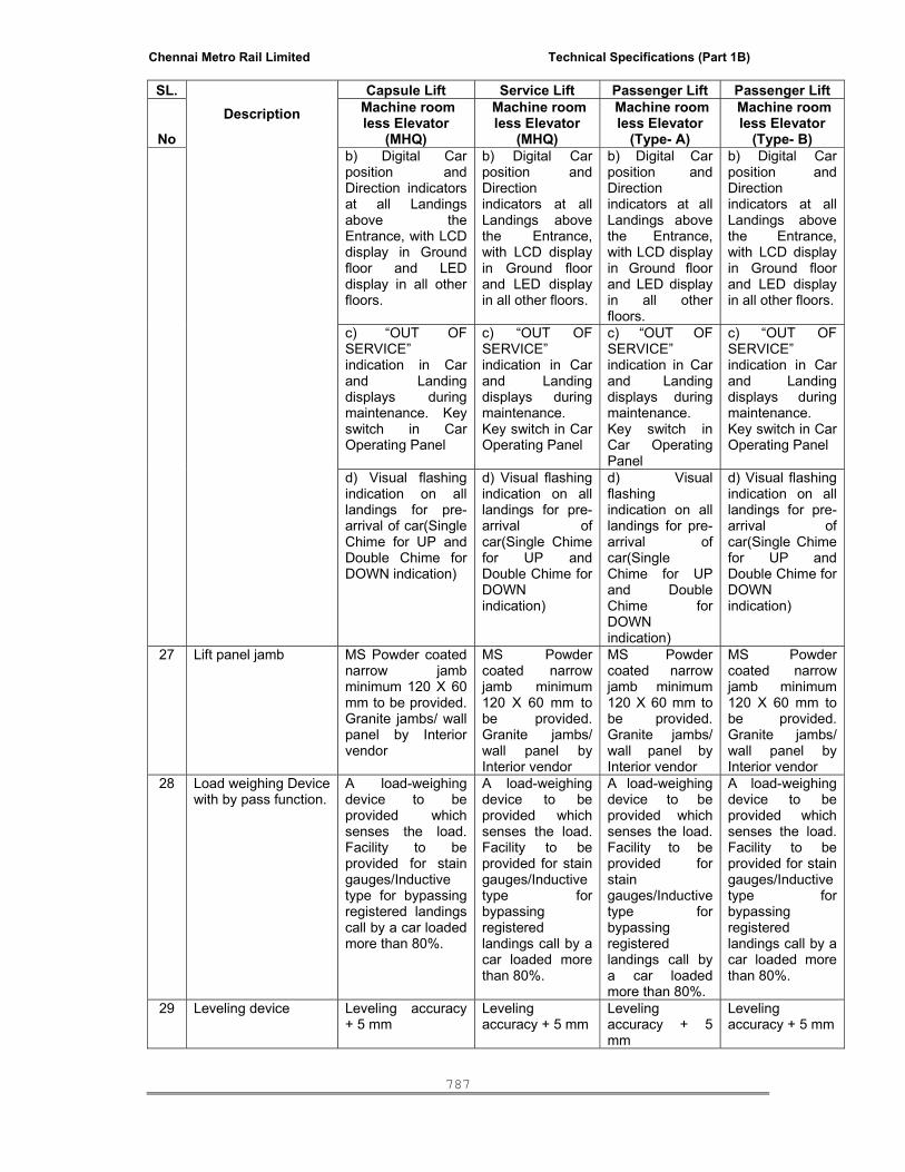
Chennai Metro Rail Limited Technical Specifications (Part 1B)
787
SL. Description
Capsule Lift Service Lift Passenger Lift Passenger Lift
No
Machine room less Elevator
(MHQ)
Machine room less Elevator
(MHQ)
Machine room less Elevator
(Type- A)
Machine room less Elevator
(Type- B) b) Digital Car position and Direction indicators at all Landings above the Entrance, with LCD display in Ground floor and LED display in all other floors.
b) Digital Car position and Direction indicators at all Landings above the Entrance, with LCD display in Ground floor and LED display in all other floors.
b) Digital Car position and Direction indicators at all Landings above the Entrance, with LCD display in Ground floor and LED display in all other floors.
b) Digital Car position and Direction indicators at all Landings above the Entrance, with LCD display in Ground floor and LED display in all other floors.
c) “OUT OF SERVICE” indication in Car and Landing displays during maintenance. Key switch in Car Operating Panel
c) “OUT OF SERVICE” indication in Car and Landing displays during maintenance. Key switch in Car Operating Panel
c) “OUT OF SERVICE” indication in Car and Landing displays during maintenance. Key switch in Car Operating Panel
c) “OUT OF SERVICE” indication in Car and Landing displays during maintenance. Key switch in Car Operating Panel
d) Visual flashing indication on all landings for pre-arrival of car(Single Chime for UP and Double Chime for DOWN indication)
d) Visual flashing indication on all landings for pre-arrival of car(Single Chime for UP and Double Chime for DOWN indication)
d) Visual flashing indication on all landings for pre-arrival of car(Single Chime for UP and Double Chime for DOWN indication)
d) Visual flashing indication on all landings for pre-arrival of car(Single Chime for UP and Double Chime for DOWN indication)
27 Lift panel jamb MS Powder coated narrow jamb minimum 120 X 60 mm to be provided. Granite jambs/ wall panel by Interior vendor
MS Powder coated narrow jamb minimum 120 X 60 mm to be provided. Granite jambs/ wall panel by Interior vendor
MS Powder coated narrow jamb minimum 120 X 60 mm to be provided. Granite jambs/ wall panel by Interior vendor
MS Powder coated narrow jamb minimum 120 X 60 mm to be provided. Granite jambs/ wall panel by Interior vendor
28 Load weighing Device with by pass function.
A load-weighing device to be provided which senses the load. Facility to be provided for stain gauges/Inductive type for bypassing registered landings call by a car loaded more than 80%.
A load-weighing device to be provided which senses the load. Facility to be provided for stain gauges/Inductive type for bypassing registered landings call by a car loaded more than 80%.
A load-weighing device to be provided which senses the load. Facility to be provided for stain gauges/Inductive type for bypassing registered landings call by a car loaded more than 80%.
A load-weighing device to be provided which senses the load. Facility to be provided for stain gauges/Inductive type for bypassing registered landings call by a car loaded more than 80%.
29 Leveling device Leveling accuracy + 5 mm
Leveling accuracy + 5 mm
Leveling accuracy + 5 mm
Leveling accuracy + 5 mm
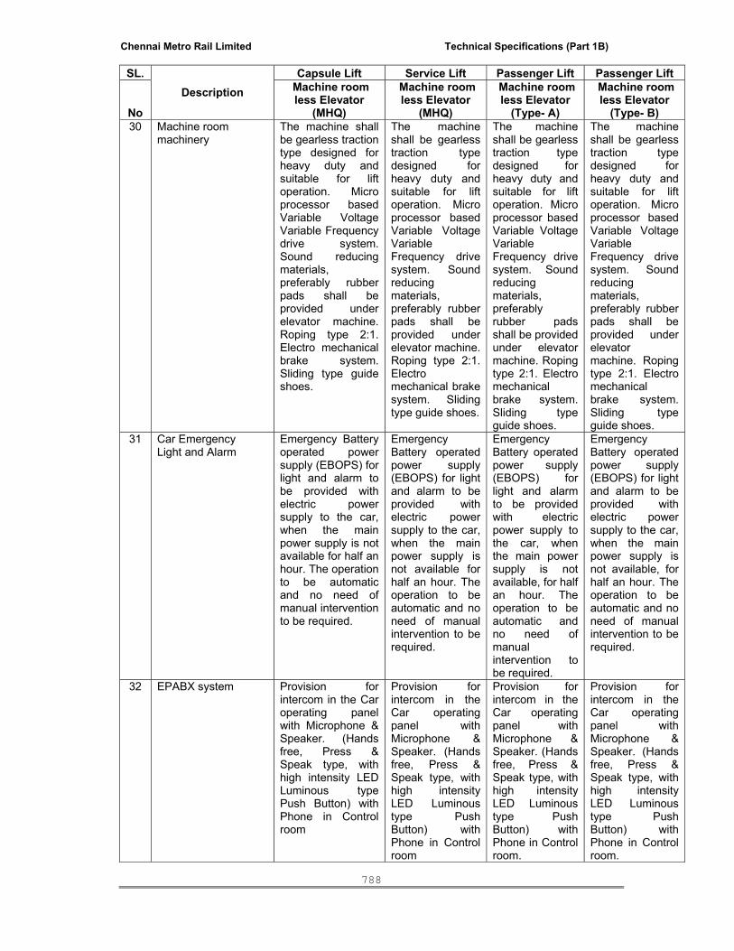
Chennai Metro Rail Limited Technical Specifications (Part 1B)
788
SL. Description
Capsule Lift Service Lift Passenger Lift Passenger Lift
No
Machine room less Elevator
(MHQ)
Machine room less Elevator
(MHQ)
Machine room less Elevator
(Type- A)
Machine room less Elevator
(Type- B) 30 Machine room
machinery The machine shall be gearless traction type designed for heavy duty and suitable for lift operation. Micro processor based Variable Voltage Variable Frequency drive system. Sound reducing materials, preferably rubber pads shall be provided under elevator machine. Roping type 2:1. Electro mechanical brake system. Sliding type guide shoes.
The machine shall be gearless traction type designed for heavy duty and suitable for lift operation. Micro processor based Variable Voltage Variable Frequency drive system. Sound reducing materials, preferably rubber pads shall be provided under elevator machine. Roping type 2:1. Electro mechanical brake system. Sliding type guide shoes.
The machine shall be gearless traction type designed for heavy duty and suitable for lift operation. Micro processor based Variable Voltage Variable Frequency drive system. Sound reducing materials, preferably rubber pads shall be provided under elevator machine. Roping type 2:1. Electro mechanical brake system. Sliding type guide shoes.
The machine shall be gearless traction type designed for heavy duty and suitable for lift operation. Micro processor based Variable Voltage Variable Frequency drive system. Sound reducing materials, preferably rubber pads shall be provided under elevator machine. Roping type 2:1. Electro mechanical brake system. Sliding type guide shoes.
31 Car Emergency Light and Alarm
Emergency Battery operated power supply (EBOPS) for light and alarm to be provided with electric power supply to the car, when the main power supply is not available for half an hour. The operation to be automatic and no need of manual intervention to be required.
Emergency Battery operated power supply (EBOPS) for light and alarm to be provided with electric power supply to the car, when the main power supply is not available for half an hour. The operation to be automatic and no need of manual intervention to be required.
Emergency Battery operated power supply (EBOPS) for light and alarm to be provided with electric power supply to the car, when the main power supply is not available, for half an hour. The operation to be automatic and no need of manual intervention to be required.
Emergency Battery operated power supply (EBOPS) for light and alarm to be provided with electric power supply to the car, when the main power supply is not available, for half an hour. The operation to be automatic and no need of manual intervention to be required.
32 EPABX system Provision for intercom in the Car operating panel with Microphone & Speaker. (Hands free, Press & Speak type, with high intensity LED Luminous type Push Button) with Phone in Control room
Provision for intercom in the Car operating panel with Microphone & Speaker. (Hands free, Press & Speak type, with high intensity LED Luminous type Push Button) with Phone in Control room
Provision for intercom in the Car operating panel with Microphone & Speaker. (Hands free, Press & Speak type, with high intensity LED Luminous type Push Button) with Phone in Control room.
Provision for intercom in the Car operating panel with Microphone & Speaker. (Hands free, Press & Speak type, with high intensity LED Luminous type Push Button) with Phone in Control room.

Chennai Metro Rail Limited Technical Specifications (Part 1B)
789
SL. Description
Capsule Lift Service Lift Passenger Lift Passenger Lift
No
Machine room less Elevator
(MHQ)
Machine room less Elevator
(MHQ)
Machine room less Elevator
(Type- A)
Machine room less Elevator
(Type- B) 33 Terminal buffers Terminal buffers
shall be installed as a means of stopping the car and counter weight at the extreme limits of travel and shall be spring or oil buffers. Buffers in pit shall be mounted on the steel channels or on the suitable concrete blocks.
Terminal buffers shall be installed as a means of stopping the car and counter weight at the extreme limits of travel and shall be spring or oil buffers. Buffers in pit shall be mounted on the steel channels or on the suitable concrete blocks.
Terminal buffers shall be installed as a means of stopping the car and counter weight at the extreme limits of travel and shall be spring or oil buffers. Buffers in pit shall be mounted on the steel channels or on the suitable concrete blocks.
Terminal buffers shall be installed as a means of stopping the car and counter weight at the extreme limits of travel and shall be spring or oil buffers. Buffers in pit shall be mounted on the steel channels or on the suitable concrete blocks.
34 Counter weight Provided in steel structure as per clause-12 of IS-14665 (part-I) 2000 amended till date.
Provided in steel structure as per clause-12 of IS-14665 (part-I) 2000 amended till date.
Provided in steel structure as per clause-12 of IS-14665 (part-I) 2000 amended till date.
Provided in steel structure as per clause-12 of IS-14665 (part-I) 2000 amended till date.
35 Guide rails Machined T-guide section shall be provided for both car & counter weight. The guide rails shall be continuous throughout the entire travel and shall withstand without any deformation the action of safety gear with a fully loaded car. The guide rail anchorage at pit floor must be made without puncturing the waterproofing. The expansion joints in the guide rails shall be so designed as to avoid jerks in the lift car. Machined guide rails shall have finished surfaces, which shall be coated with corrosion preventive compound, which shall be maintained till the commissioning of
Machined T-guide section shall be provided for both car & counter weight. The guide rails shall be continuous throughout the entire travel and shall withstand without any deformation the action of safety gear with a fully loaded car. The guide rail anchorage at pit floor must be made without puncturing the waterproofing. The expansion joints in the guide rails shall be so designed as to avoid jerks in the lift car. Machined guide rails shall have finished surfaces, which shall be coated with corrosion preventive compound, which shall be
Machined T-guide section shall be provided for both car & counter weight. The guide rails shall be continuous throughout the entire travel and shall withstand without any deformation the action of safety gear with a fully loaded car. The guide rail anchorage at pit floor must be made without puncturing the waterproofing. The expansion joints in the guide rails shall be so designed as to avoid jerks in the lift car. Machined guide rails shall have finished surfaces, which shall be coated with corrosion preventive compound,
Machined T-guide section shall be provided for both car & counter weight. The guide rails shall be continuous throughout the entire travel and shall withstand without any deformation the action of safety gear with a fully loaded car. The guide rail anchorage at pit floor must be made without puncturing the waterproofing. The expansion joints in the guide rails shall be so designed as to avoid jerks in the lift car. Machined guide rails shall have finished surfaces, which shall be coated with corrosion preventive compound, which shall be

Chennai Metro Rail Limited Technical Specifications (Part 1B)
790
SL. Description
Capsule Lift Service Lift Passenger Lift Passenger Lift
No
Machine room less Elevator
(MHQ)
Machine room less Elevator
(MHQ)
Machine room less Elevator
(Type- A)
Machine room less Elevator
(Type- B) the installation. Before the car is placed in operation, the preventive coating shall be removed and the guide rails thoroughly cleaned and smoothened
maintained till the commissioning of the installation. Before the car is placed in operation, the preventive coating shall be removed and the guide rails thoroughly cleaned and smoothened
which shall be maintained till the commissioning of the installation. Before the car is placed in operation, the preventive coating shall be removed and the guide rails thoroughly cleaned and smoothened
maintained till the commissioning of the installation. Before the car is placed in operation, the preventive coating shall be removed and the guide rails thoroughly cleaned and smoothened
36 Safety gears & Over speed Governor
Progressive type Safety gear, mounted on the bottom members of Car frame or otherwise as per Manufacturer’s specification and shall be operated by an Over speed Governor erected in Machine room. The safety device shall stop the Car whenever excessive descending speed is attained with means to cut-off power from the motor and apply the brake prior to application of safety gear. Over speed governor shall have arrangement to
Progressive type Safety gear, mounted on the bottom members of Car frame or otherwise as per Manufacturer’s specification and shall be operated by an Over speed Governor erected in Machine room. The safety device shall stop the Car whenever excessive descending speed is attained with means to cut-off power from the motor and apply the brake prior to application of safety gear. Over speed governor shall have
Progressive type Safety gear, mounted on the bottom members of Car frame or otherwise as per Manufacturer’s specification and shall be operated by an Over speed Governor erected in Machine room. The safety device shall stop the Car whenever excessive descending speed is attained with means to cut-off power from the motor and apply the brake prior to application of
Progressive type Safety gear, mounted on the bottom members of Car frame or otherwise as per Manufacturer’s specification and shall be operated by an Over speed Governor erected in Machine room. The safety device shall stop the Car whenever excessive descending speed is attained with means to cut-off power from the motor and apply the brake prior to application of safety gear. Over

Chennai Metro Rail Limited Technical Specifications (Part 1B)
791
SL. Description
Capsule Lift Service Lift Passenger Lift Passenger Lift
No
Machine room less Elevator
(MHQ)
Machine room less Elevator
(MHQ)
Machine room less Elevator
(Type- A)
Machine room less Elevator
(Type- B) detect slack, loosened or broken over speed rope
arrangement to detect slack, loosened or broken over speed rope
safety gear. Over speed governor shall have arrangement to detect slack, loosened or broken over speed rope
speed governor shall have arrangement to detect slack, loosened or broken over speed rope
37 Ropes Hoisting suspension ropes shall be of steel of suitable size, construction and number as per IS 2365-1977 and designed as per IS 14665 Part III: 2000 amended till date/DIN EN 12385 & DIN EN 10264. Governor ropes shall be of Steel. All Ropes shall be specially designed and manufactured for elevator application. The minimum factor of safety in rope capacity shall be 12.
Hoisting suspension ropes shall be of steel of suitable size, construction and number as per IS 2365-1977 and designed as per IS 14665 Part III: 2000 amended till date/DIN EN 12385 & DIN EN 10264. Governor ropes shall be of Steel. All Ropes shall be specially designed and manufactured for elevator application. The minimum factor of safety in rope capacity shall be 12.
Hoisting suspension ropes shall be of steel of suitable size, construction and number as per IS 2365-1977 and designed as per IS 14665 Part III: 2000 amended till date/DIN EN 12385 & DIN EN 10264. Governor ropes shall be of Steel. All Ropes shall be specially designed and manufactured for elevator application. The minimum factor of safety in rope capacity shall be 12.
Hoisting suspension ropes shall be of steel of suitable size, construction and number as per IS 2365-1977 and designed as per IS 14665 Part III: 2000 amended till date/DIN EN 12385 & DIN EN 10264. Governor ropes shall be of Steel. All Ropes shall be specially designed and manufactured for elevator application. The minimum factor of safety in rope capacity shall be 12.
38 i)Phase failure relay i) Phase failure relay shall be provided to protect the machine against failure of any one phase.
i) Phase failure relay shall be provided to protect the machine against failure of any one phase.
i) Phase failure relay shall be provided to protect the machine against failure of any one phase.
i) Phase failure relay shall be provided to protect the machine against failure of any one phase.

Chennai Metro Rail Limited Technical Specifications (Part 1B)
792
SL. Description
Capsule Lift Service Lift Passenger Lift Passenger Lift
No
Machine room less Elevator
(MHQ)
Machine room less Elevator
(MHQ)
Machine room less Elevator
(Type- A)
Machine room less Elevator
(Type- B) ii) Automatic
Phase-reversal corrector unit shall be provided to correct Phase reversal
ii) Automatic Phase-reversal corrector unit shall be provided to correct Phase reversal
ii) Automatic Phase-reversal corrector unit shall be provided to correct Phase reversal
ii) Automatic Phase-reversal corrector unit shall be provided to correct Phase reversal
ii)Automatic Phase-reversal unit
iii)A single phase failure or phase imbalance sensing device is to be provided which senses the power failure or power interruption or single phasing or unbalanced phases or any problem in the power supply which affect the normal operation of elevator and switches the Automatic Rescue Device(ARD) into operation. Trapping of passengers in case of problems in power supply can be avoided
iii)A single phase failure or phase imbalance sensing device is to be provided which senses the power failure or power interruption or single phasing or unbalanced phases or any problem in the power supply which affect the normal operation of elevator and switches the Automatic Rescue Device(ARD) into operation. Trapping of passengers in case of problems in power supply can be avoided
iii)A single phase failure or phase imbalance sensing device is to be provided which senses the power failure or power interruption or single phasing or unbalanced phases or any problem in the power supply which affect the normal operation of elevator and switches the Automatic Rescue Device(ARD) into operation. Trapping of passengers in case of problems in power supply can be avoided.
iii)A single phase failure or phase imbalance sensing device is to be provided which senses the power failure or power interruption or single phasing or unbalanced phases or any problem in the power supply which affect the normal operation of elevator and switches the Automatic Rescue Device(ARD) into operation. Trapping of passengers in case of problems in power supply can be avoided.
D SAFETY MEASURES 39 Automatic rescue
device Automatic Rescue Device (ARD) to rescue the stranded lift passengers in the event of a power failure, operated on dry maintenance - free batteries of required capacity to continuously monitor the normal power supply in the main elevator controller and activate rescue operation within 60 seconds of a power failure by which the lift is brought to the
Automatic Rescue Device (ARD) to rescue the stranded lift passengers in the event of a power failure, operated on dry maintenance - free batteries of required capacity to continuously monitor the normal power supply in the main elevator controller and activate rescue operation within 60 seconds of a
Automatic Rescue Device (ARD) to rescue the stranded lift passengers in the event of a power failure, operated on dry maintenance - free batteries of required capacity to continuously monitor the normal power supply in the main elevator controller and activate rescue operation within
Automatic Rescue Device (ARD) to rescue the stranded lift passengers in the event of a power failure, operated on dry maintenance - free batteries of required capacity to continuously monitor the normal power supply in the main elevator controller and activate rescue operation within 60 seconds of a

Chennai Metro Rail Limited Technical Specifications (Part 1B)
793
SL. Description
Capsule Lift Service Lift Passenger Lift Passenger Lift
No
Machine room less Elevator
(MHQ)
Machine room less Elevator
(MHQ)
Machine room less Elevator
(Type- A)
Machine room less Elevator
(Type- B) nearest landing and doors remain open
power failure by which the lift is brought to the nearest landing and doors remain open
60 seconds of a power failure by which the lift is brought to the nearest landing and doors remain open
power failure by which the lift is brought to the nearest landing and doors remain open
40 Fireman Drive Provision for Fireman drive to be made to bring the car to the main floor immediately after the fireman switch is operated. Thereafter the car is for operation by the rescue person. All landing calls are ignored. Lift answers one car call at a time. The rescue person controls opening and closing of doors at a floor. Returns to normal when fireman switch is opened.
Provision for Fireman drive to be made to bring the car to the main floor immediately after the fireman switch is operated. Thereafter the car is for operation by the rescue person. All landing calls are ignored. Lift answers one car call at a time. The rescue person controls opening and closing of doors at a floor. Returns to normal when fireman switch is opened.
Provision for Fireman drive to be made to bring the car to the main floor immediately after the fireman switch is operated. Thereafter the car is for operation by the rescue person. All landing calls are ignored. Lift answers one car call at a time. The rescue person controls opening and closing of doors at a floor. Returns to normal when fireman switch is opened.
Provision for Fireman drive to be made to bring the car to the main floor immediately after the fireman switch is operated. Thereafter the car is for operation by the rescue person. All landing calls are ignored. Lift answers one car call at a time. The rescue person controls opening and closing of doors at a floor. Returns to normal when fireman switch is opened.
Fireman switch drive to be provided for the lift in ground floor lobby with individual switch control.
Fireman switch drive to be provided for the lift in ground floor lobby with individual switch control.
Fireman switch drive to be provided for the lift in ground floor lobby with individual switch control.
Fireman switch drive to be provided for the lift in ground floor lobby with individual switch control.
41 Car call backward Car calls behind the direction of travel are to be accepted and registered
Car calls behind the direction of travel are to be accepted and registered
Car calls behind the direction of travel are to be accepted and registered
Car calls behind the direction of travel are to be accepted and registered
42 Car door lock Car door lock to be provided as per CVC guidelines
Car door lock to be provided as per CVC guidelines
Car door lock to be provided as per CVC guidelines
Car door lock to be provided as per CVC guidelines

Chennai Metro Rail Limited Technical Specifications (Part 1B)
794
SL. Description
Capsule Lift Service Lift Passenger Lift Passenger Lift
No
Machine room less Elevator
(MHQ)
Machine room less Elevator
(MHQ)
Machine room less Elevator
(Type- A)
Machine room less Elevator
(Type- B) 43 False call canceling Canceling of all car
calls to be provided if there is lift movement without transfer of people at landings.
Canceling of all car calls to be provided if there is lift movement without transfer of people at landings.
Canceling of all car calls to be provided if there is lift movement without transfer of people at landings.
Canceling of all car calls to be provided if there is lift movement without transfer of people at landings.
44 Priority call in main landing
During priority service, the car should answer the nearest car call and return to normal service.
During priority service, the car should answer the nearest car call and return to normal service.
During priority service, the car should answer the nearest car call and return to normal service.
During priority service, the car should answer the nearest car call and return to normal service.
45 Priority call in Car Selected by key-operated switch in car-elevator. Exclusively serves the person inside the car (one call at a time), to be provided.
Selected by key-operated switch in car-elevator. Exclusively serves the person inside the car (one call at a time), to be provided.
Selected by key-operated switch in car-elevator. Exclusively serves the person inside the car (one call at a time), to be provided.
Selected by key-operated switch in car-elevator. Exclusively serves the person inside the car (one call at a time), to be provided.
46 Main entrance floor In this floor in which the fire fighters switch and alarm bell will be fixed, so that in case of emergency the lift can be taken control by the firefighters at that floor.
In this floor in which the fire fighters switch and alarm bell will be fixed, so that in case of emergency the lift can be taken control by the firefighters at that floor.
In this floor in which the fire fighters switch and alarm bell will be fixed, so that in case of emergency the lift can be taken control by the firefighters at that floor.
In this floor in which the fire fighters switch and alarm bell will be fixed, so that in case of emergency the lift can be taken control by the firefighters at that floor.
47 Variable door opening time
The opening time of the car door and landing door can be varied according to the requirement
The opening time of the car door and landing door can be varied according to the requirement
The opening time of the car door and landing door can be varied according to the requirement
The opening time of the car door and landing door can be varied according to the requirement
48 Full collective logic Full collective control system to be provided to facilitate the optimum function of the elevator. Here the lift will accept the car and landing calls in both directions
Full collective control system to be provided to facilitate the optimum function of the elevator. Here the lift will accept the car and landing calls in both directions
Full collective control system to be provided to facilitate the optimum function of the elevator. Here the lift will accept the car and landing calls in both directions
Full collective control system to be provided to facilitate the optimum function of the elevator. Here the lift will accept the car and landing calls in both directions
49 Zoning of Elevators - - - - 50 Accurate Re-leveling,
Automatic Automatic accurate Re-leveling of car, after stopping at a floor should take place. Automatic
Automatic accurate Re-leveling of car, after stopping at a floor should
Automatic accurate Re-leveling of car, after stopping at a floor should
Automatic accurate Re-leveling of car, after stopping at a floor should

Chennai Metro Rail Limited Technical Specifications (Part 1B)
795
SL. Description
Capsule Lift Service Lift Passenger Lift Passenger Lift
No
Machine room less Elevator
(MHQ)
Machine room less Elevator
(MHQ)
Machine room less Elevator
(Type- A)
Machine room less Elevator
(Type- B) Re-leveling should take place before door open.
take place. Automatic Re-leveling should take place before door open.
take place. Automatic Re-leveling should take place before door open.
take place. Automatic Re-leveling should take place before door open.
51 Built in Voltage stabilizer
To be provided to avoid problems / hazards due to voltage fluctuation, thereby increasing the life of electrical and electronic components for the better service of the elevator.
To be provided to avoid problems / hazards due to voltage fluctuation, thereby increasing the life of electrical and electronic components for the better service of the elevator.
To be provided to avoid problems / hazards due to voltage fluctuation, thereby increasing the life of electrical and electronic components for the better service of the elevator.
To be provided to avoid problems / hazards due to voltage fluctuation, thereby increasing the life of electrical and electronic components for the better service of the elevator.
52 Hall lantern Illuminated arrows to indicate the next travel direction of arriving / available car to be provided. Electronic chime that sounds when the car arrives at a landing to serve a landing call to be provided.(Single / Double Chime for direction identification)
Illuminated arrows to indicate the next travel direction of arriving / available car to be provided. Electronic chime that sounds when the car arrives at a landing to serve a landing call to be provided.(Single / Double Chime for direction identification)
Illuminated arrows to indicate the next travel direction of arriving / available car to be provided. Electronic chime that sounds when the car arrives at a landing to serve a landing call to be provided.(Single / Double Chime for direction identification)
Illuminated arrows to indicate the next travel direction of arriving / available car to be provided. Electronic chime that sounds when the car arrives at a landing to serve a landing call to be provided.(Single / Double Chime for direction identification)
53 Speaker for music/ announcement
Required Required Required Required
54 Direction and position indicator in car and landings and Hall buttons.
LED display in all floors on SS panel to be provided in car and lift lobby.
LED display in all floors on SS panel to be provided in car and lift lobby.
LED display in all floors on SS panel to be provided in car and lift lobby.
LED display in all floors on SS panel to be provided in car and lift lobby.
55 Notices and Signage All necessary safety notices and signage required near and inside the elevators. Instructions to be provided on Photo luminescent signage.
All necessary safety notices and signage required near and inside the elevators. Instructions to be provided on Photo luminescent signage.
All necessary safety notices and signage required near and inside the elevators. Instructions to be provided on Photo luminescent signage.
All necessary safety notices and signage required near and inside the elevators. Instructions to be provided on Photo luminescent signage.

Chennai Metro Rail Limited Technical Specifications (Part 1B)
796
SL. Description
Capsule Lift Service Lift Passenger Lift Passenger Lift
No
Machine room less Elevator
(MHQ)
Machine room less Elevator
(MHQ)
Machine room less Elevator
(Type- A)
Machine room less Elevator
(Type- B) 56 Miscellaneous i) All electrical wiring shall be with fire resistant, moisture proof insulation and
shall be run in heavy gauge metal conduit. The trailing cable is between the car and lift well shall be flat multi-core type designed for lift services and shall be fire resistant. Moisture proof covering cables should conform to IS 4289 – 1967 as amended upto date. All exposed metal parts shall be properly painted with good quality paint after erection and before commissioning the lift. The supply and erection of lift shall conform to the latest lift act in force and modern lift practice in all respects. All wiring and earthing etc shall conform to IE rules and regulations. ii) Single Maintenance Access Panel to be provided for each lift in the Top most Landing.
57 Electric supply 415 Volts (+5% to –10%) AC 50 Hz 3 phase 4 wire system AC power supply. Built-in Voltage Stabilizer to be provided by the Lift Supplier to avoid hazards due to Voltage fluctuation.
58 Instruction manuals 3 sets of operation and maintenance manuals and special instructions if any for care and maintenance during lift operation shall be supplied preferably before commencement of installation work.
59 Guarantee & Maintenance
The firm shall guarantee that the entire installation shall be free from material/ workmanship/ manufacturing defects for a period of twelve months from the date of completion of work and inspection of lift by the lift inspecting authority. During this period the firm shall carry out routine maintenance like general cleaning, oiling, greasing adjustment and checking of all safety devices etc. as may be required in addition to attending to break down calls, The agency has to clear all the faults without any extra charge.
60 General All necessary scaffoldings for the erection of lift, Minor builders work, all necessary steel items such as machine beams, ladder in pit, stretchers, hitch beams, bearing plates, Fascias etc., all of which if any shall be provided by the lift supplier. All other minor bldg works like chipping of walls for accommodating the lift doors and making good the same as required shall also be done by the supplier. Hoist way wiring in MS conduit with PVC insulated Copper wires for lighting with Bulk head fitting & lamp and 5A Power socket with MS box, laminated hy-lam sheet for each floor with individual switch control as per the direction of Engineer in Charge shall be carried out by the Electrical contractor.

Chennai Metro Rail Limited Technical Specifications (Part 1B)
797
SL. Description
Capsule Lift Service Lift Passenger Lift Passenger Lift
No
Machine room less Elevator
(MHQ)
Machine room less Elevator
(MHQ)
Machine room less Elevator
(Type- A)
Machine room less Elevator
(Type- B)
61 References: All lift equipments and installation shall conform to the relevant ISI standards amended upto date. However, reference to a few IS standards is given below.
a) IS 14665-2000 Part III
Specifications for Electrical passenger & goods lift.
b) IS 14665-2000, Part-I
Outline dimension of electric lift.
c) IS 14665, Part-2 Sec:1
Code and practice for installation operation& maintenance of electrical passenger and goods lift.
d) IS 14665, Part-3, Section-1
Safety rules for passengers and goods lift.
e) IS 14665, Part 4, Section-1
Lift Buffer
f) IS 14665, Part 4, Section- 2
Lift guide rails and guide shoes.
g) IS 14665, Part 4 Section- 3
Lift car frame, car, counter weight and suspension.
h) IS 14665, Part 4, Section- 4
Lift safety gears and governors.
i) IS 14665, Part 4, Section- 5
Lift retiring cam.
j) IS 14665, Part 4, Section- 6
Lifts doors and locking devices and contacts.
k) IS 14665, Part 4, Section- 7
Lift machines and brakes
l) IS 14665, Part 4, Section- 8
Steel wire suspension ropes
IS 2365:1977
m) IS 14665, Part 4, Section- 9
Controller and operating devices for lifts.
n) IS 4289 : 1984 Part I
Specifications for flexible cables lift. Elastomer insulated cables.

Chennai Metro Rail Limited Technical Specifications (Part 1B)
798
SL. Description
Capsule Lift Service Lift Passenger Lift Passenger Lift
No
Machine room less Elevator
(MHQ)
Machine room less Elevator
(MHQ)
Machine room less Elevator
(Type- A)
Machine room less Elevator
(Type- B) o) IS 4289 : 1984 Part
II Specifications for flexible cables lift. PVC insulated circular cables.
p) IS 15785 : 2007 Installation and maintenance of Lifts without conventional machine rooms
Note:
1. The Contractor has to arrange at their own cost including supply, fabricate and erect in position structural steel required for support of machine, brackets for guide rails, facia plates at all landings etc., including three coats of anticorrosive paint of approved make and connected Civil works such as cutting of holes, chases etc., in brick work, concrete etc., including scaffolding of walls, floors on partitions together and making good holes for fixing brackets in lift walls, grouting of all bolts, sills, brackets / control board/button boxes, limit switches etc., all in position for all lifts together.
2. Provision shall also be made available in the controller and wherever necessary for the lift(s) to directly travel to ground floor on any signal from Fire Alarm Control Panel having lead to lift machine room, automatically, ignoring direction of travel and other pending commands as per special condition of the tender.
3. Requirements indicated in the National Building Code of India in respect of Fire Protection requirements of lifts (Clause ‘D-1.5’ – Latest Issue) shall be fully complied with in respect of Design, Manufacturing and Erection of the Lifts.
4. Construct a mock-up complete with lift finish. Upon the approval of the same, contractor shall proceed for erection of other lifts.
5. Full set of tools required for maintenance of lifts shall be provided by contractor in the Lift Machine Room.
6. Notice required from the statutory authority shall be obtained.
III. SPECIAL CONDITIONS -TECHNICAL
1. All lifts shall be suitable / compatible for integration with fire alarm system signals and Building Management system. The elevator shall be capable of entering into 'Emergency Fire Mode Service' upon receiving a signal from fire alarm system. The wiring from lift controller to Fire Alarm system shall be done by the Fire Alarm contractor.
Monitoring the ON / OFF / status (position ,direction, emergency alarm, inspection drive) of all Lifts from the Building Management System shall be through potential free contacts and a separate terminal block within the lift control panel which shall be provided by the Lift Contractor including wiring. The wiring from the lift controller to BMS shall however be done by the Contractor for BMS. All the lifts shall be designated and fitted up as 'Firemans' Lift' and perform fireman’s drive. Identification of ‘Firemans’ lift shall be conspicuously displayed with the words ‘FIRE LIFT’ in fluorescent paint on the landing doors at each floor level. “FIRE MAN SWITCH” shall be provided in ground floor in all the lifts and use the designated “FIRE LIFT” as per local statutory regulation.
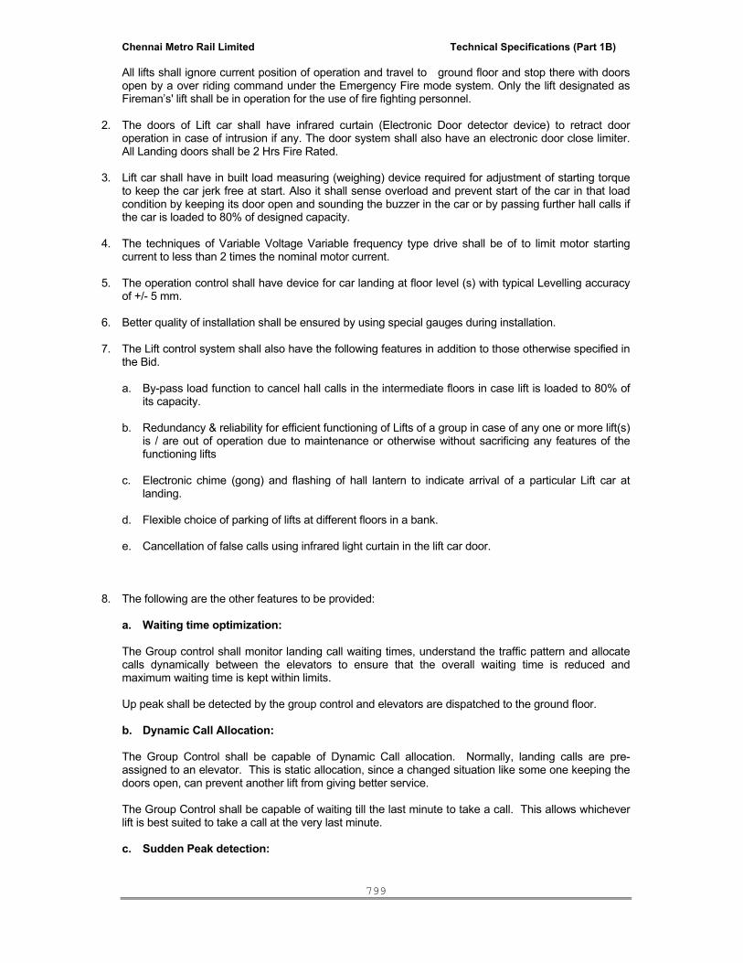
Chennai Metro Rail Limited Technical Specifications (Part 1B)
799
All lifts shall ignore current position of operation and travel to ground floor and stop there with doors open by a over riding command under the Emergency Fire mode system. Only the lift designated as Fireman’s' lift shall be in operation for the use of fire fighting personnel.
2. The doors of Lift car shall have infrared curtain (Electronic Door detector device) to retract door operation in case of intrusion if any. The door system shall also have an electronic door close limiter. All Landing doors shall be 2 Hrs Fire Rated.
3. Lift car shall have in built load measuring (weighing) device required for adjustment of starting torque to keep the car jerk free at start. Also it shall sense overload and prevent start of the car in that load condition by keeping its door open and sounding the buzzer in the car or by passing further hall calls if the car is loaded to 80% of designed capacity.
4. The techniques of Variable Voltage Variable frequency type drive shall be of to limit motor starting current to less than 2 times the nominal motor current.
5. The operation control shall have device for car landing at floor level (s) with typical Levelling accuracy of +/- 5 mm.
6. Better quality of installation shall be ensured by using special gauges during installation.
7. The Lift control system shall also have the following features in addition to those otherwise specified in the Bid. a. By-pass load function to cancel hall calls in the intermediate floors in case lift is loaded to 80% of
its capacity. b. Redundancy & reliability for efficient functioning of Lifts of a group in case of any one or more lift(s)
is / are out of operation due to maintenance or otherwise without sacrificing any features of the functioning lifts
c. Electronic chime (gong) and flashing of hall lantern to indicate arrival of a particular Lift car at
landing. d. Flexible choice of parking of lifts at different floors in a bank. e. Cancellation of false calls using infrared light curtain in the lift car door.
8. The following are the other features to be provided:
a. Waiting time optimization: The Group control shall monitor landing call waiting times, understand the traffic pattern and allocate
calls dynamically between the elevators to ensure that the overall waiting time is reduced and maximum waiting time is kept within limits.
Up peak shall be detected by the group control and elevators are dispatched to the ground floor.
b. Dynamic Call Allocation:
The Group Control shall be capable of Dynamic Call allocation. Normally, landing calls are pre-
assigned to an elevator. This is static allocation, since a changed situation like some one keeping the doors open, can prevent another lift from giving better service.
The Group Control shall be capable of waiting till the last minute to take a call. This allows whichever
lift is best suited to take a call at the very last minute.
c. Sudden Peak detection:
Chennai Metro Rail Limited Technical Specifications (Part 1B)
800
The Group Control shall be capable of detecting sudden requirement for lift in any floor and meet such a demand. For example, if some one is holding a group meeting at a floor, and the group meeting is over many people come out looking for the elevator. Here the Group Control can sense that a car is fully loaded and dispatch other lifts to meet the demand instantaneously. d. Misuse of Landing Calls:
It is quite common that the passenger standing in a floor will press both the direction hall calls though he wants to go in one direction only. The lift will make an unnecessary stop in the other direction also, though there may not be any one standing on the floor lobby. Unnecessary stops will delay the lift service to others.
The simultaneous registering of up and down calls at the same floor is prevented by a time delay after
the first registered call e. Door Open Time: The door opening time at any floor shall be capable of being set at site depending on the site conditions. f. The lift safety mechanisms shall include the provision of Automatic Rescue Device (ARD) to rescue the stranded lift passengers in the event of a power failure, operated on dry maintenance - free batteries of required capacity to continuously monitor the normal power supply in the main elevator controller and activate rescue operation within ten seconds of a power failure by which the lift is brought to the nearest landing and doors remain open.
IV . SPECIAL CONDITIONS - OTHERS 1.0 DRAWINGS & DOCUMENTS 1.1 The tender drawings are guideline for explaining the scheme. However there may be certain detail, which may require further detailing while actual execution or there may be certain detail which could have been inadvertently overlooked. Such details shall not constitute extra items. The drawings guide the contractor when he works out his quotation. Any item of work, not indicated in the drawing but in line with the design and with the thinking shall be deemed to be part of contractual obligation and nothing extra shall be paid to the contractor for the same. 1.2 All work shall be carried out on the basis of approved shop drawings. Drawings furnished shall include, but shall not be limited to a. Schematic diagrams. b. Layout drawings. c. Drawings for control panels. d. GA drawings for lift shaft, lift pit and Lift machine rooms 1.3 The Elevator Contractor should furnish: a. Drawings necessary to show the general arrangement of the Elevator equipment and get the same approved from the Employer before the work begins. b. Drawings / Sketches showing the details of controller in respect of design and metal used for its contract points should be enclosed. 2.0 DETAILED WORKING DRAWINGS 2.1 Prior to execution of the work, the contractor shall check all the drawings, specifications and shall within twenty-one days report any errors, discrepancy and/or omissions discovered therein to

Chennai Metro Rail Limited Technical Specifications (Part 1B)
801
the Employer and obtain appropriate orders on the same. Any adjustments made by the contractor without prior approval of the Employer shall be at his own risk and cost. 2.2 Shop drawing will not be constituted as an extra item and shall include, but not restricted to mechanical, electrical and structural layout and requirements of the lift machine rooms, lift shafts, lift pits, lift lobbies, lift cabs, operating panels, indicator panels, safety devices, etc., Contractors work can be commenced at site only once the contractors shop drawings are approved by the Employer in writing and after giving a prior notice for commencement of work. 2.3 Shafts allotted for all the traction lifts shall be taken into consideration before ordering the equipment. 2.4 Prior to submission of drawings for approval, the contractor shall be responsible for thoroughly checking all drawings to ensure that they comply with the intent and the requirements of the contract specifications. 2.5 The contractor shall secure the approval of the Employer for his detailed working drawings before proceeding with the work. For this purpose, he shall submit six sets of drawings to the Employer. Any alterations proposed by the Employer shall be incorporated in the drawings by the contractor and the corrected drawings shall be submitted once again in six sets to Employer. 2.6 The approval of the drawing by the Employer shall not be considered as a complete dimensional check but will indicate that the general method of construction and detailing is satisfactory. The contractor shall be responsible for the dimensions and the design of adequate connections, supports, details, etc. and for the satisfactory construction of the work. 2.7 After installation is completed, 6 sets of “As built drawings" shall be prepared with full details and submitted to the Employer along with the final bill. 3.0 METHOD STATEMENT The successful Tenderer shall have to prepare a Method Statement for each item of work including for Quality Assurance and this shall be submitted to the Employer / Project Managers for approval prior to start of work. 4.0 METHOD OF MEASUREMENT All works shall be measured net as completed or as fixed in place with no allowance (unless specified). No allowance shall be made for narrow width, easy access or difficult position. Any work executed over and above the dimensions given in the drawings or sketches provided by the Client or without written instruction by the Client shall be ignored and no payment shall be made for such extra work. 5.0 TRAINING 5.1 The successful contractor shall fully provide training to Employer personnel in operation and routine maintenance of the elevator plant. Such training shall be imparted during installation of the plant/system and also after commissioning. 5.2 The tenderers shall state the facilities they have for executing the work at Chennai, if the contract is awarded to them. Details of the set-up with particular reference to their establishment at Chennai should be furnished. They are also required to present a list of projects of comparable magnitude and nature which have been executed by them or are under execution with particular reference to those in and around Chennai. Capacity to render prompt and effective after-sales service is an important consideration. Accordingly, the Tenderers shall furnish the details of any service schemes (including the fees payable) that they are in a position to offer and the facilities they have for implementing such schemes. 5.3 In particular, the tenderers shall note that the successful contractor will be required to post a competent supervisor on full-time basis once the work is taken up. Tenderers shall specifically confirm this point in their tender.

Chennai Metro Rail Limited Technical Specifications (Part 1B)
802
5.4 The tenderers shall quote according to the specifications as far as possible, but where deviations are unavoidable, they shall state the reasons thereof clearly and shall also (in case alternative proposals are made) back them up by furnishing all relevant technical data. They shall also indicate the financial implications.
5.5. No terms and conditions stipulated by the tenderers (whether printed or otherwise) will be accepted. In the event and in case, the tenderers find deviations unavoidable; such deviations shall be with reference to specific clauses in the tender documents. They shall, as far as possible, be so worded that in the agreement which the successful contractor shall enter into with the Owners, they can be introduced as amendments.
6.0 Operating Instructions: The Contractor shall furnish a neatly typed set of operating instructions securely framed and glassed. These instructions shall furnish information and guidance on operating pressures, temperatures, and quantities, etc. Do's & Don’ts, Safety Measures & Precautions shall also be featured in the Instructions. Two more copies shall be supplied without framing. In addition the contractor shall supply suitably bound 3 copies of Operation and Maintenance Manuals. Such manuals should include wiring diagrams, manufacturers’ lists of spare parts with part numbers, exploded views with identification of parts etc. for facility of ordering - all in originals. 7.0 SPECIAL CONDITIONS - OTHERS 7.1 The manufacture, supply and installation of Lifts shall be complete in all respect in a first class workmen like manner and shall cover all work including Structural Steel work necessary for the supporting structures for the Lift machine room and other minor Civil works such as scaffolding etc., required for installation and materials, all complying the requirement of local body if any, and in accordance with the I.S. specifications I.S. 14665 and fire protection requirement as per National Building Code of India. 7.2 Quality Assurance Plan (QAP) in respect of Lift shall be submitted before commencement of work for approval of the Architects. 7.3 The Elevators offered shall be in accordance with the safety of lifts in public buildings CVC Report for the guidelines for Safety (Refer Annexure VIII) 1 PARTICULAR: a) Salient features of the Equipment provision as to manufacture; furnishing, finish etc. shall be highlighted with reference to the material input and operational supremacy. b) Necessary drawings showing the general arrangements of the equipment etc. shall be furnished. The drawing shall also detail out all items/components, which shall have to be provided by other agencies such as the Main Contractor for Civil and Associated works and the Electrical Contractor and member of consortium during the execution of the main work/installation. c) The materials and workmanship of the Lifts and its installations shall be guaranteed and the guarantee shall cover making good of any defects, not due to any ordinary wear and tear or improper use and care, which may develop within One year from the date of handing over of installations duly tested and commissioned. d) The Lifts installations shall be maintained for a period of 12 (Twelve) months commencing from the date, the Elevator equipments are taken over to use and the maintenance shall include periodical lubrication of the equipment and adjustment thereof, if any, under supervision and direction of Competent Personnel and replacement of parts that become necessary due to normal wear and tear during the guarantee period. All Operation / Maintenance shall be performed during regular hours of regular working days.

Chennai Metro Rail Limited Technical Specifications (Part 1B)
803
e) The Lift service particular and General Specification/Condition appended shall be adhered to in all respect, except for specific change contemplated otherwise in the offer. f) The local statutory Lift Rules for Lift Control as applicable shall be complied with, No extra payment shall be considered either due to escalation or amendments / modifications to local Act / Rules issued during the contract period. g) Bidder / Contractor shall be responsible to obtain necessary License from the Electrical / Lift Inspectorate of Lifts before handing over of the installation(s) by taking timely action in submission of prescribed application form therefore along with documents like completion drawing etc., duly making payment of required statutory fees / charges in the manner specified by the Inspectorate on behalf of the Employer and further follow up action. The expenses will be deemed to be covered by the quoted rates. The statutory fees /charges payable to Inspectorate shall be reimbursed by the Employer as per actual on evidence of payment.

Chennai Metro Rail Limited Technical Specifications (Part 1B)
804
2 Insurance: - The work shall have adequate insurance cover as specified by the employer and the employer shall be kept indemnified from all claims unless otherwise provided for. 3 Test at Site: - Tests at site shall be carried out as per I.S. 14665 part 5 4 Approval of Installations and Completion Certificate: - Approval/Completion Certificate from the Electrical Inspectorate of Local/ Government for installation and Commissioning of Lifts shall be obtained and made available to the Employer before handing over Lifts at no extra cost. Fees payable to the authorities shall however be made by the employer. 5 Servicing: - The servicing facilities shall be made available at Chennai, for maintenance of Lift(s) during guarantee period of 12 (Twelve) months, free of cost and there after under annual service contract.
V. GENERAL / DETAILED SPECIFICATIONS 1. a) Drawings: The work shall be proceeded with, the preparation of the general arrangement drawings based on the site/building plans handed over for the purpose and submission of the same for approval of the Architects according to the time Schedule specified. Any doubt on dimensions shall be got cleared by verifying at site/building under construction. Detailed drawings of all items/components which are to be provided for in the construction by other agencies such as Main Contractor for Civil and associated works or Electrical Contractor shall also be furnished well ahead of the requirement.
b) Project information / data: Design ambient for electrical equipment is 40°C.
c) Technical:
i) Variations in Power supply: All equipments shall be capable of working efficiently under conditions of Voltage and frequency variations. The range of variation is as below: Voltage : +5% to -10% Frequency : + 5%
ii) Steelwork & Civil Works: All Structural Steel fabrication, supply and delivery to site, erecting it in place, including painting, making necessary holes, chases in concrete masonry etc., aligning and grouting steel members in Cement Concrete of approved proportion including curing shall be done unless otherwise considered separately. The Structural Steel work shall cover all items necessary for efficient and safe functioning of the lifts such as Machine beams, hoisting beams, guide rails, strut angles at every landings, rail brackets, bearing plates, hitch beams, stretchers, separators, buffer supports, cleats, bolts, etc. All guide rail

Chennai Metro Rail Limited Technical Specifications (Part 1B)
805
brackets shall be provided with adequate supports. No claim for extra payment shall be admitted because of missing out any of these aspects while quoting for the work. Also all Civil works necessary for the installations and commissioning of the lifts such as beams, pedestal for lift buffer springs grouting of all the pockets, holes etc., including fixing in position of indicator call bell and other boxes, grouting of sill and patching around the entrance etc., shall also be covered in the quoted price unless otherwise considered separately. Making good of cutting of walls etc and rectification of repair works shall be carried out using specifically fire retarding material of approved make. Scaffolding required for the erection of the lift(s) and hoisting of all machinery and equipment to the required heights shall also be arranged within the quoted price of Lifts. iii) Work Co-ordination: The Work shall be coordinated well in advance with Architects, Civil Contractor, and Electrical Contractor and IBMS contractor in all respect for satisfactory installation of lifts including location of lift wells, and supporting structures etc. Safe storage and protection of all equipment and accessories shall be made at no extra cost and loss or damage of the equipment or the accessories until handing over of the lift(s) shall be made good without claiming any extra. Unless otherwise provided for in the Bid / Contract specifically.
VI . TECHNICAL SPECIFICATION FOR EMERGENCY BATTERY OPERATED POWER SUPPLY (EBOPS)
1 Emergency Battery Operated Power Supply (EBOPS) For Passenger Lifts a) The inverter of Emergency battery operated power supply shall satisfy the following electrical requirement:
i) AC output voltage : 415V (+5% to –10%)
ii) Frequency : 50 Hz ±1%
b) BATTERY FOR THE EMERGENCY BATTERY OPERATED POWER SUPPLY
i) The battery shall be of “sealed -Maintenance free type” and conform with IS/BS.
ii) The capacity of the battery is such that when fully charged it is capable of operating a fan, some of the existing lighting fixtures and all alarm bells for a period of at least 30 minutes.
2 Elevator monitoring a) The LIFT CONTRACTOR shall supply, install, wire and commission an Elevator monitoring system in IBMS Room.
b) The system shall consist of the following status & alarm indications
i) A position and direction indication for each lift car.

Chennai Metro Rail Limited Technical Specifications (Part 1B)
806
ii) Normal/ Maintenance indication
iii) Emergency alarm
iv) Fire alarm
v) Lift out of order.
VII. INPUT / OUTPUT SUMMARY
Lift Contractor shall provide the following facility for monitoring system in IBMS.
The quoted rate inclusive of providing auxiliary contact as per the below list.
FUNCTION
Sl. No DISCRIPTION DI AI DO AO STATUS ALARM CONTROL LOCATION
1
Monitor alarm bell status of lifts
*
2 Monitor Fireman's emergency operation status under fire drive
* -
3 Monitor operation of elevator in 'Attendant mode'
* -
4 Monitor lift under inspection/test drive
* -
5 Trip Alarm * -
6 ON/OFF Status *
7 FLOOR LEVEL Status. *
DI: Digital Input AI: Analog Input DO: Digital output AO: Analog output
*******

Chennai Metro Rail Limited Technical Specifications (Part 1B)
807
INTEGRATED BUILDING MANAGEMENT SYSTEM
I N D E X
SECTION DESCRIPTION
1 INTRODUCTION
2 TECHNICAL SPECIFICATIONS FOR INTEGRATED BUILDING MANAGEMENT SYSTEM.
3 INTEGRATION OF THE VARIOUS SYSTEMS
4 TECHNICAL SPECIFICATIONS FOR FIRE DETECTION AND ALARM SYSTEM
5 TECHNICAL SPECIFICATIONS FOR PUBLIC ADDRESS SYSTEM
6 TECHNICAL SPECIFICATIONS FOR ACCESS CONTROL SYSTEM
7 TECHNICAL SPECIFICATIONS FOR CLOSED CIRCUIT TELEVISION SYSTEM
8 TECHNICAL SPECIFICATIONS FOR CLEAN AGENT GAS SUPRESSION SYSTEM
9 TECHNICAL SPECIFICATIONS FOR CABLE AND CONDUITS
10 TECHNICAL SPECIFICATIONS FOR ELECTRICAL SYSTEM MONITORING & CONTROL
11 TECHNICAL SPECIFICATIONS FOR OTHER UTILITY MONITORING SYSTEM
12 TECHNICAL SPECIFICATION FOR BUILDING AUTOMATION SYSTEM (BAS)
13 TECHNICAL SPECIFICATION FOR FIELD DEVICES AND MISCELLANEOUS EQUIPMENT
14 LIST OF DOCUMENTS TO BE SUBMITTED
Chennai Metro Rail Limited Technical Specifications (Part 1B)
808
TECHNICAL SPECIFICATION FOR INTEGRATED BUILDING MANAGEMENT
SYSTEM
SECTION-1
INTRODUCTION
This specification comprises the concept and codes to be followed for the Integrated Building Management System at Office and Residential building in Nandanam, Chennai
1.1 The IBMS shall integrate smallest sensor to the operator work stations. 1.2 All the functions of entire campus services shall be available at the Main IBMS room.
Integration shall mean all the parts of the system are connected together through software and shall share the information.
1.3 The integration of the systems shall be achieved through software program, electronic
components and hardware packaging and communication network. 1.4 The IBMS contractor shall integrate with different system through BACnet / RS 485 Modbus
/LON network protocol and through PLC controller for system of electrical equipments, lifts, UPS, DG set etc., Necessary hard point and soft point controller shall be considered because very long distance from Main BMS room to auxiliary building such as UG Sump, Substation etc and also refer the drawings
1.5 IBMS components:
An Integrated Building Management system comprises of a management system for the following sections: Monitoring and control of utility system:
• Monitoring of Electrical System • Energy Meter recording and Billing system • Fire door monitoring system and Fire pump monitoring • Water sump – Motor control and monitoring • UPS Monitoring System • Controlling and monitoring of all equipments but not limited to:
a. Chiller b. AHU c. Exhaust and Fresh air fan d. Motorized Dampers e. Modulating Valve – Control & ON/OFF f. VFD / VAV / VRV Monitoring g. Chemical Dosing System & any other 3rd party Interface
Safety and security system:
• Attendance and Access control • IP based Addressable Fire alarm panel- Alarm and Detection • Public Address System. • Proximity card based Access Control system • IP based Closed Circuit Surveillance for Internal area • Non IP based Closed circuit Surveillance for External Solvency system (IP Based
Encoder)
Chennai Metro Rail Limited Technical Specifications (Part 1B)
809
The design of the Integrated System shall have integration of the smallest sensor to the operator workstations (Computers) with all function of the entire building services available at the control stations. Integration shall mean all the parts of system are connected together through software and shall share all the information. The integration of all systems shall be achieved through software programs, electronic components, hardware packaging and communication network through Local Area Network through IP. .
1.6 The IBMS comprises the following parts:
(a) Automation stations (b) Field devices (c) Field communication network (d) Main server (e) LAN Network
1.7 The Automation stations are autonomous, networked units. Multiple networks may be
required to be installed. 1.8 Each network is an island and forms a sub-network. The sub-network shall function
independently to ensure against total system failure and isolation / speedy servicing in the eventuality of a bus fault. However the end controller shall be provided with IP based in respective locations.
1.9 All such islands of network shall be interconnected at the MAIN MONITORING/CONTROL
STATION or gateway level. Thus multiple islands can interact to form a common network link to the Operator Stations over LAN Network.
1.10 PLC controllers connected on the sub-networks shall have full peer-to-peer capability. 1.11 Local storage at PLCs minimum 500KB events shall be provided. 1.12 Hot standby feature shall be provided for smooth interruption-free changeover in the event
of a Main station failure. 1.13 Hot standby /parallel redundant feature shall retain communication with the field network
and all data shall be available at the standby unit continuously to integrate to Operator station.
1.14 The Main Operator station shall function as a viewing and controlling workstation operated
through any standard Graphical User Interface software or web browser. 1.15 The main Operator station is not required to pool data from the field or be communicated by
any interfaces to the field but shall access data from sub-system. 1.16 It must be possible to access and control the operation of one system from the other system
in case of necessity. 1.17 The system shall allow for operation scheduling, sequencing of various systems,
maintenance shutdowns etc., 1.18 The system shall record alarms, events and other measurements and shall create a
historical database. 1.19 IBMS shall provide following functions:
a. Supervise the operation of the facilities listed above b. Facilitate quicker response time in respect to complaints c. Better coordination of monitoring and control d. Database for recording system history, information and management pertaining to
preventive maintenance
Chennai Metro Rail Limited Technical Specifications (Part 1B)
810
e. Facilitate to control from a remote location using internet/intranet. f. Optimum energy utilization. g. Shall provide open system architecture on which several other third parties system can
be connected through required software drivers. h. Coordinated emergency procedures. i. Advanced smart alarm management system (mobile, pager, and fax).
2.0 The Integrated Building Management System comprises the following sections – 2.1 ENERGY METERING SYSTEM
• Maximum demand controller recording • Metering bus interfaces • Power consumption details
*************
SECTION-2
TECHNICAL SPECIFICATION FOR INTEGRATED BUILDING MANAGEMENT SYSTEM
2.1 Electrical Metering.
The electrical energy consumption of all the monitoring points shall be integrated to Data Manager where the data are utilized for record.
2.2 FUNCTION OF INTEGRATED BUILDING AUTOMATION SYSTEM:
2.2.1 The scope includes Supply Installation Testing and Commissioning of operator work stations (PC) including hardware and software confirming to the specification, drawings and schedule of quantities.
2.2.2 The IBMS comprises the following components –
a) Field control devices/components a) PLC controllers c) Process Data Manager which process data from the field through required
interface. d) Central Monitoring Station (CMS) with sub systems, which provides
graphical user interface 2.2.3 The IBMS and BAS shall accompany all the integration features and work seamlessly. The
integration shall cover various subsystems provided by other contractors confirming to the specification, drawings and schedule of quantities.
2.3 Hardware
2.3.1 The Main Operator work station shall comprise of windows based function units necessary
to acquire data directly or through a gateway / router, store, visualize and communicate with other, providing high-level operator interface with the system. It shall provide for GUI (Graphical user interface.) with the system.
Chennai Metro Rail Limited Technical Specifications (Part 1B)
811
2.3.2 The operator station shall support consistent archiving of alarms, offline trend data and data backup.
2.3.3 All the hardware components shall be complied to -10° C to 60° C with ambient ranging between 0° C to 55° C.
2.3.4 The maximum logic scanning time between the command of a binary object by the operator and the reaction by the device shall be less than 2 seconds. Analog objects should start to adjust within 2 seconds
2.3.5 Isolation barriers shall be provided for Analog PLC modules.
2.3.6 32/64 bit resolution to be maintained for PLC.
2.3.7 Cabling: a) All cables shall be Twisted Pair Screened Cables for Instrumentation & control cables confirming to EN 50288 along with a drain wire which is a bare conductor wound inside the cable jacket and in continuous contact with the shield b) All cables shall be Twisted Pair Screened Cables for Fire Detection & Alarm System cables confirming to BS 7629 along with testing compliance confirming to BS 6387 (CWZ category) and it shall be laid in GI conduits. Where ever drop required it shall be laid in Flexible GI Conduits.
2.3.8 The actual conductors in the cable should be stranded plated copper, and a conductor size of at least 18 AWG is recommended. Although most instrument signals can be carried by wiring smaller than this, keeping the conductors 18 AWG or larger increases reliability and makes terminations easier. The drain wire should also be stranded plated copper and should be at most one size smaller than the conductors, but again at least 18 AWG for reliability.
2.3.9 All the sensors & PLC used shall have history of 5 years along with type test report for respective models and an appreciation letter from the client which shall be submitted by the product vendor / bidder.
2.4 The operator station comprise of the following: Monitoring station as per minimum required technical specification and system PC comprising Intel core i 7- 3.33 Ghz Processor @ L2 Cache 3 MB intel 31 PR mother board, 8GB DDR2 RAM @ 667 Mhz , 8TB HDD complying to RAID 5, Keyboard, Optical mouse, external speakers, sound card ATX P IV Cabinet with SMPS Prime Source, DVD Writer,Service pack -1 with Windows 7/8 professional operating system .The system should be supplied with 23" TFT Color Monitor. The Server should be loaded with antivirus software.
a) It shall have minimum 3 serial and 1 parallel port operation facility b) The CPU shall have a LAN card with 2 USB ports c) One set of speakers with necessary interconnection wires. d) The system shall be provided with pre-loaded antivirus software.
SERVER: Microprocessor based Integrated Building Management System as per the detailed specifications for complete and satisfactory operation and control and to local authorities' approval. Main stations and subsystems with LAN, complete with hardware and software to provide graphical users interface consisting of System PC comprising Intelcore i 7, 3.33 Ghz Processor @ L2 Cache 3 MB intel 31 PR mother board, 8 GB DDR2 RAM @ 667 Mhz , 8TB HDD complying to RAID 5, Keyboard, Optical mouse ATX P IV Cabinet with SMPS Prime Source, DVD Writer, Creative 2.1 Speaker. Service pack -1 with Windows 7/8 professional operating system .The system should be supplied with 23" TFT Color Monitor (BMS Main server ). The Server should be loaded with antivirus software.

Chennai Metro Rail Limited Technical Specifications (Part 1B)
812
Both server & monitoring station shall have HDMI/parallel connectivity to the main display wall screen in the IBMS room for complete multifunction monitoring of FDA/ACS/CCTV/BMS in the same screen. The above said feature shall be inline & compatible to virtual infrastructure arrangement along with IBMS. 2.5 PRINTER:
2.5.1 The Laser monochrome printer shall be provided with 12ppm or higher (paper per
minute) and a Colour inkjet printer with 12ppm or higher and with suitable resolution.
2.5.2 One colour printer shall be capable of printing visitor data along with photo ID. Speed: A 4 size - Colour / Block = 31/ 32 ppm or higher.
2.6 SOFTWARE
2.6.1 The system shall be completely modular in structure and freely expandable at any stage. a) Each level of the system shall operate independently of the next level. b) The software for the IBMS server shall be latest 2012 version datacenter
edition. c) All the System hardware / software shall be compatible for UNIX/LINUX
(Open Source) Platform as a mandatory requirement. 2.6.2 The Management Level:
a) The head-end of management shall be multiple of sub system. b) The Main operator station includes process visualization, data analysis. c) The system shall be open for vertical and horizontal integration
2.6.3 Network:
a) The system configuration shall facilitate the current network to be expanded
in future at locations designated by the user.
b) Central management of user-specific information such as passwords and protected access to data and programs shall be made easy.
c) The management system shall support software updates and changes in
the project data.
2.6.4 Automation level:
a) The logic written on the PLC shall determine the level at which the actual processing takes place.
b) The processes are carried out at PLC controllers for autonomous control
(all control functions shall be independent of the network/other PLCs).
2.6.5 PLC programming SOFTWARE
a) The software shall be a graphically programming tool. It enables the user to b) Make a function diagram to parameters. c) commission all the automation station d) Change the parameters etc when the system is in operation. e) The software shall be windows based..
Chennai Metro Rail Limited Technical Specifications (Part 1B)
813
f) The software shall be modular, structured and shall be based on Window NT/2000 standard 32-bit technology with Firewall protection
g) The software shall be with upgradable facility. h) All driver software used for graphics development has to be uploaded in the
server
2.6.6 Process visualization software Features:-
Each system shall have the following software incorporated with
a. Open system b. Web technology c. Provision shall be made for supporting the web clients d. Scalable system e. System redundancy f. Smart user/maintenance management g. Smart alarm management (Advanced alarm module: notification via SMS,
fax, email) h. Web scheduler
2.6.7 The Software shall be a flexible, user-friendly and user programmable package. It
shall allow the operator to construct customized display screens and programs for control, monitoring and information management and analysis.
2.6.8 The System Software shall comprise the real time operating system,
Communications Control, Graphical Operator Interface which includes editors and viewers with original licenses for editing and viewing.
2.6.9 The editors shall include Schematic editor, trend editor, alarm editor, event editor, report editor, and web application editor.
2.6.10 The Software shall provide true multitasking, concurrent execution of multiple real
time programs and custom program development.
2.6.11 Switching from foreground applications to background applications where the background applications are suspended shall not be permitted.
2.6.12 The software program configurations will be done in English language. 2.6.13 The Software shall allow the user to modify and tailor the Operator Interface
software to the specific and unique requirements of the equipment installed, the programs implemented and to staffing and operational practices.
2.6.14 Online modification of system configuration, program parameters, and data base
shall be provided. 2.6.15 The Software shall provide a hierarchical linked dynamic GOI for accessing and
displaying system data, commanding and modifying equipment operation. 2.6.16 The graphics shall form the main interface for all the operator actions. 2.6.17 Any level of graphic penetration shall be provided with the operator assignable
hierarchy. (ex: area, building, wing, floor, AHU, sequence of operator pages, dynamic program display, point group etc.).
2.6.18 Dynamic system data points shall be assignable to each penetration level. 2.6.19 Descriptors for graphics, points, alarms etc. shall be able to be modified through
operator station under password control.

Chennai Metro Rail Limited Technical Specifications (Part 1B)
814
2.6.20 Points shall be unique with respect to coloration, animation, audible rate and duration, point descriptors, operator messages, alarm archival option, alarm and warning limits, and engineering units.
2.6.21 It shall be possible to make point related changes such as system /point
enable/disable; run time enable/disable; analogue value reset, lockout, run time limits, and setting a fixed input or output value /status.
2.6.22 Sign-off from a station shall be a manual operation. 2.6.23 All sign on/Sign-off activity shall be automatically indicated on the operator station
disk for subsequent display or printout. 2.7 Graphics:
2.7.1 Operator access to system points shall be controlled by individual operator
assigned graphic hierarchy and by privileges. 2.7.2 An operator shall have access to only those graphics and points assigned to him.
2.7.3 The hierarchy shall permit operator to access initially assigned graphic and to all
graphics linked to and below the initial graphic.
2.7.4 The operator shall not have access to graphics in another hierarchical graphic “tree”.
2.7.5 Each operator shall have combination of user assigned operating privileges of
alarm acknowledgement, point commanding, data modification, and operating system access schedule and system configuration changes.
2.7.6 The graphics shall provide the operator dynamic screen displays of real time data
with full color animated displays of equipment status, site layouts/building plans and other system configurations.
2.7.7 The user shall be able to develop or modify graphic displays and assign and
position any array of points within each group “Online”.
2.7.8 Creation of graphics and assigning of points to the graphics shall not interfere with point archiving and alarms.
2.7.9 Graphics shall be created via mouse and keyboard selection of graphic library
stored symbols and system profiles.
2.7.10 The Software shall provide the capability to create custom symbols, system profiles, floor plans, buildings etc and to store them in the graphic library.
2.7.11 It shall be possible to import third party developed drawings of the type *.bmp,
*.jpg etc. These imported drawings shall be displayed as regular graphics with dynamic displays programmed on them.
2.7.12 It shall be possible for the operator to penetrate from one graphic to another by a
simple mouse click on the graphic. 2.7.13 It shall be possible to select further penetration via a mouse click on an area,
building, floor, fan etc. The defined linked graphic below that selection shall then be displayed.
2.7.14 Dynamic data shall be assignable to any and all graphics. 2.7.15 Shall be possible to display all data on a graphic regardless of physical hardware
address, communication channel or point type (temperature, humidity, fire etc.)

Chennai Metro Rail Limited Technical Specifications (Part 1B)
815
2.7.16 Data points may be assignable to multiple graphics where necessary. 2.7.17 Graphics shall contain calculated or pseudo points. Each physical point and point
assigned to a graphic shall be assigned an English descriptor for use in reports. 2.7.18 Points (Physical and pseudo) shall be displayed on the Graphic with dynamic data
provided by the system with appropriate text descriptors, status or value, and engineering unit.
2.7.19 In order to view graphics in greater detail, a zoom/pan display feature shall be
provided.
2.8 COLORATION
i. Coloration shall be used to indicate status and alarm condition
ii. Coloration schemes shall be variable for each class of points as chosen by the user.
iii. It shall be possible for the user to create and apply custom colors to depict
different equipment status and conditions.
2.9 ANIMATION
i) Dynamic animation shall be used to represent data (e.g., fan rotation, damper position, fluid flow, tank levels, etc.)
ii) It shall be possible to customize animation to enable effective depiction of real time data
on the screen.
iii) The animation shall be applicable to both analog and digital points.
2.10 SIMULATION OF POINTS
i) It shall be possible for the authorized operator to simulate a point condition from the
operator station for testing the logic/control functions without physically having the input devices connected.
ii) It shall be possible to simulate all types of point’s i.e. analog as well as digital
irrespective of the nature of point hardware. 2.11 HELP
i. An on-line project specific, context-sensitive “help” utility shall be provided to
Facilitate operator training and understanding.
ii. The document shall contain text and graphics to clarify system operation.
iii. Help shall be available for every menu item and dialog box.
iv. The system operation on a single mouse click shall call up the help document
v. Pertaining to the dialog box that is currently on.
2.12 MISCELLANEOUS

Chennai Metro Rail Limited Technical Specifications (Part 1B)
816
i) Messaging and Alarm routing facility shall be provided on the operator station for e-mail, mobile, pager, fax etc., (Alarms like ”MCP FAULT” and message like Change Break Glass Unit )
ii) The operator shall be able, (against the password control) to command a point without having to place the system in manual mode.
iii) For a digital command point such as a 2 position damper actuator, the actuator shall show its current state (e.g.: say “Closed”) and operator shall be able to select “Open” via a mouse click. A keyboard option shall also be available.
iv) For an analog command point, such as cooling coil valve, the dialog box shall provide facility to change the value as under.
v) By clicking the cursor on the set point value and entering a new value through the keyboard.
vi) By driving the value up or down via the up, down arrows or slider feature
2.13 SOFTWARE APPLICATION
The main software applications shall comprise
Plant Viewer : Graphics based operation of the plant
Trend Viewer : Logging and display of measured value Alarm Viewer : Display of alarm messages Alarm Router : Automatic routing of alarms
Event Summary Logging of alarms, system events and user Activities.
2.14 PLANT VIEWER
The plant viewer shall support the following features
a) Hierarchically linked animated high-resolution bit-map color graphics.
b) Choice of 2D and 3D symbols with animation based on status. c) Direct access to set points, parameters, operating modes, alarms, time programs, on-line and off-line trend features. d) Dynamic multi-tasking with all active pages e) Monitoring and operation of plant at several levels
f) Navigation to all other management station software applications g) User definable page size. h) Jump tags for jumps on the same level or between levels i) Capable of graphics to be printed in color or monochrome j) All graphic file formats supported by Windows can be imported (e.g. jpg, bmp etc.,)
2.15 Trend Viewer
Chennai Metro Rail Limited Technical Specifications (Part 1B)
817
The trend viewer shall have the following features
a) On-line or off –line real time data. b) Simultaneous display of up to ten signals per window c) Absolute or relative time intervals. d) Zoom, scroll and cursor features for faster data analysis. e) Flexible, easy to use scaling feature with charts displayed in 2D or 3D. f) Management station display and archiving of on-line and off line trend data g) Printouts of trend data.
2.16 Alarms Handling & Alarm Viewer
As a minimum, the system shall support the following features
a) Operation and manipulation of alarms (based on user privileges). b) Alarm message printing c) Alarms printed independently of the central station (direct connection at automation level) d) Automatic pop-up windows for immediate display of operation of alarms. e) Audible or multimedia alarm indication. f) Continuous overview of all active alarms from site (updated automatically, displayed in order of priority, option of personalized view) g) Option of displaying detailed information. h) Direct access to associated plant graphics. i) Comprehensive filter and search criteria (time, date, priority, discipline, alarm status etc.,) j) Color-coding based on alarm priority/alarm status k) Alarms for out of limit values (high, low), change of status, run time limits exceeded etc., l) Option of repeating unacknowledged alarms at regular intervals. m) Facility to save user-defined criteria. n) User-specific configuration of the alarm view including on-line configuration.
Alarm management services shall also report the system alarms such as
a) PLC failure b) Network failure c) Communication error with PLC/PLC d) Disk full
2.17 Alarm Router

Chennai Metro Rail Limited Technical Specifications (Part 1B)
818
In order to monitor alarms round the clock, alarm routing is an important feature of the IBMS. The IBMS shall have the following features
a) Routing of alarms to alarm printer, fax pager or mobile phone. b) Time schedule for each message recipient. c) Alarm routing based on priority. d) Alarm routing based on discipline (Security etc.,). e) Alarms routing to person responsible at site. f) Alarm routing based on text. g) Alarm routing to person(s) responsible for specific equipments or systems. h) Option of manual transmission of messages from the management system.
2.18 EVENT SUMMARY
The Event Summary enables the operator to see the active alarms and events and to acknowledge the alarms. The features are as follows. a) It displays the active alarms and events according to the events summary profile definitions that have been set by the system integrator.
b) The system integration enables the operator to change some of the
settings of the Event summary.
c) The Event summary profiles file should contain the filter (zones,
severity, stations), security/feature options, default display options,
default color and default sort order.
d) Event summary displays filtered alarms and events by using filter.
e) Event summary enables to assign colors to the alarms and events
displayed in the browser.
2.19 Time Scheduling
The time scheduler shall have the following features a) Weekly/Monthly time programs. b) Exception programs (local, building wise or system wise). c) Direct display of time programs within Plant viewer graphics. d) Direct entry of various operating modes. e) Easy creation, modification and deletion of all time programs. f) Scroll features for fast access to specific weeks or days g) Printed reports in various display forms.
2.20 Web Scheduler -
The web scheduler shall function over a standard web browser and shall be accessible through a standard Internet/Intranet connection and enables remote development of all scheduling programs.

Chennai Metro Rail Limited Technical Specifications (Part 1B)
819
Using the browser the user can do the following. a) Define/modify tasks. b) Define as many states as required for each task. c) Define as many actions required for each task. d) Schedule a timetable for each task. e) Create weekly timetable templates and to use these templates later for
tasks. f) Activity blocking both partially and fully for special days (some holidays,
religious days).
2.21 Exchange of Data through Standard Interfaces.
1. The system shall be an open system using an OPC, (OLE for process control (Object linking embedding)) which is a standard communication protocol to exchange data.
2. The system shall support the use of standard interfaces and drivers that
make it easy to integrate with third party software. 3 This integration shall be directly at the management station level or to make
common use of data from the system, e.g. via ODBC (Open Database Connectivity).
4. DDE (Dynamic Data Exchange) shall enable current data to be loaded
continuously into a spreadsheet program such as MS Excel. 5. The system shall be capable of integrating with third party system using
BACNET/LON works/ Modbus RTU / Ethernet IP protocols.
2.22 Reports
1. Reports shall provide the user with the latest information from the system at specific times or when specific events occur.
2. The following features shall be supported a) Reports routed on basis of time and /or priority. b) Manual or automatic triggering. c) User-definable or standard reports.
2.23 Access Protection
1. The management station shall grant access to the system only to authorized users.
2. The system administrator shall adapt to an environment to match the
individual requirements of each user. 3. The access protection facility shall define sites and equipment to which a
given user has access and the software functions available to the user within the site.
4. The system shall support the following features
a) Access to control and develop functions is protected with User name/
password.
Chennai Metro Rail Limited Technical Specifications (Part 1B)
820
b) Individual access privileges covering access to sites, subsystems, and program functions down to individual objects in Plant Viewer.
c) Encrypted Passwords. d) Association of users to groups. e) Association of objects to groups.
5. Every single group shall have the rights to
Lock a station Shut down a station Log off Change the password
2.24 Totalization
1. For every digital point, the system shall be able to calculate:
.1.0 Cumulative on-time
.2.0 Cumulative off-time 2. For every point, analog and digital, the system shall be able to calculate:
.1.0 Cumulative alarm time.
.2.0 Cumulative time overridden by operator
.3.0 Cumulative off-line time. 3. Time tantalization shall have a resolution of one minute or less and shall be
displayed in hours and minutes
2.25 System Design 1. The PLC controller shall be a decentralized module with autonomous
intelligence 2. It shall be able to process, store and handle a large volume of data and
meet all the demands placed on it. 3. It should not need to be supported / located centrally. 4. The System shall co-ordinate the flow of data in both directions. 3. It shall be responsible for the communication upwards with the
management station, on the same level with other system controllers, and downwards with the field devices.
2.26 The Data Exchange
1. The interface transmits and receives data both via the PLC bus and trunk
bus via System controller. 2. The tasks of the interface shall include: a) Processing the installed PLC data points. b) Converting local system controller addresses (PLC) into physical PLC
module addresses. c) Monitoring network and PLC bus communication. d) Optimizing communication between the interface and the system controller. e) Synchronizing date, time adjustments in the interface and the PLC
modules.
2.27 The PLC Controllers 1. The PLC shall be designed with functions distributed both physically and
functionally over the field controllers. 2. The PLC shall be truly autonomous with peer-to-peer
communication. However the end controller shall be provided with IP.
Chennai Metro Rail Limited Technical Specifications (Part 1B)
821
3. The PLC shall have the following minimum features:
a) 16/32-bit processor: b) Inbuilt real time clock with a battery backup for a minimum of 3 years c) i) Inbuilt memory for viewing any historic data base at least for 300 KB
events of various signals in each controller. ii) Stipulated parameters such as temperature, RH, pressure etc shall be
stored in each controller. iii) These parameters shall be available for viewing/uploading in case
central system is switched off or communication network is under maintenance.
d) Provision shall be available for connecting laptops or PC directly to PLC for
local evaluation.
4. The autonomous controller for each unit shall be with EPROM and EEPROM.
5. It shall also have Flash ROM chip of required capacity with function blocks
for performing required closed loop and open loop (interlocks) functions at various locations.
6. The controller shall be housed in proper lockable enclosure, providing for
required data acquisition, processing capability etc as required. 7. The controllers shall be completely wired 8. The controllers shall have all interface relays required for interfacing with
external system like MCC etc. 9. Autonomous PLC Controllers shall be able to access any data directly with
any other PLC Controller or combination of controllers on the network without depending on the central processing/monitoring station.
10. These controllers shall also work without dependence on Main operating
station. 11. PLC controllers shall be provided with I/O points as per schedule. 12. Each PLC controller’s location shall have 30% spare capacity for future
expansion not limited to additional 20% spare in respective I/O cards. 13. Life cycle policy – in case of obsolete parts / spares in comprehensive
warranty shall be guaranteed, either h/w or s/w for redundancy & made availability by the product vendor / bidder post award of order.
14. The expansion /addition of I/Os shall be possible. 15. The PLC controllers shall also house the associated terminal blocks, power
supply, relays (with change over contacts), etc. 16. They shall also have self diagnostic (testing) capabilities to monitor
healthiness of the controller. 17. All the PLC's shall be certified from BTL / LEED / etc. 18. All the PLC's shall be available with 3rd party VFD / VAV soft point
communication ports for smooth interfacing and the parameter limitation for

Chennai Metro Rail Limited Technical Specifications (Part 1B)
822
soft point integration shall be decided by the employer/purchaser for final I/O listing.
19. Detail Simulation shall be done for all the I/O Points and soft points while
inspection along with the detailed I/O list.
2.28 Functions The following user program must be processed by the Control Station
a) Operating functions:
• Via graphic management schematics with dynamic display of actual status information.
• Manual control of parameters and status variables of the electrical and mechanical plant.
• Manual switch of programs which are not part of progress routines.
b) Monitoring functions:
• automatic monitoring of connected plant and equipment • automatic monitoring of the system (idle or operation)

Chennai Metro Rail Limited Technical Specifications (Part 1B)
823
c) Data Visualization functions:
• Individual processing of operating data for Building Management. • comfort chart data for temperature / humidity using psychometric charts d) In standardized form for:
• trend reports • consumer statistics • fault statistics • maintenance management
e) Display functions:
• for the representation and display of operating data and management
information in alphanumeric and graphic form.
f) Management functions:
• for optimization of energy consumption. • for rational use of personnel
g) Access control functions: • Different operating levels for all information and all data by way of code word
or user key.
h) Commissioning functions:
• for system specific software of the field stations and the management system • downloading the system specific software to the PLC units. • testing of the software in connection with electrical and mechanical plant.
Automatic and periodic storage of all system data. ix Test functions :
• automatic and continuously running test functions for system tests (hardware and operating software) and management system configuration (communication)
• test tools for individual hardware and software components which can be activated manually.
• Self test functions for individual system components which can be activated manually.
*************
SECTION-3
INTEGRATION OF THE VARIOUS SYSTEMS:
3.1.1 Analogue Addressable Fire Alarm System
a. The monitoring of the status of various detectors/devices should be possible at the PC level (Main Operator station)
b. Alarms and trouble condition reporting at fire alarm system Control panel shall also repeat at the main Operator station.
c. In the event of fire, FAS using addressable relay outputs d. Directly trip the AHU’s in respective Floor. e. Start Stair case & Lobby pressurization fans integration to start on incase
of fire f. Give output to the Lift control units for landing to Ground level g. Start Lift well pressurization units for pumping the air to lift well.

Chennai Metro Rail Limited Technical Specifications (Part 1B)
824
3.1.2 Integration with Access control
h. In case of fire, the FAS, using addressable outputs shall directly release the door locks controlled by the Access control system.
i. In case of fire, the fire system outputs shall be used to deactivate vehicle
rising barriers, Flap barriers at Ground floor and all floor door locks to facilitate speedy evacuation.
j. In case a door magnetic contact shows open condition due to improper
closing of doors or long time opening, Access control system shall raise an audio alarm at BMS room level.
3.1.3 PA System
k. During normal conditions, these systems play music at common area and can be used to page people and to make public announcements.
l. In case of fire, a signal from fire alarm panel shall initiate announcement of pre-recorded message in all the groups/zones. This has the highest priority.
m. To avoid panic in the entire building, manual announcements shall be made to be restricted to the affected areas through the PA system.
The above said Fire alarm & Public address systems all are integrated with IBMS software and centrally we can monitor and control the entire system by manually / automatically.
SECTION-4
ANALOGUE ADDRESSABLE FIRE ALARM SYSTEM 3.1. Scope of Work
3.1.1. The scope of work shall include designing supplying and installing testing and
commissioning of Analogue Addressable Fire Detection cum Alarm System with central monitoring system. This shall conform to relevant latest standards for fire alarm systems.
3.1.2 It shall be possible to trip from the Fire Alarm Panel through the use of Addressable
Output Modules, individual AHU activated by the fire signal of specified detectors.
3.1.3 Input modules for monitoring water flow switches and other contacts like magnetic door contacts.
3.1.4 The Building shall have a multi zone panel with each area forming of one or more
software programmed zones.
3.1.3 All wiring shall be done using 2c x 1.5mm2 PVC insulated armoured copper cable. (FRLS)
3.1.4 Life cycle policy – in case of obsolete parts / spares in comprehensive warranty
shall be guaranteed, either h/w or s/w for redundancy & made availability by the product vendor / bidder post award of order.
3.1.5 Operation and Maintenance Manual shall be given product vendor / bidder post
award of order 3.1.6 Necessary training shall be provided product vendor / bidder post award of order in
operational & maintenance point of view without any additional cost impact.

Chennai Metro Rail Limited Technical Specifications (Part 1B)
825
3.2 GLOSSARY OF TERMS
FIRE ALARM PANEL (FACP)
a) This is a microprocessor-based panel which shall be connected to the various
detectors/devices by means of 2 wire loops. b) The Fire alarm control panel shall be able to supervise individual detectors for
proper performance as well as to give pinpoint location of fire alarm. c) The panel shall have hooter alarm as well as facility for cutting off of AHUs and
ventilation fans. d) The panel shall also have the facility for automatically dialing select phone numbers
in case of fire.
3.2.1. Loop
a) A loop shall mean a 2-wire circuit connecting minimum 159 addressable detectors/devices
b) The loop card shall have built-in circuit isolator to accommodate Class ‘A’ wiring. c) The loop cards shall be of modular construction. 3.2.2 Addressable Devices
This term indicates the complete group of addressable devices such as detectors,
Manual call Stations, addressable output/input modules etc.
3.2.3 Detectors
a) The Detector shall be analogue addressable type. b) The chamber should be easily removable for the purpose of easy maintenance. c) The address programming shall be done by a Base/detector or from the Fire alarm
control panel. d) The detectors shall have a common base to allow easy interchange of various types
of detectors.
3.2.4 Manual Call Station
a) The Manual Call Station shall be addressable type with input modules to define the device/location.
b) The Manual call station shall be breakable type with suitable protection and base
box. .
3.2.5 Output Module
a) Output module shall mean addressable points from the Fire alarm control panel with potential free contacts for tripping of AHUs, power supply etc. as required.
b) The system shall also be able to handle separate modules to interface the speakers
of the Public Address System.
3.2.6 Input Module
a) The input modules shall be of dual/single point type.

Chennai Metro Rail Limited Technical Specifications (Part 1B)
826
b) The dual channel module shall be selectable for Normally Open or closed.
3.2.7 Fault Isolator
a) This unit shall be placed on the loop preferably after every 20 devices and shall be
able to isolate electrical short circuit in the wiring. b) All the other detectors shall remain functional because of the Class A wiring of the
loop. c) The isolator shall not utilize an address and shall be built into the detector base
wherever required.
3.2.8 Sounders
a) The sounders shall be of addressable type/connected by addressable module. b) The sounders shall derive power from separate cable with voltage adopter. c) It shall be capable of being directly mounted on the wall/ceiling or along with the
detector. d) The sounder shall have an output of atleast 85 db at 1 mtr. The sounder shall be
programmed to get activated in event of an alarm from a single detector/device or a group of detectors/ devices.
3.3 Fire Alarm System
3.3.1 The Fire Alarm System shall give Audio/Visual Alarm Signals when the temperature
in case of Heat Detector or smoke density in case of Smoke Detector exceeds the pre-set limit.
3.3.2 The system shall give pinpoint location of fire with warning system.
3.3.3 The voice communication for commands and instruction shall be given to PA
system console. 3.3.4 The system shall have a microprocessor-based control and monitoring facility.
3.3.5 It shall be possible to program each loop with up to 159 /devices.
3.3.6 Annunciation facility shall also be inbuilt into the Fire alarm control panel, the panel being able to initiate alarm signal for any particular zone.
3.3.7 a) The system shall be fully supervised for all fault conditions with distinctive alarm
operated for fault and fire conditions.
b) Test buttons and software features shall be provided to test the electronic circuits and detector health.
3.3.8 a) The Fire alarm control panel shall be so programmed that when a particular
detector or group of detectors gives a fire signal the Fire alarm control panel should be able to trip AHU/AHU’s/Ventilation fans etc
b) In case of Fire in a area handled by an AHU the Fire alarm control panel shall be able to trigger a Relay that shall shut off the AHU through an additional contact provided in the AHU panel by the AC contractor.
3.3. 9 The system shall be based on an open protocol to ensure flexibility.

Chennai Metro Rail Limited Technical Specifications (Part 1B)
827
3.4 Fire Alarm Control Panel (FACP)
3.4.1 The Fire Alarm Control Panel shall be micro processor based fully Analogue Addressable, Analogue Control Unit with centralized monitoring which shall control all Analogue Addressable Detectors, Manual Call Stations and Switching Systems (for disconnecting AHU and power supply) connected to it.
3.4.2 a) All addressable units shall be connected to the Fire alarm control panel through
the Loop Cards and shall be addressed through individual numbers. b) The Fire alarm control panel shall be able to obtain analogue value for all
detectors in the circuit through a pulsed digitalized current data. c) The Fire alarm control panel shall be able to analyses all analogue inputs from all
addressable units, and through its own software and ambient level screening the Fire alarm control panel shall be able to identify fire, possible fire or fault conditions.
d) The unit supervision shall be dynamic and continuous.
3.4.3 a) All the events occurring anywhere in building shall be captured in the Main Fire
alarm panel provided in the IBMS room. b) Also, the all the events capturing by Main Fire alarm panel should be repeated at
repeater panel at security Gate.
3.4.4 a) The Fire alarm control panel shall also give adequate warning signal whenever there is dust accumulation in detectors.
b) It should be possible to change the level of ambient alarm calibration condition by
the use of software program.
3.4.3 a) Short / Open circuit fault shall also be reported at the Fire alarm control panel. b) In such cases, the system through the use of fault isolators shall be able to isolate
that segment. c) The missing Detectors/Devices shall also be reported at the Fire alarm control
panel with identification of the location.
3.4.6 a)The Fire alarm control panel shall have the facility to set each smoke sensor sensitivity remotely.
b)It shall also be possible to set the sensitivity to a high level or low level based on
night or day time.(time based sensing)
3.4.4 a) When an alarm condition is sensed at the Fire alarm control panel from a smoke or heat detector, a delay time/alarm verification period shall be started.
b) If the sensor is still in alarm after the delay time expires, an alarm condition is
reported. c) The delay time shall be adjustable from 0 to 990 sec’s.
3.4.3 The Fire alarm control panel shall have the facility to perform walk test.
3.4.9 In the walk test mode, the performance of each device is checked out by initiating
the device.
3.4.10 As each device is placed into alarm the Fire alarm control panel shall print the condition and automatically reset the device.
3.4.11 Audible devices shall be initiated, if required at a preprogrammed time.

Chennai Metro Rail Limited Technical Specifications (Part 1B)
828
3.4.12 If a zone is inadvertently left in walk test mode, it shall automatically reset to normal
after the idle time is exceeded.
3.4.13 During the walk test the zones other than the programmed zones shall be under continuous supervision (normal mode).
3.4.14 In case of any alarm initiated by detector/devices the walk test shall get terminated
automatically.
3.4.13 Programming functions shall include alarm/trouble type assignment, point descriptor assignment, alarm message assignment, etc.
3.4.16 Programming shall be carried out from the Fire alarm control panel keyboard or
utilizing the authorized laptop/desktop computer software.
3.4.14 The Fire alarm control panel shall have a Liquid Crystal Display of Alphanumeric type.
3.4.13 The display should have high resolution, backlit 2 (lines) x 40 character.
3.4.19 In case of testing of the system from the Fire alarm control panel the Display shall
be able to give readouts of analogue value of all detectors being tested.
3.4.20 The Fire alarm control panel shall also be able to carry out continuous self-monitoring when in normal condition.
3.4.21 The Fire alarm control panel shall have either an in-built or external printer coupled
to the Fire alarm control panel, which shall log all events with time.
3.4.22 The printout shall clearly indicate the event - Fire/Pre Alarm/Fault etc. With the unit address and time.
3.4.23 The Fire alarm control panel shall also be able to discriminate between false alarms
and fire conditions.
3.4.24 The Fire alarm control panel shall carry out priority selection of alarm in case alarm activities in two or more remotely located units simultaneously. In such cases, the manual call stations shall have the highest priority.
3.4.23 The Fire alarm control panel shall also be able to actuate switches automatically in
case of Fire condition that of AHU’s and power supply or other systems such as piped pressurized gas supply /Access control doors.
3.4.23 The System shall be fail safe and adequate safe guards should be ensured that in
the event of a failure of a part of the System it shall not handicap the complete System.
3.4.24 The agency shall be responsible for preparation and installation of System Software
into the Fire Alarm Control Panel.
3.4.23 The Software shall be user friendly.
3.4.29 The system shall be secured against Software errors.
3.4.30 The system shall have the ability to be upgraded so as to incorporate more features at a later date.
3.4.31 a) The Fire alarm control panel shall have its own Battery Backup of a minimum of
48 hours in normal run and then half an hour in alarm condition.

Chennai Metro Rail Limited Technical Specifications (Part 1B)
829
b) The backup time calculation shall be done as per relevant standards and produced for approval. c) The Battery shall be 2*12V (24V) DC and of sealed lead acid rechargeable maintenance free type, housed inside the FACP.
3.4.32 The voltage rating shall be from 14V DC to 31V DC, though the voltage may be
change.
3.4.33 a) The Fire alarm control panel shall be totally enclosed dust and vermin proof type made of minimum 13 gauge dust inhibited sheet with even baked finish. b) The Fire alarm control panel shall be of completely solid state design.
3.4.34 a) The logic circuitry shall be based on high noise immunity solid state hardware
employing modular construction.
b) Logic cards shall be of epoxy fiber glass construction.
3.4.33 The Fire alarm control panel & the entire product devices shall have UL and (or) FM approval.
3.4.33 The system shall be designed such that it shall be possible to add at least 20% of
the Detectors for future expansion without extra cost on the panel.
3.4.34 The Fire alarm control panel shall be capable of being networked with other similar Fire alarm control panel’s located at different part of the premises through a single RS485 bus.
3.4.33 The Fire alarm control panel shall have provision for interfacing with the Public
Address System.
3.4.39 a) The panel should have the facility to interface with an automatic two channel programmable speech dialer for verbal reporting of fire.
b) Fire alarm control panel shall be able to call four telephone numbers per channel. c) The programmable speech dialer shall have two alarm inputs and shall provide listen-in capabilities through the built-in microphone. d) The dialer shall have a built-in keypad for easy operation, programming and voice recording.
3.3 Addressable Detectors
Multi-sensor Detector
3.3.1 a) All detectors shall be fitted with plug-in system type, from the maintenance and
compatibility point of views.
b) An alarm condition should not affect a detector’s good functioning. c) After resetting the alarm, the detector shall resume operations without readjustment of any kind.
3.3.2. a) The detector shall have a Multi-sensor type integrates photoelectric smoke and
fixed temperature heat sensing technology.
b) It shall be possible to use a single detector type for both above and below false ceiling applications.

Chennai Metro Rail Limited Technical Specifications (Part 1B)
830
c) The detector shall be capable of detecting fast flaming fires and slow smoldering fires equally well. d) The detector shall therefore be a multi technology detector or shall be of unique design whereby a single type/model can be used in applications where either ISD/OSD would be normally used.
3.3.3 a)The detector shall be able to sense incipient fire by detecting the presence of
visible and invisible products of combustion.
b) The detector shall be suitable for low voltage (between 13 to 31V DC) two wire supply. c) The detector shall be provided with Single/Twin LED indication. d) The sensitivity of the detector shall not vary with change in ambient temperature, humidity, pressure or voltage variation, air currents and should not trigger the false alarm due to the above condition.
3.3.4 a) The detector shall be suitably protected against dust accumulation/ ingress.
b) The detector shall be free from maintenance and functionally tested at periodic intervals. c) All detectors shall be identical in construction design and characteristic to facilitate easy replacement and interchangeable by suitable programming.
3.3.5 a) The coverage per smoke detector shall strictly follow relevant standards.
b) It shall be possible to connect Smoke Detector with Heat Detector or Manual Push Button in the same circuit. c) The sensitivity of detector shall be set from the Fire alarm control panel to suit the site requirement.
B. Heat Detector
3.3.6 a) Heat detector shall go into the alarm mode when the temperature reaches 34degree
Centigrade in normal course. b) The operator (users) shall have the option of calling up the temperature measured by the specific
detector as and when required. 3.3.7 a) It shall have in-built locking mechanism to check the removal and pilferage of the
detector.
b) The quiescent current flow must not exceed 400 micro amps and alarm condition current shall be maximum 40 mille amps.
3.3.8 a) The heat detector shall be Analogue Addressable type and be able to send
analogue output to the Fire alarm control panel regarding its condition.
b) It shall be able to communicate with the Fire alarm control panel by the pulses emitted from the Fire alarm control panel c) The detector should be addressed through base/detector and address stored in a non-volatile memory within the sensor or by a decade switch.
3.3.9 a) The base of the Detector shall be electronics free and interchangeable with other
smoke or heat detectors.
b) The enclosure shall meet as per the relevant protection grade.
c)The voltage rating shall be between 13V -31V DC though the voltage may be changed depending upon the working voltages of a proprietary FACP.
Chennai Metro Rail Limited Technical Specifications (Part 1B)
831
3.3.10 a) The Detector shall have UL and (or) FM approval.
b) It shall be possible to test the Detectors working both from the FACP as well as locally.
3.3.11 a) It shall be possible to mount the detectors in Duct Casting Unit for sampling of
Supplying Air from the AHUs.
b) Secondary response indicators shall be provided for all the Above False Ceiling Detectors.
3.3.12 a) The detector shall have twin LED’s/Single LED for 380/180 degree viewing angle.
b) LED on the detector shall blink each time the sensor is scanned by the Fire alarm control panel. c) If the Fire alarm control panel determines that the sensor is in alarm, the Fire alarm control panel will command the sensor LED to remain on to indicate the same. d) Each sensor shall be capable of being tested for alarm via command from the Fire alarm control panel e) Each sensor shall respond to Fire alarm control scan with the information about its type for identification.
3.4 Manual Call Stations
3.4.1 a)The Manual call station shall be breakable type with suitable protection and base box. .
b) The device shall be red in colour and suitable for surface or flush mounting.
c) Manual stations shall be interfacable to an addressable input module. The manual station shall have normally open fire alarm and enunciator contacts and these contacts shall close on activation. Contacts shall remain closed until station is manually reset.
3.4.2 a) The Manual Call Station shall be fully addressable with its own addressable
module and operated by digitized signals from the FACP.
b) The voltage range shall be from 13V -31V. c) It shall have protection as per relevant standard.
3.5 SOUNDER
3.5.1 The sounder shall be addressable electronic type and shall give discontinuous/ intermittent audible alarm whenever any detector or call box operates.
3.5.2 The sound output from the Hooter should not be less than 85 decibels at one meter.
3.5.3 The sounder shall be powered from Main Fire alarm control panel through separate
2 wire cable.
3.6 FIRE ALARM SYSTEM TESTING
3.6.1 FACP:

Chennai Metro Rail Limited Technical Specifications (Part 1B)
832
a) The FACP shall be visually checked for input voltage and ampere. All zones one by one shall be de wired to check for fault signal indication in the FACP.
b) The Power Source shall be cut off and checked for stand by Supply from the Batteries. After six hours the FACP Source shall be switched on to check for auto switch over to the Mains mode.
c) Tests shall be conducted for AC fail, charger fail, DC fail, Battery Disconnect or Battery fail. In all such cases the relevant L E D should glow and the piezo sound shall also give sound output.
d) Low battery indication, fault indication should be made available at the panel.
3.6.2 Smoke Detector
a) The testing shall be carried out for each loop / zone, b) Initially one detector in a zone and subsequently 2 or more disassociated detectors in each zone shall be tested for Alarm Priority, Alarm Queuing and Call Logging with time lapse between detectors.
c) An identified detector shall be subject to smoke aspiration from burning paper/cigarette puffs, rubber and other materials which give dense smoke held at 0.3 M distance from the detector. d) The FACP should indicate increased analogue output for that address and after the programmed delay time, a fire alarm signal shall be indicated. This delay shall be utilized for alarm verification.
3.6.3 Heat Detector
a) The same tests in the same sequence shall be carried out for this detector but with the application of hot air from a hair dryer.
3.6.4 Combined Test
a) The combined test shall be in combination of Photoelectric / Heat Detectors simultaneously with time lapse between application of smoke or heat or as required by the client/consultant.
3.6.5 Additional Test:
a) One detector of each type will be disconnected and subjected to slow dust build - up by means as desired by the Consultant/client and again connected in the circuit.
b) Any part of the Loop shall be short circuited. The FACP shall indicate the communication failure of all the devices connected in the short circuited segment. C) After the short circuit is corrected, the Fault Isolator shall return to its normal status automatically, this being reflected in the FACP. d) The Loop shall then be in normal operation again. Any part of the Loop shall be de wired and tested as given above for open fault.
3.6.6 All other tests as required by the client at the time of handing over shall also to be
conducted 3.6.7 Integrated Test shall be done as mentioned below at the time of handing over:
a) Verification of completeness and integrity of building construction.

Chennai Metro Rail Limited Technical Specifications (Part 1B)
833
b) Individual system functional operation and acceptance as required in applicable installation standards tests. c) Completion of pre-functional tests of integrated systems d) Integrated testing should demonstrate that the final integrated system installation complies with the specific design objectives for the project and applicable codes and standards e) Written documentation of the testing and inspection should be provided. f) Testing should be repeated if changes are made to systems g) An integrated testing plan specifying the interval for integrated testing should be submitted
Design Guidelines to be followed:
• National Building Code (NBC) Part 4 Fire and Life Safety.
• National Fire Protection Authority (NFPA) and UL listed.
• Bureau of Indian standard codes 2189 – 2008Any other applicable laws as advised
by the client.
SOFTWARE a) The software shall comprise of the multi-tasking, multi-user software system and shall
have password restricted access for each individual operator. b) The Operator station shall be capable of restricting access to the viewing and/or editing
functions as required by the user. c) The software shall have the capability of displaying alarm if communication is lost
between the Fire Alarm Control Panel and the Operator stations. The operator station shall retain the master program for each controller in the system and shall continuously poll each unit and review its program.
d) The Fire Alarm software, as defined above, shall be implemented in the central station
of the IBMS. The same shall be upgradable without any cost impact for future expansions.
VESDA SYSTEM General A Very Early Warning Smoke Detection System similar to the VESDA System shall be installed throughout the areas nominated on the drawings.The system shall consist of highly sensitive LASER-based Smoke Detectors with aspirators connected to networks of sampling pipes. When required, an optional Display unit shall be provided to monitor each detector, and a Programmer shall be supplied to configure the system. Approvals The Very Early Warning Smoke Detection System must be of a type submitted to, tested, approved, and/or listed by a Nationally Recognized Testing Laboratory (NRTL) as follows: • UL (Underwriters Laboratories Inc), USA

Chennai Metro Rail Limited Technical Specifications (Part 1B)
834
• FM (Factory Mutual), and FM approved for Hazardous Locations, • CSFM (California State Fire Marshall, USA) • LPCB (Loss Prevention Certification Board), UK • VdS (Verband der Sachversicherer e. V.), Germany When used within the EU, the system shall be formally approved by a notified body (such as VdS or LPCB) to EN54-20 Class A, B and C and shall carry appropriate CE marking to confirm this approval. Codes, Standards or Regulations The VESDA smoke detector shall be installed to comply with one or more of the following codes or standards: • AS 1670.1-2004, AS1603.8 – 1996, ASNZS 3000 • Fire Industry Association (FIA), Code of Practice for Design, Installation, Commissioning & Maintenance of Aspirating Smoke Detector (ASD) Systems • NFPA Standards, US System Description Design Requirements 1. Shall consist of a highly sensitive LASER-based smoke detector, aspirator, and filter. 2. It shall be modular, with each detector optionally monitored by a Display featuring LEDs and a sounder. The system shall be configured by a Programmer that is either integral to the system, portable or PC based. The system shall allow programming of: • four smoke threshold alarm levels; • time delays; • faults including airflow, detector, power, filter and network as well as an indication of the urgency of the fault; • seven or more configurable relay outputs for remote indication of alarm and fault conditions. 3. It shall consist of an air sampling pipe network to transport air to the detection system, supported by calculations from a computer-based design modelling tool. 4. Optional equipment may include intelligent remote displays and/or a high level interface with the building fire alarm system, or a dedicated Xtralis VSM graphics package. 5. Performance Requirements • Shall be tested and approved to cover up to 2,000m2 (20,000 sq.ft). • Shall be approved to provide very early warning smoke detection and provide four output levels corresponding to Alert, Action, Fire 1 and Fire 2.

Chennai Metro Rail Limited Technical Specifications (Part 1B)
835
These levels shall be programmable and able to be set at sensitivities ranging from 0.005-20% obs/m (0.0015–6% obs/ft). For compliance to UL approval range is 0.0015-4% obsc/ft. • Shall report any fault on the unit by using configurable fault relay outputs or via VSM. • Shall be self monitoring for filter contamination. • Shall incorporate a flow sensor in each pipe and provide staged airflow faults. Submittals Product data and site drawings shall be submitted and shall include pipe layout, operational calculations (ASPIRE2) and performance criteria. A copy of the manufacturer’s installation, operation and maintenance manuals shall be supplied upon completion of the installation. System commissioning data shall be supplied (in a format recommended by the manufacturer and per the instructions provided by the manufacturer) within 30 days of completion of the installation. Detector Assembly 1. The Detector, Filter, Aspirator and Relay Outputs shall be housed in a mounting box and shall be arranged in such a way that air is drawn from the fire risk area and a sample passed through the Dual Stage Filter and Detector by the Aspirator. 2. The Detector shall be LASER-based type and shall have an obscuration sensitivity range of 0.005-20% obs/m (0.0015–6% obs/ft). 3. The Detector shall have four independent field programmable smoke alarm thresholds across its sensitivity range with adjustable time delays for each threshold between 0-60 seconds. 4. The Detector shall also incorporate facilities to transmit the following faults • Detector • Air flow • Filter • System • Zone • Network • Power 5. Urgent and Minor faults. Minor faults shall be considered as servicing or maintenance signals. Urgent faults indicate the unit may not be able to detect smoke. 6. The detector shall have four in-line sample pipe inlets and must contain a flow sensor for each pipe inlet. Both Minor and Urgent flow faults can be reported. 7. The filter shall be a two-stage disposable filter cartridge. The first stage shall be capable of filtering particles in excess of 20 microns from the air sample. The second stage shall be
Chennai Metro Rail Limited Technical Specifications (Part 1B)
836
ultrafine, removing more than 99% of contaminant particles of 0.3microns or larger, to provide a clean air barrier around the detector’s optics to prevent contamination and increase service life. 8. The aspirator shall be a purpose-designed rotary vane air pump. It shall be capable of allowing for multiple sampling pipe runs up to 200m (650 ft) in total, (4 pipe runs per detector) with a transport time per applicable local codes. 9. The Assembly must contain relays for alarm and fault conditions. The relays shall be software programmable to the required functions. The relays must be rated at 2 AMP at 30 VDC. Remote relays shall be offered as an option and either configured to replicate those on the detector or programmed differently. 10. The Assembly shall be able to be surface mounted to a wall or recessed in the wall cavity (the unit may be inverted in either option). 11. The assembly shall have built-in event and smoke logging. It shall store smoke levels, alarm conditions, operator actions and faults. The date and time of each event shall be recorded. Each detector (zone) shall be capable of storing up to 18,000 events and does not require the presence of a display in order to do so. Digital Communication Port Shall comply with EIA RS485 Protocol. Application Detection Alarm Levels The laser based ASD system shall have four (4) independently programmable alarm thresholds. The four alarm levels may be used as follows: • Alarm Level 1 (Alert) Activate a visual and audible alarm in the fire risk area. • Alarm Level 2 (Action) Activate the electrical/electronic equipment shutdown relay and activate visual and audible alarms in the Security Office or other appropriate location. • Alarm Level 3 (Fire 1) Initiates an alarm condition in the Fire Alarm Control Panel to call the Fire Brigade and activate all warning systems. • Alarm Level 4 (Fire 2) Activate a suppression system and/or other suitable countermeasures. Note: The alarm level functions as listed are possible scenarios. Consideration should be given to the best utilization of these facilities for each application and the requirements of local authorities Initial Detection Alarm Settings Initial settings for the alarm levels shall be determined by the requirements of the fire zone. However, the setting for Fire 1 (Alarm Level 3) shall always appear as 100% on the bar graph scale. Default settings of the unit shall be: • Alarm Level 1 (Alert) 0.08% obs/m (0.025% obs/ft) • Alarm Level 2 (Action) 0.14% obs/m (0.0448% obs/ft) • Alarm Level 3 (Fire 1) 0.20% obs/m (0.0625% obs/ft)

Chennai Metro Rail Limited Technical Specifications (Part 1B)
837
• Alarm Level 4 (Fire 2) 2.0% obs/m (0.625% obs/ft) Initial (factory default) Alarm Delay Thresholds Initial (factory default) settings for the alarm delay threshold shall be: • Alarm Level 1 (Alert) 10 seconds • Alarm Level 2 (Action) 10 seconds • Alarm Level 3 (Fire 1) 10 seconds • Alarm Level 4 (Fire 2) 10 seconds • Fault Alarm 5 seconds Fault Alarms The Detector Fault relay shall be connected to the appropriate alarm zone on the Fire Alarm Control Panel (FACP) in such a way that a Detector Fault would register a fault condition on the FACP. The Minor Fault and Isolate relays shall also be connected to the appropriate control system. (Check local Codes, Standards or Regulations to determine whether compliance with this set up is required) Power Supply and Batteries The system shall be powered from a regulated supply of nominally 24V DC. The battery charger and battery shall comply with the relevant Codes, Standards or Regulations. Typically 24 hours standby battery backup is required followed by 30 minutes in an alarm condition. Sampling Pipe Design Sampling Pipe 1. The sampling pipe shall be smooth bore. Normally, pipe with an outside diameter (OD) of 25mm or 1.05” and internal diameter (ID) of 21mm or ¾” should be used. 2. The pipe material should be suitable for the environment in which it is installed, or should be the material as required by the specifying body (e.g. VESDA pipe material shall be CPVC). 3. All joints in the sampling pipe must be air tight and made by using solvent cement, except at entry to the detector. 4. The pipe shall be identified as Air Sampling/Aspirating Smoke Detector Pipe (or similar wording) along its entire length at regular intervals not exceeding the manufacturer’s recommendation or that of local codes and standards. 5. All pipes should be supported at not less than 1.5m (5ft) centers, or that of the local codes or standards. 6. The far end of each trunk or branch pipe shall be fitted with an end-cap and made air-tight. Use of an end vent will be dependent on ASPIRE2 calculations Sampling Holes 1. Sampling holes shall not be separated by more than the maximum distance allowed for conventional point detectors as specified in the local codes and standards. Intervals may vary according to calculations. For AS1670.1 -2004 the maximum allowable distance is 10.2m. For FIA the maximum allowable distance is 10.6m. For NFPA the maximum allowable distance is 30ft. 2. Each sampling point port shall be identified in accordance with Codes or Standards.

Chennai Metro Rail Limited Technical Specifications (Part 1B)
838
3. Consideration shall be given to the manufacturer’s recommendations and standards in relation to the number of sampling points and the distance of the sampling points from the ceiling or roof structure and forced ventilation systems. 4. Sample port size shall be as specified by ASPIRE2 calculations. Installation The Detection system The contractor shall install the system in accordance with the manufacturer's System Design Manual. The Capillary Sampling Network 1. Where false ceilings are installed, the sampling pipe shall be installed above the ceiling, and Capillary Sampling Points shall be installed on the ceiling and connected by means of a capillary tube. 2. The typical internal diameter of the capillary tube shall be 5mm or 3/8”, the maximum length of the capillary tube shall be 8m (26 ft) unless the manufacturer in consultation with the engineer have specified otherwise. 3. The Capillary tube shall terminate at a Ceiling Sampling Point specifically designed and approved by the manufacturer. The performance characteristics of the Sampling Points shall be taken into account during the system design. Air Sampling Pipe Network Calculations Air Sampling Pipe Network Calculations shall be provided by Air Sampling Pipe Network modeling program such as ASPIRE2. Pipe network calculations shall be supplied with the proposed pipe layout design to indicate the following performance criteria: Transport Time Wherever possible the transport time (i.e. the time taken by smoke sampled to reach the detector) for the least favourable sampling point shall be less than 60 seconds for open hole sampling and less than 90 seconds for capillary tubes. Longer transport times may be tolerated where long pipe runs are required and where local codes and standards permit. Local codes and standards may also apply. For example: • AS1670, Part 1 Australia 90 Seconds • FIA Code of Practice UK 120 Seconds • NFPA 72 The Americas 120 Seconds • NFPA 76 The Americas 60 Second Balance % The sample point balance for the pipe shall not be less than 70% as indicated by ASPIRE2. That is, the volume of air drawn from the last sampling point shall not be less than 70% of the average volume of air through the other holes.

Chennai Metro Rail Limited Technical Specifications (Part 1B)
839
Commissioning Tests 1. The contractor shall allow for the manufacturer’s representative to attend commissioning of the entire installation in the presence of the owner and/or its representative. 2. All necessary instrumentation, equipment, materials and labor shall be provided by the Contractor. 3. The Contractor shall record all tests and system configuration and a copy of these results shall be retained on site in the System Log Book. System Checks 1. Visually check all pipes to ensure that all joints, fittings, bends, sampling points, etc., comply with the Specification. 2. Check the system to ensure the following features are operational and programmed in accordance with the specification. • Alarm threshold levels (for both day and night settings), • Pipes in use, • Detector address, • Display address, • Clock and date, • Time delays, • Air flow fault thresholds, • Display buttons operable (Mode, Silence, Reset, Isolate), • Referencing • Units set to U.S./S.I. (for US only) or metric for other regions 3. Check to ensure that all ancillary warning devices operate as specified. 4. Check interconnection with Fire Alarm Control Panel to ensure correct operation. Tests 1. Introduce smoke into the detector assembly to provide a basic Go / No-Go functional test. 2. Verify that transport time from farthest sampling port does not exceed the local code requirements. 3. Activate the appropriate Fire Alarm zones and advise all concerned that the system is fully operational. Fill out the logbook and commissioning report accordingly.
**************
SECTION- 5
TECHICAL SPECIFICATION FOR PUBLIC ADDRESS SYSTEM
4.1 The Public Address System shall serve to
a) Play the music b) Make general announcement c) Transmit fire tone under fire condition.

Chennai Metro Rail Limited Technical Specifications (Part 1B)
840
4.2 Different levels of priorities as per following shall be allotted to different signals for transmission through the same speaker.
1. Emergency announcements - highest priority. b) Fire tone/Paging - Next c) Music - Last
4.3 All control consoles shall be placed in the IBMS room.
4.4 Announcement and background music shall be played from the IBMS room. 4.5 A signal from FA panel shall initiate announcements of pre-recorded message in all the
groups/zones in case of fire. This emergency announcement shall have highest priority. 4.6 The system shall have a chime module for paging. 4.7 The chime module shall generate two types of signals consisting of either a two-note chime or a
single gong tone to capture attention before paging. 4.8 The speakers shall be distributed in the entire building and configured in different zones.
4.9 The Zone cabling shall done with class 'A' wiring 4.10 The announcement shall be made in Individual mode i.e. one zone at a time or to all zones
simultaneously in ALL CALL mode. 4.11 Public Address system comprising of
Metal Cabinet. Ceiling ring speakers. Public Addressing Amplifiers Central Control Console.
(All samples shall be produced for approval from Client/ Consultant before placement of order)
4.12 Speakers
1. Speakers shall be in metal enclosures with their line matching transformers. They shall be interconnected in the zone configurations.
2. The types of speakers to be used in various areas shall be as follows a. Office area 6W ceiling speakers. b. External & basement car parking Area - 20W Horn type speaker c. Utility Room, Service room, Stair case etc – 6 W wall mounted speaker.
4.13 The Ceiling Speakers shall be as follows:
a. The speaker shall be of high quality flush mount ceiling speaker. b. 6” dia suitable for max. of 3/6W/100V c. Metal grill with powder coated and attractive design. d. Tap selection with matching transformer – 1.5W/3W/6W
4.14 Column / wall mounted speakers shall be as follows:
a. The speaker shall be with metal cabinet with suitable paint finish. b. Terminal strip at rear side for connections. c. 100V line matching transformer with 1.5W/3W /6W/10W/30W.
4.15 Public Address Amplifiers
1. These amplifiers shall be designed to accept the input sources i.e., Microphone/CD player/Fire tone generator.
2. The output is having a 100 Volts line to take care of line drop.
Chennai Metro Rail Limited Technical Specifications (Part 1B)
841
3. The Amplifiers shall be stacked in the rack system. 4. Tone control circuit is provided to alter the quality of the output as per the user’s
requirement. a. Minimum 3 mic inputs b. Minimum 2 Aux inputs c. Resettable circuit breaker for protection against overload and short
circuit d. Tone controls : Bass and Treble e. Amplifier Outputs for speakers– 4/3 ohm and 40/100V f. Input power supply: 220-240V, 50 Hz
4.16 RACK ASSEMBLY
1. Rack assembly shall stack the public addressing amplifiers. 2. Rack shall be factory wired and shall have different channels for AC mains cable
and Audio signal Cables. 3. Rack shall be provided with wheels and with one lockable rear door. 4. The rack shall be operating on 230 VAC. 5. Internal power strip shall be provided.
4.17 CONTROL CONSOLE
1) The heart of the entire public addressing system is the Console. 2) One microphone given for announcements. 3) The selection of Music or Announcements shall be done by console through a
hardware or software switching facility. 4) The system shall make provision for dual channel output i.e both music and audio
announcement shall be made for the entire system. 5) The control console shall make announcement such as Music, Fire one or
announcements zone wise. 6) The console shall have keypads on a sloped surface. The switches are having
respective LED’s. 7) Construction materials shall be of Hard PVC.
The different modes of transmission in P.A System are as follows: 4.18 MUSIC
1. The music is through the CD Players can be fed to the amplifiers. The music transmission is having the least priority.
2. If FIRE condition occurs, then the Alert tone overrides the music in the speaker. 3. In case any announcement is made, then the music will be stopped till the time of
announcement and music shall continue after pressing key. 4. To play music a separate switch for MUSIC shall be provided and by operating this
switch, the music is transmitted to all specified zones. 4.19 ANNOUNCEMENTS
Announcements can be made through the microphone and by selecting the required zones.
Announcements can be made in following modes: 1. Individual mode 2. All Call mode
4.20 KEY SWITCHES
The following key switches are provided for different operations. i ) Number Keys : 0 to 9 NUMBERS

Chennai Metro Rail Limited Technical Specifications (Part 1B)
842
ii) : MUSIC iii) : ALLCALL iv) : RESET iv) : ENTER
4.21 SYSTEM INTERCONNECTION
a. The speakers in each zone are connected in parallel and are connected to the relay and switching unit. .
4.22 TECHNICAL SPECIFICATION
1. CD Player - DVD/MP3 The Player shall be supplied with remote control and suitable for 220-240V AC supply operations. The system shall be capable of playing ‘DIVX’ files.
2. Dual auto reverse cassette deck
Type: Auto reverse 4 – track, 2 channel recording and playback setup, double cassette deck. Heads : Recording/playback : Hard perm alloy Erase : Double gap tenite Motors : DC servo motors Voltage : 220-240V AC and 12V/24V DC
4.23 WIRING 4.23.1 Microphone level circuits, line level circuits, loudspeaker circuits and power circuits shall run
in separate conduits. The conduits shall be medium duty PVC when run concealed and metal conduit when run exposed.
4.23.2 All audio lines, including microphone, line level and loud-speaker lines shall be floating with
respect to ground, neither side of the audio lines shall be grounded. No equipment employing single ended input shall be used in the system. If equipment has a single ended input, it must be provided with an input transformer to provide for floating condition.
4.23.3 Cables for zone distribution with class A wiring for redundancy purpose . Cables for both
internal wiring and external connections shall be of high conductivity stranded annealed copper conductor. PVC insulated, Extruded PVC inner sheathed, overall extruded PVC sheathed conforming to applicable standard. Voltage grade, size, no. of cores and screening shall be consistent with circuit requirements and shall be furnished by the CONTRACTOR. All outdoor cables shall be armored.
The cables shall be run in cable trays in the communication shaft and in conduits up to the handsets/loudspeakers in each location. The installation of the cable trays and conduits shall be in line with the requirements given in the electrical installation write-up.
SECTION- 6
TECHNICAL SPECIFICATION FOR ACCESS CONTROL SYSTEM 5.1 SCOPE
a. The system shall prevent unauthorized entry in to the facilities and keep track of the
occupancy of the building all the time. b. Access control system shall be based on Proximity card technology. 5.2 Ground Floor: a) The Tripod/Flab barriers shall be provided at the lift lobbies.
Chennai Metro Rail Limited Technical Specifications (Part 1B)
843
b) The Access control system shall validate the cards presented at the card readers corresponding to each barrier.
c) The event of passage across the barrier without a valid card shall be detected by the access
control system. 5.3 LEVEL OF ACCESS • LEVEL-1 - VISITOR - ONLY THE SELECTOR AREAS subject to authorization.
• LEVEL-2 - Employees – admitted to respective area
• LEVEL- 3 –Equipment room, Server Rooms– Restricted entry The level of access shall be approved by client / consultant /PMC at time of execution. 5.4 SYSTEM FEATURES a) An access card given to each person configured to specific accesses shall be used as an
identity card, attendance instrument, and access key. b) It shall incorporate the following. c) Acceptable interval between consecutive cards reads. d) Selectively adjust door open period to accommodate cardholders with disabilities and other
situations that require additional time for passage through the doorway. e) It shall be possible to know at any point of time the occupancy of the building, the people
who went out of the building, monitor the visitors and guests by unique ID given to them during the entry.
f) The facility shall be monitored from the IBMS room and shall maintain record of all events
continuously, round the clock, throughout the year. g) The system shall be able to be placed in auto unlock which over rides normal operation and
places the door in an unlocked state for the duration of the assigned period. h) The system shall include anti pass back feature to prevent a valid card holder from entering
and then passing his card back to another person. i) The system should be able to be programmed through keypads with unique PIN numbers
for individual cards for server room and cage areas. j) The details of card holders should register on real time immediately after presenting the
card. The date and time stamp should also be registered. k) The card activation and deactivation should occur online based on a time schedule. l) Each panel should be able to be programmed for different time zones which include the
holiday programming also. m) The card database should contain information on all cards/card users in the system.
n) The system shall be capable of detecting door forced open condition when the magnetic
contact detects the door being open without valid access being allowed. o) In case of double leaf doors, the magnetic contacts provided on both the leaves shall be
considered while determining forced open condition. p) The card readers and access controller shall be UL/EN certified and shall conform to FCC
(Federal communication commission)/CE regulations for requirements related to radio frequency interference.

Chennai Metro Rail Limited Technical Specifications (Part 1B)
844
q) The Access control system shall be disabled in the event of fire in the building. r) This disabling shall be in addition to the direct action by the fire system. s) The Master controller shall be linked with Direct IP. 5.5 HARDWARE 5.5.1 Card readers a. Readers shall be directly connected to access control unit and shall be of Proximity type
allowing use of durable operating devices/cards.
b. The typical read ranges for the short and long range readers shall be not less than 50 mm and minimum 450mm respectively.
5.5.2 Features
a. It shall Offer high reliability, consistent read range and low power consumption in an easy to install package.
b. Shall be able to provide multicolor LED, compatibility with all standard access control
systems and internal or host control of LED and beeper. c. On reader power up, an internal self test routine shall check and verify the setup
configuration, determine the internal and external control LED and beeper, and initialize reader operation.
d. Readers shall be sealed in a rugged, weatherized polycarbonate enclosure, to provide
reliable performance and high degree of resistance to withstand harsh environment. e. Readers shall be easily interfaced.
5.5.3 Specifications of reader:
Smart Card Reader : Mifare type smart (as existing CRMLs Equivalent ) Material : Polycarbonate UL 94 Power supply : between 12V to 24 VDC
Read range : not less than 75 mm for door & Flap barriers and
minimum 450mm for boom barrier. Certification : CE /EN Canada
5.6 Smart Cards
i.Features
a. Shall offer extremely consistent read range with "Mifare" type they shall be unaffected by body shielding or variable environmental conditions, even when close to keys and coins.
b. Cards shall fit into a wallet or purse and shall be used with a strap and clip as a photo ID
badge.
c. Cards shall be passive, no-battery design allows for an infinite number of reads. d. Cards shall be strong, flexible and resistant to cracking and breaking.

Chennai Metro Rail Limited Technical Specifications (Part 1B)
845
ii. Specifications
• Max Dimensions : 86 mm x 55 mm x 0.7 mm MAX • (as per ISO std) • Minimum Operating temperature : 0° to 50 °C • Description : 13.56 MHZ RF id technology • The card shall be provided with card holder, lanyard and printed logo of the company as per their requirement. • The card shall be provided with Name, staff number, department, and designation, date of birth, blood group and validity period in a separate PVC card.
5.7 Door control System 5.7.1 The Access controller should control the doors directly by providing controlled power supply
to the door magnetic locks. 5.7.2 The readers/keypads should get directly connected to the controller. The controllers process
the reader information and control the door direct 5.7.3 (a) All the access controllers shall be connected in a network and allow a central
programming for configuring, monitoring and control. However the Master controller shall be provided with IP. All the access controllers and master controller shall be intelligent.
b) The controllers shall operate as stand alone in case the communication network fails. c) Additional access controllers can be added to the same network for future expansion
needs. d) The access controller shall be able to record and store a large number of events and
shall independently control and monitor the devices attached to it such as card readers, door position sensors, electromagnetic locks, alarm inputs and output relays.
5.7.4 a) The access controller shall perform the functions of access control Management, alarm monitoring and control of outputs.
b) Once programmed from the Operator station, the controller shall be capable of
independently performing the above mentioned tasks. c) In the event of disruption of communication with the Operator station; the controller shall
have the capacity to store a minimum of 5000 transactions / events.
5.7.5 a) Each access controller shall have its own Central Processing Unit (CPU),. Memory and control capability. b) The controller shall operate the door control circuit within one second of presentation of
a valid card at the associated card reader.
5.7.6 The controllers shall be connected over a network and the network shall be connected to Operator work station.
5.7.7 The controllers shall be interlocked with the fire alarm system to release the access door in
the event of fire.
5.8 SOFTWARE

Chennai Metro Rail Limited Technical Specifications (Part 1B)
846
e) The software shall comprise of the multi-tasking, multi-user software system and shall have password restricted access for each individual operator.
f) The Operator station shall be capable of restricting access to the viewing and/or editing
functions as required by the user. g) The software shall have the capability of displaying alarm if communication is lost
between the Access controllers and the Operator stations. The operator station shall retain the master program for each controller in the system and shall continuously poll each unit and review its program.
h) The ACS software, as defined above, shall be implemented in the central station of the
IBMS.
5.9 Electro magnetic locks
a) The Electro Magnetic Lock (EML) shall mean a locking mechanism that works on the principle of electromagnetic attraction.
b) Single EM Lock shall be installed on single leaf doors and double EM lock shall be installed for double swing doors. Also the lock shall be suitable for fixing with Glass door/flush doors. Suitable bracket shall be included for Glass doors.
c) The Electromagnetic Locks shall utilize direct hold low-voltage DC electromagnet and
armatures to lock a door. They shall be surface mounted and therefore no mortising of the header is needed. There shall be no moving parts to bend or wear, safe egress in emergencies is assured whilst giving optimum protection at exits. The Electromagnetic Locks shall be used on any 90° degree hinged door and with adapting brackets on sliding doors. They can be fully monitored and will interface with any access control system allowing integration with building management, fire and security control. Standard locks shall be configured for outwards opening doors.
d) 600 lbs holding force e) Fail safe type f) Operating voltage 12 / 24 vdc g) The lock should be provided with Green color/Red LED for showing open/close operation.
5.10 Magnetic Contact
i) The magnetic contact shall be of flush / surface mount type. ii) The contacts shall be corrosion resistant and completely hermetically sealed. iii) 3 million cycles of operation shall not affect the contact. (Manufacturer certificates shall
be produced)
SPECIAL NOTE ON TIME AND ATTENDANCE MANAGEMENT SYSTEM: The attendance module shall work as a report generation module for the employees card badges/ swipes data acquired by security management suites. It will allow attendance data to be automatically updated, as well and leave requests and records shall be maintained. It shall allow complete flexibility in defining the rules for attendance keeping facilitating data keeping with a range of reports, catering to user requirements on a regular or periodic basis. It shall provide a strong communication environment for employees and HR departments for exchanging information related to attendances and leave status. With a feature of multiple file uploads. It shall support a multi site operation. The system supports multiple database environments viz. MSDE for lower levels and SQL Server for higher levels of transactions It shall allow the attendance rules logic to be set dynamically by the administrator. The system will allow visually setting rules relating to swiping data, attendance record (Present, Late etc), typing of reader / controller, shifts and leave and over time etc.

Chennai Metro Rail Limited Technical Specifications (Part 1B)
847
It shall be a Web browser based application with password protection for security. The application shall support multiple shifts and shall take due care of the shifts which cross during the midnight. The application shall be capable of supporting unlimited cardholders. Shift allocation employee and department wise, defining periodic rotation pattern shall also possible. Manual updation of attendance / leaves / Outdoor duty shall be possible. The system shall minimum have the following reports : Employee List , Shift Allocation , Holiday Attendance muster report indicating Present, absent, single swipe , early going , late coming , half day, outdoor duty , Leave along with man hour and over time . Reports can be sorted one or all shift / date / employees’ wise. The system shall be capable of exporting the data into *.doc , csv , *.xls formats.
******
SECTION-7
TECHNICAL SPECIFICATION FOR CLOSED CIRCUIT TELEVISION SYSTEM
6.1 GENERAL: a) The objective of the CCTV system is to bring under observation all the key indoor and
outdoor areas at a central location.
b) Products with necessary certificates to be produced.
1. The CCTV system shall be designed, supplied, installed, tested and commissioned as per the schedule and specifications. For monitoring the system necessary Pop up, audio alarm, message indication shall be made available by the IBMS vendor
The CCTV System must have the following Features: 1 The CCTV must integrate with the Access Control and Fire Alarm System through Software based Integration. 2 The CCTV Software must have Video Analytic Capability. Various Critical Scenarios should
be built into this project allowing users to gain intelligent functions from the CCTV Platform. The CCTV Platform through analytics should also allow People Counting, Vehicle Counting etc allowing customer to customize these features into a business process support function.
6.2 SCOPE OF WORK:
The CCTV system shall be based on the use of integrated dome cameras (fixed) and integrated pan/tilt/zoom cameras that can be controlled from monitor location. The CCTV system shall have the following features:
a. To observe entire area or specific location of that area with minimum operation of
the remote positioning device.
b. To have totally flexible motorized zoom facility with a minimum magnification of 30 X
c. Tele position of the zoom lens shall be at the highest focal length and bring under observation any part / area being observed.

Chennai Metro Rail Limited Technical Specifications (Part 1B)
848
d. The system and each of its devices shall be designed to meet the site ambient
temperature and the site environmental conditions and shall operate satisfactorily under the specified permitted voltage and frequency variation band of the power supply.
e. A set of integrated dome cameras (fixed), pan / tilt / zoom (PTZ) cameras (indoor
and outdoor) with remote control operation of focus and zoom. f. A professional housing with internal and external cooling fans to protect both the
camera and lens from the rigors of all environments and at the same time it should be designed and built for ease of installation and maintenance.
6.3 TECHNICAL REQUIREMENTS: 6.3.1 CAMERAS: a. The cameras will be of 1/3” format CCD pickup device. b. The cameras shall be used for special observation purposes shall be located both indoor
and outdoor.
6.3.2 The cameras being used at these locations shall have the following basic minimum requirements.
a) The cameras shall be integrated dome (fixed) and the integrated Pan/Tilt/Zoom type . b) These cameras shall be controlled from its monitor position, such that the cameras can be
panned, tilted, zoomed and focused on to any part or entire area which they have been located to bring under observation from keyboard location.
c) The cameras shall be complete with the latest state of the art optical systems, filters, light
sensitive pickup systems suitable for capturing images with very low light levels. d) The camera shall have necessary interlaced scanners, encoders, decoders, associated
amplifiers, synchronization facilities and any interfacing adapters as required, with all systems of that type suitable for a compact, durable, distortion free and clear image processing type camera.
e) The cameras shall have automatic level control complete with auto iris, and gain control of
the amplifier and shall be complete with spot filter as required. f) The cameras shall have automatic shutter or 100% closing iris to prevent burning-in of
image pickup device when the camera is not in use. g) Both the shutter and it is shall fully close upon failure of power supply in order to prevent
damage. h) The cameras shall have standby mode. i) When the camera is not selected on any of the monitors, the power supply to camera pickup
device shall be switched off automatically. j) Limits the video signal in case of scene high-lights in order to prevent overloading k) The cameras shall have the features that shall prevent the occurrence of internal
condensation or condensation on the window, for which necessary heaters/thermostats shall be provided as required.
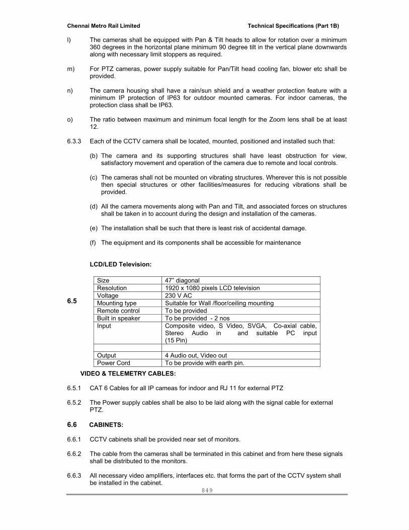
Chennai Metro Rail Limited Technical Specifications (Part 1B)
849
l) The cameras shall be equipped with Pan & Tilt heads to allow for rotation over a minimum 360 degrees in the horizontal plane minimum 90 degree tilt in the vertical plane downwards along with necessary limit stoppers as required.
m) For PTZ cameras, power supply suitable for Pan/Tilt head cooling fan, blower etc shall be
provided. n) The camera housing shall have a rain/sun shield and a weather protection feature with a
minimum IP protection of IP63 for outdoor mounted cameras. For indoor cameras, the protection class shall be IP63.
o) The ratio between maximum and minimum focal length for the Zoom lens shall be at least
12. 6.3.3 Each of the CCTV camera shall be located, mounted, positioned and installed such that:
(b) The camera and its supporting structures shall have least obstruction for view, satisfactory movement and operation of the camera due to remote and local controls.
(c) The cameras shall not be mounted on vibrating structures. Wherever this is not possible
then special structures or other facilities/measures for reducing vibrations shall be provided.
(d) All the camera movements along with Pan and Tilt, and associated forces on structures
shall be taken in to account during the design and installation of the cameras.
(e) The installation shall be such that there is least risk of accidental damage.
(f) The equipment and its components shall be accessible for maintenance
LCD/LED Television:
6.5
VIDEO & TELEMETRY CABLES: 6.5.1 CAT 6 Cables for all IP cameas for indoor and RJ 11 for external PTZ 6.5.2 The Power supply cables shall be also to be laid along with the signal cable for external
PTZ. 6.6 CABINETS:
6.6.1 CCTV cabinets shall be provided near set of monitors. 6.6.2 The cable from the cameras shall be terminated in this cabinet and from here these signals
shall be distributed to the monitors. 6.6.3 All necessary video amplifiers, interfaces etc. that forms the part of the CCTV system shall
be installed in the cabinet.
Size 47” diagonal Resolution 1920 x 1080 pixels LCD television Voltage 230 V ACMounting type Suitable for Wall /floor/ceiling mounting Remote control To be provided Built in speaker To be provided - 2 nos Input Composite video, S Video, SVGA, Co-axial cable,
Stereo Audio in and suitable PC input (15 Pin)
Output 4 Audio out, Video out Power Cord To be provide with earth pin.

Chennai Metro Rail Limited Technical Specifications (Part 1B)
850
6.7 DOME CAMERA
Image Device : 1/3” CCD (Day Night),
Resolution : not less than 540TV lines horizontal
Input Power Source : POE
Min. Illumination : Not more than 1.2 lux Resolution : 1.3m (1280x960)
Compression : MPEG 4 Video Bit rate : 32 kbps to 4 Mbps
Listing & Approval : UL /EN listed Communication : IPEnabled– IEEE802.3 and IEPFstd. Video output : 75 ohms 1 V (PP) Binary input/ouput : Opto – Isolated inputs
1 solid state opto- isolated relay output Multi streaming : CIF and 2 CIF – 2 Streams 4 CIF resolution – 1 stream Housing : Poly carbonate ABS alloy 6.8 Hi-Speed Pan / Tilt / Zoom Color Dome camera
Housing : Integrated dome type compatible for wall and
ceiling Mount, o Minimum 100 presets o 12" enclosure o 120/230Vac o 360 deg continuous rotation o Tilt – 90 degree
Imager : ¼” Interline transfer CCD Signal System : PAL
Resolution : 1.3m (1280x960) Minimum sensitivity of colour : 1.4 lux at 36 X and 0.8 lux at 18 X
Lens : 30X optical or better Digital zooming : 10 x or above Video output : 25 to 30 FPS shall be guaranteed
Multi streaming : CIF and 2 CIF – 2 Streams 4 CIF resolutions – 1 stream
Input Power Source : Separate or inbuilt -24 V DC or 240 V AC

Chennai Metro Rail Limited Technical Specifications (Part 1B)
851
Listings & approvals : UL/EN 6.9 SPECIFICATION FOR SERVERs FOR CAMERAS: Vendors are requested to refer this specification for minimum standards. However as per their system requirements, the costing and capacity needs to be worked and same should be mentioned in the separate sheet. TYPE : Microprocessor-based video processor combining
functions of multiplexing, digital recording, PTZ control, motion detection and alarm event detection as a minimum; to support color and monochrome formats.
Processor : Dual core Intel Xeon Pro 5100, 4 Mb cache and 3.0 G hz or higher.
Chipset : Intel 5000x chipset Memory (RAM) : As per requirement Min 4GB FDD DIMMS Flash BIOS : 8MB flash memory for system BIOS and SMBIOS 2.3.1.
support Graphic Memory : ATI ESI 1000 controller with 256 MB SDRAM. Hard disk : For 30 days storage- 4 CIF resolution- 25 frame
viewing and 4 frame for recording. Network : Dual Embedded broadcon, nextreme 100/1000 Ethernet
NIC I/O Ports : 1 Serial, 1 Parallel, 2 PS/2, RJ -45 & USB 2.0 Other Peripherals : Keyboard, optical scroll Mouse OS : Windows 2003 server with SPI ( 32 bits) or latest SP.
Other Medias : 52 x CD/DVD/RW Operation temperature : 10 degree to 43 degree C. Alarm Inputs : 3 nos. programmable as ‘NO or ‘NC’. Alarm Outputs : 3 nos. PAN / TILT / ZOOM CONTROL : To be provided over serial link to the receivers; keyboard
to be provided. IMAGE RATE SETTINGS / UPDATE RATE
: Selectable from 1 to 30 images per second per camera.
OTHER FEATURES : • Multiple- and single-camera display options. • Operator-selected activity target settings. • Image enhancement tools. • Alarm/event triggered response options. • Simultaneous recording, playback, transmitting,
database searching and archiving.(storing) • Motion detection and / or sensor based recording with
multiple levels of motion detection sensitivity to be provided.
6.10 DETAILED SPECIFICATION FOR DIGITAL VIDEO RECORDING SYSTEM
The Digital Video Recording & Management System shall be designed and developed to the
following standards:
• ISO/IEC15504Level3orhigher
(SPICE 2.0 Software Process Improvement and Capability Determination)

Chennai Metro Rail Limited Technical Specifications (Part 1B)
852
• SEI CMM Level 3 or higher
(American Software Engineering Institute - Capability Maturity Model)
The Digital Video Recording & Management System shall include:
• Camera Servers
• Analytics Servers
• Security or Control Systems
• Operator Stations
• Operator Keyboards
• Network connected cameras and/or network connected camera streamers
• Network infrastructure
6.11 DATABASE SERVERS
The Database Server contains a database of all network-connected cameras and their
configuration.
The Database Server shall:
• Manage the system database, containing details including
o System configuration
o Camera configuration and settings
o Streamer and/or IP Camera Input/Output configuration and settings
o Recording configuration and settings
o Details of recordings
o Configuration of operator views showing multiple camera layouts
o Schedules for recording, Input monitoring, Output switching and video
analytics
o Operator security details
o Configuration of Surveillance and Alarm Monitors
o Configuration of CCTV Keyboards
o Configuration of Video Analytics including:
Video Motion Detection
Object Tracking
Object Classification
Intelligent Video Analytics
Camera Tamper
Manage communication between the Operator Stations and the
Camera Servers
Allow alarms/events in the Security System or Control System to
initiate recordings
Support connection to multiple Security System or Control System
servers simultaneously
o Each connected server shall be able to receive alarms, activate events and
view live or recorded video from the DVRMS

Chennai Metro Rail Limited Technical Specifications (Part 1B)
853
• Report any camera failures or recording failures to the integrated Control system or
Security system
• Provide a full audit log of all system status (camera, streamer, server availability)
and operator actions.
• Utilize Microsoft SQL Server 2005 as it’s database engine
The Database Server shall be able to be used in a redundant configuration, using two
separate Database Servers (being executed on separate computers). The backup
Database Server shall be continuously synchronized with the master Database
Server to ensure that it is always up-to-date and ready for a fail-over, when required.
There shall only be one Database Server or Redundant Database Server pair in the
system.
Hardware clustering shall not be an acceptable means of achieving Redundancy for
the Database Server
6.12 CAMERA SERVERS
The Camera Server(s) must be capable of supporting a large amount of disk space for online
video storage and access to high capacity archiving mechanisms for the transfer of stored
video to off-line media.
The Camera Server shall:
• Manage live video and/or video and audio from camera streamers
• Transmit live and/or recorded video and audio with video to Operator Stations
• Transmit live video to Surveillance Monitors or Alarm Monitors
• Transmit live video to the Analytics Server(s) for processing using video analytics
algorithms
• Receive analytics events from the Analytics Server(s) and perform actions on these
events based on pre-configured settings
• Receive camera control commands from Operator Stations or Operator Keyboards
and then send the commands to cameras
• Store live video and/or video and audio to hard disk
• Transmit previously stored video and/or video and audio to Operator Stations
• Archive previously stored video and/or video and audio to off-line storage media
• Retrieve archived video and/or video and audio from off-line storage media
• Provide Video Analytics functionality including:
Video Motion Detection
Object Tracking
Object Classification
• Export the recordings into Windows Media Video file format so that it can be viewed
using standard tools including Microsoft’s Windows Media Player.
• Provide the ability to monitor cameras for tampering including:
o Changed field of view
o Blurred image

Chennai Metro Rail Limited Technical Specifications (Part 1B)
854
o Camera blinded or covered
• Receive input events from IP cameras or streamers and react to these events in a
pre-configured manner including but not limited to:
o Start recordings on 1 or more cameras
o Send alarms to the Security System or Control System
• Transmit output commands to the output port(s) of the IP cameras or streamers
• Facilitate intercom functionality by routing video and audio from the field to the
relevant operator station and routing audio from the operator station to the relevant
field device.
The Camera Servers shall rely on the Database Server for all camera database information.
The system shall support multiple Camera Servers, with no limit to the number of Camera
Servers used in the DVRMS.
6.13 ANALYTICS SERVERS
The Analytics Server(s) must be dedicated to analysing video of interest streamed from the
Camera Server(s). The Analytics Server(s) shall not be used to record video footage but shall
pass event information from the analysis of the video streams back to the Camera Server(s)
supplying the video for analysis for further action.
The Analytics Server shall:
• Receive live video from Camera Servers
• Process the live video using preconfigured rules and Intelligent Video Analytics
algorithms to determine events of interest
• Transmit Intelligent Video Analytics event information to the Camera Servers
• Provide Video Analytics including:
o Simple Video Motion Detection
o Advanced Video Motion Detection
• Provide the ability to monitor cameras for tampering including:
o Changed field of view
o Blurred image
o Camera blinded or covered
The Analytics Server shall not be used to record live video or transmit any video – live or
recorded – to any other part of the DVRMS.
The above mentioned server application like data base management, camera recording and
Analytic application shall be operated from a single Hardware.

Chennai Metro Rail Limited Technical Specifications (Part 1B)
855
Security System
The Security System monitors and controls Security and Access. It provides a real-time
view of the status of the security system to operators using dedicated Operator Station
machines.
In relation to the DVRMS system, the Security System shall:
• limit and grant operators access to live and recorded video images
• send requests to record video
• Command PTZ cameras to preset positions based on events within the Security System
• provide indication of any cameras or recordings which have failed
• provide a link in it’s alarm list directly to any associated video recording. Clicking on the
link shall call up a pop up window that allows the operator to replay the video without the
need to navigate to the DVRMS.
• provide the ability to develop custom displays with video and video controls integrated
within the displays
6.14 OPERATOR STATION
Operator view shall be provided using one or more Operator Station machines. These are
connected via a TCP/IP network to the Security, Building Control or Industrial Control
System. They are capable of viewing live video and recorded video from the Camera
Servers. They also provide levels of operator security.
In addition, the DVRMS shall provide a Microsoft Internet Explorer client interface for
viewing and recording live video, video search, replaying recorded video, system
configuration and system administration. The Internet Explorer station shall require no more
than a once-off installation of software to the client at the first connection of the client the
DVRMS server.
Both client interfaces shall provide the ability to play live or recorded audio when configured
and available with the associated video stream. The clients shall have the ability to manage
Intercom calls using bi-directional audio when supported and configured on the system.
The client shall provide the ability to display up to at least 16 simultaneous video streams in
various configurations. It must be possible to support both standard aspect ratio screens
(4:3 ratio) and wide aspect ratio screens (16:9 ratio) without distortion of video but also
taking advantage of the entire screen viewing area.
6.15 SYSTEM SIZING
The security system or control system for the site/complex requires that operators be able to
simultaneously view, record and replay video, as detailed in this specification, for an
Chennai Metro Rail Limited Technical Specifications (Part 1B)
856
unlimited number of cameras throughout the site/complex. The vendor must size the
Camera Servers to accommodate the requirements of the cameras and desired recording
frame rates.
6.16 MULTIPROCESSOR SUPPORT
The Database Server, Camera Server and Video Analytics Server software shall be able to run on both multiple and single processor computers. Where a multiple processor system is used the DVRS software shall be able to make optimal use of that configuration.
6.17 SYSTEM FAULT TOLERANCE
A failure of any one of the Database Servers or Camera Servers shall NOT cause the DVRMS system to cease operation. As a worst case, only the cameras controlled by the Camera Server will be temporarily unavailable until re-allocated to other Camera Servers using the DVRMS software. No physical changes to hardware, cabling or connections shall be required.
6.18 SYSTEM SOFTWARE
This section describes the required System Software. If other software is proposed then
suppliers must be able to demonstrate full compliance with Section 4.
6.19 DATABASE SERVER
The Database Server will include the following system software components:
• Windows 2003 Server (SP2) 32-bit edition or Windows XP Professional (SP2) 32-bit
edition
• Microsoft SQL Server 2005 database with Service Pack 2
• Microsoft Internet Information Server (IIS) (web server)
• Application software with functionality detailed in Section 4.
6.20 CAMERA SERVER
The Camera Server will include the following system software components:
• Windows 2003 Server (SP2) 32-bit edition or Windows XP Professional (SP2) 32-bit
edition
• Application software with functionality detailed in Section 4.
It shall be possible to install the Camera Server software for all Camera Servers on the
DVRMS from a central location.
Chennai Metro Rail Limited Technical Specifications (Part 1B)
857
The SERVER QUANTITY SHOULD BE SELECTED BASED ON THE SYSTEM CONFIGURATION BY EACH VENDOR.
6.21 VIDEO ANALYTICS SERVER
The Video Analytics Server will include the following system software components:
• Windows 2003 Server (SP2) 32-bit edition or Windows XP Professional (SP2) 32-bit
edition
• Application software with functionality detailed in Section 4.
6.22 SECURITY SERVER
The Security System will include the following system software components:
• System and Application software detailed in the Security System Specification
• Application software with functionality detailed in Section 4.
6.23 BUILDING CONTROL SERVER
The Building Control System will include the following system software components:
• System and Application software detailed in the Building Control System
Specification
• Application software with functionality detailed in Section 4.
6.24 OPERATOR STATION
The Operator Station will include the following system software components:
• Application software detailed in the Security System or Control System Specification
• Windows 2003 Server (SP1) 32-bit edition, Windows XP Professional (SP2) 32-bit
edition, Windows Vista Business 32-bit edition.
• Microsoft Internet Explorer 6 SP1 or greater
6.25 APPLICATION SOFTWARE FUNCTIONS 6.25.1 Live Video
The live output from cameras shall be configured and viewed through a series of displays. These shall
support:
• Single camera view
• Multiple camera viewing of up to 16 cameras simultaneously, each at 25/30fps and
each view port supporting sequencing of cameras and/or cameras presets for PTZ
cameras

Chennai Metro Rail Limited Technical Specifications (Part 1B)
858
• Specific viewing options for both 4:3 aspect ratio as well as 16:9 aspect ratio (wide
screen) monitors thus preventing distortion of original video aspect ratio while still
taking advantage of the entire screen area for image display of multiple video
channels.
• Sequence view of camera preset positions
• Modifying settings for a camera
• Modify recording settings for a camera
• Adding and deleting cameras
• Creating schedules for recordings, video analytics and Input/Output monitoring and
switching
• Modifying Video Analytics settings and tuning for:
o Video Motion Detection
o Object Tracking
o Object Classification
o Intelligent Video Analytics
• Modify settings for Inputs and Outputs on IP cameras and streamers
• Modify settings for camera tamper detection
• View and initiate Intercom calls with cameras configured with bi-directional audio
capabilities.
Users shall be able to select a camera from a tree control listing the cameras available to
the user.
The system shall also support multiple monitors in the following manner:
• Alarm monitor: When an alarm occurs in the Security or Control System Server, the
live video output of the camera associated with that alarm shall be switched directly to
an alarm monitor. The user shall be able to acknowledge the alarm to clear the monitor
using the numeric keypad. Cameras that are directed to alarm monitors will not be
removed from the queue unless explicitly cleared by the operator. It shall be possible
to create a queue of alarm monitors to manage multiple alarm views simultaneously.
• Cyclic Alarm Monitors: An alarm monitor shall be available at the end of an alarm
monitor queue to cycle the camera views from unacknowledged alarms if the number
of cameras to view exceeds the number of alarm monitors. Once the alarm monitor
queue is filled, any new alarm will be placed in the queue relative to its priority and
then time of occurrence. Existing activated alarm camera views shall reshuffle to
accommodate the new alarm. In the event that all the available alarm monitors are
used, the oldest active alarm camera shall be added to the cycling alarm monitor. The
alarm views shall cycle on this final alarm monitor until acknowledged and cleared by
an operator in the event of multiple alarms added to this monitor.

Chennai Metro Rail Limited Technical Specifications (Part 1B)
859
• Surveillance monitor: Operators shall be able to command multiple camera view or
sequence or Single Camera View to a surveillance monitor. The User shall be able to
clear the monitor using the numeric keypad.
• Monitors shall be able to be configured to act as both Alarm and Surveillance
monitors. In this case, the monitor behaves as a Surveillance monitor until an alarm
occurs, in which case it shall show the alarm video. Once the alarm is acknowledged,
the video previously shown (as a surveillance monitor) is displayed again.
In each of these cases, these additional monitors shall be either connected to an Operator
Station using a multi-monitor PC card or to other PCs.
Systems that do not offer this functionality are not acceptable.
6.25.2 Video Loss Alarm
The DVRMS shall support the video streamer Video Loss Alarm feature. The Video
Loss Alarm feature shall provide DVRMS operators with a notification when the video
signal from the camera to the video streamer is lost. A video loss alarm shall result in
an alarm being raised, the change of the camera icon in the camera tree to indicate
the alarm condition and an entry in the system audit log for future reference.
6.25.3 Camera Tamper Detection
The DVRMS shall provide the ability to detect attempts to tamper with connected
cameras. The system will at minimum detect the following:
• Changed field of view: repositioning the camera away from a reference position
shall trigger an alarm
• Camera blur: any attempt to defocus or blur the camera shall trigger an alarm
• Camera blind: any attempt to cover or blind the camera (via abnormally high light
levels) shall trigger an alarm
Each of the above options shall be individually selectable as required per camera. It
shall thus be possible to enable any combination of the above three detection options
on each camera connected to the DVRMS.
The detection algorithms for tampering shall be run on one or more of the DVRMS
Camera Servers. It shall be possible to configure and tune the algorithms individually
per camera. The configuration screen shall provide:
• The ability to enable any combination of the tamper detection algorithms
• Real time feedback of the percentage of tampering detected
• The ability to set the threshold at which a tamper alarm will be generated
• Real time feedback of when a tamper threshold has been crossed
• How often the detection algorithm should check for a tamper condition

Chennai Metro Rail Limited Technical Specifications (Part 1B)
860
• System response to a tamper alarm including:
o Starting a recording with the possibility of also configuring the system to
record video prior to the event occurring. It must be possible to record video
prior to the event occurring where the duration of this pre-record is a pre-
configured value.
o Generating alarms with configurable alarm levels
o Sending video to an Operator Station
o Trigger an output on a device connected to the DVRMS such as a network
camera or video encoder.
Once a tamper condition is detected, the system shall provide visual indication to the operator
through both a text overlay on the live video and indication on the camera tree. The text
overlay shall be for viewing purposes only and shall not be recorded.
Systems that provide the same camera tamper settings for all cameras shall not be
acceptable.
Single Camera
From this display, the user shall be able to:
• View the live output from the selected camera
• Pan, tilt, zoom and focus the camera using a joystick attached to the Operator
Station PC
• Pan, tilt, zoom and focus the camera using a pointing device attached to the
Operator Station PC. Standard Microsoft Windows 2003, Microsoft Windows XP or
Microsoft Windows Vista pointing devices such as a mouse or touch-screen shall be
supported.
• For cameras which support continuous pan, tilt, zoom (PTZ), a mouse shall be able
to be used for continuous PTZ directly in the live video window. By dragging the
mouse up or down, left or right in the video window, the operator shall be able to tilt
the camera up or down, or pan the camera left or right. Zooming must also be
provided using the mouse in a similar way.
• Manually record live video. Recording will continue for the configured period of time.
Once recording has begun, a stop button shall be provided as well as a counter
showing the recording time remaining.
• Manually store the current frame of video (snapshot) as a bitmap image file. The file
name shall be automatically generated by the DVRMS software and include the
camera name, date and time of the recording (to millisecond precision).
• Indicate whether video motion detection is currently enabled for the selected
camera.
• Initiate an intercom call or accept an incoming intercom call.

Chennai Metro Rail Limited Technical Specifications (Part 1B)
861
Multiple camera views
The DVRMS shall support multiple camera views. A multiple camera view consists of up to sixteen related cameras viewed simultaneously on a single display.
The layout for a view shall be configurable from a selection of different layouts templates. There shall be a set of templates for standard aspect ratio (4:3) monitors and another set of templates for wide aspect ration (16:9) monitors to properly utilise the entire monitor screen real estate without distorting the original video aspect ratio.
It shall be possible to configure and save individual views for re-use. It shall be possible for the view to be created by dragging and dropping cameras and presets if applicable directly into the view ports from the camera tree.
Multiple camera views shall be divided into quadrants. For each quadrant the view shall
have a camera or be blank. Within each quadrant the view shall be configured to cycle
between any of the cameras accessible to the user on a configurable time basis. Pan-tilt-
zoom cameras, which support preset positions, can have these presets cycled on a time
basis. In this way an operator can view a variety of presets on a series of PTZ cameras in a
multiple camera view.
It shall be possible to show the camera names of each camera and preset (if applicable)
configured in a view on either the operator station and on surveillance monitors. Hovering
the mouse pointer over a view port shall trigger a tooltip showing the camera name and
preset (if applicable).
There shall be no limit to the number of cameras that can be assigned to a single multiple
camera view. There shall also be no limit to the number of available multiple camera views.
Sequence View
The DVRMS shall support sequence views. A sequence view consists of a single camera view, which can be cycled on a time basis. Pan-tilt-zoom cameras, which support preset positions, can have these presets cycled on a time basis. In this way an operator can view a variety of presets on a series of PTZ cameras. Fixed cameras can also be included in the sequence and cycled accordingly.
There shall be no limit to the number of cameras that can be assigned to a single Sequence View. There shall also be no limit to the number of available Sequence Views.

Chennai Metro Rail Limited Technical Specifications (Part 1B)
862
Camera settings
Users shall be able to change important settings for an individual camera. The details are
grouped into several sections:
• Camera Details
• Camera Connection
• Camera PTZ Control
• Security
• Camera Deletion
The parameters listed in the sub-sections below are configurable on a per camera basis and
their specific selection on a particular camera(s) will not limit the ability to freely select other
options on other cameras as required. It will be easy to change any of these parameters for
each camera individually as and when required. Systems that do not allow changes to each
camera’s parameters on an individual basis will not be acceptable.
Only users with the highest level of security are permitted to modify camera connection
details, camera PTZ control or delete cameras.
Camera Details
The user shall be able to configure the following parameters for each camera:
• Name
• Location
• Description
• Camera Number (for fast numeric keypad call-up)
Camera Control
The user shall be able to configure any appropriate camera to be PTZ controllable. The
following camera types must be supported as a minimum:
• Streamer supported PTZ cameras and devices
The following PTZ characteristics shall be tunable on a camera-by-camera basis from the
camera definition pages:
• Pan speed
• Tilt Speed
• Zoom speed
• Focus speed
• Iris speed
• Increment step size
• Continuous Pan/Tilt speed

Chennai Metro Rail Limited Technical Specifications (Part 1B)
863
The DVRMS shall support streamer-side camera control for video encoders. In this case,
the streamer will be responsible for providing the control mechanism to the associated
camera and the communications protocol will not need to be natively supported in the
DVRMS.
Security
The following parameters shall be configurable for each camera:
• Area: Allows the system to be configured to only allow users to view specified
cameras. These areas shall be the defined by the Security System, Building Control
System or the Industrial Control System.
• Control Level: Determines if a user is allowed to operate the PTZ controls for a
camera. Also used to allow higher-level users to take control of cameras. These
Control Levels shall be defined by the Security System, Building Control System or
Industrial Control System.
• Control Reservation Period: Once a particular user has controlled the camera no
other user can control the camera until this reservation period has expired. Users
with a higher security level shall be able to take control of the camera at any time.
Camera Deletion
The “Delete” function shall allow a user with the highest-level security to delete the camera
from the system. After deletion name of the camera will no longer appear in the list of
cameras. All camera settings will be deleted but the camera record will remain in the
database for searching purposes.
Any recordings associated with a deleted camera will remain until their configured deletion
date. The recordings will remain on the Camera Server and archive media unless they are
later individually deleted. The camera name will also continue to appear in the list of
cameras used for searching the video clip database.
The Video Analytics License for the following should be considered in the quoted price:
1 People Counting License for Main Door Cameras to determine the Number of People in and out of the Facility. 2 The Vehicle Counting Camera that allows you to Count the Vehicles 3 The Intrusion Detection License for the External Cameras 4 Any other Specific Process Control Licenses that may be required by CUSTOMER. 5 Lift lobbies in all the floors. 6.26 RECORDING
Recorded video is stored on the Camera Server. The Operator station shall be able to
locate relevant recorded video and to then replay that video at the Operator Station.
The following methods of recording live video shall be supported:
• User activated

Chennai Metro Rail Limited Technical Specifications (Part 1B)
864
• Intercom activated
• Event activated
o Security, Building Control or Industrial Control System
• Streamer and/or IP camera Inputs/Outputs
• Scheduled
• Continuous background recording
• Video Analytics
o Video Motion Detection
o Intelligent Video Analytics
o Camera Tamper events
• Snapshot
User Activated
User activated recording occurs when a user viewing live video chooses to record the
currently viewed camera output by selecting the “Record” button.
The user shall be able to configure the following parameters uniquely for each camera:
• Pre-Record Duration: The amount of pre-recorded video that will be associated
with a user request for recorded video. This will allow the Camera Server to capture
video prior to the user request, as well as after the request. Shall be selectable from
a list of values ranging from No Recording to 5 minutes.
• Frame Rate: Video quality required for user activated recording. It shall be possible
to have different frame rates for user and event-activated recordings. Shall be
selectable from the entire range of frame rates supported for the camera. For
MPEG encoding, support shall also be provided to record only the Index frames, or
a subset of the Index frames.
• Record Duration: User activated recordings shall terminate after this period. Shall
be selectable from a list of values ranging between 0 seconds and 10 minutes
• Retention Period: The default period that the Camera Server shall retain user-
activated recordings before being deleted. The retention period of individual
recordings shall be able to be changed on a per-recording basis. Shall be selectable
from a list of values ranging between one hour and forever.
• Archive After period: The default period for which user activated recordings are
available for playback before they are automatically archived. The Archive After
period of individual recordings shall commence at the video clip’s end date and time
and be able to be changed on a per-recording basis. The period shall be selectable
from a list of values to provide a default setting for all recordings of this type per
camera but shall also be manually configurable on each individual recording after
the recording has occurred.
• Delete After period: The default period that the recording will be retained before
being automatically deleted by the system. The Delete After period of individual

Chennai Metro Rail Limited Technical Specifications (Part 1B)
865
recordings shall commence at the video clip’s end date and time and shall be and
be able to be changed on a per-recording basis. The period shall be selectable from
a list of values to provide a default setting for all recordings of this type per camera
but shall also be manually configurable on each individual recording after the
recording has occurred.
Event Activated
Event activated recording is a process that allows a segment of video or a snapshot to be
associated with the Security System, Building Control System or Industrial Control System
alarm or event.
There shall be at least four priorities of alarms/events in the Security or Control System:
• Event (journal priority)
• Low priority alarms
• High priority alarms
• Urgent priority alarms
The following settings shall be individually configurable for each alarm and each
camera:
• Pre-Record Duration: The amount of pre-recorded video that will be associated
with an alarm/event. This shall allow the Camera Server to capture video prior to the
alarm/event, as well as after the alarm/event. Shall be selectable from a list of
values ranging between 0 seconds and 5 minutes.
• Post Record Duration: Event activated recordings shall terminate after this period.
Shall be selectable from a list of values ranging between 0 seconds and 5 minutes
• Frame Rate. Video quality required for event activated recording. It shall be
possible to have different frame rates for user, event-activated, scheduled and
motion detection activated recordings. Shall be selectable from the entire range of
frame rates supported for the camera/streamer. For MPEG encoding, support shall
also be provided to record only the Index frames, or a subset of the Index frames.
• Retention period. The default period the Camera Server will retain event-activated
recordings before being deleted. The retention period of individual recordings shall be able
to be changed as necessary. Shall be selectable from a list of values ranging between one
hour and forever.
• Archive After period: The default period for which event activated recordings are
available for playback before they are automatically archived. The Archive After
period of individual recordings shall commence at the video clip’s end date and time
and be able to be changed on a per-recording basis. The period shall be selectable
from a list of values to provide a default setting for all recordings of this type per
camera but shall also be manually configurable on each individual recording after
the recording has occurred.

Chennai Metro Rail Limited Technical Specifications (Part 1B)
866
• Delete After period: The default period that the recording will be retained before
being automatically deleted by the system. The Delete After period of individual
recordings shall commence at the video clip’s end date and time and shall be and
be able to be changed on a per-recording basis. The period shall be selectable from
a list of values to provide a default setting for all recordings of this type per camera
but shall also be manually configurable on each individual recording after the
recording has occurred.
The pre-record and post-record durations in the paragraph above define the maximum
allowable limits for each camera. They shall be configured on a camera-by-camera basis.
However each alarm or event causing video to be recorded shall also be capable of
individual configuration with pre and post alarm periods being selected from a range defined
by the maximum settings for the camera.
DVRMS systems requiring a single pre and post record event period to be defined for all
alarms and events on an individual camera are not acceptable. DVRMS systems requiring a
single pre and post event period to be defined for all alarms and events on all cameras are
also not acceptable.
In the case of multiple alarms/events relating to the same camera, a video clip shall be
created for each alarm/event.
For cameras that support Pan/Tilt/Zoom and Presets, a specified preset location shall be
selected automatically when the alarm/event occurs prior to the event activated recording
commencing. For example, when an alarm is detected on a security door, the alarm shall
trigger a PTZ camera to move to a preset position, which is pointing at the door prior to the
DVRMS commencing recording.
Device Input/Output Activated
Input or output recording activation occurs when an input or an output connected to an IP
camera or streamer is activated and then subsequently triggers recording on one or more
associated cameras.
It shall be possible for any digital input or output connected to a streamer or IP camera on
the system to trigger a recording on one or more cameras simultaneously.
The following settings shall be individually configurable for each alarm and each
camera:
• Pre-Record Duration: The amount of pre-recorded video that will be associated
with a device input/output. This shall allow the Camera Server to capture video prior
to the alarm/event, as well as after the alarm/event. Shall be selectable from a list of
values ranging between 0 seconds and 5 minutes.

Chennai Metro Rail Limited Technical Specifications (Part 1B)
867
• Post Record Duration: Device input/output activated recordings shall terminate
after this period. Shall be selectable from a list of values ranging between 0
seconds and 10 minutes or while the device is active.
• Frame Rate. Video quality required for device inout/output activated recording. It
shall be possible to have different frame rates for user, device input/output
activated, event-activated, scheduled and motion detection activated recordings.
Shall be selectable from the entire range of frame rates supported for the
camera/streamer. For MPEG encoding, support shall also be provided to record
only the Index frames, or a subset of the Index frames.
• Retention period. The default period the Camera Server will retain device input/output
activated recordings before being deleted. The retention period of individual recordings shall
be able to be changed as necessary. Shall be selectable from a list of values ranging between
one hour and forever.
• Archive After period: The default period for which device input/output activated
recordings are available for playback before they are automatically archived. The
Archive After period of individual recordings shall commence at the video clip’s end
date and time and be able to be changed on a per-recording basis. The period shall
be selectable from a list of values to provide a default setting for all recordings of
this type per camera but shall also be manually configurable on each individual
recording after the recording has occurred.
• Delete After period: The default period that the recording will be retained before
being automatically deleted by the system. The Delete After period of individual
recordings shall commence at the video clip’s end date and time and shall be and
be able to be changed on a per-recording basis. The period shall be selectable from
a list of values to provide a default setting for all recordings of this type per camera
but shall also be manually configurable on each individual recording after the
recording has occurred.
The pre-record and post-record durations in the paragraph above define the maximum
allowable limits for each camera. They shall be configured on a camera-by-camera basis.
For cameras that support Pan/Tilt/Zoom Presets, a specified preset location shall be
selected automatically when the input/output event occurs prior to the recording
commencing. For example, when an intrusion alarm is detected, the alarm shall trigger a
PTZ camera to move to a preset position, which is pointing at the area monitored by the
intrusion sensor prior to the DVRMS commencing recording.
Scheduled
Scheduled recording allows video to be recorded between start and stop times on
defined days.
The system shall support the ability to schedule recordings for each individual camera
Chennai Metro Rail Limited Technical Specifications (Part 1B)
868
for times in the future. For each scheduled recording the user shall be able to
configure the following (with descriptions as per User Activated and Event Activated
recordings):
• Start time
• Stop time
• Frame rate for the recording
• Retention period before the recording will be deleted
• Recurrence (if this is to be a recurring schedule)
• Description (at least 255 characters)
• Archive After period providing the period after which the recording will automatically
be archived
• Delete After period providing the period after which the recording will automatically
be deleted
• Whether audio is recorded with the scheduled recording or not (if supported on the
camera)
There shall be no limit on the number of schedules that can be entered for the
system. There shall be no limit to the number of schedules per camera.
Continuous background recording
The system shall support the ability to provide continuous background recording from
any camera(s) managed by the system. Background recordings will be stored as a
discrete series of clips and will continue to operate in the event that communication
between the Camera Server and the Database Server is lost. Once communication is
restored, all relevant information will be updated to the Database Server.
For each camera the user shall be able to configure the following (with descriptions as
per User Activated and Event Activated recordings):
• Enable / disable background recording
• Duration of the recorded clip
• Frame rate for the recording
• Enable / disable archiving of the clip and the period after which to archive
• Retention period before the recording will be deleted
• Enable or disable audio recording (if available)
• Archive After period providing the period after which the recording will automatically
be archived
• Delete After period providing the period after which the recording will automatically
be deleted

Chennai Metro Rail Limited Technical Specifications (Part 1B)
869
Systems that require the configuration of multiple time periods to manage background
recordings will not be accepted.
Continuous background recordings will not be dependant on network communications
between the Camera Server and the Database server. Once configured, these recordings
will continue to operate in the event that this communication is lost.
Video analytics
The DVRMS system must be able to activate recordings automatically based on events
generated by the real-time analysis of video from any camera on the system that has Video
Analytics enabled. The real time analysis comprises several algorithms as follows:
• Video Motion Detection
• Object Tracking and Object Classification
• Intelligent Video Analytics.
Video Motion Detection
The DVRMS system must be able to support video motion detection algorithms, which can
be executed by the video streamer or the Camera Server. The enabling of Video Motion
Detection shall be either:
• on a continuous basis
• scheduled for particular times, dates, days, months etc
The Camera Server-based algorithm must be able to provide the following functionality:
• Detect and track objects
• Learn the scene
• Adapt to a changing outdoor environment
• Ignore environmental changes including rain, hail, wind, swaying trees and gradual
light changes
The user shall be able to configure the following parameters for each camera:
• Detection Type: Continuous or scheduled
• Actions to Perform When Motion is Detected: When motion is detected, the
following actions shall be performed automatically:
o Generate an alarm in the Security System, Building Control System or
Industrial Control System of configurable priority (journal, low, medium,
high)
o Start a recording, with the following configurable settings
Pre-Record Duration: The amount of pre-recorded video, allowing
the Camera Server to capture video prior to the detection of motion,
as well as after the detection of motion. Shall be selectable from a
list of values ranging between 0 seconds and 5 minutes.
Chennai Metro Rail Limited Technical Specifications (Part 1B)
870
Post Record Duration: Motion detection activated recordings will
terminate after this period. Shall be selectable from a list of values
ranging between 0 seconds and 10 minutes or until motion has
stopped. It shall be possible for the recording to continue until the
motion detection algorithm considers motion finished.
Frame Rate. Video quality required for motion detection activated
recordings. Shall be selectable from the entire range of frame rates
supported for the camera/streamer. For MPEG encoding, support
shall be provided to record only the Index frames, or a subset of the
Index frames.
Retention period. The default period that motion detection activated
recordings will be retained by the Camera Server before being deleted.
The retention period of individual recordings shall be able to be changed
as necessary. Shall be selectable from a list of values ranging between one
hour and forever.
Archive After period: The default period for which motion
detection activated recordings are available for playback before
they are automatically archived. The Archive After period of
individual recordings shall commence at the video clip’s end date
and time and be able to be changed on a per-recording basis. The
period shall be selectable from a list of values to provide a default
setting for all recordings of this type per camera but shall also be
manually configurable on each individual recording after the
recording has occurred.
Delete After period: The default period that the recording will be
retained before being automatically deleted by the system. The
Delete After period of individual recordings shall commence at the
video clip’s end date and time and shall be and be able to be
changed on a per-recording basis. The period shall be selectable
from a list of values to provide a default setting for all recordings of
this type per camera but shall also be manually configurable on
each individual recording after the recording has occurred.
o Send video to an operator station or alarm monitor: Automatically switch an
operator station or alarm monitor to view the camera which has motion
detected
o Trigger an output device on a related network camera or video encoder
• Motion Finished Time: The amount of time where no motion (inactivity) is detected
before the previous motion is classified as completed. This shall be used for
allowing recordings to continue until motion has finished.

Chennai Metro Rail Limited Technical Specifications (Part 1B)
871
The DVRMS must provide a means of automatic and manual tuning of the Video Motion
Detection for each camera. Incorporated within this tuning are the following:
• Selection of the frame rate used for detection
• Optimization for directions of movement
o In any direction
o Across the camera view
o Towards and away from the camera
• Sensitivity level to fine tune the motion detection algorithm
• Specification of a minimum object size to allow noise filtering in the system to
reduce false detections and alarms.
The DVRMS must also provide the ability to only detect motion in particular regions of
the camera view. The ability to graphically select these regions using the mouse must
be provided, with an unlimited number of regions permitted per camera. The regions
of interest will be multi-verticed shapes with a minimum of 6 vertices to allow the
region to be properly matched to the scene being detected. It shall be possible to add
and remove vertices from the defined region of interest as needed. Solutions
providing only rectangular regions of interest will not be accepted.
Each region must be able to be individually tuned and have separate tuning
parameters. This method of tuning must also provide a live tuning window whereby
these settings and regions can be altered and tested prior to be being used. This live
tuning window shall show the live video as well as the regions of interest. During the
time that motion is detected within a region, the border of the region shall change to a
different color. In this way, tuning can be performed to achieve the desired
performance. Text shall also be provided in the window to alert the user that motion
has been detected.
Object Tracking and Object Classification
The DVRMS must provide the ability to acquire, classify and track an object within a
predefined field of view on selected cameras.
The Camera Server-based algorithm must be able to provide the following functionality:
• Detect and track objects
• Classify the object with the following groupings
o Person
o Vehicle
o Other
o Any
• Learn the scene
• Adapt to a changing outdoor environment
Chennai Metro Rail Limited Technical Specifications (Part 1B)
872
• Ignore environmental changes including rain, hail, wind, swaying trees and gradual
light changes
The user shall be able to configure the following parameters for each camera:
• Actions to Perform When an Object is detected, classified and tracked: When
the event/alarm is raised, the following actions shall be performed automatically:
o Generate an alarm in the Security System, Building Control System or
Industrial Control System of configurable priority (journal, low, medium,
high)
o Start a recording, with the following configurable settings
Pre-Record Duration: The amount of pre-recorded video, allowing
the Camera Server to capture video prior to the alarm/event, as well
as after the alarm/event, shall be selectable from a list of values
ranging between 0 seconds and 5 minutes.
Record Duration: The period that the recording is active relating to
the period of activity in the region of interest. Activated recordings
will terminate after this period. Shall be selectable from a list of
values ranging between 0 seconds and 10 minutes or the object is
no longer in the region of interest.
Frame Rate. Video quality required for Object Tracking and/or
Object Classification activated recordings. Shall be selectable from
the entire range of frame rates supported for the camera/streamer.
For MPEG encoding, support shall be provided to record only the
Index frames, or a subset of the Index frames.
Retention period. The default period that Object Tracking and/or Object
Classification activated recordings will be retained by the Camera Server
before being deleted. The retention period of individual recordings shall be
able to be changed as necessary. Shall be selectable from a list of values
ranging between one hour and forever.
Archive data: enable/disable archiving and set the period after
which the recording will be automatically archived
Deletion data: Set the period after which the recording will be
automatically deleted
o Send video to an operator station or alarm monitor: Automatically switch an
operator station or alarm monitor to view the camera which has motion
detected
o Trigger an output device on a related network camera or video encoder
The DVRMS must provide a means of automatic and manual tuning of the Object Tracking
and/or Object Classification for each camera. Incorporated within this tuning are the
following:
Chennai Metro Rail Limited Technical Specifications (Part 1B)
873
• Selection of the frame rate used for detection
• Optimization for directions of movement
o In any direction
o Motion to left, right, top, bottom or any direction into a region
o Motion to left, right, top, bottom or any direction out of a region
• Sensitivity level to fine tune the detection algorithm
• Specification of a minimum object size to allow noise filtering in the system to
reduce false detections and alarms.
The DVRMS must also provide the ability to only detect, classify and track objects in
particular regions of the camera view. The ability to graphically select these regions
using the mouse must be provided, with an unlimited number of regions permitted per
camera. The regions of interest will be multi-verticed shapes with a minimum of 6
vertices to allow the region to be properly matched to the scene being detected. It
shall be possible to add and remove vertices from the defined region of interest as
needed. Solutions providing only rectangular regions of interest will not be accepted.
Each region must be able to be individually tuned and have separate tuning
parameters. This method of tuning must also provide a live tuning window whereby
these settings and regions can be altered and tested prior to be being used. This live
tuning window shall show the live video as well as the regions of interest. During the
time that motion is detected within a region, the border of the region shall change to a
different color. In this way, tuning can be performed to achieve the desired
performance. Text shall also be provided in the window to alert the user that motion
has been detected.
Intelligent Video Analytics
The DVRMS must provide integration to an Intelligent Video Analytics system. The
Intelligent Video Analytics system will be specified separately.
Video for analysis will be supplied to the Intelligent Video Analytics system algorithms by the
Analytics Server(s) of the DVRMS. The Intelligent Video Analytics system will run on the
DVRMS Camera Servers and shall accept and process the video based on preconfigured
conditions of interest.
Events from the Intelligent Video Analytics system will be passed back to the DVRMS for
further action. It will be possible to automatically perform the following actions from the
DVRMS based on events detected by the Intelligent Video Analytics system:
• Generate an alarm in the Security System, Building Control System or Industrial
Control System of configurable priority (journal, low, medium, high)
• Start a recording, with the following configurable settings
Chennai Metro Rail Limited Technical Specifications (Part 1B)
874
o Pre-Record Duration: The amount of pre-recorded video, allowing the
Camera Server to capture video prior to the alarm/event, as well as after
the alarm/event, shall be selectable from a list of values ranging between 0
seconds and 5 minutes.
o Record Duration: The period that the recording is active relating to the
period of activity in the region of interest. Activated recordings will terminate
after this period. Shall be selectable from a list of values ranging between 0
seconds and 10 minutes or the object is no longer in the region of interest.
o Frame Rate. Video quality required for recordings triggered by events from
the Intelligent Video Analytics system. Shall be selectable from the entire
range of frame rates supported for the camera/streamer. For MPEG
encoding, support shall be provided to record only the Index frames, or a
subset of the Index frames.
o Retention period. The default period that recordings generated based on
events from the Intelligent Video Analytics system will be retained by the
Camera Server before being deleted. The retention period of individual
recordings shall be able to be changed as necessary. Shall be selectable
from a list of values ranging between one hour and forever.
o Archive data: enable/disable archiving and set the period after which the
recording will be automatically archived
o Deletion data: Set the period after which the recording will be automatically
deleted
• Send video to an operator station or alarm monitor: Automatically switch an
operator station or alarm monitor to view the camera which has motion detected
• Trigger an output device on a related network camera or video encoder
Snapshot
The DVRMS system must provide every operator with the ability to record the current frame
of video. This snapshot of video shall be stored as a bitmap file. The file name shall be
automatically generated by the DVRMS software and include the camera name, date and
time of the recording (to millisecond precision). An audible sound shall be produced by the
Client computer, to ensure that the operator has feedback when the snapshot is taken.
Recorded Video
The DVRMS shall allow camera output to be recorded for the following conditions:
• Manually activated by a user viewing a live camera
• Activated by or during an intercom call
• Activated by a Security System Or Control System alarm or event
• Activated by inputs or outputs on a streamer or IP Camera

Chennai Metro Rail Limited Technical Specifications (Part 1B)
875
• Continuous background recording
• Scheduled recording
• Specialised real-time video analysis including:
o Video Motion Detection
o Intelligent Video Analytics
o Camera Tamper events
User activated recording occurs when a user viewing live video chooses to record the
currently viewed camera output by selecting the “Record” button.
Intercom activated recording occurs when an operator either accepts an intercom call from
the field or when the operator chooses to start a recording during an intercom call when the
system is configured without automatic recording of intercom calls enabled.
Event activated recording is a process that allows a segment of video or a snapshot to be
associated with a Security System, Building Control System or Industrial Control System
alarm or event.
Input or output recording activation occurs when an input or an output connected to an IP
camera or streamer is activated and then subsequently triggers recording on one or more
associated cameras.
Scheduled recording allows video to be recorded between start and stop times on
defined days.
Real-time video analysis activated recording is a process that allows a segment of video or
a snapshot to be recorded when a specific event is detected by a video analysis algorithm
used by the DVRMS.
Recorded video is stored on the Camera Server. The Operator station shall be able to query
the Database Server to locate relevant recorded video and to then replay that video at the
Operator Station.
Live and Recorded Audio
The DVRMS shall provide the ability to have audio included with the video. Two types
of audio support shall be provided:
• Single directional audio from the field (camera or streamer) locations to the DVRMS
Camera Servers (and Operator Stations)
• Bi-directional audio (intercom) between the field (camera or streamer) locations and
the DVRMS Camera Servers (and Operator Stations)

Chennai Metro Rail Limited Technical Specifications (Part 1B)
876
Single Directional Audio
The DVMRMS shall provide the following single directional audio support:
• Audio shall be recorded by the streamer using an attached microphone (or similar
device)
• Audio shall be streamed along with the video from the camera (or streamer) locations
to the DVRMS Camera Servers (and Operator Stations) using the same network used
for the video stream. This shall require no additional network cabling
• Audio shall be played at the Operator Stations using speakers connected to the
Operator Station computer
• Live audio shall be played whenever the live video is displayed
• Audio shall be recorded whenever the video is recorded.
• For scheduled and continuous (background) recordings, the audio shall be optionally
disabled
• Audio shall be played when the recording containing audio is played. The audio shall
be heard in the same synchronization it was recorded in.
• Wherever the audio is played with the video, a mute button and volume control shall
be provided on the video player. It is unacceptable to use the Operating System’s
volume controls for this purpose.
• Recordings containing audio shall be exported with the audio and video in the same
synchronization it was recorded in.
Viewing Recordings
The recorded video shall be available to all users, which have adequate security.
Each user shall only be able to view recordings from cameras they have security
access to view.
A display shall be provided to view recordings from any Operator Station. From this
display, the operator can select the recording he/she wishes to view, which shall be
immediately shown in an embedded video player.
The following information and controls shall be provided on this display:
• A navigation panel to allow the user to select the required camera
• A calendar control (similar to Microsoft Outlook) to select the desired date. All days
which have recordings for the chosen camera shall be displayed in bold font.
• A table listing all the recordings on the chosen camera for the chosen day. The user
shall be able to select the required recording from this table. Each column shall be
able to be sorted by selecting the column heading. This table shall display the
following information as a minimum:
o The time each recording was activated
o The duration of each recording

Chennai Metro Rail Limited Technical Specifications (Part 1B)
877
o The type of recording (operator, intercom, event, video analytics, camera
tamper, input/output scheduled or background)
o The Operator or user that activated the recording (for operator activated
recordings)
o The Name, Description and Value of the Security System Server or Control
System Server which activated the recording (for alarm/event activated
recordings)
• An embedded video player with controls (buttons) similar to a VCR (video cassette
recorder). The information displayed on the video player and the controls provided
shall include:
o The time and date of the frame being displayed
o A slider control which is used to move backwards and forwards through the
recording
o Play, pause and stop buttons
o Step forward and step backward buttons, to move through the recording
frame by frame
o Fast forward and rewind buttons, to play the recording at speeds of x2, x4,
x8, x16, etc (to a minimum of x1024).
o A snapshot button, to allow for the frame being displayed to be stored as a
bitmap file (in a similar way to the snapshot button for live video).
• Information about the chosen recording. The following information as a minimum shall
be displayed with the chosen recording
o The type of recording (operator, intercom, event, video analytics, camera
tamper, input/output scheduled or background)
o The Operator or user that activated the recording (for operator activated
recordings)
o The Name, Description and Value of the Security System, Building Control
System or Industrial Control System which activated the recording (for
alarm/event activated recordings)
o The sub-priority of the recording (for alarm/event activated recordings)
o The frame rate that the recording was recorded at
o The resolution of the recording
o The compression used
o The recording start time and date (including pre-record)
o The recording end time and date
o The date and time that the recording will be deleted by default (which can be
changed as required)
o Operator comments and notes about the recording (made by the scheduled
recording configuration automatically or by an operator)
o The date and time that the recording will be archived by default (which can be
changed as required)

Chennai Metro Rail Limited Technical Specifications (Part 1B)
878
o The date and time that the recording will be deleted by default (which can be
changed as required)
• When a recording is displayed, the exact frame of video when the recording was
activated shall be shown. The slider shall be positioned accordingly along with the
frame time. It is not appropriate to show the first frame in the recording, as the
recording may have pre-event recording.
• Buttons to allow the operator to archive, delete or export the chosen recording
• A button is provided to playback the recording at the recorded resolution. This shall be
done using a display that pops up containing the embedded video control with full
playback functionality as described above.
Searching for recorded video
Simple Search
The DVRMS shall provide a simple search for all video recorded. The user selects the time indicator which shows a calendar and time line. The user selects the required search period.
Once the time criterion is entered, the “search” is selected. Video recorded during the selected period will be returned by the search.
The user shall be able to search on combinations of cameras by clicking on an “Advanced Search” icon as described in the next section.
Advanced Search
The DVRMS shall provide an advanced search of recorded video. The search shall be based on recording time, camera and recording details.
The user shall select from the list of cameras. It shall also include any cameras that have
been deleted from the system but still have video stored on a Camera Server or on archived
media. If a camera has been deleted and all video associated with the camera has been
deleted, the camera name will not appear in this list.
The time criterion shall be selected from a calendar and time line control. Days containing
recorded video shall be shown in bold on the calendar control. Cameras shall be able to be
added and removed from the search list.
The user shall be able to choose to filter the search based on the following criteria:
• Alarm or event type for alarm/event activated recordings
• Recording type (operator, intercom, event, video analytics, camera tamper,
input/output scheduled or background)
Chennai Metro Rail Limited Technical Specifications (Part 1B)
879
• Area
• Point name
• Event description (urgent, high, low, journal and all)
• Operator name
• Camera name or number
• Any comments entered by users in the comments field of recordings
Wildcards shall be accepted for the Point ID, description, area, priority and value for
alarm/event activated recordings.
Search Results
The DVRMS shall show the results of the basic and advanced searches in a table format,
such that the user is able to select columns within the list to sort the output.
Functionality shall be provided to allow the user to see a list of recordings for a camera from
the past 24 hours without needing to use one of the searches.
6.27 SYSTEM AND USER AUDIT TRAIL
It is a requirement that all user actions on the DVRMS Operator Station be recorded
in a log file along with the Security System or Control System’s actions. User actions
include:
• Interventions such as manual recording and configuration setting changes
• Cameras viewed
• Video replayed
• Video exported
• Cameras pan/tilt/zoomed and preset switching
This log must also contain a history of the status of the DVRMS system components. It shall
list the status of all cameras, streamers, servers and other system components including
when they were disabled or failed or a tamper occurred.
The log of user and system actions shall be available in text format and automatically
included with any video recordings that are exported.
6.28 DIGITALLY SIGNED RECORDINGS AND AUDIT LOGS
It is a requirement for all exported recordings and exported audit logs to be digitally signed.
This is required to prove authentication (origin of the recording and audit log) and integrity
(exported recording and audit log have not been altered or tampered with).

Chennai Metro Rail Limited Technical Specifications (Part 1B)
880
The DVRMS system shall provide a default digital certificate for signing the exported
recordings and audit logs. Customization shall also be provided to allow for the user to supply
his/her own digital certificate.
A utility shall be provided to display the exported recording, view the audit log and verify the
digital signatures. A visual indication shall be provided to whether the exported recording and
audit log have been altered or tampered with.
Watermarking of recordings is not an acceptable method to prove authentication and integrity
as it alters the recording and audit log.
6.29 STORAGE (a) Online Storage
The system shall hold a configurable amount of video in online storage. The amount of video stored on-line shall only be limited by the Camera Server’s disk capacity.
For each Camera Server a limit on available storage space for on-line video shall be configurable.
The system shall support RAID 0+1, 1, 3, 5 or 1+0 for video recordings (clips).
Off-line Storage
The Camera Server shall be able to manage several off-line media devices for archiving and restoring video. The Camera Server must use a standard archiving method such as Microsoft Remote Storage Services to handle offline media.
At least one of the following off-line devices shall be supported:
• CD-RW
• DVD-RW
• USB-connected storage devices
• Magnetic tape media
If a user attempts to replay video stored in off-line media then the Camera Server will automatically restore and play the video if it is accessible to the robotic tape unit, or shall prompt the user the make the media containing the video available to the archive device.
Chennai Metro Rail Limited Technical Specifications (Part 1B)
881
Storage & disk administration
The DVRMS shall provide a flexible means to configure storage behavior within the system administration displays. The system will provide an automated and configurable means to delete those remaining clips closest to their deletion criteria in order to increase available system storage. The disk space configuration will be separately configurable for each drive volume on each Camera Server.
Deletions will commence once the amount of available disk space decreases to below a configurable limit. Alarms will be generated by the system to warn operators of this action. It shall be possible to configure the following parameters for this purpose:
• The Camera Server and volume being configured
• Threshold values for alarm generation (2 alarms: low and very low)
• Enable or disable automatic deletion of clips based on available disk space
• The threshold value used to initiate the automatic deletion of clips
• Inclusion or exclusion of clips marked for archiving in automatic deletions
• Threshold value to stop recordings when available storage is critically low
• Threshold value to restart recordings when more disk space becomes available
The DVRMS shall provide a summary showing the available disk space, total disk space and
number of recordings for directories used for this purpose on camera servers.
Automatic Archiving
The DVRMS shall provide the ability to automatically archive all recordings. It shall be possible to automatically archive any type of recording at a preconfigured period after the recording has completed.
It shall be possible to modify the automatic archive setting for each recording individually, as required.
6.30 OPERATOR STATION
Video Integration User Tasks
The following system tasks shall be performed from the Operator Station
• View live video
• Adjust the PTZ position of a camera
• Live video is automatically displayed on a monitor when an event occurs
• Search through the stored video clips of a camera
• An operator records an incident
• An operator records a snapshot of the current viewed video

Chennai Metro Rail Limited Technical Specifications (Part 1B)
882
• Add a new camera to the system
• Delete a camera from the system
• Change the configuration settings for a camera
• Provide alarm/event activated recording from the integrated Security System,
Building Control System or Industrial Control System
• Search for video clips from different cameras
• Create a sequence (camera tour)
• Conduct a sequence (camera tour)
• Create a multiple camera view
• View a multiple camera view
• View live video from a custom schematic
• Add live video to a custom schematic
• Configure, schedule and tune Video Analytics
• Configure, schedule and tune camera tamper alarms
• Add new input or output devices on the streamers or IP cameras
• View input or output devices on the streamers or IP cameras
• Command output devices on the streamers or IP cameras
• Change the configurations settings of input or output devices on the streamers or IP
cameras
• Accept an Intercom call
• Initiate an Intercom call
• View the audit log
The following tasks shall also be performed from the Operator Station
• View the organization’s Intranet from within the Operator Station window.
Security, Building Control Integration User Tasks
It shall be possible to perform the following tasks in the Security or Control System from the
DVRMS Operator Station:
• Acknowledge an alarm
• Reset an acknowledged alarm
• Control a security or control system point
• Run a report containing security information
• Run a report containing process control information
• Respond to a security alarm
• View security and control system information on a process control schematic
• Configure a security report
• Configure a point control schedule
• Change an access level and download it to all affected access controllers
• View Access Controller details

Chennai Metro Rail Limited Technical Specifications (Part 1B)
883
All alarms and events from the DVRMS, Security and Control systems shall appear and
be able to be managed from the same display on the Operator Station.
All alarms passed from the DVRMS to the Security, Building Control or Industrial Control
Systems shall have configurable priorities.
The system shall support the display of live video within custom display screens of the
Security or Control System. The DVRMS system shall support the simultaneous display
of dynamic data from the Security or Control System and live video.
The system shall support the display of dynamic Intranet information on DVRMS displays
6.31 Network
The Network Management Station shall perform the following functions:
• Provide a graphical display of the network topology
• Provide network traffic statistics for each LAN port
• Configuration of network equipment
• Support standard Management Information Bases (MIBs)
6.32 International Language Support The DVRMS Operator Station shall be fully translatable into the local language. This
includes languages not supporting the European character set (e.g. Chinese). All text
displayed in the DVRMS user interface shall be stored in the DVRMS database to allow for
easy translation to another language. The process of translating a system shall be done by
editing the DVRMS database and replace all English words with the required local language
equivalent.
6.33 APPLICATION DEVELOPMENT INTERFACE
The DVRMS shall provide for the ability of custom developed applications to access and
control the DVRMS system using a complete application development interface. These
applications shall be able to be developed without the need to contact the DVRMS
manufacturer. Complete documentation of this application development interface shall also
be provided.
6.34 SERVICES The vendor should be capable of providing supporting services as detailed in the following sections.
Chennai Metro Rail Limited Technical Specifications (Part 1B)
884
6.34.1 TRAINING
The vendor either at vendor’s premises or on site shall provide standard training on all aspects of
the system.
6.34.2 CONFIGURATION SERVICES
The vendor should be able to supply all necessary configuration services if required including
controller configuration, database configuration, etc.
6.34.3 INSTALLATION SERVICES
The vendor should be able to provide installation services for the system including validation
services if necessary.
6.34.4 HARDWARE MAINTENANCE
The vendor should be able to provide hardware maintenance and spare parts support if required.
6.34.5 SOFTWARE ENHANCEMENT & SOFTWARE SUPPORT
The vendor should be able to provide a comprehensive software maintenance and enhancement
program for on-going support of the system
********
SECTION-8
TECHNICAL SPECIFICATIONS FOR CLEAN AGENT FIRE SUPPRESSION SYSTEM
General The bidder shall supply, install, test and put in operation NOVEC 1230 based fire suppression system. The fire suppression system shall include and not be limited to gas release control panel, PESO approved seamless cylinders, discharge valve (with solenoid or pneumatic actuator) as the case may be, discharge pipe, check valve and all other accessories required to make a complete operation system meeting applicable requirements of NFPA 2001 standards and installed in compliance with all applicable requirements of the local codes and standards. The system design should be based on the specifications contained herein, NFPA 2001 and in accordance with the requirements specified in the design manual of the agent. The bidder, shall confirm compliance to the above along with their bid. The system shall be properly filled and supplied by an approved OEM (Original Equipment Manufacturer) Generally the key components* of the system shall be FM/UL listed. The NOVEC 1230gas shall: Comply with NFPA 2001 standard
Chennai Metro Rail Limited Technical Specifications (Part 1B)
885
Have the approval from US EPA (Environmental Protection Agency) for use as a total flooding fire extinguishing for the protection of occupied space: Be given Underwriters' Laboratories Inc. (UL, USA) component listing for the NOVEC1230 gaseous agent. Must have zero ozone depletion potential (ODP) Have a minimal life span in atmosphere, with atmospheric life time of less than 5 days Be efficient, effective and does not require excessive space and high pressure for storage; Commercially available *Key components are valves and its accessories, actuators, flexible discharge and connection hoses, check valves, pressure switch, and nozzles Design Condition The Novec 1230 agent is stored in seamless steel cylinders and dry nitrogen is added to provide additional energy to give the required rapid discharge. At the normal operating pressure of 25 bar at 21o C, the agent is a liquid in the container. - The designer shall consider simultaneous total flooding of all voids within the protected volume. The system shall be designed in accordance with the OEM’s Design Manual. - In order to extinguish a fire using clean agent, the concentration of agent delivered to each void shall be above the minimum design concentration. The following shall be considered while designing the system. - The minimum design concentration shall be 4.2%. Class A Design concentration. - If the protected volume has a floor and / or ceiling void the spaces shall be included in the protected volume, employing a minimum design concentration not below that of the main room compartment. - The discharge nozzles shall be located within the protected volume in compliance to limitations and with regard to spacing, floor and ceiling coverage, etc. The nozzles shall be positioned such that they would cover the entire area up to the extreme corners of the area under protection and the design concentration will be established in all parts of the protected volumes. - The final numbers of discharge nozzles shall be according to the OEM’s product manual. - The average pressure at each nozzle shall not be less than 6.034 Bar. The gas flow calculations shall be carried out on special software given by the OEM.The software should support usage of seamless cylinders which have a different design compared to the standard containers used worldwide. The system acceptance report shall show the resulting concentration in each independent void to be above 4.2% and the average pressure at each nozzle to be not less than 6.034 Bar. The agent discharge time shall not exceed 10 seconds and not less than 5 seconds. The design concentration shall follow at minimum NFPA 2001 for under floor, room and ceiling space. Unless otherwise approved, room temperature for air-conditioned space shall be taken around 20°C. For non-air conditioned space, the temperature shall be taken around ambient temperature. The system shall be designed with minimum design concentration of 4.2 % as applicable to Class A & C fire.

Chennai Metro Rail Limited Technical Specifications (Part 1B)
886
The system engineering company should carry out the piping Isometric design and validate the same with a hydraulic flow calculation generated by using the agent's design software. Appropriate fill density to be arrived at based on the same. The system shall be so designed that a fire condition in any one protected area shall actuate automatically the total flooding of clean agent in that area independently. The entire system shall incorporate inter-alia detection, audible and visual alarms, actuation and extinguishing. SYSTEM DESIGN Cylinders Each cylinder shall be seamless steel type manufactured from billets and tested in accordance with IS 7285 / BS 5045 standard and approved by PESO. The cylinder/valve assembly shall have suitable metallic protection for the valve enabling transportation of the filled cylinders safely. The cylinders shall be super-pressurized with dry Nitrogen to 25 bar. The cylinder shall be capable of withstanding any temperature between -30 Deg C and 70 Deg C. All cylinders shall be distinctly and permanently marked with the quantity of agent contained, the empty cylinder weight, the pressurization pressure and the zones they are protecting. Cylinder Valve The Valve assembly shall be mounted directly on the cylinder and should NOT have any adaptor provision between the cylinder and Valve as per requirements of PESO. Cylinders with Adaptor between Valve assembly shall be rejected as it is a violation of the PESO norms. Each cylinder valve shall have a provision for fixing a supervisory pressure switch and a safety burst disc to protect the cylinder from over pressure. The cylinder valve shall have a disabling plug to prevent accidental discharge of the valve during transportation and installation. Each valve is to be fitted with a pressure gauge for monitoring loss of pressure. The master cylinder valve is to be released electrically which is performed by means of a solenoid valve arrangement. Pilot cylinder actuation and pyrotechnic devices shall not be used. Cylinder valve Actuators In a single cylinder system the cylinder shall have a solenoid operated actuator and a manual actuator incorporating a strike knob mounted on top of the solenoid operated actuator. Multi cylinder systems shall have the same fitted on to the master cylinder and pressure operated actuators fitted on each slave cylinder. All actuators shall be original OEM make and locally manufactured actuators shall not be used. Hoses Each cylinder valve shall be provided with a plug in type flexible rubber discharge hose of minimum 40mm size with a test pressure of 52 Bar. Each hose shall be permanently marked with the test pressure and OEM’s part number. Multi cylinder systems shall have an interconnect hose for each cylinder. All hoses shall be original OEM make and locally manufactured hoses shall not be used. Manifold with Check valve The manifold shall be fabricated from ASTM A106 Schedule 80 seamless pipe and shall have integral check valves provided for each cylinder. The Manifold shall preferably be supplied by the original equipment manufacturer instead of fabricating the same at site. RE-FILLING AND MAINTENANCE In case of any leakage or accidental discharge of the agent, it should be possible to re-fill the cylinders from a valid PESO approved OEM filling station in India itself. The contractor should indicate the source of re-filling and the time that will be taken for re-filling and replacement. PIPING AND FITTINGS

Chennai Metro Rail Limited Technical Specifications (Part 1B)
887
All piping shall be ASTM A-106, Grade-B, Schedule 40 seamless pipes and all fitting shall be of ASTM A-105. DOCUMENTATION The system engineering company should prepare & submit along with the bid documents, the piping Isometric drawing and support the same with a UL listed hydraulic flow calculation generated using the agent's design software. The calculations shall validate the fill density assumed by the bidder. The bidder shall submit copies of datasheets of hardware used in the system. The bidder shall also submit copy of PESO approval letter for the cylinder proposed to be used. The bidder shall also submit calculations to evidence the qty of agent considered for the system. The successful vendor must submit, along with the supply invoice, a certificate of authenticity for the agent, duly checked and vetted by the OEM. The system engineering company should provide, as part of the handing over, the As-built drawings and operation & maintenance manual. S. No. Hazard to be protected
1 2nd Floor - OCC Theater
2 AFC CC & CCHS ROOM, PAC Room
3 IT EQUIPMENT
4 AFC ANALYST ROOM
5 AFC SR ROOM, PAC Room for AFC SR Room
6 UPS FOR S & T/UPS FOR AFC
7 TESTING & COMMISSIONING OCC CONTROL ROOM
8 ATS
9 AFC EQUPIMENT ROOM, PAC Room For AFC Equipment Room & Comm. Equipment Room
10 COMM. EQUIPMENT ROOM-1, PAC Room for Comm. Equipment Room
11 SAR & ISCR
12 COMM. EQUIPMENT ROOM-2
13 AFC AR ROOM
14 COMM.SWITCH ROOM /FIRE CONTROL ROOM
15 NETWORK MANAGEMENT ROOM
16 AFC CARD INITIALIZATION MACHINE
17 HUB ROOM
Chennai Metro Rail Limited Technical Specifications (Part 1B)
888
18 1st Floor SERVER ROOM
19 1st Floor UPS Room
MANUAL RELEASE a) A manual release station shall be located at each exit from the protected hazard. b) The manual release switch or manual pull station shall be a dual action device requiring two distinct operations to initiate a system actuation. ABORT STATION a) An abort switch shall be provided at a primary path of egress. b) Operation of the abort station shall send a “system aborted” indication to the control panel and offer a minimum reset discharge countdown of ten seconds. c) Abort station should be placed in close proximity to the Control Panel. RELEASE DISABLE SWITCH a) Each releasing circuit shall have a Keyed Release Disable Switch to allow system maintenance and test without discharge. b) Switches should be placed in close proximity to the Control Panel. AUDIBLE AND VISUAL ALARMS a) Electrically actuated fire alarms, both audible and visible, shall be furnished and installed. All alarm devices shall be UL listed and/or FM approved. b) Alarms device shall be adequate to alert personnel located in the protected areas. c) A horn/strobe device shall be placed outside of the protected space above each exit door CAUTION AND ADVISORY SIGNS a) Caution and advisory signs are required at each entrance/exit to a protected space. SEQUENCE OF OPERATION The system shall be designed and installed such that it is activated by two detectors in alarm. The automatic operation of each protected area shall be as follows: CROSS-ZONE DETECTION In the case of cross-zone detection, (1) Actuation of any one detector shall: a) Illuminate an “ALARM” indicator on control panel face. b) Energize an alarm bell. c) Perform necessary control functions such as HVAC equipment shutdown. d) Close all doors leading into the protected area.

Chennai Metro Rail Limited Technical Specifications (Part 1B)
889
(2) Actuation of a second detector shall: a) Illuminate a “PREDISCHARGE” indicator on control panel face. b) Energize a pre-discharge alarm. c) Perform necessary control functions such as HVAC equipment shutdown. d) Actuate a time delay sequence and enable the system abort sequence. e) After completion of the time-delay sequence, discharge the agent. TESTING AND DOCUMENTATION SYSTEM INSPECTION AND CHECKOUT The final test and acceptance shall be conducted in the presence of the system Owner’s representative and governing authorities a) Tests shall demonstrate that the entire control system functions as intended. Automatic discharge, manual discharge, equipment shutdown, and alarm devices shall be tested. b) All containers and distribution piping shall be checked for proper mounting and installation. c) All electrical wiring shall be tested for proper connection, continuity and resistance to earth. d) An inspection shall be made to ensure that all required dampers, door bottom seals, weather-stripping, caulking and foam sealant have been installed and that the areas protected shall contain the NOVEC 1230® for 10 minutes or until emergency response arrives on site. TRAINING REQUIREMENTS Prior to final acceptance, the installing contractor shall provide operational training to each shift of the owners personnel. The training shall address emergency procedures, abort functions, control panel operation, troubleshooting and safety requirements. OPERATION AND MAINTENANCE Prior to final acceptance, the installing contractor shall provide the Product Owner’s Manual to the system Owner. AS-BUILT DRAWINGS Upon completion of each system, the installing contractor shall provide copies of the system “as-built” drawings to the system owner. SYSTEM INSPECTIONS The installing contractor shall meet with the system Owner to discuss future required maintenance inspections, as per National and local code requirements of each system installed under this contract.
********
Chennai Metro Rail Limited Technical Specifications (Part 1B)
890
SECTION-9
TECHNICAL SPECIFICATIONS FOR CABLE AND CONDUITS.
7.1 SPECIFICATION FOR THE WORK OF PROVIDING IBMS works 7.1.1 The works shall be done as per standards. 7.1.2 The work shall be supervised by qualified Engineer. 7.1.3 The layout of the work shall be given by Engineer-in-charge or his duly authorized
representative at site of work. 7.1.4 The following wiring shall be done in separate conduits.
a. Power wiring b. Control wiring c. Signal wiring
7.1.5 The MS conduit shall be of IS marked, stove enameled. The conduits shall be delivered
to site in original bundles and each length shall bear the label of the manufacturer. The materials brought at site shall be with proper challan with quantity mentioned on it.
7.1.6 The makes of material have been indicated in the list of approved makes. No other make
will be acceptable. The material to be used in the work shall be got approved from the Engineer-in- charge before its use at site. The Engineer-in-charge shall reserve the right to instruct the contractor to remove the material which, in his opinion ,is not as per specifications
7.1.7 All hardware material such as nuts/bolts /screws/washers etc. to be used in the work
shall be zinc/cadmium galvanized iron. 7.1.8 The outer surface of conduits including all bends, unions, tees, junction boxes etc.
forming part of the conduit system, shall be of Mild Steel and adequately protected against rust. The conduits are to be painted with 2 coats of red oxide paint before they are fixed. All bare threaded portions shall be treated with anticorrosive preservative (or) approved plastic compound.
7.1.9 At the time of laying conduit pipe in the slab in recess, the contractor will keep fish wires
of 18 SWG GI wire throughout conduit pipe and will have to take special care so that the conduits do not pass through air-conditioning ducts , grills, beams etc. If any, such necessity is foreseen special written permission of the Engineer-in-charge will be obtained before such work is carried out. In case of failure, the contractor will not be paid on this account and the work has to be redone by the contractor as per direction of Engineer-in-charge.
7.1.10 The conduits are to be concealed in the walls before the walls are plastered and work is
to be done in coordination with building work. Any damage thus done will have to be made good by the contractor at his own risk and cost. The conduit pipe should mechanically and electrically continuous.
7.1.11 Wherever it is not possible to provid rigid conduits, flexible metallic pipe shall be
provided for running the wires. However, such arrangement has to be kept to the barest minimum and to be done only with the prior approval of Engineer-in-charge.
7.1.12 Different colour painting shall be done for different wiring as per the Standards. 7.2 CONDUITS AND WIRING
Chennai Metro Rail Limited Technical Specifications (Part 1B)
891
7.2.1 Prior to laying and fixing of conduits, the contractor shall carefully examine the drawings indicating the layout, satisfy himself about the sufficiency of number and sizes of conduits, sizes and location of conduits and other relevant details. Any discrepancy found in the drawings shall be brought to the notice of Architect/Engineers. Any modifications suggested by the Contractor shall be got approved by the Architect /Engineers before the actual laying of conduits is commenced.
CONDUITS
7.2.2 The work shall be done as per standrads for Electrical works as amended from tine to
time and Indian Electrical Rules as amended up to date. 7.2.3 The lay out of the work will be given be the Engineer-in-charge or his duly authorized
representative at site of work. 7.3 CONNECTIONS
All jointing methods shall be subject to the approval of the Engineer-in-charge.
7.4 DRAWING OF CONDUCTORS 7.4.1 While drawing insulated wires/cable into the conduits, care shall be taken to avoid
scratches and kinks which may cause breakage of conductors. 7.4.2 Insulation shall be shaved off like sharpening of a pencil and it shall not be removed by
cutting it square to avoid depression/cutting of conducting material. 7.4.3 Strands of wires shall not be cut to accommodate & connect to the terminals. Terminals
shall have sufficient cross-sectional area to take all the strands. 7.4.4 No wire shall be drawn into any conduit until all work of any nature that may cause injury
to wire is completed. Before the wires are drawn into the conduit, the conduits shall be thoroughly cleaned of moisture, dust, dirt or any other obstruction.
7.4.5 Where wires are connected to detectors, or panel, sufficient extra length of wires shall
be provided to facilitate easy connections and maintenance. 7.4.6 Only licensed supervisors/wiremen shall be employed for cabling and other connected work.
Only approved make of cables shall be used. The cables shall be brought to the site in original packing.
7.5 MODE OF MEASUREMENT
Signal Cable 7.5.1 The cabling running between PLC controllers to the field devices shall be termed as
signal cabling. This cabling along with conduits shall be payable on running meter basis.
Communication Cable
7.5.2 The cabling running between the system integration units to the PLC controllers shall be
defined as communication cable. This cable shall also be measured on per running metre basis.
7.6 SPECIFICATION FOR CABLES:
The cable shall be manufacture/tested as per the latest IS standards.
Chennai Metro Rail Limited Technical Specifications (Part 1B)
892
a) All cables shall be Twisted Pair Screened Cables for Instrumentation & control cables confirming to EN 50288 along with a drain wire which is a bare conductor wound inside the cable jacket and in continuous contact with the shield b) All cables shall be Twisted Pair Screened Cables for Fire Detection & Alarm System cables confirming to BS 7629 along with testing compliance confirming to BS 6387 (CW2 category).
7.7 Signal and communication Cable: (shielded)
The signal cable shall be of the following specifications: (communication cable)
a. Wire : multistrand Copper
b. Size : as per BOQ
c. No. of conductors : as per BOQ
d. Shielding : Overall belt foil aluminum polyester shield.
e. Jacket : Chrome PVC
7.8 SPECIFICATION FOR RG 59/ RJ11 CO-AXIAL CABLE: (For Camera)
a. Ohm : 75 Ohm
b. Conductor : Tin coated copper
c. Insulation : PE/FEP/PFA
d. Sheath : Extruded layer of PVC
e. Protection : Armoured
7.9 SPECIFICATION FOR ATC with PVC insulated twin TWISTED CORE CABLE:
(speakers-Blue color)
a. Size : 48/0.2
b. Conductor : Multistrand copper
c. insulation : ATC
d. No. of cores : Two
e. Type : Twisted core
All the cables shall be individual core aluminium shielded along with overall shielding and steel armoured cables for sensors & devices. All the Analogue signal cables shall be twisted pair with individual and overall aluminium shielding with copper braiding. The cross section of the cables shall be maintained for a minimum 1.5 Sq.mm as per the tender specification requirement. 7.10 ENCLOSURES FOR CONTROLLERS AND ELECTRICAL PANELS

Chennai Metro Rail Limited Technical Specifications (Part 1B)
893
7.10.1 All the controllers shall be housed in Lockable Vandal proof boxes which shall either be floor mounted or wall mounted. These shall be free standing, totally enclosed, dust and vermin proof and suitable for tropical climatic conditions.
7.10.2 The panel shall be metal enclosed 14 SWG CRCA sheet steel cubicle with gaskets
between all adjacent units and beneath all covers to render the joints dust proof. All doors and covers shall be hinged and latched and shall be folded and braced as necessary to provide a rigid support. Joints of any kind in sheet metal shall be seam welded with welding slag grounded off and welding pits wiped smooth with plumber metal.
7.10.3 All panels and covers shall be properly fitted and secured with the frame and holes in the panels correctly positioned. Fixing screws shall enter into holes tapped into an adequate thickness of metal or provided with nuts. Self threading screws shall not be used in the construction of control panels. Knockout holes of approved size and number shall be provided in the panels in conformity with the location of incoming and outgoing conduits/cables. Clamps shall be provided to support the weight of the cables. The dimension of the boxes shall depend on the requirement with the colour decided in consultation with the Engineer in charge.
*********
SECTION - 10
TECHNICAL SPECIFICATION FOR ELECTRICAL SYSTEM MONITORING/CONTROL/RECORDING
8.1 SUBSTATION AND LT PANEL
a) For monitoring the system necessary Pop up,audio alarm, message indication shall be
made available by the IBMS vendor.
b) Monitor Incoming HT voltage ,current, frequency, power, MVA
c) Monitor Incoming LT voltage, current, Frequency /PF/KVA
d) Monitor breaker status (ON/OFF/TRIP) and Auto /Manual
e) Outgoing feeder monitoring in MPCC with ON/OFF/Trip status.
f) KWH monitoring and recording of individual feeder at MPCC.
8.2 DG SET (THROUGH PLC) - RS 485 Modbus protocol
i. For monitoring the system necessary Pop up,audio alarm, message indication shall be
made available by the IBMS vendor
ii. Monitor the status of DG set and Log number of run hours.
iii. Monitor DG Battery charger.
iv. Control start/stop of each pump and link it to start/stop of D G sets.
v. Monitor of Voltage, KW, KVA, frequency & KWH of each DG.
vi. Monitoring of breaker status available in the DG control panel
(Cabling from respective equipment to IBMS room will be done by IBMS vendor.) 8.3 ENERGY RECORDING AND BILLING:

Chennai Metro Rail Limited Technical Specifications (Part 1B)
894
Main LT Panel, 200V Main Panel DG synch panel with energy meter. Each meter reading should record and billing should be done for each module, common areas etc. The necessary billing format should be supplied by vendor part of this package.
SECTION - 11
TECHNICAL SPECIFICATIONS FOR OTHER UTILITY MONITORING SYSTEM
9.1 WATER LEVEL MONITORING AND CONTROL SYSTEM:
The proposed water management system consists of one underground sump consisting of 5 divisions and Over head water tanks. The depth of the sump will be maximum 3 mtrs.
9.1.1 The proposal consists of water level transmitters in O/H tanks each compartment of UGS
and Over head tanks.
9.1.2 There shall be level transmitters giving an output which is linear / proportional to the level of water in each tank.
9.1.3 These displacement type level transmitters shall be connected to controllers which are hooked up to an Operator station where the levels are monitored.
9.1.4 There shall be one number of flow meter connected at the outlet of the make-up water tank and one number of flow meter connected at cooling tower water discharge line.
9.1.5 The PLC shall raise alarm to the Operator station in case of low or high water limit in both auto and manual modes.
9.1.6 Potential free contract will be provided by Pump vendor at Pump room area. The status
can be monitored through PLC at Operator station level. 9.2 Fire pump monitoring : Main Electrical Pump
Hydrant pumps. Sprinkler pumps. Terrace Pumps. Flow switch for each riser and branch. Monitor status of each of the above pumps through an electrical feedback contact from the starter. For diesel driven pumps on/off status shall be monitored through differential pressure switch.
9.3 UPS MONITORING SYSTEM: THORUGH RS 232 /Modbus
• UPS ON/OFF/Trip status
• Battery voltage monitoring
• Battery Backup monitoring
• Input/Output current monitoring etc
Chennai Metro Rail Limited Technical Specifications (Part 1B)
895
The provision shall be made by UPS supplier for each UPS.
9.4 FIRE DOOR MONITORING SYSTEM All the fire doors shall be monitored from Main control/Security area. The door shall be provided with door sensor and monitored through monitor module. All individual location shall be provided with hooter with different sound tone. The indication mimic panel shall be provided in the Security area of individual block for easy identification.
*********
SECTION – 12
TECHNICAL SPECIFICATION FOR BUILDING AUTOMATION SYSTEM (BAS)
10.0 SCOPE 10.1.1 The Scope of this section comprises the design, supply, erection, testing, commissioning of
preprogrammed distributed digital type Building Automation system (BAS) with Operator station and Programmable Logic Controller (PLC).
10.1.2 This includes hardware and software, signal & communication cabling etc., conforming to the
features detailed in this specification and in accordance with the requirement of I/O list. 10.1.3 “Building Automation System” means the portion of the control system concerned with the
ACMV system. 10.1.4 The BAS system installed shall be hierarchical in structure. The different levels shall be
capable of working either independently or in conjunction with one another. 10.1.5 The BAS system shall comprise of the following components:
a) PLC b) Field control devices/components like temperature sensors, humidity sensors,
differential pressure switches, duct smoke detectors, chilled water valve actuators, fire damper actuators etc.
c) Central Monitoring station (BMS PC) which process the data from the field through
required interfaces. d) Field Communication cabling
10.1.6 All the components mentioned above shall be integrated to work envisaged seamlessly
providing safety, protection, efficiency and comfort to the building.
10.1.7 General The Contractor shall fully coordinate with Employer's Representative and/or Designated Contractors in collecting all necessary technical interface details and information to produce the necessary interface document between civil contractor and Signaling and Telecommunication contractor 10.1.8 Standard and Reference The BMS-MHQ-SCADA system and its components shall comply with the following codes and standards.

Chennai Metro Rail Limited Technical Specifications (Part 1B)
896
Sl.No Standard/ Code No Title
1 IEC 445
Identification of equipment terminals and terminations of certain designated conductors, including general rules for an alphanumeric system
2 IEC 571-1 General requirements and tests for electronic equipment
3 IEC 571-3 Components, programmable electronic equipment and electronic system reliability
4 IEC 617-12
Binary logic elements-Graphical symbols to represent dependency notation, combinative and sequential element, as well as complex-function elements
5 IEC 801-3 Radiated electromagnetic field requirements
6 IEC 870-1-1 Tele-control equipment and systems- General considerations
7 IEC 870-2-1 Operating conditions 8 IEC 870-4 Performance requirements
9 IEC 870-5-4 Definition and coding of application information elements- Transmission protocols
10 IEC 1082-1 Preparation of document (Signals, Diagrams)
11 ISO/IEC 4873 Information technology ISO 8-bit code for information interchange-Structure and rules for implementation
12 IEC 60848 Preparation of function charts for control systems
13 IEC 61175 Designations for signals and connections
14 IEC 61346(All parts) Industrial system installation, equipment and industrial products-Structuring principles and reference designations
15 IEC 61850-Part 2 Glossary 16 IEC 61850-Part 3 General requirements
17 IEC 61850- Part 4 Communication networks and systems in substations- System and Project management
18 IEC 61850- Part6 Substation automation system configuration description language
19 IEC 61850-7-1 Basic communication structure for substation and feeder equipment- Principles and models
20 IEC 61850-10 Conformance testing
21 BS 4737: Part 2 Specification for installed systems for deliberate operation
22 BS 4737: Section 4.1 Code of practice for planning and installation
23 BS 4737: Section 4.2 Code of practice for maintenance and records
24 BS EN 14908-1:2005
Open data communication in building automation, controls and building management, building network protocol, protocol stack.
25 BS EN 50090-2-1 Home and building electronic systems-System overview, Architecture
26 BS EN 50090-2-2 Home and building electronic systems-System overview, General technical

Chennai Metro Rail Limited Technical Specifications (Part 1B)
897
requirements
27 BS ISO/IEC 6592 Information technology. Guidelines for the documentation of computer-based application systems
28 BS 5839-1:2002
Code of practice for system design, installation, commissioning and maintenance for fire detection and alarm systems for buildings
29 BS EN 54-2 Specification for control and indicating equipment
30 BS 6266 Code of practice for fire protection for electronic data processing installations
31 BS EN ISO 9000-3 Development, supply, installation and maintenance of computer software
32 IS: 1765 Direct current potentiometers 33 IS: 3043 Code of practice for Earthing
34 IS: 3700 Essential rating and characteristics of semiconductor devices
35 IS: 4007 Part1 Terminals for electronic equipment- General requirements
36 IS: 5051 Part 1 Relays for electronic and telecommunication equipment- General requirements
37 IEEE 802 series Local area network
38 ISO 3511 Process measurement control functions and instrumentation-Symbolic representation-Part 1 Basic requirements
39 IEC 947-7-1 Low-voltage switchgear and control gear – Part 7-1: Ancillary equipment – Terminal blocks for copper conductors
40 IEC 60529 Degree of protection provided by enclosures ( IP code)
Material Description The BMS-MHQ-SCADA interfacing system for E & M service shall consist of the following equipment:
(1) Microprocessor based distributed controllers interface directly with sensors, actuators and environmental delivery systems, i.e. HVAC units, electrical system, etc.
(2) Remote Processor units required for interface with different stations.
(3) A serial link communication network shall be provided by other contractor to allow data exchange between devices in the system, i.e. Fire alarm system, Fire Fighting system, Lifts and Escalators, HVAC, Pumping and Drainage System, Lighting System, Low Voltage Power Supply System, Uninterruptible Power Supply (UPS), etc.
(4) Marshalling Cabinets (MS) shall be provided for termination all BMS-MHQ-SCADA interface monitor and control signal wiring.
(5) Associated Power & Control Cables 10.1.9 Technical Requirement

Chennai Metro Rail Limited Technical Specifications (Part 1B)
898
REMOTE PROCESSING UNIT (RPU)
(a) The RPU shall be microprocessor based design for performing control, alarm and monitoring programs.
(b) Each RPU shall be sufficiently equipped with input/output points including 30% spare capacity. Expansion by at least 50% shall be possible simply by adding more I/O modules and reconfiguring the software.
(c) The RPU shall be provided for interfacing with the equipment to be monitored and controlled via hardwired cables and shall be located in proximity of the equipment in order to minimize the amount of hardwired cables. Alternatively Programmable Logic Controllers (PLC) shall be installed with equipment to be monitored and controlled.
(d) The RPU shall be as well as provided for interfacing with systems through serial or LAN data interface. The RPU shall communicate with the BMS-MHQ-SCADA workstation via the Ethernet LAN.
(e) The RPU shall be capable of control on-off command, mode change, status input and digital alarms etc. The RPU shall also include energy management program for time of the day program, optimum start/stop and duty cycling, etc.
(f) RPU shall be installed in electrical room or mechanical room or as specified on the drawings. It shall be possible to expand each RPU by additional input/output modules.
(g) The RPU shall accept the following type of inputs and outputs
Input OutputAnalog 4 – 20 mA Dry contact (NO or NC) Pulse accumulator Override switch Photocell contact Transducer sensors Etc.
Analog 4 – 20 mA Dry contact (NO or NC), 20A, 250V Momentary-pulsed and Mechanically latched
If the CPU transmission network fails but power to RPU does not, the RPU shall continue to monitor all changes of state or value and shall retain the most recent values for 30 minutes and the RPU shall also maintain all analog set points and command positions. Sensors and operating equipment The Contractor shall supply the sensors, transmitters and relays necessary for the BMS-MHQ-SCADA system, where necessary or as specified on the drawings. Monitoring points shall include but not limited to following: (a) Filter pressure drop of each filter bank as specified in the point list shall be sensed by means of a diff. pressure sensing device which shall close a contact when the filter pressure differential exceeds a typical pressure.
(b) Air proving switches shall utilize a differential pressure activated/ diaphragm Actuated/ snap acting SPDT switch. (c) Pressure transmitters shall have a linear output of 0-10V. Pressure transmitters shall be a span of not greater than twice the static pressure at maximum flow or differential pressure at shutoff as applicable.
(d) Water flow for pumps shall be indicated by means of diff. pressure or flow switches which open a contact as the diff. pressure or flow falls below a typical value. Water flow switches shall have a paddle actuated, snap acting SPDT switch.
(e) Humidity sensors shall be suitable for operating ranges of 10 to 100% RH and shall incorporate a solid state sensing element. Sensor accuracy shall be 3% over a range of 5 to 95% RH. Humidity sensors shall also incorporate a transducing circuit for conversion of the sensed variable to a voltage level for digital conversion.
Chennai Metro Rail Limited Technical Specifications (Part 1B)
899
(f) Water-flow measuring devices consisting of annular averaging pilot tube flow elements having the following minimum Specifications. Select the Annular for the operating flow range, pipe size and fluid temperature. (i) Accuracy - 2% (ii) Repeatability - 1.2% (iii) Pressure Drop - 1.5 kPa maximum (iv) Operating Temperature Range - 4 C to 95 C [140 F to 203 F] (v) Operating Pressure Rating - 174 kPa [250 psig] Provide weld couples for installation by the Contractor. Provide Model 1440, 25 mm. [1”] carbon steel coupling with MPE stainless steel cap for future Annubar corrections. Install the annubar flow device in accordance with the manufacturer's recommendations and located with sufficient upstream and downstream straight pipe without obstructions.
(g) Pressure sensing elements shall be bourdon tube, bellows or diaphragm type. Adjustable set point and differential. Pressure switches shall be snap action type rated at 220 volts, 10 amp AC or 24 volts DC.
(h) Temperature sensing element shall be liquid, vapour or bimetallic type. Supply adjustable set point and differential. Snap action type rated at 220 volts, 10 amps or 24volts DC as required. Sensors shall operate automatically and reset automatically. Temperature switches shall be of the following types.
a) Room type shall be suitable for wall mounting on standard electrical box with or without protective guard.
b) General purpose duct type shall be suitable for insertion into air ducts, insertion length of
450 mm. [18”].
c) Thermo well type shall be complete with compression fitting for 20 mm. [0.8”] NPT well mounting of length of 100 mm. [4”]. Immersion wells shall be stainless steel.
d) Strap-on type shall be complete with helical screw stainless steel clamps.
(i) Wind Velocity measuring devices shall consisting of solid metallic frame with monitoring display, roof top sensor and mounting hardware, the minimum specifications select the following characteristics:
i. Wind speed range: 0 – 320 KMPH ii. Accuracy: - 3% iii. Display: 3 digit digital display wind speed iv. Power cable as required v. Power supply: internal battery for 2 hours back-up.
The wind velocity measuring device shall be interface to BMS-MHQ-SCADA to give the speed display at SCADA Workstation of OCC. An alarm shall be generated when wind speed is more than 75kmph.(m) (j) Start/stop relay modules shall if possible provide either momentary or maintained switch actions as appropriate for the unit being started and depending on the fact whether the units are subjected to a power fail restart program or not. All relays shall be mounted in interface panels and/or starter panels.
Control Cable and Cable Connection Type of cable shall be as per manufacturer or recommendations as follows:- (a) Multi-core-twisted pair with shielded cable or as specified on the drawings shall be used between CPU and RPU.
(b) Twisted pair with aluminum shielded cable shall be used for analogue input/output point between RPU and Marshalling box or Marshalling cabinet or as specified on the Drawings.
Chennai Metro Rail Limited Technical Specifications (Part 1B)
900
(c) Multicore cable shall be used for digital input/output points between RPU and Marshalling box or Marshalling cabinet or as specified on the Drawings. (d) Terminal blocks shall be provided in panel for RPUs to load points.
(e) If screen is required, aluminum tape laid longitudinally and in contact with the un- insulated drain wire or un-insulated circuit protective conductor (cpc) shall be provided. All field control wiring associated with analogue inputs/outputs shall be run in screened cable with a minimum cross sectional areas of 1.5 mm2. All field control wiring associated with digital inputs/outputs shall be wired in unscreened cable with a minimum cross sectional areas of 1.5 mm2. All field control wiring shall be wired contained in trunking or conduits. All field control wiring for equipment used for life safety shall be of fire resistant cable. Control RPU Software (a) General: The RPU shall be capable of fully stand-alone operation and shall be independent of any central computer for all specified control or communication applications. The software shall include all necessary routines and modules required to implement any control strategy and shall be user programmable. The programming language shall be English and shall use standard controls terminology. (b) Input and Output point processing shall include: (i) Continuous update of input and output values, conditions and status. All connected points are to be updated at a maximum of 5 second intervals, under worst conditions. (ii) Analog to digital conversion of input values shall be carried out with at least 11 bit resolution with typically 40 dB series mode rejection @50 Hz. It shall be possible to calibrate the inputs by means of movable jumpers or links to suit the sensor type in use, to achieve a high accuracy reading. (iii) Input reading shall be automatically checked to determine that the reading is within the sensor‟s range and within the range of the input circuit, i.e. 0-10V or 4-20mA. Should this not be the case then an alarm status shall be indicated. User-defined units, normally recognized engineering units. (iv) All sensor readings shall be in engineering or user-definable units. These units shall be calculated by the sensor scaling type assigned to each sensor. (v) Each sensor shall have, in addition to the checks specified above, operator adjustable High and Low alarm limits. (vi) If the sensor reading is outside these limits then an alarm shall be generated. It shall be possible to delay these alarms by a user-defined amount so that spurious alarms are not reported. (vii) All inputs shall be filtered to reject mains frequency interference. The mains frequency of 50 Hz shall be selectable in software. (c) Each RPU is to be configured to run the control strategies called for in the sequence of operation sections of this specification. Each RPU shall have the required software modules available for arithmetic calculations, logical decisions and relational operators necessary for the implementation of these control sequences. (i) RPU data such as set points, sensor values, loop parameters etc., shall be available to the operator for display and modification at the main supervisor, the portable supervisor or the display panel.

Chennai Metro Rail Limited Technical Specifications (Part 1B)
901
(ii) The reschedule time of control loops shall be adjustable, in 5 second intervals. (d) Each RPU shall provide five independent time zones, each of which shall have three separate starts and stop periods within each 24 hours. (i) Unique time program shall be provided for each day of the week, plus a unique holiday schedule. Each RPU time zone may be provided with unique time programs, or they may be grouped and assigned a common time program as configured by the operator. (ii) For each time program, the main supervisor shall have a calendar available which may be used to make simple modifications up to a year in advance. The calendar shall allow these modifications to be permanent or to execute only once and then return to the previous (permanent) schedule. (iii) Calendar days which are intended to operate as Holidays shall also be definable up to a year in advance. (e) All control strategies shall be held in RAM, battery backed up for at least 2 years. All data shall be available for review and modification from the main or portable supervisors. Marshalling Cabinets (MS) (1) The terminal blocks shall be provided for termination of all BMS-MHQ- SCADA interface monitor and control signal wiring. Terminal blocks shall be designed and tested in complying with IEC 60947-7-1. Terminal block shall have ability to receive unprepared conductors. (2) Terminal block shall be single terminal type. Each terminal shall be exchangeable without dismounting adjacent terminals and also suitable for designative labeling. (3) Terminal blocks shall be of the rail-mounted type and shall be of screwless type terminals 600V a.c. moulded block type with molded insulating barrier between terminals. Terminal connections shall be such that the conductors shall be connected with the necessary maintained contact pressure. Terminals shall be so constructed that the conductors can be clamped between suitable surface without any significant damage either to conductors or terminals. (4) Terminal blocks shall have test probe facilities for connections of test leads and an integral disconnecting device to facilitate testing. (5) The rated cross-section of a terminal block shall be 0.5-2.5 mm2 of round copper conductor. No terminal can carry more two conductors simultaneously connectable on each incoming/outgoing side. (6) The spare terminating block in all MS shall be provided with capacity at least 20% of the number of I/O points. (7) The Marshalling Cabinet shall be of 1.6 mm thick galvanized sheet steel with gray colour epoxy and electrostatic powered coated. The protection class shall be IP 31. BMS-MHQ-SCADA Interfacing Cables (1) Digital input (DI) and Digital output (DO) signals shall be used multi-core FRLS, PVC cables via conduits or cable trays.

Chennai Metro Rail Limited Technical Specifications (Part 1B)
902
(2) Analog input (AI) and Analog output (AO) signals shall be used twisted pair with aluminum shield cables via conduits or cable trays. (3) BMS-MHQ-SCADA interfacing cables for life safety lifts, fire alarm system and fire pumps shall be used FR cable tested to BS 6387 category CWZ via conduits only. Field Control Wiring (1) If screen is required, aluminum tape laid longitudinally and in contact with the un-insulated drain wire or un-insulated circuit protective conductor (cpc) shall be provided.
(2) All field control wiring associated with analogue inputs/outputs shall be run in screened cable with a minimum cross sectional areas of 0.5 mm2.
(3) All field control wiring associated with digital inputs/outputs shall be wired in unscreened cable with a minimum cross sectional areas of 1.0 mm2.
(4) All field control wiring shall be wired contained in trunking or conduits.
(5) All field control wiring for equipment used for life safety shall be of fire resistant cable. BMS-MHQ-SCADA Control and Communication Protocol The International standard open protocol system shall be adopted for various communication links .The communication Protocol can be classified as per following requirements: (a) The communication between E&M equipment to RPU such as MODBUS, BACnet, Lontalk, ARCNET etc.
(b) The communication between RPU to the SCR Workstation should adopt an universally adopted open protocol such as OPC.
(c) RPU to the server: They have to agree on requirements for control, monitory & parameter measurement of each field and also on format of display at the SCR & OCC and mode of control.
(d) The communication between Multifunction Meters and Energy meters and their communication to RPU/Workstation such as MODBUS, BACnet, Lontalk, ARCNET, etc on RS 232/485 port.
(e) The communication between Dimming Light Control Panel, Fire Alarm Control Panel, MDB & Electrical panels, Escalator Panel, AMF Panel etc to the RPU/SCR Workstation such as MODBUS, BACnet, Lontalk, ARCNET etc on RS 232/485 port. Local Control Panel (LCP) in PLC Room The principal functions of the Local Control Panel shall be as follows:
• To display the operating status and alarm of each VAC equipment on the LCD monitor (except those equipment not taking power from the MCC).
• To provide individual control of VAC equipment when the local control mode is selected by using the touch screen operation.
• To provide operation mode control of the VAC equipment from the LCP.
• To monitor the status and alarm conditions for all the automatic dampers.
• To display the following VAC control mode selected: remote control from OCC, VCP or SCP: local control from the LCP
• To provide visual and audio alarm indications for all the VAC equipment.

Chennai Metro Rail Limited Technical Specifications (Part 1B)
903
• To provide analog readings of measurements by temperature and humidity sensors, set point settings,
• To display the measured and control parameters.
• To provide display and adjustment of the temperature control set points for each of the air-conditioned units and thermostat controlled equipment.
• To provide individual timer control (7 days) which is synchronized with SCADA and the communication system for each of the timer controlled equipment by software program in PLC. Timer controlled equipment shall have independent timers. Each timer shall be resettable to operate at different times. The operating parameters (data) shall be changeable using a portable device, which can be interfaced to the PLC or from the OCC.
• To provide interface ports for connection to external Personal Computer or data logger for data logging purposes.
• To activate alarm buzzer and to display equipment alarm on the Local Control Panel. Touch screen operation of buzzer output ON/OFF and alarm reset shall be provided.
• To initiate Damper Test via touch screen operation on the Local Control Panel for each operation mode. Only appropriate automatic dampers shall be operated without the associated fans being energized.
Installation All equipment and accessories shall be installed in accordance with the manufacturer‟s recommendation and in the locations as indicated on the approved Design and Drawings. Testing and Commissioning Type of tests • Factory Acceptance test for RPU - During the test all logics shall be demonstrated with simulator and sample RPU. • Installation test- After delivery of the RPU at the site, this test shall be arranged to check the physical healthiness of the hardware. • Functional test- This test shall be arranged to test the functioning of RPU, workstation and printer and communication network. • System acceptance test- This test shall be arranged to test all automation and I/O list, with integration of communication network. However, an indicative SAT document is described in this specification, but it is the Contractor's responsibility to submit the separate test document for each type of test to Employer's Representative for the Notice of No objection. All tests shall be in sequence and on completion of previous test, the next test shall be arranged. Before installation test, all QA/QC document shall be submitted to the Employer's Representative for the Notice of No objection. The contractor shall test the system to full function. The contractor shall prepare instruction manual of the system for users. The contractor shall provide training to maintenance staffs covering the function and maintenance. 10.2 Air – Conditioning system: 10.2.1 HIGH side works:
Chennai Metro Rail Limited Technical Specifications (Part 1B)
904
All the High side works like chiller controls, VFD Primary pumps controls shall be controlled by PLC Panel. However all the parameters shall be hook up to Main IBMS room through RS 485 Modbus/ BACnet, or any third party system coming on these universal protocols provided by AC Vendor. 10.2.2 Down stream Works: All the AHU’s, VRV Unit’s, Ventilation fans along with necessary control valves are controlled and monitored by BAS system from IBMS room. The automatic controls shall include the following works:
a) Starting and controls of Air handling units / VRV Unit’s / VAV Unit's
b) Ventilation fans.
c) Exhaust fans.
d) Staircase pressurization fans etc
e) Lift well pressurization fans
f) Variable Frequency Drive (VFD)
g) Heat Recovery Wheel in AHU's
h) FCU's / Cassette Units, etc. The BMS Contractor shall prepare full detailed control schemes, logic and wiring diagrams
for the Engineer’s approval. 10.3 SYSTEM ARCHITECTURE 10.3.1 The BAS shall provide for monitoring, data acquisition, control and optimization of
all the building’s technical plant, plus monitoring and control of connected subsystems.
10.3.2 The system structure shall be as follows:-
a. Autonomous stand alone PLC technology with digital and analog inputs and outputs, software for control, alarms, limit-value monitoring, formation and processing of data history.
b. Individual- AHU’s, Ceiling mounted units shall be controlled by PLC from IBMS room. ON/OFF functions, timely program also should be done from IBMS room.
c. Bus link to the central monitoring station (BMS PC), resulting in saving on cables.
10.3.3 Function of Building Automation System.
The various functions that this system shall perform are as follows:
a) The system shall ensure sequential and automatic start/stop of the various air-conditioning equipment based on time schedule and ambient temperature.
b) It shall maintain design inside conditions, within the specified limits, throughout the year.
c) It shall monitor the start/stop and faults of units like filter clogging, overload trip etc. d) It shall maintain duty cycle to provide equal run time for all equipment wherever applicable.
Chennai Metro Rail Limited Technical Specifications (Part 1B)
905
10.3.4 The BAS system and the addressable fire detection system should be compatible to each other to enable their connectivity.
10.3.5 All goods and materials to be used in the works shall be of the most recent or current
models and incorporate all recent improvements in design and materials. 10.4 ACCURACY 10.4.1 Control and measuring devices shall have the following limits of accuracy.
a. Temperature : +/- 1 deg C over the range.
b. Pressure : +/- 1.5% of measured value.
c. Humidity : +/- 5% over the range of 10% to 90% RH.
10.4.2 The supplier shall provide a system that is based on standard hardware suitable for local technology plus standard software (basic-operation and user software) for AHU/FCU controllers and central CMS.
10.4.3 The system shall be ‘open’, i.e. fully upgradeable. 10.4.4 The system shall be designed for safety and reliability. 10.4.5 Should the PDM ever fail, the operation of the PLC substations shall be unaffected. 10.4.6 Should a PLC substation ever fail, then the other PLC substations shall function
normally.
10.4.7 All the PLC's shall be individually I/P based & I/P Networkable type. 10.4.8 The system reliability shall be augmented by additional precautions:-
a. Optimum distribution of the functions to the PLC. b. Suitable number of data points per PLC.
10.4.9 System shall be user-friendly and the user programs of the Main operator station at BMS room level shall be clearly laid out (general overview, plant schematics with Graphics, well-documented program listings, on-line help facility etc.).
10.4.10 Text alterations, priority changes, screen-mask texts etc. shall be easy to
comprehend. 10.4.11 In each PLC RPU station there shall be a provision for connecting a laptop for
programming the Data’s. 10.4.12 The structure of the user software - shall be modular and simple design - allowing
the operator to make changes for project – related requirements. 10.4.13 For operation, alteration and maintenance, no EDP (Electronic Data Processor)
specialists should be needed. No knowledge of programming languages such as Basic, Pascal, Fortran, ‘C’ etc. should be called for.
10.4.14 The control loops shall be programmed using the software in interactive mode.
They shall be assigned to the various analog inputs and outputs as desired.
NOTE: The Copy of all test certificates shall be produced for verification. *********

Chennai Metro Rail Limited Technical Specifications (Part 1B)
906
SECTION – 13
TECHNICAL SPECIFICATION FOR FIELD DEVICES AND MISCELLANEOUS EQUIPMENT
11.1 General Requirements: 11.0.1 All controls shall be capable of operating in ambient conditions varying between 0-
55 deg. C and 90% R.H. non-condensing. 11.0.2 All Control devices shall have a 20 mm conduit knockout. Alternatively, they shall be
supplied with adaptors for 20 mm conduit.
11.2 Ancillary items:
When items of equipment are installed in the situations listed below, the BAS contractor shall include the following ancillary items :
11.2.1 Weather Protection(for extermal)
All devices required to be weatherproofed are detailed in the Schedule of Quantities. IP ratings for the equipment is mentioned in the respective section.
11.2.2 Pipework Immersion
Corrosion resisting pockets of a length suitable for the complete active length of the device, screwed ½” (13 mm) or ¾” (20 mm) NPT suitable for the temperature, pressure and medium.
11.2.3 Duct Mounting (Metal or Builders Work)
Mounting flanges, clamping bushes, couplings, locknuts, gaskets, brackets, sealing glands and any special fittings necessitated by the device.
Additional features Concealed Adjustment: All two position switching devices shall have concealed adjustment unless detailed. Operating Voltage : All two position switching devices shall operate on 230V a.c and all accessible live parts shall be shrouded. An earth terminal shall be provided. TEMPERATURE SENSOR
Temperature sensors for space, pipes and ducts, shall be of the Resistance Temperature detector (RTD) type or thermistor. These shall be two wire type and shall conform to the following specifications :
Immersion sensors shall be high accuracy type with a high resistance versus temperature change. The accuracy shall be atleast +/- 1 deg C over the range
Immersions sensors shall be provided with separate stainless steel thermo well.
Chennai Metro Rail Limited Technical Specifications (Part 1B)
907
The connection to the pipe shall be screwed ½ inch or ¾ inch NPT (M). An aluminum sleeve shall be provided to ensure proper heat transfer from the well to the sensor. Terminations to be provided on the head.
The sensor housing shall plug into the base so that the same can be easily removed without disturbing the wiring connections.
Duct temperature sensors shall be with rigid stem and of averaging type. These shall be suitable for duct installation.
Outdoor air temperature sensor shall be provided with a sun shield.
The sensors shall not be mounted near any heat source such as windows, electrical appliances etc. The temperature sensors may be of any of the following types :
PT 100 NI 100
ROOM TEMPERATURE SENSOR Room Temperature Sensors shall comply to the following but not limited to, Measuring range : 35°C to +70°C Accuracy : ±0.2°C from 0°C to 70°C Potentiometer (P) : 5kW 3-wire, max load 0,25W Connection : Terminal screws, max. 1,5mm² Housing : for wall mounting, material ASA, colour pure white, similar to RAL9010 Protection : IP20 Cable entry : from behind or side-mounted entry from top/below Ambient temperature : < 50°C Ambient humidity : < 85%rF, no condensation CE-Conformity : 89/336/EWG Electromagnetic compatibility Standards : EN 60730-1: 2000
HUMIDITY SENSOR Space and duct humidity sensors shall be of capacitance type with an effective sensing range of 10% to 90% RH. Accuracy shall be +/- 5% or better. Duct mounted humidity sensors shall be provided with a sampling chamber. Wall mounted sensors shall be provided with a housing. The sensor housing shall plug into the base so that the same can be easily removed without disturbing the wiring connections. The sensors shall not be mounted near any heat source such as windows, electrical appliances etc. FLOW SWITCH & FLOW METER Water flow switches shall be either Ultrasonic type or electromagnetic type.
For electromagnetic flow meter, Teflon lining with electrodes must be provided. The housing shall have IP 55 protection.
The exact ranges to be set shall be determined by the contractor at the time of commissioning. It should be possible to ‘zero’ the flow meter without any external instruments, with the overall accuracy of at least ± 1% full scale.
Chennai Metro Rail Limited Technical Specifications (Part 1B)
908
PRESSURE TRANSMITTER FOR WATER Pressure transmitters shall be piezo-electric type or diaphragm type. (Bourdon Tube type shall not be acceptable). Output shall be 4-20mA or 0-10V DC and the range as specified in the data sheet depending on the line pressure. Power supply shall be either 24 V AC, 24 V DC or 230 V AC. Connection shall be as per manufacturer’s standards. The pressure detector shall be capable of withstanding a hydraulic test pressure of twice the working pressure. The set point shall fall within 40%-70% of the sensing range and detector shall have sensitivity such that change of 1.5% from the stabilized condition shall cause modulation of the corrective element. The sensor must be pressure compensated for a medium temperature of -10 o C to 60o C with ambient ranging between 0 o C to 55 o C. DIFFERENTIAL PRESSURE SWITCH FOR PIPE WORK These shall be used to measure pressure differential across suction and discharge of pumps. The range shall be as specified in the data sheet. Switch shall be ON with increase in differential. Housing for these shall be weather proof with IP 55 protection. The pressure switch shall be capable of withstanding a hydraulic test pressure of 1.5 times the working pressure. The set point shall fall in 40-70% of the scale range and shall have differentials adjustable over 10%-30% of the scale range. The switches shall be provided with site adjustable settings and with 2 NO/NC contacts.
DIFFERENTIAL PRESSURE SENSOR / TRANSMITTER FOR PIPE WORK These shall be used to measure pressure differential across suction and discharge of pumps. The range shall be as specified in the data sheet. Sensor shall be ON with increase in differential. Housing for these shall be weather proof with IP 55 protection. The pressure sensor / transmitter shall be of gage / absolute type capable with HART protocol. The set point shall fall in the scale range and shall have differentials adjustable over 10%-30% of the scale range along 4 ~ 20mA analog with digital signal based output. The sensors shall be provided with site adjustable settings. DIFFERENTIAL PRESSURE SWITCH FOR AIR SYSTEMS These shall be diaphragm operated. Switches shall be supplied with air connections permitting their use as static or differential pressure switches. The switch shall be of differential pressure type complete with connecting tube and metal bends for connections to the duct. The housing shall be IP 54 rated. The pressure switches shall be available in minimum of 3 ranges suitable for applications like Air flow filter, clog etc. The contact shall be 230 VAC, 1 A rating.
Chennai Metro Rail Limited Technical Specifications (Part 1B)
909
The switch shall be supplied suitable for wall mounting on ducts in any plane. It should be mounted in such a way that the condensation flow out of the sensing tips. Proper adaptor shall be provided for the cables. The set point shall fall within 40%-70% of the scale range and have differentials adjustable over 10%-30% of the scale range.
The switches shall be provided with site adjustable settings and with 2 NO/NC contacts.
AIR FLOW SWITCHES Air flow switches shall be selected for the correct air velocity, duct size and mounting attitude. If any special atmospheric conditions are detailed in the Schedule of Quantity the parts of the switches shall be suitably coated or made to withstand such conditions. These shall be suitable for mounting in any plane. Output shall be 2 NO/NC potential free. Site adjustable settings shall also be provided. LEVEL SWITCH The level switches shall have to meet the following requirement : Type : Capacitance type/Conductivity type Mounting : To suit application. Float material : SS Stem Material : SS Output : 2 NO, 2 NC potential free
Switch Enclosure : IP 55
DUCT SMOKE SENSOR The Duct Smoke Sensor shall have to meet the following requirement : Type : Cross Sectional Sampling Tube. Mounting : Direct Mounting type in HVAC duct Wiring : 4 Wire system, 24VDC Range : 600 to 4000 ft/min airflow range (duct mount model) Output : 1 NO, 1 NC potential free each (Form A & Form C) Indication : LED located on the housing illuminated to provide a visual indication that an alarm condition has occurred
Switch Enclosure : IP 55
STATIC PRESSURE SENSOR – DUCT MOUNTED The duct mounted Static pressure sensors shall meet the following requirements:
1. Input range shall be appropriate for the application. Select range such that it covers from zero duct static pressure relative to the exterior of the duct up to a static pressure of between 20% and 50% in excess of the maximum static pressure that could be encountered in the duct relative to the duct exterior. 2. Typically, for low pressure commercial duct consider using a range of 0 to 500Pa (0 to 2” wc.), for medium pressure duct use a range of 0 to 1500Pa (0 to 6” wc.) and for high-pressure duct use a range of 0 to 2500 Pa (0 to 10” wc.).

Chennai Metro Rail Limited Technical Specifications (Part 1B)
910
3. 4-20mA, 0-5 or 0-10Vdc output proportional to pressure input range compatible with BMS system. 4. 1% Full scale output accuracy 5. Operating temperature range of 0°C to 60°C (32°F to 140°F). 6. Easily accessible, integral non-interacting zero adjustment. 7. Minimum over pressure input protection of two times rated input or 7 kpa (20 psi) whichever is greater.
SECTION - 14
LIST OF DOCUMENTS TO BE SUBMITTED (By Bidder) The following list of documents shall be submitted by the bidder post award of order for IBMS System. 1. Master Document List (MDL) 2. Design Basis Report (DBR) 3. Main System Architecture / Schematic 4. I/O Schedule in proper format (with signal classification) 5. General Arrangement Drawing (GAD) for PLC Panel 6. RISK ASSESSMENT / METHOD STATEMENT (RAMS – such as PHA,SHA, Design Safety Case, Maintenance Plan, Reliability Critical items list, FMECEA, reliability Block diagram, Fault tree analysis, Safety Critical Item List, etc.) 7. Programming concept as per IE-61508 (SIL-0) 8. Logic diagram for individual equipments / Field Devices 9. AI/AO/DI/DO – Loop Wiring Drawings 10. Technical Datasheets for individual items as per approved males list & Graphical User Interface Manuals 11. Operation & Maintenance Manual with OEM Catalogs 12. Functional Test / Simulation Test 13. Factory Acceptance Test (FAT) 14. Site Acceptance Test (SAT) 15. Site Installation Test Report 16. Testing & Commissioning Activity Report All the above mentioned documents are subject to Employer/Purchaser review & approval.
Chennai Metro Rail Limited Technical Specifications (Part 1B)
911
*******
Technical Specifications for Structured Cabling System
1) Industry requirements
The following installation, documentation, component and system industry specifications shall be met or exceeded:
Passive Components: General Requirements
ANSI/TIA/EIA-568-C.0 and addenda

Chennai Metro Rail Limited Technical Specifications (Part 1B)
912
ANSI/TIA/EIA-568-C.2 and addenda ANSI/TIA/EIA-568-C.3 ISO/IEC/11801:2010 and addenda CENELEC EN 50173:2000 and amendments TIA 1179
The optical fibre SCS shall serve as the transport infrastructure for data, video and voice telephony signals throughout the network from designated demarcation points to outlets located at various Desktop, Workstation, Data Centre, Intelligent Building facilities or other locations as indicated on the contract drawings and described herein. These options shall include at a minimum the following:
1. Pre-terminated SCS consisting of factory terminated and tested optical fibre
assemblies. 2. Field configurable options to facilitate either field termination or fusion splicing to
pigtails. 3. Intelligence-based systems which document end-to-end connectivity between
networked devices.
All optical fibre cables and cable assemblies shall utilise Low Smoke Zero Halogen (LSZH) materials and be fully compliant with industry standards regarding fire safety. The fibre-optic SCS shall comply with the relevant sections below regarding components, in accordance with the type of fibre optic system being deployed:
1. OPTICAL FIBRE
1.1 OM3 Multimode Fiber
1.2 Specifications
1.2.1 The OM3 Multimode Fibre SCS shall comply with the following standards
1.2.1.1 ISO/IEC 11801:2010
1.2.1.2 EN 50173-1:2011 1.2.1.3 EN 50173-2:2010 1.2.1.4 ANSI/TIA-568-C
1.2.1.6 IEEE 802.3 applications as outlined in section 2 1.2.1.7 Local/National Codes and Regulations
1.2.2 Application Support
1.2.2.1 The OM3 Multimode Fibre SCS shall be capable of supporting, at minimum,
the following IEEE Ethernet applications:
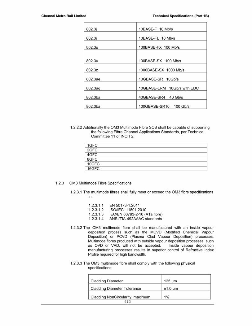
Chennai Metro Rail Limited Technical Specifications (Part 1B)
913
1.2.2.2 Additionally the OM3 Multimode Fibre SCS shall be capable of supporting the following Fibre Channel Applications Standards, per Technical Committee 11 of INCITS:
1GFC 2GFC 4GFC 8GFC 10GFC 16GFC
1.2.3 OM3 Multimode Fibre Specifications
1.2.3.1 The multimode fibres shall fully meet or exceed the OM3 fibre specifications in:
1.2.3.1.1 EN 50173-1:2011 1.2.3.1.2 ISO/IEC 11801:2010 1.2.3.1.3 IEC/EN 60793-2-10 (A1a fibre) 1.2.3.1.4 ANSI/TIA-492AAAC standards
1.2.3.2 The OM3 multimode fibre shall be manufactured with an inside vapour
deposition process such as the MCVD (Modified Chemical Vapour Deposition) or PCVD (Plasma Clad Vapour Deposition) processes. Multimode fibres produced with outside vapour deposition processes, such as OVD or VAD, will not be accepted. Inside vapour deposition manufacturing processes results in superior control of Refractive Index Profile required for high bandwidth.
1.2.3.3 The OM3 multimode fibre shall comply with the following physical
specifications:
Cladding Diameter 125 μm
Cladding Diameter Tolerance ±1.0 μm
Cladding NonCircularity, maximum 1%
802.3j 10BASE-F 10 Mb/s 802.3j 10BASE-FL 10 Mb/s 802.3u 100BASE-FX 100 Mb/s 802.3u 100BASE-SX 100 Mb/s 802.3z 1000BASE-SX 1000 Mb/s 802.3ae 10GBASE-SR 10Gb/s 802.3aq 10GBASE-LRM 10Gb/s with EDC 802.3ba 40GBASE-SR4 40 Gb/s 802.3ba 100GBASE-SR10 100 Gb/s

Chennai Metro Rail Limited Technical Specifications (Part 1B)
914
Coating Diameter (Colored) 254 μm
Coating Diameter (Uncolored) 245 μm
Coating Diameter Tolerance (Colored) ±7 μm Coating Diameter Tolerance (Uncolored) ±10 μm Coating/Cladding Concentricity Error, maximum 6 μm
Core Diameter 50.0 μm
Core Diameter Tolerance ±2.5 μm
Core/Clad Offset, maximum 1.5 μm
Numerical Aperture 0.200 ± 0.015
Zero dispersion wavelength 1297 − 1316 nm
Zero dispersion slope ≤ 0.105 ps/nm2-km Maximum DMD (note: must comply with at least one of the 6 templates specified below 850 nm 1300 nm
Meets or exceeds TIA/EIA-492AAAC-A and IEC 60793-2-10 A1a.2 See attached templates 0.88 ps/m
1.2.3.4 The OM3 multimode fibre shall meet the following requirements:
Maximum Fibre Cabled Loss
3.0 dB/km at 850 nm* 1.0 dB/km at 1300 nm*
Minimum Bandwidth
2000 MHz.km at 850 nm (DMD, laser) 500 MHz.km at 1300 nm (DMD, laser)
1500 MHz.km at 850 nm (OFL) 500 MHz.km at 1300 nm (OFL)
Operating Temperature Range (cabled fibre)
-20°C to 50°C (-4°F to 122°F)*
Storage Temperature Range (cabled fibre)
0°C to 50°C (32°F to 122°F) for LSZH -40°C to 65°C (-40°F to 149°F) for others
Maximum Pulling Tension
90 kg
Minimum Tensile Strength
0.7 GPa (100,000 psi)
* note: this value reflects cabled fibre loss. Uncabled fibre values will not be accepted.
1.2.3.5 The OM3 multimode fibres shall be colour coded to facilitate individual fibre
identification. Colour coding shall follow industry standard TIA-598-C Optical Fibre Cable Color Coding

Chennai Metro Rail Limited Technical Specifications (Part 1B)
915
1.2.3.6 The coating shall be mechanically strippable.
1.2.4 Differential Mode Delay
1.2.4.1 The OM3 fibre shall meet a minimum of one of the DMD templates listed below, accounting for the wider inner and outer mask specifications when compared with TIA 492AAAc and IEC 60793-2-10 standards:
Template 850 nm DMD-Inner Mask (ps/m) Radius from 0 to 18 μm)
850 nm DMD-Outer Mask (ps/m) Radius from 0-23 μm
1 ≤ 0.23 ≤ 0.70
2 ≤0.24 ≤ 0.60 3 ≤0.25 ≤ 0.50 4 ≤0.26 ≤ 0.40 5 ≤0.27 ≤ 0.35 6 ≤0.33 ≤ 0.33
1.2.5 Differential Mode Delay Testing
1.2.5.1 The OM3 multimode fibre shall be tested in accordance with:
1.2.5.1.1 IEC/EN 60793-1-49 1.2.5.1.2 ANSI/TIA-455-220-A 1.2.5.1.3 ANSI/TIA-492AAAC-A 1.2.5.1.4 The following additional enhancements to the DMD tests
must be made to ensure high bandwidth:
Enhancement to IEC/EN 60793-1-49 and ANSI/TIA-492AAAC-A
standards
Parameters Test Requirement Speed of Laser 5 ps pulse width Scan Resolution (Radial Increment)
1 µm
Inner Mask Radial Coverage 0 – 18 µm (no central hole) Number of Quadrants Tested 4 quadrants Test Length 300 metre
1.2.5.2 Third party verification of the DMD test bench must be provided with
the bid response.
1.2.5.3 The OM3 cable should have been performance verified with both DMD as well EMBc.
1.2.5.4 The solution should be provided with the application support chart.
Chennai Metro Rail Limited Technical Specifications (Part 1B)
916
2. OPTICAL FIBRE CABLING 2.1 Indoor/Outdoor Cabling
Outdoor cabling must be available for campus based networks or those requiring a simplified transition point between outdoor cabling and building cable. Indoor/outdoor cabling meets the fire safety requirements of an indoor environment, along with the rigors of an outdoor environment such as extended temperature range, UV resistance and water blocking capabilities.
2.1.1 The fibre-optic SCS shall be available with a wide range of outdoor cabling which
include the following designs: 2.1.1.1 Standard all-dielectric central tube 2.1.1.2 All dielectric stranded loose-tube 2.1.1.3 Metallic central tube 2.1.1.4 Metallic stranded loose tube 2.1.1.5 All dielectric rodent resistant stranded loose tube
2.1.2 Outdoor cabling shall be available with 900 micron buffered fibres up to 72 fibres 2.1.3 For LSZH indoor/outdoor tight-buffered fibre cables using a multi-unit construction,
all sub-unit buffer tubes shall be coloured. Numbered tubes of identical colour will not be accepted.
2.1.4 Outdoor cabling shall be available with 250 micron buffered fibres up to 144 fibres 2.1.5 The LSZH version of the indoor/outdoor cabling must comply with the following Fire
Safety standards:
2.1.5.1 ISO/IEC 60332-3: Vertical Flame Spread 2.1.5.2 ISO/IEC 60754-2: Acidity 2.1.5.3 ISO/IEC 61034-2: Smoke Density
2.1.6 Outdoor LSZH cabling shall comply with appropriate sections of IEC 607942.
3. OPTICAL FIBRE PATCH CORDS
3.1 Optical fibre patchcords shall be available in simplex or duplex configurations.
3.2 Fibre patch cords will utilise indoor rated cordage with LSZH rating.
3.3 The following connector types must be used :
• LC/UPC ( MM), compliant with IEC 61754-20 and TIA 604-10-A
4. OPTICAL FIBRE APPARATUS: FIELD TERMINATED SYSTEMS
4.1 Fibre-Optic shelves
4.1.1 Fibre Optic shelves shall have field installable distribution modules and distribution panels.
4.1.4 Fibre optic shelves will be used 1U designs.
4.1.5 The distribution modules shall accommodate LC duplex connectors in
removable panels. Modules shall be available as front plate only or with integral slack spool management.

Chennai Metro Rail Limited Technical Specifications (Part 1B)
917
4.1.6 Distribution modules with integral slack management shall be optionally available with pre-populated fibre pigtails.
4.1.7 Distribution modules shall be specifically designed for the respective cable/connector type
4.1.8 Distribution modules shall possess plastic covers on the front of the housing to prevent dust or other debris from entering unused ports.
4.1.9 Distribution panels shall also be used with LC adapters
4.1.10 Intelligent patch panel shall provide a button and an LED indicator at every panel port to enable easy tracing and identification of patch connections in the telecom room.
4.1.11 Intelligent fiber patch panels shall be compatible with standards-compliant LC and MPO fiber optic connectors and shall detect the insertion and removal of standards-compliant plugs into a patch panel port.
4.1.12 Intelligent fiber patch panels shall be available in traditional field-terminated as well as Pre-terminated intelligent configurations with MPO fiber optic interfaces in the rear that enable quick connectivity of MPO style pre-terminated multi-fiber/ribbon trunk cables.
4.1.13 Intelligent field-terminated and pre-terminated fiber shelves shall be available in 1U fixed and sliding configurations to support 24-duplex LC ports and 48-duplex LC ports.
4.1.14 Intelligent pre-terminated fiber shelves shall be available in 2U sliding
configuration to support up to 144 -duplex LC ports as well as in 4U configuration supporting up to 244 duplex LC ports.
4.1.15 Intelligent fiber patch panels shall be available in 1U fixed and sliding configurations with up to 32 MPO ports, in 2U sliding configuration to support up to 96 MPO ports, and in 4U sliding configuration to support up to 192 MPO ports.
4.1.16 Intelligent patch panels should be as easy to install/terminate as non-intelligent panels.
4.1.17 Intelligent patch panels shall be compatible with mounting on 19” based hardware per EIA-310.
4.1.18 Intelligent fiber shelves shall include a built-in feature to enable attachment of cord management accessory directly to the panel to maximize panel density on a rack/cabinet.
4.1.19 Intelligent patch panels shall be packaged with all necessary system-connecting cable(s) attached to the panel. Intelligent patch panels should be ready for use right out of the shipping box.
4.1.20 Intelligent copper and fiber patch panels should allow for removal and replacement of sensing assembly without requiring disconnection of installed patch cords.
4.2 Fibre Adapters
4.2.1 Fibre adapters will be multimode fibre.

Chennai Metro Rail Limited Technical Specifications (Part 1B)
918
4.2.2 The following fibre adapters must be available in duplex adapter configurations as part of distribution modules and panels:
4.2.2.1.1 LC adapter compliant with IEC 61754-20 and TIA 604-10-A.
4.2.2.1.2 Fibre adapters must be colour coded to ensure correct.
4.3 Fibre Pigtails
4.3.1 Optical fibre pigtails shall be used standard 900 micron tight buffered or
ruggedised with additional strength elements.
4.3.2 The following connector types must be used: 4.3.2.1 LC/UPC (MM) compliant with IEC 61754-20
4.4 Splice Trays
4.4.1 Splice trays must be used for the 1U shelves to secure fusion splices.
4.4.2 Splice trays must be stackable and must accommodate up to 48 single fusion
splices in a single tray.
5 DOCUMENTATION
The Optical Fibre Structured Cabling System (SCS) shall be provided with a complete set of documentation such that the design, installation and commissioning of the system can be done properly.
This documentation shall consist of the following, to be included in the bid response:
5.1.5.1.1 Design and Installation guidelines, which shall include configurations for typical
local-area network and data centre applications 5.1.5.1.2 Performance specifications, which shall state the maximum supportable
distance for all protocols which are anticipated to be transported by the SCS. These specifications must be provided in table format to list the number of permissible connections, by connection type, along with the guaranteed distance based on connection number and type, for a given protocol.
5.1.5.1.3 Field testing guidelines based on use of Power Meters to determine insertion
loss of a given link. 5.1.5.1.4 A link loss calculator must also be provided. This link-loss calculator must be
capable of calculating the expected maximum loss for a given fibre link, based on length, fibre type, number and type of connectors and splices. The calculation shall be used as “pass/fail” criteria after installation to ensure that the actual insertion loss meets the manufacturer’s guidelines.
CATEGORY 6A/ CLASS EA UTP CABLING SYSTEM REQUIREMENTS
Furnish and install, complete with all accessories, a Category 6A/ Class EA Unshielded Twisted Pair (UTP) Structured Cabling System (SCS). The SCS shall serve as the t ransport infrastructure for data, video and voice telephony signals throughout the network from designated demarcation points to outlets located at various Desktop, Workstation, Data Centre, Intelligent Building facilities or other locations as indicated on the contract drawings and described herein. The Category 6A/ Class EA UTP Structured Cabling System (SCS) shall comply with the following requirements:

Chennai Metro Rail Limited Technical Specifications (Part 1B)
919
1. STANDARDS COMPLIANCE
The Category 6A/ Class EA UTP SCS shall comply with the following standards
• ISO/IEC 11801:2010 • EN 50173 Part 1 through Part 5:2010 and 2011 • ANSI/TIA-568-C • IEC 60603-7-4 • IEEE 802.3 applications as outlined in section 2 • Local/National Codes and Regulations
2. APPLICATION SUPPORT
2.1 The Category 6A/ Class EA UTP SCS shall be capable of supporting, at minimum, the following IEEE Ethernet applications:
802.3e 1BASE5 802.3i 10BASE-T 10 Mbit/s over twisted pair
802.3u 100BASE-TX, 100BASE-T4, Fast Ethernet at 100 Mbit/s w/auto negotiation
802.3y 100BASE-T2 100 Mbit/s (12.5 MB/s) over low quality twisted pair
802.3z 1000BASE-X Gbit/s Ethernet over Fiber-Optic at 1 Gbit/s
802.3ab 1000BASE-T Gbit/s Ethernet over twisted pair at 1 Gbit/s
802.3af Power over Ethernet (12.95 W)
802.3an 10GBASE-T 10 Gbit/s Ethernet over unshielded twisted pair
802.3at Power over Ethernet enhancements (25.5 W) 802.3az Energy Efficient Ethernet
2.2 Additionally the Category 6A/ Class EA UTP SCS shall be capable of supporting the
following Fibre Channel Applications Standards, per Technical Committee 11 of INCITS:
3. STRUCTURED COPPER CABLING CHANNEL PERFORMANCE
3.1.1 Guaranteed Values in Worst-Case 100 Metre, 4 Connector Channel:
It is critical that guaranteed worst-case values are provided to ensure the SCS can support 10G transmission without risk. “Average value” or “Typical Value” is not acceptable as they do not account for lower performance channels. The proposed Category 6A/ Class EA UTP SCS, when configured as a worst-case 100 metre, 4 connection channel shall meet the following specifications: Note that these specifications meet or exceed the ISO/IEC IS 11801:2010, Class EA channel requirements when configured as a worst-case 100 metre, 4 connection channel. The Guaranteed channel performance for a 4 connector channel should meet the following guaranteed performance criteria.
1GFC-BASE-T 2GFC-BASE-T 4GFC-BASE-T
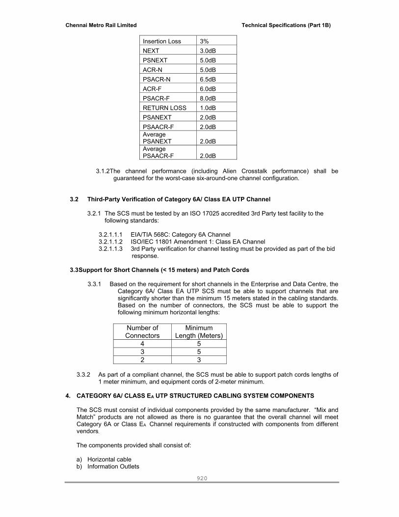
Chennai Metro Rail Limited Technical Specifications (Part 1B)
920
Insertion Loss 3% NEXT 3.0dB PSNEXT 5.0dB ACR-N 5.0dB PSACR-N 6.5dB ACR-F 6.0dB PSACR-F 8.0dB RETURN LOSS 1.0dB PSANEXT 2.0dB PSAACR-F 2.0dBAverage PSANEXT 2.0dB Average PSAACR-F 2.0dB
3.1.2 The channel performance (including Alien Crosstalk performance) shall be
guaranteed for the worst-case six-around-one channel configuration.
3.2 Third-Party Verification of Category 6A/ Class EA UTP Channel
3.2.1 The SCS must be tested by an ISO 17025 accredited 3rd Party test facility to the following standards:
3.2.1.1.1 EIA/TIA 568C: Category 6A Channel 3.2.1.1.2 ISO/IEC 11801 Amendment 1: Class EA Channel 3.2.1.1.3 3rd Party verification for channel testing must be provided as part of the bid
response.
3.3 Support for Short Channels (< 15 meters) and Patch Cords
3.3.1 Based on the requirement for short channels in the Enterprise and Data Centre, the Category 6A/ Class EA UTP SCS must be able to support channels that are significantly shorter than the minimum 15 meters stated in the cabling standards. Based on the number of connectors, the SCS must be able to support the following minimum horizontal lengths:
Number of Connectors
Minimum Length (Meters)
4 5 3 5 2 3
3.3.2 As part of a compliant channel, the SCS must be able to support patch cords lengths of
1 meter minimum, and equipment cords of 2-meter minimum.
4. CATEGORY 6A/ CLASS EA UTP STRUCTURED CABLING SYSTEM COMPONENTS
The SCS must consist of individual components provided by the same manufacturer. “Mix and Match” products are not allowed as there is no guarantee that the overall channel will meet Category 6A or Class EA Channel requirements if constructed with components from different vendors.
The components provided shall consist of:
a) Horizontal cable b) Information Outlets

Chennai Metro Rail Limited Technical Specifications (Part 1B)
921
c) Intelligent ganged adapter style patch panel d) Ganged adapter style patch panel upgradeable to an intelligent system e) Patch-cords f) Zone cords (outlet-to-plug) g) Pre-Terminated cable assemblies
4.1 Horizontal Cable 4.1.1 When configured in worst-case 100 metre channels with full cross-connects and
consolidation points with the other products proposed, the cable shall be capable of delivering the minimum guaranteed channel performance specified in section 3.0
4.1.2 The length of each individual run of horizontal cable from the telecommunications closet on
each floor to the telecommunications outlet shall not exceed 90 metres, and shall be continuous without any joints or splices.
4.1.3 Contractor shall observe the bending radius and pulling strength requirements of the 4-pair UTP cable during handling and installation.
4.1.4 The cable shall be round in construction, with a maximum nominal diameter of 7.24mm
4.1.5 The minimum bend radius for the 4-pair UTP cable under no load shall be 29 mm.
4.1.6 The cable will consist of eight 23 AWG copper conductors. Copper-clad aluminium is not permitted.
4.1.7 The cable and cordage shall be used in Low-Smoke, Zero Halogen (LSZH) compatibility. 4.1.8 The LSZH version must comply with the following Fire Safety standards:
4.1.8.1 ISO/IEC 60332-3-22: Vertical Flame Spread 4.1.8.2 ISO/IEC 60754-2: Acidity 4.1.8.3 ISO/IEC 61034-2: Smoke Density
4.1.9 3rd Party verification of the Fire Safety/ Environmental tests listed above must be provided as part of the bid response.
4.1.10 The cable and cordage shall be UTP components that do not include internal or external
shields, screened components or drain wires.
4.1.11 The horizontal cable shall have a unique print string on the cable jacket. This unique identifier shall also be used for on-line reference to a full set of factory tests that were performed on a sample from the same master reel. The test parameters shall include NEXT, PSNEXT, Return Loss, Attenuation, ELFEXT and PSELFEXT. The on-line reference must be available on the SCS vendor public website, such that it can be accessed at any time.
4.1.12 The print string will also include markings in both meters and feet.
4.1.13 The Cat6A/ Class EA horizontal cable shall be available to order in the following options:
4.1.13.1 Cardboard box in 305 meter (1000 foot) lengths 4.2 Information Outlets

Chennai Metro Rail Limited Technical Specifications (Part 1B)
922
4.2.1 Information outlets shall consist of 8-pin modular (RJ-45) jacks which are labelled with both the T568B and T568A wiring schemes.
T568A pin assignment T568B pin assignment
4.2.2 The 8-pin modular (RJ-45) jacks shall comply with IEC 60603-7-4.
4.2.3 The information outlet shall have a Current Rating of 1.5 A at 20°C 4.2.4 The information outlet must support 90 degree cable termination. As some
mounting hardware does not allow for cable entry directly from the rear, this capability is necessary.
4.2.5 When configured in worst-case 100 metre channels with full cross-connects
and consolidation points with the other products proposed in this tender, the outlet shall be capable of delivering the minimum guaranteed channel performance specified in section 3.0.
4.2.6 3rd Party Verification test certificates shall be provided to show compliance to ISO/IEC 11801 Amendment 2 testing for Cat 6A components.
4.2.7 The information outlet will have insertion life of 750 cycles minimum.
4.2.8 Information outlet caps with integrated strain relief shall be available as an option. 4.2.9 The information outlet shall be available in eleven (11) different colours.
4.2.10 The information outlet must be able to accept termination of solid conductors with nominal diameter of between 0.40 mm to 0.64 mm (26 to 22 AWG).
4.2.11 The information outlet must be able to accept termination of stranded conductors
with nominal diameter of between 0.51 mm to 0.64 mm (24 to 22 AWG). 4.3 Ganged adapter style patch panel system:

Chennai Metro Rail Limited Technical Specifications (Part 1B)
923
4.3.1 The ganged adapter style patch panel will utilise increments of six RJ-45 style jacks in a common moulded component.
4.3.2 The patch panel type shall be compliant with IEC 60603-7-4. 4.3.3 The ganged adapters shall have RJ45 jack in the front and Insulation Displacement
Connector (IDC) at the rear of the module.
4.3.4 The patch panels shall be available in the following configurations:
4.3.4.1 1U 24-port Intelligent enabled panel. 4.3.4.2 Intelligent patch panel shall provide a button and an LED indicator
at every panel port to enable easy tracing and identification of patch connections in the telecom room.
4.3.5 The upgrade to an intelligent system shall be performed through the addition of an
overlay panel that does not require tools for installation. 4.3.6 Termination managers must be provided with the panel. These termination
managers provide proper pair positioning, control, and strain relief features to the rear termination area of the panel.
4.3.7 3rd Party Verification test certificates shall be provided to show compliance to
ISO/IEC 11801 Amendment 2 testing for Cat 6A components.
4.3.8 When configured in worst-case 100 meter channels with full cross-connects and consolidation points with the other products proposed in this tender, the panel shall be capable of delivering the minimum guaranteed channel performance specified in section 3.0.
4.4 Intelligent System Controller
4.4.1 The Intelligent Infrastructure Control System is a device that performs the following functions:
4.4.2 Communicate with intelligent patch panels
4.4.3 Provide power to intelligent patch panels on a rack
4.4.4 Record connectivity information
4.4.5 Communicate to other System Controllers
4.4.6 Communicate to Intelligent Infrastructure Operations Software via Ethernet
4.4.7 Display electronic work orders and guide the technician with visual and audio alerts
4.4.8 Display trace and connectivity information
4.4.9 The Intelligent Infrastructure Control System shall be compatible with mounting on 19” (width) based hardware per EIA-310
4.4.10 The Intelligent System Controller shall occupy no more than 1U of vertical rack space (height), as defined per EIA-310, with the capability for 0U mounting (mounting without occupying any RU space).
4.4.11 The Intelligent Infrastructure Control System shall communicate with the intelligent patch panels in a rack using serial bus interconnection architecture.
Chennai Metro Rail Limited Technical Specifications (Part 1B)
924
4.4.12 The Intelligent Infrastructure Control System shall be packaged with the required serial bus cable and connector system required to connect the maximum number of panels in a rack
4.4.13 The serial bus interconnection architecture shall fit into and be easily assembled to a standard 7’ high equipment mounting hardware.
4.4.14 Once installed, the serial bus shall provide for plug-and-play capabilities between intelligent patch panels and the Intelligent Infrastructure Control System installed on that rack, including panel adds, re-arrangement as well as replacement of panels.
4.4.15 The Intelligent System Controller shall be able to communicate with up to 45 1U-size intelligent copper or fiber patch panels per rack.
4.4.16 Only one Intelligent System Controller shall be required per rack.
4.4.17 The Intelligent System Controller shall be provided with a color LCD screen with a touch screen interface to enable for easy interactions with the Intelligent Infrastructure Solution directly at a rack.
4.4.18 The Intelligent System Controller LCD screen shall have ability to turn off the backlight when not in use.
4.4.19 The Intelligent System Controller shall be able to display tracing information on its LCD screen when a trace button is pressed on an intelligent panel.
4.4.20 The Intelligent System Controller shall be able to display live end-to-end tracing information on its LCD screen during patching activities.
4.4.21 The Intelligent System Controller shall be able to display on the LCD screen information indicating if a traced panel port is assigned to a scheduled work order.
4.4.22 The Intelligent System Controller shall be able to display electronic work orders for moves, adds and changes (MACs).
4.4.23 The Intelligent System Controller shall provide capability for a technician to communicate with Intelligent Infrastructure Solution database.
4.4.24 The Intelligent System Controller shall be able display text in multiple languages (one language at a time), including English, Spanish, Danish, French, German, Italian, Russian, Polish, Portuguese, Chinese and Korean.
4.4.25 The Intelligent System Controller shall provide audible feedback to the technician while the technician is performing various MAC activities.
4.4.26 The Intelligent System Controller shall store connectivity information that is collected from intelligent patch panels in non-volatile memory.
4.4.27 Multiple Intelligent System Controllers in a telecom room shall be interconnected together using serial bus architecture such as “daisy chain”, with standard modular RJ45 patch cords.
4.4.28 The Serial bus for Intelligent System Controller shall be capable of supporting for up to 50 Intelligent Infrastructure Control System on the same bus in the same telecom room.
4.4.29 The maximum combined length of connecting cords in a serial bus for System Controllers in the same telecom room shall be 1000 meters.

Chennai Metro Rail Limited Technical Specifications (Part 1B)
925
4.4.30 The Intelligent System Controller shall have a configurable Ethernet LAN connection capability to enable communication with Intelligent Infrastructure Operations Software.
4.4.31 At least one Intelligent System Controller with an enabled Ethernet connection shall be installed per telecom room.
4.4.32 The Intelligent System Controller shall be capable of managing an unlimited number of Ethernet enabled Intelligent Infrastructure Control Systems.
4.4.33 Enabling of Ethernet capabilities for an System Controller System shall not require the use of external devices.
4.4.34 The Intelligent System Controller shall have the capability to indicate when intelligent hardware is communicating with Intelligent Infrastructure Operations Software.
4.4.35 The Intelligent System Controller shall be equipped with an LED indicator to enhance visual communication to the technician.
4.4.36 The Intelligent System Controller shall provide the ability to configure local “patching zones”.
4.4.37 The Intelligent System Controller shall support IPv6 communications.
4.4.38 Intelligent Infrastructure Operations Software
4.4.39 The AIM Operations Software shall be web based.
4.4.40 The AIM Operations Software shall be compatible with Simple Network Management Protocol (SNMP) and support SNMP v1, SNMP v2c, and SNMP v3.
4.4.41 The AIM Operations Software shall support IPv6 communications.
4.4.42 The AIM Operations Software shall be capable of importing, displaying and printing CAD drawings for accurate representation of building’s floor plans.
4.4.43 The AIM Operations Software shall provide drag-and-drop capabilities for
populating floor plans with database objects.
4.4.44 Database objects that are placed onto a floor plan shall be fully functional so that system’s management capabilities can be administered directly from the floor plan.
4.4.45 The AIM Operations Software shall provide capabilities for documenting Outside Plant cabling infrastructure that includes campus maps, cable vaults, conduits, splice enclosures, etc.
4.4.46 The AIM Operations Software shall support automatic and manual database backups.
4.4.47 The AIM Operations Software shall have capability to auto discover the installed intelligent hardware (intelligent panels and control systems) in each rack/cabinet and to auto populate this information in its database.
4.4.48 The AIM Operations Software shall have the capability of auto discover the configuration of predefined managed switches (LAN and SAN environments) and then to auto populate that information in its database.
4.4.49 The AIM Operations Software shall have the capability to auto discover networked devices that are connected to the pre-defined managed network
Chennai Metro Rail Limited Technical Specifications (Part 1B)
926
switches (LAN and SAN environments) and then to auto populate that information in its database.
4.4.50 The AIM Operations Software shall provide end user with ability to define manual, automatic, or disabled mode for conducting discovery of networked devices. The automatic device discovery feature shall allow end user to determine a polling schedule, as well as the ability to automatically trigger the discovery process based on SNMP link-up traps from managed network switches.
4.4.51 The AIM Operations Software shall have the capability to auto discover IP address, MAC ID, WWN and Host Name information for networked devices and then to auto populate this information into its database.
4.4.52 The AIM Operations Software shall have the capability to auto discover networked devices with multiple MAC addresses (i.e. servers with multiple NICs, virtual machines, wireless APs, IP phone/ computer pairs, etc.) and then to auto populate that information in its database.
4.4.53 The Intelligent Infrastructure Operations Software shall have the capability to auto discover VLAN ID information on managed network switches and then to auto populate that information in its database.
4.4.54 The AIM Operations Software shall provide the end user with the ability to define type of networked devices based on MAC address range that could also be applied retroactively to already discovered devices. Once defined, each device upon its discovery shall be automatically labeled and represented with an appropriate icon in the database to correspond to the device type definition.
4.4.55 The AIM Operations Software shall have the capability to accurately identify the physical location of the discovered networked devices (physical or virtual) within the corporate network (as defined within site/building/telecom room/rack/office/outlet/jack).
4.4.56 The AIM Operations Software shall have the capability to detect configuration changes to managed SAN and LAN switches.
4.4.57 The AIM Operations Software shall have the capability to detect when a networked device has moved or changed its physical location.
4.4.58 The AIM Operations Software shall provide capabilities for defining a set of specific system conditions that need to be tracked.
4.4.59 The AIM Operations Software shall provide a simple “select and schedule” service-provisioning feature that is part of the electronic work order system. Service provisioning algorithm shall be integrated into Intelligent Infrastructure Operations Software to eliminate tedious MAC definition tasks.
4.4.60 The Service provisioning algorithm shall be capable of supporting devices/equipment that are connected to the network in the work area as well as in the data center.
4.4.61 The AIM Operations Software shall provide a dedicated service-provisioning feature for servers, including server templates, and graphics to allow for efficient planning and deployment of servers in the data center.
4.4.62 The AIM Operations Software shall have the capability to document various topologies (zone, pod, cell, etc.) for Data Center applications.
4.4.63 The AIM Operations Software shall have the capability to allow end user to define the preferred connectivity routing when provisioning services.

Chennai Metro Rail Limited Technical Specifications (Part 1B)
927
4.4.64 The AIM Operations Software shall have the capability to enable or disable
switch ports a part of the electronic work order feature.
4.4.65 The AIM Operations Software shall have the capability to control and audit the enabling and disabling of switch ports.
4.4.66 The AIM Operations Software shall have the capability to provide real-time alerts to the system administrator about defined system conditions so proper and timely action could take place.
4.4.67 The AIM Operations Software shall have the capability to, send email, and text messages to specified personnel to inform them in real-time about specific pre-defined system events.
4.4.68 The AIM Operations Software shall provide multiple user privilege levels (read only, based on physical location/building/floor, ability to schedule work orders, access to web client, access restrictions based on available services).
4.4.69 The AIM Operations Software shall provide the capability to allow external Software systems (for example Aperture, Remedy HelpDesk, HP Service Manager, etc.) to interact with the AIM Solution.
4.4.70 The AIM Operations Software shall provide web-based reports capabilities. This feature should allow for reports to be automatically generated based on a pre-defined schedule for distribution to pre-defined groups of recipients.
4.4.71 The AIM Operations Software shall be capable of receiving SNMP traps from SNMP enabled devices. It shall also be able to generate alerts based on the received SNMP traps.
4.5 Modular RJ45 Patch Cords
4.5.1 Cords shall be equipped with 8-pin modular plugs on each end. 4.5.2 All cords shall be round, and consist of copper conductors, tightly twisted into
individual pairs.
4.5.3 Nominal cordage diameter shall not exceed 7.24 mm.
4.5.4 Plugs shall be designed with an anti-snag latch to facilitate easy removal during move, add and change processes.
4.5.5 The cordage must consist of 8 solid 23 AWG copper conductors. Copper clad aluminium is not permitted.
4.5.6 The cordage will be used Low-Smoke, Zero Halogen (LSZH) compatibility.
4.5.7 The LSZH version must comply with the following Fire Safety standards:
4.5.7.1 ISO/IEC 60332-3-22: Vertical Flame Spread 4.5.7.2 ISO/IEC 60754-2: Acidity 4.5.7.3 ISO/IEC 61034-2: Smoke Density
4.5.8 3rd Party verification of the Fire Safety/ Environmental tests listed above must be provided as part of the bid response.
Chennai Metro Rail Limited Technical Specifications (Part 1B)
928
4.5.9 The cordage shall be UTP components that do not include internal or external shields, screened components or drain wires.
4.5.10 The cordage shall have a unique print string on the cable jacket. This unique
identifier shall also be used for on-line reference to a full set of factory tests that were performed on a sample from the same master reel. The test parameters shall include NEXT, PSNEXT, Return Loss, Attenuation, ELFEXT and PSELFEXT. The on-line reference must be available on the SCS vendor public website, such that it can be accessed at any time.
4.5.11 3rd Party Verification test certificates shall be provided to show compliance to ISO/IEC 11801 Amendment 2 testing for Cat 6A components.
4.5.12 The patch cords will have insertion life of 750 cycles minimum.
4.5.13 When configured in worst-case 100 metre channels with full cross-connects and consolidation points with the other products proposed in this tender, the patch cords shall be capable of delivering the minimum guaranteed channel performance specified in section 3.0.
4.6 Zone Cords
4.6.1 The Category 6A/Class EA SCS shall provide an option for factory-terminated zone cabling
4.6.2 The cordage used in the zone cords shall meet all requirements specified in
section 4.5. 4.6.3 Zone cord connector types shall be an unshielded modular 8-pin connectors
compliant with IEC 60603-7-4, as described in 4.2 (outlet) and 4.5 (plug). 4.6.4 Zone cables shall consist of solid 23 AWG copper cabling with factory
terminated plug on one end and a factory terminated information outlet on the other end.
4.6.5 When configured in worst-case 100 metre channels with full cross-connects and consolidation points with the other products proposed in this tender, the zone cords shall be capable of delivering the minimum guaranteed channel performance specified in section 3.0.
5. DOCUMENTATION
The Category 6A/ Class EA Unshielded Twisted Pair (UTP) Structured Cabling System (SCS) shall be provided with a complete set of documentation such that the design, installation and commissioning of the system can be done properly.
5.1 This documentation shall consist of the following, to be included in the bid response:
5.1.1 Design and Installation guidelines, which shall include configurations for
typical local-area network and data centre applications for 2, 3 and 4 connector channels
5.1.2 Performance specifications, which shall state the maximum supportable
distance for all protocols which are anticipated to be transported by the SCS
5.1.3 Zone cabling guidelines

Chennai Metro Rail Limited Technical Specifications (Part 1B)
929
5.1.4 Power separation guidelines
RACK SPECIFICATION : Floor Standing Rack Bill of Material: Open Rack : 42U • 42U Height, 600mm Width & 1200mm Depth.( Server rooms) • Rack consists of 4 nos. of Steel vertical pillars. • Horizontal support with steel welded end frames. • Top cover with heat exhaust kit & Removable Cable entry provision with brushes panel. • Bottom cover with Removable cable entry provision with brush panel. • Rack Loading capacity should be minimum of 1000 Kgs. • Pairs of Depth Support Channel for equal loading distribution. • Pairs of Universal Cabling Frame for proper & neat dressing of cables & PDU Mounting. • Each rack will have two pairs of 19" equipment mounting angle with "U" marking. • Sets of Rear Split Mounting Angles for mounting different equipments. • 19" equipment mounting angle should be recessible fully. Side Panel : • Secured dual plain side panel with no opening provision on the outer cover. • Locking provision only from inside of the cabinet. • Plain dual side Panel without ventilation & in two depths 1000mm & 200mm. • Side Panels should have the provision of hooking from top. Rack Door : • Front & Rear Door should be of Steel Construction with 1.6mm CRCA Sheet. • Hexagonal perforation of 6.5mm Dia and Pitch 8 mm. • The Doors need to be fabricated in Single sheet with box bends on the end for rigidity. • Doors should be of 42U height and 600mm width with 3 Point Locking mechanism. • Fully perforated doors with hexagonal pattern having 70% Ventilation for airflow. • All doors should have Provision for Fixing Digital Key Pad Lock in the front door and
solenoid at the front and rear door. Cable Management : • Vertical Cabling Frame 42U 300mm Width & 1200mm Depth. • 1U Vertical Cable Hangers from Top to Bottom • 19” Conversion Kit to mount jack panels on the cabling frame • 3U Cable brushes for easy routing out cables from front to rear • Cable brushes at the entry, middle & top of the frame for smooth cable routing, • Kick off plate to block the air flow • Center vertical cable ladder with fingers • Hardware packet of 20 for mount the equipment – 3Pkts per rack. • Base Frame, 100mm height / 600mm width / 1200mm depth • Door Mountable Fans (90 CFM) - 4 nos per rack • Fan Housing Unit - 2 nos per rack • Rack should be completely knocked-down. Standards: • Conforms to DIN 41494 / EIA 310-D standard. • Cabinet has to be undergo Nano-Ceramic, minimum 7 stage pre-treatment process. • ROHS compliance as per the best industry standard practice. • Powder coating deposit on the sheet should be between 80 TO 120 Microns. • 100% corrosion Free Cabinet. • Rack Colour should be a standard colour. Preferably Black.

Chennai Metro Rail Limited Technical Specifications (Part 1B)
930
• Delivery lead time should be 4 weeks from the time of PO release. • Rack should be compatible with assembled & installed at site if required. IP Based PDU : • Remote Monitoring Power Distribution Unit with 36 nos of C13 & 6 nos of C19 IEC Socket with 2
nos of 16 Amp Internal Circuit Breaker and cable Length upto 3Mtr with Industrial Plug Top & Temperature/Humidity Combo Sensor.
InterConnect Power Cord : • C13-C14 Inter Connect lockable Power Cable, 1.5Mtr • C19-C20 Inter Connect lockable Power Cable, 1.5Mtr • Warranty should be Two Years Back-To-Bench on the hardware • ROHS Compliance. Closed Rack: 17U • 15U Height, 600mm Width & 500mm Depth. • Rack consists of 4 nos. of Steel vertical pillars. • Horizontal support with steel welded end frames. • Top cover with heat exhaust kit & Cable entry provision. • Bottom cover with cable entry. • Rack Loading capacity should not be maximum of 400 Kgs.. • Each rack will have two pairs of 19" equipment mounting angle with "U" marking. • 19" equipment mounting angle should be recessible fully. • Plain side panel with slam latch. Rack Door : • Front & Rear Door should be of Steel Construction with 1.6mm CRCA Sheet. • Hexagonal perforation of 6.5mm Dia and Pitch 8 mm. • The Doors need to be fabricated in Single sheet with box bends on the end for rigidity. • Doors should be of 15U height and 600mm width. • Fully perforated doors with hexagonal pattern having 70% Ventilation for airflow. • All doors should have Provision for Fixing Digital Key Pad Lock Kit or HID access control. • Hardware packet of 20 for mount the equipment – 3Pkts per rack. • Castor Set of 4 nos with brakes for 2 nos • Top Mountable Fans (90 CFM) - 2 nos per rack • Fan Housing Unit - 1 nos per rack • Conforms to DIN 41494 / EIA 310-D standard. • Cabinet has to be undergo Nano-Ceramic, minimum 7 stage pre-treatment process. • ROHS compliance as per the best industry standard practice. • Power coating deposit on the sheet should be between 80 TO 120 Microns. • 100% corrosion Free Cabinet. • Rack Colour should be Black. • Delivery lead time should not be more than 3 weeks from the time of PO release. Analog PDU: • Power Distribution Unit with 10 nos. of C13 IEC Socket with 16 Amp Miniature Circuit Breaker
and cable Length upto 3Mtr with Plug Top. Voice System: 1.0 System hardware and software architecture requirements
The offered system shall have at least following hardware and software features as per the requirement :
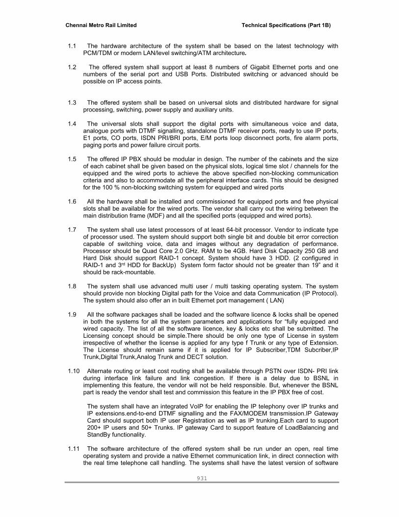
Chennai Metro Rail Limited Technical Specifications (Part 1B)
931
1.1 The hardware architecture of the system shall be based on the latest technology with
PCM/TDM or modern LAN/level switching/ATM architecture.
1.2 The offered system shall support at least 8 numbers of Gigabit Ethernet ports and one numbers of the serial port and USB Ports. Distributed switching or advanced should be possible on IP access points.
1.3 The offered system shall be based on universal slots and distributed hardware for signal processing, switching, power supply and auxiliary units.
1.4 The universal slots shall support the digital ports with simultaneous voice and data,
analogue ports with DTMF signalling, standalone DTMF receiver ports, ready to use IP ports, E1 ports, CO ports, ISDN PRI/BRI ports, E/M ports loop disconnect ports, fire alarm ports, paging ports and power failure circuit ports.
1.5 The offered IP PBX should be modular in design. The number of the cabinets and the size
of each cabinet shall be given based on the physical slots, logical time slot / channels for the equipped and the wired ports to achieve the above specified non-blocking communication criteria and also to accommodate all the peripheral interface cards. This should be designed for the 100 % non-blocking switching system for equipped and wired ports
1.6 All the hardware shall be installed and commissioned for equipped ports and free physical
slots shall be available for the wired ports. The vendor shall carry out the wiring between the main distribution frame (MDF) and all the specified ports (equipped and wired ports).
1.7 The system shall use latest processors of at least 64-bit processor. Vendor to indicate type
of processor used. The system should support both single bit and double bit error correction capable of switching voice, data and images without any degradation of performance. Processor should be Quad Core 2.0 GHz. RAM to be 4GB. Hard Disk Capacity 250 GB and Hard Disk should support RAID-1 concept. System should have 3 HDD. (2 configured in RAID-1 and 3rd HDD for BackUp) System form factor should not be greater than 19” and it should be rack-mountable.
1.8 The system shall use advanced multi user / multi tasking operating system. The system
should provide non blocking Digital path for the Voice and data Communication (IP Protocol). The system should also offer an in built Ethernet port management ( LAN)
1.9 All the software packages shall be loaded and the software licence & locks shall be opened
in both the systems for all the system parameters and applications for “fully equipped and wired capacity. The list of all the software licence, key & locks etc shall be submitted. The Licensing concept should be simple.There should be only one type of License in system irrespective of whether the license is applied for any type f Trunk or any type of Extension. The License should remain same if it is applied for IP Subscriber,TDM Subcriber,IP Trunk,Digital Trunk,Analog Trunk and DECT solution.
1.10 Alternate routing or least cost routing shall be available through PSTN over ISDN- PRI link
during interface link failure and link congestion. If there is a delay due to BSNL in implementing this feature, the vendor will not be held responsible. But, whenever the BSNL part is ready the vendor shall test and commission this feature in the IP PBX free of cost.
The system shall have an integrated VoIP for enabling the IP telephony over IP trunks and IP extensions.end-to-end DTMF signalling and the FAX/MODEM transmission.IP Gateway Card should support both IP user Registration as well as IP trunking.Each card to support 200+ IP users and 50+ Trunks. IP gateway Card to support feature of LoadBalancing and StandBy functionality.
1.11 The software architecture of the offered system shall be run under an open, real time
operating system and provide a native Ethernet communication link, in direct connection with the real time telephone call handling. The systems shall have the latest version of software

Chennai Metro Rail Limited Technical Specifications (Part 1B)
932
packages for the basic operating system, programming language and all the applications to meet all system features and functional requirements for the proposed configurations.
1.12 The software shall include the full trunk routing software for daytime routing, distributed
trunk routing, alternative routing, route optimisations and digit manipulations also. 1.13 The offered system shall have voice guided auto attendant features on all caller lines and
accordingly the vendor shall provide the required number of interconnecting ports for voice-guided auto attendant. The offered system shall have capability to incorporate the Interactive Voice Response (IVR) facilities in latter date.
1.14 Any analog or digital telephone should be empowered to alter the auto attendant message as per programmed in telephone exchange.
1.15 Analogue extension ports shall have built in or distributed DTMF receiver circuits. Minimum
one number of DTMF circuit shall be available for ten analogue ports. All the DTMF cards shall be equipped in universal slots and accordingly the physical slot and time slot calculation is to be taken care for specified non-blocking communication.
1.16 Ringer circuit per line card should be provided. The design of ringer circuit for the analogue
ports shall be such that it shall provide the ringer current to all the ports simultaneously and it shall be equipped with over voltage and over current protection.
1.17 System Redundancy:-
The system should be provided with 100% Duplicated control unit in Hot stand By mode. The basic system should be capable of achieving its ultimate capacity (12000 Lines) without the need of adding / Upgrading CP. There should not be any call Drop or Voice delay during switchover from 1st Processor to 2nd Processor.
1.18 The system shall have the required management facilities for system feature programming, fault location and diagnosis, main and remote unit monitoring and fault annunciation using external audible devices.
1.19 The system should support a minimum of 225,000 BHCC (Busy Hour Call Completion)
1.20 The system architecture should be such that it is inherently able to handle high traffics and
it does not require any traffic engineering to take care of high loads. Enough time slots should be available within the system, which ensures that not extra time slot cards needs to be added to do load balancing-vendor to confirm this. Vendors to design the system to meet BHCC requirement as per clause.
1.21 The system should be open architecture, which is designed to add new features,
applications, hardware, etc. by more addition of cards or suitable software changing the entire system.
1.22 The system should be able to provide a single unified platform connecting various signal
units for catering to current requirement of 800 ports equipped, 1200 ports wired and future expansion up to 2000 ports( for future requirement site expansion). This should be possible with a single system using same processing unit and NOT through networking of multiple IP PBX systems.
1.23 The system should work on the latest FLASH ROMs; both the primary and secondary
storage devices should be of RAMs, ROMs and flash ROMs. The system data should be automatically updated and also backup data should be available on CD media/Magneto Optical Device/Hard disk.
1.24 The system shall support the architecture to provide simultaneous voice, data and video
transmission without any degradation of services.
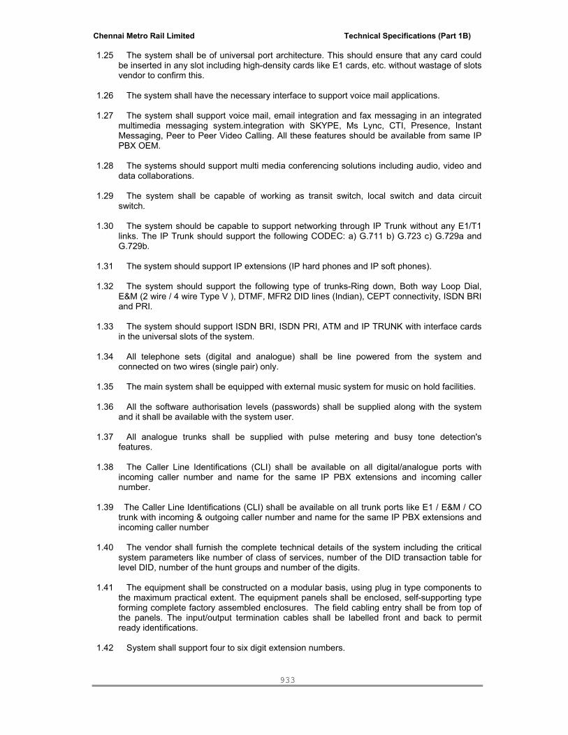
Chennai Metro Rail Limited Technical Specifications (Part 1B)
933
1.25 The system shall be of universal port architecture. This should ensure that any card could be inserted in any slot including high-density cards like E1 cards, etc. without wastage of slots vendor to confirm this.
1.26 The system shall have the necessary interface to support voice mail applications.
1.27 The system shall support voice mail, email integration and fax messaging in an integrated
multimedia messaging system.integration with SKYPE, Ms Lync, CTI, Presence, Instant Messaging, Peer to Peer Video Calling. All these features should be available from same IP PBX OEM.
1.28 The systems should support multi media conferencing solutions including audio, video and
data collaborations. 1.29 The system shall be capable of working as transit switch, local switch and data circuit
switch. 1.30 The system should be capable to support networking through IP Trunk without any E1/T1
links. The IP Trunk should support the following CODEC: a) G.711 b) G.723 c) G.729a and G.729b.
1.31 The system should support IP extensions (IP hard phones and IP soft phones).
1.32 The system should support the following type of trunks-Ring down, Both way Loop Dial,
E&M (2 wire / 4 wire Type V ), DTMF, MFR2 DID lines (Indian), CEPT connectivity, ISDN BRI and PRI.
1.33 The system should support ISDN BRI, ISDN PRI, ATM and IP TRUNK with interface cards
in the universal slots of the system. 1.34 All telephone sets (digital and analogue) shall be line powered from the system and
connected on two wires (single pair) only. 1.35 The main system shall be equipped with external music system for music on hold facilities.
1.36 All the software authorisation levels (passwords) shall be supplied along with the system
and it shall be available with the system user. 1.37 All analogue trunks shall be supplied with pulse metering and busy tone detection's
features. 1.38 The Caller Line Identifications (CLI) shall be available on all digital/analogue ports with
incoming caller number and name for the same IP PBX extensions and incoming caller number.
1.39 The Caller Line Identifications (CLI) shall be available on all trunk ports like E1 / E&M / CO
trunk with incoming & outgoing caller number and name for the same IP PBX extensions and incoming caller number
1.40 The vendor shall furnish the complete technical details of the system including the critical
system parameters like number of class of services, number of the DID transaction table for level DID, number of the hunt groups and number of the digits.
1.41 The equipment shall be constructed on a modular basis, using plug in type components to
the maximum practical extent. The equipment panels shall be enclosed, self-supporting type forming complete factory assembled enclosures. The field cabling entry shall be from top of the panels. The input/output termination cables shall be labelled front and back to permit ready identifications.
1.42 System shall support four to six digit extension numbers.

Chennai Metro Rail Limited Technical Specifications (Part 1B)
934
1.43 The system platform shall be based on open system architecture and universal multitasking real time operating system.
1.44 The operating system shall enable easy development of applications by providing window
based API Library. 1.45 The software version offered shall be of the latest release and the updated software
versions should be given free of cost for further 10 years from the date of completion of warranty period.
1.46 AUTHORISATION CODES: Every user shall have his own authorisation code to make
outgoing calls thereby ensuring no misuse of the system. At large no. of unique authorisation codes shall be possible in the system.
OR Password facility should be similar to BSNL for opening and closing of STD/ ISD facility and pass word should be user changeable
1.47 System should have time synchronisation facility with external clock/ GPS system through IP connection or maintenance terminal.
1.48 System to support 80+ Distributed Gateway units for remote location connectivity of all IP, TDM Subscribers and Trunks.
1.49 Remote Gateway Unit to support Survivability feature in case main system Processor board fails.
2.0 System main features/facilities The proposed system should be capable to provide the following features /facilities to the subscribers through user-friendly system programming.
2.1. Abbreviated dialling 2.2. Account code charging 2.3. Appointment reminder 2.4. Assigned night answer for Trunks. 2.5. Automatic call back on Busy trunk/bundle/network link 2.6. Automatic call back on free/busy extension 2.7. Automatic lockout of faulty lines 2.8. Boss-Secretary feature digital subscribers. 2.9. Call by name and number from the digital station 2.10. Call forwarding to extension or hunting group, voice mail, operator, paging, etc. 2.11. Call Forwarding (Internal and External) – no answer / busy/immediate/follow-
me/fixed/variable 2.12. Call Park 2.13. Call Pickup from any extension (individual and in a group) 2.14. Call transfer 2.15. Camp on busy extension/line 2.16. CLI on the selected terminal. 2.17. Choice of supervisory tones or voice announcements. 2.18. Class of service changeover by station/operator/administration. 2.19. Controlled private call by pin code. 2.20. Digit suffixing / prefixing – For the incoming calls, either from other exchanges or trunk, it
shall be possible to insert/suppress at least 6 number or more of digits. 2.21. Direct Inward Dialling supporting DP/DTMF/MIXED
a. Direct inward dialling (DID) on CO line b. Direct inward dialling (DID) on 2Mbps ISDN / R2MFC link
c. Direct outward dialling (DOD) on 2Mbps ISDN / R2MFC link. 2.22. Directory Services (System should support minimum 5000 entries – name and numbers). 2.23. Do not disturb 2.24. Executive Override. 2.25. Feature Portability. 2.26. Forced Release under the following conditions:
a. User exceeds a present inter digit time interval

Chennai Metro Rail Limited Technical Specifications (Part 1B)
935
b. Calling user exceeds a preset time while listening to the ringing or busy tone c. When any of the two users of a normal call terminates.
2.27. Group Hunting 2.28. Hold facility 2.29. Hot-line services on extensions and trunks 2.30. Individual directory internal/external 2.31. It shall be possible to suppress or add digits for outgoing calls. 2.32. Last number redial 2.33. Local and external call 2.34. Malicious Call Identification – Manual & Automatic 2.35. Multiparty Conference. System to support 8 party Conference and it should be possible to
have 20+ such conferences running simultaneously. 2.36. Priority call 2.37. Private incoming / outgoing trunk (Dedicated Trunks for Priority Users) 2.38. Recorded announcement / music on hold (internal & external) for waiting party 2.39. Saved number redial – After dialling an internal or external number it can be saved by
dialling a code, then number can dialled by using the same code. 2.40. Selection of night service – at least 3 options should be selectable from console that is a
line transfer to predefined extension, to voice mail, to a hunting group. It should also be possible to allocate each trunk line a different Night Destination.
2.41. Special night answer points. 2.42. Support of DP/ DTMF/mixed/digital/IP/DECT signalling. 2.43. Support the flexible numbering plan for dialling up to ten digits. 2.44. Time of day barring of Local/STD/ISD calls from specified extensions. 2.45. Timed reminder – wake up call 2.46. Toll / code restriction for trunk/tie or station-to-station calls. 2.47. Voice guided auto attendant facilities at least for 12 numbers of the Internal/External callers
and capability of the interactive voice response for Internal/External callers for the system. 2.48. Time and date announcement facility through auto attendant system or voicemail system
on dialling of code. 2.49. Auto attendant messages should be user programmable form any analog and digital
telephone.
3.0: System networking and interface capability requirements
The offered system shall provide the connectivity with all types of IP PBXs approved by TEC / DOT and it shall support at least standard QSIG-BC-GF, Extended QSIG and DPNSS standard protocols for inter connectivity. Vendor shall supply licence software package/locks along with the hardware for enabling the QSIG, Extended QSIG and DPNSS link protocol.
The proposed system shall be compatible to handle the following links/connectivity for the system networking to achieve above requirements.
3.1Terminal connectivity:
a. Analogue/digital/IP/DECT interfaces b. ISDN (2B + D)/(3B+D) interface bus for S0 terminals 3B+D not required c. ISDN BRI (2B+D) & PRI (30B+D) for BSNL connectivity d. Ring down line connectivity e. E & M trunks connectivity f. Link for fully integrated Voice Mail/Fax Mail link g. Link for Interactive Voice Response System (IVRS). h. DID, Level DID/Indian R2MFC. i. CLI link on all Analog and Digital ports. j. Loop disconnect type.
3.2Public switched networks connectivity:
a. Analogue CO trunks b. Analogue DID R2MFC

Chennai Metro Rail Limited Technical Specifications (Part 1B)
936
c. Digital DID R2MFC/ISDN d. ISDN Basic rate interface access e. ISDN Primary rate interface access
3.3Public packet networks connectivity:
a. ATM 155 M/bit SDH b. X21/X24/V11/V24/V35 or V36/Frame relay c. Ethernet 10/100 BT
3.4Private networks connectivity:
a. Analogue Tie lines through long distance modem (if required) at both end 2,4,6 wires & E&M
b. Digital Tie lines, E&M c. Digital DID R2MFC/ISDN d. ISDN Basic rate interface access, ISDN Primary rate interface access, Proprietary private
network, QSIG, DPNSS protocols, proprietary private network protocol. e. ATM 155 M/bit SDH, QSIG, Extended QSIG, DPNSS protocols f. X24/V11/V35 or V36 Frame relay, Private network, QSIG, Extended QSIG, DPNSS
protocols g. Ethernet TCP-IP, Private network, QSIG, DPNSS protocols h. E1 connectivity
4.0Characteristics of telephone sets (subscriber terminals)
The proposed system should provide the connectivity for all types of the telephone sets (subscriber terminals) like basic analogue telephone set, premium analogue telephone set, digital telephone sets, IP based soft and hard telephone sets, and DECT based telephone sets. Vendor should offer various range of analogue/digital/IP/DECT telephone equipment, each capable of meeting one or more of a variety of needs for the corporate offices
4.1Analogue telephone sets
The analogue push button telephone sets to meet the following requirements.
a. It shall be copper track PCB. b. It shall be desktop type. c. It shall have both DTMF/DP facilities. d. It shall have anti skid foot e. Redial facility f. It shall have at least two colour options g. It shall have at least two lines alphanumerical display window h. It shall have at least 8 memory keys. i. It shall have caller line identification facilities. j. Redial Switch on panel. k. It shall be with built-in speaker and microphone for hand free operation. l. It should be battery free.
4.2Digital telephone sets
The professional digital telephone sets to meet the following minimum requirements: a. Line power feeding using two wire (single pair) b. Alphanumerical display windows for at least two lines c. Capability for simultaneous voice and data transmission. d. Capability for converting the digital set as an ISDN, CTI or analogue terminal using
additional interface adopters. e. Selectable ringing patterns at least two types of the patterns. f. Programmable/fixed feature buttons for conference, mute, transfer, drop and hold,
redial, do not disturb. g. Built in message waiting lamp h. Call logging services

Chennai Metro Rail Limited Technical Specifications (Part 1B)
937
i. Integrated personal directory services and name dialling facilities. j. Built in microphone and speaker for hands free operation. k. Caller Line Identification (CLI) feature by caller number and name. l. Phone should have 3 Fixed Keys, 8 Programmable Keys,3 Navigation Key.
5.0Operator console system
The vendor shall offer the PC based console with a detailed description of features. The console shall be equipped with the headset with volume control Plantronics make for hand free operations along with the required furniture. The minimum specifications of the attendant console are as follows:
5.1 The PC based attendant console should be with 17-inches LCD-TFT colour monitor and
Antiglare screen and keyboard. This console shall provide the following minimum facilities: a. PC based terminal along with head set with volume control b. Telephony application running under Windows NT client c. Full windows resizing and layout personalisation d. Multi-applications compliant e. Hands-free operation f. Supports all telephony applications. g. Subscriber and trunk Supervision facilities h. Manual or automatic answering facilities i. Call internal or external correspondent by name j. Software shall support the set of soft keys on the monitor as per the normal telephone
layout. k. Software shall support the set of function and program keys designed to handle special
operators features like hold, night answer mode, call splitting, call pickup. l. Software shall support the set of programmable keys for direct dialling (One touch
dialling) of internal or external numbers. m. Text messaging facilities n. Multiple Ringing levels o. DTMF transmission p. Automatic call transfer q. Locking the terminal r. Withdrawal of consoles s. System management t. System and port wise diagnosis and built in audio visual alarms on screen u. Corporate directory services using LDAP server/ Directory server
6.0 System Administration The system administration shall have the Exchange (Switch) Management system in one PC. 7.1The Exchange ( Switch) management system software shall be based on latest open platforms
running under Windows/Unix/Linux, providing multiple graphical applications offering a consistent and friendly graphical user interface (GUI). This system shall integrate all applications needed for complete telephone system administration such as:
a. System configuration and subscriber management application. b. Performance application in text as well as graphical format. c. Built in fault diagnosis and audio-visual alarm system. d. Offer user–friendly access to the various proposed services. e. Be protected by an overall access code and offer several secondary access codes. f. Provide the overall management of the system. g. Provide all menus in English language. h. Enable printout of information via printing software. i. Provide the TCP/IP based LAN connectivity j. Traffic measurement facilities such as
i. Overall internal traffic of the installation ii. Traffic of one attendant position

Chennai Metro Rail Limited Technical Specifications (Part 1B)
938
iii. Traffic of attendants groups iv. Trunk group traffic v. Traffic per external trunk vi. Traffic per normal user vii. Traffic per user group viii. Traffic per mobile DECT user ix. Traffic per private link, proprietary protocol x. Traffic per private link, QSIG protocol xi. Traffic per private link, DPNSS protocol xii. Virtual private network traffic per direction xiii. User traffic observation facilities xiv. Presented calls xv. Number of calls answered xvi. Number of calls abandoned
Switches:
Specifications for Layer 3 24-Port 1G Switch, with 1G/10G Uplinks:
Stackable Access Switch with 24X 10/100/1000 SFP Ports and 8 X1G/10G SFP/SFP+ Ports
1 Product details- Please specify 1.1 Make, Model No with part no. 2 Architecture
2.1 Switch should offer Wire-Speed and Non-Blocking Switching. 2.2 Switch should have 24X 10/100/1000 SFP ports.
2.3 Switch should have additional 8 X1G/10G SFP/SFP+ ports. 1G SFP connectivity on all these ports should be enabled by default with support for SX, LX, TX and Long Haul Transceivers capable of proving connectivity up to 150 Kms.
2.4 Switch should support the activation of up to 8 10G ports using additional hardware modules or software licenses to support SR, LR and Long Haul Transceivers capable of proving connectivity up to 40 Kms.
2.5 Switch should provide up to 4 X40G ports for Stacking and should support 40G Uplink capability in future.
2.6 Should have Flash ROM of 64MB or more. 2.7 Should have DRAM of 512MB or more. 3 Performance & Scalability
3.1 Should provide Non-Blocking switch fabric capacity of 528 Gbps or more. 3.2 Should provide wire-speed packet forwarding of 396 Mpps or more. 3.3 Should support 32,000 MAC addresses or more. 4 Layer 2 Features
4.1 Should support 4000 VLANs and 4000 VLAN IDs 4.2 Should support 802.1Q with tagging 4.3 Should support 802.1ad (Q-in-Q) tagging 4.4 Should support Dual-mode VLANs 4.5 Should support GVRP 4.6 Should support Port-based VLANs 4.7 Should support Protocol VLANs (IPv4, dynamic IPv6, and IPX) 4.8 Should support Layer 3 Subnet VLANs (IP subnet network, and IPX) 4.9 Should support Private VLANs 4.1 Should support VLAN groups 4.11 Should support Multi-range VLANs

Chennai Metro Rail Limited Technical Specifications (Part 1B)
939
4.12 Should support Uplink Ports within a Port-Based VLAN 4.13 Should support VLAN-based mirroring
4.14 Should support MAC-Based VLANs, including support for dynamic MAC-Based VLAN activation
4.14 Should support 802.1p Quality of Service (QoS) with Strict Priority (SP), Weighted Round Robin (WRR) and Combined SP and WRR providing 8 priority queues
4.15 Should support ACL-based rate limiting QoS
4.16 Should support 802.1D Spanning Tree Protocol (STP) with enhancements that includes Fast Port Span, Fast Uplink Span, and Single-instance Span
4.17 Should support 802.1s Multiple Spanning Tree 4.18 Should support 802.1W Rapid Spanning Tree (RSTP) 4.19 Should support PVST/PVST+ and PVRST+ compatibility 4.2 Should support Root Guard 4.21 Should support BPDU Guard 4.22 Should support 802.3ad link aggregation (dynamic trunk groups) 4.23 Should support Link Aggregation Control Protocol (LACP) with support for Single link LACP 4.24 Should support Uni-directional Link Detection (UDLD) for Link keepalive. 4.25 Should support Link Fault Signaling (LFS) for 10G 4.26 Should support Dynamic Host Configuration Protocol (DHCP) Assist 4.27 Should support IGMP v1/v2/v3 Snooping on a Global basis and on a per VLAN basis. 4.28 Should support IGMP v2/v3 Fast Leave (membership tracking)
4.29 Should support MLD Snooping V1/V2 with support for MLD V1/V2 snooping (global and local), MLD fast leave for V1, MLD tracking and fast leave for V2 & Static MLD and IGMP groups with support for proxy.
4.3 Should support Multicast static group traffic filtering (for 4.31 snooping scenarios) 4.32 Should support PIM-SM V2 Snooping 4.33 Should support Interpacket Gap (IPG) adjustment 4.34 Should support IP MTU setting per port 4.35 Should support Jumbo frames up to 10232 bytes 4.35 Should support VoIP Auto configuration and CDP
5 Base Layer 3 Features 5.1 Should support BootP/DHCP Relay 5.2 Should support Equal Cost Multi Path (ECMP) load sharing 5.3 Should support IP helper 5.4 Should support RIP V1 and V2 (advertising only) 5.5 Should support Routing for directly connected IP subnets 5.6 Should support Static IP routing 5.7 Should support up to 255 Virtual Interfaces 5.8 Should support Virtual Router Redundancy Protocol (VRRP) 5.9 Should support VRRP timer scaling 6 Advanced Layer 3 Features
6.1 Should support up to 15K IPv4 Routes and 2800 IPv6 Routes in hardware 6.2 Should support up to 16K Active host routes 6.3 Should support Route-only support at the Global CONFIG level and Interface level 6.4 Should support Static ARP entries 6.5 Should support Route redistribution 6.6 Should support IPv6 Static Routes
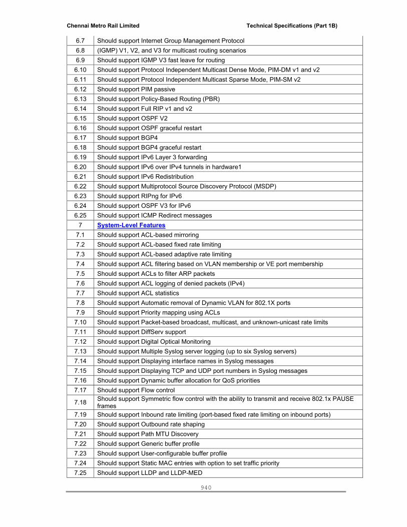
Chennai Metro Rail Limited Technical Specifications (Part 1B)
940
6.7 Should support Internet Group Management Protocol 6.8 (IGMP) V1, V2, and V3 for multicast routing scenarios 6.9 Should support IGMP V3 fast leave for routing 6.10 Should support Protocol Independent Multicast Dense Mode, PIM-DM v1 and v2 6.11 Should support Protocol Independent Multicast Sparse Mode, PIM-SM v2 6.12 Should support PIM passive 6.13 Should support Policy-Based Routing (PBR) 6.14 Should support Full RIP v1 and v2 6.15 Should support OSPF V2 6.16 Should support OSPF graceful restart 6.17 Should support BGP4 6.18 Should support BGP4 graceful restart 6.19 Should support IPv6 Layer 3 forwarding 6.20 Should support IPv6 over IPv4 tunnels in hardware1 6.21 Should support IPv6 Redistribution 6.22 Should support Multiprotocol Source Discovery Protocol (MSDP) 6.23 Should support RIPng for IPv6 6.24 Should support OSPF V3 for IPv6 6.25 Should support ICMP Redirect messages
7 System-Level Features 7.1 Should support ACL-based mirroring 7.2 Should support ACL-based fixed rate limiting 7.3 Should support ACL-based adaptive rate limiting 7.4 Should support ACL filtering based on VLAN membership or VE port membership 7.5 Should support ACLs to filter ARP packets 7.6 Should support ACL logging of denied packets (IPv4) 7.7 Should support ACL statistics 7.8 Should support Automatic removal of Dynamic VLAN for 802.1X ports 7.9 Should support Priority mapping using ACLs 7.10 Should support Packet-based broadcast, multicast, and unknown-unicast rate limits 7.11 Should support DiffServ support 7.12 Should support Digital Optical Monitoring 7.13 Should support Multiple Syslog server logging (up to six Syslog servers) 7.14 Should support Displaying interface names in Syslog messages 7.15 Should support Displaying TCP and UDP port numbers in Syslog messages 7.16 Should support Dynamic buffer allocation for QoS priorities 7.17 Should support Flow control
7.18 Should support Symmetric flow control with the ability to transmit and receive 802.1x PAUSE frames
7.19 Should support Inbound rate limiting (port-based fixed rate limiting on inbound ports) 7.20 Should support Outbound rate shaping 7.21 Should support Path MTU Discovery 7.22 Should support Generic buffer profile 7.23 Should support User-configurable buffer profile 7.24 Should support Static MAC entries with option to set traffic priority 7.25 Should support LLDP and LLDP-MED
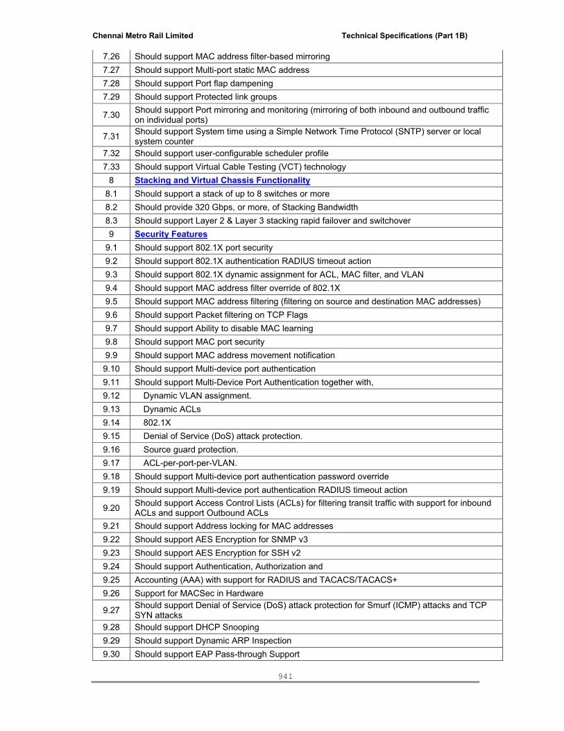
Chennai Metro Rail Limited Technical Specifications (Part 1B)
941
7.26 Should support MAC address filter-based mirroring 7.27 Should support Multi-port static MAC address 7.28 Should support Port flap dampening 7.29 Should support Protected link groups
7.30 Should support Port mirroring and monitoring (mirroring of both inbound and outbound traffic on individual ports)
7.31 Should support System time using a Simple Network Time Protocol (SNTP) server or local system counter
7.32 Should support user-configurable scheduler profile 7.33 Should support Virtual Cable Testing (VCT) technology
8 Stacking and Virtual Chassis Functionality 8.1 Should support a stack of up to 8 switches or more 8.2 Should provide 320 Gbps, or more, of Stacking Bandwidth 8.3 Should support Layer 2 & Layer 3 stacking rapid failover and switchover 9 Security Features
9.1 Should support 802.1X port security 9.2 Should support 802.1X authentication RADIUS timeout action 9.3 Should support 802.1X dynamic assignment for ACL, MAC filter, and VLAN 9.4 Should support MAC address filter override of 802.1X 9.5 Should support MAC address filtering (filtering on source and destination MAC addresses) 9.6 Should support Packet filtering on TCP Flags 9.7 Should support Ability to disable MAC learning 9.8 Should support MAC port security 9.9 Should support MAC address movement notification 9.10 Should support Multi-device port authentication 9.11 Should support Multi-Device Port Authentication together with, 9.12 Dynamic VLAN assignment. 9.13 Dynamic ACLs 9.14 802.1X 9.15 Denial of Service (DoS) attack protection. 9.16 Source guard protection. 9.17 ACL-per-port-per-VLAN. 9.18 Should support Multi-device port authentication password override 9.19 Should support Multi-device port authentication RADIUS timeout action
9.20 Should support Access Control Lists (ACLs) for filtering transit traffic with support for inbound ACLs and support Outbound ACLs
9.21 Should support Address locking for MAC addresses 9.22 Should support AES Encryption for SNMP v3 9.23 Should support AES Encryption for SSH v2 9.24 Should support Authentication, Authorization and 9.25 Accounting (AAA) with support for RADIUS and TACACS/TACACS+ 9.26 Support for MACSec in Hardware
9.27 Should support Denial of Service (DoS) attack protection for Smurf (ICMP) attacks and TCP SYN attacks
9.28 Should support DHCP Snooping 9.29 Should support Dynamic ARP Inspection 9.30 Should support EAP Pass-through Support

Chennai Metro Rail Limited Technical Specifications (Part 1B)
942
9.31 Should support HTTPS 9.32 Should support IP Source Guard 9.33 Should support Local passwords 9.34 Should support Secure Copy (SCP) 9.35 Should support Secure Shell (SSH) v2 9.36 Should support Web Authentication 10 Management Features
10.1 Should support 802.1X accounting. 10.2 Should support AAA support for console commands 10.3 Should support Access Control Lists (ACLs) for controlling management access 10.4 Should support Alias command 10.5 Should support DHCP Client 10.6 Should support DHCP client-based auto-configuration 10.7 Should support DHCP Server 10.8 Should support Specifying which IP address will be included in a DHCP/BOOTP reply packet 10.9 Should support Disabling TFTP access 10.10 Should support Web-based GUI 10.11 Should support Web-based management HTTPS/SSL
10.12 Should support manageability using an Element or Network Management System. This EMS or NMS should be able to configure and monitor the switch.
10.13 Should support Hitless stacking management with Hitless stacking switchover and Hitless stacking failover
10.14 Should support Remote monitoring (RMON) 10.15 Should support Retaining Syslog messages after a soft reboot 10.16 Should support Hitless failover for Policy based Routing (PBR) 10.17 Support for sFlow version 2 and version 5 10.18 Should support sFlow support for IPv6 packets 10.19 Should support SNTP Server 10.20 Should support SNTP Client (Broadcast & Unicast)
10.21 Should provide Industry-standard Command Line Interface (CLI), including support for Serial and Telnet access, Alias command, On-line help, Command completion, Scroll control, Line editing, Searching and filtering output and Special characters
10.22 Should support SNMP v1, v2, v3 10.23 Should support SNMP V3 traps
11 IPv6 Management Features 11.1 Should support for Link-Local IPv6 Address 11.2 Should support IPv6 Access List (management ACLs) 11.3 Should support IPv6 copy 11.4 Should support IPv6 ncopy 11.5 Should support IPv6 debug 11.6 Should support IPv6 ping 11.7 Should support IPv6 traceroute 11.8 Should support IPv6 DNS server name resolution 11.9 Should support IPv6 HTTP/HTTPS 11.10 Should support IPv6 Logging (Syslog) 11.11 Should support IPv6 RADIUS 11.12 Should support IPv6 SCP

Chennai Metro Rail Limited Technical Specifications (Part 1B)
943
11.13 Should support IPv6 SSH 11.14 Should support IPv6 SNMP 11.15 Should support IPv6 SNMP Traps 11.16 Should support IPv6 SNTP 11.17 Should support IPv6 TACACS/TACACS+ 11.18 Should support IPv6 Telnet 11.19 Should support IPv6 TFTP
12 Physical Attributes, Power Supply and Fans
12.1 The switch should be 19" Universal EIA (Telco) rack mountable and should be provided with a rack mount kit.
12.2 The switch should not be more than 1 Rack Unit (RU) in height. 12.3 Should support 100-240VAC, 50/60 Hz internal universal power; Indian type power cord.
12.4 Should support Optional Internal Hot-Swappable Load Sharing Redundant AC Power Supply for System Power.
12.5 Should support Optional Internal Hot-Swappable Redundant Fan Tray.
12.6 Should support Energy Efficient Ethernet (802.3az-2010 - EEE) capability in hardware for efficient power utilization.
13 MTBF 13.1 Please specify the MTBF, at 25 degC, of all components. 14 Heat dissipation
14.1 Please specify in BTU per hour 15 Power consumption
15.1 please specify max in Watts 16 Temperature
16.1 Operating: 0° - 40° C (32° - 104°) 16.1 Storage: -40° - 70° C (-40° - 158° F) 17 Humidity
17.1 Operating: 5% to 95% RH, Non-Condensing 18 Warranty
18.1 The proposed switches should be provided with 5 years warranty which includes RMA support, software updates/upgrades and access to TAC.
19 Product brochure
19.1 Vendor should provide printed technical catalogs/brochures for the quoted model containing technical specifications, features.
20 Any other features not covered above 20.1 Please specify 21 Core Switch quantity details are below –
Core Switch with 24 10/100/1000 SFP Ports and 8 1G/10G SFP/SFP+ with 8 ports activated for 1G SFP connectivity.- 6 No's
5 Amp Power Cord.-12 No's Stacking Cable (1 Meter).-12 No's 1G SX MMF Transceiver.- 1G LX SMF Transceiver.- Redundant Hot-Swappable Load Sharing AC Power Supply for System Power.-6 No's Redundant Fan Tray.- 6 No's
Five Year, 24x7 TAC Telephonic & Email Support, Code Upgrades, and NBD Spare replacement.- 6 No's

Chennai Metro Rail Limited Technical Specifications (Part 1B)
944
B) 48 port Gigabit Layer 2 switches with 4X1G uplinks
Specification Required
1 The proposed switches should be Enterprise grade products
2 The switch should support a minimum of 48 no's of 10/100/1000 Mbps RJ45 Ports.
3 The switch should support minimum 4 no’s of 1G ports.
4 The Switch should support minimum - *Switching Capacity of 104 Gbps (48 port) *Forwarding Performance of 77 Mpps (48 port)
5 The Switch should support 16K MAC addresses and minimum 4096 VLANs
6 The switch should suport resilient failsafe stacking up to 4 switches in a stack with min stack bandwidth of 4 Gbps per switch
7 The switch should support IPv4 and IPv6 static routes
8 The Switch should support minimum 12k routes in hardware and future scalability to support IPv4 & IPv6 dynamic routing protocols like RIPv1/v2, OSPFv3 etc
9 The switch should support multicast capability features like IGMPv1, v2, v3, and MLD snooping
10 The switch should support Per-VLAN Spanning Tree (PVST/PVST+/PVRST)
11 The Switch should support Industry Standard Command Line Interface (CLI).
12 Should support min 2000 ACL's/ACE's in hardware
Access Switch quantity details are below –
13 48 port Gigabit switch with 4 no's of 1G ports – 60 No’s
14 The proposed switches should be provided with 5 years warranty which includes RMA support, software updates/upgrades and access to TAC.
15 5 Amp Power Cord.
C) 24 port PoE Gigabit Layer 2 switches with 4X1G uplinks
1 The proposed switches should be Enterprise grade products
2 The switch should support a minimum of 24 no's of 10/100/1000 Mbps PoE RJ45 Ports.
3 The switch should support minimum 4 no’s of 1G ports.
4 The Switch should support minimum - *Switching Capacity of 56 Gbps (24 port) *Forwarding Performance of 42 Mpps (24 port)
5 The Switch should support 16K MAC addresses and minimum 4096 VLANs
6 The switch should suport resilient failsafe stacking up to 4 switches in a stack with min stack bandwidth of 4 Gbps per switch
7 The switch should support IPv4 and IPv6 static routes
8 The Switch should support minimum 12k routes in hardware and future scalability to support IPv4 & IPv6 dynamic routing protocols like RIPv1/v2, OSPFv3 etc
9 The switch should support multicast capability features like IGMPv1, v2, v3, and MLD snooping
10 The switch should support Per-VLAN Spanning Tree (PVST/PVST+/PVRST)
11 The Switch should support Industry Standard Command Line Interface (CLI).
12 Should support min 2000 ACL's/ACE's in hardware
13 Internal AC power supply rating 525W
14 Should Support External power supply(redundant power and PoE power)
15 Should Support PoE/PoE+ power budget (internal power supply) 390W
16 Should Support PoE Class 3 ports (internal power supply) 24 Ports
17 Should Support PoE+ ports (internal power supply) 12 Ports
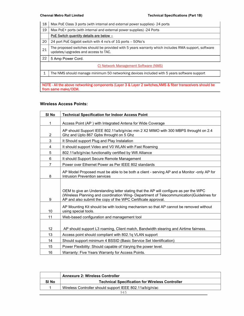
Chennai Metro Rail Limited Technical Specifications (Part 1B)
945
18 Max PoE Class 3 ports (with internal and external power supplies)- 24 ports
19 Max PoE+ ports (with internal and external power supplies) -24 Ports
PoE Switch quantity details are below –
20 24 port PoE Gigabit switch with 4 no's of 1G ports – 50No’s
21 The proposed switches should be provided with 5 years warranty which includes RMA support, software updates/upgrades and access to TAC.
22 5 Amp Power Cord.
C) Network Management Software (NMS)
1 The NMS should manage minimum 50 networking devices included with 5 years software support
NOTE - All the above networking components (Layer 3 & Layer 2 switches,NMS & fiber transceivers should be from same make/OEM.
Wireless Access Points:
Sl No Technical Specification for Indoor Access Point
1 Access Point (AP ) with Integrated Antena for Wide Coverage
2 AP should Support IEEE 802.11a/b/g/n/ac min 2 X2 MIMO with 300 MBPS throught on 2.4 Ghz and Upto 867 Gpbs throught on 5 Ghz
3 It Should support Plug and Play Instalation 4 It should support Video and V0 WLAN with Fast Roaming 5 802.11a/b/g/n/ac functionality certified by Wifi Alliance 6 It should Support Secure Remote Management 7 Power over Ethernet Power as Per IEEE 802 standards
8 AP Model Proposed must be able to be both a client - serving AP and a Monitor -only AP for Intrusion Prevention services
9
OEM to give an Understanding letter stating that the AP will configure as per the WPC (Wireless Planning and coordination Wing- Department of Telecommunication)Guidelines for AP and also submit the copy of the WPC Certificate approval.
10 AP Mounting Kit should be with locking mechanism so that AP cannot be removed without using special tools.
11 Web-based configuration and management tool
12 AP should support L3 roaming, Client match, Bandwidth stearing and Airtime fairness. 13 Access point should compliant with 802.1q VLAN support 14 Should support minimum 4 BSSID (Basic Service Set Identification) 15 Power Flexibility: Should capable of Varying the power level. 16 Warranty: Five Years Warranty for Access Points. Annexure 2: Wireless Controller
Sl No Technical Specification for Wireless Controller 1 Wireless Controller should support IEEE 802.11a/b/g/n/ac

Chennai Metro Rail Limited Technical Specifications (Part 1B)
946
2 The Wireless Controller should support 256 Nos. of Access Point License
3 Rack mountable with a minimum of 2 numbers 10/100/1000 base T ports. It should also have atleast 1-management port and 1-console port.
4 The Controller Architecture should be Layer 3 based 5 It should support atleast 2000 concurrent users 6 It shoud support Dynamic RF management
7 It should support Intelligent Traffic forwarding by user/application based scenarios. 8 It should support Auto-discovery of new Aps.
9 The Architecture of controller should support Centerlized and Distrbutedfunctionalities
10 Central configuration and software update of access points through the central instance, with the option of automatic configuration and management of Aps
11 It should supports video and VoIP with roamng facility 12 It Should support bandwidth load-balancing of access point (Switching over)
13 It should support cover Network monitoring with the option of detecting unauthorized access points (rogue detection)
14 It should support IEEE 802.11 a/b/g/n/ac standards-based wireless access points
15 It should have capability of Detection areas of insufficient radio frequency coverage or access point failure with correction through automatic service adaptation.
16 The entire solution should support centralized management architecture 17 Support SNMPv3 and web-based secured management interfaces
18 The authentication should be facilitated by local database and remote services such as Radius, LDAP
19
BYOD Feature (Bring your Own Device) The Controller should be Detect Client Device MAC address, device type such as windows device, Android Device, Iphone, Ipad tec and host name.
20 The Controller should support Mac binding access
21
Warranty a. OEM Should give the necessary OS and patch updates for the controller for 5 years b. Should include 5 year hardware warranty
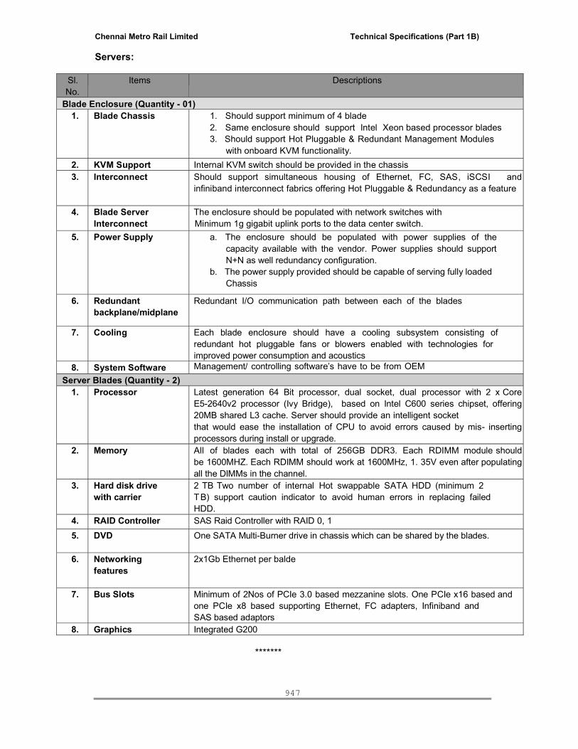
Chennai Metro Rail Limited Technical Specifications (Part 1B)
947
Servers:
Sl. No.
Items Descriptions
Blade Enclosure (Quantity - 01) 1. Blade Chassis 1. Should support minimum of 4 blade
2. Same enclosure should support Intel Xeon based processor blades 3. Should support Hot Pluggable & Redundant Management Modules
with onboard KVM functionality. 2. KVM Support Internal KVM switch should be provided in the chassis 3. Interconnect Should support simultaneous housing of Ethernet, FC, SAS, iSCSI and
infiniband interconnect fabrics offering Hot Pluggable & Redundancy as a feature
4. Blade Server Interconnect
The enclosure should be populated with network switches with Minimum 1g gigabit uplink ports to the data center switch.
5. Power Supply a. The enclosure should be populated with power supplies of the capacity available with the vendor. Power supplies should support N+N as well redundancy configuration.
b. The power supply provided should be capable of serving fully loaded Chassis
6. Redundant backplane/midplane
Redundant I/O communication path between each of the blades
7. Cooling Each blade enclosure should have a cooling subsystem consisting of redundant hot pluggable fans or blowers enabled with technologies for improved power consumption and acoustics
8. System Software Management/ controlling software’s have to be from OEM Server Blades (Quantity - 2)
1. Processor Latest generation 64 Bit processor, dual socket, dual processor with 2 x CoreE5-2640v2 processor (Ivy Bridge), based on Intel C600 series chipset, offering20MB shared L3 cache. Server should provide an intelligent socket that would ease the installation of CPU to avoid errors caused by mis- insertingprocessors during install or upgrade.
2. Memory All of blades each with total of 256GB DDR3. Each RDIMM module shouldbe 1600MHZ. Each RDIMM should work at 1600MHz, 1. 35V even after populatingall the DIMMs in the channel.
3. Hard disk drive with carrier
2 TB Two number of internal Hot swappable SATA HDD (minimum 2 T B) support caution indicator to avoid human errors in replacing failed HDD.
4. RAID Controller SAS Raid Controller with RAID 0, 1 5. DVD One SATA Multi-Burner drive in chassis which can be shared by the blades.
6. Networking features
2x1Gb Ethernet per balde
7. Bus Slots Minimum of 2Nos of PCIe 3.0 based mezzanine slots. One PCIe x16 based and one PCIe x8 based supporting Ethernet, FC adapters, Infiniband and SAS based adaptors
8. Graphics Integrated G200 *******

Chennai Metro Rail Limited Technical Specifications (Part 1B)
948
LIST OF APPROVED MAKE / MANUFACTURER OF MATERIALS
MATERIAL APPROVED MAKE
PARTITIONS BOARDS and FINISHES
1 Water proof Plywood Greenply / Uniply / Euro
2 Plain/Pre-laminated Particle Boards TESA / Archidply /
3 Plain/Prelaminated MDF Boards TESA / Greenply / Archidply / Eximcorp India (P) Ltd.
4 Veneer Jacsons / Timex / Euro
5 Laminates Merino / Greenlam / Century
6 Gypsum Board Saint Gobain / LaFarge / Vans Gypsum
7 Fire Cement Board Saint Gobain / USG
8 GI sections for partition Rondo / Gypsteel
9 Acoustic Wall Panels ECHO Panel / Armstrong / Annutone
10 Aluminium Skirting Aluskirt (Falanx) / Alloy / JEB
11 Aluminium Partitions Vetro / Alloy / JEB
MISC
12 Aluminium Sections Jindal / Indal
13 Plain and Tinted Glass Saint Gobain / Ashai / Emirates
14 Mirror Saint Gobain / Modiguard
15 Vertical & Horizontal blinds Vista levelor / Hunter Dogular
16 Drapery Rods STYLE DÉCOR / Rekha Décor / Vista levelor
17 White board White mark / Alsosign / Writex
18 Vinyl privacy frosting films 3M / Avery Dennison
19 Lockers Banhart / American Lockers / Godrej
20 Floor Transition trims Gradus / Salag / Pawling
21 Wall / Plaster / Tile protection trims (Aluminum / GI) Dural / Amax / approved equivalent
22 External Corner Protection Guards Arpitha / Dural
HARDWARE AND IRON MONGERY
23 Hardware Fittings such as Hinges, Handle etc for Wardrobes, Modular Kitchen, etc
Hettich / Hafele / Blum
24 Cup board and Multipurpose Locks for Wardrobes and Cupboards
YALE / Godrej / Dorset
25 Residential Building Joinery Hardware ( Hinges, Locks etc..)
YALE / Dorma / Godrej
26 Tower Bolts, Castors, Door Stopper etc PAG / Godrej / Dorset

Chennai Metro Rail Limited Technical Specifications (Part 1B)
949
27 Door Viewer YALE / Godrej / Dorset
28 Commercial Building Joinery Hardware ( Door Closer, panic Bar, Tower bolt, Hinges etc….)
DORMA / GEZE / LOCKWOOD
29 Intumescent sealant for Fire rated wooden doors and frames
Promat/ 3M / RAVEN
PAINTS, POLISH AND ADHESIVES
30 Paints Akzonobel / Asian / Berger/Jotun
31 Internal Texture paint Akzonobel / Asian / Berger/Jotun
32 Melamine / French Polish Asian / ICI Dulux / Berger
33 Wood Preservatives Berger / Wood guard / Termisil.
34 Adhesive Fevicol SH/ Araldite / Vamicol
MODULAR AND LOOSE FURNITURE
35 Cabin Furniture POSH(Herman Miller) / Haworth / Rockworth
36 Conference Table POSH(Herman Miller) / Haworth / Rockworth
37 Workstations POSH(Herman Miller) / Haworth / Rockworth
38 Chairs Haworth / SteelCase / Hermin Miller
39 Executive Chairs Haworth / SteelCase / Hermin Miller
40 Sofa / Lounge Seating BAB Leather / SUNON / Profim
41 Modular Kitchen Spica Kitchens / Sleek Kitchen / Cookscape
42 Modular Wardrobes Spica Kitchens / Johnson / Cookscape
43 Chimney Faber / Kaff / Gilma
44 Fabric protection coating for upholstery. Scotchgard of 3 M Ltd or Equivalent
45 Foams in Chairs / Sofas MM Foam or Equivalent
46 Fabric / Upholstery / Curtains Muslin / DeDecor / Atmosphere
FLOOR & FINISHES
47 Ceramic Tiles Kajaria / Nitco / Somany
48 Vitrified Tiles Bellisimo / RAK / Kajaria
49 Cement based Tiles Eurocon / Ultra
50 Ceramics for dado Kajaria / Nitco / Somany
51 Antistatic Vinyl floor Poly floor / Armstrong / Tarkett
52 Vinyl Tiles Amtico / Poly floor / Armstrong / Tarkett
53 Glazed mosaic tiles Bissaza
54 Adhesive for Tiles / Natural stone floor/ dado Laticrete / Kerakoll / Bal Endura
55 Tile Grout (Adhesive and Grouts have to be same brand)
Laticrete / Kerakoll / Bal Endura
56 Epoxy / PU flooring Flowcrete /Swathi / Sika / Fosroc / BASF
57 Wooden Flooring BERRYFLOOR / Square Foot / Tarkett

Chennai Metro Rail Limited Technical Specifications (Part 1B)
950
58 Barrier mats Gradus / Falanx / Mouvahika
59 Carpet TOLI / Bentelely / Millken / Tandus
60 Access Floors / False Flooring Unitile / Alcol
FALSE CEILING
61 Glass Reinforced Gypsum tile Saint Gobain/ AMF/ USG.
62 Aluminium - Non Metallic ceiling tile Fameline / Armstrong / Saint Gobain
63 Aluminium - Metallic ceiling tile Fameline / Armstrong / Saint Gobain
64 Aluminium Metal ceiling tile Fameline / Armstrong / Saint Gobain
65 Aluminium Metal ceiling Panel Fameline / Armstrong / Saint Gobain
66 Mineral Fibre Acoustic ceiling Tile Saint Gobain / Armstrong / USG
67 Seamless Gypsum Board False Ceiling Saint Gobain / LaFarge / Vans Gypsum
68 E' Board panel Eternit Everest
69 Acoustic False Ceiling Panels Armstrong / Saint Gobain / Annutone
CONCRETE AND ALL WORKS.
70 Cement Grade – 53 or Grade 43 Ultratech, Ramco, Coromandel, ACC, Zuari
71 Ready Mix Concrete L&T, Ramco, Coromandel, RMC India
72 Steel for Reinforcement SAIL, TISCO, RINL, JSW, Vizag
73 Steel Sections SAIL, TISCO and Jindal
74 Admixture as Retarder Cico, Sika and Fosroc.
75 Water proofing chemicals CICO / SIKA / BASF
76 Anti-treatment Bi-flex / TATA
77 Internal Plastering- Perlite Gypsum Plastering Saint Gobain-Gyproc / BUILDON GYPSUM
78 Fire Sealant Hilti / 3 M
79 RCC hume pipes Premier Spun Pipe/ Rashmi enterprises/Sabarmani
80 Light Weight Concrete Hemalite/ Vermiculite
MASONRY WORKS
81 Autoclaved Cellular (Aerated) Concrete Blocks Aerocon Blocks and Conmat India
82 Solid concrete Blocks Aeons and Bessar
83 Glass Blocks Crystalite Glass Technologies
JOINERY WORKS
84 Aluminium Rolling shutter Gandhi / AEGIS / Horman
85 Mild steel Rolling shutter Gandhi / AEGIS / Horman

Chennai Metro Rail Limited Technical Specifications (Part 1B)
951
86 ROL - A - Door Gandhi / AEGIS / Horman
87 Sliding Gate Gandhi / AEGIS / Horman
88 Steel Fire Door Schroder / Horman / AEGIS
89 Flush Door / Pre- Hung Door Jacsons / Shakthi Doors
90 Teak Wood Doors - Main Turii doors/ Zazzy Doors / Deko Doors
91 Flush Door Frames Shakthi Doors / Jacsons
92 Fire rated glass St. Gobain / Pyron / Pilkington
EXTERNAL CLADDING
93 Aluminium Extrusions - Glazing Bhoruka Aluminium / Century Extrusions / Global Aluminium /SAPA
94 Aluminium Extrusions & Anodizing - Windows Bhoruka Aluminium / Century Extrusions / Global Aluminium /SAPA
95 Aluminium Anodizing Bhoruka Aluminium Ltd / Ajit Coatings
96 Glass Saint Gobain Ltd, India / Asahi Glass, India/PPG/Pilkington
97 Glass processor – Insulated, laminated and Monolithic Glass with Reflective coated Glass
Fuso / Glass Tech /GSC.Glass Ltd/FG Glass
98 Aluminium Composite Panel (Laminated sandwiched Composite Panel) Note: Composite panel (As a complete panel) to be sourced only from one approved supplier / source.
Alucobond / Knauf /Alubond
99 EPDM / Silicon Gasket Sai Rubber Industries / Anand Reddiflex / Osaka Rubber
100 Silicone Sealant Dow Corning India Pvt Ltd / Sika / Momentive
101 Double Adhesive Tape Saint Gobain - Nortan
102 Friction Hinges & Restrictor Assembly Securistyle / Alualpha/Cotsworld/Giesse
103 Cremany / Handle with Key Alualpha
104 Anchor fasteners – 316 Grade. Hilti India Pvt Ltd / Fischer / Mungo
105 SS Nut Bolt / screws – 316 Grade. Nut Bolt Centre / Kunthan
106 Shim/Backup rod Supreme Enterprises
107 Masking tape Royal Traders
108 Glass Wool U.P.Twiga Fiberglass Ltd
109 Rock wool Rocklyod Insulations
110 Spiders & Articulated Bolts, Tensile cable Door Fittings and Hardwares
Dorma / Geze / Kinlong / Lisus
111 Special profiled Aluminum Louver / Grille Fameline / Hunter Douglas
112 E board Associated Agencies
113 Bitumen STP ltd
114 Structural Steel TATA / SAIL
115 PU painting Akzo Nobel India Ltd

Chennai Metro Rail Limited Technical Specifications (Part 1B)
952
ROAD WORKS
116 Interlock Pavers Besant Beton / Aeons / Super Pavers
117 Filler, Bakerrod & Sealent - Road Supreme / CS Group
MISCELLANEOUS
118 Poly carbonate Sheet "GE” / Tuflite Polymers/Amudha Decors/Bright Engineers
119 Galvalume Sheet Amudha Decors / Bright Engineers / Rashmi Enterprises
120 Expansion / Cover filling pad Supreme / Tristar
121 M.S Grating Indiana / Neco
122 GI Pipes ‘B’ Class TATA
123 Thermo static painting Shanash road construction/ Bright Engineers
124 Garbage Chute Enmax Global Technologies
LIFT
125 LIFT Mitsubishi / Kone / Schnider
TENSILE ROOF STRUCTURE 126 Tensile roof Structure Ambre / Frameline / Tensonite
127 Tensile Ferrari / Mehler / Versadice
FACADE ACCESS SYSTEM (FAS)
128 Structural steel TATA / JINDAL 129 Aluminium Sections Hindalco / Jindal 130 Anchor Fastener Hilti India Pvt Ltd / Fischer / Mungo 131 Paint for FAS Akzo Noble / Asian / Berger 132 Rope (Gondola) Power climber- Belgium / Secalt - Luxembourg 133 Winch (Gondola) Power climber- Belgium / Secalt - Luxembourg 134 Motor (Gondola) Power climber- Belgium / Secalt - Luxembourg 135 Aerial work platform Dino Lift, Finland / Falcon 136 Hydraulic vertical platform Faraone
ELECTRICAL WORKS
(All The panels to be totally type tested and all as per IEC61439-1&2.
137 11KV Vacuum Circuit Breakers Alstom / Schneider / Siemens
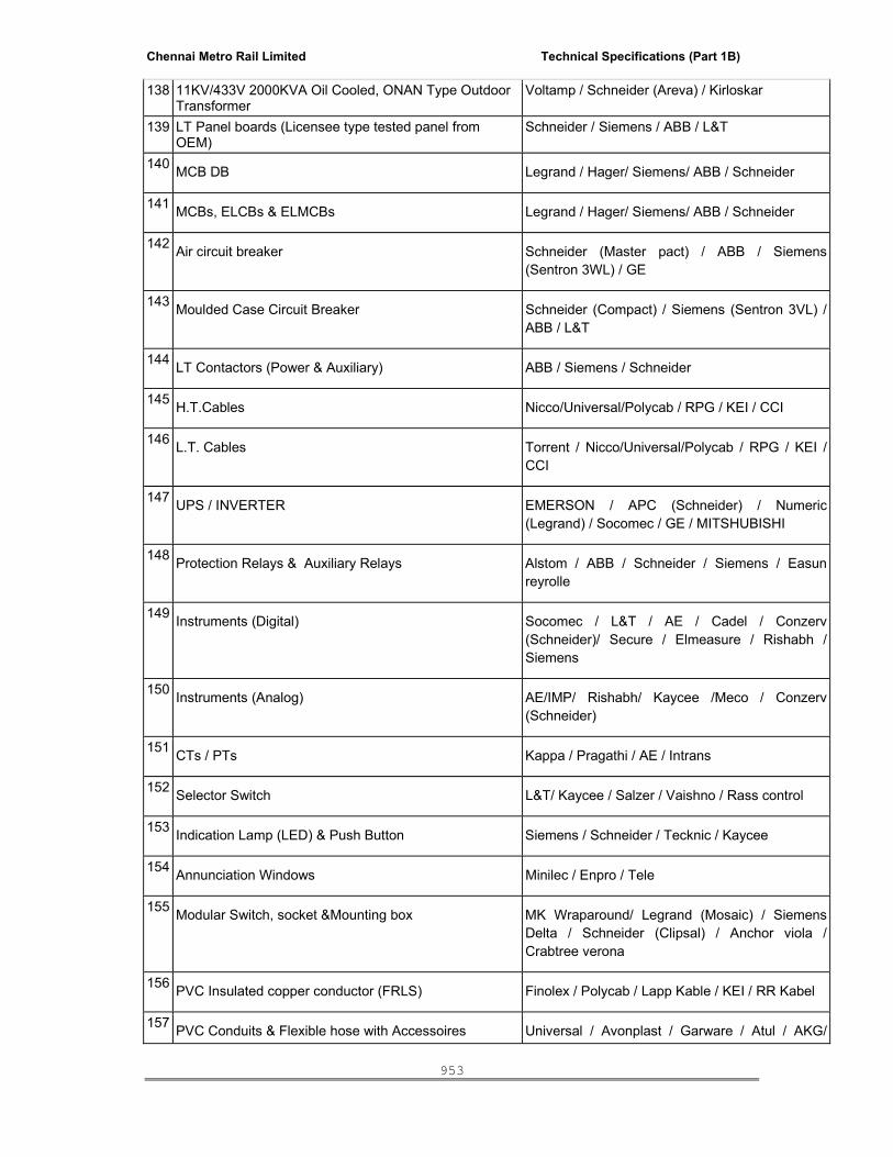
Chennai Metro Rail Limited Technical Specifications (Part 1B)
953
138 11KV/433V 2000KVA Oil Cooled, ONAN Type Outdoor Transformer
Voltamp / Schneider (Areva) / Kirloskar
139 LT Panel boards (Licensee type tested panel from OEM)
Schneider / Siemens / ABB / L&T
140 MCB DB Legrand / Hager/ Siemens/ ABB / Schneider
141 MCBs, ELCBs & ELMCBs Legrand / Hager/ Siemens/ ABB / Schneider
142 Air circuit breaker Schneider (Master pact) / ABB / Siemens (Sentron 3WL) / GE
143 Moulded Case Circuit Breaker Schneider (Compact) / Siemens (Sentron 3VL) / ABB / L&T
144 LT Contactors (Power & Auxiliary) ABB / Siemens / Schneider
145 H.T.Cables Nicco/Universal/Polycab / RPG / KEI / CCI
146 L.T. Cables Torrent / Nicco/Universal/Polycab / RPG / KEI / CCI
147 UPS / INVERTER EMERSON / APC (Schneider) / Numeric (Legrand) / Socomec / GE / MITSHUBISHI
148 Protection Relays & Auxiliary Relays Alstom / ABB / Schneider / Siemens / Easun reyrolle
149 Instruments (Digital) Socomec / L&T / AE / Cadel / Conzerv (Schneider)/ Secure / Elmeasure / Rishabh / Siemens
150 Instruments (Analog) AE/IMP/ Rishabh/ Kaycee /Meco / Conzerv (Schneider)
151 CTs / PTs Kappa / Pragathi / AE / Intrans
152 Selector Switch L&T/ Kaycee / Salzer / Vaishno / Rass control
153 Indication Lamp (LED) & Push Button Siemens / Schneider / Tecknic / Kaycee
154 Annunciation Windows Minilec / Enpro / Tele
155 Modular Switch, socket &Mounting box MK Wraparound/ Legrand (Mosaic) / Siemens Delta / Schneider (Clipsal) / Anchor viola / Crabtree verona
156 PVC Insulated copper conductor (FRLS) Finolex / Polycab / Lapp Kable / KEI / RR Kabel
157 PVC Conduits & Flexible hose with Accessoires Universal / Avonplast / Garware / Atul / AKG/
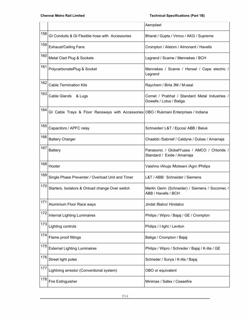
Chennai Metro Rail Limited Technical Specifications (Part 1B)
954
Aeroplast
158 GI Conduits & GI Flexible hose with Accessories Bharat / Gupta / Vimco / AKG / Supreme
159 Exhaust/Ceiling Fans Crompton / Alstom / Almonard / Havells
160 Metal Clad Plug & Sockets Legrand / Scame / Mennekes / BCH
161 PolycarbonatePlug & Socket Mennekes / Scame / Hensel / Cape electric / Legrand
162 Cable Termination Kits Raychem / Birla 3M / M-seal
163 Cable Glands & Lugs Comet / Prabhat / Standard Metal Industries / Dowells / Lotus / Baliga
164 GI Cable Trays & Floor Raceways with Accessories
OBO / Rukmani Enterprises / Indiana
165 Capacitors / APFC relay Schneider/ L&T / Epcos/ ABB / Beluk
166 Battery Charger Chaabbi /Sabnief / Caldyne / Dubas / Amarraja
167 Battery Panasonic / GlobalYuasa / AMCO / Chloride / Standard / Exide / Amarraja
168 Hooter Vaishno /Ahuja /Motwani /Agni /Philips
169 Single Phase Preventer / Overload Unit and Timer L&T / ABB/ Schneider / Siemens
170 Starters, Isolators & Onload change Over switch
Merlin Gerin (Schneider) / Siemens / Socomec / ABB / Havells / BCH
171 Aluminium Floor Race ways Jindal /Balco/ Hindalco
172 Internal Lighting Luminaires Philips / Wipro / Bajaj / GE / Crompton
173 Lighting controls Philips / I light / Leviton
174 Flame proof fittings Baliga / Crompton / Bajaj
175 External Lighting Luminaires Philips / Wipro / Schreder / Bajaj / K-lite / GE
176 Street light poles Schreder / Surya / K-lite / Bajaj
177 Lightning arrestor (Conventional system) OBO or equivalent
178 Fire Extinguisher Minimax / Safex / Ceasefire

Chennai Metro Rail Limited Technical Specifications (Part 1B)
955
179 Rubber Matt & Safety Equipments Any Brand Name with ISI Mark
180 Voltage Surge Protector OBO / Phoenix / Legrand / Schneider
181 Harmonic Suppressor (Detuned reactor) Schneider / L&T / EPCOS
182 Special Earth Electrode OBO / JEF
183 Sandwich Busduct Legrand / L&T / Schneider / Godrej
184 PLC with Software licence ( Latest Version) Siemens / Allen Bradley / Schneider
DG SETS
185 Generator Alternator - Stamford/ Leroy Somer /AVKC 186 Generator Engine - Caterpiller / Cummins / MTU / Volvo / Kirloskar187 AMF/SYNCHRONIZING PANEL Lotus/Power Contorl / Powerica 188 Miniature Circuit Breakers - Legrand / Schneider / L&T / Hager / ABB 189 Air circuit breaker - Siemens/L&T/Abb/Schneider 190 Moulded Case Circuit Breaker - Schneider /Siemens/Abb/ L&T 191
LT Contactors - Siemens / L&T / Schneider Telemechanique (France)
192 L.T. Cables - Polycab / KEI / RPG 193 Protection Relays and Auxiliary Relays Alstom / ABB / CSPC / L & T / Schneider 194 Instruments(Digital) - Schneider (CONZERV)- IP Based195 CTs / PTs - Kappa/ Pragathi/Instrans/ Ae / Prayog/ Indcoil 196 Control Switch / Indication Lamp- Push Button Siemens / Teknic / Kaycee / L&T/ Schneider 197 Annunciation Windows - Enpro / Minilec /TELE 198 Cable Glands - Comet /Prabhat /Standard Metal Industries199 Battery Charger - Chaabbi/Sabnief/Caldyne/ Dubas/Amar Raja 200 Battery Amco/Chloride/Standard / Exide/Amar Raja
(IF DG MANUFACTURER HAS THEIR OWN MANUFACTURING UNIT FOR PANELS OR TIE-UP WITH REPUTED MANUFACTURERS CAN SUBMIT THEIR CREDENTIAL FOR APPROVAL. APPROVAL WILL BE GIVEN BASED ON THE CREDENTIAL BY ARCHITECT/ CLEINT. ONLY APPROVED FIRMS SHALL BE PERMITTED FOR MANUFACTURING THE PANELS.)
FIRE PROTECTION SYSTEM
201 Electrical Driven Pump Kirloskar/Mather & plat/Armstrong/Grundfos
202 Diesel Engine Pump Kirloskar/Mather & plat/Armstrong/Grundfos
203 Pipes – G.I. / M.S. Tata / Jindal
204 DI Pipes / Fittings Electro steel / Lanco / Jindal / Kejriwal
205 Pipe Fittings Bharat Forge / VS Brand / B & M /Metal Lloyd

Chennai Metro Rail Limited Technical Specifications (Part 1B)
956
206 Butterfly Valves Audco / Intervalve /KSB
207 Non return valve Normex / Audco /Advance
208 Sluice Gate valve Kalpana/Upadaya/Amco
209 Gate / Ball valve Kitz /Audco/Leader
210 Pressure Gauge Brecco/ WIKA /Fivalco/Econosto
211 Anticorrosive Materials IWL- Pypkote
212 Hydrant Valves Newage / Shah Bhogilal / Minimax
213 Branch Pipe with Nozzle Newage / Shah Bhogilal / Minimax
214 Fire Hoses Newage / Shah Bhogilal / Minimax
215 Hose Couplings Newage / Shah Bhogilal / Minimax
216 Hose Reel Newage / Shah Bhogilal / Minimax
217 Fire Brigade Inlet Newage / Shah Bhogilal / Minimax
218 Paint Asian / Berger
219 Air Release Valve Winco / Newage
220 Sprinkler Flexible Drop Tyco / Victaulic /Easyflex-kanwall /Gilpro
221 Fire extinguishers Minimax / Ceasefire
222 Supports Hitec / Fisher
223 Sprinklers Tyco / Victaulic/HD fire /Viking
224 Alarm Valve Viking / Tyco /HD fire /Victaulic
225 Deluge valve Viking / Tyco /HD fire /Victaulic
226 Pressure Reducing valve tyco/Victaulic/Cla-val
227 Flow meter Tyco/Victaulic/Viking
228 Grooved/fitting &coupling Grinnell/Victaulic
HVAC
229 Water Cooled Magnetic centrifugal Chillers Carrier / York / Trane / Daikin Mcquay
230 Centrifugal pumps Grundfos / Armstrong / ITT- Xylem
231 Cooling Tower (CTI Certified) Baltimore / Marle
232 Air Handling Units
Zeco / Systemair / Trane / Edgetech /Daikin Mcquay
233 AHU Fans Kruger / Greenheck
234 Filters AAF / Thermodyne / Spectrum
235 Ventilation Fans Kruger / Greenheck
236 Jet Fans Kruger / Greenheck
237 Energy Recovery Wheel with Treated fresh air unit DRI / Greenheck / Enventus
238 Variable Frequency Drives Danfoss / Allen Bradley
239 Dual Fluid Precision AC Emerson / Climeveneta / Uniflair / Stulz

Chennai Metro Rail Limited Technical Specifications (Part 1B)
957
240 Variable Refrigerant Flow System
LG /Daikin / Toshiba / Mitsubishi /Blue star / Panasonic
241 MS Pipes Jindal / Tata
242 Pre-insulated pipes Seven star / Venus
243 Copper pipes Totalline / Nisson / Mandev / Rajco
244 Butterfly Valves Audco / Danfoss/ Advance / Syncro
245 Ball Valve Audco / Leader / Kitz
246 Check valve Audco / Advance / Syncro
247 Flow Control Valves (Pressure Independent type)
Danfoss / T&A Hydronics
248 2-Way Modulating & On / Off Valves
Danfoss / T&A Hydronics / Johnson Controls /Siemens
249 Balancing Valves Danfoss / T&A Hydronics
250 Strainer / Sediment Separator Sant / Advance /ITT 251 Ultrasonic BTU meter / Flow meter Landis + Gyr, Kamstrup, Basic Controls 252 Pre-insulated Valves Valtree/Venus 253 Pressure & Temperature Gauges Wika / Fiebig / Waree 254 Pipe Insulation K flex/Armacell/Aflex/Thermobreak 255 Auto Airvent Valve Amtrol / Flamco / Anergy 256 Galvanized Steel Sheet TATA / Jindal / Sail 257
Duct – Factory Fabricated Rolastar / Zeco duct / Western Air Duct / Venus/ seven star
258 Duct Insulation – Acoustic & Thermal Thermobreak/ Trocellin 259 Fibre glass UP Twiga / Owens corning 260 Pre insulated Cross talk silencer UP Twiga / Owens corning 261 Air Terminal / Distribution Devices - Grilles, Diffusers, Caryaire / Air Master / System air / Cosmic 262 Insulated Flexible Ducting Caryaire / Atco / System air / seven star / Venus 263 Fire dampers Greenheck / Ruskin Titus / Trox 264 Volume control Damper Greenheck / Ruskin Titus / Trox /Air master 265 Welding Electrodes Advani / Esab / Sun arc / Sechron Universal 266 Pipe supports Hitech supports / Hilti / Kanwal Industries 267 Paint Asian / Nerolec / Berger 268 Fire Sealant Birla 3 M / Hilti / Promat / GE/ Dow Corning 269 Vibration Isolator / Flexible Bellow Kanwal Industries / Resistoflex / Cori 270 VAV Box Trane / / Jhonson Controls / Barcol-Air / Trox 271 Motors ABB / Siemens 272 MS / GI Conduit Bharat / Gupta / Vimco / Supreme

Chennai Metro Rail Limited Technical Specifications (Part 1B)
958
273 Cable tray Profab / Techno Fab / Pearl Enterprises 274 Copper cables for signal and power Neoflex / Teleflex / Finecore / Varsha /
Technoflex / Polycab 275 Sensors & Field Equipments Siemens / Johnson control / Honeywell /
Schneider / Grey stone 276 Soft starters Danfoss/Siemens/Schneider
277 Modular Switch, socket &Mounting box MK (Honeywell) / Legrand Mosaic /Crabtree / Siemens
IBMS
278 Microprocessor based Fire alarm Control panel – UL listed
Honeywell/Edwards/ Siemens/NOTIFIER/BOSCH
279 Ceiling speakers, wall Speakers, column speakers Bosch
280 External Horns Bosch / Ahuja
281 DVD players Philips / Sony / Panasonic
282 Speech processor (Voice recorder) VISONIC or approved equivalent
283 Electromagnetic lock BEL/ Sprint/Faraday/Insyn
284 Magnetic contract Sentrol/Faraday /Insyn/security/change
285 Emergency Release switch , Emergency Break Glass KEC, Sentrol, Honeywell /EST
286 Power supply units Custamade
287 System CPU HP /IBM/ DELL
288 Modular socket and switches MK India/ Mosiac / Crabtree/Northwest
289 Proximity card and Card reader HID (Mifare type)
290 Biometric Card reader Honeywell /Mifare/Legic
291 CCTV Equipments and softwares SONY/Axis/Panasonic
292 Access controllers Honeywell/HID/Siemens/GE
293 Rack Net rack/HCL
294 Level Switch Fluitec/Veksier/Techtrol
295 Copper cables for signal and power Varsha/ Teleflex / Finecore/Technoflex/LAPP
296 PLC controllers-BMS Siemens / Johnson control / Honeywell/L&T/AB
297 Enclosure Rital
298 Field Devices Johnson /Honeywell, Alerton, Siemens, Sontay, Satchwell/ABB/Greystone/cylon
299 Cable Tray OBO/Indiana / Profab
300 MS Conduits with Accessories Bharat/Gupta/ Vimco / AKG / Supreme/ BEC
301 PVC conduits Avon plast/VIP/Precision / BEC
302 Door Position Sensor Ademco/ Honeywell /Siemens,

Chennai Metro Rail Limited Technical Specifications (Part 1B)
959
SANITARY WORKS
303 Sanitaryware Kohler / Roca / American Standards
304 Stainless Steel Sink Nirali / Lizen / Blanco
305 Stand Alone SENSOR Aos System / American Standard /
306 Water Heater Venus / Bajaj / Crompton Greaves 307 CP Fittings Kohler / Grohe / Roca
308 Concealed Flush Valve Jaquar / Kohler / American Standards 309 Concealed Cisten Gebrit / Grohe / Kohler 310 UPVC Swr Pipe/Fittings Astral / Ashirvad / Supreme 311 UPVC Pipes And Fittings Astral / Ashirvad / Supreme 312 CPVC Pipes And Fittings Astral / Ashirvad / Supreme 313 SS Ball Valve TBS /Leader/SANT 314 Ball Valve TBS / Cim / SKS 315 Butter Fly Valve/Checkvale Leader / Normex /Rb / Zoloto 316 Y' Strainer Leader/Normex / Rb 317 Air Release Valves Watts 318 Check Value / Non Return Valve Normax/Audco/Lehary/Leader 319 Water Supply Pumps / Sewage Pumps/Dewatering
Pumps Grundfos/ Kirloskar/Texmo /Itt/Ksb 320 Sfrc Cover K K Precast Concrete Fabricators 321 CI Grating Neco 292 CPGrating Chilly/Neer 293 Stone Ware Pipes & Gully Traps Syscraft Global Enterprises (Sge) / 294 Bevelled Edge Mirror Atul/ Modi Guard / Saint Gobain 295 CI / DI / SFRC/ PFRC Manhole Cover Neco 296 STP Ion Exchange / Thermax / Ge 297 Water Treatment Plant Ion Exchange / Thermax / Ge 298 Fabricated Floor Traps Freedom Enterprises 299 Heat Pump A.O Smith/Honeywell 300 Open Well Submersible Transfer Pump Grundfos / C.R.I / Itt-Lowara 301 G.I Rubber Lined Split Clamps/'U' Bolts Hilti 302 Water Meters Jenner Aquamet,Toshnival 303 Water Level Controllers Jkn Enterprises / Active Controls 304 Elastomeric Rubber Insulation K-Flex/Vidoflex 305 Fastners Hilti/Fisher 306 Rain Water Outlets Neer/Sge
Chennai Metro Rail Limited Technical Specifications (Part 1B)
960
307 Hdpe Pipes & Fittings Geberit/Kissan/Sangir 308 Pressure Reducing Valve Watts 309 Ball Float Valve Zoloto / Teleflow / Lehary 310 Water Hammer Arrestors Watts / Tbs 311 Electrical Water Heater A.O Smith/Honeywell 312 Pressure Gauge Weika/H-Guru 313 Foot Valve Normax/Lehary 314 Solar Panel V-Guard / Honeywell 315 Hdpe Water Tanks Sintex 316 Hydropneumatic Pumps Itt / Grundfos 317 Sewage Cutter Version Pumps Itt / Grundfos 318 Centrifugal Monoblock Transfer Pumps Itt / Grundfos 319 PVC Pipes Floking 320 HT - Poly Propalane Gf - Hakan
Structured Cabling System
321 DATA,Voice (CAT6A,),Firber Cable ( Indoor / Outdoor), I/O, Jack Panels,Face plates Systimax / Panduit ( PanNet)/Siemon
322 Backbox Non Systimax
323 Switch Rack APW President / Netrack
324 Switches Cisco/Brocade/Juniper
325 Servers HP/DELL/IBM
326 IP PBX Alcatel / Unify (Siemens) 1. The contractor shall produce all samples including natural stones, before procurement of the materials, for approval of the Employer / Employer Representative. 2. Where more than one manufacturer is listed, the names are given in the order of preference. The contractor shall quote the rates for the various items of work based on the materials of first preference after ascertaining the availability, delivery schedule of the same. Unless the contractor stipulates in this tender, it shall be presumed that the rates quoted are for material of first preference only.
3. In the event, the contractor is permitted to use the material of lower preference because of valid reasons, then the contract rates for the relevant items of work shall be suitably adjusted on the basis of variation in prices of the materials of first preference and those actually used. If the prices of the materials used are higher than the material of the first preference, the owner shall not be liable to make any enhanced payment for the affected items of work on this account. 4. In respect of materials for which approved makes are not specified above, these will be makes to be decided by the Employer / Employer Representative and as per samples getting approved.
---------------------------------- END --------------------------------------------------
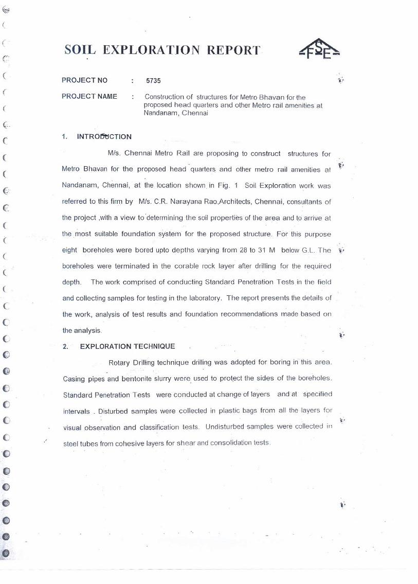


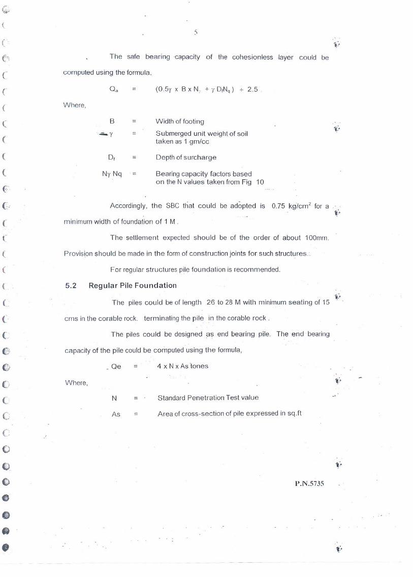
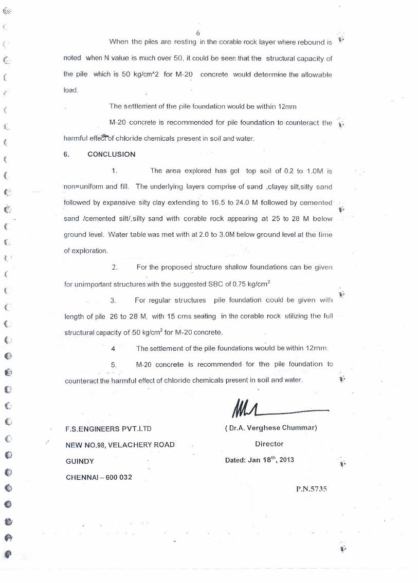

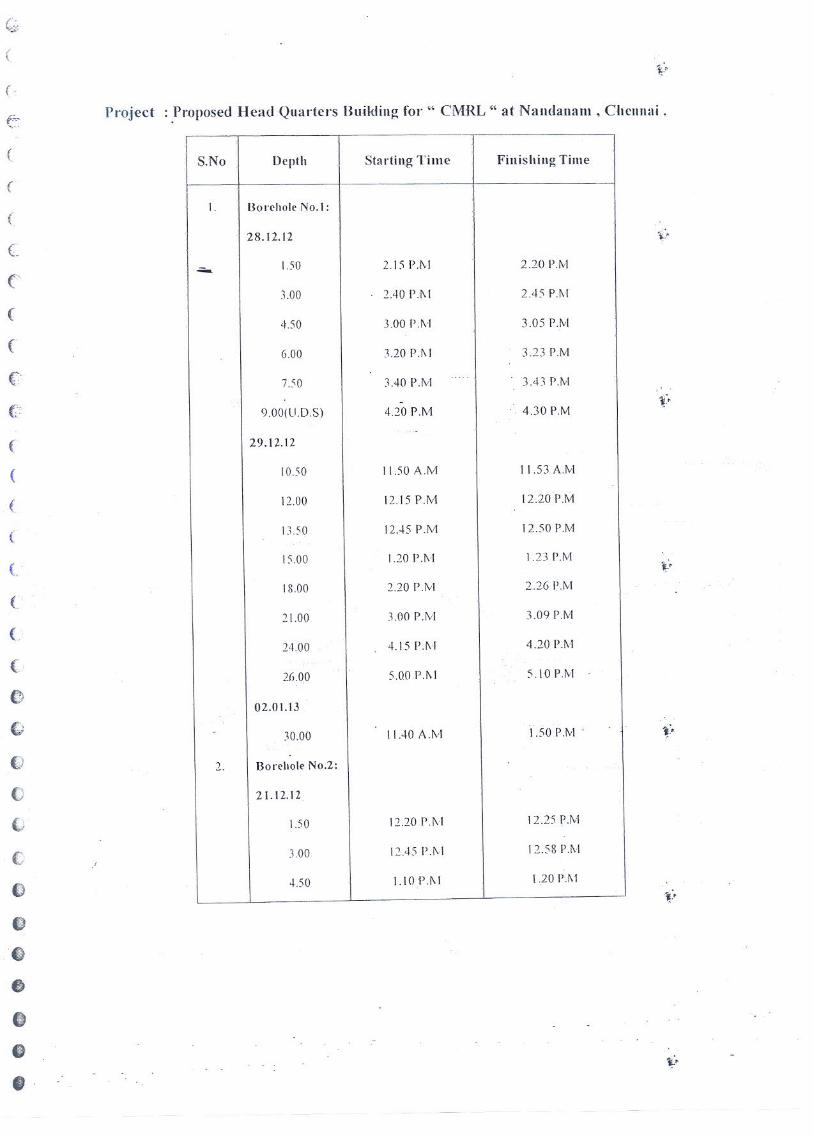


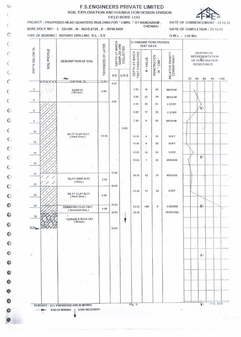

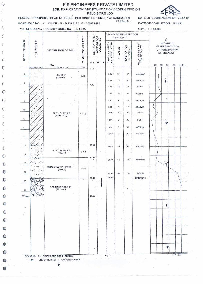
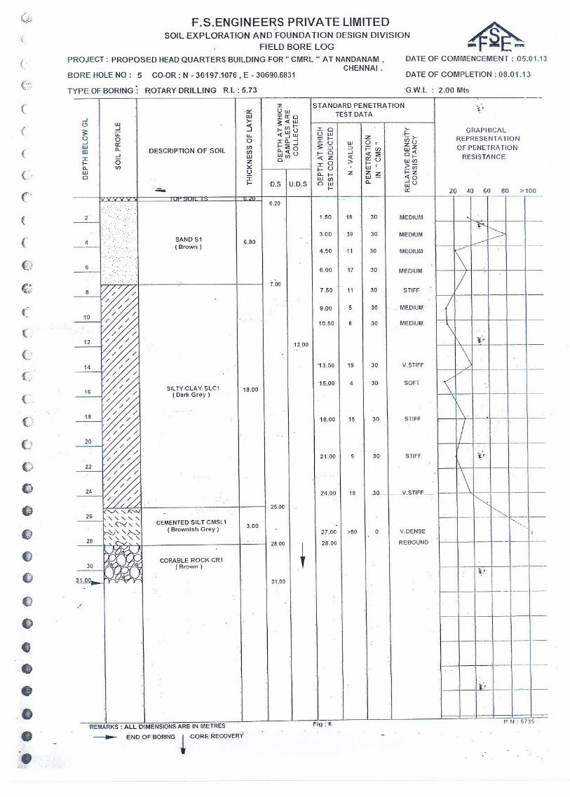


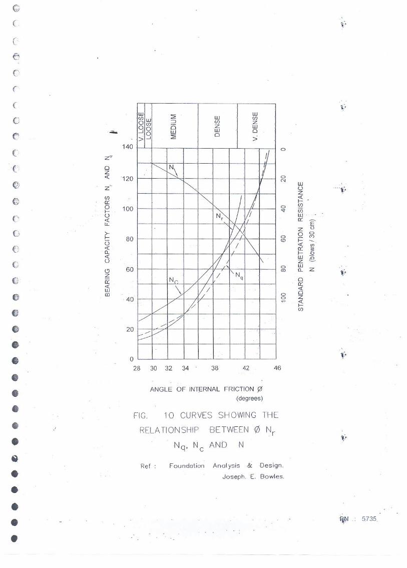


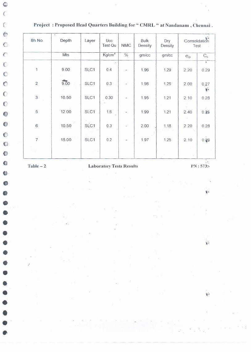


Chennai Metro Rail Ltd, Chennai Part – II – Preamble to BOQ and Bills of Quantities
CHENNAI METRO RAIL LIMITED (A JOINT VENTURE OF GOVERNMENT OF INDIA AND GOVERNMENT OF TAMILNADU)
TECHNO COMMERCIAL TENDER TWO COVER SYSTEM
CONSTRUCTION OF METRO HEAD QUARTERS BUILDING AND OTHER METRO RAIL AMENITIES AT ANNA SALAI, NANDANAM,
CHENNAI 600 035 Cover – B
Price Tender
PART – II : PREAMBLE TO BILLS OF QUANTITIES &
BILLS OF QUANTITIES
DATE OF SUBMISSION OF TENDER – 13-04-2016 2015 at 15.00 Hours
DATE OF OPENING OF TENDER - 13-04-2016 2015 at 15.30 Hours TO BE SUBMITTED TO:
The Chief General Manager(EC) Chennai Metro Rail Limited Admin. Building, CMRL Depot Poonnamallee High Road , Koyambedu, Chennai - 600107
TENDER SUBMITTED BY:
M/s._________________________
Address_____________________
____________________________

CMRL, Chennai Preamble to BOQ
1 The Preamble to the Bills of Quantities and Bill of Quantities must be read with the Drawings, Conditions ofContract and the Specification and the tenderer shall be deemed to have examined the Drawings, Specifications,Conditions of Contract and to have acquainted himself with the Works to be done and the way in which they areto be carried out. This preamble to the Bills of Quantities shall form part of the Contract.
2 Notwithstanding that the work has been sectionalised every part of it shall be deemed to be supplementary to andcomplementary of every other part and shall be read with it or into it so far as it may be practicable to do so.
3 The description of an item shall be deemed to include all preambles, headings, sub-headings and references toother documents. The detailed description of work and materials, given in the Specification are not necessarilyrepeated in the Bill of Quantities.
4 The rates for all items shall be quoted and priced in Indian Rupees only. Prices inserted in this BOQ are fullincluding cost of the work described and of the obligations setforth in the tender document. Rates should bequoted both in Figures & words in Columns specified. In case of discrepency between the rates quoted in figuresand in words, lower of the two shall be considered. While quoting the rates for the items covered under bill ofmaterials, the tenderers should carefully read the Preamble under the respective heads also and quote the rateaccordingly.
5 Tenderers are instructed to quote the rates for all items nearest to one rupee and to avoid in quoting with fraction /paise.
6 Each individual item in the Bill of Quantities is to be priced or if any items are not priced it is to be indicated underwhich item or items the value of the work has been included. If the tenderer omits to quote an item the cost of thework of such item shall be held to be spread over and included in the prices given for other items and the tenderershould compulsorily execute that item for full quantity given in the bill of quantities at free of cost, if the tenderergets the work. However the successful tenderer shall quote the rates for such items and get approved by theEmployer. In such case such items are not required to be executed full / part quantity, the successful tenderershall pay appropriate amount for the quantity at the accepted rate to the Employer. Tenderer should not markitems as "included" when the rate is asked for. Exactly similar items in indivitual sections/sub-Head shall be pricedsimilarly.
7 The rate entered against each item in the Schedule of Quantities shall be binding through out the Contract andshall not be changed on account of any discrepancies or inaccuracies in the estimated quantities or any othercause. All prices quoted shall be firm for the entire duration of the contract. The Contractor shall when contractingsatisfy himself that the quantities are reasonably correct within the scope of work. If there is any discrepancy, heshould at once notify the Employer, so that the matter can be examined, and if necessary altered before tendersclose.
8 For the sake of convenience the Bill of Quantities is sectionalised to cover one structure or a group of structures.
9 Unit Rates will be used as basis of payment for schedules and variation orders.
10 Cost of all materials, labour, equipment required, tools & plants required, conveyance, infrastructure facilitiesrequired including heavy excavation machinery with supporting transport facility either own or leased, shall beincluded in the quoted rates elsewhere. Contractor shall provide Steel pipe double Scaffolding to carry out theirworks during execution of the project in good and operational condition within the Quoted Rates.
CONSTRUCTION OF METRO HEADQUARTERS BUILDING AND OTHER METRO RAIL AMENITIES AT NANDANAM,CHENNAI
PREAMBLE TO THE BILL OF QUANTITIES1. GENERAL
1 General
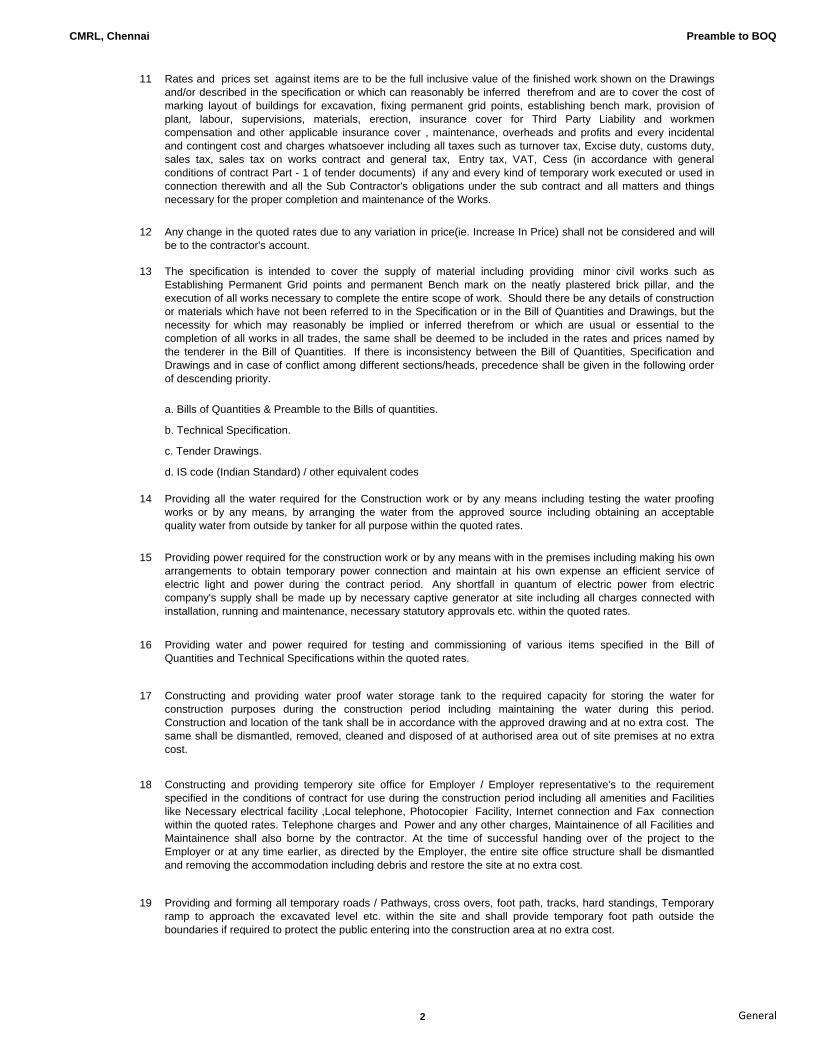
CMRL, Chennai Preamble to BOQ
11 Rates and prices set against items are to be the full inclusive value of the finished work shown on the Drawingsand/or described in the specification or which can reasonably be inferred therefrom and are to cover the cost ofmarking layout of buildings for excavation, fixing permanent grid points, establishing bench mark, provision ofplant, labour, supervisions, materials, erection, insurance cover for Third Party Liability and workmencompensation and other applicable insurance cover , maintenance, overheads and profits and every incidentaland contingent cost and charges whatsoever including all taxes such as turnover tax, Excise duty, customs duty,sales tax, sales tax on works contract and general tax, Entry tax, VAT, Cess (in accordance with generalconditions of contract Part - 1 of tender documents) if any and every kind of temporary work executed or used inconnection therewith and all the Sub Contractor's obligations under the sub contract and all matters and thingsnecessary for the proper completion and maintenance of the Works.
12 Any change in the quoted rates due to any variation in price(ie. Increase In Price) shall not be considered and willbe to the contractor's account.
13 The specification is intended to cover the supply of material including providing minor civil works such asEstablishing Permanent Grid points and permanent Bench mark on the neatly plastered brick pillar, and theexecution of all works necessary to complete the entire scope of work. Should there be any details of constructionor materials which have not been referred to in the Specification or in the Bill of Quantities and Drawings, but thenecessity for which may reasonably be implied or inferred therefrom or which are usual or essential to thecompletion of all works in all trades, the same shall be deemed to be included in the rates and prices named bythe tenderer in the Bill of Quantities. If there is inconsistency between the Bill of Quantities, Specification andDrawings and in case of conflict among different sections/heads, precedence shall be given in the following orderof descending priority.
a. Bills of Quantities & Preamble to the Bills of quantities.
b. Technical Specification.
c. Tender Drawings.
d. IS code (Indian Standard) / other equivalent codes
14 Providing all the water required for the Construction work or by any means including testing the water proofingworks or by any means, by arranging the water from the approved source including obtaining an acceptablequality water from outside by tanker for all purpose within the quoted rates.
15 Providing power required for the construction work or by any means with in the premises including making his ownarrangements to obtain temporary power connection and maintain at his own expense an efficient service ofelectric light and power during the contract period. Any shortfall in quantum of electric power from electriccompany's supply shall be made up by necessary captive generator at site including all charges connected withinstallation, running and maintenance, necessary statutory approvals etc. within the quoted rates.
16 Providing water and power required for testing and commissioning of various items specified in the Bill ofQuantities and Technical Specifications within the quoted rates.
17 Constructing and providing water proof water storage tank to the required capacity for storing the water forconstruction purposes during the construction period including maintaining the water during this period.Construction and location of the tank shall be in accordance with the approved drawing and at no extra cost. Thesame shall be dismantled, removed, cleaned and disposed of at authorised area out of site premises at no extracost.
18 Constructing and providing temperory site office for Employer / Employer representative's to the requirementspecified in the conditions of contract for use during the construction period including all amenities and Facilitieslike Necessary electrical facility ,Local telephone, Photocopier Facility, Internet connection and Fax connectionwithin the quoted rates. Telephone charges and Power and any other charges, Maintainence of all Facilities andMaintainence shall also borne by the contractor. At the time of successful handing over of the project to theEmployer or at any time earlier, as directed by the Employer, the entire site office structure shall be dismantledand removing the accommodation including debris and restore the site at no extra cost.
19 Providing and forming all temporary roads / Pathways, cross overs, foot path, tracks, hard standings, Temporaryramp to approach the excavated level etc. within the site and shall provide temporary foot path outside theboundaries if required to protect the public entering into the construction area at no extra cost.
2 General
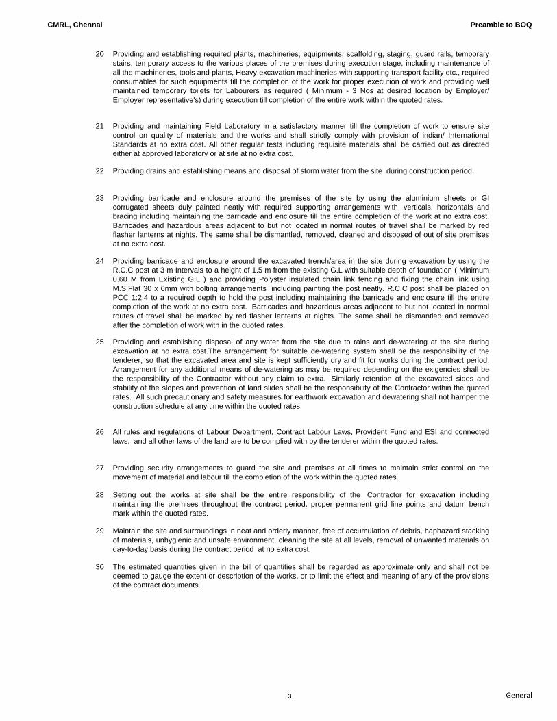
CMRL, Chennai Preamble to BOQ
20 Providing and establishing required plants, machineries, equipments, scaffolding, staging, guard rails, temporarystairs, temporary access to the various places of the premises during execution stage, including maintenance ofall the machineries, tools and plants, Heavy excavation machineries with supporting transport facility etc., requiredconsumables for such equipments till the completion of the work for proper execution of work and providing wellmaintained temporary toilets for Labourers as required ( Minimum - 3 Nos at desired location by Employer/Employer representative's) during execution till completion of the entire work within the quoted rates.
21 Providing and maintaining Field Laboratory in a satisfactory manner till the completion of work to ensure sitecontrol on quality of materials and the works and shall strictly comply with provision of indian/ InternationalStandards at no extra cost. All other regular tests including requisite materials shall be carried out as directedeither at approved laboratory or at site at no extra cost.
22 Providing drains and establishing means and disposal of storm water from the site during construction period.
23 Providing barricade and enclosure around the premises of the site by using the aluminium sheets or GIcorrugated sheets duly painted neatly with required supporting arrangements with verticals, horizontals andbracing including maintaining the barricade and enclosure till the entire completion of the work at no extra cost.Barricades and hazardous areas adjacent to but not located in normal routes of travel shall be marked by redflasher lanterns at nights. The same shall be dismantled, removed, cleaned and disposed of out of site premisesat no extra cost.
24 Providing barricade and enclosure around the excavated trench/area in the site during excavation by using theR.C.C post at 3 m Intervals to a height of 1.5 m from the existing G.L with suitable depth of foundation ( Minimum0.60 M from Existing G.L ) and providing Polyster insulated chain link fencing and fixing the chain link usingM.S.Flat 30 x 6mm with bolting arrangements including painting the post neatly. R.C.C post shall be placed onPCC 1:2:4 to a required depth to hold the post including maintaining the barricade and enclosure till the entirecompletion of the work at no extra cost. Barricades and hazardous areas adjacent to but not located in normalroutes of travel shall be marked by red flasher lanterns at nights. The same shall be dismantled and removedafter the completion of work with in the quoted rates.
25 Providing and establishing disposal of any water from the site due to rains and de-watering at the site duringexcavation at no extra cost.The arrangement for suitable de-watering system shall be the responsibility of thetenderer, so that the excavated area and site is kept sufficiently dry and fit for works during the contract period.Arrangement for any additional means of de-watering as may be required depending on the exigencies shall bethe responsibility of the Contractor without any claim to extra. Similarly retention of the excavated sides andstability of the slopes and prevention of land slides shall be the responsibility of the Contractor within the quotedrates. All such precautionary and safety measures for earthwork excavation and dewatering shall not hamper theconstruction schedule at any time within the quoted rates.
26 All rules and regulations of Labour Department, Contract Labour Laws, Provident Fund and ESI and connectedlaws, and all other laws of the land are to be complied with by the tenderer within the quoted rates.
27 Providing security arrangements to guard the site and premises at all times to maintain strict control on themovement of material and labour till the completion of the work within the quoted rates.
28 Setting out the works at site shall be the entire responsibility of the Contractor for excavation includingmaintaining the premises throughout the contract period, proper permanent grid line points and datum benchmark within the quoted rates.
29 Maintain the site and surroundings in neat and orderly manner, free of accumulation of debris, haphazard stackingof materials, unhygienic and unsafe environment, cleaning the site at all levels, removal of unwanted materials onday-to-day basis during the contract period at no extra cost.
30 The estimated quantities given in the bill of quantities shall be regarded as approximate only and shall not bedeemed to gauge the extent or description of the works, or to limit the effect and meaning of any of the provisionsof the contract documents.
3 General

CMRL, Chennai Preamble to BOQ
31 The quantities in the Bill of quantities approximately indicate the total extent of work but may vary to any extentand may even be omitted thus altering the aggregate value of the contract. A Schedule of Probable Quantities inrespect of each trade of work is covered in Part – II. Individual items in the Schedule of Probable Quantities isliable to alteration without any pre-specified limit to extent of such variations by way of omissions, deductions oradditions at the discretion of the Architect. Each Bid should contain not only the rates but also the value of eachitem of work entered in the amount column and all the items should be totaled in order to show the aggregatevalue of the entire Bid. The value of each item worked out shall be rounded off to a nearest Rupee ignoring paisebelow fifty.
32 Employer/ Employer representative's reserves the right to itself the right of altering the drawings and nature ofwork by adding to or omitting any items of work or having portions of the same carried out without prejudice to thiscontract. There shall be no limit on the scope and extent the changes that can be ordered by the employer andthe contractor shall not be entitled to any compensation or claim due to such change(s) / order(s) by theemployer. The contractor will only be paid for the actual quantity of works done payable at the agreed unit rates.
33 Any permission required for establishing the site office including executing the work to be obtained from thestatutory Authority shall be responsibility of the tenderer within the Quoted rates.
34 No Land will be provided by the company to the contractor for constructing any structure, his labour, workman andsupervisory camps, un-authorised hutments, canteen or teashops at site or within the premises. Contractor shallmake his own arrangements for the same outside the Premies / boundary. These if any, shall be with theknowledge of and prior approval of the Employer / Architect.
35 Arranging, taking and providing colour photographs, video films during construction period at various stages fromdifferent locations to show the progress of work at every week including on special occasions and novel featuresof the work as desired through out the contract period. The photographs shall be of acceptable quality and they shall be taken by a professionally competent commercialphotographer with camera having the facility to record the date of photographs taken in the prints and negative.The Contractor shall supply five colour prints of each of the photographs taken to the standard maximum sizemounted in albums of acceptable quality. Also the negative in 35mm size shall be supplied for each photograph.Each photograph in the album shall be suitably captioned.
Video films shall be taken by a professionally competent commercial video cameraman and edited with DigitalPhotographs( Both Soft & Hard Copies ) to be taken and submitted as a part of Monthly Report - to be includeddate and time. The edited video cassettes shall contain narration of the activities in Engilish by a competentnarrator. The edition of the video film and the script for narration shall be as approved. The video cassettes shallbe of acceptable quality and the film shall be capable of producing colour pictures.Videocasettes shall beconverted in to CD form as & when required by Employer/ Employer representative's and required no. of copiesshall be supplied. The entire expenses on this account shall be borne by the Contractor and he is not eligible forany payment on this account.
The abbreviations used in the Specification and Bill of Quantities shall be read as follows : IS - Indian Standard A.S.T.M - American Society for Testing and MaterialsA.W.S. - American Welding SocietyMM & mm - Millimetre /s CM & cm - centimetre /s L.M.(lm) - Linear metre /s RM (rm) / RMT (rmt) - Running metre /s KG (kg) - Kilograme /s Tonne/t/MT - Metric ton/s (1000 Kilogrammes)Dia. - Diameter Wt .- WeightSq.m. - Square metre Cum - Cubic metre No. - Number Qty. - Quantity L.S - Lumpsum. P.S. - Provisional sumQ.R.O - Quote rate only.Drg.No. - Drawing number P.C.C. - Plain Cement ConcreteR.C.C. - Reinforced cement concreteH.S.D - High Yield strength Deformed bars.M.S. - MildsteelC.R.S. - Corrosion resistence steel.
36
4 General

CMRL, Chennai Preamble to BOQ
C.T.D. - Cold Twisted Deformed steel.TMT - Thermo Mechanically Treated BarsA copy of soil report is enclosed in Part - I for the reference to the tenderer as to identify the nature of soil, but theenclosed soil report is only indicative. The tenderer is expected to inspect the site to investigate the followingitems before quoting the rates in the tender and the entire responsibility for amenities & services therefore shall besole responsibility of the tenderer.a. Nature and type of soil proposed for excavation and safety of excavation.. b. Availability of Power for execution.c. Availability of Water for execution.d. Means of Disposal of storm water/bailingout water from the site. e. Means of Disposal of water due to De-watering at the site. f. Nature and type of protection required for Neighbouring property to ensure full safety during Constructionactivities in Progress.
g.Place for disposal of serviciable / unserviciable materials obtained during Construction activities in Progress.38 Housekeeping for the entire site on a regular basis by deputing adequate dedicated resources (To be agreed with
PMC) at no extra cost.39 Area lighting and Task lighting in accordance with site safety rules.
40 Fall protection in mass excavated and such other areas are to be factored as per safety guidelines.
37
5 General
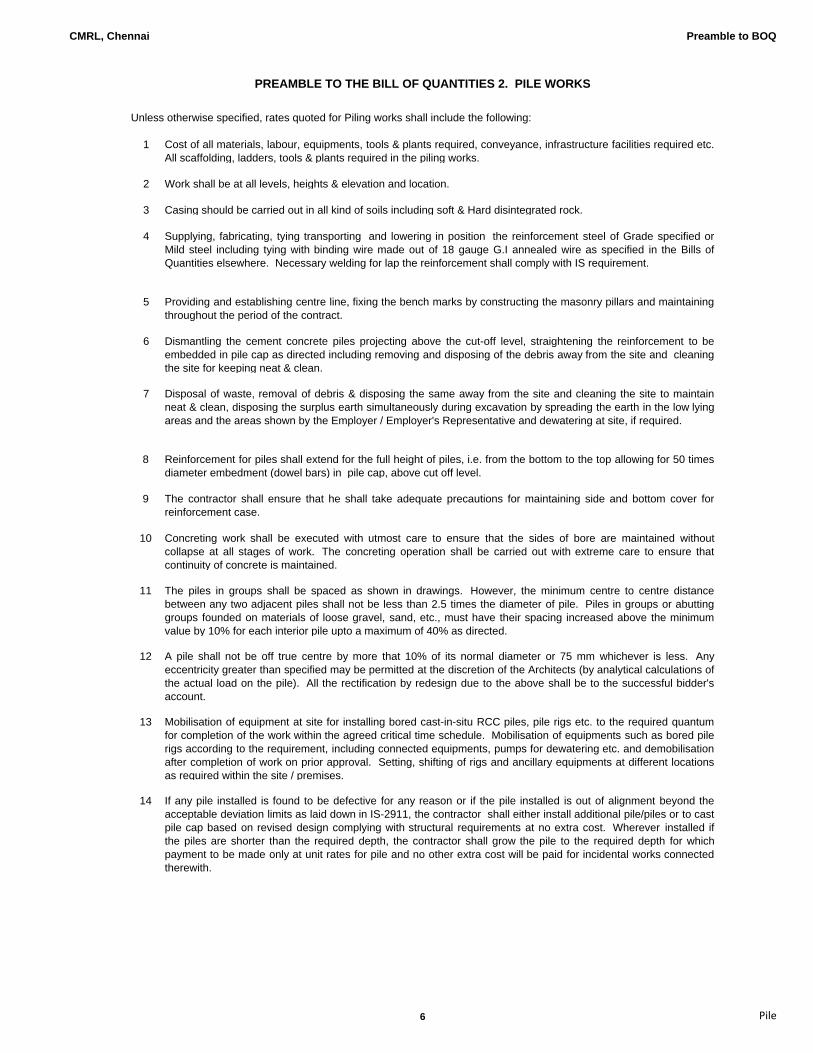
CMRL, Chennai Preamble to BOQ
1 Cost of all materials, labour, equipments, tools & plants required, conveyance, infrastructure facilities required etc.All scaffolding, ladders, tools & plants required in the piling works.
2 Work shall be at all levels, heights & elevation and location.
3 Casing should be carried out in all kind of soils including soft & Hard disintegrated rock.
4 Supplying, fabricating, tying transporting and lowering in position the reinforcement steel of Grade specified orMild steel including tying with binding wire made out of 18 gauge G.I annealed wire as specified in the Bills ofQuantities elsewhere. Necessary welding for lap the reinforcement shall comply with IS requirement.
5 Providing and establishing centre line, fixing the bench marks by constructing the masonry pillars and maintainingthroughout the period of the contract.
6 Dismantling the cement concrete piles projecting above the cut-off level, straightening the reinforcement to beembedded in pile cap as directed including removing and disposing of the debris away from the site and cleaningthe site for keeping neat & clean.
7 Disposal of waste, removal of debris & disposing the same away from the site and cleaning the site to maintainneat & clean, disposing the surplus earth simultaneously during excavation by spreading the earth in the low lyingareas and the areas shown by the Employer / Employer's Representative and dewatering at site, if required.
8 Reinforcement for piles shall extend for the full height of piles, i.e. from the bottom to the top allowing for 50 timesdiameter embedment (dowel bars) in pile cap, above cut off level.
9 The contractor shall ensure that he shall take adequate precautions for maintaining side and bottom cover forreinforcement case.
10 Concreting work shall be executed with utmost care to ensure that the sides of bore are maintained withoutcollapse at all stages of work. The concreting operation shall be carried out with extreme care to ensure thatcontinuity of concrete is maintained.
11 The piles in groups shall be spaced as shown in drawings. However, the minimum centre to centre distancebetween any two adjacent piles shall not be less than 2.5 times the diameter of pile. Piles in groups or abuttinggroups founded on materials of loose gravel, sand, etc., must have their spacing increased above the minimumvalue by 10% for each interior pile upto a maximum of 40% as directed.
12 A pile shall not be off true centre by more that 10% of its normal diameter or 75 mm whichever is less. Anyeccentricity greater than specified may be permitted at the discretion of the Architects (by analytical calculations ofthe actual load on the pile). All the rectification by redesign due to the above shall be to the successful bidder'saccount.
13 Mobilisation of equipment at site for installing bored cast-in-situ RCC piles, pile rigs etc. to the required quantumfor completion of the work within the agreed critical time schedule. Mobilisation of equipments such as bored pilerigs according to the requirement, including connected equipments, pumps for dewatering etc. and demobilisationafter completion of work on prior approval. Setting, shifting of rigs and ancillary equipments at different locationsas required within the site / premises.
14 If any pile installed is found to be defective for any reason or if the pile installed is out of alignment beyond theacceptable deviation limits as laid down in IS-2911, the contractor shall either install additional pile/piles or to castpile cap based on revised design complying with structural requirements at no extra cost. Wherever installed ifthe piles are shorter than the required depth, the contractor shall grow the pile to the required depth for whichpayment to be made only at unit rates for pile and no other extra cost will be paid for incidental works connectedtherewith.
Unless otherwise specified, rates quoted for Piling works shall include the following:
PREAMBLE TO THE BILL OF QUANTITIES 2. PILE WORKS
6 Pile
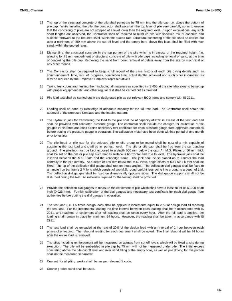
CMRL, Chennai Preamble to BOQ
15 The top of the structural concrete of the pile shall penetrate by 75 mm into the pile cap, i.e. above the bottom ofpile cap. While installing the pile, the contractor shall ascertain the top level of pile very carefully so as to ensurethat the concreting of piles are not stopped at a level lower than the required level. If upon excavations, any suchshort lengths are observed, the Contractor shall be required to build up pile with specified mix of concrete andsuitable formwork to the required level, within the quoted rate. Structural concreting of the pile shall be carried outupto a minimum of 450 mm above the cut off level and the empty bore above this level shall be filled with riversand, within the quoted rates.
16 Dismantling the structural concrete in the top portion of the pile which is in excess of the required height (i.e.allowing for 75 mm embedment of structural concrete of pile with pile cap) including removal of sand, at the timeof concreting the pile cap. Removing the sand from bore, removal of debris away from the site by mechnical orany other means.
17 The Contractor shall be required to keep a full record of the case history of each pile giving details such ascommencement time, rate of progress, completion time, actual depths achieved and such other information asmay be required by the Employer/ Employer representative's
18 Taking test cubes and testing them including all materials as specified in IS 456 at the site laboratory to be set upwith proper equipment etc. and other regular test shall be carried out as directed .
19 Pile load test shall be carried out in the designated pile as per relevant BOQ items and comply with IS 2911.
20 Loading shall be done by Kentledge of adequate capacity for the full test load. The Contractor shall obtain theapproval of the proposed Kentlage and the loading pattern.
21 The Hydraulic jack for transferring the load to the pile shall be of capacity of 25% in excess of the test load andshall be provided with calibrated pressure gauge. The contractor shall include the charges for calibration of thegauges in his rates and shall furnish necessary test certificate for each pressure gauge from approved authoritiesbefore putting the pressure gauge in operation. The calibration must have been done within a period of one monthprior to testing.
22 The pile head or pile cap for the selected pile or pile group to be tested shall be cast of a mix capable ofsustaining the test load and shall be in perfect level. The pile or pile cap shall be free from the surroundingground. The pile top must be kept exposed to a depth 600 mm below the cap. An M.S. Plates of 50 mm thickshall be set on the pile or pile cap such that its surface is horizontal and true to level. The hydraulic jack shall beinserted between the M.S. Plate and the kentledge frame. The jack shall be so placed as to transfer the loadcentrally to the pile directly. At a depth of 150 mm below the M.S. Plate, angle cleats of 50 x 50 x 6 mm shall befixed. The tip of the deflection dial gauge shall rest on these angles. The deflection dial gauges shall be fixed toan angle iron bar frame 2 M long which consist of two M.S. round upright legs going into ground to a depth of 1 M.The deflection dial gauges shall be fixed on diametrically opposite sides. The dial gauge supports shall not bedisturbed during the test. All materials required for the testing shall be provided.
23 Provide the deflection dial gauges to measure the settlement of pile which shall have a least count of 1/1000 of aninch (0.025 mm). Furnish calibration of the dial gauges and necessary test certificate for each dial gauge fromauthorities before putting the dial gauges in operation.
24 The test load (i.e. 1.5 times design load) shall be applied in increments equal to 20% of design load till reaching
the test load. For the incremental loading the time interval between each loading shall be in accordance with IS2911. and readings of settlement after full loading shall be taken every hour. After the full load is applied, theloading shall remain in place for minimum 24 hours. However, the reading shall be taken in accordance with IS2911.
25 The test load shall be unloaded at the rate of 20% of the design load with an interval of 1 hour between eachphase of unloading. The rebound reading for each decrement shall be noted. The final rebound will be 24 hoursafter the entire load is removed.
26 The piles including reinforcement will be measured on actuals from cut-off levels which will be fixed at site duringexecution. The pile will be embedded in pile cap by 75 mm will not be measured under pile. The initial excessconcreting above the pile cut off level and river sand filling of the empty bore, as well as pile driving for this portionshall not be measured separately.
27 Cement for all piling works shall be as per relevant IS code.
28 Coarse graded sand shall be used.
7 Pile
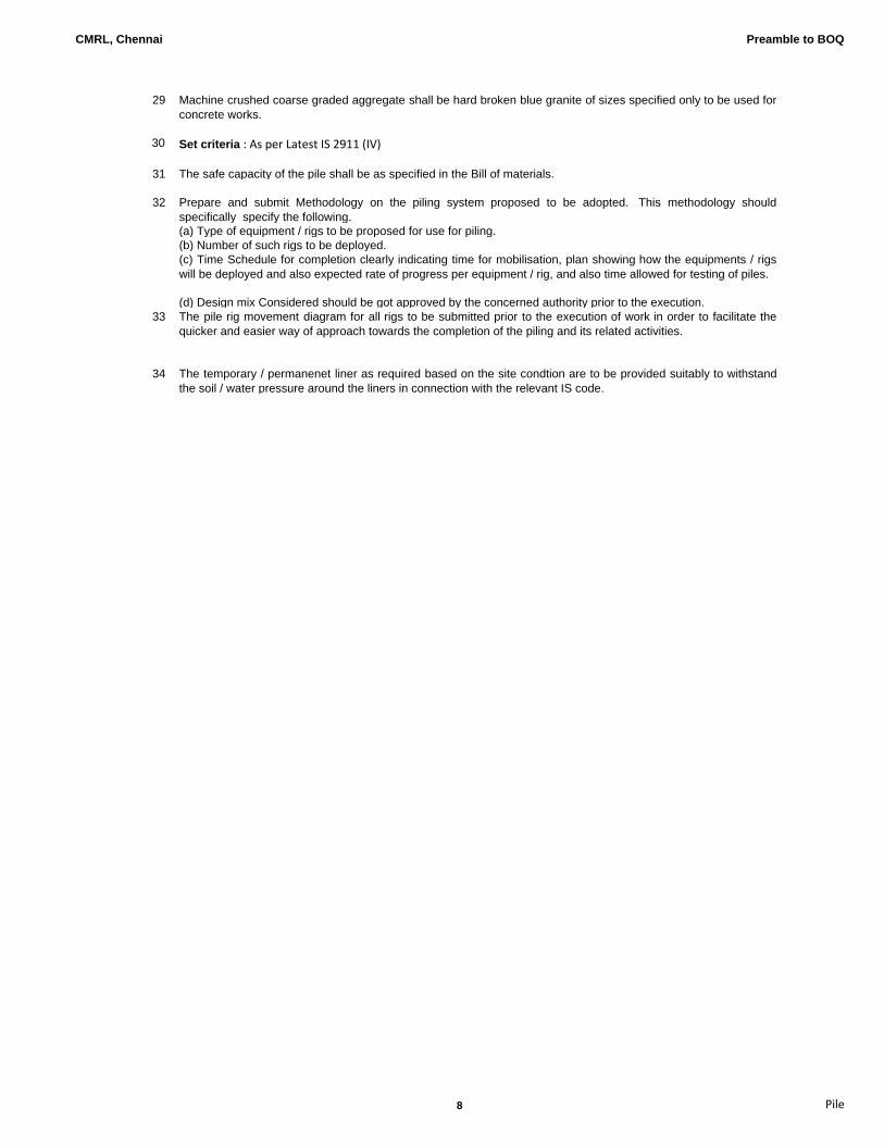
CMRL, Chennai Preamble to BOQ
29 Machine crushed coarse graded aggregate shall be hard broken blue granite of sizes specified only to be used forconcrete works.
30 Set criteria : As per Latest IS 2911 (IV)
31 The safe capacity of the pile shall be as specified in the Bill of materials.
Prepare and submit Methodology on the piling system proposed to be adopted. This methodology shouldspecifically specify the following.(a) Type of equipment / rigs to be proposed for use for piling.(b) Number of such rigs to be deployed.(c) Time Schedule for completion clearly indicating time for mobilisation, plan showing how the equipments / rigswill be deployed and also expected rate of progress per equipment / rig, and also time allowed for testing of piles.
(d) Design mix Considered should be got approved by the concerned authority prior to the execution.33 The pile rig movement diagram for all rigs to be submitted prior to the execution of work in order to facilitate the
quicker and easier way of approach towards the completion of the piling and its related activities.
34 The temporary / permanenet liner as required based on the site condtion are to be provided suitably to withstandthe soil / water pressure around the liners in connection with the relevant IS code.
32
8 Pile
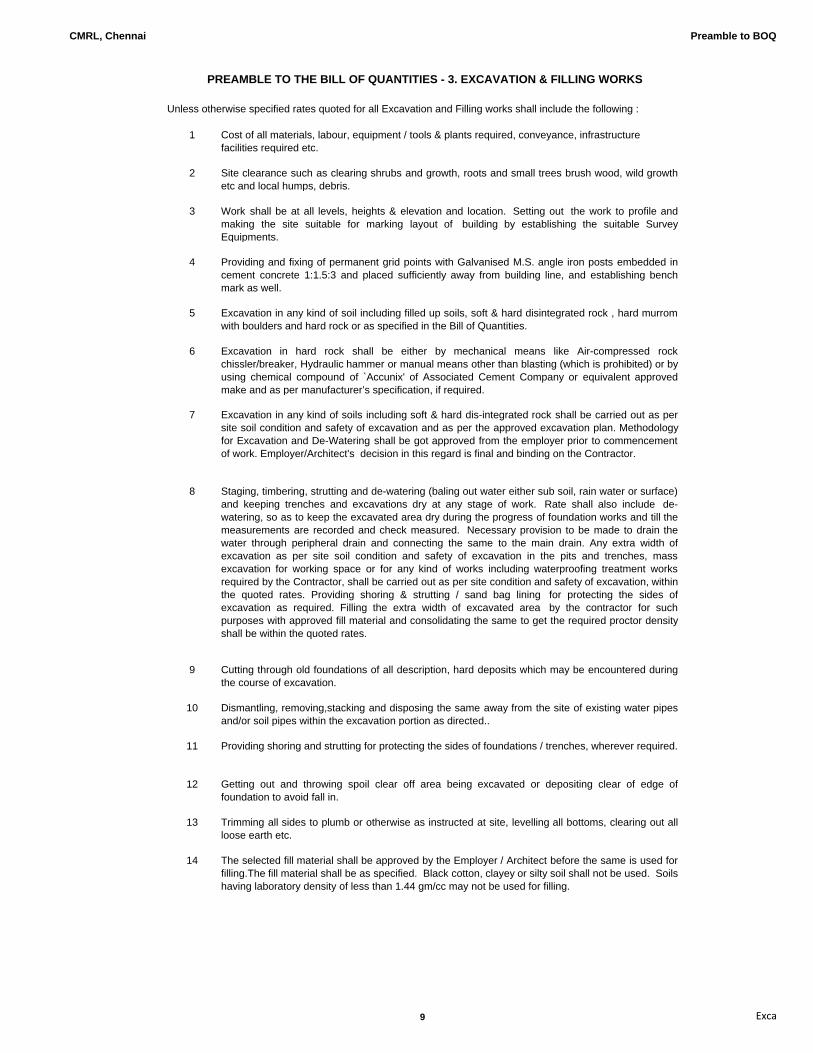
CMRL, Chennai Preamble to BOQ
1 Cost of all materials, labour, equipment / tools & plants required, conveyance, infrastructure facilities required etc.
2 Site clearance such as clearing shrubs and growth, roots and small trees brush wood, wild growthetc and local humps, debris.
3 Work shall be at all levels, heights & elevation and location. Setting out the work to profile andmaking the site suitable for marking layout of building by establishing the suitable SurveyEquipments.
4 Providing and fixing of permanent grid points with Galvanised M.S. angle iron posts embedded incement concrete 1:1.5:3 and placed sufficiently away from building line, and establishing benchmark as well.
5 Excavation in any kind of soil including filled up soils, soft & hard disintegrated rock , hard murromwith boulders and hard rock or as specified in the Bill of Quantities.
6 Excavation in hard rock shall be either by mechanical means like Air-compressed rockchissler/breaker, Hydraulic hammer or manual means other than blasting (which is prohibited) or byusing chemical compound of `Accunix' of Associated Cement Company or equivalent approvedmake and as per manufacturer’s specification, if required.
7 Excavation in any kind of soils including soft & hard dis-integrated rock shall be carried out as persite soil condition and safety of excavation and as per the approved excavation plan. Methodologyfor Excavation and De-Watering shall be got approved from the employer prior to commencementof work. Employer/Architect's decision in this regard is final and binding on the Contractor.
8 Staging, timbering, strutting and de-watering (baling out water either sub soil, rain water or surface)and keeping trenches and excavations dry at any stage of work. Rate shall also include de-watering, so as to keep the excavated area dry during the progress of foundation works and till themeasurements are recorded and check measured. Necessary provision to be made to drain thewater through peripheral drain and connecting the same to the main drain. Any extra width ofexcavation as per site soil condition and safety of excavation in the pits and trenches, massexcavation for working space or for any kind of works including waterproofing treatment worksrequired by the Contractor, shall be carried out as per site condition and safety of excavation, withinthe quoted rates. Providing shoring & strutting / sand bag lining for protecting the sides ofexcavation as required. Filling the extra width of excavated area by the contractor for suchpurposes with approved fill material and consolidating the same to get the required proctor densityshall be within the quoted rates.
9 Cutting through old foundations of all description, hard deposits which may be encountered duringthe course of excavation.
10 Dismantling, removing,stacking and disposing the same away from the site of existing water pipes
and/or soil pipes within the excavation portion as directed..
11 Providing shoring and strutting for protecting the sides of foundations / trenches, wherever required.
12 Getting out and throwing spoil clear off area being excavated or depositing clear of edge offoundation to avoid fall in.
13 Trimming all sides to plumb or otherwise as instructed at site, levelling all bottoms, clearing out allloose earth etc.
14 The selected fill material shall be approved by the Employer / Architect before the same is used forfilling.The fill material shall be as specified. Black cotton, clayey or silty soil shall not be used. Soilshaving laboratory density of less than 1.44 gm/cc may not be used for filling.
PREAMBLE TO THE BILL OF QUANTITIES - 3. EXCAVATION & FILLING WORKS
Unless otherwise specified rates quoted for all Excavation and Filling works shall include the following :
9 Exca

CMRL, Chennai Preamble to BOQ
15 Filling in foundations and in plinth in layers not exceeding 150 mm, watering, consolidation,dressing etc. complete and include for all lifts and leads, transport from stacks, rehandling etc.
16 Filled earth shall be watered and compacted by power roller or any other approved mechanicalmeans or adequate capacity to achieve the required minimum proctor density of 95% to 98 %.
17 Top layer of filling shall be brought to the specified line, levels grade and to the required proctordensity and as directed.
18 Disposing of excavated earth as directed and dressing to proper level and grade as required or bytransporting out of site to dumping ground legally approved by local authorities at no extra cost.
19 Taking necessary precautions to prevent spillage of disposable earth during transport.
20 Removal of excavated earth out of the premises shall be done simultaneously during the excavation stage itself due to paucity of working space.
21 Supplying of utility services as directed and providing guard lights and Guard railing for trencheswherever required.
22 Wherever the double handling of excavated earth is required, the place of deposit should bedecided in the first instance and to be deposited as directed.
23 Excavation will be measured on the basis of the horizontal area of open mass excavation at thebase for raft slab or any other structures to be built. The actual depth of excavation will be arrived atas the difference between the spot levels taken at existing ground level prior to excavation at aspacing of 3m intervals in both directions and the final bottom level of founding level as perdrawings.Quoted rate shall include cost of excavation of working space as required, slopes andberms as per site soil condition/nature of the site soil and safety of excavation.Rate shall alsoinclude for refilling the such excavation of working space with approved filling Material includingconsolidating to the required proctor density.Quoted rate shall be deemed to have considered theabove stipulation.
24 Excess excavation if any, in horizontal direction shall be filled with concrete of Grade 1:2:4, on priorapproval by the Employer/Architect for making up the excavated area to the required level at noextra cost. Any other means of filling shall not be allowed.
25 Cement for all works shall be High strength ordinary portland cement 53 grade shall be used.
26 Tests on materials shall conform to IS Specification and the test shall be carried out as directedeither at site Laboratory or at any approved test laboratory.
27 The method statement shall include all safety features and protection to workmen, thitrd party aswell as property and services nearby. Methods of shoring and struting should be fully detailed in themethod statement.Removal of excavated material from excavated area,method of handling,methodof storage( including double handling if necassary) as well as disposal shall be explained fully.Where controlled blasting resircted to,the contractor should ensure that all necassary statutoryapprovals are obtained in advance and kept in current and all necassary insurance and othercovers shall be taken and kept valid in the case of sub-contracting this job,such cover shall includesub-contractor's workman also.Where controlled blasting is resorted to, contractor should take allnecasry precaution for ensuring safety of life end property in the visinity.Suitable barigading,warningsystems, sand cushing,heavy duty protection in the blast area shall be under contractorsresponsibility.
The contractor shall note that surrounding buildings are fully occupied and are in operation and assuch, all possible special preacautions shall be taken care, where for any special reason, controlledblasting is permitted,alternative and equally efficient excavation methods shall be adopted withoutcost for delay.Multiple handling of excavated materials shall be taken into account in view ofrestricted area availabe for contruction.No extra claim for payment are additional time will beaccepted on account of failure to take into account the above factors prior to quoting.
28 Excavated material to be carted away to the dumping yard as shown by the Employer / EmployersRepresentative and to be levelled uniformly as directed.
10 Exca

CMRL, Chennai Preamble to BOQ
1 Cost of all materials, labour, equipment / tools & plants required, conveyance, toll charges if anyinfrastructure facilities required etc..
2 Work shall be at all levels, depth and location.
3 All equipments ,employed, tools, tackles etc.
4 Treatment to all areas required to be treated at any depth & level in the sequence includingtrenches, pits and tunnels etc.
5 Making holes, providing nozzles and injecting etc.
6 Treatment should be carried out by an approved specialised pest control agency on prior approval.
7 Treatment should be carried out generally in accordence with the technical specification andconfirming to IS 6313.
8 The chemical to be used as insecticide for the treatment shall be Biflex Tc, TC stands forTermiticide Concentrate for Termite Control (Bifenthrin) and the application shall be diluted 1 part ofchemical Biflex Tc with 49 parts of water to get 0.05% emuls
9 Connected civil work such as cut-open the surface for treatment, insertions like nozzles at requireplaces. Protecting the treated surface and other works in progress and redoing in case of anydamage.
10 The description and specification for treatment contained in the Bill of Quantities is indicative onlyand is meant to set out a general outline of the Proprietary system as commonly understood. Theeventual requirement is performance oriented to achieve
11 Anti-termite treatment shall be guaranteed for a period of 10 (Ten) years in an approved proformaacceptable to the Employer on a stamp paper.
12 Material Safety Data Sheet to be submitted and approved prior to use at site.
13 The final claim of the contractor will be released after submission of powercard of perimeter ofbuilding .
Unless otherwise specified, the rates quoted for Anti-Termite treatment shall include the following :
PREAMBLE TO THE BILL OF QUANTITIES - 4. ANTI - TERMITE TREATMENT WORKS.
11 Anti‐ter
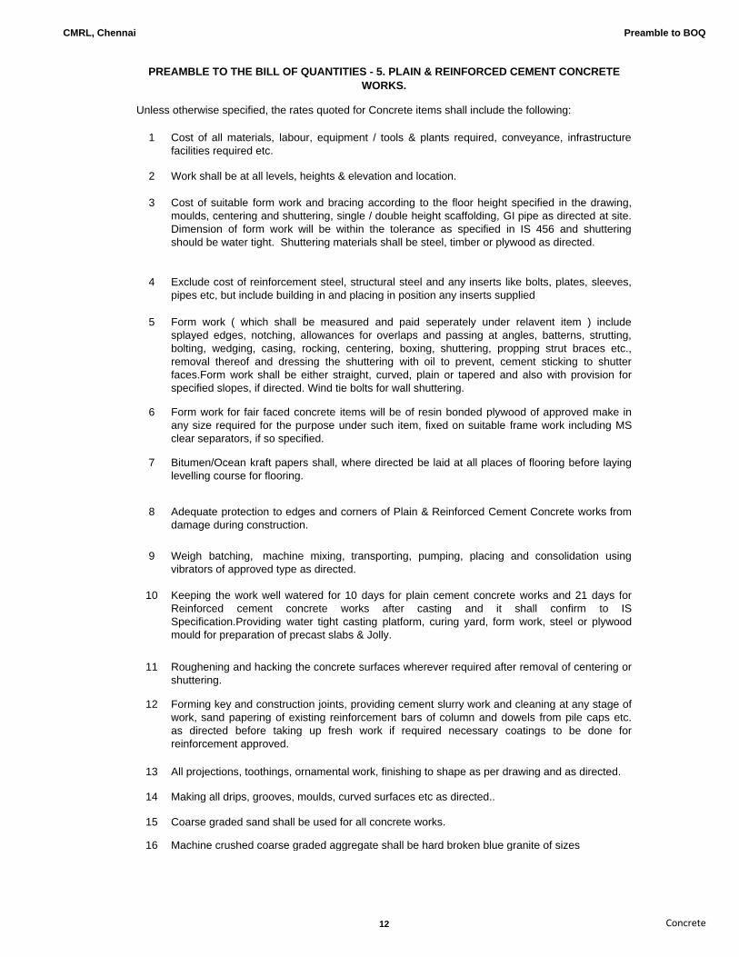
CMRL, Chennai Preamble to BOQ
1 Cost of all materials, labour, equipment / tools & plants required, conveyance, infrastructurefacilities required etc.
2 Work shall be at all levels, heights & elevation and location.
3 Cost of suitable form work and bracing according to the floor height specified in the drawing,moulds, centering and shuttering, single / double height scaffolding, GI pipe as directed at site.Dimension of form work will be within the tolerance as specified in IS 456 and shutteringshould be water tight. Shuttering materials shall be steel, timber or plywood as directed.
4 Exclude cost of reinforcement steel, structural steel and any inserts like bolts, plates, sleeves,pipes etc, but include building in and placing in position any inserts supplied
5 Form work ( which shall be measured and paid seperately under relavent item ) includesplayed edges, notching, allowances for overlaps and passing at angles, batterns, strutting,bolting, wedging, casing, rocking, centering, boxing, shuttering, propping strut braces etc.,removal thereof and dressing the shuttering with oil to prevent, cement sticking to shutterfaces.Form work shall be either straight, curved, plain or tapered and also with provision forspecified slopes, if directed. Wind tie bolts for wall shuttering.
6 Form work for fair faced concrete items will be of resin bonded plywood of approved make inany size required for the purpose under such item, fixed on suitable frame work including MSclear separators, if so specified.
7 Bitumen/Ocean kraft papers shall, where directed be laid at all places of flooring before layinglevelling course for flooring.
8 Adequate protection to edges and corners of Plain & Reinforced Cement Concrete works fromdamage during construction.
9 Weigh batching, machine mixing, transporting, pumping, placing and consolidation usingvibrators of approved type as directed.
10 Keeping the work well watered for 10 days for plain cement concrete works and 21 days forReinforced cement concrete works after casting and it shall confirm to ISSpecification.Providing water tight casting platform, curing yard, form work, steel or plywoodmould for preparation of precast slabs & Jolly.
11 Roughening and hacking the concrete surfaces wherever required after removal of centering orshuttering.
12 Forming key and construction joints, providing cement slurry work and cleaning at any stage ofwork, sand papering of existing reinforcement bars of column and dowels from pile caps etc.as directed before taking up fresh work if required necessary coatings to be done forreinforcement approved.
13 All projections, toothings, ornamental work, finishing to shape as per drawing and as directed.
14 Making all drips, grooves, moulds, curved surfaces etc as directed..
15 Coarse graded sand shall be used for all concrete works.
16 Machine crushed coarse graded aggregate shall be hard broken blue granite of sizes
PREAMBLE TO THE BILL OF QUANTITIES - 5. PLAIN & REINFORCED CEMENT CONCRETE WORKS.
Unless otherwise specified, the rates quoted for Concrete items shall include the following:
12 Concrete

CMRL, Chennai Preamble to BOQ
17 Cement for all concrete works shall only be High strength ordinary portland cement Grade-43.
18 Cement Grade 53 shall be used only for the items so specified within the Quoted Rates.Cement - Ordinary Portland Cement 53 grade conforming to IS: 269, shall be used for allReinforced Cement Concrete works and Portland Pozzalona Cement conforming to IS: 1489for Plain cement concrete works, masonry, plastering and any such other works. In general flyash based cement shall not be used for RCC works.Water used for concrete shall conform to the requirement of IS: 456.
19 Minimum cement content for specified design mix shall be in accordance with specification.Minimum cement content will be the same as specified in the Technical specificationIrrespective of grade of cement used.
20 Designing the concrete mix and batching as per specifications, wherever design mix isspecified and approved, if so directed.
21 Use of weighbatch equipment for design mix concrete and machine mixed and mechanicallyvibrated on placement in position as directed.
22 Providing Ready Mix concrete from approved source conforming to Specification & standards.
23 Adding of admixture to increase the workability and consistancy in the concrete as slumpretarder as per manufacturer’s specification wherever required and applying admixture /bonding agent to increase the bonding between the old & New concrete and at Constructionjoints as per manufacturer’s specification wherever required, on prior approval at no extra cost.
24 Limiting the temperature of concrete to the required level as directed, wherever required undersuch item and if so specified on prior approval.
25 Providing sunk floors, pockets, cutouts, holes and larger size openings for security doors asalso concreting them after the doors are held in position, including grouting of hold fasts, underthe supervision and instructions of security contractors.
26 Embedding electrical conduits, junction boxes, fan hooks, cutout boxes and other inserts,sleeves hold fasts, pipes etc.
27 Necessary spacer blocks made out of plain cement concrete 1:2:4 or cement mortar 1: 4 to beprovided to prevent the displacement of reinforcement and also to maintain the requireddimension, if required..
28 No finishing item is to be considered in quoting the rates for plain cement concrete works &Reinforced cement concrete works, if so specified.
30 Taking test cubes for all concrete items and testing them as specified in IS 456 at the sitelaboratory to be set up with proper equipment etc. and other regular test shall be carried out asdirected either at site Laboratory or at any approved test laboratory.
13 Concrete

CMRL, Chennai Preamble to BOQ
31 Tenderer shall ensure that they have adequate quantity of shuttering and suitable proppingmaterials according to the floor height specified in the drawing to keep up the requiredConcreting cycle per floor as set out in the Tender Documents, Drawings and tentative Barchart enclosed. They shall also ensure that the de-shuttering sequence with proper propping,taking into account the Construction Loading of the upper slabs, as set out in the TenderDrawings, is also kept up.Scheme to maintain the props shall ensure that main supports arenot disturbed.Reproping by means of removal and reintrodusing of props is not allowed.
De-shuttering and re-propping scheme shall be such that any undue loading on the structure isavoided at all times. On award of contract, the scheme must be submitted by the contractoralong with submission of the CPM / PERT to the Architect / Owner’s Engineer for necessaryapproval.No extra charge will be allowed to the Contractor for all above such works
32 Any tenderer who proposes any innovative or special propping according to the floor heightspecified in the drawing, shuttering and de-shuttering methodology maintaining the requiredConcreting cycle per floor shall furnish comprehensive and complete details of the same alongwith tender submission.
33 After deshuttering the repropping to be done without any extra cost.
14 Concrete

CMRL, Chennai Preamble to BOQ
1 Cost of all materials, labour, equipment / tools & plants required, conveyance, infrastructure facilitiesrequired etc..
2 Work at any depth below ground level or any height above ground level and at all levels, heights &elevation and location.
3 All double height scaffolding, ladders, platforms, staging and plant required in the execution of work toany height and depth.
4 Best quality well chamber burnt moulded bricks conforming to IS 1077 and with minimum compressivestrength of 50 Kg/Sqcm only shall be used on the masonary work.
5 Brick work shall conform to IS 2212.
6 Hacking and roughening of concrete or other surface in contact with masonry for proper bondage.
7 All work in narrow widths, curved or straight as per drawing and as directed.
8 Provision for drip moulds, projections and architectural mouldings etc. and excludes RCC mullions,panels and stiffeners to be provided in Masonry work.
9 Embedding in Galvanised M.S. holdfasts in Plain cement concrete 1:1.5:3 blocks, coach screws,anchor fasteners and such other inserts, including chasing, grouting,curing etc..
10 Fix in position electrical conduits, cut-outs, and with chasing wherever necessary.
11 Raking out joints to specified depth either for plastering or pointing.
12 Levelling up and preparing top of masonry for damp proof course.
13 Keeping the work well wetted for two weeks or necessary dates or identification marks to be mentionedon the necessary walls for curing.
14 Providing key stones to any thickness of walls as required in block masonry.
15 Tests on bricks/block/ or any other masonry items as directed, conforming to IS Specification shall becarried out as directed either at site Laboratory or at any approved test laboratory.
16 Providing water tight casting platform, curing yard, form work, steel or plywood mould for preparation ofprecast blocks.
17 Conveyance of all materials to the required places.
18 Solid / Hollow block to any size shall conform to IS : 2185 and confirming to :A. Solid Block :1. Size of Block :400x200 mm - 100 mm thick400x200 mm - 200 mm thick400x200 mm - 300 mm thick2.Dimension tolerance: Length of the units - Not morethan (+) or (-) 5 mm.Height & width of the units - Not morethan (+) or (-) 3 mm.3.Percentage of solids - Not less than 75%4.Weight of a block in Kg.
Unless otherwise specified, the rates quoted for items under masonry work shall include the following :PREAMBLE TO THE BILL OF QUANTITIES : 6. MASONRY WORKS
15 Masonry

CMRL, Chennai Preamble to BOQ
400x200 mm - 100 mm thick - Not less than 14.4 Kg.400x200 mm - 200 mm thick - Not less than 28.8 Kg.400x200 mm - 300 mm thick - Not less than 43.2 Kg.5.Yard dry density in Kg/Cum - not less than 1800 Kg/Cum.6. Water Absorption - 5 to 6 %7. Compressive Strength - not less than 5 N/Sq.mm conforming to BOQ Specification.8. Thermal resistance - .38 to .33 Sq.mm9. Estimated sound - 46 to 58 Db.
B. Hollow Blocks :1. Size of Block :400x200 mm - 100 mm thick400x200 mm - 200 mm thick400x200 mm - 300 mm thick2.Dimension tolerance Length of the units - Not morethan (+) or (-) 5 mm.Height & width of the units - Not morethan (+) or (-) 3 mm.3.Percentage of solids - 55%4.Weight of a block in Kg.400x200 mm - 100 mm thick - Not less than 12 Kg.400x200 mm - 200 mm thick - Not less than 24 Kg.400x200 mm - 300 mm thick - Not less than 36 Kg.5.Yard dry density in Kg/Cum - Not less than 1500 Kg/Cum.6. Water Absorption - 5 to 6 %7. Compressive Strength - not less than 5.5 N/Sq.mm conforming to BOQ Specification. Compressive Strength - not less than 3.5 N/Sq.mm conforming to BOQ Specification.8. Thermal resistance - .38 to .33 Sq.mm9. Estimated sound - 46 to 58 Db.
19 Providing reinforced cement concrete binder in 1:1.5:3 - 80mm thick with reinforcement steel of Fe 415 -8 mm dia. 3 Nos.at bottom & 2 Nos at top and 6mm dia Mild steel stirrups at 200mm centres inhorizontal direction for Half brick masonry wall - 115mm thick at 1000mm intervals under the respectiveBOQ item.
20 Providing reinforced cement concrete binder in 1:1.5:3 - 80mm thick with reinforcement steel of Fe 415grade - 8 mm dia. 3 Nos.at bottom & 2 Nos at top and 8mm dia at 1000mm intervals stirrups at 200mmcentres in horizontal direction for Solid / Hollow block masonry wall - 100 /150 mm thick under therespective BOQ item.
21 At the junction of Hollow block or brick masonry a bearing block of concrete or intervening brick inmortar courses shall have to be introduced wherever required including nominal reinforcement.
22 Cement used for all Masonry works shall be High strength ordinary portland cement Grade 43.
23 Coarse graded sand shall be used for mortars in all masonry works.
24 Machine crushed coarse graded aggregate shall be hard broken blue granite of sizes specified only tobe used for concrete works.
16 Masonry
CMRL, Chennai Preamble to BOQ
1 Cost of all materials, labour, equipment / tools & plants required, conveyance, infrastructurefacilities required etc..
2 Work at any depth below ground level or any height above ground level and at all levels,heights & elevation and location.
3 All reinforcement steel shall be the Grade of Fe 500 CRS or Fe 500 or Fe 415 or Mild steel.In General, Mild steel conforming to IS 432 and HSD(High yield strength deformed) twistedbar conforming to IS 1786 and shall be used as specified elsewhere in the bills of materials.
4 Cutting and waste, straightening, bending, hoisting, fixing, supporting in position usingprecast plain cement concrete 1:2:4 spacer blocks and tying with approved binding wiremade out of no 18 gauge G.I. annealed and welding with electrodes for lapping the rodswherever required. All welding with electrodes shall be in accordance with IS.
5 Unless otherwise noted in the bills of Quantities, method of measurements shall be generally
in accordence with IS 1200. Reinforcement shall be measured only in lengths of bars asactually placed in position on standard weight basis, no allowance being made in the weightfor rolling margin. Authorised laps and splices only will be measured. Chairs of any shape &profile, Spacer bar of any shape & profile, cover block, wastage and binding wire will not bemeasured and shall be included in the quoted rates.
6 All materials supplied shall be free from manufacturing defects and defective workmanshipand guaranteed. Any defects noticed shall be made good at no extra cost.
7 Steel doors and Steel casement windows and ventilators, including all its fittings, shall bemanufactured to conform to IS 1038 and IS 7452.
8 Appropriate sections having the specified weight characteristics only shall be used for theframes and shutters.
9 Shutters of all Doors, windows and ventilators shall be as per drawing and as approved.
10 Projecting type stainless steel hinges / pivot hinges must be provided for all side hung
11 Providing and fixing all joinery hardware fittings like floor spring, mortice lock, cylindrical lock,door closer, handle, hinges of approved make and ISI mark.
12 All the members shall be finished with one coat of Anti- corrosive primer/ Zinc chromate /Zinc phosphate primer after through cleaning of the surface to remove rust/scale, oil etc., inaccordance with relavant I.S standards and specifications. Extra coat of painting shall begiven to obtain uniform and good finish and extra putty shall be applied to ensure uniformand smooth finish, if directed.
13 Fittings supplied shall be sturdy and samples of all fittings shall be got approved before
PREAMBLE TO THE BILL OF QUANTITIES : 7. IRON AND STEEL WORKS
Unless otherwise specified, the rates quoted for items under Reinforced steel Iron works shall include the following:
17 Iron & Steel
CMRL, Chennai Preamble to BOQ
14 Workmanship and finish of the Doors, windows, ventilators and fittings should be as perapproved standards and confirming to IS specification.
15 All hardware fittings such as Pegstays with screws, Standard Handles, Spring, catches, lugswith suitable screws, Glazing clips, Transomes, Mullions, Coupling bars, Weathering bars,where necessary Cast aluminium alloy or pressed steel stove enameled wrinkle finish.
16 Supply of hardware fittings like coupling, mullions, and additional fixing like clamps, bolts,nuts, washers etc., for continuous fastening of windows / structural steel members.
17 Fabrication of Doors, windows and ventilators shall be in all respects including all associatedcosts upto delivery at site.
18 Erection of fabricated Doors, windows and ventilators shall be placed in position includinglifting, jointing and painting as specified in the bills of quantities.
19 All welding with electrodes used for fabrication shall be in accordence with IS specificationand as approved.
20 Tests on materials shall conform to IS Specification and the test shall be carried out asdirected either at site Laboratory or at any approved test laboratory.
21The delivery material with manufacture's test certificate to be submitted.The randomsupplying lab test to be done.
18 Iron & Steel
CMRL, Chennai Preamble to BOQ
1 Cost of all materials, labour, equipment / tools & plants required, conveyance, infrastructurefacilities required etc..
2 Work at all levels, heights & elevation and location.
3 All scaffolding, ladders, platforms, staging and plant required in the execution of work to anyheight and depth.
4 Final preparation of base sub-grade or sub-floor by cleaning of all dust/dirt, loose particles,caulked mortar dropping by scrubbing with coir or steel wire brushes, caulking etc.Roughening surface if so directed, cleaning with water and keeping surface wet for 12 hoursand removing surplus water by mopping before topping is laid and minor trimming of the base toremove undulations.
5 Cleaning, preparation of surface and watering immediately before laying the floor as directed.
6 Providing bedding layer of mortar for flooring / skirting / dadoing / steps shall be as specified inbills of materials either in the case of slabs or tiles, etc. to correct levels and gradients as calledfor.
7 Cutting, rubbing and polishing where applicable (both machine and hand) including grinding,rubbing, acid cleaning, wax and tin-oxide polishing etc.
8 Keeping the surface wet for a minimum period of one week.
9 Providing all Marble and granite slab / tile flooring, skirting, dadooing with neat white cementslurry coat to the required thickness over bed mortar before laying the slab/tile. All claddingworks in marble and granite slab/tile etc,shall be provided with requisite brass / gun metal clamps/ stainless steel clamps and keys in required sizes and pattern. Unless noted otherwise in the bills of materials brass / gun metal clamps / stainless steel clampsand keys shall be suitably designed to the requirement of internal wall cladding and to bedesigned to the specified wind pressure in the case of external wall cladding.
10 Providing vitrified ceramic tile,ceramic tile, glazed tile flooring with the clamps bedding layer ofmortar as specified in the bill of quantities .
11 Providing vitrified ceramic tile, ceramic tiles glazed tile skirting and dadoing with bedding layer ofmortar as specified in the bill of quantities or with bedding layer of "ROFF TILE” Water proof TileAdhesive or equivalent "Laticrete product" for fixing and pointing shall have ‘Roff Tile – JointFillers’ or equivalent "Laticrete product" of approved shade and colour as per Manufacturer'sSpecification.
12 All vitrified ceramic tile, ceramic tile, glazed tile skirting and dadoing shall have final light acidcleaning, as directed.
13 Work in jambs, soffits and sills of openings in Lift entrance/ Main entrance shall be arranged tomatch with the surrounding finishes and as directed.
14 Formation of vertical grooves on vertical surfaces and provision of mortar bed of requiredthickness to achieve proper level/slope.
Unless otherwise specified, the rates quoted for items under Flooring works shall include the following :
PREAMBLE TO THE BILL OF QUANTITIES - 8. FLOORING WORKS
19 Flooring

CMRL, Chennai Preamble to BOQ
15 Provision in small quantities, narrow width, mitred and returned ends, sinking, risers, set back andany other sundry items for cutting, fixing, making good upto and which may be required forforming base.
16 Any additional mortar or concrete required to bring the surface to the required level and gradientbefore laying the base mortar at no extra cost.
17 Machine crushed coarse graded aggregate shall be hard broken blue granite of sizes specifiedonly to be used for concrete works.
18 Cement used for all flooring works shall be High strength ordinary portland cement Grade- 43.
19 Coarse graded sand shall be used for mortars in all flooring works.
20 Tests on materials shall conform to IS Specification and the test shall be carried out as directedeither at site Laboratory or at any approved test laboratory.
21
The contractor should protect the entire area which is executed under his control and coveredwith necessary protection and supervision. If any damages occurred should be rectified withoutany extra cost until handing over.
20 Flooring

CMRL, Chennai Preamble to BOQ
1 Cost of all materials, labour, equipment / tools & plants required, conveyance, infrastructurefacilities required etc..
2 Work at any depth below ground level or any height above ground level and at all levels, heights &elevation and location.
3 Works internally and externally at any heights and in any position or shape as directed..
4 Providing scaffolding, staging, working platforms, ladder, plants etc., as required and removal of thesame after completion of the work.
5 Hacking and for bush hammering to form key for plaster and for better dash treatment as and wherenecessary.
6 All work in narrow width haunching chamfered drips external angles, drip moulds to chajjas,balcony, parapet projections etc.
7 Providing and fixing a layer of GI chicken mesh (Double folded) to a required width at the junctionsof concrete and brick work before plastering and curing the works.
8 Providing and fixing GI corner beads of ARPITHA EXPORTS or equivalent in all edges of plasteringand isolated column, column projections everywhere.
9 Providing plaster grooves wherever different materials are used and at junctions of RCC membersand masonry works both in ceiling and on walls and the junctions at wall & openings,as directed.
10 Hacking or roughening concrete surface, ceilings or masonry surface by raking out joints, preparingand wetting the surface to receive the plaster / paint and curing etc. complete.
11 Holes on the walls shall not be made to provide support to the single scaffolding, staging,working platform etc.
12 Different grades of coarse sand required for use of work including sieving sand to get the required grade of sand.
13 Making the surface well watered and thoroughly soaked for atleast 12 hours prior to plastering.
14 Keeping the plastered surfaces wet continuously for a period of 7 days after the completion of the item in any area by proper spraying of water and necessary identification to be done.
15 Neat finishing of junctions of plaster at the junctions of skirting, dadooing and cladding works.
16 Washing floors, cleaning of glass, aluminium works, aluminium composite Panel, flooring works, cladding works shall be carried out to ensure the premises is clean and tidy after completion of plastering and painting works.
17 Work in jambs, soffits and sills of openings shall be carried out as directed.
Unless otherwise specified, the rates quoted for items under Internal & External finishes shall include the following:
PREAMBLE TO THE BILL OF QUANTITIES : 9. INTERNAL & EXTERNAL FINISING WORKS.
21 Int & Ext finish

CMRL, Chennai Preamble to BOQ
18 Providing plaster in small areas & quantities, narrow width, mitred and returned ends, sunken areas,risers, making the surface good upto and which may be required for forming good finish. Anyadditional plaster required to bring the surface to the required level and plumb shall be carried outat no extra cost.
19 Tests on materials shall conform to IS Specification and the test shall be carried out as directedeither at site Laboratory or at any approved test laboratory.
20 Cement used for all finishing and plastring works shall be High strength ordinary portland cementGrade- 43.
21 Paint shall be applied as per the specification and to Manufacturer’s specification & instructions.
22 Curing, protecting the painted surface, adjacent work and thoroughly cleaning of the premises.
23 Paint shall be ready mixed and of first quality of the approved brand and manufacturer. The paintshall generally conform to the chemical composition and other characteristics laid down in therelevant Indian standard specification.
24 Mixing of paint by the Contractor at site will not be allowed.
25 In the case of selection of special shades and colours (not available standard shades), theContractor shall mix different shades of ready mixed paints at approved place and as perManufacturer’s instructions.
26 Materials shall be the highest grade products of well known approved manufacturers. It is desiredthat materials of one manufacturer only shall be used as far as possible and paint of one shade beobtained from the same manufacturing batch. All paints shall be subjected to analysis from randomsamples taken at site from the painter’s bucket, if so desired.
27 Any materials found not conforming to the relevant specification shall have to be removed by theContractor from the site at no extra cost.
28 All primer coats shall be compatible to the material of the surface to be finished as well as to thefinishing coats to be applied.
29 Lime for white washing shall be pure shell lime or fat lime, or a mixture of both and shall conform toIS:712 and approved lime shall be brought to site in an unslaked condition.
30 Synthetical enamel paint shall be in a smooth, hard, durable and glossy finish to all exterior andinterior surfaces and it shall conform to IS:2932 and IS:2933.
31 Waterproof Cement Paint Shall conform to IS:5410.
32 Dry distemper of required colour conforming to IS:427.The primer where used shall be cementprimer or distemper primer of same manufacturer as that of distemper.
33 Acrylic Emulsion Paint Shall be in accordance with the specification. The paint should be able towithstand washing with mild soap and water without any deterioration in colour or without showingflaking, blistering or peeling after its dried.
34 Oil bound distemper shall confirm IS:428. The primer where used be cement primer or distemperprimer of same manufacturer as that of distemper. The distemper shall be diluted with prescribedthinner in a manner recommended by the manufacturer.
22 Int & Ext finish
CMRL, Chennai Preamble to BOQ
35 Chemical resistant paint shall confirm IS:157 and the primer coat shall be used as permanufacturer’s specifications.
36 Fire resisting paint (silicate type & waterbased) shall confirm IS:162 and and the primer coat shallbe used as per manufacturer’s specifications.
37 Oil resistant paint shall confirm IS:161 and and and the primer coat shall be used as permanufacturer’s specifications.
38 French polish shall be an approved make conforming to IS : 348.
39 Concrete / masonry surface and cement plastered surfaces shall be thoroughly cleaned of mortardroppings and other stickings. All loose scales and flakes shall be removed by rubbing withhessian cloth or sand papering. All holes shall be filled and the surface rubbed smooth to getevenness of the existing surface. The surface shall be free from all oil, grease, efflorescence,mildew, loose paint or other foreign and loose materials. Masonry cracks shall be cleaned out andpatch filled with mortar similar to the original surface and uniformly textured. Where this type ofresurfacing may lead to the finishing paint being different in shade from the original surfaces, theresurfaced area shall be treated with a minimum of one coat of cement primer and should becontinued to the surrounding area for a distance of atleast 100mm.
40 Painting work on wood, steel and iron surface shall conform to IS : 1477 and one shop coat of redoxide or zinc chromate primer or as specified shall be given to all iron surfaces. Preparation ofsurface by sand papering in the case of wood works and wire brushing/sanding or chemical removalof rust and scaling in the case of steel work.
41 All primer coats shall be compatible to the material of the surface to be finished as well as to thefinishing coat to be applied.
42 No painting shall be done when plastering is in progress or is drying. Paint which seals the surfacesto moisture shall be applied only after the moisture on and below the surface has dried out.
43 All coats shall be thoroughly dry before being sand papered or before the succeeding coat isapplied. Coats of painting as specified are intended to cover surfaces perfectly. In case the surfaceis not covered properly by applying the specified number of coats, further coats shall be applied bythe Contractor when so directed by the Engineer at no extra cost.
44 All parts of mouldings and ornaments shall be left clean and true to finish after completion of
45 Stopping and filling carpentry work should be carried out when the primer is just dry. Providingdeep scratches,holes,stopping with putty of plastic wood confirming to IS 423. The putty shall bewhite lead with linseed oil base or synthetic metal putty.
46 Providing filling to the all minor scratches and rough surfaces, like flush door’s faces shall be madeout of one part of white lead, two parts of whiting (powdered chalk) mixed and kneaded in doubleboiled linseed oil shall be evenly applied and rubbed down with G/220 or G/240 sand paper afterallowing it to dry .
47 Painting shall be done by skilled labourers in a workmanlike manner. All materials shall be evenlyapplied so as to be free from sags, runs, crawls, or other defects. All coats shall be of properconsistency and shall be well brushed out, so that no brush marks are visible, except varnish andenamels which shall be uniformly flowed on. The brushes shall be clean and in good conditionbefore application of paint.
23 Int & Ext finish

CMRL, Chennai Preamble to BOQ
48 Ready mixed synthetic enamel paint or fill paint may be used for the undercoat. The undercoatingshould be nearest to the specified colour of the finishing coat and shall be uniform and free of allbrush marks.
49 Undercoats should be completely dry before finishing coat is taken up. For synthetic enamelsovernight and for oil paints, a whole day shall be left between undercoat and finishing coat. Theundercoat shall then be rubbed with G/240 sand paper and dusted clean. The finishing coat ofapproved paint shall then be applied. If the surface is not satisfactory additional finish coats shallbe applied at no extra cost. The paints shall be applied with bristle brushes and not horse hairones.
50 When the final coat is applied, if directed, the surface shall be rolled with a roller or if directed itshall be stippled with a stippling brush.
51 All painted surfaces shall be uniform and pleasing the appearance.The colour, texture etc. shallmatch exactly with approved samples. All stains, splashes and splatters of paint shall be removedfrom surrounding surfaces.
52 Ceiling of basement floor is not intended to be plastered but finished under form finish with neatcement wash only. Hence, shuttering must be of such type that uniform and level finish is obtainedwithout requiring plastering.However rate shall include neat cement wash. Cost to include deburringof shuttering joints and ensuring smooth finish as directed.
24 Int & Ext finish

CMRL, Chennai Preamble to BOQ
GENERAL NOTES:
1 All items of work under this Contract shall be executed strictly to fulfill the requirements laid down under “Basis of Design” inthe specifications. Type of equipment, material specification, methods of installation and testing and type of control shall bein accordance with the specifications, approved shop drawings and the relevant Indian Standards, however capacity of eachcomponent and their quantities shall be such as to fulfill the above mentioned requirement.
2 The unit rate for all equipment or materials shall include cost in INDIAN RUPEES (INR) for equipment and materialsincluding all taxes and duties and also including forwarding, freight, insurance and transport into Contractor’s store at site,storage, installation, testing, balancing, commissioning and other works required.
3 The rate for each item of work included in the Schedule of Quantities shall, unless expressly stated otherwise, include costof:
a All materials, fixing materials, accessories, appliances tools, plants, equipment, transport, labour and incidentals required inpreparation for and in the full and entire execution, testing, balancing, commissioning and completion of work called for inthe item and as per Specifications and Drawings.
b Wastage on materials and labour.
c Loading, transporting, unloading, handling/double handling, hoisting to all levels, setting, fitting and fixing in position,protecting, disposal of debris and all other labour necessary in and for the full and entire execution and for the job inaccordance with the contract documents, good practice and recognized principles.
d Liabilities, obligations and risks arising out of Conditions of Contract.
e All requirements of Specifications, whether such requirements are mentioned in the item or not. The Specifications andDrawings where available, are to be read as complimentary to and part of the Bill of Quantities and any work called for inone shall be taken as required for all.
f In the event of conflict between Bill of Quantities and other documents including the Specifications, the most stringent shallapply. The interpretation of the Architect / Consultant /Project Manager shall be final and binding.
4 The Contractor shall procure and bring Materials/Equipment to the site only on the basis of drawings approved forconstruction and shop drawings and not on the basis of Bill of Quantities which are approximate only. This also applies tothe Contractor’s requisition for Owner supplied materials.
5 The contractor shall include for making all the opening in slabs, beams, walls etc. as required for his work. However, thecontractor can coordinate with civil work to provide necessary sleeves. All openings shall be closed using water proofingcompound or as specified by Employer / Employer's representative.
6 The work shall be carried out in conformity with the plumbing drawings and within the requirements of architectural, HVAC,electrical structural and other specialized services drawings.
7 The contractor shall cooperate with all trades and agencies working on the site. He shall make provision for hangers,sleeves, structural openings and other requirements well in advance to prevent hold up of progress of the constructionschedule. All supports to the civil structure shall be provided with anchor fastners.
8 On award of the work, contractor shall submit a schedule of construction in the form of a PERT chart or BAR chart forapproval of the Employer / Employer's representative..
9 On award of the work the contractor shall be issued two (2) sets of consultant’s drawings. The drawings shall be the basisof contractor’s shop drawings.
10 Shop drawings are detailed working drawings coordinated with other trading work, which incorporate the contractor’s detailsfor execution of the work and incorporate equipment manufacturer’s details and dimensions to ensure that the same can beinstalled in the space provided.
11 All shop drawings should detail pipe routing and levels, showing location of other services at crossings etc., cable runs,route cable trays and all allied works and must be fully coordinated with other services, before execution of the works.
12 All shop drawings will be made on Autocad and coloured prints has to be produced for site work.
PREAMBLE TO THE BILL OF QUANTITIES - 10. PLUMBING ANDSANITARY WORKS
25 Plumbing

CMRL, Chennai Preamble to BOQ
13 All rates quoted are inclusive of cutting holes and chases in walls and floors and making good the same with cement mortar/ concrete / water proofing of appropriate mix and strength as directed by the Employer / Employer's representative..Contractor shall provide holes, sleeves, recesses in the concrete and masonry work as the work proceeds. All hot and coldwater supply pipes crossing masonry walls of toilets shall be provided with GI pipe sleeves. The annular space between thepipe and sleeve shall be filled up with glass wool in between and fire proof sealent on either end after testing.
14 Any pipe crossing fire rated wall as per fire compartmentation will be provide with higher size of GI sleeve. All floor crossingpipes will be provided with higher size GI sleeve.
15 The contractor shall , from time to time, clear away all debris and excess materials accumulated at the site failing which thesame shall be done by Employer / Employer's representative. at contractor’s risk and cost and cost of clean up shall bededucted from the contractors prorata bill.
16 After the fixtures, equipment and appliances have been installed and commissioned, contractor shall cleanup the same andremove all plaster, paints, stains, stickers and other foreign matter or discoloration leaving the same in a ready to usecondition.
17 On completion of all works, contractor shall demolish all stores, remove all surplus materials and leave the site in a broomclean condition, failing which the same shall be done by the Employer / Employer's representative. at the Contractor'’ riskand cost. Cost of the cleanup shall be deducted from the contractor’s bills on pro-rata basis in proportion to his contactvalue.
18 The entire water fixtures in the building has to be selected to reduce the overall water consumption and it is recommended to use the following water fittings as they should be done keeping in mind the overall water saving that can be achieved.
Dual flush toilets with 6/3 liters per flush, Handwashes < maximum flow rate of 7.5 Litres per minute Kitchen sinks < maximum flow rate of 7.5 Litres per minute Sensor Based urinals < 6.75 liters per flush, Health faucet < maximum flow rate of 7.5 Litres per minute Showers < maximum flow rate of 7.5 Litres per minute
The above said water flow rates are said at 80PSI & 60 PSI of pressure. Also its responsibility of the contractor to provide catalogues or test certificate for each water fixtures authenticating the same.
26 Plumbing

Chennai Metro Rail Limited,Chennai
S.No Description of Works Amount in Rs….
Schedule - I - Civil works
Schedule - II - Plumbing and Sanitary works
Schedule - III - External Façade and Associated works
Schedule - IV - Interior works
Schedule - V - Electrical Works
Schedule - VI - DG Set Works
Schedule - VII - Fire Protection System
Schedule - VIII - Air -Conditioning System
Schedule - IX - Integrated Building Management System
Schedule - X - Lifts
Schedule - XI - Data and Voice Network
Total Amount excluding service tax in Rs.... ( I to XI )
Tamil Nadu VAT ( ceiling Amount)
Grand Total Amount excluding service tax and including VAT in Rs…
Date :Signature of the Contractor with
seal Place :
CONSTRUCTION OF METRO HEADQUARTERS BUILDING AND OTHER METRO RAIL AMENITIES AT NANDANAM,CHENNAI
GENERAL SUMMARY
Grand Total excluding Service Tax and including TN VAT in words …………………………………………………………………………………………………..……………………………………………………………………..………………………………………………………………………………………….
27 Gen.Summary
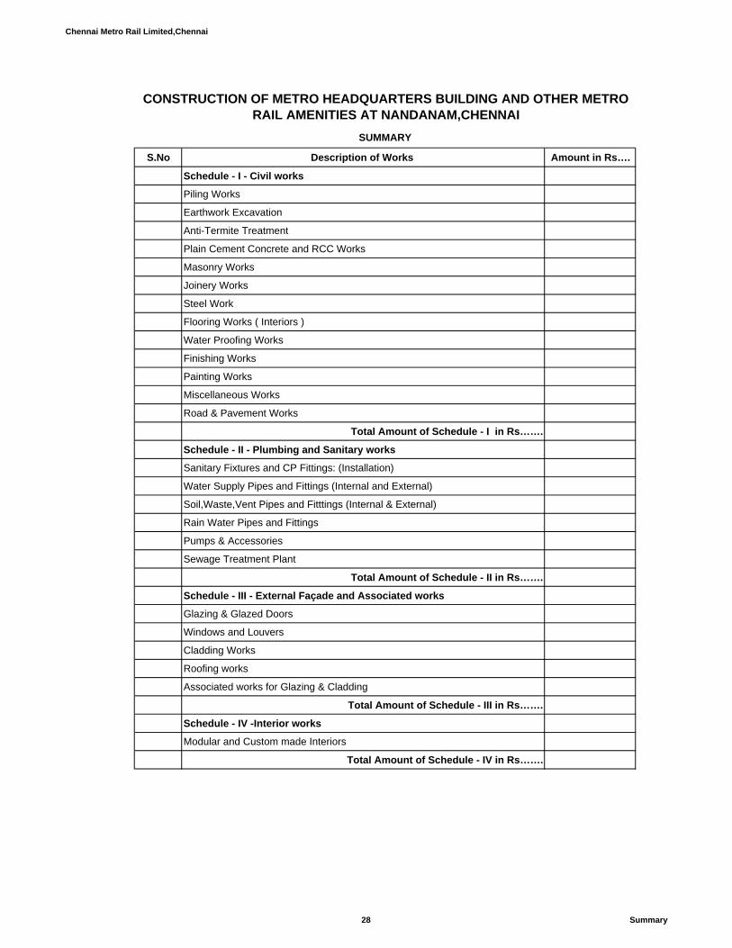
Chennai Metro Rail Limited,Chennai
S.No Description of Works Amount in Rs….
Schedule - I - Civil works
Piling Works
Earthwork Excavation
Anti-Termite Treatment
Plain Cement Concrete and RCC Works
Masonry Works
Joinery Works
Steel Work
Flooring Works ( Interiors )
Water Proofing Works
Finishing Works
Painting Works
Miscellaneous Works
Road & Pavement Works
Total Amount of Schedule - I in Rs…….
Schedule - II - Plumbing and Sanitary works
Sanitary Fixtures and CP Fittings: (Installation)
Water Supply Pipes and Fittings (Internal and External)
Soil,Waste,Vent Pipes and Fitttings (Internal & External)
Rain Water Pipes and Fittings
Pumps & Accessories
Sewage Treatment Plant
Total Amount of Schedule - II in Rs…….
Schedule - III - External Façade and Associated works
Glazing & Glazed Doors
Windows and Louvers
Cladding Works
Roofing works
Associated works for Glazing & Cladding
Total Amount of Schedule - III in Rs…….
Schedule - IV -Interior works
Modular and Custom made Interiors
Total Amount of Schedule - IV in Rs…….
CONSTRUCTION OF METRO HEADQUARTERS BUILDING AND OTHER METRO RAIL AMENITIES AT NANDANAM,CHENNAI
SUMMARY
28 Summary

Chennai Metro Rail Limited,Chennai
S.No Description of Works Amount in Rs….
Schedule - V - Electrical Works
Transformers and HT Breakers & LT Busducts
LT Panel Boards
Raising Mains and Tap-Off Boxes
UPS and Batteries
Distribution Boards
Isolators and Starter Panels
Wiring and Connected Accessories
Power and Control Cables / Terminations
Earthing System , Cable Tray and MS Items
Safety Equipments
Lighting Luminaires & Fans
External Works
Lighting Protection System
Solar system
Total Amount of Schedule - V in Rs…….
Schedule - VI - DG Set Works
DG works
Total Amount of Schedule - VI in Rs…….
Schedule - VII - Fire Protection System
Pump room
Hydrant System
Sprinkler System
Portable Fire Extinguishers
Transformer Sprinkler
Total Amount of Schedule - VII in Rs…….
Schedule - VIII - Air -Conditioning System
Water Cooled Screw Chillers
Chilled Water and Condenser Water Pumps
Cooling Tower
Pipes and Valves
Air Handling Units
Precision Air -Conditioning (PAC) System
DX System
VRV System
Air Distribution System
Ventilation System
Electrical Works
Total Amount of Schedule - VIII in Rs…….
Schedule - IX - Integrated Building Management System
29 Summary

Chennai Metro Rail Limited,Chennai
S.No Description of Works Amount in Rs….
Fire Alarm System
Public Address System
Access Control System
IP Based CCTV Camera
Novec Gas Based Fire Surpression System
Aspiration Smoke Detection System
Ultrasonic Pest Repller System-Digital System
Addressable Type Water Leak Detection System
Building Management System
Automatic Fire Detection and Supression System for HT Panel , MPCCs
Miscellaneous Items
Total Amount of Schedule - IX in Rs…….
Schedule - X - Lifts
Lifts
Total Amount of Schedule - X in Rs…….
Schedule - XI - Data and Voice Network
Data and Voice Network
Total Amount of Schedule - XI in Rs…….
30 Summary

Chennai Metro Rail Limited,Chennai
In Figures In Words
A Piling Works 1 Boring, providing and installing bored cast-in-situ reinforced cement
concrete piles of grade M-25 of specified diameter and length below thepile cap, to carry a safe working load not less than specified, excludingthe cost of steel reinforcement but including the cost of boring, withbentonite solution and temporary casing of appropriate length for settingout and removal of same and the length of the pile to be embedded inthe pile cap etc. all complete, including removal of excavated earth withall lifts and leads (Length of pile for payment shall be measured uptobottom of pile cap).
a 60 Rmt 450 mm dia piles Rmt
b 60 Rmt 600 mm dia piles Rmt
c 60 Rmt 750 mm dia piles. Rmt
d 60 Rmt 1000 mm dia piles. Rmt
PerUnit Description of Work
CONSTRUCTION OF METRO HEADQUARTERS BUILDING AND OTHER METRO RAIL AMENITIES AT NANDANAM,CHENNAI
Amount in Rs….
BILLS OF QUANTITIES
SCHEDULE - I - CIVIL WORKS
S.No TotalQuantity
Rate in INR
31 Civil
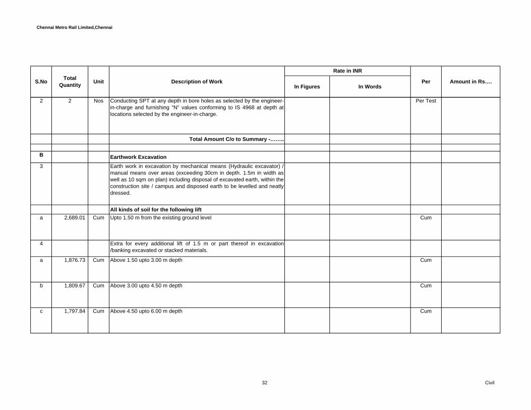
Chennai Metro Rail Limited,Chennai
In Figures In WordsPerUnit Description of Work Amount in Rs….S.No Total
Quantity
Rate in INR
2 2 Nos Conducting SPT at any depth in bore holes as selected by the engineer-in-charge and furnishing "N" values conforming to IS 4968 at depth atlocations selected by the engineer-in-charge.
Per Test
Total Amount C/o to Summary -……..
B Earthwork Excavation3 Earth work in excavation by mechanical means (Hydraulic excavator) /
manual means over areas (exceeding 30cm in depth. 1.5m in width aswell as 10 sqm on plan) including disposal of excavated earth, within theconstruction site / campus and disposed earth to be levelled and neatlydressed.
All kinds of soil for the following lifta 2,689.01 Cum Upto 1.50 m from the existing ground level Cum
4 Extra for every additional lift of 1.5 m or part thereof in excavation/banking excavated or stacked materials.
a 1,876.73 Cum Above 1.50 upto 3.00 m depth Cum
b 1,809.67 Cum Above 3.00 upto 4.50 m depth Cum
c 1,797.84 Cum Above 4.50 upto 6.00 m depth Cum
32 Civil

Chennai Metro Rail Limited,Chennai
In Figures In WordsPerUnit Description of Work Amount in Rs….S.No Total
Quantity
Rate in INR
d 392.51 Cum Above 6.00 upto 7.50 m depth Cum
5 Filling using available excavated earth lying or stocked elsewhere insidethe campus (excluding rock) to be filled in trenches, plinth, sides offoundations, pilecaps and the like at all heights and depths etc. in layersnot exceeding 20cm in depth, consolidating each deposited layer byramming and watering etc complete in all respects as directed.
a 29.59 Cum Available excavated earth Cum
6 Supplying and filling in plinth with river sand under floors, includingwatering, ramming, consolidating and dressing complete.
1,142.57 Cum River sand filling Cum
7 Supplying and filling in plinth, under floors and foundation with stonedust, including watering, ramming, consolidating and dressing etccomplete in all respects.
1,054.59 Cum Stone dust Cum
8 Supplying and filling in plinth, under floors and foundation with moorumincluding watering, ramming, consolidating and dressing etc complete inall respects.
3,166.97 Cum Moorum Cum
Total Amount C/o to Summary -……..
33 Civil

Chennai Metro Rail Limited,Chennai
In Figures In WordsPerUnit Description of Work Amount in Rs….S.No Total
Quantity
Rate in INR
C Anti-Termite Treatment
9 Providing Pre - construction Anti - termite treatment and creating achemical barrier to the building by injecting chemical emulsion ofrequired concentration under grade slab and grade beam, all round thePile Caps, Catch basins, trenches, pits, tunnels, wall trenches, back fill,plinth filling, junction of wall and floor. External perimeter of building,surrounding of pipes, expansion joints, below U.G. sump andretaining/side walls etc. as per instructions of chemical manufacturer asdirected by the Department officer/ Architect. The treatment shall becarried out strictly in accordance with the technical specification andconforming to IS 6313 or equivalent BS specification. The chemical tobe used as insecticide for the treatment shall be Biflex Tc, TC stands forTermiticide Concentrate for Termite Control (Bifenthrin) and theapplication shall be diluted 1 part of chemical Biflex Tc with 49 parts ofwater to get 0.05% emulsion and strictly in accordance with themanufacturer’s specification.
The work should be carried out by an approved and registered specialistpest control agency only. Tenderer to furnish the name of the proposedspecialist firm. A 10 years post application guarantee against defectsshall be furnished by the main Contractor.Note : Horizontal plan area at ground floor level of the building will bemeasured and paid.
The chemical to be used for the treatment and concentration of thechemical solutions should be as laid down in IS - 6313 Part II.asdirected by the Engineer-in-charge.
a 10,629.30 Sqm Termite Treatment Sqm
Total Amount C/o to Summary -……..
34 Civil
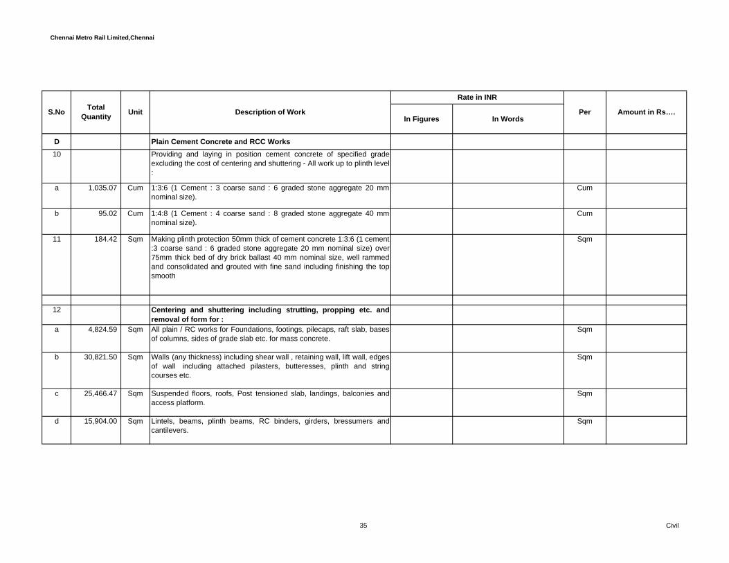
Chennai Metro Rail Limited,Chennai
In Figures In WordsPerUnit Description of Work Amount in Rs….S.No Total
Quantity
Rate in INR
D Plain Cement Concrete and RCC Works 10 Providing and laying in position cement concrete of specified grade
excluding the cost of centering and shuttering - All work up to plinth level:
a 1,035.07 Cum 1:3:6 (1 Cement : 3 coarse sand : 6 graded stone aggregate 20 mmnominal size).
Cum
b 95.02 Cum 1:4:8 (1 Cement : 4 coarse sand : 8 graded stone aggregate 40 mmnominal size).
Cum
11 184.42 Sqm Making plinth protection 50mm thick of cement concrete 1:3:6 (1 cement:3 coarse sand : 6 graded stone aggregate 20 mm nominal size) over75mm thick bed of dry brick ballast 40 mm nominal size, well rammedand consolidated and grouted with fine sand including finishing the topsmooth
Sqm
12 Centering and shuttering including strutting, propping etc. andremoval of form for :
a 4,824.59 Sqm All plain / RC works for Foundations, footings, pilecaps, raft slab, basesof columns, sides of grade slab etc. for mass concrete.
Sqm
b 30,821.50 Sqm Walls (any thickness) including shear wall , retaining wall, lift wall, edgesof wall including attached pilasters, butteresses, plinth and stringcourses etc.
Sqm
c 25,466.47 Sqm Suspended floors, roofs, Post tensioned slab, landings, balconies andaccess platform.
Sqm
d 15,904.00 Sqm Lintels, beams, plinth beams, RC binders, girders, bressumers andcantilevers.
Sqm
35 Civil
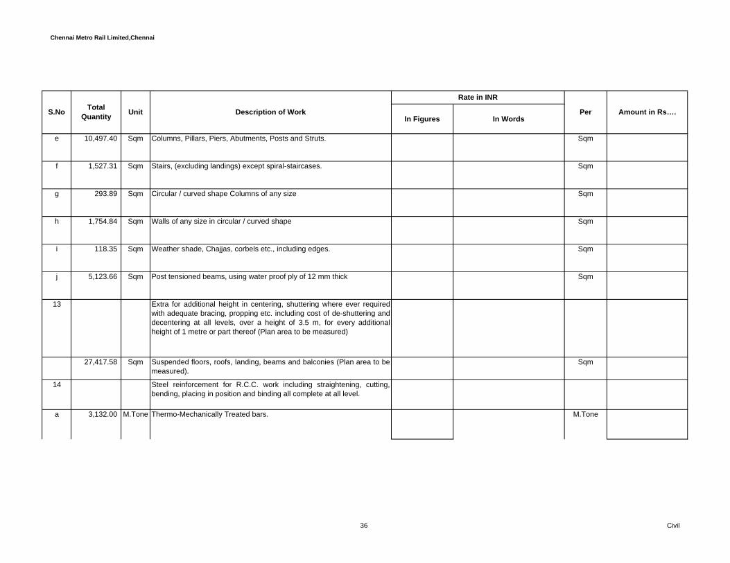
Chennai Metro Rail Limited,Chennai
In Figures In WordsPerUnit Description of Work Amount in Rs….S.No Total
Quantity
Rate in INR
e 10,497.40 Sqm Columns, Pillars, Piers, Abutments, Posts and Struts. Sqm
f 1,527.31 Sqm Stairs, (excluding landings) except spiral-staircases. Sqm
g 293.89 Sqm Circular / curved shape Columns of any size Sqm
h 1,754.84 Sqm Walls of any size in circular / curved shape Sqm
i 118.35 Sqm Weather shade, Chajjas, corbels etc., including edges. Sqm
j 5,123.66 Sqm Post tensioned beams, using water proof ply of 12 mm thick Sqm
13 Extra for additional height in centering, shuttering where ever requiredwith adequate bracing, propping etc. including cost of de-shuttering anddecentering at all levels, over a height of 3.5 m, for every additionalheight of 1 metre or part thereof (Plan area to be measured)
27,417.58 Sqm Suspended floors, roofs, landing, beams and balconies (Plan area to bemeasured).
Sqm
14 Steel reinforcement for R.C.C. work including straightening, cutting,bending, placing in position and binding all complete at all level.
a 3,132.00 M.Tone Thermo-Mechanically Treated bars. M.Tone
36 Civil

Chennai Metro Rail Limited,Chennai
In Figures In WordsPerUnit Description of Work Amount in Rs….S.No Total
Quantity
Rate in INR
15 Providing ,laying , tensioning/ stressing of tendons for post tensioningworks in slabs and beams with specified Tendons at all levels includingsupplying and laying of HT strands sheathing duct 80mmx20mm or65mm dia. or 85mm dia., as required ,made of 0.3 mm thick GIcorrugated sheeting to facilitate the threading of HT strands,jointing withcouplers, fixing of ducts into the anchorages,decoiling thestrands,cutting to the required lengths, threading of strands into theducts , including all necessary profiling by fixing of all necessary tendonsupport bars,fixing of dead end of HT strands including flowering thestrands,fixing of grout vents, fixing of live end anchorages including thesupply of stressing anchorages (SS) suitable for 5-4, 5-5 tendons,supervising the fabrication and fixing of anti burstingreinforcement,stressing the cables,end trimming of cables afterstressing ,grouting the annular space around the cable in the ducts withcement slurry mixed with approved admixtures with required tools,plants, machineries and consumables
81.86 M.Tone including providing ,cement and admixture for grouting, packing ofsheathing and anchorages blockings, filling of recess pockets afterstressing using grouts (cement slurry mixed with approved admixtures)including providing access to post tensioning at all heights including allleads, lifts etc. all complete as per particular specification and asdirected by the Engineer-in-Charge but excluding shuttering , concreting& reinforcement steel which shall be payable under respective itemsseparately.
M.Tone
16 1,557.20 Rmt Add for plaster drip course/ groove in plastered surface or moulding toR.C.C. projections.
Rmt
37 Civil

Chennai Metro Rail Limited,Chennai
In Figures In WordsPerUnit Description of Work Amount in Rs….S.No Total
Quantity
Rate in INR
17 Providing and laying in position machine batched and machine mixeddesign mix for the following grade cement concrete for reinforcedcement concrete work, using cement content as per approved designmix, including pumping of concrete to site of laying but excluding thecost of centering, shuttering, finishing and reinforcement, includingadmixtures in recommended proportions as per IS: 9103 to accelerate,retard setting of concrete, improve workability without impairing strengthand durability as per direction of Engineer-in-charge.
M25 Grade
a 1.02 Cum All works upto plinth level Cum
b 11.18 Cum All works above plinth level up to floor V level. (M25 Grade) Cum
c 1.02 Cum All works above floor V level upto floor IX level (M25 Grade) Cum
18 M30 Grade of any shape and size for pilecap, raftslab, grade beam,walls, shear walls, retaining walls, columns, beams, slabs, ramps,staircase, steps, landing, sills, chajjas, lintels, pergolas, fins. facia, dropsand the like for the following levels
a 877.72 Cum All works upto plinth level Cum
b 2,108.00 Cum All works above plinth level up to floor V level. (M30 Grade) Cum
38 Civil

Chennai Metro Rail Limited,Chennai
In Figures In WordsPerUnit Description of Work Amount in Rs….S.No Total
Quantity
Rate in INR
c 1,037.48 Cum All works above floor V level upto floor IX level (M30 Grade) Cum
d 333.34 Cum All works above floor IX level upto floor XIII level (M30 Grade)\ Cum
e - Cum All works above floor XIII level uoto floor XVII level (M30 Grade) Cum
19 M40 Grade of any shape and size for pilecap, raftslab, grade beam,walls, shear walls, retaining walls, columns, conventional beams andslabs, Post tensioned slab and beams, ramps, staircase, steps, landing,and the like for the following levels
a 14,476.65 Cum All works upto plinth level Cum
b 6,733.09 Cum All works above plinth level up to floor V level. (M40 Grade) Cum
c 904.46 Cum All works above floor V level upto floor IX level (M40 Grade) Cum
20 62.87 Cum Providing and laying Plum concrete1: 5: 10 (lean mix ) ( 1 cement :5coarse sand : 10 aggregate of 40 mm and down size ) for extension ofcolumns wherever specified including sub grade preparation, leveling,all leads and lifts, rough finishing at the top surface, curing etc complete.
Cum
Total Amount C/o to Summary -……..
E Masonry Works
39 Civil
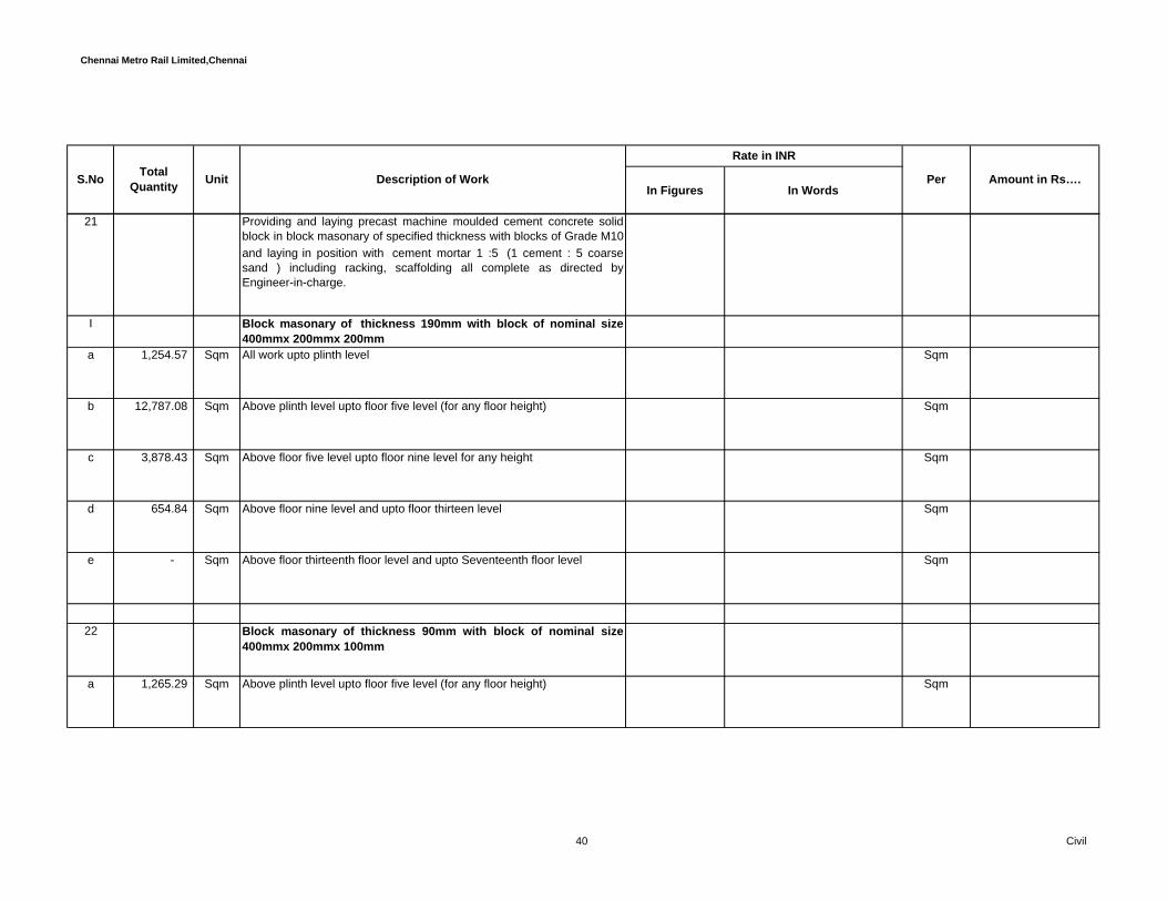
Chennai Metro Rail Limited,Chennai
In Figures In WordsPerUnit Description of Work Amount in Rs….S.No Total
Quantity
Rate in INR
21 Providing and laying precast machine moulded cement concrete solidblock in block masonary of specified thickness with blocks of Grade M10and laying in position with cement mortar 1 :5 (1 cement : 5 coarsesand ) including racking, scaffolding all complete as directed byEngineer-in-charge.
I Block masonary of thickness 190mm with block of nominal size400mmx 200mmx 200mm
a 1,254.57 Sqm All work upto plinth level Sqm
b 12,787.08 Sqm Above plinth level upto floor five level (for any floor height) Sqm
c 3,878.43 Sqm Above floor five level upto floor nine level for any height Sqm
d 654.84 Sqm Above floor nine level and upto floor thirteen level Sqm
e - Sqm Above floor thirteenth floor level and upto Seventeenth floor level Sqm
22 Block masonary of thickness 90mm with block of nominal size400mmx 200mmx 100mm
a 1,265.29 Sqm Above plinth level upto floor five level (for any floor height) Sqm
40 Civil

Chennai Metro Rail Limited,Chennai
In Figures In WordsPerUnit Description of Work Amount in Rs….S.No Total
Quantity
Rate in INR
b 852.08 Sqm Above floor five level upto floor nine level for any height Sqm
c 180.48 Sqm Above floor nine level and upto floor thirteen level Sqm
d - Sqm Above floor thirteenth level and upto floor seventeen level Sqm
23 Half brick masonry with common burnt clay F.P.S. (non modular) bricks of class designation 7.5 in superstructure
cement mortar 1:4 (1 cement : 4 coarse sand) a 110.46 Sqm
Above plinth level up to floor V level.Sqm
b 51.29 Sqm Above floor five level upto floor nine level for any height Sqm
c 7.89 Sqm Above floor nine level and upto floor thirteen level Sqm
d - Sqm Above floor thirteenth level and upto floor seventeen level Sqm
41 Civil

Chennai Metro Rail Limited,Chennai
In Figures In WordsPerUnit Description of Work Amount in Rs….S.No Total
Quantity
Rate in INR
24 - Extra rate over & above any type of Masonry work for providingR.C.Binder - 80 mm thick with 1:2:4 reinforced cement concrete usingcoarse graded aggregate of 20 mm and downsize, reinforced with 4nos. of 8 mm dia. Tor steel and 6 mm dia. Mild steel stirrups at 200 mmc/c and binders placed at intervals not more than 1000 mm, includingcost of reinforcements and tying in position using binding wire made outof 16 gauge GI annealed or 18 gauge SS, form work, scaffolding, alllabour, hire and fuel charges for all tools and plants employed and allother incidental charges etc. all complete, as directed by the Engineer-in-charge.
I For 200 mm thick maosnry walla 6,258.74 Rmt Up to Floor V level Rmt
b 1,162.98 Rmt Above floor five level upto floor nine level for any height Rmt
c 75.94 Rmt Above floor nine level and upto floor thirteen level Rmt
d - Rmt Above floor thirteenth level and upto floor seventeen level Rmt
II For 100 mm thick maosnry walla 1,532.55 Rmt Up to Floor V level Rmt
b 822.49 Rmt Above floor five level upto floor nine level for any height Rmt
42 Civil
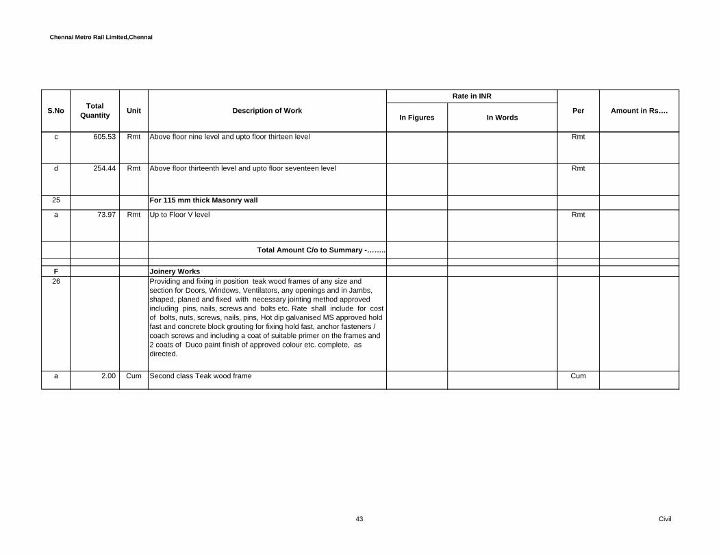
Chennai Metro Rail Limited,Chennai
In Figures In WordsPerUnit Description of Work Amount in Rs….S.No Total
Quantity
Rate in INR
c 605.53 Rmt Above floor nine level and upto floor thirteen level Rmt
d 254.44 Rmt Above floor thirteenth level and upto floor seventeen level Rmt
25 For 115 mm thick Masonry wall
a 73.97 Rmt Up to Floor V level Rmt
Total Amount C/o to Summary -……..
F Joinery Works 26 Providing and fixing in position teak wood frames of any size and
section for Doors, Windows, Ventilators, any openings and in Jambs, shaped, planed and fixed with necessary jointing method approved including pins, nails, screws and bolts etc. Rate shall include for cost of bolts, nuts, screws, nails, pins, Hot dip galvanised MS approved hold fast and concrete block grouting for fixing hold fast, anchor fasteners / coach screws and including a coat of suitable primer on the frames and 2 coats of Duco paint finish of approved colour etc. complete, as directed.
a 2.00 Cum Second class Teak wood frame Cum
43 Civil
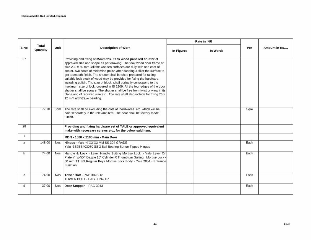
Chennai Metro Rail Limited,Chennai
In Figures In WordsPerUnit Description of Work Amount in Rs….S.No Total
Quantity
Rate in INR
27 Providing and fixing of 35mm thk. Teak wood panelled shutter of approved size and shape as per drawing. The teak wood door frame of size 230 x 50 mm .All the wooden surfaces are duly with one coat of sealer, two coats of melamine polish after sanding & filler the surface to get a smooth finish. The shutter shall be shop prepared for taking suitable lock block of wood may be provided for fixing the hardware, including polish. The size of block, shall perfectly correspond to the maximum size of lock, covered in IS 2209. All the four edges of the door shutter shall be square. The shutter shall be free from twist or warp in its plane and of required size etc. The rate shall also include for fixing 75 x 12 mm architrave beading.
77.70 Sqm The rate shall be excluding the cost of hardwares etc. which will be paid separately in the relevant item. The door shall be factory made Finish.
Sqm
28 Providing and fixing hardware set of YALE or approved equivalent make with necessary screws etc., for the below said item.
i MD 3 - 1000 x 2100 mm - Main Door a 148.00 Nos Hinges - Yale -4"X3"X3 MM SS 304 GRADE
Yale -3S2BB403030 SS 2 Ball Bearing Button Tipped Hinges Each
b 74.00 Nos Handle & Lock - Lever Handle Suiting Mortise Lock - Yale Lever OnPlate Ymp-554 Dazzle 10" Cylinder X Thumbturn Suiting Mortise Lock -60 mm TT SN Regular Keys Mortise Lock Body - Yale 28p4 - EntranceFunction
Each
c 74.00 Nos Tower Bolt - PAG 3026- 6" TOWER BOLT - PAG 3026- 10"
Each
d 37.00 Nos Door Stopper - PAG 3043 Each
44 Civil

Chennai Metro Rail Limited,Chennai
In Figures In WordsPerUnit Description of Work Amount in Rs….S.No Total
Quantity
Rate in INR
e 37.00 Nos Door Guard - Yale -V18L US 26D -SC DOOR GUARD Each
f 37.00 Nos OTHERS- DOOR EYE - YALE V0401A Each
29 Providing and fixing 35 mm thick flush door pre hung door set ( factorymade ) of M/s.Shree sakthi doors or approved equivalent make singleleaf of door frame in soild wood Mahagony with ICLA or equivalent PUpolish fixed with HILTI or equivalent anchor fastener. The finishing ofdoor on both sides with 1.5mm laminate of approved shade. The ratealso include for fixing 40 x 15 mm laminate finish engineered hardwoodarchitrave beading with a 10 mm thick gripping PU foam between themasonry and hardwood.are as per detailed drawing. The rate shallinclude for making all provisions and fixing all the required hardware.The hardware which will be paid separately in the relevant item. Thedoor shall be factory made Finish
i D 6 & D6 a - 900 x2100 mm ( Bed Room , Kitchen, Study )
a 72 Sqm Providing and Fixing Doors, Door Frames and Architrave as perspecifications listed above in 200 / 230 mm wall and Door Frame of230 x 40 mm
Sqm
b 280 Sqm Providing and Fixing Doors, Door Frames and Architrave as perspecifications listed above in 100 / 115 mm wall and Door Frame of115 x 40 mm.
Sqm
30 Providing and fixing hardware set of YALE or approved equivalentmake with necessary screws etc., for the below said item.
a 555.00 Nos Hinges - Yale -4"X3"X3 MM SS 304 GRADEYale -3S2BB403030 SS 2 Ball Bearing Button Tipped Hinges
Each
45 Civil

Chennai Metro Rail Limited,Chennai
In Figures In WordsPerUnit Description of Work Amount in Rs….S.No Total
Quantity
Rate in INR
b 185.00 Nos Handle & Lock - Yale CA5127 US32D - Cylindrical Knob Lock -Entrance Function
Each
c 185.00 Nos Tower Bolt - PAG 3026- 6" Each
d 185.00 Nos Door Stopper - PAG 3043 Each
31 Providing and fixing 35 mm thick flush door pre hung door set ( factorymade ) of M/s.Shree sakthi doors or approved equivalent make singleleaf of door frame in soild wood Mahagony with ICLA or equivalent PUpolish fixed with HILTI or equivalent anchor fastener. The finishing ofdoor on both sides with 1.5mm laminate of approved shade. The ratealso include for fixing 40 x 15 mm laminate finish engineered hardwoodarchitrave beading with a 10 mm thick gripping PU foam between themasonry and hardwood.are as per detailed drawing. The rate shallinclude for making all provisions and fixing all the required hardware.The hardware which will be paid separately in the relevant item. Thedoor shall be factory made Finish
i D7 a - 750 x2100 mm ( Toilet )
a 74 Providing and Fixing Doors, Door Frames and Architrave as perspecifications listed above in 200 / 230 mm wall and Door Frame of230 x 40 mm
Sqm
b 74 Providing and Fixing Doors, Door Frames and Architrave as perspecifications listed above in 100 / 115 mm wall and Door Frame of115 x 40 mm.
Sqm
46 Civil

Chennai Metro Rail Limited,Chennai
In Figures In WordsPerUnit Description of Work Amount in Rs….S.No Total
Quantity
Rate in INR
i 282.00 Nos Hinges - Yale -4"X3"X3 MM SS 304 GRADEYale -3S2BB403030 SS 2 Ball Bearing Button Tipped Hinges
Each
ii 94.00 Nos Handle & Lock - Yale CA5122 US32D 60 / 70 BS - Cylindrical KnobSET - Privacy Function
Each
iii 94.00 Nos Tower Bolt - PAG 3026- 4" Each
32 Providing and fixing 35 mm thick flush door pre hung door set ( factorymade ) of M/s.Shree sakthi doors or approved equivalent make singleleaf of door frame in soild wood Mahagony with ICLA or equivalent PUpolish fixed with HILTI or equivalent anchor fastener. The finishing ofdoor on both sides with 1.5mm laminate of approved shade. The ratealso include for fixing 40 x 15 mm laminate finish engineered hardwoodarchitrave beading with a 10 mm thick gripping PU foam between themasonry and hardwood.are as per detailed drawing. The rate shallinclude for making all provisions and fixing all the required hardware.The hardware which will be paid separately in the relevant item. Thedoor shall be factory made Finish
D 8 - 750 x2100 mm ( Service Verandah )
a 74 Providing and Fixing Doors, Door Frames and Architrave as perspecifications listed above in 200 / 230 mm wall and Door Frame of230 x 40 mm
Sqm
b 16 Providing and Fixing Doors, Door Frames and Architrave as perspecifications listed above in 100 / 115 mm wall and Door Frame of115 x 40 mm.
Sqm
33 Providing and fixing hardware set of YALE or approved equivalentmake with necessary screws etc., for the below said item.
47 Civil

Chennai Metro Rail Limited,Chennai
In Figures In WordsPerUnit Description of Work Amount in Rs….S.No Total
Quantity
Rate in INR
i 171.00 Nos Hinges - Yale -4"X3"X3 MM SS 304 GRADEYale -3S2BB403030 SS 2 Ball Bearing Button Tipped Hinges
Each
ii 57.00 Nos Handle & Lock - Yale CA5127 US32D - Cylindrical Knob Lock -Entrance Function
Each
iii 57.00 Nos Tower Bolt - PAG 3026- 6" Each
iv 57.00 Nos Door Stopper - PAG 3043 Each
34.00 145.00 Sqm Providing and fixing thick 35mm thick Fully flush shutter with 1.5 mmthick laminate on both sides.The shutter shall be made of solid core ofblock board type bonded with PF synthetic resin conforming to BWPgrade of IS 848 with 8 mm thick teak wood lipping finished with DUCOpaint of approved make, colour.The construction procedure of theshutter should be as per IS 2202. The shutter shall be shop prepared fortaking mortice lock or latches suitable lock block of wood may beprovided for fixing the hardware, including painting and the lippingworks.The size of block, shall perfectly correspond to the maximum sizeof lock, covered in IS 2209. All the four edges of the door shutter shallbe square. The shutter shall be free from twist or warp in its plane and ofrequired size etc. complete as directed. Rate includes vision panel.Thehardware which will be paid separately in the relevant item. Hardwoodarchitrave size 25 x 12mm .Rate shall include for Air transfer grill / louverof approved make and size as per drawings.
Sqm
35.00 Providing and fixing hardware set of DORMA or approvedequivalent make with necessary screws etc., for the below saiditem.
a 258.00 Nos DORMA BB 4330- 2 BALL BEARING BUTT HINGES SIZE 4" X 3" X3MM IN SS 304 FOR FLUSH DOORS
48 Civil

Chennai Metro Rail Limited,Chennai
In Figures In WordsPerUnit Description of Work Amount in Rs….S.No Total
Quantity
Rate in INR
b 86.00 Nos DORMA H TYPE TGDI 350 X 25 IN SS 304
c 41.00 Nos DORMA MORTISE DEAD LOCK 278 WITH EUROPROFILECYLINDER 60MM LENGTH TYPE 1 (BOTH SIDE KEY) WITH 4 LEVELMASTER KEY
d 137.00 Nos CONCEALED FLUSH BOLT L=300 mm DORMA 91143006
e 92.00 Nos DORMA TS 71 DOOR CLOSER
36.00 Supply and fixing of UPVC Sliding window 2Track 4Panel withoutflyscreen duly manufactured using uPVC reinforced profiles of60X49X2.5 mm for outer frames, 62x41x2.5mm for sliding shutter. Theminimum wall thickness for the external surfaces shall be 2.2 +/- 0.3mm.The windows has to be design as per applicable wind pressure atvarious heights for the location of the building as stipulated in IS codes.The window system shall be designed for water tightness.The systemmust have 2 sealed chambers for frame and 1 sealed chamber forsliding shutter, capable of mounting single/ double glazing system,structurally reinforced with hot dip galvanized steel with 120 GSM ofminimum thickness of 1.5mm prefabricated and welded through fusionwelding, the window shall be fitted with 5mm thick toughened glass ofSaint gobain / Asahi or equivalent make duly fitted with EPDMweathering seal resistant accessories like clipping locking system madeof aluminium 1 No. per set of sashes and the system is to be installed atsite using anchor fasteners, silicion sealent, easy glazing / deglazing atsite etc..
49 Civil

Chennai Metro Rail Limited,Chennai
In Figures In WordsPerUnit Description of Work Amount in Rs….S.No Total
Quantity
Rate in INR
368.84 Sqm The rate shall be include for preaparing & submitting shop drawings,calculations etc.. and for conducting the necessary test to check forwater tightness at various heights etc.. and also inclusive of cost andconveyance of all materials, accessories, labour charges fortransportation, erection at site complete for finished item of work, ascomplete with all respects complying with relevant standard codes &specification, as directed by the Engineer-in-charge.Windows, W1- 1800 X 1350 mm/ W2- 1500 X 1350 mm/ W3- 1200 X1350mm (2T 2P W/O FS type & Single Point lock). Sizes are indicativeonly.
Sqm
37 Kitchen Window - Supply and fixing of uPVC Sliding window 2Track4Panel without flyscreen duly manufactured using uPVC reinforcedprofiles of 60X49X2.5 mm for outer frames, 62x41x2.5mm for slidingshutter. The minimum wall thickness for the external surfaces shall be2.2 +/- 0.3mm. The windows has to be design as per applicable windpressure at various heights for the location of the building as stipulatedin IS codes. The window system shall be designed for watertightness.The system must have 2 sealed chambers for frame and 1sealed chamber for sliding shutter, capable of mounting single/ doubleglazing system, structurally reinforced with hot dip galvanized steel with120 GSM of minimum thickness of 1.2mm prefabricated and weldedthrough fusion welding, the window shall be fitted with 5mm thicktoughened glass of Saint gobain / Asahi or equivalent make duly fittedwith EPDM weathering seal resistant accessories like clipping lockingsystem made of aluminium 1 No. per set of sashes and the system is tobe installed at site using anchor fasteners, silicion sealent, easy glazing/ deglazing at site etc..
50 Civil
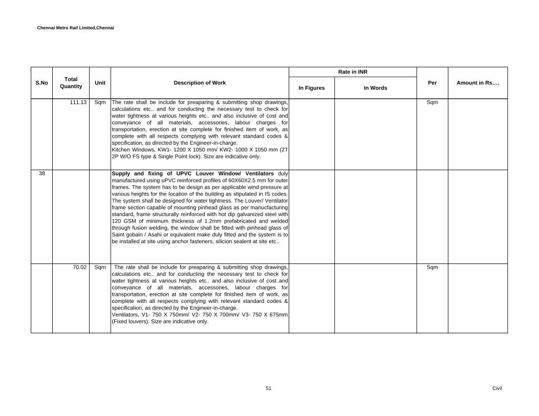
Chennai Metro Rail Limited,Chennai
In Figures In WordsPerUnit Description of Work Amount in Rs….S.No Total
Quantity
Rate in INR
111.13 Sqm The rate shall be include for preaparing & submitting shop drawings,calculations etc.. and for conducting the necessary test to check forwater tightness at various heights etc.. and also inclusive of cost andconveyance of all materials, accessories, labour charges fortransportation, erection at site complete for finished item of work, ascomplete with all respects complying with relevant standard codes &specification, as directed by the Engineer-in-charge.Kitchen Windows, KW1- 1200 X 1050 mm/ KW2- 1000 X 1050 mm (2T2P W/O FS type & Single Point lock). Size are indicative only.
Sqm
38 Supply and fixing of UPVC Louver Window/ Ventilators dulymanufactured using uPVC reinforced profiles of 60X60X2.5 mm for outer frames. The system has to be design as per applicable wind pressure atvarious heights for the location of the building as stipulated in IS codes.The system shall be designed for water tightness. The Louver/ Ventilatorframe section capable of mounting pinhead glass as per manucfacturingstandard, frame structurally reinforced with hot dip galvanized steel with120 GSM of minimum thickness of 1.2mm prefabricated and weldedthrough fusion welding, the window shall be fitted with pinhead glass ofSaint gobain / Asahi or equivalent make duly fitted and the system is tobe installed at site using anchor fasteners, silicion sealent at site etc..
70.02 Sqm The rate shall be include for preaparing & submitting shop drawings,calculations etc.. and for conducting the necessary test to check forwater tightness at various heights etc.. and also inclusive of cost andconveyance of all materials, accessories, labour charges fortransportation, erection at site complete for finished item of work, ascomplete with all respects complying with relevant standard codes &specification, as directed by the Engineer-in-charge.Ventilators, V1- 750 X 750mm/ V2- 750 X 700mm/ V3- 750 X 675mm(Fixed louvers). Size are indicative only.
Sqm
51 Civil

Chennai Metro Rail Limited,Chennai
In Figures In WordsPerUnit Description of Work Amount in Rs….S.No Total
Quantity
Rate in INR
39 Sliding Doors - Supply and fixing of UPVC Sliding Door 2Track 4Panelwithout flyscreen duly manufactured using uPVC reinforced profiles of60X49X2.5 mm for outer frames, 85x41x2.5mm for sliding shutter. Theminimum wall thickness for the external surfaces shall be 2.2 +/- 0.3mm.The system has to be design as per applicable wind pressure at variousheights for the location of the building as stipulated in IS codes. Thesystem shall be designed for water tightness.The system must have 2sealed chambers for frame and 1 sealed chamber for sliding shutter,capable of mounting single/ double glazing system, structurallyreinforced with hot dip galvanized steel with 120 GSM of minimumthickness of 1.2mm prefabricated (1.2mm for Sash) and welded throughfusion welding, the window shall be fitted with 5mm thick toughenedglass of Saint gobain / Asahi or equivalent make duly fitted with EPDMweathering seal resistant accessories like clipping locking system madeof aluminium 1 No. per set of sashes and the system is to be installed atsite using anchor fasteners, silicion sealent, easy glazing / deglazing atsite etc..
288.96 Sqm The rate shall be include for preaparing & submitting shop drawings,calculations etc.. and for conducting the necessary test to check forwater tightness at various heights etc.. and also inclusive of cost andconveyance of all materials, accessories, labour charges fortransportation, erection at site complete for finished item of work, ascomplete with all respects complying with relevant standard codes &specification, as directed by the Engineer-in-charge.Door cum Window, DW1- 3000 X 2100 mm/ DW2- 2500 X 2100 mm (2T4P W/O FS type & Multi Point lock). Sizes are indicative only.
Sqm
2hr. Fire rated hollow metal doors - Painted
52 Civil

Chennai Metro Rail Limited,Chennai
In Figures In WordsPerUnit Description of Work Amount in Rs….S.No Total
Quantity
Rate in INR
40 Providing and fixing of Hollow metal fire rated doors as per BS 476 part-22 for stability and integrity. Pressed Galvanized steel confirming to IS 277 with the following specification. Recommended fire door shall have doors tested and third party certified by CERTIFIRE or equivavelent, for maximum rating of 120Mins. with vision panel. Labled doors with certifiaction shall be with vision glass as a part of complete assembly. Manufacturer test certificate shall cover doors both single and double leaf and all doors supplied shall be within the tested specimen, deviation in specification and sheet thickness other than what is mentioned in the test certificates are not allowed. Proper label confirming the type of door and the hourly rating is mandatory. Pressed Galvanized steel Single / Double leaf door of approved manufacturer Shakti . or approved equivalent. which consists of frame, shutter, infill and finish as detailed below and conforming to IS 277.
Door frame shall be double rebate Kerf frame profile of size 143 x 58mm made out of 1.60mm (16gauge) minimum thick galvanized steel sheet. Frames shall be Mitered and field assembled with self tabs. All provision should be mortised, drilled and tapped for receiving appropriate hardware. Frames should be provided with back plate bracket and anchor fasteners for installation on a finished plastered masonry wall opening. Once frame installed should be grouted with cement & sand slurry necessary for fire doors on the clear masonry opening.
53 Civil

Chennai Metro Rail Limited,Chennai
In Figures In WordsPerUnit Description of Work Amount in Rs….S.No Total
Quantity
Rate in INR
Door leaf shall be 46mm thick fully flush double skin door with or without vision lite. Door leaf shall be manufactured from 1.2mm (18guage) minimum thick galvanised steel sheet. The internal construction of the door should be rigid reinforcement pads for receiving appropriate hardware. The infill material shall be resin bonded honeycomb core / mineral wool. All doors shall be factory prepped for receiving appropriate hardware and provided with necessary reinforcement for hinges, locks, and door closers. The edges should be interlocked with lock seam. For pair of doors astragals will be provided as required. 200x300mm Vision lite wherever applicable should be provided as per manufacturers recommendation with a beeding and screws from inside. The glass should be 6mm clear borosilicate fire rated glass of relavant rating of the door.
All doors and frames shall be finished with polyurethane aliphatic grade paint of approved colour. The door leaf and frame shall have passed minimum 250 hours of salt sprey test.
Rate should include supply and installation of door and hardware set as mentioned in the door and hardware schedule.
a 71.82 Sqm 120Mins Fire Rated Double leaf door of size FD: 1800x2100mm with vision panel
Sqm
b 18.90 Sqm 120Mins Fire Rated Unequal Double leaf door of size FD1: 1500x2100mm with vision panel
Sqm
c 110.88 Sqm 120Mins Fire Rated Single leaf door of size FD2: 1200x2100mm with vision panel
Sqm
54 Civil

Chennai Metro Rail Limited,Chennai
In Figures In WordsPerUnit Description of Work Amount in Rs….S.No Total
Quantity
Rate in INR
d 10.08 Sqm 120Mins Fire Rated Single leaf door of size FD3: 1200x2100mm with vision panel
Sqm
e 4.62 Sqm 120Mins Fire Rated Single leaf door of size FD4: 1100x2100mm with vision panel
Sqm
f 71.40 Sqm 120Mins Fire Rated Single leaf door of size FD5: 1000x2100mm with vision panel
Sqm
41.00 60Mins. Fire rated hollow metal doors - PaintedProviding and fixing of Hollow metal fire rated doors as per BS 476 part-22 for stability and integrity. Pressed Galvanized steel confirming to IS 277 with the following specification. Recommended fire door shall have doors tested and third party certified by CERTIFIRE or equivavelent, for maximum rating of 60Mins. with vision panel. Labled doors with certifiaction shall be with vision glass as a part of complete assembly. Manufacturer test certificate shall cover doors both single and double leaf and all doors supplied shall be within the tested specimen, deviation in specification and sheet thickness other than what is mentioned in the test certificates are not allowed. Proper label confirming the type of door and the hourly rating is mandatory. Pressed Galvanized steel Single / Double leaf door of approved manufacturer Shakti . or approved equivalent. which consists of frame, shutter, infill and finish as detailed below and conforming to IS 277.
55 Civil
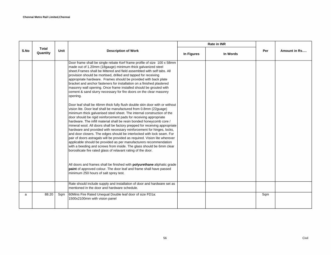
Chennai Metro Rail Limited,Chennai
In Figures In WordsPerUnit Description of Work Amount in Rs….S.No Total
Quantity
Rate in INR
Door frame shall be single rebate Kerf frame profile of size 100 x 58mm made out of 1.20mm (18gauge) minimum thick galvanized steel sheet.Frames shall be Mitered and field assembled with self tabs. All provision should be mortised, drilled and tapped for receiving appropriate hardware. Frames should be provided with back plate bracket and anchor fasteners for installation on a finished plastered masonry wall opening. Once frame installed should be grouted with cement & sand slurry necessary for fire doors on the clear masonry opening.
Door leaf shall be 46mm thick fully flush double skin door with or without vision lite. Door leaf shall be manufactured from 0.8mm (22guage) minimum thick galvanised steel sheet. The internal construction of the door should be rigid reinforcement pads for receiving appropriate hardware. The infill material shall be resin bonded honeycomb core / mineral wool. All doors shall be factory prepped for receiving appropriate hardware and provided with necessary reinforcement for hinges, locks, and door closers. The edges should be interlocked with lock seam. For pair of doors astragals will be provided as required. Vision lite wherever applicable should be provided as per manufacturers recommendation with a beeding and screws from inside. The glass should be 6mm clear borosilicate fire rated glass of relavant rating of the door.
All doors and frames shall be finished with polyurethane aliphatic grade paint of approved colour. The door leaf and frame shall have passed minimum 250 hours of salt sprey test.
Rate should include supply and installation of door and hardware set as mentioned in the door and hardware schedule.
a 88.20 Sqm 60Mins Fire Rated Unequal Double leaf door of size FD1a: 1500x2100mm with vision panel
Sqm
56 Civil

Chennai Metro Rail Limited,Chennai
In Figures In WordsPerUnit Description of Work Amount in Rs….S.No Total
Quantity
Rate in INR
b 12.60 Sqm 60Mins Fire Rated Door Single leaf of size FD3a: 1200x2100mm with vision panel
Sqm
c 6.30 Sqm 60Mins Fire Rated Door Single leaf of size FD6 : 1000x2100mm with vision panel
Sqm
d 67.50 Sqm 60Mins Fire Rated Door Double leaf of size FD7: 900x1500mm without vision panel
Sqm
e 198.00 Sqm 60Mins Fire Rated Door Single leaf of size FD8: 600x1500mm without vision panel
Sqm
42.00 Supplying and fixing hardware set of DORMA or approvedequivalent make with necessary screws etc., for the below saiditem.
a 1,404.00 Nos SS Ball Bearing Hinges 4"x3"x3" - BB 4330 Each
b 111.00 Nos TS 92 Door Closer with G-N EN 2-4, B/G, Finish : Silver Max. Door width : 1100mm
Each
c 19.00 Nos G GSR Slide channel door co-ordinator with thrust rod clamp system, complete, non-handedfor door width: 1350 - 2500 mm
Each
d 53.00 Nos TS 93 Door Closer with G-N EN 2-5, B/G, Finish : SilverWith Back Check & Delayed action Max. Door width : 1250mm
Each
57 Civil

Chennai Metro Rail Limited,Chennai
In Figures In WordsPerUnit Description of Work Amount in Rs….S.No Total
Quantity
Rate in INR
e 115.00 Nos Dorma TH 126 type 1 package with pair of TH 126 design lever handle on roses & escutcheons. Including 271 sash lock with 72mm ctc, 55mm backset 20mm square forend. Epc 60mm length both side key operation
Each
f 320.00 Nos SS Flush Pull Handle - Rectangular Each
g 19.00 Nos Mortice dead lock 278, 55mm bs/20mm sq. Fornd, sss ep cyl. 3515, 5pin both side key length=60mm, snp
Each
h 270.00 Nos Shaft Lock with Allen Key Each
i 156.00 Nos Concealed Tower Bolt 19 x 3mm SS finish Each
j 87.00 Nos PHA 2000 Panic Bar with Single point locking - PHA Micro Switch and Half Cylinder - 40mm External Trim PHT - 3905
Each
k 164.00 Nos Vision Panel ( 200 X 300 MM ) - 2 Hrs fire rated 6mm thick glass VETROTECH of Saint Gobin
Each
Total Amount C/o to Summary -……..
G Steel Work
43 986.20 Kg Structural steel work in single section fixed with or without connectingplate including cutting, hoisting, fixing in position and applying a primingcoat of approved steel primer all complete.
Kg
58 Civil
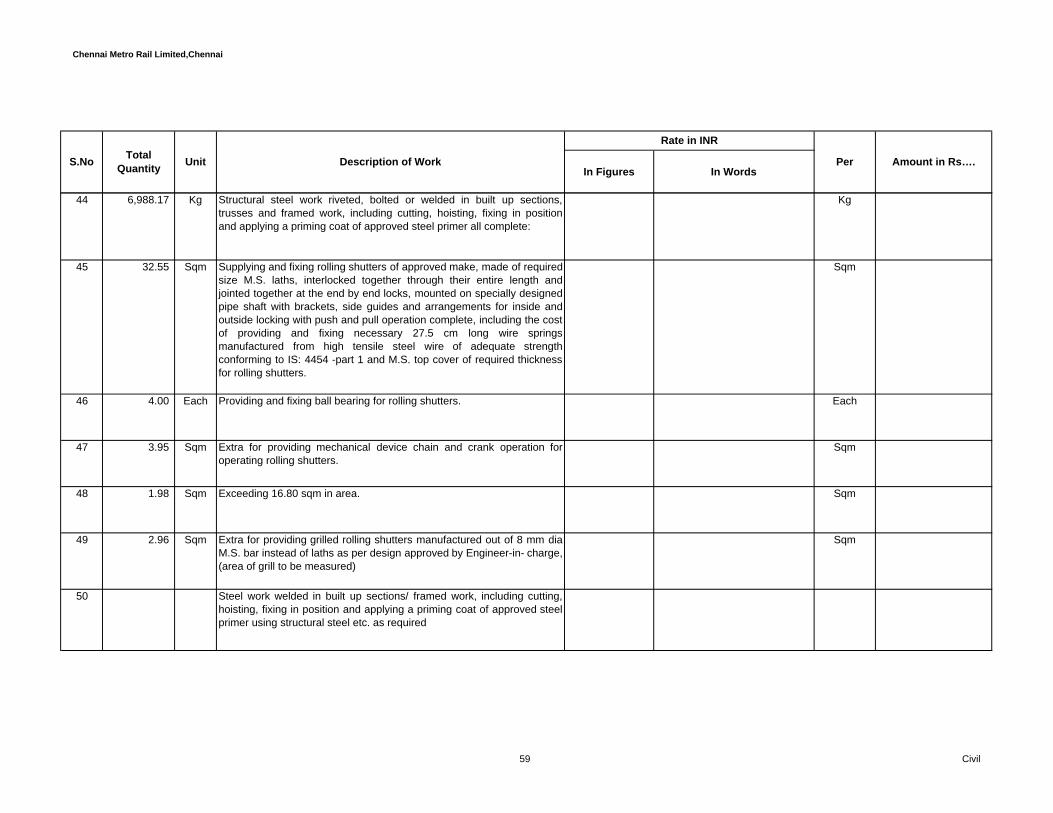
Chennai Metro Rail Limited,Chennai
In Figures In WordsPerUnit Description of Work Amount in Rs….S.No Total
Quantity
Rate in INR
44 6,988.17 Kg Structural steel work riveted, bolted or welded in built up sections,trusses and framed work, including cutting, hoisting, fixing in positionand applying a priming coat of approved steel primer all complete:
Kg
45 32.55 Sqm Supplying and fixing rolling shutters of approved make, made of requiredsize M.S. laths, interlocked together through their entire length andjointed together at the end by end locks, mounted on specially designedpipe shaft with brackets, side guides and arrangements for inside andoutside locking with push and pull operation complete, including the costof providing and fixing necessary 27.5 cm long wire springsmanufactured from high tensile steel wire of adequate strengthconforming to IS: 4454 -part 1 and M.S. top cover of required thicknessfor rolling shutters.
Sqm
46 4.00 Each Providing and fixing ball bearing for rolling shutters. Each
47 3.95 Sqm Extra for providing mechanical device chain and crank operation foroperating rolling shutters.
Sqm
48 1.98 Sqm Exceeding 16.80 sqm in area. Sqm
49 2.96 Sqm Extra for providing grilled rolling shutters manufactured out of 8 mm diaM.S. bar instead of laths as per design approved by Engineer-in- charge,(area of grill to be measured)
Sqm
50 Steel work welded in built up sections/ framed work, including cutting,hoisting, fixing in position and applying a priming coat of approved steelprimer using structural steel etc. as required
59 Civil

Chennai Metro Rail Limited,Chennai
In Figures In WordsPerUnit Description of Work Amount in Rs….S.No Total
Quantity
Rate in INR
a 17,704.15 Kg In stringers, treads, landings etc. of stair cases, including use ofchequered plate wherever required, all complete
Kg
51 Providing and fixing hand rail of approved size by welding etc. to steelladder railing, balcony railing, staircase railing and similar works,including applying priming coat of approved steel primer
a 3,550.30 Kg Using GI pipes Kg
52 3,254.05 Kg Providing and fixing stainless steel ( Grade 304) railing made of Hollowtubes, channels, plates etc., including welding, grinding, buffing,polishing and making curvature (wherever required) and fitting the samewith necessary stainless steel nuts and bolts complete, i/c fixing therailing with necessary accessories & stainless steel dash fasteners,stainless steel bolts etc., of required size, on the top of the floor or theside of waist slab with suitable arrangement as per approval of Engineer-in-charge, (for payment purpose only weight of stainless steel membersshall be considered excluding fixing accessories such as nuts, bolts,fasteners etc.)
Kg
Total Amount C/o to Summary -……..
H Flooring Works ( Interiors )
60 Civil

Chennai Metro Rail Limited,Chennai
In Figures In WordsPerUnit Description of Work Amount in Rs….S.No Total
Quantity
Rate in INR
53 628.21 Sqm 52 mm thick cement concrete flooring with concrete hardener topping,under layer 40 mm thick cement concrete 1:2:4 (1 cement : 2 coarsesand : 4 graded stone aggregate 20 mm nominal size) and top layer 12mm thick cement hardener consisting of mix 1:2 (1 cement hardener mix: 2 graded stone aggregate 6 mm nominal size) by volume, hardeningcompound mixed @ 2 litre per 50 kg of cement or as per manufacturer’sspecifications. This includes cost of cement slurry, but excluding thecost of nosing of steps etc. complete.
Sqm
54 Providing and laying in panels not more than 20 sqm. in plangranolithic flooring with cement concrete 1:2:4 by using coarse gradedaggregate of 6 to 12 mm size laid monolithic with floor concrete andfinished smooth with power trowel including preparation of concretesurface and form work. The screed shall be laid for effective separationof panels not exceeding 20 sqm. in plan etc. complete as perSpecifications and as directed. Unevenness in floor finish shall notexceed +2mm in one square meter area. Rate to include lead , lift at alllevels, pumping, placing, necessary formwork, curing etc., complete
a 497.05 Sqm 50 mm thick Sqm
55 28.60 Sqm Providing and laying self levelling epoxy of 1000 micron thick joint lessfloor topping from approved make, application over the granolithicflooring as per approved manufacturer's specification, includingpreparation of surface, application, wastage, equipment, tools andplants, work at all levels etc. complete as directed by theEmployer /Employer's Representative
Sqm
61 Civil

Chennai Metro Rail Limited,Chennai
In Figures In WordsPerUnit Description of Work Amount in Rs….S.No Total
Quantity
Rate in INR
56 8,907.30 Sqm Providing,laying decorative coloured stamping for the required ordinarycolours and pattern over the concrete and with sealant on the top ofBomanite of approved shade and colour with controlled cementconcrete mix of M25 grade to a thickness of 65 mm for side form work,expansion joint / control joint curing, lighting, power, water laid torequired slope and camber in panels confirming to IRC standard Rateshall also include for Color hardners, releasing Agents, stamping, men,tools & tackles etc.
Sqm
Total Amount C/o to Summary -……..
I Water Proofing Works
PILE CAP OVER PCC57 Providing and laying integral cement based treatment for water proofing
on top of PCC laid for Pile Cap and lift pit, raft slab, UG Sump, STP inthe following order and consisting of following operations. :
Providing plastering over the PCC with CM 1 : 3 - 12 mm thick admixedwith CICO No. 1 @ 2% by weight of cement
Application 2 coats of TAPECRETE Acrylic Polymer ModifiedCementitious Coating over plastered surface
9,924.66 Sqm Providing plastering over treated area with CM 1 : 3 - 12 mm thickadmixed with CICO No. 1 at 2 % by weight of cement
Sqm
58 Providing and Fixing 18 mm dia GI nozzles on pile cap, lift pits, raft slab,UG sump, STP consisting of following operations
62 Civil
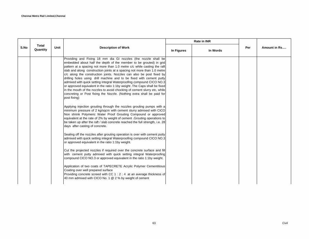
Chennai Metro Rail Limited,Chennai
In Figures In WordsPerUnit Description of Work Amount in Rs….S.No Total
Quantity
Rate in INR
Providing and Fixing 18 mm dia GI nozzles (the nozzle shall beembedded about half the depth of the member to be grouted) in gridpattern at a spacing not more than 1.0 metre c/c while casting the raftslab and along construction joints at a spacing not more than 1.0 metrec/c along the construction joints. Nozzles can also be post fixed bydrilling holes using drill machine and to be fixed with cement puttyadmixed with quick setting integral Waterproofing compound CICO NO.3or approved equivalent in the ratio 1:1by weight .The Caps shall be fixedin the mouth of the nozzles to avoid chocking of cement slurry etc, whileconcreting or Post fixing the Nozzle. (Nothing extra shall be paid forpost fixing)
Applying injection grouting through the nozzles grouting pumps with aminimum pressure of 2 kg/sqcm with cement slurry admixed with CICONon shrink Polymeric Water Proof Grouting Compound or approvedequivalent at the rate of 2% by weight of cement .Grouting operations tobe taken up after the raft / slab concrete reached the full strength, i.e. 28days after casting of concrete.
Sealing off the nozzles after grouting operation is over with cement puttyadmixed with quick setting integral Waterproofing compound CICO NO.3or approved equivalent in the ratio 1:1by weight.
Cut the projected nozzles if required over the concrete surface and fillwith cement putty admixed with quick setting integral Waterproofingcompound CICO NO.3 or approved equivalent in the ratio 1:1by weight.
Application of two coats of TAPECRETE Acrylic Polymer CementitiousCoating over well prepared surfaceProviding concrete screed with CC 1 : 2 : 4 at an average thickness of40 mm admixed with CICO No. 1 @ 2 % by weight of cement
63 Civil
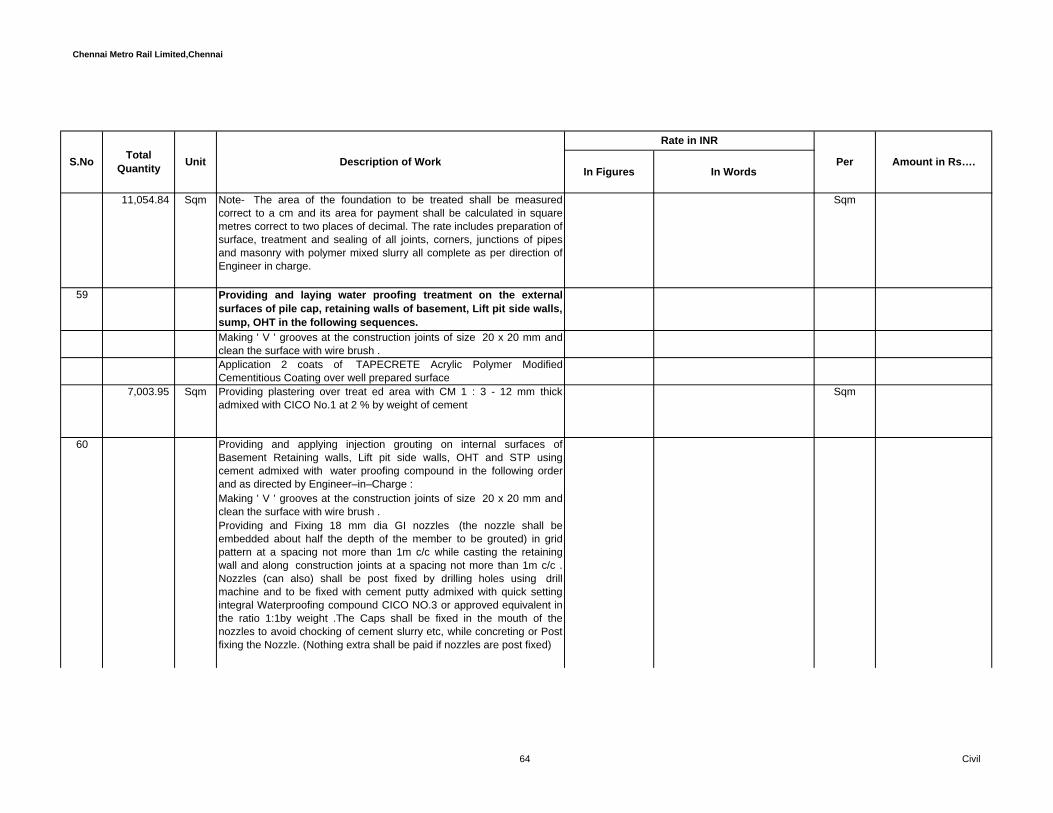
Chennai Metro Rail Limited,Chennai
In Figures In WordsPerUnit Description of Work Amount in Rs….S.No Total
Quantity
Rate in INR
11,054.84 Sqm Note- The area of the foundation to be treated shall be measuredcorrect to a cm and its area for payment shall be calculated in squaremetres correct to two places of decimal. The rate includes preparation ofsurface, treatment and sealing of all joints, corners, junctions of pipesand masonry with polymer mixed slurry all complete as per direction ofEngineer in charge.
Sqm
59 Providing and laying water proofing treatment on the externalsurfaces of pile cap, retaining walls of basement, Lift pit side walls,sump, OHT in the following sequences. Making ' V ' grooves at the construction joints of size 20 x 20 mm andclean the surface with wire brush .Application 2 coats of TAPECRETE Acrylic Polymer ModifiedCementitious Coating over well prepared surface
7,003.95 Sqm Providing plastering over treat ed area with CM 1 : 3 - 12 mm thickadmixed with CICO No.1 at 2 % by weight of cement
Sqm
60 Providing and applying injection grouting on internal surfaces ofBasement Retaining walls, Lift pit side walls, OHT and STP usingcement admixed with water proofing compound in the following orderand as directed by Engineer–in–Charge : Making ' V ' grooves at the construction joints of size 20 x 20 mm andclean the surface with wire brush .Providing and Fixing 18 mm dia GI nozzles (the nozzle shall beembedded about half the depth of the member to be grouted) in gridpattern at a spacing not more than 1m c/c while casting the retainingwall and along construction joints at a spacing not more than 1m c/c .Nozzles (can also) shall be post fixed by drilling holes using drillmachine and to be fixed with cement putty admixed with quick settingintegral Waterproofing compound CICO NO.3 or approved equivalent inthe ratio 1:1by weight .The Caps shall be fixed in the mouth of thenozzles to avoid chocking of cement slurry etc, while concreting or Postfixing the Nozzle. (Nothing extra shall be paid if nozzles are post fixed)
64 Civil

Chennai Metro Rail Limited,Chennai
In Figures In WordsPerUnit Description of Work Amount in Rs….S.No Total
Quantity
Rate in INR
pplying injection grouting through the nozzles by hand operated groutingpumps with a minimum pressure of 2 kg/sqcm with cement slurryadmixed with CICO Non shrink Polymeric Water Proof GroutingCompound or approved equivalent at the rate of 2% by weight of cement.Grouting operations to be taken up after the concrete reached the fullstrength, i.e 28 days after casting of concrete.
Sealing off the nozzles after grouting operation is over with cement puttyadmixed with quick setting integral Waterproofing compound CICO NO.3or approved equivalent in the ratio 1:1by weight.
Cut the projected nozzles if required over the concrete surface and fillwith cement putty admixed with quick setting integral Waterproofingcompound CICO NO.3 or approved equivalent in the ratio 1:1by weight.
Application of two coats of TAPECRETE Acrylic Polymer CementitiousCoating over well prepared surfaceProviding Plastering over treated area with CM 1 : 3 - 20 mm thickadmixed with CICO No. 1 @ 2 % by weight of cement
9,929.99 Sqm Note- The area of the RCC to be treated shall be measured correct to acm and its area for payment shall be calculated in square metres correctto two places of decimal
Sqm
61 BALCONY AREA WATERPROOFING (WITH BRICK BAT COBA) :-
GENERAL:- 1. Preparation of surface on Plain cement concrete by mechanicalupgrading to remove all loose mortar, laitance, oil, grease and wash thesurface by using fine dressed tools and tackles.
Application of two coats of TAPECRETE - RTU Polymer BasedElastomeric Coating over well prepared surface
65 Civil

Chennai Metro Rail Limited,Chennai
In Figures In WordsPerUnit Description of Work Amount in Rs….S.No Total
Quantity
Rate in INR
627.22 Sqm Providing plastering over treated area with CM 1 : 3 - 20 mm thickadmixed with CICO No. 1 @ 2 % by weight of cement
Sqm
62 TOILET SUNKEN AREA WATERPROOFINGTreatment to bottom and sides of toilet sunken slab covering thefollowing sequence of operations :a). Providing, supplying, mixing, laying cement plaster 12 mm thick withcement sand mortar 1:3 mixed with approved water proofing compoundlike CICO No.1 or approved equivalent conforming to IS 2645 at the ratespecified by the manufacturer over coated surface of operation (a)above including preparation of surface, dewatering, finishing, curing,etc. all complete as per manufacturer's specifications and asdirected.
b) Providing, supplying, mixing, applying two coats of TAPECRETEAcrylic Polymer Modified Cementitious Coating, flexible water proofing toa thickness of 2 mm over the surface of bottom and sides of toiletsunken slab including preparation of surface, finishing, curing etc. allcomplete at all levels as per manufacturer's specifications and asdirected.
c) Final coat of plaster as per operation (a) above over the coatedsurface of operation (b) above all complete as directed.
63 Treatment to top of brick jelly concrete / BRICK - BAT COBA insunken slab covering the following sequence of operations :
66 Civil

Chennai Metro Rail Limited,Chennai
In Figures In WordsPerUnit Description of Work Amount in Rs….S.No Total
Quantity
Rate in INR
a) Providing, supplying, mixing, laying cement plaster 12 mm thick withcement mortar 1:3 mixed with approved water proofing compound likeCICO NO:1 or approved equivalent conforming to IS 2645 at the ratespecified by the manufacturer over BRICKBAT COBA Elevations andheights including preparation of surfaces, finishing, curing etc. allcomplete as per manufacturer’s specification and as directed.
b) Providing, supplying, mixing, applying 2 coats of TAPECRETE AcrylicPolymer Modified Cementitious Coating, flexible, water proofing to athickness of 2 mm over the plastered surface of operation (a) aboveincluding preparation of surface, dewatering, finishing, curing etc. allcomplete as per manufacturer's specification and as directed.
c) Final coat of plaster as per operation (a) above over the coatedsurface of operation (b) above to receive floor finish all complete asdirected.
67 Civil
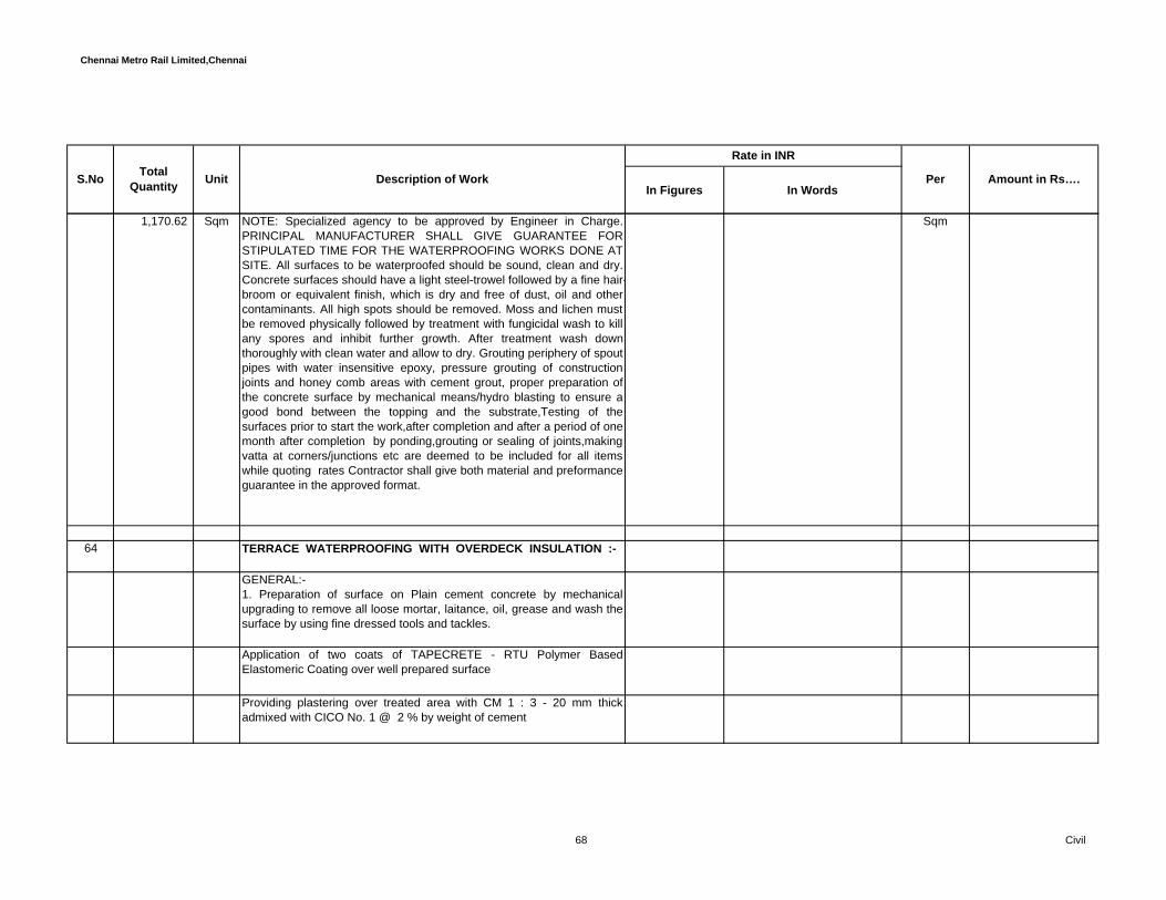
Chennai Metro Rail Limited,Chennai
In Figures In WordsPerUnit Description of Work Amount in Rs….S.No Total
Quantity
Rate in INR
1,170.62 Sqm NOTE: Specialized agency to be approved by Engineer in Charge.PRINCIPAL MANUFACTURER SHALL GIVE GUARANTEE FORSTIPULATED TIME FOR THE WATERPROOFING WORKS DONE ATSITE. All surfaces to be waterproofed should be sound, clean and dry.Concrete surfaces should have a light steel-trowel followed by a fine hair-broom or equivalent finish, which is dry and free of dust, oil and othercontaminants. All high spots should be removed. Moss and lichen mustbe removed physically followed by treatment with fungicidal wash to killany spores and inhibit further growth. After treatment wash downthoroughly with clean water and allow to dry. Grouting periphery of spoutpipes with water insensitive epoxy, pressure grouting of constructionjoints and honey comb areas with cement grout, proper preparation ofthe concrete surface by mechanical means/hydro blasting to ensure agood bond between the topping and the substrate,Testing of thesurfaces prior to start the work,after completion and after a period of onemonth after completion by ponding,grouting or sealing of joints,makingvatta at corners/junctions etc are deemed to be included for all itemswhile quoting rates Contractor shall give both material and preformanceguarantee in the approved format.
Sqm
64 TERRACE WATERPROOFING WITH OVERDECK INSULATION :-
GENERAL:- 1. Preparation of surface on Plain cement concrete by mechanicalupgrading to remove all loose mortar, laitance, oil, grease and wash thesurface by using fine dressed tools and tackles.
Application of two coats of TAPECRETE - RTU Polymer BasedElastomeric Coating over well prepared surface
Providing plastering over treated area with CM 1 : 3 - 20 mm thickadmixed with CICO No. 1 @ 2 % by weight of cement
68 Civil
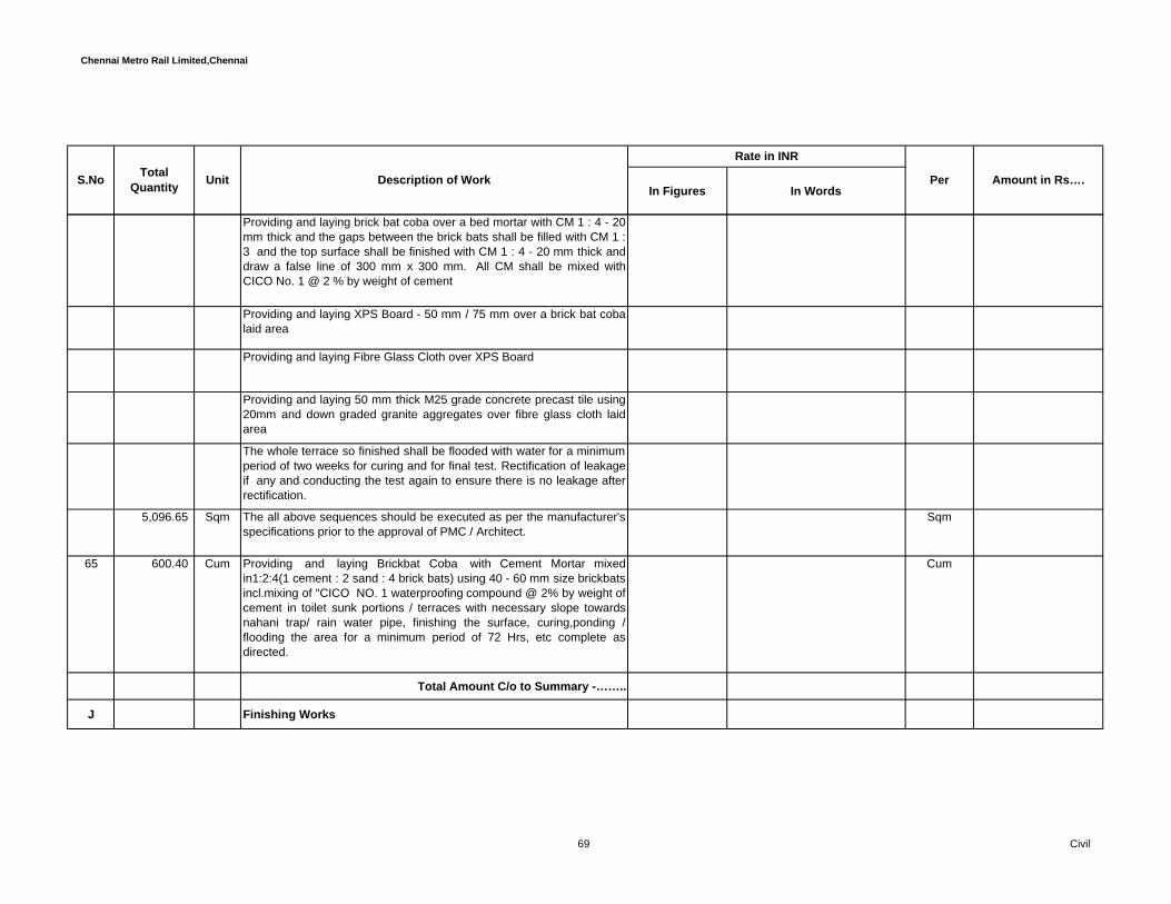
Chennai Metro Rail Limited,Chennai
In Figures In WordsPerUnit Description of Work Amount in Rs….S.No Total
Quantity
Rate in INR
Providing and laying brick bat coba over a bed mortar with CM 1 : 4 - 20mm thick and the gaps between the brick bats shall be filled with CM 1 :3 and the top surface shall be finished with CM 1 : 4 - 20 mm thick anddraw a false line of 300 mm x 300 mm. All CM shall be mixed withCICO No. 1 @ 2 % by weight of cement
Providing and laying XPS Board - 50 mm / 75 mm over a brick bat cobalaid area
Providing and laying Fibre Glass Cloth over XPS Board
Providing and laying 50 mm thick M25 grade concrete precast tile using20mm and down graded granite aggregates over fibre glass cloth laidarea
The whole terrace so finished shall be flooded with water for a minimumperiod of two weeks for curing and for final test. Rectification of leakageif any and conducting the test again to ensure there is no leakage afterrectification.
5,096.65 Sqm The all above sequences should be executed as per the manufacturer'sspecifications prior to the approval of PMC / Architect.
Sqm
65 600.40 Cum Providing and laying Brickbat Coba with Cement Mortar mixedin1:2:4(1 cement : 2 sand : 4 brick bats) using 40 - 60 mm size brickbatsincl.mixing of "CICO NO. 1 waterproofing compound @ 2% by weight ofcement in toilet sunk portions / terraces with necessary slope towardsnahani trap/ rain water pipe, finishing the surface, curing,ponding /flooding the area for a minimum period of 72 Hrs, etc complete asdirected.
Cum
Total Amount C/o to Summary -……..
J Finishing Works
69 Civil

Chennai Metro Rail Limited,Chennai
In Figures In WordsPerUnit Description of Work Amount in Rs….S.No Total
Quantity
Rate in INR
66 45,582.06 Sqm Plastering for internal surfaces with 12 mm thick in Cement Mortar 1:6(1 cement : 6 six sand ) and as directed. Rate shall include fornecessary hacking, staging, scafolding and curing at all levels andelevations as directed by the Engineer-in-charge..
Sqm
67 7,694.29 Sqm Plastering for external surfaces with18 mm cement plaster in two coatsunder layer 12 mm thick cement plaster 1:5 (1 cement: 5 coarse sand)and a top layer 6 mm thick cement plaster 1:3 (1 cement : 3 coarsesand) finished rough withsponge. Rate shall include for necessary hacking, staging, scafoldingand curing to the height of 10m from the ground level as directed by theEngineer-in-charge..
Sqm
68Extra for plastering exterior walls of height more than 10 m from ground level for every additional height of 3 m or part thereof.
a 1,162.73 Sqm 10m to 13m lvl Sqm
b 1,236.69 Sqm 13m to 16m lvl Sqm
c 1,028.60 Sqm 16m to 19m lvl Sqm
d 599.61 Sqm 19m to 22m lvl Sqm
e 508.88 Sqm 22m to 25m lvl Sqm
70 Civil

Chennai Metro Rail Limited,Chennai
In Figures In WordsPerUnit Description of Work Amount in Rs….S.No Total
Quantity
Rate in INR
f 508.88 Sqm 25m to 28m lvl Sqm
g 508.88 Sqm 28m to 31m lvl Sqm
h 424.07 Sqm 31m to 34m lvl Sqm
i 177.52 Sqm 34m to 37m lvl Sqm
j - Sqm 37m to 40m lvl Sqm
k - Sqm 40m to 43m lvl Sqm
l - Sqm 43m to 46m lvl Sqm
m - Sqm 46m to 49m lvl Sqm
69 52,796.85 Sqm Plastering to R.C walls, slabs, peripheral beams and columns withCement Mortar 1:3,(1cement : 3 fine sand) 6 mm thick according to thespecification. Rate shall include for necessary hacking, staging,scafolding and curing at all levels and elevations etc.complete asdirected. and as directed by the Engineer-incharge.
Sqm
71 Civil

Chennai Metro Rail Limited,Chennai
In Figures In WordsPerUnit Description of Work Amount in Rs….S.No Total
Quantity
Rate in INR
70 4,759.37 Sqm Applying white washing three coats to ceilings and walls with pure shelllime or fat lime conforming to IS-712 all as per Specification and asdirected. complying with relevant standard specification, as directed.
Sqm
Total Amount C/o to Summary -……..
L Miscellaneous Works
71 587.78 Sqm Providing, supplying and spraying/spreading the Fire sealing in shaftchequered plate for pipe outlets, trays, cables, openings of required diaoutlets using penetration seals of approved make including necessarymechanical equipments, tools and tackles etc complete.The rate shouldinclude cotton pads, sealing of joints using self sealing, non shrinkcement penetration seals / grouts of approved makes either single ordouble component with necessary formwork, staging, tools, etc.,complete with minimum of 30 mm depth for two hours fire rating.Hilti orPromat or Equivalent make or approved by the Engineer-in-charge/consultant
Sqm
72 Making Core Cutting in slabs / beams / retaining walls and any otherR.C members to any dia & depth by using 'HILTI' or equivalent makediamond drilling machine with tolerance for any type of inserts, anchorfasteners etc. Rate shall include for all charge, preparation of surface,cutting of reinforcement, cleaning the surface, staging, scaffoldingapplication of necessary chemical / foil (HAV) as per manufacturesspecification with necessary tools and equipments water and power,removal of debris from the site, staging scaffolding etc complete, asdirected by the Engineer-in-charge.
i 75 to 100 mm dia to the following depth:
72 Civil

Chennai Metro Rail Limited,Chennai
In Figures In WordsPerUnit Description of Work Amount in Rs….S.No Total
Quantity
Rate in INR
a 9.00 Nos 150 mm Depth Nos
b 9.00 Nos 200 mm Depth Nos
c 9.00 Nos 250 mm Depth Nos
d 9.00 Nos 300 mm Depth Nos
ii 100 to 150 mm dia to the following depth:
a 9.00 Nos 150 mm Depth Nos
b 9.00 Nos 200 mm Depth Nos
c 9.00 Nos 250 mm Depth Nos
d 9.00 Nos 300 mm Depth Nos
iii 150 to 225 mm dia to the following depth:
73 Civil
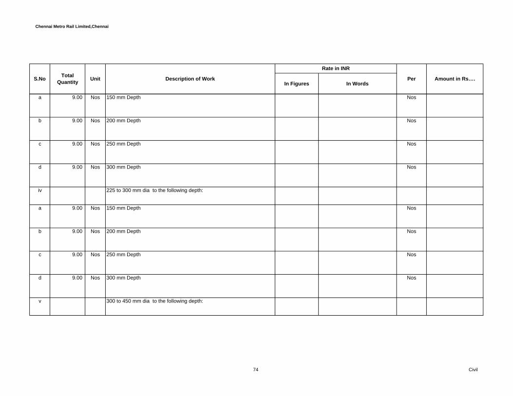
Chennai Metro Rail Limited,Chennai
In Figures In WordsPerUnit Description of Work Amount in Rs….S.No Total
Quantity
Rate in INR
a 9.00 Nos 150 mm Depth Nos
b 9.00 Nos 200 mm Depth Nos
c 9.00 Nos 250 mm Depth Nos
d 9.00 Nos 300 mm Depth Nos
iv 225 to 300 mm dia to the following depth:
a 9.00 Nos 150 mm Depth Nos
b 9.00 Nos 200 mm Depth Nos
c 9.00 Nos 250 mm Depth Nos
d 9.00 Nos 300 mm Depth Nos
v 300 to 450 mm dia to the following depth:
74 Civil

Chennai Metro Rail Limited,Chennai
In Figures In WordsPerUnit Description of Work Amount in Rs….S.No Total
Quantity
Rate in INR
a 9.00 Nos 150 mm Depth Nos
b 9.00 Nos 200 mm Depth Nos
c 9.00 Nos 250 mm Depth Nos
d 9.00 Nos 300 mm Depth Nos
73 460.00 No's Supplying and fixing poly-propelene rungs of 25 mm square bar of size260 x 170 mm for access way including anchorage in walls to aminimum depth of 100 mm with C.C 1:2:4 (one cement,two fineaggregate and four coarse aggregate) etc. complete and as directed bythe Engineer-in-charge.( Duct ,Shafts & UG sump,Over Head Tank andwherever necessary) Note: Rungs to be fixed before concreting and necessary provision to bemade in the shuttering.etc complete, as directed by the Engineer-in-charge.
No's
74 9.87 Cum Providing and laying of light weight concrete fill on structural slabusing Hemalite/Vermiculite cement based composition having physicalelasticity , chemical inertness, firm adhesion, fire resistance with thermal/ acoustic insulation properties, anti-corrosion, anti-condensation, etc inthe required proportion to get the desired density, mixing, transportation,placing, compacting and finishing to the required level with necessaryside supports, equipments and its density is 600kg/cum wherevernecessary areas to be fill as directed by the Engineer-in-charge.etc ascomplete with all respects complying with relevant standaradspecification as directed by the Engineer-in-charge.
Cum
75 Civil

Chennai Metro Rail Limited,Chennai
In Figures In WordsPerUnit Description of Work Amount in Rs….S.No Total
Quantity
Rate in INR
75 9.00 No's Supplying and fixing 40mm dia. and 150mm or more long G.I. pipespouts in sun shades including painting two coats of first qualitysynthetic enamel paint of approved make and tint over one coat ofprimer as complete in all respects complying with relevant standardspecification and as directed by the Engineer-in-charge.
No's
76 Supplying and fixing Ductile Iron manhole cover and frame as perapproved make ,cover weight and being size mentioned below andspecified size in the drawing etc., including painting with two coats ofanticorrosive paint over a coat of primer etc., fixing lockingarrangements, fixing Man-hole over, grouting the anchors with CC 1:2:4(one cement,two fine aggregate and four coarse aggregate), ascomplete in all respects complying with relevant standard specificationsand as directed by the Engineer-in-charge.
a 79.00 No's 600X600 mm Medium duty DI manhole cover not less than 65kgs No's
77 Providing and laying in position the RCC humepipes (NP2) of approvedquality and make including collars,. necessary Excavation, PCC 1:2:4supports, Sand cushion of 150mm on all sides, Refilling with earth,Compaction and making good the level, alignment etc.,complete asdirected by the Engineer-in-charge.
a 394.48 RMT 300 mm dia RMT
78 Providing, Fabricating and fixing puddle flanges made of GI 'c' class pipewith 6mm thick MS plate alround 50 mm fixed to sump and water tanketc. all complete as directed by the Engineer-in-Charge.
76 Civil

Chennai Metro Rail Limited,Chennai
In Figures In WordsPerUnit Description of Work Amount in Rs….S.No Total
Quantity
Rate in INR
a 59.00 Nos 50mm dia - 1000mm long Each
b 39.00 Nos 80mm dia - 1000mm long Each
c 47.00 Nos 100mm dia - 1000mm long Each
79 Providing and fixing in position single component, self sealing waterswelling bars made up of flexible polymer composites at constructionjoints of retaining walls and water retaining structures and whereverspecified with proper overlaps at joints of approved makes as perconsultants approval.
a 9.86 Rmt Syncoflex make (Vertical joints) Rmt
b Masterflex 610 of MBT make
i 14.79 Rmt 20mm x 20mm Rmt
ii 14.79 Rmt 10mm x10mm (Horizontal joints) Rmt
77 Civil
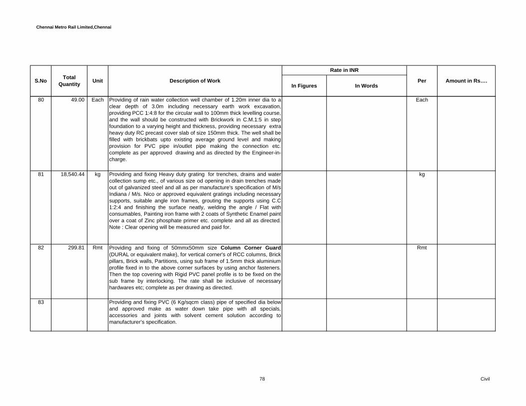
Chennai Metro Rail Limited,Chennai
In Figures In WordsPerUnit Description of Work Amount in Rs….S.No Total
Quantity
Rate in INR
80 49.00 Each Providing of rain water collection well chamber of 1.20m inner dia to aclear depth of 3.0m including necessary earth work excavation,providing PCC 1:4:8 for the circular wall to 100mm thick levelling course,and the wall should be constructed with Brickwork in C.M.1:5 in stepfoundation to a varying height and thickness, providing necessary extraheavy duty RC precast cover slab of size 150mm thick. The well shall befilled with brickbats upto existing average ground level and makingprovision for PVC pipe in/outlet pipe making the connection etc.complete as per approved drawing and as directed by the Engineer-in-charge.
Each
81 18,540.44 kg Providing and fixing Heavy duty grating for trenches, drains and watercollection sump etc., of various size od opening in drain trenches madeout of galvanized steel and all as per manufacture's specification of M/sIndiana / M/s. Nico or approved equivalent gratings including necessarysupports, suitable angle iron frames, grouting the supports using C.C1:2:4 and finishing the surface neatly, welding the angle / Flat withconsumables, Painting iron frame with 2 coats of Synthetic Enamel paintover a coat of Zinc phosphate primer etc. complete and all as directed.Note : Clear opening will be measured and paid for.
kg
82 299.81 Rmt Providing and fixing of 50mmx50mm size Column Corner Guard(DURAL or equivalent make), for vertical corner's of RCC columns, Brickpillars, Brick walls, Partitions, using sub frame of 1.5mm thick aluminiumprofile fixed in to the above corner surfaces by using anchor fasteners.Then the top covering with Rigid PVC panel profile is to be fixed on thesub frame by interlocking. The rate shall be inclusive of necessaryhardwares etc; complete as per drawing as directed.
Rmt
83 Providing and fixing PVC (6 Kg/sqcm class) pipe of specified dia belowand approved make as water down take pipe with all specials,accessories and joints with solvent cement solution according tomanufacturer’s specification.
78 Civil

Chennai Metro Rail Limited,Chennai
In Figures In WordsPerUnit Description of Work Amount in Rs….S.No Total
Quantity
Rate in INR
a 641.03 Rmt 150 mm dia Rmt
b 16.77 Rmt 110 mm dia Rmt
Total Amount C/o to Summary -……..
M Road & Pavement Works
84 5,680.48 Sqm Preparation & sectioning the area road surface and compacting with 10ton power roller including forming camber and gradients watering androlling to reach required density as complete.as directed by the Engineer-in-charge.
Sqm
85 1,704.15 Cum Construction of 300mm the Granular subbase (GSB) by providingcoarse graded material 53mm to 4.75 mm ,spreading in uniform layerswith motor grader on prepared surface mixing by mix in place methodwith rotavator at OMC and compacting with vibratory roller to achieve the desired density, as complete in all respects complying with relevantstandard IRC,MORTH and MOST Specifications and as directed by theEngineer-in-charge.
Cum
86 6,146.95 Cum Providing, Laying, Spreading and compacting 45 mm to 4.75 mmgraded stone aggregate of 200mm the wet mix macadam (WMM)specification including premixing the material with water at OMC inmechanical mix plant,carriage of mixed material by tipper to site,layingin uniform layers with paver in subbase / sub course on well preparedsurface and compacting with vibratory roller to achieve the desireddensity,as complete in all respects complying with relevant standardMOST specification,as directed by the Engineer-in-charge.
Cum
79 Civil

Chennai Metro Rail Limited,Chennai
In Figures In WordsPerUnit Description of Work Amount in Rs….S.No Total
Quantity
Rate in INR
87 572.00 Cum Providing and laying 100mm the. Plain cement concrete1:3:6 (Onecement, three fine aggregate and six coarse aggregate) by using coarsegraded aggregate of 25 mm and down size for levelling course in roadand pavement areas wherever necessary (as per drawing) includinglaying in layers of thickness not exceeding 100mm and in alternativebays not exceeding 40 sqm as directed including form work wherevernecessary and well compacted etc. as complete in all respectscomplying with relevant standard specification as directed by theEngineer-in-charge.
Cum
88 Providing and laying controlled cement concrete mix of M20 grade toa thickness of 150 mm for roads and pavements laid to required slopeand camber in panels confirming to IRC standard. Rate shall include forproviding IRC Weldmesh of size 100x100 - 12 Gauge - one layersconfirming to IS: 1566 & IS: 4948 or equivalent BS, necessaryformwork, shuttering,props, bracing and wedges, sufficiently strong &stable, providing 10 to 25 mm wide expansion joints and constructionjoints & closing the joints using polyurethane sealant - "VULKEM" - 202PU from Supreme or approved equivalent make etc.complete, asdirected by the Engineer-in-charge .
857.99 Cum Rate shall include for preparation of surface, laying the concrete inpanels of area not more than 40 Sqm with construction joints and suchjoints shall be made in the position hereinafter specified or elsewhere asapproved. Such joints shall be truly vertical or horizontal as the casemay be, except that in an inclined or curved members the joints shall bestrictly at right angles to the axis of the member.Concrete shall becompacted by mechanical vibrating machine until a dense concrete isobtained. The vibration continues during entire period of placingconcrete with top shall be provided with broom finish. Compaction shallbe complete before the initial setting starts confirming to specificationand over vibration shall be avoided and all confirming to IRC standardsor equivalent BS specification etc complete, as directed by the Engineer-
Cum
80 Civil

Chennai Metro Rail Limited,Chennai
In Figures In WordsPerUnit Description of Work Amount in Rs….S.No Total
Quantity
Rate in INR
89 5,223.87 Sqm Supplying and laying Shotblasted Flexi Pavers of approved design -65 mm thick, total weight shall be 25 kg approximately per one set or1.94 Sft of flexi pavers contains five pieces including transportation ofthe blocks to the site ,preparation of surface,supplying and filling with dryriver sand to 50 mm thick, leveling and compacting with plate vibratorand laying of the flexi paver blocks with sand binding and finalcompaction with plate vibrator of 3 tone capacity finishing the surfaceincluding cutting of blocks at the edges including all labour and materialsetc as complete in all respects complying with relevant standardspecification, as directed by the Engineer-incharge. (For Pathway)
Sqm
90 719.93 RMT Providing thermoplastic painting for car park and road line and arrowmarks with 100mm wide involving cleaning the surface free of dirt andloose particles applying one coat of primer and applying one layer ofthermoplastic paint with drop on glass beads. Rate shall include for allmaterials & labour components etc., as complete all respects complyingwith relevant IRC specifications, as directed by the Engineer-incharge.
RMT
Total Amount C/o to Summary -……..
81 Civil
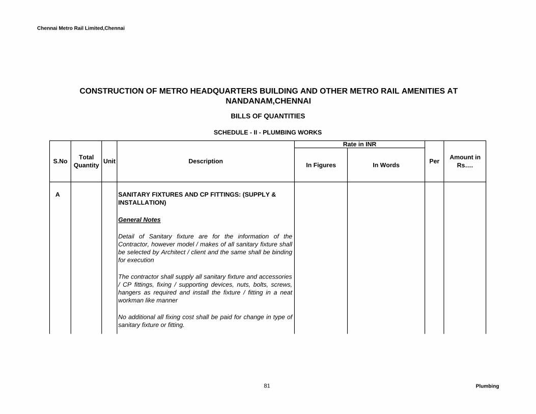
Chennai Metro Rail Limited,Chennai
In Figures In Words
A SANITARY FIXTURES AND CP FITTINGS: (SUPPLY & INSTALLATION)
General Notes
Detail of Sanitary fixture are for the information of theContractor, however model / makes of all sanitary fixture shallbe selected by Architect / client and the same shall be bindingfor execution
The contractor shall supply all sanitary fixture and accessories/ CP fittings, fixing / supporting devices, nuts, bolts, screws,hangers as required and install the fixture / fitting in a neatworkman like manner
No additional all fixing cost shall be paid for change in type ofsanitary fixture or fitting.
Rate in INR
Amount in Rs….
CONSTRUCTION OF METRO HEADQUARTERS BUILDING AND OTHER METRO RAIL AMENITIES AT NANDANAM,CHENNAI
BILLS OF QUANTITIES
SCHEDULE - II - PLUMBING WORKS
S.No TotalQuantity Unit Description Per
81 Plumbing
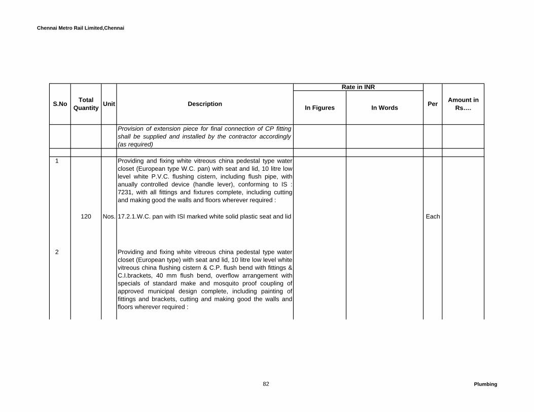
Chennai Metro Rail Limited,Chennai
In Figures In Words
Rate in INR
Amount in Rs….S.No Total
Quantity Unit Description Per
Provision of extension piece for final connection of CP fittingshall be supplied and installed by the contractor accordingly(as required)
1 Providing and fixing white vitreous china pedestal type watercloset (European type W.C. pan) with seat and lid, 10 litre lowlevel white P.V.C. flushing cistern, including flush pipe, withanually controlled device (handle lever), conforming to IS :7231, with all fittings and fixtures complete, including cuttingand making good the walls and floors wherever required :
120 Nos. 17.2.1.W.C. pan with ISI marked white solid plastic seat and lid Each
2 Providing and fixing white vitreous china pedestal type watercloset (European type) with seat and lid, 10 litre low level whitevitreous china flushing cistern & C.P. flush bend with fittings &C.I.brackets, 40 mm flush bend, overflow arrangement withspecials of standard make and mosquito proof coupling ofapproved municipal design complete, including painting offittings and brackets, cutting and making good the walls andfloors wherever required :
82 Plumbing

Chennai Metro Rail Limited,Chennai
In Figures In Words
Rate in INR
Amount in Rs….S.No Total
Quantity Unit Description Per
91 Nos. 17.3.1 W.C. pan with ISI marked white solid plastic seat and lid Each
3 Providing and fixing wash basin with C.I. brackets, 15 mm C.P.brass pillar taps, 32 mm C.P. brass waste of standard pattern,including painting of fittings and brackets, cutting and makinggood the walls wherever require:
200 Nos. 17.7.1 White Vitreous China Wash basin size 630x450 mmwith a pair of 15 mm C.P. brass pillar taps
Each
4 Providing and fixing white vitreous china flat back half stallurinal of size 580x380x350 mm with white PVC automaticflushing cistern, with fittings, standard size C.P. brass flushpipe, spreaders with unions and clamps (all in C.P. brass) withwaste fitting as per IS : 2556, C.I. trap with outlet grating andother couplings in C.P. brass, including painting of fittings andcutting and making good the walls and floors whereverrequired :
83 Plumbing
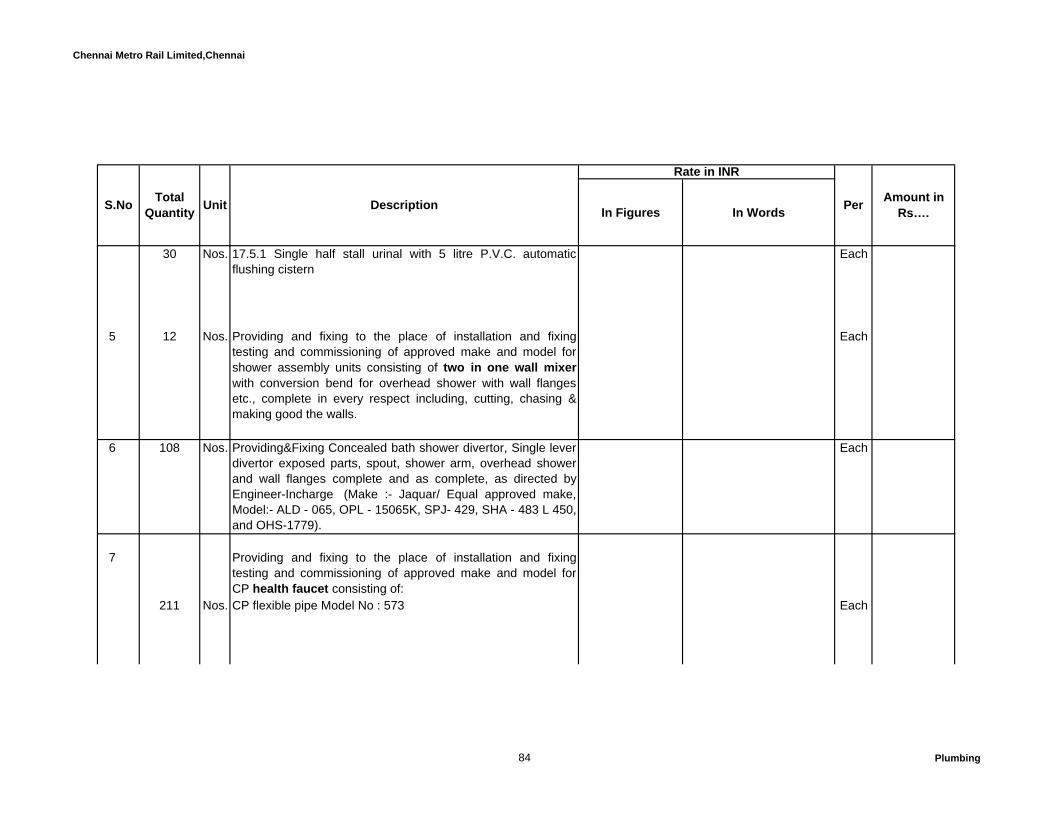
Chennai Metro Rail Limited,Chennai
In Figures In Words
Rate in INR
Amount in Rs….S.No Total
Quantity Unit Description Per
30 Nos. 17.5.1 Single half stall urinal with 5 litre P.V.C. automaticflushing cistern
Each
5 12 Nos. Providing and fixing to the place of installation and fixingtesting and commissioning of approved make and model forshower assembly units consisting of two in one wall mixerwith conversion bend for overhead shower with wall flangesetc., complete in every respect including, cutting, chasing &making good the walls.
Each
6 108 Nos. Providing&Fixing Concealed bath shower divertor, Single leverdivertor exposed parts, spout, shower arm, overhead showerand wall flanges complete and as complete, as directed byEngineer-Incharge (Make :- Jaquar/ Equal approved make,Model:- ALD - 065, OPL - 15065K, SPJ- 429, SHA - 483 L 450,and OHS-1779).
Each
7 Providing and fixing to the place of installation and fixingtesting and commissioning of approved make and model forCP health faucet consisting of:
211 Nos. CP flexible pipe Model No : 573 Each
84 Plumbing

Chennai Metro Rail Limited,Chennai
In Figures In Words
Rate in INR
Amount in Rs….S.No Total
Quantity Unit Description Per
211 Nos. PTMT Angle Stop cock with Flange 15 mm Each
8 48 Nos. Providing and fixing to the place of installation and fixingtesting and commissioning of approved make and model forbest quality stainless steel sink with drain board 510x1040mm bowl depth 178 mm,38mm dia CP waste couplings, 38mmdia bottle trap etc complete. The working shall include fixingthe sink in position setting in CM etc, complete and also cuttingholes in wall and floors and making good the floor.
Each
9 1 Nos. Providing and fixing to the place of installation and fixingtesting and commissioning of approved make and model forbest quality and approved make stainless steel kitchen sinkwith single bowl only size 610x460 bowl depth 200 mm madeof 18 gauge sheet 40mm dia CP waste coupling, 40mm PVCwaste pipe etc, complete.
Each
85 Plumbing
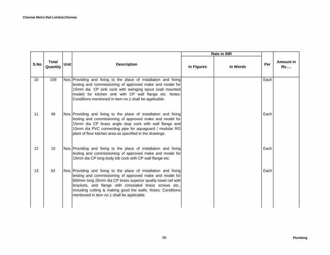
Chennai Metro Rail Limited,Chennai
In Figures In Words
Rate in INR
Amount in Rs….S.No Total
Quantity Unit Description Per
10 109 Nos. Providing and fixing to the place of installation and fixingtesting and commissioning of approved make and model for15mm dia CP sink cock with swinging spout (wall mountedmodel) for kitchen sink with CP wall flange etc. Notes:Conditions mentioned in item no.1 shall be applicable.
Each
11 48 Nos. Providing and fixing to the place of installation and fixingtesting and commissioning of approved make and model for15mm dia CP brass angle stop cock with wall flange and15mm dia PVC connecting pipe for aquaguard / modular ROplant of floor kitchen area as specified in the drawings.
Each
12 10 Nos. Providing and fixing to the place of installation and fixingtesting and commissioning of approved make and model for15mm dia CP long body bib cock with CP wall flange etc.
Each
13 62 Nos. Providing and fixing to the place of installation and fixingtesting and commissioning of approved make and model for600mm long 25mm dia CP brass superior quality towel rail withbrackets, and flange with concealed brass screws etc.,including cutting & making good the walls. Notes: Conditionsmentioned in item no.1 shall be applicable.
Each
86 Plumbing
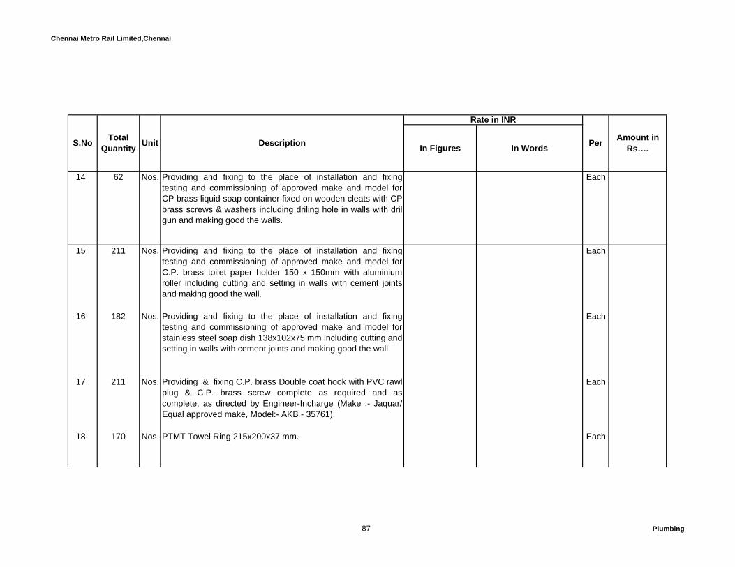
Chennai Metro Rail Limited,Chennai
In Figures In Words
Rate in INR
Amount in Rs….S.No Total
Quantity Unit Description Per
14 62 Nos. Providing and fixing to the place of installation and fixingtesting and commissioning of approved make and model forCP brass liquid soap container fixed on wooden cleats with CPbrass screws & washers including driling hole in walls with drilgun and making good the walls.
Each
15 211 Nos. Providing and fixing to the place of installation and fixingtesting and commissioning of approved make and model forC.P. brass toilet paper holder 150 x 150mm with aluminiumroller including cutting and setting in walls with cement jointsand making good the wall.
Each
16 182 Nos. Providing and fixing to the place of installation and fixingtesting and commissioning of approved make and model forstainless steel soap dish 138x102x75 mm including cutting andsetting in walls with cement joints and making good the wall.
Each
17 211 Nos. Providing & fixing C.P. brass Double coat hook with PVC rawlplug & C.P. brass screw complete as required and ascomplete, as directed by Engineer-Incharge (Make :- Jaquar/Equal approved make, Model:- AKB - 35761).
Each
18 170 Nos. PTMT Towel Ring 215x200x37 mm. Each
87 Plumbing

Chennai Metro Rail Limited,Chennai
In Figures In Words
Rate in INR
Amount in Rs….S.No Total
Quantity Unit Description Per
19 176 Nos. P.T.M.T. Stop cock (concealed) 15 mm Each
20 120 Nos. Providing and fixing to the place of installation and fixingtesting and commissioning of approved make and model forracold / venus / equalent make electically operated storagewater heater having 25lts. Capacity, inner container made fromcopper or stainless steel including the remal instalation safetyvalve, vacuum relief valve, neon lamp, mounting brackets,installing in position with coach screws or bolts, nuts, 2nosangle stop cock and 2nos flexible hose etc, complete. Notes:a) Conditions mentioned in item no.1 shall be applicable.(Venus - Magma-Vertical-Model 15GV) 15 lit. capacity.
Each
21 10 Nos. Providing&Fixing solid state, no touch operting, fully hygienichand drier of approved shade with single/double blower,with time delay, summer & winter control, music while drying,volume ON/OFF controls including providing necessarybrackets, cable from drier to Plug, Plug top key and lock etc,complete as directed by the Engineer-incharge.(Make-Eronics /Equal approved make Model No EH06S )
Each
88 Plumbing
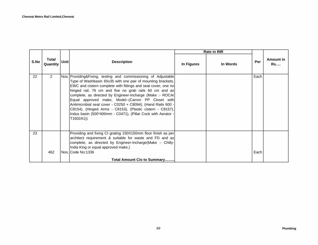
Chennai Metro Rail Limited,Chennai
In Figures In Words
Rate in INR
Amount in Rs….S.No Total
Quantity Unit Description Per
22 2 Nos. Providing&Fixing, testing and commissioning of AdjustableType of Washbasin 65x35 with one pair of mounting brackets,EWC and cistern complete with fittings and seat cover, one nohinged rail, 76 cm and five no grab rails 60 cm and ascomplete, as directed by Engineer-Incharge (Make :- ROCA/Equal approved make, Model:-(Carron PP Closet withAntimicrobial seat cover - C0250 + C8094), (Hand Rails 600 -C8154), (Hinged Arms - C8153), (Plastic cistern - C8157),Indus basin (500*400mm - C0471), (Pillar Cock with Aerator -T1602A1))
Each
23 Providing and fixing CI grating 150X150mm floor finish as perarchitect requirement & suitable for waste and FD and ascomplete, as directed by Engineer-Incharge(Make :- Chilly-India King or equal approved make,)
462 Nos. Code No:1336 Each
Total Amount C/o to Summary……..
89 Plumbing

Chennai Metro Rail Limited,Chennai
In Figures In Words
Rate in INR
Amount in Rs….S.No Total
Quantity Unit Description Per
B WATER SUPPLY PIPES AND FITTNGS (INTERNAL AND EXTERNAL ):INTERNAL:
1 Providing & fixing testing and commissioning of CPVC (Chlorinated Poly Vinyl Chloride) water supply pipes withpipe as per CTS SDR - 11 at a working pressure of 320 PSI at23 deg C & 80 PSI at 82 deg C, using solvent welded CPVCfittings i.e. Tees, Elbows, Couplers, Unions, Reducers,brushings etc. including transition fittings connection betweenCPVC & metal pipe/GI) ie. Brass Adaptors (both Male &Female threaded) conforming to ASTM D-2846 with onlyCPVC solvent cement conforming to ASTM F-493 withfabricated & subsequently hot dip galvanized clamps /structural steel supports as required / directed at site includingcutting chasing and fixing the same with cement concrete /cement mortar as required, including painting the exposedpipes with one coat of desired shade of enamel paint. Alltermination points for installation of faucets shall have brasstermination fittings. Installation shall be to the satisfaction ofPMC /Consultant / manufacturer of pipes & fittings.
Notes: Rate Quoted shall be inclusive of cost of otherconsumables like hacksaw blade, solvent for CPVC pipe ofmake flowguard etc.Cold,Flush&Hot water Supply:
90 Plumbing

Chennai Metro Rail Limited,Chennai
In Figures In Words
Rate in INR
Amount in Rs….S.No Total
Quantity Unit Description Per
1.1 2656 Mtr. 20 mm dia Mtr
1.2 372 Mtr. 25 mm dia Mtr
1.3 14 Mtr. 32 mm dia Mtr
Shaft,terrace ground and basement Piping
91 Plumbing

Chennai Metro Rail Limited,Chennai
In Figures In Words
Rate in INR
Amount in Rs….S.No Total
Quantity Unit Description Per
2 Providing & fixing testing and commissioning of CPVC (Chlorinated Poly Vinyl Chloride) water supply pipes withpipe as per CTS SDR - 11 at a working pressure of 320 PSI at23 deg C & 80 PSI at 82 deg C, using solvent welded CPVCfittings i.e. Tees, Elbows, Couplers, Unions, Reducers,brushings etc. including transition fittings connection betweenCPVC & metal pipe/GI) ie. Brass Adaptors (both Male &Female threaded) conforming to ASTM D-2846 with onlyCPVC solvent cement conforming to ASTM F-493 withfabricated & subsequently hot dip galvanized clamps /structural steel supports as required / directed at site includingcutting chasing and fixing the same with cement concrete /cement mortar as required, including painting the exposedpipes with one coat of desired shade of enamel paint. Alltermination points for installation of faucets shall have brasstermination fittings. Installation shall be to the satisfaction ofPMC /Consultant / manufacturer of pipes & fittings.
Notes: Rate Quoted shall be inclusive of cost of otherconsumables like hacksaw blade, solvent for CPVC pipe ofmake flowguard etc.Cold,Flush&Hot water Supply:
92 Plumbing

Chennai Metro Rail Limited,Chennai
In Figures In Words
Rate in INR
Amount in Rs….S.No Total
Quantity Unit Description Per
2.1 402 Mtr. 20 mm dia Mtr
2.2 982 Mtr. 25 mm dia Mtr
2.3 920 Mtr. 32 mm dia Mtr
2.4 442 Mtr. 40 mm dia Mtr
2.5 787 Mtr. 50 mm dia Mtr
2.6 308 Mtr. 65 mm dia Mtr
93 Plumbing
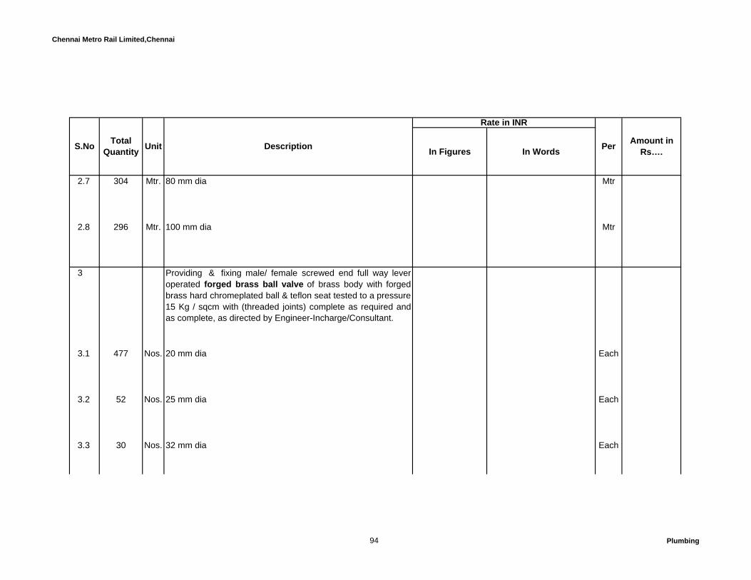
Chennai Metro Rail Limited,Chennai
In Figures In Words
Rate in INR
Amount in Rs….S.No Total
Quantity Unit Description Per
2.7 304 Mtr. 80 mm dia Mtr
2.8 296 Mtr. 100 mm dia Mtr
3 Providing & fixing male/ female screwed end full way leveroperated forged brass ball valve of brass body with forgedbrass hard chromeplated ball & teflon seat tested to a pressure15 Kg / sqcm with (threaded joints) complete as required andas complete, as directed by Engineer-Incharge/Consultant.
3.1 477 Nos. 20 mm dia Each
3.2 52 Nos. 25 mm dia Each
3.3 30 Nos. 32 mm dia Each
94 Plumbing

Chennai Metro Rail Limited,Chennai
In Figures In Words
Rate in INR
Amount in Rs….S.No Total
Quantity Unit Description Per
3.4 13 Nos. 40 mm dia Each
3.5 23 Nos. 50 mm dia Each
4 Providing and fixing C.I. Butterfly valve (Body : Grey CastIron, shaft : SS, Disc : SG Iron (nickel plated), Liner : HT -EPDM/Nylon) of approved make with flange, washer, nuts &bolts and PN 16 pressure rating including rubber gasket &painting complete.and as directed by Engineer-Incharge.
4.1 8 Nos. 65 mm dia Each
4.2 2 Nos. 80 mm dia Each
95 Plumbing

Chennai Metro Rail Limited,Chennai
In Figures In Words
Rate in INR
Amount in Rs….S.No Total
Quantity Unit Description Per
5 Providing & fixing dual flanged C.I. `Y' Strainer with stainlesssteel fine wire mesh perforated sheet basket with necessaryflange/ unions nuts, bolts and washers complete as requiredand as complete, as directed by Engineer-Incharge
5.1 2 Nos. 40 mm dia Each
5.2 3 Nos. 50 mm dia Each
5.3 1 Nos. 65 mm dia Each
5.4 1 Nos. 80 mm dia Each
96 Plumbing

Chennai Metro Rail Limited,Chennai
In Figures In Words
Rate in INR
Amount in Rs….S.No Total
Quantity Unit Description Per
6 Providing and fixing testing and commissioning of 600mmlong puddle flange consisting of 6mm thick welded MS plate,flanges of sutible size property fixed in walls of water tanks asper specifications and approved drawings of followingdiameters.
6.1 5 Nos. 32 mm dia Each
6.2 3 Nos. 40 mm dia Each
6.3 10 Nos. 50 mm dia Each
6.4 6 Nos. 65 mm dia Each
97 Plumbing

Chennai Metro Rail Limited,Chennai
In Figures In Words
Rate in INR
Amount in Rs….S.No Total
Quantity Unit Description Per
7 Constructing masonry Chamber 60x60x75 cm inside, in brickwork in cement mortar 1:4 (1 cement : 4 coarse sand) forsluice valve, with C.I. surface box 100mm top diameter, 160mm bottom diameter and 180 mm deep ( inside) with chainedlid and RCC top slab 1:2:4 mix (1 cement : 2 coarse sand : 4graded stone aggregate 20mm nominal size ) , i/c necessaryexcavation, foundation concrete 1:5:10 (1 cement : 5 fine sand:10 graded stone aggregate 40 mm nominal size) and insideplastering with cement mortar 1:3 (1 cement : 3 coarse sand)12 mm thick, finished with a floating coat of neat cementcomplete as per standard design :
2 Nos. 18.33.1 With common burnt clay F.P.S.(non modular) bricks ofclass designation 7.5
Each
8 Providing and fixing in position of approved quality highpressure rated Gun Metal Float Valve with copper ball floatand brass rods of required length suitable for test pressureof not less than 15 Kg/sqcm of the following sizes and ascomplete,over head water tank. as directed by Engineer-
8.1 2 Nos. 32 mm dia Each
98 Plumbing
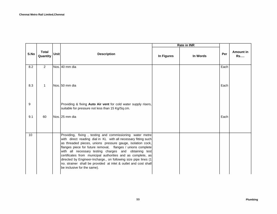
Chennai Metro Rail Limited,Chennai
In Figures In Words
Rate in INR
Amount in Rs….S.No Total
Quantity Unit Description Per
8.2 2 Nos. 40 mm dia Each
8.3 1 Nos. 50 mm dia Each
9 Providing & fixing Auto Air vent for cold water supply risers,suitable for pressure not less than 15 Kg/Sq.cm.
9.1 60 Nos. 25 mm dia Each
10 Providing, fixing , testing and commissioning water metrewith direct reading dial in KL with all necessary fitting suchas threaded pieces, unions pressure gauge, isolation cock,flanges piece for future removal, flanges / unions completewith all necessary testing charges and obtaining testcertificates from municipal authorities and as complete, asdirected by Engineer-Incharge., on following size pipe lines (1no. strainer shall be provided at inlet & outlet and cost shallbe inclusive for the same).
99 Plumbing

Chennai Metro Rail Limited,Chennai
In Figures In Words
Rate in INR
Amount in Rs….S.No Total
Quantity Unit Description Per
1 Nos. 50 mm dia CI Each
11 91 Nos. Providing, fixing, testing and commissioning of PVCencappsulated foot steps 300 mm staggered apart for UGsump tank as per standard make of SFRC or equivalent makefixing in RCC walls during casting of RCC walls as per locationshown in drawings.
Each
12 23 Nos. Rectangular shape 500x500 mm precast R.C.C. manholecover with frame - M.D. - 10
Each
13 18 Nos. Rectangular shape 600x450 mm precast R.C.C. manholecover with frame - L.D. - 25 in as per location shown indrawings.
Each
100 Plumbing

Chennai Metro Rail Limited,Chennai
In Figures In Words
Rate in INR
Amount in Rs….S.No Total
Quantity Unit Description Per
14 Providing and fixing pressure reducing station for coldwater supply comprising of 2 Nos Gun Metal ball valves oninlet & outlet & 1 no. globe valve for by-pass 1 No pressurereducing valve with flanged/ screwed connection, 1 No. `Y'strainer, 2 Nos Pressure gauge on inlet & outlet, and1 No. 15 mm dia safety valve. The complete system is testedto a pressure not less than 15 Kg/Sq.cm and suitable to reducethe pressure upto 2 Kg/Sq.cm) Including necessary pipe &fittings; i.e. flanges/ unions, nuts, bolts and washers completeas required and as complete, as directed by Engineer-Incharge/Consultant.
14.1 12 Nos. 25 mm dia Each
14.2 10 Nos. 32 mm dia Each
14.3 9 Nos. 40 mm dia Each
101 Plumbing

Chennai Metro Rail Limited,Chennai
In Figures In Words
Rate in INR
Amount in Rs….S.No Total
Quantity Unit Description Per
Total Amount C/o to Summary……..
C SOIL,WASTE,VENT PIPES AND FITTINGS ( INTERNAL & EXTERNAL)
1 Providing, fixing, testing and commissioning of uPVC soil,waste and vent pipe confirming to IS : 13592 -and confirmingto IS : 4985 of Pipe Class II- 6 kg / sq.cm pressure rated self fittype with socket and solvent cement joint including all fittings,like Bends, Tees, Elbows, Collars, junction, inspection doors,cowls, offsets, access pipes, jointing with solvent cementfollowed by application of leak proof adhesive like FRP paste &laid on floors inside the toilets kitchen and utility to the requiredslope including making necessary bores in walls / foundations /concrete slab as applicable, making good the bores with CM1:3 or cement concrete 1:2:4 as applicable, curing etc.,complete. Cost shall be inclusive of providing protection to pipeall round / haunches as per specification. (Running at toiletsunken/balcony&Basement ).
Notes:Wall chasing shall be done with chasing machine to requiredlines and levels. Rate Quoted shall be inclusive of cost of cement, sand andother consumables like hacksaw blade etc. INTERNAL:
102 Plumbing
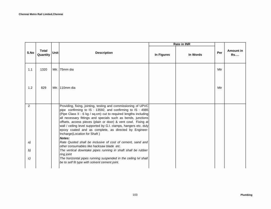
Chennai Metro Rail Limited,Chennai
In Figures In Words
Rate in INR
Amount in Rs….S.No Total
Quantity Unit Description Per
1.1 1320 Mtr. 75mm dia Mtr
1.2 829 Mtr. 110mm dia Mtr
2 Providing, fixing, jointing, testing and commissioning of UPVCpipe confirming to IS : 13592, and confirming to IS : 4985(Pipe Class II - 6 kg / sq.cm) cut to required lengths includingall necessary fittings and specials such as bends, junctionsoffsets, access pieces (plain or door) & vent cowl. Fixing atwall / ceiling level supported by G.I. clamps, hangers etc. dulyepoxy coated and as complete, as directed by Engineer-Incharge(Location for Shaft )Notes:
a) Rate Quoted shall be inclusive of cost of cement, sand andother consumables like hacksaw blade etc.
b) The vertical downtake pipes running in shaft shall be rubberring joint
c) The horizontal pipes running suspended in the ceiling lvl shallbe to self fit type with solvent cement joint.
103 Plumbing

Chennai Metro Rail Limited,Chennai
In Figures In Words
Rate in INR
Amount in Rs….S.No Total
Quantity Unit Description Per
2.1 1343 Mtr. 75mm dia Mtr
2.2 1027 Mtr. 110mm dia Mtr
2.3 83 Mtr. 160mm dia Mtr
3 Providing, fixing, jointing and testing in position the followingUPVC pipes confirming to IS:4985 of 6 Kg / Sq.cm for drainagesystem cut to required length. Pipe to be laid below groundlevel in trenches upto required depth including excavation in allkind of soil (hard rock), dewatering, refilling, watering, rammingand removing the surplus excavated material and making goodthe same complete as required. Cost shall be inclusive ofproviding protection to pipe all round / haunches as perspecification and also as complete, as directed by Engineer-Incharge (For sewer and Sullage line)
Notes:
104 Plumbing

Chennai Metro Rail Limited,Chennai
In Figures In Words
Rate in INR
Amount in Rs….S.No Total
Quantity Unit Description Per
a) Rate is excluding for earthwork and backfilling. It shall bemeasured separate and paid for.
b) Rate Quoted shall be inclusive of cost of cement, sand andother consumables like hacksaw blade etc.
3.1 52 Mtr. 75 mm dia Mtr
3.2 89 Mtr. 110 mm dia Mtr
3.3 292 Mtr. 160 mm dia Mtr
3.4 65 Mtr. 200 mm dia Mtr
105 Plumbing
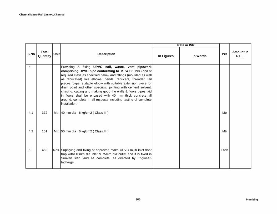
Chennai Metro Rail Limited,Chennai
In Figures In Words
Rate in INR
Amount in Rs….S.No Total
Quantity Unit Description Per
4 Providing & fixing UPVC soil, waste, vent pipeworkcomprising UPVC pipe conforming to IS :4985-1983 and ofrequired class as specified below and fittings (moulded as wellas fabricated) like elbows, bends, reducers, threaded tailpieces, caps, suitable elbow with suitable extension piece fordrain point and other specials. jointing with cement solvent,chasing, cutting and making good the walls & floors pipes laidin floors shall be encased with 40 mm thick concrete allaround, complete in all respects including testing of completeinstallation.
4.1 372 Mtr. 40 mm dia 6 kg/cm2 ( Class III ) Mtr
4.2 101 Mtr. 50 mm dia 6 kg/cm2 ( Class III ) Mtr
5 462 Nos. Supplying and fixing of approved make UPVC multi inlet floortrap with110mm dia inlet & 75mm dia outlet and it is fixed inSunken slab .and as complete, as directed by Engineer-Incharge.
Each
106 Plumbing
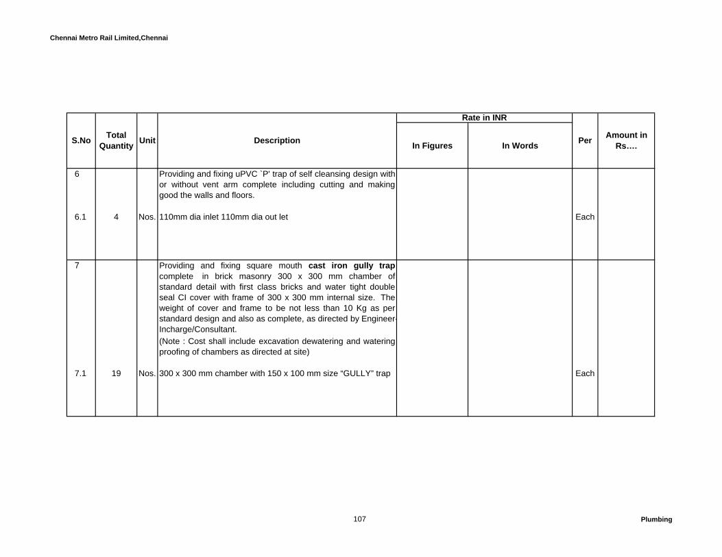
Chennai Metro Rail Limited,Chennai
In Figures In Words
Rate in INR
Amount in Rs….S.No Total
Quantity Unit Description Per
6 Providing and fixing uPVC `P' trap of self cleansing design withor without vent arm complete including cutting and makinggood the walls and floors.
6.1 4 Nos. 110mm dia inlet 110mm dia out let Each
7 Providing and fixing square mouth cast iron gully trapcomplete in brick masonry 300 x 300 mm chamber ofstandard detail with first class bricks and water tight doubleseal CI cover with frame of 300 x 300 mm internal size. Theweight of cover and frame to be not less than 10 Kg as perstandard design and also as complete, as directed by Engineer-Incharge/Consultant.(Note : Cost shall include excavation dewatering and wateringproofing of chambers as directed at site)
7.1 19 Nos. 300 x 300 mm chamber with 150 x 100 mm size “GULLY” trap Each
107 Plumbing

Chennai Metro Rail Limited,Chennai
In Figures In Words
Rate in INR
Amount in Rs….S.No Total
Quantity Unit Description Per
8 Designing and constructing brick masonry inspection chamber of the following sizes in brick work of class 75 incement mortar 1:5 (1 cement:5 fine sand), R.C.C. top slab with1:2:4 mix (1 cement : 2 coarse sand : 4 graded stoneaggregate 20mm. nominal size) embeded with frame formanhole, RCC foundation slab. 1:2:4 mix (1 cement : 2coarse sand:4 graded stone aggregate 40 mm nominal size)both inside and outside of plastering 12 mm thick with cementmotar 1:3 (1 cement : 3 coarse sand) with a floating coat ofneat cement on inside face, proper water proofing to ensureno ground water seepage in the manhole, Poly propylene(conforming to ASTMD - 4101) foot rests (meeting the 224 kgload requirement as per IS 5455) at 300 mm spacing,benching and making channels with 1:2:4 cementconcrete neatly finished, including necessary centering andshuttering, reinforcement, excavation, in all kind of soil,dewatering, refilling, watering, ramming and removing thesurplus excavated earth, making good the same complete asrequired.
Contractor shall submit the structural design and drawings forthe approval of Project Manager prior to execution.
108 Plumbing

Chennai Metro Rail Limited,Chennai
In Figures In Words
Rate in INR
Amount in Rs….S.No Total
Quantity Unit Description Per
8.1 16 Nos. 900 x 800 mm size (UP TO 900mm) Each
8.2 8 Nos. 1200 x 900 mm size (UP TO 2.4M) Each
8.3 3 Nos. 1500mm Dia Circular (2.4 to 9.0m Depth) Each
4 Providing & fixing Cast Iron Manhole cover with frame inCement concrete 1:2:4 (one of cement two of sand and four ofhardbroken stone jally) finished neatly etc..as complete, asdirected by Engineer-Incharge.- For inspection chamber
4.1 27 Nos. 600 x 600 mm, Heavy Duty (B-125), Wt 115 kg Each
Total Amount C/o to Summary……..
D RAIN WATER PIPES AND FITTINGS
109 Plumbing

Chennai Metro Rail Limited,Chennai
In Figures In Words
Rate in INR
Amount in Rs….S.No Total
Quantity Unit Description Per
1 Providing, fixing, jointing, testing and commissioning PVC(Class III) of pressure rating 0.6 Mpa Rain water downtakepipe conforming to IS:4985 cut to required lengths includingall necessary fittings and specials. Fixing at wall/ceiling levelsupported by galvanized steel clamps & hangers etc. Makingproper connection with cement solvent joint as per BIS /manufacturer. Cutting chases/holes in floors/walls/slab.
1.1 734 Mtr 75mm dia Mtr
1.2 954 Mtr 160mm dia Mtr
110 Plumbing

Chennai Metro Rail Limited,Chennai
In Figures In Words
Rate in INR
Amount in Rs….S.No Total
Quantity Unit Description Per
2 Providing, fixing, jointing and testing in position the followingUPVC pipes confirming to IS:4985 of 6 Kg / Sq.cm for rainwater pipe cut to required length. Pipe to be laid below groundlevel in trenches upto required depth including excavation in allkind of rain water pipes (hard rock), dewatering, refilling,watering, ramming and removing the surplus excavatedmaterial and making good the same complete as required.Cost shall be inclusive of providing protection to pipe all round /haunches as per specification. (For Rain water line)
2.1 51 Mtr 75mm dia Mtr
2.2 49 Mtr 160mm dia Mtr
2.3 140 Mtr 200mm dia Mtr
111 Plumbing
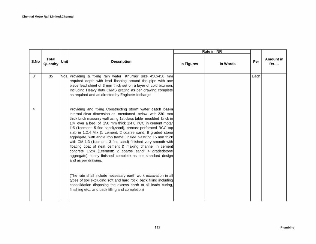
Chennai Metro Rail Limited,Chennai
In Figures In Words
Rate in INR
Amount in Rs….S.No Total
Quantity Unit Description Per
3 35 Nos. Providing & fixing rain water `Khurras' size 450x450 mmrequired depth with lead flashing around the pipe with onepiece lead sheet of 3 mm thick set on a layer of cold bitumen.Including Heavy duty CI/MS grating as per drawing completeas required and as directed by Engineer-Incharge
Each
4 Providing and fixing Constructing storm water catch basininternal clear dimension as mentioned below with 230 mmthick brick masonry wall using 1st class table moulded brick in1:4 over a bed of 150 mm thick 1:4:8 PCC in cement motar1:5 (1cement: 5 fine sand),sand), precast perforated RCC topslab in 1:2:4 Mix (1 cement: 2 coarse sand: 8 graded stoneaggregate),with angle iron frame, inside plastring 15 mm thickwith CM 1:3 (1cement: 3 fine sand) finished very smooth withfloating coat of neat cement & making channel in cementconcrete 1:2:4 (1cement: 2 coarse sand: 4 gradedstoneaggregate) neatly finished complete as per standard designand as per drawing.
(The rate shall include necessary earth work excavation in alltypes of soil excluding soft and hard rock, back filling includingconsolidation disposing the excess earth to all leads curing,finishing etc., and back filling and completion)
112 Plumbing

Chennai Metro Rail Limited,Chennai
In Figures In Words
Rate in INR
Amount in Rs….S.No Total
Quantity Unit Description Per
Note: Rate Quoted shall be inclusive of cost of cement, sandand other consumables like hacksaw blade etc includingcuring.
4.1 17 Nos. Inside size of 450 x 450mm & depth not exceeding 600mmincluding providing 450 x450mm precast perforated RCCcover with 50 x 50 x 6mm thick with MS L angle frame.
Each
5 Providing & fixing of uPVC nahani trap of self cleansingdesign moulded or fabricated, if not available in sizementioned below, with or without vent arm, connecting tobalcony rain water pipe, complete including cutting and makinggood the walls and floors.
5.1 180 Nos. 110mm x 75mm dia Each
6 Providing and fixing CP grating of 6mm thick with rim includingsetting in floor with white cement mortar and making good thefloor (Chilli Make).
180 Nos. P.T.M.T. Grating square slit 150 mm Each
113 Plumbing
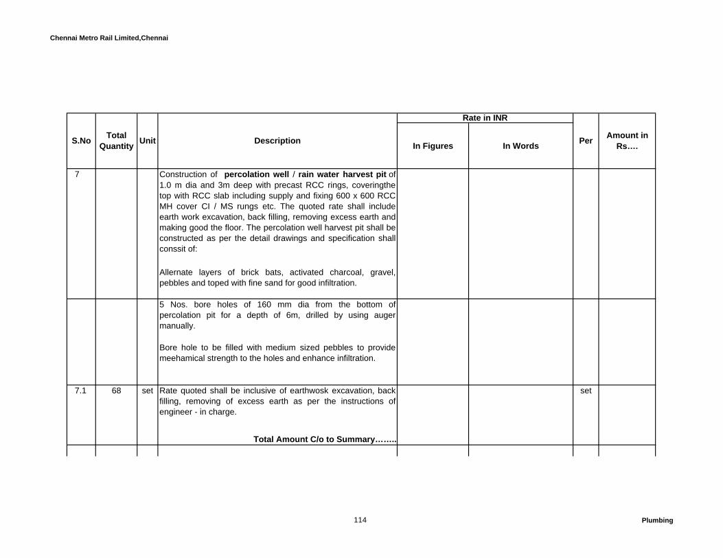
Chennai Metro Rail Limited,Chennai
In Figures In Words
Rate in INR
Amount in Rs….S.No Total
Quantity Unit Description Per
7 Construction of percolation well / rain water harvest pit of 1.0 m dia and 3m deep with precast RCC rings, coveringthetop with RCC slab including supply and fixing 600 x 600 RCCMH cover CI / MS rungs etc. The quoted rate shall includeearth work excavation, back filling, removing excess earth andmaking good the floor. The percolation well harvest pit shall beconstructed as per the detail drawings and specification shallconssit of:
Allernate layers of brick bats, activated charcoal, gravel,pebbles and toped with fine sand for good infiltration.
5 Nos. bore holes of 160 mm dia from the bottom ofpercolation pit for a depth of 6m, drilled by using augermanually.
Bore hole to be filled with medium sized pebbles to providemeehamical strength to the holes and enhance infiltration.
7.1 68 set Rate quoted shall be inclusive of earthwosk excavation, backfilling, removing of excess earth as per the instructions ofengineer - in charge.
set
Total Amount C/o to Summary……..
114 Plumbing

Chennai Metro Rail Limited,Chennai
In Figures In Words
Rate in INR
Amount in Rs….S.No Total
Quantity Unit Description Per
E PUMPS & ACCESSORIES
1 HYDRO-PNEUMATIC SYSTEM
Supply, Installation, Testing And Commissioning Of CompactSelf Contained Skid Mounted Hydropneumatic System AsFollows:
a. Vertical, In-Line, Multisage, centrifugal pumps with SS-304casing and impeller and SS-316 shaft, CI base & head TEFCmotor (with mechanical seal)
(Vendor to submit performance curves and technical catalog ofthe proposed model for review & information)
The pump shall be selected for performance at best efficiencypoint. However, the pump selection shall be suitable forperformance with set point @ + 20% of the rated head.
115 Plumbing

Chennai Metro Rail Limited,Chennai
In Figures In Words
Rate in INR
Amount in Rs….S.No Total
Quantity Unit Description Per
b. External Pump mounted or wall mounted microprocessorPID controller and frequency inverter integrated in a singlebody or as separate components with pressure sensortransmitter minimum two lined LCD display, diodes to indicatepump ready, pump running and fault and capable tocommunicate with other controllers following MODBUS-RTU orBACNET Class-2 protocall through RS485 port. Systemshould be capable to compensate for frictional losses at lowerflows. All alarms should be displayed in the controller. Systemshould be equiped with dry running protection - Quantity : 1No.
c. Complete (Skid mounted wall mounted / floor mounted)electrical control panel comprising of all accessories such asPLCs, pressure switches, pressure transducers, control wiringand any other necessary imports etc. (list to be provided by thevendor)
d. Precharged diaphram pressure vessel with food grademembrane, charging connection, connected to outlet headerwith necessary flanges, gaskets, isolating valves, nuts/bolts etccomplete.
e. Set of accessories such as pressure switches, pressuretransducers, inter connecting power and control cabling etc.complete
116 Plumbing
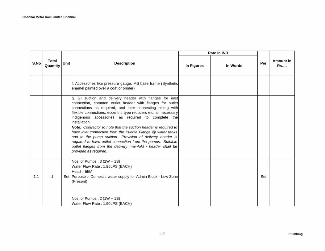
Chennai Metro Rail Limited,Chennai
In Figures In Words
Rate in INR
Amount in Rs….S.No Total
Quantity Unit Description Per
f. Accessories like pressure gauge, MS base frame (Syntheticenamel painted over a coat of primer)
g. GI suction and delivery header with flanges for inletconnection, common outlet header with flanges for outletconnections as required, and inter connecting piping withflexible connections, eccentric type reducers etc. all necessaryindigenous accessories as required to complete theinstallation.Note: Contractor to note that the suction header is required tohave inlet connection from the Puddle Flange @ water tanksand to the pump suction. Provision of delivery header isrequired to have outlet connection from the pumps. Suitableoutlet flanges from the delivery mainfold / header shall beprovided as required.
Nos. of Pumps : 3 (2W + 1S)Water Flow Rate : 1.95LPS (EACH)Head : 55M
1.1 1 Set Purpose :- Domestic water supply for Admin Block - Low Zone(Present)
Set
Nos. of Pumps : 2 (1W + 1S)Water Flow Rate : 1.90LPS (EACH)
117 Plumbing

Chennai Metro Rail Limited,Chennai
In Figures In Words
Rate in INR
Amount in Rs….S.No Total
Quantity Unit Description Per
Head : 45M1.2 1 Set Purpose :- Domestic water supply for Type A&B and Guest
house- Low Zone (Present)Set
2 Metro Water Transfer Pumps:
Supply, Installation, Testing, Commissioning and Handing overof 2 nos.Pumps, one no. working and one no. stand-by, fortransfering municipal water from Treated Metro water ug sumpto Metro / RO water over head tanks. The pump set shall be ofmonobloc type with bronze impeller and SS shaft. The motorshall be directly coupled to the pump set and shall be of TEFCSquirrel Cage type. The pump shall be fitted with mechanicalseal. The pump shall be selected for handling water at 15-40deg. C. The pump shall be supplied complete with FRP coatedMS fabricated base frame, foundation bolts, base plate boltsetc. The duty condition of the pump shall be as under:
Nos. of Pumps : 4(3W + 1S)Water Flow Rate : 0.55LPSHead : 90M
2.1 1 Set Purpose :- Drinking water supply for Guest house & QuartersType A&B Block (Present)
Set
118 Plumbing

Chennai Metro Rail Limited,Chennai
In Figures In Words
Rate in INR
Amount in Rs….S.No Total
Quantity Unit Description Per
Nos. of Pumps : 2(1W + 1S)Water Flow Rate : 0.55LPSHead : 45M
2.2 1 Set Purpose :- Drinking water supply for Admin, Block (Present) Set
3 HYDRO-PNEUMATIC SYSTEM
Supply, Installation, Testing And Commissioning Of CompactSelf Contained Skid Mounted Hydropneumatic System AsFollows:
a. Vertical, In-Line, Multisage, centrifugal pumps with SS-304casing and impeller and SS-316 shaft, CI base & head TEFCmotor (with mechanical seal)
(Vendor to submit performance curves and technical catalog ofthe proposed model for review & information)
The pump shall be selected for performance at best efficiencypoint. However, the pump selection shall be suitable forperformance with set point @ + 20% of the rated head.
119 Plumbing

Chennai Metro Rail Limited,Chennai
In Figures In Words
Rate in INR
Amount in Rs….S.No Total
Quantity Unit Description Per
b. External Pump mounted or wall mounted microprocessorPID controller and frequency inverter integrated in a singlebody or as separate components with pressure sensortransmitter minimum two lined LCD display, diodes to indicatepump ready, pump running and fault and capable tocommunicate with other controllers following MODBUS-RTU orBACNET Class-2 protocall through RS485 port. Systemshould be capable to compensate for frictional losses at lowerflows. All alarms should be displayed in the controller. Systemshould be equiped with dry running protection - Quantity : 1No.
c. Complete (Skid mounted wall mounted / floor mounted)electrical control panel comprising of all accessories such asPLCs, pressure switches, pressure transducers, control wiringand any other necessary imports etc. (list to be provided by thevendor)
d. Precharged diaphram pressure vessel with food grademembrane, charging connection, connected to outlet headerwith necessary flanges, gaskets, isolating valves, nuts/bolts etccomplete.
e. Set of accessories such as pressure switches, pressuretransducers, inter connecting power and control cabling etc.complete
120 Plumbing

Chennai Metro Rail Limited,Chennai
In Figures In Words
Rate in INR
Amount in Rs….S.No Total
Quantity Unit Description Per
f. Accessories like pressure gauge, MS base frame (Syntheticenamel painted over a coat of primer)
g. GI suction and delivery header with flanges for inletconnection, common outlet header with flanges for outletconnections as required, and inter connecting piping withflexible connections, eccentric type reducers etc. all necessaryindigenous accessories as required to complete theinstallation.
Note: Contractor to note that the suction header is required tohave inlet connection from the Puddle Flange @ water tanksand to the pump suction. Provision of delivery header isrequired to have outlet connection from the pumps. Suitableoutlet flanges from the delivery mainfold / header shall beprovided as required.
Nos. of Pumps : 4(3W + 1S)Water Flow Rate : 2.94LPSHead : 55M
3.1 1 Set Purpose :- Recycled Treated / Flushing water supply for AdminBlock - Low Zone (Present)
Set
Nos. of Pumps : 4 (3W+1S)
121 Plumbing

Chennai Metro Rail Limited,Chennai
In Figures In Words
Rate in INR
Amount in Rs….S.No Total
Quantity Unit Description Per
Water Flow Rate : 0.70LPSHead : 90M
3.2 1 Set Purpose :- Recycled Treated / Flushing water supply for TypeA&B and Guest house- Low Zone (Present))
Set
4 Automatic Level Control for Over Head Tank -Domestic,Recycled treated/Flushing & Metro Water:
Supply, Installation, Testing, Commissioning and handing overof automatic tank level controller comprising of the followinginstalled in each over head tank and wired up to the basementfloor pump room:
.Magnetic type Level sensor for tank with High Level cut-outand Low level cut-in - 1 set.
Wiring with 2cx2.5 sqmm PVC insulated, PVC sheathedarmoured cables with copper conductors, duly clamped onwalls, under side of ceiling slabs, etc., interconnecting the levelsensor at the OHT and the control panel in the basement pumproom. Consider 300 RMT.
122 Plumbing
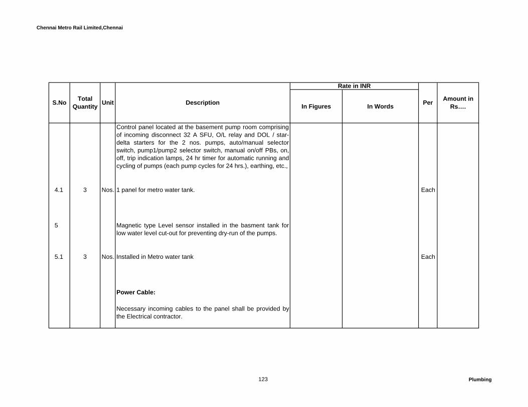
Chennai Metro Rail Limited,Chennai
In Figures In Words
Rate in INR
Amount in Rs….S.No Total
Quantity Unit Description Per
Control panel located at the basement pump room comprisingof incoming disconnect 32 A SFU, O/L relay and DOL / star-delta starters for the 2 nos. pumps, auto/manual selectorswitch, pump1/pump2 selector switch, manual on/off PBs, on,off, trip indication lamps, 24 hr timer for automatic running andcycling of pumps (each pump cycles for 24 hrs.), earthing, etc.,
4.1 3 Nos. 1 panel for metro water tank. Each
5 Magnetic type Level sensor installed in the basment tank forlow water level cut-out for preventing dry-run of the pumps.
5.1 3 Nos. Installed in Metro water tank Each
Power Cable:
Necessary incoming cables to the panel shall be provided bythe Electrical contractor.
123 Plumbing

Chennai Metro Rail Limited,Chennai
In Figures In Words
Rate in INR
Amount in Rs….S.No Total
Quantity Unit Description Per
6 Supply, Installation, Testing and Commissioning ofSubmersible type Pumps with open type impellers with solidhandling capacity of minimum 20mm, for rain water collectionsump pump-out. The pump shall be supplied with pumpmounting clamps, lifting chain of approximately 3 mtrs. lengths,flexible LDPE helically ribbed / braided rubber hose dischargepipe fitted to the pump discharge and of sufficient length andwith flanged connections at both ends to suit pump side & theoutlet puddle flanges provided in the basement floor rain water collection sump near ramp area.
The pumps shall be supplied with integral or external levelcontrollers, common control panel with starting contactors forthe 2 nos. pumps, dry run preventors, O/L protection etc.,complete. The works shall include control and power wiringbetween the level probes & the panel and power wiringbetween the panel and the pumps.
Necessary incoming cables to the panel shall be provided bythe Electrical contractor.
Two nos. pumps (1 working & 1 standby) shall be installed inthe basement floor rain water collection sump near ramp area.
6.1 Nos. of Pumps : 2 (1W + 1S)
124 Plumbing

Chennai Metro Rail Limited,Chennai
In Figures In Words
Rate in INR
Amount in Rs….S.No Total
Quantity Unit Description Per
Water Flow Rate : 1LPSHead : 20M
4 Set Purpose :- Rain water Disposal to neat Storm water drain(Present)
Set
7 Supply, Installation, Testing and Commissioning ofSubmersible type Pumps with open type impellers with solidhandling capacity of minimum 20mm, for Back wash watercollection sump pump-out. The pump shall be supplied withpump mounting clamps, lifting chain of approximately 3 mtrs.lengths, flexible LDPE helically ribbed / braided rubber hosedischarge pipe fitted to the pump discharge and of sufficientlength and with flanged connections at both ends to suit pumpside & the outlet puddle flanges provided in the basement floor Back wash water collection sump in Pump roomarea.
The pumps shall be supplied with integral or external levelcontrollers, common control panel with starting contactors forthe 2 nos. pumps, dry run preventors, O/L protection etc.,complete. The works shall include control and power wiringbetween the level probes & the panel and power wiringbetween the panel and the pumps.
125 Plumbing

Chennai Metro Rail Limited,Chennai
In Figures In Words
Rate in INR
Amount in Rs….S.No Total
Quantity Unit Description Per
Necessary incoming cables to the panel shall be provided bythe Electrical contractor.
Two nos. pumps (1 working & 1 standby) shall be installed inthe Pump room area
7.1 Nos. of Pumps : 2 (1W + 1S)Water Flow Rate : 1LPSHead : 20M
2 Set Purpose :- pump room drain pump Set
8 Pipes,Valves&Accessories for Transfer Pumps within thepump room.
8.1 Ball Valves
8.1.1 6 Nos. 25 mm Each
8.1.2 1 Nos. 40 mm Each
126 Plumbing
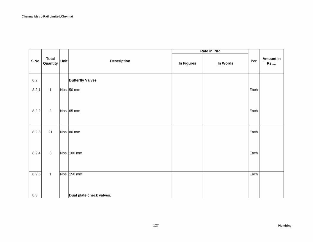
Chennai Metro Rail Limited,Chennai
In Figures In Words
Rate in INR
Amount in Rs….S.No Total
Quantity Unit Description Per
8.2 Butterfly Valves
8.2.1 1 Nos. 50 mm Each
8.2.2 2 Nos. 65 mm Each
8.2.3 21 Nos. 80 mm Each
8.2.4 3 Nos. 100 mm Each
8.2.5 1 Nos. 150 mm Each
8.3 Dual plate check valves.
127 Plumbing
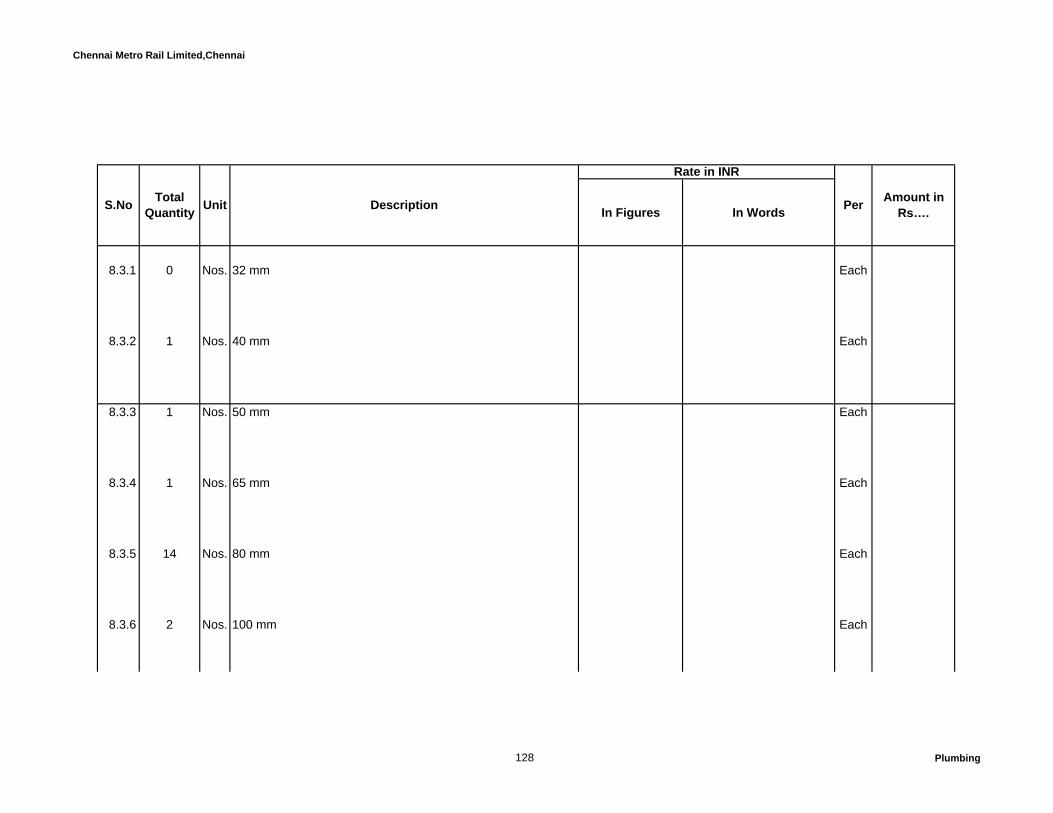
Chennai Metro Rail Limited,Chennai
In Figures In Words
Rate in INR
Amount in Rs….S.No Total
Quantity Unit Description Per
8.3.1 0 Nos. 32 mm Each
8.3.2 1 Nos. 40 mm Each
8.3.3 1 Nos. 50 mm Each
8.3.4 1 Nos. 65 mm Each
8.3.5 14 Nos. 80 mm Each
8.3.6 2 Nos. 100 mm Each
128 Plumbing

Chennai Metro Rail Limited,Chennai
In Figures In Words
Rate in INR
Amount in Rs….S.No Total
Quantity Unit Description Per
8.4 "Y" type strainer
8.4.1 1 Nos. 50 mm Each
8.4.2 1 Nos. 65 mm Each
8.4.3 2 Nos. 80 mm Each
8.4.4 2 Nos. 100 mm Each
8.4.5 1 Nos. 150 mm Each
129 Plumbing
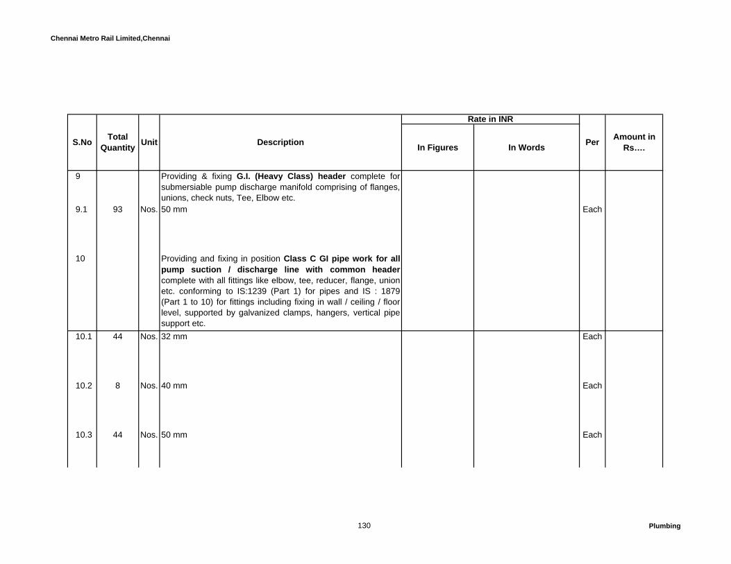
Chennai Metro Rail Limited,Chennai
In Figures In Words
Rate in INR
Amount in Rs….S.No Total
Quantity Unit Description Per
9 Providing & fixing G.I. (Heavy Class) header complete forsubmersiable pump discharge manifold comprising of flanges,unions, check nuts, Tee, Elbow etc.
9.1 93 Nos. 50 mm Each
10 Providing and fixing in position Class C GI pipe work for allpump suction / discharge line with common headercomplete with all fittings like elbow, tee, reducer, flange, unionetc. conforming to IS:1239 (Part 1) for pipes and IS : 1879(Part 1 to 10) for fittings including fixing in wall / ceiling / floorlevel, supported by galvanized clamps, hangers, vertical pipesupport etc.
10.1 44 Nos. 32 mm Each
10.2 8 Nos. 40 mm Each
10.3 44 Nos. 50 mm Each
130 Plumbing

Chennai Metro Rail Limited,Chennai
In Figures In Words
Rate in INR
Amount in Rs….S.No Total
Quantity Unit Description Per
10.4 52 Nos. 65 mm Each
10.5 34 Nos. 80 mm Each
10.6 52 Nos. 100 mm Each
10.7 6 Nos. 150 mm Each
11 6 Nos. Automatic air vents of 15-mm dia., complete with 15-mm ballvalves.
Each
12 6 Nos. 100mm dial pressure guage with syphon and pet cock. Each
131 Plumbing

Chennai Metro Rail Limited,Chennai
In Figures In Words
Rate in INR
Amount in Rs….S.No Total
Quantity Unit Description Per
Total Amount C/o to Summary……..
Sewage treatment plant:Design and build the STP plant considering the following parameters:Capacity 80KLDOperating hours 20 hoursFlow rate 4.0 m3/hr
Treated sewage quality at the outlet of the Activated Carbon Filter will be as follows:
PARAMETERS - VALUES – at the outlet of ACF
pH - 6.5 – 9.0BOD < 20 ppmTSS < 30 ppm
132 Plumbing
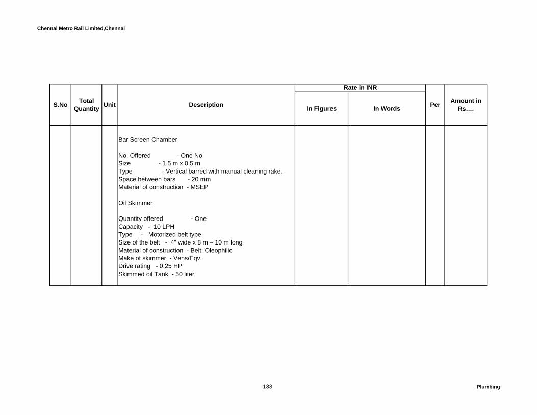
Chennai Metro Rail Limited,Chennai
In Figures In Words
Rate in INR
Amount in Rs….S.No Total
Quantity Unit Description Per
Bar Screen Chamber
No. Offered - One NoSize - 1.5 m x 0.5 mType - Vertical barred with manual cleaning rake.Space between bars - 20 mmMaterial of construction - MSEP
Oil Skimmer
Quantity offered - OneCapacity - 10 LPHType - Motorized belt typeSize of the belt - 4” wide x 8 m – 10 m longMaterial of construction - Belt: OleophilicMake of skimmer - Vens/Eqv.Drive rating - 0.25 HPSkimmed oil Tank - 50 liter
133 Plumbing

Chennai Metro Rail Limited,Chennai
In Figures In Words
Rate in INR
Amount in Rs….S.No Total
Quantity Unit Description Per
Raw Sewage Transfer Pump
No. Offered - Two Nos(1W+1S)Capacity - 4 m3/hrHead - 10mwcType - Horizontal Centrifugal, Self PrimingMaterial of construction - CIDrive rating - 1.0 HPMake - Kirloskar/ Eqv.
Aeration System
FBBR Media
Quantity - 4 m3Surface area - 400 m2/m3Material of construction - PPMake - Energy Equipment
134 Plumbing

Chennai Metro Rail Limited,Chennai
In Figures In Words
Rate in INR
Amount in Rs….S.No Total
Quantity Unit Description Per
Air Blowers
No. of air blowers - Two (1w + 1s)Capacity - 69 m3/hr-42 m3/hr for Aeration Tank- 24 m3/hr for Equalization Tank/ 3 m3/hr for Sludge Holding TankHead - 5 MWCMotor rating - 5.0 HPBlower make - Kay International or equivalent Motor Make - Bharat Bijlee or equivalent
Coarse diffusers (Eq.T)
No. of Diffusers - 1 LotMaterial of construction - PVCType - Course Bubble
135 Plumbing

Chennai Metro Rail Limited,Chennai
In Figures In Words
Rate in INR
Amount in Rs….S.No Total
Quantity Unit Description Per
Fine Bubble Diffusers for AT
Quantity Offered - 5 Nos.Capacity of each - 10 m3/hrType - Fine BubbleMaterial of construction - EPDM
Tube Settler- Internals
Quantity Offered - One No.Volume of media - 2 m3Type - Tube Dek MediaMOC - PVC
Hypo Dosing System
Dosing Pump
No. offered - One NoCapacity - 0-4 liters/hrType - Electronic, diaphragmMaterial of construction - PPMake - Xeed or Eqv
136 Plumbing
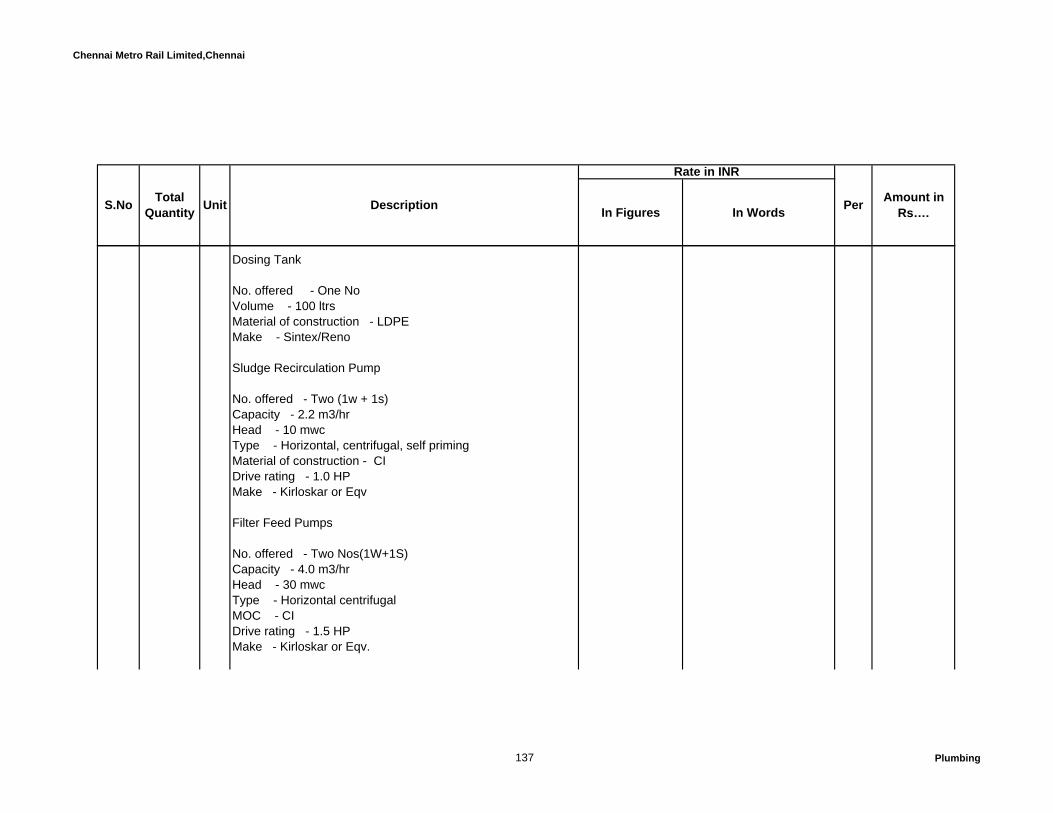
Chennai Metro Rail Limited,Chennai
In Figures In Words
Rate in INR
Amount in Rs….S.No Total
Quantity Unit Description Per
Dosing Tank
No. offered - One NoVolume - 100 ltrsMaterial of construction - LDPEMake - Sintex/Reno
Sludge Recirculation Pump
No. offered - Two (1w + 1s)Capacity - 2.2 m3/hrHead - 10 mwcType - Horizontal, centrifugal, self primingMaterial of construction - CIDrive rating - 1.0 HPMake - Kirloskar or Eqv
Filter Feed Pumps
No. offered - Two Nos(1W+1S)Capacity - 4.0 m3/hrHead - 30 mwcType - Horizontal centrifugalMOC - CIDrive rating - 1.5 HPMake - Kirloskar or Eqv.
137 Plumbing

Chennai Metro Rail Limited,Chennai
In Figures In Words
Rate in INR
Amount in Rs….S.No Total
Quantity Unit Description Per
Pressure Sand Filter
Quantity - OneService flow - 4.0 m3/hrDiameter - 30”Height - 72”Filtering Media - Graded Sand & PebblesMaterial Construction - FRPValve type - Manually operated Multi port valve
Activated Carbon Filter
Quantity - OneService flow - 4.0 m3/hrDiameter - 24”Height on straight - 72”Filtering Media - Granular Sand, Pebbles & Activated CarbonMaterial Construction - FRPValve type - Manually operated Multi port valve
138 Plumbing

Chennai Metro Rail Limited,Chennai
In Figures In Words
Rate in INR
Amount in Rs….S.No Total
Quantity Unit Description Per
Sludge Handling System
Filter Press Feed Pumps
No. of pumps - Two Nos(1W+1S)Capacity - 1.0 m3/hrHead - 60 mwcType - Helical screw typeMaterial of construction - CIMotor rating 1.0 HP
Poly Dosing System
Dosing Pump
No. offered - One NoCapacity - 0-4 liters/hrMaterial of construction - PPMake - Xeed/Eqv
Dosing Tank
No. offered - One NoVolume - 100 ltrsMaterial of construction - LDPEMake - Sintex/ Reno
139 Plumbing

Chennai Metro Rail Limited,Chennai
In Figures In Words
Rate in INR
Amount in Rs….S.No Total
Quantity Unit Description Per
Filter Press
Nos. offered - OneNo of Batches - OneType - Sliding, Recessed – Plate and Frame typeSize - 18” X 18”Cake Holding Capacity - 70 Ltrs/BatchNo. of plates - 15 Nos.No. of chambers - 14 Nos.MOC of plates - PPMOC of filter press - MSDrive Rating - 1.0 HPMake - Icura or Eqv
2 Nos In Plant Piping & Valves
Quantity of Pipes - One lotMaterial of construction Air line : - MSSewage lines : - UPVCQuantity of valves - One lotMaterial of construction - Air line : CISewage line : - Poly Propylene/CI
Each
Total Amount C/o to Summary……..
140 Plumbing

Chennai Metro Rail Limited,Chennai
In Figures In Words
A Glazing & Glazed Doors
1.00 Unitized Glazing system
1.01 Unitized Glazing system with Vision, Vision on Spandrel panel(System without Glass): Quote rate for complete systemdesigning, providing and fixing Unitized structural glazing visionpanel & vision on spandrel panel structurally held in position byStructural sealant and factory fabricated with Aluminium frames ofsuitable size in order to satisfy the structural design criteriaspecified in the Technical specification. In general, the systemcomprising Aluminium anodized extruded frames, HDG brackets,SS anchors & bolts and bolts, flashing etc with Insulated Glass of24 mm thick / Monolithic glass 6 mm thick . Rate shall exclude thecost of supplying Glass, top hung window hardwares andinsulation, which will be measured and paid separately under therespective item below. Rate shall include the cost of fixing of Glass& Top hung window hardwares.
S.No Description of Items Quantity Unit Per Amount
General Note : Refer Particular specifications and Technical specification, while quoting the rate for the respective items under this schedule. Also,the BOQ item descriptions shall be read in conjunction with corresponding material specification and design criteria as specified in the tenderspecification as well as particular specification, in addition to the detailed specification and standards specified in the corresponding codes andstandards.The quoted rate under this schedule shall be deemed to have considered Technical specification and particular specification.
CONSTRUCTION OF METRO HEADQUARTERS BUILDING AND OTHER METRO RAIL AMENITIES AT NANDANAM,CHENNAI
BILLS OF QUANTITIES
SCHEDILE - III - EXTERNAL FAÇADE AND ASSOCIATED WORKS
Rate in INR
141 Stru. Glazing

Chennai Metro Rail Limited,Chennai
In Figures In WordsS.No Description of Items Quantit
y Unit Per AmountRate in INR
a 1,700 Sqm Vision Panel & Vision on Spandrel panel Sqm
b 1,550 Sqm Spandrel panel Sqm
1.02 80 Sqm Spandrel panel with ACP (System with ACP): Quote rate forcomplete system designing, providing and fixing Unitized structuralglazing spandrel panel structurally held in position by Structuralsealant and factory fabricated with Aluminium frames of suitablesize in order to satisfy the structural design criteria specified in theTechnical specification. In general, the system comprisingAluminium anodized extruded frames, HDG brackets, SS anchors& bolts and bolts, flashing etc with Spandrel panel havingLaminated sandwiched composite panel of Alucobond or Alpolic orKnauf of Fameline make with approved colour and shade (4 mm(0.5 + 3.0 + 0.5) ACP with 5000 series coil and 100% virgin whitecore FR Grade - Class - B1). Refer Technical specification fordetailed specification of Laminated sandwiched composite panel,which shall form part of this item. Rate shall include the cost forSupplying and fixing of Laminated sandwiched composite panelwith Mineral core (ACP), sealant and etc complete. Refer ParticularSpecification item - 22.01 - Provisional Qty
Sqm
142 Stru. Glazing

Chennai Metro Rail Limited,Chennai
In Figures In WordsS.No Description of Items Quantit
y Unit Per AmountRate in INR
1.03 65 Each Hardware for top hung window: Quote rate Extra rate over &above the Semi unitized structural glazing item above fordesigning, providing and fixing hardwares for top hung openableoutward shutter as per particular specification. Rate shall excludecost of Glass and main frame, but include cost of sub frame forshutter. Refer Particular Specification item - 22.01
Each
2.00 Glass for Structural Glazing system: Quote rate for completesupply of glass as per the options given below to the respectiveplace to fix the glass on the system as described above. Fixing theglass shall form part of the system cost quoted under respectiveitem in Schedule. Refer attached Annexure - I for the glassperformance requirement of 24 mm thick (6 + 12 Air gap + 6) Doubleglazed unit (DGU), processing, thickness and coating of glass, tintand other parametres like heat treatment process etc. All panes ofglass shall be heat strengthened. Rate shall include the cost ofnecessary wastages, transporting etc complete.
Mode of Measurement : Glass on structural Glazing & others : Length and breadth of thesuperficial area of the finished work shall be measured centre tocentre of the grooves on the external surface viewed externallycorrect to a centimetre under the respective items. Areas shall becalculated in a square metre correct to two places of decimal. Attic stock Glass: Actual size of the glass shall be measuredcorrect to a centimetre. Areas shall be calculated in a square metrecorrect to two places of decimal. Refer Particular SpecificationItem. No. 22.04
143 Stru. Glazing

Chennai Metro Rail Limited,Chennai
In Figures In WordsS.No Description of Items Quantit
y Unit Per AmountRate in INR
2.01 3,250 Sqm Glass for Vision Panel, Spandrel panel, Vision on Spandrel panel(Continuous Glazing, Strip window and Punched window) :Insulated glass of 24 mm thick having 6 mm thick Reflective coatedlow E glass on # 2 surface with Bluelite LH 37/24 of Asahi make orSolarban 70 XL(2) Solar blue of PPG Make as outer pane and 12mm airgap and 6 mm thick glass uncoated clear as inner pane ofsame make. Both panes are shall be heat strengthened.
3.00 FRAMELESS GLAZING (POINT FIXED / SPIDER GLAZING) SYSTEM.
3.01 75 Sqm System for Frameless glazing:Quote rate for complete point fixed glazing system using 2 wayspider / GT Spiders as mentioned in Particular Specificationincluding supplying and fixing of 19.52 mm thick laminated glasshaving 10 mm thick as outer panel and 8 mm thick as inner panelwith interlayer of 1.52 mm thick Sentry Glas (R) of DuPont make.Outer pane glass shall be reflective coated glass - Spring(SC60/52) clear of Asahi make or Equivalent glass of PPGmake. Inner pane shall be heat soak tested un coated clear glassand both panes shall be heat treated. Rate shall include cost ofspiders, Articulated bolts, PVC clear edge strip for all exposedlaminated edges and supply and fixing the Glass fin with requiredsize to satisfy the structural criteria, but excluding the cost of door,which will be measured separately under the respective item. Thethickness of glass fin shall be 21.52mm thick (Min) laminatedtoughened and heat soak tested as per specification.System to bedesigned to with stand design wind pressure and other loadparameters specified. Refer Particular Specification Item. No.22 02 & 22 05
Sqm
144 Stru. Glazing
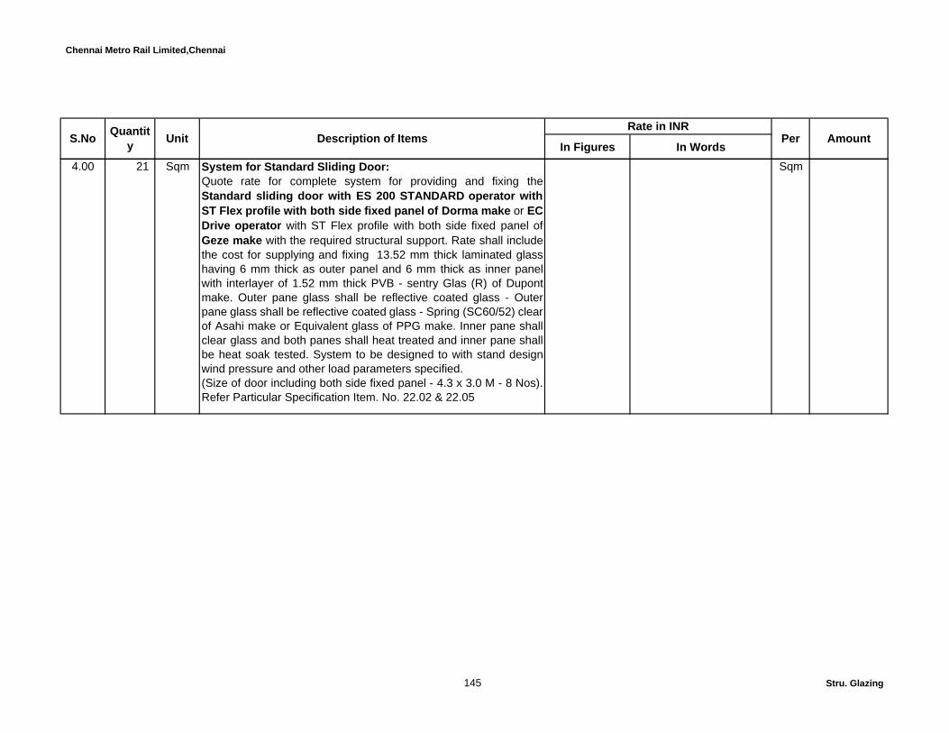
Chennai Metro Rail Limited,Chennai
In Figures In WordsS.No Description of Items Quantit
y Unit Per AmountRate in INR
4.00 21 Sqm System for Standard Sliding Door:Quote rate for complete system for providing and fixing theStandard sliding door with ES 200 STANDARD operator withST Flex profile with both side fixed panel of Dorma make or EC Drive operator with ST Flex profile with both side fixed panel ofGeze make with the required structural support. Rate shall includethe cost for supplying and fixing 13.52 mm thick laminated glasshaving 6 mm thick as outer panel and 6 mm thick as inner panelwith interlayer of 1.52 mm thick PVB - sentry Glas (R) of Dupontmake. Outer pane glass shall be reflective coated glass - Outerpane glass shall be reflective coated glass - Spring (SC60/52) clearof Asahi make or Equivalent glass of PPG make. Inner pane shallclear glass and both panes shall heat treated and inner pane shallbe heat soak tested. System to be designed to with stand designwind pressure and other load parameters specified.(Size of door including both side fixed panel - 4.3 x 3.0 M - 8 Nos).Refer Particular Specification Item. No. 22.02 & 22.05
Sqm
145 Stru. Glazing

Chennai Metro Rail Limited,Chennai
In Figures In WordsS.No Description of Items Quantit
y Unit Per AmountRate in INR
5.00 Providing and fixing colour anodized aluminium Swing Dooras part of Glazing system and fabricated as per drawing andfixed at all levels, elevations and heights by using aluminiumframes for Doors with thickness not less than 2.0mm of approvedsize subject to design criteria. The door frame shall be fixed in tothe adjoining mullion and transom. All glass panels shall be fixedby using snap fit aluminium colour anodized beading with specialwater proof cascades, Neoprene, hardwares etc. complete, asdirected. All aluminium sections shall be 63400 (H9) gradeconforming to IS 8147, finished with AC25 grade Architecturalquality electrolytic colour anodic coating conforming to IS 1868 ofapproved colour and weight ratio joints mitered adjoined withheavy duty aluminium pressure die cast cleats with fins to matchthe sections of frames. The section unit weight per running meter issubjected to tolerance on the wall thickness as per IS 6977/Equivalent BS.
146 Stru. Glazing

Chennai Metro Rail Limited,Chennai
In Figures In WordsS.No Description of Items Quantit
y Unit Per AmountRate in INR
Door shall be provided with necessary hardwares such asConsealed Door closer - ITS 96 EN 2 - 4 (Opening restrict to 85deg), Mortise dead lock - Model No. 278 (both side key operation)SS forend and SS strike plate (Suitable for both single / double leafshutter) of Satin finish - Grade SS 316, SS satin finish handle -TG9377- 25 (Angled Spacer) - 600 mm long with back to backhandle SS 316 grade, SS hinges (Minimum 4 Nos / Shutter) SSDoor stoppers floor mounted, Door buffers etc. complete and asdirected. All Hardwares shall be Dorma / Kinlong / Geze Make.Rate shall include the cost of supplying & fixing 13.52 mm thicklaminated glass for door having 6 mm thick as outer panel and 6mm thick as inner panel with interlayer of 1.52 mm thick - PVB ofDupont make. Outer pane glass shall be reflective coated glass -Outer pane glass shall be reflective coated glass - Spring(SC60/52) clear of Asahi make or Equivalent glass of PPG make.Inner pane of un coated clear glass heat soak tested but bothpanes shall be heat treated.Refer Particular Specification Item. No. 22.01 & 22.05
5.01 11 Sqm Single Leaf door (1.00 x 2.40 M) Sqm
5.02 11 Sqm Double Leaf door (2.0 x 2.40 M) Sqm
Total Amount C/o to Summary……..
147 Stru. Glazing

Chennai Metro Rail Limited,Chennai
In Figures In WordsS.No Description of Items Quantit
y Unit Per AmountRate in INR
B Windows and Louvers
6.00 Quote rate for providing and fixing aluminium extruded louver"Z" type as described below and to be designed to with stand thedesign wind pressure and as directed by Site Incharge /Consultant. Refer Particular Specification item - 22.13
6.01 300 Kg Support system to fix the Louver:Quote rate for complete system having colour anodized aluminiumbox frame, aluminium flat to receive the louvers and aluminiumangles around the louvered window to protect the water ingressthrough the outer frame etc.and to be designed to with standdesign wind pressure specified. Note : Weight will be considered only for the assembled frame partand hence necessary wastage shall form part of the rate quoted.
Kg
6.02 25 Sqm Louver : Quote rate for complete colour anodized extruded profilelouver system to be designed to with stand design wind pressurespecified. . Rate shall include supply and fixing of Louver at thepitch specified below, but excluding cost frame and otheraccessories, which shall part of Item above.Fixed Louver: Providing and fixing Storm proof louver "Z" typeor Aerofoil 100 made out of specially extruded aluminium withanodized finish and as specified in Particular specifications and tobe fixed with pitch not less than 50 mm and overlapping shall be 25mm as minimum as shown in the drawing.
Sqm
148 Stru. Glazing

Chennai Metro Rail Limited,Chennai
In Figures In WordsS.No Description of Items Quantit
y Unit Per AmountRate in INR
7.00 10 Sqm Quote rate for providing and fixing Luxalon SL - 4 Stringer with84R plain Louvers panel of Hunter Douglas make or equivalent Fameline make with Luxacote finish and the louver system shallbe designed to with stand the design wind pressure. Rate shallinclude louver Panel, Carrier, Carrier Splice, Panel Splice andaccessories etc and as directed by Site Incharge / Consultant.Refer Particular Specification item - 22.14 - Provisional Qty
Sqm
8.00 Quote rate for providing and fixing Aluminium Grille of Famelinemake with specified product code as below PVDF finish and thelouver system shall be designed to with stand the design windpressure with pitch not less than 75 mm as shown in the drawing.Louver thickness not less than 0.8mm. Rate shall include louverPanel, aluminium frames, aluminium end caps, aluminium brackets/ clamps, SS anchors, bolts and accessories etc and as directed bySite Incharge / Consultant. Refer Particular Specification item -22.15
8.01 10 Sqm Product code 2050RT Sqm
Total Amount C/o to Summary……..
C Cladding works
9.00 Laminated sandwiched composite panel cladding and Associated works
149 Stru. Glazing

Chennai Metro Rail Limited,Chennai
In Figures In WordsS.No Description of Items Quantit
y Unit Per AmountRate in INR
9.01 6,650 Sqm Dry wall cladding : Providing and fixing the system to clad theLaminated sandwiched composite panel of Alucobond or Alpolic orKnauf of Fameline make with approved colour and shade (4 mm(0.5 + 3.0 + 0.5) ACP with 5000 series coil and 100% virgin whitecore FR Grade - Class - B1) as per the specification described inTechnical specifications, on the external surface the externalsurface like column, wall, jambs, sills, projected area, ceiling or anysurface to any profile and shape, horizontally, vertically, sloped,curved, circular etc complete.
Sqm
Rate shall include the cost of supplying and fixing of Laminatedsandwiched composite panel (ACP), Non staining weather forVertical & horizontal joints in general the frame work for ACPcladding consists of aluminium box frame with thickness of not lessthan 2.0mm with suitable size of box frame to satisfying the designcriteria with require nos of cleat (spacing not more than 300 mm)having thickness not less than 2.0mm to hold the ACP and HDGbracket with maximum 600mm c/c spacing with minimum 2 Nos ofChemical Anchors etc, complete. All anchors, bolts and screwsshall be SS 316 grade of Hilti / Fischer make.
150 Stru. Glazing
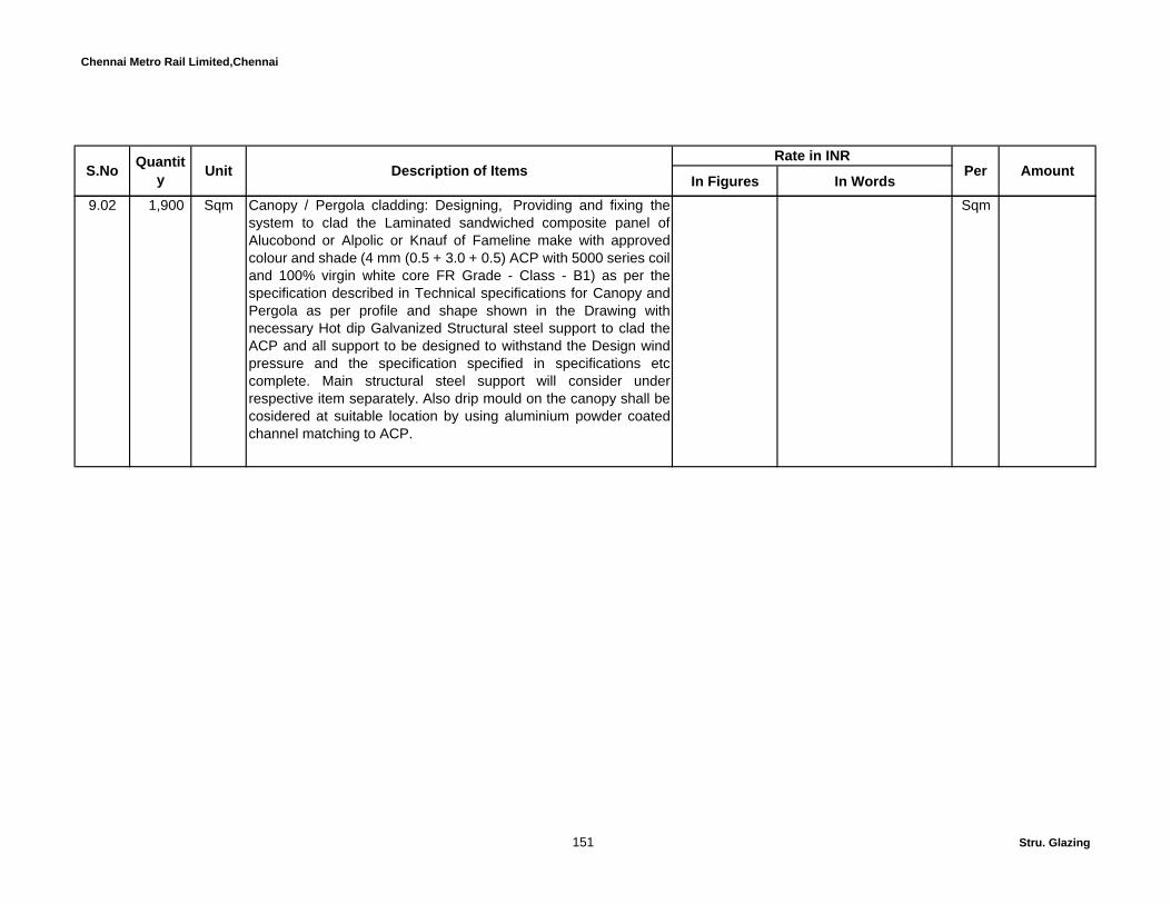
Chennai Metro Rail Limited,Chennai
In Figures In WordsS.No Description of Items Quantit
y Unit Per AmountRate in INR
9.02 1,900 Sqm Canopy / Pergola cladding: Designing, Providing and fixing thesystem to clad the Laminated sandwiched composite panel ofAlucobond or Alpolic or Knauf of Fameline make with approvedcolour and shade (4 mm (0.5 + 3.0 + 0.5) ACP with 5000 series coiland 100% virgin white core FR Grade - Class - B1) as per thespecification described in Technical specifications for Canopy andPergola as per profile and shape shown in the Drawing withnecessary Hot dip Galvanized Structural steel support to clad theACP and all support to be designed to withstand the Design windpressure and the specification specified in specifications etccomplete. Main structural steel support will consider underrespective item separately. Also drip mould on the canopy shall becosidered at suitable location by using aluminium powder coatedchannel matching to ACP.
Sqm
151 Stru. Glazing
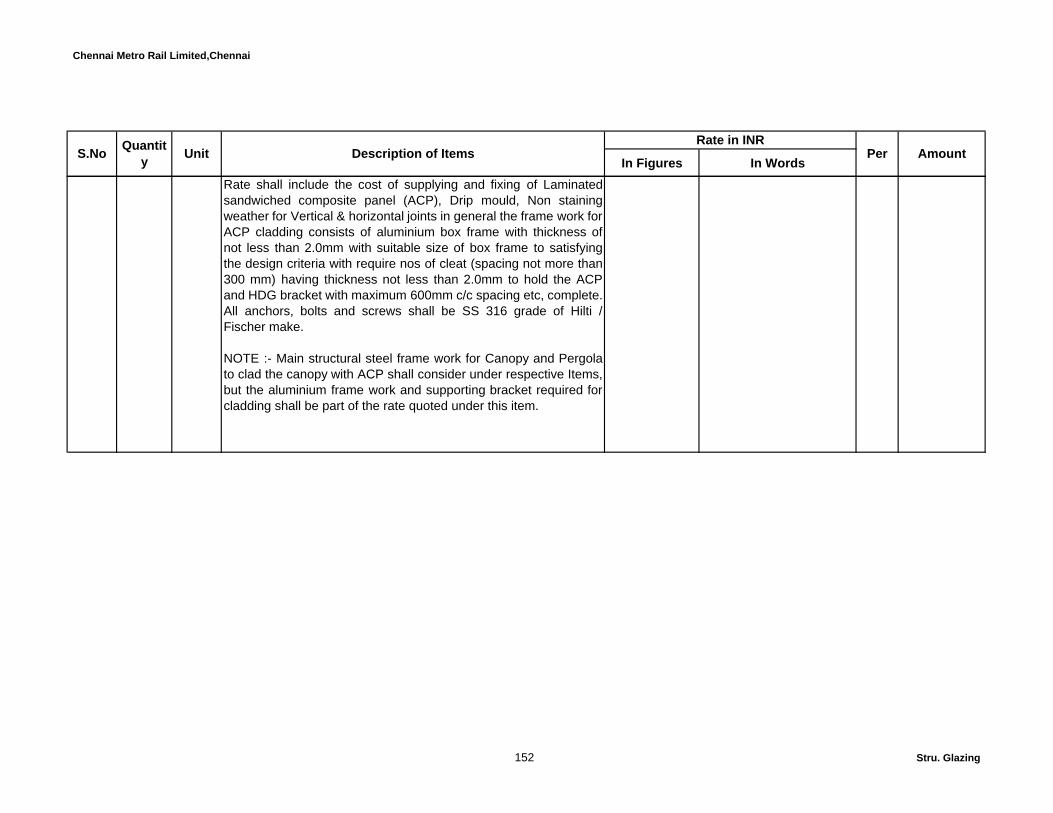
Chennai Metro Rail Limited,Chennai
In Figures In WordsS.No Description of Items Quantit
y Unit Per AmountRate in INR
Rate shall include the cost of supplying and fixing of Laminatedsandwiched composite panel (ACP), Drip mould, Non stainingweather for Vertical & horizontal joints in general the frame work forACP cladding consists of aluminium box frame with thickness ofnot less than 2.0mm with suitable size of box frame to satisfyingthe design criteria with require nos of cleat (spacing not more than300 mm) having thickness not less than 2.0mm to hold the ACPand HDG bracket with maximum 600mm c/c spacing etc, complete.All anchors, bolts and screws shall be SS 316 grade of Hilti /Fischer make.
NOTE :- Main structural steel frame work for Canopy and Pergolato clad the canopy with ACP shall consider under respective Items,but the aluminium frame work and supporting bracket required forcladding shall be part of the rate quoted under this item.
152 Stru. Glazing

Chennai Metro Rail Limited,Chennai
In Figures In WordsS.No Description of Items Quantit
y Unit Per AmountRate in INR
10.00 500 Sqm Dry wall granite cladding: Quote rate for providing and fixingGranite slab - Dry type fixing using Silver grey or approved shadegranite slab cladding the external surface on any surface to anyprofile and shape, horizontally, vertically, sloped, curved, circularetc with approved shade of Granite thickness not less than 25 mmthick and as per the sizes shown in the Drawing etc complete andas directed and to be designed to with stand design wind pressurespecified.(On the Facade areas). Granite shall be fixed with agroove of 6mm and to be filled with weather sealant recessed by2mm and the granite joints at corners shall be chamfered as perArchitectural requirements and granite shall be fixed in the M.S /RCC wall with SS brackets and SS anchor bolts. Projection upto200 mm from the Main base structure either RCC / Masonry / steel.Granite shall be fixed in the RCC / Masonry / steel with SSbrackets and SS anchor bolts. Granite basic cost of Rs.160/- perSq.ft shall be considered subject to compliance of the abovespecification.Refer Particular Specification Item. No. 22.15.
Sqm
Total Amount C/o to Summary……..
D Roofing works
153 Stru. Glazing

Chennai Metro Rail Limited,Chennai
In Figures In WordsS.No Description of Items Quantit
y Unit Per AmountRate in INR
11.00 550 Sqm Design, Supply, Fabricate & Install Tensile roof structure usingFerrari make Fabric of product code no. 702 T2 at all levels andelevation as per drawing with the approved Profile. In General, theFabric shall have thickness not less than 0.55 mm with tensilestrength 280/280 daN/5cm,Tear resistance of 30/28 daN -750g/sqm and the Fabric shall made out of PES HT 1100Dtex yarnwith flame Retardancy to meet Euro Class B-s2.do/EN 1350-1 andthe Surface treatment shall be Floutop® T2 (High concentrationPVDF) having coating thickness not less than 240 µ and back sidetreatment shall be weldable PVDF (for a better resistance topollution of the back side of the fabric) with a minimumManufacturere warrenty of 10 yeras. Rate Shall include patterning,form finding, cutting, welding & installation of fabric at site, primarysteel in MS of TATA,JINDAL or Equivalent make with YST 310grade as minimum including fabrication and erection of structuralelements duly painted with two coats of Pu based Metallic shadepaint of approved shade over one coat of epoxy primer to a totalDFT of 230 Microns of Akzo noble or Jotun make.
Sqm
Rate to include necessay tensining hardwares for fabric in SSinclusive of Wireropes (GI hot dip galvanized cables), Swage ends& membrane plates etc as per drawings and ManufacturersSpecification.
154 Stru. Glazing
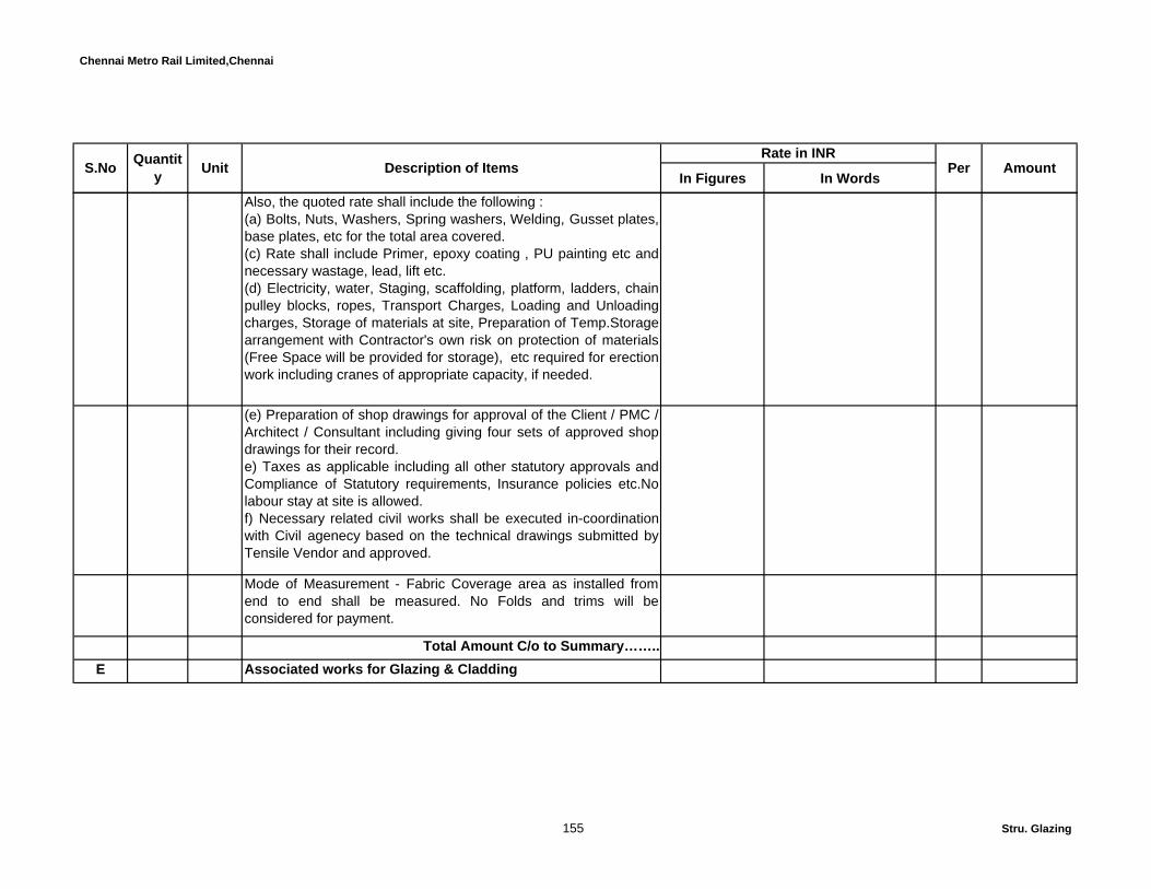
Chennai Metro Rail Limited,Chennai
In Figures In WordsS.No Description of Items Quantit
y Unit Per AmountRate in INR
Also, the quoted rate shall include the following :(a) Bolts, Nuts, Washers, Spring washers, Welding, Gusset plates,base plates, etc for the total area covered.(c) Rate shall include Primer, epoxy coating , PU painting etc andnecessary wastage, lead, lift etc.(d) Electricity, water, Staging, scaffolding, platform, ladders, chainpulley blocks, ropes, Transport Charges, Loading and Unloadingcharges, Storage of materials at site, Preparation of Temp.Storagearrangement with Contractor's own risk on protection of materials(Free Space will be provided for storage), etc required for erectionwork including cranes of appropriate capacity, if needed.
(e) Preparation of shop drawings for approval of the Client / PMC /Architect / Consultant including giving four sets of approved shopdrawings for their record.e) Taxes as applicable including all other statutory approvals andCompliance of Statutory requirements, Insurance policies etc.Nolabour stay at site is allowed.f) Necessary related civil works shall be executed in-coordinationwith Civil agenecy based on the technical drawings submitted byTensile Vendor and approved.
Mode of Measurement - Fabric Coverage area as installed fromend to end shall be measured. No Folds and trims will beconsidered for payment.
Total Amount C/o to Summary……..E Associated works for Glazing & Cladding
155 Stru. Glazing
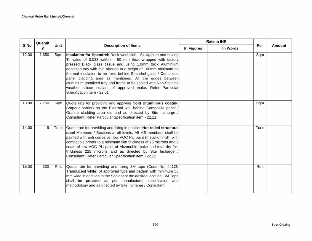
Chennai Metro Rail Limited,Chennai
In Figures In WordsS.No Description of Items Quantit
y Unit Per AmountRate in INR
12.00 1,650 Sqm Insulation for Spandrel: Rock wool slab - 64 Kg/cum and having'K' value of 0.033 w/Mok - 50 mm thick wrapped with factorypressed Black glass tissue and using 1.0mm thick Aluminiumanodized tray with fold alround to a height of 100mm minimum asthermal insulation to be fixed behind Spandrel glass / Compositepanel cladding area as mentioned. All the edges betweenaluminium anodized tray and frame to be sealed with Non-Stainingweather silicon sealant of approved make. Refer ParticularSpecification item - 22.01
Sqm
13.00 7,150 Sqm Quote rate for providing and applying Cold Bituminous coating(Vapour barrier) on the External wall behind Composite panel /Granite cladding area etc and as directed by Site Incharge /Consultant. Refer Particular Specification item - 22.11
Sqm
14.00 5 Tone Quote rate for providing and fixing in position Hot rolled structuralsteel Members / Sections at all levels. All MS members shall bepainted with anti corrosive, low VOC PU paint (metallic finish) withcompatible primer to a minimum film thickness of 75 microns and 2coats of low VOC PU paint of Akzonoble make and total dry filmthickness 225 microns and as directed by Site Incharge /Consultant. Refer Particular Specification item - 22.12
Tone
15.00 300 Rmt Quote rate for providing and fixing 3M tape (Code No: 4412NTranslucent white) of approved type and pattern with minimum 50mm wide in addition to the Sealant at the desired location. 3M Tapeshall be provided as per manufacturer specification andmethodology and as directed by Site Incharge / Consultant.
Rmt
156 Stru. Glazing

Chennai Metro Rail Limited,Chennai
In Figures In WordsS.No Description of Items Quantit
y Unit Per AmountRate in INR
16.00 500 Sqm Quote rate for providing and applying over the granite / stonesurface one coat of environment friendly silicon based WaterRepellent as per manufacturers specification with no undulationsand waviness as per the specification and as directed by SiteIncharge / Consultant. Provisional Qty
Sqm
Total Amount C/o to Summary……..
157 Stru. Glazing

Chennai Metro Rail Limited,Chennai
1
Outer Pane Inner Pane
a Option - I - Asahi BlueliteLH 37/24 Blue
Un coated Neutral of
similar make
Reflective Low e
coating# 2 As per
Manufacturer India 37% 7% 15% 0.24 0.28 1.70
b Option - II - PPG Solarban 70 XL(2) Solar blue Blue
Un coated Neutral of
similar make
Reflective Low e
coating# 2 As per
Manufacturer India 39% 7% 12% 0.21 0.24 1.50
c Option - III Asahi Green VisionLN 34/22 Green
Un coated Neutral of
similar make
Reflective Low e
coating# 2 As per
Manufacturer India 34% 19% 13% 0.22 0.25 1.70
d Option - IV - PPGSolarban R100
(2) Atlantica Green
GreenUn coated Neutral of
similar make
Reflective Low e
coating# 2 As per
Manufacturer India 32% 20% 13% 0.19 0.22 1.60
U Value (European)
Solar Factor
Light Ref (Int)
Visual Light Trans
CHENNAI METRO RAIL LIMITEDPROPOSED CONSTRUCTION OF HEADQUARTERS AT CHENNAI
TENDER FOR EXTERNAL FAÇADE AND ASSOCIATED WORKS
ANNEXURE - I - GLASS SPECTRAL VALUES
Insulated Glass
Product Code
Type of Glass
Inne
r pan
e -6
mm
thic
k H
eat s
treng
then
ed
Optimum Performance
Out
er p
ane
- 6 m
m th
ick
Hea
t stre
ngth
ened
Air G
ap -
12 m
m th
ick
24 mm Thick
Details of the GlassLight Ref
(Ext) Type of Coating2 Make
Insulated Glass - 24 mm thick (Outer Pane - 6 mm + Air Gap 12 mm + 6 mm thick ) - Both panes are Heat strengthened. BLUE TINTED GLASS
Place of Coating
Surface of Coating Sha.C
Colour / AppearancePlace of
Processing
158 Annex - I - Glass perfomanc

Chennai Metro Rail Limited,Chennai
In Figures In Words
1 Providing and fixing Reception table made to shape and pattern identicalas per Drawing. and to a height of two levels 1050 mm/ 750 mm , but ingeneral it shall be made of 18mm thick BWR plywood as table top,sides, front and rear side with adequate supports as directed in bothhorizontal and vertical directions. Providing drawers unit with threedrawer as per drawing, and side storage with openable postformed edgeshutters and one intermediate shelf at one sides of the table. All the front,side’s surfaces finished with combination of corian material of approvedcolor and 6mm thick milky white glass with inside light provision as perdrawing detail, Table top at 750mm with 25mm thick exterior gradeparticle board with postformed laminate (campagne shade from Merino)and at 1050mm ht top shall be finished with corian material of approvedcolor.
Per Amount in Rs….
CONSTRUCTION OF METRO HEADQUARTERS BUILDING AND OTHER METRO RAIL AMENITIES AT NANDANAM,CHENNAI
BILLS OF QUANTITIES
SCHEDULE - IV - INTERIOR WORKS
S.No TotalQuantity Unit Description of Work
Rate in INR
159 Interiors

Chennai Metro Rail Limited,Chennai
In Figures In WordsPer Amount in
Rs….S.No TotalQuantity Unit Description of Work
Rate in INR
7.89 Rmt Rate shall be inclusive of providing edge molding of approved shape,making cut open in the table as per drawing detail, storage shutter anddrawer are made with 18mm thick BWR ply finished with 1.5mm thicklaminate of approved colour and other recessed surfaces are finishedwith 1mm thick laminate. Rate shall include for necessary wastages,hardware's(Hettich) like sliding runners, auto closing hinges, lockingfacility with one master key for Two drawers and storage, aralditeadhesive for fixing corian etc. Rate to include for providing teakwoodlipping, teak wood foot rest duly finished with melamine polish etc. Allfactory finished as per drawing.
Rmt
2 271.21 Sqm Providing and fixing soft board panel of specified sizes having 12 mmthick soft board covered with felt fabric of approved make and shade ofpremium quality The board shall have beech wood beading, lipping all-round. The board shall be fixed on prepared surface with necessaryhardware fittings etc. complete. All concealed wood works shall havesealer polish as directed. Rate quoted shall be for the complete finishedwork including all the materials and labour mentioned above.
Sqm
3 Providing and fixing Pelmet made to shape and sizes as given in below,but in general it shall be made out of 18mm thick BWR plywood and linedwith 1.5mm thick lamination of approved colour as directed. The rateshall be inclusive of necessary accessories like hangers rods/ Hilti anchorfasteners, sunken screws etc; complete. All factory finished
a 611.44 Rmt Same as above specification but the size of the pelmet shall be150x150mm
Rmt
160 Interiors

Chennai Metro Rail Limited,Chennai
In Figures In WordsPer Amount in
Rs….S.No TotalQuantity Unit Description of Work
Rate in INR
b 591.72 Rmt Same as above specification but the size of the pelmet shall be300x150mm
Rmt
4 897.44 Rmt Providing and fixing Drapery rod, using decorative aluminium tubularpipe with approved color powder coating of required length. Rate toinclude side covering heads, required number of holding bracket andnecessary hardwares etc.
Rmt
5 1,410.26 Rmt Providing sill level covering 150mm to 300mm wide with 18mm thick1st quality jet black granite of approved shade set in Laticreteadhesive L290 including pointing with Latapoxy SP 100 joint fillercompound of Laticrete or approved matching shade and all as perManufacturer's Specification. Rate shall include for making edge bullnoising with good polishing, preparation of base surface and acid washat all levels and as directed.
Rmt
5 123.28 Sqm Providing and fixing of Digitally reproduced Scotch print decorative 3Mgraphics (with controltac & comply feature for direct, bubble-freeapplication on walls) as per the theme selected by clients with UVprotective matte over laminate. Customized imagery. The rate shall beinclusive of material, Hardware for fixing the graphics and fixing chargesetc.
Sqm
6 147.93 Sqm Providing and fixing of imported wall paper of approved design, fixingdetails as per manufacturer standard.
Sqm
161 Interiors

Chennai Metro Rail Limited,Chennai
In Figures In WordsPer Amount in
Rs….S.No TotalQuantity Unit Description of Work
Rate in INR
7 Providing and fixing matt finish white mark writing board of enamelledsheet steel front, GI back over approved inner core, of specified sizeblack or chocolate colour anodised aluminium beading to form the screenincluding the necessary accessories such as magnetic symbols,magnetic letters, magnetic strips, magnetic eraser, magnetic dry marker4 Nos., spare felt for eraser, board fixing clips etc. and the board shall bemade out of enamelled sheet with backing of AC sheet to suitablethickness etc. complete and all as per manufacturer's specification andas directed by the Engineer-Incharge/Consultant. The rate include exciseduty, sales tax and surcharge, central excise duty, delivery charges andfixing charges, if any etc. complete and all as directed by the Engineer-Incharge/Consultant. Rate shall inclusive of making and fixing woodenledge for full length of the board for keeping marker pen, eraser etc. Ratequoted shall be for the complete finished work including ledgeboard tokeep accesories , and all materials and labour mentioned above.
a 4.00 Nos Size of 2400 x 1200mm(meeting room) Each
b 36.00 Nos Size of 1800 x 1200mm Each
c 64.00 Nos Size of 1500 x 1200mm (Head room) Each
d 11.00 Nos Size of 450x600mm(cabins) Each
162 Interiors

Chennai Metro Rail Limited,Chennai
In Figures In WordsPer Amount in
Rs….S.No TotalQuantity Unit Description of Work
Rate in INR
8 Providing and fixing vertical blinds with 89/75 mm wide importedsuperior polyster base fabric vanes with Scotchguard application as perapproved sample, make of Vista Levellor or approvred equivalent makeand the ranges of louver shall be in ' Select and Classsic'. The verticalblinds shall have a head rail of extruded anodised high strengthaluminium alloy, shall be 25 mm x 50 mm high or equivalent with wallthickness of 1.2 mm or equivalent. End control units consists ofreduction gearbox having the reduction ratio of 3.:5:1 for a very smoothoperation of the blind.This unit consists of planetry gear in the outerhousing,four small tranmission gears fitted in the middle assembly and aend receiving gear attached to central sprocket unit.
Tilter chain is made of 4.5mm plastic beads moulded on 2.2mm thickpolyster card.The pitch of the beads is 6mm.The end control unit havethe facility to rotate the louver by 180 degrees.Tilt rod is made ofextruded aluminium having 3 keyways and the average dia shasll be 5.8mm .Carrier ( Runner ) is made of moulded plastic having anti frictionadditive.It consists of polymer housing with wheels mounted on sides &has a gear and worm mechanism with vertical worm fixed with a tonguedpoly-carbonate stem to hold the louvers. Spacer is made of MouldedDerlin having friction additive.
a 468.45 Sqm The vanes shall be capable of 180 deg. rotation in position and shall beof polyester / viscose yarn dyed in fast colors a strain resistant chemicalstreatment or equivalent protective coating shall be applied on vanes. Theinstallation shall be complete in all respects.(N&S)
Sqm
163 Interiors
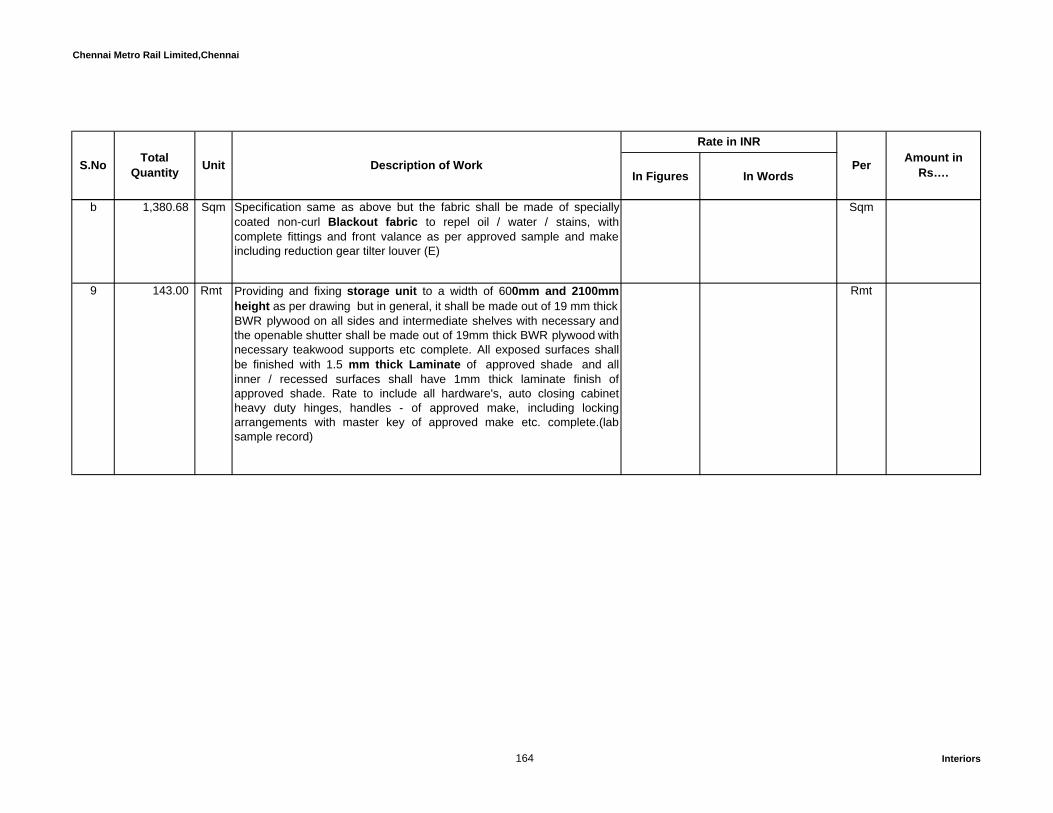
Chennai Metro Rail Limited,Chennai
In Figures In WordsPer Amount in
Rs….S.No TotalQuantity Unit Description of Work
Rate in INR
b 1,380.68 Sqm Specification same as above but the fabric shall be made of speciallycoated non-curl Blackout fabric to repel oil / water / stains, withcomplete fittings and front valance as per approved sample and makeincluding reduction gear tilter louver (E)
Sqm
9 143.00 Rmt Providing and fixing storage unit to a width of 600mm and 2100mmheight as per drawing but in general, it shall be made out of 19 mm thick BWR plywood on all sides and intermediate shelves with necessary andthe openable shutter shall be made out of 19mm thick BWR plywood withnecessary teakwood supports etc complete. All exposed surfaces shallbe finished with 1.5 mm thick Laminate of approved shade and allinner / recessed surfaces shall have 1mm thick laminate finish ofapproved shade. Rate to include all hardware's, auto closing cabinetheavy duty hinges, handles - of approved make, including lockingarrangements with master key of approved make etc. complete.(labsample record)
Rmt
164 Interiors

Chennai Metro Rail Limited,Chennai
In Figures In WordsPer Amount in
Rs….S.No TotalQuantity Unit Description of Work
Rate in INR
10 12.33 Rmt Counter with Storage Cabinet:Providing and fixing granite counter to a minimum width of 600 mm andto a specified height as shown in drawing(750 to 900mm) but in general,the counter top shall be made of 18mm thick water proof plywood toppedwith granite slab of 18 mm thick Black colour. The rate shall include forthe providing storage unit below with openable shutters. The top, bottomand intermediate shelf having 18 mm thick water proof plywood with 1.5mm thick laminate. The openable shutter shall be made of 18 mm thickBWR plywood finished with laminate including hardwares likehandles,hinges, ball catches etc.complete. Rate shall be inclusive ofproviding SS sink with drain board, garbo drain of approved make atspecified location. Rate shall be inclusive providing water supply inlet anddrainage outlet for each floor as per site condition. The rate shall beinclusive of all CP sanitary accessories such as pillar cock, bottle trap,angle valve etc. of Jaguar make.
Rmt
11 109.97 Rmt Sink and wash basin bottom covered with louvered shutter:Providing and fixing of to a specified height as shown in drawing(750 to900mm) but in general the counter bottom frame of 75x37mm first classteak wood at top and verticals at 900mm c/c. The openable shutter shallbe made of 18 mm thick BWR plywood with louvered all the exposedsurfaces of ply finished with 1.5mm thick laminate including hardwareslike handles, tower bolt, hinges, ball catches etc.complete. All theexposed edges of ply shall covered with teak wood lipping. Rate shall beinclusive of applying melamine polish at all the teak wood surfaces andother hidden inside surfaces are covered with sealer polish.
Rmt
165 Interiors
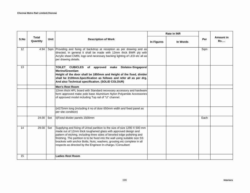
Chennai Metro Rail Limited,Chennai
In Figures In WordsPer Amount in
Rs….S.No TotalQuantity Unit Description of Work
Rate in INR
12 4.94 Sqm Providing and fixing of backdrop at reception as per drawing and asdirected, in general it shall be made with 12mm thick BWR ply withAcrylic sheet CMRL logo and necessary backing lighting of LED etc all asper drawing details.
Sqm
13 TOILET CUBICLES of approved make Stelatex-Singapore/Merino/GreenlamHeight of the door shall be 1850mm and Height of the fixed, dividershall be 2100mm.Specification as follows and refer all as per drg.And also Technical specification. (SOLID COLOUR)
Men's Rest Room12mm thick HPL board with Standard necessary accessory and hardware form approved make pole base Aluminium Nylon Polyamide Accessoriesof approved model including Top rail of "U" channel.
i)4275mm long (including 4 no of door 650mm width and fixed panel as per site condition)
24.00 Set ii)Fixed divider panels 1500mm Each
14 29.00 Set Supplying and fixing of Urinal partition to the size of size 1290 X 500 mm made out of 12mm thick toughened glass with approved design and pattern of etching, including three sides of beveled edge polishing and finishing. The partition is to be fixed into the wall using suitable size SS brackets with anchor Bolts, Nuts, washers, grouting etc complete in all respects as directed by the Engineer-In-charge./ Consultant
15 Ladies Rest Room
166 Interiors
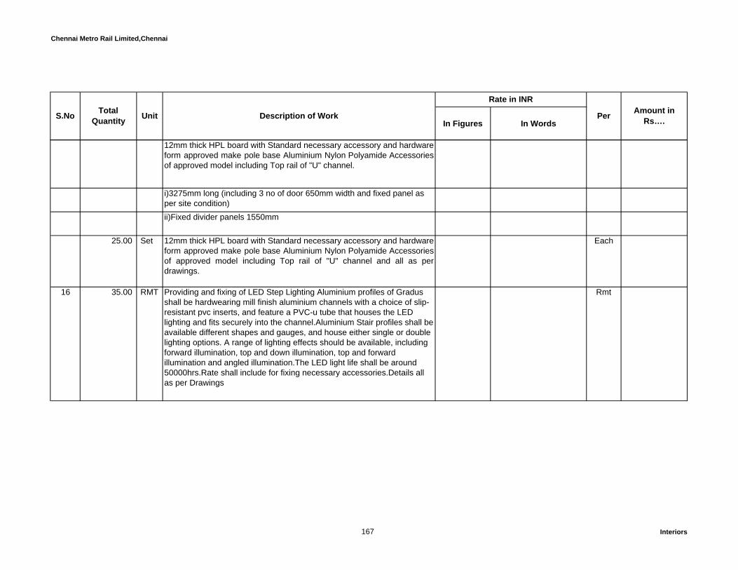
Chennai Metro Rail Limited,Chennai
In Figures In WordsPer Amount in
Rs….S.No TotalQuantity Unit Description of Work
Rate in INR
12mm thick HPL board with Standard necessary accessory and hardware form approved make pole base Aluminium Nylon Polyamide Accessoriesof approved model including Top rail of "U" channel.
i)3275mm long (including 3 no of door 650mm width and fixed panel as per site condition) ii)Fixed divider panels 1550mm
25.00 Set 12mm thick HPL board with Standard necessary accessory and hardware form approved make pole base Aluminium Nylon Polyamide Accessoriesof approved model including Top rail of "U" channel and all as perdrawings.
Each
16 35.00 RMT Providing and fixing of LED Step Lighting Aluminium profiles of Gradus shall be hardwearing mill finish aluminium channels with a choice of slip-resistant pvc inserts, and feature a PVC-u tube that houses the LED lighting and fits securely into the channel.Aluminium Stair profiles shall be available different shapes and gauges, and house either single or double lighting options. A range of lighting effects should be available, including forward illumination, top and down illumination, top and forward illumination and angled illumination.The LED light life shall be around 50000hrs.Rate shall include for fixing necessary accessories.Details all as per Drawings
Rmt
167 Interiors

Chennai Metro Rail Limited,Chennai
In Figures In WordsPer Amount in
Rs….S.No TotalQuantity Unit Description of Work
Rate in INR
17 140.00 RMT Providing and fixing Stair Edging Aluminium with PVC insert of Gradus Elite aluminium hardwearing stair edgings (stair nosings) shall comprise of aluminium channels with slip-resistant inserts of standard colours. The stair edging shall be fixed to the step with the pvc insert to cover the screw neatly and should be suitable for commercial applications. Rate shall include for fixing necessary accessories.Details all as per Drawings
Rmt
18 235.00 Nos Supply and installation of Auditorium chair of Model no - VEHJ 9502 orEQ with pressure die cast aluminum legs , one foldable writing pad ofMDF per each chair, tip – up fabric seat. shell at the back and seat of PP.Details all as per drawings.
Each
PARTITIONS19 Providing and fixing of Partition total four layers of GYPROC FIBRE
CEMENT BOARD or approved equivalent, each layer 12mm thick (instaggered pattern) is screw fixed with drywall screws(zinc chromiumplated, self drilling ) of 25mm/35mm at 300mm centres two layers oneach side of 70mm Rondo™/Gypsteel ultra GI C-stud {0.5mm thickhaving one flange of 34mm and another flange of 36mm) placed at610mm centre to centre in 72mm Rondo™/Gypsteel ultra GI floorChannel (0.55 mm thick have equal flanges of 32mm) which is anchoredto the floor & true ceiling using anchor fasteners. Finally square andtapered edges of the boards are to be jointed and finished so as to havea flush look which includes filling and finishing with Jointing compound,Joint Paper tape.
168 Interiors

Chennai Metro Rail Limited,Chennai
In Figures In WordsPer Amount in
Rs….S.No TotalQuantity Unit Description of Work
Rate in INR
The additional supports shall be provided to the vertical stud and RCCslab above the false ceiling at top with 'Y' type supports. Air gap betweenthe plasterboards is lined with 50mm rock wool of density 48 Kg/m3 ofapproved make shall be placed in the cavity rock wool rapped with40GSM fiber glass tissue. The contractor must ensure that the wool iswire-braced to prevent it from ‘lumping down’ over a period of time. Fixing of channels shall also to provide suitable for attachment of fixtures to thepartitions and the perimeter opening should be trimmed with studspacked with best quality treated timber frame to a required size andshape with 2 coats of fire proof paint over a coat of anti-termitetreatment / anti-corrosive primer to receive screws / anchor fasteners tofix Joinery frame in position etc. as per drawing as complete in allrespects complying with relevant standard specifications and as directedby the Employer/Employer's Representative.
a 3,249.51 Sqm Rate shall include for providing resin bonded rockwool - 50 mm (Acoustic Insulation Material ) .In solid partition to make it as acousticproof.Rate also shall be inclusive of 12mm thick BWR ply boxing forfixing Switches, sockets, Backup box etc on the partition to a requiredsize and shape.
Sqm
b 2,248.53 Sqm Specification same as above but providing one layers of board only oneside of the stud for wall paneling/column panelings etc.,
Sqm
20 4,649.91 Sqm Extra rate for over the above, for providing Resin bonded rock wool50mm to (acoustic insulation material) density of 48kg/cum in solidpartition to make it as acoustic proof.
Sqm
169 Interiors

Chennai Metro Rail Limited,Chennai
In Figures In WordsPer Amount in
Rs….S.No TotalQuantity Unit Description of Work
Rate in INR
21 1,548.33 Sqm Providing and fixing of 1.0mm thick laminate of approved color andshade with grooves and lines and in patterns drawing on specified areaas instructed by Engineer-Incharge/Consultant . The cost of necessaryhardware's, adhesives, wastages etc; as required for complete the works.Base cost of 1.0mm laminate is Rs.375/1sqmt. Actual visible surfacesonly will be measured and paid.
Sqm
22 1,139.06 Sqm Providing and fixing of 3.5mm thick veneer of approved color and shadewith grooves and lines and in patterns drawing on specified area asinstructed by Engineer-Incharge/Consultant, exposed surfaces of veneershall be finished with melamine polish of required level. The cost ofnecessary hardware's, adhesives, wastages etc; as required for completethe works. Actual visible surfaces only will be measured and paid. Basiccost of veneer Rs.900/Sqm Finishes shall made at Factory onlyinstallation at site(portal and DH cabin)
Sqm
23 4,911.25 Sqm Providing and Fixing of 12.5mm Gypboard and the joints between the gyp-boards are finished flush and even with jointing compound and papertape and the surface shall be painted with 3 coats of acrylic emulsionpaint of approved make and shade over a coat of primer suitable for gyp-board after E-Mix / Pop / Gypsum putty and all as per manufacturer’sspecification etc complete and all as directed. Rate shall include forproviding all hardware's, etc.complete as per drawing as directed..
Sqm
170 Interiors

Chennai Metro Rail Limited,Chennai
In Figures In WordsPer Amount in
Rs….S.No TotalQuantity Unit Description of Work
Rate in INR
24 Providing and fixing toughened glass panel to the specified thickness asgiven in below in the solid partition (laminated/Veneer/ calciumsilicate/Gypsum board). The frame work in the the glass panelcircumference shall be fixed with 75mmx19mm size first class teak woodframe and fixing the toughened glass at the centre of teak wood frameusing first class teak wood beadings to shape and size as per drawing.The exposed teak wood surfaces shall be finished with melamine polish.The rate to be include the cost of necessary hardware's, adhesives,wastage etc; as required for complete the works. Actual seen glasssurface area will be measured and paid.
a 89.75 Sqm Single layer 8mm thick toughened clear glass Sqm
b 203.65 Sqm 6mm thick lacquered glass of approved colour and Saint Gobain orequivalent make
Sqm
25 54.25 Sqm Providing and fixing of 6mm thick lacquered glass of approved colourand Saint Gobain or equivalent make over the existing partition, panelingor wall surfaces as per drawing as directed. The rate shall be inclusive ofnecessary SS Stud/Double side 3M sticker, hardware and wastage etc;complete.
Sqm
171 Interiors

Chennai Metro Rail Limited,Chennai
In Figures In WordsPer Amount in
Rs….S.No TotalQuantity Unit Description of Work
Rate in INR
26 567.07 Sqm Providing and fixing Partition above the false ceiling level using total twolayers of GYPROC FIBRE CEMENT BOARD or approved equivalent,each layer 12mm thick (in staggered pattern) is screw fixed with drywallscrews of 25mm / 35mm at 300mm centres one layers on each side of70mm Rondo™/Gypsteel ultra GI C-stud {0.5mm thick having one flangeof 34mm and another flange of 36mm) placed at 610mm centre to centrein 72 mm Rondo™/Gypsteel Ultra GI floor Channel (0.55 mm thick haveequal flanges of 32mm) which is anchored to the partition bottom & trueceiling using an anchor fasteners. Finally square and tapered edges ofthe boards are to be jointed and finished so as to have a flush look whichincludes filling and finishing with Jointing compound, Joint Paper tape asper manufacturers specification, as complete in all respects complyingwith relevant standard specifications and as directed by theEmployer/Employer's Representative.
Sqm
27 833.34 Sqm Providing and fixing of single layer 9mm thick calcium silicate board inthe existing aluminium/GI partitions except the cost of aluminium/GIframe work. The joints are to be finished with jointing compound as permanufacturers specification. The boards shall be fixed with counter sunkstainless steel / fully threaded self tapping screws of suitable dia andlength at every 300 mm c/c. The rate shall be inclusive of necessaryscaffolding, hardware etc.complete. (above false ceiling solid partition)
Sqm
172 Interiors
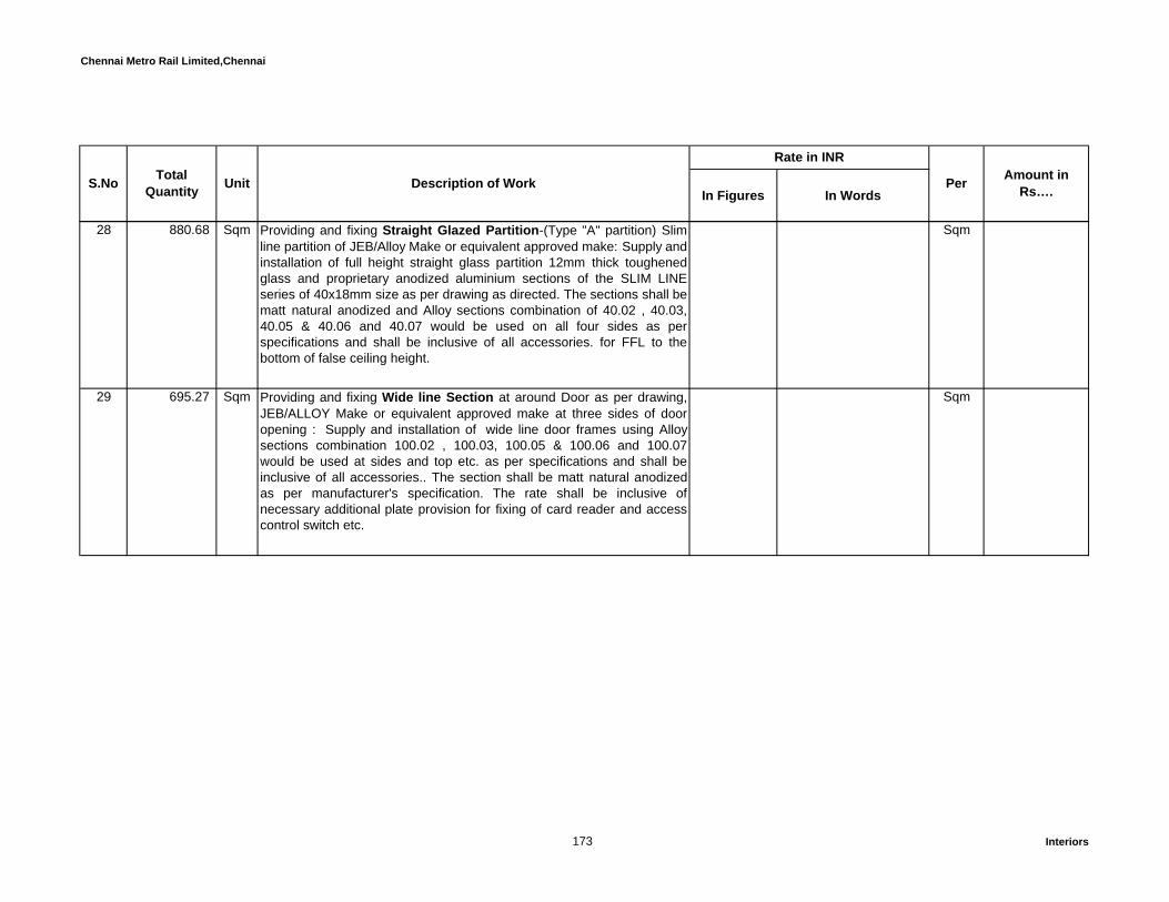
Chennai Metro Rail Limited,Chennai
In Figures In WordsPer Amount in
Rs….S.No TotalQuantity Unit Description of Work
Rate in INR
28 880.68 Sqm Providing and fixing Straight Glazed Partition-(Type "A" partition) Slimline partition of JEB/Alloy Make or equivalent approved make: Supply andinstallation of full height straight glass partition 12mm thick toughenedglass and proprietary anodized aluminium sections of the SLIM LINEseries of 40x18mm size as per drawing as directed. The sections shall bematt natural anodized and Alloy sections combination of 40.02 , 40.03,40.05 & 40.06 and 40.07 would be used on all four sides as perspecifications and shall be inclusive of all accessories. for FFL to thebottom of false ceiling height.
Sqm
29 695.27 Sqm Providing and fixing Wide line Section at around Door as per drawing,JEB/ALLOY Make or equivalent approved make at three sides of dooropening : Supply and installation of wide line door frames using Alloysections combination 100.02 , 100.03, 100.05 & 100.06 and 100.07would be used at sides and top etc. as per specifications and shall beinclusive of all accessories.. The section shall be matt natural anodizedas per manufacturer's specification. The rate shall be inclusive ofnecessary additional plate provision for fixing of card reader and accesscontrol switch etc.
Sqm
173 Interiors

Chennai Metro Rail Limited,Chennai
In Figures In WordsPer Amount in
Rs….S.No TotalQuantity Unit Description of Work
Rate in INR
30 Supplying and fixing Fully openable Patch Fitting partition DORMA pathfittings are based on a modular system, consisting of a base unit,functional inserts and clip-on covers in the widest. Fttings are supplied asstandard with gasket to suit 10 mm glass. For 8 mm and 12 mm glass,correspondingly thicker and thinner gasket is available. Toughened glassassemblies can be provided with fixed parts in widely differingarrangements – with corner fittings or fin fittings at different angles, andwith double or single action doors in single-leaf or double-leaf designs.The inserts for corner and overpanel patches in the DORMA patchprogram have been designed and manufactured to give two options inthe pivot point distance from the sidepanel or frame. It can be either 55mm or 65 mm.
Maximum door weight andwidth for DORMA patch fittingsmax. door weight: 130 kgmax. door width: 1300 mmmax. door height: 2500 mmFor doors with a height of more than 2,500 mm we have to keepadditional conditions / limits:• Glass thickness >/= 10 mm• Usage of a handle bar with 3 connection points in minimum and aminimum height of 2/3 door height
Finish : Satin stainless steel,The surface finishes of the fittings are notmaintenance free and should be cleaned according to their material anddesign. For metallic surfaces (stainless steel) please use appropriatecleaning agents without abrasive additives only.
Patch fittings has been tested in an durability test according to DIN EN1154.
174 Interiors

Chennai Metro Rail Limited,Chennai
In Figures In WordsPer Amount in
Rs….S.No TotalQuantity Unit Description of Work
Rate in INR
Rate shall include for providing Glass Fin to support the Patch FittingDoor, transport charges, handling, loading and unloading, Installation,protecting the module and glass till handing over, testing, commissioningall necessary hardware's, Structural supports if any, etc. complete and allas per manufacturers specifications as directed.
a 147.93 Sqm Rate for partition only Sqm
b 335.31 Sqm Rate for single/double leaf doors only. Sqm
31 991.13 Rmt Glass Etching:Fixing to glass panels using 3M film stickers as per required patterndrawing and shape and as directed by the Engineer-Incharge/Consultant.
Rmt
175 Interiors
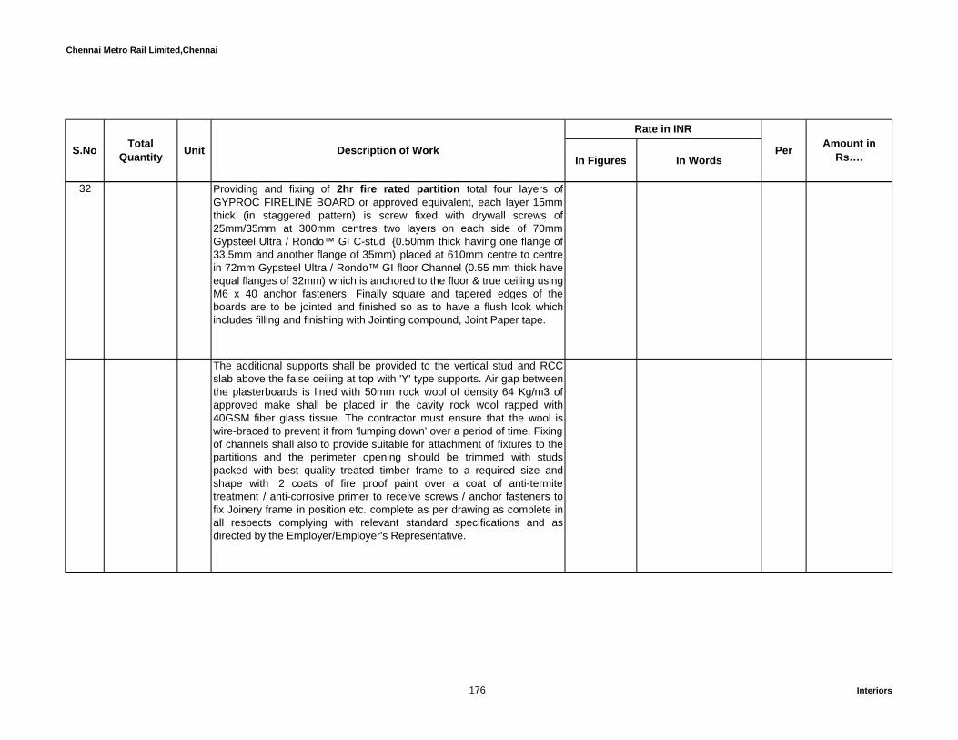
Chennai Metro Rail Limited,Chennai
In Figures In WordsPer Amount in
Rs….S.No TotalQuantity Unit Description of Work
Rate in INR
32 Providing and fixing of 2hr fire rated partition total four layers ofGYPROC FIRELINE BOARD or approved equivalent, each layer 15mmthick (in staggered pattern) is screw fixed with drywall screws of25mm/35mm at 300mm centres two layers on each side of 70mmGypsteel Ultra / Rondo™ GI C-stud {0.50mm thick having one flange of33.5mm and another flange of 35mm) placed at 610mm centre to centrein 72mm Gypsteel Ultra / Rondo™ GI floor Channel (0.55 mm thick haveequal flanges of 32mm) which is anchored to the floor & true ceiling usingM6 x 40 anchor fasteners. Finally square and tapered edges of theboards are to be jointed and finished so as to have a flush look whichincludes filling and finishing with Jointing compound, Joint Paper tape.
The additional supports shall be provided to the vertical stud and RCCslab above the false ceiling at top with 'Y' type supports. Air gap betweenthe plasterboards is lined with 50mm rock wool of density 64 Kg/m3 ofapproved make shall be placed in the cavity rock wool rapped with40GSM fiber glass tissue. The contractor must ensure that the wool iswire-braced to prevent it from ‘lumping down’ over a period of time. Fixing of channels shall also to provide suitable for attachment of fixtures to thepartitions and the perimeter opening should be trimmed with studspacked with best quality treated timber frame to a required size andshape with 2 coats of fire proof paint over a coat of anti-termitetreatment / anti-corrosive primer to receive screws / anchor fasteners tofix Joinery frame in position etc. complete as per drawing as complete inall respects complying with relevant standard specifications and asdirected by the Employer/Employer's Representative.
176 Interiors

Chennai Metro Rail Limited,Chennai
In Figures In WordsPer Amount in
Rs….S.No TotalQuantity Unit Description of Work
Rate in INR
Rate shall be inclusive of 12mm thick BWR ply boxing for fixing Switches,sockets, Backup box etc on the partition to a required size and shape.(alllab partition)
33 Providing and fixing of fully glazed steel fire rated partition and doorwith 120 minutes of integrity (E=120) fabricated with 1.6 mm thickgalvanized steel sheet. The door frames are manufactured from 1.6 mmgalvanized steel sheet pressed to form a profile of 35 mm x 60 mm onthe vertical sides and 50 x 60 mm on the horizontal side. The doorshutter would have a top rail and side rail 60 mm x 60 mm and a bottomrail of 110 mm x 60 mm. The overall door opening is 1800 mm x2100+fixed 1800x1700mm. The test is conducted in CBRI, Roorkee asper BS 476 Part 22. The glass should be SGGCFDL 11mm clear 120 minrated ( E120) Non Wired Toughened glass with a light transmission of89% and a sound reduction of 32 db. The glass should be class 1C1category of Impact Resistance as per EN 12600. The glass should beheld in its place with the help of 2 mm GI beading and a special ceramictape with cross section of 5 x 20 mm..
177 Interiors

Chennai Metro Rail Limited,Chennai
In Figures In WordsPer Amount in
Rs….S.No TotalQuantity Unit Description of Work
Rate in INR
The shutters should be fixed to the frame using 4nos of Dorma SS BallBearing Hinges of size 100 mm x 75 mm and 3 mm thickness. Beadingshould be attached using 4 mm x 35 mm SS screws at a distance of 75mm from the edges and 150 mm c/c henceforth. The door should befitted with Dorma Mortise Sash lock 952F and door closer TS 68 ofDorma make or equivalent. The inactive leaf should be fixed to the frameusing 1200mm long Dorma tower bolt no 9114306 or equivalent. (SAINTGOBAIN 11mm CONTRA FLAME or approved equivalent make)
a 49.31 Sqm For partition only(UPS and server) Sqm
b 9.87 Sqm For single/double leaf doors only(lobby) Sqm
178 Interiors
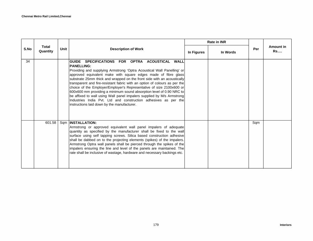
Chennai Metro Rail Limited,Chennai
In Figures In WordsPer Amount in
Rs….S.No TotalQuantity Unit Description of Work
Rate in INR
34 GUIDE SPECIFICATIONS FOR OPTRA ACOUSTICAL WALLPANELLING:Providing and supplying Armstrong ‘Optra Acoustical Wall Panelling’ orapproved equivalent make with square edges made of fibre glasssubstrate 25mm thick and wrapped on the front side with an acousticallytransparent and fire-resistant fabric with an option of colours as per thechoice of the Employer/Employer's Representative of size 2100x600 or600x600 mm providing a minimum sound absorption level of 0.90 NRC tobe affixed to wall using Wall panel impalers supplied by M/s ArmstrongIndustries India Pvt. Ltd and construction adhesives as per theinstructions laid down by the manufacturer.
601.58 Sqm INSTALLATION:Armstrong or approved equivalent wall panel impalers of adequatequantity as specified by the manufacturer shall be fixed to the wallsurface using self tapping screws. Silica based construction adhesiveshall be dabbed on to the projecting elements (spikes) of the impalers.Armstrong Optra wall panels shall be pierced through the spikes of theimpalers ensuring the line and level of the panels are maintained. Therate shall be inclusive of wastage, hardware and necessary backings etc.
Sqm
179 Interiors

Chennai Metro Rail Limited,Chennai
In Figures In WordsPer Amount in
Rs….S.No TotalQuantity Unit Description of Work
Rate in INR
35 GUIDE SPECIFICATIONS FOR ARMSTRONG OR APPROVEDEQUIVALENT MAKE CHANNELED WOODWORKS WALL PANELLINGOF SIZE: 128X2440X16MMProviding and Fixing Armstrong Channeled Woodworks perforatedpanels of width 128mm, thickness of 16mm and length 2440 mm or asrequired by the Employer/Employer's Representative, made of a highdensity particle board substrate with a laminated facing as per theapproved shade/ species & finish and a melamine balancing layer on thereverse side. The boards shall have a special perforation pattern wherethe visible surface has a (“Helmholtz” fluted perforation of 2mm width and14mm of visible panel / 4mm width and 28mm visible panel) each. Thepanels shall provide a minimum sag resistance of RH90 and a fire ratingclass of 1 as per Part 7 of BS 476. The edges of the panels shall be“tongue-and-grooved” to receive special clips for installation. The back ofthe perforated panel shall have sound absorbing non-woven acousticalfleece. The panels shall be mounted on special aluminium splines usingclips provided by Armstrong or approved equivalent make and approvedby the Employer/Employer's Representative.
180 Interiors

Chennai Metro Rail Limited,Chennai
In Figures In WordsPer Amount in
Rs….S.No TotalQuantity Unit Description of Work
Rate in INR
147.93 Sqm INSTALLATION:Install wooden battens (provided by others) of section 50mmx50mm oras approved by the Employer/Employer's Representative on the solid wallhorizontally using screws and plugs at spacing of 600mm centre-to-centre. Screw the aluminium extruded keel for channelled woodworks(GTPT001) over the lowest and second wooden batten at an on-centerdistance of 600mm. Install the first set of wooden panels by inserting theclips for border channelled woodworks (GTPT002) and insert the grooveof the panel into the projecting flange of the aluminium clip. Continueinstalling rows of panels by inserting the tongue into the groove of theearlier inserted panel and progressively installing clips for insidechannelled woodworks (GTPT003) into the next keel till the actual heightis achieved. Use clips for border channelled woodworks (GTPT002) tofinish off the installation. Finish off the edges using wooden moulding ofmatching colour. The rate shall be inclusive of wastage, hardware andnecessary backing etc.
Sqm
Painting Works
36 28,115.39 Sqm Providing Acrylic emulsion paint - Painting with acrylic emulsion paint ofLow VOC paint ( complying with all green rating systems) and ofapproved make and colour or equivalent make two or more coats as permanufacturers specifications and as directed. The rate shall beinclusive of necessary scaffolding or staging etc.as complete with allrespects complying with relevant standard specification, as directed bythe Engineer-Incharge/Consultant
Sqm
181 Interiors

Chennai Metro Rail Limited,Chennai
In Figures In WordsPer Amount in
Rs….S.No TotalQuantity Unit Description of Work
Rate in INR
37 14,945.76 Sqm Supplying and applying "RENOVA" Synthetic plaster over the preparedexternal plastered surface at three coats of approved colour shade &pattern . The first coat of application to be done with Renova ASP bytrowel. The second coat with brush and the final coat should also beapplied with brush. The rate shall include for carrying out work at alllevels as per manufacture specification and all necessary surfacepreparation, tools, scaffolding, water, electricity,taxes etc..as completewith all respects complying with relevant standard specification, asdirected
Sqm
38 7,140.04 Sqm Providing & applying POP punning plaster 2 mm thick over exposedwall surface including scaffolding etc. complete. Rate to include formaking the wall with plumb line and get smooth surface to receive thepaint.( all plaster surface) and also include cost of material, labour,unloading and shifting of material,water etc..as complete and as directedby Engineer-Incharge/Consultant.
Sqm
39 49.31 Sqm Providing two coats of Enamel paint to wooden / M.S grill of approvedcolour over a coat primer including preparation of surface by throughcleaning as per manufacture's specification fully to give an even shade.
Sqm
182 Interiors

Chennai Metro Rail Limited,Chennai
In Figures In WordsPer Amount in
Rs….S.No TotalQuantity Unit Description of Work
Rate in INR
40 250.00 Sqm Providing & Applying 10mm thick Perlite based Gypsum plaster oninternal RCC wall/beam & block wall and Ceilings surfaces with Bulkdensity of 650-710 Kg/m3 and finesses of 95% passing through 150micron like Gyproc- One Coat Elite (N2+) or approved equivalent make .Rate shall be include for Surface Preparation, filling cracks in thebackground if any, surface cleaning/curing (if required), finishing ofElectrical Switch Boxes, light points, DB’s etc and necessarystaging,scafolding, GI edge beading,GI plaster mesh at all levels andelevations and also include cost of material, labour, unloading andshifting of material,water etc..as complete with all respects complyingwith relevant standard specification, as directed by the Engineer-Incharge/Consultant.
Sqm
41 Preparing the surface, making and fixing of POP cornice at the junctionof wall and ceiling. The rate shall be inclusive wastage, mould,scaffolding, cleaning the surface etc. size as mentioned below
a - Rmt size diagonally 150mm Rmt
b 3,784.03 Rmt size diagonally 200mm Rmt
42 4.00 Nos Supplying and fixing of MS powder coated Letter Box of approved sizeand shape as per drawing as directed 1150 ht x 900 w x 100D. Cluster of21 Boxes
Each
43 81.86 Sqm Providing and fixing of mirror But in general 6mm thick mirror withaluminium frame for backing frame fixing with 12MM thick BWR ply fixingwith stainless steel studs.
Sqm
183 Interiors
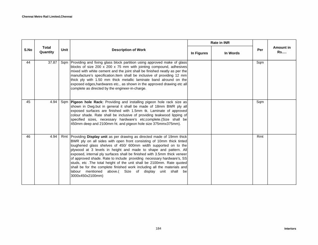
Chennai Metro Rail Limited,Chennai
In Figures In WordsPer Amount in
Rs….S.No TotalQuantity Unit Description of Work
Rate in INR
44 37.87 Sqm Providing and fixing glass block partition using approved make of glassblocks of size 200 x 200 x 75 mm with jointing compound, adhesivesmixed with white cement and the joint shall be finished neatly as per themanufacture's specification.Item shall be inclusive of providing 12 mmthick ply with 1.50 mm thick metallic laminate band alround on theexposed edges,hardwares etc., as shown in the approved drawing etc allcomplete as directed by the engineer-in-charge.
Sqm
45 4.94 Sqm Pigeon hole Rack: Providing and installing pigeon hole rack size asshown in Dwg.but in general it shall be made of 18mm BWR ply allexposed surfaces are finished with 1.5mm tk. Laminate of approvedcolour shade. Rate shall be inclusive of providing teakwood lipping ofspecified sizes, necessary hardware's etc;complete.(Size shall be450mm deep and 2100mm ht. and pigeon hole size 375mmx375mm).
Sqm
46 4.94 Rmt Providing Display unit as per drawing as directed made of 19mm thickBWR ply on all sides with open front consisting of 10mm thick tintedtoughened glass shelves of 450/ 600mm width supported on to theplywood at 3 levels in height and made to shape and pattern. Allexposed, internal ply surfaces shall be finished with 3.5mm thick veneerof approved shade. Rate to include providing necessary hardware's, SSstuds, etc .The total height of the unit shall be 2100mm. Rate quotedshall be for the complete finished work including all the materials andlabour mentioned above.( Size of display unit shall be3000x450x2100mm)
Rmt
184 Interiors
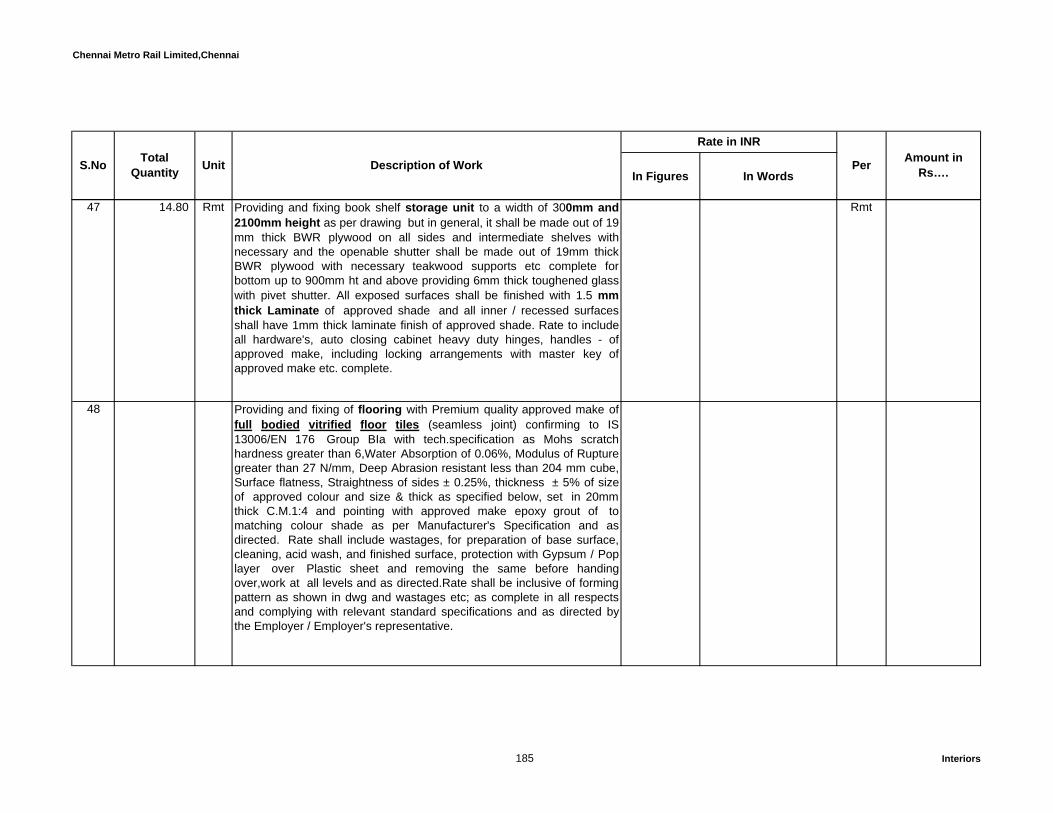
Chennai Metro Rail Limited,Chennai
In Figures In WordsPer Amount in
Rs….S.No TotalQuantity Unit Description of Work
Rate in INR
47 14.80 Rmt Providing and fixing book shelf storage unit to a width of 300mm and2100mm height as per drawing but in general, it shall be made out of 19mm thick BWR plywood on all sides and intermediate shelves withnecessary and the openable shutter shall be made out of 19mm thickBWR plywood with necessary teakwood supports etc complete forbottom up to 900mm ht and above providing 6mm thick toughened glasswith pivet shutter. All exposed surfaces shall be finished with 1.5 mm thick Laminate of approved shade and all inner / recessed surfacesshall have 1mm thick laminate finish of approved shade. Rate to includeall hardware's, auto closing cabinet heavy duty hinges, handles - ofapproved make, including locking arrangements with master key ofapproved make etc. complete.
Rmt
48 Providing and fixing of flooring with Premium quality approved make offull bodied vitrified floor tiles (seamless joint) confirming to IS13006/EN 176 Group BIa with tech.specification as Mohs scratchhardness greater than 6,Water Absorption of 0.06%, Modulus of Rupturegreater than 27 N/mm, Deep Abrasion resistant less than 204 mm cube,Surface flatness, Straightness of sides ± 0.25%, thickness ± 5% of sizeof approved colour and size & thick as specified below, set in 20mmthick C.M.1:4 and pointing with approved make epoxy grout of tomatching colour shade as per Manufacturer's Specification and asdirected. Rate shall include wastages, for preparation of base surface,cleaning, acid wash, and finished surface, protection with Gypsum / Poplayer over Plastic sheet and removing the same before handingover,work at all levels and as directed.Rate shall be inclusive of formingpattern as shown in dwg and wastages etc; as complete in all respectsand complying with relevant standard specifications and as directed bythe Employer / Employer's representative.
185 Interiors

Chennai Metro Rail Limited,Chennai
In Figures In WordsPer Amount in
Rs….S.No TotalQuantity Unit Description of Work
Rate in INR
a 3,032.55 Sqm 800mmx800mmx12mm.
Basic Rate . Rs. 135/ Sq.Ft
Sqm
b 3,692.16 Sqm 600mmx600mmx10mm.
Basic Rate . Rs. 116/ Sq.Ft
Sqm
49 500.77 Sqm Same as above specification but the tile shall be Matt finish, outdoorfull bodied vitrified tiles 8mm thick of 300x300 size.
Basic Rate . Rs. 98/ Sq.Ft
Sqm
50 355.65 Sqm Providing flooring with best quality approved make Anti Skid Ceramic tiles ranges, sizes as listed below shall 8.0mm thick set in CM 1:4, 20mmthick and pointing the joints with Laticrete adhesive L 290 and pointingwith Laticrete make Latapoxy SP 100 of approved make as perManufacturer's Specification and as directed. Rate shall include forpreparation of base surface, and finishing the surface, cleaning thesurface, and protecting and with Gypsum / POP layer over Plastic sheetand removing the same before handing over, work at all levels etc. ascomplete in all respects and complying with relevant standardspecifications and as directed by the Employer/Employer'sRepresentative. Size of tiles shall be 300mmx300mm.Basic Rate . Rs. 56/ Sq.Ft
Sqm
186 Interiors

Chennai Metro Rail Limited,Chennai
In Figures In WordsPer Amount in
Rs….S.No TotalQuantity Unit Description of Work
Rate in INR
51 1,923.08 Sqm Providing and fixing of flooring with Premium quality approved make offull bodied vitrified floor tiles (seamless joint) confirming to IS13006/EN 176 Group BIa with tech.specification as Mohs scratchhardness greater than 6,Water Absorption of 0.06%, Modulus of Rupturegreater than 27 N/mm, Deep Abrasion resistant less than 204 mm cube,Surface flatness, Straightness of sides ± 0.25%, thickness ± 5% of sizeof approved colour and size & thick as specified, the tile shall be laid with4mm thick spacer semi glossi / honed finish joints are fillied withapproved make Epoxy grout (office area) and tile set in combination ofLaticrete adhesive L 111 and L 73 ( cementtiious powder and latexrubberised liquid ) or Equivalent approved make to a thick not less than6mm (for surface contact of the bottom of the granite slab) as perapproved pattern/design using irrespective of size and shape, Rate shallinclude for preparation of base surface & finishing as per manufacturer'sSpecification and as directed.- 600 x 600 mm Basic Rate . Rs. 128/ Sq.Ft
Sqm
52 Providing flooring with best quality approved colour natural marble slabthick 18mm of size not less than 1200 x 900 mm/ 900 x 600mm,machine cut with water ( without kerosene ), set in combination ofLaticrete adhesive L 111 and L 73 ( cementtiious powder and latexrubberised liquid ) or Equivalent approved make to a thick not less than9mm (for surface contact of the bottom of the granite slab) as perapproved pattern/design drawing using irrespective of size and shape,including finishing the joints with Laticrete make Unsanded Cementitiousgrout L 600 series or Rate shall include for preparation of base surface& finishing the joints with white cement slurry, cutting, edge chamferingand polishing rough, medium, nice and acid wash and tin-oxide polish asper manufacturer's Specification and as directed.
187 Interiors

Chennai Metro Rail Limited,Chennai
In Figures In WordsPer Amount in
Rs….S.No TotalQuantity Unit Description of Work
Rate in INR
1,608.31 Sqm Rate shall include for preparation of base surface & finished thesurface, protection with gypsum/pop layer over plastic sheet andremoving the same before handing over, work at all levels and ascomplete in all respects and complying with relevant standardspecifications and as directed by the Employer/Employer'sRepresentative. The tolerance in level shall be +/-1mm. (Basic costRs.850/Sqm)
Sqm
53 1,985.89 Sqm Kota stone slab flooring over 20 mm (average) thick base laid over andjointed with grey cement slurry mixed with pigment to match the shade ofthe slab, including rubbing and polishing complete with base of cementmortar 1 : 4 (1 cement : 4 coarse sand) - 25 mm thixk
Sqm
54 731.38 Sqm Kota stone slabs 20 mm thick in risers of steps, skirting, dado and pillarslaid on 12 mm (average) thick cement mortar 1:3 (1 cement: 3 coarsesand) and jointed with grey cement slurry mixed with pigment to matchthe shade of the slabs, including rubbing and polishing complete
Sqm
188 Interiors

Chennai Metro Rail Limited,Chennai
In Figures In WordsPer Amount in
Rs….S.No TotalQuantity Unit Description of Work
Rate in INR
55 330.76 Sqm Providing flooring with best quality of approved colour leather finishgranite slab not less than 18 mm thick of size not less than 1200 x 900mm/ 900 x 600, machine cut and machine high pre-polished, set in C.M1:4, 20 mm thick topped with white cement slurry (for surface contact ofthe bottom of the granite slab) as per approved pattern/design drawing,including finishing the joints with white cement slurry, cutting, edgechamfering and polishing rough, medium, nice and acid wash and tin-oxide polish as per manufacturer's Specification and as directed. Rateshall include for preparation of base surface & finished the surface,protection with gypsum/pop layer over plastic sheet and removing thesame before handing over, work at all levels and as complete in allrespects and complying with relevant standard specifications and asdirected by the Employer/Employer's Representative The tolerance inlevel shall be +/-1mm. Basic Rate . Rs. 350/ Sq.Ft
Sqm
56 26.12 Sqm Providing and fixing flooring with cement based pressed button tile ofapproved make, thick not not less than 22 mm thick of approved colour /pattern of specified shape & size (as per drg), over a bed of CM 1:4,20mm thick including jointed with matching cement slurry includingpreparation of base surface, and finished the surface, cleaning thesurface, work at all levels etc.,as complete in all respects and complyingwith relevant standard specifications and as directed by the
Sqm
189 Interiors
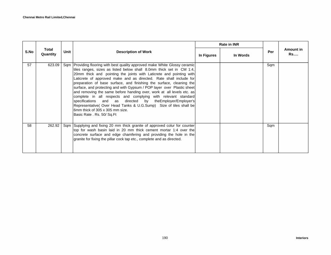
Chennai Metro Rail Limited,Chennai
In Figures In WordsPer Amount in
Rs….S.No TotalQuantity Unit Description of Work
Rate in INR
57 623.09 Sqm Providing flooring with best quality approved make White Glossy ceramictiles ranges, sizes as listed below shall 8.0mm thick set in CM 1:4,20mm thick and pointing the joints with Laticrete and pointing withLaticrete of approved make and as directed. Rate shall include forpreparation of base surface, and finishing the surface, cleaning thesurface, and protecting and with Gypsum / POP layer over Plastic sheetand removing the same before handing over, work at all levels etc. ascomplete in all respects and complying with relevant standardspecifications and as directed by theEmployer/Employer'sRepresentative( Over Head Tanks & U.G.Sump) Size of tiles shall be6mm thick of 305 x 305 mm size.Basic Rate . Rs. 50/ Sq.Ft
Sqm
58 262.92 Sqm Supplying and fixing 20 mm thick granite of approved colur for countertop for wash basin laid in 20 mm thick cement mortar 1:4 over theconcrete surface and edge chamfering and providing the hole in thegranite for fixing the pillar cock tap etc., complete and as directed.
Sqm
190 Interiors

Chennai Metro Rail Limited,Chennai
In Figures In WordsPer Amount in
Rs….S.No TotalQuantity Unit Description of Work
Rate in INR
59 Providing and laying with best qualityof approved colur Italian marbleperlato sicilio 20mm of size not less than 1200 x 900 mm/ 900 x 600mm,machine cut with water ( without kerosene ), set in combination ofLaticrete adhesive L 111 and L 73 ( cementtiious powder and latexrubberised liquid ) or Equivalent approved make to a thick not less than9mm (for surface contact of the bottom of the granite slab) as perapproved pattern/design drawing using irrespective of size and shape,including finishing the joints with Laticrete make Unsanded Cementitiousgrout L 600 series or Rate shall include for preparation of base surface& finishing the joints with white cement slurry, cutting, edge chamferingand polishing rough, medium, nice and acid wash and tin-oxide polish asper manufacturer's Specification and as directed. Basic Rate Rs. 450/ Sq.Ft
359.97 Sqm Rate shall include for preparation of base surface & finished thesurface, protection with gypsum/pop layer over plastic sheet andremoving the same before handing over, work at all levels and ascomplete in all respects and complying with relevant standardspecifications and as directed by the Engineers In-charge/Consultant.The tolerance in level shall be +/-1mm.
Sqm
60 73.97 Sqm Providing and laying of laminated wooden flooring but in general it shallbe provided with 8mm thick HDF planks of size 194mmx1286mm withfactory tongue and groove joints, glue fixed and edges finished withnecessary profiles of skirting / reducer as per manufactures specification.Rate shall be inclusive of providing 4mm polyethene sheets as under layon the existing floor. The tolerance in level shall be +/-1mm. Note:Approved make shall be Tarkett Sommer or equivalent, as completedwith all respect and complying with relevant standard specification asdirected by the Engineer-Incharge/Consultant and as per drawing.
Sqm
191 Interiors

Chennai Metro Rail Limited,Chennai
In Figures In WordsPer Amount in
Rs….S.No TotalQuantity Unit Description of Work
Rate in INR
61 118.35 Sqm Supplying and fixing Imported Vinyl flooring with roll form vinyl tile ofapproved make & shade 2mm mm thick of standard sizes as per IS–3462 / BS 3261 of manufacturers specification over the existing floor.The rate shall include all cuttings and wastages, cutting and providing tileabove electrical trunking, cost of all materials adhesives of SR-505FEVICOL of M/s. PIDILITE Industries Ltd., make etc, including welding ofjoints., complete. Only laid area will be measured for payment. Ratequoted shall be for the complete finished work including all the materialsand labour mentioned above.
Sqm
62 Sqm Providing and applying Polished Concrete Floor Work using“ULTRAFLOOR system using imported machines Grinding with 20 - 120grit Diamond Tool including polishing with Polishing with 100 – 800 gritresin bonded tool. The rate to include for cost of all materials, labour, allleads and lifts, washers, tools, plant and machinery, equipment hire andfuel charges, dewatering, finishing, curing, floor thickening wherevernecessary and all other incidental charges and the entire work shall beexecuted as per specifications, drawings and as directed.
The Quoted rate shall include for providing colour staining of the concreteof approved shade. The specification of ULTRA floor shall be equivalentto "GOLD " HTC super floor specification
63 Providing, supplying & installing imported Broad loom carpet / ROLLTYPE of approved make in the specified areas as per specifications,patterns/drawing specified below.
Face ConstructionConstruction - Roll Type
192 Interiors

Chennai Metro Rail Limited,Chennai
In Figures In WordsPer Amount in
Rs….S.No TotalQuantity Unit Description of Work
Rate in INR
Yarn- recyclable NylonGauge - 1/10 to 1/12 Pile stitches per inch : 9 to 12Pile Height Average : 5mmDensity factor Minimum 25000 to 37500 oz/cubic yardOver All Thickness : 7 to 8 mmFiber System : NylonDye Method - Solution dyed yarn Soil / stain protection - suitable pretreatment required (protect)Backing SystemBacking System : PolypropyleneProduct TestingSurface FlammabilityFlooring radiant panel -Class1Electrostatic property-3.0 kv or lowerColour fastness to light-great->_4 after 100 hoursAdhesive systemTackifier applied to the floor meeting low VOC (Volatile Organiccompound) specificationsInstallation MethodAdhesive applied on the floor.WarrantiesMinimum 15 year warranty with replacement against excessive wear,edge ravel, zippering & backing reiliency loss. Warranty certificate frommanufacturer to be furnished.
ProductSize : 3.66m widthCost
193 Interiors

Chennai Metro Rail Limited,Chennai
In Figures In WordsPer Amount in
Rs….S.No TotalQuantity Unit Description of Work
Rate in INR
3,875.74 Sqm Cost to include plastic covering protection after installation, shampooingbefore hand over, 2% attic stock, all handling, transportation, wastage,taxes and duties that are applicable etc; complete.
Sqm
False Flooring64 Providing and fixing Access floor systems of Unitile® or approved
equivalent make all as per following specifications confirming to PSAMOB - PF2 PS/SPU or NFPA 262 standards.
System : Access floor system to be installed shall provide a maximumfinished floor height of upto 600mm from the existing floor level. Thesystem shall provide for suitable pedestal and under-structure designedto withstand various static loads and rolling loads subjected to it in anoffice / server / DCS / panel / rack area. The entire Access floor systemshall provide for adequate fire resistance, acoustic barrier and air leakageresistance.
Panels : Access Floor panel of size 600x600 mm shall be all steelwelded construction, with an enclosed bottom pan of 64 hemisphericalcones and top plain sheet which are fuse welded at 124 locations to forma panel of an overall depth of 37 mm. The inner empty core of the panelis injected with a light weight fire retardant, non combustible cementitiouscompound at high pressure to fill in all the crevices of the panel andensures support of not less than 85% of the top surface area of thepanel. The panel after cleaning, degreasing, phosphate by 7 tankprocess is coated with 40 micron epoxy coat and is heated to achievemaximum adhesion and surface resistance. The Panels shall be ULlisted/ FM approved.
194 Interiors

Chennai Metro Rail Limited,Chennai
In Figures In WordsPer Amount in
Rs….S.No TotalQuantity Unit Description of Work
Rate in INR
The panel is then laminated with 1.5 mm thick fire retardant floor grade antistatic laminate/pvc on a semi -automated lamination line toensure maximum bonding to the steel surface. The edges of thelaminated/PVC are protected with black PVC edge trim 5mm wide on allsides. This edge trim is mechanically locked and sealed in place to avoiddetachment
Pedestals : Pedestal installed to support the panel shall be suitable toachieve a finished floor height of 75 to 600mm. Pedestal design shallconfirm speedy assembly and removal for relocation and maintenance.Pedestal base to be permanently secured to position on the sub floor.Pedestal assembly shall provide for easy adjustment of leveling andaccurately align panels to ensure lateral restrain. Pedestals shall supportan axial load of 2000 Kgs, without permanent deflection and an ultimateload of 3500 Kegs. Pedestal head shall be designed to avoid any rattleor squeaks.
Pedestal Assembly : Consisting of 100 x 100 x 2mm thick galvanizedepoxy polyester coated MS Base plate die-pressed orbitally riveted to a21mm O.D. 2.5mm thick epoxy coated MS pipe to engage the pedestalhead assembly. The pedestal head assembly consists of an embossedsteel plate having 4 holes with ¼ th tapping for fastening and locating oftile ; orbitally riveted to a corresponding threaded stud 16mmdia. (O.D),length 100mm which is designed to engage the pedestal base assembly.The assembly shall provide a range of height adjustment upto 25mm,with the help of check nuts.
195 Interiors
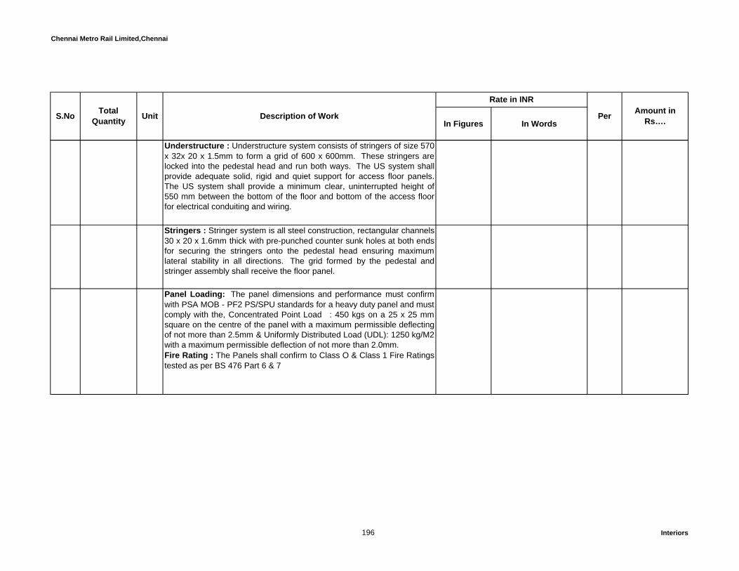
Chennai Metro Rail Limited,Chennai
In Figures In WordsPer Amount in
Rs….S.No TotalQuantity Unit Description of Work
Rate in INR
Understructure : Understructure system consists of stringers of size 570x 32x 20 x 1.5mm to form a grid of 600 x 600mm. These stringers arelocked into the pedestal head and run both ways. The US system shallprovide adequate solid, rigid and quiet support for access floor panels.The US system shall provide a minimum clear, uninterrupted height of550 mm between the bottom of the floor and bottom of the access floorfor electrical conduiting and wiring.
Stringers : Stringer system is all steel construction, rectangular channels30 x 20 x 1.6mm thick with pre-punched counter sunk holes at both endsfor securing the stringers onto the pedestal head ensuring maximumlateral stability in all directions. The grid formed by the pedestal andstringer assembly shall receive the floor panel.
Panel Loading: The panel dimensions and performance must confirmwith PSA MOB - PF2 PS/SPU standards for a heavy duty panel and mustcomply with the, Concentrated Point Load : 450 kgs on a 25 x 25 mmsquare on the centre of the panel with a maximum permissible deflectingof not more than 2.5mm & Uniformly Distributed Load (UDL): 1250 kg/M2with a maximum permissible deflection of not more than 2.0mm.Fire Rating : The Panels shall confirm to Class O & Class 1 Fire Ratingstested as per BS 476 Part 6 & 7
196 Interiors

Chennai Metro Rail Limited,Chennai
In Figures In WordsPer Amount in
Rs….S.No TotalQuantity Unit Description of Work
Rate in INR
Rate shall include to produce a test certificate for the above load ofapproved laboratory, preparation of surface, cutting for supply/return AirGrills and for Grommet of required size, wastages, lead & lift, groutingthe system with anchor fastener, removing all debris from the premisesetc. complete, as directed and for providing class O Armaflex Nitrilerubber of 15mm thick as a sub floor insulation with SSR 98adhesives to the entire area of existing (Below false flooring) as permanufacturer's specification. Rate shall inclusive of providing ramp/Stepsin false flooring in the entry as shown in drawing.
a 335.31 Sqm The height of the jacks shall be 300 mm . Sqm
b 335.31 Sqm The height of the jacks shall be 450 mm . Sqm
65 2.00 Nos Providing and fixing Unitile® or approved equivalent makes panel lifter.The panel lifter having special two cup suction panel lifting tool,designed for heavy duty load carrying capacities with safety leverattachment which requires deliberate manual movement to unlock thepanel.
Each
66 44.38 Sqm Supplying and fixing of barrier mat of Esplanade Plus from GRADUSMATTING. The rate inclusive of necessary edging strips/mat well frameect, all as per manufacture slandered specification. Size as per approveddrawings.
Sqm
67 Providing and fixing of SS Box section for edge guard to barrier mat asper approved drawing
197 Interiors

Chennai Metro Rail Limited,Chennai
In Figures In WordsPer Amount in
Rs….S.No TotalQuantity Unit Description of Work
Rate in INR
a 29.59 Rmt Size 25x25mm Rmt
68 823.48 Sqm Providing and laying 3mm thk self smoothing Epoxy floor topping over the grano flooring in recreational block areas.Grinding the surfaces, cleaningthe surface thoroughly & removing laitance completely and then applyingsolvent free primer on the concrete surface and seeding with fineaggregates so as to get a good mechanical key and allow it dry and thenapplying and laying 3mm thick self-smoothing epoxy topping flowshieldSL or approved equivalent make in approved colour and allow it dry. Rateshall include chipping, levelling, applying, tool & tackles,electricity, wateretc.. as directed by the Engineer-Incharge/Consultant.(Guarantee shallbe given by the authorized applicator for a period of one year)
Sqm
Skirting Works69 Providing skirting 100 mm high with full bodied vitrified floor tiles of
approved equivalent make, 7.5 / 9 mm thick set in Laticrete adhesiveL290 including pointing with Latapoxy SP 100 joint filler compound ofLaticrete or approved matching shade and all as per Manufacturer'sSpecification. Rate shall include for chasing of wall for flushing the tileinline with wall surface, preparation of base surface and acid wash atall levels and as per drawing.
a 1,912.69 Rmt Vitrified tile – Matt finish. Rmt
198 Interiors

Chennai Metro Rail Limited,Chennai
In Figures In WordsPer Amount in
Rs….S.No TotalQuantity Unit Description of Work
Rate in INR
b 5,443.20 Rmt Vitrified tile – Polished. Rmt
70 1,207.44 Rmt Providing 100 mm high skirting with best quality approved colour marble slab of thickness not less than 18 mm, machine cut and machine highpre-polished set in Laticrete adhesive L 290 to a thick of 4mm uniformlyand finishing the joints with Latapoxy SP 100 of Laticrete or equivalentmake, at all levels and all as per drawing directed. Rate shall include forpreparation of surface, with tin-oxide / high gloss factory polish. Ratealso to include filleting/ chamfering of the edges along with partialrecessing of the skirting into masonry / gypsum wall
Rmt
71 1,787.92 Rmt Providing 100 mm high skirting with best quality approved Kotah slab ofthickness not less than 20 mm, machine cut and machine high pre-polished set in Laticrete adhesive L 290 to a thick of 4mm uniformly andfinishing the joints with Latapoxy SP 100 of Laticrete or equivalent make,at all levels and all as per drawing . Rate shall include for preparation ofsurface, with tin-oxide / high gloss factory polish. Rate also to includefilleting/ chamfering of the edges along with partial recessing of theskirting into masonry / gypsum wall
Rmt
199 Interiors

Chennai Metro Rail Limited,Chennai
In Figures In WordsPer Amount in
Rs….S.No TotalQuantity Unit Description of Work
Rate in INR
72 263.32 Rmt Providing 100 mm high skirting with best quality approved Jet Blackgranite slab of thickness not less than 18 mm, machine cut andmachine high pre-polished set in Laticrete adhesive L 290 to a thick of4mm uniformly and finishing the joints with Latapoxy SP 100 of Laticreteor equivalent make, at all levels and all as per drawing. Rate shallinclude for preparation of surface, with tin-oxide / high gloss factorypolish. Rate also to include filleting/ chamfering of the edges along withpartial recessing of the skirting into masonry / gypsum wall(basic cost ofgranite Rs.150/Sq.ft)
Rmt
73 374.76 Rmt Providing and fixing 100 mm high skirting made from 12 mm thick BWPboard finished with 1.5mm laminate of approved shade & colour, bottomand top edge covered with 4mm thick polished teak wood lipping as perarchitectural drawing with 4 mm grooves at top enamel painted ofapproved colour. The ply being grouted to the GI channel.
Rmt
74 1,829.39 Rmt Providing and fixing of Aluminium Skirting-100mm Screw Fixed (AluskirtBrand-Falanx or approved equivalent make ) made of T6 Alloy acidetched and anodised 18-20 micron and hardness of min 75BHN.Anodising should meet Qualonod standard. The product shall be finishedwith PVC Strips to cover the screws and provided with PVC Sliderbetween two joints to prevent misalignment and ABS End/Corner Cap forneat finish of corner and end of approved colour fixed at wall/partition.
Rmt
Dadoing works
200 Interiors

Chennai Metro Rail Limited,Chennai
In Figures In WordsPer Amount in
Rs….S.No TotalQuantity Unit Description of Work
Rate in INR
75 322.43 Sqm Providing dadoing with machine cut and machine high pre-polished bestquality approved colour granite tile of thickness not less than 10mmof size 600x600mm/600x300mm, set in cement mortar 1:3, pointingthe joints with approved Tile’ joint filler grout compound matching to thegranite color and as directed. Rate shall include for preparation of basesurface, such as hacking, cleaning, wastages, smooth joint, necessarycorner/edge guards of matching color, cleaning and acid wash etc.complete and as per drawing as directed.( Lift Lobby, Corridor )
Sqm
76 5,620.36 Sqm Providing Dadoing with best quality Ceramic tile of approved make andsize of 300x450mm set in cement mortar 1:3, pointing the joints withapproved Tile’ joint filler grout compound as per Manufacturer'sSpecification and as directed. Rate shall include for preparation of basesurface, such as hacking, cleaning and acid wash complete all asdirected. Rate shall include wastages, smooth joint, necessarycorner/edge guards of matching color, cleaning and acid wash etc.complete and as per drawing as directed. (toilets)
Sqm
201 Interiors
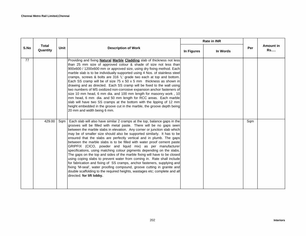
Chennai Metro Rail Limited,Chennai
In Figures In WordsPer Amount in
Rs….S.No TotalQuantity Unit Description of Work
Rate in INR
77 Providing and fixing Natural Marble Cladding slab of thickness not lessthan 25 mm size of approved colour & shade of size not less than900x600 / 1200x600 mm or approved size, using dry fixing method. Eachmarble slab is to be individually supported using 4 Nos. of stainless steelcramps, screws & bolts are 316 'L' grade two each at top and bottom.Each SS cramp will be of size 75 x 50 x 5 mm thickness as shown indrawing and as directed. Each SS cramp will be fixed to the wall usingtwo numbers of MS oxidized non-corrosive expansion anchor fasteners ofsize 10 mm head, 6 mm dia. and 100 mm length for masonry work , 10mm head, 6 mm dia. and 50 mm length for RCC areas. Each marbleslab will have two SS cramps at the bottom with the lipping of 12 mmheight embedded in the groove cut in the marble, the groove depth being20 mm and width being 6 mm.
429.00 Sqm Each slab will also have similar 2 cramps at the top, balance gaps in thegrooves will be filled with metal paste. There will be no gaps seenbetween the marble slabs in elevation. Any corner or junction slab whichmay be of smaller size should also be supported similarly. It has to beensured that the slabs are perfectly vertical and in plumb. The gapsbetween the marble slabs is to be filled with water proof cement pasteGRIPFIX (CICO, powder and liquid mix) as per manufacturerspecifications, using matching colour pigments depending on the slabs.The gaps on the top and sides of the marble fixing will have to be closedusing coping slabs to prevent water from coming in. Rate shall includefor fabrication and fixing of SS cramps, anchor fasteners, supplying andfixing ‘M-seal’, water proofing compound, groove cutting in granite anddouble scaffolding to the required heights, wastages etc; complete and alldirected. for lift lobby.
Sqm
202 Interiors
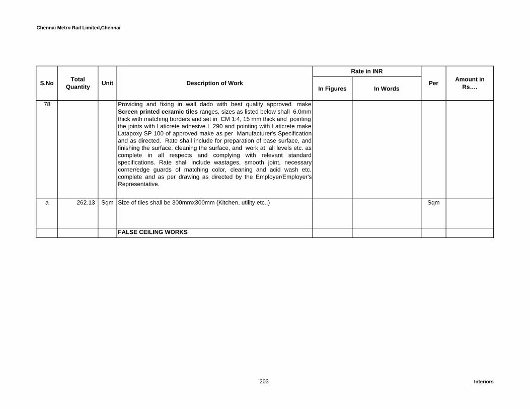
Chennai Metro Rail Limited,Chennai
In Figures In WordsPer Amount in
Rs….S.No TotalQuantity Unit Description of Work
Rate in INR
78 Providing and fixing in wall dado with best quality approved makeScreen printed ceramic tiles ranges, sizes as listed below shall 6.0mmthick with matching borders and set in CM 1:4, 15 mm thick and pointing the joints with Laticrete adhesive L 290 and pointing with Laticrete makeLatapoxy SP 100 of approved make as per Manufacturer's Specificationand as directed. Rate shall include for preparation of base surface, andfinishing the surface, cleaning the surface, and work at all levels etc. ascomplete in all respects and complying with relevant standardspecifications. Rate shall include wastages, smooth joint, necessarycorner/edge guards of matching color, cleaning and acid wash etc.complete and as per drawing as directed by the Employer/Employer'sRepresentative.
a 262.13 Sqm Size of tiles shall be 300mmx300mm (Kitchen, utility etc..) Sqm
FALSE CEILING WORKS
203 Interiors

Chennai Metro Rail Limited,Chennai
In Figures In WordsPer Amount in
Rs….S.No TotalQuantity Unit Description of Work
Rate in INR
79 Providing & Fixing of Eco Perforated metal Lay in ceilings System(Fameline/Armstrong or approved equivalent make) consisting of600x600mm Lay in tiles made of Aluminium Alloy 1100 with powdercoated(polyester base) to 60 microns in 0.7 mm thickness in approvedcolour with standard perforation of 2.6mm dia & open area of 17% andFreudenberg Soundtex acoustical fleece glued to the back of the tile tobe laid on grid systems with 15mm wide T - section flanges colour whitehaving rotary stitching on the Main Runner, 1200 mm & 600 mm CrossTees. The T Sections have a Galvanizing of 120 grams per M2 & passedthrough 500 hrs of Salt test. The tiles should have Humidity Resistance(RH) of 100%, NRC of 0.70, Fire Performance A2-s1.d0 in module size of600 X 600 mm, suitable for Green Building application, with Recycledcontent of 50%. The Tile & Grid system used together should carry a 15 year warrantee.
INSTALLATION: To comprise main runner spaced at 1200mm centerssecurely fixed to the structural suffix at 1200mm maximum centre & notmore than 150mm from spliced joints. The First/Last suspension systemat the end of each main runner should not be greater than 600mm fromthe adjacent wall. 1800mm long cross tees to be interlocked betweenmain runners at 300mm centre to form 1800 x 300 mm module. Cutcross tees longer than 600mm require independent support. Perimetertrim to be wall angles, secured to walls at 450 mm maximum centers.The rate shall be inclusive of making openings for light fittings, grills,diffusers, cutouts, wastage and necessary hardware etc. as complete inall respects complying with relevant standard specifications and asdirected by theEmployer/Employer's Representative(hall )
204 Interiors

Chennai Metro Rail Limited,Chennai
In Figures In WordsPer Amount in
Rs….S.No TotalQuantity Unit Description of Work
Rate in INR
a 4,546.36 Sqm For the above specification for Grid system Sqm
b 4,193.30 Sqm For the above specification for board (measurement only laid area) Sqm
80 Providing and fixing in true horizontal level false ceiling of 15mm T-section grid system Manufactured by M/s. SaintGobain/Armstrong/USG/Daiken or approved equivalent make using hotdipped galvanized steel section, exposed surface chemically cleanedcapping pre-finished in baked polyester paint, wall angle of size 3000 x19 x 19mm used in the periphery of the ceiling fixed to the wall partition /R.C. Column / band walls with the help of screws at 600 mm C/C. Mainrunner spaced at a 1200mm C/C suspended by using 2mm dia G.I. wirehanger securely fixed to the structural soffit of RC slab by using 6mmanchor fastener at every 1200mm (max) and 1200mm long cross tee tobe interlocked between in Main runner at 600mm C/C (max) to form agrid of 1200 x 600mm. 600mm long cross tee fixed in between 1200mmlong cross tee for forming a grid of 600 x 600mm.
205 Interiors

Chennai Metro Rail Limited,Chennai
In Figures In WordsPer Amount in
Rs….S.No TotalQuantity Unit Description of Work
Rate in INR
Laying of FINE FISSURED (MICRO LOOK) tiles should have HumidityResistance (RH) of 99%, NRC 0.55, Light Reflectance >85%, ThermalConductivity k = 0.052- 0.057 w/m K, Colour White, Fire PerformanceClass 0/ Class 1 (BS476 Part 6&7) in module size of 600 X 600 X 16 mmwith Bio Block coating on the face of the tile, suitable for Green Buildingapplication, with Recycled content of 63%. as complete in all respectscomplying with relevant standard specifications and as directed bytheEmployer/Employer's Representative
a 2,647.93 Sqm For the above specification for Grid system Sqm
b 2,647.93 Sqm For the above specification for Fine fissured board (measurement onlylaid area)
Sqm
81 Providing and fixing mositure resistant seamless gypsum ceiling withGyproc MR or approved equivalent make of 12.5 mm thick, fixed to theunderside of the suspended grid formed of GI perimeter channel of size20 x 28 x 30 mm fixed along the wall by using wood screws and metalexpansion rawl plugs. The GI intermediate channel of size 15 x 45 x 15 x0.90 mm shall be fixed to the suspended strap hanger / GI ceiling angleat intervals not more than 1220 mm. The suspended GI ceiling angle /.Strap hanger is to be connected with GI soffit cleat of size 37 x 27 x 25 x1.6 mm and it should be fixed on the roof slab / beam, by using metalexpansion fasteners (wt. Type) of 12.5 mm dia. to a length of 35 mm with6 mm dia. bolt / screw at top ends.
206 Interiors

Chennai Metro Rail Limited,Chennai
In Figures In WordsPer Amount in
Rs….S.No TotalQuantity Unit Description of Work
Rate in INR
The GI ceiling section of size 80 x 26 x 0.5 mm (MF 5) is to be providedacross the intermediate channel at intervals not more than 457 mmcentres at bottom and the same shall be fixed by GI connection clips 2.64mm dia. at the intersection points. The ends of ceiling section channel byadopting an overlap length of minimum 150 mm, connected withintermediate channel shall be fixed to perimeter channel in insertion. Thegypboard shall be fixed to the under side of the suspended grid by using25 mm long dry wall screws. The joints shall be finished with joint papertape by using jointing compound of Saint Gobain Gyproc or approvedequivalent make and applying over it 3 layers of the filler compound toprovide a smooth surface. The ceiling surface shall be painted with threecoats of approved first quality acrylic emulsion over a coat of primer etc.complete. The rate shall include making cutouts for tube lights, spotlights, duct doors, for specified size, grills etc. for which no extra will bepaid separately.
7,421.11 Sqm Rate shall include providing additional trimming around cutouts for lightfittings etc. and grills also for providing additional supports from ceilingwhere main / cross members are cut for light fittings etc. Rate shallinclude vertical as well as horizontal surfaces as per detailed drawing.Actual “seen” surface of horizontal and vertical will be measured and paidfor, as complete in all respects complying with relevant standardspecifications and as directed by theEmployer/Employer's Representative
Sqm
207 Interiors

Chennai Metro Rail Limited,Chennai
In Figures In WordsPer Amount in
Rs….S.No TotalQuantity Unit Description of Work
Rate in INR
82Supplying, Fabricating and commissioning of Centralized Garbage chuteof approved make (SS430 X 1.2mm thk), 450mm dia with a provision ofautoclosing intake down at every floor level and a fire rated door (90minutes rating-UL label 10B) at the discharged end, with requiredgarbage trolley, etc., complete as per BS 1703:2005,IS6924-2001& NBC2005 specification. The rate shall include all installation components,scaffolding for erection, required structural brackets with anchorfasteners, Sprinklers for fire and cleaning, necessary vent with birdnetting etc.. as directed.
a 1.00 Nos Ground Floor to Fifth Floor Each
b 1.00 Nos Ground Floor to Ninenth Floor Each
83 798.82 Sqm Design and built Tensile Atrium roof with Structure load shall be made ofhollow tube structure tubes of mild steel confirming to Latest relevant IScodes. Structure shall be analysed and designed for primary loads i.e.Dead Load, Live Load & Wind Load and their combinations specified asper Latest relevant IS codes : 875 Part - I, II & III .Structure shall bechecked for Structural stability and critical stresses confirming to LatestIS:800, & IS:806 . Welded Structural joints shall confirm to Latest IS:816and the electrodes for welding shall confirm to Latest IS:814 (Part I &II).Bolted Structural joints shall confirm to Latest IS:1367 (Part - III) &IS:3757. Structure shall be treated with suitable sand blasted andsuitable polyurethene paint over a coat of primer.
Sqm
Quoted rate shall include the following :
208 Interiors
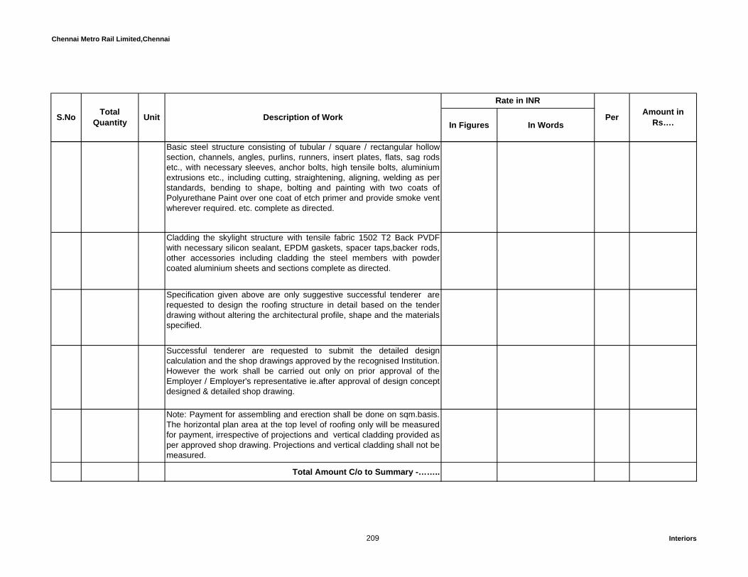
Chennai Metro Rail Limited,Chennai
In Figures In WordsPer Amount in
Rs….S.No TotalQuantity Unit Description of Work
Rate in INR
Basic steel structure consisting of tubular / square / rectangular hollowsection, channels, angles, purlins, runners, insert plates, flats, sag rodsetc., with necessary sleeves, anchor bolts, high tensile bolts, aluminiumextrusions etc., including cutting, straightening, aligning, welding as perstandards, bending to shape, bolting and painting with two coats ofPolyurethane Paint over one coat of etch primer and provide smoke ventwherever required. etc. complete as directed.
Cladding the skylight structure with tensile fabric 1502 T2 Back PVDFwith necessary silicon sealant, EPDM gaskets, spacer taps,backer rods,other accessories including cladding the steel members with powdercoated aluminium sheets and sections complete as directed.
Specification given above are only suggestive successful tenderer arerequested to design the roofing structure in detail based on the tenderdrawing without altering the architectural profile, shape and the materialsspecified.
Successful tenderer are requested to submit the detailed designcalculation and the shop drawings approved by the recognised Institution.However the work shall be carried out only on prior approval of theEmployer / Employer's representative ie.after approval of design conceptdesigned & detailed shop drawing.
Note: Payment for assembling and erection shall be done on sqm.basis.The horizontal plan area at the top level of roofing only will be measuredfor payment, irrespective of projections and vertical cladding provided asper approved shop drawing. Projections and vertical cladding shall not bemeasured.
Total Amount C/o to Summary -……..
209 Interiors
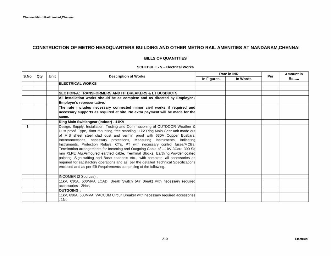
Chennai Metro Rail Limited,Chennai
In Figures In WordsELECTRICAL WORKS
SECTION-A: TRANSFORMERS AND HT BREAKERS & LT BUSDUCTSAll installation works should be as complete and as directed by Employer /Employer's representative. The rate includes necessary connected minor civil works if required andnecessary supports as required at site. No extra payment will be made for thesame. Ring Main Switichgear (Indoor) - 11KV
1 Design, Supply, Installation, Testing and Commissioning of OUTDOOR Weather &Dust proof Type, floor mounting, free standing 11kV Ring Main Gear unit made outof M.S sheet steel clad dust and vermin proof with 630A Copper Busbars,Interconnections, necessary protections, Measuring Instruments, IndicatingInstruments, Protection Relays, CTs, PT with necessary control fuses/MCBs,Termination arrangements for Incoming and Outgoing Cable of 11 kV 3Core 300 Sqmm XLPE Alu.Armoured earthed cable, Terminal Blocks, Earthing,Powder coatedpainting, Sign writing and Base channels etc., with complete all accessories asrequired for satisfactory operations and as per the detailed Technical Specificationsenclosed and as per EB Requirements comprising of the following.
INCOMER (2 Sources) :11kV, 630A, 500MVA LOAD Break Switch (Air Break) with necessary requiredaccessories - 2NosOUTGOING :11kV, 630A, 500MVA VACCUM Circuit Breaker with necessary required accessories: 1No
Unit Description of Works Rate in INR Per Amount in Rs…..
CONSTRUCTION OF METRO HEADQUARTERS BUILDING AND OTHER METRO RAIL AMENITIES AT NANDANAM,CHENNAI
BILLS OF QUANTITIES
SCHEDULE - V - Electrical Works
S.No Qty
210 Electrical
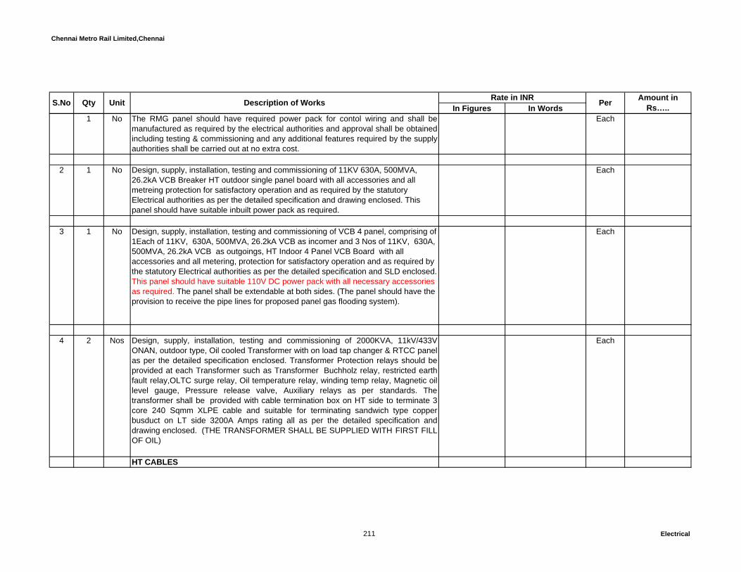
Chennai Metro Rail Limited,Chennai
In Figures In WordsUnit Description of Works Rate in INR Per Amount in Rs…..S.No Qty
1 No The RMG panel should have required power pack for contol wiring and shall bemanufactured as required by the electrical authorities and approval shall be obtainedincluding testing & commissioning and any additional features required by the supplyauthorities shall be carried out at no extra cost.
Each
2 1 No Design, supply, installation, testing and commissioning of 11KV 630A, 500MVA, 26.2kA VCB Breaker HT outdoor single panel board with all accessories and all metreing protection for satisfactory operation and as required by the statutory Electrical authorities as per the detailed specification and drawing enclosed. This panel should have suitable inbuilt power pack as required.
Each
3 1 No Design, supply, installation, testing and commissioning of VCB 4 panel, comprising of 1Each of 11KV, 630A, 500MVA, 26.2kA VCB as incomer and 3 Nos of 11KV, 630A, 500MVA, 26.2kA VCB as outgoings, HT Indoor 4 Panel VCB Board with all accessories and all metering, protection for satisfactory operation and as required by the statutory Electrical authorities as per the detailed specification and SLD enclosed. This panel should have suitable 110V DC power pack with all necessary accessories as required. The panel shall be extendable at both sides. (The panel should have the provision to receive the pipe lines for proposed panel gas flooding system).
Each
4 2 Nos Design, supply, installation, testing and commissioning of 2000KVA, 11kV/433VONAN, outdoor type, Oil cooled Transformer with on load tap changer & RTCC panelas per the detailed specification enclosed. Transformer Protection relays should beprovided at each Transformer such as Transformer Buchholz relay, restricted earthfault relay,OLTC surge relay, Oil temperature relay, winding temp relay, Magnetic oillevel gauge, Pressure release valve, Auxiliary relays as per standards. Thetransformer shall be provided with cable termination box on HT side to terminate 3core 240 Sqmm XLPE cable and suitable for terminating sandwich type copperbusduct on LT side 3200A Amps rating all as per the detailed specification anddrawing enclosed. (THE TRANSFORMER SHALL BE SUPPLIED WITH FIRST FILLOF OIL)
Each
HT CABLES
211 Electrical

Chennai Metro Rail Limited,Chennai
In Figures In WordsUnit Description of Works Rate in INR Per Amount in Rs…..S.No Qty
5 250 RMT Design, supply, laying, testing and commissioning of 3 core 300 sqmm 11KV, XLPEAluminium conductor individual core screened, flat steel strip armoured, PVCsheathed cable inside the building in the prepared trench/under ground (From 11KVRMG to outdoor HT single VCB panel and outdoor single VCB to HT indoor VCB 4panel)
RMT
6 110 RMT Design, supply, laying, testing and commissioning of 3 core 240 sqmm 11KV, XLPEAluminium conductor individual core screened, flat steel strip armoured, PVCsheathed cable inside the building in the prepared trench/under ground (From 11KVHT indoor VCB panel to transformer)
RMT
7 HT Terminations:a 2 No Design, supply, termination, testing and commissioning of OUTDOOR type
termination kit and accessories suitable for 11KV, 3 core 300 Sqmm XLPE cable.Each
b 6 No Design, supply, termination, testing and commissioning of INDOOR type terminationkit and accessories suitable for 11KV, 3 core 300 Sqmm XLPE cable.
Each
c 2 No Design, supply, termination, testing and commissioning of OUTDOOR typetermination kit and accessories suitable for 11KV, 3 core 240 Sqmm XLPE cable.
Each
d 4 No Design, supply, termination, testing and commissioning of INDOOR type terminationkit and accessories suitable for 11KV, 3 core 240 Sqmm XLPE cable.
Each
8 1 No Design, supply, erection, testing and commissioning of Battery Charger 110V DC 100AH Trip unit combined with trickle & boost charge facilities with battery bank(SMF) &Distribuition Board and as per the detailed specification / drawing enclosed.
Each
212 Electrical
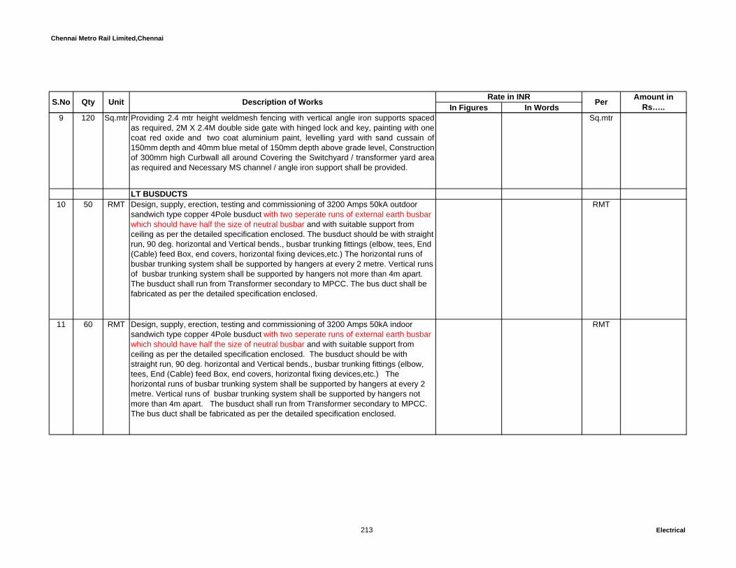
Chennai Metro Rail Limited,Chennai
In Figures In WordsUnit Description of Works Rate in INR Per Amount in Rs…..S.No Qty
9 120 Sq.mtr Providing 2.4 mtr height weldmesh fencing with vertical angle iron supports spacedas required, 2M X 2.4M double side gate with hinged lock and key, painting with onecoat red oxide and two coat aluminium paint, levelling yard with sand cussain of150mm depth and 40mm blue metal of 150mm depth above grade level, Constructionof 300mm high Curbwall all around Covering the Switchyard / transformer yard areaas required and Necessary MS channel / angle iron support shall be provided.
Sq.mtr
LT BUSDUCTS10 50 RMT Design, supply, erection, testing and commissioning of 3200 Amps 50kA outdoor
sandwich type copper 4Pole busduct with two seperate runs of external earth busbar which should have half the size of neutral busbar and with suitable support from ceiling as per the detailed specification enclosed. The busduct should be with straight run, 90 deg. horizontal and Vertical bends., busbar trunking fittings (elbow, tees, End (Cable) feed Box, end covers, horizontal fixing devices,etc.) The horizontal runs of busbar trunking system shall be supported by hangers at every 2 metre. Vertical runs of busbar trunking system shall be supported by hangers not more than 4m apart. The busduct shall run from Transformer secondary to MPCC. The bus duct shall be fabricated as per the detailed specification enclosed.
RMT
11 60 RMT Design, supply, erection, testing and commissioning of 3200 Amps 50kA indoor sandwich type copper 4Pole busduct with two seperate runs of external earth busbar which should have half the size of neutral busbar and with suitable support from ceiling as per the detailed specification enclosed. The busduct should be with straight run, 90 deg. horizontal and Vertical bends., busbar trunking fittings (elbow, tees, End (Cable) feed Box, end covers, horizontal fixing devices,etc.) The horizontal runs of busbar trunking system shall be supported by hangers at every 2 metre. Vertical runs of busbar trunking system shall be supported by hangers not more than 4m apart. The busduct shall run from Transformer secondary to MPCC. The bus duct shall be fabricated as per the detailed specification enclosed.
RMT
213 Electrical

Chennai Metro Rail Limited,Chennai
In Figures In WordsUnit Description of Works Rate in INR Per Amount in Rs…..S.No Qty
12 30 RMT Design, supply, erection, testing and commissioning of 2500 Amps 50kA indoor sandwich type copper 4Pole busduct with two seperate runs of external earth busbar which should have half the size of neutral busbar and with suitable support from ceiling as per the detailed specification enclosed. The busduct should be with straight run, 90 deg. horizontal and Vertical bends., busbar trunking fittings (elbow, tees, end End (Cable) feed Box, end covers, horizontal fixing devices,etc.) The horizontal runs of busbar trunking system shall be supported by hangers at every 2 metre. Vertical runs of busbar trunking system shall be supported by hangers not more than 4m apart. The busduct shall run from DG to DG sync. panel and Synch panel to MPCC panel. The bus duct shall be fabricated as per the detailed specification enclosed.
RMT
13 30 RMT Design, supply, erection, testing and commissioning of 800 Amps 50kA indoor sandwich type copper TPN busduct with two seperate runs of external earth busbar which should have half the size of neutral busbar and with suitable support from ceiling as per the detailed specification enclosed. The busduct should be with straight run, 90 deg. horizontal and Vertical bends., busbar trunking fittings (elbow, tees, end End (Cable) feed Box, end covers, horizontal fixing devices,etc.) The horizontal runs of busbar trunking system shall be supported by hangers at every 2 metre. Vertical runs of busbar trunking system shall be supported by hangers not more than 4m apart. The busduct shall run from MPCC panel to APFC panel. The bus duct shall be fabricated as per the detailed specification enclosed.
RMT
14 4 Sets Design, supply, erection, testing and commissioning of 3200 Amps flexible jointssuitable for sandwich type 4P copper bus duct at end terminals including allaccessories.(RYBN=1 set)
Sets
15 4 Sets Design, supply, erection, testing and commissioning of 2500 Amps flexible jointssuitable for sandwich type 4pole copper bus duct at end terminals including allaccessories.(RYBN=1 set)
Sets
16 4 Sets Design, supply, erection, testing and commissioning of 800 Amps flexible jointssuitable for sandwich type TPN copper bus duct at end terminals including allaccessories.(RYBN=1 set)
Sets
214 Electrical

Chennai Metro Rail Limited,Chennai
In Figures In WordsUnit Description of Works Rate in INR Per Amount in Rs…..S.No Qty
17 1 Sets Design, supply, erection, testing and commissioning of 3200 Amps Phase crosschangeover box suitable for sandwich type 4P copper bus duct including allaccessories. (it will operate in case of phase change over is required as per sitecondition) (RYBN=1 set)
Sets
18 1 Sets Design, supply, erection, testing and commissioning of 2500 Amps Phase crosschangeover box suitable for sandwich type 4pole copper bus duct including allaccessories. (it will operate in case of phase change over is required as per sitecondition) (RYBN=1 set)
Sets
19 1 Sets Design, supply, erection, testing and commissioning of 800 Amps Phase crosschangeover box suitable for sandwich type TPN copper bus duct including allaccessories. (it will operate in case of phase change over is required as per sitecondition) (RYBN=1 set)
Sets
SECTION - A:-Total C/o to summary: Rs.
SECTION – B : LT PANEL BOARDSAll installation works should be as complete and as directed by Employer /Employer's representative.For all Panel boards in section-B, the rate includes necessary connected minor civil works if required and necessary supports as required at site. No extra payment will be made for the same. As mentioned in SLD, MFM shall be provided in all panels incomer and MPCC panel's outgoings with necessary CTs, PTs, control switches like MPCB, MCB, ELCB, RCBOs and all other necessary accessories as per the specification and drawing. All the meters should have RS 485 modbus output for BMS integration and also All ACB & MCCB should have dedicated potential free contacts to monitor (ON/OFF) & TRIP status from BMS system
215 Electrical
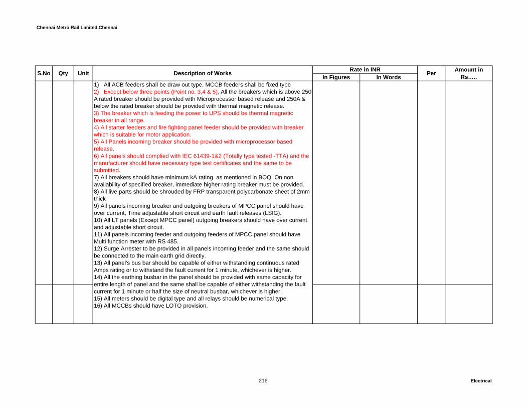
Chennai Metro Rail Limited,Chennai
In Figures In WordsUnit Description of Works Rate in INR Per Amount in Rs…..S.No Qty
1) All ACB feeders shall be draw out type, MCCB feeders shall be fixed type 2) Except below three points (Point no. 3,4 & 5), All the breakers which is above 250 A rated breaker should be provided with Microprocessor based release and 250A & below the rated breaker should be provided with thermal magnetic release. 3) The breaker which is feeding the power to UPS should be thermal magnetic breaker in all range .4) All starter feeders and fire fighting panel feeder should be provided with breaker which is suitable for motor application.5) All Panels incoming breaker should be provided with microprocessor based release.6) All panels should complied with IEC 61439-1&2 (Totally type tested -TTA) and the manufacturer should have necessary type test certificates and the same to be submitted.7) All breakers should have minimum kA rating as mentioned in BOQ. On non availability of specified breaker, immediate higher rating breaker must be provided.8) All live parts should be shrouded by FRP transparent polycarbonate sheet of 2mm thick9) All panels incoming breaker and outgoing breakers of MPCC panel should have over current, Time adjustable short circuit and earth fault releases (LSIG).10) All LT panels (Except MPCC panel) outgoing breakers should have over current and adjustable short circuit.11) All panels incoming feeder and outgoing feeders of MPCC panel should have Multi function meter with RS 485.12) Surge Arrester to be provided in all panels incoming feeder and the same should be connected to the main earth grid directly.13) All panel's bus bar should be capable of either withstanding continuous rated Amps rating or to withstand the fault current for 1 minute, whichever is higher.14) All the earthing busbar in the panel should be provided with same capacity for entire length of panel and the same shall be capable of either withstanding the fault current for 1 minute or half the size of neutral busbar, whichever is higher.15) All meters should be digital type and all relays should be numerical type.16) All MCCBs should have LOTO provision.
216 Electrical

Chennai Metro Rail Limited,Chennai
In Figures In WordsUnit Description of Works Rate in INR Per Amount in Rs…..S.No Qty
20 Design, supply, erection, testing and commissioning of cubicle type floor mountingmain power control centre made out of MS sheet enclosure with copper busbars,single busbar system, cable chamber, interconnection, painting, earthing, protectionrelays etc. comprising of the following : (MPCC)INCOMINGEB Incomer2 Nos. 3200 Amps 4 Pole 50kA electrical draw out type Air circuit breaker with RS485, shunt release shutter assembly, door interlock and all other accessories.
Instruments Panel Providing TNC switch, emergency lockable push button, Maximum demand controller (Similar to SOCOMEC - Diris A40) with RS485, Ammeter, Voltmeter, Instantaneous over current, earthfault relay (2 O/C+ 1 E/F), Restricted earth fault relay(64R) and necessary CTs, PTs, control MPCB/MCB/ ELCB/RCBOs, RYB Indication lamps and “ON/OFF/Trip/Rest" indicating lamp, voltage surge protection with emergency lockable push buttons. 3200A NCT shall be provided in the Transformers side of the neutral and also refer the specification and SLD.
Solar power Incomer1 Each 400 Amps 4 Pole 50kA MCCB with all necessary accessories.Instruments Panel Providing emergency lockable push button, Multi Function meter (Similar to SOCOMEC - Countis E53) with RS485, Ammeter, Voltmeter and necessary CTs, PTs, control MPCB/MCB/ ELCB/RCBOs, RYB Indication lamps and “ON/OFF/Trip/Rest" indicating lamp, voltage surge protection with emergency lockable push buttons. DG Incomer2 Nos. 2500 Amps 4 Pole 50kA electrical draw out type Air circuit breaker with RS 485, shunt release shutter assembly, door interlock and all other accessories.
Instruments Panel
217 Electrical

Chennai Metro Rail Limited,Chennai
In Figures In WordsUnit Description of Works Rate in INR Per Amount in Rs…..S.No Qty
Providing TNC switch, emergency lockable push button, Maximum demand controller (Similar to SOCOMEC - Diris A40) with RS485, Ammeter, Voltmeter, Instantaneous over current, earthfault relay (2 O/C+ 1 E/F), and necessary CTs, PTs, control MPCB/MCB/ ELCB/RCBOs, RYB Indication lamps and “ON/OFF/Trip/Rest" indicating lamp, voltage surge protection with emergency lockable push buttons and
l f th ifi ti d SLDBuscoupler3 Nos. 3200 Amps 4 pole 50kA electrical draw out type Air circuit breaker with RS485, shunt release, shutter assembly, door interlock and all other required necessary accessories and ON/OFF/TRIP lampsThe buscoupler shall be provided with mechanical & electrical Inetrlocking arrangements. and also should have TNC switch, emergency lockable push button, Ammeter, Voltmeter, indication lamps and instantaneous over current, earth fault relay (2 O/C + 1 E/F), CTs, PTs and control MPCB/MCB/ ELCB/RCBOs with all other necessary accessories and also refer the SLD.OUTGOINGS1250A 4P EDO ACB, 50kA – 4Nos800A 4P EDO ACB, 50kA – 6Nos (Thermal magnetic release for fire fighting panel feeder)630A 4P MCCB, 50kA – 7Nos400A 4P MCCB, 50kA – 4Nos315A 4P MCCB, 50kA – 2Nos.250A 4P MCCB, 50kA – 1EachAll the Outgoing feeder shall be ON/OFF/Trip indication lamps, emergency lockable push buttons, all ACB and MCCBs should have two (spare) potential free contactor for BMS monitoring, Combined digital type Multi function meter (Similar to SOCOMEC - Countis E53) with RS485 port. All ACB feeders should have TNC switch. The rate shall inclusive of necessary CTs, control switches, Front operating handles etc., All switch boards shall be fabricated as per the detailed specification enclosed. Suitable size outgoing cable chamber and extra busbars should be provided for connecting the number of outgoing cables as per the schematic drawing.The board shall be fabricated for future extension of the panel board.
218 Electrical

Chennai Metro Rail Limited,Chennai
In Figures In WordsUnit Description of Works Rate in INR Per Amount in Rs…..S.No Qty
The transformers incomer, DGs incomer shall be provided with protection relays suchas IDMT (2O/C + E/F), REFR (Restricted Earth fault Relay) etc., both the incomer'sshall be interlocked with mechanical and electrical arrangements by hardware controlwiring alongwith PLC (Programmable Logic Controls). The Hardware control wiring &PLC operation shall be feasible to extend for future 1 Each Transformer & DG setand all as per the detailed specification and drawings enclosed. The PLC shouldhave suitable communication port for BMS integration.
The both incoming & buscoupler breakers should be with energy releases & will measure the following parameters such as current demand, voltages, instantanious power, power factor, power demand etc.All outgoing breakers shall be with built-in microprocessor based release with overload,short circuit,earth fault,neutral protection,etc.Incoming metre for Transformer shall be with demand controller, Harmonic THD andindividual harmonic display+ Regular parameters like V, I, KVA, KVAR, KW, KWH,KVARh, PF, Freq, Max, AVG Incoming metre for Generator shall be with Load monitoring without demand controland with regular parameter & Harmonics THD & Individual harmonic display
All Outgoing Feeders in Main panel shall be with MFM monitoring V,I, KWH, KVARH,PF with RS 485 BMS integration. All the metres to be connected in series thro' buscable terminated at common metre chamber.The panel should have the provision to receive the pipe lines for proposed panel gasflooding systemMain Power Control Centre (MPCC)
1 No 3200Amps 50kA 4P copper busbars:- All the neutral busbars shall have the same capacity of phase busbars.
No
21 Design, Supply, Installation, testing and commissioning of cubicle type floor mountingswitch board comprising of the following, the board shall be fabricated as per thedetailed specification enclosed APFC PANEL with Harmonic filters .
Incoming800A, 50KA, TPN MDO ACB with all connected accessories - 1Each as incomer.
219 Electrical

Chennai Metro Rail Limited,Chennai
In Figures In WordsUnit Description of Works Rate in INR Per Amount in Rs…..S.No Qty
Instrumental compartmentMulti function meter, Voltmeter and Ammeter with selector switches, R,Y,B andOn/Off/Trip indication lamp, Control fuses/MCBs, necessary CTs, PTs, PF meter etc.as per the specification and SLD.
1 Each Intelligent Automatic Power Factor Controller and Voltage & Power FactorMonitoring Relay can control up to 9 Capacitor Banks with LED indiication for Alarmcode, Eachof Banks selected, PF status-Lead / Lag / Unity, Auto & Manual Mode,DIP Switches selection for Each of Banks / Time Relay, Bank ratios and the relayshould have dual incoming ports to receive the sensing cable from two differentsource / with summation CTs arrangements with single input signal port relay etc.,with control wiring and all other required necessary accessories.
Outgoing: Total 350 KVAR2 Sets of 100 KVAR Capacitor (4 x 25 KVAR) with suitable 315A TP MCCB 50KAwith SSR(Thyristor), High speed fuses for SSR, control MCBs, On & Off IndicatingLamp, Push Buttons, Ammeter with Selector switch, CTs etc.,Includinginterconnection busbars, control wiring with all other required necessary accessories.
1 Sets of 50 KVAR Capacitor (2 x 25 KVAR) with suitable 160A TP MCCB 50KA withSSR(Thyristor), High speed fuses for SSR, control MCBs, On & Off IndicatingLamp, Push Buttons, Ammeter with Selector switch, CTs etc.,Includinginterconnection busbars, contrring with all other required necessaryaccessories.3 Sets of 25 KVAR Capacitor (1 x 25 KVAR) with suitable 63A TP MCCB 50KA with SSR(Thyristor), High speed fuses for SSR, control MCBs, On & Off Indicating Lamp, Push Buttons, Ammeter with Selector switch, CTs etc.,Including interconnection busbars, contrring with all other required necessary accessories.
2 Set of 10 KVAR Capacitor (1 x 10 KVAR) with suitable 32A TP MCCB 50KA withSSR(Thyristor), High speed fuses for SSR, control MCBs, On & Off Indicating Lamp,Push Buttons, Ammeter with Selector switch, CTs etc.,Including interconnectionbusbars, contrring with all other required necessary accessories.
220 Electrical
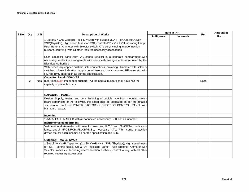
Chennai Metro Rail Limited,Chennai
In Figures In WordsUnit Description of Works Rate in INR Per Amount in Rs…..S.No Qty
1 Set of 5 KVAR Capacitor (1 x 5 KVAR) with suitable 32A TP MCCB 50KA with SSR(Thyristor), High speed fuses for SSR, control MCBs, On & Off Indicating Lamp, Push Buttons, Ammeter with Selector switch, CTs etc.,Including interconnection busbars, contrring with all other required necessary accessories.
Each capacitor bank (with 7% series reactor) in a separate compartment withnecessary ventilation arrangemnts with wire mesh arrangements as required by theElectrical Authorities .With necessary copper busbars, interconnections, providing Ammeter with selectorswitches, phase indication lamp, control fuse and switch control, PFmetre etc. withRS 485 BMS integration as per the specification.Capacitor Panel - 350KVAR
2 Nos 800 Amps 50kA PN copper busbars:- All the neutral busbars shall have half the capacity of phase busbars
Each
CAPACITOR PANEL:Design, Supply, testing and commissioning of cubicle type floor mounting switchboard comprising of the following, the board shall be fabricated as per the detailedspecification enclosed POWER FACTOR CORRECTION CONTROL PANEL withHarmonic reactor.
Incoming125A, 50kA, TPN MCCB with all connected accessories - 1Each as incomer.Instrumental compartmentVoltmeter and Ammeter with selector switches, R,Y,B and On/Off/Trip indicationlamp,Control MPCB/RCBO/ELCB/MCBs, necessary CTs, PTs, surge protectiondevice etc. for each incomer as per the specification and SLD.
Outgoing: Total 40 KVAR 1 Set of 40 KVAR Capacitor (2 x 20 KVAR ) with SSR (Thyristor), High speed fusesfor SSR, control fuses, On & Off Indicating Lamp, Push Buttons, Ammeter withSelector switch etc.,Including interconnection busbars, control wiring with all otherrequired necessary accessories.
221 Electrical

Chennai Metro Rail Limited,Chennai
In Figures In WordsUnit Description of Works Rate in INR Per Amount in Rs…..S.No Qty
Capacitor bank (with 7% series reactor) in a separate compartment with necessaryventilation arrangemnts with wire mesh arrangements as required by the ElectricalAuthorities .
2 Nos. CAPACITOR PANEL Each.
22 Design, Supply, testing and commissioning of cubicle type floor mounting switchboard comprising of the following, the board shall be fabricated as per the detailedspecification enclosed. UTILITY LIGHTING PANELIncoming100A 4P MCCB 25kA with all connected accessories – 1Each as incomerOutgoing32A 4P MCCB 25kA - 5 Nos.32A 4P MCCB 25kA with 4P contactor, timer (24hr.) and auto/manual selector switchwith all other necessary accessories. - 3Nos.With necessary Copper busbars, interconnections, providing Combined Digital type Mulitifunction Meter with RS485, Surge protection device, phase indication lamps etc. in the incoming feeder and also providing ON,OFF,TRIP indication lamps with control MCB/MPCB/ELCB/RCBOs, and necessary CTs, PTs etc.all MCCBs should have two (spare) potential free contactor for BMS monitoring and the same to be wired up to the cable champer/any common feeder and all as per the specifications and drawings.
1 Nos 100 Amps 25kA 4P copper busbars:- All the neutral busbars shall have same the capacity of phase busbars.
Each
23 Design, Supply, testing and commissioning of cubicle type floor mounting switchboard comprising of the following, the board shall be fabricated as per the detailedspecification enclosed. UTILITY PANELIncoming400A 4P MCCB 36kA with all connected accessories – 1Each as incomerOutgoing200A 4P MCCB 36kA - 2 Nos.125A 4P MCCB 36kA - 2 Nos.
222 Electrical

Chennai Metro Rail Limited,Chennai
In Figures In WordsUnit Description of Works Rate in INR Per Amount in Rs…..S.No Qty
100A 4P MCCB 36kA - 1 Each63A 4P MCCB 36kA - 3 Nos.32A 4P MCCB 36kA - 2 Nos.With necessary Copper busbars, interconnections, providing Combined Digital type Mulitifunction Meter with RS485, Surge protection device, phase indication lamps etc. in the incoming feeder and also providing ON,OFF,TRIP indication lamps with control MCB/MPCB/ELCB/RCBOs, and necessary CTs, PTs etc.all MCCBs should have two (spare) potential free contactor for BMS monitoring and the same to be wired up to the cable champer/any common feeder and all as per the specifications and drawings.
1 Nos 400 Amps 36kA 4P copper busbars:- All the neutral busbars shall have same the capacity of phase busbars.
Each
24 Design, Supply, testing and commissioning of cubicle type floor mounting switchboard comprising of the following, the board shall be fabricated as per the detailedspecification enclosed. PLUMBING PANELIncoming200A 4P MCCB 25kA with all connected accessories – 1Each as incomerOutgoing100A TPN MCCB 25kA - 2 Nos.63A TPN MCCB 25kA - 7 Nos.32A TPN MCCB 25kA - 5 Nos.With necessary Copper busbars, interconnections, providing Combined Digital type Mulitifunction Meter with RS485, Surge protection device, phase indication lamps etc. in the incoming feeder and also providing ON,OFF,TRIP indication lamps with control MCB/MPCB/ELCB/RCBOs, and necessary CTs, PTs etc.all MCCBs should have two (spare) potential free contactor for BMS monitoring and the same to be wired up to the cable champer/any common feeder and all as per the specifications and drawings.
1 Nos 200 Amps 25kA TPN copper busbars:- All the neutral busbars shall have half the capacity of phase busbars.
Each
223 Electrical
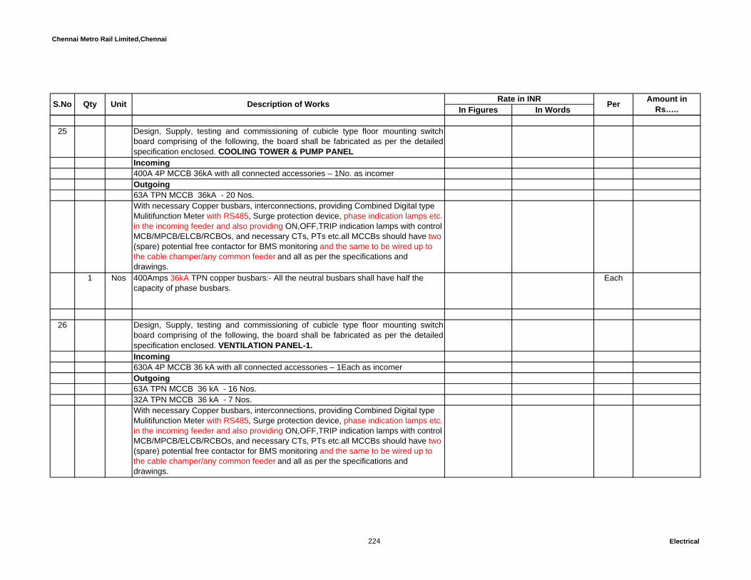
Chennai Metro Rail Limited,Chennai
In Figures In WordsUnit Description of Works Rate in INR Per Amount in Rs…..S.No Qty
25 Design, Supply, testing and commissioning of cubicle type floor mounting switchboard comprising of the following, the board shall be fabricated as per the detailedspecification enclosed. COOLING TOWER & PUMP PANELIncoming400A 4P MCCB 36kA with all connected accessories – 1No. as incomerOutgoing63A TPN MCCB 36kA - 20 Nos.With necessary Copper busbars, interconnections, providing Combined Digital type Mulitifunction Meter with RS485, Surge protection device, phase indication lamps etc. in the incoming feeder and also providing ON,OFF,TRIP indication lamps with control MCB/MPCB/ELCB/RCBOs, and necessary CTs, PTs etc.all MCCBs should have two (spare) potential free contactor for BMS monitoring and the same to be wired up to the cable champer/any common feeder and all as per the specifications and drawings.
1 Nos 400Amps 36kA TPN copper busbars:- All the neutral busbars shall have half the capacity of phase busbars.
Each
26 Design, Supply, testing and commissioning of cubicle type floor mounting switchboard comprising of the following, the board shall be fabricated as per the detailedspecification enclosed. VENTILATION PANEL-1.Incoming630A 4P MCCB 36 kA with all connected accessories – 1Each as incomerOutgoing63A TPN MCCB 36 kA - 16 Nos.32A TPN MCCB 36 kA - 7 Nos.With necessary Copper busbars, interconnections, providing Combined Digital type Mulitifunction Meter with RS485, Surge protection device, phase indication lamps etc. in the incoming feeder and also providing ON,OFF,TRIP indication lamps with control MCB/MPCB/ELCB/RCBOs, and necessary CTs, PTs etc.all MCCBs should have two (spare) potential free contactor for BMS monitoring and the same to be wired up to the cable champer/any common feeder and all as per the specifications and drawings.
224 Electrical

Chennai Metro Rail Limited,Chennai
In Figures In WordsUnit Description of Works Rate in INR Per Amount in Rs…..S.No Qty
1 Nos 630Amps 36kA TPN copper busbars:- All the neutral busbars shall have half the capacity of phase busbars.
Each
27 Design, Supply, testing and commissioning of cubicle type floor mounting switchboard comprising of the following, the board shall be fabricated as per the detailedspecification enclosed. VENTILATION PANEL-2.Incoming630A 4P MCCB 36 kA with all connected accessories – 1Each as incomerOutgoing250A TPN MCCB 36 kA - 2 Nos63A TPN MCCB 36 kA - 5 Nos.With necessary Copper busbars, interconnections, providing Combined Digital type Mulitifunction Meter with RS485, Surge protection device, phase indication lamps etc. in the incoming feeder and also providing ON,OFF,TRIP indication lamps with control MCB/MPCB/ELCB/RCBOs, and necessary CTs, PTs etc.all MCCBs should have two (spare) potential free contactor for BMS monitoring and the same to be wired up to the cable champer/any common feeder and all as per the specifications and drawings.
1 Nos 630Amps 36kA TPN copper busbars:- All the neutral busbars shall have half the capacity of phase busbars.
Each
28 Design, Supply, testing and commissioning of cubicle type floor mounting switchboard comprising of the following, the board shall be fabricated as per the detailedspecification enclosed. SUB VENTILATION PANELIncoming250A 4P MCCB 25 kA with all connected accessories – 1Each as incomerOutgoing63A TPN MCCB 25 kA - 5 Nos.32A TPN MCCB 25 kA - 23 Nos.
225 Electrical

Chennai Metro Rail Limited,Chennai
In Figures In WordsUnit Description of Works Rate in INR Per Amount in Rs…..S.No Qty
With necessary Copper busbars, interconnections, providing Combined Digital type Mulitifunction Meter with RS485, Surge protection device, phase indication lamps etc. in the incoming feeder and also providing ON,OFF,TRIP indication lamps with control MCB/MPCB/ELCB/RCBOs, and necessary CTs, PTs etc.all MCCBs should have two (spare) potential free contactor for BMS monitoring and the same to be wired up to the cable champer/any common feeder and all as per the specifications and drawings.
1 Nos 250 Amps 25kA TPN copper busbars:- All the neutral busbars shall have half the capacity of phase busbars.
Each
29 Design, Supply, testing and commissioning of cubicle type floor mounting switchboard comprising of the following, the board shall be fabricated as per the detailedspecification enclosed. AHU PANEL - 1.Incoming125A 4P MCCB 16kA with all connected accessories – 2Nos. as incomerOutgoing63A 4P MCCB 16kA - 4 Nos.32A 4P MCCB 16kA - 2 Nos.With necessary Copper busbars, interconnections, electrical / mechanical interlock arrangements between both the incomers and providing Combined Digital type Mulitifunction Meter with RS485, Surge protection device, phase indication lamps etc. in the incoming feeder and also providing ON,OFF,TRIP indication lamps with control MCB/MPCB/ELCB/RCBOs, and necessary CTs, PTs etc.all MCCBs should have two (spare) potential free contactor for BMS monitoring and the same to be wired up to the cable champer/any common feeder and all as per the specifications and drawings.The panel should be suitable for changeover the power automatically from source-1(I/C-1) to source-2 (I/C-2) and vise versa while power failure happened at any onesource with necessary contactors and all required accessories. And also provide theselector switch for selecting auto / manual mode. In normal case the power shall befeed from source-1.
226 Electrical

Chennai Metro Rail Limited,Chennai
In Figures In WordsUnit Description of Works Rate in INR Per Amount in Rs…..S.No Qty
1 Nos 125Amps 16kA 4P Copper busbars:- All the neutral busbars shall have same the capacity of phase busbars.
Each
30 Design, Supply, testing and commissioning of cubicle type floor mounting switchboard comprising of the following, the board shall be fabricated as per the detailedspecification enclosed. AHU PANEL - 2.Incoming160A 4P MCCB 25kA with all connected accessories – 2Nos. as incomerOutgoing63A 4P MCCB 25kA - 2 Nos.32A 4P MCCB 25kA - 4 Nos.With necessary Copper busbars, interconnections, electrical / mechanical interlock arrangements between both the incomers and providing Combined Digital type Mulitifunction Meter with RS485, Surge protection device, phase indication lamps etc. in the incoming feeder and also providing ON,OFF,TRIP indication lamps with control MCB/MPCB/ELCB/RCBOs, and necessary CTs, PTs etc.all MCCBs should have two (spare) potential free contactor for BMS monitoring and the same to be wired up to the cable champer/any common feeder and all as per the specifications and drawings.
The panel should be suitable for changeover the power automatically from source-1(I/C-1) to source-2 (I/C-2) and vise versa while power failure happened at any onesource with necessary contactors and all required accessories. And also provide theselector switch for selecting auto / manual mode. In normal case the power shall befeed from source-1.
1 Nos 160Amps 25kA 4P Copper busbars:- All the neutral busbars shall have same the capacity of phase busbars.
Each
31 Design, Supply, testing and commissioning of cubicle type floor mounting switchboard comprising of the following, the board shall be fabricated as per the detailedspecification enclosed. AHU PANEL - 3
227 Electrical
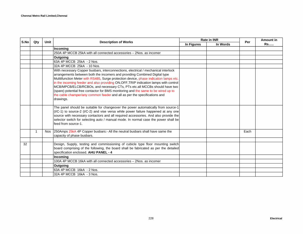
Chennai Metro Rail Limited,Chennai
In Figures In WordsUnit Description of Works Rate in INR Per Amount in Rs…..S.No Qty
Incoming250A 4P MCCB 25kA with all connected accessories – 2Nos. as incomerOutgoing63A 4P MCCB 25kA - 2 Nos.32A 4P MCCB 25kA - 10 Nos.With necessary Copper busbars, interconnections, electrical / mechanical interlock arrangements between both the incomers and providing Combined Digital type Mulitifunction Meter with RS485, Surge protection device, phase indication lamps etc. in the incoming feeder and also providing ON,OFF,TRIP indication lamps with control MCB/MPCB/ELCB/RCBOs, and necessary CTs, PTs etc.all MCCBs should have two (spare) potential free contactor for BMS monitoring and the same to be wired up to the cable champer/any common feeder and all as per the specifications and drawings.
The panel should be suitable for changeover the power automatically from source-1(I/C-1) to source-2 (I/C-2) and vise versa while power failure happened at any onesource with necessary contactors and all required accessories. And also provide theselector switch for selecting auto / manual mode. In normal case the power shall befeed from source-1.
1 Nos 250Amps 25kA 4P Copper busbars:- All the neutral busbars shall have same the capacity of phase busbars.
Each
32 Design, Supply, testing and commissioning of cubicle type floor mounting switchboard comprising of the following, the board shall be fabricated as per the detailedspecification enclosed. AHU PANEL - 4Incoming100A 4P MCCB 16kA with all connected accessories – 2Nos. as incomerOutgoing63A 4P MCCB 16kA - 2 Nos.32A 4P MCCB 16kA - 3 Nos.
228 Electrical
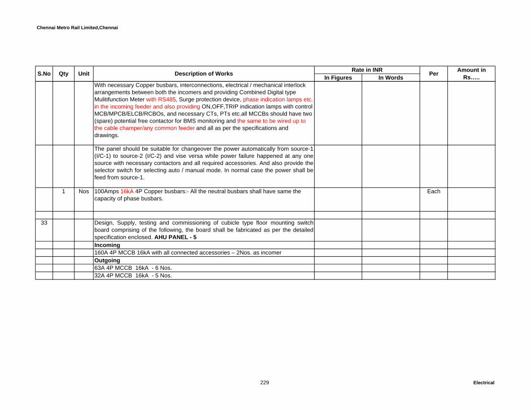
Chennai Metro Rail Limited,Chennai
In Figures In WordsUnit Description of Works Rate in INR Per Amount in Rs…..S.No Qty
With necessary Copper busbars, interconnections, electrical / mechanical interlock arrangements between both the incomers and providing Combined Digital type Mulitifunction Meter with RS485, Surge protection device, phase indication lamps etc. in the incoming feeder and also providing ON,OFF,TRIP indication lamps with control MCB/MPCB/ELCB/RCBOs, and necessary CTs, PTs etc.all MCCBs should have two (spare) potential free contactor for BMS monitoring and the same to be wired up to the cable champer/any common feeder and all as per the specifications and drawings.
The panel should be suitable for changeover the power automatically from source-1(I/C-1) to source-2 (I/C-2) and vise versa while power failure happened at any onesource with necessary contactors and all required accessories. And also provide theselector switch for selecting auto / manual mode. In normal case the power shall befeed from source-1.
1 Nos 100Amps 16kA 4P Copper busbars:- All the neutral busbars shall have same the capacity of phase busbars.
Each
33 Design, Supply, testing and commissioning of cubicle type floor mounting switchboard comprising of the following, the board shall be fabricated as per the detailedspecification enclosed. AHU PANEL - 5Incoming160A 4P MCCB 16kA with all connected accessories – 2Nos. as incomerOutgoing63A 4P MCCB 16kA - 6 Nos.32A 4P MCCB 16kA - 5 Nos.
229 Electrical

Chennai Metro Rail Limited,Chennai
In Figures In WordsUnit Description of Works Rate in INR Per Amount in Rs…..S.No Qty
With necessary Copper busbars, interconnections, electrical / mechanical interlock arrangements between both the incomers and providing Combined Digital type Mulitifunction Meter with RS485, Surge protection device, phase indication lamps etc. in the incoming feeder and also providing ON,OFF,TRIP indication lamps with control MCB/MPCB/ELCB/RCBOs, and necessary CTs, PTs etc.all MCCBs should have two (spare) potential free contactor for BMS monitoring and the same to be wired up to the cable champer/any common feeder and all as per the specifications and drawings.
The panel should be suitable for changeover the power automatically from source-1(I/C-1) to source-2 (I/C-2) and vise versa while power failure happened at any onesource with necessary contactors and all required accessories. And also provide theselector switch for selecting auto / manual mode. In normal case the power shall befeed from source-1.
1 Nos 160Amps 16kA 4P Copper busbars:- All the neutral busbars shall have same the capacity of phase busbars.
Each
34 Design, Supply, testing and commissioning of cubicle type floor mounting switchboard comprising of the following, the board shall be fabricated as per the detailedspecification enclosed. UPSB- 1Incoming100A 4P MCCB 16kA with all connected accessories – 2Nos. as incomerOutgoing32A 4P MCCB 16kA - 13 Nos.With necessary Copper busbars, interconnections, electrical / mechanical interlock arrangements between both the incomers and providing Combined Digital type Mulitifunction Meter with RS485, Surge protection device, phase indication lamps etc. in the incoming feeder and also providing ON,OFF,TRIP indication lamps with control MCB/MPCB/ELCB/RCBOs, and necessary CTs, PTs etc.all MCCBs should have two (spare) potential free contactor for BMS monitoring and the same to be wired up to the cable champer/any common feeder and all as per the specifications and drawings.
230 Electrical

Chennai Metro Rail Limited,Chennai
In Figures In WordsUnit Description of Works Rate in INR Per Amount in Rs…..S.No Qty
The panel should be suitable for changeover the power automatically from source-1(I/C-1) to source-2 (I/C-2) and vise versa while power failure happened at any onesource with necessary contactors and all required accessories. And also provide theselector switch for selecting auto / manual mode. In normal case the power shall befeed from source-1.
1 Nos 100Amps 16kA 4P Copper busbars:- All the neutral busbars shall have same the capacity of phase busbars.
Each
35 Design, Supply, testing and commissioning of cubicle type floor mounting switchboard comprising of the following, the board shall be fabricated as per the detailedspecification enclosed. UPSB- 2,3,4 & 5Incoming100A 4P MCCB 16kA with all connected accessories – 2Nos. as incomerOutgoing32A 4P MCCB 16kA - 9 Nos.With necessary Copper busbars, interconnections, electrical / mechanical interlock arrangements between both the incomers and providing Combined Digital type Mulitifunction Meter with RS485, Surge protection device, phase indication lamps etc. in the incoming feeder and also providing ON,OFF,TRIP indication lamps with control MCB/MPCB/ELCB/RCBOs, and necessary CTs, PTs etc.all MCCBs should have two (spare) potential free contactor for BMS monitoring and the same to be wired up to the cable champer/any common feeder and all as per the specifications and drawings.
The panel should be suitable for changeover the power automatically from source-1(I/C-1) to source-2 (I/C-2) and vise versa while power failure happened at any onesource with necessary contactors and all required accessories. And also provide theselector switch for selecting auto / manual mode. In normal case the power shall befeed from source-1.
4 Nos 100Amps 16kA 4P Copper busbars:- All the neutral busbars shall have same the capacity of phase busbars.
Each
231 Electrical

Chennai Metro Rail Limited,Chennai
In Figures In WordsUnit Description of Works Rate in INR Per Amount in Rs…..S.No Qty
36 Design, Supply, testing and commissioning of cubicle type floor mounting switchboard comprising of the following, the board shall be fabricated as per the detailedspecification enclosed. PSB- 1 & 5Incoming100A 4P MCCB 16kA with all connected accessories – 2Nos. as incomerOutgoing32A TPN MCCB 16kA - 5 Nos.With necessary Copper busbars, interconnections, electrical / mechanical interlock arrangements between both the incomers and providing Combined Digital type Mulitifunction Meter with RS485, Surge protection device, phase indication lamps etc. in the incoming feeder and also providing ON,OFF,TRIP indication lamps with control MCB/MPCB/ELCB/RCBOs, and necessary CTs, PTs etc.all MCCBs should have two (spare) potential free contactor for BMS monitoring and the same to be wired up to the cable champer/any common feeder and all as per the specifications and drawings.
The panel should be suitable for changeover the power automatically from source-1(I/C-1) to source-2 (I/C-2) and vise versa while power failure happened at any onesource with necessary contactors and all required accessories. And also provide theselector switch for selecting auto / manual mode. In normal case the power shall befeed from source-1.
2 Nos 100Amps 16kA 4P Copper busbars:- All the neutral busbars shall have same the capacity of phase busbars.
Each
37 Design, Supply, testing and commissioning of cubicle type floor mounting switch board comprising of the following, the board shall be fabricated as per the detailed specification enclosed. PSB- 2 & 3Incoming125A 4P MCCB 16kA with all connected accessories – 2Nos. as incomerOutgoing63A 4P MCCB 16kA - 6 Nos.
232 Electrical

Chennai Metro Rail Limited,Chennai
In Figures In WordsUnit Description of Works Rate in INR Per Amount in Rs…..S.No Qty
With necessary Copper busbars, interconnections, electrical / mechanical interlock arrangements between both the incomers and providing Combined Digital type Mulitifunction Meter with RS485, Surge protection device, phase indication lamps etc. in the incoming feeder and also providing ON,OFF,TRIP indication lamps with control MCB/MPCB/ELCB/RCBOs, and necessary CTs, PTs etc.all MCCBs should have two (spare) potential free contactor for BMS monitoring and the same to be wired up to the cable champer/any common feeder and all as per the specifications and drawings.The panel should be suitable for changeover the power automatically from source-1(I/C-1) to source-2 (I/C-2) and vise versa while power failure happened at any onesource with necessary contactors and all required accessories. And also provide theselector switch for selecting auto / manual mode. In normal case the power shall befeed from source-1.
2 Nos 125Amps 16kA 4P Copper busbars:- All the neutral busbars shall have same the capacity of phase busbars.
Each
38 Design, Supply, testing and commissioning of cubicle type floor mounting switchboard comprising of the following, the board shall be fabricated as per the detailedspecification enclosed. PSB- 4
Incoming100A 4P MCCB 16kA with all connected accessories – 2Nos. as incomerOutgoing63A 4P MCCB 16kA - 6 Nos.With necessary Copper busbars, interconnections, electrical / mechanical interlock arrangements between both the incomers and providing Combined Digital type Mulitifunction Meter with RS485, Surge protection device, phase indication lamps etc. in the incoming feeder and also providing ON,OFF,TRIP indication lamps with control MCB/MPCB/ELCB/RCBOs, and necessary CTs, PTs etc.all MCCBs should have two (spare) potential free contactor for BMS monitoring and the same to be wired up to the cable champer/any common feeder and all as per the specifications and drawings.
233 Electrical

Chennai Metro Rail Limited,Chennai
In Figures In WordsUnit Description of Works Rate in INR Per Amount in Rs…..S.No Qty
The panel should be suitable for changeover the power automatically from source-1(I/C-1) to source-2 (I/C-2) and vise versa while power failure happened at any onesource with necessary contactors and all required accessories. And also provide theselector switch for selecting auto / manual mode. In normal case the power shall befeed from source-1.
1 Nos 100Amps 16kA 4P Copper busbars:- All the neutral busbars shall have same the capacity of phase busbars.
Each
39 Design, Supply, testing and commissioning of cubicle type floor mounting switchboard comprising of the following, the board shall be fabricated as per the detailedspecification enclosed. PSB- 6Incoming160A 4P MCCB 16kA with all connected accessories – 2Nos. as incomerOutgoing63A 4P MCCB 16kA - 6 Nos.With necessary Copper busbars, interconnections, electrical / mechanical interlock arrangements between both the incomers and providing Combined Digital type Mulitifunction Meter with RS485, Surge protection device, phase indication lamps etc. in the incoming feeder and also providing ON,OFF,TRIP indication lamps with control MCB/MPCB/ELCB/RCBOs, and necessary CTs, PTs etc.all MCCBs should have two (spare) potential free contactor for BMS monitoring and the same to be wired up to the cable champer/any common feeder and all as per the specifications and drawings.
The panel should be suitable for changeover the power automatically from source-1(I/C-1) to source-2 (I/C-2) and vise versa while power failure happened at any onesource with necessary contactors and all required accessories. And also provide theselector switch for selecting auto / manual mode. In normal case the power shall befeed from source-1.
1 Nos 160Amps 16kA 4P Copper busbars:- All the neutral busbars shall have same the capacity of phase busbars.
Each
234 Electrical

Chennai Metro Rail Limited,Chennai
In Figures In WordsUnit Description of Works Rate in INR Per Amount in Rs…..S.No Qty
40 Design, Supply, testing and commissioning of cubicle type floor mounting switchboard comprising of the following, the board shall be fabricated as per the detailedspecification enclosed. LSB -1Incoming100A 4P MCCB 16kA with all connected accessories – 2Nos. as incomerOutgoing32A 4P MCCB 16kA - 7 Nos.With necessary Copper busbars, interconnections, electrical / mechanical interlock arrangements between both the incomers and providing Combined Digital type Mulitifunction Meter with RS485, Surge protection device, phase indication lamps etc. in the incoming feeder and also providing ON,OFF,TRIP indication lamps with control MCB/MPCB/ELCB/RCBOs, and necessary CTs, PTs etc.all MCCBs should have two (spare) potential free contactor for BMS monitoring and the same to be wired up to the cable champer/any common feeder and all as per the specifications and drawings.
The panel should be suitable for changeover the power automatically from source-1(I/C-1) to source-2 (I/C-2) and vise versa while power failure happened at any onesource with necessary contactors and all required accessories. And also provide theselector switch for selecting auto / manual mode. In normal case the power shall befeed from source-1.
1 Nos 100Amps 16kA 4P Copper busbars:- All the neutral busbars shall have same the capacity of phase busbars.
Each
41 Design, Supply, testing and commissioning of cubicle type floor mounting switchboard comprising of the following, the board shall be fabricated as per the detailedspecification enclosed. LSB - 2,3,4,5 & 6Incoming100A 4P MCCB 16kA with all connected accessories – 2Nos. as incomerOutgoing32A 4P MCCB 16kA - 6 Nos.
235 Electrical

Chennai Metro Rail Limited,Chennai
In Figures In WordsUnit Description of Works Rate in INR Per Amount in Rs…..S.No Qty
With necessary Copper busbars, interconnections, electrical / mechanical interlock arrangements between both the incomers and providing Combined Digital type Mulitifunction Meter with RS485, Surge protection device, phase indication lamps etc. in the incoming feeder and also providing ON,OFF,TRIP indication lamps with control MCB/MPCB/ELCB/RCBOs, and necessary CTs, PTs etc.all MCCBs should have two (spare) potential free contactor for BMS monitoring and the same to be wired up to the cable champer/any common feeder and all as per the specifications and drawings.
The panel should be suitable for changeover the power automatically from source-1(I/C-1) to source-2 (I/C-2) and vise versa while power failure happened at any onesource with necessary contactors and all required accessories. And also provide theselector switch for selecting auto / manual mode. In normal case the power shall befeed from source-1.
5 Nos 100Amps 16kA 4P Copper busbars:- All the neutral busbars shall have same the capacity of phase busbars.
Each
42 Design, Supply, testing and commissioning of cubicle type floor mounting switchboard comprising of the following, the board shall be fabricated as per the detailedspecification enclosed. UPS INCOMING PANEL (For Safety system)
Incoming125A 4P MCCB 16kA with all connected accessories – 2Nos. as incomerOutgoing63A 4P MCCB 16kA - 2 Nos.With necessary Copper busbars, interconnections, electrical / mechanical interlock arrangements between both the incomers and providing Combined Digital type Mulitifunction Meter with RS485, Surge protection device, phase indication lamps etc. in the incoming feeder and also providing ON,OFF,TRIP indication lamps with control MCB/MPCB/ELCB/RCBOs, and necessary CTs, PTs etc.all MCCBs should have two (spare) potential free contactor for BMS monitoring and the same to be wired up to the cable champer/any common feeder and all as per the specifications and drawings.
236 Electrical
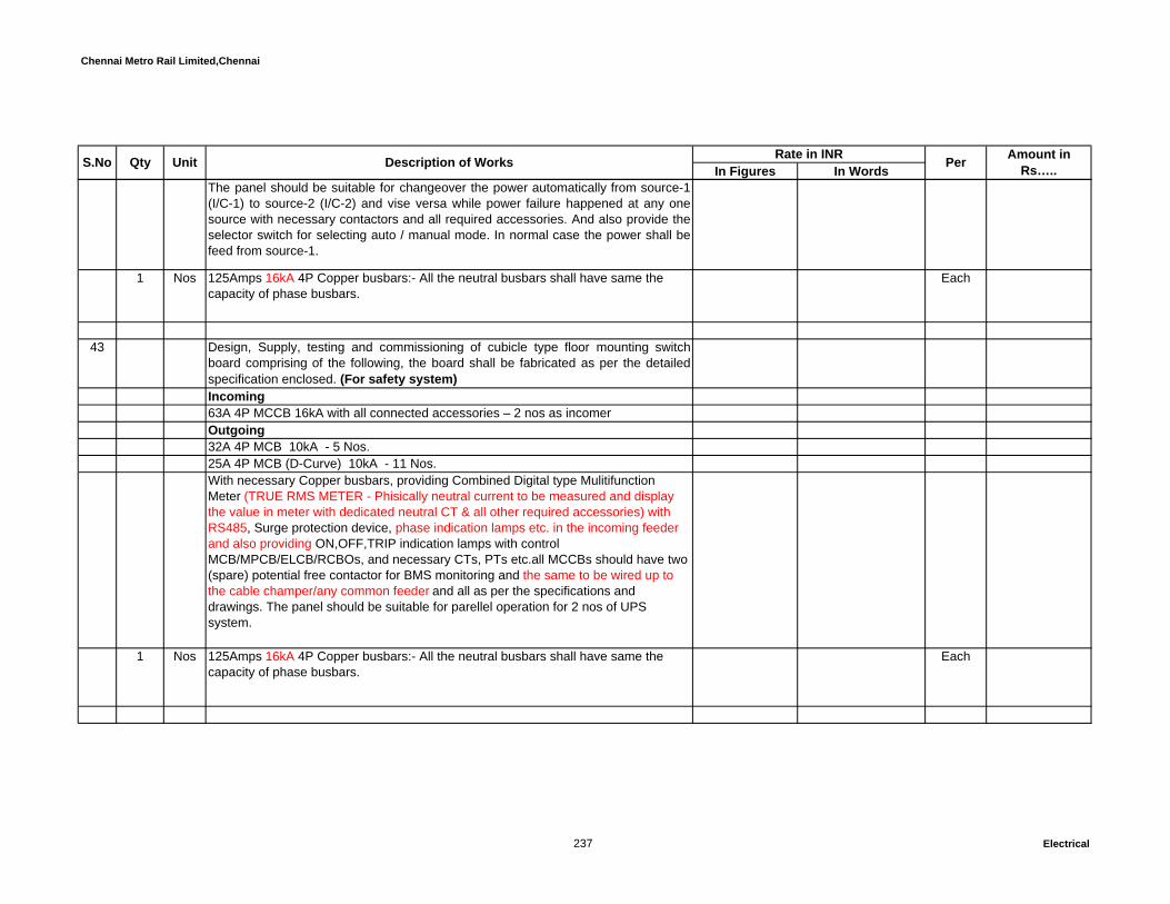
Chennai Metro Rail Limited,Chennai
In Figures In WordsUnit Description of Works Rate in INR Per Amount in Rs…..S.No Qty
The panel should be suitable for changeover the power automatically from source-1(I/C-1) to source-2 (I/C-2) and vise versa while power failure happened at any onesource with necessary contactors and all required accessories. And also provide theselector switch for selecting auto / manual mode. In normal case the power shall befeed from source-1.
1 Nos 125Amps 16kA 4P Copper busbars:- All the neutral busbars shall have same the capacity of phase busbars.
Each
43 Design, Supply, testing and commissioning of cubicle type floor mounting switchboard comprising of the following, the board shall be fabricated as per the detailedspecification enclosed. (For safety system)Incoming63A 4P MCCB 16kA with all connected accessories – 2 nos as incomerOutgoing32A 4P MCB 10kA - 5 Nos.25A 4P MCB (D-Curve) 10kA - 11 Nos. With necessary Copper busbars, providing Combined Digital type Mulitifunction Meter (TRUE RMS METER - Phisically neutral current to be measured and display the value in meter with dedicated neutral CT & all other required accessories) with RS485, Surge protection device, phase indication lamps etc. in the incoming feeder and also providing ON,OFF,TRIP indication lamps with control MCB/MPCB/ELCB/RCBOs, and necessary CTs, PTs etc.all MCCBs should have two (spare) potential free contactor for BMS monitoring and the same to be wired up to the cable champer/any common feeder and all as per the specifications and drawings. The panel should be suitable for parellel operation for 2 nos of UPS system.
1 Nos 125Amps 16kA 4P Copper busbars:- All the neutral busbars shall have same the capacity of phase busbars.
Each
237 Electrical
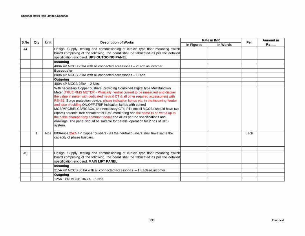
Chennai Metro Rail Limited,Chennai
In Figures In WordsUnit Description of Works Rate in INR Per Amount in Rs…..S.No Qty
44 Design, Supply, testing and commissioning of cubicle type floor mounting switchboard comprising of the following, the board shall be fabricated as per the detailedspecification enclosed. UPS OUTGOING PANELIncoming400A 4P MCCB 25kA with all connected accessories – 2Each as incomerBuscoupler800A 4P MCCB 25kA with all connected accessories – 1EachOutgoing400A 4P MCCB 25kA - 2 Nos.With necessary Copper busbars, providing Combined Digital type Mulitifunction Meter (TRUE RMS METER - Phisically neutral current to be measured and display the value in meter with dedicated neutral CT & all other required accessories) with RS485, Surge protection device, phase indication lamps etc. in the incoming feeder and also providing ON,OFF,TRIP indication lamps with control MCB/MPCB/ELCB/RCBOs, and necessary CTs, PTs etc.all MCCBs should have two (spare) potential free contactor for BMS monitoring and the same to be wired up to the cable champer/any common feeder and all as per the specifications and drawings. The panel should be suitable for parellel operation for 2 nos of UPS system.
1 Nos 800Amps 25kA 4P Copper busbars:- All the neutral busbars shall have same the capacity of phase busbars.
Each
45 Design, Supply, testing and commissioning of cubicle type floor mounting switchboard comprising of the following, the board shall be fabricated as per the detailedspecification enclosed. MAIN LIFT PANELIncoming315A 4P MCCB 36 kA with all connected accessories – 1 Each as incomerOutgoing125A TPN MCCB 36 kA - 5 Nos.
238 Electrical

Chennai Metro Rail Limited,Chennai
In Figures In WordsUnit Description of Works Rate in INR Per Amount in Rs…..S.No Qty
With necessary Copper busbars, interconnections, providing Combined Digital type Mulitifunction Meter with RS485, Surge protection device, phase indication lamps etc. in the incoming feeder and also providing ON,OFF,TRIP indication lamps with control MCB/MPCB/ELCB/RCBOs, and necessary CTs, PTs etc.all MCCBs should have two (spare) potential free contactor for BMS monitoring and the same to be wired up to the cable champer/any common feeder and all as per the specifications and drawings.
1 Nos 315Amps 36kA 4P Copper busbars:- All the neutral busbars shall have same the capacity of phase busbars.
Each
46 Design, Supply, testing and commissioning of cubicle type floor mounting switchboard comprising of the following, the board shall be fabricated as per the detailedspecification enclosed. SUB LIFT PANEL -1Incoming125A 4P MCCB 16 kA with all connected accessories – 2 Nos. as incomerOutgoing63A TPN MCCB 16 kA - 4 Nos.32A TPN MCCB 16 kA - 2 Nos.With necessary Copper busbars, interconnections, electrical / mechanical interlock arrangements between both the incomers and providing Combined Digital type Mulitifunction Meter with RS485, Surge protection device, phase indication lamps etc. in the incoming feeder and also providing ON,OFF,TRIP indication lamps with control MCB/MPCB/ELCB/RCBOs, and necessary CTs, PTs etc.all MCCBs should have two (spare) potential free contactor for BMS monitoring and the same to be wired up to the cable champer/any common feeder and all as per the specifications and drawings.
The panel should be suitable for changeover the power automatically from source-1(I/C-1) to source-2 (I/C-2) and vise versa while power failure happened at any onesource with necessary contactors and all required accessories. And also provide theselector switch for selecting auto / manual mode. In normal case the power shall befeed from source-1.
239 Electrical

Chennai Metro Rail Limited,Chennai
In Figures In WordsUnit Description of Works Rate in INR Per Amount in Rs…..S.No Qty
1 Nos 125Amps 16kA 4P Copper busbars:- All the neutral busbars shall have same the capacity of phase busbars.
Each
METERING PANEL BOARD (For residential block)47 Design, Supply, Installation, testing and commissioning of cubicle type floor mounting
switch board comprising of the following, the board shall be fabricated as per thedetailed specification enclosed. EB METERING PANEL (For type A)
Incoming250A TPN FSU with connected accessories – 1Each as incomer with lock andsealing fecility. Outgoings3 sets of 100A TP rewireable cutout with neutral link, Space Provision for 3phase EBmetering and 100A TPN 16kA MCCB with all other necessary accessories.
14 sets of 63A TP rewireable cutout with neutral link, Space Provision for 3phase EB metering and 63A TPN 10kA MCB with all other necessary accessories.
3 sets of 32A TP rewireable cutout with neutral link, Space Provision for 3phase EB metering and 32A TPN 10kA MCB with all other necessary accessories.
Cable Entry : TopCable Gland Plate : 3mm thick MS sheetsEnergy meters for individual consumers shall be purchased by theconsumer/Promoter at his own cost.These meters shall be got tested and certified byElectrical Inspectorate of TNEB.Note : All switch boards shall be fabricated as per the detailed specification enclosed.Suitable size outgoing cable chamber and extra busbars should be provided forconnecting the number of outgoing cables and refer also the Schematic drawing.
240 Electrical

Chennai Metro Rail Limited,Chennai
In Figures In WordsUnit Description of Works Rate in INR Per Amount in Rs…..S.No Qty
1 Nos 250 Amps 16kA 4P copper busbars:- All the neutral busbars shall have same the capacity of phase busbars.
Each
48 Design, Supply, Installation, testing and commissioning of cubicle type floor mountingswitch board comprising of the following, the board shall be fabricated as per thedetailed specification enclosed. DG METERING PANEL (For type A)
Incoming250A TPN MCCB with connected accessories – 1Each as incomer Outgoings3 sets of 100A TPN 16kA MCCB, Energy (which is having the parameters of KWH,A& V) meter with RS485 port and 100A 4P 16kA ATS with Auto/Manual selectorswitch and all other necessary accessories.14 sets 63A TPN 10kA MCB, Energy (which is having the parameters of KWH, A & V) meter with RS485 port and 63A 4P10kA ATS with Auto/Manual selector switch and all other necessary accessories.3 sets 32A TPN 10kA MCB, Energy (which is having the parameters of KWH, A & V) meter with RS485 port and 32A 4P10kA ATS with Auto/Manual selector switch and all other necessary accessories.Cable Entry : TopCable Gland Plate : 3mm thick MS sheetsWith necessary copper busbars, interconnections, providing energy meter for DGpower reading, ON,OFF,TRIP, phase indication lamps with controlMCB/MPCB/ELCB/RCBOs & necessary CTs, PTs etc. and all as per the detailedspecification and drawings enclosed.
1 Nos 250 Amps 16kA 4P copper busbars:- All the neutral busbars shall have same the capacity of phase busbars.
Each
49 Design, Supply, testing and commissioning of cubicle type floor mounting switchboard comprising of the following, the board shall be fabricated as per the detailedspecification enclosed. LIFT PANEL (For residential block)
241 Electrical

Chennai Metro Rail Limited,Chennai
In Figures In WordsUnit Description of Works Rate in INR Per Amount in Rs…..S.No Qty
Incoming100A TPN MCCB 16kA with all connected accessories – 1Each as incomerOutgoing63A TPN MCCB 16 kA - 3 Nos.32A TPN MCCB 16 kA - 2 Nos.With necessary Copper busbars, interconnections, providing Combined Digital typeMulitifunction Meter, Surge protection device, ON,OFF,TRIP, phase indication lampswith control MCB/MPCB/ELCB/RCBOs, and necessary CTs, PTs etc.and both theincomer's shall be interlocked with mechanical and electrical arrangements byhardware control wiring. All MCCBs should have one (spare) potential free contactor,Combined digital type Multi function meter with RS485 port. with Modebus TCPprovisions, as per the specification and drawings.
2 Nos 100Amps 16kA 4P copper busbars:- All the neutral busbars shall have same the capacity of phase busbars.
Each
50 Design, Supply, Installation, testing and commissioning of cubicle type floor mountingswitch board comprising of the following, the board shall be fabricated as per thedetailed specification enclosed. EB METERING PANEL-1 (For type B)
Incoming250A TPN FSU with connected accessories – 1Each as incomer with lock andsealing fecility. Outgoings2 sets of 100A TP rewireable cutout with neutral link, Space Provision for 3phase EB metering and 100A TPN 16kA MCCB with all other necessary accessories.
17 sets of 32A TP rewireable cutout with neutral link, Space Provision for 3phase EB metering and 32A TPN 10kA MCB with all other necessary accessories.
Cable Entry : TopCable Gland Plate : 3mm thick Aluminium sheets
242 Electrical
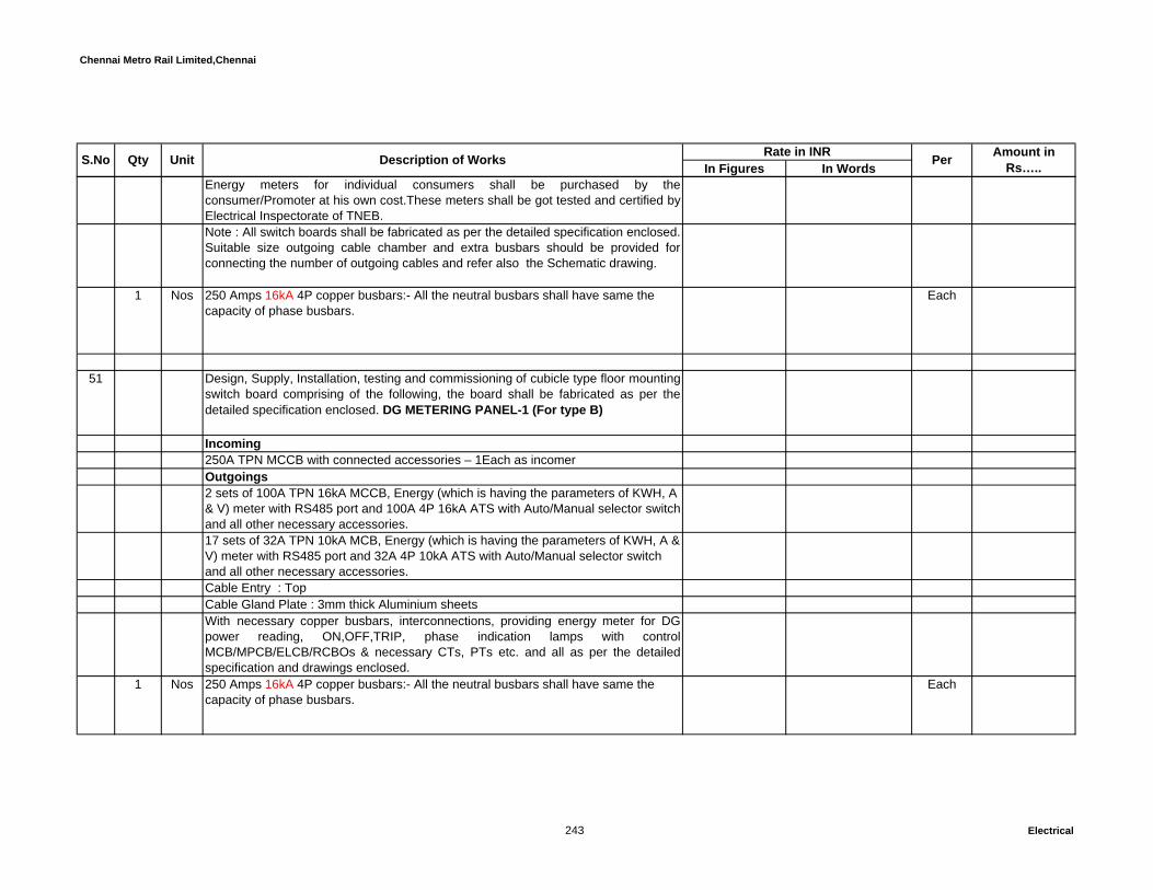
Chennai Metro Rail Limited,Chennai
In Figures In WordsUnit Description of Works Rate in INR Per Amount in Rs…..S.No Qty
Energy meters for individual consumers shall be purchased by theconsumer/Promoter at his own cost.These meters shall be got tested and certified byElectrical Inspectorate of TNEB.Note : All switch boards shall be fabricated as per the detailed specification enclosed.Suitable size outgoing cable chamber and extra busbars should be provided forconnecting the number of outgoing cables and refer also the Schematic drawing.
1 Nos 250 Amps 16kA 4P copper busbars:- All the neutral busbars shall have same the capacity of phase busbars.
Each
51 Design, Supply, Installation, testing and commissioning of cubicle type floor mountingswitch board comprising of the following, the board shall be fabricated as per thedetailed specification enclosed. DG METERING PANEL-1 (For type B)
Incoming250A TPN MCCB with connected accessories – 1Each as incomer Outgoings2 sets of 100A TPN 16kA MCCB, Energy (which is having the parameters of KWH, A & V) meter with RS485 port and 100A 4P 16kA ATS with Auto/Manual selector switch and all other necessary accessories.17 sets of 32A TPN 10kA MCB, Energy (which is having the parameters of KWH, A & V) meter with RS485 port and 32A 4P 10kA ATS with Auto/Manual selector switch and all other necessary accessories.Cable Entry : TopCable Gland Plate : 3mm thick Aluminium sheetsWith necessary copper busbars, interconnections, providing energy meter for DGpower reading, ON,OFF,TRIP, phase indication lamps with controlMCB/MPCB/ELCB/RCBOs & necessary CTs, PTs etc. and all as per the detailedspecification and drawings enclosed.
1 Nos 250 Amps 16kA 4P copper busbars:- All the neutral busbars shall have same the capacity of phase busbars.
Each
243 Electrical
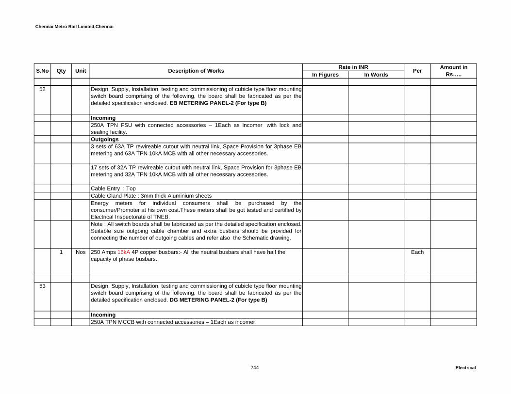
Chennai Metro Rail Limited,Chennai
In Figures In WordsUnit Description of Works Rate in INR Per Amount in Rs…..S.No Qty
52 Design, Supply, Installation, testing and commissioning of cubicle type floor mountingswitch board comprising of the following, the board shall be fabricated as per thedetailed specification enclosed. EB METERING PANEL-2 (For type B)
Incoming250A TPN FSU with connected accessories – 1Each as incomer with lock andsealing fecility. Outgoings3 sets of 63A TP rewireable cutout with neutral link, Space Provision for 3phase EBmetering and 63A TPN 10kA MCB with all other necessary accessories.
17 sets of 32A TP rewireable cutout with neutral link, Space Provision for 3phase EBmetering and 32A TPN 10kA MCB with all other necessary accessories.
Cable Entry : TopCable Gland Plate : 3mm thick Aluminium sheetsEnergy meters for individual consumers shall be purchased by theconsumer/Promoter at his own cost.These meters shall be got tested and certified byElectrical Inspectorate of TNEB.Note : All switch boards shall be fabricated as per the detailed specification enclosed.Suitable size outgoing cable chamber and extra busbars should be provided forconnecting the number of outgoing cables and refer also the Schematic drawing.
1 Nos 250 Amps 16kA 4P copper busbars:- All the neutral busbars shall have half the capacity of phase busbars.
Each
53 Design, Supply, Installation, testing and commissioning of cubicle type floor mountingswitch board comprising of the following, the board shall be fabricated as per thedetailed specification enclosed. DG METERING PANEL-2 (For type B)
Incoming250A TPN MCCB with connected accessories – 1Each as incomer
244 Electrical

Chennai Metro Rail Limited,Chennai
In Figures In WordsUnit Description of Works Rate in INR Per Amount in Rs…..S.No Qty
Outgoings3 sets of 63A TPN 10kA MCB, Energy (which is having the parameters of KWH, A &V) meter with RS485 port and 63A 4P 10kA ATS with Auto/Manual selector switchand all other necessary accessories.18 sets of 32A TPN 10kA MCB, Energy (which is having the parameters of KWH, A &V) meter with RS485 port and 32A 4P 10kA ATS with Auto/Manual selector switchand all other necessary accessories.Cable Entry : TopCable Gland Plate : 3mm thick Aluminium sheetsWith necessary copper busbars, interconnections, providing energy meter for DGpower reading, ON,OFF,TRIP, phase indication lamps with controlMCB/MPCB/ELCB/RCBOs & necessary CTs, PTs etc. and all as per the detailedspecification and drawings enclosed.
1 Nos 250 Amps 16kA 4P copper busbars:- All the neutral busbars shall have same the capacity of phase busbars.
Each
54 DG PANEL (For Residential block -A & B)Design, Supply, Installation, testing and commissioning of cubicle type floor mountingswitch board comprising of the following, the board shall be fabricated as per thedetailed specification enclosed. DG PANEL (For type A&B)
1 Each of 1250 Amps 4 Pole 50kA electrical draw out type Air circuit breaker withearth fault relay and shunt release shutter assembly, door interlock and all otheraccessories.Instrumental compartmentProviding TNC Switch, Emergency lockable push button, Digital multi function meter (Similar to SOCOMEC - Diris A40) with RS 485, Ammeter, Voltmeter, Instantaneous over current, earthfault relay (2 O/C+ 1 E/F), necessary CTs, PTs, control MPCB/MCB/ ELCB/RCBOs, RYB Indication lamps and “ON/OFF/Trip/Rest" indicating lamp, voltage surge protection with emergency lockable push buttons and also refer the specification and SLD.OUTGOINGS250A TPN MCCB 36 KA - 6 nos
245 Electrical

Chennai Metro Rail Limited,Chennai
In Figures In WordsUnit Description of Works Rate in INR Per Amount in Rs…..S.No Qty
All the Outgoing feeder shall be ON/OFF/Trip indication lamps, emergency lockable push buttons, all ACB and MCCBs should have two (spare) potential free contactor for BMS monitoring, Combined digital type Multi function meter (Similar to SOCOMEC - Countis E53) with RS485 port. The rate shall inclusive of necessary CTs, control switches, Front operating handles etc., All switch boards shall be fabricated as per the detailed specification enclosed. Suitable size outgoing cable chamber and extra busbars should be provided for connecting the number of outgoing cables as per the schematic drawing.The board shall be fabricated for future extension of the panel board.
1 Each 1250 Amps 36kA 4P copper busbars:- All the neutral busbars shall have same the capacity of phase busbars.
Each
SECTION - B:-Total C/o to summary: Rs.
SECTION-C: RAISNG MAINS AND TAP-OFF BOXESAll installation works should be as complete and as directed by Employer / Employer's representative. The rate includes necessary connected minor civil works if required andnecessary supports as required at site. No extra payment will be made for thesame.
55 1250A Copper conductor Sandwich type Rising Main for Lighting and RawPower
50 RMT Supply, Installation, Testing and Commissioning of 4P, 4Wire, 1250A Coppercondutor sandwich type Rising Mains with 50X6 mm (2) External Copper earthing,Plug in Point at every 500mm, Fire Barriers at every Floor Crossing : Indoor : 36kA The product shall be based on Temp. rise & not on current density and as pertechical specification and drawing.
RMT
2 Nos 1250A End Feed Unit with 36kA 4P ACB Each
246 Electrical

Chennai Metro Rail Limited,Chennai
In Figures In WordsUnit Description of Works Rate in INR Per Amount in Rs…..S.No Qty
2 Nos End Covers Each
35 Nos Mounting Brackets (Recommended 1Each per 1.5 Mtrs) Each
2 Nos 250A Tap Off Box with 25kA 4P MCCB Each
4 Nos 160A Tap Off Box with 25kA 4P MCCB Each
10 Nos 125A Tap Off Box with 25kA 4P MCCB Each
22 Nos 100A Tap Off Box with 25kA 4P MCCB Each
56 400A Copper conductor Sandwich type Rising Main for UPS Power50 RMT Supply, Installation, Testing and Commissioning of 4P, 4Wire, 400A Copper condutor
sandwich type Rising Mains with 25X3 mm (2) External Copper earthing, Plug inPoint at every 500mm, Fire Barriers at every Floor Crossing : Indoor : 25kA The product shall be based on temperature rise & not on current density and as pertechnical specification and drawing.
RMT
2 Nos 400A End Feed Unit with 25kA 4P MCCB Each
2 Nos End Covers Each
247 Electrical

Chennai Metro Rail Limited,Chennai
In Figures In WordsUnit Description of Works Rate in INR Per Amount in Rs…..S.No Qty
35 Nos Mounting Brackets (Recommended 1Each per 1.5 Mtrs) Each
10 Nos 100A Tap Off Box with 16kA 4P MCCB Each
SECTION - C:-Total C/o to summary: Rs.
SECTION-D :UPS AND BATTERIESAll UPS should have at least one spare potential free contacts to integrate withBMS system to know the status like ON, OFF, TRIP, etc.,
57 Supply, Installation, Testing and commissioning of 120 KVA UPS system 3 phaseinput and three phase output and as per the detailed specification enclosed.(ForUPS power for Server, computers & Emergency lighting)Supply, Installation, Testing and Commissioning of 2V, VRLA (SMF) SealedMaintenance Free Batteries to support 120KVA for 30 minutes complete withintercell connectors & copper cables, battery stand made out of Powder Coated MSAngles with adequate supports to carry the load of the batteries.
2 Nos The vendor shall submit dimensional GA drawing of complete UPS system, batteryrack with batteries,Service bypass Panel and Battery bank calculations along withoffer.
Each
58 Supply, Installation, Testing and commissioning of 20 KVA UPS system 3 phaseinput and three phase output and as per the detailed specification enclosed.(ForSafety systems). Supply, Installation, Testing and Commissioning of 2V, VRLA (SMF) SealedMaintenance Free Batteries to support 20KVA for 2 hours complete with intercellconnectors & copper cables, battery stand made out of Powder Coated MS Angleswith adequate supports to carry the load of the batteries.
2 Nos The vendor shall submit dimensional GA drawing of complete UPS system, batteryrack with batteries,Service bypass Panel and Battery bank calculations along withoffer.
Each
248 Electrical

Chennai Metro Rail Limited,Chennai
In Figures In WordsUnit Description of Works Rate in INR Per Amount in Rs…..S.No Qty
59 Supply, Installation, Testing and commissioning of 5 KVA UPS system 1phase inputand 1phase output and as per the detailed specification enclosed. (For LT panelcontrol supply). Supply, Installation, Testing and Commissioning of 2V, VRLA (SMF) SealedMaintenance Free Batteries to support 5 KVA for 30 minutes complete with intercellconnectors & copper cables, battery stand made out of Powder Coated MS Angleswith adequate supports to carry the load of the batteries.
1 Nos The vendor shall submit dimensional GA drawing of complete Inverter system,battery rack with batteries,Service bypass Panel and Battery bank calculations alongwith offer.
Each
SECTION - D:-Total C/o to summary: Rs.
SECTION – E : DISTRIBUTION BOARDSAll installation works should be as complete and as directed by Employer /Empolyer's representative. The rate includes necessary connected minor civil works if required andnecessary supports as required at site. No extra payment will be made for thesame.
57 PDB (VTPN DB) - 12 WAY: Supply, fixing, testing and commissioning of the double door type VTPN 12wayMCCB DB comprising of the following :125A 4P MCCB 16KA with ELM and all other required accessories – 1 Each asincomer.16/20/32A TP MCB 10KA – 12 Nos. as outgoings.
1 Nos With necessary tinned copper busbars, interconnections, separate earth bus,separate neutral bus for each phases. The board shall be powder coated type fixedwith concealed system in wall. The rate shall include necessary connected civilworks like chipping, rough plastering etc.
Each
58 PDB (VTPN DB) - 12 WAY: (PLUMBING)Supply, fixing, testing and commissioning of the double door type VTPN 12wayMCCB DB comprising of the following :
249 Electrical
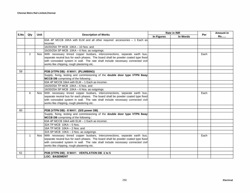
Chennai Metro Rail Limited,Chennai
In Figures In WordsUnit Description of Works Rate in INR Per Amount in Rs…..S.No Qty
63A 4P MCCB 16KA with ELM and all other required accessories – 1 Each asincomer.16/20/25A TP MCB 10KA – 10 Nos. and16/20/25A SP MCB 10KA – 6 Nos. as outgoings.
2 Nos With necessary tinned copper busbars, interconnections, separate earth bus,separate neutral bus for each phases. The board shall be powder coated type fixedwith concealed system in wall. The rate shall include necessary connected civilworks like chipping, rough plastering etc.
Each
59 PDB (VTPN DB) - 8 WAY: (PLUMBING)Supply, fixing, testing and commissioning of the double door type VTPN 8wayMCCB DB comprising of the following :63A 4P MCCB 16kA with ELM – 1 Each as incomer.16/20/25A TP MCB 10KA – 6 Nos. and16/20/25A SP MCB 10KA – 6 Nos. as outgoings.
6 Nos With necessary tinned copper busbars, interconnections, separate earth bus,separate neutral bus for each phases. The board shall be powder coated type fixedwith concealed system in wall. The rate shall include necessary connected civilworks like chipping, rough plastering etc.
Each
60 PDB (VTPN DB) - 8 WAY: (S/S power DB)Supply, fixing, testing and commissioning of the double door type VTPN 8wayMCCB DB comprising of the following :63A 4P MCCB 16kA with ELM – 1 Each as incomer.32A TP MCB 10KA – 5 Nos.16A TP MCB 10KA – 2 Nos. and32A SP MCB 10KA – 3 Nos. as outgoings.
1 Nos With necessary tinned copper busbars, interconnections, separate earth bus,separate neutral bus for each phases. The board shall be powder coated type fixedwith concealed system in wall. The rate shall include necessary connected civilworks like chipping, rough plastering etc.
Each
61 PDB (VTPN DB) - 8 WAY: VENTILATION DB -1 to 5LOC: BASEMENT
250 Electrical
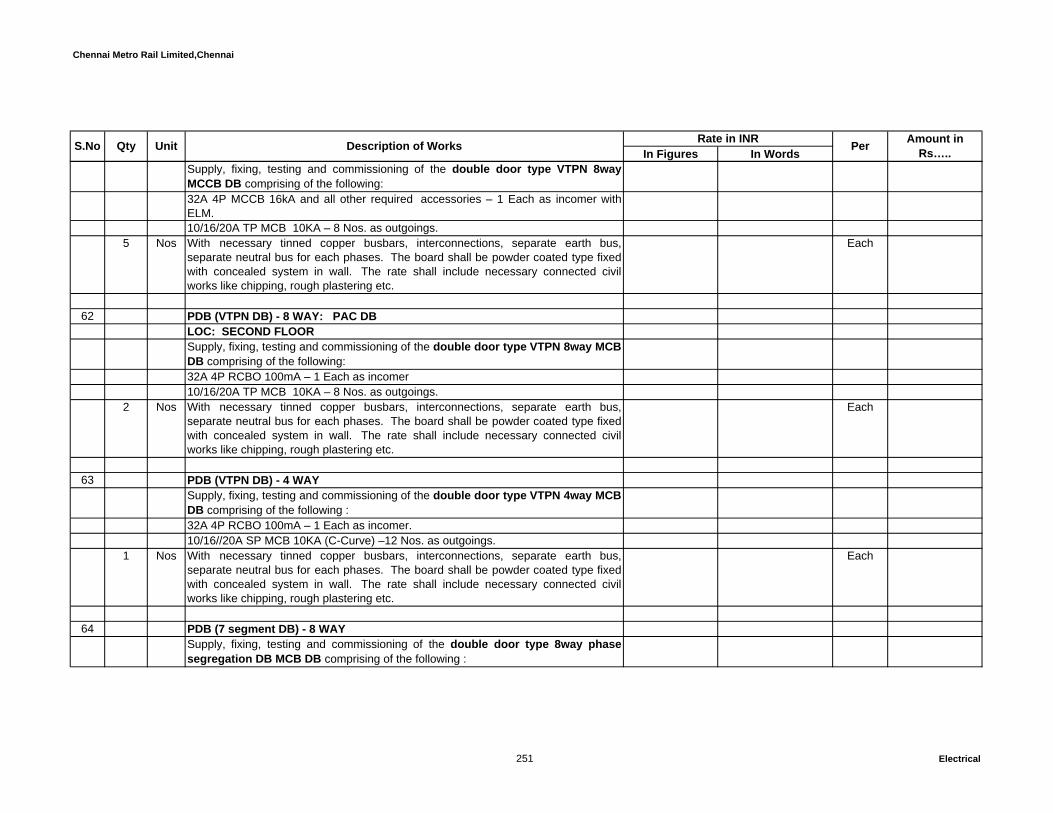
Chennai Metro Rail Limited,Chennai
In Figures In WordsUnit Description of Works Rate in INR Per Amount in Rs…..S.No Qty
Supply, fixing, testing and commissioning of the double door type VTPN 8wayMCCB DB comprising of the following:32A 4P MCCB 16kA and all other required accessories – 1 Each as incomer withELM.10/16/20A TP MCB 10KA – 8 Nos. as outgoings.
5 Nos With necessary tinned copper busbars, interconnections, separate earth bus,separate neutral bus for each phases. The board shall be powder coated type fixedwith concealed system in wall. The rate shall include necessary connected civilworks like chipping, rough plastering etc.
Each
62 PDB (VTPN DB) - 8 WAY: PAC DBLOC: SECOND FLOORSupply, fixing, testing and commissioning of the double door type VTPN 8way MCBDB comprising of the following:32A 4P RCBO 100mA – 1 Each as incomer 10/16/20A TP MCB 10KA – 8 Nos. as outgoings.
2 Nos With necessary tinned copper busbars, interconnections, separate earth bus,separate neutral bus for each phases. The board shall be powder coated type fixedwith concealed system in wall. The rate shall include necessary connected civilworks like chipping, rough plastering etc.
Each
63 PDB (VTPN DB) - 4 WAYSupply, fixing, testing and commissioning of the double door type VTPN 4way MCBDB comprising of the following :32A 4P RCBO 100mA – 1 Each as incomer.10/16//20A SP MCB 10KA (C-Curve) –12 Nos. as outgoings.
1 Nos With necessary tinned copper busbars, interconnections, separate earth bus,separate neutral bus for each phases. The board shall be powder coated type fixedwith concealed system in wall. The rate shall include necessary connected civilworks like chipping, rough plastering etc.
Each
64 PDB (7 segment DB) - 8 WAYSupply, fixing, testing and commissioning of the double door type 8way phasesegregation DB MCB DB comprising of the following :
251 Electrical

Chennai Metro Rail Limited,Chennai
In Figures In WordsUnit Description of Works Rate in INR Per Amount in Rs…..S.No Qty
63A 4P MCB 10KA (C-Curve) – 1Each as main incomer.63A DP RCBO 100mA – 3 Nos. as phase incomerEach 63A DP MCB outgoing consist of 8nos. 10/16/20A 10KA SP MCB (C-Curve) ina separate compartment with necessary phase segregation as required by theElectrical Inspectorate.
5 Nos With necessary tinned copper busbars, interconnections, separate earth bus,separate neutral bus for each phases. The board shall be powder coated type fixedwith concealed system in wall. The rate shall include necessary connected civilworks like chipping, rough plastering etc.
Each
65 PDB (7 segment DB) - 6 WAYSupply, fixing, testing and commissioning of the double door type 6way phasesegregation DB MCB DB comprising of the following :63A 4P MCB 10KA (C-Curve) – 1Each as main incomer.63A DP RCBO 100mA – 3 Nos., as phase incomerEach 40A DP MCB outgoing consist of 6nos.6/10/16/20A 10KA SP MCB (C-Curve)in a separate compartment with necessary phase segregation as required by theElectrical Inspectorate.
14 Nos With necessary tinned copper busbars, interconnections, separate earth bus,separate neutral bus for each phases. The board shall be powder coated type fixedwith concealed system in wall. The rate shall include necessary connected civilworks like chipping, rough plastering etc.
Each
66 PDB (7 segment DB) - 4 WAYSupply, fixing, testing and commissioning of the double door type 6way phasesegregation DB MCB DB comprising of the following :63A 4P MCB 10KA (C-Curve) – 1Each as main incomer.63A DP RCBO 100mA – 3 Nos., as phase incomerEach 63A DP MCB outgoing consist of 6nos.6/10/16/20A 10KA SP MCB (C-Curve)in a separate compartment with necessary phase segregation as required by theElectrical Inspectorate.
252 Electrical

Chennai Metro Rail Limited,Chennai
In Figures In WordsUnit Description of Works Rate in INR Per Amount in Rs…..S.No Qty
1 Nos With necessary tinned copper busbars, interconnections, separate earth bus,separate neutral bus for each phases. The board shall be powder coated type fixedwith concealed system in wall. The rate shall include necessary connected civilworks like chipping, rough plastering etc.
Each
67 LPDB (6Way 7 segment DB)LOC: Type -ASupply, fixing, testing and commissioning of the double door type 6way phasesegregation DB MCB DB comprising of the following :63A 4P MCB 10KA (C-Curve) – 1Each With Surge Protection device (shall besuitable for operation on 415 V, 50 Hz, 3 phase, 4 wire AC supply - Similar to 'OBO:V20-C/3+NPE') as main incomer as main incomer.63A DP RCBO 30mA – 3 Nos., as phase incomerEach 63A DP RCBO outgoing consist of 6nos.6/10/16/20A 10KA SP MCB (C-Curve)in a separate compartment with necessary phase segregation as required by theElectrical Inspectorate.
14 Nos With necessary tinned copper busbars, interconnections, separate earth bus,separate neutral bus for each phases. The board shall be powder coated type fixedwith concealed system in wall. The rate shall include necessary connected civilworks like chipping, rough plastering etc.
Each
68 LPDB (6Way 7 segment DB)LOC: Type -BSupply, fixing, testing and commissioning of the double door type 6way phasesegregation DB MCB DB comprising of the following :32A 4P MCB 10KA (C-Curve) – 1Each With Surge Protection device (shall besuitable for operation on 415 V, 50 Hz, 3 phase, 4 wire AC supply - Similar to 'OBO:V20-C/3+NPE') as main incomer as main incomer.32A DP RCBO 30mA – 3 Nos., as phase incomerEach 32A DP RCBO outgoing consist of 6nos.6/10/16/20A 10KA SP MCB (C-Curve)in a separate compartment with necessary phase segregation as required by theElectrical Inspectorate.
253 Electrical
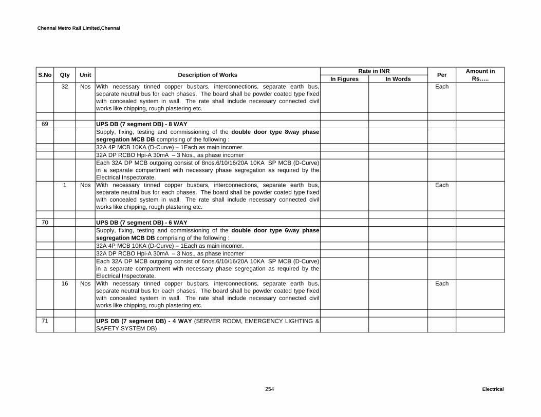
Chennai Metro Rail Limited,Chennai
In Figures In WordsUnit Description of Works Rate in INR Per Amount in Rs…..S.No Qty
32 Nos With necessary tinned copper busbars, interconnections, separate earth bus,separate neutral bus for each phases. The board shall be powder coated type fixedwith concealed system in wall. The rate shall include necessary connected civilworks like chipping, rough plastering etc.
Each
69 UPS DB (7 segment DB) - 8 WAYSupply, fixing, testing and commissioning of the double door type 8way phasesegregation MCB DB comprising of the following :32A 4P MCB 10KA (D-Curve) – 1Each as main incomer.32A DP RCBO Hpi-A 30mA – 3 Nos., as phase incomerEach 32A DP MCB outgoing consist of 8nos.6/10/16/20A 10KA SP MCB (D-Curve)in a separate compartment with necessary phase segregation as required by theElectrical Inspectorate.
1 Nos With necessary tinned copper busbars, interconnections, separate earth bus,separate neutral bus for each phases. The board shall be powder coated type fixedwith concealed system in wall. The rate shall include necessary connected civilworks like chipping, rough plastering etc.
Each
70 UPS DB (7 segment DB) - 6 WAYSupply, fixing, testing and commissioning of the double door type 6way phasesegregation MCB DB comprising of the following :32A 4P MCB 10KA (D-Curve) – 1Each as main incomer.32A DP RCBO Hpi-A 30mA – 3 Nos., as phase incomerEach 32A DP MCB outgoing consist of 6nos.6/10/16/20A 10KA SP MCB (D-Curve)in a separate compartment with necessary phase segregation as required by theElectrical Inspectorate.
16 Nos With necessary tinned copper busbars, interconnections, separate earth bus,separate neutral bus for each phases. The board shall be powder coated type fixedwith concealed system in wall. The rate shall include necessary connected civilworks like chipping, rough plastering etc.
Each
71 UPS DB (7 segment DB) - 4 WAY (SERVER ROOM, EMERGENCY LIGHTING &SAFETY SYSTEM DB)
254 Electrical

Chennai Metro Rail Limited,Chennai
In Figures In WordsUnit Description of Works Rate in INR Per Amount in Rs…..S.No Qty
Supply, fixing, testing and commissioning of the double door type 4way phasesegregation MCB DB comprising of the following :32A 4P MCB 10KA (D-Curve) – 1Each as main incomer.32A DP RCBO Hpi-A 30mA – 3 Nos. as phase incomerEach 32A DP RCBO outgoing consist of 6nos.6/10/16/20A 10KA SP MCB (D-Curve)in a separate compartment with necessary phase segregation as required by theElectrical Inspectorate.
28 Nos With necessary tinned copper busbars, interconnections, separate earth bus,separate neutral bus for each phases. The board shall be powder coated type fixedwith concealed system in wall. The rate shall include necessary connected civilworks like chipping, rough plastering etc.
Each
72 UPS DB (7 segment DB) - 4 WAY ( SAFETY SYSTEM DB)Supply, fixing, testing and commissioning of the double door type 4way phasesegregation MCB DB comprising of the following :25A 4P MCB 10KA (D-Curve) – 1Each as main incomer.25A DP RCBO Hpi-A 30mA – 3 Nos. as phase incomerEach 25A DP RCBO outgoing consist of 6nos.6/10/16/20A 10KA SP MCB (D-Curve)in a separate compartment with necessary phase segregation as required by theElectrical Inspectorate.
9 Nos With necessary tinned copper busbars, interconnections, separate earth bus,separate neutral bus for each phases. The board shall be powder coated type fixedwith concealed system in wall. The rate shall include necessary connected civilworks like chipping, rough plastering etc.
Each
72 LDB (7 segment DB) - 8 WAYSupply, fixing, testing and commissioning of the double door type 8way phasesegregation MCB DB comprising of the following :32A 4P MCB 10KA (C-Curve) – 1Each as main incomer.32A DP RCBO 30mA – 3 Nos. as phase incomerEach 32A DP RCBO outgoing consist of 8nos.6/10/16/20A 10KA SP MCB (C-Curve)in a separate compartment with necessary phase segregation as required by theElectrical Inspectorate.
255 Electrical

Chennai Metro Rail Limited,Chennai
In Figures In WordsUnit Description of Works Rate in INR Per Amount in Rs…..S.No Qty
21 Nos With necessary tinned copper busbars, interconnections, separate earth bus,separate neutral bus for each phases. The board shall be powder coated type fixedwith concealed system in wall. The rate shall include necessary connected civilworks like chipping, rough plastering etc.
Each
73 LDB (7 segment DB) - 6 WAYSupply, fixing, testing and commissioning of the double door type 6way phasesegregation MCB DB comprising of the following :32A 4P MCB 10KA (C-Curve) – 1Each as main incomer.32A DP RCBO 30mA – 3 Nos. as phase incomerEach 32A DP RCBO outgoing consist of 6nos.6/10/16/20A 10KA SPMCB (C-Curve)in a separate compartment with necessary phase segregation as required by theElectrical Inspectorate.
2 Nos With necessary tinned copper busbars, interconnections, separate earth bus,separate neutral bus for each phases. The board shall be powder coated type fixedwith concealed system in wall. The rate shall include necessary connected civilworks like chipping, rough plastering etc.
Each
74 LPDB (7 segment DB) - 4 WAY (For Lift shaft)Supply, fixing, testing and commissioning of the double door type 4way phasesegregation MCB DB comprising of the following :32A 4P MCB 10KA (C-Curve) – 1Each as main incomer.32A DP RCBO 30mA – 3 Nos. as phase incomerEach 32A DP MCB outgoing consist of 4nos.6/10/16/20A 10KA SPMCB (C-Curve) ina separate compartment with necessary phase segregation as required by theElectrical Inspectorate.
4 Nos With necessary tinned copper busbars, interconnections, separate earth bus,separate neutral bus for each phases. The board shall be powder coated type fixedwith concealed system in wall. The rate shall include necessary connected civilworks like chipping, rough plastering etc.
Each
75 ELDB - 12 WAYSupply, fixing, testing and commissioning of the double door type 12way SPN DBcomprising of the following :
256 Electrical

Chennai Metro Rail Limited,Chennai
In Figures In WordsUnit Description of Works Rate in INR Per Amount in Rs…..S.No Qty
32A DP RCBO 30 mA – 1 Each as incomer.6/10A SP MCB (D-Curve) 10KA – 10 Nos. as outgoings.
1 Nos With necessary tinned copper busbars, interconnections, separate earth bus,separate neutral bus for each phases. The board shall be powder coated type fixedwith concealed system in wall. The rate shall include necessary connected civilworks like chipping, rough plastering etc.
Each
76 ELDB - 8 WAYSupply, fixing, testing and commissioning of the double door type 8way SPN DBcomprising of the following :20A DP RCBO 30 mA – 1 Each as incomer.6/10A SP MCB (D-Curve) 10KA – 6 Nos. as outgoings.
1 Nos With necessary tinned copper busbars, interconnections, separate earth bus,separate neutral bus for each phases. The board shall be powder coated type fixedwith concealed system in wall. The rate shall include necessary connected civilworks like chipping, rough plastering etc.
Each
77 EXTERNAL LDBSupply, fixing, testing and commissioning of the double door type VTPN 8 wayMCB DB comprising of the following :32A 4P RCBO 30mA – 1Each as incomer10/16A TP MCB 10KA – 8Nos. as outgoings.
3 Nos With necessary tinned copper busbars, interconnections, earth bus, neutral bus. Theboard shall be powder coated type fixed with concealed system in wall. The rate shallinclude necessary connected civil works like chipping, rough plastering etc.
Each
SECTION - E:-Total C/o to summary: Rs.
SECTION- F : ISOLATORS AND STARTER PANELS
257 Electrical

Chennai Metro Rail Limited,Chennai
In Figures In WordsUnit Description of Works Rate in INR Per Amount in Rs…..S.No Qty
Design, Supply, Installation, testing and commissioning of MS powder coatedisolator/ MCB enclosure boxes and the boxes shall be fixed in floor/wall withsuitable MS frames. The boxes should have suitable knock out provisions forcable IN and OUT and earth connecting terminals in both the sides.
78 2 Nos 10A DP MCB 10 KA (C-Curve) with connected accessories. (Outdoor Type -Weather proof - IP66)
Each
79 37 Nos 20A DP MCB 10 KA (C-Curve) with connected accessories. Each
80 1 Nos 32A DP MCB 10 KA (D-Curve) with connected accessories. Each
81 3 Nos 32A 4P MCB 10 KA (C-Curve) with connected accessories. Each
82 2 Nos 63A 4P MCB 10 KA (C-Curve) with connected accessories. Each
82 15 Nos 20A 4P MCB 10 KA (C-Curve) with connected accessories.(Outdoor Type - Weatherproof -- IP66)
Each
83 31 Nos 32A 4P MCB 10 KA (C-Curve) with connected accessories.(Outdoor Type - Weatherproof - IP66)
Each
84 14 Nos 63A 4P MCB 10 KA (C-Curve) with connected accessories.(Outdoor Type - Weatherproof - IP66)
Each
85 5 Nos 32A 4P MCCB 16 KA with all other necessary connected accessories. (Outdoor Type- Weather proof - IP66)
Each
258 Electrical

Chennai Metro Rail Limited,Chennai
In Figures In WordsUnit Description of Works Rate in INR Per Amount in Rs…..S.No Qty
86 3 Nos 63A 4P MCCB 16 KA with all other necessary connected accessories. (Outdoor Type- Weather proof - IP66)
Each
87 1 Nos 100A 4P MCCB 25 KA with all other necessary connected accessories. Each
88 1 Nos 125A 4P MCCB 25 KA with ELM and all other necessary connected accessories. Each
89 1 Nos 250A 4P MCCB 25 KA with all other necessary connected accessories. Each
90 2 Nos 630A 4P MCCB 36 KA with all other necessary connected accessories. Each
STARTER PANELS:Design, supplying, fixing, testing and commissioning of the following 3 phase Starterwith MPCB/MCCB breaker, contactor, (type-2 co-ordination) in the suitable size MSenclosure.The stater panel should have ON, OFF, TRIP indication lamps, controlMCB's, Auto / Manual selector switch, ON/OFF push button's,Ammeter with selectorswitch, single phase preventer, under & over voltage relay, necessary CT's, PTs,indication lamps,NO/NC for remote ON/OFF,TRIP provision to intergrate with BMSsystems,Auto/Mannual selector switch.
91 2 Nos 0.6/0.8KW DOL Starter Each
92 1 Nos 1.1KW DOL Starter Each
259 Electrical
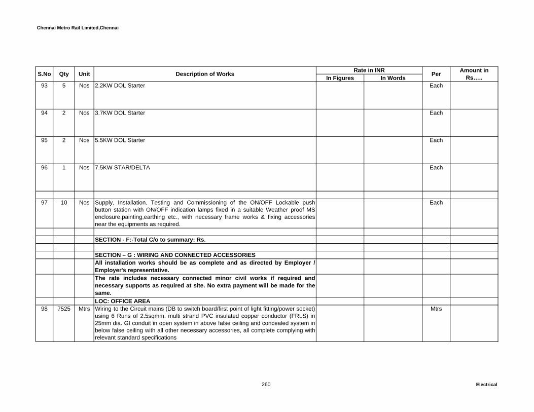
Chennai Metro Rail Limited,Chennai
In Figures In WordsUnit Description of Works Rate in INR Per Amount in Rs…..S.No Qty
93 5 Nos 2.2KW DOL Starter Each
94 2 Nos 3.7KW DOL Starter Each
95 2 Nos 5.5KW DOL Starter Each
96 1 Nos 7.5KW STAR/DELTA Each
97 10 Nos Supply, Installation, Testing and Commissioning of the ON/OFF Lockable pushbutton station with ON/OFF indication lamps fixed in a suitable Weather proof MSenclosure,painting,earthing etc., with necessary frame works & fixing accessoriesnear the equipments as required.
Each
SECTION - F:-Total C/o to summary: Rs.
SECTION – G : WIRING AND CONNECTED ACCESSORIESAll installation works should be as complete and as directed by Employer /Employer's representative. The rate includes necessary connected minor civil works if required andnecessary supports as required at site. No extra payment will be made for thesame. LOC: OFFICE AREA
98 7525 Mtrs Wiring to the Circuit mains (DB to switch board/first point of light fitting/power socket)using 6 Runs of 2.5sqmm. multi strand PVC insulated copper conductor (FRLS) in25mm dia. GI conduit in open system in above false ceiling and concealed system inbelow false ceiling with all other necessary accessories, all complete complying withrelevant standard specifications
Mtrs
260 Electrical

Chennai Metro Rail Limited,Chennai
In Figures In WordsUnit Description of Works Rate in INR Per Amount in Rs…..S.No Qty
99 11300 Mtrs Wiring to the Circuit mains (DB to switch board / first point of light fittting/power point)using 3 Runs of 2.5sqmm. multi strand PVC insulated copper conductor (FRLS) insuitable size GI conduit in open system in above false ceiling and concealed systemin below false ceiling with all other necessary accessories, all complete complyingwith relevant standard specifications
Mtrs
100 1752 Mtrs Wiring to the Circuit mains (DB to switch board / first point of power socket) using 6Runs of 4sqmm multi strand PVC insulated copper conductor (FRLS) in 25mm dia.GI conduit in open system in above false ceiling and concealed system in below falseceiling with all other necessary accessories, all complete complying with relevantstandard specifications
Mtrs
101 2697 Mtrs Wiring to the Circuit mains (DB to switch board / first point of power point) using 3Runs of 4sqmm multi strand PVC insulated copper conductor (FRLS) in suitable sizeGI conduit in open system in above false ceiling and concealed system in below falseceiling with all other necessary accessories, all complete complying with relevantstandard specifications
Mtrs
102 Wiring to the light points/ 6/16A power point using 3 Runs of 2.5sqmm for primarypoint (switch to first point) and 3 Runs of 1.5 Sqmm for secondary point (point topoint looping), multi strand PVC insulated copper conductor (FRLS) in suitable sizeGI conduit in open system in above false ceiling and concealed system in below falseceiling. The primary point rate should inclusive of supply and fixing of 10A modulartype switch in a suitable size modular box in concealed system,the secondary pointrate should inclusive of supply, laying of GI flexible hose for lighting drops fromceiling, all complete complying with relevant standard specifications
a 816 Pts. Primary point Pts.
b 3249 Pts. Secondary point Pts.
261 Electrical

Chennai Metro Rail Limited,Chennai
In Figures In WordsUnit Description of Works Rate in INR Per Amount in Rs…..S.No Qty
103 10 Pts Wiring to the light points using 3 Runs of 1.5sqmm multi strand PVC insulated copperconductor (FRLS) for two way control (switch to switch and first point of lighting) insuitable size GI conduit in concealed system in RCC slab/ wall / column etc. The rateshould inclusive of supply and fixing of 2 sets of 1 Each 6A 2 way modular typeswitch with face plate in a suitable size modular box in concealed system, with allother necessary accessories, all complete complying with relevant standardspecifications
Pts
LOC : RESIDENTIAL TOWER
104 1885 Mtrs Wiring to the Circuit mains (DB to switch board / first point of light fitting/ powerpoints) using 6 Runs of 2.5sqmm multi strand PVC insulated copper conductor(FRLS) in 25mm PVC (MMS- Medium mechanical strength) conduit in concealedsystem in RCC slab/ wall / column etc with all other necessary accessories. allcomplete complying with relevant standard specifications
Mtrs
105 3765 Mtrs Wiring to the Circuit mains (DB to switch board / first point of light fitting/ powerpoints) using 3 Runs of 2.5sqmm multi strand PVC insulated copper conductor(FRLS) in suitable size PVC (MMS) conduit in concealed system in RCC slab/ wall /column etc. with all other necessary accessories. all complete complying withrelevant standard specifications
Mtrs
106 1970 Mtrs Wiring to the Circuit mains (DB to switch board / first point of power points) using 6Runs of 4sqmm multi strand PVC insulated copper conductor (FRLS) in 25mm PVCconduit in concealed system in RCC slab/ wall / column etc. with all other necessaryaccessories, all complete complying with relevant standard specifications.
Mtrs
107 3930 Mtrs Wiring to the Circuit mains (DB to switch board / first point of power socket) using 3Runs of 4sqmm multi strand PVC insulated copper conductor (FRLS) in suitable sizePVC (MMS) conduit in concealed system in RCC slab/ wall / column etc. with all other necessary accessories, all complete complying with relevant standard specifications.
Pts.
262 Electrical
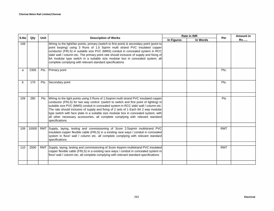
Chennai Metro Rail Limited,Chennai
In Figures In WordsUnit Description of Works Rate in INR Per Amount in Rs…..S.No Qty
108 Wiring to the light/fan points, primary (switch to first point) & secondary point (point topoint looping) using 3 Runs of 1.5 Sqmm multi strand PVC insulated copperconductor (FRLS) in suitable size PVC (MMS) conduit in concealed system in RCCslab/ wall / column etc. The primary point rate should inclusive of supply and fixing of6A modular type switch in a suitable size modular box in concealed system, allcomplete complying with relevant standard specifications
a 2305 Pts. Primary point Pts.
b 170 Pts. Secondary point Pts.
109 280 Pts Wiring to the light points using 3 Runs of 1.5sqmm multi strand PVC insulated copperconductor (FRLS) for two way control (switch to switch and first point of lighting) insuitable size PVC (MMS) conduit in concealed system in RCC slab/ wall / column etc.The rate should inclusive of supply and fixing of 2 sets of 1 Each 6A 2 way modulartype switch with face plate in a suitable size modular box in concealed system, withall other necessary accessories, all complete complying with relevant standardspecifications
Pts
109 10000 RMT Supply, laying, testing and commissioning of 3core 2.5sqmm multistrand PVCinsulated copper flexible cable (FRLS) in a existing race ways / conduit in concealedsystem in floor/ wall / column etc. all complete complying with relevant standardspecifications
RMT
110 2500 RMT Supply, laying, testing and commissioning of 3core 4sqmm multistrand PVC insulatedcopper flexible cable (FRLS) in a existing race ways / conduit in concealed system infloor/ wall / column etc. all complete complying with relevant standard specifications
RMT
263 Electrical
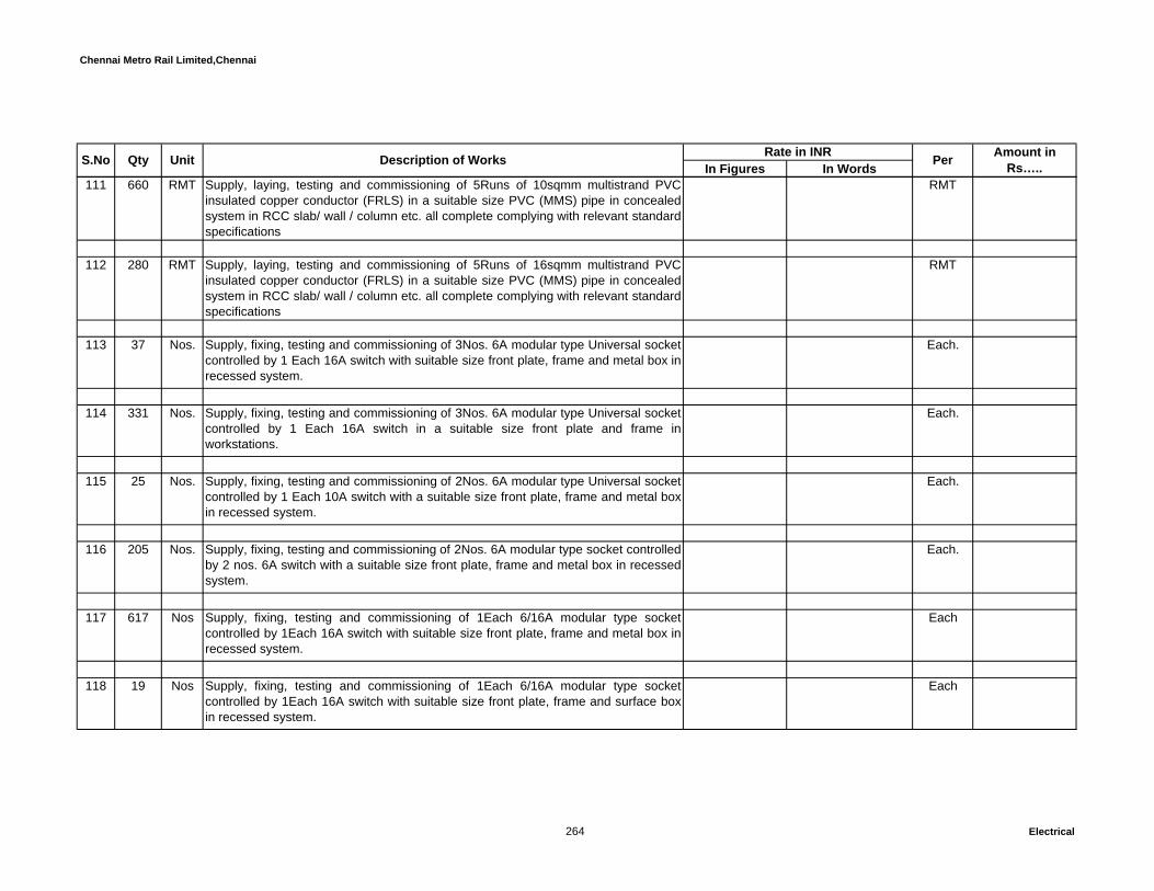
Chennai Metro Rail Limited,Chennai
In Figures In WordsUnit Description of Works Rate in INR Per Amount in Rs…..S.No Qty
111 660 RMT Supply, laying, testing and commissioning of 5Runs of 10sqmm multistrand PVCinsulated copper conductor (FRLS) in a suitable size PVC (MMS) pipe in concealedsystem in RCC slab/ wall / column etc. all complete complying with relevant standardspecifications
RMT
112 280 RMT Supply, laying, testing and commissioning of 5Runs of 16sqmm multistrand PVCinsulated copper conductor (FRLS) in a suitable size PVC (MMS) pipe in concealedsystem in RCC slab/ wall / column etc. all complete complying with relevant standardspecifications
RMT
113 37 Nos. Supply, fixing, testing and commissioning of 3Nos. 6A modular type Universal socketcontrolled by 1 Each 16A switch with suitable size front plate, frame and metal box inrecessed system.
Each.
114 331 Nos. Supply, fixing, testing and commissioning of 3Nos. 6A modular type Universal socketcontrolled by 1 Each 16A switch in a suitable size front plate and frame inworkstations.
Each.
115 25 Nos. Supply, fixing, testing and commissioning of 2Nos. 6A modular type Universal socketcontrolled by 1 Each 10A switch with a suitable size front plate, frame and metal boxin recessed system.
Each.
116 205 Nos. Supply, fixing, testing and commissioning of 2Nos. 6A modular type socket controlledby 2 nos. 6A switch with a suitable size front plate, frame and metal box in recessedsystem.
Each.
117 617 Nos Supply, fixing, testing and commissioning of 1Each 6/16A modular type socketcontrolled by 1Each 16A switch with suitable size front plate, frame and metal box inrecessed system.
Each
118 19 Nos Supply, fixing, testing and commissioning of 1Each 6/16A modular type socketcontrolled by 1Each 16A switch with suitable size front plate, frame and surface boxin recessed system.
Each
264 Electrical
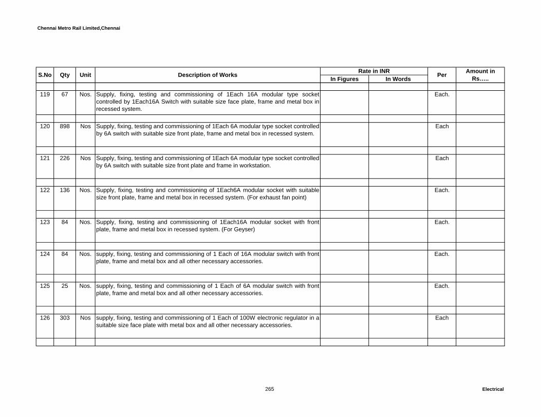
Chennai Metro Rail Limited,Chennai
In Figures In WordsUnit Description of Works Rate in INR Per Amount in Rs…..S.No Qty
119 67 Nos. Supply, fixing, testing and commissioning of 1Each 16A modular type socketcontrolled by 1Each16A Switch with suitable size face plate, frame and metal box inrecessed system.
Each.
120 898 Nos Supply, fixing, testing and commissioning of 1Each 6A modular type socket controlledby 6A switch with suitable size front plate, frame and metal box in recessed system.
Each
121 226 Nos Supply, fixing, testing and commissioning of 1Each 6A modular type socket controlledby 6A switch with suitable size front plate and frame in workstation.
Each
122 136 Nos. Supply, fixing, testing and commissioning of 1Each6A modular socket with suitablesize front plate, frame and metal box in recessed system. (For exhaust fan point)
Each.
123 84 Nos. Supply, fixing, testing and commissioning of 1Each16A modular socket with frontplate, frame and metal box in recessed system. (For Geyser)
Each.
124 84 Nos. supply, fixing, testing and commissioning of 1 Each of 16A modular switch with frontplate, frame and metal box and all other necessary accessories.
Each.
125 25 Nos. supply, fixing, testing and commissioning of 1 Each of 6A modular switch with frontplate, frame and metal box and all other necessary accessories.
Each.
126 303 Nos supply, fixing, testing and commissioning of 1 Each of 100W electronic regulator in asuitable size face plate with metal box and all other necessary accessories.
Each
265 Electrical

Chennai Metro Rail Limited,Chennai
In Figures In WordsUnit Description of Works Rate in INR Per Amount in Rs…..S.No Qty
127 20 Nos Supply and Fixing of Copper and aluminium -alloy POP UP Box on ideal table top,the combination will be 2 nos. 6 A Socket controlled by 1 Each of 10A switch with 1Each RJ45 socket, Colour may be Brushed steel or gold finish trap covers, positiveearthing terminals provided at the back box for safety.
Each
128 20 Nos Supply and Fixing of Copper and aluminium -alloy POP UP Box on ideal table top,the combination will be 1 Each 6A Socket controlled by 1 Each of 6A switch, Colourmay be Brushed steel or gold finish trap covers, positive earthing terminals providedat the back box for safety
Each
129 20 Nos Supply and Fixing of Copper and aluminium -alloy POP UP Box on ideal table top,the combination will be 1 Each RJ45 and 1 Each RJ11 outlets, Colour may beBrushed steel or gold finish trap covers, positive earthing terminals provided at theback box for safety
Each
130 2 Nos. Design, supply,fixing, testing and commissioning of 32A 5 pin metal clad socketcontrolled by 32A 4P MCB in a suitable size MS enclosure fixed in open system.
Each.
131 121 Nos. Design, supply, fixing, testing and commissioning of 20A 3 pin metal clad socketcontrolled by 20A DP MCB in a suitable size MS enclosure fixed in open system.(For Air conditioner)
Each.
132 205 Nos Supply, fixing, testing and commissioning of RJ11 Telephone socket with suitablesize face plate and metal box and all other necessary accessories.
Each
133 127 Nos Supply, fixing, testing and commissioning of TV socket with suitable size face plateand metal box and all other necessary accessories.
Each
134 37 Nos Supply, fixing, testing and commissioning of Calling bell/ Buzzer with push typeswitch, suitable size face plate, metal box and all other necessary accessories.
Each
266 Electrical
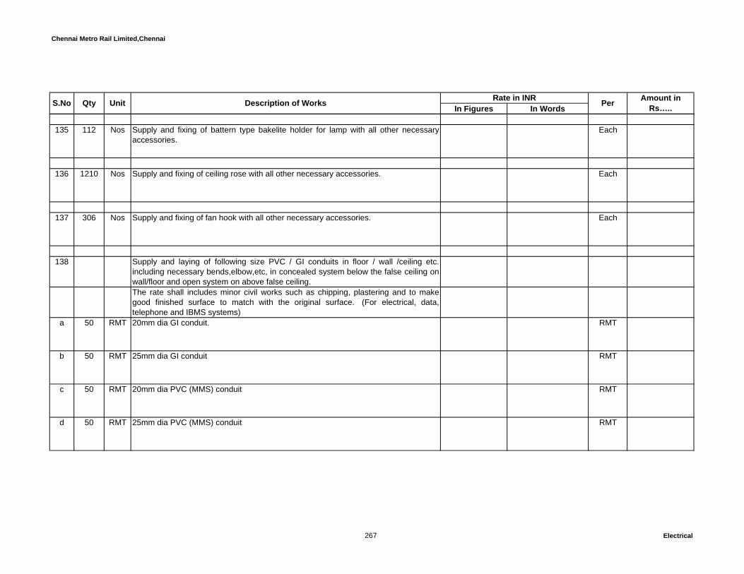
Chennai Metro Rail Limited,Chennai
In Figures In WordsUnit Description of Works Rate in INR Per Amount in Rs…..S.No Qty
135 112 Nos Supply and fixing of battern type bakelite holder for lamp with all other necessaryaccessories.
Each
136 1210 Nos Supply and fixing of ceiling rose with all other necessary accessories. Each
137 306 Nos Supply and fixing of fan hook with all other necessary accessories. Each
138 Supply and laying of following size PVC / GI conduits in floor / wall /ceiling etc.including necessary bends,elbow,etc, in concealed system below the false ceiling onwall/floor and open system on above false ceiling.The rate shall includes minor civil works such as chipping, plastering and to makegood finished surface to match with the original surface. (For electrical, data,telephone and IBMS systems)
a 50 RMT 20mm dia GI conduit. RMT
b 50 RMT 25mm dia GI conduit RMT
c 50 RMT 20mm dia PVC (MMS) conduit RMT
d 50 RMT 25mm dia PVC (MMS) conduit RMT
267 Electrical

Chennai Metro Rail Limited,Chennai
In Figures In WordsUnit Description of Works Rate in INR Per Amount in Rs…..S.No Qty
e 50 RMT 32mm dia PVC (MMS) conduit RMT
Telephone and TV cabling 139 6 Nos. Supplying, fixing, connecting and commissioning of reputed Brand 10Pair Krone
Connector Type Telephone Tag Block in 16G Thick sheet steel enclosure at eachflat fixed flush with the wall.
Each.
140 10 Nos. Supplying, fixing, connecting and commissioning 20 Pair KRONE CONNECTORTYPE Telephone Tag Block - Sub Tag Block in 14 G Thick sheet steel enclosure atEach Floor.
Each.
141 2 Nos. Supplying, fixing, connecting and commissioning 100 Pair KRONE CONNECTORTYPE Telephone Tag Block - Sub Tag Block in 14 G Thick sheet steel enclosure atEach Floor.
Each.
142 2 Nos. Supplying, fixing, connecting and commissioning 200 Pair KRONE CONNECTORTYPE Telephone Tag Block - Sub Tag Block in 14 G Thick sheet steel enclosure atEach Floor.
Each.
143 1 Nos. Supplying,fixing,connecting and commissioning 400 Pair KRONE CONNECTORTYPE Telephone Tag Block - Main Tag Block in 14 G Thick sheet steel enclosureat Ground Floor
Each.
144 1890 RMT Supplying, laying, connecting & commissioning of reputed brand 4 Pair un armouredwith colour coded 0.5 Sq.mm. annealed copper conductor Telephone cable in 20mmPVC (MMS) conduit in concealed system in RCC slab/ wall / column etc. all completecomplying with relevant standard specifications (from 10/20 pair Krone Connector toeach telephone points).
RMT
268 Electrical
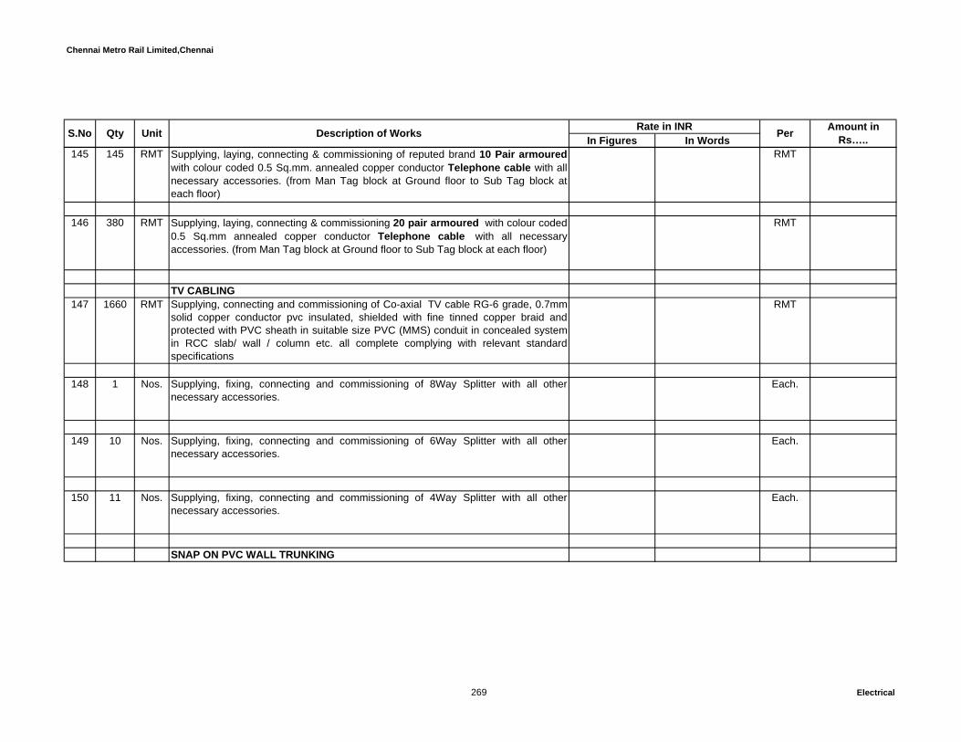
Chennai Metro Rail Limited,Chennai
In Figures In WordsUnit Description of Works Rate in INR Per Amount in Rs…..S.No Qty
145 145 RMT Supplying, laying, connecting & commissioning of reputed brand 10 Pair armouredwith colour coded 0.5 Sq.mm. annealed copper conductor Telephone cable with allnecessary accessories. (from Man Tag block at Ground floor to Sub Tag block ateach floor)
RMT
146 380 RMT Supplying, laying, connecting & commissioning 20 pair armoured with colour coded0.5 Sq.mm annealed copper conductor Telephone cable with all necessaryaccessories. (from Man Tag block at Ground floor to Sub Tag block at each floor)
RMT
TV CABLING147 1660 RMT Supplying, connecting and commissioning of Co-axial TV cable RG-6 grade, 0.7mm
solid copper conductor pvc insulated, shielded with fine tinned copper braid andprotected with PVC sheath in suitable size PVC (MMS) conduit in concealed systemin RCC slab/ wall / column etc. all complete complying with relevant standardspecifications
RMT
148 1 Nos. Supplying, fixing, connecting and commissioning of 8Way Splitter with all othernecessary accessories.
Each.
149 10 Nos. Supplying, fixing, connecting and commissioning of 6Way Splitter with all othernecessary accessories.
Each.
150 11 Nos. Supplying, fixing, connecting and commissioning of 4Way Splitter with all othernecessary accessories.
Each.
SNAP ON PVC WALL TRUNKING
269 Electrical

Chennai Metro Rail Limited,Chennai
In Figures In WordsUnit Description of Works Rate in INR Per Amount in Rs…..S.No Qty
151 Snap on Wall trunking with cover shall be made up of Lead free Polyvinylchloridematerial as per EN 50085-2-1 and shall be ROHS complied.The trunking shall havesmooth surface finish without sharp edges and Burrs.The trunking shall have IP 30Protection against access to hazardous parts and shall be non flamepropagating.The trunking shall have all accessories like internal corner cover,external corner cover, T intersection cover, flat angle cover...etc for complete cablemanagement. The wall trunking shall be of Cream in colour and the standard size ofthe wall trunking shall be of dimensions mentioned below.
a 200 Mtrs 60 mm Width x 50/60 mm Depth Mtrs
b 100 Mtrs 110 mm Width x 50/60 mm Depth Mtrs
Underfloor GI Raceway , Junction boxes & Service Outlet152 Supply and installing following size of under floor GI (hot dip galvanized) raceways
made out of 1.6 mm thick sheet steel on the upper part and 1 mm thick on the bottom,with internal compartments complete with jointing sleeves and other accessoriesunder floor installation including cutting and chasing the floor, making good the same,placing in position and cleaning from inside complete of following sizes etc. asrequired as per specifications.
a 200 Mtrs 100 mm wide x 25 mm deep raceway (1 compartment) Mtrs
b 500 Mtrs 100 mm wide x 38 mm deep raceway (1 compartment) Mtrs
c 200 Mtrs 250 mm wide x 38 mm deep raceway (3 compartment) Mtrs
270 Electrical

Chennai Metro Rail Limited,Chennai
In Figures In WordsUnit Description of Works Rate in INR Per Amount in Rs…..S.No Qty
e 100 Mtrs 350 mm wide x 38 mm deep raceway (3 compartment) Mtrs
153 Supply, fixing, testing of under floor access outlet box / Floor junction box /crossover junction box as per the detailed specification as below:The rate shall includes cutting the existing floor with a use of cutting machine andchipping the cement mortar and the debris shall be removed from the site. After fixingthe trunking the floor shall be plastered to match the original surface.
A Floor access outlet boxesSupply of MK access outlet boxes, manufactured from high-pressure die castmaterial with trap frame & trap made of flame retardant Engineering Plastic . ABS.Patented screwless polyamide ratchets are provided for self adjusting of the floor boxfor any floor finishes. Trap cover is reinforced with a 2.5mm thick pre-galvanizedsteel plate with a recess of 8mm for accommodating the flooring.The trap cover isprovided with Electrostatic Polyester Epoxy Coating, to prevent rust accumulation.
25 each The system has provision to accommodate three compartment trunking to run MainsVoltage & Extra Low Voltage cables. The system has Positive Double EarthingConnections to ensure safety.The system also has the provision to accommodate25/38mm deep trunking with a Knockout of 65,100,150,200,225mm. Load bearingCapacity: 2 tons; Dimensions: 250*250mm similar to MK List EachESB 250/3/1 in theExisting floor with concealed system. Combination of switch & sockets will be decidedat the time of execution
each
B Floor Junction Boxes without flyoverSupply and fixing of Junction boxes manufactured from high-pressure die castmaterial. The Trap Cover & Trap frame of the box should be made of 2.5mm thick pre-galvanized steel plate made of Electrostatic Polyester epoxy coating. The recessshould be 8mm on the trap lid to accommodate the specified flooring.
271 Electrical

Chennai Metro Rail Limited,Chennai
In Figures In WordsUnit Description of Works Rate in INR Per Amount in Rs…..S.No Qty
The junction boxes should have the provision to route and distribute either the poweror networking cables. The system must have smooth curved die cast pillars for easeof pulling cables. The system must have the provision to accommodate 25/38mmdeep and upto 350mm wide GI trunking. similar to MK List EachJB 150 / 250 / 300 /350 / 400Height adjustment: The system must have the stainless steel leveling screws; Loadbearing Capacity: 3.6 tons on the trap lid; Standards: The system must comply withthe relevant specification & IEC 61084
i 100 each JB 150 each
ii 75 each JB 250 each
iii 20 each JB 300 each
iv 60 each JB 350 each
v 20 each JB 400 each
C Cross Over Junction Boxes without flyoverSupply and fixing of Junction boxes manufactured from high-pressure die castmaterial. The Trap Cover & Trap frame of the box should be made of 2.5mm thick pre-galvanized steel plate made of Electrostatic Polyester epoxy coating. The recessshould be 8mm on the trap lid to accommodate the specified flooring.
272 Electrical

Chennai Metro Rail Limited,Chennai
In Figures In WordsUnit Description of Works Rate in INR Per Amount in Rs…..S.No Qty
The cross over boxes should have flyover units made of ABS plastic or metal to routeand distribute power, data and voice cables. The system must have smooth curveddie cast pillars for ease of pulling cables. The system must have the provision toaccommodate 25/38mm deep and upto 225mm wide GI trunking. similar to MK ListEachEJB 250 / 300 / 350 / 400Height adjustment: The system must have the stainless steel leveling screws; Loadbearing Capacity: 3.6 to 4.8 tons on the trap lid; Standards: The system must complywith the relevant specification & IEC 61084
i 10 each EJB 250 each
ii 10 each EJB 300 each
iii 10 each EJB 350 each
iv 10 each EJB 400 each
154 CEILING CABLE MANAGEMENT SYSTEM:i 50 each Supply and fixing of the 100mm x 50mm x 1.6mm thick GI cable management system
fixed on wall/column/ceiling, including the removable top cover, cable divider andrequired accessories like flat, tee, angle, end cap etc complete as requried.
each
ii 200 each Supply and fixing of the 300mm x 75mm x 1.6mm thick GI cable management systemfixed on wall/column/ceiling, including the removable top cover, cable divider andrequired accessories like flat, tee, angle, end cap etc complete as requried.
each
273 Electrical
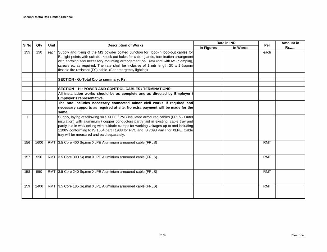
Chennai Metro Rail Limited,Chennai
In Figures In WordsUnit Description of Works Rate in INR Per Amount in Rs…..S.No Qty
155 150 each Supply and fixing of the MS powder coated Junction for loop-in loop-out cables forEL light points with suitable knock out holes for cable glands, termination arrangmentwith earthing and necessary mounting arrangement on Tray/ roof with MS clamping,screws etc.as required. The rate shall be inclusive of 1 mtr length 3C x 1.5sqmmflexible fire resistant (FS) cable. (For emergency lighting)
each
SECTION - G:-Total C/o to summary: Rs.
SECTION – H : POWER AND CONTROL CABLES / TERMINATIONS:All installation works should be as complete and as directed by Employer /Employer's representative. The rate includes necessary connected minor civil works if required andnecessary supports as required at site. No extra payment will be made for thesame.
I Supply, laying of following size XLPE / PVC insulated armoured cables (FRLS - Outer insulation) with aluminium / copper conductors partly laid in existing cable tray andpartly laid in wall/ ceiling with suitbale clamps for working voltages up to and including1100V conforming to IS 1554 part I 1988 for PVC and IS 7098 Part I for XLPE. Cabletray will be measured and paid separately.
156 1600 RMT 3.5 Core 400 Sq.mm XLPE Aluminium armoured cable (FRLS) RMT
157 550 RMT 3.5 Core 300 Sq.mm XLPE Aluminium armoured cable (FRLS) RMT
158 550 RMT 3.5 Core 240 Sq.mm XLPE Aluminium armoured cable (FRLS) RMT
159 1400 RMT 3.5 Core 185 Sq.mm XLPE Aluminium armoured cable (FRLS) RMT
274 Electrical

Chennai Metro Rail Limited,Chennai
In Figures In WordsUnit Description of Works Rate in INR Per Amount in Rs…..S.No Qty
160 100 RMT 3.5 Core 150 Sq.mm XLPE Aluminium armoured cable (FRLS) RMT
161 25 RMT 3.5 Core 120 Sq.mm XLPE Aluminium armoured cable (FRLS) RMT
162 250 RMT 3.5 Core 95 Sq.mm XLPE Aluminium armoured cable (FRLS) RMT
163 350 RMT 3.5 Core 70 Sq.mm XLPE Aluminium armoured cable (FRLS) RMT
164 500 RMT 3.5 Core 50 Sq.mm XLPE Aluminium armoured cable (FRLS) RMT
165 650 RMT 4 Core 35 Sq.mm XLPE Copper armoured cable (FRLS) RMT
166 500 RMT 4 Core 25 Sq.mm XLPE Copper armoured cable (FRLS) RMT
167 4800 RMT 4 Core 16 Sq.mm XLPE Copper armoured cable (FRLS) RMT
168 5550 RMT 4 Core 10 Sq.mm XLPE Copper armoured cable (FRLS) RMT
169 1450 RMT 4 Core 6 Sq.mm PVC Copper armoured cable (FRLS) RMT
275 Electrical
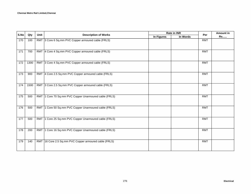
Chennai Metro Rail Limited,Chennai
In Figures In WordsUnit Description of Works Rate in INR Per Amount in Rs…..S.No Qty
170 100 RMT 3 Core 6 Sq.mm PVC Copper armoured cable (FRLS) RMT
171 700 RMT 4 Core 4 Sq.mm PVC Copper armoured cable (FRLS) RMT
172 1300 RMT 3 Core 4 Sq.mm PVC Copper armoured cable (FRLS) RMT
173 900 RMT 4 Core 2.5 Sq.mm PVC Copper armoured cable (FRLS) RMT
174 1500 RMT 3 Core 2.5 Sq.mm PVC Copper armoured cable (FRLS) RMT
175 500 RMT 1 Core 70 Sq.mm PVC Copper Unarmoured cable (FRLS) RMT
176 500 RMT 1 Core 50 Sq.mm PVC Copper Unarmoured cable (FRLS) RMT
177 500 RMT 1 Core 25 Sq.mm PVC Copper Unarmoured cable (FRLS) RMT
178 200 RMT 1 Core 16 Sq.mm PVC Copper Unarmoured cable (FRLS) RMT
179 140 RMT 16 Core 2.5 Sq.mm PVC Copper armoured cable (FRLS) RMT
276 Electrical

Chennai Metro Rail Limited,Chennai
In Figures In WordsUnit Description of Works Rate in INR Per Amount in Rs…..S.No Qty
180 140 RMT 24 Core 2.5 Sq.mm PVC Copper armoured cable (FRLS) RMT
181 300 RMT 4 Core 400 Sq.mm fIre resistant (FS) aluminium armoured cable RMT
182 200 RMT 3.5 Core 400 Sq.mm fire resistant (FS) aluminium armoured cable RMT
183 200 RMT 3.5 Core 95 Sq.mm fire resistant (FS) aluminium armoured cable RMT
184 100 RMT 4 Core 70 Sq.mm fire resistant (FS) aluminium armoured cable RMT
185 100 RMT 4 Core 16 Sq.mm fire resistant (FS) copper armoured cable RMT
186 3000 RMT 3 Core 2.5 Sq.mm fire resistant (FS) copper armoured cable RMT
187 200 RMT 1 Core 16 Sq.mm fire resistant (FS) Copper Unarmoured cable RMT
188 200 RMT 1 Core 300 Sq.mm fire resistant (FS) Copper Unarmoured cable RMT
277 Electrical

Chennai Metro Rail Limited,Chennai
In Figures In WordsUnit Description of Works Rate in INR Per Amount in Rs…..S.No Qty
II Supply and termination of the following size cables with suitable double compressionglands (flame proof glands for all FS cables and weather proof glands for all otherFRLS cables) with suitable size PVC boot and suitable crimping socket, glandearthing by using copper flexible and all other necessary accessories. (coppersockets for copper cables and Alu. Sockets for alum. Cable)
189 18 Nos. 3.5 Core 400 Sq.mm XLPE Aluminium armoured cable (FRLS) Each.
190 18 Nos. 3.5 Core 300 Sq.mm XLPE Aluminium armoured cable (FRLS) Each.
191 8 Nos. 3.5 Core 240 Sq.mm XLPE Aluminium armoured cable (FRLS) Each.
192 18 Nos. 3.5 Core 185 Sq.mm XLPE Aluminium armoured cable (FRLS) Each.
193 2 Nos. 3.5 Core 150 Sq.mm XLPE Aluminium armoured cable (FRLS) Each.
194 2 Nos. 3.5 Core 120 Sq.mm XLPE Aluminium armoured cable (FRLS) Each.
195 8 Nos. 3.5 Core 95 Sq.mm XLPE Aluminium armoured cable (FRLS) Each.
196 8 Nos. 3.5 Core 70 Sq.mm XLPE Aluminium armoured cable (FRLS) Each.
197 4 Nos. 3.5 Core 50 Sq.mm XLPE Aluminium armoured cable (FRLS) Each.
278 Electrical
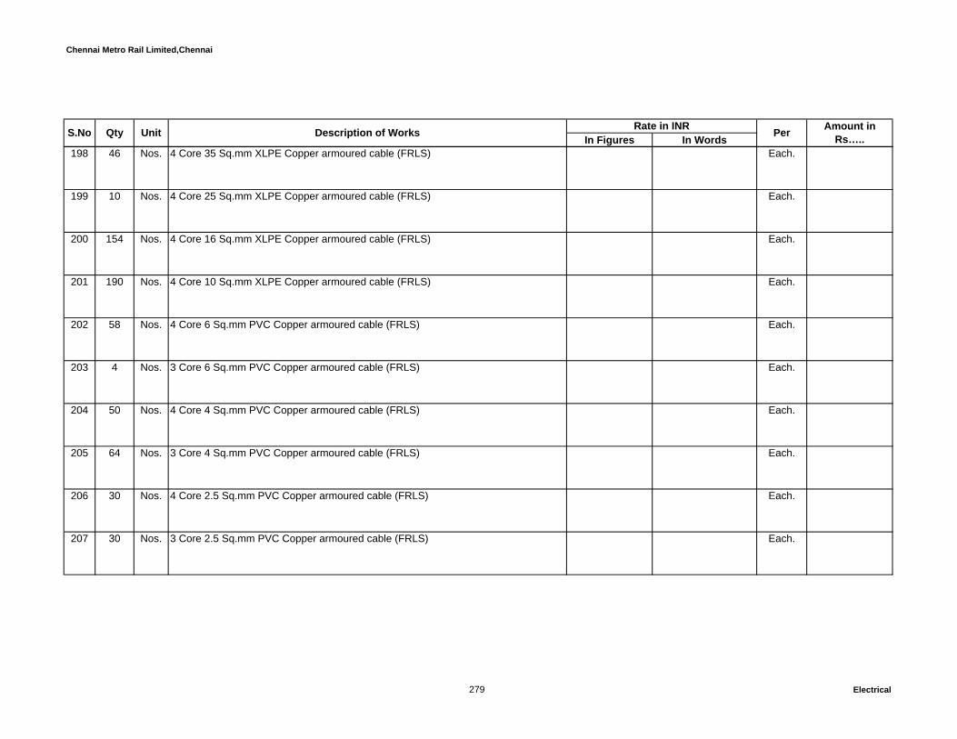
Chennai Metro Rail Limited,Chennai
In Figures In WordsUnit Description of Works Rate in INR Per Amount in Rs…..S.No Qty
198 46 Nos. 4 Core 35 Sq.mm XLPE Copper armoured cable (FRLS) Each.
199 10 Nos. 4 Core 25 Sq.mm XLPE Copper armoured cable (FRLS) Each.
200 154 Nos. 4 Core 16 Sq.mm XLPE Copper armoured cable (FRLS) Each.
201 190 Nos. 4 Core 10 Sq.mm XLPE Copper armoured cable (FRLS) Each.
202 58 Nos. 4 Core 6 Sq.mm PVC Copper armoured cable (FRLS) Each.
203 4 Nos. 3 Core 6 Sq.mm PVC Copper armoured cable (FRLS) Each.
204 50 Nos. 4 Core 4 Sq.mm PVC Copper armoured cable (FRLS) Each.
205 64 Nos. 3 Core 4 Sq.mm PVC Copper armoured cable (FRLS) Each.
206 30 Nos. 4 Core 2.5 Sq.mm PVC Copper armoured cable (FRLS) Each.
207 30 Nos. 3 Core 2.5 Sq.mm PVC Copper armoured cable (FRLS) Each.
279 Electrical
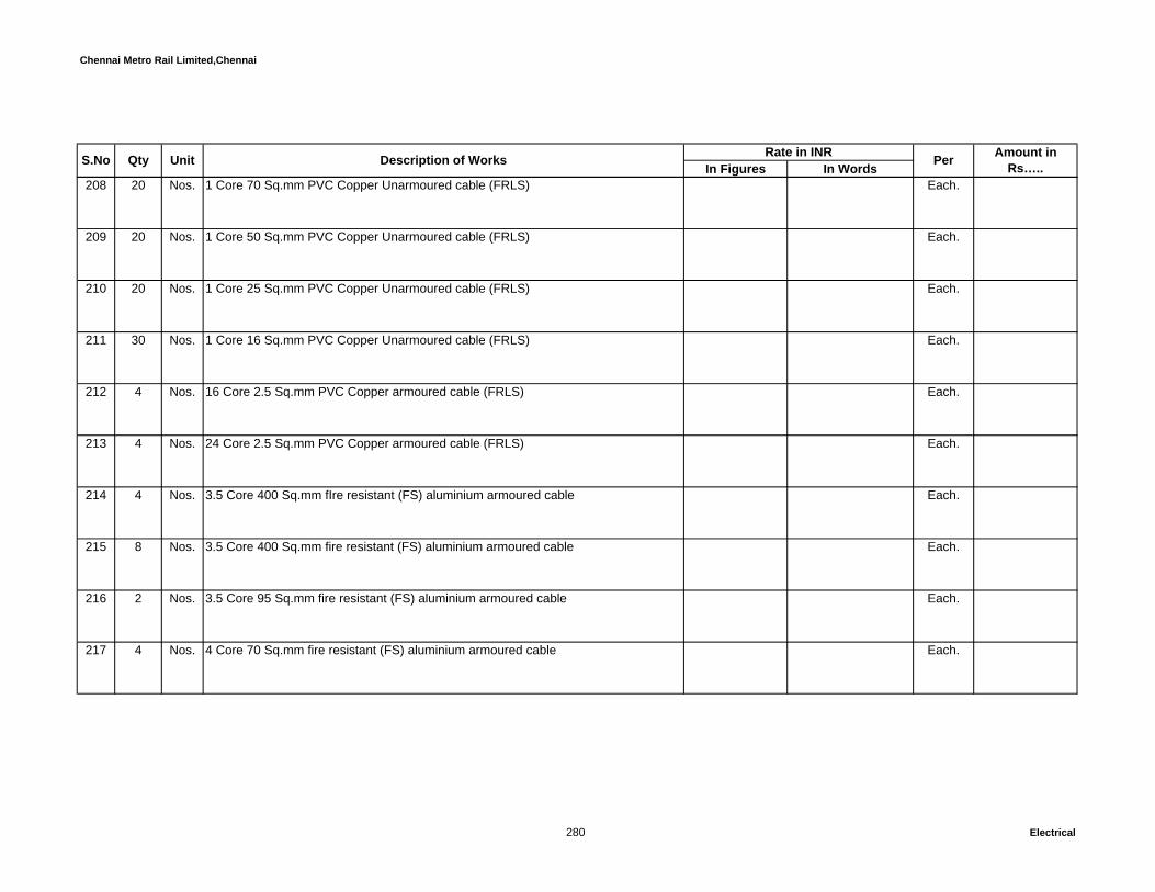
Chennai Metro Rail Limited,Chennai
In Figures In WordsUnit Description of Works Rate in INR Per Amount in Rs…..S.No Qty
208 20 Nos. 1 Core 70 Sq.mm PVC Copper Unarmoured cable (FRLS) Each.
209 20 Nos. 1 Core 50 Sq.mm PVC Copper Unarmoured cable (FRLS) Each.
210 20 Nos. 1 Core 25 Sq.mm PVC Copper Unarmoured cable (FRLS) Each.
211 30 Nos. 1 Core 16 Sq.mm PVC Copper Unarmoured cable (FRLS) Each.
212 4 Nos. 16 Core 2.5 Sq.mm PVC Copper armoured cable (FRLS) Each.
213 4 Nos. 24 Core 2.5 Sq.mm PVC Copper armoured cable (FRLS) Each.
214 4 Nos. 3.5 Core 400 Sq.mm fIre resistant (FS) aluminium armoured cable Each.
215 8 Nos. 3.5 Core 400 Sq.mm fire resistant (FS) aluminium armoured cable Each.
216 2 Nos. 3.5 Core 95 Sq.mm fire resistant (FS) aluminium armoured cable Each.
217 4 Nos. 4 Core 70 Sq.mm fire resistant (FS) aluminium armoured cable Each.
280 Electrical

Chennai Metro Rail Limited,Chennai
In Figures In WordsUnit Description of Works Rate in INR Per Amount in Rs…..S.No Qty
218 8 Nos. 4 Core 16 Sq.mm fire resistant (FS) copper armoured cable Each.
219 300 Nos. 3 Core 2.5 Sq.mm fire resistant (FS) copper armoured cable Each.
220 40 Nos. 1 Core 16 Sq.mm fire resistant (FS) Copper Unarmoured cable Each.
221 40 Nos. 1 Core 300 Sq.mm fire resistant (FS) Copper Unarmoured cable Each.
SECTION - H:-Total C/o to summary: Rs.
SECTION – I : EARTHING SYSTEM, CABLE TRAY AND MS ITEMSAll installation works should be as complete and as directed by Employer /Employer's representative. The rate includes necessary connected minor civil works if required andnecessary supports as required at site. No extra payment will be made for thesame.
222 24 Nos Supply and installation of earth pipe electrode as per IS 3043 complete with 3mtr long with 40mm dia 'B' class G.I. pipe and GI earth plate of size 600mm x 600mm x 6mmincluding 2 runs of 65 x 10mm GI flat upto test link from plate earth electrode,watering funnel and necessary bolt, nut and double washer. Including 750mm x750mm x 3mtr long excavation and construction of 850mm x 850mm x 300 mm highbrick wall chamber with cement mortor. The chamber shall be provided with 450mm x450mm x 10mm cast iron / RCC cover with frame and lockable facility. The plateelectrode shall be filled with alternate layer of salt and charcoal as required full depth.The Cover shall be heavy duty to suit heavy vehicle movements (Common bodyearth)
Each
281 Electrical

Chennai Metro Rail Limited,Chennai
In Figures In WordsUnit Description of Works Rate in INR Per Amount in Rs…..S.No Qty
223 4 Nos Supply and installation of earth pipe electrode as per IS 3043 complete with 3mtr long with 40mm dia 'B' class G.I. pipe and GI earth plate of size 600mm x 600mm x 6mmincluding 2 runs of 50 x 6mm GI flat upto test link from plate earth electrode, wateringfunnel and necessary bolt, nut and double washer. Including 750mm x 750mm x 3mtrlong excavation and construction of 850mm x 850mm x 300 mm high brick wallchamber with cement mortor. The chamber shall be provided with 450mm x 450mm x10mm cast iron / RCC cover with frame and lockable facility. The plate electrodeshall be filled with alternate layer of salt and charcoal as required full depth. TheCover shall be heavy duty to suit heavy vehicle movements (Common body earth -Residential tower)
Each
224 4 Nos Supply and installation of earth pipe electrode as per IS 3043 complete with 3 mtrlong with 40mm dia 'B' class G.I. pipe and copper earth plate of size 600mm x600mm x 3mm including 2 runs of 75 x 12mm CU. flat upto test link from plate earthelectrode, watering funnel and necessary bolt, nut and double washer. Including750mm x 750mm x 3mtr long excavation and construction of 850mm x 850mm x 300mm high brick wall chamber with cement mortor. The chamber shall be provided with450mm x 450mm x 10mm cast iron / RCC cover with frame and lockable facility. Theplate electrode shall be filled with alternate layer of salt and charcoal as required fulldepth. The Cover shall be heavy duty to suit heavy vehicle movements (Transformerneutral)
Each
225 46 Nos Supply and installation of earth pipe electrode as per IS 3043 complete with 3 mtrlong with 40mm dia 'B' class G.I. pipe and copper earth plate of size 600mm x600mm x 3mm including 2 runs of 50 x 6mm CU. flat upto test link from plate earthelectrode, watering funnel and necessary bolt, nut and double washer. Including750mm x 750mm x 3mtr long excavation and construction of 850mm x 850mm x 300mm high brick wall chamber with cement mortor. The chamber shall be provided with450mm x 450mm x 10mm cast iron / RCC cover with frame and lockable facility. Theplate electrode shall be filled with alternate layer of salt and charcoal as required fulldepth. The Cover shall be heavy duty to suit heavy vehicle movements (HT panel &Transformer body earth and all dedicated earth)
Each
282 Electrical

Chennai Metro Rail Limited,Chennai
In Figures In WordsUnit Description of Works Rate in INR Per Amount in Rs…..S.No Qty
Supply and installation of UL listed and CPRI tested copper bonded steel electrodeof 17.2 mm dia. With a min. coating thickness of 250 microns and length of 3 meters.25 kgs of earth enhancing compound needs to be considered to fill the 100mmaugered hole surrounding to the electrode.25x6x300mm copper busbar to beexothermically welded to the electrode. All connection to the busbar shall beexothermically welded as per the drawing and should comply with IEEE 837 and ULapproved .The rate shall include excavation of earth, filling with back fill compound,exothermic welding and earth pit marking. The Complete installation shall be as perthe drawing and technical specifications.
Supply of UL Listed 25 mm dia. Copper bonded carbon steel core Electrode testedaccording to IEC 62561-2 - Similar to OBO BettermannSupply of Earth enhancing compound(PROCEM) tested as per IEC 62561-7 - Similarto OBO Bettermann
5 Nos Universal clamp made of stainless steel - Similar to OBO Bettermann Each
Supply and laying of following sizes of cu / GI strips with all necessary accessories.The cost is including the required bimettalic strip to make a smooth connectivitybetween GI and copper stip and also the cost is including the excavation and refillingthe soil. The strip should be run minimum 600mm depth from finished ground level.
226 70 RMT Supply and laying of 75 x 12 mm CU. Flat with required black colour sleeves fortransformer neutral
RMT
227 210 RMT Supply and laying of 50 x 6 mm CU. flat RMT
228 250 RMT Supply and laying of 25 x 6 mm CU. flat RMT
283 Electrical

Chennai Metro Rail Limited,Chennai
In Figures In WordsUnit Description of Works Rate in INR Per Amount in Rs…..S.No Qty
229 800 RMT Supply and laying of 25 x 3 mm CU. flat RMT
230 3000 RMT Supply and laying of 65 x 10 mm G.I flat RMT
231 750 RMT Supply and laying of 50 x 10 mm G.I flat RMT
232 750 RMT Supply and laying of 50 x 6 mm G.I flat RMT
233 750 RMT Supply and laying of 40 x 10 mm G.I flat RMT
234 350 RMT Supply and laying of 25 x 6 mm G.I flat RMT
235 900 RMT Supply and laying of 25 x 3 mm G.I flat RMT
236 1750 RMT Supply and laying of 8 gauge bare copper wire RMT
284 Electrical

Chennai Metro Rail Limited,Chennai
In Figures In WordsUnit Description of Works Rate in INR Per Amount in Rs…..S.No Qty
237 Supply, erection of following sizes GI ladder / perforated type cable rack systemmade out of sheet steel folded to required shape with adequate number of supports.
The cable rack shall have runners rugs of suitable size, horizontal elbow, verticalelbow 90 Deg. Up vertical elbow 90 Deg. Down, re-deep, coupler plates, materials.The cable racks shall be suspended from ceiling supported from side walls incolumns etc. with adequate size supporting angles / channels with fastners, welding,anchor bolts, nuts etc. The rack shall have suitable cable clamping arrangementsetc. complete with all civil works for fabrication details. Refer enclosed drawing.
The rate shall be inclusive of suitable hanging support - gripple make cable withcrimp arrangement supports, spacing and fixing as per standards. The height of thehanging arrangement shall be as per drawing and with all accesories to fix thehangers at roof with required clamps nuts & bolts to be considered.
I Perforated typeFor Perforated Cable trays designed, tested and confirming to IEC 61537, thicknessof cable tray should be according to the manufacturers catalogue. For locallyfabricated and non tested tray, thickness should be 2 mm up to span length of 1.5meter, 2.5 mm for span length between 2 to 3 meter and 3 to 4 mm for span lengthbetween 4 and 10 meter
a 60 RMT 150mm x 50mm RMT
b 810 RMT 300mm x 50mm RMT
c 140 RMT 450mm x 75mm RMT
d 70 RMT 600mm x 75mm RMT
285 Electrical

Chennai Metro Rail Limited,Chennai
In Figures In WordsUnit Description of Works Rate in INR Per Amount in Rs…..S.No Qty
e 15 RMT 750mm x 75mm RMT
II Ladder typeFor Ladder Cable trays designed, tested and confirming to IEC 61537, thickness ofcable tray should be according to the manufacturers catalogue. For locally fabricatedand non tested tray, thickness should be 2.5 mm up to span length of 1.5 to 2 meter,3 mm for span length between 2.5 to 4 meter and 3 to 4 mm for span length between5 and 10 meter
a 110 RMT 150mm x 50mm RMT
b 810 RMT 300mm x 50mm RMT
c 290 RMT 450mm x 75mm RMT
d 460 RMT 600mm x 75mm RMT
e 415 RMT 750mm x 100mm RMT
f 50 RMT 1000mm x 100mm RMT
III Fire rated cable tray
286 Electrical
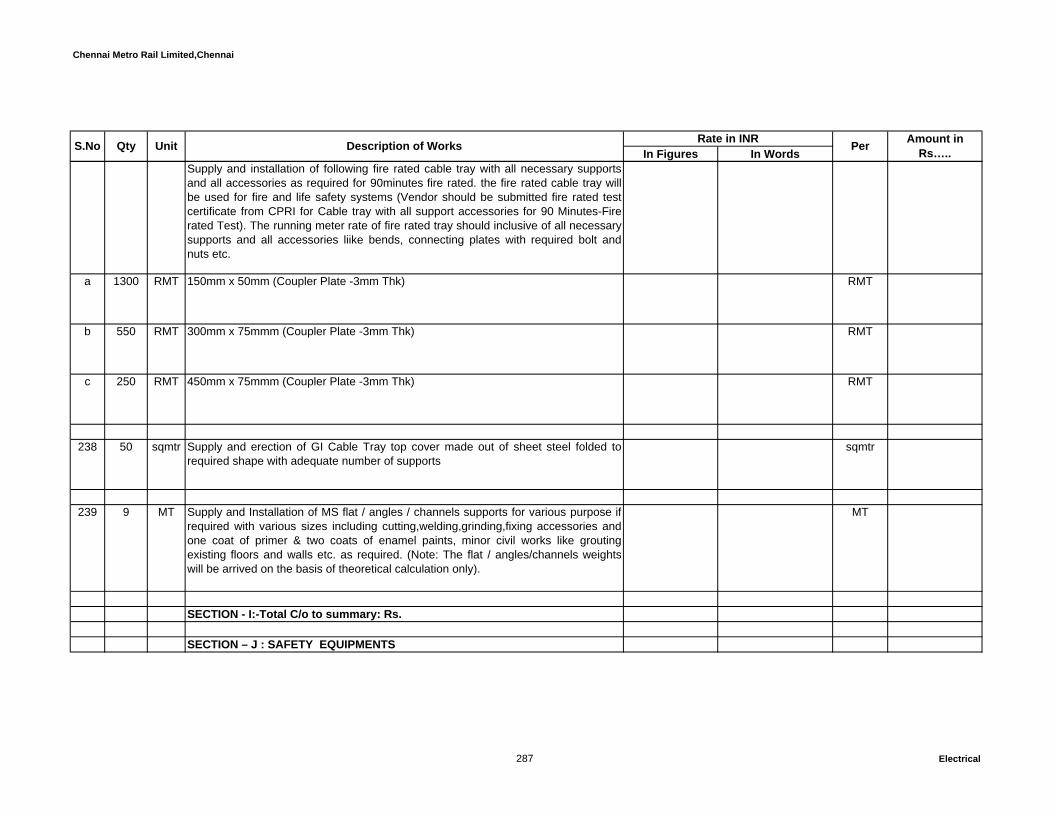
Chennai Metro Rail Limited,Chennai
In Figures In WordsUnit Description of Works Rate in INR Per Amount in Rs…..S.No Qty
Supply and installation of following fire rated cable tray with all necessary supportsand all accessories as required for 90minutes fire rated. the fire rated cable tray willbe used for fire and life safety systems (Vendor should be submitted fire rated testcertificate from CPRI for Cable tray with all support accessories for 90 Minutes-Firerated Test). The running meter rate of fire rated tray should inclusive of all necessarysupports and all accessories liike bends, connecting plates with required bolt andnuts etc.
a 1300 RMT 150mm x 50mm (Coupler Plate -3mm Thk) RMT
b 550 RMT 300mm x 75mmm (Coupler Plate -3mm Thk) RMT
c 250 RMT 450mm x 75mmm (Coupler Plate -3mm Thk) RMT
238 50 sqmtr Supply and erection of GI Cable Tray top cover made out of sheet steel folded torequired shape with adequate number of supports
sqmtr
239 9 MT Supply and Installation of MS flat / angles / channels supports for various purpose ifrequired with various sizes including cutting,welding,grinding,fixing accessories andone coat of primer & two coats of enamel paints, minor civil works like groutingexisting floors and walls etc. as required. (Note: The flat / angles/channels weightswill be arrived on the basis of theoretical calculation only).
MT
SECTION - I:-Total C/o to summary: Rs.
SECTION – J : SAFETY EQUIPMENTS
287 Electrical
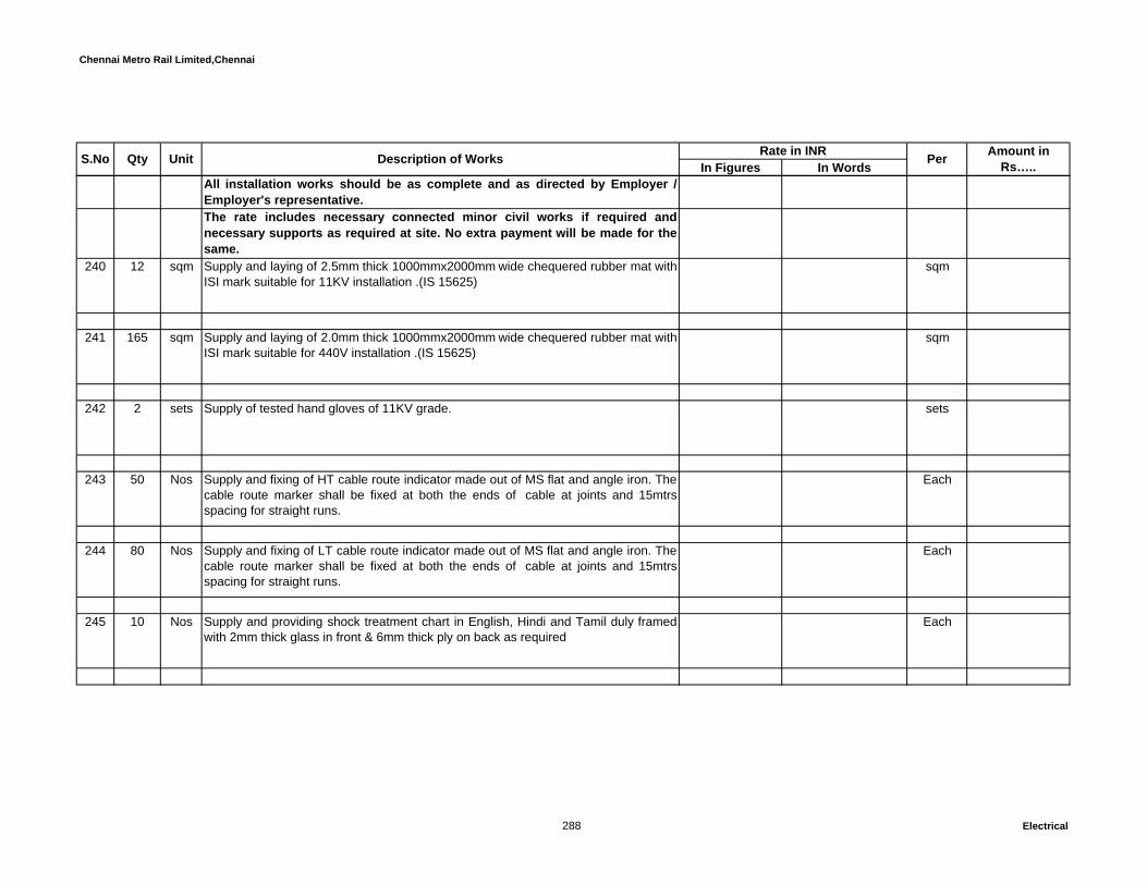
Chennai Metro Rail Limited,Chennai
In Figures In WordsUnit Description of Works Rate in INR Per Amount in Rs…..S.No Qty
All installation works should be as complete and as directed by Employer /Employer's representative. The rate includes necessary connected minor civil works if required andnecessary supports as required at site. No extra payment will be made for thesame.
240 12 sqm Supply and laying of 2.5mm thick 1000mmx2000mm wide chequered rubber mat withISI mark suitable for 11KV installation .(IS 15625)
sqm
241 165 sqm Supply and laying of 2.0mm thick 1000mmx2000mm wide chequered rubber mat withISI mark suitable for 440V installation .(IS 15625)
sqm
242 2 sets Supply of tested hand gloves of 11KV grade. sets
243 50 Nos Supply and fixing of HT cable route indicator made out of MS flat and angle iron. Thecable route marker shall be fixed at both the ends of cable at joints and 15mtrsspacing for straight runs.
Each
244 80 Nos Supply and fixing of LT cable route indicator made out of MS flat and angle iron. Thecable route marker shall be fixed at both the ends of cable at joints and 15mtrsspacing for straight runs.
Each
245 10 Nos Supply and providing shock treatment chart in English, Hindi and Tamil duly framedwith 2mm thick glass in front & 6mm thick ply on back as required
Each
288 Electrical

Chennai Metro Rail Limited,Chennai
In Figures In WordsUnit Description of Works Rate in INR Per Amount in Rs…..S.No Qty
246 5 Nos Supply and fixing of GI fire buckets with round bottom, each set comprising 4Nos.firebuckets of 9Kg capacity including supply of M.S pedestal stand with hooks suitablefor holding of 4Nos of fire buckets, painted with Post Office Red oil paint and letterFIRE on each bucket and filling with sand complete as required. .
Each
247 5 Nos Supply and providing St. John make first aid box 18SWG MS sheet duly painted asapproved by Indian red cross soceity complete with all first aid medicines.
Each
248 2 Nos Supply & Fixing HT danger notice plate 250mm x 200mm made of MS steel 2mmthick & Vitreous enameled white on both sides and with inscriptions in signal Red onfront side as required by the electrical authorities.
Each
249 8 Nos Supply & Fixing LT danger notice plate 200mm x 150mm made of MS steel 2mmthick & Vitreous enameled white on both sides and with inscriptions in signal Red onfront side as required
Each
250 10 Nos Supply and erection of fire extinguisher Co2 4.5 Kg. confirm to IS norms. Each
251 7 Nos Supply & Fixing of MS sheet board of size 500mm x 300mm of 16 SWG with Entry Restricted To Authorised Persons Only near the Main entrance of the Substation.The lettering shall be Black painted on Yellow Back ground.
Each
25 Kgs Supply and Erection of Fire resistant Mortar with fire resistance class S90 accordingto testing standard DIN 4102 Part 9 DIBT approval Z- 19.15 – 2046 suitable to sealthe openings with all kinds of cables, pipes and cable support system in steel and ,aluminium and plastic profiles ( Except hollow core conductors). The residualopenings shall be closed with filler. (Equivalent to Pyromix of OBO Bettermann -Model: MSX - S1)
Kgs
289 Electrical

Chennai Metro Rail Limited,Chennai
In Figures In WordsUnit Description of Works Rate in INR Per Amount in Rs…..S.No Qty
15 Nos Supply and Erection of Fire Protection foam from with fire resistance class to EI120according to testing standard EN 1366 PART 9 approval ETA -11/0527, VKF22552,22553,22554,22555 suitable to seal the openings with a combinationinsulation cables, pipes and the cable trays. (Equivalent to Pyrosit NG fire protectionfoam of OBO Bettermann) -350ml tube
Each
SECTION - J :-Total C/o to summary: Rs.
SECTION – K : LIGHTING LUMINAIRES & FANS All installation works should be as complete and as directed by Employer /Employer's representative. The rate includes necessary connected minor civil works if required andnecessary supports as required at site. No extra payment will be made for thesame. Samples to be submitted and get approval fom Architect / Consultant beforeprocurementFor LED light fittings, the complete luminaire should have a warranty for 5years which includes the housing + LED + Driver Supply, fixing, testing and commissioning of the following lighting luminaires with allother necessary accessories.
252 10W LED down lighter Equivalent to PHILIPS - DN191B LED6S-6500 PSU WH
482 Nos Recess mounted 10W LED downlighter made of a high quality diffuser with a die castheat sink and a polycarbonate diffuser. CCT shall be of 6500K.
Each
253 15W LED down lighter Equivalent to PHILIPS - DN192B-LED9S-6500 PSU WH
1539 Nos 15W Recess mounted integral LED down lighter with high efficient diffuser delivering900 system lumens with 6500K
Each
290 Electrical
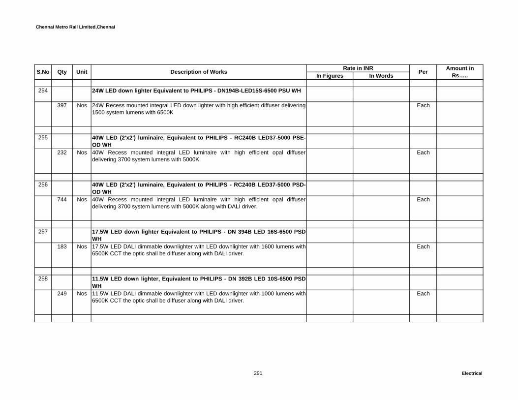
Chennai Metro Rail Limited,Chennai
In Figures In WordsUnit Description of Works Rate in INR Per Amount in Rs…..S.No Qty
254 24W LED down lighter Equivalent to PHILIPS - DN194B-LED15S-6500 PSU WH
397 Nos 24W Recess mounted integral LED down lighter with high efficient diffuser delivering1500 system lumens with 6500K
Each
255 40W LED (2'x2') luminaire, Equivalent to PHILIPS - RC240B LED37-5000 PSE-OD WH
232 Nos 40W Recess mounted integral LED luminaire with high efficient opal diffuserdelivering 3700 system lumens with 5000K.
Each
256 40W LED (2'x2') luminaire, Equivalent to PHILIPS - RC240B LED37-5000 PSD-OD WH
744 Nos 40W Recess mounted integral LED luminaire with high efficient opal diffuserdelivering 3700 system lumens with 5000K along with DALI driver.
Each
257 17.5W LED down lighter Equivalent to PHILIPS - DN 394B LED 16S-6500 PSDWH
183 Nos 17.5W LED DALI dimmable downlighter with LED downlighter with 1600 lumens with6500K CCT the optic shall be diffuser along with DALI driver.
Each
258 11.5W LED down lighter, Equivalent to PHILIPS - DN 392B LED 10S-6500 PSDWH
249 Nos 11.5W LED DALI dimmable downlighter with LED downlighter with 1000 lumens with6500K CCT the optic shall be diffuser along with DALI driver.
Each
291 Electrical

Chennai Metro Rail Limited,Chennai
In Figures In WordsUnit Description of Works Rate in INR Per Amount in Rs…..S.No Qty
259 Industrial channel with 2x20W TLED, Equivalent to PHILIPS - TMC501 2x20WMaster TLED
92 Nos Industrial channel with 2x20W TLED delivering 2100 lumens in each lamp with6500K
Each
260 Industrial channel with 1x20W TLED, Equivalent to PHILIPS - TMC501 1x20WMaster TLED
325 Nos Industrial channel with 1x20W TLED delivering 2100 lumens in each lamp with6500K
Each
261 15W LED surface mounted luminaire, Equivalent to PHILIPS - SM518C LED9S6500 PSU OD GR
221 Nos 15W surface mounted integral LED luminaire with high efficient opal diffuserdelivering 900 system lumens with 6500K.
Each
262 8W LED wall mounted luminaire with IP65, Equivalent to PHILIPS - BWS150LED200/WW PSU 220-240V 7043
163 Nos 8W wall mounted integral LED luminaire with IP65 protection delivering 200 systemlumens with 4000K.
Each
263 42W LED luminaire with IP65, Equivalent to PHILIPS - WT550W315 Nos 42W integral LED luminaire with IP65 protection made of polycarbonate body and
diffuser delivering 3500 system lumens with 6500K.Each
264 40W LED surface mounted luminaire, Equivalent to PHILIPS - SM365C LED-34-5000 PSE-OD GR
292 Electrical

Chennai Metro Rail Limited,Chennai
In Figures In WordsUnit Description of Works Rate in INR Per Amount in Rs…..S.No Qty
88 Nos Surface mounted LED luminaire with Mid flux LED using efficient optics Each
265 13W LED decorative luminaire, Equivalent to PHILIPS - QWG305 with MASTERLED13-75W E27 2700K 230V A67 DIM
128 Nos 13W LED decorative wall light with premium sand blasted glass and steel suitable for13W LED lamp with E27 base.
Each
266 LED foot lamp modular type with metal box and all other necessaryaccessories. Equivalent to Legrand - Cat. Each 6730 36
124 Nos Foot lamp for bed room & Hall Each
267 28W LED 4' decorative luminaire, Equivalent to PHILIPS - BN150W LED 20S-6500 PSE OD WH
388 Nos 28W LED 4' decorative wall light with 2000 system lumens delivering 6500K. Each
268 15W LED 2' decorative luminaire, Equivalent to PHILIPS - BN150W LED 13S-6500 PSE OD WH
170 Nos 15W LED 2' decorative mirror light with 1280 system lumens delivering 6500K. Each
269 2 x4W LED decorative wall luminaire, Equivalent to PHILIPS - QWZ802 - 2 xMASTER LED 4W 2700K 230V B35 CL DIM
293 Electrical
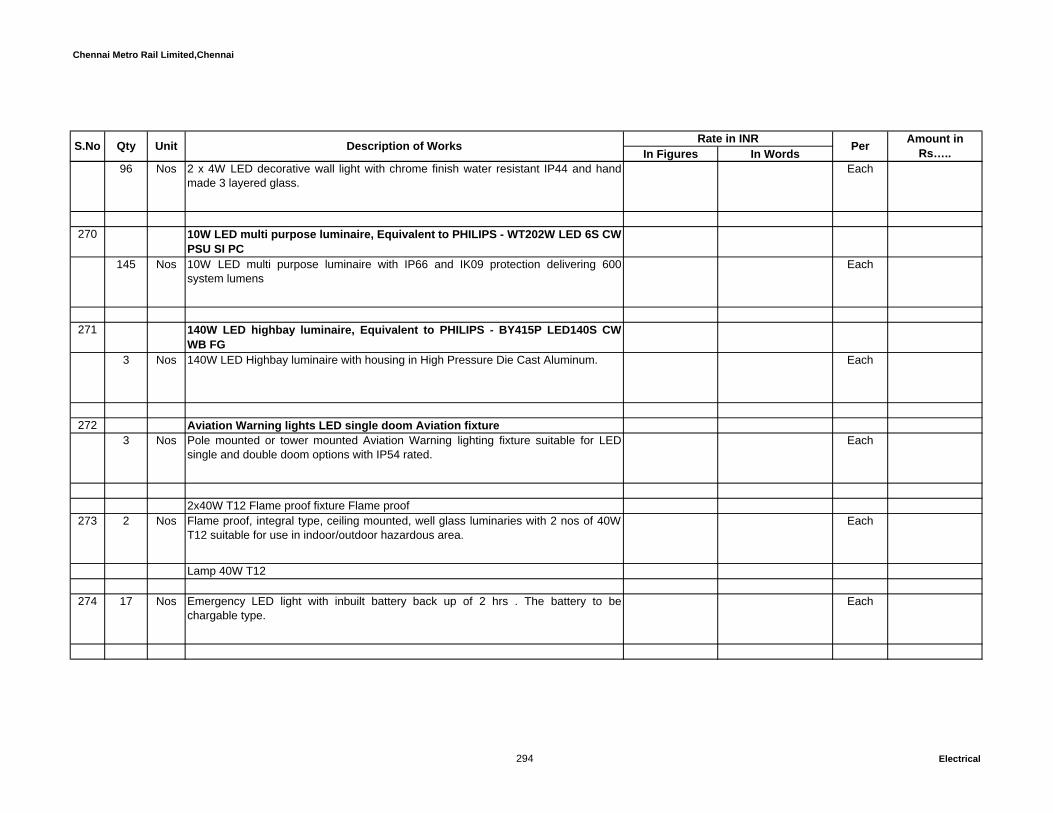
Chennai Metro Rail Limited,Chennai
In Figures In WordsUnit Description of Works Rate in INR Per Amount in Rs…..S.No Qty
96 Nos 2 x 4W LED decorative wall light with chrome finish water resistant IP44 and handmade 3 layered glass.
Each
270 10W LED multi purpose luminaire, Equivalent to PHILIPS - WT202W LED 6S CWPSU SI PC
145 Nos 10W LED multi purpose luminaire with IP66 and IK09 protection delivering 600system lumens
Each
271 140W LED highbay luminaire, Equivalent to PHILIPS - BY415P LED140S CWWB FG
3 Nos 140W LED Highbay luminaire with housing in High Pressure Die Cast Aluminum. Each
272 Aviation Warning lights LED single doom Aviation fixture3 Nos Pole mounted or tower mounted Aviation Warning lighting fixture suitable for LED
single and double doom options with IP54 rated.Each
2x40W T12 Flame proof fixture Flame proof 273 2 Nos Flame proof, integral type, ceiling mounted, well glass luminaries with 2 nos of 40W
T12 suitable for use in indoor/outdoor hazardous area.Each
Lamp 40W T12
274 17 Nos Emergency LED light with inbuilt battery back up of 2 hrs . The battery to bechargable type.
Each
294 Electrical

Chennai Metro Rail Limited,Chennai
In Figures In WordsUnit Description of Works Rate in INR Per Amount in Rs…..S.No Qty
275 27 Nos Exit Sign light fixtures -10watts with inbuilt battery back up of 2 hrs Each
276 27 Nos Directional Exit Sign light fixtures -10 watts with inbuilt battery back up of 2 hrs Each
277 342 Nos Supply, installation, testing and commissioning of ceiling recessed mounted Occu-movement PIR sensor with detection area of 5m X 7M when mounted at 3mts fromFFL. Operational voltage: 220-250Vac and max Load rating 6A. Optional time delayranging 1-30 mins. With dipswitch option to override the occu-movement based onthe available daylight. Similar to PHILIPS LRM1071.
Each
LIGHTING MANAGEMENT SYSTEM278 195 Nos Supply, installation, testing and commissioning of Multi Function sensor recessed
flush mount 360 degree ceiling mount with combination of Motion detection(PIR),Ambient light level detection(PE), Infrared remote control reception (IR). PIRdetection range 5M with Quad element pyro electric and 64 detection zones. PE cellrange 5lux to 5000lux (reflected) with Auto Daylight Harvesting mode. Operating on12V DC @ 20mA from Dynet network. Similar to PHILIPS- product code - DUS804C
Each
279 10 Nos Supply, installation, testing and commissioning of 3 Channel DALI Ballast Controller,DIN Rail mount, Suitable for controlling high frequesncy ballasts / drivers compatibleto DALI type lighting fixtures. 3 x DALI Control Outputs, each supporting a full DALIuniverse of 64 channels (192 total), including backward channel. Internal 15V rated128mA per universe. 3 x 20 Amp feed through switched circuits for DALI ballastmains supply. Control supply AC 100-240V, 50/60Hz @ 0.5A. Dynet supply voltage12V @ 200mA. (Similar to PHILIPS- product code: DDBC320-DALI)
Each
295 Electrical
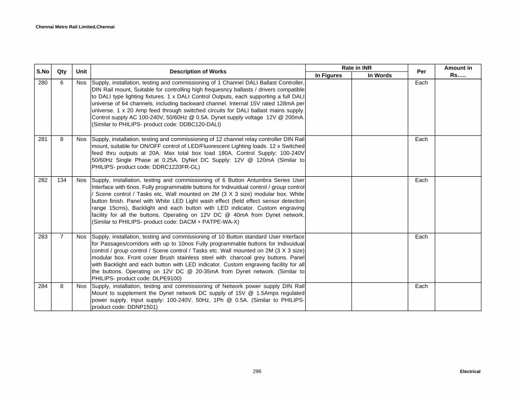
Chennai Metro Rail Limited,Chennai
In Figures In WordsUnit Description of Works Rate in INR Per Amount in Rs…..S.No Qty
280 6 Nos Supply, installation, testing and commissioning of 1 Channel DALI Ballast Controller,DIN Rail mount, Suitable for controlling high frequesncy ballasts / drivers compatibleto DALI type lighting fixtures. 1 x DALI Control Outputs, each supporting a full DALIuniverse of 64 channels, including backward channel. Internal 15V rated 128mA peruniverse. 1 x 20 Amp feed through switched circuits for DALI ballast mains supply.Control supply AC 100-240V, 50/60Hz @ 0.5A. Dynet supply voltage 12V @ 200mA.(Similar to PHILIPS- product code: DDBC120-DALI)
Each
281 8 Nos Supply, installation, testing and commissioning of 12 channel relay controller DIN Railmount, suitable for ON/OFF control of LED/Fluorescent Lighting loads. 12 x Switchedfeed thru outputs at 20A. Max total box load 180A. Control Supply: 100-240V50/60Hz Single Phase at 0.25A. DyNet DC Supply: 12V @ 120mA (Similar toPHILIPS- product code: DDRC1220FR-GL)
Each
282 134 Nos Supply, installation, testing and commissioning of 6 Button Antumbra Series UserInterface with 6nos. Fully programmable buttons for Indivuidual control / group control/ Scene control / Tasks etc. Wall mounted on 2M (3 X 3 size) modular box. Whitebutton finish. Panel with White LED Light wash effect (field effect sensor detectionrange 15cms), Backlight and each button with LED indicator. Custom engravingfacility for all the buttons. Operating on 12V DC @ 40mA from Dynet network.(Similar to PHILIPS- product code: DACM + PATPE-WA-X)
Each
283 7 Nos Supply, installation, testing and commissioning of 10 Button standard User Interfacefor Passages/corridors with up to 10nos Fully programmable buttons for Indivuidualcontrol / group control / Scene control / Tasks etc. Wall mounted on 2M (3 X 3 size)modular box. Front cover Brush stainless steel with charcoal grey buttons. Panelwith Backlight and each button with LED indicator. Custom engraving facility for allthe buttons. Operating on 12V DC @ 20-35mA from Dynet network. (Similar toPHILIPS- product code: DLPE9100)
Each
284 8 Nos Supply, installation, testing and commissioning of Network power supply DIN RailMount to supplement the Dynet network DC supply of 15V @ 1.5Amps regulatedpower supply. Input supply: 100-240V, 50Hz, 1Ph @ 0.5A. (Similar to PHILIPS-product code: DDNP1501)
Each
296 Electrical
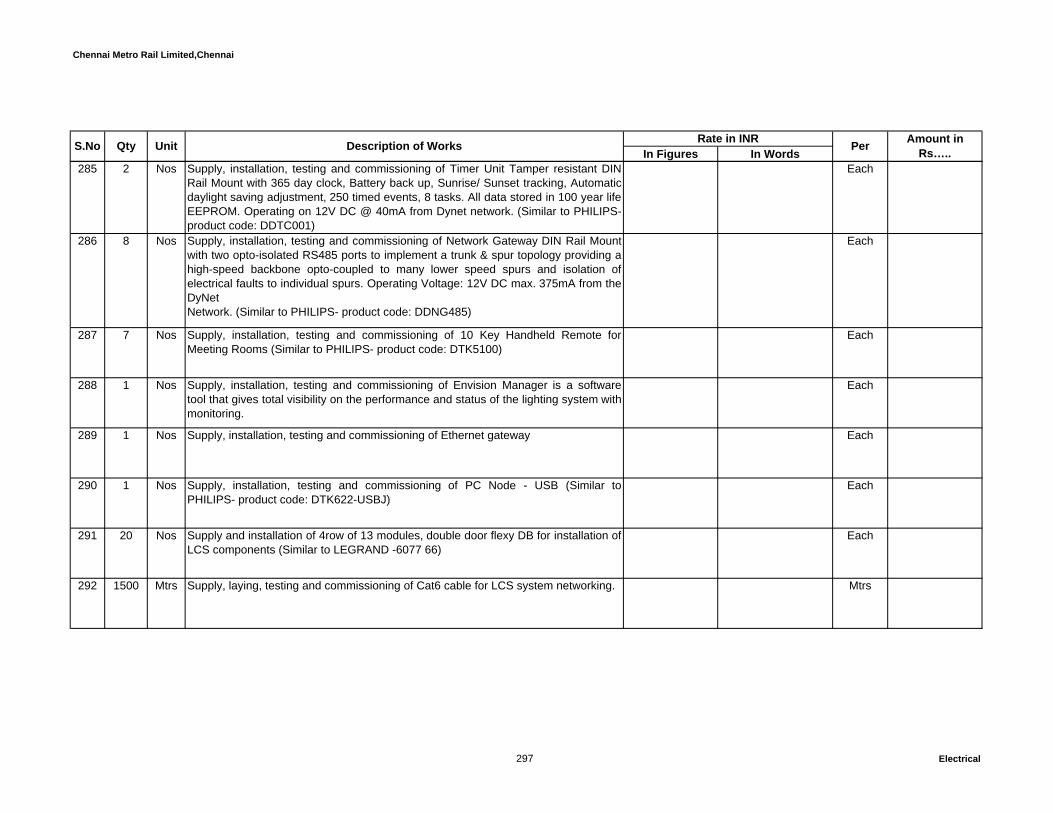
Chennai Metro Rail Limited,Chennai
In Figures In WordsUnit Description of Works Rate in INR Per Amount in Rs…..S.No Qty
285 2 Nos Supply, installation, testing and commissioning of Timer Unit Tamper resistant DINRail Mount with 365 day clock, Battery back up, Sunrise/ Sunset tracking, Automaticdaylight saving adjustment, 250 timed events, 8 tasks. All data stored in 100 year lifeEEPROM. Operating on 12V DC @ 40mA from Dynet network. (Similar to PHILIPS-product code: DDTC001)
Each
286 8 Nos Supply, installation, testing and commissioning of Network Gateway DIN Rail Mountwith two opto-isolated RS485 ports to implement a trunk & spur topology providing ahigh-speed backbone opto-coupled to many lower speed spurs and isolation ofelectrical faults to individual spurs. Operating Voltage: 12V DC max. 375mA from theDyNetNetwork. (Similar to PHILIPS- product code: DDNG485)
Each
287 7 Nos Supply, installation, testing and commissioning of 10 Key Handheld Remote forMeeting Rooms (Similar to PHILIPS- product code: DTK5100)
Each
288 1 Nos Supply, installation, testing and commissioning of Envision Manager is a softwaretool that gives total visibility on the performance and status of the lighting system withmonitoring.
Each
289 1 Nos Supply, installation, testing and commissioning of Ethernet gateway Each
290 1 Nos Supply, installation, testing and commissioning of PC Node - USB (Similar toPHILIPS- product code: DTK622-USBJ)
Each
291 20 Nos Supply and installation of 4row of 13 modules, double door flexy DB for installation ofLCS components (Similar to LEGRAND -6077 66)
Each
292 1500 Mtrs Supply, laying, testing and commissioning of Cat6 cable for LCS system networking. Mtrs
297 Electrical
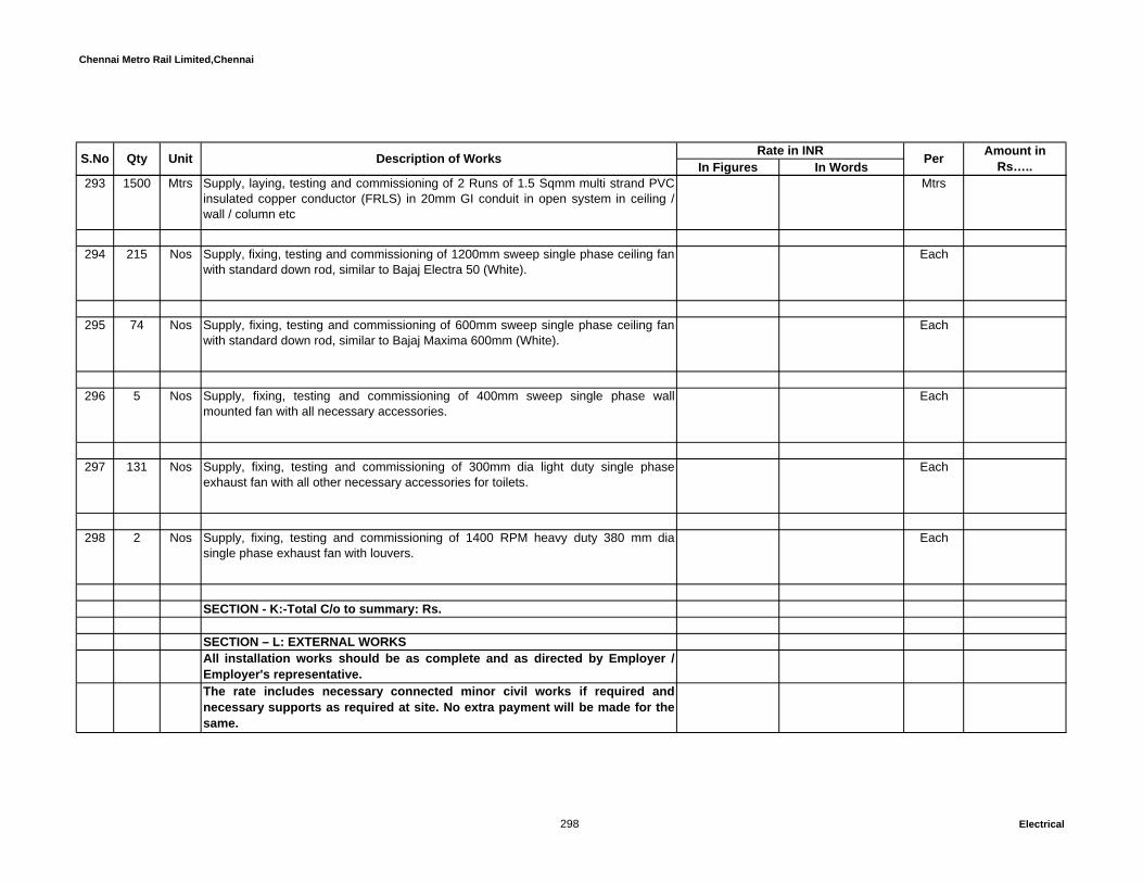
Chennai Metro Rail Limited,Chennai
In Figures In WordsUnit Description of Works Rate in INR Per Amount in Rs…..S.No Qty
293 1500 Mtrs Supply, laying, testing and commissioning of 2 Runs of 1.5 Sqmm multi strand PVCinsulated copper conductor (FRLS) in 20mm GI conduit in open system in ceiling /wall / column etc
Mtrs
294 215 Nos Supply, fixing, testing and commissioning of 1200mm sweep single phase ceiling fanwith standard down rod, similar to Bajaj Electra 50 (White).
Each
295 74 Nos Supply, fixing, testing and commissioning of 600mm sweep single phase ceiling fanwith standard down rod, similar to Bajaj Maxima 600mm (White).
Each
296 5 Nos Supply, fixing, testing and commissioning of 400mm sweep single phase wallmounted fan with all necessary accessories.
Each
297 131 Nos Supply, fixing, testing and commissioning of 300mm dia light duty single phaseexhaust fan with all other necessary accessories for toilets.
Each
298 2 Nos Supply, fixing, testing and commissioning of 1400 RPM heavy duty 380 mm diasingle phase exhaust fan with louvers.
Each
SECTION - K:-Total C/o to summary: Rs.
SECTION – L: EXTERNAL WORKSAll installation works should be as complete and as directed by Employer /Employer's representative. The rate includes necessary connected minor civil works if required andnecessary supports as required at site. No extra payment will be made for thesame.
298 Electrical

Chennai Metro Rail Limited,Chennai
In Figures In WordsUnit Description of Works Rate in INR Per Amount in Rs…..S.No Qty
299 Design, supply, erection and testing of 6mtrs octogonal poles hot dip galvanised,Top dia 70mm, Bottom dia 135mm, sheet thickness 3mm & base plate size225mmx225mmx16mm. With 1000mm length of standard single/ double arm bracketincluding Supply of M24X750 mm foundation bolts suitable for 6m octagonal pole.The construction of MS weather proof marshalling box (to fix it in pole) shouldcapable to accommodate 10A DP MCB and 32A 8way loop in-loop out terminalconnector mounted in din rail including knockout provision for cable in and out.Thecost inclusive of 3C x 2.5 sq.mm PVC flexible Cu. cable from MCB to light fittings andterminations,coil earthing using 8 SWG Cu with 25mm 2mtr long GI pipe, 40 mm diaGI pipe for incoming cable loop in and out and necessary cable dressing clamps.The rate includes excavation and foundation for erecting the above referred streetlight as required at site and inclusive of necessary connected minor civil works ifrequired and necessary supports as required at site. No extra payment will be madefor the same. Pole top bracket should suitable for 1 No.BRP409 LED CW 034 MR PC S1GREENLINE
The rate includes excavation and foundation for erecting the above refered streetlight as required at site and inclusive of necessary connected minor civil works ifrequired and necessary supports as required at site. No extra payment will be madefor the same.
a 45 Nos Single bracket type. Each
b 5 Nos Double bracket type. Each
300 5 Nos Supply and Fixing of 2Mtr height wall bracket with all other necessary accessories,top bracket should suitable for 1 EachBRP409 LED CW 034 MR PC S1GREENLINE
Each
301 Supply Fixing, testing and commissioning of 37W LED Street light luminaire,equivalent to Philips - BRP409 LED CW 034 MR PC S1 GREENLINE
299 Electrical

Chennai Metro Rail Limited,Chennai
In Figures In WordsUnit Description of Works Rate in INR Per Amount in Rs…..S.No Qty
60 Nos LED street light of 37W suitable for 6Mtr pole with inbuilt gear and >3400 lumenpackage at fixture level
Each
302 4 Nos Supply, fixing, testing and commissioning of 30W LED post top lantern with3000LUMEN Equivalent to PHILIPS CAT. Each TOWNGUIDE - BDP001 ECO40-/830 DS PCC GR MSP 62P for gate light.
Each
Excavation 303 800 Mtrs Excavation of the 300mm(W) x 750mm(D) cable trench in soil including river sand
cushioning (150mm thick both at top and bottom of the cable), brick protectioncovering (size of brick 220 x 100 x 70 mm) after laying the cable,back filling, rammingand compacting the soil,etc., as required.
Mtrs
304 250 Mtrs Excavation of the 600mm(W) x 1000mm(D) cable trench in soil including river sandcushioning (150mm thick both at top and bottom of the cable), brick protectioncovering (size of brick 220 x 100 x 70 mm) after laying the cable,back filling, rammingand compacting the soil,etc., as required.
Mtrs
305 Supply and laying of the following size RCC hume pipes with collar.The costincluding excavation to a depth of 750mm to 1000mm from existing groundlevel,plasterings, back filling, ramping the soil, making the surface to match theoriginal surface as required.
a 50 Mtrs 100 mm dia Mtrs
b 50 Mtrs 200 mm dia Mtrs
c 100 Mtrs 300 mm dia Mtrs
300 Electrical

Chennai Metro Rail Limited,Chennai
In Figures In WordsUnit Description of Works Rate in INR Per Amount in Rs…..S.No Qty
306 Supply, providing, construction of following size Masanory inspection (Man hole)chamber with cover for hume pipes .The man hole cover shall be provided with heavyduty CI/RCC type for inspection chamber.
a 10 Nos Chamber size: 600 (L) x1200 (W) x1000mm (D) Each
b 20 Nos Chamber size: 1000 (L) x1200 (W) x1000mm (D) Each
SECTION - L :-Total C/o to summary: Rs.
SECTION – M : LIGHTNING PROTECTION SYSTEMAll installation works should be as complete and as directed by Employer /Employer's representative. The rate includes necessary connected minor civil works if required andnecessary supports as required at site. No extra payment will be made for thesame.
307 Lightning protection systemAir Terminal (Horizontal)
1 1500 Mtr 8 mm Copper Round Conductor as horizontal air terminal Mtr
2 750 Nos Conductor Holder for parapet Each
3 750 Nos Wood screws(5 x60) and plastic dowels(8x 40) Each
4 750 Nos Conductor holder for terrace Each
301 Electrical

Chennai Metro Rail Limited,Chennai
In Figures In WordsUnit Description of Works Rate in INR Per Amount in Rs…..S.No Qty
5 30 Nos Glue to fix the plastic conductive holder Each
6 100 Nos Cross connector (At every crossing of conductor) Each
7 50 Nos Expansion Piece (At every 20 metre) Each
8 90 Nos Connector for expansion piece ( 2 Nos / Expansion Piece) Each
9 25 Nos Equipotential Bonding Rail, Black Each
10 20 Nos 2mtr Interception rod Each
11 3 Nos 4mtr Interception rod Each
12 20 Nos Stand fang fix Each
13 6 Nos F-Fix-S16 Concrete Stone - 16 Kgs. Each
Structural Earthing
302 Electrical
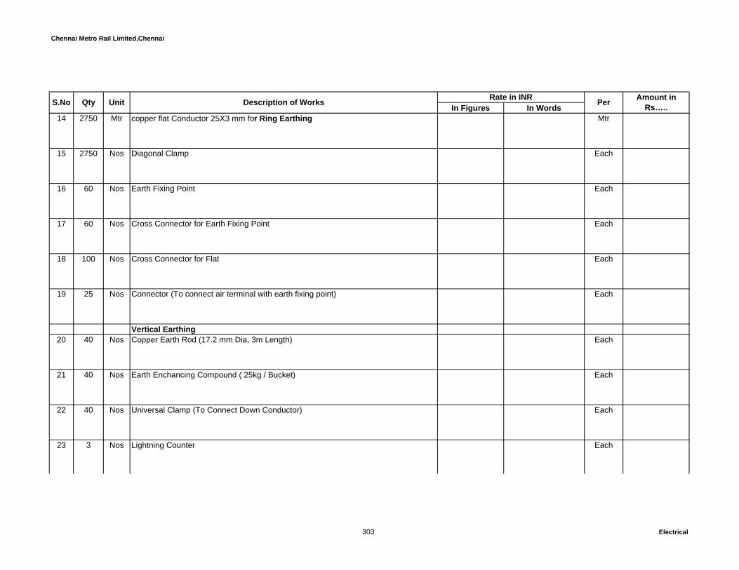
Chennai Metro Rail Limited,Chennai
In Figures In WordsUnit Description of Works Rate in INR Per Amount in Rs…..S.No Qty
14 2750 Mtr copper flat Conductor 25X3 mm for Ring Earthing Mtr
15 2750 Nos Diagonal Clamp Each
16 60 Nos Earth Fixing Point Each
17 60 Nos Cross Connector for Earth Fixing Point Each
18 100 Nos Cross Connector for Flat Each
19 25 Nos Connector (To connect air terminal with earth fixing point) Each
Vertical Earthing20 40 Nos Copper Earth Rod (17.2 mm Dia, 3m Length) Each
21 40 Nos Earth Enchancing Compound ( 25kg / Bucket) Each
22 40 Nos Universal Clamp (To Connect Down Conductor) Each
23 3 Nos Lightning Counter Each
303 Electrical

Chennai Metro Rail Limited,Chennai
In Figures In WordsUnit Description of Works Rate in INR Per Amount in Rs…..S.No Qty
SECTION - M:-Total C/o to summary: Rs.
SECTION – N : Solar systemAll installation works should be as complete and as directed by Employer /Employer's representative. The rate includes necessary connected minor civil works if required and necessarysupports as required at site. No extra payment will be made for the same.
The complete Solar PV system should have a warranty and after sales service for 5years
1 Supply, erection, testing and commisioning of 120Kwp solar roof top grid tie systemcomplete with all accessories and as mentioned below and as per the detailedtechnical specifications 250 Wp Solar Array (high efficiency multi crystalline modules)Galvanized MS Module mounting structure120KWp,3Phase,415V,50HZ, Power Conditioning Unit with MPPT Solar ChargeController and Data LoggerData logging and monitoring systemArray & Main junction boxesAC Distribution panel Earthing Kit as per IS 3043Lightning arrestorInstallation Hardware Kit1C x 4 sq.mm PVC Copper Cables2C x 10 sq.mm PVC Copper Cables3C x 25 sq.mm PVC Copper CablesStatutory permissions and approvals
SECTION - N:-Total C/o to summary: Rs.
GRAND TOTAL AMOUNT (SECTION: A - N) IN Rs….
304 Electrical

Chennai Metro Rail Limited,Chennai
In Figures In WordsDG SET WITH EXHAUST PIPE, STACK AND CONNECTED WORKSAll installation works should be as complete and as directed by Engineer-Incharge/consultant.
1
1
Nos Supply, Installation, Testing and Commissioning of factory assembled and factorytested, radiator cooled, turbo charged after cooled diesel engine alternator set capableof generating full load of 1500 KVA capacity at 40° C, power factor not less than 0.8lag, 415 Volts, 1500rpm, 3 phase, 50 Hz, AC supply and driven with diesel enginecomplete with all accessories such as Base frame, residential silencer, radiator,alternator capable of delivering 415 Volts, 50Hz, 3 phase, PF 0.8, 1500 KVA load,coupling arrangement of alternator with engine, coupling guard, water pump, oil pump,fuel filter, oil filter, air filter, exhaust flexible piping, fuel transfer hand pump with suitablehose pipe, battery 24 Volts and 200 AH capacity, battery charging alternator, enginecontrol panel, anti-vibration spring type mounting (quantity as per the manufacturer’srecommendation), and includes the following transport, insurance, handling, safekeeping at site etc., installation, testing and commissioning including performance testsas per Specifications. The necessary foundation will be provided by other agency.
Each
Note : The sucessful tenderer should confirm that the engine model shall be capableof delivering minimum 1500KVA and suitable for delivering 1500 KVA when coupledwith alternator given below at site condition as required. The Acoustic Enclosure isincluded seperately in below.
CONSTRUCTION OF METRO HEADQUARTERS BUILDING AND OTHER METRO RAIL AMENITIES AT NANDANAM,CHENNAI
BILLS OF QUANTITIES SCHEDULE - VI - DG SET WORKS
S.No Qty Unit Description of Works Per Amount in Rs…..Rate in INR
301 DG works

Chennai Metro Rail Limited,Chennai
In Figures In WordsS.No Qty Unit Description of Works Per Amount in Rs…..Rate in INR
2
1
Nos Supply, Installation, Testing and Commissioning of factory assembled and factorytested, radiator cooled, turbo charged after cooled diesel engine alternator set capableof generating full load of 750 KVA capacity at 40° C, power factor not less than 0.8 lag,415 Volts, 1500rpm, 3 phase, 50 Hz, AC supply and driven with diesel engine completewith all accessories such as Base frame, residential silencer, radiator, alternatorcapable of delivering 415 Volts, 50Hz, 3 phase, PF 0.8, 750 KVA load, couplingarrangement of alternator with engine, coupling guard, water pump, oil pump, fuel filter,oil filter, air filter, exhaust flexible piping, fuel transfer hand pump with suitable hosepipe, battery 24 Volts and 200 AH capacity, battery charging alternator, engine controlpanel, anti-vibration spring type mounting (quantity as per the manufacturer’srecommendation), and includes the following transport, insurance, handling, safekeeping at site etc., installation, testing and commissioning including performance testsas per Specifications. The necessary foundation will be provided by other agency.
Each
Note : The sucessful tenderer should confirm that the engine model shall be capableof delivering minimum 750KVA and suitable for delivering 750 KVA when coupled withalternator given below at site condition as required. The Acoustic Enclosure is includedseperately in below
302 DG works
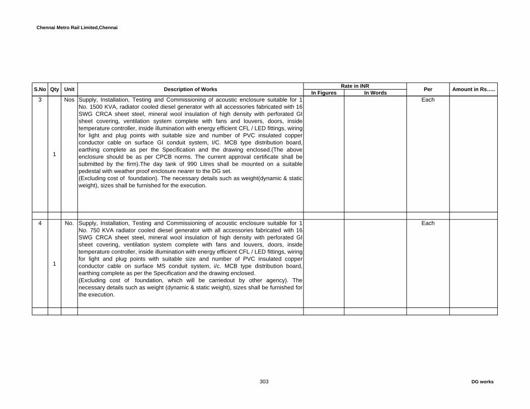
Chennai Metro Rail Limited,Chennai
In Figures In WordsS.No Qty Unit Description of Works Per Amount in Rs…..Rate in INR
3
1
Nos Supply, Installation, Testing and Commissioning of acoustic enclosure suitable for 1No. 1500 KVA, radiator cooled diesel generator with all accessories fabricated with 16SWG CRCA sheet steel, mineral wool insulation of high density with perforated GIsheet covering, ventilation system complete with fans and louvers, doors, insidetemperature controller, inside illumination with energy efficient CFL / LED fittings, wiringfor light and plug points with suitable size and number of PVC insulated copperconductor cable on surface GI conduit system, I/C. MCB type distribution board,earthing complete as per the Specification and the drawing enclosed.(The aboveenclosure should be as per CPCB norms. The current approval certificate shall besubmitted by the firm).The day tank of 990 Litres shall be mounted on a suitablepedestal with weather proof enclosure nearer to the DG set.(Excluding cost of foundation). The necessary details such as weight(dynamic & staticweight), sizes shall be furnished for the execution.
Each
4
1
No. Supply, Installation, Testing and Commissioning of acoustic enclosure suitable for 1No. 750 KVA radiator cooled diesel generator with all accessories fabricated with 16SWG CRCA sheet steel, mineral wool insulation of high density with perforated GIsheet covering, ventilation system complete with fans and louvers, doors, insidetemperature controller, inside illumination with energy efficient CFL / LED fittings, wiringfor light and plug points with suitable size and number of PVC insulated copperconductor cable on surface MS conduit system, i/c. MCB type distribution board,earthing complete as per the Specification and the drawing enclosed. (Excluding cost of foundation, which will be carriedout by other agency). Thenecessary details such as weight (dynamic & static weight), sizes shall be furnished forthe execution.
Each
303 DG works

Chennai Metro Rail Limited,Chennai
In Figures In WordsS.No Qty Unit Description of Works Per Amount in Rs…..Rate in INR
5
1
Nos Supply, Installation, Testing and Commissioning of Control panel indoor, floor mounting type and 4B constuction with IP54 and 2500Amps, 4pole 50KA ,EDO type ,air circuit breaker with shunt release, shutter assembly, door interlock and other required accessories, copper busbar, complete set of instrument panel, protection release/relays, auto start/stop arrangement as per detailed specification.The panel shall be installed inside the acoustic enclosure and it should complied with IEC 61439-1&2 (totally type tested -TTA).
Each
6
1
No. Supply, Installation, Testing and Commissioning of Control panel indoor, floor mounting type and 4B construction with IP 54 and 1250Amps, 4pole 50KA ,EDO type, air circuit breaker with shunt release, shutter assembly, door interlock and other required accessories, copper busbar, complete set of instrument panel, protection release/relays, auto start/stop arrangement as per detailed specification. The panel shall be installed inside the acoustic enclosure and it should complied with IEC 61439-1&2 (totally type tested -TTA).
Each
7 AUTO START & AUTO SYNC. PANELDesign, supply, testing and commissioning of Auto start and Auto syn panel with auto load sharing arrangement of Indoor, cubicle type floor mounting panel made out of MS sheet enclosure with Copper busbars, single busbar system, 4B construction with IP42, cable chamber, interconnection, painting, earthing, protection relays etc. comprising of the following : (DG AMF with auto Synchronising control Panel). The panel should complied with IEC 61439-1&2 (totally type tested -TTA)
INCOMINGFrom DG3 Sets 2500Amps, TP, 50KA ,EDO type, ACB with UV coil, shunt release, shutter assembly with 315A 4 pole neutral isolating contactor with all other necessary accessories.1set of 1250Amps, TP, 50KA ,EDO type,A CB with UV coil, shunt release, shutter assembly with 160A 4 pole neutral isolating contactor with all other necessary accessories.
304 DG works

Chennai Metro Rail Limited,Chennai
In Figures In WordsS.No Qty Unit Description of Works Per Amount in Rs…..Rate in INR
Instrumental compartmentProviding TNC switch, emergency lockable push button, Multi load manager, Energy meter, Voltmeter, Instantaneous over current, earthfault relay (2 O/C+ 1 E/F), Restricted earth fault relay, Standby earth fault relay, Under voltage relay, Over voltage relay, Reverse directional power relay, Differential protective relay, Under frequency relay, Over frequency relay and Master trip relay, necessary CTs, PTs, control MPCB/MCB/ ELCB/RCBOs, RYB Indication lamps and “ON/OFF/Trip/Rest" indicating lamp, and emergency lockable push buttons, GCU, Battary charger and also as per the specification and SLD.
Buscoupler3sets 6300Amps, 4pole, 50KA, EDO ACB with shunt release, shutter assembly, doorinterlock and other required accessories and ON/OFF/TRIP lamps
The buscoupler shall be provided with mechanical & electrical Inetrlockingarrangements. and also should have digital type Ammeter, Voltmeter, indication lampsand necessary CTs, PTs and control MPCB/MCB/ ELCB/RCBOs with all othernecessary accessories and also refer the SLD.Instruments PanelDual type voltmeter, Dual type frequency meter, Synchronous scope, Synchronisingcheck devise relay, Auto load sharing relay, Voltage balance relay, Current balancerelay, Frequency relay with all necessary CTs, PTs, control MPCB/MCB/ ELCB/RCBOsand as per specification and SLD.OUTGOINGS2500A 4P EDO ACB 50kA – 3 Nos1250A 4P EDO ACB 50kA – 1 No.
305 DG works

Chennai Metro Rail Limited,Chennai
In Figures In WordsS.No Qty Unit Description of Works Per Amount in Rs…..Rate in INR
All the Outgoing feeder shall be ON/OFF/Trip indication lamps, emergency lockable push buttons, all ACB and MCCBs should have two (spare) potential free contactor for BMS monitoring, Combined digital type Multi function meter (Similar to SOCOMEC - Countis E53) with RS485 port. All ACB feeders should have TNC switch. The rate shall inclusive of necessary CTs, control switches, Front operating handles etc., All switch boards shall be fabricated as per the detailed specification enclosed. Suitable size outgoing cable chamber and extra busbars should be provided for connecting the number of outgoing cables as per the schematic drawing.The board shall be fabricated for future extension of the panel board.
The necessary electrical interlocking arrangement between incomer and bus coupler byhardware control wiring along with PLC (Programmable Logic Control). The hardwarecontrol wiring for MPCC, AMF Panel, Capacitor Panel, Auto Synchronisation Panel andother necessary control wiring and PLC operation shall be feasible to extend for thepanel as per the detailed specification and drawings enclosed. (panel for 4 nos DG sets- 3 Nos of 1500KVA (2Working + 1Standby) & 1No. 750KVA) (refer attached drawing)
Each incoming feeders should have inbuilt battery charger for DG sets such as 24Volts,40Amps,SCR controlled battery charger made up of 16SWG MS sheet enclosure withall accessories having automatic boost and trickle charging arrangements with volt andcurrent limiting circuits, voltmeter for AC/DC supply, ammeter for charging circuit (DC),automatic cut off facility when the Engine alternator is in working condition, MCB forprotection, suitable for 230V,50Hz, AC supply, interconnections, body earthing etc.complete as required.
The panel should have the provision to receive the pipe lines for proposed panel gasflooding system.6300Amps 4P copper busbars:- All the neutral busbars shall have the same capacity ofphase busbars.
306 DG works

Chennai Metro Rail Limited,Chennai
In Figures In WordsS.No Qty Unit Description of Works Per Amount in Rs…..Rate in INR
1No. DG AMF with Auto Synchronising Control Panel Each
BUSDUCT8
25
Mtrs Design, supply, erection, testing and commissioning of 2500 Amps outdoor sandwich type copper 4Pole busduct with two seperate runs of external earth busbar which should have half the size of neutral busbar and with suitable support from ceiling as per the detailed specification enclosed. The busduct should be with straight run, 90 deg. horizontal and Vertical bends., busbar trunking fittings (elbow, tees, end End (Cable) feed Box, end covers, horizontal fixing devices,etc.) The horizontal runs of busbar trunking system shall be supported by hangers at every 2 metre. Vertical runs of busbar trunking system shall be supported by hangers not more than 4m apart. The busduct shall run from DG to DG sync. panel. The bus duct shall be fabricated as per the detailed specification enclosed.
Mtrs
9
25
Mtrs Design, supply, erection, testing and commissioning of 1250 Amps outdoor sandwich type copper 4Pole busduct with two seperate runs of external earth busbar which should have half the size of neutral busbar and with suitable support from ceiling as per the detailed specification enclosed. The busduct should be with straight run, 90 deg. horizontal and Vertical bends., busbar trunking fittings (elbow, tees, end End (Cable) feed Box, end covers, horizontal fixing devices,etc.) The horizontal runs of busbar trunking system shall be supported by hangers at every 2 metre. Vertical runs of busbar trunking system shall be supported by hangers not more than 4m apart. The busduct shall run from DG to DG sync. panel. The bus duct shall be fabricated as per the detailed specification enclosed.
Mtrs
307 DG works

Chennai Metro Rail Limited,Chennai
In Figures In WordsS.No Qty Unit Description of Works Per Amount in Rs…..Rate in INR
10
10
Mtrs Design, supply, erection, testing and commissioning of 1250 Amps indoor sandwich type copper 4Pole busduct with two seperate runs of external earth busbar which should have half the size of neutral busbar and with suitable support from ceiling as per the detailed specification enclosed. The busduct should be with straight run, 90 deg. horizontal and Vertical bends., busbar trunking fittings (elbow, tees, end End (Cable) feed Box, end covers, horizontal fixing devices,etc.) The horizontal runs of busbar trunking system shall be supported by hangers at every 2 metre. Vertical runs of busbar trunking system shall be supported by hangers not more than 4m apart. The busduct shall run from DG to DG sync. panel. The bus duct shall be fabricated as per the detailed specification enclosed.
Mtrs
112
Sets Design, supply, erection, testing and commissioning of 1250 Amps flexible jointssuitable for sandwich type 4pole copper bus duct at end terminals including allaccessories.(RYBN=1 set)
Sets
12
1
Sets Design, supply, erection, testing and commissioning of 1250 Amps Phase crosschangeover box suitable for sandwich type TPN copper bus duct including allaccessories. (it will operate in case of phase change over is required as per sitecondition) (RYBN=1 set)
Sets
EARTHING SYSTEM13
2
Nos Supply, installation, testing and commissioning of earth electrode as per IS 3043complete with 3 mtr long with 40mm dia 'B' class G.I. pipe and copper earth plate ofsize 600mm x 600mm x 3 mm including 2 runs of 75 x 10 mm CU. flat upto test linkfrom plate earth electrode, watering funnel and necessary bolt, nut and double washer.Including 750mm x 750mm x 3mtr long excavation and construction of 850mm x850mm x 300 mm high brick wall chamber with cement mortor. The chamber shall beprovided with 600mm x 600mm x 10mm cast iron / RCC cover with frame and lockablefacility. The plate electrode shall be filled with alternate layer of salt and charcoal asrequired full depth. The Cover shall be heavy duty to suit heavy vehicle movements. (1500 KVA- Neutral)
Each
308 DG works

Chennai Metro Rail Limited,Chennai
In Figures In WordsS.No Qty Unit Description of Works Per Amount in Rs…..Rate in INR
14
2
Nos Supply, installation, testing and commissioning of earth electrode as per IS 3043complete with 3 mtr long with 40mm dia 'B' class G.I. pipe and copper earth plate ofsize 600mm x 600mm x 3 mm including 2 runs of 40 x 10 mm CU. flat upto test linkfrom plate earth electrode, watering funnel and necessary bolt, nut and double washer.Including 750mm x 750mm x 3mtr long excavation and construction of 850mm x850mm x 300 mm high brick wall chamber with cement mortor. The chamber shall beprovided with 600mm x 600mm x 10mm cast iron / RCC cover with frame and lockablefacility. The plate electrode shall be filled with alternate layer of salt and charcoal asrequired full depth. The Cover shall be heavy duty to suit heavy vehicle movements. (1250 KVA- Neutral)
Each
15
8
Nos Supply, installation, testing and commissioning of earth electrode as per IS 3043complete with 3 mtr long with 40mm dia 'B' class G.I. pipe and copper earth plate ofsize 600mm x 600mm x 3 mm including 2 runs of 40 x 6 mm CU. flat upto test link fromplate earth electrode, watering funnel and necessary bolt, nut and double washer.Including 750mm x 750mm x 3mtr long excavation and construction of 850mm x850mm x 300 mm high brick wall chamber with cement mortor. The chamber shall beprovided with 600mm x 600mm x 10mm cast iron / RCC cover with frame and lockablefacility. The plate electrode shall be filled with alternate layer of salt and charcoal asrequired full depth. The Cover shall be heavy duty to suit heavy vehicle movements. (DG - Body earth, Stack earthing and lightning arrestor)
Each
16
60
Mtrs Supply and Laying of 75mm x 10mm copper flat from earth electrode directly in groundincluding earth work excavation, refilling the trench, with all accessories, jointing theflats with lap joint with 2Nos. of bolt/nuts/spring washers/check nuts and all necessaryaccessories like black colour sleeve, insulators etc. as required. (For 1500KVA DGneutral)
Mtrs
309 DG works

Chennai Metro Rail Limited,Chennai
In Figures In WordsS.No Qty Unit Description of Works Per Amount in Rs…..Rate in INR
17
50
Mtrs Supply and Laying of 40mm x 10mm copper flat from earth electrode directly in groundincluding earth work excavation, refilling the trench, with all accessories, jointing theflats with lap joint with 2Nos. of bolt/nuts/spring washers/check nuts and all necessaryaccessories like black colour sleeve, insulators etc. as required. (For 750KVA DGneutral)
Mtrs
18
40
Mtrs Supply and Laying of 40mm x 6mm copper flat from earth electrode directly in groundincluding earth work excavation, refilling the trench, with all accessories, jointing theflats with lap joint with 2Nos. of bolt/nuts/spring washers/check nuts and all necessaryaccessories like green colour sleeve, insulators etc. as required. (For 1500KVA DGbody earthing)
Mtrs
19
150
Mtrs Supply and Laying of 25mm x 6mm copper flat from earth electrode directly in groundincluding earth work excavation, refilling the trench, with all accessories, jointing theflats with lap joint with 2Nos. of bolt/nuts/spring washers/check nuts and all necessaryaccessories like green colour sleeve, insulators etc. as required. (For 750KVA DG bodyearthing)
Mtrs
20200
Mtrs Supply and Laying of 65mm x 10mm GI flat (For body earthing on cable tray) Mtrs
21300
Mtrs Supply, laying of 8SWG copper wire Mtrs
22 Exhaust System
310 DG works
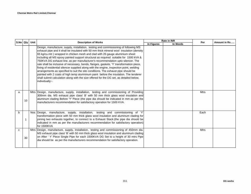
Chennai Metro Rail Limited,Chennai
In Figures In WordsS.No Qty Unit Description of Works Per Amount in Rs…..Rate in INR
Design, manufacture, supply, installation, testing and commissioning of following MS exhaust pipe and it shall be insulated with 50 mm thick mineral wool insulation (density 65 kg/cu.mtr.) wrapped in chicken mesh and clad with 26 gauge aluminium sheet including all MS epoxy painted support structural as required suitable for 1500 kVA & 750KVA DG exhaust line, as per manufacturer's recommendation upto silencer. The rate shall be inclusive of necessary, bends, flanges, gaskets, 'Y' transformation piece, fixing of residential silencer supplied along with the engine, inspection point, welding arrangements as specified to suit the site conditions. The exhaust pipe should be painted with 2 coats of high temp alumninum paint before the insulation. The tenderer shall submit calculation along with the size offered for the DG set, as detailed below, individually:-.
a
10
Mtrs Design, manufacture, supply, installation, testing and commissioning of Providing300mm dia. MS exhaust pipe class' B' with 50 mm thick glass wool insulation andaluminum clading Before 'Y' Piece (the pipe dia should be indicated in mm as per themanufacturers recommendation for satisfactory operation for 1500 KVA.
Mtrs
b
1
Nos Design, manufacture, supply, installation, testing and commissioning of 'Y'transformation piece with 50 mm thick glass wool insulation and aluminum clading forjoining two exhausts together, to connect to a Exhaust Stack.(the pipe dia should beindicated in mm as per the manufacturers recommendation for satisfactory operation)for 1500KVA
Each
c
30
Mtrs Design, manufacture, supply, installation, testing and commissioning of 450mm dia.MS exhaust pipe class' B' with 50 mm thick glass wool insulation and aluminum cladingon After ' Y' Piece Single Pipe for each 1500KVA DG Set to a height of 30 mtrs Pipedia should be as per the manufacturers recommendation for satisfactory operation.
Mtrs
311 DG works
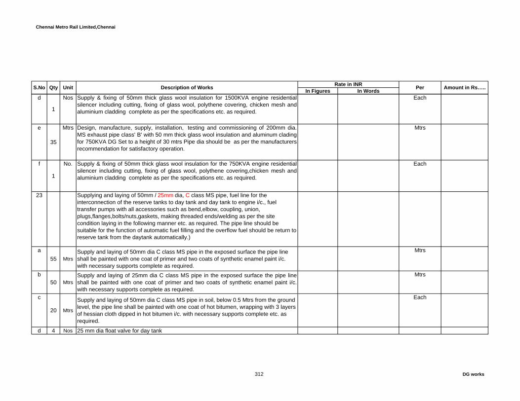
Chennai Metro Rail Limited,Chennai
In Figures In WordsS.No Qty Unit Description of Works Per Amount in Rs…..Rate in INR
d
1
Nos Supply & fixing of 50mm thick glass wool insulation for 1500KVA engine residentialsilencer including cutting, fixing of glass wool, polythene covering, chicken mesh andaluminium cladding complete as per the specifications etc. as required.
Each
e
35
Mtrs Design, manufacture, supply, installation, testing and commissioning of 200mm dia.MS exhaust pipe class' B' with 50 mm thick glass wool insulation and aluminum cladingfor 750KVA DG Set to a height of 30 mtrs Pipe dia should be as per the manufacturersrecommendation for satisfactory operation.
Mtrs
f
1
No. Supply & fixing of 50mm thick glass wool insulation for the 750KVA engine residentialsilencer including cutting, fixing of glass wool, polythene covering,chicken mesh andaluminium cladding complete as per the specifications etc. as required.
Each
23 Supplying and laying of 50mm / 25mm dia, C class MS pipe, fuel line for the interconnection of the reserve tanks to day tank and day tank to engine i/c., fuel transfer pumps with all accessories such as bend,elbow, coupling, union, plugs,flanges,bolts/nuts,gaskets, making threaded ends/welding as per the site condition laying in the following manner etc. as required. The pipe line should be suitable for the function of automatic fuel filling and the overflow fuel should be return to reserve tank from the daytank automatically.)
a55 Mtrs
Supply and laying of 50mm dia C class MS pipe in the exposed surface the pipe line shall be painted with one coat of primer and two coats of synthetic enamel paint i/c. with necessary supports complete as required.
Mtrs
b50 Mtrs
Supply and laying of 25mm dia C class MS pipe in the exposed surface the pipe lineshall be painted with one coat of primer and two coats of synthetic enamel paint i/c.with necessary supports complete as required.
Mtrs
c
20 Mtrs
Supply and laying of 50mm dia C class MS pipe in soil, below 0.5 Mtrs from the ground level, the pipe line shall be painted with one coat of hot bitumen, wrapping with 3 layers of hessian cloth dipped in hot bitumen i/c. with necessary supports complete etc. as required.
Each
d 4 Nos 25 mm dia float valve for day tank
312 DG works
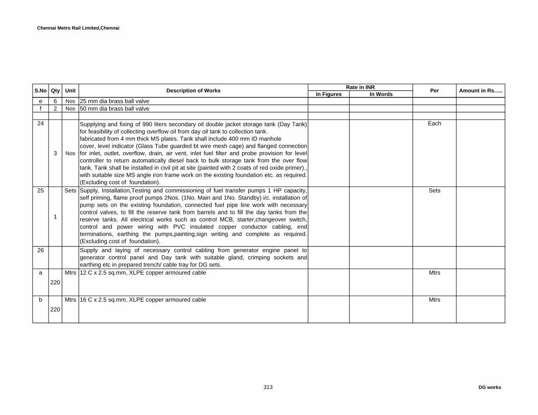
Chennai Metro Rail Limited,Chennai
In Figures In WordsS.No Qty Unit Description of Works Per Amount in Rs…..Rate in INR
e 6 Nos 25 mm dia brass ball valve f 2 Nos 50 mm dia brass ball valve
24
3 Nos
Supplying and fixing of 990 liters secondary oil double jacket storage tank (Day Tank)for feasibility of collecting overflow oil from day oil tank to collection tank.fabricated from 4 mm thick MS plates. Tank shall include 400 mm ID manholecover, level indicator (Glass Tube guarded bt wire mesh cage) and flanged connectionfor inlet, outlet, overflow, drain, air vent, inlet fuel filter and probe provision for levelcontroller to return automatically diesel back to bulk storage tank from the over flowtank. Tank shall be installed in civil pit at site (painted with 2 coats of red oxide primer).,with suitable size MS angle iron frame work on the existing foundation etc. as required.(Excluding cost of foundation).
Each
25
1
Sets Supply, Installation,Testing and commissioning of fuel transfer pumps 1 HP capacity,self priming, flame proof pumps 2Nos. (1No. Main and 1No. Standby) i/c. installation ofpump sets on the existing foundation, connected fuel pipe line work with necessarycontrol valves, to fill the reserve tank from barrels and to fill the day tanks from thereserve tanks. All electrical works such as control MCB, starter,changeover switch,control and power wiring with PVC insulated copper conductor cabling, endterminations, earthing the pumps,painting,sign writing and complete as required.(Excluding cost of foundation).
Sets
26 Supply and laying of necessary control cabling from generator engine panel togenerator control panel and Day tank with suitable gland, crimping sockets andearthing etc in prepared trench/ cable tray for DG sets.
a
220
Mtrs 12 C x 2.5 sq.mm, XLPE copper armoured cable Mtrs
b
220
Mtrs 16 C x 2.5 sq.mm, XLPE copper armoured cable Mtrs
313 DG works

Chennai Metro Rail Limited,Chennai
In Figures In WordsS.No Qty Unit Description of Works Per Amount in Rs…..Rate in INR
c
150
Mtrs 4 C x 4 sq.mm cable Mtrs
d
150
Mtrs 4C x 2.5 sq.sq.mm, PVC copper armoured cable Mtrs
e
170
Mtrs 3C x 1.5 sq.mm, PVC copper armoured cable Mtrs
f
150
Mtrs Screened communciation cable Mtrs
27 Terminations of the cablesa
6Nos 12 C x 2.5 sq.mm, XLPE copper armoured cable Each
b6
Nos 16 C x 2.5 sq.mm, XLPE copper armoured cable Each
c6
Nos 4 C x 4 sq.mm cable Each
d6
Nos 4C x 2.5 sq.sq.mm, PVC copper armoured cable Each
e6
Nos 3C x 1.5 sq.mm, PVC copper armoured cable Each
314 DG works

Chennai Metro Rail Limited,Chennai
In Figures In WordsS.No Qty Unit Description of Works Per Amount in Rs…..Rate in INR
f6
Nos Screened communciation cable Each
Supply, erection of following sizes GI perforated type cable rack system made out ofsheet steel folded to required shape with adequate number of supports. The lighting/power cable rack shall have runners rugs of suitable size, horizontal elbow,vertical elbow 90 Deg.Up vertical elbow 90 Deg. Down, re-deep, couplerplates,materials. The lighting/powercable racks shall be suspended from ceiling andsupported from side walls or columns etc. with adequate size supporting GI threadedrod's, 'C' channels with fastners, anchor bolts, nuts etc. The rack shall have suitablecable clamping arrangements etc and also as per the technical specification.The heightof the hanging arrangement shall be as per drawing and with all accesories to fix thehangers at coloumns/purlin / rafter beam/walls with required MS clamps nuts & bolts tobe considered.No extra payment will be made for the same.(The MS angle and channelsupports used for cable trays as per approved drawings, site conditions,client andconsultant requirments will be measured and paid separately)
28 Perforated type
For Perforated Cable trays designed, tested and confirming to IEC 61537, thickness ofcable tray should be according to the manufacturers catalogue. For locally fabricatedand non tested tray, thickness should be 2 mm up to span length of 1.5 meter, 2.5 mmfor span length between 2 to 3 meter and 3 to 4 mm for span length between 4 and 10meter
a100
100 mm perforated tray
315 DG works

Chennai Metro Rail Limited,Chennai
In Figures In WordsS.No Qty Unit Description of Works Per Amount in Rs…..Rate in INR
b65
300 mm perforated tray
29
20
MT Supply and Installation of MS flat / angle iron supports for Exhaust pipes (30 Mtrsheight from ground level) , exhaust stack with necessary accessories,stands,etc.,various sizes including cutting,welding,grinding,fixing accessories and one coat ofprimer & two coats of enamel paints, minor civil works etc. as required.(Note: The flat /angle iron weight will be arrived on the basis of theoretical calculation only). (The DGstack should be suitable to accomodate and withstand the load of future capacity ofanother 2number of 1250KVA DG set's exhaust pipe.)
MT
303
Nos Supply and fixing of emergency lamp with 1No. 13W CFL light fitting with one hourbattery back up.
Each
3130
Mtrs 110 mm dia GI pipe Mtrs
322
Sets Fuel unloading hand pump with 10 mtrs PVC hose Sets
333
Nos Design, supply and fixing of copper lightning spike at the top of the stack with suitablesupports.
Each
343
Nos Supply, fixing of 2x12W LED cluster integral type aviation lamp at top of the Chimneywith Auto ON / OFF photo cell controller, connecting wires upto aviation lamp etc
Each
TOTAL AMOUNT
316 DG works

Chennai Metro Rail Limited,Chennai
In Figures In Words
A PUMP ROOM
STANDBY DIESEL ENGINE PUMP1 1.00 No Supply, installation, testing and commissioning of diesel engine
driven pump set as per specification.The engine should have RPMbetween 1800 to 2100. The Pump shall be horizontal end suction,top discharge mounted on common baseframe. Pump shall bedirectly coupled to diesel engine of suitable BHP as per systemdesign condition. Engine shall be complete with flywheel, spidercoupling, Air cleaners, water cooled Heat exchanger type, CorrosionResistor, Oil Sump with lube at pump. Governor, Fuel Filter, startingmotor,2 sets of battery with charging arrangement, alternator &instrument panel suitable for 24 volt DC including starting switches,Diesel tank and exhaust arrangement as per specification. Thepump shall be capable to delivery 171m3/hr at 105 meter head. Rateshall be inclusive of steel fabricated tank fitted with level indicatorwith stand, the tank should in elevated level so that the fuel is drawnto the Engine due to gravity.
No
2 MAIN ELECTRICAL DRIVEN FIRE PUMPSET
Rate in INR
Per
CONSTRUCTION OF METRO HEADQUARTERS BUILDING AND OTHER METRO RAIL AMENITIES AT NANDANAM,CHENNAI
BILLS OF QUANTITIES
SCHEDILE - VII - FIRE PROTECTION SYSTEM WORKS
S.No TotalQuantity Unit Description of Work Total Amount in
Rs….
316 FPS
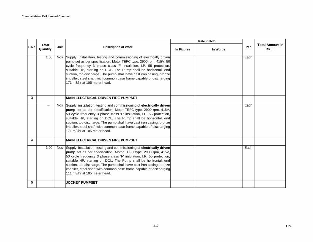
Chennai Metro Rail Limited,Chennai
In Figures In Words
Rate in INR
PerS.No TotalQuantity Unit Description of Work Total Amount in
Rs….
1.00 Nos Supply, installation, testing and commissioning of electrically drivenpump set as per specification. Motor TEFC type, 2900 rpm, 415V, 50cycle frequency 3 phase class ‘F’ insulation, I.P. 55 protection,suitable HP, starting on DOL. The Pump shall be horizontal, endsuction, top discharge. The pump shall have cast iron casing, bronzeimpeller, steel shaft with common base frame capable of discharging171 m3/hr at 105 meter head.
Each
3 MAIN ELECTRICAL DRIVEN FIRE PUMPSET
- Nos Supply, installation, testing and commissioning of electrically driven pump set as per specification. Motor TEFC type, 2900 rpm, 415V,50 cycle frequency 3 phase class ‘F’ insulation, I.P. 55 protection,suitable HP, starting on DOL. The Pump shall be horizontal, endsuction, top discharge. The pump shall have cast iron casing, bronzeimpeller, steel shaft with common base frame capable of discharging171 m3/hr at 105 meter head.
Each
4 MAIN ELECTRICAL DRIVEN FIRE PUMPSET
1.00 Nos Supply, installation, testing and commissioning of electrically driven pump set as per specification. Motor TEFC type, 2900 rpm, 415V,50 cycle frequency 3 phase class ‘F’ insulation, I.P. 55 protection,suitable HP, starting on DOL. The Pump shall be horizontal, endsuction, top discharge. The pump shall have cast iron casing, bronzeimpeller, steel shaft with common base frame capable of discharging111 m3/hr at 105 meter head.
Each
5 JOCKEY PUMPSET
317 FPS

Chennai Metro Rail Limited,Chennai
In Figures In Words
Rate in INR
PerS.No TotalQuantity Unit Description of Work Total Amount in
Rs….
2.00 Nos Supply, installation, testing and commissioning of electrically drivenVertical In line pump set as per specification. Motor TEFC type,2900 RPM 415 V, 50 cycles, 3 phase, class ‘F’ insulation, IP 55protection, suitable HP starting on DOL. The pump shall have castiron casing, Cast iron impeller, steel shaft with common base framecapable of discharging 10.8 m3/hour at 105 meter head.
Each
6 1.00 No Supply and installation of 600 liters Diesel tank with supply and return piping,steel supports for diesel tank,valves,fil and vent lines ,flexible connections.Diesel tank supply and installation shall confirm to BIS.
No
BOOSTER PUMPSET
7 1.00 No Supply, installation, testing & commissioning of electrically driven pumpset as per specification. Motor TEFC type, 2900 RPM, 415 V 50 cycle, 3 phase Class 'F" insulation, IP - 55 protection, 15 HP starting on DOL. The Pump shall be horizontal, end suction, top discharge. The pump shall be cast iron casing, bronze impeller, steel shaft. with common base frame capable of discharging 54 m3/hour at 45 m head. Pump to be installed at Terrace.
No
8 - No Supply, installation, testing & commissioning of electrically driven pumpset as per specification. Motor TEFC type, 2900 RPM, 415 V 50 cycle, 3 phase Class 'F" insulation, IP - 55 protection, 15 HP starting on DOL. The Pump shall be horizontal, end suction, top discharge. The pump shall be cast iron casing, bronze impeller, steel shaft. with common base frame capable of discharging 27 m3/hour at 45 m head. Pump to be installed at Terrace.
No
318 FPS

Chennai Metro Rail Limited,Chennai
In Figures In Words
Rate in INR
PerS.No TotalQuantity Unit Description of Work Total Amount in
Rs….
9 1.00 No Supply, installation and commissioning of precharged air vessel (size 450 mm Dia & 1500 mm height) for pressurization of hydrant system complete with adequate pressure switches (as per design / requirement) with valves to operate as per operating sequences including 25 mm Dia drain valve, air release valve with stop cock on the top, 25 mm Dia inlet with isolating valve duly painted from inside and outside with two coats of synthetic enamel paint over a coat of zinc rich primer complete as required. (Vessel should be suitable for rated working pressure).
No
Total Pump room carry over to summary
B HYDRANT SYSTEM
1 - Supply, installation, testing and commissioning of Cast Iron Sluice gate(PN-20) valve with cast iron body, brass stem, cast iron gland with square braided non-asbestos packing, cast iron hand wheel, including making necessary flanged joints by providing necessary nuts, bolts, gaskets, etc. all complete as per specification.
a - Nos 300 NB Each
b - Nos 250 NB Each
c 6.00 Nos 200 NB Each
d 8.00 Nos 150 NB Each
319 FPS

Chennai Metro Rail Limited,Chennai
In Figures In Words
Rate in INR
PerS.No TotalQuantity Unit Description of Work Total Amount in
Rs….
e - Nos 100 NB Each
f 2.00 Nos 80NB Each
g 4.00 Nos 50NB Each
2 Supplying & installation standard Cast Iron Swing check valve(PN-20) Valves including making flanged joints by providing necessarynuts, bolts, gaskets etc.
a - Nos 250 NB Each
b 1.00 Nos 200 NB Each
c 6.00 Nos 150NB Each
d 4.00 Nos 50NB Each
3 Supply and installation of fittings shall be cast of cast iron conforming to ASTM A-536, Grade 65-45-12, with grooved or shouldered ends for direct connection into grooved piping systems with steel pipe . Fittings may be standard dimension steel or by manufacturers standards.
320 FPS

Chennai Metro Rail Limited,Chennai
In Figures In Words
Rate in INR
PerS.No TotalQuantity Unit Description of Work Total Amount in
Rs….
3.1 Equal Tee joint
a - Nos 300 NB Each
b - Nos 250 NB Each
c - Nos 200 NB Each
d 6.00 Nos 150 NB Each
e 4.00 Nos 50NB Each
3.2 Elbow - 90 Deg
a - Nos 300 NB Each
b - Nos 250 NB Each
c 4.00 Nos 200 NB Each
321 FPS
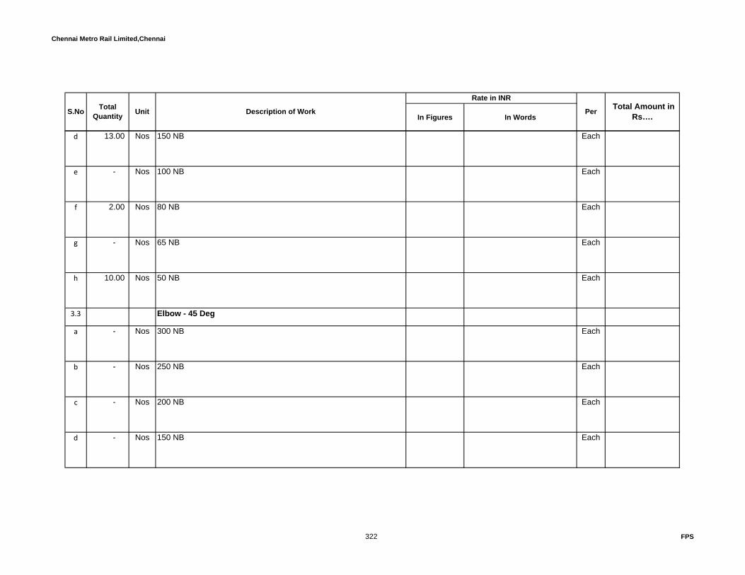
Chennai Metro Rail Limited,Chennai
In Figures In Words
Rate in INR
PerS.No TotalQuantity Unit Description of Work Total Amount in
Rs….
d 13.00 Nos 150 NB Each
e - Nos 100 NB Each
f 2.00 Nos 80 NB Each
g - Nos 65 NB Each
h 10.00 Nos 50 NB Each
3.3 Elbow - 45 Deg
a - Nos 300 NB Each
b - Nos 250 NB Each
c - Nos 200 NB Each
d - Nos 150 NB Each
322 FPS

Chennai Metro Rail Limited,Chennai
In Figures In Words
Rate in INR
PerS.No TotalQuantity Unit Description of Work Total Amount in
Rs….
e - Nos 100 NB Each
f - Nos 80 NB Each
g - Nos 65 NB Each
h - Nos 50 NB Each
3.4 End Cap
a 2.00 Nos 300 NB Each
b - Nos 250 NB Each
c 2.00 Nos 200 NB Each
d - Nos 150 NB Each
e 1.00 Nos 100 NB Each
3.5 Reducing Tee
a 5.00 Nos 300 x 200 NB Each
b 2.00 Nos 300 x 80 NB Each
323 FPS

Chennai Metro Rail Limited,Chennai
In Figures In Words
Rate in INR
PerS.No TotalQuantity Unit Description of Work Total Amount in
Rs….
c - Nos 300 x 250 NB Each
f 1.00 Nos 250 x 200 NB Each
g 4.00 Nos 250 x 150 NB Each
h - Nos 250 X 100 NB Each
i - Nos 250 x65 NB Each
j 2.00 Nos 250 x50 NB Each
3.6 Grooved Coupling
a 12.00 Nos 350NB Each
b - Nos 300NB Each
c 22.00 Nos 250NB Each
324 FPS
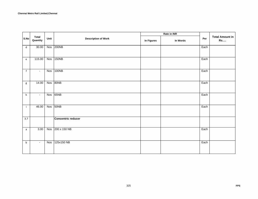
Chennai Metro Rail Limited,Chennai
In Figures In Words
Rate in INR
PerS.No TotalQuantity Unit Description of Work Total Amount in
Rs….
d 30.00 Nos 200NB Each
e 115.00 Nos 150NB Each
f - Nos 100NB Each
g 14.00 Nos 80NB Each
h - Nos 65NB Each
i 46.00 Nos 50NB Each
3.7 Concentric reducer
a 3.00 Nos 200 x 150 NB Each
b - Nos 125x150 NB Each
325 FPS

Chennai Metro Rail Limited,Chennai
In Figures In Words
Rate in INR
PerS.No TotalQuantity Unit Description of Work Total Amount in
Rs….
c - Nos 100 x 80 NB Each
d 2.00 Nos 50 x 40 NB Each
3.8 Eccentric reducer
a 3.00 Nos 250 x 200 NB Each
b 2.00 Nos 80 x 65 NB Each
4 Supply, erection, testing and installation of heavy class GI pipes conforming to IS 1239 heavy class (Equivalant to Schedule 40) pipes upto 65mm dia and above Butt welding joints ,50 dia and below threaded joints including cutting the pipes to correct lengths,roll grooving, fixing with clamps to MS brackets / hangers, steel supports, hitec supports as per NFPA with paintings and clamping as per NFPA-13. The hydro testing to (13.8 kgs/cm2) pressure.providing wherever necessary nuts, bolts, gaskets. Rates to inclusive of all complete as per specifications.
a - Rmt 350NB -8 mm thick Rmt
b 18.00 Rmt 300NB -8 mm thick Rmt
326 FPS
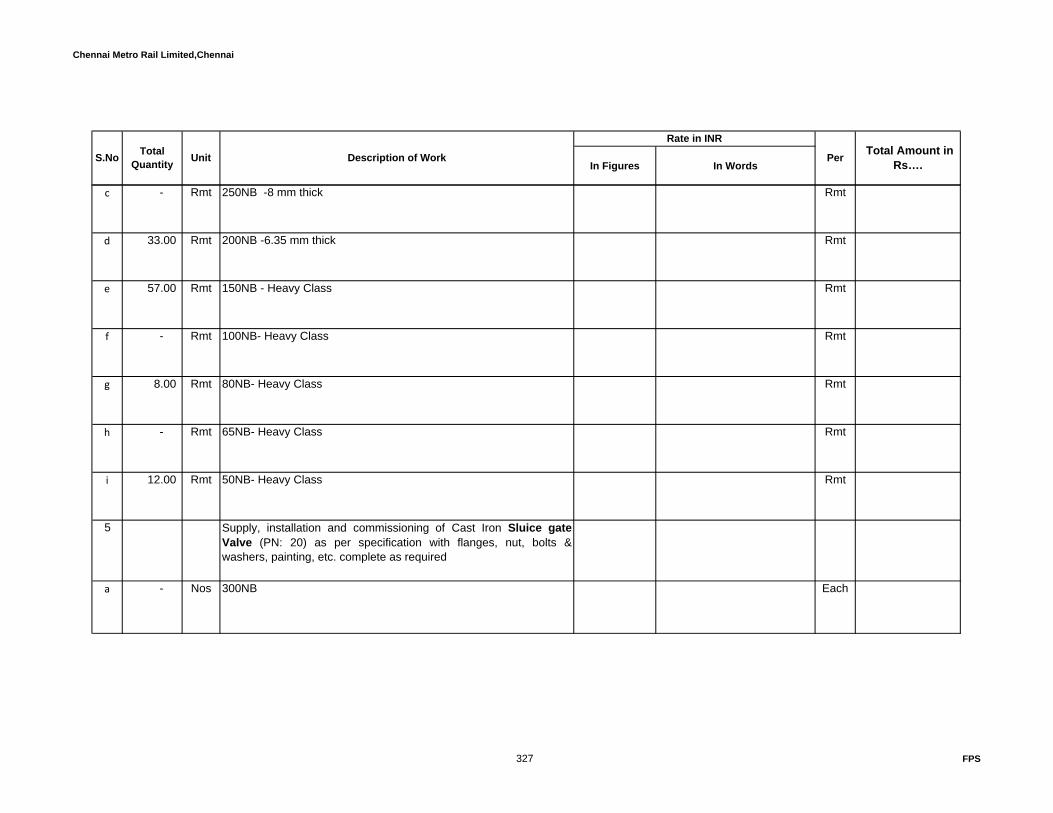
Chennai Metro Rail Limited,Chennai
In Figures In Words
Rate in INR
PerS.No TotalQuantity Unit Description of Work Total Amount in
Rs….
c - Rmt 250NB -8 mm thick Rmt
d 33.00 Rmt 200NB -6.35 mm thick Rmt
e 57.00 Rmt 150NB - Heavy Class Rmt
f - Rmt 100NB- Heavy Class Rmt
g 8.00 Rmt 80NB- Heavy Class Rmt
h - Rmt 65NB- Heavy Class Rmt
i 12.00 Rmt 50NB- Heavy Class Rmt
5 Supply, installation and commissioning of Cast Iron Sluice gateValve (PN: 20) as per specification with flanges, nut, bolts &washers, painting, etc. complete as required
a - Nos 300NB Each
327 FPS

Chennai Metro Rail Limited,Chennai
In Figures In Words
Rate in INR
PerS.No TotalQuantity Unit Description of Work Total Amount in
Rs….
b - Nos 200NB Each
c 22.00 Nos 150 NB Each
d - Nos 100 NB Each
e - Nos 80 NB Each
f - Nos 65 NB Each
g - Nos 50 NB Each
6 Supply and installation of Cast Iron gear operated Butterfly isolation valve (PN 20) as per specification with necessary flanges,nut, bolts & washers, painting, etc. complete as required
a 20.00 Nos 150 NB -Gear operated Each
b 13.00 Nos 100 NB -Gear operated Each
328 FPS

Chennai Metro Rail Limited,Chennai
In Figures In Words
Rate in INR
PerS.No TotalQuantity Unit Description of Work Total Amount in
Rs….
c 16.00 Nos 80 NB.-Lever operated Each
d 1.00 Nos 65 NB.-Lever operated Each
e - Nos 50 NB.-Lever operated Each
7 Supply, installation, testing and commissioning of FM approved post indicator valve consists of cast iron telecopic barrel, cast iron baseflange, tamper switch, the sign shall be Aluminium with minimum0.080" high and letter shall be minimum 1" high black lettering withwhite background and as per specification.
a - Nos 200 NB Each
b 3.00 Nos 150 NB Each
c - Nos 100 NB Each
d - Nos 80 NB Each
329 FPS

Chennai Metro Rail Limited,Chennai
In Figures In Words
Rate in INR
PerS.No TotalQuantity Unit Description of Work Total Amount in
Rs….
8 Supplying and installation of Ball type Cast Iron Non-Return Valves(PN:20) as per specifications including making flanged joints byproviding with necessary flanges, nut, bolts & washers, painting, etc.complete as required .
a - Nos 200 NB Each
b 8.00 Nos 150 NB Each
c 3.00 Nos 100 NB Each
d - Nos 80 NB Each
e 1.00 Nos 65 NB Each
f - Nos 50NB Each
9 Supplying and installation of gunmetal gate valve having screwedends as per specification with necessary flanges, nut, bolts &washers, painting, etc. complete as required
a - Nos 50 NB Each
330 FPS

Chennai Metro Rail Limited,Chennai
In Figures In Words
Rate in INR
PerS.No TotalQuantity Unit Description of Work Total Amount in
Rs….
b - Nos 40 NB Each
c - Nos 25 NB Each
10 Supplying and installation of Ball valve having screwed ends as perspecification with necessary flanges, nut, bolts & washers, painting,etc. complete as required
a 30.00 Nos 50 NB Each
b - Nos 40 NB Each
c - Nos 25 NB Each
11 Under Ground piping - Under Ground piping - Supply, erection,testing and installation of Ductile iron pipes conforming to IS 8329-2000 with Spigot joints to pipe with necessary gaskets,blankflanges,and Fittings(Bend,Flange tee,etc.,) shall confirm to Relevant ISstandards .Rate shall include thrust block design for tees,elbows,etcas per NFPA.
a - Rmt 200 NB - Class K-9 - 6mm thick Rmt
b 170.00 Rmt 150 NB - Class K-9 - 6mm thick Rmt
331 FPS
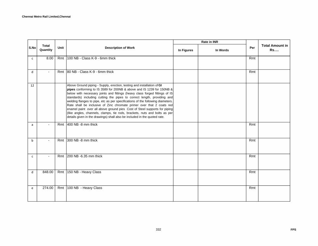
Chennai Metro Rail Limited,Chennai
In Figures In Words
Rate in INR
PerS.No TotalQuantity Unit Description of Work Total Amount in
Rs….
c 8.00 Rmt 100 NB - Class K-9 - 6mm thick Rmt
d - Rmt 80 NB - Class K-9 - 6mm thick Rmt
12 Above Ground piping - Supply, erection, testing and installation of GIpipes conforming to IS 3589 for 200NB & above and IS 1239 for 150NB &below with necessary joints and fittings (heavy class forged fittings of ISstandards) including cutting the pipes to correct length, providing andwelding flanges to pipe, etc as per specifications of the following diameters.Rate shall be inclusive of Zinc chromate primer over that 2 coats redenamel paint over all above ground pies Cost of Steel supports for piping(like angles, channels, clamps, tie rods, brackets, nuts and bolts as perdetails given in the drawings) shall also be included in the quoted rate.
a - Rmt 400 NB -8 mm thick Rmt
b - Rmt 300 NB -8 mm thick Rmt
c - Rmt 200 NB -6.35 mm thick Rmt
d 848.00 Rmt 150 NB - Heavy Class Rmt
e 274.00 Rmt 100 NB - Heavy Class Rmt
332 FPS

Chennai Metro Rail Limited,Chennai
In Figures In Words
Rate in INR
PerS.No TotalQuantity Unit Description of Work Total Amount in
Rs….
f 34.00 Rmt 80 NB - Heavy Class Rmt
g 4.00 Rmt 65 NB - Heavy Class Rmt
h - Rmt 50 NB - Heavy Class Rmt
i - Rmt 40 NB - Heavy Class Rmt
j - Rmt 32 NB - Heavy Class Rmt
k - Rmt 25 NB - Heavy Class Rmt
13 - Nos Supply, installation, testing and commissioning of courtyard Gunmetal Single headed hydrant as per IS: 5290 consisting of 63NBsingle outlet flanged oblique type hydrants valve with instantaneousfemale plunger type coupling, chained blank cap including makingflanged joints by providing necessary nuts, bolts, gaskets allcomplete as per specifications suitable for 80 NB stand post.
Each
333 FPS

Chennai Metro Rail Limited,Chennai
In Figures In Words
Rate in INR
PerS.No TotalQuantity Unit Description of Work Total Amount in
Rs….
14 56.00 Nos Supply, installation, testing and commissioning of 63mm dia.approved make GM double headed fire hydrant landing valves(with pressure reducing valve,instantaneous female plunger typecouplings, chained blank caps) including making flanged joints byproviding necessary nuts, bolts, gaskets, etc. painting complete asper specifications.
Each
15 8.00 Nos Supply, installation, testing and commissioning of 63mm dia.approved make GM single headed fire hydrant landing valves(with pressure reducing valve,instantaneous female plunger typecouplings, chained blank caps) including making flanged joints byproviding necessary nuts, bolts, gaskets, etc. painting complete asper specifications.
Each
16 10.00 Nos Supply and installation of Hose cabinet consists of 2 nos RRL type-A hoses of 63mm dia x 15 meters long with heavy quality gun metalmale coupling as per IS: 903 combined with 2 Nos of nozzle andbranch pipe. Rate shall be inclusive of cabinet fabricated from MSsheet (16 SWG thick) of size 750x600x250 with 4MM thick havingdouble glass toughened fronted door, painted in red out side andwhite in inside, hose boxes along with GI support angles forcourtyard hydrants/internal hydrants.
Each
17 Supply and installation of Hose cabinet consists of 2 nos RRL type-A hoses of 63mm dia x 7.5 meters long with heavy quality gunmetal male coupling as per IS: 903 combined with 1 Nos of nozzleand branch pipe. Rate shall be inclusive of cabinet fabricated fromMS sheet (16 SWG thick) of size 750x600x250 with 4MM thickhaving double glass toughened fronted door, painted in red out sideand white in inside, hose boxes along with GI support angles forcourtyard hydrants/internal hydrants.
Each
334 FPS

Chennai Metro Rail Limited,Chennai
In Figures In Words
Rate in INR
PerS.No TotalQuantity Unit Description of Work Total Amount in
Rs….
46.00 Nos Supply and installation of MS Hose Tray consists of 2 nos RRL type-A hoses of 63mm dia x 15 meters long with heavy quality gun metalmale coupling as per IS: 903 combined with 2 Nos of nozzle andbranch pipe for internal hydrants located inside the FCO
18 8.00 Nos Supply and installation of MS Hose Tray consists of 2 nos RRL type-A hoses of 63mm dia x 15 meters long with heavy quality gun metalmale coupling as per IS: 903 combined with 1 No of nozzle andbranch pipe for internal hydrants located inside the FCO
Each
19 54.00 Nos Supply & Installation of drum type wall mounting hose reels, swiveling 180o consisting of 25 mm dia. x 36 meters long armoredrubber hose pipe with 15 mm dia. bronze shut of type jet nozzle &cut-off valve on the inlet including making connection to the wetriser, by drilling welding, fixing the hose reel to the wall by providingnecessary anchor fasteners/ expansion bolts, grouting the same withcement mortar, painting all complete as per drawings, specifications.
Each
20 9.00 Nos Supply & installation of Siamese 4Way Fire Brigade inletconnection with provision for Four male instantaneous couplingfabricated out of 150 mm dia. approved make heavy class MS pipefor fire fighting system including necessary fittings to the fire storagetank, ring mains of wet riser and sprinkler system. Rate shallinclusive of painting the same with 2 coats of red enamel paint overa coat of Zinc Chromate primer all complete as per drawings andspecifications.
Each
21 54.00 Nos Supply and fixing of Fire shaft door fabricated out of M.S. sheetand frame, door shall be 900mm x 1500mm min with double leaf. &fixed with 4 mm thick Glass, suitable Rubber beeding and Lockingarrangement. Quoted rate shall be includes all fasteners etc, andcomplete shutter shall be powder coated of approved colour bothinside and out side.
Each
335 FPS

Chennai Metro Rail Limited,Chennai
In Figures In Words
Rate in INR
PerS.No TotalQuantity Unit Description of Work Total Amount in
Rs….
22 - Sq.m Supply and wraping of Coating & Wrapping Materials manufactured as per IS 10221 (make:Pypkote) 4mm thick forunderground Pipes as per specification
Sq.m
23 Designing, providing and fixing Orifice plate made out of stainlesssteel plate (thickness as per specification) with matching flanges onboth sides for following size of pipe to reduce pressure upto 3.5Kg/sqcm complete in all respects.
i - Nos 100 NB Each
ii - Nos 80 NB Each
24 9.00 Nos Supply & installation of 20 NB CI Automatic Air Release Valvealong with ball valve to all wet risers all complete as perspecifications.
Each
25 1.00 Nos Supply and installation of 150mm dia venturi type flow meter able to measure 175 % of the pump rating.
Each
26 1.00 Nos Supply,installation and commissioning of 200 mm dia pressure reducing valve (range 8 - 16 bar)
27 1.00 Set Test Array Manifold Arangement for pumpset with pressure guage (1No.), pressure switch (3 Nos.)
Set
28 1.00 Set Test Array Manifold Arangement for pumpset with pressure guage (1 No.), pressure switch (2 Nos.)
Set
336 FPS

Chennai Metro Rail Limited,Chennai
In Figures In Words
Rate in INR
PerS.No TotalQuantity Unit Description of Work Total Amount in
Rs….
29 1.00 Set Test Array Manifold Arangement for pumpset with pressure guage (1 No.), pressure switch (1 No.)
Set
30 28.00 Nos Supply and erection of Bourdon type Pressure gauges complete with ball valve, valve mounting, fittings and copper tubing extension where required.The dial shall be 150mm dia
Each
Total amount for Hydrant System Carry over summaryC SPRINKLER SYSTEM
1 Under Ground piping - Under Ground piping - Supply, erection,testing and installation of Ductile iron pipes conforming to IS 8329-2000 with Spigot joints to pipe with necessary gaskets,blankflanges,and Fittings(Bend,Flange tee,etc.,) shall confirm to RelevantIS standards .Rate shall include thrust block design fortees,elbows,etc as per NFPA.
a - Rmt 200 NB - Class K-9 - 6mm thick Rmt
b 32.00 Rmt 150 NB - Class K-9 - 6mm thick Rmt
337 FPS

Chennai Metro Rail Limited,Chennai
In Figures In Words
Rate in INR
PerS.No TotalQuantity Unit Description of Work Total Amount in
Rs….
2 Supply, erection, testing and installation of GI pipes conforming toIS 3589 for 200NB & above and IS 1239 for 150NB & below withnecessary joints and fittings (heavy class forged fittings of ISstandards) including cutting the pipes to correct length, providingand welding flanges to pipe, etc as per specifications of the followingdiameters. Rate shall be inclusive of Zinc chromate primer over that2 coats red enamel paint as per over all above ground pies a Costof Steel supports for piping (like angles, channels, clamps, tie rods,brackets, nuts and bolts as per details given in the drawings) shallalso be included in the quoted rate.
a - Rmt 200 NB -6.35 mm thick Rmt
b 1,171.00 Rmt 150 NB - Heavy Class Rmt
c 485.00 Rmt 100 NB - Heavy Class Rmt
d 408.00 Rmt 80 NB - Heavy Class Rmt
e 597.00 Rmt 65 NB - Heavy Class Rmt
f 1,871.00 Rmt 50 NB - Heavy Class Rmt
338 FPS

Chennai Metro Rail Limited,Chennai
In Figures In Words
Rate in INR
PerS.No TotalQuantity Unit Description of Work Total Amount in
Rs….
g 1,495.00 Rmt 40 NB - Heavy Class Rmt
h 608.00 Rmt 32 NB - Heavy Class Rmt
i 4,808.00 Rmt 25 NB - Heavy Class Rmt
3 Supply and installation of Side wall Sprinkler head with thefollowing temperature rating & respond, universal deflector,chromium finish as per specifications. Size: 15-mm dia.
a 210.00 Nos Sprinkler Temperature -68°C (K=80) Quick response Each
b 84.00 Nos Sprinkler Temperature - 100°C (K=80) Standard response standardresponse for kitchen
Each
4 Supply and installation of FM approved Pendant Sprinkler head withthe following temperature rating & respond, universal deflector,chromium finish, stainless steel rossette plate as perspecifications.The sprinkler head shall be 3/4 inches
a 993.00 Nos Temperature Rating: 68°C (K=80) Quick response Each
b - Nos Temperature Rating:79°C (K=80) Quick response Each
339 FPS

Chennai Metro Rail Limited,Chennai
In Figures In Words
Rate in INR
PerS.No TotalQuantity Unit Description of Work Total Amount in
Rs….
5 Supply and installation of Upright Sprinkler head with the following temperature rating & respond, universal deflector, as per specifications. The sprinkler head shall be 3/4 inches
a 2,078.00 Nos Sprinkler Temperature - 79°C (K=80) Quick response Each
6 993.00 Nos Supply, erection, testing and commissioning of UL/FM approvedMetallic stainless steel (SS 304) braided Flexible drop pipes of25mm dia with cross bar assembly support suitable for grid ceiling,reducing fitting, special shoulder Nipple, redcing nipple, T bar braket,braket clip assembly. Flexible length shall be upto 1500mm long
Each
7 Supplying & installing of FM approved make vane type flow switches(flow sensors) suitable to be fixed directly on line of the followingdiameters, with 1 NO & 1 NC potential free contacts (suitableprovision for IBMS system)
a 10.00 Nos 150NB Each
b 2.00 Nos 100NB Each
c 15.00 Nos 80NB Each
8 6,200.00 Rmt Supply & installation of Instrument cables for flow switches. Thecable should be 2 core x 1.5 Sq.mm copper armoured cable.
Rmt
340 FPS

Chennai Metro Rail Limited,Chennai
In Figures In Words
Rate in INR
PerS.No TotalQuantity Unit Description of Work Total Amount in
Rs….
9 6.00 Nos Supply and instaltion of FM approved alarm check valve with fullvalve trim. The alarm check valve shall be equipped with aremovable cover assembly. The alrm valve shall be listed for verticalposition. T shall be equipped with gauge connections on the systemside and supply side of the valve claper. The alarm valve trim pipingshall be externally galvanised. Maximum water working pressure to250 PSI. This shall be inclusive of hydraulic powered water motoralarm by way of integral valve alarm line trim piping. Water motorgong shall be connected to a water pressure retarding chamber tolimit the propensity of unnecessary alarms. Water motor alarm shallbe equipped with a rear closure plate to limit the access of foreignmaterials of accumulation of debris. Water
Each
10 1.00 Nos Supply and installation of sprinkler Annunciator panel consisting of63 windows capable of working on 230V AC single phase supplyand provided with battery back-up of 24V complete as perspecification. Each windows shall be provided with potential freecontact for connecting to the BMS system
Each
11 2,300.00 Kg Supply & Installation of MS Structural Supports with one coat ofredoxide & two coats of synthetic enamel paint and structure workincluding all welding,Nut-bolting and accessories
Kg
Total amount for Sprinkler System carry over summaryD PORTABLE FIRE EXTINGUISHERS:
1 Supply & installation of following Portable Fire Extinguisher :ABC Type Extinguisher
Capacity - 4 Kg
Type - Upright
IS - 13849,15683
Carbon Dioxide Fire Extinguisher
Each
Each64 Nos
86 Nos
b
a
341 FPS

Chennai Metro Rail Limited,Chennai
In Figures In Words
Rate in INR
PerS.No TotalQuantity Unit Description of Work Total Amount in
Rs….
Capacity - 4.5 Kg
Type - Upright
IS - 2878,15683
Carbon Dioxide Fire Extinguisher
Capacity - 2.0 Kg
Type - Upright
IS - 2878,15683
Foam Fire Extinguisher
Capacity - 9 Litres
Type - Upright, Trolley mounted
IS - 10204,15683
DCP Type Extinguisher
Capacity - 6 Kg
Type - Upright
IS - 2171,15683
Clean agent Fire Extinguisher
Capacity - 2 Kg
Type - Upright
Water type Fire Extinguisher
Each
Each2 Nos
Each
Each
Each
17 Nos
g
1 Nos
f
7 Nos
e
0 Nos
d
c
342 FPS

Chennai Metro Rail Limited,Chennai
In Figures In Words
Rate in INR
PerS.No TotalQuantity Unit Description of Work Total Amount in
Rs….
Capacity - 9 litres
Type - Upright
2 11.00 Nos Supply and installation of Fire buckets of 9 ltrs capacity. Standmade of MS Channel and angle to accommodate 4 Nos of bucketsfilled with cleaned soft sand. Rate shall be inclusive of red panit asper Fire Codes for buckets and MS Stand.
Each
Total amount for Sprinkler System carry over summaryE TRANSFORMER SPRINKLER
1 Above Ground Piping - Supply, erection, testing and installation of GI steel pipes heavy class conforming to IS 1239- heavy grade with welded joints including cutting the pipes to correct lengths, fixing with clamps to MS brackets / hangers, steel supports, hitec supports and paintings. (including heavy class forged fittings of IS standards) of the following diameters. Make: Tata/Jindal
a 12.00 Rmt 150 NB -Heavy Class Rmt
b 36.00 Rmt 100 NB -Heavy Class Rmt
c - Rmt 80 NB -Heavy Class Rmt
d 36.00 Rmt 65 NB - Heavy Class Rmt
343 FPS

Chennai Metro Rail Limited,Chennai
In Figures In Words
Rate in INR
PerS.No TotalQuantity Unit Description of Work Total Amount in
Rs….
e 36.00 Rmt 50 NB -Heavy Class Rmt
f 24.00 Rmt 40 NB - Heavy Class Rmt
g 96.00 Rmt 25 NB - Heavy Class Rmt
2 Under Ground piping - Supply, erection, testing and commissioning of GI pipes heavy class conforming to IS 3589 for 200NB & above and IS 1239 for 150NB & below with necessary joints and fittings (heavy class forged fittings of IS standards) including cutting the pipes to correct length, providing and welding flanges to pipe, etc as per specifications of the following diameters. Rates shall be inclusive of Holiday test complete as per specifications of the following diameters and all necessary supports.
a 80.00 Rmt 150 NB.-Heavy Class Rmt
b 20.00 Rmt 100 NB. -Heavy Class Rmt
c - Rmt 80 NB -Heavy Class Rmt
d - Rmt 65 NB - Heavy Class Rmt
344 FPS

Chennai Metro Rail Limited,Chennai
In Figures In Words
Rate in INR
PerS.No TotalQuantity Unit Description of Work Total Amount in
Rs….
e - Rmt 50 NB -Heavy Class Rmt
f - Rmt 40 NB - Heavy Class Rmt
g - Rmt 25 NB - Heavy Class Rmt
3 Providing and laying reinforced cement concrete heavy duty NP3 type hume pipe of the following diameter with necessary collars conforming to IS 458 complete as per specifications.
a - Nos 400 NB Hume pipe for Hydrant pipe Each
b 38.00 Nos 300 NB Hume pipe for Hydrant pipe Each
c 10.00 Nos 250 NB Hume pipe for Hydrant pipe Each
4 4.00 Nos Supply and installation of Cast Iron Butterfly isolation valve with limit switch (PN 20) with necessary flanges, supports, bolts, nuts, etc - 100 mm DIA
Each
5 2.00 Nos Supply and installation of Cast Iron Butterfly isolation valve (PN 20) with necessary flanges, supports, bolts, nuts, etc - 100 mm DIA : Make: Audco / Intervalve
Each
6 Supply, erection, testing and commissioning of Ball valve having screwed ends with nessary flanges for easy maintenance.
345 FPS

Chennai Metro Rail Limited,Chennai
In Figures In Words
Rate in INR
PerS.No TotalQuantity Unit Description of Work Total Amount in
Rs….
a - Nos 50 NB , Each
b - Nos 25 NB , Each
7 Supply and installation of CI Fabricated basket type 'Y' type strainer
a - Nos 200 mm dia Each
b 1.00 Nos 100mm dia Each
c - Nos 65 mm dia Each
8 2.00 Nos FM Approved Pressure Gauge & syphon with isolating valves. Make: Tyco/Wika
Each
9 2.00 Set Supply,installation and commissioning of FM approved Deluge valve 100 mm dia with Hydraulic / electrical operated
Set
10 Supply,installation and commissioning of FM approved High velocity Water spray nozzle with brass chrome plated for the below K factor.The angle shall be designed based on the shop drawing and distance from the transformer - Make : HD Fire
a 30.00 Nos K factor -1.82 Each
346 FPS

Chennai Metro Rail Limited,Chennai
In Figures In Words
Rate in INR
PerS.No TotalQuantity Unit Description of Work Total Amount in
Rs….
b 30.00 Nos K factor -2.24 Each
11 50.00 Nos Quterzoid bulb detector K-80 79 deg C.. HD Fire Each
12 CONTROL PANEL/CABLES:
a 2.00 Nos Weather proof Local control Panel for Deluge valve including battery charger / batteries of 24 volts/22.5 Amp. Hr.
Each
b 2.00 Nos. Weather proof MCP - Make : Baliga Each.
c 2.00 Nos. Electronic Hooter Make: Ravel Each.
d 100.00 Rmtr 4 C x 2.5 Sq.mm 'Cu' Armoured Cable Rmtr
e 50.00 Rmtr 2 C x 2.5 Sq.mm 'Cu' Armoured Cable Rmtr
f 2.00 Nos. Flow switch - 100 dia Each.
g 2.00 Nos. Differential pressure switch Each.
347 FPS

Chennai Metro Rail Limited,Chennai
In Figures In Words
Rate in INR
PerS.No TotalQuantity Unit Description of Work Total Amount in
Rs….
13 1.00 No Construction of 230mm PCC deluge valve housing chamber at height of 2500mm as per BIS/TAC
No
14 2,400.00 Kgs Supply and installation of MS support,angle,bracket plate,varios plates , clamp,GI U bolt,GI bolt & nut ect. Inclusive of painting wherever required for water spray system
Kgs
15 1.00 Lot Testing and commissioning of the Fire Fighting system with one time flushing and re- filling the water by the contractor after completion of all the works with respect to waterfilling/pressure checking/commissioning the equipments with proper air releasing points.
Lot
Total amount for Transformer Sprinkler System carry over summary
348 FPS
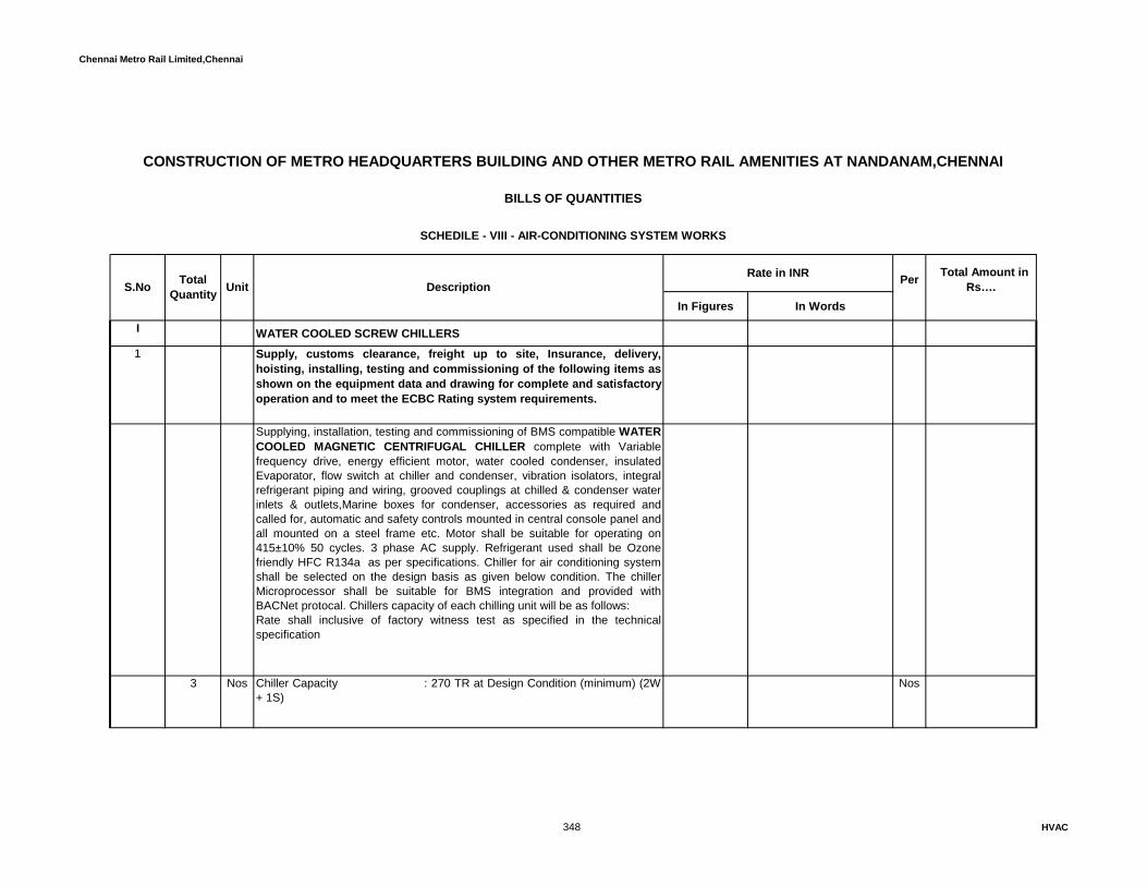
Chennai Metro Rail Limited,Chennai
In Figures In Words
I WATER COOLED SCREW CHILLERS1 Supply, customs clearance, freight up to site, Insurance, delivery,
hoisting, installing, testing and commissioning of the following items asshown on the equipment data and drawing for complete and satisfactoryoperation and to meet the ECBC Rating system requirements.
Supplying, installation, testing and commissioning of BMS compatible WATER COOLED MAGNETIC CENTRIFUGAL CHILLER complete with Variablefrequency drive, energy efficient motor, water cooled condenser, insulatedEvaporator, flow switch at chiller and condenser, vibration isolators, integralrefrigerant piping and wiring, grooved couplings at chilled & condenser waterinlets & outlets,Marine boxes for condenser, accessories as required andcalled for, automatic and safety controls mounted in central console panel andall mounted on a steel frame etc. Motor shall be suitable for operating on415±10% 50 cycles. 3 phase AC supply. Refrigerant used shall be Ozonefriendly HFC R134a as per specifications. Chiller for air conditioning systemshall be selected on the design basis as given below condition. The chillerMicroprocessor shall be suitable for BMS integration and provided withBACNet protocal. Chillers capacity of each chilling unit will be as follows:Rate shall inclusive of factory witness test as specified in the technicalspecification
3 Nos Chiller Capacity : 270 TR at Design Condition (minimum) (2W+ 1S)
Nos
Rate in INR Total Amount in Rs….
CONSTRUCTION OF METRO HEADQUARTERS BUILDING AND OTHER METRO RAIL AMENITIES AT NANDANAM,CHENNAI
BILLS OF QUANTITIES
SCHEDILE - VIII - AIR-CONDITIONING SYSTEM WORKS
S.No TotalQuantity Unit Description Per
348 HVAC
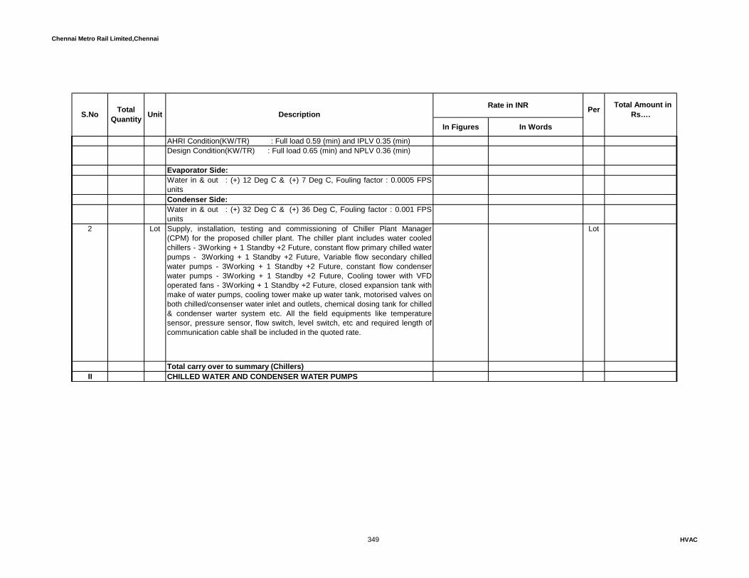
Chennai Metro Rail Limited,Chennai
In Figures In Words
Rate in INR Total Amount in Rs…. S.No Total
Quantity Unit Description Per
AHRI Condition(KW/TR) : Full load 0.59 (min) and IPLV 0.35 (min)Design Condition(KW/TR) : Full load 0.65 (min) and NPLV 0.36 (min)
Evaporator Side:Water in & out : (+) 12 Deg C & (+) 7 Deg C, Fouling factor : 0.0005 FPSunitsCondenser Side:Water in & out : (+) 32 Deg C & (+) 36 Deg C, Fouling factor : 0.001 FPSunits
2 Lot Supply, installation, testing and commissioning of Chiller Plant Manager(CPM) for the proposed chiller plant. The chiller plant includes water cooledchillers - 3Working + 1 Standby +2 Future, constant flow primary chilled waterpumps - 3Working + 1 Standby +2 Future, Variable flow secondary chilledwater pumps - 3Working + 1 Standby +2 Future, constant flow condenserwater pumps - 3Working + 1 Standby +2 Future, Cooling tower with VFDoperated fans - 3Working + 1 Standby +2 Future, closed expansion tank withmake of water pumps, cooling tower make up water tank, motorised valves onboth chilled/consenser water inlet and outlets, chemical dosing tank for chilled& condenser warter system etc. All the field equipments like temperaturesensor, pressure sensor, flow switch, level switch, etc and required length ofcommunication cable shall be included in the quoted rate.
Lot
Total carry over to summary (Chillers)II CHILLED WATER AND CONDENSER WATER PUMPS
349 HVAC

Chennai Metro Rail Limited,Chennai
In Figures In Words
Rate in INR Total Amount in Rs…. S.No Total
Quantity Unit Description Per
1 Supplying, installing, testing and commissioning of Centrifugal End Suction Pumps, factory mounted on a common base with electric motor for recirculation of water for the central air conditioning system. All pumps shall be factory aligned properly as required. The pump motor shall be suitable for 415 + 10% volts, 50 cycles, 3 phase power supply & high efficiency (IE3). The quoted price shall include cost of thermal insulation and cladding for chilled water application. Pump shall be made of C.I. casing, bronze impeller, mechanical seal, Internal Self-flushing type, stainless steel(SS316) shaft sleeve, integral motors complete with Factory made weather cowl, acoustic box, drive guard, 50x50x3 mm thick nosing angle frame floating fountation with spring isolator as per specification. Based on the Approved shop drawing the pump head calculation shall be submitted along with the Data sheets. Pumps with performance characteristics as given below:
a 3 Nos. Primary Chilled water pumps (2W + 1S) Nos.
Flow Rate & Head : 720 USGPM, 15mIndicative motor rating : 11.0 kW
b 3 Nos. Secondary Chilled water pumpset (2W + 1S) Nos.
Flow Rate & Head : 705 USGPM, 25mIndicative motor rating : 18.7 kW
c 3 Nos. Condenser water pumps (2W + 1S) Nos.
Flow Rate & Head : 1000 USGPM, 18mIndicative motor rating : 20.0 kW
350 HVAC
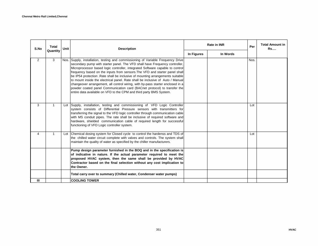
Chennai Metro Rail Limited,Chennai
In Figures In Words
Rate in INR Total Amount in Rs…. S.No Total
Quantity Unit Description Per
2 3 Nos. Supply, installation, testing and commissioning of Variable Frequency Drivesecondary pump with starter panel. The VFD shall have Frequency controller,Microprocessor based logic controller, integrated Software capable to controlfrequency based on the inputs from sensors.The VFD and starter panel shallbe IP54 protection .Rate shall be inclusive of mounting arrangements suitableto mount inside the electrical panel. Rate shall be inclusive of Auto / Manualchangeover arrangement, all control wiring, with by-pass starter enclosed in apowder coated panel Communication card (BACnet protocol) to transfer theentire data available on VFD to the CPM and third party BMS System.
Nos.
3 1 Lot Supply, installation, testing and commissioning of VFD Logic Controllersystem consists of Differential Pressure sensors with transmitters fortransferring the signal to the VFD logic controller through communication cable with MS conduit pipes. The rate shall be inclusive of required software andhardware, shielded communication cable of required length for successfulfunctioning of VFD Logic controller system.
Lot
4 1 Lot Chemical dosing system for Closed cycle to control the hardenss and TDS ofthe chilled water circuit complete with valves and controls. The system shallmaintain the quality of water as specified by the chiller manufacturers.
Lot
Pump design parameter furnished in the BOQ and in the specification isof indicative in nature. If the actual parameter required to meet theproposed HVAC system, then the same shall be provided by HVACContractor based on the final selection without any cost implication tothe Owner.
Total carry over to summary (Chilled water, Condenser water pumps)
III COOLING TOWER
351 HVAC

Chennai Metro Rail Limited,Chennai
In Figures In Words
Rate in INR Total Amount in Rs…. S.No Total
Quantity Unit Description Per
1 Supplying, installing, testing and commissioning of Cross Flow or Counterflow,Induced Draft, Vertical Discharge Type, Single Cell, Fibre glass & Galvanizedsteel Cooling Tower complete with motor, fan, film type Fill, other completeaccessories as described in the technical specifications. It shall be designedwith high efficiency drift eliminator. Vibration Isolators of spring open typedesigned to minimize any vibration from transmitting to other structures to beincluded in the scope of supply. Motors shall be suitable for 415 + 10%volt, 50cycles 3phase power supply and high efficiency IE 3 type. Isolators at coolingtower enclosed in weather proof panel shall also be included. Tower for airconditioning system shall be selected on the basis of below condition and theTower shall be CTI certified. The heat rejection capacity of the tower must be1.25 times greater than the chiller capacity. The tower fan motor shall besuitable for VFD Operation.
3 Nos. Chiller Capacity : 270 TR (2W + 1S) Nos.
Cooling Tower Capacity : 338 TR (minimum)Water Flow Rate : 1000 USGPMWater Temp In & Out : 35 oC & 31 oC
Wet bulb Temperature : 28.6 ° C Max.Motor rating : 11 KW
2 3 Nos. Supply, installation, testing and commissioning of Variable Frequency Driveand temperature sensors/pressure transmitter with wiring(FRLS shieldedcable). The VFD shall have Frequency controller, Microprocessor based logiccontroller, integrated Software capable to control frequency based on theinputs from temperature sensors. Rate shall be inclusive of Auto / Manualchangeover arrangement, all control wiring, with by-pass starter enclosed in apowder coated panel. The VFD and starter panel shall be IP54 protection.The rate shall also be inclusive of Communication card (BACnet protocol) totransfer the entire data available on VFD to the CPM and third party BMSSystem.
Nos.
352 HVAC

Chennai Metro Rail Limited,Chennai
In Figures In Words
Rate in INR Total Amount in Rs…. S.No Total
Quantity Unit Description Per
3 1 Lot Supply, installation, testing and commissioning of VFD Logic Controllersystem consists of temperature sensors with transmitters for transferring thesignal to the VFD logic controller. The rate shall be inclusive of requiredsoftware and hardware, shielded copper communication cable of requiredlength for successful functioning of VFD Logic controller system.
Lot
4 1 Lot Design,supply,installation and commisioning of Auto Chemical dosagesystem with required PLC controller with tank and pump for chilled watersystem with dosage pump,passivation,pre cleaning chemicals and regulartreatment. The PLC controller shall be suitable for integration with BMSintegration and provided with open BAcnet protocol.
Lot
Total carry over to summary (Cooling tower)IV PIPES AND VALVES1 Supply, erection, testing and commissioning of chilled water & condenser
water pipes. Pipes will be of Mild Steel - Heavy class’. The thickness of thepipes up to 150mm Dia as per IS 1239, minimum 6.3 mm thick for 200mmand 250mm Dia pipes and 8mm thick above 300mm Dia as per IS 3589. Rateshall be inclusive of all necessary fittings like bends, elbows, Tee, etc andinclusive of making hole in the wall, chasing, chipping, making good withplastering after completion of work, pipe sleeve of suitable higher size, sealingthe sleeves with 2 hour fire sealant, etc. Cost of supports for piping likeclamps, anchor fasteners, tie rods, brackets, nuts and bolts, etc as shall alsobe included in the quoted rate.
a 5 Rmt 400 NB - 8.0 mm thick Rmt
b 4 Rmt 350 NB - 8.0 mm thick Rmt
c 6 Rmt 300 NB - 8.0 mm thick Rmt
353 HVAC
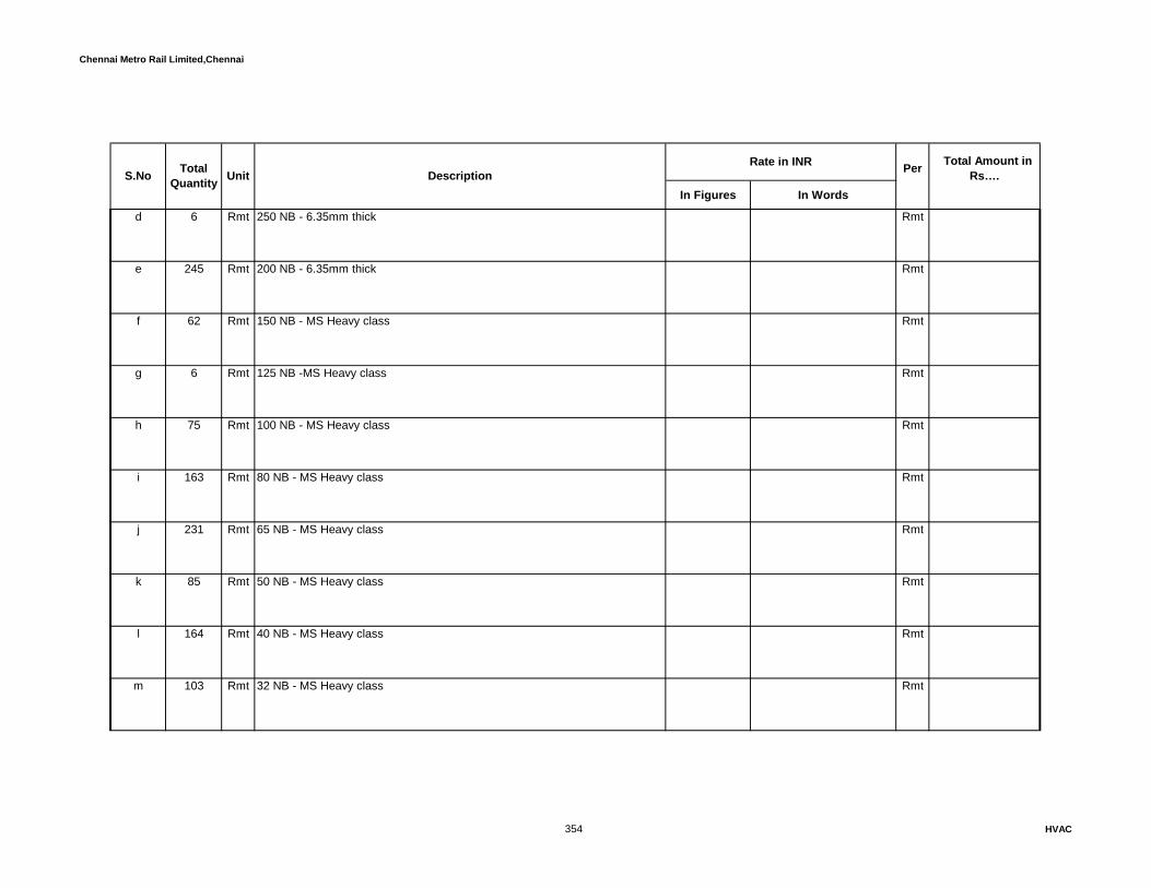
Chennai Metro Rail Limited,Chennai
In Figures In Words
Rate in INR Total Amount in Rs…. S.No Total
Quantity Unit Description Per
d 6 Rmt 250 NB - 6.35mm thick Rmt
e 245 Rmt 200 NB - 6.35mm thick Rmt
f 62 Rmt 150 NB - MS Heavy class Rmt
g 6 Rmt 125 NB -MS Heavy class Rmt
h 75 Rmt 100 NB - MS Heavy class Rmt
i 163 Rmt 80 NB - MS Heavy class Rmt
j 231 Rmt 65 NB - MS Heavy class Rmt
k 85 Rmt 50 NB - MS Heavy class Rmt
l 164 Rmt 40 NB - MS Heavy class Rmt
m 103 Rmt 32 NB - MS Heavy class Rmt
354 HVAC

Chennai Metro Rail Limited,Chennai
In Figures In Words
Rate in INR Total Amount in Rs…. S.No Total
Quantity Unit Description Per
n 18 Rmt 25 NB - MS Heavy class Rmt
2Supply of Pre-insulated heavy Class MS Pipes .Chilled water pipeinsulation with 30mm thick upto 100 mm dia & 50 mm thick from 125 mm diato 300 mm dia and 75 mm thick from 350mm dia with 40+/-2Kg/Cu.Mtrdensity PUF insulation covered with 24g G.I spiral Cladding." The joint shallbe insulated with injuction method by recommended machine
a 120 Rmt 400 NB - 8.0 mm thick Rmt
b 560 Rmt 350 NB - 8.0 mm thick Rmt
c 12 Rmt 300 NB - 8.0 mm thick Rmt
d 6 Rmt 250 NB - 6.35mm thick Rmt
e 140 Rmt 200 NB - 6.35mm thick Rmt
f 18 Rmt 150 NB - MS Heavy class Rmt
g 18 Rmt 125 NB - MS Heavy class Rmt
355 HVAC
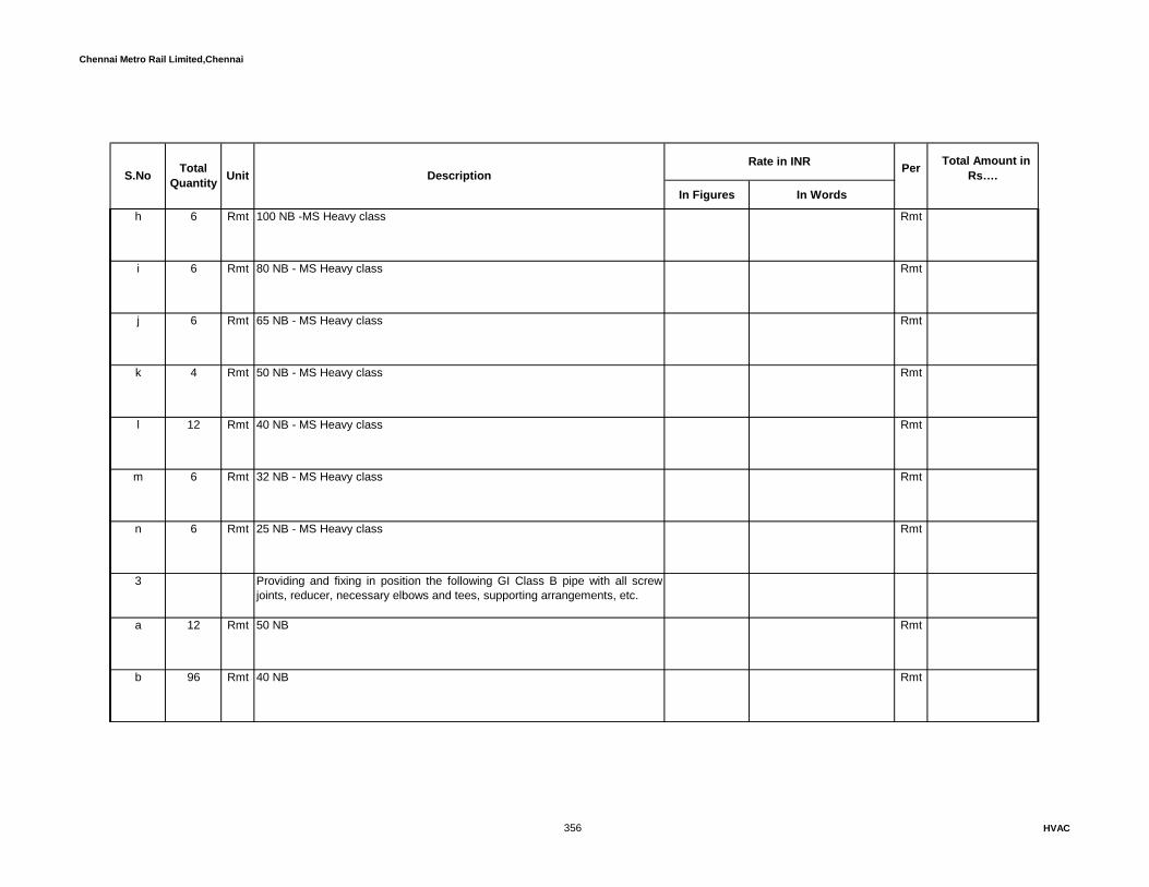
Chennai Metro Rail Limited,Chennai
In Figures In Words
Rate in INR Total Amount in Rs…. S.No Total
Quantity Unit Description Per
h 6 Rmt 100 NB -MS Heavy class Rmt
i 6 Rmt 80 NB - MS Heavy class Rmt
j 6 Rmt 65 NB - MS Heavy class Rmt
k 4 Rmt 50 NB - MS Heavy class Rmt
l 12 Rmt 40 NB - MS Heavy class Rmt
m 6 Rmt 32 NB - MS Heavy class Rmt
n 6 Rmt 25 NB - MS Heavy class Rmt
3 Providing and fixing in position the following GI Class B pipe with all screwjoints, reducer, necessary elbows and tees, supporting arrangements, etc.
a 12 Rmt 50 NB Rmt
b 96 Rmt 40 NB Rmt
356 HVAC

Chennai Metro Rail Limited,Chennai
In Figures In Words
Rate in INR Total Amount in Rs…. S.No Total
Quantity Unit Description Per
c 24 Rmt 25 NB Rmt
4 Supply and installation of closed cell elastromeric Nitrile rubber insulation with24 gauge aluminium cladding for chilled water piping and the density shall bebetween 40-60 Kg/Cu.Mtr. • Thermal conductivity of elastomeric nitrile rubbershall not exceed 0.035 W/m.K at an mean temperature of 0 deg C as perspecification.
6 Rmt 44mm thick insulation for 350 NB pipe Rmt
a 6 Rmt 44mm thick insulation for 300 NB pipe Rmt
b 6 Rmt 44mm thick insulation for 250 NB pipe Rmt
b 240 Rmt 38mm thick insulation for 200 NB pipe Rmt
c 60 Rmt 38mm thick insulation for 150 NB pipe Rmt
d 12 Rmt 38mm thick insulation for 125 NB pipe Rmt
e 75 Rmt 38mm thick insulation for 100 NB pipe Rmt
357 HVAC

Chennai Metro Rail Limited,Chennai
In Figures In Words
Rate in INR Total Amount in Rs…. S.No Total
Quantity Unit Description Per
f 160 Rmt 38mm thick insulation for 80 NB pipe Rmt
g 215 Rmt 32mm thick insulation for 65 NB pipe Rmt
h 85 Rmt 32mm thick insulation for 50 NB pipe Rmt
i 164 Rmt 32mm thick insulation for 40 NB pipe Rmt
j 102 Rmt 32mm thick insulation for 32 NB pipe Rmt
k 18 Rmt 32mm thick insulation for 25 NB pipe Rmt
5 Supply, installation, testing and commissioning of Metallic-Rubber bellowflexible connections of suitable pressure rating to be installed at equipmentssuction, discharge and at pipes crossing building expansion joints.
a 1 Nos. 250 NB Nos.
b 30 Nos. 200 NB Nos.
c 1 Nos. 150 NB Nos.
358 HVAC
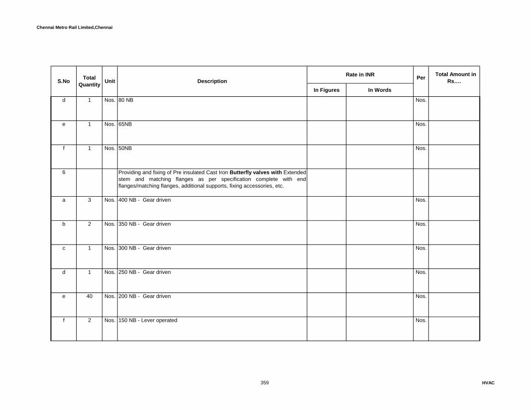
Chennai Metro Rail Limited,Chennai
In Figures In Words
Rate in INR Total Amount in Rs…. S.No Total
Quantity Unit Description Per
d 1 Nos. 80 NB Nos.
e 1 Nos. 65NB Nos.
f 1 Nos. 50NB Nos.
6 Providing and fixing of Pre insulated Cast Iron Butterfly valves with Extended stem and matching flanges as per specification complete with endflanges/matching flanges, additional supports, fixing accessories, etc.
a 3 Nos. 400 NB - Gear driven Nos.
b 2 Nos. 350 NB - Gear driven Nos.
c 1 Nos. 300 NB - Gear driven Nos.
d 1 Nos. 250 NB - Gear driven Nos.
e 40 Nos. 200 NB - Gear driven Nos.
f 2 Nos. 150 NB - Lever operated Nos.
359 HVAC
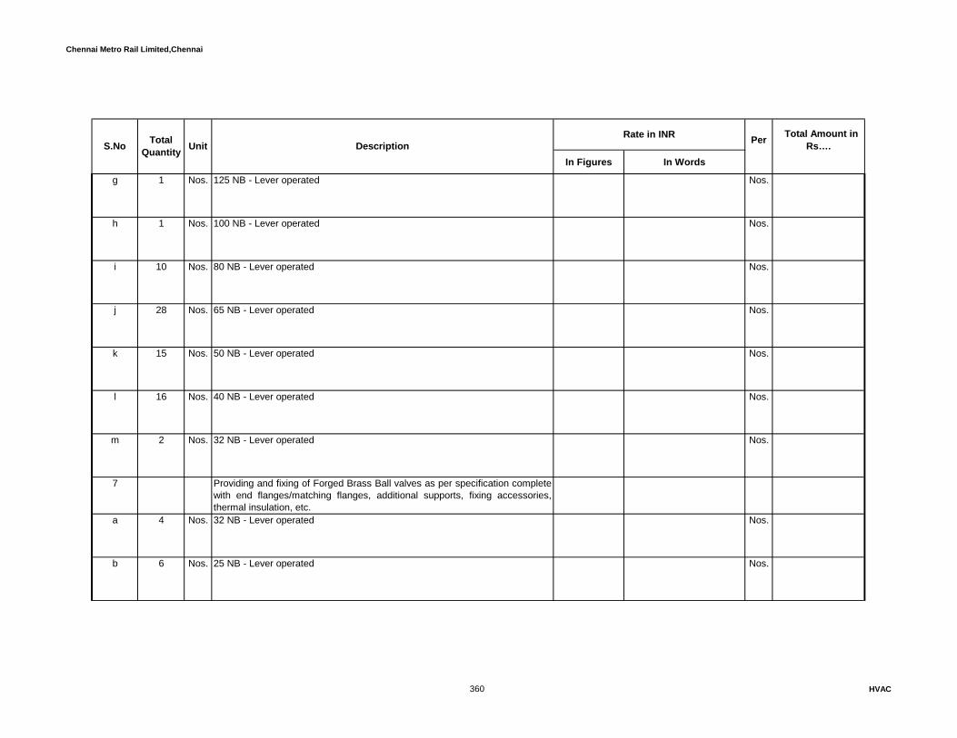
Chennai Metro Rail Limited,Chennai
In Figures In Words
Rate in INR Total Amount in Rs…. S.No Total
Quantity Unit Description Per
g 1 Nos. 125 NB - Lever operated Nos.
h 1 Nos. 100 NB - Lever operated Nos.
i 10 Nos. 80 NB - Lever operated Nos.
j 28 Nos. 65 NB - Lever operated Nos.
k 15 Nos. 50 NB - Lever operated Nos.
l 16 Nos. 40 NB - Lever operated Nos.
m 2 Nos. 32 NB - Lever operated Nos.
7 Providing and fixing of Forged Brass Ball valves as per specification completewith end flanges/matching flanges, additional supports, fixing accessories,thermal insulation, etc.
a 4 Nos. 32 NB - Lever operated Nos.
b 6 Nos. 25 NB - Lever operated Nos.
360 HVAC

Chennai Metro Rail Limited,Chennai
In Figures In Words
Rate in INR Total Amount in Rs…. S.No Total
Quantity Unit Description Per
8 Providing and fixing of pre insulated Cast Iron Dual plate Check valves andmatching flanges as per specification complete with end flanges/matchingflanges, additional supports, fixing accessories, thermal insulation, etc. - 200NB.
a 9 Nos. 200 mm dia Nos.
9 Supply, Installation, testing and commissioning of Flow Control Valve -Pressure independent Balancing Control valves for Chiller & Coolingtower actuator in a single Unit of Valve. Valve shall be of PN16 Rating. Theactuator shall be supplied by the valve manufacturer and capable of accepting2-10VDC, 4- 20 mA electric signal and shall provide similar transducedfeedback output signal to control system. The minimum close off Pressure ofactuator must be 1.5 times shut off head of pump as per specifications. Rateshall inclusive of thermostat suitable for the given actuator, required length of2Cx1.5Sqmm shielded communication cable, end flanges / matching flanges,additional supports, fixing accessories, thermal insulation, etc.
a 12 Nos 200 NB Nos
b 1 Nos 150 NB Nos
c 1 Nos 100 NB Nos
d 4 Nos 80 NB Nos
361 HVAC

Chennai Metro Rail Limited,Chennai
In Figures In Words
Rate in INR Total Amount in Rs…. S.No Total
Quantity Unit Description Per
e 13 Nos 65 NB Nos
f 6 Nos 50 NB Nos
g 8 Nos 40 NB Nos
h 2 Nos 32 NB Nos
i 3 Nos 25 NB Nos
10 Supply, installation, testing and commissioning of Two way motorized Valves(ON / OFF Type) with actuator provided with spring return function in chilledwater lines at chillers and condenser water line at cooling towers. The actuatorof the motorized valve shall have required torque to ON/Off the actuator with220 V / 24 V transformer duly encased and wired. The motorized valve &actuator shall be compatible to third party integration and necessarycommunication cables, hardware, converter, etc shall be included.
a 6 Nos. 200 NB Nos.
11 Supply and erection of Semi Auto Balancing Valve shall be of factorycalibrated direct, acting, automatic pressure compensation type. Each valveshall limit flow rates to within ± 5 % accuracy, regardless of the systempressure fluctuations.
362 HVAC

Chennai Metro Rail Limited,Chennai
In Figures In Words
Rate in INR Total Amount in Rs…. S.No Total
Quantity Unit Description Per
a 1 Nos. 350 NB Nos.
b Nos. 250 NB Nos.
c 3 Nos. 200 NB Nos.
d Nos. 150 NB Nos.
e Nos. 125 NB Nos.
f Nos. 100 NB Nos.
g Nos. 80 NB Nos.
h Nos. 65 NB Nos.
12 Supply and erection of Pre insulated ‘Y’ type strainer and matching flangeswith removable stainless steel (SS316)screen with 3mm perforation andpermanent magnet, drain piping. Rate shall inclusive of , additional supports,fixing accessories, etc.
a 4 Nos 80 NB Nos
363 HVAC

Chennai Metro Rail Limited,Chennai
In Figures In Words
Rate in INR Total Amount in Rs…. S.No Total
Quantity Unit Description Per
b 14 Nos 65 NB Nos
c 6 Nos 50 NB Nos
d 8 Nos 40 NB Nos
13 Supply, Installation and commissioning of pre insulated Suction Guide and matching flanges made up of Cast iron body and stainless steel. Rate shallinclusive of end flanges/matching flanges, additional supports, fixingaccessories, etc.
a 1 Nos 250 NB Nos
b 8 Nos 200 NB Nos
14 Supply, Installation and commissioning of Pot strainer made up of Cast ironbody with stainless steel perforation. Rate shall inclusive of endflanges/matching flanges, additional supports, fixing accessories, etc.
a 1 Nos 400 NB Nos
b 1 Nos 200 NB Nos
364 HVAC
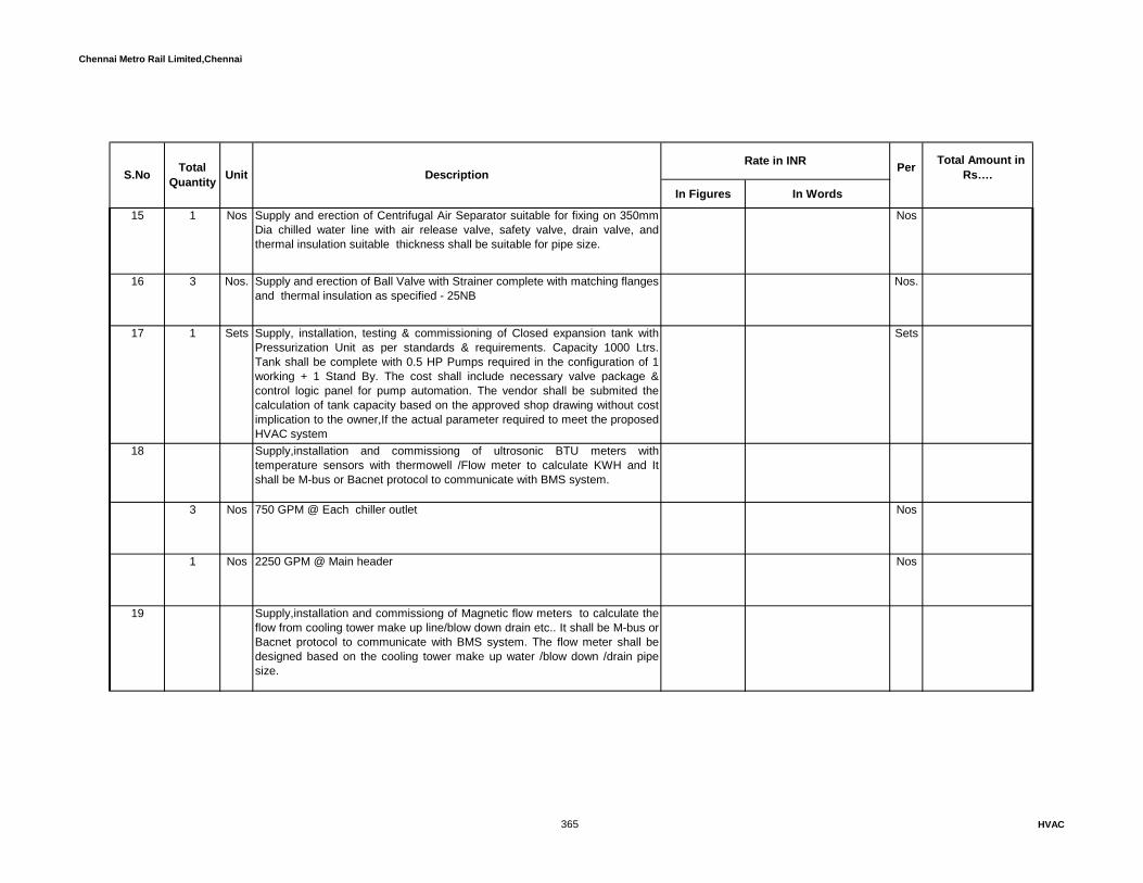
Chennai Metro Rail Limited,Chennai
In Figures In Words
Rate in INR Total Amount in Rs…. S.No Total
Quantity Unit Description Per
15 1 Nos Supply and erection of Centrifugal Air Separator suitable for fixing on 350mmDia chilled water line with air release valve, safety valve, drain valve, andthermal insulation suitable thickness shall be suitable for pipe size.
Nos
16 3 Nos. Supply and erection of Ball Valve with Strainer complete with matching flangesand thermal insulation as specified - 25NB
Nos.
17 1 Sets Supply, installation, testing & commissioning of Closed expansion tank withPressurization Unit as per standards & requirements. Capacity 1000 Ltrs.Tank shall be complete with 0.5 HP Pumps required in the configuration of 1working + 1 Stand By. The cost shall include necessary valve package &control logic panel for pump automation. The vendor shall be submited thecalculation of tank capacity based on the approved shop drawing without costimplication to the owner,If the actual parameter required to meet the proposedHVAC system
Sets
18 Supply,installation and commissiong of ultrosonic BTU meters withtemperature sensors with thermowell /Flow meter to calculate KWH and Itshall be M-bus or Bacnet protocol to communicate with BMS system.
3 Nos 750 GPM @ Each chiller outlet Nos
1 Nos 2250 GPM @ Main header Nos
19 Supply,installation and commissiong of Magnetic flow meters to calculate theflow from cooling tower make up line/blow down drain etc.. It shall be M-bus orBacnet protocol to communicate with BMS system. The flow meter shall bedesigned based on the cooling tower make up water /blow down /drain pipesize.
365 HVAC

Chennai Metro Rail Limited,Chennai
In Figures In Words
Rate in INR Total Amount in Rs…. S.No Total
Quantity Unit Description Per
1 Nos 50 mm dia Nos
3 Nos 150mm dia Nos
20 1 Nos. Supply, installation, testing and commissioning of Make up water tank forchilled water system shall be made out of HDPE heavy duty with necessaryinlet, outlet, over flow, drain and float valve and electronic type level indicatoretc. Tank shall be cylindrical in shape and shall be mounted vertically. Thequoted rate shall be inclusive of concrete bed / steel supports. Tank capacity:1000 L
Nos.
21 1 Nos. Supply, installation, testing and commissioning of Cooling Tower Make upwater tank shall be made out of HDPE heavy duty with necessary inlet, outlet,over flow, drain and float valve and electronic type level indicator etc. Tankshall be cylindrical in shape and shall be mounted vertically. The quoted rateshall be inclusive of concrete bed / steel supports. Tank capacity: 25000 L
Nos.
22 74 Nos. Supply and erection of SS Bourdon dial type Pressure gauges with syphoncomplete with ball valve, mounting well, fittings as per specification
Nos.
23 74 Nos. Supply and erection of industrial type Thermometers with copper separablewell complete with guard mounted on water lines as per specification.
Nos.
24 10 Nos. Supply and erection of Automatic Air Vents shall be installed at all highsections of piping. As per specification.
Nos.
25 1200 kg Supply and erection of steel supports like MS plate, angles, channels, etc.Rate shall inclusive of cutting, welding, grinding, fixing accessories and onecoat of primer & two coats of enamel paints, etc. as required.
kg
366 HVAC

Chennai Metro Rail Limited,Chennai
In Figures In Words
Rate in INR Total Amount in Rs…. S.No Total
Quantity Unit Description Per
26 10 Nos. Test Points for pressure & temperature measurement complete with Brassbody & nitrile rubber sealing bushes.
Nos.
27 10 Nos. Temperature guages suitable for taking temperature measurement in chilledwater line through Test points.
Nos.
28 10 Nos. Pressure guages suitable for taking Pressure measurement in chilled waterline through Test points.
Nos.
Total carry over to summary ( Pipes and Valves)V AIR HANDLING UNITS 1 Supply, installation, testing and commissioning of Double Skin Air Handling
Units of Horizontal Configuration 45±5mm thick panel with PUF insulation,filter sections, min 6 row deep water coil of copper tube & aluminium fins,copper header, Plug type fan, High efficiency direct driven motor, springvibration isolator for fan and motor, factory assembled Low leak Aluminiumvolume control damper, Fire ratardant canvass connections, power and control wiring, Aluminium base frame complete as per specifications as required. Fanmotor shall be suitable for 415±10% volts, 50 cycles, 3 phase AC supply &high efficiency (IE 3).
a 1 Nos. Capacity: 37 TR, Dehumidified Air: 24000 CFM; Indicative motor :18.0 KW (GF Atrium)ESP : 40 mm wg
Nos.
b 1 Nos. Capacity: 31 TR, Dehumidified Air: 17500 CFM ; Indicative motor :11.0 KW (GF Passage)ESP : 40 mm wg
Nos.
c 1 Nos. Capacity: 25 TR, Dehumidified Air: 14200 CFM; Indicative motor : 9.3 KW (1st Floor Office & cabin)ESP : 40 mm wg
Nos.
d 1 Nos. Capacity: 30 TR, Dehumidified Air: 17200 CFM ; Indicative motor :9.30 KW (1st Floor Office & cabin)ESP : 40 mm wg
Nos.
367 HVAC

Chennai Metro Rail Limited,Chennai
In Figures In Words
Rate in INR Total Amount in Rs…. S.No Total
Quantity Unit Description Per
e 1 Nos. Capacity: 20 TR, Dehumidified Air: 11850 CFM; Indicative motor : 9.3 KW (1st Floor Office & cabin)ESP : 40 mm wg
Nos.
f 1 Nos. Capacity: 20 TR, Dehumidified Air: 13350 CFM; Indicative motor : 9.3 KW (2nd Floor Ats, Comm etc)ESP : 40 mm wg
Nos.
g 1 Nos. Capacity: 26 TR, Dehumidified Air: 16500 CFM; Indicative motor : 11.0 KW (2nd Floor Office & cabin)ESP : 40 mm wg
Nos.
h 1 Nos. Capacity: 17 TR, Dehumidified Air: 11500 CFM ; Indicative motor :7.50 KW (2nd Floor Office & cabin)ESP : 40 mm wg
Nos.
i 1 Nos. Capacity: 26 TR, Dehumidified Air: 14850 CFM; Indicative motor : 7.5 KW (3rd Floor Office & cabin)ESP : 30 mm wg
Nos.
j 1 Nos. Capacity: 19 TR, Dehumidified Air: 11700 CFM ; Indicative motor :7.50 KW (3rd Floor Office & cabin)ESP : 30 mm wg
Nos.
k 1 Nos. Capacity: 13 TR, Dehumidified Air: 7250 CFM; Indicative motor : 5.50 KW (3rd Floor Office & cabin)ESP : 30 mm wg
Nos.
l 1 Nos. Capacity: 18 TR, Dehumidified Air: 11600 CFM ; Indicative motor :7.50 KW (3rd Floor occ controle room)ESP : 25 mm wg
Nos.
m 1 Nos. Capacity: 21 TR, Dehumidified Air: 11850 CFM ; Indicative motor :7.5 KW (4th Floor Office & cabin)ESP : 35 mm wg
Nos.
368 HVAC
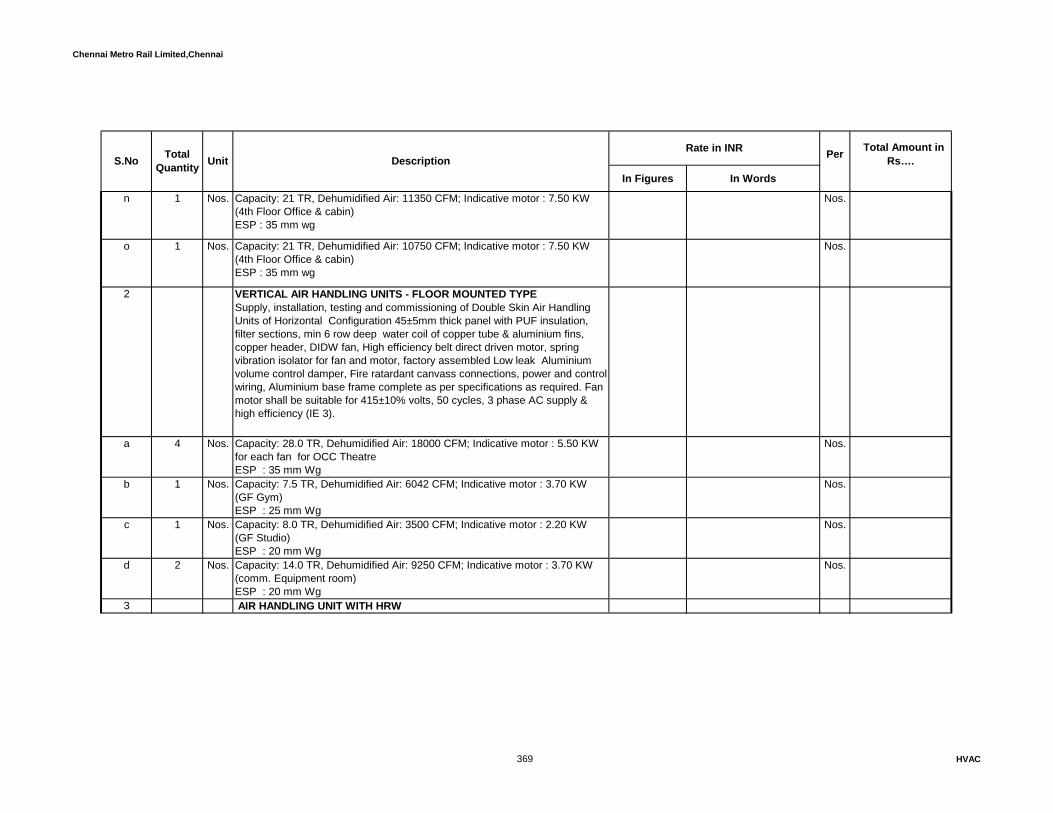
Chennai Metro Rail Limited,Chennai
In Figures In Words
Rate in INR Total Amount in Rs…. S.No Total
Quantity Unit Description Per
n 1 Nos. Capacity: 21 TR, Dehumidified Air: 11350 CFM; Indicative motor : 7.50 KW (4th Floor Office & cabin)ESP : 35 mm wg
Nos.
o 1 Nos. Capacity: 21 TR, Dehumidified Air: 10750 CFM; Indicative motor : 7.50 KW (4th Floor Office & cabin)ESP : 35 mm wg
Nos.
2 VERTICAL AIR HANDLING UNITS - FLOOR MOUNTED TYPESupply, installation, testing and commissioning of Double Skin Air Handling Units of Horizontal Configuration 45±5mm thick panel with PUF insulation, filter sections, min 6 row deep water coil of copper tube & aluminium fins, copper header, DIDW fan, High efficiency belt direct driven motor, spring vibration isolator for fan and motor, factory assembled Low leak Aluminium volume control damper, Fire ratardant canvass connections, power and control wiring, Aluminium base frame complete as per specifications as required. Fan motor shall be suitable for 415±10% volts, 50 cycles, 3 phase AC supply & high efficiency (IE 3).
a 4 Nos. Capacity: 28.0 TR, Dehumidified Air: 18000 CFM; Indicative motor : 5.50 KW for each fan for OCC TheatreESP : 35 mm Wg
Nos.
b 1 Nos. Capacity: 7.5 TR, Dehumidified Air: 6042 CFM; Indicative motor : 3.70 KW (GF Gym)ESP : 25 mm Wg
Nos.
c 1 Nos. Capacity: 8.0 TR, Dehumidified Air: 3500 CFM; Indicative motor : 2.20 KW (GF Studio)ESP : 20 mm Wg
Nos.
d 2 Nos. Capacity: 14.0 TR, Dehumidified Air: 9250 CFM; Indicative motor : 3.70 KW (comm. Equipment room)ESP : 20 mm Wg
Nos.
3 AIR HANDLING UNIT WITH HRW
369 HVAC

Chennai Metro Rail Limited,Chennai
In Figures In Words
Rate in INR Total Amount in Rs…. S.No Total
Quantity Unit Description Per
a Supply, installation, testing and commissioning of Double Skin Air HandlingUnits of Horizontal Configuration 45±5mm thick panel with PUF insulation,filter sections, min 6 row deep water coil of copper tube & aluminium fins,copper header,It shall be inclusive of supply air and exhaust are sections,enthalpy recovery wheel, forward curved DIDW centrifugal fan, High efficiencymotor, vibration isolator for fan and motor, factory assembled Low leak volumecontrol damper, Flexible connections, power and control wiring, Aluminiumbase frame complete as per specifications as required. Fan motor shall besuitable for 415±10% volts, 50 cycles, 3 phase AC supply & high efficiency (IE3)
1 Nos. Supply Air Quantity: 15750 De-Humidified CFM, Indicative Motor 9.30 KW ( Auditorium & Stage )
Nos.
Fresh Air Quantity : 2000cfmReturn Air Quantity : 1750cfmExternal Static pressure : 40 mm wg
4TREATED FRESH AIR UNIT WITH ENTHALPY RECOVERY WHEEL
Supply, installation, testing and commissioning of double deck, double skinTreated Fresh Air - Air Handling Units. AHU shall be of 25±3mm thick panelwith PUF insulation, supply air and exhaust are sections, enthalpy recoverywheel, forward curved DIDW centrifugal fan, High efficiency motor, vibrationisolator for fan and motor, factory assembled Low leak volume control damper, Flexible connections, power and control wiring, Aluminium base framecomplete as per specifications as required. Fan motor shall be suitable for415±10% volts, 50 cycles, 3 phase AC supply & high efficiency (IE3) .Energyrecovery wheel and Treated frsh air unit sjhall be supplied by the ERWmanufacturer.Supply Air Stream consists of Filter sections, Heat recovery wheel for fresh airsection & accessories, Fan section with blower and motor, Discharge PlenumsectionReturn Air Stream consists filer section, Heat recovery wheel section, Fansection with blower and motor
370 HVAC

Chennai Metro Rail Limited,Chennai
In Figures In Words
Rate in INR Total Amount in Rs…. S.No Total
Quantity Unit Description Per
a 1 Nos. Supply Air Quantity: 5283 CFM, Return Air Quantity: 4226 CFM 7.5 KW External static pressure : 30 mm Wg
Nos.
b 1 Nos. Supply Air Quantity: 5130 CFM, Return Air Quantity: 4104 CFM 7.5 KWExternal static pressure : 30 mm Wg
Nos.
c 1 Nos. Supply Air Quantity: 6330 CFM, Return Air Quantity: 5064 CFM 11.1 KWExternal Static Pressure : 30 mm Wg
Nos.
5 Supply, installation, testing and commissioning of Double Skin Air HandlingUnits of ceiling suspended type, 25±3mm thick panel with PUF insulation, filtersections, min 4 row deep water coil of copper tube & aluminium fins, copperheader, single / multiple forward curved DIDW centrifugal fan, High efficiencymotor, vibration isolator for fan and motor, factory assembled Low leak volumecontrol damper, Fire ratardant canvass connections, internal power andcontrol wiring, complete as per specifications as required. Fan motor shall besuitable for 415±10% volts, 50 cycles, 3 phase AC supply & high efficiency(IE3).
a 2 Nos. Capacity: 7.5 TR, Dehumidified Air: 3958 CFM 2.20 KW (GF Cafeteria)ESP : 25 mm wg
Nos.
6 FAN COIL UNITS
371 HVAC
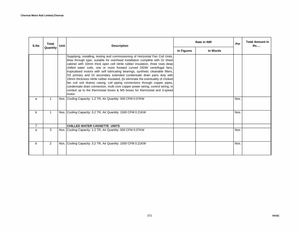
Chennai Metro Rail Limited,Chennai
In Figures In Words
Rate in INR Total Amount in Rs…. S.No Total
Quantity Unit Description Per
Supplying, installing, testing and commissioning of Horizontal Fan Coil Units,blow through type, suitable for overhead installation complete with GI sheetcabinet with 10mm thick open cell nitrile rubber insulation, three rows deepchilled water coils, one or more forward curved DIDW centrifugal fans,tropicalised motors with self lubricating bearings, synthetic cleanable filters,SS primary and GI secondary extended condensate drain pans duly with19mm thickness nitrile rubber insulated, (to eliminate the eventuality of chokedfan coil unit drains) casing, coil piping connections through copper pipes,condensate drain connection, multi core copper power wiring, control wiring, inconduit up to the thermostat boxes & MS boxes for thermostat and 3-speedmotor.
a 1 Nos. Cooling Capacity: 1.2 TR, Air Quantity: 500 CFM 0.07KW Nos.
b 1 Nos. Cooling Capacity: 3.2 TR, Air Quantity: 1500 CFM 0.21KW Nos.
7 CHILLED WATER CASSETTE UNITSa 3 Nos. Cooling Capacity: 1.2 TR, Air Quantity: 500 CFM 0.07KW Nos.
b 2 Nos. Cooling Capacity: 3.2 TR, Air Quantity: 1500 CFM 0.21KW Nos.
372 HVAC

Chennai Metro Rail Limited,Chennai
In Figures In Words
Rate in INR Total Amount in Rs…. S.No Total
Quantity Unit Description Per
8 Supply, installation, testing and commissioning of Variable Frequency Drivewith starter panel . The VFD shall have Frequency controller, Microprocessorbased logic controller, integrated Software capable to control frequency basedon the inputs from sensors. Rate shall be inclusive of mounting arrangementssuitable to mount inside the electrical panel. The VFD shall have IP-20protection and the enclousure starter panel shall be IP54 protection.VFD MMIshould be detachable and provide with flexible cable up to VFD panel. MMIshall be suitable to install on VFD panel door so that it will accessible withoutopening door The rate shall also be inclusive of Communication card (BACnetprotocol) to transfer the entire data available on VFD to the BMS System. Rateshall be inclusive of Auto/manual with by pass starter arrangement.AFD canbe equipped with a Harmonic Filter, sized by the manufacturer in accordancewith the compressor size, with a minimum capability of 5% THiD (TotalHarmonic Distortion)
a 1 Nos. Motor rating: 15.0kW Nos.
c 1 Nos. Motor rating: 11. kW Nos.
d 8 Nos. Motor rating: 9.3 kW Nos.
e 4 Nos. Motor rating: 7.5 kW Nos.
f 9 Nos. Motor rating: 5.5 kW Nos.
373 HVAC
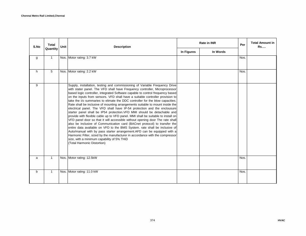
Chennai Metro Rail Limited,Chennai
In Figures In Words
Rate in INR Total Amount in Rs…. S.No Total
Quantity Unit Description Per
g 1 Nos. Motor rating: 3.7 kW Nos.
h 5 Nos. Motor rating: 2.2 kW Nos.
9 Supply, installation, testing and commissioning of Variable Frequency Drivewith stater panel. The VFD shall have Frequency controller, Microprocessorbased logic controller, integrated Software capable to control frequency basedon the inputs from sensors. VFD shall have a suitable controller provision totake the i/o summaries to elimate the DDC controller for the blow capacities.Rate shall be inclusive of mounting arrangements suitable to mount inside theelectrical panel. The VFD shall have IP-54 protection and the enclousurestarter panel shall be IP54 protection.VFD MMI should be detachable andprovide with flexible cable up to VFD panel. MMI shall be suitable to install onVFD panel door so that it will accessible without opening door The rate shallalso be inclusive of Communication card (BACnet protocol) to transfer theentire data available on VFD to the BMS System. rate shall be inclusive ofAuto/manual with by pass starter arrangement.AFD can be equipped with aHarmonic Filter, sized by the manufacturer in accordance with the compressorsize, with a minimum capability of 5% THiD (Total Harmonic Distortion)
a 1 Nos. Motor rating: 12.5kW Nos.
b 1 Nos. Motor rating: 11.0 kW Nos.
374 HVAC
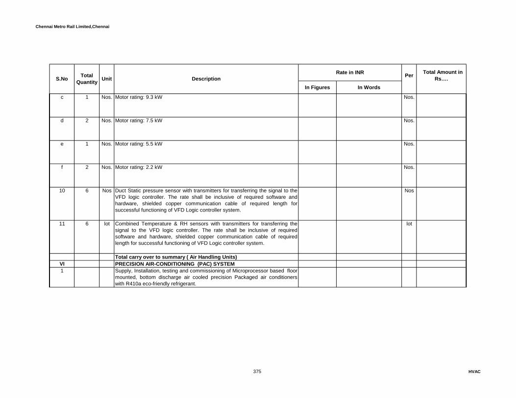
Chennai Metro Rail Limited,Chennai
In Figures In Words
Rate in INR Total Amount in Rs…. S.No Total
Quantity Unit Description Per
c 1 Nos. Motor rating: 9.3 kW Nos.
d 2 Nos. Motor rating: 7.5 kW Nos.
e 1 Nos. Motor rating: 5.5 kW Nos.
f 2 Nos. Motor rating: 2.2 kW Nos.
10 6 Nos Duct Static pressure sensor with transmitters for transferring the signal to theVFD logic controller. The rate shall be inclusive of required software andhardware, shielded copper communication cable of required length forsuccessful functioning of VFD Logic controller system.
Nos
11 6 lot Combined Temperature & RH sensors with transmitters for transferring thesignal to the VFD logic controller. The rate shall be inclusive of requiredsoftware and hardware, shielded copper communication cable of requiredlength for successful functioning of VFD Logic controller system.
lot
Total carry over to summary ( Air Handling Units)VI PRECISION AIR-CONDITIONING (PAC) SYSTEM 1 Supply, Installation, testing and commissioning of Microprocessor based floor
mounted, bottom discharge air cooled precision Packaged air conditionerswith R410a eco-friendly refrigerant.
375 HVAC

Chennai Metro Rail Limited,Chennai
In Figures In Words
Rate in INR Total Amount in Rs…. S.No Total
Quantity Unit Description Per
Acoustically insulated Indoor unit with DX cooling coil, filter, EC Fan, digitalscroll compressor, preheater, humidifier, automatic control thermostat andhumidistat, canvass connections, fixing/mounting accessories, adjustable andlockable support brackets, hardware rubber pads etc. The outdoor unit shallconsists of Air cooled condenser with condenser coil and less powerconsumed inverter type condenser fans
Electro-Mechanical Microprocessor panel, digital display, programmablecontrol & recording unit complete with intelligent 16 digit 2 line alpha numericdisplay, function keys, cursor keys, free programmable keys, multi colorLEDS, inscription fields with integrated battery backup supply at 24 V AC 50Hz, starter, push buttons, SPP, thermal overload, safety cut-offs, MCBsprovision receive zone fire alarm signal and tripping of PACs during the fire.The price shall be inclusive of the sequence controller and necessaryhardware for third party BMS integration.
Unit shall be fitted with high limit humidity sensor / humidistat mounted in thefan outlet and wired to prevent discharge of saturated air from the precision air-conditioner. The unit shall be provided with an under water leakage sensor tobe installed in the false flooring below the drain pan for floor discharge units.Rate shall be inclusive of selection of unit capacity based on the outdoor unitloaction(probably located at terrace) andf required "U" trap and kit shall beprovided to avoid deration & unit permormance.
The price shall inculde the cost of height-adjustable units stands ( epoxypainted MS angle frames), vibration isolators and base plates. The price shalllinclude the cost of communication cable between two units, in GI conduit.
Inside condition (cold asile) shall be maintained as 20 ± 1 °C DBT & 50 ± 5 % RH. The Unit d shall be rated for the indoor/outdoor rating conditions as per specification. The unit shall be sized to deliver following rated capacities minimum which excludes de-rated capacity due to excess length of refrigeration pipes, different elevation and the ambient temperature of 40 deg C.The details of the calculation sheets shall be submitted along with shop drawing.
376 HVAC

Chennai Metro Rail Limited,Chennai
In Figures In Words
Rate in INR Total Amount in Rs…. S.No Total
Quantity Unit Description Per
a 1 Nos. Nominal Capacity: 5.6 TR, Air flow rate: 3823 CFM (min) - Downward Flow (AFC EQUIPMENT ROOM)
Nos.
b 1 Nos. Nominal Capacity: 5.6 TR, Air flow rate: 3823 CFM (min) - Downward Flow ( AFC CARD AND AFC AR ROOM)
Nos.
c 1 Nos. Nominal Capacity: 7.7 TR, Air flow rate: 4588 CFM (min) - Downward Flow ( AFC SR & AFC ANALYST ROOM )
Nos.
d 1 Nos. Nominal Capacity: 15.4 TR, Air flow rate: 9117 CFM (min) - Downward Flow ( AFC CC & CCH ROOM )
Nos.
e 1 Nos. Nominal Capacity: 5.6 TR, Air flow rate: 3823 CFM (min) - Downward Flow ( UPS FOR S & T/UPS FOR AFC)
Nos.
f 1 Nos. Nominal Capacity: 7.0 TR, Air flow rate: 4600 CFM (min) - Downward Flow ( 1st FLOOR SERVER ROOM)
Nos.
2 Supply and erection of 1.2mm thick Refrigerant Copper pipes to integrateoutdoor / indoor units as per specification. (Vendor shall confirm the cable size basedon the selected model). The rate shall be inclusive of EBDM insulation over thecopper pipes and glass cloth with UV protection coating shall be applied over theinsulation wherever exposed to the sun. . The pipe sizes and insulation thickness asfollows.
a 12 Rmt. 6.35mm dia liquid pipe with 19mm thick insulation Rmt.
b 10 Rmt. 9.5mm dia liquid pipe with 19mm thick insulation Rmt.
377 HVAC

Chennai Metro Rail Limited,Chennai
In Figures In Words
Rate in INR Total Amount in Rs…. S.No Total
Quantity Unit Description Per
c 90 Rmt. 12.7mm dia liquid pipe with 19mm thick insulation Rmt.
d 125 Rmt. 15.9mm dia liquid pipe with 19mm thick insulation Rmt.
e 90 Rmt. 19.1mm dia gas pipe with 19mm thick insulation Rmt.
f 132 Rmt. 22.2mm dia gas pipe with 19mm thick insulation Rmt.
g 12 Rmt. 25.4mm dia gas pipe with 19mm thick insulation Rmt.
h 6 Rmt 28.4mm dia gas pipe with 25mm thick insulation Rmt
i 6 Rmt. 34.9mm dia gas pipe with 25mm thick insulation Rmt.
CHILLED WATER PRECISION UNITS - With heater and humidifier3 Supply, Installation, testing and commissioning of Microprocessor based floor
mounted, bottom discharge chilled water type precision Packaged airconditioners.Acoustically insulated Indoor unit with chilled water cooling coil, filter, EC Fan,automatic control thermostat and humidistat, canvass connections,fixing/mounting accessories, adjustable and lockable support brackets,hardware rubber pads etc.
378 HVAC

Chennai Metro Rail Limited,Chennai
In Figures In Words
Rate in INR Total Amount in Rs…. S.No Total
Quantity Unit Description Per
Electro-Mechanical Microprocessor panel, digital display, programmablecontrol & recording unit complete with intelligent 16 digit 2 line alpha numericdisplay, function keys, cursor keys, free programmable keys, multi colorLEDS, inscription fields with integrated battery backup supply at 24 V AC 50Hz, starter, push buttons, SPP, thermal overload, safety cut-offs, MCBsprovision receive zone fire alarm signal and tripping of PACs during the fire.The price shall be inclusive of the sequence controller and necessaryhardware for third party BMS integration.
Unit shall be fitted with high limit humidity sensor / humidistat mounted in thefan outlet and wired to prevent discharge of saturated air from the precision air-conditioner. The unit shall be provided with an under water leakage sensor tobe installed in the false flooring below the drain pan for floor discharge units.
The price shall inculde the cost of height-adjustable units stands ( epoxypainted MS angle frames), vibration isolators and base plates. The price shalllinclude the cost of communication cable between two units, in GI conduit.
a 1 Nos. Nominal Capacity: 5.6 TR, Air flow rate: 3823 CFM (min) - Downward Flow(AFC EQUIPMENT ROOM)
Nos.
b 1 Nos. Nominal Capacity: 5.6 TR, Air flow rate: 3823 CFM (min) - Downward Flow (AFC CARD AND AFC AR ROOM)
Nos.
c 1 Nos. Nominal Capacity: 7.7 TR, Air flow rate: 4588 CFM (min) - Downward Flow (AFC SR & AFC ANALYST ROOM )
Nos.
d 1 Nos. Nominal Capacity: 15.4 TR, Air flow rate: 9117 CFM (min) - Downward Flow (AFC CC & CCH ROOM )
Nos.
e 1 Nos. Nominal Capacity: 5.6 TR, Air flow rate: 3823 CFM (min) - Downward Flow (UPS FOR S & T/UPS FOR AFC) - Heater and humidifier shall not be requiredfor UPS room.
Nos.
379 HVAC
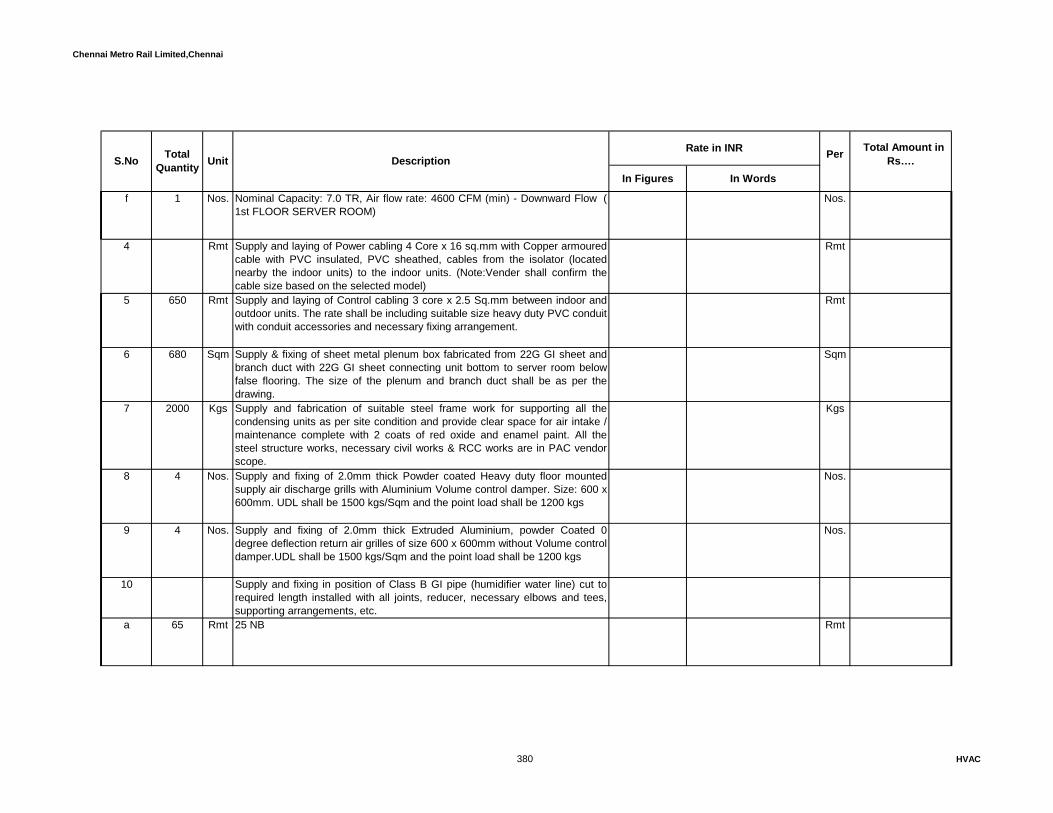
Chennai Metro Rail Limited,Chennai
In Figures In Words
Rate in INR Total Amount in Rs…. S.No Total
Quantity Unit Description Per
f 1 Nos. Nominal Capacity: 7.0 TR, Air flow rate: 4600 CFM (min) - Downward Flow (1st FLOOR SERVER ROOM)
Nos.
4 Rmt Supply and laying of Power cabling 4 Core x 16 sq.mm with Copper armouredcable with PVC insulated, PVC sheathed, cables from the isolator (locatednearby the indoor units) to the indoor units. (Note:Vender shall confirm thecable size based on the selected model)
Rmt
5 650 Rmt Supply and laying of Control cabling 3 core x 2.5 Sq.mm between indoor andoutdoor units. The rate shall be including suitable size heavy duty PVC conduitwith conduit accessories and necessary fixing arrangement.
Rmt
6 680 Sqm Supply & fixing of sheet metal plenum box fabricated from 22G GI sheet andbranch duct with 22G GI sheet connecting unit bottom to server room belowfalse flooring. The size of the plenum and branch duct shall be as per thedrawing.
Sqm
7 2000 Kgs Supply and fabrication of suitable steel frame work for supporting all thecondensing units as per site condition and provide clear space for air intake /maintenance complete with 2 coats of red oxide and enamel paint. All thesteel structure works, necessary civil works & RCC works are in PAC vendorscope.
Kgs
8 4 Nos. Supply and fixing of 2.0mm thick Powder coated Heavy duty floor mountedsupply air discharge grills with Aluminium Volume control damper. Size: 600 x600mm. UDL shall be 1500 kgs/Sqm and the point load shall be 1200 kgs
Nos.
9 4 Nos. Supply and fixing of 2.0mm thick Extruded Aluminium, powder Coated 0degree deflection return air grilles of size 600 x 600mm without Volume controldamper.UDL shall be 1500 kgs/Sqm and the point load shall be 1200 kgs
Nos.
10 Supply and fixing in position of Class B GI pipe (humidifier water line) cut torequired length installed with all joints, reducer, necessary elbows and tees,supporting arrangements, etc.
a 65 Rmt 25 NB Rmt
380 HVAC

Chennai Metro Rail Limited,Chennai
In Figures In Words
Rate in INR Total Amount in Rs…. S.No Total
Quantity Unit Description Per
b 24 Rmt 15 NB Rmt
11 Supply and fixing in position of Heavy duty PVC pipe cut to required lengthwith 13mm thick nitrile rubber with factory laminated aluminium foil insulation,installed with all joints, reducer, necessary elbows and tees, supportingarrangements, etc.
a 6 Rmt 32 NB Rmt
b 6 Rmt 25 NB Rmt
12 Providing and fixing in position the following Ball valves complete with endflanges / matching flanges, additional supports, fixing accessories etc. Thevalve shall be thermally insulated with 13mm thick nitrile rubber insulation.
a 60 Nos. 25 NB Nos.
b 12 Nos. 15 NB Nos.
13 Supply and erection of following sizes Ladder type cable tray made out of 16Gthick GI sheet steel folded to required shape with adequate number ofsupports for Insulated refrigerant pipe and cable conduits.
a 500 Rmt 300mm wide Rmt
b 200 Rmt 450mm wide Rmt
381 HVAC

Chennai Metro Rail Limited,Chennai
In Figures In Words
Rate in INR Total Amount in Rs…. S.No Total
Quantity Unit Description Per
14 Sqm Supply and installation of cold Aisle containment with Dual swing door at entryand exit Aisle. Poly carbonate sheet at top with required size. The containmentshall be supplied and executed by the supplier only
Sqm
15 Supply and fixing of UL certified with labelled 16G G.I. Fire damper &Motorized (ON / OFF type ) actuators with sleeves. . These dampers will have90 Minutes fire rating as per specification.
a 61 Sqm 16 G GI Damper Smoke & Fire Dampers. Sqm
16 10 Nos Supply and installation of active floor grills & EC fan with temperature sensorand controller. The rate shall be inclusive of control wiring between fan andtemperature sensor.The fan speed shall be varied based on the temperaturesensor.
Nos
Total carry over to summary ( PAC System )VII DX SYSTEM1 DUCTABLE SPLIT UNITS
Supply,Installation,testing and commissioing of Ceiling mounted ductable split units of specified capacities with R-410A / R-407c refrigerant gas filling. The indoor units shall be ceiling mounted duct type. The Indoor unit shall comprise of Fan, Cooling coil, Filter and Expansion device. The Outdoor unit shall comprise of inverter scroll / rotary Compressors, Air cooled condenser & Condenser fan. If multiple compressors are offered, they shall have independent refrigerant circuits. Also, compressors shall be cut-off automatically under part load conditions. The units shall have microprocessor controls. The outdoor unit shall be installed as per the tender drawings.The rate shall inclusive of control wiring between indoor and outdoor units, refrigerant charging, insulated drain pipes and supports for the indoor and outdoor units.The unit shall be sized to deliver following rated capacities minimum which excludes de-rated capacity due to excess length of refrigeration pipes, different elevation and the ambient temperature of 40 deg C.
382 HVAC

Chennai Metro Rail Limited,Chennai
In Figures In Words
Rate in INR Total Amount in Rs…. S.No Total
Quantity Unit Description Per
The details of the calculation sheets shall be submitted along with shop drawing
a 1 Nos. Cooling Capacity :11.0 TR / 4400CFM 132000 Btu/hr (For 1st Floor UPS Room)
Nos.
2 Supply and Installation of Hi-Wall Split air conditioning units of specified capacities with R410A/R407C Equivalent refrigerant gas filling.The indoor units shall be wall fixing type. The Indoor unit shall comprise of Blower, Cooling coil, Filter and Expansion device. The Outdoor unit shall comprise of scroll / rotary Compressor, Air cooled condenser & Condenser fans. The outdoor unit shall be installed as per the tender drawings. Scope shall include all supports for the indoor and outdoor units. Rate inclusive of suitable voltage stabilizer,drain kit pump, cabling 20 Amps contactor with NO+NC (for remote operation through BMS) and control cable.The unit shall be sized to deliver following rated capacities minimum which excludes de-rated capacity due to excess length of refrigeration pipes, different elevation and the ambient temperature of 40 deg C.The details of the calculation sheets shall be submitted along with shop drawing
a Nos. Cooling Capacity: 36,000 Btu/hr Nos.
b 1 Nos. Cooling Capacity: 24,000 Btu/hr Nos.
c 1 Nos. Cooling Capacity: 18,000 Btu/hr Nos.
d 1 Nos. Cooling Capacity: 12,200 Btu/hr Nos.
383 HVAC
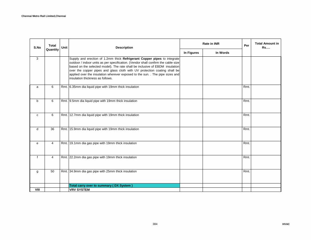
Chennai Metro Rail Limited,Chennai
In Figures In Words
Rate in INR Total Amount in Rs…. S.No Total
Quantity Unit Description Per
3 Supply and erection of 1.2mm thick Refrigerant Copper pipes to integrateoutdoor / indoor units as per specification. (Vendor shall confirm the cable sizebased on the selected model). The rate shall be inclusive of EBDM insulationover the copper pipes and glass cloth with UV protection coating shall beapplied over the insulation wherever exposed to the sun. . The pipe sizes andinsulation thickness as follows.
a 6 Rmt. 6.35mm dia liquid pipe with 19mm thick insulation Rmt.
b 6 Rmt. 9.5mm dia liquid pipe with 19mm thick insulation Rmt.
c 6 Rmt. 12.7mm dia liquid pipe with 19mm thick insulation Rmt.
d 36 Rmt. 15.9mm dia liquid pipe with 19mm thick insulation Rmt.
e 4 Rmt. 19.1mm dia gas pipe with 19mm thick insulation Rmt.
f 4 Rmt. 22.2mm dia gas pipe with 19mm thick insulation Rmt.
g 50 Rmt. 34.9mm dia gas pipe with 25mm thick insulation Rmt.
Total carry over to summary ( DX System )VIII VRV SYSTEM
384 HVAC

Chennai Metro Rail Limited,Chennai
In Figures In Words
Rate in INR Total Amount in Rs…. S.No Total
Quantity Unit Description Per
1 Supply,Installation, testing and commissioning of VRF/VRV Indoor air conditioning units with direct driven fan, high efficient filter, inbuilt microprocessor thermostat, electronic expansion valve, provision of fresh air duct connection, wired PID remote controller, drain pump,refnet joints, necessary ceiling supports & vibration isolators, refrigerant charging, oil charging, control wiring and drain connection, etc. The fan power consumption of VRF Indoor units should not exceed 0.0006 bhp/cfm for ductable units and 0.0004 bhp/cfm for cassette units. The capacities are as mentioned below:-
a Wall Mounted unit i Nos. Cooling Capacity: 1.05 TR, Flow rate-318cfm Nos.
ii Nos. Cooling Capacity: 1.33 TR, Flow rate-424cfm Nos.
iii Nos. Cooling Capacity: 1.65 TR, Flow rate-530cfm Nos.
iv 1 Nos. Cooling Capacity: 2.07 TR, Flow rate-671cfm Nos.
v 4 Nos. Cooling Capacity: 3.3 TR, Flow rate-1130cfm Nos.
b Four Way Cassette Units i 1 Nos. Cooling Capacity: 3.3 TR, Flow rate-1130cfm Nos.
ii Nos. Cooling Capacity: 2.65 TR, Flow rate-742cfm Nos.
385 HVAC
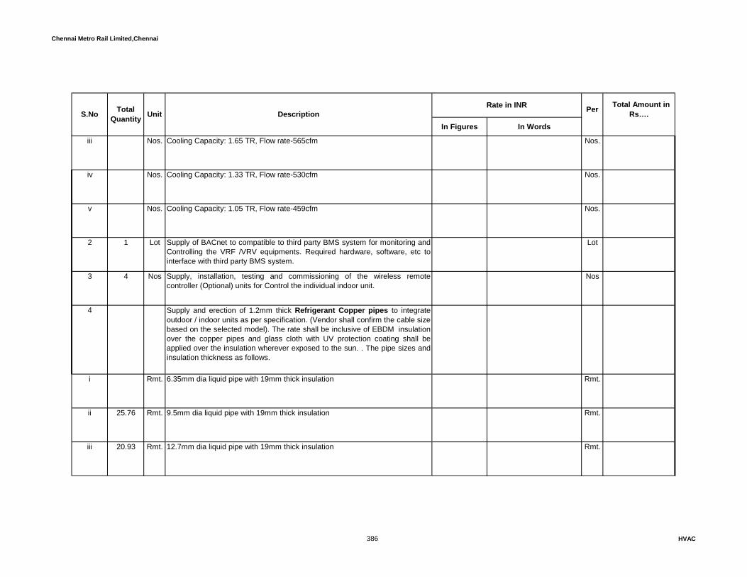
Chennai Metro Rail Limited,Chennai
In Figures In Words
Rate in INR Total Amount in Rs…. S.No Total
Quantity Unit Description Per
iii Nos. Cooling Capacity: 1.65 TR, Flow rate-565cfm Nos.
iv Nos. Cooling Capacity: 1.33 TR, Flow rate-530cfm Nos.
v Nos. Cooling Capacity: 1.05 TR, Flow rate-459cfm Nos.
2 1 Lot Supply of BACnet to compatible to third party BMS system for monitoring andControlling the VRF /VRV equipments. Required hardware, software, etc tointerface with third party BMS system.
Lot
3 4 Nos Supply, installation, testing and commissioning of the wireless remotecontroller (Optional) units for Control the individual indoor unit.
Nos
4 Supply and erection of 1.2mm thick Refrigerant Copper pipes to integrateoutdoor / indoor units as per specification. (Vendor shall confirm the cable sizebased on the selected model). The rate shall be inclusive of EBDM insulationover the copper pipes and glass cloth with UV protection coating shall beapplied over the insulation wherever exposed to the sun. . The pipe sizes andinsulation thickness as follows.
i Rmt. 6.35mm dia liquid pipe with 19mm thick insulation Rmt.
ii 25.76 Rmt. 9.5mm dia liquid pipe with 19mm thick insulation Rmt.
iii 20.93 Rmt. 12.7mm dia liquid pipe with 19mm thick insulation Rmt.
386 HVAC

Chennai Metro Rail Limited,Chennai
In Figures In Words
Rate in INR Total Amount in Rs…. S.No Total
Quantity Unit Description Per
iv 13.8 Rmt. 15.9mm dia liquid pipe with 19mm thick insulation Rmt.
v Rmt. 19.1mm dia gas pipe with 19mm thick insulation Rmt.
vi 11.96 Rmt. 22.2mm dia gas pipe with 19mm thick insulation Rmt.
vii Rmt. 25.4mm dia gas pipe with 19mm thick insulation Rmt.
viii 20.93 Rmt 28.4mm dia gas pipe with 25mm thick insulation Rmt
ix Rmt. 34.9mm dia gas pipe with 25mm thick insulation Rmt.
5 Supply & Installation, testing and commissioning of Outdoor units consists of 100% inverter compressors, inverter fan motor with aero-spiral fan blade and, e-pass heat exchanger, safety valves, solenoid valves, receiver, capillary tube, check valve, electronic expansion valve, high pressure switch, low pressure sensor, pressure regulating valve, refrigerant filter, stop valve, accumulator and refnet kits. The EER of VRF system shall be minimum 12.5 at AHRI condition. Rate shall be inclusive of R-410A refrigerant & oil pre charging, vibration isolators, supports, necessary foundation / pedestal works etc.The unit shall be sized to deliver following rated capacities minimum which excludes de-rated capacity due to excess length of refrigeration pipes, different elevation and the ambient temperature of 40 deg C.The details of the calculation sheets shall be submitted along with shop drawing.
387 HVAC

Chennai Metro Rail Limited,Chennai
In Figures In Words
Rate in INR Total Amount in Rs…. S.No Total
Quantity Unit Description Per
a 1 Nos. 14HP Nos.
b Nos. 18HP Nos.
Total carry over to summary ( VRV System )
IX AIR DISTRIBUTION SYSTEM1 Supply, installation, testing and balancing of Air Distribution System consists
of factory fabricated Rectangular duct Galvanized Iron sheet metal ductingwith TDF flanges upto 1.0mm thick & above shall be GI angle Flange jointscomplete with supports (anchor fasteners and tie-rods, cradles, angle ironsupports, bolts and nuts, 4mm thick self-adhesive neoprene rubber gasket,stiffeners, zinc chromate painted angle iron flanges, chipping and plastering ofopenings made for duct supports etc., filling the gap with fibre glass wool andwith fire sealant complete as per specification. The rates quoted shall includeturning vanes, straightening vanes, splitters, inspection doors for fire dampers, probe, inlets with test openings enclosures complete with locking caps,chain, gaskets, insulating plugs, and extension for insulated ductwork etc.
a 110 sqm 1.25mm thick GSS ducting sqm
b 1072 sqm 1.0mm thick GSS ducting sqm
c 1297 sqm 0.8mm thick GSS ducting sqm
388 HVAC

Chennai Metro Rail Limited,Chennai
In Figures In Words
Rate in INR Total Amount in Rs…. S.No Total
Quantity Unit Description Per
d 3043 sqm 0.6mm thick GSS ducting sqm
e 1051 sqm 0.5mm thick GSS ducting sqm
2 423 sqm Supply and installing of Acoustic insulation, Material shall be processedNitrile Rubber foam with anti-microbial protection. The material should be fibrefree. The density of the same shall be within 140-180 Kg/m3.The materialshould have a thermal conductivity not exceeding 0.038 W/mK. The maximumsurface temperature the material should withstand is 105º C and minimumtemperature should be -20ºC. The Thickness of the material shall be 15mm.The material should conform to Class 1 rating for surface spread of Flame asper BS 476 Part 7.
sqm
3 Supply and erection of Thermal Insulation of Supply air duct with closed cellnitrile rubber insualtion with factory laminated aluminium foil ,temperaturerange from -10ºC to +60ºC, Class O fire category and as per specification.
a 4900 sqm 13mm thick sqm
b 215 sqm 9mm thick sqm
4 Supply and installation of crosslinked polyolefin foam insulation with factoryapplied reinforced aluminium foil facing on one side and self adhesivebacking. The density of the foam should be not less than 25kg/m3 and themaximum thermal conductivity K should be 0.032W/mK@ 23 Deg C. Thewater vapour permeability should be better than 0.8gm/m2 /24hrs(90%RH,38Deg C). The minimum fire rating property of the insulation material whentested to BS476 part6 & 7 should be Class 0.
389 HVAC
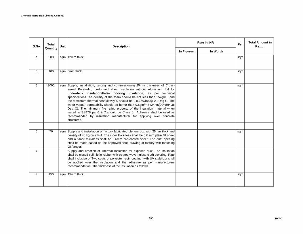
Chennai Metro Rail Limited,Chennai
In Figures In Words
Rate in INR Total Amount in Rs…. S.No Total
Quantity Unit Description Per
a 500 sqm 12mm thick sqm
b 100 sqm 8mm thick sqm
5 3000 sqm Supply, installation, testing and commissioning 25mm thickness of Cross-linked Polyolefin, preformed sheet insulation without Aluminium foil forunderdeck insulation/False flooring insulation, as per technicalspecifications.The density of the foam should be not less than 25kg/m3 andthe maximum thermal conductivity K should be 0.032W/mK@ 23 Deg C. Thewater vapour permeability should be better than 0.8gm/m2 /24hrs(90%RH,38Deg C). The minimum fire rating property of the insulation material whentested to BS476 part6 & 7 should be Class 0. Adhesive shall be used asrecommended by insulation manufacturer for applying over concretestructures.
sqm
6 70 sqm Supply and installation of factory fabricated plenum box with 25mm thick anddensity of 40 kg/cm2 Puf. The inner thickness shall be 0.6 mm plain GI sheetand outdoor thickness shall be 0.6mm pre coated sheet. The duct openingshall be made based on the approved shop drawing at factory with matchingGI flanges.
sqm
7 Supply and erection of Thermal Insulation for exposed duct. The insulationshall be closed cell nitrile rubber with treated woven glass cloth covering. Rateshall inclusive of Two coats of polyester resin coating with UV stabilizer shallbe applied over the insulation and the adhesive as per manufacturersrecommendation. The thickness of the insulation as follows
a 150 sqm 15mm thick sqm
390 HVAC

Chennai Metro Rail Limited,Chennai
In Figures In Words
Rate in INR Total Amount in Rs…. S.No Total
Quantity Unit Description Per
b 150 sqm 19mm thick sqm
8 650 sqm Supply and installation of Modular removal type wall acoustic paneling systemwith 0.5 mm thick 600mm x 600 mm Aluminium hydraulic pressed panels byClip on type method and insulated with 32 Kg. /m3 density, 50 mm thickFiberglass wool including Clips and consumables complete.
sqm
9 540 sqm Supply, installation, testing and commissioning 25mm thickness of Cross-linked Polyolefin, preformed sheet insulation with Aluminium foil for server room floor insulation, as per technical specifications and as shown. Rateshall be inclusive of self Adhesive and tape for joints shall be supplied withinsulation. The density of the foam should be not less than 25kg/m3 and themaximum thermal conductivity K should be 0.032W/mK@ 23 Deg C. Thewater vapour permeability should be better than 0.8gm/m2 /24hrs(90%RH,38Deg C). The minimum fire rating property of the insulation material whentested to BS476 part6 & 7 should be Class 0.The measurement shall notinclude any wastage.
sqm
10 Supply and fixing of Spigot damper shall be installed from take off collar todiffuser plenum boxes and at plenum boxes (low leakage) made out of 16Ggalvanized sheet steel frame and blades of 18G galvanized steel with suitableli ka 22 Nos 250mm Dia Nos
b 28 Nos 300mm Dia Nos
c 325 Nos 350mm Dia Nos
391 HVAC

Chennai Metro Rail Limited,Chennai
In Figures In Words
Rate in INR Total Amount in Rs…. S.No Total
Quantity Unit Description Per
11 Flexible duct connections between main duct and diffuser plenums shall be25mm thick fiber glass pre-insulated, single ply / multiply Aluminiumconstruction and with multiple layers of polyester film glass fiber covered withmechanical lock sheets/ Aluminium laminated jackets-Fire resistant completewith Pre-fabricated and powder coated Aluminium angle frame mountingbrackets and supports
a 550 Rmt 350mm dia Rmt
b 40 Rmt 300mm dia Rmt
c 35 Rmt 250mm dia Rmt
d 12 Rmt 200mm dia Rmt
e 15 Rmt 150mm dia Rmt
f 22 Rmt 100mm dia Rmt
12 Supply and fixing of Powder coated Extruded Aluminium Supply air diffuserswith 600 x 600mm size. The diffuser shall be provided with 24G GI sheet pre-fabricated plenum box with 10mm thick open cell nitrile rubber acoustic lining.The plenum shall be of 450mm height. The plenum box shall be supported atthe four corners with adjustable hanger / chain support.
392 HVAC

Chennai Metro Rail Limited,Chennai
In Figures In Words
Rate in INR Total Amount in Rs…. S.No Total
Quantity Unit Description Per
a 325 Nos 300 x 300mm neck size Nos
b 28 Nos 375 x 375mm neck size Nos
c 22 Nos 450 x 450mm neck size Nos
13 250 Nos Supply and fixing of Extruded Aluminium, powder Coated return air diffuserswith removable centre core overall size 600 x 600mm without volume controldampers.
Nos
14 15 Nos Supply and fixing of Extruded Aluminium, powder coated Supply air diffusers-Perforated Diffuser with removable centre core overall size 600 x 600mmwithout volume control dampers. The rate shall inclusive of Pre-fabricatedAcoustic insulated plenum boxes with 10mm thick open cell nitrile rubber lining inside the plenum box with a height 450mm. The plenum box shall besupported at the four corners with adjustable hanger / chain support.
Nos
15 Rmt Supply and installation of Powder coated extruded aluminium continuous linear 2 way grilles with 15 degree deflection and volume control damper forsupply air as per drawing & specifications. The rate shall inclusive Pre-fabricated Acoustic insulated plenum boxes with 10mm thick open cell nitrilerubber lining inside the plenum box with a height 450mm. The plenum boxshall be supported at the four corners with adjustable hanger / chain support.
Rmt
a 10 Rmt 150 mm width Rmt
393 HVAC

Chennai Metro Rail Limited,Chennai
In Figures In Words
Rate in INR Total Amount in Rs…. S.No Total
Quantity Unit Description Per
16 Supply and installation of Powder coated extruded aluminium continuous linear grilles for return air as per specifications. The rate shall inclusive ofnecessary fixing and supporting arrangement for the grilles
a 15 Rmt 200 mm width Rmt
b 165 Rmt 150 mm width Rmt
c 150 Rmt 100 mm width Rmt
17 Rmt Supply and installation of Powder coated extruded aluminium continuouslinear 2 Slot Grilles with 15 degree deflection and volume control damper forsupply air as per drawing & specifications. The rate shall inclusive Pre-fabricated Acoustic insulated plenum boxes with 10mm thick open cell nitrilerubber lining inside the plenum box with a height 450mm. The plenum boxshall be supported at the four corners with adjustable hanger / chain support.
Rmt
18 Supply and installation of Powder coated extruded aluminium continuous linear 2 Slot Grille for return air as per specifications. The rate shall inclusiveof necessary fixing and supporting arrangement for the grilles
a 10 Rmt 150 mm width Rmt
b 6 Rmt 100 mm width Rmt
394 HVAC

Chennai Metro Rail Limited,Chennai
In Figures In Words
Rate in INR Total Amount in Rs…. S.No Total
Quantity Unit Description Per
19 15 Rmt Supply and installation of Stainless steel continuous linear 2 way grilles with0 degree deflection and volume control damper for return air as per drawing.The rate shall inclusive of necessary fixing and supporting arrangement for thegrilles.150mm width
Rmt
20 Supply and installation of Powder coated extruded aluminium 0 Deg deflectionlinear grilles with Aluminium collar damper for supply air as per specificationsfor toilets
a 50 Rmt 150mm Width Rmt
b 44 Nos 150 x 150mm width Nos
21 4 Sqm Supply and installation of Non return damper of gravity type. The dampershall be made up of 16G thick GSS and less leakage type. The rate shallinclusive of necessary fixing and supporting arrangement
Sqm
22 65 Sqm Supply, installation, testing and commissioning of Factory fabricatedRectangular shape - Galvanized Volume control dampers, 16G GI SteelFrame with aerofoil type blades, 150-mm width, with required hardware andaccessories. Stiffen damper blades for stability. Include locking device tohold single-blade dampers in a fixed position without vibration & engravedmarking on position of damper as per specifications.
Sqm
23 42 Sqm Supply and installation of Sound Attenuators consist of outer casing with1.2m Long, sound absorbing material and internal baffles, splitters andsupports as required.Casing shall be of 20 thick GI steet. Sound absorbingmaterial shall be high density fibre glass held in place with at least 5%compression to prevent voids due to settling. Absorption material densityshall be minimum 48 kg/cum. Fibreglass faced with minimum 26G perforatedGI sheet of minimum 40% open area.
Sqm
395 HVAC

Chennai Metro Rail Limited,Chennai
In Figures In Words
Rate in INR Total Amount in Rs…. S.No Total
Quantity Unit Description Per
24 40 Nos Supply and installation of Powder Coated Supply air diffusers with adjustablelouvers.Flush mounted square ceiling diffusers (overall size shall be of 600 to suitstandard ceiling grids) manufactured entirely from heavy gauge aluminiumalloy extrusion frames fitted with the following features.a) 4 Nos. Hi-flow jet diffusers/nozzles (size 400mm dia circular or 400mmsquare mounted in the above panel) with double banks of deflection louvers(wide extruded air foil blade design) which are individually adjustable to allowjet adjustments potential in two planes for spread or deflection to be set within45 degree of the duct access and suitable for long throw air distribution.b) Acoustically insulated plenum chamber fitted with the above diffuser havingside entry spigots of size550mm.c) Neck mounted OBD control to improve face velocity distributiond) Hidden mounting mechanism. e) Colour – Powder coated as per Archtiect requirements.
Nos
25 310 Sqm factory fabricated Supply and installation of Z shape Cross talk silencer &Flanges both side with rigid glass wool 25 mm thick PREINSULATED DUCT &80 kg/cm3 density ( OWENSCORNING/UP TWIGA ) with one side aluminiumfoil / Vinayl facing..The attenauator shall be selected as per standard
Sqm
26 Supply and installation of Powder coated extruded aluminium Disc Valve ofthe following diameter for exhaust air. The rate shall be inclusive of volumecontrol damper and necessary fixing and supporting arrangement for the valve
a 95 Nos 150mm dia Nos
b 22 Nos 100mm dia Nos
396 HVAC
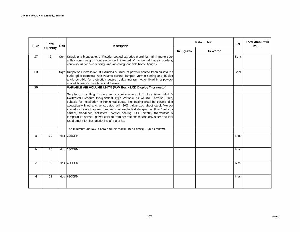
Chennai Metro Rail Limited,Chennai
In Figures In Words
Rate in INR Total Amount in Rs…. S.No Total
Quantity Unit Description Per
27 3 Sqm Supply and installation of Powder coated extruded aluminium air transfer doorgrilles comprising of front section with inverted ‘V’ horizontal blades, borders,countersunk for screw fixing, and matching rear side frame flanges
Sqm
28 6 Sqm Supply and installation of Extruded Aluminium powder coated fresh air intake /outlet grille complete with volume control damper, vermin netting and 45 degangle suitable for protection against splashing rain water fixed in a powdercoated Aluminium angle mount frames.
Sqm
29 VARIABLE AIR VOLUME UNITS (VAV Box + LCD Display Thermostat)
Supplying, installing, testing and commissioning of Factory Assembled &Calibrated Pressure Independent Type Variable Air volume Terminal units,suitable for installation in horizontal ducts. The casing shall be double skinacoustically lined and constructed with 20G galvanized sheet steel. Vendorshould include all accessories such as single leaf damper, air flow / velocitysensor, tranducer, actuators, control cabling, LCD display thermostat &temperature sensor, power cabling from nearest socket and any other ancillary requirement for the functioning of the units.
The minimum air flow is zero and the maximum air flow (CFM) as follows
a 28 Nos 225CFM Nos
b 50 Nos 350CFM Nos
c 15 Nos 450CFM Nos
d 28 Nos 650CFM Nos
397 HVAC

Chennai Metro Rail Limited,Chennai
In Figures In Words
Rate in INR Total Amount in Rs…. S.No Total
Quantity Unit Description Per
e 15 Nos 800CFM Nos
f 12 Nos 1050CFM Nos
g 5 Nos 1350CFM Nos
h 10 Nos 2100CFM Nos
i 6 Nos 3200CFM Nos
j 11 Nos 4000CFM Nos
30 2 Nos Supply, installation and commissioning of the Controller for hook up all theVAVs to the BMS system. All the VAVs shall be monitored through the BMSsystem for the parameters like VAV status, temperature status, Damperposition with % of opening,CFM details,Max cfm etc. The vendor shall provideall the VAV's with BACNet IP protocol. The rate shall inclusive of necessaryhardwares and softwares, communication cables between the interface to theBMS.
Nos
31 1250 Rmt Supply and installation of communication cables for VAV Boxes. The cableshould be 2 core x 1.5 Sq.mm copper shielded cable. The rate shall beinclusive 25mm dia Heavy duty PVC conduit with necessary fittings, fixing andsupporting arrangements
Rmt
Total carry over to summary ( Air Distribution System )
X VENTILATION SYSTEM
398 HVAC

Chennai Metro Rail Limited,Chennai
In Figures In Words
Rate in INR Total Amount in Rs…. S.No Total
Quantity Unit Description Per
1 Supply, Installation, testing and commissioning of factory-fabricated, -assembled, tested, and -finished, Direct-driven Inline type forward curvedcentrifugal fans consisting of 0.8mm thick GI Cabinet, housing, internalaccoustical lining, wheel, fan shaft, bearings, motor, drive assembly, beltguard, Access door, filter & filter frame (only for fresh air application) Inlet Fireretardant Flexible Connection, Outlet Fire retardant Flexible Connection,vibration isolator and support structure etc. The price shall include the cost ofGI wire mesh at fan outlet or duct outlet.
2 Supply, installation and commissioning of the following capacity Wall mounted Axial / Propeller Fans for exhaust air. The fan shall be of noiseless operation and having good aesthetic. The fan motor shall be suitable for operating on 230V, 1 phase, 50Hz AC supply. Location of the fan shall be in the peripheral wall. The cost shall inclusive of wall housing, vermin net on both sides, louvers on one end, steel supports required for mounting the fan and bird screen, wire mess and storm proof louvers as required. The fan shall have min ESP of 10mmWC
a Nos Air flow rate : 100 CFM Nos
b Nos Air flow rate : 150 CFM Nos
c 2 Nos Air flow rate : 200 CFM Nos
d Nos Air flow rate : 300 CFM Nos
e Nos Air flow rate : 400 CFM Nos
399 HVAC
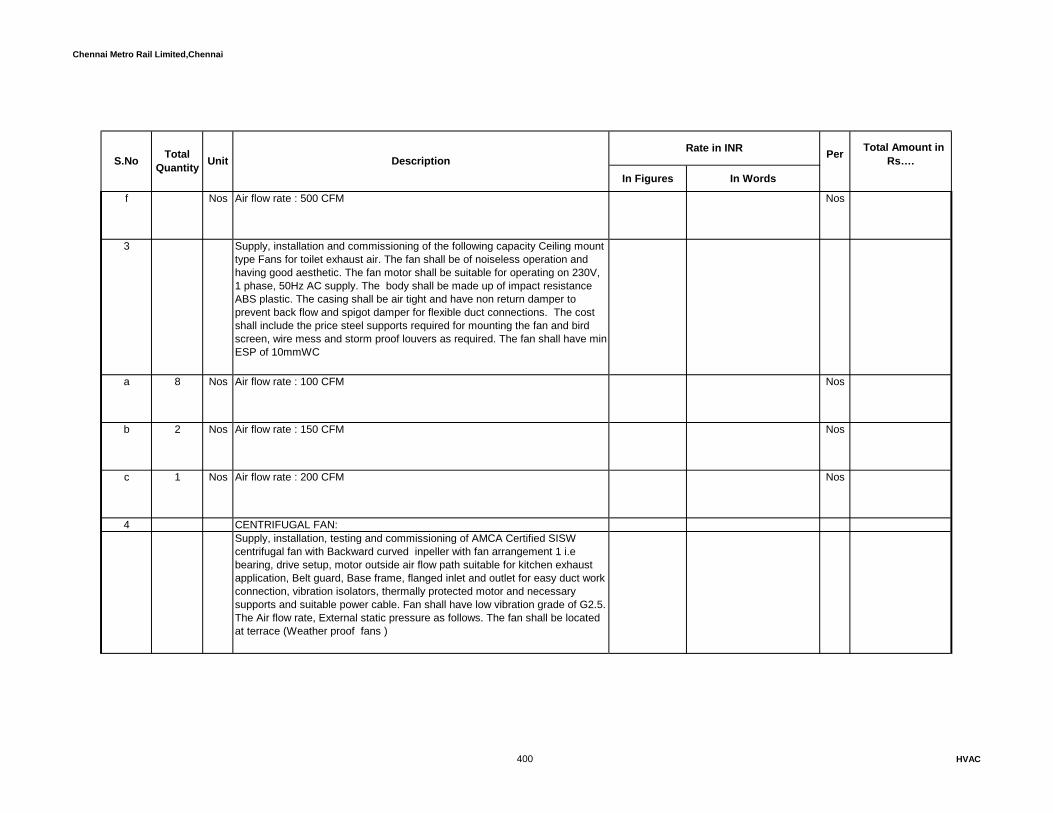
Chennai Metro Rail Limited,Chennai
In Figures In Words
Rate in INR Total Amount in Rs…. S.No Total
Quantity Unit Description Per
f Nos Air flow rate : 500 CFM Nos
3 Supply, installation and commissioning of the following capacity Ceiling mount type Fans for toilet exhaust air. The fan shall be of noiseless operation and having good aesthetic. The fan motor shall be suitable for operating on 230V, 1 phase, 50Hz AC supply. The body shall be made up of impact resistance ABS plastic. The casing shall be air tight and have non return damper to prevent back flow and spigot damper for flexible duct connections. The cost shall include the price steel supports required for mounting the fan and bird screen, wire mess and storm proof louvers as required. The fan shall have min ESP of 10mmWC
a 8 Nos Air flow rate : 100 CFM Nos
b 2 Nos Air flow rate : 150 CFM Nos
c 1 Nos Air flow rate : 200 CFM Nos
4 CENTRIFUGAL FAN: Supply, installation, testing and commissioning of AMCA Certified SISW centrifugal fan with Backward curved inpeller with fan arrangement 1 i.e bearing, drive setup, motor outside air flow path suitable for kitchen exhaust application, Belt guard, Base frame, flanged inlet and outlet for easy duct work connection, vibration isolators, thermally protected motor and necessary supports and suitable power cable. Fan shall have low vibration grade of G2.5. The Air flow rate, External static pressure as follows. The fan shall be located at terrace (Weather proof fans )
400 HVAC

Chennai Metro Rail Limited,Chennai
In Figures In Words
Rate in INR Total Amount in Rs…. S.No Total
Quantity Unit Description Per
a 1 Nos Indoor Type Nos
Air Qty: 6500 CFM, ESP: 25mmWC, Max Motor Rating: 2.20 kW (3 Phase)
5 INLINE CENTRIFUGAL FAN:
Supply, Installation, testing and commissioning of factory-fabricated, -assembled, tested, and -finished, Direct-driven Inline type forward curved centrifugal fans consisting of 0.8mm thick GI Cabinet, housing, internal accoustical lining, wheel, fan shaft, bearings, motor, drive assembly, belt guard, Access door, filter & filter frame (only for fresh air application) Inlet Fire retardant Flexible Connection, Outlet Fire retardant Flexible Connection, vibration isolator and support structure etc. The price shall include the cost of GI wire mesh at fan outlet or duct outlet.
a 1 Nos Indoor Type Nos
Air Qty: 5500 CFM, ESP: 25mmWC, Max Motor Rating: 2.20 kW (3 Phase)
6 CABINET TYPE DIDW CENTRIFUGAL FAN : (EXHAUST)
Supply, Installation, Testing & Commissioning of factory-fabricated, -assembled, -tested, and -finished, belt-driven centrifugal fans consisting of 25 mm thick double skin Cabinet with PUFdensity of 40+-2kg/m3, Housing, Forward-Curved wheels, Shafts, Pre-lubricated and Sealed Shaft Bearings, Belt Drives, Cleanout Door, Motor, Vibration isolators etc. The cabinet shall be factory-fabricated, -assembled, tested, and preplasticised finishing, Horizontal, double skin, 0.8mm thick GI Sheet cabinet on both side, PUF filled, formed with 2mm Thick Extruded aluminium standard profile structure, Galvanised formed channels riveted for sturdiness and reinforcement provided as per specification.
401 HVAC
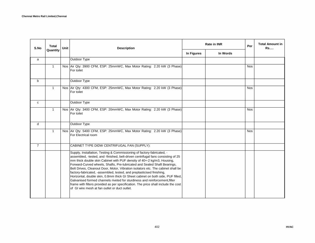
Chennai Metro Rail Limited,Chennai
In Figures In Words
Rate in INR Total Amount in Rs…. S.No Total
Quantity Unit Description Per
a Outdoor Type
1 Nos Air Qty: 3900 CFM, ESP: 25mmWC, Max Motor Rating: 2.20 kW (3 Phase)For toilet
Nos
b Outdoor Type
1 Nos Air Qty: 4300 CFM, ESP: 25mmWC, Max Motor Rating: 2.20 kW (3 Phase)For toilet
Nos
c Outdoor Type
1 Nos Air Qty: 3400 CFM, ESP: 20mmWC, Max Motor Rating: 2.20 kW (3 Phase)For toilet
Nos
d Outdoor Type
1 Nos Air Qty: 5400 CFM, ESP: 25mmWC, Max Motor Rating: 2.20 kW (3 Phase)For Electrical room
Nos
7 CABINET TYPE DIDW CENTRIFUGAL FAN (SUPPLY):
Supply, Installation, Testing & Commissioning of factory-fabricated, -assembled, -tested, and -finished, belt-driven centrifugal fans consisting of 25 mm thick double skin Cabinet with PUF density of 40+-2 kg/m3, Housing, Forward-Curved wheels, Shafts, Pre-lubricated and Sealed Shaft Bearings, Belt Drives, Cleanout Door, Motor, Vibration isolators etc. The cabinet shall be factory-fabricated, -assembled, tested, and preplasticised finishing, Horizontal, double skin, 0.8mm thick GI Sheet cabinet on both side, PUF filled, Galvanised formed channels riveted for sturdiness and reinforcement,filter frame with filters provided as per specification. The price shall include the cost of GI wire mesh at fan outlet or duct outlet.
402 HVAC
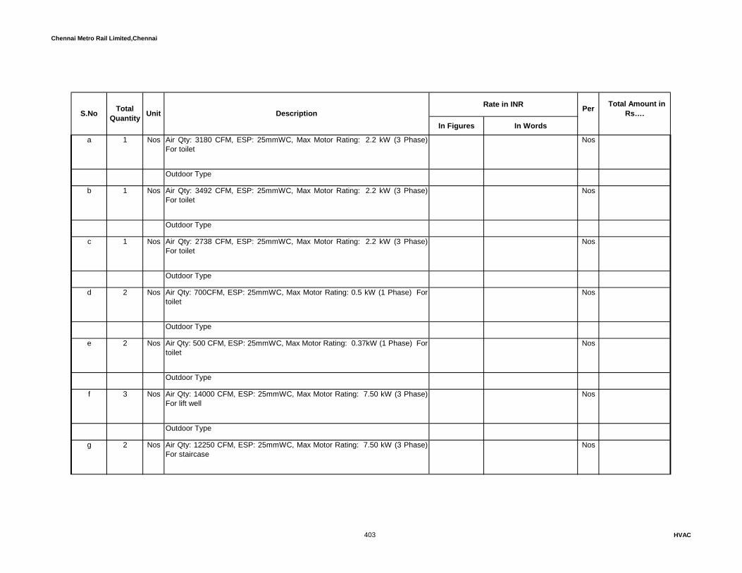
Chennai Metro Rail Limited,Chennai
In Figures In Words
Rate in INR Total Amount in Rs…. S.No Total
Quantity Unit Description Per
a 1 Nos Air Qty: 3180 CFM, ESP: 25mmWC, Max Motor Rating: 2.2 kW (3 Phase)For toilet
Nos
Outdoor Type
b 1 Nos Air Qty: 3492 CFM, ESP: 25mmWC, Max Motor Rating: 2.2 kW (3 Phase)For toilet
Nos
Outdoor Type
c 1 Nos Air Qty: 2738 CFM, ESP: 25mmWC, Max Motor Rating: 2.2 kW (3 Phase)For toilet
Nos
Outdoor Type
d 2 Nos Air Qty: 700CFM, ESP: 25mmWC, Max Motor Rating: 0.5 kW (1 Phase) Fortoilet
Nos
Outdoor Type
e 2 Nos Air Qty: 500 CFM, ESP: 25mmWC, Max Motor Rating: 0.37kW (1 Phase) Fortoilet
Nos
Outdoor Type
f 3 Nos Air Qty: 14000 CFM, ESP: 25mmWC, Max Motor Rating: 7.50 kW (3 Phase)For lift well
Nos
Outdoor Type
g 2 Nos Air Qty: 12250 CFM, ESP: 25mmWC, Max Motor Rating: 7.50 kW (3 Phase)For staircase
Nos
403 HVAC
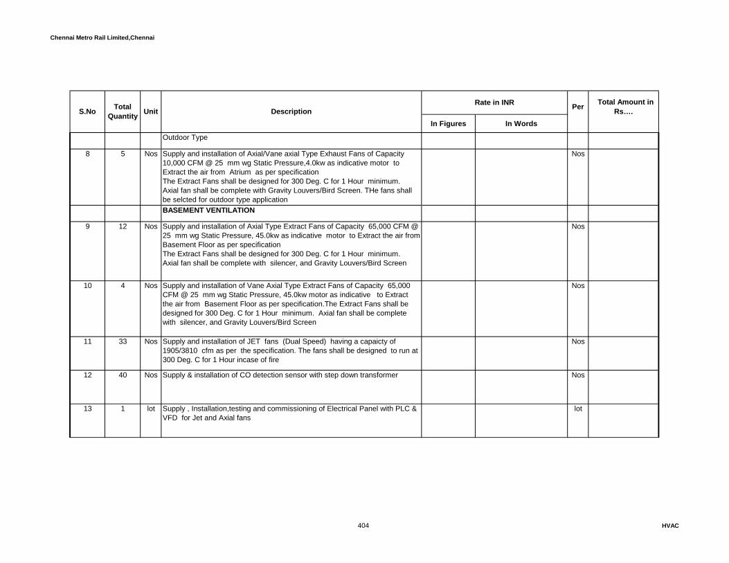
Chennai Metro Rail Limited,Chennai
In Figures In Words
Rate in INR Total Amount in Rs…. S.No Total
Quantity Unit Description Per
Outdoor Type
8 5 Nos Supply and installation of Axial/Vane axial Type Exhaust Fans of Capacity 10,000 CFM @ 25 mm wg Static Pressure,4.0kw as indicative motor to Extract the air from Atrium as per specificationThe Extract Fans shall be designed for 300 Deg. C for 1 Hour minimum. Axial fan shall be complete with Gravity Louvers/Bird Screen. THe fans shall be selcted for outdoor type application
Nos
BASEMENT VENTILATION
9 12 Nos Supply and installation of Axial Type Extract Fans of Capacity 65,000 CFM @ 25 mm wg Static Pressure, 45.0kw as indicative motor to Extract the air from Basement Floor as per specificationThe Extract Fans shall be designed for 300 Deg. C for 1 Hour minimum. Axial fan shall be complete with silencer, and Gravity Louvers/Bird Screen
Nos
10 4 Nos Supply and installation of Vane Axial Type Extract Fans of Capacity 65,000 CFM @ 25 mm wg Static Pressure, 45.0kw motor as indicative to Extract the air from Basement Floor as per specification.The Extract Fans shall be designed for 300 Deg. C for 1 Hour minimum. Axial fan shall be complete with silencer, and Gravity Louvers/Bird Screen
Nos
11 33 Nos Supply and installation of JET fans (Dual Speed) having a capaicty of 1905/3810 cfm as per the specification. The fans shall be designed to run at 300 Deg. C for 1 Hour incase of fire
Nos
12 40 Nos Supply & installation of CO detection sensor with step down transformer Nos
13 1 lot Supply , Installation,testing and commissioning of Electrical Panel with PLC & VFD for Jet and Axial fans
lot
404 HVAC

Chennai Metro Rail Limited,Chennai
In Figures In Words
Rate in INR Total Amount in Rs…. S.No Total
Quantity Unit Description Per
14 1 lot CFD (Computational Fluid Dynamics ) analysis lot
15 Supply and installation of FRLS control cables in 19 mm GI conduits from the CO Sensors to the PLC panel as per specification.
a 200 Rmt 4 core 1.0 sqmm Cu.cable Rmt
b 1450 Rmt 3 core 1.5 sqmm Cu.cable Rmt
c 950 Rmt 2 core 1.0 sqmm Cu.cable Rmt
Total carry over to summary ( Ventilation System )
XI ELECTRICAL WORKS The specified rating as are indicative only. However, the vendor's shall be select the ratings asper the selected equipments without any cost implication and without deviating performance of the euipments.
1 PRIMARY PUMP
Supply,erection,testing and commissioning of starter comprising of the following 1No. 63A TP&N MCB with adjustable variable settings 16 KA with all connected accessories
405 HVAC
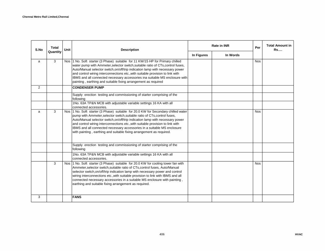
Chennai Metro Rail Limited,Chennai
In Figures In Words
Rate in INR Total Amount in Rs…. S.No Total
Quantity Unit Description Per
a 3 Nos 1 No. Soft starter (3 Phase) suitable for 11 KW/15 HP for Primary chilled water pump with Ammeter,selector switch,suitable ratio of CTs,control fuses, Auto/Manual selector switch,on/off/trip indication lamp with necessary power and control wiring interconnections etc.,with suitable provision to link with IBMS and all connected necessary accessories ina suitable MS enclosure with painting , earthing and suitable fixing arrangement as required
Nos
2 CONDENSER PUMP
Supply erection testing and commissioning of starter comprising of the following 1No. 63A TP&N MCB with adjustable variable settings 16 KA with all connected accessories.
a 3 Nos 1 No. Soft starter (3 Phase) suitable for 20.0 KW for Secondary chilled water pump with Ammeter,selector switch,suitable ratio of CTs,control fuses, Auto/Manual selector switch,on/off/trip indication lamp with necessary power and control wiring interconnections etc.,with suitable provision to link with IBMS and all connected necessary accessories in a suitable MS enclosure with painting , earthing and suitable fixing arrangement as required.
Nos
Supply erection testing and commissioning of starter comprising of the following 1No. 63A TP&N MCB with adjustable variable settings 16 KA with all connected accessories.
3 Nos 1 No. Soft starter (3 Phase) suitable for 20.0 KW for cooling tower fan with Ammeter,selector switch,suitable ratio of CTs,control fuses, Auto/Manual selector switch,on/off/trip indication lamp with necessary power and control wiring interconnections etc.,with suitable provision to link with IBMS and all connected necessary accessories in a suitable MS enclosure with painting , earthing and suitable fixing arrangement as required.
Nos
3 FANS
406 HVAC
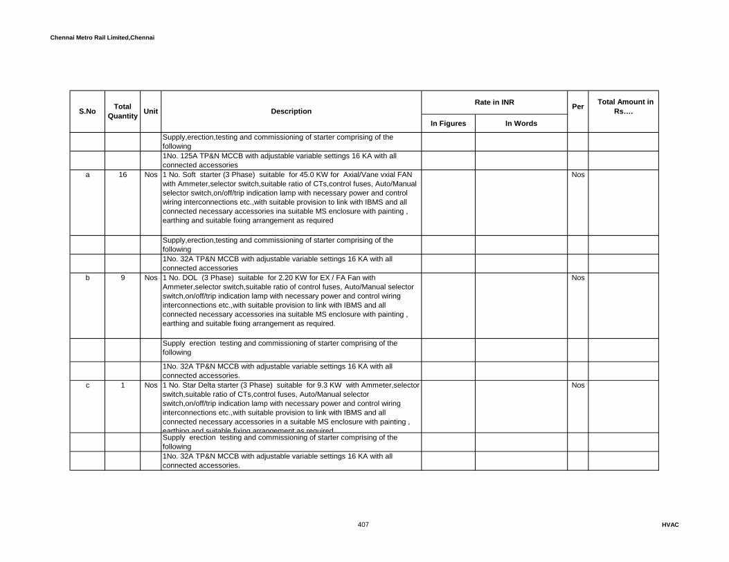
Chennai Metro Rail Limited,Chennai
In Figures In Words
Rate in INR Total Amount in Rs…. S.No Total
Quantity Unit Description Per
Supply,erection,testing and commissioning of starter comprising of the following 1No. 125A TP&N MCCB with adjustable variable settings 16 KA with all connected accessories
a 16 Nos 1 No. Soft starter (3 Phase) suitable for 45.0 KW for Axial/Vane vxial FAN with Ammeter,selector switch,suitable ratio of CTs,control fuses, Auto/Manual selector switch,on/off/trip indication lamp with necessary power and control wiring interconnections etc.,with suitable provision to link with IBMS and all connected necessary accessories ina suitable MS enclosure with painting , earthing and suitable fixing arrangement as required
Nos
Supply,erection,testing and commissioning of starter comprising of the following 1No. 32A TP&N MCCB with adjustable variable settings 16 KA with all connected accessories
b 9 Nos 1 No. DOL (3 Phase) suitable for 2.20 KW for EX / FA Fan with Ammeter,selector switch,suitable ratio of control fuses, Auto/Manual selector switch,on/off/trip indication lamp with necessary power and control wiring interconnections etc.,with suitable provision to link with IBMS and all connected necessary accessories ina suitable MS enclosure with painting , earthing and suitable fixing arrangement as required.
Nos
Supply erection testing and commissioning of starter comprising of the following
1No. 32A TP&N MCCB with adjustable variable settings 16 KA with all connected accessories.
c 1 Nos 1 No. Star Delta starter (3 Phase) suitable for 9.3 KW with Ammeter,selector switch,suitable ratio of CTs,control fuses, Auto/Manual selector switch,on/off/trip indication lamp with necessary power and control wiring interconnections etc.,with suitable provision to link with IBMS and all connected necessary accessories in a suitable MS enclosure with painting , earthing and suitable fixing arrangement as required
Nos
Supply erection testing and commissioning of starter comprising of the following 1No. 32A TP&N MCCB with adjustable variable settings 16 KA with all connected accessories.
407 HVAC

Chennai Metro Rail Limited,Chennai
In Figures In Words
Rate in INR Total Amount in Rs…. S.No Total
Quantity Unit Description Per
d 5 Nos 1 No. Star Delta starter (3 Phase) suitable for 7.5 KW for Presurization fans with Ammeter,selector switch,suitable ratio of CTs,control fuses, Auto/Manual selector switch,on/off/trip indication lamp with necessary power and control wiring interconnections etc.,with suitable provision to link with IBMS and all connected necessary accessories in a suitable MS enclosure with painting , earthing and suitable fixing arrangement as required
Nos
Supply erection testing and commissioning of starter comprising of the following 1No. 32A TP&N MCCB with adjustable variable settings 16 KA with all connected accessories.
e 5 Nos 1 No. DOL(3 Phase) suitable for 4.0 KW for Atrium Ex Fan with Ammeter,selector switch,suitable ratio of control fuses, Auto/Manual selector switch,on/off/trip indication lamp with necessary power and control wiring interconnections etc.,with suitable provision to link with IBMS and all connected necessary accessories ina suitable MS enclosure with painting , earthing and suitable fixing arrangement as required.
Nos
Supply erection testing and commissioning of starter comprising of the following 1No. 32A TP&N MCCB with adjustable variable settings 16 KA with all connected accessories.
f 11 Nos 1 No. DOL (3 Phase) suitable for 1.1 KW for Toilet Ex fan with Ammeter,selector switch,suitable ratio of control fuses, Auto/Manual selector switch,on/off/trip indication lamp with necessary power and control wiring interconnections etc.,with suitable provision to link with IBMS and all connected necessary accessories ina suitable MS enclosure with painting , earthing and suitable fixing arrangement as required.
Nos
Supply erection testing and commissioning of starter comprising of the following 1No. 32A TP&N MCCB with adjustable variable settings 16 KA with all connected accessories.
408 HVAC

Chennai Metro Rail Limited,Chennai
In Figures In Words
Rate in INR Total Amount in Rs…. S.No Total
Quantity Unit Description Per
g 33 Nos 1 No. DOL (3 Phase) suitable for 1.1 KW for Jet Fans with Ammeter,selector switch,suitable ratio of control fuses, Auto/Manual selector switch,on/off/trip indication lamp with necessary power and control wiring interconnections etc.,with suitable provision to link with IBMS and all connected necessary accessories in a suitable MS enclosure with painting , earthing and suitable fixing arrangement as required.
Nos
h Supply erection testing and commissioning of isolator starter comprising of the following
3 Nos 1No of isolator panel, 630A TP&N MCCB with adjustable variable settings 35 KA with all connected accessories.
Nos
3 CABLE AND TERMINATION
Supply laying of following size PVC insulated copper. armoured conductor cable.
a 60 Rmt 3.5 core 185 sqmm PVC Cu.cable Rmt
b 160 Rmt 4 Core 35 Sqmm PVC Cu. cable Rmt
c 260 Rmt 4 Core 16 Sqmm PVC Cu. cable Rmt
d 56 Rmt 4 Core 10 Sqmm PVC Cu. cable Rmt
e 112 Rmt 4 Core 6 Sqmm PVC Cu. cable Rmt
409 HVAC

Chennai Metro Rail Limited,Chennai
In Figures In Words
Rate in INR Total Amount in Rs…. S.No Total
Quantity Unit Description Per
f 126 Rmt 4 Core 4 Sqmm PVC Cu. cable Rmt
g 427 Rmt 4 Core 2.5 Sqmm PVC Cu. cable Rmt
h Rmt 3 Core 2.5 Sqmm PVC Cu. cable Rmt
4 Supply termination and commissioning of the following size cables with suitable double compression glands and crimping socket with suitable earth clipp & fixing accessories.
a 12 Nos 3.5 core 185 sqmm PVC Cu.cable Nos
b 24 Nos 4 Core 35 Sqmm PVC Cu. cable Nos
c 64 Nos 4 Core 16 Sqmm PVC Cu. cable Nos
d 16 Nos 4 Core 10 Sqmm PVC Cu. cable Nos
e 32 Nos 4 Core 6 Sqmm PVC Cu. cable Nos
410 HVAC

Chennai Metro Rail Limited,Chennai
In Figures In Words
Rate in INR Total Amount in Rs…. S.No Total
Quantity Unit Description Per
f 16 Nos 4 Core 4 Sqmm PVC Cu. cable Nos
g 122 Nos 4 Core 2.5 Sqmm PVC Cu. cable Nos
h Nos 3 Core 2.5 Sqmm PVC Cu. cable Nos
5 EARTHING
a 140 Nos Supply and laying of 8 gauge bare copper wire for equipments earthing. Nos
b 45 Nos Supply and laying of 10 gauge bare copper wire for equipments earthing. Nos
c Nos Supply and laying of 14 gauge bare copper wire for equipments and gland earthing.
Nos
6 3 Nos Suplly and installation of isolator panel for water cooled chillers as per manufacturere recommention to terminate the cables from Main panel and outgoing to chillers
Nos
7 29 Nos Supply,installation and commisioning of ON/OFF push button station with required accessories for AHU ,Pumps and Ventilation fans
Nos
8 Supply, erection of following sizes GI perforated type cable rack system made out of sheet steel folded to required shape with adequate number of supports.
411 HVAC

Chennai Metro Rail Limited,Chennai
In Figures In Words
Rate in INR Total Amount in Rs…. S.No Total
Quantity Unit Description Per
The cable rack shall have runners rugs of suitable size, horizontal elbow, vertical elbow 90 Deg. Up vertical elbow 90 Deg. Down, re-deep, coupler plates, materials. The cable racks shall be suspended from ceiling supported from side walls in columns etc. with adequate size supporting angles / channels with fastners, welding, anchor bolts, nuts etc. The rack shall have suitable cable clamping arrangements etc. The metal rack system shall be treated with one coat of rubber based polyvinyl paint as primer and finished with two coats of green enamel paint complete with all civil works for fabrication details
a 650 Rmt 150 MM Rmt
b 850 Rmt 300 MM Rmt
Total carry over to summary ( Electrical System )
412 HVAC

Chennai Metro Rail Limited,Chennai
In Figures In Words
I FIRE ALARM SYSTEMSupply, intallation, testing and Commissioning of the following system as per the technical specification.
1 Analogue addressable micro Process - controlled Fire Alarm Control Panels with interfacing box, capable of being to the central monitoring System, to monitor and integrated the following quantity of accessories like detectors, MCP's/hooters/control modules, Fault Isolation Modules, hooters, response indicators, fire/fault indicators, audio-visual signals, central processing units, complete with LCD display, zone indicating LEDs as per the detailed specification: complete with Battery backup for 48 hours in standy mode and 30 minutes in alarm condition. The system should be capable of detecting fire within 3secs as per UL 9th edition/FM approval with charger for each panel. Each loop should provide with minimum 126 detectors and 126 devices. Fire panel should be RS-485 communication port and integrate with other fire panel and Repeater panel
a 1 Nos 10 Loop Panel 1.00No.(Each )
b 1 Nos 4 Loop Panel 1.00No.(Each )
Rate in INR
Amount in Rs….
CONSTRUCTION OF METRO HEADQUARTERS BUILDING AND OTHER METRO RAIL AMENITIES AT NANDANAM,CHENNAI
BILLS OF QUANTITIES
SCHEDILE - IX - INTEGRATED BUILDING MANAGEMENT SYSTEM
S.NoTotal
Quantity
Unit Description of Work Per
411 IBMS

Chennai Metro Rail Limited,Chennai
In Figures In Words
Rate in INR
Amount in Rs…. S.NoTotal
Quantity
Unit Description of Work Per
c 1 Nos 1 Loop Panel 1.00No.(Each )
d 1 Set Graphical software for entire fire alarm panels including detector configuration, commissioning etc
1.00No.(Each )
1.1 4 Nos Networkable fire alram active repeater panel. It should reflect all parameters of main panel. The rate shall be inclusive of power supply unit and battery backup of 8 hrs minimum in BMS room
1.00No.(Each )
2 375 Nos Rate of Rise Heat Detectors (Thermal Detectors): Addressable analogue type Heat Detectors with solid state design with sensing element combination of fixed type and rate of rise of temperature indicating LED, mounting base,as per detailed specifications.
1.00No.(Each )
3 975 Nos Addressable analogue smoke sensor with dual chamber, solid state design, indicating LED, mounting base, as per detailed specifications.
1.00No.(Each )
4 55 Nos Duct detector suitable for providing the return air path with suitable fixing accessories
1.00No.(Each )
5 208 Nos Hooter with relay module and storb light with minimum 85 db audiable and control relay module, power supply units etc @ 3m for Audible annunciation and 75cd flashintg at 1 Hz for visual indication with Control Module. The Hooter with Control Module shall be flush or surface mountable type with all accessories etc., complete and as per technical specification.
1.00No.(Each )
6 83 Nos Manual call points pull stations of approved make with NO/NC contacts slim type and projecting out from the surface of enclosurewith glass suitable for addressable function
1.00No.(Each )
412 IBMS
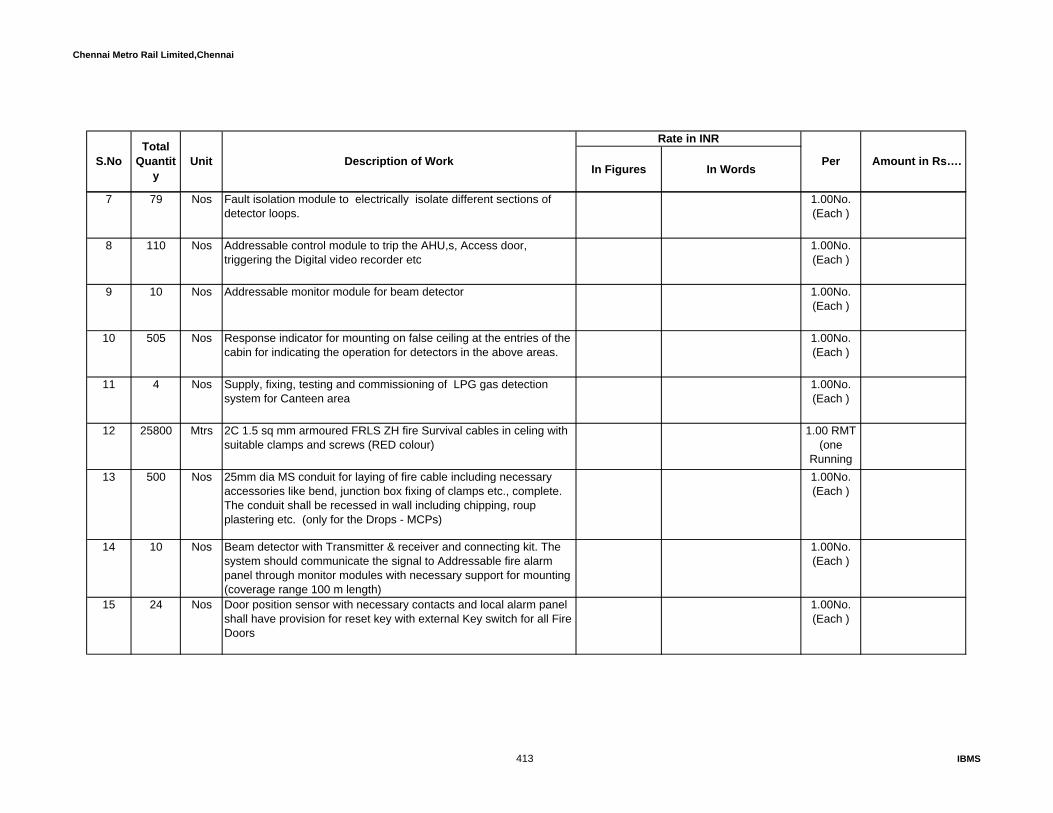
Chennai Metro Rail Limited,Chennai
In Figures In Words
Rate in INR
Amount in Rs…. S.NoTotal
Quantity
Unit Description of Work Per
7 79 Nos Fault isolation module to electrically isolate different sections of detector loops.
1.00No.(Each )
8 110 Nos Addressable control module to trip the AHU,s, Access door, triggering the Digital video recorder etc
1.00No.(Each )
9 10 Nos Addressable monitor module for beam detector 1.00No.(Each )
10 505 Nos Response indicator for mounting on false ceiling at the entries of the cabin for indicating the operation for detectors in the above areas.
1.00No.(Each )
11 4 Nos Supply, fixing, testing and commissioning of LPG gas detection system for Canteen area
1.00No.(Each )
12 25800 Mtrs 2C 1.5 sq mm armoured FRLS ZH fire Survival cables in celing with suitable clamps and screws (RED colour)
1.00 RMT (one
Runningt )13 500 Nos 25mm dia MS conduit for laying of fire cable including necessary
accessories like bend, junction box fixing of clamps etc., complete. The conduit shall be recessed in wall including chipping, roup plastering etc. (only for the Drops - MCPs)
1.00No.(Each )
14 10 Nos Beam detector with Transmitter & receiver and connecting kit. The system should communicate the signal to Addressable fire alarm panel through monitor modules with necessary support for mounting (coverage range 100 m length)
1.00No.(Each )
15 24 Nos Door position sensor with necessary contacts and local alarm panel shall have provision for reset key with external Key switch for all Fire Doors
1.00No.(Each )
413 IBMS
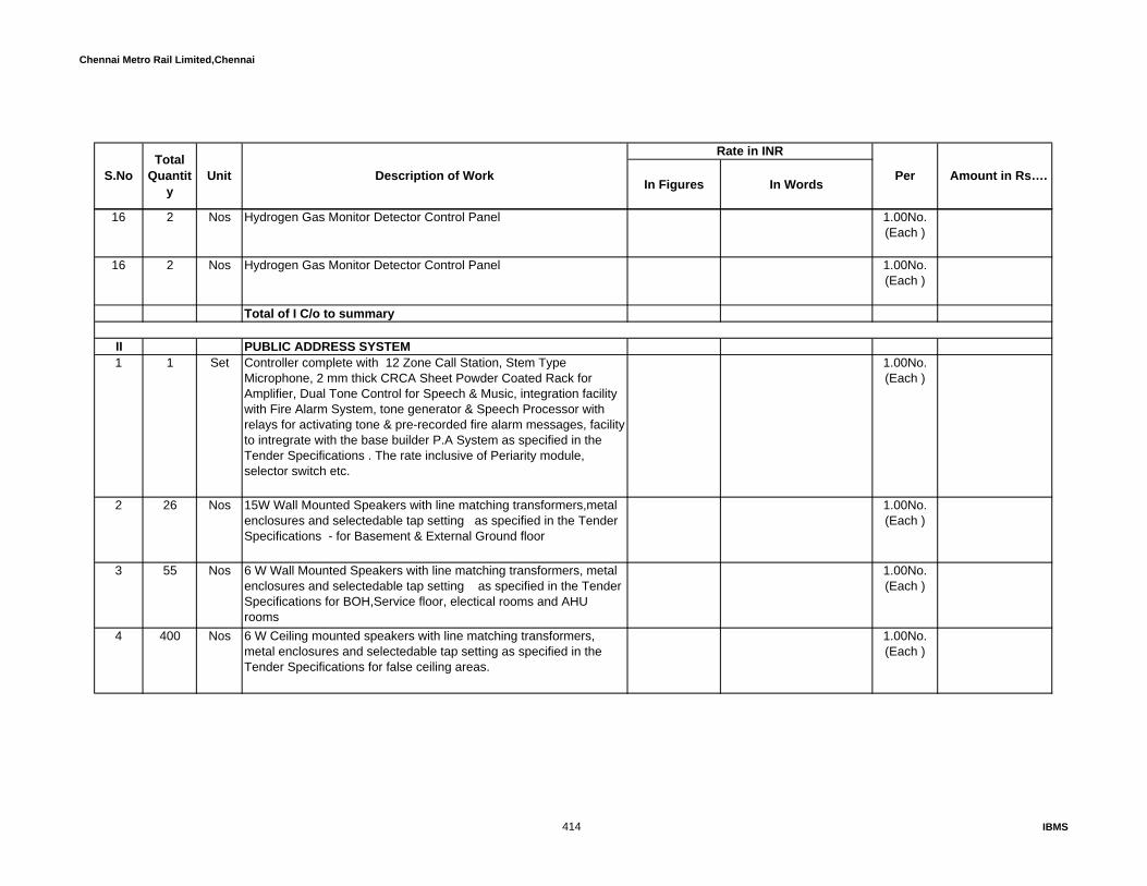
Chennai Metro Rail Limited,Chennai
In Figures In Words
Rate in INR
Amount in Rs…. S.NoTotal
Quantity
Unit Description of Work Per
16 2 Nos Hydrogen Gas Monitor Detector Control Panel 1.00No.(Each )
16 2 Nos Hydrogen Gas Monitor Detector Control Panel 1.00No.(Each )
Total of I C/o to summary
II PUBLIC ADDRESS SYSTEM1 1 Set Controller complete with 12 Zone Call Station, Stem Type
Microphone, 2 mm thick CRCA Sheet Powder Coated Rack for Amplifier, Dual Tone Control for Speech & Music, integration facility with Fire Alarm System, tone generator & Speech Processor with relays for activating tone & pre-recorded fire alarm messages, facility to intregrate with the base builder P.A System as specified in the Tender Specifications . The rate inclusive of Periarity module, selector switch etc.
1.00No.(Each )
2 26 Nos 15W Wall Mounted Speakers with line matching transformers,metal enclosures and selectedable tap setting as specified in the Tender Specifications - for Basement & External Ground floor
1.00No.(Each )
3 55 Nos 6 W Wall Mounted Speakers with line matching transformers, metal enclosures and selectedable tap setting as specified in the Tender Specifications for BOH,Service floor, electical rooms and AHU rooms
1.00No.(Each )
4 400 Nos 6 W Ceiling mounted speakers with line matching transformers, metal enclosures and selectedable tap setting as specified in the Tender Specifications for false ceiling areas.
1.00No.(Each )
414 IBMS

Chennai Metro Rail Limited,Chennai
In Figures In Words
Rate in INR
Amount in Rs…. S.NoTotal
Quantity
Unit Description of Work Per
5 6 Nos Rack Mounted minimum 480 W Power Amplifier as specified in the Tender Specifications
1.00No.(Each )
6 5 Nos Rack Mounted minimum 240 W Power Amplifier as specified in the Tender Specifications
1.00No.(Each )
7 14750 Mtrs 2 core twin twisted 48/0.2 ATC, Multi strand, over all armoured FRLS ZH fire Survival speaker cable as specified in the Tender Specifications
1.00 RMT (one
Runningmetre )
8 1 Nos Micro phone unit with back box, call sation key pad suitable for above system
1.00No.(Each )
9 1 Nos 1 No. DVD player with overriding facility, Music Source Selector, with assignable priority on each channel to accept Music, Telephone, Microphone, Recorded message from Voice recorder etc., with in-built comprossor and limiter. -
1.00No.(Each )
10 2 Nos 42U rack for mounting all the above equipment 1.00No.(Each )
II a Emergency Voice Communication system:11 30 Nos Supply, installation, testing and Commissioning of Emergency voice
communication instrument for staircase (two way) with press to talk specility. The instrument should made out of Stainless steel place as per the specification
1.00No.(Each )
415 IBMS

Chennai Metro Rail Limited,Chennai
In Figures In Words
Rate in INR
Amount in Rs…. S.NoTotal
Quantity
Unit Description of Work Per
12 1 Nos Supply, installation, testing and Commissioning of the 12 Zone for above mentioned instruments .Emergency voice communication system Control panel with necessary zone selector switch with monitoring speaker as per the detailed specification
1.00No.(Each )
13 1000 Mtr Supply, Installation, Testing and Commissioning of Supply & Laying of 4 core 1.5 Sqmm armored copper FRLS cable as specified in the Tender Specifications for EVC
1.00 RMT (one
Runningt )Total of 'II' C/o to summary
III ACCESS CONTROL SYSTEMAccess control system complete with necessary hardware, Software etc., The system should capable to integrate with existing CMRL system Those smart card & readers are MIFARE type “A”Access Controllers, each with capacity of 10000 events buffer memory to r connecting the the item listed below such as card readers, Turnstiles, Magnetic locks, boom barriers etc. The required master controller shall be included part of the controller line items. The system should include existing Server with software license..
1 66 Each 2 Card reader controller 1.00No.(Each )
2 8 Each 4 Card reader controller (double door) 1.00No.(Each )
3 104 Nos Smart Card readers ( MIFARE Type "(A)" ) with stainless steel base plate
1.00No.(Each )
416 IBMS

Chennai Metro Rail Limited,Chennai
In Figures In Words
Rate in INR
Amount in Rs…. S.NoTotal
Quantity
Unit Description of Work Per
4 4 Nos Supply and commissioning of Biometric Readers for Access Control System as specified for centralized securtiy monitoring.
1.00No.(Each )
5 20 Nos Pin Pad + readers with necessary accessories. 1.00No.(Each )
6 66 Nos Emergency break Glass 1.00No.(Each )
7 8 Nos Egress Swith (Push Button) 1.00No.(Each )
8 48 Nos Electromagnetic Locks - Double Door 1.00No.(Each )
9 12 Nos Electromagnetic Locks - Single Door 1.00No.(Each )
10 114 Nos Magnetic Contact 1.00No.(Each )
11 Cables: a 4000 mtr Cable from electromagnetic lock/Sensor to Controller - 1Sqmm 4 C
sqmm multistand armoured cable1.00 RMT
(one Runningmetre )
417 IBMS

Chennai Metro Rail Limited,Chennai
In Figures In Words
Rate in INR
Amount in Rs…. S.NoTotal
Quantity
Unit Description of Work Per
b 600 Mtrs Cable from Reader to Controller - 1Sqmm 12 C sqmm multistand shielded armoured cable
1.00 RMT (one
Runningmetre )
c 4500 Mtrs Cable from Reader to Controller - 1Sqmm 6 C sqmm multistand shielded armoured cable
1.00 RMT (one
Runningmetre )
d 650 Mtrs 2C Network cable for controller to controller (armoured) 1.00 RMT (one
Runningmetre )
12 600 Mtrs 25 mm dia PVC conduit for the laying of cable with suitable clamp in ceiling witn juction box, bend etc (for drop points)
1.00 RMT (one
Runningmetre )
13 1 set Access management software with time and attendance module and required license as per the detailed specification provided in the Technical spec. However the system should be integrated with existing client software
1.00No.(Each )
14 1000 Each Smart Cards MIFARE Type "(A)". The card shall be Corporate 1000 Format.
1.00No.(Each )
15 12 Nos Stainless steel Tripod Turnstile with electric operated horms (motorized) as per the detailed specification attached. The motor shall be servo type and drop arm faciltiy during the fire condition. (simillar to MPP112)
1.00No.(Each )
16 4 Nos Swing gate for Handicap line1.00No.(Each )
418 IBMS

Chennai Metro Rail Limited,Chennai
In Figures In Words
Rate in INR
Amount in Rs…. S.NoTotal
Quantity
Unit Description of Work Per
17 4 Nos 3Mtr. Rising Boom Barrier with LED strip Indicator per the specification complete with control unit and accessories, for Four wheel vehicle entry. The rate shall includes supply and providing of necessary safety loop coil, pedestal for fixing the Card reader in suitable height with weather proof arrangements.
1.00No.(Each )
18 4 Nos Booster antenna with pole 3.5 meter height to activate the RFID tag located at security gate with required necessary hardware & software controller, cabling etc., and also other necessary accessories
1.00No.(Each )
19 500 Nos 2.42 GHZ contact less smart Tag with Adhesive back. (Rfid tag) 1.00No.(Each )
20 25 set U braket support for fixing of Magnetic latch in all glass door with suitable accessoreise
1.00No.(Each )
21 2 set Walk -through detector system with required hardware & software, cabling etc., and also other necessary accessories. (For Entry )
1.00No.(Each )
22 2 set Video Baggage scanner system with required hardware & software, cabling etc., and also other necessary accessories. (For Entry)
1.00No.(Each )
Total `III' C/o to Summary
IV IP BASED CCTV CAMERASupply, installation, testing and commissioning of the following system as per the technical specification.
419 IBMS

Chennai Metro Rail Limited,Chennai
In Figures In Words
Rate in INR
Amount in Rs…. S.NoTotal
Quantity
Unit Description of Work Per
1 100 Each IP Based IR Dome Camera, 1/3" progressive scan, 1280*720 Pixels, H.264 High-profile, 2.8 to 12mm varifocal Lens, True Mechanical Day & Night, Color: 0.01 Lux @ F1.4 (AGC ON), B/W: 0.001 Lux @ F1.4 (AGC ON), Simultaneous H.264&MJPEG Video Compression with independent frame rate setting, 25FPS, Auto IRIS, 3D Noise Reduction, 2Way Audio, WDR, ONVIF, deattachable Memory card support, PoE, 24VAC/12VDC, 10 to 20metres IR distance, 4 Simultaneous Users, Intelligent Analytics: Alarm in, motion detection, Network loss detection, camera tampering, Video loss, 4 privacy Mask Zones, CE,FCC,UL Certifications . including all mounting supports / brackets and fixing accessories. Camera Power supply will be taken from Ethernet cable.
1.00No.(Each )
2 8 Each IP Based IR Bullet Camera, 1/3" progressive scan, 1280*720 Pixels, H.264 High-profile, 2.8 to 12mm varifocal Lens, True Mechanical Day &Night, Simultaneous H.264&MJPEG Video Compression with independent frame rate setting, 25FPS, Auto IRIS, 3D Noise Reduction, 2Way Audio, WDR, ONVIF, inbuilt Memory card support, PoE, 24VAC/12VDC, 40metres IR distance with Array LED, 4 Simultaneous Users, Intelligent Analytics: Alarm in, motion detection, Network loss detection, camera tampering, Video loss, 4 privacy Mask Zones, CE,FCC,UL Certifications
1.00No.(Each )
3 8 Each Intergrated (IP)Color high speed 1/4" Pan/Tilt/Zoom indoor camera, 540 lines resolution and sensittivity of 1 lux at F1.2 with 18X motorized zoom lens, receiver, driver, Pan/Tilt and necessay mounting support / bracket, accessories as required for indoor installation. Camera Power supply will be taken from Ethernet cable.
1.00No.(Each )
420 IBMS

Chennai Metro Rail Limited,Chennai
In Figures In Words
Rate in INR
Amount in Rs…. S.NoTotal
Quantity
Unit Description of Work Per
4 1 set Dual core Server suitable to connect max. 200 cameras. The rate shall inclusive of necessary softwre etc. The rate shall inclusive of necessary Camara server, storage server, Analytics server etc.4CIF, 8 frame /second - 30 days - continuos recording 8 am to 8 pm and 8 pm to 8 am will be motion based. (The system configuration and system architecture along with the bid)
1.00No.(Each )
5 2 Nos Client Workstation with Client Software:- Monitoring station as per technical specification and system PC comprising Intel core i 7- 3.33 Ghz Processor @ L2 Cache 3 MB Intel 31 PR mother board, 4GB DDr2 RAM @ 667 Mhz , 500 GB HDD , Keyboard, Optical mouse, external speakers, 4TB External hard disc ,sound card ATX P IV Cabinet with SMPS Prime Source, DVD Writer, Service pack -1 with Windows 7 professional operating system. The system should be supplied with 23" TFT Color Monitor. The Server should be loaded with antivirus software. It shall have minimum 3 serial and 1 parallel port operation facility .The CPU shall have a LAN card with 2 USB ports with dual monitor card . One set of speakers with necessary interconnection wires. The system shall be provided with pre-loaded antivirus software and PC configuration should be considered latest at time of installation stage.-
1.00No.(Each )
6 4 Nos 42" diagonal, 1024 x 768 pixels Plasma television with all mounting bracket, connection card wire, remote control etc as per the specification. The braket shall be provided with adjustable type from wall for better servicibility.
1.00No.(Each )
7 4 Nos Pixels 752 (H) x 582(V) non IP IR Box type Camera, 1/3" sony progressive scan, H.264 High-profile, 2.8~12mm, 30~40m IR distance, Audio chip, IP66. The rate shall be inclusive of necessay mounting support / bracket, accessories as required for outdoor installation along with standard outdoor enclosure with suitable accessories and mounting support as per specification
1.00No.(Each )
421 IBMS
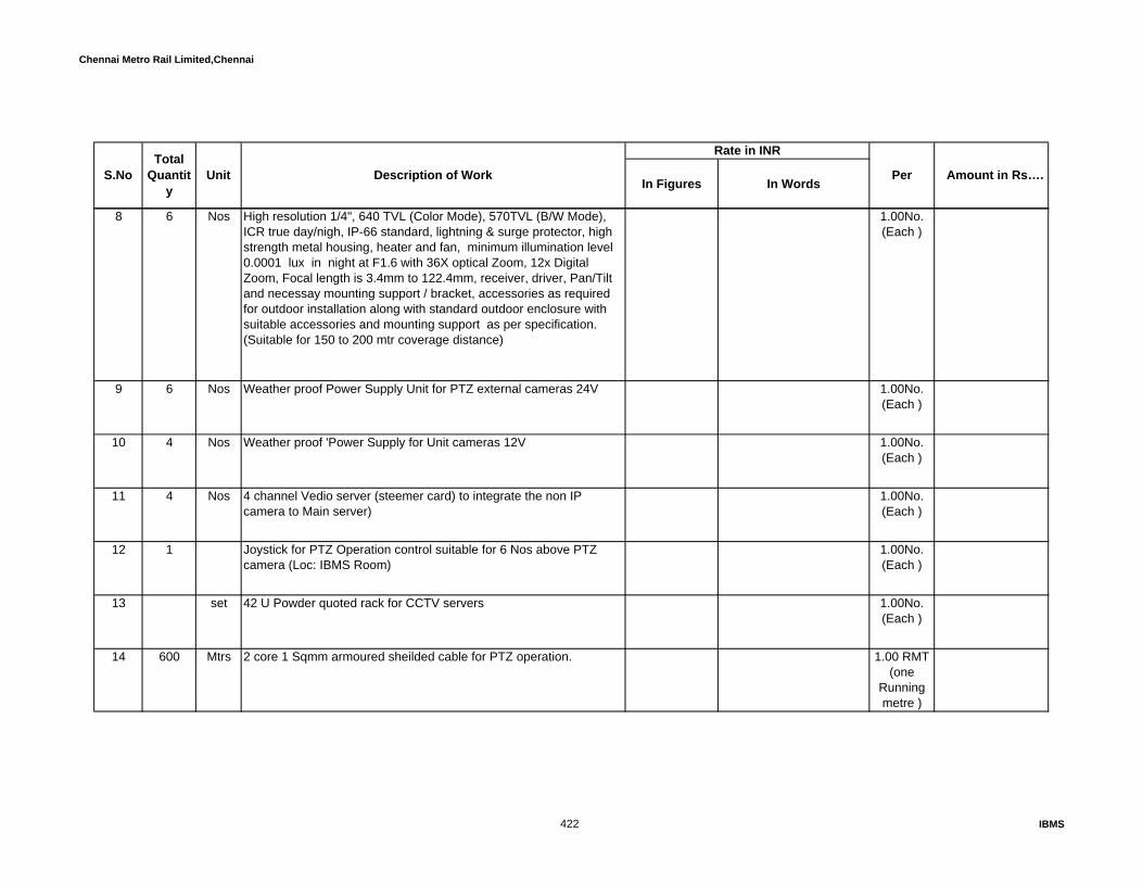
Chennai Metro Rail Limited,Chennai
In Figures In Words
Rate in INR
Amount in Rs…. S.NoTotal
Quantity
Unit Description of Work Per
8 6 Nos High resolution 1/4", 640 TVL (Color Mode), 570TVL (B/W Mode), ICR true day/nigh, IP-66 standard, lightning & surge protector, high strength metal housing, heater and fan, minimum illumination level 0.0001 lux in night at F1.6 with 36X optical Zoom, 12x Digital Zoom, Focal length is 3.4mm to 122.4mm, receiver, driver, Pan/Tilt and necessay mounting support / bracket, accessories as required for outdoor installation along with standard outdoor enclosure with suitable accessories and mounting support as per specification. (Suitable for 150 to 200 mtr coverage distance)
1.00No.(Each )
9 6 Nos Weather proof Power Supply Unit for PTZ external cameras 24V 1.00No.(Each )
10 4 Nos Weather proof 'Power Supply for Unit cameras 12V 1.00No.(Each )
11 4 Nos 4 channel Vedio server (steemer card) to integrate the non IP camera to Main server)
1.00No.(Each )
12 1 Joystick for PTZ Operation control suitable for 6 Nos above PTZ camera (Loc: IBMS Room)
1.00No.(Each )
13 set 42 U Powder quoted rack for CCTV servers 1.00No.(Each )
14 600 Mtrs 2 core 1 Sqmm armoured sheilded cable for PTZ operation. 1.00 RMT (one
Runningmetre )
422 IBMS

Chennai Metro Rail Limited,Chennai
In Figures In Words
Rate in INR
Amount in Rs…. S.NoTotal
Quantity
Unit Description of Work Per
15 1500 Mtrs RG 11 co-axial armourd cable 1.00 RMT (one
Runningmetre )
16 1000 Mtrs 3c x 2.5 sq mm cu. armourd cable for power supply 1.00 RMT (one
Runningmetre )
17 6 Nos 6 Mtr height 50 mm dia GI post with necessary mounting bracket and Civil works for external speaker. The rate shall inclusive of execavation for mounting the post, construction of piller 600 mm above ground level.
1.00No.(Each )
18 600 Mtrs Excavation of ground to a depth of 3' level and width of 1.5' and refilling elc.for laying the RG 11 Coaxial armored Cable with PTZ operation cable and power cable. Extra earth after fe-filling to be leveled in low lying area as directed by the Site incharge.
1.00 RMT (one
Runningmetre )
Total IV C/o to Summary
V NOVEC GAS BASED FIRE SUPRESSION SYSTEMSupply, intallation, testing and Commissioning of the following system.
1 69 Nos 120 Ltrs. Cylinder with Valve for Server Room 1.00No.(Each)
2 7 Nos 80 Ltrs. Cylinder with Valve for Server Room 1.00No.(Each)
3 6900.42 Kgs Novec gas 1.00Kg.(Each)
423 IBMS
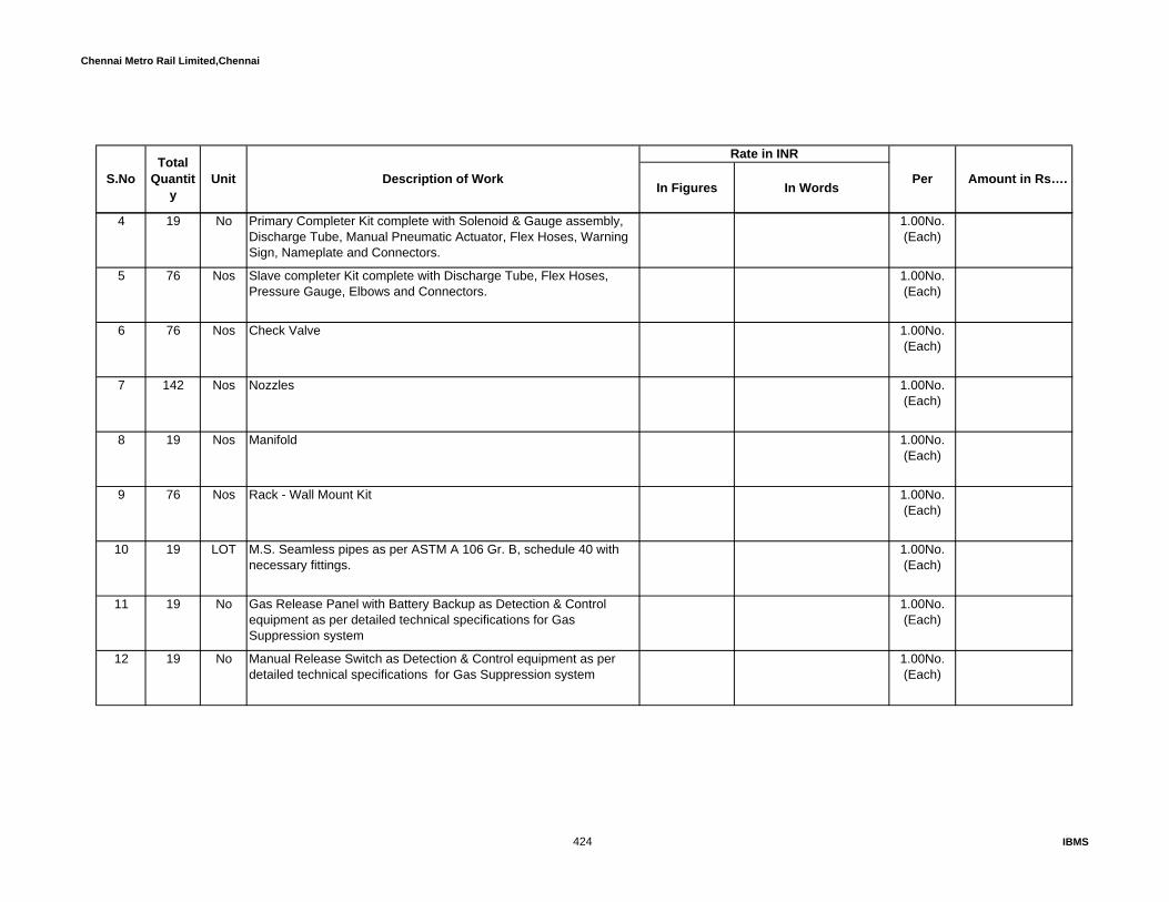
Chennai Metro Rail Limited,Chennai
In Figures In Words
Rate in INR
Amount in Rs…. S.NoTotal
Quantity
Unit Description of Work Per
4 19 No Primary Completer Kit complete with Solenoid & Gauge assembly, Discharge Tube, Manual Pneumatic Actuator, Flex Hoses, Warning Sign, Nameplate and Connectors.
1.00No.(Each)
5 76 Nos Slave completer Kit complete with Discharge Tube, Flex Hoses, Pressure Gauge, Elbows and Connectors.
1.00No.(Each)
6 76 Nos Check Valve 1.00No.(Each)
7 142 Nos Nozzles 1.00No.(Each)
8 19 Nos Manifold 1.00No.(Each)
9 76 Nos Rack - Wall Mount Kit 1.00No.(Each)
10 19 LOT M.S. Seamless pipes as per ASTM A 106 Gr. B, schedule 40 with necessary fittings.
1.00No.(Each)
11 19 No Gas Release Panel with Battery Backup as Detection & Control equipment as per detailed technical specifications for Gas Suppression system
1.00No.(Each)
12 19 No Manual Release Switch as Detection & Control equipment as per detailed technical specifications for Gas Suppression system
1.00No.(Each)
424 IBMS
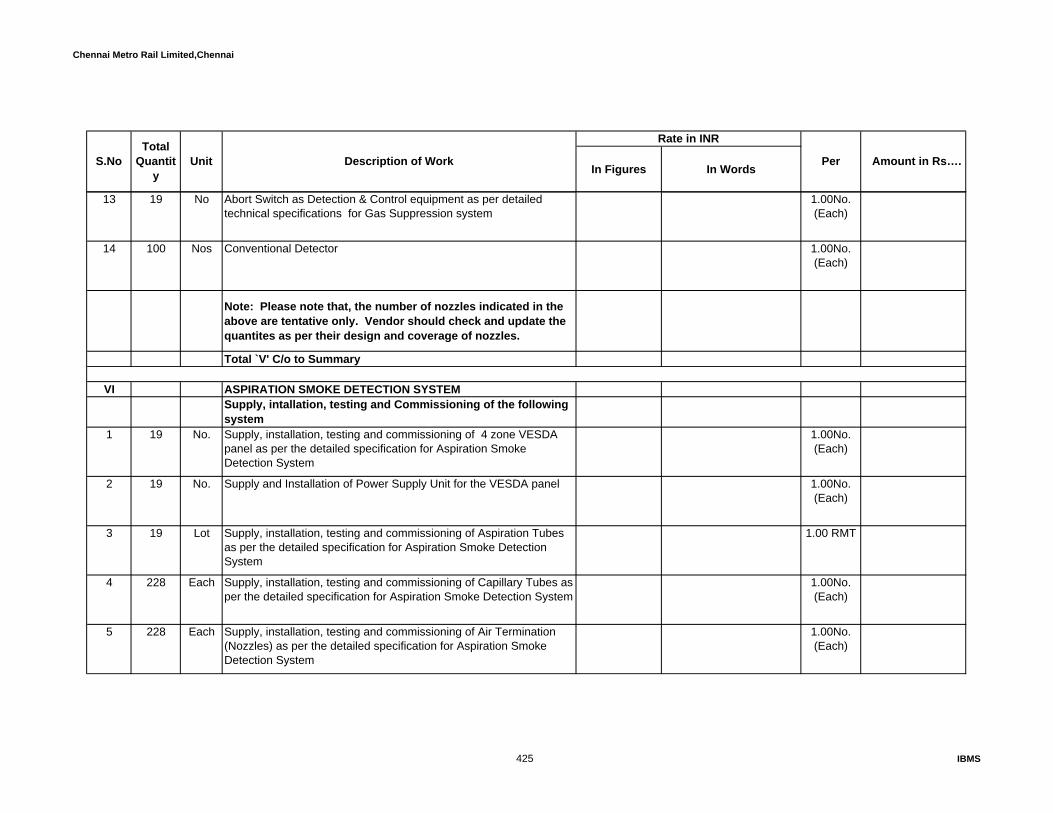
Chennai Metro Rail Limited,Chennai
In Figures In Words
Rate in INR
Amount in Rs…. S.NoTotal
Quantity
Unit Description of Work Per
13 19 No Abort Switch as Detection & Control equipment as per detailed technical specifications for Gas Suppression system
1.00No.(Each)
14 100 Nos Conventional Detector 1.00No.(Each)
Note: Please note that, the number of nozzles indicated in the above are tentative only. Vendor should check and update the quantites as per their design and coverage of nozzles.
Total `V' C/o to Summary
VI ASPIRATION SMOKE DETECTION SYSTEM Supply, intallation, testing and Commissioning of the following system
1 19 No. Supply, installation, testing and commissioning of 4 zone VESDA panel as per the detailed specification for Aspiration Smoke Detection System
1.00No.(Each)
2 19 No. Supply and Installation of Power Supply Unit for the VESDA panel 1.00No.(Each)
3 19 Lot Supply, installation, testing and commissioning of Aspiration Tubes as per the detailed specification for Aspiration Smoke Detection System
1.00 RMT
4 228 Each Supply, installation, testing and commissioning of Capillary Tubes as per the detailed specification for Aspiration Smoke Detection System
1.00No.(Each)
5 228 Each Supply, installation, testing and commissioning of Air Termination (Nozzles) as per the detailed specification for Aspiration Smoke Detection System
1.00No.(Each)
425 IBMS

Chennai Metro Rail Limited,Chennai
In Figures In Words
Rate in INR
Amount in Rs…. S.NoTotal
Quantity
Unit Description of Work Per
6 19 Set Supply, installation and commissioning of Vesda Configurator software as per the detailed specification for Aspiration Smoke Detection System (for both the panel)
1.00No.(Each)
7 19 Set Supply, installation, testing and commissioning of High Level Interface as per the detailed specification for Aspiration Smoke Detection System (for both the panels)
1.00No.(Each)
8 19 Each Supply, installation, testing and commissioning of Electronic Hooter for Aspiration Smoke Detection System
1.00No.(Each)
9 600 Mtrs 2C x 1.5 Sq.mm. Cu. Armoured Cable. 1.00 RMT
10 1 Each Repeater panel to indicate the fault (at BMS room) as per the specification
1.00No.(Each)
Total `VI' C/o to Summary
VII ULTRASONIC PEST REPLLER SYSTEM-DIGITAL SYSTEM
Supply, Installation, Testing and Commissioning of the following system for Hub Room
1 20 Set VHFO controller 1.00No.(Each)
2 200 Each Satellites 1.00No.(Each)
3 4500 Mtrs Suitable cable for the above laid in FRLS MS conduits 1.00No.(Each)
426 IBMS

Chennai Metro Rail Limited,Chennai
In Figures In Words
Rate in INR
Amount in Rs…. S.NoTotal
Quantity
Unit Description of Work Per
Total `VII' C/o to Summary
VIII ADDRESSABLE TYPE WATER LEAK DETECTION SYSTEM
1 19 Set Water Leak detection panel with battery as per specification. The panel should have communication protcal of any open system like Modubus, bacnet over IP etc with suitable stand alone power supply
1.00No.(Each)
2 550 Mtrs Water leak detection cable sensor 1.00 RMT
3 19 each Hooter at panel location 1.00No.(Each)
Total `VIII' C/o to Summary
IX BUILDING MANAGEMENT SYSTEM: Supply, intallation, testing and Commissioning of the following system as per the technical specification.
1 1 Nos Design supply, installing, testing and commissioning Microprocessor based Integrated Building Management System as per the detailed specifications for complete and satisfactory operation and control. Both BAS and IBMS system to be integrated in a single Central Monitoring station and a single Software.Operator Workstation with latest intel micriprocessor, I 3 or latest, 8 GB RAM, 8 TB HDD, 2.8 Ghz, Wirless keyboard, mouse, windows Operating system Software SQL with MS Office Software latest & Licenced Anti-Virus Software LED Monitor - 21 inch , DVD Writer, with A4 Size Laser Jet Printer (with software required License)
1.00No.(Each )
427 IBMS

Chennai Metro Rail Limited,Chennai
In Figures In Words
Rate in INR
Amount in Rs…. S.NoTotal
Quantity
Unit Description of Work Per
2 1 Each Monitoring station as per technical specification and system PC comprising Intel core i 7- 3.33 Ghz Processor @ L2 Cache 3 MB Intel 31 PR mother board, 8GB DDr2 RAM @ 667 Mhz , 8 TB HDD , Keyboard, Optical mouse, external speakers, 4TB External hard disc ,sound card ATX P IV Cabinet with SMPS Prime Source, DVD Writer, Service pack -1 with Windows 7 professional operating system. The system should be supplied with 23" TFT Color Monitor. The Server should be loaded with antivirus software. It shall have minimum 3 serial and 1 parallel port operation facility .The CPU shall have a LAN card with 2 USB ports . One set of speakers with necessary interconnection wires. The system shall be provided with pre-loaded antivirus software and PC configuration should be considered latest at time of installation stage.- (BMS-1 No, Access-1 No. and FAS 1 No.)
1.00No.(Each )
3 1 Set Supply,installatioin and commissioning of Graphical interface software for 1 No Workstation PC and two web based clients based on MS Windows 7 / Latest. The Software shall be BACnet compliant for integration & inter-operability with 3rd party microprocessor systems of various Building Services
1.00No.(Each )
4 1 Set Providing necessary Software and Hardware for Interfacing through a gate way for monitoring through serial Modbus interface for the data points for Chillers, PUMPS, Microcontroller ,AHUs, Pumps, DG & UPSs, VAVs, Energy meters as per the detailed Annexure- 1,2 & 3 in I/ o list. Total soft points ( 3500 points)
1.00No.(Each )
5 1 Set Providing necessary Software and Hardware for interfacing through a gate way for monitoring through using the Modbus RTU, BACNET or Lon works protocols, interface for the data points for as following as per the detailed AC-BAS scope matrix. The software shall include the cost of the rquired drivers
1.00No.(Each )
428 IBMS
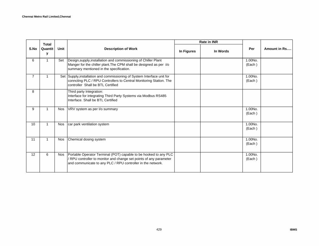
Chennai Metro Rail Limited,Chennai
In Figures In Words
Rate in INR
Amount in Rs…. S.NoTotal
Quantity
Unit Description of Work Per
6 1 Set Design,supply,installation and commissioning of Chiller Plant Manger for the chiller plant.The CPM shall be designed as per i/o summary mentioned in the specification.
1.00No.(Each )
7 1 Set Supply,installation and commissioning of System Interface unit for conncting PLC / RPU Controllers to Central Monitoring Station. The controller Shall be BTL Certified
1.00No.(Each )
8 Third party Integration:Interface for integrating Third Party Systems via Modbus RS485 Interface. Shall be BTL Certified
9 1 Nos VRV system as per I/o summary 1.00No.(Each )
10 1 Nos car park ventilation system 1.00No.(Each )
11 1 Nos Chemical dosing system 1.00No.(Each )
12 6 Nos Portable Operator Terminal (POT) capable to be hooked to any PLC / RPU controller to monitor and change set points of any parameter and communicate to any PLC / RPU controller in the network.
1.00No.(Each )
429 IBMS

Chennai Metro Rail Limited,Chennai
In Figures In Words
Rate in INR
Amount in Rs…. S.NoTotal
Quantity
Unit Description of Work Per
Supply, installation, testing and commissioning of Autonomous networkable PLC / RPU Controller with 32/64 bit microprocessor based standalone and networkable type with real time clock and historical database of min 1 Mb with panels, peer to peer communicable PLC / RPU modules, input or output relays, terminal block, real time clock, networking and inbuilt data buffer for following requirement as per enclosed IO summary
13 6 Set Weather proof enclosure for suitable to above mentioned PLC / RPU panel to suit external use with sutiable floor/wall mounting accessoreis including necessary civil works if any
1.00No.(Each )
FIELD EQUIPMENT14 3 Nos Supply, installation, testing and commissioning of immersion type
Flow switch to monitor the dry run status for Chiller system as per the I/O listed for BAS system
1.00No.(Each )
15 1 Nos Supply, installation, testing and commissioning of immersion type Flow meter to measure the flow status for Chiller system as per the I/O listed for w BAS system
1.00No.(Each )
16 52 Nos Supply, installation, testing and commissioning of immersion type Termperature Sensors with thermowell & all mounting accessories as per the seystem mentioned in I/O summary for BAS system
1.00No.(Each )
17 3 Nos Supply, installation, testing and commissioning of differencial pressure switch across the secondary pumps for status monitoring as per I/O summary for BAS system
1.00No.(Each )
18 1 Nos Supply, installation, testing and commissioning of Outdoor type combined Termperature & Relative Humidity Sensors with all mounting accessories for Ambient Temperature as per the seystem mentioned in Chiller I/O summary for BAS system
1.00No.(Each )
430 IBMS

Chennai Metro Rail Limited,Chennai
In Figures In Words
Rate in INR
Amount in Rs…. S.NoTotal
Quantity
Unit Description of Work Per
19 2 Nos Suply ,installation and commissioning of Level switches 1.00No.(Each )
20 26 Nos Supply, installation, testing and commissioning of Duct type Termperature Sensors with all duct mounting accessories as per the seystem AHU mentioned in I/O summary for BAS system
1.00No.(Each )
21 26 Nos Supply, installation, testing and commissioning of Duct type Termperature & Rh Sensors with all duct mounting accessories as per the seystem AHU mentioned in I/O summary for BAS system
1.00No.(Each )
22 34 Nos Supply, installation, testing and commissioning of differential pressure switch to monitor the Run status & Filter status as per AHU & TFA I/O listed for BAS system
1.00No.(Each )
23 Nos Supply, installation, testing and commissioning of immersion type Termperature Sensors with thermowell & all mounting accessories as per the seystem mentioned in AHU I/O summary for BAS system
1.00No.(Each )
24 21 Nos Supply, installation, testing and commissioning of Duct smoke Detector. Duct smoke detector with necessary Irms (interposing relay Modules) which is being linked by LOR of BAS system
1.00No.(Each )
25 24 Nos Supply and installtion of duct static pressure sensor to control VFD 1.00No.(Each )
26 28 Nos Supply,installation and testing of indoor CO2 sensor 1.00No.(Each )
27 2 Nos Supply,installation and testing of outdoor co2 sensor to monitor the Co2 level as per i/o summary
1.00No.(Each )
431 IBMS

Chennai Metro Rail Limited,Chennai
In Figures In Words
Rate in INR
Amount in Rs…. S.NoTotal
Quantity
Unit Description of Work Per
28 12 Nos signal propotional to level of contamination by cabron Monoxide and other athmospheric pollutants.
1.00No.(Each )
29 CABLES & CONDUITS30 5500 Mtrs Supply, laying, terminating, testing and commissioning of 2 core 1.0
SQ.MM, GI armoured ATC conductor multistranded, Unscreened FRLS cable (For ON / OFF Command & various status / Power Supply for field Devices)
1.00 RMT (one
Runningmetre )31 5500 Mtrs Supply, laying, testing and commissioning of 2 core 1.0 SQ.MM, GI
armoured ATC conductor multistranded, screened FRLS cable (For Sensors)
1.00 RMT (one
Runningmetre )32 770 Mtrs Supply, laying, terminating, testing and commissioning of 4 core 1.5
SQ.MM, GI armoured ATC conductor multistranded, screened FRLS cable (For Modulating Actuator & T & Rh sensors)
1.00 RMT (one
Runningmetre )33 425 Mtrs Supply, laying, terminating, testing and commissioning of 4 core 1.5
SQ.MM, GI armoured ATC conductor multistranded, Unscreened FRLS cable (For ON/OFF Actuator)
1.00 RMT (one
Runningmetre )34 25 Mtrs Supply, laying, terminating, testing and commissioning of 2 core 1.5
SQ.MM, GI armoured twisted pair shielded FRLS cable for bus connection (For communication)
1.00 RMT (one
Runningmetre )35 40 Mtrs Supply, laying, terminating, testing and commissioning of 12 core 1.5
SQ.MM, GI armoured ATC conductor multistranded, Unscreened FRLS cable (For ON / OFF Command & various status / Power Supply for sec I to XI's Field Devices)
1.00 RMT (one
Runningmetre )
36 25 Mtrs Supply, laying, terminating, testing and commissioning of 16 core 1.5 SQ.MM, GI armoured ATC conductor multistranded, Unscreened FRLS cable (For ON / OFF Command & various status / Power Supply for sec I to XI's Field Devices)
1.00 RMT (one
Runningmetre )
432 IBMS
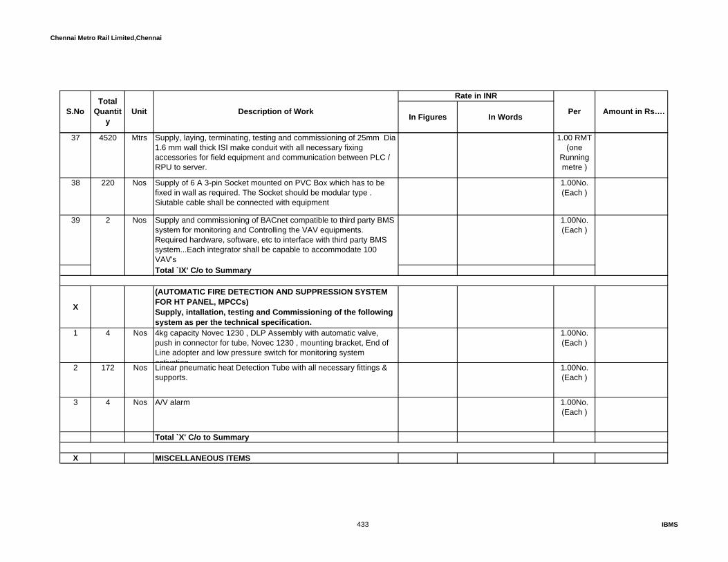
Chennai Metro Rail Limited,Chennai
In Figures In Words
Rate in INR
Amount in Rs…. S.NoTotal
Quantity
Unit Description of Work Per
37 4520 Mtrs Supply, laying, terminating, testing and commissioning of 25mm Dia 1.6 mm wall thick ISI make conduit with all necessary fixing accessories for field equipment and communication between PLC / RPU to server.
1.00 RMT (one
Runningmetre )
38 220 Nos Supply of 6 A 3-pin Socket mounted on PVC Box which has to be fixed in wall as required. The Socket should be modular type . Siutable cable shall be connected with equipment
1.00No.(Each )
39 2 Nos Supply and commissioning of BACnet compatible to third party BMS system for monitoring and Controlling the VAV equipments. Required hardware, software, etc to interface with third party BMS system...Each integrator shall be capable to accommodate 100 VAV's
1.00No.(Each )
Total `IX' C/o to Summary
X
(AUTOMATIC FIRE DETECTION AND SUPPRESSION SYSTEM FOR HT PANEL, MPCCs) Supply, intallation, testing and Commissioning of the following system as per the technical specification.
1 4 Nos 4kg capacity Novec 1230 , DLP Assembly with automatic valve, push in connector for tube, Novec 1230 , mounting bracket, End of Line adopter and low pressure switch for monitoring system activation
1.00No.(Each )
2 172 Nos Linear pneumatic heat Detection Tube with all necessary fittings & supports.
1.00No.(Each )
3 4 Nos A/V alarm 1.00No.(Each )
Total `X' C/o to Summary
X MISCELLANEOUS ITEMS
433 IBMS

Chennai Metro Rail Limited,Chennai
In Figures In Words
Rate in INR
Amount in Rs…. S.NoTotal
Quantity
Unit Description of Work Per
Supply, intallation, testing and Commissioning of the following system as per the technical specification.Supply and installation of following size slotted angle GI ready made cable trays of 14 SWG GI sheet. The Quoted rates for installation shall including necessary anchor fasteners and downroad supports @ 600mm interval etc., to suit site conditions as required. All the cables in vertical running from IBMS room to each floor at shaft should be taken through below suitable size cable trays
1 300 Mtrs 450 mm wide cable tray 1.00 RMT (one
Runningmetre )
2 600 Mtrs 300 mm wide cable tray 1.00 RMT (one
Runningmetre )
3 800 Mtrs 150 mm wide cable tray 1.00 RMT (one
Runningmetre )
4 2500 Each Wiring to the IBMS equipment using 2 R uns of 2.5 Sqmm insulated copper cable and 1R-1.5 Sqmmof earthing the suitable size 25mm MS conduits with clamp and fixing accessories -
1.00 RMT (one
Runningmetre )
5 300 Nos 6 A 3-Pin Socket mounted on PVC Box which has to be fixed in wall as required. The Socket should be of modular type
1.00No.(Each )
6 200 Mtrs 150mm dia HDPE pipe in execavated ground. The rate shall be including necessary coupler, bend etc.
1.00 RMT (one
Runningmetre )
434 IBMS

Chennai Metro Rail Limited,Chennai
In Figures In Words
Rate in INR
Amount in Rs…. S.NoTotal
Quantity
Unit Description of Work Per
7 100 Mtrs 40mm dia HDPE pipe in execavated ground. The rate shall be including necessary coupler, bend etc.
1.00 RMT (one
Runningmetre )
Total `X' C/o to Summary
XI IT EQUIPMENT WITH ACCESSORIES FOR ACCESS & CCTV
Supply, installation, testing and commissioning of following systems as per the detailed technical specification.
1 Each Stackable Edge Switch with layer-2 48 ports (24 nos POE port for CCTV+24 nos non POE port for access controller system) including redundant power supply. (Cisco)
1.00No.(Each )
2 Each 9U wall mounted rack made out of powder cated materials with ventilation louvers, glass door in front side. The rack shall be provided with suitable power sockets/strips, lock and key, cable manager etc(600Wx500D)
1.00No.(Each )
3 Mtr CAT-6 E UTP cable 4 pair as per the technical specification 1.00 RMT (one
Runningmetre )4 Each CAT 6 E patch cords of 3 feet 1.00No.(Each )
5 Each Single I/O face plate with RJ 45 connectors with suitable base box 1.00No.(Each )
6 Mtr 12 Core indoor type OFC cable consist 12 core OM 3 Multimode Fibres in a separate PVC pipe (measured under seperate line items) with standard colour code index as per the detailed specification.
1.00 RMT (one
Runningmetre )
435 IBMS

Chennai Metro Rail Limited,Chennai
In Figures In Words
Rate in INR
Amount in Rs…. S.NoTotal
Quantity
Unit Description of Work Per
7 Mtr 19mm dia FRLS MS pipes/flexible layed /clamped in the existing wall/cable tray with suitable supports for CAT-6 cables
1.00 RMT (one
Runningmetre )
8 Each Stackable Edge Switch with layer-3 24 ports POE with including redundant power supply. (Cisco)
1.00No.(Each )
Total `XI' C/o to Summary
436 IBMS

Soft Points QTY1 AO AI DO DI High Low
1 Pre-Filter dust status 1 BMS to Provide Air DP Switch2 Bag filter dust status 1 BMS to Provide Air DP Switch3 PIBCV control valve - control for cooling coil 1 BMS to Provide modulating type Valve and actuator4 PIBCV PID control valve - feedback for cooling coil 1 BMS to Provide modulating type Valve and actuator5 SA duct temp sensor 2 BMS to Provide combined Duct type Temp sensor6 RA duct type temp sensor 2 BMS to Provide combined Duct type Temp sensor7 AHU Fan On /Off Command 1 Potential Free Contact from BMS to Electrical Starter panel8 AHU Fan On /Off Status 1 BMS to Provide Air DP Switch9 AHU Panel Incomer ACB On/Off Status 2 potential free contact from AHU Panel to BMS
10 AHU Panel Incomer ACB Trip Status 1 potential free contact from AHU Panel to BMS11 VFD - Trip status 1 potential Free Contact from BMS12 AHU Fan VFD - Speed Control 1 0-10VDC from BMS to VFD13 AHU Fan VFD - Status feed back 1 0-10VDC from BMS to VFD14 AHU Fan Auto/Manual 1 Potential Free Contact to BMS from Electrical Starter panel15 AHU Fan Bypass (VFD) 116 Inlet & Out let Immersion type Temp Sensor 217 CO2 Sensor 118 Fa damper position status 119 Cfm Sensor 120 VAV'S Cfm 121 VFD - Softpoint status 10
Sub Total 10 3 10 1 10Spare 20% 1 2 0 2Total I/O Points 10 4 12 1 12
GF AHU - 2 (Passage)
Sl.No Signal DescriptionIO POINTS Severity
Remarks
CONSTRUCTION OF METRO HEADQUARTERS BUILDING AND OTHER METRO RAIL AMENITIES AT NANDANAM,CHENNAIANNEXURE - 6 , HVAC - I/O SUMMARY
PLC - 1GF AHU - 1 (Atrium, Corridor, Hub, Mail Room)
Sl.No Signal DescriptionIO POINTS Severity
Remarks

Soft Points QTY1 AO AI DO DI High Low
1 Pre-Filter dust status 1 BMS to Provide Air DP Switch2 Bag filter dust status 1 BMS to Provide Air DP Switch3 PIBCV control valve - control for cooling coil 1 BMS to Provide modulating type Valve and actuator4 PIBCV PID control valve - feedback for cooling coil 1 BMS to Provide modulating type Valve and actuator5 SA duct temp sensor 2 BMS to Provide combined Duct type Temp sensor6 RA duct type temp sensor 2 BMS to Provide combined Duct type Temp sensor7 AHU Fan On /Off Command 1 Potential Free Contact from BMS to Electrical Starter panel8 AHU Fan On /Off Status 1 BMS to Provide Air DP Switch9 AHU Panel Incomer ACB On/Off Status 2 potential free contact from AHU Panel to BMS
10 AHU Panel Incomer ACB Trip Status 1 potential free contact from AHU Panel to BMS11 VFD - Trip status 1 potential Free Contact from BMS12 AHU Fan VFD - Speed Control 1 0-10VDC from BMS to VFD13 AHU Fan VFD - Status feed back 1 0-10VDC from BMS to VFD14 AHU Fan Auto/Manual 1 Potential Free Contact to BMS from Electrical Starter panel15 AHU Fan Bypass (VFD) 116 Inlet & Out let Immersion type Temp Sensor 217 CO2 Sensor 118 Fa damper position status 119 Cfm Sensor 120 VAV'S Cfm 121 VFD - Softpoint status 10
Sub Total 10 3 10 1 10Spare 20% 1 2 0 2Total I/O Points 10 4 12 1 12
Soft Points QTY2 AO AI DO DI
1 CSU Fan ON/OFF Command 2 Potential Free Contact from BMS to Electrical Starter panel2 CSU Fan Auto/Manual Status 2 Potential Free Contact to BMS from Electrical Starter panel3 CSU Fan ON/OFF Status 2 BMS Vendor to Provide Air DP Switch4 CSU Filter Status 2 BMS Vendor to Provide Air DP Switch5 SA duct temp sensor 2 BMS to Provide combined Duct type Temp sensor6 Return air temperature monitoring 2 BMS Vendor to Provide Duct type temperature sensor7 PIBCV Valve control 1 2 BMS Vendor to Provide modulating type Valve and actuator
Sub Total 0 1 4 2 8Spare 20% 0 1 0 2Total I/O Points 0 1 5 2 10
Soft Points QTY4 AO AI DO DI
1 CASSETTE UNIT Fan ON/OFF Command 4 Potential Free Contact from BMS to Electrical Starter panel2 CASSETTE UNIT Fan Auto/Manual Status 4 Potential Free Contact to BMS from Electrical Starter panel3 CASSETTE UNIT Fan ON/OFF Status 4 BMS Vendor to Provide Air DP Switch4 PIBCV Valve control 4 BMS Vendor to Provide modulating type Valve and actuator
Sub Total 0 4 0 4 8Spare 20% 1 0 1 2Total I/O Points 0 5 0 5 10
Soft Points QTY1 AO AI DO DI
1 CASSETTE UNIT Fan ON/OFF Command 1 Potential Free Contact from BMS to Electrical Starter panel2 CASSETTE UNIT Fan Auto/Manual Status 1 Potential Free Contact to BMS from Electrical Starter panel3 CASSETTE UNIT Fan ON/OFF Status 1 BMS Vendor to Provide Air DP Switch
Sl.No Signal DescriptionIO POINTS
Remarks
GF CASSETTE - 7 (Green room)
Sl.No Signal DescriptionIO POINTS
Remarks
GF CSU - 1 & 2 (Cafeteria )
Sl.No Signal DescriptionIO POINTS
Remarks
GF CASSETTE - 3, 4, 5 & 6 (Doctor room,Medical room,Gents &Ladies rest room )
GF AHU - 3 (GYM)
Sl.No Signal DescriptionIO POINTS Severity
Remarks
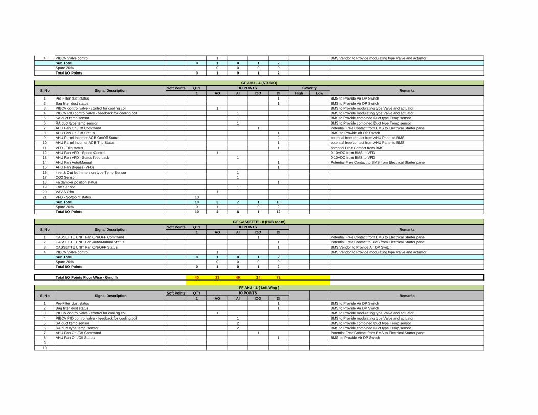
4 PIBCV Valve control 1 BMS Vendor to Provide modulating type Valve and actuatorSub Total 0 1 0 1 2Spare 20% 0 0 0 0Total I/O Points 0 1 0 1 2
Soft Points QTY1 AO AI DO DI High Low
1 Pre-Filter dust status 1 BMS to Provide Air DP Switch2 Bag filter dust status 1 BMS to Provide Air DP Switch3 PIBCV control valve - control for cooling coil 1 BMS to Provide modulating type Valve and actuator4 PIBCV PID control valve - feedback for cooling coil 1 BMS to Provide modulating type Valve and actuator5 SA duct temp sensor 1 BMS to Provide combined Duct type Temp sensor6 RA duct type temp sensor 1 BMS to Provide combined Duct type Temp sensor7 AHU Fan On /Off Command 1 Potential Free Contact from BMS to Electrical Starter panel8 AHU Fan On /Off Status 1 BMS to Provide Air DP Switch9 AHU Panel Incomer ACB On/Off Status 2 potential free contact from AHU Panel to BMS
10 AHU Panel Incomer ACB Trip Status 1 potential free contact from AHU Panel to BMS11 VFD - Trip status 1 potential Free Contact from BMS12 AHU Fan VFD - Speed Control 1 0-10VDC from BMS to VFD13 AHU Fan VFD - Status feed back 1 0-10VDC from BMS to VFD14 AHU Fan Auto/Manual 1 Potential Free Contact to BMS from Electrical Starter panel15 AHU Fan Bypass (VFD) 116 Inlet & Out let Immersion type Temp Sensor 117 CO2 Sensor 118 Fa damper position status 119 Cfm Sensor 120 VAV'S Cfm 121 VFD - Softpoint status 10
Sub Total 10 3 7 1 10Spare 20% 0 1 1 0 2Total I/O Points 10 4 8 1 12
Soft Points QTY1 AO AI DO DI
1 CASSETTE UNIT Fan ON/OFF Command 1 Potential Free Contact from BMS to Electrical Starter panel2 CASSETTE UNIT Fan Auto/Manual Status 1 Potential Free Contact to BMS from Electrical Starter panel3 CASSETTE UNIT Fan ON/OFF Status 1 BMS Vendor to Provide Air DP Switch4 PIBCV Valve control 1 BMS Vendor to Provide modulating type Valve and actuator
Sub Total 0 1 0 1 2Spare 20% 0 0 0 0Total I/O Points 0 1 0 1 2
Total I/O Points Floor Wise - Grnd flr 40 23 49 14 72
Soft Points QTY1 AO AI DO DI
1 Pre-Filter dust status 1 BMS to Provide Air DP Switch2 Bag filter dust status 1 BMS to Provide Air DP Switch3 PIBCV control valve - control for cooling coil 1 BMS to Provide modulating type Valve and actuator4 PIBCV PID control valve - feedback for cooling coil 1 BMS to Provide modulating type Valve and actuator5 SA duct temp sensor 2 BMS to Provide combined Duct type Temp sensor6 RA duct type temp sensor 2 BMS to Provide combined Duct type Temp sensor7 AHU Fan On /Off Command 1 Potential Free Contact from BMS to Electrical Starter panel8 AHU Fan On /Off Status 1 BMS to Provide Air DP Switch9
10
Sl.No Signal DescriptionIO POINTS
Remarks
GF CASSETTE - 8 (HUB room)
Sl.No Signal DescriptionIO POINTS
Remarks
FF AHU - 1 ( Left Wing )
GF AHU - 4 (STUDIO)
Sl.No Signal DescriptionIO POINTS Severity
Remarks

11 VFD - Trip status 1 potential Free Contact from BMS12 AHU Fan VFD - Speed Control 1 0-10VDC from BMS to VFD13 AHU Fan VFD - Status feed back 1 0-10VDC from BMS to VFD14 AHU Fan Auto/Manual 1 Potential Free Contact to BMS from Electrical Starter panel15 AHU Fan Bypass (VFD) 116 Inlet & Out let Immersion type Temp Sensor 217 CO2 Sensor 118 Fa damper position status 119 Cfm Sensor 120 VAV'S Cfm 121 VFD - Softpoint status 10
Sub Total 10 3 10 1 7Spare 20% 1 2 0 1Total I/O Points 10 4 12 1 8
Soft Points QTY1 AO AI DO DI
1 Pre-Filter dust status 1 BMS to Provide Air DP Switch2 Bag filter dust status 1 BMS to Provide Air DP Switch3 PIBCV control valve - control for cooling coil 1 BMS to Provide modulating type Valve and actuator4 PIBCV PID control valve - feedback for cooling coil 1 BMS to Provide modulating type Valve and actuator5 SA duct temp sensor 2 BMS to Provide combined Duct type Temp sensor6 RA duct type temp sensor 2 BMS to Provide combined Duct type Temp sensor7 AHU Fan On /Off Command 1 Potential Free Contact from BMS to Electrical Starter panel8 AHU Fan On /Off Status 1 BMS to Provide Air DP Switch9 AHU Panel Incomer ACB On/Off Status 2 potential free contact from AHU Panel to BMS
10 AHU Panel Incomer ACB Trip Status 1 potential free contact from AHU Panel to BMS11 VFD - Trip status 1 potential Free Contact from BMS12 AHU Fan VFD - Speed Control 1 0-10VDC from BMS to VFD13 AHU Fan VFD - Status feed back 1 0-10VDC from BMS to VFD14 AHU Fan Auto/Manual 1 Potential Free Contact to BMS from Electrical Starter panel15 AHU Fan Bypass (VFD) 116 Inlet & Out let Immersion type Temp Sensor 217 CO2 Sensor 118 Fa damper position status 119 Cfm Sensor 120 VAV'S Cfm 121 VFD - Softpoint status 10
Sub Total 10 3 10 1 10Spare 20% 1 2 0 2Total I/O Points 10 4 12 1 12
Soft Points QTY1 AO AI DO DI
1 HRW TFA Supply Air Fans ON/OFF Command 12 HRW TFA Supply Air Fans ON/OFF Status 13 HRW TFA Supply Auto/Manual staus 14 HRW TFA Supply Trip staus 15 VFD Speed control command for Supply air fan 16 VFD Speed control feedback status for Supply air fan 17 HRW TFA Exhaust Air Fans ON/OFF Command 18 HRW TFA Exhaust Air Fans ON/OFF Status 19 HRW TFA Exhaust Auto/Manual status 1
10 HRW TFA Supply Trip staus 111 VFD Speed control command for Exhaust Air Fans 112 VFD Speed control feedback status for Exhaust Air Fans 113 HRW Wheel ON/OFF Command 114 HRW Wheel ON/OFF Status 1
FF - HRW - 1
Sl.No Signal DescriptionIO POINTS
Remarks
IBMS vendor shall be wire the Potential free contact from chiller panel to IBMS.
FF AHU - 2 ( Right Wing )
Sl.No Signal DescriptionIO POINTS
Remarks

15 HRW Wheel Auto/Manual status 116 HRW Wheel Trip Status 117 Supply Air Temperature leaving Wheel 118 Return Air Temperature Entering Wheel 119 Differential Pressure Switch across filter 120 Outdoor Temperatue sensor (1no. Sufficient for 2 nos HRW) 121 Outdoor CO2 sensor (1no. Sufficient for 2 nos HRW) 122 Duct static pressure sensor in Supply air fan 123 Fire Status and Damper Status 324 HRW - VFD Trip Status 1
Sub Total 0 7 2 13 4Spare 20% 1 0 3 1Total I/O Points 0 8 2 16 5
Soft Points QTY1 AO AI DO DI
1 HRW TFA Supply Air Fans ON/OFF Command 12 HRW TFA Supply Air Fans ON/OFF Status 13 HRW TFA Supply Auto/Manual staus 14 HRW TFA Supply Trip staus 15 VFD Speed control command for Supply air fan 16 VFD Speed control feedback status for Supply air fan 17 HRW TFA Exhaust Air Fans ON/OFF Command 18 HRW TFA Exhaust Air Fans ON/OFF Status 19 HRW TFA Exhaust Auto/Manual status 1
10 HRW TFA Supply Trip staus 111 VFD Speed control command for Exhaust Air Fans 112 VFD Speed control feedback status for Exhaust Air Fans 113 HRW Wheel ON/OFF Command 114 HRW Wheel ON/OFF Status 115 HRW Wheel Auto/Manual status 116 HRW Wheel Trip Status 117 Supply Air Temperature leaving Wheel 118 Return Air Temperature Entering Wheel 119 Differential Pressure Switch across filter 120 Outdoor Temperatue sensor (1no. Sufficient for 2 nos HRW) 121 Outdoor CO2 sensor (1no. Sufficient for 2 nos HRW) 122 Duct static pressure sensor in Supply air fan 123 Fire Status and Damper Status 324 HRW - VFD Trip Status 1
Sub Total 0 7 2 13 4Spare 20% 1 0 3 1Total I/O Points 0 8 2 16 5
Soft Points QTY2 AO AI DO DI
1 Pre-Filter dust status 2 BMS to Provide Air DP Switch2 Bag filter dust status 2 BMS to Provide Air DP Switch3 PIBCV control valve - control for cooling coil 2 BMS to Provide modulating type Valve and actuator4 PIBCV PID control valve - feedback for cooling coil 2 BMS to Provide modulating type Valve and actuator5 SA duct temp sensor 4 BMS to Provide combined Duct type Temp sensor6 RA duct type temp sensor 4 BMS to Provide combined Duct type Temp sensor7 AHU Fan On /Off Command 2 Potential Free Contact from BMS to Electrical Starter panel8 AHU Fan On /Off Status 2 BMS to Provide Air DP Switch9 VFD - Trip status 2 potential Free Contact from BMS
10 AHU Fan VFD - Speed Control 2 0-10VDC from BMS to VFD11 AHU Fan VFD - Status feed back 2 0-10VDC from BMS to VFD12 AHU Fan Auto/Manual 2 Potential Free Contact to BMS from Electrical Starter panel
IBMS vendor shall be wire the Potential free contact from chiller panel to IBMS.
IBMS vendor to provide the Field devises. Cabling provided between Field devices to PLC Panel
FF PAC - 1 & 2 ( Server Room )
Sl.No Signal DescriptionIO POINTS
Remarks
IBMS vendor to provide the Field devises. Cabling provided between Field devices to PLC Panel
FF - HRW - 2( Auditorium & Stage )
Sl.No Signal DescriptionIO POINTS
Remarks

13 AHU Fan Bypass (VFD) 214 Inlet & Out let Immersion type Temp Sensor 415 CO2 Sensor 216 Fa damper position status 217 Cfm Sensor 218 VAV'S Cfm 2
Sub Total 0 6 20 2 14Spare 20% 1 4 0 3Total I/O Points 0 7 24 2 17
Soft Points QTY1 AO AI DO DI
1 Fan ON/OFF Command 1 Potential Free Contact from BMS to Electrical Starter panel2 Fan Auto/Manual Status 1 Potential Free Contact to BMS from Electrical Starter panel3 Fan ON/OFF Status 1 BMS Vendor to Provide Air DP Switch4 Filter Status 1 BMS Vendor to Provide Air DP Switch5 SA duct temp sensor 1 BMS to Provide combined Duct type Temp sensor6 Return air temperature monitoring 1 BMS Vendor to Provide Duct type temperature sensor7 PIBCV Valve control 1 1 BMS Vendor to Provide modulating type Valve and actuator8 FF Dx Split - 1 Softpoints 20
Sub Total 20 1 2 1 4Spare 20% 0 0 0 1Total I/O Points 20 1 2 1 5
Total I/O Points Floor Wise - First flr 30 32 55 37 52
Total I/O Points for PLC - 1 30 55 104 52 124
Soft Points QTY2 AO AI DO DI
1 Pre-Filter dust status 2 BMS to Provide Air DP Switch2 Bag filter dust status 2 BMS to Provide Air DP Switch3 PIBCV control valve - control for cooling coil 2 BMS to Provide modulating type Valve and actuator4 PIBCV PID control valve - feedback for cooling coil 2 BMS to Provide modulating type Valve and actuator5 SA duct temp sensor 4 BMS to Provide combined Duct type Temp sensor6 RA duct type temp sensor 4 BMS to Provide combined Duct type Temp sensor7 AHU Fan On /Off Command 2 Potential Free Contact from BMS to Electrical Starter panel8 AHU Fan On /Off Status 2 BMS to Provide Air DP Switch9 AHU Panel Incomer ACB On/Off Status 2 potential free contact from AHU Panel to BMS
10 AHU Panel Incomer ACB Trip Status 1 potential free contact from AHU Panel to BMS11 VFD - Trip status 2 potential Free Contact from BMS12 AHU Fan VFD - Speed Control 2 0-10VDC from BMS to VFD13 AHU Fan VFD - Status feed back 2 0-10VDC from BMS to VFD14 AHU Fan Auto/Manual 2 Potential Free Contact to BMS from Electrical Starter panel15 AHU Fan Bypass (VFD) 216 Inlet & Out let Immersion type Temp Sensor 417 CO2 Sensor 218 Fa damper position status 219 Cfm Sensor 220 VAV'S Cfm 221 VFD - Softpoint status 10
Sub Total 10 6 20 2 17Spare 20% 1 4 0 3Total I/O Points 10 7 24 2 20
SF AHU 1 & 2 - (Com. Equipment Room - 1)
Sl.No Signal DescriptionIO POINTS
Remarks
FF Dx Split - 1 ( UPS Room )
Sl.No Signal DescriptionIO POINTS
Remarks
RPU / PLC - 2

Soft Points QTY1 AO AI DO DI
1 Pre-Filter dust status 1 BMS to Provide Air DP Switch2 Bag filter dust status 1 BMS to Provide Air DP Switch3 PIBCV control valve - control for cooling coil 1 BMS to Provide modulating type Valve and actuator4 PIBCV PID control valve - feedback for cooling coil 1 BMS to Provide modulating type Valve and actuator5 SA duct temp sensor 2 BMS to Provide combined Duct type Temp sensor6 RA duct type temp sensor 2 BMS to Provide combined Duct type Temp sensor7 AHU Fan On /Off Command 1 Potential Free Contact from BMS to Electrical Starter panel8 AHU Fan On /Off Status 1 BMS to Provide Air DP Switch9 AHU Panel Incomer ACB On/Off Status 2 potential free contact from AHU Panel to BMS
10 AHU Panel Incomer ACB Trip Status 1 potential free contact from AHU Panel to BMS11 VFD - Trip status 1 potential Free Contact from BMS12 AHU Fan VFD - Speed Control 1 0-10VDC from BMS to VFD13 AHU Fan VFD - Status feed back 1 0-10VDC from BMS to VFD14 AHU Fan Auto/Manual 1 Potential Free Contact to BMS from Electrical Starter panel15 AHU Fan Bypass (VFD) 116 Inlet & Out let Immersion type Temp Sensor 217 CO2 Sensor 118 Fa damper position status 119 Cfm Sensor 120 VAV'S Cfm 121 VFD - Softpoint status 10
Sub Total 10 3 10 1 10Spare 20% 1 2 0 2Total I/O Points 10 4 12 1 12
Soft Points QTY1 AO AI DO DI
SF AHU - 5 (Right Wing)
Sl.No Signal DescriptionIO POINTS
Remarks
Sl.No Signal DescriptionIO POINTS
Remarks
SF AHU - 4 (Left Wing)
Sl.No Signal DescriptionIO POINTS
Remarks
SF AHU - 3 (Top Wing)

1 Pre-Filter dust status 1 BMS to Provide Air DP Switch2 Bag filter dust status 1 BMS to Provide Air DP Switch3 PIBCV control valve - control for cooling coil 1 BMS to Provide modulating type Valve and actuator4 PIBCV PID control valve - feedback for cooling coil 1 BMS to Provide modulating type Valve and actuator5 SA duct temp sensor 2 BMS to Provide combined Duct type Temp sensor6 RA duct type temp sensor 2 BMS to Provide combined Duct type Temp sensor7 AHU Fan On /Off Command 1 Potential Free Contact from BMS to Electrical Starter panel8 AHU Fan On /Off Status 1 BMS to Provide Air DP Switch9 AHU Panel Incomer ACB On/Off Status 2 potential free contact from AHU Panel to BMS
10 AHU Panel Incomer ACB Trip Status 1 potential free contact from AHU Panel to BMS11 VFD - Trip status 1 potential Free Contact from BMS12 AHU Fan VFD - Speed Control 1 0-10VDC from BMS to VFD13 AHU Fan VFD - Status feed back 1 0-10VDC from BMS to VFD14 AHU Fan Auto/Manual 1 Potential Free Contact to BMS from Electrical Starter panel15 AHU Fan Bypass (VFD) 116 Inlet & Out let Immersion type Temp Sensor 217 CO2 Sensor 118 Fa damper position status 119 Cfm Sensor 120 VAV'S Cfm 121 VFD - Softpoint status 10
Sub Total 10 3 10 1 10Spare 20% 1 2 0 2Total I/O Points 10 4 12 1 12
Soft Points QTY1 AO AI DO DI
1 Pre-Filter dust status 1 BMS to Provide Air DP Switch2 Bag filter dust status 1 BMS to Provide Air DP Switch3 PIBCV control valve - control for cooling coil 1 BMS to Provide modulating type Valve and actuator4 PIBCV PID control valve - feedback for cooling coil 1 BMS to Provide modulating type Valve and actuator5 SA duct temp sensor 2 BMS to Provide combined Duct type Temp sensor6 RA duct type temp sensor 2 BMS to Provide combined Duct type Temp sensor7 AHU Fan On /Off Command 1 Potential Free Contact from BMS to Electrical Starter panel8 AHU Fan On /Off Status 1 BMS to Provide Air DP Switch9 AHU Panel Incomer ACB On/Off Status 2 potential free contact from AHU Panel to BMS
10 AHU Panel Incomer ACB Trip Status 1 potential free contact from AHU Panel to BMS11 VFD - Trip status 1 potential Free Contact from BMS12 AHU Fan VFD - Speed Control 1 0-10VDC from BMS to VFD13 AHU Fan VFD - Status feed back 1 0-10VDC from BMS to VFD14 AHU Fan Auto/Manual 1 Potential Free Contact to BMS from Electrical Starter panel15 AHU Fan Bypass (VFD) 116 Inlet & Out let Immersion type Temp Sensor 217 CO2 Sensor 118 Fa damper position status 119 Cfm Sensor 120 VAV'S Cfm 121 SF Dx Split Softpoints 20
Sub Total 20 3 10 1 10Spare 20% 1 2 0 2Total I/O Points 20 4 12 1 12
Soft Points QTY1 AO AI DO DI
1 Pre-Filter dust status 1 BMS to Provide Air DP Switch2 Bag filter dust status 1 BMS to Provide Air DP Switch3 PIBCV control valve - control for cooling coil 1 BMS to Provide modulating type Valve and actuator4 PIBCV PID control valve - feedback for cooling coil 1 BMS to Provide modulating type Valve and actuator
Sl.No Signal DescriptionIO POINTS
Remarks
SF PAC - CHW ( UPS fo S&T )
Sl.No Signal DescriptionIO POINTS
Remarks
SF PAC - DX ( UPS fo S&T )

5 SA duct temp sensor 2 BMS to Provide combined Duct type Temp sensor6 RA duct type temp sensor 2 BMS to Provide combined Duct type Temp sensor7 AHU Fan On /Off Command 1 Potential Free Contact from BMS to Electrical Starter panel8 AHU Fan On /Off Status 1 BMS to Provide Air DP Switch9 AHU Panel Incomer ACB On/Off Status 2 potential free contact from AHU Panel to BMS
10 AHU Panel Incomer ACB Trip Status 1 potential free contact from AHU Panel to BMS11 VFD - Trip status 1 potential Free Contact from BMS12 AHU Fan VFD - Speed Control 1 0-10VDC from BMS to VFD13 AHU Fan VFD - Status feed back 1 0-10VDC from BMS to VFD14 AHU Fan Auto/Manual 1 Potential Free Contact to BMS from Electrical Starter panel15 AHU Fan Bypass (VFD) 116 Inlet & Out let Immersion type Temp Sensor 217 CO2 Sensor 118 Fa damper position status 119 Cfm Sensor 120 VAV'S Cfm 1
Sub Total 0 3 10 1 10Spare 20% 1 2 0 2Total I/O Points 0 4 12 1 12
Soft Points QTY1 AO AI DO DI
1 Pre-Filter dust status 1 BMS to Provide Air DP Switch2 Bag filter dust status 1 BMS to Provide Air DP Switch3 PIBCV control valve - control for cooling coil 1 BMS to Provide modulating type Valve and actuator4 PIBCV PID control valve - feedback for cooling coil 1 BMS to Provide modulating type Valve and actuator5 SA duct temp sensor 2 BMS to Provide combined Duct type Temp sensor6 RA duct type temp sensor 2 BMS to Provide combined Duct type Temp sensor7 AHU Fan On /Off Command 1 Potential Free Contact from BMS to Electrical Starter panel8 AHU Fan On /Off Status 1 BMS to Provide Air DP Switch9 AHU Panel Incomer ACB On/Off Status 2 potential free contact from AHU Panel to BMS
10 AHU Panel Incomer ACB Trip Status 1 potential free contact from AHU Panel to BMS11 VFD - Trip status 1 potential Free Contact from BMS12 AHU Fan VFD - Speed Control 1 0-10VDC from BMS to VFD13 AHU Fan VFD - Status feed back 1 0-10VDC from BMS to VFD14 AHU Fan Auto/Manual 1 Potential Free Contact to BMS from Electrical Starter panel15 AHU Fan Bypass (VFD) 116 Inlet & Out let Immersion type Temp Sensor 217 CO2 Sensor 118 Fa damper position status 119 Cfm Sensor 120 VAV'S Cfm 121 SF Dx Split Softpoints 20
Sub Total 20 3 10 1 10Spare 20% 1 2 0 2Total I/O Points 20 4 12 1 12
Soft Points QTY1 AO AI DO DI
1 Pre-Filter dust status 1 BMS to Provide Air DP Switch2 Bag filter dust status 1 BMS to Provide Air DP Switch3 PIBCV control valve - control for cooling coil 1 BMS to Provide modulating type Valve and actuator4 PIBCV PID control valve - feedback for cooling coil 1 BMS to Provide modulating type Valve and actuator5 SA duct temp sensor 2 BMS to Provide combined Duct type Temp sensor6 RA duct type temp sensor 2 BMS to Provide combined Duct type Temp sensor7 AHU Fan On /Off Command 1 Potential Free Contact from BMS to Electrical Starter panel8 AHU Fan On /Off Status 1 BMS to Provide Air DP Switch9 AHU Panel Incomer ACB On/Off Status 2 potential free contact from AHU Panel to BMS
Sl.No Signal DescriptionIO POINTS
Remarks
SF PAC - DX ( AFC CC & CCHS Room )
Sl.No Signal DescriptionIO POINTS
Remarks
SF PAC - CHW ( AFC CC & CCHS Room )

10 AHU Panel Incomer ACB Trip Status 1 potential free contact from AHU Panel to BMS11 VFD - Trip status 1 potential Free Contact from BMS12 AHU Fan VFD - Speed Control 1 0-10VDC from BMS to VFD13 AHU Fan VFD - Status feed back 1 0-10VDC from BMS to VFD14 AHU Fan Auto/Manual 1 Potential Free Contact to BMS from Electrical Starter panel15 AHU Fan Bypass (VFD) 116 Inlet & Out let Immersion type Temp Sensor 217 CO2 Sensor 118 Fa damper position status 119 Cfm Sensor 120 VAV'S Cfm 1
Sub Total 0 3 10 1 10Spare 20% 1 2 0 2Total I/O Points 0 4 12 1 12
Soft Points QTY1 AO AI DO DI
1 Pre-Filter dust status 1 BMS to Provide Air DP Switch2 Bag filter dust status 1 BMS to Provide Air DP Switch3 PIBCV control valve - control for cooling coil 1 BMS to Provide modulating type Valve and actuator4 PIBCV PID control valve - feedback for cooling coil 1 BMS to Provide modulating type Valve and actuator5 SA duct temp sensor 2 BMS to Provide combined Duct type Temp sensor6 RA duct type temp sensor 2 BMS to Provide combined Duct type Temp sensor7 AHU Fan On /Off Command 1 Potential Free Contact from BMS to Electrical Starter panel8 AHU Fan On /Off Status 1 BMS to Provide Air DP Switch9 AHU Panel Incomer ACB On/Off Status 2 potential free contact from AHU Panel to BMS
10 AHU Panel Incomer ACB Trip Status 1 potential free contact from AHU Panel to BMS11 VFD - Trip status 1 potential Free Contact from BMS12 AHU Fan VFD - Speed Control 1 0-10VDC from BMS to VFD13 AHU Fan VFD - Status feed back 1 0-10VDC from BMS to VFD14 AHU Fan Auto/Manual 1 Potential Free Contact to BMS from Electrical Starter panel15 AHU Fan Bypass (VFD) 116 Inlet & Out let Immersion type Temp Sensor 217 CO2 Sensor 118 Fa damper position status 119 Cfm Sensor 120 VAV'S Cfm 121 SF Dx Split Softpoints 20
Sub Total 20 3 10 1 10Spare 20% 1 2 0 2Total I/O Points 20 4 12 1 12
Soft Points QTY1 AO AI DO DI
1 Pre-Filter dust status 1 BMS to Provide Air DP Switch2 Bag filter dust status 1 BMS to Provide Air DP Switch3 PIBCV control valve - control for cooling coil 1 BMS to Provide modulating type Valve and actuator4 PIBCV PID control valve - feedback for cooling coil 1 BMS to Provide modulating type Valve and actuator5 SA duct temp sensor 2 BMS to Provide combined Duct type Temp sensor6 RA duct type temp sensor 2 BMS to Provide combined Duct type Temp sensor7 AHU Fan On /Off Command 1 Potential Free Contact from BMS to Electrical Starter panel8 AHU Fan On /Off Status 1 BMS to Provide Air DP Switch9 AHU Panel Incomer ACB On/Off Status 2 potential free contact from AHU Panel to BMS
10 AHU Panel Incomer ACB Trip Status 1 potential free contact from AHU Panel to BMS11 VFD - Trip status 1 potential Free Contact from BMS12 AHU Fan VFD - Speed Control 1 0-10VDC from BMS to VFD13 AHU Fan VFD - Status feed back 1 0-10VDC from BMS to VFD14 AHU Fan Auto/Manual 1 Potential Free Contact to BMS from Electrical Starter panel
SF PAC - CHW ( AFC SR & AFC Analyst )
Sl.No Signal DescriptionIO POINTS
Remarks
SF PAC - DX ( AFC SR & AFC Analyst )
Sl.No Signal DescriptionIO POINTS
Remarks

15 AHU Fan Bypass (VFD) 116 Inlet & Out let Immersion type Temp Sensor 217 CO2 Sensor 118 Fa damper position status 119 Cfm Sensor 120 VAV'S Cfm 1
Sub Total 0 3 10 1 10Spare 20% 1 2 0 2Total I/O Points 0 4 12 1 12
Soft Points QTY1 AO AI DO DI
1 Pre-Filter dust status 1 BMS to Provide Air DP Switch2 Bag filter dust status 1 BMS to Provide Air DP Switch3 PIBCV control valve - control for cooling coil 1 BMS to Provide modulating type Valve and actuator4 PIBCV PID control valve - feedback for cooling coil 1 BMS to Provide modulating type Valve and actuator5 SA duct temp sensor 2 BMS to Provide combined Duct type Temp sensor6 RA duct type temp sensor 2 BMS to Provide combined Duct type Temp sensor7 AHU Fan On /Off Command 1 Potential Free Contact from BMS to Electrical Starter panel8 AHU Fan On /Off Status 1 BMS to Provide Air DP Switch9 AHU Panel Incomer ACB On/Off Status 2 potential free contact from AHU Panel to BMS
10 AHU Panel Incomer ACB Trip Status 1 potential free contact from AHU Panel to BMS11 VFD - Trip status 1 potential Free Contact from BMS12 AHU Fan VFD - Speed Control 1 0-10VDC from BMS to VFD13 AHU Fan VFD - Status feed back 1 0-10VDC from BMS to VFD14 AHU Fan Auto/Manual 1 Potential Free Contact to BMS from Electrical Starter panel15 AHU Fan Bypass (VFD) 116 Inlet & Out let Immersion type Temp Sensor 217 CO2 Sensor 118 Fa damper position status 119 Cfm Sensor 120 VAV'S Cfm 121 SF Dx Split Softpoints 20
Sub Total 20 3 10 1 10Spare 20% 1 2 0 2Total I/O Points 20 4 12 1 12
Soft Points QTY1 AO AI DO DI
1 Pre-Filter dust status 1 BMS to Provide Air DP Switch2 Bag filter dust status 1 BMS to Provide Air DP Switch3 PIBCV control valve - control for cooling coil 1 BMS to Provide modulating type Valve and actuator4 PIBCV PID control valve - feedback for cooling coil 1 BMS to Provide modulating type Valve and actuator5 SA duct temp sensor 2 BMS to Provide combined Duct type Temp sensor6 RA duct type temp sensor 2 BMS to Provide combined Duct type Temp sensor7 AHU Fan On /Off Command 1 Potential Free Contact from BMS to Electrical Starter panel8 AHU Fan On /Off Status 1 BMS to Provide Air DP Switch9 AHU Panel Incomer ACB On/Off Status 2 potential free contact from AHU Panel to BMS
10 AHU Panel Incomer ACB Trip Status 1 potential free contact from AHU Panel to BMS11 VFD - Trip status 1 potential Free Contact from BMS12 AHU Fan VFD - Speed Control 1 0-10VDC from BMS to VFD13 AHU Fan VFD - Status feed back 1 0-10VDC from BMS to VFD14 AHU Fan Auto/Manual 1 Potential Free Contact to BMS from Electrical Starter panel15 AHU Fan Bypass (VFD) 116 Inlet & Out let Immersion type Temp Sensor 217 CO2 Sensor 118 Fa damper position status 119 Cfm Sensor 1
Sl.No Signal DescriptionIO POINTS
Remarks
SF PAC - CHW ( AFC SR & AR Room )
Sl.No Signal DescriptionIO POINTS
Remarks
SF PAC - DX ( AFC SR & AR Room )
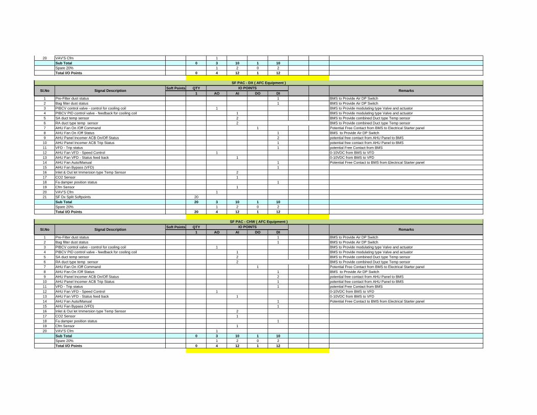
20 VAV'S Cfm 1Sub Total 0 3 10 1 10Spare 20% 1 2 0 2Total I/O Points 0 4 12 1 12
Soft Points QTY1 AO AI DO DI
1 Pre-Filter dust status 1 BMS to Provide Air DP Switch2 Bag filter dust status 1 BMS to Provide Air DP Switch3 PIBCV control valve - control for cooling coil 1 BMS to Provide modulating type Valve and actuator4 PIBCV PID control valve - feedback for cooling coil 1 BMS to Provide modulating type Valve and actuator5 SA duct temp sensor 2 BMS to Provide combined Duct type Temp sensor6 RA duct type temp sensor 2 BMS to Provide combined Duct type Temp sensor7 AHU Fan On /Off Command 1 Potential Free Contact from BMS to Electrical Starter panel8 AHU Fan On /Off Status 1 BMS to Provide Air DP Switch9 AHU Panel Incomer ACB On/Off Status 2 potential free contact from AHU Panel to BMS
10 AHU Panel Incomer ACB Trip Status 1 potential free contact from AHU Panel to BMS11 VFD - Trip status 1 potential Free Contact from BMS12 AHU Fan VFD - Speed Control 1 0-10VDC from BMS to VFD13 AHU Fan VFD - Status feed back 1 0-10VDC from BMS to VFD14 AHU Fan Auto/Manual 1 Potential Free Contact to BMS from Electrical Starter panel15 AHU Fan Bypass (VFD) 116 Inlet & Out let Immersion type Temp Sensor 217 CO2 Sensor 118 Fa damper position status 119 Cfm Sensor 120 VAV'S Cfm 121 SF Dx Split Softpoints 20
Sub Total 20 3 10 1 10Spare 20% 1 2 0 2Total I/O Points 20 4 12 1 12
Soft Points QTY1 AO AI DO DI
1 Pre-Filter dust status 1 BMS to Provide Air DP Switch2 Bag filter dust status 1 BMS to Provide Air DP Switch3 PIBCV control valve - control for cooling coil 1 BMS to Provide modulating type Valve and actuator4 PIBCV PID control valve - feedback for cooling coil 1 BMS to Provide modulating type Valve and actuator5 SA duct temp sensor 2 BMS to Provide combined Duct type Temp sensor6 RA duct type temp sensor 2 BMS to Provide combined Duct type Temp sensor7 AHU Fan On /Off Command 1 Potential Free Contact from BMS to Electrical Starter panel8 AHU Fan On /Off Status 1 BMS to Provide Air DP Switch9 AHU Panel Incomer ACB On/Off Status 2 potential free contact from AHU Panel to BMS
10 AHU Panel Incomer ACB Trip Status 1 potential free contact from AHU Panel to BMS11 VFD - Trip status 1 potential Free Contact from BMS12 AHU Fan VFD - Speed Control 1 0-10VDC from BMS to VFD13 AHU Fan VFD - Status feed back 1 0-10VDC from BMS to VFD14 AHU Fan Auto/Manual 1 Potential Free Contact to BMS from Electrical Starter panel15 AHU Fan Bypass (VFD) 116 Inlet & Out let Immersion type Temp Sensor 217 CO2 Sensor 118 Fa damper position status 119 Cfm Sensor 120 VAV'S Cfm 1
Sub Total 0 3 10 1 10Spare 20% 1 2 0 2Total I/O Points 0 4 12 1 12
Sl.No Signal DescriptionIO POINTS
Remarks
SF PAC - DX ( AFC Equipment )
Sl.No Signal DescriptionIO POINTS
Remarks
SF PAC - CHW ( AFC Equipment )
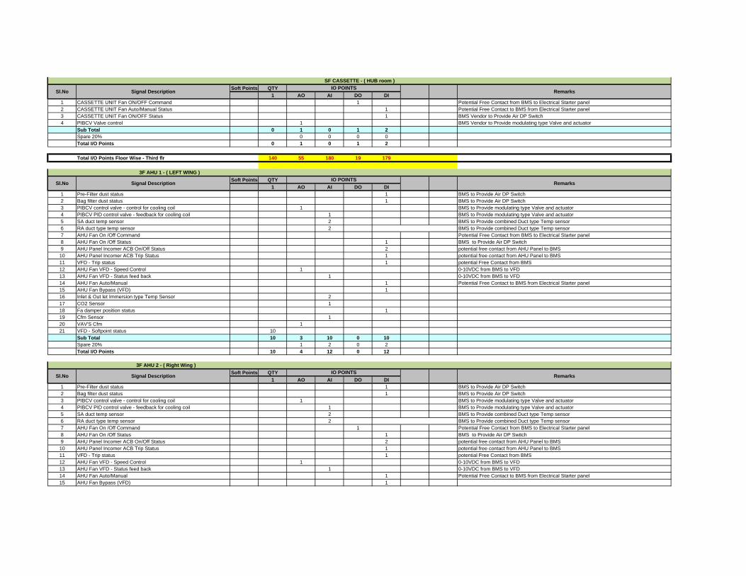
Soft Points QTY1 AO AI DO DI
1 CASSETTE UNIT Fan ON/OFF Command 1 Potential Free Contact from BMS to Electrical Starter panel2 CASSETTE UNIT Fan Auto/Manual Status 1 Potential Free Contact to BMS from Electrical Starter panel3 CASSETTE UNIT Fan ON/OFF Status 1 BMS Vendor to Provide Air DP Switch4 PIBCV Valve control 1 BMS Vendor to Provide modulating type Valve and actuator
Sub Total 0 1 0 1 2Spare 20% 0 0 0 0Total I/O Points 0 1 0 1 2
Total I/O Points Floor Wise - Third flr 140 55 180 19 179
Soft Points QTY1 AO AI DO DI
1 Pre-Filter dust status 1 BMS to Provide Air DP Switch2 Bag filter dust status 1 BMS to Provide Air DP Switch3 PIBCV control valve - control for cooling coil 1 BMS to Provide modulating type Valve and actuator4 PIBCV PID control valve - feedback for cooling coil 1 BMS to Provide modulating type Valve and actuator5 SA duct temp sensor 2 BMS to Provide combined Duct type Temp sensor6 RA duct type temp sensor 2 BMS to Provide combined Duct type Temp sensor7 AHU Fan On /Off Command Potential Free Contact from BMS to Electrical Starter panel8 AHU Fan On /Off Status 1 BMS to Provide Air DP Switch9 AHU Panel Incomer ACB On/Off Status 2 potential free contact from AHU Panel to BMS
10 AHU Panel Incomer ACB Trip Status 1 potential free contact from AHU Panel to BMS11 VFD - Trip status 1 potential Free Contact from BMS12 AHU Fan VFD - Speed Control 1 0-10VDC from BMS to VFD13 AHU Fan VFD - Status feed back 1 0-10VDC from BMS to VFD14 AHU Fan Auto/Manual 1 Potential Free Contact to BMS from Electrical Starter panel15 AHU Fan Bypass (VFD) 116 Inlet & Out let Immersion type Temp Sensor 217 CO2 Sensor 118 Fa damper position status 119 Cfm Sensor 120 VAV'S Cfm 121 VFD - Softpoint status 10
Sub Total 10 3 10 0 10Spare 20% 1 2 0 2Total I/O Points 10 4 12 0 12
Soft Points QTY1 AO AI DO DI
1 Pre-Filter dust status 1 BMS to Provide Air DP Switch2 Bag filter dust status 1 BMS to Provide Air DP Switch3 PIBCV control valve - control for cooling coil 1 BMS to Provide modulating type Valve and actuator4 PIBCV PID control valve - feedback for cooling coil 1 BMS to Provide modulating type Valve and actuator5 SA duct temp sensor 2 BMS to Provide combined Duct type Temp sensor6 RA duct type temp sensor 2 BMS to Provide combined Duct type Temp sensor7 AHU Fan On /Off Command 1 Potential Free Contact from BMS to Electrical Starter panel8 AHU Fan On /Off Status 1 BMS to Provide Air DP Switch9 AHU Panel Incomer ACB On/Off Status 2 potential free contact from AHU Panel to BMS
10 AHU Panel Incomer ACB Trip Status 1 potential free contact from AHU Panel to BMS11 VFD - Trip status 1 potential Free Contact from BMS12 AHU Fan VFD - Speed Control 1 0-10VDC from BMS to VFD13 AHU Fan VFD - Status feed back 1 0-10VDC from BMS to VFD14 AHU Fan Auto/Manual 1 Potential Free Contact to BMS from Electrical Starter panel15 AHU Fan Bypass (VFD) 1
Sl.No Signal DescriptionIO POINTS
Remarks
3F AHU 1 - ( LEFT WING )
Sl.No Signal DescriptionIO POINTS
Remarks
3F AHU 2 - ( Right Wing )
SF CASSETTE - ( HUB room )
Sl.No Signal DescriptionIO POINTS
Remarks

16 Inlet & Out let Immersion type Temp Sensor 217 CO2 Sensor 118 Fa damper position status 119 Cfm Sensor 120 VAV'S Cfm 121 VFD - Softpoint status 10
Sub Total 10 3 10 1 10Spare 20% 1 2 0 2Total I/O Points 10 4 12 1 12
Soft Points QTY1 AO AI DO DI
1 Pre-Filter dust status 1 BMS to Provide Air DP Switch2 Bag filter dust status 1 BMS to Provide Air DP Switch3 PIBCV control valve - control for cooling coil 1 BMS to Provide modulating type Valve and actuator4 PIBCV PID control valve - feedback for cooling coil 1 BMS to Provide modulating type Valve and actuator5 SA duct temp sensor 2 BMS to Provide combined Duct type Temp sensor6 RA duct type temp sensor 2 BMS to Provide combined Duct type Temp sensor7 AHU Fan On /Off Command 1 Potential Free Contact from BMS to Electrical Starter panel8 AHU Fan On /Off Status 1 BMS to Provide Air DP Switch9 AHU Panel Incomer ACB On/Off Status 2 potential free contact from AHU Panel to BMS
10 AHU Panel Incomer ACB Trip Status 1 potential free contact from AHU Panel to BMS11 VFD - Trip status 1 potential Free Contact from BMS12 AHU Fan VFD - Speed Control 1 0-10VDC from BMS to VFD13 AHU Fan VFD - Status feed back 1 0-10VDC from BMS to VFD14 AHU Fan Auto/Manual 1 Potential Free Contact to BMS from Electrical Starter panel15 AHU Fan Bypass (VFD) 116 Inlet & Out let Immersion type Temp Sensor 217 CO2 Sensor 118 Fa damper position status 119 Cfm Sensor 120 VAV'S Cfm 121 VFD - Softpoint status 10
Sub Total 10 3 10 1 10Spare 20% 1 2 0 2Total I/O Points 10 4 12 1 12
Soft Points QTY1 AO AI DO DI
1 Pre-Filter dust status 1 BMS to Provide Air DP Switch2 Bag filter dust status 1 BMS to Provide Air DP Switch3 PIBCV control valve - control for cooling coil 1 BMS to Provide modulating type Valve and actuator4 PIBCV PID control valve - feedback for cooling coil 1 BMS to Provide modulating type Valve and actuator5 SA duct temp sensor 2 BMS to Provide combined Duct type Temp sensor6 RA duct type temp sensor 2 BMS to Provide combined Duct type Temp sensor7 AHU Fan On /Off Command 1 Potential Free Contact from BMS to Electrical Starter panel8 AHU Fan On /Off Status 1 BMS to Provide Air DP Switch9 AHU Panel Incomer ACB On/Off Status 2 potential free contact from AHU Panel to BMS
10 AHU Panel Incomer ACB Trip Status 1 potential free contact from AHU Panel to BMS11 VFD - Trip status 1 potential Free Contact from BMS12 AHU Fan VFD - Speed Control 1 0-10VDC from BMS to VFD13 AHU Fan VFD - Status feed back 1 0-10VDC from BMS to VFD14 AHU Fan Auto/Manual 1 Potential Free Contact to BMS from Electrical Starter panel15 AHU Fan Bypass (VFD) 116 Inlet & Out let Immersion type Temp Sensor 217 CO2 Sensor 118 Fa damper position status 119 Cfm Sensor 1
3F AHU 4 - ( OCC Control Room )
Sl.No Signal DescriptionIO POINTS
Remarks
3F AHU 3 - ( Top Wing )
Sl.No Signal DescriptionIO POINTS
Remarks

20 VAV'S Cfm 121 VFD - Softpoint status 10
Sub Total 10 3 10 1 10Spare 20% 1 2 0 2Total I/O Points 10 4 12 1 12
Soft Points QTY1 AO AI DO DI
1 CASSETTE UNIT Fan ON/OFF Command 1 Potential Free Contact from BMS to Electrical Starter panel2 CASSETTE UNIT Fan Auto/Manual Status 1 Potential Free Contact to BMS from Electrical Starter panel3 CASSETTE UNIT Fan ON/OFF Status 1 BMS Vendor to Provide Air DP Switch4 PIBCV Valve control 1 BMS Vendor to Provide modulating type Valve and actuator
Sub Total 0 1 0 1 2Spare 20% 0 0 0 0Total I/O Points 0 1 0 1 2
Total I/O Points Floor Wise - Third flr 40 16 48 5 50
Total I/O Points for PLC/RPU - 2 180 71 228 24 229
Soft Points QTY4 AO AI DO DI
1 Pre-Filter dust status 4 BMS to Provide Air DP Switch2 Bag filter dust status 4 BMS to Provide Air DP Switch3 PIBCV control valve - control for cooling coil 4 BMS to Provide modulating type Valve and actuator4 PIBCV PID control valve - feedback for cooling coil 4 BMS to Provide modulating type Valve and actuator5 SA duct temp sensor 8 BMS to Provide combined Duct type Temp sensor6 RA duct type temp sensor 8 BMS to Provide combined Duct type Temp sensor7 AHU Fan On /Off Command 4 Potential Free Contact from BMS to Electrical Starter panel8 AHU Fan On /Off Status 4 BMS to Provide Air DP Switch9 AHU Panel Incomer ACB On/Off Status 2 potential free contact from AHU Panel to BMS
10 AHU Panel Incomer ACB Trip Status 1 potential free contact from AHU Panel to BMS11 VFD - Trip status 4 potential Free Contact from BMS12 AHU Fan VFD - Speed Control 4 0-10VDC from BMS to VFD13 AHU Fan VFD - Status feed back 4 0-10VDC from BMS to VFD14 AHU Fan Auto/Manual 4 Potential Free Contact to BMS from Electrical Starter panel15 AHU Fan Bypass (VFD) 416 Inlet & Out let Immersion type Temp Sensor 817 CO2 Sensor 418 Fa damper position status 419 Cfm Sensor 420 VAV'S Cfm 421 VFD - Softpoint status 10
Sub Total 10 12 40 4 31Spare 20% 2 8 1 6Total I/O Points 10 14 48 5 37
Soft Points QTY1 AO AI DO DI
1 Pre-Filter dust status 1 BMS to Provide Air DP Switch2 Bag filter dust status 1 BMS to Provide Air DP Switch3 PIBCV control valve - control for cooling coil 1 BMS to Provide modulating type Valve and actuator4 PIBCV PID control valve - feedback for cooling coil 1 BMS to Provide modulating type Valve and actuator5 SA duct temp sensor 2 BMS to Provide combined Duct type Temp sensor
Sl.No Signal DescriptionIO POINTS
Remarks
4th Floor AHU-2 - ( Left Wing )
Sl.No Signal DescriptionIO POINTS
Remarks
Sl.No Signal DescriptionIO POINTS
Remarks
RPU / PLC - 34th Floor AHU-1 - ( OCC Theatre )
3F CASSETTE - ( HUB room )
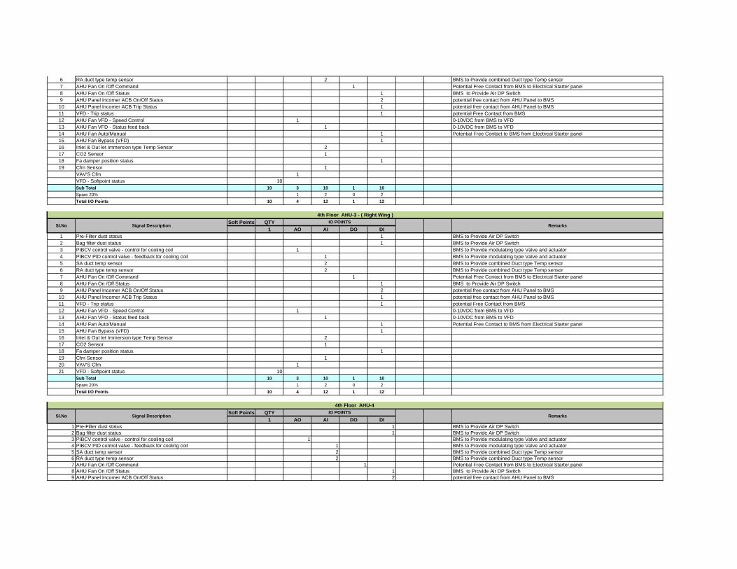
6 RA duct type temp sensor 2 BMS to Provide combined Duct type Temp sensor7 AHU Fan On /Off Command 1 Potential Free Contact from BMS to Electrical Starter panel8 AHU Fan On /Off Status 1 BMS to Provide Air DP Switch9 AHU Panel Incomer ACB On/Off Status 2 potential free contact from AHU Panel to BMS
10 AHU Panel Incomer ACB Trip Status 1 potential free contact from AHU Panel to BMS11 VFD - Trip status 1 potential Free Contact from BMS12 AHU Fan VFD - Speed Control 1 0-10VDC from BMS to VFD13 AHU Fan VFD - Status feed back 1 0-10VDC from BMS to VFD14 AHU Fan Auto/Manual 1 Potential Free Contact to BMS from Electrical Starter panel15 AHU Fan Bypass (VFD) 116 Inlet & Out let Immersion type Temp Sensor 217 CO2 Sensor 118 Fa damper position status 119 Cfm Sensor 1
VAV'S Cfm 1VFD - Softpoint status 10Sub Total 10 3 10 1 10Spare 20% 1 2 0 2Total I/O Points 10 4 12 1 12
Soft Points QTY1 AO AI DO DI
1 Pre-Filter dust status 1 BMS to Provide Air DP Switch2 Bag filter dust status 1 BMS to Provide Air DP Switch3 PIBCV control valve - control for cooling coil 1 BMS to Provide modulating type Valve and actuator4 PIBCV PID control valve - feedback for cooling coil 1 BMS to Provide modulating type Valve and actuator5 SA duct temp sensor 2 BMS to Provide combined Duct type Temp sensor6 RA duct type temp sensor 2 BMS to Provide combined Duct type Temp sensor7 AHU Fan On /Off Command 1 Potential Free Contact from BMS to Electrical Starter panel8 AHU Fan On /Off Status 1 BMS to Provide Air DP Switch9 AHU Panel Incomer ACB On/Off Status 2 potential free contact from AHU Panel to BMS
10 AHU Panel Incomer ACB Trip Status 1 potential free contact from AHU Panel to BMS11 VFD - Trip status 1 potential Free Contact from BMS12 AHU Fan VFD - Speed Control 1 0-10VDC from BMS to VFD13 AHU Fan VFD - Status feed back 1 0-10VDC from BMS to VFD14 AHU Fan Auto/Manual 1 Potential Free Contact to BMS from Electrical Starter panel15 AHU Fan Bypass (VFD) 116 Inlet & Out let Immersion type Temp Sensor 217 CO2 Sensor 118 Fa damper position status 119 Cfm Sensor 120 VAV'S Cfm 121 VFD - Softpoint status 10
Sub Total 10 3 10 1 10Spare 20% 1 2 0 2Total I/O Points 10 4 12 1 12
Soft Points QTY1 AO AI DO DI
1 Pre-Filter dust status 1 BMS to Provide Air DP Switch2 Bag filter dust status 1 BMS to Provide Air DP Switch3 PIBCV control valve - control for cooling coil 1 BMS to Provide modulating type Valve and actuator4 PIBCV PID control valve - feedback for cooling coil 1 BMS to Provide modulating type Valve and actuator5 SA duct temp sensor 2 BMS to Provide combined Duct type Temp sensor6 RA duct type temp sensor 2 BMS to Provide combined Duct type Temp sensor7 AHU Fan On /Off Command 1 Potential Free Contact from BMS to Electrical Starter panel8 AHU Fan On /Off Status 1 BMS to Provide Air DP Switch9 AHU Panel Incomer ACB On/Off Status 2 potential free contact from AHU Panel to BMS
Sl.No Signal DescriptionIO POINTS
Remarks
4th Floor AHU-3 - ( Right Wing )
Sl.No Signal DescriptionIO POINTS
Remarks
4th Floor AHU-4

10 AHU Panel Incomer ACB Trip Status 1 potential free contact from AHU Panel to BMS11 VFD - Trip status 1 potential Free Contact from BMS12 AHU Fan VFD - Speed Control 1 0-10VDC from BMS to VFD13 AHU Fan VFD - Status feed back 1 0-10VDC from BMS to VFD14 AHU Fan Auto/Manual 1 Potential Free Contact to BMS from Electrical Starter panel15 AHU Fan Bypass (VFD) 116 Inlet & Out let Immersion type Temp Sensor 217 CO2 Sensor 118 Fa damper position status 119 Cfm Sensor 120 VAV'S Cfm 121 VFD - Softpoint status 10
Sub Total 10 3 10 1 10Spare 20% 1 2 0 2Total I/O Points 10 4 12 1 12
Soft Points QTY1 AO AI DO DI
1 CASSETTE UNIT Fan ON/OFF Command 1 Potential Free Contact from BMS to Electrical Starter panel2 CASSETTE UNIT Fan Auto/Manual Status 1 Potential Free Contact to BMS from Electrical Starter panel3 CASSETTE UNIT Fan ON/OFF Status 1 BMS Vendor to Provide Air DP Switch4 PIBCV Valve control 1 BMS Vendor to Provide modulating type Valve and actuator
Sub Total 0 1 0 1 2Spare 20% 0 0 0 0Total I/O Points 0 1 0 1 2
Total I/O Points Floor Wise - Fourth flr 40 26 84 10 76
Soft Points QTY3 AO AI DO DI
1 HRW TFA Supply Air Fans ON/OFF Command 32 HRW TFA Supply Air Fans ON/OFF Status 33 HRW TFA Supply Auto/Manual staus 34 HRW TFA Supply Trip staus 35 VFD Speed control command for Supply air fan 36 VFD Speed control feedback status for Supply air fan 37 HRW TFA Exhaust Air Fans ON/OFF Command 38 HRW TFA Exhaust Air Fans ON/OFF Status 39 HRW TFA Exhaust Auto/Manual status 3
10 HRW TFA Supply Trip staus 311 VFD Speed control command for Exhaust Air Fans 312 VFD Speed control feedback status for Exhaust Air Fans 313 HRW Wheel ON/OFF Command 314 HRW Wheel ON/OFF Status 315 HRW Wheel Auto/Manual status 316 HRW Wheel Trip Status 317 Supply Air Temperature leaving Wheel 318 Return Air Temperature Entering Wheel 319 Differential Pressure Switch across filter 320 Outdoor Temperatue sensor (1no. Sufficient for 2 nos HRW) 321 Outdoor CO2 sensor (1no. Sufficient for 2 nos HRW) 322 Duct static pressure sensor in Supply air fan 323 Fire Status and Damper Status 1
Sub Total 0 21 6 31 9Spare 20% 4 1 6 2Total I/O Points 0 25 7 37 11
Soft Points QTY5 AO AI DO DI
IBMS vendor to provide the Field devises. Cabling provided between Field devices to PLC Panel
Terrace Floor - TOILET EXHAUST FAN (Left / Right /Top)
Sl.No Signal DescriptionIO POINTS
Remarks
Terrace Floor -HRW (Left / Right /Top)
Sl.No Signal DescriptionIO POINTS
Remarks
IBMS vendor shall be wire the Potential free contact from chiller panel to IBMS.
4F CASSETTE - ( HUB room )
Sl.No Signal DescriptionIO POINTS
Remarks
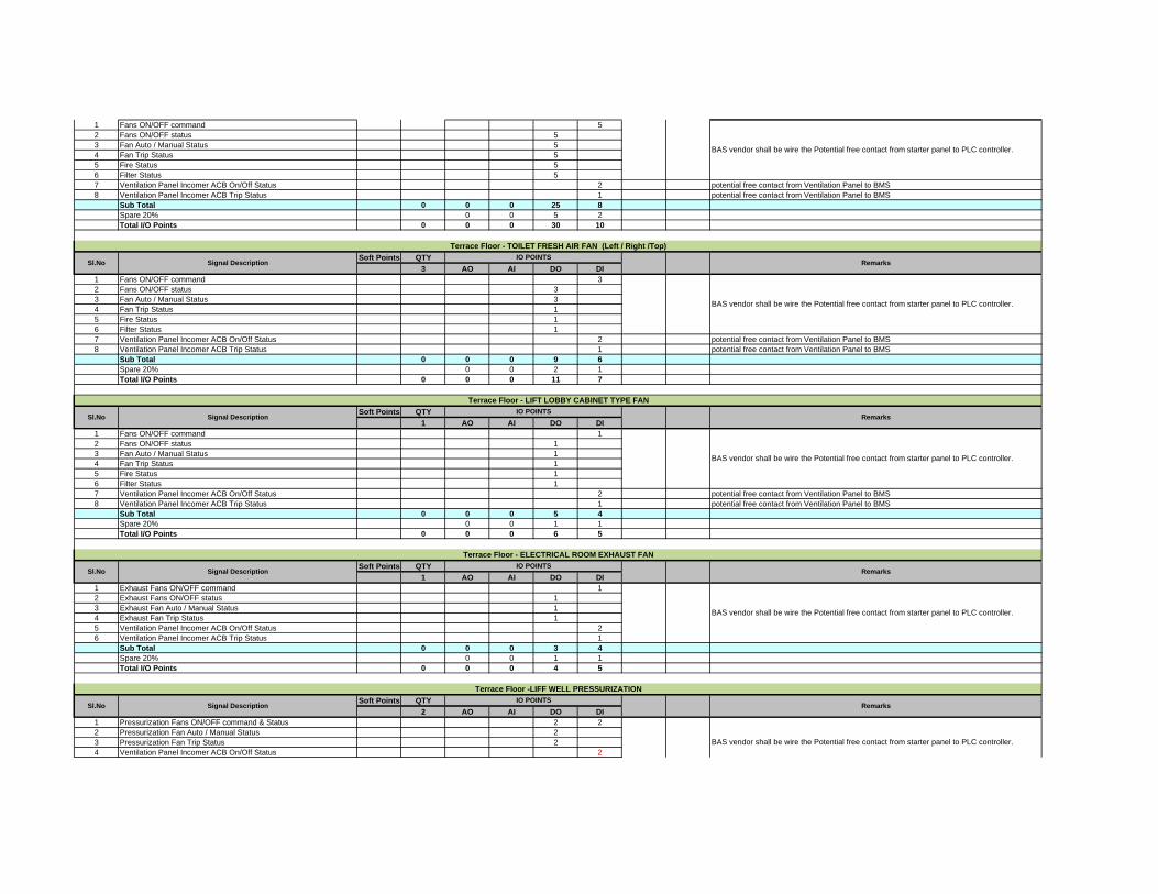
1 Fans ON/OFF command 52 Fans ON/OFF status 53 Fan Auto / Manual Status 54 Fan Trip Status 55 Fire Status 56 Filter Status 57 Ventilation Panel Incomer ACB On/Off Status 2 potential free contact from Ventilation Panel to BMS8 Ventilation Panel Incomer ACB Trip Status 1 potential free contact from Ventilation Panel to BMS
Sub Total 0 0 0 25 8Spare 20% 0 0 5 2Total I/O Points 0 0 0 30 10
Soft Points QTY3 AO AI DO DI
1 Fans ON/OFF command 32 Fans ON/OFF status 33 Fan Auto / Manual Status 34 Fan Trip Status 15 Fire Status 16 Filter Status 17 Ventilation Panel Incomer ACB On/Off Status 2 potential free contact from Ventilation Panel to BMS8 Ventilation Panel Incomer ACB Trip Status 1 potential free contact from Ventilation Panel to BMS
Sub Total 0 0 0 9 6Spare 20% 0 0 2 1Total I/O Points 0 0 0 11 7
Soft Points QTY1 AO AI DO DI
1 Fans ON/OFF command 12 Fans ON/OFF status 13 Fan Auto / Manual Status 14 Fan Trip Status 15 Fire Status 16 Filter Status 17 Ventilation Panel Incomer ACB On/Off Status 2 potential free contact from Ventilation Panel to BMS8 Ventilation Panel Incomer ACB Trip Status 1 potential free contact from Ventilation Panel to BMS
Sub Total 0 0 0 5 4Spare 20% 0 0 1 1Total I/O Points 0 0 0 6 5
Soft Points QTY1 AO AI DO DI
1 Exhaust Fans ON/OFF command 12 Exhaust Fans ON/OFF status 13 Exhaust Fan Auto / Manual Status 14 Exhaust Fan Trip Status 15 Ventilation Panel Incomer ACB On/Off Status 26 Ventilation Panel Incomer ACB Trip Status 1
Sub Total 0 0 0 3 4Spare 20% 0 0 1 1Total I/O Points 0 0 0 4 5
Soft Points QTY2 AO AI DO DI
1 Pressurization Fans ON/OFF command & Status 2 22 Pressurization Fan Auto / Manual Status 23 Pressurization Fan Trip Status 24 Ventilation Panel Incomer ACB On/Off Status 2
BAS vendor shall be wire the Potential free contact from starter panel to PLC controller.
BAS vendor shall be wire the Potential free contact from starter panel to PLC controller.
Terrace Floor -LIFF WELL PRESSURIZATION
Sl.No Signal DescriptionIO POINTS
Remarks
BAS vendor shall be wire the Potential free contact from starter panel to PLC controller.
Terrace Floor - ELECTRICAL ROOM EXHAUST FAN
Sl.No Signal DescriptionIO POINTS
Remarks
BAS vendor shall be wire the Potential free contact from starter panel to PLC controller.
Terrace Floor - LIFT LOBBY CABINET TYPE FAN
Sl.No Signal DescriptionIO POINTS
Remarks
BAS vendor shall be wire the Potential free contact from starter panel to PLC controller.
Terrace Floor - TOILET FRESH AIR FAN (Left / Right /Top)
Sl.No Signal DescriptionIO POINTS
Remarks
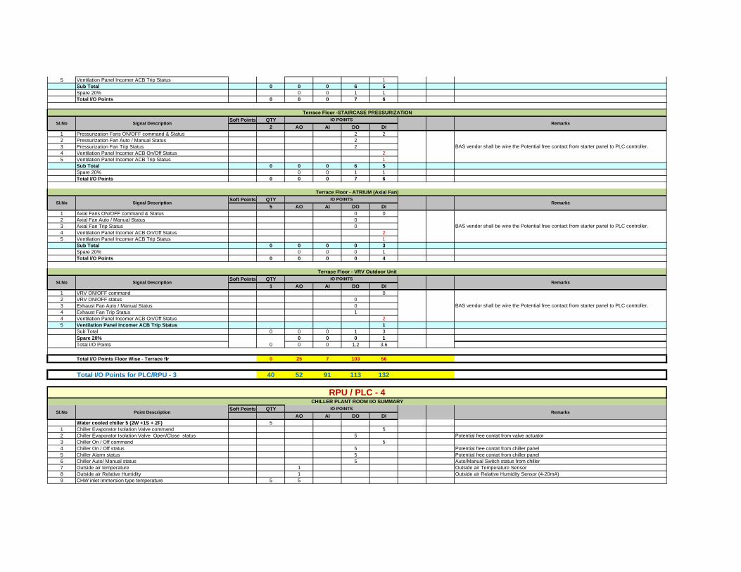
5 Ventilation Panel Incomer ACB Trip Status 1Sub Total 0 0 0 6 5Spare 20% 0 0 1 1Total I/O Points 0 0 0 7 6
Soft Points QTY2 AO AI DO DI
1 Pressurization Fans ON/OFF command & Status 2 22 Pressurization Fan Auto / Manual Status 23 Pressurization Fan Trip Status 24 Ventilation Panel Incomer ACB On/Off Status 25 Ventilation Panel Incomer ACB Trip Status 1
Sub Total 0 0 0 6 5Spare 20% 0 0 1 1Total I/O Points 0 0 0 7 6
Soft Points QTY5 AO AI DO DI
1 Axial Fans ON/OFF command & Status 0 02 Axial Fan Auto / Manual Status 03 Axial Fan Trip Status 04 Ventilation Panel Incomer ACB On/Off Status 25 Ventilation Panel Incomer ACB Trip Status 1
Sub Total 0 0 0 0 3Spare 20% 0 0 0 1Total I/O Points 0 0 0 0 4
Soft Points QTY1 AO AI DO DI
1 VRV ON/OFF command 02 VRV ON/OFF status 03 Exhaust Fan Auto / Manual Status 04 Exhaust Fan Trip Status 14 Ventilation Panel Incomer ACB On/Off Status 25 Ventilation Panel Incomer ACB Trip Status 1
Sub Total 0 0 0 1 3Spare 20% 0 0 0 1Total I/O Points 0 0 0 1.2 3.6
Total I/O Points Floor Wise - Terrace flr 0 25 7 103 56
Total I/O Points for PLC/RPU - 3 40 52 91 113 132
Soft Points QTYAO AI DO DI
Water cooled chiller 5 (2W +1S + 2F) 51 Chiller Evaporator Isolation Valve command 52 Chiller Evaporator Isolation Valve Open/Close status 5 Potential free contat from valve actuator3 Chiller On / Off command 54 Chiller On / Off status 5 Potential free contat from chiller panel5 Chiller Alarm status 5 Potential free contat from chiller panel6 Chiller Auto/ Manual status 5 Auto/Manual Switch status from chiller7 Outside air temperature 1 Outside air Temperature Sensor8 Outside air Relative Humidity 1 Outside air Relative Humidity Sensor (4-20mA)9 CHW inlet Immersion type temperature 5 5
BAS vendor shall be wire the Potential free contact from starter panel to PLC controller.
RPU / PLC - 4CHILLER PLANT ROOM I/O SUMMARY
Sl.No Point DescriptionIO POINTS
Remarks
BAS vendor shall be wire the Potential free contact from starter panel to PLC controller.
Terrace Floor - VRV Outdoor Unit
Sl.No Signal DescriptionIO POINTS
Remarks
BAS vendor shall be wire the Potential free contact from starter panel to PLC controller.
Terrace Floor - ATRIUM (Axial Fan)
Sl.No Signal DescriptionIO POINTS
Remarks
Terrace Floor -STAIRCASE PRESSURIZATION
Sl.No Signal DescriptionIO POINTS
Remarks

10 CHW outlet Immersion type temperature 5 511 CDW inlet Immersion type temperature 5 512 CDW outlet Immersion type temperature 5 513 CHW supply header temperature 1 Immersion Temperature sensor14 CHW return header temperature 1 Immersion Temperature sensor15 CDW supply header temperature 1 Immersion Temperature sensor16 CDW return header temperature 1 Immersion Temperature sensor17 Condenser Outlet Valve (ON/OFF) Command 218 Condenser Outlet Valve (OPEN/CLOSE) Status 219 CHW Differential Pressure Switch Status 120 CHW Flow Switch Status 121 CDW Differential Pressure Switch Status 122 CDW Flow Switch Status 123 Chiller Panel Incomer ACB ON/OFF Status 224 Chiller Panel Incomer ACB Trip Status 1
Primary chilled water pumps 5 (2W +1S + 2F) No's 51 Pump Start / Stop command 52 Pump Auto/ Manual status 5 Potential free contat from pump panel3 Pump run status 5 Potential free contat from pump panel4 Pump trip status 5 Potential free contat from pump panel
Secondary chilled water pumps 5 (2W +1S + 2F) No's with pump Logic controller 5
1 VFD Enable Start/Stop command via PLC 12 VFD Enable Auto/ manual status via PLC 1 Potential free contat from pump panel3 VFD run status via PLC 1 Potential free contat from pump panel4 VFD trip status via PLC 1 Potential free contat from pump panel
Condenser water pumps 5 (2W +1S + 2F) 51 Pump Start / Stop command 52 Pump Auto/ manual status 5 Potential free contat from pump panel3 Pump run status 5 Potential free contat from pump panel4 Pump trip status 5 Potential free contat from pump panel
Condenser water pumps 2 No's 21 Pump Start / Stop command 22 Pump Auto/ manual status 2 Potential free contat from pump panel3 Pump run status 2 Potential free contat from pump panel4 Pump trip status 2 Potential free contat from pump panel
Cooling Tower 5 (2W +1S + 2F) 51 Cooling tower VFD controle 52 CT VFD Feedback 53 CT Outlet temperature 54 Cooling tower fan Start/stop command 55 Cooling tower fan Auto/manual command 5 Potential free contat from pump panel6 Cooling tower fan Run status 5 Potential free contat from pump panel7 Cooling tower fan Trip status 5 Potential free contat from pump panel8 Cooling tower inlet isolation valve command 59 Cooling tower inlet isolation valve Open/Close status 5 Potential free contat from pump panel
10 Cooling tower outlet valve command 511 Cooling tower outlet valve Open/Close status 512 Emergency Stop button status 1
Misc1 Cooling tower sump level 102 Low Suction Pressure 53
SUB TOTAL 52 36 5 56 88Spare 10 % 2 1 8 3Total I/O Points 52 38 6 64 91
Total I/O Points 52 38 6 64 91
Total I/O Points for PLC/RPU - 4 52 38 6 64 91
RPU / PLC - 5RMG Outdoor Panel

Soft Points QTYAO AI DO DI
1 RMG Outdoor Panel ON/OFF status 62 RMG Outdoor Panel Trip Status 3
Sub Total 0 0 0 0 9Spare 20% 0 0 0 0 2Total I/O Points 0 0 0 0 11
Soft Points QTYAO AI DO DI
1 HT Outdoor Panel ON/OFF status 22 HT Outdoor Panel Trip Status 13 TVM with RS 485 (Soft) 124 HT Outdoor Panel Outgoing Feeder VCB ON/OFF status 35 HT Outdoor Panel Outgoing Feeder VCB Trip status 3
Sub Total 12 0 0 0 9Spare 20% 0 0 0 0 2Total I/O Points 12 0 0 0 11
Soft Points QTYAO AI DO DI
1 LDB Panel Basement Floor ON/OFF status 82 LDB Panel Basement Floor Trip status 43 LDB Panel Ground Floor ON/OFF status 124 LDB Panel Ground Floor Trip status 65 LDB Panel First Floor ON/OFF status 126 LDB Panel First Floor Trip status 67 LDB Panel Second Floor ON/OFF status 208 LDB Panel Second Floor Trip status 109 LDB Panel Third Floor ON/OFF status 12
10 LDB Panel Third Floor Trip status 611 LDB Panel Fourth Floor ON/OFF status 1212 LDB Panel Fourth Floor Trip status 613 LDB Panel Terrace Floor ON/OFF status 814 LDB Panel Terrace Floor Trip status 4
Sub Total 0 0 0 0 126Spare 20% 0 0 0 0 25Total I/O Points 0 0 0 0 151
Soft Points QTYAO AI DO DI
1 UPS Panel - 1 Incomer ON/OFF status 42 UPS Panel - 1 Incomer Trip status 23 UPS Panel - 1 O/G Feeder ON/OFF status 44 UPS Panel - 1 O/G Feeder Trip status 25 UPS Panel - 2 Incomer ON/OFF status 46 UPS Panel - 2 Incomer Trip status 27 UPS Panel - 2 Ground Floor Incomer ON/OFF status 48 UPS Panel - 2 Ground Floor Incomer Trip status 29 UPS Panel - 2 First Floor Incomer ON/OFF status 4
10 UPS Panel - 2 First Floor Incomer Trip status 211 UPS Panel - 2 Second Floor Incomer ON/OFF status 412 UPS Panel - 2 Second Floor Incomer Trip status 213 UPS Panel - 2 Third Floor Incomer ON/OFF status 414 UPS Panel - 2 Third Floor Incomer Trip status 215 UPS Panel - 2 Fourth Floor Incomer ON/OFF status 416 UPS Panel - 2 Fourth Floor Incomer Trip status 2
Sub Total 0 0 0 0 48Spare 20% 0 0 0 0 10
BAS vendor shall be wire the Potential free contact from starter panel to PLC controller.
BAS vendor shall be wire the Potential free contact from starter panel to PLC controller.
UPS Panels
Sl.No Signal DescriptionIO POINTS
Remarks
BAS vendor shall be wire the Potential free contact from starter panel to PLC controller.
Lighting Distribution Panels
Sl.No Signal DescriptionIO POINTS
Remarks
BAS vendor shall be wire the Potential free contact from starter panel to PLC controller.
HT Outdoor Panel
Sl.No Signal DescriptionIO POINTS
Remarks
Sl.No Signal DescriptionIO POINTS
Remarks

Total I/O Points 0 0 0 0 58
Total I/O Points 12 0 0 0 230
Total I/O Points for PLC/RPU - 5 12 0 0 0 230
Soft Points1 AO AI DO DI
1 MPCC Panel Incomer - 1 ON/OFF status 22 MPCC Panel Incomer - 1 Trip Status 13 MDC with RS 485 (Soft) 124 MPCC Panel Incomer - 2 ON/OFF status 25 MPCC Panel Incomer - 2 Trip Status 16 MDC with RS 485 (Soft) 127 MPCC Panel Incomer - 3 ON/OFF status 28 MPCC Panel Incomer - 3 Trip Status 19 MFM with RS 485 (Soft) 12
10 MPCC Panel Incomer - 4 ON/OFF status 211 MPCC Panel Incomer - 4 Trip Status 112 MFM with RS 485 (Soft) 1213 MPCC Panel Bus Coupler - 1 ON/OFF status 214 MPCC Panel Bus Coupler - 1 Trip Status 115 MPCC Panel Bus Coupler - 2 ON/OFF status 216 MPCC Panel Bus Coupler - 2 Trip Status 117 MPCC Panel Bus Coupler - 3 ON/OFF status 218 MPCC Panel Bus Coupler - 3 Trip Status 119 MPCC Outgoing Feeder ACB ON/OFF status 1020 MPCC Outgoing Feeder ACB Trip status 1021 MPCC Outgoing Feeder MCCB ON/OFF status 1622 MPCC Outgoing Feeder MCCB Trip status 16
Sub Total 48 0 0 0 73Spare 20% 0 0 0 0 15Total I/O Points 48 0 0 0 88
Soft Points1 AO AI DO DI
1 FFTG Pump Panel Incomer - 1 ON/OFF status 22 FFTG Pump Panel Incomer - 1 Trip Status 13 MDC with RS 485 (Soft) 124 FFTG Pump Panel Incomer - 2 ON/OFF status 25 FFTG Pump Panel Incomer - 2 Trip Status 16 MDC with RS 485 (Soft) 127 FFTG Pump Panel Bus Coupler - 1 ON/OFF status 28 FFTG Pump Panel Bus Coupler - 1 Trip Status 19 FFTG Sump Level Switch - High 2
10 FFTG Sump Level Switch - Low 2Sub Total 24 0 0 0 13Spare 20% 0 0 0 0 3Total I/O Points 24 0 0 0 16
Soft Points1 AO AI DO DI
1 Drinking water Pump Panel Incomer - 1 ON/OFF status 22 Drinking water Pump Panel Incomer - 1 Trip Status 13 MDC with RS 485 (Soft) 124 Drinking water Pump Panel Incomer - 2 ON/OFF status 25 Drinking water Pump Panel Incomer - 2 Trip Status 16 MDC with RS 485 (Soft) 12
BAS vendor shall be wire the Potential free contact from starter panel to PLC controller.
Drinking Water Pump Panel
Sl.No Signal DescriptionIO POINTS
Remarks
BAS vendor shall be wire the Potential free contact from starter panel to PLC controller.
FFTG Pump - Fire Fighting Panel
Sl.No Signal DescriptionIO POINTS
Remarks
RPU / PLC - 4A ( Remote I/O Panel)MPCC Panel
Sl.No Signal DescriptionIO POINTS
Remarks
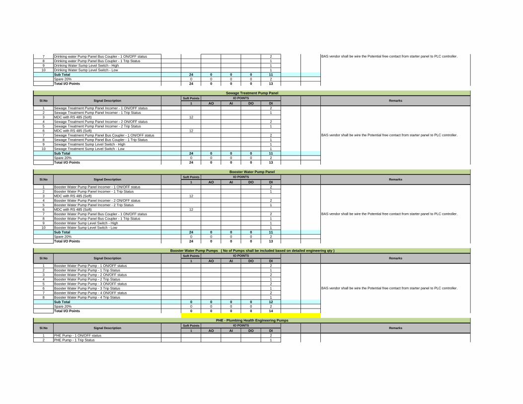
7 Drinking water Pump Panel Bus Coupler - 1 ON/OFF status 28 Drinking water Pump Panel Bus Coupler - 1 Trip Status 19 Drinking Water Sump Level Switch - High 1
10 Drinking Water Sump Level Switch - Low 1Sub Total 24 0 0 0 11Spare 20% 0 0 0 0 2Total I/O Points 24 0 0 0 13
Soft Points1 AO AI DO DI
1 Sewage Treatment Pump Panel Incomer - 1 ON/OFF status 22 Sewage Treatment Pump Panel Incomer - 1 Trip Status 13 MDC with RS 485 (Soft) 124 Sewage Treatment Pump Panel Incomer - 2 ON/OFF status 25 Sewage Treatment Pump Panel Incomer - 2 Trip Status 16 MDC with RS 485 (Soft) 127 Sewage Treatment Pump Panel Bus Coupler - 1 ON/OFF status 28 Sewage Treatment Pump Panel Bus Coupler - 1 Trip Status 19 Sewage Treatment Sump Level Switch - High 1
10 Sewage Treatment Sump Level Switch - Low 1Sub Total 24 0 0 0 11Spare 20% 0 0 0 0 2Total I/O Points 24 0 0 0 13
Soft Points1 AO AI DO DI
1 Booster Water Pump Panel Incomer - 1 ON/OFF status 22 Booster Water Pump Panel Incomer - 1 Trip Status 13 MDC with RS 485 (Soft) 124 Booster Water Pump Panel Incomer - 2 ON/OFF status 25 Booster Water Pump Panel Incomer - 2 Trip Status 16 MDC with RS 485 (Soft) 127 Booster Water Pump Panel Bus Coupler - 1 ON/OFF status 28 Booster Water Pump Panel Bus Coupler - 1 Trip Status 19 Booster Water Sump Level Switch - High 1
10 Booster Water Sump Level Switch - Low 1Sub Total 24 0 0 0 11Spare 20% 0 0 0 0 2Total I/O Points 24 0 0 0 13
Soft Points1 AO AI DO DI
1 Booster Water Pump Pump - 1 ON/OFF status 22 Booster Water Pump Pump - 1 Trip Status 13 Booster Water Pump Pump - 2 ON/OFF status 24 Booster Water Pump Pump - 2 Trip Status 15 Booster Water Pump Pump - 3 ON/OFF status 26 Booster Water Pump Pump - 3 Trip Status 17 Booster Water Pump Pump - 4 ON/OFF status 28 Booster Water Pump Pump - 4 Trip Status 1
Sub Total 0 0 0 0 12Spare 20% 0 0 0 0 2Total I/O Points 0 0 0 0 14
Soft Points1 AO AI DO DI
1 PHE Pump - 1 ON/OFF status 22 PHE Pump - 1 Trip Status 1
BAS vendor shall be wire the Potential free contact from starter panel to PLC controller.
PHE - Plumbing Health Engineering Pumps
Sl.No Signal DescriptionIO POINTS
Remarks
BAS vendor shall be wire the Potential free contact from starter panel to PLC controller.
Booster Water Pump Pumps ( No of Pumps shall be included based on detailed engineering qty )
Sl.No Signal DescriptionIO POINTS
Remarks
BAS vendor shall be wire the Potential free contact from starter panel to PLC controller.
Booster Water Pump Panel
Sl.No Signal DescriptionIO POINTS
Remarks
BAS vendor shall be wire the Potential free contact from starter panel to PLC controller.
Sewage Treatment Pump Panel
Sl.No Signal DescriptionIO POINTS
Remarks

3 PHE Pump - 2 ON/OFF status 24 PHE Pump - 2 Trip Status 15 PHE Pump - 3 ON/OFF status 26 PHE Pump - 3 Trip Status 1
Sub Total 0 0 0 0 9Spare 20% 0 0 0 0 2Total I/O Points 0 0 0 0 11
Soft Points1 AO AI DO DI
1 DG Panel Incomer - 1 ON/OFF status 22 DG Panel Incomer - 1 Trip Status 13 MDC with RS 485 (Soft) 124 DG Panel Incomer - 2 ON/OFF status 25 DG Panel Incomer - 2 Trip Status 16 MDC with RS 485 (Soft) 127 DG Panel Incomer - 3 ON/OFF status 28 DG Panel Incomer - 3 Trip Status 19 MFM with RS 485 (Soft) 12
10 DG Panel Incomer - 4 ON/OFF status 211 DG Panel Incomer - 4 Trip Status 112 MFM with RS 485 (Soft) 1213 DG Panel Bus Coupler - 1 ON/OFF status 214 DG Panel Bus Coupler - 1 Trip Status 115 DG Panel Bus Coupler - 2 ON/OFF status 216 DG Panel Bus Coupler - 2 Trip Status 117 DG Panel Bus Coupler - 3 ON/OFF status 218 DG Panel Bus Coupler - 3 Trip Status 119 DG Outgoing Feeder ACB ON/OFF status 420 DG Outgoing Feeder ACB Trip status 4
Sub Total 48 0 0 0 29Spare 20% 0 0 0 0 6Total I/O Points 48 0 0 0 35
Total I/O Points 192 0 0 0 203
Total I/O Points for PLC/RPU - 4A 192 0 0 0 203
Total I/O Points for All PLC/RPU 506 216 430 252 1009
Soft Points I / O Points 16 Channel 32 ChannelTotal Analog Output Points ( AO Card ) 506 216 13 7Total Analog Input Points ( AI Card ) 430 27 13Total Digital Output Points ( DO Card ) 252 16 8Total Digital Input Points ( DI Card ) 1009 63 32Grand Total of All I/O Points ( AO+AI+DO+DI ) 1907
BAS vendor shall be wire the Potential free contact from starter panel to PLC controller.
BAS vendor shall be wire the Potential free contact from starter panel to PLC controller.
DG Panel
Sl.No Signal DescriptionIO POINTS
Remarks

Chennai Metro Rail Limited,Chennai
In Figures In Words
Design, manufacture, supply, erect at site & commissioning of passenger & service liftsNote :The rate shall include approval / obtaining completion certificate from the electrical / lift inspectorate of Government of Tamil Nadu for installation and commissioning of lifts before handing over the entire installation of the lift.Capsule Lifts
1 3.00 Nos Design, manufacture, supply, erect at site, test, Commission and maintain (duringguarantee period of one year) Machineroom less capsule shape / Panoramic viewPassenger lift with Hairline finish stainless steel with car enclosure as perspecification to carry 13 (Thirteen) persons capacity of load 884 Kgs with a minimumspeed of 1.5 metre per second with attendant operation including all necessary safetyfeatures and in accordance with the particulars of lift service requirement andtechnical specifications etc. complete for servicing 6 Stopings and 6 openings.
Nos
Passenger Lifts2 2.00 Nos Design, manufacture, supply, erect at site, test, Commission and maintain (during
guarantee period of one year) Machineroom less Passenger lift with Hairline finishstainless steel with car enclosure as per specification to carry 20 (Twenty) persons capacity of load 1360 Kgs with a minimum speed of 1.50 metre per second withattendant operation including all necessary safety features and in accordance with theparticulars of lift service requirement and technical specifications etc. complete forservicing 7 Stopings and 7 openings.
Nos
Per Amount in Rs….
CONSTRUCTION OF METRO HEADQUARTERS BUILDING AND OTHER METRO RAIL AMENITIES AT NANDANAM,CHENNAI
BILLS OF QUANTITIES
SCHEDILE - X - LIFTS
S.No Total Qty Unit Description of Work
Rate in INR
436 Lifts
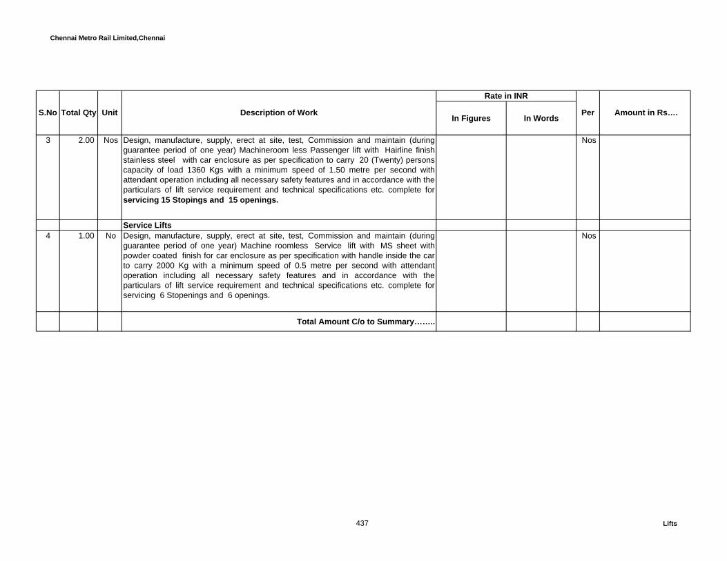
Chennai Metro Rail Limited,Chennai
In Figures In WordsPer Amount in Rs…. S.No Total Qty Unit Description of Work
Rate in INR
3 2.00 Nos Design, manufacture, supply, erect at site, test, Commission and maintain (duringguarantee period of one year) Machineroom less Passenger lift with Hairline finishstainless steel with car enclosure as per specification to carry 20 (Twenty) personscapacity of load 1360 Kgs with a minimum speed of 1.50 metre per second withattendant operation including all necessary safety features and in accordance with theparticulars of lift service requirement and technical specifications etc. complete forservicing 15 Stopings and 15 openings.
Nos
Service Lifts 4 1.00 No Design, manufacture, supply, erect at site, test, Commission and maintain (during
guarantee period of one year) Machine roomless Service lift with MS sheet withpowder coated finish for car enclosure as per specification with handle inside the carto carry 2000 Kg with a minimum speed of 0.5 metre per second with attendantoperation including all necessary safety features and in accordance with theparticulars of lift service requirement and technical specifications etc. complete forservicing 6 Stopenings and 6 openings.
Nos
Total Amount C/o to Summary……..
437 Lifts

Chennai Metro Rail Limited,Chennai
In Figures In WordsI SECTION – A :DATA AND VOICE NETWORK A DATA: Copper
CAT6A UTP Cables (305Meter)1 51686 Rmt Supplying, Laying, termination, testing and commissioning in the existing
conduit / Duct, Labelling for the identification of Category 6A U/UTPCable, slate jacket, 4 pair count, 1000 ft (305 m) length, as complete withall respects complying with relevant standard specification, as directed bythe Engineer-in-charge.
Rmt
2 940 Nos Supplying, termination, testing, commissioning and Fixing & Labelling forthe Identification of Category 6A I/O Module and also submit the TestingReport using Fluke Scanner for Data, as complete with all respectscomplying with relevant standard specification, as directed by theEngineer-in-charge.
Nos
3 39 Nos Supplying, Erection, termination, testing and commissioning in inside theWall mount / Floored Rack, of Category 6A 24 Port Fully loaded IntelligentPatch panel ,as complete with all respects complying with relevantstandard specification, as directed by the Engineer-in-charge.
Nos
5 39 Nos Supplying,Erection testing,commissioning and fixing 1U Cable Managerfor Jackpanel
Nos
6 1067 Rmt Supplying and testing of Category 6A U/UTP Patch Cable 2M, ascomplete with all respects complying with relevant standard specification,as directed by the Engineer-in-charge.
Rmt
7 407 Nos Supplying, termination, testing, commissioning and Fixing of Back boxcomplete with all respects complying with relevant standard specification,as directed by the Engineer-in-charge.
Nos
CONSTRUCTION OF METRO HEADQUARTERS BUILDING AND OTHER METRO RAIL AMENITIES AT NANDANAM,CHENNAI
BILLS OF QUANTITIES SCHEDULE - XI - DATA AND VOICE NETWORK
Per Amount in Rs….TotalQuantity UnitS.No Description of Works
Rate in INR
438 Networking

Chennai Metro Rail Limited,Chennai
In Figures In WordsPer Amount in Rs….Total
Quantity UnitS.No Description of WorksRate in INR
B Voice : Copper1 17498 Rmt Supplying, Laying, termination, testing and commissioning in the existing
conduit / Duct, Labelling for the identification of Category 6A U/UTP Cable, slate jacket, 4 pair count, 1000 ft (305 m) length, as complete with all respectscomplying with relevant standard specification, as directed by the Engineer-in-charge.
Rmt
2 13 Nos Supplying, Erection, termination, testing and commissioning in inside theWall mount / Floored Rack, of Category 6A 24 Port Fully loaded Patchpanel ,as complete with all respects complying with relevant standardspecification, as directed by the Engineer-in-charge.
Nos
3 318 Nos Supplying, termination, testing, commissioning and Fixing and Labellingfor the Identification of Category 6A I/O Module and also submit theTesting Report using Fluke Scanner for Voice,as complete with allrespects complying with relevant standard specification, as directed bythe Engineer-in-charge.
Nos
4 6 Nos Supplying, Erection, termination, testing and commissioning in inside theWall mount / Floored Rack, of Category 3 50 Port Voice Resource panel,as complete with all respects complying with relevant standardspecification, as directed by the Engineer-in-charge.
Nos
5 3 Nos Supplying, Erection, termination, testing and commissioning in inside theWall mount / Floored Rack, of Category 5e 24 Port Voice Resource panel,as complete with all respects complying with relevant standardspecification, as directed by the Engineer-in-charge.
Nos
6 7 Nos Supplying and testing of Category 6A U/UTP Patch Cable 2M, ascomplete with all respects complying with relevant standard specification,as directed by the Engineer-in-charge.( For User End)
Nos
C Fiber Backbone Connectivity1 1000 RMT 12 Core fiber cable , 50/125 micron Multimode outdoor metalic OM3
Supplying, Laying, testing and commissioning in the existing conduit / Duct, Labelling the identification of 12 Core Multimode OM3 OFC Cable - Steel Armoured, as complete with all respects complying with relevant standard specification, as directed by the Engineer-in-charge.
RMT
439 Networking
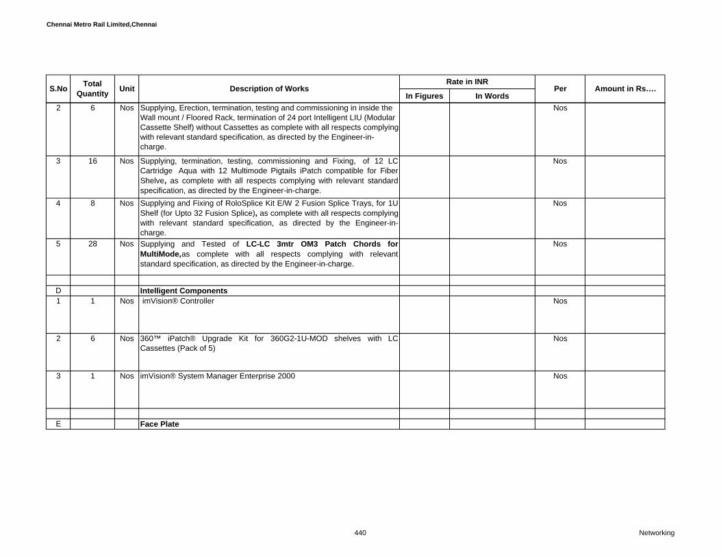
Chennai Metro Rail Limited,Chennai
In Figures In WordsPer Amount in Rs….Total
Quantity UnitS.No Description of WorksRate in INR
2 6 Nos Supplying, Erection, termination, testing and commissioning in inside the Wall mount / Floored Rack, termination of 24 port Intelligent LIU (Modular Cassette Shelf) without Cassettes as complete with all respects complying with relevant standard specification, as directed by the Engineer-in-charge.
Nos
3 16 Nos Supplying, termination, testing, commissioning and Fixing, of 12 LCCartridge Aqua with 12 Multimode Pigtails iPatch compatible for FiberShelve, as complete with all respects complying with relevant standardspecification, as directed by the Engineer-in-charge.
Nos
4 8 Nos Supplying and Fixing of RoloSplice Kit E/W 2 Fusion Splice Trays, for 1UShelf (for Upto 32 Fusion Splice), as complete with all respects complyingwith relevant standard specification, as directed by the Engineer-in-charge.
Nos
5 28 Nos Supplying and Tested of LC-LC 3mtr OM3 Patch Chords forMultiMode,as complete with all respects complying with relevantstandard specification, as directed by the Engineer-in-charge.
Nos
D Intelligent Components1 1 Nos imVision® Controller Nos
2 6 Nos 360™ iPatch® Upgrade Kit for 360G2-1U-MOD shelves with LCCassettes (Pack of 5)
Nos
3 1 Nos imVision® System Manager Enterprise 2000 Nos
E Face Plate
440 Networking
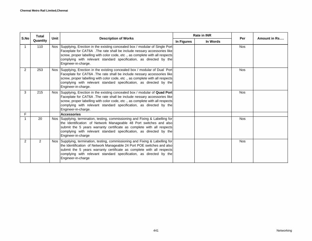
Chennai Metro Rail Limited,Chennai
In Figures In WordsPer Amount in Rs….Total
Quantity UnitS.No Description of WorksRate in INR
1 110 Nos Supplying, Erection in the existing concealed box / modular of Single PortFaceplate for CAT6A .The rate shall be include nessary accessories likescrew, proper labelling with color code, etc ., as complete with all respectscomplying with relevant standard specification, as directed by theEngineer-in-charge.
Nos
2 253 Nos Supplying, Erection in the existing concealed box / modular of Dual PortFaceplate for CAT6A .The rate shall be include nessary accessories likescrew, proper labelling with color code, etc ., as complete with all respectscomplying with relevant standard specification, as directed by theEngineer-in-charge.
Nos
3 215 Nos Supplying, Erection in the existing concealed box / modular of Quad PortFaceplate for CAT6A .The rate shall be include nessary accessories likescrew, proper labelling with color code, etc ., as complete with all respectscomplying with relevant standard specification, as directed by theEngineer-in-charge.
Nos
F Accessories 1 20 Nos Supplying, termination, testing, commissioning and Fixing & Labelling for
the Identification of Network Manageable 48 Port switches and alsosubmit the 5 years warranty certificate as complete with all respectscomplying with relevant standard specification, as directed by theEngineer-in-charge
Nos
2 2 Nos Supplying, termination, testing, commissioning and Fixing & Labelling forthe Identification of Network Manageable 24 Port POE switches and alsosubmit the 5 years warranty certificate as complete with all respectscomplying with relevant standard specification, as directed by theEngineer-in-charge
Nos
441 Networking

Chennai Metro Rail Limited,Chennai
In Figures In WordsPer Amount in Rs….Total
Quantity UnitS.No Description of WorksRate in INR
3 Enclousers ( Switch Rack) Height: 1869mm Width:800mm Depth:1200mmSupply and fixing of 42U floor mounted Rack with required accessoriessuch as Fan Tray with Fans,Front End toughned tightned Glass Doors -with optional vented side trims forfront-to-back air flow, Rear Metal Door, Castors, Levellers, Vertical CableManagers(Monitored Fan Tray Conforms to DIN 41494 - and currentindustry practices ,Load rating of 500 Kgs,Fine styling, plus economy Withall necessary Hardware PocketsSteel Doors - plain, vented at bottom, Stationary and sliding shelvesCantilever shelvesEquipment support anglesCooling fans -4 NosCable management accessories with closed optionsAC Mains channelVertical Power Manager(10x5A, 2 x 15A India Round Pin )Earth continuity kitCastors with foot-operated brakesCaptive mounting hardware
3 Nos IP Based PDU :• Remote Monitoring Power Distribution Unit with 36 nos of C13 & 6 nosof C19 IEC Socket with 2 nos of 16 Amp Internal Circuit Breaker andcable Length upto 3Mtr with Industrial Plug Top & Temperature/HumidityCombo Sensor.
InterConnect Power Cord :
• C13-C14 Inter Connect lockable Power Cable, 1.5Mtr• C19-C20 Inter Connect lockable Power Cable, 1.5Mtr• Warranty should be Two Years Back-To-Bench on the hardware• ROHS Compliance.
Nos
4 3 Nos Enclousers ( Switch Rack) Height: 856 mm Width: 600mm Depth:1000mm Nos
442 Networking

Chennai Metro Rail Limited,Chennai
In Figures In WordsPer Amount in Rs….Total
Quantity UnitS.No Description of WorksRate in INR
4a 2 Nos Supply and fixing of 15U and above Table Rack with Front End GlassDoors -Top Cover with Gland plate with fan cutout with power coated.Castors, Levellers, current industry practices ,Load rating of 100 Kgs,Steel Doors - plain, vented at bottom, Compatable with 19" accessories(Fan: 2 Nos;Horizontal PDC and necessary Hardware Pockets.
Nos
5 1 No Supply and errection of IP based 100 percent non blocking IP PBXsystem with hard stand by 19" Rack mountable with all accessories.System should have centralized administration along with the Softwareand also submit the 5 years warranty certificate as complete with allrespects complying with relevant standard specification, as directed bythe Engineer-in-charge
No
6 2 No Supply and Configuation of Blade server along with the Software awarranty certificate as complete with all respects complying with relevantstandard specification, as directed by the Engineer-in-charge
No
Total Amount C/o to Summary in Rs…………..
443 Networking
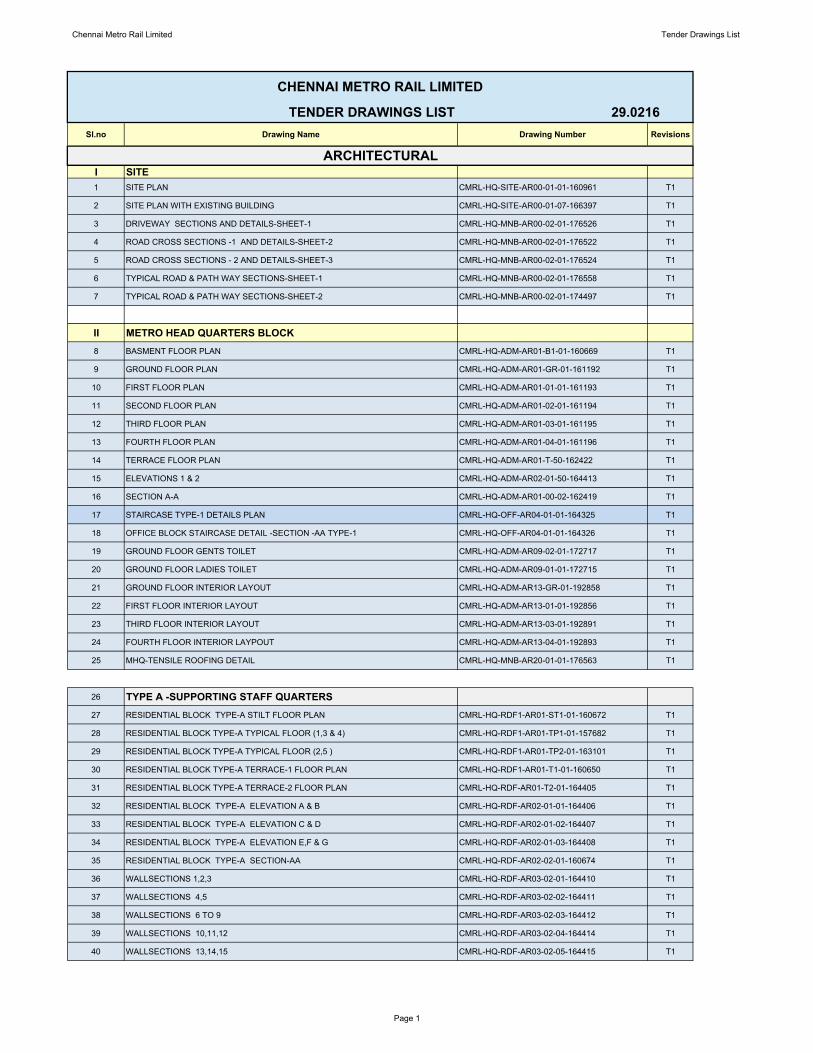
Chennai Metro Rail Limited Tender Drawings List
Sl.no Drawing Name Drawing Number Revisions
I SITE1 SITE PLAN CMRL-HQ-SITE-AR00-01-01-160961 T1
2 SITE PLAN WITH EXISTING BUILDING CMRL-HQ-SITE-AR00-01-07-166397 T1
3 DRIVEWAY SECTIONS AND DETAILS-SHEET-1 CMRL-HQ-MNB-AR00-02-01-176526 T1
4 ROAD CROSS SECTIONS -1 AND DETAILS-SHEET-2 CMRL-HQ-MNB-AR00-02-01-176522 T1
5 ROAD CROSS SECTIONS - 2 AND DETAILS-SHEET-3 CMRL-HQ-MNB-AR00-02-01-176524 T1
6 TYPICAL ROAD & PATH WAY SECTIONS-SHEET-1 CMRL-HQ-MNB-AR00-02-01-176558 T1
7 TYPICAL ROAD & PATH WAY SECTIONS-SHEET-2 CMRL-HQ-MNB-AR00-02-01-174497 T1
II METRO HEAD QUARTERS BLOCK8 BASMENT FLOOR PLAN CMRL-HQ-ADM-AR01-B1-01-160669 T1
9 GROUND FLOOR PLAN CMRL-HQ-ADM-AR01-GR-01-161192 T1
10 FIRST FLOOR PLAN CMRL-HQ-ADM-AR01-01-01-161193 T1
11 SECOND FLOOR PLAN CMRL-HQ-ADM-AR01-02-01-161194 T1
12 THIRD FLOOR PLAN CMRL-HQ-ADM-AR01-03-01-161195 T1
13 FOURTH FLOOR PLAN CMRL-HQ-ADM-AR01-04-01-161196 T1
14 TERRACE FLOOR PLAN CMRL-HQ-ADM-AR01-T-50-162422 T1
15 ELEVATIONS 1 & 2 CMRL-HQ-ADM-AR02-01-50-164413 T1
16 SECTION A-A CMRL-HQ-ADM-AR01-00-02-162419 T1
17 STAIRCASE TYPE-1 DETAILS PLAN CMRL-HQ-OFF-AR04-01-01-164325 T1
18 OFFICE BLOCK STAIRCASE DETAIL -SECTION -AA TYPE-1 CMRL-HQ-OFF-AR04-01-01-164326 T1
19 GROUND FLOOR GENTS TOILET CMRL-HQ-ADM-AR09-02-01-172717 T1
20 GROUND FLOOR LADIES TOILET CMRL-HQ-ADM-AR09-01-01-172715 T1
21 GROUND FLOOR INTERIOR LAYOUT CMRL-HQ-ADM-AR13-GR-01-192858 T1
22 FIRST FLOOR INTERIOR LAYOUT CMRL-HQ-ADM-AR13-01-01-192856 T1
23 THIRD FLOOR INTERIOR LAYOUT CMRL-HQ-ADM-AR13-03-01-192891 T1
24 FOURTH FLOOR INTERIOR LAYPOUT CMRL-HQ-ADM-AR13-04-01-192893 T1
25 MHQ-TENSILE ROOFING DETAIL CMRL-HQ-MNB-AR20-01-01-176563 T1
26 TYPE A -SUPPORTING STAFF QUARTERS27 RESIDENTIAL BLOCK TYPE-A STILT FLOOR PLAN CMRL-HQ-RDF1-AR01-ST1-01-160672 T1
28 RESIDENTIAL BLOCK TYPE-A TYPICAL FLOOR (1,3 & 4) CMRL-HQ-RDF1-AR01-TP1-01-157682 T1
29 RESIDENTIAL BLOCK TYPE-A TYPICAL FLOOR (2,5 ) CMRL-HQ-RDF1-AR01-TP2-01-163101 T1
30 RESIDENTIAL BLOCK TYPE-A TERRACE-1 FLOOR PLAN CMRL-HQ-RDF1-AR01-T1-01-160650 T1
31 RESIDENTIAL BLOCK TYPE-A TERRACE-2 FLOOR PLAN CMRL-HQ-RDF-AR01-T2-01-164405 T1
32 RESIDENTIAL BLOCK TYPE-A ELEVATION A & B CMRL-HQ-RDF-AR02-01-01-164406 T1
33 RESIDENTIAL BLOCK TYPE-A ELEVATION C & D CMRL-HQ-RDF-AR02-01-02-164407 T1
34 RESIDENTIAL BLOCK TYPE-A ELEVATION E,F & G CMRL-HQ-RDF-AR02-01-03-164408 T1
35 RESIDENTIAL BLOCK TYPE-A SECTION-AA CMRL-HQ-RDF-AR02-02-01-160674 T1
36 WALLSECTIONS 1,2,3 CMRL-HQ-RDF-AR03-02-01-164410 T1
37 WALLSECTIONS 4,5 CMRL-HQ-RDF-AR03-02-02-164411 T1
38 WALLSECTIONS 6 TO 9 CMRL-HQ-RDF-AR03-02-03-164412 T1
39 WALLSECTIONS 10,11,12 CMRL-HQ-RDF-AR03-02-04-164414 T1
40 WALLSECTIONS 13,14,15 CMRL-HQ-RDF-AR03-02-05-164415 T1
CHENNAI METRO RAIL LIMITED
TENDER DRAWINGS LIST 29.0216
ARCHITECTURAL
Page 1

Chennai Metro Rail Limited Tender Drawings List
41 TYPICAL STAIRCASE 1 & 2 DETAIL PLANS CMRL-HQ-RDF1-AR04-50-01-175077 T1
42 TYPICAL STAIRCASE 1 & 2 DETAIL SECTIONS CMRL-HQ-RDF1-AR04-50-01-175078 T1
43 TYPICAL LIFT DETAIL 1&2 CMRL-HQ-RDF1-AR07-50-01-175080 T1
44 BED ROOM-2 TOILET & COMMON TOILET DETAIL PLAN AND SECTIONS CMRL-HQ-RDF1-AR09-50-01-175081 T1
45 BED ROOM-2 TOILET & COMMON TOILET SECTIONS CMRL-HQ-RDF1-AR09-50-01-175083 T1
46 BED ROOM-3 TOILET & COMMON TOILET SECTIONS CMRL-HQ-RDF1-AR09-50-01-175084 T1
47 BALCONY DETAIL PLAN,ELEVATION AND SECTION – SHEET-1 CMRL-HQ-RDF1-AR18-04-11-175088 T1
48 BALCONY DETAIL PLAN,ELEVATION AND SECTION – SHEET-2 CMRL-HQ-RDF1-AR18-04-11-175089 T1
49 SERVANT-1 TOILET & COMMON TOILET SECTIONS CMRL-HQ-RDF1-AR09-50-01-175085 T1
50 SERVANT-2 TOILET & COMMON TOILET SECTIONS CMRL-HQ-RDF1-AR09-50-01-175086 T1
51 PHISICALLY CHALLANGED RAMP DETAIL CMRL-HQ-RDF2-AR05-52-01-176120 T1
52 OVER HEAD TANK DETAIL CMRL-HQ-RDF2-AR08-50-01-176110 T1
53 SECOND FLOOR - ELECTRICAL LAYOUT CMRL-HQ-RDF1-Ele02-02-01-176512 T1
TYPE B - SUPPORTING STAFF QUARTERS54 RESIDENTIAL BLOCK TYPE-B STILT FLOOR PLAN CMRL-HQ-RDF2-AR01-ST1-01-160675 T2
55 RESIDENTIAL BLOCK TYPE-B FIRST FLOOR PLAN CML-HQ-RDF2-AR01-TP1-02-157683. T1
56 RESIDENTIAL BLOCK TYPE B SECOND FLOOR PLAN CMRL-HQ-RDF2-AR01-02-01-169743 T1
57 RESIDENTIALBLOCK TYPE B THIRD FLOOR PLAN CMRL-HQ-RDF2-AR01-03-01-169746 T1
58 RESIDENTIAL BLOCK TYPE B 4TH FLOOR PLAN (SHEET -1) CMRL-HQ-RDF2-AR01-04-01-169748 T1
59 RESIDENTIAL BLOCK TYPE B 5TH FLOOR PLAN (SHEET - 2) CMRL-HQ-RDF2-AR01-05-01-169748 T1
60 RESIDENTIAL BLOCK TYPE B 6TH FLOOR PLAN CMRL-HQ-RDF2-AR01-06-01-169749 T1
61 RESIDENTIAL BLOCK TYPE B 7TH FLOOR PLAN CMRL-HQ-RDF2-AR01-07-01-169751 T1
62 RESIDENTIAL BLOCK TYPE B 8TH FLOOR PLAN CMRL-HQ-RDF2-AR01-08-01-169752 T1
63 RESIDENTIAL BLOCK TYPE B 9TH FLOOR PLAN CMRL-HQ-RDF2-AR01-09-01-169753 T1
64 RESIDENTIAL BLOCK TYPE B TERRACE-1 FLOOR PLAN CMRL-HQ-RDF2-AR01-T1-01-160651 T1
65 RESIDENTIAL BLOCK TYPE B TERRACE-2 FLOOR PLAN CMRL-HQ-RDF2-AR01-T2-01-173701 T1
66 RESIDENTIAL BLOCK TYPE B ELEVATION A , B & C CMRL-HQ-RDF2-AR02-01-51-163574 T1
67 RESIDENTIAL BLOCK TYPE B ELEVATION D , E & F CMRL-HQ-RDF2-AR02-01-04-174737 T1
68 RESIDENTIAL BLOCK TYPE B ELEVATION G , H & J CMRL-HQ-RDF2-AR02-01-50-174738 T1
69 RESIDENTIAL BLOCK TYPE B ELEVATION K , L & M CMRL-HQ-RDF2-AR02-01-50-174739 T1
70 RESIDENTIAL BLOCK TYPE B SECTION-AA & SECTION- BB CMRL-HQ-RDF2-AR02-02-01-160680 T2
71 WALLSECTIONS 1 & 2 CMRL-HQ-RDF1-AR03-02-50-175092 T1
72 WALLSECTIONS 3 & 4 CMRL-HQ-RDF1-AR03-02-50-175094 T1
73 WALLSECTIONS 5 & 6 CMRL-HQ-RDF1-AR03-02-50-175095 T1
74 WALLSECTIONS 7 & 8 CMRL-HQ-RDF1-AR03-02-50-175096 T1
75 WALLSECTIONS 9 CMRL-HQ-RDF1-AR03-02-50-175097 T1
76 WALLSECTIONS 10 CMRL-HQ-RDF2-AR03-02-50-175098 T1
77 WALLSECTIONS 11 CMRL-HQ-RDF2-AR03-02-50-175099 T1
78 WALLSECTIONS 12 & 13 CMRL-HQ-RDF2-AR03-02-50-175100 T1
79 WALLSECTIONS 14 & 14a CMRL-HQ-RDF2-AR03-02-50-175101 T1
80 WALLSECTIONS 15 & 16 CMRL-HQ-RDF2-AR03-02-50-175102 T1
81 WALLSECTIONS 17 & 18 CMRL-HQ-RDF2-AR03-02-50-175103 T1
Page 2
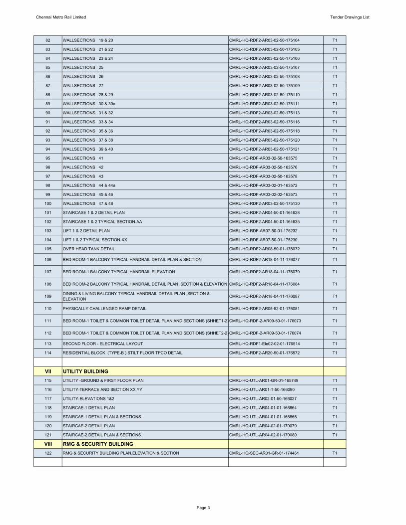
Chennai Metro Rail Limited Tender Drawings List
82 WALLSECTIONS 19 & 20 CMRL-HQ-RDF2-AR03-02-50-175104 T1
83 WALLSECTIONS 21 & 22 CMRL-HQ-RDF2-AR03-02-50-175105 T1
84 WALLSECTIONS 23 & 24 CMRL-HQ-RDF2-AR03-02-50-175106 T1
85 WALLSECTIONS 25 CMRL-HQ-RDF2-AR03-02-50-175107 T1
86 WALLSECTIONS 26 CMRL-HQ-RDF2-AR03-02-50-175108 T1
87 WALLSECTIONS 27 CMRL-HQ-RDF2-AR03-02-50-175109 T1
88 WALLSECTIONS 28 & 29 CMRL-HQ-RDF2-AR03-02-50-175110 T1
89 WALLSECTIONS 30 & 30a CMRL-HQ-RDF2-AR03-02-50-175111 T1
90 WALLSECTIONS 31 & 32 CMRL-HQ-RDF2-AR03-02-50-175113 T1
91 WALLSECTIONS 33 & 34 CMRL-HQ-RDF2-AR03-02-50-175116 T1
92 WALLSECTIONS 35 & 36 CMRL-HQ-RDF2-AR03-02-50-175118 T1
93 WALLSECTIONS 37 & 38 CMRL-HQ-RDF2-AR03-02-50-175120 T1
94 WALLSECTIONS 39 & 40 CMRL-HQ-RDF2-AR03-02-50-175121 T1
95 WALLSECTIONS 41 CMRL-HQ-RDF-AR03-02-50-163575 T1
96 WALLSECTIONS 42 CMRL-HQ-RDF-AR03-02-50-163576 T1
97 WALLSECTIONS 43 CMRL-HQ-RDF-AR03-02-50-163578 T1
98 WALLSECTIONS 44 & 44a CMRL-HQ-RDF-AR03-02-01-163572 T1
99 WALLSECTIONS 45 & 46 CMRL-HQ-RDF-AR03-02-02-163573 T1
100 WALLSECTIONS 47 & 48 CMRL-HQ-RDF2-AR03-02-50-175130 T1
101 STAIRCASE 1 & 2 DETAIL PLAN CMRL-HQ-RDF2-AR04-50-01-164628 T1
102 STAIRCASE 1 & 2 TYPICAL SECTION-AA CMRL-HQ-RDF2-AR04-50-01-164635 T1
103 LIFT 1 & 2 DETAIL PLAN CMRL-HQ-RDF-AR07-50-01-175232 T1
104 LIFT 1 & 2 TYPICAL SECTION-XX CMRL-HQ-RDF-AR07-50-01-175230 T1
105 OVER HEAD TANK DETAIL CMRL-HQ-RDF2-AR08-50-01-176072 T1
106 BED ROOM-1 BALCONY TYPICAL HANDRAIL DETAIL PLAN & SECTION CMRL-HQ-RDF2-AR18-04-11-176077 T1
107 BED ROOM-1 BALCONY TYPICAL HANDRAIL ELEVATION CMRL-HQ-RDF2-AR18-04-11-176079 T1
108 BED ROOM-2 BALCONY TYPICAL HANDRAIL DETAIL PLAN ,SECTION & ELEVATION CMRL-HQ-RDF2-AR18-04-11-176084 T1
109 DINING & LIVING BALCONY TYPICAL HANDRAIL DETAIL PLAN ,SECTION & ELEVATION CMRL-HQ-RDF2-AR18-04-11-176087 T1
110 PHYSICALLY CHALLENGED RAMP DETAIL CMRL-HQ-RDF2-AR05-52-01-176081 T1
111 BED ROOM-1 TOILET & COMMON TOILET DETAIL PLAN AND SECTIONS (SHHET1-2) CMRL-HQ-RDF-2-AR09-50-01-176073 T1
112 BED ROOM-1 TOILET & COMMON TOILET DETAIL PLAN AND SECTIONS (SHHET2-2) CMRL-HQ-RDF-2-AR09-50-01-176074 T1
113 SECOND FLOOR - ELECTRICAL LAYOUT CMRL-HQ-RDF1-Ele02-02-01-176514 T1
114 RESIDENTIAL BLOCK (TYPE-B ) STILT FLOOR TPCO DETAIL CMRL-HQ-RDF2-AR20-50-01-176572 T1
VII UTILITY BUILDING115 UTILITY -GROUND & FIRST FLOOR PLAN CMRL-HQ-UTL-AR01-GR-01-165749 T1
116 UTILITY-TERRACE AND SECTION XX,YY CMRL-HQ-UTL-AR01-T-50-166090 T1
117 UTILITY-ELEVATIONS 1&2 CMRL-HQ-UTL-AR02-01-50-166027 T1
118 STAIRCAE-1 DETAIL PLAN CMRL-HQ-UTL-AR04-01-01-166864 T1
119 STAIRCAE-1 DETAIL PLAN & SECTIONS CMRL-HQ-UTL-AR04-01-01-166866 T1
120 STAIRCAE-2 DETAIL PLAN CMRL-HQ-UTL-AR04-02-01-170079 T1
121 STAIRCAE-2 DETAIL PLAN & SECTIONS CMRL-HQ-UTL-AR04-02-01-170080 T1
VIII RMG & SECURITY BUILDING122 RMG & SECURITY BUILDING PLAN,ELEVATION & SECTION CMRL-HQ-SEC-AR01-GR-01-174461 T1
Page 3

Chennai Metro Rail Limited Tender Drawings List
IX UG SUMP & STP123 UG SUMP & STP DETAILS CMRL-HQ-UGS-AR00-05-01-176574 T1
X JOINERY124 FIRE DOOR DETAILS SHEET -1 CMRL-HQ-OFF-AR15-02-05-176643 T1
125 FIRE DOOR DETAILS SHEET -2 CMRL-HQ-OFF-AR15-02-05-176644 T1
126 FLUSH DOOR DETAILS CMRL-HQ-OFF-AR15-02-04-176647 T1
127 TYPE A & B FLUSH DOOR DETAILS CMRL-HQ-RDF-AR11-GR-02-194493 T1
128 GLASS DOOR DETAILS CMRL-HQ-OFF1-AR10-T-02-194490 T1
129 SPIDER GLAZING WITH GLASS DOOR DETAILS CMRL-HQ-OFF1-AR11-GR-02-194491 T1
130 UPVC DOOR,WINDOW AND VENTILATOR DETAILS CMRL-HQ-MNB-AR10-T-02-194724 T1
131 ALUMIMUM WINDOW DETAILS CMRL-HQ-MNB-AR10-TP1-02-194725 T1
132 MOTORIZED ROLLING SHUTTER CMRL-HQ-LPG-AR10-TP2-02-194726 T1
133 COLUMN LAYOUT (OVER ALL BLOCKS) BASEMENT LVL. (SHEET-1OF 4) CMRL-HQ-ADM-ST04-B1-00-164979 T1
134 COLUMN LAYOUT GROUND FLOOR LVL. (SHEET-2OF4) CMRL-HQ-ADM-ST04-B1-00-164979 T1
135 COLUMN LAYOUT FIRST FLOOR LVL. (SHEET-3/4) CMRL-HQ-ADM-ST04-B1-00-164979 T1136 COLUMN LAYOUT TYPICAL FLOOR (SHEET-4/4) CMRL-HQ-ADM-ST04-B1-00-164979 T1
137 COLUMN SCHEDULES FROM BASEMENT TO SECOND FLOOR AUDITORIUM & OTHER AREA CMRL-HQ-AUM-ST04-GR-01-164754 T1
138 RC DETAIL OF COLUMN FROM BASEMENT TO SIXTH FLOOR FOR CENTRAL TOWERCMRL-HQ-ADM-ST04-B1-02-163468 T1139 OCC AREA - COLUMN SCHEDULES FROM BASEMENT TO SECOND FLOOR LVL. CMRL-HQ-OFF-ST04-GR-03-164846 T1140 LAYOUT OF TYPICAL FLOOR FRAMING (3RD TO 5TH & TERRACE FLOOR) CMRL-HQ-ADM-ST05-TP1-00-162415 T1141 TYPICAL FLOOR SLAB DETAIL (3RD TO 5TH & TERRACE FLOOR) CMRL-HQ-ADM-ST06-TP-1-00-164089 T1142 TYPICAL FLOOR BEAM SCHEDULES (3RD TO 5TH & TERRACE FLOOR) CMRL-HQ-ADM-ST0 5-TP-02-163912 T1143 RC DETAIL OF SHEAR WALL FROM BASEMENT TO 6TH FLOOR LVL CMRL-HQ-ADM-ST03-01-02-163573 T1144 GROUND FLOOR FRAMING LAYOUT CMRL-HQ-ADM-ST05-GR-00-163693 T1145 GROUND FLOOR SLAB LAYOUT CMRL-HQ-OFF-ST06-GR-1-01-164849 T1146 GROUND FLOOR BEAM SCHEDULES (SH-1) CMRL-HQ-ADM-ST05-GR-02-164404 T1147 GROUND FLOOR BEAM SCHEDULES (SH-2) CMRL-HQ-AUM-ST05-GR-02-164767 T1148 FIRST FLOOR FRAMING LAYOUT CMRL-HQ-ADM-ST05-01-00-162417 T1149 FIRST FLOOR SLAB LAYOUT CMRL-HQ-ADM-ST06-01-1-02-164461 T1150 FIRST FLOOR BEAM SCHEDULES (SH-1/2) CMRL-HQ-AUM-ST05-01-02-165129 T1151 FIRST FLOOR BEAM SCHEDULES (SH-2/2) CMRL-HQ-ADM-ST05-01-02-164399 T1152 SECOND FLOOR FRAMING LAYOUT CMRL-HQ-ADM-ST05-02-00-166572 T1153 SECOND FLOOR SLAB LAYOUT CMRL-HQ-ADM-ST06-02-1-00-166574 T1154 SECOND FLOOR BEAM SCHEDULES CMRL-HQ-ADM-ST05-02-02-164471 T1155 MHQ.LAYOUT OF PILE CMRL-HQ-ADM-ST01-02-00-165207 T1156 PILE CAP LAYOUT (SHT 1 of 2) CMRL-HQ-ADM-ST01-02-05-165003 T1157 PILE REINFORCEMENT DETAILS CMRL-HQ-ADM-ST01-02-01-165163 T2158 LAYOUT AND DETAILS OF PILE CAP (SH1OF5) CMRL-HQ-ADM-ST01-02-04-167914 T1159 LAYOUT AND DETAILS OF PILE CAP (SH2OF5) CMRL-HQ-ADM-ST01-02-04-167916 T1160 LAYOUT AND DETAILS OF PILE CAP (SH3OF5) CMRL-HQ-ADM-ST01-02-04-167917 T1161 RAFT SLAB & RETAINING WALL LAYOUT (SHT 1 of 2) CMRL-HQ-ADM-ST01-03-22-167913 T1162 RAFT SLAB & RETAINING WALL DETAILS (SHT 2 of 2) CMRL-HQ-ADM-ST02-01-04-166284 T1163 TYPICAL FLOOR BEAM DETAILS TB1&TB2 CMRL-HQ-ADM-ST05-TP-04-167848 T1164 TYPICAL FLOOR BEAM DETAILS TB3 TO TB7 CMRL-HQ-ADM-ST05-TP-05-169280 T1165 TYPICAL FLOOR BEAM DETAILS TB14TO TB22 CMRL-HQ-ADM-ST05-TP-06-167850 T1166 TYPICAL FLOOR BEAM DETAILS TB8TO TB12 CMRL-HQ-ADM-ST05-TP-06-169282 T1167 THIRD FLOOR FRAMING LAYOUT CMRL-HQ-ADM-ST05-03-00-191136 T1168 FOURTH FLOOR FRAMING LAYOUT CMRL-HQ-ADM-ST05-03-00-191137 T1169 GROUND FLR. P.T BEAM LAYOUT (NON TOWER) (SH1/4) CMRL-HQ-ADM-ST05-GR-00-166588 T1170 GROUND FLOOR POST-TENSIONED LAYOUT (SH-2OF4) CMRL-HQ-ADM-ST05-GR-00-166589 T1171 GROUND FLOOR. P.T SLAB LAYOUT NON TOWER AREA (SH-3OF4) CMRL-HQ-ADM-ST06-GR-1-00-166983 T1172 P.T. GROUND FLOOR.TENDON LAYOUT (SH-4OF4) CMRL-HQ-ADM-ST06-GR-1-00-166984 T1173 G.F PT BEAM TENDON & PROFILES DETAILS (SH 1OF4) CMRL-HQ-ADM-ST05-GR-04-166987 T1174 GROUND FLOOR P.T BEAM REINF. DETAILS (SH-2OF4) CMRL-HQ-ADM-ST05-GR-05-166988 T1175 GROUND FLOOR P.T BEAM REINF. DETAILS (SH 3OF4) CMRL-HQ-ADM-ST05-GR-06-166989 T1176 GROUND FLOOR P.T BEAM REINF. DETAILS (SH 4OF4) CMRL-HQ-ADM-ST05-GR-07-167038 T1177 FIRST FLOOR POST-TENSIONED LAYOUT (SH 1OF2) CMRL-HQ-ADM-ST05-01-00-166590 T1178 1ST FLOOR SLAB. & TENDON LAYOUT (SH-2OF2) CMRL-HQ-ADM-ST06-01-1-00-166591 T1179 FIRST FLOOR POST-TENSIONED BEAM DETAILS (SH.1/2) CMRL-HQ-ADM-ST05-01-04-166592 T1180 1st FLR.PT BEAM TENDON,PROFILES DETAILS (SH.2OF2) CMRL-HQ-ADM-ST05-01-05-166593 T1
STRUCTURAL
Page 4

Chennai Metro Rail Limited Tender Drawings List
181 2ND FLOOR SLAB LAYOUT (SH 1OF 3) CMRL-HQ-ADM-ST06-02-1-00-166595 T1182 2ND FLOOR TENDON SLAB LAYOUT (SH 2OF 3) CMRL-HQ-ADM-ST06-02-1-00-166596 T1183 2ND FLOOR BEAM LAYOUT (SH 3OF3) CMRL-HQ-ADM-ST05-02-00-166594 T1184 2ND FLOOR PT BEAM REINFT.DETAILS (SH 1OF6) CMRL-HQ-ADM-ST05-02-04-166597 T1185 2ND FLOOR PT BEAM REINFT DETAILS (SH 2OF6) CMRL-HQ-ADM-ST05-02-05-166598 T1186 2ND FLR PT BEAM TENDON & PROFILES DETAILS (SH 3OF 6) CMRL-HQ-ADM-ST05-02-06-166599 T1187 2ND FLR PT BEAM TENDON&PROFILES DETAILS (SH 4 OF6) CMRL-HQ-ADM-ST05-02-07-166600 T1188 2ND FLR PT BEAM TENDON&PROFILES DETAILS (SH 5 OF6) CMRL-HQ-ADM-ST05-02-08-167040 T1189 2ND FLR PT BEAM TENDON&PROFILES DETAILS (SH 6 OF6) CMRL-HQ-ADM-ST05-02-08-167041 T1190 TYPICAL (3RD TO 5TH & TERRACE) FLOOR LAYOUT CMRL-HQ-ADM-ST05-TP-00-166601 T1191 (3RD TO 5TH & TERRACE) FLOOR PT BEAM DETAILS (SH 1/2) CMRL-HQ-ADM-ST05-TP-00-167019 T1192 (3RD TO 5TH & TERRACE) FLOOR PT BEAM DETAILS (SH2/2) CMRL-HQ-ADM-ST05-TP-05-167021 T1193 P.T PRESTRESSING GENERAL NOTES CMRL-HQ-ADM-ST00-01-00-167556 T1194 RESIDENTIAL BLOCK (TYPE – A) PILE & PILECAP LAYOUT CMRL-HQ-RDF1-ST01-02-00-164264 T2195 RESIDENTIAL BLOCK (TYPE – A) PILE & PILECAP SECTION AND DETAILS CMRL-HQ-RDF1-ST01-02-07-164317 T1196 RESIDENTIAL BLOCK (TYPE – A) SHEAR WALL LAYOUT AT STILT LEVEL CMRL-HQ-RDF1-ST03-01-00-164119 T2197 RESIDENTIAL BLOCK (TYPE – A) SHEAR WALL LAYOUT AT TYPICAL FLOOR LEVEL CMRL-HQ-RDF1-ST03-01-03-164856 T1198 RESIDENTIAL BLOCK (TYPE – A) SHEAR WALL REINFORCEMENT DETAILS CMRL-HQ-RDF1-ST03-01-01-164120 T2199 RESIDENTIAL BLOCK (TYPE – A) SHEAR WALL REINFORCEMENT DETAILS CMRL-HQ-RDF1-ST03-01-01-164121 T2200 RESIDENTIAL BLOCK (TYPE – A) GRADE BEAM LAYOUT & DETAILS CMRL-HQ-RDF1-ST05-PB-00-164263 T2201 RESIDENTIAL BLOCK (TYPE – A) TYPICAL FLOOR FRAMING LAYOUT CMRL-HQ-RDF1-ST05-TP-00-162391 T2202 RESIDENTIAL BLOCK (TYPE – A) TYPICAL FLOOR SLAB LAYOUT & DETAILS CMRL-HQ-RDF1-ST06-TP-1-02-164062 T2203 RESIDENTIAL BLOCK (TYPE – A) TYPICAL FLOOR BEAM SCHEDULE CMRL-HQ-RDF1-ST05-TP-02-164063 T2204 RESIDENTIAL BLOCK (TYPE – B) PILE AND PILE CAP LAYOUT CMRL-HQ-RDF-ST01-02-00-163429 T1205 RESIDENTIAL BLOCK (TYPE – B) PILE & PILECAP SECTION AND DETAILS CMRL-HQ-RDF1-ST01-02-07-163555 T2206 RESIDENTIAL BLOCK (TYPE – B) SHEAR WALL LAYOUT CMRL-HQ-RDF1-ST03-01-00-164078 T1207 RESIDENTIAL BLOCK (TYPE – B) SHEAR WALL REINFORCEMENT DETAILS CMRL-HQ-RDF1-ST03-01-01-164087 T1208 RESIDENTIAL BLOCK (TYPE – B) SHEAR WALL REINFORCEMENT DETAILS CMRL-HQ-RDF1-ST03-01-01-164088 T1209 RESIDENTIAL BLOCK (TYPE – B) GRADE BEAM LAYOUT & DETAILS CMRL-HQ-RDF-ST05-GB-01-163522 T1210 RESIDENTIAL BLOCK (TYPE – B) FIRST FLOOR BEAM LAYOUT CMRL-HQ-RDF2-ST05-01-00-163672 T1211 RESIDENTIAL BLOCK (TYPE – B) FIRST FLOOR SLAB LAYOUT & SCHEDULE CMRL-HQ-RDF2-ST06-01-1-02-163679 T1212 RESIDENTIAL BLOCK (TYPE – B) FIRST FLOOR BEAM SCHEDULE CMRL-HQ-RDF2-ST05-01-02-163676 T1213 STANDARD DETAILS (SHEET 1 OF 4) CMRL-HQ-RDF1-ST00-01-00-164825 T1214 STANDARD DETAILS (SHEET 2 OF 4) CMRL-HQ-RDF1-ST00-01-00-164826 T1215 STANDARD DETAILS (SHEET 3 OF 4) CMRL-HQ-RDF1-ST00-01-00-164827 T1216 STANDARD DETAILS (SHEET 4 OF 4) CMRL-HQ-RDF1-ST00-01-00-164828 T1
217 Main Electrical Schematic Diagram (Sheet 1 of 3) CMRL-HQ-GEN1-Ele00-01-11-165730 T1218 Sub Electrical Schematic Diagram (Sheet 2of 3) CMRL-HQ-GEN1-Ele00-01-11-167467 T1219 Sub Electrical Schematic Diagram (Sheet 3of 3) CMRL-HQ-GEN1-Ele00-01-11-167468 T1220 Main Electrical Earthing Schematic Diagram (Sheet 1 of 2) CMRL-HQ-ACD-Ele00-01-16-191692 T1
UTILITY BUILDING 221 Lighting Layout For Ground & First Floor CMRL-HQ-UTL-Ele02-GRM-01-165623 T1222 Power Layout For Ground & First Floor CMRL-HQ-UTL-Ele02-GRM-03-165624 T1223 Lighting Layout For Terrace Floor CMRL-HQ-UTL-Ele02-T1-01-165625 T1224 Panel Location Layout for Ground and First Floor CMRL-HQ-UTL1-Ele01-01-02-192987 T1
ADMIN BLOCK225 Lighting & Power Socket Layout For Basement Floor CMRL-HQ-ADM-Ele02-B1-01-165628 T1226 Lighting Layout For Ground Floor CMRL-HQ-ADM-Ele02-GR-01-165629 T1227 Lighting Layout For First Floor CMRL-HQ-ADM-Ele02-01-01-165637 T1228 Lighting Layout For Second Floor CMRL-HQ-ADM-Ele02-02-01-165638 T1227 Lighting Layout For Third Floor CMRL-HQ-ADM-Ele02-03-01-165641 T1228 Power Socket LayouT For Ground Floor CMRL-HQ-ADM-Ele02-GR-03-165645 T1229 Power Socket LayouT For First Floor CMRL-HQ-ADM-Ele02-01-03-165646 T1230 Power Socket LayouT For Second Floor CMRL-HQ-ADM-Ele02-02-03-165648 T1231 Power Socket LayouT For Third Floor CMRL-HQ-ADM-Ele02-03-03-165650 T1232 Power Socket LayouT For Fourth Floor CMRL-HQ-ADM-Ele02-04-03-165652 T1
RESEDENTIAL TYPE BLOCK – A233 Lighting & Power Socket Layout For Stilt Floor CMRL-HQ-RDF1-Ele02-GR-01-165661 T1234 Lighting & Power Socket Layout For Typical Floor (1,3 & 4 ) CMRL-HQ-RDF1-Ele02-TP1-01-165662 T1235 Lighting & Power Socket Layout For Typical Floor (2,5 & 6) CMRL-HQ-RDF1-Ele02-TP2-01-165663 T1236 Lighting & Power Socket Layout For Terrace Floor CMRL-HQ-RDF1-Ele02-T1-01-165664 T1
ELECTRICAL
Page 5

Chennai Metro Rail Limited Tender Drawings List
RESEDENTIAL TYPE BLOCK – B237 Lighting & Power Socket Layout For Stilt Floor CMRL-HQ-RDF2-Ele02-GR-01-165680 T1238 Lighting & Power Socket Layout For Typical Floor (1st To 12th Floor) CMRL-HQ-RDF2-Ele02-01-01-165681 T1239 Lighting & Power Socket Layout For 13Th Floor CMRL-HQ-RDF2-Ele02-TP1-01-165682 T1240 Lighting & Power Socket Layout For 14Th Floor CMRL-HQ-RDF2-Ele02-TP2-01-165683 T1241 Lighting & Power Socket Layout For Terrace Floor CMRL-HQ-RDF2-Ele02-T1-01-165685 T1
SUBSTATION LAYOUT242 EXTERNAL LIGHTING LAYOUT CMRL-HQ-SITE-Ele01-01-07-165626 T1
243 FIRE ALARM SYSTEM FOR BASEMENT FLOOR CMRL-HQ-ADM-IBMS02-B1-01-189297 T1244 FIRE ALARM SYSTEM FOR GROUND FLOOR CMRL-HQ-ADM-IBMS02-GR-01-189299 T1245 FIRE ALARM SYSTEM FOR FIRST FLOOR CMRL-HQ-ADM-IBMS02-01-01-189300 T1246 FIRE ALARM SYSTEM FOR SECOND FLOOR CMRL-HQ-ADM-IBMS02-02-01-189301 T1247 FIRE ALARM SYSTEM FOR THRID FLOOR CMRL-HQ-ADM-IBMS02-03-01-189302 T1248 FIRE ALARM SYSTEM FOR FOURTH FLOOR CMRL-HQ-ADM-IBMS02-04-01-189303 T1249 SCHEMATIC LAYOUT FOR FIRE ALARM SYSTEM CMRL-HQ-ADM-IBMS00-02-01-189304 T1250 FIRE ALARM AND PA SYSTEM FOR UTILITY BLOCK CMRL-HQ-SUB-IBMS01-01-01-192741 T1251 FIRE ALARM SYSTEM FOR STILT FLOOR-TYPE A CMRL-HQ-RDF-IBMS02-GRM-01-193028 T1252 FIRE ALARM SYSTEM FOR TYPICAL FLOOR-TYPE-A CMRL-HQ-RDF-IBMS02-TM1-01-193025 T1253 FIRE ALARM SYSTEM FOR STILT FLOOR-TYPE B CMRL-HQ-RDF1-IBMS02-GRM-01-193031 T1254 FIRE ALARM SYSTEM FOR TYPICAL FLOOR-TYPE-B CMRL-HQ-RDF-IBMS02-TP2-01-193032 T1255 PA SYSTEM FOR BASEMENT FLOOR CMRL-HQ-ADM-IBMS02-B1-02-189305 T1256 PA SYSTEM FOR GROUND FLOOR CMRL-HQ-ADM-IBMS02-GR-02-189306 T1257 PA SYSTEM FOR FIRST FLOOR CMRL-HQ-ADM-IBMS02-01-02-189307 T1258 PA SYSTEM FOR SECOND FLOOR CMRL-HQ-ADM-IBMS02-02-02-189308 T1259 PA SYSTEM FOR THRID FLOOR CMRL-HQ-ADM-IBMS02-03-02-189309 T1260 PA SYSTEM FOR FOURTH FLOOR CMRL-HQ-ADM-IBMS02-04-02-189310 T1261 SCHEMATIC LAYOUT FOR PUBLIC ADDRESS SYSTEM CMRL-HQ-ADM-IBMS00-02-03-189311 T1262 SCHEMATIC LAYOUT FOR EMERGENCY VOICE SYSTEM CMRL-HQ-ADM-IBMS00-02-02-189312 T1263 CCTV AND ACCESS CONTROL SYSTEM FOR GROUND FLOOR CMRL-HQ-ADM-IBMS02-GR-03-189316 T1264 CCTV AND ACCESS CONTROL SYSTEM FOR FIRST FLOOR CMRL-HQ-ADM-IBMS02-01-03-189317 T1265 CCTV AND ACCESS CONTROL SYSTEM FOR SECOND FLOOR CMRL-HQ-ADM-IBMS02-02-03-189318 T1266 CCTV AND ACCESS CONTROL SYSTEM FOR THRID FLOOR CMRL-HQ-ADM-IBMS02-03-03-189319 T1267 CCTV AND ACCESS CONTROL SYSTEM FOR FOURTH FLOOR CMRL-HQ-ADM-IBMS02-04-03-189320 T1268 SCHEMATIC LAYOUT FOR CCTV CMRL-HQ-ADM-IBMS00-02-04-189313 T1269 SCHEMATIC LAYOUT FOR BMS CMRL-HQ-FST-IBMS00-02-05-193020 T1
270 BASEMENT1 VENTILATION LAYOUT CMRL-HQ-OFF-AC02-B1-01-189276 (A1) T2271 GROUND FLOOR ACMV LAYOUT CMRL-HQ-ADM-AC02-GR-01-170817 T2272 FIRST FLOOR ACMV LAYOUT CMRL-HQ-ADM-AC02-01-01-170818 T2273 SECOND FLOOR ACMV LAYOUT CMRL-HQ-ADM1-AC02-02-02-170831 T2274 THIRD FLOOR ACMV LAYOUT CMRL-HQ-ADM1-AC02-03-02-170832 T2275 FOURTH FLOOR ACMV LAYOUT CMRL-HQ-ADM1-AC02-04-02-170833 T2276 TERRACE FLOOR 1 VENTILATION DRAWING CMRL-HQ-ADM-AC02-T1-01-170819 T2277 STAIRCASE & LIFT LOBBY PRESSURIZATION LAYOUT CMRL-HQ-ADM-AC04-01-02-170844 T1278 CHILLED WATER PIPING SCHEMATIC DRAWING CMRL-HQ-ADM-AC00-01-03-170820 T2279 CHILLER PUMP ROOM SCHEMATIC LAYOUT CMRL-HQ-ADM-AC00-01-02-170822 T2280 HRW(HEAT RECOVERY WHEEL) SCHEMATIC LAYOUT CMRL-HQ-ADM-AC00-01-07-190979 T2281 TOILET VENTILATION AND SHAFT DETAILS LAYTOUT CMRL-HQ-ADM-AC04-01-01-190981 T2282 TYPICAL DETAILS FOR AIR CONDITIONING AND MECHANICAL VENTILATION
SYSTEM CMRL-HQ-ADM-AC00-01-08-190982 T1283 CHILLER PLANT ROOM LAYOUT CMRL-HQ-ADM-AC01-01-01-170823 T2
IBMS
ACMV
Page 6
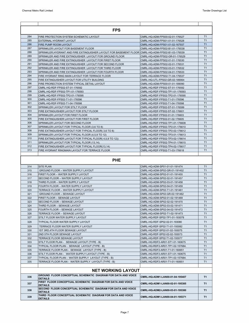
Chennai Metro Rail Limited Tender Drawings List
284 FIRE PROTECTION SYSTEM SCHEMATIC LAYOUT CMRL-HQ-ADM-FPS00-02-01-176527 T1285 EXTERNAL HYDRANT LAYOUT CMRL-HQ-ADM-FPS01-01-01-176528 T1286 FIRE PUMP ROOM LAYOUT CMRL-HQ-ADM-FPS01-01-02-167937 T1287 SPRINKLER LAYOUT FOR BASEMENT FLOOR CMRL-HQ-ADM-FPS02-B1-01-176538 T1288 SPRINKLER,HYDRANT AND FIRE EXTINGUISHER LAYOUT FOR BASEMENT FLOOR CMRL-HQ-ADM-FPS02-B1-03-176539 T1289 SPRINKLER AND FIRE EXTINGUISHER LAYOUT FOR GROUND FLOOR CMRL-HQ-ADM-FPS02-GR-01-176529 T1290 SPRINKLER AND FIRE EXTINGUISHER LAYOUT FOR FIRST FLOOR CMRL-HQ-ADM-FPS02-01-01-176530 T1291 SPRINKLER AND FIRE EXTINGUISHER LAYOUT FOR SECOND FLOOR CMRL-HQ-ADM-FPS02-02-01-176531 T1292 SPRINKLER AND FIRE EXTINGUISHER LAYOUT FOR THIRD FLOOR CMRL-HQ-ADM-FPS02-03-01-176532 T1293 SPRINKLER AND FIRE EXTINGUISHER LAYOUT FOR FOURTH FLOOR CMRL-HQ-ADM-FPS02-04-01-176533 T1294 FIRE HYDRANT RING MAIN LAYOUT FOR TERRACE FLOOR CMRL-HQ-ADM-FPS02-T1-04-176537 T1295 FIRE EXTINGUISHER LAYOUT FOR UTILITY BUILDING CMRL-HQ-UTL-FPS02-GR-02-189064 T1296 FIRE PRORECTION SYSTEM TYPICAL DETAIL LAYOUT CMRL-HQ-ADM-FPS00-01-01-189090 T1297 CMRL-HQ-RDF-FPS02-ST-01-176592 CMRL-HQ-RDF-FPS02-ST-01-176592 T1298 CMRL-HQ-RDF-FPS02-TP1-01-176593 CMRL-HQ-RDF-FPS02-TP1-01-176593 T1299 CMRL-HQ-RDF-FPS02-TP2-01-176595 CMRL-HQ-RDF-FPS02-TP2-01-176595 T1300 CMRL-HQ-RDF-FPS02-T1-01-176596 CMRL-HQ-RDF-FPS02-T1-01-176596 T1301 CMRL-HQ-RDF-FPS02-T1-04-176598 CMRL-HQ-RDF-FPS02-T1-04-176598 T1302 SPRINKLER LAYOUT FOR STILT FLOOR CMRL-HQ-RDF-FPS02-ST-01-176599 T1303 FIRE EXTINGUISHER LAYOUT FOR STILT FLOOR CMRL-HQ-RDF-FPS02-ST-02-176601 T1304 SPRINKLER LAYOUT FOR FIRST FLOOR CMRL-HQ-RDF-FPS02-01-01-176603 T1305 FIRE EXTINGUISHER LAYOUT FOR FIRST FLOOR CMRL-HQ-RDF-FPS02-01-02-176605 T1306 SPRINKLER LAYOUT FOR SECOND FLOOR CMRL-HQ-RDF-FPS02-TP1-01-176608 T1307 SPRINKLER LAYOUT FOR TYPICAL FLOOR (3,6 TO 8) CMRL-HQ-RDF-FPS02-TP2-01-176610 T1308 FIRE EXTINGUISHER LAYOUT FOR TYPICAL FLOOR( 3,6 TO 8) CMRL-HQ-RDF-FPS02-TP2-02-176612 T1309 SPRINKLER LAYOUT FOR TYPICAL FLOOR (4,5,9 TO 12) CMRL-HQ-RDF-FPS02-TP3-01-176613 T1310 FIRE EXTINGUISHER LAYOUT FOR TYPICAL FLOOR( 4,5,9 TO 12)) CMRL-HQ-RDF-FPS02-TP3-02-176614 T1311 SPRINKLER LAYOUT FOR TYPICAL FLOOR (13,14). CMRL-HQ-RDF-FPS02-TP4-01-176615 T1312 FIRE EXTINGUISHER LAYOUT FOR TYPICAL FLOOR(13,14) CMRL-HQ-RDF-FPS02-TP4-02-176617 T1313 FIRE HYDRANT RINGMAIN LAYOUT FOR TERRACE FLOOR CMRL-HQ-RDF-FPS02-T1-03-176618 T1
314 SITE PLAN CMRL-HQ-ADM-SP01-01-01-191474 T1315 GROUND FLOOR – WATER SUPPLY LAYOUT CMRL-HQ-ADM-SP02-GR-01-191452 T1316 FIRST FLOOR – WATER SUPPLY LAYOUT CMRL-HQ-ADM-SP02-01-01-191455 T1317 SECOND FLOOR – WATER SUPPLY LAYOUT CMRL-HQ-ADM-SP02-02-01-191457 T1318 THIRD FLOOR – WATER SUPPLY LAYOUT CMRL-HQ-ADM-SP02-03-01-191458 T1319 FOURTH FLOOR – WATER SUPPLY LAYOUT CMRL-HQ-ADM-SP02-04-01-191459 T1320 TERRACE FLOOR – WATER SUPPLY LAYOUT CMRL-HQ-ADM-SP02-T1-01-191461 T1321 GROUND FLOOR – SEWAGE LAYOUT CMRL-HQ-ADM-SP02-GR-02-191462 T1322 FIRST FLOOR – SEWAGE LAYOUT CMRL-HQ-ADM-SP02-01-02-191469 T1323 SECOND FLOOR – SEWAGE LAYOUT CMRL-HQ-ADM-SP02-02-02-191470 T1324 THIRD FLOOR – SEWAGE LAYOUT CMRL-HQ-ADM-SP02-03-02-191471 T1325 FOURTH FLOOR – SEWAGE LAYOUT CMRL-HQ-ADM-SP02-04-02-191472 T1326 TERRACE FLOOR – SEWAGE LAYOUT CMRL-HQ-ADM-SP02-T1-02-191473 T1327 STILT FLOOR WATER SUPPLY LAYOUT CMRL-HQ-RDF-SP02-TP1-01-193078 T1
328 TYPICAL FLOOR WATER SUPPLY LAYOUT CMRL-HQ-RDF-SP02-02-01-193080 T1
329 TERRACE FLOOR WATER SUPPLY LAYOUT CMRL-HQ-RDF-SP02-T1-01-193082 T1330 1ST 3RD,4TH FLOOR SEWAGE LAYOUT CMRL-HQ-RDF-SP02-01-02-193075 T1331 2ND 5TH FLOOR SEWAGE LAYOUT CMRL-HQ-RDF-SP02-02-02-193073 T1332 TERRACE FLOOR SEWAGE LAYOUT CMRL-HQ-RDF-SP02-T1-02-193077 T1333 STILT FLOOR PLAN - SEWAGE LAYOUT (TYPE - B) CMRL-HQ-RDF2-AR01-ST1-01-160675 T1334 TYPICAL FLOOR PLAN - SEWAGE LAYOUT (TYPE - B) CMRL-HQ-RDF2-AR01-TP1-02-157684. T1335 TERRACE FLOOR PLAN - SEWAGE LAYOUT (TYPE - B) CMRL-HQ-RDF2-AR01-T1-01-160651 T1336 STILT FLOOR PLAN - WATER SUPPLY LAYOUT (TYPE - B) CMRL-HQ-RDF2-AR01-ST1-01-160675 T1337 TYPICAL FLOOR PLAN - WATER SUPPLY LAYOUT (TYPE - B) CMRL-HQ-RDF2-AR01-TP1-02-157684. T1335 TERRACE FLOOR PLAN - WATER SUPPLY LAYOUT (TYPE - B) CMRL-HQ-RDF2-AR01-T1-01-160651 T1
336 GROUND FLOOR CONCEPTUAL SCHEMATIC DIAGRAM FOR DATA AND VOICE DETAILS CMRL-HQ-ADM1-LAN00-01-04-195407 T1
337 FIRST FLOOR CONCEPTUAL SCHEMATIC DIAGRAM FOR DATA AND VOICE DETAILS CMRL-HQ-ADM1-LAN00-02-01-195385 T1
338 SECOND FLOOR CONCEPTUAL SCHEMATIC DIAGRAM FOR DATA AND VOICE DETAILS CMRL-HQ-ADM2-LAN00-03-01-195380 T1
339 THIRD FLOOR CONCEPTUAL SCHEMATIC DIAGRAM FOR DATA AND VOICE DETAILS CMRL-HQ-ADM1-LAN00-04-01-195371 T1
NET WORKING LAYOUT
FPS
PHE
Page 7

Chennai Metro Rail Limited Tender Drawings List
340 FOURTH FLOOR CONCEPTUAL SCHEMATIC DIAGRAM FOR DATA AND VOICE DETAILS CMRL-HQ-ADM1-LAN00-05-01-195368 T1
Page 8