SYSTEMS INTERFACES FOR A RAIL TRANSIT SYSTEM A Guide for Project Managers
47
SYSTEMS INTERFACES FOR A RAIL TRANSIT SYSTEM A Guide for Project Managers Produced by TQM Group A, Newark, New Jersey September, 1997 PB Transit & Rail Systems, Inc.
-
Upload
independent -
Category
Documents
-
view
0 -
download
0
Transcript of SYSTEMS INTERFACES FOR A RAIL TRANSIT SYSTEM A Guide for Project Managers

SYSTEMS INTERFACESFOR A RAIL TRANSIT SYSTEM
A Guide for Project Managers
Produced by TQM Group A, Newark, New JerseySeptember, 1997
PB Transit & Rail Systems, Inc.

1. ACKNOWLEDGEMENTS
The members of PBT&RS TQM Team A wish to thank all the members ofthe group (those from last year and this year alike) that assisted in making this Guide a reality. This has been a challenging project because of its nature and because of the number of disciplines required to coordinate and integrate their activities. It required a diligent coordination effort that covered the full spectrum of implementing all phases of a transitsystem through the planning, design, and construction stages.
We thank our PBT&RS management for their full support of this project and its needs. We thank G. Touryan, Manager of Quality, for his guidance and leadership that brought us this far.
Last and most, we thank the PB Management for their dedication and commitment to quality. Without top management sincere beliefin quality, and their support to the Total Quality Program (TQM).This project would have never commenced to begin with, without this top management support.
document.doc Page 1 10/19/2022

2. PBT&RS TQM TEAMS A and B MEMBERS (1996 - 1997)NEWARK, New Jersey
The development of the guidelines as summarized in this report required the diligent involvement and input of every discipline necessary for designing a transit system. TQM Group B, 1996, under the leadership of T. Carroll started this project which wascompleted by TQM Group A, 1997, under the leadership of Tony Atala.
Eighteen (18) PBT&RS staff members were involved in this project.Most of the member served on this project for the last two years.Following are the names and disciplines of our team members who contributed to this project:
Name Discipline Name DisciplineKen Addison Overhead Contact Systems Thomas Li Electrical & Traction
PowerMunir Armanious Communications G. Milanowski Fire / Intrusion Alarm and
Fire ProtectionTony Atala Operations & Systems Safety
and AssuranceMarian Roberts Administration
Glenn Biles Signaling & Train Control Ed Rose Traction Power & 3rd RailTom Carroll Civil & Track Doug Simkins Signaling & Train ControlLee Denny Communications Scott Spencer OperationsJalal Gohari Electrical & Mechanical Clive Thornes VehiclesIakov Golovithcer Signaling & Train Control G. Touryan Project ManagementManny Intatano Electrical Shing Yu Overhead Contact
System.
document.doc Page 2 10/19/2022

3. Mission StatementOur mission is a simple one. It is to effectively communicate with the Project Managers and other team members in the requirements of systems engineering, on every transit design and construction management project. Our mission is to deliver a quality product in the most efficient and cost effective way to our clients.
3.1. Objective and PurposeThe objective is to carry out a transit system planning, design, and construction management project in an efficient and cost effective manner. This objective can be accomplished by providing the PB Project Managers with discipline interface matrix of the activities performed by PBT&RS systems groups. Thisdiscipline interface matrix describes the inputs, outputs, and ongoing interfaces required by the various disciplines during allstages of a transit project. A well-coordinated effort at the onset of a project assures the success of such project. Successful projects are conducive for repeat business. Repeat business is the best business.
3.2. Benefits to PB· Assists Project Managers to better coordinate the systems
requirements and their interfaces with other disciplines.· Provides a reference for guidance for the development and
execution of a project management plan.· Fully and properly integrates the systems design work into the
project schedule, project workflow, and communications structure at appropriate schedule points to assist in an efficient and well-integrated design.
· Assists the Project Managers in planning, coordinating and integrating the systems requirements into the overall project.
· Aids business development by providing a reference for use during project proposal and cost estimating stages.
· Provides business development with a document for giving visibility to Parsons Brinckerhoff systems engineering
TQM_SI 1997 Page 3 10/19/2022

related disciplines and their capabilities, particularly those within PBT&RS.
· Increases the awareness level of systems requirements throughout the Parsons Brinckerhoff family of companies.
· Ensures that there is sufficient time allowed in the overall project plan for the systems related work to be completed effectively and efficiently. Proper allocated time to perform a job, improves project cost (fewer errors), reducesemployee stress, and improves morale.
· Provides the clients with a high quality, well-coordinated, andfully integrated project design in a timely and cost effective manner. We estimate that this approach can save the project approximately 10-15 Percent of design cost.
4. Introduction
Managing and directing the development of a major transit system design or construction management project is a very complex work effort and a major source of revenue for PB. Efficient and effective project management becomes more critical with projects that use the concept of Design Build Operate and Maintain (DBOM).This requires more coordination, interaction and interface with alarger number of disciplines and sub-consultants, and hence making the work required from our systems engineering groups moredifficult. The project manager must have clear and concise guidelines to help him/her grasp a full depth of systems requirements. This documents does just that.
The Project Manager and his/her team have many concerns to address, particularly developing an alignment with all the attendant issues. The track alignment has to be integrated in an urban area, which inevitably causes many adjustments and disruptions that may affect the quality of life in affected locations.
In many cases, experience has shown that it is critical for the project management staff to clearly visualize the detailed requirements of the systems engineering and its related interdisciplinary activities and interfaces. This can help
TQM_SI 1997 Page 4 10/19/2022

minimize the project impact on the local community. Typical of such system disciplines are:
· Auxiliary Electrical (Power and Lighting)· Catenary· Communications· Corrosion Control· Operations Planning and Analysis· Safety, Security, and Systems Assurance including Reliability
and Maintainability· Signaling and Train Control· Systems Integration.· Track· Traction Power· Vehicles
One of the major challenges to systems engineers on the project is when last minute alignment changes, station architectural design, and structural details are changed shortly before final design submittal is due. In the past, the perception has been that any systems related changes could be completed instantly andautomatically. A minor alignment change, for example, can have major repercussions on catenary pole design, traction power substation location, signal system layout, and the operating plan. This is a detailed System Interface Guide for Rail Transit Systems to help establish systems requirements and their interfaces. Hence, the quality of documents presented to clientsand maintenance of our quality standards and image in the eyes ofclients will keep us apart from the competition.
In an effort to provide the project staff with an understanding of the interdisciplinary interfaces, the TQM Groups have identified the multitude of interfaces that must be considered during the development of a transit system project.
This document provides the project staff with an understanding ofthe interdisciplinary interfaces which must be considered, and the time frame in which they need to be coordinated and performedduring the development of a rail transit project. It is anticipated that this document be used by the project staff as a check list when preparing the project schedule to establish that
TQM_SI 1997 Page 5 10/19/2022

all the systems activities have been properly addressed in a timely manner.
Brevity has been the guiding principle in the production of this document. The issues and period for their resolution are identified.
TQM_SI 1997 Page 6 10/19/2022

5. Approach and EvolutionThis document was designed to be a “living” document. Effective guidelines are those that are reviewed and updated on a regular basis.
This project went through various phases that lead to these guidelines. Following are the steps describing the team’s efforts:
1. Choice of Project: the 1996 TQM Team B chose this project. At that time, we raised the concern of having to resolve coordination problems on the major transit projects that required systems input. The more topics discussed, the morewe felt that this project is an absolute necessity. We recognized at that time, the complexity of assembling guidelines such as these presented in this report.
2. Development of the Disciplines List: each team member was giventhe responsibility to prepare a list of disciplines that they had to interface with. The group would meet and reviewthe disciplines that each had to interface with and would work together in fine-tuning each one.
3. Interface and information flow between disciplines: once the list of discipline interfaces was finalized, each of the team members was responsible to fill in the cells that wouldindicate the direction of information flow between disciplines. Additionally, each team member had to identifywhether the information flow between two disciplines was critical or not.
4. Development of interface stages: now that the interface betweendisciplines was identified, and the required direction of information flow was determined, the team expanded the scopeof the project. This included guidelines to assist the project managers to determine the project stage at which disciplines have to interface. This provides the project manager a better handle over his/her project planning in meeting staffing requirements, and work schedule. Knowing when the various interfaces have to coordinate activities
TQM_SI 1997 Page 7 10/19/2022

also helps the workforce to plan their work and better meet schedules.
5. Development of a Summary Matrix: The group prepared and evaluated several formats for presenting the interface matrix and concluded that the most presentable and comprehensible one was the summary matrix presented in Section 7.
6. Finalizing the project: once we had prepared the raw product, the group then moved into analyzing methods on making this document valuable to PB and its clients. The project report was then drafted with each team member assigned a section to write. Once we had assembled a draft report, we canvassed comments from new team members and members of the PBT&RS management team for their comments. This “new blood” input into the report proved to be very valuable.
TQM_SI 1997 Page 8 10/19/2022

6. How to Use This Guidelines DocumentThe summary matrix below is the includes key information for determining the interface between the various discipline. It is divided into boxes with headings that apply to systems engineering disciplines, and rows that list all disciplines need to interface with systems. The rows include the list of systems engineering disciplines for interface between one system engineering discipline and another.
6.1 Summary MatrixThe summary matrix is a graphical representation of interface of rail transit systems disciplines with systems engineering disciplines. It has been in a simplified manner to assist the project management to quickly identify the required interdisciplinary interfaces. The interface matrix is divided into twelve (12) boxes, each of which includes twenty-three (23) rows. The column titles indicate the systems engineering discipline, while the rows indicate the disciplines that generally interface with systems engineering. Each box includes five columns representing the project stages (1 – 5) when the various disciplines need to interface. Arrows are used in different cells (as applicable), indicating the stage(s) at whichan interface is required between two disciplines. The direction of the arrow indicates the direction of the information flow (from – to) at a specific stage of the project. Solid arrows indicate critical flow of information that requires action by therecipient during that stage. Hollow arrows indicate a flow of information that is for background use and/or for information where action is not required at that stage.The following are steps in using the summary matrix:· Determine the discipline(s) in question· Locate the discipline in question in the summary matrix.· Identify the disciplines it needs to interface with· Identify the stages (1 –5) at which different interface
activities need to take place. · Use the arrows to determine who is responsible to provide
information (the direction of the arrow indicates from – to).
· Provide the matrix to task leaders, and review project requirements.

· Plan and schedule the project tasks.If one needs to know the stage at which a specific discipline interfaces with other disciplines, and a brief description of theactivity, go to Section 8, “Coordination Between Disciplines” matrix. The first column indicates where the information is generated and the second column represents the recipient.

7. Summary Matrix
Systems Engineering DisciplinesRail Transit Systems Discipline CORROSION CONTROL COMMUNICATIONS COMPUTERS Auxiliary ELECTRICAL
PowerSTAGE 1 2 3 4 5 1 2 3 4 5 1 2 3 4 5 1 2 3 4 5
ARCHITECT ð ç ç ç è è è è è è ï
CORROSION CONTROL è çè çè
CIVIL ð ð ç è çè
COMMUNICATIONS çè çè çè çè çè
COMPUTERS çè çè çè
AUXILIARY ELECTRICAL POWER ð ð è çè çè
ENVIRONMENTAL ð ð è çè çè
FIRE PROTECT., INTRUSION / ALARM è è çè
FARE VENDING è ð ð è çè çè
LANDSCAPE è
MECHANICAL è ð çè çè çè
OVERHEAD CONTACT SYSTEM ð ð ï ç ç ð ð çè çè çè çè çè
OPERATIONS è ç è è è è çè çè
SURVEY & RIGHT OF WAY è ï çè
STRUCTURE ð è çè ç ç ð ð çè çè ï çè çè
SAFETY & SYSTEM ASSURANCE çè ï ð çè çè
STATIONS è è è çè çè ï
TRAIN CONTROL çè ð è çè è è çè çè
TRACK ð è çè ç ç çè ï çè
TRACTION POWER/THIRD RAIL ð çè çè ç ç è ð ð çè
TRAFFIC è è è çè
UTILITIES è è çè ç ç è çè ï çè
VEHICLES ï ï ï çè è çè çè
Legend:çè: Crititical Interface Requiring inpout and response from both disciplinesè: Criitical Information from the transit systems discipline to the corrsponding systems engineering discipline.ç: Critical Information from the systems engineering discipline to the corresponding transit sytems disciplineð / ï: Non-critical information from / to the transit systems discipline to the corresponding systems engineering discipline. Background information and does not require response.
TQM_SI 1997 Page 11 10/19/2022

Project Stages:Stage 1: Conceptual design and criteria development.Stage 2: Preliminary design and development of contract specificationStage 3: Final design stageStage 4: Construction and Systemwide procurement stageStage 5: Commissioning and testing stage
TQM_SI 1997 Page 12 10/19/2022

Systems Engineering DisciplinesRail Transit Systems
DisciplinesFIRE PR., INTRUSION &
ALARMOVERHEAD CONTACT
SYSTEMOPERATIONS Systems Safety & Assurance
1 2 3 4 5 1 2 3 4 5 1 2 3 4 5 1 2 3 4 5ARCHITECT ç çè ç çè çè çè çè çè
CORROSION CONTROL çè çè çè çè ð ï ï ï çè
CIVIL ð ð ð ð çè è è ð çè çè çè çè ð
COMMUNICATIONS ð çè çè çè çè çè çè
COMPUTERS ç çè ç çè ð çè çè çè
AUXILIARY ELECTRICAL POWER çè çè çè çè çè çè
ENVIRONMENTAL ð çè çè çè ç çè çè çè çè
FIRE PROTECT., INTRUSION ALARM çè çè çè çè çè çè
FARE VENDING çè çè çè çè çè
LANDSCAPE ð çè çè çè ð ï ï ï ï çè
MECHANICAL çè çè çè çè çè
OVERHEAD CONTACT SYSTEM çè çè çè çè ï çè çè çè çè çè çè
OPERATIONS çè çè çè çè çè
SURVEY & RIGHT OF WAY çè çè çè çè è ï çè çè çè çè çè ð
STRUCTURE è ð ï ï ï ï ï çè
SAFETY & SYSTEM ASSURANCE çè çè çè çè çè çè
STATIONS çè çè çè çè ç çè çè çè çè çè çè
TRAIN CONTROL çè çè çè çè ï çè çè çè çè çè
TRACK çè çè çè çè è ç çè çè çè çè çè çè
TRACTION POWER/THIRD RAIL çè è ç ï çè çè çè çè çè çè
TRAFFIC çè çè çè çè ð ï çè çè çè çè çè çè
UTILITIES çè çè çè çè
VEHICLES çè çè çè çè çè çè çè çè çè çè çè çè ð
Legend:çè: Crititical Interface Requiring inpout and response from both disciplinesè: Criitical Information from the transit systems discipline to the corrsponding systems engineering discipline.ç: Critical Information from the systems engineering discipline to the corresponding transit sytems disciplineð / ï: Non-critical information from / to the transit systems discipline to the corresponding systems engineering discipline. Background information and does not require response.Project Stages:Stage 1: Conceptual design and criteria development.Stage 2: Preliminary design and development of contract specification
TQM_SI 1997 Page 13 10/19/2022

Stage 3: Final design stageStage 4: Construction and Systemwide procurement stageStage 5: Commissioning and testing stage
TQM_SI 1997 Page 14 10/19/2022

Systems Engineering DisciplinesRail Transit Systems
DisciplinesTRACK TRACTION POWER/THIRD
RAILTRAIN CONTROL VEHICLES
1 2 3 4 5 1 2 3 4 5 1 2 3 4 5 1 2 3 4 5ARCHITECT çè ð çè
CORROSION CONTROL è çè ç ç
CIVIL çè çè è è è çè
COMMUNICATIONS ï ï çè çè çè çè çè çè çè çè
COMPUTERSAUXILIARY ELECTRICAL POWER è è çè çè
ENVIRONMENTAL ð
FIRE PROTECT., INTRUSION / ALARM çè çè è
FARE VENDING çè çè
LANDSCAPE ï çè çè
MECHANICALOVERHEAD CONTACT SYSTEM ç ç çè çè çè çè çè çè çè çè çè çè çè
OPERATIONS è çè è è è çè çè çè è çè
SURVEY & RIGHT OF WAY è è è è
STRUCTURE çè çè çè çè çè çè
SAFETY & SYSTEM ASSURANCE ï è çè çè çè çè çè
STATIONS ï ï è çè çè çè ç çè
TRAIN CONTROL çè çè ï è çè çè çè
TRACK çè çè çè çè çè
TRACTION POWER/THIRD RAIL ï çè çè çè çè çè
TRAFFIC çè çè çè ç çè
UTILITIES è è çè çè ð
VEHICLES çè è ð çè çè ð ç çè
Legend:çè: Crititical Interface Requiring inpout and response from both disciplinesè: Criitical Information from the transit systems discipline to the corrsponding systems engineering discipline.ç: Critical Information from the systems engineering discipline to the corresponding transit sytems disciplineð / ï: Non-critical information from / to the transit systems discipline to the corresponding systems engineering discipline. Background information and does not require response.Project Stages:Stage 1: Conceptual design and criteria development.Stage 2: Preliminary design and development of contract specificationStage 3: Final design stage
TQM_SI 1997 Page 15 10/19/2022

Stage 4: Construction and Systemwide procurement stageStage 5: Commissioning and testing stage
TQM_SI 1997 Page 16 10/19/2022

8. Coordination Between DisciplinesThe following matrix identifies the coordination activities between the various disciplinesand systems engineering. It also provides the project stage at which the coordination has to take place.
DISCIPLINE STAGE COORDINATION ACTIONArchitect Corrosion Control 2 Determine corrosion survey requirements systemwide.Architect Corrosion Control 3 Develop the necessary corrosion protection
requirements.Architect Corrosion Control 4 Coordinate with utilities for corrosion test
equipment.Architect Corrosion Control 5 Interface with utilities for corrosion testing.Architect Communications 1 Determine where communications equipment can be
primarily locateArchitect Communications 2 Determine exact location of communications
equipment.Architect Fire Protection 1 Establish type of fire detection and protection
system.Architect Fire Protection 2 Establish standards for fire detection and
protection equipment.Architect Fire Protection 4 Interface with contractor for effect on the
architecture.Architect Fire Protection 5 Test fire detection and protection system.Architect Overhead Contact
System1 Agree on pole types, styles of catenary & pole
position concept for stations.Architect Overhead Contact
System2 Agree on pole design details, including lighting and

DISCIPLINE STAGE COORDINATION ACTIONactual position of poles in station areas.
Architect Safety & Systems Assurance
1 Safety/Architectural code compliance interfaces for passenger stations and other facilities, modal access, ADA requirements, fire protection during conceptual design.
Architect Safety & Systems Assurance
2 Safety/Architectural interfaces for passenger stations and other facilities, modal access, ADA requirements, fire protection, emergency access and egress, and materials selection during engineering design.
Architect Safety & Systems Assurance
4 Safety/Architectural interfaces for passenger stations and other facilities, construction safety, fire protection and suppression during construction and procurement.
Architect Train Control System
1 Determine signal equipment location and equipment aesthetics requirements and where cables are installed.
Architect Train Control System
2 Verify requirements and locations.
Corrosion Control Civil 2 Develop corrosion protection requirements.Corrosion Control Civil 1 Determine corrosion protection requirements.Corrosion Control Civil 3 Finalize corrosion protection requirements.Corrosion Control Auxiliary
Electrical & Power
2 Identify grounding technique, ground resistivity, and necessity for corrosion control
Corrosion Control Environmental 1 Determine corrosion protection requirements.Corrosion Control Environmental 2 Develop corrosion protection requirements.

DISCIPLINE STAGE COORDINATION ACTION
Corrosion Control Fire Protection/Intrusion Alarm
1 Determine corrosion protection requirement for fire detection and protection.
Corrosion Control Fire Protection/Intrusion Alarm
2 Develop corrosion protection requirements for fire detection and protection.
Corrosion Control Fire Protection/Intrusion Alarm
3 Finalize corrosion protection requirements for fire detection and protection.
Corrosion Control Fire Protection/Intrusion Alarm
4 Check installation and interface of corrosion protection for fire detection and protection.
Corrosion Control Overhead CatenarySystem
1 Determine catenary system corrosion protection standards.
Corrosion Control Overhead CatenarySystem
2 Develop catenary system corrosion protection measures. Agree on grounding treatment for foundations, types of paint and organic coatings that are used on poles and foundations.
Corrosion Control Overhead CatenarySystem
3 Finalize catenary system corrosion protection requirements.
Corrosion Control Overhead CatenarySystem
4 Interface with contractor for structure protection.
Corrosion Control Overhead CatenarySystem
5 Test catenary structure corrosion protection.
Corrosion Control Structure 1 Determine protective standards for structures.Corrosion Control Structure 2 Develop protective measures for structures.Corrosion Control Structure 3 Finalize corrosion protective requirements for

DISCIPLINE STAGE COORDINATION ACTIONstructures.
Corrosion Control Structure 5 Test structure protection Corrosion Control Safety & Systems
Assurance2 Safety/Civil interfaces for at-grade, below grade
and above grade structures, emergency egress, fire suppression, graphics, walking surfaces during engineering design.
Corrosion Control Safety & Systems Assurance
2 Safety/Corrosion Control interfaces during design and engineering for underground storage fuel tanks, stray current protection.
Corrosion Control Safety & Systems Assurance
4 Safety/Civil interfaces during construction and procurement, (structures, construction safety, fire suppression and protection, emergency access and egress, ventilation).
Corrosion Control Safety & Systems Assurance
5 Safety review/certification inspections and tests during the commissioning process.
Corrosion Control Safety & Systems Assurance
5 Validation of stray current and corrosion control systems during final tests and inspections.
Corrosion Control Track 1 Determine track corrosion protection standards alongalignment.
Corrosion Control Track 2 Develop track corrosion protection measures along alignment.
Corrosion Control Track 3 Finalize corrosion protective requirements along alignment.
Corrosion Control Track 5 Test corrosion protective measures with base reference survey.
Corrosion Control Traction Power/Third Rail
1 Determine traction power drainage board provisions

DISCIPLINE STAGE COORDINATION ACTIONand manhole interface requirements.
Corrosion Control Traction Power/Third Rail
1 Determine traction power protective equipment requirements
Corrosion Control Traction Power/Third Rail
2 Specify traction power drainage board equipment and manhole arrangements
Corrosion Control Traction Power/Third Rail
2 Develop traction power protective equipment requirements.
Corrosion Control Traction Power/Third Rail
3 Finalize traction power drainage board design and manhole layout
Corrosion Control Traction Power/Third Rail
3 Finalize traction power protective equipment requirements
Corrosion Control Traction Power/Third Rail
5 Test traction power drainage for base reference
Corrosion Control Utilities 1 Determine traction power protective equipment requirements
Corrosion Control Utilities 2 Develop traction power protective equipment requirements with utilities
Corrosion Control Utilities 3 Finalize protective equipment requirements with utilities
Corrosion Control Utilities 5 Test traction power drainage for base reference Civil Corrosion Control 1 Share knowledge of locations of major utilities
along the alignment. Likely to be affected by stray currents.
Civil Communications 1 Establish preferred method of providing cable runs, e.g. Pole line, duct bank, direct-bury cable, etc. Determine needs for space to install base stations, repeaters.

DISCIPLINE STAGE COORDINATION ACTIONCivil Communications 2 Establish locations and extent of cable runs for
communications.Civil Communications 3 Finalize locations of manholes, hand-holes and stub-
up electrical conduit.Civil Auxiliary
Electrical & Power
2 Identify wayside equipment locations, substation locations, cable and electrical conduit runs.
Civil Auxiliary Electrical & Power
1 Determine anticipated needs for substations and establish site requirements.
Civil Auxiliary Electrical & Power
2 Determine location of cable runs.
Civil Auxiliary Electrical & Power
3 Finalize locations of manholes, hand-holes and stub-up electrical conduit.
Civil Environmental 1 Design drainage in accordance with local water quality requirements
Civil Environmental 2 Prepare permit applications for wetland, floodplain or other impacts
Civil Environmental 3 Finalize permit applications and comply in designCivil Fire
Protection /Intrusion Alarm
1 Determine communication requirements for fire supplylines. Impacts of fire protection code on civil design.
Civil Fire Protection /Intrusion Alarm
2 Develop civil requirements for fire protection.
Civil Fire 3 Finalize civil requirements for fire protection.

DISCIPLINE STAGE COORDINATION ACTIONProtection /Intrusion Alarm
Civil Fare Vending Determine communications for fare vending.Civil Landscape 2 Determine treatments of embankments and crossings
and how this affects design.Civil Stations 3 Finalize treatments of embankments and crossings,
and include in specifications e.g. CC TV cameras.Civil Mechanical 1 Establish needs for sump pumps at sag points in
alignment for drainage, especially in tunnels.Civil Overhead Contact
system1 Establish horizontal and vertical curvature limits.
Agree upon typical section (center or side poles)Civil Overhead Contact
system2 Agree on typical position of poles. (Refer to
streets & roads, under-grade & grade crossing.) Agree wire heights under overhead bridges.
Civil Overhead Contact system
3 Agree on pole location & wire heights.
Civil Overhead Contact system
5 Testing of the entire overhead contact system.
Civil Operations 1 Establish maximum train speeds and design alignments. Determine typical and maximum train lengths. Confirm need to accommodate other users of the line (e.g. Rail freight service)if any
Civil Operations 2 Agree on cost-effective siding locations that support operating plan. Provide for sidings in alignment design. Size yards for fleet and consist size. Locate yard consideration of initial operatingsegment as well as planned extensions.

DISCIPLINE STAGE COORDINATION ACTIONCivil Survey & Right of
Way1 Establish limits of available right of way (if
corridor is pre-existing). Target and obtain additional survey details required to support civil and track design
Civil Survey & Right ofWay
2 Identify additional right of way needed for connections, sidings, yards and ancillary facilitiesand arrange preparation of acquisition documents.
Civil Structures 1 Estimate locations and lengths of structures.Civil Structures 2 Set types, sizes and locations of bridges and
retaining walls. Civil Structures 3 Coordinate drawings and specifications on
structures, drainage, and earthwork. Consider access to structures in developing staging plans.
Civil Safety & Systems Assurance
2 Review alignments for emergency access/egress capabilities.
Civil Stations 1 Establish typical station width, length and configuration (center or side platforms). Determine whether pedestrian access to platforms will be at grade or grade separated.
Civil Train Control 1 Establish grade crossing signalization concepts. Civil Train Control 1 Receive any civil codes and speed restrictions that
affect signal design construction.Civil Train Control 2 Verify codes and restrictions requirements that may
have changed due to modifications.Civil Train Control 3 Verify codes and restrictions requirements that may
have changed due to modifications.

DISCIPLINE STAGE COORDINATION ACTIONCivil Track 1 Establish typical track sections with minimum
allowable width and depth..Civil Track 2 Refine horizontal and vertical alignments. Optimize
drainage and earthwork where possible. Determine locations where special sub-grade treatments may be required.
Civil Track 3 Finalize horizontal and vertical alignments. Civil Traction
Power/Third Rail1 Determine substation site locations and requirements
Civil Traction Power/Third Rail
2 Develop substation site work and access requirements
Civil Traction Power/Third Rail
2 Provide locations for traction power substations
Civil Traffic 3 Develop proposed road closures, grade separations ornew crossings, either temporary or permanent
Civil Traffic 3 Provide plans and details for maintenance of highwaytraffic during construction.
Civil Utilities 1 Locate major utilities and design to minimize impacts
Civil Vehicle 1 Establish general rolling stock technology and configuration and develop system spatial needs.
Civil Vehicle 2 Determine maximum grades and minimum horizontal and vertical curve radii. Establish vehicle clearance envelope. Define shop facilities and determine location.
Communications Auxiliary Electrical & Power
1 Determine communication needs at substations, and power requirement of the communication system.

DISCIPLINE STAGE COORDINATION ACTIONCommunications Auxiliary Electrical &
Power2 Get the required electrical power for the
communications equipment.Communications Fire
Protection /Intrusion Alarm
1 Determine communication requirements for fire protection and intrusion.
Communications Fire Protection /Intrusion Alarm
3 Finalize communication requirements for fire detection and intrusion.
Communications Fire Protection /Intrusion Alarm
4 Interface with contractor for communication system.
Communications Fire Protection /Intrusion Alarm
5 Test fire detection system and intrusion communication.
Communications Fare Vending 1 Obtain information about the communications equipment needed for protecting the vending machines,
Communications Fare Vending 1,2,3
Determine the proper location of Communications equipment needed for fare vending machines (e.g. ccTV Cameras)
Communications Fare Vending 2 Determine the proper location of communications equipment needed for fare vending machines.
Communications Fare Vending 3 To confirm that the communications requirements for fare vending machines have been satisfactorily met.
Communications Landscape 1 To identify location of radio antennas (if needed).Communications Overhead Contact
System2 Obtain information about poles for possible use of
light communications equipment mountings.Communications Overhead Contact 3 Agree on joint use of poles for light communications

DISCIPLINE STAGE COORDINATION ACTIONSystem equipment supports.
Communications Operations 1 Get the operations communications requirements.Communications Operations 2 Ensure that user requirements are satisfied from the
operational point of view and discuss any further operational requirements.
Communications Operations 3 Operations to confirm their requirements have been satisfied.
Communications Operations 2 Develop communication interfaces for fire detection and intrusion equipment.
Communications Survey & Right ofWay
1 Establish the run of cableways.
Communications Structures 2 To reserve space requirements for the location of heavy communications equipment, e.g. Telephone Terminal Boxes on walls.
Communications Structures 3 To confirm the location of heavy communications equipment.
Communications Safety & Systems Assurance
1 Safety/Communications interface during conceptual design for radio, telephone, security, intrusion, alarms, public address.
Communications Safety & Systems Assurance
2 Safety/Communications interface during the engineering phase (s), fire detection, Intrusion detection, closed circuit television, emergency communications, public address.
Communications Safety & Systems Assurance
5 Safety/Communications interface during commissioningtests, (safety certification inspection and tests).
Communications Stations 1 To confirm with Stations their communications requirements.

DISCIPLINE STAGE COORDINATION ACTIONCommunications Stations 2 Work closely together to satisfy the station
requirements keeping the stations amenity standards in the same time.
Communications Stations 3 To confirm that the design has been updated according to the latest station requirements.
Communications Train Control 1 Establish any lines of common usage for data and voice links to reduce installation and maintenance cost. Coordinate the signals and communications cable runs along the right of way.
Communications Train Control 2 Coordinate interfaces as required.Communications Train Control 3 Finalize design and construction interfaces as
required. Coordinate the signals and communicationscable runs as well as any other equipment.
Communications Train Control 4 Verify all interfaces and construction requirements.Communications Traction
Power/Third Rail1 Determine wayside tripping, data and voice
requirements. Also identify the locations where intrusion and/or fire alarms are to be interfaced toremote equipment and Operating Control Room.
Communications Traction Power/Third Rail
2 Develop wayside tripping circuitry, SCADA, and Communications needs
Communications Traction Power/Third Rail
3 Finalize wayside tripping network, SCADA interface, and telephones
Communications Utilities 1 Coordinate the run of communications conduits with others.
Communications Vehicle 1 Establish basic communications concept and vehicle concept for on-board communications equipment.

DISCIPLINE STAGE COORDINATION ACTIONCommunications Vehicle 2 Establish communications performance data.
Establish vehicle environmental data.Communications Vehicle 3 Prepare installation drawings with size and location
of equipment. Prepare communications functional test procedures. Establish allocation of available space on vehicle. Prepare vehicle interface drawings.
Communications Vehicle 5 Perform joint communications/vehicle testing.Computers Safety & Systems
Assurance2 Computer centers for train control fire suppression
and protection, access (security), emergency power, shock, vibration during the engineering phases.
Computers Safety & Systems Assurance
5 Safety validation of SCADA, train control, software.
Auxiliary Electrical & Power
Fire Protection /Intrusion Alarm
1 Determine electrical requirements for fire detectionand intrusion.
Auxiliary Electrical & Power
Fire Protection /Intrusion Alarm
2 Develop electrical requirements for fire detection and intrusion.
Auxiliary Electrical & Power
Fire Protection /Intrusion Alarm
3 Finalize electrical requirements for fire detection and intrusion.
Auxiliary Electrical & Power
Fire Protection /Intrusion Alarm
4 Interface with contractor for communications system.
Auxiliary Electrical & Power
Fire Protection /Intrusion Alarm
5 Test fire detection system and intrusion with electrical.

DISCIPLINE STAGE COORDINATION ACTIONAuxiliary Electrical & Power
Mechanical 2 Determine electrical load for the HVAC and other mechanical elements such as pumps and fans for the installation.
Auxiliary Electrical & Power
Overhead Contact System
2 Identify the demand and interface to the overhead contact system. Define connection methods, manholes, conduits, conductors, etc.
Auxiliary Electrical & Power
Operations 2 Plan the operational requirements of the system and the anticipated contingency operating conditions that are desired. Incorporate in the one-line diagram and identify the limitations.
Auxiliary Electrical & Power
Structures 2 Plan available locations, utilities, access roads, etc.
Auxiliary Electrical & Power
Structures 2 Identify structural design requirements of the electrical items, and conformance with codes, standards, and client directives.
Auxiliary Electrical & Power
Safety & Systems Assurance
1 Traction power, (3rd rail/overhead catenary) emergency power removal, cable protection, maintenance access, grounding protection.
Auxiliary Electrical & Power
Safety & Systems Assurance
2 Traction power design interfaces for power removal, overcurrent protection , worker safety, hazardous workplace procedures, 3rd rail cover board protection, etc.
Auxiliary Electrical & Power
Safety & Systems Assurance
4 Verification inspections and tests for compliance todesign requirements and codes.
Auxiliary Electrical & Power
Safety & Systems Assurance
5 Maintenance programs and maintenance practices, inspections, tests, etc.
Auxiliary Electrical & Stations 1 Coordinate electrical requirements of the station.

DISCIPLINE STAGE COORDINATION ACTIONPowerAuxiliary Electrical & Power
Train Control 1 Establish preliminary electrical, signal equipment requirements and locations and who will make connections.
Auxiliary Electrical & Power
Train Control 2 Finalize electrical requirements and locations.
Auxiliary Electrical & Power
Train Control 3 Finalize electrical requirements and locations.
Auxiliary Electrical & Power
Track 1 Coordinate right of way and electrical equipment locations.
Auxiliary Electrical & Power
Traction Power/Third Rail
1 Determine requirements for non-traction loads
Auxiliary Electrical & Power
Traction Power/Third Rail
2 Develop requirements for non-traction loads
Auxiliary Electrical & Power
Traction Power/Third Rail
3 Finalize requirements for non-traction loads
Auxiliary Electrical & Power
Vehicle 1 Establish electrical utility supply incoming details, and utility requirements.
Environmental Overhead Contact System
1 Agree on appearance of supporting structure & overhead contact system.
Environmental Safety & Systems Assurance
2 Design of handling, storage and disposal of hazardous/waste materials.
Environmental Safety & Systems Assurance
4 Develop Materials Safety Data Sheets, procedures forhandling storage and disposal of waste materials.
Environmental Safety & Systems Assurance
5 Monitor the use, handling, storage and disposal of hazardous/waste materials in accordance with federal, state and local codes.
Fire Protection Fare Vending 1 Determine fare-vending requirements for fire

DISCIPLINE STAGE COORDINATION ACTION/Intrusion Alarm detection and intrusion.Fire Protection /Intrusion Alarm
Fare Vending 2 Develop fare-vending requirements for fire detectionand intrusion.
Fire Protection /Intrusion Alarm
Fare Vending 3 Finalize fare-vending requirements for fire detection and intrusion.
Fire Protection /Intrusion Alarm
Fare Vending 4 Interface with contractor for fare vending system.
Fire Protection /Intrusion Alarm
Fare Vending 5 Test fire detection and intrusion with fare vending.
Fire Protection /Intrusion Alarm
Mechanical 1 Determine mechanical requirements and other requirements for elevators, escalators, and emergency ventilation fans.
Fire Protection /Intrusion Alarm
Mechanical 2 Develop mechanical requirements for elevators, escalators, emergency ventilation fans, and other mechanical related area for fire detection, protection and intrusion..
Fire Protection /Intrusion Alarm
Mechanical 3 Finalize with contractor for mechanical systems requirements.
Fire Protection /Intrusion Alarm
Mechanical 4 Test the elevators, escalators, emergency ventilation fans, and other mechanical system with fire protection and intrusion system.
Fire Protection /Intrusion Alarm
Overhead Contact System
2 Develop overhead contact system requirements with fire protection and intrusion.
Fire Protection /Intrusion Alarm
Overhead Contact System
3 Finalize overhead contact systems requirements for fire protection and intrusion.
Fire Protection /Intrusion Alarm
Operations 1 Determine operation requirements for fire detection,protection, and intrusion.

DISCIPLINE STAGE COORDINATION ACTIONFire Protection /Intrusion Alarm
Operations 2 Develop maintenance and emergency plan for fire detection, protection, and intrusion.
Fire Protection /Intrusion Alarm
Operations 3 Finalize operation plan with fire detection, protection, and intrusion.
Fire Protection /Intrusion Alarm
Operations 4 Demonstration test of the operation plan for fire detection, protection, and intrusion.
Fire Protection /Intrusion Alarm
Survey & Right ofWay
1 Determine structure requirements for fire detection,protection, and intrusion.
Fire Protection /Intrusion Alarm
Survey & Right ofWay
2 Develop structure requirements for fire detection, protection, and intrusion.
Fire Protection /Intrusion Alarm
Survey & Right ofWay
3 Finalize structure requirements for fire detection, protection, and intrusion.
Fire Protection /Intrusion Alarm
Survey & Right ofWay
4 Interface with contractor for the fire detection, protection, and intrusion systems.
Fire Protection /Intrusion Alarm
Safety & Systems Assurance
1 Determine criteria for system safety.
Fire Protection /Intrusion Alarm
Safety & Systems Assurance
2 Develop performance requirements for fire detection,protection, and intrusion.
Fire Protection /Intrusion Alarm
Safety & Systems Assurance
3 Finalize system safety requirements for fire detection, protection, and intrusion.
Fire Protection /Intrusion Alarm
Safety & Systems Assurance
4 Demonstration of maintenance programs, inspection and tests
Fire Protection /Intrusion Alarm
Stations 1 Determine station requirements for fire detection, protection, and intrusion.
Fire Protection /Intrusion Alarm
Stations 2 Develop station requirements for fire detection, protection and intrusion.
Fire Protection Stations 3 Finalize station requirements for fire detection,

DISCIPLINE STAGE COORDINATION ACTION/Intrusion Alarm protection, and intrusion.Fire Protection /Intrusion Alarm
Stations 4 Interface with contractor for fire detection, protection, and intrusion systems.
Fire Protection /Intrusion Alarm
Stations 5 Test station fire detection, protection, and intrusion systems.
Fire Protection /Intrusion Alarm
Train Control 1 Establish fire protection requirements and pertinentlocal or national codes to be adhered to.
Fire Protection /Intrusion Alarm
Train Control 2 Design and install to any applicable fire codes.
Fire Protection /Intrusion Alarm
Traction Power/Third Rail
1 Determine traction power requirements for fire detection, protection, and intrusion.
Fire Protection /Intrusion Alarm
Traction Power/Third Rail
2 Develop traction power requirements for fire detection, protection, and intrusion.
Fire Protection /Intrusion Alarm
Traction Power/Third Rail
3 Finalize traction power requirements for fire detection, protection, and intrusion.
Fire Protection /Intrusion Alarm
Traction Power/Third Rail
4 Interface with contractor for installation of fire detection, protection, and intrusion.
Fire Protection /Intrusion Alarm
Traction Power/Third Rail
5 Test the fire detection, protection, and intrusion systems with traction power.
Fire Protection /Intrusion Alarm
Traffic 2 Develop track requirements for fire protection.
Fire Protection /Intrusion Alarm
Traffic 3 Finalize track requirements for fire protection.
Fire Protection /Intrusion Alarm
Traffic 4 Interface with contractor for installation of fire protection.
Fire Protection /Intrusion Alarm
Utilities 1 Determine utilities requirements for fire detection,protection and intrusion.

DISCIPLINE STAGE COORDINATION ACTIONFire Protection /Intrusion Alarm
Utilities 2 Develop utilities requirements for fire detection, protection, and intrusion.
Fire Protection /Intrusion Alarm
Utilities 3 Finalize utilities requirements for fire detection, protection, and intrusion.
Fire Protection /Intrusion Alarm
Utilities 4 Interface with contractor for installation for fire detection, protection, and intrusion.
Fire Protection /Intrusion Alarm
Utilities 5 Test the fire detection, protection, and intrusion systems.
Fire Protection /Intrusion Alarm
Vehicle 1 Establish vehicle requirements for fire, smoke, and toxicity.
Fire Protection /Intrusion Alarm
Vehicle 2 Refine vehicle requirements for fire, smoke, and toxicity.
Fire Protection /Intrusion Alarm
Vehicle 3 Evaluate vehicle materials for fire, smoke, and toxicity requirements.
Fire Protection /Intrusion Alarm
Vehicle 4 Analyze and/or test materials for fire, smoke, and toxicity requirements.
Fare Vending Vehicle 1 Establish basic fare vending concept (on or off the vehicle). (If on continue, if off, no action). Establish on-board vehicle fare collection equipmentlocation concept.
Fare Vending Vehicle 2 Establish fare vending interface requirements. Establish cab design, environmental data, and space allocation.
Landscape Overhead Contact System
2 Establish general configuration of OCS and poles.(between tracks or at track side)
Landscape Train Control 1 Establish if any equipment or cable runs will need consideration for aesthetic purposes.
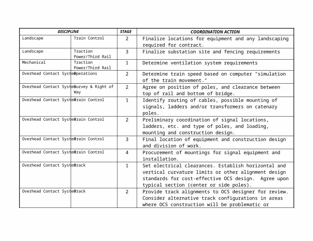
DISCIPLINE STAGE COORDINATION ACTIONLandscape Train Control 2 Finalize locations for equipment and any landscaping
required for contract.Landscape Traction
Power/Third Rail3 Finalize substation site and fencing requirements
Mechanical Traction Power/Third Rail
1 Determine ventilation system requirements
Overhead Contact SystemOperations 2 Determine train speed based on computer "simulation of the train movement."
Overhead Contact SystemSurvey & Right ofWay
2 Agree on position of poles, and clearance between top of rail and bottom of bridge.
Overhead Contact SystemTrain Control 1 Identify routing of cables, possible mounting of signals, ladders and/or transformers on catenary poles.
Overhead Contact SystemTrain Control 2 Preliminary coordination of signal locations, ladders, etc. and type of poles, and loading, mounting and construction design.
Overhead Contact SystemTrain Control 3 Final location of equipment and construction design and division of work.
Overhead Contact SystemTrain Control 4 Procurement of mountings for signal equipment and installation.
Overhead Contact SystemTrack 1 Set electrical clearances. Establish horizontal and vertical curvature limits or other alignment design standards for cost-effective OCS design. Agree upontypical section (center or side poles).
Overhead Contact SystemTrack 2 Provide track alignments to OCS designer for review.Consider alternative track configurations in areas where OCS construction will be problematic or

DISCIPLINE STAGE COORDINATION ACTIONexpensive.
Overhead Contact SystemTrack 3 Communicate track alignment changes promptly to OCS designer.
Overhead Contact SystemTraction Power/Third Rail
1 Determine traction system distribution network
Overhead Contact SystemTraction Power/Third Rail
2 Develop traction system distribution network
Overhead Contact SystemTraction Power/Third Rail
3 Finalize traction system distribution network
Overhead Contact SystemTraction Power/Third Rail
4 Shop drawing review and construction services
Overhead Contact SystemTraction Power/Third Rail
1 Agree on wire sizes & material.
Overhead Contact SystemTraction Power/Third Rail
2 Agree on feeder pole design; location of switch heater, surge arrester, feeder pole and sectionalizing diagram.
Overhead Contact SystemTraction Power/Third Rail
5 Test entire traction power system.
Overhead Contact SystemTraffic 1 Wire sizes and material agreed.Overhead Contact SystemTraffic 2 Feeder Pole Design; Location of switch heater, surge
arrester, feeder pole and sectionalizing diagram agreed.
Overhead Contact SystemTraffic 5 Testing of the entire traction power system.Overhead Contact SystemUtilities 2 Confirm position of poles relative to underground
services.(based on location of underground facility& utility company.)
Overhead Contact SystemVehicle 1 Establish basic concept (O/H versus Third Rail). Establish vehicle concept for dynamic envelope and

DISCIPLINE STAGE COORDINATION ACTIONlocation of current collector. (If O/H continue, if3rd rail, see TP)
Overhead Contact SystemVehicle 2 Establish catenary height, stagger, and change of height. Establish clearance diagram, pantograph location and height data.
Overhead Contact SystemVehicle 3 Refine catenary height, stagger, change of height. Refine clearance diagram, pantograph location and height data.
Overhead Contact SystemVehicle 5 Perform joint overhead contact/vehicle testing.Operations Structures 1 Establish dynamic clearance envelope for planned
equipment and service.Operations Train Control 1 Determine types of systems to be considered and most
efficient and cost effective.Operations Train Control 2 Determine what types of unusual operational movement
maybe required and finalize signal design.Operations Track 1 Determine maximum train speeds and typical and
maximum train lengths. Establish turnout speeds, which conform to signal aspects. Establish whether other users of line (e.g. freight railroad) will dictate modification of turnout standards.
Operations Track 3 If full-build track configuration cannot be built due to funding or physical constraints, revise trackand operating plans to be compatible. Develop construction staging sequence that provides for maintenance and protection of rail traffic, if applicable.

DISCIPLINE STAGE COORDINATION ACTIONOperations Traction
Power/Third Rail1 Establish proposed operating schedule for simulation
Operations Traction Power/Third Rail
2 Develop operating scenarios for train simulation process.
Operations Traction Power/Third Rail
3 Finalize operating schedule for train simulation performance.
Operations Vehicle 1 Establish basic operations and maintenance concept, size of fleet, number of seats/standees, and servicefrequency.
Operations Vehicle 2 Establish maintenance, shop, maintenance equipment, and MOW equipment concepts. Establish vehicle data and performance, location of equipment, Operator's cab, and controls. Establish available MOW equipment performance and data.
Survey & Right of Way Train Control 1 Determine right of way with track alignment and signal equipment and bungalow locations.
Survey & Right of Way Traction Power/Third Rail
2 Same as RWTC1, plus finalize any land acquisition ifrequired.
Survey & Right of Way Traction Power/Third Rail
1 Determine cable, conduit, & stub-up criteria
Survey & Right of Way Traction Power/Third Rail
2 Develop cable, conduit, & stub-up criteria
Survey & Right of Way Traction Power/Third Rail
3 Finalize cable, conduit, & stub-up criteria
Structures Overhead Contact System
2 Agree on dimensions of pole & foundation etc. Integrate pole positions with elevated structures etc.
Structures Train Control 1 Determine if any special structures for signal

DISCIPLINE STAGE COORDINATION ACTIONequipment are required, foundation, poles or bungalow supports.
Structures Train Control 2 Coordinate structural and signal requirements and locations.
Structures Train Control 3 Finalize structural and signal requirements and installations.
Structures Track 1 Establish track construction type on structures and associated size/loading requirements.
Structures Track 2 If welded rail is used, determine how longitudinal rail forces are handled.
Structures Track 3 Coordinate specs and drawings at track structure/bridge structure interface.
Structures Vehicle 1 Establish dynamic clearance envelope for planned equipment and service. Establish weight of vehicle,location of trucks, and wheelbase.
Safety & Systems Assurance
Train Control 1 Determine any local or national safety codes that may apply to signal rooms or bungalows.
Safety & Systems Assurance
Train Control 2 Determine any specialized equipment that may be required or conditions to consider.
Safety & Systems Assurance
Traction Power/Third Rail
3 Finalize equipment to be installed.
Safety & Systems Assurance
Traction Power/Third Rail
1 Determine blue light & electrical safety requirements
Safety & Systems Assurance
Traction Power/Third Rail
2 Develop blue light & electrical safety requirements
Safety & Systems Assurance
Vehicle 1 Establish basic safety requirements.

DISCIPLINE STAGE COORDINATION ACTIONSafety & Systems Assurance
Vehicle 2 Establish requirements for safety, signs, ADA, handholds, NFPA, Quality. Establish vehicle data, quality requirements, materials and workmanship requirements.
Safety & Systems Assurance
Vehicle 5 Perform joint Safety & System Assurance/ Vehicle testing.
Stations Train Control 1 Determine any signals, cable runs and equipment rooms that will be installed in station areas.
Stations Train Control 2 Establish locations of equipment, conduits, cable troughs, etc., to be installed.
Stations Train Control 3 Finalize all locations of signals, equipment housings, cable troughs and conduits.
Stations Traction Power/Third Rail
2 Coordinate electrical equipment with power source
Stations Traction Power/Third Rail
3 Finalize routing & location of traction power equipment
Stations Vehicle 1 Establish basic station design concept.Stations Vehicle 2 Establish platform height above top of rail,
platform lateral distance from rail, canopy location. Establish vehicle width, vehicle door threshold height, maximum distance between front andrear end doors of a maximum length train, and maximum length of a train
Train Control Fire Protection /Intrusion Alarm
1 Determine train control requirements for fire detection, protection, and intrusion.
Train Control Fire 2 Develop train control interface and space

DISCIPLINE STAGE COORDINATION ACTIONProtection /Intrusion Alarm
requirements for fire detection, protection, and intrusion.
Train Control Fire Protection /Intrusion Alarm
3 Finalize train control requirements for detection, protection, and intrusion.
Train Control Fire Protection /Intrusion Alarm
4 Interface with contractor for the fire detection, protection and intrusion.
Train Control Fire Protection /Intrusion Alarm
5 Test the fire detection, protection, and intrusion systems with train control.
Train Control Track 2 Verify that proposed track configurations can be signaled and interlocked. Determine mounting plan for track-mounted signal equipment (e.g. switch machines, trip stops) especially if concrete ties ordirect fixation is used.
Train Control Track 3 Establish insulated joint locations and record on track plans. Jointly agree on construction staging and temporary signal protection to support ongoing operations.
Train Control Traction Power/Third Rail
1 Establish speed zones for simulation and bond locations
Train Control Traction Power/Third Rail
2 Develop speed zones for simulation and bond locations
Train Control Vehicle 1 Establish basic train control concept. Establish train control equipment location concept on vehicle.
Train Control Vehicle 2 Establish train control performance data. Establishsystem environmental data.

DISCIPLINE STAGE COORDINATION ACTIONTrain Control Vehicle 3 Establish train control installation drawings with
size and location of equipment. Perform a review ofvehicle interface drawings. Prepare functional train control test procedures. Establish space allocation for train control equipment. Review interface drawings.
Train Control Vehicle 5 Perform joint vehicle/train control testing.Track Overhead Contact
System2 Establish position of poles (based on track
alignment & station locations.)Track Traction
Power/Third Rail1 Determine horizontal. & vertical. Track alignment &
stations Track Traction
Power/Third Rail2 Develop horizontal & vertical track alignment &
stations Track Traction
Power/Third Rail3 Finalize horizontal & vertical track alignment &
stations Track Vehicle 1 Establish general rolling stock technology and configuration
so that approximate trackwork spatial needs can be determined.Track Vehicle 2 Establish car wheel size, profile and gauge so that
special trackwork (switch points, guard rails, frogs, restraining rails, etc.) can be designed. Establish car weight, leading dimensions, and minimum turning radii so track design can determined.
Traction Power/Third Rail
Utilities 1 Determine utility needs & conflicts
Traction Power/Third Rail
Utilities 2 Develop utility interfaces & minimize conflicts

DISCIPLINE STAGE COORDINATION ACTIONTraction Power/Third Rail
Utilities 3 Finalize utility interface
Traction Power/Third Rail
Vehicle 1 Establish basic vehicle traction power concept, and basic operating criteria for train simulation. Establish basic traction power concept
Traction Power/Third Rail
Vehicle 2 Establish line voltage and tolerance, location of third rail. Establish vehicle load requirements, frequency of service, regenerative braking, third rail shoe data and location. Establish vehicle-operating parameters for train simulation.
Traction Power/Third Rail
Vehicle 3 Review vehicle/traction power interfaces drawings, and test procedures. Refine vehicle-operating criteria for train simulation performance.
Traction Power/Third Rail
Vehicle 5 Perform joint vehicle/traction power testing.
9. Conclusions and Recommendations
In conclusion, a “Guidelines” document such as this is imperativeand a necessity for PB’s well being. In a competitive market, itis our duty to search for better ways to perform our work while maintaining the highest quality standards, and lowest costs to both PB and our clients.
The results of our efforts include a host of critical informationfor use by the project manager and his/her staff as follows:· It provides them with the disciplines necessary to successfully
complete their projects. · It provides for the interface between different disciplines,
and the direction of information flow between them.· It indicates the criticality/necessity of the information
transferred between disciplines, and the stage at which any twoneed to coordinate and interface their efforts in order to successfully complete the work required by their tasks.
It is imperative to realize that the guidelines presented herein are generic in nature, and require the review of the project management team on project-by-project bases
The intention is to have this document available to project managers at the proposal stage so they can have a clear idea of the systems requirements in designing and commissioning a rail transit system.
This information can prove to be invaluable to the project manager and his/her task leaders. With that in mind, the projectmanager will:
· Know which disciplines he/she needs to work on his/her project and thus, properly staff the project at different stages.
· Have a simple Summary Interface Matrix that he/she can follow to maintain project schedule and helps know when certain tasks must commence.
· Be able to assist his/her task leaders in staffing their tasks at the proper project stage

· Have better-coordinated interfaces between the various disciplines which result in more successful project leadership.
· Have more control over the project schedule and thus, its budget
· Have more organized work distribution that results in a work atmosphere with less stress.
· Have a satisfied client.
It is recommended that this document be reviewed and updated regularly to ensure the incorporation of necessary changes and that each project is dealt with based on its own circumstances. This will ensure the value of the document and its contribution to PB’s quality philosophy. After all, a good quality program saves time, and money to PB and ultimately to the client and the taxpayers.