An Integrated Forecasting and Regularization Framework for Light Rail Transit Systems
Upload
khangminh22Category
view
5download
0
®
TWINCO MFG. CO., INC.
30 Commerce Dr., Hauppauge, NY 11788-3904
Ph 800-854-2338 Fx 631-231-0314
http://www.twincomfg.com
Certificate # 2380/00 1 of 1
PDS 0515-17 E
®
RAIL & TRANSIT
PRODUCTS

®
TABLE OF CONTENTS
TWINCO MFG. CO., INC.
30 Commerce Dr., Hauppauge, NY 11788-3904
Ph 800-854-2338 Fx 631-231-0314
http://www.twincomfg.com
Certificate # 2380/00 1 of 9
SLS 0512-08 A
TOPIC SECTION
Introduction A
Automatic Train Stop B
Impedance Bonds C
TMC-1 Switch Machine D
Custom Wayside Equipment E
Signal Wiring Projects F
AREMA (AAR) Hardware G
Vital Relays and Contacts H
Identification Products I

SECTION A
Introduction
TWINCO MFG. CO., INC. Ph 800-854-2338 Fx 631-231-0314 http://www.twincomfg.com
®
2 of 9
SLS 0512-08 A

®
COMPANY PROFILE
TWINCO MFG. CO., INC.
30 Commerce Dr., Hauppauge, NY 11788-3904
Ph 800-854-2338 Fx 631-231-0314 http://www.twincomfg.com
Certificate # 2380/00 1 of 2
PDS 0419-08 A
TWINCO was started in 1957 by John H. Schatz in the basement of his house for the purpose of making tools & dies for various industries. The company was incorporated in 1965 as Twinco Manufacturing Company, Inc. Until 1984 Transcontrol Corporation was TWINCO’s largest customer. Transcontrol produced vital relays and signal systems for the Railroad and Transit Industry. During this time TWINCO’s capabilities grew to a point where we manufactured most all of the components Transcontrol required to assemble a product. TWINCO has grown over the years because of our commitment to the customer. We continually invest in the best and most modern, facilities and equipment to enable our employees to be as productive as possible. TWINCO is primarily engaged in production of electrical and electro-mechanical products for the Railroad & Transit Industry. In 1985 TWINCO received approval of its first major product: a Train Stop for the New York City Transit Authority. As we have grown so has our products. The following is a brief list of some of our products to date:
AAR Hardware Vital Relays & Components Replacement Contacts Laminated Tags & Wire Markers Train Stops & Trip Layouts Impedance Bonds Rectifiers Pre-wired Signal Instrument Huts & Cases Local Control & Indication Panels Switch Heater Controls Specialized Wayside and Car Equipment Manufacturing Engineering support for special projects

The company activities are conducted in a modern 50,000 square foot freestanding building located in the Hauppauge Industrial Park. We have excellent facilities and equipment, and perform and control as much of the manufacturing process as possible. All production is undertaken at this location with the exception of raw material processes such as casting and a few specialized processes. We are routinely engaged in the following manufacturing activities: Engineering & Design Assembly & Wiring Metal Stamping Plastic Molding CNC Machining Tool, Die & Mold Making All manufacturing activities are under the direct control of the President and the Supervisors who with their personnel has broad experience and expertise in the manufacture and function of our products. Reasonable access will be available to customer’s representatives to verify that the quality system described herein is effective.
TWINCO MFG. CO., INC. http://www.twincomfg.com Ph 800-854-2338 Fx 631-231-0314
®
2 of 2
PDS 0419-08 A

®
TWINCO MFG. CO., INC.
30 Commerce Dr., Hauppauge, NY 11788-3904
Ph 800-854-2338 Fx 631-231-0314 http://www.twincomfg.com
Certificate # 2380/00 1 of 1
ADV 0512-08 A
Company Mission Statement
Twinco’s mission is to manufacture and deliver high quality and competitively priced products that fulfill our customers requirements. We do this by adhering to the following philosophies: Customer: We work to satisfy the customer. If we don’t take care of the
customer, somebody else will. Quality: We will perform and control as much of the manufacturing
process as possible. True quality is designed, manufactured and controlled, not merely inspected, into a product.
Productivity: We invest in the best and most modern facilities and
equipment to enable our employees to be as productive as possible.
Improvement: We believe in the process of continuous improvement. It is
the relentless quest for a better way, the challenge of higher and higher quality craftsmanship. It is not perfection but rather the pursuit of it.
Teamwork: We strive to work together as a spirited team in an
environment of trust, cooperation, mutual respect, understanding and support of the needs of others.
Ethics: We strive to maintain the highest standards of honesty and
integrity in all facets of our activities.

SECTION B
Automatic Train Stop
TWINCO MFG. CO., INC. Ph 800-854-2338 Fx 631-231-0314 http://www.twincomfg.com
®
3 of 9
SLS 0512-08 A

®
PS-1 AUTOMATIC TRAIN STOP
TWINCO MFG. CO., INC.
30 Commerce Dr., Hauppauge, NY 11788-3904
Ph 800-854-2338 Fx 631-231-0314 http://www.twincomfg.com
Certificate # 2380/00 1 of 4
PDS 2181-11 B
P/N 069-2181-3-0
• Ensure Compliance of Restrictive Signals • Variety of Layouts Available • Approved by : New York City Transit Chicago Transit Authority Massachusetts Bay Transportation Authority

TWINCO PS-1 Automatic Train Stop
The Train Stop is used in conjunction with wayside signals in rapid transit systems to ensure observance of, and compliance with, restrictive indications. Failure to comply with the rules regarding such indications results in activation of the train's braking system. Operation is completely automatic, entirely independent of any action on the part of the motorman. The system functions by mechanical contact between a wayside trip arm and a trip cock lever on the underside of the train. The wayside trip arm is lowered when the signal is clear and is raised when the signal is at “stop” or “danger”. In the raised position, the trip arm will engage the trip cock lever of any train attempting to pass the signal, thus bringing it to a stop.
The Train Stop mechanism, housed in a cast-iron case, consists of a combined motor and gear housing, circuit controller with driving arm, compression return spring and sector gear. The general arrangement of these components is shown above. The machine by itself measures 9-7/8" high by 21-13/16" wide by 26-3/8" long and weighs approximately 250 pounds
Figure 1 Train Stop Mechanism
TWINCO MFG. CO., INC. http://www.twincomfg.com Ph 800-854-2338 Fx 631-231-0314
®
2 of 4
PDS 2181-11 B

Shown in Figure 2 below is a plan view of the Train Stop installed in a typical layout. It is mounted on two ties and includes the mechanism case. The trip arm assembly is mounted on the rocker shaft. One end of the rocker shaft is attached to the output shaft of the Train Stop mechanism. The other end is supported by an adjustable bearing strap. A trip hook assembly is mounted on top of the bearing strap and is used to hook or hold down the trip arm when required. Figure 3 on the following page shows a side view of the trip arm in the tripping position. The trip arm is driven under electric power to the clear position, ½ inch below the top of the running rail. It is returned to the tripping position, 2-1/2 inches minimum and 2-3/4 inches maximum, above the top of the rail by a compression return spring. When electric power is interrupted, the trip arm automatically assumes the tripping position, giving fail-safe operation. The Train Stop is in the tripping (trip arm up) position, as shown in figure 3, when the unit is de-energized. This position, when the trip arm is up is also referred to as the stop or danger position. The trip arm is driven to a clear position when energized. The clear position is a ½" below the top of the running rail to the top of the trip arm head. The unit is energized when the wayside signaling system provides 1 1 0 V AC a t 6 0 H z . W h e n de-energized, the trip arm is returned to the stop position above the running rail, by the compression return spring. The Train Stop mechanism will cause the trip arm to automatically assume the stop position if the power is interrupted. Movement of the unit’s output shaft is caused by the operation of an induction type motor and gear housing, acting on a sector gear attached to the output shaft. This counter-clockwise rotation of the sector gear also causes compression of the return spring. The output from the special 1/8 Hp single phase motor is changed through a series of three gears arranged in a cast iron gear box. A ratchet feature is incorporated in this gear arrangement, to protect the drive train when the rotation of the motor and gear housing is reversed by the main units’ compression spring.
Figure 2 Typical Layout of Train Stop
TWINCO MFG. CO., INC. Ph 800-854-2338 Fx 631-231-0314 http://www.twincomfg.com
®
3 of 4
PDS 2181-11 B

In order for the Train Stop to remain in the clear position, enough power must be continually supplied to the motor, to overcome the force of the compressed state of the return spring. Maximum drive down current at 110 VAC 60 Hz is 1.5 Amp. Maximum holding current is 0.75 Amp. The Train Stop will leave the clear position when the voltage is reduced to 60 volts or less. Twinco also manufactures a Train Stop mechanism which operates on 110 VAC at 25 Hz (Twinco P/N 069-2181-4-0). Operation is the same as the 60 Hz unit except that a special 25 Hz motor is used with a 25 mfd motor run capacitor and a 40 mfd holding capacitor.
Figure 3 Trip Arm in Tripping Position
• Part Numbers referenced above are for mechanism only. • Contact Factory for various layout requirements and drawings. • Request Twinco Service Manual for more detailed information.
TWINCO MFG. CO., INC. http://www.twincomfg.com Ph 800-854-2338 Fx 631-231-0314
®
4 of 4
PDS 2181-11 B

®
TRAIN STOP MOTOR & GEAR HOUSING
TWINCO MFG. CO., INC.
30 Commerce Dr., Hauppauge, NY 11788-3904
Ph 800-854-2338 Fx 631-231-0314 http://www.twincomfg.com
Certificate # 2380/00 1 of 2
PDS 2081-14 C
P/N 000-2081-3-0*
Water Resistant Maintenance Free Oil Free Motor & gear box integrated into one unit Compatible with Twinco, GRS, & US&S Train Stops Designed, Manufactured, & Assembled by Twinco

PRODUCT DETAILS
Unit Design Information Maximum drive down current at 110 VAC is 1.5 Amps Maximum holding current at 110 VAC is 0.75 Amps Final Output RPM 16 Renewable motor cable Viton & Buna-N O-rings used for water tight seal Unit is sealed, no user serviceable parts inside Unit weight 66 lbs.
Motor Design Information
Completely Encapsulated Stator Winding High Temperature winding insulation 3000 VAC insulation withstand test to ground for one minute
1000 MΩ @ 1000 VDC Insulation Resistance
Gear Section Design Information Case Hardened Gears Overrunning clutch permanently lubricated NSK brand, premium grade, double shielded ball bearings throughout Hardened steel output shaft Gear Ratio 45:1
*Motor available in both 60 Hz (000-2081-3-0) & 25 Hz (000-2081-4-0) Versions
TWINCO MFG. CO., INC. http://www.twincomfg.com Ph 800-854-2338 Fx 631-231-0314
®
2 of 2
PDS 2081-14 C

SECTION C
Impedance Bonds
TWINCO MFG. CO., INC. Ph 800-854-2338 Fx 631-231-0314 http://www.twincomfg.com
®
4 of 9
SLS 0512-08 A

®
IMPEDANCE BOND
TWINCO MFG. CO., INC.
30 Commerce Dr., Hauppauge, NY 11788-3904
Ph 800-854-2338 Fx 631-231-0314
http://www.twincomfg.com
1 of 4
PDS 1446-17 D
• Permits Overlay of Signal Currents in DC Territories
• High Impedance, Wide Frequency Range • Meets AAR Specifications • Special Models Available

TWINCO MFG. CO., INC.
http://www.twincomfg.com Ph 800-854-2338 Fx 631-231-0314 ®
2 of 4
PDS 1446-17 D
INTRODUCTION
The Twinco Impedance Bond is a rugged, high quality, self-contained product, designed for electrified territories that utilize standard insulated joint isolation of signaling currents. It meets all applicable AAR specifications. Hundreds of Style ST-1 2500 AMP units have been in service with the Long Island Railroad (LIRR) since 1992. All components are contained in a low profile heavy duty cast iron housing, designed for mounting between the rails and across two adjacent ties. A heavy duty ramped, and diamond patterned slip resistant, removable cover is provided for ease of installation, inspection, and weather resistance. The bonds are filled with oil or petrolatum to provide moisture and corrosion protection and to aid in cooling of the bond. All hardware is either stainless steel or zinc plated for corrosion resistance. Twinco offers a variety of impedance bonds to suit numerous applications. In addition, customized models can be developed for special situations. For over 50 years Twinco has been manufacturing solutions for the needs of many rail/ transit customers. Please contact your nearest Twinco sales representative, or the factory directly, to discuss your requirements.

TWINCO MFG. CO., INC.
Ph 800-854-2338 Fx 631-231-0314 http://www.twincomfg.com ®
3 of 4
PDS 1446-17 D
THEORY OF OPERATION The Style ST & SZ Impedance Bonds are designed to allow return DC propulsion current to flow around insulated rail joints without interfering with the functioning of adjacent track circuits. A tuned circuit can be incorporated to enhance the impedance characteristics of the Bond for AC track circuits that are operated at the resonant frequency of this circuit. A Bond is typically installed on both sides of the insulated joints (see figure 1) and connected together through the units center tap. Signal and propulsion cables are connected to the taps on either side of the Bond. Signal currents transmitted on the tracks are effectively blocked, rail to rail, by the inductive impedance of the bond coils. Propulsion currents, however, pass through the coils in a manner that offers little impedance to the propulsion current. Signal current passes through the windings in series, producing an unopposed magnetic flux and thus the required impedance.

TWINCO MFG. CO., INC.
http://www.twincomfg.com Ph 800-854-2338 Fx 631-231-0314 ®
4 of 4
PDS 1446-17 D
• Standard part numbers listed above. Contact factory for specific requirements
• Contact factory for mounting & cable connection hardware.
• Request Twinco Service Manual for more detailed information

TWINCO MFG. CO., INC.
Ph 800-854-2338 Fx 631-231-0314 http://www.twincomfg.com ®
5 of 9
SLS 0512-08 A
SECTION D
TMC-1
Switch
Machine

®
TWINCO MFG. CO., INC.
30 Commerce Dr., Hauppauge, NY 11788-3904
Ph 800-854-2338 Fx 631-231-0314 http://www.twincomfg.com
TMC-1 WR Switch Machine
Submersible Design
Compact Mechanical Switch & Lock Movement
Low Height Profile
Wayside or Mid-Track Mounting
Dual Switch Point Indication Available
Competitively Priced
Made in the U.S.A.
Certificate # 2380/00 PDS 4623-16 B

TWINCO MFG. CO., INC. http://www.twincomfg.com Ph 800-854-2338 Fx 631-231-0314
®
Introduction The Twinco TMC-1 WR Submersible Switch Machine was conceived, designed and
manufactured to address the most demanding requirements of todays rail and transit operations.
Chief among these needs is resiliency to uncontrolled climatic events such as flooding and
extreme temperature variations. Controlling intrusion of all phases of water, be it gas, liquid or
solid (i.e. moisture, rain or snow) into the machine, is essential to maintain serviceability under
these conditions. To accomplish this we have employed proven sealing technologies used in
other industries to control all electrical and mechanical inputs and outputs to the machine. In
addition to the machine as a whole being rated IP68, all interior electrical connections and
components are sealed to a minimum of IP66 to provide safety and redundancy.
Reliability and serviceability under normal conditions is also critical in todays economic
environment. Simplicity and modularity of a design are fundamental hallmarks of any well
conceived machine. To this end we have created an electrical-mechanical switch machine with
the fewest parts of any machine on the market while employing as many modular components as
possible. This compact and low profile height switch machine can be readily adapted to customer
specific requirements such as trailable vs. non-trailable or between the gauge or beside the rail.
Most importantly, quality and competitive pricing is built in by design and execution of
manufacturing by a company that has been serving our industry for over 50 years. Our skilled
team members use premium materials, the latest CAD design software and manufacturing
technologies such as:
fiber-optic laser cutting
CNC synchronized hydraulic bending
Robotic welding
Laser probed CNC machining
3D printing
This allows us to custom tailor the TMC-1 to any customer specific needs, and do it better and
faster than others.

TWINCO MFG. CO., INC. Ph 800-854-2338 Fx 631-231-0314 http://www.twincomfg.com
®
Submersible Turnout Test Bed
Cycle testing at Twinco allows us to continuously evaluate
and improve our product offering.

TWINCO MFG. CO., INC. Ph 800-854-2338 Fx 631-231-0314 http://www.twincomfg.com
®
Typical Wayside Layout

TWINCO MFG. CO., INC. Ph 800-854-2338 Fx 631-231-0314 http://www.twincomfg.com
®
Internal Arrangement of Components (Shown with Cover removed)

TWINCO MFG. CO., INC. http://www.twincomfg.com Ph 800-854-2338 Fx 631-231-0314
®
Technical Data
The data listed below are the standard data for the TMC-1 WR Switch Machine. Order-specific
modifications are included in the documents of the order. Specific (measured) data of the switch
machine are on the inspection label of each machine.
Overall system
Operating conditions
Electrical connection data:
Note:
For reliability and serviceability purposes it is recommended that all machine electrical control
configuration components be mounted in an enclosure (IP68) separate from the machine.
Designation of the machine: TMC-1
For switches: Track gauge 56.5 inches (1432 mm)
Installation position: Outside or Inside between switch points:
Principal dimensions (L x W x H): 47 x 20.25 x 7.63 inches
Weight: 600 lbs.
Travel: 6-5/16” Max.
Switching time: < 2 s
Protection class: IP 68
Noise level (LPA) < 70 dB (A)
Temperature: - 40°F* to + 185 °F * Internal heater required
Nominal motor voltage: 110 VDC or AC Rated current: < 8 A
Motor protection class: IP 68
Control voltage: As specified by Customer
Cable resistance: < 30 Ohm per strand
Hi-pot Voltage: 2,500 V, 60 Hz, 1 s

TWINCO MFG. CO., INC.
Ph 800-854-2338 Fx 631-231-0314 http://www.twincomfg.com ®
6 of 9
SLS 0512-08 A
SECTION E
Custom
Wayside
Equipment

®
CUSTOM ENCLOSURES
TWINCO MFG. CO., INC. 30 Commerce Dr., Hauppauge, NY 11788-3904
Ph 800-854-2338 Fx 631-231-0314 http://www.twincomfg.com
Certificate # 2380/00 1 of 1
Custom Built to Customers Specifications
Sizes Range from Small Junction
Box Enclosures to Large Cabinets Stainless, Aluminum, Steel and
Other Construction Materials Offered
Engineering Designing Services
Available Highest Level of Quality and
Workmanship Flexible Manufacturing Facility
Geared to Custom Production Runs
Offer Wiring, Assembly
and Other Operational Services

®
LED WAYSIDE LIGHT
TWINCO MFG. CO., INC.
30 Commerce Dr., Hauppauge, NY 11788-3904
Ph 800-854-2338 Fx 631-231-0314
http://www.twincomfg.com
Certificate # 2380/00 1 of 4
PDS 2130-09 B
P/N 069-2616-1-0
Switch Point Light Configuration
• Provides reliable lighting for maintenance, service and emergency personnel.
• Features include: • Solid state design • Low heat generation • Low power consumption • 100,000 hour life LED’s • Vandal and impact resistant • Suitable for wet and hazardous
locations • Rugged aluminum housing • No re-strike time
• 115VAC operation.
• Consult factory for various configurations.
• Replaces Holophane Small Predator Series Light

TWINCO MFG. CO., INC.
http://www.twincomfg.com Ph 800-854-2338 Fx 631-231-0314 ®
2 of 4
PDS 2130-09 B
High vibration pole mount-ed configuration
Wall or ceiling mounted configuration

TWINCO MFG. CO., INC.
Ph 800-854-2338 Fx 631-231-0314 http://www.twincomfg.com ®
3 of 4
PDS 2310-09 B
LED DIRECTIONAL ARROW LIGHT

TWINCO MFG. CO., INC.
http://www.twincomfg.com Ph 800-854-2338 Fx 631-231-0314 ®
4 of 4
PDS 2130-09 B
• Provides emergency lighting for maintenance and service personnel.
• Lamp and socket are shock and
vibration mounted to reduce the level of vibration transmitted from the right-of-way.
• 115VAC operation.
• 5 & 6 foot height configurations available.
• NYCT Approved Design
P/N 069-2717-1-0
METAL HALIDE HID SWITCH POINT LIGHT

®
ST LED SIGN
TWINCO MFG. CO., INC.
30 Commerce Dr., Hauppauge, NY 11788-3904
Ph 800-854-2338 Fx 631-231-0314 http://www.twincomfg.com
Certificate # 2380/00 1 of 3
PDS 2110-09 A
• Utilizes LED Technology for: - Long Life - Reduced Maintenance Costs. - Low Power Consumption. • Water Resistant Aluminum Housing • Rear Mounting Bracket for 3” Diameter Pole Provided • Other Custom Arrangements
Available, Consult Factory • Operating Voltage - AC 12-15 V, 60 HZ - DC 12-15 V

General Specifications
Weight 25 lbs Power Consumption 5 watts at 12V
TWINCO MFG. CO., INC. http://www.twincomfg.com Ph 800-854-2338 Fx 631-231-0314
®
2 of 3
PDS 2110-09 A

TWINCO PART NUMBER DESCRIPTION
069-2110-1-0 ST-10 MPH LED SIGN
069-2110-2-0 ST-15 MPH LED SIGN
069-2110-3-0 ST-20 MPH LED SIGN
069-2110-4-0 ST-25 MPH LED SIGN
069-2110-5-0 ST-30 MPH LED SIGN
069-2110-6-0 LED SIGN “D”
069-2110-7-0 LED SIGN “S”
069-2110-8-0 ST-35 MPH LED SIGN
ST LED SIGNS
TWINCO MFG. CO., INC. Ph 800-854-2338 Fx 631-231-0314 http://www.twincomfg.com
®
3 of 3
PDS 2110-09 A

®
STATION TIME WHITE LED
TWINCO MFG. CO., INC.
30 Commerce Dr., Hauppauge, NY 11788-3904
Ph 800-854-2338 Fx 631-231-0314 http://www.twincomfg.com
Certificate # 2380/00 1 of 2
PDS 2650-01 A
P/N 069-2650-1-0
• Other Custom Arrangements Available, Consult Factory
• Water Resistant Aluminum Housing Compatible with TWINCO's LED Speed Sign
• Operates from 12VAC/DC, 25/60Hz
• Utilizes LED Technology for:
Long Life, Reduced Maintenance Costs.
Low Power Consumption.
• 5-1/4” Diameter Clear Lens meets AAR Standards
• Provided with Rear Mounting Bracket for 3” Diameter Pole

General Specifications
Weight 10 lbs
Power Consumption 5 watts at 12V
TWINCO MFG. CO., INC. http://www.twincomfg.com Ph 800-854-2338 Fx 631-231-0314
®
2 of 2
PDS 2650-01 A

®
RAIL SIGNAL BOND
TWINCO MFG. CO., INC.
30 Commerce Dr., Hauppauge, NY 11788-3904
Ph 800-854-2338 Fx 631-231-0314 http://www.twincomfg.com
Certificate # 2380/00 1 of 2
PDS 2738-09 C
P/N 000-2738-1-0
• Provides a reliable electrical connection to rail • Quick and easy to install • Fixture is both easily removable and reusable • Accommodates all rail sizes • Preserves rail integrity

ORDERING INFORMATION
TWINCO PART NUMBER DESCRIPTION
000-2738-1-0 RAIL SIGNAL BOND KIT (INCLUDES ITEMS SHOWN IN FIGURE 1 AND FIGURE 2)
000-2851-1-0 CLAMP ASSEMBLY (INCLUDES ITEMS SHOWN IN FIGURE 1)
000-2742-1-0 WIRE CONTACT JAW (INCLUDES ITEMS SHOWN IN FIGURE 2)
FIGURE 1 FIGURE 2
GENERAL DESCRIPTION
Twinco Rail Signal Bonds features a spring loaded Clamp Assembly (Figure 1),
which is used to mechanically press a Wire Contact Jaw (Figure 2) into the rail
flange. This process ensures a constant electrical connection is maintained over
a wide range of temperature and vibration conditions. This results in an
unchanging electrical resistance of the bond for as long as it is applied.
TWINCO MFG. CO., INC. http://www.twincomfg.com Ph 800-854-2338 Fx 631-231-0314
®
2 of 2
PDS 2738-09 C

®
CONSTANT POTENTIAL RECTIFIERS
TWINCO MFG. CO., INC.
30 Commerce Dr., Hauppauge, NY 11788-3904
Ph 800-854-2338 Fx 631-231-0314 http://www.twincomfg.com
Certificate # 2380/00 1 of 2
PDS 0995-09 B
• Ideal for track line applications • High efficiency • Housing designed to keep dirt & debris
away from transformer & diode rectifier bridge
• Intended for use with DC equipment such as relay or other devices requiring a constant voltage source
• NYCT approved

TWINCO Constant Potential Rectifiers
Twinco Model
AC Input DC Output
Volts Hz Volts Amps
PS-2 110 60/100 16.0 0.30 069-0995-1-0
PS-3* 55 25 16.0 0.30 069-0995-2-0
PS-4 110 60/100 13.5 4.40 069-0995-4-0
Twinco P/N
PS-5 115 60/100 12.0 0.30 069-0995-5-0
PS-8 55 25 12.0 0.50 069-2252-1-0
* Model PS-3 is the same dimensions as the model PS-2 shown below.
TWINCO MFG. CO., INC. http://www.twincomfg.com Ph 800-854-2338 Fx 631-231-0314
®
2 of 2 PDS 0995-09 B

®
3rd RAIL TAP FUSE BOX
TWINCO MFG. CO., INC.
30 Commerce Dr., Hauppauge, NY 11788-3904
Ph 800-854-2338 Fx 631-231-0314 http://www.twincomfg.com
Certificate # 2380/00 1 of 1
PDS 1106-03-B
TWINCO Fuse Box Styles Twinco Part Number Box Capacity Box Size (in.)
069-1170-1-0 30 Amp 4-1/4 x 8-1/4 x 14
069-1170-2-0 60 Amp 4-1/4 x 8-1/4 x 14
069-1106-1-0 100 Amp 4-1/4 x 8-1/4 x 15
069-1106-2-0 200 Amp 4-1/4 x 8-1/4 x 15
• Manufactured from low smoke Glastic 1130 • Tongue and groove construction • Fuse mounted in cover allows circuit to open when cover is
removed • Consult factory for various mounting bracket arrangements

®
TYPE S1 TRANSFORMER
TWINCO MFG. CO., INC.
30 Commerce Dr., Hauppauge, NY 11788-3904
Ph 800-854-2338 Fx 631-231-0314 http://www.twincomfg.com
Certificate # 2380/00 1 of 2
PDS 2036-04 A
P/N 067-2036-1-0
Design Features: • Small and compact • Mount in housing of most signal units and
switch machines • Can be wall or rack mounted Applications include: • lighting signal lamps • panel lamps • feeding clearance track circuits. Connections are made to No. 10-32 terminal screws which are securely fastened to an interface board.

Primary Volts Secondary Volts Secondary Amperes
Total Volts/ Amps
Part Number
115 (5-100-10) 12.5 (0.5-9-1-1-1) 4.8 60 067-2036-1-0
Length: 4.875” Height: 3.75” Width: 2.75”
TYPE S1 TRANSFORMER
TWINCO MFG. CO., INC. http://www.twincomfg.com Ph 800-854-2338 Fx 631-231-0314
®
2 of 2
PDS 2036-04 A

®
COLUMN CLAMPS
TWINCO MFG. CO., INC.
30 Commerce Dr., Hauppauge, NY 11788-3904
Ph 800-854-2338 Fx 631-231-0314 http://www.twincomfg.com
Certificate # 2380/00 1 of 2
PDS 1103-11 D
• Accommodates I-Beam Flange Thickness up to 1” • NYCT approved • Cast Steel per ASTM A27 Grade 60-30 • Hot Dipped Galvanized • 5/8” Galvanized Bolt, Nut, and Lock washer included • Custom Configurations Available
STYLE 3
STYLE 1
STYLE 4
STYLE 2

* Consult Factory for Custom Configurations or Dimensional Details
COLUMN CLAMPS
Twinco P/N Style Column Flange Width Bolt Length
069-1103-1-0 1 5” 5-1/2”
069-1103-2-0 1 5-1/2” 6”
069-1103-3-0 1 6” 6-1/2”
069-1103-4-0 1 7” 7-1/2”
069-1103-5-0 1 8-1/2” 9”
069-1103-6-0 1 10-1/2” 11”
069-1103-7-0 1 12-1/2” 13”
069-1104-1-0 2 5” 5-1/2”
069-1104-2-0 2 5-1/2” 6”
069-1104-3-0 2 6” 6-1/2”
069-1104-4-0 2 7” 7-1/2”
069-1104-5-0 2 8-1/2” 9”
069-1104-6-0 2 10-1/2” 11”
069-1104-7-0 2 12-1/2” 13”
069-1105-1-0 3 5” 5-1/2”
069-1105-2-0 3 5-1/2” 6”
069-1105-3-0 3 6” 6-1/2”
069-1105-4-0 3 7” 7-1/2”
069-1105-5-0 3 8-1/2” 9”
069-1105-6-0 3 10-1/2” 11”
069-1105-7-0 3 12-1/2” 13”
069-2119-1-0 4 5” 5-1/2”
069-2119-2-0 4 5-1/2” 6”
069-2119-3-0 4 6” 6-1/2”
069-2119-4-0 4 7” 7-1/2”
069-2119-5-0 4 8-1/2” 9”
069-2119-6-0 4 10-1/2” 11”
069-2119-7-0 4 12-1/2” 13”
TWINCO MFG. CO., INC. http://www.twincomfg.com Ph 800-854-2338 Fx 631-231-0314
®
2 of 2
PDS 1103-11 D

®
SIGNAL BASE ASSEMBLY
TWINCO MFG. CO., INC.
30 Commerce Dr., Hauppauge, NY 11788-3904
Ph 800-854-2338 Fx 631-231-0314 http://www.twincomfg.com
Certificate # 2380/00 1 of 1
PDS 1944-02 B
P/N 000-1944-1-0
Replacement Parts Twinco Part Number Description
000-1918-1-0 Base Half
701-0874 5/8-11 Cap Screw SS
701-0875 5/8 Flat Washer SS
5/8 Lock Washer SS
701-0878 5/8-11 Hex Nut SS
• 3” Split Base accepts 3” Schedule 40 Pipe • Gray Cast Iron • 13/16” Diameter x 1-5/16” Long slotted mounting holes for easy
installation • Mounting holes 9-1/2” Center to Center • Offered with either Stainless Steel or Galvanized Hardware • Overall Height 10”

®
PORTABLE RAIL CLAMP
TWINCO MFG. CO., INC.
30 Commerce Dr., Hauppauge, NY 11788-3904
Ph 800-854-2338 Fx 631-231-0314 http://www.twincomfg.com
Certificate # 2380/00 1 of 1
PDS 1523-05 A
P/N 069-1523-2-0 Black Handle P/N 069-1523-3-0 Red Handle
• NYCT Approved Design
• Handle constructed out of Phenolic and finished with a non-conductive paint
• The clamp body and hook manufactured from brass • Heavy duty internal spring securely grips the 3rd rail web • Provided with a 30 Amp fuse in the handle • Consult factory for additional hook configurations

®
RAIL CONNECTION RISER BOX
TWINCO MFG. CO., INC.
30 Commerce Dr., Hauppauge, NY 11788-3904
Ph 800-854-2338 Fx 631-231-0314 http://www.twincomfg.com
Certificate # 2380/00 1 of 1
PDS 1643-02 B
P/N 069-1643-1-0
• Three slip fit hubs for 1” conduit • Cover drilled to accept ¾” Crouse-Hinds Type CGE cable fitting • Box cast from ASTM A48 Class 30 Gray Iron • Cover made from NYCT approved Glastic 1130 glass reinforced
polyester plastic • All machined plastic surfaces sealed with resin for weather
resistance • Hardware is all bronze

®
600 VDC PORTABLE LAMP BANK
TWINCO MFG. CO., INC.
30 Commerce Dr., Hauppauge, NY 11788-3904
Ph 800-854-2338 Fx 631-231-0314
http://www.twincomfg.com
Certificate # 2380/00 1 of 1
PDS 2678-14 B
P/N 069-2678-1-0
Two 25 ft. long 14 Awg 1/C EPR insulated yellow hypalon® jacketed 1000 Volt Connection Cables
Combination Cushioned Cable Holder & Lamp Bank Hanger
Five Medium Base 600 Volt DC Lamp Sockets connected in a splice free series arrangement, mounted on a fire retardant painted wood base
One piece Neoprene Handle Grip provides safe grip & protects Connection Cables
NYCT Approved Design

®
P/N 069-0994-1-0 Left Hand P/N 069-0994-2-0 Right Hand
HEAD LIGHT/TAIL LIGHT ASSEMBLY
TWINCO MFG. CO., INC.
30 Commerce Dr., Hauppauge, NY 11788-3904
Ph 800-854-2338 Fx 631-231-0314 http://www.twincomfg.com
Certificate # 2380/00 1 of 1
PDS 0994-05 A
• NYCT Approved Design
• Rugged steel housing primed with zinc chromate primer inside and out.
• Finish paint per customer specification. • Furnished with 4-point communication
port.
• Selector switch and wiring harness included.
• Various configurations including LED tail light available.

TWINCO MFG. CO., INC.
Ph 800-854-2338 Fx 631-231-0314 http://www.twincomfg.com ®
7 of 9
SLS 0512-08 A
SECTION F
Signal
Wiring
Projects

®
SIGNAL SYSTEMS
TWINCO MFG. CO., INC.
30 Commerce Dr., Hauppauge, NY 11788-3904
Ph 800-854-2338 Fx 631-231-0314 http://www.twincomfg.com
Certificate # 2380/00 1 of 2
ADV-0908-00 B
Twinco delivers an Instrument Hut, Battery Case, & Switch
Heater Case to the LIRR for its Sayville Y Interlocking.
Utilized in this project were twenty seven JBT-97 Vital
Relays, also manufactured by Twinco in our Hauppauge
plant.

TWINCO MFG. CO., INC. http://www.twincomfg.com Ph 800-854-2338 Fx 631-231-0314
®
2 of 2
ADV-0908-00 B
WHO IS TWINCO We have been a “well kept secret” in the signal business. In fact, you’ve probably been using parts manufactured by us for decades without even knowing it.
From AAR terminal hardware to vital relay components we have produced over 1500 different parts during the past 40 years. OUR STRENGTHS What sets us apart from the larger traditional Signal & Communication companies is our manufacturing abilities. We are routinely engaged in the following manufacturing activities: • Engineering & Design • Assembly & Wiring • Product Manufacturing
OUR PHILOSOPHIES Quality We perform and control as much of the manufacturing process as possible. True quality is designed, manufactured and controlled, not merely inspected into a product. Productivity We invest in the best and most modern, facilities and equipment, to enable our employees to be as productive as possible. Improvement We believe in the process of continuous improvement. It is the relentless quest for a better way and the challenge of higher and higher quality craftsmanship. It is not perfection but rather the pursuit of it.
Field Installation & Service
Modern Assembly Facilities
Rack View of Twinco Produced JBT-97 Vital Relays

®
SWITCH HEATER CONTROLS
TWINCO MFG. CO., INC.
30 Commerce Dr., Hauppauge, NY 11788-3904
Ph 800-854-2338 Fx 631-231-0314 http://www.twincomfg.com
Certificate # 2380/00 1 of 2
PDS 1446-04 B
• Switch heater control cases manufactured to customers specification.
• AC or DC input
configurations • 2, 4, 8, & 12 circuit
configurations available.
• Single phase or three phase power operation.
• All wire and cables ends are
clearly tagged for easy identification.
• Cases can be furnished in a variety of configurations.
• Available material is aluminum, stainless steel, or Cor-Ten® steel.

NYCT 600VDC, 4 Circuit Controller
MNCRR 480VAC, 6 Circuit Controller
LIRR 750VAC, 4 Circuit Controller
LIRR 480VAC, 3 Circuit Controller
NYCT Stainless Steel Vibration Isolated Case
TWINCO MFG. CO., INC. http://www.twincomfg.com Ph 800-854-2338 Fx 631-231-0314
®
2 of 2
PDS 1446-04 B

®
BH110 TRANSFORMER RECTIFIER
TWINCO MFG. CO., INC.
30 Commerce Dr., Hauppauge, NY 11788-3904
Ph 800-854-2338 Fx 631-231-0314 http://www.twincomfg.com
Certificate # 2380/00 1 of 4
PDS 1794-00 C
• Provides Constant Voltage for Switch, Signal, & Communication Circuits
• Simple, Rugged, Modular Design • Available in Single or Three Phase AC Input • NYCT Approved & Preferred

PRODUCT DETAILS All Wires are #6 Awg except as noted. Transformer: Dry Type, Air Cooled. All Taps Terminated with Standard AAR Terminal hardware. Single Phase 110/120V Primary, 125/130/135/140V Secondary. Three Phase 208/220V Delta Primary, 89/96/105V Secondary Wye. AC Input Circuit Breaker: Single Phase 50A / 240V 2 Pole Molded Case. Three Phase 30A / 240V 3 Pole Molded Case. DC Output Switch 100A / 250VDC 2 Pole Square D Class 601. Fuses, 60A Class RK1 Dual Element, Time Delay. Note replace with a shunt to utilize existing system fuses if required. LED Indicators for Energized (Amber) and On Line (Green). DC Voltmeter 0-150 VDC +/-2% full scale accuracy. DC Ammeter 0-100 Amperes +/- 2% full scale accuracy with 100 Amp Shunt. Standard AAR Terminal Output connections. Natural Convection Cooling.
Interior Component Layout
(Cover Removed)
TWINCO MFG. CO., INC. http://www.twincomfg.com Ph 800-854-2338 Fx 631-231-0314
®
2 of 4 PDS 1794-00 C

TWINCO BH110 Transformer Rectifiers
TWINCO PART
NUMBER
DESCRIPTION
STYLE PHASE TRANS-FORMER
Input (KVA)
DC OUTPUT DIMENSIONS (In.) WT.
(Lbs.) VOLTS AMPS D W H
069-1794-1-0 BH110 1 7.5 110 100 16 30 36 300
069-1794-2-0 BH110 3 9.0 110 100 16 30 36 450
3 PHASE WIRING SCHEMATIC
TWINCO MFG. CO., INC. Ph 800-854-2338 Fx 631-231-0314 http://www.twincomfg.com
®
3 of 4
PDS 1794-00 C

• Standard part number listed above. Contact factory for specific requirements • Contact factory for mounting & cable connection hardware. • Request Twinco Service Manual for more detailed information
MOUNTING DETAILS
TWINCO MFG. CO., INC. http://www.twincomfg.com Ph 800-854-2338 Fx 631-231-0314
®
4 of 4 PDS 1794-00 C

SECTION G
AREMA (AAR)
Hardware
TWINCO MFG. CO., INC. Ph 800-854-2338 Fx 631-231-0314 http://www.twincomfg.com
®
8 of 9
SLS 0512-08 A

®
AAR HARDWARE
TWINCO MFG. CO., INC.
30 Commerce Dr., Hauppauge, NY 11788-3904
Ph 800-854-2338 Fx 631-231-0314 http://www.twincomfg.com
Certificate # 2380/00 1 of 1
PDS 1187-98 A
AAR Washer
14-24 Clamp Nut 14-24 Binding Nut 14-24 Insulated Nut
Terminal Post With Hardware Insulating Sheild
• Twinco Binding Nuts and Clamp Nuts have a #14-24 UNS-2B thread and are made from nickel plated brass.
• Twinco Insulated Nut consists of a Binding Nut molded in black phenolic with a standard AAR hex head.
• Twinco AAR Washers are made from nickel plated copper and accommodate #14-24 terminal posts.
• Twinco Terminal Posts can be ordered with or without AAR Binding Nuts, Clamp Nuts, and Washers.
• Twinco Terminal Shields are made from black phenolic and come in a variety of sizes.
Twinco Part Number Description AAR Spec.
701-0136 Binding Nut, 14-24 14.1.11-6
701-0192 Clamp Nut, 14-24 14.1.11-7
000-1187-0-0 Insulated Nut N/A
000-0543-0-0 AAR Washer 14.1.11-8
701-0312 Binding Post Bare 14.1.11-9
048-1657-*-0 Insulating Shield N/A
TWINCO AAR Hardware

®
AAR TERMINAL BLOCKS
TWINCO MFG. CO., INC.
30 Commerce Dr., Hauppauge, NY 11788-3904
Ph 800-854-2338 Fx 631-231-0314 http://www.twincomfg.com
Certificate # 2380/00 1 of 2
PDS 0633-11 C
Single Row Multi-Unit
Double Row Multi-Unit 2-3/8” Two Post Unit
• Molded from High Quality Bakelite Phenolic • AAR 14.1.12-1 Terminal Posts • Easily Cut

TWINCO Terminal Blocks
Twinco Part Number Description Terminal
Spacing
014-0633-0-0 2-3/8” Two Post Unit (as shown) 2 -3/8
000-1828-1-0 2-3/8” Two Post Unit Complete w/ hardware 2-3/8
014-0632-0-0 Double Row Multi-Unit (as shown) 1
000-1814-1-0 Double Row Multi-Unit Complete w/ hardware 1
000-1697-0-0 Single Row Multi-Unit (as shown) 1
000-1805-1-0 Single Row Multi-Unit, Complete w/ hardware 1
014-0633-0-A 2-3/8” Two Post Unit (Bare Block) 2 -3/8
014-0632-0-A Double Row Multi-Unit (Bare Block) 1
000-1697-0-A Single Row Multi-Unit (Bare Block) 1
• Twinco Terminal Blocks are sold either Bare Block (No Hardware), with 1 AAR Washer and 1 AAR Clamp Nut on each post, or “Complete w/ Hardware” (Refer to Chart for Twinco Part Numbers)
• “Complete w/ Hardware” indicates terminal post hardware is supplied. Hardware
consists of 3 AAR Washers (14.1.11-8), 2 AAR Binding Nuts (14.1.11-6) and 1 AAR Clamp Nut (14.1.11-7) per post.
• Consult the factory for any special hardware arrangements or assembly requirements.
TWINCO MFG. CO., INC. http://www.twincomfg.com Ph 800-854-2338 Fx 631-231-0314
®
2 of 2
PDS 0633-11 C

®
AAR TERMINAL CONNECTORS
TWINCO MFG. CO., INC.
30 Commerce Dr., Hauppauge, NY 11788-3904
Ph 800-854-2338 Fx 631-231-0314 http://www.twincomfg.com
Certificate # 2380/00 1 of 1
PDS 0553-09 A
• Twinco Terminal Connectors are made from nickel plated copper and are available in a variety of lengths and center to center mounting sizes.
• Twinco Buss Connectors can be ordered in specified lengths with and without holes.
*Custom Hole Spacing
Insulated Link
Connector Style 1 Connector Style 2 Switch Buss Connector Style 3
Connector Style 4 Buss Connector
Twinco Part Number Description Center to Center Distance (in.)
AREMA Spec.
001-0553-1-0 Connector Style 1 1 14.1.15-3
001-0553-2-0 Connector Style 1 1-1/8 14.1.15-*
001-0553-3-0 Connector Style 1 2-3/8 14.1.15-4
001-0553-4-0 Connector Style 1 2-19/32 14.1.15-*
000-1812-1-0 Connector Style 2 3/8 Through 1 14.1.15-1
000-1812-2-0 Connector Style 2 1 Through 1-5/8 14.1.15-*
000-1825-1-0 Switch Bus 1- 3/8 14.1.15-7
000-1826-1-0 Connector Style 3 1 14.1.15-8
000-1812-3-0 Connector Style 4 1-3/4 Through 2-3/8 14.1.15-2
000-0571-1-0 Insulated Link 1 14.1.15-9
000-1827-1-0 Buss Connector 1 14.1.15-6
000-1827-0-0 Buss Connector Less Holes 14.1.15-5
TWINCO Terminal Connectors
001-0553-5-0 Connector Style 1 1-3/8 14.1.15-*

TWINCO MFG. CO., INC.
Ph 800-854-2338 Fx 631-231-0314 http://www.twincomfg.com ®
9 of 9
SLS 0512-08 A
SECTION H
Vital Relays &
Contacts

®
JBT-97 VITAL PLUG-IN RELAY
TWINCO MFG. CO., INC.
30 Commerce Dr., Hauppauge, NY 11788-3904
Ph 800-854-2338 Fx 631-231-0314 http://www.twincomfg.com
Certificate # 2380/00 1 of 4
PDS 1069-00 C
• For Railroad or Transit Applications, Wayside or Car Carried • Wide Selection of Coil Resistance & Contact Configurations • Front or Rear Serviceable • Compatible with the PD-1 Relay

GENERAL DESCRIPTION
Twinco JBT-97 relays are designed to meet the special needs of vital circuits employed in railroad and transit signal systems. A plug-in design allows for close mounting of relays as well as ease of service. The JBT-97 relays meet all applicable AREMA recommended specifications for vital relays. Integral to the plug coupler is a unique registration coding that is designed to match each specific type of relay. Each relay has a corresponding arrangement of indexing pins to ensure insertion of the proper relay for each circuit function. The plug coupler contacts are designed to ensure a low resistance contact with the relay contact points. Wire termination to the plug coupler is accomplished with standard commercially available “Faston” plug connectors. The plug connectors can be either soldered or crimped to the wire and are available with or without a locking feature. Up to two connections may be made to each contact. The relay is built on a specially designed fiberglass reinforced, thermal treated base plate. The magnetic structure of the relay is mounted directly on this base plate. It is made from high quality, nickel plated, non-aging silicon iron. A heavy armature provides for positive and consistent drop away characteristics. The magnetic air gap between the armature and corepins is protected by a separate clear polycarbonate cover. This ensures the air gap is not disturbed when the relay’s contacts or coil are being replaced, adjusted or measured. The contact finger and springs are manufactured from grade A spring tempered phosphorus bronze. The fingers are molded into a phenolic block. Each individual contact spring is pushed on and soldered to the contact block fingers. A bronze bearing is employed to connect the heel spring to the contact driver rod, thus ensuring a proper contact wiping action. The heel and back contact tips are swaged from pure fine silver. Low voltage front contacts are made from silver impregnated carbon material. Heavy duty contacts are silver to silver. A second independent clear polycarbonate cover is used to protect the contact arrangement from dust, moisture, or tampering. Please consult the factory for other special contact requirements. The relay’s operating coil is a one piece totally encapsulated molded part. It can be easily replaced without disturbing the armatures’ magnetic air gap or the calibration
TWINCO MFG. CO., INC. http://www.twincomfg.com Ph 800-854-2338 Fx 631-231-0314
®
2 of 4
PDS 1069-00 C

Twinco P/N Contacts Nominal
Resistance (Ohms)
Max. PU & Work-ing
Current (Amps)
Low Voltage Heavy Duty FB F B FB F B
000-1889-1-X* - - - - 6 - 2 0.1870
000-1889-2-X** - 6 - - - 6 2 0.1870
000-1889-3-X** 6 - - - - - 2 0.1870
JBT-97 Ordinary Acting DC Track Relay
* Neutral Relay ** Biased Neutral Relay
JBT-97 Ordinary Acting Biased Neutral DC Line Relay
Twinco P/N Contacts Nominal
Resistance (Ohms)
Max. PU & Work-ing
Current (Amps) Low Voltage Heavy Duty
FB F B FB F B 000-1890-1-X 6 - - - - - 125 0.0308
000-1890-2-X 2 4 2 - - - 125 0.0280
000-1891-1-X 6 - - - - - 200 0.0260
000-1690-2-X 2 4 2 - - - 500 0.0143
000-1690-1-X 6 - - - - - 500 0.0143
000-1690-3-X - 6 - - - 6 500 0.0143
000-1690-4-X*** 6 - - - - - 500 0.0143
000-1887-1-X 6 - - - - - 800 0.0110
000-1887-2-X 2 4 2 - - - 800 0.0110
000-1888-1-X**** 2 4 2 - - - 3500 0.0053
000-1888-2-X**** 2 4 2 - - - 3500 0.0053
000-1888-3-X 6 - - - - - 3500 0.0053
000-1888-4-X - - - 6 - - 3500 0.0053
*** 2K arc suppressor connected externally **** 12K arc suppressor connected externally
ORDERING INFORMATION
TWINCO MFG. CO., INC. Ph 800-854-2338 Fx 631-231-0314 http://www.twincomfg.com
®
3 of 4
PDS 1069-00 C

Twinco P/N Contacts Nominal
Resistance (Ohms)
Max. PU & Work-ing
Current (Amps)
Low Voltage Heavy Duty FB F B FB F B
000-1847-1-X* 4 - - - - - 164 0.0244
000-1847-2-X* 2 - - - - - 164 0.0244
000-1847-3-X* 4 - - - - - 200 0.0250
JBT-97 Slow Pick-Up, Slow Release DC Line Relay
JBT-97 Slow Pick-Up DC Line Relay
Twinco P/N Contacts Nominal
Resistance (Ohms)
Max. PU & Work-ing
Current (Amps) Low Voltage Heavy Duty
FB F B FB F B 000-1848-1-X* 6 - - - - - 120 0.0750
000-1848-3-X* 4 - - - - - 200 0.0450
000-1849-1-X** 2 - - - - - 200 0.0330
000-1849-2-X** 4 - - - - - 200 0.0468
* Biased Neutral Relay ** Neutral Relay
JBT-97 Slow Release DC Line Relay
Twinco P/N Contacts Nominal
Resistance (Ohms)
Max. PU & Work-ing
Current (Amps) Low Voltage Heavy Duty
FB F B FB F B 000-1850-1-X* 4 - - - - - 200 0.0350
000-1850-3-X* 6 - - - - - 200 0.0390
000-1851-1-X** 6 - - - - - 200 0.0360
000-1851-2-X** - - - 6 - - 200 0.0360
000-1851-3-X** 4 - - - - - 200 0.0330
000-1851-4-X** - - - 4 - - 200 0.0330
000-1851-5-X** 4 - - 2 - - 200 0.0330
* Biased Neutral Relay ** Neutral Relay
* Biased Neutral Relay
Use Letter X of part number to designate mounting according to the following: -1 for Front Service arrangement -2 for Rear Service arrangement -3 for Shelf Mounting -4 for Train Carried
TWINCO MFG. CO., INC. http://www.twincomfg.com Ph 800-854-2338 Fx 631-231-0314
®
4 of 4
PDS 1069-00 C

®
VR-1 CONTACT BLOCK
TWINCO MFG. CO., INC.
30 Commerce Dr., Hauppauge, NY 11788-3904
Ph 800-854-2338 Fx 631-231-0314 http://www.twincomfg.com
Certificate # 2380/00 1 of 1
PDS 1873-00 A
• Direct replacement for Westinghouse VR-1 Vital Relay • 6FB 3F Contact Arrangement • Front Contact made from silver impregnated carbon alloy
for high conductivity and non welding • BART approved

®
REPLACEMENT CONTACTS
TWINCO MFG. CO., INC.
30 Commerce Dr., Hauppauge, NY 11788-3904
Ph 800-854-2338 Fx 631-231-0314 http://www.twincomfg.com
Certificate # 2380/00 1 of 2
PDS 0942-98 A
Double Tip Contact Finger Special Tip Contact Finger Single Tip Contact Finger
TWINCO Replacement Contact Fingers
Twinco Part Number Description Overall Length
069-0942-1-N Single Tip Finger, “G Contact” 1.66
069-0942-0-L Single Tip Finger, “D Contact” 1.75
069-1056-0-0 Single Tip Finger, “E Contact” 2.94
069-1311-1-0 Single Tip Finger, “C Contact” 1.52
069-0942-0-M Double Tip Finger, “H Contact” 2.10
069-0942-0-N Double Tip Finger, “F Contact” 2.23
069-1073-0-0 Double Tip Finger, “B Contact” 2.35
069-1311-2-0 Double Tip Finger, “K Contact” 1.88
069-1057-0-0 Special Tip Finger, “J Contact” 2.22
OEM Part Number
51195-9-GR-7
51195-9-GR-4
51195-9-GR-6
51195-9-GR-3
51195-10-GR-3
51195-10-GR-2
51195-10-GR-1
51195-10-GR-5
51195-10-GR-4
• Superior Quality • Meets OEM Requirements • NYCT Approved

Single Wiper Double Wiper Special Wiper
Twinco Part Number Description
069-0942-0-C Single Wiper Contact Block
069-0942-0-B Double Wiper Contact Block
TWINCO Replacement Wiper Contacts
060-1055-0-0 Special Wiper Contact Block
OEM Part Number
54027-4-GR-1
54027-5-GR-1
54027-6-GR-1
TWINCO MFG. CO., INC. http://www.twincomfg.com Ph 800-854-2338 Fx 631-231-0314
®
2 of 2
PDS 0942-98 A
®
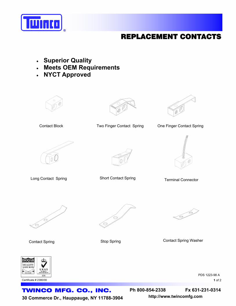
REPLACEMENT CONTACTS
TWINCO MFG. CO., INC.
30 Commerce Dr., Hauppauge, NY 11788-3904
Ph 800-854-2338 Fx 631-231-0314 http://www.twincomfg.com
Certificate # 2380/00 1 of 2
PDS 1223-98 A
Long Contact Spring Short Contact Spring
Contact Block One Finger Contact Spring Two Finger Contact Spring
Terminal Connector
Contact Spring Stop Spring Contact Spring Washer
• Superior Quality • Meets OEM Requirements • NYCT Approved

• Contact Blocks are made from precision machined brass alloy.
• Contact Springs are made from grain oriented grade A phosphorous bronze.
• Blocks & Springs are nickel plated for superior corrosion resistance.
• Assemblies are carefully soldered for electrical contact.
• Consult factory for special requirements.
Twinco Part Number Description
069-1223-0-A Contact Block
245-1788-2-0 Two Finger Contact Spring
245-1788-1-0 One Finger Contact Spring
069-1223-1-0 Short Contact Spring
069-1223-2-0 Long Contact Spring
245-1788-3-0 Terminal Connector, With Braid
245-1789-3-0 Contact Spring
245-1789-2-0 Stop Spring
245-1789-1-0 Contact Spring Washer
OEM Replacement Contacts
OEM Part Number
N/A
N156367
N156377
N179246
N236209
N167538
M153495
M157743
M187712
TWINCO MFG. CO., INC. http://www.twincomfg.com Ph 800-854-2338 Fx 631-231-0314
®
2 of 2
PDS 1223-98 A

TWINCO MFG. CO., INC.
http://www.twincomfg.com Ph 800-854-2338 Fx 631-231-0314 ®
10 of 4
PDS XXXX-08 A
SECTION I
Identification
Products

®
IDENTIFICATION PRODUCTS
TWINCO MFG. CO., INC.
30 Commerce Dr., Hauppauge, NY 11788-3904
Ph 800-854-2338 Fx 631-231-0314 http://www.twincomfg.com
Certificate # 2380/00 1 of 12
PDS 1699-00-G
Single source for all your identification needs Fast turn around

TWINCO MFG. CO., INC. http://www.twincomfg.com Ph 800-854-2338 Fx 631-231-0314
®
2 of 12
PDS 1699-00-G
Twinco Vinyl Identification Products are manufactured from high quality vinyl film. Your text is printed on a 10 mil solid base color of your choice and then permanently protected by lamination of a 5 mil thick clear film. This manufacturing process insures that Twinco Tags will stand the test of time in the harshest environments. For this reason, the New York City Transit, specifies only these type tags be used in their system. Twinco Vinyl Identification Products offer the following product features:
Extremely Long Life
Impervious to Water, Oil, Dirt, Cleaning Solvents, etc.
Vermin and Fungus Proof
Outstanding Legibility
High Abrasion Resistance
UV Resistant
Withstands Temperatures to 220°F**
New York City Transit Approved
Fast Delivery
Great Prices
The features above apply to all flat tags, disc tags, split sleeve wire markers and pipe markers. ** For split sleeve wire markers at temperatures above 150°F the split joint should be welded with special cement. Consult factory for additional info.
VINYL IDENTIFICATION PRODUCTS

TWINCO MFG. CO., INC.
Ph 800-854-2338 Fx 631-231-0314 http://www.twincomfg.com ®
3 of 12
PDS 1699-00-G
Twinco RA Style Flat Tags
Twinco P/N Hole Diameter Hole Location
51-002-1-A 3/16 Left
51-002-1-B 5/16 Left
51-002-1-C 1/2 Left
51-002-2-A 3/16 Right
51-002-2-B 5/16 Right
51-002-2-C 1/2 Right
Twinco RB Style Flat Tags
Twinco P/N Hole Diameter Hole Location
51-002-3-A 3/16 Top
51-002-3-B 5/16 Top
51-002-3-C 1/2 Top
51-002-4-A 3/16 Bottom
51-002-4-B 5/16 Bottom
51-002-4-C 1/2 Bottom
* ALL RA & RB are 3/4” x 1 1/2”
FLAT TAGS
DISC TAGS
Twinco DA Style Disc Tags
Twinco P/N Disc Diameter Hole Diameter
51-003-3-B 3/4 1/8
51-003-3-C 3/4 3/16
51-003-3-D 3/4 1/4
51-003-4-B 1 1/8
51-003-4-C 1 3/16
51-003-4-D 1 1/4
51-003-6-B 1 1/2 1/8
51-003-6-C 1 1/2 3/16
51-003-6-D 1 1/2 1/4
51-003-8-B 2 1/8
51-003-8-C 2 3/16
51-003-8-D 2 1/4
51-003-8-E 2 5/16
51-003-8-F 2 3/8

TWINCO MFG. CO., INC. http://www.twincomfg.com Ph 800-854-2338 Fx 631-231-0314
®
4 of 12
PDS 1699-00-G
PN: 51-014-2-A
PN: 51-014-6-A
XXXXX XXX
XXXX
Twinco RC Style Flat Tags
Twinco P/N Hole Diameter Hole Location
51-010-1-B 5/16 Left
51-010-2-B 5/16 Right
Twinco RD Style Flat Tags
Twinco P/N Hole Diameter Hole Location
51-010-3-B 5/16 Top
51-010-4-B 5/16 Bottom * ALL RC & RD are 7/8” x 1 1/2”
Twinco RM Style Flat Tags
Twinco P/N Hole Diameter Hole Location
51-018-1-E 1/4 Left
51-018-2-E 1/4 Right
Twinco RN Style Flat Tags
Twinco P/N Hole Diameter Hole Location
51-018-3-E 1/4 Top
51-018-4-E 1/4 Bottom * ALL RM & RN are 3/4” x 1”
XXXX XXXX
Twinco RJ Style Flat Tags
Twinco P/N Tag Description
51-014-1-A 1/2” x 2”
51-014-1-B 1/2” x 2” w/ adhesive
51-014-1-C 1/2” x 2” w/ 1/8” holes LR
51-014-1-D 1/2” x 2” w/ 1/8” holes LR & adhesive
51-014-2-A 3/8” x 1-5/8”
51-014-2-B 3/8” x 1-5/8” w/ adhesive
51-014-5-A 5/16” x 1-3/4”
51-014-6-A 1” x 7/8” w/ 1/8” holes TB
XXXX XXXX
XXXX
XXXX
PN: 51-014-1-A
** When ordering Style RJ Flat Tags, please indi-cate what mounting options are required. (I.e. Adhesive backing, mounting holes, both or neither.)
VARIOUS FLAT TAGS

TWINCO MFG. CO., INC.
Ph 800-854-2338 Fx 631-231-0314 http://www.twincomfg.com ®
5 of 12
PDS 1699-00-G
SPLIT SLEEVE WIRE MARKERS
* See table and pictures located in the upper half of pg. 7. ** For split sleeve wire markers at temperatures above 150°F the split joint should be welded with special cement. Consult factory for additional info.
Along with the product features of our other tags the Twinco Split Sleeve Wire Marker has a “lap type” joint. This allows for application* of the marker either before or after the termination of the wire. It also provides for minor diameter changes so the marker will grip tightly around the wire. If required the split sleeve marker may be welded into a solid sleeve simply by applying our special cement** onto the split. Twinco Split Sleeve Wire Markers are available in diameters ranging from 1/8” through 3” and lengths from 1/2” through 8”. Below are our more common markers.
Twinco SSA Style Wire Markers
Twinco P/N Length Diameter Twinco P/N Length Diameter Twinco P/N Length Diameter
51-001-2-A 1/2
1/8
51-001-3-F 1 3/4
3/16
51-001-6-B 1
3/8
51-001-2-B 1 51-001-3-D 2 51-001-6-E 1 1/4
51-001-2-E 1 1/4 51-001-3-G 2 1/2 51-001-6-C 1 1/2
51-001-2-C 1 1/2 51-001-3-H 3 51-001-6-F 1 3/4
51-001-2-F 1 3/4 51-001-4-A 1/2
1/4
51-001-6-D 2
51-001-2-D 2 51-001-4-B 1 51-001-6-G 2 1/2
51-001-2-G 2 1/2 51-001-4-E 1 1/4 51-001-6-H 3
51-001-2-H 3 51-001-4-C 1 1/2 51-001-7-B 1
7/16
51-001-532-A 1/2
5/32
51-001-4-F 1 3/4 51-001-7-E 1 1/4
51-001-532-B 1 51-001-4-D 2 51-001-7-C 1 1/2
51-001-532-E 1 1/4 51-001-4-G 2 1/2 51-001-7-F 1 3/4
51-001-532-C 1 1/2 51-001-4-H 3 51-001-7-D 2
51-001-532-F 1 3/4 51-001-5-A 1/2
5/16
51-001-7-G 2 1/2
51-001-532-D 2 51-001-5-B 1 51-001-7-H 3
51-001-532-G 2 1/2 51-001-5-E 1 1/4 51-001-8-E 1 1/4
51-001-532-H 3 51-001-5-C 1 1/2 51-001-8-C 1 1/2
51-001-3-A 1/2
3/16
51-001-5-F 1 3/4 51-001-8-F 1 3/4
51-001-3-B 1 51-001-5-D 2 51-001-8-D 2
51-001-3-E 1 1/4 51-001-5-G 2 1/2 51-001-8-G 2 1/2
51-001-3-C 1 1/2 51-001-5-H 3 51-001-8-H 3
1/2

TWINCO MFG. CO., INC. http://www.twincomfg.com Ph 800-854-2338 Fx 631-231-0314
®
6 of 12
PDS 1699-00-G
SPLIT SLEEVE WIRE MARKERS (CONT.)
Twinco SSA Style Wire Markers (cont.)
Twinco P/N Length Diameter Twinco P/N Length Diameter
51-001-10-E 1 1/4
5/8
51-001-14-C 1 1/2
7/8
51-001-10-C 1 1/2 51-001-14-F 1 3/4
51-001-10-F 1 3/4 51-001-14-D 2
51-001-10-D 2 51-001-14-G 2 1/2
51-001-10-G 2 1/2 51-001-14-H 3
51-001-10-H 3 51-001-16-C 1 1/2
1
51-001-12-C 1 1/2
3/4
51-001-16-F 1 3/4
51-001-12-F 1 3/4 51-001-16-D 2
51-001-12-D 2 51-001-16-G 2 1/2
51-001-12-G 2 1/2 51-001-16-H 3
51-001-12-H 3
Twinco PMA Style Pipe Markers
Twinco P/N Length Diameter
51-005-16-J 8 1
51-005-24-J 8 1 ½
51-005-32-J 8 2
51-005-48-J 8 3
Twinco Pipe Markers share all the products features of Twinco Split Sleeve Wire Markers. The only difference being that they are on a larger scale. Twinco Pipe Markers are available in diameters ranging from 1” through 3” and lengths 1” through 8”. Below are some of the more common sizes.
PIPE MARKERS

TWINCO MFG. CO., INC.
Ph 800-854-2338 Fx 631-231-0314 http://www.twincomfg.com ®
7 of 12
PDS 1699-00-G
ENGRAVED NAMEPLATES/SIGNS
1. Select Material Twinply Ultra - for exterior/interior use, scratch resistant, UV resistant and can
withstand temperatures up to 180°F. Comes in matte or satin finish. Other materials available upon request. Beveling is an option for engraved plates greater than a 1/2” high.
2. Choose Lettering Indicate any special lettering styles or heights required. Otherwise, a standard
lettering will be used and letter height will be determined by size of engraving surface.
3. Choose A Color Combination Black background w/ white letters White background w/ black letters Red background w/ white letters And many other colors available
4. Specify The Text/Symbols Required You can either mail, fax or e-mail your requirements over to Twinco. When
sending via mail or fax, please write as neat as possible. When e-mailing your list (when text only) you can attach an Excel file to your e-mail. Column A would contain Line 1, Column B would contain Line 2, etc… If you have any questions on formatting, please call.
5. Mounting Options High Strength Adhesive Backing Mounting holes Both
WHEN ORDERING ENGRAVED NAMEPLATES/SIGNS
*** See pages 8 and 9 for our more common Engraved Nameplates ***

TWINCO MFG. CO., INC. http://www.twincomfg.com Ph 800-854-2338 Fx 631-231-0314
®
8 of 12
PDS 1699-00-G
ENGRAVED NAMEPLATES/SIGNS
Twinco ENV Style Engraved Nameplates/Signs
Twinco P/N Size
All Engraved Nameplates/Signs can have the following
mounting options:
1. Adhesive Backing 2. Mounting Holes 3. Both 1 & 2 4. Neither
51-004-10-A 1/2”h x 2 1/2”w
51-004-12-C 1”h x 3”w
51-004-16-E 1 1/2”h x 4”w
51-004-20-L 3”h x 5”w
51-004-24-H 2”h x 6”w
51-004-28-T 5”h x 7”w
51-004-32-P 4”h x 8”w
51-004-36-Y 7”h x 9”w
51-004-40-AA 8”h x 10”w
51-004-44-P 4”h x 11”w
Some of the more common sizes:

TWINCO MFG. CO., INC.
Ph 800-854-2338 Fx 631-231-0314 http://www.twincomfg.com ®
9 of 12
PDS 1699-00-G
NUMBERED TERMINAL STRIPS
5/16”
1
2
3
4
5
6
7
8
9
10
11
12
13
14
15
16
17
18
19
20
21
22
23
24
25
1/2”
16”
26
27
28
29
30
31
32
33
34
35
36
37
38
39
40
41
42
43
44
45
46
47
48
49
50
51
52
53
54
55
56
57
58
59
60
61
62
63
64
65
66
67
68
69
70
71
72
73
74
75
76
77
78
79
80
81
82
83
84
85
86
87
88
89
90
91
92
93
94
95
96
97
98
99
100
5/8”
1/4”
Twinco ENV Style Numbered Terminal Strips
Twinco P/N Marked:
51-004-2-T25 1-25
51-004-2-T50 26-50
51-004-2-T75 51-75
51-004-2-T100 76-100
Standard Size of Terminal Strip is 1/2” Wide x 16” Long with letters/numbers vertically placed.
Made From High Quality Engraving
Material White Background with 1/4” Black
Numbers/Letters * Adhesive Backing, Mounting Holes
or Both **
NYCT Approved
* If a color other than white w/ black letters is needed, please indicate on purchase order. ** When ordering, please indicate what mounting options are required.

TWINCO MFG. CO., INC. http://www.twincomfg.com Ph 800-854-2338 Fx 631-231-0314
®
10 of 12
PDS 1699-00-G
METAL DISC TAGS
XXXXXX XXXX XXX
Twinco BDA Style Brass Disc Tags
Twinco P/N Tag Diameter
51-006-4-C 1
51-006-5-C 1-1/4
51-006-375-C 1-3/8
51-006-6-C 1-1/2
51-006-8-C 2 Twinco Brass Disc Tags are made from 18 gauge brass (.040” thick) and have a top hole (3/16” dia.) for attachments. The letters are engraved into the tag. The letters can be made various sizes depending on the diameter of the tag. Twinco Stainless Steel Disc Tags are made from 20 gauge stainless steel (.036” thick) and have a top hole (3/16” dia.) for attachments. The letters are engraved into the tag. The letters can be made various sizes depending on the diameter of the tag. ** P/N’s shown are for tags w/ engraved lettering. Add the letter “B” to the P/N for a Blank Tag.
Top hole (3/16” dia.)
Twinco SDA Style Stainless Steel Disc Tags
Twinco P/N Tag Diameter
51-007-4-C 1
51-007-5-C 1-1/4
51-007-375-C 1-3/8
51-007-6-C 1-1/2
51-007-8-C 2
Tag Diameter (varies)
2”
1-1/2” 3/16” dia. hole
Twinco BRA Style Brass Flat Tags
Twinco P/N Hole Diameter Hole Location
51-008-1-A 3/16 Left
51-008-2-A 3/16 Right
Twinco SRA Style Stainless Steel Flat Tags
Twinco P/N Hole Diameter Hole Location
51-009-1-A 3/16 Left
51-009-2-A 3/16 Right
Twinco Brass Flat Tags are made from 0.040” thick brass and have a 3/16” diameter hole for attachments. The letters are engraved into the tag. Twinco Stainless Steel Flat Tags are made from 0.036” thick stainless steel and have a 3/16” diameter hole for attachments. The letters are engraved into the tag.
* Standard size = 1-1/2” x 2”.
XXXXXX XXXX
XXXXXX
METAL FLAT TAGS

TWINCO MFG. CO., INC.
Ph 800-854-2338 Fx 631-231-0314 http://www.twincomfg.com ®
11 of 12
PDS 1699-00-G
SPLIT SLEEVE TAG APPLICATORS
NYLON STRING
*Split Sleeve Applicators
Twinco P/N For diameters:
51-000-2-A 1/8, 5/32
51-000-2-B 3/16
51-000-2-C 1/4, 5/16*
* Split Sleeve Wire Markers larger than 5/16” will not require an applicator. They can be opened and put on a terminated wire by hand.
P/N: 51-000-2-A
P/N: 51-000-2-B
P/N: 51-000-2-C
Twinco offers nylon string for attaching tags. There are two types; wax coated and non-wax coated. Wax: P/N 51-000-1-A Non-Wax: P/N 51-000-1-B It is sold in bags of 100 pre-tied string.

TWINCO MFG. CO., INC. http://www.twincomfg.com Ph 800-854-2338 Fx 631-231-0314
®
12 of 12
PDS 1699-00-G
ORDERING INFORMATION
Send order via : Tag nomenclature can be faxed or mailed for Twinco to do the data entry. Files can be sent directly to Twinco on floppy disk. Files can be e-mailed to [email protected] .
Please indicate the following somewhere on your order : Style & Type of ID Product P/N (if available) color (background & lettering) wire diameter or wire # and type (for Style SSA) Purchase Order # Attn: and Ship to: information Phone #, Fax # or E-mail address Or any other information you feel necessary for your order
Regardless of how information is sent to Twinco, it should be presented in the following format:
Data should be presented in a simple spreadsheet format, preferably in an Excel or Lotus file. The first row should be column headers designating line numbers If tags are being sent in Excel or Lotus, Twinco prefers a worksheet be created for each style of
tag. (Notice on picture below, there is a tab for each style of tag, Disc Tags, Flat Tags, etc.) When sending an Excel or Lotus file, please do not put a quantity column. Instead actually copy
and paste a particular nomenclature the number of times you need it. For more information on formatting your order, please call Jayson Skowronek at (631) 231-0022.
Copyright © 2022 FDOKUMEN