Installation, Operations and Maintenance Guide - AtmosAir
12
Installation, Operations and Maintenance Guide AtmosAir 500 Series
-
Upload
khangminh22 -
Category
Documents
-
view
1 -
download
0
Transcript of Installation, Operations and Maintenance Guide - AtmosAir
Installation, Operations and
Maintenance Guide
AtmosAir 500 Series
Visibly Cleaner Air
AtmosAir eliminates pollutants and restores air quality in commercial, industrial and residential buildings. When you choose AtmosAir, you’ll refresh your indoor environment with the same clean, pure air found only at the highest mountain elevations.
Product Overview
The AtmosAir 500 series, models 500F and 508F, bipolar ionization generators are industrial quality
units intended for installation in air conditioning systems or in custom designed air distribution
systems in commercial and industrial facilities. Custom designs include supply air distribution and
exhaust treatment systems. AtmosAir equipment is effective in reducing odors and harmful
pollutants through the introduction of positive and negative ions into the air stream to be treated.
The number and size of the ionization tubes used is dependent upon the airflow, size of the space,
and severity of the pollution and odors. The AtmosAir 500 series equipment is designed for minimal
maintenance efforts. The 500 series has two components that require inspection and maintenance:
1. AtmosAir 500 series bi-polar ionization generator 2. Ionization tubes
Because there are no moving parts the systems have low failure rates and minimal maintenance
requirements.
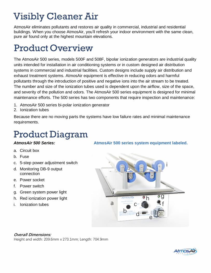
Product Diagram AtmosAir 500 Series:
a. Circuit box
b. Fuse
c. 5-step power adjustment switch
d. Monitoring DB-9 output connection
e. Power socket
f. Power switch
g. Green system power light
h. Red ionization power light
i. Ionization tubes
AtmosAir 500 series system equipment labeled.
Overall Dimensions: Height and width: 209.6mm x 273.1mm; Length: 704.9mm
a b
c
d e
f
g h
i
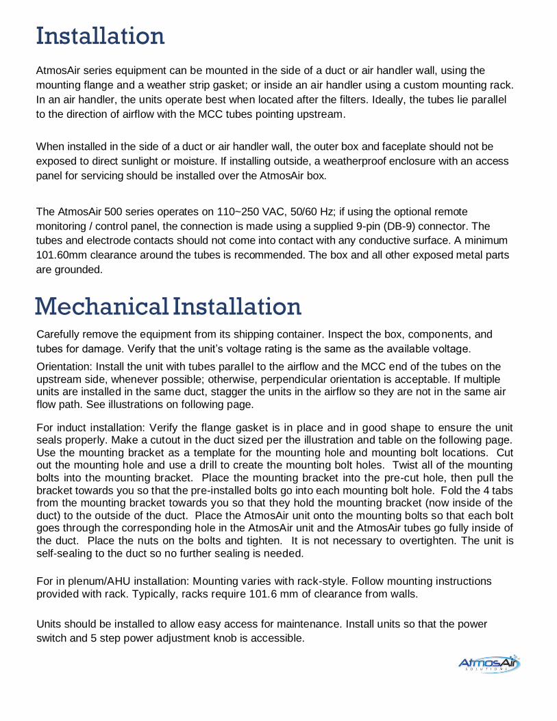
Installation
AtmosAir series equipment can be mounted in the side of a duct or air handler wall, using the
mounting flange and a weather strip gasket; or inside an air handler using a custom mounting rack.
In an air handler, the units operate best when located after the filters. Ideally, the tubes lie parallel
to the direction of airflow with the MCC tubes pointing upstream.
When installed in the side of a duct or air handler wall, the outer box and faceplate should not be
exposed to direct sunlight or moisture. If installing outside, a weatherproof enclosure with an access
panel for servicing should be installed over the AtmosAir box.
The AtmosAir 500 series operates on 110~250 VAC, 50/60 Hz; if using the optional remote
monitoring / control panel, the connection is made using a supplied 9-pin (DB-9) connector. The
tubes and electrode contacts should not come into contact with any conductive surface. A minimum
101.60mm clearance around the tubes is recommended. The box and all other exposed metal parts
are grounded.
Mechanical Installation
Carefully remove the equipment from its shipping container. Inspect the box, components, and
tubes for damage. Verify that the unit’s voltage rating is the same as the available voltage.
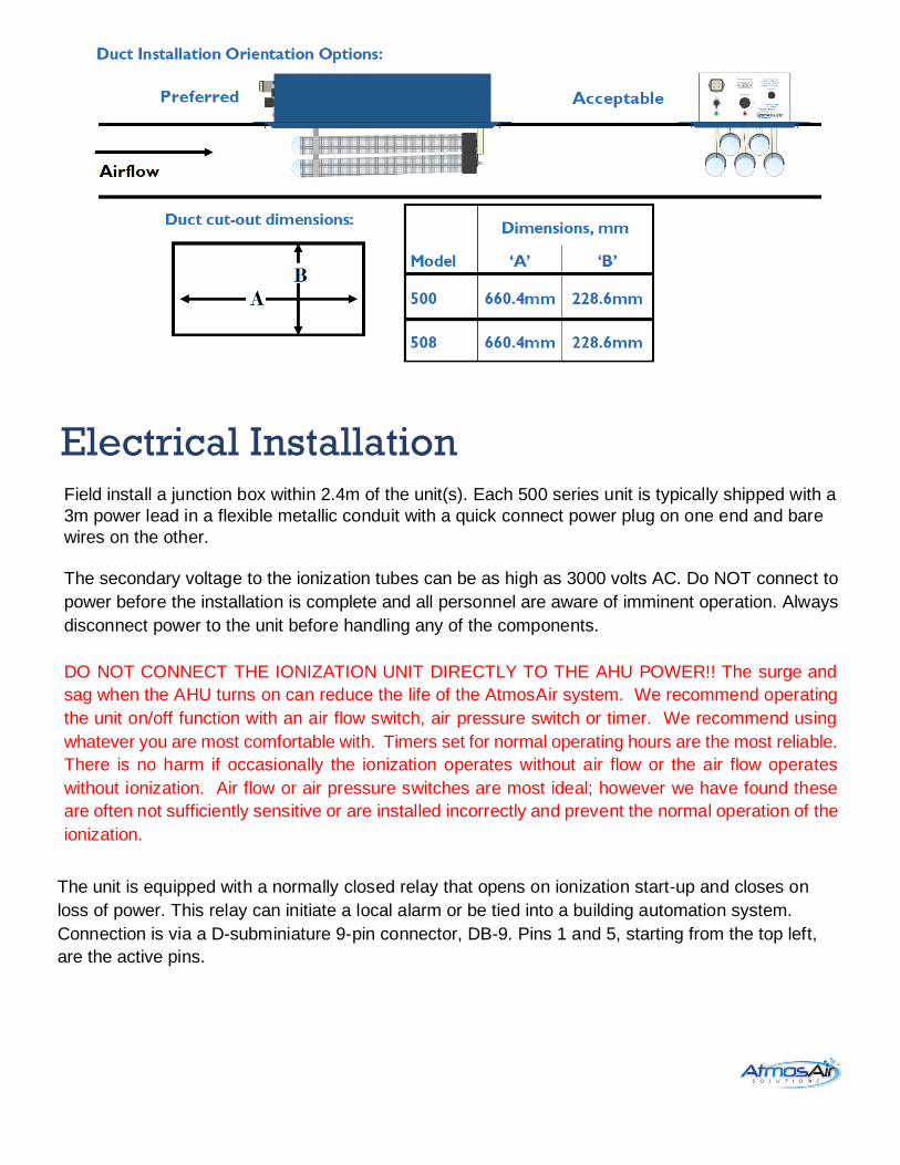
Orientation: Install the unit with tubes parallel to the airflow and the MCC end of the tubes on the upstream side, whenever possible; otherwise, perpendicular orientation is acceptable. If multiple units are installed in the same duct, stagger the units in the airflow so they are not in the same air flow path. See illustrations on following page.
For induct installation: Verify the flange gasket is in place and in good shape to ensure the unit seals properly. Make a cutout in the duct sized per the illustration and table on the following page. Use the mounting bracket as a template for the mounting hole and mounting bolt locations. Cut out the mounting hole and use a drill to create the mounting bolt holes. Twist all of the mounting bolts into the mounting bracket. Place the mounting bracket into the pre-cut hole, then pull the bracket towards you so that the pre-installed bolts go into each mounting bolt hole. Fold the 4 tabs from the mounting bracket towards you so that they hold the mounting bracket (now inside of the duct) to the outside of the duct. Place the AtmosAir unit onto the mounting bolts so that each bolt goes through the corresponding hole in the AtmosAir unit and the AtmosAir tubes go fully inside of the duct. Place the nuts on the bolts and tighten. It is not necessary to overtighten. The unit is self-sealing to the duct so no further sealing is needed.
For in plenum/AHU installation: Mounting varies with rack-style. Follow mounting instructions provided with rack. Typically, racks require 101.6 mm of clearance from walls.
Units should be installed to allow easy access for maintenance. Install units so that the power
switch and 5 step power adjustment knob is accessible.
Electrical Installation
Field install a junction box within 2.4m of the unit(s). Each 500 series unit is typically shipped with a
3m power lead in a flexible metallic conduit with a quick connect power plug on one end and bare
wires on the other.
The secondary voltage to the ionization tubes can be as high as 3000 volts AC. Do NOT connect to
power before the installation is complete and all personnel are aware of imminent operation. Always
disconnect power to the unit before handling any of the components.
DO NOT CONNECT THE IONIZATION UNIT DIRECTLY TO THE AHU POWER!! The surge and
sag when the AHU turns on can reduce the life of the AtmosAir system. We recommend operating
the unit on/off function with an air flow switch, air pressure switch or timer. We recommend using
whatever you are most comfortable with. Timers set for normal operating hours are the most reliable.
There is no harm if occasionally the ionization operates without air flow or the air flow operates
without ionization. Air flow or air pressure switches are most ideal; however we have found these
are often not sufficiently sensitive or are installed incorrectly and prevent the normal operation of the
ionization.
The unit is equipped with a normally closed relay that opens on ionization start-up and closes on
loss of power. This relay can initiate a local alarm or be tied into a building automation system.
Connection is via a D-subminiature 9-pin connector, DB-9. Pins 1 and 5, starting from the top left,
are the active pins.

!!!WARNING!!!
The secondary voltage to the ionization tube can be as high as 3000 volts AC. Do NOT connect
to power before the installation is complete and all personnel are aware of imminent operation.
Always disconnect power to the unit before handling any of the components.
!!!WARNING!!!
Operation
Once the system is properly installed and all personnel are clear of the high voltage tubes, the
system can be turned on:
Ensure the ionization power knob is turned all the way counter clockwise in the ‘off’ position. Flip the power switch up to the ‘on’ position. The green embedded LED light above the power switch should light up to indicate that the power is on and running to the system. Set the ionization power knob to the appropriate setting (1-5, with 1 being low and 5 being high). The red embedded LED above the power knob should light up to indicate that ionization has been activated and high voltage is being sent to the tubes’ electrodes. The system is intended to deliver ions into the treated area such that the ion levels should increase by 100 up to 1,500 positive and negative ions / cm3. The desired ion increase is dependent on many factors, including space, use, contaminant level and distribution effectiveness. An authorized AtmosAir design consultant should recommend the desired ion increase and appropriate system layout. Optimization and tuning can be provided by AtmosAir personnel.
!!!CAUTION!!! A nonfunctioning LED light may improperly indicate that the system is not functioning. Be sure to disconnect from the mains power before performing maintenance or troubleshooting the system.
Maintenance Requirements
The maintenance requirements on an AtmosAir system are mainly site dependent; a dirtier environment requires more frequent maintenance. In general, quarterly or biannual maintenance is recommended along with tube replacement every two years. The local AtmosAir dealer can provide you with a maintenance/service contract.
Quarterly/ Bi-annual Maintenance Requirements:
Visually check the performance of the system by checking the red and green lights on the individual units. If both lights are on, and you can hear the ‘buzz’ of the tubes, then unit is functioning properly. If not, proceed to the troubleshooting section for repair. Maintain a physical distance between all personnel and the tubes while system is operating or turned on. Optional: Check performance using a high voltage probe (minimum of 5000 V) paired with a multimeter. Follow proper safety procedures for dealing with high voltages. If you are uncertain, do NOT perform any maintenance with the power on and, instead, proceed to the next step. Follow the voltage measurement guidelines and instructions in this guide. Disconnect the system from the mains power before performing any maintenance steps. Inspect the unit box, plastic tube caps, and black tube mounting plate. Remove particles from mounting plate, and thoroughly wipe clean any tracks or grooves that may have developed in the plate or caps. Inspect connections: tightness of all nuts and screws; remove excessive rust on the connections using sand paper or wire brush, it may be necessary to remove the tubes for this step. It may be beneficial to clean the tubes to improve performance. The tubes can be cleaned using an air compressor for a quick clean, or more thoroughly with cleaning solutions. Read tube cleaning section for detailed tube cleaning instructions. Do not immerse the tubes in water. Ensure that the MCC and mesh are completely dry before reinstalling. Tube Replacements: The ionization tubes should be replaced once every 24 months, as the production efficiency slowly declines over time due to the stress caused by plasma and (lack of) cleanliness of the electrodes. Old or excessively dirty tubes can also put undue stress on the transformer causing premature failure.
Troubleshooting
In the event that the system is not functioning, the first step is to check the power source and fuse.
• Check the fuse. If it is blown, replace it as per the label/submittal sheet. The fuse is 5 x 20 mm in
size.
• Check that the main power supply is sending the correct power to the unit.
• If the system is controlled by an air pressure switch, and/or a door switch, check that these are
not preventing power from being sent to the system.
If power is reaching the unit and it was necessary to replace the fuse, the next step is to determine
whether there is a fault in the system or a tube. First, to check that the system’s power is functioning,
set the ionization power knob and the power switch both to the ‘off’ position. Make sure all personnel
are clear of the high voltage tubes, then reconnect the power supply. Flip the power switch to ‘on’
and observe the green light. If the light does not turn on, there is still a problem with delivering power
to the system. If all external sources of failure are eliminated, the system should be serviced by a
qualified AtmosAir technician.
Troubleshooting, continued
The next step is to determine the cause of the failure, or blown fuse.
Typically, failures are caused by arcing between the inner and outer electrodes, or between one
electrode and ground. This often occurs because of damaged tubes or dirty and/or wet conditions
that have allowed carbon tracking to temporarily connect two electrodes and/or a grounding point
electrically.
Inspect the mounting plate for tracking evidence.
Inspect end on view of the tube for a purple edge glow. This glow is the plasma generated
between the MCC and the outer mesh electrode. Check the MCC tubes for cracks, pitting, or
other degeneration of the MCC material that causes the dielectric to fail and arcing to occur.
If physical inspection has not revealed the cause of failure, one may carefully observe the tubes
as the ionization system is turned on to determine whether arcing is occurring at a particular
tube. The fuse will usually blow, again, but for a short time, one may observe the cause of the
power surge in the form of a visual or audio cue. The visual cue may be small or may be a large
spark or spark trail, so be cautious when turning system on. Start on the lowest setting with
personnel clear of the system, but observant.
It is recommended to also check the voltage levels of the system when a fuse has blown and been
replaced, in order to ensure that the transformer has not been irreparably damaged. If the voltages
are lower than expected, check that all the connections are secure and rust free; also check that
the voltage is approximately 110~250 VAC.
If the fuse continuously blows, or if the voltages are lower than expected, then the system should
be serviced by a qualified AtmosAir technician.
If there seems to be a gradual loss of effectiveness, check the tubes and clean them if necessary.
Overly dirty tubes not only provide additional stress on the transformer, they can block the ability to
form plasmas and thus generate sufficient ions.
It may be necessary to remove all the tubes to ensure that the transformer is working properly
in the absence of tubes.
Wire Color Key:
Black or Brown Hot/ Live
White or Blue Neutral
Green Ground
Troubleshooting, continued
Fuse Blows’ list in order of ‘likelihood’. 1. Tube breach. 2. Poor connections between tube(s) and loops. 3. Surges and sags due to connection on a circuit with high amp draw/ capacitors/ motors and no surge suppressors. 4. Ion switch has been impacted. 5. In correct fuse/ thermistor pairing. 500mA only. No exceptions. 6. Floating ground. (not connected to a PROVEN ground) {not an ‘assumed ground’} 7. Is anything contacting the tubes or the loops? (Dead short) 8. Unlikely…Transformer. 9. Unit has been opened and the plastic baseplate has been ‘clamped’ down on the white hi-tension wires to the tubes…dead short. Does the fuse blow right away as soon as the Ion dial is switched to #1 or does it blow as you ramp up the ionization power? Do you see a ‘flash’ at the tubes as soon as the unit is powered on? Then a half second later the fuse blows? = Tube problem Remove all tubes and replace fuse…does the unit work now? = TUBE PROBLEM. CAUTION! DO NOT TOUCH ANYTHING METAL DURING THIS TEST! HIGH VOLTAGE AT FULL ‘POTENTIAL’! If it’s not a fuse blow issue, I’m afraid that the unit in question may need to be returned (contact: [email protected] and complete: https://www.atmosair.com/rmaform)... Customers should not attempt to open and repair our units.
Tube Installation Instructions
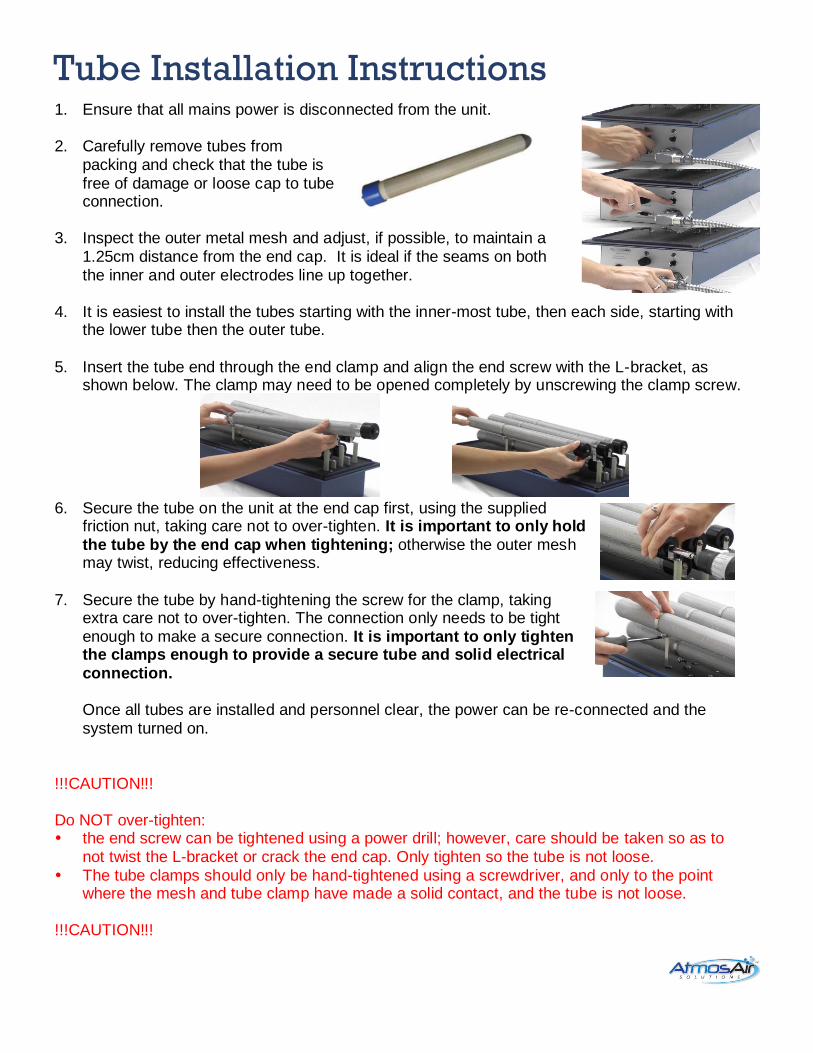
1. Ensure that all mains power is disconnected from the unit.
2. Carefully remove tubes from packing and check that the tube is free of damage or loose cap to tube connection.
3. Inspect the outer metal mesh and adjust, if possible, to maintain a 1.25cm distance from the end cap. It is ideal if the seams on both the inner and outer electrodes line up together.
4. It is easiest to install the tubes starting with the inner-most tube, then each side, starting with the lower tube then the outer tube.
5. Insert the tube end through the end clamp and align the end screw with the L-bracket, as shown below. The clamp may need to be opened completely by unscrewing the clamp screw.
6. Secure the tube on the unit at the end cap first, using the supplied
friction nut, taking care not to over-tighten. It is important to only hold the tube by the end cap when tightening; otherwise the outer mesh may twist, reducing effectiveness.
7. Secure the tube by hand-tightening the screw for the clamp, taking extra care not to over-tighten. The connection only needs to be tight enough to make a secure connection. It is important to only tighten the clamps enough to provide a secure tube and solid electrical connection. Once all tubes are installed and personnel clear, the power can be re-connected and the system turned on.
!!!CAUTION!!! Do NOT over-tighten: the end screw can be tightened using a power drill; however, care should be taken so as to
not twist the L-bracket or crack the end cap. Only tighten so the tube is not loose. The tube clamps should only be hand-tightened using a screwdriver, and only to the point
where the mesh and tube clamp have made a solid contact, and the tube is not loose. !!!CAUTION!!!
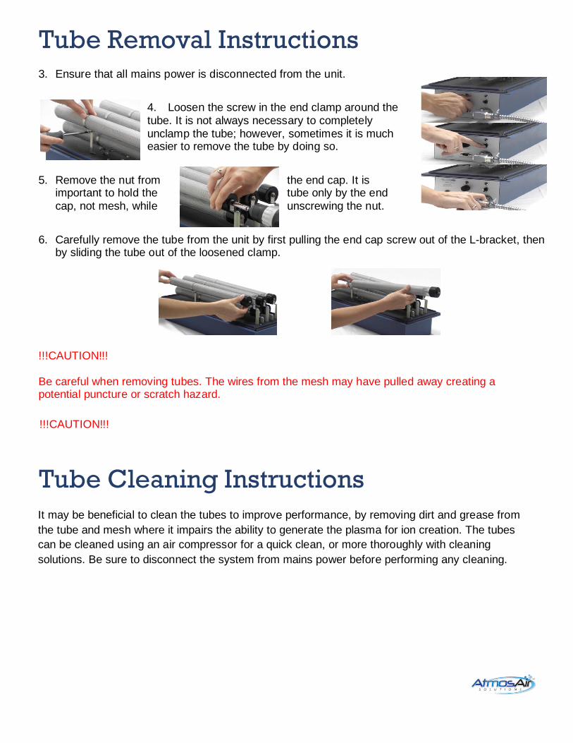
Tube Removal Instructions
3. Ensure that all mains power is disconnected from the unit.
4. Loosen the screw in the end clamp around the tube. It is not always necessary to completely unclamp the tube; however, sometimes it is much easier to remove the tube by doing so.
5. Remove the nut from the end cap. It is important to hold the tube only by the end cap, not mesh, while unscrewing the nut.
6. Carefully remove the tube from the unit by first pulling the end cap screw out of the L-bracket, then by sliding the tube out of the loosened clamp.
!!!CAUTION!!! Be careful when removing tubes. The wires from the mesh may have pulled away creating a potential puncture or scratch hazard.
!!!CAUTION!!!
Tube Cleaning Instructions
It may be beneficial to clean the tubes to improve performance, by removing dirt and grease from
the tube and mesh where it impairs the ability to generate the plasma for ion creation. The tubes
can be cleaned using an air compressor for a quick clean, or more thoroughly with cleaning
solutions. Be sure to disconnect the system from mains power before performing any cleaning.
Quick-Clean
Disconnect the system from the main power before performing any cleaning. Even if no person or
object is in contact with the system, the air flow may inadvertently cause dirt, debris, water, or other
objects to come into contact with an electrode or both electrodes and create a spark, if the system is
operating. Use a light-duty air compressor for a quick clean of the tubes. Sweep the airflow over the
tubes to remove the loose dirt and debris from the tubes. Clear the areas between and under the
tubes with the air compressor. It may be useful to remove the tubes for improved cleaning. Cleaning
the general area around the tubes to remove dust, dirt, and debris will keep the tubes clean longer.
CAUTION Do not immerse the tubes in water. Ensure that the tube and mesh are completely dry before re-installing.
Thorough Clean
Disconnect the system from main power before performing any cleaning. Remove the tubes from
the system.
A more thorough method for cleaning the tubes is to separate the outer mesh from the tube and use
mild cleaning solutions.
1. Remove the mesh from the tube. Grasp the tube, not the end cap, while removing the mesh. Provide firm but gentle pressure when holding the tube. It may be necessary to gently twist the mesh in sections working from top to bottom until the entire length is loose enough to pull off. 2. Soak the mesh in a mild soap solution: 30ml of dish detergent per liter of water makes a great cleanser. Or use running warm tap water in a sink, gently rub the mesh to remove dirt. 3. If you allow the mesh to soak for a few minutes, rinse the mesh thoroughly with water to remove all
traces of soap. Allow the mesh to dry completely.
4. Clean the tube with a mild soap solution, and a soft cloth or sponge. A non-scratch scrub sponge may help remove sticky material. Clean any carbon tracking residue off of the end cap. Rinse or wipe the tube and dry thoroughly. Be sure to avoid the seal between the cap and tube and between the cap and the end screw when rinsing.
5. Once the mesh and tube are completely dry, replace the mesh on the tube by sliding it gently over
the tube. Be sure that the outer mesh is at least 1.25 cm from the end cap, and that both vertical
seams on the inner and outer electrodes line up. Once the tubes are clean and completely dry, reinstall the tubes in the system.
Tips on Tube Life Cleaning the tube is beneficial because it reduces stress on the transformer and also removes any
dirt or oil that can inhibit the plasma from forming on the outside of the tube. Unfortunately, there are
many other factors that affect the efficiency and life of the tube:
The silicone seal between the tube and the cap keeps moisture from infiltrating the tube.
Excessive aluminum oxide build-up on the inner electrode can decrease the strength of the
plasma as the oxide essentially increases the thickness of the dielectric barrier.
The plasma discharges between the mesh and the tube slowly wears on the tube, thinning the
dielectric barrier. Eventually, repetitive stress from the discharges can create erosion holes.
Carbon tracking or cracks in the end cap should be gently cleaned by hand; these allow an easy
path for current to flow and creates a short in the system.
Improper installation by tightening the tube clamps or the end nut on the 500 series could cause
the end cap to separate from the tube.
AtmosAir SolutionsTM mission is to bring and restore every indoor environment the same clean and pure quality air that is typically found at higher mountain elevations. AtmosAir’s unique and proven air purification process significantly reduces mold, controls the spread of bacteria and airborne viruses, and reduces airborne particles that evade normal filtration solutions. AtmosAir equipment uses non-thermal plasma technologies to generate bi-polar ionization that attacks and breaks down odors and contaminants.


![[NN40170-305] Installation and Maintenance Guide](https://static.fdokumen.com/doc/165x107/63376cb7d293c4548c06b868/nn40170-305-installation-and-maintenance-guide.jpg)