
CRANE MANUAL (Operations, maintenance and safety)
118
The Deeside Railway Crane Manual 29/3/2007 1 CRANE MANUAL (Operations, maintenance and safety) The Deeside Railway Company Limited
-
Upload
khangminh22 -
Category
Documents
-
view
2 -
download
0
Transcript of CRANE MANUAL (Operations, maintenance and safety)

The Deeside Railway Crane Manual
29/3/2007 1
CRANE MANUAL
(Operations, maintenance and safety)
The Deeside Railway Company Limited

The Deeside Railway Crane Manual
29/3/2007 2
Crane Manual
Contents
1 OVERVIEW 2 RESPONSIBILITIES
2.1 Company Directors 2.2 Duty manager 2.3 Crane operator and Banksman
3 PERSONNEL COMPETENCE, QUALIFICATIONS AND CERTIFICATION
3.1 Operator 3.2 Banksman
4 CRANE BASICS
4.1 Crane and boom types 4.2 Crane moments 4.3 Stability 4.4 Mechanical principles 4.5 Load moments 4.6 Reeving 4.7 Winches 4.8 Radius and boom angle 4.9 Safe Working Loads 4.10 Limit switches 4.11 Static and dynamic loads 4.12 Rated capacity Indicators
5 PRIME MOVER
5.1 Diesel engine 5.2 Speed governor 5.3 Lubrication system 5.4 Filters 5.5 Cooling system 5.6 Air cleaner 5.7 Starting system

The Deeside Railway Crane Manual
29/3/2007 3
6 WIRE ROPES 6.1 Factor of safety 6.2 Construction 6.3 Multi-stranded rope 6.4 Breaking load – size relationship 6.5 Strength and flexibility 6.6 Rope removal criteria 6.7 Factors causing rope deterioration 6.8 Inspection 6.9 Critical points 6.10 End attachments 6.11 Measuring diameter 6.12 Measuring rope lay 6.13 Finding broken wires 6.14 Making an internal rope examination 6.15 Fleet angle 6.16 Inspecting Sheaves / pulleys 6.17 Evaluating drums 6.18 Replacing wire ropes 6.19 Steel wire rope summary
7 GENERAL PROCEDURES
7.1 Personnel safety equipment 7.2 Rigging store 7.3 Access to working area 7.4 Load charts 7.5 Signals and communications 7.6 Crane movements along the track 7.7 Overhead power lines 7.8 Emergency procedures 7.9 Shutdown 7.10 Electrical safety 7.11 Troubleshooting
8 PRE-LIFTING PROCEDURES
8.1 Worksite planning 8.2 Crane pre-start check

The Deeside Railway Crane Manual
29/3/2007 4
9 LIFTING PROCEDURES 9.1 Lifting operations 9.2 Operation of controls 9.3 Checks during lifting operations 9.4 General techniques 9.5 Use and abuse of safety devices 9.6 Crane operations checklist
10 CRANE INSPECTION AND MAINTENANCE
10.1 Routine maintenance 10.2 Annual certification 10.3 Maintenance activities
11 APPENDICES
11.1 Glossary 11.2 Hand signals 11.3 Load chart 11.4 Basic crane data 11.5 Lift plan pro-forma 11.6 Daily pre-operation check list 11.7 Routine maintenance check lists 11.8 Crane end elevation drawing - front 11.9 Crane end elevation drawing - rear 11.10 Crane side elevation drawing 11.11 Troubleshooting chart 11.12 Electrical diagrams 11.13 The Wylie Safe Load Indicator manual 11.14 Lifting Operations legislation 11.15 Hook height profile 11.16 Polyester sling rating

The Deeside Railway Crane Manual
29/3/2007 5
1. OVERVIEW
The crane in use by the Royal Deeside Railway is a diesel-electric type, built in 1961 at Rodley, Leeds by Thomas Smith & sons Ltd. Load capacity is 6 tons at the maximum radius of 33 feet, 10 tons at 25 feet in to the minimum radius of 15 feet. Total crane weight is 75 tons. The manufacturer has ceased trading and little original operating data is available. See Appendix 3 – Crane basic data. A full set of ‘as-built’ electrical drawings have been prepared and are available for maintenance purposes.
All crane functions are electrically powered from a 55 kW diesel-electric generator operating at 440 volts DC. A 24 volt DC utility circuit is available for crane lighting and engine starting.
The jib winch has a non-progressive spring loaded brake, electrically held off when the jibbing motor is energised.
The slewing motor drives through a friction clutch to prevent side loading of the jib and minimise obstruction impact damage to the crane body. A slew foot brake is fitted to the motor side of the friction clutch, no other slew brake is provided.
The hoist winch has a non-progressive spring loaded brake, electrically held off when the hoist motor is energised. A hoist foot brake is also provided.
A traction motor is fitted to each of the two bogies, each driving a single axle through a reduction gearbox. Each traction motor has a non-progressive spring loaded brake, electrically held off when the motor is energised. A manually operated parking brake operating on a non-driven axle is also provided.
All crane motors are directly switched by the drum controllers operated by the control handles, with the exception of the traction system. The traction motor operating lever and associated drum controller provide control currents to operate the sequencing contactors in the travel speed relay control panel, and use timers in conjunction with the control handle position to manage the rate of travel speed increase.
Various trip functions are fitted to prevent: excessive jibbing in either direction, over-hoisting of the block, excessive motor current, incorrect operating lever position at start-up, etc. These trips operate by de-energising the main contactor coil, allowing the main contactor to open and shutting down the high voltage supply to all motors.
A Wylie Safe Load Indicator is fitted to provide a warning and alarm facility for overload conditions at any position between the maximum and minimum working radii. A warning bell and indicator light test facility is also provided.

The Deeside Railway Crane Manual
29/3/2007 6
2. RESPONSIBILITIES 2.1 Company Directors
Company Directors are responsible for ensuring that appropriate safety management systems and procedures are in place for :
personnel training – to ensure all operators and banksmen receive training appropriate to the activities in which they are involved, personnel competence assessment – to ensure that all operators and banksmen are sufficiently competent to handle the tasks they are involved with, equipment certification – to ensure that the crane and all lifting equipment such as slings, shackles and ropes have been independently assessed for fitness for purpose in accordance with Statutory requirements, and are in date. equipment maintenance and inspection – to ensure that all crane functions operate correctly at all times and remain safe to use, operating procedures – to ensure that all lifting activities, crane movements and maintenance activities are carried out in a safe manner, systems auditing – to validate that all the above safety management systems are being applied correctly.
2.2 Duty Manager
The Duty Manager is responsible for ensuring that the operator and banksman working the crane are currently certified as competent, according to company records.
2.3 Crane operator and Banksman
The crane operator and banksman are responsible for carrying out their duties in accordance with the training and certification provided.

The Deeside Railway Crane Manual
29/3/2007 7
3. PERSONNEL COMPETENCE, QUALIFICATIONS AND CERTIFICATION 3.1 Operator
The minimum qualifications for a volunteer approved to operate a crane are as follows: - have corrected vision that meets the same requirements as vision for a driver’s licence. - have effective use of all four limbs. - be of sufficient height to operate the controls and to have an unobstructed view over the controls into the work area. - have suitable coordination between eyes, hands, and feet. - be free of known convulsive disorders and episodes of unconsciousness. - have the ability to understand signs, labels, and instructions. The volunteer must have undertaken an approved course of training in crane operations, been assessed as competent, and be registered in the Company database of competent personnel.
3.2 Banksman The minimum qualifications for a volunteer selected to work as banksman are as
follows:
- have corrected vision that meets the same requirements as vision for a driver’s licence.
- have effective use of all four limbs. - have the ability to understand signs, labels, and instructions.
The volunteer must have undertaken an approved course of training as banksman, been assessed as competent, and be registered in the Company database of competent personnel.
3.3 Maintenance Personnel All maintenance and engineering activities on the crane must be carried out by
personnel authorised as competent.

The Deeside Railway Crane Manual
29/3/2007 8
4 CRANE BASICS 4.1 Crane and boom types

The Deeside Railway Crane Manual
29/3/2007 9
4.2 Crane movements
Cranes are machines that are designed/used to lift loads. This is their main purpose. Most cranes can also move and position loads. It can be said that most cranes can LIFT loads VERTICALLY and MOVE loads HORIZONTALLY. There are many different types and sizes of cranes from many different manufacturers. The type of crane which this manual deals with is known as the boom type crane, sometimes called jib crane. There are also different types of BOOM. Many manufacturers have their own special equipment or systems to achieve the way in which the crane works but, whatever the method used, cranes perform only three basic functions, namely - VERTICAL Movement is carried out by the crane's HOIST (and lowering)
function - HORIZONTAL Fore and Aft Movement is carried out by the cranes BOOM
HOIST function, sometimes called DERRICKING or LUFFING. - HORIZONTAL Movement is also carried out using the cranes SWING (or
SLEWING) function. Basically the load that a crane can lift depends upon two or more of the following points:
1. How big is it ? 2. How heavy is it ? 3. How strong is it ? (structurally) 4. How much power is available ?

The Deeside Railway Crane Manual
29/3/2007 10

The Deeside Railway Crane Manual
29/3/2007 11
4.3 Stability
STABILITY is very important where any crane is concerned. If a crane, or any object, is in no danger of falling over, or tipping, it is said to be STABLE. When it approaches the point where it can be easily tipped, it is said to be UNSTABLE. The STABILITY of mobile cranes depends on three basic elements.
1. Deadweight The weight of the machine without a load (this includes all the equipment on the
crane). Most mobile cranes are fitted with counterweights (or ballast) and the main purpose of these is to increase the weight of the machine. This is especially important for the raising of long booms from ground level.
2. Stability base / Ground area Stability also depends on the size of stability base or ground area of the crane.
(In other words, the distance between the outermost points where the machine is in contact with the ground).
Mobile cranes are usually "square based", that is the length and width are
approximately the same.
Truck-mounted cranes are generally fitted with outriggers and these are used to increase the stability base. When the outriggers are extended (fully) and down, the crane is said to be blocked, and the stability base is approximately square.
3. Centre of Gravity (C of G) Every object has a centre of gravity and it is the point where the weight of the
object is exerted vertically downwards. It is also the point of balance. If the centre of gravity of a crane is supported from below then the crane will be
stable. If it is not supported, in other words, if it moves outside the stability base, then the crane must tip over.
Where a crane is concerned the centre of gravity does not stay in the same place,
it moves depending on, if the load weight is changed (increased or decreased), and/or the radius is changed.

The Deeside Railway Crane Manual
29/3/2007 12

The Deeside Railway Crane Manual
29/3/2007 13
4.4 Basic Mechanical Principles
It has already been said that cranes are machines.
Cranes and their systems can seem to be very complicated but there are certain principles that are used, or are present that are not difficult to understand.
Mechanics is a large subject, which is concerned with the study of the action of forces on bodies and motions which they produce.
This section will try to keep things simple and in terms that can be easily understood. The mathematics are not important but understanding the principles can help the crane operator to appreciate what is happening and why, while the crane is working.
Basically, a machine is a device used to overcome resistance (load) at one point, by applying a force (power or weight) at another, point.
They are generally used to take mechanical advantage, which is to increase the load that can be lifted using a fixed amount of power (or weight).
When a machine is used, there will be changes in SPEED (or distance) and LOAD (or weight). If one of these is increased then the other will be decreased.
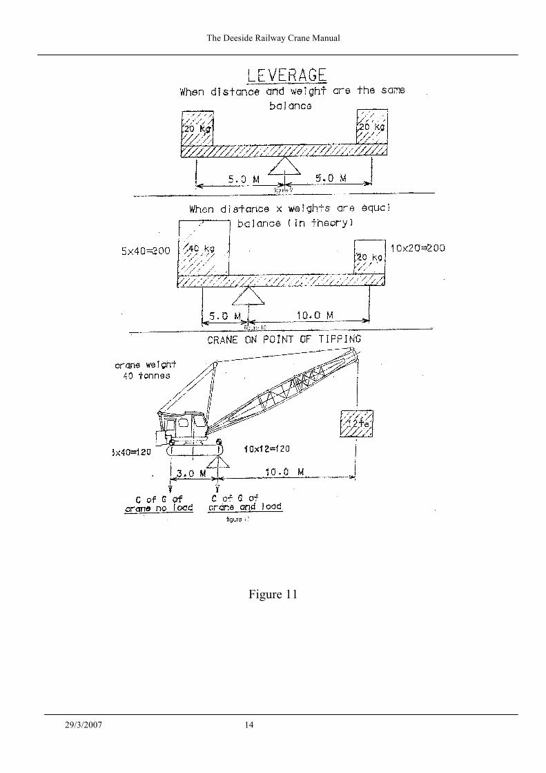
Simply speaking "nothing is for nothing" - if speed or distance is increased, it must be "paid for" by reduced load and vice-versa. One of the simplest machines is the lever and leverage is important when cranes are considered.
The Deeside Railway Crane Manual
29/3/2007 14
Figure 11

The Deeside Railway Crane Manual
29/3/2007 15
4.5 Load Moments
A load moment is a force created by a load applied through a distance from a pivot point (Fulcrum). Load (force) x distance (from the fulcrum) equals load moment.
In effect a crane is a balance of loads through a fulcrum point, (crane's fulcrum is the centre pin).
Figure 9
The loads of 20Kg are equidistant from the fulcrum
with a resultant moment of 20 x 5 = 100 Kg metres both sides of fulcrum
result - the loads are in balance
Figure 10
40 Kg x 5 metres = 20Kg x 10 metres 200 Kg metres = 200 Kg metres
result - again the moments are equal even though loads and distances not equal
Figure 11
this principle can be applied to cranes
left 'hand side 40 tons x 3 metres = 120 ton metres right hand side 12 tons x 10 metres = 120 ton metres
result - the crane is in balance
Mobile cranes operate under the principle of stability, with the centre of gravity moving within the stability base. If the centre of gravity stays within the stability base the crane is stable.
Therefore, in conclusion, a load moment when applied to cranes is a load multiplied by a distance (radius) plus other forces.
NOTE - This explanation is very basic, in reality there would be other forces to take into effect when calculating out the load moment and that is beyond the-scope of this course.

The Deeside Railway Crane Manual
29/3/2007 16
4.6 Reeving
Mechanical advantage by "Reeving". The crane use winches and wire ropes in the hoist and boom hoist systems.
These are used with pulleys or sheaves.
Any crane will only have a certain amount of power to operate all its functions. When all the power is "used up", then the crane will stop.
Power is needed to lift loads and to raise the boom. A lesser amount is needed to swing the crane.
When power for the hoist and boom hoist are considered, the power available is enough to achieve the single line pull of the winch.
That is, the load which the winch can lift using only one part of line (rope) between the winch and the load. Diesel engine cranes usually have fairly low single line pull. Even a 100 ton crane will not lift more than 10 to 12 tons (approximately) using only one part of line.
If the winch has to lift more than its single line pull, then a method has to be found to increase the load using the same fixed amount of power.
With cranes, the system used is called reeving, using more than one sheave. By using this method the load that can be lifted is increased but speed and distance are reduced.
Line speed is the speed at which the winch pulls the rope.
On single part line the hook speed is the same as the line speed.
As more parts of line are used the hook speed is reduced.
When using reeving systems there is always a loss of load due to friction of the rope around sheaves and in sheave bearings or bushes.
NOTE - Friction loss is not taken into account in this explanation.

The Deeside Railway Crane Manual
29/3/2007 17
Figure 12

The Deeside Railway Crane Manual
29/3/2007 18
4.7 Winches
It has been said that winches are machines, or devices, used for "pulling" wire rope. Winches also have to "spool" or store the rope.
When a hook or boom is at a low point then most of the rope may be "off' the winch. When the hook or boom is at a high point, then the rope will be "on" the winch or the winch may be "full". This is important because as the winch is lifting, or lowering it may change in effective size or diameter. The root diameter of a winch is the diameter of the drum without a rope on it. The first layer of rope is the bottom layer. The last layer of rope is the top layer. If the same amount of power is used and the winch turns at the same speed, the line speed changes and when it does, the line pull changes also.

The Deeside Railway Crane Manual
29/3/2007 19
4.8 Radius and Boom Angle
The load that any boom type crane can lift will depend on a measurement which is known as radius (half the diameter).
This is the distance from the centre line of rotation to the vertical load or hook line. The centre line of rotation is the very centre of the swing (slew) joint (usually the centre pin).
It never moves in relation to the crane.
The vertical load (hook) line is the line drawn from the boom head, straight downwards.
This may be the centre of the main hoist sheaves, if more than one part of line is being used, or the outside edge of the pulley if a single part line is used.
Radius of course, changes as the boom is raised or lowered.
Cranes also have a tail radius or tail swing. This is the furthest projection behind the centre line of rotation.
Any boom crane will have minimum radius, and a maximum radius. These will depend upon the length of the boom.
The Deeside Railway Crane Manual
29/3/2007 20
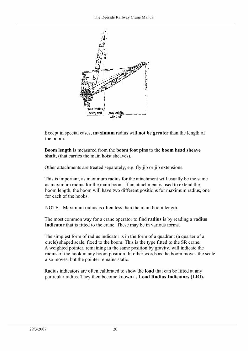
Except in special cases, maximum radius will not be greater than the length of the boom.
Boom length is measured from the boom foot pins to the boom head sheave shaft, (that carries the main hoist sheaves).
Other attachments are treated separately, e.g. fly jib or jib extensions.
This is important, as maximum radius for the attachment will usually be the same as maximum radius for the main boom. If an attachment is used to extend the boom length, the boom will have two different positions for maximum radius, one for each of the hooks.
NOTE Maximum radius is often less than the main boom length.
The most common way for a crane operator to find radius is by reading a radius indicator that is fitted to the crane. These may be in various forms.
The simplest form of radius indicator is in the form of a quadrant (a quarter of a circle) shaped scale, fixed to the boom. This is the type fitted to the SR crane. A weighted pointer, remaining in the same position by gravity, will indicate the radius of the hook in any boom position. In other words as the boom moves the scale also moves, but the pointer remains static.
Radius indicators are often calibrated to show the load that can be lifted at any particular radius. They then become known as Load Radius Indicators (LRI).
•

The Deeside Railway Crane Manual
29/3/2007 21
The scales on load radius indicators are interchangeable and the correct scale for the boom length must be fitted. If the boom length is changed, the scale must be changed. This is also true for any attachments fitted to boom.
The quadrant can usually be adjusted by measuring a given radius on the ground exactly and placing the hook over the mark. The indicator can then be set accordingly to that radius.

The Deeside Railway Crane Manual
29/3/2007 22
4.9 Safe Working Load
The SWL (safe working load) of a boom crane is the load that the crane can lift safely under any conditions (combination) of boom length and radius.
If either of these is changed then the SWL will be affected.
Safe working loads are also known as
• Duties • Capacities • Ratings • Rated loads
The crane operator can find the information he needs on the SWL Chart (Duties chart etc) for that machine.
CHARTS SHOULD BE IN ALL CRANE CABS
Some charts may appear quite simple, while others can be quite complicated so the notes on the chart are important.
Basically, everything that is attached to the boom is considered to be part of the load. This includes hooks, slings, any attachments, fly jibs etc and, of course, the load being lifted.
Mobile cranes are rated on stability, or stability and structural strength. They also have a safety margin.
As a general rule, this safety margin will be 25% or more which means that if the load on the SWL chart is increased by 25%, the crane will still remain stable, and strong enough. This safety margin is designed into the crane by its manufacturer.
This should not be confused with test loads, these will be explained later.
The crane operator must never exceed the loads set out on the SWL chart
To find radius and load, the operator must now look at two sources. The indicator itself, and the relevant capacity chart (or part of a chart).
He must know the length of the boom.
The crane must not lift loads outside the working range.
The only time the boom may be lowered below the minimum boom angle, or outside maximum radius is when it is being brought down to rest, never with a load.

The Deeside Railway Crane Manual
29/3/2007 23
NOTE : Boom angle indication is not available on the SR crane.

The Deeside Railway Crane Manual
29/3/2007 24
4.10 Limit Switches
There are a number of safety devices that can be fitted to cranes.
Limit switches are fitted to the SR crane's hoist, and boom hoist functions.
A hoist limit switch is fitted to limit the hook travel, these are installed to prevent the hook being pulled into the boom head pulleys. A limit switch is also fitted to prevent the hook being lowered too far. These switches must be reset if boom length, or parts of line, (reeving) is changed.
Boom limit switch/system is fitted to prevent the boom being lifted beyond its maximum angle (minimum radius) and is also used to limit the minimum angle (maximum radius).

The Deeside Railway Crane Manual
29/3/2007 25
The system on the SR crane uses mechanically operated switches to electrically shut down the power supply to the relevant winch motors.
Swing (slew) limits are sometimes fitted to prevent cranes working over hazardous areas or close to power lines. Whatever limit systems are fitted to a crane they should never be totally relied upon. A good operator will always know the position of his boom and hooks. No slew limit is fitted to the SR crane.
Limits should be regarded as being there to prevent accidental damage. Always approach any limit with caution and remember that they may not work.

The Deeside Railway Crane Manual
29/3/2007 26
4.11 Static and Dynamic Loads
The crane operator should understand the terms "static" and "dynamic" where loads and conditions are concerned.
A static load on a crane means that the effect of the load on the machine never becomes greater that the weight of the load.
A dynamic load is one where the effect of the load on the crane is more than the actual weight of the load.
This can happen for a variety of reasons:
- Sudden acceleration in the hoist or boom hoist systems can create dynamic
loading. Swinging loads, in any direction, will also increase the effect of the load on the machine and in addition directional forces come into play
- Loads that are lowered quickly and stopped abruptly will also lead to dynamic
loading
The most common cause of this potentially dangerous situation is when the load comes onto the crane suddenly. Basically, slings should be brought under tension as slowly as possible.
Damage caused by shock loading may not be immediately visible, but monitoring and experience have shown that the cumulative effects can and do lead to serious faults in both the structural and mechanical components of the crane.
4.12 Rated Capacity Indicators (RCI) or Safe Load Indicator (SLI)
The Lifting Operations and Lifting Equipment Regulations (LOLER).
The Approved Code of Practice (ACOP). Section 4 states: ‘Where there is a significant risk of overturning and/or overloading arising from the use of equipment it should be provided where appropriate with equipment or devices such as Rated Capacity Indicators and Rated Capacity Limiters. Such devices provide audible and/or visual warning when the safe lifting limits are being approached’.
Section 7(b) : ‘Where there is a significant hazard arising from the use of the machinery it should be provided with appropriate equipment or devices such as Rated Capacity Indicators and Rated Capacity Limiters’.
A rated capacity indicator was originally referred to in the United Kingdom as an Automatic Safe Load Indicator (ASLI) but due to European alignment/legislation, Rated Capacity Indicator (RCI) is now the preferred option.
The RCI/SLI must :

The Deeside Railway Crane Manual
29/3/2007 27
1. Visually Warn the operator when the crane is approaching the Maximum SWL
for any boom length and radius within the working range.
2. Audibly and Visually inform the operator when the crane has reached an Overload condition
The device fitted to the SR crane is a WYLIE RCI of the MECHANICAL TYPE and is fitted into the boom hoist system. It senses the tension (pull) in the boom hoist and is mechanically linked to the crane to allow for changes in boom angle (radius). The warning box is mounted in the crane cab and consists of a bell unit and amber and red warning lights, together with a test function to check the bulbs and bell are serviceable. The Amber light is normally set to indicate that the maximum safe working load has been reached.
The Red light and the Audible warning denotes the safe working load has been exceeded by 10%.
The crane operator should take corrective action when the first visible amber warning light comes on.
Since approximately 10 - 12 % additional loading is required to trigger off the next danger signal, the red light and warning bell should rarely be activated and then only for a brief moment.
Safe operating depends on the Rated Capacity Indicator (Automatic Safe Load Indicators) being in working condition and no crane should be operated with defective indicators.
In particular the sound warning system should not be rendered ineffective by the operator. This warning bell must be audible to persons outside the cab situated within 1 ½ times the boom length.
All Rated Capacity Indicators (Automatic Safe Load Indicators) are sensitive instruments and are calibrated only for cranes on firm, level and uniform ground.
Specialist skills are available for repairing defective indicators and operators are instructed to call the engineers, rather than attempt repairs/adjustments themselves.
It is the operator's responsibility to prevent the crane from becoming overloaded. If the RCI /ASLI indicates an overload, the operator must take immediate action to return the crane to a safe condition i.e. by lowering the load and/or reducing the radius to a safe point. NOTE the operator must never lift a load if an overload signal is being registered.

The Deeside Railway Crane Manual
29/3/2007 28
5 PRIME MOVER 5.1 Diesel Engine
The diesel engine has no spark plugs as do petrol engines; however some diesel engines have "glow plugs" or heaters to aid starting in cold weather.
In a diesel engine the fuel is ignited by the heat of compression. In fact diesel engines are often referred to as Compression Ignition (C.I.) engines. Ignition takes place when the air compressed by the piston exceeds 1,000 °F and diesel oil is sprayed into the cylinder.
Speed and power are controlled by the amount of diesel oil sprayed into the cylinder. The amount of air is constant and the fuel-to-air ratio is not critical.
In the four stroke engine fitted to the SR crane, the complete firing cycle is accomplished in four strokes of the piston. On the first upstroke, the air is compressed raising the temperature to about 1,000 ° F, the point at which diesel fuel will ignite. Near the top of this stroke, diesel fuel is injected into the cylinder.
By the time the piston reaches the top of the stroke and starts down again, the fuel is ignited and the expanding gases will power the piston down (second stroke).
At the bottom of the power stroke, the exhaust valve opens and the rising piston will push out the spent gases (third stroke).
At the top of this stroke, the exhaust valve will close and the inlet valve will open allowing air to be drawn into the cylinder by the descending piston, this is the fourth stroke of the piston to complete the cycle
5.2 Diesel Engine Governor
In the diesel engine, speed control is related to the amount of fuel injected into the engine because there is no way to control the amount of air taken into the engine. The SR crane uses a constant speed governor to hold the engine at the some rpm regardless of load. No overspeed governor is fitted to the SR crane.
5.3 Lubrication System
A large diesel engine consists of many moving parts designed to give thousands of hours of trouble-free service, all of these parts depend on a thin film of oil for protection against the destructive action of metal-to-metal friction.
The amount of oil actually forming the oil film essential to the life of the engine may be only a small percentage of the oil in the crankcase when the engine is running. A large reserve of oil is provided which helps cooling and allows a reasonably long period between oil changes.
The Deeside Railway Crane Manual
29/3/2007 29
The basic functions of lubricating oil in a diesel engine are:
• to provide a film between moving parts to prevent metal-to-metal friction and reduce wear
• to serve as an intimate cooling medium to reach heated areas more directly than cooling water e.g. on the underside of a piston or the moving parts of a bearing
• to form a pressure seal between the piston and cylinder walls and to act as a cleaning agent to remove gummy compounds that are the products of combustion and heat
5.4 Filters Diesel engines are fitted with oil filters in the lubrication system. These filters clean the oil of small particles of metal and dirt.
When replacing these filters the correct type and size must be used. Many filters look the same on the outside, but differ a great deal on the inside. Should a fuel filter be installed instead of an oil filter, the smaller holes in the fuel filter will cause an excessive amount of resistance to the thick lubricating oil. As a result, much of the oil would flow around the filter and no filtering would take place.
As a safety feature, all oil filters are equipped with a relief valve
This valve serves as a bypass so that the oil supply to the engine will not be interrupted even if the filters clog. This relief valve is usually set to actuate at about 20 p.s.i. Should a filter become clogged to the point that it puts up more than 20 p.s.i resistance, the valve will automatically open to allow passage of unfiltered oil. Of course the unfiltered and dirty oil can cause engine damage but not to the extent of a total lack of oil.
One word of caution. An operator can not take a sample of oil, put it on his finger and decide if the oil needs changing due to the colour of the oil. The new high detergent oils will be dark in colour almost immediately after they are put into service.
The word detergent in the designation of oil indicates that there is some type of cleaning action taking place inside the engine. The oil has chemicals in it that serve to cleanse and break down carbon deposits. As this cleaning action takes place, the dark particles of carbon are carried by the oil into the filter system. The particles that are large enough to cause damage to the moving parts of an engine by breaking through the oil film are taken out by the filters, but small particles will remain in the oil to make it darker coloured.
5.5 Cooling System
About one-third of the heat generated by the combustion of fuel within a diesel engine is converted into mechanical energy. The other two-thirds must be dissipated by one means or another. Half of this unused heat (one third of the total) is ejected by the engine exhaust or lost to the atmosphere by direct radiation. The other third that is wasted must be absorbed by the cooling system.

The Deeside Railway Crane Manual
29/3/2007 30
Dissipation of this heat is of prime importance. Normal combustion of fuel in an engine produces peak temperatures between 3,600° F and 5000° F. A large portion is transferred to the cylinder walls and head, pistons and valves. Unless this excess heat is carried away, the engine will be damaged. A cooling system must be provided not only to prevent damage to vital parts of the engine but the temperature of the components must be maintained within certain limits in order to obtain maximum performance from the engine. Except on very large engines the radiator is probably the most common method used to cool an engine's coolant. A radiator is a fluid-to-air heat exchanger, in that heat in the coolant is transferred to the air that passes through the radiator. The air is forced through the radiator by means of a fan, a good flow of air through the radiator is essential for good heat transfer. A good flow of coolant is also necessary to carry heat away from the engine, a pump is provided for this purpose.
5.6 Air Cleaner
The filters in the oil lubrication system must be maintained in a clean condition to minimise engine wear due to oil contamination. Small particles of dirt and foreign objects could also enter the engine through the air intake, unless the incoming air is property filtered. The size of an air cleaner is important whether the cleaner is an oil bath, dry or paper element type. If an air cleaner is too small, maintenance intervals will be frequent and in the case of the oil bath type, oil could be drawn into the engine resulting in an overspeed occurrence. On the other hand if the air cleaner is too large, its efficiency will be poor and dirt may be allowed to enter the engine.
5.7 Starting System
Electric starters are probably the most common type of starter motor. The SR crane has an electrical circuit of 24 volts to operate the starter motor. An electric starting system is dangerous if not operated properly. Storage batteries are necessary to provide current for the starter motor. Care should be taken to assure that a direct connection between the two posts on the battery cannot occur or an explosion could take place.

The Deeside Railway Crane Manual
29/3/2007 31
6 WIRE ROPES
Wire ropes are used throughout industry on hoists, rope-operated plant and on all types of crane work. Wire rope manufacturers have developed many types of wire rope construction. Each feature of construction has some special advantage for a particular application. A wire rope of the wrong type will not give satisfactory service. Always replace a worn out rope with the type recommended.
6.1 Factor of Safety
A safety factor is put on all ropes used in industry.
A sample piece of rope is tested to destruction which gives a MINIMUM BREAKING LOAD (M.B.L.) and this breaking load is then divided by the Factor Of Safety (relevant to the wire ropes intended use) to give the safe working load (S.W.L.) for that rope.

The Deeside Railway Crane Manual
29/3/2007 32
A test certificate is raised for each drum of rope at the manufacturers and a test certificate is issued with each length from a drum, stating the safe working load of the rope.
6.2 Rope Construction
Generally speaking, all ropes nowadays are PREFORMED in manufacture and there are a great many different rope constructions, each one having its own particular use.
There are three main things to observe when examining the construction: • Number of wires in each strand • Number of strands in the rope • Direction in which wires and strands lay (spiral) in the rope In extreme cases of abrasion, flattened strand may be used and this construction offers the maximum wearing surface due to the strands being either triangular or oval, resulting in a wire rope with its circumference forming an almost continuous circle. Flattened strand is supplied only in Lang's lay. Ropes are normally made in right-hand lay, but they can be supplied in left-hand if ordered. There are three types of rope in common use on cranes:
• Ordinary/Regular lay • Lang's lay • Multi-Stranded (Low-rotational, rotation resistant) Even though there are many other different types of lay available e.g. Alternate Lay, Herring Bone Lay etc. these 3 lays are the used in the majority of cranes.

The Deeside Railway Crane Manual
29/3/2007 33
Regular / Ordinary Lay In this construction, the wires and strands spiral in opposite directions: • In RIGHT-HAND ordinary lay, the wires spiral to the left and the strands to the
right. • In LEFT-HAND ordinary lay, the wires spiral to the right and the stands to the
left.
These ropes are easily handled, and can be used with one end left free to rotate, but they wear quickly because only a few crown wires are in contact with the bearing surfaces at any one time.
6 and 8 Stranded Lang’s Lay
In this construction, wires and strands spiral in the same direction. Right-hand lay is usual, but it can be supplied in left-hand lay.
6 and 8 Stranded Lang's lay rope has better wearing properties than ordinary lay, but it is harder to handle. Both ends must be secured to prevent twisting.

The Deeside Railway Crane Manual
29/3/2007 34
6.3 Multi-Stranded Rope
Both multi-stranded Lang's lay and regular/ordinary lay are used, with a double-layer (or triple layer) construction. If the inner rope is left-handed Lang's lay, then the outer covering will be right-handed ordinary lay, or vice versa.
Low-rotating ropes resist twisting and are ideal for long, unguided lifting purposes, particularly for crane hoist ropes.
Where high lifts are involved, a hoist rope having minimum rotational properties is required to eliminate "cabling", and here "Dyform" multi-strand low-rotational ropes have been recommended.
Compacted (Dyform) Strand
Dyform strand, a product developed by British ropes, involves the spinning of conventional tensile wires into a strand which is subsequently drawn through a die. A high steel content in the strand results in much higher strength than from a comparable size of conventional strand.
As Dyform is a trademark owned by Bridon Ropes, other rope manufacturers refer to this type of Die Formed rope as Compacted Rope.
6.4 Breaking Load - Size Relationship
Dyform multi-strand wire ropes achieve minimum. breaking loads approximately 23% above conventional multi-strand construction in the same initial tensile.

The Deeside Railway Crane Manual
29/3/2007 35
Dyform multi-strand wire ropes have higher strength than the same size of standard size strand with a steel core. These features eliminate the normal breaking load disadvantage associated with multi-strand ropes.
The high steel content available in Dyform multi-strand provides maximum resistance to crushing on multi-layer drums. At the same time, the design gives excellent flexibility so that coiling on drums and pulleys having drum/rope diameter ratios down to 14:1 creates no problems. The smooth periphery eliminates interference between adjacent laps of rope on the drum
6.5 Strength and Flexibility
• Strength depends on rope size, rope construction, and wire tensile.
• The standard tensile for general engineering wire rope is 180 KG/mm2 (1770 N/mm2).
• Fibre core may give impression of flexibility but can be a problem in
difficult service conditions.
• I.W.R.C. supports the load bearing outer strands of the rope.
• The greater number of wires in the outer strands, the greater the flexibility.
• The fewer numbers of wires in the strand, the better resistance to abrasion.
• Longs lay, in six and eight strand constructions, can only be used if both ends of the rope are fixed and the load is guided (i.e. not free to rotate).
• Corrosion will affect small wires more quickly than larger wires.
• Multi-strand ropes are prone to internal deterioration and are poor in bending
fatigue but may be essential for some applications where limited rotation is needed.
• Ropes are supplied preformed unless otherwise specified. In a preformed
rope, the strands and wires have been given the helix they take up in the completed rope. In a non-preformed rope the wires and strands are held forcibly in position, and immediately fly apart when the rope is cut.
Important When cutting multi strand rope it is important that it is treated as a non-preformed rope and the proper procedure used to size the rope. See diagram.

The Deeside Railway Crane Manual
29/3/2007 36
• Preforming balances the load on individual strands and equalises load distribution, the rope having less tendency to form "high" strands even under the severest conditions.
6.6 Rope Removal Criteria
• Consider which regulations apply to your work and apply the relevant criteria where applicable.
• Recognise the removal criteria - 9 points. Consider the environment.
BRITISH STANDARDS - WIRE ROPE DISCARD CRITERIA
• Number, nature, type and position of visible broken wires in 10 x diameter maximum 5% of total number of wires in the rope.
• Local groups of visible broken wires - a maximum of 3 in one or adjacent
strand. • Deterioration in the vicinity of the termination or terminal damage - no broken
wires within 6mm of the termination. • Core deterioration - abrupt loss in diameter.
• Wear - maximum reduction in diameter - 10% from nominal (6 & 8 Strand)
3% from nominal (multi-strand). • Internal corrosion - reject ropes if internal corrosion is confirmed.
• External corrosion - corrosion causes very high losses in rope breaking load.
Reject ropes if corrosion causes wire slackness. • Deformations. • Thermal damage.

The Deeside Railway Crane Manual
29/3/2007 37
6.7 Factors Causing Rope Deterioration
Deterioration may result from normal usage, from misuse or as a result of abnormal incidents.
• WEAR Normal wear occurring on strand crowns - The appliance (rope tension, number of sheaves, condition of drum and
sheaves, rate of acceleration/ deceleration, inertia or momentum of sheave, fleet angle).
- The environmental conditions (abrasive dust, lack of, or inability to adequately lubricate rope in service).
Degree of wear can normally be seen without difficulty by
- Measurement of rope diameter. - Assessment of the wear on individual visible wires.
• INTERNAL DETERIORATION such as interstrand, interwire, and
strand/core interfaces. - Notches/indents caused by pressure/friction - such increase as rope tensions
increase, sheave rope diameter ratio reduces at high levels of bending cycles and if there is a lack of adequate lubrication.
• CORROSION can be a major cause of rope deterioration. - Hostile environment - steam, water, corrosive fumes, etc. - Contamination of lubricant - foreign matter, products of fretting - Hot/cold environments - adequate dressing cannot be maintained External corrosion can normally be seen and assessed but internal corrosion is
more difficult • ABRASION usually at strand crowns and additional to normal wear. - Seized, misaligned sheaves - Abrasion against structure, spillage, etc. • MECHANICAL DAMAGE - Incorrect reeving - Displacement of rope from sheaves - Poor coiling on drum (cross laps, sunken laps) - Incorrect fleet angle - Run over by tractors - Struck by objects - Incorrectly profiled sheaves and drum grooves - Kinking and bends caused during installation. • OVERHEATING - Conduction, radiation, direct flame, electrical arcing can cause serious
reduction in rope strength.

The Deeside Railway Crane Manual
29/3/2007 38
• MALFORMATIONS - Resulting from poor installation procedures - Shock loading - The introduction of turn (+ve/-ve) into the rope by operation of the
appliance • ROTATION - Wrong rope for the duty - Long lengths of rope with inappropriate handling technique • FATIGUE - Individual wires in ropes usually fail due to either being bent, tensioned or
torsioned through large number of cycles, or a combination of all three. • TERMINATION FAILURES - Incorrect fitting - Corrosion fatigue - Misalignment.
6.8 Wire Rope Inspection
Periodic inspections of wire ropes in use are necessary for one very important reason, wire rope is a 'consumable' item. It is literally 'used' up as it is used and gradually loses strength during its useful life. The purpose of an inspection then is simply to ascertain, insofar as may be possible, whether a wire rope retains sufficient capability to perform the work to be done before the next scheduled inspection
That regular inspections are required by certain governmental regulations is, in a sense, of secondary importance, since the need to perform such inspections would exist anyway. The government does, however, require machine owners and/or users to conduct regular, proper inspections, and to keep written records of such inspections and the burden of this requirement is upon the owner/user.
Probably the primary rule to follow in conducting a wire rope inspection on any typical machine or piece of equipment is that each wire rope must be considered individually.
The individual treatment is particularly important when inspecting standing ropes -those which are primarily supporting, or structural, members. For example, the pendants which support long crane booms are frequently made up of several sections each of which are an individual rope and must be examined individually.
Because different inspection criteria frequently apply, so-called standing ropes should be inspected separately from the running or operating ropes on the same machine or installation. It should not be necessary to point out, but it must be emphasized, that a proper inspection cannot be made when a wire rope is supporting a load or is in motion. A rope should be 'relaxed and at rest' during the inspection.

The Deeside Railway Crane Manual
29/3/2007 39
Several tools are useful in inspections and these include:
- An awl - A marlin spike - A calliper - A steel tape - Two groove gauges - Chalk - Wiping cloths - Pencil paper and carbon paper
The manufacturer's handbook or operator's manual for the machine involved, and copies of pertinent governmental and other inspection criteria and specifications are also useful.
6.9 Critical Points
There are certain points along any given rope which should receive more attention than others, since some areas will usually be subjected to greater internal stresses or to greater external forces and hazards.
Carefully select the most critical points for close inspection - points where failure would be most likely to occur. The same critical points on each installation should be compared at each succeeding inspection.
Critical points which should be considered for careful inspection on most installations would include the following:
• Pick-up Points - These are sections of rope which are repeatedly placed
under stress when the initial load of each lift is applied - such as those sections in contact with sheaves.
• End Attachments - At each end of the rope two things must be inspected,
the fitting that is attached to the rope, or to which the rope is attached, and the condition of the rope itself where it enters the attachment.
• Equalizing Sheaves - The section of a rope which is in contact with and
adjacent to such sheaves, as on boom hoist lines, should receive careful inspection.
• • Drums - The general condition of the drum and the condition of grooves if
the drum is grooved, should receive careful inspection - as should the manner in which the rope 'spools' onto the drum.
• Sheaves -Every sheave in the rope system must be inspected and checked
with a groove gauge.
Sparrows Training Centre Page No 98 Controlled Document Rev 0 Sept 04

The Deeside Railway Crane Manual
29/3/2007 40
• Heat Exposure - .Be especially watchful for signs that a rope has been subjected to extreme heat or to repetitive heat exposure.
• Abuse Points - Frequently ropes are subjected to abnormal scuffing and
scraping, such as contact with cross-members of a boom. Look for 'bright' spots.
6.10 End Attachments
All end attachments have one characteristic in common, all restrict to some degree the free movement of wires at the end of the rope. This impairment of the ability of wires to adjust and move at the end can ultimately result in breakage of wires at the point where restriction occurs. Thus broken wires are a primary concern when inspecting end attachments on a rope. A single broken wire is usually reason to question continued use of the rope and more than one is usually sufficient cause for rejection. Broken wires may be more difficult to locate at end fittings than in other sections of rope. An awl, used to pick and probe at the point where strands enter the end attachment, can often expose broken wires not otherwise visible. Another problem frequently encountered at end fittings is corrosion or rust. Such corrosion can easily conceal broken wires, and if left to accumulate can erode the surface of wires to weaken them, or can restrict normal wire movement. Inspection of rope ends should also include the condition of the actual attachment -worn eyes, missing thimbles bent or opened hooks work clevis pins, and so on.

The Deeside Railway Crane Manual
29/3/2007 41
6.11 Measuring Diameter
Every periodic inspection must also include diameter measurement at critical points and recording of measurements for future comparisons. Most inspection standards are specific on permissible reductions in diameter and the criteria for the installation and industry involved should be known by the inspector before starting to take measurements.
Measurements are proper only when made across the 'crowns' of rope strands, so that the true diameter is the largest diameter at any given point on the rope. Always rotate the calliper on the rope - or the rope inside the calliper - to take a measurement. Reductions in diameter are caused by several factors, including:
- Initial Pull-Down - All ropes are manufactured larger than nominal diameter. When placed in operation the first time strands of a new unused rope will 'seat-
in' and the diameter will be 'pulled down' from original diameter. Therefore, the first measurements should be made and recorded for future reference after the time of such a rope's initial loading.
Sparrows Training Centre Page No 100 Controlled Document Rev 0 Sept 04

The Deeside Railway Crane Manual
29/3/2007 42
- Normal Wear - In normal usage the outer wires, particularly on the crowns of strands, will exhibit wear. Various inspection standards are specific as to the amount of such metal loss that is permissible.
- Internal Rope Damage - When the core of a wire rope has begun to deteriorate, diameter reduction is often the first detectable outward sign. Impending internal breakdown should always be suspected when a sudden or significant diameter reduction is noted and it is recommended that an internal rope examination should be made.

The Deeside Railway Crane Manual
29/3/2007 43
6.12 Measuring Rope Lay
One rope lay is the length along the rope which a single strand requires to make one complete spiral or turn round the core. It is an engineering factor in the design of a rope, and is carefully controlled during manufacturing.
Since there is often some 'adjustment' in rope lay during the initial 'break-in' stages of a rope's usage, it is recommended that rope lay measurements should be made after the initial loading for comparison purposes at succeeding inspections.
One method for measuring rope lay is with ordinary carbon paper, blank white paper and a pencil. Firmly hold the paper and the carbon on the rope and 'stroke' the side of the pencil so the ropes 'print' is made on the paper. By drawing a line through one strand of the 'print', counting-off the number of strands in the rope and then drawing another line on the 'print' at the place where the same strand appears, again a measurement is established.
Many inspectors have found that a crayon or marking stick and roll of adding machine tape are ideal for making a 'print' of at least three rope lays long - so that the average lay length can then be determined.
Changes in length of lay are usually gradual through the working fife of a rope. It is important to compare current lay measurements with previous inspection results to note any sudden changes as an abrupt change in the pattern can be the signal of an impending problem.
As a rule, if lengthening of lay is noted with loss of rope diameter, internal break-up or core destruction should he suspected.

The Deeside Railway Crane Manual
29/3/2007 44
When lengthening of lay is noted WITHOUT loss of rope diameter the rope is probably unlaying for some reason and further examination should be made for the cause. Unlaying sometimes results from operating a rope without having both ends secured to prevent rotation. An end swivel attachment permits such rotation and unlaying. Another common cause of unlaying is worn sheaves. When the bottom of a sheave groove wears it can restrict normal movement as the rope enters and leaves the groove, the result can be a build-up of twist which can change the length of lay. Whatever the cause, unlaying is an abnormality and should be noted for future reference if the immediate cause cannot be determined.
6.13 Finding Broken Wires
Probably the most common sign of rope deterioration and approaching failure is broken wires and inspection criteria are specific as to the number of broken wires allowable under various circumstances.
It is normal for a properly designed and used 'running' or operating rope to exhibit broken wires as it approaches the end of its useful life. Under ideal conditions the first wires to break would be the outside wires at the crowns of the strands - where surface wear is expected to occur. On 'standing' ropes wire breakage may not be so easily observed
It is important that a diligent search be made for broken wires, particularly in critical areas such as 'pickup points' where stresses are concentrated. The first step in looking for broken wires is to make sure the surface is clean enough that breaks can be seen, wipe with a cloth, if necessary scour with a wire brush to clean grease from the valley and between strands.
A thorough search for broken wires cannot be made when a rope is in tension or is supporting a load. Relax the rope, move 'pick-up points' off sheaves and flex the rope as much as possible.
With a sharp awl, pick and probe between wire and strands, lifting any wires which appear loose or move excessively.
If you find a number of broken wires approaching the maximum allowable permitted per strand or per rope lay, extend the search to other parts of the rope, and also take diameter and lay measurements in the area. If internal wire breaks or core damage are suspected an internal examination should be made if possible.
6.14 Making an Internal Rope Examination
An internal rope examination should only be carried out by personnel who are deemed component to undertake such a task, so the following is only for reference purposes. Anytime interior damage, broken wires or core failure may be suspected, a section of rope should be opened for internal examination. This may be accomplished without destroying the rope's future usefulness if due care is exercised and wires are not kinked or notched.
CnnirnIled Document Rev 0 Sept 04

The Deeside Railway Crane Manual
29/3/2007 45
A rope can be opened for internal inspection only when completely relaxed. Using due care, 'work' a marlin spike beneath two strands and rotate the spike to expose the core and 'under' side of strands. Use an awl to probe for broken wires and examine inner surfaces.
If the rope has an independent wire rope core (IWRC)
• Look for broken wires on the 'under' side of strands where the strands contact the IWRC.
• Look for excessive 'nicks' or broken wires in the strands caused by contact between adjacent strands or with IWRC.
• Examine the IWRC for broken wires also. In the case of fibre core ropes • Examine the core for excessive breakage of fibres. If short pieces of fibre -
less than 1/4 Inch long - sift out of the core, it is breaking up. • Such short broken fibres sometimes indicate the rope is being overloaded,
pinched in tight sheaves, or subjected to other abuse.
If a rope has been opened properly and carefully, and internal condition does not show cause for removal, strands can be returned to their original working positions without distorting the rope or impairing future usefulness.
It must be noted that examination of the inner rope core of 'dyform' or ropes of anti rotational qualities is practically impossible on site. Ropes of this type usually are susceptible to violent reaction in failure of the inner wire rope core, due to the inbuilt anti rotational qualities.
Failure of any part of the construction results in adverse torsional effects causing crown fractures high stress situations i.e. nicking of wires in outer strands, strand protrusion, bird caging, and protrusion of inner wire rope core.
Whilst it is possible for the exterior of the rope to appear to be in good condition, it is possible that the inner core may be corroded. Complete lack of strand gap externally would indicate internal degradation.
Should wire rope be badly corroded externally, it is usually impossible to determine the usefulness, or safe continued use of that rope, so it must be replaced.
Severe corrosion induces accelerated wear, high tension, and constant abrasion, resulting in early failure of a wire rope.
6.15 Fleet Angle
When ropes are wound on drums, attention must be paid to the fleet angle, which is the included angle between the rope running to or from the extreme left or right of the drum and an imaginary line drawn from the centre of the sheave normal to the axis of the drum.

The Deeside Railway Crane Manual
29/3/2007 46
When this angle is too large, the rope in these extreme positions will be pressed with great force against the flange of the sheave, which causes undue friction of both the rope and the sheave.
With a plain-faced drum a large fleet angle will, in addition, cause the rope to travel too fast from the side to the centre of the drum, thereby leaving open gaps between the wraps. When a second layer is wound the rope is forced into these gaps which results in serious deterioration. When, on the other hand, the rope is wound past the centre of the drum, too large a fleet angle will cause the next wrap to scrub against the preceding wrap, because the rope runs more towards the side of the drum.
If the fleet angle is too small, the rope does not travel fast enough towards the centre of the drum and, in addition to scrubbing, the wraps will at a certain moment pile up, i.e. the next wrap is laid on top of the preceding one and is then pressed with great force to the side of the preceding wrap. This has a very detrimental effect on the rope and the equipment on which it is used.

The Deeside Railway Crane Manual
29/3/2007 47
6.16 Inspecting Sheaves / Pulleys
Almost every rope installation has one or more sheaves, ranging from travelling blocks with complicated reeving patterns to equalizing sheaves where only minimal rope movement is noticeable. Each sheave should receive individual examination at periodic inspections covering at least the following points
• Groove depth, width and contour • Groove smoothness • Broken or chipped flanges • Cracks in hubs, spokes etc. • Signs of rope contact with guards • Sheave bearings and shaft • Out of round condition • Alignment with other sheaves
Assessing the general physical condition of a sheave - groove smoothness, freedom from cracks and 'nicks', existence of wear on guards etc - is a matter of careful, knowledgeable observation.

The Deeside Railway Crane Manual
29/3/2007 48
Properly gauging and evaluating the width, depth and contour of grooves with a groove gauge requires keen observation as well as knowledge of gauge design and use.
There are two types of wire rope groove gauges
• Those used by manufacturers of sheaves and drums which make allowances
for the maximum allowable oversize for wire rope and are used to determine the proper contour for NEW grooves.
• Those used in the 'field' which are made to the nominal diameter of the rope PLUS one half the allowable rope oversize. These are used to determine the MINIMUM condition for WORN grooves.
In a field inspection, when the gauge for worn grooves fits perfectly the groove is at the minimum permissible contour, anything narrower is unsuitable for use. It is a good rule to keep in mind that under normal operating conditions, as a groove wears it tends to become deeper and narrower. Sheave inspection should also include the condition of bearings and shaft. With the rope relaxed the sheave should be rotated by hand to determine the fit of the bearing and effectiveness of its lubrication, whether the sheave runs true without wobbling on its shaft, whether the bottom of the groove is still concentric or 'round' in relation to the shaft and whether the sheave and its shaft are in proper alignment with other sheaves or components of the system.

The Deeside Railway Crane Manual
29/3/2007 49
6.17 Evaluating Drums
Inspection criteria for drums will usually specify the following
• Minimum number of dead wraps to remain on the drum. • Condition of drum grooves. • Condition of flanges at the ends of the drum. • Rope end attachment. • Spooling characteristics of the rope. • Rope condition, particularly at pick up points on the rope.
There is a wide acceptance of the following guidelines for checking drums and drum operation. Grooves should be of proper contour and checked with a groove gauge if normal tolerances apply.
Bottoms of grooves should be smooth, drums that have become imprinted with the rope's tread or excessively roughened should be corrected or replaced.
Grooves should be spaced so one wrap of rope does not scrub the next wrap as it spools onto the drum.

The Deeside Railway Crane Manual
29/3/2007 50
Even though both these gauges properly follow the groove contours, when used side by side they indicate grooves are too close. Two gauges which overlap in this manner reveal that the wraps of rope would scrub together when spooling.
Spooling is that characteristic of a rope which affects how it wraps onto and off a drum
• Spooling is affected by the care and skill with which the first layers of wraps
are applied on drums with two or more wraps. • Wraps should be tight and a loose condition must be corrected. • It is important to examine a rope for kinks or other damage when loose or
irregular spooling has been observed.
Drum crushing is a rope condition sometimes observed which indicates deterioration of the rope. Sometimes crushing is inevitable on a given drum winding, as is deformation of the wires in the rope usually described as peening. Crushed and peening affect rope performance insofar as these conditions impair adjustment of wires in the rope and damage the wires themselves. When observed either condition should be noted and careful evaluation made.
6.18 Replacing Wire Ropes
Ensure that the new rope is correct size for the pulleys and anchorages.
All pulleys should be checked to ensure that they have not WORN with the old rope and become undersized for the new rope.

The Deeside Railway Crane Manual
29/3/2007 51
It is recommended that the
• Minimum oversize pulley groove nominal rope diameter + 7 1/2 % • Maximum oversize pulley groove nominal rope diameter 10%.
Ensure that no turn is allowed into the rope during installation.
Ensure that care is taken in the joining together of the old and new rope.
Check the passage of the rope through all pulleys and guards during the reeving operation.
Ensure that ropes having electrically tapered ends are not cut without applying adequate servings.
Having completed the installation of a new hoist line, care must be exercised after reeving the main block. This is especially important where 4 or more falls are required when the block may not be heavy enough to overcome the weight of the wire rope. Paying out of the rope or lowering the unloaded hook should be carefully watched in case the rope becomes slack on the winch drum, causing the rope to foul other parts of the machinery, like drive gears or other rotating parts. This condition may also cause lower layers on the drum to become loose so that when the rope is subsequently loaded it may be trapped between the coils causing damage. In extreme cases it may be that the load cannot be lowered, in any event the rope will probably be seriously damaged and have to be replaced.
Cold weather may also cause the rope and its lubricant to stiffen with the same effect and it should be seen that good maintenance of all sheaves in the system is essential.
6.19 Steel Wire Rope Summary
Only rope of the correct size type and construction should be fitted to a crane. All rope reeving should conform to the manufacturer's specification for any particular crane.
At least three turns of rope must remain on rope drums in any operating position of the crane although some manufacturers will stipulate more than the minimum.
Only fit correct length of rope, excessive lengths cause rope damage, bad spooling and premature failing of rope.
Ensure protective gloves are worn when handling rope.
Avoid twisting-or kinking wire rope on installation as this seriously affects its working life. All ropes should be installed from a reel for ease of installation and to minimise damage.

The Deeside Railway Crane Manual
29/3/2007 52
Ropes supplied in coils should be rolled out before installation or mounted on a turntable.
Rope guards should only be removed for the purpose of maintenance, inspection or adjustments.
Rope guides or rollers fitted to prevent rope abrasion to boom structure should be free to rotate.
Rope drums and sheaves and pulleys should be examined at regular intervals, for when badly worn this can seriously affect the working life of a rope.
All ropes must be maintained at least once every month.
Ensure all rope anchorages are secure and only the correct size and type of fillings are used. Replacement ropes should be stored where deterioration is prevented.
On replacement of a crane rope, the new rope's test certificate must be appended to the crane's register.
All wire rope removed from crane service as unserviceable should be identified as such and scrapped.
All wire rope terminal fittings shall be of the approved type, construction and fitting.
All wire ropes used for raising and lowering, or as a means of suspension, must be thoroughly examined every six months. The report of such examinations being entered in the appropriate register.

The Deeside Railway Crane Manual
29/3/2007 53
7. GENERAL REQUIREMENTS 7.1 Personal safety equipment
All persons working within a 15 metre radius of the crane are required to wear hard hats, safety boots, gloves and hi-vis vests.
7.2 Rigging Store
All rigging equipment such as slings, wire ropes, shackles etc., will be kept in a rigging store. In-date equipment will be segregated from out-of-date equipment awaiting inspection. Out-of-date equipment is not to be used.
7.3 Access to working area Only personnel involved in the lift and associated activities should be allowed into the
working area. At the tool-box talk, emphasis should be placed on safety awareness, in particular the hazard from a slewing block or load, with which some volunteers may be unfamiliar.
7.4 Load chart The crane has been certified in accordance with the load chart, the Wylie Safe Load
Indicator has been calibrated to meet the same limitations, as have the jibbing limit switches. The operator must be aware of the load chart for the crane, and understand its implications for safe operation. A copy of the load chart is shown at Appendix 2, and is also displayed alongside the Operator’s station in the crane cab.
Lifting operations outwith the load chart
are NOT permitted under any circumstances. 7.5 Signals and communications
An operator must respond only to signals from the banksman directing the lift, except for an emergency stop signal which must be obeyed when given by any volunteer.
The signals given to an operator should conform to the table shown in Appendix 2. A copy of the chart showing the approved signals is also displayed alongside the Operator’s station in the crane cab.
7.6 Crane movements along the track Prior to crane movement, the banksman must ensure that all personnel are clear of the
area into which the crane is to move. The operator will only commence to move the crane once he has received the appropriate signal from the banksman.
On hearing the crane travel motion warning siren, all volunteers must ensure they are in a safe location as the crane may move initially in an unexpected direction.
The banksman must pay particular attention to ensuring that the jib and crane body are
clear of any nearby obstructions whilst the crane is travelling, including overhead power lines as indicated below.

The Deeside Railway Crane Manual
29/3/2007 54
The slew footbrake must be in the locked ON position and the jib lowered to maximum radius while travelling.
When the crane traction system is de-energised, the transmission brakes are spring-loaded ON. If the crane needs to be moved by shunting when the traction system is unserviceable for any reason, the transmission brakes must be manually held off or damage may be caused to the brakes or transmission. This requires a competent person to access the underside of each bogie and attach a suitable strap to hold the transmission brakes in the OFF position.
7.7 Overhead power lines
Crane operations are not permitted under power lines unless a safe clearance is maintained between power line and crane / load. This is considered to be 3 metres (10 feet) for lifting operations, and 1.5 metres (4 feet) in transit with no load and the jib lowered.
When the crane is in transit, all locations where an overhead power line is to be passed
will be identified and assessed by the Banksman to ensure the required minimum clearance is maintained.
7.8 Emergency procedures
In the event of power failure during lifting operations, the crane will fail safe as all brakes will come on. The operator must then place all controllers, breakers and isolators in the “off” position.
If there is a load on the hook following a power failure, the manual hoist brake over-
ride may be operated with care by a competent person to allow the load to return to ground level in a controlled manner.
7.9 Shut-down When an operator leaves a crane unattended, s/he must land any attached load, place
the controllers in the “off” position, open the main breaker, and shut down the diesel engine if running.
At the end of crane operations for the day, the jib must be raised to the ‘park’ position to minimise load on the jib ropes. The crane body should be positioned in line with the track.
The crane must not be left parked with a load on the hook, other than chain brothers.
All controllers, isolators and breakers must be set to the ‘open’ position, and the
battery isolation switch set to ‘off’. Any maintenance issues should be logged in the crane log-book and also marked on
the office whiteboard for action by the maintenance crew. All doors, windows and openings should be closed and locks fitted to ensure the crane
remains secure.
The Deeside Railway Crane Manual
29/3/2007 55
The manual parking brake must be applied. 7.10 Electrical safety
The crane uses a high voltage DC electrical system and is perfectly safe in normal operating circumstances. However the control cabinets all contain dangerously high DC voltages and under NO circumstances must anyone, except competent persons as registered in company database, attempt to open any electrical cabinet.
No liquids such as cups of tea or coffee may be brought into the crane cab or placed
near the control levers, or any other electrical equipment. Any covers or doors on electrical equipment that are found to be insecure must be
reported to the Duty Manager and the equipment placed out of use, unless approval for continued use is given by the Duty Manager.
7.11 Troubleshooting
A troubleshooting chart is provided in the crane to provide guidance for simple or common faults that are within the competence of a trained operator to address. All other fault conditions must be referred to the Engineering department for action.
Under NO circumstances must an operator who is not formally approved as competent, attempt to open any electrical cabinets and effect repairs.

The Deeside Railway Crane Manual
29/3/2007 56
8 PRE LIFTING PROCEDURES
Common sense plays a major part in the safe working of any machine and crane operators should always be aware of danger, carrying out each operation with the utmost care. Everything possible should be done to ensure the complete safety of the crane, the unit and all personnel.
8.1 Worksite planning
Many of the crane operations are expected to take place in congested locations, due to the wooded nature of the area. It is essential that all worksites are carefully inspected prior to operations commencing, to ascertain the areas of concern that may cause interference with slewing, jibbing, or crane travel.
The crane body has a large rear overhang that cannot be seen by the operator, and any slewing constraints in particular must be identified prior to operations commencing.
Any relevant local conditions that will affect the lift will be incorporated into the lift plan.
All lifts must take place in accordance with a lift plan. The lift plan must be prepared in advance and give consideration to the work to be done, the equipment to be used, any potential hazards and the mitigation precautions to be taken. Standard lift plans may be used for regular lifts which are repeated and routine. A lift plan pro forma (Appendix 4) is available in the site office for use with one-off lifts, and must be completed and lodged with the site office before the lift takes place.
Before any crane is put to work certain checks should be carried out
8.2 Crane Pre Start Check
• An examination of the previous crane operator's shift report, or a talk to the crane operator before he leaves the crane, to determine if the crane has any defects that would require immediate rectification.
• A visual examination of the crane to determine serviceability of boom, hoist blocks, wire ropes, pulleys, lay of ropes on drums, wire rope anchorage etc.
• A physical check of fuel, lubricating oil, torque oil, hydraulic oil and engine coolant water levels (a check for leaks being done at the same time).
• On engine start-up, ensure all air/oil gauges reach operating pressure before operating the crane controls.
• Check the crane controls for their correct operation before lifting any loads.
• Check serviceability of any safety devices fitted to the crane using extreme care in this operation.

The Deeside Railway Crane Manual
29/3/2007 57
NOTE: Whilst there are specific checks relevant to specific cranes, the above checks ensure the crane is safe to use irrespective of type. However, the following additional points would give increased safety before any crane is operated: • Be aware of wind speed and direction. • Be aware of obstructions within crane's outreach and working area. • Ensure crane cab windows are clean for maximum visibility. • Keep crane cab and walkways free from obstructions and wash off any
oil or grease. • Ensure all safety guards are fitted. • Ensure complete familiarity with the crane controls. • Ensure that there is a primed fire extinguisher present and that you
know how to use it.

The Deeside Railway Crane Manual
29/3/2007 58
9 LIFTING PROCEDURES 9.1 Lifting operations
The footpath and the A93 road both fall within the maximum radius of the crane jib at certain locations. At no time will the jib head be allowed to encroach nearer than three metres (10 feet) to the edge of the road without appropriate traffic warning and management precautions being taken.
The jib head, with or without a load, may pass over the footpath only after a temporary closure of the footpath has been made. The closure will be manned by railway personnel and the duration will be made as short as possible.
All persons in the work area must remain aware of the position of the load at all times, and move away as appropriate to ensure the load at no time passes above them
The crane must not be used to make a side pull, or any lift outwith the jib radius.
Long or awkward loads may require handling lines to be attached to ensure that swinging of the load is minimised. The banksman is responsible for the attachment of such lines, where appropriate.
Volunteers must not ride any hoisting device, such as a hook, load or sling. No exceptions are permitted.
When attaching or moving a load, the banksman must make sure of the following:
- the hoisting rope or chain is free of kinks or twist and not wrapped around the load, - the load is attached to the block hook by means of a sling or other approved device, - the sling and load will clear all obstacles or obstructions. - the load is balanced and secured before lifting the load more than a few inches. - multiple lines are not twisted around each other. - where chain brothers are used, the hook must NOT be passed around the load and
hooked back on to the chain in place of using a sling.
The operator must ensure that: - the hook is brought over the load in a manner to prevent swinging, - there is no sudden acceleration or deceleration of the moving load.
9.2 Operation of Controls
The hoisting limit switch must not be used as an operating control.
A load must not be lowered below a point where less than two full wraps of wire rope remain on the hoisting drum.
All control levers must be in the neutral or OFF position before the high voltage electrical system can be energised.

The Deeside Railway Crane Manual
29/3/2007 59
There is no progressive braking provided on the traction system. Movement of the traction control lever directly to the neutral position with the 75 ton crane motoring at speed, results in the undesirable condition of a full application of the transmission ‘parking’ brakes, and consequent severe loading of the transmission gearboxes. Care should be taken to anticipate the requirement to reduce travel speed, and to slow the crane by notching down with the control lever to position 1, until the speed has reduced sufficiently to allow the transmission brake to be used without the risk of damage.
If there is doubt concerning the safety of the crane, the operator must immediately stop the crane and report the condition creating the concern to the Duty Manager.
9.3 Checks During Lifting Operations
• Keep a check on other activities within the crane working range to avoid the development of unforeseen hazards.
• Check that lifting equipment being used is slung correctly to the load. • Listen for unusual engine and/or machinery noises. • Operate the crane controls as smoothly as conditions will allow and try to
avoid 'snatch' as shock loading imposes undue strain on the crane and equipment.
• Be aware of slight shocks which could indicate bad spooling, fouled gears etc.
If anything out of the ordinary occurs STOP! (CHECK). Periodically have a look to check all gauges are functioning correctly.
Hoisting / Lowering :
• Before hoisting ensure hook is correctly positioned over load and
lifting accessories being used are correctly attached to load. • As load is lifted off the ground, check the safe load indicator for
warning of possible overload. • During first lift, check the operation of the hoist brake (this too
should be repeated when moving from light to heavy loads).. • Ensure taglines or steady rope are used on any long/awkward loads. • Resist pressure to carry out lifts which you consider dangerous. • If any load is inadvertently lifted out of radius, the crane operator
should be fully aware of the load's tendency to slide over the ground and swing when lifted, with all the possible inherent dangers involved.
• Do not forget weight of hook block and all lifting accessories are part of the load.
• Approach all limits with extreme care. Never rely on any limit to stop a motion.

The Deeside Railway Crane Manual
29/3/2007 60
Slewing : • Become familiar with obstructions within your crane's working area. • Be aware of wind direction and speed (pressure). • Slew gently, avoid side shock in the boom and slew gear, and help to avoid
load swing tendencies which affect crane stability. • Correct load swing by engaging the slew control to coincide with the direction
of the swing of the load. • Ensure the boom head is centralised over the load before hoisting otherwise
load swing is induced into the load. • Do not use slew control to drag loads over the ground as this imposes severe
side stresses into the crane boom. • Make use of the slew, when leaving the crane with the boom raised. • Control any load swing before lowering the load or hook block within
confined areas or close to personnel.
Booming / Derricking / Luffing: • Keep loads within the specified radius/working range of the crane. • Do not lift loads out of radius. • Use extreme caution when approaching the boom limit or stops. • Do not use limit for stopping boom motion. • Where possible use the movement of the boom to control fore and aft swing
of the load. 9.4 General Techniques
• Be familiar with any signals used for crane operation. • If operator loses sight of banksman, use a second man to convey the
banksman's signals. • Never slew blind. • Stop lifting operations if given the signal to 'stop' by any other person
other than the banksman. • Do keep within crane's operating radius/working range • If rope becomes slack or cross-coiled on the drum stop crane operations,
inspect rope for damage and re-spool rope back onto drum correctly before continuing operations.
• Only use authorised lifting equipment. • Ensure crane is safe before leaving. • Never interfere with audible warnings - horns, bells etc. • Do not use hoist limit as a direct means of stopping the hoist motion. • Estimate the weight of the load you are lifting and check it against your
load/radius indicator. • Do not hoist or lower until the signal has been given to do so. • Never leave a crane unattended with a load suspended on the hook.

The Deeside Railway Crane Manual
29/3/2007 61
9.5 Use and Abuse of Safety Devices
Safe Load Indicators
• Check against known loads when possible. • Never interfere with audible warnings - horns, bells etc. • If a safe load indicator is defective, it must be reported and repaired
before continuing operations. • Be sure that the correct cam/radius indicator is fitted or adjusted.
Limit Switches
• Do not rely on limit switches to stop crane motions. • Always approach limits with caution.
Emergency Engine Stops
• Never use an emergency stop to shut down an engine during normal
operations. • These systems should only be used as periodic checks or if normal stop
system fails to work. In the event of dangerous engine conditions e.g. overspeeding, overheating etc.
Crane Operating Safety Limits
• Safety limits for crane operation may be broadly classified as either those inherent in the design of the equipment itself, or environmental where the operating conditions are such that further use of the crane is prohibited by law, direction of the Duty Manager or prudence and common sense.
Design Limitations
• Load radius combinations in excess of those specified. • Wind speeds in excess of those specified by company policy. • Due to wear or damage temporary limitations may be imposed until
suitable rectification can be carried out. • Notices defining such limitations should be posted in the crane
operator's cab. • The design limitations of the lifting system as a whole are, of course, related to
the weakest component in that system. This includes the lifting accessories such as slings, shackles, ropes, and nets etc which are attached to the load and will often dictate the maximum allowable lift.
Environmental Limitations
• Maintenance work on the crane where the Duty Officer will issue
clearance for the work which will specify if, and under what circumstances the crane may be operated.

The Deeside Railway Crane Manual
29/3/2007 62
9.6 Crane Operators Checklist
Although not exhaustive this check list should be the minimum carried out before operating crane. INITIAL CHECKS Access Clear Ladders, hatches & floor plating Clean, secure and unobstructed Machinery house Clean & tidy Operator's cabin Clean & tidy Windscreen wipers Condition Windscreens Clean PRE-START CHECKS Boom chords Check for damage Pendants & hook blocks Condition Wire ropes/terminations Condition & security Machinery guards In place & secure Oil, fuel & coolant Check levels PRE-OPERATION CHECKS Oil pressures In safe operating range Controls, incl. brakes Check operation Boom radius cut-outs/alarms Check operation Hook block cut-out/alarm Check operation Brake linings Check for contamination SAFE LOAD INDICATOR Audible/visual alarms Check operation Load radius chart Displayed in cab COMMUNICATIONS Banksman Distinctively attired Crane signal charts Displayed in cab OTHER ACTIVITIES/CONDITIONS Within crane radius Confirm no conflicts General activities Confirm no conflicts with Duty Officer Crane movements Confirm token to hand Wind/visibility Within limits SAFETY EQUIPMENT/ FEATURES Fire extinguisher Available / serviceable Floodlights Check serviceable

The Deeside Railway Crane Manual
29/3/2007 63
10 CRANE INSPECTION AND MAINTENANCE
The crane and its associated equipment must be maintained in a condition that will not endanger an operator or other volunteer.
10.1 In – Service Inspection
Inspection of the crane and appropriate maintenance will be carried out on a regular basis by competent persons. Items to be covered are listed in the In-Service inspection check list shown in Appendix 6.
10.2 Annual Certification
The crane will inspected annually by an independent certifying authority in accordance with the Statutory requirements. No lifting operations may be carried out without a valid Certificate being in force.
10.3 Maintenance Activities
Before adjustments or repairs are made on a crane, all of the following precautions must be taken:
- The crane will be moved to a location where it will cause the least interference
with other rolling stock and operations in the area. - control levers will be placed in the “off” position, all power circuit breakers and
isolators will be placed in the “off” or “open” position, except where power is necessary to adjust or service the crane.
- a warning sign or “out of order” sign will be placed at the operator control station. - a crane that has been adjusted or repaired must not be returned to normal
operation until all guards have been replaced, any locks removed by those who installed them, safety devices reactivated, and the maintenance equipment removed.
- all maintenance activities may only be carried by competent persons, as recorded
in the company database of competent persons. - access behind the jib is not permitted unless the diesel generator is shut down.

The Deeside Railway Crane Manual
29/3/2007 64
APPENDIX 1
GLOSSARY OF FUNDAMENTAL CRANE TERMS A Frame/Gantry/Mast - That part of the revolving upper works to which boom suspension is anchored. Angle Boom/Boom Angle - The angle from the horizontal (0°) at which the boom rests. A.S.L.I. Automatic Safe Load Indicator (R.C.I. Rated Capacity Indicator) - Safety device fitted to crane to indicate working parameters of crane. Backward Stability - Tendency for a machine to tip backward when its boom is at minimum radius and has no load on the hook. Band Brake - Circular brake of the external contracting type, with a contracting surface of heat and wear-resisting friction material. Ballast/Counterweight - Dead weights attached to the rear of the revolving frame. Block - Sheaves or grooved pulleys in a frame supporting a hook. Boom/Jib - Main structure, usually of lattice construction, also called the main jib. Booming/Derricking/Luffing - The movement of the boom/main jib through an angle from one radius to another. Boom Backstops - Safety device fitted to crane to prevent boom from going backwards over machine. Boom/Jib Foot - The base of the boom where it is attached to revolving super structure.
Boom/Jib Head - Sheaves, pins and other mechanisms at the top or peak of the boom. Boom/Jib Length - The straight-line distance from the centre of the boom foot pins to the centre of the boom head shaft. Brake Band - A circular steel strap lined with heat and wear-resistant material, external contracting in its operation. Centre Pin - A large pin or vertical shaft acting at the centre of rotation for the revolving frame. It may carry the drive to the travelling base. (sometimes referred to as the Kingpin or Kingpost.) Component - Any part of an assembly or machine referred to separately. Drum - Any spool on which is wrapped the wire ropes used in operations. Also called a barrel. Drum Shaft - the shaft on which the hoist drum or drive gear is mounted. In addition, it usually carries the hoist clutches and brakes. Dynamic Load - Effect of the load on the crane is more than the actual weight of the load. Factor of Safety - The ratio of load that would cause failure (of an item of lifting equipment) to the load that is imposed upon it in service i.e. SWL. Fleet Angle - Angle formed between line from centre of first pulley to the centre of the winch drum and a line from centre of pulley to inside edge of winch drum. Fly Jib - an extension fitted to the main boom/jib over which a secondary hoist

The Deeside Railway Crane Manual
29/3/2007 65
system is fitted. Also called Auxiliary Jib (usually has its own suspension ropes). Not fitted to the SR crane. Free Fall - Allowing a boom or hook-block to descend by its own weight. Hoist System - The function of raising and lowering loads. Hook Block - A block with a hook attached, used in lifting. Kingpin/Kingpost - A secure method used for attaching crane to pedestal. Lifting Capacity - The load a machine can lift at any given radius. Line Pull - The maximum pulling force exerted by the drum/winch on the wire rope at full load. Line Speed - The speed in feet or metres per minute of a single wire rope spooling on or off drum. Load Line - Another term for hoist line (usually refers to the main hoist or main block). Load Radius Indicator (L.R.I.) A device to show the driver the radius at which his jib or trolley is set and the safe working load at that radius. Lower Frame - The structure upon which the lower machinery and the slewing ring are mounted. Limiting Device - A device fitted to a cranes motions (e.g. Slew, Boom and hoist motions). Designed to prevent excess travel by sounding a warning and/or isolating the motion. Low-Rotational Rope - Inner and outer layers of a rope are laid in opposite directions to minimise the amount of twist.
Overhauling Weight - The ability of a weight fitted to a hoist line to unwind the wire rope from the drum when the brake is released. Overspeed (Governor) - Safety device fitted to diesel engines to prevent damage due to overspeed from any cause. Not fitted to the SR crane. Outreach - Horizontal distance from centre line of lifting hook to nearest point of the crane other than the jib. Radius of Load/Operating Radius - The horizontal distance from the centre of rotation to a vertical line measured through the suspension point of a load on the hook. RCI - Rated Capacity indicator Safety device fitted to crane to indicate working parameters of crane. Reeving - The passing of wire rope over drums, sheaves and pulleys to give a mechanical advantage. Revolving Frame - The structure on which the power unit and machinery for upper assembly are fitted. Roller Path - The surface upon which the rollers run, that also supports the revolving superstructure. Safe Working Load S.W.L. - The safe working load calibrated for each radius of the boom. The S.W.L. is the maximum load for the particular radius, and should never be exceeded unless for the purpose of a test. Safe Load Indicator (S.L.I.) - Device fitted to crane to indicate safe load. Slewing - Rotation of a crane about its vertical axis.
The Deeside Railway Crane Manual
29/3/2007 66
Slewing Centre - The vertical axis about which superstructure and jib rotate horizontally. Sole Plate - Base plate supporting the mast of a derrick crane and carrying slewing gear. Static Load - Effect of the load on the crane never becomes greater than the actual weight of load. Steady Rope/Tag Line - Ropes tied to a load to prevent load spin or to orientate load position. Suspension Rope - Wire ropes supporting the boom and connecting the bridle to the boom head (commonly referred to as boom pendant ropes).
Swing/Slew/Ring Gear - Geared ring fitted to crane. Tail swing or Tail Radius - The distance from centre of rotation to furthermost point of rear of machine. Tare Weight - Unladen weight of Item Tipping Load - The load that will overcome the stability of machine in its least stable position. W.L.L Working Load Limit - Maximum load which an item of lifting equipment is designed to raise, lower or suspend. Does not take into account service conditions that may affect final rating. S.W.L may be lower than W.L.L according to how equipment is used.

The Deeside Railway Crane Manual
29/3/2007 67
APPENDIX 2
Hand signals

The Deeside Railway Crane Manual
29/3/2007 68
APPENDIX 3
Load chart

The Deeside Railway Crane Manual
29/3/2007 69
APPENDIX 4
Basic crane data
Power Unit Maker : Thistle Generators Type : MPV 55 Output : 55 kW 440 volts DC, 125 amps, 1500 rpm Genereator serial No. T 7486/1, Gen No. 82/35/12, D.C. 2 wire Engine : Perkins V8, Type: XC13658U, serial No. 5331981 Protective Systems Cabinet V.G.Howell & Co. Ltd. Mech and Electrical Engineers Wolverhampton Protective cabinet serial No.9636 1 Diagram of connections : 1046 C Max amps : 250 Volts : 440 Controllers : Jib Slew Hoist Traction Diagram of connections : 950D 114E/1 950D 1050D Controller No. 6660 6657 6653 6655 Travel Speed Control Relay Cabinet The Acme Electrical Manufacturing Company (Tottenham) Ltd. London N17 Tel. 018082702 FLC : 60 Volts : 440 DC Overload Alarm Maker : Wylie Safe Load Indicators Ltd. Menzies Road Hastings Sussex

The Deeside Railway Crane Manual
29/3/2007 70
APPENDIX 4 (continued)
Basic crane data North end Traction Motor.
Lancashire Dynamo & Crypto Ltd,. Manchester & Willesden Trafford Park Manchester Type: Series Size: GPD 50A No: 348323 Date: 1961 BS: 2613 Class: 'A ' RTG: 1/4 Hr Volts: 440 Amps: 49.5 (E / BAF / 286) BHP: 25 RPM: 750 South end Traction Motor.
Lancashire Dynamo & Crypto Ltd,. Manchester & Willesden Trafford Park Manchester Type: Series Size: GPD 50A No: 348320 Date: 1961 BS: 2613 Class: 'A' RTG: 1/4 Hr Volts: 440 Amps: 49.5 BHP: 25 RPM: 750

The Deeside Railway Crane Manual
29/3/2007 71
APPENDIX 5
Lift Plan – Thos. Smith Rail Crane LOAD LIFT Description : Location :
Description :
LOADING RIGGING Load weight estimate - tons: Sling type : wire rope / synthetic / chain Rigging weight estimate – tons : No. of slings : Total load on hook - tons: Sling rating : Max radius to be used - feet : No. of shackles : Capacity at max radius to be used – tons : Shackle rating : % of maximum crane capacity to be used : Rail clamps :
CLEARANCES & LIMITATIONS (Any precautions required for ‘limited’ situation shown below) Slew - jib : limited / unlimited Load to jib and crane body : limited / unlimited Slew – rear : limited / unlimited Tag lines required : yes / no Footpath : limited / unlimited Crane body level : yes / no Road : limited / unlimited Wind speed OK : yes / no Overhead power lines either in transit or at work site : yes / no
TRAINING & CERTIFICATION Crane operator certified : yes / no Banksman certified : yes / no Crane certification valid : yes / no All crane limit switches operable : yes / no All rigging used is certified : yes / no
PRECAUTIONS TO BE TAKEN All personnel on lifting job to wear hard hats, safety boots, gloves and hi-vis vests Toolbox talk to be held prior to job to discuss work to be done
Operator signature :
Duty Manager signature :
Date :

The Deeside Railway Crane Manual
29/3/2007 72
APPENDIX 6
DAILY CHECK LIST – RAIL CRANE PASS FAIL
1 Tagging – check that the crane is not tagged with an ‘out-of-order’ sign.
2 Hook – check for damage, cracks, nicks, gouges,
deformations of the throat opening, wear on the saddle or load bearing point, and twist.
3 Hook latch – check for proper operation.
4
Reeving – Check that the wire rope is properly reeved and that rope parts are not twisted about each other. Check for obvious rope damage and broken strands.
5
Limit switches – check the operation of jibbing and hoist limit switches.
NO lifting operation is permitted with limit switches inoperable.
6
Wylie Safe Load Indicator – use the Wylie test facility to ensure that the warning lights and bell are functional prior to lifting operations commencing.
7 Unusual sounds – Check for any unusual sounds
from the crane or hoist mechanism while operating the crane.
8 Housekeeping – check for accumulation of
material, trip or slip hazards, and poor lighting.
9
Engine – check water, oil and fuel levels prior to starting the diesel engine. Ensure there is sufficient fuel to complete the planned activities to minimise the possibility of loss of power during a lift.
Notes :
Date : Name : Sign :

The Deeside Railway Crane Manual
29/3/2007 73
APPENDIX 7
In-Service Inspection Check List Vehicle number : Vehicle type : Rail Crane Date of inspection : Name of Inspector : PASS FAIL N/A WHEELS AND AXLES Relative movement of wheels/axles/tyres/axle mounted eqpt Cracks, fractures, scoring, and surface damage Dimensions affecting running safety Tread surface damage Flange and tread profile WHEEL BEARINGS AND TRANSMISSION GEARBOXES Signs of overheating Signs of damage Oil levels BUFFERS Heights Damage Wear BRAKE EQUIPMENT Brake block wear and integrity Pins, bushes, linkages, screws – integrity and function Integrity of electric cables, conduit, junction boxes STRUCTURE / BODY Integrity of body, loose panels, doors, Slew gears and rollers condition and lubrication Windows undamaged and clear view, clean GENERATOR PACKAGE Fluid leakage – oil, water, fuel Injector fuel leakage onto exhaust manifold, fire hazard Diesel auxiliary equipment and instrumentation secure Battery terminals, cables and connections clean and tight JIB King pins Strut integrity / damage Jib head – pulley condition / rope pins and split pins Work lights WINCHES / ROPES Rope condition / broken strands Winch and motor lubrication Winch brake linkages / shoe condition ELECTRICAL Cover panels and electrical cabinet doors secure Conduit integrity, loose wiring tie wrapped Warning notices and control lever legends legible All lights functional SAFETY SYSTEMS Hoist and jibbing over-travel trips operable Travel motion warning siren operable Wylie SLI lamp and bell test facility operable Signature : Date :

The Deeside Railway Crane Manual
29/3/2007 74
APPENDIX 8
Crane end elevation - front

The Deeside Railway Crane Manual
29/3/2007 75
APPENDIX 9
Crane end elevation – rear

The Deeside Railway Crane Manual
29/3/2007 76
APPENDIX 10
Crane side elevation

The Deeside Railway Crane Manual
29/3/2007 77
APPENDIX 11
Electrical drawings
1 - Jib system
2 - Slew system
3 - Hoist system
4 - Traction system
5 - Control circuits
6 - Protective circuits (VGH panel)
7 - Limit switch circuit – hoisting
8 - Limit switch circuit – jibbing
9 - Drum contact positions
10 - Auxiliaries – 24 volt

The Deeside Railway Crane Manual
29/3/2007 78

The Deeside Railway Crane Manual
29/3/2007 79

The Deeside Railway Crane Manual
29/3/2007 80

The Deeside Railway Crane Manual
29/3/2007 81

The Deeside Railway Crane Manual
29/3/2007 82

The Deeside Railway Crane Manual
29/3/2007 83

The Deeside Railway Crane Manual
29/3/2007 84

The Deeside Railway Crane Manual
29/3/2007 85

The Deeside Railway Crane Manual
29/3/2007 86
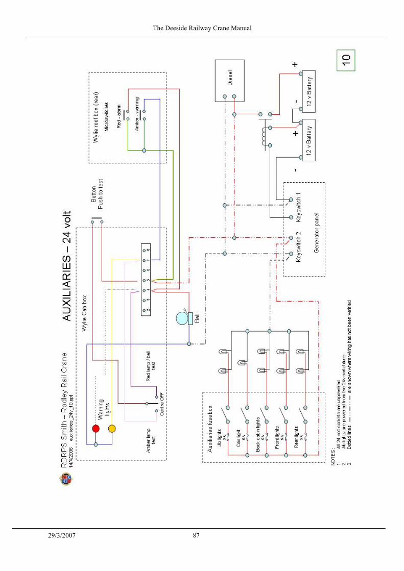
The Deeside Railway Crane Manual
29/3/2007 87

The Deeside Railway Crane Manual
29/3/2007 88
APPENDIX 12
WYLIE SAFE LOAD INDICATOR MANUAL
SETTING INSTRUCTIONS FOR WYLIE MODEL DLT,
DIP(0) and OLP AUTOMATIC SAFE LOAD INDICATORS
(For Rope Operated Machines)
WYLIE SAFE LOAD INDICATORS LTD. Menzies Road, Ponswood Industrial Estate, Hastings, Sussex TN34 1X0. Telephone:
Hastings 421235 Telex: 95304 Telegrams: Baradix Hastings
INTRODUCTION

The Deeside Railway Crane Manual
29/3/2007 89
Each Indicator is identified by a serial number stamped on the nameplate, and if any difficulty is met either in testing the Indicator or in future maintenance, it is necessary that this Indicator number be quoted either to the Indicator manufacturer or his distributor. TYPE OF MOUNTING The DL Indicator is supplied mounted on a variety of steel frames to adapt the Indicator to be suitable for fitting to different types of cranes or in different positions to suit the rope reeving of the crane. Depending on the adaptation the frame may be of DLT type (Figure 1), taking the tension load from a pulley or rope, DLP type (Figure 3), deflecting the hoist rope, or OLP(0) type (Figure 2), measuring the force in one of the crane ropes by deflecting it from its true line by a pulley deflection unit. The end connections and other details of the frames will differ from the illustrations depending on the crane details, and the correct General Arrangement drawing showing the Indicator on the crane is issued with each Indicator. Either one or two Indicators may be mounted on the frame and in the latter case each Indicator is used for a separate duty, such as blocked and unblocked ratings with rubber tyre cranes or with crawler cranes one may be set to the main boom load curves and the other for the fly jib load curves. It is also possible to use the single Indicator version for two different duties such as blocked and unblocked, but in this case when the crane changes duty it is necessary to reposition the lever at the back of the Indicator to select the different Indicator setting. To facilitate possible removal, some DLT Indicators (Figure 1) have bolted end connections to which links are added to suit the crane structure. It is essential that fitted bolts are used for these connections and on no account must clearance bolts be used. If the connections are ~supplied by the crane owner, templates are available from Wylie to correctly space the matching holes in the parts supplied by the crane owner. HOW IT WORKS The DL Indicator is shown on Figure 4 and the force from the crane is applied through plunger 14 to the internal leverage system in the Indicator. The leverage system is altered by cam 66 so that depending on the point of contact of roller 23 on the cam, the switches 50 will give warning with different loads. The cam 66 is rotated by lever 72 (Figure 5a) which is connected to a fixed part of the crane which will cause the lever to assume a different position relative to the Indicator at different crane radii. A typical arrangement of the cam control on a DLT Indicator is shown diagrammatically on Figure 5a. (Figure 5b shows an alternative method of control using cable control.)

The Deeside Railway Crane Manual
29/3/2007 90

The Deeside Railway Crane Manual
29/3/2007 91
To make the operation of the Indicator clear, the lever carrying the pulley has been shown cranked with an offset about its pivot, thus causing a force on plunger 14 due to the load on the rope but, in most OLT models, the same effect is obtained by making the lever straight and mounting it on an eccentric pivot at O. As the cam is cut closer to its centre the lever in the Indicator control box assumes a position which will permit the Indicator to take a heavier load before the warning signals are given. The mechanism is adjusted prior to leaving the maker's works so that the range of loading which will be met on the crane is within the limits of the cam roller touching the cam holder with heavy loads and being on the extreme surface of the uncut cam with light loads. For this reason each Indicator is only suitable for the crane for which it is supplied. To agree with the load rating of the crane it is necessary to determine the shape of the cam under actual load test at site. Where blocked and unblocked load curves have to be dealt with by a single Indicator, one sector of the cam is used for the unblocked rating and a different sector is used for the blocked rating. Each sector has to be cut separately and evenly joined up so that when moving the lever at, the back of the Indicator to change from blocked to unblocked condition the cam roller can roll freely from one sector to the other (see dotted part of cam in Figure 121. When the cam has been correctly cut the amber light will indicate approach to maximum safe load anti the red light and bell will give warning when maximum safe load is exceeded. MI additional normally closed circuit is fitted to allow the safe load Indicator to operate a cut out (see Figures 7a and 7b.) Where Indicators are fitted to new cranes, cam cutting is usually completed by the Cranemaker before despatch of the crane, and no further site adjustments are necessary. On certain cranes it is also possible for tie Indicator Manufacturer to supply cams already cut to the shape required for the load curves. These bear a' "WTC" reference number for identification purposes. ASSEMBLY ON CRANE Before the site test, check that the Indicator is fitted correctly to the crane and for this purpose a General Arrangement drawing can be supplied by the Indicator Manufacturer or his distributor. (For certain applications a typical installation drawing only is supplied.) CAM CONTROL MECHANISM Indicators will either be supplied with a cam control mechanism similar to that shown in Figure 5a or 5b. The arrangement drawing will show which system is used. In the case of rod type control (see Figure 5a and 6a), first check that the hole A shown in Figure 5a is correctly positioned and connect the control rod between this hole and the correct hole (shown on the Arrangement Drawing) in the lever 72 on the back of the Indicator control box, nearest to the "A" frame shaft'. Also check that the length of the rod is correct. With the boom at minimum radius check that angle "B" is not less than 30° and that there is no possibility of lever 72 and the cam rod moving into the "in line" position.' If a different angle is required, this will be marked on the Arrangement Drawing. The crane boom should now be lowered from minimum radius position to maximum radius position to check that there is freedom of movement on the cam rod without any causes of stress being developed due to the angle between the levers and the cam rod becoming too acute.

The Deeside Railway Crane Manual
29/3/2007 92
If the boom can be lowered to ground level, then it should also be checked that this throws no undue stress on the cam rod. It will be noted that there is a screwed adjustment on the cam rod permitting it to be altered in length. For cable type control, see Figure 5b and 6b, the cable should be connected between the disc mounting on the "A" frame shaft and the disc on the back face of the Indicator. The diameter of the two discs should allow an angular movement of the disc on the Indicator box of not less than 60' for change in-main boom position from minimum radius to maximum radius. If the boom can be lowered to ground level, then it should also be checked that this throws no undue stress om the cable system. As shown in Figure 6a and 6b, the Indicators may be fitted either with a gear lever to select a different cam sector, or alternatively fora 2, 3 or 4 armed lever, pinned by fixing screw 73 to the cam control lever 72 (see Figure 6a). Both gear lever and star lever can be rotated to different positions to select a new sector of the cam for a different load curve. With single Indicators on cranes, having only two different rated conditions, e.g. a crane having only one boom used with blocked and free on tyres load curves, the cam control lever 76 has only two arms. In this case attachment of the cam control lever 72 (Figure 6a) to either arm brings into operation either the blocked or free on tyres sector of the cam. On cranes having several boom lengths a 2, 3 or 4 arm cam change lever (item 76, Figure 6a) is fitted to the Indicator so that there may be up to four different sectors of the cam available for the different boom lengths. When the sectors have been used for particular load curves, further sectors must be cut on a new cam. Where this is necessary it is desirable to have a summary chart in the driver's cabin; similar to that shown on page 14 defining the cam sectors and different cam numbers required for each boom length. WARNING SIGNAL UNIT Mount the light signal unit and bell in a convenient place, readily visible to the driver and wire up in accordance with the wiring diagram. The standard wiring diagram for the Indicator is given in Figure 7. This wiring diagram is only suitable for cranes having 12 or 24 volt starting equipment and where this voltage supply is available to the Indicator. On cranes not fitted with a battery, the Indicator can be supplied with its own battery, but a separate wiring diagram will be required, and this is obtainable either from the manufacturer or distributor. A special diagram, is also required if the Indicator is to be fitted to an electric crane where mains supply is used. On Indicators fitted to new cranes, the crane maker sometimes departs from the wiring diagram on Figure 7, and in such cases reference should be made to the diagram in the "Cranemaker's Handbook". Single box Indicators are supplied with signal units suitable for subsequent conversion to a twin unit if the Indicator design permits. It is important that the wires to the Indicator switches are connected to terminals 4, 5 and 6 of the Light Signal Unit. It will be noted from Figure 7 that the switch in the main boom Indicator is cross connected so that this Indicator is always in circuit.

The Deeside Railway Crane Manual
29/3/2007 93

The Deeside Railway Crane Manual
29/3/2007 94
To test that the Indicator has been correctly wired, lever 33 (Figure 4) can be pushed clockwise until it operates switches 50. The amber light is operated by the front switch and the red light and bell by the rear switch. On modern Indicators the striker for the red switch is adjustable but this must only be altered after carefully reading the section of these instructions headed "Load Test". Before despatch the switches are adjusted so that the amber light will show with approximately 10 per cent lighter load than the red light signal. During the load test the cam will be cut to make the red light show at given test loads, and if it is desired to alter the load at which the amber light gives warning, perhaps to increase the degree of warning of this signal, the amber switch can be adjusted by means of a lock nut and screw. A push button is fitted to the light signal unit. If the red light and bell do not function when the button is pressed, this indicates a fault either in the lamp, bell or connecting wiring. On certain Indicators a green light is also fitted and this stays on while the crane is operating. The bell must be placed in a position where it will give a clear warning both to the crane driver and any other person in the immediate vicinity of the crane. On twin box Indicators a changeover switch is provided on the warning unit. This switch permits selection of the correct Indicator to suit the operating conditions, e.g. lifting duties on outriggers, or free on tyres. LOAD TEST Unless specified by the maker it is best to test the Indicator first with the minimum boom length and also to start with the highest rated crane loadings. With twin Indicators normally the Indicator furthest from the jib head is the one which should be used for the heaviest rates loads. Any deviations from this ruling will be shown on the General Arrangment drawing. The positions of the lever 76, or the gear selector lever, shown in Figure 6a and 6b, must be clearly marked for each cam sector which is cut. It is normal also to stamp the sector of the cam which is cut with the duty concerned, e.g. 15 m boom length on outriggers. DLT Type Indicators The full test loads corresponding to all the rated radii on the Crane Maker's Load Schedule should be available before starting the test. When lifting the test loads referred to in the following instructions the radius should be checked by measuring tape and it is also necessary that the crane should be on level ground with the tyres correctly inflated for duties free on wheels. Instead of arranging for the bell to ring at full rated loads it is sometimes permissible, if adequate safety margins are available, to allow the red light "Overload" signal to be given slightly in excess of the rated load. Unless otherwise stated on the General Arrangement drawing, it is recommended that this overload should never exceed 10 per cent above the crane maker's ratings. In the following test instructions this load will be referred to as the "Test Load".

The Deeside Railway Crane Manual
29/3/2007 95
To avoid damage to the Indicator it is delivered with the cam roller removed and it is most important that the first part of the test is completed before the cam roller is fitted. Cutting the cam without the roller in position is possible by treating the portion of lever 20 marked C in Figure 4 as if it were the roller. This permits the position of the cam roller to be scribed on the cam blank prior to cutting and the approximate point of contact of the roller can thus be marked on the cam blank. During the test load, lever 20 can be held in different positions by fitting the hook bolt supplied with the Indicator, in the manner shown in Figure 8. Before calibration is started the cam follower adjuster nut E must be turned to bring the roller cam lever close to the circular cam holder. Each cam point should then be found by tightening the nut E so that the cam lever gradually moves away from the cam holder until the correct position is found when lifting the Test Load at the correct radius. Until the cam is finally cut the cam lever 20 must be kept against the cam holder otherwise serious overloading of certain parts of the Indicator will occur. With the boom at minimum radius (boom hard in) the appropriate Test Load for this radius should be lifted with the hoist block reeved to the correct number of falls for that load and position of cam lever 20 adjusted until the red light just shows. A mark should be made. on the face of the cam by scribing round the boss C of the lever 20 and also scribing a radial mark approximately where the cam roller would make contact with the same as shown in Figure 8. If the same load rating also applies to a greater radius than the minimum radius then the above test must be repeated at the new radius and also at intermediate points as considered necessary. The test procedure should be repeated with the appropriate Test Load at each different radius of the cranemaker's schedule of load ratings (Figure 9 shows the subsequent form of the cam). The points of contact where the roller would touch the cam at each rated radius are then joined by a curve as shown in Figure 10. The shaded area should be cut away to within 1 mm of the curve and the cam carefully replaced in its correct position. Now the cam roller can be fitted. Tighten the roller set screw and check that the roller is still free to rotate. Remove the hook bolt and clamp. If it is found when lifting the Test Load that the desired position of the cam roller is beyond the surface of the cam blank or alternatively fouls the cam holder, then advice should be obtained from the Indicator maker or distributor before the test can proceed. The Test Load should again be lifted at each rated radius and the cam filed at the points of contact of the roller with the cam until the red light just shows and the bell rings. During this part of the test it is best to lower the load to the ground and lift slowly after each trial filing.

The Deeside Railway Crane Manual
29/3/2007 96
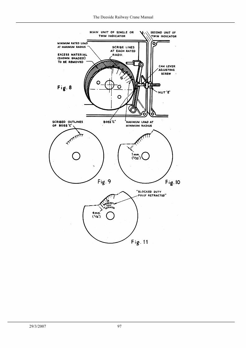
The Deeside Railway Crane Manual
29/3/2007 97

The Deeside Railway Crane Manual
29/3/2007 98
It will assist future maintenance if the roller contact point at a rated radius halfway between minimum and maximum is clearly marked with a chisel cut and with an identifying number corresponding to the radius. On the typical cam in Figure 11 the number "10" shows that the chisel mark has been made at the 10 m radius. The contact point at maximum and minimum radii should also be marked with a deep scribe or chisel mark which will be permanent. Each end of the cut portion of the cam should be extended 6 mm at the same radius as the last mark. If the Indicator has to be adjusted for only one condition a curve is drawn as shown in Figure 8 and the shaded portion removed, but if it has to be adjusted for more than one condition, e.g. blocked or unblocked, or for different lengths of boom, then the cam roller should be removed before proceeding further With the test and arm 76 (see Figure 6a), or the selector lever (see Figure 6b), should be rotated to a different position bringing a fresh part of the cam adjacent to the cam roller. The complete test should then be repeated with the new load ratings and when the surface of the new cam has been finally completed it can be merged into the previous cam surface by a smooth curve. Figure 12 shows the correct trimming of a combination cam with two working conditions. Where two Indicators are fitted to a common frame the foregoing test procedure applies individually to each Indicator. On certain cranes having alternative boom lengths, the shorter boom may have blocked and unblocked ratings but the long booms only have blocked ratings, and cams for these are therefore only required in the blocked 'Indicator box. The unblocked cam should NOT be left uncut but should be trimmed so that there is a smooth curve joining the cut sectors of the cam as shown in the two sector cam of Figure 12. Check that the cam bolts have been tightened and replace the cover. Where Indicators are supplied complete with the crane as original equipment they will have been adjusted by the crane maker to cover certain boom variations and care must be taken that these ratings and boom lengths are known to the crane operators and that no other combinations are used without reference to the crane maker. DLP(0) and OLP Indicators This type of Indicator is fitted with a transit bolt to prevent damage due to mishandling before the Indicator is erected on the crane. The bolt, which is painted white, locks the pulley lever solid with the pulley frame and must be removed before proceeding with the Load Test. The Load Test as described for the OLT type Indicator also applies to DLP(0) and DLP Indicators. If it is found when lifting the Test Load that the position of the cam roller is beyond the surface of the cam blank, then the pulley adjuster should be used to vary the rope deflection.

The Deeside Railway Crane Manual
29/3/2007 99
The adjustment is clearly marked on the General Arrangement drawing and should be used to adjust the force on the Indicator so that, with the maximum derrick rope force, the red light and bell operate when the cam roller is close to the cam holder. This permits the full range of the cam blank to be available for the range of forces arising from the maximum to minimum loads. Normally the rated load at maximum radius will give the maximum derrick rope force for any given boom. After selection of the correct' position, carefully lock the nuts of the adjuster and then proceed with the test as described for the OLT type. Where DLP(0) units are supplied as original crane equipment on multi-boom length cranes, it is imperative that the cranemaker's recommended length of pendant tie ropes are closely adhered to for each jib length combination, as any variation from the lengths used during the original calibration will affect the accuracy of the unit. When pendant ropes are renewed the accuracy of the Indicator should be checked by lifting a Test Load. It is essential that fitted bolts be used to fasten the Indicator baseplate to the bridle to ensure accurate positioning of the Indicator if it is removed at any time for repair and on re-assembly these must be replaced by clearance bolts. A similar adjuster is supplied for DLP Indicators, and this is illustrated on the Arrangement Drawing of the Indicator. If the maximum and minimum load range for this Indicator cannot be obtained within the depth of the cam profile, the Indicator manufacturer or distributor should be contacted. Load Test of Constant Load Indicator This type of Indicator can be supplied either in OLT, DLP(0) or DLP specification. It is used on those cranes where the Indicator need only be set to one load and because of this a cam control mechanism is not required and the internal cam, which is necessary to accommodate variable loads, is also not required. The form of this Indicator is shown in Figure 13. The Indicator is set by adjusting the screw 151, thereby adjusting the position of the track rollers shown in Figure 13. This screw is then locked in the position necessary to just bring on the Indicator signal. Care should be taken when adjusting the screw under test load that the track rollers line up with the roller track. When the adjustment has been completed the alignment should be re-checked. Special Note Most Indicators are fitted with an adjustable striker which activates the red warning switch. Normally it is never necessary to adjust this striker. Only if the Indicator is supplied with a factory cut cam may this striker be adjusted by a small amount (not more than .010"). This adjustment may be carried out when the initial Test Load on the basic boom is lifted, so that the Indicator setting can be exactly set to the load concerned, without adjustment to the already established profile of the cam. After this adjustment has been made the striker should be locked and a check made to ensure that the red signal is just on for a particular load. Checks should then be made to ensure that the signal is being given correctly at other loads, at other radii, and if the loads at which the Indicator gives a signal are
The Deeside Railway Crane Manual
29/3/2007 100
varying from the correct test loads, the Indicator manufacturer or distributor should be contacted before proceeding further. MAINTENANCE To check that the switches are operating, it is desirable at weekly intervals to remove the cover from the Indicator and push the switch striker until the two switches progressively close, and check that they are correctly operating the warning signals. When making this routine check on the switches look for nuts or other parts which may have slackened by vibration and tighten where necessary. The lever pivots of the Indicator are greased for life and do not require attention, but thin oil should be dropped on the cam roller and spindle and rubbed on any parts which show signs of rust. A light grease should be coated over the length of cam control cable or some light oil applied to the joints at either end of the cam control rod...whichever is applicable. If the cam control rod/wire is damaged, it should be immediately repaired and, on replacement, a check must be made that it rotates the cam to the correct angular position. For this purpose a load is derricked to the radius corresponding to the mid-angle chisel mark on the cam (see Test Instructions page 8). If the cam roller does not line up to the scribe mark the cam control rod or wire should be adjusted in accordance with the Indicator arrangement drawing to correct the error. When making this adjustment the radius of load should be measured by measuring tape with the crane on level ground. This method of checking the cam position should always be used if the Indicator has been removed to permit repairs or maintenance of the crane. By derricking to minimum and maximum angle and comparing the points of contact of the roller with the scribed marks on the cam, a check can be made that the cam control mechanism is working correctly. If it is necessary to replace a switch or other part of the Indicator then the accuracy of the warning signals will have to be checked by lifting .a test load at rated test radius. If the red light comes on too soon the striker operating the red switch (nearest back of Indicator) should be adjusted. Under no circumstances should the cam be filed, otherwise a complete series of load tests must be carried out. The red switch movement is limited by a stop hitting lever 33 (Figure 4) the clearance between lever 33 and stop should be adjusted to between .015" and .020" when the red switch has just operated. An optional extra for tension type units (DLT types) is the provision of a lock out device for use when a crane is converted for dragline usage. This prevents the load from the operating lever being transferred to the DL box. When ordering spare parts always quote the serial number of the Indicator and the part number given on the Spare Parts List.

The Deeside Railway Crane Manual
29/3/2007 101

The Deeside Railway Crane Manual
29/3/2007 102
ADDENDUM TO MAINTENANCE INSTRUCTIONS
PLEASE NOTE IF HARDWOOD PACKING BLOCKS ARE USED FOR INSTALLATIONS, IT IS RECOMMENDED THAT THE BOLTS AND NUTS
SECURING THE BLOCKS BE CHECKED FOR TIGHTNESS AT LEAST ANNUALLY
SUMMARY OF DO'S AND DONT'S 1. Never use an Indicator except on the crane for which it was supplied. 2. Test the warning signals each shift by using the push button (page 9). 3. At the initial load test do not place the cam roller in position until
the cam has been cut to shape (page14). 4. With a single Indicator having separate cam sectors for blocked and
unblocked load curves, always use the blocked sector when 1 lifting the boom from the ground.
5. When changing cams do not have a load on the crane hook. It is advisable to position the boom at minimum radius.
6. Where the Indicator has more than one cam sector always be sure that the correct cam sector has been selected to suit the boom length or operating condition.
7. With twin Indicators always be sure that the switch on the Light Signal Unit is in the correct position for the operating condition being used.
8. Be sure that the rope reeving is the same as used for the Indicator test.
9. If the cam control rod/wire or other portion of the Indicator is damaged, repair it immediately. Then check the Indicator setting as described on page 12.
10. If the cam control rod or wire is removed, pay particular attention to the instructions on page 14.
11. Cover nuts should be evenly tightened to ensure that the Indicator is waterproof, replacing seal if necessary.
PATENTS The Indicators described in these Instructions may include items covered by British Patent Nos. 978,822; 980,132; 133,756; 183,190; 191,866; 310,012; and U.S.A. Patent Nos. 3,123,814; 3,148,659. Other British and Foreign Patents pending.

The Deeside Railway Crane Manual
29/3/2007 103
Type DL Safe Load Indicator Supplementary Checking Instructions
When Replacing A Cam Control Rod or Ancillary Parts If the cam control rod is damaged or bent it should be immediately replaced and a check must be made that it rotates the cam to the correct radius positions. For this purpose, the load is derricked to the radius corresponding to the mid-radius chisel mark on the cam (see Standard Test Instructions) for the relevant cut-sector for the jib length in use. If the cam roller does not line up with the scribe mark the length of cam control rod can be adjusted to correct the error. When making this adjustment the radius of load should be measured by a measuring tape. If the chisel mark has not been made, then by derricking-in to minimum, and then out to maximum radius and comparing the points of contact of the roller with the scribe marks on the cam, a check can be made that the cam rod has been replaced in correct hole of Lever 72 and that the length of rod is correct. On certain cranes the anchor bracket for the rod is dowelled to the 'A' frame shaft and it is possible that this may have been moved. If, therefore, the original movement cannot be obtained by utilising the existing position of anchor there is no alternative but to set up the cam control mechanism as specified on the GA drawing and re-calibrate to our standard instructions.

The Deeside Railway Crane Manual
29/3/2007 104

The Deeside Railway Crane Manual
29/3/2007 105

The Deeside Railway Crane Manual
29/3/2007 106

The Deeside Railway Crane Manual
29/3/2007 107

The Deeside Railway Crane Manual
29/3/2007 108
APPENDIX 14
LIFTING OPERATIONS APPLICABLE LEGISLATION 1 HEALTH & SAFETY AT WORK ACT 1974
Employers Responsibilities -
It shall be the duty of every employer to ensure, as far as is reasonably practicable the health, safety and welfare at work of all his employees
Employees Responsibilities -
• to take reasonable care for the health and safety of themselves and others who
may be affected by their acts or omissions • they must co-operate with their employers, so far as is necessary, to
enable that duty or requirement to be performed or complied with • no person shall intentionally or recklessly interfere with or misuse any
equipment provided in the interest of health, safety or welfare 2 MANAGEMENT OF HEALTH & SAFETY AT WORK REGS 1992
• requires employers and self-employed persons to assess the risks to workers and any others who may be affected by their undertaking
• employers with five or more employees must also record the significant findings of that assessment assessments should be reviewed and if necessary modified when the nature of the work or the physical conditions of the workplace changes
• suitable and sufficient risk assessments should be carried out by
1. a competent person 2. ensure that all relevant risks or hazards are addressed 3. determine the likelihood of injury or harm arising 4. take into account any existing control measures 5. identity the measures that employers must take in order to comply with
their duties under all applicable health and safety legislation
• generic or "model" risk assessments are acceptable where similar .activities are being undertaken in similar places of work
.

The Deeside Railway Crane Manual
29/3/2007 109
3. PROVISION and USE of WORK EQUIPMENT REGULATIONS 1992
• every employer shall ensure that work equipment is so constructed or adapted as to be suitable for the purpose for which it is used or provided
• the suitability of work equipment should be addressed from three aspects
1. it's initial integrity 2. the place where it will be used 3. the purpose for which it will be used
• in selecting work equipment every employer shall have regard to the
'working conditions and to the risks to the health and safety of persons which exist in the premises or undertaking in which the work equipment is to be used
• ''suitable" means that it must be suitable by design, construction or adaptation for the work it is provided to do and suitable in every respect which it is reasonably foreseeable will affect the safety or health of any person
• risk assessments carried out under the MHSWR will help employers to select work equipment and assess it's suitability for particular tasks
every employer shall ensure:
• that work equipment is maintained in an efficient state, in efficient
working order and in good repair and that where there is a maintenance log it is kept up to date
• the use of work equipment is restricted to those persons given the task of using it
• that all persons who use or supervise the use of work equipment have available to them adequate health and safety information and where appropriate written instructions pertaining to it's use
• that all persons who use work equipment have received adequate training in the methods which may be adopted when using the work equipment, any risks which are entailed and precautions to be taken
• that effective measures are taken to prevent contact with dangerous parts of machinery, this includes measures at four levels - fixed enclosing guards, other guards or protection devices, protection appliances and the provision of information, instruction, training and supervision

The Deeside Railway Crane Manual
29/3/2007 110
4. MANUAL HANDLING OPERATIONS REGULATIONS 1992
• manual handling operations - means any transporting or supporting of a load by hand or bodily force i.e. lifting, pulling, pushing, carrying, putting down or moving thereof by hand or bodily force they refer to the manual handling of loads by human effort as opposed to mechanical handling by a crane or other such equipment
• a load in this context must be a discrete moveable object, but does not include an implement, tool or machine while in use for ifs intended purpose
• the regs seek to prevent injury to any part of the body and as such account should be taken of physical properties which might either effect grip or cause direct injury
• each employer shall so far as is reasonably practicable, avoid the need for his employee to undertake any manual handling at work which involves a risk of their being injured
• where it is not reasonably practicable to avoid the need for the employee to undertake manual handling which involves the risk of injury, the employer shall make a suitable assessment of all such manual handling operations
• the assessment should be carried out by a competent person and shall take into account the task, load, working environment and individual capability
• properly based generic assessments are acceptable if they draw together common threads from a range of broadly similar manual handling operations
• the significant findings of the manual handling assessment should be recorded and the record should be readily accessible, as long as it remains relevant
• REMEMBER - assessment is not an end in itself, merely a structured way of analysing risks and pointing the way to practical solutions
• More than 25% of the accidents reported each year to the enforcing authority are associated with manual handling

The Deeside Railway Crane Manual
29/3/2007 111
5 LIFTING OPERATIONS AND LIFTING EQUIPMENT REGULATIONS 1998
Introduction On the 5th of December 1998 the Lifting Operations and Lifting Equipment Regulations (LOLER) became law. The regulations were made under the Health and Safety at Work Act 1974 (HSW Act) as a means of implementing the lifting provisions of the Amending Directive to the Use of Work Equipment Directive (AUWED, 95/63/EC). Unlike previous legislation used to control the operation and use of lifting equipment LOLER is industry wide, covering all workplaces subject to the HSW Act. This section provides a brief overview of the regulations. Regulation 1 - Citation and. Commencement Synopsis - Lays out the overall scope and timing of the regulations at its highest level. Key Points . Came into effect for all lifting equipment on 5th December 1998.
Regulation 2 – Interpretation Synopsis - A series of definitions used throughout the regulations with the ACoP giving guidance on the equipment and operations which are covered by LOLER, although it is stressed that the list is not exclusive and all work equipment associated with lifting or lowering of a load is covered by the regulations. Key Points Definitions of particular note are: • "lifting equipment" - work equipment for lifting or lowering loads and
includes its attachments for anchoring, fixing or supporting it. • "accessory for lifting" - work equipment for attaching loads to machinery for
lifting (pendant, sling, shackle, etc) • "load" - includes material or people lifted by the lifting equipment • Examination scheme"- suitable scheme drawn up by a competent person for
such thorough examination of lifting equipment at such intervals as may be appropriate for the purpose described in regulation 9
• "thorough examination" - means a thorough examination by a competent person including such testing as is appropriate for the purpose

The Deeside Railway Crane Manual
29/3/2007 112
Examples As the range of LOLER is all encompassing the following list of equipment covered by the regulations is by no means exhaustive: • Pedestal cranes Mobile cranes • Overhead gantry cranes • Loose lifting gear - chain hoists, lever hoists, slings, shackles, pendants etc. • Lifts for persons or goods • Abseiling equipment Sling-sets attached to containers or pieces of
equipment • Runway beams and padeyes to which lifting equipment is anchored or fixed
Regulation 3 – Application Synopsis - Details the where and who to which the regulations apply. The where is anywhere that the HSWA applies and the who is an employer whose personnel use lifting equipment. Key Points - Applies to all work locations covered by the Health and Safety at Work Act. Roles and Responsibilities Although LOLER uses the term employer rather than duty-holder, any duties specifically assigned to the employer can be assumed to apply to the duty holder, if they have any control over lifting operations. Where a company provides personnel to undertake work which will involve the use of lifting equipment then that company is regarded • as an employer and has a duty under LOLER to provide persons competent to
undertake the work. • A duty also rests with the controller of the work to ensure that the competency
of the persons provided can be assured. Regulation 4 - Strength and Stability Synopsis - Calls upon the employer to ensure that the lifting equipment and its load is of adequate strength and stability for the anticipated use. Key Points - To ensure adequate strength and stability you must:

The Deeside Railway Crane Manual
29/3/2007 113
• Take account of the combination of forces which the equipment may be subjected to
• Assess the implication of the weight of any accessories • Ensure that the equipment is not susceptible to in-service failure modes
(fracture, wear or fatigue) • Have an appropriate factor of safety against foreseeable failure modes • Take account of any combination of destabilising forces • Provide resistance to overturning • Where there is a significant risk of overload, then the lifting equipment should
be fitted with equipment, which provides an audible, and/or visual warning before an overload situation is reached.
Although the load does not fall within LOLER it is incumbent upon the employer (person in control of the lifting operations) to ensure that any lifting points on the load are of adequate strength. Examples Points provided on a load to assist with lifting are regarded as part of the load and do not fall under LOLER; for example padeyes built into a container. However, screw-in eyebolts would be regarded as lifting accessories and would be covered by LOLER. Equipment typically used for warning of overload is a Rated Capacity Indicator (previously called Automatic Safe Load Indicators, ASLI's). Regulation 6 - Positioning and Installation Synopsis - A very straightforward regulation whereby equipment must be positioned and installed so as to minimise the risk of the equipment or its load striking a person or of control over the load being lost. Key Points In particular lifting equipment should be installed in such a way that:
• The need to lift loads over people is minimised • Crushing is prevented at extreme operating positions • Loads moving along a fixed path are suitably protected to minimise the risk of
the load or equipment striking a person • Trapping points are prevented or access limited on travelling or slewing
equipment The employer must also minimise the risk of a load:
• Drifting - runway beams should be level and tag lines used to control the movement of long or awkwardly shaped loads

The Deeside Railway Crane Manual
29/3/2007 114
• Falling freely - through the fitting of suitable devices such as multiple ropes, safety gear or check valves
• Being unintentionally released during a loss of power to the lifting equipment or through the collision of equipment or their loads. The use of hooks with safety catches, motion limiting devices and safe systems of work are possible means of minimising these risks.
Regulation 7 - Marking of Lifting Equipment Synopsis - A basic requirement to mark the Safe Working Load of the lifting equipment on the equipment, or to make readily available to the operator such information Key Points • Safe Working Load (SWL) - the maximum load that the equipment may
safely lift. • If it is not possible to mark the equipment with the SWL then a coding system
or labels may be used. • If the SWL is dependent upon the configuration of the equipment then the SWL
for each configuration should either be marked on the equipment or the information kept with the equipment where it is readily available to the operator, for example load-radius charts.
• Where the SWL changes with the operating radius of the equipment then a load-limiting device may need to be fitted to inhibit the equipment and provide visual and/or audible warnings.
• Lifting equipment designed for lifting persons should be marked as such and the carrier should display the SWL and maximum number of persons, which may be carried.
Regulation 8 - Organisation of Lifting Operations Synopsis - The basis upon which all other regulations in LOLER are formed this regulation calls for all lifting operations to be carried out in a safe manner, under adequate supervision and following a plan. Key Points
• The competent person planning the operation should have adequate practical and theoretical knowledge and experience of planning lifting operations.
• The plan will need to address the risks identified during a risk assessment and should identity all resources, procedures and responsibilities necessary for safe operation.
• The degree of planning will vary considerably depending on the type of lifting equipment and complexity of the lifting operation and degree of risk involved.

The Deeside Railway Crane Manual
29/3/2007 115
• There are two elements to the plan: the suitability of the lifting equipment as per Regulation 4 of PUWER and the individual lifting operation to be performed.
Roles and Responsibilities Under Regulation 8 the employer or controller of lifting operations has a primary responsibility to ensure that suitable persons are appointed for planning and supervising of such operations. For any lifting operation it is necessary to:
(a) Carry out a risk assessment under the MHSWR (b) Select suitable equipment for the range of tasks (c) Plan the individual lifting operation
Examples The term "Competent Person" is not prescriptively described in LOLER and is used to identity a number of different roles under the regulations. In practical terms the competency of a person may be confirmed by formal, vocational qualification or through first hand knowledge of planning or supervising the lifting operations. Reference should be made to the following publications for more explicit guidance on the safe use of particular items of lifting equipment: • British Standard BS 7121 - Code of Practice for Safe Use of Cranes Regulation 9 -Thorough Examination Synopsis - Throughout the life of any piece of lifting equipment it must be accompanied by a valid certificate to show that it has been manufactured properly and subsequently received thorough examinations to ensure continued integrity and fitness for safe use. This regulation presents the owner and user of lifting equipment with a number of options, some prescriptive, for establishing examination schemes. The term "inspection" has a special meaning under LOLER and in general "thorough examination" should always be used. Key Points • Employer must identify all equipment, which requires thorough examination. • The employer shall ensure that lifting equipment transferred in or out of his
undertaking has a valid thorough examination record.

The Deeside Railway Crane Manual
29/3/2007 116
In-Service • All lifting equipment deteriorates in use and therefore a thorough examination
must be carried out. • A choice exists, either to have the lifting equipment thoroughly examined at
intervals no longer than those specified in the regulation or in accordance with intervals specified in an examination scheme
• Thorough examination intervals under the fixed scheme:
1. every 6 months if the equipment is used for lifting persons 2. every 6 months for lifting accessories (slings, shackles etc) 3. every 12 months for all other lifting equipment (chain hoists, lever hoists etc)
• A thorough examination must. be carried out following exceptional circumstances which may have jeopardised' safety of the equipment; for example, following an overload or change out of a major load path item
• In addition to thorough examinations, where user risks have been identified inspections should be carried out. The inspection should include visual checks and function tests and be carried out by persons competent to do so
Regulation 10 - Reports and Defects Places a duty on the examiner to provide a report of examination to Employer and HSE in certain circumstances Regulation 11 - Keeping of Information − Keeping of information to ensure that initial conformity, certificates and examination reports follow a piece of equipment. Schedule 1 Information for Report of Thorough Examination contains a list of eleven pieces of information which must be recorded.

The Deeside Railway Crane Manual
29/3/2007 117
APPENDIX 15
HOOK HEIGHT PROFILE

The Deeside Railway Crane Manual
29/3/2007 118
APPENDIX 16
POLYESTER SLING RATINGS