SuperLite 27 Helmet Operations and Maintenance Manual
153
Diving with compressed breathing gas is a hazardous activity. Even if you do everything right there is always the danger that you may be killed or injured. No piece of diving equipment can prevent the possibility that you may be killed or injured any time you enter the water. SuperLite ® 27 Helmet Operations and Maintenance Manual KMDSI Part # 100-027 Kirby Morgan Dive Systems, Inc. 1430 Jason Way Santa Maria, CA 93455, USA Telephone (805) 928-7772, FAX (805) 928-0342 E-Mail: [email protected], Web Site:www.KirbyMorgan.com Manual prepared by Marine Marketing and Consulting, Dive Lab, Inc., and KMDSI. NOTE: This manual is the most current for the SuperLite 27 Helmet. It is page dated May 2008. Future changes will be shown on page III and the changed pages will carry the date of change. Previous manuals may not reflect these updates. ™ Document Number 080528001 Kirby Morgan, SuperLite, BandMask, Band Mask, KMB, KMB-Band Mask, DSI, Diving Systems International, EXO, REX, SuperFlow and DECA are all registered trademarks of Kirby Morgan Dive Systems, Inc. Use of these terms to describe products that are not manufactured by KMDSI is illegal. The two dimensional images (such as photographs and illustrations) of our products are © copyrighted and trademarks of Kirby Morgan Dive Systems, Inc. The three dimensional forms of our products are trademark, trade design and trade dress protected. © Copyright 1970-2007 Kirby Morgan Dive Systems, Inc. All rights reserved. This manual is made available for the express use of the owner of this Kirby Morgan product. No part of this manual may be reproduced, stored in any retrieval system, or transmitted, or used in any form or by any means, whether graphic, electronic, mechanical, photocopy, or otherwise by technology known or unknown, without the prior written permission of Kirby Morgan Dive Systems, Inc. The SuperLite 27 helmet is CE Approved and meets or exceeds all performance and testing require- ments of all government and non-government testing agencies throughout the world. It is approved for use on all commercial and military work underwater. Only Kirby Morgan masks and helmets have achieved the CR (Commercial Rated) mark, the highest United States of America rating. WARNING
-
Upload
khangminh22 -
Category
Documents
-
view
1 -
download
0
Transcript of SuperLite 27 Helmet Operations and Maintenance Manual
Diving with compressed breathing gas is a hazardous activity. Even if you do everything right there is always the danger that you may be killed or injured. No piece of diving equipment can prevent the possibility that you may be killed or injured any time you enter the water.
SuperLite® 27 HelmetOperations and Maintenance Manual
KMDSI Part # 100-027
Kirby Morgan Dive Systems, Inc.1430 Jason Way
Santa Maria, CA 93455, USATelephone (805) 928-7772, FAX (805) 928-0342
E-Mail: [email protected], Web Site:www.KirbyMorgan.com
Manual prepared by Marine Marketing and Consulting, Dive Lab, Inc., and KMDSI.
NOTE: This manual is the most current for the SuperLite 27 Helmet. It is page dated May 2008. Future changes will be shown on page III and the changed pages will carry the date of change. Previous manuals may not reflect these updates.
™
Document Number 080528001
Kirby Morgan, SuperLite, BandMask, Band Mask, KMB, KMB-Band Mask, DSI, Diving Systems International, EXO, REX, SuperFlow and DECA are all registered trademarks of Kirby Morgan Dive Systems, Inc. Use of these terms to describe products that are not manufactured by KMDSI is illegal.
The two dimensional images (such as photographs and illustrations) of our products are © copyrighted and trademarks of Kirby Morgan Dive Systems, Inc. The three dimensional forms of our products are trademark, trade design and trade dress protected.
© Copyright 1970-2007 Kirby Morgan Dive Systems, Inc. All rights reserved. This manual is made available for the express use of the owner of this Kirby Morgan product. No part of this manual may be reproduced, stored in any retrieval system, or transmitted, or used in any form or by any means, whether graphic, electronic, mechanical, photocopy, or otherwise by technology known or unknown, without the prior written permission of Kirby Morgan Dive Systems, Inc.
The SuperLite 27 helmet is CE Approved and meets or exceeds all performance and testing require-ments of all government and non-government testing agencies throughout the world. It is approved for use on all commercial and military work underwater. Only Kirby Morgan masks and helmets have achieved the CR (Commercial Rated) mark, the highest United States of America rating.
WARNING
SuperLite 27
II © Copyright 1970-2008 Kirby Morgan Dive Systems, Inc. All rights reserved. Document # 080528001
WARRANTY INFORMATIONKirby Morgan Dive Systems, Inc. warrants every new mask, helmet, or KMAC Air Control System to be free from defects in workmanship for a period of ninety (90) days from date of purchase. This warranty covers all metal, fiberglass, and plastic parts. This warranty does NOT cover rubber parts, communications components, or headliners. In addition, due to the electrolytic nature of underwater cutting and welding, chrome plating cannot be warranted when the diver engages in these activities.
Should any part become defective, contact the nearest authorized KMDSI dealer. If there is no dealer in your area, contact KMDSI directly at (805) 928-7772. You must have a return authorization from KMDSI prior to the return of any item, Upon approval from KMDSI, return the defective part, freight prepaid, to the KMDSI plant. The part will be repaired or replaced at no charge as deemed necessary by KMDSI.This warranty becomes null and void if:1) The product is not registered with KMDSI within ten (10) days of purchase.2) The product has not been properly serviced and/or maintained according to the appropri-
ate KMDSI manual. In addition, the user is responsible to ensure that all product updates as recommended by KMDSI have been performed.
3) Unauthorized modifications have been made to the product.4) The product has been abused or subjected to conditions which are unusual or exceed the
product’s intended service.
NOTE: Be sure to complete the enclosed warranty card and return it to KMDSI immediately. No war-ranty claims will be honored without a satisfactorily completed warranty card on file at KMDSI.
SuperLite 27
III© Copyright 1970-2008 Kirby Morgan Dive Systems, Inc. All rights reserved. Document # 080528001
It is the responsibility of the owner of this product to register their ownership with Kirby Morgan Dive Systems, Inc., by sending the warranty card provided. This card is to establish registration for any necessary warranty work and provides a means of communication that allows KMDSI to contact the user regarding this product. The user must notify KMDSI of any change of address by the user or sale of the product.
All changes or revisions to this manual must be recorded in this document to ensure that the manual is up to date.
RECORD OF CHANGES
Change Number Date Description of Change Page Number
1 05/28/2008 Reworded: 2.1 Product Specifications, 2.4 Operational Specifi-cations & Limitations, Warning bottom left on page 23
Added: 2.2.1 SuperFlow® and SuperFlow® 350 Demand Regu-lators, 2.2.2 SuperFlow® 450 Performance, Appendix A2, 3 and 4.
Moved: 2.3 Cage Code to page 23
Removed: Tables 1 and 2 from chapter 2
22-23, 146-153
SuperLite 27
IV © Copyright 1970-2008 Kirby Morgan Dive Systems, Inc. All rights reserved. Document # 080528001
Diving with compressed breathing gas is a hazardous activity. Even if you do everything right there is always the potential for serious injury or death. No one piece of diving equipment can prevent the possibility that you may be injured or killed any time you enter the water. We do not herein make any effort to teach the principles of diving. The information in this manual is intended for users of Kirby Morgan helmets and persons that maintain or service Kirby Morgan helmets.
WARNING
SuperLite 27
V© Copyright 1970-2008 Kirby Morgan Dive Systems, Inc. All rights reserved. Document # 080528001
ContentsDefinition of Signal Words Used in this Manual X
Chapter 1.0 - General Information KMDSI Products 151.1 Introduction 151.2 The Kirby Morgan Diving Helmets, Masks & Air Control System 16
Chapter 2 - Description & Operational Specifications - SuperLite-27 222.1 Product Specifications 222.2 Regulator Performance 222.3 Cage Code 222.4 Operational Specifications & Limitations 232.5 Helmet Features 252.6 General Description 282.6.1 Helmet Shell 282.6.2 Gas Flow Systems 282.6.3 Emergency Gas Supply System (EGS) 302.6.4 Helmet Attachment to the Diver 312.6.5 Locking Sealed Pull Pins 312.6.6 Sealing Arrangement 322.6.7 Reducing Carbon Dioxide 322.6.8 Communications 322.6.9 Equalizing the Middle Ear 322.6.10 Face Port or Viewing Lens 322.7 Accessories 332.7.1 Eye Protection for Welding 332.7.2 Hot Water Shroud 332.7.3 Helmet Carrying Bag 342.7.4 Special Regulator Tools 34
Chapter 3.0 Operating Instructions 353.1 Introduction 353.2 Design Purpose 353.3 First Use of Your Kirby Morgan Diving Helmet 373.4 Initial Adjustments to Your SuperLite 27 373.4.1 Head Cushion 373.4.2 Trimming the Neck dam 373.4.3 Adjusting the Neck Pad 383.5 Pre Dress-In Procedure 393.5.1 Pre-Dive Visual Inspection 393.6 Preparing the Helmet for Diving 403.6.1 Clean Face Port 403.6.2 Check Moving Parts 403.6.3 Check Communications 403.6.4 One Way Valve Check 403.7 Emergency Gas System (EGS) 403.8 Setting Up to Dive 453.8.1 Flushing Out the Umbilical 453.8.2 Connecting the Umbilical to the Helmet 453.8.3 Opening the Breathing Gas Supply to the Helmet 463.8.4 Fogging Prevention 463.8.5 Donning the Helmet 463.8.6 Testing the Breathing System 493.8.7 Sealing Integrity Check 49
SuperLite 27
VI © Copyright 1970-2008 Kirby Morgan Dive Systems, Inc. All rights reserved. Document # 080528001
3.9 Diving Procedures 503.9.1 Standing By to Dive 503.9.2 Attaching the Umbilical to the Harness 503.9.3 Diver Dons Helmet 503.9.4 Diver Check Gas Flow Systems 503.9.5 Communications Check 503.9.6 Diver Ready 503.9.7 Water Entry and Descent 503.9.8 Adjust Regulator for Low Work Rates 503.10 Emergency Procedures 523.10.1 Flooding 523.10.2 Inhalation Resistance 523.10.3 Gas Flow Stops 523.10.4 Demand Regulator Free Flow 523.11 Post Dive Procedures 533.11.1 Removing the Equipment 533.11.2 Removing the Helmet 533.11.3 Storage of the Helmet Between Dives 53
Chapter 4.0 Troubleshooting 544.1 General 544.2 Communication Malfunction 544.3 One Way Valve Malfunction 554.4 Side Block Malfunction 554.5 Water Leakage Into Helmet 554.6 Demand Regulator Malfunction 564.7 Emergency Gas Supply Valve 56
Chapter 5.0 Inspection 575.1 Daily Maintenance 575.2 Monthly Maintenance 575.3 Maintenance to be Performed Every Six Months 575.4 Yearly Maintenance 57
Chapter 6.0 General Preventative Maintenance 586.1 Introduction 586.2 Required tools, Cleaning Agents, Lubrication 586.2.1 Component and Parts Cleaning 596.2.2 Component and Parts Lubrication 596.2.3 Teflon Tape 606.2.4 RTV Sealant 606.2.5 Thread Locker 616.3 General Cleaning & Inspection Procedures 626.3.1 O-Ring Removal/Inspection/Cleaning and Lubrication 63O-Ring Removal: 63O-Ring Inspection: 63O-Ring Reuse: 636.3.2 General Cleaning Guidelines 636.3.2.1 Soap Solution for General Cleaning and Leak Detector Use 636.3.2.2 Acidic Cleaning Solution and Procedures 636.3.2.3 Germicidal Cleaning Solutions and Procedure 636.4 Daily Maintenance 656.5 Monthly Maintenance (or between jobs) 66
SuperLite 27
VII© Copyright 1970-2008 Kirby Morgan Dive Systems, Inc. All rights reserved. Document # 080528001
6.5.1 Locking Collar Assembly & Helmet Ring 666.5.2 Neck Dam Ring Assembly 666.5.3 Head Cushion and Chin Cushion 676.5.4 Communications Inspection 676.5.5 Lubricate Nose Block O-Rings 676.5.6 Inspect the Exhaust Valve 67
Chapter 7.0 Breathing System Maintenance and Repairs 697.1 Introduction 697.2 Torque Values 697.3 One Way Valve 697.3.1 Disassembly Of The One Way Valve 697.3.2 Reassembly of the One Way Valve 707.4 Side Block Assembly 727.4.1 General 727.4.2 Side Block Assembly Removal 727.4.3 Separating the Side Block Assembly from the Helmet Shell 727.4.4 Side Block Assembly Replacement 747.5 Defogger Valve 767.5.1 Disassembly of the Defogger Valve 767.5.2 Cleaning and Lubricating 767.5.3 Reassembly of the Defogger Valve 777.6 Emergency Valve Assembly 787.6.1 Disassembly of the Emergency Valve 787.6.2 Cleaning and Lubricating 787.6.3 Reassembly of Emergency Valve 797.7 Bent Tube Assembly 817.7.1 General 817.7.2 Removal of the Bent Tube Assembly 817.7.3 Inspection of Bent Tube Assembly 817.7.4 Reinstallation of the Bent Tube Assembly 827.8 Demand Regulator SuperFlow 350 827.8.1 Demand Regulator Test for Correct Adjustment, Fully Assembled 837.8.2 Inspection of Regulator Body Interior 837.8.3 Demand Regulator Bias Adj. Servicing, Demand Regulator on Helmet 847.8.4 Reassembly of Adjustment System 857.8.5 Demand Regulator Assembly Removal from Helmet 857.8.6 Disassembly of the SuperFlow 350 Demand Regulator 867.8.7 Inspection of Demand Regulator Parts 887.8.8 Reassembly of the SuperFlow 350 Demand Regulator 897.8.9 Tuning the SuperFlow 350 Regulator 937.8.10 Regulator Steady Flows When Pressured Up: Special Tools Used 947.8.11 Regulator has Low or No Flow When Pressurized 967.8.12 Unexplained Demand Regulator Free Flow 967.9 Oral/Nasal 977.9.1 Oral/Nasal Removal 977.9.2 Inspection of Oral/Nasal 977.9.3 Oral/Nasal Replacement 977.10 Tri-Valve Exhaust 987.10.1 Tri-Valve™ Assembly Removal 987.10.2 Tri-Valve™ Exhaust Valve & Regulator Exhaust Valve Replacement 997.10.2.1 Tri-Valve™ Exhaust Valve Replacement 997.10.2.2 Regulator Exhaust Valve Replacement 1007.10.3 Tri-Valve™ Assembly Installation 1017.11 Main Exhaust Assembly Water Dump 102
SuperLite 27
VIII © Copyright 1970-2008 Kirby Morgan Dive Systems, Inc. All rights reserved. Document # 080528001
7.11.1 Water Dump Valve Removal 1037.11.2 Water Dump Valve Replacement 1037.11.3 Purge Valve Body Removal and Replacement 1037.11.4 Purge Valve Body Installation 1037.11.5 Water Dump Valve Body Removal 1047.11.6 Water Dump Valve Body Remounting 1047.12 Overpressure Relief / Bleed Valve Overhaul Procedures 1057.12.1 Overpressure Relief Valve 1057.12.2 Overpressure Relief Valve Disassembly and Cleaning 1057.12.3 Overpressure Relief Valve Reassembly 1067.12.4 Overpressure Relief Valve Lift Check/Setting 106
Chapter 8 Corrective Maintenance 1088.1 General 1088.2 Helmet Shell Inspection 1088.3 Nose Block Assembly 1098.3.1 Nose Block Assembly Removal 1098.3.2 Nose Block Device Replacement 1098.4 Handle and Weights 1108.4.1 Handle Removal 1108.4.2 Handle Replacement 1108.4.3 Side Weight Removal 1118.4.4 Weight Replacement 1128.4.5 Diamond Weight Removal 1128.4.6 Diamond Weight Replacement 1128.5 Face Port 1138.5.1 General 1138.5.2 Face Port and Nose Block Device Removal 1138.5.3 Face Port and Nose Block Replacement 1148.5.4 Special Note Regarding Ports 1168.6 Neck Dam 1178.6.1 Removal of the Neck Dam 1178.6.2 Neoprene Neck Dam Replacement 1178.6.3 Latex Neck Dam Replacement 1208.6.4 Trimming a Latex Neck Seal 1218.7 Neck Dam Pull Strap 1228.7.1 Neck Dam Pull Strap Removal 1228.7.2 Neck Dam Pull Strap Replacement 1228.8 Chin Strap 1228.8.1 Chin Strap Removal 1228.8.2 Chin Strap Replacement 1228.9 O-Ring Seal Replacement 1238.10 Helmet Ring 1248.10.1 Helmet Ring Repairs 1248.11 Sealed Pull Pins 1248.11.1 Removal of Sealed Pull Pins 1248.11.2 Replacement of Sealed Pull Pins 1248.12 Swing Tongue Catch 1258.12.1 Disassembly of the Swing Tongue Catch 1258.12.2 Reassembly of the Swing Tongue Catch 1268.13 Locking Collar 1278.13.1 Locking Collar Removal 1278.13.2 Locking Collar Disassembly 1288.13.3 Locking Collar Reassembly 1298.14 Head Cushion and Chin Cushion 130

SuperLite 27
IX© Copyright 1970-2008 Kirby Morgan Dive Systems, Inc. All rights reserved. Document # 080528001
8.14.1 Head Cushion Foam 1308.14.2 Chin Cushion Foam 1308.15 Communications System 1318.15.1 General 1318.15.2 Earphone Inspection 1318.15.3 Removal of Communications Assembly 1328.15.4 Replacement of Communications Assembly 1328.15.5 Microphone Replacement 1328.15.6 Earphone Replacement 1338.15.7 Waterproof Connector 1348.15.8.1 Connector Removal 1348.15.8.2 Connector Replacement 1348.15.9 Communications Posts 1348.15.9.1 Communications Post Removal 1348.15.9.2 Communications Post Replacement 135
Chapter 9.0 Accessories for the SuperLite 27 1369.1 Introduction 1369.2 Hot Water Shroud 1369.2.1 Hot Water Shroud Installation Procedures 1369.3 Low Pressure Inflator Hose 1399.3.1 Installation of the Low Pressure Inflator Hose 1399.4 Weld Lens Assembly 1409.4.1 Weld Lens Assembly Installation 1409.5 Weld Shield Assembly 1419.5.1 Weld Shield Assembly Installation 1419.6 Use of Quick Disconnect 141
Table of Equivalents 157Appendix 1: Torque Specifications 158Note on Torque Specifications 159Appendix A2 - Maintenance and Inspection Procedures 160Appendix 3 - Pressure Tables 148Appendix 4 - Standard KMDSI Surface Supply Pressure Formula - Old Method 153
SuperLite 27
X © Copyright 1970-2008 Kirby Morgan Dive Systems, Inc. All rights reserved. Document # 080528001
DANGER
CAUTION
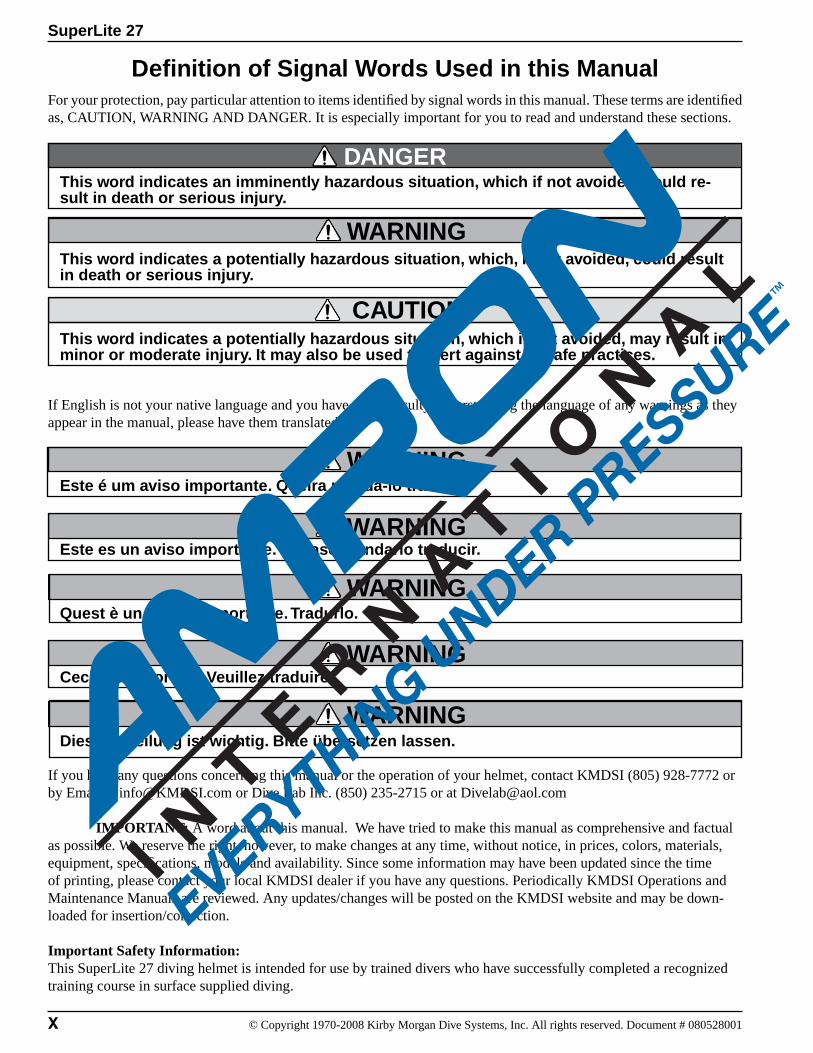
For your protection, pay particular attention to items identified by signal words in this manual. These terms are identified as, CAUTION, WARNING AND DANGER. It is especially important for you to read and understand these sections.
This word indicates an imminently hazardous situation, which if not avoided, could re-sult in death or serious injury.
This word indicates a potentially hazardous situation, which, if not avoided, could result in death or serious injury.
This word indicates a potentially hazardous situation, which if not avoided, may result in minor or moderate injury. It may also be used to alert against unsafe practices.
If English is not your native language and you have any difficulty understanding the language of any warnings as they appear in the manual, please have them translated.
Este é um aviso importante. Queira mandá-lo traduzir.
Este es un aviso importante. Sirvase mandario traducir.
Quest è un avviso importante. Tradurlo.
Ceci est important. Veuillez traduire.
Diese Mitteilung ist wichtig. Bitte übersetzen lassen.
If you have any questions concerning this manual or the operation of your helmet, contact KMDSI (805) 928-7772 or by Email at [email protected] or Dive Lab Inc. (850) 235-2715 or at [email protected]
IMPORTANT: A word about this manual. We have tried to make this manual as comprehensive and factual as possible. We reserve the right, however, to make changes at any time, without notice, in prices, colors, materials, equipment, specifications, models and availability. Since some information may have been updated since the time of printing, please contact your local KMDSI dealer if you have any questions. Periodically KMDSI Operations and Maintenance Manuals are reviewed. Any updates/changes will be posted on the KMDSI website and may be down-loaded for insertion/correction.
Important Safety Information:This SuperLite 27 diving helmet is intended for use by trained divers who have successfully completed a recognized training course in surface supplied diving.
Definition of Signal Words Used in this Manual
WARNING
WARNING
WARNING
WARNING
WARNING
WARNING
SuperLite 27
XI© Copyright 1970-2008 Kirby Morgan Dive Systems, Inc. All rights reserved. Document # 080528001
WARNING
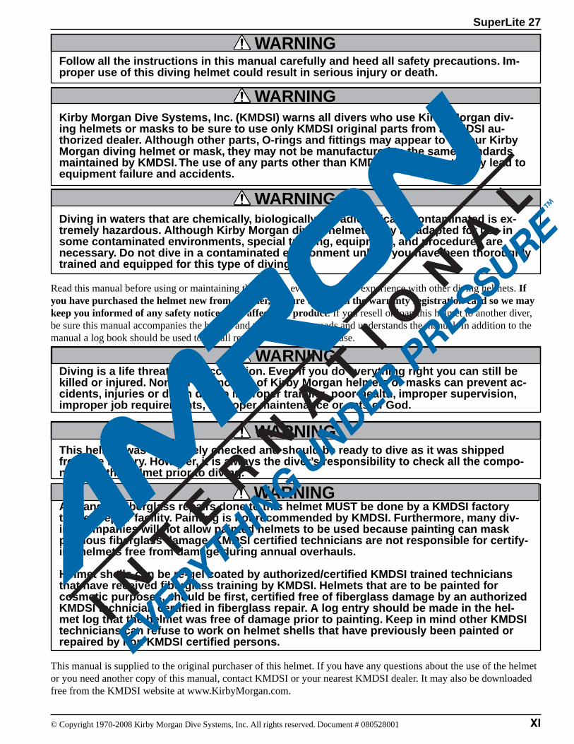
Follow all the instructions in this manual carefully and heed all safety precautions. Im-proper use of this diving helmet could result in serious injury or death.
Kirby Morgan Dive Systems, Inc. (KMDSI) warns all divers who use Kirby Morgan div-ing helmets or masks to be sure to use only KMDSI original parts from a KMDSI au-thorized dealer. Although other parts, O-rings and fittings may appear to fit your Kirby Morgan diving helmet or mask, they may not be manufactured to the same standards maintained by KMDSI. The use of any parts other than KMDSI original parts may lead to equipment failure and accidents.
Diving in waters that are chemically, biologically, or radiologically contaminated is ex-tremely hazardous. Although Kirby Morgan diving helmets may be adapted for use in some contaminated environments, special training, equipment, and procedures are necessary. Do not dive in a contaminated environment unless you have been thoroughly trained and equipped for this type of diving.
Read this manual before using or maintaining the helmet, even if you have experience with other diving helmets. If you have purchased the helmet new from a dealer, be sure to send in the warranty registration card so we may keep you informed of any safety notices that affect this product. If you resell or loan this helmet to another diver, be sure this manual accompanies the helmet and that the person reads and understands the manual. In addition to the manual a log book should be used to log all repairs, maintenance and use.
Diving is a life threatening occupation. Even if you do everything right you can still be killed or injured. None of the models of Kirby Morgan helmets or masks can prevent ac-cidents, injuries or death due to improper training, poor-health, improper supervision, improper job requirements, improper maintenance or acts of God.
This helmet was completely checked and should be ready to dive as it was shipped from the factory. However, it is always the diver’s responsibility to check all the compo-nents of the helmet prior to diving.
Any and all fiberglass repairs done to this helmet MUST be done by a KMDSI factory trained repair facility. Painting is not recommended by KMDSI. Furthermore, many div-ing companies will not allow painted helmets to be used because painting can mask previous fiberglass damage. KMDSI certified technicians are not responsible for certify-ing helmets free from damage during annual overhauls.
Helmet shells can be re-gel coated by authorized/certified KMDSI trained technicians that have received fiberglass training by KMDSI. Helmets that are to be painted for cosmetic purposes, should be first, certified free of fiberglass damage by an authorized KMDSI technician certified in fiberglass repair. A log entry should be made in the hel-met log that the helmet was free of damage prior to painting. Keep in mind other KMDSI technicians can refuse to work on helmet shells that have previously been painted or repaired by non KMDSI certified persons.
This manual is supplied to the original purchaser of this helmet. If you have any questions about the use of the helmet or you need another copy of this manual, contact KMDSI or your nearest KMDSI dealer. It may also be downloaded free from the KMDSI website at www.KirbyMorgan.com.
WARNING
WARNING
WARNING
WARNING
WARNING
SuperLite 27
XII © Copyright 1970-2008 Kirby Morgan Dive Systems, Inc. All rights reserved. Document # 080528001
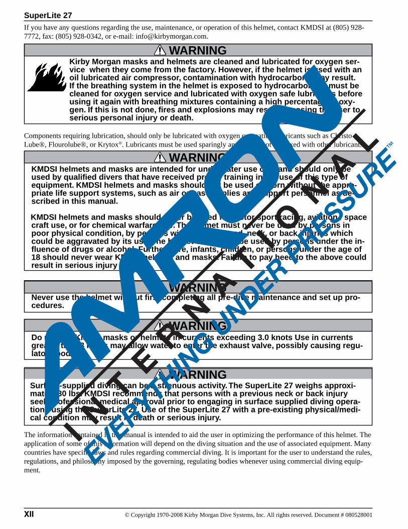
If you have any questions regarding the use, maintenance, or operation of this helmet, contact KMDSI at (805) 928-7772, fax: (805) 928-0342, or e-mail: [email protected].
Kirby Morgan masks and helmets are cleaned and lubricated for oxygen ser-vice when they come from the factory. However, if the helmet is used with an oil lubricated air compressor, contamination with hydrocarbons may result. If the breathing system in the helmet is exposed to hydrocarbons, it must be cleaned for oxygen service and lubricated with oxygen safe lubricants before using it again with breathing mixtures containing a high percentage of oxy-gen. If this is not done, fires and explosions may result, exposing the user to serious personal injury or death.
Components requiring lubrication, should only be lubricated with oxygen compatible lubricants such as Christo Lube®, Flourolube®, or Krytox®. Lubricants must be used sparingly and should not be mixed with other lubricants.
KMDSI helmets and masks are intended for underwater use only and should only be used by qualified divers that have received proper training in the use of this type of equipment. KMDSI helmets and masks should not be used or worn without the appro-priate life support systems, such as air or gas supplies and support personnel as de-scribed in this manual.
KMDSI helmets and masks should never be used for motor sport racing, aviation / space craft use, or for chemical warfare use. The helmet must never be used by persons in poor physical condition, by persons with previous head, neck, or back injuries which could be aggravated by its use. The helmet should not be used by persons under the in-fluence of drugs or alcohol. Furthermore, infants, children, or persons under the age of 18 should never wear KMDSI helmets and masks. Failure to pay heed to the above could result in serious injury or death.
Never use the helmet without first completing all pre-dive maintenance and set up pro-cedures.
Do not use KMDSI masks or helmets in currents exceeding 3.0 knots Use in currents greater than 3 knots may allow water to enter the exhaust valve, possibly causing regu-lator flooding.
Surface-supplied diving can be a strenuous activity. The SuperLite 27 weighs approxi-mately 30 lbs. KMDSI recommends that persons with a previous neck or back injury seek professional medical approval prior to engaging in surface supplied diving opera-tions using the SuperLite 27. Use of the SuperLite 27 with a pre-existing physical/medi-cal condition may result in death or serious injury.
The information contained in this manual is intended to aid the user in optimizing the performance of this helmet. The application of some of this information will depend on the diving situation and the use of associated equipment. Many countries have specific laws and rules regarding commercial diving. It is important for the user to understand the rules, regulations, and philosophy imposed by the governing, regulating bodies whenever using commercial diving equip-ment.
WARNING
WARNING
WARNING
WARNING
WARNING

SuperLite 27
XIII© Copyright 1970-2008 Kirby Morgan Dive Systems, Inc. All rights reserved. Document # 080528001
Whenever KMDSI helmets or masks are used in European Countries, which have adopted the C.E. certification pro-grams, they must only be used with C.E. certified components. Diving operations should only be conducted within the limits of the operational specifications, and in accordance with the rules and regulations established by the governing authority in the specific country or geographical location where the diving operations are being conducted. If you have any questions concerning this manual or the operation of your helmet, contact KMDSI (805) 928-7772 or at [email protected] or Dive Lab Inc. (850) 235-2715 or at [email protected]
WARNINGAlways read the Material Safety Data Sheet (MSDS) for any chemical - adhesive, clean-ing agent, or lubricant - used on your Kirby Morgan helmet. Some of these chemicals may cause serious bodily injury or death if used improperly or without the proper per-sonal protective equipment.
SuperLite 27
XIV © Copyright 1970-2008 Kirby Morgan Dive Systems, Inc. All rights reserved. Document # 080528001
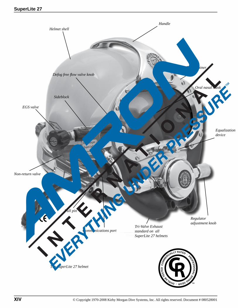
Handle
Sideblock
Port retainer
Non-return valve
EGS valve
Helmet shell
The SuperLite 27 helmet
Defog free flow valve knob
Tri-Valve Exhaust standard on all SuperLite 27 helmets
Regulator adjustment knob
Communications port
Pull pin
Equalization device
Oral nasal mask
CO
MM
ERCIALLY RATED - PROFE
SS
ION
AL D
IVING GEAR - DIVELAB TE
ST
ED
™

SuperLite 27
15© Copyright 1970-2008 Kirby Morgan Dive Systems, Inc. All rights reserved. Document # 080528001
This manual will refer to location numbers in specific drawings, or in the exploded view, which is in the back of this manual. These numbers are called “location” numbers. They are used to find the referred to parts in the drawings in this manual only. They are not the part number. Next to the exploded drawing is a list of the “location” numbers that match the Kirby Morgan part numbers along with the name of the part. Always check the part number when ordering to make sure it is correct. When ordering, always specify the helmet model number and serial number as well.
The Kirby Morgan Corporation was started in 1965. The copper and brass “heavy gear” or “Standard Dress” helmets were the first helmets manufactured by the company. Over the years Kirby Morgan de-signed, manufactured and sold many different helmets and masks for commercial divers.
Staying active in commercial diving has contributed to the successful design innovations of KMDSI prod-ucts. This may be the primary reason for the accep-tance of our designs by professional divers.
Bev Morgan has designed more than seventy seven (77) diving helmets and over 40 diving masks. All employees of KMDSI participate as part of the Kirby Morgan design team. It would not be possible for us to supply the commercial, military, scientific, and public service diving industries with our equip-ment, without the team of people that make up Kirby Morgan Dive Systems, Inc. (KMDSI)
We feel it is important for the reader to understand that we at KMDSI consider ourselves as only part of the process along the path in diving equipment design. We welcome all input from our customers. The thinking of many good divers, diving equip-ment engineers, diving medical specialists, diving organization administrators and their supporting personnel has contributed to the current state of the art of diving.
Each piece of gear we manufacture has in it some of the thinking of those who have gone before us. To all those people who gave something of themselves to the men and women who work underwater, we express a thank you.
We have a strong commitment to providing the best diving equipment and service possible. This thinking has been the policy of Kirby Morgan Dive Systems, Inc. and we will continue to take this approach to our work.
Our extensive dealer network makes it easy to obtain genuine Kirby Morgan replacement parts, as well as technical assistance worldwide.
Chapter 1.0General Information KMDSI Products
1.1 Introduction
Bev Morgan, Chairman of the BoardKirby Morgan Dive Systems, Inc.
STOP!BEFORE GOING FURTHER-
SuperLite 27
16 © Copyright 1970-2008 Kirby Morgan Dive Systems, Inc. All rights reserved. Document # 080528001
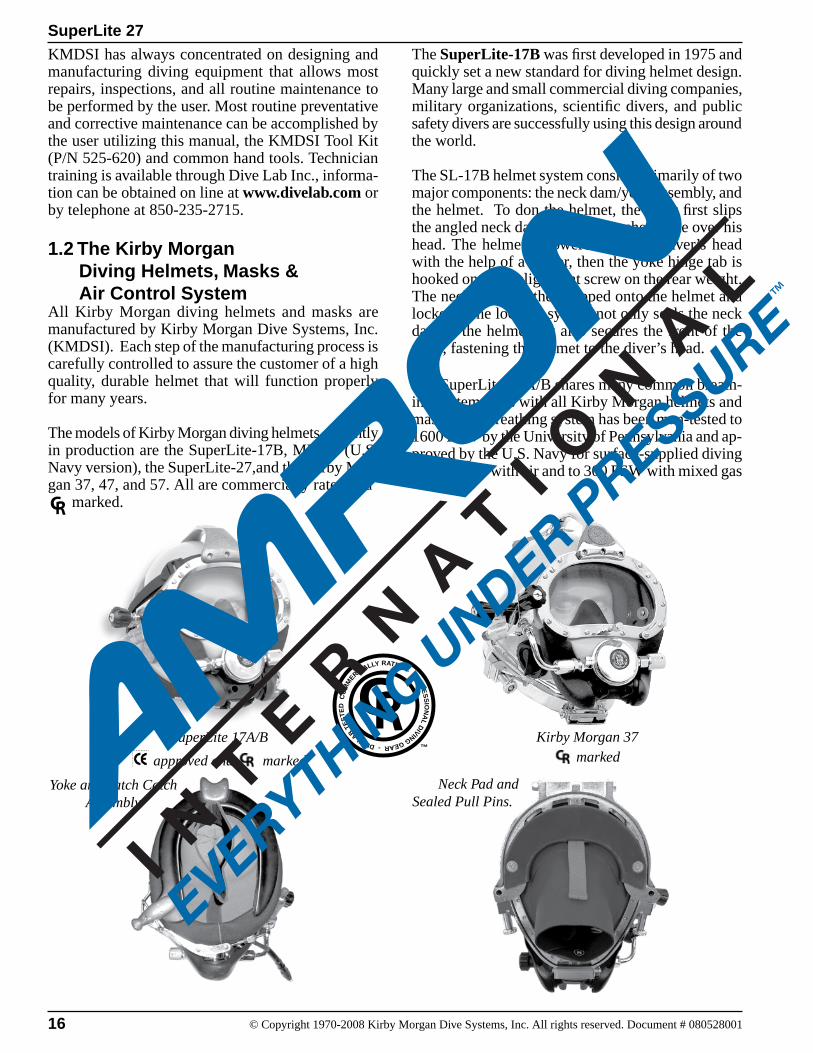
KMDSI has always concentrated on designing and manufacturing diving equipment that allows most repairs, inspections, and all routine maintenance to be performed by the user. Most routine preventative and corrective maintenance can be accomplished by the user utilizing this manual, the KMDSI Tool Kit (P/N 525-620) and common hand tools. Technician training is available through Dive Lab Inc., informa-tion can be obtained on line at www.divelab.com or by telephone at 850-235-2715.
1.2 The Kirby Morgan Diving Helmets, Masks & Air Control SystemAll Kirby Morgan diving helmets and masks are manufactured by Kirby Morgan Dive Systems, Inc. (KMDSI). Each step of the manufacturing process is carefully controlled to assure the customer of a high quality, durable helmet that will function properly for many years.
The models of Kirby Morgan diving helmets currently in production are the SuperLite-17B, MK-21 (U.S. Navy version), the SuperLite-27,and the Kirby Mor-gan 37, 47, and 57. All are commercially rated and marked.
The SuperLite-17B was first developed in 1975 and quickly set a new standard for diving helmet design. Many large and small commercial diving companies, military organizations, scientific divers, and public safety divers are successfully using this design around the world.
The SL-17B helmet system consists primarily of two major components: the neck dam/yoke assembly, and the helmet. To don the helmet, the diver first slips the angled neck dam with the attached yoke over his head. The helmet is lowered onto the diver’s head with the help of a tender, then the yoke hinge tab is hooked onto the alignment screw on the rear weight. The neck clamp is then slipped onto the helmet and locked. The locking system not only seals the neck dam to the helmet but also secures the front of the yoke, fastening the helmet to the diver’s head.
The SuperLite-17A/B shares many common breath-ing system parts with all Kirby Morgan helmets and masks. The breathing system has been man-tested to 1600 FSW by the University of Pennsylvania and ap-proved by the U.S. Navy for surface-supplied diving to 190 FSW with air and to 300 FSW with mixed gas
SuperLite 17A/B Kirby Morgan 37
Yoke and Latch CatchAssembly
Neck Pad and Sealed Pull Pins.
approved and marked marked
CO
MM
ERCIALLY RATED - PROFE
SS
ION
AL D
IVING GEAR - DIVELAB TE
ST
ED
™
SuperLite 27
17© Copyright 1970-2008 Kirby Morgan Dive Systems, Inc. All rights reserved. Document # 080528001
(helium and oxygen). It surpasses all requirements of all governing agencies and it is approved for com-mercial diving through out the world.
Other features that are common to all Kirby Morgan helmets and Band Masks include:* Face port and retainer ring* Communications components* Oral/nasal mask* Nose block device* Air train defogger
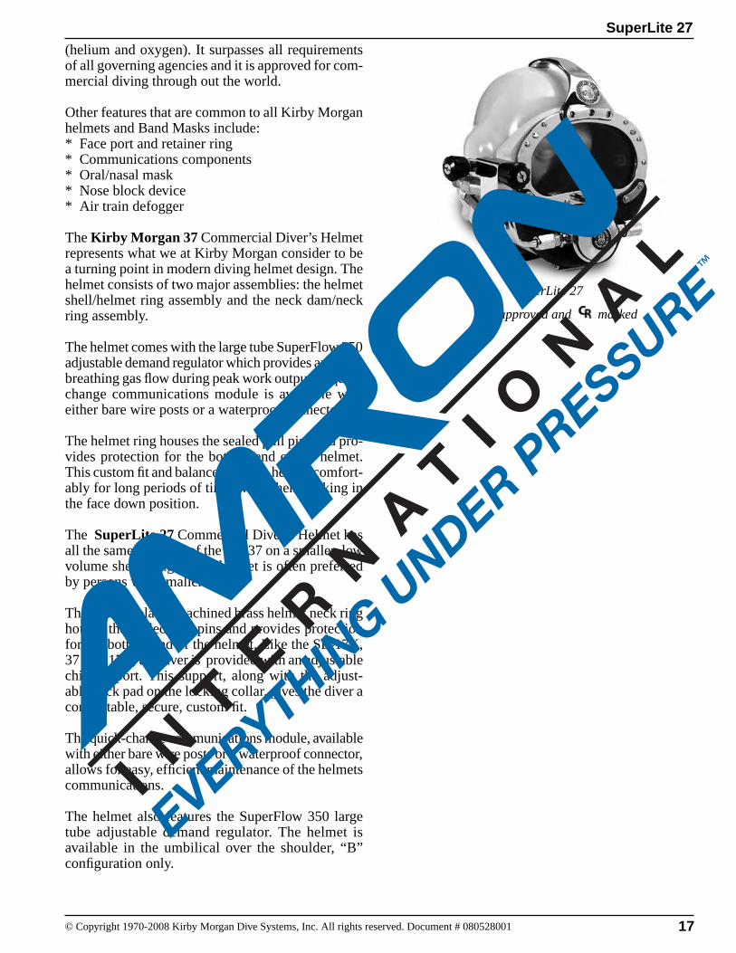
The Kirby Morgan 37 Commercial Diver’s Helmet represents what we at Kirby Morgan consider to be a turning point in modern diving helmet design. The helmet consists of two major assemblies: the helmet shell/helmet ring assembly and the neck dam/neck ring assembly.
The helmet comes with the large tube SuperFlow 350 adjustable demand regulator which provides an easier breathing gas flow during peak work output. A quick change communications module is available with either bare wire posts or a waterproof connector.
The helmet ring houses the sealed pull pins and pro-vides protection for the bottom end of the helmet. This custom fit and balance seats the helmet comfort-ably for long periods of time even when working in the face down position.
The SuperLite 27 Commercial Diver’s Helmet has all the same features of the KM37 on a smaller, low volume shell design. This helmet is often preferred by persons with smaller heads.
The chrome plated machined brass helmet neck ring houses the sealed pull pins and provides protection for the bottom end of the helmet. Like the SL-17K, 37 and 17C, the diver is provided with an adjustable chin support. This support, along with the adjust-able neck pad on the locking collar, gives the diver a comfortable, secure, custom fit. The quick-change communications module, available with either bare wire posts or a waterproof connector, allows for easy, efficient maintenance of the helmets communications.
The helmet also features the SuperFlow 350 large tube adjustable demand regulator. The helmet is available in the umbilical over the shoulder, “B” configuration only.
approved and marked
SuperLite 27
SuperLite 27
18 © Copyright 1970-2008 Kirby Morgan Dive Systems, Inc. All rights reserved. Document # 080528001
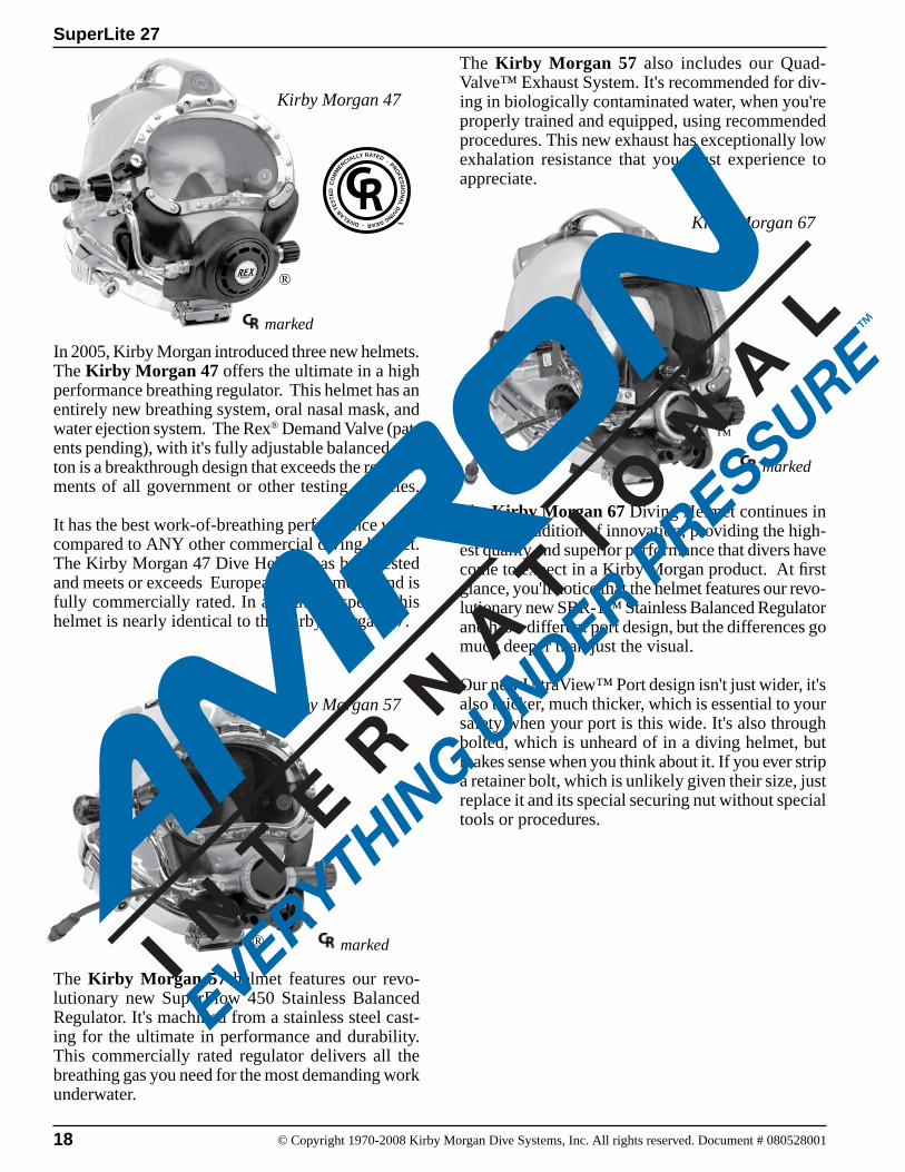
The Kirby Morgan 57 helmet features our revo-lutionary new SuperFlow 450 Stainless Balanced Regulator. It's machined from a stainless steel cast-ing for the ultimate in performance and durability. This commercially rated regulator delivers all the breathing gas you need for the most demanding work underwater.
In 2005, Kirby Morgan introduced three new helmets. The Kirby Morgan 47 offers the ultimate in a high performance breathing regulator. This helmet has an entirely new breathing system, oral nasal mask, and water ejection system. The Rex® Demand Valve (pat-ents pending), with it's fully adjustable balanced pis-ton is a breakthrough design that exceeds the require-ments of all government or other testing agencies.
It has the best work-of-breathing performance when compared to ANY other commercial diving helmet. The Kirby Morgan 47 Dive Helmet has been tested and meets or exceeds European requirements and is fully commercially rated. In all other respects, this helmet is nearly identical to the Kirby Morgan 37.
The Kirby Morgan 57 also includes our Quad-Valve™ Exhaust System. It's recommended for div-ing in biologically contaminated water, when you're properly trained and equipped, using recommended procedures. This new exhaust has exceptionally low exhalation resistance that you must experience to appreciate. lon
The Kirby Morgan 67 Diving Helmet continues in our long tradition of innovation, providing the high-est quality and superior performance that divers have come to expect in a Kirby Morgan product. At first glance, you'll notice that the helmet features our revo-lutionary new SBR-1™ Stainless Balanced Regulator and has a different port design, but the differences go much deeper than just the visual.
Our new UltraView™ Port design isn't just wider, it's also thicker, much thicker, which is essential to your safety when your port is this wide. It's also through bolted, which is unheard of in a diving helmet, but makes sense when you think about it. If you ever strip a retainer bolt, which is unlikely given their size, just replace it and its special securing nut without special tools or procedures.
CO
MM
ERCIALLY RATED - PROFE
SS
ION
AL D
IVING GEAR - DIVELAB TE
STE
D
™
marked
®
® marked
marked
™
Kirby Morgan 47
Kirby Morgan 57
Kirby Morgan 67
SuperLite 27
19© Copyright 1970-2008 Kirby Morgan Dive Systems, Inc. All rights reserved. Document # 080528001
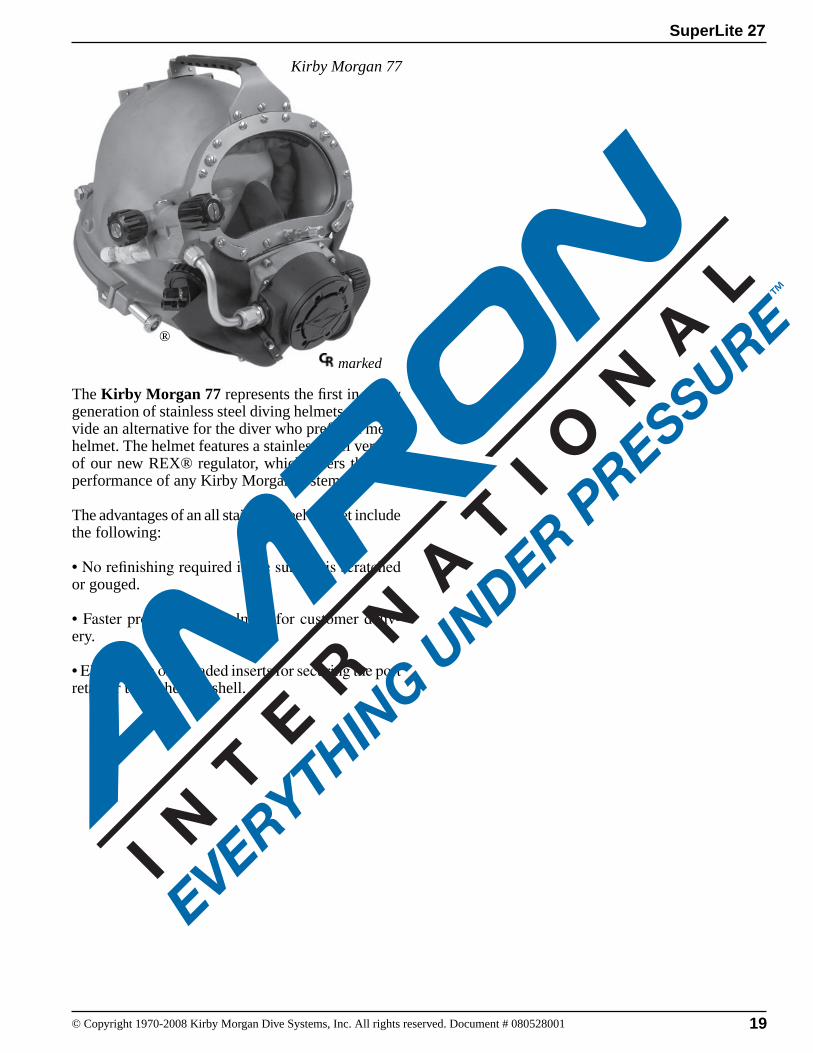
The Kirby Morgan 77 represents the first in a new generation of stainless steel diving helmets that pro-vide an alternative for the diver who prefers a metal helmet. The helmet features a stainless steel version of our new REX® regulator, which offers the best performance of any Kirby Morgan system. The advantages of an all stainless steel helmet include the following:
• No refinishing required if the surface is scratched or gouged.
• Faster production of helmets for customer deliv-ery.
• Elimination of threaded inserts for securing the port retainer to the helmet shell.
Kirby Morgan 77
marked
®
SuperLite 27
20 © Copyright 1970-2008 Kirby Morgan Dive Systems, Inc. All rights reserved. Document # 080528001
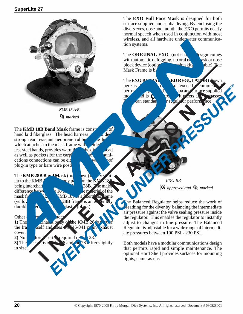
The EXO Full Face Mask is designed for both surface supplied and scuba diving. By enclosing the divers eyes, nose and mouth, the EXO permits nearly normal speech when used in conjunction with most wireless, and all hardwire underwater communica-tion systems.
The ORIGINAL EXO (not shown) design comes with automatic defogging, no oral nasal mask or nose block device (optional conversion kits available). The Mask Frame is black.
The EXO BR (BALANCED REGULATOR) shown here is designed to meet or exceed recommended performance goals in both scuba and surface supplied modes and is approved. It meets and surpasses European standards for regulator performance.
EXO BR
approved and marked
KMB 18 A/B
marked
The KMB 18B Band Mask frame is constructed of hand laid fiberglass. The head harness is a molded, strong tear resistant neoprene rubber. The hood, which attaches to the mask frame with welded stain-less steel bands, provides warmth for the diver’s head as well as pockets for the earphones. The communi-cations connections can be either a male waterproof plug-in type or bare wire posts.
The KMB 28B Band Mask (not shown) is very simi-lar to the KMB 18, with many parts on the KMB 18B being interchangeable with the KMB 28B. The major difference between the 18 and 28 is the material of the mask frame itself. The KMB 18 has a fiberglass frame (yellow) while the KMB 28B frame is an extremely durable injection molded plastic (black).
Other differences include: 1) The main exhaust body of the KMB 28 is part of the frame itself and uses a #545-041 main exhaust cover.2) No comfort insert is required on the 28. 3) The face ports for the 18 and the 28 differ slightly in size.
The Balanced Regulator helps reduce the work of breathing for the diver by balancing the intermediate air pressure against the valve sealing pressure inside the regulator. This enables the regulator to instantly adjust to changes in line pressure. The Balanced Regulator is adjustable for a wide range of intermedi-ate pressures between 100 PSI - 230 PSI.
Both models have a modular communications design that permits rapid and simple maintenance. The optional Hard Shell provides surfaces for mounting lights, cameras etc.
SuperLite 27
21© Copyright 1970-2008 Kirby Morgan Dive Systems, Inc. All rights reserved. Document # 080528001
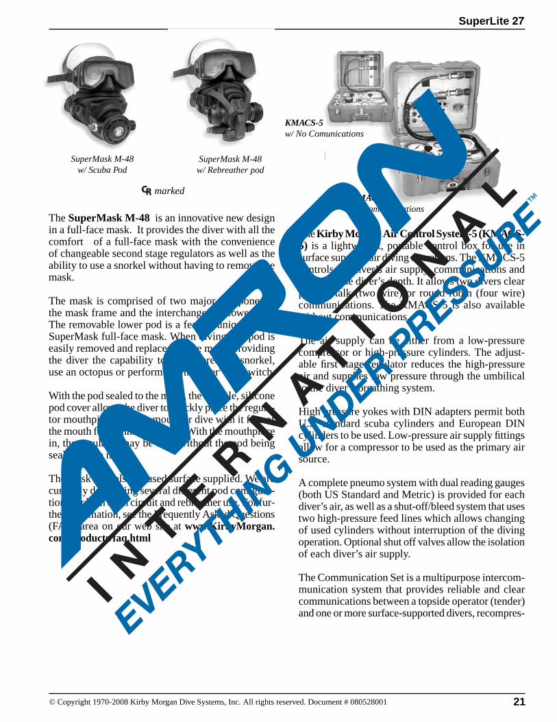
The SuperMask M-48 is an innovative new design in a full-face mask. It provides the diver with all the comfort of a full-face mask with the convenience of changeable second stage regulators as well as the ability to use a snorkel without having to remove the mask.
The mask is comprised of two major components, the mask frame and the interchangeable lower pod. The removable lower pod is a feature unique to the SuperMask full-face mask. When diving, the pod is easily removed and replaced on the mask, providing the diver the capability to buddy-breathe, snorkel, use an octopus or perform an “in water” gas switch.
With the pod sealed to the mask, the flexible, silicone pod cover allows the diver to quickly place the regula-tor mouthpiece into the mouth or dive with it free of the mouth for communications. With the mouthpiece in, the regulator may be used without the pod being sealed to the mask.
The mask may also be used surface supplied. We are currently developing several different pod configura-tions for both open circuit and rebreather use. For fur-ther information, see the Frequently Asked Questions (FAQ) area on our web site at www.KirbyMorgan.com/products/faq.html
The Kirby Morgan Air Control System-5 (KMACS-5) is a lightweight, portable control box for use in surface supplied air diving operations. The KMACS-5 controls the diver’s air supply, communications and monitors the diver’s depth. It allows two divers clear push-to-talk (two wire) or round robin (four wire) communications. The KMACS-5 is also available without communications.
The air supply can be either from a low-pressure compressor or high-pressure cylinders. The adjust-able first stage regulator reduces the high-pressure air and supplies low pressure through the umbilical to the diver’s breathing system.
High pressure yokes with DIN adapters permit both U.S. standard scuba cylinders and European DIN cylinders to be used. Low-pressure air supply fittings allow for a compressor to be used as the primary air source.
A complete pneumo system with dual reading gauges (both US Standard and Metric) is provided for each diver’s air, as well as a shut-off/bleed system that uses two high-pressure feed lines which allows changing of used cylinders without interruption of the diving operation. Optional shut off valves allow the isolation of each diver’s air supply.
The Communication Set is a multipurpose intercom-munication system that provides reliable and clear communications between a topside operator (tender) and one or more surface-supported divers, recompres-
SuperMask M-48 w/ Scuba Pod
SuperMask M-48w/ Rebreather pod
KMACS-5w/ No Comunications
KMACS-5w/ Communications
marked
22 © Copyright 1970-2008 Kirby Morgan Dive Systems, Inc. All rights reserved. Document # 080528001
SuperLite 27
Chapter 2Description & Operational Specifications
This section includes a detailed decsription of the this Kirby Morgan Helmet as well as important op-erational specifications.
2.1 Product SpecificationsWeight: 27 poundsHelmet Shell: Fiberglass, polyester resin, and carbon fibersControl Knobs: ABS plasticLens: Clear polycarbonateNeck Dam: Neoprene. Optional latex neck dam avail-able.O-Rings: Buna-NHead Cushion: Nylon bag filled with #4 Polyester foam
The recommended lubrication type for breathing gas mixtures containing oxygen percentages greater than 50% is Christo Lube®, Krytox®, and Halocarbon®. Helmet gas train components being used with gas mixtures containing less than 50% oxygen can be lubricated with food grade silicone grease such as Dow Corning®111.
Never use aerosol-propelled sprays near the face port of any Kirby Morgan diving helmet. The propellant used in these aerosols can invisibly damage the face port and cause it to shatter on impact from any strong blow. If the face port fails underwater, injury or death may result.
DANGER
The helmet has been tested and conforms to the performance requirements as set forth in Annex II of Directive 89/686/EEC and as far as applicable, the EN250 (edition Jan 2000) and the E DIN 58 642 (edition Feb 1998). When the helmet is used for air diving in countries that conform to C.E. regulations it may be used to a maximum depth of 164fsw (50 msw). I.A.W. EN250.
If you have any questions regarding proper set-up, op-eration, or maintenance of your SuperLite-27 contact KMDSI (850) 928-7772 or [email protected] or Dive Lab Inc. (850) 235-2715 or [email protected]
2.2 Regulator Performance2.2.1 SuperFlow® and SuperFlow® 350 Demand RegulatorsThe SuperFlow 350 non balanced regulator is the standard demand regulator found on the SL-27, KM-37 and KMB 18/28 Band Masks. NOTE: Pre Sep. 2004 KMB 28 plastic frames will only except the smaller mount tube found on the SuperFlow (non 350) regulator. The SuperFlow 350 is fully CE marked and CR rated. The SuperFlow 450 SS balanced regulator can be used on the SL-27, KM-37 and KMB-18/28 band Masks. Breathing performance is greatly affected by the support equipment used, as well as the supply pressure to the helmet or mask.
2.2.2 SuperFlow® 450 PerformanceThe SuperFlow® 450 is an all Stainless Steel regula-tor of a balanced design that offers a slightly higher degree of breathing performance and extreme breath-ing rates, more than the non balanced SuperFlow regulator.
This manual is our effort to explain the operation, maintenance and use of the SL 27. We do not herein make any effort to teach the principles of diving. It is our assumption the reader is a quali-fied diver. We highly recommend that all divers should train under controlled conditions, in the use of any commercial diving helmet that they have not previously used, or trained in, prior to use on the job.
WARNING
SuperLite 27
23© Copyright 1970-2008 Kirby Morgan Dive Systems, Inc. All rights reserved. Document # 080528001
2.3 Cage CodeThe cage code for identifying KMDSI products for U.S. government purchase purposes is 58366.
2.4 Operational Specifications & LimitationsThis helmet meets or exceeds all performance require-ments and is fully CE marked with the SuperFlow® and SuperFlow® 350 non balanced regulator and is CR rated by Dive Lab Inc. The helmet when equipped with the SuperFlow® 450 SS balanced regulator is CR rated but not currently CE certified. CE certification is scheduled for late 2008
Every model of KMDSI helmets and masks undergo extensive type testing to fully document the perfor-mance capability and required supply pressures when using various umbilical and pressure combinations. All users should take the time to become knowledge-able on supply requirements to insure proper perfor-mance and for the comfort and safety of the diver.
The required supply pressures for the KM-37 equipped with either the SuperFlow® 350 or SuperFlow® 450 regulators are listed in the appropriate supply pressure tables in Appendix 3.
The supply pressures listed in the supply tables were derived by breathing simulator trials. There are two tables used for the SuperFlow® and SuperFlow® 350 regulators and two separate tables for the SuperFlow® 450 regulator. It is important that users understand how to use the tables. For further information on sup-ply requirements for the KM-37® or any Kirby Morgan helmet or mask check the Kirby Morgan website at www.kirbymorgan.com.
-Umbilical minimum I.D. 3/8” (9.5 mm) of not more than two sections, total length not to exceed 600 feet (183m).
-Temperature Limitations: Use at water temperatures below 33°F (1°C) requires the use of hot water shroud PN# 525-100 and hot water to help prevent icing of the demand regulator.
It is important for the user/diver to take excessive currents into consideration. The Tri-Valve Exhaust® system (Part # 525-755) which is now standard, will help prevent wa-ter intrusion when diving in heavy currents. Unlike the old double exhaust, the Tri-Valve does not limit the diving depth.
WARNING
Decompression diving always involves the risk of decompression sickness. Omitted decompression due to a loss of the breath-ing gas supply or other accidents can cause serious injury or death. Use of a Kirby Morgan helmet or full-face mask cannot prevent this type of injury.
DANGER
WARNINGThe demand regulator and side block assemblies have a maxi-mum design pressure of 250 psig over the ambient pressure, higher pressures could lead to component failure resulting in serious injury.
NOTE The Hot Water Shroud (Part #525-100) in conjunction with hot water to the diver should be used whenever diving operations are conducted using HEO
2 at water temperatures less than 60°F
(15.56°C) for the comfort of the diver. KMDSI further recommends that the shroud be used in conjunction with hot water to the diver whenever diving operations are conducted using air or mixed gas, in waters colder than 33°F (1°C) to reduce the possibility of demand regulator icing. NOTE: Usually the greatest danger of demand regulator icing will be encountered on deck when the surrounding air temperature is less than 32°F (0°C). This effect is primarily due to the refrigera-tion effect of breathing air pressure reduction, and the addition of moisture from the divers exhalation coming in contact with the topside air tempera-ture. If diving where the water temperature is 33°F (1°C) or warmer but the topside air temperature is below freezing, 32°F (0°C) icing of the demand regulator is possible. To help eliminate the possibil-ity of freezing on the surface, warm water should be run over the exterior of the demand regulator prior to water entry, if the hot water system is not used.
Only equipment certified and tested according to EN 250/E DIN 58 642 may be used with the KM 37 helmet when conducting diving operations in European EC compliant countries.
The umbilical assembly should be composed of good quality diving hose that meets industry standards. Generally, gas hose will be married to the commu-nications wire, pneumofathometer hose, and strength member in a manner that will allow the strength
24 © Copyright 1970-2008 Kirby Morgan Dive Systems, Inc. All rights reserved. Document # 080528001
SuperLite 27
Gas systems used to supply Kirby Morgan helmets and masks must be capable of sup-plying gas to the diver at the required pres-sure and flow rates as stated in the opera-tional specifications. The use of unregulated gas sources is extremely dangerous.
The use of standard SCUBA type regulators is unacceptable, as there are no provisions for adjusting the intermediate pressure to the diver. Only proven systems that allow for varying the gas supply pressure to the diver should be used for umbilical diving.
WARNING
member to receive all the strain. There are also good quality umbilicals available that are assembled at the factory using a twisted method which does not require marrying. Regardless of the system used, the umbilical is the diver’s life line and should always be of excellent quality and maintained carefully.
If you have any questions regarding proper set-up, operation, or maintenance of your Kirby Morgan 37/57 helmet contact KMDSI (850) 928-7772 or at [email protected] or Dive Lab Inc. (850) 235-2715 or at [email protected].
This helmet meets or exceeds all requirements of NPD, CE, Health and Safety, (U.K.), United States Navy, ADCI United States and is CR rated by Dive Lab, Panama City, Fla., USA.
SuperLite 27
25© Copyright 1970-2008 Kirby Morgan Dive Systems, Inc. All rights reserved. Document # 080528001
2.5 Helmet FeaturesAll Kirby Morgan diving helmets are manufactured by hand. Each step of the manufacturing process is carefully controlled to assure the customer a high quality, durable helmet that will function properly.
The SL 27 was developed in 1991. The goal was to bring together all of the top design elements of the various SuperLite helmets and then refine the mix into what we at KMDSI consider to be an outstand-ing diving helmet design. The SL 27 takes the best design features of our world famous SuperLite-17B and blends in many advanced design features. Add in some fine tuned balance refinements and you have a low volume diving helmet. Exemplifying our adher-ence to the highest quality and proven superior work performance, the SL 27 is one of the standards of the commercial diving industry worldwide.
The SL 27 incorporates an innovative locking system and the SuperFlow 350 large tube adjustable demand regulator which provides an outstanding breathing gas flow during peak work output. The helmet consists of two pieces: the helmet shell/helmet ring and the neck dam neck ring assembly. The machined brass helmet ring houses the latch catches and provides protection for the bottom end of the helmet. It also mounts an externally adjustable chin support. This support, along with the adjustable neck pad on the locking collar, gives the diver a se-cure, custom tailored fit in the helmet. This custom fit and balance seats the helmet comfortably for long periods of time even when working in the face down position.
A quick change communications module, available in either bare wire posts or a waterproof connector, allows for easy, efficient maintenance of the commu-nications in the helmet.
The SL 27 is configured to receive the umbilical over the shoulder. In the past, the optional Double Exhaust System (Part # 525-102) was available to reduce the possibility of back flow of water and contaminants into the helmet. This system has been used successfully for diving in biologically contaminated environments for many years. To further reduce the possibility of water intru-sion regardless of the exhaust system being used, the diver should avoid working in an inverted position.
The double exhaust was replaced by the Tri-Valve™ System. The unique design of the Tri-Valve™ helps
keep exhalation resistance low while maintaining excellent watertight integrity.
WARNINGBefore attempting any diving in any type of contaminated water, a complete diving and topside course in hazardous materi-als emergencies should be completed. The divers and the topside team must be properly trained and have the proper safety equipment. All helmets and suits can leak water under certain conditions. Divers should use extreme caution when diving in contaminated waters. For more information see the book “Diving in High-Risk Environments” by Steven M. Barsky.
The Tri-Valve™ exhaust system is now standard equipment for the SL 27. This superior exhaust system has exceptionally low exhalation resistance, and helps to keep the helmet free of contaminants in polluted water. The Tri-Valve™ isolates the breathing system from the surrounding water with a three valve, low breathing resistance design (Patents Pending).
The Tri-Valve™ is designed to couple the regulator exhaust with the helmet main exhaust and route them into a single plenum chamber, mounted between the regulator body and main exhaust body. The exhaust gas then must pass through either one of two (or both) exhaust valves that are part of the bubble deflector (whisker). By having an exhaust valve in both sides of the bubble deflector, exhalation resistance is mini-mized, while still helping to maintain the isolation of the main helmet and regulator exhaust valves.
In addition, the water dump valve now has two one-way valves to further help protect the diver in polluted water.
When diving in heavy current (i.e. exceed-ing 3 knots) the single exhaust system on all KMDSI masks/helmets could allow water to enter, due to turbulence/eddying. It is important for the user/diver to take excessive currents into consideration. The Tri-Valve Exhaust® system (Part # 525-755) will help prevent water intrusion when diving in heavy currents. The Tri-Valve provides exceptionally low exhala-tion resistance.
CAUTION
26 © Copyright 1970-2008 Kirby Morgan Dive Systems, Inc. All rights reserved. Document # 080528001
SuperLite 27
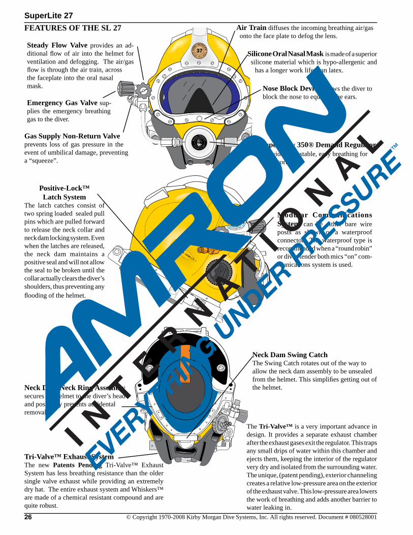
Neck Dam/Neck Ring Assembly secures the helmet to the diver’s head and positively prevents accidental removal.
SuperFlow 350® Demand Regulator provides adjustable, easy breathing for hard work.
Nose Block Device allows the diver to block the nose to equalize the ears.
Modular Communications System can be either bare wire posts as shown or a waterproof connector. The waterproof type is recommended when a “round robin” or diver/tender both mics “on” com-munications system is used.
The Tri-Valve™ is a very important advance in design. It provides a separate exhaust chamber after the exhaust gases exit the regulator. This traps any small drips of water within this chamber and ejects them, keeping the interior of the regulator very dry and isolated from the surrounding water. The unique, (patent pending), exterior channeling creates a relative low-pressure area on the exterior of the exhaust valve. This low-pressure area lowers the work of breathing and adds another barrier to water leaking in.
Positive-Lock™ Latch System
The latch catches consist of two spring loaded sealed pull pins which are pulled forward to release the neck collar and neck dam locking system. Even when the latches are released, the neck dam maintains a positive seal and will not allow the seal to be broken until the collar actually clears the diver’s shoulders, thus preventing any flooding of the helmet.
Air Train diffuses the incoming breathing air/gas onto the face plate to defog the lens.
Silicone Oral Nasal Mask is made of a superior silicone material which is hypo-allergenic and
has a longer work life than latex.
Steady Flow Valve provides an ad-ditional flow of air into the helmet for ventilation and defogging. The air/gas flow is through the air train, across the faceplate into the oral nasal mask.
Emergency Gas Valve sup-plies the emergency breathing gas to the diver.
FEATuRES OF ThE SL 27
Tri-Valve™ Exhaust SystemThe new Patents Pending Tri-Valve™ Exhaust System has less breathing resistance than the older single valve exhaust while providing an extremely dry hat. The entire exhaust system and Whiskers™ are made of a chemical resistant compound and are quite robust.
Neck Dam Swing CatchThe Swing Catch rotates out of the way to allow the neck dam assembly to be unsealed from the helmet. This simplifies getting out of the helmet.
Gas Supply Non-Return Valve prevents loss of gas pressure in the event of umbilical damage, preventing a “squeeze”.
SuperLite 27
27© Copyright 1970-2008 Kirby Morgan Dive Systems, Inc. All rights reserved. Document # 080528001
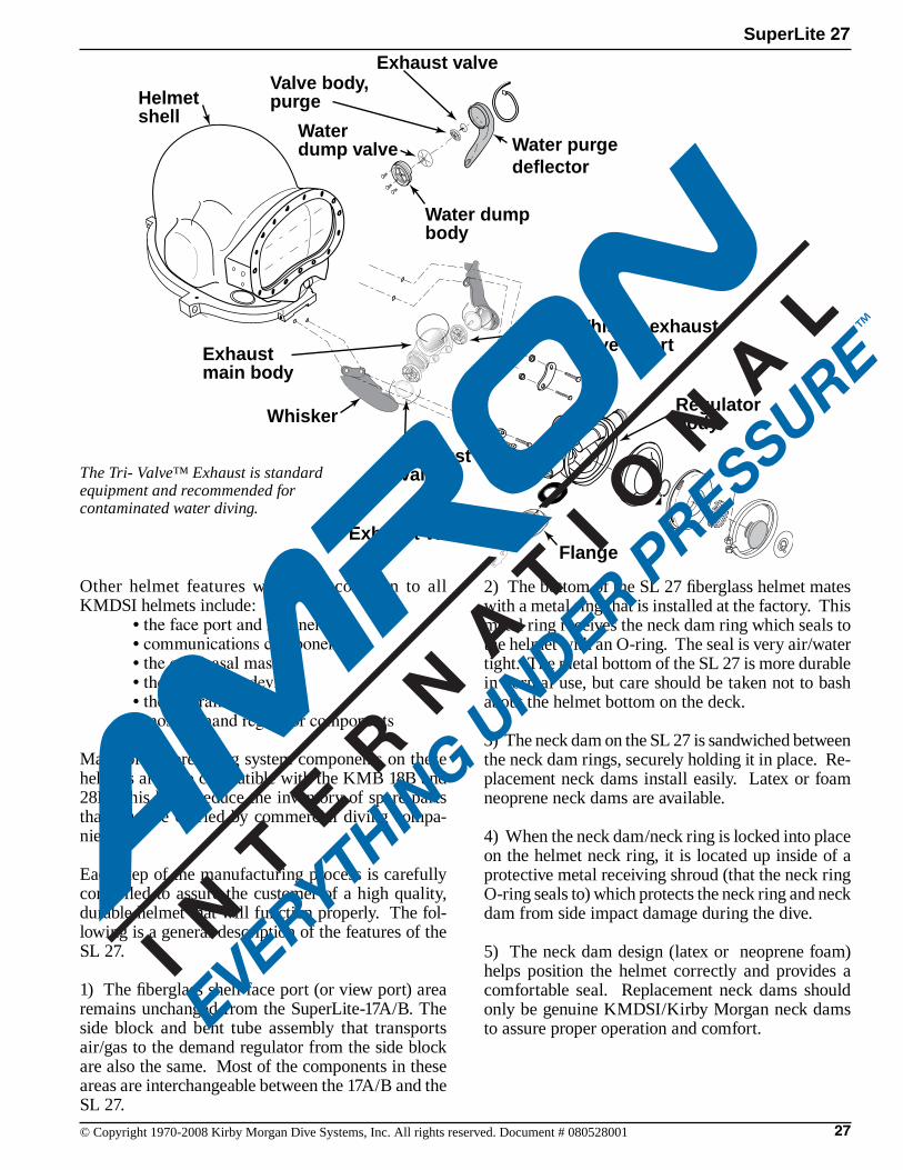
Water purgedeflector
Water dump body
Water dump valve
Whisker
Whisker exhaustvalve insert
Exhaust valve
Exhaust valve
Helmetshell
FlangeExhaust valve
Regulatorbody
Exhaustmain body
Valve body,purge
Other helmet features which are common to all KMDSI helmets include: •thefaceportandretainerring •communicationscomponents •theoral/nasalmask •thenoseblockdevice •theairtrain •mostdemandregulatorcomponents Many of the breathing system components on these helmets are also compatible with the KMB 18B and 28B. This helps reduce the inventory of spare parts that must be carried by commercial diving compa-nies.
Each step of the manufacturing process is carefully controlled to assure the customer of a high quality, durable helmet that will function properly. The fol-lowing is a general description of the features of the SL 27.
1) The fiberglass shell face port (or view port) area remains unchanged from the SuperLite-17A/B. The side block and bent tube assembly that transports air/gas to the demand regulator from the side block are also the same. Most of the components in these areas are interchangeable between the 17A/B and the SL 27.
2) The bottom of the SL 27 fiberglass helmet mates with a metal ring that is installed at the factory. This metal ring receives the neck dam ring which seals to the helmet with an O-ring. The seal is very air/water tight. The metal bottom of the SL 27 is more durable in normal use, but care should be taken not to bash about the helmet bottom on the deck.
3) The neck dam on the SL 27 is sandwiched between the neck dam rings, securely holding it in place. Re-placement neck dams install easily. Latex or foam neoprene neck dams are available.
4) When the neck dam/neck ring is locked into place on the helmet neck ring, it is located up inside of a protective metal receiving shroud (that the neck ring O-ring seals to) which protects the neck ring and neck dam from side impact damage during the dive.
5) The neck dam design (latex or neoprene foam) helps position the helmet correctly and provides a comfortable seal. Replacement neck dams should only be genuine KMDSI/Kirby Morgan neck dams to assure proper operation and comfort.
The Tri- Valve™ Exhaust is standard equipment and recommended for contaminated water diving.
28 © Copyright 1970-2008 Kirby Morgan Dive Systems, Inc. All rights reserved. Document # 080528001
SuperLite 27
6) The locking collar design holds the neck ring in the sealed position. It is not necessary for the locking collar to exert an upward pressure on the neck ring to maintain a seal. The O-ring seal is continuous once the neck ring enters the helmet ring.
7) Attached to the locking collar is an adjustable neck pad that should be adjusted to the diver prior to diving. This will improve the fit and performance of the SL 27.
8) A system of two sealed pull pin locks is on the SL 27. One lock is located on each side of the helmet. The spring and sliding shaft of these locks are inside an O-ring sealed cylinder. The interior of the cylinder is filled with silicon fluid. No fine sand or other debris can reach the interior of these locks to interfere with their operation.
9) The head cushion attaches just inside the bottom of the helmet, keeping it in place when the diver dons the hat. The standard head cushion consists of a brushed nylon bag with an open cell polyester foam inside. The 17A/B head cushion should not be used in the SL 27 because the design of the head cushions is different. Only genuine Kirby Morgan SL 27 head cushions should be used to assure proper operation and comfort.
10) The handle that is fitted to the top of the SL 27 and the port weight are areas that can be used as mounting brackets for lights, TV cameras, etc.
11) The communications system is a modular, quick change design.
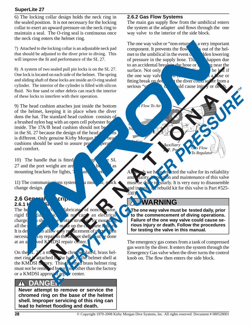
Gas Flow To Air Train
Main Gas Supply Auxiliary
L.P. Port Gas Flow To Regulator
EGS Gas Supply
2.6 General Description2.6.1 Helmet ShellThe helmet shell (61) is fabricated of noncorrosive, rigid fiberglass which will not carry an electrical charge. This shell is the central structure for mounting all the components that make up the complete helmet. It is designed to allow easy replacement of parts when necessary. Any repair to the helmet shell must be done at an approved KMDSI repair center.
On the SL 27, a machined, chrome plated, brass hel-met ring is attached to the base of the helmet shell at the KMDSI factory. This chromed brass helmet ring must not be removed by anyone other than the factory or a KMDSI approved repair center.
2.6.2 Gas Flow SystemsThe main gas supply flow from the umbilical enters the system at the adapter and flows through the one way valve to the interior of the side block.
The one way valve or “non-return” is a very important component. It prevents the flow of gas out of the hel-met to the umbilical in the event of a sudden lowering of pressure in the supply hose. This can happen due to an accidental break in the hose or a fitting near the surface. Not only would the Auxiliary gas be lost if the one way valve failed (concurrent with a hose or fitting break on deck), but the diver could suffer from a serious “squeeze” that could cause injury or death.
Although we have selected the valve for its reliability and quality, inspection and maintenance of this valve must be done regularly. It is very easy to disassemble and inspect. (A rebuild kit for this valve is Part #525-330).
Never attempt to remove or service the chromed ring on the base of the helmet shell. Improper servicing of this ring can lead to helmet flooding and death.
DANGER
The emergency gas comes from a tank of compressed gas worn by the diver. It enters the system through the Emergency Gas valve when the diver turns the control knob on. The flow then enters the side block.
The one way valve must be tested daily, prior to the commencement of diving operations. Failure of the one way valve could cause se-rious injury or death. Follow the procedures for testing the valve in this manual.
WARNING

SuperLite 27
29© Copyright 1970-2008 Kirby Morgan Dive Systems, Inc. All rights reserved. Document # 080528001
Adjustmentknob
Regulatorbody
Diaphragm
Cover
ClampInlet valve
Inlet nipple
Gasket
Adjustmentshaft
PackingnutPiston
Spacer
Roller lever
Exhaustvalve
Spacer
Nut
Exhaust Flange
Retainingpin
The SuperFlow 350 Demand Regulator
Both sources of gas flow through the same passage in the side block body to two exits. One exit is always open to supply gas to the demand regulator assem-bly. The other exit is to the defogger valve (free-flow valve) assembly.
The diver controls the flow of gas through the defog-ger system with the control knob. The gas enters the helmet and flows through the air train which directs the gas onto the face port to help eliminate or clear fogging of the faceplate that forms from the diver’s warm breath.
The flow continues out through the water dump (hel-met exhaust) valve, or into the oral nasal by means of the valve, then into the regulator and out through the regulator exhaust to the Tri-Valve™ whiskers. The diver can breathe from this flow of gas if the demand regulator malfunctions.
Returning to the side block assembly: the other pas-sage for gas is to the demand regulator. It goes to a bent tube assembly that connects to the inlet nipple of the demand regulator. The flow of gas in the demand regulator assembly is controlled by the inlet valve that supplies gas to the diver on inhalation “demand” only, and shuts off during the exhalation cycle. The SuperFlow demand regulator senses the start of the divers inhalation and opens the inlet valve, match-ing the diver’s need. The regulator continues to match the diver’s inhalation as the rate increases, peaks, then ebbs and stops. When the diver exhales, the supply gas stays off as the exhalation gas flows through the regu-lator body, out the regulator exhaust valve, through the Tri-Valve™ whiskers, and out into the water. The whiskers deflect the exhaust bubbles away from the face port to keep the diver’s view clear.
All KMDSI Helmets and Band Masks are equipped with a multi-turn demand regulator adjustment knob. This adjustment knob allows the diver to make cor-rections to compensate for a wide range of incoming gas supply pressures. See section 2.4 in this chapter regarding appropriate supply pressures.
The adjustment knob operates by simply increasing or decreasing the amount of spring bias tension on the demand regulator inlet valve. The adjustment knob has a range of approximately 13 turns from full in to full out. The intent of this bias adjustment device is strictly to allow the diver to make adjustments for variations in umbilical supply pressure.
This adjustment device is not intended as a minimum-maximum device. Minimum and maximum applies to supply pressure only. The adjustment knob should be adjusted by the diver to be at the easiest breathing setting at all times. The exact number of turns required is dependent on the supply pressure.
Diving a KMDSI helmet or bandmask with a bias setting greater than that just necessary to keep the demand valve from free flowing increases the work of breathing and reduces the diver’s ability to perform heavy work.
The regulator adjustment knob should be adjusted to the easiest breathing setting at all times. Adjusting the regulator fur-ther in than necessary to keep from free-flowing increases breathing resistance.
CAUTION
DANGERNever connect the main gas supply hose from the diving station/umbilical to the emer-gency valve. There is no one way valve in the emergency valve. If this mistake is made, any break in the supply hose could possibly result in a “squeeze”.
This could result in serious injury or death.
30 © Copyright 1970-2008 Kirby Morgan Dive Systems, Inc. All rights reserved. Document # 080528001
SuperLite 27
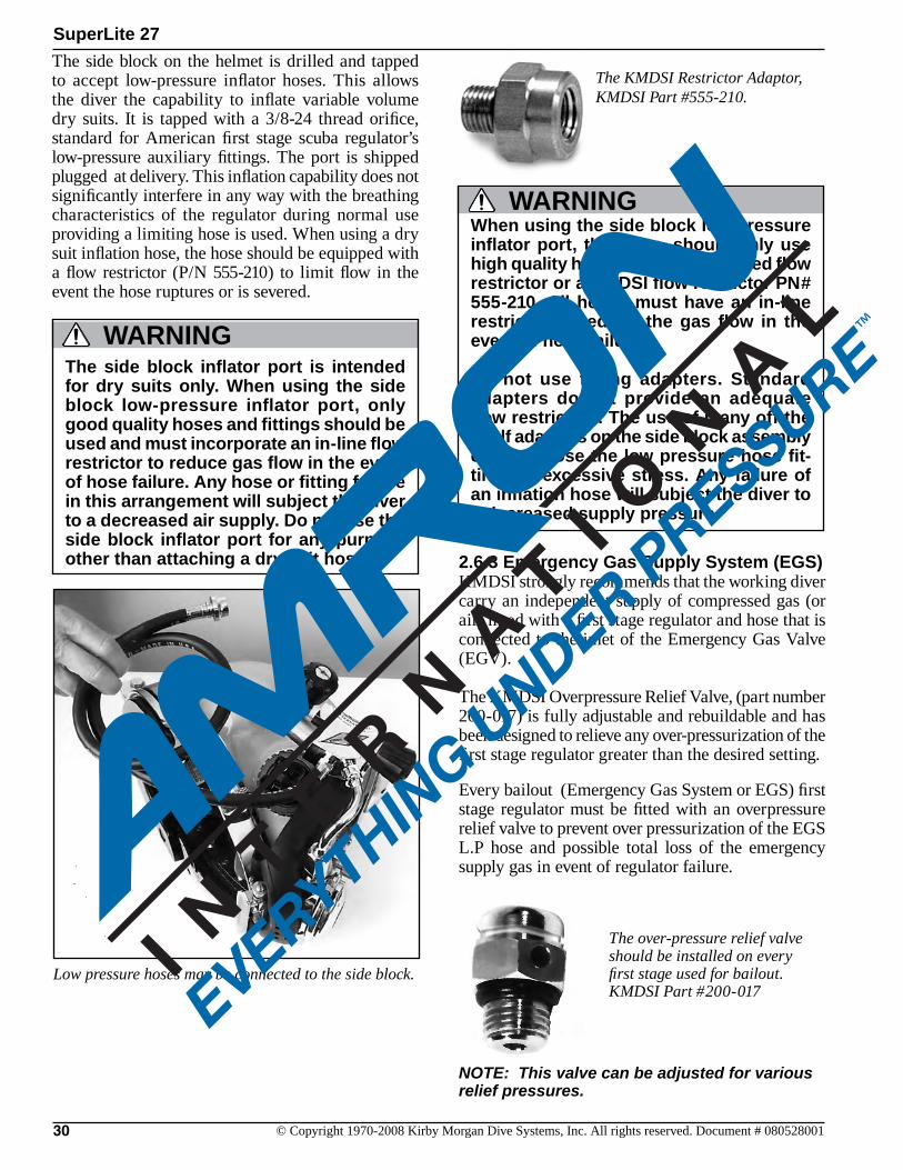
Low pressure hoses may be connected to the side block.
The KMDSI Restrictor Adaptor, KMDSI Part #555-210.
The side block on the helmet is drilled and tapped to accept low-pressure inflator hoses. This allows the diver the capability to inflate variable volume dry suits. It is tapped with a 3/8-24 thread orifice, standard for American first stage scuba regulator’s low-pressure auxiliary fittings. The port is shipped plugged at delivery. This inflation capability does not significantly interfere in any way with the breathing characteristics of the regulator during normal use providing a limiting hose is used. When using a dry suit inflation hose, the hose should be equipped with a flow restrictor (P/N 555-210) to limit flow in the event the hose ruptures or is severed.
WARNINGThe side block inflator port is intended for dry suits only. When using the side block low-pressure inflator port, only good quality hoses and fittings should be used and must incorporate an in-line flow restrictor to reduce gas flow in the event of hose failure. Any hose or fitting failure in this arrangement will subject the diver to a decreased air supply. Do not use the side block inflator port for any purpose other than attaching a dry suit hose. 2.6.3 Emergency Gas Supply System (EGS)
KMDSI strongly recommends that the working diver carry an independent supply of compressed gas (or air) fitted with a first stage regulator and hose that is connected to the inlet of the Emergency Gas Valve (EGV).
The KMDSI Overpressure Relief Valve, (part number 200-017) is fully adjustable and rebuildable and has been designed to relieve any over-pressurization of the first stage regulator greater than the desired setting.
Every bailout (Emergency Gas System or EGS) first stage regulator must be fitted with an overpressure relief valve to prevent over pressurization of the EGS L.P hose and possible total loss of the emergency supply gas in event of regulator failure.
When using the side block low pressure inflator port, the diver should only use high quality hoses with an integrated flow restrictor or a KMDSI flow restrictor PN# 555-210. All hoses must have an in-line restrictor to reduce the gas flow in the event of hose failure.
Do not use fitting adapters. Standard adapters do not provide an adequate flow restriction. The use of many off the shelf adapters on the side block assembly could expose the low pressure hose fit-tings to excessive stress. Any failure of an inflation hose will subject the diver to a decreased supply pressure.
WARNING
The over-pressure relief valve should be installed on every first stage used for bailout.KMDSI Part #200-017
NOTE: This valve can be adjusted for various relief pressures.
SuperLite 27
31© Copyright 1970-2008 Kirby Morgan Dive Systems, Inc. All rights reserved. Document # 080528001
WARNINGBe sure the Emergency air/gas first stage regulator is fitted with a relief valve to help prevent over-pressurization of the emergency gas supply hose. A leaky first stage can overpressure the hose result-ing in hose rupture. This would cause a loss of the entire emergency gas supply, with possible serious injury or death.
Hinge bolt
Nut
Locking collar
Neck pad
Adjustment nut
Washer
Washer
Screw
T-washer
O-ring
Split Ring
Neck dam
SteppedRing
PullStrap
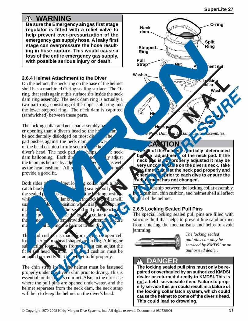
The locking sealed pull pins can only be serviced by KMDSI or an authorized dealer.
2.6.4 Helmet Attachment to the DiverOn the helmet, the neck ring on the base of the helmet shell has a machined O-ring sealing surface. The O-ring that seals against this surface sits inside the neck dam ring assembly. The neck dam ring is actually a two part ring, consisting of the upper split ring and the lower stepped ring. The neck dam is captured (sandwiched) between these parts.
The locking collar and neck pad assembly has a small-er opening than a diver’s head so the helmet cannot be accidentally dislodged on most divers. The neck pad pushes against the neck dam and lower portion of the head cushion firmly securing the helmet to the diver’s head. The neck pad also helps prevent neck dam ballooning. Each diver must personally adjust the fit on his helmet by adjusting the neck pad, as well as the head cushion. All of these parts together help provide a good fit.
Both sides of the helmet locking collar have a latch catch block to receive the locking sealed pull pins. If the sealed pull pins are turned to the locking position while the locking collar is open, the locking collar will snap into the locked position when it is pushed up into the helmet neck ring. The sealed pull pin on each side must be pulled to release the locking collar to remove the helmet. This system provides an extremely secure method of attaching the helmet to the diver.
The head cushion is made from layers of open cell foam inserted in a head shaped nylon bag. Adding or subtracting foam layers from the bag can adjust the fit of the head cushion. The head cushion must be adjusted correctly for the helmet to fit properly.
The chin strap inside the helmet must be fastened properly under the diver’s chin prior to diving. This is essential for the diver’s comfort. Also, in the rare case where the pull pins are opened underwater, and the helmet separates from the neck dam, the neck strap will help to keep the helmet on the diver’s head.
The relationship between the locking collar assembly, head cushion, chin cushion, and helmet shell all affect the fit of the helmet.
2.6.5 Locking Sealed Pull PinsThe special locking sealed pull pins are filled with silicone fluid that helps to prevent fine sand or mud from entering the mechanisms and helps to avoid jamming.
The Neck Dam and Locking Collar Assemblies.
CAUTIONThe fit of the helmet is partially determined by the adjustment of the neck pad. If the neck pad is not properly adjusted it may be very uncomfortable on the diver’s neck. Take the time to adjust the neck pad properly and check the fit prior to each dive to ensure the adjustment has not changed.
DANGERThe locking sealed pull pins must only be re-paired or overhauled by an authorized KMDSI dealer or returned directly to KMDSI. This is not a field serviceable item. Failure to prop-erly service this pin could result in a failure of the locking collar latch system, which could cause the helmet to come off the diver’s head. This could lead to drowning.
32 © Copyright 1970-2008 Kirby Morgan Dive Systems, Inc. All rights reserved. Document # 080528001
SuperLite 27
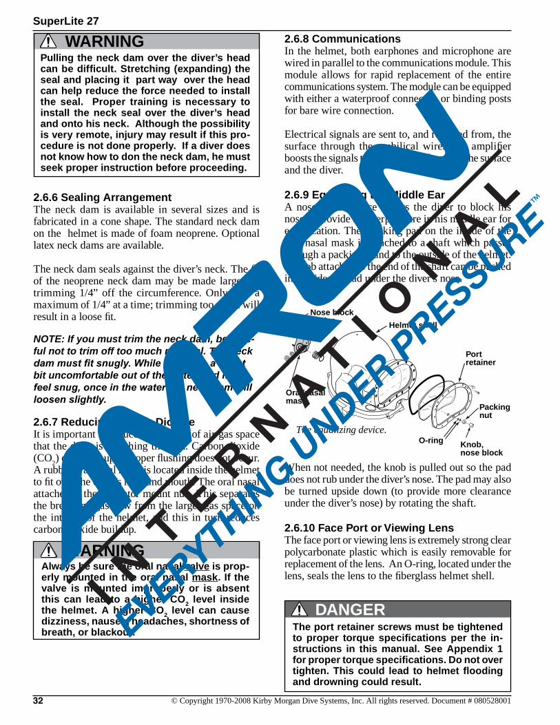
When not needed, the knob is pulled out so the pad does not rub under the diver’s nose. The pad may also be turned upside down (to provide more clearance under the diver’s nose) by rotating the shaft.
2.6.10 Face Port or Viewing LensThe face port or viewing lens is extremely strong clear polycarbonate plastic which is easily removable for replacement of the lens. An O-ring, located under the lens, seals the lens to the fiberglass helmet shell.
2.6.8 CommunicationsIn the helmet, both earphones and microphone are wired in parallel to the communications module. This module allows for rapid replacement of the entire communications system. The module can be equipped with either a waterproof connector, or binding posts for bare wire connection.
Electrical signals are sent to, and received from, the surface through the umbilical wires. An amplifier boosts the signals to the desired volume for the surface and the diver.
2.6.9 Equalizing the Middle EarA nose block device allows the diver to block his nose to provide an overpressure in his middle ear for equalization. The blocking pad on the inside of the oral nasal mask is attached to a shaft which passes through a packing gland to the outside of the helmet. A knob attached to the end of the shaft can be pushed in to slide the pad under the diver’s nose.
2.6.6 Sealing ArrangementThe neck dam is available in several sizes and is fabricated in a cone shape. The standard neck dam on the helmet is made of foam neoprene. Optional latex neck dams are available.
The neck dam seals against the diver’s neck. The fit of the neoprene neck dam may be made larger by trimming 1/4” off the circumference. Only trim a maximum of 1/4” at a time; trimming too much will result in a loose fit.
NOTE: If you must trim the neck dam, be care-ful not to trim off too much material. The neck dam must fit snugly. While it may be a slight bit uncomfortable out of the water, and may feel snug, once in the water the neck dam will loosen slightly.
2.6.7 Reducing Carbon DioxideIt is important to reduce the volume of air/gas space that the diver is breathing through. Carbon dioxide (CO
2) can build up if proper flushing does not occur.
A rubber oral nasal mask is located inside the helmet to fit over the diver’s nose and mouth. The oral nasal attaches to the regulator mount nut. This separates the breathing gas flow from the larger gas space on the interior of the helmet, and this in turn reduces carbon dioxide buildup.
WARNINGPulling the neck dam over the diver’s head can be difficult. Stretching (expanding) the seal and placing it part way over the head can help reduce the force needed to install the seal. Proper training is necessary to install the neck seal over the diver’s head and onto his neck. Although the possibility is very remote, injury may result if this pro-cedure is not done properly. If a diver does not know how to don the neck dam, he must seek proper instruction before proceeding.
WARNINGAlways be sure the oral nasal valve is prop-erly mounted in the oral nasal mask. If the valve is mounted improperly or is absent this can lead to a higher CO2 level inside the helmet. A higher CO2 level can cause dizziness, nausea, headaches, shortness of breath, or blackout.
The equalizing device.
Nose blockdevice
Oral/nasalmask
Helmet shell
Knob,nose block
Packingnut
Portretainer
O-ring
DANGERThe port retainer screws must be tightened to proper torque specifications per the in-structions in this manual. See Appendix 1 for proper torque specifications. Do not over tighten. This could lead to helmet flooding and drowning could result.
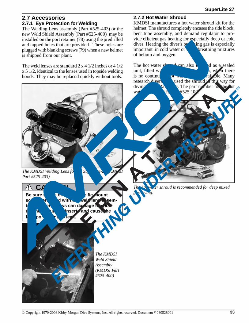
SuperLite 27
33© Copyright 1970-2008 Kirby Morgan Dive Systems, Inc. All rights reserved. Document # 080528001
2.7 Accessories2.7.1 Eye Protection for WeldingThe Welding Lens assembly (Part #525-403) or the new Weld Shield Assembly (Part #525-400) may be installed on the port retainer (78) using the predrilled and tapped holes that are provided. These holes are plugged with blanking screws (79) when a new helmet is shipped from our plant.
The weld lenses are standard 2 x 4 1/2 inches or 4 1/2 x 5 1/2, identical to the lenses used in topside welding hoods. They may be replaced quickly without tools.
The KMDSI Welding Lens for the SuperLite-27 (KMDSI Part #525-403)
The KMDSI Weld Shield Assembly (KMDSI Part #525-400)
Be sure to use only the specific mount screws provided with the weld lens assem-bly. Longer screws can damage the port retainer mounting inserts and cause the face port O-ring to leak.
CAUTION
2.7.2 Hot Water ShroudKMDSI manufactures a hot water shroud kit for the helmet. The shroud completely encases the side block, bent tube assembly, and demand regulator to pro-vide efficient gas heating for especially deep or cold dives. Heating the diver’s breathing gas is especially important in cold water or when breathing mixtures of helium and oxygen.
The hot water shroud can also be used as a sealed unit, filled with a hypersaline solution, when there is no continuous hot water supply available. Many research divers have used the shroud in this way for diving in the Antarctic. The part number for the hot water shroud kit is Part #525-100.
The hot water shroud is recommended for deep mixed gas diving.
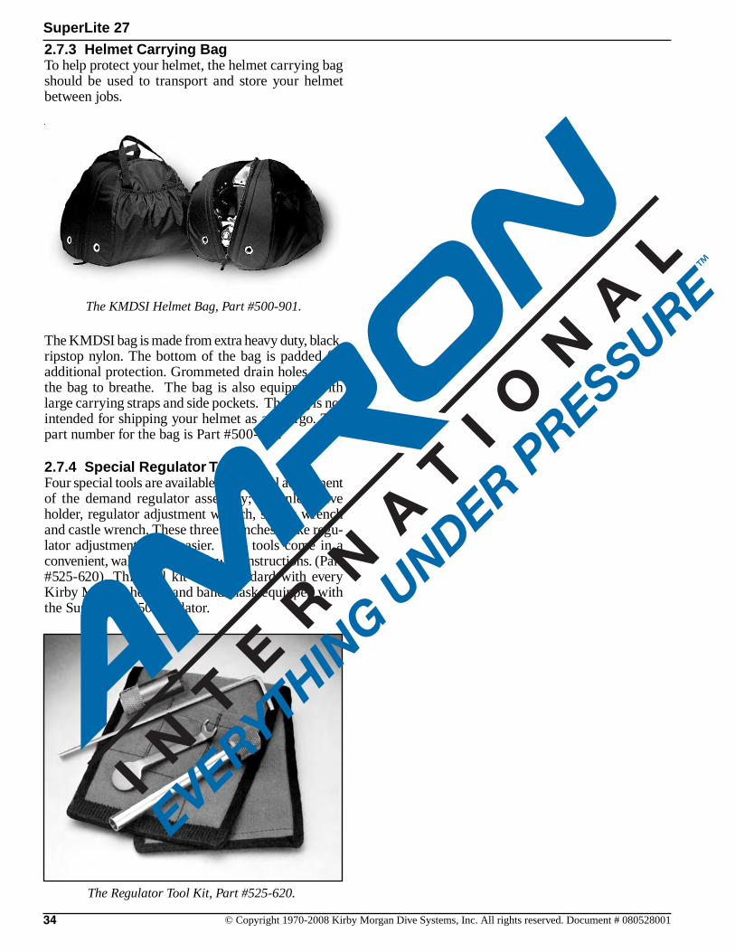
34 © Copyright 1970-2008 Kirby Morgan Dive Systems, Inc. All rights reserved. Document # 080528001
SuperLite 27
2.7.3 Helmet Carrying BagTo help protect your helmet, the helmet carrying bag should be used to transport and store your helmet between jobs.
The KMDSI bag is made from extra heavy duty, black, ripstop nylon. The bottom of the bag is padded for additional protection. Grommeted drain holes allow the bag to breathe. The bag is also equipped with large carrying straps and side pockets. The bag is not intended for shipping your helmet as air cargo. The part number for the bag is Part #500-901.
2.7.4 Special Regulator ToolsFour special tools are available for internal adjustment of the demand regulator assembly; the inlet valve holder, regulator adjustment wrench, socket wrench and castle wrench. These three wrenches make regu-lator adjustment much easier. The tools come in a convenient, wallet sized pouch with instructions. (Part #525-620). This tool kit ships standard with every Kirby Morgan helmet and band mask equipped with the SuperFlow 350 regulator.
The KMDSI Helmet Bag, Part #500-901.
The Regulator Tool Kit, Part #525-620.
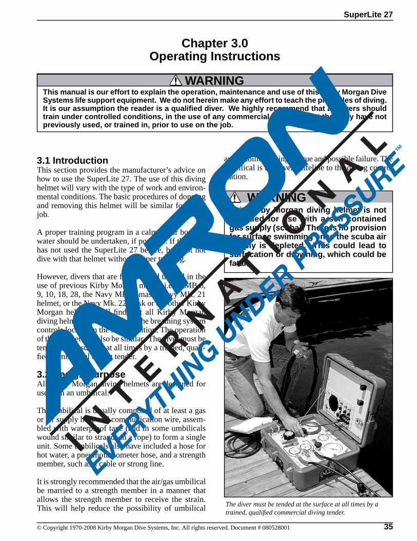
35© Copyright 1970-2008 Kirby Morgan Dive Systems, Inc. All rights reserved. Document # 080528001
SuperLite 27
3.1 IntroductionThis section provides the manufacturer’s advice on how to use the SuperLite 27. The use of this diving helmet will vary with the type of work and environ-mental conditions. The basic procedures of donning and removing this helmet will be similar for every job.
A proper training program in a calm, clear body of water should be undertaken, if possible. If the diver has not used the SuperLite 27 before, he must not dive with that helmet without proper training.
However, divers that are familiar and trained in the use of previous Kirby Morgan masks; i.e., KMB 8, 9, 10, 18, 28, the Navy MK. 1 mask, Navy MK. 21 helmet, or the Navy Mk. 22 mask or the other Kirby Morgan helmets, will find that all Kirby Morgan diving helmets and masks have the breathing system controls located in the same position. The operation of this helmet will also be similar. The diver must be tended at the surface at all times by a trained, quali-fied commercial diving tender.
3.2 Design PurposeAll Kirby Morgan diving helmets are designed for use with an umbilical.
The umbilical is usually composed of at least a gas or air supply hose and communication wire, assem-bled with waterproof tape (and in some umbilicals wound similar to strands in a rope) to form a single unit. Some umbilicals also have included a hose for hot water, a pneumofathometer hose, and a strength member, such as a cable or strong line.
It is strongly recommended that the air/gas umbilical be married to a strength member in a manner that allows the strength member to receive the strain. This will help reduce the possibility of umbilical The diver must be tended at the surface at all times by a
trained, qualified commercial diving tender.
Chapter 3.0Operating Instructions
This manual is our effort to explain the operation, maintenance and use of this Kirby Morgan Dive Systems life support equipment. We do not herein make any effort to teach the principles of diving. It is our assumption the reader is a qualified diver. We highly recommend that all divers should train under controlled conditions, in the use of any commercial diving helmet that they have not previously used, or trained in, prior to use on the job.
WARNING
WARNINGThis Kirby Morgan diving helmet is not intended for use with a self contained gas supply (scuba). There is no provision for surface swimming once the scuba air supply is depleted. This could lead to suffocation or drowning, which could be fatal.
and umbilical fitting fatigue and possible failure. The umbilical is the diver’s lifeline to the diving control station.
36 © Copyright 1970-2008 Kirby Morgan Dive Systems, Inc. All rights reserved. Document # 080528001
SuperLite 27
The diver must be tended at the surface at all times by a trained, qualified commercial diving tender. Never dive without a qualified tender holding your diving hose.
The diving control station can be at the surface, in a diving bell, or in a submerged habitat. The diving control station is the center of the air/gas supply, com-munications with the diver, and diving procedures. The station can be as simple as a tender with a set of “phones” (communication amplifier), or as complex as a control van in the midst of a saturation system.
KMDSI manufactures a complete air Control System, the KMACS 5™ with integrated communications and pneumofathometer. This portable system can be operated on either a high pressure air supply or on a low pressure compressor. The air Control System has a specially designed high pressure regulator that reduces high pressure air and provides an adequate flow to support divers to a depth of 130 fsw (40 msw)
WARNINGDecompression diving always involves the risk of decompression sickness. Omitted decompression due to loss of gas supply or other accidents can cause serious injury or death. The use of any diving helmet cannot prevent this type of injury.
WARNINGHigh pressure supply regulators and as-sociated piping systems for surface sup-plied diving with Kirby Morgan helmets and masks must be capable of delivering a minimum of 4.5 acfm to the diver at depth. Only systems that can deliver the required gas flow should be used.
The helmet demand regulator and side block assem-bly have been designed to operate over a wide range of pressures which allows flexibility when using various gas supply systems.
The minimum supply pressures that your helmet should receive are found in the tables in Chapter 2.
With the many different gas supply console con-figurations in use, it is important to ensure that the gas supply system used, is capable of supplying the helmet with the necessary pressure and flow of gas to allow the diver to work safely and efficiently.
In countries that have adopted C.E. standards only C.E. certified supply systems and components may be used in conjunction with the helmet.
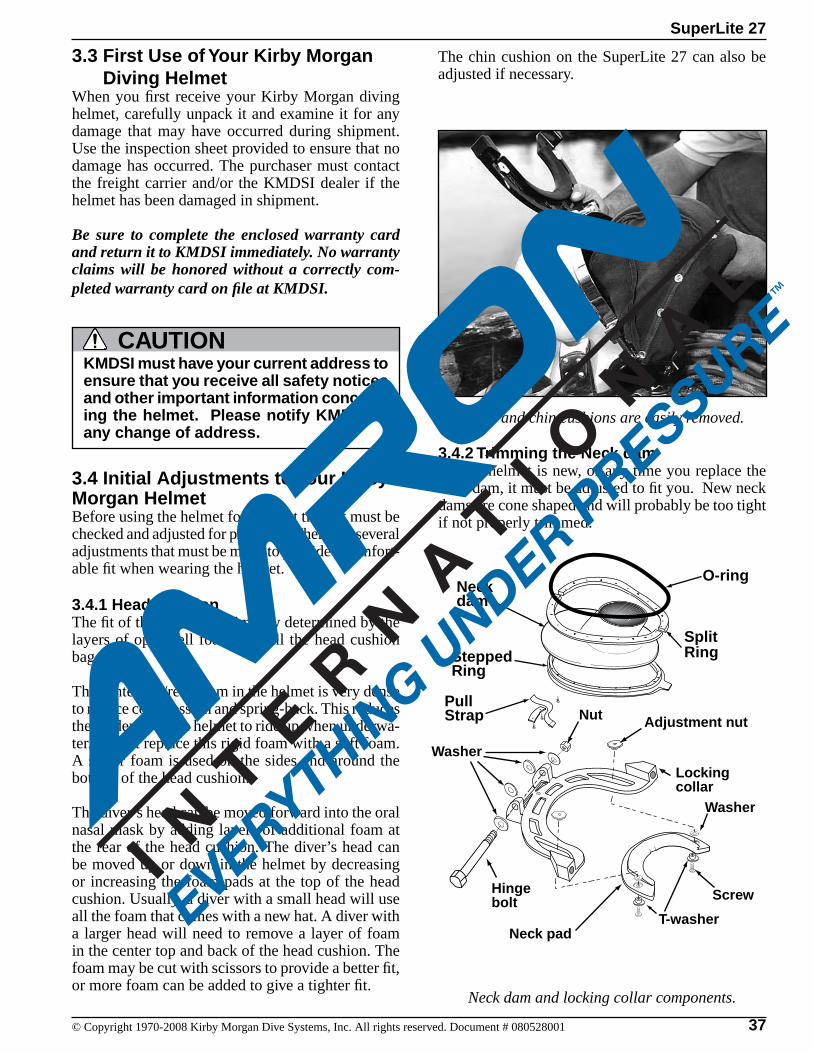
37© Copyright 1970-2008 Kirby Morgan Dive Systems, Inc. All rights reserved. Document # 080528001
SuperLite 27
3.3 First Use of Your Kirby Morgan Diving HelmetWhen you first receive your Kirby Morgan diving helmet, carefully unpack it and examine it for any damage that may have occurred during shipment. Use the inspection sheet provided to ensure that no damage has occurred. The purchaser must contact the freight carrier and/or the KMDSI dealer if the helmet has been damaged in shipment.
Be sure to complete the enclosed warranty card and return it to KMDSI immediately. No warranty claims will be honored without a correctly com-pleted warranty card on file at KMDSI.
The chin cushion on the SuperLite 27 can also be adjusted if necessary.
Neck dam and locking collar components.
3.4.2 Trimming the Neck damIf your helmet is new, or any time you replace the neck dam, it must be adjusted to fit you. New neck dams are cone shaped and will probably be too tight if not properly trimmed.
The head and chin cushions are easily removed.
3.4 Initial Adjustments to Your Kirby Morgan HelmetBefore using the helmet for the first time, it must be checked and adjusted for proper fit. There are several adjustments that must be made to provide a comfort-able fit when wearing the helmet.
3.4.1 Head Cushion The fit of the helmet is primarily determined by the layers of open cell foam that fill the head cushion bag.
The center top/rear foam in the helmet is very dense to reduce compression and spring-back. This reduces the tendency of the helmet to ride up when underwa-ter. Do not replace this rigid foam with a soft foam. A softer foam is used on the sides and around the bottom of the head cushion.
The diver’s head can be moved forward into the oral nasal mask by adding layers of additional foam at the rear of the head cushion. The diver’s head can be moved up or down in the helmet by decreasing or increasing the foam pads at the top of the head cushion. Usually, a diver with a small head will use all the foam that comes with a new hat. A diver with a larger head will need to remove a layer of foam in the center top and back of the head cushion. The foam may be cut with scissors to provide a better fit, or more foam can be added to give a tighter fit.
Hinge bolt
Nut
Locking collar
Neck pad
Adjustment nut
Washer
Washer
Screw
T-washer
O-ring
Split Ring
Neck dam
SteppedRing
PullStrap
KMDSI must have your current address to ensure that you receive all safety notices and other important information concern-ing the helmet. Please notify KMDSI of any change of address.
CAUTION
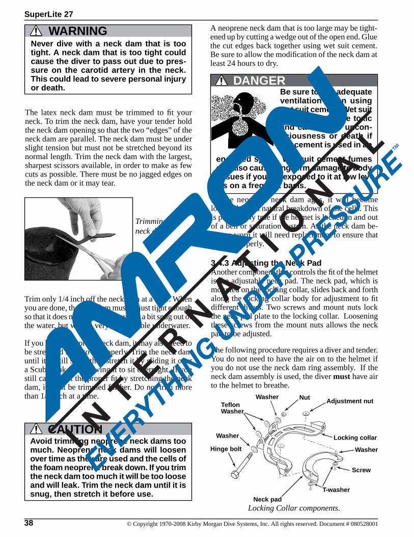
38 © Copyright 1970-2008 Kirby Morgan Dive Systems, Inc. All rights reserved. Document # 080528001
SuperLite 27
The latex neck dam must be trimmed to fit your neck. To trim the neck dam, have your tender hold the neck dam opening so that the two “edges” of the neck dam are parallel. The neck dam must be under slight tension but must not be stretched beyond its normal length. Trim the neck dam with the largest, sharpest scissors available, in order to make as few cuts as possible. There must be no jagged edges on the neck dam or it may tear.
A neoprene neck dam that is too large may be tight-ened up by cutting a wedge out of the open end. Glue the cut edges back together using wet suit cement. Be sure to allow the modification of the neck dam at least 24 hours to dry.
As the neoprene neck dam ages, it will become looser, due to a natural breakdown of the cells. This is particularly true if the helmet is locked in and out of a bell or saturation system. As the neck dam be-comes worn it will need replacement to ensure that it seals properly.
3.4.3 Adjusting the Neck PadAnother component that controls the fit of the helmet is the adjustable neck pad. The neck pad, which is mounted on the locking collar, slides back and forth along the locking collar body for adjustment to fit different divers. Two screws and mount nuts lock the neck pad plate to the locking collar. Loosening these screws from the mount nuts allows the neck pad to be adjusted.
The following procedure requires a diver and tender. You do not need to have the air on to the helmet if you do not use the neck dam ring assembly. If the neck dam assembly is used, the diver must have air to the helmet to breathe.
Locking Collar components.
Never dive with a neck dam that is too tight. A neck dam that is too tight could cause the diver to pass out due to pres-sure on the carotid artery in the neck. This could lead to severe personal injury or death.
WARNING
Trimming the neck dam.
Trim only 1/4 inch off the neck dam at a time. When you are done, the neck dam must be just tight enough so that it does not leak. This may feel a bit snug out of the water, but will be very comfortable underwater.
If you have a neoprene neck dam, it may also need to be stretched for it to fit properly. Trim the neck dam until it is still snug, then stretch it by sliding it over a Scuba tank and allowing it to sit overnight. If you still cannot get the proper fit by stretching the neck dam, it must be trimmed further. Do not trim more than 1/4 inch at a time.
Avoid trimming neoprene neck dams too much. Neoprene neck dams will loosen over time as they are used and the cells of the foam neoprene break down. If you trim the neck dam too much it will be too loose and will leak. Trim the neck dam until it is snug, then stretch it before use.
CAUTION
Be sure to use adequate ventilation when using wet suit cement. Wet suit cement fumes are toxic and can lead to uncon-sciousness or death if the cement is used in an
enclosed space. Wet suit cement fumes can also cause long term damage to body tissues if you are exposed to it at low lev-els on a frequent basis.
DANGER
Hinge bolt
Nut
Locking collar
Neck pad
Adjustment nut
Washer
Screw
Washer
T-washer
Teflon Washer
Washer
39© Copyright 1970-2008 Kirby Morgan Dive Systems, Inc. All rights reserved. Document # 080528001
SuperLite 27
With the helmet face down on a suitable surface, pull and turn each of the sealed pull pins until they are clear of their locking notch and the pins are fully retracted. Open the locking collar/neck pad assembly fully by swinging it away from the base of the helmet. Slightly loosen the screws until the neck pad and plate can slide back and forth. Be sure the head cushion snaps are attached to the bottom of the helmet.
Pick up the helmet and pull the nose block device knob out fully. Position the helmet on your head so the oral nasal is in the proper position on your face, covering your nose and mouth. Turn the sealed pull pins to the locking position with the ridge on the pins engaging the notch in the sleeve and the pins fully extended.
Tilt your head forward so the locking collar/neck pad assembly may be swung forward and locked up into its closed position. The locking sealed pull pins must snap into place on the locking collar.
Lift your head back up and slide the neck pad forward until it is snug but comfortable. Mark the position of the neck pad on the locking collar using an indelible marker. Open the locking sealed pull pins and let the locking collar open.
Tilt your head forward and open the locking collar so the screws can be tightened. Position the neck pad plate on the locking collar at the marked position and tighten the screws on each side. After the adjustment screws are tightened, tilt your head forward and lock the locking collar/neck pad assembly. Move your head in various positions making sure the pad is adjusted for comfort.
The helmet is now adjusted for your head. It should need no further adjustment unless another diver uses the helmet.
3.5 Pre Dress-In ProcedureBefore dressing in for a dive, inspection of the helmet system must be made to be sure it is in proper work-ing order. This must be done well in advance of the dive so any problems can be fixed without delaying the dive. The following steps are part of the recom-mended daily maintenance.
3.5.1 Pre-Dive Visual InspectionVisually inspect the exterior and interior of the hel-met.
1) The demand regulator cover should not be dented.
2) The neck dam must not be torn or punctured.
WARNINGThere must be no holes in the neck dam. If there are any holes in the neck dam the helmet could leak or flood. In addition, the demand regulator will not operate properly. Drowning could result.
3) Inspect the O-ring on the neck dam ring assembly. The O-ring must be in place and undamaged.
4) Inspect the bent tube that supplies breathing gas to the regulator. There must be no dents or kinks in the assembly.
5) Inspect the face port. It must be in good condi-tion.
The O-ring on the neck dam ring assem-bly on the helmet must be in place and in good condition. It must be properly lubricated for smooth operation. Without a proper functioning O-ring the helmet will leak and possibly flood. Drowning could result.
WARNING
6) Be sure the communications wires are hooked up and there are no loose connections.
7) Inspect the oral/nasal mask. Make sure it is on the regulator mount nut properly.
8) Inspect the sealed pull pin on each side of the hel-met. They must engage and disengage properly.
9) Make sure the head cushion and chin cushion are properly fastened inside the helmet.
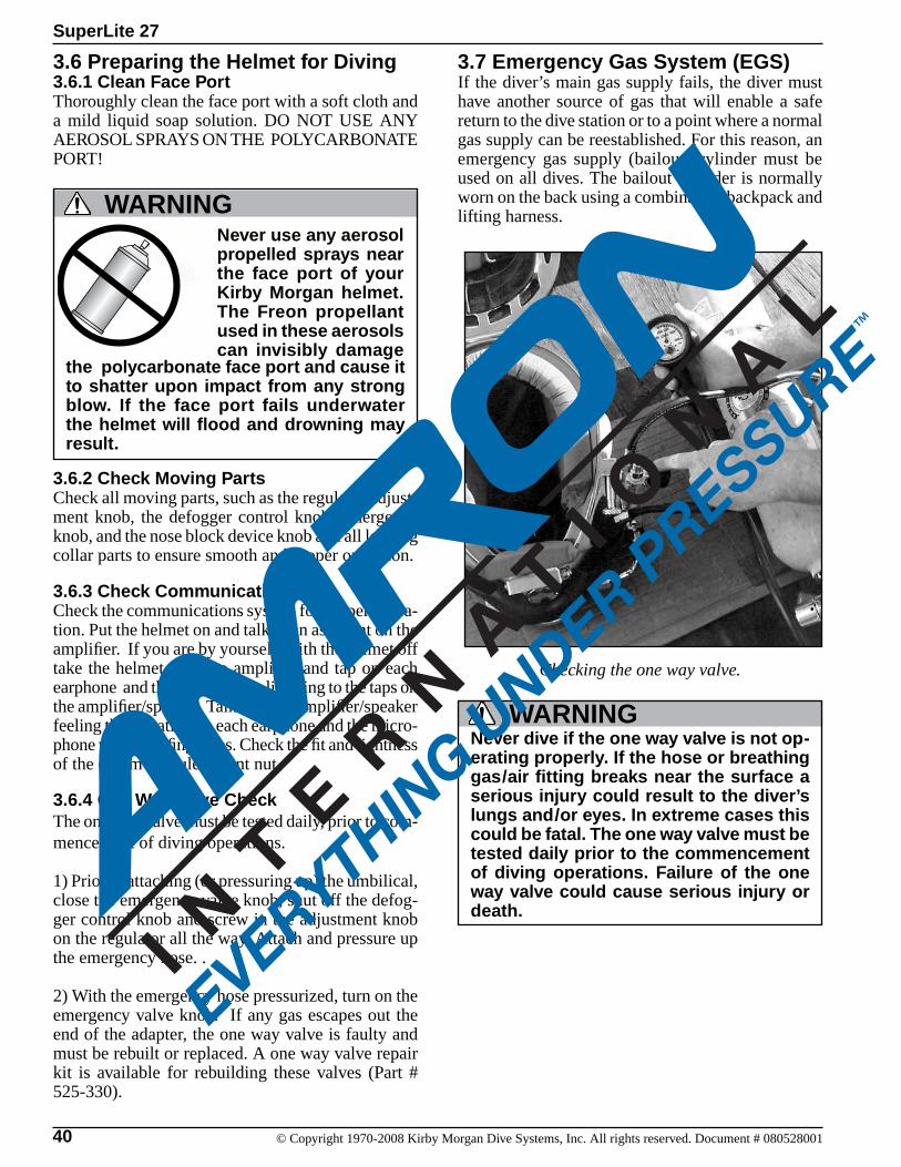
40 © Copyright 1970-2008 Kirby Morgan Dive Systems, Inc. All rights reserved. Document # 080528001
SuperLite 27
Never dive if the one way valve is not op-erating properly. If the hose or breathing gas/air fitting breaks near the surface a serious injury could result to the diver’s lungs and/or eyes. In extreme cases this could be fatal. The one way valve must be tested daily prior to the commencement of diving operations. Failure of the one way valve could cause serious injury or death.
WARNING
3.7 Emergency Gas System (EGS)If the diver’s main gas supply fails, the diver must have another source of gas that will enable a safe return to the dive station or to a point where a normal gas supply can be reestablished. For this reason, an emergency gas supply (bailout) cylinder must be used on all dives. The bailout cylinder is normally worn on the back using a combination backpack and lifting harness.
Checking the one way valve.
3.6 Preparing the Helmet for Diving3.6.1 Clean Face PortThoroughly clean the face port with a soft cloth and a mild liquid soap solution. DO NOT USE ANY AEROSOL SPRAYS ON THE POLYCARBONATE PORT!
3.6.2 Check Moving PartsCheck all moving parts, such as the regulator adjust-ment knob, the defogger control knob, emergency knob, and the nose block device knob and all locking collar parts to ensure smooth and proper operation.
3.6.3 Check CommunicationsCheck the communications system for proper opera-tion. Put the helmet on and talk to an assistant on the amplifier. If you are by yourself, with the helmet off take the helmet near the amplifier and tap on each earphone and the microphone, listening to the taps on the amplifier/speaker. Talk into the amplifier/speaker feeling the vibration on each earphone and the micro-phone with your fingertips. Check the fit and tightness of the comm module mount nut.
3.6.4 One Way Valve CheckThe one way valve must be tested daily, prior to com-mencement of diving operations.
1) Prior to attaching (or pressuring up) the umbilical, close the emergency valve knob, shut off the defog-ger control knob and screw in the adjustment knob on the regulator all the way. Attach and pressure up the emergency hose. .
2) With the emergency hose pressurized, turn on the emergency valve knob. If any gas escapes out the end of the adapter, the one way valve is faulty and must be rebuilt or replaced. A one way valve repair kit is available for rebuilding these valves (Part # 525-330).
Never use any aerosol propelled sprays near the face port of your Kirby Morgan helmet. The Freon propellant used in these aerosols can invisibly damage
WARNING
the polycarbonate face port and cause it to shatter upon impact from any strong blow. If the face port fails underwater the helmet will flood and drowning may result.

41© Copyright 1970-2008 Kirby Morgan Dive Systems, Inc. All rights reserved. Document # 080528001
SuperLite 27
When determining the size of the emergency gas cylinder to use, several factors must be considered. The divers depth, the length of time the diver may be without the main gas supply, and the gas consump-tion rate. Regardless of the cylinder used, it should be of sufficient volume to allow the diver to ascend at a normal rate or transit to a point where a normal gas supply can be reestablished. European C.E. ONLYIn European countries that have adopted C.E. certi-fication, only C.E. certified cylinders are allowed to be used and must have a minimum charged capacity available to the diver of 1400 N/l (50 scf). The emer-gency gas supply must only be fitted with a KMDSI first stage regulator and have a KMDSI over pressure relief valve installed (Part # 200-017). The relief must be adjusted to start lifting at approximately 20 p.s.i.g. (1.4 bar) above the regulator intermediate setting. The purpose of the relief valve is to allow pressure to vent off in the event the first stage regulator develops a leak or creeps. Without a pressure relief valve, the hose could rupture and the emergency gas supply would be lost.
Most commercial divers wear a harness (separate from the weight belt) that is used for several pur-poses. The harness is fitted with large metal rings (usually brass or stainless steel). The umbilical is hooked into one of these rings to keep any strain off the helmet. In addition, the rings on the harness are used to hang tools and other equipment. Usually the harness is also designed to provide a means of lifting an unconscious diver from the water. This harness is the best method of securing the emergency breathing gas to the diver.
A small tank can be mounted horizontally on the lower rear or front, while larger tanks are usually mounted vertically in the center back similar to a Scuba diver’s tank. Some harness designs incorporate a cloth enclosure into which the tank fits. The entire tank, valve, and regulator are enclosed in fabric. This helps to prevent snagging.
The emergency air/gas tank must be fitted with a good quality first stage regulator to reduce the pressure to less than 225 p.s.i.g. (16 bar) ambient diver pressure. The helmet cannot properly handle more pressure without modification. The KMDSI SuperFlow® First Stage Scuba regulator (Part #305-161) is an excellent device for this use. These regulators reduce the tank pressure to approximately 145 p.s.i.g. (9.9 bar). Other quality high performance Scuba regulators may also be used. Connect the first stage hose with a set of quick disconnecting locking sleeves to the emergency valve assembly located on the side block.
Do not dive without a diver worn Emer-gency Gas System (EGS). If the main gas supply is lost, you will have nothing to breathe and may drown.
WARNING
The diving harness must have a provision for attach-ing the emergency gas supply and a place to attach the diver’s umbilical.
Use a good quality first stage for your emergency gas supply.
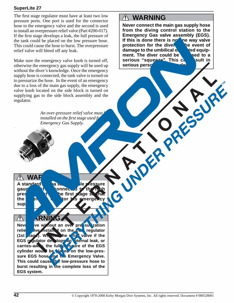
42 © Copyright 1970-2008 Kirby Morgan Dive Systems, Inc. All rights reserved. Document # 080528001
SuperLite 27
The first stage regulator must have at least two low pressure ports. One port is used for the connector hose to the emergency valve and the second is used to install an overpressure relief valve (Part #200-017). If the first stage develops a leak, the full pressure of the tank could be placed on the low pressure hose. This could cause the hose to burst. The overpressure relief valve will bleed off any leak.
Make sure the emergency valve knob is turned off, otherwise the emergency gas supply will be used up without the diver’s knowledge. Once the emergency supply hose is connected, the tank valve is turned on to pressurize the hose. In the event of an emergency due to a loss of the main gas supply, the emergency valve knob located on the side block is turned on supplying gas to the side block assembly and the regulator.
A standard Scuba submersible pressure gauge must be connected to the high pressure port on the first stage so that the diver can monitor his emergency supply.
WARNING
Never dive without an over pressurization relief valve installed on the EGS regulator (1st stage). Without the relief valve if the EGS regulator develops an internal leak, or carries-away, the full pressure of the EGS cylinder would be placed on the low-pres-sure EGS hose and the Emergency Valve. This could cause the low-pressure hose to burst resulting in the complete loss of the EGS system.
WARNING
An over-pressure relief valve must be installed on the first stage used for the Emergency Gas Supply.
WARNINGNever connect the main gas supply hose from the diving control station to the Emergency Gas valve assembly (EGS). If this is done there is no one way valve protection for the diver in the event of damage to the umbilical or related equip-ment. The diver could be exposed to a serious “squeeze”. This can result in serious personal injury or death.
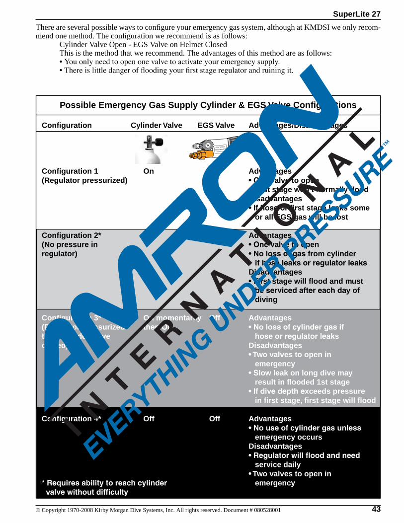
43© Copyright 1970-2008 Kirby Morgan Dive Systems, Inc. All rights reserved. Document # 080528001
SuperLite 27
There are several possible ways to configure your emergency gas system, although at KMDSI we only recom-mend one method. The configuration we recommend is as follows: Cylinder Valve Open - EGS Valve on Helmet Closed This is the method that we recommend. The advantages of this method are as follows: •Youonlyneedtoopenonevalvetoactivateyouremergencysupply. •Thereislittledangeroffloodingyourfirststageregulatorandruiningit.
Possible Emergency Gas Supply Cylinder & EGS Valve Configurations
Configuration Cylinder Valve EGS Valve Advantages/Disadvantages
Configuration 1 On Off Advantages(Regulator pressurized) • One valve to open • First stage won’t normally flood Disadvantages • If hose or first stage leaks some or all EGS gas will be lost
Configuration 2* Off On Advantages(No pressure in • One valve to openregulator) • No loss of gas from cylinder if hose leaks or regulator leaks Disadvantages • First stage will flood and must be serviced after each day of diving
Configuration 3* On momentarily Off Advantages(Regulator pressurized then Off • No loss of cylinder gas if then cylinder valve hose or regulator leaksclosed) Disadvantages • Two valves to open in emergency • Slow leak on long dive may result in flooded 1st stage • If dive depth exceeds pressure in first stage, first stage will flood
Configuration 4* Off Off Advantages • No use of cylinder gas unless emergency occurs Disadvantages • Regulator will flood and need service daily • Two valves to open in * Requires ability to reach cylinder emergency valve without difficulty
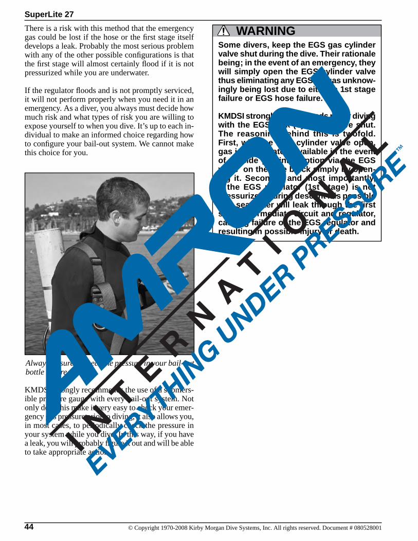
44 © Copyright 1970-2008 Kirby Morgan Dive Systems, Inc. All rights reserved. Document # 080528001
SuperLite 27
There is a risk with this method that the emergency gas could be lost if the hose or the first stage itself develops a leak. Probably the most serious problem with any of the other possible configurations is that the first stage will almost certainly flood if it is not pressurized while you are underwater.
If the regulator floods and is not promptly serviced, it will not perform properly when you need it in an emergency. As a diver, you always must decide how much risk and what types of risk you are willing to expose yourself to when you dive. It’s up to each in-dividual to make an informed choice regarding how to configure your bail-out system. We cannot make this choice for you.
Always be sure to check the pressure in your bail-out bottle before you dive.
KMDSI strongly recommends the use of a submers-ible pressure gauge with every bail-out system. Not only does this make it very easy to check your emer-gency gas pressure prior to diving, it also allows you, in most cases, to periodically check the pressure in your system while you dive. In this way, if you have a leak, you will probably figure it out and will be able to take appropriate action.
Some divers, keep the EGS gas cylinder valve shut during the dive. Their rationale being; in the event of an emergency, they will simply open the EGS cylinder valve thus eliminating any EGS air/gas unknow-ingly being lost due to either a 1st stage failure or EGS hose failure.
KMDSI strongly recommends never diving with the EGS tank (cylinder) valve shut. The reasoning behind this is twofold. First, with the EGS cylinder valve open, gas is immediately available in the event of topside gas interruption via the EGS valve on the side block simply by open-ing it. Secondly, and most importantly, if the EGS regulator (1st stage) is not pressurized, during descent it is possible that sea water will leak through the first stage intermediate circuit and regulator, causing failure of the EGS regulator and resulting in possible injury or death.
WARNING
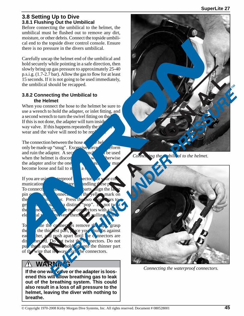
45© Copyright 1970-2008 Kirby Morgan Dive Systems, Inc. All rights reserved. Document # 080528001
SuperLite 27
3.8 Setting Up to Dive3.8.1 Flushing Out the UmbilicalBefore connecting the umbilical to the helmet, the umbilical must be flushed out to remove any dirt, moisture, or other debris. Connect the topside umbili-cal end to the topside diver control console. Ensure there is no pressure in the divers umbilical.
Carefully uncap the helmet end of the umbilical and hold securely while pointing in a safe direction, then slowly bring up gas pressure to approximately 25-40 p.s.i.g. (1.7-2.7 bar). Allow the gas to flow for at least 15 seconds. If it is not going to be used immediately, the umbilical should be recapped.
3.8.2 Connecting the Umbilical to the Helmet When you connect the hose to the helmet be sure to use a wrench to hold the adapter, or inlet fitting, and a second wrench to turn the swivel fitting on the hose. If this is not done, the adapter will turn inside the one way valve. If this happens repeatedly the threads will wear and the valve will need to be replaced.
The connection between the hose and the helmet must only be made up “snug”. Excessive force will deform and ruin the adapter. A second wrench must be used when the helmet is disconnected as well, otherwise the adapter and/or the one way valve assembly may become loose and fail to make a seal.
If you are using waterproof connectors for your com-munications, take extra care in handling these pieces. To connect the male and female parts, align the large pin on the male connector with the yellow mark on the female connector. Press the two connectors to-gether until you hear a distinct “pop”. Do not twist the connectors. Tape the two connectors with a bit of electrical tape to prevent them from pulling apart.
To separate the connectors remove the tape, grasp them at the thickest part, place your thumbs against each other, and push apart until the connectors are disconnected. Do not twist the connectors. Do not pull them apart while holding onto the thinner part of the wire that is away from the connectors.
Connecting the umbilical to the helmet.
If the one way valve or the adapter is loos-ened this will allow breathing gas to leak out of the breathing system. This could also result in a loss of all pressure to the helmet, leaving the diver with nothing to breathe.
WARNING Connecting the waterproof connectors.
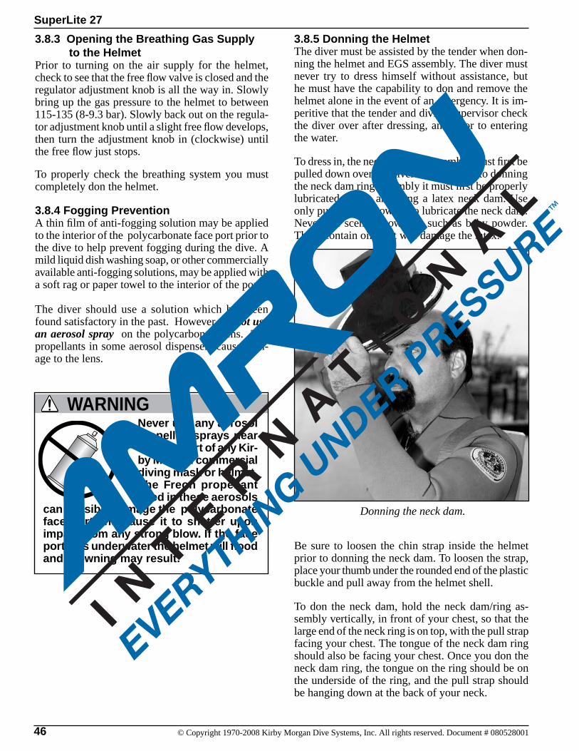
46 © Copyright 1970-2008 Kirby Morgan Dive Systems, Inc. All rights reserved. Document # 080528001
SuperLite 27
3.8.5 Donning the HelmetThe diver must be assisted by the tender when don-ning the helmet and EGS assembly. The diver must never try to dress himself without assistance, but he must have the capability to don and remove the helmet alone in the event of an emergency. It is im-peritive that the tender and diving supervisor check the diver over after dressing, and prior to entering the water.
To dress in, the neck dam ring assembly must first be pulled down over the diver’s head. Prior to donning the neck dam ring assembly it must first be properly lubricated if you are using a latex neck dam. Use only pure talcum powder to lubricate the neck dam. Never use scented powders, such as baby powder. These contain oils that will damage the latex.
3.8.3 Opening the Breathing Gas Supply to the Helmet Prior to turning on the air supply for the helmet, check to see that the free flow valve is closed and the regulator adjustment knob is all the way in. Slowly bring up the gas pressure to the helmet to between 115-135 (8-9.3 bar). Slowly back out on the regula-tor adjustment knob until a slight free flow develops, then turn the adjustment knob in (clockwise) until the free flow just stops. To properly check the breathing system you must completely don the helmet.
3.8.4 Fogging PreventionA thin film of anti-fogging solution may be applied to the interior of the polycarbonate face port prior to the dive to help prevent fogging during the dive. A mild liquid dish washing soap, or other commercially available anti-fogging solutions, may be applied with a soft rag or paper towel to the interior of the port.
The diver should use a solution which has been found satisfactory in the past. However, do not use an aerosol spray on the polycarbonate lens. The propellants in some aerosol dispensers cause dam-age to the lens.
Donning the neck dam.
Be sure to loosen the chin strap inside the helmet prior to donning the neck dam. To loosen the strap, place your thumb under the rounded end of the plastic buckle and pull away from the helmet shell.
To don the neck dam, hold the neck dam/ring as-sembly vertically, in front of your chest, so that the large end of the neck ring is on top, with the pull strap facing your chest. The tongue of the neck dam ring should also be facing your chest. Once you don the neck dam ring, the tongue on the ring should be on the underside of the ring, and the pull strap should be hanging down at the back of your neck.
Never use any aerosol propelled sprays near the face port of any Kir-by Morgan commercial diving mask or helmet. The Freon propellant used in these aerosols
WARNING
can invisibly damage the polycarbonate face port and cause it to shatter upon impact from any strong blow. If the face port fails underwater the helmet will flood and drowning may result.
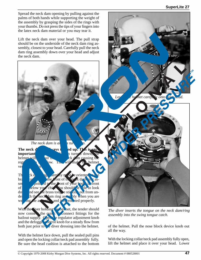
47© Copyright 1970-2008 Kirby Morgan Dive Systems, Inc. All rights reserved. Document # 080528001
SuperLite 27
Spread the neck dam opening by pulling against the palms of both hands while supporting the weight of the assembly by grasping the sides of the rings with your thumbs. Do not press the tips of your fingers into the latex neck dam material or you may tear it.
Lift the neck dam over your head. The pull strap should be on the underside of the neck dam ring as-sembly, closest to your head. Carefully pull the neck dam ring assembly down over your head and adjust the neck dam.
The neck dam is always turned up. This is very important! With the neck dam turned down, the helmet will vent air from the neck dam causing the regulator to free flow. This will make the helmet very uncomfortable.
The neck dam ring assembly must be oriented so the brass “tongue” on the front of the neck dam ring as-sembly is pointed to the front of your body, in front of and below your chin. You should be able to look down and see the brass tongue sticking out from un-derneath the neck dam ring assembly when you are wearing the assembly and it is oriented properly.
With the diver holding the helmet, the tender should now connect the quick disconnect fittings for the bailout supply. Open the regulator adjustment knob and the defogger control knob for a steady flow from both just prior to the diver dressing into the helmet.
With the helmet face down, pull the sealed pull pins and open the locking collar/neck pad assembly fully. Be sure the head cushion is attached to the bottom
The diver inserts the tongue on the neck dam/ring assembly into the swing tongue catch.
Lower the helmet carefully onto your head.
pull strap
The neck dam is always turned up.
tongue
of the helmet. Pull the nose block device knob out all the way.
With the locking collar/neck pad assembly fully open, lift the helmet and place it over your head. Lower
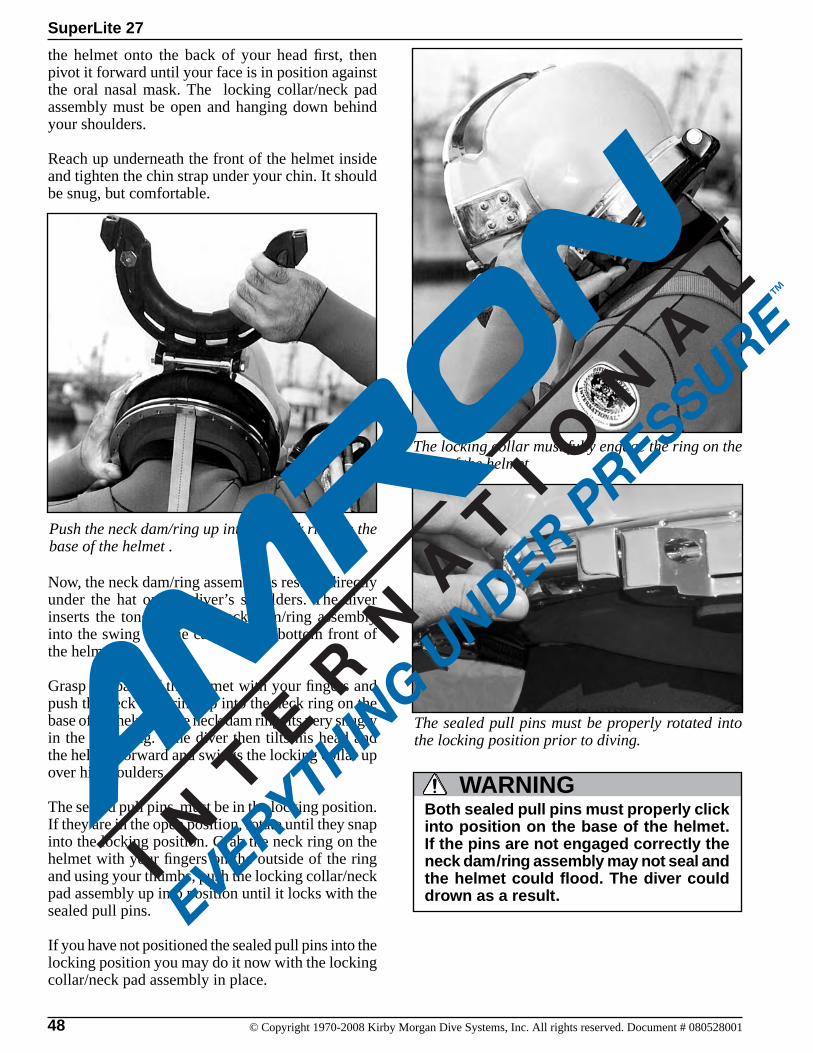
48 © Copyright 1970-2008 Kirby Morgan Dive Systems, Inc. All rights reserved. Document # 080528001
SuperLite 27
The sealed pull pins must be properly rotated into the locking position prior to diving.
the helmet onto the back of your head first, then pivot it forward until your face is in position against the oral nasal mask. The locking collar/neck pad assembly must be open and hanging down behind your shoulders.
Reach up underneath the front of the helmet inside and tighten the chin strap under your chin. It should be snug, but comfortable.
Push the neck dam/ring up into the neck ring on the base of the helmet .
The locking collar must fully engage the ring on the base of the helmet
Now, the neck dam/ring assembly is resting directly under the hat on the diver’s shoulders. The diver inserts the tongue on the neck dam/ring assembly into the swing tongue catch on the bottom front of the helmet.
Grasp the base of the helmet with your fingers and push the neck dam/ring up into the neck ring on the base of the helmet. The neck dam ring fits very snugly in the neck ring. The diver then tilts his head and the helmet forward and swings the locking collar up over his shoulders.
The sealed pull pins must be in the locking position. If they are in the open position, rotate until they snap into the locking position. Grab the neck ring on the helmet with your fingers on the outside of the ring and using your thumbs, push the locking collar/neck pad assembly up into position until it locks with the sealed pull pins.
If you have not positioned the sealed pull pins into the locking position you may do it now with the locking collar/neck pad assembly in place.
Both sealed pull pins must properly click into position on the base of the helmet. If the pins are not engaged correctly the neck dam/ring assembly may not seal and the helmet could flood. The diver could drown as a result.
WARNING
49© Copyright 1970-2008 Kirby Morgan Dive Systems, Inc. All rights reserved. Document # 080528001
SuperLite 27
3.8.6 Testing the Breathing SystemTest the defogger system by turning on and off the defogger control knob. The regulator should be adjusted by turning the adjustment knob out until a slight steady flow starts, then back in until the flow just stops. Next, the demand regulator system is checked for proper function: breathe in and out. Inhalation and exhalation effort should be nearly unnoticeable. Press in on the purge button in the regulator cover. This should produce a strong burst of breathing gas.
3.8.7 Sealing Integrity CheckIf there is any doubt that the helmet is sealing prop-erly, perform the following test prior to diving.
Turn the supply gas off at the dive control system and bleed the umbilical.
To perform this test, the diver must have an assistant standing by. The assistant should be in control of the gas supply console in the event the diver needs air or he must be ready to lend a hand. The diver must be next to the dive control manifold so that the air may be turned on instantly, or the diver must be ready to run a hand between his neck and the sealing neck dam in order to pull the neck dam away from the neck to allow breathing.
With the neck dam ring on the diver’s head, the helmet is installed and the locking collar closed. When the diver attempts to inhale, a suction on the neck dam is formed, indicating he is achieving a good seal. The diver must then turn the air on immediately so that he can breathe. If the diver does not turn the air on he will not be able to breathe, unless the neck dam is pulled away from his neck.
Do not perform this test unless the diver and his tender are stationed immediately adjacent to the diver’s air manifold and you are certain the air is on to the mani-fold. If the diver is unable to flow air to the helmet, either through the umbilical or the bailout, he may not be able to remove the helmet easily.
To break the seal in this situation, the diver must put his hand between the neck dam and the neck, and pull the neck dam away from the neck. A tender must be standing by to assist the diver in removing the helmet if needed. Suffocation could result.
WARNING
To remove the helmet, start by pulling out (forward) on each sealed pull pin and turning so each remains in the open position. Tilt your head, and the helmet, forward and swing the locking collar assembly back behind your shoulders.
Tilt your head upright again and push the swinging tongue catch forward with one hand and hold it in this position. Grasp the pull strap at the back of the helmet and pull down on it. This will break the seal between the neck dam/neck ring and the helmet neck ring on the base of the helmet. Once the seal is broken the neck ring assembly will come loose from the helmet.
Pull the nose block device knob away from your face, loosen the chin strap inside the helmet, and lift the helmet off of your head. A good tender will be prepared to help the diver with the removal of the helmet as required.
Reach in and spread the neck dam, pulling against the sides of the neck dam with the palms of both hands. Slide the neck dam/neck ring assembly forward so your chin will clear the chin strap. Lift the neck dam over your head.
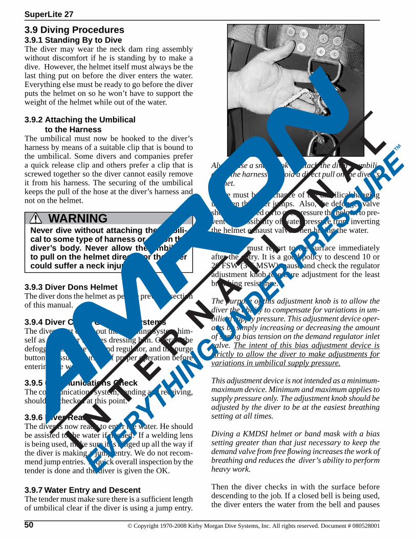
50 © Copyright 1970-2008 Kirby Morgan Dive Systems, Inc. All rights reserved. Document # 080528001
SuperLite 27
3.9 Diving Procedures3.9.1 Standing By to DiveThe diver may wear the neck dam ring assembly without discomfort if he is standing by to make a dive. However, the helmet itself must always be the last thing put on before the diver enters the water. Everything else must be ready to go before the diver puts the helmet on so he won’t have to support the weight of the helmet while out of the water.
3.9.2 Attaching the Umbilical to the HarnessThe umbilical must now be hooked to the diver’s harness by means of a suitable clip that is bound to the umbilical. Some divers and companies prefer a quick release clip and others prefer a clip that is screwed together so the diver cannot easily remove it from his harness. The securing of the umbilical keeps the pull of the hose at the diver’s harness and not on the helmet.
There must be no chance of the umbilical hanging up when the diver jumps. Also, the defogger valve should be turned on to overpressure the helmet to pre-vent the possibility of water pressure from inverting the helmet exhaust valve when hitting the water.
The diver must report to the surface immediately after the entry. It is a good policy to descend 10 or 20 FSW (3-6 MSW), pause and check the regulator adjustment knob to ensure adjustment for the least breathing resistance.
The purpose of this adjustment knob is to allow the diver the ability to compensate for variations in um-bilical supply pressure. This adjustment device oper-ates by simply increasing or decreasing the amount of spring bias tension on the demand regulator inlet valve. The intent of this bias adjustment device is strictly to allow the diver to make adjustments for variations in umbilical supply pressure.
This adjustment device is not intended as a minimum-maximum device. Minimum and maximum applies to supply pressure only. The adjustment knob should be adjusted by the diver to be at the easiest breathing setting at all times.
Diving a KMDSI helmet or band mask with a bias setting greater than that just necessary to keep the demand valve from free flowing increases the work of breathing and reduces the diver’s ability to perform heavy work.
Then the diver checks in with the surface before descending to the job. If a closed bell is being used, the diver enters the water from the bell and pauses
Never dive without attaching the umbili-cal to some type of harness or clip on the diver’s body. Never allow the umbilical to pull on the helmet directly or the diver could suffer a neck injury.
WARNING
3.9.3 Diver Dons HelmetThe diver dons the helmet as per the previous section of this manual.
3.9.4 Diver Check Gas Flow SystemsThe diver must check out the breathing system him-self as the tender finishes dressing him. Operate the defogger valve, the demand regulator, and the purge button to assure yourself of proper operation before entering the water.
3.9.5 Communications CheckThe communications system, sending and receiving, should be checked at this point.
3.9.6 Diver ReadyThe diver is now ready to enter the water. He should be assisted to the water if needed. If a welding lens is being used, make sure it is hinged up all the way if the diver is making a jump entry. We do not recom-mend jump entries. A quick overall inspection by the tender is done and the diver is given the OK.
3.9.7 Water Entry and DescentThe tender must make sure there is a sufficient length of umbilical clear if the diver is using a jump entry.
Always use a snap hook to attach the diver’s umbili-cal to the harness to avoid a direct pull on the diver’s helmet.
51© Copyright 1970-2008 Kirby Morgan Dive Systems, Inc. All rights reserved. Document # 080528001
SuperLite 27
for a short time outside the trunk until he is sure all systems are operating properly.
During the decent the communications must be checked again and the diver supply pressure should be adjusted as necessary to maintain the required over-bottom pressure. It may be necessary for the diver to readjust the demand regulator by means of the adjustment knob (98) once at the work site to compensate for any variation in umbilical supply pressure.
3.9.8 Adjust Regulator for Low Work RatesAt very low work rates, such as when the diver is resting, or during in-water decompression, the diver’s respiratory rate may be quite slow (10-15 breaths per minute). When this occurs, the diver’s exhalations may not be sufficient to move enough breathing gas through the helmet exhaust to adequately wash out carbon dioxide (CO
2).
In order to ensure that carbon dioxide does not ac-cumulate in the helmet, divers who are at rest under-water should screw the regulator adjustment knob “out,” i.e., away from the regulator, until a slight steady flow occurs and the regulator can be heard to hiss. This will help to eliminate any excess carbon dioxide from the helmet.
WARNINGExcess carbon dioxide (CO2) is danger-ous. Too much carbon dioxide in the div-er’s breathing system can cause the diver to feel that he cannot breathe for comfort. In extreme circumstances, carbon dioxide can cause unconsciousness. This could lead to suffocation and death.
52 © Copyright 1970-2008 Kirby Morgan Dive Systems, Inc. All rights reserved. Document # 080528001
SuperLite 27
3.10 Emergency Procedures3.10.1 FloodingIn the event of partial or complete flooding, the diver may clear the helmet quickly by tilting the helmet down and activating the defogger control knob or by pressing in on the manual purge button in the center of the regulator cover.
The water dump valve is located on the diver’s left side of the helmet. The opening in this valve is much larger than the opening in the regulator exhaust valve. By placing this valve in the lowest position on the helmet, water will exit more easily.
After clearing, cautiously check for additional flood-ing. If the helmet continues to take on water, return to the diving station, swimming with the water dump valve positioned at the lowest part of the hat: that is with the diver’s face forward and slightly tilted down. Keep the free flow knob on. This increases the air/gas pressure slightly inside the hat and keeps the water out. Any incoming water is automatically purged.
3.10.2 Inhalation ResistanceIf breathing becomes difficult, adjust the demand regulator adjustment knob, for easier breathing by rotating the adjustment knob counter clockwise. If the breathing does not get noticeably better, press the purge button in the regulator cover. If a surge of gas does not flow with this action, open the emergency valve.
If the flow is noticeably better, immediately notify topside that you are on emergency gas. Ensure your umbilical is clear and return to the stage or descent line. The diver should stay in communication with topside personnel and make preparations to abort the dive. The console operator should check to en-sure the supply pressure to the diver is at the proper pressure.
3.10.3 Gas Flow StopsA stop of flow in the demand regulator usually in-dicates the main gas supply has stopped. The diver should first open the emergency valve by turning the knob. If there is still no flow from the demand regulator, the defogger valve knob should be opened. Keep in mind that if the defogger valve is left open, the bailout bottle will drain very quickly, particularly if the diver is deep.
Immediately notify topside, check to ensure your umbilical is clear and return to the diving station us-ing the emergency breathing supply. Avoid making a rapid ascent if at all possible.
Once at the surface, or inside the bell, the diver may remove the helmet if needed. Never ditch the helmet underwater because you will be unable to see and there is usually the possibility that topside will be able to get an air supply back on line.
Rapid ascent is dangerous. It can lead to air embolism or decompression sickness. Air/gas embolism can cause immediate loss of consciousness and/or death. Even on a no decompression dive, a rapid ascent may cause decompression sickness. A diver must only make a rapid ascent when he is in immediate danger of death by drowning or asphyxiation.
DANGER
Ditching the helmet underwater must be avoided. If the diver ditches the helmet underwater he will not be able to see. In many instances, even if the air sup-ply is interrupted, topside will be able to get it back on line quickly. Do not ditch the helmet underwater unless you are completely out of breathing gas and it is impossible to return to the surface due to entanglement of your equipment or similar circumstances.
DANGER
Never remove the diving helmet while you are in the stage. If you fall out of the stage with the helmet off but still attached to your harness it may be very difficult to swim. Drowning may result.
WARNING
3.10.4 Demand Regulator Free FlowIf the demand regulator free flows, adjust the knob in (clockwise) until it stops. If the free flow cannot be stopped, the dive should be aborted. Even if there is no serious problem to the diver, the dive should be aborted and the problem with the regulator cor-rected.
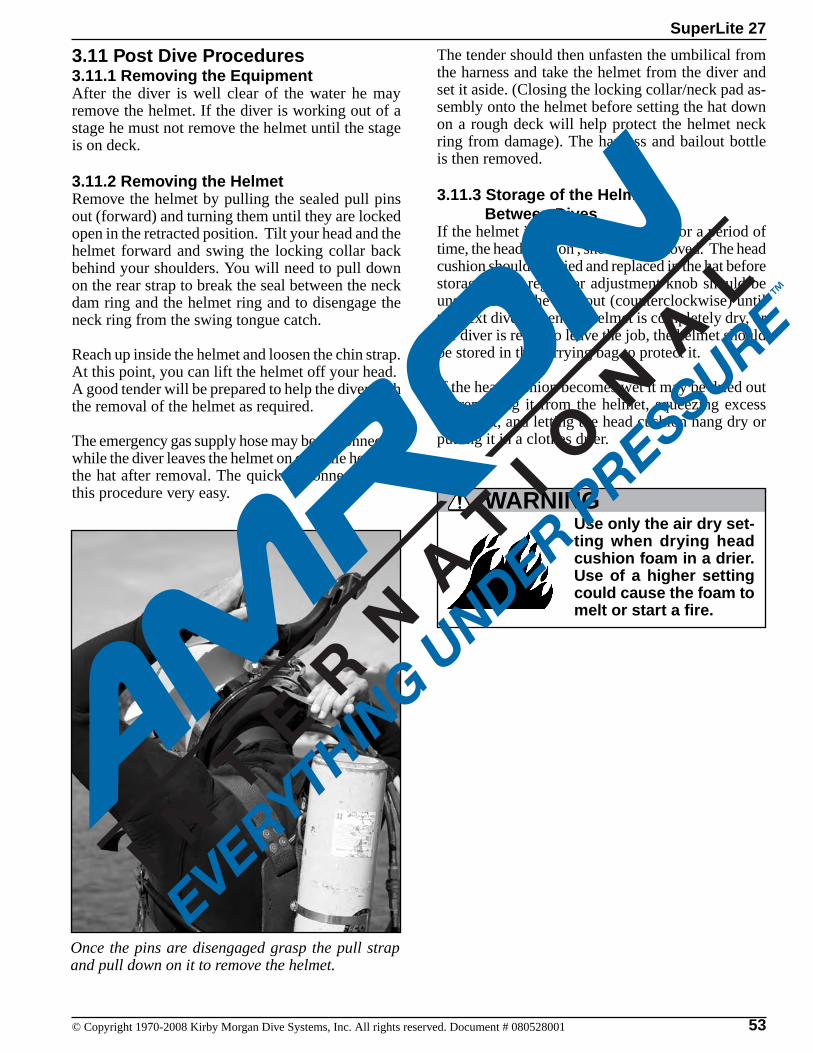
53© Copyright 1970-2008 Kirby Morgan Dive Systems, Inc. All rights reserved. Document # 080528001
SuperLite 27
3.11 Post Dive Procedures3.11.1 Removing the EquipmentAfter the diver is well clear of the water he may remove the helmet. If the diver is working out of a stage he must not remove the helmet until the stage is on deck.
3.11.2 Removing the HelmetRemove the helmet by pulling the sealed pull pins out (forward) and turning them until they are locked open in the retracted position. Tilt your head and the helmet forward and swing the locking collar back behind your shoulders. You will need to pull down on the rear strap to break the seal between the neck dam ring and the helmet ring and to disengage the neck ring from the swing tongue catch.
Reach up inside the helmet and loosen the chin strap. At this point, you can lift the helmet off your head.A good tender will be prepared to help the diver with the removal of the helmet as required.
The emergency gas supply hose may be disconnected while the diver leaves the helmet on or while he holds the hat after removal. The quick disconnect makes this procedure very easy.
The tender should then unfasten the umbilical from the harness and take the helmet from the diver and set it aside. (Closing the locking collar/neck pad as-sembly onto the helmet before setting the hat down on a rough deck will help protect the helmet neck ring from damage). The harness and bailout bottle is then removed.
3.11.3 Storage of the Helmet Between DivesIf the helmet is not going to be used for a period of time, the head cushion , should be removed. The head cushion should be dried and replaced in the hat before storage. The regulator adjustment knob should be unscrewed all the way out (counterclockwise) until the next dive. When the helmet is completely dry, or the diver is ready to leave the job, the helmet should be stored in the carrying bag to protect it.
If the head cushion becomes wet it may be dried out by removing it from the helmet, squeezing excess water out, and letting the head cushion hang dry or putting it in a clothes drier.
Once the pins are disengaged grasp the pull strap and pull down on it to remove the helmet.
Use only the air dry set-ting when drying head cushion foam in a drier. Use of a higher setting could cause the foam to melt or start a fire.
WARNING
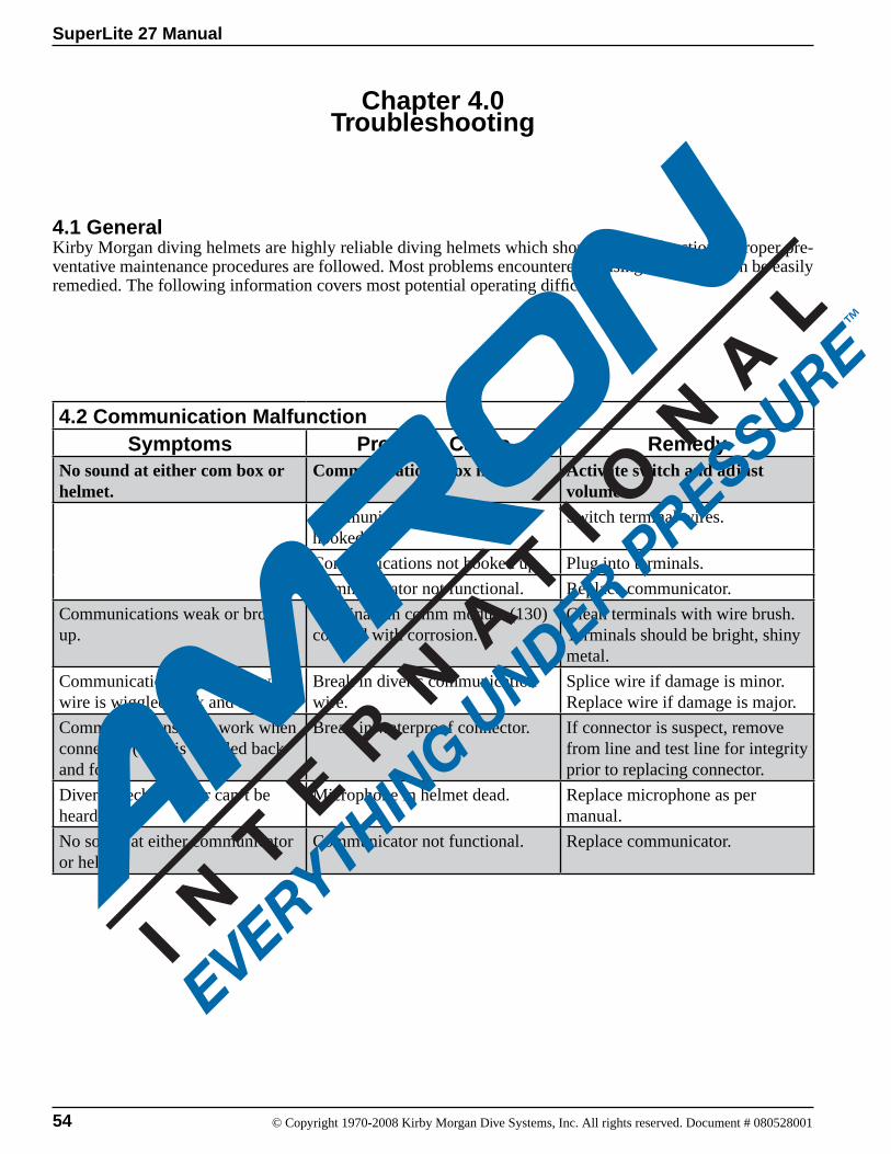
© Copyright 1970-2008 Kirby Morgan Dive Systems, Inc. All rights reserved. Document # 080528001
SuperLite 27 Manual
54
4.2 Communication MalfunctionSymptoms Probable Cause Remedy
No sound at either com box or helmet.
Communications box not on. Activate switch and adjust volume.
Communications incorrectly hooked up.
Switch terminal wires.
Communications not hooked up. Plug into terminals.
Communicator not functional. Replace communicator.
Communications weak or broken up.
Terminals in comm module (130) covered with corrosion.
Clean terminals with wire brush. Terminals should be bright, shiny metal.
Communications only work when wire is wiggled back and forth.
Break in diver’s communication wire.
Splice wire if damage is minor. Replace wire if damage is major.
Communications only work when connector (146) is wiggled back and forth.
Break in waterproof connector. If connector is suspect, remove from line and test line for integrity prior to replacing connector.
Diver speech weak or can’t be heard.
Microphone in helmet dead. Replace microphone as per manual.
No sound at either communicator or helmet.
Communicator not functional. Replace communicator.
4.1 GeneralKirby Morgan diving helmets are highly reliable diving helmets which should not malfunction if proper pre-ventative maintenance procedures are followed. Most problems encountered in using the helmet can be easily remedied. The following information covers most potential operating difficulties.
Chapter 4.0Troubleshooting
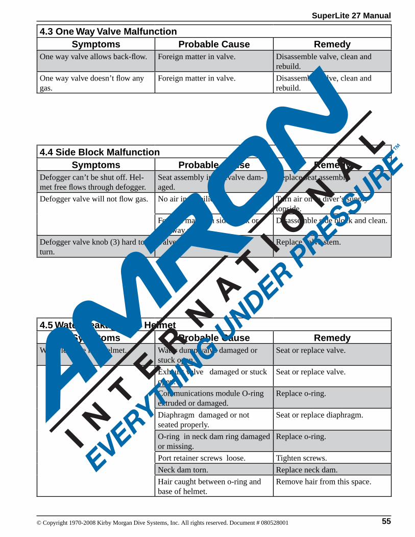
© Copyright 1970-2008 Kirby Morgan Dive Systems, Inc. All rights reserved. Document # 080528001
SuperLite 27 Manual
55
4.3 One Way Valve MalfunctionSymptoms Probable Cause Remedy
One way valve allows back-flow. Foreign matter in valve. Disassemble valve, clean and rebuild.
One way valve doesn’t flow any gas.
Foreign matter in valve. Disassemble valve, clean and rebuild.
4.4 Side Block MalfunctionSymptoms Probable Cause Remedy
Defogger can’t be shut off. Hel-met free flows through defogger.
Seat assembly in sidevalve dam-aged.
Replace seat assembly.
Defogger valve will not flow gas. No air in umbilical. Turn air on to diver’s supply topside.
Foreign matter in side block or one way valve.
Disassemble side block and clean.
Defogger valve knob (3) hard to turn.
Valve stem bent. Replace valve stem.
4.5 Water Leakage Into HelmetSymptoms Probable Cause Remedy
Water leakage into helmet. Water dump valve damaged or stuck open.
Seat or replace valve.
Exhaust valve damaged or stuck open.
Seat or replace valve.
Communications module O-ring extruded or damaged.
Replace o-ring.
Diaphragm damaged or not seated properly.
Seat or replace diaphragm.
O-ring in neck dam ring damaged or missing.
Replace o-ring.
Port retainer screws loose. Tighten screws.
Neck dam torn. Replace neck dam.
Hair caught between o-ring and base of helmet.
Remove hair from this space.
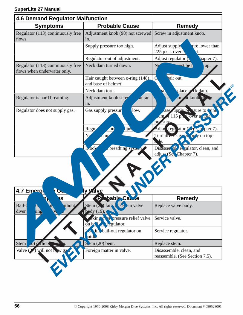
© Copyright 1970-2008 Kirby Morgan Dive Systems, Inc. All rights reserved. Document # 080528001
SuperLite 27 Manual
56
4.6 Demand Regulator MalfunctionSymptoms Probable Cause Remedy
Regulator (113) continuously free flows.
Adjustment knob (98) not screwed in.
Screw in adjustment knob.
Supply pressure too high. Adjust supply pressure lower than 225 p.s.i. over ambient.
Regulator out of adjustment. Adjust regulator (See Chapter 7).
Regulator (113) continuously free flows when underwater only.
Neck dam turned down. Neck dam must be turned up.
Hair caught between o-ring (148) and base of helmet.
Clean hair out.
Neck dam torn. Repair or replace neck dam.
Regulator is hard breathing. Adjustment knob screwed too far in.
Screw adjustment knob out.
Regulator does not supply gas. Gas supply pressure too low. Increase supply pressure to mini-mum of 115 p.s.i. over ambient pressure.
Regulator is out of adjustment. Adjust regulator (See Chapter 7).
No gas in umbilical Turn diver’s gas supply on top-side.
Blockage in breathing system. Disassemble regulator, clean, and adjust (See Chapter 7).
4.7 Emergency Gas Supply ValveSymptoms Probable Cause Remedy
Bail-out bottle drained without diver opening EGS valve
Stem (20) fails to seat in valve body (19).
Replace valve body.
Leaking over-pressure relief valve on bail-out regulator.
Service valve.
Leaking bail-out regulator on bottle.
Service regulator.
Stem (20) difficult to turn. Stem (20) bent. Replace stem.
Valve (27) will not flow gas. Foreign matter in valve. Disassemble, clean, and reassemble. (See Section 7.5).

© Copyright 1970-2008 Kirby Morgan Dive Systems, Inc. All rights reserved. Document # 080528001
SuperLite 27 Manual
57
Chapter 5.0Inspection and Maintenance
5.1 Routine Maintenance
Routine and preventative maintenance is critical and must be done on a regular basis. All parts and components of the helmet have a useful service life and eventually will require replacement. Some items, when properly maintained, can go many years before replacement becomes necessary. Each helmet or mask should have a logbook that tracks the usage, maintenance and repairs.
It is essential to safety of the user that a routine and periodic schedule of maintenance, inspection, and testing be carried out. Helmets should be inspected pre-dive on a daily basis. Helmets in continuous use around the clock should be rotated out every 24 hours and have a daily pre-dive inspection performed. Post dive cleaning and inspections should be completed each time helmet or mask use is finished for the day. To minimize the spread of germs, sanitizing should be performed after use, and in between use by different divers. Sanitizing procedures and recommended solutions are de-scribed and explained in the General preventative section of each KMDSI helmet and mask manual. If the user is in doubt about the serviceability or has questions in general, please contact your local KMDSI authorized repair facility or KMDSI at Tel. 805-928-7772. Check the Dive Lab website at www.divelab.com for the most up-to-date mainte-nance procedures.
KMDSI Maintenance Checklist are located on the KMDSI and Dive Lab websites. The checklists are intended for all helmet and mask models. There are also checklists for the KMB-18/28 band masks which are done up the same as the helmet check-lists.
A2.1. All SL and KM helmets (all models) Rec-ommended Annual Maintenance Inspection and Overhaul A2.2. Monthly MaintenanceA2.3. Daily Set-Up and Functional ChecklistA2.4. Supervisor’s Equipment Checks Prior to Entry
A2.5. Supervisor’s Equipment Checks In-WaterA2.6. Post Dive Cleaning
Daily Pre-Dive Maintenance A2.3The helmets and masks should be set up in accor-dance with the Daily Set-Up and Function Check-list A2.3. The checklist can be laminated placed on a clipboard and checked off with a grease pencil. Completion should be logged in both the supervi-sors log and the helmet or mask log book. The daily pre-dive is minimum daily checks KMDSI recom-mends. The daily pre dive may be modified to suit the needs of the user providing the basic intent of the checklist is being completed in a manner with the original intent.
Daily Post Dive Maintenance A2.6The helmets and masks should be cleaned in ac-cordance with the A2.4 checklist The checklist can be laminated placed on a clipboard and checked off with a grease pencil. Completion should be logged in both the supervisor’s log, and the helmet or mask log book. The daily pre-dive is minimum daily checks KMDSI recommends. The daily post-dive may be modified to suit the needs of the user providing the basic intent of the checklist is being completed in a manner consistent with the original intent.
Supervisors Equipment Checks A2.4 and A2.5 These checks should be conducted by the diving supervisor or by persons designated by the supervi-sor in accordance with company policy.
5.2 Monthly Maintenance
A monthly inspection should be performed IAW the A2.2 checklist on a monthly or as directed by the A2.2 and / or anytime serviceability of the helmet or mask is in doubt. Helmets or masks used in contaminated waters or for welding, burning, and jetting operations will require service and inspec-tion more frequently. If a situation arises that casts any doubt as to the serviceability of a part or com-ponent it should be replaced.
© Copyright 1970-2008 Kirby Morgan Dive Systems, Inc. All rights reserved. Document # 080528001
SuperLite 27 Manual
58
Use the appropriate manual for the model helmet or mask being serviced.
5.3 Yearly Maintenance
Overhaul/Inspection Checklist A2.1The A2.1 checklist procedure fulfills all requirements for complete inspection. The checklist should be performed at least annually and or more often if daily and monthly inspections reveal signs of excessive corrosion, contamination, improper operation or signs of damage. The daily and monthly inspections will determine the necessity for overhaul with greater accuracy than simply placing a number of hours on the overhaul schedule. All O-ring’s, exhaust valves, and soft goods should be replaced at least once a year. In between overhauls the soft goods can be cleaned inspect and reused providing a careful inspection reveals no damage or deterioration. The A2.1 checklist should be filled out and retained in the maintenance files and provides an excellent record of maintenance. All maintenance should be annotated in the helmet log. The Overhaul Checklist Procedure A2.1 is intended to aid persons performing routine overhauls of KMDSI SuperLite Helmets and Band Masks. The checklist should be used in conjunction with the applicable Operations and Maintenance Manual for the model helmet being serviced and is primarily intended to guide and document the maintenance as it is completed. Specific detailed procedures for each section of this checklist can be found in the Operations and Maintenance Manuals. This checklist when completed should be retained in the equipment maintenance files and the helmet or mask log book should be updated. The checklist’s are intended to be used for all models of KMDSI SuperLite and KM Helmets and band masks. All KMDSI helmet and band mask manuals can be downloaded free at www.kirbymorgan.com.
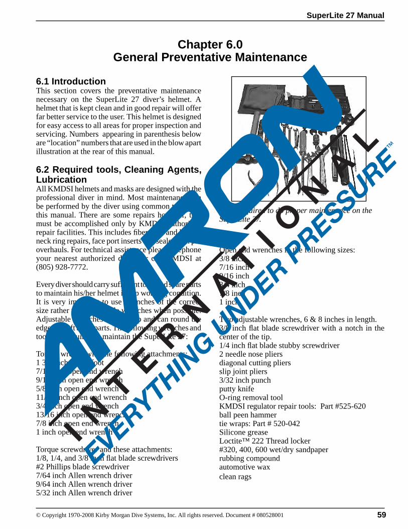
SuperLite 27 Manual
© Copyright 1970-2008 Kirby Morgan Dive Systems, Inc. All rights reserved. Document # 080528001 59
6.1 IntroductionThis section covers the preventative maintenance necessary on the SuperLite 27 diver’s helmet. A helmet that is kept clean and in good repair will offer far better service to the user. This helmet is designed for easy access to all areas for proper inspection and servicing. Numbers appearing in parenthesis below are “location” numbers that are used in the blow apart illustration at the rear of this manual.
6.2 Required tools, Cleaning Agents, LubricationAll KMDSI helmets and masks are designed with the professional diver in mind. Most maintenance can be performed by the diver using common tools and this manual. There are some repairs however, that must be accomplished only by KMDSI authorized repair facilities. This includes fiberglass and helmet neck ring repairs, face port inserts and sealed pull pin overhauls. For technical assistance please telephone your nearest authorized dealer or call KMDSI at (805) 928-7772.
Every diver should carry sufficient tools and spare parts to maintain his/her helmet in top working condition. It is very impor tant to use wrenches of the correct size rather than adjustable wrenches when possible. Adjustable wrenches tend to slip and can round the edges of soft brass parts. The following wrenches and tools are required to maintain the SuperLite 27:
Torque wrench with the following attachments:1 3/8 inch crows foot7/16 inch open end wrench9/16 inch open end wrench5/8 inch open end wrench11/16 inch open end wrench3/4 inch open end wrench13/16 inch open end wrench7/8 inch open end wrench1 inch open end wrench
Torque screwdriver and these attachments:1/8, 1/4, and 3/8 inch flat blade screwdrivers#2 Phillips blade screwdriver7/64 inch Allen wrench driver9/64 inch Allen wrench driver5/32 inch Allen wrench driver
Chapter 6.0General Preventative Maintenance
Tools required to do proper maintenance on the SuperLite 27.
Open end wrenches in the following sizes:3/8 inch7/16 inch9/16 inch3/4 inch7/8 inch1 inch
Two adjustable wrenches, 6 & 8 inches in length.3/8 inch flat blade screwdriver with a notch in the center of the tip.1/4 inch flat blade stubby screwdriver2 needle nose pliersdiagonal cutting pliersslip joint pliers3/32 inch punchputty knifeO-ring removal toolKMDSI regulator repair tools: Part #525-620ball peen hammertie wraps: Part # 520-042Silicone greaseLoctite™ 222 Thread locker#320, 400, 600 wet/dry sandpaperrubbing compoundautomotive waxclean rags

60
SuperLite 27 Manual
© Copyright 1970-2008 Kirby Morgan Dive Systems, Inc. All rights reserved. Document # 080528001
6.2.1 Component and Parts CleaningThe helmet and components should only be cleaned using a mild solution of dishwashing soap such as JOY ™ or Dawn ™ hand dishwashing soap.
Parts that have corrosion should be washed and scrubbed with a nylon bristle brush and then soaked in a solution of 50% white vinegar and water for 30-60 minutes followed by a light brushing and a good fresh water rinse. Helmet liners and rubber compo-nents should be cleaned using a mild soapy solution followed by a good rinsing and air-dried.
DO NOT use hair dryers or high heat to dry the rubber or fabric components, high temperatures will severely reduce their serviceability. To clean parts heavily encrusted with salt we recommend a dilute solution of white vinegar and a toothbrush.
6.2.2 Component and Parts Lubrication All helmets are lubricated at KMDSI with Christo Lube. Helmets used for air diving or diving with gas containing less than 50 % oxygen can be lubricated with food grade silicone such as Dow corning 111 or equivalent.
NOTE: All parts on the helmet that require lubrication must be lubricated sparingly with the appropriate lubricant. DO NOT USE AEROSOL SPRAY LUBRICANTS. Many aerosol propellants will damage plastic. Avoid lubricant contact with plastic parts/components.
Food grade silicone grease on all non-gas transporting components is acceptable. KMDSI recommends Dow corning 111 or equivalent. KMDSI strongly recommends using Christo Lube ™ for aIl gas system lubrication. If the helmet is intended to be used with breathing mixtures greater than 50% oxygen, it should be cleaned for oxygen service, and components requiring lubrication should be lubricated with a suitable oxygen compatible lubricant such as Christo Lube ™ Halocarbon Flourolube® or Krytox ™.
Silicone grease is not recommended for helmets used with oxygen. (Avoid mixing lubricants to preclude incompatibility).
All parts on Kirby Morgan helmets and masks must be adjusted to their proper torque specifications. See the table of torque specifications at the rear of this manual for a complete listing of torque specifications for each part. Failure to adjust parts to the recommended specifications could lead to helmet failure and accidents. This could be fatal.
WARNING
Never use any aerosol propelled sprays near the face port of any Kirby Morgan commercial diving helmet or full-face mask. The Freon propellent used in
Silicone Spray
these aerosols can invisibly damage the polycarbonate face port and cause it to shatter upon impact from any strong blow. If the face port fails underwater the helmet will flood and drowning may result.
WARNING
The standard SuperLite 27 helmet is cleaned for oxygen service as it comes from the factory. If the user intends to use this helmet for such service, the helmet must not be used with
an oil lubricated compressor and proper procedures for diving with mixtures containing high percentages of oxygen must be followed.
Only lubricants such as Krytox®, Fluorolube®, or Christo lube™ are acceptable for oxygen service. Care must be taken to avoid contamination of gas system components with hydrocarbons when air is used as a breathing medium. Contamination with hydrocarbons can lead to fire or explosions when they make contact with high oxygen percentages.
WARNING
Do not use aerosol lubricants! Many aerosol pro-pellants will damage plastic. Avoid lubricant contact with plastic parts.

SuperLite 27 Manual
© Copyright 1970-2008 Kirby Morgan Dive Systems, Inc. All rights reserved. Document # 080528001 61
6.2.3 Teflon TapeAll pipe thread fittings used on our helmets, masks and components require sealing with Teflon tape. KMDSI only recommends Teflon tape for this application. When installing Teflon tape on pipe threads, apply the tape starting two threads back from the end of the fitting.
Apply the tape in a clockwise direction under tension. 11/
2 wraps is all that is needed. Applying more than
11/2 wraps of tape is not recommended. The use of
more than 11/2 wraps could cause excess Teflon tape
to travel into the breathing system.
Do not allow any excess Teflon tape to cover the end of the pipe thread fittings. Loose pieces of Teflon tape can interfere with the performance of helmet components and may block the diver's air supply. This could lead to death through suffocation.
WARNING
6.2.4 RTV SealantCertain components used in KMDSI helmets and masks use RTV adhesive / sealant to provide bond-ing and sealing. KMDSI recommends Dow Corning ™ RTV 732 multi purpose sealant. When sealant is applied the user must use care to insure excess seal-ant is wiped clean so as not to interfere with other components. Sealant should be allowed to cure fo 24 hours before use.
Use good ventilation w h e n u s i n g RT V sealant. Fumes from this material may irritate your lungs. Read and follow the d i rec t ions in the MSDS before using this material.
CAUTION
CAUTIONWear hand protection when using RTV sealant. This material may irritate your skin. Read and follow the directions in the MSDS before using this material
Wear eye protection when using RTV sealant. This material may irritate your eyes. Read and follow the directions in the MSDS before using this material.
CAUTION
WARNINGDo not use any sealant on pipe threads on Kirby Morgan products other than Teflon tape or other approved sealants. Other sealants may not be
oxygen compatible and may lead to fire or explosions which may cause severe personal injury or death.

62
SuperLite 27 Manual
© Copyright 1970-2008 Kirby Morgan Dive Systems, Inc. All rights reserved. Document # 080528001
CAUTIONWear hand protection when using Loctite. This material may irritate your skin. Read and follow the directions in the MSDS before using this material
Wear eye protection when using Loctite. This material may irritate your eyes. Read and follow the directions in the MSDS before using this material.
CAUTION
Use good ventilation when using Loctite. F u m e s f ro m t h i s material may irritate your lungs. Read and follow the directions in the MSDS before using this material.
CAUTION
6.2.5 Thread LockerKMDSI recommends Loctite ™ 222 as the thread locking compound that should be used on compo-nents that call for a thread locker. Threads should be clean and dry prior to applying thread locker.
Ensure that all excess thread locker has been removed. Allow thread locker to cure for at least 3 hours prior to using the component.
SuperLite 27 Manual
© Copyright 1970-2008 Kirby Morgan Dive Systems, Inc. All rights reserved. Document # 080528001 63
6.3 General Cleaning & Inspection ProceduresEach diver must establish his own minimum standards for the care of his helmet. We offer recommendations here with the suggestion that the diver establish for himself what is necessary to provide a good working unit. Use of the helmet in fresh water will require a timetable for maintenance procedures different from that when the helmet is used in salt water.
Using the helmet in sea water while jetting in sand will necessitate increased maintenance. Use of the helmet in a heavy oil and/or chemical environment may make it necessary to replace rubber parts to assure proper function. Regardless, all helmets and masks should be disassembled, cleaned and inspected at least once a year. All o-rings should be replaced at least once a year.
NOTE: Certain fuel oils and/or chemicals will cause premature degradation of soft goods and seals by mak-ing them become soft, swell or break down. Upon exit-ing the contaminant, KMDSI recommends a thorough external decontamination/washing of the helmet/neck dam ring assembly as soon as feasibly possible, followed by a vigilant inspection of the interior of the helmet to ensure that no contaminant has entered.
Pay particular attention to the following parts prior to re-use; whisker, demand regulator diaphragm, demand regulator exhaust valve, exhaust valve, Tri-Valve Ex-haust Valve(s), communications post(s) or communica-tions connector assembly, and neck dam.
If in doubt about the serviceability of a part, repair or replace it immediately. Use only Genuine Kirby Morgan replacement parts. The use of unauthorized parts may result in injury or death to the user.
WARNING
Do not use solvents or bleach for cleaning. These agents are toxic and use of them may result in injury or death to personnel and damage to equipment.
WARNING
Wear eye protection to prevent cleaning and germicidal cleansing solutions from contacting eyes. If contact occurs, rinse
WARNING
eyes with copious amounts of water and consult medical help immediately.
Cleanliness is imperative in maintaining and handling the Kirby Morgan masks and helmets. All tools, parts, and components must be kept free of oil, grease, rust, and other contamination. Foreign substances within an assembly may result in equipment failure and possible injury or death to personnel.
WARNING
Different brands of grease should never be mixed. Ensure all old grease is removed prior to applying new grease.
WARNING
64
SuperLite 27 Manual
© Copyright 1970-2008 Kirby Morgan Dive Systems, Inc. All rights reserved. Document # 080528001
6.3.1 O-Ring Removal/Inspection/Cleaning and LubricationStrict cleanliness and proper lubrication are extremely important during o-ring installation. Comply with the following instructions to ensure proper installation:
NOTE: Ensure all parts are clean throughout the assembly procedure. Dirt or loose particles in the o-ring groove can cause leaks in the seal and dam-age to the o-ring, reducing its life. During cleaning of equipment, carefully clean o-ring grooves, using a soft bristle brush and liquid soap solution.
O-Ring Removal: Do not use screwdrivers or metal picks to remove o-rings. When possible, only use fingers to remove o-rings. If an o-ring fits too tightly in its groove to be removed using the fingers, use the appropriate tool from an o-ring removal kit (brass pick). You can also use the corner of a plastic credit card.
A plastic cable tie makes an effective O-Ring removal tool. Use of an appropriate tool helps prevent scratch-ing the o-ring groove, which can cause leakage or premature failure of the seal.
O-Ring Inspection: If during routine corrective maintenance o-rings are to be reused, only reuse o-rings that pass a visual in-spection. Inspect for deformities or compression set, hardening or brittleness, nicks or cuts, pits or blisters, or any other signs of damage. Cut and discard dam-aged o-rings and replace them with new ones.
O-Ring Reuse: All o-rings and soft goods must be replaced whenever scheduled overhauls are being completed. During routine repairs or maintenance in between overhauls, o-rings and soft goods may be reused after cleaning provided a careful inspection reveals no wear or damage.
Place the o-rings in a cleaning basin, cover with a mild liquid soap solution, and brush gently with a soft bristle brush to remove all traces of old lubricant and contamination. Rinse cleaned o-rings with fresh water and wipe clean with lint-free cloths, then allow to air dry, carefully inspect for cracking, cuts, abra-sions and deformities. Replace o-rings if any damage is found or suspected.
6.3.2 General Cleaning Guidelines Cleaning and sanitizing of the SuperLite 27 should be accomplished upon completion of use and/or prior to storage. Clean is defined as free of dirt, rust particles, grease and oil and other contaminants as viewed by the unaided eye.
Sanitizing is defined as eliminating germs and mi-croorganisms. Sanitizing should be accomplished post use or prior to use by another user. KMDSI recommends sanitizing be accomplished any time the unit is to be used by another person during the mission or operation.
NOTE: The sanitizing procedure should be accom-plished, if possible, between uses by different users during the same operation.
6.3.2.1 Soap Solution for General Cleaning and Leak Detector Use Maintenance procedures include cleaning with a general-purpose soap solution of a mild diluted hand dishwashing soap such as Joy® or Palmolive®. Cleaning solution is prepared by mixing approxi-mately one teaspoon of soap to 1/2 gallon of warm fresh water. This solution may also be used as a leak detector solution. Place all parts and components in a clean washbasin or sink and immerse in soap solution.
Allow parts/components to soak for at least five min-utes, and then scrub using a nylon brush. Carefully brush all surfaces, paying close attention to o-ring grooves and threaded surfaces ensuring all greases are removed. Regardless of the soap used, all com-ponents must be thoroughly rinsed post cleaning to remove all traces of soap.
6.3.2.2 Acidic Cleaning Solution and Procedures Metal parts that have visible corrosion should first be cleaned using the soap solution scrubbed with a nylon bristle brush, then soaked in a solution of 50% white vinegar and water for less than 60 minutes. They may also be placed in an ultrasonic sink followed by a light brushing and thorough rinsing with fresh water and air-dried. If corrosion is such that 50/50 vinegar will not clean components, it will be best to replace the components.
6.3.2.3 Germicidal Cleaning Solutions and Procedure Sanitizing of the oral-nasal mask/regulator of Kirby Morgan commercial diving masks and helmets is accomplished using one of four approved germicidal
SuperLite 27 Manual
© Copyright 1970-2008 Kirby Morgan Dive Systems, Inc. All rights reserved. Document # 080528001 65
cleansing solutions. There are four examples of solu-tions shown below, along with the necessary ordering information and mixing instructions.
NOTE: Ensure helmet liner and cushion are removed prior to sanitizing the oral-nasal mask/regulator.
1. SaniZide Plus: P/N: 34805 (spray) or 34810 (gallon), Ready to use; do not dilute. SAFETEC of America, Inc 1055 E. Delavan Ave. Buffalo, NY 14215 USA 1-800-456-7077
2. Advance TBE: P/N: AD160 (spray) or AD1128 (gallon), Infection Control Technology ): Ready to use. Infection Control Technology 1751 So. Redwood Rd. Woodscross, UT 84087 USA 1-800-551-0735
3. Bi-Arrest 2: P/N: BP201 (4 ounces) or BP 222 (32 ounces), Infection Control Technology. Mix two pumps of the concentrate with 16 ounces of fresh water. Infection Control Technology 1751 So. Redwood Rd. Woodscross, UT 84087 USA 1-800-551-0735
4. Confidence Plus: P/N: 10009971 (32 ounces) Mix one ounce of concentrate with one gallon of fresh water. Mine Safety Appliances, 1-800-MSA-2222
Sanitizing Procedure: Unless otherwise directed, use the following proce-dure to disinfect the SL 27 oral-nasal mask/regula-tor:
1) Wet or immerse all components to be sanitized. Allow components to stay in contact with the solution for at least 10 minutes.
2) If the solution appears to be drying, apply more solution to keep it wet for the full 10 minutes.
3) After 10 minutes, thoroughly rinse components under running potable water.
NOTE: The purpose of this procedure is to sani-tize the components exposed to each of the divers. KMDSI recommends sanitizing be performed daily
in between use by different divers, after each use, or when future use is anticipated within the mission (job) period. KMDSI defines “A mission is defined as use of the Kirby Morgan commercial diving mask or helmet over a seven-day period.”
Germicidal cleansing solutions must be carefully diluted if required in accordance with the manufacturer’s recommendation. If solution is not of the recommended strength, it will not act as an effective disinfectant. Failure to thoroughly rinse germicidal cleansing solution from diving equipment may result in lung irritation and/or long-term degradation of rubber and silicone components of this equipment.
CAUTION
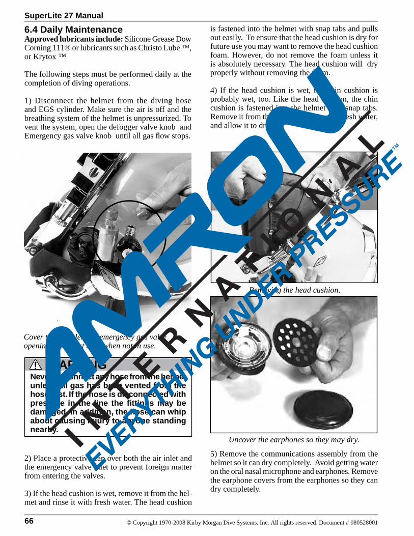
66
SuperLite 27 Manual
© Copyright 1970-2008 Kirby Morgan Dive Systems, Inc. All rights reserved. Document # 080528001
6.4 Daily Maintenance Approved lubricants include: Silicone Grease Dow Corning 111® or lubricants such as Christo Lube ™, or Krytox ™
The following steps must be performed daily at the completion of diving operations.
1) Disconnect the helmet from the diving hose and EGS cylinder. Make sure the air is off and the breathing system of the helmet is unpressurized. To vent the system, open the defogger valve knob and Emergency gas valve knob until all gas flow stops.
is fastened into the helmet with snap tabs and pulls out easily. To ensure that the head cushion is dry for future use you may want to remove the head cushion foam. However, do not remove the foam unless it is absolutely necessary. The head cushion will dry properly without removing the foam.
4) If the head cushion is wet, the chin cushion is probably wet, too. Like the head cushion, the chin cushion is fastened into the helmet with snap tabs. Remove it from the helmet, rinse it with fresh water, and allow it to dry.
Cover the air inlet and emergency gas valve openings with dust caps when not in use.
Never disconnect any hose from the helmet unless all gas has been vented from the hose first. If the hose is disconnected with pressure in the line the fittings may be damaged. In addition, the hose can whip about causing injury to anyone standing nearby.
WARNING
Removing the head cushion.
Uncover the earphones so they may dry.
2) Place a protective cap over both the air inlet and the emergency valve inlet to prevent foreign matter from entering the valves.
3) If the head cushion is wet, remove it from the hel-met and rinse it with fresh water. The head cushion
5) Remove the communications assembly from the helmet so it can dry completely. Avoid getting water on the oral nasal microphone and earphones. Remove the earphone covers from the earphones so they can dry completely.
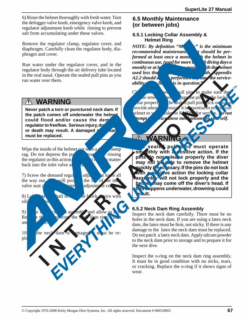
SuperLite 27 Manual
© Copyright 1970-2008 Kirby Morgan Dive Systems, Inc. All rights reserved. Document # 080528001 67
6) Rinse the helmet thoroughly with fresh water. Turn the defogger valve knob, emergency valve knob, and regulator adjustment knob while rinsing to prevent salt from accumulating under these valves.
Remove the regulator clamp, regulator cover, and diaphragm. Carefully clean the regulator body, dia-phragm and cover.
Run water under the reg ulator cover, and in the regulator body through the air delivery tube located in the oral nasal. Operate the sealed pull pins as you run water over them.
Wipe the inside of the helmet out with a clean, damp rag. Do not depress the purge button while rinsing the regulator as this action will permit foreign matter back into the inlet valve and seat.
7) Screw the demand regulator adjustment knob all the way out. This will prolong the life of the inlet valve seat and keep the internal adjustment correct.
8) Lubricate the shaft of the nose block device with silicone grease.
9) Rinse the neck dam assembly and allow to dry. Remove the o-ring from the neck dam ring, clean and lubricate.
10) If the neck dam is damaged it must be re-placed.
6.5 Monthly Maintenance(or between jobs)
6.5.1 Locking Collar Assembly & Helmet Ring
6.5.2 Neck Dam Ring Assembly Inspect the neck dam carefully. There must be no holes in the neck dam. If you are using a latex neck dam, the latex must be firm, not sticky. If there is any damage to the latex the neck dam must be replaced. Do not patch a latex neck dam. Apply talcum powder to the neck dam prior to storage and to prepare it for the next dive.
Inspect the o-ring on the neck dam ring assembly. It must be in good condition with no nicks, tears, or cracking. Replace the o-ring if it shows signs of wear.
Never patch a torn or punctured neck dam. If the patch comes off underwater the helmet could flood and/or cause the demand regulator to freeflow. Serious injury, drowning or death may result. A damaged neck dam must be replaced.
WARNING
The sealed pull pins must operate smoothly with a positive action. If the pins do not release properly the diver may not be able to remove the helmet quickly if necessary. If the pins do not lock with a positive action the locking collar assembly will not lock properly and the helmet may come off the diver’s head. If this happens underwater, drowning could result.
WARNING
NOTE: By definition “Monthly” is the minimum recommended maintenance that should be per-formed at least once a month with the helmet in continuous use, (used for more than 20 diving days a month) or at least every two months with the helmet used less than 10 diving days a month. Appendix A2.2 should also be performed any time the service-ability of the helmet is in question.”
Check the two sealed pull pins to make sure they operate smoothly and engage the pins on the locking collar properly. If the sealed pull pins stick or do not provide adequate tension it is essential to return your helmet to your dealer or KMDSI for service. Do not attempt to service these mechanisms by yourself.
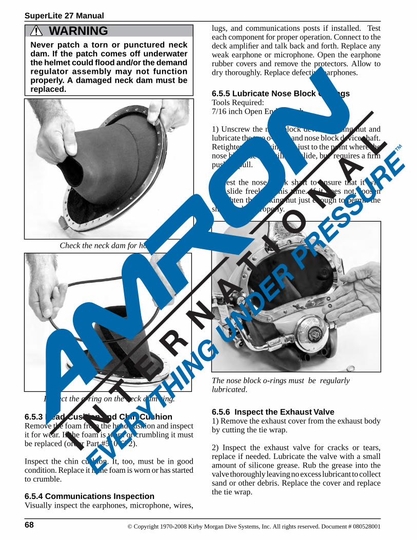
68
SuperLite 27 Manual
© Copyright 1970-2008 Kirby Morgan Dive Systems, Inc. All rights reserved. Document # 080528001
Check the neck dam for holes.
Inspect the o-ring on the neck dam ring.
The nose block o-rings must be regularly lubricated.
Never patch a torn or punctured neck dam. If the patch comes off underwater the helmet could flood and/or the demand regulator assembly may not function properly. A damaged neck dam must be replaced.
WARNING
6.5.3 Head Cushion and Chin Cushion Remove the foam from the head cushion and inspect it for wear. If the foam is worn or crumbling it must be replaced (order Part #510-672).
Inspect the chin cushion. It, too, must be in good condition. Replace it if the foam is worn or has started to crumble.
6.5.4 Communications Inspection Visually inspect the earphones, microphone, wires,
lugs, and communications posts if installed. Test each component for proper operation. Connect to the deck amplifier and talk back and forth. Replace any weak earphone or microphone. Open the earphone rubber covers and remove the protectors. Allow to dry thoroughly. Replace defective earphones.
6.5.5 Lubricate Nose Block O-Rings Tools Required:7/16 inch Open End wrench
1) Unscrew the nose block device packing nut and lubricate the two o-rings and nose block device shaft. Retighten the packing nut just to the point where the nose block device will still slide, but requires a firm push or pull.
2) Test the nose block shaft to ensure that it will still slide freely at this time. If it does not, loosen or tighten the packing nut just enough to permit the shaft to slide properly.
6.5.6 Inspect the Exhaust Valve1) Remove the exhaust cover from the exhaust body by cutting the tie wrap.
2) Inspect the exhaust valve for cracks or tears, replace if needed. Lubricate the valve with a small amount of silicone grease. Rub the grease into the valve thoroughly leaving no excess lubricant to collect sand or other debris. Replace the cover and replace the tie wrap.
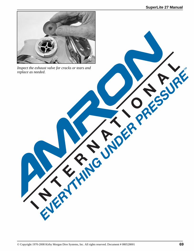
SuperLite 27 Manual
© Copyright 1970-2008 Kirby Morgan Dive Systems, Inc. All rights reserved. Document # 080528001 69
Inspect the exhaust valve for cracks or tears and replace as needed.
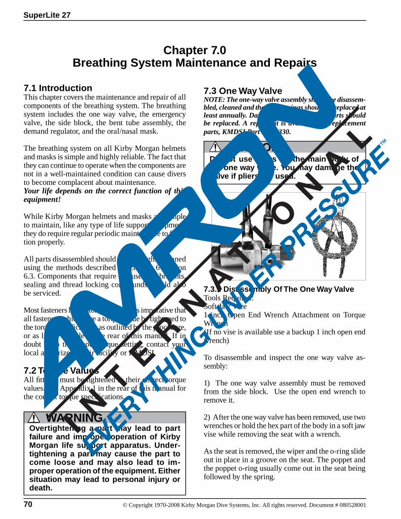
70 © Copyright 1970-2008 Kirby Morgan Dive Systems, Inc. All rights reserved. Document # 080528001
SuperLite 27
Chapter 7.0Breathing System Maintenance and Repairs
7.1 IntroductionThis chapter covers the maintenance and repair of all components of the breathing system. The breathing system includes the one way valve, the emergency valve, the side block, the bent tube assembly, the demand regulator, and the oral/nasal mask.
The breathing system on all Kirby Morgan helmets and masks is simple and highly reliable. The fact that they can continue to operate when the components are not in a well-maintained condition can cause divers to become complacent about maintenance. Your life depends on the correct function of this equipment!
While Kirby Morgan helmets and masks are simple to maintain, like any type of life support equipment, they do require regular periodic maintenance to func-tion properly.
All parts disassembled should be thoroughly cleaned using the methods described in Chapter 6 Section 6.3. Components that require the use of lubricants, sealing and thread locking compounds should also be serviced.
Most fasteners have a torque value. It is imperative that all fasteners which have a torque value be tightened to the torque specifications as outlined by the procedure, or as listed in table in the rear of this manual. If in doubt as to the proper torque setting, contact your local authorized repair facility or KMDSI.
7.2 Torque ValuesAll fittings must be tightened to their correct torque values. See Appendix 1 in the rear of this manual for the correct torque specifications.
7.3 One Way ValveNOTE: The one-way valve assembly should be disassem-bled, cleaned and the three o-rings should be replaced at least annually. Damaged and/or corroded parts should be replaced. A repair kit is available for replacement parts, KMDSI Part #525-330.
Do not use pliers on the main body of the one way valve. You may damage the valve if pliers are used.
CAUTION
7.3.1 Disassembly Of The One Way ValveTools Required:Soft Jaw Vice1 inch Open End Wrench Attachment on Torque Wrench(If no vise is available use a backup 1 inch open end wrench)
To disassemble and inspect the one way valve as-sembly:
1) The one way valve assembly must be removed from the side block. Use the open end wrench to remove it.
2) After the one way valve has been removed, use two wrenches or hold the hex part of the body in a soft jaw vise while removing the seat with a wrench. As the seat is removed, the wiper and the o-ring slide out in place in a groove on the seat. The poppet and the poppet o-ring usually come out in the seat being followed by the spring.
WARNINGOvertightening a part may lead to part failure and improper operation of Kirby Morgan life support apparatus. Under-tightening a part may cause the part to come loose and may also lead to im-proper operation of the equipment. Either situation may lead to personal injury or death.

71
SuperLite 27
© Copyright 1970-2008 Kirby Morgan Dive Systems, Inc. All rights reserved. Document # 080528001
6) Replace the spring.
The only functional part remaining in the valve body is a non-moving, pressed-in cage. The function of the cage is to contain the poppet during high gas flows.
Correct assembly order of the one way valve.
7.3.2 Reassembly of the One Way Valve
1) Slide the new o-ring over the poppet.
2) Insert the new spring into the valve body, followed by the poppet.
3) Next, install the new o-ring and new wiper on the seat. Thread the seat into the valve body.
4) Tighten the seat to 150 inch lbs. (17 newton me-ters) with a torque wrench while holding the body in a soft jaw vice or wrench.
5) If the adapter has been removed, it must be cleaned and wrapped with Teflon tape.
6) Test the operation of the valve.
7) Place the new o-ring on the end of the one way valve assembly and reinstall the valve assembly in the side block. Tighten to 150 inch lbs. (270 kg.cm.) with a torque wrench.
Use two wrenches or hold the hex part of the body in a vise while removing or turning the seat with a wrench. Do not use pliers on the main body of the one-way valve. You may damage the valve if pliers are used.
CAUTION
Do not allow any Teflon tape to cover the end of the adapter, or to enter the one-way valve. Loose pieces of Teflon tape can interfere with the performance of the one-way valve or the regulator and may block the diver’s air supply. This could lead to death through suffocation.
WARNING
3) Inspect the body interior for foreign matter of any type and clean, if necessary. Clean in accordance with the cleaning instructions in Section 6.3.2. If corrosion is present, clean using the acidic solution as outlined in Section 6.3.2.2.
4) Inspect the seat, wiper, o-ring, poppet o-ring and poppet for wear, replace if necessary. Be sure each part is clean and all components are lightly lubricated with the appropriate lubricant. A repair kit is available for replacement parts, (Part #525-330). All o-rings should be replaced during normal/annual overhauls.
5) Be careful to wipe the poppet and poppet o-ring thoroughly, removing nearly all silicone to prevent foreign materials from sticking to these compo-nents.
WARNINGDo not attempt to move or remove the cage that sits inside the non-return (one-way) valve. Any attempt to remove this part can cause the non-return valve to fail, which can lead to serious personal injury or death.
Adapter
Seat
Wiper
O-ring
O-ring
Poppet
Spring
Body
O-ring
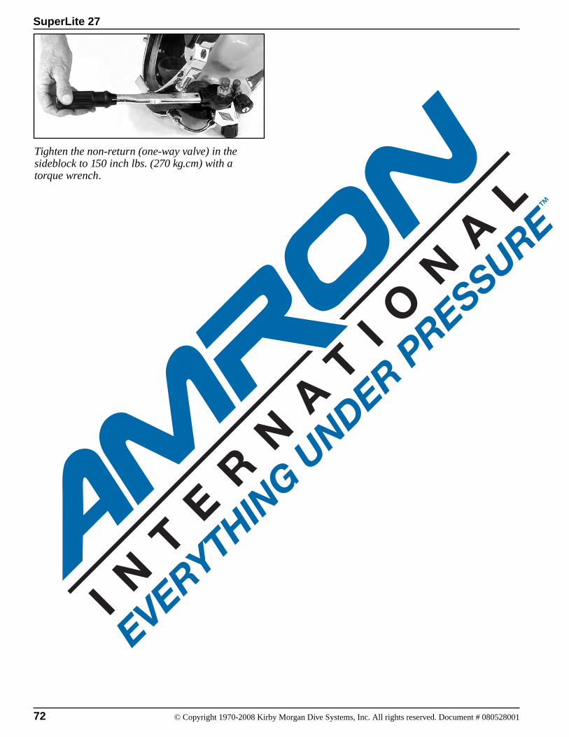
72 © Copyright 1970-2008 Kirby Morgan Dive Systems, Inc. All rights reserved. Document # 080528001
SuperLite 27
Tighten the non-return (one-way valve) in the sideblock to 150 inch lbs. (270 kg.cm) with a torque wrench.
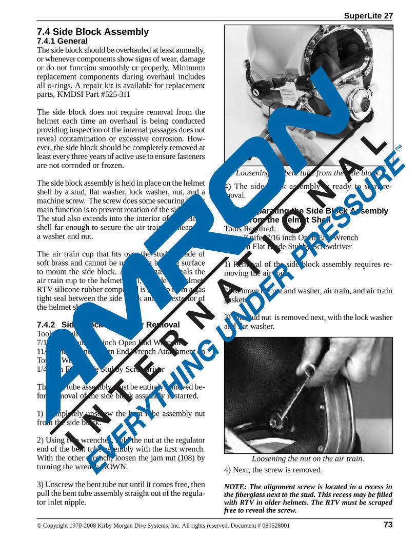
73
SuperLite 27
© Copyright 1970-2008 Kirby Morgan Dive Systems, Inc. All rights reserved. Document # 080528001
7.4 Side Block Assembly 7.4.1 GeneralThe side block should be overhauled at least annually, or whenever components show signs of wear, damage or do not function smoothly or properly. Minimum replacement components during overhaul includes all o-rings. A repair kit is available for replacement parts, KMDSI Part #525-311
The side block does not require removal from the helmet each time an overhaul is being conducted providing inspection of the internal passages does not reveal contamination or excessive corrosion. How-ever, the side block should be completely removed at least every three years of active use to ensure fasteners are not corroded or frozen.
The side block assembly is held in place on the helmet shell by a stud, flat washer, lock washer, nut, and a machine screw. The screw does some securing but its main function is to prevent rotation of the side block. The stud also extends into the interior of the helmet shell far enough to secure the air train by means of a washer and nut.
The air train cup that fits over the stud is made of soft brass and cannot be used for a bearing surface to mount the side block. A special gasket seals the air train cup to the helmet shell, incisde the helmet. RTV silicone rubber compound is used to form a gas tight seal between the side block and the exterior of the helmet shell.
7.4.2 Side Block Assembly RemovalTools Required:7/16, 11/16, and 7/8 inch Open End Wrenches11/16 and 7/8 inch Open End Wrench Attachment on Torque Wrench1/4 inch Flat Blade Stubby Screwdriver
The bent tube assembly must be entirely removed be-fore removal of the side block assembly is started.
1) Completely unscrew the bent tube assembly nut from the side block.
2) Using two wrenches, hold the nut at the regulator end of the bent tube assembly with the first wrench. With the other wrench, loosen the jam nut (108) by turning the wrench DOWN.
3) Unscrew the bent tube nut until it comes free, then pull the bent tube assembly straight out of the regula-tor inlet nipple.
4) The side block assembly is ready to start re-moval.
7.4.3 Separating the Side Block Assembly from the Helmet ShellTools Required:Putty Knife, 7/16 inch Open End Wrench1/4 inch Flat Blade Stubby Screwdriver
1) Removal of the side block assembly requires re-moving the air train.
2) Remove the nut and washer, air train, and air train gasket.
3) The stud nut is removed next, with the lock washer and flat washer.
Loosening the nut on the air train.
Loosening the bent tube from the side block.
4) Next, the screw is removed.
NOTE: The alignment screw is located in a recess in the fiberglass next to the stud. This recess may be filled with RTV in older helmets. The RTV must be scraped free to reveal the screw.
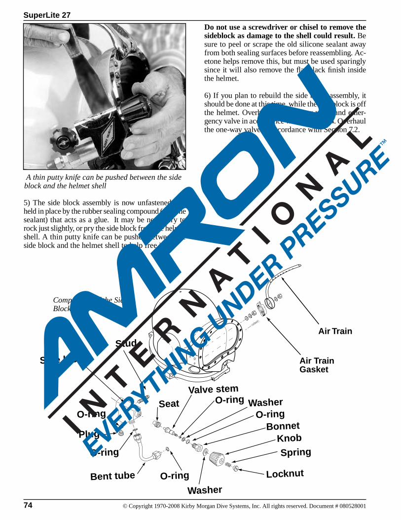
74 © Copyright 1970-2008 Kirby Morgan Dive Systems, Inc. All rights reserved. Document # 080528001
SuperLite 27
Knob
Spring
Washer
Locknut
Bonnet
Valve stemO-ring Washer
Side block
Stud
Bent tube
Seat
Plug
O-ring
O-ring
O-ring
O-ring
Air Train
Air TrainGasket
5) The side block assembly is now unfastened, but held in place by the rubber sealing compound (silicone sealant) that acts as a glue. It may be necessary to rock just slightly, or pry the side block from the helmet shell. A thin putty knife can be pushed between the side block and the helmet shell to help free it.
Do not use a screwdriver or chisel to remove the sideblock as damage to the shell could result. Be sure to peel or scrape the old silicone sealant away from both sealing surfaces before reassembling. Ac-etone helps remove this, but must be used sparingly since it will also remove the flat black finish inside the helmet.
6) If you plan to rebuild the side block assembly, it should be done at this time, while the side block is off the helmet. Overhaul the defogger valve and emer-gency valve in accordance with Section 7.4. Overhaul the one-way valve in accordance with Section 7.2.
A thin putty knife can be pushed between the side block and the helmet shell
Components of the Side Block & Air Train
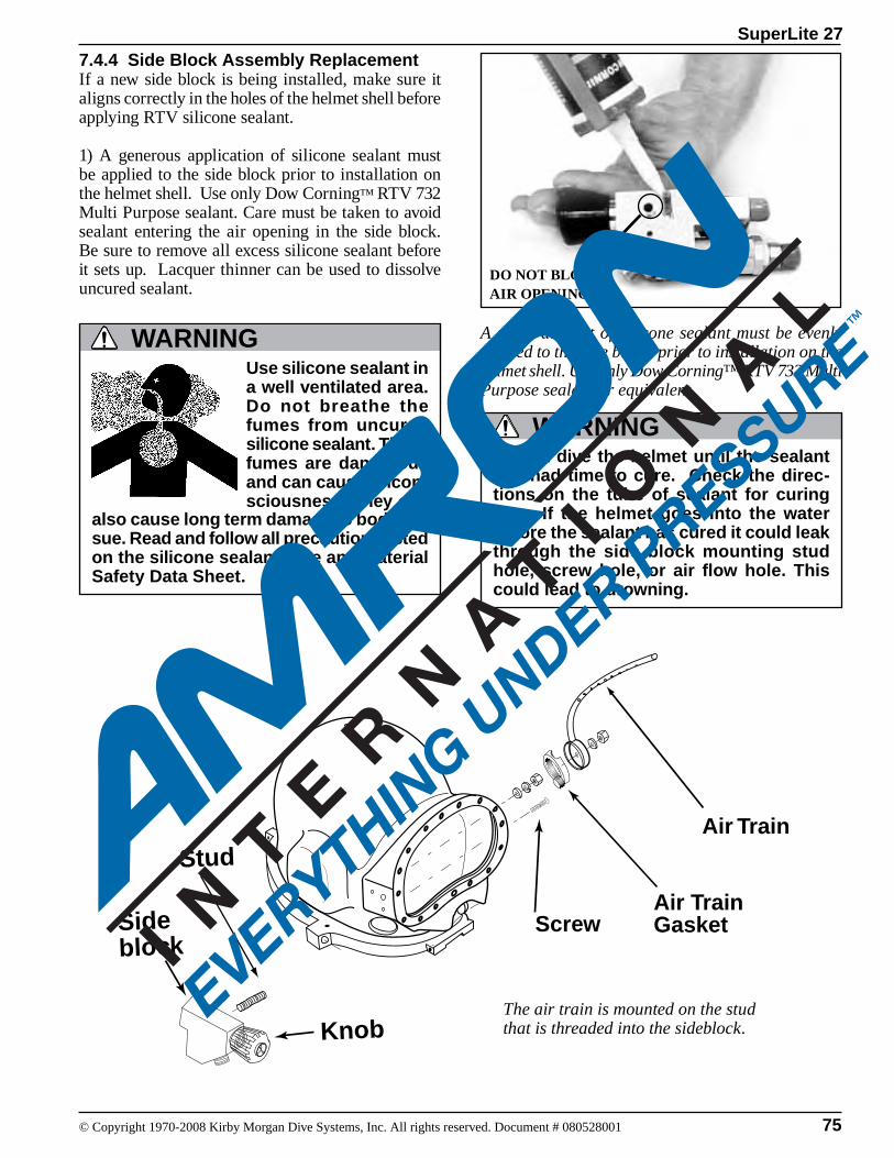
75
SuperLite 27
© Copyright 1970-2008 Kirby Morgan Dive Systems, Inc. All rights reserved. Document # 080528001
Knob
Side block
StudAir Train
Air TrainGasketScrew
A small amount of silicone sealant must be evenly applied to the side block prior to installation on the helmet shell. Use only Dow Corning™ RTV 732 Multi Purpose sealant or equivalent.
DO NOT BLOCK AIR OPENING!
Do not dive the helmet until the sealant has had time to cure. Check the direc-tions on the tube of sealant for curing time. If the helmet goes into the water before the sealant has cured it could leak through the side block mounting stud hole, screw hole, or air flow hole. This could lead to drowning.
WARNING
also cause long term damage to body tis-sue. Read and follow all precautions listed on the silicone sealant tube and Material Safety Data Sheet.
WARNINGUse silicone sealant in a well ventilated area. Do not breathe the fumes from uncured silicone sealant. These fumes are dangerous and can cause uncon-sciousness. They can
The air train is mounted on the stud that is threaded into the sideblock.
7.4.4 Side Block Assembly ReplacementIf a new side block is being installed, make sure it aligns correctly in the holes of the helmet shell before applying RTV silicone sealant.
1) A generous application of silicone sealant must be applied to the side block prior to installation on the helmet shell. Use only Dow Corning™ RTV 732 Multi Purpose sealant. Care must be taken to avoid sealant entering the air opening in the side block. Be sure to remove all excess silicone sealant before it sets up. Lacquer thinner can be used to dissolve uncured sealant.
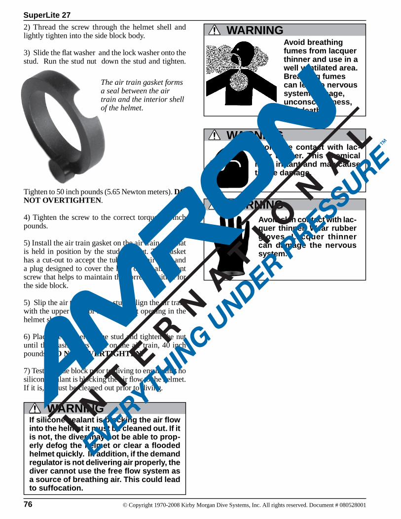
76 © Copyright 1970-2008 Kirby Morgan Dive Systems, Inc. All rights reserved. Document # 080528001
SuperLite 27
2) Thread the screw through the helmet shell and lightly tighten into the side block body.
3) Slide the flat washer and the lock washer onto the stud. Run the stud nut down the stud and tighten.
The air train gasket forms a seal between the air train and the interior shell of the helmet.
Tighten to 50 inch pounds (5.65 Newton meters). DO NOT OVERTIGHTEN.
4) Tighten the screw to the correct torque, 20 inch pounds.
5) Install the air train gasket on the air train cup that is held in position by the stud and nut. The gasket has a cut-out to accept the tube of the air train and a plug designed to cover the head of the alignment screw that helps to maintain the correct position for the side block.
5) Slip the air train over the stud. Align the air train with the upper edge of the view port opening in the helmet shell.
6) Place the washer on the stud and tighten the nut until the washer lays flush on the air train, 40 inch pounds. DO NOT OVERTIGHTEN.
7) Test the side block prior to diving to ensure that no silicone sealant is blocking the air flow to the helmet. If it is, it must be cleaned out prior to diving.
Avoid breathing fumes from lacquer thinner and use in a well ventilated area. Breathing fumes can lead to nervous system damage, unconsciousness, and death.
WARNING
If silicone sealant is blocking the air flow into the helmet it must be cleaned out. If it is not, the diver may not be able to prop-erly defog the helmet or clear a flooded helmet quickly. In addition, if the demand regulator is not delivering air properly, the diver cannot use the free flow system as a source of breathing air. This could lead to suffocation.
WARNING
Avoid eye contact with lac-quer thinner. This chemical is an irritant and may cause tissue damage.
WARNING
WARNINGAvoid skin contact with lac-quer thinner. Wear rubber gloves. Lacquer thinner can damage the nervous system.
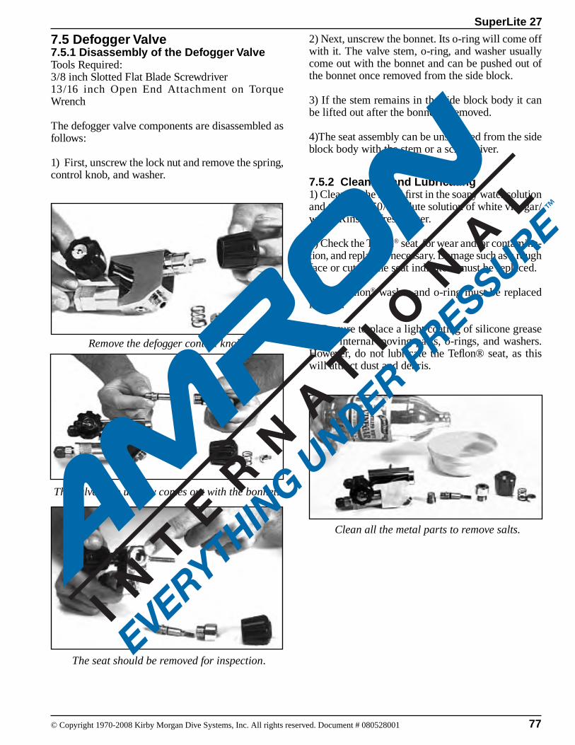
77
SuperLite 27
© Copyright 1970-2008 Kirby Morgan Dive Systems, Inc. All rights reserved. Document # 080528001
7.5 Defogger Valve7.5.1 Disassembly of the Defogger ValveTools Required:3/8 inch Slotted Flat Blade Screwdriver 13/16 inch Open End Attachment on Torque Wrench
The defogger valve components are disassembled as follows:
1) First, unscrew the lock nut and remove the spring, control knob, and washer.
Remove the defogger control knob.
The seat should be removed for inspection.
The valve stem usually comes out with the bonnet.
Clean all the metal parts to remove salts.
2) Next, unscrew the bonnet. Its o-ring will come off with it. The valve stem, o-ring, and washer usually come out with the bonnet and can be pushed out of the bonnet once removed from the side block.
3) If the stem remains in the side block body it can be lifted out after the bonnet is removed.
4)The seat assembly can be unscrewed from the side block body with the stem or a screwdriver.
7.5.2 Cleaning and Lubricating1) Clean all the metal first in the soapy water solution and then in a 50/50 dilute solution of white vinegar/water. Rinse in fresh water.
2) Check the Teflon® seat for wear and/or contamina-tion, and replace if necessary. Damage such as a rough face or cuts to the seat indicate it must be replaced.
3) The Teflon® washer and o-ring must be replaced if worn.
4) Be sure to place a light coating of silicone grease on all internal moving parts, o-rings, and washers. However, do not lubricate the Teflon® seat, as this will attract dust and debris.
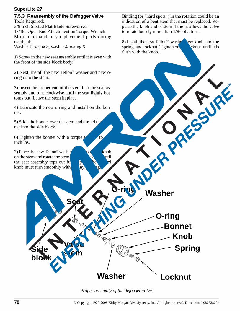
78 © Copyright 1970-2008 Kirby Morgan Dive Systems, Inc. All rights reserved. Document # 080528001
SuperLite 27
7.5.3 Reassembly of the Defogger ValveTools Required:3/8 inch Slotted Flat Blade Screwdriver 13/16” Open End Attachment on Torque WrenchMinimum mandatory replacement parts during overhaul:Washer 7, o-ring 8, washer 4, o-ring 6
1) Screw in the new seat assembly until it is even with the front of the side block body.
2) Next, install the new Teflon® washer and new o-ring onto the stem.
3) Insert the proper end of the stem into the seat as-sembly and turn clockwise until the seat lightly bot-toms out. Leave the stem in place.
4) Lubricate the new o-ring and install on the bon-net.
5) Slide the bonnet over the stem and thread the bon-net into the side block.
6) Tighten the bonnet with a torque wrench to 100 inch lbs.
7) Place the new Teflon® washer and the control knob on the stem and rotate the stem counterclockwise until the seat assembly tops out fully open. The control knob must turn smoothly without any binding.
Knob
Side block
Spring
Seat
Washer Locknut
Bonnet
Valve stem
O-ring Washer
O-ring
Proper assembly of the defogger valve.
Binding (or “hard spots”) in the rotation could be an indication of a bent stem that must be replaced. Re-place the knob and or stem if the fit allows the valve to rotate loosely more than 1/8th of a turn.
8) Install the new Teflon® washer, new knob, and the spring, and locknut. Tighten on the locknut until it is flush with the knob.
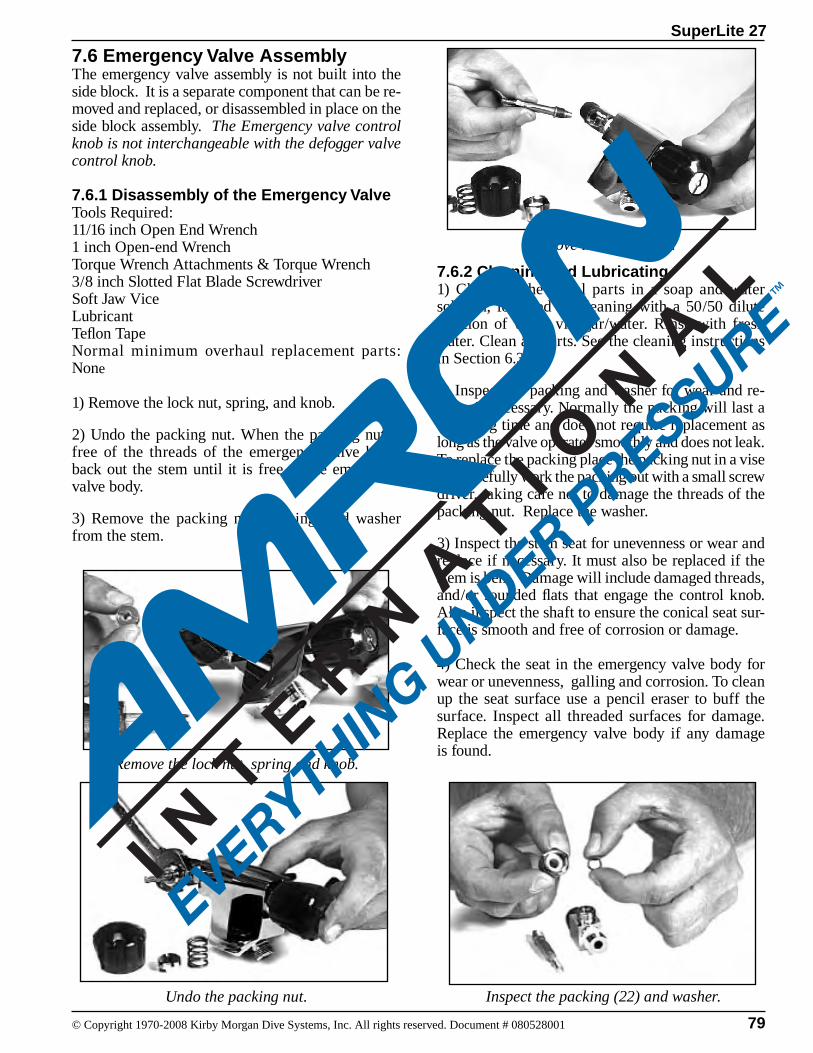
79
SuperLite 27
© Copyright 1970-2008 Kirby Morgan Dive Systems, Inc. All rights reserved. Document # 080528001
7.6 Emergency Valve AssemblyThe emergency valve assembly is not built into the side block. It is a separate component that can be re-moved and replaced, or disassembled in place on the side block assembly. The Emergency valve control knob is not interchangeable with the defogger valve control knob.
7.6.1 Disassembly of the Emergency ValveTools Required:11/16 inch Open End Wrench1 inch Open-end WrenchTorque Wrench Attachments & Torque Wrench3/8 inch Slotted Flat Blade ScrewdriverSoft Jaw ViceLubricantTeflon TapeNormal minimum overhaul replacement parts: None
1) Remove the lock nut, spring, and knob.
2) Undo the packing nut. When the packing nut is free of the threads of the emergency valve body, back out the stem until it is free of the emergency valve body.
3) Remove the packing nut, packing, and washer from the stem.
Remove the valve stem.
Remove the lock nut, spring and knob.
Undo the packing nut.
7.6.2 Cleaning and Lubricating1) Clean all the metal parts in a soap and water solution, followed by cleaning with a 50/50 dilute solution of white vinegar/water. Rinse with fresh water. Clean all parts. See the cleaning instructions in Section 6.3.2.
2) Inspect the packing and washer for wear and re-place if necessary. Normally the packing will last a very long time and does not require replacement as long as the valve operates smoothly and does not leak. To replace the packing place the packing nut in a vise and carefully work the packing out with a small screw driver, taking care not to damage the threads of the packing nut. Replace the washer.
3) Inspect the stem seat for unevenness or wear and replace if necessary. It must also be replaced if the stem is bent. Damage will include damaged threads, and/or rounded flats that engage the control knob. Also inspect the shaft to ensure the conical seat sur-face is smooth and free of corrosion or damage.
4) Check the seat in the emergency valve body for wear or unevenness, galling and corrosion. To clean up the seat surface use a pencil eraser to buff the surface. Inspect all threaded surfaces for damage. Replace the emergency valve body if any damage is found.
Inspect the packing (22) and washer.

80 © Copyright 1970-2008 Kirby Morgan Dive Systems, Inc. All rights reserved. Document # 080528001
SuperLite 27
Valve Body
Valve Stem
Packing nut
Knob
Spring
Lock nut
Packing
Washer
5) Thread the packing nut onto the emergency valve body (19). Run the nut in and tighten slightly with a wrench.
6) Inspect the emergency gas valve knob for wear and damage. Ensure the flats that engage the valve stem shaft are not rounded, cracked or damaged. The valve knob should not have rotational play greater than 1/16th of a turn.
NOTE: This knob is not interchangeable with the defogger valve knob.
7) Place the emergency gas valve knob onto the stem and rotate the stem all the way out, then back again. The rotation must be smooth. If “hard spots” or un-evenness are felt during the rotation, the stem may be bent and could need replacement.
5) To remove the emergency valve body from the side block the one way valve assembly must first be removed.
6) If the emergency valve body is removed, clean and inspect the pipe thread and inspect for damaged threads, cracking or distortion. Replace the emer-gency valve if any damage is present.
Re-tape threads with Teflon tape, 1 1/2 wraps starting two threads back. Tighten using good engineering practice. Reinstall the emergency valve body into the side block before installing the one way valve assembly.
7.6.3 Reassembly of Emergency Valve1) Lightly lubricate the stem threads in the body as well as the bonnet threads.
2) Replace the washer and packing on the stem, then lightly lubricate the stem shaft and threads..
NOTE: There are two different packings and washers supplied in the kit, 525-311, for rebuild-ing both the older style and the newer high flow emergency gas valve. Match the removed packing and washers to the new ones supplied and discard the others.
3) Holding these components in place on the stem, screw the stem into the emergency gas valve body.
4) Rotate the stem until it is seated all the way in then, back it out -1/2 turn.
The components of the emergency valve.
Installing the valve stem in the emergency valve.
81
SuperLite 27
© Copyright 1970-2008 Kirby Morgan Dive Systems, Inc. All rights reserved. Document # 080528001
8) Tighten the packing nut with a torque wrench until moderate resistance is felt when turning the knob. Torque to 50 inch pounds after seating.
9) Place the spring, and locknut onto the stem secur-ing the knob.
10) Tighten the locknut until its top is flush with the top of the knob. The assembly is now complete and ready for testing.
NOTE: If the valve was removed from the side block, testing of the emergency gas valve is easily accomplished by attaching the valve, by itself, in the shut position, on to the intermediate whip of the first stage. Pressurized to a minimum 135 p.s.i.g. (9.3 bar) using the EGS Cylinder and dropping it into a bucket of clean water a minimum 30 seconds to check for leaks.
11) Before installing any pipe sealant, check the fit of the valve assembly pipe threads to the mating threads of the side block. There should be 2 turns of hand make up before needing to use a wrench.
If there is less make up, then the threads will need to be chased with a 1/4” NPT tap to obtain the proper make up. If tapping is required, the bent tube assembly, the one way valve assembly and steady flow (defogger valve) components must all be removed and the side block body must be thoroughly cleaned to remove any loose particles.
12) Before installing the valve assembly, wrap the pipe threads with 1-1/2 turns of Teflon tape starting after the first thread. The amount of tape used should be based on what is found in the fit check. Apply the tape with slight tension to allow the tape to fill into the threads. Use only Teflon tape.
Hand tighten the valve, then continue an additional 1-1/2 to 2 turns with a wrench keeping in mind the proper alignment of the control knob to the side block. Also, there should be at least one male thread visible. Check to be certain the valve is tight by trying to loosen the fit by hand.
DO NOT TIGHTEN THE VALVE BODY TIGHTER THAN NECESSARY! OVER TIGHTENING MAY OVERSTRESS THE PART AND CAUSE THE PART TO FAIL.
It is NOT necessary to have the control knob for the emergency gas supply valve perfectly “square,” i.e., at a 90 degree angle to the side block. Any angle is ac-ceptable provided that 1) the valve handle can be turned easily and 2) the diver can locate the handle easily.
a) Attach supply whip from the EGS first stage to EGS helmet valve.
b) Ensure the defogger valve knob is open and the EGS Valve is shut.
c) Pressurize EGS Valve to a minimum of 135 p.s.i.g. (9.3 bar) using the EGS cylinder as supply. Allow system pressure to stabilize , and then shut the EGS supply cylinder valve. Note time and final stabilized system pressure.
d) Perform the leak check for minimum of five min-utes, using a mild soap solution. Ensure there is no gas flowing or pressure drop in the system. There should be no visible signs of external leakage if the valve is operating properly.
A leaking Emergency Gas Valve as-sembly can cause the diver to exhaust his entire EGS (bailout) without his knowledge. This may lead the diver to mistakenly assume his EGS supply is available when it is not. This could lead to panic or drowning in an emergency. Any worn or damaged components must be replaced.
WARNING
WARNINGDo not use any sealant on pipe threads on Kirby Morgan products other than Teflon tape or other approved sealants. Other sealants may not be oxy-
gen compatible and may lead to fire or explosions which may cause severe per-sonal injury or death.
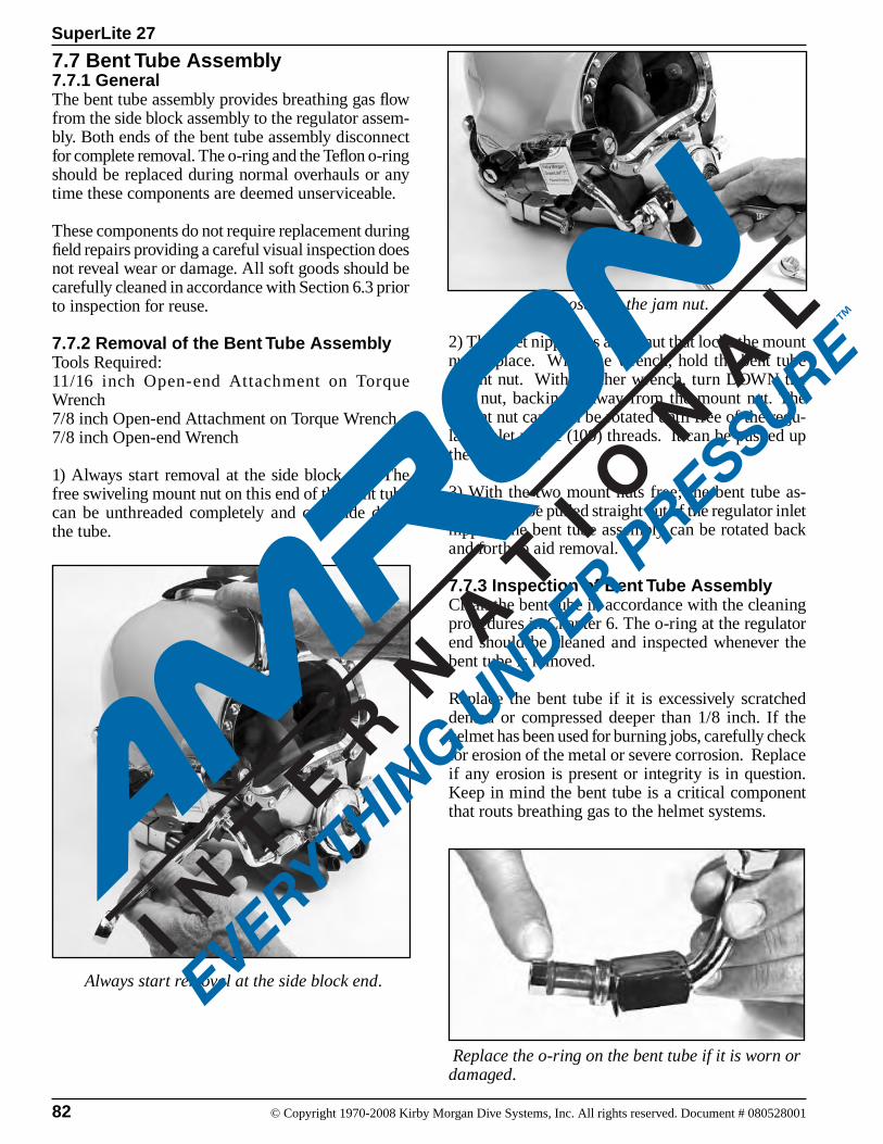
82 © Copyright 1970-2008 Kirby Morgan Dive Systems, Inc. All rights reserved. Document # 080528001
SuperLite 27
7.7 Bent Tube Assembly7.7.1 GeneralThe bent tube assembly provides breathing gas flow from the side block assembly to the regulator assem-bly. Both ends of the bent tube assembly disconnect for complete removal. The o-ring and the Teflon o-ring should be replaced during normal overhauls or any time these components are deemed unserviceable.
These components do not require replacement during field repairs providing a careful visual inspection does not reveal wear or damage. All soft goods should be carefully cleaned in accordance with Section 6.3 prior to inspection for reuse.
7.7.2 Removal of the Bent Tube AssemblyTools Required:11/16 inch Open-end Attachment on Torque Wrench 7/8 inch Open-end Attachment on Torque Wrench7/8 inch Open-end Wrench
1) Always start removal at the side block end. The free swiveling mount nut on this end of the bent tube can be unthreaded completely and can slide down the tube.
2) The inlet nipple has a jam nut that locks the mount nut in place. With one wrench, hold the bent tube mount nut. With another wrench, turn DOWN the jam nut, backing it away from the mount nut. The mount nut can then be rotated until free of the regu-lator inlet nipple (109) threads. It can be pushed up the bent tube.
3) With the two mount nuts free; the bent tube as-sembly can be pulled straight out of the regulator inlet nipple. The bent tube assembly can be rotated back and forth to aid removal.
7.7.3 Inspection of Bent Tube AssemblyClean the bent tube in accordance with the cleaning procedures in Chapter 6. The o-ring at the regulator end should be cleaned and inspected whenever the bent tube is removed.
Replace the bent tube if it is excessively scratched dented or compressed deeper than 1/8 inch. If the helmet has been used for burning jobs, carefully check for erosion of the metal or severe corrosion. Replace if any erosion is present or integrity is in question. Keep in mind the bent tube is a critical component that routs breathing gas to the helmet systems.
Loosening the jam nut.
Replace the o-ring on the bent tube if it is worn or damaged.
Always start removal at the side block end.
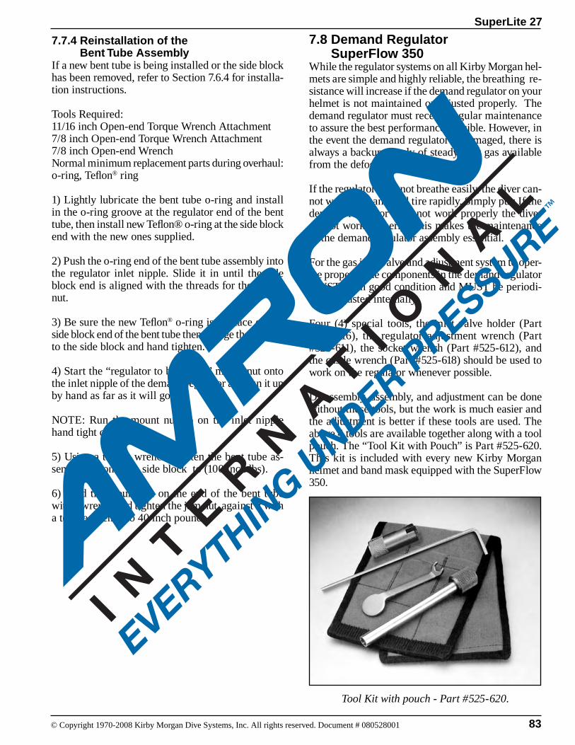
83
SuperLite 27
© Copyright 1970-2008 Kirby Morgan Dive Systems, Inc. All rights reserved. Document # 080528001
7.7.4 Reinstallation of the Bent Tube AssemblyIf a new bent tube is being installed or the side block has been removed, refer to Section 7.6.4 for installa-tion instructions.
Tools Required:11/16 inch Open-end Torque Wrench Attachment 7/8 inch Open-end Torque Wrench Attachment 7/8 inch Open-end WrenchNormal minimum replacement parts during overhaul:o-ring, Teflon® ring
1) Lightly lubricate the bent tube o-ring and install in the o-ring groove at the regulator end of the bent tube, then install new Teflon® o-ring at the side block end with the new ones supplied.
2) Push the o-ring end of the bent tube assembly into the regulator inlet nipple. Slide it in until the side block end is aligned with the threads for the mount nut.
3) Be sure the new Teflon® o-ring is in place on the side block end of the bent tube then engage the threads to the side block and hand tighten.
4) Start the “regulator to bent tube” mount nut onto the inlet nipple of the demand regulator and run it up by hand as far as it will go.
NOTE: Run the mount nut up on the inlet nipple hand tight only. 5) Using a torque wrench, tighten the bent tube as-sembly nut onto the side block to (100 inch lbs).
6) Hold the mount nut on the end of the bent tube with a wrench and tighten the jam nut against it with a torque wrench to 40 inch pounds.
7.8 Demand Regulator SuperFlow 350While the regulator systems on all Kirby Morgan hel-mets are simple and highly reliable, the breathing re-sistance will increase if the demand regulator on your helmet is not maintained or adjusted properly. The demand regulator must receive regular maintenance to assure the best performance possible. However, in the event the demand regulator is damaged, there is always a backup supply of steady flow gas available from the defogger valve.
If the regulator does not breathe easily, the diver can-not work hard and will tire rapidly. Simply put: If the demand regulator does not work properly the diver cannot work properly. This makes the maintenance of the demand regulator assembly essential.
For the gas inlet valve and adjustment system to oper-ate properly, the components in the demand regulator MUST be in good condition and MUST be periodi-cally adjusted internally.
Four (4) special tools, the inlet valve holder (Part #525-616), the regulator adjustment wrench (Part #525-611), the socket wrench (Part #525-612), and the castle wrench (Part #525-618) should be used to work on the regulator whenever possible.
Disassembly, assembly, and adjustment can be done without these tools, but the work is much easier and the adjustment is better if these tools are used. The above 4 tools are available together along with a tool pouch. The “Tool Kit with Pouch” is Part #525-620. This kit is included with every new Kirby Morgan helmet and band mask equipped with the SuperFlow 350.
Tool Kit with pouch - Part #525-620.

84 © Copyright 1970-2008 Kirby Morgan Dive Systems, Inc. All rights reserved. Document # 080528001
SuperLite 27
7.8.1 Demand Regulator Test for Correct Adjustment, Fully AssembledTo maintain optimum performance of the demand regulator, it should be checked for proper function and adjustment prior to commencement of diving each diving day.
Check the regulator for adjustment and proper func-tion with the assembly complete, and supplied with a breathing gas supply pressure of 135 to 150 p.s.i.g.
NOTE: 135 to 150 p.s.i.g. over ambient is the stan-dard supply pressure to be used when adjusting all KMDSI helmets and band-mask demand regula-tors. See Chapter 2 for tables that list the proper supply pressures for specific depths.
NOTE: When storing the helmet for any length of time, ensure that the regulator adjustment knob is turned “out” fully counterclockwise to avoid stressing the bias springs. This will prolong the life of both the inlet valve, seat, and bias springs.
1) Ensure the supply pressure is properly adjusted to 135 to 150 p.s.i.g.
2) Rotate the adjustment knob out counterclockwise slowly, until a slight steady flow develops.
3) Slowly rotate the adjustment knob in clockwise, un-til the free flow stops. Lightly depress the purge button several times to ensure the gas flow has stopped.
4) Lightly depress the purge button. There should be between 1/16” and 1/8” free travel in the button before gas flow starts. When the button is fully depressed, a strong surge of gas must be heard.
5) If the purge button travels less than 1/16” or greater than 1/8” before free flow is heard, the demand regu-lator requires internal adjustment.
7.8.2 Inspection of Regulator Body Interior Tools Required:1/4 inch Flat Blade Attachment on Torque Screw-driver
Remove the demand regulator clamp.
Use only replacement diaphragms manu-factured by Kirby Morgan. Use of other diaphragms may degrade performance and may cause increased breathing re-sistance. This can lead to fatigue and the inability to work at full capacity.
WARNING
1) On the demand regulator remove the demand regu-lator clamp by removing the clamp screw.
2) Lift off the demand regulator cover and dia-phragm.
3) Clean the diaphragm with the soap solution, per Section 6.3 and wipe dry. Inspect the diaphragm for holes, tears or any signs of deterioration by hold-ing it up to a white light and stretching and pulling. Check for a good bond between the metal disc and the silicone membrane. Replace diaphragm if any doubt exists.
4) Inspect the interior of the demand regulator body for damage, corrosion and cleanliness. Clean the interior of the regulator body if necessary per Sec-tion 6.3.
6) Reinstall the diaphragm, cover, and clamp. Tighten the clamp screw to the recommended torque to 12 inch pounds using a torque screwdriver.

85
SuperLite 27
© Copyright 1970-2008 Kirby Morgan Dive Systems, Inc. All rights reserved. Document # 080528001
NOTE: Older regulator clamps, when properly torqued, had a gap of approximately 1/32” to 1/16” between the interior retaining clamp sur-faces when fully tightened. All new clamps when properly torqued, have little or no gap between the interior retaining clamp surfaces.
7.8.3 Demand Regulator Bias Adjustment Servicing, Demand Regulator on the Helmet
Note: This procedure should be used when replac-ing the o-ring on the adjustment shaft and or clean-ing and lubricating the shaft threads during field repairs with the demand regulator on the helmet. Start at the adjustment knob end of the regulator:
Tools Required:3/4 inch Open-end Wrench Attachment on Torque Wrench3/32 inch Punch & Small Block of Wood Ball-Peen Hammer Regulator Adjustment Tool Kit, Part #525-620Torque Wrench
1) Unscrew the adjustment knob until it stops and a wrench can be placed on the nut. If the knob wobbles as you turn it, or is extremely hard to turn, the shaft is bent and needs to be replaced is over the hole. The adjustment knob can be held
against the wood block allowing the roll pin to be driven into the 1/4” hole.
4) Remove the adjustment knob, the washer and o-ring.
NOTE: If the spacer and the spring set are stuck, this could indicate corrosion or possible saltwater intrusion into the adjustment tube and assembly, or that the adjustment tube is bent. The demand regulator should be removed from the helmet and cleaned and inspected, per Sections 6.3 and 7.7.5.
5) Carefully inspect all parts for corrosion, paying particular attention to threaded surfaces and the spring set. Clean and lightly lubricate parts per Chapter 6.
NOTE: Carefully inspect the adjustment shaft to ensure it is straight, Check for damaged threads. Replace the adjustment shaft if any damage is found. Replace the o-ring.
Remove the spacer, spring set, and piston.
Screw the regulator adjustment knob out for removal.2) Loosen the nut, then rotate the adjustment knob counterclockwise until the adjustment knob and the adjustment shaft are free, then remove the spacer, springs, and piston. At this point the threads can be cleaned and lubricated as well as the adjustment shaft.
3) Punch out the roll pin using a 3/32 punch. Use a block of wood with a 1/4” hole drilled through it to support the knob. Position the knob so the roll pin
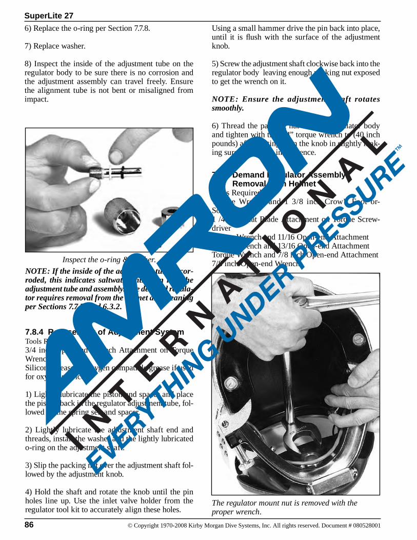
86 © Copyright 1970-2008 Kirby Morgan Dive Systems, Inc. All rights reserved. Document # 080528001
SuperLite 27
6) Replace the o-ring per Section 7.7.8.
7) Replace washer.
8) Inspect the inside of the adjustment tube on the regulator body to be sure there is no corrosion and the adjustment assembly can travel freely. Ensure the alignment tube is not bent or misaligned from impact.
NOTE: If the inside of the adjustment tube is cor-roded, this indicates saltwater intrusion into the adjustment tube and assembly. The demand regula-tor requires removal from the helmet and cleaning per Sections 7.7.5 and 6.3.2.
7.8.4 Reassembly of Adjustment SystemTools Required:3/4 inch Open-end Wrench Attachment on Torque WrenchSilicone grease, or oxygen compatible grease if used for oxygen service.
1) Lightly lubricate the piston and spacer and place the piston back in the regulator adjustment tube, fol-lowed by the spring set, and spacer.
2) Lightly lubricate the adjustment shaft end and threads, install the washer and the lightly lubricated o-ring on the adjustment shaft.
3) Slip the packing nut over the adjustment shaft fol-lowed by the adjustment knob.
4) Hold the shaft and rotate the knob until the pin holes line up. Use the inlet valve holder from the regulator tool kit to accurately align these holes.
Inspect the o-ring & washer.
Using a small hammer drive the pin back into place, until it is flush with the surface of the adjustment knob.
5) Screw the adjustment shaft clockwise back into the regulator body leaving enough packing nut exposed to get the wrench on it.
NOTE: Ensure the adjustment shaft rotates smoothly.
6) Thread the packing nut onto the regulator body and tighten with the 3/4” torque wrench to (40 inch pounds) after seating, turn the knob in slightly mak-ing sure there is no interference.
7.8.5 Demand Regulator Assembly Removal from HelmetTools Required:Torque Wrench and 1 3/8 inch Crow’s Foot or-Socket1 /4 inch Flat Blade Attachment on Torque Screw-driverTorque Wrench and 11/16 Open-end AttachmentTorque Wrench and 13/16 Open-end AttachmentTorque Wrench and 7/8 inch Open-end Attachment7/8 inch Open-end Wrench
The regulator mount nut is removed with the proper wrench.
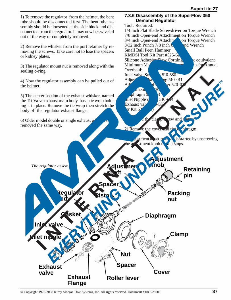
87
SuperLite 27
© Copyright 1970-2008 Kirby Morgan Dive Systems, Inc. All rights reserved. Document # 080528001
1) To remove the regulator from the helmet, the bent tube should be disconnected first. The bent tube as-sembly should be loosened at the side block and dis-connected from the regulator. It may now be swiveled out of the way or completely removed.
2) Remove the whisker from the port retainer by re-moving the screws. Take care not to lose the spacers or kidney plates.
3) The regulator mount nut is removed along with the sealing o-ring.
4) Now the regulator assembly can be pulled out of the helmet.
5) The center section of the exhaust whisker, named the Tri-Valve exhaust main body has a tie wrap hold-ing it in place. Remove the tie wrap then stretch the body off the regulator exhaust flange.
6) Older model double or single exhaust whiskers are removed the same way.
7.8.6 Disassembly of the SuperFlow 350 Demand RegulatorTools Required:1/4 inch Flat Blade Screwdriver on Torque Wrench 7/8 inch Open-end Attachment on Torque Wrench3/4 inch Open-end Attachment on Torque Wrench 3/32 inch Punch 7/8 inch Open-end WrenchSmall Ball Peen HammerKMDSI Tool Kit Part #525-620Silicone Adhesive Dow Corning 732 or equivalent Minimum Mandatory Replacement Parts for Annual Overhaul:Inlet valve Soft Seat 510-580Adjustment shaft o-ring 510-011Adjustment Shaft Washer 520-032Adjustment nut 530-303Diaphragm 510-553Inlet Nipple o-ring 510-014Exhaust valve 510-552(or Kit 525-309)
1) Remove the clamp screw and clamp.
2) Remove the cover and the diaphragm.
3) Adjustment knob removal is started by unscrewing the adjustment knob until it stops.
Adjustmentknob
Regulatorbody
Diaphragm
Cover
Clamp
Inlet valve
Inlet nipple
Gasket
Adjustmentshaft
Packingnut
Piston
Spacer
Roller lever
Exhaustvalve
Spacer
Nut
Exhaust Flange
Retainingpin
The regulator assembly.
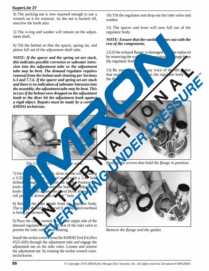
88 © Copyright 1970-2008 Kirby Morgan Dive Systems, Inc. All rights reserved. Document # 080528001
SuperLite 27
4) The packing nut is now exposed enough to use a wrench on it for removal. As the nut is backed off, unscrew the knob also.
5) The o-ring and washer will remain on the adjust-ment shaft.
6) Tilt the helmet so that the spacer, spring set, and piston fall out of the adjustment shaft tube.
NOTE: If the spacer and the spring set are stuck, this indicates possible corrosion or saltwater intru-sion into the adjustment tube or the adjustment tube may be bent. The demand regulator requires removal from the helmet and cleaning per Sections 6.3 and 7.7.6. If the spacer and spring set are stuck and there is no indication of saltwater intrusion into the assembly, the adjustment tube may be bent. This occurs if the helmet were dropped on the adjustment knob or the diver hit the adjustment knob against a rigid object. Repairs must be made by a certified KMDSI technician.
7) On the adjustment knob, drive out the roll pin using a 3/32 punch. Use a block of wood with a 1/4 ” hole drilled through it to support the knob. Position the knob so the roll pin is over the hole. The adjustment knob can be held against the wood block allowing the roll pin to be driven into the 1/4 ” hole.
8) Remove the inlet nipple from the regulator body. The o-ring should be replaced if a scheduled overhaul is being performed.
9) Place the castle wrench in the inlet nipple side of the demand regulator over the soft seat of the inlet valve to prevent the inlet valve from rotating.
Install the socket wrench from the KMDSI Tool Kit (Part #525-620) through the adjustment tube and engage the adjustment nut on the inlet valve. Loosen and remove the adjustment nut by rotating the socket wrench coun-terclockwise.
The Castle Wrench and inlet valve.
10) Tilt the regulator and drop out the inlet valve and washer.
11) The spacer and lever will now fall out of the regulator body.
NOTE: Ensure that the washer comes out with the rest of the components.
12) If the exhaust flange is damaged it can be replaced by removing the screws and separating the flange from the regulator body.
13) Be sure to clean off any trace of the old gasket that makes the seal between the regulator body and the flange.
Remove the screws that hold the flange in position.
Remove the flange and the gasket.
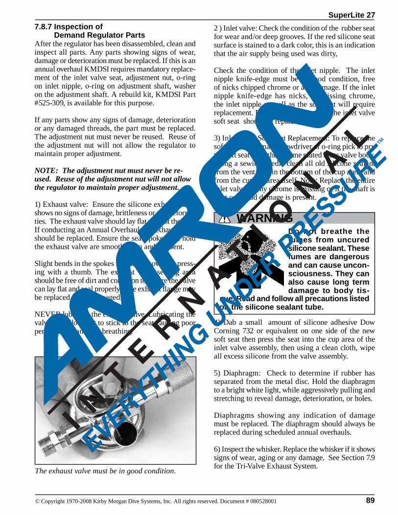
89
SuperLite 27
© Copyright 1970-2008 Kirby Morgan Dive Systems, Inc. All rights reserved. Document # 080528001
7.8.7 Inspection of Demand Regulator PartsAfter the regulator has been disassembled, clean and inspect all parts. Any parts showing signs of wear, damage or deterioration must be replaced. If this is an annual overhaul KMDSI requires mandatory replace-ment of the inlet valve seat, adjustment nut, o-ring on inlet nipple, o-ring on adjustment shaft, washer on the adjustment shaft. A rebuild kit, KMDSI Part #525-309, is available for this purpose.
If any parts show any signs of damage, deterioration or any damaged threads, the part must be replaced. The adjustment nut must never be reused. Reuse of the adjustment nut will not allow the regulator to maintain proper adjustment.
NOTE: The adjustment nut must never be re-used. Reuse of the adjustment nut will not allow the regulator to maintain proper adjustment.
1) Exhaust valve: Ensure the silicone exhaust valve shows no signs of damage, brittleness or any deformi-ties. The exhaust valve should lay flat against the seat. If conducting an Annual Overhaul, the exhaust valve should be replaced. Ensure the seat spokes that hold the exhaust valve are smooth, even and not bent.
Slight bends in the spokes may be removed by press-ing with a thumb. The exhaust valve seating area should be free of dirt and corrosion to ensure the valve can lay flat and seal properly. The exhaust flange may be replaced if it is damaged.
NEVER lubricate the exhaust valve. Lubricating the valve can allow dirt to stick to the seat causing poor performance and wet breathing.
The exhaust valve must be in good condition.
sue. Read and follow all precautions listed on the silicone sealant tube.
WARNINGDo not breathe the fumes from uncured silicone sealant. These fumes are dangerous and can cause uncon-sciousness. They can also cause long term damage to body tis-
2 ) Inlet valve: Check the condition of the rubber seat for wear and/or deep grooves. If the red silicone seat surface is stained to a dark color, this is an indication that the air supply being used was dirty,
Check the condition of the inlet nipple. The inlet nipple knife-edge must be in good condition, free of nicks chipped chrome or any damage. If the inlet nipple knife-edge has nicks, or missing chrome, the inlet nipple as well as the soft seat will require replacement. During annual overhaul the inlet valve soft seat should be replaced.
3) Inlet Valve Soft Seat Replacement: To replace the soft seat use a small screwdriver or o-ring pick to pry the soft seat from the chrome plated brass valve body. Using a sewing needle clean all old silicone sealant from the vent hole in the bottom of the cup area, and from the cupped area itself. Note: Replace the entire inlet valve if any chrome is missing or if the shaft is bent or thread damage is present.
4) Dab a small amount of silicone adhesive Dow Corning 732 or equivalent on one side of the new soft seat then press the seat into the cup area of the inlet valve assembly, then using a clean cloth, wipe all excess silicone from the valve assembly.
5) Diaphragm: Check to determine if rubber has separated from the metal disc. Hold the diaphragm to a bright white light, while aggressively pulling and stretching to reveal damage, deterioration, or holes.
Diaphragms showing any indication of damage must be replaced. The diaphragm should always be replaced during scheduled annual overhauls.
6) Inspect the whisker. Replace the whisker if it shows signs of wear, aging or any damage. See Section 7.9 for the Tri-Valve Exhaust System.
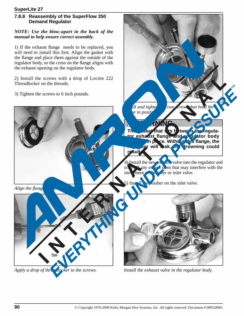
90 © Copyright 1970-2008 Kirby Morgan Dive Systems, Inc. All rights reserved. Document # 080528001
SuperLite 27
7.8.8 Reassembly of the SuperFlow 350 Demand Regulator
NOTE: Use the blow-apart in the back of the manual to help ensure correct assembly.
1) If the exhaust flange needs to be replaced, you will need to install this first. Align the gasket with the flange and place them against the outside of the regulator body, so the cross on the flange aligns with the exhaust opening on the regulator body.
2) Install the screws with a drop of Loctite 222 Threadlocker on the threads.
3) Tighten the screws to 6 inch pounds.
4) Install the new exhaust valve into the regulator and trim off any excess stem that may interfere with the movement of the lever or inlet valve.
5) Install the washer on the inlet valve.Align the flange and the gasket.
Apply a drop of threadlocker to the screws.
Install and tighten the two screws that hold the flange in position.
WARNINGThe gasket that sits between the regula-tor exhaust flange and regulator body must be in place. Without this flange, the regulator will leak and drowning could result.
Install the exhaust valve in the regulator body.
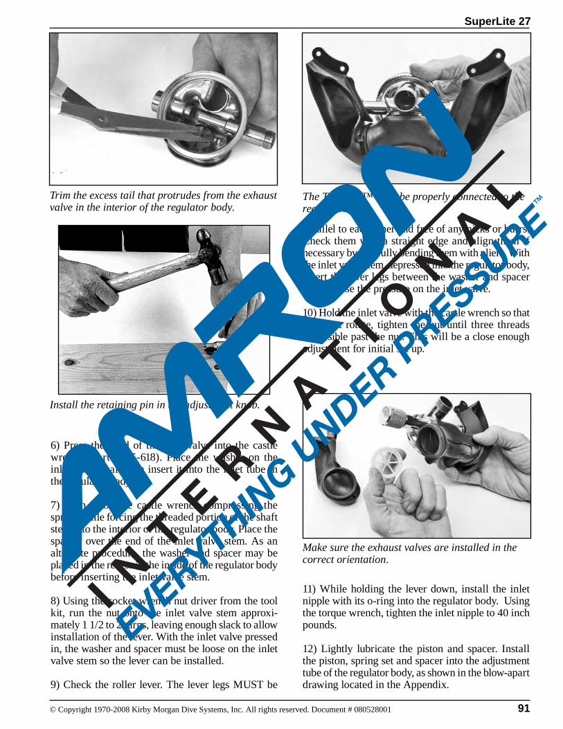
91
SuperLite 27
© Copyright 1970-2008 Kirby Morgan Dive Systems, Inc. All rights reserved. Document # 080528001
parallel to each other and free of any nicks or burrs. Check them with a straight edge and align them if necessary by carefully bending them with pliers. With the inlet valve stem depressed into the regulator body, insert the lever legs between the washer and spacer then release the pressure on the inlet valve.
10) Hold the inlet valve with the castle wrench so that it cannot rotate, tighten the nut until three threads are visible past the nut. This will be a close enough adjustment for initial set up.
11) While holding the lever down, install the inlet nipple with its o-ring into the regulator body. Using the torque wrench, tighten the inlet nipple to 40 inch pounds.
12) Lightly lubricate the piston and spacer. Install the piston, spring set and spacer into the adjustment tube of the regulator body, as shown in the blow-apart drawing located in the Appendix.
Install the retaining pin in the adjustment knob.
6) Press the head of the inlet valve into the castle wrench (Part #525-618). Place the washer on the inlet valve shaft then insert it into the inlet tube in the regulator body.
7) Push in on the castle wrench compressing the spring while forcing the threaded portion of the shaft stem into the interior of the regulator body. Place the spacer over the end of the inlet valve stem. As an alternate procedure, the washer and spacer may be placed in the recess in the inside of the regulator body before inserting the inlet valve stem.
8) Using the socket wrench nut driver from the tool kit, run the nut onto the inlet valve stem approxi-mately 1 1/2 to 2 turns, leaving enough slack to allow installation of the lever. With the inlet valve pressed in, the washer and spacer must be loose on the inlet valve stem so the lever can be installed.
9) Check the roller lever. The lever legs MUST be
The Tri-Valve™ must be properly connected to the regulator.
Make sure the exhaust valves are installed in the correct orientation.
Trim the excess tail that protrudes from the exhaust valve in the interior of the regulator body.
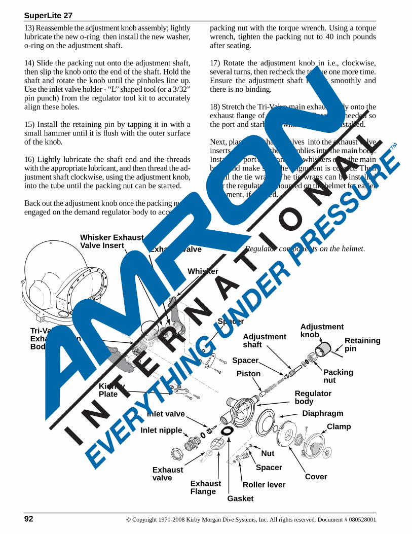
92 © Copyright 1970-2008 Kirby Morgan Dive Systems, Inc. All rights reserved. Document # 080528001
SuperLite 27
13) Reassemble the adjustment knob assembly; lightly lubricate the new o-ring then install the new washer, o-ring on the adjustment shaft.
14) Slide the packing nut onto the adjustment shaft, then slip the knob onto the end of the shaft. Hold the shaft and rotate the knob until the pinholes line up. Use the inlet valve holder - “L” shaped tool (or a 3/32” pin punch) from the regulator tool kit to accurately align these holes.
15) Install the retaining pin by tapping it in with a small hammer until it is flush with the outer surface of the knob.
16) Lightly lubricate the shaft end and the threads with the appropriate lubricant, and then thread the ad-justment shaft clockwise, using the adjustment knob, into the tube until the packing nut can be started.
Back out the adjustment knob once the packing nut is engaged on the demand regulator body to access the
packing nut with the torque wrench. Using a torque wrench, tighten the packing nut to 40 inch pounds after seating.
17) Rotate the adjustment knob in i.e., clockwise, several turns, then recheck the torque one more time. Ensure the adjustment shaft rotates smoothly and there is no binding.
18) Stretch the Tri-Valve main exhaust body onto the exhaust flange of the regulator. Rotate as needed so the port and starboard whiskers can be installed.
Next, place the exhaust valves into the exhaust valve inserts. Then place the assemblies into the main body. Install the port and starboard whiskers onto the main body and make sure the alignment is correct. Then install the tie wraps. The tie wraps can be installed after the regulator is mounted on the helmet for easier alignment, if desired.
Tri-ValveExhaust Main Body
Whisker ExhaustValve Insert
Whisker
Spacer
KidneyPlate
Exhaust Valve
Inlet valve
Inlet nipple
Exhaustvalve
Adjustmentknob
Regulatorbody
Diaphragm
Cover
Clamp
Gasket
Adjustmentshaft
Packingnut
Piston
Spacer
Roller lever
Spacer
Nut
Exhaust Flange
Retainingpin
Regulator components on the helmet.

93
SuperLite 27
© Copyright 1970-2008 Kirby Morgan Dive Systems, Inc. All rights reserved. Document # 080528001
For the old double exhaust or single exhaust, stretch the exhaust whisker onto the exhaust flange of the regulator.
19) Mount the regulator to the mask or helmet. Lightly lubricate and install the sealing o-ring and thread on the regulator mount nut.
20) Install the bent tube assembly before tightening the regulator mount nut.
NOTE: If this maintenance is during an annual overhaul, replace the Teflon ring (13) at the side block end of the bent tube and the o-ring (15) at the demand regulator inlet side of the bent tube.
Using the appropriate lubricant per Chapter 6, lightly lubricate the o-ring on the bent tube assembly. Slide the o-ring end of the bent tube assembly into the regu-lator inlet nipple until the side block end is aligned with the threads for the bent tube mount nut. Rotating clockwise, thread the large nut on the bent tube as-sembly onto the inlet nipple 1 to 2 threads.
Ensure that the Teflon® ring is in place and engage the bent tube nut to the side block fully until it is hand tight. You may need to gently rock the regulator body and/or the bent tube to fully engage side block nut. Next, fully engage (clockwise) the large nut on the bent tube onto the regulator inlet until hand tight. This will ensure the nut is bottomed on the shoulder on the bent tube. Do not tighten further.
Loosen the jam nut on the regulator inlet (counter-clockwise), and engage the jam nut fully to the large nut on the bent tube. Using a torque wrench and an 7/8” open end wrench hold the large nut on the regu-lator end of the bent tube and tighten the jam nut to 40 inch pounds.
21) Ensuring the o-ring is in place, use a torque wrench, a 1 3/8” socket and an extension, torque the regulator mount nut to 100 inch pounds. Next using a torque wrench with an 11/16” adapter, torque the bent tube nut to the side block to 100 inch pounds.
22) Attach the whisker to each side of the face port retainer using the screws, plates and spacers. Using a torque wrench with a flat blade screwdriver adapter, carefully torque these screws to 12 inch pounds.
23) Adjust the regulator following instructions in in this chapter.
24) Install the diaphragm, cover, clamp and screw.
Tighten the screw to 12 inch pounds using a torque screwdriver.
25) Check the regulator for proper operation and fine-tune the adjustment if necessary.
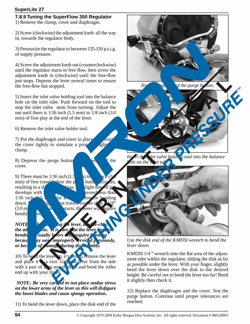
94 © Copyright 1970-2008 Kirby Morgan Dive Systems, Inc. All rights reserved. Document # 080528001
SuperLite 27
Insert the inlet valve holding tool into the balance hole on the inlet tube.
7.8.9 Tuning the SuperFlow 350 Regulator 1) Remove the clamp, cover and diaphragm.
2) Screw (clockwise) the adjustment knob all the way in, towards the regulator body.
3) Pressurize the regulator to between 135-150 p.s.i.g. of supply pressure.
4) Screw the adjustment knob out (counterclockwise) until the regulator starts to free flow, then screw the adjustment knob in (clockwise) until the free-flow just stops. Depress the lever several times to ensure the free-flow has stopped.
5) Insert the inlet valve holding tool into the balance hole on the inlet tube. Push forward on the tool to stop the inlet valve stem from turning. Adjust the nut until there is 1/16 inch (1.5 mm) to 1/8 inch (3.0 mm) of free play at the end of the lever.
6) Remove the inlet valve holder tool.
7) Put the diaphragm and cover in place, depressing the cover tightly to simulate a properly tightened clamp.
8) Depress the purge button in the center of the cover.
9) There must be 1/16 inch (1.5 mm) to 1/8 inch (3.0 mm) of free travel before the purge button actuates, resulting in a slight flow of gas. If a slight flow of gas develops with the purge button depressed less than 1/16 inch (1.5 mm) the lever will require bending down. If the purge button travels further than a 1/8” (3.0 mm) before gas flow starts, the lever will require bending upward.
NOTE: Before bending the lever, double-check the adjustments. It is rare that the lever requires bending. Usually levers only require bending because they were improperly serviced previously, or because of damage during disassembly.
10) To bend the lever up, it’s best to remove the lever and place it in a vice. Grip the lever from the side with a pair of long nosed pliers and bend the roller end up with your finger.
NOTE: Be very careful to not place undue stress on the lower arms of the lever as this will disfigure the lower blades and cause spongy operation.
11) To bend the lever down, place the disk end of the
Test the response of the purge button.
Use the disk end of the KMDSI wrench to bend the lever down.
KMDSI 1/4 ” wrench onto the flat area of the adjust-ment tube within the regulator, sliding the disk as far as possible under the lever. With your finger, slightly bend the lever down over the disk to the desired height. Be careful not to bend the lever too far! Bend it slightly then check it.
12) Replace the diaphragm and the cover. Test the purge button. Continue until proper tolerances are reached.
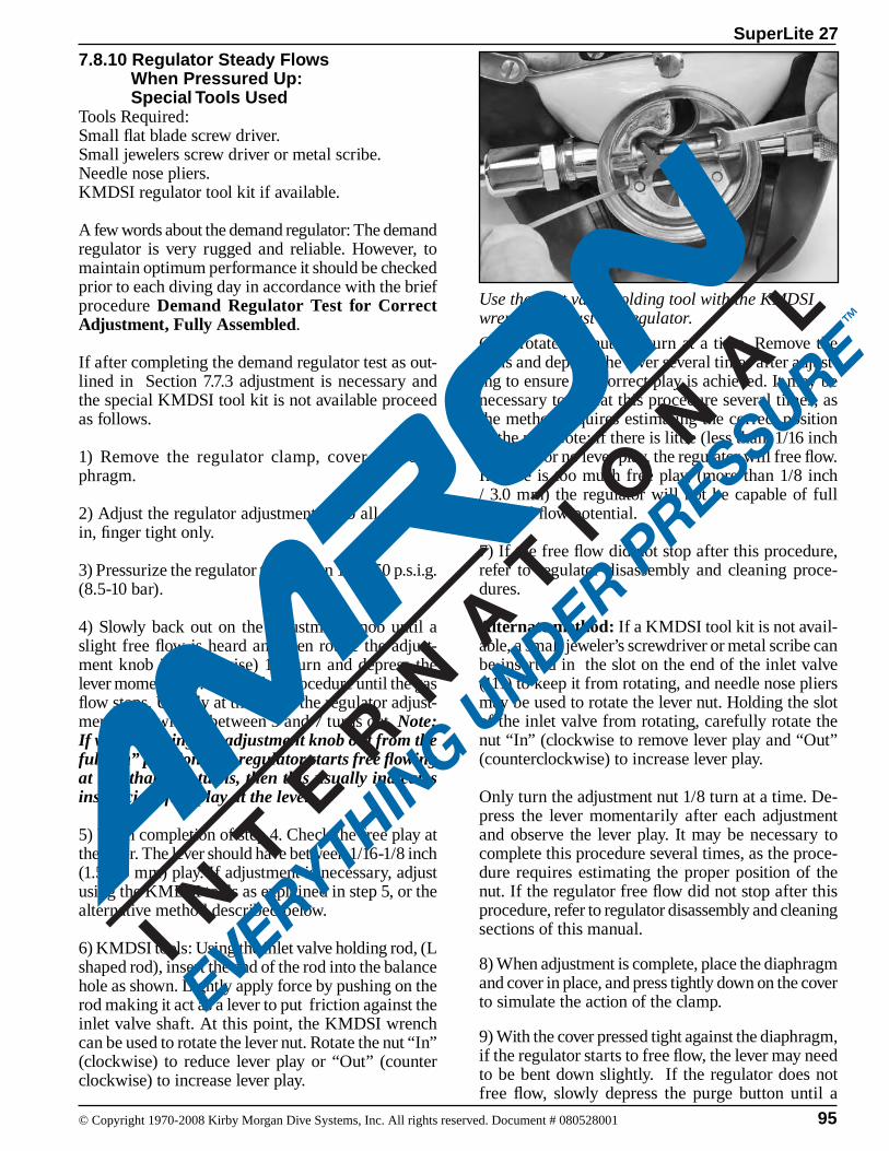
95
SuperLite 27
© Copyright 1970-2008 Kirby Morgan Dive Systems, Inc. All rights reserved. Document # 080528001
7.8.10 Regulator Steady Flows When Pressured Up: Special Tools UsedTools Required:Small flat blade screw driver.Small jewelers screw driver or metal scribe.Needle nose pliers.KMDSI regulator tool kit if available.
A few words about the demand regulator: The demand regulator is very rugged and reliable. However, to maintain optimum performance it should be checked prior to each diving day in accordance with the brief procedure Demand Regulator Test for Correct Adjustment, Fully Assembled.
If after completing the demand regulator test as out-lined in Section 7.7.3 adjustment is necessary and the special KMDSI tool kit is not available proceed as follows.
1) Remove the regulator clamp, cover and dia-phragm.
2) Adjust the regulator adjustment knob all the way in, finger tight only.
3) Pressurize the regulator to between 135-150 p.s.i.g. (8.5-10 bar).
4) Slowly back out on the adjustment knob until a slight free flow is heard and then rotate the adjust-ment knob in (clockwise) 1/4 turn and depress the lever momentarily. Repeat this procedure until the gas flow stops. Usually at this point the regulator adjust-ment knob will be between 5 and 7 turns out. Note: If when backing the adjustment knob out from the full “in” position, the regulator starts free flowing at less than five turns, then this usually indicates insufficient free play at the lever.
5) Upon completion of step 4. Check the free play at the lever. The lever should have between 1/16-1/8 inch (1.5-3.0 mm) play. If adjustment is necessary, adjust using the KMDSI tools as explained in step 5, or the alternative method described below.
6) KMDSI tools: Using the inlet valve holding rod, (L shaped rod), insert the end of the rod into the balance hole as shown. Lightly apply force by pushing on the rod making it act as a lever to put friction against the inlet valve shaft. At this point, the KMDSI wrench can be used to rotate the lever nut. Rotate the nut “In” (clockwise) to reduce lever play or “Out” (counter clockwise) to increase lever play.
Only rotate the nut 1/8 turn at a time. Remove the tools and depress the lever several times after adjust-ing to ensure the correct play is achieved. It may be necessary to repeat this procedure several times, as the method requires estimating the correct position of the nut. Note: if there is little (less than 1/16 inch /1.5 mm) or no lever play, the regulator will free flow. If there is too much free play, (more than 1/8 inch / 3.0 mm) the regulator will not be capable of full demand flow potential.
7) If the free flow did not stop after this procedure, refer to regulator disassembly and cleaning proce-dures.
Alternate method: If a KMDSI tool kit is not avail-able, a small jeweler’s screwdriver or metal scribe can be inserted in the slot on the end of the inlet valve (111) to keep it from rotating, and needle nose pliers may be used to rotate the lever nut. Holding the slot of the inlet valve from rotating, carefully rotate the nut “In” (clockwise to remove lever play and “Out” (counterclockwise) to increase lever play.
Only turn the adjustment nut 1/8 turn at a time. De-press the lever momentarily after each adjustment and observe the lever play. It may be necessary to complete this procedure several times, as the proce-dure requires estimating the proper position of the nut. If the regulator free flow did not stop after this procedure, refer to regulator disassembly and cleaning sections of this manual.
8) When adjustment is complete, place the diaphragm and cover in place, and press tightly down on the cover to simulate the action of the clamp.
9) With the cover pressed tight against the diaphragm, if the regulator starts to free flow, the lever may need to be bent down slightly. If the regulator does not free flow, slowly depress the purge button until a
Use the inlet valve holding tool with the KMDSI wrench to adjust the regulator.
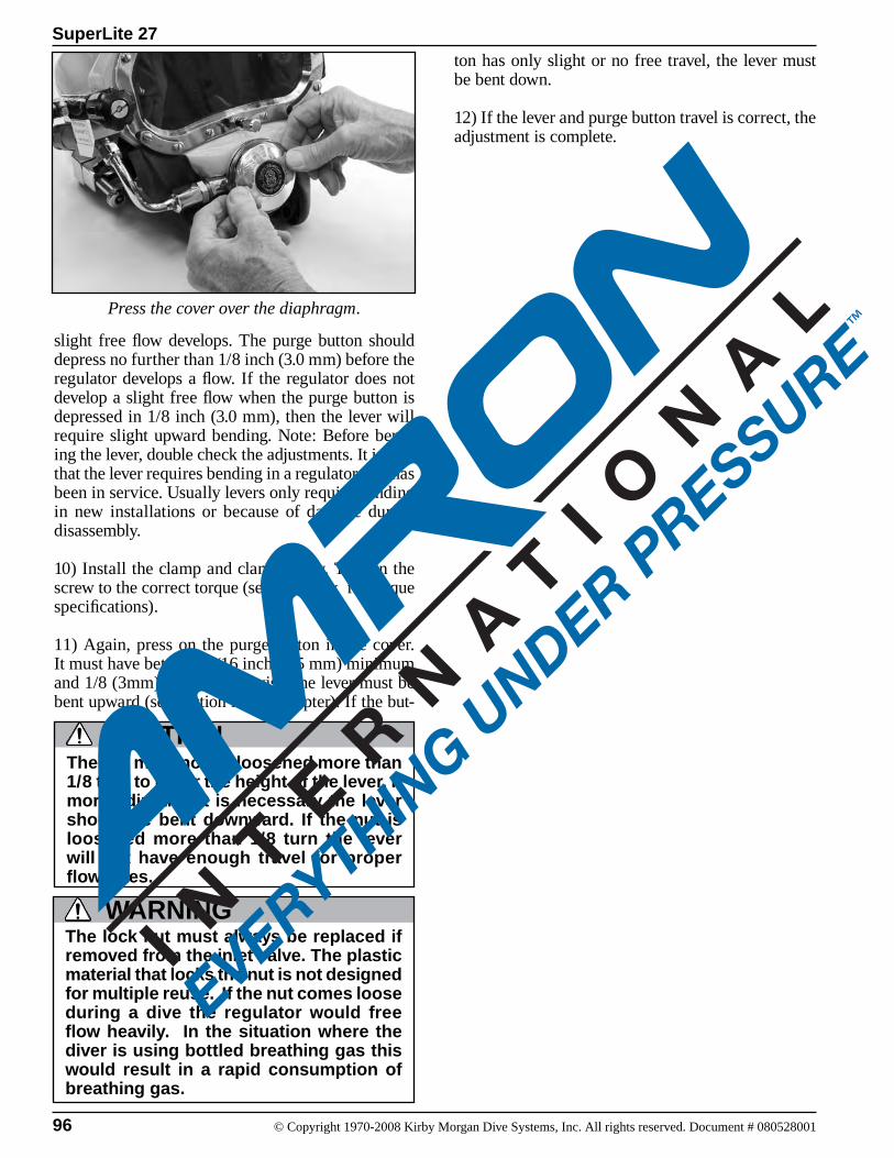
96 © Copyright 1970-2008 Kirby Morgan Dive Systems, Inc. All rights reserved. Document # 080528001
SuperLite 27
slight free flow develops. The purge button should depress no further than 1/8 inch (3.0 mm) before the regulator develops a flow. If the regulator does not develop a slight free flow when the purge button is depressed in 1/8 inch (3.0 mm), then the lever will require slight upward bending. Note: Before bend-ing the lever, double check the adjustments. It is rare that the lever requires bending in a regulator that has been in service. Usually levers only require bending in new installations or because of damage during disassembly.
10) Install the clamp and clamp screw. Tighten the screw to the correct torque (see appendix for torque specifications).
11) Again, press on the purge button in the cover. It must have between 1/16 inch (1.5 mm) minimum and 1/8 (3mm) travel. Otherwise, the lever must be bent upward (see section in this chapter). If the but-
Press the cover over the diaphragm.
The nut must not be loosened more than 1/8 turn to lower the height of the lever. If more adjustment is necessary the lever should be bent downward. If the nut is loosened more than 1/8 turn the lever will not have enough travel for proper flow rates.
CAUTION
The lock nut must always be replaced if removed from the inlet valve. The plastic material that locks the nut is not designed for multiple reuse. If the nut comes loose during a dive the regulator would free flow heavily. In the situation where the diver is using bottled breathing gas this would result in a rapid consumption of breathing gas.
WARNING
ton has only slight or no free travel, the lever must be bent down.
12) If the lever and purge button travel is correct, the adjustment is complete.
97
SuperLite 27
© Copyright 1970-2008 Kirby Morgan Dive Systems, Inc. All rights reserved. Document # 080528001
7.8.12 Unexplained Demand Regulator Free FlowAny leak in the neck dam when the diver is face down will cause gas to vent out into the water from the inside of the helmet. This causes the demand regulator to steady flow, making up for the vented gas. Even if the adjustment knob is turned in, the leak may continue.
1) One method to check for this is for the diver to place the demand regulator above the neck dam by looking up. Free flow from a leaky neck dam should cease as long as the helmet is in the upright position.
2) Ensure the demand regulator bias adjustment knob (98) is properly adjusted for the supply pressure.
3) During ascent the regulator will free flow if the supply pressure to the helmet is not backed off (top-side) or, the diver does not adjust “in” (clockwise), the demand regulator adjustment knob as the diver’s depth and the ambient pressure decreases.
4) If the preceding steps were checked and the de-mand regulator still steady flows the regulator requires adjustment.
7.8.11 Regulator has Low or No Flow When PressurizedTools Required:Regulator Adjustment Tools, (Part #525-620)1/4 inch Flat Blade Attachment on Torque Screw-driver
NOTE: If there is low or no flow when the regulator is pressurized, and the lever is very loose (travels more than 1/8 inch at the roller end), the nut must be tightened.
1) Adjust demand regulator bias adjustment knob “in”, i.e., clockwise.
2) Ensure supply pressure is adjusted between 135-150 p.s.i.g. (9.3-10.3 bar).
3) Back the demand regulator bias adjustment knob (98) out counterclockwise until a slight steady flow develops. Then adjust the knob in clockwise until the free-flow just stops. Depress the lever several times to ensure the regulator is stabilized.
4) Recheck the lever play at the purge button ensuring 1/16 inch (1.5 mm) to l/8 inch (3.0 mm) of free travel before the purge button comes in contact with the diaphragm actuating a slight flow of gas. If a slight flow of gas develops with the purge button depressed less than 1/16 inch (1.5 mm), the lever will require slightly more play. If the purge button travels greater than 1/8 inch (3.0 mm), the lever will require a reduc-tion of play by adjusting.
5) Recheck that gas source pressure is set between 135-150 p.s.i.g. The gas source must be capable of supplying 4.5 a.c.f.m. (127.4 L/min per diver) at the required over bottom pressures for the depth of the dive per Section 2, Tables 1 and 2.
6) If the preceding steps were satisfactory, check the following helmet/mask parts for foreign debris in the air/gas passages:a. One-way valveb. Side block assembly1. Defogger valve2. Emergency Valve Assembly3. Bent Tube Assembly

98 © Copyright 1970-2008 Kirby Morgan Dive Systems, Inc. All rights reserved. Document # 080528001
SuperLite 27
7.9 Oral/Nasal
7.9.1 Oral/Nasal Removal Tools Required: 7/16 inch Open-end Wrench
The oral/nasal mask is easily replaced.
The oral nasal mask and the parts associated with it are easy to access.
1) Remove the nose block device (51) first. See Chap-ter 8 for this procedure.
The nose block device MUST be removed and reinstalled when installing a new oral nasal mask. Simply stretching the oral nasal mask over the nose block device can cause the oral nasal mask to tear.
CAUTION
2) Remove the microphone.
3) The oral/nasal mask can then be pulled off the regulator mount nut. It is held on by a snap fit.
7.9.2 Inspection of Oral/Nasal
1) Inspect the oral/nasal mask. If it is torn, damaged or aged it must be replaced.
2) Inspect the oral/nasal valve. If it is torn or dam-aged it must be replaced.
3) Remove the valve body by pushing it out of the oral nasal.
4) Remove the old valve by pulling it out.
The oral/nasal valve must be replaced correctly to provide gas flow in the proper direction. The flow through the valve must be from the interior of the helmet into the oral nasal mask. This will allow the diver to breathe the gas from the defogger valve freely, yet help to reduce carbon dioxide inside the helmet.
If the valve is not replaced properly this could make it difficult to breathe the gas supplied by the defogger and expose the diver to an excess of carbon dioxide. This could lead to exhaustion and blackout resulting in serious injury or death.
WARNING
5) Install the new valve by feeding the thin tail through the valve body and pulling on it until the valve is seated.
6) Install the valve body in the oral nasal. The valve MUST be on the inside of the oral nasal.
7.9.3 Oral/Nasal Replacement
1) Snap the oral/nasal over the regulator mount nut (49).
2) Reinstall the microphone.
3) Reinstall the nose block device. See Chapter 8 for complete instructions on reinstalling the nose block device.
Correct installation of the oral/nasal valve is extremely important to your safety.
Oral/Nasal Mask
RegulatorMount Nut
O-ring
EqualizingDevice
ValveBody
Oral/NasalValve
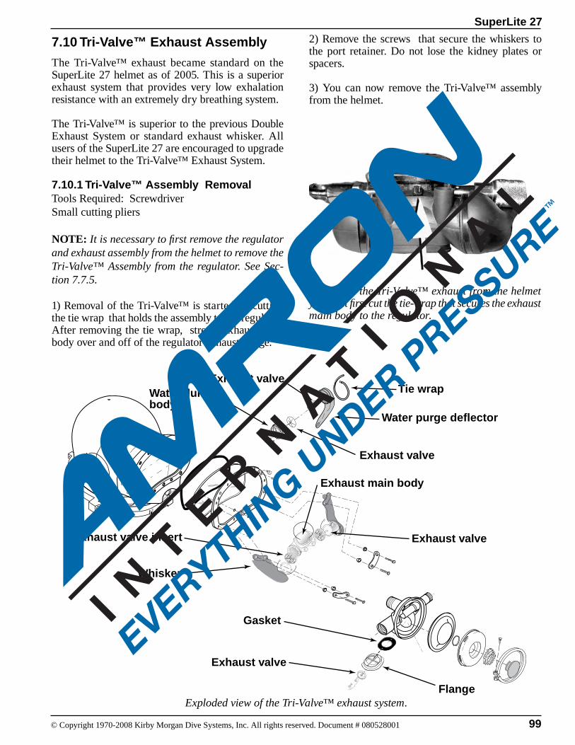
99
SuperLite 27
© Copyright 1970-2008 Kirby Morgan Dive Systems, Inc. All rights reserved. Document # 080528001
7.10 Tri-Valve™ Exhaust Assembly
The Tri-Valve™ exhaust became standard on the SuperLite 27 helmet as of 2005. This is a superior exhaust system that provides very low exhalation resistance with an extremely dry breathing system.
The Tri-Valve™ is superior to the previous Double Exhaust System or standard exhaust whisker. All users of the SuperLite 27 are encouraged to upgrade their helmet to the Tri-Valve™ Exhaust System.
7.10.1 Tri-Valve™ Assembly RemovalTools Required: ScrewdriverSmall cutting pliers
NOTE: It is necessary to first remove the regulator and exhaust assembly from the helmet to remove the Tri-Valve™ Assembly from the regulator. See Sec-tion 7.7.5.
1) Removal of the Tri-Valve™ is started by cutting the tie wrap that holds the assembly to the regulator. After removing the tie wrap, stretch exhaust main body over and off of the regulator exhaust flange.
Exploded view of the Tri-Valve™ exhaust system.
To remove the Tri-Valve™ exhaust from the helmet you must first cut the tie-wrap that secures the exhaust main body to the regulator.
2) Remove the screws that secure the whiskers to the port retainer. Do not lose the kidney plates or spacers.
3) You can now remove the Tri-Valve™ assembly from the helmet.
Exhaust valve
Whisker
Flange
Gasket
Exhaust valve insert
Exhaust main body
Water dumpbody
Exhaust valve
Exhaust valve
Exhaust valve
Water purge deflector
Tie wrap
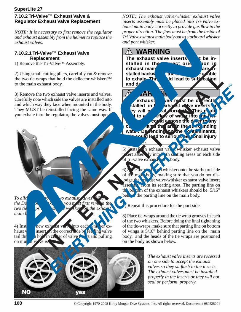
100 © Copyright 1970-2008 Kirby Morgan Dive Systems, Inc. All rights reserved. Document # 080528001
SuperLite 27
7.10.2 Tri-Valve™ Exhaust Valve & Regulator Exhaust Valve Replacement
NOTE: It is necessary to first remove the regulator and exhaust assembly from the helmet to replace the exhaust valves.
7.10.2.1 Tri-Valve™ Exhaust Valve Replacement1) Remove the Tri-Valve™ Assembly.
2) Using small cutting pliers, carefully cut & remove the two tie wraps that hold the deflector whiskers™ to the main exhaust body.
3) Remove the two exhaust valve inserts and valves. Carefully note which side the valves are installed into and which way they face when mounted in the body. They MUST be reinstalled facing the same way. If you exhale into the regulator, the valves must open.
To allow access to the two exhaust valves (86e) in the Deflector Whiskers™, you must first remove the two tie wraps that hold the whiskers on the exhaust main body.
4) Install a new exhaust valve into each whisker ex-haust valve insert on the correct side by feeding valve tail through hole in center of valve insert and pulling on it until valve is seated.
NOTE: The exhaust valve/whisker exhaust valve inserts assembly must be placed into Tri-Valve ex-haust main body correctly to provide gas flow in the proper direction. The flow must be from the inside of Tri-Valve exhaust main body out to starboard whisker and port whisker.
The exhaust valve inserts are recessed on one side to accept the exhaust valves so they sit flush in the inserts. The exhaust valves must be installed properly in the inserts or they will not seal or perform properly.
The exhaust valves must be correctly installed in the exhaust valve inserts or they will not seal correctly. This could lead to a backflow of water into the hel-met, which could expose the diver to any contaminants that are in the surrounding water. Depending on the contaminants, this could lead to serious personal injury or death.
WARNING
The exhaust valve inserts must be in-stalled in the correct orientation in exhaust main body. If the inserts are in-stalled backwards, the diver will be unable to exhale. This could lead to suffocation and death.
WARNING
5) Install an exhaust valve/whisker exhaust valve insert assembly into both seating areas on each side of tri-valve exhaust main body.
6) Slide the starboard whisker onto the starboard side of the main body, making sure that you do not dis-lodge the exhaust valve/whisker exhaust valve insert assembly from its seating area. The parting line on the bottom of the exhaust whiskers should be 5/16” behind the parting line on the main body.
7) Repeat this procedure for the port side.
8) Place tie-wraps around the tie wrap grooves in each of the two whiskers. Before doing the final tightening of the tie-wraps, make sure that parting line on bottom of wings is 5/16” behind parting line on the main body, and the heads of the tie wraps are positioned on the body as shown below.
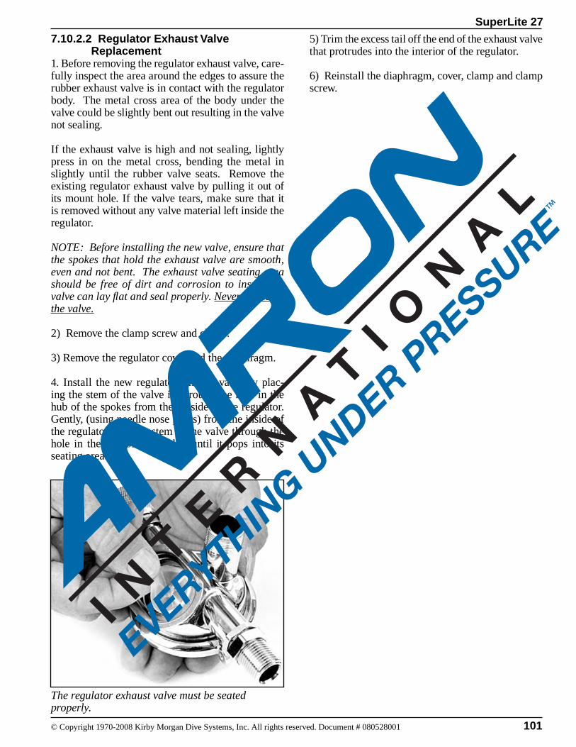
101
SuperLite 27
© Copyright 1970-2008 Kirby Morgan Dive Systems, Inc. All rights reserved. Document # 080528001
7.10.2.2 Regulator Exhaust Valve Replacement1. Before removing the regulator exhaust valve, care-fully inspect the area around the edges to assure the rubber exhaust valve is in contact with the regulator body. The metal cross area of the body under the valve could be slightly bent out resulting in the valve not sealing.
If the exhaust valve is high and not sealing, lightly press in on the metal cross, bending the metal in slightly until the rubber valve seats. Remove the existing regulator exhaust valve by pulling it out of its mount hole. If the valve tears, make sure that it is removed without any valve material left inside the regulator.
NOTE: Before installing the new valve, ensure that the spokes that hold the exhaust valve are smooth, even and not bent. The exhaust valve seating area should be free of dirt and corrosion to insure the valve can lay flat and seal properly. Never lubricate the valve.
2) Remove the clamp screw and clamp.
3) Remove the regulator cover and the diaphragm.
4. Install the new regulator exhaust valve by plac-ing the stem of the valve in through the hole in the hub of the spokes from the outside of the regulator. Gently, (using needle nose pliers) from the inside of the regulator, pull the stem of the valve through the hole in the hub of the spokes until it pops into its seating area.
5) Trim the excess tail off the end of the exhaust valve that protrudes into the interior of the regulator.
6) Reinstall the diaphragm, cover, clamp and clamp screw.
The regulator exhaust valve must be seated properly.
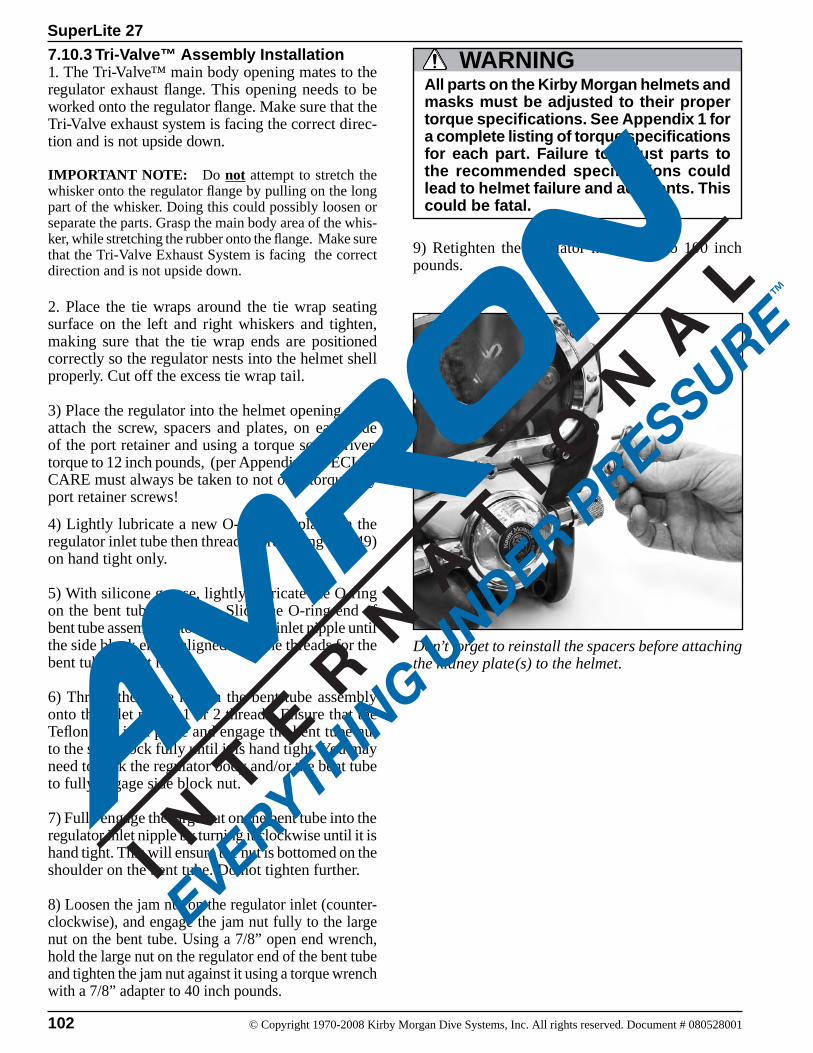
102 © Copyright 1970-2008 Kirby Morgan Dive Systems, Inc. All rights reserved. Document # 080528001
SuperLite 27
Don’t forget to reinstall the spacers before attaching the kidney plate(s) to the helmet.
4) Lightly lubricate a new O-ring and place on the regulator inlet tube then thread the retaining nut (49) on hand tight only.
5) With silicone grease, lightly lubricate the O-ring on the bent tube assembly. Slide the O-ring end of bent tube assembly into the regulator inlet nipple until the side block end is aligned with the threads for the bent tube mount nut.
6) Thread the large nut on the bent tube assembly onto the inlet nipple 1 or 2 threads. Ensure that the Teflon ring is in place and engage the bent tube nut to the side block fully until it is hand tight. You may need to rock the regulator body and/or the bent tube to fully engage side block nut.
7) Fully engage the large nut on the bent tube into the regulator inlet nipple by turning it clockwise until it is hand tight. This will ensure the nut is bottomed on the shoulder on the bent tube. Do not tighten further.
8) Loosen the jam nut on the regulator inlet (counter-clockwise), and engage the jam nut fully to the large nut on the bent tube. Using a 7/8” open end wrench, hold the large nut on the regulator end of the bent tube and tighten the jam nut against it using a torque wrench with a 7/8” adapter to 40 inch pounds.
9) Retighten the regulator mount nut to 100 inch pounds.
All parts on the Kirby Morgan helmets and masks must be adjusted to their proper torque specifications. See Appendix 1 for a complete listing of torque specifications for each part. Failure to adjust parts to the recommended specifications could lead to helmet failure and accidents. This could be fatal.
WARNING7.10.3 Tri-Valve™ Assembly Installation 1. The Tri-Valve™ main body opening mates to the regulator exhaust flange. This opening needs to be worked onto the regulator flange. Make sure that the Tri-Valve exhaust system is facing the correct direc-tion and is not upside down.
IMPORTANT NOTE: Do not attempt to stretch the whisker onto the regulator flange by pulling on the long part of the whisker. Doing this could possibly loosen or separate the parts. Grasp the main body area of the whis-ker, while stretching the rubber onto the flange. Make sure that the Tri-Valve Exhaust System is facing the correct direction and is not upside down.
2. Place the tie wraps around the tie wrap seating surface on the left and right whiskers and tighten, making sure that the tie wrap ends are positioned correctly so the regulator nests into the helmet shell properly. Cut off the excess tie wrap tail.
3) Place the regulator into the helmet opening, then attach the screw, spacers and plates, on each side of the port retainer and using a torque screwdriver, torque to 12 inch pounds, (per Appendix). SPECIAL CARE must always be taken to not over torque any port retainer screws!
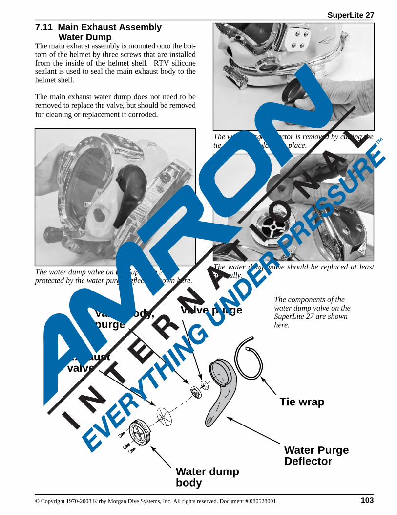
103
SuperLite 27
© Copyright 1970-2008 Kirby Morgan Dive Systems, Inc. All rights reserved. Document # 080528001
7.11 Main Exhaust Assembly Water DumpThe main exhaust assembly is mounted onto the bot-tom of the helmet by three screws that are installed from the inside of the helmet shell. RTV silicone sealant is used to seal the main exhaust body to the helmet shell.
The main exhaust water dump does not need to be removed to replace the valve, but should be removed for cleaning or replacement if corroded.
The water dump valve on the SuperLite 27 is protected by the water purge deflector shown here.
The water purge deflector is removed by cutting the tie wrap that holds it in place.
The water dump valve should be replaced at least annually.
Exhaustvalve
Water PurgeDeflector
Water dumpbody
Tie wrap
Valve body,purge
Valve purgeThe components of the water dump valve on the SuperLite 27 are shown here.
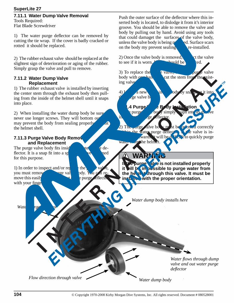
104 © Copyright 1970-2008 Kirby Morgan Dive Systems, Inc. All rights reserved. Document # 080528001
SuperLite 27
7.11.1 Water Dump Valve RemovalTools Required:Flat Blade Screwdriver
1) The water purge deflector can be removed by cutting the tie wrap. If the cover is badly cracked or rotted it should be replaced.
2) The rubber exhaust valve should be replaced at the slightest sign of deterioration or aging of the rubber. Simply grasp the valve and pull to remove.
7.11.2 Water Dump Valve Replacement1) The rubber exhaust valve is installed by inserting the center stem through the exhaust body then pull-ing from the inside of the helmet shell until it snaps into place.
2) When installing the water dump body be sure to never use longer screws. They will bottom out and may prevent the body from sealing properly against the helmet shell.
7.11.3 Purge Valve Body Removal and ReplacementThe purge valve body fits inside the water purge de-flector. It is a snap fit into a special groove designed for this purpose.
1) In order to inspect and/or replace the purge valve, you must remove the purge valve body. You can re-move this easily by prying it out of the purge deflector with your finger.
Push the outer surface of the deflector where this in-serted body is located, to dislodge it from it’s interior groove. You should be able to remove the valve and body by pulling out by hand. Avoid using any tools that could damaget the surfaces of the valve body, unless the valve body is being replaced. Surface scars on the body my prevent sealing when re-installed.
2) Once the valve body is removed, inspect the valve to see if it is worn. If so it should be replaced.
3) To replace the purge valve, hold the purge valve body with one hand and cut the stem from the exist-ing valve.
4) Install a new valve in the body by snapping it into the purge valve body.
7.11.4 Purge Valve Body Installation1) The purge valve body simply snaps into its groove in the water purge deflector.
2) The purge valve body must be oriented correctly within the water purge deflector. If the valve is in-stalled backwards, it will be difficult to quickly purge water from the helmet.
If the purge valve is not installed properly it will be impossible to purge water from the helmet through this valve. It must be installed with the proper orientation.
WARNING
Water purge deflector
Water dump body
Water dump body installs here
Flow direction through valve
Water flows through dump valve and out water purge deflector

105
SuperLite 27
© Copyright 1970-2008 Kirby Morgan Dive Systems, Inc. All rights reserved. Document # 080528001
7.11.5 Water Dump Valve Body Removal 1) The main exhaust body may need to be removed for cleaning or replacement if it has become corroded. A corroded main exhaust body may cause water to leak into the helmet.
If it is to be removed, you must first remove the three screws inside the helmet shell.
Prior to removal of the valve body, mark the helmet shell with a grease pencil so that the valve body is oriented properly, i.e., note the orientation of the slot on the top of the valve body. If the valve body is ori-ented improperly, the valve will not be able to dump water quickly.
After this is done, gently twist the valve body off of the helmet shell. A putty knife may be used to slide between the valve body and the shell to break the RTV sealant.
7.11.6 Water Dump Valve Body RemountingTools Required: 1/4 inch Flat Blade Attachment on Torque Screw-driverDow Corning® RTV 732 Multi Purpose sealant
1) Apply silicone sealant Dow Corning® RTV 732 Multi Purpose sealant to the base of the exhaust body. Take care not to block the opening for the main exhaust valve.
2) Position the water dump exhaust body on the helmet shell. Note orientation of body. Install the screws and using a torque screwdriver, Tighten the screws to (12 inch pounds) of torque. Wipe off any excess sealant.
3) Allow 24-hour cure time before using the helmet. Install the new valve.
sue. Read and follow all precautions listed on the silicone sealant tube.
WARNINGDo not breathe the fumes from uncured silicone sealant. These fumes are dangerous and can cause uncon-sciousness. They can also cause long term damage to body tis-
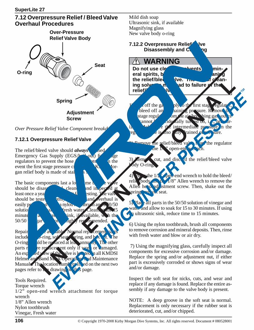
106 © Copyright 1970-2008 Kirby Morgan Dive Systems, Inc. All rights reserved. Document # 080528001
SuperLite 27
7.12 Overpressure Relief / Bleed Valve Overhaul Procedures
Over Pressure Relief Valve Component breakdown
7.12.1 Overpressure Relief Valve
The relief/bleed valve should always be used on all Emergency Gas Supply (EGS/bail-out) first stage regulators to prevent the hose from rupturing in the event the first stage pressure creeps. The Kirby Mor-gan relief body is made of stainless steel.
The basic components last a long time but the valve should be disassembled, cleaned, and inspected at least once a year or whenever it fails testing. The valve should be tested monthly. Cleaning and overhaul is easily performed using a nylon toothbrush and a 50/50 solution of vinegar and fresh water. Cleaning for 15 minutes in an ultrasonic sink, if available, with the 50/50 vinegar solution is highly recommended.
Repair parts are available. Normal replacement parts include the O-ring, soft seat, spring, and hex nut. The O-ring should be replaced at least annually. The other parts require replacement only if worn or damaged. An exploded view of the valve is located in all KMDSI Helmet and Band Mask Operations and Maintenance Manuals. The location numbers listed on the next two pages refer to the drawing on this page.
Tools Required.Torque wrench1/2” open-end wrench attachment for torque wrench1/8” Allen wrenchNylon toothbrushVinegar, Fresh water
Mild dish soapUltrasonic sink, if availableMagnifying glassNew valve body o-ring
7.12.2 Overpressure Relief Valve Disassembly and Cleaning
Do not use cleaning solvents (i.e. min-eral spirits, bleach, etc.) when cleaning the relief/bleed valve. The use of clean-ing solvents may lead to failure of the relief/bleed valve.
WARNING
1) Turn off the gas supply to the first stage regulator, then bleed off any remaining pressure. Remove the first stage regulator from the air/breathing gas source so it cannot be accidentally turned on, i.e., pressur-ized. Make sure the intermediate pressure in the regulator hose is also fully drained of pressure.
2) Remove the relief/bleed valve from the regulator body using the 1/2” open-end wrench.
3) Remove, cut, and discard the relief/bleed valve body O-ring.
4) Using the 1/2” open-end wrench to hold the bleed/ relief body, use the 1/8” Allen wrench to remove the Allen head adjustment screw. Then, shake out the spring and soft seat.
5) Place all parts in the 50/50 solution of vinegar and water and allow to soak for 15 to 30 minutes. If using an ultrasonic sink, reduce time to 15 minutes.
6) Using the nylon toothbrush, brush all components to remove corrosion and mineral deposits. Then, rinse with fresh water and blow or air dry.
7) Using the magnifying glass, carefully inspect all components for excessive corrosion and/or damage. Replace the spring and/or adjustment nut, if either part is excessively corroded or shows signs of wear and/or damage.
Inspect the soft seat for nicks, cuts, and wear and replace if any damage is found. Replace the entire as-sembly if any damage to the valve body is present.
NOTE: A deep groove in the soft seat is normal. Replacement is only necessary if the rubber seat is deteriorated, cut, and/or chipped.
O-ring
Over-PressureRelief Valve Body
Seat
Spring
AdjustmentScrew

107
SuperLite 27
© Copyright 1970-2008 Kirby Morgan Dive Systems, Inc. All rights reserved. Document # 080528001
7.12.3 Overpressure Relief Valve Reassembly1) After cleaning, inspection and/or parts replace-ment, reassemble the valve by installing the soft seat, spring, and adjustment nut. Screw the adjustment nut down until it is approximately 1/2 thread from being flush with the top of the valve body.
2) Lightly lubricate a new body O-ring, then install on the valve body.
3) Test the relief/bleed valve according to the test procedure below.
7.12.4 Overpressure Relief Valve Lift Check/SettingTools required:Adjustable first stage scuba regulator or controlled adjustable pressure source Intermediate pressure test gaugeTorque wrench1/2” open-end wrench adapter for torque wrench1/8” Allen wrenchHP air source {SCUBA tank) with at least 500 p.s.i.g. (34.4 bar).Mild dish soap
The purpose of lift checking the relief/bleed valve is to ensure it operates properly, allowing excess pressure to escape in the event the first stage develops a slight leak. Without the relief/bleed valve, high-pressure gas will continue to increase until the emergency supply hose ruptures, possibly causing injury and a complete loss of the Emergency Gas System (EGS).
This procedure explains the steps necessary for readjust-ing the relief/bleed valve after it is cleaned, overhauled or any time the valve is tested.
Ensure the relief/bleed valve is only installed in a low-pressure port of the first stage regulator. Installation in a high-pressure port will lead to
loss of EGS supply and possible serious personal injury if the valve fails.
WARNING
Do not use oxygen, or mixed gas containing more than 23% oxygen by volume, for lift checking the relief/bleed valve. The use of oxygen, or mixed gas, in a high-pressure
supply system not designed and cleaned for oxygen service, can result in a fire or explosion causing serious injury or death.
WARNING
NOTE: The relief/bleed valve is lift checked and/or adjusted using an adjustable first stage regulator, equipped with a low-pressure test gauge, which is used for adjusting the intermediate pressure of scuba regulators. The check/adjustment can be performed using a standard scuba test stand, or a gas control console, using air or mixed gas with an oxygen content below 23% by volume.
If a first stage scuba regulator is used, it must be able to be adjusted to the desired lifting pressure. The pressure gauge should be compared to a gauge of known accuracy.
NOTE: If the Allen screw on the relief/bleed valve hex nut is rotated too far, too fast, the relief/bleed valve will pop open. This could possibly require the air to be secured at the cylinder or supply source to reset the seat before the adjustment can be accomplished.
NOTE: The relief/bleed valve can be installed in any first stage regulator, providing the first stage has an intermediate setting of 135 - 165 p.s.i.g. (9.3 – 11.4 bar).
1) Install the relief valve in a low-pressure port on an adjustable 1st stage regulator. Or install on the scuba test stand.
2) Install the intermediate pressure gauge in one of the low-pressure ports of the first stage regulator.
3) Install the 1st stage regulator on the cylinder. En-sure the relief valve and intermediate pressure gauge are attached to low-pressure ports.
4) Wet the relief valve with soapy water to help in-dicate gas flow
5) Slowly bring up air pressure while watching the intermediate pressure gauge until the pressure gauge indicates 180- 200 p.s.i.g. (12.40-13.78 bar). If the
108 © Copyright 1970-2008 Kirby Morgan Dive Systems, Inc. All rights reserved. Document # 080528001
SuperLite 27
relief valve starts venting at a pressure below 180- 200 p.s.i.g. (12.40-13.78 bar), secure the air supply and adjust the adjustment screw (1) in (clockwise) 1/8th turn. Slowly bring up pressure and recheck.
Continue this procedure as necessary until the relief valve consistently vents at a pressure between 180- 200 p.s.i.g. (12.40-13.78 bar). If the valve does not start venting when the gauge reads 200 p.s.i.g. (13.78 bar), slowly back out on the adjustment screw (coun-ter clockwise) until the valve starts venting, forming bubbles in the soap solution.
6) After the valve has been adjusted, adjust the 1st stage regulator intermediate setting to 135 p.s.i.g. (9.3 bar), re-wet the valve, then slowly increase the intermediate pressure on the 1st stage regulator one last time to recheck the lift pressure. The valve should start forming bubbles or venting at between 180- 200 p.s.i.g. (12.40-13.78 bar).
7) After final lift check reset the regulator to the ap-propriate over bottom setting. Remove the intermedi-ate pressure gauge.
TROUBLESHOOTINGProblem: Valve pops open and will not stop flow-ing:
Check: If while setting the relief/bleed valve the valve pops open and will not stop flowing, secure the air supply valve and allow the valve to reseat. Try the procedure again, ensuring that the supply valve is only slightly cracked open, allowing full test pressure but minimizing high flow potential.
Problem: After resetting the first stage to 135 p.s.i.g. (9.3 bar), the valve continues to leak:
Check: This indicates the valve body, seating surface or the soft seat is either dirty or damaged. Usually, cleaning both the metal body, seating surface in the valve body and the soft seat will fix the problem. If, after cleaning, the problem persists, replace the soft seat and spring and retest the unit. If the seat continues to leak, then replacement of the complete valve will be necessary. The purpose of lift checking the valve is to ensure the relief operates properly allowing excess pressure to escape in the event the first stage develops a slight leak. This procedure also explains the steps necessary for readjusting after cleaning or overhaul. pressure port. Installation in a high
109© Copyright 1970-2008 Kirby Morgan Dive Systems, Inc. All rights reserved. Document # 080528001
SuperLite 27
8.1 GeneralThis section covers the maintenance and repair of all non-breathing system components of the SuperLite 27 Diver’s Helmet. Correct repairs will result in better communications and improved overall diver comfort and performance in getting the job done. Numbers appearing in parentheses below are “loca-tion” numbers that are used in the blowapart draw-ing at the rear of this manual.
Chapter 8Corrective Maintenance
Use only KMDSI original replacement spares when repairing your helmet. The use of other manufacturer’s parts will in-terfere with the performance character-istics of your life support equipment and may jeopardize your safety. Additionally, any substitutions will void all warranties offered by KMDSI.
WARNING
All the spare parts in our catalog were specifically manufactured (or inspected and tested) for Kirby Morgan designed helmets and masks. When ordering spares, insist on KMDSI original parts.
All parts on Kirby Morgan masks and helmets must be adjusted to their prop-er torque specifications. See Appendix 1 for a complete listing of torque speci-fications for each part. Failure to adjust parts to the recommended specifica-tions could lead to helmet failure and accidents. This could be fatal.
WARNING
NOTE: For O-ring Removal/Inspection/Cleaning & Installation see Section 6.3.1. For General Clean-ing Guidelines, including KMDSI recommended cleaning, sanitizing solutions, and procedures, see Section 6.3.
8.2 Helmet Shell InspectionThe helmet shell is constructed using hand laid fi-berglass cloth, carbon fiber, mat, and strands, im-pregnated with polyester resin. It is extremely du-rable but can be damaged.
Helmets that have suffered damage can often be re-paired, but repairs to the helmet shell must only be accomplished by KMDSI technicians that have been trained and certified in fiberglass repair by KMDSI. Many Kirby Morgan fiberglass helmets and masks still in use today are more than 30 years old.
1) Visually inspect the helmet shell exterior for ob-vious signs of fiberglass damage including cracks, gouges or depressions.
NOTE: All gouges and scrapes should be covered with tape or paint to reduce absorbtion of moisture in the fiberglass until repairs can be made. The hel-met should not be used if it has any gouges deep-er than 1/8 inch. Fiberglass and gel coat repairs should only be completed by a KMDSI trained and certified repair technician that has received certifi-cation for helmet shell repairs by KMDSI or Dive Lab Inc. Any signs of cracks or depressions with fractures or other damage should be checked by an authorized KMDSI repair facility or a technician certified in fiberglass repair by KMDSI.
Do not attempt to install new thread in-serts in the helmet shell for the port retain-er screws by yourself. If the installation is done improperly, the port retainer can come loose and the helmet could flood resulting in drowning. Fiberglass and insert repairs should be only be completed by technicians specifically trained and certified in these procedures.
WARNING
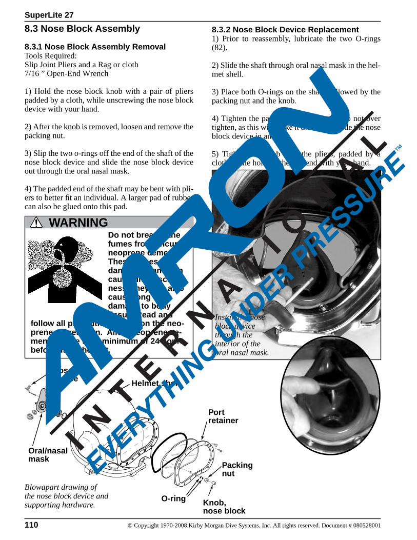
110 © Copyright 1970-2008 Kirby Morgan Dive Systems, Inc. All rights reserved. Document # 080528001
SuperLite 27
Nose blockdevice
Oral/nasalmask
Helmet shell
Knob,nose block
Packingnut
Portretainer
O-ring
8.3 Nose Block Assembly
8.3.1 Nose Block Assembly RemovalTools Required:Slip Joint Pliers and a Rag or cloth7/16 ” Open-End Wrench
1) Hold the nose block knob with a pair of pliers padded by a cloth, while unscrewing the nose block device with your hand.
2) After the knob is removed, loosen and remove the packing nut.
3) Slip the two o-rings off the end of the shaft of the nose block device and slide the nose block device out through the oral nasal mask.
4) The padded end of the shaft may be bent with pli-ers to better fit an individual. A larger pad of rubber can also be glued onto this pad.
Install the nose block device through the interior of the oral nasal mask.
8.3.2 Nose Block Device Replacement1) Prior to reassembly, lubricate the two O-rings (82).
2) Slide the shaft through oral nasal mask in the hel-met shell.
3) Place both O-rings on the shaft, followed by the packing nut and the knob.
4) Tighten the packing nut until snug. Do not over tighten, as this will make it difficult to slide the nose block device in and out.
5) Tighten the knob with the pliers, padded by a cloth, while holding the pad end with your hand.
Blowapart drawing of the nose block device and supporting hardware.
Do not breathe the fumes from uncured neoprene cement. These fumes are dangerous and can cause unconscious-ness. They can also cause long term damage to body tissue. Read and
WARNING
follow all precautions listed on the neo-prene cement can. Allow neoprene ce-ment to cure for a minimum of 24 hours before using helmet.
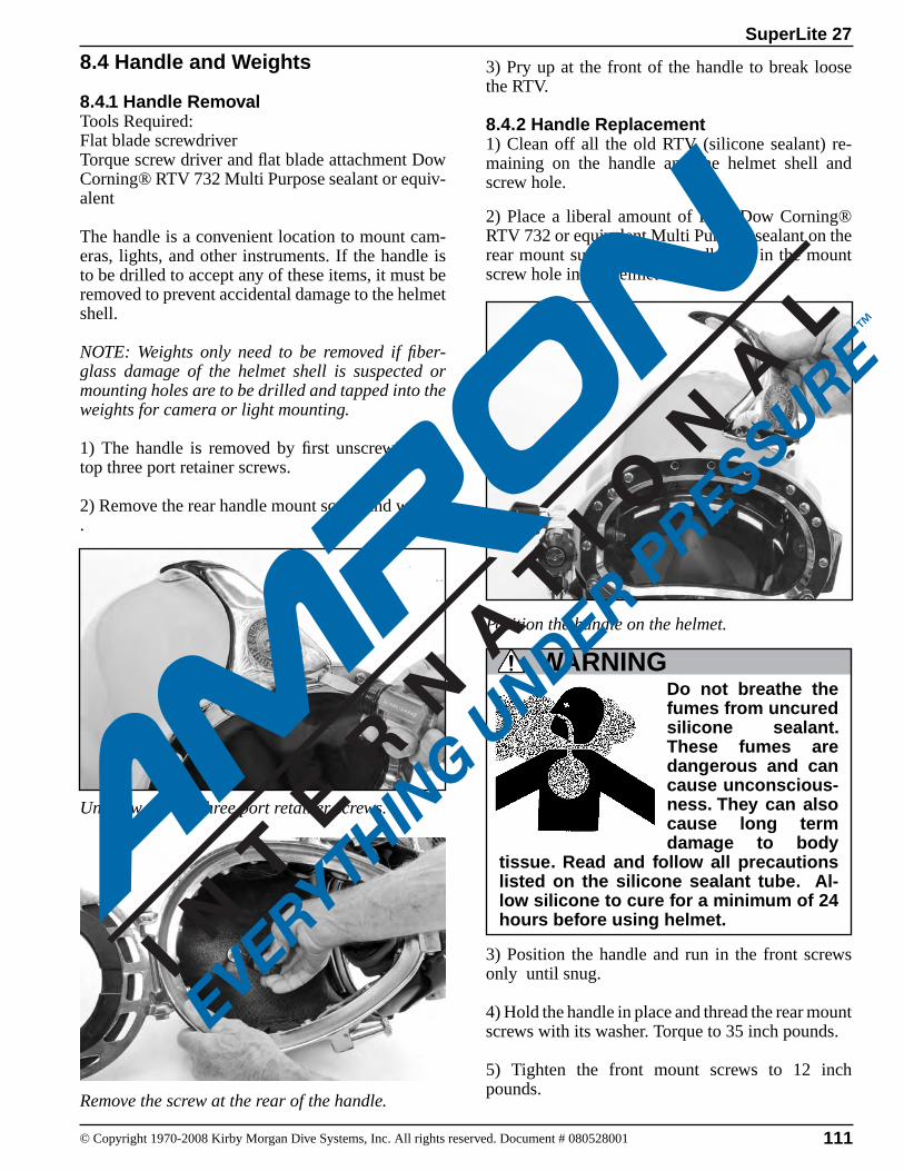
111© Copyright 1970-2008 Kirby Morgan Dive Systems, Inc. All rights reserved. Document # 080528001
SuperLite 27
8.4 Handle and Weights
8.4.1 Handle Removal Tools Required:Flat blade screwdriverTorque screw driver and flat blade attachment Dow Corning® RTV 732 Multi Purpose sealant or equiv-alent
The handle is a convenient location to mount cam-eras, lights, and other instruments. If the handle is to be drilled to accept any of these items, it must be removed to prevent accidental damage to the helmet shell.
NOTE: Weights only need to be removed if fiber-glass damage of the helmet shell is suspected or mounting holes are to be drilled and tapped into the weights for camera or light mounting.
1) The handle is removed by first unscrewing the top three port retainer screws.
2) Remove the rear handle mount screw and washer .
Unscrew the top three port retainer screws.
Position the handle on the helmet.
3) Pry up at the front of the handle to break loose the RTV.
8.4.2 Handle Replacement1) Clean off all the old RTV (silicone sealant) re-maining on the handle and the helmet shell and screw hole.
2) Place a liberal amount of RTV Dow Corning® RTV 732 or equivalent Multi Purpose sealant on the rear mount surface of the handle and in the mount screw hole in the helmet shell.
Remove the screw at the rear of the handle.
WARNINGDo not breathe the fumes from uncured silicone sealant. These fumes are dangerous and can cause unconscious-ness. They can also cause long term damage to body
tissue. Read and follow all precautions listed on the silicone sealant tube. Al-low silicone to cure for a minimum of 24 hours before using helmet.
3) Position the handle and run in the front screws only until snug.
4) Hold the handle in place and thread the rear mount screws with its washer. Torque to 35 inch pounds.
5) Tighten the front mount screws to 12 inch pounds.
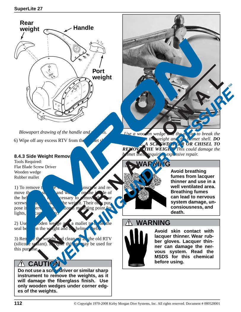
112 © Copyright 1970-2008 Kirby Morgan Dive Systems, Inc. All rights reserved. Document # 080528001
SuperLite 27
8.4.3 Side Weight RemovalTools Required:Flat Blade Screw DriverWooden wedgeRubber mallet
1) To remove the side weight, first unscrew and re-move the two screws and washers on the inside of the helmet. It is not necessary to remove the four screws on the outside of the weight. Their only pur-pose is to serve as an additional mounting point for lights, TV cameras, etc.
2) Use a wooden wedge and a mallet to break the seal between the weight and the helmet shell.
3) Remove the weight and clean off all the old RTV (silicone sealant). Lacquer thinner may be used for this purpose.
Use a wooden wedge and the mallet to break the seal between the weight and the helmet shell. DO NOT USE A SCREWDRIVER OR CHISEL TO REMOVE THE WEIGHT. This could damage the helmet shell, requiring expensive repair.
Do not use a screwdriver or similar sharp instrument to remove the weights, as it will damage the fiberglass finish. Use only wooden wedges under corner edg-es of the weights.
CAUTION
Blowapart drawing of the handle and weights.
6) Wipe off any excess RTV from the helmet shell.
Avoid breathing fumes from lacquer thinner and use in a well ventilated area. Breathing fumes can lead to nervous system damage, un-consiousness, and death.
WARNING
WARNINGAvoid skin contact with lacquer thinner. Wear rub-ber gloves. Lacquer thin-ner can damage the ner-vous system. Read the MSDS for this chemical before using.
Rear weight
Port weight
Handle
113© Copyright 1970-2008 Kirby Morgan Dive Systems, Inc. All rights reserved. Document # 080528001
SuperLite 27
8.4.4 Weight Replacement1) Apply silicone sealant to the the sides and top of the weight, leaving the bottom open. Be sure to apply sealant to the holes where the screws attach to the weight.
2) Thread the screws and washers into the weight. Tighten securely.
3) Wipe off any excess silicone sealant.
Do not breathe the fumes from uncured silicone sealant. These fumes are dangerous and can cause unconscious-ness. They can also cause long term damage to body
WARNING
tissue. Read and follow all precautions listed on the silicone sealant tube. Al-low silicone to cure for a minimum of 24 hours before using helmet.
8.4.5 Diamond Weight Removal Tools Required:Flat Blade Torque ScrewdriverRubber MalletWooden Wedge
The diamond weight is an optional weight.
1) To remove the diamond weight, first unscrew and remove the two screws and washers on the inside of the helmet.
2) Use a wooden wedge and a mallet to break the seal between the weight and the helmet shell.
3) Remove the weight and clean off all the old RTV (silicone sealant).
8.4.6 Diamond Weight Replacement1) Apply silicone sealant to the back side of the weight. Be sure to apply sealant to the holes where the screws attach to the weight.
2) Position the weight on the helmet shell.
2) Thread the screws and washers into the weight. Tighten securely.
3) Wipe off any excess silicone sealant.
Avoid eye contact with lac-quer thinner. This chemical is an irritant and may cause tissue damage.
WARNING
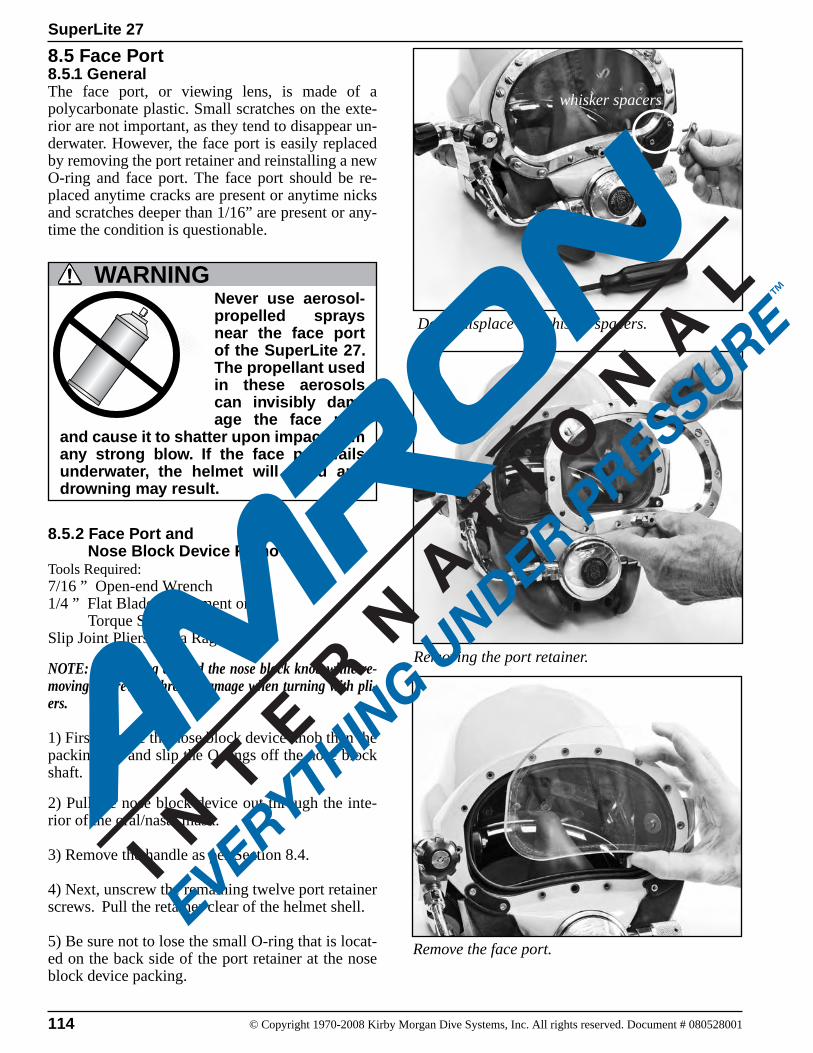
114 © Copyright 1970-2008 Kirby Morgan Dive Systems, Inc. All rights reserved. Document # 080528001
SuperLite 27
Removing the port retainer.
8.5 Face Port8.5.1 GeneralThe face port, or viewing lens, is made of a polycarbonate plastic. Small scratches on the exte-rior are not important, as they tend to disappear un-derwater. However, the face port is easily replaced by removing the port retainer and reinstalling a new O-ring and face port. The face port should be re-placed anytime cracks are present or anytime nicks and scratches deeper than 1/16” are present or any-time the condition is questionable.
Never use aerosol-propelled sprays near the face port of the SuperLite 27. The propellant used in these aerosols can invisibly dam-age the face port
and cause it to shatter upon impact from any strong blow. If the face port fails underwater, the helmet will flood and drowning may result.
WARNING
8.5.2 Face Port and Nose Block Device RemovalTools Required:7/16 ” Open-end Wrench1/4 ” Flat Blade Attachment on Torque Screwdriver Slip Joint Pliers and a Rag or cloth
NOTE: Wrap a rag around the nose block knob while re-moving to prevent chrome damage when turning with pli-ers.
1) First remove the nose block device knob then the packing nut and slip the O-rings off the nose block shaft.
2) Pull the nose block device out through the inte-rior of the oral/nasal mask.
3) Remove the handle as per Section 8.4.
4) Next, unscrew the remaining twelve port retainer screws. Pull the retainer clear of the helmet shell.
5) Be sure not to lose the small O-ring that is locat-ed on the back side of the port retainer at the nose block device packing.
Remove the face port.
Don't misplace the whisker spacers.
whisker spacers
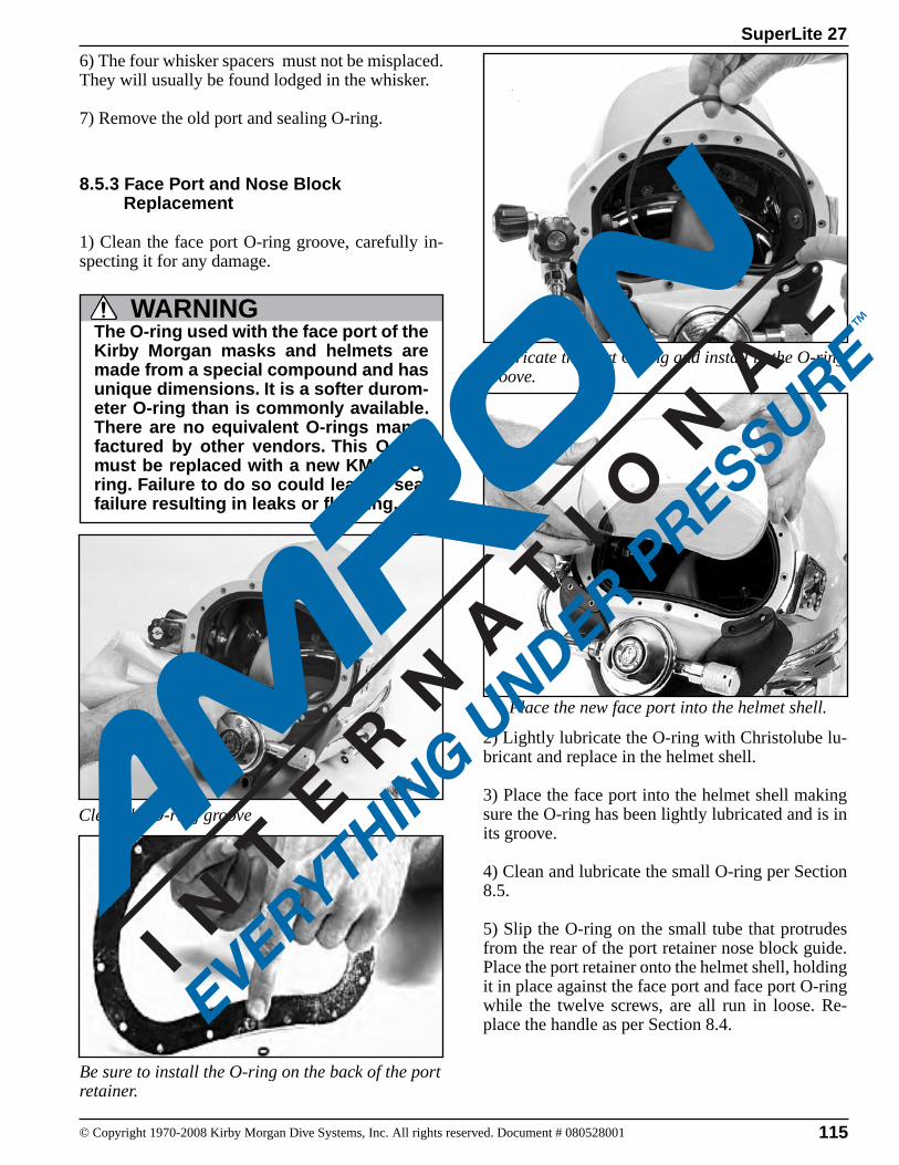
115© Copyright 1970-2008 Kirby Morgan Dive Systems, Inc. All rights reserved. Document # 080528001
SuperLite 27
Be sure to install the O-ring on the back of the port retainer.
Clean the O-ring groove
6) The four whisker spacers must not be misplaced. They will usually be found lodged in the whisker.
7) Remove the old port and sealing O-ring.
8.5.3 Face Port and Nose Block Replacement
1) Clean the face port O-ring groove, carefully in-specting it for any damage.
The O-ring used with the face port of the Kirby Morgan masks and helmets are made from a special compound and has unique dimensions. It is a softer durom-eter O-ring than is commonly available. There are no equivalent O-rings manu-factured by other vendors. This O-ring must be replaced with a new KMDSI O-ring. Failure to do so could lead to seal failure resulting in leaks or flooding.
WARNING
2) Lightly lubricate the O-ring with Christolube lu-bricant and replace in the helmet shell.
3) Place the face port into the helmet shell making sure the O-ring has been lightly lubricated and is in its groove.
4) Clean and lubricate the small O-ring per Section 8.5.
5) Slip the O-ring on the small tube that protrudes from the rear of the port retainer nose block guide. Place the port retainer onto the helmet shell, holding it in place against the face port and face port O-ring while the twelve screws, are all run in loose. Re-place the handle as per Section 8.4.
Lubricate the port O-ring and install in the O-ring groove.
Place the new face port into the helmet shell.
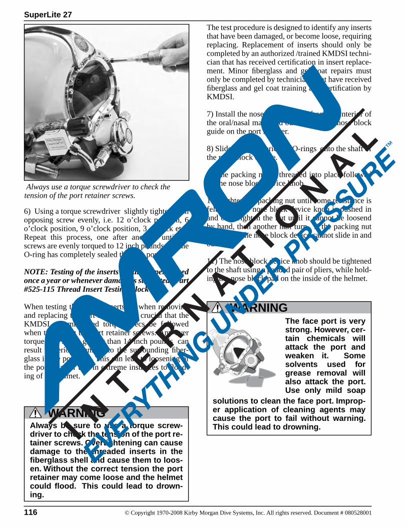
116 © Copyright 1970-2008 Kirby Morgan Dive Systems, Inc. All rights reserved. Document # 080528001
SuperLite 27
Always be sure to use a torque screw-driver to check the tension of the port re-tainer screws. Overtightening can cause damage to the threaded inserts in the fiberglass shell and cause them to loos-en. Without the correct tension the port retainer may come loose and the helmet could flood. This could lead to drown-ing.
WARNING
6) Using a torque screwdriver slightly tighten each opposing screw evenly, i.e. 12 o’clock position, 6 o’clock position, 9 o’clock position, 3 o’clock etc.. Repeat this process, one after another, until all screws are evenly torqued to 12 inch pounds and the O-ring has completely sealed the face port.
NOTE: Testing of the inserts should be performed once a year or whenever damage is suspected. Part #525-115 Thread Insert Testing Block Kit.
When testing the thread inserts, or when removing and replacing the port retainer, it is crucial that the KMDSI recommended torque specs be followed when tightening the port retainer screws. Any over torque of a screw greater than 14 inch pounds can result in serious damage to the surrounding fiber-glass in the port area. This can lead to loosening of the port retainer and in extreme instances to flood-ing of the helmet.
The test procedure is designed to identify any inserts that have been damaged, or become loose, requiring replacing. Replacement of inserts should only be completed by an authorized /trained KMDSI techni-cian that has received certification in insert replace-ment. Minor fiberglass and gel coat repairs must only be completed by technicians that have received fiberglass and gel coat training and certification by KMDSI.
7) Install the nose block device from the interior of the oral/nasal mask and out through the nose block guide on the port retainer.
8) Slide the two lubricated O-rings onto the shaft of the nose block device.
9) The packing nut is threaded into place followed by the nose block device knob.
10) Tighten the packing nut until some resistance is felt when the nose block device knob is pushed in and out. Tighten the nut until it cannot be loosend by hand, then another half turn. If the packing nut is too tight the nose block device cannot slide in and out.
11) The nose block device knob should be tightened to the shaft using a padded pair of pliers, while hold-ing the nose block pad on the inside of the helmet.
The face port is very strong. However, cer-tain chemicals will attack the port and weaken it. Some solvents used for grease removal will also attack the port. Use only mild soap
WARNING
solutions to clean the face port. Improp-er application of cleaning agents may cause the port to fail without warning. This could lead to drowning.
Always use a torque screwdriver to check the tension of the port retainer screws.
117© Copyright 1970-2008 Kirby Morgan Dive Systems, Inc. All rights reserved. Document # 080528001
SuperLite 27
The face port for all Kirby Morgan helmets and KMB 28 mask are not interchange-able. Do not attempt to use a face port from a KMB 28 in a Kirby Morgan helmet. Although the port will fit into the helmet shell, it will not seal properly. This could lead to flooding of the helmet, resulting in serious personal injury or death.
WARNING
Use only genuine KMDSI face ports. An aftermarket face port’s thickness or outer periphery may be incorrect and cause the helmet to flood. It could also be made of inferior materials causing it to fail. This could result in serious injury or death.
WARNING8.5.4 Special Note Regarding Ports
NOTE: There are two different face ports available for KMDSI helmets and masks. One port specifically fits the SuperLite 27 helmets and the KMB 18. One port only fits the KMB 28 Band Mask. These two ports are not interchangeable. The face port for the SuperLite-17A/B the SuperLite-17K, SuperLite-27, SL-17C and the KMB 18 Band mask is Part #520-004. The face port for the KMB 28 Band Mask is Part #520-128.
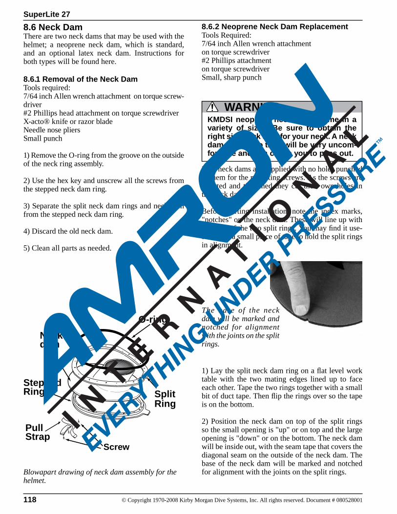
118 © Copyright 1970-2008 Kirby Morgan Dive Systems, Inc. All rights reserved. Document # 080528001
SuperLite 27
The base of the neck dam will be marked and notched for alignment with the joints on the split rings.
8.6 Neck Dam There are two neck dams that may be used with the helmet; a neoprene neck dam, which is standard, and an optional latex neck dam. Instructions for both types will be found here.
8.6.1 Removal of the Neck DamTools required:7/64 inch Allen wrench attachment on torque screw-driver#2 Phillips head attachment on torque screwdriverX-acto® knife or razor bladeNeedle nose pliersSmall punch
1) Remove the O-ring from the groove on the outside of the neck ring assembly.
2) Use the hex key and unscrew all the screws from the stepped neck dam ring.
3) Separate the split neck dam rings and neck dam from the stepped neck dam ring.
4) Discard the old neck dam.
5) Clean all parts as needed.
Blowapart drawing of neck dam assembly for the helmet.
8.6.2 Neoprene Neck Dam Replacement Tools Required:7/64 inch Allen wrench attachment on torque screwdriver#2 Phillips attachment on torque screwdriverSmall, sharp punch
KMDSI neoprene neck dams come in a variety of sizes. Be sure to obtain the right size neck dam for your neck. A neck dam that is too tight will be very uncom-fortable and can cause you to pass out.
WARNING
New neck dams are supplied with no holes punched in them for the mounting screws. As the screws are inserted and tightened they cut their own holes in the neck dam.
Before starting installation, note the index marks, "notches" on the neck dam. These will line up with the ends of the two split rings. You may find it use-ful to use a small piece of tape to hold the split rings in alignment.
1) Lay the split neck dam ring on a flat level work table with the two mating edges lined up to face each other. Tape the two rings together with a small bit of duct tape. Then flip the rings over so the tape is on the bottom.
2) Position the neck dam on top of the split rings so the small opening is "up" or on top and the large opening is "down" or on the bottom. The neck dam will be inside out, with the seam tape that covers the diagonal seam on the outside of the neck dam. The base of the neck dam will be marked and notched for alignment with the joints on the split rings.
O-ring
Split Ring
Neck dam
SteppedRing
PullStrap
Screw
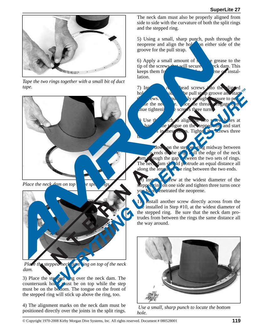
119© Copyright 1970-2008 Kirby Morgan Dive Systems, Inc. All rights reserved. Document # 080528001
SuperLite 27
Place the stepped neck dam ring on top of the neck dam.
Tape the two rings together with a small bit of duct tape.
Place the neck dam on top of the split rings.
Use a small, sharp punch to locate the bottom hole.
3) Place the stepped ring over the neck dam. The countersunk holes must be on top while the step must be on the bottom. The tongue on the front of the stepped ring will stick up above the ring, too.
4) The alignment marks on the neck dam must be positioned directly over the joints in the split rings.
The neck dam must also be properly aligned from side to side with the curvature of both the split rings and the stepped ring.
5) Using a small, sharp punch, push through the neoprene and align the holes on either side of the groove for the pull strap.
6) Apply a small amount of silicone grease to the tip of the screws that will secure the neck dam. This keeps them from binding in the neoprene on instal-lation.
7) Insert the Allen head screws into the aligned holes on either side of the pull strap groove and start the screws. You must apply enough pressure to pen-etrate the neoprene. Once the threads engage con-tinue tightening the screws three turns.
8) Use the punch to align the two screw holes at the base of the tongue on the stepped ring and start the screws in these holes. Tighten the screws three turns.
9) Press down on the stepped ring midway between the two ends of the ring. Pull the edge of the neck dam through the gap between the two sets of rings. The neck dam should protrude an equal distance all along the length of the ring between the two ends.
10) Install a screw at the widest diameter of the stepped ring on one side and tighten three turns once you have penetrated the neoprene.
11) Install another screw directly across from the one installed in Step #10, at the widest diameter of the stepped ring. Be sure that the neck dam pro-trudes from between the rings the same distance all the way around.
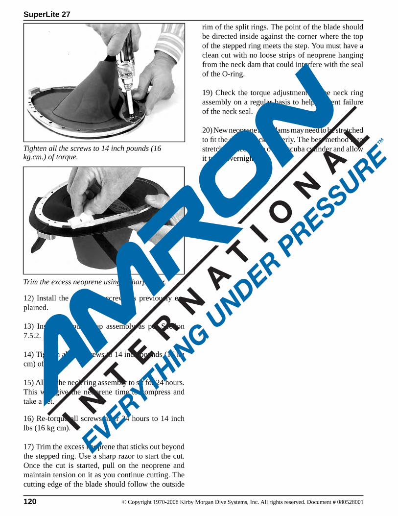
120 © Copyright 1970-2008 Kirby Morgan Dive Systems, Inc. All rights reserved. Document # 080528001
SuperLite 27
Tighten all the screws to 14 inch pounds (16 kg.cm.) of torque.
Trim the excess neoprene using a sharp razor.
12) Install the remaining screws as previously ex-plained.
13) Install the pull strap assembly as per Section 7.5.2.
14) Tighten all the screws to 14 inch pounds (16 kg cm) of torque.
15) Allow the neck ring assembly to sit for 24 hours. This will give the neoprene time to compress and take a set.
16) Re-torque all screws after 24 hours to 14 inch lbs (16 kg cm).
17) Trim the excess neoprene that sticks out beyond the stepped ring. Use a sharp razor to start the cut. Once the cut is started, pull on the neoprene and maintain tension on it as you continue cutting. The cutting edge of the blade should follow the outside
rim of the split rings. The point of the blade should be directed inside against the corner where the top of the stepped ring meets the step. You must have a clean cut with no loose strips of neoprene hanging from the neck dam that could interfere with the seal of the O-ring.
19) Check the torque adjustment on the neck ring assembly on a regular basis to help prevent failure of the neck seal.
20) New neoprene neck dams may need to be stretched to fit the diver's neck properly. The best method is to stretch the neck dam over a scuba cylinder and allow it to sit overnight.
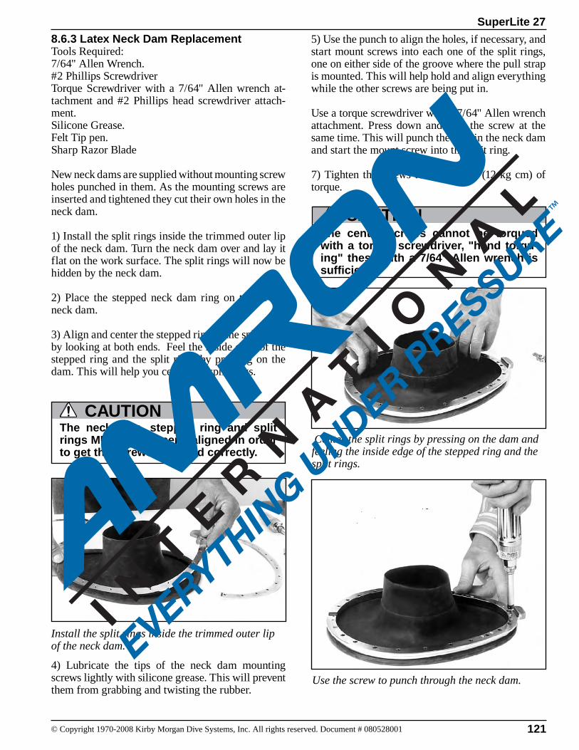
121© Copyright 1970-2008 Kirby Morgan Dive Systems, Inc. All rights reserved. Document # 080528001
SuperLite 27
8.6.3 Latex Neck Dam ReplacementTools Required:7/64" Allen Wrench.#2 Phillips ScrewdriverTorque Screwdriver with a 7/64" Allen wrench at-tachment and #2 Phillips head screwdriver attach-ment.Silicone Grease.Felt Tip pen.Sharp Razor Blade
New neck dams are supplied without mounting screw holes punched in them. As the mounting screws are inserted and tightened they cut their own holes in the neck dam.
1) Install the split rings inside the trimmed outer lip of the neck dam. Turn the neck dam over and lay it flat on the work surface. The split rings will now be hidden by the neck dam.
2) Place the stepped neck dam ring on top of the neck dam.
3) Align and center the stepped ring to the split rings by looking at both ends. Feel the inside edge of the stepped ring and the split rings by pressing on the dam. This will help you center the split rings.
4) Lubricate the tips of the neck dam mounting screws lightly with silicone grease. This will prevent them from grabbing and twisting the rubber.
Center the split rings by pressing on the dam and feeling the inside edge of the stepped ring and the split rings.
Install the split rings inside the trimmed outer lip of the neck dam.
The neck dam, stepped ring and split rings MUST be properly aligned in order to get the screws to thread correctly.
CAUTION
The center screws cannot be torqued with a torque screwdriver, "hand torqu-ing" these with a 7/64" Allen wrench is sufficient.
CAUTION
5) Use the punch to align the holes, if necessary, and start mount screws into each one of the split rings, one on either side of the groove where the pull strap is mounted. This will help hold and align everything while the other screws are being put in.
Use a torque screwdriver with a 7/64" Allen wrench attachment. Press down and turn the screw at the same time. This will punch the hole in the neck dam and start the mount screw into the split ring.
7) Tighten the screws to 10 inch lbs (12 kg cm) of torque.
Use the screw to punch through the neck dam.
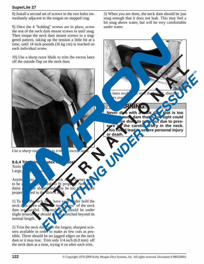
122 © Copyright 1970-2008 Kirby Morgan Dive Systems, Inc. All rights reserved. Document # 080528001
SuperLite 27
8.6.4 Trimming a Latex Neck SealTools Required:Large, sharp scissors
Anytime you replace the neck dam, it may need to be adjusted (trimmed) to fit properly. New neck dams are cone shaped and may be too tight if not properly fitted to the diver's neck.
1) To trim the neck dam, have your tender hold the neck dam open so that the two "edges" of the neck dam are parallel. The neck dam should be under slight tension but should not be stretched beyond its normal length.
2) Trim the neck dam with the largest, sharpest scis-sors available in order to make as few cuts as pos-sible. There should be no jagged edges on the neck dam or it may tear. Trim only 1/4 inch (6.0 mm) off the neck dam at a time, trying it on after each trim.
Trim latex neck dams with the largest, sharpest scissors available.
Never dive with a neck dam that is too tight. A neck dam that is too tight could cause the diver to pass out due to pres-sure on the carotid artery in the neck. This could lead to severe personal injury or death.
WARNING
Use a sharp razor blade to trim the excess latex.
8) Install a second set of screws in the two holes im-mediately adjacent to the tongue on stepped ring.
9) Once the 4 "holding" screws are in place, screw the rest of the neck dam mount screws in until snug. Then torque the neck dam mount screws in a stag-gered pattern, taking up the tension a little bit at a time, until 14 inch pounds (16 kg cm) is reached on each individual screw.
10) Use a sharp razor blade to trim the excess latex off the outside flap on the neck dam.
3) When you are done, the neck dam should be just snug enough that it does not leak. This may feel a bit snug above water, but will be very comfortable under water.
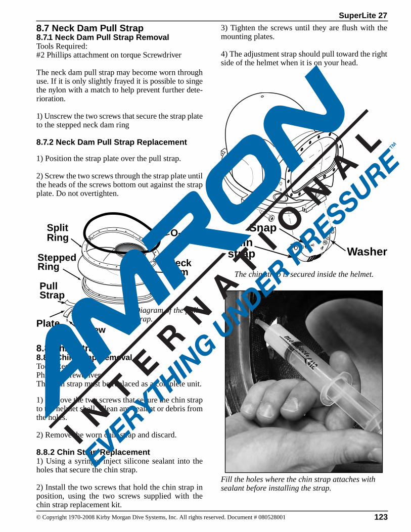
123© Copyright 1970-2008 Kirby Morgan Dive Systems, Inc. All rights reserved. Document # 080528001
SuperLite 27
8.7 Neck Dam Pull Strap8.7.1 Neck Dam Pull Strap RemovalTools Required:#2 Phillips attachment on torque Screwdriver
The neck dam pull strap may become worn through use. If it is only slightly frayed it is possible to singe the nylon with a match to help prevent further dete-rioration.
1) Unscrew the two screws that secure the strap plate to the stepped neck dam ring
8.7.2 Neck Dam Pull Strap Replacement
1) Position the strap plate over the pull strap.
2) Screw the two screws through the strap plate until the heads of the screws bottom out against the strap plate. Do not overtighten.
8.8 Chin Strap8.8.1 Chin Strap RemovalTools Required:Phillips screwdriverThe chin strap must be replaced as a complete unit.
1) Remove the two screws that secure the chin strap to the helmet shell. Clean any sealant or debris from the holes.
2) Remove the worn chin strap and discard.
8.8.2 Chin Strap Replacement1) Using a syringe, inject silicone sealant into the holes that secure the chin strap.
2) Install the two screws that hold the chin strap in position, using the two screws supplied with the chin strap replacement kit.
3) Tighten the screws until they are flush with the mounting plates.
4) The adjustment strap should pull toward the right side of the helmet when it is on your head.
Fill the holes where the chin strap attaches with sealant before installing the strap.
The chin strap is secured inside the helmet.
Chin strap
Snap
Washer
O-ring Split Ring
Neck dam
Stepped Ring
Pull Strap
ScrewPlate
Diagram of the pull strap.
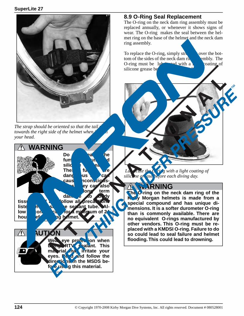
124 © Copyright 1970-2008 Kirby Morgan Dive Systems, Inc. All rights reserved. Document # 080528001
SuperLite 27
8.9 O-Ring Seal Replacement The O-ring on the neck dam ring assembly must be replaced annually, or whenever it shows signs of wear. The O-ring makes the seal between the hel-met ring on the base of the helmet and the neck dam ring assembly.
To replace the O-ring, simply stretch it over the bot-tom of the sides of the neck dam ring assembly. The O-ring must be lubricated with a light coating of silicone grease before each diving day.
Lubricate the O-ring with a light coating of silicone grease before each diving day.
The O-ring on the neck dam ring of the Kirby Morgan helmets is made from a special compound and has unique di-mensions. It is a softer durometer O-ring than is commonly available. There are no equivalent O-rings manufactured by other vendors. This O-ring must be re-placed with a KMDSI O-ring. Failure to do so could lead to seal failure and helmet flooding. This could lead to drowning.
WARNING
The strap should be oriented so that the tail pulls towards the right side of the helmet when it is on your head.
WARNINGDo not breathe the fumes from uncured silicone sealant. These fumes are dangerous and can cause unconscious-ness. They can also cause long term damage to body
tissue. Read and follow all precautions listed on the silicone sealant tube. Al-low silicone to cure for a minimum of 24 hours before using helmet.
Wear eye protection when using RTV sealant. This material may irritate your eyes. Read and follow the directions in the MSDS be-fore using this material.
CAUTION
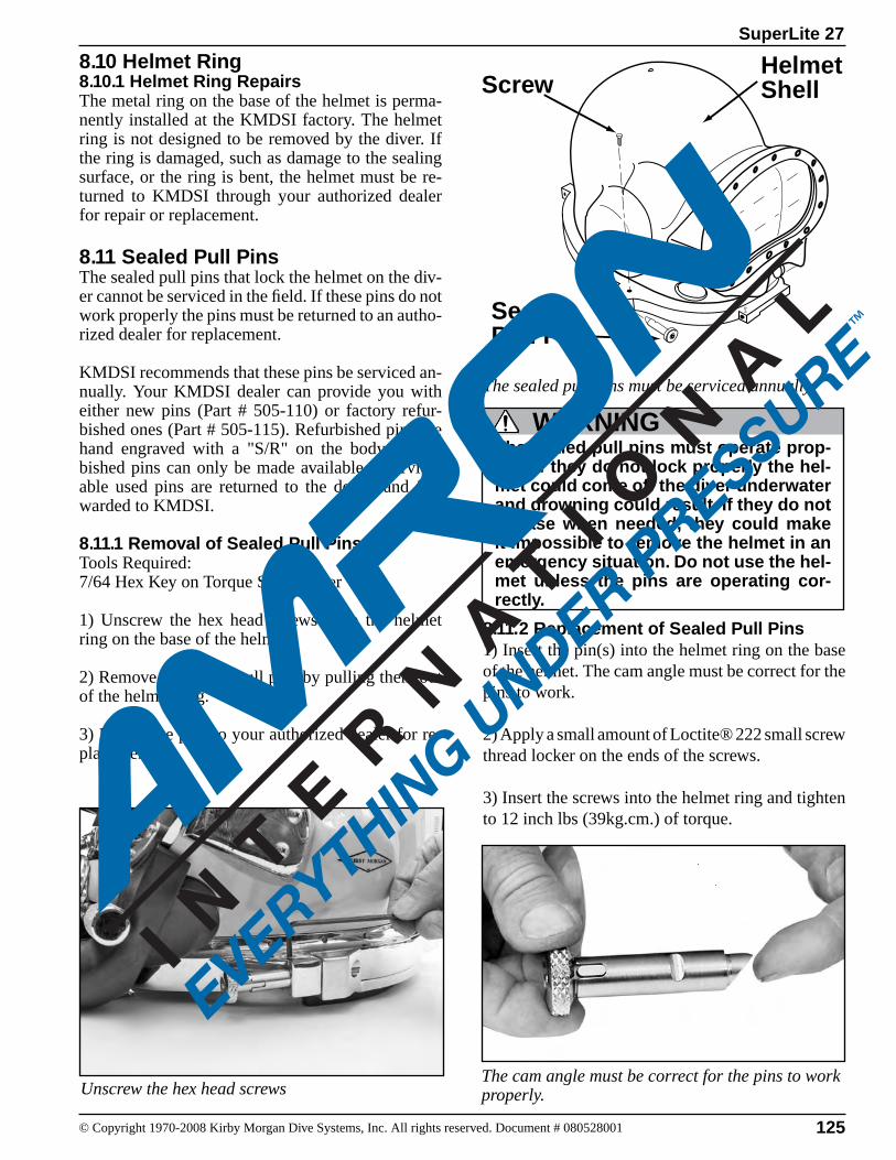
125© Copyright 1970-2008 Kirby Morgan Dive Systems, Inc. All rights reserved. Document # 080528001
SuperLite 27
ScrewHelmetShell
SealedPull Pin
8.10 Helmet Ring8.10.1 Helmet Ring RepairsThe metal ring on the base of the helmet is perma-nently installed at the KMDSI factory. The helmet ring is not designed to be removed by the diver. If the ring is damaged, such as damage to the sealing surface, or the ring is bent, the helmet must be re-turned to KMDSI through your authorized dealer for repair or replacement.
8.11 Sealed Pull PinsThe sealed pull pins that lock the helmet on the div-er cannot be serviced in the field. If these pins do not work properly the pins must be returned to an autho-rized dealer for replacement.
KMDSI recommends that these pins be serviced an-nually. Your KMDSI dealer can provide you with either new pins (Part # 505-110) or factory refur-bished ones (Part # 505-115). Refurbished pins are hand engraved with a "S/R" on the body. Refur-bished pins can only be made available if service-able used pins are returned to the dealer and for-warded to KMDSI.
8.11.1 Removal of Sealed Pull PinsTools Required:7/64 Hex Key on Torque Screwdriver
1) Unscrew the hex head screws from the helmet ring on the base of the helmet.
2) Remove the sealed pull pins by pulling them out of the helmet ring.
3) Return the pins to your authorized dealer for re-placement.
The sealed pull pins must be serviced annually.
The sealed pull pins must operate prop-erly. If they do not lock properly the hel-met could come off the diver underwater and drowning could result. If they do not release when needed, they could make it impossible to remove the helmet in an emergency situation. Do not use the hel-met unless the pins are operating cor-rectly.
WARNING
Unscrew the hex head screws
8.11.2 Replacement of Sealed Pull Pins1) Insert the pin(s) into the helmet ring on the base of the helmet. The cam angle must be correct for the pins to work.
2) Apply a small amount of Loctite® 222 small screw thread locker on the ends of the screws.
3) Insert the screws into the helmet ring and tighten to 12 inch lbs (39kg.cm.) of torque.
The cam angle must be correct for the pins to work properly.
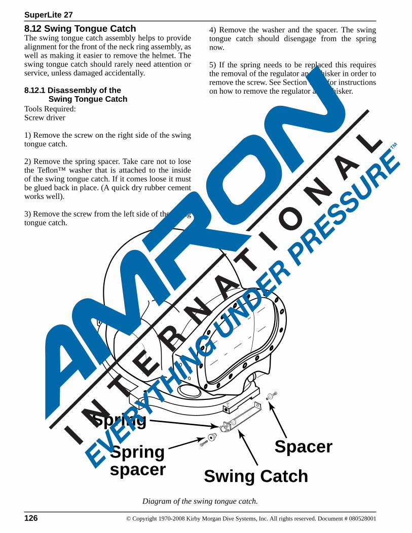
126 © Copyright 1970-2008 Kirby Morgan Dive Systems, Inc. All rights reserved. Document # 080528001
SuperLite 27
8.12 Swing Tongue Catch The swing tongue catch assembly helps to provide alignment for the front of the neck ring assembly, as well as making it easier to remove the helmet. The swing tongue catch should rarely need attention or service, unless damaged accidentally.
8.12.1 Disassembly of the Swing Tongue CatchTools Required:Screw driver
1) Remove the screw on the right side of the swing tongue catch.
2) Remove the spring spacer. Take care not to lose the Teflon™ washer that is attached to the inside of the swing tongue catch. If it comes loose it must be glued back in place. (A quick dry rubber cement works well).
3) Remove the screw from the left side of the swing tongue catch.
4) Remove the washer and the spacer. The swing tongue catch should disengage from the spring now.
5) If the spring needs to be replaced this requires the removal of the regulator and whisker in order to remove the screw. See Section 7.7.5 for instructions on how to remove the regulator and whisker.
Diagram of the swing tongue catch.
Swing Catch
Spring
Spring spacer
Spacer
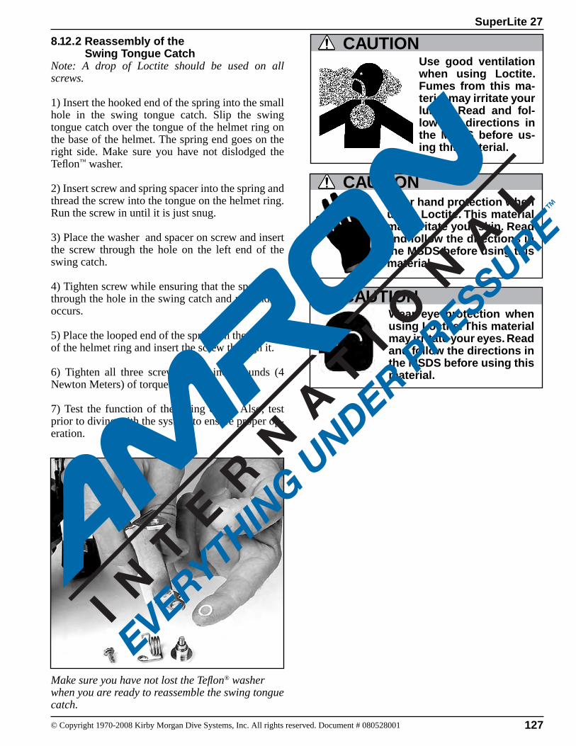
127© Copyright 1970-2008 Kirby Morgan Dive Systems, Inc. All rights reserved. Document # 080528001
SuperLite 27
8.12.2 Reassembly of the Swing Tongue CatchNote: A drop of Loctite should be used on all screws.
1) Insert the hooked end of the spring into the small hole in the swing tongue catch. Slip the swing tongue catch over the tongue of the helmet ring on the base of the helmet. The spring end goes on the right side. Make sure you have not dislodged the Teflon™ washer.
2) Insert screw and spring spacer into the spring and thread the screw into the tongue on the helmet ring. Run the screw in until it is just snug.
3) Place the washer and spacer on screw and insert the screw through the hole on the left end of the swing catch.
4) Tighten screw while ensuring that the spacer fits through the hole in the swing catch and no binding occurs.
5) Place the looped end of the spring on the top side of the helmet ring and insert the screw through it.
6) Tighten all three screws to 20 inch pounds (4 Newton Meters) of torque.
7) Test the function of the swing catch. Also, test prior to diving with the system to ensure proper op-eration.
Make sure you have not lost the Teflon® washer when you are ready to reassemble the swing tongue catch.
CAUTIONWear hand protection when using Loctite. This material may irritate your skin. Read and follow the directions in the MSDS before using this material
Wear eye protection when using Loctite. This material may irritate your eyes. Read and follow the directions in the MSDS before using this material.
CAUTION
Use good ventilation when using Loctite. Fumes from this ma-terial may irritate your lungs. Read and fol-low the directions in the MSDS before us-ing this material.
CAUTION
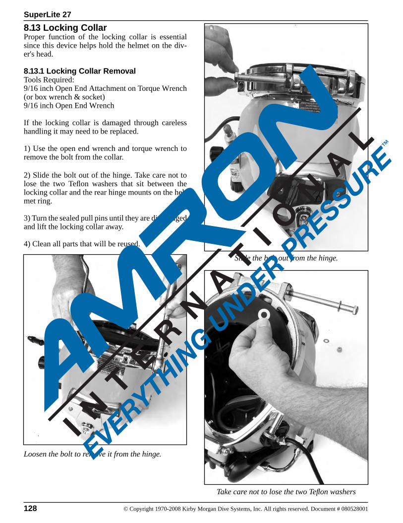
128 © Copyright 1970-2008 Kirby Morgan Dive Systems, Inc. All rights reserved. Document # 080528001
SuperLite 27
8.13 Locking CollarProper function of the locking collar is essential since this device helps hold the helmet on the div-er's head.
8.13.1 Locking Collar RemovalTools Required:9/16 inch Open End Attachment on Torque Wrench (or box wrench & socket)9/16 inch Open End Wrench
If the locking collar is damaged through careless handling it may need to be replaced.
1) Use the open end wrench and torque wrench to remove the bolt from the collar.
2) Slide the bolt out of the hinge. Take care not to lose the two Teflon washers that sit between the locking collar and the rear hinge mounts on the hel-met ring.
3) Turn the sealed pull pins until they are disengaged and lift the locking collar away.
4) Clean all parts that will be reused.
Take care not to lose the two Teflon washers
Loosen the bolt to remove it from the hinge.
Slide the bolt out from the hinge.
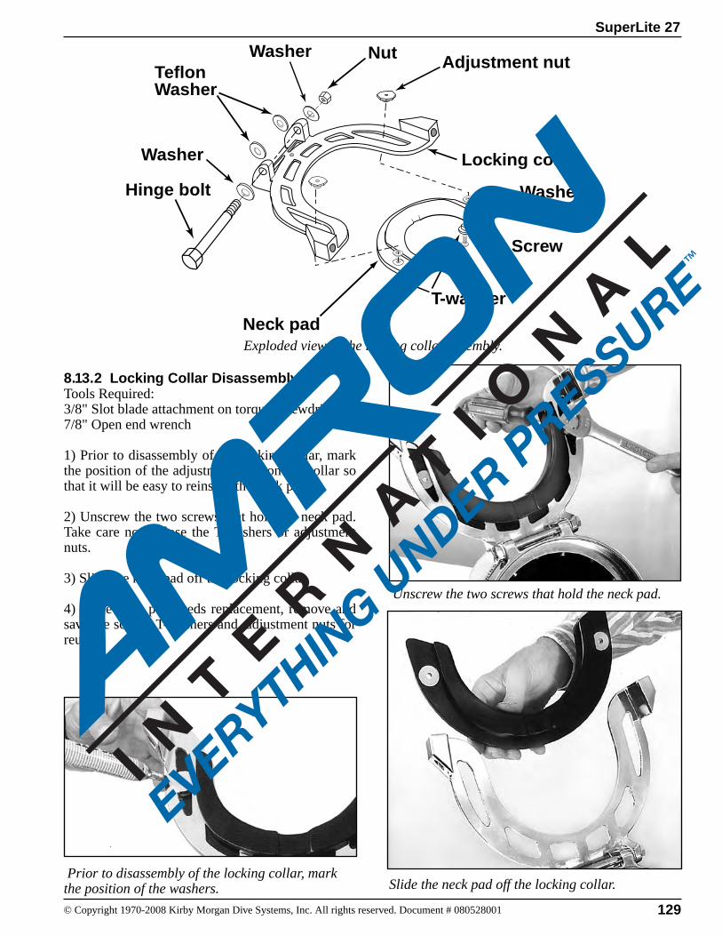
129© Copyright 1970-2008 Kirby Morgan Dive Systems, Inc. All rights reserved. Document # 080528001
SuperLite 27
8.13.2 Locking Collar DisassemblyTools Required:3/8" Slot blade attachment on torque screwdriver 7/8" Open end wrench
1) Prior to disassembly of the locking collar, mark the position of the adjustment nuts on the collar so that it will be easy to reinstall the neck pad.
2) Unscrew the two screws that hold the neck pad. Take care not to lose the T-washers or adjustment nuts.
3) Slide the neck pad off the locking collar.
4) If the neck pad needs replacement, remove and save the screws T-washers and adjustment nuts for reuse.
Exploded view of the locking collar assembly.
Hinge bolt
Nut
Locking collar
Neck pad
Adjustment nut
Washer
Screw
Washer
T-washer
Teflon Washer
Washer
Prior to disassembly of the locking collar, mark the position of the washers. Slide the neck pad off the locking collar.
Unscrew the two screws that hold the neck pad.
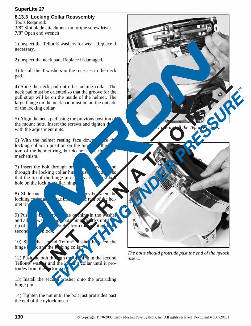
130 © Copyright 1970-2008 Kirby Morgan Dive Systems, Inc. All rights reserved. Document # 080528001
SuperLite 27
8.13.3 Locking Collar ReassemblyTools Required:3/8" Slot blade attachment on torque screwdriver 7/8" Open end wrench
1) Inspect the Teflon® washers for wear. Replace if necessary.
2) Inspect the neck pad. Replace if damaged.
3) Install the T-washers in the recesses in the neck pad.
4) Slide the neck pad onto the locking collar. The neck pad must be oriented so that the groove for the pull strap will be on the inside of the helmet. The large flange on the neck pad must be on the outside of the locking collar.
5) Align the neck pad using the previous position of the mount nuts. Insert the screws and tighten them with the adjustment nuts.
6) With the helmet resting face down, place the locking collar in position on the hinge on the bot-tom of the helmet ring, but do not close the catch mechanism.
7) Insert the bolt through one of the washers and through the locking collar hinge just far enough so that the tip of the hinge pin shows at the first bolt hole on the locking collar hinge.
8) Slide one of the Teflon® washers between the locking collar and hinge block on the rear of the hel-met ring.
9) Push the bolt through the opening in the washer and all the way through both hinge blocks until the tip of the bolt just protrudes from the opening in the second hinge block.
10) Slide the second Teflon® washer between the hinge block and the locking collar.
12) Push the bolt through the opening in the second Teflon® washer and the locking collar until it pro-trudes from the locking collar.
13) Install the second washer onto the protruding hinge pin.
14) Tighten the nut until the bolt just protrudes past the end of the nylock insert.
Make sure to re-install the Teflon washers.
The bolts should protrude past the end of the nylock insert.
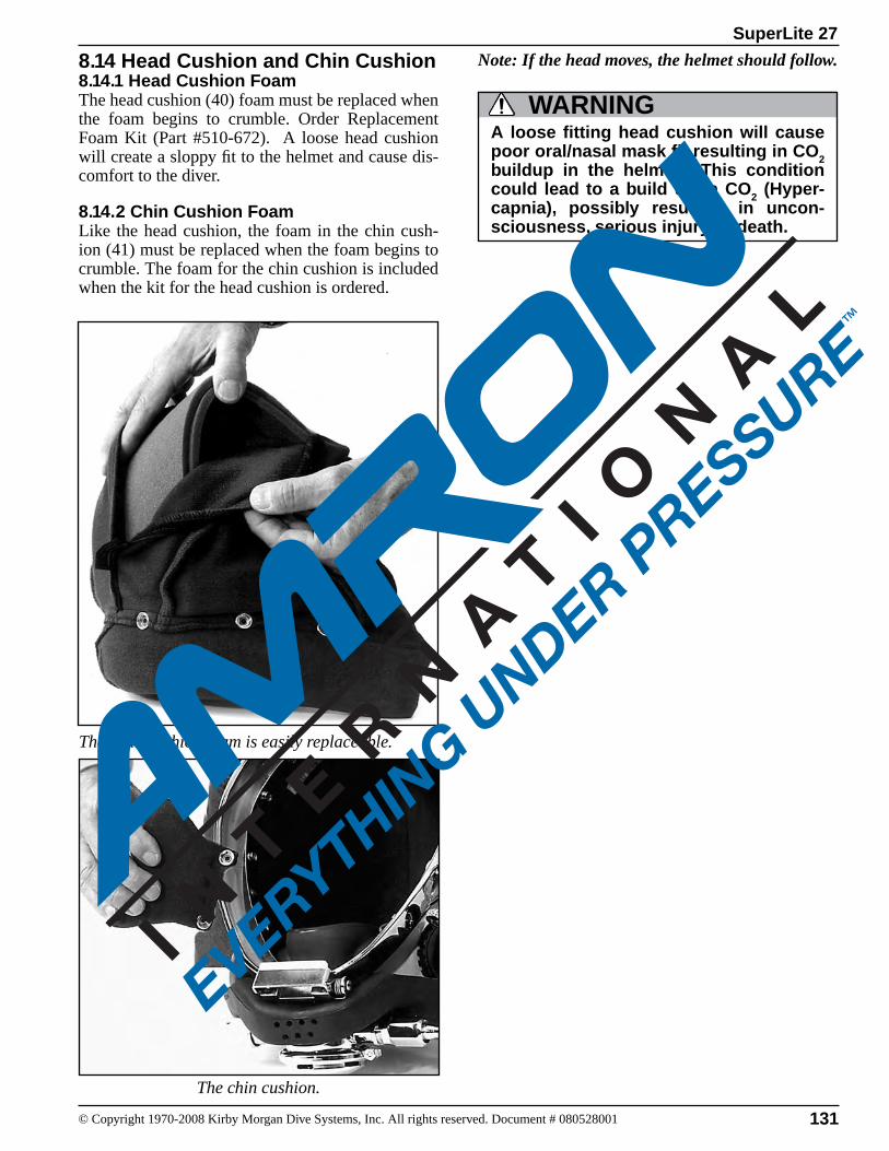
131© Copyright 1970-2008 Kirby Morgan Dive Systems, Inc. All rights reserved. Document # 080528001
SuperLite 27
8.14 Head Cushion and Chin Cushion8.14.1 Head Cushion FoamThe head cushion (40) foam must be replaced when the foam begins to crumble. Order Replacement Foam Kit (Part #510-672). A loose head cushion will create a sloppy fit to the helmet and cause dis-comfort to the diver.
8.14.2 Chin Cushion FoamLike the head cushion, the foam in the chin cush-ion (41) must be replaced when the foam begins to crumble. The foam for the chin cushion is included when the kit for the head cushion is ordered.
The head cushion foam is easily replaceable.
The chin cushion.
Note: If the head moves, the helmet should follow.
A loose fitting head cushion will cause poor oral/nasal mask fit resulting in CO2 buildup in the helmet. This condition could lead to a build up in CO2 (Hyper-capnia), possibly resulting in uncon-sciousness, serious injury or death.
WARNING
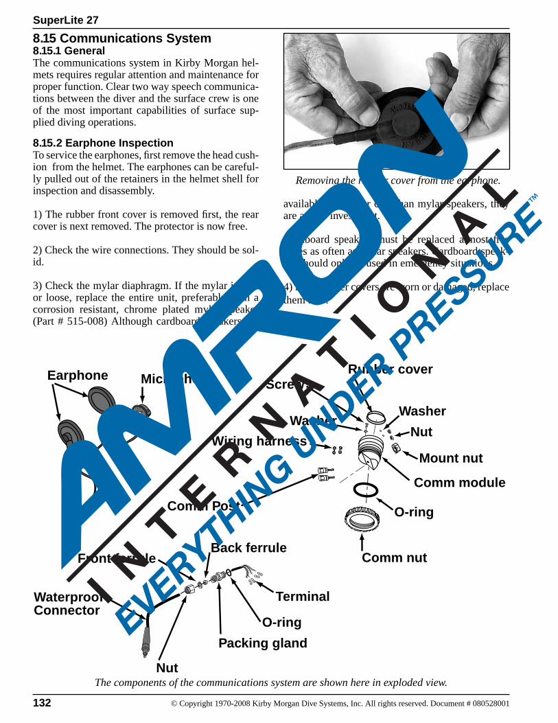
132 © Copyright 1970-2008 Kirby Morgan Dive Systems, Inc. All rights reserved. Document # 080528001
SuperLite 27
8.15 Communications System8.15.1 GeneralThe communications system in Kirby Morgan hel-mets requires regular attention and maintenance for proper function. Clear two way speech communica-tions between the diver and the surface crew is one of the most important capabilities of surface sup-plied diving operations.
8.15.2 Earphone InspectionTo service the earphones, first remove the head cush-ion from the helmet. The earphones can be careful-ly pulled out of the retainers in the helmet shell for inspection and disassembly.
1) The rubber front cover is removed first, the rear cover is next removed. The protector is now free.
2) Check the wire connections. They should be sol-id.
3) Check the mylar diaphragm. If the mylar is torn or loose, replace the entire unit, preferably with a corrosion resistant, chrome plated mylar speaker (Part # 515-008) Although cardboard speakers are
available at a lower cost than mylar speakers, they are a poor investment.
Cardboard speakers must be replaced almost five times as often as mylar speakers. Cardboard speak-ers should only be used in emergency situations.
4) If the rubber covers are worn or damaged, replace them also.
The components of the communications system are shown here in exploded view.
Removing the rubber cover from the earphone.
MicrophoneEarphone
Waterproof Connector
Nut
Packing gland
Back ferrule
Comm Post
Comm nut
Comm module
Rubber cover
Wiring harness
Terminal
O-ring
O-ring
Screw
Front ferrule
Mount nut
WasherWasher
Nut
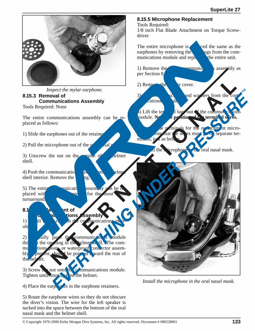
133© Copyright 1970-2008 Kirby Morgan Dive Systems, Inc. All rights reserved. Document # 080528001
SuperLite 27
Inspect the mylar earphone.8.15.3 Removal of Communications AssemblyTools Required: None
The entire communications assembly can be re-placed as follows:
1) Slide the earphones out of the retainers.
2) Pull the microphone out of the oral/nasal mask.
3) Unscrew the nut on the outside of the helmet shell.
4) Push the communications module into the helmet shell interior. Remove the O-ring.
5) The entire communications assembly can be re-placed with a spare assembly for the most rapid turnaround.
8.15.4 Replacement of Communications Assembly1) Install the O-ring on the communications mod-ule.
2) Carefully push the communications module through the opening in the helmet shell. The com-munications posts, or waterproof connector assem-bly if present, should be pointed toward the rear of the helmet.
3) Screw the nut onto the communications module. Tighten until snug against the helmet.
4) Place the earphones in the earphone retainers.
5) Route the earphone wires so they do not obscure the diver’s vision. The wire for the left speaker is tucked into the space between the bottom of the oral nasal mask and the helmet shell.
8.15.5 Microphone ReplacementTools Required:1/8 inch Flat Blade Attachment on Torque Screw-driver
The entire microphone is replaced the same as the ear phones by removing the wire lugs from the com-munications module and replacing the entire unit.
1) Remove the entire communications assembly as per Section 8.15.3.
2) Remove the rubber cover.
3) Remove the screws and washers from the com-munications module.
4) Lift the terminal lugs out of the communications module. Note the position of the terminal wires.
5) Install the terminals for the replacement micro-phone. Note that the wires must go on separate ter-minals, just as before.
6) Install the microphone in the oral nasal mask.
Install the microphone in the oral nasal mask.
134 © Copyright 1970-2008 Kirby Morgan Dive Systems, Inc. All rights reserved. Document # 080528001
SuperLite 27
8.15.6 Earphone ReplacementTools Required:1/8 inch Flat Blade Attachment on Torque Screw-driver
The earphones may be replaced individually if need-ed, however, if one is “bad”, the other earphone will probably need to be replaced soon, too.
1) Remove the entire communications assembly as per Section 8.15.3.
2) Remove the rubber cover of the communications module.
3) Remove the screws and washers from the com-munications module.
4) Lift the terminal lugs out of the communications module. Note the position of the terminal wires.
5) Install the terminals for the earphones. Note that the wires must go on separate terminals as before.
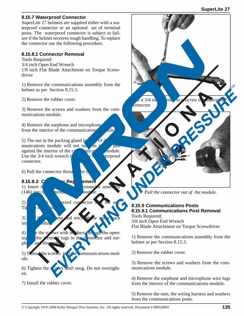
135© Copyright 1970-2008 Kirby Morgan Dive Systems, Inc. All rights reserved. Document # 080528001
SuperLite 27
Use a 3/4 inch wrench to unscrew the waterproof connector.
Pull the connector out of the module.
8.15.7 Waterproof ConnectorSuperLite 27 helmets are supplied either with a wa-terproof connector or an optional set of terminal posts. The waterproof connector is subject to fail-ure if the helmet receives rough handling. To replace the connector use the following procedure.
8.15.8.1 Connector RemovalTools Required:3/4 inch Open End Wrench 1/8 inch Flat Blade Attachment on Torque Screw-driver
1) Remove the communications assembly from the helmet as per Section 8.15.3.
2) Remove the rubber cover.
3) Remove the screws and washers from the com-munications module.
4) Remove the earphone and microphone wire lugs from the interior of the communications module.
5) The nut in the packing gland interior of the com-munications module will not turn, as it will jam against the interior of the communications module. Use the 3/4 inch wrench to unscrew the waterproof connector.
6) Pull the connector through the module.
8.15.8.2 Connector Replacement1) Insert the new waterproof connector assembly (146) into the communications module.
2) Screw the waterproof connector into the nut. Tighten until snug.
3) Slip the earphone and microphone wires back into the module.
4) Place the screws with washers through the open-ing on the terminal lugs in the connector and ear-phone and microphone.
5) Thread the screws into the communications mod-ule.
6) Tighten the screws until snug. Do not overtight-en.
7) Install the rubber cover.
8.15.9 Communications Posts 8.15.9.1 Communications Post RemovalTools Required;3/8 inch Open End WrenchFlat Blade Attachment on Torque Screwdriver
1) Remove the communications assembly from the helmet as per Section 8.15.3.
2) Remove the rubber cover.
3) Remove the screws and washers from the com-munications module.
4) Remove the earphone and microphone wire lugs from the interior of the communications module.
5) Remove the nuts, the wiring harness and washers from the communications posts.
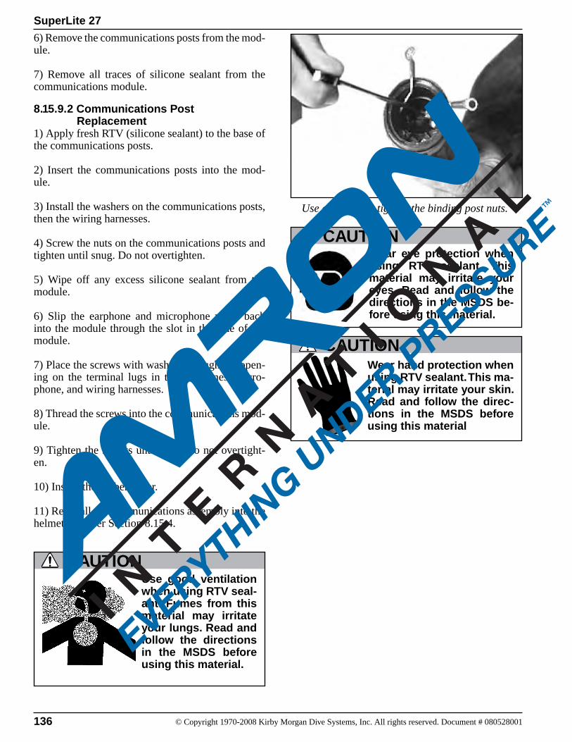
136 © Copyright 1970-2008 Kirby Morgan Dive Systems, Inc. All rights reserved. Document # 080528001
SuperLite 27
Use a wrench to tighten the binding post nuts.
6) Remove the communications posts from the mod-ule.
7) Remove all traces of silicone sealant from the communications module.
8.15.9.2 Communications Post Replacement1) Apply fresh RTV (silicone sealant) to the base of the communications posts.
2) Insert the communications posts into the mod-ule.
3) Install the washers on the communications posts, then the wiring harnesses.
4) Screw the nuts on the communications posts and tighten until snug. Do not overtighten.
5) Wipe off any excess silicone sealant from the module.
6) Slip the earphone and microphone wires back into the module through the slot in the side of the module.
7) Place the screws with washers through the open-ing on the terminal lugs in the earphones, micro-phone, and wiring harnesses.
8) Thread the screws into the communications mod-ule.
9) Tighten the screws until snug; do not overtight-en.
10) Install the rubber cover.
11) Reinstall the communications assembly into the helmet shell per Section 8.15.4.
Use good ventilation when using RTV seal-ant. Fumes from this material may irritate your lungs. Read and follow the directions in the MSDS before using this material.
CAUTION
CAUTIONWear hand protection when using RTV sealant. This ma-terial may irritate your skin. Read and follow the direc-tions in the MSDS before using this material
Wear eye protection when using RTV sealant. This material may irritate your eyes. Read and follow the directions in the MSDS be-fore using this material.
CAUTION
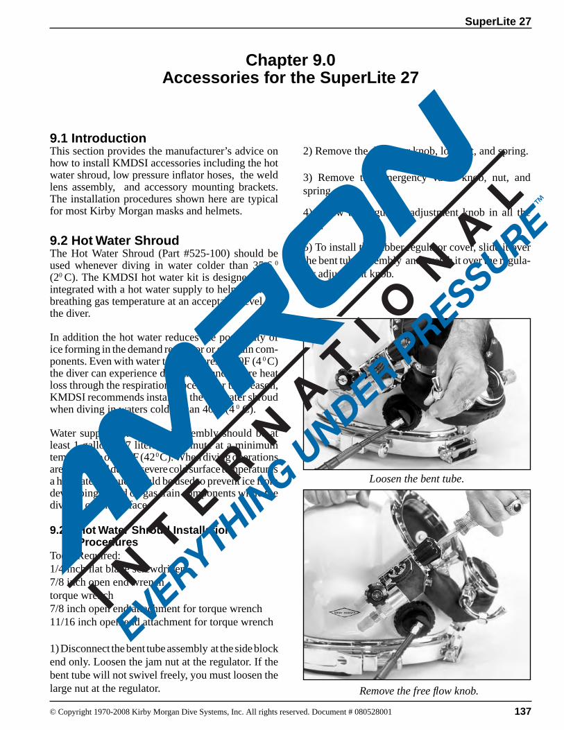
137© Copyright 1970-2008 Kirby Morgan Dive Systems, Inc. All rights reserved. Document # 080528001
SuperLite 27
Chapter 9.0Accessories for the SuperLite 27
Loosen the bent tube.
Remove the free flow knob.
9.1 IntroductionThis section provides the manufacturer’s advice on how to install KMDSI accessories including the hot water shroud, low pressure inflator hoses, the weld lens assembly, and accessory mounting brackets. The installation procedures shown here are typical for most Kirby Morgan masks and helmets.
9.2 Hot Water ShroudThe Hot Water Shroud (Part #525-100) should be used whenever diving in water colder than 35.6 0 (20 C). The KMDSI hot water kit is designed to be integrated with a hot water supply to help maintain breathing gas temperature at an acceptable level for the diver.
In addition the hot water reduces the possibility of ice forming in the demand regulator or gas train com-ponents. Even with water temperatures of 40F (4 0 C) the diver can experience discomfort and severe heat loss through the respiration process. For this reason, KMDSI recommends installing the hot water shroud when diving in waters colder than 40 F (4 0 C).
Water supply to the shroud assembly should be at least 1 gallon (3.7 liters) per minute at a minimum temperature of 105 F (42 0 C). When diving operations are conducted during severe cold surface temperatures a hot water shroud should be used to prevent ice from developing in and on gas train components while the diver is on the surface.
9.2.1 Hot Water Shroud Installation ProceduresTools Required:1/4 inch flat blade screwdriver7/8 inch open end wrenchtorque wrench7/8 inch open end attachment for torque wrench 11/16 inch open end attachment for torque wrench
1) Disconnect the bent tube assembly at the side block end only. Loosen the jam nut at the regulator. If the bent tube will not swivel freely, you must loosen the large nut at the regulator.
2) Remove the defogger knob, locknut, and spring.
3) Remove the emergency valve knob, nut, and spring.
4) Screw the regulator adjustment knob in all the way.
5) To install the rubber regulator cover, slide it over the bent tube assembly and stretch it over the regula-tor adjustment knob.

138 © Copyright 1970-2008 Kirby Morgan Dive Systems, Inc. All rights reserved. Document # 080528001
SuperLite 27
6) Install the rubber side block cover. Start by insert-ing the non-return valve through the square hole on the back side of the cover. All the other holes will then line up correctly.
7) Slide one of the PVC Flanges (Part #520-046) over the bent tube and insert it into the regulator shroud.
8) Slide the corrugated tube over the bent tube. The PVC flange previously installed in the regulator shroud mates with the corrugated tube, with the tube rubber going over the PVC Flange and the regulator shroud rubber.
9) Install the second PVC flange in the other end of the corrugated tube. (1/4 of the flange should still show).
10) Attach the side block end of the bent tube to the side block assembly . Using the torque wrench and 11/16 attachment, tighten to 100 inch lbs (112 kgcm). if the regulator end of the bent tube was loosened, torque the jam nut to 40 inch lbs (112 kg cm).
11) Slide the PVC flange up towards the side block and install it in the side block rubber tube. (1/4 of the flange should still show).
12) Stretch the corrugated tube over the PVC flange and the side block rubber tube.
13) Wrap the tie wraps around the corrugated tube at the PVC stiffeners and tighten.
14) Trim the excess ends from the tie wraps.
Pull the shroud over the regulator.
Install the corrugated tube.
Position the shroud over the side block.
Slide one of the PVC pieces over the bent tube and insert it into the regulator shroud.
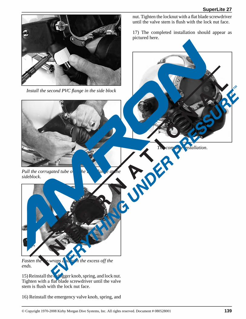
139© Copyright 1970-2008 Kirby Morgan Dive Systems, Inc. All rights reserved. Document # 080528001
SuperLite 27
The complete installation.
nut. Tighten the locknut with a flat blade screwdriver until the valve stem is flush with the lock nut face.
17) The completed installation should appear as pictured here.
Install the second PVC flange in the side block
15) Reinstall the defogger knob, spring, and lock nut. Tighten with a flat blade screwdriver until the valve stem is flush with the lock nut face.
16) Reinstall the emergency valve knob, spring, and
Pull the corrugated tube over the PVC flange at the sideblock.
Fasten the tie-wraps and trim the excess off the ends.
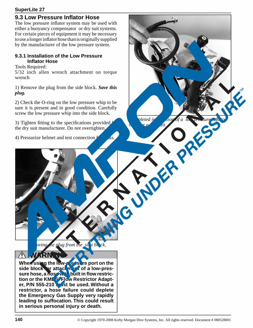
140 © Copyright 1970-2008 Kirby Morgan Dive Systems, Inc. All rights reserved. Document # 080528001
SuperLite 27
9.3 Low Pressure Inflator HoseThe low pressure inflator system may be used with either a buoyancy compensator or dry suit systems. For certain pieces of equipment it may be necessary to use a longer inflator hose than is originally supplied by the manufacturer of the low pressure system.
9.3.1 Installation of the Low Pressure Inflator HoseTools Required:5/32 inch allen wrench attachment on torque wrench
1) Remove the plug from the side block. Save this plug.
2) Check the O-ring on the low pressure whip to be sure it is present and in good condition. Carefully screw the low pressure whip into the side block.
3) Tighten fitting to the specifications provided by the dry suit manufacturer. Do not overtighten.
4) Pressurize helmet and test connection for leaks.
9.4 WELD LENS ASSEMBLY
Completed installation of a low pressure inflator hose for a dry suit.
Removing the plug from the side block.
When using the low-pressure port on the side block for attachment of a low-pres-sure hose, a hose with built in flow restric-tion or the KMDSI Flow Restrictor Adapt-er, P/N 555-210 must be used. Without a restrictor, a hose failure could deplete the Emergency Gas Supply very rapidly leading to suffocation. This could result in serious personal injury or death.
WARNING
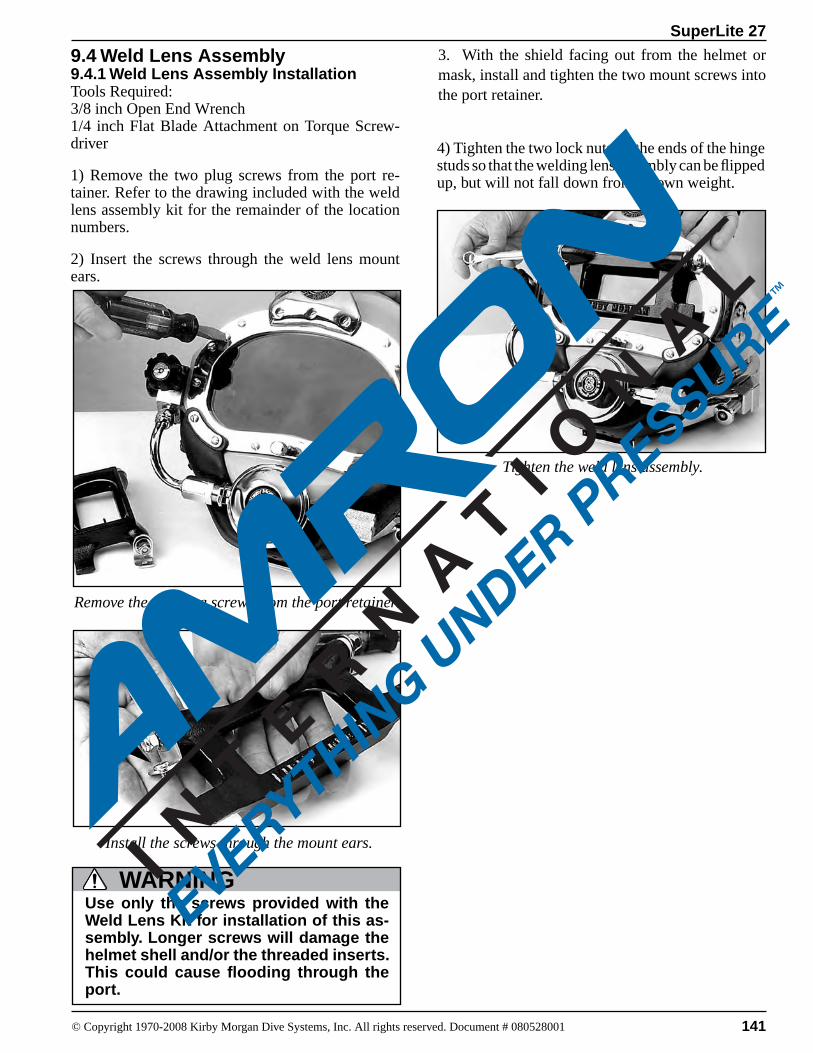
141© Copyright 1970-2008 Kirby Morgan Dive Systems, Inc. All rights reserved. Document # 080528001
SuperLite 27
9.4 Weld Lens Assembly9.4.1 Weld Lens Assembly InstallationTools Required:3/8 inch Open End Wrench1/4 inch Flat Blade Attachment on Torque Screw-driver
1) Remove the two plug screws from the port re-tainer. Refer to the drawing included with the weld lens assembly kit for the remainder of the location numbers.
2) Insert the screws through the weld lens mount ears.
Install the screws through the mount ears.
Remove the two plug screws from the port retainer.
Tighten the weld lens assembly.
4) Tighten the two lock nuts on the ends of the hinge studs so that the welding lens assembly can be flipped up, but will not fall down from its own weight.
3. With the shield facing out from the helmet or mask, install and tighten the two mount screws into the port retainer.
Use only the screws provided with the Weld Lens Kit for installation of this as-sembly. Longer screws will damage the helmet shell and/or the threaded inserts. This could cause flooding through the port.
WARNING
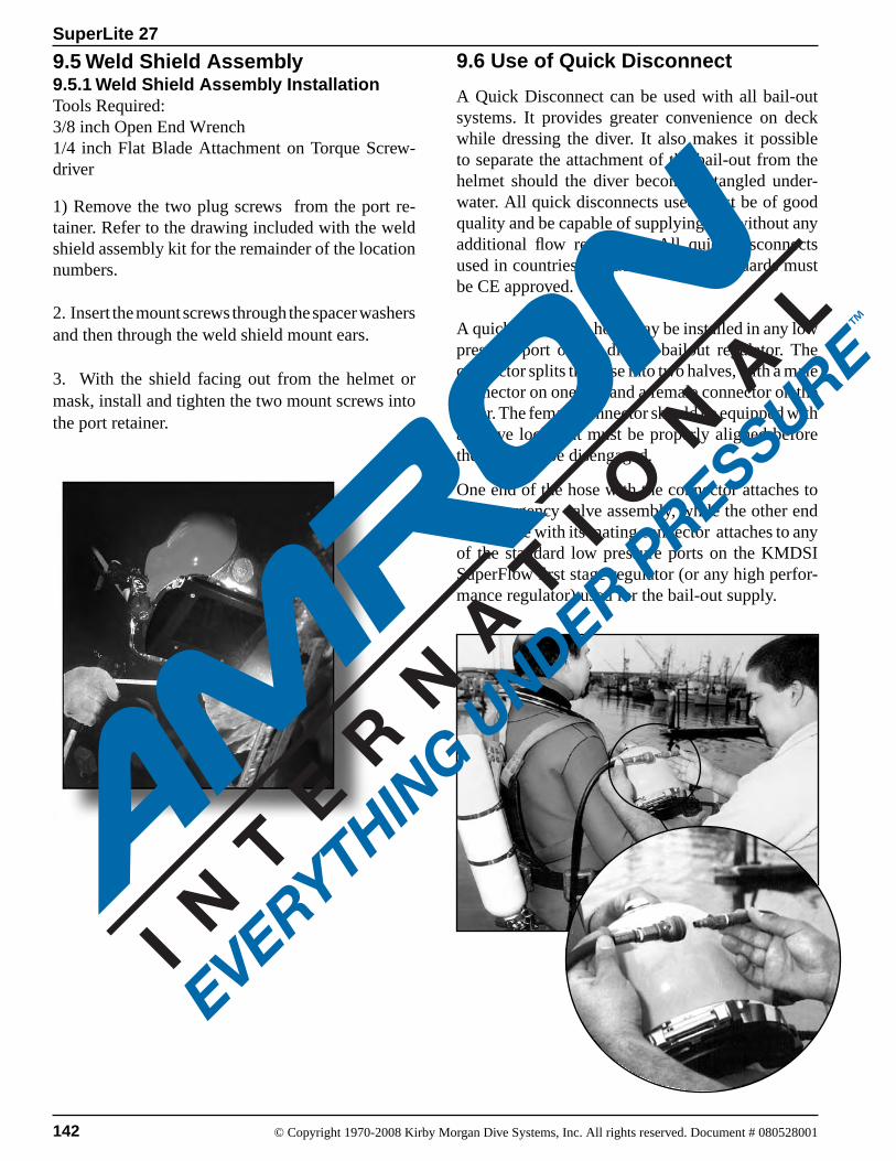
142 © Copyright 1970-2008 Kirby Morgan Dive Systems, Inc. All rights reserved. Document # 080528001
SuperLite 27
9.6 Use of Quick Disconnect
A Quick Disconnect can be used with all bail-out systems. It provides greater convenience on deck while dressing the diver. It also makes it possible to separate the attachment of the bail-out from the helmet should the diver become entangled under-water. All quick disconnects used must be of good quality and be capable of supplying gas without any additional flow restriction. All quick disconnects used in countries that adhere to CE standards must be CE approved.
A quick disconnect hose may be installed in any low pressure port of the diver’s bailout regulator. The connector splits the hose into two halves, with a male connector on one end and a female connector on the other. The female connector should be equipped with a sleeve lock that must be properly aligned before the hose can be disengaged.
One end of the hose with the connector attaches to the emergency valve assembly, while the other end of the hose with its mating connector attaches to any of the standard low pressure ports on the KMDSI SuperFlow first stage regulator (or any high perfor-mance regulator) used for the bail-out supply.
9.5 Weld Shield Assembly9.5.1 Weld Shield Assembly InstallationTools Required:3/8 inch Open End Wrench1/4 inch Flat Blade Attachment on Torque Screw-driver
1) Remove the two plug screws from the port re-tainer. Refer to the drawing included with the weld shield assembly kit for the remainder of the location numbers.
2. Insert the mount screws through the spacer washers and then through the weld shield mount ears.
3. With the shield facing out from the helmet or mask, install and tighten the two mount screws into the port retainer.

SuperLite 27
143© Copyright 1970-2008 Kirby Morgan Dive Systems, Inc. All rights reserved. Document # 080528001
To convert units appearing in Column 1 (left column) into equivalent values in Column 2 (center column), multiply by factor in Column 3. Example: To convert 7 gallons into cubic inches, multiply 7 x 231 = 1617. To convert units appearing in Column 2 (center) into equiva-lent values of units in Column 1 (left), divide by factor in Col-umn 3. Example: To convert 25 horsepower into Btu per minute, divide 25 by 0.02356 = 1061
TO CONVERT INTO MULTIPLY BY INTO TO CONVERT DIVIDE BY
AtmospheresAtmospheresAtmospheresBTUBTU per hourBTU per minuteCelsius (Centigrade)CentimetersCubic CentimetersCubic CentimetersCubic FeetCubic FeetCubic InchesCubic InchesDaysDegrees (Angle)FeetFeetFeet of WaterFeet of WaterFeet of WaterFeet per MinuteFeet per SecondFoot-PoundsFoot-Pounds per MinuteFoot-Pounds per SecondGallons (U.S. Liquid)Gallons (U.S. Liquid)Gallons of WaterHorsepowerHorsepowerHorsepowerHorsepowerHoursHoursInchesInches of Mercury (Hg)Inches of Mercury (Hg)Inches of Mercury (Hg)Inches of WaterLitersLitersMicronMiles (Statute)Miles per hour (MPH)Miles per hourOunces (Weight)Ounces (Liquid)Pints (Liquid)PoundsPoundsPoundsPSI (Pounds per Sq. Inch)PSI (Pounds per Sq. Inch)PSI (Pounds per Sq. Inch)QuartsSquare FeetTemperature (oF - 32)Tons (U.S.)Watts
Feet of WaterInches of Mercury (Hg)PSI (LBS per Sq. InchFoot PoundsWattsHorsePowerFahrenheitInchesGallons (U.S. Liquid)LitersCubic InchesGallons (U.S. Liquid)Cubic FeetGallons (U.S. Liquid)SecondsRadiansMetersMilesAtmospheresInches of Mercury (Hg)PSI (Lbs per Sq. Inch)Miles per HourMiles per HourBTUHorsepowerHorsepowerCubic FeetCubic InchesPounds of WaterBTU per MinuteFoot-Pound per MinuteFoot Pounds per SecondWattsDaysWeeksCentimetersAtmospheresFeet of WaterPSI (Lbs. per Sq. Inch)PSI (Lbs. per Sq. Inch)Cubic CentimetersGallons (U.S. Liquid)InchesFeetFeet per MinuteFeet per SecondPoundsCubic InchesQuarts (Liquid)GrainsGramsOuncesAtmospheresFeet of WaterInches of Mercury (Hg)GallonsSquare InchesTemperature (oC)PoundsHorsepower
33.929.9214.7778.30.29310.02356oC x 1.8 + 320.39370.00026420.000117287.480520.00057870.00432986.4000.017450.30480.00018940.02950.88260.43350.011360.68180.0012860.00003030.0018180.13372318.345342.4433,000550745.70.041670.0059522.540.033421.1330.49120.0361310000.26420.000045280881.4670.06251.8050.57000453.59160.068042.3072.0360.251440.555520000.001341
Table of Equivalents
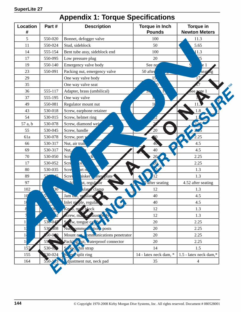
144 © Copyright 1970-2008 Kirby Morgan Dive Systems, Inc. All rights reserved. Document # 080528001
SuperLite 27
Appendix 1: Torque SpecificationsLocation
#Part # Description Torque in Inch
PoundsTorque in
Newton Meters5 550-020 Bonnet, defogger valve 100 11.3
11 550-024 Stud, sideblock 50 5.65
14 555-154 Bent tube assy, sideblock end 100 11.3
17 550-095 Low pressure plug 20 2.25
19 550-140 Emergency valve body See note 1 See note 1
23 550-091 Packing nut, emergency valve 50 after seating 5.65 after seating
29 One way valve body 150 17
35 One way valve seat 150 17
36 555-117 Adapter, brass (umbilical) See note 1 See note 1
37 555-195 One way valve 150 17
49 550-081 Regulator mount nut 100 11.3
43 530-018 Screw, earphone retainer 16 1.8
54 530-015 Screw, helmet ring 12 1.3
57 a, b 530-078 Screw, diamond weight 20 2.25
55 530-045 Screw, handle 20 2.25
61a 530-078 Screw, port weight 20 2.25
66 530-317 Nut, air train 40 4.5
69 530-317 Nut, air train 40 4.5
70 530-050 Screw, sideblock 20 2.25
17 530-052 Screw, port plug 20 2.25
80 530-035 Screw, port retainer 12 1.3
89 530-045 Screw, whisker kidney plate 12 1.3
97 550-055 Packing nut, regulator 40 after seating 4.52 after seating
102 530-030 Screw, regulator clamp 12 1.3
108 550-050 Jam nut, regulator 40 4.5
109 550-048 Inlet nipple, regulator 40 4.5
85 550-062 Knob, nose block 12 1.3
71 530-032 Screw, main exhaust body 12 1.3
114 530-045 Screw, tongue catch 20 2.25
133 530-308 Nut, communications posts 20 2.25
147 550-040 Mount nut, communications penetrator 20 2.25
143 555-178 Packing nut, waterproof connector 20 2.25
157 530-022 Screw, chin strap 14 1.5
155 530-024 Screw, split ring 14 - latex neck dam, * 1.5 - latex neck dam,*
164 550-113 Adjustment nut, neck pad 35 4

SuperLite 27
145© Copyright 1970-2008 Kirby Morgan Dive Systems, Inc. All rights reserved. Document # 080528001
Note 1: Use Teflon® tape for one to one and a half wraps, starting two threads back from the pipe thread end of the fitting to avoid getting Teflon® tape in the valve. Tighten pipe thread using good engineering practices.
* For a neoprene neck dam, turn the screw three turns. Screws may need adjustment after several dives.
Note on Torque Specifications
Checklist, Maintenance, and Pre-Dive InspectionsFor the most current check lists, helmet maintenance procedures, and pre-dive inspections, please check on the Internet at www.divelab.com.

146 © Copyright 1970-2008 Kirby Morgan Dive Systems, Inc. All rights reserved. Document # 080528001
SuperLite 27
Appendix A2Maintenance and Inspection Procedures
The following section describes the maintenance and inspection procedures that are used to complete the Annual, Monthly and Daily Checklists, to ensure optimum reliability and performance. These proce-dures are additionally utilized in conjunction with the daily pre and post dive maintenance checklists. The following service intervals are the minimum recommended for helmets being used under good conditions. Helmets used in harsh conditions, i.e., contaminated water, welding / burning operations, or jetting may require more frequent servicing.
The intention of the maintenance and overhaul pro-gram is to help maintain all helmet components in good working order in accordance with KMDSI fac-tory specifications. It will also help to identify worn or damaged parts and components before they af-fect performance and reliability. Whenever the ser-viceability of a component or part is in question, or doubt exists, replace it. All helmet components and parts have a service life and will eventually require replacement.
NOTE: The side block does not need to be removed from the helmet annually, providing, after removal of side block components, there is no corrosion and verdigris. Kirby Morgan recommends that every three years the side block assembly be physically re-moved from the helmet per Section 7.3. Clean and inspect the stud and securing screw, replace if bent, stripped, or any damage is detected.
NOTE: The pipe thread fittings used on the umbili-cal adapter and the emergency gas valve are the only fittings that require sealing with Teflon tape. Do not use liquid sealant. When installing Teflon tape on pipe threads, apply the tape starting one thread back from the end of the fitting. Apply the tape in a clock-wise direction under tension. 1-1½ wraps is all that is needed. The use of more than 1½ wraps could cause excess Teflon tape to travel into the breathing sys-tem. Do not overtighten when installing.
Chapters 6, 7 and 8 of this maintenance manual gives guidance on all routine and corrective maintenance and repairs. Disassembly and reassembly of compo-nents is explained in a step-by-step manner that may not necessarily call out that all O-rings and normal consumable items will be replaced. The manual is written in this way so that if an assembly, compo-nent, or part is being inspected or disturbed between
normal intervals it is acceptable to reuse O-rings and components providing they pass a visual inspection . When conducting annual or scheduled overhauls all O-rings should be replaced. The side block should be removed from the helmet at least every three years (or 400 operating hours) so that the stud and secur-ing screw can be inspected. All O-rings should be lightly lubricated with the applicable lubricant.
Lubrication / Cleanliness: Helmets intended for use with breathing gas mix-tures in excess of 50% oxygen by volume, should be cleaned for oxygen service. They must only be lubricated with oxygen compatible lubricants such as Christo-Lube® or Krytox®. All air supply systems must be filtered and must meet the requirements of grade D quality air or better. Helmet breathing gas systems/gas train components used for air diving should only be lubricated with silicone grease Dow Corning 111® or equivalent. KMDSI uses Christo-Lube® at the factory for lubrication of all gas train components requiring lubrication, and highly rec-ommends its use.
Before 1999, Kirby Morgan Dive Systems, Inc., used Danger and Warning Notices in the helmet and mask owner’s manual limiting the breathing gas percent-age to less than 23.5 percent oxygen. This was due primarily to cleaning issues in regards to possible fire hazards and was in compliance with the recommen-dations of the Association of Standard Test Methods (ASTM), National Fire Protection Agency (NFPA), and the Compressed Gas Association (CGA) as well as other industry standards.
During the 1990’s, open circuit scuba use of en-riched-air (Nitrox) by technical and recreational divers became very popular, and as use increased, so did the number of combustion incidents during the mixing and handling of the breathing mixtures. These combustion incidents brought attention to the dangers and inherent risks associated with oxygen and oxygen enriched gas mixtures.
Kirby Morgan cannot dictate or override regulations or recommendations set forth by industry standards or governing bodies pertaining to enriched gas use. However, it is the opinion of Kirby Morgan that breathing gas mixtures up to 50% oxygen by volume should not pose a significant increased risk of fire or combustion in Kirby Morgan helmets and masks
SuperLite 27
147© Copyright 1970-2008 Kirby Morgan Dive Systems, Inc. All rights reserved. Document # 080528001
Do not use lubricants of any kind on the diaphragm or exhaust valves. Use of lu-bricants can attract and hold debris that could interfere with the proper operation of the regulator.
WARNINGlow-pressure components and does not warrant the need for the stringent specialized oxygen clean post-sampling and particulate analysis normally accom-plished for components used in high pressure oxygen valves, regulators, and piping systems. The decision for using 50% has been primarily based on a long history of operational field use.
As long as Kirby Morgan helmets and masks are cleaned and maintained in accordance with the maintenance manual, the equipment should not pose a significant increased risk of a fire or ignition origi-nating in the helmet or mask low-pressure (<250 p.s.i.g. /<17.2 bar or less) components when used with enriched gases of up to 50% oxygen. However, CAUTION should be exercised any time enriched gases are handled or used.
In general, helmets and masks used primarily for mixed gas use are subject to far less oil and partic-ulate contamination than those used for air diving. For this reason, helmets and masks commonly used with both air and enriched breathing gases should be cleaned and maintained with greater care and vigilance. It is important that all internal gas-trans-porting components, i.e., side block, bent tube, and demand regulator assemblies remain clean and free of hydrocarbons, dirt, and particulates. Whenever the equipment is depressurized, all exposed ports or fittings should be plugged/capped to help maintain foreign material exclusion.
Gas train components should be cleaned according to the procedures outlined in the operations manual at least annually and/or whenever contamination is suspected or found. Helmet interior and exterior sur-faces should be cleaned at least daily at the comple-tion of daily diving operations. Helmets and masks used in waters contaminated with oils and other petroleum or chemical contaminants may require cleaning after each dive.
Helmet and mask components requiring lubrica-tion should be lubricated sparingly with lubricants approved for oxygen use such as Christo-Lube®, Krytox®, or Flourolube®. KMDSI highly recom-mends using Christo-Lube®, and uses Christo-Lube® during the assembly of all KMDSI gas train compo-nents.
Regardless of the approved lubricant used, never mix different kinds of lubricants. Persons mixing han-dling and working with breathing gases should be properly trained in all aspects of safe gas handling.
NOTE: Refer to Chapter 7 for removal and disassembly / reassembly procedures.
NOTE: The helmet weights do not need to be removed from the helmet unless fiberglass damage is present or suspected.
NOTE: During annual overhauls, all O-rings and soft goods, i.e., valve seats and washers should be replaced. KMDSI offers kits that have all the necessary parts.
NOTE: The neck dam rubber need not be replaced if the inspection reveals no damage or significant wear and the rubber components are not dried out.
NOTE: The oral nasal mask and oral nasal valve re-quires replacement, only if inspection reveals damage, distortion, or signs of damage.
NOTE: All threaded fasteners and parts require care-ful cleaning and inspection as well as the mating parts. Replace any and all threaded parts or components that show signs of wear or damage.
KMDSI highly recommends a certified KMDSI repair technician make all repairs and that only genuine KMDSI repair and replacement parts be used. Owners of KMDSI products that elect to do their own repairs and inspections should only do so if they possess the knowledge and ex-perience. All inspections, maintenance and repairs should be completed using the appropriate KMDSI Operation and Maintenance Manual.
Persons performing repairs should retain all replacement component receipts for additional proof of maintenance history. Should any questions on procedures, compo-nents, or repairs arise, please telephone Kirby Morgan Dive Systems, Inc., at 1-805-928-7772 or E-mail them at [email protected] or telephone Dive Lab, Inc., at 1-850-235-2715 or E-mail them at [email protected].
148 © Copyright 1970-2008 Kirby Morgan Dive Systems, Inc. All rights reserved. Document # 080528001
SuperLite 27
Appendix 3Supply Pressure Requirements & Tables
Table 1 should be used whenever low pressure com-pressors are used or when using surface control panels that are limited to outlet pressures within the range of 220 psig or less.It is important to insure the required outlet pressure from the table can be maintained in a stable man-ner at the surface to insure adequate supply at depth. When used with high pressure consoles that can regulate pressures greater than 220 psig use Appen-dix 3 Table 3 SuperFlow® / SuperFlow® 350 Regula-tor High Pressure Regulated Source.
Diver Work RatesThe divers work rate, also known as respiratory min-ute volume (RMV), is basically how hard the diver breathes. As the diver’s physical exercise increases, so does the ventilation rate. Proper training teaches the diver to never push the work rate beyond nor-mal labored breathing. (This is in the 30-50 RMV range). To put things in perspective, heavy work for a physically fit person:
Swimming at one knot is about 38 RMVRunning at 8 miles per hour is about 50 RMV
Once the diver hits 55 RMV, he is entering the ex-treme range. Many fit divers can do 75 RMV for one to two minutes providing the inhalation resistive ef-fort of the breathing system is not much above 1-1.3 J/L. The divers work rate should never be so heavy that the diver cannot maintain a simple conversation with topside.
When the work rate gets into the moderately heavy to heavy range 40-50 RMV the diver needs to slow down!
Working to the point of being excessively winded should be avoided at all costs!
Working at rates greater than 58 RMV underwater is extreme, and can pose hazards that are not pres-ent when doing extreme rates on the surface. When underwater, inhalation and exhalation resistive ef-fort increases due to the density of the breathing gas and resistive effort of the equipment. The increase in resistive effort can cause an increase in blood level CO
2 because the diver cannot ventilate as freely as
when breathing at the surface. When breathing air at the deeper depths, nitrogen narcosis can mask CO
2
symptoms which can then snowball into even heavi-er breathing, often resulting in confusion, panic, and in rare cases muscle spasm, unconsciousness, some-times resulting in death. In some rare cases high ventilation rates has been suspected as the cause of respiratory barotraumas, including arterial gas em-bolism. The possibility of suffering a respiratory over inflation event during high work rates while un-derwater could be even greater for divers that smoke, or have previous known or unknown lung disease or respiratory damage. The safest course for the diver is to keep the equipment properly maintained for peak performance and to know and understand the capabilities and limitations of the equipment includ-ing all breathing supply systems they use. The output capability of the supply system including umbilicals should be known to all that use it and pe-riodic tests should be done to insure flow capability.
Use Of Low Pressure Supply TableThe low pressure supply tables were developed to simplify calculation of supply pressure. In order to get the required volume to the diver, you need to have the proper supply pressure. The table starts at 90 psig and increases in 10 psig increments. The user simply selects the lowest pressure that best represents the low cycling pressure of the compressor being used. The table basically shows the maximum depth that can be attained while breathing at RMV’s (breath-ing rates in liters per minute) listed. It is strongly recommended that divers plan for a minimum sup-ply pressure that will allow the diver to work at no less that 50 - 62.5 RMV.
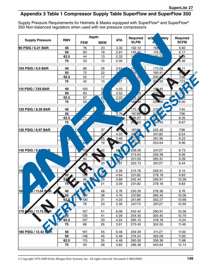
SuperLite 27
149© Copyright 1970-2008 Kirby Morgan Dive Systems, Inc. All rights reserved. Document # 080528001
Appendix 3 Table 1 Compressor Supply Table SuperFlow and SuperFlow 350
Supply Pressure Requirements for Helmets & Masks equipped with SuperFlow® and SuperFlow® 350 Non-balanced regulators when used with low pressure compressors
Supply Pressure RMVDepth
ATARequired
SLPMw/20% safety
marginRequired
SCFMFSW MSW
90 PSIG / 6.21 BAR 40 76 23 3.30 132.12 158.55 5.6050 63 19 2.91 145.45 174.55 6.17
62.5 44 13 2.33 145.83 175.00 6.1875 33 10 2.00 150.00 180.00 6.36
100 PSIG / 6.9 BAR 40 86 26 3.61 144.24 173.09 6.1150 72 22 3.18 159.09 190.91 6.74
62.5 55 17 2.67 166.67 200.00 7.0675 42 13 2.27 170.45 204.55 7.23
110 PSIG / 7.59 BAR 40 100 31 4.03 161.21 193.45 6.8350 83 25 3.52 175.76 210.91 7.45
62.5 67 20 3.03 189.39 227.27 8.0375 50 15 2.52 188.64 226.36 8.00
120 PSIG / 8.28 BAR 40 112 34 4.39 175.76 210.91 7.4550 91 28 3.76 187.88 225.45 7.96
62.5 71 22 3.15 196.97 236.36 8.3575 57 17 2.73 204.55 245.45 8.67
130 PSIG / 8.97 BAR 40 122 37 4.70 187.88 225.45 7.9650 100 31 4.03 201.52 241.82 8.54
62.5 82 25 3.48 217.80 261.36 9.2375 60 19 2.82 211.36 253.64 8.96
140 PSIG / 9.66 BAR 40 137 42 5.15 206.06 247.27 8.7350 108 33 4.27 213.64 256.36 9.06
62.5 84 26 3.55 221.59 265.91 9.3975 65 20 2.97 222.73 267.27 9.44
150 PSIG / 10.35 BAR 40 145 44 5.39 215.76 258.91 9.1550 120 37 4.64 231.82 278.18 9.83
62.5 95 29 3.88 242.42 290.91 10.2875 69 21 3.09 231.82 278.18 9.83
160 PSIG / 11.04 BAR 40 157 48 5.76 230.30 276.36 9.7650 124 38 4.76 237.88 285.45 10.08
62.5 100 31 4.03 251.89 302.27 10.6875 76 23 3.30 247.73 297.27 10.50
170 PSIG / 11.73 BAR 40 167 51 6.06 242.42 290.91 10.2850 135 41 5.09 254.55 305.45 10.79
62.5 107 33 4.24 265.15 318.18 11.2475 86 26 3.61 270.45 324.55 11.46
180 PSIG / 12.42 BAR 40 181 55 6.48 259.39 311.27 11.0050 148 45 5.48 274.24 329.09 11.62
62.5 115 35 4.48 280.30 336.36 11.8875 93 28 3.82 286.36 343.64 12.14
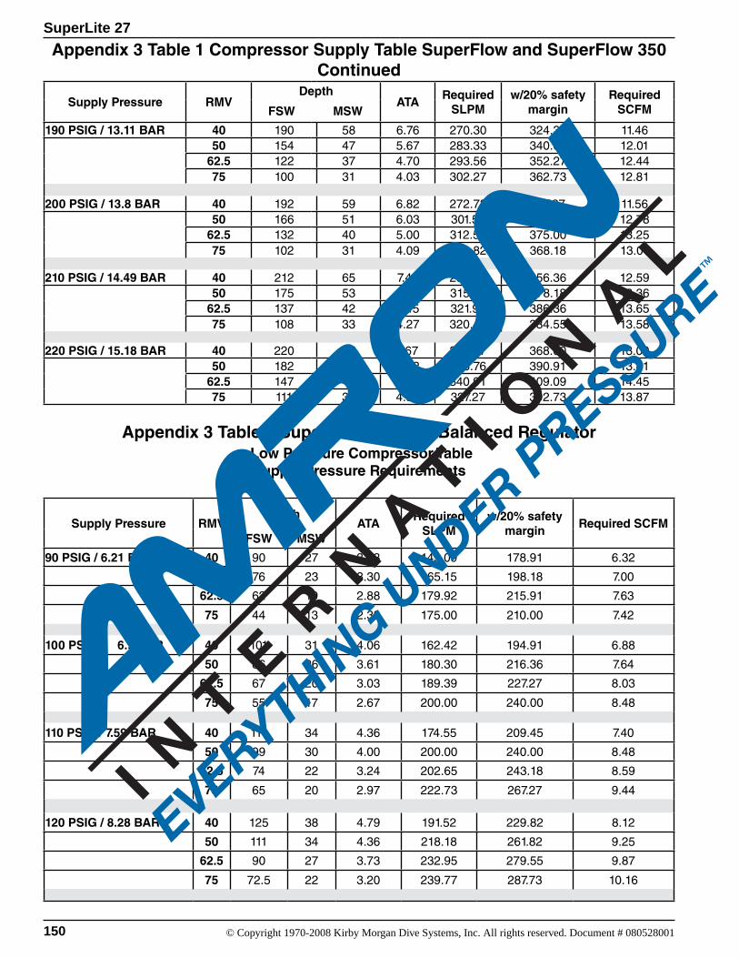
150 © Copyright 1970-2008 Kirby Morgan Dive Systems, Inc. All rights reserved. Document # 080528001
SuperLite 27
Supply Pressure RMVDepth
ATARequired
SLPMw/20% safety
marginRequired
SCFMFSW MSW
190 PSIG / 13.11 BAR 40 190 58 6.76 270.30 324.36 11.4650 154 47 5.67 283.33 340.00 12.01
62.5 122 37 4.70 293.56 352.27 12.4475 100 31 4.03 302.27 362.73 12.81
200 PSIG / 13.8 BAR 40 192 59 6.82 272.73 327.27 11.5650 166 51 6.03 301.52 361.82 12.78
62.5 132 40 5.00 312.50 375.00 13.2575 102 31 4.09 306.82 368.18 13.01
210 PSIG / 14.49 BAR 40 212 65 7.42 296.97 356.36 12.5950 175 53 6.30 315.15 378.18 13.36
62.5 137 42 5.15 321.97 386.36 13.6575 108 33 4.27 320.45 384.55 13.58
220 PSIG / 15.18 BAR 40 220 67 7.67 306.67 368.00 13.0050 182 56 6.52 325.76 390.91 13.81
62.5 147 45 5.45 340.91 409.09 14.4575 111 34 4.36 327.27 392.73 13.87
Appendix 3 Table 2 SuperFlow® 450 SS Balanced Regulator Low Pressure Compressor TableSupply Pressure Requirements
Supply Pressure RMVDepth
ATARequired
SLPMw/20% safety
marginRequired SCFM
FSW MSW
90 PSIG / 6.21 BAR 40 90 27 3.73 149.09 178.91 6.32
50 76 23 3.30 165.15 198.18 7.00
62.5 62 19 2.88 179.92 215.91 7.63
75 44 13 2.33 175.00 210.00 7.42
100 PSIG / 6.9 BAR 40 101 31 4.06 162.42 194.91 6.88
50 86 26 3.61 180.30 216.36 7.64
62.5 67 20 3.03 189.39 227.27 8.03
75 55 17 2.67 200.00 240.00 8.48
110 PSIG / 7.59 BAR 40 111 34 4.36 174.55 209.45 7.40
50 99 30 4.00 200.00 240.00 8.48
62.5 74 22 3.24 202.65 243.18 8.59
75 65 20 2.97 222.73 267.27 9.44
120 PSIG / 8.28 BAR 40 125 38 4.79 191.52 229.82 8.12
50 111 34 4.36 218.18 261.82 9.25
62.5 90 27 3.73 232.95 279.55 9.87
75 72.5 22 3.20 239.77 287.73 10.16
Appendix 3 Table 1 Compressor Supply Table SuperFlow and SuperFlow 350 Continued
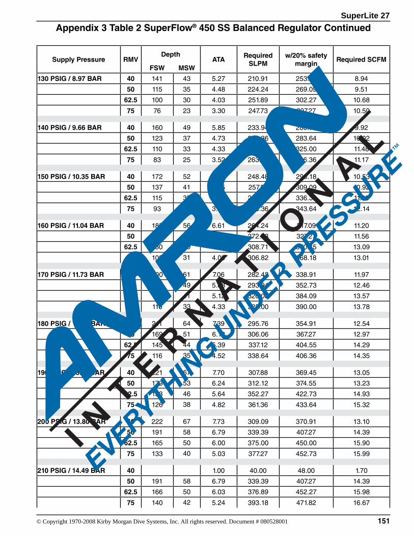
SuperLite 27
151© Copyright 1970-2008 Kirby Morgan Dive Systems, Inc. All rights reserved. Document # 080528001
Supply Pressure RMVDepth
ATARequired
SLPMw/20% safety
marginRequired SCFM
FSW MSW
130 PSIG / 8.97 BAR 40 141 43 5.27 210.91 253.09 8.94
50 115 35 4.48 224.24 269.09 9.51
62.5 100 30 4.03 251.89 302.27 10.68
75 76 23 3.30 247.73 297.27 10.50
140 PSIG / 9.66 BAR 40 160 49 5.85 233.94 280.73 9.92
50 123 37 4.73 236.36 283.64 10.02
62.5 110 33 4.33 270.83 325.00 11.48
75 83 25 3.52 263.64 316.36 11.17
150 PSIG / 10.35 BAR 40 172 52 6.21 248.48 298.18 10.53
50 137 41 5.15 257.58 309.09 10.92
62.5 115 35 4.48 280.30 336.36 11.88
75 93 28 3.82 286.36 343.64 12.14
160 PSIG / 11.04 BAR 40 185 56 6.61 264.24 317.09 11.20
50 147 45 5.45 272.73 327.27 11.56
62.5 130 40 4.94 308.71 370.45 13.09
75 102 31 4.09 306.82 368.18 13.01
170 PSIG / 11.73 BAR 40 200 61 7.06 282.42 338.91 11.97
50 161 49 5.88 293.94 352.73 12.46
62.5 136 41 5.12 320.08 384.09 13.57
75 110 33 4.33 325.00 390.00 13.78
180 PSIG / 12.42 BAR 40 211 64 7.39 295.76 354.91 12.54
50 169 51 6.12 306.06 367.27 12.97
62.5 145 44 5.39 337.12 404.55 14.29
75 116 35 4.52 338.64 406.36 14.35
190 PSIG / 13.11 BAR 40 221 67 7.70 307.88 369.45 13.05
50 173 53 6.24 312.12 374.55 13.23
62.5 153 46 5.64 352.27 422.73 14.93
75 126 38 4.82 361.36 433.64 15.32
200 PSIG / 13.80 BAR 40 222 67 7.73 309.09 370.91 13.10
50 191 58 6.79 339.39 407.27 14.39
62.5 165 50 6.00 375.00 450.00 15.90
75 133 40 5.03 377.27 452.73 15.99
210 PSIG / 14.49 BAR 40 1.00 40.00 48.00 1.70
50 191 58 6.79 339.39 407.27 14.39
62.5 166 50 6.03 376.89 452.27 15.98
75 140 42 5.24 393.18 471.82 16.67
Appendix 3 Table 2 SuperFlow® 450 SS Balanced Regulator Continued
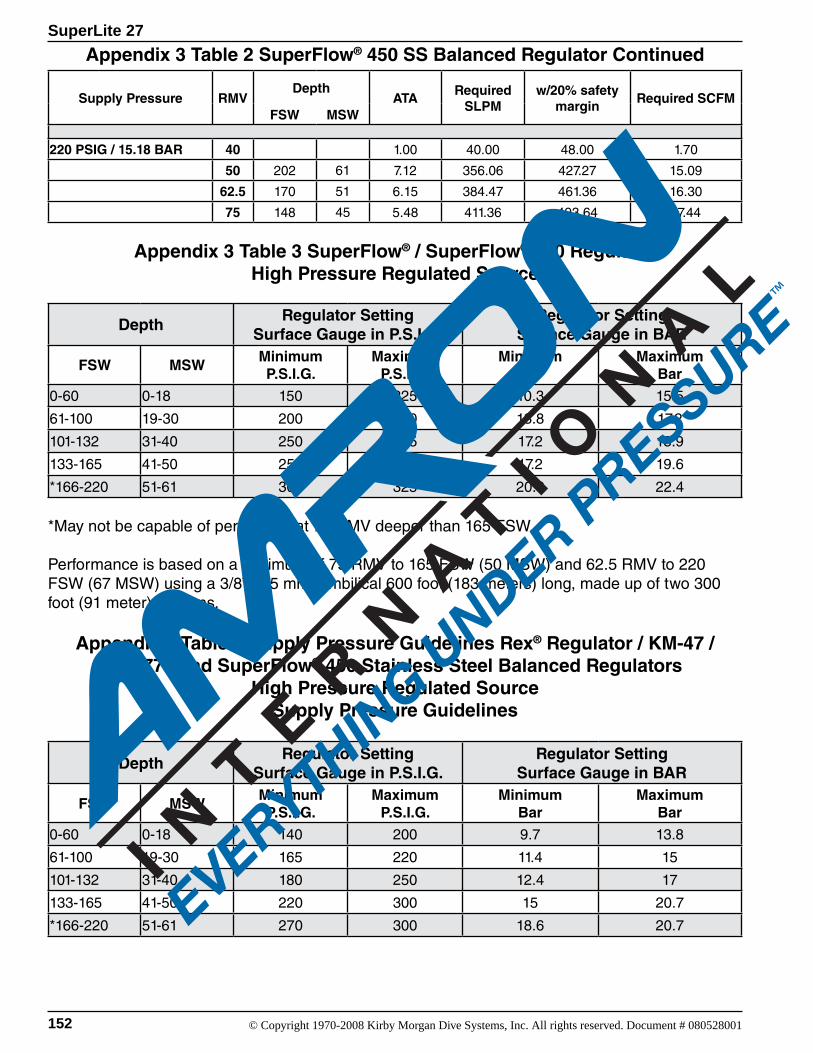
152 © Copyright 1970-2008 Kirby Morgan Dive Systems, Inc. All rights reserved. Document # 080528001
SuperLite 27
Supply Pressure RMVDepth
ATARequired
SLPMw/20% safety
marginRequired SCFM
FSW MSW
220 PSIG / 15.18 BAR 40 1.00 40.00 48.00 1.70
50 202 61 7.12 356.06 427.27 15.09
62.5 170 51 6.15 384.47 461.36 16.30
75 148 45 5.48 411.36 493.64 17.44
Appendix 3 Table 3 SuperFlow® / SuperFlow® 350 RegulatorHigh Pressure Regulated Source
DepthRegulator Setting
Surface Gauge in P.S.I.G.Regulator Setting
Surface Gauge in BAR
FSW MSWMinimumP.S.I.G.
MaximumP.S.I.G.
MinimumBar
MaximumBar
0-60 0-18 150 225 10.3 15.5
61-100 19-30 200 250 13.8 17.2
101-132 31-40 250 275 17.2 18.9
133-165 41-50 250 300 17.2 19.6
*166-220 51-61 300 325 20.6 22.4
*May not be capable of performing at 75 RMV deeper than 165 FSW.
Performance is based on a minimum of 75 RMV to 165 FSW (50 MSW) and 62.5 RMV to 220 FSW (67 MSW) using a 3/8” (9.5 mm) umbilical 600 foot (183 meters) long, made up of two 300 foot (91 meter) sections.
Appendix 3 Table 4 Supply Pressure Guidelines Rex® Regulator / KM-47 / KM-77 / and SuperFlow® 450 Stainless Steel Balanced Regulators
High Pressure Regulated SourceSupply Pressure Guidelines
DepthRegulator Setting
Surface Gauge in P.S.I.G.Regulator Setting
Surface Gauge in BAR
FSW MSWMinimumP.S.I.G.
MaximumP.S.I.G.
MinimumBar
MaximumBar
0-60 0-18 140 200 9.7 13.8
61-100 19-30 165 220 11.4 15
101-132 31-40 180 250 12.4 17
133-165 41-50 220 300 15 20.7
*166-220 51-61 270 300 18.6 20.7
Appendix 3 Table 2 SuperFlow® 450 SS Balanced Regulator Continued
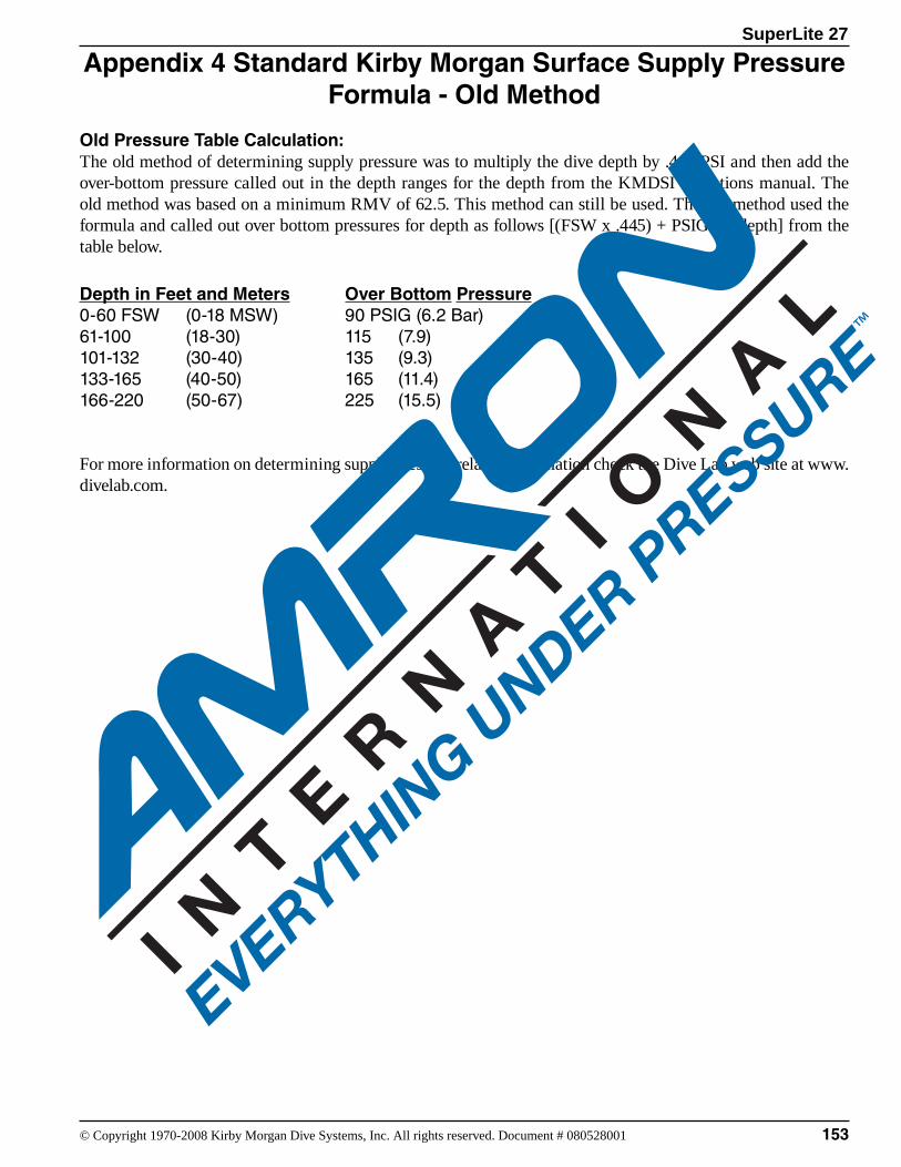
SuperLite 27
153© Copyright 1970-2008 Kirby Morgan Dive Systems, Inc. All rights reserved. Document # 080528001
Appendix 4 Standard Kirby Morgan Surface Supply Pressure Formula - Old Method
Old Pressure Table Calculation:The old method of determining supply pressure was to multiply the dive depth by .445 PSI and then add the over-bottom pressure called out in the depth ranges for the depth from the KMDSI operations manual. The old method was based on a minimum RMV of 62.5. This method can still be used. The old method used the formula and called out over bottom pressures for depth as follows [(FSW x .445) + PSIG for depth] from the table below.
Depth in Feet and Meters Over Bottom Pressure 0-60 FSW (0-18 MSW) 90 PSIG (6.2 Bar)61-100 (18-30) 115 (7.9) 101-132 (30-40) 135 (9.3) 133-165 (40-50) 165 (11.4) 166-220 (50-67) 225 (15.5)
For more information on determining supply pressure related information check the Dive Lab web site at www.divelab.com.